1 LCS Mission Modules Systems Engineering & Integration Achieving MBSE Benefits amidst Multiple Government Program Office System of System Challenges John Tyreman – Lockheed Martin Undersea Systems George Saroch – PMS 420 SEIT PAPM Rich Byers – Naval Surface Warfare Center, Panama CIty

Welcome message from author
This document is posted to help you gain knowledge. Please leave a comment to let me know what you think about it! Share it to your friends and learn new things together.
Transcript
1
LCS Mission Modules Systems Engineering & Integration
Achieving MBSE Benefits amidst Multiple
Government Program Office System of System
Challenges
John Tyreman – Lockheed Martin Undersea Systems
George Saroch – PMS 420 SEIT PAPM
Rich Byers – Naval Surface Warfare Center, Panama CIty
LCS Mission Modules
Systems Engineering & Integration
2
Agenda/Objective
• LCS Mission Module Challenges
• Submarine and LCS synergy
• Come as you are benefit/challenge
• LCS Model based SoS SE&I approach summary
• Interface model SoS analysis schema
• Data concordance analysis capabilities
• Model benefits
• Conclusion

LCS Mission Modules
Systems Engineering & Integration
LCS Mission Modules Challenge: Sheer Complexity
LCS Mission Capabilities • Multiple Mission Packages
Mine Countermeasures Mission Package • Multiple Mission Modules & Multiple Increments
Remote Minehunting Mission Module • Multiple Mission Systems
System PM OEM
RMS PMS 420 LM
Ships LH&R PMS 501 LM (FRE), GD (IND)
Mission Bay Stations PMS 501 LM (FRE), GD (IND)
MVCS PMS 420 NSWC-PCD
Ship C2 IWS-8 LM (FRE), GD (IND)
Mission Package C2 PMS 420 NSWC-PCD
MCM Analysis PMS 495 SAIC, NSWC-PCD
LCS mission modules have both system- and organizational-complexity
which results in formidable integration challenges
RMH Mission Systems • Multiple Development Organizations
3
LCS Mission Modules
Systems Engineering & Integration
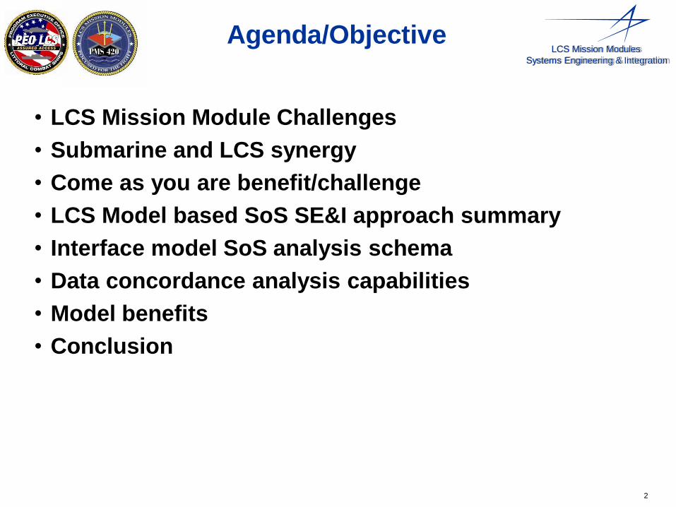
Submarine SoS SE & I (SWFTS/NPES SE&I) : Thought Leader, Steve Lose
• Big System: Multiple PEOs and program offices, 4 ship classes, 4 Million lines of SW code, 65 cabinets
• Complex interfaces: 30 subsystems, 2800 interface requirements, 25 OEMs
• Fast Update Pace: Yearly alternating capability / technology updates
LCS MP Model Based SoS SE Analysis History & Submarine Reuse
2000 2005 2010
Point to Point
IRS Documents
Centrally managed
interface requirements Model based Systems
Engineering (MBSE)
Come as you are Remote Minehunting
MBSE SoS Pilot
Re
use
SoS MBSE Methodology
LCS Mission Module SoS SE & I, Thought Leader, George Saroch
Significant Submarine Methodology and Tool benefits to LCS
2015
MDA
Prototype
• Big System: 12 Mission modules, 2 class variants
• Complex interfaces: 25 subsystems in RMH MM alone
• Fast Update Pace: 4 planned increments / RTI updates
PMS 420 sponsored SoS LCS Interface Model Pilot
• Interface MBSE model development – Significant Submarine Reuse
•
•
RMH Mission Module Interface Requirements Generation
Multiple RMH MBSE-enabled issues identified Interface
Model
RMH Mission
Module SE Analysis
… State of practice
MP Common interface Products MVCS MPOE MPCE MP ICD
SoS Tasking
Details
4
Gaps
LCS Mission Modules
Systems Engineering & Integration
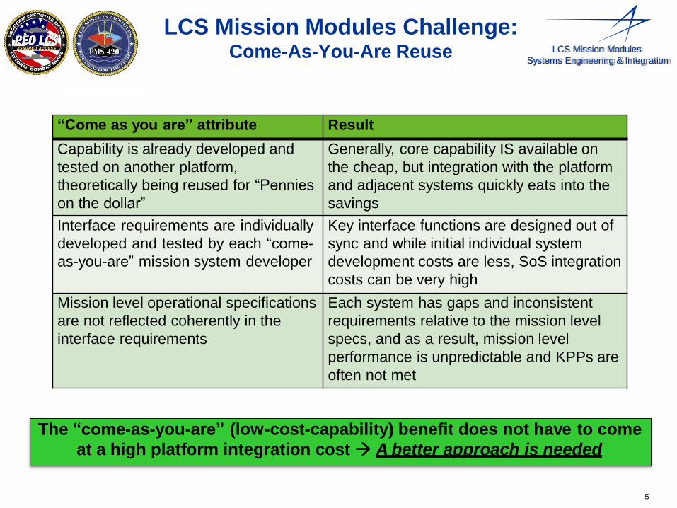
LCS Mission Modules Challenge: Come-As-You-Are Reuse
The “come-as-you-are” (low-cost-capability) benefit does not have to come
at a high platform integration cost A better approach is needed
5
“Come as you are” attribute Result
Capability is already developed and
tested on another platform,
theoretically being reused for “Pennies
on the dollar”
Generally, core capability IS available on
the cheap, but integration with the platform
and adjacent systems quickly eats into the
savings
Interface requirements are individually
developed and tested by each “come-
as-you-are” mission system developer
Key interface functions are designed out of
sync and while initial individual system
development costs are less, SoS integration
costs can be very high
Mission level operational specifications
are not reflected coherently in the
interface requirements
Each system has gaps and inconsistent
requirements relative to the mission level
specs, and as a result, mission level
performance is unpredictable and KPPs are
often not met
LCS Mission Modules
Systems Engineering & Integration
3.2.1 SYS-IF-0001-D Functional/Data Provide
Interface
Require 3.2
10.2.1.1 3.2.1.0- The Remote Minehunting System Provide
1 to OPMA Subsystem interface
shall include RMV Sensor Data.
Require 3.2.1
10.2.12. 581
3.2.4.4 CI-IF-0001 RDR OE-OPMA WS OE Provide Require 3.2.4
10.2.12. 581.501
3.2.4.4. CI-IF-0001-D Functional/Data
1 Interface
Provide Require 3.2.4.4
10.2.12. 581.514
3.2.4.4. The RDR OE Contact Data shall
1.0-1 include MsgHdr
Provide Require 3.2.4.1.0- 31
10.2.12. 581.523
3.2.4.4. The RDR OE ALS Sensor Data
1.0-10 shall include RMVInfo
Provide Require 3.2.4.1.0- 4
Interface Working Group
Mission
System
Stakeholders
MagicDraw Application with LCS SoS Interface Model
Schema and Scripts
ID Name Req Text RDR-OE OPMA-
WS-OE
Parent
10.2 3.2 SYS-IF-0001 RMS-OPMA
10.2.1
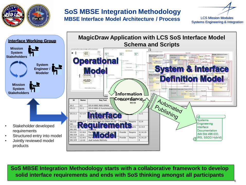
SoS MBSE Integration Methodology MBSE Interface Model Architecture / Process
SoS MBSE Integration Methodology starts with a collaborative framework to develop
solid interface requirements and ends with SoS thinking amongst all participants
System
Engineer /
Modeler
Mission
System
Stakeholders
• Stakeholder developed
requirements
• Structured entry into model
• Jointly reviewed model
products
6
LCS Mission Modules
Systems Engineering & Integration
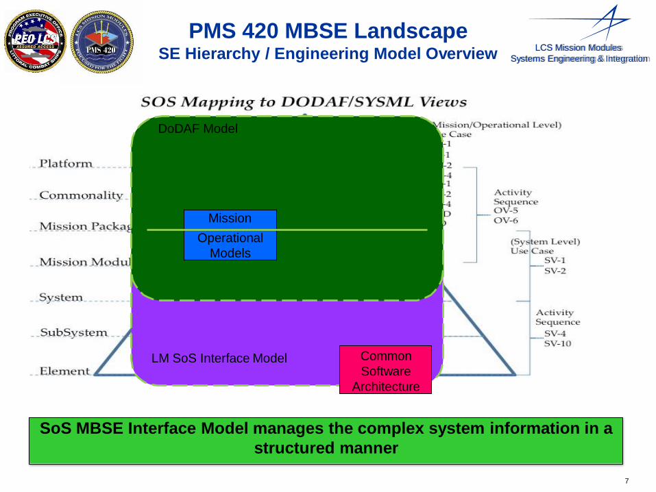
PMS 420 MBSE Landscape SE Hierarchy / Engineering Model Overview
SoS MBSE Interface Model manages the complex system information in a
structured manner
LM SoS Interface Model
DoDAF Model
7
Common
Software
Architecture
Mission
Operational
Models
LCS Mission Modules
Systems Engineering & Integration
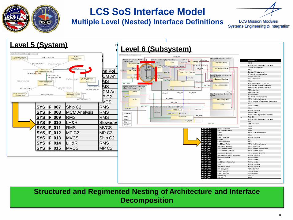
Level 5 (System)
LCS SoS Interface Model Multiple Level (Nested) Interface Definitions
nt #2
alysis
alysis
Mainten
8
Name End Point #1 E
SYS_IF_001 MCM Analysis M
SYS_IF_002 MP C2 R
SYS_IF_003 Stowage/Maint R
SYS_IF_004 MP C2 M
SYS_IF_005 Ship C2 M SYS_IF_006 MVCS M
nd Poi
CM An
MS
MS
CM An
P C2
VCS
SYS_IF_007 Ship C2 RMS
SYS_IF_008 MCM Analysis RMS
SYS_IF_009 RMS RMS
SYS_IF_010 LH&R Stowage/
SYS_IF_011 RMS MVCS
SYS_IF_012 MP C2 MP C2
SYS_IF_013 MVCS Ship C2
SYS_IF_014 LH&R RMS
SYS_IF_015 MVCS MP C2
Level 6 (Subsystem)
Structured and Regimented Nesting of Architecture and Interface
Decomposition
8
LCS Mission Modules
Systems Engineering & Integration
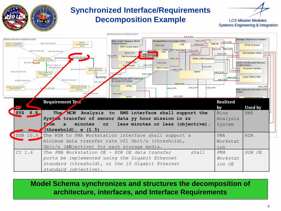
ID Requirement Text Realized
by Used by SYS 8.8 The MCM Analysis to RMS
System transfer of sensor data
from a minutes or less
(threshold), x (1.5)
interface shall
yy hour mission
minutes or less
support the
in zz
(objective).
Mine
Analysis
System
RMS
SUB 10.5 The RDR
minimum
to PMA Workstation interface shall support a
data transfer rate of1 Gbit/s (threshold),
10 Gbit/s (objective) for each storage media.
PMA
Workstat
ion
RDR
CI 1.6 The PMA Workstation OE - RDR OE data transfer
ports be implemented using the Gigabit Ethernet
standard (threshold), or the 10 Gigabit Ethernet
standard (objective).
shall PMA
Workstat
ion OE
RDR OE
Synchronized Interface/Requirements
Decomposition Example
Model Schema synchronizes and structures the decomposition of
architecture, interfaces, and Interface Requirements
9

LCS Mission Modules
Systems Engineering & Integration
LCS SoS MBSE End to End Analysis
Data Thread View
• CSCI only
• End to End data flow
• Process to process
message Flow
Electrical Thread
View
• HWCI Only
• ANSI and
custom
interfaces
Mechanical Thread
View
• HWCI Only
• Touch Points
• Complex
mechanical
Interactions
Software Allocation
View
• CSCI Only
• SW Hosting
• Basis to manage OS
Environment
Network View
• HWCI Only
• Network Topology
• Network standards
• Throughput “choke point” analysis
Interface model provides an end-to-end viewpoint in the data, electrical
and mechanical domains to engage the appropriate SME discipline.
10

LCS Mission Modules
Systems Engineering & Integration
MP ICD Content:
Operational Analysis Artifacts
Activity Diagrams
• Flow of activities for decomposing
operational information
• Lowest level activity becomes
sequence diagram
Sequence Diagrams
• Provides means to ensure
operations between subsystems
are covered by requirements
• Provides baseline for additional
operational analysis
SoS MBSE Interface mthe odadta elinlk inpterrfoacve tiodsueppsortaMVsCSoaluitdomaftioc luinkndation to ensure
2opRMeMrVaPtoisoitionn,al arCcI hiteThce DtuLI-rReCStCoI shianll steendrRfMaMcVeheradeinqg tuo tihreeNemtwoerknts integrity
Operation Reqt Requirement Text ID
1 RMMV Position, CI Heading, and Speed 68.16
Heading and Speed 98.8 longitude) to the Network Encryptor CSCI for transmission over
CI The DLI-R CSCI shall send RMMV position (latitude and
management.
Heading and Speed 98.9 Encryptor CSCI for transmission over the data link interface to support MVCS automatic link management.
The RMMV CTL CSCI shall send RMMV position (latitude a•nd
11 2 RMMV Position, CI The DLI-R CSCI shall send RMMV speed to the Network
longitude) to the DLI-R CSCI to support MVCS automatic link management.
1 RMMV Position,
Heading, and Speed
CI
68.17 The RMMV CTL CSCI shall send RMMV heading to the DL•I-R CSCI to support MVCS automatic link management.
1 RMMV Position, CI Heading, and Speed 68.18
The RMMV CTL CSCI shall send RMMV speed to the DLI-R CSCI to support MVCS automatic link management.
2 RMMV Position,
Linked Interface Requirements
Thread function integrity in
requirements baseline
Objective test checklist

12
LCS Mission Modules
Systems Engineering & Integration
System of Systems Thread Integration Maturity
Operational/System Architecture
and Interface Requirements Enhanced Interface RVM
• Interface requirements
with Verification method
and Priority
• Test conduct survey from
constituent subsystems
• Mission Module thread
functional test case
organization
SoS Thread Integration
Maturity Model
• Mission Module thread
functional test case
organized
• Compiled survey of
prioritized interface
requirements test voids
Structured SoS Thread Integration Maturity model provides a means to objectively and thoroughly plan platform integration
LCS Mission Modules
Systems Engineering & Integration
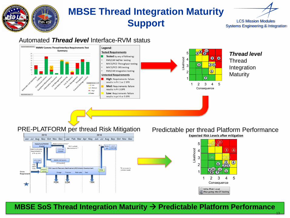
MBSE Thread Integration Maturity
Support
Automated Thread level Interface-RVM status
Thread level
Thread
Integration
Maturity
PRE-PLATFORM per thread Risk Mitigation Predictable per thread Platform Performance
MBSE SoS Thread Integration Maturity Predictable Platform Performance 13
LCS Mission Modules
Systems Engineering & Integration
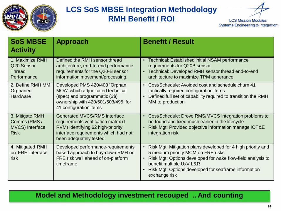
LCS SoS MBSE Integration Methodology
RMH Benefit / ROI
Model and Methodology investment recouped .. And counting
14
SoS MBSE
Activity
Approach Benefit / Result
1. Maximize RMH
Q20 Sensor
Thread
Performance
Defined the RMH sensor thread
architecture, end-to-end performance
requirements for the Q20-B sensor
information movement/processing.
• Technical: Established initial NSAM performance
requirements for Q20B sensor
• Technical: Developed RMH sensor thread end-to-end
architecture to maximize TPM adherance
2. Define RMH MM
Orphaned
Hardware
Developed PMS 420/403 “Orphan
MOA” which adjudicated technical
(spec) and programmatic ($$)
ownership with 420/501/503/495 for
41 configuration items
• Cost/Schedule: Avoided cost and schedule churn 41
tactically required configuration items
• Defined full set of capability required to transition the RMH
MM to production
3. Mitigate RMH
Comms (RMS /
MVCS) Interface
Risk
Generated MVCS/RMS interface
requirements verification matrix (I-
RVM) identifying 62 high-priority
interface requirements which had not
been adequately tested.
• Cost/Schedule: Drove RMS/MVCS integration problems to
be found and fixed much earlier in the lifecycle
• Risk Mgt: Provided objective information manage IOT&E
integration risk
4. Mitigated RMH
on FRE interface
risk
Developed performance-requirements
based approach to buy-down RMH on
FRE risk well ahead of on-platform
timeframe
• Risk Mgt: Mitigation plans developed for 4 high priority and
5 medium priority MCM on FRE risks
• Risk Mgt: Options developed for wake flow-field analysis to
benefit multiple UxV L&R
• Risk Mgt: Options developed for seaframe information
exchange risk
LCS Mission Modules
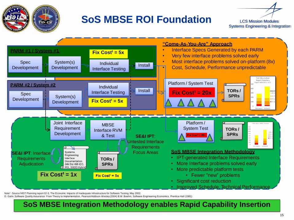
Systems Engineering & Integration SoS MBSE ROI Foundation
PARM #2 / System #2
PARM #1 / System #1
Joint Interface
Requirement
Development
Platform / System Test
Spec
Development
System(s)
Development
TORs /
SPRs
MBSE
Interface RVM
& Test
System(s)
Development
TORs /
SPRs
Fix Cost¹ = 1x
Fix Cost¹ = 20x
Individual
Interface Testing
“Come-As-You-Are” Approach
• Interface Specs Generated by each PARM
• Very few interface problems solved early
• Most interface problems solved on-platform (8x)
• Cost, Schedule, Performance unpredictable
Individual
Interface Testing Install
Install
Fix Cost¹ = 5x
Fix Cost¹ = 5x
SoS MBSE Integration Methodology
• IPT-generated Interface Requirements
• More Interface problems solved early
• More predictable platform tests
• Fewer “new” problems
• Significant cost reduction
• Improved Schedule, Technical Performance
SE&I IPT: Interface
Requirements
Adjudication
Platform /
System Test TORs /
SPRs SE&I IPT:
Untested Interface
Requirements
Focus Areas
Spec
Development
SoS MBSE Integration Methodology enables Rapid Capability Insertion
Note¹ : Source:NIST Planning report 02-3, The Economic Impacts of Inadequate Infrastructure for Software Testing, May 2002.
D. Galin, Software Quality Assurance: From Theory to Implementation, Pearson/Addison-Wesley (2004) B.W. Boehm, Software Engineering Economics, Prentice Hall (1981)
15
LCS Mission Modules
Systems Engineering & Integration
LCS SoS MBSE Integration
Methodology Conclusion / Takeaway
• Enables the “come-as-you-are” approach to be rapidly
acquiring capability from other Navy programs
• Has been proven with the RMH MM pilot to avoid costs
and manage risks at the mission module / platform
integration level
• Scales to multiple mission modules and multiple
platforms
• Enables all stakeholders to manage their own systems
and their own role in mission module / platform
integration to cohesively satisfy the LCS fleet and
sponsor
The Glue for the LCS MP Engineering Enterprise
16

Related Documents

![[MBSE 2021] ESA MBSE Evolution: From ESA SysML Toolbox to ...](https://static.cupdf.com/doc/110x72/61f003bcc08c1e795d73caa3/mbse-2021-esa-mbse-evolution-from-esa-sysml-toolbox-to-.jpg)