algorithms Article Achievement of Automatic Copper Wire Elongation System Hsiung-Cheng Lin * and Chung-Hao Cheng Department of Electronic Engineering, National Chin-Yi University of Technology, Taichung 41170, Taiwan; [email protected] * Correspondence: [email protected] Received: 17 April 2019; Accepted: 13 May 2019; Published: 15 May 2019 Abstract: Copper wire is a major conduction material that carries a variety of signals in industry. Presently, automatic wire elongating machines to produce very thin wiresare available for manufacturing. However, the original wires for the elongating process to thin sizes need heating, drawing and then threadingthrough the die molds by the manpower before the machine starts to work. This procedure repeatsuntil the wire threads through all various die molds. To replace the manpower, this paper aims to develop an automatic wire die molds threading system for the wire elongation process. Three pneumatic grippers are designed in the proposed system. The first gripper is used to clamp the wire. The second gripper fixed in the rotating mechanism is to draw the heated wire. The third gripper is used to move the wire for threading through the dies mold. The force designed for drawing the wire can be adjusted via the gear ratio. The experimental results confirm that the proposed system can accomplish the wiredies mold threading processin term of robustness, rapidness and accuracy. Keywords: automation; copper wire; drawing machine; elongation; pneumatic gripper 1. Introduction Automation on demand for all technical processes is essential in industry. However, the variety of desired functionalities makes the automation system extremely varied. As a result, the modern automation systems are moving towards very high complexity. A high degree of automation increases requirements in measurement technology and goes on in automation technology such as closed-loop and open-loop control or others. Feasible application-specific methods for signal measurement to master future systems are thus indispensable [1–6]. Unfortunately, the wire threading through the die mold for theelongation process has not been automatizeduntil now [7–10]. For advanced automation study related to this issue, many papers can be found in the literature [11–18]. Nevertheless, the design of wire die mold threading automation can be regarded as a new technological development in the copper wire manufacturing discipline. The 2.6 m/m oxygen-free copper is the original material for producing very thin wires. Applications include, for example, super thin medical cable, digestive system endoscopic ultrasound (EUS), and respiratory system EUS, etc. in the medical system. For these purposes, the 2.6 m/m wire must be elongated sufficiently to a small size like 0.05 m/m. Although there are machines available for the elongation process, currently the preparatory work still relies on human operation for the wire dies mold threading action. The whole procedure may take at least 30 minutes prior to machine operation, shown in Figure 1. Algorithms 2019, 12, 105; doi:10.3390/a12050105 www.mdpi.com/journal/algorithms

Welcome message from author
This document is posted to help you gain knowledge. Please leave a comment to let me know what you think about it! Share it to your friends and learn new things together.
Transcript
algorithms
Article
Achievement of Automatic Copper WireElongation System
Hsiung-Cheng Lin * and Chung-Hao Cheng
Department of Electronic Engineering, National Chin-Yi University of Technology, Taichung 41170, Taiwan;[email protected]* Correspondence: [email protected]
Received: 17 April 2019; Accepted: 13 May 2019; Published: 15 May 2019�����������������
Abstract: Copper wire is a major conduction material that carries a variety of signals inindustry. Presently, automatic wire elongating machines to produce very thin wiresare available formanufacturing. However, the original wires for the elongating process to thin sizes need heating,drawing and then threadingthrough the die molds by the manpower before the machine starts towork. This procedure repeatsuntil the wire threads through all various die molds. To replace themanpower, this paper aims to develop an automatic wire die molds threading system for the wireelongation process. Three pneumatic grippers are designed in the proposed system. The first gripperis used to clamp the wire. The second gripper fixed in the rotating mechanism is to draw the heatedwire. The third gripper is used to move the wire for threading through the dies mold. The forcedesigned for drawing the wire can be adjusted via the gear ratio. The experimental results confirmthat the proposed system can accomplish the wiredies mold threading processin term of robustness,rapidness and accuracy.
Keywords: automation; copper wire; drawing machine; elongation; pneumatic gripper
1. Introduction
Automation on demand for all technical processes is essential in industry. However, the varietyof desired functionalities makes the automation system extremely varied. As a result, the modernautomation systems are moving towards very high complexity. A high degree of automation increasesrequirements in measurement technology and goes on in automation technology such as closed-loopand open-loop control or others. Feasible application-specific methods for signal measurement tomaster future systems are thus indispensable [1–6]. Unfortunately, the wire threading through the diemold for theelongation process has not been automatizeduntil now [7–10]. For advanced automationstudy related to this issue, many papers can be found in the literature [11–18]. Nevertheless, the designof wire die mold threading automation can be regarded as a new technological development in thecopper wire manufacturing discipline.
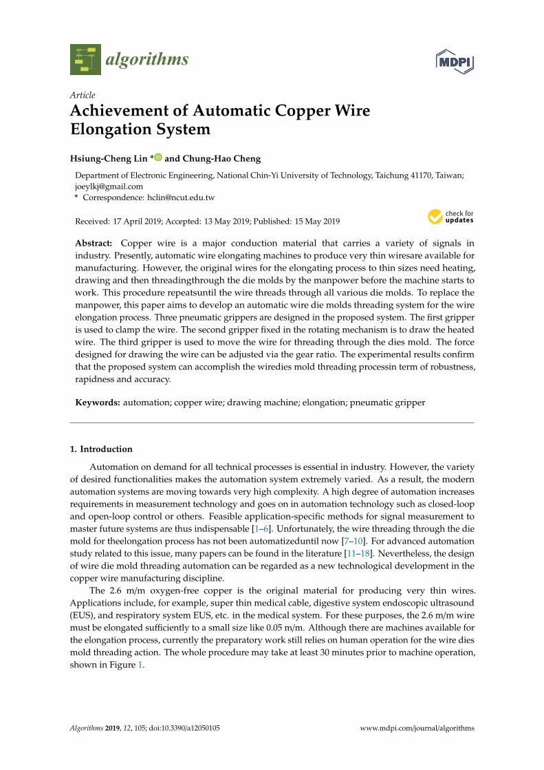
The 2.6 m/m oxygen-free copper is the original material for producing very thin wires.Applications include, for example, super thin medical cable, digestive system endoscopic ultrasound(EUS), and respiratory system EUS, etc. in the medical system. For these purposes, the 2.6 m/m wiremust be elongated sufficiently to a small size like 0.05 m/m. Although there are machines available forthe elongation process, currently the preparatory work still relies on human operation for the wire diesmold threading action. The whole procedure may take at least 30 minutes prior to machine operation,shown in Figure 1.
Algorithms 2019, 12, 105; doi:10.3390/a12050105 www.mdpi.com/journal/algorithms
Algorithms 2019, 12, 105 2 of 16
(a)
(b)
Figure 1. Human operation for wire dies mold treading. (a) Wire elongating process by hands;
(b) wire treading dies mold.
2. Design Principle
Fundamental Concept
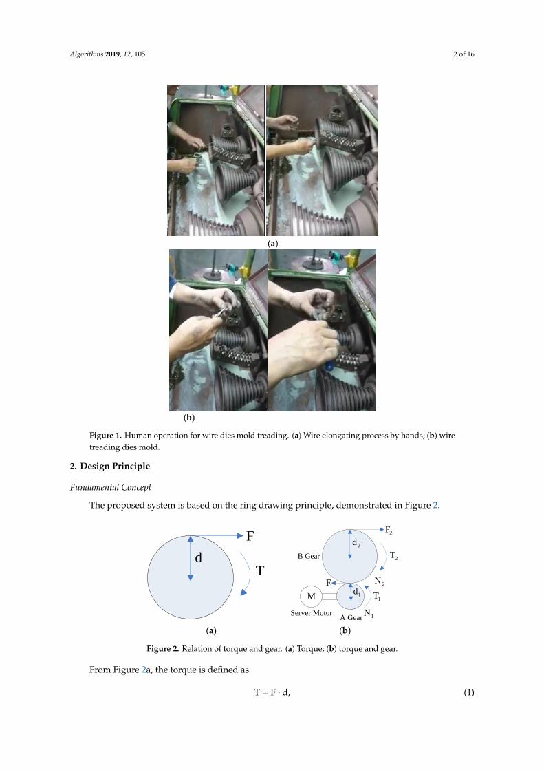
The proposed system is based on the ring drawing principle, demonstrated in Figure 2.
d
F
T
Server Motor
M
1N
2N
2d
1d
2F
1F
A Gear
B Gear 2T
1T
(a) (b)
Figure 2. Relation of torque and gear. (a) Torque; (b) torque and gear.
From Figure2a, the torque is defined as
dFT , (1)
where T: torque, F: force, d: distance from the force to the axle center.
From Figure 2b,
Figure 1. Human operation for wire dies mold treading. (a) Wire elongating process by hands; (b) wiretreading dies mold.
2. Design Principle
Fundamental Concept
The proposed system is based on the ring drawing principle, demonstrated in Figure 2.
(a)
(b)
Figure 1. Human operation for wire dies mold treading. (a) Wire elongating process by hands;
(b) wire treading dies mold.
2. Design Principle
Fundamental Concept
The proposed system is based on the ring drawing principle, demonstrated in Figure 2.
d
F
T
Server Motor
M
1N
2N
2d
1d
2F
1F
A Gear
B Gear 2T
1T
(a) (b)
Figure 2. Relation of torque and gear. (a) Torque; (b) torque and gear.
From Figure2a, the torque is defined as
dFT , (1)
where T: torque, F: force, d: distance from the force to the axle center.
From Figure 2b,
Figure 2. Relation of torque and gear. (a) Torque; (b) torque and gear.
From Figure 2a, the torque is defined as
T = F · d, (1)
Algorithms 2019, 12, 105 3 of 16
where T: torque, F: force, d: distance from the force to the axle center.From Figure 2b,
Ratio of gear A:B = N1:N2 (2)
Ratio of gear torque A:B = T1:T2 = F1d1:F2d2. (3)
By theory, the power output from the motor is equal to the power of gears A and B, respectively.
P = T1ω1 = T2ω2. (4)
It can be rewritten asT2
T1=ω1
ω2= Ng, (5)
where ω1 and ω2 are the angular frequency of gears A and B, respectively.
Ng =N2
N1. (6)
As above, it is clear that the force is the key factor for the wire elongation. It indicates thatincreasing the force can strengthen the torque. In other words, N2 > N1 will result in T2 > T1 and thusF2 is enlarged.
3. System Structure
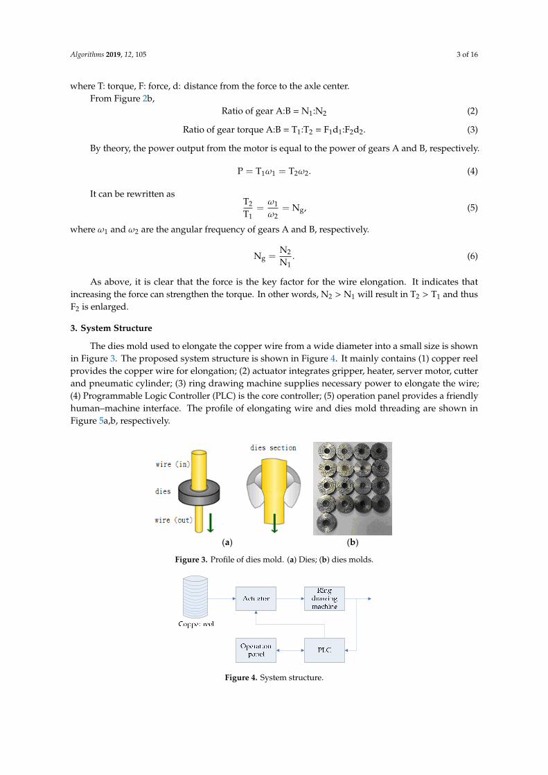
The dies mold used to elongate the copper wire from a wide diameter into a small size is shownin Figure 3. The proposed system structure is shown in Figure 4. It mainly contains (1) copper reelprovides the copper wire for elongation; (2) actuator integrates gripper, heater, server motor, cutterand pneumatic cylinder; (3) ring drawing machine supplies necessary power to elongate the wire;(4) Programmable Logic Controller (PLC) is the core controller; (5) operation panel provides a friendlyhuman–machine interface. The profile of elongating wire and dies mold threading are shown inFigure 5a,b, respectively.
Ratio of gear A:B = N1:N2 (2)
Ratio of gear torque A:B = T1:T2 = F1d1:F2d2. (3)
By theory, the power output from the motor is equal to the power of gears A and B, respectively.
2211 TTP ωω == . (4)
It can be rewritten as
g2
1
1
2 NTT ==
ωω , (5)
where 1ω and 2ω are the angular frequency of gears A and B, respectively.
1
2g N
NN = . (6)
As above, it is clear that the force is the key factor for the wire elongation. It indicates that increasing the force can strengthen the torque. In other words, 12 NN > will result in 12 TT > and thus 2F is enlarged.
3. System Structure
The dies mold used to elongate the copper wire from a wide diameter into a small size is shown in Figure 3. The proposed system structure is shown in Figure 4. It mainly contains (1) copper reel provides the copper wire for elongation; (2) actuator integrates gripper, heater, server motor, cutter and pneumatic cylinder; (3) ring drawing machine supplies necessary power to elongate the wire; (4) Programmable Logic Controller (PLC) is the core controller; (5) operation panel provides a friendly human–machine interface. The profile of elongating wire and dies mold threading are shown in Figure 5a,b, respectively.
(a) (b)
Figure 3. Profile of dies mold. (a) Dies; (b) dies molds.
Figure 4. System structure.
Figure 3. Profile of dies mold. (a) Dies; (b) dies molds.
Ratio of gear A:B = N1:N2 (2)
Ratio of gear torque A:B = T1:T2 = F1d1:F2d2. (3)
By theory, the power output from the motor is equal to the power of gears A and B, respectively.
2211 TTP ωω == . (4)
It can be rewritten as
g2
1
1
2 NTT ==
ωω , (5)
where 1ω and 2ω are the angular frequency of gears A and B, respectively.
1
2g N
NN = . (6)
As above, it is clear that the force is the key factor for the wire elongation. It indicates that increasing the force can strengthen the torque. In other words, 12 NN > will result in 12 TT > and thus 2F is enlarged.
3. System Structure
The dies mold used to elongate the copper wire from a wide diameter into a small size is shown in Figure 3. The proposed system structure is shown in Figure 4. It mainly contains (1) copper reel provides the copper wire for elongation; (2) actuator integrates gripper, heater, server motor, cutter and pneumatic cylinder; (3) ring drawing machine supplies necessary power to elongate the wire; (4) Programmable Logic Controller (PLC) is the core controller; (5) operation panel provides a friendly human–machine interface. The profile of elongating wire and dies mold threading are shown in Figure 5a,b, respectively.
(a) (b)
Figure 3. Profile of dies mold. (a) Dies; (b) dies molds.
Figure 4. System structure. Figure 4. System structure.
Algorithms 2019, 12, 105 4 of 16
Gripper 1
Copper reel
Gripper 2
Ring drawing machine
Wire cutter
Thick wire
Gripper 3
Eye moldElongated wire
Gripper 3 Gripper 2
Ring drawing machine
Copper reel
Gripper 1
(a) (b)
Figure 5. Profile of proposed system operation. (a) Profile of elongating wire; (b) profile of dies
mold threading.
4. Design of Mechanical System
The major mechanical blocks of the proposed system, shown in Figure 6, include A: gripper 1.
B: contactless heater. C: gripper 3. D: wire cutter. E: dies mold. F: ring drawing machine (including
the server motor with gripper 2).
Figure 6. Depiction of proposed mechanical system.
Based on the concept of the above theory, a 30 kg weightwas designed to elongate the copper
wire. Selecting the mechanical system parameters is shown as follows.
50N1 , 150N2 , 1d = 0.03125 m,
2d = 0.09375 m,2F = 30 kgw = 30 × 9.8 N = 294N.
2T = 22dF = 294(N) × 0.09375 (m) = 27.5625 ( mN ) (7)
(rad/sec)5(sec)10
(rad)22
.
(8)
Assume
1 =
3(rad/s)
5
(9)
m)N(19.93
15625.27
N
NTT
2
121
. (10)
According to Equation (4), the motor power should be selected larger thanthe following value.
)W(32.175
5625.27TP 22
.
(11)
In this case, a 400 W server motor with rating torque: 1.27 is used in this system.
Figure 5. Profile of proposed system operation. (a) Profile of elongating wire; (b) profile of diesmold threading.
4. Design of Mechanical System
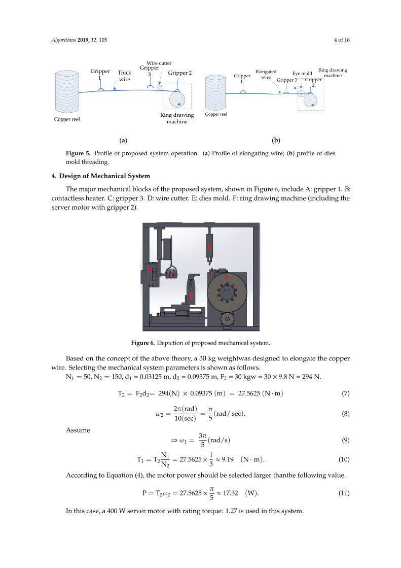
The major mechanical blocks of the proposed system, shown in Figure 6, include A: gripper 1. B:contactless heater. C: gripper 3. D: wire cutter. E: dies mold. F: ring drawing machine (including theserver motor with gripper 2).
Gripper 1
Copper reel
Gripper 2
Ring drawing machine
Wire cutter
Thick wire
Gripper 3
Eye moldElongated wire
Gripper 3 Gripper 2
Ring drawing machine
Copper reel
Gripper 1
(a) (b)
Figure 5. Profile of proposed system operation. (a) Profile of elongating wire; (b) profile of dies
mold threading.
4. Design of Mechanical System
The major mechanical blocks of the proposed system, shown in Figure 6, include A: gripper 1.
B: contactless heater. C: gripper 3. D: wire cutter. E: dies mold. F: ring drawing machine (including
the server motor with gripper 2).
Figure 6. Depiction of proposed mechanical system.
Based on the concept of the above theory, a 30 kg weightwas designed to elongate the copper
wire. Selecting the mechanical system parameters is shown as follows.
50N1 , 150N2 , 1d = 0.03125 m,
2d = 0.09375 m,2F = 30 kgw = 30 × 9.8 N = 294N.
2T = 22dF = 294(N) × 0.09375 (m) = 27.5625 ( mN ) (7)
(rad/sec)5(sec)10
(rad)22
.
(8)
Assume
1 =
3(rad/s)
5
(9)
m)N(19.93
15625.27
N
NTT
2
121
. (10)
According to Equation (4), the motor power should be selected larger thanthe following value.
)W(32.175
5625.27TP 22
.
(11)
In this case, a 400 W server motor with rating torque: 1.27 is used in this system.
Figure 6. Depiction of proposed mechanical system.
Based on the concept of the above theory, a 30 kg weightwas designed to elongate the copperwire. Selecting the mechanical system parameters is shown as follows.
N1 = 50, N2 = 150, d1 = 0.03125 m, d2 = 0.09375 m, F2 = 30 kgw = 30 × 9.8 N = 294 N.
T2 = F2d2= 294(N) × 0.09375 (m) = 27.5625 (N ·m) (7)
ω2 =2π(rad)10(sec)
=π5(rad/ sec). (8)
Assume⇒ ω1 =
3π5(rad/s) (9)
T1 = T2N1
N2= 27.5625×
13≈ 9.19 (N · m). (10)
According to Equation (4), the motor power should be selected larger thanthe following value.
P = T2ω2 = 27.5625×π5≈ 17.32 (W). (11)
In this case, a 400 W server motor with rating torque: 1.27 is used in this system.
Algorithms 2019, 12, 105 5 of 16
5. System Implementation with Experimental Results
5.1. Description of System Implementation
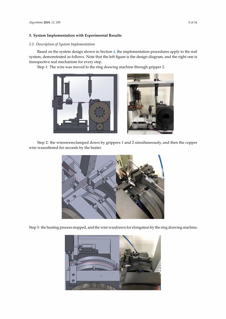
Based on the system design shown in Section 4, the implementation procedures apply to the realsystem, demonstrated as follows. Note that the left figure is the design diagram, and the right one isitsrespective real mechanism for every step.
Step 1: The wire was moved to the ring drawing machine through gripper 2.
5. System Implementation with Experimental Results
5.1. Description of System Implementation
Based on the system design shown in Section 4, the implementation procedures apply to the
real system, demonstrated as follows. Note that the left figure is the design diagram, and the right
one is itsrespective real mechanism for every step.
Step 1: The wire was moved to the ring drawing machine through gripper 2.
Step 2: the wireswereclamped down by grippers 1 and 2 simultaneously, and then the copper
wire wassoftened for seconds by the heater.
Step 3: the heating process stopped, and the wire wasdrawn for elongation by the ring
drawing machine.
Step4:gripper 1 opened.
Step 2: the wireswereclamped down by grippers 1 and 2 simultaneously, and then the copperwire wassoftened for seconds by the heater.
5. System Implementation with Experimental Results
5.1. Description of System Implementation
Based on the system design shown in Section 4, the implementation procedures apply to the
real system, demonstrated as follows. Note that the left figure is the design diagram, and the right
one is itsrespective real mechanism for every step.
Step 1: The wire was moved to the ring drawing machine through gripper 2.
Step 2: the wireswereclamped down by grippers 1 and 2 simultaneously, and then the copper
wire wassoftened for seconds by the heater.
Step 3: the heating process stopped, and the wire wasdrawn for elongation
by the ring drawing machine.
Step 3: the heating process stopped, and the wire wasdrawn for elongation by the ring drawing machine.
5. System Implementation with Experimental Results
5.1. Description of System Implementation
Based on the system design shown in Section 4, the implementation procedures apply to the
real system, demonstrated as follows. Note that the left figure is the design diagram, and the right
one is itsrespective real mechanism for every step.
Step 1: The wire was moved to the ring drawing machine through gripper 2.
Step 2: the wireswereclamped down by grippers 1 and 2 simultaneously, and then the copper
wire wassoftened for seconds by the heater.
Step 3: the heating process stopped, and the wire wasdrawn for elongation by the ring
drawing machine.
Step4:gripper 1 opened.
Algorithms 2019, 12, 105 6 of 16
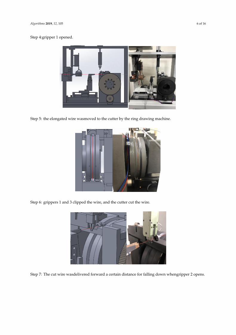
Step 4:gripper 1 opened.Step4:gripper 1 opened.
Step5: the elongated wire wasmoved to the cutter by the ring drawing machine.
Step6: grippers 1 and 3 clipped the wire, and the cutter cut the wire.
Step 5: the elongated wire wasmoved to the cutter by the ring drawing machine.
Step4:gripper 1 opened.
Step5: the elongated wire wasmoved to the cutter by the ring drawing machine.
Step6: grippers 1 and 3 clipped the wire, and the cutter cut the wire. Step 6: grippers 1 and 3 clipped the wire, and the cutter cut the wire.
Step7: The cut wire wasdelivered forward a certain distance for falling down whengripper 2
opens.
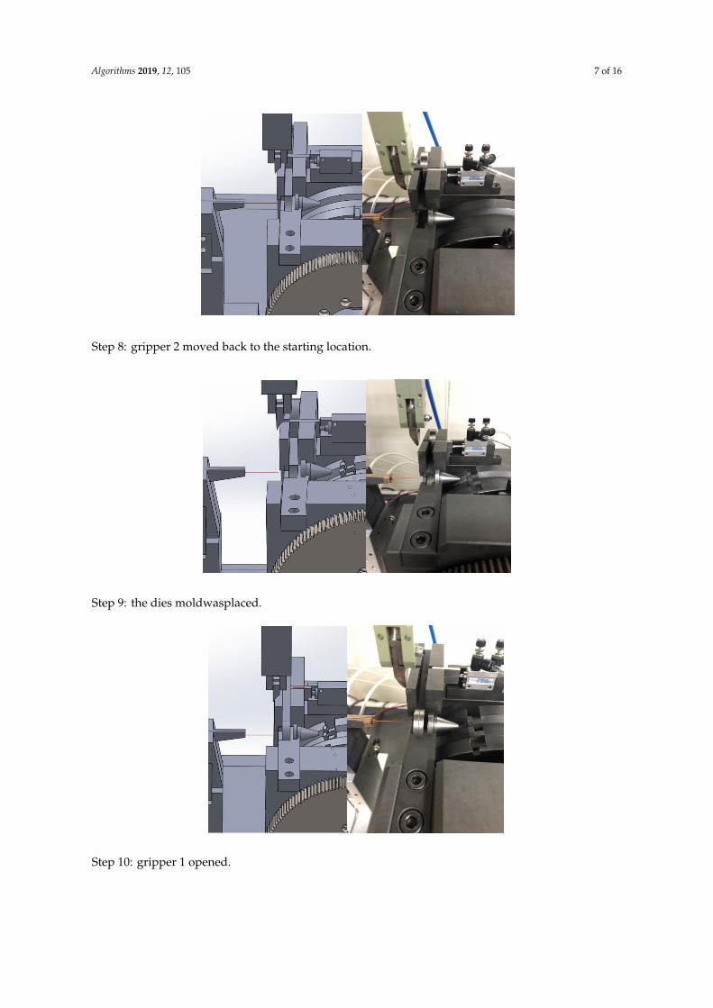
Step 8: gripper 2 moved back to the starting location.
Step 9: the dies moldwasplaced.
Step 7: The cut wire wasdelivered forward a certain distance for falling down whengripper 2 opens.
Algorithms 2019, 12, 105 7 of 16
Step7: The cut wire wasdelivered forward a certain distance for falling down whengripper 2
opens.
Step 8: gripper 2 moved back to the starting location.
Step 9: the dies moldwasplaced.
Step 8: gripper 2 moved back to the starting location.
Step7: The cut wire wasdelivered forward a certain distance for falling down whengripper 2
opens.
Step 8: gripper 2 moved back to the starting location.
Step 9: the dies moldwasplaced. Step 9: the dies moldwasplaced.
Step10: gripper 1 opened.
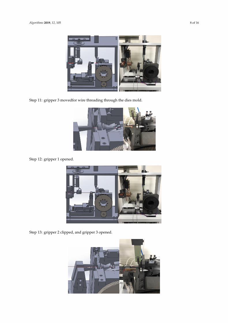
Step11: gripper 3 movedfor wire threading through the dies mold.
Step12: gripper 1 opened.
Step 10: gripper 1 opened.
Algorithms 2019, 12, 105 8 of 16
Step10: gripper 1 opened.
Step11: gripper 3 movedfor wire threading through the dies mold.
Step12: gripper 1 opened.
Step 11: gripper 3 movedfor wire threading through the dies mold.
Step10: gripper 1 opened.
Step11: gripper 3 movedfor wire threading through the dies mold.
Step12: gripper 1 opened. Step 12: gripper 1 opened.
Step13: gripper 2 clipped, and gripper 3 opened.
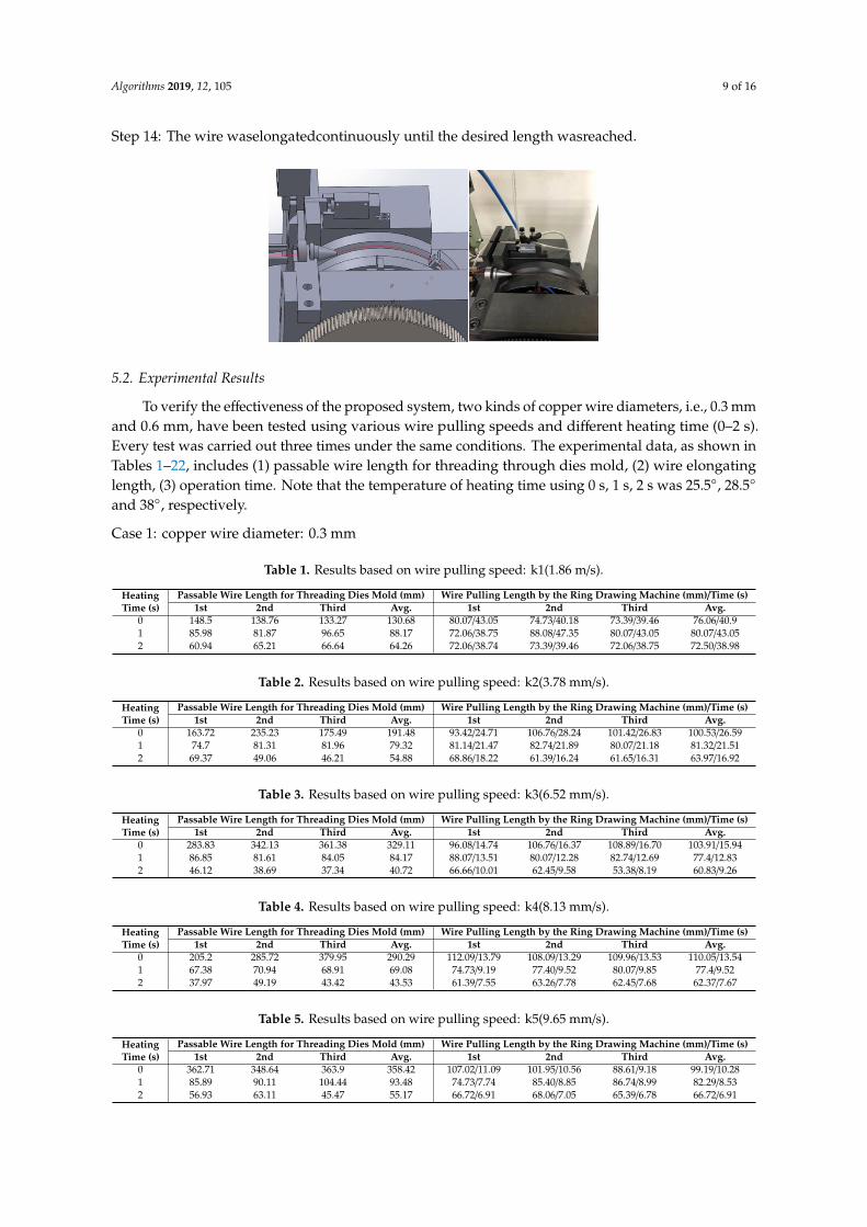
Step 14: The wire waselongatedcontinuously until the desired length wasreached.
5.2. Experimental Results
To verify the effectiveness of the proposed system, two kinds of copper wire diameters, i.e., 0.3
mm and 0.6 mm, have been tested using various wire pulling speeds and different heating time (0–
2 s). Every test was carried out three times under the same conditions. The experimental data, as
shown in Tables 1–22, includes (1) passable wire length for threading through dies mold, (2) wire
elongating length, (3) operation time. Note that the temperature of heating time using 0 s, 1 s, 2 s
was 25.5°, 28.5° and 38°, respectively.
Step 13: gripper 2 clipped, and gripper 3 opened.
Step13: gripper 2 clipped, and gripper 3 opened.
Step 14: The wire waselongatedcontinuously until the desired length wasreached.
5.2. Experimental Results
To verify the effectiveness of the proposed system, two kinds of copper wire diameters, i.e., 0.3
mm and 0.6 mm, have been tested using various wire pulling speeds and different heating time (0–
2 s). Every test was carried out three times under the same conditions. The experimental data, as
shown in Tables 1–22, includes (1) passable wire length for threading through dies mold, (2) wire
elongating length, (3) operation time. Note that the temperature of heating time using 0 s, 1 s, 2 s
was 25.5°, 28.5° and 38°, respectively.
Algorithms 2019, 12, 105 9 of 16
Step 14: The wire waselongatedcontinuously until the desired length wasreached.
Step13: gripper 2 clipped, and gripper 3 opened.
Step 14: The wire waselongatedcontinuously until the desired length wasreached.
5.2. Experimental Results
To verify the effectiveness of the proposed system, two kinds of copper wire diameters, i.e., 0.3
mm and 0.6 mm, have been tested using various wire pulling speeds and different heating time (0–
2 s). Every test was carried out three times under the same conditions. The experimental data, as
shown in Tables 1–22, includes (1) passable wire length for threading through dies mold, (2) wire
elongating length, (3) operation time. Note that the temperature of heating time using 0 s, 1 s, 2 s
was 25.5°, 28.5° and 38°, respectively.
5.2. Experimental Results
To verify the effectiveness of the proposed system, two kinds of copper wire diameters, i.e., 0.3 mmand 0.6 mm, have been tested using various wire pulling speeds and different heating time (0–2 s).Every test was carried out three times under the same conditions. The experimental data, as shown inTables 1–22, includes (1) passable wire length for threading through dies mold, (2) wire elongatinglength, (3) operation time. Note that the temperature of heating time using 0 s, 1 s, 2 s was 25.5◦, 28.5◦
and 38◦, respectively.
Case 1: copper wire diameter: 0.3 mm
Table 1. Results based on wire pulling speed: k1(1.86 m/s).
HeatingTime (s)
Passable Wire Length for Threading Dies Mold (mm) Wire Pulling Length by the Ring Drawing Machine (mm)/Time (s)1st 2nd Third Avg. 1st 2nd Third Avg.
0 148.5 138.76 133.27 130.68 80.07/43.05 74.73/40.18 73.39/39.46 76.06/40.91 85.98 81.87 96.65 88.17 72.06/38.75 88.08/47.35 80.07/43.05 80.07/43.052 60.94 65.21 66.64 64.26 72.06/38.74 73.39/39.46 72.06/38.75 72.50/38.98
Table 2. Results based on wire pulling speed: k2(3.78 mm/s).
HeatingTime (s)
Passable Wire Length for Threading Dies Mold (mm) Wire Pulling Length by the Ring Drawing Machine (mm)/Time (s)1st 2nd Third Avg. 1st 2nd Third Avg.
0 163.72 235.23 175.49 191.48 93.42/24.71 106.76/28.24 101.42/26.83 100.53/26.591 74.7 81.31 81.96 79.32 81.14/21.47 82.74/21.89 80.07/21.18 81.32/21.512 69.37 49.06 46.21 54.88 68.86/18.22 61.39/16.24 61.65/16.31 63.97/16.92
Table 3. Results based on wire pulling speed: k3(6.52 mm/s).
HeatingTime (s)
Passable Wire Length for Threading Dies Mold (mm) Wire Pulling Length by the Ring Drawing Machine (mm)/Time (s)1st 2nd Third Avg. 1st 2nd Third Avg.
0 283.83 342.13 361.38 329.11 96.08/14.74 106.76/16.37 108.89/16.70 103.91/15.941 86.85 81.61 84.05 84.17 88.07/13.51 80.07/12.28 82.74/12.69 77.4/12.832 46.12 38.69 37.34 40.72 66.66/10.01 62.45/9.58 53.38/8.19 60.83/9.26
Table 4. Results based on wire pulling speed: k4(8.13 mm/s).
HeatingTime (s)
Passable Wire Length for Threading Dies Mold (mm) Wire Pulling Length by the Ring Drawing Machine (mm)/Time (s)1st 2nd Third Avg. 1st 2nd Third Avg.
0 205.2 285.72 379.95 290.29 112.09/13.79 108.09/13.29 109.96/13.53 110.05/13.541 67.38 70.94 68.91 69.08 74.73/9.19 77.40/9.52 80.07/9.85 77.4/9.522 37.97 49.19 43.42 43.53 61.39/7.55 63.26/7.78 62.45/7.68 62.37/7.67
Table 5. Results based on wire pulling speed: k5(9.65 mm/s).
HeatingTime (s)
Passable Wire Length for Threading Dies Mold (mm) Wire Pulling Length by the Ring Drawing Machine (mm)/Time (s)1st 2nd Third Avg. 1st 2nd Third Avg.
0 362.71 348.64 363.9 358.42 107.02/11.09 101.95/10.56 88.61/9.18 99.19/10.281 85.89 90.11 104.44 93.48 74.73/7.74 85.40/8.85 86.74/8.99 82.29/8.532 56.93 63.11 45.47 55.17 66.72/6.91 68.06/7.05 65.39/6.78 66.72/6.91
Algorithms 2019, 12, 105 10 of 16
Table 6. Results based on wire pulling speed: k6(11.04 mm/s).
HeatingTime (s)
Passable Wire Length for Threading Dies Mold (mm) Wire Pulling Length by the Ring Drawing Machine (mm)/Time (s)1st 2nd Third Avg. 1st 2nd Third Avg.
0 350.16 328.05 363.61 347.27 102.46/9.31 96.08/8.70 109.96/8.95 102.83/8.991 75.75 80.72 69.07 75.18 78.74/7.13 84.34/7.64 76.60/6.94 79.89/7.242 53.85 66.36 54.67 58.29 67.53/6.11 70.46/6.38 67.79/6.14 68.59/6.21
Table 7. Results based on wire pulling speed: k7(12.83 mm/s).
HeatingTime (s)
Passable Wire Length for Threading Dies Mold(mm) Wire Pulling Length by the Ring Drawing Machine (mm)/Time (s)1st 2nd Third Avg. 1st 2nd Third Avg.
0 349.57 372.26 375.2 365.67 98.75/7.69 106.22/8.28 102.46/8.01 102.48/7.991 88.5 93.62 94.79 92.3 73.93/5.76 74.73/5.82 83.27/6.49 77.31/6.022 47.75 55.55 43.32 48.87 62.45/4.87 70.73/5.51 60.05/4.68 64.41/5.02
Table 8. Results based on wire pulling speed:k8(14.66 mm/s).
HeatingTime (s)
Passable Wire Length for Threading Dies Mold (mm) Wire Pulling Length by the Ring Drawing Machine (mm)/Time (s)1st 2nd Third Avg. 1st 2nd Third Avg.
0 291.32 242.93 313.37 282.54 90.75/6.19 90.75/6.19 85.41/5.83 88.97/6.071 69.7 84.39 73.72 75.94 81.14/5.53 81.40/5.55 80.87/5.51 81.14/5.532 35.55 39.12 47.13 40.6 62.45/4.26 61.65/4.21 68.33/4.66 64.14/4.38
Table 9. Results based on wire pulling speed: k9(16.32 mm/s).
HeatingTime (s)
Passable Wire Length for Threading Dies Mold (mm) Wire Pulling Length by the Ring Drawing Machine (mm)/Time (s)1st 2nd Third Avg. 1st 2nd Third Avg.
0 364.46 374.8 378.74 372.67 99.29/6.08 105.16/6.44 93.42/5.73 99.29/6.081 83.88 99.91 89.5 91.1 75.53/4.63 92.08/5.64 81.40/4.98 83.0/5.082 51.52 49.43 46.92 49.29 61.39/3.76 60.85/3.73 62.72/3.84 61.65/3.78
Table 10. Results based on wire pulling speed: k10(18.25 mm/s).
HeatingTime (s)
Passable Wire Length for Threading Dies Mold (mm) Wire Pulling Length by the Ring Drawing Machine (mm)/Time (s)1st 2nd Third Avg. 1st 2nd Third Avg.
0 328.16 375.626 375.8 359.87 96.08/5.26 98.21/5.38 99.28/5.44 97.86/5.361 97.44 95.02 99.67 97.38 83.01/4.55 83.54/4.58 83.01/4.55 83.19/4.562 40.68 46.05 50.23 45.65 58.18/3.19 56.31/3.09 60.32/3.30 58.27/3.19
Table 11. Results based on wire pulling speed: k11(20.15 mm/s).
HeatingTime (s)
Passable Wire Length for Threading Dies Mold (mm) Wire Pulling Length by the Ring Drawing Machine (mm)/Time (s)1st 2nd Third Avg. 1st 2nd Third Avg.
0 374.19 369.4 368.37 370.65 111.56/5.54 116.64/5.79 113.69/5.64 113.96/5.661 73.86 72.44 70.01 72.1 93.41/4.64 86.21/4.28 82.21/4.08 87.28/4.332 69.71 60.37 61.47 63.85 76.60/3.80 68.86/3.42 74.99/3.72 73.48/3.64
Case 2: Copper wire diameter: 0.6 mm
Table 12. Results based on wire pulling speed: k1(1.86 m/s).
HeatingTime (s)
Passable Wire Length for Threading Dies Mold (mm) Wire Pulling Length by the Ring Drawing Machine (mm)/time (s)1st 2nd Third Avg. 1st 2nd Third Avg.
0 417.02 415.98 390.81 407.94 156.64/84.37 158.54/85.23 117.17/62.99 144.12/77.531 394.89 390.52 400.38 395.26 155.87/83.80 130.25/70.03 155.07/83.37 147.06/79.072 367.91 373.76 374.78 372.15 130.25/70.02 148.66/79.93 131.31/70.59 136.74/73.51
Table 13. Results based on wire pulling speed: k2(3.78 mm/s).
HeatingTime (s)
Passable Wire Length for Threading Dies Mold (mm) Wire Pulling Length by the Ring Drawing Machine (mm)/Time (s)1st 2nd Third Avg. 1st 2nd Third Avg.
0 414.56 404.02 412.74 410.44 138.25/36.58 128.11/33.89 137.19/36.29 134.52/35.591 402.71 382.82 381.77 389.1 116.90/30.93 113.17/29.94 107.83/28.53 112.63/29.82 368.37 354.87 374.22 365.82 91.10/24.08 91.55/24.22 91.55/24.22 81.4/24.17

Algorithms 2019, 12, 105 11 of 16
Table 14. Results based on wire pulling speed: k3(6.52 mm/s).
HeatingTime (s)
Passable Wire Length for Threading Dies Mold (mm) Wire Pulling Length by the Ring Drawing Machine (mm)/Time (s)1st 2nd Third Avg. 1st 2nd Third Avg.
0 414.12 412.8 398.67 408.53 138.32/20.75 128.37/19.69 127.31/19.53 131.33/19.991 379.37 373.7 377.9 376.99 105.95/16.25 106.23/16.29 102.76/15.76 104.98/16.12 160.27 151.26 147.63 153.05 90.75/13.92 90.21/13.83 90.48/13.88 90.48/13.88
Table 15. Results based on wire pulling speed: k4(8.13 mm/s).
HeatingTime (s)
Passable Wire Length for Threading Dies Mold (mm) Wire Pulling Length by the Ring Drawing Machine (mm)/Time (s)1st 2nd Third Avg. 1st 2nd Third Avg.
0 398.57 406.22 398.33 401.04 126.51/15.56 132.38/16.28 126.78/15.59 128.56/15.811 361.16 372.98 370.75 368.3 105.43/12.97 105.69/13.00 105.16/12.93 105.43/12.972 121.08 118.99 119.55 119.87 84.07/10.34 83.01/10.21 83.81/10.31 83.63/10.29
Table 16. Results based on wire pulling speed: k5(9.65 mm/s).
HeatingTime (s)
Passable Wire Length for Threading Dies Mold (mm) Wire Pulling Length by the Ring Drawing Machine (mm)/Time (s)1st 2nd Third Avg. 1st 2nd Third Avg.
0 398.78 401.97 395.41 398.95 129.45/13.41 129.71/13.44 125.71/13.03 128.29/13.291 361.83 360.84 361.52 361.83 106.22/11.01 100.35/10.39 104.62/10.84 103.73/10.752 117.28 119.88 116.26 117.81 87.28/9.04 91.28/9.46 86.81/8.68 88.46/9.06
Table 17. Results based on wire pulling speed: k6(11.04 mm/s).
HeatingTime (s)
Passable Wire Length for Threading Dies Mold (mm) Wire Pulling Length by the Ring Drawing Machine (mm)/Time (s)1st 2nd Third Avg. 1st 2nd Third Avg.
0 416.57 393.32 406.06 405.32 139.32/12.62 132.12/11.97 134.75/12.21 135.4/12.271 377.08 369.25 371.11 372.48 110.49/10.01 97.15/8.79 98.75/8.95 102.13/9.252 136.83 147.97 139.27 141.36 88.88/8.05 93.68/8.49 84.34/7.64 88.97/8.06
Table 18. Results based on wire pulling speed: k7(12.83 mm/s).
HeatingTime (s)
Passable Wire Length for Threading Dies Mold (mm) Wire Pulling Length by the Ring Drawing Machine (mm)1st 2nd Third Avg. 1st 2nd Third Avg.
0 402.49 396.81 401.94 400.41 121.17/9.44 131.58/10.26 136.91/10.67 129.89/10.121 383.75 378.23 372.56 378.18 112.89/8.79 108.36/8.45 109.43/8.53 110.22/8.592 134.36 128.31 129.77 130.81 91.55/7.14 94.75/7.39 84.41/6.66 90.24/7.06
Table 19. Results based on wire pulling speed: k8(14.66 mm/s).
HeatingTime (s)
Passable Wire Length for Threading Dies Mold (mm) Wire Pulling Length by the Ring Drawing Machine (mm)/Time (s)1st 2nd Third Avg. 1st 2nd Third Avg.
0 398.96 401.23 404.89 401.69 126.24/8.61 125.71/8.58 125.98/8.59 125.98/8.591 369.07 372.55 370.9 370.84 103.02/7.03 106.49/7.26 99.82/6.81 103.11/7.032 126.11 116.09 126.24 122.81 87.01/5.94 84.34/5.75 86.21/5.88 85.85/5.86
Table 20. Results based on wire pulling speed: k9(16.32 mm/s).
HeatingTime (s)
Passable Wire Length for Threading Dies Mold (mm) Wire Pulling Length by the Ring Drawing Machine (mm)/Time (s)1st 2nd Third Avg. 1st 2nd Third Avg.
0 403.73 406.41 399.23 403.12 131.85/8.08 132.38/8.11 126.78/7.77 130.34/7.991 375.64 375.34 368.61 373.2 104.36/6.37 108.03/6.62 102.76/6.3 105.05/6.432 134.39 126.63 122.47 127.83 89.95/5.51 85.94/5.27 85.14/5.22 87.01/5.33
Table 21. Results based on wire pulling speed: k10(18.25 mm/s).
HeatingTime (s)
Passable Wire Length for Threading Dies Mold (mm) Wire Pulling Length by the Ring Drawing Machine (mm)/Time (s)1st 2nd Third Avg. 1st 2nd Third Avg.
0 395.4 395.41 399.68 396.83 126.24/6.92 121.97/6.68 122.24/6.7 123.48/6.771 368.48 381.79 375.79 375.35 103.02/5.64 106.23/5.82 102.49/5.62 103.91/5.692 121.1 114.24 125.54 120.29 90.21/4.94 85.14/4.67 99.82/5.47 91.72/5.02
Table 22. Results based on wire pulling speed: k11(20.15 mm/s).
HeatingTime (s)
Passable Wire Length for Threading Dies Mold (mm) Wire Pulling Length by the Ring Drawing Machine (mm)/Time (s)1st 2nd Third Avg. 1st 2nd Third Avg.
0 400.74 402.02 407.25 403.34 143.86/7.14 151.84/7.54 150.8/7.48 148.83/7.391 374.86 366.09 376.16 372.37 117.44/5.83 116.1/5.76 118.50/5.88 117.35/5.822 160.99 167.27 155.8 161.35 97.95/4.86 99.82/4.95 100.89/5.01 99.55/4.94
Algorithms 2019, 12, 105 12 of 16
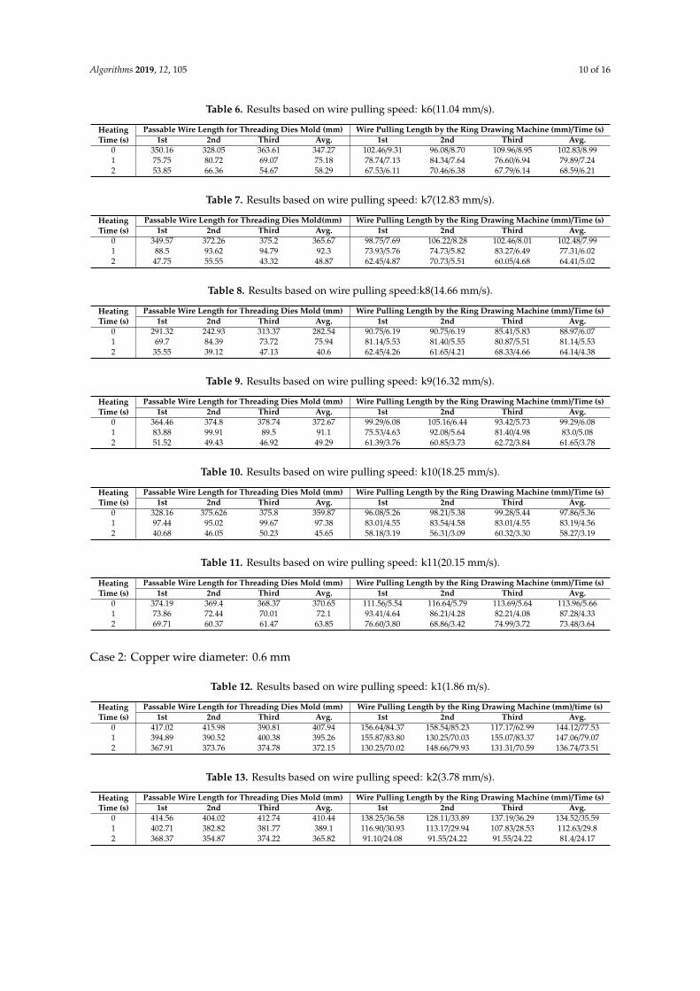
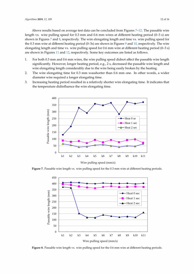
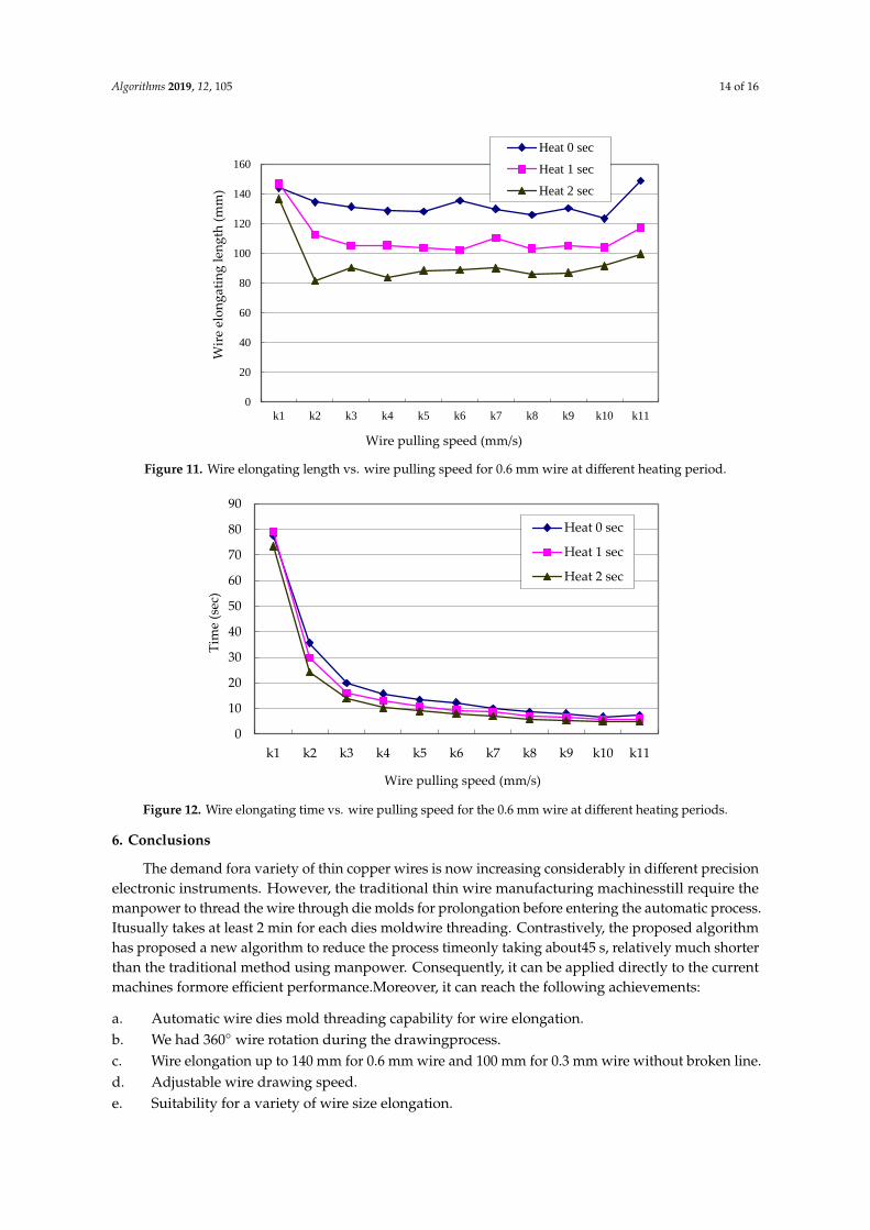
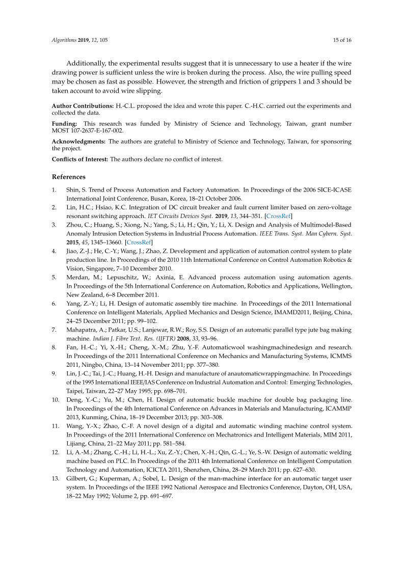
Above results based on average test data can be concluded from Figures 7–12. The passable wirelength vs. wire pulling speed for 0.3 mm and 0.6 mm wires at different heating period (0–3 s) areshown in Figures 7 and 8, respectively. The wire elongating length and time vs. wire pulling speed forthe 0.3 mm wire at different heating period (0–3s) are shown in Figures 9 and 10, respectively. The wireelongating length and time vs. wire pulling speed for 0.6 mm wire at different heating period (0–3 s)are shown in Figures 11 and 12, respectively. Some key outcomes are listed as follows.
1. For both 0.3 mm and 0.6 mm wires, the wire pulling speed didnot affect the passable wire lengthsignificantly. However, longer heating period, e.g., 2 s, decreased the passable wire length andwire elongating length considerably due to the wire being easily broken by the heating.
2. The wire elongating time for 0.3 mm wasshorter than 0.6 mm one. In other words, a widerdiameter wire required a longer elongating time.
3. Increasing heating period resulted in a relatively shorter wire elongating time. It indicates thatthe temperature didinfluence the wire elongating time.
different heating period (0–3 s) are shown in Figures 11 and 12, respectively. Some key outcomes
are listed as follows.
1. For both 0.3 mm and 0.6 mm wires, the wire pulling speed didnot affect the passable wire length
significantly. However, longer heating period, e.g., 2 s, decreased the passable wire length and
wire elongating length considerably due to the wire being easily broken by the heating.
2. The wire elongating time for 0.3 mm wasshorter than 0.6 mm one. In other words, a wider
diameter wire required a longer elongating time.
3. Increasing heating period resulted in a relatively shorter wire elongating time. It indicates that
the temperature didinfluence the wire elongating time.
Figure 7. Passable wire length vs. wire pulling speed for the 0.3 mm wire at different heating
periods.
Figure 8. Passable wire length vs. wire pulling speed for the 0.6 mm wire at different heating
periods.
0
50
100
150
200
250
300
350
400
k1 k2 k3 k4 k5 k6 k7 k8 k9 k10 k11
Pas
sab
le w
ire
len
gth
(m
m)
Wire pulling speed (mm/s)
Heat 0 se
Heat 1 sec
Heat 2 sec
0
50
100
150
200
250
300
350
400
450
k1 k2 k3 k4 k5 k6 k7 k8 k9 k10 k11
Pas
sab
le w
ire
len
gth
(m
m)
Wire pulling speed (mm/s)
Heat 0 sec
Heat 1 sec
Heat 2 sec
Figure 7. Passable wire length vs. wire pulling speed for the 0.3 mm wire at different heating periods.
different heating period (0–3 s) are shown in Figures 11 and 12, respectively. Some key outcomes
are listed as follows.
1. For both 0.3 mm and 0.6 mm wires, the wire pulling speed didnot affect the passable wire length
significantly. However, longer heating period, e.g., 2 s, decreased the passable wire length and
wire elongating length considerably due to the wire being easily broken by the heating.
2. The wire elongating time for 0.3 mm wasshorter than 0.6 mm one. In other words, a wider
diameter wire required a longer elongating time.
3. Increasing heating period resulted in a relatively shorter wire elongating time. It indicates that
the temperature didinfluence the wire elongating time.
Figure 7. Passable wire length vs. wire pulling speed for the 0.3 mm wire at different heating
periods.
Figure 8. Passable wire length vs. wire pulling speed for the 0.6 mm wire at different heating
periods.
0
50
100
150
200
250
300
350
400
k1 k2 k3 k4 k5 k6 k7 k8 k9 k10 k11
Pas
sab
le w
ire
len
gth
(m
m)
Wire pulling speed (mm/s)
Heat 0 se
Heat 1 sec
Heat 2 sec
0
50
100
150
200
250
300
350
400
450
k1 k2 k3 k4 k5 k6 k7 k8 k9 k10 k11
Pas
sab
le w
ire
len
gth
(m
m)
Wire pulling speed (mm/s)
Heat 0 sec
Heat 1 sec
Heat 2 sec
Figure 8. Passable wire length vs. wire pulling speed for the 0.6 mm wire at different heating periods.
Algorithms 2019, 12, 105 13 of 16
Figure 9. Wire elongating length vs. wire pulling speed for the 0.3 mm wire at different heating
periods.
Figure 10. Wire elongating time vs. wire pulling speed for the 0.3 mm wire at different heating
periods.
0
20
40
60
80
100
120
k1 k2 k3 k4 k5 k6 k7 k8 k9 k10 k11
Wir
e el
ongat
ing l
ength
(m
m)
Wire pulling speed (mm/s)
Heat 0 sec
Heat 1 sec
Heat 1 sec
0
5
10
15
20
25
30
35
40
45
50
k1 k2 k3 k4 k5 k6 k7 k8 k9 k10 k11
Tim
e (s
ec)
Wire pulling speed (mm/s)
Heat 0 sec
Heat 1 sec
Heat 2 sec
Figure 9. Wire elongating length vs. wire pulling speed for the 0.3 mm wire at different heating periods.
Figure 9. Wire elongating length vs. wire pulling speed for the 0.3 mm wire at different heating
periods.
Figure 10. Wire elongating time vs. wire pulling speed for the 0.3 mm wire at different heating
periods.
0
20
40
60
80
100
120
k1 k2 k3 k4 k5 k6 k7 k8 k9 k10 k11
Wir
e el
ongat
ing l
ength
(m
m)
Wire pulling speed (mm/s)
Heat 0 sec
Heat 1 sec
Heat 1 sec
0
5
10
15
20
25
30
35
40
45
50
k1 k2 k3 k4 k5 k6 k7 k8 k9 k10 k11
Tim
e (s
ec)
Wire pulling speed (mm/s)
Heat 0 sec
Heat 1 sec
Heat 2 sec
Figure 10. Wire elongating time vs. wire pulling speed for the 0.3 mm wire at different heating periods.
Algorithms 2019, 12, 105 14 of 16
Figure 11. Wire elongating length vs. wire pulling speed for 0.6 mm wire at different heating period.
Figure 12. Wire elongating time vs. wire pulling speed for the 0.6 mm wire at different heating
periods.
5. Conclusions
The demand fora variety of thin copper wires is now increasing considerably in different
precision electronic instruments. However, the traditional thin wire manufacturing machinesstill
require the manpower to thread the wire through die molds for prolongation before entering the
automatic process. Itusually takes at least 2 min for each dies moldwire threading. Contrastively,
the proposed algorithm has proposed a new algorithm to reduce the process timeonly taking
about45 s, relatively much shorter than the traditional method using manpower. Consequently, it
can be applied directly to the current machines formore efficient performance.Moreover, it can
reach the following achievements:
a. Automatic wire dies mold threading capability for wire elongation.
b. We had 360 wire rotation during the drawingprocess.
c. Wire elongation up to 140 mm for 0.6 mm wire and 100 mm for 0.3 mm wire without broken line.
d. Adjustable wire drawing speed.
e. Suitability for a variety of wire size elongation.
0
20
40
60
80
100
120
140
160
k1 k2 k3 k4 k5 k6 k7 k8 k9 k10 k11
Wir
e el
on
gat
ing
len
gth
(m
m)
Wire pulling speed (mm/s)
Heat 0 sec
Heat 1 sec
Heat 2 sec
0
10
20
30
40
50
60
70
80
90
k1 k2 k3 k4 k5 k6 k7 k8 k9 k10 k11
Tim
e (s
ec)
Wire pulling speed (mm/s)
Heat 0 sec
Heat 1 sec
Heat 2 sec
Figure 11. Wire elongating length vs. wire pulling speed for 0.6 mm wire at different heating period.
Figure 11. Wire elongating length vs. wire pulling speed for 0.6 mm wire at different heating period.
Figure 12. Wire elongating time vs. wire pulling speed for the 0.6 mm wire at different heating
periods.
5. Conclusions
The demand fora variety of thin copper wires is now increasing considerably in different
precision electronic instruments. However, the traditional thin wire manufacturing machinesstill
require the manpower to thread the wire through die molds for prolongation before entering the
automatic process. Itusually takes at least 2 min for each dies moldwire threading. Contrastively,
the proposed algorithm has proposed a new algorithm to reduce the process timeonly taking
about45 s, relatively much shorter than the traditional method using manpower. Consequently, it
can be applied directly to the current machines formore efficient performance.Moreover, it can
reach the following achievements:
a. Automatic wire dies mold threading capability for wire elongation.
b. We had 360 wire rotation during the drawingprocess.
c. Wire elongation up to 140 mm for 0.6 mm wire and 100 mm for 0.3 mm wire without broken line.
d. Adjustable wire drawing speed.
e. Suitability for a variety of wire size elongation.
0
20
40
60
80
100
120
140
160
k1 k2 k3 k4 k5 k6 k7 k8 k9 k10 k11
Wir
e el
on
gat
ing
len
gth
(m
m)
Wire pulling speed (mm/s)
Heat 0 sec
Heat 1 sec
Heat 2 sec
0
10
20
30
40
50
60
70
80
90
k1 k2 k3 k4 k5 k6 k7 k8 k9 k10 k11
Tim
e (s
ec)
Wire pulling speed (mm/s)
Heat 0 sec
Heat 1 sec
Heat 2 sec
Figure 12. Wire elongating time vs. wire pulling speed for the 0.6 mm wire at different heating periods.
6. Conclusions
The demand fora variety of thin copper wires is now increasing considerably in different precisionelectronic instruments. However, the traditional thin wire manufacturing machinesstill require themanpower to thread the wire through die molds for prolongation before entering the automatic process.Itusually takes at least 2 min for each dies moldwire threading. Contrastively, the proposed algorithmhas proposed a new algorithm to reduce the process timeonly taking about45 s, relatively much shorterthan the traditional method using manpower. Consequently, it can be applied directly to the currentmachines formore efficient performance.Moreover, it can reach the following achievements:
a. Automatic wire dies mold threading capability for wire elongation.b. We had 360◦ wire rotation during the drawingprocess.c. Wire elongation up to 140 mm for 0.6 mm wire and 100 mm for 0.3 mm wire without broken line.d. Adjustable wire drawing speed.e. Suitability for a variety of wire size elongation.
Algorithms 2019, 12, 105 15 of 16
Additionally, the experimental results suggest that it is unnecessary to use a heater if the wiredrawing power is sufficient unless the wire is broken during the process. Also, the wire pulling speedmay be chosen as fast as possible. However, the strength and friction of grippers 1 and 3 should betaken account to avoid wire slipping.
Author Contributions: H.-C.L. proposed the idea and wrote this paper. C.-H.C. carried out the experiments andcollected the data.
Funding: This research was funded by Ministry of Science and Technology, Taiwan, grant numberMOST 107-2637-E-167-002.
Acknowledgments: The authors are grateful to Ministry of Science and Technology, Taiwan, for sponsoringthe project.
Conflicts of Interest: The authors declare no conflict of interest.
References
1. Shin, S. Trend of Process Automation and Factory Automation. In Proceedings of the 2006 SICE-ICASEInternational Joint Conference, Busan, Korea, 18–21 October 2006.
2. Lin, H.C.; Hsiao, K.C. Integration of DC circuit breaker and fault current limiter based on zero-voltageresonant switching approach. IET Circuits Devices Syst. 2019, 13, 344–351. [CrossRef]
3. Zhou, C.; Huang, S.; Xiong, N.; Yang, S.; Li, H.; Qin, Y.; Li, X. Design and Analysis of Multimodel-BasedAnomaly Intrusion Detection Systems in Industrial Process Automation. IEEE Trans. Syst. Man Cybern. Syst.2015, 45, 1345–13660. [CrossRef]
4. Jiao, Z.-J.; He, C.-Y.; Wang, J.; Zhao, Z. Development and application of automation control system to plateproduction line. In Proceedings of the 2010 11th International Conference on Control Automation Robotics &Vision, Singapore, 7–10 December 2010.
5. Merdan, M.; Lepuschitz, W.; Axinia, E. Advanced process automation using automation agents.In Proceedings of the 5th International Conference on Automation, Robotics and Applications, Wellington,New Zealand, 6–8 December 2011.
6. Yang, Z.-Y.; Li, H. Design of automatic assembly tire machine. In Proceedings of the 2011 InternationalConference on Intelligent Materials, Applied Mechanics and Design Science, IMAMD2011, Beijing, China,24–25 December 2011; pp. 99–102.
7. Mahapatra, A.; Patkar, U.S.; Lanjewar, R.W.; Roy, S.S. Design of an automatic parallel type jute bag makingmachine. Indian J. Fibre Text. Res. (IJFTR) 2008, 33, 93–96.
8. Fan, H.-C.; Yi, X.-H.; Cheng, X.-M.; Zhu, Y.-F. Automaticwool washingmachinedesign and research.In Proceedings of the 2011 International Conference on Mechanics and Manufacturing Systems, ICMMS2011, Ningbo, China, 13–14 November 2011; pp. 377–380.
9. Lin, J.-C.; Tai, J.-C.; Huang, H.-H. Design and manufacture of anautomaticwrappingmachine. In Proceedingsof the 1995 International IEEE/IAS Conference on Industrial Automation and Control: Emerging Technologies,Taipei, Taiwan, 22–27 May 1995; pp. 698–701.
10. Deng, Y.-C.; Yu, M.; Chen, H. Design of automatic buckle machine for double bag packaging line.In Proceedings of the 4th International Conference on Advances in Materials and Manufacturing, ICAMMP2013, Kunming, China, 18–19 December 2013; pp. 303–308.
11. Wang, Y.-X.; Zhao, C.-F. A novel design of a digital and automatic winding machine control system.In Proceedings of the 2011 International Conference on Mechatronics and Intelligent Materials, MIM 2011,Lijiang, China, 21–22 May 2011; pp. 581–584.
12. Li, A.-M.; Zhang, C.-H.; Li, H.-L.; Xu, Z.-Y.; Chen, X.-H.; Qin, G.-L.; Ye, S.-W. Design of automatic weldingmachine based on PLC. In Proceedings of the 2011 4th International Conference on Intelligent ComputationTechnology and Automation, ICICTA 2011, Shenzhen, China, 28–29 March 2011; pp. 627–630.
13. Gilbert, G.; Kuperman, A.; Sobel, L. Design of the man-machine interface for an automatic target usersystem. In Proceedings of the IEEE 1992 National Aerospace and Electronics Conference, Dayton, OH, USA,18–22 May 1992; Volume 2, pp. 691–697.
Algorithms 2019, 12, 105 16 of 16
14. Tang, S.C.; Yao, J.M.; Zhu, S.X.; Wang, M.S.; Fang, J.N.; Taoll, X.H. Design of the Control system for FullyAutomatic Steel-tube Molding Machine. In Proceedings of the 2014 Fifth International Conference onIntelligent Systems Design and Engineering Applications (ISDEA), Zhangjiajie, China, 15–16 June 2014;pp. 393–397.
15. Bhaskarwar, T.V.; Giri, S.S.; Jamakar, R.G. Automation of shell and tube type heat exchanger with PLC andLabVIEW. In Proceedings of the 2015 International Conference on Industrial Instrumentation and Control(ICIC), Pune, India, 28–30 May 2015; pp. 841–845.
16. Maraba, V.A.; Kucuoglu, A.E. PID Neural Network Based Speed Control of Asynchronous Motor UsingProgrammable Logic Controller. Adv. Electr. Comput. Eng. 2011, 11, 23–28. [CrossRef]
17. Roman, N.; Ceanga, E.; Bivol, I.; Caraman, S. Adaptive Automatic Gauge Control of a Cold Strip RollingProcess. Adv. Electr. Comput. Eng. 2010, 10, 7–17. [CrossRef]
18. Yang, T.; Ji, X.-J.; Li, C.-J. Wrench assembly design in OpUs darwin SO (spray-off) automatic assemblymachine. In Proceedings of the 2011 International Conference on Electric Information and Control Engineering(ICEICE), Wuhan, China, 15–17 April 2011; pp. 3799–3802.
© 2019 by the authors. Licensee MDPI, Basel, Switzerland. This article is an open accessarticle distributed under the terms and conditions of the Creative Commons Attribution(CC BY) license (http://creativecommons.org/licenses/by/4.0/).
Related Documents