2010-08-U . 2010 Electric Golf Cart (eGC) CHARGING PROCEDURE California Roadster Cadillac Escalade eGC HUMMER H3 eGC

Welcome message from author
This document is posted to help you gain knowledge. Please leave a comment to let me know what you think about it! Share it to your friends and learn new things together.
Transcript

2010-08-U
.
2010 Electric Golf Cart (eGC)
CHARGING PROCEDURE
California Roadster
Cadillac Escalade eGC HUMMER H3 eGC

Charging Procedure Page 2
GENERAL WARNINGS
1) This “Charging Procedures Manual” should be read completely before attempting to charge or service the vehicle. Failure to follow the instructions in this manual could result in property damage, severe personal injury, or death.
2) When charging the vehicle, be sure that the key switch is in the “OFF” position.
3) If the key is left in the “ON“ position, it may damage the charger or the vehicle.
4) Your vehicle is equipped with an on-board UL- listed charger. When charging
your vehicle, please be sure to use a proper, grounded cord to provide power to the charger. (see Table T, Page 6 for details)
5) Please be sure to raise the hood of the vehicle to allow ventilation of the charger so that it does not overheat.
Please refer to the separate “Owner’s Manual” for further detailed information about your vehicle. 6) When stopping and leaving the vehicle:
a) Make sure vehicle has come to a complete stop. b) Switch “Forward-Neutral-Reverse Switch” to the “Neutral” position. c) Engage parking brake d) Turn the “Key Switch” to “OFF” position and remove key.

Charging Procedure Page 3
VEHICLE CHARGING
Follow the recommended “step-by-step” procedure below to re-charge the vehicle.
1. MAIN KEY SWITCH –
turn the switch located on right of the Steering Column to “OFF” position “(0)”.
(As Shown in Picture below)
The “Key Switch” is mounted on the dash to the right of the steering column.
It has two positions:
1. OFF position- “OFF” There is no power to vehicle. (Key is Vertical as shown above)
2. ON position- vehicle is “ON” and can be driven. (Key is turned clockwise 45 degrees)
WARNING! The Vehicle Power must be turned “OFF” before and during the Charging Cycle.
Failure to do so may cause Vehicle damage.

Charging Procedure Page 4
2. PARKING BRAKE –
Fully apply the parking brake by depressing the portion of the Brake Pedal (STOP) that is
labeled “PARK”.
Verify that the Brake Pedal is in locked (PARK) position and the vehicle is stationary.
WARNING! The “Park Brake” will release automatically when either the “Accelerator Pedal” or “Brake Pedal” is depressed. The park brake has multiple locking positions and should be firmly pressed and locked to prevent the vehicle from rolling.

Charging Procedure Page 5
3. Switch “Forward-Neutral-Reverse Switch” to the “Neutral” position.
4. AC Cord – a.) Plug the AC Extension Cord into the vehicle charging inlet socket located at the
center of the vehicle under the Front seats.
CAUTION: AC Extension Cord must be of suitable length and proper AWG.
(See Table T on Page 6 for proper AWG wire size)
Plug the other end of the AC Extension Cord into 120V AC 3-conductor (Grounded) 120V AC household socket that is fused at a minimum of 15 Amp; 20 Amp circuit is preferable if available. (or optionally see item “b” on next page)

Charging Procedure Page 6
b.) Plug the other end of the extension cord into front of the Kill-A-Watt Meter
c.) Plug the Kill-A-Watt Meter into 120V AC household socket that is fused at a minimum of
15 Amp; 20 Amp circuit is preferable if available.
d.) AVOID connecting any other device or appliance into the same 15A/20A circuit or the
circuit may become overloaded, which will result in tripping of the circuit breaker.
Kill-A-Watt Meter – if you use this optional device to monitor charging refer to Page 11 for
operating instructions.
Table T (AWG extension cable selection)
Extension Cable Length Minimum AWG rating (Wire Size)
100 Feet 10 - AWG
50 Feet 12 - AWG
25 Feet 14 - AWG
12 Feet 14 - AWG
6 Feet 16 - AWG
3 Feet 16 - AWG

Charging Procedure Page 7
5.) 48 V SYSTEM CHARGER (TRACTION Batteries)
a.) Open the Passenger Side Glove Box
b.) Locate the Front Hood Release Handle on the Right side of the Glove Box
c.) Pull on Top of the handle towards you , to release the Front Hood Latch
d.) Open the vehicle’s hood to locate the on-board charger.
5. Check the Charger LED display

Charging Procedure Page 8
a.) verify that the charger ON telltale LED (~) on the Charger is lighted. Condition YELLOW = ON
b.) verify that one of the charger charge rate telltale LEDs ( I – IIIIII ) on the Charger is
lighted Condition YELLOW = ON = OK/Charging
Condition YELLOW = FLASHING = OK/Charging at reduced rate
Charger ON
(Start of Charge)
Charging Procedure Page 9
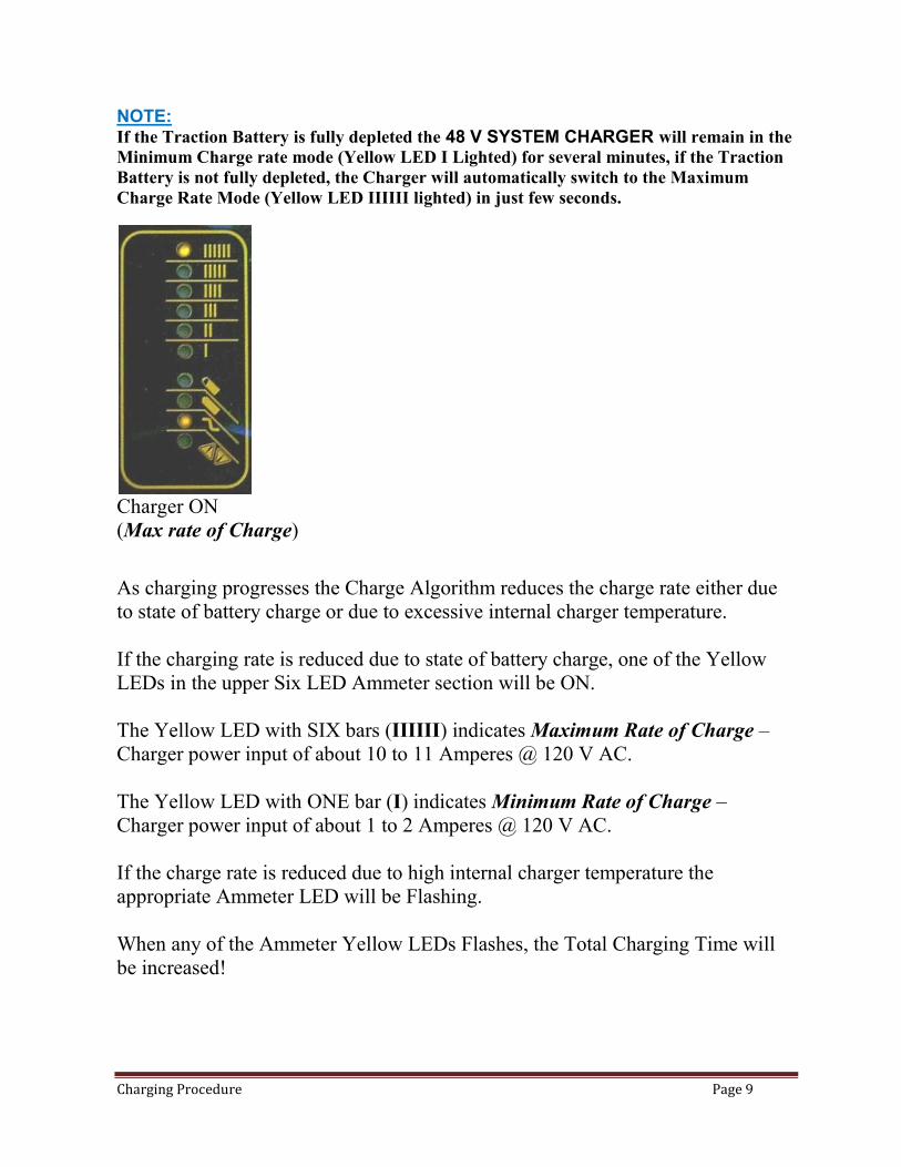
NOTE: If the Traction Battery is fully depleted the 48 V SYSTEM CHARGER will remain in the
Minimum Charge rate mode (Yellow LED I Lighted) for several minutes, if the Traction
Battery is not fully depleted, the Charger will automatically switch to the Maximum
Charge Rate Mode (Yellow LED IIIIII lighted) in just few seconds.
Charger ON
(Max rate of Charge)
As charging progresses the Charge Algorithm reduces the charge rate either due
to state of battery charge or due to excessive internal charger temperature.
If the charging rate is reduced due to state of battery charge, one of the Yellow
LEDs in the upper Six LED Ammeter section will be ON.
The Yellow LED with SIX bars (IIIIII) indicates Maximum Rate of Charge –
Charger power input of about 10 to 11 Amperes @ 120 V AC.
The Yellow LED with ONE bar (I) indicates Minimum Rate of Charge –
Charger power input of about 1 to 2 Amperes @ 120 V AC.
If the charge rate is reduced due to high internal charger temperature the
appropriate Ammeter LED will be Flashing.
When any of the Ammeter Yellow LEDs Flashes, the Total Charging Time will
be increased!

Charging Procedure Page 10
Charger ON (Min rate of Charge)
When the “80% state of Charge” is reached the Yellow LED indicating 80%
charge will be lighted. Bulk charge phase is complete and the charger is now in Absorption charge phase.
Charger ON
(Min rate of Charge)
(80% state of Charge)
When Absorption charge phase is completed and the charger now enters the Finish
charge phase Green LED indicating “End of Charge” charge will be Flashing.
When the “100% state of Charge” is reached the Green LED indicating “End of
Charge” charge will be lighted continuously.

Charging Procedure Page 11
Charger ON / Stand-by (End of Charge)
(Maintenance Mode) When the “End of Charge” condition is reached the Charger will automatically
switch to “Maintenance Mode”.
Charger will Auto-restart if 30 days elapse or if Traction Battery Voltage drops
to below 50.4 Volts. ( Voltage less than 2.1V per battery cell )
VEHICLE CHARGING (End of Charge)
Follow the recommended step-by-step procedure after vehicle was re-charged.
a.) 48 V SYSTEM CHARGER (TRACTION Batteries) -
a.) verify that the charger ON telltale LED (~) on the Charger is lighted.
Condition YELLOW = ON
b.) verify that end of the charge telltale LED on the Charger is lighted.
Condition GREEN = FULLY CHARGED
b.) Kill-A-Watt Meter – if you use this optional device to monitor charging refer to Page 12
for operating instructions.
Record the Accumulated data: “Total Charging Time” and “Total kWh”
c.) Extension Cord – Unplug the 120V AC extension power cord from vehicle
charging inlet socket.
d.) Extension Cord - Unplug the extension power cord from the household power
socket and stove it properly.

Charging Procedure Page 12
P3 - KILL A WATT TM
Operation Manual 1. The LCD shows all meter readings: Volts, Current, Watts, Frequency, Power Factor, and VA. The unit will start to accumulate kWh and powered duration time (hours & minutes) after power is applied. 2. Press Volt Key for true RMS Voltage (Volts) display. 3. Press Amp Key for true RMS output current (Amps) display. 4. The Watt/VA Key is a toggle function key. Press the Watt/VA key once to display Watt meter, then press the Watt/VA key again to display VA meter. The LCD will display Watts as the active power, where VA is the apparent Power. (VA = Vrms * Arms) 5. The HZ/PF is a toggle function key. Press the HZ/PF key once to display the frequency (Hertz), then press key again to display the Power Factor. HZ is the Frequency of output Voltage, where PF is the Power Factor (PF = W / Vrms Arms). 6. The KWH/Hour is a toggle function key. Press the KWH/Hour key once to show the cumulative energy consumption since power was applied to the unit (kWh). Then press key to display the cumulative time since power was applied to the unit. 7. Consumption will be displayed in Kilowatt-Hours (from 0.01 KWH to 9999 KWH). Time will initially be displayed as Hours:Minutes (from 00:00) and switch to Hours (to 9999). Counters will recycle to zero when they reach their maximum. 8. To reset all counters to zero, remove power from unit momentarily for about 15 seconds.
WARNING: Do not exceed maximum ratings as detailed on label.
Button 1 = Volt Button 2 = Amp Button 3 = Watt / VA (toggle) Button 4 = Hz / PF (toggle) Button 5 = kWh / TIME (toggle)

2010-08-U
.
California Roadster eGC
Cadillac ESCALADE eGC
HUMMER H3 eGC
Manufactured by:
American Custom Golf Cars, Inc. (ACG)
15740 El Prado Rd.
Chino, CA 91710 USA
(909) 597-2885
(909) 597-7183 fax
www.californiaroadster.com
Copyright © 2009-2010 American Custom Golf Cars, Inc.
American Custom Golf Cars, Inc., ACG logo and California Roadster
Are registered trademarks of American Custom Golf Cars, Inc.
Cadillac and Escalade
Are registered trademarks of General Motors Corporation.
HUMMER and H3
Are registered trademarks of General Motors Corporation.
Related Documents