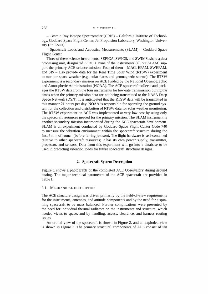
ACE SPACECRAFT M. C. CHIU, U. I. VON-MEHLEM, C. E. WILLEY, T. M. BETENBAUGH, J. J. MAYNARD, J. A. KREIN, R. F. CONDE, W. T. GRAY, J. W. HUNT, JR., L. E. MOSHER, M. G. McCULLOUGH, P. E. PANNETON, J. P. STAIGER and E. H. RODBERG The Johns Hopkins University Applied Physics Laboratory, Laurel, Maryland, U.S.A. Abstract. The Johns Hopkins University Applied Physics Laboratory (JHU/APL) was responsible for the design and fabrication of the ACE spacecraft to accommodate the ACE Mission requirements and for the integration, test, and launch support for the entire ACE Observatory. The primary ACE Mission includes a significant number of science instruments – nine – whose diverse requirements had to be factored into the overall spacecraft bus design. Secondary missions for monitoring space weather and measuring launch vibration environments were also accommodated within the space- craft design. Substantial coordination and cooperation were required between the spacecraft and instrument engineers, and all requirements were met. Overall, the spacecraft was kept as simple as possible in meeting requirements to achieve a highly reliable and low-cost design. 1. Introduction The ACE spacecraft accommodates a total of ten instruments; nine scientific in- struments for the primary mission and one engineering instrument for a secondary mission. – Solar Energetic Particle Ionic Charge Analyzer (SEPICA) – University of New Hampshire, Max-Planck Institute for Extraterrestrial Physics. – Ultra Low Energy Isotope Spectrometer (ULEIS) – University of Maryland, The Johns Hopkins University Applied Physics Laboratory (JHU/APL). – Solar Wind Ion Mass Spectrometer (SWIMS) – University of Maryland, Uni- versity of Bern (Switzerland). – Solar Wind Ion Composition Spectrometer (SWICS) – University of Mary- land, University of Bern (Switzerland). – Solar Wind Electron, Proton and Alpha Monitor (SWEPAM)–Los Alamos National Laboratory (includes SWEPAME, the electron component, and SWEPAMI, the ion component). – Electron, Proton and Alpha Monitor (EPAM) – JHU/APL. – Magnetic Field Experiment (MAG) – University of Delaware Bartol Research Institute, National Aeronautics and Space Administration (NASA) Goddard Space Flight Center. – Solar Isotope Spectrometer (SIS) – California Institute of Technology, God- dard Space Flight Center, Jet Propulsion Laboratory. Space Science Reviews 86: 257–284, 1998. © 1998 Kluwer Academic Publishers. Printed in the Netherlands.

Welcome message from author
This document is posted to help you gain knowledge. Please leave a comment to let me know what you think about it! Share it to your friends and learn new things together.
Transcript
ACE SPACECRAFT
M. C. CHIU, U. I. VON-MEHLEM, C. E. WILLEY, T. M. BETENBAUGH,J. J. MAYNARD, J. A. KREIN, R. F. CONDE, W. T. GRAY, J. W. HUNT, JR.,
L. E. MOSHER, M. G. McCULLOUGH, P. E. PANNETON, J. P. STAIGER andE. H. RODBERG
The Johns Hopkins University Applied Physics Laboratory, Laurel, Maryland, U.S.A.
Abstract. The Johns Hopkins University Applied Physics Laboratory (JHU/APL) was responsiblefor the design and fabrication of the ACE spacecraft to accommodate the ACE Mission requirementsand for the integration, test, and launch support for the entire ACE Observatory. The primary ACEMission includes a significant number of science instruments – nine – whose diverse requirementshad to be factored into the overall spacecraft bus design. Secondary missions for monitoring spaceweather and measuring launch vibration environments were also accommodated within the space-craft design. Substantial coordination and cooperation were required between the spacecraft andinstrument engineers, and all requirements were met. Overall, the spacecraft was kept as simple aspossible in meeting requirements to achieve a highly reliable and low-cost design.
1. Introduction
The ACE spacecraft accommodates a total of ten instruments; nine scientific in-struments for the primary mission and one engineering instrument for a secondarymission.
– Solar Energetic Particle Ionic Charge Analyzer (SEPICA) – University ofNew Hampshire, Max-Planck Institute for Extraterrestrial Physics.
– Ultra Low Energy Isotope Spectrometer (ULEIS) – University of Maryland,The Johns Hopkins University Applied Physics Laboratory (JHU/APL).
– Solar Wind Ion Mass Spectrometer (SWIMS) – University of Maryland, Uni-versity of Bern (Switzerland).
– Solar Wind Ion Composition Spectrometer (SWICS) – University of Mary-land, University of Bern (Switzerland).
– Solar Wind Electron, Proton and Alpha Monitor (SWEPAM)–Los AlamosNational Laboratory (includes SWEPAME, the electron component, and SWEPAMI,the ion component).
– Electron, Proton and Alpha Monitor (EPAM) – JHU/APL.– Magnetic Field Experiment (MAG) – University of Delaware Bartol Research
Institute, National Aeronautics and Space Administration (NASA) Goddard SpaceFlight Center.
– Solar Isotope Spectrometer (SIS) – California Institute of Technology, God-dard Space Flight Center, Jet Propulsion Laboratory.
Space Science Reviews86: 257–284, 1998.© 1998Kluwer Academic Publishers. Printed in the Netherlands.
258 M. C. CHIU ET AL.
– Cosmic Ray Isotope Spectrometer (CRIS) – California Institute of Technol-ogy, Goddard Space Flight Center, Jet Propulsion Laboratory, Washington Univer-sity (St. Louis).
– Spacecraft Loads and Acoustics Measurements (SLAM) – Goddard SpaceFlight Center.
Three of these science instruments, SEPICA, SWICS, and SWIMS, share a dataprocessing unit, designated S3DPU. Nine of the instruments (all but SLAM) sup-port the primary ACE science mission. Four of them – MAG, EPAM, SWEPAM,and SIS – also provide data for the Real Time Solar Wind (RTSW) experimentto monitor space weather (e.g., solar flares and geomagnetic storms). The RTSWexperiment is a secondary mission on ACE funded by the National Oceanographicand Atmospheric Administration (NOAA). The ACE spacecraft collects and pack-ages the RTSW data from the four instruments for low-rate transmission during thetimes when the primary mission data are not being transmitted to the NASA DeepSpace Network (DSN). It is anticipated that the RTSW data will be transmitted inthis manner 21 hours per day. NOAA is responsible for operating the ground sys-tem for the collection and distribution of RTSW data for solar weather monitoring.The RTSW experiment on ACE was implemented at very low cost by using onlythe spacecraft resources needed for the primary mission. The SLAM instrument isanother secondary mission incorporated during the ACE spacecraft development.SLAM is an experiment conducted by Goddard Space Flight Center Code 740to measure the vibration environment within the spacecraft structure during thefirst 5 min of launch (before fairing jettison). The flight hardware is self-containedrelative to other spacecraft resources; it has its own power supply, transmitter,processor, and sensors. Data from this experiment will go into a database to beused in predicting vibration loads for future spacecraft structural designs.
2. Spacecraft System Description
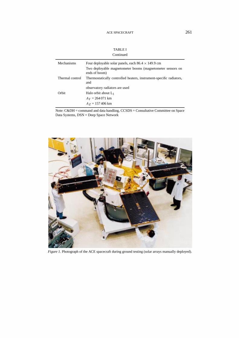
Figure 1 shows a photograph of the completed ACE Observatory during groundtesting. The major technical parameters of the ACE spacecraft are provided inTable I.
2.1. MECHANICAL DESCRIPTION
The ACE structure design was driven primarily by the field-of-view requirementsfor the instruments, antennas, and attitude components and by the need for a spin-ning spacecraft to be mass balanced. Further complications were presented bythe need for individual thermal radiators on the instruments and structure, whichneeded views to space, and by handling, access, clearance, and harness routingissues.
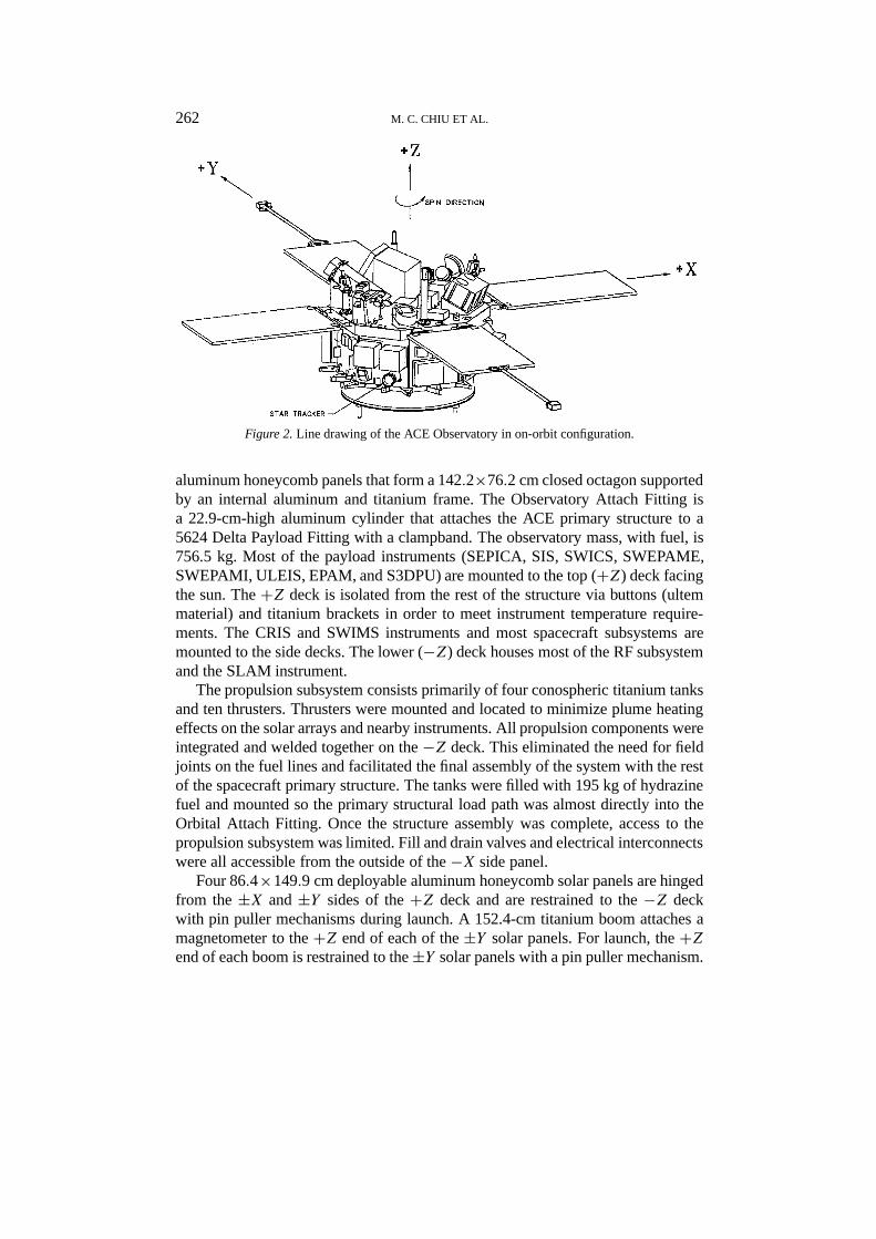
An orbital view of the spacecraft is shown in Figure 2, and an exploded viewis shown in Figure 3. The primary structural components of ACE consist of ten

ACE SPACECRAFT 259
TABLE I
Technical parameters of the ACE spacecraft
Attitude Star tracker
– 20◦ × 20◦ field of view
– +0.1 to +4.5 sensitivity range
– 30 arc sec (1σ ) total random error
– 1 to 5 simultaneous stars
Sun sensor
–±64◦ field of view
– Sun angle is gray-coded in 0.5◦ increments
–±0.02◦ short-term repeatability of most significant bit
Observatory orientation
– Known (after the fact) to±0.7◦; stable to±0.5◦Pointing at Earth
– Angle between the observatoryZ axis and the Earth – observatoryline is within±3◦, to stay within the required beamwidth of thehigh-gain antenna
– Angle between the Sun–Earth line and the observatory – Earthline is≥ 5◦, to limit the solar noise contribution to the receivingsystem noise temperature
Maneuvering capability Tanks
– Four tanks with total of 195 kg of hydrazine fuel expelled in blow-down (97% efficiency), providing mission average specific impulseof 216–221 s at 10–21◦CThrusters
– Four axial and six radial thrusters
Spin rate
– Maintained at 5± 0.1 rpm to meet science requirements
Maneuvers
– All maneuvers except onboard autonomy performed underground control
Communications Downlink data rate
– 434 bps (low rate and NOAA)
– 6944 kbps (real-time transmission)
– 76 384 kbps (recorder playback interleaved with real-time data)
– Uplink data rate
– 1000 bps
RF frequencies
– 2097.9806 MHz uplink
– 2278.35 MHz downlink
Data storage 1.073 Gbit solid-state memory per recorder capacity beginning oflife
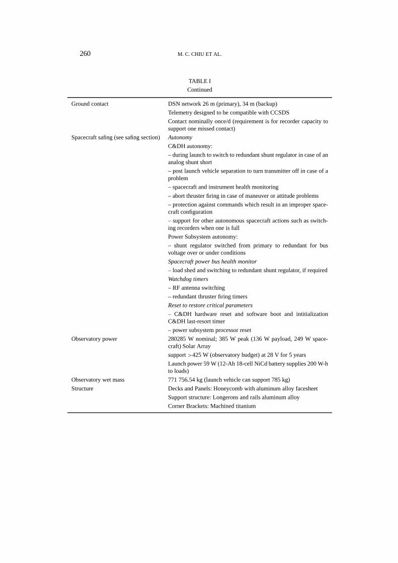
260 M. C. CHIU ET AL.
TABLE I
Continued
Ground contact DSN network 26 m (primary), 34 m (backup)
Telemetry designed to be compatible with CCSDS
Contact nominally once/d (requirement is for recorder capacity tosupport one missed contact)
Spacecraft safing (see safing section)Autonomy
C&DH autonomy:
– during launch to switch to redundant shunt regulator in case of ananalog shunt short
– post launch vehicle separation to turn transmitter off in case of aproblem
– spacecraft and instrument health monitoring
– abort thruster firing in case of maneuver or attitude problems
– protection against commands which result in an improper space-craft configuration
– support for other autonomous spacecraft actions such as switch-ing recorders when one is full
Power Subsystem autonomy:
– shunt regulator switched from primary to redundant for busvoltage over or under conditions
Spacecraft power bus health monitor
– load shed and switching to redundant shunt regulator, if required
Watchdog timers
– RF antenna switching
– redundant thruster firing timers
Reset to restore critical parameters
– C&DH hardware reset and software boot and intitializationC&DH last-resort timer
– power subsystem processor reset
Observatory power 280285 W nominal; 385 W peak (136 W payload, 249 W space-craft) Solar Array
support>425 W (observatory budget) at 28 V for 5 years
Launch power 59 W (12-Ah 18-cell NiCd battery supplies 200 W-hto loads)
Observatory wet mass 771 756.54 kg (launch vehicle can support 785 kg)
Structure Decks and Panels: Honeycomb with aluminum alloy facesheet
Support structure: Longerons and rails aluminum alloy
Corner Brackets: Machined titanium
ACE SPACECRAFT 261
TABLE I
Continued
Mechanisms Four deployable solar panels, each 86.4× 149.9 cm
Two deployable magnetometer booms (magnetometer sensors onends of boom)
Thermal control Thermostatically controlled heaters, instrument-specific radiators,and
observatory radiators are used
Orbit Halo orbit about L1AY = 264 071 km
AZ = 157 406 km
Note: C&DH = command and data handling, CCSDS = Consultative Committee on SpaceData Systems, DSN = Deep Space Network
Figure 1.Photograph of the ACE spacecraft during ground testing (solar arrays manually deployed).
262 M. C. CHIU ET AL.
Figure 2.Line drawing of the ACE Observatory in on-orbit configuration.
aluminum honeycomb panels that form a 142.2×76.2 cm closed octagon supportedby an internal aluminum and titanium frame. The Observatory Attach Fitting isa 22.9-cm-high aluminum cylinder that attaches the ACE primary structure to a5624 Delta Payload Fitting with a clampband. The observatory mass, with fuel, is756.5 kg. Most of the payload instruments (SEPICA, SIS, SWICS, SWEPAME,SWEPAMI, ULEIS, EPAM, and S3DPU) are mounted to the top (+Z) deck facingthe sun. The+Z deck is isolated from the rest of the structure via buttons (ultemmaterial) and titanium brackets in order to meet instrument temperature require-ments. The CRIS and SWIMS instruments and most spacecraft subsystems aremounted to the side decks. The lower (−Z) deck houses most of the RF subsystemand the SLAM instrument.
The propulsion subsystem consists primarily of four conospheric titanium tanksand ten thrusters. Thrusters were mounted and located to minimize plume heatingeffects on the solar arrays and nearby instruments. All propulsion components wereintegrated and welded together on the−Z deck. This eliminated the need for fieldjoints on the fuel lines and facilitated the final assembly of the system with the restof the spacecraft primary structure. The tanks were filled with 195 kg of hydrazinefuel and mounted so the primary structural load path was almost directly into theOrbital Attach Fitting. Once the structure assembly was complete, access to thepropulsion subsystem was limited. Fill and drain valves and electrical interconnectswere all accessible from the outside of the−X side panel.
Four 86.4×149.9 cm deployable aluminum honeycomb solar panels are hingedfrom the±X and±Y sides of the+Z deck and are restrained to the−Z deckwith pin puller mechanisms during launch. A 152.4-cm titanium boom attaches amagnetometer to the+Z end of each of the±Y solar panels. For launch, the+Zend of each boom is restrained to the±Y solar panels with a pin puller mechanism.
ACE SPACECRAFT 263
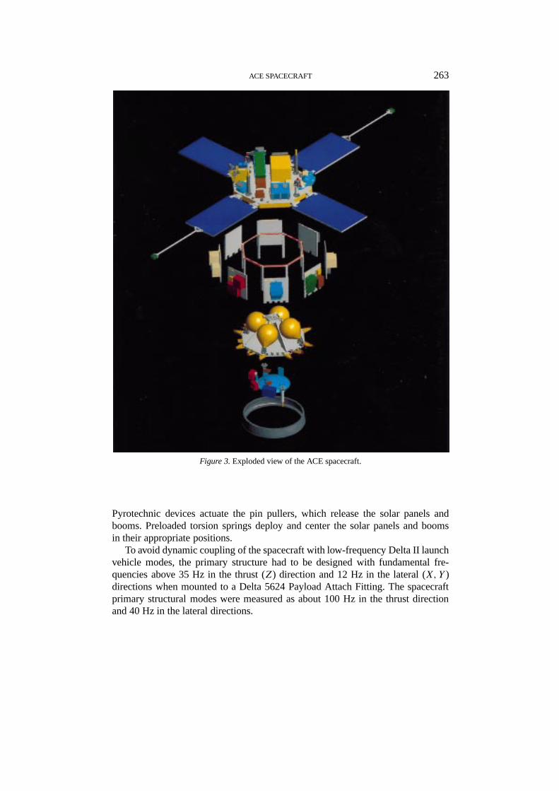
Figure 3.Exploded view of the ACE spacecraft.
Pyrotechnic devices actuate the pin pullers, which release the solar panels andbooms. Preloaded torsion springs deploy and center the solar panels and boomsin their appropriate positions.
To avoid dynamic coupling of the spacecraft with low-frequency Delta II launchvehicle modes, the primary structure had to be designed with fundamental fre-quencies above 35 Hz in the thrust (Z) direction and 12 Hz in the lateral (X,Y )directions when mounted to a Delta 5624 Payload Attach Fitting. The spacecraftprimary structural modes were measured as about 100 Hz in the thrust directionand 40 Hz in the lateral directions.
264 M. C. CHIU ET AL.
The ACE Observatory was designed for launch on a Delta II 7920. The Delta II7920 flight events produce loads from steady-state and dynamic environments. Thesteady-state environment produces a maximum thrust acceleration at the end of thefirst-stage burn or main engine cut-off. The dynamic environments produced by theDelta II are sinusoidal vibration, acoustics, and shock. The sinusoidal environmentis a result of liftoff transients, oscillations before main engine cut-off, and engineignition and shutdown. A spacecraft random vibration environment is generatedby launch vehicle acoustics. The ACE Observatory was designed to withstandthe loads from these environments. A protoflight test program (flight qualificationlevels at acceptance-level duration) was used to verify the observatory strength andstiffness. Vibration (sine and random), acoustic, and shock (clampband separation)testing was performed on the fully flight configured observatory.
2.2. THERMAL CONTROL DESCRIPTION
The thermal design of the ACE Observatory was created through the joint ef-forts of the spacecraft and instrument thermal engineers. Early in the program,it was decided that most of the instruments should be thermally isolated from thespacecraft. Uncertainty in the instrument schedules, together with stringent and dif-fering instrument temperature requirements, made thermal isolation the best path tosuccess. Instruments and instrument components whose temperature requirementscould be managed by the spacecraft (SWEPAME, SWEPAMI, S3DPU, ULEISdata processing unit, ULEIS analog electronics) were allowed to thermally conducttheir heat to the spacecraft.
The observatory uses a combination of multilayer insulation (MLI), thermalradiators, and thermostatically controlled heater circuits to meet its thermal de-sign requirements, without the need for more active (and expensive) methods ofmoving heat such as louvers and heat pipes. Aluminum doubler plates (additionalaluminum material) from 0.15 to 0.32 cm thick were added where necessary toenhance heat conduction away from an area. Where required, instruments werethermally isolated at the mounting interface using a combination of bushings madeof insulating material (ultem), titanium mounting hardware, and MLI blankets.
Most of the MLI blankets on the ACE Observatory were fabricated using anouter layer of white Beta Cloth (a type of thermal insulating material) with an em-bedded 10.2×15.2 cm graphite weave. The Beta Cloth provides durability and thedesired optical properties while minimizing specular reflections. Although a con-ductive spacecraft was not a requirement for the ACE program, the graphite weavewas incorporated into the Beta Cloth to provide some protection from electrostaticdischarge.
In some areas, special requirements dictated the use of alternative materialsfor the MLI outer layer. Thruster plume impingement is possible on the+X sidepanel in the area of the battery and on the Observatory Attach Fitting below the+X and−X aft axial thrusters. The MLI blankets were hardened to increased
ACE SPACECRAFT 265
temperature by replacing the Beta Cloth with five layers of embossed 0.25-milaluminized Kapton and a 3-mil aluminized Kapton outer layer. Specular reflectionsare not a problem in these areas. In addition to the special requirements imposed bythe spacecraft, the SWIMS and SWEPAME instruments had special requirementsthat dictated the use of more electrically conductive MLI outer layer materials.ITO-coated aluminized Kapton was used for SWIMS and for the+X + Y sidepanel below SWEPAME. The alternative material was allowed only on the apertureface of SWEPAME to avoid problems with specular reflections.
The forward (+Z) deck of the observatory is covered by thermal insulation toshield it from the sun as much as possible. Heat is rejected from the forward deckvia radiators attached to each of the eight deck edges. The silvered Teflon radiatorsface radially away from the axis of symmetry of the observatory to maximize heatrejection.
The aft (−Z) deck of the observatory serves as the mounting platform for theinternal components of the propulsion system. In addition, components of the RFsubsystem and the SLAM instrument are mounted to the space side of the aft deck.The Observatory Attach Fitting is bolted to the aft deck and is covered with silveredTeflon to serve as a thermal radiator for the side panels and the aft deck. Exceptfor the RF-radiating surfaces of the two low-gain antenna towers and the high-gainantenna dish, the aft deck is protected from a direct view toward space by an MLIblanket.
The spacecraft side panels are used primarily for mounting spacecraft compo-nents. However, the+X−Y and−X+Y panels are used for the isolated mountingof the SWIMS and CRIS instruments, respectively. The spacecraft thermal designminimizes heat exchange between the side panels and space by covering the sidepanels with MLI blankets that extend from the bottom of the forward deck radi-ators to the Observatory Attach Fitting mounted to the aft deck. For side panelswith instruments, the spacecraft blankets provide radiative isolation between theinstrument and side panel. Sun sensor and star scanner apertures, thruster nozzles,and umbilical connectors remain free from MLI blockage.
The spacecraft radiators were oversized during design and fabrication. The ef-fective radiator sizes were then tailored using MLI after correlation between theresults of the observatory-level thermal vacuum test and the observatory thermalmodel.
On orbit, the ACE spacecraft thermal environment is expected to show littleor no short-term variation. The environment will vary as the sun angle changesfrom a nominal minimum (4◦) to a nominal maximum (20◦). However, sun anglevariation will occur on a scale of months and will be corrected periodically viathe propulsion system. The actual maximum sun angle will be controlled to lessthan 20◦ to keep the high-gain antenna pointed at the DSN. The additional controlprovides greater margin in the spacecraft hot-case thermal analysis, where 20◦ wasused as a worst-case assumption. The spin of the spacecraft (5 rpm) will dampenany short-term azimuthal variations.
266 M. C. CHIU ET AL.
The observatory thermal analysis includes worst-case variations in all thermaldesign parameters, including incident solar flux, sun angle, MLI effectiveness,optical properties of thermal radiators and other external surfaces, and minimumvoltage on heaters. Therefore, the analysis results bracket all possible temperaturevariations over the entire mission life.
The spacecraft thermal control system is robust and versatile. A primary re-quirement of the thermal control system is to minimize peak heater power whileproviding adequate support of observatory temperatures. Survival, operational, andinterface heaters manage the resources to meet the observatory’s thermal require-ments.
Survival heater circuits provide control when instruments are off and whenmost spacecraft components are either off or in low-power states. Operationalheater circuits provide control during normal observatory power dissipation states.To minimize peak heater power, interface heaters are used to replace part of thedissipation of a component placed in a nonoperational state while the operationalheaters are active. Interface heaters are used for all isolated instruments and forsome higher-power spacecraft components. Without interface heaters, larger op-erational heater circuits would have been needed to accommodate the occasionallower-power modes. The result would have been higher peak operational heaterpower.
The extensive use of thermal components to distribute heater power about theobservatory provides added reliability to the design. In general, heater circuitsconsist of multiple thermostats, each with multiple small heaters. The failure ofan individual heater element is not likely to cause significant problems. Many ofthe survival thermostats have the same temperature set points as the operationalthermostats due to the overriding requirement that hydrazine in the fuel lines notbe allowed to freeze. Therefore, in many cases, the survival heaters can provideadditional backup capabilities.
2.3. SPACECRAFT SUBSYSTEM DESCRIPTIONS
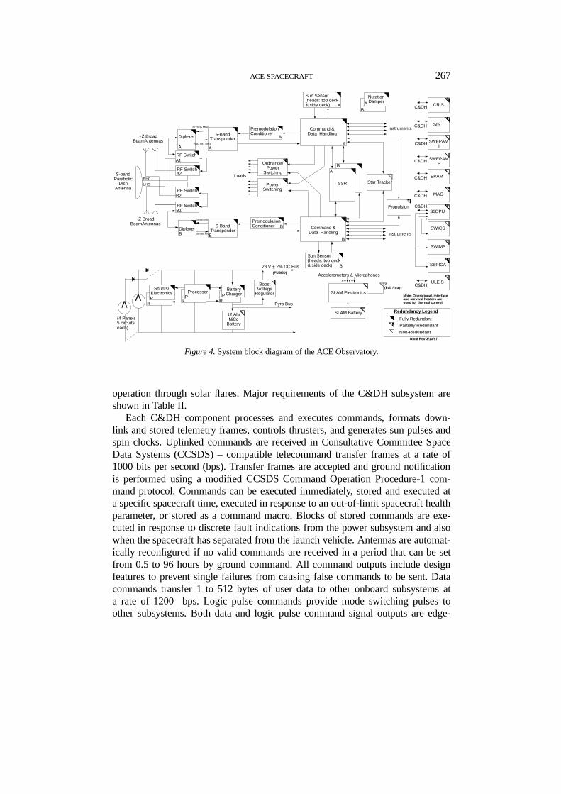
The spacecraft subsystems are described in the following paragraphs. A simplifiedblock diagram is provided in Figure 4.
2.3.1. Command and Data Handling SubsystemThe ACE command and data handling (C&DH) subsystem provides capabilitiesfor ground and stored commanding; onboard autonomy and safing; collection,formatting, and storage of science and engineering data; switching of spacecraftpower and energizing of pyrotechnic devices; thruster firing control; and generationand distribution of sun pulses and spin clocks. The C&DH subsystem consists ofredundant C&DH components, two 1-Gbit solid-state recorders (SSRs), a powerswitching component, and an ordnance fire component. Special design featuresare included to avoid any single-point mission failures and to allow continuous
ACE SPACECRAFT 267
-Z Broad BeamAntennas
RF Switch
RF Switch
RF Switch
S-Band Transponder
Premodulation Conditioner
Ordnance/ Power
Switching
Sun Sensor (heads: top deck & side deck)
Sun Sensor (heads: top deck & side deck)
Loads
Instruments
Instruments
A2
B2
A
B1
B
B
B
Redundancy Legend
Fully Redundant
Partially Redundant
Non-Redundant
Note: Operational, interface and survival heaters are used for thermal control
2278.35 MHz
2278.35 MHz
2097.981 MHz
Nutation DamperA
B
(4 Panels 5 circuits each)
ΛSLAM Electronics
SLAM Battery
Accelerometers & Microphones
(Pull Away)
LHC
RHC
B
SEPICA
S-Band TransponderDiplexer
RF SwitchA1
A A
Premodulation Conditioner
A
Processor
Boost Voltage
RegulatorBattery Charger
Pyro Bus
PR
(FUSED)
PR
Shunts/ ElectronicsP
R
28 V + 2% DC Bus
12 Ahr NiCd
Battery
Λ
UIvM Rev 3/10/97
Star Tracker
PropulsionS3DPU
C&DH
MAGC&DH
C&DHULEIS
SWIMS
SWICS
C&DH EPAM
C&DH SWEPAM E
C&DH SWEPAM I
CRIS
SISC&DH
SSR
Command & Data Handling
A
A
+Z Broad
BeamAntennas
S-band Parabolic
Dish Antenna
DiplexerB
Command & Data Handling
B
C&DH
Power Switching
2097.981 MHz
Figure 4.System block diagram of the ACE Observatory.
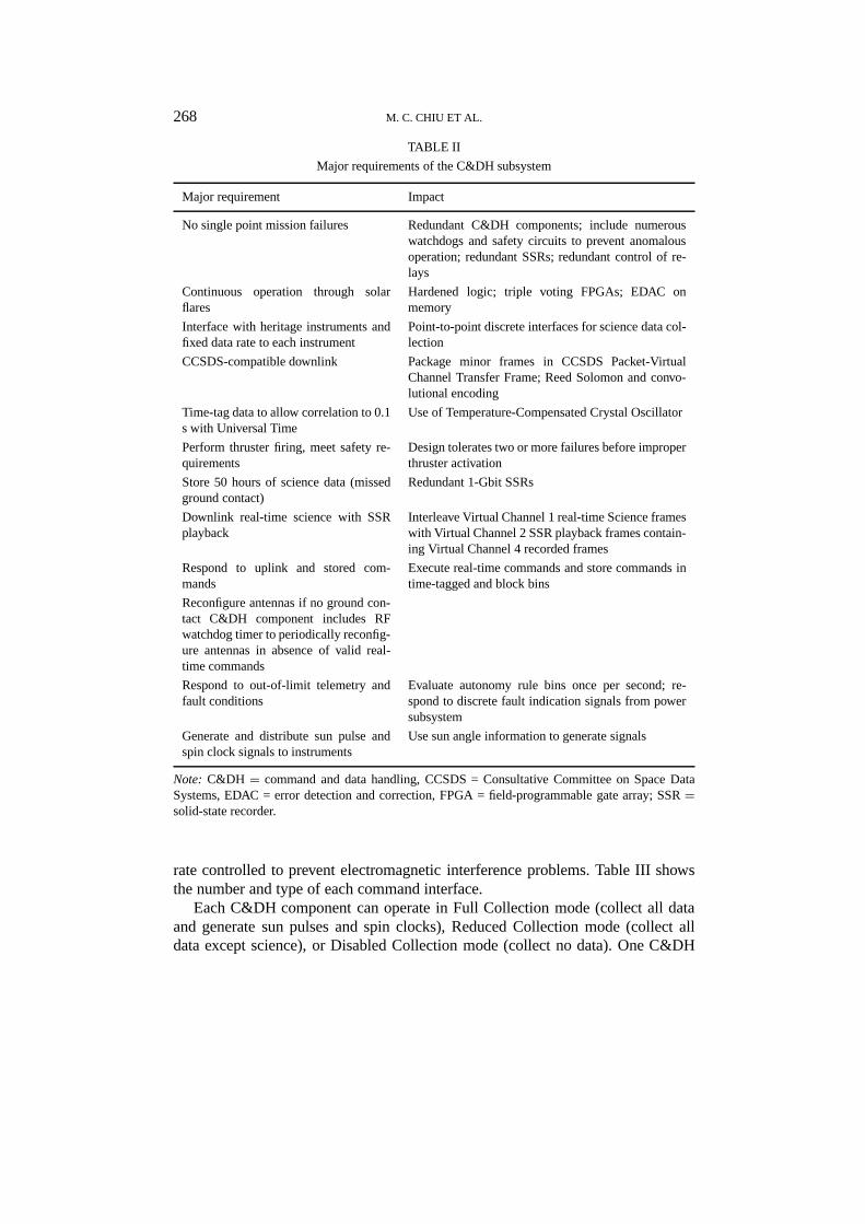
operation through solar flares. Major requirements of the C&DH subsystem areshown in Table II.
Each C&DH component processes and executes commands, formats down-link and stored telemetry frames, controls thrusters, and generates sun pulses andspin clocks. Uplinked commands are received in Consultative Committee SpaceData Systems (CCSDS) – compatible telecommand transfer frames at a rate of1000 bits per second (bps). Transfer frames are accepted and ground notificationis performed using a modified CCSDS Command Operation Procedure-1 com-mand protocol. Commands can be executed immediately, stored and executed ata specific spacecraft time, executed in response to an out-of-limit spacecraft healthparameter, or stored as a command macro. Blocks of stored commands are exe-cuted in response to discrete fault indications from the power subsystem and alsowhen the spacecraft has separated from the launch vehicle. Antennas are automat-ically reconfigured if no valid commands are received in a period that can be setfrom 0.5 to 96 hours by ground command. All command outputs include designfeatures to prevent single failures from causing false commands to be sent. Datacommands transfer 1 to 512 bytes of user data to other onboard subsystems ata rate of 1200 bps. Logic pulse commands provide mode switching pulses toother subsystems. Both data and logic pulse command signal outputs are edge-
268 M. C. CHIU ET AL.
TABLE II
Major requirements of the C&DH subsystem
Major requirement Impact
No single point mission failures Redundant C&DH components; include numerouswatchdogs and safety circuits to prevent anomalousoperation; redundant SSRs; redundant control of re-lays
Continuous operation through solarflares
Hardened logic; triple voting FPGAs; EDAC onmemory
Interface with heritage instruments andfixed data rate to each instrument
Point-to-point discrete interfaces for science data col-lection
CCSDS-compatible downlink Package minor frames in CCSDS Packet-VirtualChannel Transfer Frame; Reed Solomon and convo-lutional encoding
Time-tag data to allow correlation to 0.1s with Universal Time
Use of Temperature-Compensated Crystal Oscillator
Perform thruster firing, meet safety re-quirements
Design tolerates two or more failures before improperthruster activation
Store 50 hours of science data (missedground contact)
Redundant 1-Gbit SSRs
Downlink real-time science with SSRplayback
Interleave Virtual Channel 1 real-time Science frameswith Virtual Channel 2 SSR playback frames contain-ing Virtual Channel 4 recorded frames
Respond to uplink and stored com-mands
Execute real-time commands and store commands intime-tagged and block bins
Reconfigure antennas if no ground con-tact C&DH component includes RFwatchdog timer to periodically reconfig-ure antennas in absence of valid real-time commands
Respond to out-of-limit telemetry andfault conditions
Evaluate autonomy rule bins once per second; re-spond to discrete fault indication signals from powersubsystem
Generate and distribute sun pulse andspin clock signals to instruments
Use sun angle information to generate signals
Note: C&DH = command and data handling, CCSDS = Consultative Committee on Space DataSystems, EDAC = error detection and correction, FPGA = field-programmable gate array; SSR=solid-state recorder.
rate controlled to prevent electromagnetic interference problems. Table III showsthe number and type of each command interface.
Each C&DH component can operate in Full Collection mode (collect all dataand generate sun pulses and spin clocks), Reduced Collection mode (collect alldata except science), or Disabled Collection mode (collect no data). One C&DH

ACE SPACECRAFT 269
TABLE III
C&DH subsystem user commands
Command Number Comment
type provided
Data command 16 1 to 512 bytes of user data
Logic pulse 16 40-ms pulse
Relay 101 2-A and 10-A latching relays; 2-A and 5-A nonlatching relays
Note: C&DH = command and data handling.
TABLE IV
C&DH subsystem telemetry channels
Telemetry channel type Number Comment
provided
Serial digital 16 Includes major and minor frame pulses,clock, read-out gate
0–5 V single-ended analog 62
0–50 mV differential analog 62 Used primarily for measuring currents
AD590 temperature transducer 62 Measures temperatures in range of−60 ◦ to+100◦C
PT103 temperature transducer 62 Measures temperatures in range of−100◦ to+150◦C
Digital telltale-logic 32 Used primarily for RF transpondertelemetry
Digital telltale-switch 16 Used primarily to detect the state ofswitches
Note:C&DH = command and data handling.
component is designated the active C&DH and operates in Full Collection mode.The other C&DH component is designated the inactive C&DH and operates inReduced Collection mode. Digital and analog telemetry data are collected withsix types of telemetry channels (Table IV) from onboard subsystems at a singlerate and format. Data are collected in a major/minor frame structure at a rate of 1minor frame per second, with 16 minor frames per major frame. The collected dataare stored in the Data Collection Buffer resident in C&DH component memory.The Data Collection Buffer is the source of data in all telemetry formats and forautonomy (i.e., checking out-of-limit values of spacecraft telemetry). Both C&DHcomponents can simultaneously limit-check spacecraft telemetry data.
Three requirements – the need to be compatible with several existing instru-ments, the need to simplify the C&DH – instrument interface by allocating eachinstrument a continuous fixed science data rate, and the need to have a CCSDS-
270 M. C. CHIU ET AL.
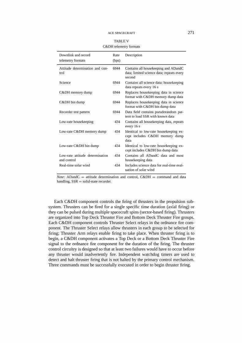
compatible downlink – led to the development of a hybrid telemetry format schemethat combines a traditional major/minor frame structure with a modern CCSDSpacket/transfer frame structure. Each telemetry frame consists of a Virtual ChannelTransfer Frame containing one telemetry packet. Each packet contains a singletelemetry minor frame in its data field. Real-time data can be formatted into oneof ten minor frame formats for downlinking or recording (Table V). The Downlinkand Record formats are independently selected. Data can be downlinked at 434 bps(low-rate engineering data or real-time solar wind data), 6944 bps (science andengineering data), or 76 384 bps (real-time and SSR playback data) while anotherformat is being recorded at 6944 bps. During normal operations, data are recordedin the science and engineering format at 6944 bps while real-time solar winddata are downlinked to NOAA ground stations at 434 bps for 21 hours per day.For 3 hours per day, real-time data are interleaved with SSR playback data at acomposite rate of 76 384 bps and transmitted to the NASA DSN. Eleven framesare downlinked per second: one real-time frame and ten SSR playback frames.Downlink frames are encoded with the CCSDS standard Reed Solomon (Interleave= 4) and convolutional coding.
Each C&DH component contains a temperature-compensated crystal oscillatorthat is the source of all C&DH telemetry timing. A 32-bit time count is providedin each minor frame. The precision of the oscillator permits correlation of onboarddata with Universal Time (UT) to at least 100 ms accuracy. Each C&DH compo-nent utilizes sun angle data from the attitude determination and control (ADandC)subsystem to generate sun pulse and spin clock signals that are distributed toinstruments. For each revolution of the spacecraft, 16 384 spin clock pulses aregenerated. All science data can be correlated to telemetry synchronizing signals(major and minor frame pulses) that are generated at known times or to the sunpulse/spin clock signals. Each sun pulse is tagged with the current spacecraft time.
The two SSRs each provide 1 Gbit of storage. They are designed to operate witha less than 10−7 bit error rate after 26 hours of continuous solar flare. (This radi-ation level significantly exceeds the worst-case scenarios ever anticipated duringthe ACE mission.) In operation, data are recorded at an average rate of 6944 bpsand reproduced at an average rate of 68 640 bps. Data are reproduced in forwardorder. Under normal operation, the observatory will be under ground control onceevery 24 hours. However, the observatory is designed for one missed contact, withautonomous collection and storage of data for up to 48 hours. If an SSR fills upwith data, the active C&DH component will use the autonomy to start recordingdata on the second SSR.
Each C&DH component has interfaces to the Power Switching and ordnancefire components to allow the selection and activation of relays. Each includes latch-ing relays for providing switched power to spacecraft subsystems and nonlatchingrelays for providing pulses. The latching relays include dual coils for redundantcontrol. Redundant nonlatching relays are used. The ordnance fire component alsoincludes interfaces to each C&DH component for firing thrusters.
ACE SPACECRAFT 271
TABLE V
C&DH telemetry formats
Downlink and record Rate Description
telemetry formats (bps)
Attitude determination and con-trol
6944 Contains all housekeeping and ADandCdata; limited science data; repeats everysecond
Science 6944 Contains all science data; housekeepingdata repeats every 16 s
C&DH memory dump 6944 Replaces housekeeping data in scienceformat with C&DH memory dump data
C&DH bin dump 6944 Replaces housekeeping data in scienceformat with C&DH bin dump data
Recorder test pattern 6944 Data field contains pseudorandom pat-tern to load SSR with known data
Low-rate housekeeping 434 Contains all housekeeping data, repeatsevery 16 s
Low-rate C&DH memory dump 434 Identical to low-rate housekeeping ex-cept includes C&DH memory dumpdata
Low-rate C&DH bin dump 434 Identical to low-rate housekeeping ex-cept includes C&DH bin dump data
Low-rate attitude determinationand control
434 Contains all ADandC data and mosthousekeeping data
Real-time solar wind 434 Includes science data for real-time eval-uation of solar wind
Note: ADandC = attitude determination and control, C&DH= command and datahandling, SSR= solid-state recorder.
Each C&DH component controls the firing of thrusters in the propulsion sub-system. Thrusters can be fired for a single specific time duration (axial firing) orthey can be pulsed during multiple spacecraft spins (sector-based firing). Thrustersare organized into Top Deck Thruster Fire and Bottom Deck Thruster Fire groups.Each C&DH component controls Thruster Select relays in the ordnance fire com-ponent. The Thruster Select relays allow thrusters in each group to be selected forfiring; Thruster Arm relays enable firing to take place. When thruster firing is tobegin, a C&DH component activates a Top Deck or a Bottom Deck Thruster Firesignal to the ordnance fire component for the duration of the firing. The thrustercontrol circuitry is designed so that at least two failures would have to occur beforeany thruster would inadvertently fire. Independent watchdog timers are used todetect and halt thruster firing that is not halted by the primary control mechanism.Three commands must be successfully executed in order to begin thruster firing.
272 M. C. CHIU ET AL.
The C&DH component was designed and fabricated at JHU/APL. It utilizesa Harris RTX2010 processor executing the FORTH language. The RTX2010 isfabricated in a CMOS/SOS process that is exceptionally hard to single-event upsets(SEUs), making it suitable for operation through solar flares. Code is stored in elec-trically erasable/programmable read-only memory (EEPROM) and downloadedinto random-access memory (RAM) for execution. EEPROM can be reloaded onthe ground, and the RAM can be patched in flight. Both RAM and EEPROMutilize error detection and correction (EDAC) circuitry to correct single errorsand detect double errors. Digital logic is implemented with radiation-hardenedHarris HCS series logic, radiation-tolerant National FACT series logic, and Ac-tel field-programmable gate arrays (FPGAs). The FPGAs are designed with triplevoting cells to minimize the probability of SEUs. The RTX2010 is programmedin FORTH using a FORTH kernel and cross-compiler developed at JHU/APLand previously used on the Freja and Near Earth Asteroid Rendezvous (NEAR)spacecraft.
The SSRs were designed and fabricated at SEAKR Corporation. They utilizeIBM 16-Mbit dynamic random access memories (DRAMs) for storage and a Harris80C85 microprocessor for control. Error detection and correction is done on 16-bitwords and allows for correction of single errors and detection of double errors.Failed memory segments are automatically mapped out.
The power switching and ordnance fire components were designed and fabri-cated at JHU/APL. They are implemented with a modular design having redundantrelay coil driver cards and application-specific relay cards. They operate directly offthe spacecraft power bus. The design was previously used on the Ballistic MissileDefense Organization’s Midcourse Space Experiment spacecraft and on the NearEarth Asteroid Rendezvous spacecraft.
2.3.2. RF Communications SubsystemThe primary function of the RF communications subsystem is to serve as theobservatory terminus for radio communications between the observatory and theNASA Deep Space Network of Earth stations. A secondary function is to transmitdownlink data in real time, at 434 bps, to Earth stations supporting the NOAA RealTime Solar Wind project. The system is designed to receive uplink commands andtransmit downlink telemetry data concurrently with coherent ranging. The systemoperates at 2097.9806 MHz for the uplink and 2278.35 MHz for the downlink.
The system consists of two identical (redundant) and independent communica-tions subsystems and a single high-gain, dual-polarized parabolic reflector antenna.Each communications subsystem consists of a transponder (transmitter and re-ceiver), diplexer, coaxial switching network, and two broad-beam antennas. Thereis no cross strapping between RF subsystems. The coaxial switching network isused to connect a given transponder to an aft (−Z) or forward (+Z) broad-beamantenna or to the aft high-gain parabolic antenna. Watchdog timers, implementedin software within the C&DH subsystem, are designed to switch the broad-beam
ACE SPACECRAFT 273
antennas if no uplink spacecraft commands are received within a preset time. Thetimers provide a means to recover spacecraft communications in the event of acommunications system or attitude anomaly. Both receivers are operated continu-ously, but only one transmitter is to be powered and one antenna energized at anygiven time.
AntennasThe purpose of the broad-beam antennas is to provide hemispherical uplink cov-erage forward and aft of the spacecraft. The broad-beam antennas also providesufficient gain in the region±34◦ off boresight for the transmission of 434 bps datato a DSN 26-m ground station. The broad-beam antennas provide right circularlypolarized coverage (gain) over a hemisphere. The gain of the broad-beam anten-nas over the hemisphere is greater than−7 dBic at uplink frequencies,−8 dBicat downlink frequencies. By configuring the RF system so that one receiver isconnected to a forward broad-beam antenna and the other to an aft broad-beamantenna, omnidirectional coverage of the spacecraft can be achieved. At anglesless than 34◦ off boresight, the broad-beam antenna gain is−1 dBic at uplinkfrequencies, 0 dBic at downlink frequencies.
The purpose of the high-gain antenna is to support DSN uplink commands andthe transmission of downlink data at 76 384 or 6944 kilobits per second (kbps).The high-gain antenna is also used to transmit 434-bps data to NOAA Real TimeSolar Wind sites. The specified gain of the high-gain antenna at 4.25◦ off boresightis greater than 18 dBic at the uplink frequency, 19 dBic at the downlink frequency.The high-gain antenna is pointed by ground commands to the spacecraft attitudesubsystem. The antenna must be pointed within±3◦ of the spacecraft–Earth linein order to have sufficient gain to achieve the signal-to-noise ratios required for thedata links. On orbit, the attitude of the observatory must be adjusted periodicallyto keep the Earth within the±3◦ beam width of the antenna.
TransponderThe transponder consists of a receiver and transmitter that are diplexed onto asingle line feeding the antenna. The receiver is a phase-locked, dual conversion,superheterodyne type with a detector and command demodulator. The transmitteris a phase-shift-keyed type with an RF output power of 5 W minimum. The outputspectrum consists of a residual carrier with data sidebands.
Communications modesThe transponder receiver and transmitter may be operated independently (nonco-herently) or coherently, where the downlink frequency is derived from the up-link signal frequency. The coherent mode permits the measurement of two-wayDoppler. The functional modes of operation are command reception, telemetrytransmission, and ranging.
274 M. C. CHIU ET AL.
Commands receptionThe uplink command data rate is 1000 bps. The pulse code modulation is NRZ-L.The command data are phase-shift-keyed onto a 16-kHz subcarrier and then phasemodulated onto the 2097.9806-MHz RF carrier.
Telemetry transmissionThere are three selectable downlink data rates: 434 bps, 6944 bps, and 76 384 bps.The pulse code modulation is bi-phase-L. The downlink data streams are encodedby the C&DH subsystem before they are routed to the transmitter. The coding con-sists of a convolutional code (7, 1
2) concatenated with a (248 217) Reed-Solomoncode. The data stream is directly phase modulated onto the 2278.35-MHz downlinkcarrier, producing a residual carrier and data sidebands. The modulation index isselectable (high/low) by ground command. The low modulation index is requiredfor transmitting the 434-bps data, and the high modulation index is used for the6944-bps and 76 384-bps data rates.
RangingThe system is capable of simultaneous command reception, telemetry transmission,and ranging. However, a noninterfering signal structure, such as that produced bythe DSN Sequential Ranging Assembly (SRA), is required. The ranging clockfrequency is approximately 512 kHz; the lower frequency codes are expected tobe component numbers 6 through 17.
2.3.3. Attitude Determination and Control SubsystemThe ADandC subsystem was designed to minimize spacecraft cost and complexitywhile maximizing reliability and mission success. It utilizes the inherent gyro-scopic stability of a spinning spacecraft for attitude control coupled with teleme-tered sun sensor and star scanner data for determining attitude on the ground. TheADandC subsystem consists of a solid-state star scanner, a redundant sun sensorsystem (which acts as an on-orbit backup to the star scanner), two fluid-filled ringnutation dampers, the ten thrusters of the propulsion system, and the command ca-pability of the C&DH subsystem. It is an extremely simple system that has provenitself on a variety of other missions.
Each redundant sun sensor system from the Adcole Corporation consists oftwo sun angle sensors and an associated electronics box. Each sensor digitallyencodes to an 8-bit value, the sun angle in nominal 0.5◦ increments over a fieldof view of ±64◦ in each of two orthogonal axes. One sun angle sensor of a pairis located on the+Z deck of the spacecraft with its normal parallel to the+Zaxis; the other is mounted on the side deck with its normal canted 125◦ away fromthe spacecraft+Z axis. Unless there is an attitude anomaly, the sun will alwaysshine on the top-deck sun angle sensor. The sun sensor electronics forwards to theC&DH subsystem the two encoded 8-bit sun angles from the illuminated sun anglesensor and two identification bits indicating which of the two sensors is providing
ACE SPACECRAFT 275
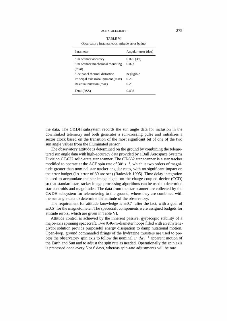
TABLE VI
Observatory instantaneous attitude error budget
Parameter Angular error (deg)
Star scanner accuracy 0.025 (3σ )
Star scanner mechanical mounting 0.023
(total)
Side panel thermal distortion negligible
Principal axis misalignment (max) 0.20
Residual nutation (max) 0.25
Total (RSS) 0.498
the data. The C&DH subsystem records the sun angle data for inclusion in thedownlinked telemetry and both generates a sun-crossing pulse and initializes asector clock based on the transition of the most significant bit of one of the twosun angle values from the illuminated sensor.
The observatory attitude is determined on the ground by combining the teleme-tered sun angle data with high-accuracy data provided by a Ball Aerospace SystemsDivision CT-632 solid-state star scanner. The CT-632 star scanner is a star trackermodified to operate at the ACE spin rate of 30◦ s−1, which is two orders of magni-tude greater than nominal star tracker angular rates, with no significant impact onthe error budget (1σ error of 30 arc sec) (Radovich 1995). Time delay integrationis used to accumulate the star image signal on the charge-coupled device (CCD)so that standard star tracker image processing algorithms can be used to determinestar centroids and magnitudes. The data from the star scanner are collected by theC&DH subsystem for telemetering to the ground, where they are combined withthe sun angle data to determine the attitude of the observatory.
The requirement for attitude knowledge is±0.7◦ after the fact, with a goal of±0.5◦ for the magnetometer. The spacecraft components were assigned budgets forattitude errors, which are given in Table VI.
Attitude control is achieved by the inherent passive, gyroscopic stability of amajor-axis spinning spacecraft. Two 0.46-m-diameter hoops filled with an ethylene-glycol solution provide purposeful energy dissipation to damp nutational motion.Open-loop, ground commanded firings of the hydrazine thrusters are used to pre-cess the observatory spin axis to follow the nominal 1◦ day−1 apparent motion ofthe Earth and Sun and to adjust the spin rate as needed. Operationally the spin axisis precessed once every 5 or 6 days, whereas spin-rate adjustments will be rare.
276 M. C. CHIU ET AL.
PTAPressuretransducer
Propellanttanks
A1
B2B1
A2
FVAPVAPVBFVB
Servicevalves
PTBPressuretransducer
FLTB2 filters FLTA1 filtersFLTB1FLTA2
LVA2 LVB2 Latch valves LVB1 LVA1 Latch valves
–X forward REMMR-111C axial
and radialthrusters group II
–X rear REMsMR-111C axial
and radialthrusters group III
+X forward REMMR-111C axial
and radialthrusters group I
+X rear REMsMR-111C axial
and radialthrusters group IV
97-7092-5
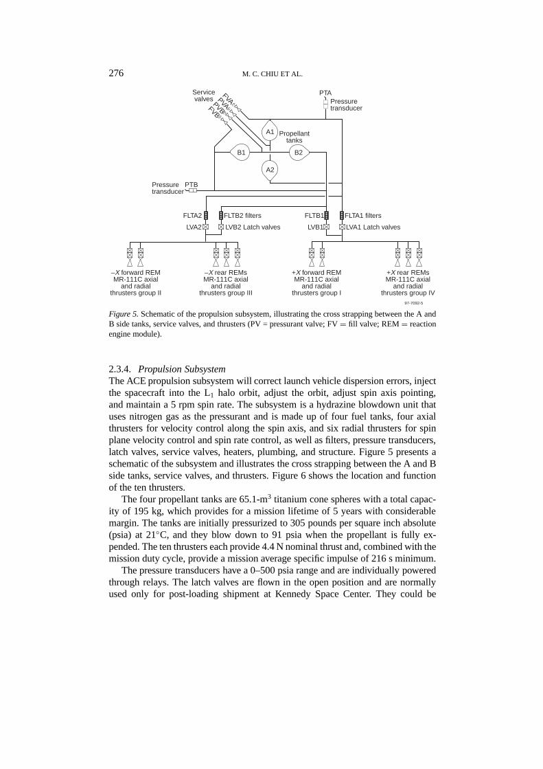
Figure 5.Schematic of the propulsion subsystem, illustrating the cross strapping between the A andB side tanks, service valves, and thrusters (PV = pressurant valve; FV= fill valve; REM= reactionengine module).
2.3.4. Propulsion SubsystemThe ACE propulsion subsystem will correct launch vehicle dispersion errors, injectthe spacecraft into the L1 halo orbit, adjust the orbit, adjust spin axis pointing,and maintain a 5 rpm spin rate. The subsystem is a hydrazine blowdown unit thatuses nitrogen gas as the pressurant and is made up of four fuel tanks, four axialthrusters for velocity control along the spin axis, and six radial thrusters for spinplane velocity control and spin rate control, as well as filters, pressure transducers,latch valves, service valves, heaters, plumbing, and structure. Figure 5 presents aschematic of the subsystem and illustrates the cross strapping between the A and Bside tanks, service valves, and thrusters. Figure 6 shows the location and functionof the ten thrusters.
The four propellant tanks are 65.1-m3 titanium cone spheres with a total capac-ity of 195 kg, which provides for a mission lifetime of 5 years with considerablemargin. The tanks are initially pressurized to 305 pounds per square inch absolute(psia) at 21◦C, and they blow down to 91 psia when the propellant is fully ex-pended. The ten thrusters each provide 4.4 N nominal thrust and, combined with themission duty cycle, provide a mission average specific impulse of 216 s minimum.
The pressure transducers have a 0–500 psia range and are individually poweredthrough relays. The latch valves are flown in the open position and are normallyused only for post-loading shipment at Kennedy Space Center. They could be

ACE SPACECRAFT 277
IV
I
II
III
R–A
R+R+
A
A R
A
R
X
Y
Z +
IAIR
IVAIVR+IVR–IIAIIRIIIA
IIIR+IIIR–
x xx x
x xxx
xx
xx
x xx x
x xx
x
x
x
xx
DecreaseIncrease+Z –ZX–Yplane
Spin AxisPointing
Spin RateVelocity Control
97-7092-6
Thrusters
Figure 6.Location and function of the ten thrusters.
used to isolate a leaking thruster or propellant tank if such a failure were de-tected during the mission. Tank, line, and thruster valve heaters are thermostaticallycontrolled and maintain the propellant components comfortably above the 0◦Chydrazine freezing point. Thruster catalyst bed heaters are relay controlled andpreheat the bed prior to thruster firings to prevent cold-start degradation. The sub-system plumbing is all welded and sized to minimize any differential flow pressuredrop that might cause a spin imbalance. Orifices are used in the latch valves andat the entrance to the pressure transducers to minimize pressure surge and waterhammer effects. Filters upstream of each latch valve and at the inlet of each thrusterremove any potential contaminating particulate before it reaches the component.
278 M. C. CHIU ET AL.
The propulsion subsystem was designed and fabricated by Primex Corpora-tion (formerly Olin Aeorospace) and shipped to JHU/APL for integration withthe spacecraft after thermal blanket installation. It was environmentally tested atprotoflight levels using water to simulate propellant and using mass simulators forthe rest of the spacecraft subsystems.
2.3.5. Power SubsystemThe ACE electrical power subsystem provides 444 W at spacecraft end of life(EOL), with EOL defined as 5 years. The electrical power load budget is 425 Wpeak. The low-magnetic-emission, fixed planar silicon solar array is connecteddirectly to the 28 V±2% shunt-regulated bus. The electrical power subsystem alsocontains an 18-cell 12 A-h NiCd battery booster capable of supporting a 165-Wlaunch load. This subsystem is one-fault tolerant with its autonomously controlledredundant shunt regulator and cross-strapped redundant battery chargers.
Solar arrayTECSTAR was contracted to fabricate and lay down five strings, each 89 solar cellslong, on each of four aluminum honeycomb substrates. The 86.4×149.9×3.2 cmsubstrates, insulated with 3-mil Kapton, were provided by Applied Aerospace Struc-tures Corporation. The 3.9× 6.3 cm, 15.1% efficient silicon cells have a diffusedboron back surface field/reflector and are covered with 12-mil, ceria-doped mi-crosheet. The cells and covers have anti-reflective coatings, and the covers alsohave ultraviolet reflective coatings. Strings are back-wired for magnetic emissionsbelow 0.1 nT at the magnetometer, which is housed on a boom extending 150 cmfrom the panel edge. Silver interconnects, which are nonstandard, were used toachieve low magnetic emissions. TECSTAR provided a coupon (i.e., a sample)and a qualification panel with accelerated thermal cycle testing to validate the silverinterconnects.
The solar arrays were designed for several worst-case operating conditions.Maximum temperature expected is 58◦C while under thruster plume impingementof the ultrapure hydrazine propellant. Conservative degradation estimates projectenough EOL power to tolerate one string failure with no effect on spacecraft per-formance. A solar cell patch located on each panel supports an experiment tomeasure the degradation over mission life. Strings also have bypass diodes toprotect against shadows cast by spacecraft instruments, antennas, and thrusters.Pyrotechnic-actuated, spring-loaded hinges deploy the panels after spacecraft sep-aration from the Delta II.
BatteryJHU/APL designed and built the 18-cell stack with redundant thermostatic con-trolled heaters and current, temperature, and full- and half-stack differential voltagemonitors. The thermal design will keep the battery between 0◦ and 25◦C. The cellsfor the flight battery are a SAFT Gates Aerospace Batteries (GAB, Gainsville,
ACE SPACECRAFT 279
Florida) 12AB28 standard profile design (4.6× 3.0× 0.9 cm, 536 g). Althoughaged for 8 years in dry storage at Gainsville, cells successfully activated in Franceperform well (typically 15 A-h).
ElectronicsThe electronics consists of six boxes and a shunt resistor dissipater assembly. Eachsolar panel has a digital shunt box nearby containing five metal oxide semicon-ductor field-effect transistors (MOSFETs) and blocking diodes for low-dissipationshorting of each string. The panel current and the voltage of each string are mon-itored. Fuses, which help filter the regulated bus, protect the bus from a shortingfailure of either blocking diodes or capacitors.
The power subsystem dissipater electronics contains redundant linear transis-tors, the booster, and redundant battery chargers. The 90% efficient booster can beconfigured in flight to provide partial battery reconditioning. The battery chargersprovide closed-loop current and voltage limiting. All boxes are constructed with acombination of semi-rigid flex printed circuit boards and heat sink subassemblies.The traces are sized for 70-A fuse blowing capability and 15-A continuous powerto the bus with less than a 2-V drop from the solar panel connector to the subsystemdissipater electronics output.
The power subsystem control electronics contain redundant hybrid power con-verters from Interpoint, shunt regulation electronics, and a circuit that will switchfrom the primary to the redundant side in response to bus under- or overvoltage.It also contains redundant processors and low battery voltage and low bus volt-age sensors. The 80C85RH-based processors digitize all electrical power subsys-tem telemetry for transmission via cross-strapped serial digital links to the redun-dant spacecraft telemetry systems. The processors also decode commands cross-strapped from the redundant spacecraft command systems. Digital-to-analog con-verters allow adjustment of the bus voltage set point (±2%), battery charge limits(0 to 1.5 A), and temperature-compensated battery voltage limits.
3. Environmental Design Drivers
As a result of specific ACE science and mission concerns, three environmentalfactors were given significant attention during the design and fabrication of theACE Observatory. By addressing these factors from the beginning of the designprocess, goals and requirements were achieved with relatively little additional cost.
3.1. MAGNETIC CLEANLINESS
The observatory has two magnetometer sensors, one at the end of each magne-tometer boom. Although ACE had no magnetic requirement, there were magneticgoals. Magnetic cleanliness precautions were undertaken to the extent practical
280 M. C. CHIU ET AL.
(i.e., without driving the cost), to limit the magnetic fields from the spacecraftcomponents that could radiate to the sensors. The goal was to achieve a spacecraftstatic magnetic field at the magnetometer sensors of less than 0.1 nT. The goal forAC interference at the sensor locations was less than 0.001 nT over a frequencyrange of 0 to 10 Hz and the specific frequencies of 15 kHz (±200 Hz), 30 kHz(±200 Hz), and 60 kHz (±200 Hz). These goals were achieved as follows:
– The spacecraft battery was wired to reduce the magnetic field and to minimizemagnetic loops, and the battery was demagnetized and located as far as practicalfrom the magnetometer sensors on the+X side panel (sensors are at±Y axis).
– Solar panels were back-wired for compensation. Magnetic loops at the end ofthe panels were minimized.
– Twisted pair wire was used for power lines; a single-point ground systemwas used; and grounding was designed to minimize ground loops, all to the extentpossible.
– Magnetic materials used in spacecraft components were reviewed on a globalbasis, and a random selection of typical parts was tested.
– Boom material is titanium; hinges and materials close to sensors are nonmag-netic; and de-permed tools were used.
– The magnetometer team used ‘sniffing’ devices to map the magnetic emis-sions of selected suspect spacecraft components and parts (e.g., analog shunt re-sistive strips and latch valves). As a result, propulsion subsystem latch valves andlatch valves for the SEPICA instrument were shielded with Met-glass.
– The ordnance fire component was compensated with external magnets afterpre-integration tests.
– Nonmagnetic connectors were used for spacecraft components as much aspossible.
– The magnetic field generated by the shaker tables used for spacecraft compo-nents and the observatory was measured (both with and without the degauss coils),and, where required, degauss coils were used to reduce the large fields generatedby the exciter.
– Instruments and spacecraft subsystems were screened prior to integration toreduce the possibility that compensation of the entire spacecraft would be required.
– No observatory-level compensation was performed after preflight static fieldtests.
Two preliminary results of the static test prior to launch indicated that if thesource locations are neglected, and if the conservative assumption is made that thesource of the field is at the center of the spacecraft, a worst-case field of 2.3 nT ateach flight sensor is predicted. If the sources have been correctly identified, basedin part on the static test and on pre-integration screening results, then the in-flightfield components are only110 this value. The preliminary results of the AC testrevealed no AC signals at a level that could significantly affect the magnetic fieldmeasurements.
ACE SPACECRAFT 281
The magnetometer sensors are flown in ‘twin design,’ with one sensor on eachboom, as opposed to ‘dual design,’ with two sensors on a long boom on the sameside of the spacecraft, so that the actual field on orbit is folded into the magne-tometer sensor and electronics calibration. The actual field will never be knownbut, from data for the early phase of the mission, is estimated to be<1 nT at thesensors.
3.2. RADIATION ENVIRONMENT
Spacecraft components had to be designed to meet the radiation requirements asfollows. Parts were required to survive a total ionizing dose of 15 krad (Si) withoutpart failure (with spot shielding as required). The 15 krad (Si) requirement wasbased on a 5-year mission goal using the projected radiation exposure for the mis-sion with a 95% level of confidence and assuming a nominal shielding of 75-milaluminum. Since ACE could operate for 4 years at solar maximum, the componentshad to withstand a total proton fluence of approximately 211 particles cm−2 forprotons with energies above 4 MeV. Components had to be immune to latch-up;parts susceptible to single-event latch-up with linear energy transfer threshold lessthan 120 MeV cm2 mg−1 could not be used in spacecraft components without latch-up mitigation techniques. Parts susceptible to SEU could not be used in criticalcomponents if these could cause mission-critical failures. In parts of noncriticalcomponents, SEU could not compromise spacecraft health or mission performance.System-level SEU effects were considered, so that upsets did not cause uncor-rectable errors that would affect system performance. SEU-susceptible parts usedfor data storage memory had to use appropriate error detection and correction tech-niques so that during exposure to maximum particle flux (as experienced during aworst-case solar particle event), the amount of data lost would not cause a violationof the component specification requirements.
3.3. CONTAMINATION CONTROL
ACE instruments are susceptible to hydrocarbons, fluoro-hydrocarbons, particles,and humidity. To satisfy instrument requirements and permit a comfortable work-ing environment, the instruments were purged and the environment kept at class100 000 clean room level (this level requires only the use of white coats). Chem-icals and compounds used were carefully screened. Nitrogen purge with 99.995%or better purity at a temperature of 15◦ to 25◦C was supplied to the instrumentsthrough a manifold at a pressure of 3.0 pounds per square inch (psi) nominal(5.0 psi maximum) with a flow rate of 5.9 cm3 min−1 total. Each instrument used arestrictor to obtain its required flow rate. The purge remained connected (with shortinterruptions of minutes’ duration) until launch. The sun sensor and star scanneroptical portions were covered unless ground support equipment (stimulators or sunsimulator) was attached.
282 M. C. CHIU ET AL.
3.4. SPACECRAFT SAFING
Spacecraft features are used to ‘safe’ the spacecraft when problems are recognizedonboard or when spacecraft actions, independent of ground intervention, are re-quired. These features are implemented with C&DH ‘autonomy rules,’ built-inpower subsystem autonomy, dedicated lines between the power subsystem and theC&DH for power bus fault indications, C&DH RF watchdog timers, and C&DHand power subsystem resets.
The C&DH autonomy rules (called ‘autonomy’ here) are widely used on thespacecraft to put an instrument, a spacecraft component, or the whole observatory(spacecraft and instruments) in a ‘safe’ configuration when certain criteria are met.The criteria used to determine the need for action, and the actions are predefinedbut can be changed. A component parameter such as a current, which requiresmonitoring, is collected by the C&DH. The value of the parameter is compared( =, >,<, etc. ) to a preselected threshold, for example, the maximum expectedcurrent for that component. Based on the result, the C&DH autonomy may issuecommands such as unpowering the component if the current is too high. Below areexamples where autonomy is used on the spacecraft for all phases of the mission:launch, postlaunch vehicle separation, and on-station operation.• Launch• Autonomy switches from the prime to the redundant power subsystem
shunt regulator in the unlikely case of an analog shunt short.• Postlaunch vehicle separation activities• After the solar panels are automatically deployed, autonomy controls the
safe configuration of the spacecraft. For example, if the solar panels aresupplying power (indicating successful panel deployment), the transmit-ter is commanded to radiate, thereby facilitating first ground contact forthe ground operators. Otherwise, the transmitter is commanded to standby,thereby conserving power until ground intervention can determine the causeof the problem.
• Health monitoring• When instrument and spacecraft health indicators, such as currents, exceed
predefined limits, autonomy takes action, such as unpowering a component,until the cause of the problem can be determined by mission operations.• For redundant thermostats / heaters, autonomy removes a failed thermostat
/ heater of a redundant set but keeps the other powered.• During battery reconditioning, autonomy stops battery reconditioning if
battery health indicators exceeds limits.• Maneuver or attitude problems• Autonomy aborts thruster firing and closes the ULEIS instrument shutter
in case of a spacecraft attitude problem. This problem is indicated by theSun angle exceeding a predefined limit or by the side panel Sun sensorssensing the Sun.
ACE SPACECRAFT 283
• Thruster firing abort commands are issued by autonomy after a maneuverif, because of a problem, the maneuver is not completed with the normalprocess.
• Protection against commands resulting in improper spacecraft configurations
• The autonomy feature can be used to protect against possible commanderrors. Two examples follow. Should both transmit/receive chains be erro-neously connected to the top-deck broad-beam antennas, autonomy is usedto configured the active side to the bottom-deck antenna (which is orientedtoward Earth). If both transmitters are configured to radiate, autonomy isused to configure the inactive side transmitter to standby.
• Support for other autonomous spacecraft actions
• After an RF watchdog timer time-out, which indicates abnormal opera-tion, the C&DH commands the active transmitter to stand by (prior toreconfiguring the broad-beam antennas). Autonomy is used to commandthe transmitter to radiate and to select the ‘attitude determination and con-trol’ format for the downlink, thereby minimizing the time required for theground station to acquire the spacecraft and to reconfigure the downlink.• Under certain conditions, e.g., power shedding, both transmitters may be
turned off by the C&DH. Autonomy is used to power the interface heaterthermostat to keep the bottom deck at an acceptable temperature for theother components on the deck.• When one recorder is filled (for example, when a ground contact where the
recorder would be dumped is missed), autonomy is used to start recordingon the other recorder so data loss is minimized.
The power subsystem autonomy feature is used to detect bus regulation fail-ures indicated by overvoltage (30 V) or undervoltage (26 V) conditions. For eithercondition, the power subsystem autonomously switches control from the primaryto the redundant shunt regulator in<10 ms. Note that in the load shed sequencedescribed in the next paragraph, the C&DH autonomy takes 90.0 to 181.8 ms toswitch to the redundant shunt regulator.
The power subsystem monitors the health of the spacecraft power bus anddetects instrument or spacecraft hardware fault conditions that cause the bus tofall below specified limits. Dedicated lines between the power subsystem and theC&DH are used to indicate faults to the C&DH. The latter autonomously executes apredetermined sequence of commands to shed loads. The default sequence, loadedat launch, sheds all noncritical loads and switches control from the primary tothe redundant power subsystem shunt regulator. Graduated sequences, which shedloads depending on the severity of the failure, will be used later in the mission.The graduated sequences attempt to preserve telemetry data history and minimizechanges to the spacecraft configuration as long as possible to help the groundoperators determine the cause of the fault. Note that the C&DH load shed andthe power subsystem autonomy can be individually disabled, if necessary
284 M. C. CHIU ET AL.
The C&DH RF watchdog timer is used to place the spacecraft in a communi-cations safe mode when a valid command has not been received for a specifiedtime. When the specified time has expired and the RF watchdog timer in the activeC&DH has timed out, the active C&DH sets the RF antenna switches in its chainto connect the transmit/receive chain on its side to the bottom-deck broad-beamantenna. When the RF watchdog timer in the inactive C&DH times out, it sets theRF antenna switches in its chain to connect the transmit/receive chain on its side tothe top-deck broad-beam antenna, thereby providing hemispheric uplink coverageto facilitate reception of a command. At the next time-out, this configuration isreversed, with the active side connected to the top-deck antenna and the inactiveside connected to the bottom-deck antenna. The C&DH toggles between these twoconfigurations for each time-out until a valid command is received, which resetsthe timer.
Each C&DH has a two independent timers used to halt thruster firing. If onetimer fails during a maneuver, the other will still time out and stop the firing.
The C&DH has four sources that can generate a reset: last resort timer, softwarewatchdog timer, error detection and correction double bit error, and C&DH circuitbus time-out error. These result in C&DH hardware reset and software boot andinitialization. Critical parameters are restored either to their pre-reset value (if twoof the three backup copies of the parameter match) or their default value (if these donot match). The power subsystem processor resets whenever the power processorwatchdog timer is not reset within 2 s. Again, majority voting is used to restorecritical parameters to their pre-reset value or default value.
Acknowledgements
The authors would like to acknowledge the contributions of the many individualsinvolved with the ACE spacecraft development at JHU/APL and its subcontractors.We would also like to acknowledge and express our appreciation of the manyindividuals within the ACE Team organizations that also contributed so much tothe success of the ACE spacecraft. These organizations include GSFC/NASA andtheir subcontractors, Caltech, and all of the science and instrument team membersin the various universities and government agencies involved with ACE.
Reference
Radovich, Mark A., Jr.: 1995, ‘Modifications of a Mosaic Focal Plane Star Tracker for ScanningApplication,’ SPIE Int. Symp. Aerospace/Defense Sensing and Control and Dual Use Photonics,Orlando, Florida.
Related Documents