11 th Annual Sucker Rod Pumping Workshop Renaissance Hotel Oklahoma City, Oklahoma September 15 - 18, 2015 Accurate Load & Position Measurement Is Critical to Quality Dynamometer Analysis Anthony Allison Weatherford

Welcome message from author
This document is posted to help you gain knowledge. Please leave a comment to let me know what you think about it! Share it to your friends and learn new things together.
Transcript

11th Annual Sucker Rod Pumping
Workshop Renaissance Hotel
Oklahoma City, Oklahoma
September 15 - 18, 2015
Accurate Load & Position Measurement Is Critical to Quality Dynamometer Analysis
Anthony Allison
Weatherford

Sept. 15 – 18, 2015 2015 Sucker Rod Pumping Workshop 2
Quality Dynamometer Analysis
• Dynamometer Overview
• Load Measurement Methodology
– Beam-Mounted Strain Gauge
– Polished Rod Load Cell
– Inferring Polished Rod Load from Motor Measurements
• Position Measurement Methodology
– Position Switch
– Hall-Effect Transducers
– Inclinometer
• Measurement Error Examples

DYNAMOMETER OVERVIEW
Sept. 15 - 16, 2015 2015 Sucker Rod Pumping Workshop 3
Quality Dynamometer Analysis
• Today’s dynamometer systems allows for near
real-time monitoring and analysis of the
performance of rod pump systems
• Rod pump controllers (RPCs), SCADA, and
diagnostic software have greatly increased the
availability of dynamometer data, but not
necessarily the quality of this data
• This is not a new problem, Kemler (1935)
described early problems with damping and
phase lag of dynamometer data
Sept. 15 - 16, 2015
2015 Sucker Rod Pumping Workshop 4
What Is a Dynamometer Card?
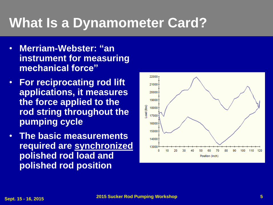
• Merriam-Webster: “an instrument for measuring mechanical force”
• For reciprocating rod lift applications, it measures the force applied to the rod string throughout the pumping cycle
• The basic measurements required are synchronized polished rod load and polished rod position
Sept. 15 - 16, 2015 2015 Sucker Rod Pumping Workshop 5

LOAD MEASUREMENT METHODOLOGY
Sept. 15 - 16, 2015 2015 Sucker Rod Pumping Workshop 6

Beam-Mounted Strain Gauge
• Measures changes in tension of the walking beam caused by changes in polished rod load
• Does not require polished rod to be clamped off during installation or replacement
• Reduced likelihood of cable damage during normal operation or workover
• Not subjected to shock loading if rods float on the downstroke
• May have integrated position measurement, requiring only one cable for installation
Sept. 15 - 16, 2015 2015 Sucker Rod Pumping Workshop 7

Beam-Mounted Strain Gauge Sources of Error
• No direct relationship between strain gauge output and force applied to the polished rod
– Each installation must be “calibrated” to expected minimum and maximum polished rod loads
– RPC must be programmed with the min/max loads from a portable dynamometer or predictive program during installation
• Polished rod load is not the only force that causes changes in beam tension
– Changes in temperature cause beam expansion/contraction, affecting the measured strain
– These temperature-induced changes manifest as drift observed in the load range and offset of the dynamometer card
Sept. 15 - 16, 2015 2015 Sucker Rod Pumping Workshop 8

Beam-Mounted Strain Gauge Sources of Error
• Measurement principle incorrectly assumes that polished rod and pitman loads imparts only a bending moment on the beam
• In fact, there is both a perpendicular, bending force (blue) and parallel force (green) that is compressive or tensile depending on crank angle
• The parallel load components prevent the measured strain from being strictly analogous to polished rod load
Sept. 15 - 16, 2015 2015 Sucker Rod Pumping Workshop 9
Beam-Mounted Strain Gauge Summary
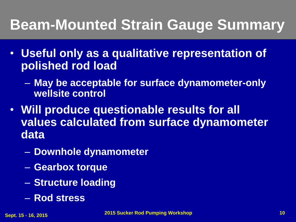
• Useful only as a qualitative representation of polished rod load
– May be acceptable for surface dynamometer-only wellsite control
• Will produce questionable results for all values calculated from surface dynamometer data
– Downhole dynamometer
– Gearbox torque
– Structure loading
– Rod stress
Sept. 15 - 16, 2015 2015 Sucker Rod Pumping Workshop 10

Polished Rod Load Cell
• Installed on the carrier bar beneath the polished rod clamps, providing direct measurement of polished rod load
• Uses a strain gauge as the base measurement element, but in a full-bridge circuit configuration
– Output changes linearly with respect to the force applied
• Inherently temperature compensated
– Changes in temperature cause an equal resistance change in all four gauges
Sept. 15 - 16, 2015 2015 Sucker Rod Pumping Workshop 11
Polished Rod Load Cell Disadvantages
• Polished rod must be clamped off during
installation/replacement
• Load cell and cable must be
removed/reinstalled during a workover,
creating an opportunity for damage to
occur
• Cable is susceptible to damage during
operation, particularly on Mark II, air
balance, and Rotaflex units
Sept. 15 - 16, 2015 2015 Sucker Rod Pumping Workshop 12

Polished Rod Load Cell Zero Offset
• A perfectly balanced strain gauge bridge will provide zero output with no load applied
• However, manufacturing tolerances of the gauges and strain induced during assembly result in a slight imbalance of the bridge
• This imbalance causes a small voltage to be output at zero load, referred to as the zero offset
• Most controllers have a simple procedure to connect the load cell to the RPC with no load and measure the zero offset
• Skipping this step will cause all points in the surface dynamometer to be shifted up or down by the load value associated with the zero offset
Sept. 15 - 16, 2015 2015 Sucker Rod Pumping Workshop 13
Polished Rod Load Cell Summary
• Predominant sensor used for polished rod load measurement
• Requires only zero offset correction to provide accurate load readings
• Proportional output, direct measurement, and temperature compensation provide superior results when compared to beam-mounted strain gauges
Sept. 15 - 16, 2015 2015 Sucker Rod Pumping Workshop 14
Inferring Polished Rod Load from Motor Measurements
• Modern variable frequency drives (VFD) are
capable calculating torque output of the motor
in ft-lbs based on current measurement
• If the API geometry of the pumping unit is
known, motor torque and crank angle can be
used to infer a polished rod load value
• The goal is to provide polished rod load
measurement without installing a load sensor
and with no load sensor cable to break
Sept. 15 - 16, 2015 2015 Sucker Rod Pumping Workshop 15

Inferred Polished Rod Load Sources of Error
• Motor must be tuned to determine the motor’s no-load current
– No-load current is critical to determining excitation vs. torque-producing current
• Ideally, a rotational motor tune is performed with the motor decoupled from the pumping unit
• More commonly, a non-rotational tune is performed, where no-load current is manually entered or calculated based on measured stator resistance
– This can lead to errors in the inferred polished rod loads, as no-load current is not directly measured during a non-rotational tune
Sept. 15 - 16, 2015 2015 Sucker Rod Pumping Workshop 16

Inferred Polished Rod Load Sources of Error
• API geometry must be properly configured, or errors in load calculation will occur
– Required dimensions indicated at right
– Structural imbalance
– Effective counterbalance
– Motor sheave & gearbox ratios
• On units without available catalog data, geometry must be measured in the field
Sept. 15 - 16, 2015 2015 Sucker Rod Pumping Workshop 17
Inferred Polished Rod Load Summary
• Inferring polished rod load from VFD data can
eliminate the need for a load sensor and cable
• Calculations depend on accurate motor tuning
and API geometry values
• Errors in no-load current from motor turning
or API geometry will lead to errors in the
inferred polished rod load values
Sept. 15 - 16, 2015 2015 Sucker Rod Pumping Workshop 18

POSITION MEASUREMENT METHODOLOGY
Sept. 15 - 16, 2015 2015 Sucker Rod Pumping Workshop 19
Position Switch
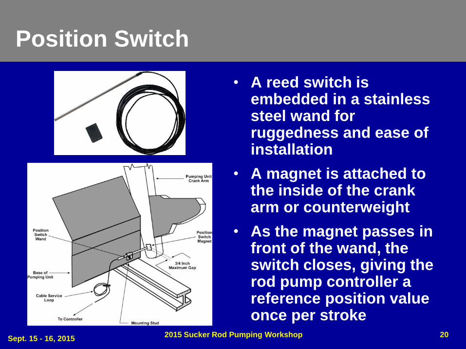
• A reed switch is embedded in a stainless steel wand for ruggedness and ease of installation
• A magnet is attached to the inside of the crank arm or counterweight
• As the magnet passes in front of the wand, the switch closes, giving the rod pump controller a reference position value once per stroke
Sept. 15 - 16, 2015 2015 Sucker Rod Pumping Workshop 20

Position Switch
• The switch closure is used as a reference point, the RPC internally generates the other position points required to plot a dynamometer
• The RPC must be calibrated to determine the time difference between the switch closure and top of stroke
• This calibration is used to scale the internally generated position points
Sept. 15 - 16, 2015 2015 Sucker Rod Pumping Workshop 21

Position Switch Sources of Error
• The RPC typically assumes polished rod movement is sinusoidal, which can cause errors in the calculated position data
• Errors in the top of stroke calibration will rotate the surface dynamometer, causing the downhole dynamometer to lean left or right
– This may give the appearance of tubing movement that is not occurring
– Will cause errors in calculation of gearbox torque and inferred production
• Calibration must be repeated after SPM, stroke length, or counterbalance is changed
Sept. 15 - 16, 2015 2015 Sucker Rod Pumping Workshop 22
Position Switch Summary
• Simple, low-cost solution for determining
polished rod position
• Requires proper top of stroke calibration to
produce acceptable dynamometer cards
• Even with proper calibration, will produce
lowest quality position measurement of
available sensors
Sept. 15 - 16, 2015 2015 Sucker Rod Pumping Workshop 23
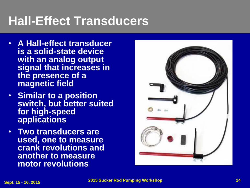
Hall-Effect Transducers
• A Hall-effect transducer is a solid-state device with an analog output signal that increases in the presence of a magnetic field
• Similar to a position switch, but better suited for high-speed applications
• Two transducers are used, one to measure crank revolutions and another to measure motor revolutions
Sept. 15 - 16, 2015 2015 Sucker Rod Pumping Workshop 24
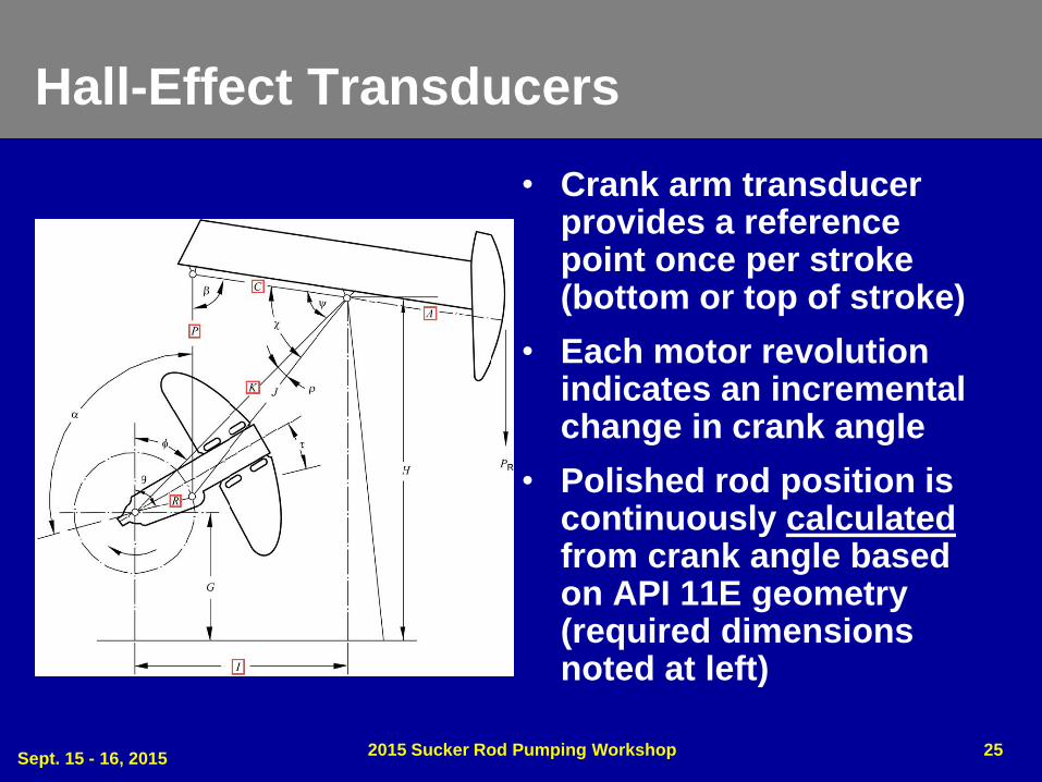
Hall-Effect Transducers
• Crank arm transducer provides a reference point once per stroke (bottom or top of stroke)
• Each motor revolution indicates an incremental change in crank angle
• Polished rod position is continuously calculated from crank angle based on API 11E geometry (required dimensions noted at left)
Sept. 15 - 16, 2015 2015 Sucker Rod Pumping Workshop 25
Hall-Effect Transducer Sources of Error
• API dimensional data must be accurate to properly calculate polished rod position
– A and C dimensions will vary due to field adjustment available in some units where the walking beam attaches to the saddle bearing, as well as manufacturing tolerances
– If dimensions are not known, they must be measured in the field (difficult on larger units)
• Phase angle adjustment must be properly set
– This corrects for the offset between when the crank arm transducer detects the magnet and when the reference point (TOS/BOS) is actually reached
– If the phase angle adjustment is incorrect the resulting surface and downhole cards will be rotated left or right (similar to a position switch with incorrect TOS)
Sept. 15 - 16, 2015 2015 Sucker Rod Pumping Workshop 26

Hall-Effect Transducer Summary
• Improves upon position switch by providing
continuous position calculation using motor
revolutions
• Requires proper configuration of API
geometry and phase angle adjustment to
produce acceptable dynamometer cards
Sept. 15 - 16, 2015 2015 Sucker Rod Pumping Workshop 27

Inclinometer
• Utilizes an accelerometer to measure the angle of the beam as it varies throughout the stroke
• In a stationary system, an accelerometer detects the direction of pull from the Earth's gravity, i.e. the angle of inclination of the sensor
• Directly relates changes in beam angle to changes in polished rod position
Sept. 15 - 16, 2015 2015 Sucker Rod Pumping Workshop 28

Inclinometer Sources of Error
• Proper installation must account for which
side of the pumping the sensor is installed on
• The standard installation on the right side
(wellhead to the operator’s right when looking
at the unit) will output an increasing voltage
as the polished rod is lifted
Sept. 15 - 16, 2015 2015 Sucker Rod Pumping Workshop 29

Inclinometer Sources of Error
• A sensor installed on the left side will output a decreasing voltage as the polished rod is lifted
– To account for this, alternate wiring is used to reverse the signal output on the left side
– Without this compensation, the dynamometer card would be plotted in reverse
Sept. 15 - 16, 2015 2015 Sucker Rod Pumping Workshop 30

Inclinometer Sources of Error
Sept. 15 - 16, 2015 2015 Sucker Rod Pumping Workshop 31
• Early inclinometers used a simple filter to reduce
distortions caused by vibration of the pumping unit
– This filter creates a time delay in the response of the output and
causes the card to lean to the left
– A de-skew adjustment in the RPC is used to correct this, similar to the
phase angle adjustment used for the Hall-effect transducer
• Newer microelectromechanical systems (MEMS) based
inclinometers more effectively filter the distortions
caused by vibration, producing a cleaner signal without
requiring skew adjustment in the rod pump controller

Inclinometer Summary
• Provides most direct measurement of
polished rod position by measuring the angle
of the walking beam
• Care must be taken regarding installation
position and wiring to produce the correct
output
• Older inclinometers required filtering that may
skew the position output and rotate the
dynamometer card, this is not necessary on
newer MEMS inclinometers
Sept. 15 - 16, 2015 2015 Sucker Rod Pumping Workshop 32
MEASUREMENT ERROR EXAMPLES
Sept. 15 - 16, 2015 2015 Sucker Rod Pumping Workshop 33

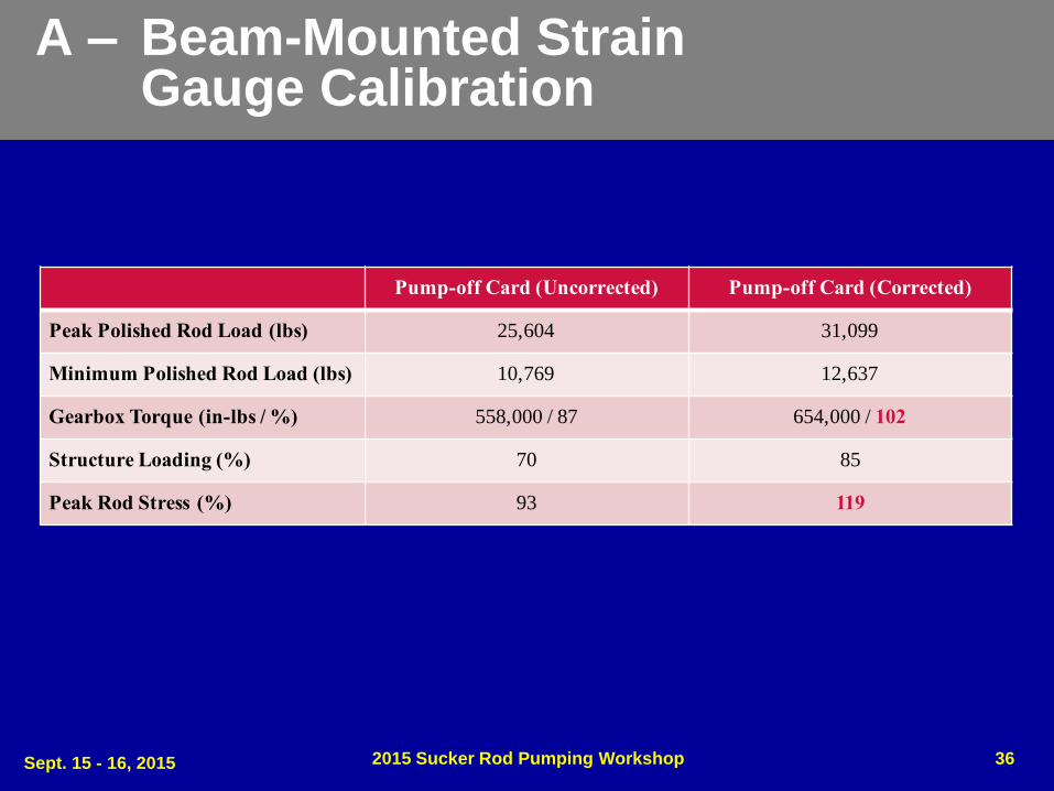
A – Beam-Mounted Strain Gauge Calibration
• Well A utilizes a beam-mounted strain gauge for measuring polished rod load
• Compared to the orange predicted card, the measured surface card is shifted significantly lower, exhibits a narrower profile, and a portion of the downhole card is below the zero load line
Sept. 15 - 16, 2015 2015 Sucker Rod Pumping Workshop 34

A – Beam-Mounted Strain Gauge Calibration
Sept. 15 - 16, 2015 2015 Sucker Rod Pumping Workshop 35
Before Load Calibration After Load Calibration
A – Beam-Mounted Strain Gauge Calibration
Sept. 15 - 16, 2015 2015 Sucker Rod Pumping Workshop 36
Pump-off Card (Uncorrected) Pump-off Card (Corrected)
Peak Polished Rod Load (lbs) 25,604 31,099
Minimum Polished Rod Load (lbs) 10,769 12,637
Gearbox Torque (in-lbs / %) 558,000 / 87 654,000 / 102
Structure Loading (%) 70 85
Peak Rod Stress (%) 93 119
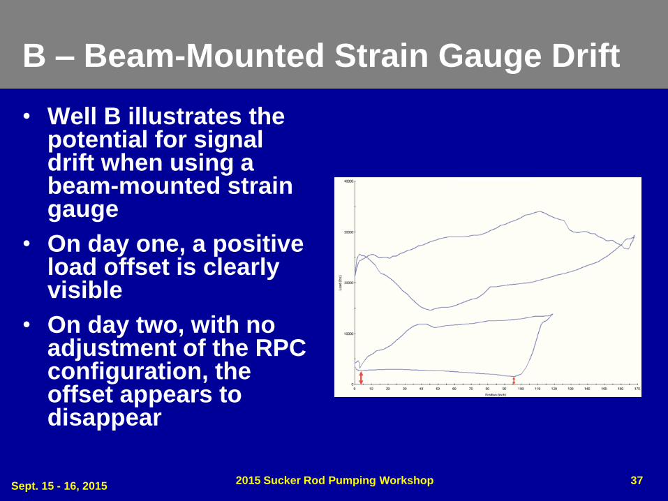
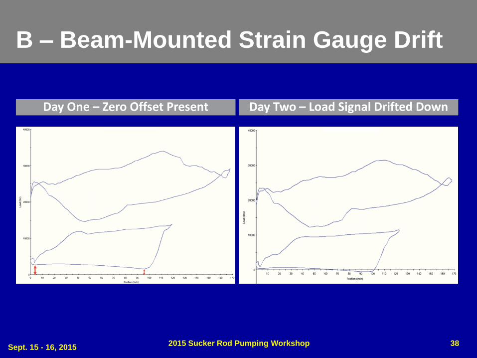
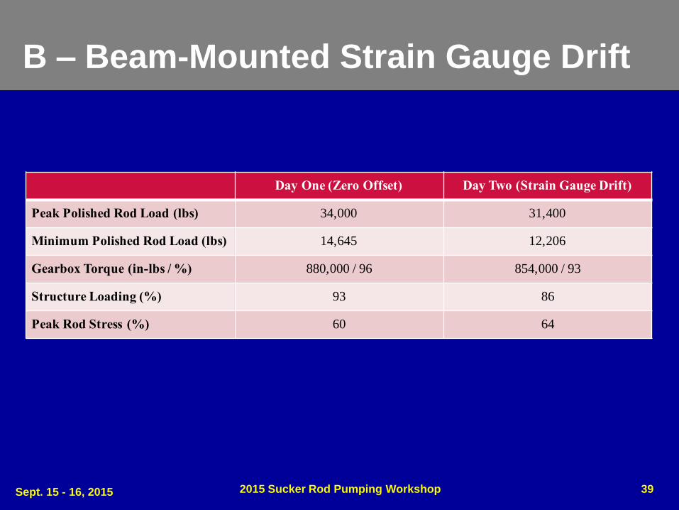
B – Beam-Mounted Strain Gauge Drift
• Well B illustrates the potential for signal drift when using a beam-mounted strain gauge
• On day one, a positive load offset is clearly visible
• On day two, with no adjustment of the RPC configuration, the offset appears to disappear
Sept. 15 - 16, 2015 2015 Sucker Rod Pumping Workshop 37
B – Beam-Mounted Strain Gauge Drift
Sept. 15 - 16, 2015 2015 Sucker Rod Pumping Workshop 38
Day One – Zero Offset Present Day Two – Load Signal Drifted Down
B – Beam-Mounted Strain Gauge Drift
Sept. 15 - 16, 2015 2015 Sucker Rod Pumping Workshop 39
Day One (Zero Offset) Day Two (Strain Gauge Drift)
Peak Polished Rod Load (lbs) 34,000 31,400
Minimum Polished Rod Load (lbs) 14,645 12,206
Gearbox Torque (in-lbs / %) 880,000 / 96 854,000 / 93
Structure Loading (%) 93 86
Peak Rod Stress (%) 60 64
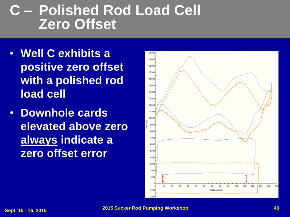
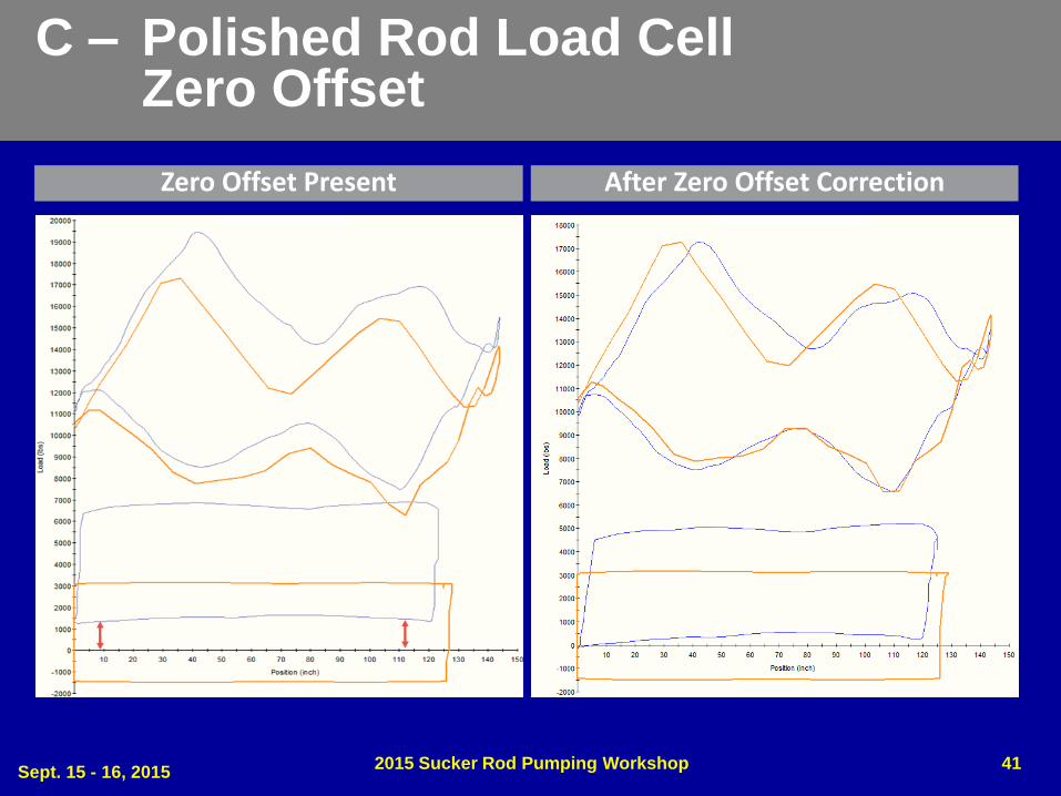
C – Polished Rod Load Cell Zero Offset
• Well C exhibits a
positive zero offset
with a polished rod
load cell
• Downhole cards
elevated above zero
always indicate a
zero offset error
Sept. 15 - 16, 2015 2015 Sucker Rod Pumping Workshop 40
C – Polished Rod Load Cell Zero Offset
Sept. 15 - 16, 2015 2015 Sucker Rod Pumping Workshop 41
Zero Offset Present After Zero Offset Correction
C – Polished Rod Load Cell Zero Offset
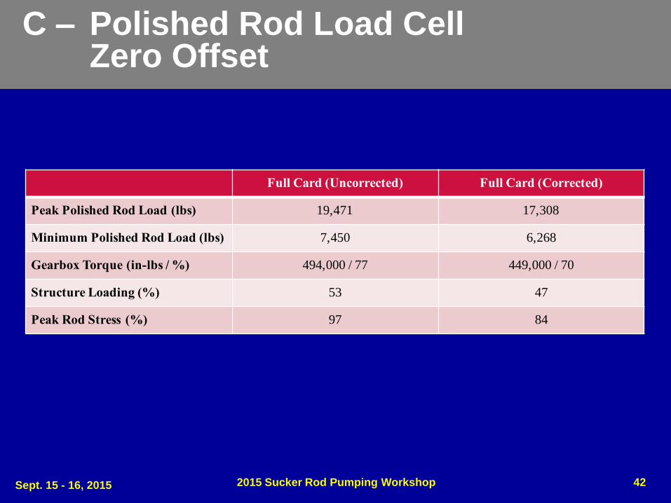
Sept. 15 - 16, 2015 2015 Sucker Rod Pumping Workshop 42
Full Card (Uncorrected) Full Card (Corrected)
Peak Polished Rod Load (lbs) 19,471 17,308
Minimum Polished Rod Load (lbs) 7,450 6,268
Gearbox Torque (in-lbs / %) 494,000 / 77 449,000 / 70
Structure Loading (%) 53 47
Peak Rod Stress (%) 97 84
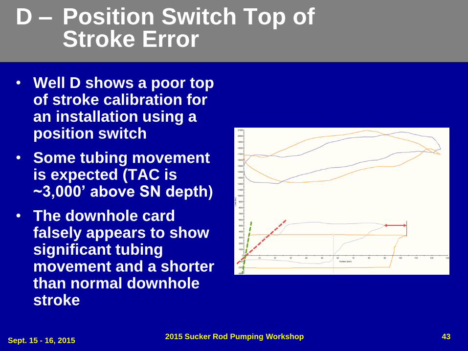
D – Position Switch Top of Stroke Error
• Well D shows a poor top of stroke calibration for an installation using a position switch
• Some tubing movement is expected (TAC is ~3,000’ above SN depth)
• The downhole card falsely appears to show significant tubing movement and a shorter than normal downhole stroke
Sept. 15 - 16, 2015 2015 Sucker Rod Pumping Workshop 43
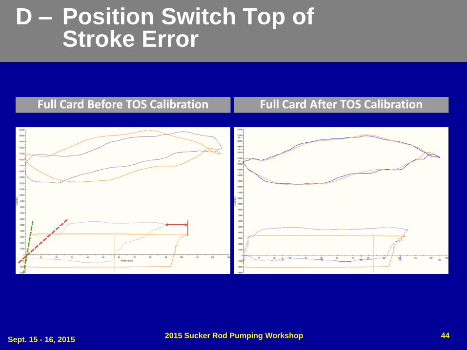
D – Position Switch Top of Stroke Error
Sept. 15 - 16, 2015 2015 Sucker Rod Pumping Workshop 44
Full Card Before TOS Calibration Full Card After TOS Calibration

D – Position Switch Top of Stroke Error
Sept. 15 - 16, 2015 2015 Sucker Rod Pumping Workshop 45
Pump Off Card Before TOS Calibration Pump Off Card After TOS Calibration
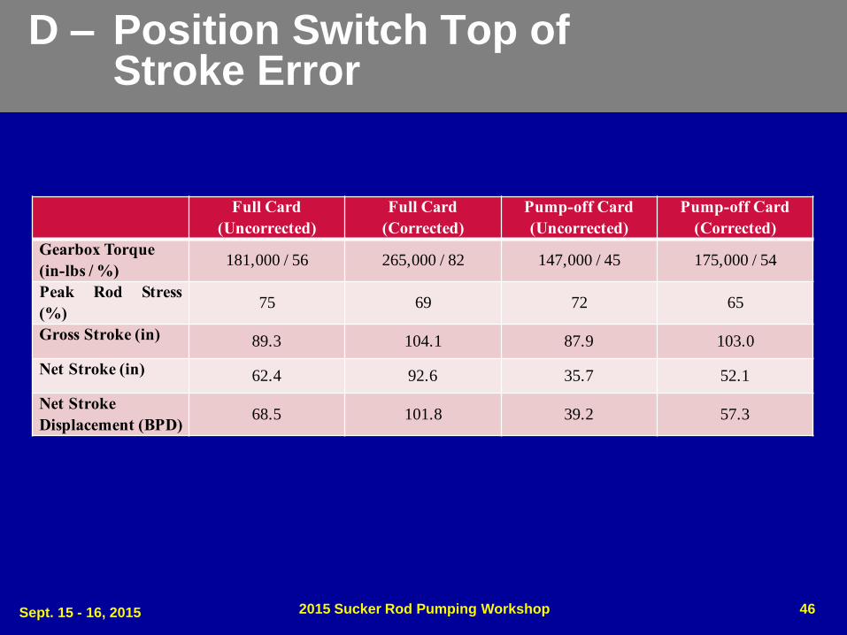
D – Position Switch Top of Stroke Error
Sept. 15 - 16, 2015 2015 Sucker Rod Pumping Workshop 46
Full Card
(Uncorrected)
Full Card
(Corrected)
Pump-off Card
(Uncorrected)
Pump-off Card
(Corrected)
Gearbox Torque
(in-lbs / %)181,000 / 56 265,000 / 82 147,000 / 45 175,000 / 54
Peak Rod Stress
(%)75 69 72 65
Gross Stroke (in) 89.3 104.1 87.9 103.0
Net Stroke (in) 62.4 92.6 35.7 52.1
Net Stroke
Displacement (BPD)68.5 101.8 39.2 57.3
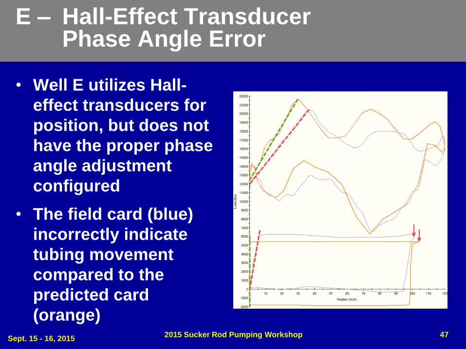
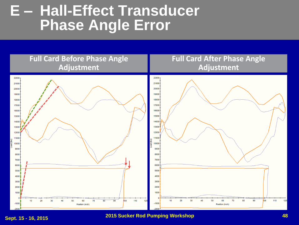
E – Hall-Effect Transducer Phase Angle Error
• Well E utilizes Hall-
effect transducers for
position, but does not
have the proper phase
angle adjustment
configured
• The field card (blue)
incorrectly indicate
tubing movement
compared to the
predicted card
(orange)
Sept. 15 - 16, 2015 2015 Sucker Rod Pumping Workshop 47
E – Hall-Effect Transducer Phase Angle Error
Sept. 15 - 16, 2015 2015 Sucker Rod Pumping Workshop 48
Full Card Before Phase Angle Adjustment
Full Card After Phase Angle Adjustment
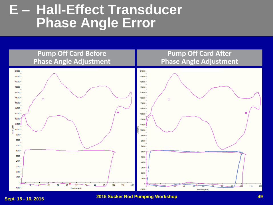
E – Hall-Effect Transducer Phase Angle Error
Sept. 15 - 16, 2015 2015 Sucker Rod Pumping Workshop 49
Pump Off Card Before Phase Angle Adjustment
Pump Off Card After Phase Angle Adjustment
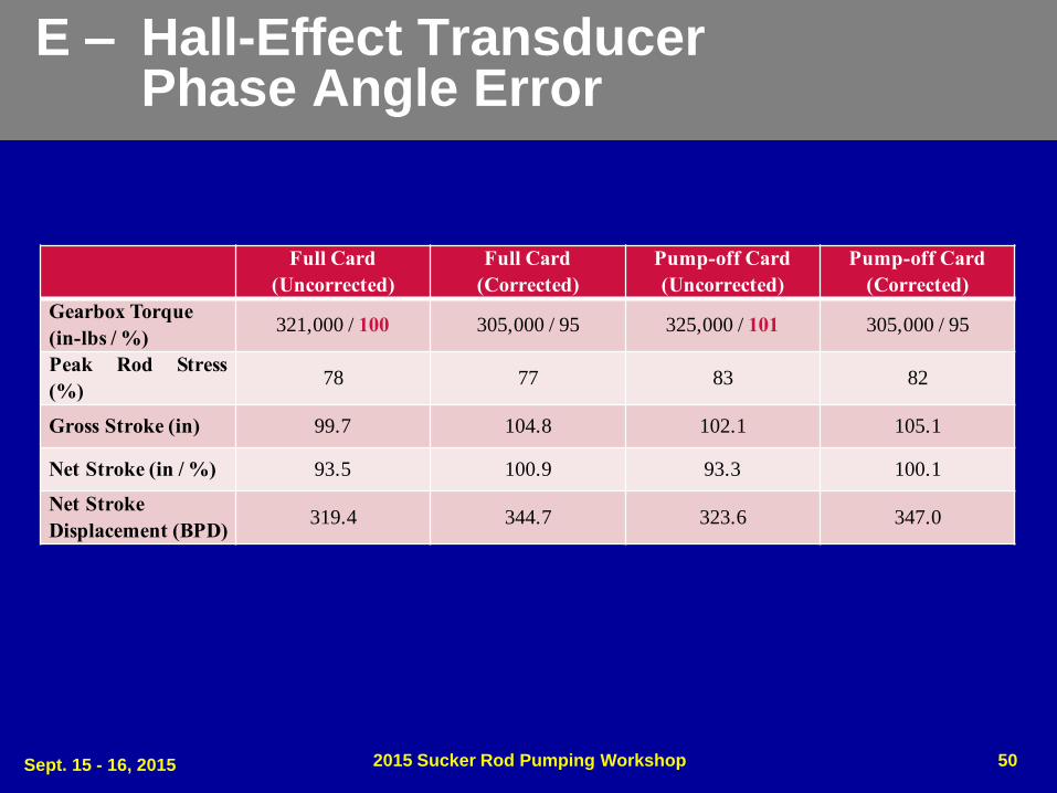
E – Hall-Effect Transducer Phase Angle Error
Sept. 15 - 16, 2015 2015 Sucker Rod Pumping Workshop 50
Full Card
(Uncorrected)
Full Card
(Corrected)
Pump-off Card
(Uncorrected)
Pump-off Card
(Corrected)
Gearbox Torque
(in-lbs / %)321,000 / 100 305,000 / 95 325,000 / 101 305,000 / 95
Peak Rod Stress
(%)78 77 83 82
Gross Stroke (in) 99.7 104.8 102.1 105.1
Net Stroke (in / %) 93.5 100.9 93.3 100.1
Net Stroke
Displacement (BPD)319.4 344.7 323.6 347.0

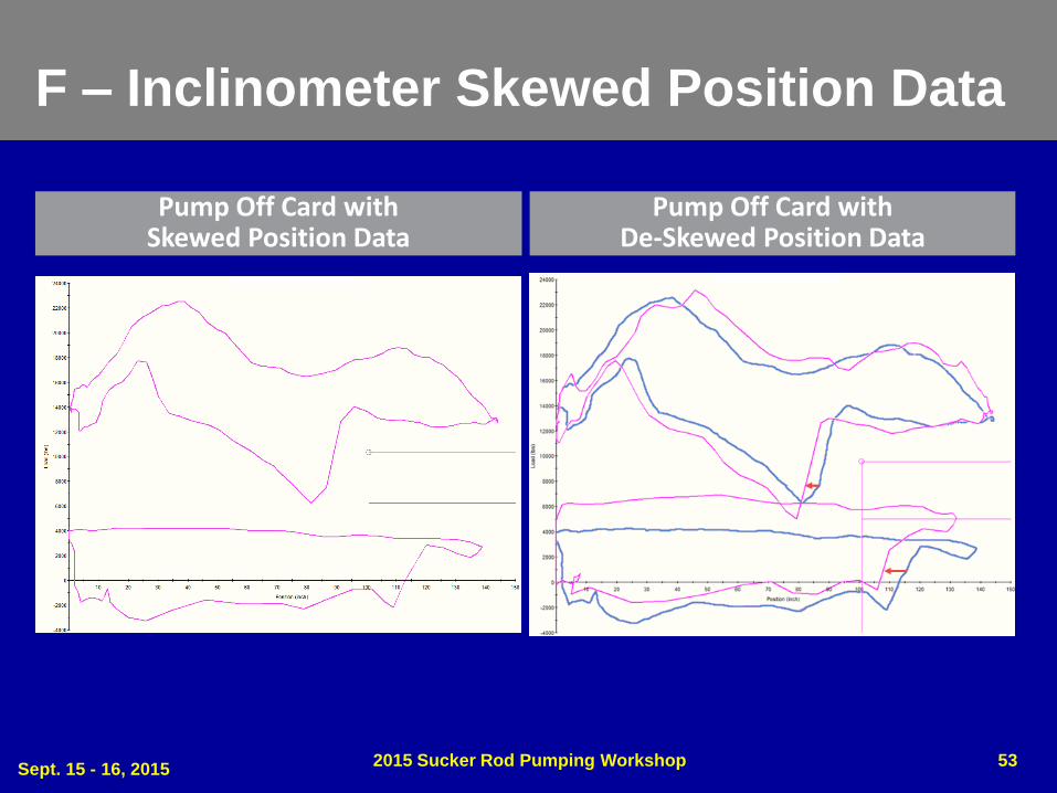
F – Inclinometer Skewed Position Data
• Well F uses an older inclinometer, filtered to reduce signal noise caused by vibration of the pumping unit
• The filtering has caused a time lag of the position signal, evident in the left lean of the downhole dynamometer card
Sept. 15 - 16, 2015 2015 Sucker Rod Pumping Workshop 51

F – Inclinometer Skewed Position Data
Sept. 15 - 16, 2015 2015 Sucker Rod Pumping Workshop 52
Full Card with Skewed Position Data Full Card with De-Skewed Position Data
F – Inclinometer Skewed Position Data
Sept. 15 - 16, 2015 2015 Sucker Rod Pumping Workshop 53
Pump Off Card with Skewed Position Data
Pump Off Card with De-Skewed Position Data

F – Inclinometer Skewed Position Data
Sept. 15 - 16, 2015 2015 Sucker Rod Pumping Workshop 54
Full Card
(Uncorrected)
Full Card
(Corrected)
Pump-off Card
(Uncorrected)
Pump-off Card
(Corrected)
Gearbox Torque
(in-lbs / %)419,000 / 65 436,000 / 68 410,000 / 64 471,000 / 73
Peak Rod Stress
(%)85 85 80 83
Gross Stroke (in) 151.0 137.0 138.6 132.2
Net Stroke (in) 145.3 127.6 108.9 103.7
Net Stroke
Displacement (BPD)472.8 415.3 354.3 337.4

Conclusions
• The dynamometer card is one of the most important tools used for control and analysis of rod pumped wells
• It is important to understand the strengths and weaknesses of the variety of sensors available for measuring dynamometer inputs
• Proper installation, calibration, and RPC configuration is required for each sensor type
• Errors in dynamometer input data can results in poor well control, under- or over-reported inferred production, and possible overloading of the gearbox, pumping unit structure, or sucker rods
Sept. 15 - 16, 2015 2015 Sucker Rod Pumping Workshop 55
Sept. 15 – 18, 2015 2015 Sucker Rod Pumping Workshop 56
Copyright
Rights to this presentation are owned by the company(ies) and/or author(s) listed on the title page. By submitting this presentation to the Sucker Rod Pumping Workshop, they grant to the Workshop, the Artificial Lift Research and Development Council (ALRDC), and the Southwestern Petroleum Short Course (SWPSC), rights to:
– Display the presentation at the Workshop.
– Place it on the www.alrdc.com web site, with access to the site to be as directed by the Workshop Steering Committee.
– Place it on a CD for distribution and/or sale as directed by the Workshop Steering Committee.
Other use of this presentation is prohibited without the expressed written permission of the author(s). The owner company(ies) and/or author(s) may publish this material in other journals or magazines if they refer to the Sucker Rod Pumping Workshop where it was first presented.

Sept. 15 - 18, 2015 2015 Sucker Rod Pumping Workshop 57
Disclaimer
The following disclaimer shall be included as the last page of a Technical Presentation or Continuing Education Course. A similar disclaimer is included on the front page of the Sucker Rod Pumping Web Site.
The Artificial Lift Research and Development Council and its officers and trustees, and the Sucker Rod Pumping Workshop Steering Committee members, and their supporting organizations and companies (here-in-after referred to as the Sponsoring Organizations), and the author(s) of this Technical Presentation or Continuing Education Training Course and their company(ies), provide this presentation and/or training material at the Sucker Rod Pumping Workshop "as is" without any warranty of any kind, express or implied, as to the accuracy of the information or the products or services referred to by any presenter (in so far as such warranties may be excluded under any relevant law) and these members and their companies will not be liable for unlawful actions and any losses or damage that may result from use of any presentation as a consequence of any inaccuracies in, or any omission from, the information which therein may be contained.
The views, opinions, and conclusions expressed in these presentations and/or training materials are those of the author and not necessarily those of the Sponsoring Organizations. The author is solely responsible for the content of the materials.
The Sponsoring Organizations cannot and do not warrant the accuracy of these documents beyond the source documents, although we do make every attempt to work from authoritative sources. The Sponsoring Organizations provide these presentations and/or training materials as a service. The Sponsoring Organizations make no representations or warranties, express or implied, with respect to the presentations and/or training materials, or any part thereof, including any warrantees of title, non-infringement of copyright or patent rights of others, merchantability, or fitness or suitability for any purpose.
Related Documents