Advanced Kiffer Systems, Inc. 4905 Rocky River Road Cleveland, Ohio 44135 Precision Plasma Cutting Machine Operator’s Manual 2 May 2014

Welcome message from author
This document is posted to help you gain knowledge. Please leave a comment to let me know what you think about it! Share it to your friends and learn new things together.
Transcript

Advanced Kiffer Systems, Inc. 4905 Rocky River Road Cleveland, Ohio 44135
Precision Plasma Cutting Machine
Operator’s Manual
2 May 2014

INTENTIONALLY LEFT BLANK

ACCU-KUT OPERATOR'S MANUAL 2-MAY-14
Revision 1 Table of Contents - i
TABLE OF CONTENTS
1. OVERVIEW...................................................................................................................................................... 1
2. INSTALLATION .............................................................................................................................................. 3
3. CUTTING-GENERAL...................................................................................................................................... 4
3.1 DEFINITIONS .................................................................................................................................... 4 3.2 CUTTING SPEED.............................................................................................................................. 4 3.3 RAPID TRAVERSE SPEED .............................................................................................................. 4 3.4 PIERCE TIME.................................................................................................................................... 5 3.5 PIERCE DELAY................................................................................................................................. 5 3.6 PIERCE HEIGHT............................................................................................................................... 5
4. PARTS DESIGN AND NESTING.................................................................................................................... 6
4.1 LEAD-IN............................................................................................................................................. 6 4.2 LEAD-OUT......................................................................................................................................... 6 4.3 KERF WIDTH..................................................................................................................................... 7 4.4 KERF ANGLE .................................................................................................................................... 7 4.5 CUT QUALITY ................................................................................................................................... 7 4.6 PARTS NESTING............................................................................................................................ 15
5. BEFORE CUTTING OPERATIONS.............................................................................................................. 16
5.1 SAFETY ........................................................................................................................................... 16 5.2 CUTTING GASES............................................................................................................................ 17
6. AKS ACCU-KUT CNC CONTROL ............................................................................................................... 18
6.1 GENERAL........................................................................................................................................ 18 6.2 POWER ON ..................................................................................................................................... 18 6.3 STARTING UP THE CNC SOFTWARE .......................................................................................... 18
7. MACHINE SETUP ......................................................................................................................................... 19
7.1 PLASMA POWER SUPPLY AND TORCH...................................................................................... 19 7.2 NETWORKING ................................................................................................................................ 19 7.3 CONNECTING MULTIPLE CONTROLS ON ONE NETWORK ...................................................... 23
8. MAINTENANCE ............................................................................................................................................ 27
8.1 ROUTINE MAINTENANCE ............................................................................................................. 27 8.2 BRIDGE TENSION .......................................................................................................................... 30 8.3 WHEN TO RELEASE BRIDGE TENSION ...................................................................................... 30 8.4 HOW TO RELEASE BRIDGE TENSION......................................................................................... 31 8.5 CHECK FOR A SQUARE BRIDGE ................................................................................................. 32 8.6 SQUARE BRIDGE........................................................................................................................... 33 8.7 DEFINITIONS .................................................................................................................................. 33 8.8 TECHNICAL SUMMARY ................................................................................................................. 34
9. WARRANTY.................................................................................................................................................. 35
9.1 SERVICE AND TECHNICAL SUPPORT......................................................................................... 35 9.2 FIELD SERVICE RATES................................................................................................................. 35 9.3 TRAVEL AND LIVING EXPENSES................................................................................................. 35 9.4 PARTS ............................................................................................................................................. 35

ACCU-KUT OPERATOR'S MANUAL 2-MAY-14
Table of Contents - ii Revision 1
10. REMOTE CONTROL..................................................................................................................................... 36
10.1 SAFETY ........................................................................................................................................... 36 10.2 OPERATION.................................................................................................................................... 38 10.3 BASIC TROUBLESHOOTING AND MAINTENANCE..................................................................... 40 10.4 FUNCTION SETTINGS ................................................................................................................... 42
Revision 1. Section 10 Remote Control added

ACCU-KUT OPERATOR'S MANUAL 2-MAY-14
Revision 1 Page 1
1. OVERVIEW
Plasma machine operators should complete their training by an AKS factory representative and familiarize themselves with the contents of this manual and the other references supplied with the machine before beginning operation.
This Plasma Cutting Machine Operation Manual offers information and suggestions for the safe and proper use of cutting machines manufactured by Advanced Kiffer Systems, Inc. It contains guidelines for the machine's Installation, routine maintenance, warranties and service, information about safety and how to operate the machine's CNC control, as well as concepts and suggestions for parts design and nesting. It is intended for use with other · technical manuals and references supplied by the manufacturers of the machine's major system components (i.e., plasma system, personal computer hardware and software, printer, etc.).
Reference material about how to draw parts and nest them on sheets or plates is not included in this manual. See the software company's documentation and help screens for information on these subjects.
Parts that are to be cut are drawn by a programmer using the engineering computer in the front office. In some cases, the programmer can copy drawings that have already been made using a CAD system into the computer from the USB drive. The programmer selects the parts and quantity desired and uses the software to "nest” the parts on a suitable sized sheet or plate.
The nested parts programs are downloaded to the CNC control which is on the shop floor next to the plasma machine. The download is usually performed over a direct wire connection between the engineering computer and the CNC control but in some cases the USB drive may be used for the transfer. The operator selects the program desired, places metal on the cutting table, adjusts the plasma power supply power level, gas flow controls; etc. The kerf offset and cutting speed are selected by the operator or the programmer (if Auto Gas controls are on the system) at the CNC control before beginning the cutting process. During cutting, all machine movement is guided by the CNC control following the program's instructions. The automatic ventilation system operates during cutting to draw smoke and fumes downward and out the port at the rear of the machine.

ACCU-KUT OPERATOR'S MANUAL 2-MAY-14
Page 2 Revision 1
An AKS plasma cutting machine installation normally consists of the following major components:
Base machine (welded tubular steel frame, gantry beam, plasma torch carriage, servo
drive motors)
CNC control mounted in a shop floor enclosure
Plasma torch height control
Plasma system power supply, leads and torch
Gas regulators and hoses
Software for parts design and nesting (optional)
Network card for connecting the engineering computer and the shop floor CNC control (optional). See Networking Section.
Plasma torch consumable starter kit and tools for plasma torch assembly
Internal zoned downdraft system and controls for removal of smoke and fumes
Customer supplied air filtration system (exhaust blower, ducting and filter)
Customer supplied cutting gases appropriate for the metal to be cut

ACCU-KUT OPERATOR'S MANUAL 2-MAY-14
Revision 1 Page 3
2. INSTALLATION An experienced AKS factory technician should install the plasma machine at the customer's site. When the plasma cutting machine arrives via truck, a fork lift crew will be required for unloading. When our installer arrives, he will work with your plant personnel. Your equipment operator and/or maintenance people should assist our installer in connecting cables, etc. This will be an opportunity for hands-on training. The entire installation and subsequent operator training require no more than four days.
Machine owner responsibilities include the following:
o Contact the AKS plasma installation manager following acceptance of the purchase
order to discuss electric power requirements, machine location, etc.
o Uncrate the new machine and place it at its permanent location before the arrival of the AKS factory technician.
o Provide electrical power for the plasma power supply (three phase, 240 Volt) and the
CNC control. Arrange for power at the computer and printer location (see separate specifications).
o Purchase an 8-foot (2.5m) copper ground rod for installation next to the cutting
machine. The ground rod will be driven into the earth during the machine's installation.
o Provide a clean, dry shop air supply near the machine (90 PSIG (6 bar), low volume, 1/4 inch fitting) for powering the machine's ventilation system.
o Have the proper gases on-site before installation that are appropriate for the material
that will be cut when the AKS technician is testing the machine. Gas regulators and hoses will be supplied with the cutting machine. (see the appropriate plasma manual for more information)
o Arrange for air filtration equipment (final positioning can wait until the plasma machine
is being installed).
o Provide metal to be cut during the machine's installation and operator training.

ACCU-KUT OPERATOR'S MANUAL 2-MAY-14
Page 4 Revision 1
3. CUTTING-GENERAL
3.1 DEFINITIONS
X-Axis: The main longitudinal rail axis of the machine, the longest side of the cutting machine. The direction away from the front of the table is defined as +X, while toward the front of the table is defined as -X. The X-Axis is also known as the rail axis. Y-Axis: The cross or transverse axis of the machine. The direction away from the right side of the table is usually defined as +Y, while toward the right side of the table is defined as -Y. The Y-Axis is also known as the transverse axis. Home position: The operator's position is normally placed at or near the corner of the machine where X= 0 and Y= 0.
Note: there may be additional Home positions established by the user, especially for extended length machines.
Nesting: The process of placing multiple parts on a sheet or plate so that they are close together and minimize cutting time and/or scrap material. Program: A sequence of machine control steps for cutting a nested sheet or plate containing one or more parts.
3.2 CUTTING SPEED
The operation manuals for all plasma systems contain charts for cutting metals of various thicknesses. Make certain that the chart being used is appropriate for the metal being cut and the gases you are using. These charts are guidelines and serve as a good reference. However, the charts are very conservative regarding cutting speeds since they are for best cut quality. You may find that faster cutting speeds produce acceptable results.
Using safety lenses, as referenced in the HyperTherm Manual, observe the arc as it cuts. If the torch is traveling too slowly, the arc will shoot ahead. When it travels too fast, the arc will lag behind. Adjust the cutting speed in small increments until the arc remains vertical. Select the best trade-off for your cutting based on your own cut quality requirements. Be sure to change to the proper consumable parts whenever you change the current.
3.3 RAPID TRAVERSE SPEED
To estimate total cutting times, you need to know the rapid traverse speed of the machine between cutting operations. The AKS plasma machine has a maximum travel speed of about 1200 inches (25.4m) per minute. Several factors influence the average speed. They include the machine's acceleration and deceleration capabilities, the distances between holes in a part, and the distance from the end of an individual part to the beginning of the next part.

ACCU-KUT OPERATOR'S MANUAL 2-MAY-14
Revision 1 Page 5
3.4 PIERCE TIME
For estimating total cutting times a good rule of thumb is to use two seconds as an approximate time for the following sequence of events to occur:
Establish its initial piercing height Start the pilot arc Initiate the plasma arc Lower to the recommended cutting height Cut the starting hole completely through the metal Stabilize the plasma arc
3.5 PIERCE DELAY
This is the time it takes for the plasma arc to make a single hole through the plate.
3.6 PIERCE HEIGHT
As a general rule the pierce height should be twice as much as the height during the cutting. This prevents pierce splatter from building up on the front of the torch nozzle.

ACCU-KUT OPERATOR'S MANUAL 2-MAY-14
Page 6 Revision 1
4. PARTS DESIGN AND NESTING
4.1 LEAD-IN
A lead-in is the cutting path between the pierce hole and the beginning of the cutting path for the finished part. Lead-ins are important for accelerating the plasma torch to the desired cutting speed before beginning to cut the finished part. Lead-in lengths should generally be at least twice the width of the plasma's kerf width. With the acceleration of the AKS plasma machines, a good lead-in length for thin metal is .25 to 0.4 inches (6-10mm). For metal 3/8 inches (10mm) or more thick a 0.6 inches (15mm) lead-in is satisfactory. Straight lead-ins are appropriate for approaching a cut path straight on. Curved lead-ins are appropriate for approaching a straight cut from an angle or approaching a curved cut. Curved lead-ins let the torch get up to speed in a shorter distance. This allows closer placement of parts on a sheet to minimize scrap material. Curved lead-ins are appropriate for use inside small holes where space is limited. If a punched hole, a drilled hole or the outside edge of the material is to be used as a start position for the plasma, the centerline of the torch nozzle orifice should be directly over the edge of the hole. When the orifice is farther from the edge of the material, the pilot arc remains on for a longer duration and excessive wear of the nozzle orifice will occur. Some experimentation may be required to determine the optimal pierce delay when starting from an edge without a lead-in.
4.2 LEAD-OUT
A lead-out is the cutting path taken immediately following completion of a finished part. Its path is into a scrap metal area and away from the finished part. Lead-outs are important because the torch's consumable parts lives are shortened when an operating torch moves unexpectedly off the edge of metal being cut. When the plasma system receives a stop signal from the CNC control, it normally ramps down the electric current and the gas flows. This takes place over the 1/4 second needed to provide long torch electrode life. For example, a plasma cutting at a speed of 60 inches (25mm/sec) will travel .25 inches (6 mm) in that time. If, for some reason, the torch runs off the edge of the plate without allowing for the ramp down, some of the molten electrode tip material could fall from the electrode, shortening its life. For this reason, the timer/counter module counts an error. When cutting a small inside hole, there is a danger of the scrap "donut hole" falling through the cutting table's slats. Since that scrap metal is normally used for the lead-out, the plasma arc may be disrupted before the shutdown process is completed. Sometimes the arc can stay attached to the edge of the hole long enough to ramp down, but there will be a small divot removed from the work-piece.
ACCU-KUT OPERATOR'S MANUAL 2-MAY-14
Revision 1 Page 7
4.3 KERF WIDTH
Kerf width is the width of the slit made by the plasma torch in the metal being cut. The kerf width depends on the plasma nozzle being used, cutting speed, etc. Normally, the kerf width is about 1.5. times the diameter of the torch nozzle but the width can vary with changes in the cutting speed and the torch height above the work-piece.
Use the following procedure to accurately determine the actual kerf width for a specific application. With the kerf width set to zero (0), cut a square piece 4 Inches (100mm) wide x 4 inches (100mm) long from the same material as will be used for your production parts. Use the same cutting speed and torch height that will be used for the production parts. Measure the finished piece. lt will be narrower than the desired size by the kerf width (1/2 the kerf width was lost on each side cut). Then, adjust the plasma machine's CNC program for that kerf width before cutting production parts. Kerf width should be set for the left side of the cutting path so that the square cut angle of the plasma torch will be on the right side with respect to the forward motion of the torch. This will ensure that the cut, and the poorer edge, are taken from the scrap material. Outside cuts will be clockwise movements around the parts. The machine will cut inside holes and slots in a counter clockwise direction.
4.4 KERF ANGLE
The angle of the edge of the cut piece should be close to vertical and as straight as possible. If the edge appears to be convex or concave rather than straight, adjustments to the torch height or cutting speed may be necessary. If the face of the edge is concave (beveled on the inside) the torch height is too low. The operator should increase the arc standoff voltage to Increase the torch height. If the face of the edge is convex and the top of the cut is rounded, try reducing the arc standoff voltage slightly. Then, try lowering the cutting current. If there is a choice of using lower power consumable parts, try using them with their respective gas flows and voltage settings.
4.5 CUT QUALITY
IMPROVING PLASMA CUT QUALITY The following reference guide offers several solutions to help improve cut quality. Consider the following factors when evaluating plasma cut quality:
Type of machine (example: XY table, punch press) Plasma cutting system (example: power supply, torch, consumables) Motion control device (example: CNC, torch height control) Process variables (example: cutting speed, gas pressures, flow rates) External variables (example: material variability, gas purity, operator experience) All of
these factors can affect the appearance of a cut.
ACCU-KUT OPERATOR'S MANUAL 2-MAY-14
Page 8 Revision 1
CUT QUALITY ISSUES
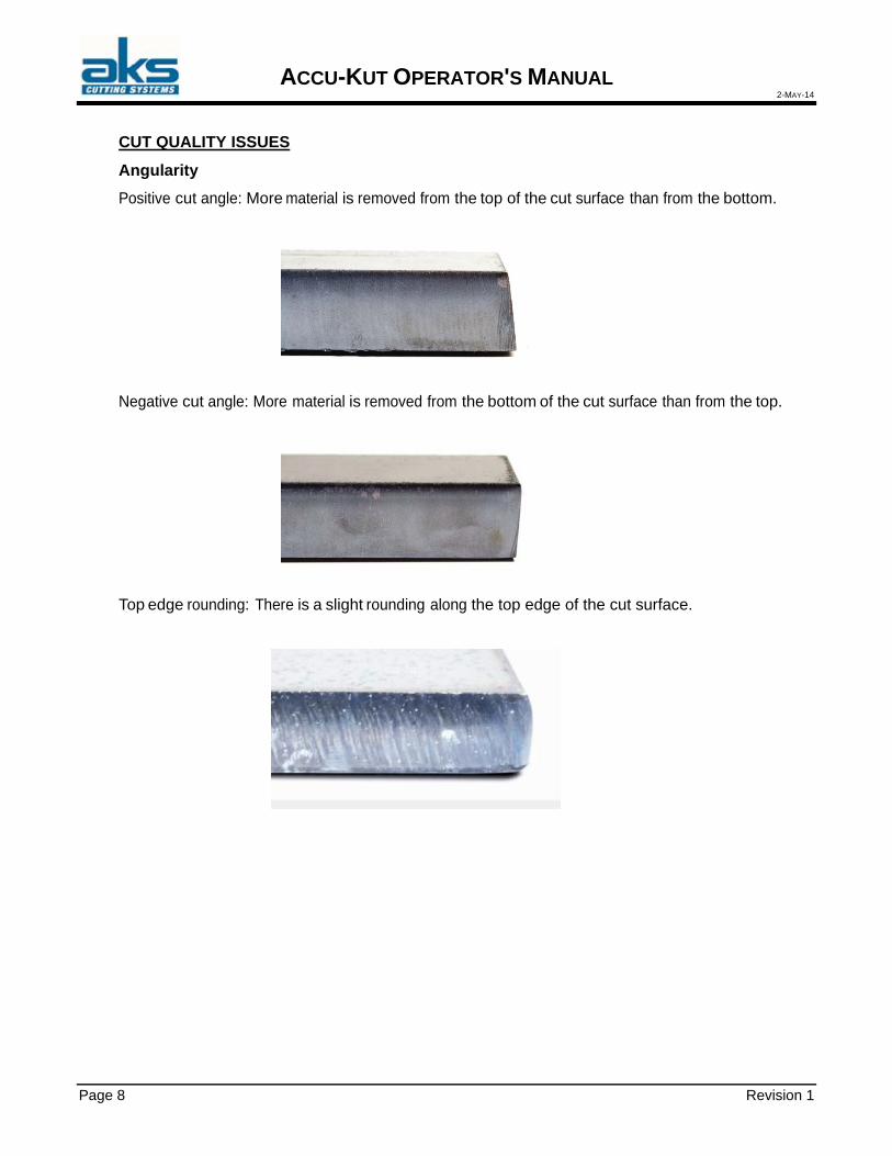
Angularity
Positive cut angle: More material is removed from the top of the cut surface than from the bottom. Negative cut angle: More material is removed from the bottom of the cut surface than from the top.
Top edge rounding: There is a slight rounding along the top edge of the cut surface.

ACCU-KUT OPERATOR'S MANUAL 2-MAY-14
Revision 1 Page 9
DROSS High-speed dross: A small, linear bead of molten material attaches and hardens along the bottom edge of the cut. In addition, S-shaped lag lines are present; dross is difficult to remove and requires grinding. Low-speed dross: A bubbly or globular accumulation of molten material attaches and hardens along the bottom edge of the cut. In addition, vertical lag lines may be present; dross is easy to remove and flakes off in large chunks. Top spatter: A light spatter of molten material collects on the top edges of the cut. Usually, this spatter is inconsequential and is most common with air plasma.

ACCU-KUT OPERATOR'S MANUAL 2-MAY-14
Page 10 Revision 1
SURFACE FINISH Roughness: Depending on the type of metal being cut, some roughness should be expected; “roughness” describes the texture of the cut face (the cut is not smooth). Aluminum Top: Air/Air
Best for thin material under 1/8" (3 mm) Bottom: H35/N2
Excellent edge quality Weld able edge
Mild steel
Top: Air/Air
Clean cut Nitrided edge Increased surface hardness
Bottom: O2 Exceptional edge quality
Weld able edge

ACCU-KUT OPERATOR'S MANUAL 2-MAY-14
Revision 1 Page 11
COLOR
Color results from a chemical reaction between a metal and the plasma gas that is used to cut it. Color changes are to be expected and vary most dramatically with stainless steel.
Top: N2/N2 Middle: H35/N2 Bottom: Air/Air

ACCU-KUT OPERATOR'S MANUAL 2-MAY-14
Page 12 Revision 1
BASIC STEPS TO IMPROVE CUT QUALITY Step 1: Is the plasma arc cutting in the appropriate direction?
The squarest cut angles are always on the right side in relation to the forward motion of the torch.
Verify the direction of the cut. Adjust the cutting direction, if necessary. The plasma arc typically spins clockwise with
standard consumables.
Contour
The torch travels clockwise. The good side of the cut is to the right side of the torch, as it travels forward.
Internal feature (hole)
Torch travels counterclockwise. Good side of the cut is to the right side of the torch as it travels forward.
End point
Start point
Step 2: Was the correct process selected for the material and thickness being cut? Refer to the cut charts in the Operation section of the Hypertherm Instruction Manual. On the CNC, choose the Cut Chart soft key on the Main Screen to view the cut chart for the selected torch type, material and thickness. Follow the specifications in the cut charts: Select the appropriate process for:
Material type Material thickness Desired cut quality Productivity goals
Select the correct plasma and shield gas.

ACCU-KUT OPERATOR'S MANUAL 2-MAY-14
Revision 1 Page 13
Select correct parameters for:
Gas pressures (or flow rates) Cut height and arc voltage Cutting speed
Confirm that the correct consumables are being used and verify the part numbers.
Note: Generally, lower amperage processes offer better angularity and surface finish.
However, cutting speeds are slower and dross levels are higher.
Step 3: Are the consumables worn?
Inspect consumables for wear. Replace worn consumables. Always replace the nozzle and electrode at the same time. Avoid over-lubricating o-rings.
Note: Use genuine Hypertherm consumables to ensure maximum cutting performance.
Step 4: Is the torch square to the workpiece?
Level the workpiece. Square the torch to the workpiece, both from the front and side of the torch.
Note: Inspect the material to see if it is bent or warped. In extreme cases this limitation cannot be corrected.
Step 5: Is the cut height set at the proper height?
Adjust the cut height to the correct setting. If you are using arc voltage control, adjust the voltage.
Note: As consumable parts wear, arc voltage settings need continual adjustment to
maintain cut height. Cut height can impact angularity.

ACCU-KUT OPERATOR'S MANUAL 2-MAY-14
Page 14 Revision 1
Negative cut angle
Square cut
Positive cut angle
Negative cut angle: torch too low; increase cut height. Positive cut angle: torch too high; decrease cut height.
Note: A slight variation in cut angles may be normal if the variation is within tolerance.
Step 6: Is the cutting speed set too fast or too slow? Adjust cutting speed as needed.
Note: Cutting speed may also impact your dross levels. High-speed dross: The cutting speed is too fast and the arc lags behind. Reduce the
cutting speed. Low-speed dross: The cutting speed is too slow and the arc shoots ahead. Increase the
cutting speed Top spatter: The cutting speed is too fast, reduce the cutting speed. Note: In addition to speed, both material chemistry and surface finish can impact dross
levels. When the workpiece heats up, more dross may form on subsequent cuts.
Step 7: Are there problems with the gas delivery system? Identify and repair any leaks or restrictions. Use properly sized regulators and gas lines. Use pure, high-quality gas. If manual purge is required, such as with the MAX200, confirm that the purging cycle
was completed. Consult the gas distributor.
Step 8: Is there torch vibration? Verify that the torch is securely attached to the table gantry. Consult the system builder, your table may require maintenance.

ACCU-KUT OPERATOR'S MANUAL 2-MAY-14
Revision 1 Page 15
Step 9: Does the table need to be tuned? Check and ensure that the table is cutting at the specified speed. Consult the system builder; the table speed may need tuning.
4.6 PARTS NESTING
When you are nesting parts you should allow an adequate distance between the parts and the outside edge. Leaving about 1/2 inch (13mm) for the outside "frame" will ensure that the remaining skeleton will reduce movement while cutting the remaining parts. It will also permit easy removal of the skeleton after cutting is completed. Keeping about 1/4 inch(6mm) between each part will leave space between them for lead-ins. It will also reduce any heat effects on parts already cut while cutting subsequent parts. See the software vendor's documentation for details about the steps for manual and automatic nesting.

ACCU-KUT OPERATOR'S MANUAL 2-MAY-14
Page 16 Revision 1
5. BEFORE CUTTING OPERATIONS
5.1 SAFETY
Plasma cutting is a safe operation when common sense precautions are followed. The plasma cutting machine uses a moving beam and a plasma arc, both of which have important safety considerations. An operator's responsibilities include:
Receive operator training from AKS factory representatives before operating the machine.
Review the safety guidelines in the Hypertherm plasma instruction manual. Inspect the work area. Make sure no scrap metal, tools, or other items will interfere with
the safe operation of the cutting machine's gantry and plasma torch. Inspect for worn cables, loose connections, etc. Follow the Routine Maintenance
recommendations included in this manual. Wear eye protection whenever the machine is in operation. Insist that others in the area
also take preventive measures and stand clear of the work area. Do not view the plasma arc without wearing dark safety glasses/goggles. See the
plasma manual for recommendations. Warn other people in the work area to not look directly at the arc unless they are wearing dark glasses.
Wear protective clothing to protect skin against burns caused by high intensity ultraviolet light, sparks, and hot metal.
Wear ear protection whenever the machine is operating at a power level of over 50 amperes.
Make sure that the plasma power supply is turned off before changing the torch's consumable parts.
Clean up any spilled torch coolant before operating the machine. Know the location and operation of all Emergency Stop control switches. Know the location and operation of each electric power and gas shut-off. Ensure that the proper ventilation/exhaust system is in operation while cutting is being
performed. Do not climb on the machine or its cable support tracks. Keep hands away from the plasma torch whenever its power is turned on. Wait for cut parts and the sheet skeleton to cool before handling or bringing it into
contact with combustible materials. Make fire extinguishers available near the cutting area. Never bypass or shortcut any safety interlocks. Assure proper grounding of the machine.

ACCU-KUT OPERATOR'S MANUAL 2-MAY-14
Revision 1 Page 17
5.2 CUTTING GASES
Dual gas plasma systems use one gas for the plasma itself and an additional gas (or gas mix) for a shield around the plasma. The shield gas provides an atmosphere around the plasma arc on the surface of the work-piece. This helps in improving cutting quality and also helps cool the shield at the front end of the torch. Plasma gases are often oxygen, nitrogen, or air. Shield gases may be oxygen, nitrogen, air or other gases or a mixture. See the plasma operations manual Operating Data Chart for the metal to be cut. Frequently, owners of plasma machines place cryotanks of the liquid gases on the shop floor near the plasma power supply. Gas flows are adjusted using the gas control panel according to the plasma's cutting chart recommendations.

ACCU-KUT OPERATOR'S MANUAL 2-MAY-14
Page 18 Revision 1
6. AKS ACCU-KUT CNC CONTROL
6.1 GENERAL
The AKS CNC proprietary control system consists of the following major components:
CNC Computer with a high capacity hard disk for part nest storage Touch screen monitor Servo amplifiers Industrial shop floor cabinet Three (3) servo drive motors mounted on the cutting machine's gantry
6.2 POWER ON
Power for the CNC control and the cutting machine is controlled by a switch near the rear of the CNC control cabinet.
6.3 STARTING UP THE CNC SOFTWARE
When the CNC power is turned on, a command file will be automatically executed by the CNC to initiate the AKS accu-kut CNC software. No action is required by the machine operator. The software will self-load and display the start-up graphic screen. (start-up time is based on network speed)

ACCU-KUT OPERATOR'S MANUAL 2-MAY-14
Revision 1 Page 19
7. MACHINE SETUP
7.1 PLASMA POWER SUPPLY AND TORCH
The plasma system receives instructions from the CNC control during the cutting process. Prior to beginning cutting the operator must check that the proper torch consumable parts are installed, the power supply power is turned on, the cutting current level (amperes) is set properly, gas flows are adjusted, etc. Review the plasma instruction manual for the plasma system being used. Their manual contains descriptive information, safety tips, cutting charts for cutting various metals, and suggestions for getting high cutting quality.
7.2 NETWORKING
Instructions:
WARNING! : Operation and maintenance of automated equipment involves potential hazards. Only authorized service personnel should perform this service.
Description: This tech memo describes the connection of the control to a customer’s local area network and some of the issues that may arise due to that connection. This list is by no means all inclusive but attempts to shed some light on the process. Because there are many different network systems, the general connection rules may need to be altered by a qualified network technician on a case by case basis.
Network Operating System:
The Hypertherm Automation controllers are designed to work with Microsoft based network operating systems
The controller is set up at the factory to automatically log into the local machine, “CNC” as the Administrator. It is important that the “local” logon takes place because the system needs to have Administrative rights on the local machine. Network connections can then be mapped to a share on the host network using whatever user name the customer provides, if the network mapping is set to re- establish on power up when it is created, then it will automatically be setup when the control is turned on.
PLEASE DO NOT CREATE ANY USER ACCOUNTS ON THE CONTROLLER OR ATTEMPT TO HAVE THE CONTROLLER LOG DIRECTLY ONTO YOUR NETWORK DOMAIN. The User Accounts will create performance issues with the cnc and are NOT RECOMMENDED. PLEASE USE THE LOCAL ADMINISTRATOR ACCOUNT AND MAP YOUR NETWORK DRIVE AS SHOWN BELOW.

ACCU-KUT OPERATOR'S MANUAL 2-MAY-14
Page 20 Revision 1
In the following steps when you need to enter a name or number, do NOT include the quotes "!
1. Plug the LAN cable into the network connector on the converter box or to the
controller as appropriate.
2. Turn on power to the controller.
3. The control will power up connected to the network, and you will be logged onto the “LOCAL MACHINE” as the Administrator. THIS IS NOT THE SAME AS BEING AN ADMINISTRATOR ON THE NETWORK. At this point the control is attached to the network and has an appropriate address. But the control is NOT “logged onto” the network.
Map a Windows connection to the “share” on the network.
4. Use Alt-F4 to get back to the start prompt.
5. Click on Start then Windows Explorer (NOT Internet Explorer!)

ACCU-KUT OPERATOR'S MANUAL 2-MAY-14
Revision 1 Page 21
6. Select the MyComputer entry in the left pane with a “right – click”.
7. Left clicking on the Map Network Drive give the following screen where a drive letter can be assigned to a share.

ACCU-KUT OPERATOR'S MANUAL 2-MAY-14
Page 22 Revision 1
8. Pick the desired Driver letter and the UNC path to the desired network share, be sure that the “Reconnect at logon” box is checked.
9. When you press ok, then Finish, you may be given a prompt for a user name and password to connect with. This username ( including the Domain name ) and password must exist on YOUR network server. [ in the form – domain\username ]
10. You will now be able to access the share from within the control software by using the drive mapping function accessible after pressing the “FILES” button on the main screen.

ACCU-KUT OPERATOR'S MANUAL 2-MAY-14
Revision 1 Page 23
For most applications this will conclude the required network setup work! Simply use the mapping function in the control software to connect to the share that has just been set up. For best results use the UNC path when defining the mapped drive and not the drive “letter”.
7.3 CONNECTING MULTIPLE CONTROLS ON ONE NETWORK
If it is necessary to connect multiple controllers on the same network then when the controllers are started you may receive a message that there are duplicate names on the network.
If you receive this message one or more of the controllers will need to have the computer “name” changed! To do this, allow the controller to power up completely and then proceed as follows:
1. Go to the Setups->Password->6931 screen.

ACCU-KUT OPERATOR'S MANUAL 2-MAY-14
Page 24 Revision 1
2. Select the “System” button from the options at the bottom of the screen.
3. Then select the “Network and Remote Tools” button. This will present a message asking you if you want remote assistance or network setup. You should choose the “NO” option to get to network setups.

ACCU-KUT OPERATOR'S MANUAL 2-MAY-14
Revision 1 Page 25
4. On the Network Connections screen select the “Network Identification” option under the “Advanced” menu.

ACCU-KUT OPERATOR'S MANUAL 2-MAY-14
Page 26 Revision 1
5. Choose the “Change” button to allow you to alter the controller name.
6. On this screen you can choose a new Computer Name for the controller, for example CNC1, CNC2, etc. Each controller should have a unique name on YOUR network. There are also options here to change the workgroup and/or domain membership – DO NOT MAKE CHANGES IN THIS AREA!
7. When done click on OK to return back to the control software.
8. At this stage you should shut the controller down and restart. The duplicate name message should now be gone!

ACCU-KUT OPERATOR'S MANUAL 2-MAY-14
Revision 1 Page 27
8. MAINTENANCE
8.1 ROUTINE MAINTENANCE
You can ensure years of quality performance from your AKS accu-kut Plasma Cutting Machine by paying attention to routine maintenance. On-site training by an AKS factory representative will cover specific for your individual machine. A guideline for routine maintenance is described below. Some procedures may apply to plasma systems. Operators should consult the manufacturers' manuals for the machine's other major components for additional guidelines.
DAILY
Use compressed shop air to blow grit off the gantry beam and all drive rails. Wipe the
X and Y axis bearing rails with a rag dampened with a light weight machine oil.
Remove the plasma torch consumable parts. Inspect the plasma torch swirl ring, inner retainer, outer shield cap, and torch body for damage or wear. Replace if necessary. Replace the torch nozzle and electrode in pairs.
Check plasma torch main body for vertical alignment.
CNC monitor screen. Perform file backups for newly created parts drawings & nested
cutting programs.
Visually confirm the bridge is square
WEEKLY
Clean out slag from the inside of the machine.
Inspect all ground wire connections. Ensure all connections are tight. Do not over
tighten.
Check the coolant level of the plasma power supply, refill the reservoir if necessary, using only recommended coolant.
Inspect material support slats, replace only when excessively damaged by plasma cutting.
Perform complete file backups for all parts drawings & nested cutting programs.
Check for bridge tension (see checking for bridge tension).
Check for gas leaks (see checking for gas leaks).

ACCU-KUT OPERATOR'S MANUAL 2-MAY-14
Page 28 Revision 1
BIWEEKLY
Lubricate the machine's gantry bearing blocks (8 places) with white lithium grease.
Blow grit from cable tracks using compressed air.
Check plasma torch leads for cracking and damage.
Check all interconnecting cables and leads for wear and damage. Ensure all connections are tight. Do not over tighten.
Check all interconnecting gas hoses for wear and damage. Ensure all connections are tight and there are no leaks. Do not over tighten.
Check the gas console's exterior for damage. Check the pressure gauges for damage.
Check the exterior of the RHF console for damage.
Check the plasma power supply's exterior for damage. Remove plasma power supply covers and inspect interior. Check wiring harnesses and connections for wear and damage. Check for loose connections. Look for areas of discoloration due to heating. Blow accumulated grit from the unit with compressed air.
Check the CNC control's exterior for damage, especially the display. If there is damage, ensure it does not affect safe operation of the CNC control. Inspect the CNC control air conditioning filter (if equipped). Remove and clean with compressed air. Replace if necessary.
MONTHLY
Inspect cables, looking for excess wear and kinks. Check that all interconnecting cables are tight. Do not over tighten.
Use a wire brush to clean the gear racks. Clean any accumulated grit from the gear teeth.
Inspect the compressed air regulator/lubricator at the rear of the machine. Drain water if necessary. Add light weight machine oil to the lubricator if needed.
Remove plasma power supply covers and blow any accumulated grit from interior using compressed air. (see plasma system manual)

ACCU-KUT OPERATOR'S MANUAL 2-MAY-14
Revision 1 Page 29
EVERY 6 MONTHS - SEMIANNUALLY
Inspect the drive mechanism on all three of the gantry drive motors. Check for tightness and wear.
Change the filter on the plasma power supply's coolant recirculator (located at the rear of the power supply).
Check all pinion drive gears for wear.
Open the RHF console's cover and Inspect the interior. Blow out the unit with compressed air. Note: It is important to keep the cover closed except when cleaning or maintenance is being performed. Check all cables and hoses for wear and damage. Check for loose connections, look for areas of discoloration due to over heating. Check for plumbing leaks. Ensure the water drainage holes are open.
REFERENCES
Plasma system manufacturer's manual. Torch Height Control manufacturer's manual.

ACCU-KUT OPERATOR'S MANUAL 2-MAY-14
Page 30 Revision 1
8.2 BRIDGE TENSION
CHECK MOTORS ARE ENGAGED PROPERLY Before squaring the machine, first confirm that there is no “slop” between the gear rack and the motor gear. To check for slop, WITH THE POWER ON to the motors physically grab the bridge and try to shake it back and forth. If there is any slop in the system there will be clunking noise back and forth and the bridge will move slightly back and forth. This MUST be adjusted prior to squaring the machine (Refer to the motor adjustment section). If the motors are adjusted correctly there will be no noise and the bridge will not move at all. And squaring the bridge can continue. Poor motor engagement required immediate adjustment!
CHECK SWITCH DOGS ARE TIGHT
Gear Rack Hard Stop Home Switch Dog
Overtravel Switch The opposite side will have the home switch dog to match this side, but the Overtravel dog is at the Positive location at the other end of the table
8.3 WHEN TO RELEASE BRIDGE TENSION Symptoms of a bridge under tension: Errors on the machine related to position or following. When pressing the emergency stop the bridge moves. When pressing the POWER ON button the bridge moves. Skew limit error when homing.
Confirm motors are properly adjusted. Command the bridge to home. Read the switch offset. It is in blue print located in the bottom left of the home
screen after final homing is complete.
ACCU-KUT OPERATOR'S MANUAL 2-MAY-14
Revision 1 Page 31
This number tells you how much the motors are moving to keep the bridge square to the table. It does not represent how square your table is. It does represent the distance your bridge is out of square with no power to the motors. More precisely it is the distance the slave drive motor is moving compared to the master drive motor to keep the bridge square to the factory set square position of the table. It is normal to have to release bridge tension every 6 months or so based on volume of production. It may also be needed to release bridge tension if a collision occurs with the bridge at any time.
If above .030” the bridge is out of square you need to release the tension in the bridge.
If below .030” the bridge is square to the table and does not need to be released.
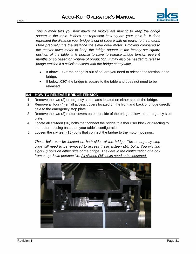
8.4 HOW TO RELEASE BRIDGE TENSION
1. Remove the two (2) emergency stop plates located on either side of the bridge. 2. Remove all four (4) small access covers located on the front and back of bridge directly
next to the emergency stop plate. 3. Remove the two (2) motor covers on either side of the bridge below the emergency stop
plate. 4. Locate all six-teen (16) bolts that connect the bridge to either riser block or directing to
the motor housing based on your table’s configuration. 5. Loosen the six-teen (16) bolts that connect the bridge to the motor housings.
These bolts can be located on both sides of the bridge. The emergency stop plate will need to be removed to access these sixteen (16) bolts. You will find eight (8) bolts on either side of the bridge. They are in the configuration of a box from a top-down perspective. All sixteen (16) bolts need to be loosened.

ACCU-KUT OPERATOR'S MANUAL 2-MAY-14
Page 32 Revision 1
DO NOT REMOVE THE BOLTS - ONLY LOOSEN.
6. Press HOME AXIS. 7. Press HOME ALL. 8. Re-home the bridge by use of the home all command. 9. Confirm the switch offset is at .000” ±.01”
10. Tighten the bolts gradually and uniformly. Snug both sides then torque both sides. 11. Remount the emergency stop plate.
8.5 CHECK FOR A SQUARE BRIDGE
All AKS True-Kut and Accu-Kut tables are squared and have square tags installed before shipping (Two riveted on tags that say “Square Bridge” one on both sides of the table near the X home trip dogs. When the Bridge is sitting at X=0, Y=0 home Position they will align with the Square indicators mounted to the X housing) and checked for square when the AKS Technician installs the cutting machine.
After homing the machine the SWITCH OFFSET DISTANCE is displayed in blue text in the homing screen. This distance should not exceed .030”. If the distance exceeds .030”, it is time to “Re-square” the bridge and release the “Tension” in the bridge.
If you home your machine and have less than .030” offset distance, you should be able to place one hand on the bridge (so you can feel if there is any movement) and trigger an emergency stop. As soon as you hit the e-stop there should not be any movement or “jumping”.

ACCU-KUT OPERATOR'S MANUAL 2-MAY-14
Revision 1 Page 33
8.6 SQUARE BRIDGE
This is an example of a “Square Bridge” even with the power off to the machine the bridge remains square to the cutting table.
To check for a square bridge, first home the machine and look at the square tags on both sides of the table if they line up then place your hand on the bridge and hit an e-stop, if the bridge doesn’t move than your Square and with no Tension.
This is an example of a bridge that has been crashed, hit with a crane, fork truck, ext.… this doesn’t mean that it cuts out of square it means that the power off position of the bridge is skewed and the motors are working harder to pull the bridge to square, also known as tension in the bridge. This is what the switch offset is measuring every time the machine is homed. (The dimension that the motors are pulling the bridge square).
8.7 DEFINITIONS
Homing offset distance The mechanical difference that the motors are correcting to make
the bridge square to the switch dogs.
Switch dog The mechanical ramp like part that trips the limit switches (home switches).
Following Error The position difference between the commanded position and
the actual position. Bridge The aluminum extrusion that spans across the table
(Transverse). X & Y Housing The aluminum housing that contains the Linear bearings and
motors (typically 2- (X) housings and 1- (Y) housing per machine.
Eccentric Cam A bushing that has a thru hole drilled off center used for
adjusting the gear and rack engagement.

ACCU-KUT OPERATOR'S MANUAL 2-MAY-14
Page 34 Revision 1
8.8 TECHNICAL SUMMARY
Machine Type X-Y cutting machine with gantry
Drives AC brushless servo drives, 2 motors in the X-axis, one motor in the Y-axis
Power Transmission Rack and pinion drive in the X and Y axis
Displacement Speed Up to 1200 inches/min (38.1 m/mln)
Standard Work Area 72 inches wide (1.5m), variable length, accessible from
all sides (other sizes optional)
Load Capacity 1.5 inch (40mm) thick material over the entire work area
CNC Control AKS touch screen control in an air condition cabinet
Communications MS Windows local area network, coaxial cable
Plasma Torch Holder Plasma voltage sensing, electro-mechanical lifting
Cutting Speeds Depends on material (see cutting charts for plasma system being used)
Compressed Air 90 psi, low volume required
Electrical Requirements See sales order for AKS machine and CNC
Plasma system - see manufacturer's specifications
Environment Power supplies will operate between +14 degrees F and +120 degrees F

ACCU-KUT OPERATOR'S MANUAL 2-MAY-14
Revision 1 Page 35
9. WARRANTY
A one year warranty on AKS manufactured components is standard. See the published AKS "Terms and Conditions of Sale" document. Other warranties are in accordance with the respective manufacturer's policies. Please refer to the manufacturers' manuals for details. All travel time associated with a warranty service call will be charged at the Travel Time Rate. Travel and living expenses will be charged as described below. Time spent at your plant for warranty repair will be free of charge. Advanced Kiffer Systems, Inc. provides no warranties either expressed or implied in conjunction with a service call.
9.1 SERVICE AND TECHNICAL SUPPORT
For any service question or problem, please contact our sales or service department. They can be reached by email, fax or phone as follows:
Department Email Fax Phone Sales [email protected] 216-267-1850 216-267-1818 Service [email protected] 216-267-1850 216-267-1818
We are open weekdays between 8:30a.m. and 5:00p.m., US Eastern Time at Kiffer Industries, Cleveland Ohio. We will analyze the question or problem and determine the best course of action. Often, troubles can be cleared with simple operator adjustments. Sometimes, a replacement part will be shipped for installation by your plant personnel. If necessary, we will dispatch a service technician to travel to your plant, analyze the problem and take corrective action.
9.2 FIELD SERVICE RATES
Work performed in connection with service visits to your plant will be charged at the current rate. All rates are subject to change without notice.
9.3 TRAVEL AND LIVING EXPENSES
Travel and living expenses are charged for the plasma machine's installation and for subsequent service work whether or not warranty coverage is in effect. All expenses such as air fare, car rental, lodging and meals will be charged to the customer at actual costs for all service trips (including installation, warranty repairs, and out-of-warranty repairs).
9.4 PARTS
Parts and materials supplied during Field Service work will be billed in accordance with Advanced Kiffer Systems, Inc. published "TERMS AND CONDITIONS OF SALE."
ACCU-KUT OPERATOR'S MANUAL 2-MAY-14
Page 36 Revision 1
10. REMOTE CONTROL
10.1 SAFETY
1.1 Safety Considerations
1. The safety guidelines in this manual are not intended to replace any rules or regulations or any applicable local, state, or federal governing laws. The following information is intended to be used in conjunction with other rules or regulations already in existence. It is important to read all safety information before operating any wireless radio remote control system.
2. Only properly trained persons designated by management should be permitted to
operate wireless radio controlled equipment. Wireless radio controlled equipment should not be operated by any person who cannot read or understand signs, notices and operating instructions that pertain to the equipment.
3. Wireless radio controlled equipment should not be operated by any person with
insufficient eyesight or hearing or by any person who may be suffering from a disorder or illness or is taking any medication that may impair judgment or the ability to operate equipment.
4. Do not use this device during electrical storms or under conditions of electrical
interference, due to the potential for equipment communication issues. Ensure transmitter batteries are in good condition and power for receiver is correct. Installation and maintenance should be done only while the controlled equipment main power and receiver’s power are off and locked out to prevent electrical shock.
5. Any person operating wireless radio controlled equipment should possess the
following knowledge and/or skills:
Knowledge of hazards peculiar to equipment operation
Knowledge of safety rules for radio controlled equipment
Knowledge of standard methods of hand and/or non-verbal signaling
Knowledge of the radio transmitter
Limit switch test procedure
Proper clearance of all moving parts on the radio controlled equipment
Proper storage space for radio control transmitter when not in use
Transferring radio control transmitter to another person
Reporting unsafe or unusual operating conditions
Remote controlled equipment capacity and limitations
Procedures for testing controlled equipment
6. Aisles between equipment, stock, etc., should be free of obstructions so the radio control operator can move freely. These aisles should meet local regulations.

ACCU-KUT OPERATOR'S MANUAL 2-MAY-14
Revision 1 Page 37
7. Radio operators should always position themselves for the best view of the
equipment they are controlling. The equipment should never be operated blindly. The operator should always remain at a safe distance, without losing line of sight with the equipment.
8. Transmitter switches should never be mechanically blocked ON or OFF for any
equipment motion. When not in use turn the transmitter OFF (RED MUSHROOM PUSHBUTTON) and remove the transmitter key.
9. After daily operation, shut off main power in machine, the power to the receiver, and
remove transmitter key. A secure storage space should be designated for the transmitter unit especially when not in use. This precaution is intended to prevent unauthorized use of the equipment.
10. The equipment operator should keep all body parts away from any moving parts. 11. If the equipment fails to respond properly, the equipment operator should stop
operation, turn the transmitter OFF (RED MUSHROOM PUSHBUTTON) and remove the transmitter key. The operator should immediately report the condition to his/her supervisor.
12. The equipment operator should turn off the transmitter and take it with him/her when
and if boarding the equipment.
13. Remote control operation should NEVER be used for “people moving” applications. Never use remote operation if there are people aboard the controlled equipment. The remote control operator should NEVER “ride” on the controlled equipment.
WARNING ALWAYS PLACE EQUIPMENT IN MANUAL OPERATION AND SECURE THE WIRELESS REMOTE CONTROL TRANSMITTER PRIOR TO PERFORMING ANY MAINTENANCE.
14. The equipment has been tested for correct operation before delivery from the
factory. However, it must not be used in critical or hazardous operation where incorrect operation may cause personal or equipment damage. If the equipment fails to respond or behaves improperly, the equipment operator should NOT operate the equipment AND should notify his/her supervisor immediately. When serious conditions are noticed (conditions that make the equipment unsafe to operate), the equipment should be shut down immediately and the supervisor notified.
CAUTION THE RECEIVER UNIT OR RELAYS ARE NOT RATED AS EXPLOSION PROOF. THE RECEIVER UNIT MUST NOT BE INSTALLED OR OPERATED IN EXPLOSIVE ENVIRONMENTS.
WARNING THE UNIT MUST BE WIRED TO THE CORRECT VOLTAGE; FAILURE TO DO SO MAY DAMAGE THE SYSTEM.

ACCU-KUT OPERATOR'S MANUAL 2-MAY-14
Page 38 Revision 1
NOTE IN AN EMERGENCY, PUSH “RED MUSHROOM PUSHBUTTON” TO STOP RADIO REMOTE CONTROLLED EQUIPMENT.
1.2 Warnings
1. Read this manual carefully before operating and installing this product.
2. Only authorized personnel should service this equipment. Unauthorized work on
this unit will void the warranty. 3. The equipment has been tested for correct operation before delivery from the
factory. However, it must not be used in critical or hazardous operation where incorrect operation may cause personal or equipment damage.
4. After daily operation, please shut off main power in machine, the power to the
receiver, and remove transmitter key. 5. Transmitter should be placed in a safe place when not in use to avoid accidental
pressing of buttons. 6. Do not use this device during electrical storms or under conditions of electrical
interference. 7. Ensure transmitter batteries are in good condition and power for receiver is correct. 8. Installation and maintenance should be done only while the machine’s main power
and receiver’s power are off and locked out to prevent electrical shock. 9. Contents of the manual may be amended by the manufacturer without notice.
10.2 OPERATION
2.1 General Precautions
1. After operating, please press the Red Mushroom Pushbutton to shut off main power in the receiver. Remove transmitter key.
2. Stop operating if irregular response occurs due to insufficient transmitter power,
operating beyond the remote control range, or severe interference. 3. Remove the batteries when the equipment is not going to be used for a long period
of time. 4. Operators must be properly trained and certified, understanding safe operation of
the crane /machine and this radio control. 5. Operator must be familiar with emergency procedures before operating (See
Section 5.4).

ACCU-KUT OPERATOR'S MANUAL 2-MAY-14
Revision 1 Page 39
6. Transmitter is durable and weather-resistant, but care should be taken not to
subject it to severe impacts or undue abuse. 7. This product is suitable for use in industrial environments. Proper care and
maintenance will extend system’s life. 8. Check the Red Mushroom Pushbutton and the other security functions of the entire
system before daily operation, including (but not limited to) switch operation, etc. 9. Stop operating if the operator’s view is not clear of machine or load. 10. Press Red Mushroom Pushbutton when malfunctions or abnormal conditions occur.
2.2 Standard Operation
2.2.1 Default Power-On Procedure
1. Rotate Red Mushroom Pushbutton clockwise and pull out.
2. Turn rotary key switch clockwise to “ON” position.
3. Depress the “START” button in order to turn on power.
2.2.2 Transmitter Power Indication
1. Transmitter has a power indication function with an LED indicator. “Green Color” Sufficient power to operate transmitter (In order to save
power, one can program to turn off LED display when power level is sufficient).
“Yellow Color” Power is depleting The operator has a short time to finish his
task (for example, lower the hoist, remove load) but then needs to replace batteries.
“Red Color” Insufficient Power. Transmitter is no longer functional.
Transmitter will send out an emergency stop signal to the receiver due to insufficient power. Operator should avoid this situation in order to maintain operation safety.
2.3 Emergency Shutdown Procedure
1. Press Red Mushroom Pushbutton.
2. Turn the rotary key to the “OFF” position.
3. Remove the rotary key.
4. Open the battery compartment and remove the transmitter’s batteries.

ACCU-KUT OPERATOR'S MANUAL 2-MAY-14
Page 40 Revision 1
5. Shut off the main power of the crane and discontinue operation until the problem is
resolved.
6. Contact your distributor or Control Chief to diagnose the problem.
10.3 BASIC TROUBLESHOOTING AND MAINTENANCE
3.1 General Precautions
Daily inspection is important and will ensure safety of operation. Inspection should include testing the “Red Mushroom Pushbutton” and other safety devices and functions. If there is any doubt, operation must be stopped immediately and problems must be corrected before operation is resumed.
3.2 Transmitter Malfunction Detection
If the transmitter’s LED is rapidly flashing red, the following may have occurred:
1. Pushbutton(s) may be jammed
2. Red mushroom Pushbutton may be Depressed
3. The correct “power on” procedure may not have been properly executed.
3.3 Receiver Malfunction Detection
The receiver is equipped with simple self- diagnosing circuits and indicators. If a malfunction is detected during operation, self-diagnosing circuits will illuminate the indicators in the following sequence:
G1 R1 G2 R2 Malfunction Type
On MCU1 Fault Blinks w/ R1 Blinks w/ RG1 DB1 / DB2 Relay Fault Alternates w/ R1 Alternates w/ G1 Relay Driver Buffer Fault Blinking Jammed relay
If the system is demonstrating improper operation, the following chart may help determine the cause of the malfunction:
Symptom Possible Cause
1. Button may be faulty or jammed 2. Transmitter and/or receiver may be improperly coded 3. Receiver may be experiencing interference 4. Receiver may not have sufficient operating power
Receiver relay does not activate when associated transmitter pushbutton is depressed
5. Transmitter’s Red Mushroom Pushbutton may be depressed
Intermittent operation 1. Receiver may be experiencing interference

ACCU-KUT OPERATOR'S MANUAL 2-MAY-14
Revision 1 Page 41
Decreased range 1. Receiver antenna may be damaged or
incorrectly installed Transmitter does not start 1. Keyswitch may not be in the “On” position
2. Red Mushroom Pushbutton may be depressed 3. “Start” pushbutton may be defective 4. Button may be faulty or jammed
If the receiver or any of its relays fail to respond to the transmitter, the following checks may be preformed:
1. Ensure the “power on” indicator located on the front of the receiver is illuminated.
If this light is off, the mainline circuit is not active. 2. Press each button on the transmitter and confirm that its associated relay’s LED is
illuminated. If an LED does not illuminate, its relay is not receiving a command from the transmitter.
3. Be sure “LED 1 is illuminated. This LED is active when the “Jammed Relay
Detect” circuit is working properly. 4. Be sure “LED 2” and “”LED 3” are illuminated. These LEDs are active when the
receiver is getting the proper operating voltages. 5. Check fuse “F1”. This fuse is rated at .5a @ 250VAC (5x20mm) 6. Check fuses “F2-F5”. These fuses are rated at 6.3a @ 250VAC (5x20mm)

ACCU-KUT OPERATOR'S MANUAL 2-MAY-14
Page 42 Revision 1
10.4 FUNCTION SETTINGS
Slow
Spare
Slow Limits the machine speed for safety during machine testing and maintenance. When this input is
active, motion is limited to the user‐defined Limited Machine Speed selected in the password protected Speeds screen.
Up A jog switch that raises the cutting stations torch. The station must be on for this input to function.
Down A jog switch that lowers the cutting stations torch. The station must be on for this input to
function.
X‐ Command manual motion (Joystick Down)
X+ Command manual motion (Joystick Up)
Y+ Command manual motion (Joystick Left)
Y‐ Command manual motion (Joystick Right)
Backup and Forward on Path Use these two pushbuttons to move backward and forward along the
cut path at the selected move speed to locate the pierce restart point. Press the Start key to resume the cut
at the programmed cut speed. In addition to all segments of a standard part, the Backup and Forward on
Path functions allow full movement through all sections of Shape Repeat part as well. Like the Manual
Mode functions, Backup and Forward on Path use the currently selected move speed. The different speeds
allow moving rapidly along the path, or precisely positioning the cutting device. When a cut loss occurs, the
initial backup and forward speed is the one that was used last. To toggle between the move speeds, press
the Change Move Speed soft key in the Pause window. The corresponding speed is displayed in the Move
Speed window.
Stan(1)
Line
Stan(1)
Line

ACCU-KUT OPERATOR'S MANUAL 2-MAY-14
Revision 1 Page 43
Manual Switches the control to manual mode.
Test Lifter Performs a test IHS function with a Sensor THC.
Start Program Start Switch; program execution begins when this switch is depressed (cutting or trail).
Stop Program Cycle Stop; program execution is paused when this switch is depressed (cutting or trail).

ACCU-KUT OPERATOR'S MANUAL 2-MAY-14
Page 44 Revision 1
INTENTIONALLY LEFT BLANK
Related Documents