1 – Auxiliary Switch – RCD-Tripping Module – Shunt Trip Release – Undervoltage Release – Remote Control and Automatic Switching Device – Switching Interlocks Accessories for RCDs, MCBs, Combined RCD/MCB Devices, Motor Starters and Power Limiters Accessories for Protective Devices SG60811 SG83911 SG30811

Welcome message from author
This document is posted to help you gain knowledge. Please leave a comment to let me know what you think about it! Share it to your friends and learn new things together.
Transcript

1
– Auxiliary Switch– RCD-Tripping Module– Shunt Trip Release– Undervoltage Release– Remote Control and Automatic Switching Device– Switching Interlocks
Accessories for RCDs, MCBs, Combined RCD/MCB
Devices, Motor Starters and Power Limiters
Accessories for Protective Devices
SG60811 SG83911 SG30811

2
Accessories for Protective Devices
Auxiliary Switch ZP-AHK, ZP-IHK, ZP-WHK; Tripping Signal Switch ZP-NHK
Design: for snapping
For Protective Device / Function Type Designation Article No. Units per package
Auxiliary Switch Z-HK, Z-AHK, Z-HD; Tripping Signal Switch Z-NHK
Design: for screwing
For Protective Device / Function Type Designation Article No. Units per package
PFIM, PFHM-4p, dRCM 1NO+1NCPLS., PKD., PFHM-2p1NO+1NCPLS., PKD., PFIM, PFHM dRCM
2COPFDM 1CO+1NC
Z-HK 248432 4 / 120Z-AHK 248433 4 / 120
Z-NHK 248434 4 / 120Z-HD 265620 1
SG60911
Z-AHK
PLS., PKN. 1NO+1NCPLS., PKN. 1NO+1NCPLS., PKN. 1COPLS., PKN. 2CO
ZP-AHK 248436 4 / 120ZP-IHK 286052 4 / 120ZP-WHK 286053 4 / 120ZP-NHK 248437 4 / 120
SG60811
ZP-IHK
RCD-Tripping Module Z-.AM
For Protective Device Type Designation Article No. Units per package
PFIM, PFHM-4p, dRCMPKNM, PKDM, PFHM-2p
Z-FAM 248293 1 / 60Z-KAM 248294 1 / 60
SG16011
Z-FAM
SG16211
Z-KAM
Shunt Trip Release Z-ASA, ZP-ASA
Operational voltage range (V~) Type Designation Article No. Units per package
to be glued on12-110110-415to be snapped on12-110110-415
Z-ASA/24 248286 1 / 60Z-ASA/230 248287 1 / 60
ZP-ASA/24 248438 1 / 60ZP-ASA/230 248439 1 / 60
SG00712
Undervoltage Release Z-USA, Z-USD
Op. voltage range (V~)/Function Type Designation Article No. Units per package
to be screwed on115 undelayed230 undelayed400 undelayed115 delayed 0.4s230 delayed 0.4s
Z-USA/115 248288 1 / 60Z-USA/230 248289 1 / 60Z-USA/400 248290 1 / 60Z-USD/115 248292 1 / 60Z-USD/230 248291 1 / 60
SG78811
SG00212
Z-ASA ZP-ASA
Phase out type

3
Remote Control and Automatic Switching Device Z-FW
Function Type Designation Article No. Units per package
Automatic restarting 230VACAutomatic restarting 24-48VDC+ Remote controlON/OFF/TEST(only in connection with Z-FW-LP, -LPD from deliverydate 2006!)
Z-FW-LP 248296 1 / 20Z-FW-LPD 265244 1 / 20Z-FW-MO 284730 1
SG30811
Accessories for Protective Devices
Pre-mounted sets Z-FW• Set consisting of automatic switching device Z-FW-LP. and switching module Z-FW-MO
230 VAC24-48 VDC
Z-FW-LP/MO 290171 1 / 12Z-FW-LPD/MO 290172 1 / 12
SG31311
Remote Testing Module Z-FW (for Z-FW-LP./MO set use only)0,01 A0,03 A0,1 A0,3 A0,5 A
Z-FW/001 248297 4 / 120Z-FW/003 248298 4 / 120Z-FW/010 248299 4 / 120Z-FW/030 248300 4 / 120Z-FW/050 248301 4 / 120
SG12111
Switching interlocks IS/SPE-1TE, Z-IS/SPE-1TE
Description Type Designation Article No. Units per package
Switching interlock without lockfor Isolators, RCDs, combinedRCD/MCBs, ...
Switching interlock without lockfor MCBs and Circuit Breaker ZP-A
IS/SPE-1TE 101911 5 / 30
Z-IS/SPE-1TE 274418 5 / 30
SG47812

4
Surge Protection
SG13309 SG11309
Surge Protection

5
SPD Class B
Impulse Current Iimp (10/350)µs Type Designation Article No. Units per package
Lightning current arresters SPI• No decoupling necessary, if arrester class C with Uc = 460 V are used for combination
35kA L - (PE)N50kA N - PE100kA N - PE
SPI-35/440 263137 6 / 120SPI-50/NPE 263138 2 / 120SPI-100/NPE 263139 1 / 60
SG50312
SPI-35/440
Lightning current arrester Sets, Lightning protection classes I, II, III, IV
Description Type Designation Article No. Units per package
TN-C-Set 3-poleTN-S/TT-Set 3+1-pole
SPI-35/440/3 267487 1 / 40SPI-3+1 267488 1 / 20
SG50212
SPD Class B+C
Impulse Current Iimp (10/350)µs Type Designation Article No. Units per package
Lightning current arrester - surge arrester SPBT12Complete
12.5kA L - (PE) N100kA N-PE
SPBT12-280/1 158306 12 / 120SPBT12-NPE100 158307 1 / 60
SG27112
SPBT12-280/1
Surge Protection
Lead-through terminal for SPISPB-D-125 248145 2 / 120
SPI-3+1
Lightning current arrester - surge arrester SPBT12Insert
12.5kA Insert SPBT12-280 167341 4 / 120

Lightning current arrester - surge arrester Sets, Lightning protection classes I, II, III, IV
Description Type Designation Article No. Units per package
SPD Class B+C, SP-B+C/
TN-C-Set 3-poleTN-S/TT-Set 3+1-pole
SP-B+C/3 267489 1SP-B+C/3+1 267510 1
SG53712
SP-B+C/3+1
Accessories
Auxiliary switch for SP-B+C ASAUXSC-SPM 131785 8 / 80
6
Surge Protection
Lightning current arrester - surge arrester Sets, Lightning protection classes III, IV
Description Type Designation Article No. Units per package
Without remote indicationTN-S/TT-Set 1+1-poleTN-S-Set 2-poleTN-C-Set 3-poleTN-S-Set 4-poleTN-S/TT-Set 3+1-poleTN-S/TT-Set 3+1-pole
SPBT12-280-1+NPE 158308 1 / 40SPBT12-280/2 158309 1 / 60SPBT12-280/3 158330 1 / 40SPBT12-280/4 158331 1 / 30SPBT12-280-3+NPE 158332 1 / 20SPBT12-280-3+NPE/BB 158333 1
Accessories
Auxiliary switch for SPBT12-280Busbar
ASAUXSC-SPM 131785 4 / 120ZV-KSBI...
With remote indication
TN-S/TT-Set 1+1-poleTN-S/TT-Set 3+1-pole
SPBT12-280-1+NPE-AX 158334 1 / 30SPBT12-280-3+NPE-AX 158335 1
SG29612
SPBT12-280/3
SPC-S-20/280/3
SPC-E-280
7
Surge Protection
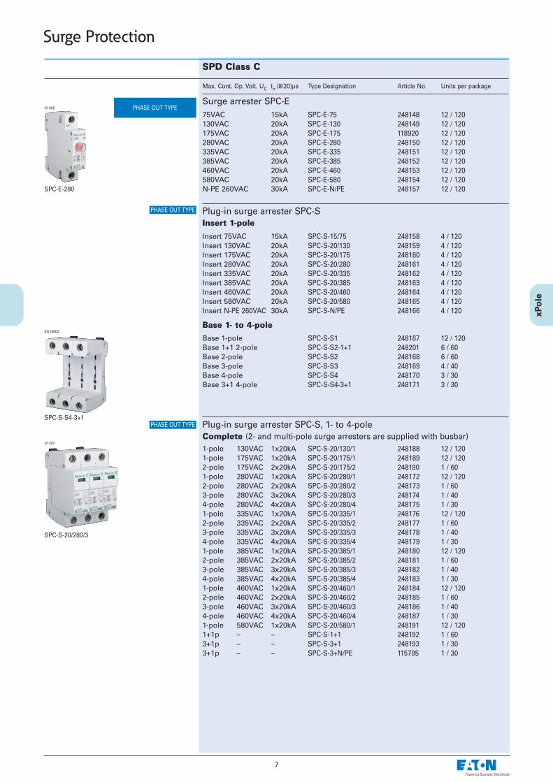
SPD Class C
Max. Cont. Op. Volt. UC In (8/20)µs Type Designation Article No. Units per package
Surge arrester SPC-E75VAC 15kA130VAC 20kA175VAC 20kA280VAC 20kA335VAC 20kA385VAC 20kA460VAC 20kA580VAC 20kAN-PE 260VAC 30kA
SPC-E-75 248148 12 / 120SPC-E-130 248149 12 / 120SPC-E-175 118920 12 / 120SPC-E-280 248150 12 / 120SPC-E-335 248151 12 / 120SPC-E-385 248152 12 / 120SPC-E-460 248153 12 / 120SPC-E-580 248154 12 / 120SPC-E-N/PE 248157 12 / 120
U1302
Plug-in surge arrester SPC-SInsert 1-pole
Insert 75VAC 15kAInsert 130VAC 20kAInsert 175VAC 20kAInsert 280VAC 20kAInsert 335VAC 20kAInsert 385VAC 20kAInsert 460VAC 20kAInsert 580VAC 20kAInsert N-PE 260VAC 30kA
SPC-S-15/75 248158 4 / 120SPC-S-20/130 248159 4 / 120SPC-S-20/175 248160 4 / 120SPC-S-20/280 248161 4 / 120SPC-S-20/335 248162 4 / 120SPC-S-20/385 248163 4 / 120SPC-S-20/460 248164 4 / 120SPC-S-20/580 248165 4 / 120SPC-S-N/PE 248166 4 / 120
Plug-in surge arrester SPC-S, 1- to 4-poleComplete (2- and multi-pole surge arresters are supplied with busbar)
U1202
1-pole 130VAC 1x20kA1-pole 175VAC 1x20kA2-pole 175VAC 2x20kA1-pole 280VAC 1x20kA2-pole 280VAC 2x20kA3-pole 280VAC 3x20kA4-pole 280VAC 4x20kA1-pole 335VAC 1x20kA2-pole 335VAC 2x20kA3-pole 335VAC 3x20kA4-pole 335VAC 4x20kA1-pole 385VAC 1x20kA2-pole 385VAC 2x20kA3-pole 385VAC 3x20kA4-pole 385VAC 4x20kA1-pole 460VAC 1x20kA2-pole 460VAC 2x20kA3-pole 460VAC 3x20kA4-pole 460VAC 4x20kA1-pole 580VAC 1x20kA1+1p – –3+1p – –3+1p – –
SPC-S-20/130/1 248188 12 / 120SPC-S-20/175/1 248189 12 / 120SPC-S-20/175/2 248190 1 / 60SPC-S-20/280/1 248172 12 / 120SPC-S-20/280/2 248173 1 / 60SPC-S-20/280/3 248174 1 / 40SPC-S-20/280/4 248175 1 / 30SPC-S-20/335/1 248176 12 / 120SPC-S-20/335/2 248177 1 / 60SPC-S-20/335/3 248178 1 / 40SPC-S-20/335/4 248179 1 / 30SPC-S-20/385/1 248180 12 / 120SPC-S-20/385/2 248181 1 / 60SPC-S-20/385/3 248182 1 / 40SPC-S-20/385/4 248183 1 / 30SPC-S-20/460/1 248184 12 / 120SPC-S-20/460/2 248185 1 / 60SPC-S-20/460/3 248186 1 / 40SPC-S-20/460/4 248187 1 / 30SPC-S-20/580/1 248191 12 / 120SPC-S-1+1 248192 1 / 60SPC-S-3+1 248193 1 / 30SPC-S-3+N/PE 115795 1 / 30
Base 1- to 4-poleBase 1-poleBase 1+1 2-poleBase 2-poleBase 3-poleBase 4-poleBase 3+1 4-pole
SPC-S-S1 248167 12 / 120SPC-S-S2-1+1 248201 6 / 60SPC-S-S2 248168 6 / 60SPC-S-S3 248169 4 / 40SPC-S-S4 248170 3 / 30SPC-S-S4-3+1 248171 3 / 30
SG14802
SPC-S-S4-3+1
PHASE OUT TYPE
PHASE OUT TYPE
PHASE OUT TYPE

SPCT2-280/3
Plug-in surge arrester SPCT2Insert 1-pole
Insert 75VAC 20kAInsert 130VAC 20kAInsert 175VAC 20kAInsert 280VAC 20kAInsert 335VAC 20kAInsert 385VAC 20kAInsert 460VAC 20kAInsert 580VAC 20kAInsert 260VAC 30kA
SPCT2-075 167577 4/120 SPCT2-130 167582 4/120 SPCT2-175 167587 4/120 SPCT2-280 167592 4/120 SPCT2-335 167597 4/120 SPCT2-385 167602 4/120 SPCT2-460 167607 4/120 SPCT2-580 167612 4/120 SPCT2-NPE60 167617 4/120
SG13109
Plug-in surge arrester SPCT2, 1- to 4-poleComplete (2- and multi-pole surge arresters are supplied with busbar)
SG50112
1-pole 75VAC 20kA1-pole 130VAC 20kA1-pole 175VAC 20kA1-pole 280VAC 20kA1-pole 335VAC 20kA1-pole 385VAC 20kA1-pole 460VAC 20kA1-pole 580VAC 20kA1+N 260VAC 30kA2-pole 75VAC 2x20kA2-pole 130VAC 2x20kA2-pole 175VAC 2x20kA2-pole 280VAC 2x20kA2-pole 335VAC 2x20kA2-pole 385VAC 2x20kA2-pole 460VAC 2x20kA2-pole 580VAC 2x20kA3-pole 75VAC 3x20kA3-pole 130VAC 3x20kA3-pole 175VAC 3x20kA3-pole 280VAC 3x20kA3-pole 335VAC 3x20kA3-pole 385VAC 3x20kA3-pole 460VAC 3x20kA3-pole 580VAC 3x20kA4-pole 75VAC 4x20kA4-pole 130VAC 4x20kA4-pole 175VAC 4x20kA4-pole 280VAC 4x20kA4-pole 335VAC 4x20kA4-pole 385VAC 4x20kA4-pole 460VAC 4x20kA4-pole 580VAC 4x20kA1+N 280VAC 20kA1+N 335VAC 20kA1+N 385VAC 20kA1+N 460VAC 20kA1+N 580VAC 20kA3+N 280VAC 20kA3+N 335VAC 20kA3+N 385VAC 20kA3+N 460VAC 20kA3+N 580VAC 20kA3+N/BB 280VAC 3x20kA3+N/BB 335VAC 3x20kA3+N/BB 385VAC 3x20kA3+N/BB 460VAC 3x20kA
SPCT2-075/1 167578 12/120 SPCT2-130/1 167583 12/120 SPCT2-175/1 167588 12/120 SPCT2-280/1 167593 12/120 SPCT2-335/1 167598 12/120 SPCT2-385/1 167603 12/120 SPCT2-460/1 167608 12/120 SPCT2-580/1 167613 12/120 SPCT2-NPE60/1 167618 12/120 SPCT2-075/2 167579 1/60 SPCT2-130/2 167584 1/60 SPCT2-175/2 167589 1/60 SPCT2-280/2 167594 1/60 SPCT2-335/2 167599 1/60 SPCT2-385/2 167604 1/60 SPCT2-460/2 167609 1/60 SPCT2-580/2 167614 1/60 SPCT2-075/3 167580 1/40 SPCT2-130/3 167585 1/40 SPCT2-175/3 167590 1/40 SPCT2-280/3 167595 1/40 SPCT2-335/3 167600 1/40 SPCT2-385/3 167605 1/40 SPCT2-460/3 167610 1/40 SPCT2-580/3 167615 1/40 SPCT2-075/4 167581 1/30 SPCT2-130/4 167586 1/30 SPCT2-175/4 167591 1/30 SPCT2-280/4 167596 1/30 SPCT2-335/4 167601 1/30 SPCT2-385/4 167606 1/30 SPCT2-460/4 167611 1/30 SPCT2-580/4 167616 1/30 SPCT2-280-1+NPE 167619 1/60 SPCT2-335-1+NPE 167621 1/60 SPCT2-385-1+NPE 167623 1/60 SPCT2-460-1+NPE 167625 1/60 SPCT2-580-1+NPE 167627 1/60 SPCT2-280-3+NPE 167620 1/30 SPCT2-335-3+NPE 167622 1/30 SPCT2-385-3+NPE 167624 1/30 SPCT2-460-3+NPE 167626 1/30 SPCT2-580-3+NPE 167628 1/30 SPCT2-280-3+NPE/BB 167629 1 SPCT2-335-3+NPE/BB 167630 1 SPCT2-385-3+NPE/BB 167631 1 SPCT2-460-3+NPE/BB 167632 1
SPCT2-280
NEW
NEW
8
Surge Protection
9
Surge arrester Set
Description Type Designation Article No. Units per package
SPD Class C, SPCSurge arrester set SPC-S-3+1-SET 248194 1
SG14805
Auxiliary Switchfor SPCT2 ASAUXSC-SPM 131785 8 / 80
SG83311
Surge Protection
PHASE OUT TYPE
SPC-S-3+1-SET
NEW
Description Type Designation Article No. Units per package
Lead-through terminal for SPB, ASLTT-63
ASLTT-63 131784 12 / 120
SG59511

10
Photovoltaic - Surge Protection
SPD-type T2 (Class C)
Max. Cont. Op. Volt. UC In ( Type Designation Article No. Units per package
600 V DC1000 V DC
with auxiliary switch1000 V DC
SPPT2PA-600-2PE 132663 1 / 60SPPT2PA-1000-2PE 132664 1 / 60
SPPT2PA-1000-2PE-AX 132666 1 / 60
For unearthed systems
600 V DC1000 V DC
with auxiliary switch1000 V DC
SPPT2PA-600-2+1PE 132661 1 / 40SPPT2PA-1000-2+1PE 132662 1 / 40
SPPT2PA-1000-2+1PE-AX 132665 1 / 40
Plug-in Surge Arrester SPPT2PA for Photovoltaic application
For earthed systems
SG11309
SG11009
600 V DC À1000 V DC À1100 V DC Á
SPPT2PA-600 132667 1SPPT2PA-1000 132668 1SPPT2PA-1100 132669 1
Inserts for replacement
Earthed system Unearthed systemSPPT2PA-600-2PESPPT2PA-1000-2PE(-AX)
SPPT2PA-600-2+1PESPPT2PA-1000-2+1PE(-AX)
L- L- L+
VOC ≤ Uc: Open circuit voltage of PV-Generator shall be equal or less than maximumcontinuous operating voltage of Surge Protective Device (SPD) to prevent itsdamage.
VOC . . . . . .Open circuit voltage of PV-Generator.UC . . . . . . .Maximum continuous operating voltage of SPD.Attention: Even at switched off DC-Disconnector system stays under high voltage!
Before mounting ensure de-energizing and check zero-potential.
DC

11
Surge Protection
Poles Type Designation Article No. Units per package
Busbars Z-GV-U/ for SPI, SP-B+C
2345689
Z-GV-U/2 272588 20 / 1200Z-GV-U/3 272589 20 / 1200Z-GV-U/4 274080 20 / 1200Z-GV-U/5 274081 20 / 1200Z-GV-U/6 274082 20 / 400Z-GV-U/8 274083 20 / 200Z-GV-U/9 274084 20 / 200
Z-GV-U/9
Busbar Z-GV-16/3P-3TE/6for SPI and SPC Z-GV-16/3P-3TE/6 267511 12 / 240
WA_SG11202
Busbars ZV-KSBI for SPC2MU3MU3MU2MU+1.5MU4MU5MU5MU2MU+3x1.5MU6MU7MU7MU7MU9MU11MU
ZV-KSBI-2TE 263961 10 / 600ZV-KSBI-3TE 263962 10 / 600ZV-KSBI-3TE/S 263963 10 / 600ZV-KSBI-3TE+HI 112370 50 / 150ZV-KSBI-4TE 263964 10 / 600ZV-KSBI-5TE 263965 10 / 200ZV-KSBI-5TE/N 263966 10 / 200ZV-KSBI-5TE+HI 112371 50 / 150ZV-KSBI-6TE 113118 50 / 500ZV-KSBI-7TE 263967 50 / 500ZV-KSBI-7TE/S 263968 10 / 100ZV-KSBI-7TE/N 263969 10 / 100ZV-KSBI-9TE/N 266874 50 / 500ZV-KSBI-11TE 263970 50 / 500

12
Description Type Designation Article No. Units per package
Surge protective device SPD-S-1+1 for TN-, TT-systems (3-phase 4-wire)Complete deviceInsert N-PEInsert L-NBase 1+1 2-poleAuxiliary switch
SPD-S-1+1 248202 1 / 60SPD-S-N/PE 248199 4 / 120SPD-S-L/N 248200 4 / 120SPC-S-S2-1+1 248201 6 / 60SPC-S-HK 248203 8 / 80
U1602
Surge protective device SPD-S-280/2 for IT-, TT-systems (3-phase 3-wire)Complete deviceInsert Base Auxiliary switch
SPD-S-280/2 269088 1 / 60SPD-S-280 269087 4 / 120SPC-S-S2 248168 6 / 60SPC-S-HK 248203 8 / 80
SPD-S-1+1
Surge Protection
SPD Class D
PHASE OUT TYPE
PHASE OUT TYPE
19” Multiple Outlet Strips NWS-STL/19/7F
7 outlets, DIN7 outlets, plus switch, DIN7 outlets, UTE
NWS-STL/19/7F 255398 1NWS-STL/19/7F/S/BL 255399 1NWS-STL/19/7F/UTE 290031 1
N00411
19” Surge Protection - Multiple Outlet Strips with Switch SPD-STL/19/7F-S/BL7 outlets, plus switch, DIN7 outlets, UTE
SPD-STL/19/7F-S/BL 283449 1SPD-STL/19/7F-S/BL/UTE 290032 1
N00511
Surge Protection Multiple Outlet Strips with High-Range Filter and EnergyAbsorption for full Equipment Protection SPD-STL/6F-S6 outlets, plus switch, DIN6 outlets, plus switch, DIN+ISDN19" fixing bracket for SPD-STL/6F-S (1U)
SPD-STL/6F-S (68583) 130000 1SPD-STL/6F-S/ISDN (68585) 147795 1NWS-HW/19/SPD-STL/6F-S 166364 1
N04011

13
Surge Protection
Earthing/Equipotential Bonding
Description Type Designation Article No. Units per package
Equipotential Bonding Bar PAS-7x16
7 x 2.5 - 16 mm2 PAS-7x16 107945 10 / 50
• For main equipotential bonding• Earthing strip up to 30 x 3.5 / Round conductor 7 - 10 mm
SG07306
Earthing Bar for Antenna Lines PAS-HF-6
6 x HF-Cable shields PAS-HF-6 107946 10 / 100
• Earthing conductor 6 - 25 mm2
— —SG07206
Earth Clips EBS
Tube Ø 1/8” - 1½”Tube Ø 1/8” - 4”
EBS-210mm 107947 20 / 80EBS-430mm 107948 20 / 80
• For copper and galvanized steel/stainless steel tubes • Cross-section for connection 1 x 2.5 mm2 to 2 x 16 mm2
SG07406

14
• Monitoring of voltage between phase and neutral conductor, if voltageis too high coupled switchgear (main switch) trips
• Possible switchgear for coupling MCB and RCBO• Single and 3-phase application possible• Remote switch off possible• Contact position indicator• ON-OFF function with switching toggle• Comprehensive range of accessories
Power Frequency Overvoltage Protective Device
(POP Device)
Power Frequency Overvoltage Protective Device (POP Device)
SG41712, SG40711
á

15
Power Frequency Overvoltage Protective Device (POP Device)
POP-270• Monitoring of voltage between phase and neutral conductor, if voltage is too high cou-
pled switchgear (main switch) trips• For 3-phase application use 3 pcs. of POP-270
230 V AC / 50 Hz POP-270 131674 1 / 60
Rated Operational Voltage Type Designation Article No. Units per packageSG41712
S P A I N , A S I A
For accessories like Auxiliary Switch ZP-IHK and ZP-WHK, Tripping Signal Switch ZP-NHK, Shunt Trip Release ZP-ASA and Undervoltage Release Z-USA, Z-USD see page xx.

16
Controlling & Switching
Controlling & Switching
– Switches– Installation Contactors– Relays– Signalling Devices– Transformers
SG10611 SG59411 SG83911
SG82911 SG84611 wa_sg04311

17
Main Load Disconnector Switch (Isolator) IS
Rated Current (A) Poles Type Designation Article No. Units per package
16 116 216 316 420 120 220 320 425 125 225 325 432 132 232 332 440 140 240 340 463 163 263 363 480 180 280 380 4100 1100 2100 3100 4125 1125 2125 3125 4
IS-16/1 276254 12 / 120IS-16/2 276255 1 / 60IS-16/3 276256 1 / 40IS-16/4 276257 1 / 30IS-20/1 276258 12 / 120IS-20/2 276259 1 / 60IS-20/3 276260 1 / 40IS-20/4 276261 1 / 30IS-25/1 276262 12 / 120IS-25/2 276263 1 / 60IS-25/3 276264 1 / 40IS-25/4 276265 1 / 30IS-32/1 276266 12 / 120IS-32/2 276267 1 / 60IS-32/3 276268 1 / 40IS-32/4 276269 1 / 30IS-40/1 276270 12 / 120IS-40/2 276271 1 / 60IS-40/3 276272 1 / 40IS-40/4 276273 1 / 30IS-63/1 276274 12 / 120IS-63/2 276275 1 / 60IS-63/3 276276 1 / 40IS-63/4 276277 1 / 30IS-80/1 276278 12 / 120IS-80/2 276279 1 / 60IS-80/3 276280 1 / 40IS-80/4 276281 1 / 30IS-100/1 276282 12 / 120IS-100/2 276283 1 / 60IS-100/3 276284 1 / 40IS-100/4 276285 1 / 30IS-125/1 276286 12 / 120IS-125/2 276287 1 / 60IS-125/3 276288 1 / 40IS-125/4 276289 1 / 30
Accessories Switching interlock without lockfor Isolators, RCDs, combinedRCD/MCBs, ...Terminal cover
IS/SPE-1TE 101911 5 / 30
Z-IS/AK-1TE 276290 10 / 600
Controlling & Switching
SG10611
SG10711
SG10811
SG10911

18
Circuit Breaker ZP-A
Number of Poles/Rated Operational Current Type Designation Article No. Units per package
1 40A2 40A3 40A3+N 40A1 63A2 63A3 63A3+N 63A
ZP-A40/1 248263 12 / 120ZP-A40/2 248264 1 / 60ZP-A40/3 248265 1 / 40ZP-A40/3N 248266 1 / 30ZP-A63/1 284906 12 / 120ZP-A63/2 284907 1 / 60ZP-A63/3 284908 1 / 40ZP-A63/3N 284909 1 / 30
SG00912
Miniature Circuit Breakers (MCBs) for Auxiliary Circuits PLSM-B4/.-HS, CLS6-B4/..-HS
Poles / Rated Breaking Capacity Type Designation Article No. Units per package
1 10kA2 10kA1 6kA1+N 6kA2 6kA
PLSM-B4-HS 247221 2 / 120PLSM-B4/2-HS 247222 1 / 60CLS6-B4-HS 247969 2 / 120CLS6-B4/1N-HS 247970 2 / 80CLS6-B4/2-HS 247971 1 / 60
SG54312
Control Switch Z-S../
Rated Current (A)/Function Type Designation Article No. Units per package
16 3NO16 4NO16 2NO+2NC16 3NO+1NC
Z-S/3S 248334 12 / 120Z-S/4S 248335 12 / 120Z-S/SSOO 248337 12 / 120Z-S/3S1O 248338 12 / 120
SG38912
Changeover Switch Z-S/.W
Function Type Designation Article No. Units per package
1CO I-0-II2CO I-0-II1CO DAY-0-NIGHT2CO DAY-0-NIGHT
Z-S/WM 248345 12 / 120Z-S/2WM 248346 12 / 120Z-S/WTN 248347 12 / 120Z-S/2WTN 248348 12 / 120
SG39012
Pushbutton Z-T/
Colour of Button/Function Type Designation Article No. Units per package
green 4NOblack 3NO+1NC
Z-T/4S-G 248328 12 / 120Z-T/3S1O 248330 12 / 120
SG37112
Controlling & Switching

Switch Z-SW, Z-SWL• Z-SWL: with LED• 16 A 250 VAC
Rated voltage LED Function Type Designation Article No. Units per package
– 1NO– 2NO– 1NO+1NC– 1CO24 V AC/DC 2NO24 V AC/DC 1NO+1NC230 V AC/DC 1NO230 V AC/DC 2NO230 V AC/DC 1NO+1NC
Z-SW/S 276300 2 / 120Z-SW/SS 276301 2 / 120Z-SW/SO 276302 2 / 120Z-SW/W 276303 2 / 120Z-SWL24/SS 276304 2 / 120Z-SWL24/SO 276305 2 / 120Z-SWL230/S 292300 2 / 120Z-SWL230/SS 276306 2 / 120Z-SWL230/SO 276307 2 / 120
SG59911
Additional LED colours, voltages and contact functions upon enquiry.
Busbar block
1-pole straight grey 10mm2
1-pole straight blue 10mm2
1-pole straight grey 16mm2
1-pole straight blue 16mm2
Extension terminal 25mm2 long, straightExtension terminal 25mm2 short, straightExtension terminal 25mm2 long, crosswiseExtension terminal 25mm2 short, crosswise
Z-SV-10/1P-F/13 264918 10Z-SV-10/N-F/13 264919 10Z-SV-16/1P-1TE/F 269523 25Z-SV-16/N-1TE/F 269524 25Z-EK/25 264935 10 / 600Z-EK/25/K 269525 10 / 600Z-EK/25/QL 264937 10 / 600Z-EK/25/Q 264936 10 / 600
wa_sg02512
Z-EK/25
19
Controlling & Switching

20
Pushbutton Unit Z-PU, Z-PUL• Z-PUL: with LED• 16 A 250 VAC
Rated voltage LED Function Type Designation Article No. Units per package
– 1NO– 2NO– 1NO+1NC– 2NC24 V AC/DC 2NO24 V AC/DC 1NO+1NC230 V AC/DC 2NO230 V AC/DC 1NO+1NC230 V AC/DC 2NC
Z-PU/S 276291 2 / 120Z-PU/SS 276292 2 / 120Z-PU/SO 276293 2 / 120Z-PU/OO 276294 2 / 120Z-PUL24/SS 276295 2 / 120Z-PUL24/SO 276296 2 / 120Z-PUL230/SS 276297 2 / 120Z-PUL230/SO 276298 2 / 120Z-PUL230/OO 276299 2 / 120
SG59811
Signal Lamps
Rated voltage LED colour Type Designation Article No. Units per package
Single Lamp Z-EL24 V AC/DC orange24 V AC/DC white230 V AC/DC red230 V AC/DC green230 V AC/DC orange230 V AC/DC blue230 V AC/DC white
Z-EL/OR24 275444 2 / 120Z-EL/WH24 107493 2 / 120Z-EL/R230 284921 2 / 120Z-EL/G230 284922 2 / 120Z-EL/OR230 275865 2 / 120Z-EL/BL230 103131 2 / 120Z-EL/WH230 107494 2 / 120
SG59211
Twin Lamp Z-DLD2 x 24 V AC/DC red + green2 x 230 V AC/DC red + green2 x 24 V AC/DC white + white2 x 230 V AC/DC white + white
Z-DLD/2/24 284926 2 / 120Z-DLD/2/230 284925 2 / 120Z-DLD/WH24 108897 2 / 120Z-DLD/WH230 108898 2 / 120
Universal Single Lamp - changeover function Z-UEL24 V AC/DC red/green230 V AC/DC red/green
Z-UEL24 284924 2 / 120Z-UEL230 284923 2 / 120
Universal Twin Lamp - changeover function Z-UDL2 x 24 V AC/DC red/green2 x 230 V AC/DC red/green
Z-UDL24 284928 2 / 120Z-UDL230 284927 2 / 120
Signal Lamp - with integrated flash function Z-BEL24 V AC/DC red24 V AC/DC green230 V AC/DC red230 V AC/DC green
Z-BEL/R24 284931 2 / 120Z-BEL/G24 284932 2 / 120Z-BEL/R230 284929 2 / 120Z-BEL/G230 284930 2 / 120
Z-BEL/R230
Controlling & Switching

21
Controlling & Switching
Rotary Switch Z-DS
Function/Switching Position Type Designation Article No. Units per package
1pole OFF 0 - 11pole CHANGE 1 - 0 - 21pole CHANGE HA - 0 - AU1pole CHANGE TA - 0 - NA2pole OFF 0 - 12pole OFF 0 - 12pole CHANGE 1 - 22pole CHANGE 1 - 0 - 22pole CHANGE HA - 0 - AU3pole CHANGE 1 - 0 - 2Voltmeter L-N L1 - N...Voltmeter L-L L1 - L2...Voltmeter L+N L1 - N3...Amperemeter 0-1-2-3
Z-DSA1-01 248868 1 / 40Z-DSU1-102 248869 1 / 40Z-DSU1-H0A 248870 1 / 40Z-DSU1-T0N 248871 1 / 40Z-DSA2-01 248872 1 / 40Z-DSA2-01-SL 248873 1 / 40Z-DSU2-12 248874 1 / 40Z-DSU2-102 248875 1 / 40Z-DSU2-H0A 248876 1 / 40Z-DSU3-102 248877 1 / 40Z-DSV-LN 248878 1 / 40Z-DSV-LL 248879 1 / 40Z-DSV-LLLN 248880 1 / 40Z-DSAM-0123 129712 1 / 40
SG85211
SG85311
Z-DSU1-102
Z-DSA2-01-SL
Relay for low-level signals RE• electronic relay• 2 relays for separate energizing with one changeover contact each relay per frame
Control Voltage Function MU Type Designation Article No. Units per package
24-230V AC/DC 1CO+1CO 124-230V AC/DC 1CO+1CO 124-230V AC/DC 1CO+1CO 1
RELLVA 120854 1 / 40REHLVA 120855 1 / 40REMLVA 120856 1 / 40
SG83411

22
Installation Relays Z-R., Z-TN
Control Voltage/Function/MU Type Designation Article No. Units per package
240 V 50Hz 2NO 1240 V 60Hz 2NO 1240 V 60Hz 2NC 1230 V 50Hz 1NO 1230 V 50Hz 2NO 1230 V 50Hz 4NO 2230 V 50Hz 1NO+1NC 1230 V 50Hz 2NO+2NC 2230 V 50Hz 3NO+1NC 2230 V 50Hz 2NC 1230 V 50Hz 4NC 2230 V 60Hz 2NO 1230 V 60Hz 1NO+1NC 1110 V 50Hz 2NO 1110 V 50Hz 2NO+2NC 2110 V 50Hz 3NO+1NC 2110 V 60Hz 2NO 1110 V DC 2NO 1110 V DC 1NO+1NC 1110 V DC 2NO+2NC 2110 V DC 3NO+1NC 248 V 50Hz 2NO 124 V 50Hz 1NO 124 V 50Hz 2NO 124 V 50Hz 4NO 224 V 50Hz 1NO+1NC 124 V 50Hz 2NO+2NC 224 V 50Hz 3NO+1NC 224 V 50Hz 2NC 124 V 50Hz 4NC 224 V 60Hz 2NO 124 V DC 1NO 124 V DC 2NO 124 V DC 1NO+1NC 124 V DC 2NO+2NC 224 V DC 4NC 212 V 50Hz 1NO 112 V 50Hz 2NO 112 V 50Hz 1NO+1NC 112 V 50Hz 2NO+2NC 212 V 50Hz 3NO+1NC 212 V DC 1NO 112 V DC 2NO 112 V DC 1NO+1NC 112 V DC 2NC 18 V 50Hz 1NO 18 V 50Hz 2NO 18 V 50Hz 1NO+1NC 18 V DC 1NO 18 V DC 2NO 1
Z-R240/SS 285525 2 / 120Z-R241/SS 265166 2 / 120Z-R241/SO 265179 2 / 120Z-R230/S 265149 2 / 120Z-R230/SS 265168 2 / 120Z-R230/4S 265226 1 / 60Z-R230/SO 265181 2 / 120Z-R230/2S2O 265215 1 / 60Z-R230/3S1O 265221 1 / 60Z-R230/OO 265188 2 / 120Z-R230/4O 265228 1 / 60Z-R231/SS 265167 2 / 120Z-R231/SO 265180 2 / 120Z-R110/SS 265170 2 / 120Z-R110/2S2O 265216 1 / 60Z-R110/3S1O 265222 1 / 60Z-R111/SS 265169 2 / 120Z-R109/SS 265171 2 / 120Z-R109/SO 265182 2 / 120Z-R109/2S2O 265217 1 / 60Z-R109/3S1O 265223 1 / 60Z-R48/SS 265172 2 / 120Z-R24/S 265160 2 / 120Z-R24/SS 265173 2 / 120Z-R24/4S 265227 1 / 60Z-R24/SO 265183 2 / 120Z-R24/2S2O 265218 1 / 60Z-R24/3S1O 265224 1 / 60Z-R24/OO 265189 2 / 120Z-R24/4O 265229 1 / 60Z-R25/SS 248368 2 / 120Z-R23/S 265161 2 / 120Z-R23/SS 265174 2 / 120Z-R23/SO 265184 2 / 120Z-R23/2S2O 265219 1 / 60Z-R23/4O 101910 1 / 60Z-R12/S 265162 2 / 120Z-R12/SS 265175 2 / 120Z-R12/SO 265185 2 / 120Z-R12/2S2O 265220 1 / 60Z-R12/3S1O 265225 1 / 60Z-R11/S 265163 2 / 120Z-R11/SS 265176 2 / 120Z-R11/SO 265186 2 / 120Z-R11/OO 290198 2 / 120Z-R8/S 265164 2 / 120Z-R8/SS 265177 2 / 120Z-R8/SO 265187 2 / 120Z-R7/S 265165 2 / 120Z-R7/SS 265178 2 / 120
SG60411
Z-R230/2S2O
Controlling & Switching
Type Z-R• with manual operation• 20 A 250 VAC AC1
SG12211
Z-R12/S

23
Controlling & Switching
Type Z-RE• with LED, without manual operation• 20 A 250 VAC
230 V 50Hz 1NO 1230 V 50Hz 2NO 1230 V 50Hz 1NO+1NC 1230 V 50Hz 2NO+2NC 2230 V 50Hz 3NO+1NC 224 V 50Hz 1NO 124 V 50Hz 2NO 124 V 50Hz 1NO+1NC 124 V 50Hz 2NO+2NC 224 V 50Hz 3NO+1NC 224 V DC 1NO 124 V DC 2NO 124 V DC 1NO+1NC 124 V DC 2NO+2NC 212 V 50Hz 2NO+2NC 212 V 50Hz 3NO+1NC 212 V DC 2NO+2NC 28 V 50Hz 2NO 1
Z-RE230/S 265190 2 / 120Z-RE230/SS 265193 2 / 120Z-RE230/SO 265197 2 / 120Z-RE230/2S2O 265230 1 / 60Z-RE230/3S1O 265235 1 / 60Z-RE24/S 265191 2 / 120Z-RE24/SS 265194 2 / 120Z-RE24/SO 265198 2 / 120Z-RE24/2S2O 265231 1 / 60Z-RE24/3S1O 265236 1 / 60Z-RE23/S 265192 2 / 120Z-RE23/SS 265195 2 / 120Z-RE23/SO 265199 2 / 120Z-RE23/2S2O 265232 1 / 60Z-RE12/2S2O 265233 1 / 60Z-RE12/3S1O 265237 1 / 60Z-RE11/2S2O 265234 1 / 60Z-RE8/SS 265196 2 / 120
SG59411
Type Z-RK• with manual operation and LED• 20 A 250 VAC AC1
230 V 60Hz 2NO 1230 V 60Hz 2NC 1230 V 50Hz 1NO 1230 V 50Hz 2NO 1230 V 50Hz 1NO+1NC 1230 V 50Hz 2NO+2NC 2230 V 50Hz 3NO+1NC 2230 V 50Hz 2NC 1110 V DC 2NO 124 V 50Hz 1NO 124 V 50Hz 2NO 124 V 50Hz 1NO+1NC 124 V 50Hz 2NO+2NC 224 V 50Hz 3NO+1NC 224 V 50Hz 2NC 124 V DC 2NO 124 V DC 1NO+1NC 124 V DC 2NO+2NC 212 V 50Hz 1NO+1NC 112 V 50Hz 2NO+2NC 212 V 50Hz 3NO+1NC 28 V 50Hz 1NO+1NC 1
Z-RK241/SS 265202 2 / 120Z-RK241/SO 265207 2 / 120Z-RK230/S 265200 2 / 120Z-RK230/SS 265203 2 / 120Z-RK230/SO 265208 2 / 120Z-RK230/2S2O 265238 1 / 60Z-RK230/3S1O 265241 1 / 60Z-RK230/OO 265213 2 / 120Z-RK109/SS 265204 2 / 120Z-RK24/S 265201 2 / 120Z-RK24/SS 265205 2 / 120Z-RK24/SO 265209 2 / 120Z-RK24/2S2O 265239 1 / 60Z-RK24/3S1O 265242 1 / 60Z-RK24/OO 265214 2 / 120Z-RK23/SS 265206 2 / 120Z-RK23/SO 265210 2 / 120Z-RK23/2S2O 271464 1 / 60Z-RK12/SO 265211 2 / 120Z-RK12/2S2O 265240 1 / 60Z-RK12/3S1O 265243 1 / 60Z-RK8/SO 265212 2 / 120
Other control voltages, frequencies, and contact functions upon enquiry.
Z-RE24/S
SG59111
Z-RK230/SS
Control Voltage/Function/MU Type Designation Article No. Units per package
Type Z-TN• with manual pre-selection of functions - permanently ON / AUTOM / OFF• 20 A 250 VAC 230 V 50Hz 2NO 1230 V 50Hz 3NO 2230 V 50Hz 4NO 2230 V 50Hz 1NO+1NC 1230 V 50Hz 2NO+2NC 224 V 50Hz 2NO 124 V 50Hz 3NO 224 V 50Hz 4NO 224 V 50Hz 1NO+1NC 1
Z-TN230/SS 265574 2 / 120Z-TN230/3S 265576 1 / 60Z-TN230/4S 265579 1 / 60Z-TN230/1S1O 267975 2 / 120Z-TN230/2S2O 103168 1 / 60Z-TN24/SS 267976 2 / 120Z-TN24/3S 267977 1 / 60Z-TN24/4S 267978 1 / 60Z-TN24/1S1O 267979 2 / 120
SG60111
Z-TN230/3S
SG59711
Z-TN230/SO

24
Controlling & Switching
AccessoriesSpacer 0.5 MU Z-DST 248949 10
Busbar block for Impulse Relays, Relays, Control and Switching Devices (Series Z-PU, Z-SW)
1-pole straight grey 10mm2
1-pole straight blue 10mm2
1-pole straight grey 16mm2
1-pole straight blue 16mm2
Extension terminal 25mm2 long, straightExtension terminal 25mm2 short, straightExtension terminal 25mm2 long, crosswiseExtension terminal 25mm2 short, crosswise
Z-SV-10/1P-F/13 264918 10Z-SV-10/N-F/13 264919 10Z-SV-16/1P-1TE/F 269523 25Z-SV-16/N-1TE/F 269524 25Z-EK/25 264935 10 / 600Z-EK/25/K 269525 10 / 600Z-EK/25/QL 264937 10 / 600Z-EK/25/Q 264936 10 / 600
wa_sg02512
Z-EK/25

Installation Contactors Z-SCH
Us / In AC1 / Function Type Designation Article No. Units per package
230VAC 25A 2NO230VAC 25A 4NO230VAC 25A 4NC230VAC 25A 3NO+1NC230VAC 25A 2NO+2NC24VAC 25A 4NO24VAC 25A 2NO+2NC230VAC 40A 4NO230VAC 40A 3NO+1NC230VAC 40A 2NO+2NC230VAC 40A 2NO230VAC 63A 4NO230VAC 63A 4NC230VAC 63A 3NO+1NC230VAC 63A 2NO+2NC230VAC 63A 2NO
Z-SCH230/1/25-20 120853 2 / 120Z-SCH230/25-40 248847 1 / 60Z-SCH230/25-04 248848 1 / 60Z-SCH230/25-31 248846 1 / 60Z-SCH230/25-22 248849 1 / 60Z-SCH24/25-40 248851 1 / 60Z-SCH24/25-22 248850 1 / 60Z-SCH230/40-40 248852 1 / 40Z-SCH230/40-31 248854 1 / 40Z-SCH230/40-22 248853 1 / 40Z-SCH230/40-20 248855 1 / 40Z-SCH230/63-40 248856 1 / 40Z-SCH230/63-04 285735 1 / 40Z-SCH230/63-31 248858 1 / 40Z-SCH230/63-22 248857 1 / 40Z-SCH230/63-20 248859 1 / 40
SG84611
Accessories suitable for Z-SCH / CMUCSealing cover (25A)Sealing cover (40, 63A)Auxiliary switch 1NO+1NCSpacer (0.5 MU)Suppressor RC-Combination12-250 VAC
Z-SCHAK-2TE 248860 10Z-SCHAK-3TE 248861 10Z-SC 248862 3Z-DST 248949 10Z-RC/230 101428 2 / 120
SG84711
Z-SCH230/25-40
Z-SCH230/63-40
SG84311
Z-SC
25
Controlling & Switching
Installation Contactors CMUC• Universal Control Voltage Uc AC/DC
Uc / In AC1 / Function Type Designation Article No. Units per package
230V AC/DC 25A 4NO230V AC/DC 25A 4NC230V AC/DC 25A 3NO+1NC230V AC/DC 25A 2NO+2NC24V AC/DC 25A 4NO24V AC/DC 25A 4NC24V AC/DC 25A 3NO+1NC24V AC/DC 25A 2NO+2NC
CMUC230/25-40 137309 1 / 60CMUC230/25-04 137405 1 / 60CMUC230/25-31 137401 1 / 60CMUC230/25-22 137403 1 / 60CMUC24/25-40 137308 1 / 60CMUC24/25-04 137404 1 / 60CMUC24/25-31 137400 1 / 60CMUC24/25-22 137402 1 / 60
SG28812
CMUC230/25-40
Installation Contactors Z-SCH/CMUC

26
Impulse Relays Z-S• 16 A 250 VAC
Control Voltage/Function/MU Type Designation Article No. Units per package
240 V 50Hz 1NO 1240 V 50Hz 2NO 1240 V 50Hz 1NO+1NC 1240 V 50Hz 2NO+2NC 2240 V 50Hz 1CO 1240 V 50Hz 2CO 2240 V 60Hz 2NO 1230 V 50Hz 1NO 1230 V 50Hz 2NO 1230 V 50Hz 4NO 2230 V 50Hz 1NO+1NC 1230 V 50Hz 2NO+2NC 2230 V 50Hz 1CO 1230 V 50Hz 2CO 2230 V 60Hz 2NO 1110 V 50Hz 1NO 1110 V 50Hz 2NO 1110 V 50Hz 1NO+1NC 1110 V 50Hz 2NO+2NC 2110 V 50Hz 1CO 1110 V 50Hz 2CO 2110 V 60Hz 2NO 1110 V DC 2NO 1110 V DC 1CO 1110 V DC 2CO 248VAC/24VDC*) 1NO 148VAC/24VDC*) 2NO 148VAC/24VDC*) 4NO 248VAC/24VDC*) 1NO+1NC 148VAC/24VDC*) 2NO+2NC 248VAC/24VDC*) 1CO 148VAC/24VDC*) 2CO 224VAC/12VDC*) 1NO 124VAC/12VDC*) 2NO 124VAC/12VDC*) 1NO+1NC 124VAC/12VDC*) 2NO+2NC 224VAC/12VDC*) 1CO 124VAC/12VDC*) 2CO 224 V 60Hz 2NO 112 V 50Hz 1NO 112 V 50Hz 2NO 112 V 50Hz 1NO+1NC 112 V 50Hz 2NO+2NC 212 V 50Hz 1CO 112 V 50Hz 2CO 28 V 50Hz 1NO 18 V 50Hz 2NO 18 V 50Hz 1NO+1NC 18 V 50Hz 2NO+2NC 28 V 50Hz 1CO 18 V 50Hz 2CO 28 V DC 2NO 18 V DC 1CO 18 V DC 2CO 2*) Double voltage AC/DC
Z-S240/S 265261 2 / 120Z-S240/SS 265269 2 / 120Z-S240/SO 265282 2 / 120Z-S240/2S2O 265304 1 / 60Z-S240/W 265289 2 / 120Z-S240/WW 265311 1 / 60Z-S241/SS 265268 2 / 120Z-S230/S 265262 2 / 120Z-S230/SS 265271 2 / 120Z-S230/4S 270335 1 / 60Z-S230/SO 265283 2 / 120Z-S230/2S2O 265305 1 / 60Z-S230/W 265290 2 / 120Z-S230/WW 265312 1 / 60Z-S231/SS 265270 2 / 120Z-S110/S 265263 2 / 120Z-S110/SS 265273 2 / 120Z-S110/SO 265284 2 / 120Z-S110/2S2O 265306 1 / 60Z-S110/W 265291 2 / 120Z-S110/WW 265313 1 / 60Z-S111/SS 265272 2 / 120Z-S109/SS 265274 2 / 120Z-S109/W 265292 2 / 120Z-S109/WW 265314 1 / 60Z-S48/S 265534 2 / 120Z-S48/SS 265536 2 / 120Z-S48/4S 100665 1 / 60Z-S48/SO 265538 2 / 120Z-S48/2S2O 265540 1 / 60Z-S48/W 265544 2 / 120Z-S48/WW 265542 1 / 60Z-S24/S 265535 2 / 120Z-S24/SS 265537 2 / 120Z-S24/SO 265539 2 / 120Z-S24/2S2O 265541 1 / 60Z-S24/W 265545 2 / 120Z-S24/WW 265543 1 / 60Z-S25/SS 265276 2 / 120Z-S12/S 265266 2 / 120Z-S12/SS 265278 2 / 120Z-S12/SO 265287 2 / 120Z-S12/2S2O 265309 1 / 60Z-S12/W 265296 2 / 120Z-S12/WW 265317 1 / 60Z-S8/S 265267 2 / 120Z-S8/SS 265280 2 / 120Z-S8/SO 265288 2 / 120Z-S8/2S2O 265310 1 / 60Z-S8/W 265297 2 / 120Z-S8/WW 265318 1 / 60Z-S7/SS 265281 2 / 120Z-S7/W 265298 2 / 120Z-S7/WW 265319 1 / 60
SG59611
Z-S230/SO
Controlling & Switching

Time-Lag Relay ZR
Function Contacts Type Designation Article No. Units per package
E, R 1COE, R, Ws, Wa, Es, Wu, Bp 1COE, R, Ws, Wa, Es, Wu, Bp 2COlp, li 1CO
ZRER/W 110405 2 / 120ZRMF1/W 110406 2 / 120ZRMF2/WW 110408 1 / 60ZRTAK/W 110747 2 / 120
Staircase Switch with switch-off warning and stop function TL
Function Type Designation Article No. Units per package
Staircase switch with switch-off warning and stop function
Staircase switch as TLE, withadditional control input forcentral control, zero-voltageproof
TLE 101064 2 / 120
TLK 101066 2 / 120
SG07312
27
Controlling & Switching
Accessories for Z-S./.Compensator 1Group block 1
Z-S/KO 270588 2 / 120Z-SC/GP 270587 2 / 120
With switchable LED Z-SB230 V 50Hz 2NO 124 V 50Hz 2NO 124 V DC 2NO 1
Z-SB230/SS 265301 2 / 120Z-SB24/SS 265302 2 / 120Z-SB23/SS 265303 2 / 120
SG69111
Other control voltages, frequencies, and contact arrangements upon enquiry.
Z-SB230/SS
Busbar block
1-pole straight grey 10mm2
1-pole straight blue 10mm2
1-pole straight grey 16mm2
1-pole straight blue 16mm2
Extension terminal 25mm2 long, straightExtension terminal 25mm2 short, straightExtension terminal 25mm2 long, crosswiseExtension terminal 25mm2 short, crosswise
Z-SV-10/1P-F/13 264918 10Z-SV-10/N-F/13 264919 10Z-SV-16/1P-1TE/F 269523 25Z-SV-16/N-1TE/F 269524 25Z-EK/25 264935 10 / 600Z-EK/25/K 269525 10 / 600Z-EK/25/QL 264937 10 / 600Z-EK/25/Q 264936 10 / 600
wa_sg02512
Z-EK/25
SG59011
Z-S/KO
Control Voltage/Function/MU Type Designation Article No. Units per package
With central control Z-SC
240 V AC 50/60Hz 3NO 2240 V AC 50/60Hz 1NO+1CO 2240 V AC 50/60Hz 2NO+1NC 2230 V AC 50/60Hz 1NO 1230 V AC 50/60Hz 3NO 2230 V AC 50/60Hz 1NO+1CO 2230 V AC 50/60Hz 2NO+1NC 2110 V AC 50/60Hz 3NO 2110 V AC 50/60Hz 1NO+1CO 2110 V AC 50/60Hz 2NO+1NC 224 V AC 50/60Hz 1NO 1
Z-SC240/3S 265320 1 / 60Z-SC240/1S1W 265323 1 / 60Z-SC240/2S1O 265326 1 / 60Z-SC230/S 265299 2 / 120Z-SC230/3S 265321 1 / 60Z-SC230/1S1W 265324 1 / 60Z-SC230/2S1O 265327 1 / 60Z-SC110/3S 265322 1 / 60Z-SC110/1S1W 265325 1 / 60Z-SC110/2S1O 265328 1 / 60Z-SC24/S 265300 2 / 120
SG69011
Z-SC230/S
SG07412 SG07912
ZRMF1/W ZRMF2/WW

28
Controlling & Switching
Bio-Switch FFS/16
Type Designation Article No. Units per package
Bio-Switch FFS/16 107325 1 / 60SG08012
Load Shedding (Current) Relay Z-LAR/
Function/Op. Current Range (A) Type Designation Article No. Units per package
NC 3-8NC 10-16NC 15-32NO 3-8NO 10-16NO 15-32CO 3-8
Z-LAR/8-O 248256 1 / 60Z-LAR/16-O 248257 1 / 60Z-LAR/32-O 248258 1 / 60Z-LAR/8-S 248259 1 / 60Z-LAR/16-S 248260 1 / 60Z-LAR/32-S 248261 1 / 60Z-LAR/8-W 248262 1 / 60
SG78711
AccessoriesBase load resistor for FFS/16 Z-NKA-SCH 120890 1 / 12
SG09708
Undervoltage Relay REUVM
UN x 0,85 230/400 VAC 1COUN x 0,85 230/400 VAC 2CO
REUVM 148598 1REUVM2 167284 1
• Optical indicationPower…green LEDFault in phases L1, L2, L3…red LED is flashingLoss of Neutral conductor N…green Power LED is flashing
• Single phase application is possible
Switching Voltage / UN / Kontakte Type Designation Article No. Units per packageSG83511
Voltage indication UVA
230/400 VAC 50/60Hz UVA 167285 1
• Optical indicationVoltage of phases L1, L2, L3 is indicated with green LED‘s even at loss of Neutral con-ductor N
• Single-phase application, or even possible to use DC
Rated operational voltage Type Designation Article No. Units per packageSG00112
PHASE OUT

29
Controlling & Switching
Drive Program Channels Type Designation Article No. Units per package
Timers digital TSDW...
Quartz Week 1 chan.Quartz Week 2 chan.DCF/GPS Week 1 chan.Quartz Week 1 chan.Quarz Day 1 chan.
TSDW1CO 167379 1TSDW2CO 167380 1TSDW1CODG 167382 1TSDW1COMIN 167383 1SA-TD/1W 111450 1
SG84011
AccessoriesDCF antenna for timers digi-tal TSDW1CODGGPS antenna with powersupply for TSDW1CODGPC Set + memory card forSRCD1CO, TSDW1CO,TSDW2CO, TSDW1COA,TSDW1CODGMemory card
TSADCF 167384 1
TSAGPSKIT 167385 1
TSAMEMKIT 167386 1
TSAMEM 167387 1
AccessoriesTerminal cover 2MUMounting plate 2MU
Z7-SDM/AK-2TE 850000317 6Z7-SDM/MP-2TE 850000318 24
Digital
Quartz Day 1 chan.Quartz Week 1 chan.Quartz Week 2 chan.
Z-SDM/1K-TA 248210 1 / 60Z-SDM/1K-WO 248211 1 / 60Z-SDM/2K-WO 248212 1 / 60
SG2302
Z-SDM/1K-WO
Drive Program Channels Type Designation Article No. Units per package
Timers digital Z-SDMPHASE OUT TYPE
Quartz Week 1 chan.Quartz Day 1 chan.
TSDW1COA 167381 1SA-TD/1W 111450 1 / 40
Astronomical Timer TSDW1COA, SA-TD/1W
Drive Programme Channels Type Designation Article No. Units per package
Astronomical, digitalSG84011
Drive Program Channels Type Designation Article No. Units per package
Timers analogue TS...
Quarz Day 1 chan.Synchron. Day 1 chan.Quarz Day 1 chan.Synchron. Day 1 chan.Quarz Week 1 chan.
TSQD1NO 167388 1TSSD1NO 167389 1TSQD1CO 167390 1TSSD1CO 167391 1TSQW1CO 167392 1
SG83911
PHASE OUT
PHASE OUT

Light Intensity Switch for support rail assembly DS-TA, DS-TD
Switching contact / Light intensity Type Designation Article No. Units per package
1NO 2 - 100 Lux1CO 2 - 2000 Lux1CO + watch 2 - 2000 Lux
DS-TA/1S 111451 1 / 40DS-TA/1W 111452 1 / 40DS-TD/1W 111453 1 / 40
AccessoriesSpare Built-in Light SensorSpare External Light Sensor
Z-DS/S-E 111457 1 / 40Z-DS/S-A 111458 1 / 40
SG11807
DS-TA/1S
SG11607
DS-TD/1W
SG47412
Z-DS/S-A
PHASE OUT TYPE
Light Intensity Switch for wall mounting DS-TA, DS-TD
Switching contact / Light intensity Type Designation Article No. Units per package
1NO 5 - 200 Lux1NO 2 - 2000 Lux1NO + watch 2 - 200 Lux
DS-TA/WA 111454 1 / 40DS-TA/VWA 111455 1 / 40DS-TD/WA 111456 1 / 40
SG11107
DS-TA/WA
SG11207
DS-TD/WA
PHASE OUT TYPE
Switching contact / Light intensity Type Designation Article No. Units per package
Light Intensity Switch SR...
1NO 2-100 Lux1NO 2-2000 Lux1NO with timer1CO 2-50000 Lux
SRSD1NO 167375 1SRSW1NO 167376 1SRCD1CO 167377 1SRSD1COW 167378 1
SG84111
30
Controlling & Switching
Timers analogue SU-T
Drive Programme Channels Type Designation Article No. Units per package
AnalogueSynchron. Day 1 chan.Synchron. Day 1 chan.Synchron. Week 1 chan.Quartz Day 1 chan.Quartz Day 1 chan.Quartz Week 1 chan.Quartz Week 2 chan.
SU-TS/TA 111442 1 / 120SU-TS/1W-TA 111443 1 / 40SU-TS/WO 111444 1 / 40SU-TQ/TA 111445 1 / 120SU-TQ/1W-TA 111446 1 / 40SU-TQ/1W-WO 111447 1 / 40SU-TQ/2W-TW 111448 1 / 40
SG12107 SG12407
SU-TQ/TASU-TQ/1W-TA
PHASE OUT TYPE

31
Controlling & Switching
Light Intensity Switch Z.-LMS
Type Designation Article No. Units per package
Support rail assembly Z-LMS 248218 1SG2402
AccessoriesSpare sensor for Z-LMSTerminal cover 2MUMounting plate 2MU
Z7-LMS/SENSOR 850000754 1 / 6Z7-SDM/AK-2TE 850000317 2Z7-SDM/MP-2TE 850000318 24
Z-LMS
PHASE OUT TYPE

32
Controlling & Switching
xSystem EASY Control Relay
230 V AC, Display
Inputs Outputs Type Designation Article No. Units per package
8 x 230 V AC 4 x Relay 8A12 x 230 V AC 6 x Relay 8A12 x 230 V AC 6 x Relay 8A
EASY512-AC-RC 274104 1EASY719-AC-RC 274115 1EASY819-AC-RC 256267 1
wa_sg03211, wa_sg02511
Inputs Outputs Type Designation Article No. Units per package
8 x 24 V DC 4 x Relay 8A8 x 24 V DC 4 x Transistor12 x 24 V DC 6 x Relay 8A12 x 24 V DC 8 x Transistor12 x 24 V DC 6 x Relay 8A12 x 24 V DC 8 x Transistor
EASY512-DC-RC 274109 1EASY512-DC-TC 274111 1EASY719-DC-RC 274119 1EASY721-DC-TC 274121 1EASY819-DC-RC 256269 1EASY821-DC-TC 256273 1
24 V DC, Display, Analog Value Processing
EASY Control Relay
230 V AC, Graphical Display, Degree of Protection IP66
Type Designation Article No. Units per package
LCD-display, 80 mm, withkeysCPU power supply for MFD,AC230V inputs, relay outputs
MFD-80-B 265251 1MFD-AC-CP8-NT 274092 1
MFD-AC-R16 274093 1
wa_sg02411
EASY Multifunction Display - MFD
24 V DC, Graphical Display, Degree of Protection IP66
Type Designation Article No. Units per package
LCD-display, 80 mm, withkeysCPU power supply for MFD,DCInputs 24 V DC, relay outputs Inputs 24 V DC, transistor out-putsInputs 24 V DC, relay outputs,analogInputs 24 V DC, transistor out-puts, analog
MFD-80-B 265251 1MFD-CP8-NT 265253 1
MFD-R16 265254 1MFD-T16 265255 1
MFD-RA17 265364 1
MFD-TA17 265256 1
wa_sg02411
Accessories for EASY and MFD
Type Designation Article No. Units per package
Operating and programming softwareOperating and programming soft ware incl. graphic editorUSB-PC programming cableeasy400 to easy700USB-PC programming cableeasy800 and multifunctiondisplayPower supply, 24VDC, 0.2APower supply, 24VDC, 1.25APower supply, 24VDC, 2.5A
EASY-SOFT-BASIC 284545 1
EASY-SOFT-PRO 266040 1
EASY-USB-CAB 107926 1
EASY800-USB-CAB 106408 1
EASY200-POW 229424 1EASY400-POW 212319 1EASY500-POW 110941 1
wa_sg02811, wa_sg02611

33
Controlling & Switching
Signalling Devices: Buzzer Z-SUM, Bell Z-GLO
Function/Rated Voltage (V~) Type Designation Article No. Units per package
Buzzer 230Buzzer 24Buzzer 12Bell 230Bell 24Bell 12
Z-SUM230 270584 2 / 120Z-SUM24 270583 2 / 120Z-SUM12 271087 2 / 120Z-GLO230 270586 2 / 120Z-GLO24 270585 2 / 120Z-GLO12 271088 2 / 120
SG27712
Transformers 230V, TR-G
2 8 12 4-8-12 1-1-0,672 8 12 4-8-12 2-2-1,53 12-24 2-1
TR-G/8 272480 1 / 28TR-G3/8 272481 1 / 28TR-G/8-S 272482 1 / 28TR-G3/18 272483 1 / 28TR-G2/24 272484 1 / 20
Bell-Transformers 230V, TR-G.• Type -S with primary switch
MU Sec.-Volt. (V) Sec.-Current (A) Type Designation Article No. Units per packageSG82911
Communication Center Z-CC/2CO• Universal remote monitoring and controlling via SMS based on GSM
2 Change-over contacts Z-CC/2CO 119383 1
Description Type Designation Article No. Units per packageSG42612
Accessories for Z-CC/2COPower supply unit (24V 0.2A)
Temperature sensor
Patch cord 2.0 m
EASYPOW200 229424 1
Z-CC/2CO-SE 119430 1
DNW-PX/0200/RJ45/RJ45/ 237271 15E/CSUTP/GR/PV
PHASE OUT TYPE
PHASE OUT TYPE
Signalling Devices AS
Bell 230V ACBell 12V ACBuzzer 230V ACSiren 24V AC/DC
ASBELL230 167393 1ASBELL12 167394 1ASBUZZ230 167395 1ASSIR24 167396 1
Function/Rated Voltage (V~) Type Designation Article No. Units per packagewa_sg04311
ASBELL230

34
Controlling & Switching
5 12-24 5,2-2,6 TR-G2/63-SF 272485 1 / 12
MU Sec.-Volt. (V) Sec.-Current (A) Type Designation Article No. Units per packageSG42512
Safety-Transformers 230V, TR-G./..-SF.• 100% ED

35
Controlling & Switching
xCommand RMQ Titan® Command and Signalling Devices• Complete units for front installation
Push-button, flat, 1 NO + 1 NC
Description Type Designation Article No. Units per package
spring-return, blackspring-return, whitespring-return, redspring-return, greenspring-return, yellowspring-return, bluestay-put, blackstay-put, whitestay-put, redstay-put, greenstay-put, yellowstay-put, blue
M22-D-S-K11 SET000001 1M22-D-W-K11 SET000002 1M22-D-R-K11 SET000003 1M22-D-G-K11 SET000004 1M22-D-Y-K11 SET000005 1M22-D-B-K11 SET000006 1M22-DR-S-K11 SET000007 1M22-DR-W-K11 SET000008 1M22-DR-R-K11 SET000009 1M22-DR-G-K11 SET000010 1M22-DR-Y-K11 SET000011 1M22-DR-B-K11 SET000012 1
wa_sg00912
Push-button, flat, LED 230 V, 1 NO + 1 NC
Description Type Designation Article No. Units per package
spring-return, whitespring-return, redspring-return, greenspring-return, yellowspring-return, bluestay-put, whitestay-put, redstay-put, greenstay-put, yellowstay-put, blue
M22-DL-W-K11-230-W SET000013 1M22-DL-R-K11-230-R SET000014 1M22-DL-G-K11-230-G SET000015 1M22-DL-Y-K11-230-W SET000016 1M22-DL-B-K11-230-B SET000017 1M22-DRL-W-K11-230-W SET000018 1M22-DRL-R-K11-230-R SET000019 1M22-DRL-G-K11-230-G SET000020 1M22-DRL-Y-K11-230-W SET000021 1M22-DRL-B-K11-230-B SET000022 1
wa_sg00912
Indicator lamp, flat, LED 230 V
Description Type Designation Article No. Units per package
whiteredgreenyellowblue
M22-L-W-230-W SET000023 1M22-L-R-230-R SET000024 1M22-L-G-230-G SET000025 1M22-L-Y-230-W SET000026 1M22-L-B-230-B SET000027 1
wa_sg00612
Selector, 1 NO + 1 NC
Description Type Designation Article No. Units per package
2 positions, spring-return2 positions, stay-put
M22-WK-K11 SET000028 1M22-WRK-K11 216519 1
wa_sg00712
Key-operated switch, 1 NO + 1 NC
Description Type Designation Article No. Units per package
2 positions, spring-return2 positions, stay-put
M22-WS-K11 SET000029 1M22-WRS-K11 216517 1
wa_sg00812

36
Controlling & Switching
Double push-button, 1 NO + 1 NC with LED
Description Type Designation Article No. Units per package
Double push-button 1 NO + 1 NC withLED
M22-DDL-GR-X1/X0/K11/230-W 216509 1wa_sg01012
I
0
Accessories for RMQ Titan®
Description Type Designation Article No. Units per package
Din rail adapterContact element 1 NOContact element 1 NC
M22-IVS 216400 1M22-K10 216376 20M22-K01 216378 20
SG06410
EMERGENCY SWITCH-OFF button, complete unit IP66
Description Type Designation Article No. Units per package
Emergency switch-off button, 2 NC, surface-mounted
M22-PV/KC02/IY 216524 1wa_sg02911
xCommand LS-TITAN® Command & Signalling Devices
Position switch LS-11, IP66• 1 NO, 1 NC
Actuation Type Designation Article No. Units per package
Cap plunger headRoller plungerSpring-rod head, snap-actionswitch Roller leverRotary leverAdjustable roller leverActuating lever, snap-actionswitch
LS-11 266109 10LS-11/P 266112 2LS-11S/S 266104 2
LS-11/L 266110 2LS-11/RL 266111 2LS-11/RLA 266113 2LS-11S/RR 266106 4
wa_sg03111

37
Controlling & Switching
xStart Contactors
Rated Rated Aux. Type Designation Article No. Units per packagecurrent (A) power (kW) contact
DILM Contactors• Control voltage 230 V 50 Hz, 240 V 60 Hz
7 3 1 NO7 3 1 NC6 4 1 NO6 4 1 NC12 5.5 1 NO12 5.5 1 NC17 7.5 1 NO17 7.5 1 NC25 11 1 NO25 11 1 NC32 15 1 NO32 15 1 NC40 18.5 –50 22 –65 30 –
DILM7-10(230V50HZ) 276550 1DILM7-01(230V50HZ) 276585 1DILM9-10(230V50HZ) 276690 1DILM9-01(230V50HZ) 276725 1DILM12-10(230V50HZ) 276830 1DILM12-01(230V50HZ) 276865 1DILM17-10(230V50HZ) 277004 1DILM17-01(230V50HZ) 277036 1DILM25-10(230V50HZ) 277132 1DILM25-01(230V50HZ) 277164 1DILM32-10(230V50HZ) 277260 1DILM32-01(230V50HZ) 277292 1DILM40(230V50HZ) 277766 1DILM50(230V50HZ) 277830 1DILM65(230V50HZ) 277894 1
wa_sg00111
Rated Rated Aux. Type Designation Article No. Units per packagecurrent (A) power (kW) contact
DILM Contactors• Control voltage 24 VDC
7 3 1 NO7 3 1 NC6 4 1 NO6 4 1 NC12 5.5 1 NO12 5.5 1 NC17 7.5 1 NO17 7.5 1 NC25 11 1 NO25 11 1 NC32 15 1 NO32 15 1 NC40 18.5 –50 22 –65 30 –
DILM7-10(24VDC) 276565 1DILM7-01(24VDC) 276600 1DILM9-10(24VDC) 276705 1DILM9-01(24VDC) 276740 1DILM12-10(24VDC) 276845 1DILM12-01(24VDC) 276880 1DILM17-10(RDC24) 277018 1DILM17-01(RDC24) 277050 1DILM25-10(RDC24) 277146 1DILM25-01(RDC24) 277178 1DILM32-10(RDC24) 277274 1DILM32-01(RDC24) 277306 1DILM40(RDC24) 277780 1DILM50(RDC24) 277844 1DILM65(RDC24) 277908 1
wa_sg00111
Overload release setting range (A) Type Designation Article No. Units per package
Motor-protective Relay ZB• Suitable for DILM7 to DILM32
0.1 - 0.160.16 - 0.250.25 - 0.40.4 - 0.630.63 - 11 - 1.61.6 - 2.52.5 - 44 - 6.36.3 - 1010 - 1212 - 1616 - 2424 - 32
ZB12-0,16 278431 1ZB12-0,24 278432 1ZB12-0,4 278433 1ZB12-0,6 278434 1ZB12-1 278435 1ZB12-1,6 278436 1ZB12-2,4 278437 1ZB12-4 278438 1ZB12-6 278439 1ZB12-10 278440 1ZB12-12 278441 1ZB32-16 278452 1ZB32-24 278453 1ZB32-32 278454 1
wa_sg17604

38
Controlling & Switching
Overload release setting range (A) Type Designation Article No. Units per package
Motor-protective Relay ZB• Suitable for DILM40 to DILM65
6 -1010 - 1616 -2424 -4040 - 5750 -65
ZB65-10 278455 1ZB65-16 278456 1ZB65-24 278457 1ZB65-40 278458 1ZB65-57 278459 1ZB65-65 278460 1
wa_sg17704
NO NC Type Designation Article No. Units per package
Auxiliary Switch Modules DILA-XHI• Suitable for DILM7 to DILM32
2 –1 14 –3 12 2
DILA-XHI20 276422 5DILA-XHI11 276421 5DILA-XHI40 276428 5DILA-XHI31 276427 5DILA-XHI22 276426 5
wa_sg17404
NO NC Type Designation Article No. Units per package
Auxiliary Switch Modules DILM150-XHI• Suitable for DILM40 to DILM65
2 –1 14 –3 12 2
DILM150-XHI20 277945 5DILM150-XHI11 277946 5DILM150-XHI40 277948 5DILM150-XHI31 277949 5DILM150-XHI22 277950 5
wa_sg03011

39
Busbar Systems
Example Plug-in Busbar System
Same connection angle ZV-L1/N (-80A) for L1and N, turned by 180°
Same connection angle ZV-L2/L3 (-80A) forL2 and L3, turned by 180°
Same connection angle ZV-N-05TE (-80A) forN (CLS6 with 1.5 MU) 50 and 80 A busbar.
L1
N
L2
L3
WA_SG08102
N
WA_SG07902 WA_SG08002
Busbar Systems
wa_sg01811
End caps ZV-AEKBusbar cover ZV-ADPBusbarZV-SSZV-SS-80A

40
Busbar Systems
Description Cu-factor Type Designation Article No. Units per package
wa_sg01811
End caps ZV-AEKBusbar cover ZV-ADPBusbarZV-SSZV-SS-80A
Plug-in Busbar System 50A, 80A ZV for PLS., CLS., PKN., PFIM, PFHM(with Auxiliary Switch)
Cover section 1 m for 50+80AEnd caps for busbar coverPower feed block 35/50mm2
ZV-ADP 263958 1 / 10ZV-AEK 263959 10 / 600Z-D80 248269 12 / 120
10 pcs. 0.00536 pcs. 0.005100 pcs. 0.00510 pcs. 0.00536 pcs. 0.005100 pcs. 0.005
ZV-L1/N-10 263941 10 / 600ZV-L1/N-36 263942 36 / 2160ZV-L1/N-100 263943 100 / 3000ZV-L1/N-80A-10 263950 10 / 600ZV-L1/N-80A-36 263951 36 / 2160ZV-L1/N-80A-100 263952 100 / 3000
Connection Angle L1, N
50 A
80 A
Same connection angle ZV-L1/N (-80A) for L1and N, turned by 180°
10 pcs. 0.00736 pcs. 0.007100 pcs. 0.00710 pcs. 0.00736 pcs. 0.007100 pcs. 0.007
ZV-L2/L3-10 263944 10 / 600ZV-L2/L3-36 263945 36 / 2160ZV-L2/L3-100 263946 100 / 3000ZV-L2/L3-80A-10 263953 10 / 600ZV-L2/L3-80A-36 263954 36 / 2160ZV-L2/L3-80A-100 263955 100 / 3000
50 A
80 A
Same connection angle ZV-L2/L3 (-80A) forL2 and L3, turned by 180°
10 pcs. 0.00536 pcs. 0.005100 pcs. 0.005
ZV-N-05TE-10 263947 10 / 600ZV-N-05TE-36 263948 36 / 2160ZV-N-05TE-100 263949 100 / 3000
50 A
80 A
Same connection angle ZV-N-05TE (-80A) forN (CLS6 with 1.5 MU) 50 and 80 A busbar.
0.143
0.230
ZV-SS 263956 1 / 10
ZV-SS-80A 263957 1 / 10
Busbar 1m
50 A
80 A
330607 SG7997
50 A, ZV-SS 80 A, ZV-SS-80A
N
WA_SG08102
L1
N
Connection Angle L2, L3WA_SG07902
L2
L3
Connection Angle N (0.5 MU) for PLSM, CLS6 with 1.5 MUWA_SG08002
N

41
Busbar Systems
Description Cu-factor Type Designation Article No. Units per package
Busbar block (Fork) Z-GVfor PLS., CLS., PKN., PFIM, PFHM, Z-SLS/D01• Delivered with end caps
• Rated current 63 A
1-phase 16x 0.0952-phases 8x 0.1873-phases 2x 0.1403-phases 5x 0.3574-phases 4x 0.444
Z-GV-16/1P-1TE/16 271074 50Z-GV-16/1P+N-2TE/16 271075 20Z-GV-16/3P-3TE/8 271073 40Z-GV-16/3P-3TE/16 271076 20Z-GV-16/3P+N-4TE/16 271078 15
wa_sg01711
10 mm2
3-phases 6x PKN. 0.372 Z-GV-10/3P-4TE/17 271081 25
• Rated current 80 A
16 mm2
Busbar block ( Fork) Z-GVfor PLS., CLS., PKN., PFIM, PFHM, Z-SLS/D01• Delivered without end caps
• Rated current 63 A
1-phase 0.4701-phase+aux. switch 0.4702-phases 0.6573-phases 1.0423-phases+aux. switch 0.9984-phases 1.4654-phases 1.5224-phases 1.050End cap 1-phaseEnd cap 2+3-phasesEnd cap 4-phasesEnd cap 4-phases
Z-GV-16/1P-1TE 271061 50Z-GV-16/1P+HS 271062 50Z-GV-16/1P+N-2TE 271063 20Z-GV-16/3P-3TE 271064 20Z-GV-16/3P+HS 271065 20Z-GV-16/3P+N-4TE 271066 15Z-GV-16/3P+3N-6TE 263142 15Z-GV-16/PKPX/4PHAS 116882 10Z-V-AK/1P 104905 10 / 600Z-AK-16/2+3P 271070 10 / 600Z-AK-16/4P 271071 10 / 600Z-V-AK/4P 264931 10 / 600
10 mm2
1-phase 0.4083-phases 0.7393-phases 0.739End cap 1-phaseEnd cap 2+3-phases
Z-GV-10/1P-1TE 270339 50Z-GV-10/3P-3TE 271060 20Z-GV-10/3P-4TE 271080 20Z-V-AK/1P 104905 10 / 600Z-AK-10/2+3P 271069 10 / 600
• Rated current 80 A
16 mm2
1 m
Accessories
Description Type Designation Article No. Units per package
Busbar Tag Shrouds ZV-BS-G
ZV-BS-G 104903 10 / 600SG05705

42
Busbar Systems
Devices to busbar Pcs. of the devices End caps Type
Description of the Busbar Block (Fork) Z-GV
1-phase
2-phases
3-phases
4-phases
For 2-pole Combined RCD/MCB Device, 3-phases
1-phase + Auxiliary Switch
3-phases + Auxiliary Switch
For 2-pole Combined RCD/MCB Device, 4-phases

43
Busbar Systems
Description Cu-factor Type Designation Article No. Units per package
Busbar block (Fork and Pin) Z-GSV-16/for PLS.1N (1.5MU)• Delivered with end caps
• Rated current 63 A
10 mm2
2-phases 9x 0.1794-phases 3x 0.408
Z-GSV-16/1P+N/9 271077 15Z-GSV-16/3P+3N/9 271079 15
Busbar block (Fork and Pin) Z-GSV-16/for PLS.1N (1.5MU)• Delivered without end caps
• Rated current 80 A
16 mm2
2-phases 0.5854-phases 1.8404-phases 2.196End cap 2+3-phasesEnd cap 4-phasesEnd cap 4-phases
Z-GSV-16/1P+N 271067 10Z-GSV-16/3P+3N 271068 10Z-GSV-16/FI+EH+KR+30XLS1N 113137 7Z-AK-16/2+3P 271070 10 / 600Z-AK-16/4P 271071 10 / 600Z-V-AK/4P 264931 10 / 600
1 m
Devices to busbar Pcs. of the devices End caps Type
2-phases
4-phases
• Rated current 80 A
16 mm2
4-phases 0.2084-phases 0.277
Z-GSV-10/FI+EH+2XLS1N 113138 10Z-GSV-10/FI+EH+4XLS1N 113139 10
wa_sg01611
4-phases
4-phases
4-phases

44
Busbar Systems
Description Cu-factor Type Designation Article No. Units per package
Busbar block (Pin) Z-SV...-SDfor Protected Earth Socket Z-SD230• Delivered with end caps
• Rated current 50 A
10 mm2
2-phases 0.588End cap
Z-SV-10/1P+N-SD 269526 10Z-V-AK/2+3P 264930 10 / 600
1 m
x22

45
Busbar Systems
Description Cu-factor Type Designation Article No. Units per package
Busbar block 13MU (Pin) Z-SV-10/for PLN. (1MU), Z-SI• Delivered with end caps
• Rated current 50 A
WA_SG11302
10 mm2
1-phase straight grey 0.0551-phase straight blue 0.0551-phase crosswise grey 0.0551-phase crosswise blue 0.0552-phases 0.1263-phases 0.2034-phases 0.2584-phases (for PLN.) 0.258
Z-SV-10/1P-1TE/13 264916 10Z-SV-10/N-1TE/13 264917 10Z-SV-10/1P-F/13 264918 10Z-SV-10/N-F/13 264919 10Z-SV-10/2P-2TE/13 264922 10Z-SV-10/3P-3TE/13 264924 10Z-SV-10/3P+N-4TE/12 264926 10Z-SV-10/3P+3N-3TE/13 264927 10
Busbar block (Pin) Z-SV-16/for PLN. (1MU), Z-SI• Delivered without end caps
• Rated current 63 A
16 mm2
1-phase straight grey 0.3851-phase straight blue 0.3851-phase crosswise grey 0.3851-phase crosswise blue 0.3852-phases 0.9413-phases (for PLN.) 1.3263-phases 1.4224-phases 2.1774-phases (for PLN.) 1.807
Z-SV-16/1P-1TE 264912 25Z-SV-16/N-1TE 264913 25Z-SV-16/1P-1TE/F 269523 25Z-SV-16/N-1TE/F 269524 25Z-SV-16/2P-2TE 264923 10Z-SV-16/2P+2N-2TE 264914 7Z-SV-16/3P-3TE 264925 10Z-SV-16/3P+N-4TE 264928 7Z-SV-16/3P+3N-3TE 264915 7
1 mWA_SG11502
Accessories
2+3-phases4-phases
Z-V-AK/2+3P 264930 10 / 600Z-V-AK/4P 264931 10 / 600
Description Type Designation Article No. Units per package
End Caps, Z-V-AK/WA_SG10602
long, straightshort, straightlong, crosswiseshort, crosswise
Z-EK/25 264935 10 / 600Z-EK/25/K 269525 10 / 600Z-EK/25/QL 264937 10 / 600Z-EK/25/Q 264936 10 / 600
Extension Terminal 6 - 25 mm2, Z-EK/25• for busbar type Z-SV
wa_sg02512
Busbar Tag Shrouds ZV-BS-G
ZV-BS-G 104903 10 / 600SG05705

46
Busbar Systems
Z-SV-10/1P-F/13Z-SV-16/1P-1TE/F
1-phasig + 2-phasig
T
x13x56
Z-SV-10/2P-2TE/13Z-SV-16/2P-2TE
2-phasig
x6x28
Z-SV-16/2P+2N-2TE
3-phasigx56
Z-SV-10/3P+N-4TE/12Z-SV-16/3P+N-4TE
x3x14
L
N
L
N
L
N
L
N
L
N
L
N
L
N
L
N
L
N
L
N
L
N
L L
N N
L1
L1 N
L1
L1
L1
L2
L2 N
L1
N
L1
L1
L1 N
L1
L3
L1
L2
L2 N
L1
L2
L1
L2
L2 N
L2
L2
L2
L1
L1 N
L2
L1
L2
L2
L2 N
L2
N
L2
L1
L1 N
L2
L3
L2
L1
L1 N
L3
L3
L3
L2
L2 N
L3
L2
L3
L1
L1 N
L3
L1
L3
L2
L2 N
L3
N
L3
L1
L1
L1
L1
L2
L2 N
L2
L2
L2
L1
L1 N
L2
L1
L2
L2
L2 N
L2
N
L2
L1
L1 N
L2
L3
L2
L1
L1 N
L3
L3
L3
L2
L2 N
L3
L2
L3
L1
L1 N
L3
L1
L3
L2
L2 N
L3
N
L3
L1
L1 N
L1
L1
L1
L2
L2
L3
L3
L2
L2 N
L1
N
L1
L1
L1 N
L1
L3
L1
L2
L2 N
L1
L2
L1
Z-V-AK/2+3P
L LL LLLLLLLLLL
N NN NNNNNNNNNN
Z-V-AK/2+3P
Z-V-AK/2+3P
Z-V-AK/2+3P
Z-V-AK/4P
N N N NN N N NN N N NNNNN NNN N NNNN
L
N
L
N
L
N
L
N
L
N
L
N
L
N
L
N
L
N
L
N
L
N
L L
N N
Z-SV-10/3P-3TE/13Z-SV-16/3P-3TE
x4x19
4-phasig
Z-SV-10/3P+3N-3TE/13Z-SV-16/3P+3N-3TE
x13x56
Z-SV-10/N-F/13Z-SV-16/N-1TE/F
x13x56
Z-SV-10/1P-1TE/13Z-SV-16/1P-1TE
x13x56
Z-SV-10/N-1TE/13Z-SV-16/N-1TE
x13x56
Devices to busbar Pcs. of the devices End caps Type
Description of the Busbar Block (Pin) Z-SV
1-phase + 2-phases
2-phases
3-phases
4-phases
Example
L3L1
Z-SV-10/1P-F/13, Z-SV-16/1P-1TE/FZ-SV-10/N-F/13, Z-SV-16/N-1TE/F
58
98
L N
62
102
L N
Z-SV-.. 2-phasig bis 4-phasig
73
113
L2 N
76
116
L1 L2 L3 N
Connection terminalZ-EK/25/QL
Connection terminalZ-EK/25
Connection terminalZ-EK/25/Q
Connection terminalZ-EK/25/K

47
Busbar Systems
Description Cu-factor Type Designation Article No. Units per package
Busbar block 12MU (Fork + Pin) Z-GSV-10/for PLN. (1MU) + RCD• Delivered with end caps
• Rated current 63 A
SG4700
10 mm2
below2-phases, RCD-2p + 4xPLN 0.072-phases, RCD-2p + 10xPLN 0.1314-phases, RCD-4p + 4xPLN 0.134-phases, RCD-4p + 8xPLN 0.4634-phases, RCD-4p + 3xPLS.. 0.463
+ 5xPLNabove2-phases, RCD-2p + 10xPLN 0.1314-phases, RCD-4p + 8xPLN 0.463
Z-GSV-10/1P+N-NL/6 274297 10 / 200Z-GSV-10/1P+N/12-U 274299 10 / 100Z-GSV-10/3P+N-NL/8 116858 10Z-GSV-10/3P+N/12-U 274400 10 / 100Z-GSV-10/3P+N/12H-U 274401 10 / 100
Z-GSV-10/1P+N/12-O 274402 10 / 100Z-GSV-10/3P+N/12-O 274403 10 / 100
Devices to busbar Pcs. of the devices End caps Type
2-phases
4-phases

Accessories
Description Type Designation Article No. Units per package
long, straightlong, crosswise
Z-EK/25 264935 10 / 600Z-EK/25/QL 264937 10 / 600
Extension Terminal 6 - 25 mm2, Z-EK/25wa_sg02512
Busbar Tag Shrouds ZV-BS-G
ZV-BS-G 104903 10 / 600SG05705
48
Busbar Systems
Description Cu-factor Type Designation Article No. Units per package
Busbar block 13MU (Fork + Pin) Z-GSV-10/for 1x RCD + PLG. (1MU)• Do not cut!
• Rated current 63 A
wa_sg14303
10 mm2
above2-phases, RCD-2p + 11xPLG0.2514-phases, RCD-4p + 9xPLG 0.439
Z-GSV-10/1P+N-F/13 264920 10Z-GSV-10/3P+N-F/13 264921 10
N
N L2
N
NNN
L
L1 L3
L
L3L2L1
N L N L N L N L N L N L N L N L N L N L
NNN L3L2L1 NNN L3L2L1
Z-GSV-10/1P+N-F/13
Z-GSV-10/3P+N-F/134-phasig x9
2-phasig x11
Devices to busbar Pcs. of the devices Type
2-phases
4-phases
Description Cu-factor Type Designation Article No. Units per package
Busbar block (Pin) Z-SV-10/1P+N-F/for 1x PFGC + PLGC. (1MU)• Do not cut!
• Rated current 63 A• 2-phases
SG07106
10 mm2
PFGC + 4x PLGC 0.105PFGC + 7x PLGC 0.155PFGC + 11x PLGC 0.22
Z-SV-10/1P+N-F/6 107944 10 / 100Z-SV-10/1P+N-F/9 107943 10 / 100Z-SV-10/1P+N-F/13 107942 10 / 100
Devices to busbar Pcs. of the devices Type
2-phases
Busbar Tag Shrouds ZV-BS-G
ZV-BS-G 104903 10 / 600SG05705

49
Busbar Systems
Accessories
Description Cu-factor Type Designation Article No. Units per package
2.5-35mm2, 0.035AWG 14-2
Z-EK/35/UL 104901 3 / 180
Extension Terminal 35 mm2 UL489, Z-EK/35/ULSG07506
Busbar Tag Shrouds UL489, ZV-BS-UL
for 3 pins ZV-BS-UL 104904 10 / 600SG07706
Phases MU Cu-factor Type Designation Article No. Units per package
Busbar block UL489 (Pin), Z-SV/UL-16/for FAZ-NA, FAZ-RT• Do not cut!
• Rated current 80 A
wa_sg03511
16 mm2
1-phase 6MU 0.0351-phase 12MU 0.0701-phase 18MU 0.1052-phases 6MU 0.0702-phases 12MU 0.1402-phases 18MU 0.2103-phases 6MU 0.1403-phases 12MU 0.2213-phases 18MU 0.332
Z-SV/UL-16/1P-1TE/6 104892 10 / 200Z-SV/UL-16/1P-1TE/12 104893 10 / 200Z-SV/UL-16/1P-1TE/18 104894 10 / 40Z-SV/UL-16/2P-2TE/6 104895 10 / 200Z-SV/UL-16/2P-2TE/12 104896 10 / 200Z-SV/UL-16/2P-2TE/18 104897 10 / 40Z-SV/UL-16/3P-3TE/6 104898 10 / 200Z-SV/UL-16/3P-3TE/12 104899 10 / 200Z-SV/UL-16/3P-3TE/18 104900 10 / 40
Devices to busbar Pcs. of the devices Type
1-phase
2-phases
3-phases

50
Busbar Systems
Description Cu-factor Type Designation Article No. Units per package
Busbar block (Pin) Z-SV-16/3Pfor Z-SLS, PLHT, D0.-SO/.. (1.5MU)• Delivered without end caps
• Rated current 80 A
wa_sg03611
16 mm2
3-phases 0.84End capExtension terminal 6-50mm2
Z-SV-16/3P 271072 20Z-AK-16/2+3P 271070 10 / 600Z-EK/50 264934 3 / 180
Busbar block (Pin) Z-SV-35for Z-SLS, PLHT, D0.-SO/.. (1.5MU), PLHT-V (1.5MU)• Delivered without end caps
• Rated current 110 A
wa_sg03711
35 mm2
1-phase crosswise grey 0.833-phases 2.743-phases 2.744-phases* 1,57End cap
Z-SV-35/1P 113135 1Z-SV-35/3P 264938 4Z-SV-35/PLHT-V 264939 4Z-SV-35/3P+N-6TE 263110 4Z-V-35/AK/3P 264932 10 / 600
* delivered with end caps
wa_sg10802, SG4800
SG4800
Description Cu-factor Type Designation Article No. Units per package
Accessories
Description Type Designation Article No. Units per package
for Z-SV-35/1Pfor Z-SV-... 3-phasesfor Z-SV-35/3P+N
Z-EK/95-1 113136 3 / 90Z-EK/95 264933 3 / 90Z-EK/95-3N 264911 4 / 120
Extension Terminal Z-EK/95• 25-95 mm2 single-/multi-wired• 16-70 mm2 fine-wired with wire end ferrule
wa_sg11002
Devices to busbar Pcs. of the devices End caps Type
3-phases
4-phases
1-phase

51
Busbar Systems
for combination RCD/MCBs with RCD 4-pole3-phases 4+5 0.1383-phases 4+8 0.188
EVG-3PHAS/N/5MODUL/LS 215659 20 / 200EVG-3PHAS/N/8MODUL/LS 215660 20 / 200
for applications with Auxiliary Switch1-phase 2.5 0.0251-phase 13 0.0962-phases 4.5 0.0532-phases 12 0.1603-phases 6.5 0.1003-phases 13.5 0.200
EVG-1PHAS/2MODUL/HI 215655 40 / 200EVG-1PHAS/9MODUL/HI 215656 40EVG-2PHAS/4MODUL/HI 219573 20 / 400EVG-2PHAS/10MODUL/HI 215657 20EVG-3PHAS/6MODUL/HI 216411 20 / 200EVG-3PHAS/12MODUL/HI 215658 20
Wa_sg01602
for 2-pole Combined RCD/MCB Device with a width of 3MU1-phase 2-5 0.045 EVG-1PHAS/N/2-5MODUL/FILS 285384 40 / 800
Phases MU Cu-factor Type Designation Article No. Units per package
Euro-Vario-Busbar (Fork) EVGfor PLS., CLS., PKN., PFIM, PFHM, PFNM• No end caps necessary• Do not cut!
• Rated current 63 A
Wa_sg02902
10 mm2
1-phase 2 0.0151-phase 6 0.0391-phase 12 0.0752-phases 4 0.0512-phases 6 0.0792-phases 12 0.1503-phases 6 0.0863-phases 9 0.1283-phases 12 0.1683-phases 16 0.2303-phases 20 0.3104-phases 16 0.3204-phases 18 0.3504-phases 8 0.2194-phases 12 0.324
EVG-1PHAS/2MODUL 215646 40 / 800EVG-1PHAS/6MODUL 215638 40 / 800EVG-1PHAS/12MODUL 215637 40 / 400EVG-2PHAS/4MODUL 268220 20 / 400EVG-2PHAS/6MODUL 215642 20 / 400EVG-2PHAS/12MODUL 215641 20 / 200EVG-3PHAS/6MODUL 215640 20 / 400EVG-3PHAS/9MODUL 215645 20 / 200EVG-3PHAS/12MODUL 215639 20 / 200EVG-3PHAS/16MODUL 285381 20EVG-3PHAS/20MODUL 285383 20 / 180EVG-3P+3N/16MODUL 105215 20EVG-3P+3N/18MODUL 274161 20EVG-4PHAS/8MODUL 215644 10 / 100EVG-4PHAS/12MODUL 215643 10 / 100
1-phase 2 0.0231-phase 6 0.0591-phase 12 0.1132-phases 4 0.0802-phases 6 0.1202-phases 12 0.2253-phases 6 0.1123-phases 9 0.1633-phases 12 0.2183-phases 16 0.3003-phases 20 0.3634-phases 8 0.2004-phases 12 0.284
EVG-16/1PHAS/2MODUL 291464 40 / 800EVG-16/1PHAS/6MODUL 291465 40 / 800EVG-16/1PHAS/12MODUL 291466 40 / 400EVG-16/2PHAS/4MODUL 291467 20 / 400EVG-16/2PHAS/6MODUL 291468 20 / 400EVG-16/2PHAS/12MODUL 291469 20 / 200EVG-16/3PHAS/6MODUL 291470 20 / 400EVG-16/3PHAS/9MODUL 291471 20 / 200EVG-16/3PHAS/12MODUL 291472 20 / 200EVG-16/3PHAS/16MODUL 291473 20 / 80EVG-16/3PHAS/20MODUL 291474 10 / 100EVG-16/4PHAS/8MODUL 291475 10 / 100EVG-16/4PHAS/12MODUL 291476 10 / 100
for combination RCD/MCBs with RCD 4-pole3-phases 4+5 0.1793-phases 4+8 0.244
EVG-16/3PHAS/N/5MODUL/LS 291477 20 / 200EVG-16/3PHAS/N/8MODUL/LS 291478 20 / 200
• Rated current 80 A
16 mm2
WA_SG02902
for 2-pole Combined RCD/MCB Device with a width of 3MU4-phases 18 0.2604-phases 24 0.360
EVG-16/4PHAS/L-N-X/6PC 116880 10EVG-16/4PHAS/L-N-X/8PC 116881 10

52
Busbar Systems
for applications with Auxiliary Switch
1-phase 2.5 0.0381-phase 8.5 0.1051-phase 13 0.1622-phases 4.5 0.0802-phases 7 0.1202-phases 12 0.2003-phases 6.5 0.1303-phases 13.5 0.2603x1-phase 8.5 0.2313x1-phase 11.5 0.3003x1-phase 13 0.344
EVG-16/1PHAS/2MODUL/HI 291479 40 / 800EVG-16/1PHAS/6MODUL/HI 291480 40 / 400EVG-16/1PHAS/9MODUL/HI 291481 40 / 160EVG-16/2PHAS/4MODUL/HI 291482 20 / 400EVG-16/2PHAS/6MODUL/HI 291483 20 / 200EVG-16/2PHAS/10MODUL/HI 291484 20 / 200EVG-16/3PHAS/6MODUL/HI 291485 20 / 200EVG-16/3PHAS/12MODUL/HI 291486 20 / 80EVG-16/3x1PHAS/6MODUL/HI 291487 20 / 200EVG-16/3x1PHAS/8MODUL/HI 291488 20 / 200EVG-16/3x1PHAS/9MODUL/HI 291489 20 / 80
WA_SG01602
Phases MU Cu-factor Type Designation Article No. Units per package

53
Busbar Systems
Devices to busbar Pieces of the devices Type
Description of the Euro-Vario-Busbar (Fork) EVG
1-phase
2-phases
3-phases
4-phases
For 2-pole Combined RCD/MCB Device, 1-phase
For combination RCD/MCBs with RCD 4-pole, 3-phases
1-phase + Auxiliary Switch
2-phases + Auxiliary Switch
3-phases + Auxiliary Switch
For 2-pole Combined RCD/MCB Device, 4-phases

54
Fuse Devices
Fuse Devices
D0 Fuse-Bases
D0 Switch-Disconnectors
Cylindrical Switch-Disconnectors
D0
D0
C
SG80911
DIN-rail
D0 Fuse-Bases
D0 Switch-Disconnectors
Cylindrical Switch-Disconnectors
DII Fuse-Bases, DIII Fuse-Bases
NH Fuse-Switch-Disconnectors
D0
D0
C
NH
SG82311
Busbar60 mm
NH Fuse-Switch-DisconnectorsNHSG46912
Busbar185 mm
NH Fuse-Switch-DisconnectorsNHSG45512
Mounting Plate
DesignMounting Application
NH Fuse-Switch-DisconnectorsNHSG45512
Busbar100 mm
D
V E R S I O N E A S T

55
Fuse Devices
Fuse Devices
D0 Fuse-Bases
D0 Switch-Disconnectors
Cylindrical Switch-Disconnectors
D0
D0
C
SG80911
DIN-rail
D0 Fuse-Bases
D0 Switch-Disconnectors
Cylindrical Switch-Disconnectors
DII Fuse-Bases, DIII Fuse-Bases
NH Fuse-Switch-Disconnectors
D0
D0
C
NH
SG82311
Busbar60 mm
NH Fuse-Switch-DisconnectorsNHSG47012
Busbar185 mm
NH Fuse-Switch-DisconnectorsNHSG45612
Mounting Plate
DesignMounting Application
D
V E R S I O N W E S T

56
Fuse Devices D0
Switch-Disconnector-Fuse D01
Poles/Rated uninterrupted current (A) Type Designation Article No. Units per package
With visual tripping indicator Z-SLS/D01 (empty)
1 max. 16 A1+N max. 16 A2 max. 16 A3 max. 16 A3+N max. 16 A
Z-SLS/D01/1 263155 18 / 180Z-SLS/D01/1+N 263158 9 / 90Z-SLS/D01/2 263156 9 / 90Z-SLS/D01/3 263157 6 / 60Z-SLS/D01/3+N 263159 4 / 40
Accessories
Fuse-links Z-D01/SE-.. see chapter Accessories Fuse Devices
• Rated operational voltage 230/400 VAC1-pole 60 VDC, 2-pole 110 VDC
• Suitable for fuse-links with operating classes gG (gL) , aM• Mechanical current coding is integrated• Lead-sealable• Supply side from top or bottom
SG80411
Screw Caps Z-D0./SKD01 max. 16 AD02 max. 63 A
Z-D01/SK 100650 20Z-D02/SK 100651 20
SG11205
Adapter Spring Z-D02/SIKA-HF• To apply D01-Fuse-links into the screw cap Z-D02/SK
D02-D01 Z-D02/SIKA-HF 263149 50 / 3000wa_sg02612
Accessories for FCFBD02DI-.Fuse-links Z-D0./SE-...Cartridge-ring adapter inserts Z-D02-PE-… und Z-D02-D01-PE-…Adapter spring Z-D02/SIKA-HF (Scope of delivery)Cartridge-ring adapter insert plier Z-D0-PE-z see chapter Accessories Fuse DevicesFor busbar blocks and feed terminals refer to the technical part, fuse-switch-disconnec-tor, and ordering part, busbar systems.
Fuse-Base D01+D02
Rated Current/Poles/Width Type Designation Article No. Units per package
Fuse-Base FCFBD02DI• One design for Fuse-links size D02 and D01, because adapter springs for screw caps D02
are in scope of delivery• Only screw cap D02 for all applications necessary • Mounting on DIN-rail or mounting plate possible• Finger and hand touch safe according to BGV A3, ÖVE-EN 6• Fuse-base is equipped with holes for sealing
63 A 1 27 mm63 A 3 81 mm
FCFBD02DI-1 148599 15/60FCFBD02DI-3 148810 5/20
SG80211

With fuse monitoring Z-SLK/NEOZ (empty)
1+HS max. 63 A2+HS max. 63 A3+HS max. 63 A3+N+HS max. 63 A
Z-SLK/NEOZ/1 248238 6 / 60Z-SLK/NEOZ/2 248239 4 / 40Z-SLK/NEOZ/3 248240 3 / 30Z-SLK/NEOZ/3+N 248241 2 / 20
Complete with captive current code Z-SLS/CEK1-pole 10 A1-pole 16 A1-pole 25 A3-pole 16 A3-pole 25 A 3-pole 35 A3-pole 40 A3-pole 50 A3-pole 63 A
Z-SLS/CEK10/1 272587 12 / 120Z-SLS/CEK16/1 263135 12 / 120Z-SLS/CEK25/1 263136 12 / 120Z-SLS/CEK16/3 248243 4 / 40Z-SLS/CEK25/3 248244 4 / 40Z-SLS/CEK35/3 248245 4 / 40Z-SLS/CEK40/3 150687 4 / 16Z-SLS/CEK50/3 248246 4 / 40Z-SLS/CEK63/3 263160 4 / 40
Accessories for Z-SLS/NEOZ, Z-SLS/CEK, Z-SLK/NEOZ, Z-SLK/D0
Metal locking device f. 1-pole Z-SLZ/SCPlastic locking device f. 1-pole Z-SLZ/SPFuse-link set with visual tripping indicator Z-SLS/B-..Fuse-link set without visual tripping indicator Z-SLS/E-..Plug-in Busbars ...
Fuse-Switch-Disconnector D02+D01
Poles/Rated uninterrupted current (A) Type Designation Article No. Units per package
• Rated operational voltage 1-pole 60-230 VAC / 60-110 VDC2-pole 60-400 VAC / 60-220 VDC1+N, 3-pole, 3+N 60-400 VAC
• Mechanical current coding with Fuse-link set• Lead-sealable• Supply side from top or bottom
SG80711
• Rated operational voltage 1-pole 60-230 VAC / 60-110 VDC2-pole 60-400 VAC / 60-220 VDC1+N, 3-pole, 3+N 60-400 VAC
• Mechanical current coding with Fuse-link set• Lead-sealable• Supply side from top or bottom
SG80911
57
Fuse Devices
Fuse-Switch-Disconnector D02+D01
Poles/Rated uninterrupted current (A) Type Designation Article No. Units per package
Standard Z-SLS/NEOZ (empty)
1 max. 63 A1+N max. 63 A2 max. 63 A3 max. 63 A3+N max. 63 A
Z-SLS/NEOZ/1 248235 12 / 120Z-SLS/NEOZ/1+N 248237 6 / 60Z-SLS/NEOZ/2 248233 6 / 60Z-SLS/NEOZ/3 248234 4 / 40Z-SLS/NEOZ/3+N 248236 3 / 30
• Rated operational voltage 230/400 VAC1-pole 110 VDC, 2-pole 220 VDC
• Suitable for fuse-links with operating classes gG (gL) , aM• Mechanical current coding with Fuse-link set• Lead-sealable• Supply side from top or bottom
SG80611
D0

58
Fuse Devices
Fuse-link sets complete• For Z-SLS/NEOZ, Z-SLS/CEK, Z-SLK/NEOZ, Z-SLK/D0• 1 set consists of 3 fuse-links, 3 gauge-pieces, 1 plastic box in the color of the visual trip-
ping indicator - to snap on DIN-rail
Rated Current (A) Type Designation Article No. Units per package
With visual tripping indicator Z-SLS/B, rated operational voltage 60-400 V AC
124610131620253235405063
Z-SLS/B-1A 268983 1 / 12 / 120Z-SLS/B-2A 268984 1 / 12 / 120Z-SLS/B-4A 268985 1 / 12 / 120Z-SLS/B-6A 268986 1 / 12 / 120Z-SLS/B-10A 268987 1 / 12 / 120Z-SLS/B-13A 289972 1 / 12 / 120Z-SLS/B-16A 268988 1 / 12 / 120Z-SLS/B-20A 268989 1 / 12 / 120Z-SLS/B-25A 268990 1 / 12 / 120Z-SLS/B-32A 289973 1 / 12 / 120Z-SLS/B-35A 268991 1 / 12 / 120Z-SLS/B-40A 289974 1 / 12 / 120Z-SLS/B-50A 268992 1 / 12 / 120Z-SLS/B-63A 268993 1 / 12 / 120
SG81211
Without visual tripping indicator Z-SLS/E, rated operational voltage 400 V AC, 220 V DC24610131620253235405063
Z-SLS/E-2A 263147 1 / 12 / 120Z-SLS/E-4A 263148 1 / 12 / 120Z-SLS/E-6A 269005 1 / 12 / 120Z-SLS/E-10A 269006 1 / 12 / 120Z-SLS/E-13A 289978 1 / 12 / 120Z-SLS/E-16A 269007 1 / 12 / 120Z-SLS/E-20A 269008 1 / 12 / 120Z-SLS/E-25A 269009 1 / 12 / 120Z-SLS/E-32A 289979 1 / 12 / 120Z-SLS/E-35A 269010 1 / 12 / 120Z-SLS/E-40A 289990 1 / 12 / 120Z-SLS/E-50A 269011 1 / 12 / 120Z-SLS/E-63A 269012 1 / 12 / 120
With visual tripping indicator Z-SLS/B, rated operational voltage 24-60 V AC / V DC
124610131620253235405063
Z-SLS/B/24-1A 268994 1 / 12 / 120Z-SLS/B/24-2A 268995 1 / 12 / 120Z-SLS/B/24-4A 268996 1 / 12 / 120Z-SLS/B/24-6A 268997 1 / 12 / 120Z-SLS/B/24-10A 268998 1 / 12 / 120Z-SLS/B/24-13A 289975 1 / 12 / 120Z-SLS/B/24-16A 268999 1 / 12 / 120Z-SLS/B/24-20A 269000 1 / 12 / 120Z-SLS/B/24-25A 269001 1 / 12 / 120Z-SLS/B/24-32A 289976 1 / 12 / 120Z-SLS/B/24-35A 269002 1 / 12 / 120Z-SLS/B/24-40A 289977 1 / 12 / 120Z-SLS/B/24-50A 269003 1 / 12 / 120Z-SLS/B/24-63A 269004 1 / 12 / 120
NEW
NEW
NEW
NEW
NEW
NEW
NEW
NEW
NEW
Solid-link Set complete• For Z-SLS/NEOZ, Z-SLK/NEOZ, Z-SLS/CEK• 1 set consists of 3 solid-link inserts, 3 gauge-pieces, 1 plastic box to be snapped onto
DIN rail• By installing this set, the fuse-switch-disconnector is converted into a switch-disconnector
Rated Current Type Designation Article No. Units per package
63 A Z-SLS/TR-SET 100660 1 / 12 / 120SG81311
D0

Accessories for Z-SLSFor busbar blocks and feed terminals refer to the technical part, fuse-switch-disconnec-tor, and ordering part, busbar systems.
With visual tripping indicator Z-SLS/CB - Current coding by cartridge-ring adapter inserts1 max. 63 A1+N max. 63 A2 max. 63 A3 max. 63 A3+N max. 63 A
Z-SLS/CB/1 248247 12 / 120Z-SLS/CB/1+N 167282 6 / 60Z-SLS/CB/2 248248 6 / 60Z-SLS/CB/3 248249 4 / 40Z-SLS/CB/3+N 167283 3 / 30
SG80811
Accessories for Z-SLS/CB
Fuse-links Z-D0./SE-..Cartridge-ring adapter inserts D01 Z-D02-D01/PE-..Cartridge-ring adapter inserts D02 Z-D02/PE-..Adapter spring D01 Z-SLS/CB-HF see chapter Accessories Fuse Devices
Fuse-Switch-Disconnector D02+D01
Adapter Spring• For Z-SLS/CB/. for the use of fuse-links size D01
Size Type Designation Article No. Units per package
D01 Z-SLS/CB-HF 263154 12 / 288wa_sg02712
Double Terminal• For Z-SLS/NEOZ, Z-SLS/CEK, Z-SLK/NEOZ, Z-SLK/D0
Size Type Designation Article No. Units per package
Terminal 2 x 3x35mm2 Z-SLZ/KL 268982 15 / 150SG60212
Terminal capacity
59
Fuse Devices
Switch-on-locking• For Z-SLS/NEOZ, Z-SLS/CEK, Z-SLK/NEOZ, Z-SLK/D0• Only one lock per device required
Type Designation Article No. Units per package
Plastic lock Z-SLZ/SP 268981 1 / 12 / 120SG81011
D0

60
Fuse Devices
Switch-Disconnector-Fuse D02+D01
Poles/Rated uninterrupted current (A) Type Designation Article No. Units per package
With visual tripping indicatior and thermal monitoring D02-LTS• Rated operational voltage 400 VAC• Suitable for fuse-links with operating classes gG (gL), aM• Only 4MU in width, busbar compatible to Xpole switchgear• Current coding with Cartridge-ring adapter inserts• Lead-sealable• Supply side from top or bottom• Version D02-LTS/63-3-HK with incorporated auxiliary switch• Delivered with Adapter Springs for fuse-links D01 or cylindrical fuse-links 10x38
3 max. 63 A3 max. 63 A3N max. 63 A
D02-LTS/63-3 114320 3 / 30D02-LTS/63-3-HK 114322 3 / 30D02-LTS/63-3N 114321 3 / 30
SG80511
Adadpter Spring• To accomodate D01 fuse-links or cylindrical fuse-links 10x38 in the Switch-disconnetor-
fuse D02-LTS/63...
Accessories for D02-LTS/63-3..Fuse-links Z-D0./SE-...Cartridge-ring adapter inserts D01: Z-D02-D01/PE-...
D02: Z-D02/PE-...Adadpter Spring Z-D02-LTS-HF (scope of delivery)
Fuse-links Z-C10/SE-...Adadpter Spring Z-D02-LTS-HF (scope of delivery)
See chapter Accessories Fuse Devices
D0
C
Rated operational Size Type Designation Article No. Units per packagecurrent Ie (A)
16 D02-D0132 C 10x38
Z-D02-LTS-HF 114323 12 / 288SG81811
D0 C

61
Fuse Devices
Fuse-Disconnector (empty)• For cylindrical fuse-links• The visual tripping indicator indicates the tripped fuse-link• Lead-sealable
Poles Size Type Designation Article No. Units per package
For industry Z-SH.
Rated Current (A) Size Type Designation Article No. Units per package
For household applications Z-SI., 1-pole
For household applications Z-SI., 1+N-pole
C
Accessories for Z-SH., Z-SI.
Fuse-links Z-C/SE...see chapter Accessories Fuse Devices
without visual tripping indicator
1 10x381+N 10x382 10x383 10x383+N 10x38
Z-SHL/1 263883 12 / 120Z-SHL/1N 263884 12 / 120Z-SHL/2 263885 6 / 60Z-SHL/3 263886 4 / 40Z-SHL/3N 263887 4 / 40
1 10x381+N 10x382 10x383 10x383+N 10x38
Z-SH/1 263876 12 / 120Z-SH/1N 263877 12 / 120Z-SH/2 263878 6 / 60Z-SH/3 263879 4 / 40Z-SH/3N 263880 4 / 40
SG00612
SG36412
with visual tripping indicator
10 8.5x2316 10.3x25.820 8.5x31.525 10.3x31.532 10.3x38
Z-SI/10/1 263889 12 / 120Z-SI/16/1 263890 12 / 120Z-SI/20/1 263891 12 / 120Z-SI/25/1 263892 12 / 120Z-SI/32/1 263893 12 / 120
without visual tripping indicatorSG00412
20 8.5x31.525 10.3x31.532 10.3x38
Z-SIL/20/1 263901 12 / 120Z-SIL/25/1 263902 12 / 120Z-SIL/32/1 263903 12 / 120
with visual tripping indicator
10 8.5x2316 10.3x25.820 8.5x31.525 10.3x31.532 10.3x38
Z-SI/10/1N 263894 12 / 120Z-SI/16/1N 263895 12 / 120Z-SI/20/1N 263896 12 / 120Z-SI/25/1N 263897 12 / 120Z-SI/32/1N 263898 12 / 120
without visual tripping indicator
20 8.5x31.525 10.3x31.532 10.3x38
Z-SIL/20/1N 263938 12 / 120Z-SIL/25/1N 263939 12 / 120Z-SIL/32/1N 263940 12 / 120
with visual tripping indicator
SG15605

62
Fuse-Switch-Disconnector (empty) C10-SLS, VLC• The visual tripping indicator indicates the tripped fuse-link• Rated operational voltage 690 VAC• For cylindrical fuse-links with operating classes gG (gL), aM• Lead-sealable• Supply side from top or bottom
Number of Poles / Size Type Designation Article No. Units per package
1 10x381+N 10x382 10x383 10x383+N 10x38
C10-SLS/32/1 112220 12 / 108C10-SLS/32/1N 112221 12 / 108C10-SLS/32/2 112222 6 / 54C10-SLS/32/3 112223 4 / 36C10-SLS/32/3N 112224 4 / 36
Size 10x38 C10-SLS, Rated operational current 32 Awithout Visual Tripping Indicator
SG27212
1 10x381+N 10x382 10x383 10x383+N 10x38
C10-SLS/32/1-L 112225 12 / 108C10-SLS/32/1N-L 112226 12 / 108C10-SLS/32/2-L 112227 6 / 54C10-SLS/32/3-L 112228 4 / 36C10-SLS/32/3N-L 112229 4 / 36
with Visual Tripping Indicator
1 14x511+N 14x512 14x513 14x513+N 14x51
VLC14-1P 285361 12 / 96VLC14-1P+N 285362 6 / 48VLC14-2P 285363 6 / 48VLC14-3P 285364 4 / 32VLC14-3P+N 285365 3 / 24
Size 14x51 VLC14, Rated operational current 50 Awithout Visual Tripping Indicator
SG29112
1 14x512 14x513 14x51
VLC14-1P/L 285371 12 / 96VLC14-2P/L 285373 6 / 48VLC14-3P/L 285374 4 / 32
with Visual Tripping Indicator
1 22x581+N 22x582 22x583 22x583+N 22x58
VLC22-1P 285366 3 / 105VLC22-1P+N 285367 2 / 48VLC22-2P 285368 2 / 48VLC22-3P 285369 1 / 35VLC22-3P+N 285370 1 / 24
Size 22x58 VLC22, Rated operational current 100 Awithout Visual Tripping Indicator
SG43612
1 22x582 22x583 22x58
VLC22-1P/L 285376 3 / 105VLC22-2P/L 285378 2 / 48VLC22-3P/L 285379 1 / 35
with Visual Tripping Indicator
Fuse Devices C
Accessories for C10-SLS, VLC14, VLC22
Fuse-links Z-C10/SE...Z-C14/SE...Z-C22/SE...
see chapter Accessories Fuse Devices

63
Fuse Devices CDC
Fuse-Disconnector (empty) FCFDC10DI-..-SOL• String protection of PV generator• The visual tripping indicator indicates the tripped fuse-link
50-400 V flashing400-1000 V permanent light
• Rated operational voltage 1000 VDC• For cylindrical fuse-links photovoltaic application• Lead-sealable
Number of Poles / Size Type Designation Article No. Units per package
Size 10x38 FCFDC10DI, Rated operational current 25 A DCwithout Visual Tripping Indicator
1 10x382 10x38
FCFDC10DI-1-SOL 137256 12 / 108FCFDC10DI-2-SOL 137257 6 / 54
1 10x382 10x38
FCFDC10DI-1L-SOL 137258 12 / 108FCFDC10DI-2L-SOL 137259 6 / 54
with Visual Tripping Indicator
Application PhotovoltaicEarthed System
Unearthed System
FCFDC10DI-1-SOL FCFDC10DI-1L-SOL
FCFDC10DI-1-SOL FCFDC10DI-2L-SOL
wa_sg00210

64
Fuse Devices D0Rated Rated Size Width Utilisation Designation Notes UnitsOperational Voltage Article No. per PackageCurrentIe (A) Ue (V AC)
Slide Fuse-Base D02 (+D01)• Incl. shock hazard protection cover with front and bottom plate and marking label• Delivered empty, without screw caps
max. 63 400 E18, D02 27 12 x 5/10 D02-SO/63/3-R-27 Cartridge-ring 1020 x 5/10 114315 adapter insert25 x 5/10
36 30 x 5/10 Z-D02/R/3-36 Cartridge-ring 10Double-T 100663 adapter insert
54 Z-D02/R/3-54 Cartridge-ring 10100664 adapter insert
SG82411
Set for covering busbar support 36 D02 Z-D02-S-AB-SET Suitable for 10100662 D02-SO/63/3-R-27
CoverSG60412
63 400 E18, D02 – D02-SO... Z-D02/SK – 20/500100651
Screw CapSG11205
16 – D02-D01 – – Z-D02/SIKA-HF – 50/3000263149
Adapter Spring• To accommodate D01 fuse-links in Z-D02/SK screw caps
wa_sg02612
max. 63 400 E18, D02 36 20 x 5/10 D02-S/63/3-RS Cartridge-ring 1030 x 5/10 284649 adapter insertDouble-T
Switch-Disconnector-Fuse D02 (+D01)• Incl. shock hazard protection cover with front and bottom plate• Delivered empty, without screw caps
SG45912
Accessories for D02-Type Slide Fuse-Base and D02-S/63/3-RS
Fuse-links Z-D0./SE...Cartridge-ring adapter inserts D01 Z-D02-D01/PE...Cartridge-ring adapter inserts D02 Z-D02/PE... see chapter Accessories Fuse DevicesScrew cap D02 Z-D02/SKAdapter Spring D01 Z-D02-SIKA/HF

65
Fuse Devices
max. 63 400 E18, D02 27 12 x 5/10 D02-LTS/63/3-R Cartridge-ring 3max. 32 400 C 10x38 15 x 5/10 114316 adapter insert
20 x 5/10 without auxiliary 25 x 5/10 switch30 x 5/10Double-T
D02-LTS/63/3-R-HK Cartridge-ring 3114318 adapter insert
with auxiliaryswitch
Switch-Disconnector-Fuse D02 (+D01) + C• Visiual tripping indicator is flashing• Delivered empty, without cartridge-ring adapter inserts and fuse-links• Delivered with adapter springs for fuse-links D01 or cylindrical fuse-links 10x38• Contact position indicator red - green• Plug-in technique without screw caps• All-pole and hand independent switching of load• Version D02-LTS/63/3-R-HK with incorporated auxliliary switch• Lead-seal- and lockable
16 – D02-D01 – – Z-D02-LTS-HF – 12 / 28832 C 10x38 114323
Adapter Spring• to accommodate D01 fuse-links or cylindrical fuse-links 10x38 in the Switch-disconnector-fuse D02-LTS/63...
SG81811
SG82311
Accessories for D02-LTS/63..Fuse-links Z-D0./SE-...Cartridge-ring adapter inserts D01: Z-D02-D01/PE-...
D02: Z-D02/PE-...Adapter spring Z-D02-LTS-HF (scope of delivery)
Fuse-links Z-C10/SE-...Adapter spring Z-D02-LTS-HF (scope of delivery)
See chapter Accessories Fuse Devices
D0
C
Rated Rated Size Width Utilisation Designation Notes UnitsOperational Voltage Article No. per PackageCurrentIe (A) Ue (V AC)
D0 C
3P
max. 63 400 E18, D02 27 12 x 5/10 D02-LTS/63/3N-R Cartridge-ring 3max. 32 400 C 10x38 15 x 5/10 114317 adapter insert
20 x 5/10 without auxiliary 25 x 5/10 switch30 x 5/10Double-T
D02-LTS/63/3N-R-HK Cartridge-ring 3114319 adapter insert
with auxiliary switch
SG822113P+N

66
Fuse Devices D
max. 25 500 E27, D II 45 12 x 5/10 DII-SO/25/3-R Gauge ring 1020 x 5/10 10796525 x 5/1030 x 5/10Double-T
DII-SO/25/3-R-PS Screw-in 10110394 gauge ring
Rated Rated Size Width Utilisation Designation Notes UnitsOperational Voltage Article No. per PackageCurrentIe (A) Ue (V AC)
Slide Fuse-Base DII and DIII• Incl. shock hazard protection cover with front and bottom plate and marking label• Delivered empty, without fuse carriers
wa_sg01112
max. 63 690 E33, D III 54 12 x 5/10 DIII-SO/63/3-R Gauge ring 1020 x 5/10 10796625 x 5/1030 x 5/10Double-T
DIII-SO/63/3-R-PS Screw-in 10110395 gauge ring
wa_sg01212
Cover
25 500 E27, D II – DII-SO... Z-DII/SK – 50/600112148
63 500 E33, D III – DIII-SO... Z-DIII/SK – 30/360112149
63 690 E33, D III – DIII-SO... Z-DIII/SK-690 – 3118904
Screw capsSG11205
Side cover DII. SBS-RS60 Suitable for 10060541 DII.-SO/.../3-R
SG04407
Accessories for DII.-SO...
Fuse-links Z-DII./SE...Gauge rings Z-DII./PE-...Screw-in gauge rings Z-DII./PS-... see chapter Accessories Fuse Devices

NH
100 100 – 000 20 x 5/10 LTS-100/C00/3-R Width 130 x 5/10 284690 63 mm.Double-T Connection
at the bottom.Liftterminal1.5-50mm2
Rated Max. Size Utilisation Designation Notes UnitsOperational Fuse-link Article No. per Current 500V 690V PackageIe (A) (A) (A)
NH-Fuse-Switch-Disconnector• Incl. shock hazard protection at the top and bottom (except with GST00-160-40-60-AOU, GST00-160-40-60-AOU-F)• Drill-free mounting
SG45812
160 160 100 00 20 x 5/10 GST00-160-40-60-AOU Connection 125 x 5/10 224550 at the top30 x 5/10 or bottom.Double-T Lift
Terminal1.5-50mm2
No shock hazard For ordering information on shock hazard protection BS-SET-GST00 see “Accessories” protection.
SG45712
250 250 200 1 20 x 5/10 GST1-AO Connection 125 x 5/10 107250 at the top.30 x 5/10 Screw M10.Double-T
GST1-AU Connection 1107251 at the bottom.
Screw M10.
SG46512
400 400 315 2 20 x 5/10 GST2-AO Connection 125 x 5/10 107252 at the top.30 x 5/10 Screw M10.Double-T
GST2-AU Connection 1107253 at the bottom.
Screw M10.
SG46412
630 630 500 3 20 x 5/10 GST3-AO Connection 125 x 5/10 107254 at the top.30 x 5/10 Screw M10.Double-T
GST3-AU Connection 1107255 at the bottom.
Screw M10.
SG46212
Accessories for NH-Fuse-Switch-Disconnector
– – – – GST00... BS-SET-GST00 1 set 1107955 includes
shock hazardprotection at the top and bottom.
For NH-fuse-links Z-NH... and solid-links Z-NH-../TR see chapter Accessories Fuse Devices.
Shock Hazard Protection Set GST00wa_sg02912
160 160 100 00 20 x 5/10 GST00-160-40-60-AOU-F Connection 125 x 5/10 149418 at the top30 x 5/10 or bottom.Double-T Screw M8.
For ordering information on shock hazard protection BS-SET-GST00 see “Accessories” protection.
SG45612
67
Fuse Devices
V E R S I O N W E S T

68
Fuse Devices NHV E R S I O N W E S T
Rated Operational Size Utilisation Designation Notes Units Voltage Article No. per Package
70-150 mm2 GST1... PSK1 One set includes 1038734 3 prism terminals
120-240 mm2 GST2... PSK2 One set includes 1043480 3 prism terminals
120-300 mm2 GST3… PSK3 One set includes 1048226 3 prism terminals
2x(70-95) mm2 GST1... PSK12 One set includes 1041107 3 double-
prism terminals2x(120-150) mm2 GST2... PSK22 One set includes 1
045853 3 double-prism terminals
2x(120-240) mm2 GST3… PSK32 One set includes 1050599 3 double-
prism terminals
1.5-70 mm2 GST00 SK00-GS 3149419
25-150 mm2 GST1... SK1-GS 3Cu-Band 6 x 16 x 0.8 mm 107960
25-240 mm2 GST2... SK2-GS 3Cu-Band 10 x 16 x 0.8 mm 107961
25-300 mm2 GST3… SK3-GS 3Cu-Band 11 x 21 x 1 mm 107962
Set of Prism Terminals wa_vt00406
Set of Double-Prism Terminalswa_vt00506
Clamp-Type Terminalwa_vt00306
Switch cover with Fuse Monitoring for NH-Fuse-Switch-Disconnector• Operating indication 1 green LED
Error indication 3 red LEDs (F1, F2, F3)• Error indication via relay contacts (potential-free)
1 NO + 1 NC contactAC15: 24 V / 4 A, 230 V / 3 AAC13: 24 V / 1 A, 220 V / 0.5 ATerminal capacity: 0.25 - 1.5 mm2
400-690 V / 50-60 Hz 00 GST00... GST00-DSI 1107956
1 GST1... GST1-DSI 1107957
2 GST2... GST2-DSI 1107958
3 GST3... GST3-DSI 1107959
wa_sg01312
Terminal Capacity Utilisation Designation Notes Units Article No. per Package

69
Fuse Devices NHV E R S I O N W E S T
Rated Operational Size Utilisation Designation Notes Units Voltage Article No. per Package
Compensation Covers for Cu-front distance 60 mm00 GST00-160- Z-GST00-AB/60 1
40-60-AOU 119009
1 GST1-AO Z-GST1-AB/60 1GST1-AU 119010
2 GST2-AO Z-GST2-AB/60 1GST2-AU 118903
SG21407
SG21307
SG21207
A part of black plastic cover of NH-fuse-switch-disconnector GST2 has to be broken off (predetermined breaking point)before mounting compensation cover Z-GST2-AB/60.

70
Fuse Devices NH
100 100 – 000 20 x 5/10 LTS-100/C00/3-R Width 130 x 5/10 284690 63 mm.Double-T Connection
at the bottom.Liftterminal1.5-50mm2
Rated Max. Size Utilisation Designation Notes UnitsOperational Fuse-link Article No. per Current 500V 690V PackageIe (A) (A) (A)
NH-Fuse-Switch-Disconnector• Delivered with clamp straps Z-LTS-160-BK at LTS-160/00/3-R• LTS-160/00/3E-R allows to overbuilt busbar supports• Drill-free mounting
SG45812
160 160 100 00 12 x 5/10 LTS-160/00/3E-R Connection 1 / 315 x 5/10 120603 at the top20 x 5/10 or bottom.25 x 5/10 Lift terminal30 x 5/10 2.5-70mm2
Double-T LTS-160/00/3-R Connection 1 / 3263122 at the top
or bottom.Clamp StrapsTerminal4-70mm2
or screw M8For ordering information on shock hazard protection Z-LTS-00/3-R-AB see “Accessories” protection.
SG45512
250 250 200 1 20 x 5/10 LTS-250/1/3-R Connection 1 / 3225 x 5/10 269348 at the top30 x 5/10 or bottom.
Screw M10.
SG46712
400 400 315 2 20 x 5/10 LTS-400/2/3-R Connection 1 / 2025 x 5/10 284648 at the top30 x 5/10 or bottom.
Screw M10
SG46712
Accessories for NH-Fuse-Switch-Disconnector
– – – 00 LTS-160/00/3-R Z-LTS-00/3-R-AB Protection 2 / 30263124 at the
top/bottom.
For NH-fuse-links Z-NH... and solid-links Z-NH-../TR see chapter Accessories Fuse Devices.
Shock Hazard Protection Set Z-LTS-00/3-R-ABwa_sg03012
– – – 00 LTS-160/00/3-R Z-LTS-00/3-KA – 4 / 80263126
Terminal cover Z-LTS-00/3-KAwa_sg03112
V E R S I O N E A S T
NEW

71
Fuse Devices NHAccessories for NH-Fuse-Switch-Disconnector
4-70 mm2 Cu LTS-160/00/3-R Z-LTS-160-BK 3 Clamp Straps 3 / 180286812 per device
70-150 mm2 Cu/Al LTS-250/1/3-R Z-LTS-250-BK 3 Clamp Straps 3 / 18018x10 mm Cu flat 286812 per device
Clamp Strapswa_sg02312
Terminal Capacity Utilisation Designation Notes Units Article No. per Package
V-shaped terminal lug size 00 LTS-160/00/3-R Z-LTS-00-V-LA – 3 / 180263130
V-shaped terminal size 00 Z-LTS-00-V-KL – 3 / 180263128
V-cover cap size 00 Z-LTS-00-V-KLA – 3 / 180263132
V-shaped terminal Z-LTS-..-V• 70 mm2 Sm (sectorial stranded)• 95 mm2 Se (sectorial solid)
wa_sg02412
V-shaped terminal lug LTS-250/1/3-R Z-LTS-V-LA – 3 / 180LTS-400/2/3-R 263129LTS-630/3/3-R
V-shaped terminal Z-LTS-V-KL – 3 / 180263127
V-cover cap Z-LTS-V-KLA – 3 / 180263131
• 185 mm2 Sm (sectorial stranded)• 240 mm2 Se (sectorial solid)
V E R S I O N E A S T
Cover level to LTS-160/00/3(E)-R Z-LTS-160-AB/70 2 per 1Cu-front distance: 70 mm 288901 device
LTS-250/1/3-R Z-LTS-250-AB/70 2 per 2288902 device
LTS-400/2/3-R Z-LTS-400-AB/70 2 per 2288903 device
Cover level to LTS-160/00/3(E)-R Z-LTS-160-AB/90 2 per 1Cu-front distance: 90 mm 288904 device
LTS-250/1/3-R Z-LTS-250-AB/90 2 per 2288905 device
LTS-400/2/3-R Z-LTS-400-AB/90 2 per 2288906 device
LTS-630/3/3-R Z-LTS-630-AB/90 2 per 2288907 device
Compensation covers for the heights balancing the NH-fuse-switch-disconnectorsSG47312
In connection with the LTS-L... Z-LTS-SAB/70-90 2compensation covers they LTS... 288908serve as support for the front plate, as well as electric shock protection
Lateral cover for LTS, LTS-LSG16005
70
90

72
Fuse Devices
Rated Max. Size Utilisation Designation Notes UnitsOperational Fuse-link Article No. per Current 500V 690V PackageIe (A) (A) (A)
NH-Vertical Fuse-Switch-Disconnector, 3-pole• Incl. terminal cover• Drill-free mounting • Clamp straps included in the delivery
SG46912
Without fuse monitoring160 160 160 00 12 x 5/10 NH-SLS-00/160-60 Connection 1 / 182
20 x 5/10 106211 at the25 x 5/10 top or30 x 5/10 bottomDouble-T
With fuse monitoring160 160 – 00 12 x 5/10 NH-SLS-00/160-60-SI Connection 1 / 112
20 x 5/10 106216 at the25 x 5/10 top or30 x 5/10 bottomDouble-T
For NH-SLS-00/160-60 Z-NH-SLS-KA 2106223
For NH-fuse-links Z-NH/00... and solid-links Z-NH-...TR see chapter Accessories Fuse Devices.
Teminal Cover/Size Compensation for GST.../LTS...wa_sg01712
NHV E R S I O N W E S T

73
Fuse Devices
Rated Max. Size Utilisation Designation Notes UnitsOperational Fuse-link Article No. per Current 500V 690V PackageIe (A) (A) (A)
NH-Vertical Fuse-Switch-Disconnector, 3-pole• Incl. terminal cover• Drill-free mounting • Clamp straps included in the delivery
wa_sg02212
160 160 100 00 20 x 10 LTS-L/160/00-60-10-R Connection 1 / 10025 x 10 289997 at the30 x 10 top or
bottom.Clamp strap4-70mm2
or screw M8.
NHV E R S I O N E A S T
Accessories for NH-Vertical Fuse-Switch-Disconnector
Terminal Capacity Utilisation Designation Notes Units Article No. per Package
Cover level to LTS-L/160/00-60-10-R Z-LTS-L/160-AB/70-SET 1 set 1Cu-front distance: 70 mm 289995
Cover level to LTS-L/160/00-60-10-R Z-LTS-L/160-AB/90-SET 1 set 1Cu-front distance: 90 mm 289996
Compensation covers for combination with NH-fuse-switch-disconnectors LTS
In connection with the LTS-L... Z-LTS-SAB/70-90 2compensation covers they LTS... 288908serve as support for the front plate, as well as electric shock protection
Lateral cover for LTS, LTS-LSG16005
4-70 mm2 Cu LTS-L/160/00-60-10-R Z-LTS-160-BK 3 Clamp 3 / 180286812 Straps
per device
Clamp Strapswa_sg02312
M8 LTS-L/160/00-60-10-R Z-LTS-SC 3 screws 3 / 18016-70 mm2 Cu 263119 per device16-95 mm2 Al
ScrewsWa_sg02702
For NH-fuse-links Z-NH/00... and solid-links Z-NH-...TR see chapter Accessories Fuse Devices.
70
90

74
Fuse Devices NHV E R S I O N W E S T
Coordination Tables• Combinations possible without bending the copper busbar
Device GST-00-160-40-60-AOU LTS-100/C00/3-R D02-S/63/3-RS D02-LTS/63/3-R(-HK) D02-SO/63/3-R-27 DII-SO/25/3-R(-PS) DIII-SO/63/3-R(-PS)Z-D02/R/3-..
Accessory BS-SET-GST00 SBS-RS60 SBS-RS60Cu 12x5/10 X X X X
20x5/10 X X X X X X X25x5/10 X X X X X30x5/10 X X X X X X XDouble-T X X X X X X X
B [mm] 106 63 36 27 27 45 5436-54
B
Device GST-00-160-40-60-AOU LTS-100/C00/3-R D02-LTS/63/3-R(-HK)Accessory BS-SET-GST00
Cu 12x5/10 X20x5/10 X X X25x5/10 X X30x5/10 X X XDouble-T X X X
B [mm] 106 63 27
B60
Device GST2-AO GST1-AO GST-00-160-40-60-AOU LTS-100/C00/3-R D02-LTS/63/3-R(-HK)GST2-AU GST1-AU
Accessory Z-GST2-AB/60 Z-GST1-AB/60 Z-GST00-AB/60BS-SET-GST00
Cu 12x5/10 X20x5/10 X X X X X25x5/10 X X X X30x5/10 X X X X XDouble-T X X X X X
A [mm] 278 278 195-210 195 195B [mm] 236 205 115 63 27
B60
A

75
Fuse Devices NHRated Max. Size Utilisation Designation Notes UnitsOperational Fuse-link Article No. per Current 500V 690V PackageIe (A) (A) (A)
160 160 160 00 Z-NH-SLS-00- NH-SLS-00/160 Connection 1 / 182SAD... 106210 at the top
or bottom
NH-Vertical Fuse-Switch-Disconnector, 3-pole• Incl. terminal cover• Drill-free mounting thanks to terminal clamps• Scope of delivery NH-SLS-00/160(-SI): incl. clamp straps
NH-SLS sizes 1, 2, 3: no terminal clamps included, no clamp straps included• Busbar mounting
Size 00: NH-SLS-00/160(-SI) distance 100 mm, screw-mounting / drill-free mounting optionalSizes 1, 2, 3: distance 185 mm, screw-mounting / drill-free mounting
Without fuse monitoringSG46912
250 250 250 1 screwed NH-SLS-1/250 Connection 1 / 4130 x 5/10 106212 at the top40 x 5/10 or bottom50 x 5/10
400 400 400 2 60 x 5/10 NH-SLS-2/400 1 / 4180 x 5/10 106213100 x 5/10120 x 5/10
630 630 630 3 terminal clamps NH-SLS-3/630 1 / 4130 x 10 10621440 x 1050 x 1060 x 10Double-T
160 160 – 00 Z-NH-SLS-00- NH-SLS-00/160-SI Connection 1 / 112SAD... 106215 at the top
or bottom
With fuse monitoringwa_sg01912
250 250 – 1 screwed NH-SLS-1/250-SI Connection 1 / 3830 x 5/10 106217 at the top40 x 5/10 or bottom50 x 5/1060 x 5/1080 x 5/10100 x 5/10120 x 5/10
400 400 – 2 terminal clamps NH-SLS-2/400-SI 1 / 3830 x 10 10621840 x 1050 x 10
630 630 – 3 60 x 10 NH-SLS-3/630-SI 1 / 38Double-T 106219
NH-SLS-00/160
V E R S I O N W E S T
For NH-fuse-links Z-NH/00... and solid-links Z-NH-...TR see chapter Accessories Fuse Devices.

76
Fuse Devices NHAccessories for NH-Vertical Fuse-Switch-Disconnector
Terminal Capacity Utilisation Designation Units Article No. per Package
Single adapter 100/185 ... x 5/10 Z-NH-SLS-00-SAD 1106220
Double adapter 100/185 ... x 5/10 Z-NH-SLS-00-SADD 1106221
Adapters
Single adapter 100/185 ... x 10 Z-NH-SLS-00-SAD-KR 1106222
Adapter for drill-free mounting
wa_sg06206
Z-NH-SLS-00-SAD
for bottom connection NH-SLS Z-NH-SLS-KRU 3Size 1, 2, 3 106224
for top connection NH-SLS Z-NH-SLS-KRO 3Size 1, 2, 3 106225
Terminals clampsSG00706
NH-SLS-00/160 Z-NH-SLS-KA 2106223
Terminal cover/Size compensation to NH-SLS size 1, 2, 3wa_sg01712
NH-SLS, Size 1, 2 Z-NH-SLS-1+2-VAK 3106226
NH-SLS, Size 3 Z-NH-SLS-3-VAK 3106227
V-Connection terminals -240mm2 sm / -300 mm2 sewa_sg06706
Size 1, 2 Z-NH-SLS-1+2-AE 1106239
Size 3 Z-NH-SLS-3-AE 1106240
Extension for connection of 2 cable lugswa_sg06806
Bottom part Size 1, 2, 3 Z-NH-SLS-1+2+3-GT 1106230
Cover Size 1, 2, 3 Z-NH-SLS-1+2+3-GTAB 1106231
Supports with DIN-rail for terminals, etc. ...wa_sg07106
Z-NH-SLS-1+2+3-GT
wa_sg05406
Z-NH-SLS-1+2+3-GTAB
V E R S I O N W E S T

77
Fuse Devices
Accessories for NH-SLS
150/5 A 1 3 VA200/5 A 1 4 VA250/5 A 1 4 VA300/5 A 1 5 VA400/5 A 1 5 VA500/5 A 1 5 VA600/5 A 1 5 VA
Z-WAS-150/5A-1 106232 3Z-WAS-200/5A-1 106233 3Z-WAS-250/5A-1 106234 3Z-WAS-300/5A-1 106235 3Z-WAS-400/5A-1 106236 3Z-WAS-500/5A-1 106237 3Z-WAS-600/5A-1 106238 3
Ratio Acc.-Class Rat. apparent power Type Designation Article No. Units per package
Current transformerNH-SLS-00• On Z-NH-SLS-00-SAD ... to be fixed with fastening clip Z-NH-SLS-00-BCNH-SLS size 1, 2, 3• To be placed in the standard vertical fuse-switch-disconnector - no additional space
required • Terminal clamp mounting is possible just the same• Use Z-NH-SLS-1+2+3-BC fastening clips to fix the current transformer wires • Supports for transformer terminals are available
See accessories for NH-SLS size 1, 2, 3
wa_sg06906
Fastening clips for current transformer onthe busbar adapter of the 185 mm-busbar system (size 00)
(Transformer) wires to befixed at the back of the NH-vertical fuse-switch-dis-connector size 1, 2, 3
Z-NH-SLS-00-BC 106229 3
Z-NH-SLS-1+2+3-BC 106228 100
Description Type Designation Article No. Units per packagewa_sg06606
Z-NH-SLS-00-BCwa_sg07006
Z-NH-SLS-1+2+3-BC
NHV E R S I O N W E S T

78
Fuse Devices NH
160 160 160 00 FCFSDNH00BB100 Connection at 1149430 the top or at
the bottom
Rated Max. Size Utilisation Designation Notes UnitsOperational Fuse-link Article No. per Current 500V 690V PackageIe (A) (A) (A)
NH In-line Fuse Switch Disconnectors, 3 poles, FCFSDNH• Incl. cover for connection area• Mounting without the need of drilling (Accessories)• Connection either at the top or at the bottom
Center-to-center distance of 100 mm between the phases - size 00SG09310
250 250 250 1 FCFSDNH1BB185 Connection at 1149436 the top or at
the bottom
400 400 400 2 FCFSDNH2BB185 1149437
630 630 630 3 FCFSDNH3BB185 1149438
160 160 160 00 FCFSDNH00BB100-CTO Connection at 1149431 the top or at
the bottom
Center-to-center distance of 100 mm between the phases - size 00 - for installing current transformers
Center-to-center distance of 185 mm between the phases - size 1 to size 3SG09410
250 250 250 1 FCFSDNH1BB185-CTO Connection at 1149439 the top or at
the bottom
400 400 400 2 FCFSDNH2BB185-CTO 1149440
630 630 630 3 FCFSDNH3BB185-CTO 1149441
Center-to-center distance of 185 mm between the phases - size 1 to size 3 - for installing current transformers
• Equipped with spacer pins for retro-fitting of current transformers if ever the need should araise
• Equipped with spacer pins for retro-fitting of current transformers if ever the need should araise

79
Fuse Devices NHAccessories for NH In-line Fuse Switch Disconnectors
Adpater for fixing two strips of size 00 ASNH100BABB100 1on a busbar of 185 mm 149454
Double adapter to adjust the center-to-center distance between the phases from 100 to 185 mm
Terminal Capacity Utilisation Designation Units Article No. per Package
SG10010
Clip for fixing one stip of size 00 ASNH100ACBB100 1on a busbar of 185 mm 149455
Adapter clip to adjust the center-to-center distance between the phases from 100 to 185 mmSG10910
For mounting the NH in-line fuse switch disconnector ASNH100CT 15without the need of drilling 149457Size 00 for a busbar thickness of 5 - 10 mm
Busbar Terminal Size 00SG10610
For height adjustment of a size 00 strip to a ASNH185CP100 1strip of size 1 to size 3 149458
Compensation CoverSG09710
Set for 2 cable lugs suitable for a strip of ASNH185 1185 mm size 1-3 149459
Connection SetSG11210
Handle connection ASNH185HCK 10149460
Connection Assembly Kit - consisting of 3 different items
SG11010
• for parallel switching of 2 strips of size 2 or 3
Busbar kit ASNH185RK 1149461
SG10710
Cover for connection area ASNH185CP 1149462
SG09910
ASPT70 3149456
Prism Terminal SG11110

80
Fuse Devices
Accessories for NH In-line Fuse Switch Disconnectors
100/5 A 0,5 1 VA150/5 A 0,5 1,5 VA100/5 A 1 1,5 VA150/5 A 1 2,5 VA
ASCNH100CT100-5-05 149432 3ASCNH100CT150-5-05 149433 3ASCNH100CT100-5-1 149434 3ASCNH100CT150-5-1 149435 3
Transformation G Class Rated Apparent Power Type Designation Article No. Units per package
Current transformer for 100 mm center-to-center distance between the phases
SG00611
NH
150/5 A 0,5 1,5 VA250/5 A 0,5 2,5 VA300/5 A 0,5 2,5 VA400/5 A 0,5 2,5 VA500/5 A 0,5 2,5 VA600/5 A 0,5 2,5 VA150/5 A 1 2,5 VA250/5 A 1 3,75 VA300/5 A 1 3,75 VA400/5 A 1 5 VA500/5 A 1 5 VA600/5 A 1 5 VA
ASCNH185CT150-5-05 149442 3ASCNH185CT250-5-05 149443 3ASCNH185CT300-5-05 149444 3ASCNH185CT400-5-05 149445 3ASCNH185CT400-5-05 149446 3ASCNH185CT600-5-05 149447 3ASCNH185CT150-5-1 149448 3ASCNH185CT250-5-1 149449 3ASCNH185CT300-5-1 149450 3ASCNH185CT400-5-1 149451 3ASCNH185CT500-5-1 149452 3ASCNH185CT600-5-1 149453 3
Transformation G Class Rated Apparent Power Type Designation Article No. Units per package
Current transformer for 185 mm center-to-center distance between the phases
SG00611

81
Fuse Devices NHRated Max. Size Utilisation Designation Notes UnitsOperational Fuse-link Article No. per Current 500V 690V PackageIe (A) (A) (A)
160 160 160 00 Z-LTS-L./00-SAD. LTS-L/160/00 Connection 1 / 100269349 at the top
or bottom.Clamp straps4-70 mm2
or screw M8.
LTS-L/160/00/3-L Connection 1 / 100120600 at the top
or bottom.Lift terminal2.5-70 mm2.
NH-Vertical Fuse-Switch-Disconnector, 3-pole• Incl. terminal cover• Drill-free mounting thanks to terminal clamps• Scope of delivery LTS-L/160/00: incl. terminal clamps and clamp straps
LTS-L/160/00/3-L: type with lift terminals 70 mm2 and terminal clampsLTL-L sizes 1, 2, 3: no terminal clamps included, no clamp straps included
• Busbar mountingSize 00: LTS-L/160/00... distance 100 mm, drill-free mounting / optional screw-mountingSizes 1, 2, 3: distance 185 mm, screw-mounting / optional drill-free mounting
wa_sg02212
250 250 200 1 screwed LTS-L/250/1 Connection 1 / 3330 x 5/10 269350 at the top40 x 5/10 or bottom.50 x 5/10 Screw60 x 5/10 M10.80 x 5/10
400 400 315 2 LTS-L/400/2 Screw 1 / 33269351 M12.
630 630 500 3 terminal clamps LTS-L/630/3 Screw 1 / 3330 x 5/10 269352 M12.40 x 5/1050 x 5/1060 x 5/1080 x 5/10
V E R S I O N E A S T
For NH-fuse-links Z-NH/00... and solid-links Z-NH-...TR see chapter Accessories Fuse Devices.
SG57312
Accessories for NH-Vertical Fuse-Switch-Disconnector
Terminal Capacity Utilisation Designation Notes Units Article No. per Package
Single adapter 100/185 LTS-L/160/00... Z-LTS-LG/00-SAD Cu...x5/10 1263118
Double adapter 100/185 LTS-L/160/00... Z-LTS-L/160-SADD Cu...x5/10 1286815
Adapters
Single adapter 100/185 LTS-L/160/00... Z-LTS-L/160-SAD-KR Cu...x5/10 1286814
Double adapter 100/185 LTS-L/160/00... Z-LTS-L/160-SADD-KR Cu...x5/10 1286816
Adapter for drill-free mounting
wa_sg01202
Z-LTS-LG/00-SAD

82
Fuse Devices NHAccessories for NH-Vertical Fuse-Switch-Disconnector
Terminal Capacity Utilisation Designation Notes Units Article No. per Package
for drill-free mounting LTS-L/160/00... Z-LTS-LG/00-KR 3 terminal clamps 3 / 180263153 per device
LTS-L Z-LTS-L-KR 3 / 90Size 1, 2, 3 269353
Terminals clampsSG00706
LTS-L/160/00... Z-LTS-L-KA 2 / 40286817
Terminal cover/Size compensation to LTS-L size 1, 2, 3
Cable lugs 2x240 mm2 Size 1, 2, 3 Z-NH-AE for phase L3 1120601
Extension for connection of 2 cable lugsSG08508
V E R S I O N E A S T
4-70 mm2 Cu LTS-L/160/00 Z-LTS-160-BK 3 Clamp 3 / 180286812 Straps
per device
Clamp Strapswa_sg02312
M8 LTS-L/160/00 Z-LTS-SC 3/6 screws 3 / 18016-70 mm2 Cu 263119 per device16-95 mm2 AlFor mounting LTS-L/160/00...onto adapterZ-LTS-L...-SAD...
ScrewsWa_sg02702

83
Fuse DevicesFuse Devices
Rated Max. Size Utilisation Designation Notes UnitsOperational Fuse-link Article No. per Current 500V 690V PackageIe (A) (A) (A)
160 160 160 00 12 x 5/10 LTS-L/160/00 Connection 1 / 10020 x 5/10 269349 at the top30 x 5/10 or bottom.Double-T Clamp straps
4-70 mm2
or screw M8.
LTS-L/160/00/3-L Connection 1 / 100120600 at the top
or bottom.Lift terminal2.5-70 mm2.
NH-Vertical Fuse-Switch-Disconnector, 3-pole• LTS-L/160/00... drill-free mounting / optional screw-mounting• LTS-... drill-free mounting onto Z-LTS-...SAD-KR
wa_sg02212
V E R S I O N E A S T
For NH-fuse-links Z-NH/00... and solid-links Z-NH-...TR see chapter Accessories Fuse Devices.
NH
3P
250 250 200 1 Z-LTS-250- LTS-250/1/3 Connection 1 / 42SAD/100-KR 269140 at the top
or bottom.Screw M10.
SG46812
400 400 315 2 Z-LTS-400- LTS-400/2/3 Connection 1 / 25SAD/100-KR 284647 at the top
or bottom.Screw M10.
SG46712
630 630 500 3 Z-LTS-630- LTS-630/3/3 Connection 1 /20SAD/100-KR 284691 at the top
or bottom.Screw M12.
Accessories for NH-Fuse-Switch-Disconnector
Drill-free mounting on LTS-250/1/3 Z-LTS-250-SAD/100-KR Connection 1busbar system 120604 at the top100 mm LTS-400/2/3 Z-LTS-400-SAD/100-KR or bottom. 115 x 5/10 12060520 x 5/10 LTS-630/3/3 Z-LTS-630-SAD/100-KR 125 x 5/10 12060630 x 5/1040 x 5/1050 x 5/1060 x 5/10
Busbar Adapter 3-pole, Z-LTS-...-SAD/100-KRSG07808
Description Utilisation Designation Notes Units Article No. per Package
NEW

84
Fuse Devices NHV E R S I O N E A S T
Accessories for NH-Fuse-Switch-Disconnector
Description Utilisation Designation Notes Units Article No. per Package
4-70 mm2 Cu LTS-L/160/00 Z-LTS-160-BK 3 Clamp Straps 3 / 180286812 per device
70-150 mm2 Cu/Al LTS-250/1/3 Z-LTS-250-BK 3 Clamp Straps 3 / 18018x10 mm Cu flat 286812 per device
Clamp Strapswa_sg02312
V-shaped terminal lug LTS-250/1/3 Z-LTS-V-LA – 3 / 180LTS-400/2/3 263129LTS-630/3/3
V-shaped terminal Z-LTS-V-KL – 3 / 180263127
V-cover cap Z-LTS-V-KLA – 3 / 180263131
V-shaped terminal Z-LTS-..-V• 185 mm2 Sm (sectorial stranded)• 240 mm2 Se (sectorial solid)
wa_sg02412
M8 LTS-L/160/00 Z-LTS-SC 3 screws 3 / 18016-70 mm2 Cu 263119 per device16-95 mm2 Al
ScrewsWa_sg02702
Cover level to LTS-L/160/00... Z-LTS-L/160-AB/70-SET 1 set 1Cu-front distance: 70 mm 289995
LTS-250/1/3 Z-LTS-250-AB/70 2 per 2288902 device
LTS-400/2/3 Z-LTS-400-AB/70 2 per 2288903 device
Cover level to LTS-L/160/00... Z-LTS-L/160-AB/90-SET 1 set 1Cu-front distance: 90 mm 289996
LTS-250/1/3 Z-LTS-250-AB/90 2 per 2288905 device
LTS-400/2/3 Z-LTS-400-AB/90 2 per 2288906 device
LTS-630/3/3 Z-LTS-630-AB/90 2 per 2288907 device
Compensation covers for the heights balancing the NH-fuse-switch-disconnectors
In connection with the LTS-L... Z-LTS-SAB/70-90 2compensation covers they LTS... 288908serve as support for the front plate, as well as electric shock protection
Lateral cover for LTS, LTS-LSG16005
70
90

85
Fuse Devices
V E R S I O N W E S T
NH
160 160 100 00 1-pole GSTA00-160-1P Connection 1 (2-pole with 225000 at the topconnection set) or bottom.
Liftterminal1.5-70mm2
Rated Max. Size Utilisation Designation Notes UnitsOperational Fuse-link Article No. per Current 500V 690V PackageIe (A) (A) (A)
NH-Fuse-Switch-Disconnector• Shock hazard protection available• Connection-set for assembling of 2-pole or 4-pole GSTA00-160 available• Clip-set for mounting of GSTA00 onto two DIN-rails
SG46112
160 160 100 00 3-pole GSTA00-160 Connection 1 (4-pole with 095558 at the topconnection set) or bottom.
Liftterminal1.5-70mm2
SG45612
Accessories for NH-Fuse-Switch-Disconnector
– – – 00 GSTA00-160 ZBS-GSTA00 top or 10014411 bottom
– – – 1 GSTA1 ZBS-GSTA1 top 10082800ZBSU-GSTA1 bottom 10082804
– – – 2 GSTA2 ZBS-GSTA2 top 5082801ZBSU-GSTA2 bottom 10082805
– – – 3 GSTA3 ZBS-GSTA3 top 1082802ZBSU-GSTA3 bottom 10082806
Shock Hazard Protection 3-polewa_sg02112
250 250 200 1 3-pole GSTA1 Connection 1 017250 at the top
or bottom.Screw M10.
SG46512
400 400 315 2 3-pole GSTA2 Connection 1 021996 at the top
or bottom.Screw M10.
SG46412
630 630 500 3 3-pole GSTA3 Connection 1 026742 at the top
or bottom.Screw M10.
SG46212
160 160 100 00 3-pole GSTA00-160-F Connection 1 149417 at the top
or bottom.Screw M8.
SG45612
– – – 00 GSTA00-160-1P ZBS-GSTA00-1P top or 2119006 bottom
Shock Hazard Protection 1-polewa_sg02012

86
Fuse Devices
V E R S I O N W E S T
NHRated Max. Size Utilisation Designation Notes UnitsOperational Fuse-link Article No. per Current 500V 690V PackageIe (A) (A) (A)
NH-Fuse-Switch-Disconnector• Shock hazard protection available• Solid links integrated in the N-pole
160 160 100 00 3-pole+N GSTA00-4P Connection 1 119011 at the top
or bottom.Liftterminal1.5-70mm2
wa_sg01612
3P+N
250 250 200 1 3-pole+N GSTA1-4P Connection 1 119012 at the top
or bottom.Screw M10.
wa_sg01512
630 630 500 3 3-pole+N GSTA3-4P Connection 1 119013 at the top
or bottom.Screw M10.
wa_sg01412
– – – 00 GSTA00-160 ZBS-GSTA00 top or 10014411 bottom
– – – 1 GSTA1 ZBS-GSTA1 top 10082800ZBSU-GSTA1 bottom 10082804
– – – 3 GSTA3 ZBS-GSTA3 top 1082802ZBSU-GSTA3 bottom 10082806
Shock Hazard Protection 3-polewa_sg02112
Accessories for NH-Fuse-Switch-Disconnector
– – – 00 GSTA00-160-1P ZBS-GSTA00-1P top or 2119006 bottom
– – – 1 GSTA1-1P ZBS-GSTA1-P top or 2119007 bottom
– – – 3 GSTA3-1P ZBS-GSTA3-1P top or 2119008 bottom
Shock Hazard Protection 1-polewa_sg02012

87
Fuse Devices NHNH-Fuse-Switch-Disconnector
Rated Operational Size Utilisation Designation Notes Units Voltage Article No. per Package
70-150 mm2 GSTA1... PSK1 One set includes 1 038734 3 prism terminals
120-240 mm2 GSTA2... PSK2 One set includes 1 043480 3 prism terminals
120-300 mm2 GSTA3… PSK3 One set includes 1
2x(70-95) mm2 GSTA1... PSK12 One set includes 1 041107 3 double-
prism terminals2x(120-150) mm2 GSTA2... PSK22 One set includes 1
045853 3 double-prism terminals
2x(120-240) mm2 GSTA3… PSK32 One set includes 1 050599 3 double-
prism terminals
1.5-70 mm2 GSTA00 SK00-GS 3 149419
25-150 mm2 GSTA1... SK1-GS 3 Cu-Band 6 x 16 x 0.8 mm 10796025-240 mm2 GSTA2... SK2-GS 3 Cu-Band 10 x 16 x 0.8 mm 10796125-300 mm2 GSTA3… SK3-GS 3 Cu-Band 11 x 21 x 1 mm 107962
Set of Prism Terminals wa_vt00406
Set of Double-Prism Terminalswa_vt00506
Clamp-Type Terminalwa_vt00306
Switch cover with Fuse Monitoring for NH-Fuse-Switch-Disconnector• Operating indication 1 green LED
Error indication 3 red LEDs (F1, F2, F3)• Error indication via relay contacts (potential-free)
1 NO + 1 NC contactAC15: 24 V / 4 A, 230 V / 3 AAC13: 24 V / 1 A, 220 V / 0.5 ATerminal capacity: 0.25 - 1.5 mm2
400-690 V / 50-60 Hz 00 GSTA00... GST00-DSI 1 107956
1 GSTA1... GST1-DSI 1 107957
2 GSTA2... GST2-DSI 1 107958
3 GSTA3... GST3-DSI 1 107959
wa_sg01312
Terminal Capacity Utilisation Designation Notes Units Article No. per Package
– 00 GSTA00-160-1P V-GSTA00-1P 1228173
Connection-setSG04507
– 00 GSTA00-160 C-GSTA00 For mounting onto 5040922 2 DIN-rails
Clip-setSG10108
For NH-fuse-links Z-NH/00... and solid-links Z-NH-...TR see chapter Accessories Fuse Devices.
V E R S I O N W E S T

88
Fuse Devices
V E R S I O N E A S T
NH
160 160 125 00 1-pole LTS-1600/00/1 Connection 1 / 14263120 at the top
or bottom.Clamp strap4-70mm2
or screw M8.
Rated Max. Size Utilisation Designation Notes UnitsOperational Fuse-link Article No. per Current 500V 690V PackageIe (A) (A) (A)
NH-Fuse-Switch-Disconnector• Scope of delivery LTS-160/00/1, LTS-160/00/3 clamp straps Z-LTS-160-BK included as standard connection elements
SG46012
160 160 125 00 3-pole LTS-160/00/3E Connection 1 / 6120602 at the top
or bottom.Clamp strap4-70mm2
orscrew M8.
SG45212
Accessories for NH-Fuse-Switch-Disconnector
250 250 200 1 3-pole LTS-250/1/3 Connection 1 / 42269140 at the top
or bottom.Screw M10.
SG46812
400 400 315 2 3-pole LTS-400/2/3 Connection 1 / 25284647 at the top
or bottom.Screw M10.
SG46712
630 630 500 3 3-pole LTS-630/3/3 Connection 1 /20284691 at the top
or bottom.Screw M12.
SG57212
NEW
– – – 00 LTS-160/00/1 Z-LTS-00/1-KA 1-pole 2 / 120263125
Terminal covers Z-LTS-00/.-KAWa_sg01402
– – – 00 LTS-160/00/3 Z-LTS-00/3-KA 3-pole 4 / 80LTS-160/00/3E 263126
wa_sg03112
For NH-fuse-links Z-NH/00... and solid-links Z-NH-...TR see chapter Accessories Fuse Devices.

89
Fuse Devices
V E R S I O N E A S T
NHAccessories for NH-Fuse-Switch-Disconnector
4-70 mm2 Cu LTS-160/00/3E Z-LTS-160-BK 3 Clamp Straps 3 / 180LTS-160/00/3 286812 per device
70-150 mm2 Cu/Al LTS-250/1/3 Z-LTS-250-BK 3 Clamp Straps 3 / 18018x10 mm Cu flat 286812 per device
Clamp Strapswa_sg02312
Terminal Capacity Utilisation Designation Notes Units Article No. per Package
V-shaped terminal lug size 00 LTS-160/00/3 Z-LTS-00-V-LA – 3 / 180263130
V-shaped terminal size 00 Z-LTS-00-V-KL – 3 / 180263128
V-cover cap size 00 Z-LTS-00-V-KLA – 3 / 180263132
V-shaped terminal Z-LTS-..-V• 70 mm2 Sm (sectorial stranded)• 95 mm2 Se (sectorial solid)
wa_sg02412
V-shaped terminal lug LTS-250/1/3 Z-LTS-V-LA – 3 / 180LTS-400/2/3 263129LTS-630/3/3
V-shaped terminal Z-LTS-V-KL – 3 / 180263127
V-cover cap Z-LTS-V-KLA – 3 / 180263131
• 185 mm2 Sm (sectorial stranded)• 240 mm2 Se (sectorial solid)
M8 LTS-160/00/3E Z-LTS-SC 3/6 screws 3 / 18016-70 mm2 Cu LTS-160/00/3 263119 per device16-95 mm2 Al LTS-160/00/1
ScrewsWa_sg02702
– LTS-160/00/3E Z-LTS-00/3-R-FR – 1 / 200LTS-160/00/3 263123
Front FrameWa_sg01802
35 mm2 Cu LTS-160/00/3E Z-LTS-00/3-SV for 3 devices 4LTS-160/00/3 264929
Busbarwa_sg11102
Z-LTS-00/3-SV
25-95 mm2 Cu Z-LTS-00/3-SV Z-LTS-EK/95 3 terminals 3 / 90269522 per device
Extension Terminalwa_sg03212

90
Accessories Fuse Devices
Fuse-Links Z-D0./SE, Operating Class gG (gL)• In practical plastic box in the color of the visual tripping indicator - to snap on DIN-rail
D01 2 AD01 4 AD01 6 AD01 10 AD01 13 AD01 16 AD02 20 AD02 25 AD02 32 AD02 35 AD02 40 AD02 50 AD02 63 A
Z-D01/SE-2 288934 12 / 288Z-D01/SE-4 288935 12 / 288Z-D01/SE-6 288936 12 / 288Z-D01/SE-10 288937 12 / 288Z-D01/SE-13 288938 12 / 288Z-D01/SE-16 288939 12 / 288Z-D02/SE-20 288940 12 / 144Z-D02/SE-25 288941 12 / 144Z-D02/SE-32 288942 12 / 144Z-D02/SE-35 288943 12 / 144Z-D02/SE-40 288944 12 / 144Z-D02/SE-50 288945 12 / 144Z-D02/SE-63 288946 12 / 144
Cartridge-Ring Adapter Insert Z-D0./PE• In practical plastic box in the color of the visual tripping indicator - to snap on DIN-rail
D01 2 AD01 4 AD01 6 AD01 10 A, 13 AD02 20 AD02 25 AD02 35 A, 32 AD02 40 AD02 50 A
Z-D01/PE-2 288909 12 / 288Z-D01/PE-4 288910 12 / 288Z-D01/PE-6 288911 12 / 288Z-D01/PE-10 288912 12 / 288Z-D02/PE-20 288913 12 / 288Z-D02/PE-25 288914 12 / 288Z-D02/PE-35 288915 12 / 288Z-D02/PE-40 288916 12 / 288Z-D02/PE-50 288917 12 / 288
Screw Caps Z-D0./SKD01 max. 16 AD02 max. 63 A
Z-D01/SK 100650 20Z-D02/SK 100651 20
SG11205
Cartridge-Ring Adapter Insert Z-D02-D01/PE• D01 for Fuse-Base D02 and Fuse-Switch-Disconnector D02• In practical plastic box in the color of the visual tripping indicator - to snap on DIN-rail
D02-D01 2 AD02-D01 4 AD02-D01 6 AD02-D01 10 A, 13 AD02-D01 16 A
Z-D02-D01/PE-2 263112 12 / 288Z-D02-D01/PE-4 263113 12 / 288Z-D02-D01/PE-6 263150 12 / 288Z-D02-D01/PE-10 263151 12 / 288Z-D02-D01/PE-16 263152 12 / 288
Adapter Spring Z-D02/SIKA-HF• To apply D01-Fuse-links into the Screw cap Z-D02/SK
D02-D01 Z-D02/SIKA-HF 263149 50 / 3000wa_sg02612
NEW
NEW
NEW
SG81111
SG81611
SG81511
SG81911
Size / Rated current Type Designation Article No. Units per package
D0
Cartridge-Ring Adapter Insert Plier Z-D0-PE-ZD01, D02 Z-D0-PE-Z 114324 1 / 10
SG19707

91
Accessories Fuse Devices
Size / Rated current Type Designation Article No. Units per package
Fuse-Links Z-DII./SE../GG, Operating Class gG (gL)• Rated voltage 500 V AC / 400 V DC
DII E27 2 ADII E27 4 ADII E27 6 ADII E27 10 ADII E27 16 ADII E27 20 ADII E27 25 ADIII E33 35 ADIII E33 50 ADIII E33 63 A
Z-DII/SE-2A/GG 112125 5 / 500Z-DII/SE-4A/GG 112126 5 / 500Z-DII/SE-6A/GG 112127 5 / 500Z-DII/SE-10A/GG 112128 5 / 500Z-DII/SE-16A/GG 112129 5 / 500Z-DII/SE-20A/GG 112130 5 / 500Z-DII/SE-25A/GG 112131 5 / 500Z-DIII/SE-35A/GG 112135 5 / 500Z-DIII/SE-50A/GG 112136 5 / 500Z-DIII/SE-63A/GG 112137 5 / 500
SG19007
Fuse-Links Z-DII./SE../DZ, Operating Class DZ• Rated voltage 500 V AC / 400 V DC
DII E27 6 ADII E27 10 ADII E27 16 ADII E27 20 ADII E27 25 ADIII E33 35 ADIII E33 50 ADIII E33 63 A
Z-DII/SE-6A/DZ 112120 5 / 500Z-DII/SE-10A/DZ 112121 5 / 500Z-DII/SE-16A/DZ 112122 5 / 500Z-DII/SE-20A/DZ 112123 5 / 500Z-DII/SE-25A/DZ 112124 5 / 500Z-DIII/SE-35A/DZ 112132 5 / 500Z-DIII/SE-50A/DZ 112133 5 / 500Z-DIII/SE-63A/DZ 112134 5 / 500
SG19107
Gauge Ring Z-DII./PEDII E27 2 ADII E27 4 ADII E27 6 ADII E27 10 ADII E27 16 ADII E27 20 ADIII E33 2 ADIII E33 4 ADIII E33 6 ADIII E33 10 ADIII E33 16 ADIII E33 20 ADIII E33 25 ADIII E33 35 ADIII E33 50 A
Z-DII/PE-2A 110396 50Z-DII/PE-4A 110397 50Z-DII/PE-6A 110398 50Z-DII/PE-10A 110399 50Z-DII/PE-16A 110790 50Z-DII/PE-20A 110791 50Z-DIII/PE-2A 110792 50Z-DIII/PE-4A 110793 50Z-DIII/PE-6A 110794 50Z-DIII/PE-10A 110795 50Z-DIII/PE-16A 110796 50Z-DIII/PE-20A 110797 50Z-DIII/PE-25A 110798 50Z-DIII/PE-35A 110799 50Z-DIII/PE-50A 110800 50
wa_sg05908
Screw-in Gauge Ring Z-DII./PSDII E27 2 ADII E27 4 ADII E27 6 ADII E27 10 ADII E27 16 ADII E27 20 ADII E27 25 ADIII E33 35 ADIII E33 50 ADIII E33 63 A
Z-DII/PS-2A 112138 25 / 1500Z-DII/PS-4A 112139 25 / 1500Z-DII/PS-6A 112140 25 / 1500Z-DII/PS-10A 112141 25 / 1500Z-DII/PS-16A 112142 25 / 1500Z-DII/PS-20A 112143 25 / 1500Z-DII/PS-25A 112144 25 / 1500Z-DIII/PS-35A 112145 25 / 850Z-DIII/PS-50A 112146 25 / 850Z-DIII/PS-63A 112147 25 / 850
wa_sg03312
Screw Caps Z-DII./SKDII E27 500 VACDIII E33 500 VACDIII E33 690 VAC
Z-DII/SK 112148 50 / 600Z-DIII/SK 112149 30 / 360Z-DIII/SK-690 118904 3
D
Size / Rated voltage Type Designation Article No. Units per package
SG07608

92
Accessories Fuse Devices CSize / Rated current / Rated voltage Type Designation Article No. Units per package
Fuse-Links Z-C. /SE Operating Class gG (gL)10x38 1 A 500 V AC10x38 2 A 500 V AC10x38 4 A 500 V AC10x38 6 A 500 V AC10x38 8 A 500 V AC10x38 10 A 500 V AC10x38 12 A 500 V AC10x38 16 A 500 V AC10x38 20 A 500 V AC10x38 25 A 500 V AC10x38 32 A 400 V AC
Z-C10/SE-1A/GG 112156 10 / 500Z-C10/SE-2A/GG 112157 10 / 500Z-C10/SE-4A/GG 112158 10 / 500Z-C10/SE-6A/GG 112159 10 / 500Z-C10/SE-8A/GG 112160 10 / 500Z-C10/SE-10A/GG 112161 10 / 500Z-C10/SE-12A/GG 112162 10 / 500Z-C10/SE-16A/GG 112163 10 / 500Z-C10/SE-20A/GG 112164 10 / 500Z-C10/SE-25A/GG 112165 10 / 500Z-C10/SE-32A/GG 112166 10 / 500
SG01010
14x51 2 A 690 V AC14x51 4 A 690 V AC14x51 6 A 690 V AC14x51 8 A 690 V AC14x51 10 A 690 V AC14x51 12 A 690 V AC14x51 16 A 690 V AC14x51 20 A 690 V AC14x51 25 A 690 V AC14x51 32 A 690 V AC14x51 40 A 500 V AC14x51 50 A 500 V AC
Z-C14/SE-2A/GG 112167 10 / 200Z-C14/SE-4A/GG 112168 10 / 200Z-C14/SE-6A/GG 112169 10 / 200Z-C14/SE-8A/GG 112170 10 / 200Z-C14/SE-10A/GG 112171 10 / 200Z-C14/SE-12A/GG 112172 10 / 200Z-C14/SE-16A/GG 112173 10 / 200Z-C14/SE-20A/GG 112174 10 / 200Z-C14/SE-25A/GG 112175 10 / 200Z-C14/SE-32A/GG 112176 10 / 200Z-C14/SE-40A/GG 112177 10 / 200Z-C14/SE-50A/GG 112178 10 / 200
SG20507
22x58 16 A 690 V AC22x58 20 A 690 V AC22x58 25 A 690 V AC22x58 32 A 690 V AC22x58 40 A 690 V AC22x58 50 A 500 V AC22x58 63 A 500 V AC22x58 80 A 500 V AC22x58 100 A 500 V AC
Z-C22/SE-16A/GG 112179 10 / 480Z-C22/SE-20A/GG 112180 10 / 480Z-C22/SE-25A/GG 112181 10 / 480Z-C22/SE-32A/GG 112182 10 / 480Z-C22/SE-40A/GG 112183 10 / 480Z-C22/SE-50A/GG 112184 10 / 480Z-C22/SE-63A/GG 112185 10 / 480Z-C22/SE-80A/GG 112186 10 / 480Z-C22/SE-100A/GG 112187 10 / 480
SG20407
Cylindrical Fuse-links

93
Accessories Fuse Devices CSize / Rated current / Rated voltage Type Designation Article No. Units per package
Fuse-Links ASFLC10-..A-gPV-SOL Photolvoltaic application10x38 2 A 1000 V DC10x38 4 A 1000 V DC10x38 6 A 1000 V DC10x38 8 A 1000 V DC10x38 10 A 1000 V DC10x38 12 A 1000 V DC10x38 16 A 1000 V DC10x38 20 A 1000 V DC10x38 25 A 900 V DC
ASFLC10-2A-gPV-SOL 137279 10 / 500ASFLC10-4A-gPV-SOL 137280 10 / 500ASFLC10-6A-gPV-SOL 137281 10 / 500ASFLC10-8A-gPV-SOL 137282 10 / 500ASFLC10-10A-gPV-SOL 137283 10 / 500ASFLC10-12A-gPV-SOL 137284 10 / 500ASFLC10-16A-gPV-SOL 137285 10 / 500ASFLC10-20A-gPV-SOL 137286 10 / 500ASFLC10-25A-gPV-SOL 137287 10 / 500
SG11008
Cylindrical Fuse-links
PV-fuse-link selection:À Maximum DC Operating voltage of the fuse-link must be:
1,2 x Voc of string
Á Rated current In of the fuse-link must be higher or equal than:1,5 x Isc
Isc . . . . short circuit current of PV-moduleVoc . . . open circuit voltage of string

94
Accessories Fuse Devices
NH-Fuse-Links, 500 V AC, Z-NH• operating class gG (gL)
Size/Rated Current Type Designation Article No. Units per package
00 10 A00 16 A00 20 A00 25 A00 35 A00 40 A00 50 A00 63 A00 80 A00 100 A00 125 A00 160 A1 50 A1 63 A1 80 A1 100 A1 125 A1 160 A1 200 A1 250 A2 100 A2 125 A2 160 A2 200 A2 250 A2 315 A2 400 A3 250 A3 315 A3 400 A3 500 A3 630 A
Z-NH-00/10 289998 3Z-NH-00/16 289999 3Z-NH-00/20 290000 3Z-NH-00/25 290001 3Z-NH-00/35 290002 3Z-NH-00/40 290003 3Z-NH-00/50 290004 3Z-NH-00/63 290005 3Z-NH-00/80 290006 3Z-NH-00/100 290007 3Z-NH-00/125 290008 3Z-NH-00/160 290009 3Z-NH-1/50 290010 3Z-NH-1/63 290011 3Z-NH-1/80 290012 3Z-NH-1/100 290013 3Z-NH-1/125 290014 3Z-NH-1/160 290015 3Z-NH-1/200 290016 3Z-NH-1/250 290017 3Z-NH-2/100 290018 3Z-NH-2/125 290019 3Z-NH-2/160 290020 3Z-NH-2/200 290021 3Z-NH-2/250 290022 3Z-NH-2/315 290023 3Z-NH-2/400 290024 3Z-NH-3/250 290025 3Z-NH-3/315 290026 3Z-NH-3/400 290027 3Z-NH-3/500 290028 3Z-NH-3/630 290029 3
wa_sg03412
Solid-Links Z-NH-../TR
Size Type Designation Article No. Units per package
00123
Z-NH-00/TR 263114 3 / 180Z-NH-1/TR 263115 6 / 60Z-NH-2/TR 263116 6 / 60Z-NH-3/TR 263117 3 / 30
WA_SG02402
NH

95
Measuring Instruments
wa_sg05811 wa_sg04911
Measuring Instruments

Basic Devices
System Rated Current Type Designation Article No. Units per package
3N 5 A, CT S03N 5 A, CT S0 MID cert.3N 63 A, S03N 63 A, S0 MID cert.3N 63 A, MODBUS3N 63 A, S0 MODBUS
MID cert.3N 80 A, S0 MID cert.3N 80 A, S0 MODBUS
MID cert.
EME3PCTB 167405 1EME3PCTBMID 167406 1EME3P63B 167407 1EME3P63MID 167408 1EME3P63BMODBUS 167409 1EME3P63BMODBUSMID 167410 1
EME3P80BMID 167411 1EME3P80BMODBUSMID 167412 1
96
Measuring Instruments
Measuring Instruments
Power Meter KWZ
System Rated Current Type Designation Article No. Units per package
1N 40 A
3N 5 A,CT3N 63 A
KWZ-230 286839 1 / 60
KWZ-3PH 110825 1 / 30KWZ-3PH-63 110826 1 / 30
Accessories Current Transformer• Z-MG/WAK: maximum cable diameter 21 mm• Z-MG/WAS: maximum busbar cross section 30 x 10 mm, 40 x 10 mm or 50 x 12 mm,
maximum cable diameter 23 mm / 30 mm - according to type, see dimension diagramms
SG10007
KWZ-3PH-63
PHASE OUT TYPE
Power Meter EME
1N 32 A1N 32 A, MID cert.1N 40 A1N 40 A, MID cert.1N 80 A1N 80 A, MID cert.1N 125 A1N 125 A, MID cert.
3N 80 A3N 80 A, MID cert.3N 5 A, CT3N 5 A, CT MID cert.3N 125 A3N 125 A, MID cert.
EME1P32 167397 1EME1P32MID 167398 1EME1P40 167399 1EME1P40MID 167400 1EME1P80 167401 1EME1P80MID 167402 1EME1P125 167403 1EME1P125MID 167404 1
EME3P80 167413 1EME3P80MID 167414 1EME3PCT 167417 1EME3PCTMID 167418 1EME3P125 167415 1EME3P125MID 167416 1
EME1P125
Communication modules
Designation Type Designation Article No. Units per package
Communication moduleCommunication module
MBUSCommunication module
with MODBUS
EMECLAN 167419 1EMECMBUS 167420 1
EMECMODB 167421 1
wa_sg00312
System Rated Current Type Designation Article No. Units per packagewa_sg05311
EMECMODB

97
Measuring Instruments
Ammeter/0-10 AAmmeter/0-40 AAmmeter transformer/0-600A, x/5AVoltmeter/0-250 VVoltmeter/0-500 V
Z-MG/AA-10 248228 1 / 30Z-MG/AA-40 248229 1 / 30Z-MG/AA5-WS 248227 1 / 30Z-MG/VA-250 248223 1 / 30Z-MG/VA-500 248224 1 / 30
Digital Ammeter and Voltmeter Z-MGAmmeter/0-20 AAmmeter transformer/0-999A, x/5AVoltmeter/0-600 VAmmeter+Voltmeter/0-8kA, x/5A;0-600VAmmeter+Voltmeter/0-8kA, x/5A;0-600V, 2 programmable contacors
Z-MG/AD-20 248225 1 / 30Z-MG/AD-999 248226 1 / 30Z-MG/VD-600 248222 1 / 30Z-MG/VD+AD 263140 1 / 30
Z-MG/VD+AD+S 263141 1 / 30
SG30012
AccessoriesCurrent transformer Z-MG/WAS.., Z-MG/WAK..Exchangeable scale Z7-MG/WS-.. for Z-MG/AA5-WS
Function/Measuring Range Type Designation Article No. Units per package
Analogue Ammeter and Voltmeter Z-MGSG2802
PHASE OUT TYPE
Digital Ammeter and Voltmeter EM
AmmeterVoltmeter
EMA20 167423 1EMV600 167422 1
Description Type Designation Article No. Units per packagewa_sg00212
Accessories Current Transformer• Z-MG/WAK: maximum cable diameter 21 mm• Z-MG/WAS: maximum busbar cross section 30 x 10 mm, 40 x 10 mm or 50 x 12 mm,
maximum cable diameter 23 mm / 30 mm - according to type, see dimension diagramms
Function/Ratio/Measuring Range Type Designation Article No. Units per package
Current transf. f. cable / 40/5Current transf. f. cable / 50/5Current transf. f. cable / 60/5Current transf. f. cable / 80/5Current transf. f. busbar / 100/5Current transf. f. busbar / 150/5Current transf. f. busbar / 200/5Current transf. f. busbar / 250/5Current transf. f. busbar / 300/5Current transf. f. busbar / 400/5Current transf. f. busbar / 500/5Current transf. f. busbar / 600/5Current transf. f. busbar / 800/5Current transf. f. busbar / 1000/5Scale to Z-MG/AA5-WS / 0-50Scale to Z-MG/AA5-WS / 0-60Scale to Z-MG/AA5-WS / 0-80Scale to Z-MG/AA5-WS / 0-100Scale to Z-MG/AA5-WS / 0-150Scale to Z-MG/AA5-WS / 0-200Scale to Z-MG/AA5-WS / 0-250Scale to Z-MG/AA5-WS / 0-300Scale to Z-MG/AA5-WS / 0-400Scale to Z-MG/AA5-WS / 0-500Scale to Z-MG/AA5-WS / 0-600
Z-MG/WAK-40 101619 1Z-MG/WAK-50 101620 1Z-MG/WAK-60 101621 1Z-MG/WAK-80 101622 1Z-MG/WAS-100 101623 1Z-MG/WAS-150 101625 1Z-MG/WAS-200 101626 1Z-MG/WAS-250 101627 1Z-MG/WAS-300 101628 1Z-MG/WAS-400 101629 1Z-MG/WAS-500 101630 1Z-MG/WAS-600 101631 1Z-MG/WAS-800 101632 1Z-MG/WAS-1000 101624 1Z7-MG/WS-50 850001066 1Z7-MG/WS-60 850001086 1Z7-MG/WS-80 850001087 1Z7-MG/WS-100 850001067 1Z7-MG/WS-150 850001068 1Z7-MG/WS-200 850001069 1Z7-MG/WS-250 850001070 1Z7-MG/WS-300 850001088 1Z7-MG/WS-400 850001089 1Z7-MG/WS-500 850001092 1Z7-MG/WS-600 850001093 1
SG8797
SG8897
PHASE OUT TYPE
PHASE OUT TYPE

Pulse Counter Z-IMZ
Readout Rated Voltage Type Designation Article No. Units per package
7digit 230V 50Hz7digit 24V 50Hz
Z-IMZ/230 248206 1 / 60Z-IMZ/24 248207 1 / 60
SG2702
PHASE OUT TYPE
Pulse Counter ASPC230
7digit 230V 50Hz ASPC230 167425 1
Readout Rated Voltage Type Designation Article No. Units per packagewa_sg05011
98
Measuring Instruments
Operating Hours Counter BSZ
Readout Rated Voltage Type Designation Article No. Units per package
5+2digit 230V 50Hz5+2digit 24V 50Hz
BSZ/230 276309 1 / 60BSZ/24 276308 1 / 60
SG15805
PHASE OUT TYPE
Operating Hours Counter ASOHC230
5+2stellig 230V 50Hz ASOHC230 167424 1
Readout Rated Voltage Type Designation Article No. Units per packagewa_sg04411

99
Other Accessories
Other Accessories
SG29312 VT4900

100
Protective Earth Socket Z-SD230
Model Type Designation Article No. Units per package
StandardChild protection device a. earth pin
Z-SD230 266875 10 / 50Z-SD230-BS 266876 10 / 50
SG29312
Busbar blockBusbar blockEnd cap
Z-SV-10/1P+N-SD 269526 10Z-V-AK/2+3P 264930 10 / 600
Shaver Sockets RSD
Use/Sec. Voltage (V~) Type Designation Article No. Units per package
Insert for household 230Insert for hotels 230/120Flush installation box
RSD-1 940100101 1RSD-2 940100102 1ZRD-UD 740100600 10
SG3896
33345B
Compact Enclosure KLV-TC
Module units (1MU=17,5mm) Type Designation Article No. Units per package
1+13+16+23+1 with Terminal Block6+2 with Terminal Block 16+2 with Terminal Block 2Terminal Support with Terminal BlockTerminal Support with Terminal Block 1Terminal Support with Terminal Block 2
KLV-TC-2 276240 1KLV-TC-4 276241 1KLV-TC-8 276242 1KLV-TC-4-TB 276243 1KLV-TC-8-TB1 276244 1KLV-TC-8-TB2 276245 1KLV-TC-TB-4/4 276246 1KLV-TC-TBC-4/4 276247 1KLV-TC-TBC-4/4+4 276248 1
VT4900
Front Plate Tripping Device Z-MFPA
Type Designation Article No. Units per package
Z-MFPA 248302 6 / 60
SG58911
Neutral Conductor Lead-Through Terminal, Feed Terminal Z-D
Rated Current (A) / Model Type Designation Article No. Units per package
6363 / with test socket100
Z-D63 248267 12 / 120Z-D63/P 248268 12 / 120Z-D80 248269 12 / 120
SG59511
Other Accessories
Phase out type

Circuit Description GR• Self-adhesive table for synoptic description of circuits, to be attached inside or on a distribution box.• Pre-printed individual adhesive labels for device designation included
Number of Circuits / Dimensions Type Designation Article No. Units per package
30 210x120mm90 210x300mm
GR-2 138103900 1GR-3 138104100 1
138103900
101
Other Accessories
Plastic Box Z-BOX• empty, can be snapped onto DIN rail• for spare fuse links, small spare parts
Colour / Dimensions Type Designation Article No. Units per package
blue 45x54x75mm Z-BOX/BLA 286062 12/120SG81411
Related Documents