Access V4.X Configuration manual EN Document in original language | 153830 · A001

Welcome message from author
This document is posted to help you gain knowledge. Please leave a comment to let me know what you think about it! Share it to your friends and learn new things together.
Transcript
Access V4.X Configuration manual EN
Document in original language | 153830 · A001

3 (56) 2018-07-11
Contents
INTRODUCTION ............................................................................................................................. 5
EXPLANATION INPUT STEP VALUES .............................................................................................................. 5
EXPLANATION NUMBERS OF UNITS/VARIABLE/VARIANTS ETC. .......................................................................... 6
CHANGING OF VALUES ............................................................................................................................. 6
CONFIGURATION ........................................................................................................................... 6
TEMPERATURE CONTROL ...................................................................................................... 6
FAN CONTROL..................................................................................................................... 10
SEQUENCE CONFIGURE TYPES ............................................................................................. 13
3.1 HEATING ................................................................................................................................... 14
3.2 EXCHANGERS ............................................................................................................................. 17
3.3 COOLER .................................................................................................................................... 20
3.4 DAMPER ................................................................................................................................... 24
3.5 FAN HEATING/COOLING ............................................................................................................... 25
FAN LEVELS ......................................................................................................................... 26
CHANGEOVER ..................................................................................................................... 26
FAN COMPENSATION .......................................................................................................... 27
SUPPORT CONTROL ............................................................................................................ 28
CO2 CONTROL ..................................................................................................................... 29
FREE COOLING .................................................................................................................... 30
RECIRCULATION .................................................................................................................. 31
FIRE/SMOKE ....................................................................................................................... 33
HUMIDITY/DEHUMIDITY ..................................................................................................... 36
FILTER MONITOR ................................................................................................................ 37
EXTENDED OPERATION ....................................................................................................... 38
PRETREATMENT .................................................................................................................. 38
EXTRA CONTROLLER ........................................................................................................... 39
EXTERNAL SWITCH (EXTERNAL STOP) .................................................................................. 40
EXTERNAL MOTOR CONTROL .............................................................................................. 40
DAMPER ............................................................................................................................. 41
EXTRA INDICATION & OUTPUTS .......................................................................................... 41
EXTRA SENSORS & INPUTS .................................................................................................. 42
I/O ALLOCATION SETTINGS ................................................................................................. 43
22.1 ANALOG INPUTS ......................................................................................................................... 43
22.2 DIGITAL INPUTS .......................................................................................................................... 43
22.3 ANALOGUE OUTPUTS ................................................................................................................... 44
22.4 DIGITAL OUTPUTS ....................................................................................................................... 45
ALARM CONFIGURATION .................................................................................................... 45
PID CONTROLLERS .............................................................................................................. 47
4 (56) 2018-07-11
SYSTEM SETTINGS ............................................................................................................... 48
25.1 COMMUNICATION ....................................................................................................................... 48
25.2 NEW DEVICE .............................................................................................................................. 49
25.3 PREFERENCE UNIT SETTINGS .......................................................................................................... 50
25.4 SAVE AND RESTORE ..................................................................................................................... 51
25.5 SOFTWARE ................................................................................................................................ 51
NOTES ......................................................................................................................................... 52
Version Document
A001 Access V4.X Configuration manual
5 (56) 2018-07-11
Introduction
This specification gives a general overview description of the software menu and web interface.
Italic text in the left margin indicate an action, the following text describes the breadcrumb; the navigation path:
Activate Configuration > Function Configuration > Function Activation
If you click on breadcrumb, you will going up in menu structureTerminology
Abbreviation terms for software specification.
User levels
End user
When logged out
Read /write — Home page
Possible actions in end user mode are to stop the air handling unit for maintenance (e.g. filter exchange), change the time for extended run and change the temperature setpoint.
Operator mode — log in
with 1111
Logged in
Read and write privileges (except Configuration).
Service mode — log in
with 0612
Logged in
Full read and write privileges.
Explanation input step values
Range of input value Selectable step
0..10 Value is selectable in integer 0, 1, 2, 3 and so on up to 10
0.0..10.0 Value is selectable in one decimal 0.0, 0.1, 0.2 and so on up to 10.0
0,2,4,6,8 Value for input is only 0 or 2 or 4 or 6 or 8. No other values are allowed to use
Term Function Unit
Version Document
A001 Access V4.X Configuration manual
6 (56) 2018-07-11
Explanation numbers of units/variable/variants etc.
Varable Description
Device 1 The first device in the list
Device 2 Second device in the list
Device n Some other number of all available numbers or rest of all available numbers in the list.
Changing of values
Values Description
3 2 Set value 3 (old value was 2)
3 Off Set value 3 (old value was Off)
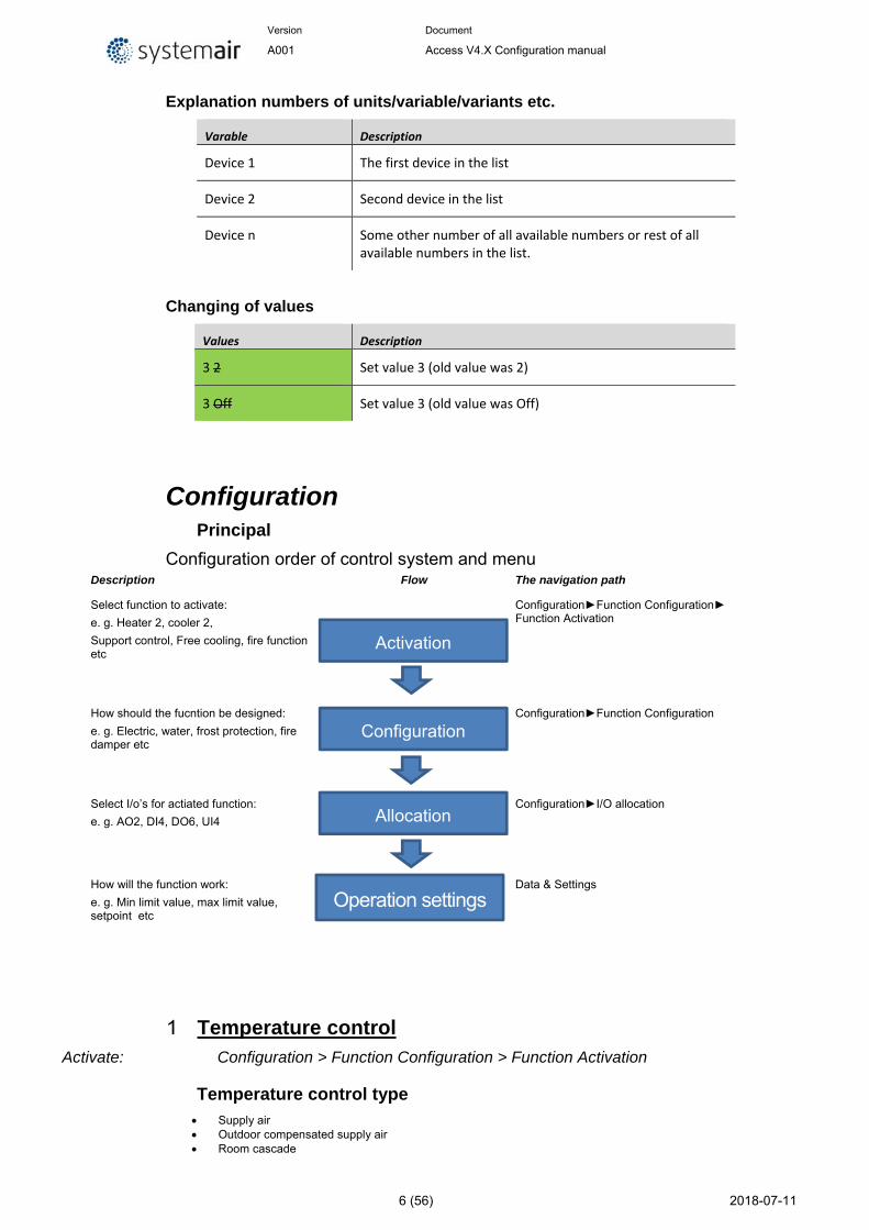
Configuration Principal
Configuration order of control system and menu Description Flow The navigation path
Select function to activate:
e. g. Heater 2, cooler 2,
Support control, Free cooling, fire function etc
Configuration►Function Configuration► Function Activation
How should the fucntion be designed:
e. g. Electric, water, frost protection, fire damper etc
Configuration►Function Configuration
Select I/o’s for actiated function:
e. g. AO2, DI4, DO6, UI4
Configuration►I/O allocation
How will the function work:
e. g. Min limit value, max limit value, setpoint etc
Data & Settings
Temperature control Activate: Configuration > Function Configuration > Function Activation
Temperature control type Supply air Outdoor compensated supply air Room cascade
Allocation
Operation settings
Configuration
Activation
Version Document
A001 Access V4.X Configuration manual
7 (56) 2018-07-11
Extract air cascade] Outdoor dependent supply air or room Outdoor dependent supply air or extract air Outdoor compensated room cascade Outdoor compensated extract air cascade Extract air depending supply air
The supply air temperature is kept at the setpoint value by controlling the output signals for "Heating (Sequence-A)", "Exchanger (Sequence-B)", "Cooling (Sequence-C)", "Heating 2 (Sequence-G)” and “Cooling 2 (Sequence-H). Up to 10 sequences (Sequence-A..J) with separate PID control settings for each sequence can be used.
A neutral zone can be set around the setpoint value.
Example:
If the setpoint is 18 °C and the neutral zone is 2 K, the cooling setpoint will be 19 °C and the heating setpoint will be 17 °C. If the supply air temperature is in the neutral zone, the heating and cooling will be blocked. If the supply air temperature decreases below the setpoint –NZ/2 the heating signal will be active until setpoint is fulfilled. If the supply air temperature increases above the setpoint +NZ/2 the cooling signal will be active until setpoint is fulfilled.
The setpoint value is set using the NaviPad or alternatively using an external setpoint device. Alarms which are activated when the supply air temperature is too high or too low are active. Alarm for control offset of the supply air temperature is active.
Supply air
The supply air temperature is kept at the setpoint value by controlling the output signals. The controller is reverse acting, i e. the output will increase for decreasing temperature.
Outdoor compensated supply air
The supply air temperature setpoint is outdoor temperature compensated using a control curve with 4 node points.
Room cascade
Cascade control of room temperature and supply air temperature to achieve a constant, settable room temperature. The room controller output signal generates the supply air controller’s setpoint value. The room controller used an own PI loops.
1..4 room sensors can be connected. If 2..4 sensors are connected, the average of their values will be used.
Extract air cascade
Cascade control of extract air temperature and supply air temperature to achieve a constant, settable room temperature. The extract air controller output signal generates the supply air controller’s setpoint value. The extract controller used an own PI loop.
Outdoor dependent supply air or room
Outdoor temperature dependent switching between supply air temperature control and room temperature control.
Version Document
A001 Access V4.X Configuration manual
8 (56) 2018-07-11
When the outdoor temperature is lower than a settable limit (winter), outdoor compensated supply air temperature control will be active, otherwise (summer) cascaded room temperature control as in room cascade type.
Outdoor dependent supply air or extract air
Outdoor temperature dependent switching between supply air temperature control and extract air temperature control.
When the outdoor temperature is lower than a settable limit (winter), outdoor compensated supply air temperature control will be active, otherwise (summer) cascaded extract air temperature control as in extract air cascade type.
Outdoor compensated room cascade
The room temperature can be compensated when the outdoor temperature increases. One can, for instance, imagine accepting a slightly higher room temperature if it is warm outside or, conversely, a slightly lower temperature if it is chilly. This function is included to conserve energy.
Outdoor compensated extract air cascade
The extract air temperature can be compensated when the outdoor temperature increases. One can, for instance, imagine accepting a slightly higher extract air temperature if it is warm outside or, conversely, a slightly lower extract air temperature if it is chilly. This function is included to conserve energy.
Extract air depending supply air
A difference between extract air temperature and supply air temperature can be configured to maintain the supply air temperature setpoint to follow extract air temperature with this difference (+10°C to -10°C). Supply air temperature setpoint = extract air temperature + difference.
Temperature control settings
Configure: Configuration > Function Configuration
Room temperature sensor None 1 2 3 4
Select the number of room sensors.
The average value of selected sensors is used in the control loop.
Outdoor sensor No Intake Outdoor Outdoor + Intake
Select the type of outdoor temperature sensor.
If only Intake is selected then it will have the same characteristics as the outdoor temperature sensor.
Extract air temperature sensor No Yes
Version Document
A001 Access V4.X Configuration manual
9 (56) 2018-07-11
Supply air temperature sensor No Yes
Summer/Winter setpoints No Yes
A special summer main setpoint (Supply/Extract/Room) can be activated by entering a supply setpoint at summer time:
External setpoint device
No TG-R4-PT100 TBI-PT1000
An external setpoint device, e.g. TBI-PT1000 or TG-R4/PT1000 can be connected. The setpoint device must follow the PT1000 resistance curve. The unit is connected to the analogue input signal ”External setpoint device”.
Control input switch Summer/winter No Yes
To control from BMS system if the building should be in Summer or Winter control mode. This is then controlled via Digital input
Cooling recovery mode Off On
If the cooling recovery has been configured, there is a cooling requirement and the extract air temperature is a settable amount lower than the outdoor temperature, cooling recovery can be activated. When cooling recovery is activated the heat exchanger and damper sequence output signal will be activated in the cooling demand. The function also activates the heating function “Free heating”: if heating is required and the outdoor temperature is higher than the extract air temperature, outdoor air will primarily be used.
Cooling recovery Limit Difference limit value
Temperature difference between Extract air and Outdoor (intake) air.
Temperature compensation related fan speed None Low High Low & High
Setpoint adjustement for Low speed and/or high speed.
Operation settings: Data & Settings > Temperature control
Setpoint Cascade controller (extract/room)
Setpoint adjustments (outdoor temp compensation, fan speed compensation etc.)
Setpoint Supply controller, min/max-limits and setpoint adjustments
Setpoint Extra controller
Settings Supply controller sequence
Settings heating/cooling pump & pump-kick
Version Document
A001 Access V4.X Configuration manual
10 (56) 2018-07-11
Settings Frost protection (1/2/3)
Settings for stopped and running mode
Settings Exchanger & defrosting
Step control settings for Step start/stop points, min switch time, outdoor temp/fan speed block of steps etc.)
Step settings
Fan heat/cool settings (Fan compensation)
Pretreatment
Fan control Activate: Configuration > Function Configuration > Function Activation
Fan control type 1. Pressure 2. Flow 3. Manual 4. External 5. Supply air pressure and extract air slave 6. Supply air pressure and extract air flow slave 7. Extract air pressure and supply air slave 8. Extract air pressure and supply air flow slave
The rotational speed is controlled by output signal (0 – 100%).
A digital Activate signal is normally used for each fan (“Supply air fan start” and “Extract air fan start”), for sending a start signal to the frequency converters/EC-motor. The start signal is activated as long as the fan is expected to be running.
For the supply and extract air fans, there are 1..3 individually settable setpoint values, one corresponding to Low speed, one corresponding to normal speed and one corresponding to high speed. Changing between the setpoint values is done using the timer channels for normal low and high speed or using digital input signals. Extended Operation, Low, normal and high speed, see chap.14.
Pressure
During pressure control, two separate analogue output signals are used for supply and extract air and two separate analogue input signals for supply and extract air for pressure transmitters. The fan speeds are controlled via frequency converters, thereby maintaining constant pressure. The pressure transmitter inputs are scalable using “Volt minimum/Minimum (pressure)” and “Volt maximum/Maximum (pressure)”.
Flow
Instead of giving a pressure setpoint value, it is possible to use an airflow volume value. The value from the pressure transmitter is recalculated to a volume flow using the formula below and the fans will be controlled to give a constant flow.
Flow = K *∆ PX
Where K and X are settable constants dependent on the fan size and ∆ P is the differential pressure, measured over the fan. Each fan has its own set of parameters.
X is normally 0.5 indicating that the flow is proportional to the square root of the differential pressure.
Flow presentation can be selected, when fan control type not are “Flow”.
Version Document
A001 Access V4.X Configuration manual
11 (56) 2018-07-11
Manual
Frequency controlled fans can be controlled at a fixed rotational speed. The rotational speed is selected by setting a fixed output signal (0 – 100%). Values for normal and reduced speed can be configured for each fan.
Fans that are run with a fixed output signal can also be compensated (see the section above). In this mode, pressure sensors are not needed.
External
Two 0…10 V input signals are used for direct control of frequency controlled fans. The signal is received from e.g. a VAV unit. The signal controls the fans 0…100% (0…10 V on the analogue output). Pressure transmitters are not used in this control mode.
Supply air pressure and extract air slave
The rotational speed of the supply air fan is controlled by a pressure transmitter (”Pressure supply air”) which is placed in the supply air duct. The extract air fan does not have a pressure transmitter, instead you let the output for the extract air fan follow the control signal for the supply air fan. A scaling factor can be added if the characteristics of the extract air fan are not the same as the characteristics of the supply air fan. (Only pressure control of the supply air fan is possible using this function.) The extract air fan will start directly at 50% after the start delay. Then the heating of the exchanger will work for this operating mode as well. When the supply air fan starts, the extract air fan will be slave controlled by the supply air flow.
Supply air pressure and extract air flow slave
The rotational speed of the supply air fan is controlled by a pressure transmitter (“Pressure supply air”) which is placed in the supply air duct. The extract air fan is controlled by the supply air flow, in order to achieve a balanced ventilation. A pressure transmitter ("Flow supply air") which is placed in the supply air fan cone gives a measured value of the present supply air flow. A corresponding pressure transmitter (”Flow extract air”) is placed in the extract air fan cone and gives a measured value of the extract air flow.
The supply air flow is the setpoint used for control of the extract air fan. A scaling factor can be added if the extract air fan does not have the same characteristics as the supply air fan.
Extract air pressure and supply air slave
The rotational speed of the extract air fan is controlled by a pressure transmitter (“Pressure extract air”) which is placed in the extract air duct. The supply air fan has no pressure transmitter. Instead, the supply air fan output is made to follow the extract air fan control signal. A scaling factor can be added if the supply air fan characteristics are not the same as the characteristics of the extract air fan (only pressure control of the extract air fan is possible using this function).
Extract air pressure and supply air flow slave
The rotational speed of the extract air fan is controlled by a pressure transmitter (”Pressure extract air”) which is placed in the extract air duct. The supply air fan is controlled by the extract air duct flow in order to achieve a balanced ventilation. A pressure transmitter (“Flow extract air”) placed in the extract air fan cone provides a measurement of the current extract air flow. A corresponding pressure
Version Document
A001 Access V4.X Configuration manual
12 (56) 2018-07-11
transmitter (“Flow supply air”) is placed in the supply air fan cone, providing a measurement of the supply air flow.
The supply air fan is controlled using the extract air flow as a setpoint. A scaling factor can be added if the supply air fan does not have the same characteristics as the extract air fan.
Configure: Configuration > Function Configuration > Fan control
Fans Supply+Extract Supply Extract
Flow presentation No Yes
Possibility to showing current flow on both fans even when pressure control or slave control is used.
Alarm / Run indication
Digital input signals are used to supervise fans. They can be configured either for indication of the motor running or for monitoring of motor alarm contacts.
An input configured for run indication should normally be closed during operation.
Open input when the motor is running, i.e. motor control output is activated, will generate an alarm.
For supply air fans and extract air fans, there is also a conflict alarm, i. e. an alarm if the run indication input is closed even though the motor control output is not activated.
An input configured as motor protection should be normally open, i. e. closed contact when the motor is running, i.e. motor control output is activated, will generate an alarm.
When running frequency controlled fans, the pressure signal from each respective fan’s pressure transmitter is normally used as run indication signal. If the pressure falls below the set value during normal operation, a malfunction alarm is activated.
Alarm from frequency converter
When running frequency controlled fans, you sometimes want to use both a pressure signal from a pressure transmitter and a digital alarm signal from a frequency converter. An analogue input for a pressure transmitter and a digital input for "Monitoring supply air fan" or "Monitoring extract air fan" must then be configured. The setting Fan indication "Run indication/Alarm” on supply and extract air fan must be set to "Alarm". A fan alarm will be activated both when there is no pressure signal from the pressure transmitter, and when the digital signal " Monitoring supply air fan " or " Monitoring extrct air fan " is activated.
Supply air fan indication None Alarm Run indication
Extract air fan indication None Alarm Run indication
Version Document
A001 Access V4.X Configuration manual
13 (56) 2018-07-11
Flow transmitter
DESCRIPTION
∗
, 5 ,
Flow transmitter supply air K-factor X-factor Default 0,5
Flow transmitter extract air K-factor X-factor Default 0,5
Exchanger supply air pressure sensor K-factor X-factor Default 0.96…0.98
Operation settings: Data & Settings > Fan control
Sequence Configure types Activate/configure: Configuration > Function Configuration > Function Activation
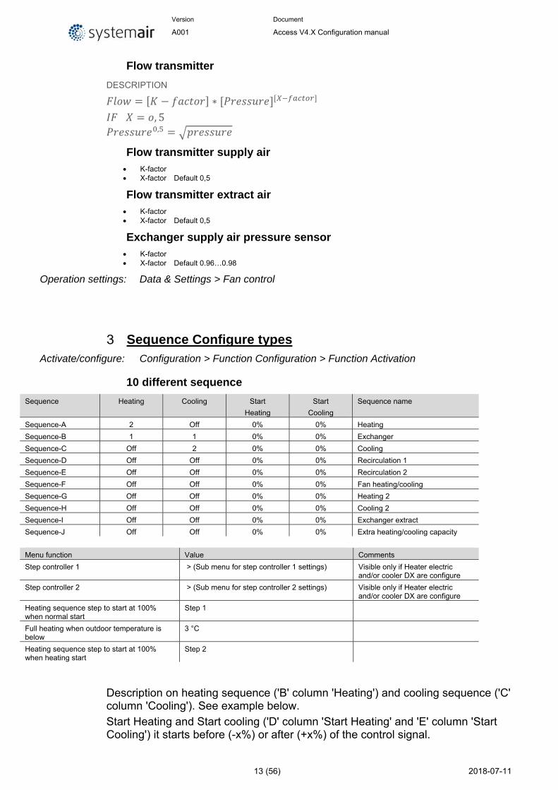
10 different sequence
Sequence Heating Cooling Start
Heating
Start
Cooling
Sequence name
Sequence-A 2 Off 0% 0% Heating
Sequence-B 1 1 0% 0% Exchanger
Sequence-C Off 2 0% 0% Cooling
Sequence-D Off Off 0% 0% Recirculation 1
Sequence-E Off Off 0% 0% Recirculation 2
Sequence-F Off Off 0% 0% Fan heating/cooling
Sequence-G Off Off 0% 0% Heating 2
Sequence-H Off Off 0% 0% Cooling 2
Sequence-I Off Off 0% 0% Exchanger extract
Sequence-J Off Off 0% 0% Extra heating/cooling capacity
Menu function Value Comments
Step controller 1 > (Sub menu for step controller 1 settings) Visible only if Heater electric and/or cooler DX are configure
Step controller 2 > (Sub menu for step controller 2 settings) Visible only if Heater electric and/or cooler DX are configure
Heating sequence step to start at 100% when normal start
Step 1
Full heating when outdoor temperature is below
3 °C
Heating sequence step to start at 100% when heating start
Step 2
Description on heating sequence ('B' column 'Heating') and cooling sequence ('C' column 'Cooling'). See example below.
Start Heating and Start cooling ('D' column 'Start Heating' and 'E' column 'Start Cooling') it starts before (-x%) or after (+x%) of the control signal.
Version Document
A001 Access V4.X Configuration manual
14 (56) 2018-07-11
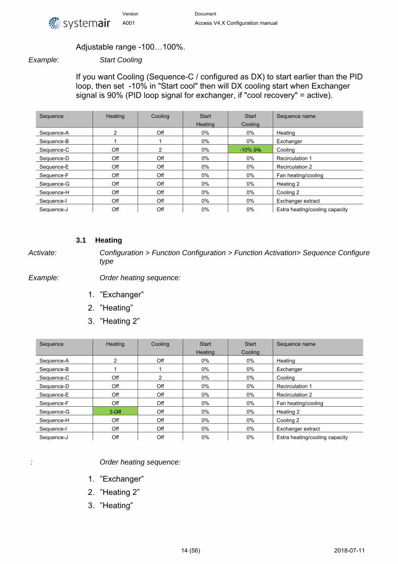
Adjustable range -100…100%.
Example: Start Cooling
If you want Cooling (Sequence-C / configured as DX) to start earlier than the PID loop, then set -10% in "Start cool" then will DX cooling start when Exchanger signal is 90% (PID loop signal for exchanger, if "cool recovery" = active).
Sequence Heating Cooling Start
Heating
Start
Cooling
Sequence name
Sequence-A 2 Off 0% 0% Heating
Sequence-B 1 1 0% 0% Exchanger
Sequence-C Off 2 0% -10% 0% Cooling
Sequence-D Off Off 0% 0% Recirculation 1
Sequence-E Off Off 0% 0% Recirculation 2
Sequence-F Off Off 0% 0% Fan heating/cooling
Sequence-G Off Off 0% 0% Heating 2
Sequence-H Off Off 0% 0% Cooling 2
Sequence-I Off Off 0% 0% Exchanger extract
Sequence-J Off Off 0% 0% Extra heating/cooling capacity
3.1 Heating
Activate: Configuration > Function Configuration > Function Activation> Sequence Configure type
Example: Order heating sequence:
1. ”Exchanger”
2. ”Heating”
3. ”Heating 2”
Sequence Heating Cooling Start
Heating
Start
Cooling
Sequence name
Sequence-A 2 Off 0% 0% Heating
Sequence-B 1 1 0% 0% Exchanger
Sequence-C Off 2 0% 0% Cooling
Sequence-D Off Off 0% 0% Recirculation 1
Sequence-E Off Off 0% 0% Recirculation 2
Sequence-F Off Off 0% 0% Fan heating/cooling
Sequence-G 3 Off Off 0% 0% Heating 2
Sequence-H Off Off 0% 0% Cooling 2
Sequence-I Off Off 0% 0% Exchanger extract
Sequence-J Off Off 0% 0% Extra heating/cooling capacity
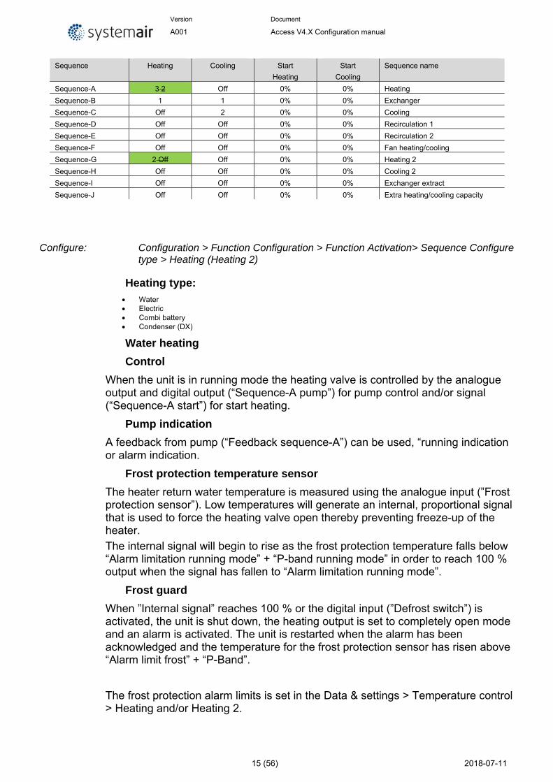
: Order heating sequence:
1. ”Exchanger”
2. ”Heating 2”
3. ”Heating”
Version Document
A001 Access V4.X Configuration manual
15 (56) 2018-07-11
Sequence Heating Cooling Start
Heating
Start
Cooling
Sequence name
Sequence-A 3 2 Off 0% 0% Heating
Sequence-B 1 1 0% 0% Exchanger
Sequence-C Off 2 0% 0% Cooling
Sequence-D Off Off 0% 0% Recirculation 1
Sequence-E Off Off 0% 0% Recirculation 2
Sequence-F Off Off 0% 0% Fan heating/cooling
Sequence-G 2 Off Off 0% 0% Heating 2
Sequence-H Off Off 0% 0% Cooling 2
Sequence-I Off Off 0% 0% Exchanger extract
Sequence-J Off Off 0% 0% Extra heating/cooling capacity
Configure: Configuration > Function Configuration > Function Activation> Sequence Configure type > Heating (Heating 2)
Heating type: Water Electric Combi battery Condenser (DX)
Water heating
Control
When the unit is in running mode the heating valve is controlled by the analogue output and digital output (“Sequence-A pump”) for pump control and/or signal (“Sequence-A start”) for start heating.
Pump indication
A feedback from pump (“Feedback sequence-A”) can be used, “running indication or alarm indication.
Frost protection temperature sensor
The heater return water temperature is measured using the analogue input (”Frost protection sensor”). Low temperatures will generate an internal, proportional signal that is used to force the heating valve open thereby preventing freeze-up of the heater.
The internal signal will begin to rise as the frost protection temperature falls below “Alarm limitation running mode” + “P-band running mode” in order to reach 100 % output when the signal has fallen to “Alarm limitation running mode”.
Frost guard
When ”Internal signal” reaches 100 % or the digital input (”Defrost switch”) is activated, the unit is shut down, the heating output is set to completely open mode and an alarm is activated. The unit is restarted when the alarm has been acknowledged and the temperature for the frost protection sensor has risen above “Alarm limit frost” + “P-Band”.
The frost protection alarm limits is set in the Data & settings > Temperature control > Heating and/or Heating 2.
Version Document
A001 Access V4.X Configuration manual
16 (56) 2018-07-11
Standby mode
If frost protection is activated, the controller will go into ”Standby mode” when the running mode switches to ”Off”. The “Standby mode” will control the heating output to maintain a constant settable temperature at the frost protection sensor “Setpoint Standby mode”.
Electric heating
Control
The heating is controlled using the analogue output and/or signal for start heating or step controller to control 1..4 digital output steps.
Overheat protection
On Activate of the digital input “Overheated electric heater” the unit will be shut down, either according to the stop sequence described in section Start/stop of unit or as an emergency shutdown. The unit will restart after the alarm has been acknowledged and “Electric heating is overheated” has reset.
Flow switch
Note that Activate of the input signal “Flow switch” will also stop the unit. Note: It is important that the high temperature thermostat is hardwired to disconnect the power to the heater. That is to ensure that the heating is shut down when the thermostat is activated even if the Access controller should be faulty.
Fast stop on overheating
If the function "Fast stop on overheating" is active, the fans will be immediately stopped when there is an overheating alarm, regardless of the set cool-down time.
Step controller heating
Activate: By configuring the electrical heater the step switch will be activated in the menu.
Configure: Configuration > Function Configuration > Function Activation> Sequence Configure type > Step controller 1 (Step controller 2)
Step controller 1 (2)
Input Select sequence to connect to step controller 1
Step control type Sequential Binary
Number of step 1 2 3 4
Select number of digital outputs
Hysteresis if low outdoor temperature block 1 °C
Version Document
A001 Access V4.X Configuration manual
17 (56) 2018-07-11
Block step signal if alam No Yes
Operation settings: Data & Settings > Temperature control > Heating (Heating 2)
Sequential control
Each output step has individually settable on and off values in percent of the control signal. The number of steps is equal to the number of heater/chiller groups. Minimum on and off times can be set, i.e. the minimum time the step has to be inactive or active for a change to occur.
Binary control
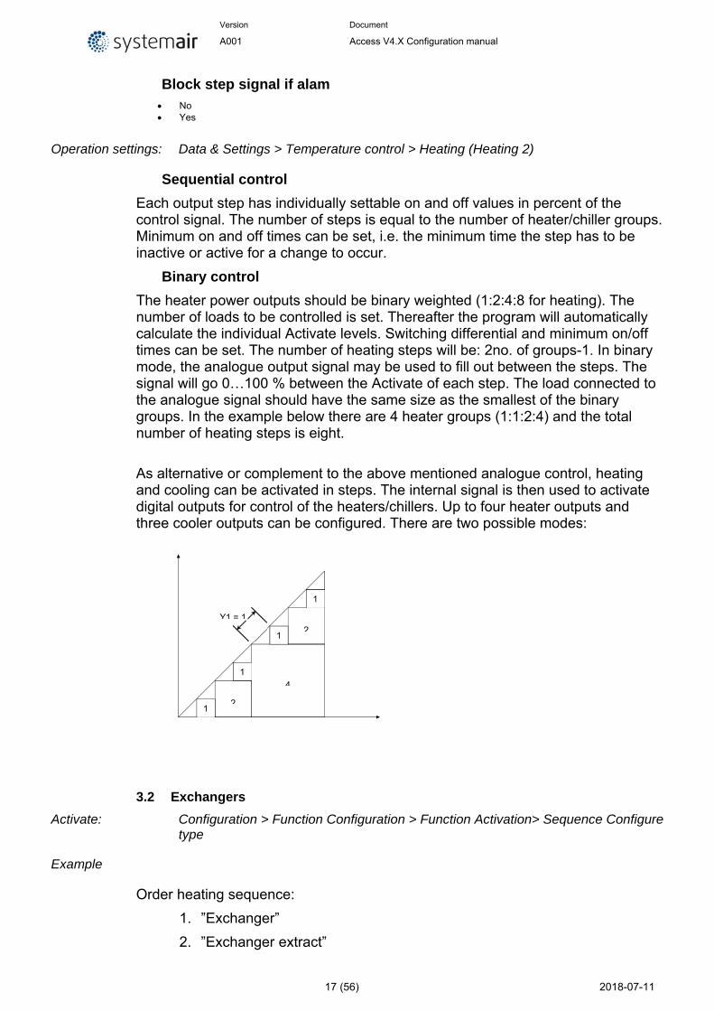
The heater power outputs should be binary weighted (1:2:4:8 for heating). The number of loads to be controlled is set. Thereafter the program will automatically calculate the individual Activate levels. Switching differential and minimum on/off times can be set. The number of heating steps will be: 2no. of groups-1. In binary mode, the analogue output signal may be used to fill out between the steps. The signal will go 0…100 % between the Activate of each step. The load connected to the analogue signal should have the same size as the smallest of the binary groups. In the example below there are 4 heater groups (1:1:2:4) and the total number of heating steps is eight.
As alternative or complement to the above mentioned analogue control, heating and cooling can be activated in steps. The internal signal is then used to activate digital outputs for control of the heaters/chillers. Up to four heater outputs and three cooler outputs can be configured. There are two possible modes:
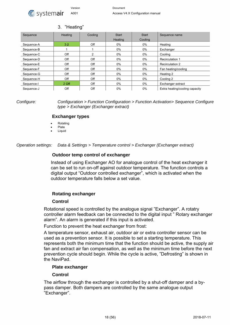
3.2 Exchangers
Activate: Configuration > Function Configuration > Function Activation> Sequence Configure type
Example
Order heating sequence:
1. ”Exchanger”
2. ”Exchanger extract”
Y1 = 1
1 2
1
4
1 2
1
Version Document
A001 Access V4.X Configuration manual
18 (56) 2018-07-11
3. ”Heating”
Sequence Heating Cooling Start
Heating
Start
Cooling
Sequence name
Sequence-A 3 2 Off 0% 0% Heating
Sequence-B 1 1 0% 0% Exchanger
Sequence-C Off 2 0% 0% Cooling
Sequence-D Off Off 0% 0% Recirculation 1
Sequence-E Off Off 0% 0% Recirculation 2
Sequence-F Off Off 0% 0% Fan heating/cooling
Sequence-G Off Off 0% 0% Heating 2
Sequence-H Off Off 0% 0% Cooling 2
Sequence-I 2 Off Off 0% 0% Exchanger extract
Sequence-J Off Off 0% 0% Extra heating/cooling capacity
Configure: Configuration > Function Configuration > Function Activation> Sequence Configure type > Exchanger (Exchanger extract)
Exchanger types Rotating Plate Liquid
Operation settings: Data & Settings > Temperature control > Exchanger (Exchanger extract)
Outdoor temp control of exchanger
Instead of using Exchanger AO for analogue control of the heat exchanger it can be set to run on-off against outdoor temperature. The function controls a digital output “Outdoor controlled exchanger”, which is activated when the outdoor temperature falls below a set value.
Rotating exchanger
Control
Rotational speed is controlled by the analogue signal ”Exchanger”. A rotatry controller alarm feedback can be connected to the digital input ” Rotary exchanger alarm”. An alarm is generated if this input is activated.
Function to prevent the heat exchanger from frost:
A temperature sensor, exhaust air, outdoor air or extra controller sensor can be used as a prevention sensor. It is possible to set a starting temperature. This represents both the minimum time that the function should be active, the supply air fan and extract air fan compensation, as well as the minimum time before the next prevention cycle should begin. While the cycle is active, ”Defrosting” is shown in the NaviPad.
Plate exchanger
Control
The airflow through the exchanger is controlled by a shut-off damper and a by-pass damper. Both dampers are controlled by the same analogue output ”Exchanger”.
Version Document
A001 Access V4.X Configuration manual
19 (56) 2018-07-11
Defrosting 1
Defrosting is activated either when the digital signal ”Defrosting” is activated or when the value of the analogue input ”Defrosting temperature” falls below the defrosting limit (-3°C), or when the analogue signal ”Exchanger extract air pressure sensor” rises above the set value for the current pressure. It is deactivated when the digital signal is reset, or alternatively when the analogue signal exceeds/falls below the limit value plus a settable differential.
When defrosting:
A PID-controller compares the defrosting setpoint with the signal ”Defrotsing exchanger”. The smallest of the output signal from this controller and the output from the ordinary controller is used as output to the dampers.
Defrosting 2
Defrosting is activated by measuring the pressure difference over the exchangers extract/exhaust side. The differential pressure transmitter is auto calibrated by the system to obtain the correct pressure in relation to the airflow.
Manual calibration is possible, e. g. after cleaning of exchanger. Defrosting is possible with by-pass or stop defrosting, adjustable in the display.
Defrosting is stopped when the desired, adjustable decrease in pressure over the heat exchanger is obtained.
If the decrease of pressure does not happens during defrost cycle, the air handling unit is stopped and an alarm is shown in the display.
Liquid exchanger
Control
A mixing valve in the exchanger circulation system is controlled by the analogue signal ”Exchanger” and digital output (“Sequence-A pump”) for pump control and/or signal (“Sequence-A start”) for start heating.
Defrosting 1
Deicing is activated either when the digital input sensor ”Defrosting temperature” is activated, when the value falls below the deicing limit (-3°C). It is deactivated when the digital input is reset or the analogue input rises above the limit value plus a settable differential.
On deicing:
A PI-controller compares the deicing setpoint with the signal ”Defrotsing Exchanger”. The lesser of the output signal from this controller and the output from the ordinary controller is used as output to the actuator.
Pump indication
A feedback from pump (“Pump sequence-B”) can be used, running indication or alarm indication (“Feedback sequence-B”).
Version Document
A001 Access V4.X Configuration manual
20 (56) 2018-07-11
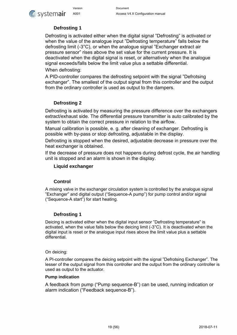
3.3 Cooler
Activate: Configuration > Function Configuration > Function Activation> Sequence Configure type
Activate extra cooler coil
Example: Order cooling sequence:
1. ”Exchanger”
2. ”Cooler”
3. ”Cooler 2”
Sequence Heating Cooling Start
Heating
Start
Cooling
Sequence name
Sequence-A 2 Off 0% 0% Heating
Sequence-B 1 1 0% 0% Exchanger
Sequence-C Off 2 0% 0% Cooling
Sequence-D Off Off 0% 0% Recirculation 1
Sequence-E Off Off 0% 0% Recirculation 2
Sequence-F Off Off 0% 0% Fan heating/cooling
Sequence-G Off Off 0% 0% Heating 2
Sequence-H Off 3 Off 0% 0% Cooling 2
Sequence-I Off Off 0% 0% Exchanger extract
Sequence-J Off Off 0% 0% Extra heating/cooling capacity
Example: Order cooling sequence:
1. ”Exchanger”
2. ”Cooler 2”
3. ”Cooler”
Sequence Heating Cooling Start
Heating
Start
Cooling
Sequence name
Sequence-A 2 Off 0% 0% Heating
Sequence-B 1 1 0% 0% Exchanger
Sequence-C Off 3 2 0% 0% Cooling
Sequence-D Off Off 0% 0% Recirculation 1
Sequence-E Off Off 0% 0% Recirculation 2
Sequence-F Off Off 0% 0% Fan heating/cooling
Sequence-G Off Off 0% 0% Heating 2
Sequence-H Off 2 Off 0% 0% Cooling 2
Sequence-I Off Off 0% 0% Exchanger extract
Sequence-J Off Off 0% 0% Extra heating/cooling capacity
Configure: Configuration > Function Configuration > Function Activation> Sequence Configure type > Cooling (Cooling 2)
Cooling type: Water
Version Document
A001 Access V4.X Configuration manual
21 (56) 2018-07-11
DX DX with exchanger control
Operation settings: Data & Settings > Temperature control > Cooling (Cooling 2)
Water cooler
Control When the unit is in running mode the heating valve is controlled by the analogue output and digital output for pump control and/or signal for start heating.
Pump indication A feedback from pump can be used, running indication or alarm indication.
DX cooler
Step controller Heating / DX cooling
As alternative or complement to the above mentioned analogue control, heating and cooling can be activated in steps. The internal signal is then used to activate digital outputs for control of the heaters/chillers. Up to four heater outputs and three cooler outputs can be configured. There are two possible modes:
Sequential control
Each output step has individually settable on and off values in percent of the control signal. The number of steps is equal to the number of heater/chiller groups. Minimum on and off times can be set, i.e. the minimum time the step has to be inactive or active for a change to occur.
Binary control
The heater power outputs should be binary weighted (1:2:4:8). The number of loads to be controlled is set. Thereafter the program will automatically calculate the individual Activate levels. Switching differential and minimum on/off times can be set.
DX cooling with room or extract air control
If DX cooling is used in conjunction with room temperature control or extract air temperature control, there are two Configure alternatives, DX cooling or DX cooling with exchanger control.
DX cooling without exchanger control
When running cascade control, the supply air controller setpoint is normally controlled by the room/extract air controller output signal.
When DX cooling is activated, the supply air controller setpoint is lowered to five degrees (adjustable) below the setpoint given by the room/extract air controller. This prevents the DX cooling from being activated/deactivated too often.
Version Document
A001 Access V4.X Configuration manual
22 (56) 2018-07-11
DX cooling with exchanger control
When running cascade control, the supply air controller setpoint is normally controlled by the room/extract air controller output signal.
When DX cooling is activated, the supply air controller setpoint is lowered to five degrees (adjustable) below the setpoint given by the room/extract air controller. This prevents the DX cooling from being activated/deactivated too often. If the supply air temperature falls below the setpoint given by the room/extract air controller, the heat exchanger output will be activated in order to try to maintain the supply air setpoint given by the room/extract air controller. The output uses P-control with a P-band of half the setpoint lowering (adjustable, 2.5°C as default). The setpoint given by the room/extract air controller cannot drop below the set min limit. When there is no longer a cooling demand, the supply air controller setpoint will return to the value given by the room/extract air controller.
Note: The function cannot be used if the exchanger signal controls a mixing damper.
Example:
The room controller gives a supply air setpoint of 16°C. If there is a cooling demand, the supply air controller setpoint is lowered to 11°C (16 – 5) and DX cooling is activated. Should the supply air temperature fall below 16°C, the exchanger output will be activated and reach 100 % output when the supply air temperature has fallen to 13.5°C (16 - 2.5).
Blocking of DX cooling at low outdoor temperature
DX cooling can be blocked when the outdoor temperature is low. It is possible to block the three cooling steps individually or to block all DX cooling. The temperature limits are adjustable (+13°C default) and have a fixed one degree hysteresis.
When two DX cooling steps are used with binary function, the cooling effect is divided into three steps. The desired blocking level can be set individually for each of these steps.
When three DX cooling steps are used with binary function, the cooling effect is divided into seven steps. However, the controller still only has three blocking level settings. Therefore, Blocking step 1 will apply to binary steps 1 and 2, Blocking step 2 to binary steps 3 and 4, and Blocking step 3 to binary steps 5, 6..etc.
Blocking of DX cooling at low supply air fan speed
When DX cooling is used in conjunction with pressure controlled or flow controlled fans it is possible to block DX cooling if the supply air fan control signal falls below a preset values. For sequential control, the blocking level is individually settable for each DX cooling step.
When two DX cooling steps are used with binary function, the cooling effect is divided into three steps. The desired blocking level can be set individually for each of these steps.
When three DX cooling steps are used with binary function, the cooling effect is divided into seven steps. However, the controller still only has three blocking level
Version Document
A001 Access V4.X Configuration manual
23 (56) 2018-07-11
settings. Therefore, Blocking step 1 will apply to binary steps 1 and 2, Blocking step 2 to binary steps 3 and 4, and Blocking step 3 to binary steps 5, 6 and 7.
Blocking of DX cooling on cooling pump alarm Corrigo can be configured to block DX cooling on cooling pump alarm. In- and outputs
Override of reduced speed for DX cooling
Override to normal quantity of air for DX cooling when the unit runs on reduced quantity of air. The fans can be set to normal operation when cooling is required at high outdoor temperatures (e.g. >14°C, the same temperature limit as for blocking of DX cooling).
Step controller
Activate: By configuring Cooler DX, the step switch will be activated in the menu.
Configure: Configuration > Function Configuration > Function Activation> Sequence Configure type > Step controller 1 (Step controller 2)
Step controller 1 (2)
Input Select sequence to connect to step controller 1
Step control type Sequenciel Binary
Number of step 1 2 3 4
Select number of digital outputs
Hysteresis if low outdoor temperature block 1 °C
Block step signal if alam No Yes
Operation settings: Data & Settings > Temperature control > Cooling (Cooling 2)
Version Document
A001 Access V4.X Configuration manual
24 (56) 2018-07-11
3.4 Damper
Activate: Configuration > Function Configuration > Function Activation> Sequence Configure type
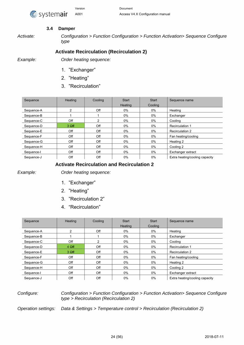
Activate Recirculation (Recirculation 2)
Example: Order heating sequence:
1. ”Exchanger”
2. ”Heating”
3. ”Recirculation”
Sequence Heating Cooling Start
Heating
Start
Cooling
Sequence name
Sequence-A 2 Off 0% 0% Heating
Sequence-B 1 1 0% 0% Exchanger
Sequence-C Off 2 0% 0% Cooling
Sequence-D 3 Off Off 0% 0% Recirculation 1
Sequence-E Off Off 0% 0% Recirculation 2
Sequence-F Off Off 0% 0% Fan heating/cooling
Sequence-G Off Off 0% 0% Heating 2
Sequence-H Off Off 0% 0% Cooling 2
Sequence-I Off Off 0% 0% Exchanger extract
Sequence-J Off Off 0% 0% Extra heating/cooling capacity
Activate Recirculation and Recirculation 2
Example: Order heating sequence:
1. ”Exchanger”
2. ”Heating”
3. ”Recirculation 2”
4. “Recirculation”
Sequence Heating Cooling Start
Heating
Start
Cooling
Sequence name
Sequence-A 2 Off 0% 0% Heating
Sequence-B 1 1 0% 0% Exchanger
Sequence-C Off 2 0% 0% Cooling
Sequence-D 4 Off Off 0% 0% Recirculation 1
Sequence-E 3 Off Off 0% 0% Recirculation 2
Sequence-F Off Off 0% 0% Fan heating/cooling
Sequence-G Off Off 0% 0% Heating 2
Sequence-H Off Off 0% 0% Cooling 2
Sequence-I Off Off 0% 0% Exchanger extract
Sequence-J Off Off 0% 0% Extra heating/cooling capacity
Configure: Configuration > Function Configuration > Function Activation> Sequence Configure type > Recirculation (Recirculation 2)
Operation settings: Data & Settings > Temperature control > Recirculation (Recirculation 2)
Version Document
A001 Access V4.X Configuration manual
25 (56) 2018-07-11
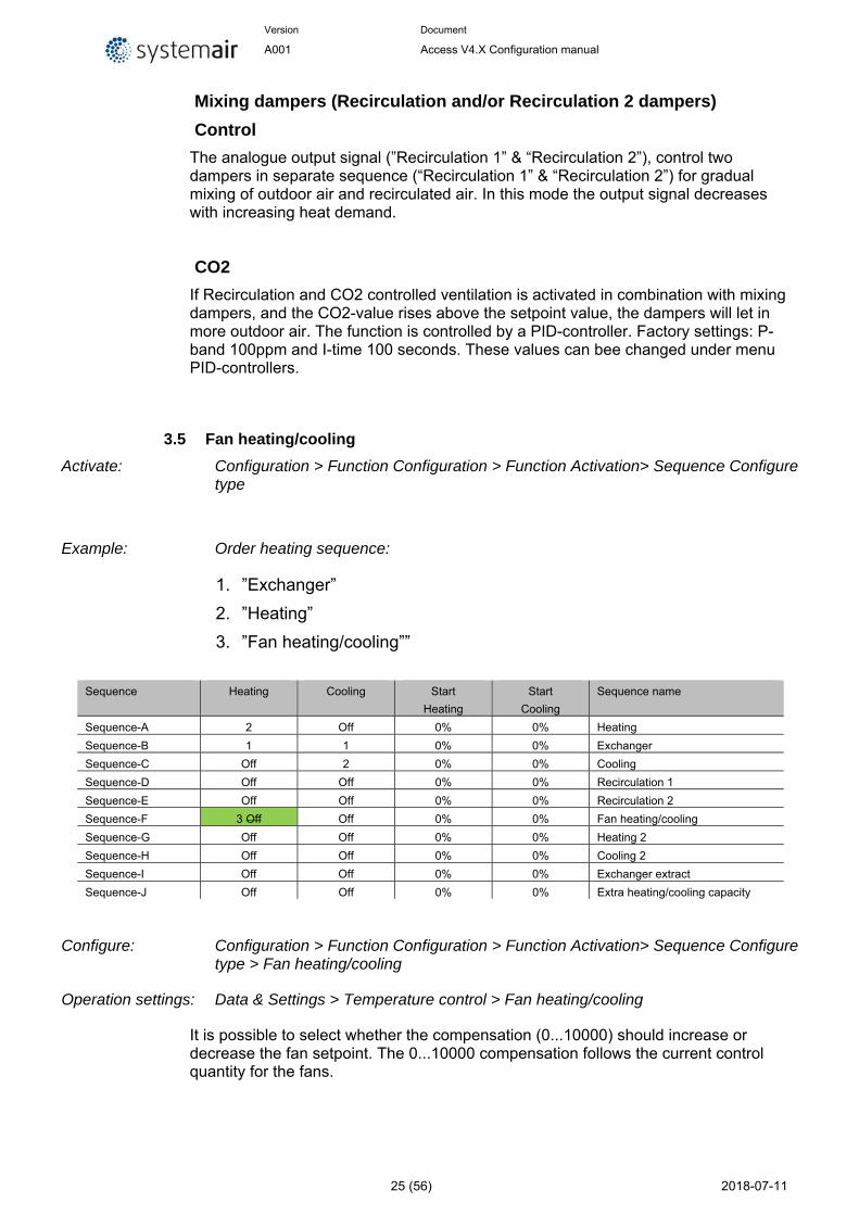
Mixing dampers (Recirculation and/or Recirculation 2 dampers)
Control
The analogue output signal (”Recirculation 1” & “Recirculation 2”), control two dampers in separate sequence (“Recirculation 1” & “Recirculation 2”) for gradual mixing of outdoor air and recirculated air. In this mode the output signal decreases with increasing heat demand.
CO2
If Recirculation and CO2 controlled ventilation is activated in combination with mixing dampers, and the CO2-value rises above the setpoint value, the dampers will let in more outdoor air. The function is controlled by a PID-controller. Factory settings: P-band 100ppm and I-time 100 seconds. These values can bee changed under menu PID-controllers.
3.5 Fan heating/cooling
Activate: Configuration > Function Configuration > Function Activation> Sequence Configure type
Example: Order heating sequence:
1. ”Exchanger”
2. ”Heating”
3. ”Fan heating/cooling””
Sequence Heating Cooling Start
Heating
Start
Cooling
Sequence name
Sequence-A 2 Off 0% 0% Heating
Sequence-B 1 1 0% 0% Exchanger
Sequence-C Off 2 0% 0% Cooling
Sequence-D Off Off 0% 0% Recirculation 1
Sequence-E Off Off 0% 0% Recirculation 2
Sequence-F 3 Off Off 0% 0% Fan heating/cooling
Sequence-G Off Off 0% 0% Heating 2
Sequence-H Off Off 0% 0% Cooling 2
Sequence-I Off Off 0% 0% Exchanger extract
Sequence-J Off Off 0% 0% Extra heating/cooling capacity
Configure: Configuration > Function Configuration > Function Activation> Sequence Configure type > Fan heating/cooling
Operation settings: Data & Settings > Temperature control > Fan heating/cooling
It is possible to select whether the compensation (0...10000) should increase or decrease the fan setpoint. The 0...10000 compensation follows the current control quantity for the fans.
Version Document
A001 Access V4.X Configuration manual
26 (56) 2018-07-11
Fan levels Activate Configuration > function Configuration > Function Activation
Fan levels Normal Low-Normal Normal-High Low-Normal-High
Select the fan stages to use in operation.
The time settings in the scheduler show only the selected steps.
Setpoints for Fans need to be updated.
Changeover Configure: Configuration > Function Configure
Changeover 1 sequence for heating Heater Changeover 1 sequence for cooling Cooler Changeover 2 sequence for heating disable Changeover 2 sequence for cooling desible
Operation settings: Data & Settings > In-/output status > Digital input (Analogue output)(digital output)*1
Change-over is a function for installations with 2-pipe systems. It makes it possible to use the same pipe for both heating and cooling, depending on whether heating or cooling is required.
A special analogue output signal, "Changeover 1 (2)*2", is used for Change-over control. Switching between heating and cooling can be done in two ways. A digital Change-over input signal “Cooling/(heating) changeover 1(2) is normally used. Open contact gives heating control and closed contact gives cooling control. If the input has not been configured, change-over is handled by the internal controller signal. The output signal (AO “changeover 1(2)” and DO “changeover 1(2)”) will follow the two regular output signals "Heating" and "Cooling". For heating control, the digital outputs Heating “Sequence-A start” or “Sequence-A pump” are active. For cooling control the digital outputs Cooling “Sequence-C start” or “Sequence-C pump” are activate.
If frost protection sensor has been configured, it will function in the usual way when heating is active. However, when cooling is active, it will only be used for indicating temperature.
*1 Digital input (Analogue output)(digital output) = Digital input, Analogue outputs and Digital outputs
*2 Changeover 1(2) = Changeover 1 and Changeover 2
Version Document
A001 Access V4.X Configuration manual
27 (56) 2018-07-11
Fan compensation Activate: Configuration > Function Configuration > Function Activation
Fan compensation No Yes
Enables the fan compensation via temperature, pressure, CO2, RH sensor.
There are 3 different compensation curves to use in the sub menu.
Configure: Configuration > Function Configuration > Fan compensation
There are three compensation functions called Fan compensation curve 1-3. Which can be used to set a compensation based on the configured analogue input signal (temperature, pressure, flow humidity, CO2). The curve has three parameter pairs which correspond to the value of the compensation at three different temperatures.
The compensation can be selected to apply to both fan or only one of the fan, to slow, normal, high or all speeds and only when defrosting.
Version Document
A001 Access V4.X Configuration manual
28 (56) 2018-07-11
Fan compensation curve 1, 2, 3
Speed All speeds Only low speed Only normal speed Only high speed Low and normal speed Normal and high speed
Select the fan steps were the compensation shall be active
Mode Off In all modes Only when defrosting
Fan Supply air fan and extract air fan Supply air fan only Extract air fan only
Sensor “Temperature sensor” “Pressure sensor” CO2 sensor RH sensor
All active temperature sensors and differential pressure sensors will be included in the "scroll list" for selectable sensors
Operation settings: Data & Settings > Fan control > Fan compensation
Settings to set up the compensation curve
Fan compensation curve 1, 2, 3
Low point Input value break point for selected sensor Compensation compensation value (negative or positive adjustment)
Middle point Input value break point for selected sensor Compensation compensation value (negative or positive adjustment)
High point Input value break point for selected sensor Compensation compensation value (negative or positive adjustment)
Support control Activate Configuration > Function Configuration > Function Activation
Support control No Yes
Configure Configuration > Function Configuration > Support control
Enable support control when ventilation unit is shut down No Yes
Version Document
A001 Access V4.X Configuration manual
29 (56) 2018-07-11
Minimum time for support control and demand control 20 min
Extract air fan running during support control No Yes
Operation settings: Data & Setings > Demand control > Support Control
Support control is normally used when room temperature control or extract air control has been configured. When extract air control is configured a room sensor must be installed. “Support control Heating” or “Support control Cooling” will run if Support control is configured, the running mode is in Off-state (timer control OFF and not in extended running) and if conditions call for support control (see below). Minimum run time is settable 0 to 720 minutes (FS= 20 minutes).
Support control can also be configured when supply air temperature control is used, if a room sensor is installed. The controller uses the configured min. (FS=15°C) and max. (FS=30°C) limitation values as support control setpoints. However, in this case the min. and max. limitation values cannot be changed. To change the values, temporarily configure room control, change the min. and max. values and then change back to supply air control.
Support control can also be configured to start only with the supply air fan. In this mode, the extract air fan is not active. This requires a digital output to be configured, which controls the recirculation damper to open completely so the supply air fan can circulate the air to and from the room. The digital output is called “recirculation damper”.
Support control heating
Demand for support control heating is when the room temperature is lower than the start value which is settable 0 to 30°C. The fans will run at the preset speed, the heater and the heat exchanger are controlled by the supply air temperature controller with the configured max limitation for the supply air (FS=30°C) as setpoint and the cooling is shut off (0%). Support control heating stops when the room temperature rises to the stop value and the minimum run time has been exceeded or the running mode changes to ”On”.
Support control cooling
Demand for support control cooling is when the room temperature is higher than the start value which is settable 20 to 50°C. The fans will run at the preset speed, the heater and the heat exchanger are shut down (0 %) and the cooling is controlled by the supply air temperature controller with the configured minimum limitation (FS=15°C) as setpoint. Support control cooling stops when the temperature falls below the stop value and the minimum run time has been exceeded or the running mode changes to ”On”.
CO2 control Activate: Configuration > Function Configuration > Function Activation
Off Start/Stop function Mixing damper function Both start/stop and mixing
Version Document
A001 Access V4.X Configuration manual
30 (56) 2018-07-11
In applications with varying occupancy the fan speeds or mixing dampers can be controlled by the air quality as measured by a CO2 sensor.
With the CO2 function it’s possible to start and stop the fans, compensate the fan speed and in combination with mixing damper let in more outdoor air depending on the CO2 value.This can be configured with the CO2 control setting:
Off Start/stop function (with fan speed compensation) Mixing damper function (with fan speed compensation) Both start/stop and mixing damper function (with fan speed compensation)
When the function is activated with start/stop function and the CO2 value rises above settable start value (default: 800ppm) the fans will start at configured speed (default: reduced speed), if they are not already running. Should the CO2 value continue to rise, the fan speed can increase if compensation with CO2 value is configured (see function “Extra comp 1 curve pressure/flow setpoint”). The fans will stop when the CO2 value falls to a settable hysteresis (default: 160 ppm) below the start value.
If demand controlled ventilation is activated in combination with mixing dampers, and the CO2-value rises above the setpoint value the dampers or exchanger controlled by a sequence with CO2 function will be overtaken by the CO2 controller and let in more outdoor air. The function is controlled by a PI-controller.
The function has a settable minimum running time.
Configure: Configuration > Function Configuration > CO2 Control
Run exhaust air fan when active No Yes
Supply air fan mode Low speed Normal speed High speed
Exhaust air fan mode Low speed Normal speed High speed
Operation settings: Data & Settings > Demand Control > CO2 Control
In buildings with strongly varying occupancy the fan speeds or mixing dampers can be controlled by the air quality measured by a CO2 sensor.
If demand controlled ventilation is activated in combination with mixing dampers, and the CO2-value rises above the setpoint value, the dampers will let in more outdoor air. The function is controlled by a PID-controller. Default: P-band 100ppm and I-time 100 seconds. CO2 control can be used on a damper sequence, “Recirculation 1” and “Recirculation 2”.
Free cooling Activate: Configuration > Function Configuration > Function Activation
No
Version Document
A001 Access V4.X Configuration manual
31 (56) 2018-07-11
Yes
Configure: There is no configurations settings, only operation settings on Free cooling
Operation settings: Data & Settings > Demand Control > Free cooling
This function is used during the summer to cool the building night-time using cool outdoor air, thereby reducing the need for cooling during the day and saving energy.
Free cooling requires an outdoor sensor (or an inlet temperature sensor) and either a room sensor or an extract air sensor. The outdoor sensor can be placed in the fresh air inlet duct. Free cooling is only activated when all the start conditions are fulfilled.
Start conditions:
• Less than four days have passed since the unit was last in running mode.
• The outdoor temperature during the previous running period exceeded a set limit (22°C).
• It is between 00:00 and 07:00:00 in the day (settable).
• The timer outputs for "normal speed", "Extended running, Normal" and "External switch" are Off.
• A timer channel will be On sometime during the recently started 24 hours.
If the outdoor sensor is located in the fresh air inlet duct and/or an extract air sensor is selected and ALL the start conditions are fulfilled, free cooling is activated and will run for 3 minutes to ensure that the temperature measurement when using an extract air sensor reflects the corresponding room temperature and that the outdoor temperature sensor senses the outdoor temperature even if it is placed in the fresh air inlet duct. If the outdoor sensor is not located in the fresh air inlet duct and a room sensor is selected, the unit will not start free cooling as long as all the temperatures are not within the start and stop temperature intervals.
After three minutes, the stop conditions will be controlled. Stop conditions:
• Outdoor temp above the set max. value (18°C) or below the set min. value (condensation risk, 10°C).
• The room temp/extract air temp. is below the set stop value (18°C).
• The timer outputs for "normal speed", "Extended running, Normal" or "External switch" are On.
• It is past 07:00:00 in the day.
If any stop condition is fulfilled after three minutes, the unit will stop again. Otherwise, operation will continue until a stop condition is fulfilled.
When free cooling is active, the fans run at normal speed or the set value for pressure/flow control. An offset can also be entered for the fan setpoints during free cooling. The digital output ”Free cool run” is active. The outputs Sequences (temperature) are interlocked. After free cooling has been active, the heating output is blocked for 60 minutes (configurable time).
Recirculation Activate: Configuration > Function Configuration > Function Activation
Yes No
Version Document
A001 Access V4.X Configuration manual
32 (56) 2018-07-11
Configure: Configuration > Function Configuration > Recirculation
Enable supply air temperature control when recirculation running No temperature control Heating/cooling Heating Cooling
Enable the night cooling function when recirculation No Yes
Use Extra time channel 4 to start recirculation run No Yes
Exhaust air fan operation during recirculation run Not running Running
Fixed setpoint or setpoint adjustment when recirculation run Fixed setpoint Setpoint adjustment
Operation settings: Data & Settings > Demand control > Recirculation
Recirculation is a function for distributing the air in the room using the supply air fan. The function can be used even when there is no heating or cooling demand. When using recirculation control, the extract air fan stops (but can also be set to run) and a recirculation damper opens which allows the air to circulate through the unit.
If timer input for Extended operation is activated during recirculation via “Extra timer group 4”, normal/reduced speed gets priority. If timer output for normal/reduced speed is activated during recirculation via a digital input, recirculation gets priority.
Analogue output (Recirculation 1 or Recirculation 2) is used as an output signal.
Recirculation control can be configured as either air circulation (temperature control inactive) or air circulation with temperature control. (Only heating, only cooling or both heating and cooling). Recirculation control has its own setpoint. However, the other settings are the same as for normal operation, i. e. if normal operation has been configured as room control, room control will also be used during recirculation.
The recirculation setpoint can be configured as constant or offset. Constant means that the recirculation setpoint will be used. Offset is based on an offset from the supply air setpoint.
To lower the temperature, it is possible to configure free cooling to be used during recirculation, if the conditions for free cooling are fulfilled. Then, the recirculation damper closes, the supply and extract air dampers open and the extract air fan starts (the supply air fan also starts, if it is not already running). If the free cooling function is not configured for recirculation control and you want to cool down the supply air via a low recirculation setpoint, the cooling battery will be used. A max. room temperature can be configured for recirculation control. If the room temperature rises above the set value (FS 25°C), recirculation will be stopped.
Version Document
A001 Access V4.X Configuration manual
33 (56) 2018-07-11
When the room temperature has fallen 1 K below the set max limit, recirculation will start again if the start conditions are still fulfilled.
Frequency controlled fans and using recirculation control you can, depending on the type of fan control, configure a special pressure/flow offset for the setpoint or a manual output signal for the supply air fan.
Fire/Smoke Activate: Configuration > Function Configuration > Function Activation
No Fire Smoke Fire+Smoke
Fan settings for Fire function
Configure: Configuration > Function Configuration > Fire/Smoke > Fans
Operation mode when fire alarm Stopped Continuons run Running via normal start/stop conditions Supply air fan run Extract air fan run
Supply air fan setpoint type when fire alarm Off/Auto normal setpoint Manual setpoint Manual outputs Low speed setpoint Normal speed setpoit High speed setpoint
Manual setpoint or output (supply air fan) 0..100% 0..
Extract air fan setpoint type when fire alarm Off/Auto normal setpoint Manual setpoint Manual outputs Low speed setpoint Normal speed setpoit High speed setpoint
Manual setpoint or output (Extract air fan) 0..100% 0..
Fire damper
Configure: Configuration > Function Configuration > Fires/Smoke > Fire damper
Mode Not active Dampers normally closed Damper normally opened
Test No test Test with unit running Test with unit stopped
Version Document
A001 Access V4.X Configuration manual
34 (56) 2018-07-11
Outdoor air damper function when fire alarm Normal function (follow the fan) Always open Always closed
Exhaust air damper function when fire alarm Normal function (follow the fan) Always open Always closed
Fire dampers
Fire dampers are normally configured to open (normally closed) on fire alarm. However, they can be configured to be normally open instead via NaviPad.
Fire damper exercising
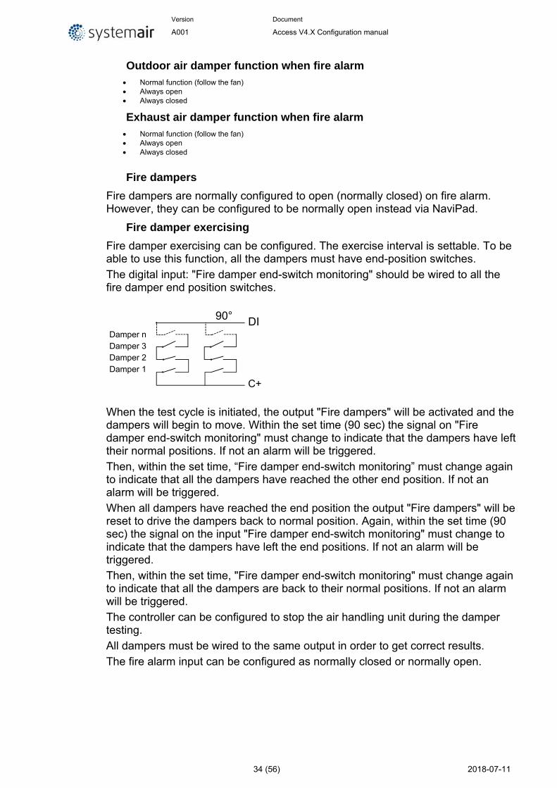
Fire damper exercising can be configured. The exercise interval is settable. To be able to use this function, all the dampers must have end-position switches.
The digital input: "Fire damper end-switch monitoring" should be wired to all the fire damper end position switches.
When the test cycle is initiated, the output "Fire dampers" will be activated and the dampers will begin to move. Within the set time (90 sec) the signal on "Fire damper end-switch monitoring" must change to indicate that the dampers have left their normal positions. If not an alarm will be triggered.
Then, within the set time, “Fire damper end-switch monitoring” must change again to indicate that all the dampers have reached the other end position. If not an alarm will be triggered.
When all dampers have reached the end position the output "Fire dampers" will be reset to drive the dampers back to normal position. Again, within the set time (90 sec) the signal on the input "Fire damper end-switch monitoring" must change to indicate that the dampers have left the end positions. If not an alarm will be triggered.
Then, within the set time, "Fire damper end-switch monitoring" must change again to indicate that all the dampers are back to their normal positions. If not an alarm will be triggered.
The controller can be configured to stop the air handling unit during the damper testing.
All dampers must be wired to the same output in order to get correct results.
The fire alarm input can be configured as normally closed or normally open.
90°
Damper n Damper 3 Damper 2 Damper 1
DI
C+
Version Document
A001 Access V4.X Configuration manual
35 (56) 2018-07-11
Smoke function
Configure: Configuration > Function Configuration > Fires/Smoke > Smoke function
Operation mode when smoke alarm Stopped Continuons run Running via normal start/stop conditions Supply air fan run Extract air fan run
Supply air fan setpoint type when smoke alarm Off/Auto normal setpoint Manual setpoint Manual outputs Low speed setpoint Normal speed setpoit High speed setpoint
Manual setpoint or output (supply air fan) 0..100% 0..
Version Document
A001 Access V4.X Configuration manual
36 (56) 2018-07-11
Extract air fan setpoint type when smoke alarm Off/Auto normal setpoint Manual setpoint Manual outputs Low speed setpoint Normal speed setpoit High speed setpoint
Manual setpoint or output (Extract air fan) 0..100% 0..
Outdoor air damper function when fire alarm Normal function (follow the fan) Always open Always closed
Exhaust air damper function when fire alarm Normal function (follow the fan) Always open Always closed
Operation settings: Data & Settings > Fire/Smoke
Humidity/Dehumidity Activate: Configuration > Function Configuration > Function Activation
No Humidity Dehumidity Humidity+Dehumidity
Configure: Configuration > Function Configuration > humidity/Dehumidity
Operation settings: Data & Settings > Humidity controller
General
Humidity control can be configured as Humidification, Dehumidification or both Humidification and Dehumidification.
Two humidity sensors can be connected, a room sensor for control and an optional duct sensor for maximum limiting. The limit sensor can be omitted.
The humidity control is handled by a PI-controller.
The humidity sensors must give 0…10 V DC for 0…100 % RH.
Humidification
An analogue output is used to control a humidifier. The output will increase on decreasing humidity. A digital output can also be used to start a humidifier.
Maximum limitation function using duct humidity sensor:
If the maximum limitation is 80 % RH and the hysteresis is 20 % RH, the controller output signal will begin decreasing at 60 % RH. When halfway to 80 % RH (i.e. when at 70 % RH), half the output signal will be damped. If the humidity in the duct still reaches 80 % RH, the entire output signal will be damped.
Version Document
A001 Access V4.X Configuration manual
37 (56) 2018-07-11
Dehumidification
An analogue output is used to control a dehumidifier. The output will increase on increasing humidity. A digital output can also be used to start a dehumidifier.
Humidification/dehumidification
An analogue output is used to control a humidifier. The output will increase on decreasing humidity.
The cooling output Y3 will be activated for dehumidification through condensation. The output will increase on increasing humidity. This signal overrides the cooling signal from the temperature controller so the output can be activated for dehumidification even if the temperature controller demand is zero.
For good temperature control when using cooling for dehumidification it is important that the cooler is placed first in the air stream so that the exchanger and heater can be used to reheat the air after dehumidification.
Digital humidity signal
A digital output signal, "Dehumidification/Humidification", can be used for on/off control of humidifiers/dehumidifiers. The output signal has an Activate value and a Deactivate value which are connected to the humidity controller output. The signal is activated when the humidity controller output rises above the set Activate value and is deactivated when the humidity controller output drops below the set Deactivate value.
If a start signal is needed for a cooling unit or a magnetic valve for DX dehumidification, the digital output signal “Start P1-Cooling” should be used. In this case, the “pump” stop delay should be set to 0 s.
Filter monitor Activate: Configuration > Function Configuration > Function Activation
No Yes
Configure: Configuration > Function Configuration > Filter monitor
Type DI Digital pressure guard AI Analog pressure transmitter
Placement Supply Extract Supply & Extract
Filter alarm reset No Yes Reset the calender counter.
Fiter alarm time (month) Time to next filter replacement
Analogue filter monitoring may be made air flow dependent. This means that a higher pressure drop is permitted across a filter at a higher air flow. For this purpose, X and Y coordinates are used to set the linear function that should be
Version Document
A001 Access V4.X Configuration manual
38 (56) 2018-07-11
followed at a pressure drop alarm. These are found under “Alarm configuration”. FS = X1:0 m3/h, Y1:10 Pa : X2:2000 m3/h, Y2:150 Pa.
If a constant pressure drop alarm level is wanted, Y1 and Y2 should be set to the same value.
Extended operation Activate: Configuration > function Configuration > Function Activation
No Yes
Configure: Configuration > function Configuration > Extended operation
Extended operation low No Yes
Extended operation normal No Yes
Extended operation high No Yes
Operation settings: Data & settings > Operation overview > Control overview
Extended operation
Actual level of digital inputs for Extended operation.
Extended operation conditions in priority
1. Extended operation high
2. Extended operation normal
3. Extended operation high
Extended operation time 0,30,60..
The unit will run for the set time. If the running time is set to 0 the unit will only run as long as the digital input is closed.
The time are “off delay time”
Extended operation time left
Run time left to end the extended operation
Pretreatment Activate: Configuration > Function Configuration > Function Activation
No Yes
Version Document
A001 Access V4.X Configuration manual
39 (56) 2018-07-11
Configue: Configuration > Function Configuration > Pretreatment
Pretreatment activation during free cooling No Yes
Control of dampers and pump for preheated or pre-cooled outdoor air via an underground intake channel. The digital output ”Pretreatment” is set to preheating when the unit is started and the outdoor temperature is below the set heating start limit (default 8°C) or to precooling when the outdoor temperature is above the set cooling start limit (default 19°C).
If the outdoor temperature exceeds the set heating start limit by more than 1°C (fixed), preheating will be aborted, as well as if the outdoor temperature falls below the cooling start limit by 1°C.
If a sensor is configured in the intake duct (”intaketemp”) this temperature will be compared with the outdoor temperature. If the temperature in the intake duct does not exceed the outdoor temperature by more than 1°C (adjustable) 5 minutes (adjustable) after start-up when using preheating, preheating will be aborted. The same conditions apply to precooling, i.e. if the intake temperature is not more than 1°C (adjustable) cooler than the outdoor temperature, precooling will be aborted.
Pretreatment always starts at start-up of the unit, if the outdoor temperature so permits. If pretreatment is aborted due to a small difference between the intake temperature and the outdoor temperature, pretreatment will be blocked for 6 hours. Then pretreatment will start (if the outdoor temperature so permits) and run for at least 5 minutes (adjustable)
Operation settings: Data & Settings > Temperature control > Pretreatment
Extra controller Activate: Configuration > Function Configuration > Function Activation
No Yes
Configure: Configuration > Function Configuration > Extra controller
Start/Stop function extra controller Off Always running Running if unit is running Defrosting
Control mode extra controller Heating Cooling
An independent temperature control circuit for control of for example after-heaters. The circuit can be configured to heating or cooling. It has an analogue input signal for temperature sensors and an analogue output signal 0…10 V. There is also a digital output signal which is activated when the analogue output signal is above 1 V and deactivated when the analogue signal is below 0.1 V. The circuit can be configured to be active all the time or to be active only when the main unit is running at normal speed.
Version Document
A001 Access V4.X Configuration manual
40 (56) 2018-07-11
The extra controller can also be used for humidity control. The cooling battery will be used for dehumidification if the room/extract air humidity is too high. The function uses the sensor “Extra unit temp” and is placed immediately after the cooling battery. The function also requires use of a room humidity or extract air humidity sensor.
Example:
If the room humidity exceeds the setpoint for the function, the cooling battery will be controlled by the external controller. The heater is controlled normally. When the room humidity falls below the setpoint once more, the cooling control will return to normal control. A hysteresis of 1 % is added to the function.
The function can be used for “Cascaded room temperature control”, “Cascade connected extract air temperature control”, “Outdoor compensated room temperature control” as well as “Outdoor compensated extract air control”.
An alarm will be triggered if “Extra controller” is in manual position or if a sensor error occurs.
Operation settings: Data & settings > Temperature control > Supply air controller
Setpoint extra controller 18 °C
Temperature extra controller Actual value for Extra temperature controller
External switch (External stop) Activate: Configuration > Function Configuration > Function Activation
No Yes
The signal “External stop” will stop the unit, even if the time channel or one of the signals “Extended Operation, Low, “Extended Operation, Normal” or “Extended Operation High” says it should stay in running mode.
External motor control Activate: Configuration > Function Configuration > Function Activation
No One fan control Two fan control
Extra fan motor control
Configure: Configuration > Function Configuration > Extra fan motor control
Motor control 1 None Motor protection Run indication
Mode motor control 1 Only Digital input Normal time channel
Version Document
A001 Access V4.X Configuration manual
41 (56) 2018-07-11
Extra time channel 4
Stop delay motor control 1 0.. s
Motor control 2 None Motor protection Run indication
Mode motor control 2 Only Digital input Normal time channel Extra time channel 4
Stop delay motor control 2 0.. s
Operation settings: Data & Settings > Fan control > Extra fan motor control
Damper Activate: Configuration > Function Configuration > Function Activation
None Outdoor Outdoor+Exhaust Exhaust
Outdoor damper follow supply air fan and exhaust damper follow extract air fan
Outdoor air damper stop delay
Operation settings: Data & Settings > Fan control > Supply air fan
0 s
Exhaust air damper stop delay
Operation settings: Data & Settings > Fan control > Exhaust air fan
0 s
Extra Indication & outputs Activate: Configuration > Function Configuration > Extra Indication & outputs
Extra time channel None 1 2 3 4
Note! Time channel 4 are used also for recirculation
Running indication No Yes
Version Document
A001 Access V4.X Configuration manual
42 (56) 2018-07-11
Alarm outputs None A/B-alarm 1 pcs Digital output A-alarm + B-alarm 2 pcs digital outputs A-alarm + B/C-alarm 2 pcs digital outputs
Alarm priorities
Alarms can be given different priority levels, A-alarm, B-alarm, C-alarm or not active. Digital outputs can be bound to act as alarm outputs for A/B-alarms on one digital output or both A- and B alarms (or B/C-alarm) on different digital ouptuts. The digital outputs can be inverted, so that an inoperative alarm gives a high output and vice versa. A- and B-alarms must be acknowledged to reset. C-alarms automatically reset as soon as there is no longer a cause for alarm.
Digital outputs
Selection A/B-alarm
A-alarm and B-alarm indicates on digital output Alarm 1
Selection A-alarm + B-alarm
A-alarm indicates on digital output Alarm 1
B-alarm indicates on digital output Alarm 2
Selection A-alarm + B/C-alarm
The A-alarm indicate on digital output Alarm 1
B-alarm and C-alarm indicate on digital output Alarm 2
Free cooling running No Yes
To use digital output too indicate when free cooling running.
Extra sensors & inputs Activate: Configuration > Function Configuration > Extra sensors & inputs
Alarm achnowledgement No Yes
Activate Digital input for remote control of acknowledgment
Extra temperature sensor None 1 2 3 4 5
The input signals ”Extra Sensor 1”, ”Extra Sensor 2”, ”...”, ”Extra Sensor 5”, can be used to add extra temperature sensors for supervision of temperatures that are not
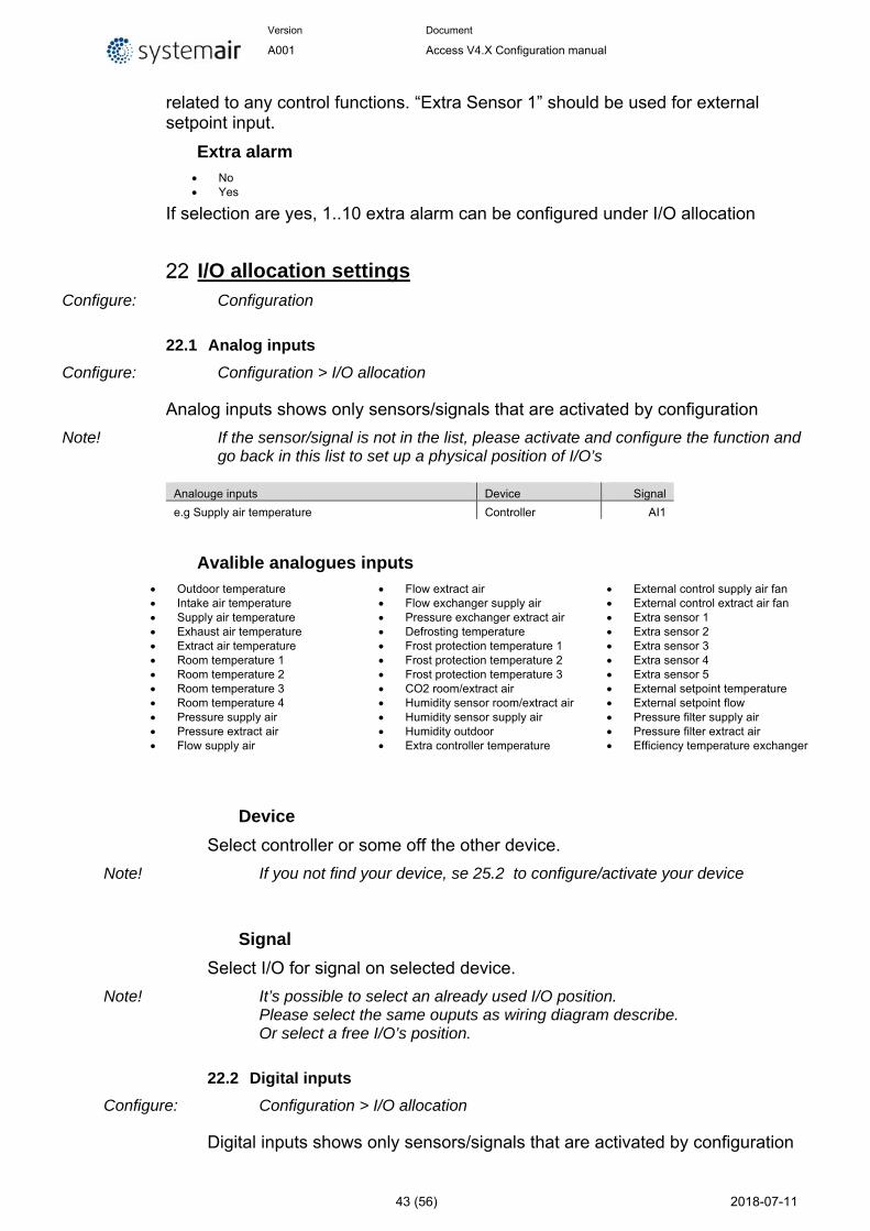
Version Document
A001 Access V4.X Configuration manual
43 (56) 2018-07-11
related to any control functions. “Extra Sensor 1” should be used for external setpoint input.
Extra alarm No Yes
If selection are yes, 1..10 extra alarm can be configured under I/O allocation
I/O allocation settings Configure: Configuration
22.1 Analog inputs
Configure: Configuration > I/O allocation
Analog inputs shows only sensors/signals that are activated by configuration
Note! If the sensor/signal is not in the list, please activate and configure the function and go back in this list to set up a physical position of I/O’s
Analouge inputs Device Signal
e.g Supply air temperature Controller AI1
Avalible analogues inputs Outdoor temperature Intake air temperature Supply air temperature Exhaust air temperature Extract air temperature Room temperature 1 Room temperature 2 Room temperature 3 Room temperature 4 Pressure supply air Pressure extract air Flow supply air
Flow extract air Flow exchanger supply air Pressure exchanger extract air Defrosting temperature Frost protection temperature 1 Frost protection temperature 2 Frost protection temperature 3 CO2 room/extract air Humidity sensor room/extract air Humidity sensor supply air Humidity outdoor Extra controller temperature
External control supply air fan External control extract air fan Extra sensor 1 Extra sensor 2 Extra sensor 3 Extra sensor 4 Extra sensor 5 External setpoint temperature External setpoint flow Pressure filter supply air Pressure filter extract air Efficiency temperature exchanger
Device
Select controller or some off the other device.
Note! If you not find your device, se 25.2 to configure/activate your device
Signal
Select I/O for signal on selected device.
Note! It’s possible to select an already used I/O position. Please select the same ouputs as wiring diagram describe. Or select a free I/O’s position.
22.2 Digital inputs
Configure: Configuration > I/O allocation
Digital inputs shows only sensors/signals that are activated by configuration
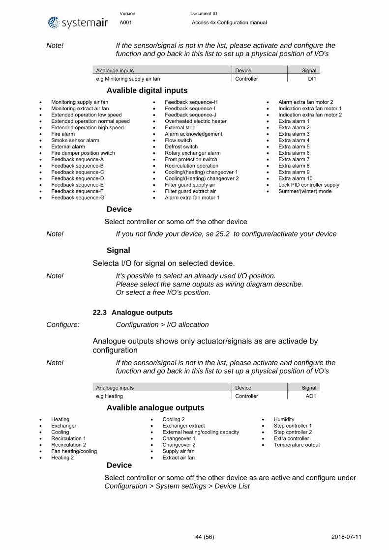
Version Document ID
A001 Access 4x Configuration manual
44 (56) 2018-07-11
Note! If the sensor/signal is not in the list, please activate and configure the function and go back in this list to set up a physical position of I/O's
Analouge inputs Device Signal
e.g Minitoring supply air fan Controller DI1
Avalible digital inputs Monitoring supply air fan Monitoring extract air fan Extended operation low speed Extended operation normal speed Extended operation high speed Fire alarm Smoke sensor alarm External alarm Fire damper position switch Feedback sequence-A Feedback sequence-B Feedback sequence-C Feedback sequence-D Feedback sequence-E Feedback sequence-F Feedback sequence-G
Feedback sequence-H Feedback sequence-I Feedback sequence-J Overheated electric heater External stop Alarm acknowledgement Flow switch Defrost switch Rotary exchanger alarm Frost protection switch Recirculation operation Cooling/(heating) changeover 1 Cooling/(Heating) changeover 2 Filter guard supply air Filter guard extract air Alarm extra fan motor 1
Alarm extra fan motor 2 Indication extra fan motor 1 Indication extra fan motor 2 Extra alarm 1 Extra alarm 2 Extra alarm 3 Extra alarm 4 Extra alarm 5 Extra alarm 6 Extra alarm 7 Extra alarm 8 Extra alarm 9 Extra alarm 10 Lock PID controller supply Summer/(winter) mode
Device
Select controller or some off the other device
Note! If you not finde your device, se 25.2 to configure/activate your device
Signal
Selecta I/O for signal on selected device.
Note! It’s possible to select an already used I/O position. Please select the same ouputs as wiring diagram describe. Or select a free I/O’s position.
22.3 Analogue outputs
Configure: Configuration > I/O allocation
Analogue outputs shows only actuator/signals as are activade by configuration
Note! If the sensor/signal is not in the list, please activate and configure the function and go back in this list to set up a physical position of I/O’s
Analouge inputs Device Signal
e.g Heating Controller AO1
Avalible analogue outputs Heating Exchanger Cooling Recirculation 1 Recirculation 2 Fan heating/cooling Heating 2
Cooling 2 Exchanger extract External heating/cooling capacity Changeover 1 Changeover 2 Supply air fan Extract air fan
Humidity Step controller 1 Step controller 2 Extra controller Temperature output
Device
Select controller or some off the other device as are active and configure under Configuration > System settings > Device List
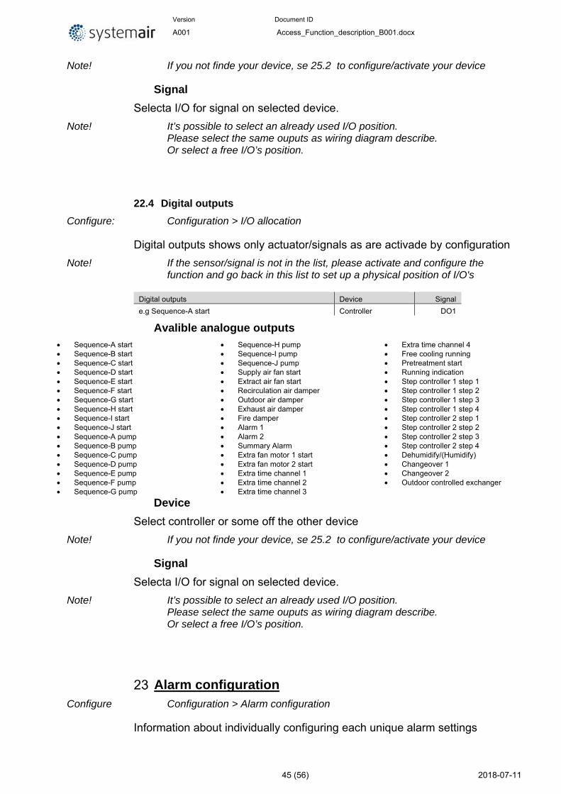
Version Document ID
A001 Access_Function_description_B001.docx
45 (56) 2018-07-11
Note! If you not finde your device, se 25.2 to configure/activate your device
Signal
Selecta I/O for signal on selected device.
Note! It’s possible to select an already used I/O position. Please select the same ouputs as wiring diagram describe. Or select a free I/O’s position.
22.4 Digital outputs
Configure: Configuration > I/O allocation
Digital outputs shows only actuator/signals as are activade by configuration
Note! If the sensor/signal is not in the list, please activate and configure the function and go back in this list to set up a physical position of I/O's
Digital outputs Device Signal
e.g Sequence-A start Controller DO1
Avalible analogue outputs Sequence-A start Sequence-B start Sequence-C start Sequence-D start Sequence-E start Sequence-F start Sequence-G start Sequence-H start Sequence-I start Sequence-J start Sequence-A pump Sequence-B pump Sequence-C pump Sequence-D pump Sequence-E pump Sequence-F pump Sequence-G pump
Sequence-H pump Sequence-I pump Sequence-J pump Supply air fan start Extract air fan start Recirculation air damper Outdoor air damper Exhaust air damper Fire damper Alarm 1 Alarm 2 Summary Alarm Extra fan motor 1 start Extra fan motor 2 start Extra time channel 1 Extra time channel 2 Extra time channel 3
Extra time channel 4 Free cooling running Pretreatment start Running indication Step controller 1 step 1 Step controller 1 step 2 Step controller 1 step 3 Step controller 1 step 4 Step controller 2 step 1 Step controller 2 step 2 Step controller 2 step 3 Step controller 2 step 4 Dehumidify/(Humidify) Changeover 1 Changeover 2 Outdoor controlled exchanger
Device
Select controller or some off the other device
Note! If you not finde your device, se 25.2 to configure/activate your device
Signal
Selecta I/O for signal on selected device.
Note! It’s possible to select an already used I/O position. Please select the same ouputs as wiring diagram describe. Or select a free I/O’s position.
Alarm configuration Configure Configuration > Alarm configuration
Information about individually configuring each unique alarm settings
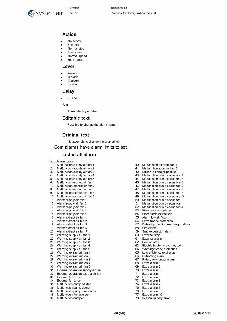
Version Document ID
A001 Access 4x Configuration manual
46 (56) 2018-07-11
Action No action Fast stop Normal stop Low speed Normal speed High speed
Level A-alarm B-alarm C-alarm disabel
Delay 0.. sec
No. Alarm identity number
Editable text Possible to change the alarm name
Original text Not possible to change the original text
Som alarms have alarm limits to set
List of all alarm ID Alarm name 1. Malfunction supply air fan 1 2. Malfunction supply air fan 2 3. Malfunction supply air fan 3 4. Malfunction supply air fan 4 5. Malfunction supply air fan 5 6. Malfunction extract air fan 1 7. Malfunction extract air fan 2 8. Malfunction extract air fan 3 9. Malfunction extract air fan 4 10. Malfunction extract air fan 5 11. Alarm supply air fan 1 12. Alarm supply air fan 2 13. Alarm supply air fan 3 14. Alarm supply air fan 4 15. Alarm supply air fan 5 16. Alarm extract air fan 1 17. Alarm extract air fan 2 18. Alarm extract air fan 3 19. Alarm extract air fan 4 20. Alarm extract air fan 5 21. Warning supply air fan 1 22. Warning supply air fan 2 23. Warning supply air fan 3 24. Warning supply air fan 4 25. Warning supply air fan 5 26. Warning extract air fan 1 27. Warning extract air fan 2 28. Warning extract air fan 3 29. Warning extract air fan 4 30. Warning extract air fan 5 31. External operation supply air fan 32. External operation extract air fan 33. External fan 1 run 34. External fan 2 run 35. Malfunction pump heater 36. Malfunction pump cooler 37. Malfunction pump exchanger 38. Malfunction fire damper 39. Malfunction damper
40. Malfunction external fan 1 41. Malfunction external fan 2 42. Error fire damper position 43. Malfunction pump sequence-A 44. Malfunction pump sequence-B 45. Malfunction pump sequence-C 46. Malfunction pump sequence-D 47. Malfunction pump sequence-E 48. Malfunction pump sequence-F 49. Malfunction pump sequence-G 50. Malfunction pump sequence-H 51. Malfunction pump sequence-I 52. Malfunction pump sequence-J 53. Filter alarm supply air 54. Filter alarm extract air 55. Alarm low air flow 56. Extra freeze protection 57. Defrost protection exchanger alarm 58. Fire alarm 59. Smoke detector alarm 60. External stop 61. External alarm 62. Service stop 63. Electric heater is overheated 64. Warning freeze protection 65. Low efficiency exchanger 66. Defrosting alarm 67. Rotary exchanger alarm 68. Extra alarm 1 69. Extra alarm 2 70. Extra alarm 3 71. Extra alarm 4 72. Extra alarm 5 73. Extra alarm 6 74. Extra alarm 7 75. Extra alarm 8 76. Extra alarm 9 77. Extra alarm 10 78. Internal battery error
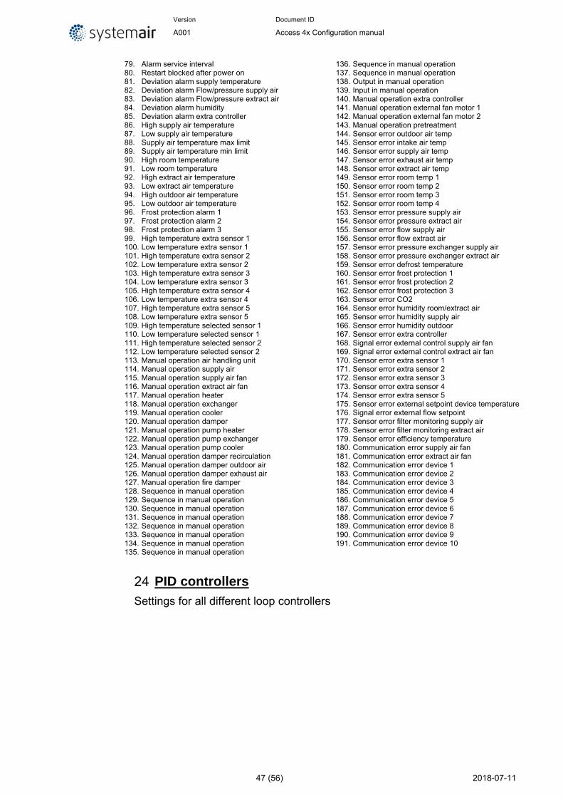
Version Document ID
A001 Access 4x Configuration manual
47 (56) 2018-07-11
79. Alarm service interval 80. Restart blocked after power on 81. Deviation alarm supply temperature 82. Deviation alarm Flow/pressure supply air 83. Deviation alarm Flow/pressure extract air 84. Deviation alarm humidity 85. Deviation alarm extra controller 86. High supply air temperature 87. Low supply air temperature 88. Supply air temperature max limit 89. Supply air temperature min limit 90. High room temperature 91. Low room temperature 92. High extract air temperature 93. Low extract air temperature 94. High outdoor air temperature 95. Low outdoor air temperature 96. Frost protection alarm 1 97. Frost protection alarm 2 98. Frost protection alarm 3 99. High temperature extra sensor 1 100. Low temperature extra sensor 1 101. High temperature extra sensor 2 102. Low temperature extra sensor 2 103. High temperature extra sensor 3 104. Low temperature extra sensor 3 105. High temperature extra sensor 4 106. Low temperature extra sensor 4 107. High temperature extra sensor 5 108. Low temperature extra sensor 5 109. High temperature selected sensor 1 110. Low temperature selected sensor 1 111. High temperature selected sensor 2 112. Low temperature selected sensor 2 113. Manual operation air handling unit 114. Manual operation supply air 115. Manual operation supply air fan 116. Manual operation extract air fan 117. Manual operation heater 118. Manual operation exchanger 119. Manual operation cooler 120. Manual operation damper 121. Manual operation pump heater 122. Manual operation pump exchanger 123. Manual operation pump cooler 124. Manual operation damper recirculation 125. Manual operation damper outdoor air 126. Manual operation damper exhaust air 127. Manual operation fire damper 128. Sequence in manual operation 129. Sequence in manual operation 130. Sequence in manual operation 131. Sequence in manual operation 132. Sequence in manual operation 133. Sequence in manual operation 134. Sequence in manual operation 135. Sequence in manual operation
136. Sequence in manual operation 137. Sequence in manual operation 138. Output in manual operation 139. Input in manual operation 140. Manual operation extra controller 141. Manual operation external fan motor 1 142. Manual operation external fan motor 2 143. Manual operation pretreatment 144. Sensor error outdoor air temp 145. Sensor error intake air temp 146. Sensor error supply air temp 147. Sensor error exhaust air temp 148. Sensor error extract air temp 149. Sensor error room temp 1 150. Sensor error room temp 2 151. Sensor error room temp 3 152. Sensor error room temp 4 153. Sensor error pressure supply air 154. Sensor error pressure extract air 155. Sensor error flow supply air 156. Sensor error flow extract air 157. Sensor error pressure exchanger supply air 158. Sensor error pressure exchanger extract air 159. Sensor error defrost temperature 160. Sensor error frost protection 1 161. Sensor error frost protection 2 162. Sensor error frost protection 3 163. Sensor error CO2 164. Sensor error humidity room/extract air 165. Sensor error humidity supply air 166. Sensor error humidity outdoor 167. Sensor error extra controller 168. Signal error external control supply air fan 169. Signal error external control extract air fan 170. Sensor error extra sensor 1 171. Sensor error extra sensor 2 172. Sensor error extra sensor 3 173. Sensor error extra sensor 4 174. Sensor error extra sensor 5 175. Sensor error external setpoint device temperature 176. Signal error external flow setpoint 177. Sensor error filter monitoring supply air 178. Sensor error filter monitoring extract air 179. Sensor error efficiency temperature 180. Communication error supply air fan 181. Communication error extract air fan 182. Communication error device 1 183. Communication error device 2 184. Communication error device 3 185. Communication error device 4 186. Communication error device 5 187. Communication error device 6 188. Communication error device 7 189. Communication error device 8 190. Communication error device 9 191. Communication error device 10
PID controllers
Settings for all different loop controllers
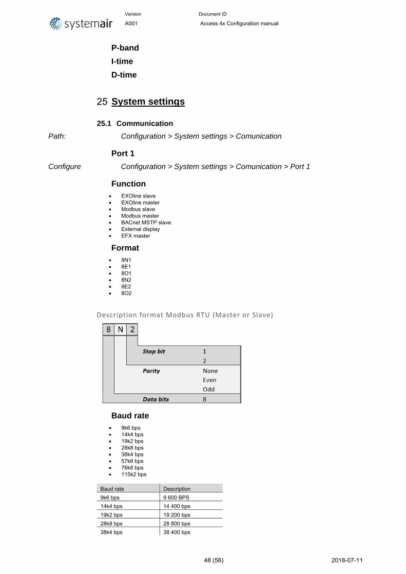
Version Document ID
A001 Access 4x Configuration manual
48 (56) 2018-07-11
P-band
I-time
D-time
System settings
25.1 Communication
Path: Configuration > System settings > Comunication
Port 1
Configure Configuration > System settings > Comunication > Port 1
Function EXOline slave EXOline master Modbus slave Modbus master BACnet MSTP slave External display EFX master
Format 8N1 8E1 8O1 8N2 8E2 8O2
Description format Modbus RTU (Master or Slave)
Baud rate 9k6 bps 14k4 bps 19k2 bps 28k8 bps 38k4 bps 57k6 bps 76k8 bps 115k2 bps
Baud rate Description
9k6 bps 9 600 BPS
14k4 bps 14 400 bps
19k2 bps 19 200 bps
28k8 bps 28 800 bps
38k4 bps 38 400 bps
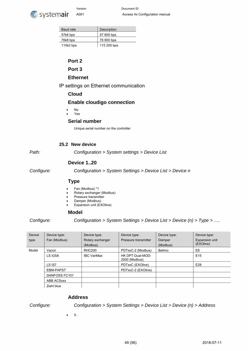
Version Document ID
A001 Access 4x Configuration manual
49 (56) 2018-07-11
Baud rate Description
57k6 bps 57 600 bps
76k8 bps 76 800 bps
115k2 bps 115 200 bps
Port 2
Port 3
Ethernet
IP settings on Ethernet communication
Cloud
Enable cloudigo connection No Yes
Serial number Unique serial number on the controller
25.2 New device
Path: Configuration > System settings > Device List
Device 1..20
Configure: Configuration > System Settings > Device List > Device n
Type Fan (Modbus) *1 Rotary exchanger (Modbus) Pressure transmitter Damper (Modbus) Expansion unit (EXOline)
Model
Configure: Configuration > System Settings > Device List > Device (n) > Type > ….
Device
type
Device type:
Fan (Modbus)
Device type:
Rotary exchanger
(Modbus)
Device type:
Pressure transmitter
Device type:
Damper
(Modbus)
Device type:
Expansion unit (EXOline)
Model Vacon RHC200 PDTxxC-2 (Modbus) Belimo E8
LS iG5A IBC VariMax HK DPT-Dual-MOD-2500 (Modbus)
E15
LS iS7 PDTxxC (EXOline) E28
EBM-PAPST PDTxxC-2 (EXOline)
DANFOSS FC101
ABB ACSxxx
Ziehl blue
Address
Configure: Configuration > System Settings > Device List > Device (n) > Address
0..
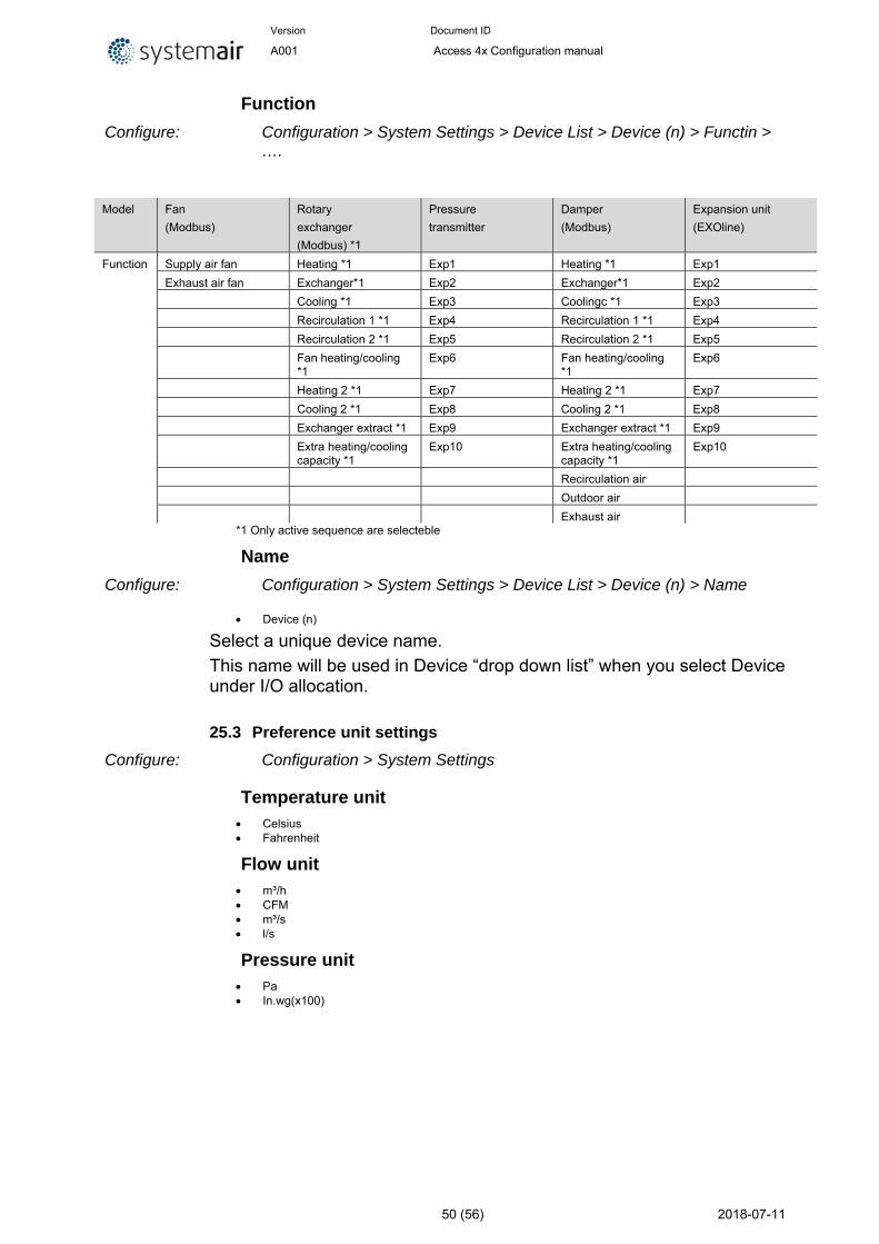
Version Document ID
A001 Access 4x Configuration manual
50 (56) 2018-07-11
Function
Configure: Configuration > System Settings > Device List > Device (n) > Functin > ….
Model Fan
(Modbus)
Rotary
exchanger
(Modbus) *1
Pressure
transmitter
Damper
(Modbus)
Expansion unit
(EXOline)
Function Supply air fan Heating *1 Exp1 Heating *1 Exp1
Exhaust air fan Exchanger*1 Exp2 Exchanger*1 Exp2
Cooling *1 Exp3 Coolingc *1 Exp3
Recirculation 1 *1 Exp4 Recirculation 1 *1 Exp4
Recirculation 2 *1 Exp5 Recirculation 2 *1 Exp5
Fan heating/cooling *1
Exp6 Fan heating/cooling *1
Exp6
Heating 2 *1 Exp7 Heating 2 *1 Exp7
Cooling 2 *1 Exp8 Cooling 2 *1 Exp8
Exchanger extract *1 Exp9 Exchanger extract *1 Exp9
Extra heating/cooling capacity *1
Exp10 Extra heating/cooling capacity *1
Exp10
Recirculation air
Outdoor air
Exhaust air *1 Only active sequence are selecteble
Name
Configure: Configuration > System Settings > Device List > Device (n) > Name
Device (n)
Select a unique device name.
This name will be used in Device “drop down list” when you select Device under I/O allocation.
25.3 Preference unit settings
Configure: Configuration > System Settings
Temperature unit Celsius Fahrenheit
Flow unit m³/h CFM m³/s l/s
Pressure unit Pa In.wg(x100)
Version Document ID
A001 Access 4x Configuration manual
51 (56) 2018-07-11
25.4 Save and restore
Activate: Configuration > System Settings
Save settings local No Yes
Commissioning settings can be stored in a local memory.
Reset settings to local No Yes
Reset to commissioning saved settings
Warning! All current value and settings will be lost when you do a “Total reset to settings to local”
Total restore to factory settings No Yes
Restore to factory delivered configuration settings
Warning! All current value and settings will be lost when you do a “Total restore to factory settings”
25.5 Software
Path: Configuration > System Settings
Software version 4.0-1-02 Build 2480
Version date 2018-06-15
Build version 2480
Version Document ID
A001 Access 4x Configuration manual
52 (56) 2018-07-11
Notes


Systemair Sverige AB
Industrivägen 3
SE-739 30 Skinnskatteberg, Sweden
Phone +46 222 440 00
Fax +46 222 440 99
www.systemair.com
Acc
ess
V4
.X C
onf
igu
ratio
n M
anua
l · 1
53
830
· e
n_
GB
· A
00
1
Related Documents