Access Control LCD Keypad Module with Built-in Reader (V2.0) DGP2-641R Reference and Installation Manual

Welcome message from author
This document is posted to help you gain knowledge. Please leave a comment to let me know what you think about it! Share it to your friends and learn new things together.
Transcript

DGP2641R_ei00.fm Page -3 Thursday, July 22, 2004 4:16 PM
Access Control LCD Keypad Module with Built-in Reader (V2.0)
DGP2-641R
Reference and Installation Manual
DGP-641

DGP2641R_ei00.fm Page -2 Thursday, July 22, 2004 4:16 PM

DGP2641R_ei00.fm Page -1 Thursday, July 22, 2004 4:16 PM
TABLE OF CONTENTS
1.0 INTRODUCTION ...........................................................11.1 Specifications .................................................................... 2
2.0 INSTALLATION .............................................................32.1 Mounting the DGP2-641R on Metal .................................. 42.2 Connecting Keypad Zones ................................................ 4
3.0 PROGRAMMING ..........................................................83.1 Entering Module Programming Mode ............................... 83.2 Programming Methods ...................................................... 9
3.2.1 Feature Select Programming .................................................93.2.2 Decimal Programming ...........................................................9
3.3 Module Broadcast ............................................................. 9
4.0 SYSTEM OPTIONS .....................................................104.1 Partition Assignment ....................................................... 104.2 Display Access Code Entry ............................................. 104.3 Display Exit Delay Timer ................................................. 104.4 Display Entry Delay Timer ............................................... 114.5 Confidential Mode ........................................................... 114.6 Confidential Mode Timer ................................................. 124.7 Time Display Option ........................................................ 124.8 Muting ............................................................................. 124.9 Beep on Exit Delay .......................................................... 134.10 Chime on Zone Closure ................................................ 134.11 Beep on Trouble ............................................................ 134.12 Keypad Tamper Enable ................................................ 144.13 Time Format .................................................................. 144.14 Combus Voltmeter ........................................................ 14
DGP2641R_ei00.fm Page 0 Thursday, July 22, 2004 4:16 PM
5.0 ACCESS CONTROL OPTIONS.................................. 155.1 Assigning Doors To Partitions ......................................... 155.2 Door Lock Options .......................................................... 16
5.2.1 Unlock on REX (Request For Exit) ...................................... 165.2.2 Door Unlocked Period ......................................................... 165.2.3 Door Unlocked Period Extension ........................................ 165.2.4 Relock Door ......................................................................... 175.2.5 Door Unlocked Schedule ..................................................... 175.2.6 Card Activates Door Unlocked Schedule ............................ 18
5.3 Door Left Open Options .................................................. 185.3.1 Door Left Open Access Alarm ............................................. 195.3.2 Door Left Open Interval Before Access Alarm .................... 195.3.3 Door Left Open Pre-Alarm ................................................... 195.3.4 Door Left Open Pre-Alarm Timer ........................................ 205.3.5 Door Left Open Alarm Feedback ......................................... 205.3.6 Beep Timer For Door Left Open Alarm ............................... 21
5.4 Door Forced Open Options ............................................. 215.4.1 Door Forced Open Access Alarm ........................................ 225.4.2 Door Forced Open Feedback .............................................. 225.4.3 Beep Timer For Door Forced Open Alarm .......................... 23
5.5 PIN Entry ON Keypad ..................................................... 23
6.0 MESSAGE PROGRAMMING ..................................... 24
7.0 PROGRAMMING SECTIONS ..................................... 27
8.0 GLOSSARY ................................................................ 31
9.0
DGP2641R_ei00.fm Page 1 Thursday, July 22, 2004 4:16 PM
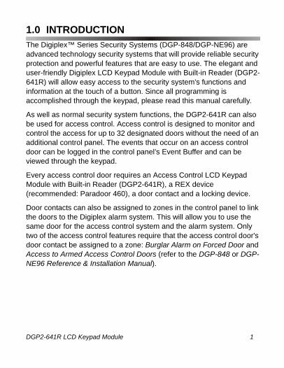
1.0 INTRODUCTIONThe Digiplex™ Series Security Systems (DGP-848/DGP-NE96) are advanced technology security systems that will provide reliable security protection and powerful features that are easy to use. The elegant and user-friendly Digiplex LCD Keypad Module with Built-in Reader (DGP2-641R) will allow easy access to the security system's functions and information at the touch of a button. Since all programming is accomplished through the keypad, please read this manual carefully.
As well as normal security system functions, the DGP2-641R can also be used for access control. Access control is designed to monitor and control the access for up to 32 designated doors without the need of an additional control panel. The events that occur on an access control door can be logged in the control panel’s Event Buffer and can be viewed through the keypad.
Every access control door requires an Access Control LCD Keypad Module with Built-in Reader (DGP2-641R), a REX device (recommended: Paradoor 460), a door contact and a locking device.
Door contacts can also be assigned to zones in the control panel to link the doors to the Digiplex alarm system. This will allow you to use the same door for the access control system and the alarm system. Only two of the access control features require that the access control door's door contact be assigned to a zone: Burglar Alarm on Forced Door and Access to Armed Access Control Doors (refer to the DGP-848 or DGP-NE96 Reference & Installation Manual).
DGP2-641R LCD Keypad Module 1n

DGP2641R_ei00.fm Page 2 Thursday, July 22, 2004 4:16 PM
1.1 SpecificationsPower input: 9 to 16 VDC, 100mA maximumPGM current limit: 50 mANumber of inputs: 2Power indication: Yellow LED onLocate indication: Green and yellow LEDs flash simultaneously Combus fault indication: Red and yellow LEDs flash alternately Tamper Switch: Yes (also used to deactivate locate)LCD: Super Twisted Nematic display (STN), wide
viewing angle, 2 lines of 16 characters, backlight and contrast adjustable
Read Range*: CR-R700 ISO PosiCard - up to 10cm (4”)CR-R704 Key Tag - up to 6cm (2.5”)
Frequency: Exciter field - 125 KHz Pulse ModulatedReceive Low Frequency - 12.500 KHzReceive High Frequency - 15.625 KHz
Compatibility: Any DGP-NE96 control panel or DGP-848 control panel V2.20ACC and higher
Specifications may change without prior notice.
* The specified read range assumes no electrical interference and that the card is presented parallel to the reader, with the reader installed and operated as outlined in this manual. The read range will vary depending on the type of card used. The larger the card, the greater the read range. The read range may decrease if the reader is mounted on metal.
2 Reference & Installation Manual

DGP2641R_ei00.fm Page 3 Thursday, July 22, 2004 4:16 PM
2.0 INSTALLATIONThe DGP2-641R is connected to the control panel's combus in a star and/or daisy chain configuration. This 4-wire combus provides power and two-way communication between the control panel and all modules connected to it. Connect the four terminals labeled red, black, green and yellow of each keypad to the corresponding terminals on the control panel (refer to Figure 1 on page 5). Refer to the DGP-848 or DGP-NE96 Reference & Installation Manual for the maximum allowable installation distance from the control panel.
See Figure 4 on page 7 for connection drawings for the REX device, locking device and door contact to the desired DGP2-641R keypad module. A typical installation is shown in Figure 2 on page 6.
The door contact follows the control panel’s EOL definition. When EOL is enabled and the door contact is not used, place a 1kΩ resistor across the keypad’s Z1 and BLK input terminals. If EOL is not enabled, use a jumper. If the REX device is not used, place a jumper across the keypad’s Z2 and BLK input terminals.
Please consider the following when installing the DGP2-641R:• Maintain all DGP2-641R wiring a minimum of 30cm (12”) away
from other wiring such as AC power, computer data wiring, telephone wiring, etc.
• Avoid installing within 1.1m (3.5ft.) of computer monitors or CRTs. The minimum distance will vary depending on the type of monitor or CRT.
• Avoid installing in proximity to sources of broad spectrum EMI noise such as motors, pumps, generators, DC to AC converters, uninterruptible power supplies, AC switching relays, light dimmers, computer monitors and CRTs.
• Avoid installing in proximity to potential sources of RF signal transmitters such as cellular phones, two-way radios, etc.
DGP2-641R LCD Keypad Module 3n

DGP2641R_ei00.fm Page 4 Thursday, July 22, 2004 4:16 PM
2.1 Mounting the DGP2-641R on MetalAlthough metal may decrease the read range of it’s built-in reader, the DGP2-641R can be mounted on metal. However, do not box in or surround the DGP2-641R with any kind of metal. If the keypad module must be installed in any kind of metal enclosure, ensure that the face of the DGP2-641R is not covered and that there is at least 4cm (1.6”) between the keypad module and the metal on all sides of the DGP2-641R.
2.2 Connecting Keypad ZonesEach keypad has one traditional hardwired input terminal, allowing you to connect one detector or door contact directly to the keypad. For example, a door contact located at the entry point of an establishment can be wired directly to the input terminal of the entry point keypad instead of wiring the door contact all the way to the control panel.
Connect the device to the keypad's input terminal as shown in Figure 1 on page 5. In order to communicate its status to the control panel, devices connected to the keypad's input terminal must be assigned to a zone in the control panel and the zone's parameters must be defined. For more information on zone assignment, please refer to the DGP-848 or DGP-NE96 Reference & Installation Manual. Please note that even with the ATZ (zone doubling) feature enabled, the keypad supports only one detection device.
4 Reference & Installation Manual

DGP2641R_ei00.fm Page 5 Thursday, July 22, 2004 4:16 PM
Figure 1: Connecting the Keypad and Keypad Zone
To Digiplex series
control panel
Combus
DGP2-641R
* The keypad zone follows the control panel’s EOL definition. The zone speed is set at 600mS and cannot be programmed.
Door ContactThe keypad’s tamper switch will communicate its status to the control panel via the combus.
DGP2-641R LCD Keypad Module 5n
DGP2641R_ei00.fm Page 6 Thursday, July 22, 2004 4:16 PM
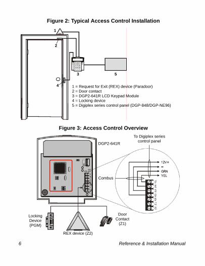
Figure 2: Typical Access Control Installation
Figure 3: Access Control Overview
1 = Request for Exit (REX) device (Paradoor)2 = Door contact3 = DGP2-641R LCD Keypad Module4 = Locking device5 = Digiplex series control panel (DGP-848/DGP-NE96)
5
4
3
1
2
Door Contact
(Z1)
Locking Device(PGM)
REX device (Z2)
DGP2-641R
Combus
To Digiplex series control panel
6 Reference & Installation Manual
DGP2641R_ei00.fm Page 7 Thursday, July 22, 2004 4:16 PM
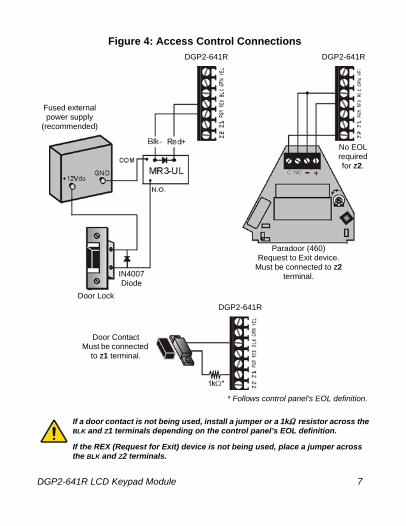
Figure 4: Access Control ConnectionsDGP2-641R DGP2-641R
Fused external power supply
(recommended)
Door Lock
IN4007Diode
DGP2-641R
Paradoor (460)Request to Exit device.
Must be connected to Z2 terminal.
If a door contact is not being used, install a jumper or a 1k resistor across the BLK and Z1 terminals depending on the control panel’s EOL definition.
If the REX (Request for Exit) device is not being used, place a jumper across the BLK and Z2 terminals.
Door ContactMust be connected
to Z1 terminal.
* Follows control panel’s EOL definition.
No EOL required for Z2.
DGP2-641R LCD Keypad Module 7n
DGP2641R_ei00.fm Page 8 Thursday, July 22, 2004 4:16 PM
3.0 PROGRAMMINGProgramming the DGP2-641R keypad module is simple. Enter Module Programming Mode, enter the desired section followed by the required data. When programming the keypad, use the keypad’s programming sheets (found in the Digiplex Series Modules’ Programming Guide) to keep track of which sections were programmed and how. We strongly recommend you read this entire manual before you begin programming.
This module can also be programmed using the WinLoad Installer Upload/Download Software. For more information, refer to the WinLoad instructions or visit our Web site at www.paradox.ca.
3.1 Entering Module Programming ModeThe keypad, like all other modules in the system, is programmed through the control panel. To do so, you must first enter Module Programming Mode:
1. From Normal Mode press and hold the [0] key.2. Enter the [INSTALLER CODE] (by default 000000).3. Enter section [953] (DGP-848) / [4003] (DGP-NE96).4. Enter the keypad’s 8-digit [SERIAL NUMBER].5. Enter the 3-digit [SECTION] you want to program.6. Enter the required [DATA].
The control panel will then redirect all programming to the selected keypad. Every time the [CLEAR] key is pressed it will revert to the preceding step, unless entering in data in which case it will erase the current data entry. Please note that the serial number is located on the keypad's PC board or enter section [000] in Step 3 to view the keypad’s serial number.
8 Reference & Installation Manual

DGP2641R_ei00.fm Page 9 Thursday, July 22, 2004 4:16 PM
3.2 Programming MethodsThe following methods can be used when programming the keypad:
3.2.1 Feature Select ProgrammingSome sections are programmed by enabling or disabling options. Within the sections, numbers from [1] to [8] represent a specific keypad option. Press the key corresponding to the desired option and the digit will appear in the display. This means the option is enabled. Press the key again to remove the digit from the display thereby disabling the option. Press [ENTER] when options are set.
3.2.2 Decimal ProgrammingSome sections require that a decimal value be entered. In this method, any digit from 000 to 255 can be entered.
3.3 Module BroadcastThe control panel’s Module Broadcast feature can be used to copy the contents of one keypad to one or many other keypads.
1. From Normal Mode press and hold the [0] key.2. Enter [INSTALLER CODE] (default: 000000).3. Enter section [954] (DGP-848) / [4004] (DGP-NE96).4. Enter the [SERIAL #] of the source keypad. The source is the
programmed keypad whose data you want to copy to other keypads.
5. Enter the [SERIAL #] of the destination keypads. The destination is the keypad(s) you want to program with the source’s data. If you want to program more than one keypad with the source’s data, enter the serial numbers of the keypads one at a time.
6. Once you have entered the serial numbers of the keypads you want to program, press the [ACC] key.
DGP2-641R LCD Keypad Module 9n

DGP2641R_ei00.fm Page 10 Thursday, July 22, 2004 4:16 PM
4.0 SYSTEM OPTIONS
4.1 Partition AssignmentSECTION [001]: OPTIONS [1] TO [8]Keypads in the system can be assigned to one or more partitions. Options [1] to [8] represent partitions 1 through 8 respectively. To assign the keypad to a partition, enable the option that corresponds to the desired partition. By default, partitions 1 to 8 are enabled.
Section [001] options [5] to [8] can only be used if the keypad is connected to a DGP-NE96 control panel.
4.2 Display Access Code EntrySECTION [003]: OPTION [1]The digits of the User Access Codes can be displayed on the LCD screen when they are entered.
Option [1] OFF= Digits are replaced by a “*“ (default)Option [1] ON = Access Code digits will be displayed
4.3 Display Exit Delay TimerSECTION [003]: OPTION [2]Based on the user's needs, an Exit Delay Timer will be programmed to provide the user time to exit the partition before the system is armed. The Exit Delay Timer's countdown can be displayed on the LCD screen.
Option [2] OFF= Will not display Exit Delay timer (default)Option [2] ON = LCD screen will display Exit Delay timer
10 Reference & Installation Manual
DGP2641R_ei00.fm Page 11 Thursday, July 22, 2004 4:16 PM
4.4 Display Entry Delay TimerSECTION [003]: OPTION [3]The Entry Delay Timer will be programmed to provide the user time to enter their User Access Code before the alarm is triggered. The Entry Delay Timer's countdown can be displayed on the LCD screen.
Option [3] OFF= Will not display the Entry Delay Timer (default)Option [3] ON = LCD screen will display Entry Delay Timer
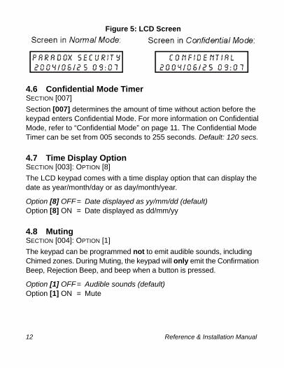
4.5 Confidential ModeSECTION [003]: OPTIONS [4] AND [5]If Confidential Mode is enabled and no actions are performed on the keypad for a period of time, the LCD will appear as shown in Figure 5 (page 12) and the “AC” and “STATUS” LED will be OFF. The period of time in which no action is performed is defined by the Confidential Mode Timer (005-255 seconds; refer to section 4.6 on page 12). Confidential Mode is activated by enabling option [4]. Option [5] regulates whether the LCD screen will be activated at the touch of a button or only when an access code is entered.
Once the LCD screen is activated (by code or button), Normal Mode will appear and display the date and time as shown in Figure 5 on page 12. The status of the areas, the open zones for every area the keypad is assigned, the Alarm Memory Display (if necessary) and the Trouble Display (if necessary. See DGP-848 or DGP-NE96 User Manual) will also scroll on the LCD screen. By default, options [4] and [5] are OFF.
Section [003]:Option [4] OFF= Normal ModeOption [4] ON = Confidential Mode
Option [5] OFF= LCD screen activated by entering an access codeOption [5] ON = LCD screen activated by pressing a button
DGP2-641R LCD Keypad Module 11n
DGP2641R_ei00.fm Page 12 Thursday, July 22, 2004 4:16 PM
Figure 5: LCD Screen
4.6 Confidential Mode TimerSECTION [007]Section [007] determines the amount of time without action before the keypad enters Confidential Mode. For more information on Confidential Mode, refer to “Confidential Mode” on page 11. The Confidential Mode Timer can be set from 005 seconds to 255 seconds. Default: 120 secs.
4.7 Time Display OptionSECTION [003]: OPTION [8]The LCD keypad comes with a time display option that can display the date as year/month/day or as day/month/year.
Option [8] OFF= Date displayed as yy/mm/dd (default)Option [8] ON = Date displayed as dd/mm/yy
4.8 MutingSECTION [004]: OPTION [1]The keypad can be programmed not to emit audible sounds, including Chimed zones. During Muting, the keypad will only emit the Confirmation Beep, Rejection Beep, and beep when a button is pressed.
Option [1] OFF= Audible sounds (default)Option [1] ON = Mute
12 Reference & Installation Manual
DGP2641R_ei00.fm Page 13 Thursday, July 22, 2004 4:16 PM
4.9 Beep on Exit DelaySECTION [004]: OPTION [2]The keypad can beep once every second during the Exit Delay Timer. During the final 10 seconds, it will beep more rapidly to provide a final warning before the area is armed.
Option [2] OFF= Exit Delay beep disabledOption [2] ON = Exit Delay beep enabled (default)
4.10 Chime on Zone Closure SECTION [004]: OPTION [4]During the Chime Zone Time Period that the user sets, the keypad can emit an intermittent beep whenever a zone with the Chime feature enabled closes (see DGP-848 or DGP-NE96 User Manual for details on Chime Zones). If the user does not set the Chime Zone Time Period and this option is enabled, the Chime Zones will always beep upon closure.
Option [4] OFF= Chime on Zone Closure disabled (default)Option [4] ON = Chime on Zone Closure enabled
4.11 Beep on TroubleSECTION [005]: OPTIONS [1] TO [4]Potential troubles have been sorted into groups. With these options enabled, the keypad will emit an intermittent beep tone whenever a trouble condition from the Trouble Groups occurs in the system. The intermittent beep will remain activated until the user enters the Trouble Display or if the trouble is resolved. For a list of the troubles, see the DGP-848 or DGP-NE96 Reference and Installation Manual. The intermittent beep will be re-initialized whenever the trouble condition re-occurs.
Option [1] OFF = Beep disabled: System Troubles and Clock LossOption [1] ON = Beep enabled: System Troubles and Clock Loss
DGP2-641R LCD Keypad Module 13n

DGP2641R_ei00.fm Page 14 Thursday, July 22, 2004 4:16 PM
Option [2] OFF= Beep disabled: Communicator TroublesOption [2] ON = Beep enabled: Communicator Troubles
Option [3] OFF= Beep disabled: Module and Combus TroublesOption [3] ON = Beep enabled: Module and Combus Troubles
Option [4] OFF= Beep disabled: all Zone TroublesOption [4] ON = Beep enabled: all Zone Troubles
4.12 Keypad Tamper EnableSECTION [006]: OPTION [5]With tamper enabled and the on-board tamper switch is triggered, a Tamper report will be sent to the control panel via the combus.
Option [5] OFF= Keypad's tamper is disabled (default)Option [5] ON = Keypad's tamper is enabled
4.13 Time FormatSECTION [005]: OPTION [7]This feature determines whether the time shown on the screen will be displayed using the International time format (24Hr. clock) or the US time format (AM/PM).
Option [7] OFF= Time uses the International time format (default).Option [7] ON = Time uses the US time format.
4.14 Combus VoltmeterThe combus voltmeter displays the real-time voltage and verifies if the combus is supplying sufficient power at the keypad module’s location. Readings will appear on the LCD screen. A reading of 10.5V indicates that the voltage is too low. This may occur when too many modules are connected to the combus, a module is installed too far from the panel or if the system is running on the battery. In some cases adding an
14 Reference & Installation Manual

DGP2641R_ei00.fm Page 15 Thursday, July 22, 2004 4:16 PM
external power supply may correct the situation.
1. From Normal Mode press and hold the [0] key.2. Enter the [INSTALLER CODE] (by default 000000).3. Press [ACC].
The voltage may drop during the control panel battery test.
5.0 ACCESS CONTROL OPTIONS
5.1 Assigning Doors To PartitionsSECTION [002]: OPTIONS [1] TO [8]Although the keypad can be programmed to display the status of various partitions, the Access Control door can be assigned to one or more partition(s) in the alarm system. This means that the actions performed with the Access Control Card will be directly linked to the partition(s) assigned to that door. For example, the keypad is assigned to all eight partitions (see section 4.1 on page 10), but the door is assigned to Partition 2. When the user presents the Access Control Card to the door's reader to arm the partition, only Partition 2 will arm.
Option [1] ON = Door assigned to Partition 1(default)Option [2] ON = Door assigned to Partition 2Option [3] ON = Door assigned to Partition 3Option [4] ON = Door assigned to Partition 4Option [5] ON = Door assigned to Partition 5 (DGP-NE96 only)Option [6] ON = Door assigned to Partition 6 (DGP-NE96 only)Option [7] ON = Door assigned to Partition 7 (DGP-NE96 only)Option [8] ON = Door assigned to Partition 8 (DGP-NE96 only)OFF = Access Control Cards will not be able to arm and/or
disarm partitions from the door's reader
DGP2-641R LCD Keypad Module 15n
DGP2641R_ei00.fm Page 16 Thursday, July 22, 2004 4:16 PM
5.2 Door Lock OptionsThe Door Lock Options allow you to program the door lock to suit its environment or security requirements.
5.2.1 Unlock on REX (Request For Exit)SECTION [006]: OPTION [8]When the REX device detects movement, it can permit passage with or without turning the door handle. If this option is on, the door is unlocked when the REX device detects movement and users on either side of the door will be able to open the door. If this option is off, the door will unlock once the handle is turned only on the REX device’s side.
Option [8] OFF = Unlock on REX disabled (default)Option [8] ON = Unlock on REX enabled
5.2.2 Door Unlocked PeriodSECTION [008]The Door Unlocked Period is the time the door can remain unlatched after access is granted or after a Request for Exit is received. Enter any value between 001 and 255 to determine the seconds the door can remain unlatched. Default = 5 secs.
5.2.3 Door Unlocked Period ExtensionSECTION [009]The Door Unlocked Period Extension is the amount of time added to the Door Unlocked Period in section [008], which leaves the door unlatched longer. This will allow those with this feature enabled on their User Access Codes extra time to enter, which may be useful for the physically challenged or for seniors. Enter any value between 001 and 255 to determine the number of seconds to be added to the time programmed in section [008]. Default = 15 secs.
16 Reference & Installation Manual
DGP2641R_ei00.fm Page 17 Thursday, July 22, 2004 4:16 PM
5.2.4 Relock DoorSECTION [006]: OPTION [6]The locking device will remain unlatched during the Door Unlocked Period (see section 5.2.2 on page 16), but once the door is opened it can be programmed to latch as soon as the door closes or latch immediately even if the door has not closed.
Option [6] OFF = Locking device latches immediately (default)Option [6] ON = Locking device latches when door closes
5.2.5 Door Unlocked ScheduleSECTION [017]The Door Unlocked Schedule determines the hours, days, and holidays that the door will remain unlocked. Therefore, users will not have to present their Access Control Cards to the reader in order to gain access to an Access Control Door during the Door Unlocked Schedule. The schedule consists of two programmable time periods called “Intervals” that determine the time of day and which days the users will be granted access. When a schedule is programmed with “H”, users will have access during the days programmed in the control panel (refer to the DGP-848 or DGP-NE96 Reference & Installation Manual).Program the Start Time and End Time according to the 24-hour clock within the same day. Use Feature Select Programming to set the options representing the Days.
Option Day Option Day[1] Sunday (S) [5] Thursday (T)[2] Monday (M) [6] Friday (F)[3] Tuesday (T) [7] Saturday (S)[4] Wednesday (W) [8] Holidays (H)
DGP2-641R LCD Keypad Module 17n

DGP2641R_ei00.fm Page 18 Thursday, July 22, 2004 4:16 PM
For example, program:• Interval A: Start time 07:00, End time 16:00, Days M, T, W,
T, & F• Interval B: Start time 10:00, End time 17:00, Days S, S, &
H
The door will stay unlocked on Monday, Tuesday, Wednesday, Thursday, and Friday between 7AM and 4PM and on Saturday, Sunday, and Holidays between 10AM and 5PM. Therefore, users will not have to present their Access Control Cards during the Door Unlocked Schedule.
5.2.6 Card Activates Door Unlocked ScheduleSECTION [006]: OPTION [1]When the Door Unlocked Schedule is programmed and this option is enabled, the door is locked until the first valid Access Control Card is presented. Once the door is unlocked, it will remain unlocked until the end of the schedule.Example: The schedule is 7AM to 5PM Monday to Friday, option [1] is enabled, and a valid Access Control Card is presented to the reader at 8AM on Monday. Although the schedule started at 7AM, the door remained locked from 7AM to 8AM. Once access was granted at 8AM, the door remained unlocked until 5PM.Option [1] OFF = The Schedule activates without CardOption [1] ON = Card activates Door Unlocked Schedule
(default)
5.3 Door Left Open OptionsThe Door Left Open Options allow you to program how the system will react to an Access Control door left open.
18 Reference & Installation Manual

DGP2641R_ei00.fm Page 19 Thursday, July 22, 2004 4:16 PM
5.3.1 Door Left Open Access AlarmSECTION [006]: OPTION [2]When an Access Control door is opened after an Access Granted or a Request for Exit, an Access Alarm can be generated if it is not closed within a certain period of time (see section 5.3.2 on page 19). When the Door Left Open Alarm is disabled, the following sections are also disabled:
Option [2] OFF = Door Left Open Alarm won’t be generated (default)
Option [2] ON = Door Left Open Alarm is enabled
5.3.2 Door Left Open Interval Before Access AlarmSECTION [010]The Door Left Open Interval is the time that a door can remain open after an Access Granted or a Request for Exit without generating an Access Alarm. Enter any value between 001 and 255 to determine the number of seconds the door may remain open before the Access Alarm is triggered. Default = 60 secs.
5.3.3 Door Left Open Pre-AlarmSECTION [004]: OPTION [3]If an Access Control door is programmed with a Door Left Open Interval (see section 5.3.2 above), the Pre-Alarm will cause the
Section[004] Option [3] Door Left Open Pre-alarm
Option [5] Door Left Open AlarmOption [6] Door Left Open Alarm follows
[010] Door Left Open Interval[011] Door Left Open Pre-alarm Timer[012] Beep Timer for Door Left Open Alarm
DGP2-641R LCD Keypad Module 19n
DGP2641R_ei00.fm Page 20 Thursday, July 22, 2004 4:16 PM
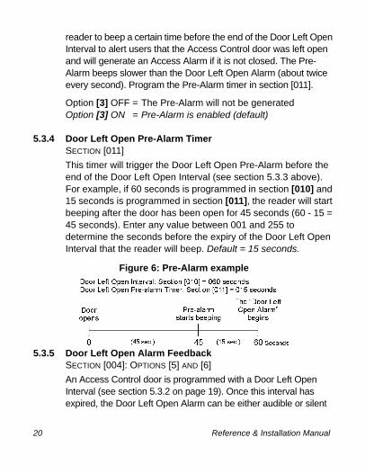
reader to beep a certain time before the end of the Door Left Open Interval to alert users that the Access Control door was left open and will generate an Access Alarm if it is not closed. The Pre-Alarm beeps slower than the Door Left Open Alarm (about twice every second). Program the Pre-Alarm timer in section [011].
Option [3] OFF = The Pre-Alarm will not be generatedOption [3] ON = Pre-Alarm is enabled (default)
5.3.4 Door Left Open Pre-Alarm TimerSECTION [011]This timer will trigger the Door Left Open Pre-Alarm before the end of the Door Left Open Interval (see section 5.3.3 above). For example, if 60 seconds is programmed in section [010] and 15 seconds is programmed in section [011], the reader will start beeping after the door has been open for 45 seconds (60 - 15 = 45 seconds). Enter any value between 001 and 255 to determine the seconds before the expiry of the Door Left Open Interval that the reader will beep. Default = 15 seconds.
Figure 6: Pre-Alarm example
5.3.5 Door Left Open Alarm FeedbackSECTION [004]: OPTIONS [5] AND [6]An Access Control door is programmed with a Door Left Open Interval (see section 5.3.2 on page 19). Once this interval has expired, the Door Left Open Alarm can be either audible or silent
20 Reference & Installation Manual
DGP2641R_ei00.fm Page 21 Thursday, July 22, 2004 4:16 PM
and will either beep as long as the Access Alarm is occurring or follow the Beep Timer in section [012]. The sound of the Door Left Open Alarm resembles the rapid beep generated during the last ten seconds of the Exit Delay. When the door is closed during an Access Alarm, the Door Left Open Restore event can be logged in the Event Buffer.
Option [5] OFF = The Door Left Open Alarm is silentOption [5] ON = The Door Left Open Alarm is audible (default)
If option [5] is enabled:Option [6] OFF = Beep as long as the Door Left Open Alarm is
occurring (default)Option [6] ON = Door Left Open Alarm follows Beep Timer
(section [012])
5.3.6 Beep Timer For Door Left Open AlarmSECTION [012]This beep timer determines the amount of time the Door Left Open Alarm will beep. Once the Door Left Open Interval (see section 5.3.2 on page 19) has expired, the Door Left Open Alarm (see section 5.3.5 on page 20) will be triggered. Enter any value between 001 and 255 to determine the number of seconds the Access Alarm will beep. Default = 5 seconds.
5.4 Door Forced Open OptionsThe Door Forced Open Options allow you to program how the system will react when an Access Control door is opened without a “Request for Exit” or “Access Granted” signal.
DGP2-641R LCD Keypad Module 21n
DGP2641R_ei00.fm Page 22 Thursday, July 22, 2004 4:16 PM
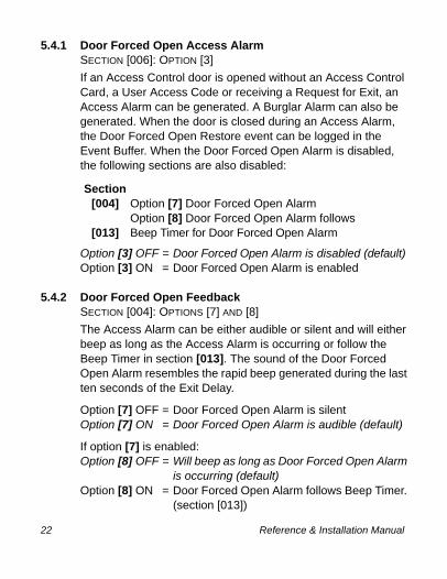
5.4.1 Door Forced Open Access AlarmSECTION [006]: OPTION [3]If an Access Control door is opened without an Access Control Card, a User Access Code or receiving a Request for Exit, an Access Alarm can be generated. A Burglar Alarm can also be generated. When the door is closed during an Access Alarm, the Door Forced Open Restore event can be logged in the Event Buffer. When the Door Forced Open Alarm is disabled, the following sections are also disabled:
Option [3] OFF = Door Forced Open Alarm is disabled (default)Option [3] ON = Door Forced Open Alarm is enabled
5.4.2 Door Forced Open FeedbackSECTION [004]: OPTIONS [7] AND [8]The Access Alarm can be either audible or silent and will either beep as long as the Access Alarm is occurring or follow the Beep Timer in section [013]. The sound of the Door Forced Open Alarm resembles the rapid beep generated during the last ten seconds of the Exit Delay.
Option [7] OFF = Door Forced Open Alarm is silentOption [7] ON = Door Forced Open Alarm is audible (default)
If option [7] is enabled:Option [8] OFF = Will beep as long as Door Forced Open Alarm
is occurring (default)Option [8] ON = Door Forced Open Alarm follows Beep Timer.
(section [013])
Section[004] Option [7] Door Forced Open Alarm
Option [8] Door Forced Open Alarm follows[013] Beep Timer for Door Forced Open Alarm
22 Reference & Installation Manual
DGP2641R_ei00.fm Page 23 Thursday, July 22, 2004 4:16 PM
5.4.3 Beep Timer For Door Forced Open AlarmSECTION [013]This Beep Timer determines the amount of time the Door Forced Open Alarm (see section 5.4.2 above) will beep. Enter any value between 001 and 255 to determine the number of seconds the Door Forced Open Alarm will beep. Default = 5 seconds.
5.5 PIN Entry ON KeypadSECTION [006]: OPTION [4]If the Card and Code Access option is enabled in the DGP-NE96 control panel (refer to the Access Control section in the DGP-NE96 Reference & Installation Manual), users must present their access control card and then enter their PIN on the DGP2-641R keypad to gain access. The PIN Entry on Keypad option cannot be turned ON and will always be OFF.
DGP2-641R LCD Keypad Module 23n

DGP2641R_ei00.fm Page 24 Thursday, July 22, 2004 4:16 PM
6.0 MESSAGE PROGRAMMINGSECTIONS [101] TO [396]Each section from [101] to [396] contains one message with a maximum of 16 characters. For more details and to record any changes, use the Digiplex Series Modules’ Programming Guide.
Section [101] to [148] = Zone 01 to Zone 48 respectivelySection [200] = Paradox FamilySection [201] to [204] = First, Second, Third, & Fourth Area (partition) respectivelySection [301] to [396] = Code 01 to Code 96 respectively
After entering the section corresponding to the desired message, the message can be re-programmed to suit your installation needs as detailed in Table 1. For example, section [101] “ZONE 01” can be changed to “FRONT DOOR”.
Table 1: Message Programming
Key Press Key Once
Press Key Twice
Press Key Three Times
[1] A B C[2] D E F[3] G H I[4] J K L[5] M N O[6] P Q R[7] S T U[8] V W X[9] Y Z
Also, see special functions on the next page.
24 Reference & Installation Manual
DGP2641R_ei00.fm Page 25 Thursday, July 22, 2004 4:16 PM
The DGP-NE96 control panel has up to 8 partitions, 96 zones and up to 999 user codes. This LCD keypad module only allows you to program the messages for up to 4 partitions, 48 zones and 96 user codes. The rest of the messages can be programmed directly into the DGP-NE96 control panel. Refer to the DGP-NE96 Reference & Installation Manual and to the DGP-NE96 Programming Guide for more details.
[STAY] - Insert SpacePressing the [STAY] key inserts a blank space in the current cursor position.
[FORCE] - DeletePressing the [FORCE] key will delete the character or blank space found at the current cursor position.
[ARM] - Delete Until the EndPressing the [ARM] key will delete all characters and spaces to the right of the cursor and at the cursor's position.
[DISARM] - Numeric Keys / Alphanumeric KeysEvery time the [DISARM] key is pressed it will toggle numeric keys to alphanumeric keys and vice versa. Numeric: Keys [0] to [9] represent numbers 0 to 9.
[BYP] - Lower Case / Upper CaseEvery time the [BYP] key is pressed it will toggle the case setting from lower to upper case and vice versa.
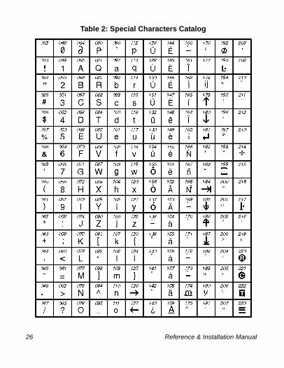
[MEM] - Special Characters After pressing the [MEM] key, the cursor will turn into a flashing black square. Using Table 2 on the following page, enter the 3-digit number that represents the desired symbol.
DGP2-641R LCD Keypad Module 25n
DGP2641R_ei00.fm Page 26 Thursday, July 22, 2004 4:16 PM
Table 2: Special Characters Catalog
26 Reference & Installation Manual

DGP2641R_ei00.fm Page 27 Thursday, July 22, 2004 4:16 PM
7.0 PROGRAMMING SECTIONS
= Default settingSECTION [001]: Keypad Partition Assignment
Option OFF ON
[1] Partition 1 Disabled Enabled[2] Partition 2 Disabled Enabled[3] Partition 3 Disabled Enabled[4] Partition 4 Disabled Enabled[5] Partition 5 (DGP-NE96 only) Disabled Enabled[6] Partition 6 (DGP-NE96 only) Disabled Enabled[7] Partition 7 (DGP-NE96 only) Disabled Enabled[8] Partition 8 (DGP-NE96 only) Disabled Enabled
SECTION [002]: Assigning Doors to Partitions
Option OFF ON
[1] Door Assigned to Partition 1 Disabled Enabled[2] Door Assigned to Partition 2 Disabled Enabled
[3] Door Assigned to Partition 3 Disabled Enabled
[4] Door Assigned to Partition 4 Disabled Enabled
[5] Door Assigned to Partition 5(DGP-NE96 only)
Disabled Enabled
[6] Door Assigned to Partition 6(DGP-NE96 only)
Disabled Enabled
[7] Door Assigned to Partition 7(DGP-NE96 only)
Disabled Enabled
[8] Door Assigned to Partition 8(DGP-NE96 only)
Disabled Enabled
DGP2-641R LCD Keypad Module 27n

DGP2641R_ei00.fm Page 28 Thursday, July 22, 2004 4:16 PM
= Default settingSECTION [003]: General Options 1
Option OFF ON
[1] Display code entry Disabled Enabled
[2] Display exit delay Disabled Enabled
[3] Display entry delay Disabled Enabled
[4] Confidential Mode(not for UL installations)
Disabled Enabled
[5] To exit Confidential Mode Enter code Press button
[6] Future use N/A N/A
[7] Future use N/A N/A
[8] Time display option yy/mm/dd dd/mm/yy
SECTION [004]: General Options 2
Option OFF ON
[1] Muting Disabled Enabled
[2] Exit Delay Beep Disabled Enabled[3] Door Left Open Pre-Alarm Disabled Enabled[4] Chime on Zone Closure Disabled Enabled
[5] Door Left Open Alarm Feedback Silent Audible[6] Door Left Open Alarm Follows Alarm
restoreBeep Timer
[7] Door Forced Alarm Silent Audible[8] Door Forced Alarm Alarm
restoreBeep Timer
28 Reference & Installation Manual
DGP2641R_ei00.fm Page 29 Thursday, July 22, 2004 4:16 PM
= Default setting
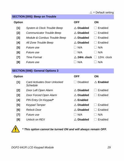
* This option cannot be turned ON and will always remain OFF.
SECTION [005]: Beep on Trouble
Option OFF ON
[1] System & Clock Trouble Beep Disabled Enabled
[2] Communicator Trouble Beep Disabled Enabled
[3] Module & Combus Trouble Beep Disabled Enabled
[4] All Zone Trouble Beep Disabled Enabled
[5] Future use N/A N/A
[6] Future use N/A N/A
[7] Time Format 24Hr. clock 12Hr. clock
[8] Future use N/A N/A
SECTION [006]: General Options 3
Option OFF ON
[1] Card Activates Door Unlocked Schedule
Disabled Enabled
[2] Door Left Open Alarm Disabled Enabled
[3] Door Forced Open Alarm Disabled Enabled
[4] PIN Entry On Keypad* Enabled[5] Keypad Tamper Disabled Enabled
[6] Relock Door Disabled Enabled
[7] Future use N/A N/A
[8] Unlock on REX Disabled Enabled
DGP2-641R LCD Keypad Module 29n
DGP2641R_ei00.fm Page 30 Thursday, July 22, 2004 4:16 PM
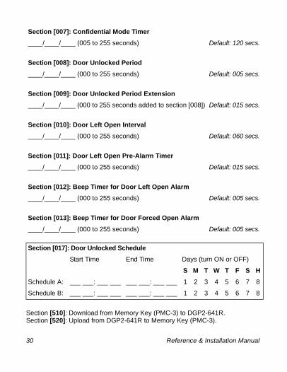
Section [510]: Download from Memory Key (PMC-3) to DGP2-641R.Section [520]: Upload from DGP2-641R to Memory Key (PMC-3).
Section [007]: Confidential Mode Timer____/____/____ (005 to 255 seconds) Default: 120 secs.
Section [008]: Door Unlocked Period____/____/____ (000 to 255 seconds) Default: 005 secs.
Section [009]: Door Unlocked Period Extension____/____/____ (000 to 255 seconds added to section [008]) Default: 015 secs.
Section [010]: Door Left Open Interval____/____/____ (000 to 255 seconds) Default: 060 secs.
Section [011]: Door Left Open Pre-Alarm Timer____/____/____ (000 to 255 seconds) Default: 015 secs.
Section [012]: Beep Timer for Door Left Open Alarm____/____/____ (000 to 255 seconds) Default: 005 secs.
Section [013]: Beep Timer for Door Forced Open Alarm____/____/____ (000 to 255 seconds) Default: 005 secs.
Section [017]: Door Unlocked ScheduleStart Time End Time Days (turn ON or OFF)
S M T W T F S HSchedule A: ___ ___: ___ ___ ___ ___: ___ ___ 1 2 3 4 5 6 7 8
Schedule B: ___ ___: ___ ___ ___ ___: ___ ___ 1 2 3 4 5 6 7 8
30 Reference & Installation Manual
DGP2641R_ei00.fm Page 31 Thursday, July 22, 2004 4:16 PM
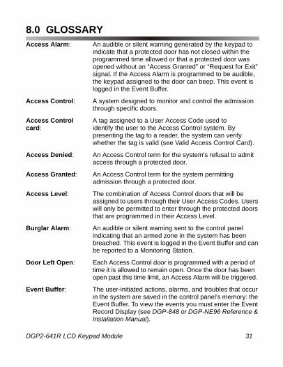
8.0 GLOSSARYAccess Alarm: An audible or silent warning generated by the keypad to
indicate that a protected door has not closed within the programmed time allowed or that a protected door was opened without an “Access Granted” or “Request for Exit” signal. If the Access Alarm is programmed to be audible, the keypad assigned to the door can beep. This event is logged in the Event Buffer.
Access Control: A system designed to monitor and control the admission through specific doors.
Access Control A tag assigned to a User Access Code used tocard: identify the user to the Access Control system. By
presenting the tag to a reader, the system can verify whether the tag is valid (see Valid Access Control Card).
Access Denied: An Access Control term for the system’s refusal to admit access through a protected door.
Access Granted: An Access Control term for the system permitting admission through a protected door.
Access Level: The combination of Access Control doors that will be assigned to users through their User Access Codes. Users will only be permitted to enter through the protected doors that are programmed in their Access Level.
Burglar Alarm: An audible or silent warning sent to the control panel indicating that an armed zone in the system has been breached. This event is logged in the Event Buffer and can be reported to a Monitoring Station.
Door Left Open: Each Access Control door is programmed with a period of time it is allowed to remain open. Once the door has been open past this time limit, an Access Alarm will be triggered.
Event Buffer: The user-initiated actions, alarms, and troubles that occur in the system are saved in the control panel’s memory: the Event Buffer. To view the events you must enter the Event Record Display (see DGP-848 or DGP-NE96 Reference & Installation Manual).
DGP2-641R LCD Keypad Module 31n

DGP2641R_ei00.fm Page 32 Thursday, July 22, 2004 4:16 PM
Forced Door: If a protected door was opened without an “Access Granted” or “Request for Exit” signal, a silent or audible Access Alarm can be triggered. If the Access Alarm is programmed to be audible, the reader assigned to the door can beep. This event is logged in the Event Buffer and cannot be reported to a Monitoring Station unless the door is also assigned to a zone. If the door is assigned to a zone, the Forced Door can also trigger a Burglar Alarm in the system.
Holidays: Days programmed in the control panel that are not considered normal work days, such as legal, religious, and feast days.
Pre-Alarm: A beep tone warning that an Access Alarm will be generated if a protected door is not closed within a specified period.
Reader: An Access Control device normally located near a protected door that serves to relay the information from an Access Control card presented to it to the control panel. The DGP2-641R has a reader built in and does not require an external reader.
Request for Exit: When a REX device (Paradoor 460) installed above an Access Control door within a protected area detects movement, it sends a signal to the control panel to permit a user to leave the protected area. This signal is a “Request for Exit” event that is logged in the Event Buffer and cannot be reported to a Monitoring Station.
Schedule: Schedules determine the hours, days, and holidays that users are permitted access.
Valid Card: An Access Control card presented to the keypad during its assigned Schedule and within its assigned Access Level.
32 Reference & Installation Manual
DGP2641R_ei00.fm Page 33 Thursday, July 22, 2004 4:16 PM
WarrantyParadox Security Systems Ltd. (“Seller”) warrants its products to be free from defects in materials and workmanship under normal use for a period of one year. Except as specifically stated herein, all express or implied warranties whatsoever, statutory or otherwise, including without limitation, any implied warranty of merchantability and fitness for a particular purpose, are expressly excluded. Because Seller does not install or connect the products and because the products may be used in conjunction with products not manufactured by Seller, Seller cannot guarantee the performance of the security system and shall not be responsible for circumstances resulting from the product’s inability to operate. Seller obligation and liability under this warranty is expressly limited to repairing or replacing, at Seller's option, any product not meeting the specifications. Returns must include proof of purchase and be within the warranty period. In no event shall the Seller be liable to the buyer or any other person for any loss or damages whether direct or indirect or consequential or incidental, including without limitation, any damages for lost profits stolen goods, or claims by any other party, caused by defective goods or otherwise arising from the improper, incorrect or otherwise faulty installation or use of the merchandise sold.
Notwithstanding the preceding paragraph, the Seller’s maximum liability will be strictly limited to the purchase price of the defective product. Your use of this product signifies your acceptance of this warranty.
*BEWARE: Dealers, installers and/or others selling the product are not authorized to modify this warranty or make additional warranties that are binding on the Seller.
© 2004 Paradox Security Systems Ltd.
Digiplex is a trademarks and/or registered trademarks of Paradox Security Systems Ltd. and its affiliates in Canada, the United States and other countries. All rights reserved.
DGP2-641R LCD Keypad Module 33n

DGP2641R_ei00.fm Page 34 Thursday, July 22, 2004 4:16 PM
NOTES
34 Reference & Installation Manual

DGP2641R_ei00.fm Page 35 Thursday, July 22, 2004 4:16 PM

DGP2641R_ei00.fm Page 36 Thursday, July 22, 2004 4:16 PM
Printed in Canada - 07/2004 DGP2641R-EI00
Related Documents