Acceptance Test for Large Biomass Gasifiers By: G.H. Huisman Huisman Thermal Engineer & Consultant P.O. Box 75 4380 AB Vlissingen The Netherlands This report has been prepared with support of NOVEM, the Dutch Organisation for Energy and Environment Summary For a numbers of years now the interest in the gasification of biomass, as technology to supply our future renewable energy, has been increasing. A numbers of different technologies have been developed over the years, pilot plants and some commercial demonstration plants have been built and are currently under evaluation. There is still a long road ahead for further development and optimization of the technology to a level that it is reliable, efficient and with an investment cost that matches the commercial supply and demand requirements for power and heat.

Welcome message from author
This document is posted to help you gain knowledge. Please leave a comment to let me know what you think about it! Share it to your friends and learn new things together.
Transcript

Acceptance Test for Large Biomass Gasifiers
By: G.H. Huisman
Huisman Thermal Engineer & Consultant P.O. Box 75
4380 AB Vlissingen The Netherlands
This report has been prepared with support of NOVEM, the Dutch Organisation for Energy and Environment Summary For a numbers of years now the interest in the gasification of biomass, as technology to supply our future renewable energy, has been increasing. A numbers of different technologies have been developed over the years, pilot plants and some commercial demonstration plants have been built and are currently under evaluation. There is still a long road ahead for further development and optimization of the technology to a level that it is reliable, efficient and with an investment cost that matches the commercial supply and demand requirements for power and heat.

In this field of developing technology there should be independent guidelines and codes on how to test these novel power plants as with any power plant or part of a plant (i.e. boiler). In the past these codes have been available (i.e. ANSI PTC16-1974) but these have been withdrawn without replacement. Recently a team was formed to develop a test code for the entire IGCC power plant, including air separation, gasification and gas- and steam turbine (ASME Performance Test Code 47). Within the IEA Task 20 Gasification of Biomass it had been decided to pay some attention to developing standards in general and in particular developing a test protocol for the acceptance of gasifiers. This work has lead to this (draft) report that describes some aspect of testing and a draft procedure on how one could use the measured values for the calculation of the efficiency, probably the parameter of highest interest. It should be remembered that this is a draft and a proposal, one of the more important aspects of standard protocols is that they should be widely tested and accepted by suppliers and purchasers of equipment (gasification systems). This requires input of all those parties over a long period of time for matters to get settled. In this document some aspects of a test protocol will be discussed and a proposal is made to use the maximum amount of available measured parameters in order to increase the accuracy of the calculation. It is also suggested that the use of a model may be of use for determining the best and most accurate strategy for the determination of efficiency and other parameters. This has been suggested within the team developing the PTC 47 but could equally well be used for only the gasifier. The draft protocol in annex 2 is not completed yet, it lacks versatility in the sense that no allowance has been made for application to gasification systems other than air blown CFB reactors. In particular a modification should be made for systems like FERCO Sylvagas (formerly Batelle process) and others. It is expected that this will be incorporated in follow-on efforts which will be dependent on continuing sipport. In the mean time comments that help to improve the protocol, additional technical information (gas properties with reference etc.) or literature on the subject should be directed to Mr. Kees Kwant, NOVEM.

Acceptance Test of Large Biomass Gasifiers Summary............................................................................................................. 2 Introduction....................................................................................................4 Objective.....................................................................................................5 System definition........................................................................................6 Development of a Protocol for testing of Large Biomass Gasifiers..........7 Acceptance tests in General......................................................................7 Guidelines and thoughts for developing of Large Biomass Gasifiers..8 Cold gas efficiency...................................................................................11 “Modified Heat loss” Methods.....................................................13 General Comments on Paramters and Measurements........................16 Wood fuel........................................................................................16 Air....................................................................................................17 Ash...................................................................................................18 Gas...................................................................................................19 Radiated Heat loss.........................................................................19 Recovered Heat..............................................................................20 Rejected Heat.................................................................................20 Accuracy.........................................................................................20 Summary of Properties of gases.......................................................................21 Literature Annexes Address: G.H. Huisman Huisman Thermal Engineer & Consultant P.O. Box 75 4380 AB Vlissingen The Netherlands e-mail: [email protected]

Introduction The IEA Task 20 “Thermal Gasification of Biomass“ has decided to start working on the development of test protocols in general (i.e. sampling and testing and analysis of tars, under development). In March 1998 it was decide in Brussels to include the development of a test protocol for the acceptance of both large and small-scale biomass gasifiers. This document describes the efforts undertaken to develop the protocol for large-scale gasifiers. There is, however, similarity between small and large-scale gasifiers and the protocol could probably equally well be used for smaller gasifiers with appropriate modifications. Since the Brussels meeting the focus has been on the investigation of available standards in the world and a questionnaire was sent out to developers of gasification technology and plant owners in order to find out if any practical and recent experience do exist. At the Dublin meeting in the fall of 1998 it has been decided to develop a standard parallel to existing standards for steam generators. Meanwhile it appeared that at least one standard, specifically for gas producers, existed. It was then proposed to change the strategy and use a mix of existing (modern) standards for steam generators and (old) standards for gas producers The ANSI PTC 16-1974 “Power Test Code for Gas Producers and Continuous Gas Generators” [1], was the only available code for gasifiers. The code had been withdrawn, however, without replacement and since this was prepared in 1958 with only reaffirmation in 1971, it is considered to be out dated. In the United Kingdom a British Standard BS 995, “Test Code for Gas Producer” [3] has been developed but this standard was also withdrawn without replacement and actually until now no copy could be obtained. Other important documentation that can provide valuable information and guidelines for procedures are acceptance “DIN 1942, Acceptance Test Code for Steam Generators, 1994” [4] and “ASME PTC 4.1, Power Test Code for Steam Generating Units, 1965” [5] Recently it was learnt that the ASME Performance Test Code 47 (PTC) for Integrated Gasification Combined Cycle, IGCC plants, was being written. This code will include definitions of the significant overall plant component performance results, input, output and effectiveness. Also codes for the associated subsets will be written to provide owners and users of IGCC power plants guidance and procedures in conducting the performance test and evaluating the deviation of its various units from specified guarantees. The following codes are being developed in this program: PTC47 Performance test code needs of an overall IGCC as a single block, thus
ignoring the performance related integration between its various units PTC47.1 Cryogenic air separation PTC47.2 Gasification unit PTC47.3 Fuel gas cleaning unit PTC47.4 IGCC power block unit The work of the committee was initiated in 1993 and a review draft is expected around 2001.
This raises, however, also the question for the current task, how much effort really is needed to develop a standard in parallel to the PTC47 activity. The PTC47 will be developed mainly for coal fired units but also a wide range of other fuels can be used in the gasifiers and actually these feedstock have not been ruled out from the protocol. The new standard will be quite comprehensive and could probably equally well be used without any modification at all for biomass fuelled gasifiers and associated equipment. The added value of the current work will in any case at least be (biomass) fuel specific and it has therefore viable reasons to continue. Without doubt, however, the PTC47 work should be followed closely and if the development of a standard is lifted to European or ISO level then the work already done for the PTC47 might well be the starting point. For further reference on the PTC47 work see [6]-[10]. Objective The objective of the activity was defined as: Development of a standard test protocol for the evaluation of large biomass fuelled gasifiers. The purpose of the protocol is to decrease the level of uncertainty between vendor and purchaser of gasification equipment by providing a standard and widely accepted document on parameters to be tested and procedures to use. It should be appreciated that normally this procedure, the preparation of International (ISO) or European standards, takes a number of years (see PTC47 schedule) which is too long for the current Task. The formulation of an acceptance test is in fact a “Daunting” task as pointed out by Horazak and Archer [6], complicated by the inherent complexity of the IGCC and the unlikely possibility of conducting actual tests under the specified conditions. Also there should be ample input from national and international industry and institutes in order to provide a good basis for wide acceptance amongst suppliers and users of the equipment (i.e. mirror committees). The first phase in the development of a standard could, however, be to develop the technical basis for further use in a future standardization process, this will now be the aim of this work. The typical stages in the European (CEN) Standardisation process are: programming drafting adoption transposition The aim should therefore be limited for the moment on the development of a draft protocol without giving too much attention to the fact that eventually every detail of the testing process should be covered. In a later stage it can be discussed how to proceed from this result to a stage where, for instance, an ISO Standard for the acceptance test of large gasifiers can be developed.
System definition The system that will be the subject of the evaluation will comprise of all the components between fuel (wood) feed and cold clean gas, ready for use. The size of the gasifier has been limited arbitrarily downwards to a size corresponding to a fuel input of 10 MWth. The fuel will be biomass exclusively and therefore a definition of biomass is required. A suggestion was made on a recent CEN (European Organization for Standardization) workshop in Stuttgart 1998, was “All kind of fuels with solid biomass as dominating component” One can, however, also question the necessity of developing standards for testing gasifiers exclusively for one type of fuel. From a testing point of view there is little difference between testing a coal or a wood fuelled gasifier. The systems will be different but there is a good resemblance between both the technologies and the type of equipment used. As far as type of reactor is considered there should not be too much difference between in- and output of various systems and therefore in principle the protocol could be used for any kind of system or with reference to PTC 16-1974: “There will be no limitation on equipment to be used for gasification, fixed-, fluidized- and entrained-bed, fuels in all sizes and shapes and gasification at about atmospheric pressure or higher, are included”, (more or less free according to PTC 16-1974). The draft for the acceptance test should also be flexible enough to cover the current varieties of wood gasifiers in use i.e. bubbling or circulating beds at atmospheric or elevated pressure (up to ~25 bar or higher), the former Batelle process with separated gasification and char combustion but also the larger (> 10 MWth) capacity fixed bed gasifiers. Gas cleaning and cooling forms an integral part of the gasification system and is therefore part of the acceptance test code. This means that proper attention should be given to a wide variety of gas cleaning equipment ranging from bag house filters for dust removal to ceramic filters, wet (chemical) scrubbers and catalytic ammonia removal. For a good demarcation it is convenient to include the feed bins for the fuel, top of feed bin is the battery limit. The purpose of the gasification system is to produce a suitable (cleaned to specification) gas for the purpose intended. The cooling and cleaning equipment therefore should be part of the evaluation. The application of the gas leaving the cleaning equipment can be for direct combustion in a furnace, for use in an IC engine, for use in a gas turbine or maybe even for use in an industrial network with multiple users. The quality of the gas will depend on the requirements of the downstream equipment. It is appropriate to define as battery limit for the produced gas the exit of the cleaning system. The confirmation of the gas specification demanded by the down stream equipment will be one of the objectives of the test. A separate acceptance test for the IC-engine or the gas turbine can be conducted according to existing standards, although it should be investigated if additional standardization is required because of the “non-standard” fuel.
The addition and removal of all materials between the indicated main boundaries will be monitored and analyzed on a normalized and standard manner in order to be able to prepare the mass and energy balance for the system. From these, the parameters that are subject of the test and of the contractual obligations, can be calculated. Development of a protocol for the testing of Large Biomass Gasifiers Acceptance tests in general Usually the contract for the supply of equipment, be it small or large and for whatever purpose, contains a paragraph that specifies the performance of the purchased equipment. For thermal conversion and power generating equipment these can be for instance efficiency, gasifier or boiler output (capacity), power consumption, consumption of chemicals, heating value of the gas, levels of impurities in the gas or flue gas etc. At the same time that the contract is signed there should be agreement between supplier and purchaser of the equipment on how the contractually agreed performance is being verified. The actual conditions and procedures in the agreement is a matter of concern between purchaser and supplier but in most cases reference is being made to generally accepted standard test protocols. These protocols have been developed by the National or International Standardization Institutes in consultation of both users, suppliers and experts. This procedure ensures that reasonable procedures are developed with respect to methods of measurement and achievable accuracy. In absence of an agreement the purchaser and the vendor have to discuss and agree on a reasonable procedure afterwards. Guidelines and thoughts for the testing of Large Biomass Gasifiers There are a number of performance characteristics that can be agreed and tested. For an overview see the PTC’s for steam boilers [4] and [5] and also PTC 16-1974 for gasifiers [1], but the most important one is probably process efficiency. In the ASME boiler code PTC 4.1-1964 [5] the efficiency is defined as the ratio of output and input, where output is defined as the “heat absorbed by the working fluids” and input is defined as the “heat in the fuel + heat credits”. Heat credits are all energy inputs other than in the fuel like heat in entering air and atomizing steam, the sensible heat in the fuel, the primary air fan power, the boiler circulation pump power etc. Which credits should be added depends on the envelope boundary that has been agreed between parties. Power test codes for steam boilers normally give two options for the procedure to test the efficiency of the boiler:
1. direct method (input/output method) where the energy input and the energy output both are measured directly from a fuel analysis and flue gas analysis. 2. indirect or loss method where the losses are related to the fuel input and only losses are measured, subtracted from 100% this gives the efficiency. Both methods are fully acceptable but there seems to be a preference for the indirect method because it focuses on the losses. The guideline, however, for a choice between the two should be which method is the most accurate. The advantage of the indirect method is that (for boilers at least) there is no need to actually measure the amount of fuel feed to the boiler, even the measurement of the flue gas flow can be omitted if accurate analysis of fuel and flue gas is available. For a gasifier there may also be more than one procedure that can be used to determine the efficiency of the system or any other performance characteristic. The direct method is of course the most obvious one and this involves the determination of the input (fuel, air etc.) and the output (LCV gas, steam or heat). According to PTC 16-1974 [1] the efficiency can be calculated according to 3 definitions namely: As cold gas efficiency which takes into account only the chemical energy stored in the gas (“ratio of potential heat [heat of combustion] in cold gas output to total heat of dry input fuel”, where the output is calculated for dry gas at 60F and 30 in. Hg). The total heat of dry fuel input includes the sensible heat of the dry fuel. As hot gas efficiency (“ratio of total heat in hot gas output to total heat of dry input fuel”). The total heat in hot gas includes potential and sensible heat of dry clean gas, sensible heat of steam in gas, sensible and potential heat in the dust, sensible and potential heat of tar. And as overall efficiency (“ratio of the sum of total heat in the gas output to the adjusted heat input”). The total heat in hot gas is the same as for the hot gas efficiency without the sensible and potential heat in the dust. The adjusted heat input is: the total of potential and sensible heat in the fuel sensible heat of moisture in the fuel sensible heat of dry air sensible heat of steam to producer sensible heat of process oxygen (if any) sensible heat of other feed items heat of evaporation of steam to producer and subtract the heat of evaporation of moisture in fuel and other (which gives the efficiency on LHV basis). This definition comes closest to the definition of efficiency in the boiler test codes (heat in fuel plus credits is defined as heat input). Both the “hot” and “cold” gas efficiencies disregard the heat credits. The hot gas efficiency includes the sensible heat in the dry clean gas. The PTC 16-1974 [1] follows the direct procedure to calculate efficiency (input/output method), no suggestion for other procedures is being made.
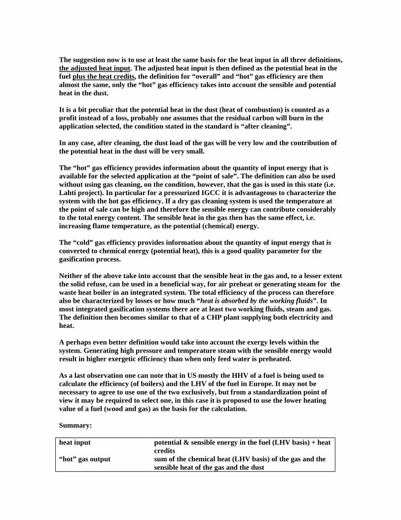
The suggestion now is to use at least the same basis for the heat input in all three definitions, the adjusted heat input. The adjusted heat input is then defined as the potential heat in the fuel plus the heat credits, the definition for “overall” and “hot” gas efficiency are then almost the same, only the “hot” gas efficiency takes into account the sensible and potential heat in the dust. It is a bit peculiar that the potential heat in the dust (heat of combustion) is counted as a profit instead of a loss, probably one assumes that the residual carbon will burn in the application selected, the condition stated in the standard is “after cleaning”. In any case, after cleaning, the dust load of the gas will be very low and the contribution of the potential heat in the dust will be very small. The “hot” gas efficiency provides information about the quantity of input energy that is available for the selected application at the “point of sale”. The definition can also be used without using gas cleaning, on the condition, however, that the gas is used in this state (i.e. Lahti project). In particular for a pressurized IGCC it is advantageous to characterize the system with the hot gas efficiency. If a dry gas cleaning system is used the temperature at the point of sale can be high and therefore the sensible energy can contribute considerably to the total energy content. The sensible heat in the gas then has the same effect, i.e. increasing flame temperature, as the potential (chemical) energy. The “cold” gas efficiency provides information about the quantity of input energy that is converted to chemical energy (potential heat), this is a good quality parameter for the gasification process. Neither of the above take into account that the sensible heat in the gas and, to a lesser extent the solid refuse, can be used in a beneficial way, for air preheat or generating steam for the waste heat boiler in an integrated system. The total efficiency of the process can therefore also be characterized by losses or how much “heat is absorbed by the working fluids”. In most integrated gasification systems there are at least two working fluids, steam and gas. The definition then becomes similar to that of a CHP plant supplying both electricity and heat. A perhaps even better definition would take into account the exergy levels within the system. Generating high pressure and temperature steam with the sensible energy would result in higher exergetic efficiency than when only feed water is preheated. As a last observation one can note that in US mostly the HHV of a fuel is being used to calculate the efficiency (of boilers) and the LHV of the fuel in Europe. It may not be necessary to agree to use one of the two exclusively, but from a standardization point of view it may be required to select one, in this case it is proposed to use the lower heating value of a fuel (wood and gas) as the basis for the calculation. Summary: heat input potential & sensible energy in the fuel (LHV basis) + heat
credits “hot” gas output sum of the chemical heat (LHV basis) of the gas and the
sensible heat of the gas and the dust
“cold” gas output potential heat of the clean gas (at standard reference condition)
1.“hot” gas efficiency ratio of “hot” gas output and heat input 2. “cold” gas efficiency ratio of “cold” gas output and heat input 3. total efficiency ratio of the sum of “hot” gas output and useful heat to
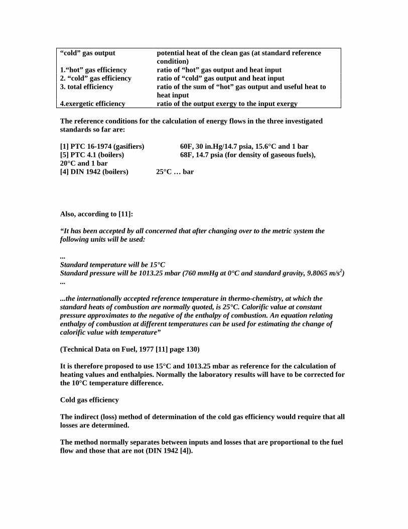
heat input 4.exergetic efficiency ratio of the output exergy to the input exergy The reference conditions for the calculation of energy flows in the three investigated standards so far are: [1] PTC 16-1974 (gasifiers) 60F, 30 in.Hg/14.7 psia, 15.6°C and 1 bar [5] PTC 4.1 (boilers) 68F, 14.7 psia (for density of gaseous fuels), 20°C and 1 bar [4] DIN 1942 (boilers) 25°C … bar Also, according to [11]: “It has been accepted by all concerned that after changing over to the metric system the following units will be used: ... Standard temperature will be 15°C Standard pressure will be 1013.25 mbar (760 mmHg at 0°C and standard gravity, 9.8065 m/s2) ... ...the internationally accepted reference temperature in thermo-chemistry, at which the standard heats of combustion are normally quoted, is 25°C. Calorific value at constant pressure approximates to the negative of the enthalpy of combustion. An equation relating enthalpy of combustion at different temperatures can be used for estimating the change of calorific value with temperature” (Technical Data on Fuel, 1977 [11] page 130) It is therefore proposed to use 15°C and 1013.25 mbar as reference for the calculation of heating values and enthalpies. Normally the laboratory results will have to be corrected for the 10°C temperature difference. Cold gas efficiency The indirect (loss) method of determination of the cold gas efficiency would require that all losses are determined. The method normally separates between inputs and losses that are proportional to the fuel flow and those that are not (DIN 1942 [4]).
For (almost) complete combustion in a boiler it is possible to develop relations for the flue gas to fuel and air to fuel values using the analysis of the fuel and flue gas. For the determination of unburnt carbon losses mass balance of the ash in the fuel is used. ****************************************************************************** In a gasifier the potential and sensible heat in the gas is the useful heat contained in the working fluid, and the generated steam from cooling the gas is a loss, at least for the cold gas efficiency. Is it possible to determine the cold efficiency of a gasifier using the loss method, with no analysis of the gas and no determination of the fuel feed? In fact, a similar method is being investigated within the development of PT47 code for IGCC. Uncertainty calculations are being made to explore energy balance methods for calculating the energy input to various gasifiers. Such methods are important as possible alternatives to direct measurements of the often inconsistent flows and heating value of fuels fed to gasifiers. Gasification is most frequently proposed to deal with heterogeneous solid and liquid fuels whose flow and composition are difficult to measure accurately. With low uncertainty, and whose heating value may vary significantly throughout a test. The energy balance or heat loss method is described in Fired Steam Generator Code and recommended by the Overall Plant Performance Code for determining the energy input of coal fed to a fired steam generator. This method makes use of the boiler as a calorimeter whose steam output and heat and stack losses are measured or estimated to calculate the energy input of the coal fuel feed. Committee members of PTC 47 are now performing input calculations to explore whether a gasifier, or perhaps a gasifier and associated heat recovery equipment of the gasification section can similarly be used as a calorimeter to determine the energy input of a fuel feed with less uncertainty than the measurement of fuel flow and heating value to determine energy input (David H. Archer, Ronald L. Bannister and Dennis A. Horazak [8]). For an overview evaluation of the alternatives consider the following: The absorbed heat in the gas coolers and the heat rejected to cooling water can be determined directly, but there is no direct proportional relation to the fuel feed. What can be determined once the absorbed heat in the cooler is available is an estimate of the gas flow, at least if the inlet and outlet temperatures of the gas are known. When the enthalpies of the gas are calculated according to the expected composition a rough and inaccurate estimate of the load can be made. More measurements and analysis seems to be necessary for accurate calculation of capacity and efficiency. The energy loss in the refuse (potential and sensible heat) can be determined directly (mass, temperature and heating value). The loss of potential energy can be linked proportional to the fuel feed with the mass balance of the solid inert material feed to the gasifier. Normally, however, the feed of inert material (sand, dolomite) is large compared to the ash flow and the accuracy of the calculated loss as percentage of fuel feed will be low. If gas composition analysis is not available there is no clue to the amount of air that is being used in the process.

Therefore, the answer seems to be that it is unlikely that the loss method, proposed for steam boilers, can be used for a gasifiers. Some additional measurements are still required in order to come to acceptable and accurate results. It probably depends on the requested accuracy of the test whether or not it is possible to be able to omit (flow and composition) measurements in the gas. It is required to have as a minimum at least 2 out of 3 measurements for the major mass flows (fuel, air and gas) together with the fuel analysis available for the calculation of the efficiency. This means that it may be possible to complete a successful test without determination by measurement of the fuel feed to the gasifier. In case the determination of quantity and composition of gas flow is not possible, both the air and fuel feed have to be measured, as well as the heating value of the wood fuel. The proposed method, deviating from the input/output method, can be denominated as “modified loss” (or input/loss) Method A in contrast to the direct input/output Method B. Modified loss Method A-1 From the measured fuel feed and air flow rate the gas flow can be calculated taking into account the flow materials to and from the system. The direct determination of major heat credits (gasification air) and losses (radiation, un-reacted carbon, generated steam, rejected heat to cooling water) is possible. The output energy can be calculated (= input-losses) as absolute value and relative to the mass flow of the gas. The heating value can be calculated if the sensible heat in the gas is known, for this estimated (design) values for the composition can be used. Both the density and sensible heat can be calculated with reasonable accuracy. The disadvantage of the method is that the composition of the gas, often subject to guarantees, is not being measured and cannot be calculated. If this is a requirement for the test then the modified heat loss method as described above cannot be applied. Modified loss Method A-2 The analysis of the composition of the gas can be used to calculate the heating value and the density, still, no measurement of gas flow or analysis of the wood fuel is needed as long as the wood and air mass flow can be determined accurately. Modified loss Method A-3 If it is not possible to accurately measure the wood feed to the gasifier then either the gas flow (A-3) should be measured or the analysis of the wood (A-4) should be determined. This makes the measurement of the air flow superfluous because the analysis of the gas will reveal the nitrogen content. The only source of nitrogen is the nitrogen in the air. Small corrections can be made for nitrogen in the wood fuel. From this the fuel feed can be calculated (correcting for condensed water) and using a measured LHV for the wood, the heat input can be calculated. Alternatively, as all losses are known as well as the output the input can be calculated.
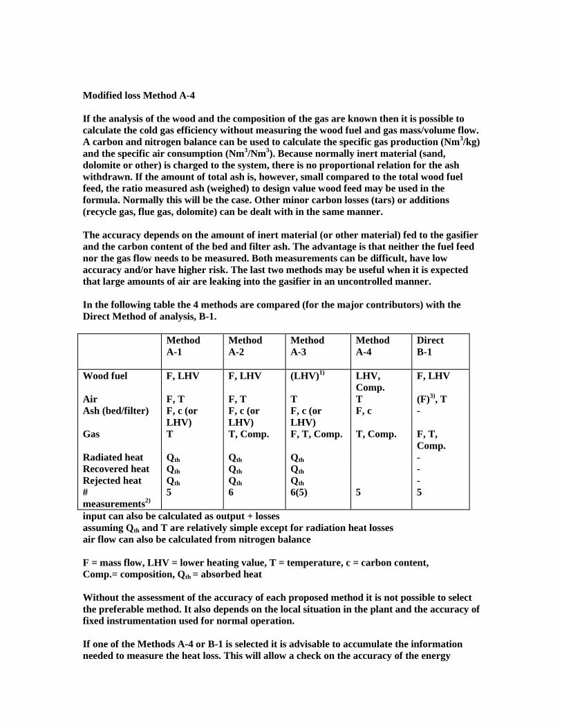
Modified loss Method A-4 If the analysis of the wood and the composition of the gas are known then it is possible to calculate the cold gas efficiency without measuring the wood fuel and gas mass/volume flow. A carbon and nitrogen balance can be used to calculate the specific gas production (Nm3/kg) and the specific air consumption (Nm3/Nm3). Because normally inert material (sand, dolomite or other) is charged to the system, there is no proportional relation for the ash withdrawn. If the amount of total ash is, however, small compared to the total wood fuel feed, the ratio measured ash (weighed) to design value wood feed may be used in the formula. Normally this will be the case. Other minor carbon losses (tars) or additions (recycle gas, flue gas, dolomite) can be dealt with in the same manner. The accuracy depends on the amount of inert material (or other material) fed to the gasifier and the carbon content of the bed and filter ash. The advantage is that neither the fuel feed nor the gas flow needs to be measured. Both measurements can be difficult, have low accuracy and/or have higher risk. The last two methods may be useful when it is expected that large amounts of air are leaking into the gasifier in an uncontrolled manner. In the following table the 4 methods are compared (for the major contributors) with the Direct Method of analysis, B-1. Method
A-1
Method A-2
Method A-3
Method A-4
Direct B-1
Wood fuel F, LHV F, LHV (LHV)1) LHV, Comp.
F, LHV
Air F, T F, T T T (F)3), T Ash (bed/filter) F, c (or
LHV) F, c (or LHV)
F, c (or LHV)
F, c -
Gas T T, Comp. F, T, Comp. T, Comp. F, T, Comp.
Radiated heat Qth Qth Qth - Recovered heat Qth Qth Qth - Rejected heat Qth Qth Qth - # measurements2)
5 6 6(5) 5 5
input can also be calculated as output + losses assuming Qth and T are relatively simple except for radiation heat losses air flow can also be calculated from nitrogen balance F = mass flow, LHV = lower heating value, T = temperature, c = carbon content, Comp.= composition, Qth = absorbed heat Without the assessment of the accuracy of each proposed method it is not possible to select the preferable method. It also depends on the local situation in the plant and the accuracy of fixed instrumentation used for normal operation. If one of the Methods A-4 or B-1 is selected it is advisable to accumulate the information needed to measure the heat loss. This will allow a check on the accuracy of the energy
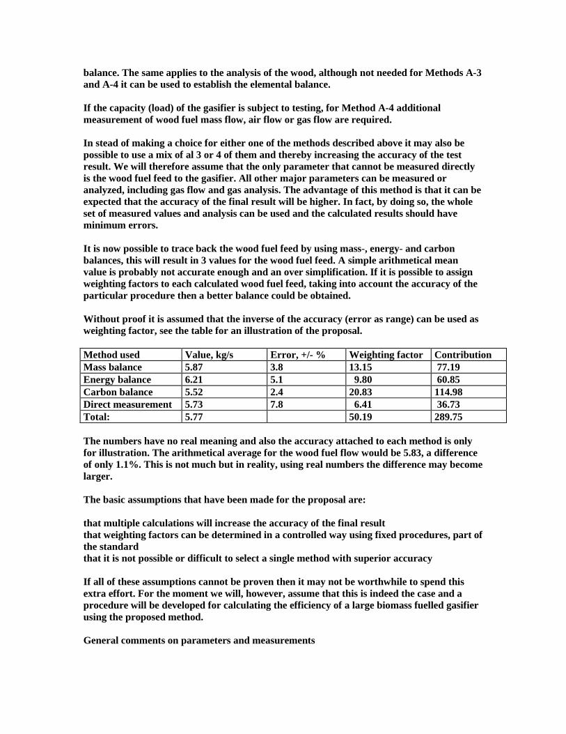
balance. The same applies to the analysis of the wood, although not needed for Methods A-3 and A-4 it can be used to establish the elemental balance. If the capacity (load) of the gasifier is subject to testing, for Method A-4 additional measurement of wood fuel mass flow, air flow or gas flow are required. In stead of making a choice for either one of the methods described above it may also be possible to use a mix of al 3 or 4 of them and thereby increasing the accuracy of the test result. We will therefore assume that the only parameter that cannot be measured directly is the wood fuel feed to the gasifier. All other major parameters can be measured or analyzed, including gas flow and gas analysis. The advantage of this method is that it can be expected that the accuracy of the final result will be higher. In fact, by doing so, the whole set of measured values and analysis can be used and the calculated results should have minimum errors. It is now possible to trace back the wood fuel feed by using mass-, energy- and carbon balances, this will result in 3 values for the wood fuel feed. A simple arithmetical mean value is probably not accurate enough and an over simplification. If it is possible to assign weighting factors to each calculated wood fuel feed, taking into account the accuracy of the particular procedure then a better balance could be obtained. Without proof it is assumed that the inverse of the accuracy (error as range) can be used as weighting factor, see the table for an illustration of the proposal. Method used Value, kg/s Error, +/- % Weighting factor Contribution Mass balance 5.87 3.8 13.15 77.19 Energy balance 6.21 5.1 9.80 60.85 Carbon balance 5.52 2.4 20.83 114.98 Direct measurement 5.73 7.8 6.41 36.73 Total: 5.77 50.19 289.75 The numbers have no real meaning and also the accuracy attached to each method is only for illustration. The arithmetical average for the wood fuel flow would be 5.83, a difference of only 1.1%. This is not much but in reality, using real numbers the difference may become larger. The basic assumptions that have been made for the proposal are: that multiple calculations will increase the accuracy of the final result that weighting factors can be determined in a controlled way using fixed procedures, part of the standard that it is not possible or difficult to select a single method with superior accuracy If all of these assumptions cannot be proven then it may not be worthwhile to spend this extra effort. For the moment we will, however, assume that this is indeed the case and a procedure will be developed for calculating the efficiency of a large biomass fuelled gasifier using the proposed method. General comments on parameters and measurements

With respect to the previous suggestions and guidelines the application for the acceptance test protocols can be commented as follows: Wood fuel Before a test can start there should be sufficient fuel available for the test period and the quality (species, heating value, moisture content, ash content, chemical analysis and physical properties etc.) should be to the satisfaction of both the supplier of the system and the purchaser or its representatives. This requires, amongst others, agreed procedures on how to sample and analyze the fuels. The analysis of the wood and the determination, for instance, of the heating value and chemical components are relatively easy and standardized procedures that can be executed “off line” in commercial laboratories. Often these parameters are subject to agreed acceptance criteria which makes it necessary to measure them, either as a condition for the test (LHV within range or size within range) or as a necessary parameter for evaluation of the final result (heating value). Currently a CEN Workshop has started to develop biomass standards for application in wood fuelled power plants. An inventory has been made of available existing standards in the European Countries and a work program will be initiated in March 2000. The first meeting took place in Stuttgart in March 1999, the second in Stockholm in September 1999. The CEN Workshop is supported by the FAIR and Thermie programs of the European Commission and on a National level mirror committees have been established which will provide information and assist in the development of standards for testing and characterization of biomass fuels. For an overview of standards see the Best Practice List [14], IEA participation in this work is within the Task… Of particular interest is a correct procedure to take samples of the fuel, it is obvious that samples that do not represent the wood fuel feed cannot be used for determination of efficiency. The samples should be taken at regular intervals and as close to the feed point as possible. The weight of the sample is determined by the average size of the fuel, according to one reference (for coal): Average particle size 10 mm 30 mm 50 mm 80 mm >80 mm Ash content, % Total raw sample weight, kg Individual sample weight, kg
<13 25 20 45 0.5
<13 25 40 90 1
<11 25 40 150 1.6
<9 25 40 210 2.5
<5 25 40 310 4
Actually the influence of ash content will not be very large for wood because this is expected to be below 5%. The total raw sample weight should be reduced to the laboratory sample i.e. by a series of mixing, quartering and again mixing of opposite quarters. If possible use should be made of standards developed for sampling and reduction of the sample size of wood. The weight of the final laboratory sample can be 1-5 kg. This sample should be stored in air tight containers, preferably filled with inert gas, marked with date, time and a
reference to the test or identification number. One can also consider to store an identical fuel sample as a back up and in case of any disputes. Sometimes it may not be possible to sample directly upstream of the wood fuel feeders, in this case the alternative will be to sample at the inlet of the intermediate storage bins for wood fuel, or even further upstream. Depending on the size of these bins and the expected test period, the sampling may even start before the actual test in order to make sure that the fuel feed from storage during the test can be represented by the samples. The continuous determination of fuel mass feed to the gasifier is normally less accurate for solid fuels, sometimes on line determination of the mass flow has been omitted for this reason. Measurement by weight is accurate, however, and in case the weight of several batches of fuel can be measured it is not an advantage that determination of fuel feed can be omitted. For smaller systems without instruments for measuring fuel feed (i.e. weighing belts) Methods A-3 and A-4 have an advantage. Air The gasification air is usually supplied by one or more compressors providing forced draft or, for smaller gasifiers with induced draft fans located down stream of the gasifier in the cold and clean part of the system. In order to increase the efficiency of the system the air can be preheated with waste heat generated within the system or with external energy. It will depend on the definition of the system and the envelope boundary to be considered. Apparatus is considered to be outside the envelope boundary when it requires an outside source of heat or where the heat exchanged is not returned to the gasification system [7]. Heat credits are defined as those amounts of heat added to the envelope of the system other than the chemical heat in the fuel. In case the air pre-heater is an integral part of the system the actual energy supplied to the air need not to be considered, only the enthalpy of the air entering the air pre-heater and the added energy from power conversion in the compressor. The air flow to the gasifier can be measured without too much problems, temperature is low even with air pre-heat, the composition is exactly known and various standardized and accurate measurement devices and procedures are available. The only reason where it would be advantageous that not to measure the air flow is when it can be expected that some air can enter the system in an uncontrolled manner. This may happen when cooling air is applied to start-up burners or sealing air to fuel feed systems or of the gasifier is operated with a pressure lower than the ambient. When these quantities of (unmeasured) air are expected to be small then the design value for the additional “parasitic” air may be used. There should be, however, proof that this is the case, i.e. by measuring a pressure difference and using graphs for air leakage. Ash The ash comprises of several components: ash as an integral part of the fuel inert materials (sand) collected simultaneously with the fuel
bed material (sand) chemicals (dolomite, limestone) used in certain applications i.e. for cracking of tars or absorption of trace components like chlorides unreacted carbon The ash is probably collected at different locations in the system, as coarse bottom ash in the gasifier and as fine dust in the gas cleaning section (ceramic, bag house or other type of filter). The filter ash can contain a high percentage of carbon and this should be treated as a loss, unless some type of recycling is used i.e. returning the ash to the gasifier or incinerate the ash and return the heat to the system. In particular the flyash with its high carbon content and small particles is considered to ignite and oxidize easily. Samples should be stored immediately in gas tight containers filled with nitrogen. The determination of total weight during the test can be accomplished by collecting and weighing all the ash removed during the test or part of the test. Normally there are no measurement devices that give an actual value for the mass flow of ash generated within and removed from the system. The accumulation of any kind of solids in the system should be prevented, this requires a careful and accurate determination of starting and stopping conditions (i.e. pressure drop in fluid bed). Handling of containers in inaccessible areas may be difficult but not impossible. Determination of the heating value and/or carbon contents is relatively easy, although one should consider that hydrogen may still be present in the ash. Sometimes, in case of very low carbon content one could consider to add material with known heating value to the ash sample and calculate the heating value of the mixture. As for the wood fuel, sampling is an important condition for the final accuracy of the result. Samples should be taken at regular intervals and the weight reduced in size i.e. by quartering several times until a laboratory sample of 1-5 kg is left. In particular for the fine filter ash it is imperative to store the sample in containers filled with nitrogen in order to avoid oxidation. For calculation of the sensible heat loss it can be assumed that the ash has the temperature of the gas at the location where it is removed. This will be more accurate than measuring exit temperatures and determination of any loss by cooling the ash to air or water. Gas The composition (with calculated LHV) of the gas is the major deliverable of the gasifier and probably subject to agreed acceptance criteria in the contract. Not needing to know the composition (A-1) is therefore normally not an advantage. The gas flow is more difficult to measure than air (unusual composition, toxic gas and explosion risk) but nevertheless it is possible and larger systems will use a measurement device which allows a continuous registration of the gas flow. In case these devices are used for the determination of the flow during the test, they should be calibrated and certificates should be available as part of the report. Probably smaller systems can benefit from procedures not needing to measure the gas flow. For sampling and analysis of gases and trace components widely accepted standards should be used. Gas can be sampled and analyzed after the gas cleaning but if evidence of the

performance of the gas cleaning system should be collected as well, also sampling upstream of the gas cleaning system is required. This may become necessary when the removal efficiency has been limited to a range of inlet concentrations of certain species like ammonia, chlorides, tars etc. The upstream reconstruction of gas composition from downstream sampling and analysis is troublesome, inaccurate and should be avoided. If evidence is needed of the quality of the gas at certain locations in the system, all efforts should be made to take direct measurements. In case of extreme conditions i.e. high gas temperature upstream of a ceramic particle filter this may not always be technically possible or safe. In these circumstances alternatives should be proposed and agreed between the supplier and purchaser of the equipment or his representative. When the heating values of the gas is not measured directly, tables with heating values of the various components should be used to calculate the heating value. These tables should be from reliable source and agreed to by all parties. Particular care should be given to the use of proper reference conditions in the table (pressure and temperature) with respect to the actual pressure and temperature at the point of gas sampling. When necessary, corrections should be made. Radiation heat loss For the testing of steam boilers the heat loss by radiation is not measured but instead standard graphs are used. For gasifiers these graphs are not available and calculation of total (relevant) outside surface, outside temperature of the vessel(s) and the ambient temperature as well as the atmospheric conditions (i.e. wind velocity) are required. It represents a certain effort but this can be done and one would probably be interested in estimating heat loss by radiation anyway. A measurement protocol for the total outside surface of the gasification system within the system boundary envelope should be part of the final report. The whole system should be divided into a number of logical subsections i.e. according to size and expected temperature of the outside surface. At the start of a test, in the middle and at the end it is advised to record the surface temperatures of the various sections with suitable means i.e. thermographic methods or optical pyrometers. The procedure and formulae used for the calculation of the heat loss should follow standard technical practices. Recovered heat In modern large biomass gasifiers i.e. circulating fluid bed gasifiers, the gas is produced at a relatively high temperature. In most cases, the gas has to be cooled down to a temperature level where it can be used in the downstream equipment. When gasifiers are used for electric power production, the sensible heat in the gas can be used in the thermal system as a useful byproduct. When inlet and outlet enthalpies of the water, steam or air as well as the mass flow are known the calculation is not difficult. When the flow of water or air is not measured during normal operation, temporary instruments are required.

Rejected heat This requires the determination of cooling water flow and its inlet and outlet temperatures. Normally it should not be a problem to measure although not always the mass flow of cooling water is measured so periodic measurement instruments are needed. On the other hand, the thermal loss from cooling water will not be extremely large and errors made in the determination are unlikely to have a large effect on the outcome of the test. Accuracy The calculation of the efficiency should be accurate. The protocol for the acceptance test should contain clear procedures on how to calculate the error in the outcome of the calculation based on the accuracy of the instruments used and the calculation procedure followed and illustrated with examples
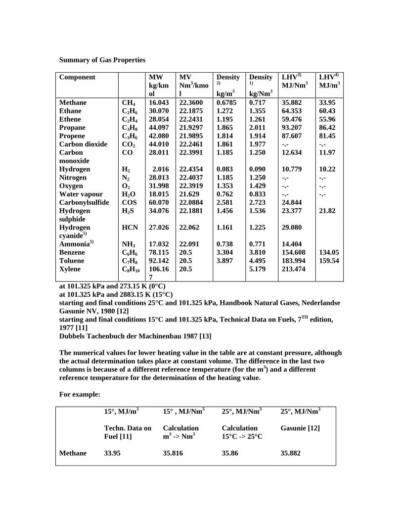
Summary of Gas Properties Component MW
kg/kmol
MV Nm3/kmol
Density2) kg/m3
Density1) kg/Nm3
LHV3) MJ/Nm3
LHV4) MJ/m3
Methane CH4 16.043 22.3600 0.6785 0.717 35.882 33.95 Ethane C2H6 30.070 22.1875 1.272 1.355 64.353 60.43 Ethene C2H4 28.054 22.2431 1.195 1.261 59.476 55.96 Propane C3H8 44.097 21.9297 1.865 2.011 93.207 86.42 Propene C3H6 42.080 21.9895 1.814 1.914 87.607 81.45 Carbon dioxide CO2 44.010 22.2461 1.861 1.977 -.- -.- Carbon monoxide
CO 28.011 22.3991 1.185 1.250 12.634 11.97
Hydrogen H2 2.016 22.4354 0.083 0.090 10.779 10.22 Nitrogen N2 28.013 22.4037 1.185 1.250 -.- -.- Oxygen O2 31.998 22.3919 1.353 1.429 -.- -.- Water vapour H2O 18.015 21.629 0.762 0.833 -.- -.- Carbonylsulfide COS 60.070 22.0884 2.581 2.723 24.844 Hydrogen sulphide
H2S 34.076 22.1881 1.456 1.536 23.377 21.82
Hydrogen cyanide5)
HCN 27.026 22.062 1.161 1.225 29.080
Ammonia5) NH3 17.032 22.091 0.738 0.771 14.404 Benzene C6H6 78.115 20.5 3.304 3.810 154.608 134.05 Toluene C7H8 92.142 20.5 3.897 4.495 183.994 159.54 Xylene C8H10 106.16
7 20.5 5.179 213.474
at 101.325 kPa and 273.15 K (0°C) at 101.325 kPa and 2883.15 K (15°C) starting and final conditions 25°C and 101.325 kPa, Handbook Natural Gases, Nederlandse Gasunie NV, 1980 [12] starting and final conditions 15°C and 101.325 kPa, Technical Data on Fuels, 7TH edition, 1977 [11] Dubbels Tachenbuch der Machinenbau 1987 [13] The numerical values for lower heating value in the table are at constant pressure, although the actual determination takes place at constant volume. The difference in the last two columns is because of a different reference temperature (for the m3) and a different reference temperature for the determination of the heating value. For example: 15°, MJ/m3 15° , MJ/Nm3 25°, MJ/Nm3 25°, MJ/Nm3
Techn. Data on Fuel [11]
Calculation m3 -> Nm3
Calculation 15°C -> 25°C
Gasunie [12]
Methane
33.95
35.816
35.86
35.882
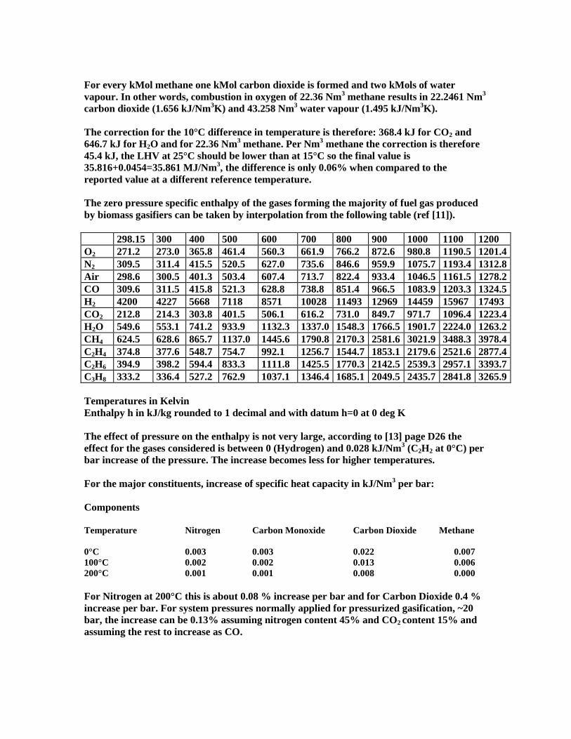
For every kMol methane one kMol carbon dioxide is formed and two kMols of water vapour. In other words, combustion in oxygen of 22.36 Nm3 methane results in 22.2461 Nm3 carbon dioxide (1.656 kJ/Nm3K) and 43.258 Nm3 water vapour (1.495 kJ/Nm3K). The correction for the 10°C difference in temperature is therefore: 368.4 kJ for CO2 and 646.7 kJ for H2O and for 22.36 Nm3 methane. Per Nm3 methane the correction is therefore 45.4 kJ, the LHV at 25°C should be lower than at 15°C so the final value is 35.816+0.0454=35.861 MJ/Nm3, the difference is only 0.06% when compared to the reported value at a different reference temperature. The zero pressure specific enthalpy of the gases forming the majority of fuel gas produced by biomass gasifiers can be taken by interpolation from the following table (ref [11]). 298.15 300 400 500 600 700 800 900 1000 1100 1200 O2 271.2 273.0 365.8 461.4 560.3 661.9 766.2 872.6 980.8 1190.5 1201.4N2 309.5 311.4 415.5 520.5 627.0 735.6 846.6 959.9 1075.7 1193.4 1312.8Air 298.6 300.5 401.3 503.4 607.4 713.7 822.4 933.4 1046.5 1161.5 1278.2CO 309.6 311.5 415.8 521.3 628.8 738.8 851.4 966.5 1083.9 1203.3 1324.5H2 4200 4227 5668 7118 8571 10028 11493 12969 14459 15967 17493 CO2 212.8 214.3 303.8 401.5 506.1 616.2 731.0 849.7 971.7 1096.4 1223.4H2O 549.6 553.1 741.2 933.9 1132.3 1337.0 1548.3 1766.5 1901.7 2224.0 1263.2CH4 624.5 628.6 865.7 1137.0 1445.6 1790.8 2170.3 2581.6 3021.9 3488.3 3978.4C2H4 374.8 377.6 548.7 754.7 992.1 1256.7 1544.7 1853.1 2179.6 2521.6 2877.4C2H6 394.9 398.2 594.4 833.3 1111.8 1425.5 1770.3 2142.5 2539.3 2957.1 3393.7C3H8 333.2 336.4 527.2 762.9 1037.1 1346.4 1685.1 2049.5 2435.7 2841.8 3265.9 Temperatures in Kelvin Enthalpy h in kJ/kg rounded to 1 decimal and with datum h=0 at 0 deg K The effect of pressure on the enthalpy is not very large, according to [13] page D26 the effect for the gases considered is between 0 (Hydrogen) and 0.028 kJ/Nm3 (C2H2 at 0°C) per bar increase of the pressure. The increase becomes less for higher temperatures. For the major constituents, increase of specific heat capacity in kJ/Nm3 per bar: Components Temperature Nitrogen Carbon Monoxide Carbon Dioxide Methane 0°C 0.003 0.003 0.022 0.007 100°C 0.002 0.002 0.013 0.006 200°C 0.001 0.001 0.008 0.000 For Nitrogen at 200°C this is about 0.08 % increase per bar and for Carbon Dioxide 0.4 % increase per bar. For system pressures normally applied for pressurized gasification, ~20 bar, the increase can be 0.13% assuming nitrogen content 45% and CO2 content 15% and assuming the rest to increase as CO.
More accurate data is required in case the test protocol is used for a pressurized gasifier. Although, the pressure effect may be discarded as concluded from this example. Literature [1] ANSI PTC 16-1974 Power Test Code for Gas Producers and Continuous Gas Generators, 1958 and revised in 1974 [2] ASME/ANSI Performance Test codes PTC1-1991 General Instructions [3] B.S. 995, Test Code for Gas Producers [4] DIN 1942, Acceptance Test Code for Steam Generators, 1994 [5] ASME PTC 4.1, Power Test Code for Steam Generating Units, 1965 [6] Performance Modeling as an Aid in the Preparation of a Test Code for IGCC Plants, PTC 47, ASME Turbo Expo Land, Sea & Air, Indianapolis, Indiana June 7-10 1999; Dennis A. Horazak and David H Archer [7] ASME PTC47.4, IGCC Performance Testing Issues for the Power Block, PWR-Vol. 34, 1999 joint Power Generation Conference, Volume 2 ASME 1999; Ashok K. Anand and Jeff Parmar [8] ASME PTC47, Gasification Combined Cycle Performance, Uncertainty, 1998 International Joint Power Conference & Exposition, Baltimore, Maryland, August 24026, 1998; David H. Archer, Ronald L. Banister and Dennis A Horazak [9] PTC 47 Fuel gas Contaminants sampling for Gasification–based Power Plants, 1998 International Joint Power Conference & Exposition, Baltimore, Maryland, August 24-26, 1998; Richard A. Newby [10] ASME PTC 47 Calculation of Overall IGCC Plant Performance, Joint Power Generation Conference and Exposition Burlingame, California, July 25-28, 1999; Tian-yu Xiong and Dennis A. Horazak [11] Technical Data on Fuel, edited by J.W. Rose and J.R. Cooper, seventh Edition 1977 ISBN 0 7073 0129 7 [12] Handbook Natural Gases, Nederlandse Gasunie NV, 1980 [13] Dubbels Taschenbuch der Machinenbau 1987 [14] VDI Wärmeatlas 4e Auflage 1984

Annexes Generic performance, mass- and energy balance of a typical 20 MWe gasification unit. Proposal for revised text of test protocol using ANSI PTC 16 as basis
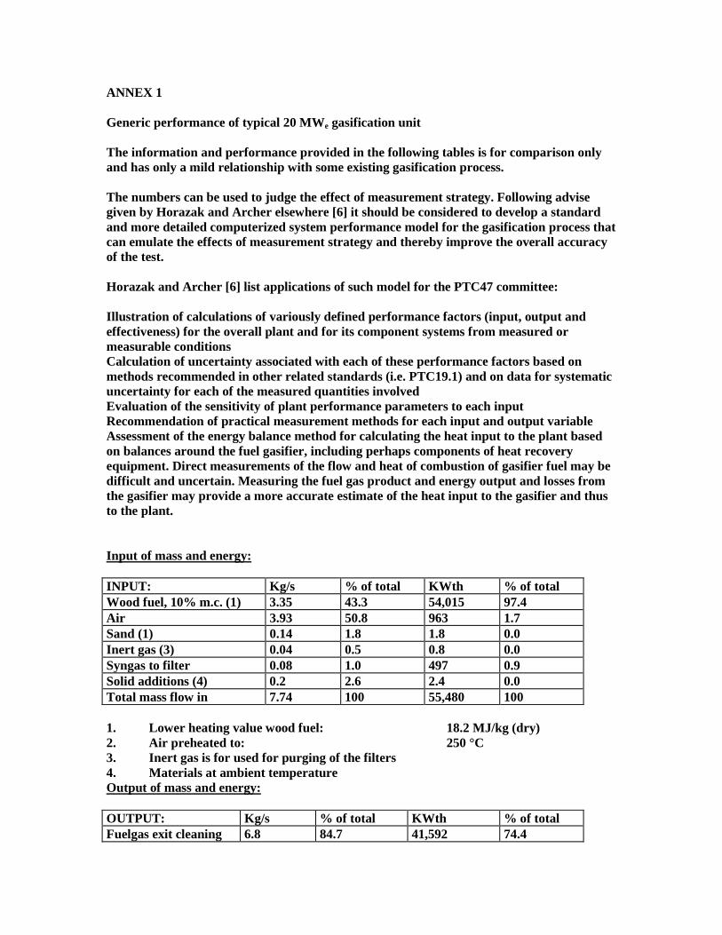
ANNEX 1 Generic performance of typical 20 MWe gasification unit The information and performance provided in the following tables is for comparison only and has only a mild relationship with some existing gasification process. The numbers can be used to judge the effect of measurement strategy. Following advise given by Horazak and Archer elsewhere [6] it should be considered to develop a standard and more detailed computerized system performance model for the gasification process that can emulate the effects of measurement strategy and thereby improve the overall accuracy of the test. Horazak and Archer [6] list applications of such model for the PTC47 committee: Illustration of calculations of variously defined performance factors (input, output and effectiveness) for the overall plant and for its component systems from measured or measurable conditions Calculation of uncertainty associated with each of these performance factors based on methods recommended in other related standards (i.e. PTC19.1) and on data for systematic uncertainty for each of the measured quantities involved Evaluation of the sensitivity of plant performance parameters to each input Recommendation of practical measurement methods for each input and output variable Assessment of the energy balance method for calculating the heat input to the plant based on balances around the fuel gasifier, including perhaps components of heat recovery equipment. Direct measurements of the flow and heat of combustion of gasifier fuel may be difficult and uncertain. Measuring the fuel gas product and energy output and losses from the gasifier may provide a more accurate estimate of the heat input to the gasifier and thus to the plant. Input of mass and energy: INPUT: Kg/s % of total KWth % of total Wood fuel, 10% m.c. (1) 3.35 43.3 54,015 97.4 Air 3.93 50.8 963 1.7 Sand (1) 0.14 1.8 1.8 0.0 Inert gas (3) 0.04 0.5 0.8 0.0 Syngas to filter 0.08 1.0 497 0.9 Solid additions (4) 0.2 2.6 2.4 0.0 Total mass flow in 7.74 100 55,480 100 1. Lower heating value wood fuel: 18.2 MJ/kg (dry) 2. Air preheated to: 250 °C 3. Inert gas is for used for purging of the filters 4. Materials at ambient temperature Output of mass and energy: OUTPUT: Kg/s % of total KWth % of total Fuelgas exit cleaning 6.8 84.7 41,592 74.4
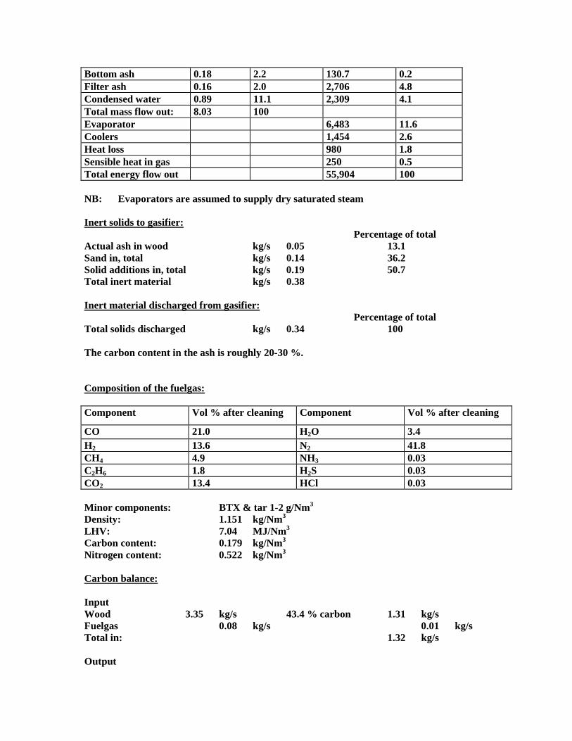
Bottom ash 0.18 2.2 130.7 0.2 Filter ash 0.16 2.0 2,706 4.8 Condensed water 0.89 11.1 2,309 4.1 Total mass flow out: 8.03 100 Evaporator 6,483 11.6 Coolers 1,454 2.6 Heat loss 980 1.8 Sensible heat in gas 250 0.5 Total energy flow out 55,904 100 NB: Evaporators are assumed to supply dry saturated steam Inert solids to gasifier: Percentage of total Actual ash in wood kg/s 0.05 13.1 Sand in, total kg/s 0.14 36.2 Solid additions in, total kg/s 0.19 50.7 Total inert material kg/s 0.38 Inert material discharged from gasifier: Percentage of total Total solids discharged kg/s 0.34 100 The carbon content in the ash is roughly 20-30 %. Composition of the fuelgas: Component Vol % after cleaning Component Vol % after cleaning
CO 21.0 H2O 3.4 H2 13.6 N2 41.8 CH4 4.9 NH3 0.03 C2H6 1.8 H2S 0.03 CO2 13.4 HCl 0.03 Minor components: BTX & tar 1-2 g/Nm3 Density: 1.151 kg/Nm3 LHV: 7.04 MJ/Nm3 Carbon content: 0.179 kg/Nm3 Nitrogen content: 0.522 kg/Nm3 Carbon balance: Input Wood 3.35 kg/s 43.4 % carbon 1.31 kg/s Fuelgas 0.08 kg/s 0.01 kg/s Total in: 1.32 kg/s Output
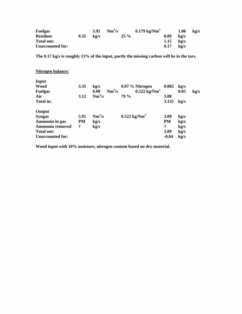
Fuelgas 5.91 Nm3/s 0.179 kg/Nm3 1.06 kg/s Residues 0.35 kg/s 25 % 0.09 kg/s Total out: 1.15 kg/s Unaccounted for: 0.17 kg/s The 0.17 kg/s is roughly 13% of the input, partly the missing carbon will be in the tars. Nitrogen balance: Input Wood 3.35 kg/s 0.07 % Nitrogen 0.002 kg/s Fuelgas 0.08 Nm3/s 0.522 kg/Nm3 0.05 kg/s Air 3.12 Nm3/s 79 % 3.08 Total in: 3.132 kg/s Output Syngas 5.91 Nm3/s 0.522 kg/Nm3 3.09 kg/s Ammonia in gas PM kg/s PM kg/s Ammonia removed ? kg/s ? kg/s Total out: 3.09 kg/s Unaccounted for: -0.04 kg/s Wood input with 10% moisture, nitrogen content based on dry material.
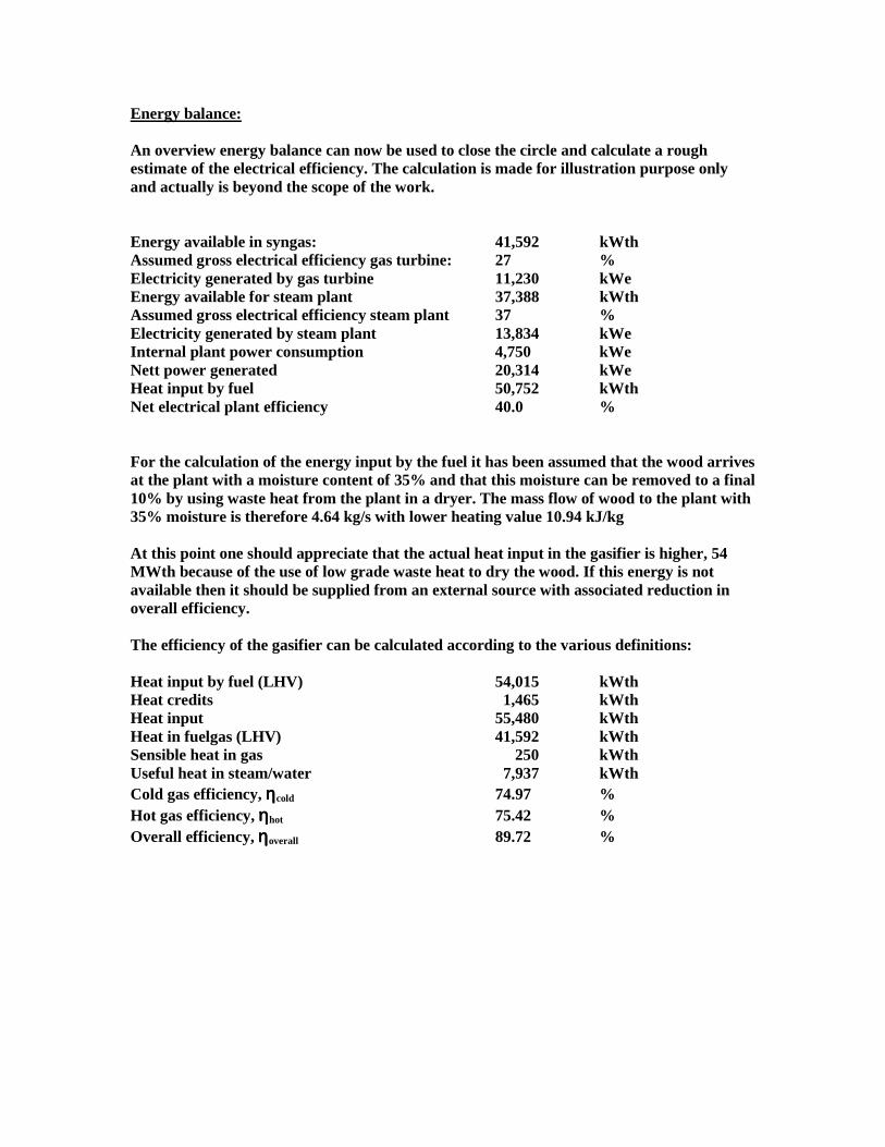
Energy balance: An overview energy balance can now be used to close the circle and calculate a rough estimate of the electrical efficiency. The calculation is made for illustration purpose only and actually is beyond the scope of the work. Energy available in syngas: 41,592 kWth Assumed gross electrical efficiency gas turbine: 27 % Electricity generated by gas turbine 11,230 kWe Energy available for steam plant 37,388 kWth Assumed gross electrical efficiency steam plant 37 % Electricity generated by steam plant 13,834 kWe Internal plant power consumption 4,750 kWe Nett power generated 20,314 kWe Heat input by fuel 50,752 kWth Net electrical plant efficiency 40.0 % For the calculation of the energy input by the fuel it has been assumed that the wood arrives at the plant with a moisture content of 35% and that this moisture can be removed to a final 10% by using waste heat from the plant in a dryer. The mass flow of wood to the plant with 35% moisture is therefore 4.64 kg/s with lower heating value 10.94 kJ/kg At this point one should appreciate that the actual heat input in the gasifier is higher, 54 MWth because of the use of low grade waste heat to dry the wood. If this energy is not available then it should be supplied from an external source with associated reduction in overall efficiency. The efficiency of the gasifier can be calculated according to the various definitions: Heat input by fuel (LHV) 54,015 kWth Heat credits 1,465 kWth Heat input 55,480 kWth Heat in fuelgas (LHV) 41,592 kWth Sensible heat in gas 250 kWth Useful heat in steam/water 7,937 kWth Cold gas efficiency, ηηηηcold 74.97 % Hot gas efficiency, ηηηηhot 75.42 % Overall efficiency, ηηηηoverall 89.72 %
Draft test protocol using parts of ASME ANSI PTC 16 - 1974 SECTION 0, INTRODUCTION This code for conducting tests of Large Biomass Fuelled Gasifiers is intended primarily for tests of those gasifiers whose gas is to be used for power, heating or chemical purposes . A Large Biomass Fuelled Gasifier is here defined as any unit which generates primarily CO or H2 continuously from biomass fuels. Units such as the fixed-bed, fluid-bed, entrained or pulverised types, all operating at about atmospheric pressure or higher, are included. 0.1 The term "fuel," as herein used, includes only biomass defined as fuel consisting for a large part of woody and herbaceous material. 0.2 In testing a Large Biomass Fuelled Gasifiers the auxiliary apparatus must be included in many cases, as being essential parts of the unit. If a complete test of the Large Biomass Fuelled Gasifiers is desired, separate records should be made of the amounts of fuel, water, power, and labour required to operate the producer and each of its auxiliaries. SECTION 1, OBJECT AND SCOPE 1.1 The purpose of this code is to establish rules for conducting tests to determine the operating characteristics of Large Biomass Fuelled Gasifiers. All continuous types of Large Biomass Fuelled Gasifiers are to be included with a fuel capacity larger than 10 MWth, such as those using fluidized beds, pulverised fuels, fixed beds and those using oxygen and/or recycled CO2 1.2 Possible objectives for which a test may be carried out may he one or more of the following The maximum capacity of the Large Biomass Fuelled Gasifier and each of its auxiliaries The efficiency of the Gasifier in making gas and the performance of each of its components The ability of the Gasifier to use a specific fuel The ability of the Gasifier to respond to varying loads The quantity, quality, and cleanliness of the gas The results obtained by using different kinds and sizes of fuels and using them in different ways The amounts and costs of labour and power required to operate the the Gasifier and its auxiliaries The reliability of the Gasifier and of its component parts The causes of faulty operation of the producer or its auxiliaries The efficiency of recovery of by-products, such as NH3. 1.3 Analysis of performance of auxiliaries is not usually contemplated, although their consumption of fuel, utilities, labour and such items as contribute to the cost of their operation will be accounted for. It should be clearly stated in the objectives of the test which producers and what auxiliary equipment are to be included. In some cases only performance data on the producer itself may be desired. SECTION 2, DESCRIPTION AND DEFINITION OF TERMS

Description and Definition of Terms. The following table defines the units and terms which are used. TO BE COMPLETED LATER INCLUDING DIAGRAM WITH BOUNDARY ENVELOPE SECTION 3, GUIDING PRINCIPLES and TEST CONDITIONS 3.1 Before the test, the parties concerned shall reach a definite agreement on the following items: Object of test Source and selection of fuel Selection of instruments Method of calibration of instruments Limits of permissible error Intent of contract or specifications if ambiguities or omissions appear evident Adjustment of equipment for continuous commercial operation and method of operating equipment under test, including that of any auxiliary equipment, the performance of which may influence the test result Methods of maintaining constant operating conditions as closely as possible to those specified Organisation of personnel, including designation of engineer in responsible charge of test Number of copies of original data required Method of determining duration of operation under test conditions before test readings are started Duration of test runs Frequency of observations Values of corrections for deviations of test conditions from those specified and provision for rejecting inconsistent readings Methods of computing results (Section 5 of this code) Preparation of final report Cost of tests Agreement in writing must be made regarding allowable deviations that may occur during testing, owing to unforeseen circumstances. Should serious inconsistencies in the observed data be detected during a run, or during the computation of results, the run shall be rejected in whole or in part. A run that has been rejected shall be repeated, if necessary, to attain the objectives of the test. Preparation for Tests. The dimensions of the Gasification system and of each of its components individual pieces of equipment, and auxiliaries together with the physical condition of each, should be carefully determined and recorded. The testing appliances should then be installed and the preparations for making the test completed, including the provision of an adequate number of suitably prepared log books and other supplies which may be needed for the different pieces of components, equipment, and auxiliaries. Tests should be made for leaks. Leaks should be stopped, but if this is impracticable, agreement should be reached on their
importance and suitable allowances should be made for them in the final results. The use of photographs of the assembled equipment is recommended. Starting and Stopping. The conditions regarding the temperature of the Gasifier and its contents, and the quantity and quality of the latter, should be as nearly as possible the same throughout the test, and particularly so at the beginning and at the end. As far as may be reasonably possible, there should be no clinker on the walls or in the Gasifier at the beginning and the end of the test. To secure the desired equality of conditions, the starting and stopping should occur at the conclusion of the times of regular cleaning, and they should be in operation for a period of not less than eight hours by the same regular working conditions as are intended to characterise the test as a whole. Unless the conditions of the fuel bed at the beginning and end of a test can be so accurately determined, and possible differences in level allowed for, that the error in determining the net weight of fuel used during the test shall not exceed two per cent, the tests should be abandoned as valueless, unless a larger allowable error has been previously agreed upon. Requirements as to Adjustment of Equipment and Methods of Operation. For acceptance tests, the equipment manufacturer or supplier shall have reasonable opportunity to ex-amine the equipment, to correct defects, and to render the equipment suitable, in his/her judgement, to undergo test. He/she may make such reasonable preliminary test runs as deemed necessary for this purpose. The manufacturer, however, is not thereby empowered to alter or adjust equipment or conditions in such a way that contract or other stipulations are altered or voided. The manufacturer may not make adjustments to the equipment for test purposes that may prevent immediate continuous and reliable operation at all capacities or outputs and under all specified operating conditions. Observations during preliminary test runs should be carried through to the calculation of results as an overall check of procedure, layout and organisation. If mutually agreed, a preliminary test may be considered an acceptance test, provided it has complied with all the necessary requirements of this code. Preliminary test runs with log records serve to determine if the equipment is in a satisfactory condition to undergo test, to check instruments and methods of measurement, and to train personnel. Requirements for Duration of Tests. Full-Time and Complete Tests: The duration, both of efficiency and capacity full-time tests of a gasifier, is a matter upon which there should he prior agreement between the parties concerned. Short-Time or Spot Tests: The use of short-time tests or spot tests is sometimes required in order to determine the capacity of the producer, the quality of the gas, and certain other specific items. The data generally required in such a test depend to some extent on the purpose of the test, but the usual procedure is to collect gas and fuel samples over a suitable period of time. An analysis of the gas sample and an ultimate analysis of the fuel provide sufficient information to enable the calculation to be made of the amounts of air and steam needed to gasify the biomass, and also the quantity of gas produced per kg of biomass. Generally this procedure neglects the carbon losses in the ash, soot and tar, but, if desired, these factors can be accounted for. However, since they are difficult to obtain they probably would not be determined in short-time tests. For more complete tests, such items of measurement as may be appropriate for the purpose required may be selected, by agreement, from Sections 5 and 6. SECTION 4, INSTRUMENTS AND METHODS OF MEASUREMENT

The necessary instruments and rules for making measurements are prescribed herein. Ref-erences will be made to Test Codes, Supplements on Instruments and Apparatus (hereinafter referred to as I & A), and to other publications describing methods and apparatus which can be used in testing gas producers under this code. The following check list, not necessarily complete, is provided to indicate the instruments and measurements that will most generally be required. An exact list for any given test will depend upon the specific objectives for which the test is being made. Input quantity measurement: Fuel weighing devices, flow meters, etc Output quantity measurements: Scales, weigh tanks, flow meters, etc Temperature measurements: Gas, steam, air, liquids, and solids. Thermometers, thermocouples, pyrometers, etc Pressure measurements: Gas, air, and liquids. Manometers, pressure gages, etc Gas and vapour analysis and quality determinations: For flue gases, feed gases, steam quality Calorimeters: Both sampling and continuous Apparatus for dust, tar, and soot determinations Instruments for power measurements

SECTION 5, COMPUTATION OF RESULTS The filled in tables will become an integral part of the report as well as additional sheets needed to calculate intermediate results i.e. heating value and density of the gas. Wood fuel No. Description Unit Value 5.1 Moisture content as received % 5.2 Ah content on dry basis % 5.3 Carbon content on dry basis % 5.4 Hydrogen content on dry basis % 5.5 Oxygen content on dry basis % 5.6 Nitrogen content on dry basis % 5.7 Chloride content on dry basis % 5.8 Sulphur content on dry basis % 5.9 Temperature of the wood as charged °C 5.10 Lower heating value of the wood as received kJ/kg 5.11 Screen analysis 5.12 Bulk density of the wood kg/m3 5.13 Fusion temperature of the ash in reducing
conditions: •••• Initial deformation •••• Softening point •••• Fluid point
°C
General: Sampling, preparation of the laboratory sample and analysis should take place according to widely accepted standards for biomass. 5.9 When the fuel is at atmospheric temperature it will suffice to use this temperature. Otherwise the fuel temperature should be measured by suitable thermometry. This will depend to a large extent on the method of feeding the fuel.
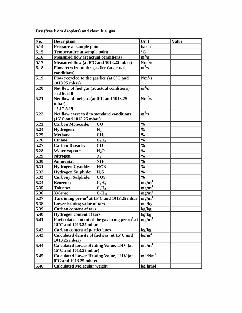
Dry (free from droplets) and clean fuel gas No. Description Unit Value 5.14 Pressure at sample point bar.a 5.15 Temperature at sample point °C 5.16 Measured flow (at actual conditions) m3/s 5.17 Measured flow (at 0°C and 1013.25 mbar) Nm3/s 5.18 Flow recycled to the gasifier (at actual
conditions) m3/s
5.19 Flow recycled to the gasifier (at 0°C and 1013.25 mbar)
Nm3/s
5.20 Net flow of fuel gas (at actual conditions) =5.16-5.18
m3/s
5.21 Net flow of fuel gas (at 0°C and 1013.25 mbar) =5.17-5.19
Nm3/s
5.22 Net flow corrected to standard conditions (15°C and 1013.25 mbar)
m3/s
5.23 Carbon Monoxide: CO % 5.24 Hydrogen: H2 % 5.25 Methane: CH4 % 5.26 Ethane: C2H6 % 5.27 Carbon Dioxide: CO2 % 5.28 Water vapour: H2O % 5.29 Nitrogen: N2 % 5.30 Ammonia: NH3 % 5.31 Hydrogen Cyanide: HCN % 5.32 Hydrogen Sulphide: H2S % 5.33 Carbonyl Sulphide: COS % 5.34 Benzene: C6H6 mg/m3 5.35 Toluene: C7H8 mg/m3 5.36 Xylene: C8H10 mg/m3 5.37 Tars in mg per m3 at 15°C and 1013.25 mbar mg/m3 5.38 Lower heating value of tars mJ/kg 5.39 Carbon content of tars kg/kg 5.40 Hydrogen content of tars kg/kg 5.41 Particulate content of the gas in mg per m3 at
15°C and 1013.25 mbar mg/m3
5.42 Carbon content of particulates kg/kg 5.43 Calculated density of fuel gas (at 15°C and
1013.25 mbar) kg/m3
5.44 Calculated Lower Heating Value, LHV (at 15°C and 1013.25 mbar)
mJ/m3
5.45 Calculated Lower Heating Value, LHV (at 0°C and 1013.25 mbar)
mJ/Nm3
5.46 Calculated Molecular weight kg/kmol
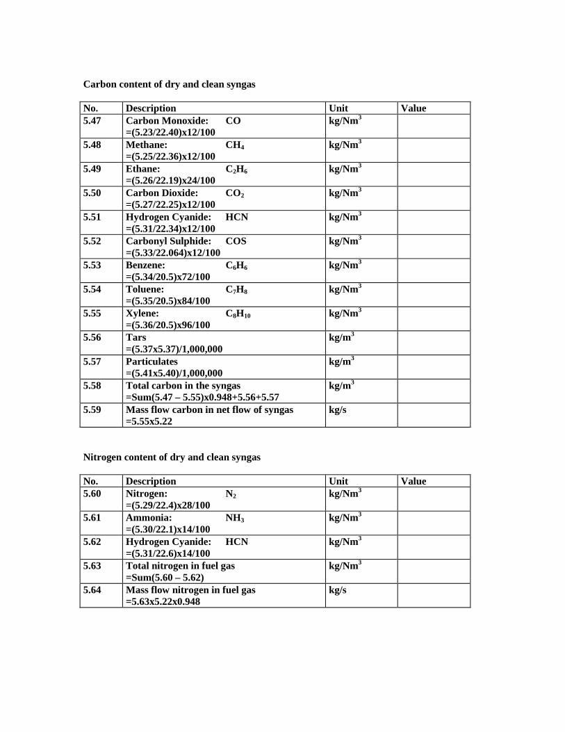
Carbon content of dry and clean syngas No. Description Unit Value 5.47 Carbon Monoxide: CO
=(5.23/22.40)x12/100 kg/Nm3
5.48 Methane: CH4 =(5.25/22.36)x12/100
kg/Nm3
5.49 Ethane: C2H6 =(5.26/22.19)x24/100
kg/Nm3
5.50 Carbon Dioxide: CO2 =(5.27/22.25)x12/100
kg/Nm3
5.51 Hydrogen Cyanide: HCN =(5.31/22.34)x12/100
kg/Nm3
5.52 Carbonyl Sulphide: COS =(5.33/22.064)x12/100
kg/Nm3
5.53 Benzene: C6H6 =(5.34/20.5)x72/100
kg/Nm3
5.54 Toluene: C7H8 =(5.35/20.5)x84/100
kg/Nm3
5.55 Xylene: C8H10 =(5.36/20.5)x96/100
kg/Nm3
5.56 Tars =(5.37x5.37)/1,000,000
kg/m3
5.57 Particulates =(5.41x5.40)/1,000,000
kg/m3
5.58 Total carbon in the syngas =Sum(5.47 – 5.55)x0.948+5.56+5.57
kg/m3
5.59 Mass flow carbon in net flow of syngas =5.55x5.22
kg/s
Nitrogen content of dry and clean syngas No. Description Unit Value 5.60 Nitrogen: N2
=(5.29/22.4)x28/100 kg/Nm3
5.61 Ammonia: NH3 =(5.30/22.1)x14/100
kg/Nm3
5.62 Hydrogen Cyanide: HCN =(5.31/22.6)x14/100
kg/Nm3
5.63 Total nitrogen in fuel gas =Sum(5.60 – 5.62)
kg/Nm3
5.64 Mass flow nitrogen in fuel gas =5.63x5.22x0.948
kg/s
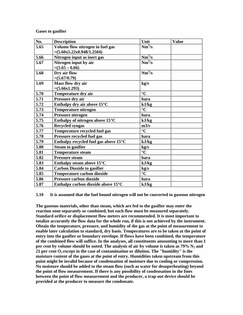
Gases to gasifier No. Description Unit Value 5.65 Volume flow nitrogen in fuel gas
=(5.60x5.22x0.948/1.2504) Nm3/s
5.66 Nitrogen input as inert gas Nm3/s 5.67 Nitrogen input by air
=(5.65 – 6.66) Nm3/s
5.68 Dry air flow =(5.67/0.79)
Nm3/s
5.69 Mass flow dry air =(5.66x1.293)
kg/s
5.70 Temperature dry air °C 5.71 Pressure dry air bara 5.72 Enthalpy dry air above 15°C kJ/kg 5.73 Temperature nitrogen °C 5.74 Pressure nitrogen bara 5.75 Enthalpy of nitrogen above 15°C kJ/kg 5.76 Recycled syngas m3/s 5.77 Temperature recycled fuel gas °C 5.78 Pressure recycled fuel gas bara 5.79 Enthalpy recycled fuel gas above 15°C kJ/kg 5.80 Steam to gasifier kg/s 5.81 Temperature steam °C 5.82 Pressure steam bara 5.83 Enthalpy steam above 15°C kJ/kg 5.84 Carbon Dioxide to gasifier kg/s 5.85 Temperature carbon dioxide °C 5.86 Pressure carbon dioxide bara 5.87 Enthalpy carbon dioxide above 15°C kJ/kg 5.10 It is assumed that the fuel bound nitrogen will not be converted to gaseous nitrogen The gaseous materials, other than steam, which are fed to the gasifier may enter the reaction zone separately or combined, but each flow must be measured separately. Standard orifice or displacement flow meters are recommended. It is most important to totalize accurately the flow data for the whole run, if this is not achieved by the instrument. Obtain the temperature, pressure, and humidity of the gas at the point of measurement to enable later calculation to standard, dry basis. Temperatures are to be taken at the point of entry into the gasifier or boundary envelope. If flows have been combined, the temperature of the combined flow will suffice. In the analyses, all constituents amounting to more than 1 per cent by volume should be noted. The analysis of air by volume is taken as 79% N2 and 21 per cent O2 except in the case of contamination or dilution. The "humidity" is the moisture content of the gases at the point of entry. Humidities taken upstream from this point might be invalid because of condensation of moisture due to cooling or compression. No moisture should be added to the steam flow (such as water for desuperheating) beyond the point of flow measurement. If there is any possibility of condensation in the lines between the point of flow measurement and the producer, a trap-out device should be provided at the producer to measure the condensate.
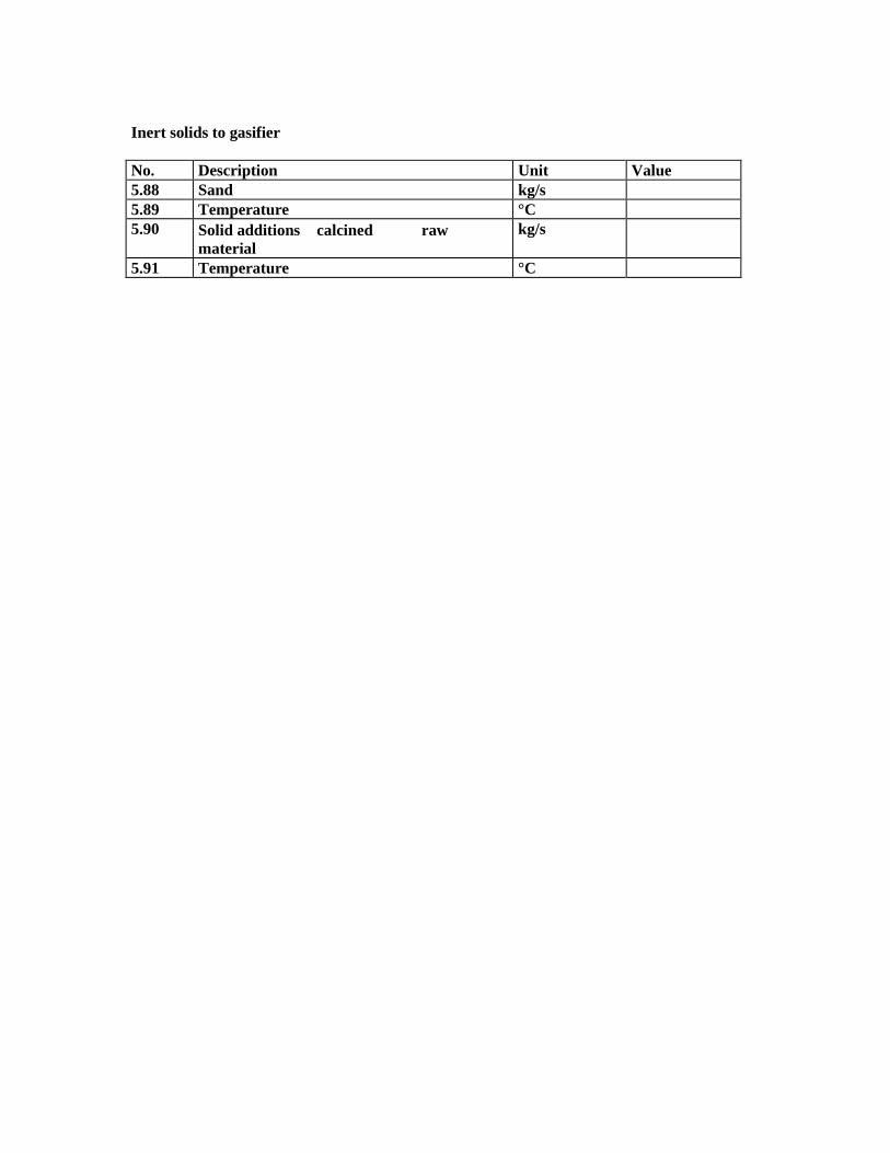
Inert solids to gasifier No. Description Unit Value 5.88 Sand kg/s 5.89 Temperature °C 5.90 Solid additions calcined raw
material kg/s
5.91 Temperature °C
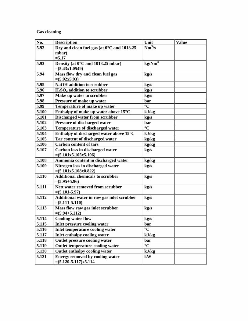
Gas cleaning No. Description Unit Value 5.92 Dry and clean fuel gas (at 0°C and 1013.25
mbar) =5.17
Nm3/s
5.93 Density (at 0°C and 1013.25 mbar) =(5.43x1.0549)
kg/Nm3
5.94 Mass flow dry and clean fuel gas =(5.92x5.93)
kg/s
5.95 NaOH addition to scrubber kg/s 5.96 H2SO4 addition to scrubber kg/s 5.97 Make up water to scrubber kg/s 5.98 Pressure of make up water bar 5.99 Temperature of make up water °C 5.100 Enthalpy of make up water above 15°C kJ/kg 5.101 Discharged water from scrubber kg/s 5.102 Pressure of discharged water bar 5.103 Temperature of discharged water °C 5.104 Enthalpy of discharged water above 15°C kJ/kg 5.105 Tar content of discharged water kg/kg 5.106 Carbon content of tars kg/kg 5.107 Carbon loss in discharged water
=(5.101x5.105x5.106) kg/s
5.108 Ammonia content in discharged water kg/kg 5.109 Nitrogen loss in discharged water
=(5.101x5.108x0.822) kg/s
5.110 Additional chemicals to scrubber =(5.95+5.96)
kg/s
5.111 Nett water removed from scrubber =(5.101-5.97)
kg/s
5.112 Additional water in raw gas inlet scrubber =(5.111-5.110)
kg/s
5.113 Mass flow raw gas inlet scrubber =(5.94+5.112)
kg/s
5.114 Cooling water flow kg/s 5.115 Inlet pressure cooling water bar 5.116 Inlet temperature cooling water °C 5.117 Inlet enthalpy cooling water kJ/kg 5.118 Outlet pressure cooling water bar 5.119 Outlet temperature cooling water °C 5.120 Outlet enthalpy cooling water kJ/kg 5.121 Energy removed by cooling water
=(5.120-5.117)x5.114 kW
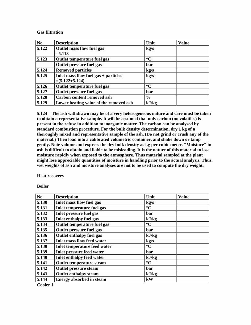
Gas filtration No. Description Unit Value 5.122 Outlet mass flow fuel gas
=5.113 kg/s
5.123 Outlet temperature fuel gas °C Outlet pressure fuel gas bar 5.124 Removed particles kg/s 5.125 Inlet mass flow fuel gas + particles
=(5.122+5.124) kg/s
5.126 Outlet temperature fuel gas °C 5.127 Outlet pressure fuel gas bar 5.128 Carbon content removed ash % 5.129 Lower heating value of the removed ash kJ/kg 5.124 The ash withdrawn may be of a very heterogeneous nature and care must be taken to obtain a representative sample. It will be assumed that only carbon (no volatiles) is present in the refuse in addition to inorganic matter. The carbon can be analysed by standard combustion procedure. For the bulk density determination, dry 1 kg of a thoroughly mixed and representative sample of the ash. (Do not grind or crush any of the material.) Then load into a calibrated volumetric container, and shake down or tamp gently. Note volume and express the dry bulk density as kg per cubic meter. "Moisture" in ash is difficult to obtain and liable to be misleading. It is the nature of this material to lose moisture rapidly when exposed to the atmosphere. Thus material sampled at the plant might lose appreciable quantities of moisture in handling prior to the actual analysis. Thus, wet weights of ash and moisture analyses are not to be used to compute the dry weight. Heat recovery Boiler No. Description Unit Value 5.130 Inlet mass flow fuel gas kg/s 5.131 Inlet temperature fuel gas °C 5.132 Inlet pressure fuel gas bar 5.133 Inlet enthalpy fuel gas kJ/kg 5.134 Outlet temperature fuel gas °C 5.135 Outlet pressure fuel gas bar 5.136 Outlet enthalpy fuel gas kJ/kg 5.137 Inlet mass flow feed water kg/s 5.138 Inlet temperature feed water °C 5.139 Inlet pressure feed water bar 5.140 Inlet enthalpy feed water kJ/kg 5.141 Outlet temperature steam °C 5.142 Outlet pressure steam bar 5.143 Outlet enthalpy steam kJ/kg 5.144 Energy absorbed in steam kW Cooler 1

No. Description Unit Value 5.145 Inlet mass flow fuel gas kg/s 5.146 Inlet temperature fuel gas °C 5.147 Inlet pressure fuel gas bar 5.148 Inlet enthalpy fuel gas kJ/kg 5.149 Outlet temperature fuel gas °C 5.150 Outlet pressure fuel gas bar 5.151 Outlet enthalpy fuel gas kJ/kg 5.152 Inlet mass flow feed water kg/s 5.153 Inlet temperature feed water °C 5.154 Inlet pressure feed water bar 5.155 Inlet enthalpy feed water kJ/kg 5.156 Outlet temperature steam/water °C 5.157 Outlet pressure steam/water bar 5.158 Outlet enthalpy steam/water kJ/kg 5.159 Energy absorbed in steam/water kW Cooler 2 No. Description Unit Value 5.160 Inlet mass flow fuel gas kg/s 5.161 Inlet temperature fuel gas °C 5.162 Inlet pressure fuel gas bar 5.163 Inlet enthalpy fuel gas kJ/kg 5.164 Outlet temperature fuel gas °C 5.165 Outlet pressure fuel gas bar 5.166 Outlet enthalpy fuel gas kJ/kg 5.167 Inlet mass flow feed water kg/s 5.168 Inlet temperature feed water °C 5.169 Inlet pressure feed water bar 5.170 Inlet enthalpy feed water kJ/kg 5.171 Outlet temperature steam/water °C 5.172 Outlet pressure steam/water bar 5.173 Outlet enthalpy steam/water kJ/kg 5.174 Energy absorbed in steam/water kW
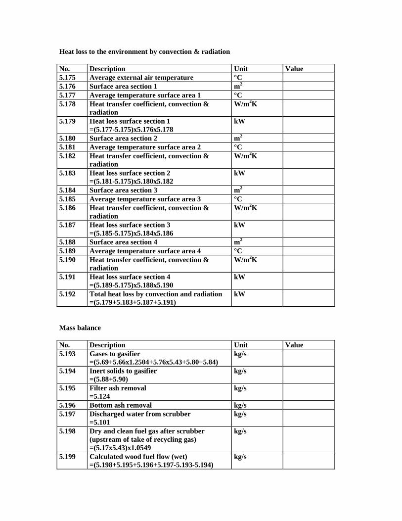
Heat loss to the environment by convection & radiation No. Description Unit Value 5.175 Average external air temperature °C 5.176 Surface area section 1 m2 5.177 Average temperature surface area 1 °C 5.178 Heat transfer coefficient, convection &
radiation W/m2K
5.179 Heat loss surface section 1 =(5.177-5.175)x5.176x5.178
kW
5.180 Surface area section 2 m2 5.181 Average temperature surface area 2 °C 5.182 Heat transfer coefficient, convection &
radiation W/m2K
5.183 Heat loss surface section 2 =(5.181-5.175)x5.180x5.182
kW
5.184 Surface area section 3 m2 5.185 Average temperature surface area 3 °C 5.186 Heat transfer coefficient, convection &
radiation W/m2K
5.187 Heat loss surface section 3 =(5.185-5.175)x5.184x5.186
kW
5.188 Surface area section 4 m2 5.189 Average temperature surface area 4 °C 5.190 Heat transfer coefficient, convection &
radiation W/m2K
5.191 Heat loss surface section 4 =(5.189-5.175)x5.188x5.190
kW
5.192 Total heat loss by convection and radiation =(5.179+5.183+5.187+5.191)
kW
Mass balance No. Description Unit Value 5.193 Gases to gasifier
=(5.69+5.66x1.2504+5.76x5.43+5.80+5.84) kg/s
5.194 Inert solids to gasifier =(5.88+5.90)
kg/s
5.195 Filter ash removal =5.124
kg/s
5.196 Bottom ash removal kg/s 5.197 Discharged water from scrubber
=5.101 kg/s
5.198 Dry and clean fuel gas after scrubber (upstream of take of recycling gas) =(5.17x5.43)x1.0549
kg/s
5.199 Calculated wood fuel flow (wet) =(5.198+5.195+5.196+5.197-5.193-5.194)
kg/s

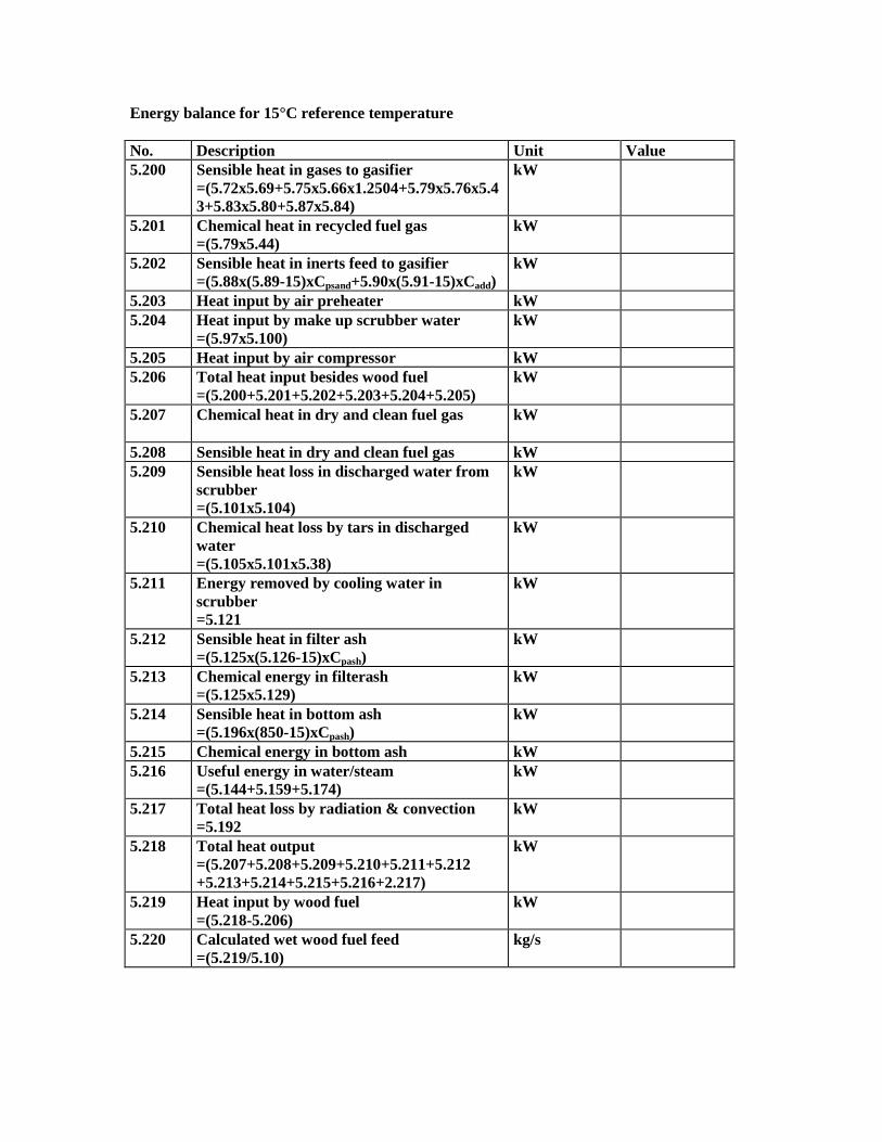
Energy balance for 15°C reference temperature No. Description Unit Value 5.200 Sensible heat in gases to gasifier
=(5.72x5.69+5.75x5.66x1.2504+5.79x5.76x5.43+5.83x5.80+5.87x5.84)
kW
5.201 Chemical heat in recycled fuel gas =(5.79x5.44)
kW
5.202 Sensible heat in inerts feed to gasifier =(5.88x(5.89-15)xCpsand+5.90x(5.91-15)xCadd)
kW
5.203 Heat input by air preheater kW 5.204 Heat input by make up scrubber water
=(5.97x5.100) kW
5.205 Heat input by air compressor kW 5.206 Total heat input besides wood fuel
=(5.200+5.201+5.202+5.203+5.204+5.205) kW
5.207 Chemical heat in dry and clean fuel gas
kW
5.208 Sensible heat in dry and clean fuel gas kW 5.209 Sensible heat loss in discharged water from
scrubber =(5.101x5.104)
kW
5.210 Chemical heat loss by tars in discharged water =(5.105x5.101x5.38)
kW
5.211 Energy removed by cooling water in scrubber =5.121
kW
5.212 Sensible heat in filter ash =(5.125x(5.126-15)xCpash)
kW
5.213 Chemical energy in filterash =(5.125x5.129)
kW
5.214 Sensible heat in bottom ash =(5.196x(850-15)xCpash)
kW
5.215 Chemical energy in bottom ash kW 5.216 Useful energy in water/steam
=(5.144+5.159+5.174) kW
5.217 Total heat loss by radiation & convection =5.192
kW
5.218 Total heat output =(5.207+5.208+5.209+5.210+5.211+5.212 +5.213+5.214+5.215+5.216+2.217)
kW
5.219 Heat input by wood fuel =(5.218-5.206)
kW
5.220 Calculated wet wood fuel feed =(5.219/5.10)
kg/s

5.202 For the heat capacity of sand Cpsand is equal to 0.84 kJ/kg°C and the heat capacity of the solid additions Cadd is equal to 0.97 kJ/kg°C and for calcined solid additions 0.84 kJ/kg°C (approximate values) for temperatures below 200°C. 5.204 The energy input by the air compressor can be determined by measuring the power consumption and using the efficiency corrections supplied with the electric motor. If the temperature can be measured accurately downstream of the compressor and air pre-heater it is possible to calculate directly the heat absorbed which can be used to replace the sum of 201 and 204. 5.212 The heat capacity of the filter ash Cpash is equal to 0.84 kJ/kg°C for temperatures below 200°C Carbon balance No. Description Unit Value 5.221 Carbon in fuel gas
=5.59 kg/s
5.222 Carbon in discharged water =5.107
kg/s
5.223 Carbon in filter ash =(5.124x5.128)/100
kg/s
5.224 Carbon in bottom ash =(5.196x...)/100
kg/s
5.225 Total carbon flow out =(5.221+5.222+5.223+5.224)
kg/s
5.226 Carbon in recycled fuel gas =(5.58x5.22)
kg/s
5.227 Carbon in added CO2 =(5.84/44)x12
kg/s
5.228 Carbon in solid additions (CO2) =(5.90x0.48)
kg/s
5.229 Carbon in besides wood fuel =(5.226+5.227+5.228)
kg/s
5.230 Carbon in wood fuel =(5.225-5.229)
kg/s
5.231 Calculated dry wood fuel feed =(5.230x100)/5.3
kg/s
5.232 Calculated wet wood fuel feed =(100x5.231)/(100-5.1)
kg/s
Calculation of weighed mass flow wood fuel feed No. Description Unit Value 5.233 Mass flow wood according to mass balance kg/s 5.234 Weighing factor mass balance - 5.235 Mass flow wood according to energy balance kg/s 5.236 Weighing factor energy balance - 5.237 Mass flow wood according to carbon balance kg/s 5.238 Weighing factor carbon balance - 5.239 Mass flow wood according to direct
measurement kg/s
5.240 Weighing factor direct measurement - 5.241 Sum(mass flow)xweighting factor
=(5.233x5.234+5.235x5.236+5.237x5.238+ 5.239x5.240)
kg/s
5.242 Sum(weighting factor) =(5.234+5.236+5.238+5.240)
-
5.243 Weighted average for mass flow =(5.241/5.242)
kg/s
Efficiency No. Description Unit Value 5.244 Potential heat input wood fuel
=(5.243x5.10) kWth
5.245 Sensible heat input wood fuel =(5.243x(5.9-15)x0.2.72
kWth
5.246 Heat credits =5.206
kWth
5.247 Heat input =(5.244+5.245+5.246)
kWth
5.248 Potential heat output fuel gas =5.207
kWth
5.249 Sensible heat output fuel gas =5.208
kWth
5.250 Useful heat in steam/water =(5.144+5.159+5.174)
kWth
5.251 Cold gas efficiency =(5.248/5.257)
%
5.252 Hot gas efficiency =(5.248+5.249)/5.257
%
5.252 Overall efficiency =(5.248+5.249+5.250)/5.257
%
Accuracy
SECTION 6, REPORT OF TEST RESULTS General information Period of test: Start: Month
Day Year Time
End Month Day Year Time
Location: Type and size of the gasifier Dates of completion of of installation: Name and address: Owner Name
Address Street and number City Post Code Country Telephone Telefax
Builder Name Address Street and number City Post Code Country Telephone Telefax
B. Summary of data
Related Documents


