FANUC AC SPINDLE MOTOR @* series DESCRIPTIONS B-65272EN/04

Welcome message from author
This document is posted to help you gain knowledge. Please leave a comment to let me know what you think about it! Share it to your friends and learn new things together.
Transcript
FANUC AC SPINDLE MOTOR @* series
DESCRIPTIONS
B-65272EN/04
No part of this manual may be reproduced in any form.
All specifications and designs are subject to change without notice.
In this manual we have tried as much as possible to describe all thevarious matters.However, we cannot describe all the matters which must not be done,or which cannot be done, because there are so many possibilities.Therefore, matters which are not especially described as possible inthis manual should be regarded as ”impossible”.
B-65272EN/04 SAFETY PRECAUTIONS
s-1
SAFETY PRECAUTIONSThis "Safety Precautions" section describes the precautions whichmust be observed to ensure safety when using FANUC spindlemotors.Users of any spindle motor model are requested to read this manualcarefully before using the spindle motor.The users are also requested to read this manual carefully andunderstand each function of the motor for correct use.The users are basically forbidden to do any behavior or action notmentioned in this manual. They are invited to ask FANUC previouslyabout what behavior or action is prohibited.
For matters that are not described in this manual, a machine must bedesigned and assembled in accordance with EN60204-1 to ensure thesafety of the machine and compliance with European specifications.For details, refer to the specification.
Contents1.1 DEFINITION OF WARNING, CAUTION, AND NOTE.........s-21.2 WARNING ................................................................................s-31.3 CAUTION..................................................................................s-51.4 NOTE ...................................................................................s-7
SAFETY PRECAUTIONS B-65272EN/04
s-2
1.1 DEFINITION OF WARNING, CAUTION, AND NOTE
This manual includes safety precautions for protecting the user andpreventing damage to the machine. Precautions are classified intoWarning and Caution according to their bearing on safety. Also,supplementary information is described as a Note. Read the Warning,Caution, and Note thoroughly before attempting to use the machine.
WARNINGApplied when there is a danger of the user beinginjured or when there is a damage of both the userbeing injured and the equipment being damaged ifthe approved procedure is not observed.
CAUTIONApplied when there is a danger of the equipmentbeing damaged, if the approved procedure is notobserved.
NOTEThe Note is used to indicate supplementaryinformation other than Warning and Caution.
- Read this manual carefully, and store it in a safe place.
B-65272EN/04 SAFETY PRECAUTIONS
s-3
1.2 WARNING
WARNING - Be safely dressed when handling a motor.
Wear safety shoes or gloves when handling a motor as you may gethurt on any edge or protrusion on it or electric shocks.
- Use a crane or lift to move a motor from one place to another.A motor is heavy. If you lift the motor by hand, you may get abackache, or you may be seriously injured when you drop the motor.A suitable crane or lift must be used to move the motor. (For theweight of motors, refer to this manual.)When moving a motor using a crane or lift, use a hanging bolt if themotor has a corresponding tapped hole, or textile rope if it has notapped hole. If a motor is attached with a machine or any other heavystuff, do not use a hanging bolt to move the motor as the hanging boltand/or motor may get broken.
- Before starting to connect a motor to electric wires, make sure they are isolatedfrom an electric power source.
A failure to observe this caution is vary dangerous because you mayget electric shocks.
- Be sure to secure power wires.If operation is performed with a terminal loose, the terminal blockmay become abnormally hot, possibly causing a fire. Also, theterminal may become disconnected, causing a ground fault or short-circuit, and possibly giving you electric shocks. See the section in thismanual that gives the tightening torque for attaching power wires andshort-bars to the terminal block.
- Be sure to ground a motor frame.To avoid electric shocks, be sure to connect the grounding terminal inthe terminal box to the grounding terminal of the machine.
- Do not ground a motor power wire terminal or short-circuit it to another powerwire terminal.
A failure to observe this caution may cause electric shocks or aburned wiring.* Some motors require a special connection such as a winding
switching. Refer to their respective motor specification manualsfor details.
- Do not supply the power to the motor while any terminal is exposed.A failure to observe this caution is very dangerous because you mayget electric shocks if your body or any conductive stuff touches anexposed terminal.
SAFETY PRECAUTIONS B-65272EN/04
s-4
WARNING - Do not bring any dangerous stuff near a motor.
Motors are connected to a power line, and may get hot. If a flammableis placed near a motor, it may be ignited, catch fire, or explode.
- Do not get close to a rotary section of a motor when it is rotating.You may get your clothes or fingers caught in a rotary section, andmay be injured. Before starting a motor, ensure that there is no stuffthat can fly away (such as a key) on the motor.
- Do not touch a motor with a wet hand.A failure to observe this caution is vary dangerous because you mayget electric shocks.
- Before touching a motor, shut off the power to it.Even if a motor is not rotating, there may be a voltage across theterminals of the motor.Especially before touching a power supply connection, take sufficientprecautions.Otherwise you may get electric shocks.
- Do not touch any terminal of a motor for a while (at least 5 minutes) after thepower to the motor is shut off.
High voltage remains across power line terminals of a motor for awhile after the power to the motor is shut off. So, do not touch anyterminal or connect it to any other equipment. Otherwise, you may getelectric shocks or the motor and/or equipment may get damaged.
- To drive a motor, use a specified amplifier and parameters.An incorrect combination of a motor, amplifier, and parameters maycause the motor to behave unexpectedly. This is dangerous, and themotor may get damaged.
- Before driving a motor, be sure to secure it.If a motor is drove without being secured, it may roll over duringacceleration or deceleration, injuring the user.
B-65272EN/04 SAFETY PRECAUTIONS
s-5
1.3 CAUTION
CAUTION - Do not touch a motor when it is running or immediately after it stops.
A motor may get hot when it is running. Do not touch the motorbefore it gets cool enough. Otherwise, you may get burned.
- Be careful not get your hair or cloths caught in a fan.Be careful especially for a fan used to generate an inward air flow.Be careful also for a fan even when the motor is stopped, because itcontinues to rotate while the amplifier is turned on.
- Ensure that motors and related components are mounted securely.If a motor or its component slips out of place or comes off when themotor is running, it is very dangerous.
- FANUC motors are designed for use with machines. Do not use them for any otherpurpose.
If a FANUC motor is used for an unintended purpose, it may cause anunexpected symptom or trouble. If you want to use a motor for anunintended purpose, previously consult with FANUC.
- Ensure that a base or frame on which a motor is mounted is strong enough.Motors are heavy. If a base or frame on which a motor is mounted isnot strong enough, it is impossible to achieve the required precision.
- Be sure to connect motor cables correctly.An incorrect connection of a cable cause abnormal heat generation,equipment malfunction, or failure. Always use a cable with anappropriate current carrying capacity (or thickness). For how toconnect cables to motors, refer to theirrespective specification manuals.
- Ensure that motors are cooled if they are those that require forcible cooling.If a motor that requires forcible cooling is not cooled normally, it maycause a failure or trouble. For a fan-cooled motor, ensure that it is notclogged or blocked with dust and dirt. For a liquid-cooled motor,ensure that the amount of the liquid is appropriate and that the liquidpiping is not clogged. For both types, perform regular cleaning andinspection.
- When attaching a component having inertia, such as a pulley, to a motor, ensurethat any imbalance between the motor and component is minimized.
If there is a large imbalance, the motor may vibrates abnormally,resulting in the motor being broken.
SAFETY PRECAUTIONS B-65272EN/04
s-6
CAUTION
- Be sure to attach a key to a motor with a keyed shaft.If a motor with a keyed shaft runs with no key attached, it may impairtorque transmission or cause imbalance, resulting in the motor beingbroken.With the αi series, a shaft with no key is used as standard.
B-65272EN/04 SAFETY PRECAUTIONS
s-7
1.4 NOTE
NOTE - Do not step or sit on a motor.
If you step or sit on a motor, it may get deformed or broken. Do notput a motor on another unless they are in packages.
- When storing a motor, put it in a dry (non-condensing) place at room temperature(0 to 40 °°°°C).
If a motor is stored in a humid or hot place, its components may getdamaged or deteriorated. In addition, keep a motor in such a positionthat its shaft is held horizontal and its terminal box is at the top.
- Do not remove a nameplate from a motor.If a nameplate comes off, be careful not to lose it. If the nameplate islost, the motor becomes unidentifiable, resulting in maintenancebecoming impossible. For a nameplate for a built-in spindle motor,keep the nameplate with the spindle.
- Do not apply shocks to a motor or cause scratches to it.If a motor is subjected to shocks or is scratched, its components maybe adversely affected, resulting in normal operation being impaired.Be very careful when handling plastic portions, sensors, and windings,because they are very liable to break. Especially, avoid lifting a motorby pulling its plastic portion, winding, or power cable.
- Do not conduct dielectric strength or insulation test for a sensor.Such a test can damage elements in the sensor.
- When testing the winding or insulation resistance of a motor, satisfy theconditions stipulated in IEC34.
Testing a motor under a condition severer than those specified inIEC34 may damage the motor.
- Do not disassemble a motor.Disassembling a motor may cause a failure or trouble in it.If disassembly is in need because of maintenance or repair, pleasecontact a service representative of FANUC.
- Do not modify a motor.Do not modify a motor unless directed by FANUC. Modifying amotor may cause a failure or trouble in it.
- Use a motor under an appropriate environmental condition.Using a motor in an adverse environment may cause a failure ortrouble in it. Refer to their respective specification manuals for detailsof the operating and environmental conditions for motors.
SAFETY PRECAUTIONS B-65272EN/04
s-8
NOTE - Do not apply a commercial power source voltage directly to a motor.
Applying a commercial power source voltage directly to a motor mayresult in its windings being burned. Be sure to use a specifiedamplifier for supplying voltage to the motor.
- For a motor with a terminal box, make a conduit hole for the terminal box in aspecified position.
When making a conduit hole, be careful not to break or damageunspecified portions. Refer to an applicable specification manual.
- Before using a motor, measure its winding and insulation resistances, and makesure they are normal.
Especially for a motor that has been stored for a prolonged period oftime, conduct these checks. A motor may deteriorate depending on thecondition under which it is stored or the time during which it is stored.For the winding resistances of motors, refer to their respectivespecification manuals, or ask FANUC. For insulation resistances, seethe following table.
- To use a motor as long as possible, perform periodic maintenance and inspectionfor it, and check its winding and insulation resistances.
Note that extremely severe inspections (such as dielectric strengthtests) of a motor may damage its windings. For the windingresistances of motors, refer to their respective specification manuals,or ask FANUC. For insulation resistances, see the following table.
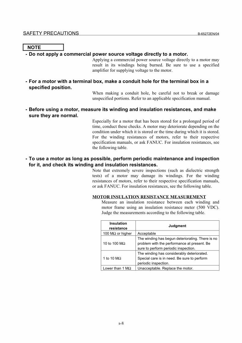
MOTOR INSULATION RESISTANCE MEASUREMENTMeasure an insulation resistance between each winding andmotor frame using an insulation resistance meter (500 VDC).Judge the measurements according to the following table.
Insulationresistance Judgment
100 MΩ or higher Acceptable
10 to 100 MΩThe winding has begun deteriorating. There is noproblem with the performance at present. Besure to perform periodic inspection.
1 to 10 MΩThe winding has considerably deteriorated.Special care is in need. Be sure to performperiodic inspection.
Lower than 1 MΩ Unacceptable. Replace the motor.
B-65272EN/04 PREFACE
p-1
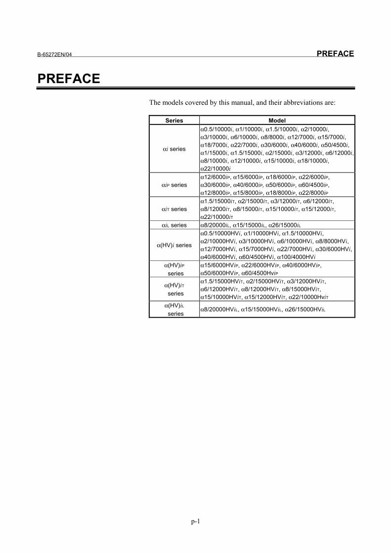
PREFACEThe models covered by this manual, and their abbreviations are:
Series Model
αi series
α0.5/10000i, α1/10000i, α1.5/10000i, α2/10000i,α3/10000i, α6/10000i, α8/8000i, α12/7000i, α15/7000i,α18/7000i, α22/7000i, α30/6000i, α40/6000i, α50/4500i,α1/15000i, α1.5/15000i, α2/15000i, α3/12000i, α6/12000i,α8/10000i, α12/10000i, α15/10000i, α18/10000i,α22/10000i
αiP seriesα12/6000iP, α15/6000iP, α18/6000iP, α22/6000iP,α30/6000iP, α40/6000iP, α50/6000iP, α60/4500iP,α12/8000iP, α15/8000iP, α18/8000iP, α22/8000iP
αiT seriesα1.5/15000iT, α2/15000iT, α3/12000iT, α6/12000iT,α8/12000iT, α8/15000iT, α15/10000iT, α15/12000iT,α22/10000iT
αiL series α8/20000iL, α15/15000iL, α26/15000iL
α(HV)i series
α0.5/10000HVi, α1/10000HVi, α1.5/10000HVi,α2/10000HVi, α3/10000HVi, α6/10000HVi, α8/8000HVi,α12/7000HVi, α15/7000HVi, α22/7000HVi, α30/6000HVi,α40/6000HVi, α60/4500HVi, α100/4000HVi
α(HV)iP series
α15/6000HViP, α22/6000HViP, α40/6000HViP,α50/6000HViP, α60/4500HviP
α(HV)iT series
α1.5/15000HViT, α2/15000HViT, α3/12000HViT,α6/12000HViT, α8/12000HViT, α8/15000HViT,α15/10000HViT, α15/12000HViT, α22/10000HviT
α(HV)iL series
α8/20000HViL, α15/15000HViL, α26/15000HViL

B-65272EN/04 TABLE OF CONTENTS
c-1
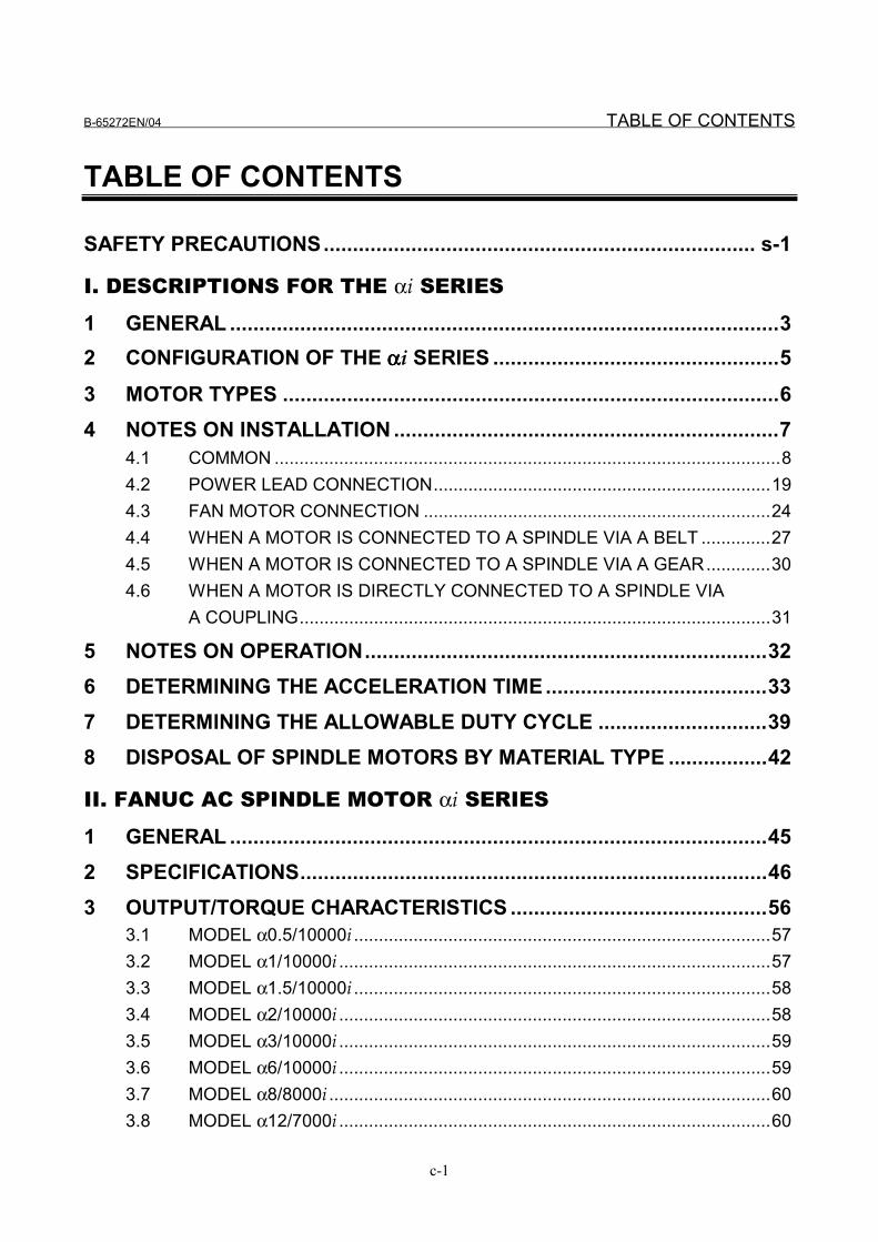
TABLE OF CONTENTS
SAFETY PRECAUTIONS.......................................................................... s-1
I. DESCRIPTIONS FOR THE αi SERIES
1 GENERAL ..............................................................................................32 CONFIGURATION OF THE ααααi SERIES .................................................53 MOTOR TYPES .....................................................................................64 NOTES ON INSTALLATION ..................................................................7
4.1 COMMON ......................................................................................................84.2 POWER LEAD CONNECTION....................................................................194.3 FAN MOTOR CONNECTION ......................................................................244.4 WHEN A MOTOR IS CONNECTED TO A SPINDLE VIA A BELT ..............274.5 WHEN A MOTOR IS CONNECTED TO A SPINDLE VIA A GEAR.............304.6 WHEN A MOTOR IS DIRECTLY CONNECTED TO A SPINDLE VIA
A COUPLING...............................................................................................31
5 NOTES ON OPERATION.....................................................................326 DETERMINING THE ACCELERATION TIME......................................337 DETERMINING THE ALLOWABLE DUTY CYCLE .............................398 DISPOSAL OF SPINDLE MOTORS BY MATERIAL TYPE .................42
II. FANUC AC SPINDLE MOTOR αi SERIES
1 GENERAL ............................................................................................452 SPECIFICATIONS................................................................................463 OUTPUT/TORQUE CHARACTERISTICS ............................................56
3.1 MODEL α0.5/10000i ....................................................................................573.2 MODEL α1/10000i .......................................................................................573.3 MODEL α1.5/10000i ....................................................................................583.4 MODEL α2/10000i .......................................................................................583.5 MODEL α3/10000i .......................................................................................593.6 MODEL α6/10000i .......................................................................................593.7 MODEL α8/8000i .........................................................................................603.8 MODEL α12/7000i .......................................................................................60
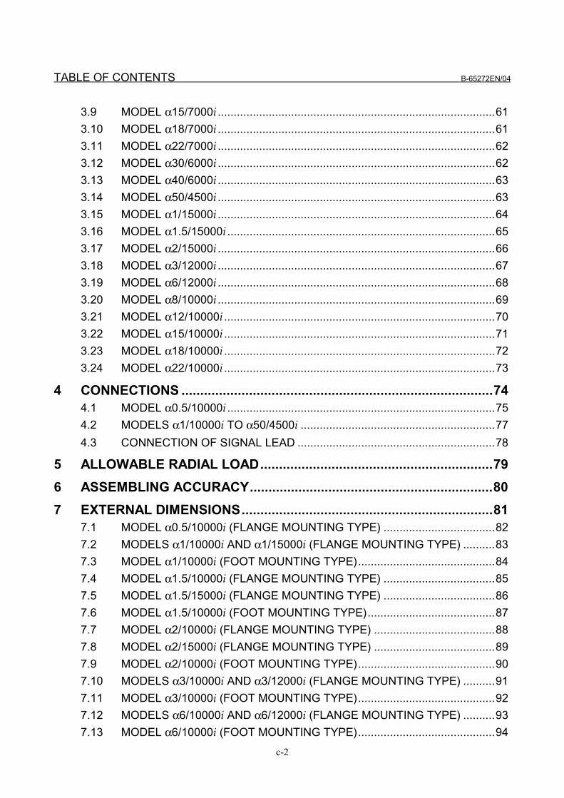
TABLE OF CONTENTS B-65272EN/04
c-2
3.9 MODEL α15/7000i .......................................................................................613.10 MODEL α18/7000i .......................................................................................613.11 MODEL α22/7000i .......................................................................................623.12 MODEL α30/6000i .......................................................................................623.13 MODEL α40/6000i .......................................................................................633.14 MODEL α50/4500i .......................................................................................633.15 MODEL α1/15000i .......................................................................................643.16 MODEL α1.5/15000i ....................................................................................653.17 MODEL α2/15000i .......................................................................................663.18 MODEL α3/12000i .......................................................................................673.19 MODEL α6/12000i .......................................................................................683.20 MODEL α8/10000i .......................................................................................693.21 MODEL α12/10000i .....................................................................................703.22 MODEL α15/10000i .....................................................................................713.23 MODEL α18/10000i .....................................................................................723.24 MODEL α22/10000i .....................................................................................73
4 CONNECTIONS ...................................................................................744.1 MODEL α0.5/10000i ....................................................................................754.2 MODELS α1/10000i TO α50/4500i .............................................................774.3 CONNECTION OF SIGNAL LEAD ..............................................................78
5 ALLOWABLE RADIAL LOAD..............................................................796 ASSEMBLING ACCURACY.................................................................807 EXTERNAL DIMENSIONS...................................................................81
7.1 MODEL α0.5/10000i (FLANGE MOUNTING TYPE) ...................................827.2 MODELS α1/10000i AND α1/15000i (FLANGE MOUNTING TYPE) ..........837.3 MODEL α1/10000i (FOOT MOUNTING TYPE)...........................................847.4 MODEL α1.5/10000i (FLANGE MOUNTING TYPE) ...................................857.5 MODEL α1.5/15000i (FLANGE MOUNTING TYPE) ...................................867.6 MODEL α1.5/10000i (FOOT MOUNTING TYPE)........................................877.7 MODEL α2/10000i (FLANGE MOUNTING TYPE) ......................................887.8 MODEL α2/15000i (FLANGE MOUNTING TYPE) ......................................897.9 MODEL α2/10000i (FOOT MOUNTING TYPE)...........................................907.10 MODELS α3/10000i AND α3/12000i (FLANGE MOUNTING TYPE) ..........917.11 MODEL α3/10000i (FOOT MOUNTING TYPE)...........................................927.12 MODELS α6/10000i AND α6/12000i (FLANGE MOUNTING TYPE) ..........937.13 MODEL α6/10000i (FOOT MOUNTING TYPE)...........................................94
B-65272EN/04 TABLE OF CONTENTS
c-3
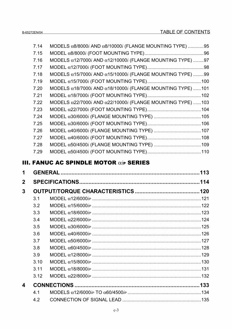
7.14 MODELS α8/8000i AND α8/10000i (FLANGE MOUNTING TYPE) ............957.15 MODEL α8/8000i (FOOT MOUNTING TYPE).............................................967.16 MODELS α12/7000i AND α12/10000i (FLANGE MOUNTING TYPE) ........977.17 MODEL α12/7000i (FOOT MOUNTING TYPE)...........................................987.18 MODELS α15/7000i AND α15/10000i (FLANGE MOUNTING TYPE) ........997.19 MODEL α15/7000i (FOOT MOUNTING TYPE).........................................1007.20 MODELS α18/7000i AND α18/10000i (FLANGE MOUNTING TYPE) ......1017.21 MODEL α18/7000i (FOOT MOUNTING TYPE).........................................1027.22 MODELS α22/7000i AND α22/10000i (FLANGE MOUNTING TYPE) ......1037.23 MODEL α22/7000i (FOOT MOUNTING TYPE).........................................1047.24 MODEL α30/6000i (FLANGE MOUNTING TYPE) ....................................1057.25 MODEL α30/6000i (FOOT MOUNTING TYPE).........................................1067.26 MODEL α40/6000i (FLANGE MOUNTING TYPE) ....................................1077.27 MODEL α40/6000i (FOOT MOUNTING TYPE).........................................1087.28 MODEL α50/4500i (FLANGE MOUNTING TYPE) ....................................1097.29 MODEL α50/4500i (FOOT MOUNTING TYPE).........................................110
III. FANUC AC SPINDLE MOTOR αiP SERIES
1 GENERAL ..........................................................................................1132 SPECIFICATIONS..............................................................................1143 OUTPUT/TORQUE CHARACTERISTICS ..........................................120
3.1 MODEL α12/6000iP ...................................................................................1213.2 MODEL α15/6000iP ...................................................................................1223.3 MODEL α18/6000iP ...................................................................................1233.4 MODEL α22/6000iP ...................................................................................1243.5 MODEL α30/6000iP ...................................................................................1253.6 MODEL α40/6000iP ...................................................................................1263.7 MODEL α50/6000iP ...................................................................................1273.8 MODEL α60/4500iP ...................................................................................1283.9 MODEL α12/8000iP ...................................................................................1293.10 MODEL α15/8000iP ...................................................................................1303.11 MODEL α18/8000iP ...................................................................................1313.12 MODEL α22/8000iP ...................................................................................132
4 CONNECTIONS .................................................................................1334.1 MODELS α12/6000iP TO α60/4500iP ........................................................1344.2 CONNECTION OF SIGNAL LEAD ............................................................135
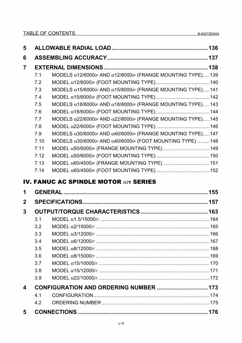
TABLE OF CONTENTS B-65272EN/04
c-4
5 ALLOWABLE RADIAL LOAD............................................................1366 ASSEMBLING ACCURACY...............................................................1377 EXTERNAL DIMENSIONS.................................................................138
7.1 MODELS α12/6000iP AND α12/8000iP (FRANGE MOUNTING TYPE).....1397.2 MODEL α12/6000iP (FOOT MOUNTING TYPE) .......................................1407.3 MODELS α15/6000iP AND α15/8000iP (FRANGE MOUNTING TYPE).....1417.4 MODEL α15/6000iP (FOOT MOUNTING TYPE) .......................................1427.5 MODELS α18/6000iP AND α18/8000iP (FRANGE MOUNTING TYPE).....1437.6 MODEL α18/6000iP (FOOT MOUNTING TYPE) .......................................1447.7 MODELS α22/6000iP AND α22/8000iP (FRANGE MOUNTING TYPE).....1457.8 MODEL α22/6000iP (FOOT MOUNTING TYPE) .......................................1467.9 MODELS α30/6000iP AND α40/6000iP (FRANGE MOUNTING TYPE).....1477.10 MODELS α30/6000iP AND α40/6000iP (FOOT MOUNTING TYPE) .........1487.11 MODEL α50/6000iP (FRANGE MOUNTING TYPE) ..................................1497.12 MODEL α50/6000iP (FOOT MOUNTING TYPE) .......................................1507.13 MODEL α60/4500iP (FRANGE MOUNTING TYPE) ..................................1517.14 MODEL α60/4500iP (FOOT MOUNTING TYPE) .......................................152
IV. FANUC AC SPINDLE MOTOR αiT SERIES
1 GENERAL ..........................................................................................1552 SPECIFICATIONS..............................................................................1573 OUTPUT/TORQUE CHARACTERISTICS ..........................................163
3.1 MODEL α1.5/15000iT ................................................................................1643.2 MODEL α2/15000iT ...................................................................................1653.3 MODEL α3/12000iT ...................................................................................1663.4 MODEL α6/12000iT ...................................................................................1673.5 MODEL α8/12000iT ...................................................................................1683.6 MODEL α8/15000iT ...................................................................................1693.7 MODEL α15/10000iT .................................................................................1703.8 MODEL α15/12000iT .................................................................................1713.9 MODEL α22/10000iT .................................................................................172
4 CONFIGURATION AND ORDERING NUMBER ................................1734.1 CONFIGURATION.....................................................................................1744.2 ORDERING NUMBER ...............................................................................175
5 CONNECTIONS .................................................................................176
B-65272EN/04 TABLE OF CONTENTS
c-5
5.1 CONNECTION OF THE POWER, FAN MOTOR, AND MZi SENSORSIGNAL LEADS.........................................................................................177
5.2 CONNECTION OF SIGNAL LEAD ............................................................179
6 ASSEMBLING ACCURACY...............................................................1807 EXTERNAL DIMENSIONS.................................................................181
7.1 MODEL α1.5/15000iT ................................................................................1827.2 MODEL α2/15000iT ...................................................................................1837.3 MODEL α3/12000iT ...................................................................................1847.4 MODEL α6/12000iT ...................................................................................1857.5 MODELS α8/12000iT AND α8/15000iT......................................................1867.6 MODEL α15/10000iT .................................................................................1877.7 MODEL α15/12000iT .................................................................................1887.8 MODEL α22/10000iT .................................................................................1897.9 DISTANCE BLOCK TYPE 1.5iT................................................................1907.10 DISTANCE BLOCK TYPE 2iT...................................................................1917.11 DISTANCE BLOCK TYPE 6iT...................................................................1927.12 DISTANCE BLOCK TYPE 15iT.................................................................193
8 POINTS ABOUT DIRECT CONNECTION STRUCTURE...................1949 NOTES ON MOTOR INSTALLATION................................................195
9.1 HIGHER-PRECISION MOUNTING FLANGE AND SHAFT .......................1969.2 CENTERING USING CENTERING PLATES.............................................1979.3 CHECKING MOTOR VIBRATION (TO SEE WHETHER CENTERING
IS SUCCESSFUL) .....................................................................................1989.4 COUPLING SELECTION...........................................................................1999.5 ROTATION JOINT.....................................................................................2029.6 COOLANT JOINT ......................................................................................2039.7 ROTATION JOINT SUPPORT HOUSING.................................................205
V. FANUC AC SPINDLE MOTOR αiL SERIES
1 GENERAL ..........................................................................................2092 SPECIFICATIONS..............................................................................2103 OUTPUT/TORQUE CHARACTERISTICS ..........................................213
3.1 MODEL α8/20000iL....................................................................................2143.2 MODEL α15/15000iL..................................................................................2153.3 MODEL α26/15000iL..................................................................................216
TABLE OF CONTENTS B-65272EN/04
c-6
4 CONNECTIONS .................................................................................2174.1 TOTAL CONNECTION DIAGRAM ............................................................2184.2 SIZE OF POWER LEAD............................................................................2194.3 CONNECTION OF SIGNAL LEAD ............................................................2204.4 COOLING ..................................................................................................221
5 ASSEMBLING ACCURACY...............................................................2236 EXTERNAL DIMENSIONS.................................................................224
6.1 MODEL α8/20000iL....................................................................................2256.2 MODEL α15/15000iL..................................................................................2266.3 MODEL α26/15000iL..................................................................................227
VI. FANUC AC SPINDLE MOTOR α(HV)i SERIES
1 GENERAL ..........................................................................................2312 SPECIFICATIONS..............................................................................2323 OUTPUT/TORQUE CHARACTERISTICS ..........................................238
3.1 MODEL α0.5/10000HVi .............................................................................2393.2 MODEL α1/10000HVi ................................................................................2393.3 MODEL α1.5/10000HVi .............................................................................2403.4 MODEL α2/10000HVi ................................................................................2403.5 MODEL α3/10000HVi ................................................................................2413.6 MODEL α6/10000HVi ................................................................................2413.7 MODEL α8/8000HVi ..................................................................................2423.8 MODEL α12/7000HVi ................................................................................2423.9 MODEL α15/7000HVi ................................................................................2433.10 MODEL α22/7000HVi ................................................................................2433.11 MODEL α30/6000HVi ................................................................................2443.12 MODEL α40/6000HVi ................................................................................2443.13 MODEL α60/4500HVi ................................................................................2453.14 MODEL α100/4000HVi ..............................................................................246
4 CONNECTIONS .................................................................................2474.1 MODEL α0.5/10000HVi .............................................................................2484.2 MODELS α1/10000HVi TO α100/4000HVi ...............................................2504.3 CONNECTION OF SIGNAL LEAD ............................................................251
5 ALLOWABLE RADIAL LOAD............................................................2526 ASSEMBLING ACCURACY...............................................................253
B-65272EN/04 TABLE OF CONTENTS
c-7
7 EXTERNAL DIMENSIONS.................................................................2547.1 MODEL α0.5/10000HVi (FLANGE MOUNTING TYPE) ............................2557.2 MODEL α1/10000HVi (FLANGE MOUNTING TYPE) ...............................2567.3 MODEL α1/10000HVi (FOOT MOUNTING TYPE)....................................2577.4 MODEL α1.5/10000HVi (FLANGE MOUNTING TYPE) ............................2587.5 MODEL α1.5/10000HVi (FOOT MOUNTING TYPE).................................2597.6 MODEL α2/10000HVi (FLANGE MOUNTING TYPE) ...............................2607.7 MODEL α2/10000HVi (FOOT MOUNTING TYPE)....................................2617.8 MODEL α3/10000HVi (FLANGE MOUNTING TYPE) ...............................2627.9 MODEL α3/10000HVi (FOOT MOUNTING TYPE)....................................2637.10 MODEL α6/10000HVi (FLANGE MOUNTING TYPE) ...............................2647.11 MODEL α6/10000HVi (FOOT MOUNTING TYPE)....................................2657.12 MODEL α8/8000HVi (FLANGE MOUNTING TYPE) .................................2667.13 MODEL α8/8000HVi (FOOT MOUNTING TYPE)......................................2677.14 MODEL α12/7000HVi (FLANGE MOUNTING TYPE) ...............................2687.15 MODEL α12/7000HVi (FOOT MOUNTING TYPE)....................................2697.16 MODEL α15/7000HVi (FLANGE MOUNTING TYPE) ...............................2707.17 MODEL α15/7000HVi (FOOT MOUNTING TYPE)....................................2717.18 MODEL α22/7000HVi (FLANGE MOUNTING TYPE) ...............................2727.19 MODEL α22/7000HVi (FOOT MOUNTING TYPE)....................................2737.20 MODEL α30/6000HVi (FLANGE MOUNTING TYPE) ...............................2747.21 MODEL α30/6000HVi (FOOT MOUNTING TYPE)....................................2757.22 MODEL α40/6000HVi (FLANGE MOUNTING TYPE) ...............................2767.23 MODEL α40/6000HVi (FOOT MOUNTING TYPE)....................................2777.24 MODEL α60/4500HVi (FLANGE MOUNTING TYPE) ...............................2787.25 MODEL α60/4500HVi (FOOT MOUNTING TYPE)....................................2797.26 MODEL α100/4000HVi (FOOT FLANGE MOUNTING TYPE) ..................280
VII. FANUC AC SPINDLE MOTOR α(HV)iP SERIES
1 GENERAL ..........................................................................................2832 SPECIFICATIONS..............................................................................2843 OUTPUT/TORQUE CHARACTERISTICS ..........................................289
3.1 MODEL α15/6000HViP ..............................................................................2903.2 MODEL α22/6000HViP ..............................................................................2913.3 MODEL α40/6000HViP ..............................................................................2923.4 MODEL α50/6000HViP ..............................................................................293
TABLE OF CONTENTS B-65272EN/04
c-8
3.5 MODEL α60/4500HViP ..............................................................................294
4 CONNECTIONS .................................................................................2954.1 MODELS α15/6000HViP TO α60/4500HViP ..............................................2964.2 CONNECTION OF SIGNAL LEAD ............................................................297
5 ALLOWABLE RADIAL LOAD............................................................2986 ASSEMBLING ACCURACY...............................................................2997 EXTERNAL DIMENSIONS.................................................................300
7.1 MODEL α15/6000HViP (FLANGE MOUNTING TYPE)..............................3017.2 MODEL α15/6000HViP (FOOT MOUNTING TYPE) ..................................3027.3 MODEL α22/6000HViP (FLANGE MOUNTING TYPE)..............................3037.4 MODEL α22/6000HViP (FOOT MOUNTING TYPE) ..................................3047.5 MODEL α40/6000HViP (FLANGE MOUNTING TYPE)..............................3057.6 MODEL α40/6000HViP (FOOT MOUNTING TYPE) ..................................3067.7 MODEL α50/6000HViP (FLANGE MOUNTING TYPE)..............................3077.8 MODEL α50/6000HViP (FOOT MOUNTING TYPE) ..................................3087.9 MODEL α60/4500HViP (FLANGE MOUNTING TYPE)..............................3097.10 MODEL α60/4500HViP (FOOT MOUNTING TYPE) ..................................310
VIII. FANUC AC SPINDLE MOTOR α(HV)iT SERIES
1 GENERAL ..........................................................................................3132 SPECIFICATIONS..............................................................................3143 OUTPUT/TORQUE CHARACTERISTICS ..........................................320
3.1 MODEL α1.5/15000HViT ...........................................................................3213.2 MODEL α2/15000HViT ..............................................................................3223.3 MODEL α3/12000HViT ..............................................................................3233.4 MODEL α6/12000HViT ..............................................................................3243.5 MODEL α8/12000HViT ..............................................................................3253.6 MODEL α8/15000HViT ..............................................................................3263.7 MODEL α15/10000HViT ............................................................................3273.8 MODEL α15/12000HViT ............................................................................3283.9 MODEL α22/10000HViT ............................................................................329
4 CONFIGURATION AND ORDERING NUMBER ................................3304.1 CONFIGURATION.....................................................................................3314.2 ORDERING NUMBER ...............................................................................332
B-65272EN/04 TABLE OF CONTENTS
c-9
5 CONNECTIONS .................................................................................3335.1 CONNECTION OF THE POWER, FAN MOTOR, AND MZi SENSOR
SIGNAL LEADS.........................................................................................3345.2 CONNECTION OF A SINGLE-PHASE FAN MOTOR ...............................3355.3 CONNECTION OF SIGNAL LEAD ............................................................336
6 ASSEMBLING ACCURACY...............................................................3377 EXTERNAL DIMENSIONS.................................................................338
7.1 MODEL α1.5/15000HViT ...........................................................................3397.2 MODEL α2/15000HViT ..............................................................................3407.3 MODEL α3/12000HViT ..............................................................................3417.4 MODEL α6/12000HViT ..............................................................................3427.5 MODELS α8/12000HViT AND α8/15000HViT ............................................3437.6 MODEL α15/10000HViT ............................................................................3447.7 MODEL α15/12000HViT ............................................................................3457.8 MODEL α22/10000HViT ............................................................................346
IX. FANUC AC SPINDLE MOTOR α(HV)iL SERIES
1 GENERAL ..........................................................................................3492 SPECIFICATIONS..............................................................................3503 OUTPUT/TORQUE CHARACTERISTICS ..........................................353
3.1 MODEL α8/20000HViL...............................................................................3543.2 MODEL α15/15000HViL.............................................................................3553.3 MODEL α26/15000HViL.............................................................................356
4 CONNECTIONS .................................................................................3574.1 POWER WIRE CRIMP TERMINAL SIZE ..................................................3584.2 CONNECTION OF SIGNAL LEAD ............................................................3594.3 COOLING ..................................................................................................360
5 ASSEMBLING ACCURACY...............................................................3626 EXTERNAL DIMENSIONS.................................................................363
6.1 MODEL α8/20000HViL...............................................................................3646.2 MODEL α15/15000HViL.............................................................................3656.3 MODEL α26/15000HViL.............................................................................366


I. DESCRIPTIONS FOR THE ααααi SERIES

B-65272EN/04 SPECIFICATIONS FOR THE αi SERIES 1.GENERAL
- 3 -
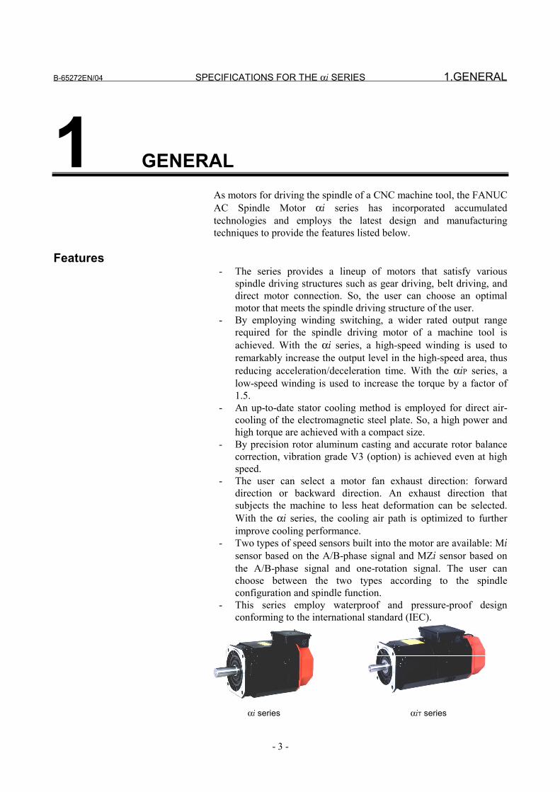
1 GENERALAs motors for driving the spindle of a CNC machine tool, the FANUCAC Spindle Motor αi series has incorporated accumulatedtechnologies and employs the latest design and manufacturingtechniques to provide the features listed below.
Features - The series provides a lineup of motors that satisfy various
spindle driving structures such as gear driving, belt driving, anddirect motor connection. So, the user can choose an optimalmotor that meets the spindle driving structure of the user.
- By employing winding switching, a wider rated output rangerequired for the spindle driving motor of a machine tool isachieved. With the αi series, a high-speed winding is used toremarkably increase the output level in the high-speed area, thusreducing acceleration/deceleration time. With the αiP series, alow-speed winding is used to increase the torque by a factor of1.5.
- An up-to-date stator cooling method is employed for direct air-cooling of the electromagnetic steel plate. So, a high power andhigh torque are achieved with a compact size.
- By precision rotor aluminum casting and accurate rotor balancecorrection, vibration grade V3 (option) is achieved even at highspeed.
- The user can select a motor fan exhaust direction: forwarddirection or backward direction. An exhaust direction thatsubjects the machine to less heat deformation can be selected.With the αi series, the cooling air path is optimized to furtherimprove cooling performance.
- Two types of speed sensors built into the motor are available: Misensor based on the A/B-phase signal and MZi sensor based onthe A/B-phase signal and one-rotation signal. The user canchoose between the two types according to the spindleconfiguration and spindle function.
- This series employ waterproof and pressure-proof designconforming to the international standard (IEC).
αi series αiT series
1.GENERAL SPECIFICATIONS FOR THE αi SERIES B-65272EN/04
- 4 -
Features of ααααi
- Higher speed - Increased rated output range by employing winding switching
(kW)
4000 1200015000
7.5
8000
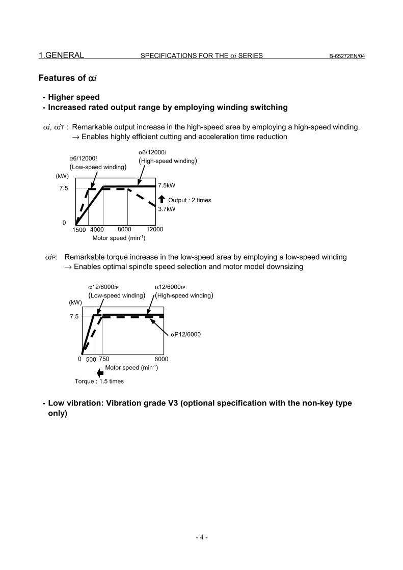
3.7kW
α6/12000i(Low-speed winding)
Motor speed (min-1)
7.5kW
Output : 2 times
750 60000
7.5
αP12/6000
Torque : 1.5 times
500
(kW)
αi, αiT : Remarkable output increase in the high-speed area by employing a high-speed winding.→ Enables highly efficient cutting and acceleration time reduction
αiP: Remarkable torque increase in the low-speed area by employing a low-speed winding→ Enables optimal spindle speed selection and motor model downsizing
α6/12000i(High-speed winding)
α12/6000iP(Low-speed winding)
α12/6000iP(High-speed winding)
Motor speed (min-1)
- Low vibration: Vibration grade V3 (optional specification with the non-key typeonly)
B-65272EN/04 SPECIFICATIONS FOR THE αi SERIES 2.CONFIGURATION OF THE αi series
- 5 -
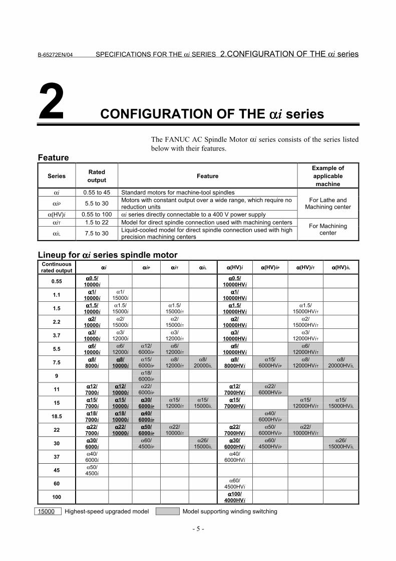
2 CONFIGURATION OF THE ααααi seriesThe FANUC AC Spindle Motor αi series consists of the series listedbelow with their features.
Feature
Series Ratedoutput Feature
Example ofapplicablemachine
αi 0.55 to 45 Standard motors for machine-tool spindles
αiP 5.5 to 30 Motors with constant output over a wide range, which require noreduction units
α(HV)i 0.55 to 100 αi series directly connectable to a 400 V power supply
For Lathe andMachining center
αiT 1.5 to 22 Model for direct spindle connection used with machining centers
αiL 7.5 to 30 Liquid-cooled model for direct spindle connection used with highprecision machining centers
For Machiningcenter
Lineup for ααααi series spindle motorContinuousrated output ααααi ααααiP ααααiT ααααiL αααα(HV)i αααα(HV)iP αααα(HV)iT αααα(HV)iL
0.55 αααα0.5/10000i
αααα0.5/10000HVi
1.1 αααα1/10000i
α1/15000i
αααα1/10000HVi
1.5 αααα1.5/10000i
α1.5/15000i
α1.5/15000iT
αααα1.5/10000HVi
α1.5/15000HViT
2.2 αααα2/10000i
α2/15000i
α2/15000iT
αααα2/10000HVi
α2/15000HViT
3.7 αααα3/10000i
α3/12000i
α3/12000iT
αααα3/10000HVi
α3/12000HViT
5.5 αααα6/10000i
α6/12000i
α12/6000iP
α6/12000iT
αααα6/10000HVi
α6/12000HViT
7.5 αααα8/8000i
αααα8/10000i
α15/6000iP
α8/12000iT
α8/20000iL
αααα8/8000HVi
α15/6000HViP
α8/12000HViT
α8/20000HViL
9 α18/6000iP
11 αααα12/7000i
αααα12/10000i
α22/6000iP
αααα12/7000HVi
α22/6000HViP
15 αααα15/7000i
αααα15/10000i
αααα30/6000iP
α15/12000iT
α15/15000iL
αααα15/7000HVi
α15/12000HViT
α15/15000HViL
18.5 αααα18/7000i
αααα18/10000i
αααα40/6000iP
α40/6000HViP
22 αααα22/7000i
αααα22/10000i
αααα50/6000iP
α22/10000iT
αααα22/7000HVi
α50/6000HViP
α22/10000HViT
30 αααα30/6000i
α60/4500iP
α26/15000iL
αααα30/6000HVi
α60/4500HViP
α26/15000HViL
37 α40/6000i
α40/6000HVi
45 α50/4500i
60 α60/4500HVi
100 αααα100/4000HVi
15000 Highest-speed upgraded model Model supporting winding switching
3.MOTOR TYPES SPECIFICATIONS FOR THE αi SERIES B-65272EN/04
- 6 -
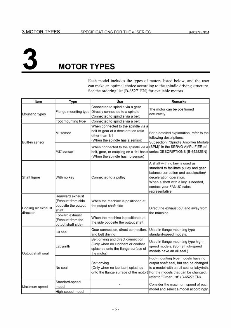
3 MOTOR TYPESEach model includes the types of motors listed below, and the usercan make an optimal choice according to the spindle driving structure.See the ordering list (B-65271EN) for available motors.
Item Type Use Remarks
Flange mounting typeConnected to spindle via a gearDirectly connected to a spindleConnected to spindle via a belt
The motor can be positionedaccurately.Mounting types
Foot mounting type Connected to spindle via a belt
Mi sensor
When connected to the spindle via abelt or gear at a deceleration ratioother than 1:1(When the spindle has a sensor)Built-in sensor
MZi sensorWhen connected to the spindle via abelt, gear, or coupling on a 1:1 basis(When the spindle has no sensor)
For a detailed explanation, refer to thefollowing descriptions:Subsection, “Spindle Amplifier Module(SPM)” in the SERVO AMPLIFIER αiseries DESCRIPTIONS (B-65282EN)
Shaft figure With no key Connected to a pulley
A shaft with no key is used asstandard to facilitate pulley and gearbalance correction and acceleration/deceleration operation.When a shaft with a key is needed,contact your FANUC salesrepresentative.
Rearward exhaust(Exhaust from sideopposite the outputshaft)
When the machine is positioned atthe output shaft sideCooling air exhaust
directionForward exhaust(Exhaust from theoutput shaft side)
When the machine is positioned atthe side opposite the output shaft
Direct the exhaust out and away fromthe machine.
Oil seal Gear connection, direct connection,and belt driving
Used in flange mounting typestandard-speed models.
Labyrinth
Belt driving and direct connection(Only when no lubricant or coolantsplashes onto the flange surface ofthe motor)
Used in flange mounting type high-speed models. (Some high-speedmodels have an oil seal.)Output shaft seal
No sealBelt driving(Only when no lubricant splashesonto the flange surface of the motor)
Foot-mounting type models have nooutput shaft seal, but can be changedto a model with an oil seal or labyrinth.For the models that can be changed,refer to "Order List" (B-65271EN).
Standard-speedmodel -
Maximum speedHigh-speed model -
Consider the maximum speed of eachmodel and select a model accordingly.

B-65272EN/04 SPECIFICATIONS FOR THE αi SERIES 4.NOTES ON INSTALLATION
- 7 -
4 NOTES ON INSTALLATION
4.NOTES ON INSTALLATION SPECIFICATIONS FOR THE αi SERIES B-65272EN/04
- 8 -
4.1 COMMON
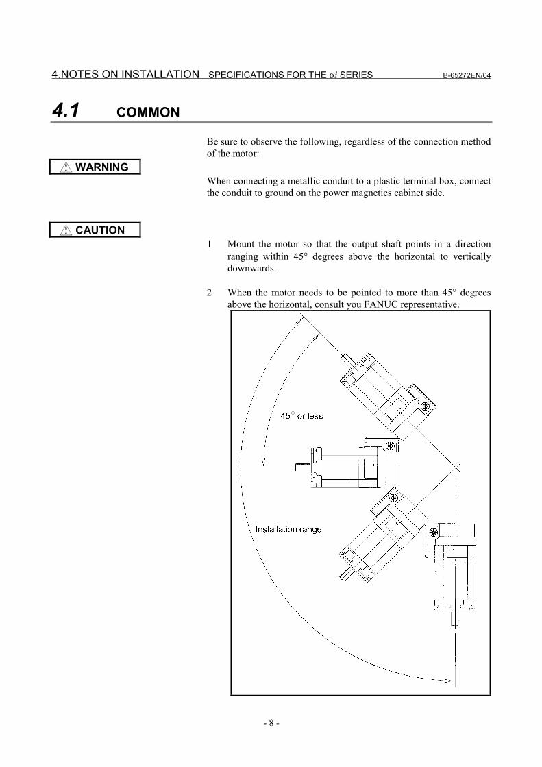
Be sure to observe the following, regardless of the connection methodof the motor:
WARNINGWhen connecting a metallic conduit to a plastic terminal box, connectthe conduit to ground on the power magnetics cabinet side.
CAUTION1 Mount the motor so that the output shaft points in a direction
ranging within 45° degrees above the horizontal to verticallydownwards.
2 When the motor needs to be pointed to more than 45° degreesabove the horizontal, consult you FANUC representative.
B-65272EN/04 SPECIFICATIONS FOR THE αi SERIES 4.NOTES ON INSTALLATION
- 9 -
3 Use the eyebolt of the motor to lift only a single motor, (gear andpulley may be attached).
4 Place a cover over an air-cooled motor to prevent the motor frombeing exposed to coolant or lubricant.
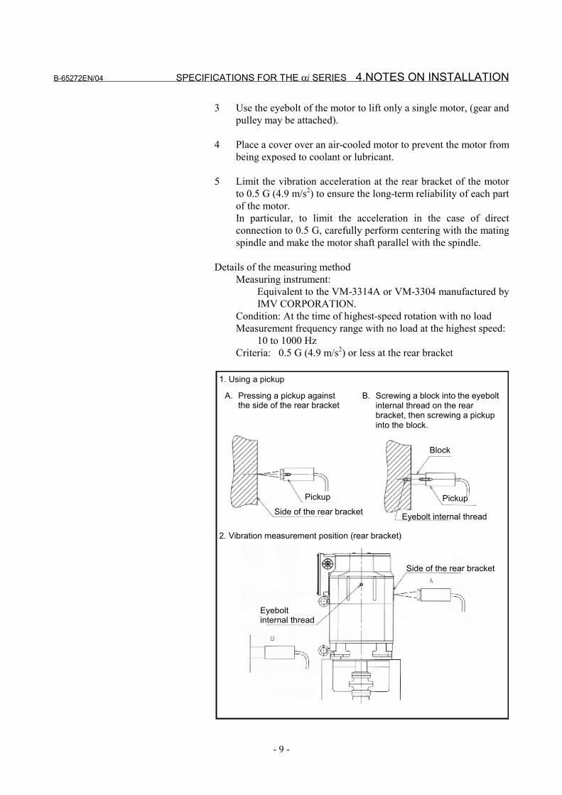
5 Limit the vibration acceleration at the rear bracket of the motorto 0.5 G (4.9 m/s2) to ensure the long-term reliability of each partof the motor.In particular, to limit the acceleration in the case of directconnection to 0.5 G, carefully perform centering with the matingspindle and make the motor shaft parallel with the spindle.
Details of the measuring methodMeasuring instrument:
Equivalent to the VM-3314A or VM-3304 manufactured byIMV CORPORATION.
Condition: At the time of highest-speed rotation with no loadMeasurement frequency range with no load at the highest speed:
10 to 1000 HzCriteria: 0.5 G (4.9 m/s2) or less at the rear bracket
1. Using a pickup
A. Pressing a pickup againstthe side of the rear bracket
B. Screwing a block into the eyeboltinternal thread on the rearbracket, then screwing a pickupinto the block.
Block
Pickup PickupSide of the rear bracket Eyebolt internal thread
2. Vibration measurement position (rear bracket)
Side of the rear bracket
Eyeboltinternal thread
4.NOTES ON INSTALLATION SPECIFICATIONS FOR THE αi SERIES B-65272EN/04
- 10 -
6 Dynamic balanceDuring high-speed operation, a small imbalance may cause alarge vibration, resulting in an unusual sound, premature bearingdamage, or some other abnormality.Therefore, reduce the amount of the imbalance with the dynamicbalance of the other rotation shafts, as well as the gear andpulley mounted on the output shaft of the motor, as much aspossible.
- Balance correctionWith the αi series, a shaft with no key is used as standard tofacilitate the balance correction of a pulley, gear, andcoupling attached to the shaft. Use a completely symmetricpulley, gear, or coupling, and use a backlash-less tighteningpart such as a SPANN ELEMENTE to secure a pulley, gear,or coupling to the shaft. When attaching a pulley to a shaft,for example, adjust the periphery vibration to within 20 µm.This basically eliminates the need for balance correction.To further reduce the vibration level, make a field balancecorrection, for example, by tightening a screw into thetapped hole for balance correction provided on acomponent such as a pulley.
NOTEWhen a shaft with a key is required, contact yourFANUC sales representative.
B-65272EN/04 SPECIFICATIONS FOR THE αi SERIES 4.NOTES ON INSTALLATION
- 11 -
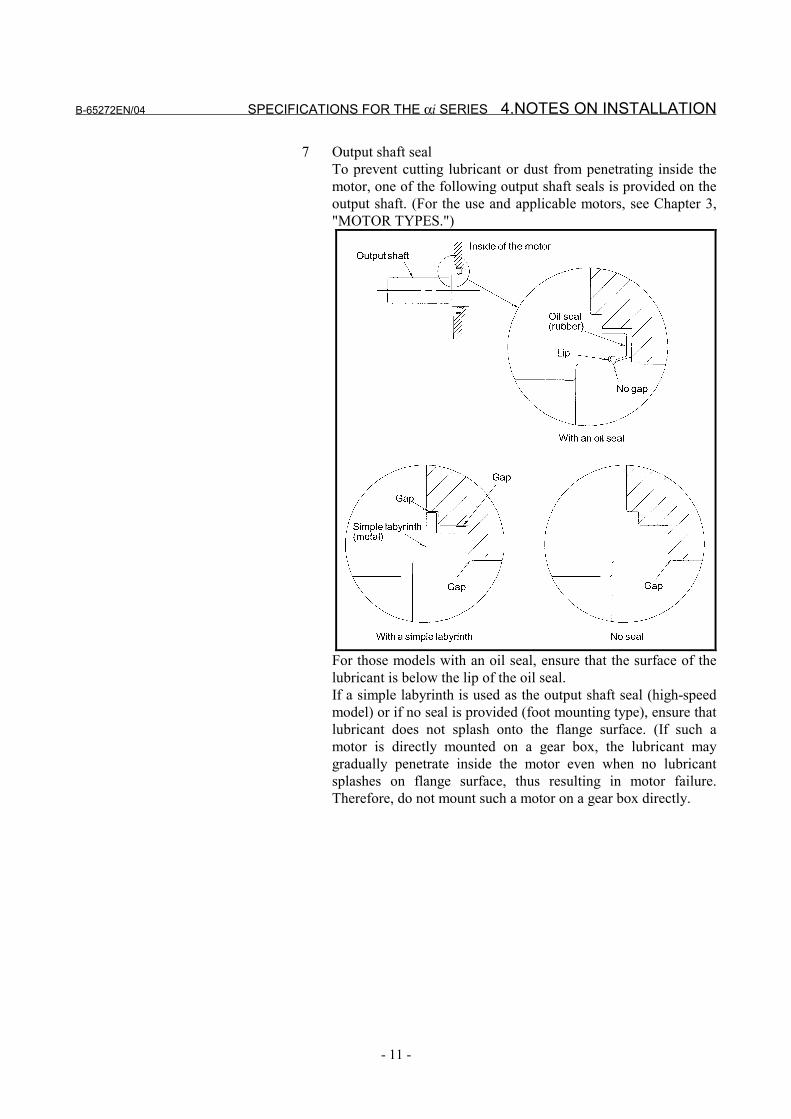
7 Output shaft sealTo prevent cutting lubricant or dust from penetrating inside themotor, one of the following output shaft seals is provided on theoutput shaft. (For the use and applicable motors, see Chapter 3,"MOTOR TYPES.")
For those models with an oil seal, ensure that the surface of thelubricant is below the lip of the oil seal.If a simple labyrinth is used as the output shaft seal (high-speedmodel) or if no seal is provided (foot mounting type), ensure thatlubricant does not splash onto the flange surface. (If such amotor is directly mounted on a gear box, the lubricant maygradually penetrate inside the motor even when no lubricantsplashes on flange surface, thus resulting in motor failure.Therefore, do not mount such a motor on a gear box directly.
4.NOTES ON INSTALLATION SPECIFICATIONS FOR THE αi SERIES B-65272EN/04
- 12 -
8 The lid of the terminal box is provided with rubber gasket tomake it waterproof.Check that the lid has this gasket, then mount it on the terminalbox.
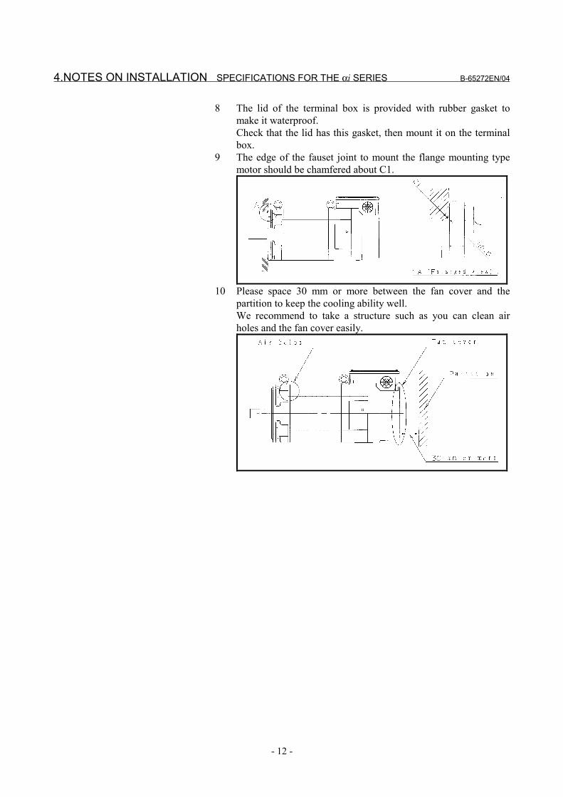
9 The edge of the fauset joint to mount the flange mounting typemotor should be chamfered about C1.
10 Please space 30 mm or more between the fan cover and thepartition to keep the cooling ability well.We recommend to take a structure such as you can clean airholes and the fan cover easily.
B-65272EN/04 SPECIFICATIONS FOR THE αi SERIES 4.NOTES ON INSTALLATION
- 13 -
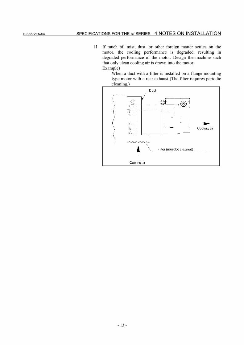
11 If much oil mist, dust, or other foreign matter settles on themotor, the cooling performance is degraded, resulting indegraded performance of the motor. Design the machine suchthat only clean cooling air is drawn into the motor.Example)
When a duct with a filter is installed on a flange mountingtype motor with a rear exhaust (The filter requires periodiccleaning.)
4.NOTES ON INSTALLATION SPECIFICATIONS FOR THE αi SERIES B-65272EN/04
- 14 -
NOTE1 A foot mounting type motor has no oil seal. When an oil seal is
required, add #0002 to the drawing number of the motor. An oilseal cannot be attached to any high-speed model, however. Fordetails, refer to "Order List" (B-65271EN).Example)
Model α12/7000i (foot mounting type, with no key,rearward exhaust)A06B-1408-B200A06B-1408-B200#0002 (with oil seal)
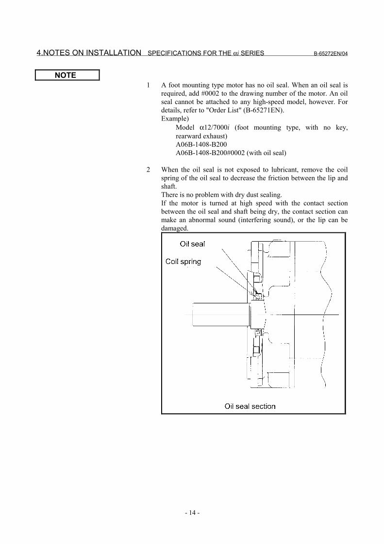
2 When the oil seal is not exposed to lubricant, remove the coilspring of the oil seal to decrease the friction between the lip andshaft.There is no problem with dry dust sealing.If the motor is turned at high speed with the contact sectionbetween the oil seal and shaft being dry, the contact section canmake an abnormal sound (interfering sound), or the lip can bedamaged.
B-65272EN/04 SPECIFICATIONS FOR THE αi SERIES 4.NOTES ON INSTALLATION
- 15 -
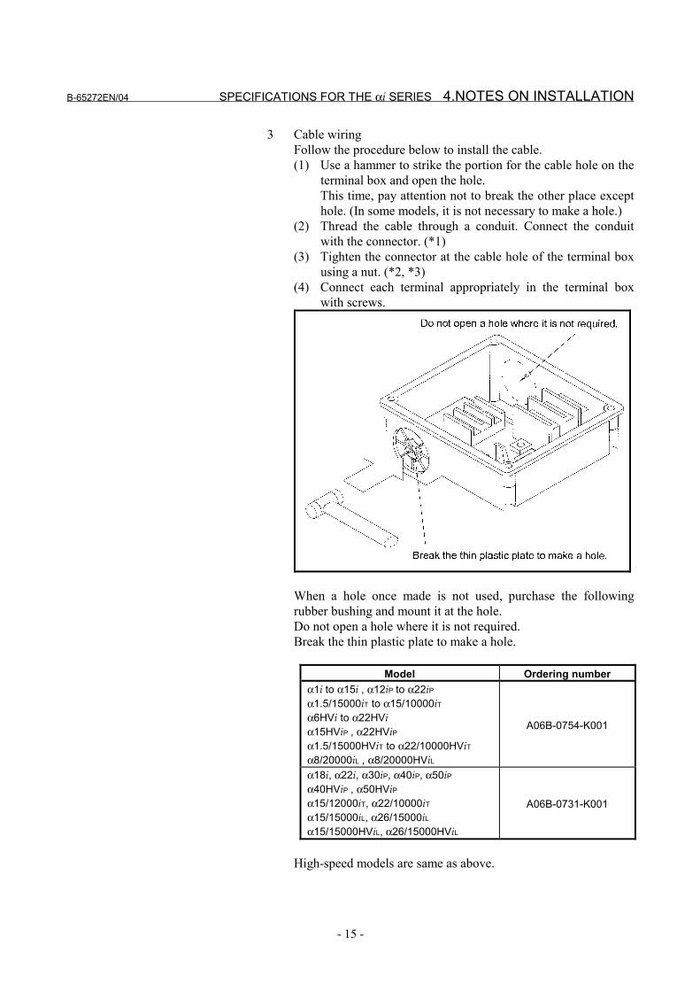
3 Cable wiringFollow the procedure below to install the cable.(1) Use a hammer to strike the portion for the cable hole on the
terminal box and open the hole.This time, pay attention not to break the other place excepthole. (In some models, it is not necessary to make a hole.)
(2) Thread the cable through a conduit. Connect the conduitwith the connector. (*1)
(3) Tighten the connector at the cable hole of the terminal boxusing a nut. (*2, *3)
(4) Connect each terminal appropriately in the terminal boxwith screws.
When a hole once made is not used, purchase the followingrubber bushing and mount it at the hole.Do not open a hole where it is not required.Break the thin plastic plate to make a hole.
Model Ordering number α1i to α15i , α12iP to α22iP α1.5/15000iT to α15/10000iT α6HVi to α22HVi α15HViP , α22HViP α1.5/15000HViT to α22/10000HViT α8/20000iL , α8/20000HViL
A06B-0754-K001
α18i, α22i, α30iP, α40iP, α50iP α40HViP , α50HViP α15/12000iT, α22/10000iT α15/15000iL, α26/15000iL α15/15000HViL, α26/15000HViL
A06B-0731-K001
High-speed models are same as above.
4.NOTES ON INSTALLATION SPECIFICATIONS FOR THE αi SERIES B-65272EN/04
- 16 -
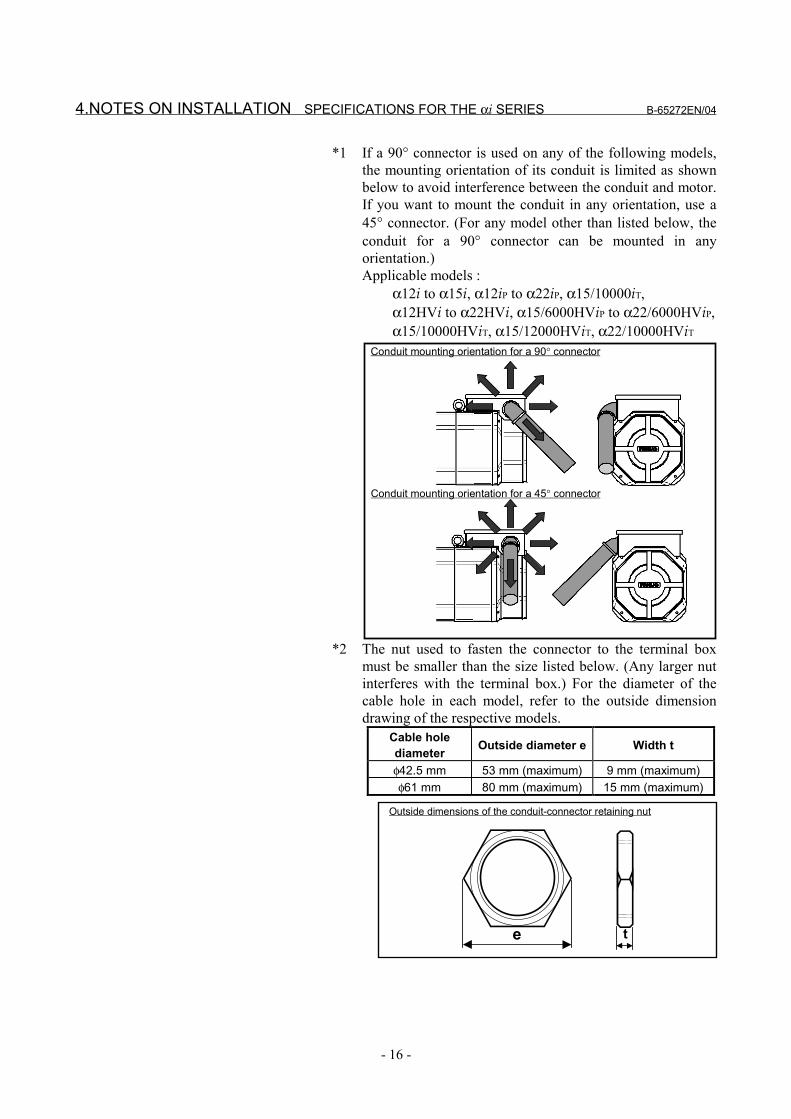
*1 If a 90° connector is used on any of the following models,the mounting orientation of its conduit is limited as shownbelow to avoid interference between the conduit and motor.If you want to mount the conduit in any orientation, use a45° connector. (For any model other than listed below, theconduit for a 90° connector can be mounted in anyorientation.)Applicable models :
α12i to α15i, α12iP to α22iP, α15/10000iT,α12HVi to α22HVi, α15/6000HViP to α22/6000HViP,α15/10000HViT, α15/12000HViT, α22/10000HViT
Conduit mounting orientation for a 90° connector
Conduit mounting orientation for a 45° connector
*2 The nut used to fasten the connector to the terminal boxmust be smaller than the size listed below. (Any larger nutinterferes with the terminal box.) For the diameter of thecable hole in each model, refer to the outside dimensiondrawing of the respective models.
Cable holediameter Outside diameter e Width t
φ42.5 mm 53 mm (maximum) 9 mm (maximum)φ61 mm 80 mm (maximum) 15 mm (maximum)
Outside dimensions of the conduit-connector retaining nut
e t
B-65272EN/04 SPECIFICATIONS FOR THE αi SERIES 4.NOTES ON INSTALLATION
- 17 -
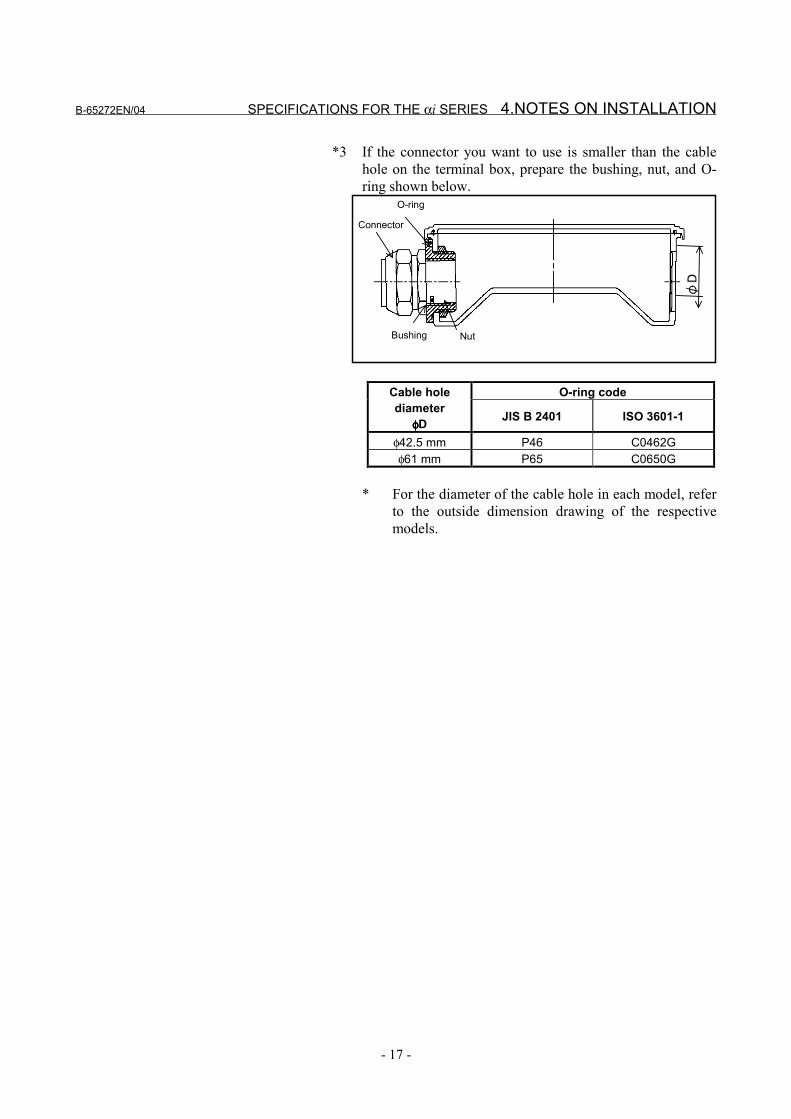
*3 If the connector you want to use is smaller than the cablehole on the terminal box, prepare the bushing, nut, and O-ring shown below.
O-ring
NutBushing
Connector
O-ring codeCable holediameter
φφφφD JIS B 2401 ISO 3601-1
φ42.5 mm P46 C0462Gφ61 mm P65 C0650G
* For the diameter of the cable hole in each model, referto the outside dimension drawing of the respectivemodels.
4.NOTES ON INSTALLATION SPECIFICATIONS FOR THE αi SERIES B-65272EN/04
- 18 -
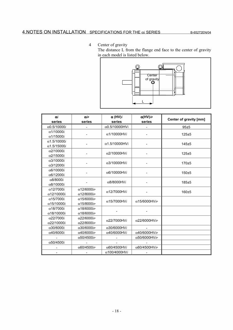
4 Center of gravityThe distance L from the flange end face to the center of gravityin each model is listed below.
Centerof gravity
L
ααααiseries
ααααiPseries
αααα (HV)iseries
αααα(HV)iPseries Center of gravity [mm]
α0.5/10000i - α0.5/10000HVi - 95±5α1/10000iα1/15000i - α1/10000HVi - 125±5
α1.5/10000iα1.5/15000i - α1.5/10000HVi - 145±5
α2/10000iα2/15000i - α2/10000HVi - 125±5
α3/10000iα3/12000i - α3/10000HVi - 170±5
α6/10000iα6/12000i - α6/10000HVi - 150±5
α8/8000iα8/10000i - α8/8000HVi - 185±5
α12/7000iα12/10000i
α12/6000iPα12/8000iP
α12/7000HVi - 160±5
α15/7000iα15/10000i
α15/6000iPα15/8000iP
α15/7000HVi α15/6000HViP
α18/7000iα18/10000i
α18/6000iPα18/6000iP - -
α22/7000iα22/10000i
α22/6000iPα22/8000iP
α22/7000HVi α22/6000HViP
α30/6000i α30/6000iP α30/6000HVi -α40/6000i α40/6000iP α40/6000HVi α40/6000HViP
- α50/4500iP - α50/6000HViPα50/4500i - - -
- α60/4500iP α60/4500HVi α60/4500HViP- - α100/4000HVi -
B-65272EN/04 SPECIFICATIONS FOR THE αi SERIES 4.NOTES ON INSTALLATION
- 19 -
4.2 POWER LEAD CONNECTION
WARNINGTo attach the power leads and jumpers, follow the proceduredescribed in this section to make connections with specified torque.Driving a motor with terminals loosened could result in the terminalboard overheating and causing a fire. In addition, it may removeterminal to cause a ground fault, short circuit, or electric shock.
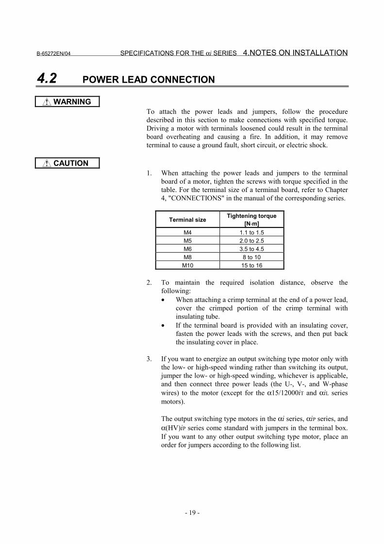
CAUTION1. When attaching the power leads and jumpers to the terminal
board of a motor, tighten the screws with torque specified in thetable. For the terminal size of a terminal board, refer to Chapter4, "CONNECTIONS" in the manual of the corresponding series.
Terminal size Tightening torque[N⋅⋅⋅⋅m]
M4 1.1 to 1.5M5 2.0 to 2.5M6 3.5 to 4.5M8 8 to 10
M10 15 to 16
2. To maintain the required isolation distance, observe thefollowing:• When attaching a crimp terminal at the end of a power lead,
cover the crimped portion of the crimp terminal withinsulating tube.
• If the terminal board is provided with an insulating cover,fasten the power leads with the screws, and then put backthe insulating cover in place.
3. If you want to energize an output switching type motor only withthe low- or high-speed winding rather than switching its output,jumper the low- or high-speed winding, whichever is applicable,and then connect three power leads (the U-, V-, and W-phasewires) to the motor (except for the α15/12000iT and αiL seriesmotors).
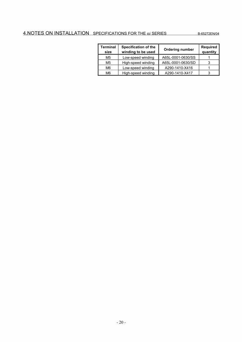
The output switching type motors in the αi series, αiP series, andα(HV)iP series come standard with jumpers in the terminal box.If you want to any other output switching type motor, place anorder for jumpers according to the following list.
4.NOTES ON INSTALLATION SPECIFICATIONS FOR THE αi SERIES B-65272EN/04
- 20 -
Terminalsize
Specification of thewinding to be used Ordering number Required
quantityM5 Low-speed winding A65L-0001-0630/SS 1M5 High-speed winding A65L-0001-0630/SD 3M6 Low-speed winding A290-1410-X416 1M6 High-speed winding A290-1410-X417 3
B-65272EN/04 SPECIFICATIONS FOR THE αi SERIES 4.NOTES ON INSTALLATION
- 21 -
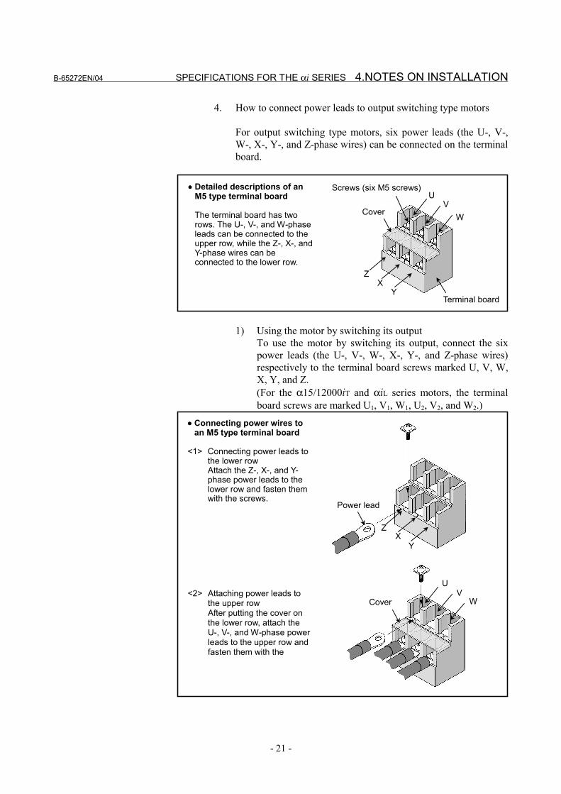
4. How to connect power leads to output switching type motors
For output switching type motors, six power leads (the U-, V-,W-, X-, Y-, and Z-phase wires) can be connected on the terminalboard.
Terminal board
Screws (six M5 screws)
VU
W
XZ
Y
Cover
•••• Detailed descriptions of anM5 type terminal board
The terminal board has tworows. The U-, V-, and W-phaseleads can be connected to theupper row, while the Z-, X-, andY-phase wires can beconnected to the lower row.
1) Using the motor by switching its outputTo use the motor by switching its output, connect the sixpower leads (the U-, V-, W-, X-, Y-, and Z-phase wires)respectively to the terminal board screws marked U, V, W,X, Y, and Z.(For the α15/12000iT and αiL series motors, the terminalboard screws are marked U1, V1, W1, U2, V2, and W2.)
•••• Connecting power wires toan M5 type terminal board
<1> Connecting power leads tothe lower rowAttach the Z-, X-, and Y-phase power leads to thelower row and fasten themwith the screws.
Power lead
XZ
Y
<2> Attaching power leads tothe upper rowAfter putting the cover onthe lower row, attach theU-, V-, and W-phase powerleads to the upper row andfasten them with the
VU
WCover
4.NOTES ON INSTALLATION SPECIFICATIONS FOR THE αi SERIES B-65272EN/04
- 22 -
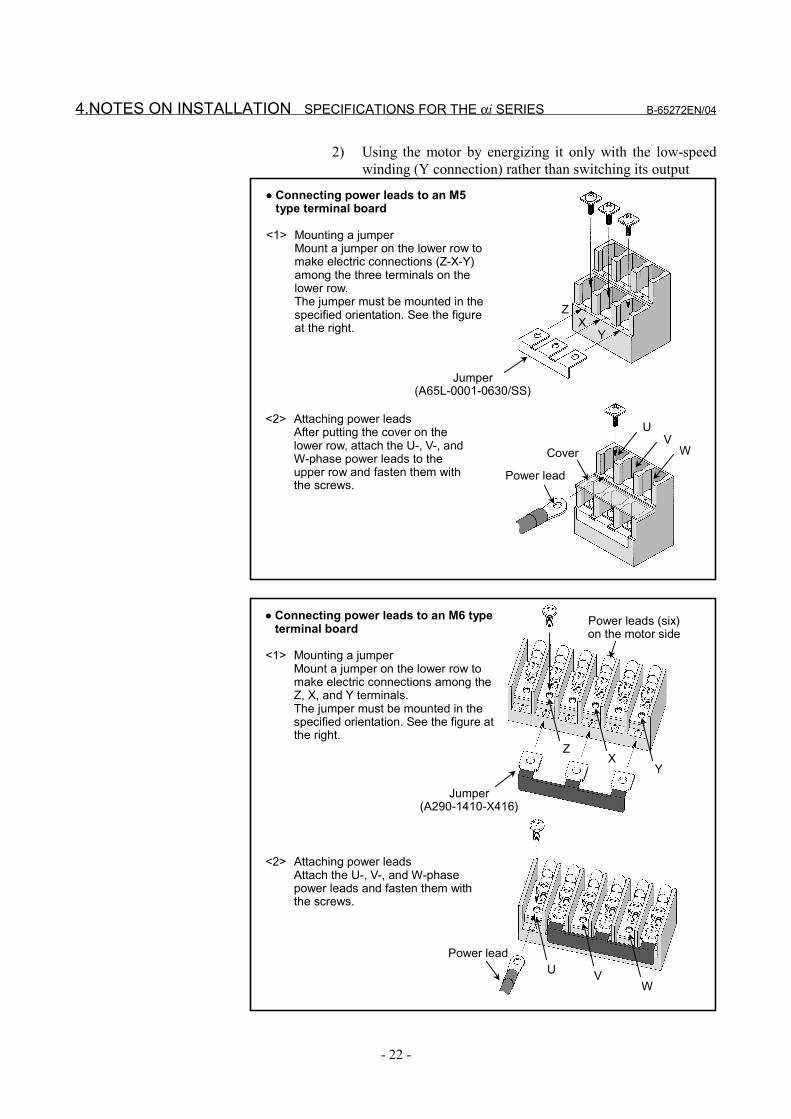
2) Using the motor by energizing it only with the low-speedwinding (Y connection) rather than switching its output
•••• Connecting power leads to an M5type terminal board
<1> Mounting a jumperMount a jumper on the lower row tomake electric connections (Z-X-Y)among the three terminals on thelower row.The jumper must be mounted in thespecified orientation. See the figureat the right.
Jumper(A65L-0001-0630/SS)
XZ
Y
<2> Attaching power leadsAfter putting the cover on thelower row, attach the U-, V-, andW-phase power leads to theupper row and fasten them withthe screws.
VU
Power lead
WCover
VW
UPower lead
•••• Connecting power leads to an M6 typeterminal board
<1> Mounting a jumperMount a jumper on the lower row tomake electric connections among theZ, X, and Y terminals.The jumper must be mounted in thespecified orientation. See the figure atthe right.
<2> Attaching power leadsAttach the U-, V-, and W-phasepower leads and fasten them withthe screws.
ZX
Y
Jumper(A290-1410-X416)
Power leads (six)on the motor side
B-65272EN/04 SPECIFICATIONS FOR THE αi SERIES 4.NOTES ON INSTALLATION
- 23 -
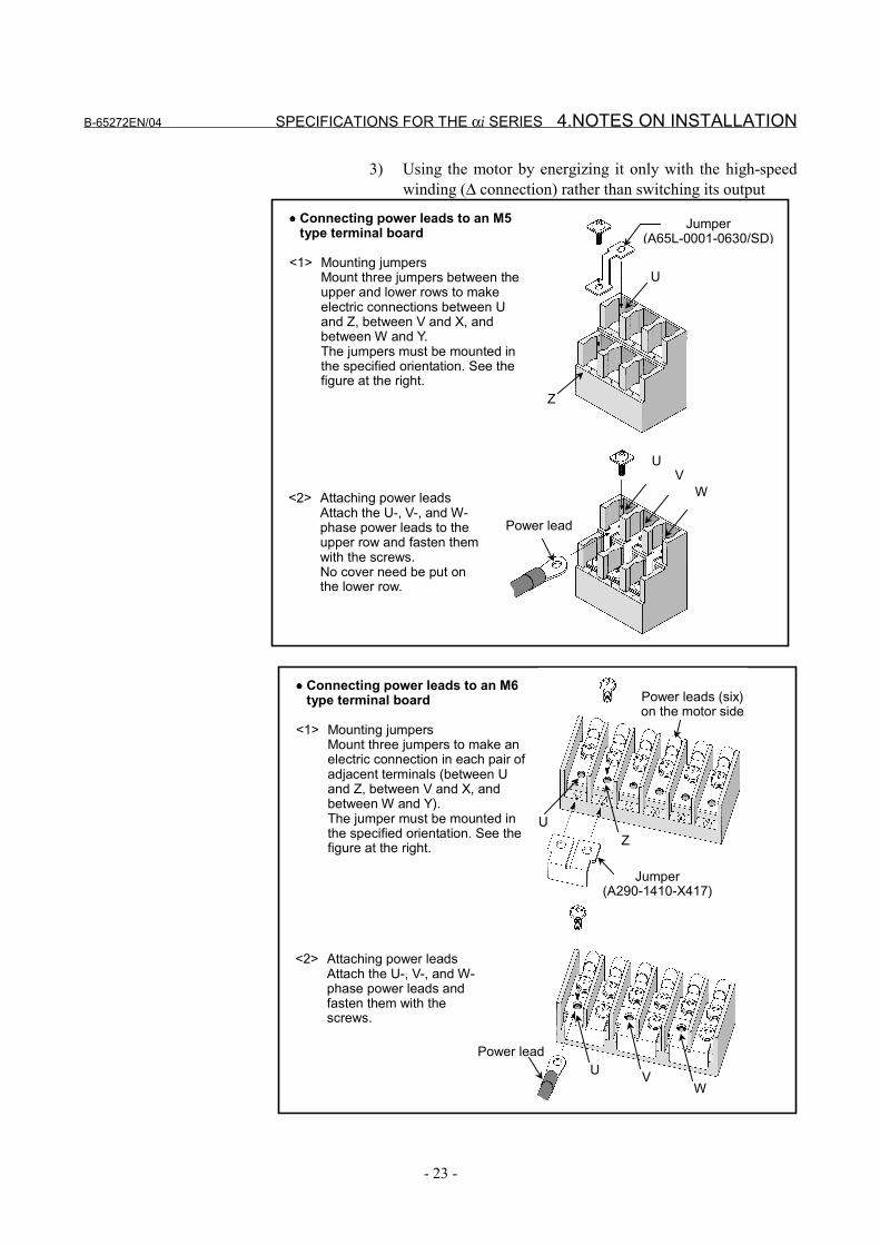
3) Using the motor by energizing it only with the high-speedwinding (∆ connection) rather than switching its output
•••• Connecting power leads to an M5type terminal board
<1> Mounting jumpersMount three jumpers between theupper and lower rows to makeelectric connections between Uand Z, between V and X, andbetween W and Y.The jumpers must be mounted inthe specified orientation. See thefigure at the right.
<2> Attaching power leadsAttach the U-, V-, and W-phase power leads to theupper row and fasten themwith the screws.No cover need be put onthe lower row.
VU
W
Power lead
U
Z
Jumper(A65L-0001-0630/SD)
•••• Connecting power leads to an M6type terminal board
<1> Mounting jumpersMount three jumpers to make anelectric connection in each pair ofadjacent terminals (between Uand Z, between V and X, andbetween W and Y).The jumper must be mounted inthe specified orientation. See thefigure at the right.
<2> Attaching power leadsAttach the U-, V-, and W-phase power leads andfasten them with thescrews.
VW
UPower lead
ZU
Jumper(A290-1410-X417)
Power leads (six)on the motor side
4.NOTES ON INSTALLATION SPECIFICATIONS FOR THE αi SERIES B-65272EN/04
- 24 -
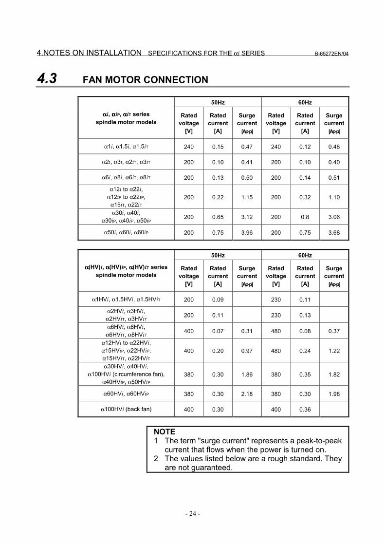
4.3 FAN MOTOR CONNECTION
50Hz 60Hz
ααααi, ααααiP, ααααiT seriesspindle motor models
Ratedvoltage
[V]
Ratedcurrent
[A]
Surgecurrent
[Ap-p]
Ratedvoltage
[V]
Ratedcurrent
[A]
Surgecurrent
[Ap-p]
α1i, α1.5i, α1.5iT 240 0.15 0.47 240 0.12 0.48
α2i, α3i, α2iT, α3iT 200 0.10 0.41 200 0.10 0.40
α6i, α8i, α6iT, α8iT 200 0.13 0.50 200 0.14 0.51
α12i to α22i,α12iP to α22iP,
α15iT, α22iT200 0.22 1.15 200 0.32 1.10
α30i, α40i,α30iP, α40iP, α50iP 200 0.65 3.12 200 0.8 3.06
α50i, α60i, α60iP 200 0.75 3.96 200 0.75 3.68
50Hz 60Hz
αααα(HV)i, αααα(HV)iP, αααα(HV)iT seriesspindle motor models
Ratedvoltage
[V]
Ratedcurrent
[A]
Surgecurrent
[Ap-p]
Ratedvoltage
[V]
Ratedcurrent
[A]
Surgecurrent
[Ap-p]
α1HVi, α1.5HVi, α1.5HViT 200 0.09 230 0.11
α2HVi, α3HVi,α2HViT, α3HViT 200 0.11 230 0.13
α6HVi, α8HVi,α6HViT, α8HViT 400 0.07 0.31 480 0.08 0.37
α12HVi to α22HVi,α15HViP, α22HViP,α15HViT, α22HViT
400 0.20 0.97 480 0.24 1.22
α30HVi, α40HVi,α100HVi (circumference fan),
α40HViP, α50HViP380 0.30 1.86 380 0.35 1.82
α60HVi, α60HViP 380 0.30 2.18 380 0.30 1.98
α100HVi (back fan) 400 0.30 400 0.36
NOTE1 The term "surge current" represents a peak-to-peak
current that flows when the power is turned on.2 The values listed below are a rough standard. They
are not guaranteed.
B-65272EN/04 SPECIFICATIONS FOR THE αi SERIES 4.NOTES ON INSTALLATION
- 25 -
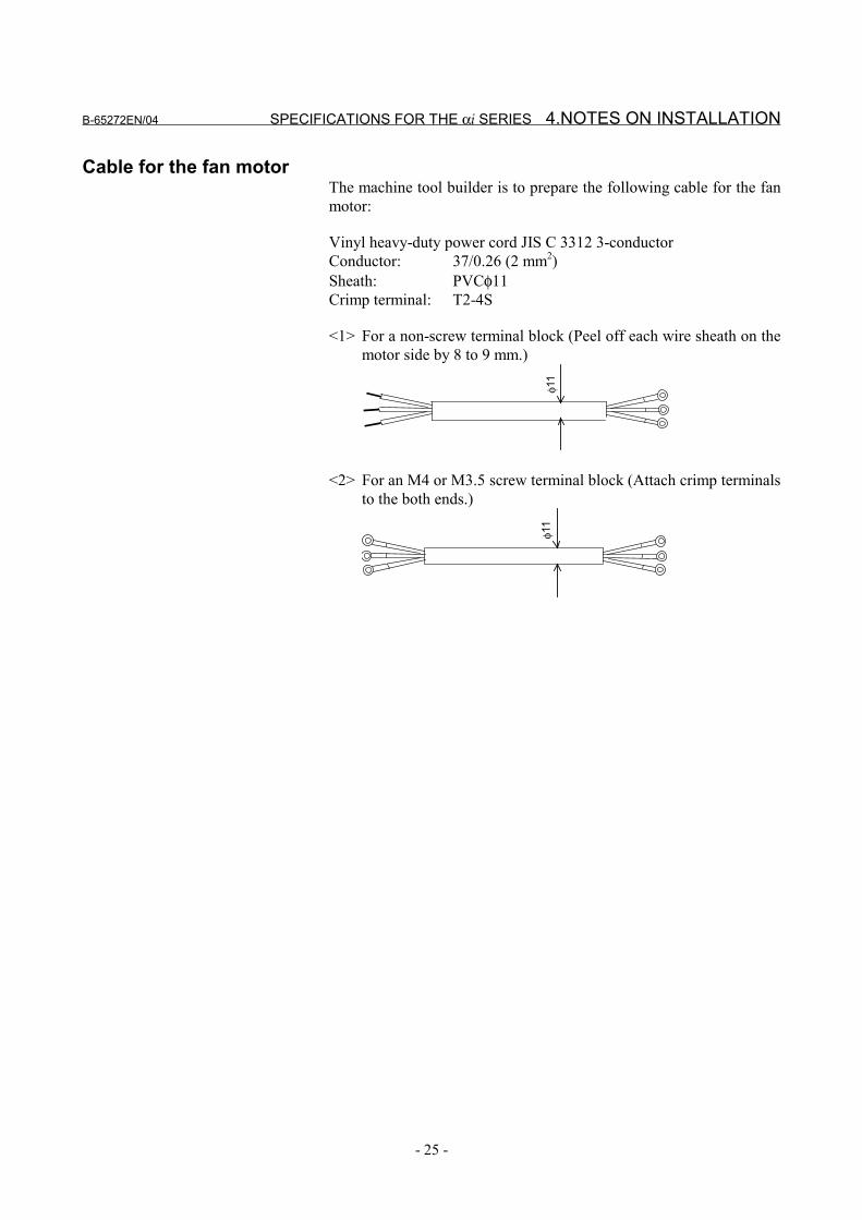
Cable for the fan motorThe machine tool builder is to prepare the following cable for the fanmotor:
Vinyl heavy-duty power cord JIS C 3312 3-conductorConductor: 37/0.26 (2 mm2)Sheath: PVCφ11Crimp terminal: T2-4S
<1> For a non-screw terminal block (Peel off each wire sheath on themotor side by 8 to 9 mm.)
φ11
<2> For an M4 or M3.5 screw terminal block (Attach crimp terminalsto the both ends.)
φ11
4.NOTES ON INSTALLATION SPECIFICATIONS FOR THE αi SERIES B-65272EN/04
- 26 -
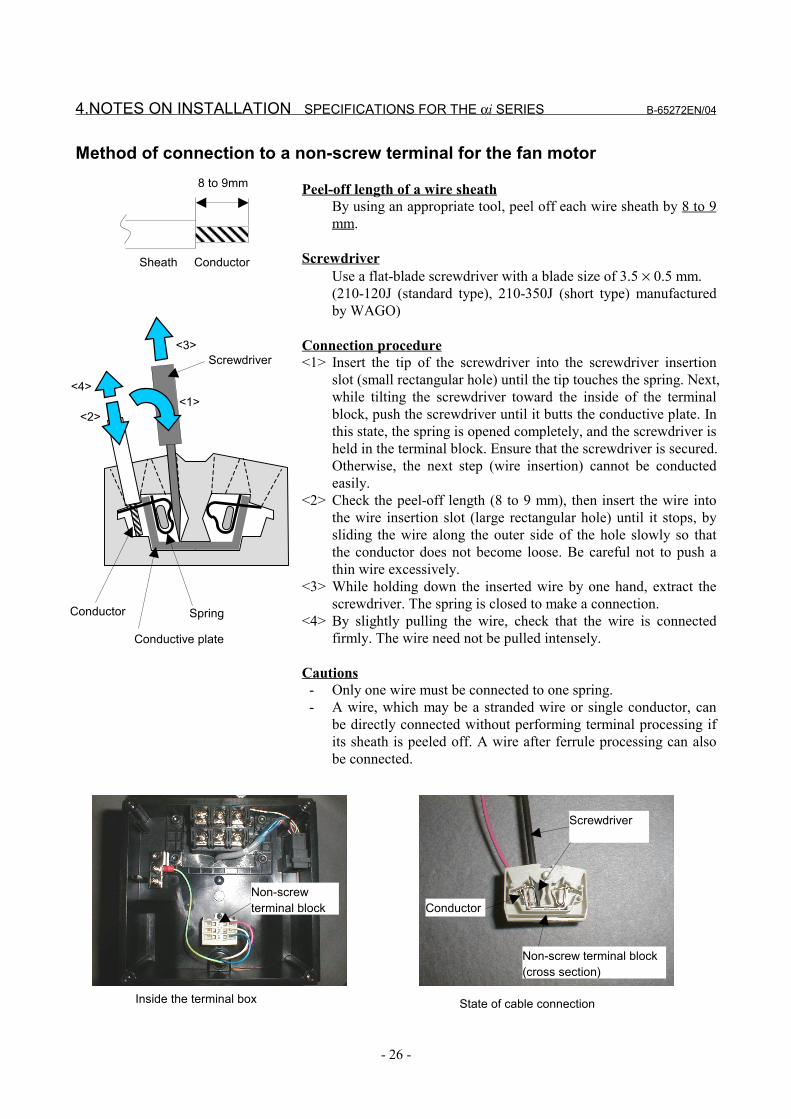
Method of connection to a non-screw terminal for the fan motor
Peel-off length of a wire sheathBy using an appropriate tool, peel off each wire sheath by 8 to 9mm.
ScrewdriverUse a flat-blade screwdriver with a blade size of 3.5 × 0.5 mm.(210-120J (standard type), 210-350J (short type) manufacturedby WAGO)
Connection procedure<1> Insert the tip of the screwdriver into the screwdriver insertion
slot (small rectangular hole) until the tip touches the spring. Next,while tilting the screwdriver toward the inside of the terminalblock, push the screwdriver until it butts the conductive plate. Inthis state, the spring is opened completely, and the screwdriver isheld in the terminal block. Ensure that the screwdriver is secured.Otherwise, the next step (wire insertion) cannot be conductedeasily.
<2> Check the peel-off length (8 to 9 mm), then insert the wire intothe wire insertion slot (large rectangular hole) until it stops, bysliding the wire along the outer side of the hole slowly so thatthe conductor does not become loose. Be careful not to push athin wire excessively.
<3> While holding down the inserted wire by one hand, extract thescrewdriver. The spring is closed to make a connection.
<4> By slightly pulling the wire, check that the wire is connectedfirmly. The wire need not be pulled intensely.
Cautions - Only one wire must be connected to one spring. - A wire, which may be a stranded wire or single conductor, can
be directly connected without performing terminal processing ifits sheath is peeled off. A wire after ferrule processing can alsobe connected.
8 to 9mm
ConductorSheath
Inside the terminal box State of cable connection
Screwdriver
Non-screw terminal block(cross section)
Non-screwterminal block Conductor
Spring
Conductive plate
Screwdriver
Conductor
<4>
<2> <1>
<3>
B-65272EN/04 SPECIFICATIONS FOR THE αi SERIES 4.NOTES ON INSTALLATION
- 27 -
4.4 WHEN A MOTOR IS CONNECTED TO A SPINDLE VIA ABELT
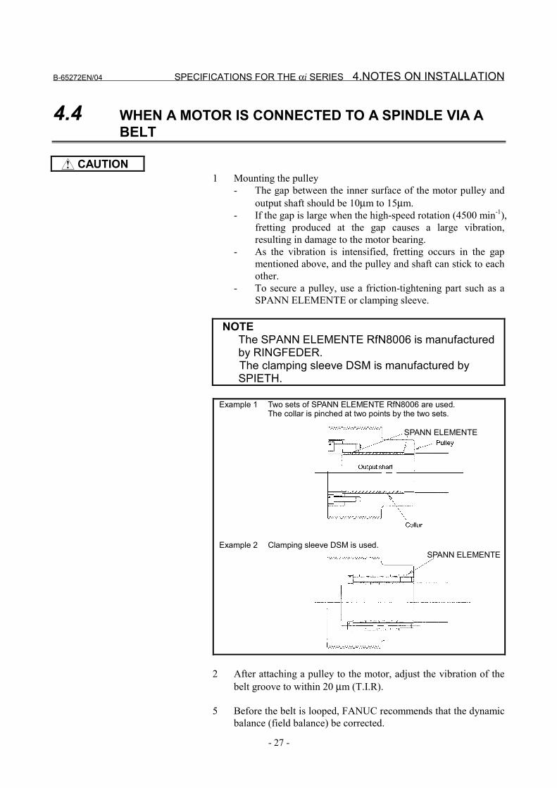
CAUTION1 Mounting the pulley
- The gap between the inner surface of the motor pulley andoutput shaft should be 10µm to 15µm.
- If the gap is large when the high-speed rotation (4500 min-1),fretting produced at the gap causes a large vibration,resulting in damage to the motor bearing.
- As the vibration is intensified, fretting occurs in the gapmentioned above, and the pulley and shaft can stick to eachother.
- To secure a pulley, use a friction-tightening part such as aSPANN ELEMENTE or clamping sleeve.
NOTEThe SPANN ELEMENTE RfN8006 is manufacturedby RINGFEDER.
The clamping sleeve DSM is manufactured bySPIETH.
Example 1 Two sets of SPANN ELEMENTE RfN8006 are used.The collar is pinched at two points by the two sets.
Example 2 Clamping sleeve DSM is used.
SPANN ELEMENTE
SPANN ELEMENTE
2 After attaching a pulley to the motor, adjust the vibration of thebelt groove to within 20 µm (T.I.R).
5 Before the belt is looped, FANUC recommends that the dynamicbalance (field balance) be corrected.
4.NOTES ON INSTALLATION SPECIFICATIONS FOR THE αi SERIES B-65272EN/04
- 28 -
4 Limit the radial load applied to the motor output shaft by thetension of the belt to the allowable value described in the manualfor each series. If the allowable value is exceeded, the bearing orshaft may fail prematurely.
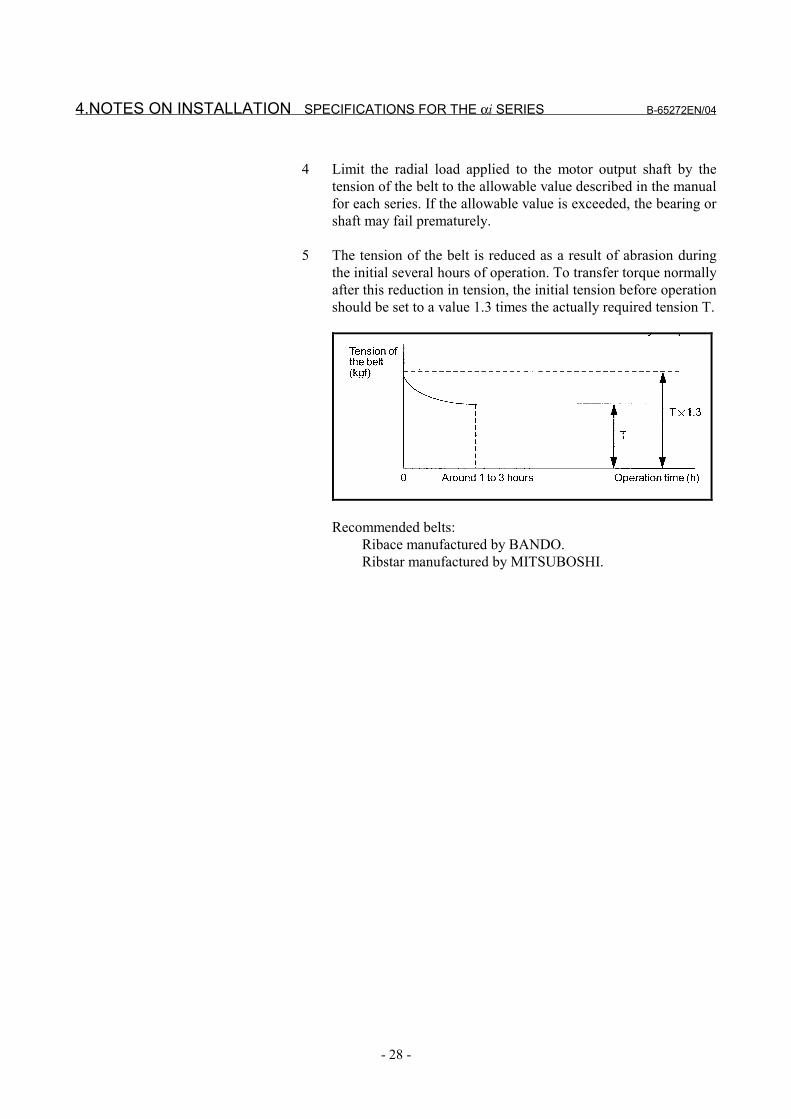
5 The tension of the belt is reduced as a result of abrasion duringthe initial several hours of operation. To transfer torque normallyafter this reduction in tension, the initial tension before operationshould be set to a value 1.3 times the actually required tension T.
Recommended belts:Ribace manufactured by BANDO.Ribstar manufactured by MITSUBOSHI.
B-65272EN/04 SPECIFICATIONS FOR THE αi SERIES 4.NOTES ON INSTALLATION
- 29 -
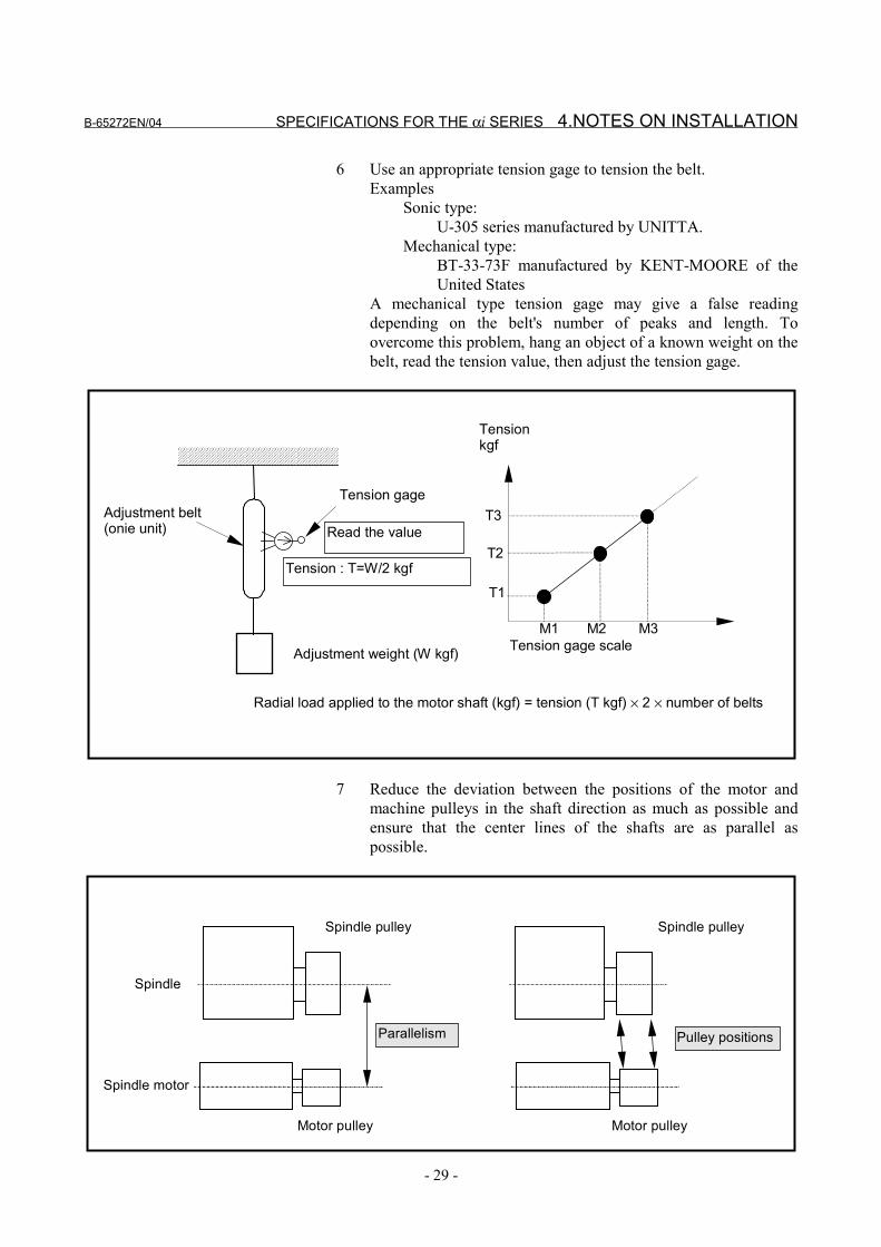
6 Use an appropriate tension gage to tension the belt.Examples
Sonic type:U-305 series manufactured by UNITTA.
Mechanical type:BT-33-73F manufactured by KENT-MOORE of theUnited States
A mechanical type tension gage may give a false readingdepending on the belt's number of peaks and length. Toovercome this problem, hang an object of a known weight on thebelt, read the tension value, then adjust the tension gage.
Tension gage
Adjustment weight (W kgf)
Adjustment belt(onie unit) Read the value
Tensionkgf
Tension : T=W/2 kgf
T3
T2
T1
M3M2 M1Tension gage scale
Radial load applied to the motor shaft (kgf) = tension (T kgf) × 2 × number of belts
7 Reduce the deviation between the positions of the motor andmachine pulleys in the shaft direction as much as possible andensure that the center lines of the shafts are as parallel aspossible.
Spindle motor
Spindle
Spindle pulley
Parallelism Pulley positions
Motor pulley
Spindle pulley
Motor pulley
4.NOTES ON INSTALLATION SPECIFICATIONS FOR THE αi SERIES B-65272EN/04
- 30 -
4.5 WHEN A MOTOR IS CONNECTED TO A SPINDLE VIA AGEAR
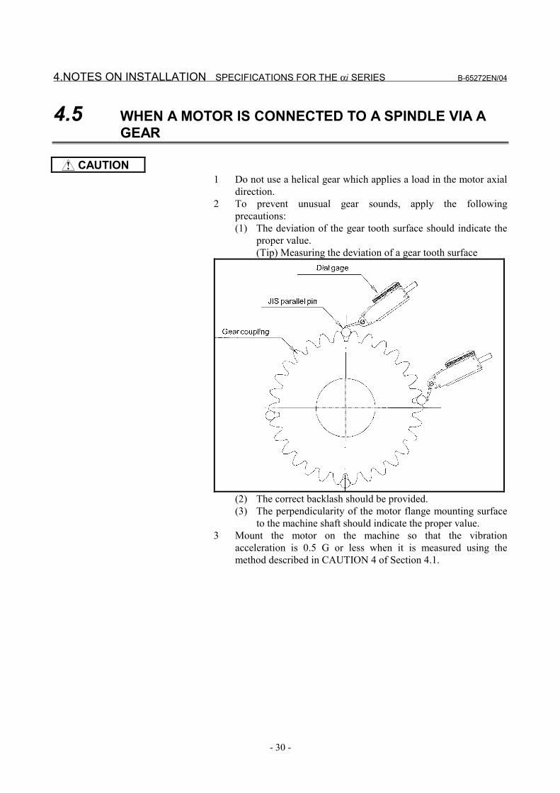
CAUTION1 Do not use a helical gear which applies a load in the motor axial
direction.2 To prevent unusual gear sounds, apply the following
precautions:(1) The deviation of the gear tooth surface should indicate the
proper value.(Tip) Measuring the deviation of a gear tooth surface
(2) The correct backlash should be provided.(3) The perpendicularity of the motor flange mounting surface
to the machine shaft should indicate the proper value.3 Mount the motor on the machine so that the vibration
acceleration is 0.5 G or less when it is measured using themethod described in CAUTION 4 of Section 4.1.
B-65272EN/04 SPECIFICATIONS FOR THE αi SERIES 4.NOTES ON INSTALLATION
- 31 -
4.6 WHEN A MOTOR IS DIRECTLY CONNECTED TO ASPINDLE VIA A COUPLING
CAUTION1 Use a coupling which can absorb thermal expansion in the axial
direction of the motor mating shaft so that no load is applied inthe motor axial direction.(Examples) - Diaphragm coupling (EAGLE INDUSTRY CO., LTD.) - Oldham's coupling - Gear coupling
2 Set the torsional rigidity of the coupling to an appropriate highvalue. If the torsional rigidity is low, vibration may be producedduring orientation.
3 It is important to perform centering and obtain parallelism toavoid having to recourse to the flexibility of the coupling.At high speeds, any eccentricity may cause the bearing to failprematurely.
4 Check all machines before shipping to confirm that the vibrationacceleration is 0.5 G or less when measured using the methoddescribed in CAUTION 4 of Section 4.1.
5.NOTES ON OPERATION SPECIFICATIONS FOR THE αi SERIES B-65272EN/04
- 32 -
5 NOTES ON OPERATION
WARNING1 When supplying voltage to the spindle motor or the fan motor,
ensure that the earth cable is connected to the earth terminal andsecure that the spindle motor is put to earth certainly.
CAUTION1 After a continuous and long operation, the temperature of model
α0.5i may rise higher than other motors because they have nofan motor. So please treat them carefully.
2 Sound and vibrationCheck that there is no abnormal sound or vibration.
3 CoolingClean off dust from the cooling air inlet and outlet of the statorevery year, and check the flow of air carefully.
NOTE1 To increase the operating lifetime of a motor of these series,
break in the motor. As a guideline, increase the speed of themotor from 1000 min-1 to its maximum speed in 1000 min-1
increments, and operate the motor at each speed for about 5minutes.
B-65272EN/04 SPECIFICATIONS FOR THE αi SERIES 6.DETERMINING THE ACCELERATION TIME
- 33 -
6 DETERMINING THE ACCELERATIONTIME
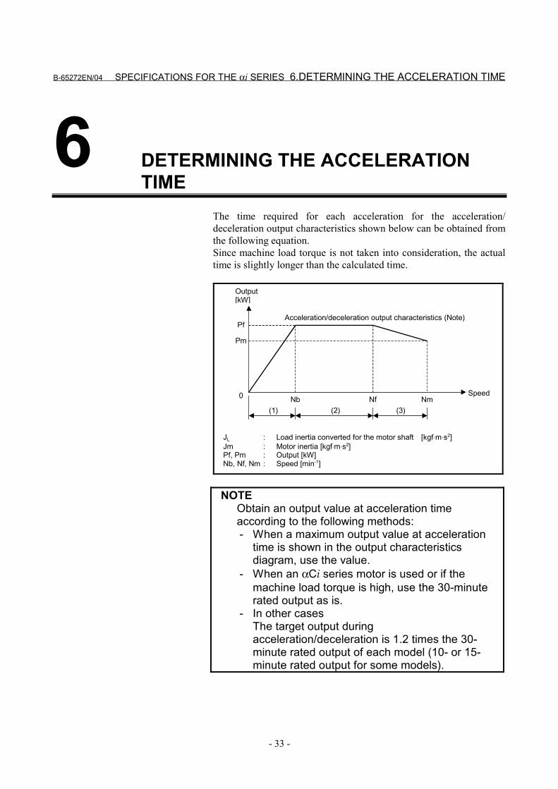
The time required for each acceleration for the acceleration/deceleration output characteristics shown below can be obtained fromthe following equation.Since machine load torque is not taken into consideration, the actualtime is slightly longer than the calculated time.
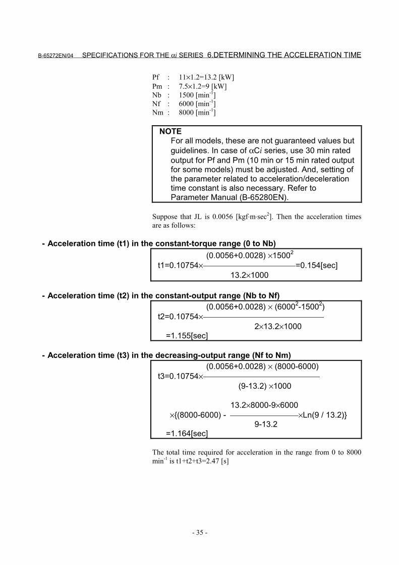
Output[kW]
Pf
Pm
0 Nb Nf NmSpeed
Acceleration/deceleration output characteristics (Note)
(1) (2) (3)
JL : Load inertia converted for the motor shaft [kgf⋅m⋅s2]Jm : Motor inertia [kgf⋅m⋅s2]Pf, Pm : Output [kW]Nb, Nf, Nm : Speed [min-1]
NOTEObtain an output value at acceleration timeaccording to the following methods:- When a maximum output value at acceleration
time is shown in the output characteristicsdiagram, use the value.
- When an αCi series motor is used or if themachine load torque is high, use the 30-minuterated output as is.
- In other casesThe target output duringacceleration/deceleration is 1.2 times the 30-minute rated output of each model (10- or 15-minute rated output for some models).
6.DETERMINING THE ACCELERATION TIME SPECIFICATIONS FOR THE αi SERIES B-65272EN/04
- 34 -
- Acceleration time (t1) in the constant-torque range (0 to Nb) (JL+Jm) ×Nb2
t1=0.10754× [sec] Pf×1000
- Acceleration time (t2) in the constant-output range (Nb to Nf) (JL+Jm) × (Nf2-Nb2)t2=0.10754× [sec] 2×Pf×1000
- Acceleration time (t3) in the decreasing-output range (Nf to Nm) (JL+Jm) × (Nm-Nf) Pf Nm-Pm Nft3=0.10754× × (Nm-Nf) - ×Ln(Pm/Pf) [sec] (Pm-Pf) ×1000 Pm-Pf
The total time (t) required for acceleration in the range from 0 to N mis t1+t2+t3 [sec]Deceleration can be controlled so that the time required fordeceleration is nearly equal to that for acceleration. When the powervoltage is high, or the impedance of the power is high, the timerequired for deceleration may not be made equal to that foracceleration.
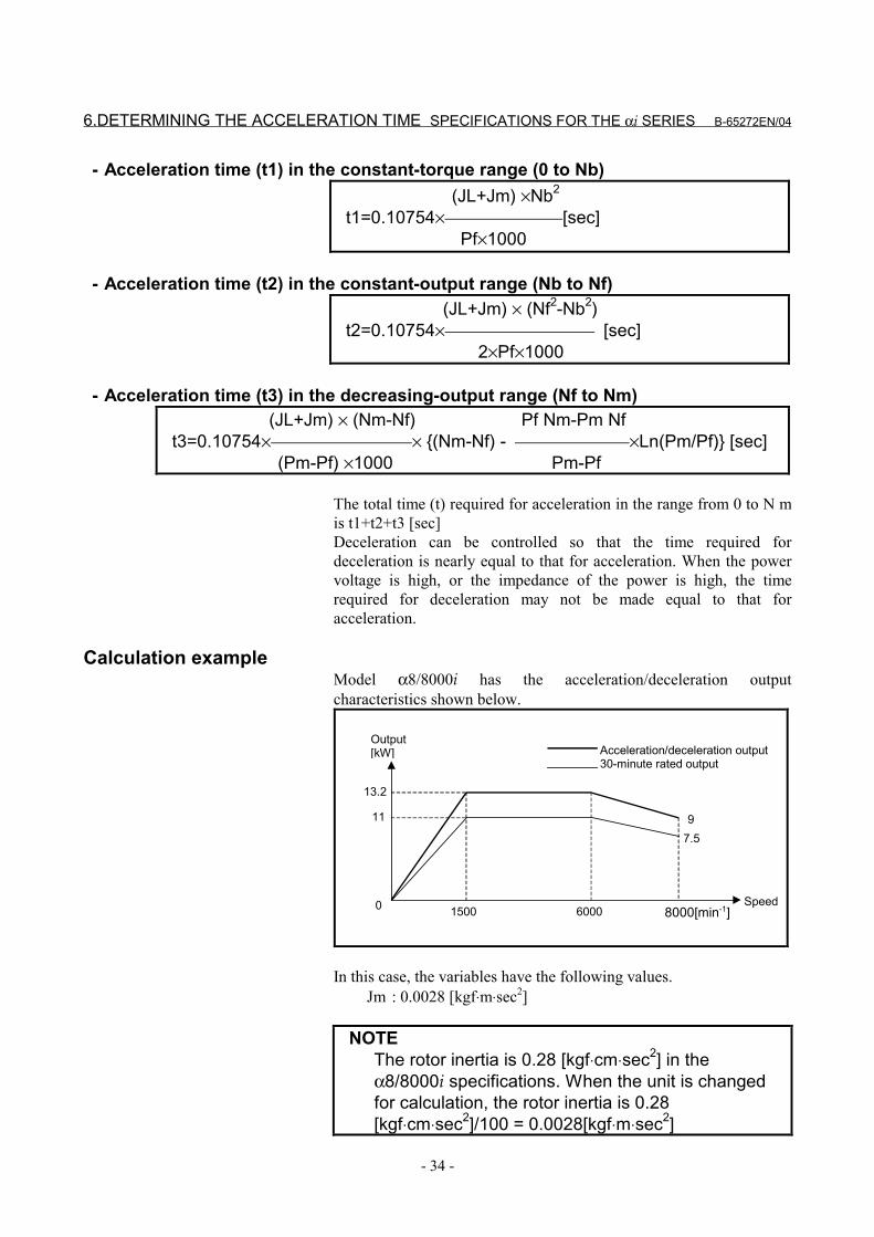
Calculation exampleModel α8/8000i has the acceleration/deceleration outputcharacteristics shown below.
13.2
11
0 1500 6000 8000[min-1]Speed
97.5
Output[kW] Acceleration/deceleration output
30-minute rated output
In this case, the variables have the following values.Jm : 0.0028 [kgf⋅m⋅sec2]
NOTEThe rotor inertia is 0.28 [kgf⋅cm⋅sec2] in theα8/8000i specifications. When the unit is changedfor calculation, the rotor inertia is 0.28[kgf⋅cm⋅sec2]/100 = 0.0028[kgf⋅m⋅sec2]
B-65272EN/04 SPECIFICATIONS FOR THE αi SERIES 6.DETERMINING THE ACCELERATION TIME
- 35 -
Pf : 11×1.2=13.2 [kW]Pm : 7.5×1.2=9 [kW]Nb : 1500 [min-1]Nf : 6000 [min-1]Nm : 8000 [min-1]
NOTEFor all models, these are not guaranteed values butguidelines. In case of αCi series, use 30 min ratedoutput for Pf and Pm (10 min or 15 min rated outputfor some models) must be adjusted. And, setting ofthe parameter related to acceleration/decelerationtime constant is also necessary. Refer toParameter Manual (B-65280EN).
Suppose that JL is 0.0056 [kgf⋅m⋅sec2]. Then the acceleration timesare as follows:
- Acceleration time (t1) in the constant-torque range (0 to Nb) (0.0056+0.0028) ×15002
t1=0.10754× =0.154[sec] 13.2×1000
- Acceleration time (t2) in the constant-output range (Nb to Nf) (0.0056+0.0028) × (60002-15002)t2=0.10754× 2×13.2×1000 =1.155[sec]
- Acceleration time (t3) in the decreasing-output range (Nf to Nm) (0.0056+0.0028) × (8000-6000)t3=0.10754× (9-13.2) ×1000
13.2×8000-9×6000 ×(8000-6000) - ×Ln(9 / 13.2) 9-13.2 =1.164[sec]
The total time required for acceleration in the range from 0 to 8000min-1 is t1+t2+t3=2.47 [s]
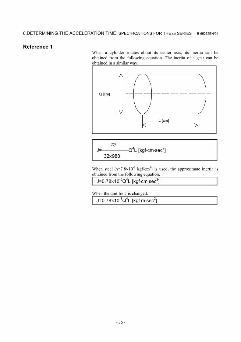
6.DETERMINING THE ACCELERATION TIME SPECIFICATIONS FOR THE αi SERIES B-65272EN/04
- 36 -
Reference 1When a cylinder rotates about its center axis, its inertia can beobtained from the following equation. The inertia of a gear can beobtained in a similar way.
L [cm]
Q [cm]
πγJ= Q4L [kgf⋅cm⋅sec2] 32×980
When steel (γ=7.8×10⁻³ kgf/cm3) is used, the approximate inertia isobtained from the following equation.
J=0.78×10⁻⁶Q4L [kgf⋅cm⋅sec2]
When the unit for J is changed.J=0.78×10⁻⁸Q4L [kgf⋅m⋅sec2]
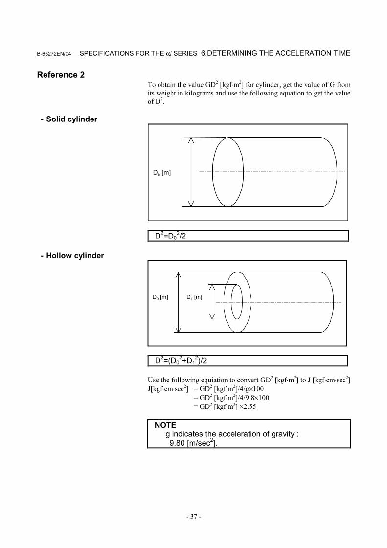
B-65272EN/04 SPECIFICATIONS FOR THE αi SERIES 6.DETERMINING THE ACCELERATION TIME
- 37 -
Reference 2To obtain the value GD2 [kgf⋅m2] for cylinder, get the value of G fromits weight in kilograms and use the following equation to get the valueof D2.
- Solid cylinder
D0 [m]
D2=D02/2
- Hollow cylinder
D0 [m] D1 [m]
D2=(D02+D1
2)/2
Use the following equiation to convert GD2 [kgf⋅m2] to J [kgf⋅cm⋅sec2]J[kgf⋅cm⋅sec2] = GD2 [kgf⋅m2]/4/g×100
= GD2 [kgf⋅m2]/4/9.8×100= GD2 [kgf⋅m2] ×2.55
NOTEg indicates the acceleration of gravity : 9.80 [m/sec2].
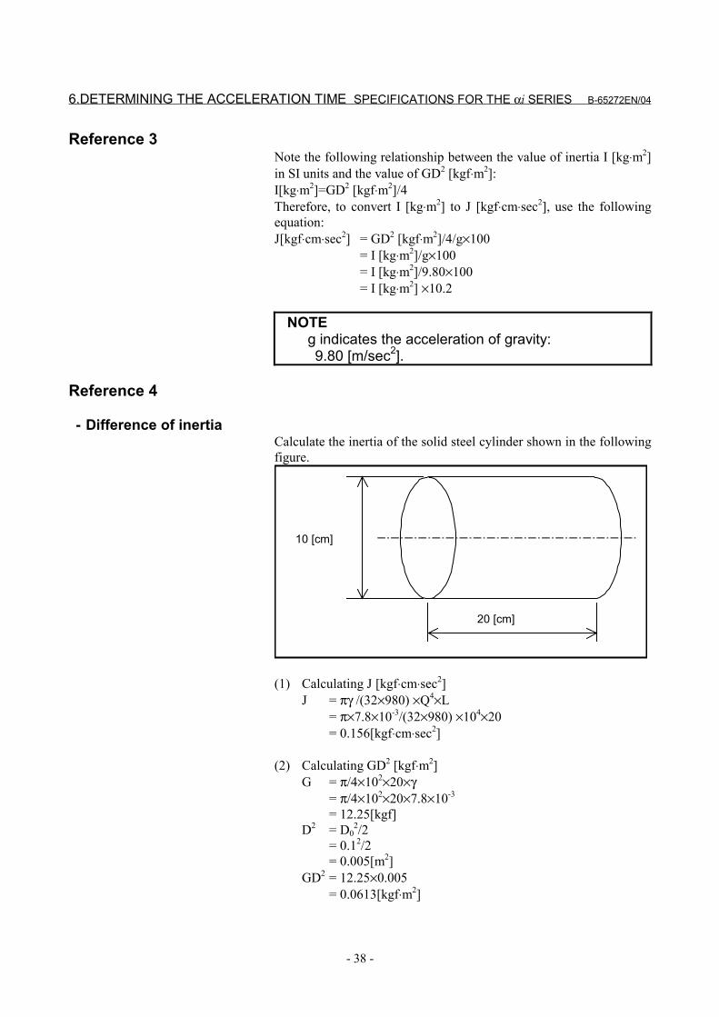
6.DETERMINING THE ACCELERATION TIME SPECIFICATIONS FOR THE αi SERIES B-65272EN/04
- 38 -
Reference 3Note the following relationship between the value of inertia I [kg⋅m2]in SI units and the value of GD2 [kgf⋅m2]:I[kg⋅m2]=GD2 [kgf⋅m2]/4Therefore, to convert I [kg⋅m2] to J [kgf⋅cm⋅sec2], use the followingequation:J[kgf⋅cm⋅sec2] = GD2 [kgf⋅m2]/4/g×100
= I [kg⋅m2]/g×100= I [kg⋅m2]/9.80×100= I [kg⋅m2] ×10.2
NOTEg indicates the acceleration of gravity: 9.80 [m/sec2].
Reference 4
- Difference of inertiaCalculate the inertia of the solid steel cylinder shown in the followingfigure.
20 [cm]
10 [cm]
(1) Calculating J [kgf⋅cm⋅sec2]J = πγ /(32×980) ×Q4×L
= π×7.8×10⁻³/(32×980) ×104×20= 0.156[kgf⋅cm⋅sec2]
(2) Calculating GD2 [kgf⋅m2]G = π/4×102×20×γ
= π/4×102×20×7.8×10-3
= 12.25[kgf]D2 = D0
2/2= 0.12/2= 0.005[m2]
GD2 = 12.25×0.005= 0.0613[kgf⋅m2]
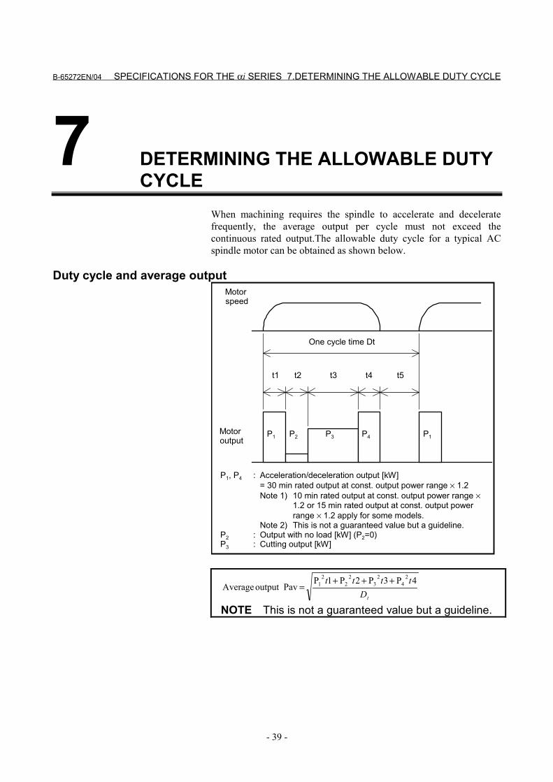
B-65272EN/04 SPECIFICATIONS FOR THE αi SERIES 7.DETERMINING THE ALLOWABLE DUTY CYCLE
- 39 -
7 DETERMINING THE ALLOWABLE DUTYCYCLE
When machining requires the spindle to accelerate and deceleratefrequently, the average output per cycle must not exceed thecontinuous rated output.The allowable duty cycle for a typical ACspindle motor can be obtained as shown below.
Duty cycle and average outputMotorspeed
t1 t2 t3 t4
P1 P2 P3 P4
t5
One cycle time Dt
P1Motoroutput
P1, P4 : Acceleration/deceleration output [kW]= 30 min rated output at const. output power range × 1.2Note 1) 10 min rated output at const. output power range ×
1.2 or 15 min rated output at const. output powerrange × 1.2 apply for some models.
Note 2) This is not a guaranteed value but a guideline.P2 : Output with no load [kW] (P2=0)P3 : Cutting output [kW]
tDtttt 4P3P2P1P
Pavoutput Average2
42
32
22
1 +++=
NOTE This is not a guaranteed value but a guideline.
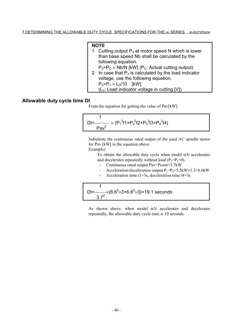
7.DETERMINING THE ALLOWABLE DUTY CYCLE SPECIFICATIONS FOR THE αi SERIES B-65272EN/04
- 40 -
NOTE1 Cutting output P3 at motor speed N which is lower
than base speed Nb shall be calculated by thefollowing equation.P3=PC × Nb/N [kW] (PC: Actual cutting output)
2 In case that P3 is calculated by the load indicatorvoltage, use the following equation.P3=P1 × L3/10 [kW](L3: Load indicator voltage in cutting [V])
Allowable duty cycle time DtFrom the equation for getting the value of Pav[kW].
1Dt= × (P1
2t1+P22t2+P3
2t3+P42t4)
Pav2
Substitute the continuous rated output of the used AC spindle motorfor Pav [kW] in the equation above.Example)
To obtain the allowable duty cycle when model α3i acceleratesand decelerates repeatedly without load (P2=P3=0). - Continuous rated output Pav=Pcont=3.7kW - Acceleration/deceleration output P1=P4=5.5kW×1.2=6.6kW - Acceleration time t1=3s, deceleration time t4=3s
1Dt= ×(6.62×3+6.62×3)=19.1 seconds 3.72
As shown above, when model α3i accelerates and deceleratesrepeatedly, the allowable duty cycle time is 19 seconds.
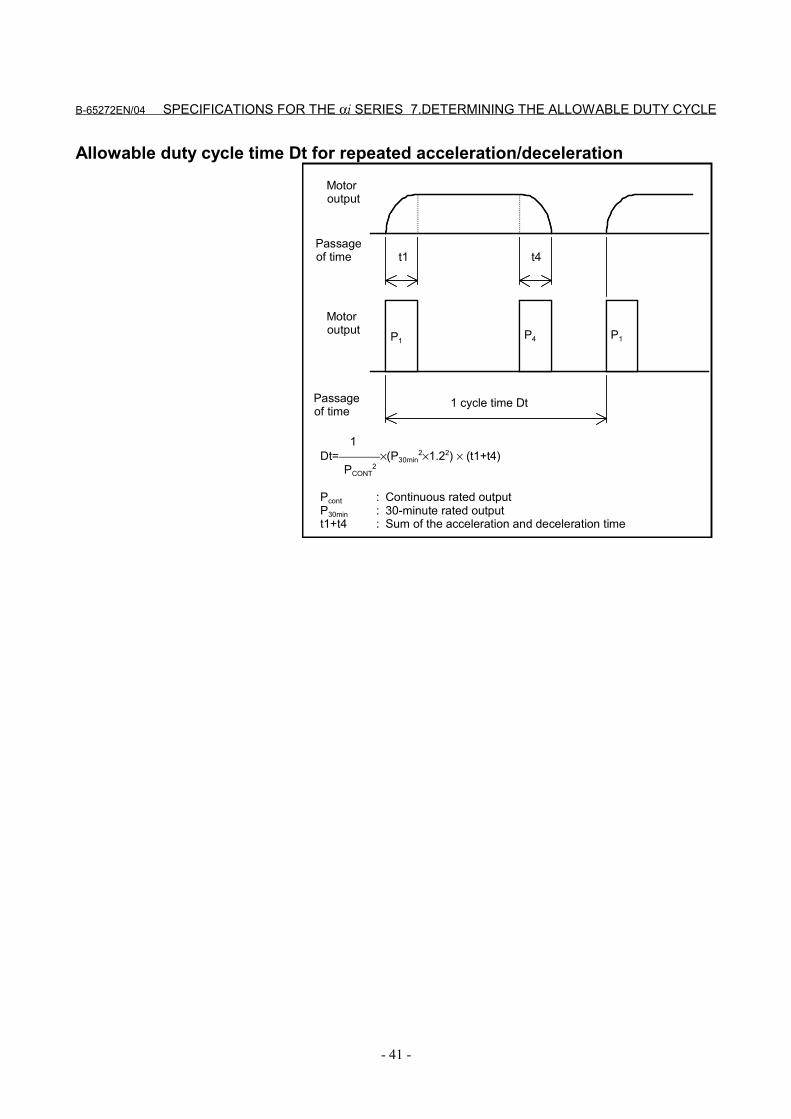
B-65272EN/04 SPECIFICATIONS FOR THE αi SERIES 7.DETERMINING THE ALLOWABLE DUTY CYCLE
- 41 -
Allowable duty cycle time Dt for repeated acceleration/deceleration
t1 t4
1 cycle time Dt
P1 P4 P1
Passageof time
Motoroutput
Motoroutput
Passageof time
1Dt= ×(P30min
2×1.22) × (t1+t4) PCONT
2
Pcont : Continuous rated outputP30min : 30-minute rated outputt1+t4 : Sum of the acceleration and deceleration time
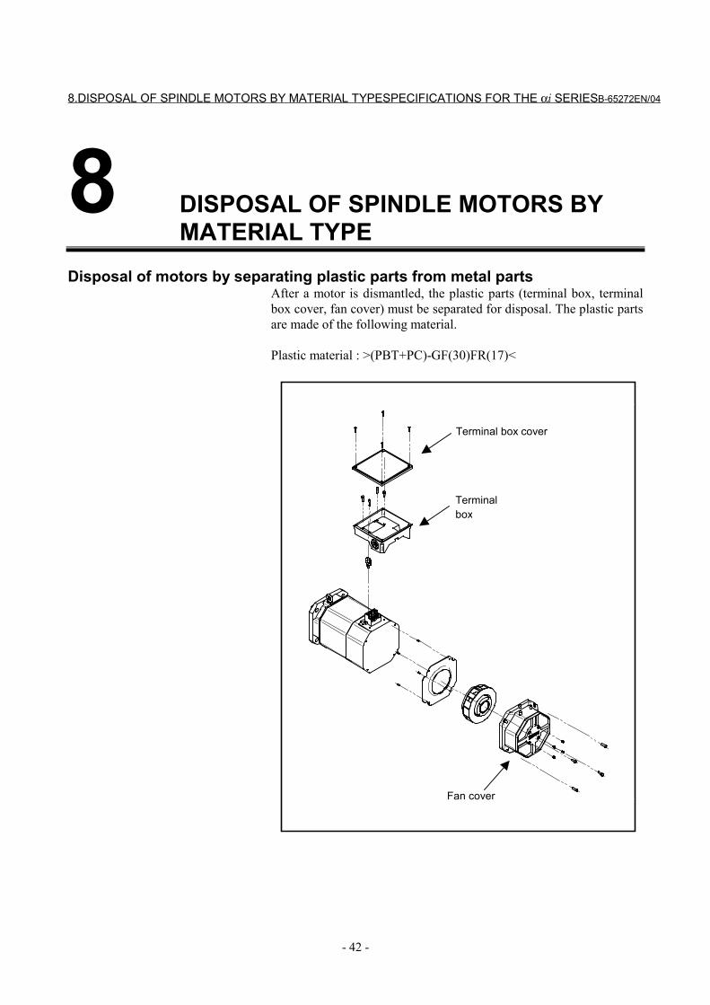
8.DISPOSAL OF SPINDLE MOTORS BY MATERIAL TYPESPECIFICATIONS FOR THE αi SERIESB-65272EN/04
- 42 -
8 DISPOSAL OF SPINDLE MOTORS BYMATERIAL TYPE
Disposal of motors by separating plastic parts from metal partsAfter a motor is dismantled, the plastic parts (terminal box, terminalbox cover, fan cover) must be separated for disposal. The plastic partsare made of the following material.
Plastic material : >(PBT+PC)-GF(30)FR(17)<
Terminalbox
Fan cover
Terminal box cover
II. FANUC AC SPINDLE MOTOR ααααi SERIES

B-65272EN/04 FANUC AC SPINDLE MOTOR αi SERIES 1.GENERAL
- 45 -
1 GENERALThe FANUC AC spindle motor αi series is ideal for CNC machinetool spindles.
Features - The motor is compact, light-weight and furnished with digital
control for much higher performance. - The motor inertia of the AC spindle motor is made smaller to
shorten the acceleration/deceleration speed. Further, optimumcontrol enables highly efficient cutting.
- The built-in Mi sensor or MZi sensor enables synchronousspindle and Z-axis feed and rigid tapping.
- Improvement in machining of the motor housing enhances theaccuracy of the mounting part.
- Waterproof and pressure-proof design conforming to theinternational standard (IEC) is employed to improve reliabilityand make it resistant to most environments.
2.SPECIFICATIONS FANUC AC SPINDLE MOTOR αi SERIES B-65272EN/04
- 46 -
2 SPECIFICATIONS
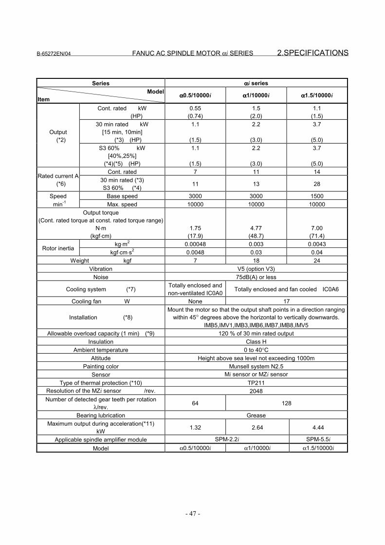
B-65272EN/04 FANUC AC SPINDLE MOTOR αi SERIES 2.SPECIFICATIONS
- 47 -
Series ααααi seriesModel
Item αααα0.5/10000i αααα1/10000i αααα1.5/10000i
Cont. rated kW (HP)
0.55(0.74)
1.5(2.0)
1.1(1.5)
30 min rated kW[15 min, 10min] (*3) (HP)
1.1
(1.5)
2.2
(3.0)
3.7
(5.0)Output (*2)
S3 60% kW[40%,25%]
(*4)(*5) (HP)
1.1
(1.5)
2.2
(3.0)
3.7
(5.0)Cont. rated 7 11 14
Rated current A (*6) 30 min rated (*3)
S3 60% (*4) 11 13 28
Speed Base speed 3000 3000 1500 min-1 Max. speed 10000 10000 10000
Output torque(Cont. rated torque at const. rated torque range)
N⋅m(kgf⋅cm)
1.75(17.9)
4.77(48.7)
7.00(71.4)
kg⋅m2 0.00048 0.003 0.0043Rotor inertia
kgf⋅cm⋅s2 0.0048 0.03 0.04Weight kgf 7 18 24
Vibration V5 (option V3)Noise 75dB(A) or less
Cooling system (*7) Totally enclosed andnon-ventilated IC0A0 Totally enclosed and fan cooled IC0A6
Cooling fan W None 17
Installation (*8)Mount the motor so that the output shaft points in a direction ranging
within 45° degrees above the horizontal to vertically downwards.IMB5,IMV1,IMB3,IMB6,IMB7,IMB8,IMV5
Allowable overload capacity (1 min) (*9) 120 % of 30 min rated outputInsulation Class H
Ambient temperature 0 to 40°CAltitude Height above sea level not exceeding 1000m
Painting color Munsell system N2.5Sensor Mi sensor or MZi sensor
Type of thermal protection (*10) TP211Resolution of the MZi sensor /rev. 2048Number of detected gear teeth per rotation
λ/rev. 64 128
Bearing lubrication GreaseMaximum output during acceleration(*11)
kW 1.32 2.64 4.44
Applicable spindle amplifier module SPM-2.2i SPM-5.5i
Model α0.5/10000i α1/10000i α1.5/10000i
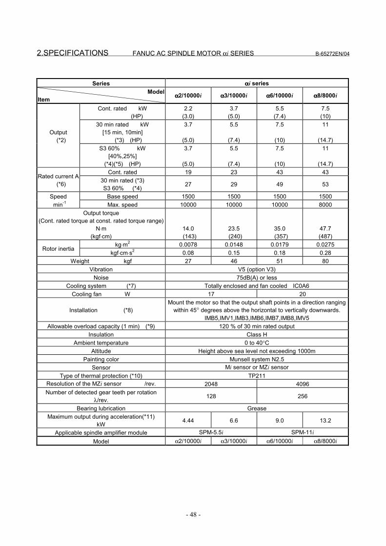
2.SPECIFICATIONS FANUC AC SPINDLE MOTOR αi SERIES B-65272EN/04
- 48 -
Series ααααi seriesModel
Item αααα2/10000i αααα3/10000i αααα6/10000i αααα8/8000i
Cont. rated kW (HP)
2.2(3.0)
3.7(5.0)
5.5(7.4)
7.5(10)
30 min rated kW[15 min, 10min] (*3) (HP)
3.7
(5.0)
5.5
(7.4)
7.5
(10)
11
(14.7)Output (*2)
S3 60% kW[40%,25%]
(*4)(*5) (HP)
3.7
(5.0)
5.5
(7.4)
7.5
(10)
11
(14.7)Cont. rated 19 23 43 43
Rated current A (*6) 30 min rated (*3)
S3 60% (*4) 27 29 49 53
Speed Base speed 1500 1500 1500 1500 min-1 Max. speed 10000 10000 10000 8000
Output torque(Cont. rated torque at const. rated torque range)
N⋅m(kgf⋅cm)
14.0 (143)
23.5 (240)
35.0 (357)
47.7(487)
kg⋅m2 0.0078 0.0148 0.0179 0.0275Rotor inertia
kgf⋅cm⋅s2 0.08 0.15 0.18 0.28Weight kgf 27 46 51 80
Vibration V5 (option V3)Noise 75dB(A) or less
Cooling system (*7) Totally enclosed and fan cooled IC0A6Cooling fan W 17 20
Installation (*8)Mount the motor so that the output shaft points in a direction ranging
within 45° degrees above the horizontal to vertically downwards.IMB5,IMV1,IMB3,IMB6,IMB7,IMB8,IMV5
Allowable overload capacity (1 min) (*9) 120 % of 30 min rated outputInsulation Class H
Ambient temperature 0 to 40°CAltitude Height above sea level not exceeding 1000m
Painting color Munsell system N2.5Sensor Mi sensor or MZi sensor
Type of thermal protection (*10) TP211Resolution of the MZi sensor /rev. 2048 4096Number of detected gear teeth per rotation
λ/rev. 128 256
Bearing lubrication GreaseMaximum output during acceleration(*11)
kW 4.44 6.6 9.0 13.2
Applicable spindle amplifier module SPM-5.5i SPM-11i
Model α2/10000i α3/10000i α6/10000i α8/8000i
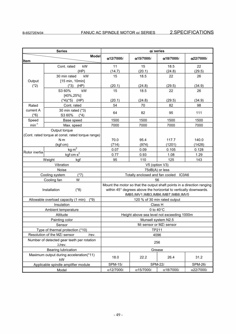
B-65272EN/04 FANUC AC SPINDLE MOTOR αi SERIES 2.SPECIFICATIONS
- 49 -
Series ααααi seriesModel
Item αααα12/7000i αααα15/7000i αααα18/7000i αααα22/7000i
Cont. rated kW (HP)
11(14.7)
15(20.1)
18.5(24.8)
22(29.5)
30 min rated kW[15 min, 10min] (*3) (HP)
15
(20.1)
18.5
(24.8)
22
(29.5)
26
(34.9)Output (*2)
S3 60% kW[40%,25%]
(*4)(*5) (HP)
15
(20.1)
18.5
(24.8)
22
(29.5)
26
(34.9)Cont. rated 54 70 82 98Rated
current A (*6)
30 min rated (*3)S3 60% (*4) 64 82 95 111
Speed Base speed 1500 1500 1500 1500 min-1 Max. speed 7000 7000 7000 7000
Output torque(Cont. rated torque at const. rated torque range)
N⋅m(kgf⋅cm)
70.0(714)
95.4 (974)
117.7(1201)
140.0(1428)
kg⋅m2 0.07 0.09 0.105 0.128Rotor inertia
kgf⋅cm⋅s2 0.77 0.93 1.08 1.29Weight kgf 95 110 125 143
Vibration V5 (option V3)Noise 75dB(A) or less
Cooling system (*7) Totally enclosed and fan cooled IC0A6Cooling fan W 56
Installation (*8)Mount the motor so that the output shaft points in a direction ranging
within 45° degrees above the horizontal to vertically downwards.IMB5,IMV1,IMB3,IMB6,IMB7,IMB8,IMV5
Allowable overload capacity (1 min) (*9) 120 % of 30 min rated outputInsulation Class H
Ambient temperature 0 to 40°CAltitude Height above sea level not exceeding 1000m
Painting color Munsell system N2.5Sensor Mi sensor or MZi sensor
Type of thermal protection (*10) TP211Resolution of the MZi sensor /rev. 4096Number of detected gear teeth per rotation
λ/rev. 256
Bearing lubrication GreaseMaximum output during acceleration(*11)
kW 18.0 22.2 26.4 31.2
Applicable spindle amplifier module SPM-15i SPM-22i SPM-26i
Model α12/7000i α15/7000i α18/7000i α22/7000i
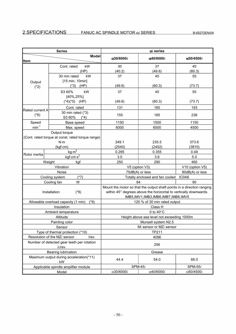
2.SPECIFICATIONS FANUC AC SPINDLE MOTOR αi SERIES B-65272EN/04
- 50 -
Series ααααi seriesModel
Item αααα30/6000i αααα40/6000i αααα50/4500i
Cont. rated kW (HP)
30(40.2)
37(49.6)
45(60.3)
30 min rated kW[15 min, 10min] (*3) (HP)
37
(49.6)
45
(60.3)
55
(73.7)Output (*2)
S3 60% kW[40%,25%]
(*4)(*5) (HP)
37
(49.6)
45
(60.3)
55
(73.7)
Cont. rated 131 160 193Rated current A
(*6) 30 min rated (*3)S3 60% (*4) 155 185 236
Speed Base speed 1150 1500 1150 min-1 Max. speed 6000 6000 4500
Output torque(Cont. rated torque at const. rated torque range)
N⋅m(kgf⋅cm)
249.1(2540)
235.5(2402)
373.6(3810)
kg⋅m2 0.295 0.355 0.49Rotor inertia
kgf⋅cm⋅s2 3.0 3.6 5.0Weight kgf 250 290 460
Vibration V5 (option V3) V10 (option V5)Noise 75dB(A) or less 80dB(A) or less
Cooling system (*7) Totally enclosed and fan cooled IC0A6Cooling fan W 84 90
Installation (*8)Mount the motor so that the output shaft points in a direction ranging
within 45° degrees above the horizontal to vertically downwards.IMB5,IMV1,IMB3,IMB6,IMB7,IMB8,IMV5
Allowable overload capacity (1 min) (*9) 120 % of 30 min rated outputInsulation Class H
Ambient temperature 0 to 40°CAltitude Height above sea level not exceeding 1000m
Painting color Munsell system N2.5Sensor Mi sensor or MZi sensor
Type of thermal protection (*10) TP211Resolution of the MZi sensor /rev. 4096Number of detected gear teeth per rotation
λ/rev. 256
Bearing lubrication GreaseMaximum output during acceleration(*11)
kW 44.4 54.0 66.0
Applicable spindle amplifier module SPM-45i SPM-55iModel α30/6000i α40/6000i α50/4500i
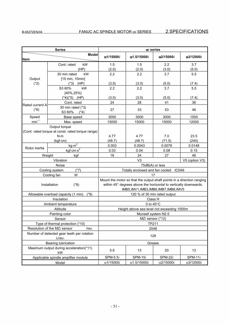
B-65272EN/04 FANUC AC SPINDLE MOTOR αi SERIES 2.SPECIFICATIONS
- 51 -
Series ααααi seriesModel
Item αααα1/15000i αααα1.5/15000i αααα2/15000i αααα3/12000i
Cont. rated kW (HP)
1.5(2.0)
1.5(2.0)
2.2(3.0)
3.7(5.0)
30 min rated kW[15 min, 10min] (*3) (HP)
2.2
(3.0)
2.2
(3.0)
3.7
(5.0)
5.5
(7.4)Output (*2)
S3 60% kW[40%,25%]
(*4)(*5) (HP)
2.2
(3.0)
2.2
(3.0)
3.7
(5.0)
5.5
(7.4)Cont. rated 24 28 41 36
Rated current A (*6) 30 min rated (*3)
S3 60% (*4) 27 33 53 46
Speed Base speed 3000 3000 3000 1500 min-1 Max. speed 15000 15000 15000 12000
Output torque(Cont. rated torque at const. rated torque range)
N⋅m(kgf⋅cm)
4.77(48.7)
4.77(48.7)
7.0(71.5)
23.5(240)
kg⋅m2 0.003 0.0043 0.0078 0.0148Rotor inertia
kgf⋅cm⋅s2 0.03 0.04 0.08 0.15Weight kgf 18 24 27 46
Vibration V3 V5 (option V3)Noise 75dB(A) or less
Cooling system (*7) Totally enclosed and fan cooled IC0A6Cooling fan W 17
Installation (*8)Mount the motor so that the output shaft points in a direction ranging
within 45° degrees above the horizontal to vertically downwards.IMB5,IMV1,IMB3,IMB6,IMB7,IMB8,IMV5
Allowable overload capacity (1 min) (*9) 120 % of 30 min rated outputInsulation Class H
Ambient temperature 0 to 40°CAltitude Height above sea level not exceeding 1000m
Painting color Munsell system N2.5Sensor MZi sensor (*12)
Type of thermal protection (*10) TP211Resolution of the MZi sensor /rev. 2048Number of detected gear teeth per rotation
λ/rev. 128
Bearing lubrication GreaseMaximum output during acceleration(*11)
kW 5.6 13 20 13
Applicable spindle amplifier module SPM-5.5i SPM-15i SPM-22i SPM-11i
Model α1/15000i α1.5/15000i α2/15000i α3/12000i
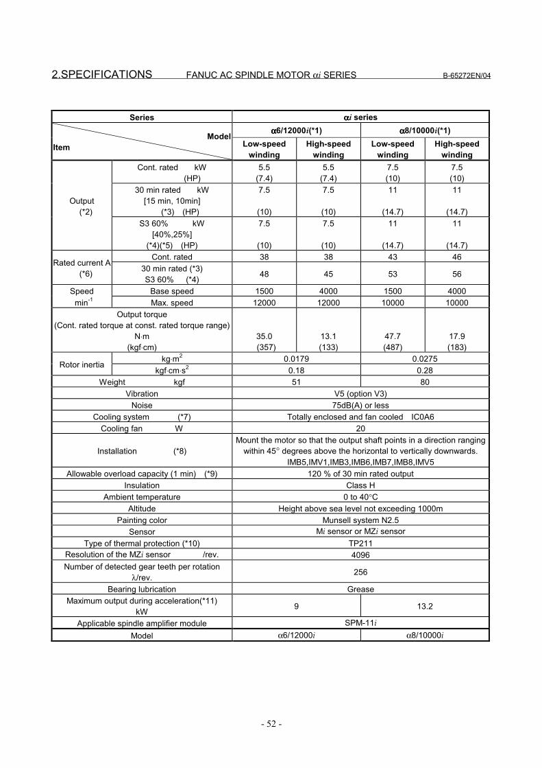
2.SPECIFICATIONS FANUC AC SPINDLE MOTOR αi SERIES B-65272EN/04
- 52 -
Series ααααi seriesαααα6/12000i(*1) αααα8/10000i(*1)
ModelItem Low-speed
windingHigh-speed
windingLow-speed
windingHigh-speed
windingCont. rated kW
(HP)5.5
(7.4)5.5
(7.4)7.5(10)
7.5(10)
30 min rated kW[15 min, 10min] (*3) (HP)
7.5
(10)
7.5
(10)
11
(14.7)
11
(14.7)Output (*2)
S3 60% kW[40%,25%]
(*4)(*5) (HP)
7.5
(10)
7.5
(10)
11
(14.7)
11
(14.7)Cont. rated 38 38 43 46
Rated current A (*6) 30 min rated (*3)
S3 60% (*4) 48 45 53 56
Speed Base speed 1500 4000 1500 4000 min-1 Max. speed 12000 12000 10000 10000
Output torque(Cont. rated torque at const. rated torque range)
N⋅m(kgf⋅cm)
35.0 (357)
13.1(133)
47.7(487)
17.9(183)
kg⋅m2 0.0179 0.0275Rotor inertia
kgf⋅cm⋅s2 0.18 0.28Weight kgf 51 80
Vibration V5 (option V3)Noise 75dB(A) or less
Cooling system (*7) Totally enclosed and fan cooled IC0A6Cooling fan W 20
Installation (*8)Mount the motor so that the output shaft points in a direction ranging
within 45° degrees above the horizontal to vertically downwards.IMB5,IMV1,IMB3,IMB6,IMB7,IMB8,IMV5
Allowable overload capacity (1 min) (*9) 120 % of 30 min rated outputInsulation Class H
Ambient temperature 0 to 40°CAltitude Height above sea level not exceeding 1000m
Painting color Munsell system N2.5Sensor Mi sensor or MZi sensor
Type of thermal protection (*10) TP211Resolution of the MZi sensor /rev. 4096Number of detected gear teeth per rotation
λ/rev. 256
Bearing lubrication GreaseMaximum output during acceleration(*11)
kW 9 13.2
Applicable spindle amplifier module SPM-11i
Model α6/12000i α8/10000i
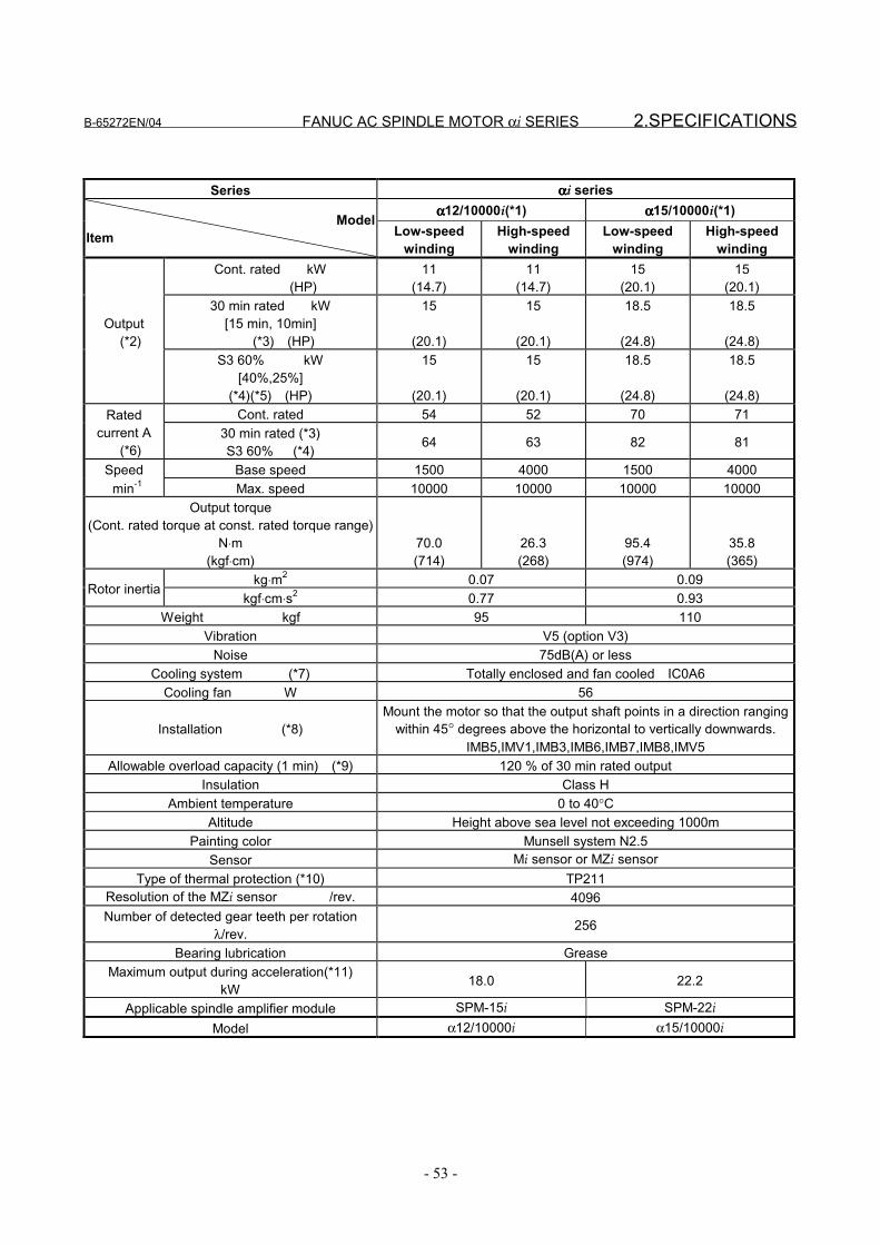
B-65272EN/04 FANUC AC SPINDLE MOTOR αi SERIES 2.SPECIFICATIONS
- 53 -
Series ααααi seriesαααα12/10000i(*1) αααα15/10000i(*1)
ModelItem Low-speed
windingHigh-speed
windingLow-speed
windingHigh-speed
windingCont. rated kW
(HP)11
(14.7)11
(14.7)15
(20.1)15
(20.1)30 min rated kW
[15 min, 10min] (*3) (HP)
15
(20.1)
15
(20.1)
18.5
(24.8)
18.5
(24.8)Output (*2)
S3 60% kW[40%,25%]
(*4)(*5) (HP)
15
(20.1)
15
(20.1)
18.5
(24.8)
18.5
(24.8)Cont. rated 54 52 70 71Rated
current A (*6)
30 min rated (*3)S3 60% (*4) 64 63 82 81
Speed Base speed 1500 4000 1500 4000 min-1 Max. speed 10000 10000 10000 10000
Output torque(Cont. rated torque at const. rated torque range)
N⋅m(kgf⋅cm)
70.0(714)
26.3(268)
95.4(974)
35.8(365)
kg⋅m2 0.07 0.09Rotor inertia
kgf⋅cm⋅s2 0.77 0.93Weight kgf 95 110
Vibration V5 (option V3)Noise 75dB(A) or less
Cooling system (*7) Totally enclosed and fan cooled IC0A6Cooling fan W 56
Installation (*8)Mount the motor so that the output shaft points in a direction ranging
within 45° degrees above the horizontal to vertically downwards.IMB5,IMV1,IMB3,IMB6,IMB7,IMB8,IMV5
Allowable overload capacity (1 min) (*9) 120 % of 30 min rated outputInsulation Class H
Ambient temperature 0 to 40°CAltitude Height above sea level not exceeding 1000m
Painting color Munsell system N2.5Sensor Mi sensor or MZi sensor
Type of thermal protection (*10) TP211Resolution of the MZi sensor /rev. 4096Number of detected gear teeth per rotation
λ/rev. 256
Bearing lubrication GreaseMaximum output during acceleration(*11)
kW 18.0 22.2
Applicable spindle amplifier module SPM-15i SPM-22i
Model α12/10000i α15/10000i
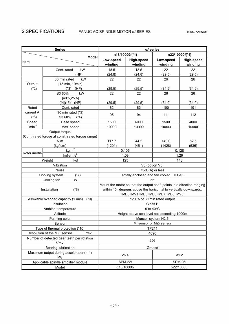
2.SPECIFICATIONS FANUC AC SPINDLE MOTOR αi SERIES B-65272EN/04
- 54 -
Series ααααi seriesαααα18/10000i(*1) αααα22/10000i(*1)
ModelItem Low-speed
windingHigh-speed
windingLow-speed
windingHigh-speed
windingCont. rated kW
(HP)18.5
(24.8)18.5
(24.8)22
(29.5)22
(29.5)30 min rated kW
[15 min, 10min] (*3) (HP)
22
(29.5)
22
(29.5)
26
(34.9)
26
(34.9)Output (*2)
S3 60% kW[40%,25%]
(*4)(*5) (HP)
22
(29.5)
22
(29.5)
26
(34.9)
26
(34.9)Cont. rated 82 83 100 101Rated
current A (*6)
30 min rated (*3)S3 60% (*4) 95 94 111 112
Speed Base speed 1500 4000 1500 4000 min-1 Max. speed 10000 10000 10000 10000
Output torque(Cont. rated torque at const. rated torque range)
N⋅m(kgf⋅cm)
117.7(1201)
44.2(451)
140.0(1428)
52.5(536)
kg⋅m2 0.105 0.128Rotor inertia
kgf⋅cm⋅s2 1.08 1.29Weight kgf 125 143
Vibration V5 (option V3)Noise 75dB(A) or less
Cooling system (*7) Totally enclosed and fan cooled IC0A6Cooling fan W 56
Installation (*8)Mount the motor so that the output shaft points in a direction ranging
within 45° degrees above the horizontal to vertically downwards.IMB5,IMV1,IMB3,IMB6,IMB7,IMB8,IMV5
Allowable overload capacity (1 min) (*9) 120 % of 30 min rated outputInsulation Class H
Ambient temperature 0 to 40°CAltitude Height above sea level not exceeding 1000m
Painting color Munsell system N2.5Sensor Mi sensor or MZi sensor
Type of thermal protection (*10) TP211Resolution of the MZi sensor /rev. 4096Number of detected gear teeth per rotation
λ/rev. 256
Bearing lubrication GreaseMaximum output during acceleration(*11)
kW 26.4 31.2
Applicable spindle amplifier module SPM-22i SPM-26i
Model α18/10000i α22/10000i
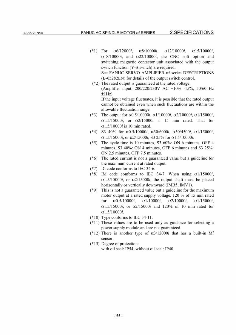
B-65272EN/04 FANUC AC SPINDLE MOTOR αi SERIES 2.SPECIFICATIONS
- 55 -
(*1) For α6/12000i, α8/10000i, α12/10000i, α15/10000i,α18/10000i, and α22/10000i, the CNC soft option andswitching magnetic contactor unit associated with the outputswitch function (Y-∆ switch) are required.See FANUC SERVO AMPLIFIER αi series DESCRIPTIONS(B-65282EN) for details of the output switch control.
(*2) The rated output is guaranteed at the rated voltage.(Amplifier input: 200/220/230V AC +10% -15%, 50/60 Hz±1Hz)If the input voltage fluctuates, it is possible that the rated outputcannot be obtained even when such fluctuations are within theallowable fluctuation range.
(*3) The output for α0.5/10000i, α1/10000i, α2/10000i, α1/15000i,α1.5/15000i, or α2/15000i is 15 min rated. That forα1.5/10000i is 10 min rated.
(*4) S3 40% for α0.5/10000i, α30/6000i, α50/4500i, α1/15000i,α1.5/15000i, or α2/15000i, S3 25% for α1.5/10000i.
(*5) The cycle time is 10 minutes, S3 60%: ON 6 minutes, OFF 4minutes, S3 40%: ON 4 minutes, OFF 6 minutes and S3 25%:ON 2.5 minutes, OFF 7.5 minutes.
(*6) The rated current is not a guaranteed value but a guideline forthe maximum current at rated output.
(*7) IC code conforms to IEC 34-6.(*8) IM code conforms to IEC 34-7. When using α1/15000i,
α1.5/15000i, or α2/15000i, the output shaft must be placedhorizontally or vertically downward (IMB5, IMV1).
(*9) This is not a guaranteed value but a guideline for the maximummotor output at a rated supply voltage. 120 % of 15 min ratedfor α0.5/10000i, α1/10000i, α2/10000i, α1/15000i,α1.5/15000i, or α2/15000i and 120% of 10 min rated forα1.5/10000i.
(*10) Type conforms to IEC 34-11.(*11) These values are to be used only as guidance for selecting a
power supply module and are not guaranteed.(*12) There is another type of α3/12000i that has a built-in Mi
sensor.(*13) Degree of protection:
with oil seal: IP54, without oil seal: IP40.

3.OUTPUT/TORQUE CHARACTERISTICS FANUC AC SPINDLE MOTOR αi SERIES B-65272EN/04
- 56 -
3 OUTPUT/TORQUE CHARACTERISTICSReferenceCalculation for torque
Torque T can be obtained by the following equation.
T[N⋅m]=P[kW]×1000/0.1047/N[min-1]P[kW]: Motor outputN[min-1]: Motor speed
When the unit of T is [kgf⋅m],T[kgf⋅m]=P[kW]×1000/1.0269/N[min-1]
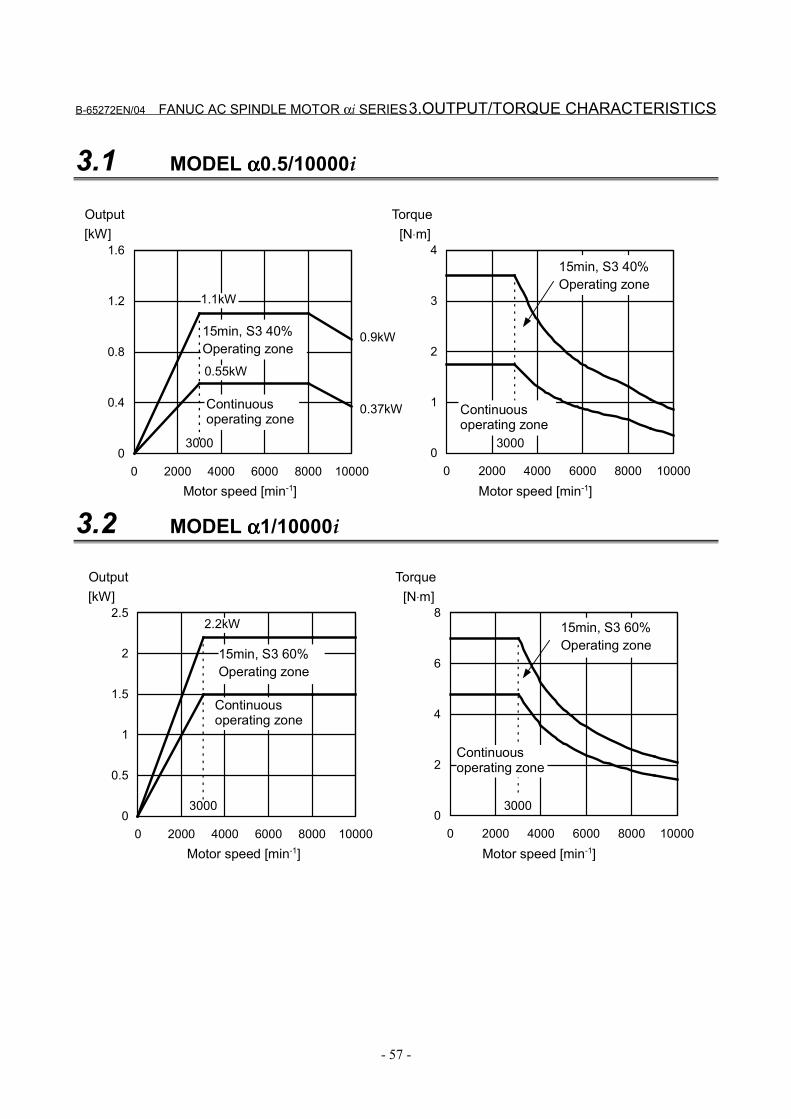
B-65272EN/04 FANUC AC SPINDLE MOTOR αi SERIES 3.OUTPUT/TORQUE CHARACTERISTICS
- 57 -
3.1 MODEL αααα0.5/10000i
0
0.4
0.8
1.2
1.6
0 2000 4000 6000 8000 10000Motor speed [min-1]
[kW]
3000
Output
Continuousoperating zone
15min, S3 40%Operating zone
0.37kW
0.9kW
0
1
2
3
4
0 2000 4000 6000 8000 10000Motor speed [min-1]
[N⋅m]
3000
Torque
15min, S3 40%Operating zone
0.55kW
1.1kW
Continuousoperating zone
3.2 MODEL αααα1/10000i
0
0.5
1
1.5
2
2.5
0 2000 4000 6000 8000 10000
[kW]
3000
2.2kW
0
2
4
6
8
0 2000 4000 6000 8000 10000
[N⋅m]
3000
Motor speed [min-1]
Output
Continuousoperating zone
15min, S3 60%Operating zone
Motor speed [min-1]
Torque
15min, S3 60%Operating zone
Continuousoperating zone
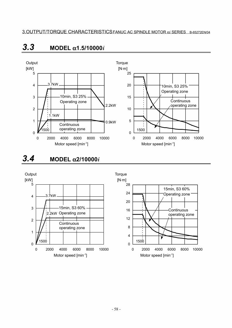
3.OUTPUT/TORQUE CHARACTERISTICS FANUC AC SPINDLE MOTOR αi SERIES B-65272EN/04
- 58 -
3.3 MODEL αααα1.5/10000i
0
1
2
3
4
5
0 2000 4000 6000 8000 10000
[kW]
1500
3.7kW
0
5
10
15
20
25
0 2000 4000 6000 8000 10000
[N⋅m]
1500
2.2kW
0.9kW
1.1kW
Motor speed [min-1]
Output
Continuousoperating zone
10min, S3 25%Operating zone
Motor speed [min-1]
Torque
10min, S3 25%Operating zone
Continuousoperating zone
3.4 MODEL αααα2/10000i
0
1
2
3
4
5
0 2000 4000 6000 8000 10000
[kW]
1500
3.7kW
0
4
8
12
16
20
24
28
0 2000 4000 6000 8000 10000
[N⋅m]
1500
2.2kW
Motor speed [min-1]
Output
Continuousoperating zone
15min, S3 60%Operating zone
Motor speed [min-1]
Torque
15min, S3 60%Operating zone
Continuousoperating zone
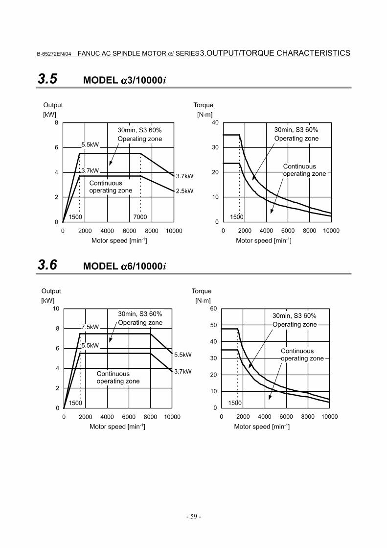
B-65272EN/04 FANUC AC SPINDLE MOTOR αi SERIES 3.OUTPUT/TORQUE CHARACTERISTICS
- 59 -
3.5 MODEL αααα3/10000i
0
2
4
6
8
0 2000 4000 6000 8000 10000
[kW]
1500
3.7kW
0
10
20
30
40
0 2000 4000 6000 8000 10000
[N⋅m]
1500
5.5kW
7000
3.7kW
2.5kW
Motor speed [min-1]
Output
Continuousoperating zone
30min, S3 60%Operating zone
Motor speed [min-1]
Torque
30min, S3 60%Operating zone
Continuousoperating zone
3.6 MODEL αααα6/10000i
0
2
4
6
8
10
0 2000 4000 6000 8000 10000
[kW]
1500
7.5kW
0
10
20
30
40
50
60
0 2000 4000 6000 8000 10000
[N⋅m]
1500
5.5kW
3.7kW
5.5kW
Motor speed [min-1]
Output
Continuousoperating zone
30min, S3 60%Operating zone
Motor speed [min-1]
Torque
30min, S3 60%Operating zone
Continuousoperating zone
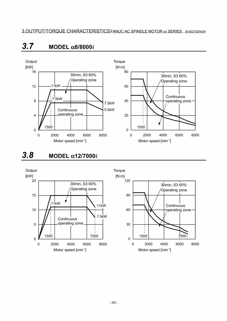
3.OUTPUT/TORQUE CHARACTERISTICS FANUC AC SPINDLE MOTOR αi SERIES B-65272EN/04
- 60 -
3.7 MODEL αααα8/8000i
0
4
8
12
16
0 2000 4000 6000 8000
[kW]
1500
7.5kW
0
20
40
60
80
0 2000 4000 6000 8000
[N⋅m]
1500
11kW
7.5kW
5.5kW
Motor speed [min-1]
Output
Continuousoperating zone
30min, S3 60%Operating zone
Motor speed [min-1]
Torque
30min, S3 60%Operating zone
Continuousoperating zone
3.8 MODEL αααα12/7000i
0
5
10
15
20
0 2000 4000 6000 8000
[kW]
15000
30
60
90
120
0 2000 4000 6000 8000
[N⋅m]
1500
11kW
7.5kW
11kW
7000 7000
Motor speed [min-1]
Output
Continuousoperating zone
30min, S3 60%Operating zone
Motor speed [min-1]
Torque
30min, S3 60%Operating zone
Continuousoperating zone
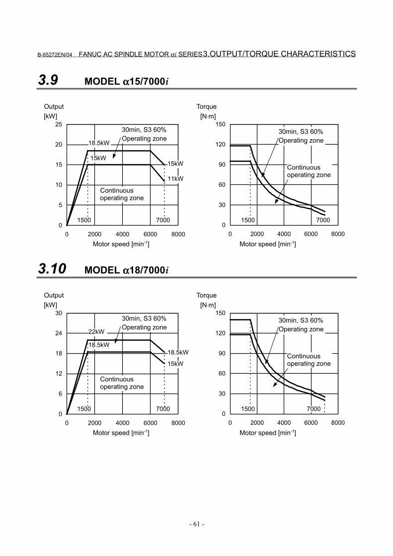
B-65272EN/04 FANUC AC SPINDLE MOTOR αi SERIES 3.OUTPUT/TORQUE CHARACTERISTICS
- 61 -
3.9 MODEL αααα15/7000i
0
5
10
15
20
25
0 2000 4000 6000 8000
[kW]
15000
30
60
90
120
150
0 2000 4000 6000 8000
[N⋅m]
1500
15kW15kW
11kW
7000 7000
18.5kW
Motor speed [min-1]
Output
Continuousoperating zone
30min, S3 60%Operating zone
Motor speed [min-1]
Torque
30min, S3 60%Operating zone
Continuousoperating zone
3.10 MODEL αααα18/7000i
0
6
12
18
24
30
0 2000 4000 6000 8000
[kW]
15000
30
60
90
120
150
0 2000 4000 6000 8000
[N⋅m]
1500
22kW
15kW
18.5kW
7000 7000
18.5kW
Motor speed [min-1]
Output
Continuousoperating zone
30min, S3 60%Operating zone
Motor speed [min-1]
Torque
30min, S3 60%Operating zone
Continuousoperating zone
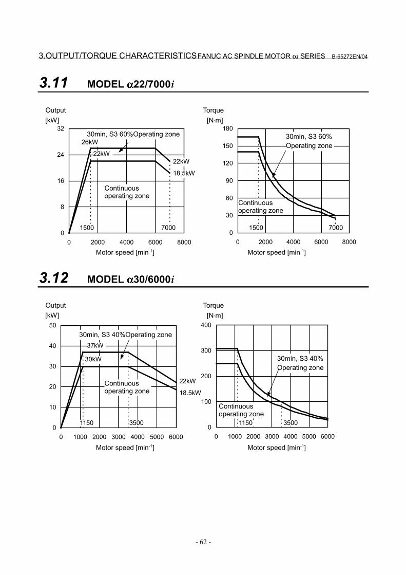
3.OUTPUT/TORQUE CHARACTERISTICS FANUC AC SPINDLE MOTOR αi SERIES B-65272EN/04
- 62 -
3.11 MODEL αααα22/7000i
0
8
16
24
32
0 2000 4000 6000 8000
[kW]
15000
30
60
90
120
150
180
0 2000 4000 6000 8000
[N⋅m]
1500
22kW22kW
18.5kW
7000 7000
26kW
Motor speed [min-1]
Output
Continuousoperating zone
30min, S3 60%Operating zone
Motor speed [min-1]
Torque
30min, S3 60%Operating zone
Continuousoperating zone
3.12 MODEL αααα30/6000i
0
100
200
300
400
0 1000 2000 3000 4000 5000 60000
10
20
30
40
50
0 1000 2000 3000 4000 5000 6000
[kW]
1150
[N⋅m]
1150
30kW
22kW
18.5kW
3500 3500
37kW
Motor speed [min-1]
Output
Continuousoperating zone
30min, S3 40%Operating zone
Motor speed [min-1]
Torque
30min, S3 40%Operating zone
Continuousoperating zone
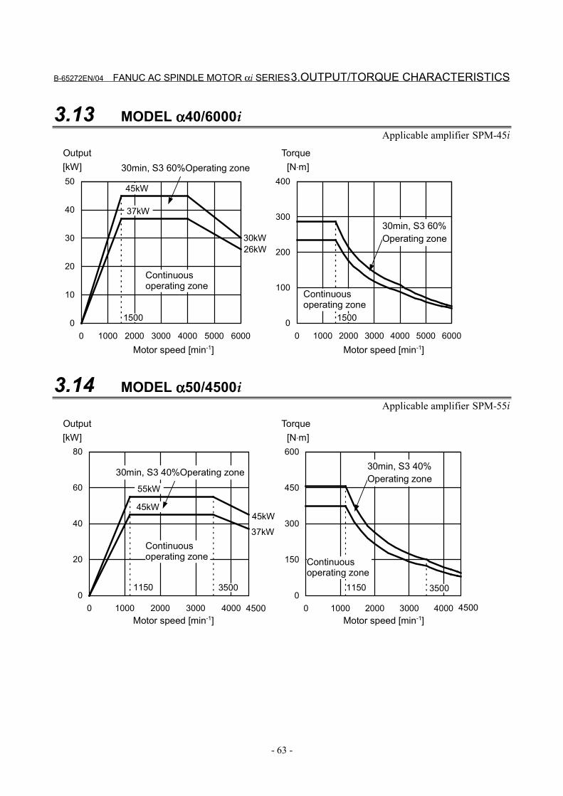
B-65272EN/04 FANUC AC SPINDLE MOTOR αi SERIES 3.OUTPUT/TORQUE CHARACTERISTICS
- 63 -
3.13 MODEL αααα40/6000iApplicable amplifier SPM-45i
0
100
200
300
400
0 1000 2000 3000 4000 5000 60000
10
20
30
40
50
0 1000 2000 3000 4000 5000 6000
30kW
45kW
37kW
26kW
15001500
[kW] [N⋅m]
Motor speed [min-1]
Output
Continuousoperating zone
30min, S3 60%Operating zone
Motor speed [min-1]
Torque
30min, S3 60%Operating zone
Continuousoperating zone
3.14 MODEL αααα50/4500iApplicable amplifier SPM-55i
0
150
300
450
600
0 1000 2000 3000 40000
20
40
60
80
0 1000 2000 3000 4000
45kW
55kW
45kW
37kW
11501150 35003500
[kW] [N⋅m]
Motor speed [min-1]
Output
Continuousoperating zone
30min, S3 40%Operating zone
Motor speed [min-1]
Torque
30min, S3 40%Operating zone
Continuousoperating zone
4500 4500
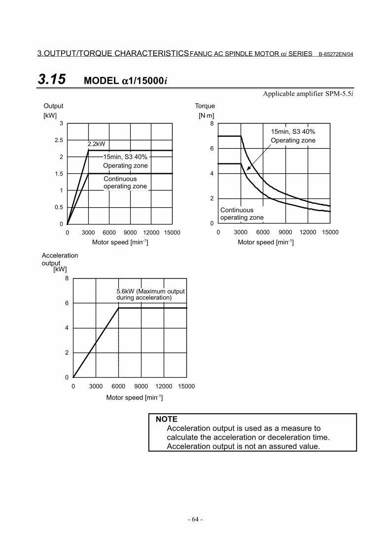
3.OUTPUT/TORQUE CHARACTERISTICS FANUC AC SPINDLE MOTOR αi SERIES B-65272EN/04
- 64 -
3.15 MODEL αααα1/15000iApplicable amplifier SPM-5.5i
0
0.5
1
1.5
2
2.5
3
0 3000 6000 9000 12000 15000
[kW]
0
2
4
6
8
0 3000 6000 9000 12000 15000
[N⋅m]
2.2kW
Motor speed [min-1]
Output
Continuousoperating zone
15min, S3 40%Operating zone
Motor speed [min-1]
Torque
15min, S3 40%Operating zone
Continuousoperating zone
0
2
4
6
8
0 3000 6000 9000 12000 15000
Motor speed [min-1]
[kW]
Accelerationoutput
5.6kW (Maximum outputduring acceleration)
NOTEAcceleration output is used as a measure tocalculate the acceleration or deceleration time.Acceleration output is not an assured value.
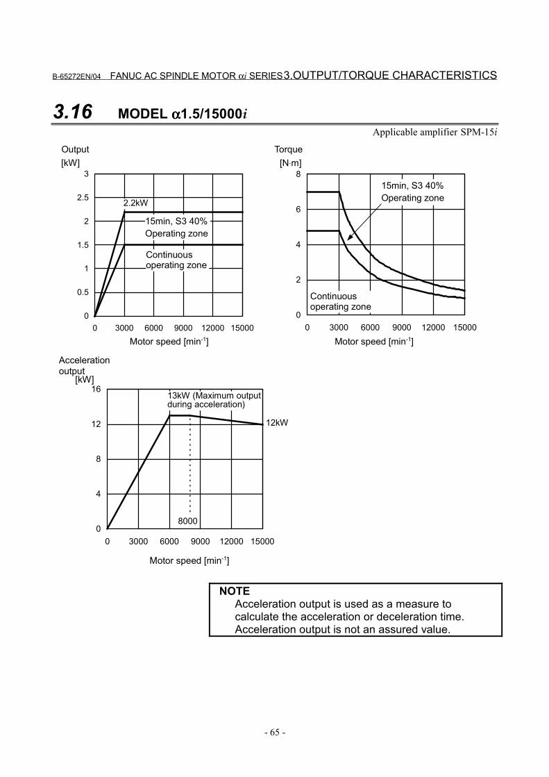
B-65272EN/04 FANUC AC SPINDLE MOTOR αi SERIES 3.OUTPUT/TORQUE CHARACTERISTICS
- 65 -
3.16 MODEL αααα1.5/15000iApplicable amplifier SPM-15i
0
0.5
1
1.5
2
2.5
3
0 3000 6000 9000 12000 15000
[kW]
0
2
4
6
8
0 3000 6000 9000 12000 15000
[N⋅m]
2.2kW
Motor speed [min-1]
Output
Continuousoperating zone
15min, S3 40%Operating zone
Motor speed [min-1]
Torque
15min, S3 40%Operating zone
Continuousoperating zone
0
4
8
12
16
0 3000 6000 9000 12000 15000
Motor speed [min-1]
[kW]
8000
Accelerationoutput
12kW
13kW (Maximum outputduring acceleration)
NOTEAcceleration output is used as a measure tocalculate the acceleration or deceleration time.Acceleration output is not an assured value.
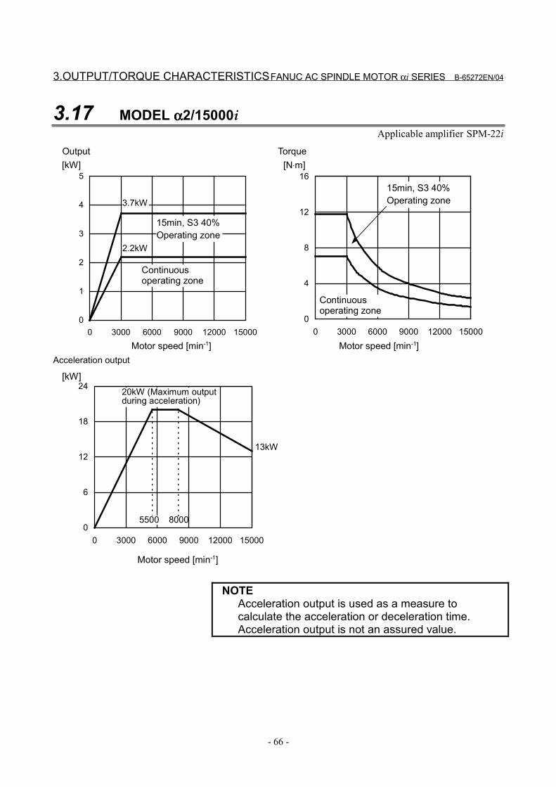
3.OUTPUT/TORQUE CHARACTERISTICS FANUC AC SPINDLE MOTOR αi SERIES B-65272EN/04
- 66 -
3.17 MODEL αααα2/15000iApplicable amplifier SPM-22i
0
1
2
3
4
5
0 3000 6000 9000 12000 15000
[kW]
0
4
8
12
16
0 3000 6000 9000 12000 15000
[N⋅m]
2.2kW
3.7kW
Motor speed [min-1]
Output
Continuousoperating zone
15min, S3 40%Operating zone
Motor speed [min-1]
Torque
15min, S3 40%Operating zone
Continuousoperating zone
0
6
12
18
24
0 3000 6000 9000 12000 15000
[kW]
8000
13kW
5500
Motor speed [min-1]
20kW (Maximum outputduring acceleration)
Acceleration output
NOTEAcceleration output is used as a measure tocalculate the acceleration or deceleration time.Acceleration output is not an assured value.
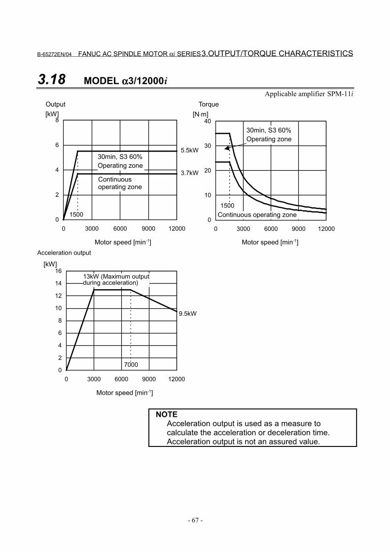
B-65272EN/04 FANUC AC SPINDLE MOTOR αi SERIES 3.OUTPUT/TORQUE CHARACTERISTICS
- 67 -
3.18 MODEL αααα3/12000iApplicable amplifier SPM-11i
0
2
4
6
8
0 3000 6000 9000 12000
[kW]
0
10
20
30
40
0 3000 6000 9000 12000
[N⋅m]
3.7kW
5.5kW
15001500
Motor speed [min-1]
Output
Continuousoperating zone
30min, S3 60%Operating zone
Motor speed [min-1]
Torque
30min, S3 60%Operating zone
Continuous operating zone
0
2
4
6
8
10
12
14
16
0 3000 6000 9000 12000
[kW]
7000
9.5kW
Motor speed [min-1]
13kW (Maximum outputduring acceleration)
Acceleration output
NOTEAcceleration output is used as a measure tocalculate the acceleration or deceleration time.Acceleration output is not an assured value.
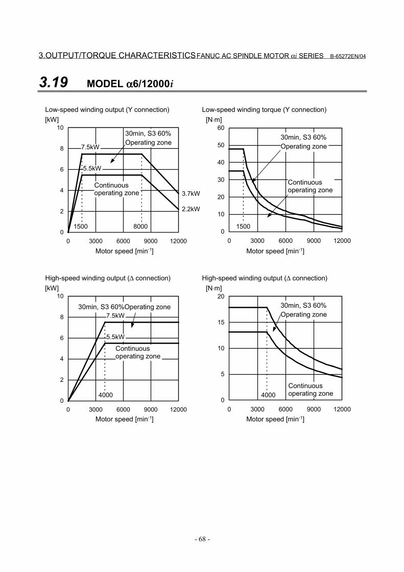
3.OUTPUT/TORQUE CHARACTERISTICS FANUC AC SPINDLE MOTOR αi SERIES B-65272EN/04
- 68 -
3.19 MODEL αααα6/12000i
0
2
4
6
8
10
0 3000 6000 9000 12000
Q
[kW]
0
10
20
30
40
50
60
0 3000 6000 9000 12000
[N⋅m]
2.2kW
7.5kW
0
2
4
6
8
10
0 3000 6000 9000 12000
[kW]
0
5
10
15
20
0 3000 6000 9000 12000
[N⋅m]
5.5kW
7.5kW
3.7kW
5.5kW
80001500 1500
40004000
Motor speed [min-1]
Continuousoperating zone
30min, S3 60%Operating zone
Motor speed [min-1]
30min, S3 60%Operating zone
Continuousoperating zone
Low-speed winding output (Y connection) Low-speed winding torque (Y connection)
Motor speed [min-1]
Continuousoperating zone
30min, S3 60%Operating zone
Motor speed [min-1]
30min, S3 60%Operating zone
Continuousoperating zone
High-speed winding output (∆ connection) High-speed winding output (∆ connection)
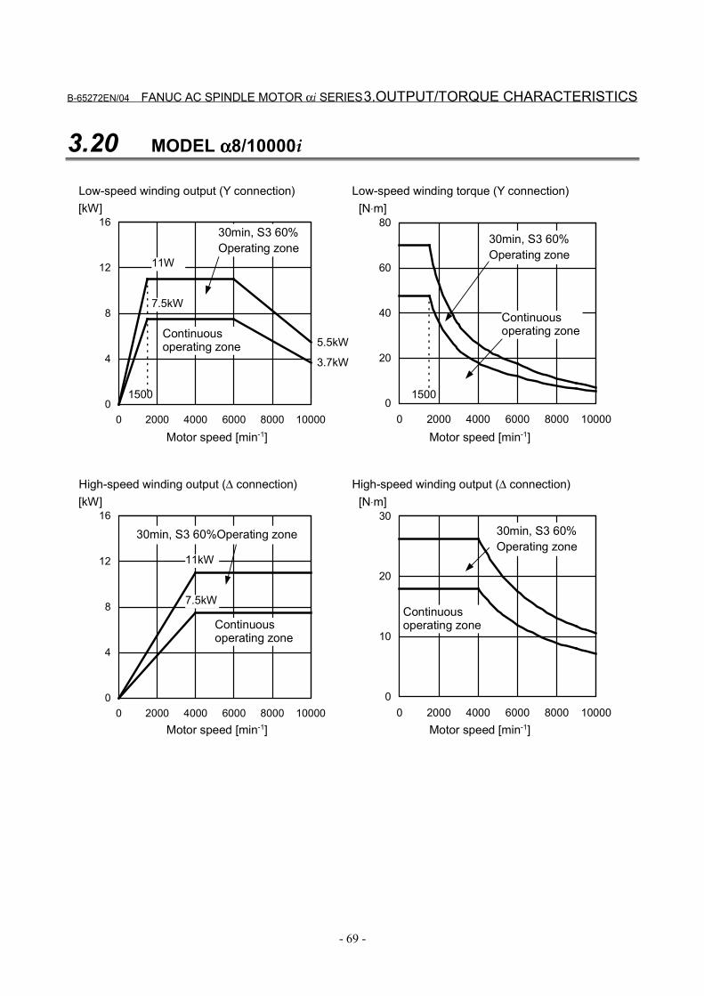
B-65272EN/04 FANUC AC SPINDLE MOTOR αi SERIES 3.OUTPUT/TORQUE CHARACTERISTICS
- 69 -
3.20 MODEL αααα8/10000i
0
4
8
12
16
0 2000 4000 6000 8000 10000
[kW]
0
20
40
60
80
0 2000 4000 6000 8000 10000
[N⋅m]
3.7kW
7.5kW
0
4
8
12
16
0 2000 4000 6000 8000 10000
[kW]
0
10
20
30
0 2000 4000 6000 8000 10000
[N⋅m]
11kW
7.5kW
5.5kW
11W
1500 1500
Motor speed [min-1]
Continuousoperating zone
30min, S3 60%Operating zone
Motor speed [min-1]
30min, S3 60%Operating zone
Continuousoperating zone
Low-speed winding output (Y connection) Low-speed winding torque (Y connection)
Motor speed [min-1]
Continuousoperating zone
30min, S3 60%Operating zone
Motor speed [min-1]
30min, S3 60%Operating zone
Continuousoperating zone
High-speed winding output (∆ connection) High-speed winding output (∆ connection)
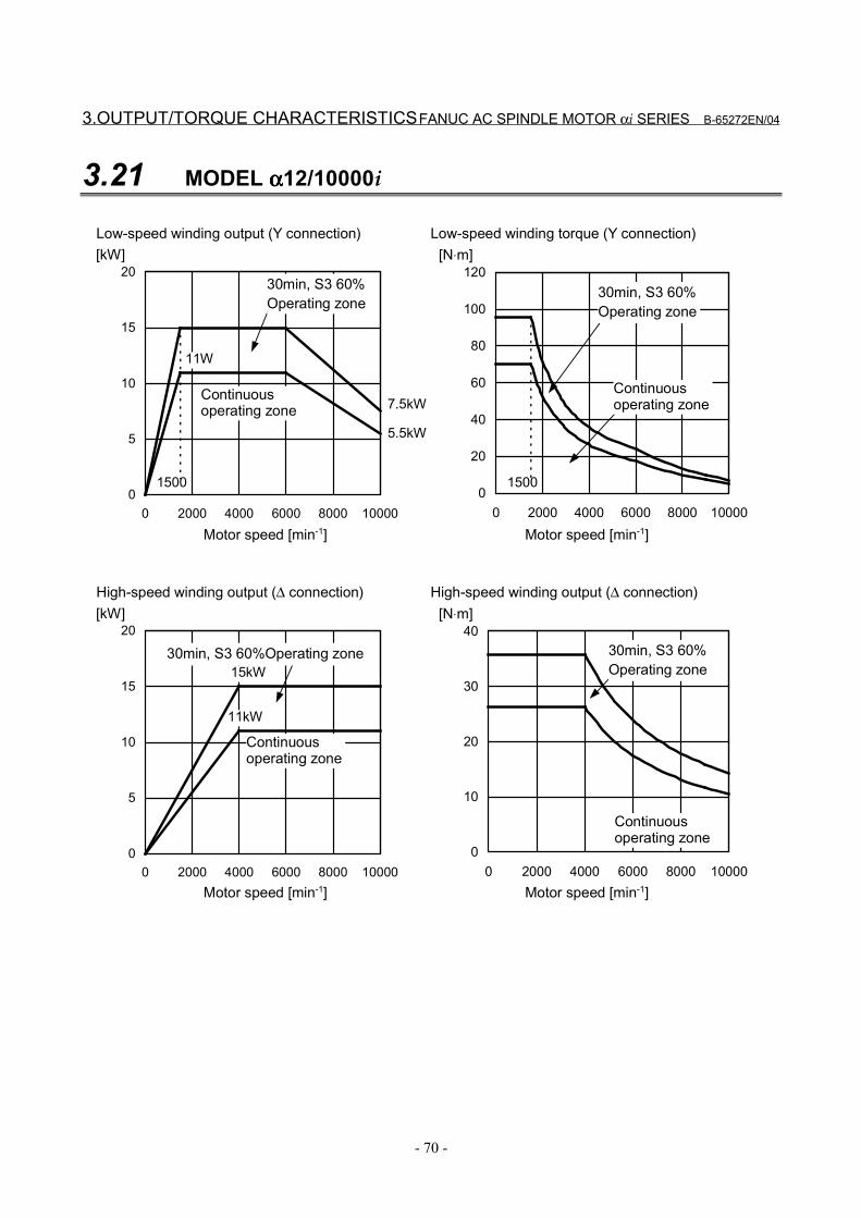
3.OUTPUT/TORQUE CHARACTERISTICS FANUC AC SPINDLE MOTOR αi SERIES B-65272EN/04
- 70 -
3.21 MODEL αααα12/10000i
0
5
10
15
20
0 2000 4000 6000 8000 10000
[kW]
0
20
40
60
80
100
120
0 2000 4000 6000 8000 10000
[N⋅m]
5.5kW
0
5
10
15
20
0 2000 4000 6000 8000 10000
[kW]
0
10
20
30
40
0 2000 4000 6000 8000 10000
[N⋅m]
11kW
15kW
7.5kW
11W
1500 1500
Motor speed [min-1]
Continuousoperating zone
30min, S3 60%Operating zone
Motor speed [min-1]
30min, S3 60%Operating zone
Continuousoperating zone
Low-speed winding output (Y connection) Low-speed winding torque (Y connection)
Motor speed [min-1]
Continuousoperating zone
30min, S3 60%Operating zone
Motor speed [min-1]
30min, S3 60%Operating zone
Continuousoperating zone
High-speed winding output (∆ connection) High-speed winding output (∆ connection)
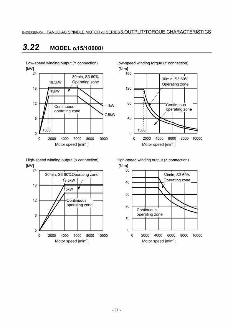
B-65272EN/04 FANUC AC SPINDLE MOTOR αi SERIES 3.OUTPUT/TORQUE CHARACTERISTICS
- 71 -
3.22 MODEL αααα15/10000i
0
6
12
18
24
0 2000 4000 6000 8000 10000
[kW]
0
40
80
120
160
0 2000 4000 6000 8000 10000
[N⋅m]
11kW
0
6
12
18
24
0 2000 4000 6000 8000 10000
[kW]
0
10
20
30
40
50
0 2000 4000 6000 8000 10000
[N⋅m]
15kW
18.5kW
7.5kW
15kW
1500 1500
18.5kW
Motor speed [min-1]
Continuousoperating zone
30min, S3 60%Operating zone
Motor speed [min-1]
30min, S3 60%Operating zone
Continuousoperating zone
Low-speed winding output (Y connection) Low-speed winding torque (Y connection)
Motor speed [min-1]
Continuousoperating zone
30min, S3 60%Operating zone
Motor speed [min-1]
30min, S3 60%Operating zone
Continuousoperating zone
High-speed winding output (∆ connection) High-speed winding output (∆ connection)
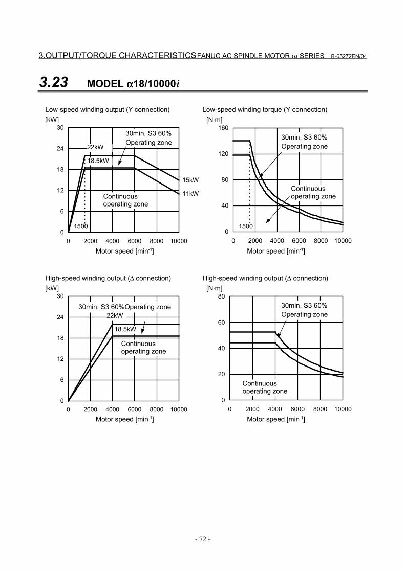
3.OUTPUT/TORQUE CHARACTERISTICS FANUC AC SPINDLE MOTOR αi SERIES B-65272EN/04
- 72 -
3.23 MODEL αααα18/10000i
0
6
12
18
24
30
0 2000 4000 6000 8000 10000
[kW]
0
40
80
120
160
0 2000 4000 6000 8000 10000
[N⋅m]
11kW
0
6
12
18
24
30
0 2000 4000 6000 8000 10000
[kW]
0
20
40
60
80
0 2000 4000 6000 8000 10000
[N⋅m]
22kW
18.5kW
15kW
18.5kW
1500 1500
22kW
Motor speed [min-1]
Continuousoperating zone
30min, S3 60%Operating zone
Motor speed [min-1]
30min, S3 60%Operating zone
Continuousoperating zone
Low-speed winding output (Y connection) Low-speed winding torque (Y connection)
Motor speed [min-1]
Continuousoperating zone
30min, S3 60%Operating zone
Motor speed [min-1]
30min, S3 60%Operating zone
Continuousoperating zone
High-speed winding output (∆ connection) High-speed winding output (∆ connection)
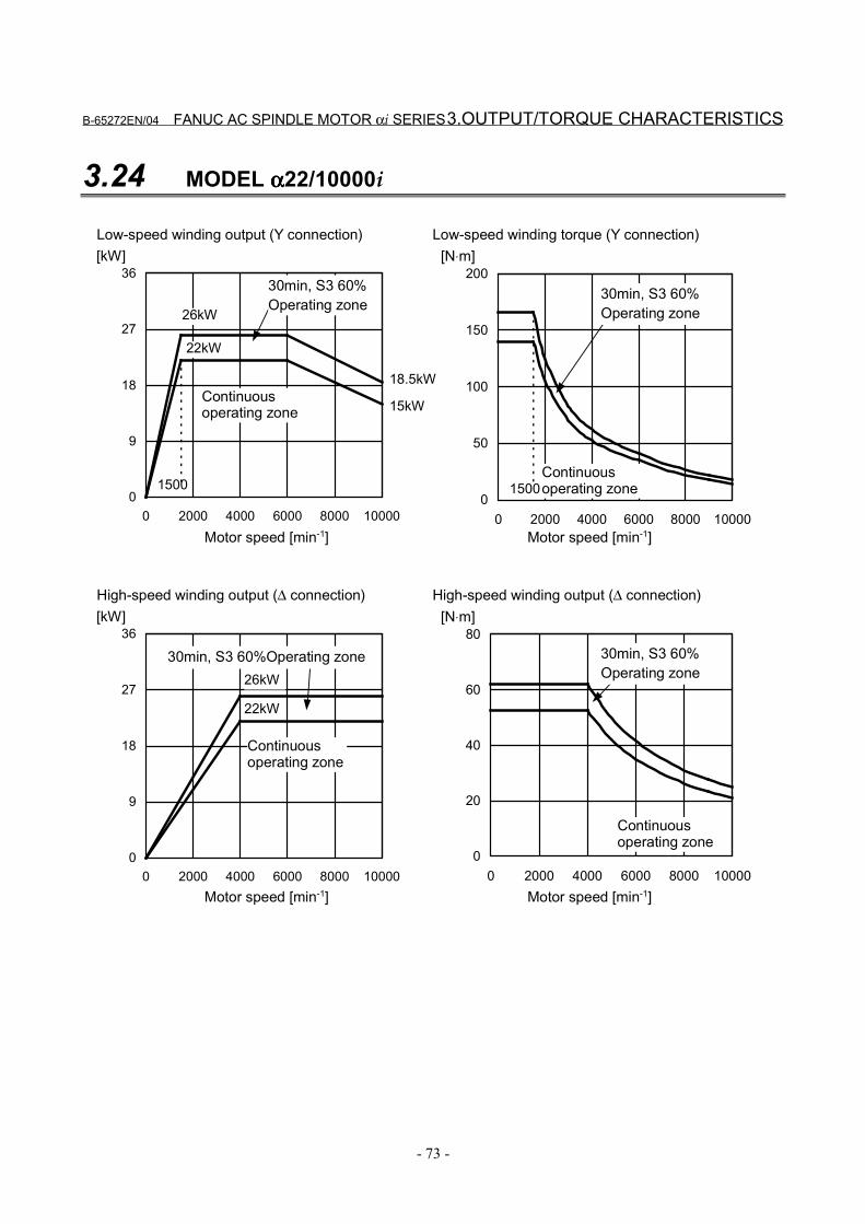
B-65272EN/04 FANUC AC SPINDLE MOTOR αi SERIES 3.OUTPUT/TORQUE CHARACTERISTICS
- 73 -
3.24 MODEL αααα22/10000i
0
9
18
27
36
0 2000 4000 6000 8000 10000
[kW]
0
50
100
150
200
0 2000 4000 6000 8000 10000
[N⋅m]
15kW
0
9
18
27
36
0 2000 4000 6000 8000 10000
[kW]
0
20
40
60
80
0 2000 4000 6000 8000 10000
[N⋅m]
22kW
26kW
18.5kW
22kW
1500 1500
26kW
Motor speed [min-1]
Continuousoperating zone
30min, S3 60%Operating zone
Motor speed [min-1]
30min, S3 60%Operating zone
Continuousoperating zone
Low-speed winding output (Y connection) Low-speed winding torque (Y connection)
Motor speed [min-1]
Continuousoperating zone
30min, S3 60%Operating zone
Motor speed [min-1]
30min, S3 60%Operating zone
Continuousoperating zone
High-speed winding output (∆ connection) High-speed winding output (∆ connection)

4.CONNECTIONS FANUC AC SPINDLE MOTOR αi SERIES B-65272EN/04
- 74 -
4 CONNECTIONS
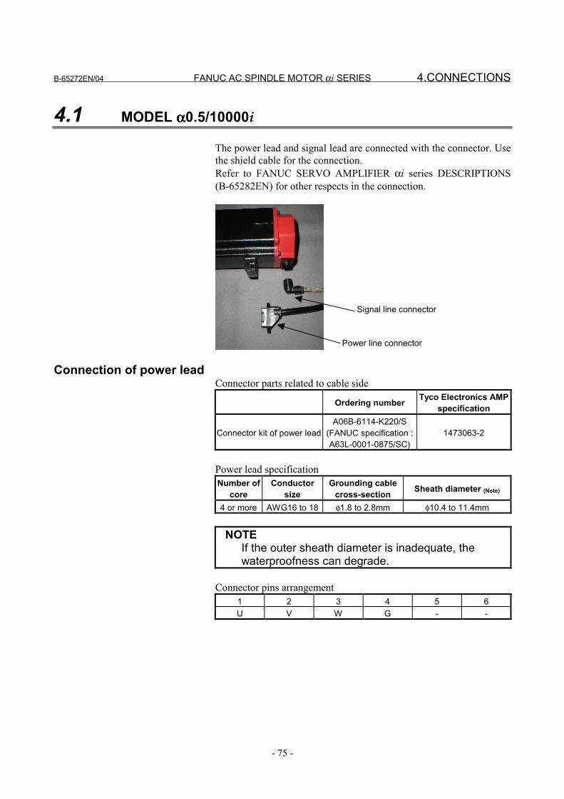
B-65272EN/04 FANUC AC SPINDLE MOTOR αi SERIES 4.CONNECTIONS
- 75 -
4.1 MODEL αααα0.5/10000i
The power lead and signal lead are connected with the connector. Usethe shield cable for the connection.Refer to FANUC SERVO AMPLIFIER αi series DESCRIPTIONS(B-65282EN) for other respects in the connection.
Power line connector
Signal line connector
Connection of power leadConnector parts related to cable side
Ordering number Tyco Electronics AMPspecification
Connector kit of power leadA06B-6114-K220/S
(FANUC specification :A63L-0001-0875/SC)
1473063-2
Power lead specificationNumber of
coreConductor
sizeGrounding cable
cross-section Sheath diameter (Note)
4 or more AWG16 to 18 φ1.8 to 2.8mm φ10.4 to 11.4mm
NOTEIf the outer sheath diameter is inadequate, thewaterproofness can degrade.
Connector pins arrangement1 2 3 4 5 6U V W G - -
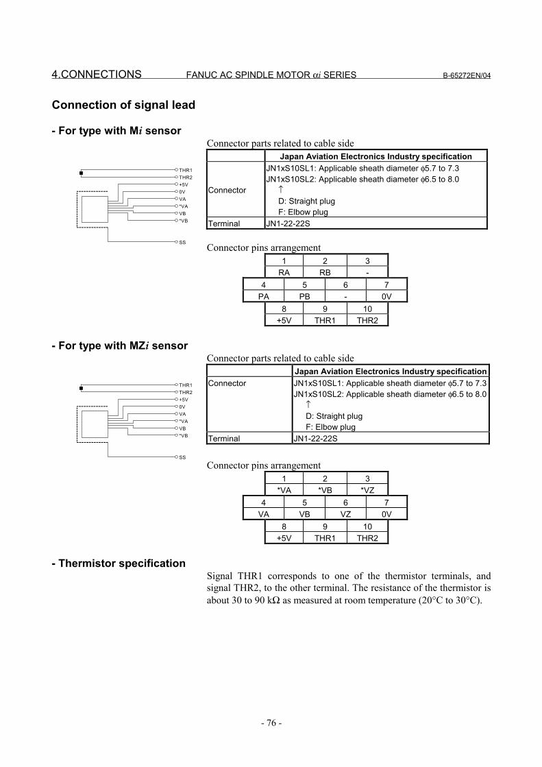
4.CONNECTIONS FANUC AC SPINDLE MOTOR αi SERIES B-65272EN/04
- 76 -
Connection of signal lead
- For type with Mi sensorConnector parts related to cable side
Japan Aviation Electronics Industry specification
Connector
JN1xS10SL1: Applicable sheath diameter φ5.7 to 7.3JN1xS10SL2: Applicable sheath diameter φ6.5 to 8.0 ↑ D: Straight plug F: Elbow plug
Terminal JN1-22-22S
Connector pins arrangement1 2 3
RA RB -4 5 6 7
PA PB - 0V8 9 10
+5V THR1 THR2
- For type with MZi sensorConnector parts related to cable side
Japan Aviation Electronics Industry specificationConnector JN1xS10SL1: Applicable sheath diameter φ5.7 to 7.3
JN1xS10SL2: Applicable sheath diameter φ6.5 to 8.0 ↑ D: Straight plug F: Elbow plug
Terminal JN1-22-22S
Connector pins arrangement1 2 3
*VA *VB *VZ4 5 6 7
VA VB VZ 0V8 9 10
+5V THR1 THR2
- Thermistor specificationSignal THR1 corresponds to one of the thermistor terminals, andsignal THR2, to the other terminal. The resistance of the thermistor isabout 30 to 90 kΩ as measured at room temperature (20°C to 30°C).
THR1THR2+5V0VVA*VAVB*VB
SS
THR1THR2+5V0VVA*VAVB*VB
SS
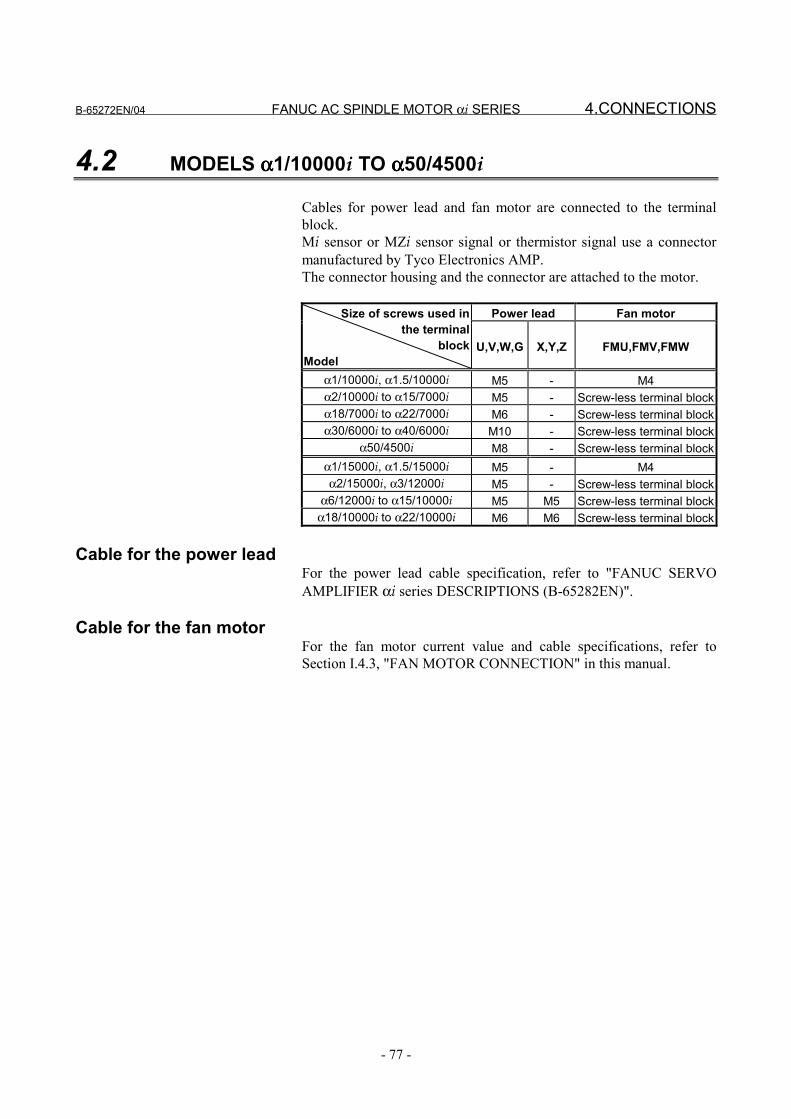
B-65272EN/04 FANUC AC SPINDLE MOTOR αi SERIES 4.CONNECTIONS
- 77 -
4.2 MODELS αααα1/10000i TO αααα50/4500i
Cables for power lead and fan motor are connected to the terminalblock.Mi sensor or MZi sensor signal or thermistor signal use a connectormanufactured by Tyco Electronics AMP.The connector housing and the connector are attached to the motor.
Power lead Fan motorSize of screws used inthe terminal
blockModel
U,V,W,G X,Y,Z FMU,FMV,FMW
α1/10000i, α1.5/10000i M5 - M4α2/10000i to α15/7000i M5 - Screw-less terminal blockα18/7000i to α22/7000i M6 - Screw-less terminal blockα30/6000i to α40/6000i M10 - Screw-less terminal block
α50/4500i M8 - Screw-less terminal blockα1/15000i, α1.5/15000i M5 - M4α2/15000i, α3/12000i M5 - Screw-less terminal block
α6/12000i to α15/10000i M5 M5 Screw-less terminal blockα18/10000i to α22/10000i M6 M6 Screw-less terminal block
Cable for the power leadFor the power lead cable specification, refer to "FANUC SERVOAMPLIFIER αi series DESCRIPTIONS (B-65282EN)".
Cable for the fan motorFor the fan motor current value and cable specifications, refer toSection I.4.3, "FAN MOTOR CONNECTION" in this manual.
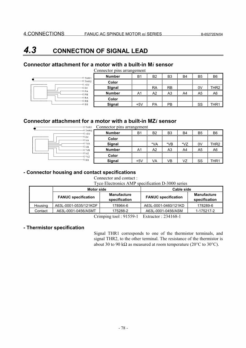
4.CONNECTIONS FANUC AC SPINDLE MOTOR αi SERIES B-65272EN/04
- 78 -
4.3 CONNECTION OF SIGNAL LEAD
Connector attachment for a motor with a built-in Mi sensorConnector pins arrangement
Number B1 B2 B3 B4 B5 B6ColorSignal RA RB 0V THR2
Number A1 A2 A3 A4 A5 A6ColorSignal +5V PA PB SS THR1
Connector attachment for a motor with a built-in MZi sensor Connector pins arrangement
Number B1 B2 B3 B4 B5 B6ColorSignal *VA *VB *VZ 0V THR2
Number A1 A2 A3 A4 A5 A6ColorSignal +5V VA VB VZ SS THR1
- Connector housing and contact specificationsConnector and contact :Tyco Electronics AMP specification D-3000 series
Motor side Cable side
FANUC specification Manufacturespecification FANUC specification Manufacture
specificationHousing A63L-0001-0535/121KDF 178964-6 A63L-0001-0460/121KD 178289-6Contact A63L-0001-0456/ASMT 175288-2 A63L-0001-0456/ASM 1-175217-2
Crimping tool : 91559-1 Extractor : 234168-1
- Thermistor specificationSignal THR1 corresponds to one of the thermistor terminals, andsignal THR2, to the other terminal. The resistance of the thermistor isabout 30 to 90 kΩ as measured at room temperature (20°C to 30°C).
TH R 1TH R 2+ 5V0VP AP BR AR BS S
TH R1TH R2+5V0VV A*V AV B*V BV Z*V ZS S
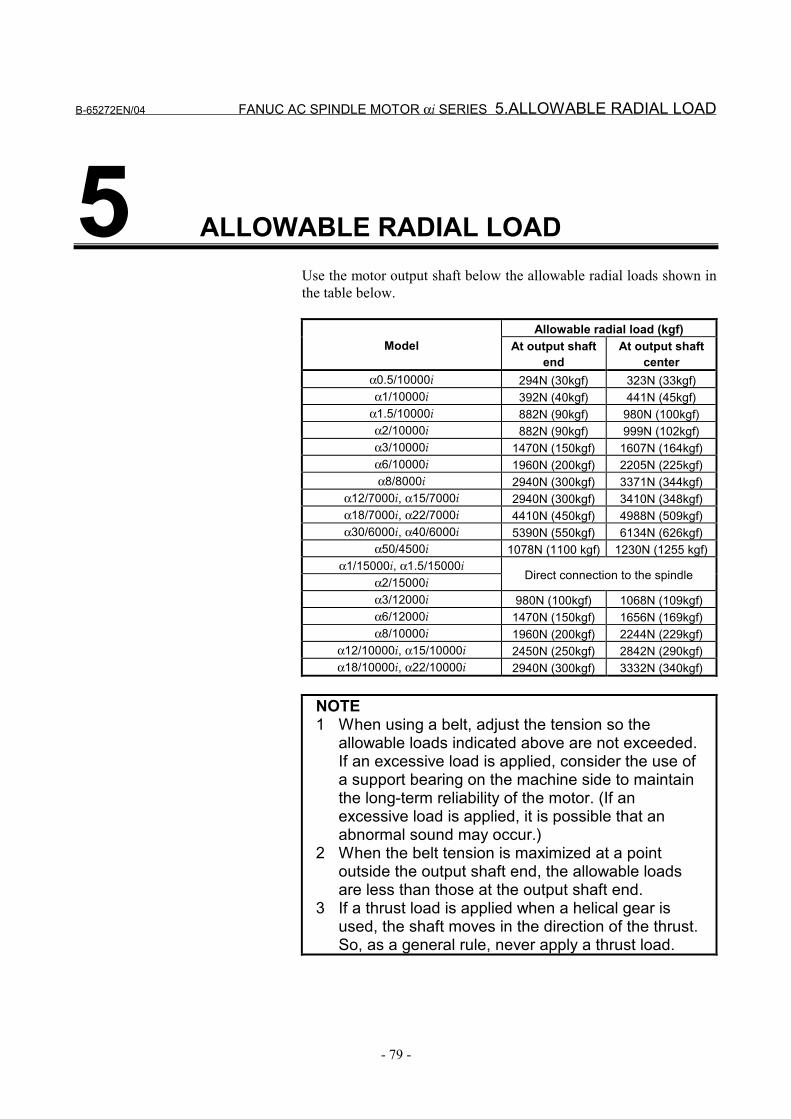
B-65272EN/04 FANUC AC SPINDLE MOTOR αi SERIES 5.ALLOWABLE RADIAL LOAD
- 79 -
5 ALLOWABLE RADIAL LOADUse the motor output shaft below the allowable radial loads shown inthe table below.
Allowable radial load (kgf)Model At output shaft
endAt output shaft
centerα0.5/10000i 294N (30kgf) 323N (33kgf)α1/10000i 392N (40kgf) 441N (45kgf)
α1.5/10000i 882N (90kgf) 980N (100kgf)α2/10000i 882N (90kgf) 999N (102kgf)α3/10000i 1470N (150kgf) 1607N (164kgf)α6/10000i 1960N (200kgf) 2205N (225kgf)α8/8000i 2940N (300kgf) 3371N (344kgf)
α12/7000i, α15/7000i 2940N (300kgf) 3410N (348kgf)α18/7000i, α22/7000i 4410N (450kgf) 4988N (509kgf)α30/6000i, α40/6000i 5390N (550kgf) 6134N (626kgf)
α50/4500i 1078N (1100 kgf) 1230N (1255 kgf)α1/15000i, α1.5/15000i
α2/15000i Direct connection to the spindle
α3/12000i 980N (100kgf) 1068N (109kgf)α6/12000i 1470N (150kgf) 1656N (169kgf)α8/10000i 1960N (200kgf) 2244N (229kgf)
α12/10000i, α15/10000i 2450N (250kgf) 2842N (290kgf)α18/10000i, α22/10000i 2940N (300kgf) 3332N (340kgf)
NOTE1 When using a belt, adjust the tension so the
allowable loads indicated above are not exceeded.If an excessive load is applied, consider the use ofa support bearing on the machine side to maintainthe long-term reliability of the motor. (If anexcessive load is applied, it is possible that anabnormal sound may occur.)
2 When the belt tension is maximized at a pointoutside the output shaft end, the allowable loadsare less than those at the output shaft end.
3 If a thrust load is applied when a helical gear isused, the shaft moves in the direction of the thrust.So, as a general rule, never apply a thrust load.
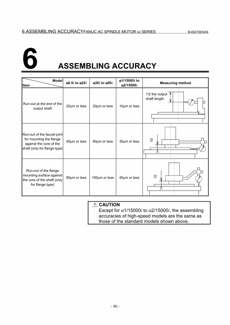
6.ASSEMBLING ACCURACYFANUC AC SPINDLE MOTOR αi SERIES B-65272EN/04
- 80 -
6 ASSEMBLING ACCURACYModel
Item αααα0.5i to αααα22i αααα30i to αααα50i αααα1/15000i toαααα2/15000i Measuring method
Run-out at the end of theoutput shaft 20µm or less 20µm or less 10µm or less
1/2 the outputshaft length
Run-out of the faucet jointfor mounting the flangeagainst the core of the
shaft (only for flange type)
40µm or less 60µm or less 30µm or less 10
Run-out of the flangemounting surface againstthe core of the shaft (only
for flange type)
80µm or less 100µm or less 40µm or less 10
CAUTIONExcept for α1/15000i to α2/15000i, the assemblingaccuracies of high-speed models are the same asthose of the standard models shown above.
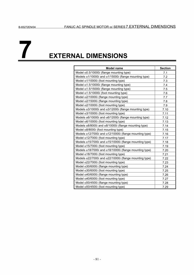
B-65272EN/04 FANUC AC SPINDLE MOTOR αi SERIES 7.EXTERNAL DIMENSIONS
- 81 -
7 EXTERNAL DIMENSIONSModel name Section
Model α0.5/10000i (flange mounting type) 7.1Models α1/10000i and α1/15000i (flange mounting type) 7.2Model α1/10000i (foot mounting type) 7.3Model α1.5/10000i (flange mounting type) 7.4Model α1.5/15000i (flange mounting type) 7.5Model α1.5/10000i (foot mounting type) 7.6Model α2/10000i (flange mounting type) 7.7Model α2/15000i (flange mounting type) 7.8Model α2/10000i (foot mounting type) 7.9Models α3/10000i and α3/12000i (flange mounting type) 7.10Model α3/10000i (foot mounting type) 7.11Models α6/10000i and α6/12000i (flange mounting type) 7.12Model α6/10000i (foot mounting type) 7.13Models α8/8000i and α8/10000i (flange mounting type) 7.14Model α8/8000i (foot mounting type) 7.15Models α12/7000i and α12/10000i (flange mounting type) 7.16Model α12/7000i (foot mounting type) 7.17Models α15/7000i and α15/10000i (flange mounting type) 7.18Model α15/7000i (foot mounting type) 7.19Models α18/7000i and α18/10000i (flange mounting type) 7.20Model α18/7000i (foot mounting type) 7.21Models α22/7000i and α22/10000i (flange mounting type) 7.22Model α22/7000i (foot mounting type) 7.23Model α30/6000i (flange mounting type) 7.24Model α30/6000i (foot mounting type) 7.25Model α40/6000i (flange mounting type) 7.26Model α40/6000i (foot mounting type) 7.27Model α50/4500i (flange mounting type) 7.28Model α50/4500i (foot mounting type) 7.29
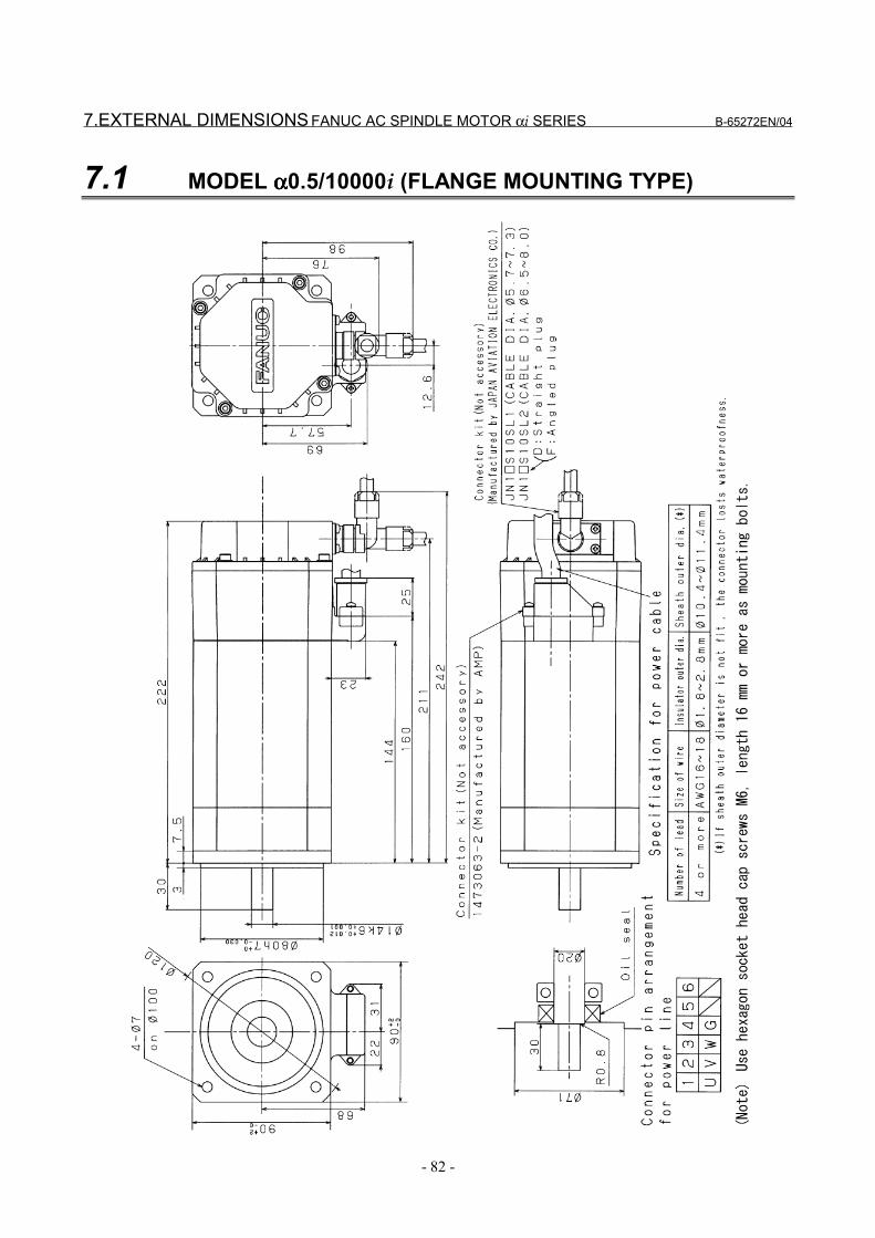
7.EXTERNAL DIMENSIONS FANUC AC SPINDLE MOTOR αi SERIES B-65272EN/04
- 82 -
7.1 MODEL αααα0.5/10000i (FLANGE MOUNTING TYPE)
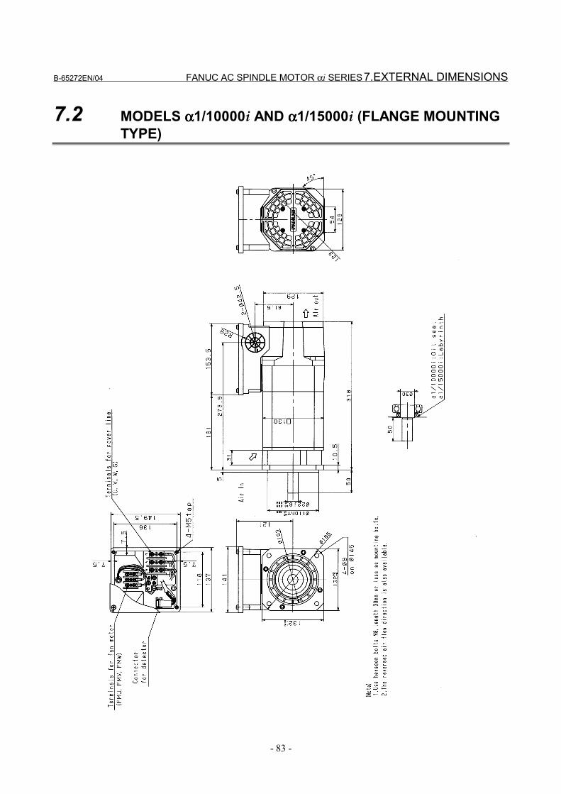
B-65272EN/04 FANUC AC SPINDLE MOTOR αi SERIES 7.EXTERNAL DIMENSIONS
- 83 -
7.2 MODELS αααα1/10000i AND αααα1/15000i (FLANGE MOUNTINGTYPE)
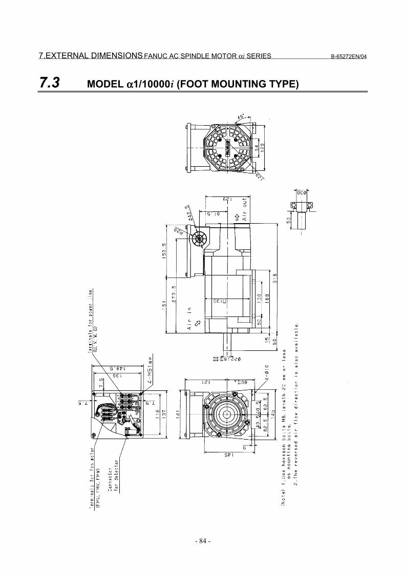
7.EXTERNAL DIMENSIONS FANUC AC SPINDLE MOTOR αi SERIES B-65272EN/04
- 84 -
7.3 MODEL αααα1/10000i (FOOT MOUNTING TYPE)
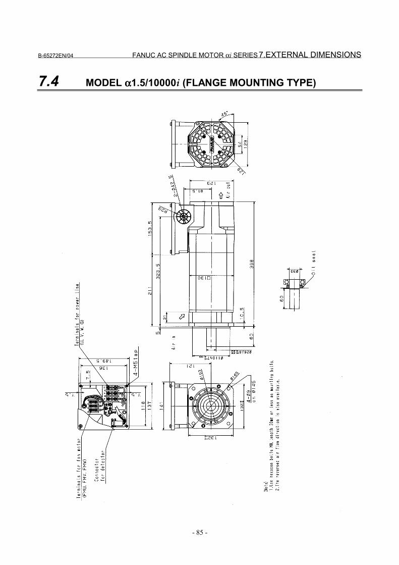
B-65272EN/04 FANUC AC SPINDLE MOTOR αi SERIES 7.EXTERNAL DIMENSIONS
- 85 -
7.4 MODEL αααα1.5/10000i (FLANGE MOUNTING TYPE)
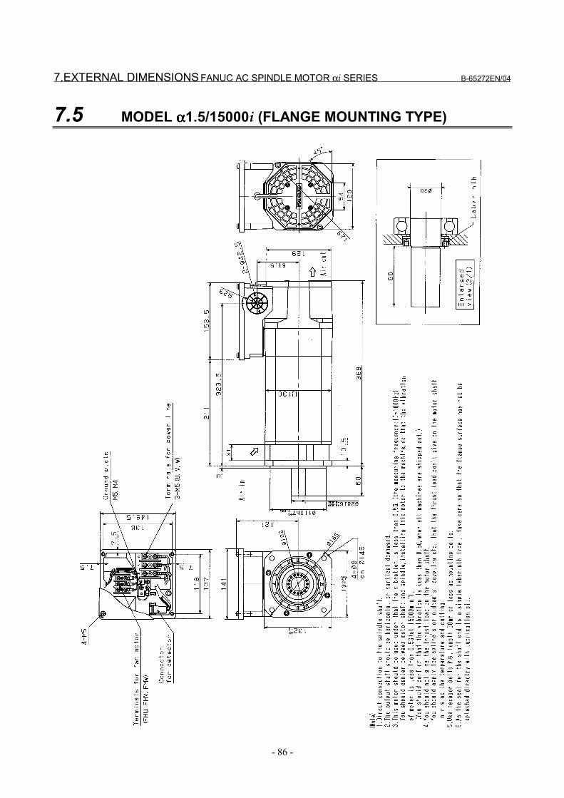
7.EXTERNAL DIMENSIONS FANUC AC SPINDLE MOTOR αi SERIES B-65272EN/04
- 86 -
7.5 MODEL αααα1.5/15000i (FLANGE MOUNTING TYPE)
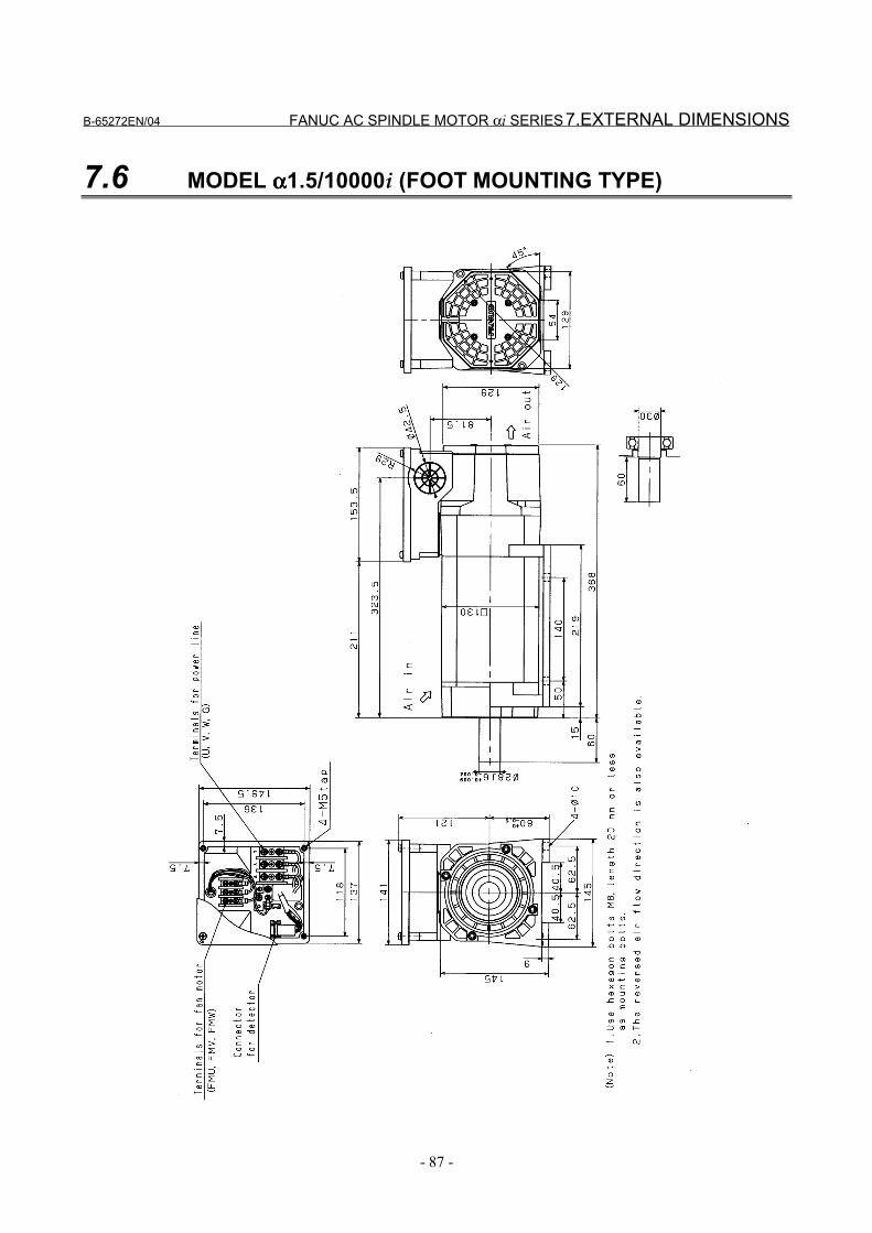
B-65272EN/04 FANUC AC SPINDLE MOTOR αi SERIES 7.EXTERNAL DIMENSIONS
- 87 -
7.6 MODEL αααα1.5/10000i (FOOT MOUNTING TYPE)
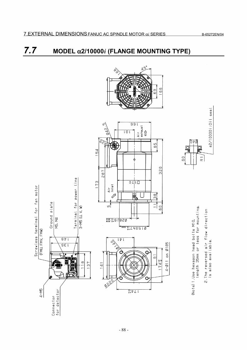
7.EXTERNAL DIMENSIONS FANUC AC SPINDLE MOTOR αi SERIES B-65272EN/04
- 88 -
7.7 MODEL αααα2/10000i (FLANGE MOUNTING TYPE)
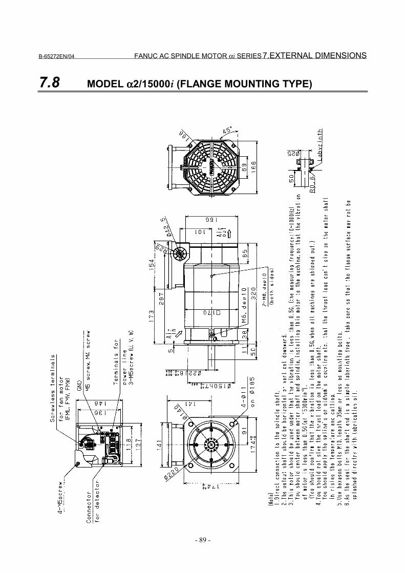
B-65272EN/04 FANUC AC SPINDLE MOTOR αi SERIES 7.EXTERNAL DIMENSIONS
- 89 -
7.8 MODEL αααα2/15000i (FLANGE MOUNTING TYPE)
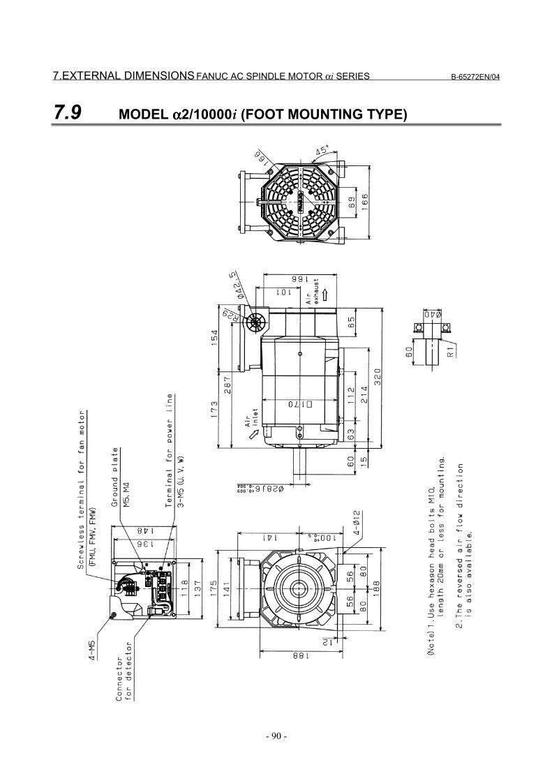
7.EXTERNAL DIMENSIONS FANUC AC SPINDLE MOTOR αi SERIES B-65272EN/04
- 90 -
7.9 MODEL αααα2/10000i (FOOT MOUNTING TYPE)
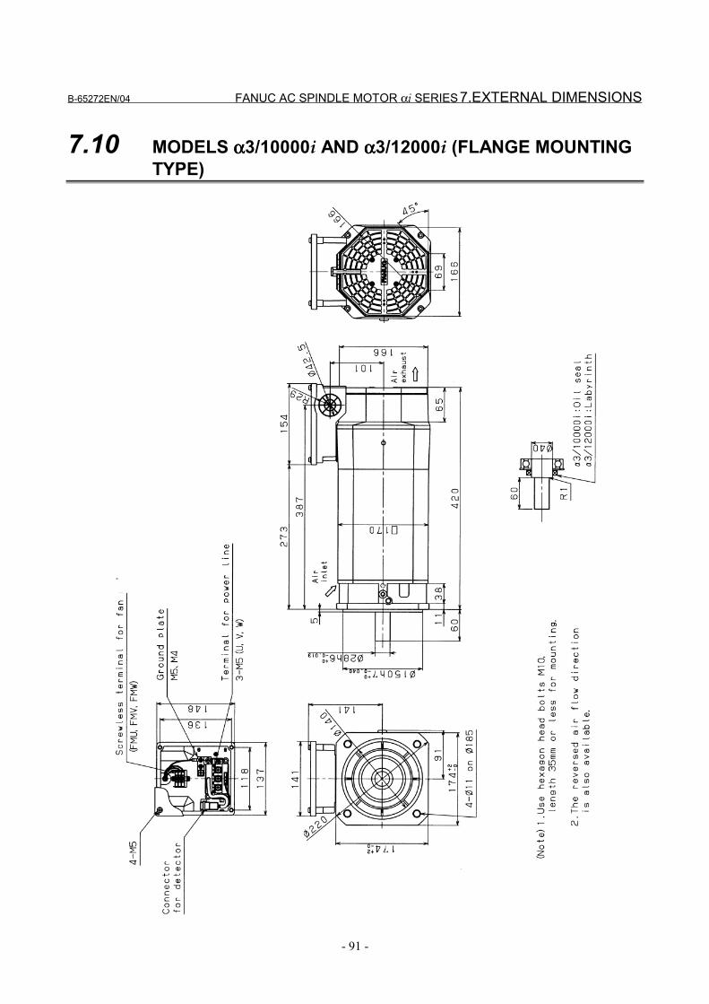
B-65272EN/04 FANUC AC SPINDLE MOTOR αi SERIES 7.EXTERNAL DIMENSIONS
- 91 -
7.10 MODELS αααα3/10000i AND αααα3/12000i (FLANGE MOUNTINGTYPE)
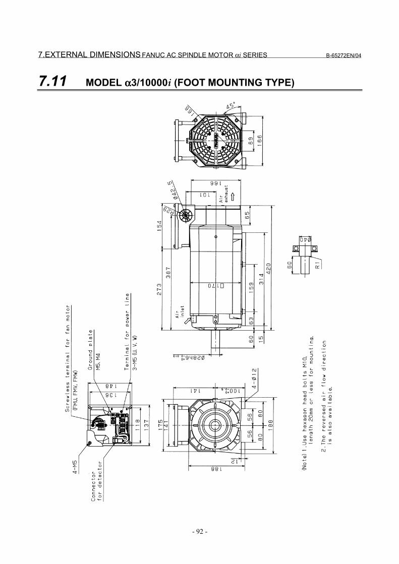
7.EXTERNAL DIMENSIONS FANUC AC SPINDLE MOTOR αi SERIES B-65272EN/04
- 92 -
7.11 MODEL αααα3/10000i (FOOT MOUNTING TYPE)
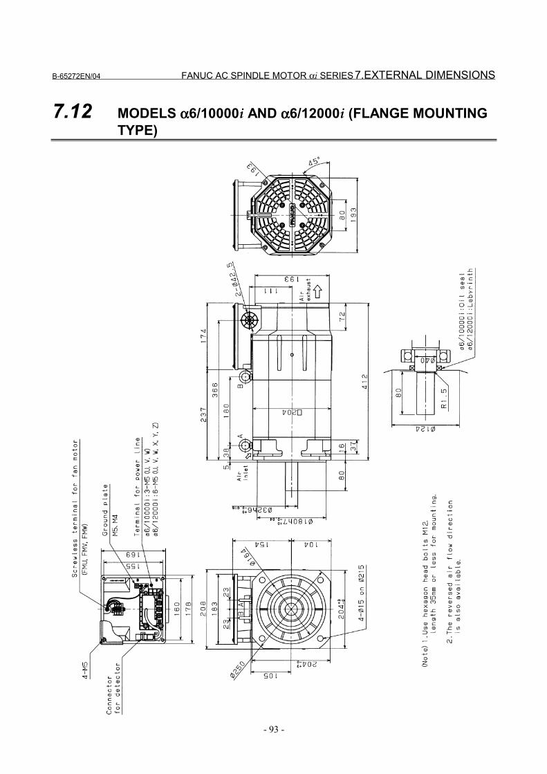
B-65272EN/04 FANUC AC SPINDLE MOTOR αi SERIES 7.EXTERNAL DIMENSIONS
- 93 -
7.12 MODELS αααα6/10000i AND αααα6/12000i (FLANGE MOUNTINGTYPE)
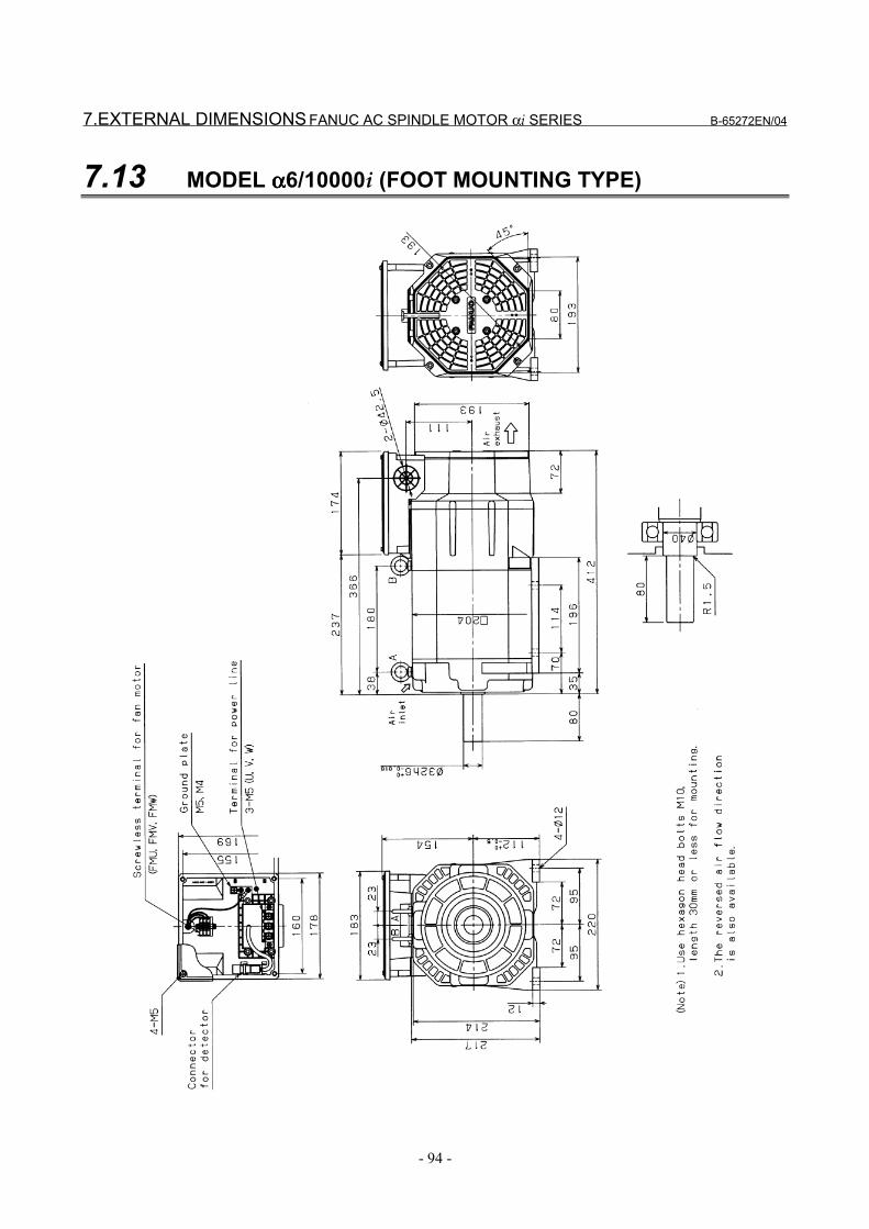
7.EXTERNAL DIMENSIONS FANUC AC SPINDLE MOTOR αi SERIES B-65272EN/04
- 94 -
7.13 MODEL αααα6/10000i (FOOT MOUNTING TYPE)
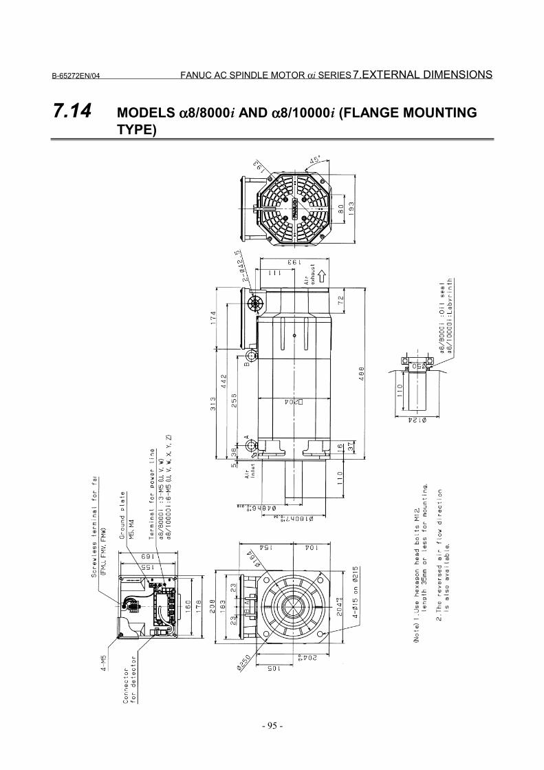
B-65272EN/04 FANUC AC SPINDLE MOTOR αi SERIES 7.EXTERNAL DIMENSIONS
- 95 -
7.14 MODELS αααα8/8000i AND αααα8/10000i (FLANGE MOUNTINGTYPE)
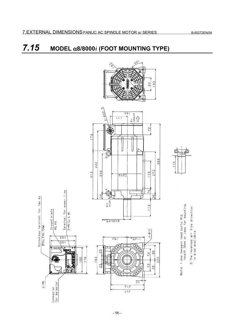
7.EXTERNAL DIMENSIONS FANUC AC SPINDLE MOTOR αi SERIES B-65272EN/04
- 96 -
7.15 MODEL αααα8/8000i (FOOT MOUNTING TYPE)
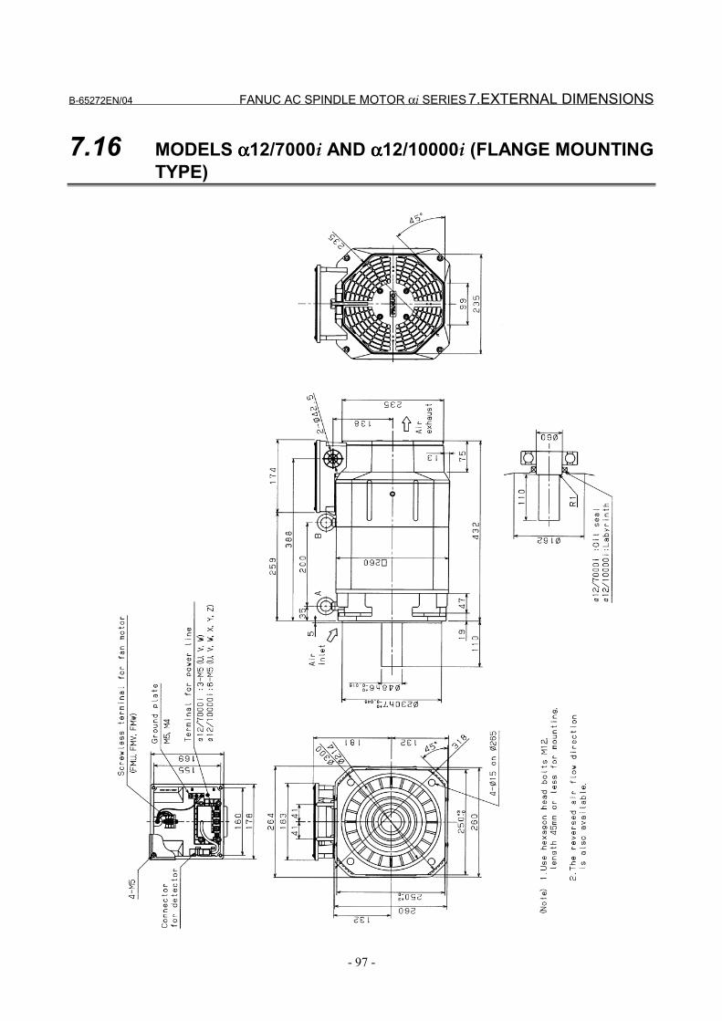
B-65272EN/04 FANUC AC SPINDLE MOTOR αi SERIES 7.EXTERNAL DIMENSIONS
- 97 -
7.16 MODELS αααα12/7000i AND αααα12/10000i (FLANGE MOUNTINGTYPE)
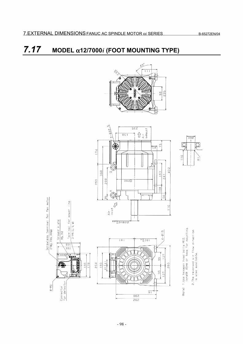
7.EXTERNAL DIMENSIONS FANUC AC SPINDLE MOTOR αi SERIES B-65272EN/04
- 98 -
7.17 MODEL αααα12/7000i (FOOT MOUNTING TYPE)
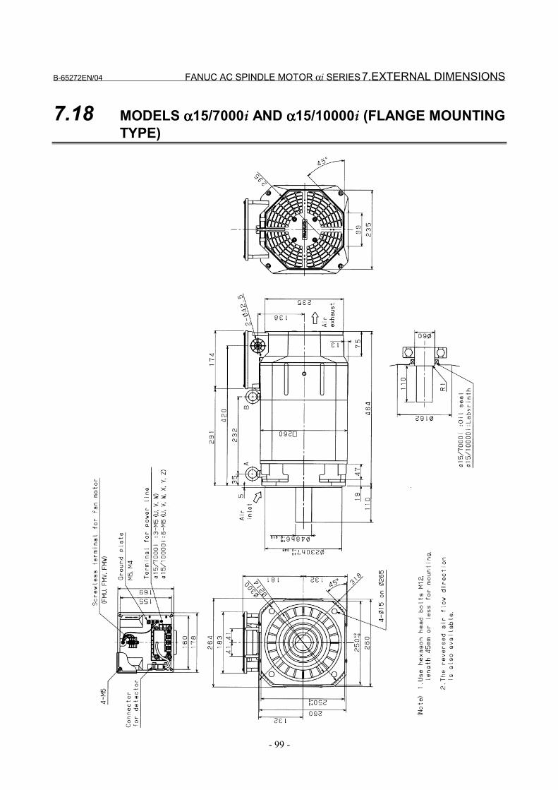
B-65272EN/04 FANUC AC SPINDLE MOTOR αi SERIES 7.EXTERNAL DIMENSIONS
- 99 -
7.18 MODELS αααα15/7000i AND αααα15/10000i (FLANGE MOUNTINGTYPE)

7.EXTERNAL DIMENSIONS FANUC AC SPINDLE MOTOR αi SERIES B-65272EN/04
- 100 -
7.19 MODEL αααα15/7000i (FOOT MOUNTING TYPE)
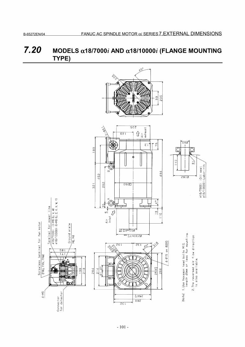
B-65272EN/04 FANUC AC SPINDLE MOTOR αi SERIES 7.EXTERNAL DIMENSIONS
- 101 -
7.20 MODELS αααα18/7000i AND αααα18/10000i (FLANGE MOUNTINGTYPE)
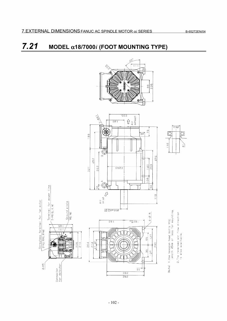
7.EXTERNAL DIMENSIONS FANUC AC SPINDLE MOTOR αi SERIES B-65272EN/04
- 102 -
7.21 MODEL αααα18/7000i (FOOT MOUNTING TYPE)
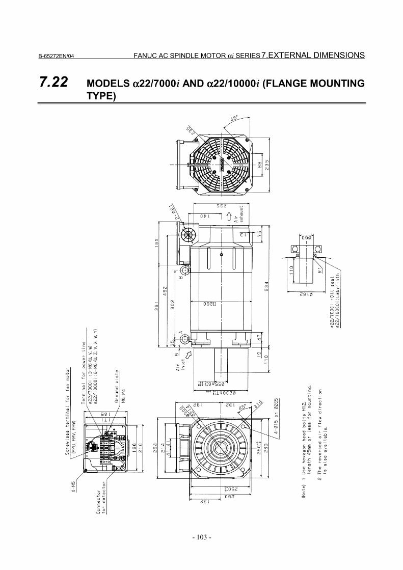
B-65272EN/04 FANUC AC SPINDLE MOTOR αi SERIES 7.EXTERNAL DIMENSIONS
- 103 -
7.22 MODELS αααα22/7000i AND αααα22/10000i (FLANGE MOUNTINGTYPE)
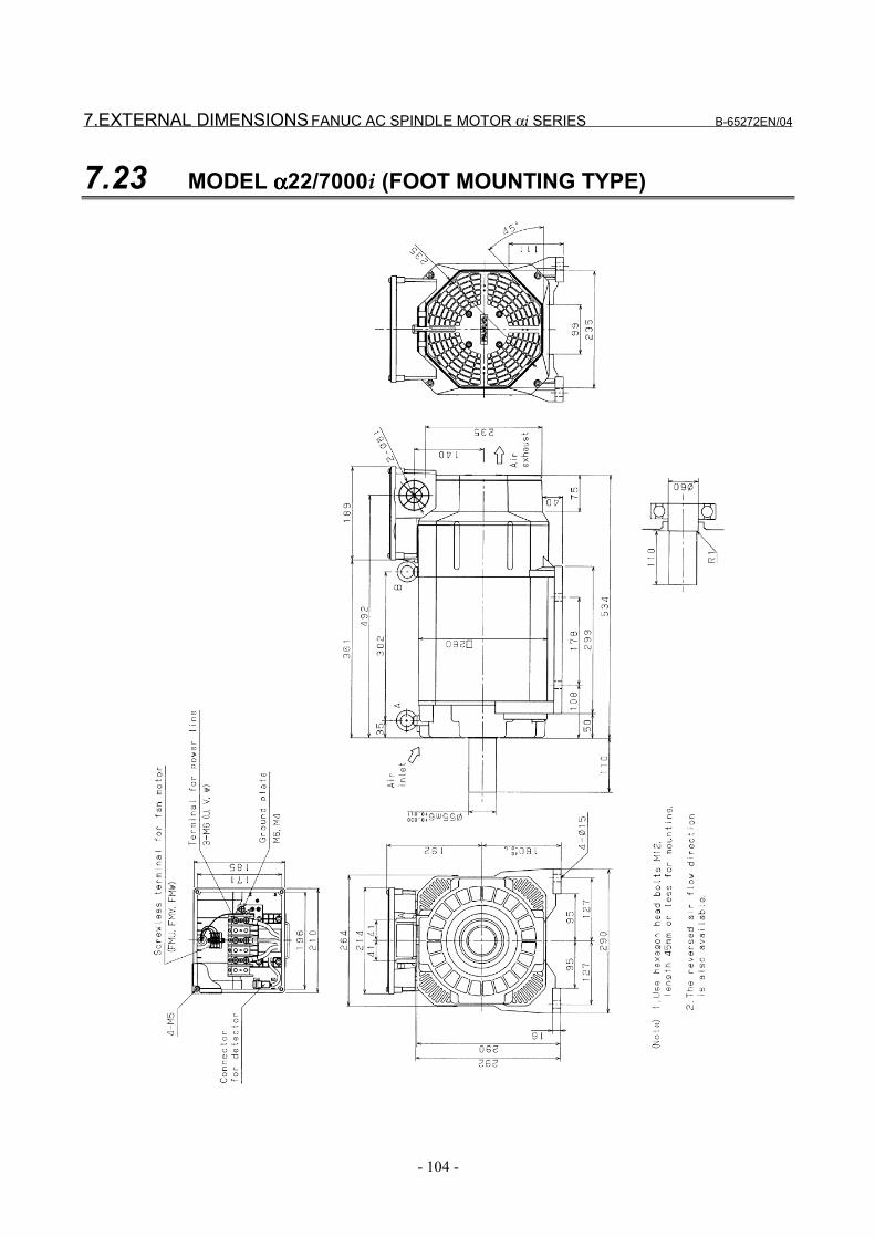
7.EXTERNAL DIMENSIONS FANUC AC SPINDLE MOTOR αi SERIES B-65272EN/04
- 104 -
7.23 MODEL αααα22/7000i (FOOT MOUNTING TYPE)
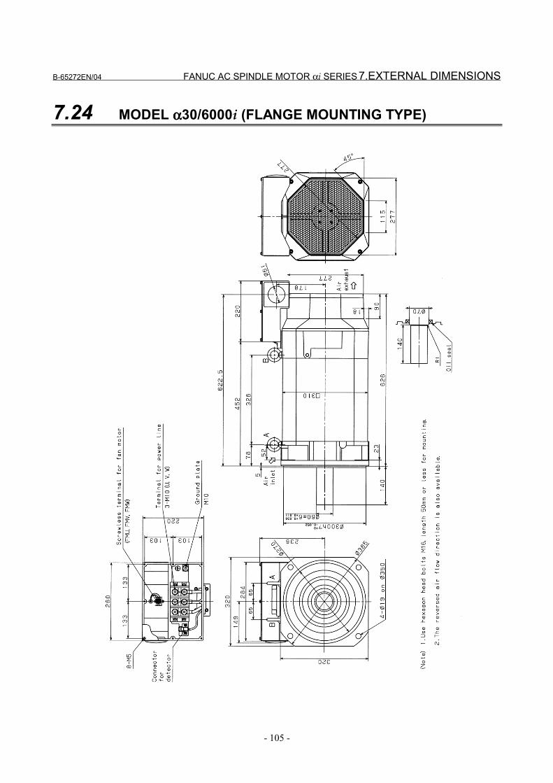
B-65272EN/04 FANUC AC SPINDLE MOTOR αi SERIES 7.EXTERNAL DIMENSIONS
- 105 -
7.24 MODEL αααα30/6000i (FLANGE MOUNTING TYPE)
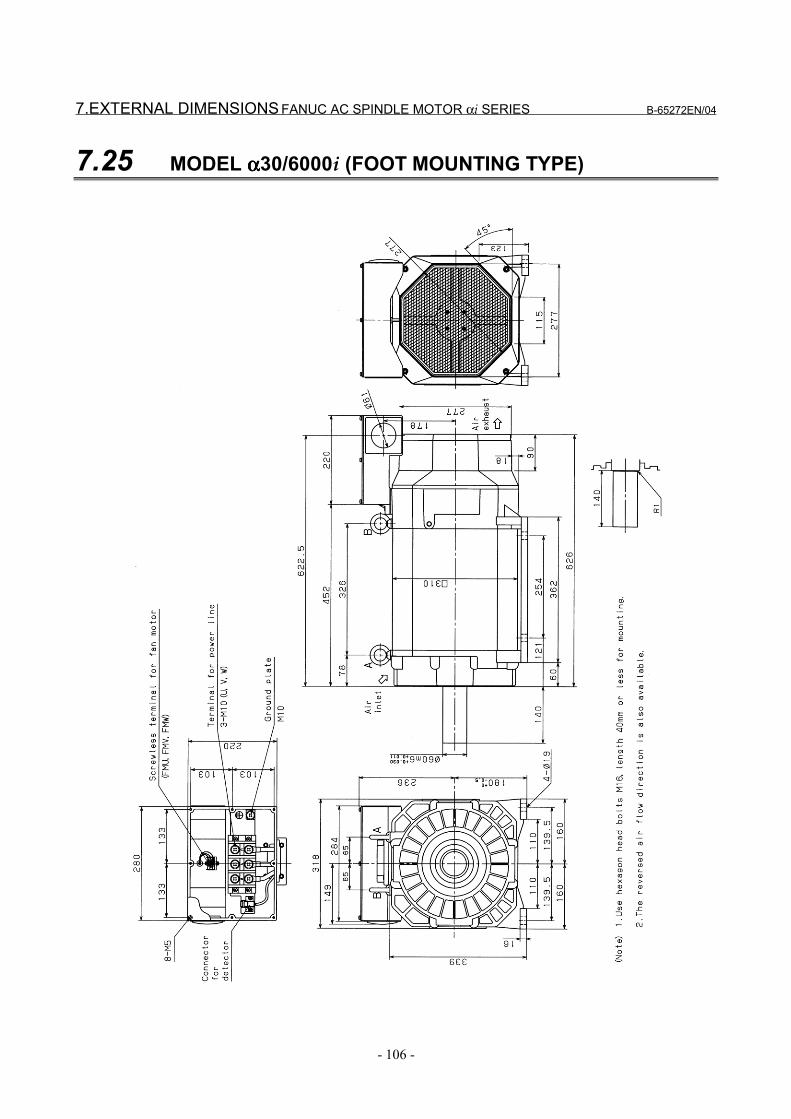
7.EXTERNAL DIMENSIONS FANUC AC SPINDLE MOTOR αi SERIES B-65272EN/04
- 106 -
7.25 MODEL αααα30/6000i (FOOT MOUNTING TYPE)
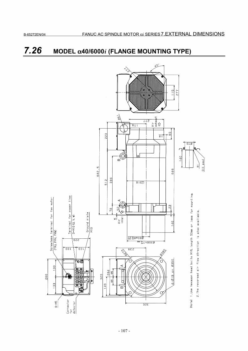
B-65272EN/04 FANUC AC SPINDLE MOTOR αi SERIES 7.EXTERNAL DIMENSIONS
- 107 -
7.26 MODEL αααα40/6000i (FLANGE MOUNTING TYPE)
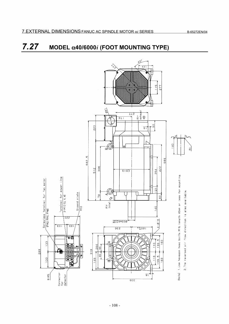
7.EXTERNAL DIMENSIONS FANUC AC SPINDLE MOTOR αi SERIES B-65272EN/04
- 108 -
7.27 MODEL αααα40/6000i (FOOT MOUNTING TYPE)
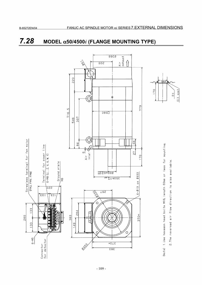
B-65272EN/04 FANUC AC SPINDLE MOTOR αi SERIES 7.EXTERNAL DIMENSIONS
- 109 -
7.28 MODEL αααα50/4500i (FLANGE MOUNTING TYPE)
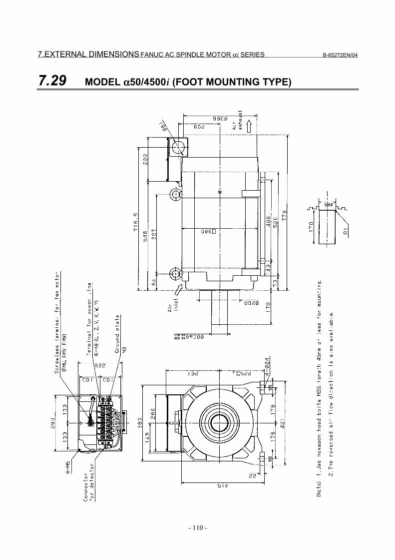
7.EXTERNAL DIMENSIONS FANUC AC SPINDLE MOTOR αi SERIES B-65272EN/04
- 110 -
7.29 MODEL αααα50/4500i (FOOT MOUNTING TYPE)

III. FANUC AC SPINDLE MOTOR ααααiP SERIES

B-65272EN/04 FANUC AC SPINDLE MOTOR αiP SERIES 1.GENERAL
- 113 -
1 GENERALFANUC AC spindle motor αiP series is suitable for structuralsimplification by eliminating the machine spindle gear box.
Features - As the rated output range is wide from 1:10 to 1:16 , a gear box
structure for speed change is not required, thereby allowing thestructure of the machine to be simplified.Accordingly, vibration and noise caused by the gear boxstructure is also eliminated.
- Improvement in efficiency of construction equipmentUnnecessary use of time is reduced because it is not necessary tostop the spindle when switching the gear.
- Despite a compact configuration, a large low-speed torque canbe obtained.
- The method of fan exhaust can be selected from either a exhaustfront type or exhaust rear type, thus preventing heat deformationof the machine.
- Waterproof and pressure-proof design conforming to theinternational standard (IEC) is employed to improve reliabilityand make it resistant to most environments.

2.SPECIFICATIONS FANUC AC SPINDLE MOTOR αiP SERIES B-65272EN/04
- 114 -
2 SPECIFICATIONS

B-65272EN/04 FANUC AC SPINDLE MOTOR αiP SERIES 2.SPECIFICATIONS
- 115 -
Series ααααiP seriesαααα12/6000iP
αααα12/8000iP
αααα15/6000iP
αααα15/8000iPModelItem Low-speed
windingHigh-speed
windingLow-speed
windingHigh-speed
windingCont. rated kW
(HP)3.7
(4.9)5.5
(7.4)5
(6.6)7.5(10)
30 min rated kW[15 min]
(*3) (HP)
7.5
(10)
7.5
(10)
9
(12)
9
(12)Output (*2)
S3 60% kW[15%]
(*4)(*5) (HP)
7.5
(10)
7.5
(10)
9
(12)
9
(12)Cont. rated 23 39 40 50
Rated current A (*6) 30 min rated (*3)
S3 60%, 15% (*4) 42 49 61 58
Speed Base speed 500 750 500 750 min-1 Max. speed 1500 6000, 8000 1500 6000, 8000
Cont. rated torque at const. rated torque rangeN⋅m
(kgf⋅cm)70.7(721)
70(714)
95.5(974)
95.5(974)
kg⋅m2 0.07 0.09Rotor inertia
kgf⋅cm⋅s2 0.77 0.93Weight kgf 95 110
Vibration V5 (option V3)Noise 75 dB (A) or less
Cooling system (*7) Totally enclosed and fan cooled IC0A6Cooling fan W 56
Installation (*8)Mount the motor so that the output shaft points in a direction ranging
within 45° degrees above the horizontal to vertically downwards.IMB5,IMV1,IMB3,IMB6,IMB7,IMB8,IMV5
Allowable overload capacity (1 min) (*9) 120 % of 30 min rated outputInsulation Class H
Ambient temperature 0 to 40 °CAltitude Height above sea level not exceeding 1000m
Painting color Munsell system N2.5Sensor Mi sensor or MZi sensor
Type of thermal protection (*10) TP211Resolution of the MZi sensor /rev. 4096Number of detected gear teeth per rotation
λ/rev. 256
Bearing lubrication GreaseMaximum output during acceleration (*11)
kW 12.3 13.5
Applicable spindle amplifier SPM-11i SPM-15iModel α12/6000iP α15/6000iP

2.SPECIFICATIONS FANUC AC SPINDLE MOTOR αiP SERIES B-65272EN/04
- 116 -
Series ααααiP seriesαααα18/6000iP
αααα18/8000iP
αααα22/6000iP
αααα22/8000iPModelItem Low-speed
windingHigh-speed
windingLow-speed
windingHigh-speed
windingCont. rated kW
(HP)6
(8)9
(12)7.5(10)
11(14.7)
30 min rated kW[15 min]
(*3) (HP)
11
(14.7)
11
(14.7)
15
(20.1)
15
(20.1)Output (*2)
S3 60% kW[15%]
(*4)(*5) (HP)
11
(14.7)
11
(14.7)
15
(20.1)
15
(20.1)Cont. rated 32 55 43 69
Rated current A (*6) 30 min rated (*3)
S3 60%, 15% (*4) 53 63 80 88
Speed Base speed 500 750 500 750 min-1 Max. speed 1500 6000, 8000 1500 6000, 8000
Cont. rated torque at const. rated torque rangeN⋅m
(kgf⋅cm)114.6(1169)
114.6(1169)
143.2(1461)
140(1428)
kg⋅m2 0.105 0.128Rotor inertia
kgf⋅cm⋅s2 1.08 1.29Weight kgf 125 143
Vibration V5 (option V3)Noise 75 dB (A) or less
Cooling system (*7) Totally enclosed and fan cooled IC0A6Cooling fan W 56
Installation (*8)Mount the motor so that the output shaft points in a direction ranging
within 45° degrees above the horizontal to vertically downwards.IMB5,IMV1,IMB3,IMB6,IMB7,IMB8,IMV5
Allowable overload capacity (1 min) (*9) 120 % of 30 min rated outputInsulation Class H
Ambient temperature 0 to 40 °CAltitude Height above sea level not exceeding 1000m
Painting color Munsell system N2.5Sensor Mi sensor or MZi sensor
Type of thermal protection (*10) TP211Resolution of the MZi sensor /rev. 4096Number of detected gear teeth per rotation
λ/rev. 256
Bearing lubrication GreaseMaximum output during acceleration (*11)
kW 15.1 20.0
Applicable spindle amplifier SPM-15i SPM-22iModel α18/6000iP α22/6000iP
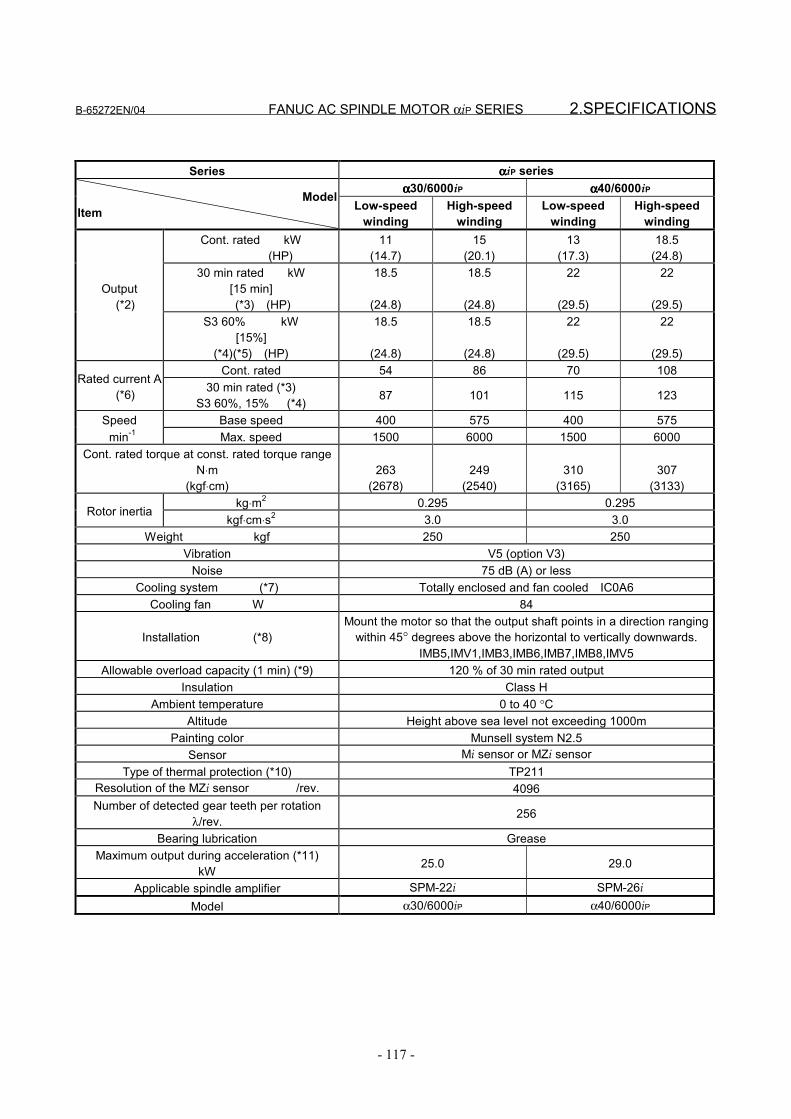
B-65272EN/04 FANUC AC SPINDLE MOTOR αiP SERIES 2.SPECIFICATIONS
- 117 -
Series ααααiP seriesαααα30/6000iP αααα40/6000iP
ModelItem Low-speed
windingHigh-speed
windingLow-speed
windingHigh-speed
windingCont. rated kW
(HP)11
(14.7)15
(20.1)13
(17.3)18.5
(24.8)30 min rated kW
[15 min] (*3) (HP)
18.5
(24.8)
18.5
(24.8)
22
(29.5)
22
(29.5)Output (*2)
S3 60% kW[15%]
(*4)(*5) (HP)
18.5
(24.8)
18.5
(24.8)
22
(29.5)
22
(29.5)Cont. rated 54 86 70 108
Rated current A (*6) 30 min rated (*3)
S3 60%, 15% (*4) 87 101 115 123
Speed Base speed 400 575 400 575 min-1 Max. speed 1500 6000 1500 6000
Cont. rated torque at const. rated torque rangeN⋅m
(kgf⋅cm)263
(2678)249
(2540)310
(3165)307
(3133)kg⋅m2 0.295 0.295
Rotor inertiakgf⋅cm⋅s2 3.0 3.0
Weight kgf 250 250Vibration V5 (option V3)
Noise 75 dB (A) or lessCooling system (*7) Totally enclosed and fan cooled IC0A6
Cooling fan W 84
Installation (*8)Mount the motor so that the output shaft points in a direction ranging
within 45° degrees above the horizontal to vertically downwards.IMB5,IMV1,IMB3,IMB6,IMB7,IMB8,IMV5
Allowable overload capacity (1 min) (*9) 120 % of 30 min rated outputInsulation Class H
Ambient temperature 0 to 40 °CAltitude Height above sea level not exceeding 1000m
Painting color Munsell system N2.5Sensor Mi sensor or MZi sensor
Type of thermal protection (*10) TP211Resolution of the MZi sensor /rev. 4096Number of detected gear teeth per rotation
λ/rev. 256
Bearing lubrication GreaseMaximum output during acceleration (*11)
kW 25.0 29.0
Applicable spindle amplifier SPM-22i SPM-26iModel α30/6000iP α40/6000iP
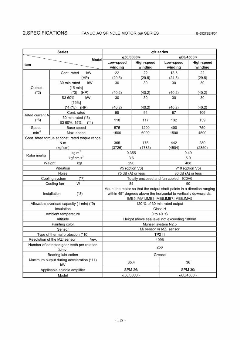
2.SPECIFICATIONS FANUC AC SPINDLE MOTOR αiP SERIES B-65272EN/04
- 118 -
Series ααααiP seriesαααα50/6000iP αααα60/4500iP
ModelItem Low-speed
windingHigh-speed
windingLow-speed
windingHigh-speed
windingCont. rated kW
(HP)22
(29.5)22
(29.5)18.5
(24.8)22
(29.5)30 min rated kW
[15 min] (*3) (HP)
30
(40.2)
30
(40.2)
30
(40.2)
30
(40.2)Output (*2)
S3 60% kW[15%]
(*4)(*5) (HP)
30
(40.2)
30
(40.2)
30
(40.2)
30
(40.2)Cont. rated 95 94 87 106
Rated current A (*6) 30 min rated (*3)
S3 60%, 15% (*4) 118 117 132 139
Speed Base speed 575 1200 400 750 min-1 Max. speed 1500 6000 1500 4500
Cont. rated torque at const. rated torque rangeN⋅m
(kgf⋅cm)365
(3726)175
(1785)442
(4504)280
(2850)kg⋅m2 0.355 0.49
Rotor inertiakgf⋅cm⋅s2 3.6 5.0
Weight kgf 290 468Vibration V5 (option V3) V10 (option V5)
Noise 75 dB (A) or less 80 dB (A) or lessCooling system (*7) Totally enclosed and fan cooled IC0A6
Cooling fan W 84 90
Installation (*8)Mount the motor so that the output shaft points in a direction ranging
within 45° degrees above the horizontal to vertically downwards.IMB5,IMV1,IMB3,IMB6,IMB7,IMB8,IMV5
Allowable overload capacity (1 min) (*9) 120 % of 30 min rated outputInsulation Class H
Ambient temperature 0 to 40 °CAltitude Height above sea level not exceeding 1000m
Painting color Munsell system N2.5Sensor Mi sensor or MZi sensor
Type of thermal protection (*10) TP211Resolution of the MZi sensor /rev. 4096Number of detected gear teeth per rotation
λ/rev. 256
Bearing lubrication GreaseMaximum output during acceleration (*11)
kW 35.4 36
Applicable spindle amplifier SPM-26i SPM-30iModel α50/6000iP α60/4500iP
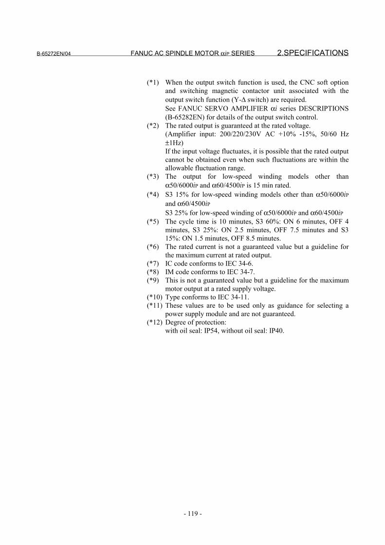
B-65272EN/04 FANUC AC SPINDLE MOTOR αiP SERIES 2.SPECIFICATIONS
- 119 -
(*1) When the output switch function is used, the CNC soft optionand switching magnetic contactor unit associated with theoutput switch function (Y-∆ switch) are required.See FANUC SERVO AMPLIFIER αi series DESCRIPTIONS(B-65282EN) for details of the output switch control.
(*2) The rated output is guaranteed at the rated voltage.(Amplifier input: 200/220/230V AC +10% -15%, 50/60 Hz±1Hz)If the input voltage fluctuates, it is possible that the rated outputcannot be obtained even when such fluctuations are within theallowable fluctuation range.
(*3) The output for low-speed winding models other thanα50/6000iP and α60/4500iP is 15 min rated.
(*4) S3 15% for low-speed winding models other than α50/6000iPand α60/4500iPS3 25% for low-speed winding of α50/6000iP and α60/4500iP
(*5) The cycle time is 10 minutes, S3 60%: ON 6 minutes, OFF 4minutes, S3 25%: ON 2.5 minutes, OFF 7.5 minutes and S315%: ON 1.5 minutes, OFF 8.5 minutes.
(*6) The rated current is not a guaranteed value but a guideline forthe maximum current at rated output.
(*7) IC code conforms to IEC 34-6.(*8) IM code conforms to IEC 34-7.(*9) This is not a guaranteed value but a guideline for the maximum
motor output at a rated supply voltage.(*10) Type conforms to IEC 34-11.(*11) These values are to be used only as guidance for selecting a
power supply module and are not guaranteed.(*12) Degree of protection:
with oil seal: IP54, without oil seal: IP40.
3.OUTPUT/TORQUE CHARACTERISTICSFANUC AC SPINDLE MOTOR αiP SERIES B-65272EN/04
- 120 -
3 OUTPUT/TORQUE CHARACTERISTICSReferenceCalculation for torque
Torque T can be obtained by the following equation.
T[N⋅m]=P[kW]×1000/0.1047/N[min-1]P[kW]: Motor outputN[min-1]: Motor speed
When the unit of T is [kgf⋅m],T[kgf⋅m]=P[kW]×1000/1.0269/N[min-1]
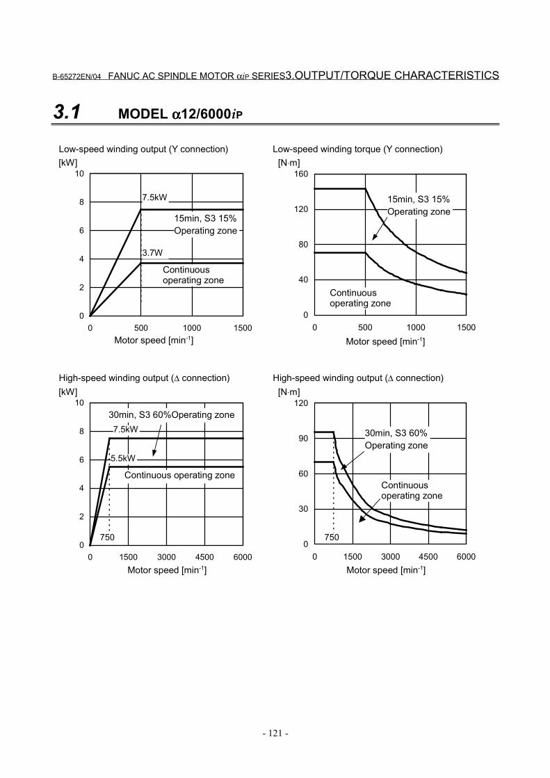
B-65272EN/04 FANUC AC SPINDLE MOTOR αiP SERIES3.OUTPUT/TORQUE CHARACTERISTICS
- 121 -
3.1 MODEL αααα12/6000iP
0
2
4
6
8
10
0 500 1000 1500
[kW]
0
40
80
120
160
0 500 1000 1500
[N⋅m]
7.5kW
0
2
4
6
8
10
0 1500 3000 4500 6000
[kW]
0
30
60
90
120
0 1500 3000 4500 6000
[N⋅m]
5.5kW
7.5kW
3.7W
750750
Motor speed [min-1]
Continuousoperating zone
15min, S3 15%Operating zone
Motor speed [min-1]
15min, S3 15%Operating zone
Continuousoperating zone
Low-speed winding output (Y connection) Low-speed winding torque (Y connection)
Motor speed [min-1]
Continuous operating zone
30min, S3 60%Operating zone
Motor speed [min-1]
30min, S3 60%Operating zone
Continuousoperating zone
High-speed winding output (∆ connection) High-speed winding output (∆ connection)
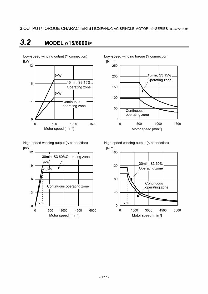
3.OUTPUT/TORQUE CHARACTERISTICSFANUC AC SPINDLE MOTOR αiP SERIES B-65272EN/04
- 122 -
3.2 MODEL αααα15/6000iP
0
4
8
12
0 500 1000 1500
[kW]
0
50
100
150
200
250
0 500 1000 1500
[N⋅m]
9kW
0
3
6
9
12
0 1500 3000 4500 6000
[kW]
0
40
80
120
160
0 1500 3000 4500 6000
[N⋅m]
9kW
7.5kW
5kW
750750
Motor speed [min-1]
Continuousoperating zone
15min, S3 15%Operating zone
Motor speed [min-1]
15min, S3 15%Operating zone
Continuousoperating zone
Low-speed winding output (Y connection) Low-speed winding torque (Y connection)
Motor speed [min-1]
Continuous operating zone
30min, S3 60%Operating zone
Motor speed [min-1]
30min, S3 60%Operating zone
Continuousoperating zone
High-speed winding output (∆ connection) High-speed winding output (∆ connection)
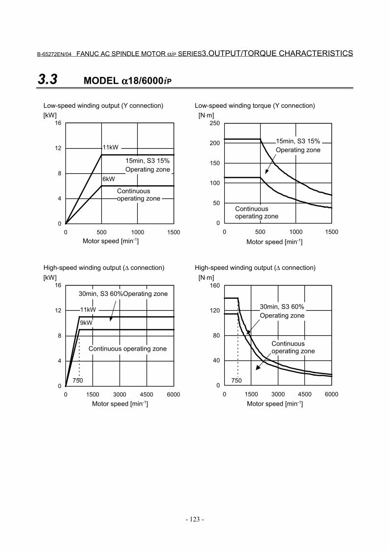
B-65272EN/04 FANUC AC SPINDLE MOTOR αiP SERIES3.OUTPUT/TORQUE CHARACTERISTICS
- 123 -
3.3 MODEL αααα18/6000iP
0
4
8
12
16
0 500 1000 1500
[kW]
0
50
100
150
200
250
0 500 1000 1500
[N⋅m]
11kW
0
4
8
12
16
0 1500 3000 4500 6000
[kW]
0
40
80
120
160
0 1500 3000 4500 6000
[N⋅m]
9kW
11kW
6kW
750750
Motor speed [min-1]
Continuousoperating zone
15min, S3 15%Operating zone
Motor speed [min-1]
15min, S3 15%Operating zone
Continuousoperating zone
Low-speed winding output (Y connection) Low-speed winding torque (Y connection)
Motor speed [min-1]
Continuous operating zone
30min, S3 60%Operating zone
Motor speed [min-1]
30min, S3 60%Operating zone
Continuousoperating zone
High-speed winding output (∆ connection) High-speed winding output (∆ connection)
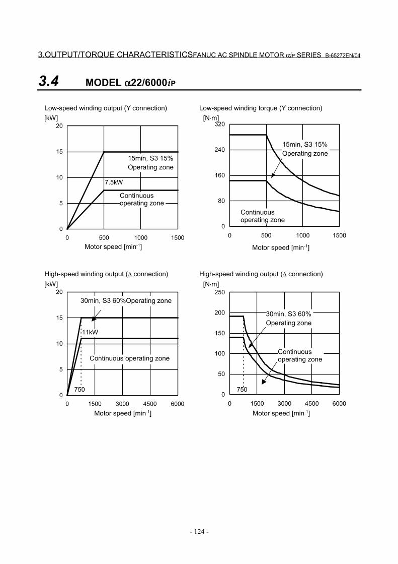
3.OUTPUT/TORQUE CHARACTERISTICSFANUC AC SPINDLE MOTOR αiP SERIES B-65272EN/04
- 124 -
3.4 MODEL αααα22/6000iP
0
5
10
15
20
0 500 1000 1500
[kW]
0
80
160
240
320
0 500 1000 1500
[N⋅m]
0
5
10
15
20
0 1500 3000 4500 6000
[kW]
0
50
100
150
200
250
0 1500 3000 4500 6000
[N⋅m]
11kW
7.5kW
750750
Motor speed [min-1]
Continuousoperating zone
15min, S3 15%Operating zone
Motor speed [min-1]
15min, S3 15%Operating zone
Continuousoperating zone
Low-speed winding output (Y connection) Low-speed winding torque (Y connection)
Motor speed [min-1]
Continuous operating zone
30min, S3 60%Operating zone
Motor speed [min-1]
30min, S3 60%Operating zone
Continuousoperating zone
High-speed winding output (∆ connection) High-speed winding output (∆ connection)
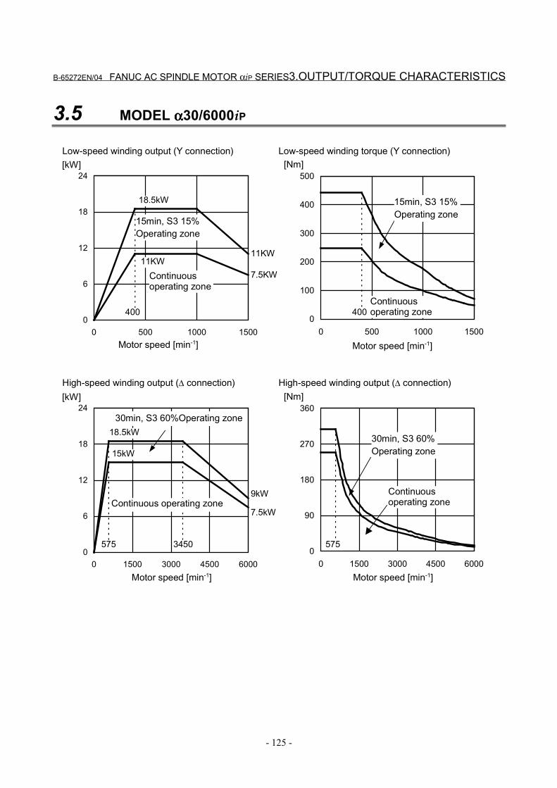
B-65272EN/04 FANUC AC SPINDLE MOTOR αiP SERIES3.OUTPUT/TORQUE CHARACTERISTICS
- 125 -
3.5 MODEL αααα30/6000iP
0
6
12
18
24
0 500 1000 1500
[kW]
0
100
200
300
400
500
0 500 1000 1500
[Nm]
18.5kW
0
6
12
18
24
0 1500 3000 4500 6000
[kW]
0
90
180
270
360
0 1500 3000 4500 6000
[Nm]
15kW
18.5kW
11KW
575575
400 400
3450
9kW
7.5kW
Motor speed [min-1]
Continuousoperating zone
15min, S3 15%Operating zone
Motor speed [min-1]
15min, S3 15%Operating zone
Continuousoperating zone
Low-speed winding output (Y connection) Low-speed winding torque (Y connection)
Motor speed [min-1]
Continuous operating zone
30min, S3 60%Operating zone
Motor speed [min-1]
30min, S3 60%Operating zone
Continuousoperating zone
High-speed winding output (∆ connection) High-speed winding output (∆ connection)
11KW
7.5KW
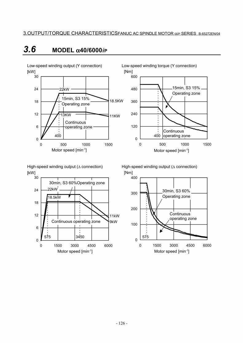
3.OUTPUT/TORQUE CHARACTERISTICSFANUC AC SPINDLE MOTOR αiP SERIES B-65272EN/04
- 126 -
3.6 MODEL αααα40/6000iP
0
6
12
18
24
30
0 500 1000 1500
[kW]
0
120
240
360
480
600
0 500 1000 1500
[Nm]
22kW
0
6
12
18
24
30
0 1500 3000 4500 6000
[kW]
0
100
200
300
400
0 1500 3000 4500 6000
[Nm]
22kW
18.5kW
13KW
575575
400 400
3450
11kW9kW
Motor speed [min-1]
Continuousoperating zone
15min, S3 15%Operating zone
Motor speed [min-1]
15min, S3 15%Operating zone
Continuousoperating zone
Low-speed winding output (Y connection) Low-speed winding torque (Y connection)
Motor speed [min-1]
Continuous operating zone
30min, S3 60%Operating zone
Motor speed [min-1]
30min, S3 60%Operating zone
Continuousoperating zone
High-speed winding output (∆ connection) High-speed winding output (∆ connection)
11KW
18.5KW
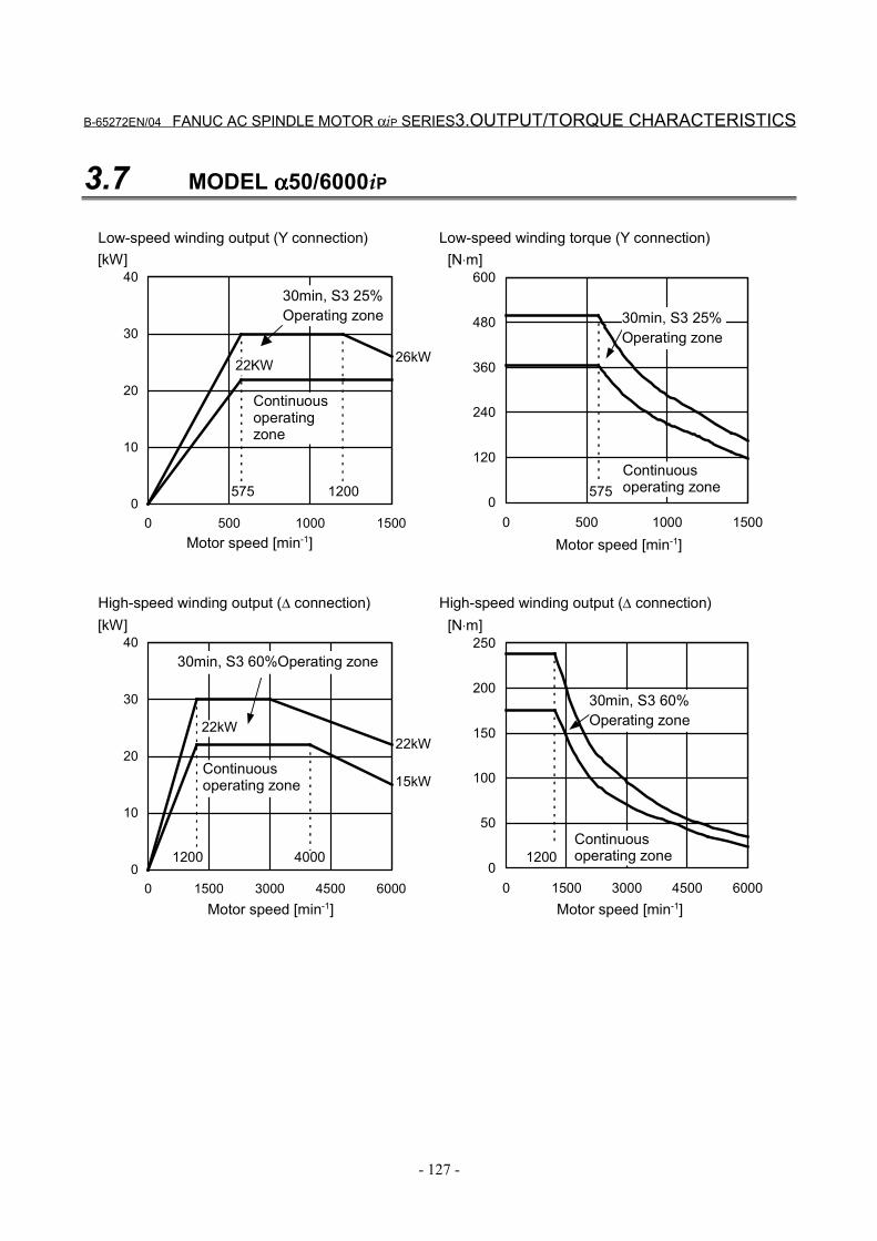
B-65272EN/04 FANUC AC SPINDLE MOTOR αiP SERIES3.OUTPUT/TORQUE CHARACTERISTICS
- 127 -
3.7 MODEL αααα50/6000iP
0
10
20
30
40
0 500 1000 1500
[kW]
0
120
240
360
480
600
0 500 1000 1500
[N⋅m]
0
10
20
30
40
0 1500 3000 4500 6000
[kW]
0
50
100
150
200
250
0 1500 3000 4500 6000
[N⋅m]
22kW
22KW
12001200
575 575
4000
22kW
15kW
26kW
1200
Motor speed [min-1]
Continuousoperatingzone
30min, S3 25%Operating zone
Motor speed [min-1]
30min, S3 25%Operating zone
Continuousoperating zone
Low-speed winding output (Y connection) Low-speed winding torque (Y connection)
Motor speed [min-1]
Continuousoperating zone
30min, S3 60%Operating zone
Motor speed [min-1]
30min, S3 60%Operating zone
Continuousoperating zone
High-speed winding output (∆ connection) High-speed winding output (∆ connection)
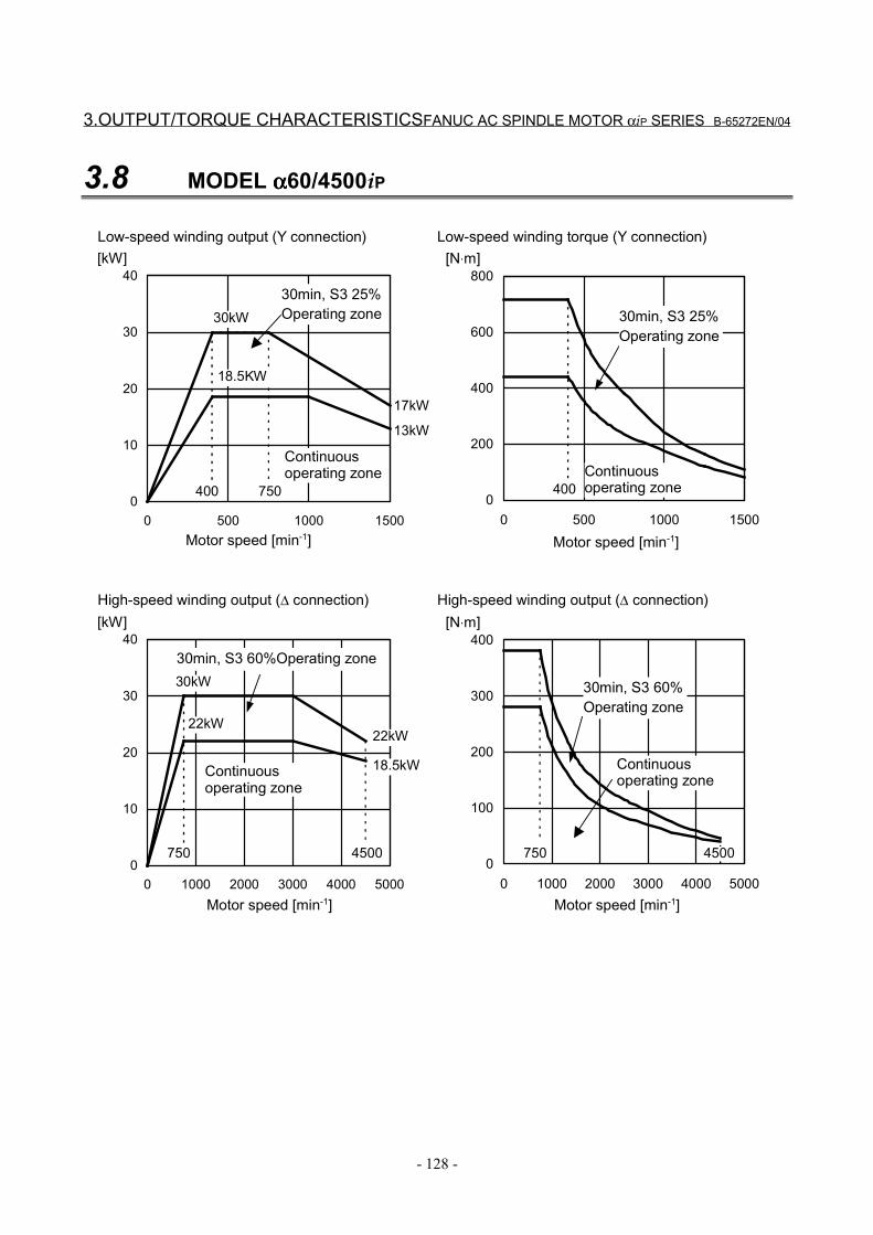
3.OUTPUT/TORQUE CHARACTERISTICSFANUC AC SPINDLE MOTOR αiP SERIES B-65272EN/04
- 128 -
3.8 MODEL αααα60/4500iP
0
10
20
30
40
0 500 1000 1500
[kW]
0
200
400
600
800
0 500 1000 1500
[N⋅m]
30kW
0
10
20
30
40
0 1000 2000 3000 4000 5000
[kW]
0
100
200
300
400
0 1000 2000 3000 4000 5000
[N⋅m]
22kW
18.5kW
18.5KW
750750
400 400
4500
30kW
22kW
17kW
13kW
750
4500
Motor speed [min-1]
Continuousoperating zone
30min, S3 25%Operating zone
Motor speed [min-1]
30min, S3 25%Operating zone
Continuousoperating zone
Low-speed winding output (Y connection) Low-speed winding torque (Y connection)
Motor speed [min-1]
Continuousoperating zone
30min, S3 60%Operating zone
Motor speed [min-1]
30min, S3 60%Operating zone
Continuousoperating zone
High-speed winding output (∆ connection) High-speed winding output (∆ connection)
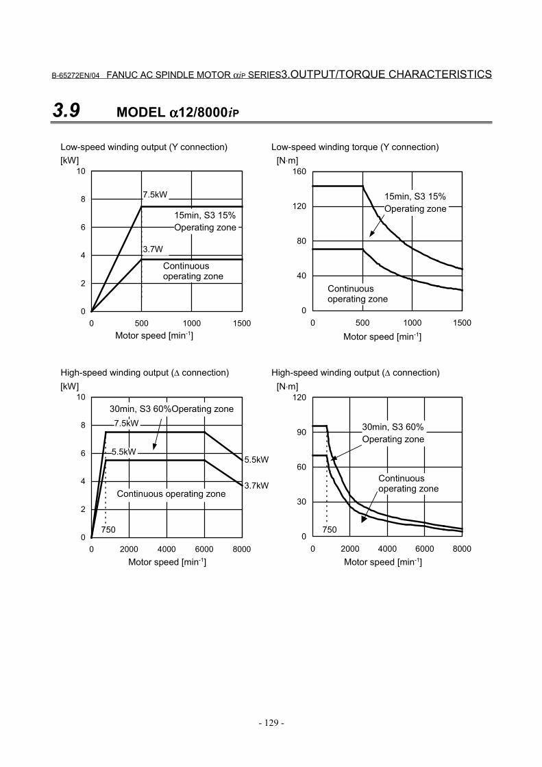
B-65272EN/04 FANUC AC SPINDLE MOTOR αiP SERIES3.OUTPUT/TORQUE CHARACTERISTICS
- 129 -
3.9 MODEL αααα12/8000iP
0
2
4
6
8
10
0 500 1000 1500
[kW]
0
40
80
120
160
0 500 1000 1500
[N⋅m]
7.5kW
0
2
4
6
8
10
0 2000 4000 6000 8000
[kW]
0
30
60
90
120
0 2000 4000 6000 8000
[N⋅m]
5.5kW
7.5kW
3.7W
750750
5.5kW
3.7kW
Motor speed [min-1]
Continuousoperating zone
15min, S3 15%Operating zone
Motor speed [min-1]
15min, S3 15%Operating zone
Continuousoperating zone
Low-speed winding output (Y connection) Low-speed winding torque (Y connection)
Motor speed [min-1]
Continuous operating zone
30min, S3 60%Operating zone
Motor speed [min-1]
30min, S3 60%Operating zone
Continuousoperating zone
High-speed winding output (∆ connection) High-speed winding output (∆ connection)
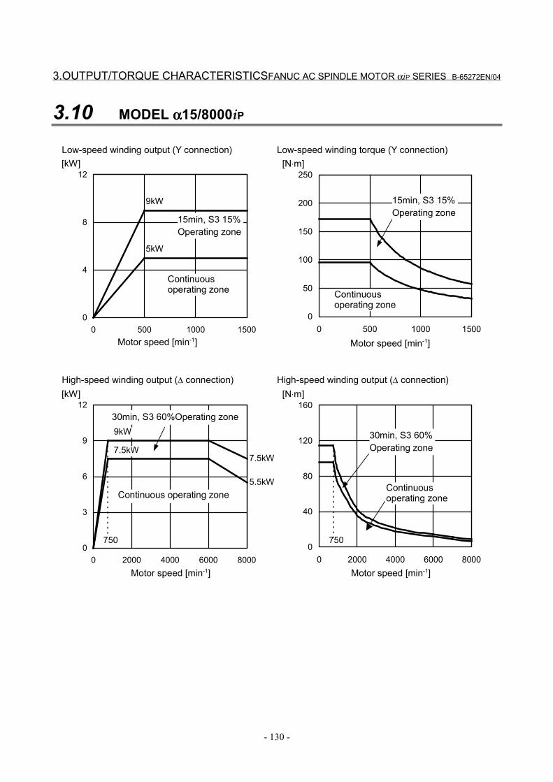
3.OUTPUT/TORQUE CHARACTERISTICSFANUC AC SPINDLE MOTOR αiP SERIES B-65272EN/04
- 130 -
3.10 MODEL αααα15/8000iP
0
4
8
12
0 500 1000 1500
[kW]
0
50
100
150
200
250
0 500 1000 1500
[N⋅m]
9kW
0
3
6
9
12
0 2000 4000 6000 8000
[kW]
0
40
80
120
160
0 2000 4000 6000 8000
[N⋅m]
9kW
7.5kW
5kW
750750
5.5kW
7.5kW
Motor speed [min-1]
Continuousoperating zone
15min, S3 15%Operating zone
Motor speed [min-1]
15min, S3 15%Operating zone
Continuousoperating zone
Low-speed winding output (Y connection) Low-speed winding torque (Y connection)
Motor speed [min-1]
Continuous operating zone
30min, S3 60%Operating zone
Motor speed [min-1]
30min, S3 60%Operating zone
Continuousoperating zone
High-speed winding output (∆ connection) High-speed winding output (∆ connection)
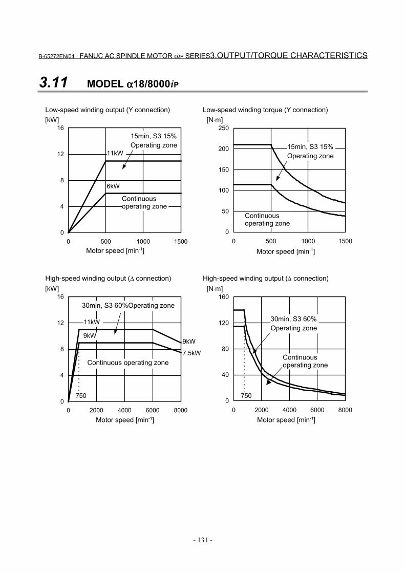
B-65272EN/04 FANUC AC SPINDLE MOTOR αiP SERIES3.OUTPUT/TORQUE CHARACTERISTICS
- 131 -
3.11 MODEL αααα18/8000iP
0
4
8
12
16
0 500 1000 1500
[kW]
0
50
100
150
200
250
0 500 1000 1500
[N⋅m]
11kW
0
4
8
12
16
0 2000 4000 6000 8000
[kW]
0
40
80
120
160
0 2000 4000 6000 8000
[N⋅m]
9kW
11kW
6kW
750750
9kW
7.5kW
Motor speed [min-1]
Continuousoperating zone
Motor speed [min-1]
15min, S3 15%Operating zone
Continuousoperating zone
Low-speed winding output (Y connection) Low-speed winding torque (Y connection)
Motor speed [min-1]
Continuous operating zone
30min, S3 60%Operating zone
Motor speed [min-1]
30min, S3 60%Operating zone
Continuousoperating zone
High-speed winding output (∆ connection) High-speed winding output (∆ connection)
15min, S3 15%Operating zone
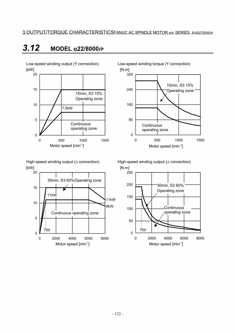
3.OUTPUT/TORQUE CHARACTERISTICSFANUC AC SPINDLE MOTOR αiP SERIES B-65272EN/04
- 132 -
3.12 MODEL αααα22/8000iP
0
5
10
15
20
0 500 1000 1500
[kW]
0
80
160
240
320
0 500 1000 1500
[N⋅m]
0
5
10
15
20
0 2000 4000 6000 8000
[kW]
0
50
100
150
200
250
0 2000 4000 6000 8000
[N⋅m]
11kW
7.5kW
750750
9kW
11kW
Motor speed [min-1]
Continuousoperating zone
15min, S3 15%Operating zone
Motor speed [min-1]
15min, S3 15%Operating zone
Continuousoperating zone
Low-speed winding output (Y connection) Low-speed winding torque (Y connection)
Motor speed [min-1]
Continuous operating zone
30min, S3 60%Operating zone
Motor speed [min-1]
30min, S3 60%Operating zone
Continuousoperating zone
High-speed winding output (∆ connection) High-speed winding output (∆ connection)

B-65272EN/04 FANUC AC SPINDLE MOTOR αiP SERIES 4.CONNECTIONS
- 133 -
4 CONNECTIONS
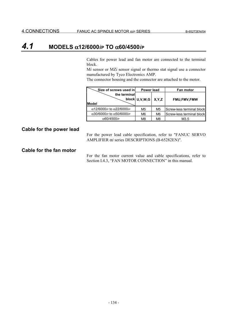
4.CONNECTIONS FANUC AC SPINDLE MOTOR αiP SERIES B-65272EN/04
- 134 -
4.1 MODELS αααα12/6000iP TO αααα60/4500iP
Cables for power lead and fan motor are connected to the terminalblock.Mi sensor or MZi sensor signal or thermo stat signal use a connectormanufactured by Tyco Electronics AMP.The connector housing and the connector are attached to the motor.
Power lead Fan motorSize of screws used inthe terminal
blockModel
U,V,W,G X,Y,Z FMU,FMV,FMW
α12/6000iP to α22/6000iP M5 M5 Screw-less terminal blockα30/6000iP to α50/6000iP M6 M6 Screw-less terminal block
α60/4500iP M8 M8 M3.5
Cable for the power leadFor the power lead cable specification, refer to "FANUC SERVOAMPLIFIER αi series DESCRIPTIONS (B-65282EN)".
Cable for the fan motorFor the fan motor current value and cable specifications, refer toSection I.4.3, “FAN MOTOR CONNECTION” in this manual.
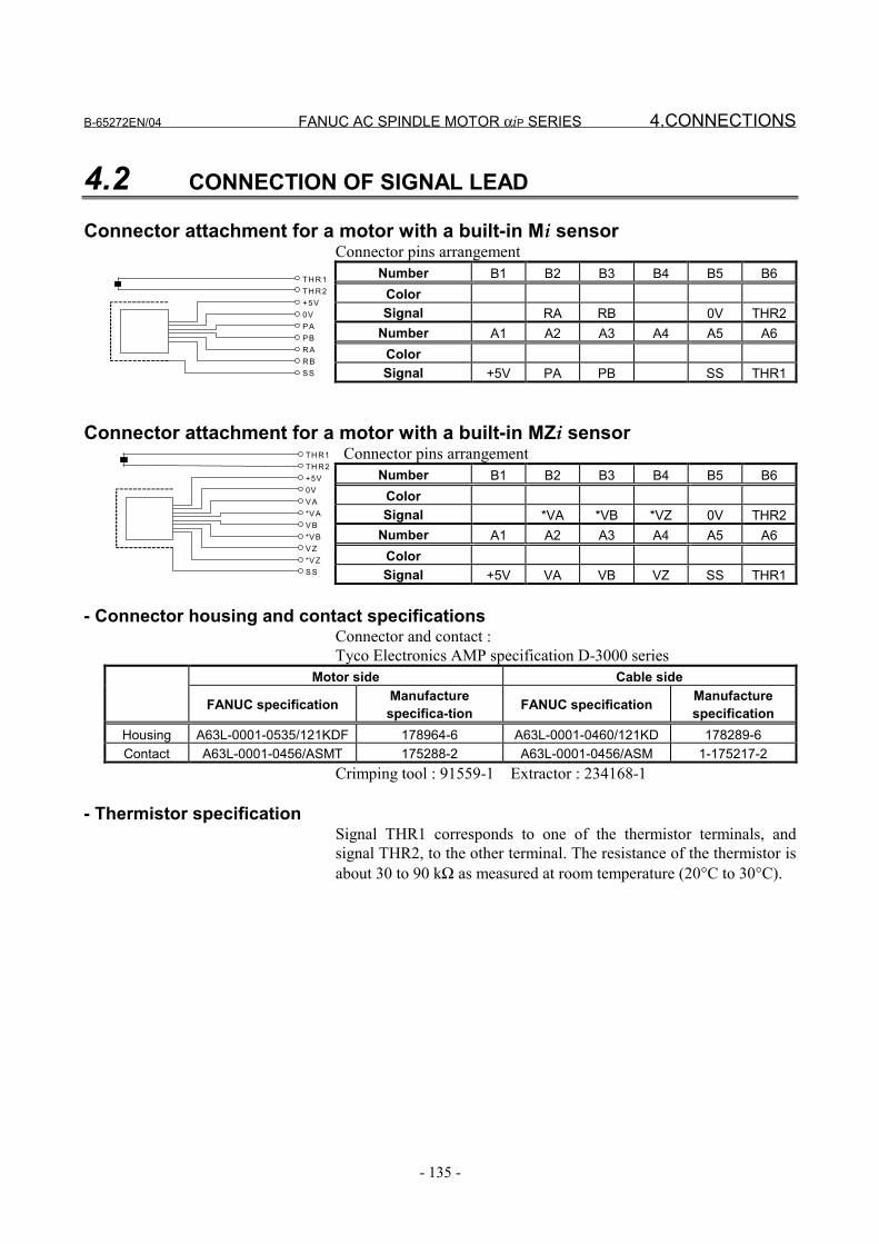
B-65272EN/04 FANUC AC SPINDLE MOTOR αiP SERIES 4.CONNECTIONS
- 135 -
4.2 CONNECTION OF SIGNAL LEAD
Connector attachment for a motor with a built-in Mi sensorConnector pins arrangement
Number B1 B2 B3 B4 B5 B6ColorSignal RA RB 0V THR2
Number A1 A2 A3 A4 A5 A6ColorSignal +5V PA PB SS THR1
Connector attachment for a motor with a built-in MZi sensor Connector pins arrangement
Number B1 B2 B3 B4 B5 B6ColorSignal *VA *VB *VZ 0V THR2
Number A1 A2 A3 A4 A5 A6ColorSignal +5V VA VB VZ SS THR1
- Connector housing and contact specificationsConnector and contact :Tyco Electronics AMP specification D-3000 series
Motor side Cable side
FANUC specification Manufacturespecifica-tion FANUC specification Manufacture
specificationHousing A63L-0001-0535/121KDF 178964-6 A63L-0001-0460/121KD 178289-6Contact A63L-0001-0456/ASMT 175288-2 A63L-0001-0456/ASM 1-175217-2
Crimping tool : 91559-1 Extractor : 234168-1
- Thermistor specificationSignal THR1 corresponds to one of the thermistor terminals, andsignal THR2, to the other terminal. The resistance of the thermistor isabout 30 to 90 kΩ as measured at room temperature (20°C to 30°C).
TH R 1TH R 2+ 5V0VP AP BR AR BS S
TH R1TH R2+5V0VV A*V AV B*V BV Z*V ZS S
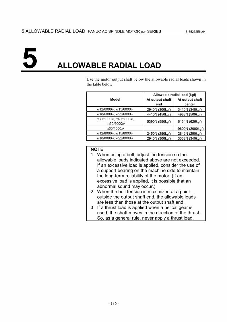
5.ALLOWABLE RADIAL LOAD FANUC AC SPINDLE MOTOR αiP SERIES B-65272EN/04
- 136 -
5 ALLOWABLE RADIAL LOADUse the motor output shaft below the allowable radial loads shown inthe table below.
Allowable radial load (kgf)Model At output shaft
endAt output shaft
centerα12/6000iP, α15/6000iP 2940N (300kgf) 3410N (348kgf)α18/6000iP, α22/6000iP 4410N (450kgf) 4988N (509kgf)α30/6000iP, α40/6000iP,
α50/6000iP 5390N (550kgf) 6134N (626kgf)
α60/4500iP - 19600N (2000kgf)α12/8000iP, α15/8000iP 2450N (250kgf) 2842N (290kgf)α18/8000iP, α22/8000iP 2940N (300kgf) 3332N (340kgf)
NOTE1 When using a belt, adjust the tension so the
allowable loads indicated above are not exceeded.If an excessive load is applied, consider the use ofa support bearing on the machine side to maintainthe long-term reliability of the motor. (If anexcessive load is applied, it is possible that anabnormal sound may occur.)
2 When the belt tension is maximized at a pointoutside the output shaft end, the allowable loadsare less than those at the output shaft end.
3 If a thrust load is applied when a helical gear isused, the shaft moves in the direction of the thrust.So, as a general rule, never apply a thrust load.
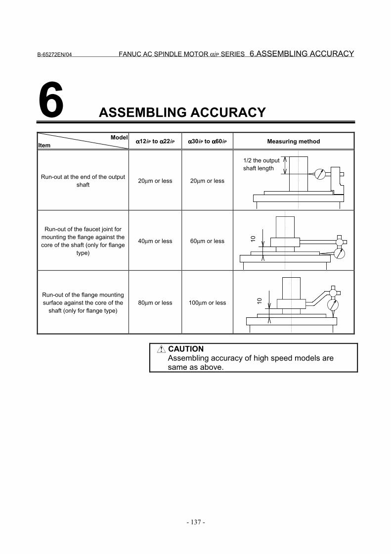
B-65272EN/04 FANUC AC SPINDLE MOTOR αiP SERIES 6.ASSEMBLING ACCURACY
- 137 -
6 ASSEMBLING ACCURACYModel
Item αααα12iP to αααα22iP αααα30iP to αααα60iP Measuring method
Run-out at the end of the outputshaft 20µm or less 20µm or less
1/2 the outputshaft length
Run-out of the faucet joint formounting the flange against thecore of the shaft (only for flange
type)
40µm or less 60µm or less 10
Run-out of the flange mountingsurface against the core of the
shaft (only for flange type)80µm or less 100µm or less 10
CAUTIONAssembling accuracy of high speed models aresame as above.
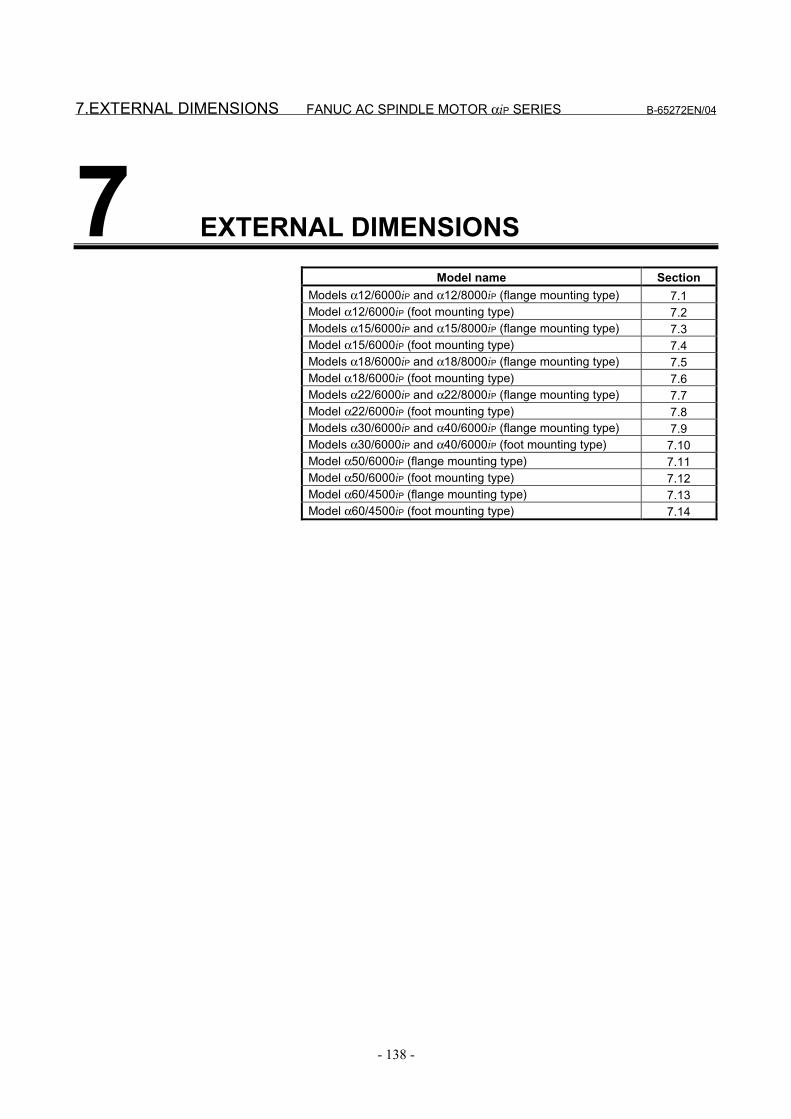
7.EXTERNAL DIMENSIONS FANUC AC SPINDLE MOTOR αiP SERIES B-65272EN/04
- 138 -
7 EXTERNAL DIMENSIONSModel name Section
Models α12/6000iP and α12/8000iP (flange mounting type) 7.1Model α12/6000iP (foot mounting type) 7.2Models α15/6000iP and α15/8000iP (flange mounting type) 7.3Model α15/6000iP (foot mounting type) 7.4Models α18/6000iP and α18/8000iP (flange mounting type) 7.5Model α18/6000iP (foot mounting type) 7.6Models α22/6000iP and α22/8000iP (flange mounting type) 7.7Model α22/6000iP (foot mounting type) 7.8Models α30/6000iP and α40/6000iP (flange mounting type) 7.9Models α30/6000iP and α40/6000iP (foot mounting type) 7.10Model α50/6000iP (flange mounting type) 7.11Model α50/6000iP (foot mounting type) 7.12Model α60/4500iP (flange mounting type) 7.13Model α60/4500iP (foot mounting type) 7.14
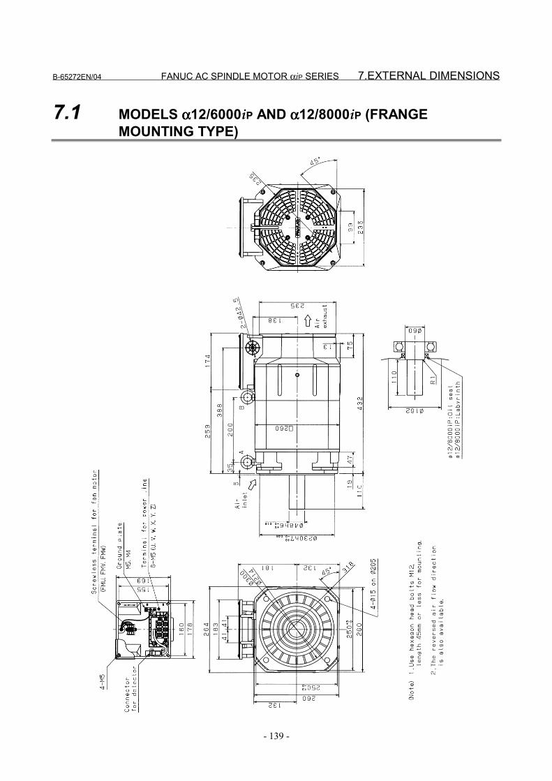
B-65272EN/04 FANUC AC SPINDLE MOTOR αiP SERIES 7.EXTERNAL DIMENSIONS
- 139 -
7.1 MODELS αααα12/6000iP AND αααα12/8000iP (FRANGEMOUNTING TYPE)

7.EXTERNAL DIMENSIONS FANUC AC SPINDLE MOTOR αiP SERIES B-65272EN/04
- 140 -
7.2 MODEL αααα12/6000iP (FOOT MOUNTING TYPE)

B-65272EN/04 FANUC AC SPINDLE MOTOR αiP SERIES 7.EXTERNAL DIMENSIONS
- 141 -
7.3 MODELS αααα15/6000iP AND αααα15/8000iP (FRANGEMOUNTING TYPE)

7.EXTERNAL DIMENSIONS FANUC AC SPINDLE MOTOR αiP SERIES B-65272EN/04
- 142 -
7.4 MODEL αααα15/6000iP (FOOT MOUNTING TYPE)

B-65272EN/04 FANUC AC SPINDLE MOTOR αiP SERIES 7.EXTERNAL DIMENSIONS
- 143 -
7.5 MODELS αααα18/6000iP AND αααα18/8000iP (FRANGEMOUNTING TYPE)

7.EXTERNAL DIMENSIONS FANUC AC SPINDLE MOTOR αiP SERIES B-65272EN/04
- 144 -
7.6 MODEL αααα18/6000iP (FOOT MOUNTING TYPE)
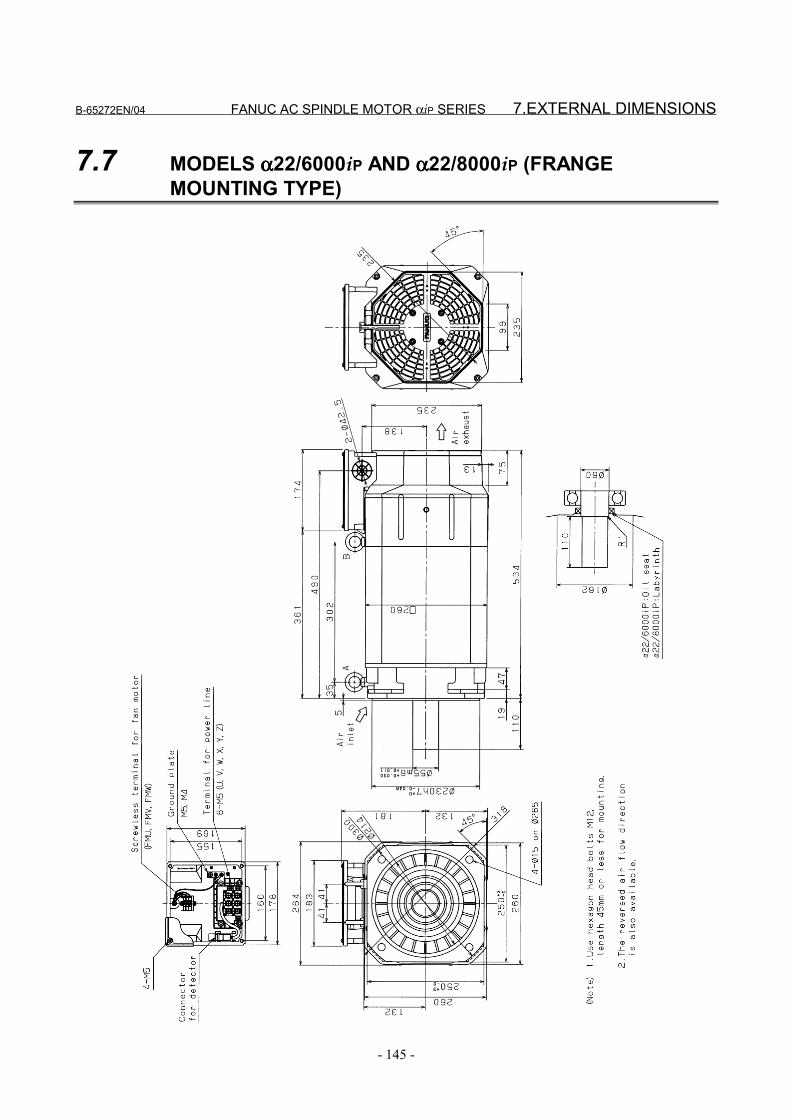
B-65272EN/04 FANUC AC SPINDLE MOTOR αiP SERIES 7.EXTERNAL DIMENSIONS
- 145 -
7.7 MODELS αααα22/6000iP AND αααα22/8000iP (FRANGEMOUNTING TYPE)
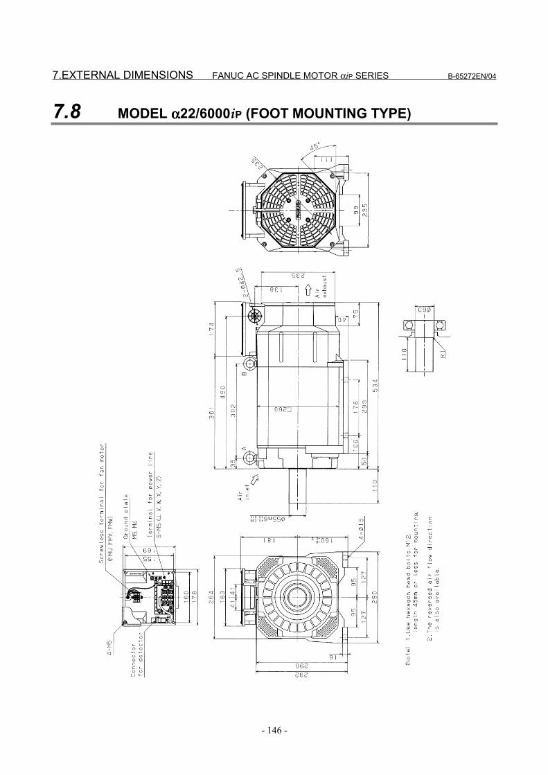
7.EXTERNAL DIMENSIONS FANUC AC SPINDLE MOTOR αiP SERIES B-65272EN/04
- 146 -
7.8 MODEL αααα22/6000iP (FOOT MOUNTING TYPE)
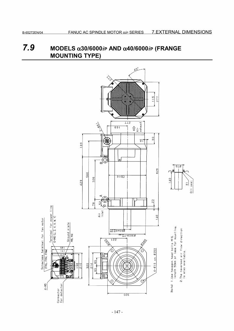
B-65272EN/04 FANUC AC SPINDLE MOTOR αiP SERIES 7.EXTERNAL DIMENSIONS
- 147 -
7.9 MODELS αααα30/6000iP AND αααα40/6000iP (FRANGEMOUNTING TYPE)
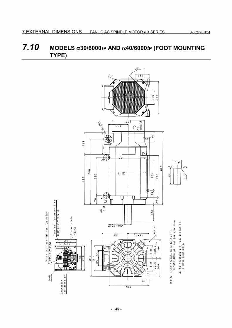
7.EXTERNAL DIMENSIONS FANUC AC SPINDLE MOTOR αiP SERIES B-65272EN/04
- 148 -
7.10 MODELS αααα30/6000iP AND αααα40/6000iP (FOOT MOUNTINGTYPE)
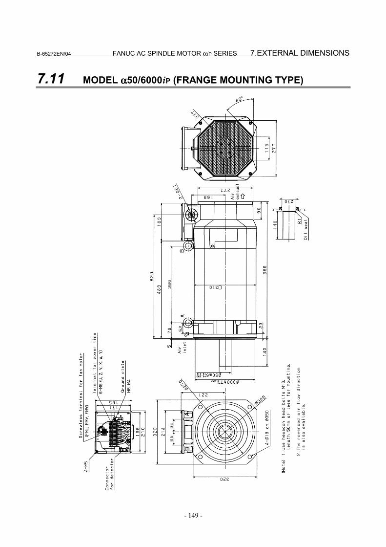
B-65272EN/04 FANUC AC SPINDLE MOTOR αiP SERIES 7.EXTERNAL DIMENSIONS
- 149 -
7.11 MODEL αααα50/6000iP (FRANGE MOUNTING TYPE)
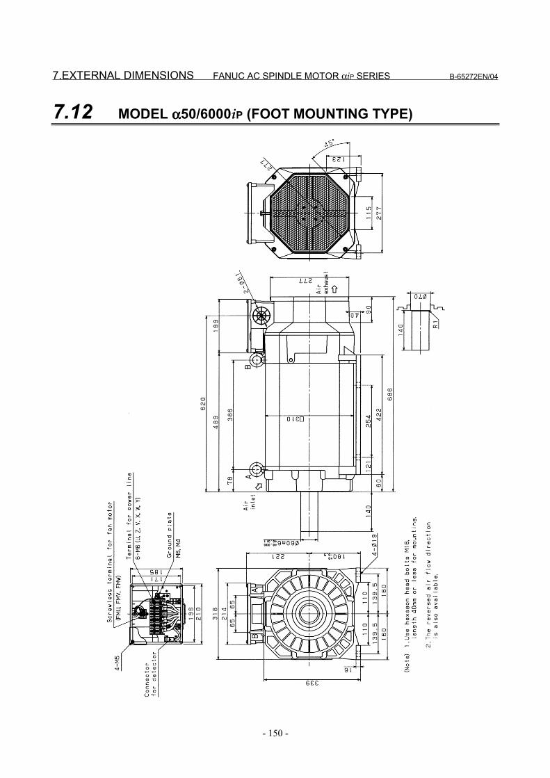
7.EXTERNAL DIMENSIONS FANUC AC SPINDLE MOTOR αiP SERIES B-65272EN/04
- 150 -
7.12 MODEL αααα50/6000iP (FOOT MOUNTING TYPE)
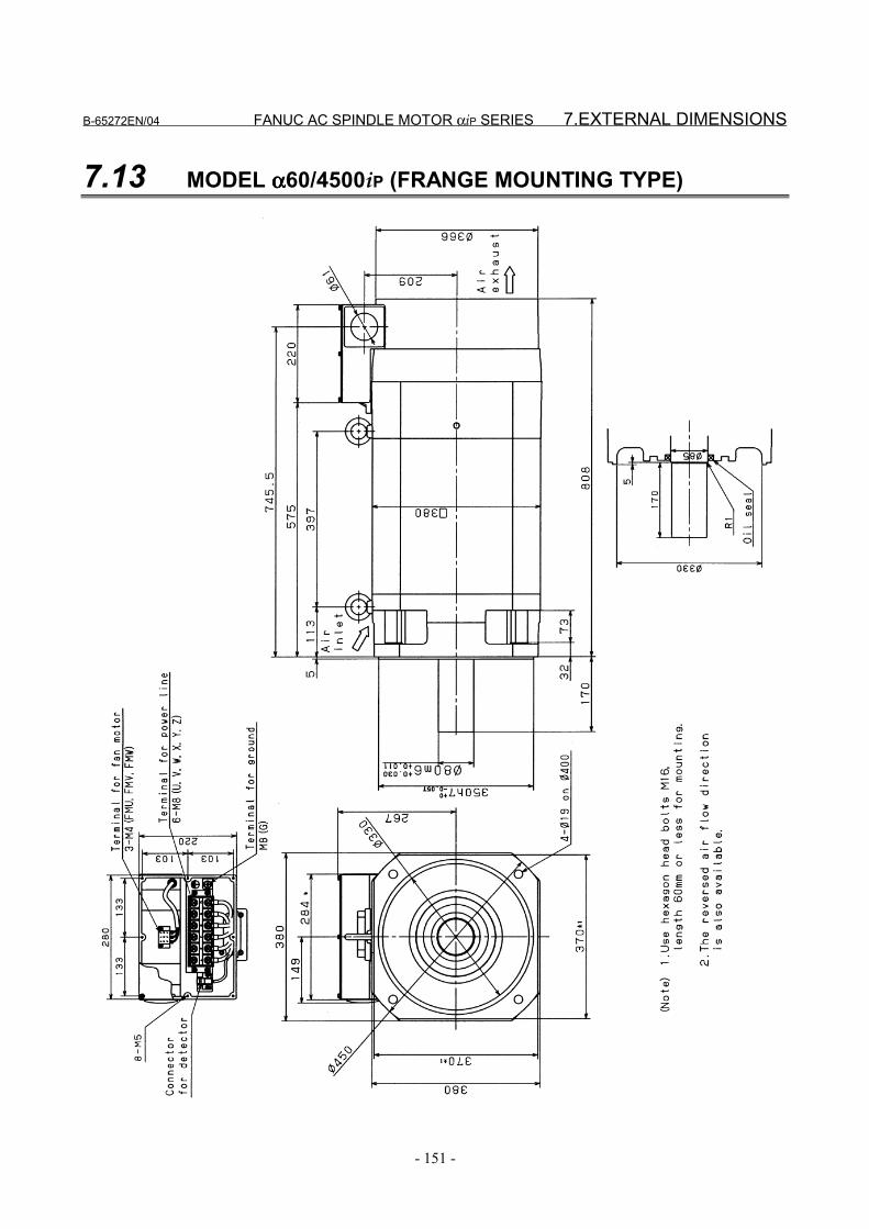
B-65272EN/04 FANUC AC SPINDLE MOTOR αiP SERIES 7.EXTERNAL DIMENSIONS
- 151 -
7.13 MODEL αααα60/4500iP (FRANGE MOUNTING TYPE)
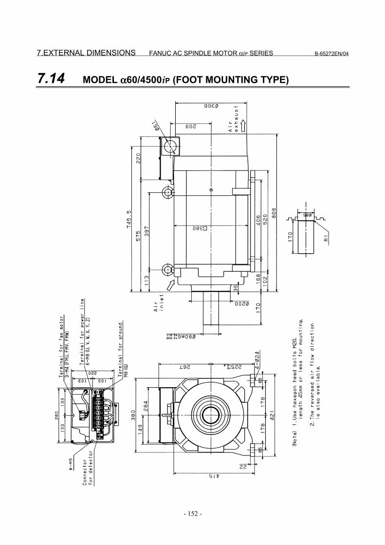
7.EXTERNAL DIMENSIONS FANUC AC SPINDLE MOTOR αiP SERIES B-65272EN/04
- 152 -
7.14 MODEL αααα60/4500iP (FOOT MOUNTING TYPE)
IV. FANUC AC SPINDLE MOTOR ααααiT SERIES

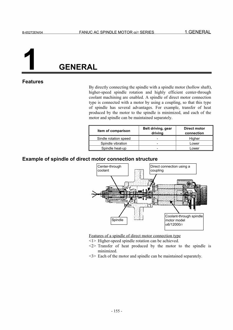
B-65272EN/04 FANUC AC SPINDLE MOTOR αiT SERIES 1.GENERAL
- 155 -
1 GENERALFeatures
By directly connecting the spindle with a spindle motor (hollow shaft),higher-speed spindle rotation and highly efficient center-throughcoolant machining are enabled. A spindle of direct motor connectiontype is connected with a motor by using a coupling, so that this typeof spindle has several advantages. For example, transfer of heatproduced by the motor to the spindle is minimized, and each of themotor and spindle can be maintained separately.
Item of comparison Belt driving, geardriving
Direct motorconnection
Sindle rotation speed - HigherSpindle vibration - LowerSpindle heat-up - Lower
Example of spindle of direct motor connection structureCenter-throughcoolant
Direct connection using acoupling
SpindleCoolant-through spindlemotor modelα6/12000iT
Features of a spindle of direct motor connection type<1> Higher-speed spindle rotation can be achieved.<2> Transfer of heat produced by the motor to the spindle is
minimized.<3> Each of the motor and spindle can be maintained separately.
1.GENERAL FANUC AC SPINDLE MOTOR αiT SERIES B-65272EN/04
- 156 -
Important(1) For attachment of this type of motor to a spindle, only coupling-
based direct connection with the spindle is allowed. When aspindle of direct motor connection type is used, fretting canoccur with the motor shaft in a short-time operation, or thebearing of the spindle or motor can be damaged if the spindleand motor are not aligned precisely. As the method ofquantitatively determining whether a spindle and motor arealigned precisely, FANUC recommends the user to measure thevibration (acceleration G) of the motor after being connectedwith the spindle. For details, see Section 9.3, "CHECKINGMOTOR VIBRATION" in this manual.
(2) Do not apply a thrust load onto the motor shaft. Select a couplingthat does not apply a thrust load onto the motor shaft for a causesuch as coolant pressure when the temperature rises or cutting isperformed.
B-65272EN/04 FANUC AC SPINDLE MOTOR αiT SERIES 2.SPECIFICATIONS
- 157 -
2 SPECIFICATIONS

2.SPECIFICATIONS FANUC AC SPINDLE MOTOR αiT SERIES B-65272EN/04
- 158 -
ModelItem αααα1.5/15000iT αααα2/15000iT αααα3/12000iT
(S1)Cont. rated kW (HP)
1.5(2.0)
2.2(3.0)
3.7(5.0)
(S2)30 min rated kW [15 min](*2)(HP)
2.2(3.0)
3.7(5.0)
5.5(7.4)
Output(*1)
(S3)60%[40%]kW (*3) (*4) (HP)
2.2(3.0)
3.7(5.0)
5.5(7.4)
(S1) A 28 41 36Ratedcurrent(*5) (S2),(S3) A 33 53 46
Speed Base speed 3,000 3,000 1,500min-1 Max. speed 15,000 15,000 12,000
Cont. rated torque at const.rated torque range
N⋅m(kgf⋅cm)
4.77(48.7)
7.0(71.5)
23.5(240)
Rotorinertia
kg⋅m2
(kgf⋅cm⋅s2)0.0043(0.04)
0.0078(0.08)
0.0148(0.15)
Weight kgf 24 27 46Vibration V3 (rotation component)Noise 75dB(A) or lessCooling system (*6) Totally enclosed and fan cooled (IC0A6)Cooling fan W 17
Installation (*7) Mount the motor so that the output shaft points in a direction ranging within thehorizontally to vertically downwards. (IMB5,IMV1)
Allowable overload capacity(1 min) (*8) 120% of (S2)
Insulation Class HAmbient temperature 0°C to 40°CAltitude Height above sea level not exceeding 1000mPainting color Munsell system N2.5Type of thermal protection (*9) TP211Resolution of thebuilt-in sensor p/rev
Built-in with MZi sensor2048
Number of detected gear teethper rotation λ/rev. 128
Bearing lubrication GreaseShaft end seal, protectionformat (IEC34) Simplified labyrinth: IP40
Method of connection with thespindle (*10) To be directly connected with the spindle
Allowable thrust load (*11)kgf 6Maximum output duringacceleration (*12) kW 13.0 20.0 13.0
Applicable spindle amplifiermodule
SPM-15i SPM-22i SPM-11i
* See Page 162 for Cautions and limitations.
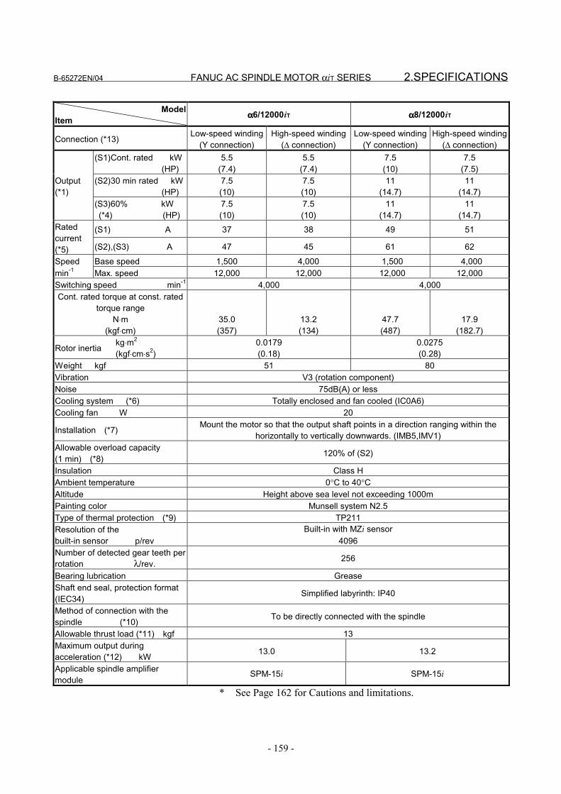
B-65272EN/04 FANUC AC SPINDLE MOTOR αiT SERIES 2.SPECIFICATIONS
- 159 -
ModelItem αααα6/12000iT αααα8/12000iT
Connection (*13) Low-speed winding(Y connection)
High-speed winding(∆ connection)
Low-speed winding(Y connection)
High-speed winding(∆ connection)
(S1)Cont. rated kW (HP)
5.5(7.4)
5.5(7.4)
7.5(10)
7.5(7.5)
(S2)30 min rated kW (HP)
7.5(10)
7.5(10)
11(14.7)
11(14.7)
Output(*1)
(S3)60% kW (*4) (HP)
7.5(10)
7.5(10)
11(14.7)
11(14.7)
(S1) A 37 38 49 51Ratedcurrent(*5) (S2),(S3) A 47 45 61 62
Speed Base speed 1,500 4,000 1,500 4,000min-1 Max. speed 12,000 12,000 12,000 12,000Switching speed min-1 4,000 4,000Cont. rated torque at const. rated
torque rangeN⋅m
(kgf⋅cm)35.0(357)
13.2(134)
47.7(487)
17.9(182.7)
Rotor inertia kg⋅m2
(kgf⋅cm⋅s2)0.0179(0.18)
0.0275(0.28)
Weight kgf 51 80Vibration V3 (rotation component)Noise 75dB(A) or lessCooling system (*6) Totally enclosed and fan cooled (IC0A6)Cooling fan W 20
Installation (*7) Mount the motor so that the output shaft points in a direction ranging within thehorizontally to vertically downwards. (IMB5,IMV1)
Allowable overload capacity(1 min) (*8) 120% of (S2)
Insulation Class HAmbient temperature 0°C to 40°CAltitude Height above sea level not exceeding 1000mPainting color Munsell system N2.5Type of thermal protection (*9) TP211Resolution of thebuilt-in sensor p/rev
Built-in with MZi sensor4096
Number of detected gear teeth perrotation λ/rev. 256
Bearing lubrication GreaseShaft end seal, protection format(IEC34) Simplified labyrinth: IP40
Method of connection with thespindle (*10) To be directly connected with the spindle
Allowable thrust load (*11) kgf 13Maximum output duringacceleration (*12) kW 13.0 13.2
Applicable spindle amplifiermodule
SPM-15i SPM-15i
* See Page 162 for Cautions and limitations.
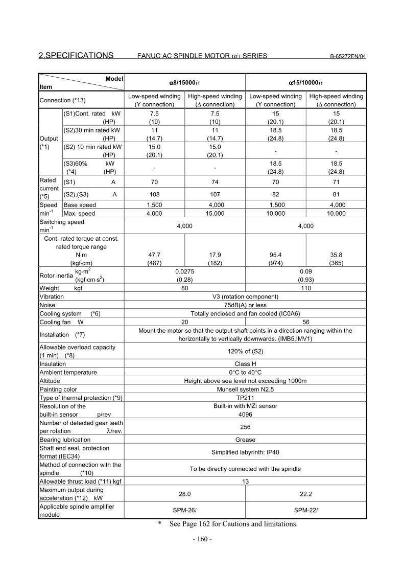
2.SPECIFICATIONS FANUC AC SPINDLE MOTOR αiT SERIES B-65272EN/04
- 160 -
ModelItem αααα8/15000iT αααα15/10000iT
Connection (*13) Low-speed winding(Y connection)
High-speed winding(∆ connection)
Low-speed winding(Y connection)
High-speed winding(∆ connection)
(S1)Cont. rated kW (HP)
7.5(10)
7.5(10)
15(20.1)
15(20.1)
(S2)30 min rated kW (HP)
11(14.7)
11(14.7)
18.5(24.8)
18.5(24.8)
(S2) 10 min rated kW (HP)
15.0(20.1)
15.0(20.1) - -
Output(*1)
(S3)60% kW (*4) (HP) - - 18.5
(24.8)18.5
(24.8)(S1) A 70 74 70 71Rated
current(*5) (S2),(S3) A 108 107 82 81
Speed Base speed 1,500 4,000 1,500 4,000min-1 Max. speed 4,000 15,000 10,000 10,000Switching speedmin-1 4,000 4,000
Cont. rated torque at const.rated torque range
N⋅m(kgf⋅cm)
47.7(487)
17.9(182)
95.4(974)
35.8(365)
Rotor inertia kg⋅m2
(kgf⋅cm⋅s2)0.0275(0.28)
0.09(0.93)
Weight kgf 80 110Vibration V3 (rotation component)Noise 75dB(A) or lessCooling system (*6) Totally enclosed and fan cooled (IC0A6)Cooling fan W 20 56
Installation (*7) Mount the motor so that the output shaft points in a direction ranging within thehorizontally to vertically downwards. (IMB5,IMV1)
Allowable overload capacity(1 min) (*8) 120% of (S2)
Insulation Class HAmbient temperature 0°C to 40°CAltitude Height above sea level not exceeding 1000mPainting color Munsell system N2.5Type of thermal protection (*9) TP211Resolution of thebuilt-in sensor p/rev
Built-in with MZi sensor4096
Number of detected gear teethper rotation λ/rev. 256
Bearing lubrication GreaseShaft end seal, protectionformat (IEC34) Simplified labyrinth: IP40
Method of connection with thespindle (*10) To be directly connected with the spindle
Allowable thrust load (*11) kgf 13Maximum output duringacceleration (*12) kW 28.0 22.2
Applicable spindle amplifiermodule
SPM-26i SPM-22i
* See Page 162 for Cautions and limitations.
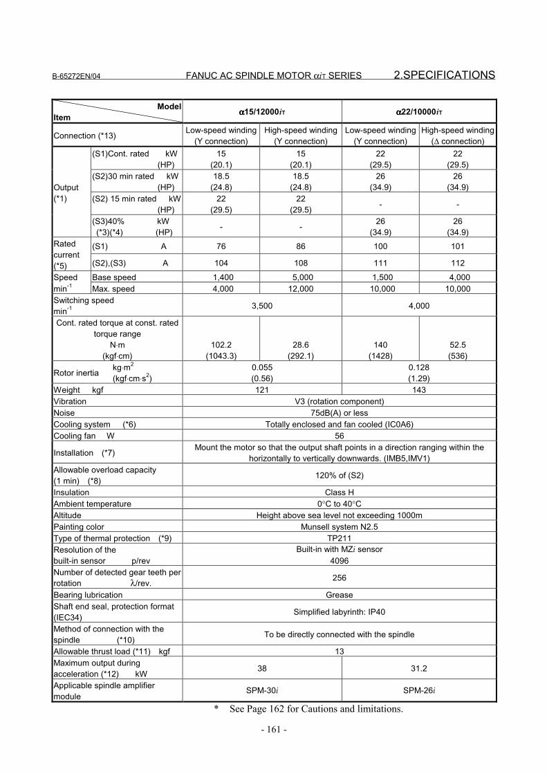
B-65272EN/04 FANUC AC SPINDLE MOTOR αiT SERIES 2.SPECIFICATIONS
- 161 -
ModelItem αααα15/12000iT αααα22/10000iT
Connection (*13) Low-speed winding(Y connection)
High-speed winding(Y connection)
Low-speed winding(Y connection)
High-speed winding(∆ connection)
(S1)Cont. rated kW (HP)
15(20.1)
15(20.1)
22(29.5)
22(29.5)
(S2)30 min rated kW (HP)
18.5(24.8)
18.5(24.8)
26(34.9)
26(34.9)
(S2) 15 min rated kW (HP)
22(29.5)
22(29.5) - -
Output(*1)
(S3)40% kW (*3)(*4) (HP) - - 26
(34.9)26
(34.9)(S1) A 76 86 100 101Rated
current(*5) (S2),(S3) A 104 108 111 112
Speed Base speed 1,400 5,000 1,500 4,000min-1 Max. speed 4,000 12,000 10,000 10,000Switching speedmin-1 3,500 4,000
Cont. rated torque at const. ratedtorque range
N⋅m(kgf⋅cm)
102.2(1043.3)
28.6(292.1)
140(1428)
52.5(536)
Rotor inertia kg⋅m2
(kgf⋅cm⋅s2)0.055(0.56)
0.128(1.29)
Weight kgf 121 143Vibration V3 (rotation component)Noise 75dB(A) or lessCooling system (*6) Totally enclosed and fan cooled (IC0A6)Cooling fan W 56
Installation (*7) Mount the motor so that the output shaft points in a direction ranging within thehorizontally to vertically downwards. (IMB5,IMV1)
Allowable overload capacity(1 min) (*8) 120% of (S2)
Insulation Class HAmbient temperature 0°C to 40°CAltitude Height above sea level not exceeding 1000mPainting color Munsell system N2.5Type of thermal protection (*9) TP211Resolution of thebuilt-in sensor p/rev
Built-in with MZi sensor4096
Number of detected gear teeth perrotation λ/rev. 256
Bearing lubrication GreaseShaft end seal, protection format(IEC34) Simplified labyrinth: IP40
Method of connection with thespindle (*10) To be directly connected with the spindle
Allowable thrust load (*11) kgf 13Maximum output duringacceleration (*12) kW 38 31.2
Applicable spindle amplifiermodule
SPM-30i SPM-26i
* See Page 162 for Cautions and limitations.
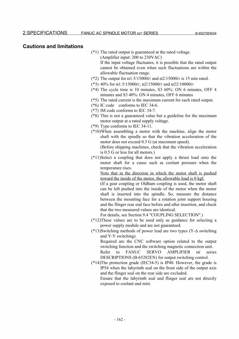
2.SPECIFICATIONS FANUC AC SPINDLE MOTOR αiT SERIES B-65272EN/04
- 162 -
Cautions and limitations(*1) The rated output is guaranteed at the rated voltage.
(Amplifier input: 200 to 230VAC)If the input voltage fluctuates, it is possible that the rated outputcannot be obtained even when such fluctuations are within theallowable fluctuation range.
(*2) The output for α1.5/15000iT and α2/15000iT is 15 min rated.(*3) 40% for α1.5/15000iT, α2/15000iT and α22/10000iT(*4) The cycle time is 10 minutes, S3 60%: ON 6 minutes, OFF 4
minutes and S3 40%: ON 4 minutes, OFF 6 minutes(*5) The rated current is the maximum current for each rated output.(*6) IC code conforms to IEC 34-6.(*7) IM code conforms to IEC 34-7.(*8) This is not a guaranteed value but a guideline for the maximum
motor output at a rated supply voltage.(*9) Type conforms to IEC 34-11.(*10)When assembling a motor with the machine, align the motor
shaft with the spindle so that the vibration acceleration of themotor does not exceed 0.5 G (at maximum speed).(Before shipping machines, check that the vibration accelerationis 0.5 G or less for all motors.)
(*11)Select a coupling that does not apply a thrust load onto themotor shaft for a cause such as coolant pressure when thetemperature rises.Note that in the direction in which the motor shaft is pushedtoward the inside of the motor, the allowable load is 0 kgf.(If a gear coupling or Oldham coupling is used, the motor shaftcan be left pushed into the inside of the motor when the motorshaft is inserted into the spindle. So, measure the distancebetween the mounting face for a rotation joint support housingand the flinger rear end face before and after insertion, and checkthat the two measured values are identical.For details, see Section 9.4 "COUPLING SELECTION".)
(*12)These values are to be used only as guidance for selecting apower supply module and are not guaranteed.
(*13)Switching methods of power lead are two types (Y-∆ switchingand Y-Y switching).Required are the CNC software option related to the outputswitching function and the switching magnetic connection unit.Refer to FANUC SERVO AMPLIFIER αi seriesDESCRIPTIONS (B-65282EN) for output switching control.
(*14)The protection grade (IEC34-5) is IP40. However, the grade isIP54 when the labyrinth seal on the front side of the output axisand the flinger seal on the rear side are excluded.Ensure that the labyrinth seal and flinger seal are not directlyexposed to coolant and mist.

B-65272EN/04 FANUC AC SPINDLE MOTOR αiT SERIES3.OUTPUT/TORQUE CHARACTERISTICS
- 163 -
3 OUTPUT/TORQUE CHARACTERISTICSReferenceCalculation for torque
Torque T can be obtained by the following equation.
T[N⋅m]=P[kW]×1000/0.1047/N[min-1]P[kW]: Motor outputN[min-1]: Motor speed
When the unit of T is [kgf⋅m],T[kgf⋅m]=P[kW]×1000/1.0269/N[min-1]

3.OUTPUT/TORQUE CHARACTERISTICSFANUC AC SPINDLE MOTOR αiT SERIES B-65272EN/04
- 164 -
3.1 MODEL αααα1.5/15000iT Applicable amplifier SPM-15i
0
0.5
1
1.5
2
2.5
0 3000 6000 9000 12000 150000
2
4
6
8
10
0 3000 6000 9000 12000 15000
1.5kW
2.2kW
0
3
6
9
12
15
0 3000 6000 9000 12000 15000
8000
12kW
[kW] [N⋅m]
Motor speed [min-1]
Continuousoperating zone
15min, S3 40%Operating zone
Motor speed [min-1]
15min, S3 40%Operating zone
Continuousoperating zone
Output Torque
Acceleration output
Motor speed [min-1]
13kW (Maximum output during acceleration)
NOTEAcceleration output is used as a measure tocalculate the acceleration or deceleration time.Acceleration output is not an assured value.
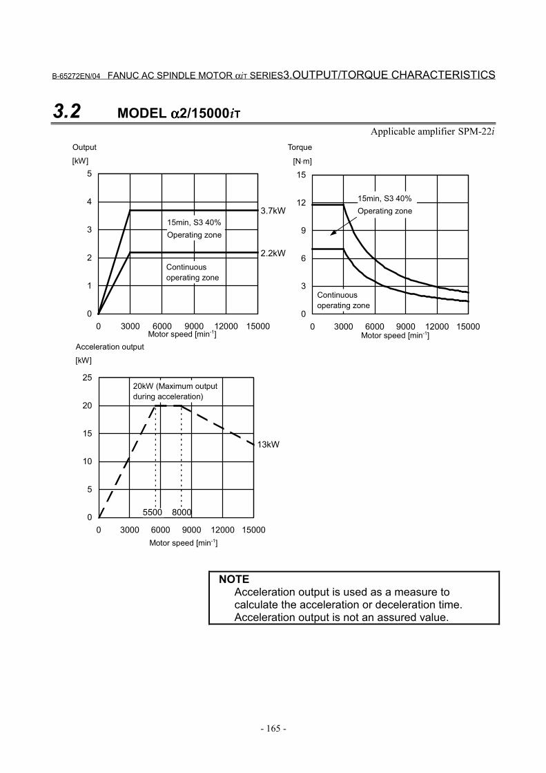
B-65272EN/04 FANUC AC SPINDLE MOTOR αiT SERIES3.OUTPUT/TORQUE CHARACTERISTICS
- 165 -
3.2 MODEL αααα2/15000iTApplicable amplifier SPM-22i
0
1
2
3
4
5
0 3000 6000 9000 12000 150000
3
6
9
12
15
0 3000 6000 9000 12000 15000
2.2kW
3.7kW
0
5
10
15
20
25
0 3000 6000 9000 12000 15000
8000
13kW
5500
[kW] [N⋅m]
Motor speed [min-1]
Continuousoperating zone
15min, S3 40%Operating zone
Motor speed [min-1]
15min, S3 40%Operating zone
Continuousoperating zone
Output Torque
[kW]Acceleration output
Motor speed [min-1]
20kW (Maximum outputduring acceleration)
NOTEAcceleration output is used as a measure tocalculate the acceleration or deceleration time.Acceleration output is not an assured value.
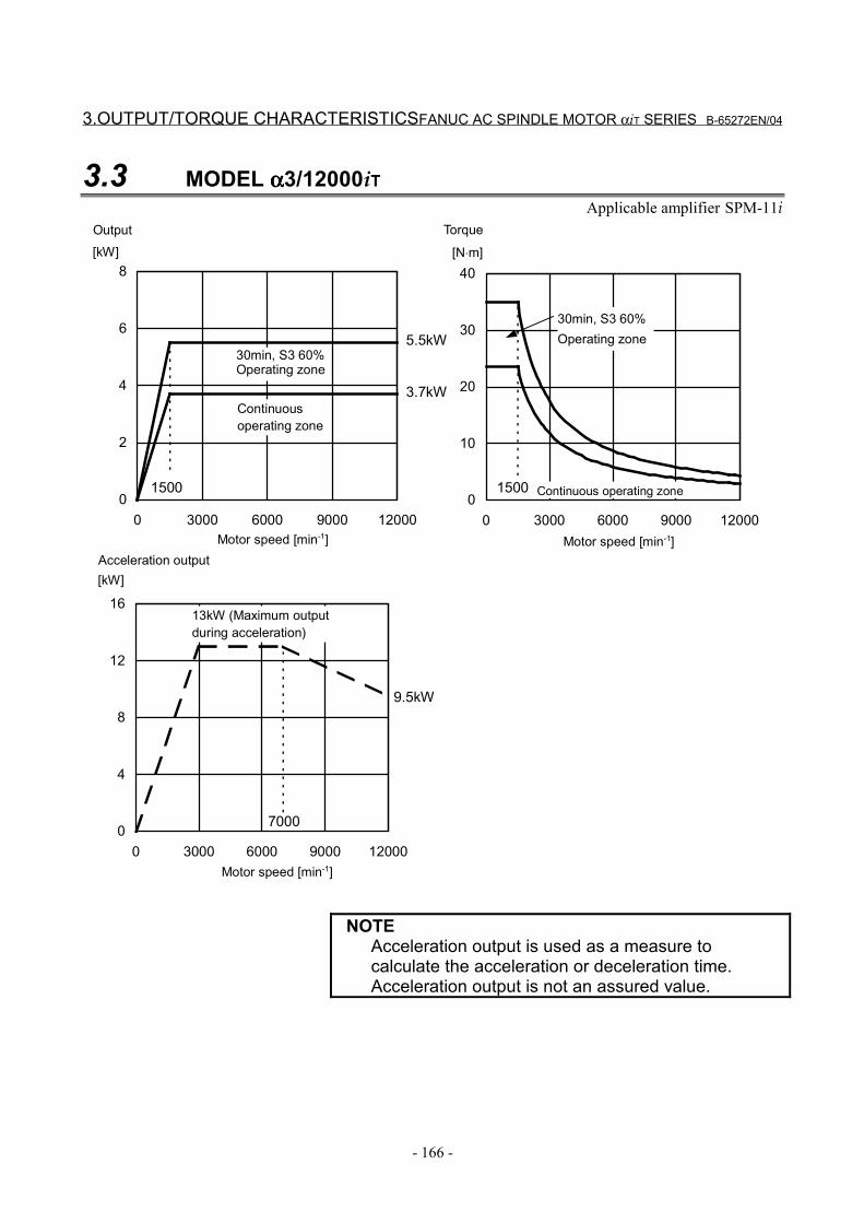
3.OUTPUT/TORQUE CHARACTERISTICSFANUC AC SPINDLE MOTOR αiT SERIES B-65272EN/04
- 166 -
3.3 MODEL αααα3/12000iTApplicable amplifier SPM-11i
0
2
4
6
8
0 3000 6000 9000 120000
10
20
30
40
0 3000 6000 9000 12000
3.7kW
5.5kW
15001500
0
4
8
12
16
0 3000 6000 9000 12000
7000
9.5kW
[kW] [N⋅m]
Motor speed [min-1]
Continuousoperating zone
30min, S3 60%Operating zone
Motor speed [min-1]
30min, S3 60%Operating zone
Continuous operating zone
Output Torque
Acceleration output
Motor speed [min-1]
13kW (Maximum outputduring acceleration)
[kW]
NOTEAcceleration output is used as a measure tocalculate the acceleration or deceleration time.Acceleration output is not an assured value.
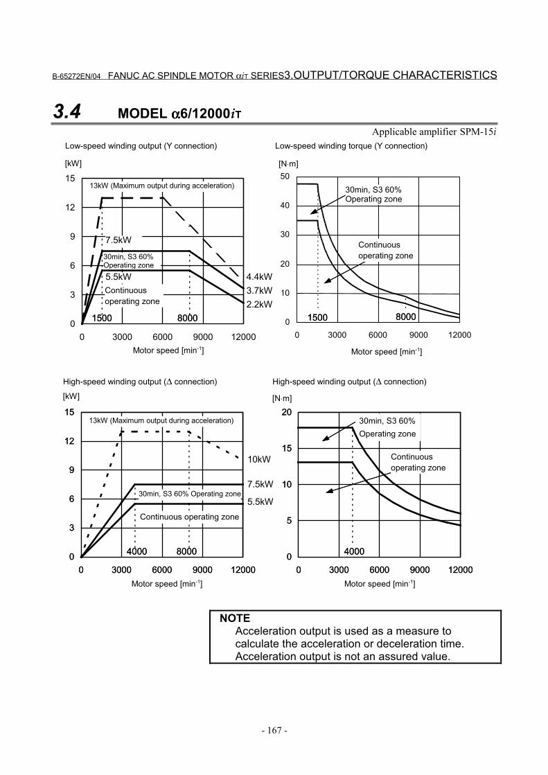
B-65272EN/04 FANUC AC SPINDLE MOTOR αiT SERIES3.OUTPUT/TORQUE CHARACTERISTICS
- 167 -
3.4 MODEL αααα6/12000iTApplicable amplifier SPM-15i
0
3
6
9
12
15
0 3000 6000 9000 12000
0
3
6
9
12
15
0 3000 6000 9000 120000
5
10
15
20
0 3000 6000 9000 120000
3
6
9
12
15
0 3000 6000 9000 12000
0
10
20
30
40
50
0 3000 6000 9000 12000
15002.2kW3.7kW4.4kW
1500
5.5kW
7.5kW
80008000
0
5
10
15
20
0 3000 6000 9000 12000
4000
5.5kW
4000
7.5kW
8000
10kW
15002.2kW3.7kW4.4kW
1500
5.5kW
7.5kW
80008000
4000
5.5kW
4000
7.5kW
8000
10kW
[kW] [N⋅m]
Motor speed [min-1]
Continuousoperating zone
30min, S3 60%Operating zone
Motor speed [min-1]
30min, S3 60%Operating zone
Continuousoperating zone
Motor speed [min-1]
[kW]
Low-speed winding output (Y connection) Low-speed winding torque (Y connection)
High-speed winding output (∆ connection) High-speed winding output (∆ connection)
13kW (Maximum output during acceleration)
13kW (Maximum output during acceleration) 30min, S3 60%Operating zone
Continuousoperating zone
[N⋅m]
Motor speed [min-1]
Continuous operating zone
30min, S3 60% Operating zone
NOTEAcceleration output is used as a measure tocalculate the acceleration or deceleration time.Acceleration output is not an assured value.
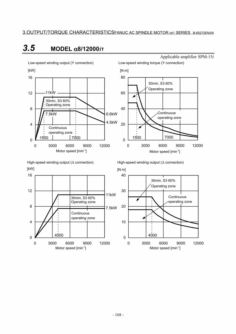
3.OUTPUT/TORQUE CHARACTERISTICSFANUC AC SPINDLE MOTOR αiT SERIES B-65272EN/04
- 168 -
3.5 MODEL αααα8/12000iTApplicable amplifier SPM-15i
0
20
40
60
80
0 3000 6000 9000 120000
4
8
12
16
0 3000 6000 9000 12000
1500
4.5kW
6.6kW
15007000
7.5kW
11kW
7000
0
10
20
30
40
0 3000 6000 9000 12000
40000
4
8
12
16
0 3000 6000 9000 12000
7.5kW
11kW
4000
[kW] [N⋅m]
Motor speed [min-1]
Continuousoperating zone
30min, S3 60%Operating zone
Motor speed [min-1]
30min, S3 60%Operating zone
Continuousoperating zone
Motor speed [min-1]
[kW]
Low-speed winding output (Y connection) Low-speed winding torque (Y connection)
High-speed winding output (∆ connection) High-speed winding output (∆ connection)
30min, S3 60%Operating zone
Continuousoperating zone
[N⋅m]
Motor speed [min-1]
Continuousoperating zone
30min, S3 60%Operating zone

B-65272EN/04 FANUC AC SPINDLE MOTOR αiT SERIES3.OUTPUT/TORQUE CHARACTERISTICS
- 169 -
3.6 MODEL αααα8/15000iTApplicable amplifier SPM-26i
0
30
60
90
120
0 1000 2000 3000 40000
5
10
15
20
0 1000 2000 3000 4000
1500
7.5kW
11kW
15kW
1500
0
10
20
30
40
0 3000 6000 9000 12000 15000
40000
6
12
18
24
30
0 3000 6000 9000 12000 15000
7.5kW
11kW
4000
15kW
[kW] [N⋅m]
Motor speed [min-1]
Continuousoperating zone
Motor speed [min-1]
Motor speed [min-1]
[kW]
Low-speed winding output (Y connection) Low-speed winding torque (Y connection)
High-speed winding output (∆ connection) High-speed winding output (∆ connection)
25kW (Maximum output during acceleration)
[N⋅m]
Motor speed [min-1]
10 minoperating zone
30 minoperating zone
Continuousoperating zone
10 minoperating zone30 minoperating zone
Continuousoperating zone
10 minoperating zone30 minoperating zone
Continuousoperating zone
10 min operating zone
30 min operating zone
NOTEAcceleration output is used as a measure tocalculate the acceleration or deceleration time.Acceleration output is not an assured value.
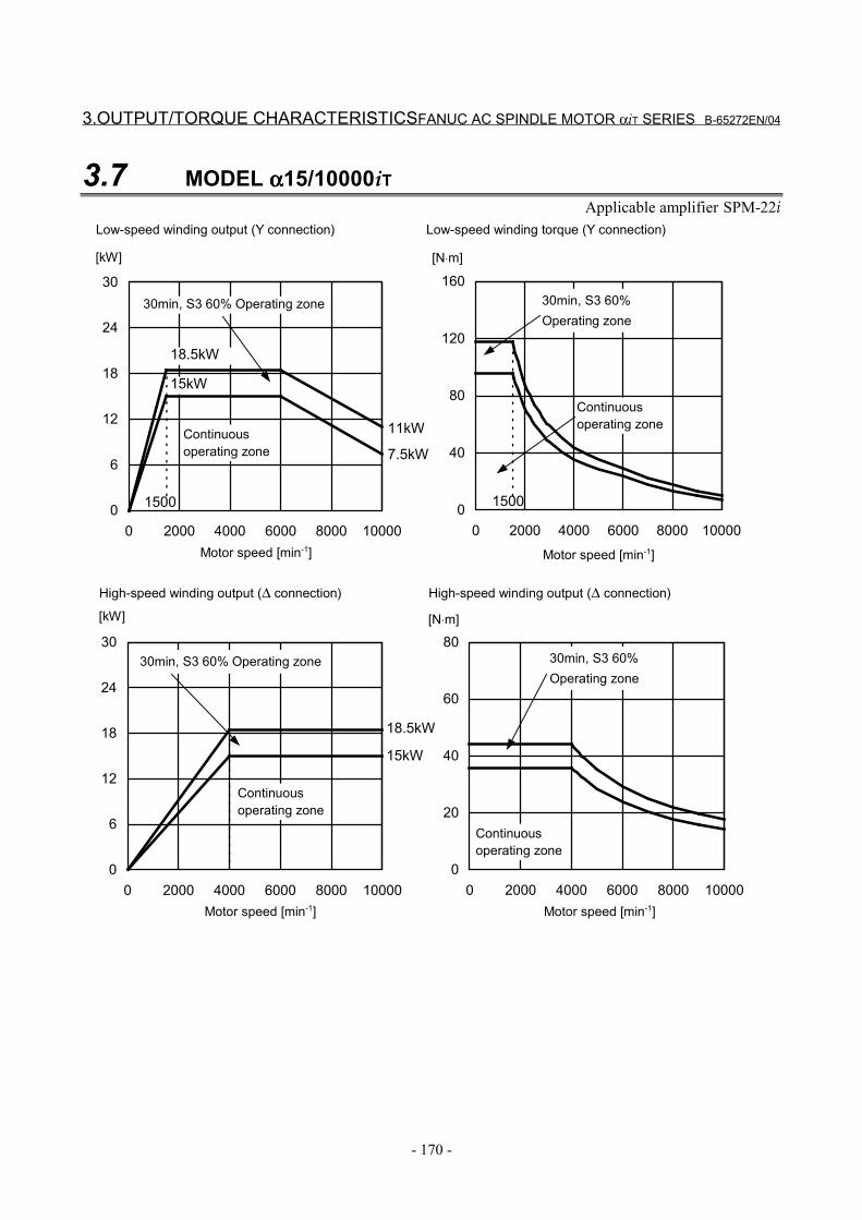
3.OUTPUT/TORQUE CHARACTERISTICSFANUC AC SPINDLE MOTOR αiT SERIES B-65272EN/04
- 170 -
3.7 MODEL αααα15/10000iTApplicable amplifier SPM-22i
0
40
80
120
160
0 2000 4000 6000 8000 100000
6
12
18
24
30
0 2000 4000 6000 8000 10000
1500
7.5kW
11kW
1500
15kW
18.5kW
0
20
40
60
80
0 2000 4000 6000 8000 100000
6
12
18
24
30
0 2000 4000 6000 8000 10000
15kW
18.5kW
[kW] [N⋅m]
Motor speed [min-1]
Continuousoperating zone
30min, S3 60% Operating zone
Motor speed [min-1]
30min, S3 60%Operating zone
Continuousoperating zone
Motor speed [min-1]
[kW]
Low-speed winding output (Y connection) Low-speed winding torque (Y connection)
High-speed winding output (∆ connection) High-speed winding output (∆ connection)
30min, S3 60%Operating zone
Continuousoperating zone
[N⋅m]
Motor speed [min-1]
30min, S3 60% Operating zone
Continuousoperating zone
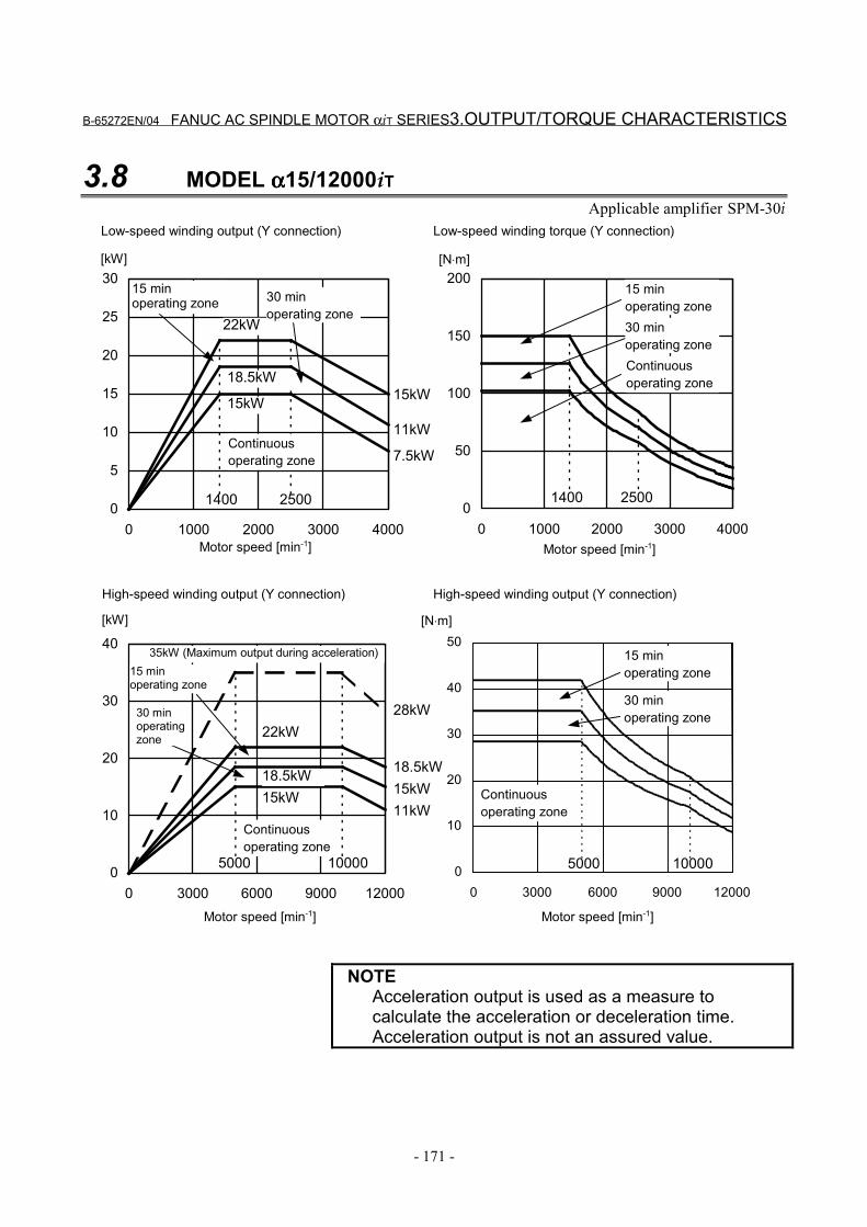
B-65272EN/04 FANUC AC SPINDLE MOTOR αiT SERIES3.OUTPUT/TORQUE CHARACTERISTICS
- 171 -
3.8 MODEL αααα15/12000iTApplicable amplifier SPM-30i
0
5
10
15
20
25
30
0 1000 2000 3000 4000
1400
7.5kW
11kW
15kW
0
50
100
150
200
0 1000 2000 3000 4000
14002500
15kW
18.5kW
22kW
2500
0
10
20
30
40
0 3000 6000 9000 12000
18.5kW
11kW
5000
15kW
10000
[N⋅m]
28kW
0
10
20
30
40
50
0 3000 6000 9000 12000
15kW18.5kW
22kW
5000 10000
[kW] [N⋅m]
Motor speed [min-1]
Continuousoperating zone
Motor speed [min-1]
Motor speed [min-1]
[kW]
Low-speed winding output (Y connection) Low-speed winding torque (Y connection)
High-speed winding output (Y connection) High-speed winding output (Y connection)
35kW (Maximum output during acceleration)
Motor speed [min-1]
30 minoperating zone
15 minoperating zone
Continuousoperating zone
30 minoperating zone
15 minoperating zone
Continuousoperating zone
15 minoperating zone
Continuousoperating zone
30 minoperating zone
15 minoperating zone
30 minoperatingzone
NOTEAcceleration output is used as a measure tocalculate the acceleration or deceleration time.Acceleration output is not an assured value.
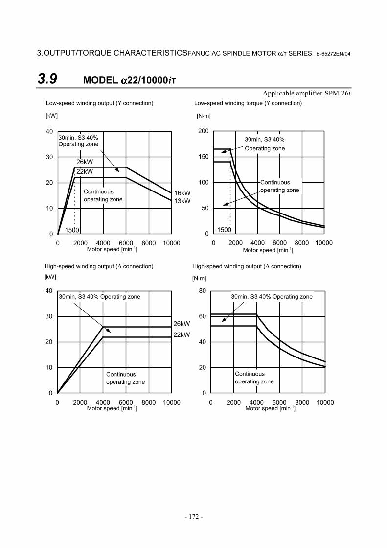
3.OUTPUT/TORQUE CHARACTERISTICSFANUC AC SPINDLE MOTOR αiT SERIES B-65272EN/04
- 172 -
3.9 MODEL αααα22/10000iTApplicable amplifier SPM-26i
0
50
100
150
200
0 2000 4000 6000 8000 100000
10
20
30
40
0 2000 4000 6000 8000 10000
1500
13kW16kW
1500
22kW26kW
0
20
40
60
80
0 2000 4000 6000 8000 100000
10
20
30
40
0 2000 4000 6000 8000 10000
22kW
26kW
[kW] [N⋅m]
Motor speed [min-1]
Continuousoperating zone
30min, S3 40%Operating zone
Motor speed [min-1]
30min, S3 40%Operating zone
Continuousoperating zone
Motor speed [min-1]
[kW]
Low-speed winding output (Y connection) Low-speed winding torque (Y connection)
High-speed winding output (∆ connection) High-speed winding output (∆ connection)
30min, S3 40% Operating zone
Continuousoperating zone
[N⋅m]
Motor speed [min-1]
Continuousoperating zone
30min, S3 40% Operating zone
B-65272EN/04 FANUC AC SPINDLE MOTOR αiT SERIES 4.CONFIGURATION AND ORDERING NUMBER
- 173 -
4 CONFIGURATION AND ORDERINGNUMBER
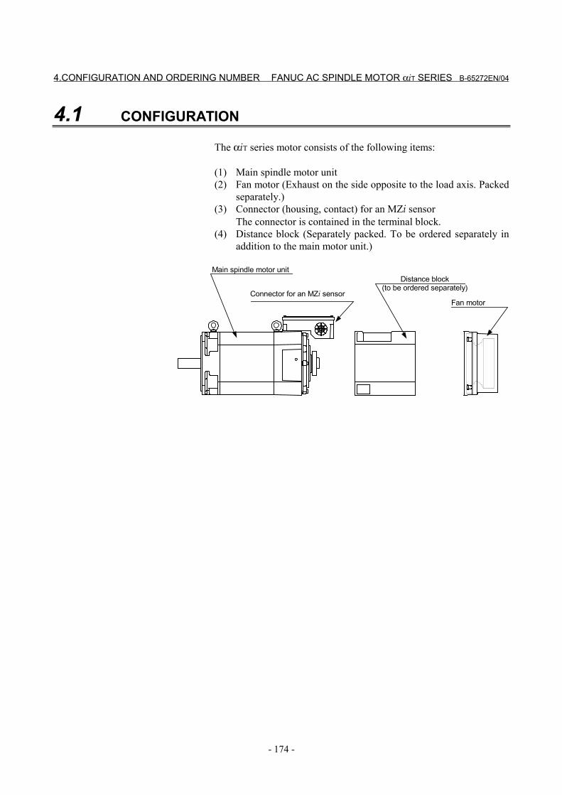
4.CONFIGURATION AND ORDERING NUMBER FANUC AC SPINDLE MOTOR αiT SERIES B-65272EN/04
- 174 -
4.1 CONFIGURATION
The αiT series motor consists of the following items:
(1) Main spindle motor unit(2) Fan motor (Exhaust on the side opposite to the load axis. Packed
separately.)(3) Connector (housing, contact) for an MZi sensor
The connector is contained in the terminal block.(4) Distance block (Separately packed. To be ordered separately in
addition to the main motor unit.)
Connector for an MZi sensor
Main spindle motor unitDistance block
(to be ordered separately)
Fan motor
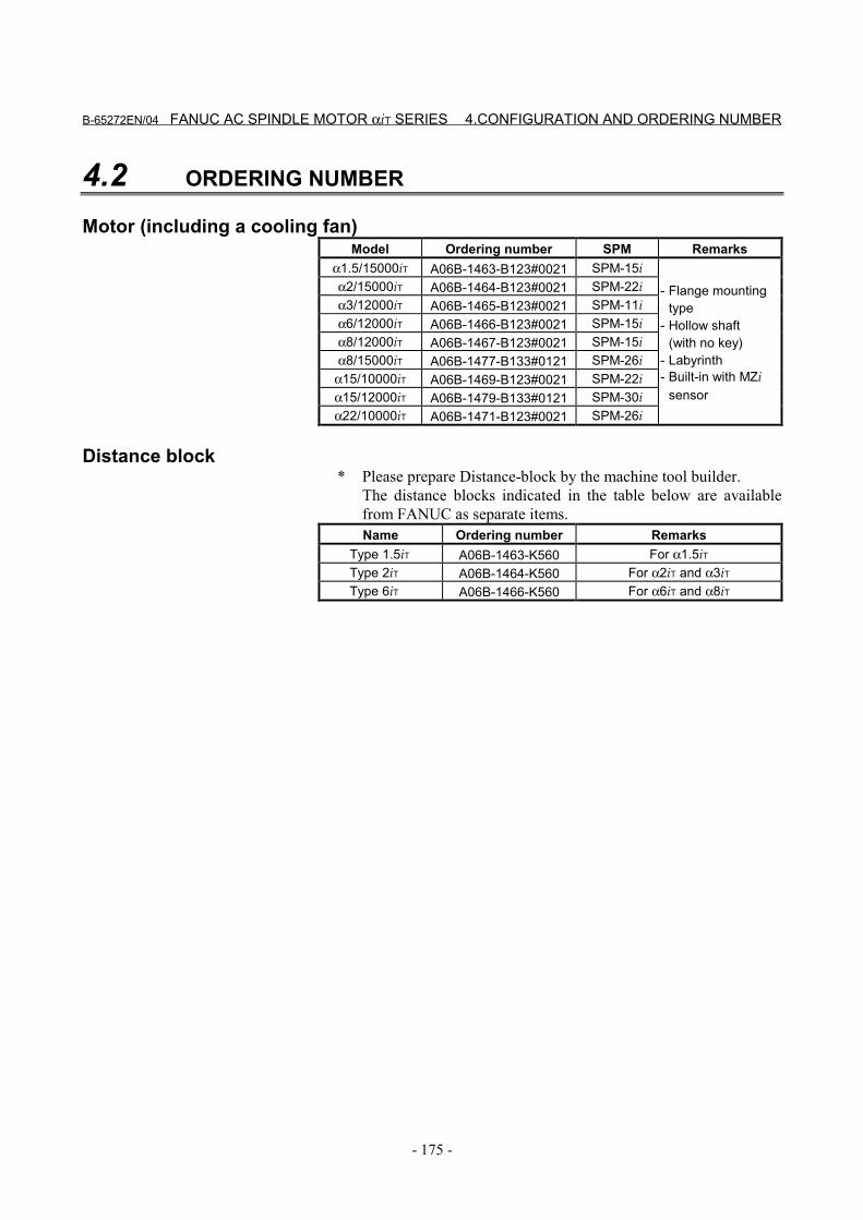
B-65272EN/04 FANUC AC SPINDLE MOTOR αiT SERIES 4.CONFIGURATION AND ORDERING NUMBER
- 175 -
4.2 ORDERING NUMBER
Motor (including a cooling fan)Model Ordering number SPM Remarks
α1.5/15000iT A06B-1463-B123#0021 SPM-15iα2/15000iT A06B-1464-B123#0021 SPM-22iα3/12000iT A06B-1465-B123#0021 SPM-11iα6/12000iT A06B-1466-B123#0021 SPM-15iα8/12000iT A06B-1467-B123#0021 SPM-15iα8/15000iT A06B-1477-B133#0121 SPM-26i
α15/10000iT A06B-1469-B123#0021 SPM-22iα15/12000iT A06B-1479-B133#0121 SPM-30iα22/10000iT A06B-1471-B123#0021 SPM-26i
- Flange mountingtype
- Hollow shaft(with no key)
- Labyrinth- Built-in with MZi
sensor
Distance block * Please prepare Distance-block by the machine tool builder.
The distance blocks indicated in the table below are availablefrom FANUC as separate items.Name Ordering number Remarks
Type 1.5iT A06B-1463-K560 For α1.5iTType 2iT A06B-1464-K560 For α2iT and α3iTType 6iT A06B-1466-K560 For α6iT and α8iT

5.CONNECTIONS FANUC AC SPINDLE MOTOR αiT SERIES B-65272EN/04
- 176 -
5 CONNECTIONS
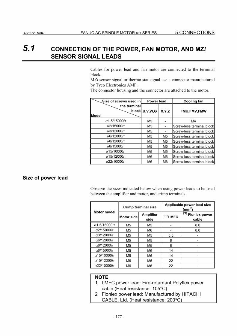
B-65272EN/04 FANUC AC SPINDLE MOTOR αiT SERIES 5.CONNECTIONS
- 177 -
5.1 CONNECTION OF THE POWER, FAN MOTOR, AND MZiSENSOR SIGNAL LEADS
Cables for power lead and fan motor are connected to the terminalblock.MZi sensor signal or thermo stat signal use a connector manufacturedby Tyco Electronics AMP.The connector housing and the connector are attached to the motor.
Power lead Cooling fanSize of screws used inthe terminal
blockModel
U,V,W,G X,Y,Z FMU,FMV,FMW
α1.5/15000iT M5 - M4α2/15000iT M5 - Screw-less terminal blockα3/12000iT M5 - Screw-less terminal blockα6/12000iT M5 M5 Screw-less terminal blockα8/12000iT M5 M5 Screw-less terminal blockα8/15000iT M5 M5 Screw-less terminal block
α15/10000iT M5 M5 Screw-less terminal blockα15/12000iT M6 M6 Screw-less terminal blockα22/10000iT M6 M6 Screw-less terminal block
Size of power lead
Observe the sizes indicated below when using power leads to be usedbetween the amplifier and motor, and crimp terminals.
Crimp terminal size Applicable power lead size(mm2)Motor model
Motor side Amplifierside
(*1) LMFC(*2) Flonlex power
cableα1.5/15000iT M5 M5 - 8.0α2/15000iT M5 M6 - 8.0α3/12000iT M5 M5 5.5 -α6/12000iT M5 M5 8 -α8/12000iT M5 M5 8 -α8/15000iT M5 M6 14 -
α15/10000iT M5 M6 14 -α15/12000iT M6 M6 22 -α22/10000iT M6 M6 22 -
NOTE1 LMFC power lead: Fire-retardant Polyflex power
cable (Heat resistance: 105°C)2 Flonlex power lead: Manufactured by HITACHI
CABLE, Ltd. (Heat resistance: 200°C)
5.CONNECTIONS FANUC AC SPINDLE MOTOR αiT SERIES B-65272EN/04
- 178 -
Cable for the fan motorFor the fan motor current value and cable specifications, refer toSection I.4.3, “FAN MOTOR CONNECTION” in this manual.
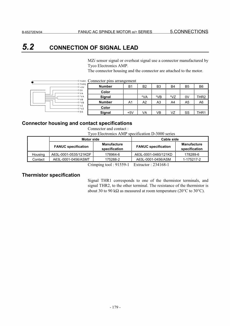
B-65272EN/04 FANUC AC SPINDLE MOTOR αiT SERIES 5.CONNECTIONS
- 179 -
5.2 CONNECTION OF SIGNAL LEAD
MZi sensor signal or overheat signal use a connector manufactured byTyco Electronics AMP.The connector housing and the connector are attached to the motor.
Connector pins arrangementNumber B1 B2 B3 B4 B5 B6
ColorSignal *VA *VB *VZ 0V THR2
Number A1 A2 A3 A4 A5 A6ColorSignal +5V VA VB VZ SS THR1
Connector housing and contact specificationsConnector and contact :Tyco Electronics AMP specification D-3000 series
Motor side Cable side
FANUC specification Manufacturespecification FANUC specification Manufacture
specificationHousing A63L-0001-0535/121KDF 178964-6 A63L-0001-0460/121KD 178289-6Contact A63L-0001-0456/ASMT 175288-2 A63L-0001-0456/ASM 1-175217-2
Crimping tool : 91559-1 Extractor : 234168-1
Thermistor specificationSignal THR1 corresponds to one of the thermistor terminals, andsignal THR2, to the other terminal. The resistance of the thermistor isabout 30 to 90 kΩ as measured at room temperature (20°C to 30°C).
TH R1TH R2+5V0VV A*V AV B*V BV Z*V ZS S
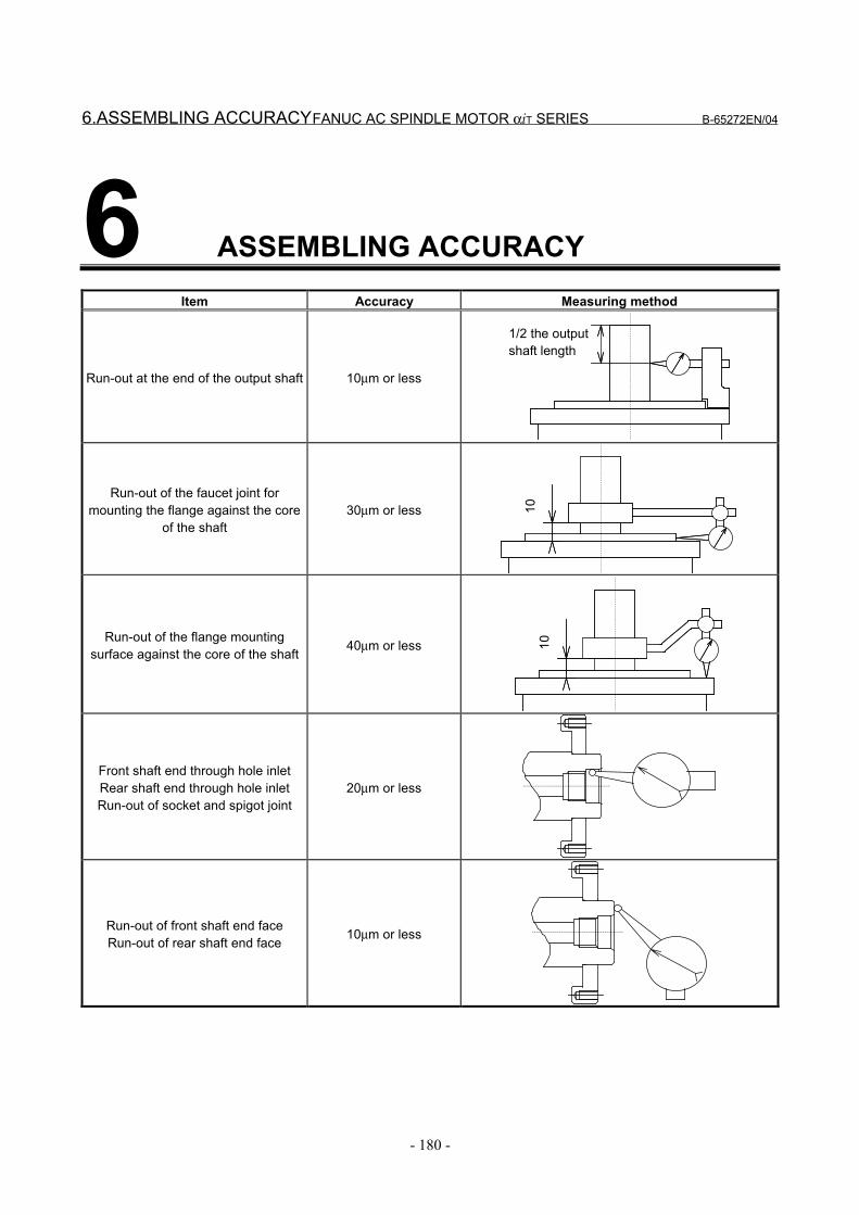
6.ASSEMBLING ACCURACY FANUC AC SPINDLE MOTOR αiT SERIES B-65272EN/04
- 180 -
6 ASSEMBLING ACCURACYItem Accuracy Measuring method
Run-out at the end of the output shaft 10µm or less
1/2 the outputshaft length
Run-out of the faucet joint formounting the flange against the core
of the shaft30µm or less 10
Run-out of the flange mountingsurface against the core of the shaft 40µm or less 10
Front shaft end through hole inletRear shaft end through hole inletRun-out of socket and spigot joint
20µm or less
Run-out of front shaft end faceRun-out of rear shaft end face 10µm or less
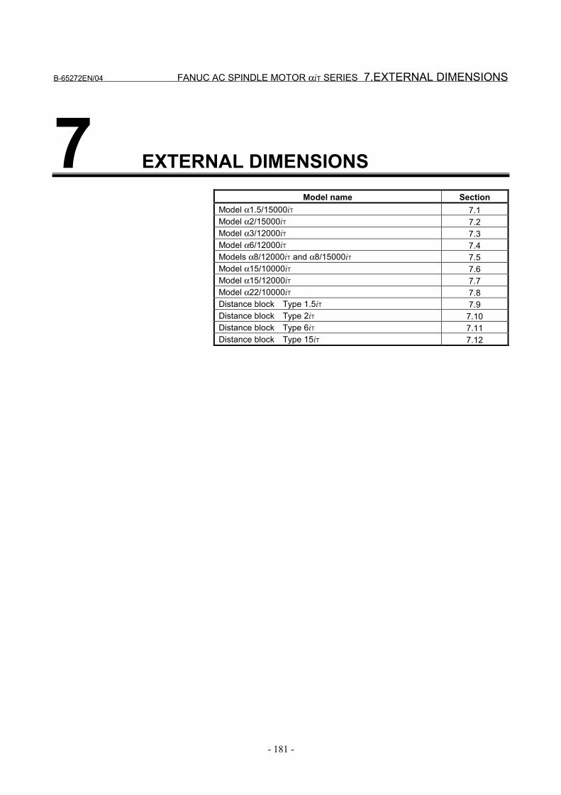
B-65272EN/04 FANUC AC SPINDLE MOTOR αiT SERIES 7.EXTERNAL DIMENSIONS
- 181 -
7 EXTERNAL DIMENSIONSModel name Section
Model α1.5/15000iT 7.1Model α2/15000iT 7.2Model α3/12000iT 7.3Model α6/12000iT 7.4Models α8/12000iT and α8/15000iT 7.5Model α15/10000iT 7.6Model α15/12000iT 7.7Model α22/10000iT 7.8Distance block Type 1.5iT 7.9Distance block Type 2iT 7.10Distance block Type 6iT 7.11Distance block Type 15iT 7.12
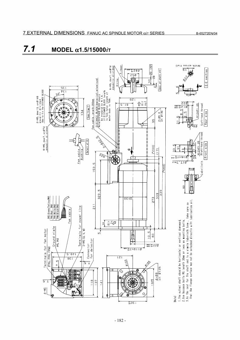
7.EXTERNAL DIMENSIONS FANUC AC SPINDLE MOTOR αiT SERIES B-65272EN/04
- 182 -
7.1 MODEL αααα1.5/15000iT
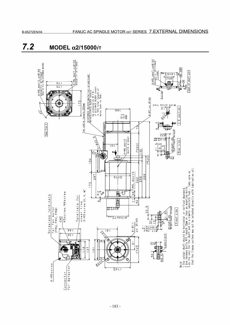
B-65272EN/04 FANUC AC SPINDLE MOTOR αiT SERIES 7.EXTERNAL DIMENSIONS
- 183 -
7.2 MODEL αααα2/15000iT
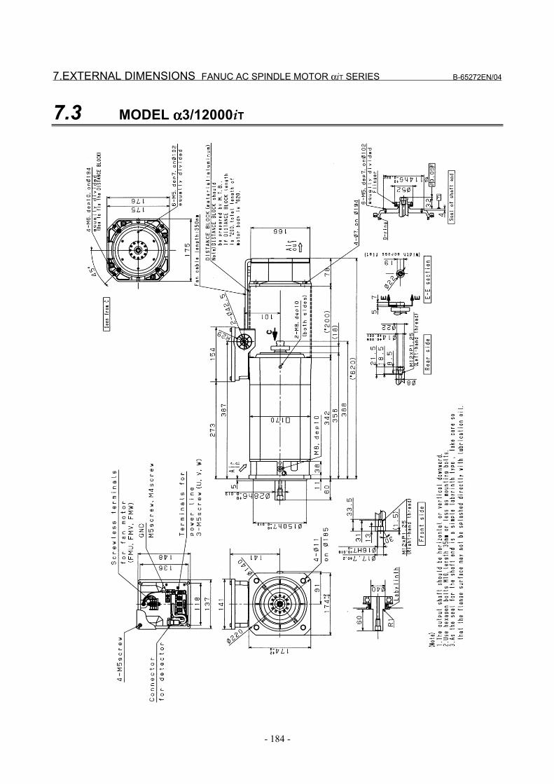
7.EXTERNAL DIMENSIONS FANUC AC SPINDLE MOTOR αiT SERIES B-65272EN/04
- 184 -
7.3 MODEL αααα3/12000iT
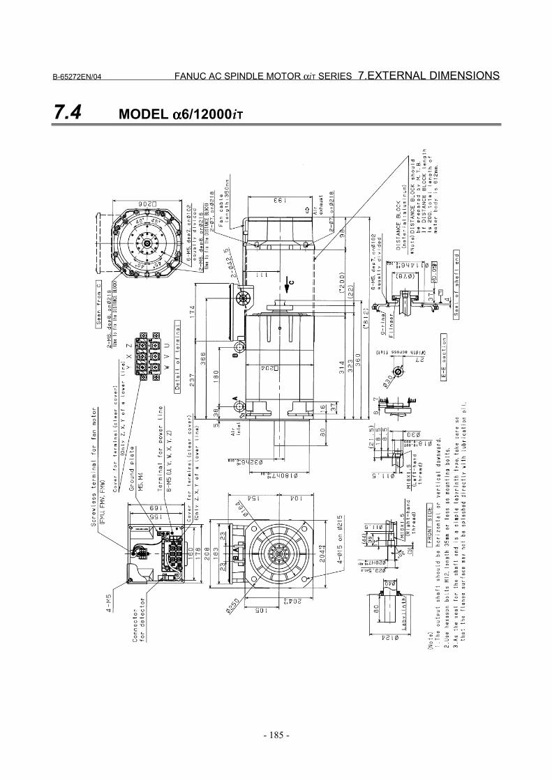
B-65272EN/04 FANUC AC SPINDLE MOTOR αiT SERIES 7.EXTERNAL DIMENSIONS
- 185 -
7.4 MODEL αααα6/12000iT
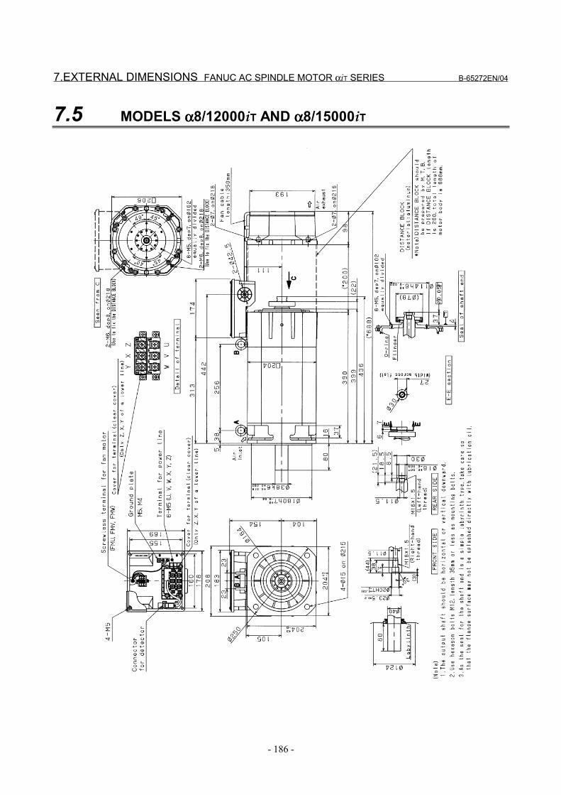
7.EXTERNAL DIMENSIONS FANUC AC SPINDLE MOTOR αiT SERIES B-65272EN/04
- 186 -
7.5 MODELS αααα8/12000iT AND αααα8/15000iT
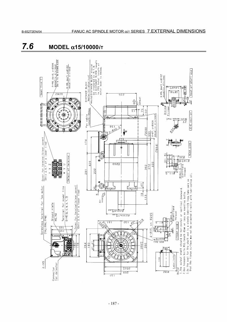
B-65272EN/04 FANUC AC SPINDLE MOTOR αiT SERIES 7.EXTERNAL DIMENSIONS
- 187 -
7.6 MODEL αααα15/10000iT
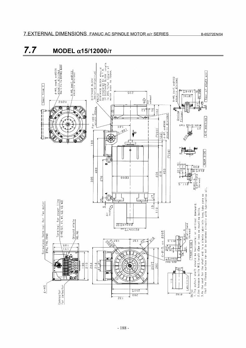
7.EXTERNAL DIMENSIONS FANUC AC SPINDLE MOTOR αiT SERIES B-65272EN/04
- 188 -
7.7 MODEL αααα15/12000iT
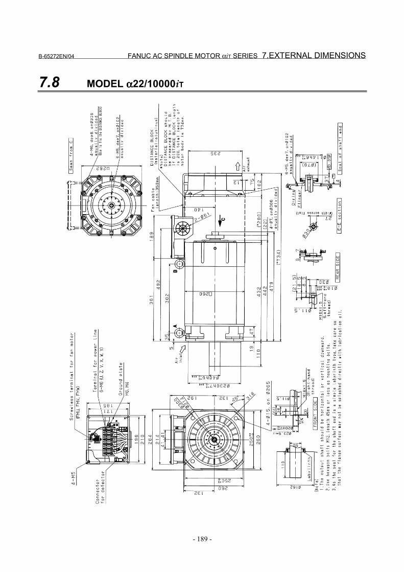
B-65272EN/04 FANUC AC SPINDLE MOTOR αiT SERIES 7.EXTERNAL DIMENSIONS
- 189 -
7.8 MODEL αααα22/10000iT
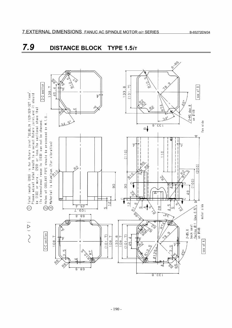
7.EXTERNAL DIMENSIONS FANUC AC SPINDLE MOTOR αiT SERIES B-65272EN/04
- 190 -
7.9 DISTANCE BLOCK TYPE 1.5iT
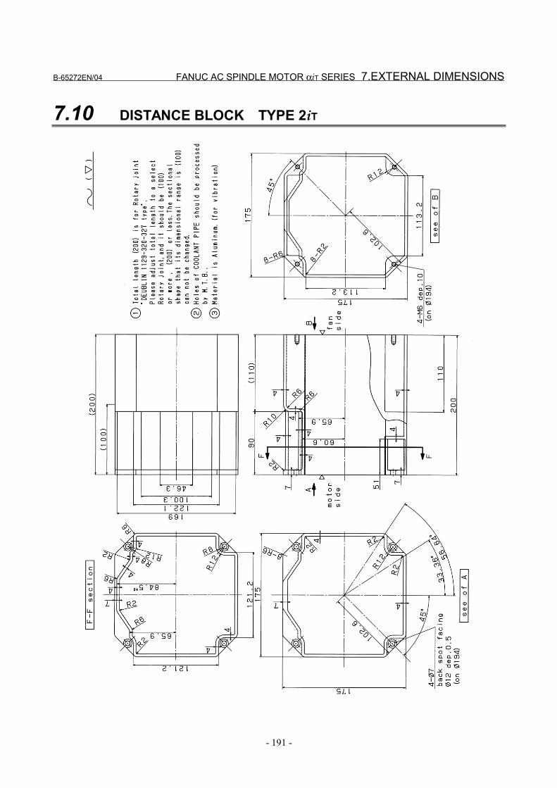
B-65272EN/04 FANUC AC SPINDLE MOTOR αiT SERIES 7.EXTERNAL DIMENSIONS
- 191 -
7.10 DISTANCE BLOCK TYPE 2iT
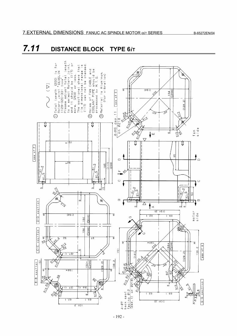
7.EXTERNAL DIMENSIONS FANUC AC SPINDLE MOTOR αiT SERIES B-65272EN/04
- 192 -
7.11 DISTANCE BLOCK TYPE 6iT
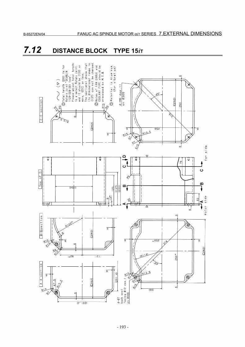
B-65272EN/04 FANUC AC SPINDLE MOTOR αiT SERIES 7.EXTERNAL DIMENSIONS
- 193 -
7.12 DISTANCE BLOCK TYPE 15iT
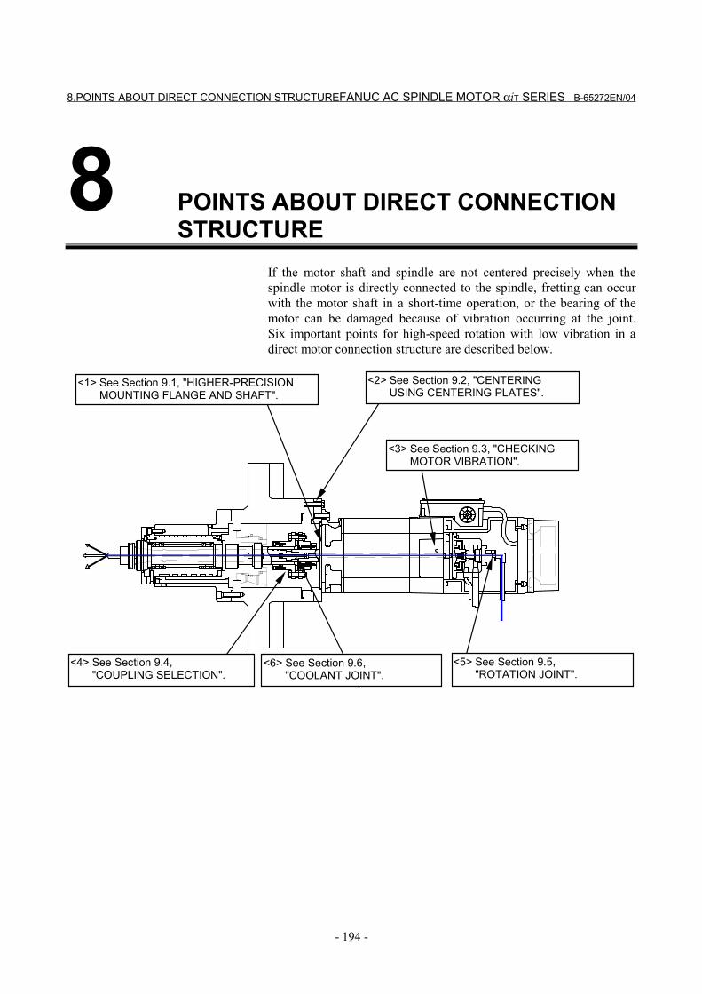
8.POINTS ABOUT DIRECT CONNECTION STRUCTUREFANUC AC SPINDLE MOTOR αiT SERIES B-65272EN/04
- 194 -
8 POINTS ABOUT DIRECT CONNECTIONSTRUCTURE
If the motor shaft and spindle are not centered precisely when thespindle motor is directly connected to the spindle, fretting can occurwith the motor shaft in a short-time operation, or the bearing of themotor can be damaged because of vibration occurring at the joint.Six important points for high-speed rotation with low vibration in adirect motor connection structure are described below.
<1> See Section 9.1, "HIGHER-PRECISIONMOUNTING FLANGE AND SHAFT".
<2> See Section 9.2, "CENTERINGUSING CENTERING PLATES".
<5> See Section 9.5,"ROTATION JOINT".
<4> See Section 9.4,"COUPLING SELECTION".
<3> See Section 9.3, "CHECKINGMOTOR VIBRATION".
<6> See Section 9.6,"COOLANT JOINT".

B-65272EN/04 FANUC AC SPINDLE MOTOR αiT SERIES 9.NOTES ON MOTOR INSTALLATION
- 195 -
9 NOTES ON MOTOR INSTALLATION
9.NOTES ON MOTOR INSTALLATION FANUC AC SPINDLE MOTOR αiT SERIES B-65272EN/04
- 196 -
9.1 HIGHER-PRECISION MOUNTING FLANGE AND SHAFT
With the αiT series, a mounting flange and shaft are assembled withhigher precision for direct connection with the spindle. For details,see Chapter 6, "ASSEMBLY PRECISION".
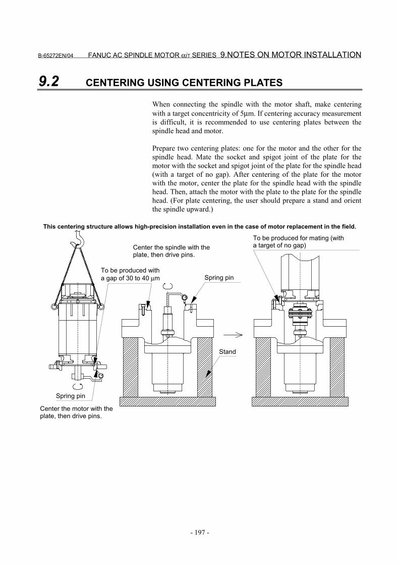
B-65272EN/04 FANUC AC SPINDLE MOTOR αiT SERIES 9.NOTES ON MOTOR INSTALLATION
- 197 -
9.2 CENTERING USING CENTERING PLATES
When connecting the spindle with the motor shaft, make centeringwith a target concentricity of 5µm. If centering accuracy measurementis difficult, it is recommended to use centering plates between thespindle head and motor.
Prepare two centering plates: one for the motor and the other for thespindle head. Mate the socket and spigot joint of the plate for themotor with the socket and spigot joint of the plate for the spindle head(with a target of no gap). After centering of the plate for the motorwith the motor, center the plate for the spindle head with the spindlehead. Then, attach the motor with the plate to the plate for the spindlehead. (For plate centering, the user should prepare a stand and orientthe spindle upward.)
This centering structure allows high-precision installation even in the case of motor replacement in the field.
Spring pin
To be produced for mating (witha target of no gap)Center the spindle with the
plate, then drive pins.
Center the motor with theplate, then drive pins.
To be produced witha gap of 30 to 40 µm
Spring pin
Stand
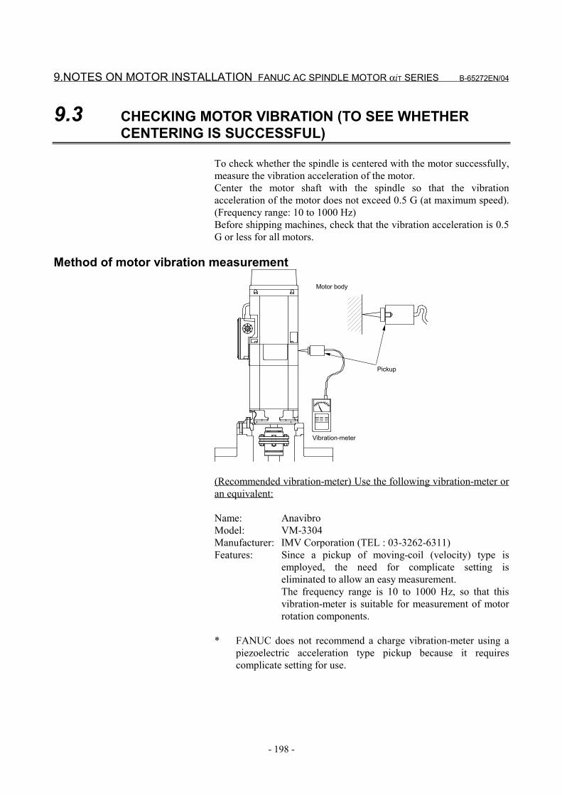
9.NOTES ON MOTOR INSTALLATION FANUC AC SPINDLE MOTOR αiT SERIES B-65272EN/04
- 198 -
9.3 CHECKING MOTOR VIBRATION (TO SEE WHETHERCENTERING IS SUCCESSFUL)
To check whether the spindle is centered with the motor successfully,measure the vibration acceleration of the motor.Center the motor shaft with the spindle so that the vibrationacceleration of the motor does not exceed 0.5 G (at maximum speed).(Frequency range: 10 to 1000 Hz)Before shipping machines, check that the vibration acceleration is 0.5G or less for all motors.
Method of motor vibration measurement
Vibration-meter
Pickup
Motor body
(Recommended vibration-meter) Use the following vibration-meter oran equivalent:
Name: AnavibroModel: VM-3304Manufacturer: IMV Corporation (TEL : 03-3262-6311)Features: Since a pickup of moving-coil (velocity) type is
employed, the need for complicate setting iseliminated to allow an easy measurement.The frequency range is 10 to 1000 Hz, so that thisvibration-meter is suitable for measurement of motorrotation components.
* FANUC does not recommend a charge vibration-meter using apiezoelectric acceleration type pickup because it requirescomplicate setting for use.
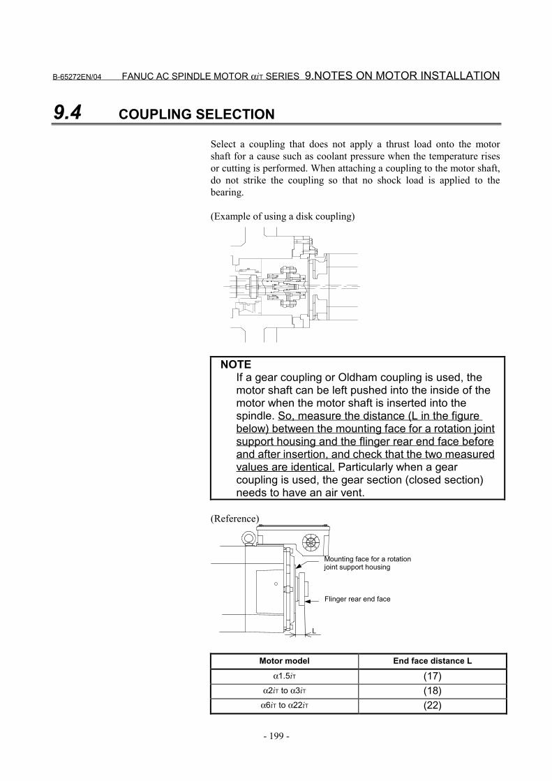
B-65272EN/04 FANUC AC SPINDLE MOTOR αiT SERIES 9.NOTES ON MOTOR INSTALLATION
- 199 -
9.4 COUPLING SELECTION
Select a coupling that does not apply a thrust load onto the motorshaft for a cause such as coolant pressure when the temperature risesor cutting is performed. When attaching a coupling to the motor shaft,do not strike the coupling so that no shock load is applied to thebearing.
(Example of using a disk coupling)
NOTEIf a gear coupling or Oldham coupling is used, themotor shaft can be left pushed into the inside of themotor when the motor shaft is inserted into thespindle. So, measure the distance (L in the figurebelow) between the mounting face for a rotation jointsupport housing and the flinger rear end face beforeand after insertion, and check that the two measuredvalues are identical. Particularly when a gearcoupling is used, the gear section (closed section)needs to have an air vent.
(Reference)
L
Mounting face for a rotationjoint support housing
Flinger rear end face
Motor model End face distance L
α1.5iT (17)α2iT to α3iT (18)
α6iT to α22iT (22)
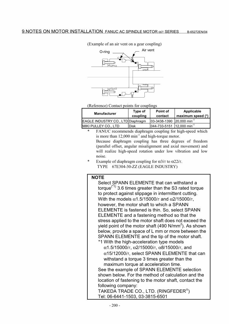
9.NOTES ON MOTOR INSTALLATION FANUC AC SPINDLE MOTOR αiT SERIES B-65272EN/04
- 200 -
(Example of an air vent on a gear coupling)Air ventO-ring
(Reference) Contact points for couplings
Manufacturer Type ofcoupling
Point ofcontact
Applicablemaximum speed (*)
EAGLE INDUSTRY CO., LTD Diaphragm 03-3438-1390 20,000 min-1
MIKI PULLEY CO., LTD Disk 044-733-5151 12,000 min-1
* FANUC recommends diaphragm coupling for high-speed whichis more than 12,000 min-1 and high-torque motor.Because diaphragm coupling has three degrees of freedom(parallel offset, angular misalignment and axial movement) andwill realize high-speed rotation under low vibration and lownoise.
* Example of diaphragm coupling for α3iT to α22iT. TYPE 67E304-30-ZZ (EAGLE INDUSTRY)
NOTESelect SPANN ELEMENTE that can withstand atorque(*1) 3.6 times greater than the S3 rated torqueto protect against slippage in intermittent cutting.With the models α1.5/15000iT and α2/15000iT,however, the motor shaft to which a SPANNELEMENTE is fastened is thin. So, select SPANNELEMENTE and a fastening method so that thestress applied to the motor shaft does not exceed theyield point of the motor shaft (490 N/mm2). As shownbelow, provide a space of L mm or more between theSPANN ELEMENTE and the tip of the motor shaft.*1 With the high-acceleration type models
α1.5/15000iT, α2/15000iT, α8/15000iT, andα15/12000iT, select SPANN ELEMENTE that canwithstand a torque 3 times greater than themaximum torque at acceleration time.
See the example of SPANN ELEMENTE selectionshown below. For the method of calculation and thelocation of fastening to the motor shaft, contact thefollowing company:TAKEDA TRADE CO., LTD. (RINGFEDER)Tel: 06-6441-1503, 03-3815-6501
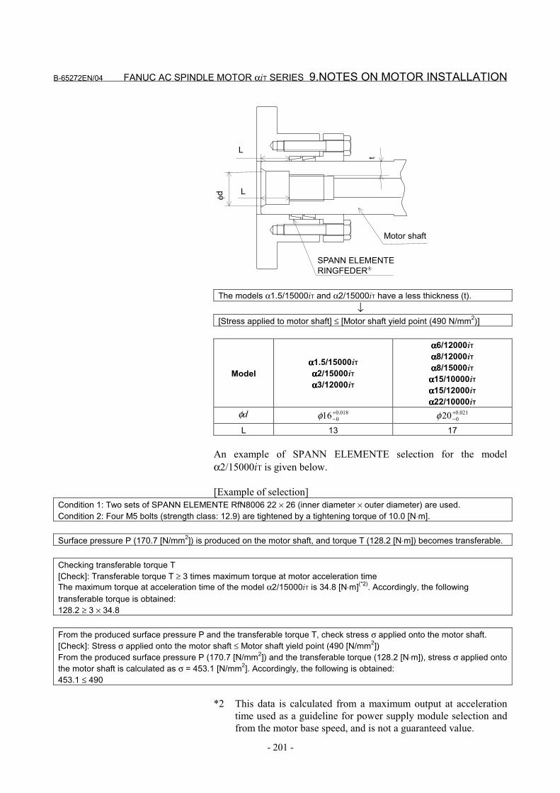
B-65272EN/04 FANUC AC SPINDLE MOTOR αiT SERIES 9.NOTES ON MOTOR INSTALLATION
- 201 -
L
L
t
φd
Motor shaft
SPANN ELEMENTERINGFEDER
The models α1.5/15000iT and α2/15000iT have a less thickness (t).↓
[Stress applied to motor shaft] ≤ [Motor shaft yield point (490 N/mm2)]
Modelαααα1.5/15000iTαααα2/15000iTαααα3/12000iT
αααα6/12000iTαααα8/12000iTαααα8/15000iT
αααα15/10000iTαααα15/12000iTαααα22/10000iT
dφ 018.0016+
−φ 021.0020+
−φL 13 17
An example of SPANN ELEMENTE selection for the modelα2/15000iT is given below.
[Example of selection]Condition 1: Two sets of SPANN ELEMENTE RfN8006 22 × 26 (inner diameter × outer diameter) are used.Condition 2: Four M5 bolts (strength class: 12.9) are tightened by a tightening torque of 10.0 [N⋅m].
Surface pressure P (170.7 [N/mm2]) is produced on the motor shaft, and torque T (128.2 [N⋅m]) becomes transferable.
Checking transferable torque T[Check]: Transferable torque T ≥ 3 times maximum torque at motor acceleration timeThe maximum torque at acceleration time of the model α2/15000iT is 34.8 [N⋅m](*2). Accordingly, the followingtransferable torque is obtained:128.2 ≥ 3 × 34.8
From the produced surface pressure P and the transferable torque T, check stress σ applied onto the motor shaft.[Check]: Stress σ applied onto the motor shaft ≤ Motor shaft yield point (490 [N/mm2])From the produced surface pressure P (170.7 [N/mm2]) and the transferable torque (128.2 [N⋅m]), stress σ applied ontothe motor shaft is calculated as σ = 453.1 [N/mm2]. Accordingly, the following is obtained:453.1 ≤ 490
*2 This data is calculated from a maximum output at accelerationtime used as a guideline for power supply module selection andfrom the motor base speed, and is not a guaranteed value.
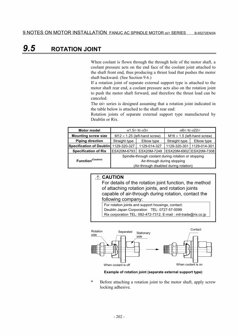
9.NOTES ON MOTOR INSTALLATION FANUC AC SPINDLE MOTOR αiT SERIES B-65272EN/04
- 202 -
9.5 ROTATION JOINT
When coolant is flown through the through hole of the motor shaft, acoolant pressure acts on the end face of the coolant joint attached tothe shaft front end, thus producing a thrust load that pushes the motorshaft backward. (See Section 9.6.)If a rotation joint of separate external support type is attached to themotor shaft rear end, a coolant pressure acts also on the rotation jointto push the motor shaft forward, and therefore the thrust load can becanceled.The αiT series is designed assuming that a rotation joint indicated inthe table below is attached to the shaft rear end:Rotation joints of separate external support type manufactured byDeublin or Rix.
Motor model α1.5iT to α3iT α6iT to α22iTMounting screw size M12 × 1.25 (left-hand screw) M16 × 1.5 (left-hand screw)
Piping direction Straight type Elbow type Straight type Elbow typeSpecification of Deublin 1129-320-327 1129-014-327 1129-320-301 1129-014-301
Specification of Rix ESX20M-6793 ESX20M-7248 ESX20M-6902 ESX20M-7308
Function(Caution)Spindle-through coolant during rotation or stopping
Air-through during stopping(Air-through disabled during rotation)
CAUTIONFor details of the rotation joint function, the methodof attaching rotation joints, and rotation jointscapable of air-through during rotation, contact thefollowing company:
For rotation joints and support housings, contact:Deublin Japan Corporation TEL: 0727-57-0099Rix corporation TEL: 092-472-7312, E-mail : [email protected]
Rotationside
Separated Stationaryside
Contact
When coolant is off When coolant is on
Example of rotation joint (separate external support type)
* Before attaching a rotation joint to the motor shaft, apply screwlocking adhesive.
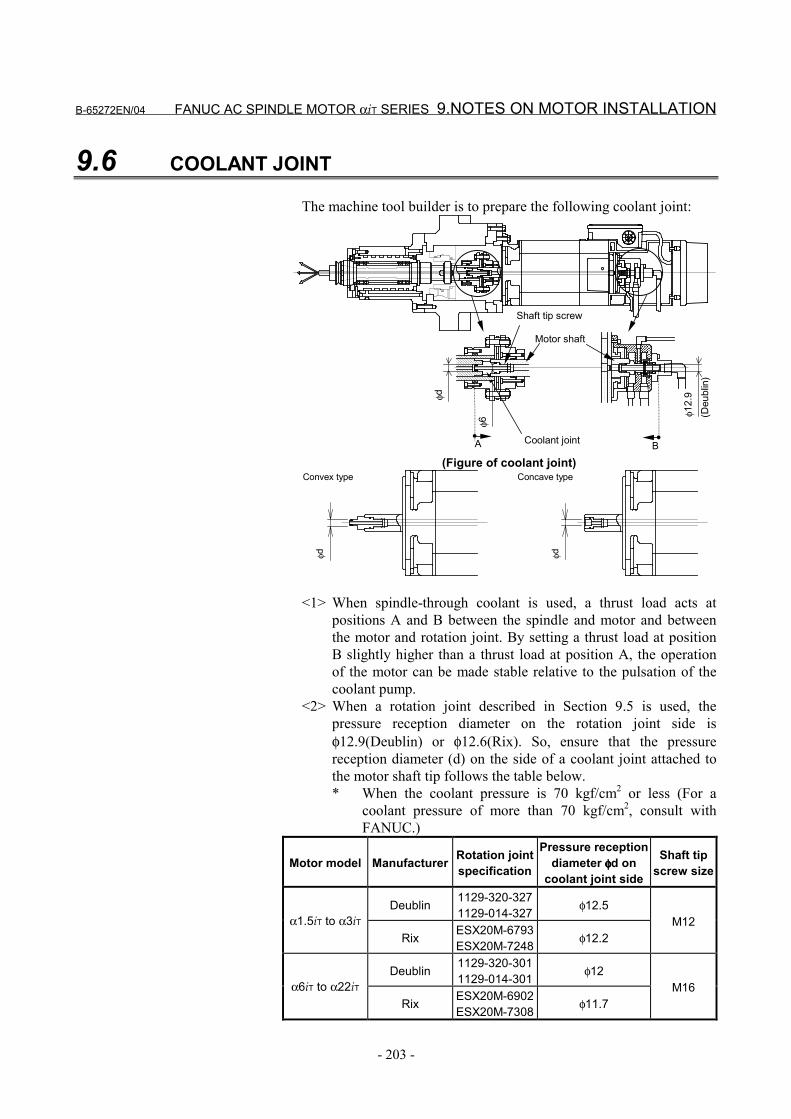
B-65272EN/04 FANUC AC SPINDLE MOTOR αiT SERIES 9.NOTES ON MOTOR INSTALLATION
- 203 -
9.6 COOLANT JOINT
The machine tool builder is to prepare the following coolant joint:
(Deu
blin
)φ1
2.9
φ6
φdA B
Shaft tip screw
Motor shaft
Coolant joint
(Figure of coolant joint)
φdφd
Convex type Concave type
<1> When spindle-through coolant is used, a thrust load acts atpositions A and B between the spindle and motor and betweenthe motor and rotation joint. By setting a thrust load at positionB slightly higher than a thrust load at position A, the operationof the motor can be made stable relative to the pulsation of thecoolant pump.
<2> When a rotation joint described in Section 9.5 is used, thepressure reception diameter on the rotation joint side isφ12.9(Deublin) or φ12.6(Rix). So, ensure that the pressurereception diameter (d) on the side of a coolant joint attached tothe motor shaft tip follows the table below.* When the coolant pressure is 70 kgf/cm2 or less (For a
coolant pressure of more than 70 kgf/cm2, consult withFANUC.)
Motor model Manufacturer Rotation jointspecification
Pressure receptiondiameter φφφφd on
coolant joint side
Shaft tipscrew size
Deublin 1129-320-3271129-014-327 φ12.5
α1.5iT to α3iTRix ESX20M-6793
ESX20M-7248 φ12.2M12
Deublin 1129-320-3011129-014-301 φ12
α6iT to α22iTRix ESX20M-6902
ESX20M-7308 φ11.7M16
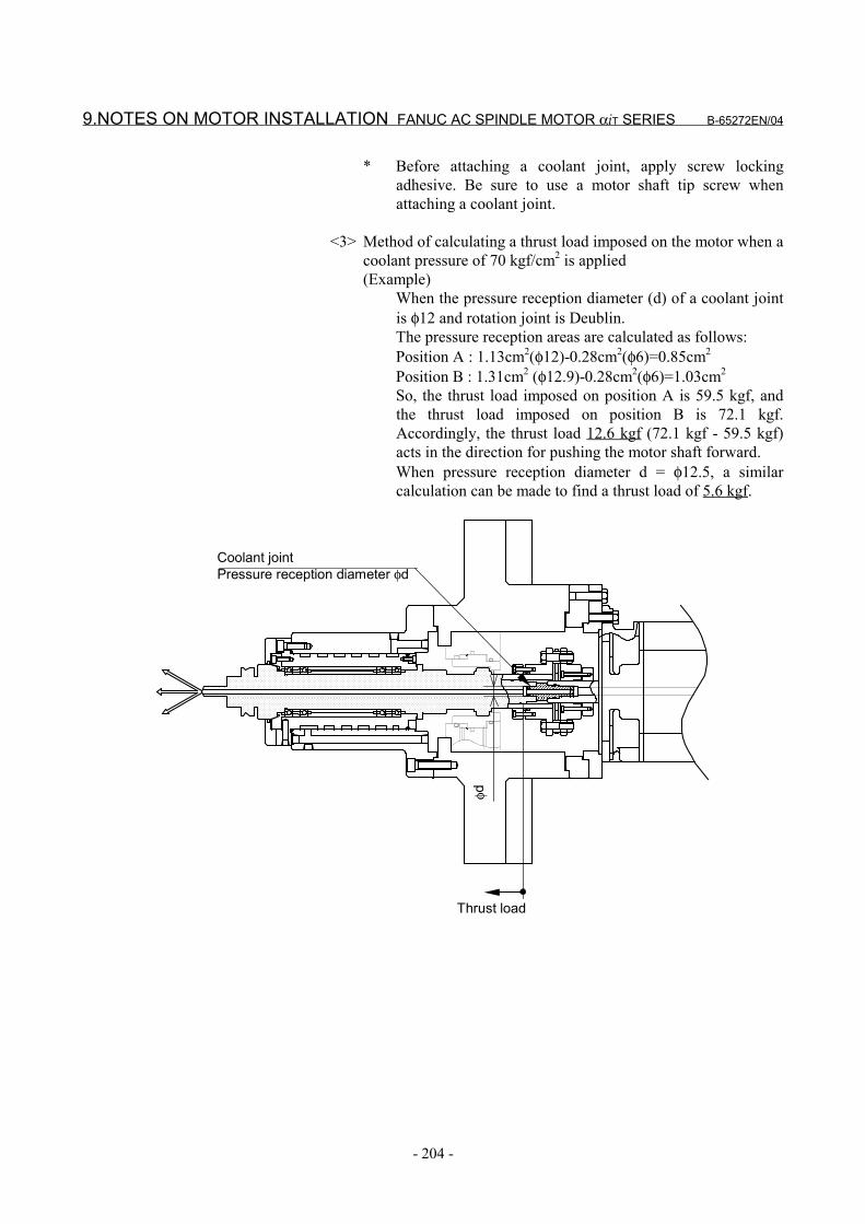
9.NOTES ON MOTOR INSTALLATION FANUC AC SPINDLE MOTOR αiT SERIES B-65272EN/04
- 204 -
* Before attaching a coolant joint, apply screw lockingadhesive. Be sure to use a motor shaft tip screw whenattaching a coolant joint.
<3> Method of calculating a thrust load imposed on the motor when acoolant pressure of 70 kgf/cm2 is applied(Example)
When the pressure reception diameter (d) of a coolant jointis φ12 and rotation joint is Deublin.The pressure reception areas are calculated as follows:Position A : 1.13cm2(φ12)-0.28cm2(φ6)=0.85cm2
Position B : 1.31cm2 (φ12.9)-0.28cm2(φ6)=1.03cm2
So, the thrust load imposed on position A is 59.5 kgf, andthe thrust load imposed on position B is 72.1 kgf.Accordingly, the thrust load 12.6 kgf (72.1 kgf - 59.5 kgf)acts in the direction for pushing the motor shaft forward.When pressure reception diameter d = φ12.5, a similarcalculation can be made to find a thrust load of 5.6 kgf.
Thrust load
Coolant jointPressure reception diameter φd
φd
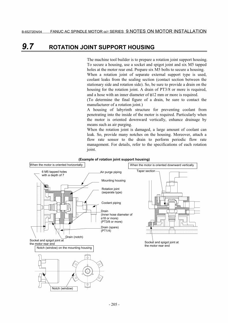
B-65272EN/04 FANUC AC SPINDLE MOTOR αiT SERIES 9.NOTES ON MOTOR INSTALLATION
- 205 -
9.7 ROTATION JOINT SUPPORT HOUSING
The machine tool builder is to prepare a rotation joint support housing.To secure a housing, use a socket and spigot joint and six M5 tappedholes at the motor rear end. Prepare six M5 bolts to secure a housing.When a rotation joint of separate external support type is used,coolant leaks from the sealing section (contact section between thestationary side and rotation side). So, be sure to provide a drain on thehousing for the rotation joint. A drain of PT3/8 or more is required,and a hose with an inner diameter of φ12 mm or more is required.(To determine the final figure of a drain, be sure to contact themanufacturer of a rotation joint.)A housing of labyrinth structure for preventing coolant frompenetrating into the inside of the motor is required. Particularly whenthe motor is oriented downward vertically, enhance drainage bymeans such as air purging.When the rotation joint is damaged, a large amount of coolant canleak. So, provide many notches on the housing. Moreover, attach aflow rate sensor to the drain to perform periodic flow ratemanagement. For details, refer to the specifications of each rotationjoint.
(Example of rotation joint support housing)
Taper section
Socket and spigot joint atthe motor rear end
When the motor is oriented downward vertically
6 M5 tapped holeswith a depth of 7
Air purge piping
Mounting housing
Coolant piping
Rotation joint(separate type)
Drain(Inner hose diameter ofφ18 or more)(PT3/8 or more)
Socket and spigot joint atthe motor rear end
Drain (notch)
Drain (spare)(PT1/4)
When the motor is oriented horizontally
Notch (window)
Notch (window) on the mounting housing

V. FANUC AC SPINDLE MOTOR ααααiL SERIES

B-65272EN/04 FANUC AC SPINDLE MOTOR αiL SERIES 1.GENERAL
- 209 -
1 GENERALThe FANUC AC spindle motor αiL series is liquid-cooled motors.They feature low temperature rise, high-speed, high torque at lowspeed, and low vibration.Coupling an αiL series motor directly to the spindle of a machiningcenter makes it possible to realize gear-less, high-precision operation.The motor shaft has a through hole, through which center-throughcoolant can be passed.
Features(1) Thermal conduction to the spindle head and heat radiation to the
machine column are reduced by cooling the front flange andmotor case with a unique conduit structure (granted Japanesepatent No. 2105-445 and US patent No. 5,084,642).
(2) A high torque at low rotation speed is realized by achievinghigh-efficient cooling based on liquid coolant and employing anoutput switching function (Y-Y switching).
(3) High-speed rotation is supported with grease-based lubrication.
(4) A vibration class of V3 (rotation component) is attained by strictrotor balance adjustments.
(5) The motor shaft is provided with a through hole for center-through coolant.
(6) The MZi sensor signal incorporated in the motor can be used inperforming orientation and rigid tapping, so there is no need tomount a detector on the machine tool.
• See descriptions about the αiT series for the features of thespindle coupled directly to the motor, the points of the directcoupling structure, and cautions for mounting the motor.

2.SPECIFICATIONS FANUC AC SPINDLE MOTOR αiL SERIES B-65272EN/04
- 210 -
2 SPECIFICATIONS
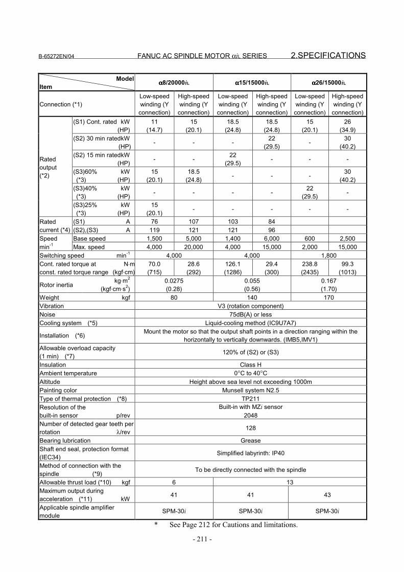
B-65272EN/04 FANUC AC SPINDLE MOTOR αiL SERIES 2.SPECIFICATIONS
- 211 -
ModelItem αααα8/20000iL αααα15/15000iL αααα26/15000iL
Connection (*1)Low-speedwinding (Y
connection)
High-speedwinding (Y
connection)
Low-speedwinding (Y
connection)
High-speedwinding (Yconnection)
Low-speedwinding (Y
connection)
High-speedwinding (Yconnection)
(S1) Cont. rated kW(HP)
11(14.7)
15(20.1)
18.5(24.8)
18.5(24.8)
15(20.1)
26(34.9)
(S2) 30 min ratedkW (HP) - - - 22
(29.5) - 30(40.2)
(S2) 15 min ratedkW(HP) - - 22
(29.5) - - -
(S3)60% kW (*3) (HP)
15(20.1)
18.5(24.8) - - - 30
(40.2)(S3)40% kW (*3) (HP) - - - - 22
(29.5) -
Ratedoutput(*2)
(S3)25% kW (*3) (HP)
15(20.1) - - - - -
(S1) A 76 107 103 84Ratedcurrent (*4) (S2),(S3) A 119 121 121 96Speed Base speed 1,500 5,000 1,400 6,000 600 2,500min-1 Max. speed 4,000 20,000 4,000 15,000 2,000 15,000Switching speed min-1 4,000 4,000 1,800Cont. rated torque atconst. rated torque range
N⋅m(kgf⋅cm)
70.0(715)
28.6(292)
126.1(1286)
29.4(300)
238.8(2435)
99.3(1013)
Rotor inertiakg⋅m2
(kgf⋅cm⋅s2)0.0275(0.28)
0.055(0.56)
0.167(1.70)
Weight kgf 80 140 170Vibration V3 (rotation component)Noise 75dB(A) or lessCooling system (*5) Liquid-cooling method (IC9U7A7)
Installation (*6) Mount the motor so that the output shaft points in a direction ranging within thehorizontally to vertically downwards. (IMB5,IMV1)
Allowable overload capacity(1 min) (*7) 120% of (S2) or (S3)
Insulation Class HAmbient temperature 0°C to 40°CAltitude Height above sea level not exceeding 1000mPainting color Munsell system N2.5Type of thermal protection (*8) TP211Resolution of thebuilt-in sensor p/rev
Built-in with MZi sensor2048
Number of detected gear teeth perrotation λ/rev 128
Bearing lubrication GreaseShaft end seal, protection format(IEC34) Simplified labyrinth: IP40
Method of connection with thespindle (*9) To be directly connected with the spindle
Allowable thrust load (*10) kgf 6 13Maximum output duringacceleration (*11) kW 41 41 43
Applicable spindle amplifiermodule
SPM-30i SPM-30i SPM-30i
* See Page 212 for Cautions and limitations.
2.SPECIFICATIONS FANUC AC SPINDLE MOTOR αiL SERIES B-65272EN/04
- 212 -
Cautions and limitations(*1) The power wire switching method is Y-Y switching. Refer to
FANUC SERVO AMPLIFIER αi series DESCRIPTIONS (B-65282EN) for explanations about output switching control.
(*2) The rated output is guaranteed at the rated voltage.(Amplifier input: 200 to 230VAC)If the input voltage fluctuates, it is possible that the rated outputcannot be obtained even when such fluctuations are within theallowable fluctuation range.
(*3) The cycle time is 10 minutes, S3 60%: ON 6 minutes, OFF 4minutes, S3 40%: ON 4 minutes, OFF 6 minutes, S3 25%: ON2.5 minutes, OFF 7.5 minutes
(*4) The rated current is the maximum current for each rated output.(*5) IC code conforms to IEC 34-6. Apply cooling conditions
stipulated elsewhere.(*6) IM code conforms to IEC 34-7.(*7) This is not a guaranteed value but a guideline for the maximum
motor output at a rated supply voltage.(*8) Type conforms to IEC 34-11.(*9) When assembling a motor with the machine, align the motor
shaft with the spindle so that the vibration acceleration of themotor does not exceed 0.5 G (at maximum speed).(Before shipping machines, check that the vibration accelerationis 0.5 G or less for all motors.)
(*10)Select a coupling that does not apply a thrust load onto themotor shaft for a cause such as coolant pressure when thetemperature rises.Note that in the direction in which the motor shaft is pushedtoward the inside of the motor, the allowable load is 0 kgf.(If a gear coupling or Oldham coupling is used, the motor shaftcan be left pushed into the inside of the motor when the motorshaft is inserted into the spindle. So, measure the distancebetween the mounting face for a rotation joint support housingand the flinger rear end face before and after insertion, and checkthat the two measured values are identical.For details, see Section 9.4 "COUPLING SELECTION" in PartIV.)
(*11)These values are to be used only as guidance for selecting apower supply module and are not guaranteed.
(*12)The protection grade (IEC34-5) is IP40. However, the grade isIP54 when the labyrinth seal on the front side of the output axisand the flinger seal on the rear side are excluded.Ensure that the labyrinth seal and flinger seal are not directlyexposed to coolant and mist.

B-65272EN/04 FANUC AC SPINDLE MOTOR αiL SERIES 3.OUTPUT/TORQUE CHARACTERISTICS
- 213 -
3 OUTPUT/TORQUE CHARACTERISTICSReferenceCalculation for torque
Torque T can be obtained by the following equation.
T[N⋅m]=P[kW]×1000/0.1047/N[min-1]P[kW]: Motor outputN[min-1]: Motor speed
When the unit of T is [kgf⋅m],T[kgf⋅m]=P[kW]×1000/1.0269/N[min-1]
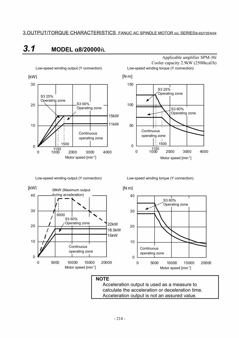
3.OUTPUT/TORQUE CHARACTERISTICS FANUC AC SPINDLE MOTOR αiL SERIES B-65272EN/04
- 214 -
3.1 MODEL αααα8/20000iLApplicable amplifier SPM-30i
Cooler capacity 2.9kW (2500kcal/h)
[kW] [N⋅m]
[N⋅m][kW]
0
10
20
30
0 1000 2000 3000 4000
1500
11kW
15kW
11500
50
100
150
0 1000 2000 3000 4000
15001150
0
10
20
30
40
0 5000 10000 15000 20000
6000
15kW18.5kW22kW
0
10
20
30
40
0 5000 10000 15000 20000
Motor speed [min-1]
Continuousoperating zone
Motor speed [min-1]
S3 25%Operating zone
Continuousoperating zone
Low-speed winding output (Y connection) Low-speed winding torque (Y connection)
S3 25%Operating zone
S3 60%Operating zone S3 60%
Operating zone
Motor speed [min-1]
Continuousoperating zone
Motor speed [min-1]
Continuousoperating zone
Low-speed winding output (Y connection) Low-speed winding torque (Y connection)
S3 60%Operating zone
38kW (Maximum outputduring acceleration)
S3 60%Operating zone
NOTEAcceleration output is used as a measure tocalculate the acceleration or deceleration time.Acceleration output is not an assured value.
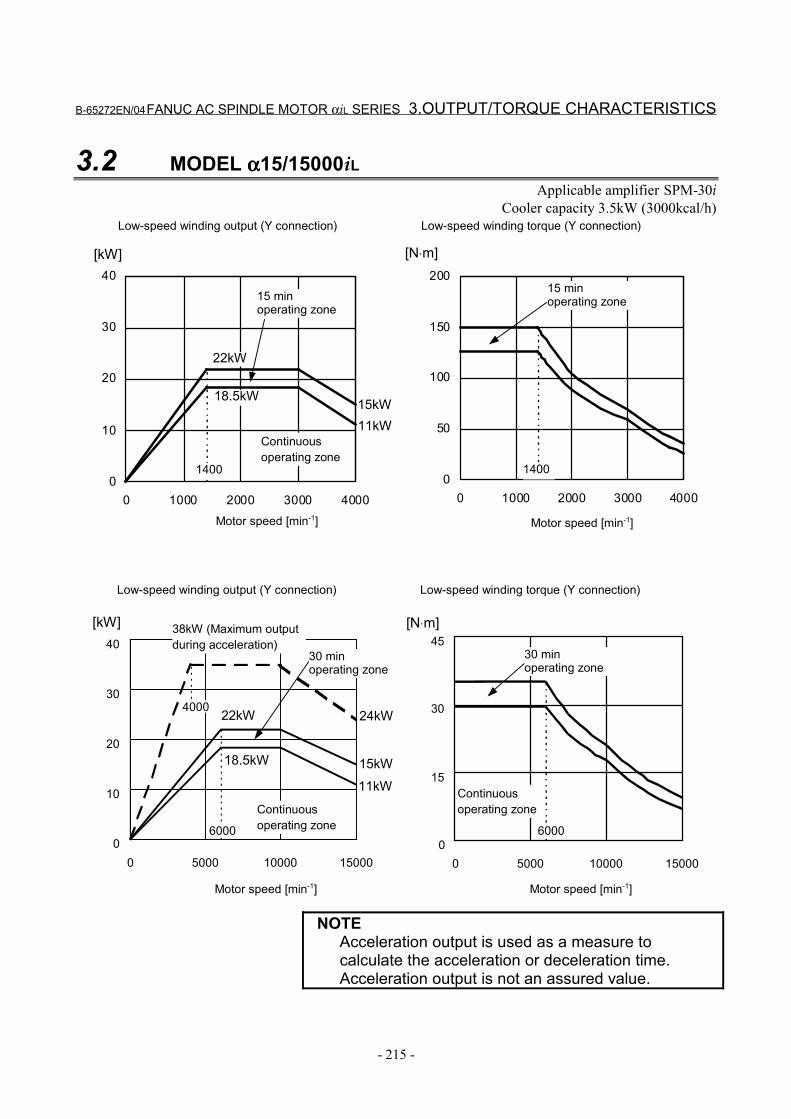
B-65272EN/04 FANUC AC SPINDLE MOTOR αiL SERIES 3.OUTPUT/TORQUE CHARACTERISTICS
- 215 -
3.2 MODEL αααα15/15000iLApplicable amplifier SPM-30i
Cooler capacity 3.5kW (3000kcal/h)
0
10
20
30
40
0 1000 2000 3000 4000
0
10
20
30
40
0 5000 10000 150000
15
30
45
0 5000 10000 15000
1400
22kW
15kW11kW
0
50
100
150
200
0 1000 2000 3000 4000
1400
6000
4000
18.5kW
22kW
11kW15kW
24kW
6000
[kW] [N⋅m]
[N⋅m][kW]
Motor speed [min-1]
Continuousoperating zone
Motor speed [min-1]
Low-speed winding output (Y connection) Low-speed winding torque (Y connection)
15 minoperating zone
Motor speed [min-1]
Continuousoperating zone
Motor speed [min-1]
Continuousoperating zone
Low-speed winding output (Y connection) Low-speed winding torque (Y connection)
38kW (Maximum outputduring acceleration)
15 minoperating zone
30 minoperating zone
30 minoperating zone
18.5kW
NOTEAcceleration output is used as a measure tocalculate the acceleration or deceleration time.Acceleration output is not an assured value.
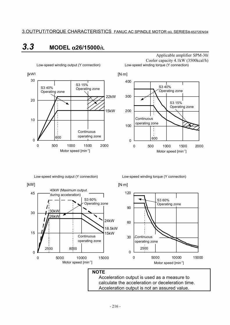
3.OUTPUT/TORQUE CHARACTERISTICS FANUC AC SPINDLE MOTOR αiL SERIES B-65272EN/04
- 216 -
3.3 MODEL αααα26/15000iLApplicable amplifier SPM-30i
Cooler capacity 4.1kW (3500kcal/h)
0
30
60
90
120
0 5000 10000 150000
15
30
45
0 5000 10000 15000
[kW] [N⋅m]
[N⋅m][kW]
0
10
20
30
0 500 1000 1500 2000
600
15kW
22kW
0
100
200
300
400
0 500 1000 1500 2000
600
2500
15kW18.5kW
26kW30kW
25008000
24kW
Motor speed [min-1]
Continuousoperating zone
Motor speed [min-1]
S3 40%Operating zone
Continuousoperating zone
Low-speed winding output (Y connection) Low-speed winding torque (Y connection)
S3 40%Operating zone
S3 15%Operating zone
S3 15%Operating zone
Motor speed [min-1]
Continuousoperating zone
Motor speed [min-1]
Continuousoperating zone
Low-speed winding output (Y connection) Low-speed winding torque (Y connection)
S3 60%Operating zone
40kW (Maximum outputduring acceleration)
S3 60%Operating zone
NOTEAcceleration output is used as a measure tocalculate the acceleration or deceleration time.Acceleration output is not an assured value.

B-65272EN/04 FANUC AC SPINDLE MOTOR αiL SERIES 4.CONNECTIONS
- 217 -
4 CONNECTIONS
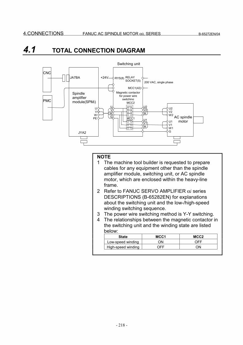
4.CONNECTIONS FANUC AC SPINDLE MOTOR αiL SERIES B-65272EN/04
- 218 -
4.1 TOTAL CONNECTION DIAGRAM
PMC
CNC
AC spindlemotor
Switching unit
Spindleamplifiermodule(SPMi)
200 VAC, single phase
RELAYSOCKET(5)
Magnetic contactorfor power wire
switching
MCC1(42)
RYS(8)JA7BA +24V
JYA2
U1V1W
U2V2W
UV
WG
UV
WPE MCC1
MCC2
U1V1W1G
U2V2W2
NOTE1 The machine tool builder is requested to prepare
cables for any equipment other than the spindleamplifier module, switching unit, or AC spindlemotor, which are enclosed within the heavy-lineframe.
2 Refer to FANUC SERVO AMPLIFIER αi seriesDESCRIPTIONS (B-65282EN) for explanationsabout the switching unit and the low-/high-speedwinding switching sequence.
3 The power wire switching method is Y-Y switching.4 The relationships between the magnetic contactor in
the switching unit and the winding state are listedbelow:
State MCC1 MCC2Low-speed winding ON OFFHigh-speed winding OFF ON
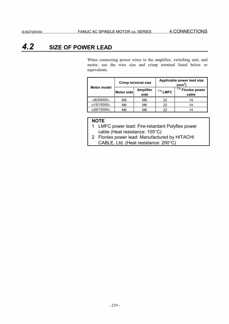
B-65272EN/04 FANUC AC SPINDLE MOTOR αiL SERIES 4.CONNECTIONS
- 219 -
4.2 SIZE OF POWER LEAD
When connecting power wires to the amplifier, switching unit, andmotor, use the wire size and crimp terminal listed below orequivalents.
Crimp terminal size Applicable power lead size(mm2)Motor model
Motor side Amplifierside
(*1) LMFC(*2) Flonlex power
cableα8/20000iL M5 M6 22 14
α15/15000iL M6 M6 22 14α26/15000iL M6 M6 22 14
NOTE1 LMFC power lead: Fire-retardant Polyflex power
cable (Heat resistance: 105°C)2 Flonlex power lead: Manufactured by HITACHI
CABLE, Ltd. (Heat resistance: 200°C)
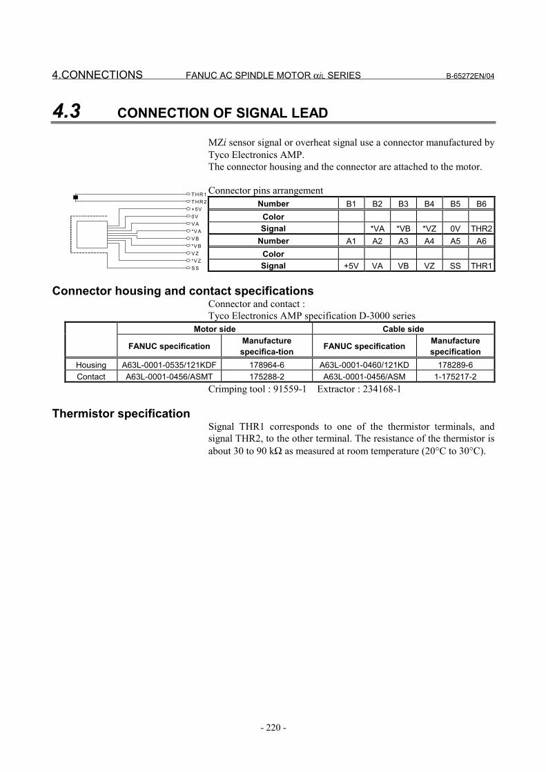
4.CONNECTIONS FANUC AC SPINDLE MOTOR αiL SERIES B-65272EN/04
- 220 -
4.3 CONNECTION OF SIGNAL LEAD
MZi sensor signal or overheat signal use a connector manufactured byTyco Electronics AMP.The connector housing and the connector are attached to the motor.
Connector pins arrangementNumber B1 B2 B3 B4 B5 B6
ColorSignal *VA *VB *VZ 0V THR2
Number A1 A2 A3 A4 A5 A6ColorSignal +5V VA VB VZ SS THR1
Connector housing and contact specificationsConnector and contact :Tyco Electronics AMP specification D-3000 series
Motor side Cable side
FANUC specification Manufacturespecifica-tion FANUC specification Manufacture
specificationHousing A63L-0001-0535/121KDF 178964-6 A63L-0001-0460/121KD 178289-6Contact A63L-0001-0456/ASMT 175288-2 A63L-0001-0456/ASM 1-175217-2
Crimping tool : 91559-1 Extractor : 234168-1
Thermistor specificationSignal THR1 corresponds to one of the thermistor terminals, andsignal THR2, to the other terminal. The resistance of the thermistor isabout 30 to 90 kΩ as measured at room temperature (20°C to 30°C).
T H R 1T H R 2+5V0VV A*V AV B*V BV Z*V ZS S
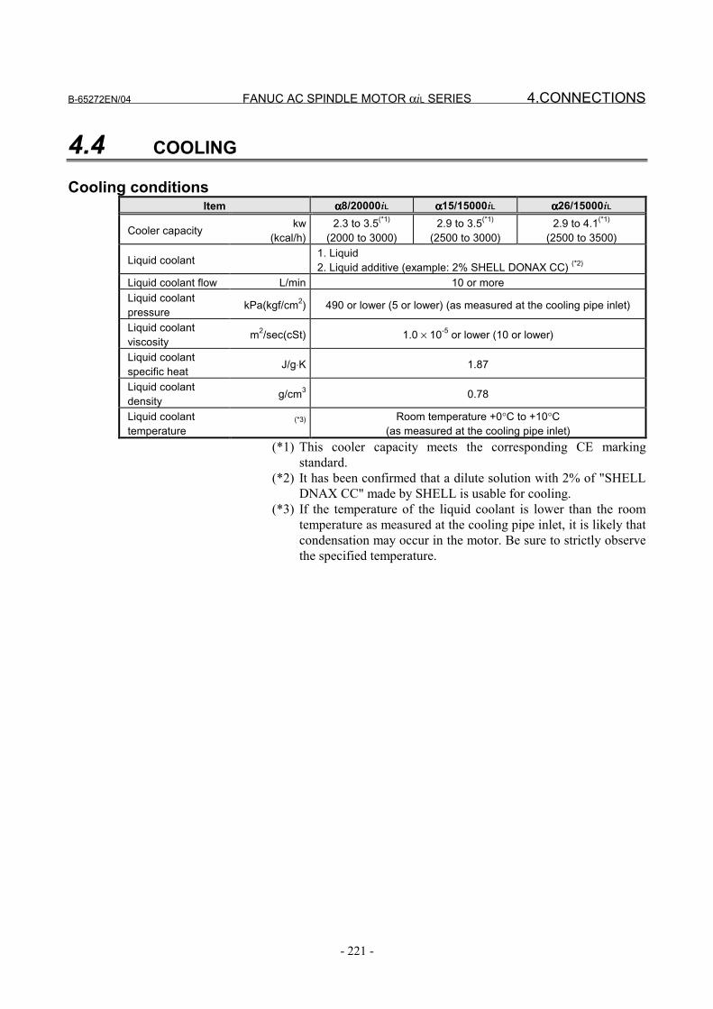
B-65272EN/04 FANUC AC SPINDLE MOTOR αiL SERIES 4.CONNECTIONS
- 221 -
4.4 COOLING
Cooling conditionsItem αααα8/20000iL αααα15/15000iL αααα26/15000iL
Cooler capacity kw(kcal/h)
2.3 to 3.5(*1)
(2000 to 3000)2.9 to 3.5(*1)
(2500 to 3000)2.9 to 4.1(*1)
(2500 to 3500)
Liquid coolant 1. Liquid 2. Liquid additive (example: 2% SHELL DONAX CC) (*2)
Liquid coolant flow L/min 10 or moreLiquid coolantpressure kPa(kgf/cm2) 490 or lower (5 or lower) (as measured at the cooling pipe inlet)
Liquid coolantviscosity m2/sec(cSt) 1.0 × 10⁻⁵ or lower (10 or lower)
Liquid coolantspecific heat J/g⋅K 1.87
Liquid coolantdensity g/cm3 0.78
Liquid coolanttemperature
(*3) Room temperature +0°C to +10°C(as measured at the cooling pipe inlet)
(*1) This cooler capacity meets the corresponding CE markingstandard.
(*2) It has been confirmed that a dilute solution with 2% of "SHELLDNAX CC" made by SHELL is usable for cooling.
(*3) If the temperature of the liquid coolant is lower than the roomtemperature as measured at the cooling pipe inlet, it is likely thatcondensation may occur in the motor. Be sure to strictly observethe specified temperature.
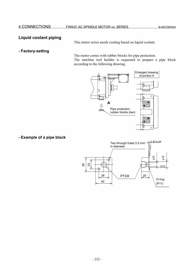
4.CONNECTIONS FANUC AC SPINDLE MOTOR αiL SERIES B-65272EN/04
- 222 -
Liquid coolant pipingThis motor series needs cooling based on liquid coolant.
- Factory-settingThe motor comes with rubber blocks for pipe protection.The machine tool builder is requested to prepare a pipe blockaccording to the following drawing.
Pipe protectionrubber blocks (two)
Enlarged drawingof portion A
A
- Example of a pipe block
42
26 PT3/8
36 23
1.8±0.05Two through holes 5.5 mmin diameter
φ10
φ15
20O-ring(P11)
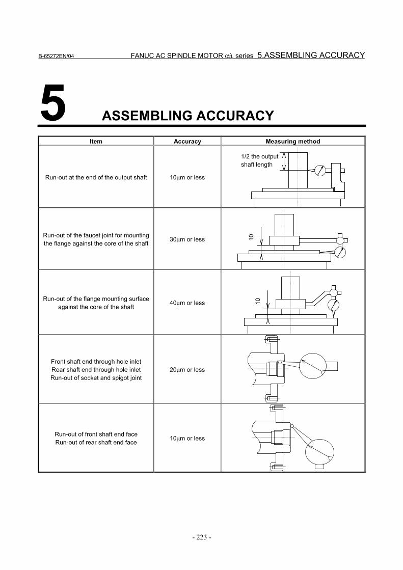
B-65272EN/04 FANUC AC SPINDLE MOTOR αiL series 5.ASSEMBLING ACCURACY
- 223 -
5 ASSEMBLING ACCURACYItem Accuracy Measuring method
Run-out at the end of the output shaft 10µm or less
1/2 the outputshaft length
Run-out of the faucet joint for mountingthe flange against the core of the shaft 30µm or less 10
Run-out of the flange mounting surfaceagainst the core of the shaft 40µm or less 10
Front shaft end through hole inletRear shaft end through hole inletRun-out of socket and spigot joint
20µm or less
Run-out of front shaft end faceRun-out of rear shaft end face 10µm or less
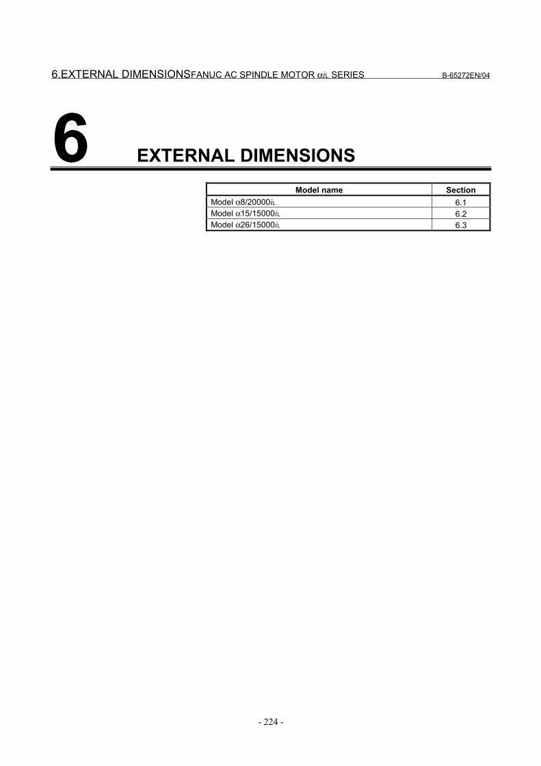
6.EXTERNAL DIMENSIONSFANUC AC SPINDLE MOTOR αiL SERIES B-65272EN/04
- 224 -
6 EXTERNAL DIMENSIONSModel name Section
Model α8/20000iL 6.1Model α15/15000iL 6.2Model α26/15000iL 6.3
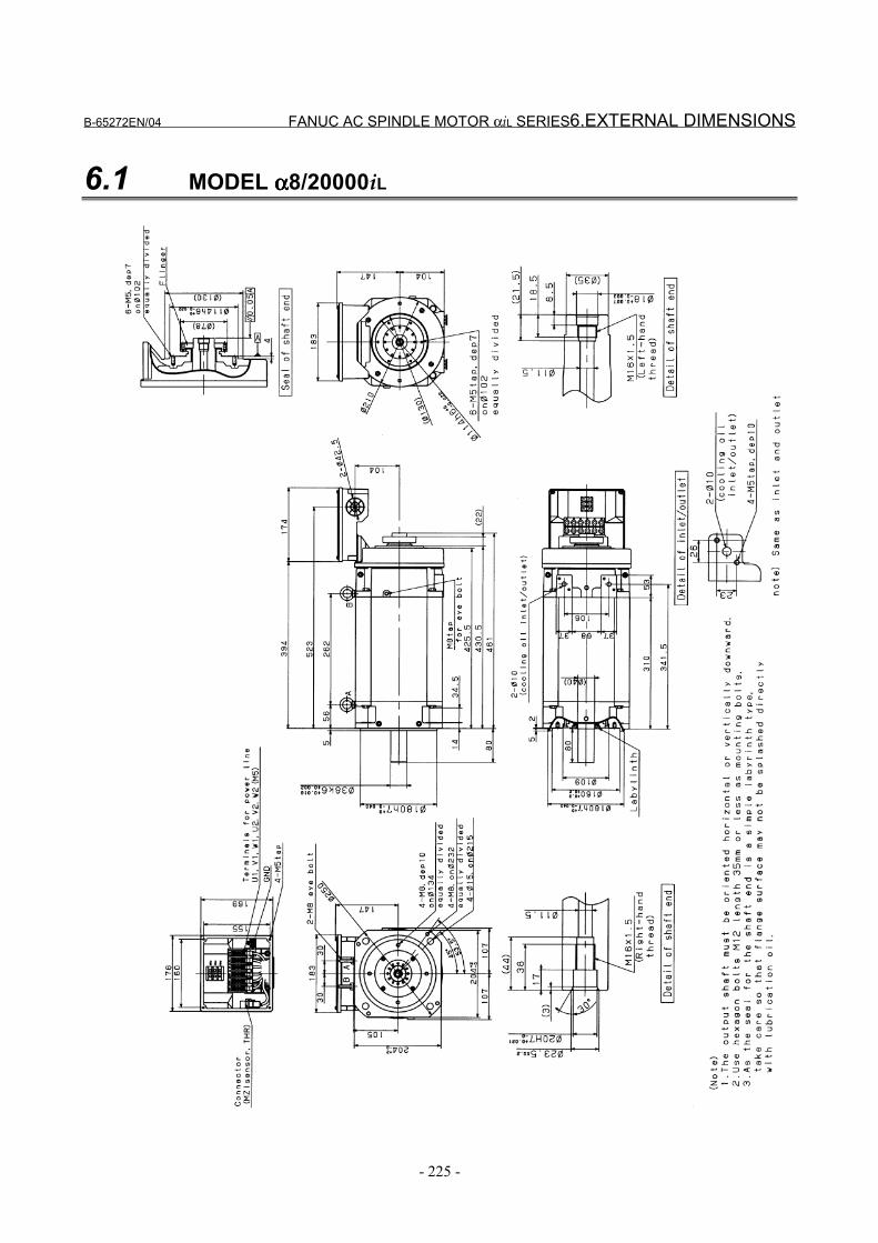
B-65272EN/04 FANUC AC SPINDLE MOTOR αiL SERIES6.EXTERNAL DIMENSIONS
- 225 -
6.1 MODEL αααα8/20000iL
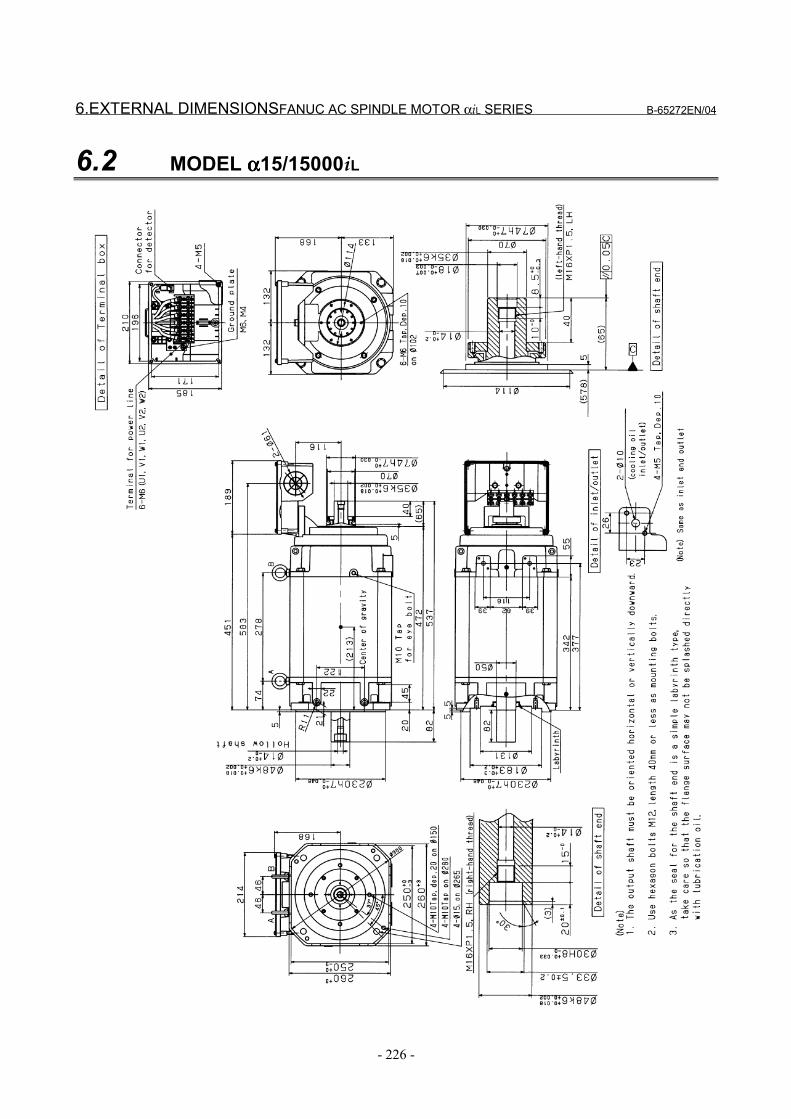
6.EXTERNAL DIMENSIONSFANUC AC SPINDLE MOTOR αiL SERIES B-65272EN/04
- 226 -
6.2 MODEL αααα15/15000iL
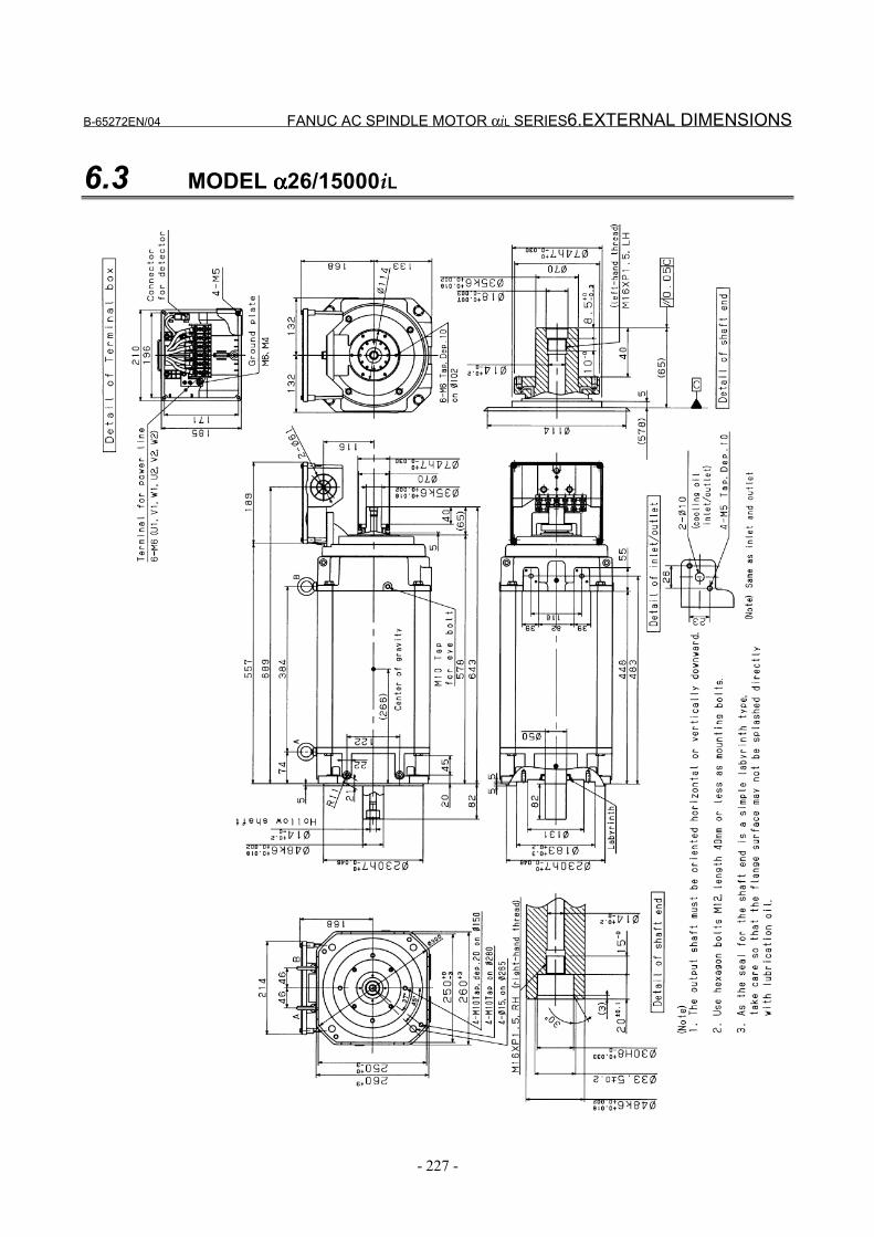
B-65272EN/04 FANUC AC SPINDLE MOTOR αiL SERIES6.EXTERNAL DIMENSIONS
- 227 -
6.3 MODEL αααα26/15000iL

VI. FANUC AC SPINDLE MOTOR αααα(HV)i SERIES

B-65272EN/04 FANUC AC SPINDLE MOTOR α(HV)i SERIES 1.GENERAL
- 231 -
1 GENERALThe FANUC AC Spindle Motor α(HV)i series includes standardspindle motors for CNC machine tool spindles, which can be drivenby 400 to 480VAC without a step-down transformer(*1).(*1) For models α1HVi, α1.5HVi, α2HVi, and α3HVi, however, a
single-phase step-down transformer for fan motors is requiredwhen 480VAC is applied.
Features - The motor is compact, light-weight and furnished with digital
control for much higher performance. - The motor inertia of the AC spindle motor is made smaller to
shorten the acceleration/deceleration speed. Further, optimumcontrol enables highly efficient cutting.
- The built-in Mi sensor or MZi sensor enables synchronousspindle and Z-axis feed and rigid tapping.
- Improvement in machining of the motor housing enhances theaccuracy of the mounting part.
- Waterproof and pressure-proof design conforming to theinternational standard (IEC) is employed to improve reliabilityand make it resistant to most environments.

2.SPECIFICATIONS FANUC AC SPINDLE MOTOR α(HV)i SERIES B-65272EN/04
- 232 -
2 SPECIFICATIONS

B-65272EN/04 FANUC AC SPINDLE MOTOR α(HV)i SERIES 2.SPECIFICATIONS
- 233 -
Series αααα(HV)i seriesModel
Item αααα0.5/10000HVi αααα1/10000HVi αααα1.5/10000HVi
Cont. rated kW (HP)
0.55(0.74)
1.5(2.0)
1.1(1.5)
30 min rated kW[15 min, 10min] (*3) (HP)
1.1
(1.5)
2.2
(3.0)
3.7
(5.0)Output (*2)
S3 60% kW[40%,25%]
(*4)(*5) (HP)
1.1
(1.5)
2.2
(3.0)
3.7
(5.0)Cont. rated 4 5 7
Rated current A (*6) 30 min rated (*3)
S3 60% (*4) 5 7 14
Speed Base speed 3000 3000 1500 min-1 Max. speed 10000 10000 10000
Output torque(Cont. rated torque at const. rated torque range)
N⋅m(kgf⋅cm)
1.75(17.9)
4.77(48.7)
7.00(71.4)
kg⋅m2 0.00048 0.003 0.0043Rotor inertia
kgf⋅cm⋅s2 0.0048 0.03 0.04Weight kgf 7 18 24
Vibration V5 (option V3)Noise 75dB(A) or less
Cooling system (*7) Totally enclosed andnon-ventilated IC0A0 Totally enclosed and fan cooled IC0A6
Cooling fan W None (*13)
Installation (*8)Mount the motor so that the output shaft points in a direction ranging
within 45° degrees above the horizontal to vertically downwards.IMB5,IMV1,IMB3,IMB6,IMB7,IMB8,IMV5
Allowable overload capacity (1 min) (*9) 120 % of 30 min rated outputInsulation Class H
Ambient temperature 0 to 40°CAltitude Height above sea level not exceeding 1000m
Painting color Munsell system N2.5Sensor Mi sensor or MZi sensor
Type of thermal protection (*10) TP211Resolution of the MZi sensor /rev. 2048Number of detected gear teeth per rotation
λ/rev. 64 128
Bearing lubrication GreaseMaximum output during acceleration(*11)
kW 1.32 2.64 4.44
Applicable spindle amplifier module SPM-5.5HViModel α0.5/10000HVi α1/10000HVi α1.5/10000HVi
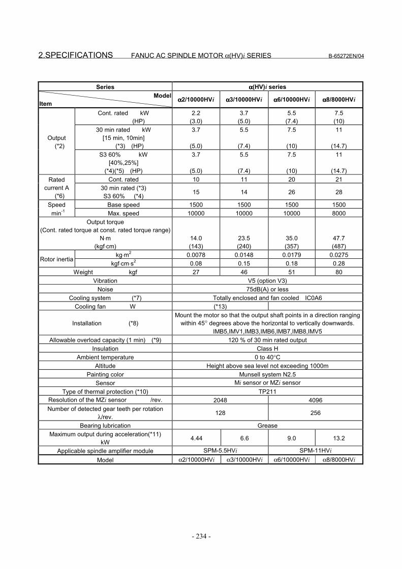
2.SPECIFICATIONS FANUC AC SPINDLE MOTOR α(HV)i SERIES B-65272EN/04
- 234 -
Series αααα(HV)i seriesModel
Item αααα2/10000HVi αααα3/10000HVi αααα6/10000HVi αααα8/8000HVi
Cont. rated kW (HP)
2.2(3.0)
3.7(5.0)
5.5(7.4)
7.5(10)
30 min rated kW[15 min, 10min] (*3) (HP)
3.7
(5.0)
5.5
(7.4)
7.5
(10)
11
(14.7)Output (*2)
S3 60% kW[40%,25%]
(*4)(*5) (HP)
3.7
(5.0)
5.5
(7.4)
7.5
(10)
11
(14.7)Cont. rated 10 11 20 21Rated
current A (*6)
30 min rated (*3)S3 60% (*4) 15 14 26 28
Speed Base speed 1500 1500 1500 1500 min-1 Max. speed 10000 10000 10000 8000
Output torque(Cont. rated torque at const. rated torque range)
N⋅m(kgf⋅cm)
14.0(143)
23.5(240)
35.0(357)
47.7(487)
kg⋅m2 0.0078 0.0148 0.0179 0.0275Rotor inertia
kgf⋅cm⋅s2 0.08 0.15 0.18 0.28Weight kgf 27 46 51 80
Vibration V5 (option V3)Noise 75dB(A) or less
Cooling system (*7) Totally enclosed and fan cooled IC0A6Cooling fan W (*13)
Installation (*8)Mount the motor so that the output shaft points in a direction ranging
within 45° degrees above the horizontal to vertically downwards.IMB5,IMV1,IMB3,IMB6,IMB7,IMB8,IMV5
Allowable overload capacity (1 min) (*9) 120 % of 30 min rated outputInsulation Class H
Ambient temperature 0 to 40°CAltitude Height above sea level not exceeding 1000m
Painting color Munsell system N2.5Sensor Mi sensor or MZi sensor
Type of thermal protection (*10) TP211Resolution of the MZi sensor /rev. 2048 4096Number of detected gear teeth per rotation
λ/rev. 128 256
Bearing lubrication GreaseMaximum output during acceleration(*11)
kW 4.44 6.6 9.0 13.2
Applicable spindle amplifier module SPM-5.5HVi SPM-11HViModel α2/10000HVi α3/10000HVi α6/10000HVi α8/8000HVi
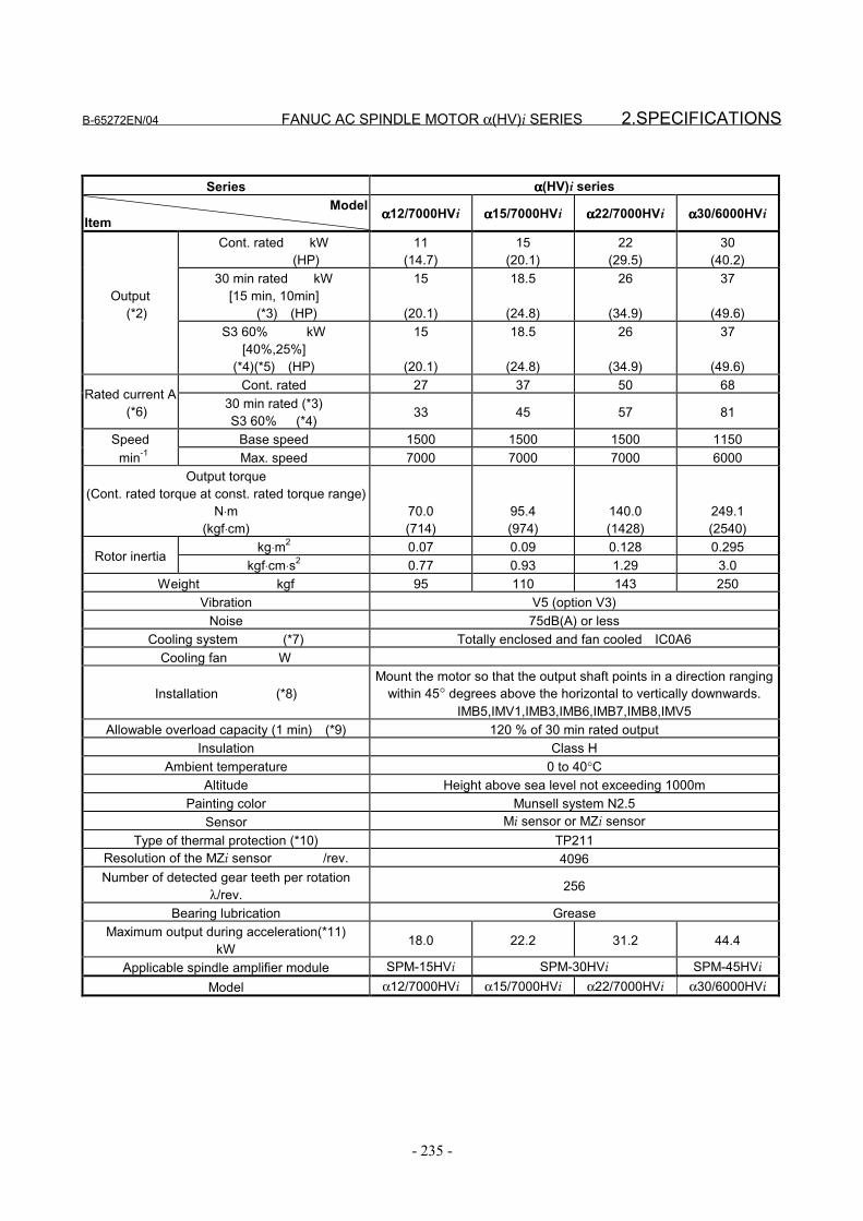
B-65272EN/04 FANUC AC SPINDLE MOTOR α(HV)i SERIES 2.SPECIFICATIONS
- 235 -
Series αααα(HV)i seriesModel
Item αααα12/7000HVi αααα15/7000HVi αααα22/7000HVi αααα30/6000HVi
Cont. rated kW (HP)
11(14.7)
15(20.1)
22(29.5)
30(40.2)
30 min rated kW[15 min, 10min] (*3) (HP)
15
(20.1)
18.5
(24.8)
26
(34.9)
37
(49.6)Output (*2)
S3 60% kW[40%,25%]
(*4)(*5) (HP)
15
(20.1)
18.5
(24.8)
26
(34.9)
37
(49.6)Cont. rated 27 37 50 68
Rated current A (*6) 30 min rated (*3)
S3 60% (*4) 33 45 57 81
Speed Base speed 1500 1500 1500 1150 min-1 Max. speed 7000 7000 7000 6000
Output torque(Cont. rated torque at const. rated torque range)
N⋅m(kgf⋅cm)
70.0(714)
95.4(974)
140.0(1428)
249.1(2540)
kg⋅m2 0.07 0.09 0.128 0.295Rotor inertia
kgf⋅cm⋅s2 0.77 0.93 1.29 3.0Weight kgf 95 110 143 250
Vibration V5 (option V3)Noise 75dB(A) or less
Cooling system (*7) Totally enclosed and fan cooled IC0A6Cooling fan W
Installation (*8)Mount the motor so that the output shaft points in a direction ranging
within 45° degrees above the horizontal to vertically downwards.IMB5,IMV1,IMB3,IMB6,IMB7,IMB8,IMV5
Allowable overload capacity (1 min) (*9) 120 % of 30 min rated outputInsulation Class H
Ambient temperature 0 to 40°CAltitude Height above sea level not exceeding 1000m
Painting color Munsell system N2.5Sensor Mi sensor or MZi sensor
Type of thermal protection (*10) TP211Resolution of the MZi sensor /rev. 4096Number of detected gear teeth per rotation
λ/rev. 256
Bearing lubrication GreaseMaximum output during acceleration(*11)
kW 18.0 22.2 31.2 44.4
Applicable spindle amplifier module SPM-15HVi SPM-30HVi SPM-45HViModel α12/7000HVi α15/7000HVi α22/7000HVi α30/6000HVi
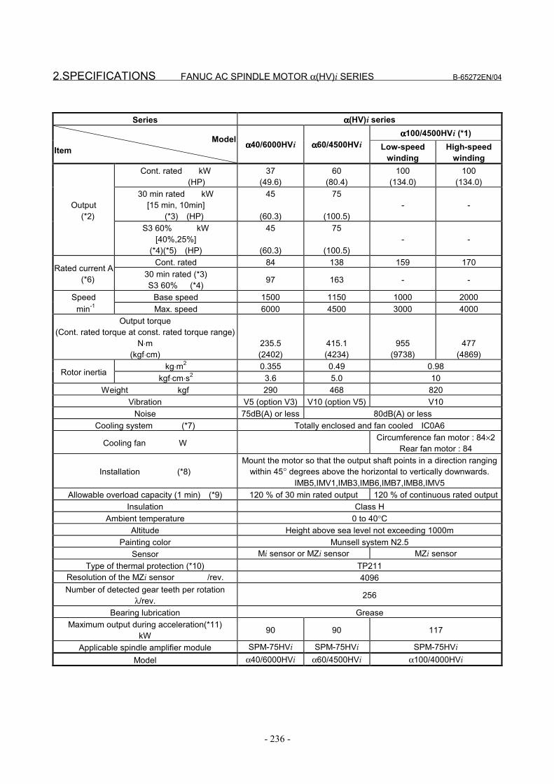
2.SPECIFICATIONS FANUC AC SPINDLE MOTOR α(HV)i SERIES B-65272EN/04
- 236 -
Series αααα(HV)i seriesαααα100/4500HVi (*1)
ModelItem αααα40/6000HVi αααα60/4500HVi Low-speed
windingHigh-speed
windingCont. rated kW
(HP)37
(49.6)60
(80.4)100
(134.0)100
(134.0)30 min rated kW
[15 min, 10min] (*3) (HP)
45
(60.3)
75
(100.5)- -Output
(*2)S3 60% kW
[40%,25%](*4)(*5) (HP)
45
(60.3)
75
(100.5)- -
Cont. rated 84 138 159 170Rated current A
(*6) 30 min rated (*3)S3 60% (*4) 97 163 - -
Speed Base speed 1500 1150 1000 2000 min-1 Max. speed 6000 4500 3000 4000
Output torque(Cont. rated torque at const. rated torque range)
N⋅m(kgf⋅cm)
235.5(2402)
415.1(4234)
955(9738)
477(4869)
kg⋅m2 0.355 0.49 0.98Rotor inertia
kgf⋅cm⋅s2 3.6 5.0 10Weight kgf 290 468 820
Vibration V5 (option V3) V10 (option V5) V10Noise 75dB(A) or less 80dB(A) or less
Cooling system (*7) Totally enclosed and fan cooled IC0A6
Cooling fan W Circumference fan motor : 84×2Rear fan motor : 84
Installation (*8)Mount the motor so that the output shaft points in a direction ranging
within 45° degrees above the horizontal to vertically downwards.IMB5,IMV1,IMB3,IMB6,IMB7,IMB8,IMV5
Allowable overload capacity (1 min) (*9) 120 % of 30 min rated output 120 % of continuous rated outputInsulation Class H
Ambient temperature 0 to 40°CAltitude Height above sea level not exceeding 1000m
Painting color Munsell system N2.5Sensor Mi sensor or MZi sensor MZi sensor
Type of thermal protection (*10) TP211Resolution of the MZi sensor /rev. 4096Number of detected gear teeth per rotation
λ/rev. 256
Bearing lubrication GreaseMaximum output during acceleration(*11)
kW 90 90 117
Applicable spindle amplifier module SPM-75HVi SPM-75HVi SPM-75HViModel α40/6000HVi α60/4500HVi α100/4000HVi
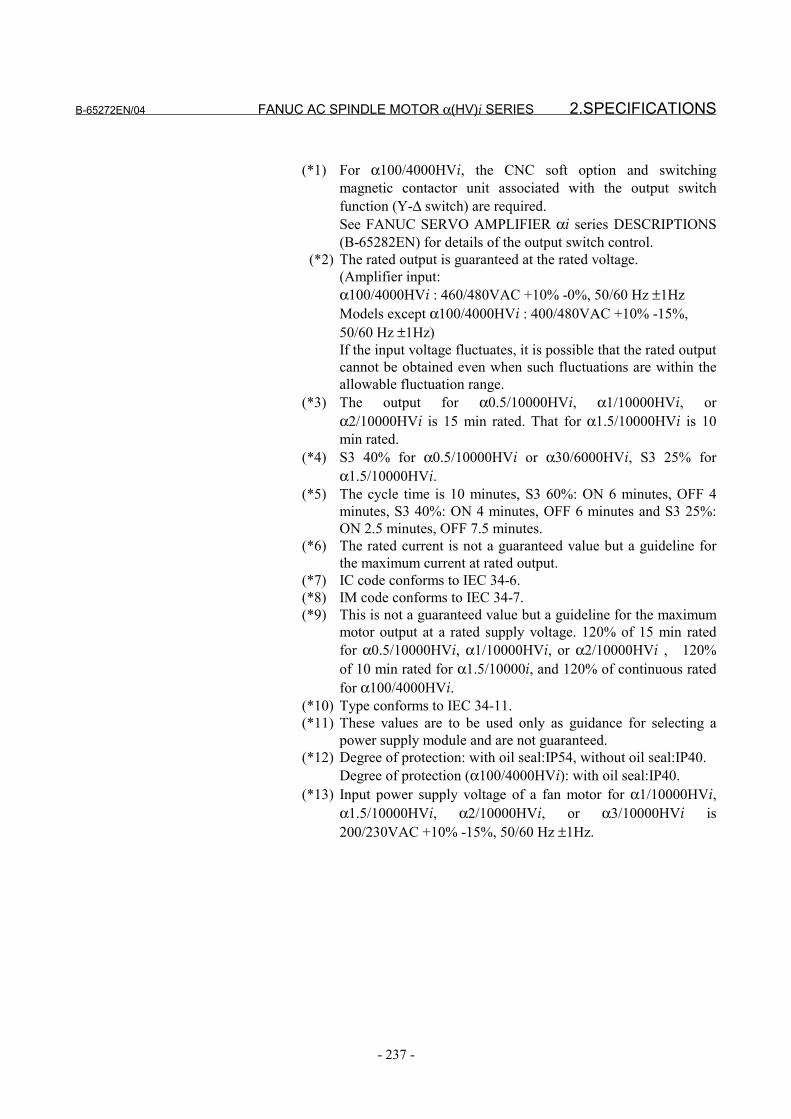
B-65272EN/04 FANUC AC SPINDLE MOTOR α(HV)i SERIES 2.SPECIFICATIONS
- 237 -
(*1) For α100/4000HVi, the CNC soft option and switchingmagnetic contactor unit associated with the output switchfunction (Y-∆ switch) are required.See FANUC SERVO AMPLIFIER αi series DESCRIPTIONS(B-65282EN) for details of the output switch control.
(*2) The rated output is guaranteed at the rated voltage.(Amplifier input:α100/4000HVi : 460/480VAC +10% -0%, 50/60 Hz ±1HzModels except α100/4000HVi : 400/480VAC +10% -15%,50/60 Hz ±1Hz)If the input voltage fluctuates, it is possible that the rated outputcannot be obtained even when such fluctuations are within theallowable fluctuation range.
(*3) The output for α0.5/10000HVi, α1/10000HVi, orα2/10000HVi is 15 min rated. That for α1.5/10000HVi is 10min rated.
(*4) S3 40% for α0.5/10000HVi or α30/6000HVi, S3 25% forα1.5/10000HVi.
(*5) The cycle time is 10 minutes, S3 60%: ON 6 minutes, OFF 4minutes, S3 40%: ON 4 minutes, OFF 6 minutes and S3 25%:ON 2.5 minutes, OFF 7.5 minutes.
(*6) The rated current is not a guaranteed value but a guideline forthe maximum current at rated output.
(*7) IC code conforms to IEC 34-6.(*8) IM code conforms to IEC 34-7.(*9) This is not a guaranteed value but a guideline for the maximum
motor output at a rated supply voltage. 120% of 15 min ratedfor α0.5/10000HVi, α1/10000HVi, or α2/10000HVi , 120%of 10 min rated for α1.5/10000i, and 120% of continuous ratedfor α100/4000HVi.
(*10) Type conforms to IEC 34-11.(*11) These values are to be used only as guidance for selecting a
power supply module and are not guaranteed.(*12) Degree of protection: with oil seal:IP54, without oil seal:IP40.
Degree of protection (α100/4000HVi): with oil seal:IP40.(*13) Input power supply voltage of a fan motor for α1/10000HVi,
α1.5/10000HVi, α2/10000HVi, or α3/10000HVi is200/230VAC +10% -15%, 50/60 Hz ±1Hz.

3.OUTPUT/TORQUE CHARACTERISTICS FANUC AC SPINDLE MOTOR α(HV)i SERIES B-65272EN/04
- 238 -
3 OUTPUT/TORQUE CHARACTERISTICSReferenceCalculation for torque
Torque T can be obtained by the following equation.
T[N⋅m]=P[kW]×1000/0.1047/N[min-1]P[kW]: Motor outputN[min-1]: Motor speed
When the unit of T is [kgf⋅m],T[kgf⋅m]=P[kW]×1000/1.0269/N[min-1]
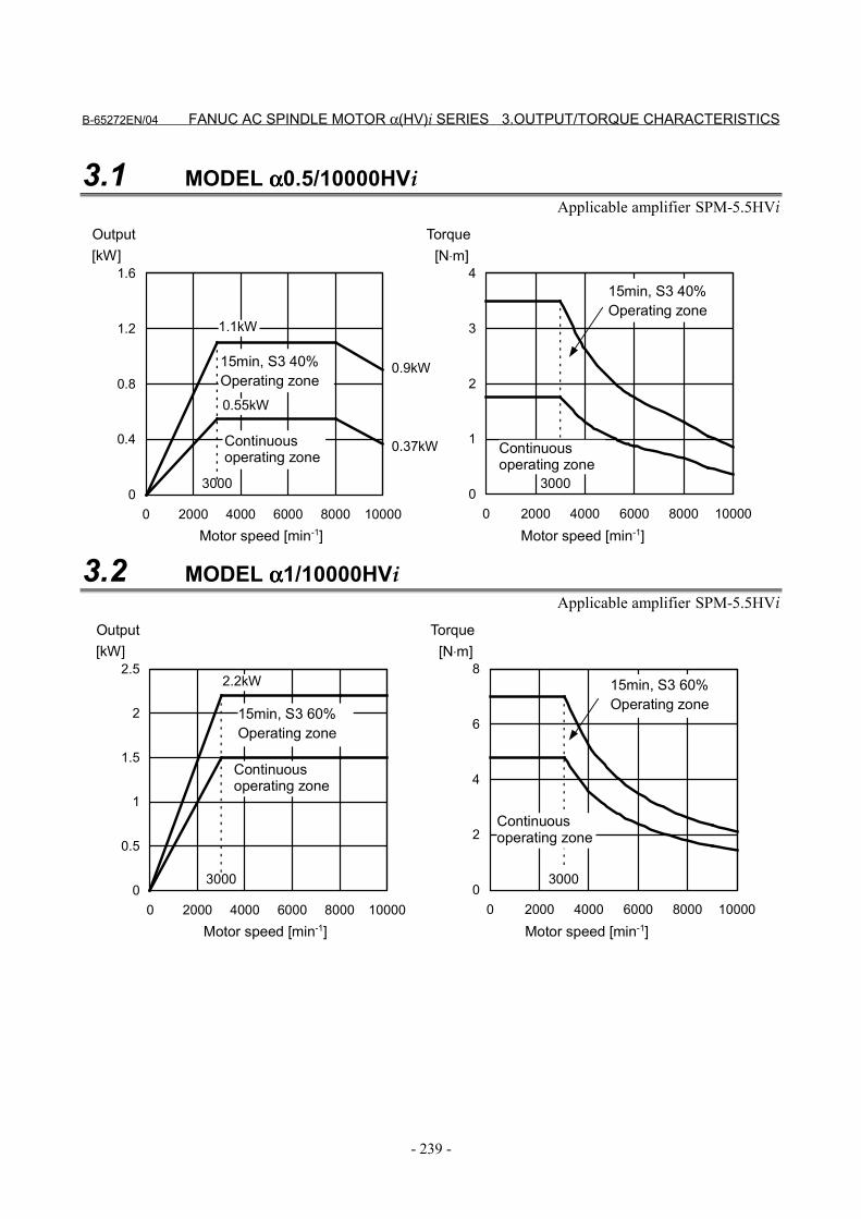
B-65272EN/04 FANUC AC SPINDLE MOTOR α(HV)i SERIES 3.OUTPUT/TORQUE CHARACTERISTICS
- 239 -
3.1 MODEL αααα0.5/10000HViApplicable amplifier SPM-5.5HVi
0
0.4
0.8
1.2
1.6
0 2000 4000 6000 8000 10000Motor speed [min-1]
[kW]
3000
Output
Continuousoperating zone
15min, S3 40%Operating zone
0.37kW
0.9kW
0
1
2
3
4
0 2000 4000 6000 8000 10000Motor speed [min-1]
[N⋅m]
3000
Torque
15min, S3 40%Operating zone
0.55kW
1.1kW
Continuousoperating zone
3.2 MODEL αααα1/10000HViApplicable amplifier SPM-5.5HVi
0
0.5
1
1.5
2
2.5
0 2000 4000 6000 8000 10000
[kW]
3000
2.2kW
0
2
4
6
8
0 2000 4000 6000 8000 10000
[N⋅m]
3000
Motor speed [min-1]
Output
Continuousoperating zone
15min, S3 60%Operating zone
Motor speed [min-1]
Torque
15min, S3 60%Operating zone
Continuousoperating zone
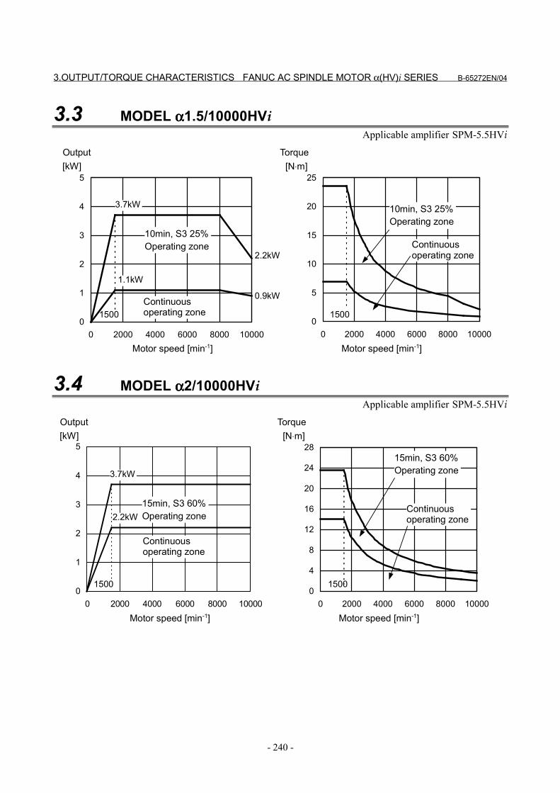
3.OUTPUT/TORQUE CHARACTERISTICS FANUC AC SPINDLE MOTOR α(HV)i SERIES B-65272EN/04
- 240 -
3.3 MODEL αααα1.5/10000HViApplicable amplifier SPM-5.5HVi
0
1
2
3
4
5
0 2000 4000 6000 8000 10000
[kW]
1500
3.7kW
0
5
10
15
20
25
0 2000 4000 6000 8000 10000
[N⋅m]
1500
2.2kW
0.9kW
1.1kW
Motor speed [min-1]
Output
Continuousoperating zone
10min, S3 25%Operating zone
Motor speed [min-1]
Torque
10min, S3 25%Operating zone
Continuousoperating zone
3.4 MODEL αααα2/10000HViApplicable amplifier SPM-5.5HVi
0
1
2
3
4
5
0 2000 4000 6000 8000 10000
[kW]
1500
3.7kW
0
4
8
12
16
20
24
28
0 2000 4000 6000 8000 10000
[N⋅m]
1500
2.2kW
Motor speed [min-1]
Output
Continuousoperating zone
15min, S3 60%Operating zone
Motor speed [min-1]
Torque
15min, S3 60%Operating zone
Continuousoperating zone
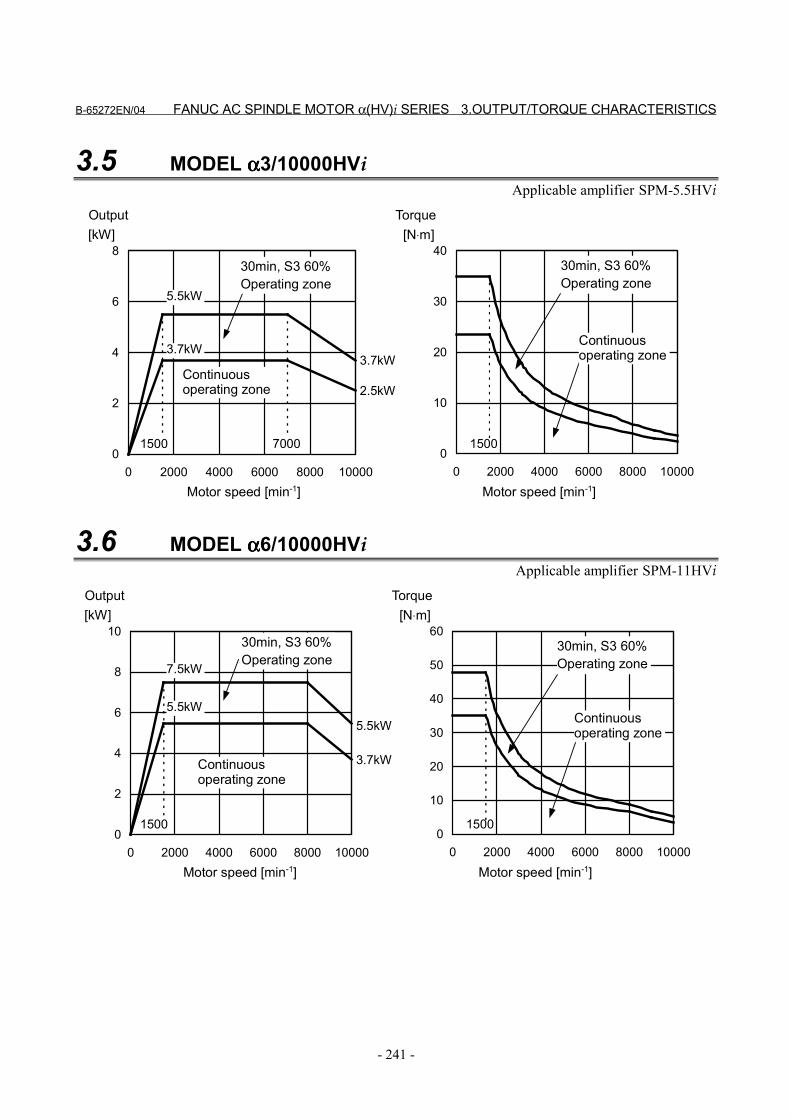
B-65272EN/04 FANUC AC SPINDLE MOTOR α(HV)i SERIES 3.OUTPUT/TORQUE CHARACTERISTICS
- 241 -
3.5 MODEL αααα3/10000HViApplicable amplifier SPM-5.5HVi
0
2
4
6
8
0 2000 4000 6000 8000 10000
[kW]
1500
3.7kW
0
10
20
30
40
0 2000 4000 6000 8000 10000
[N⋅m]
1500
5.5kW
7000
3.7kW
2.5kW
Motor speed [min-1]
Output
Continuousoperating zone
30min, S3 60%Operating zone
Motor speed [min-1]
Torque
30min, S3 60%Operating zone
Continuousoperating zone
3.6 MODEL αααα6/10000HViApplicable amplifier SPM-11HVi
0
2
4
6
8
10
0 2000 4000 6000 8000 10000
[kW]
1500
7.5kW
0
10
20
30
40
50
60
0 2000 4000 6000 8000 10000
[N⋅m]
1500
5.5kW
3.7kW
5.5kW
Motor speed [min-1]
Output
Continuousoperating zone
30min, S3 60%Operating zone
Motor speed [min-1]
Torque
30min, S3 60%Operating zone
Continuousoperating zone
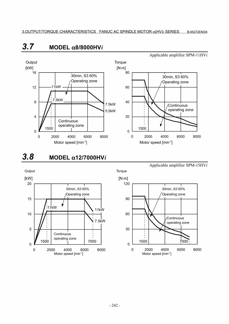
3.OUTPUT/TORQUE CHARACTERISTICS FANUC AC SPINDLE MOTOR α(HV)i SERIES B-65272EN/04
- 242 -
3.7 MODEL αααα8/8000HViApplicable amplifier SPM-11HVi
0
4
8
12
16
0 2000 4000 6000 8000
[kW]
1500
7.5kW
0
20
40
60
80
0 2000 4000 6000 8000
[N⋅m]
1500
11kW
7.5kW
5.5kW
Motor speed [min-1]
Output
Continuousoperating zone
30min, S3 60%Operating zone
Motor speed [min-1]
Torque
30min, S3 60%Operating zone
Continuousoperating zone
3.8 MODEL αααα12/7000HViApplicable amplifier SPM-15HVi
0
5
10
15
20
0 2000 4000 6000 8000
15000
30
60
90
120
0 2000 4000 6000 8000
1500
11kW
7.5kW
11kW
7000 7000
[kW] [N⋅m]
Motor speed [min-1]
Output
Continuousoperating zone
30min, S3 60%Operating zone
Motor speed [min-1]
Torque
30min, S3 60%Operating zone
Continuousoperating zone
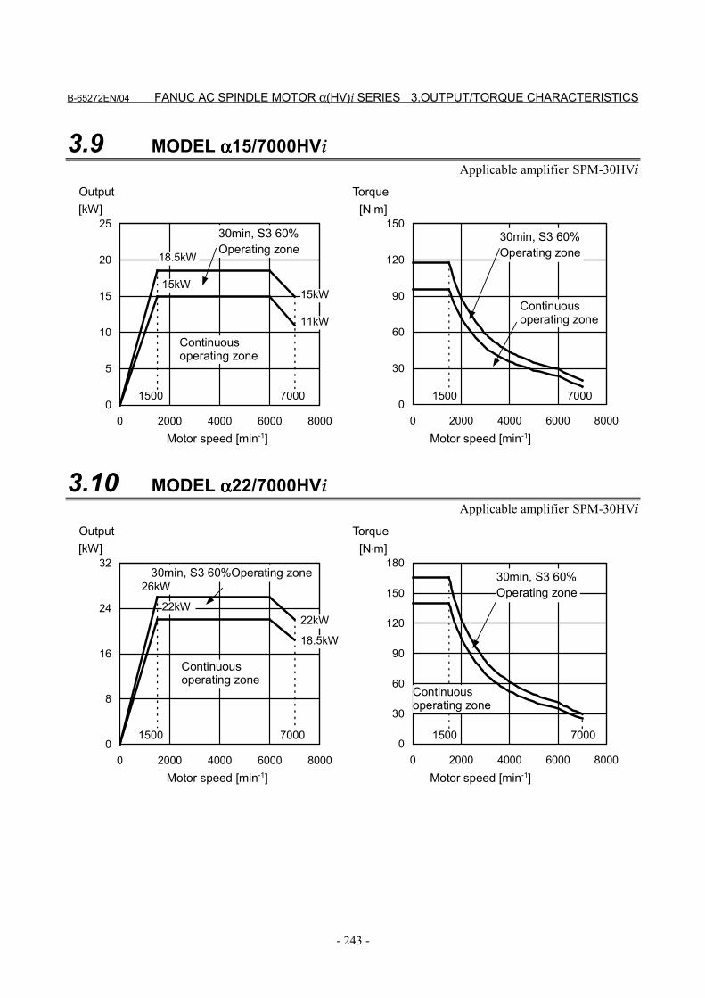
B-65272EN/04 FANUC AC SPINDLE MOTOR α(HV)i SERIES 3.OUTPUT/TORQUE CHARACTERISTICS
- 243 -
3.9 MODEL αααα15/7000HViApplicable amplifier SPM-30HVi
0
5
10
15
20
25
0 2000 4000 6000 8000
[kW]
15000
30
60
90
120
150
0 2000 4000 6000 8000
[N⋅m]
1500
15kW15kW
11kW
7000 7000
18.5kW
Motor speed [min-1]
Output
Continuousoperating zone
30min, S3 60%Operating zone
Motor speed [min-1]
Torque
30min, S3 60%Operating zone
Continuousoperating zone
3.10 MODEL αααα22/7000HViApplicable amplifier SPM-30HVi
0
8
16
24
32
0 2000 4000 6000 8000
[kW]
15000
30
60
90
120
150
180
0 2000 4000 6000 8000
[N⋅m]
1500
22kW22kW
18.5kW
7000 7000
26kW
Motor speed [min-1]
Output
Continuousoperating zone
30min, S3 60%Operating zone
Motor speed [min-1]
Torque
30min, S3 60%Operating zone
Continuousoperating zone
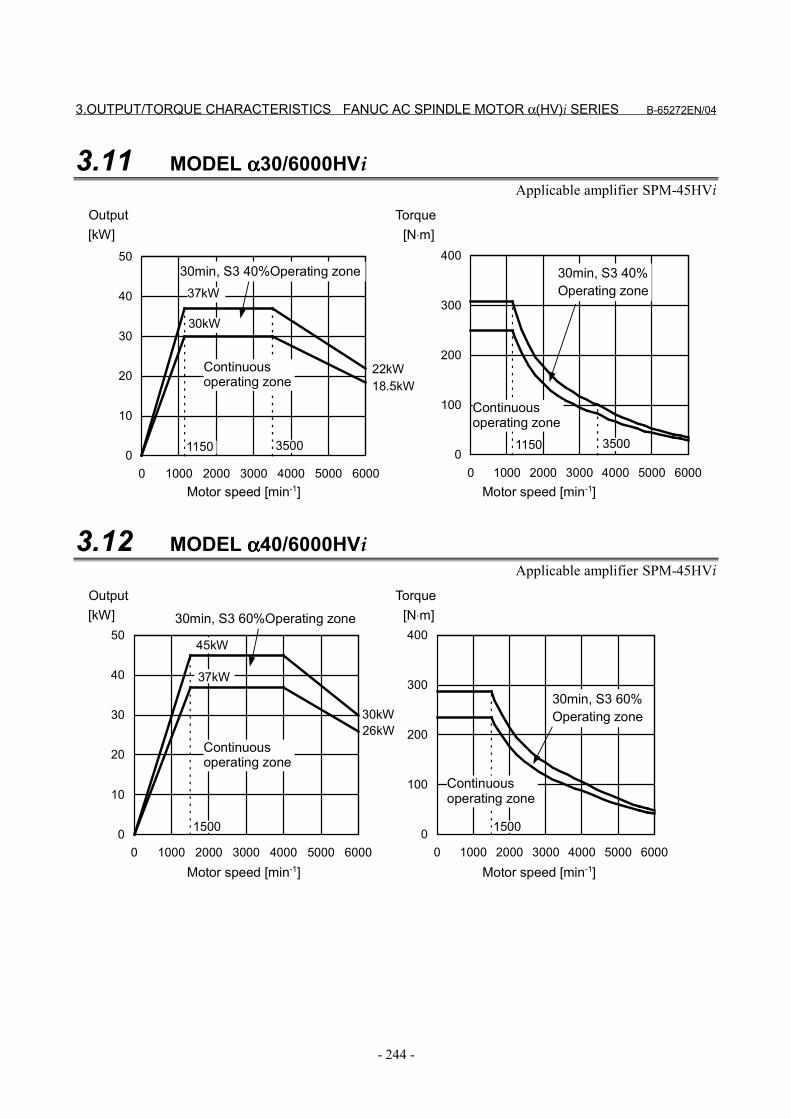
3.OUTPUT/TORQUE CHARACTERISTICS FANUC AC SPINDLE MOTOR α(HV)i SERIES B-65272EN/04
- 244 -
3.11 MODEL αααα30/6000HViApplicable amplifier SPM-45HVi
0
100
200
300
400
0 1000 2000 3000 4000 5000 60000
10
20
30
40
50
0 1000 2000 3000 4000 5000 6000
[kW]
1150
[N⋅m]
1150
30kW
22kW18.5kW
3500 3500
37kW
Motor speed [min-1]
Output
Continuousoperating zone
30min, S3 40%Operating zone
Motor speed [min-1]
Torque
30min, S3 40%Operating zone
Continuousoperating zone
3.12 MODEL αααα40/6000HViApplicable amplifier SPM-45HVi
0
100
200
300
400
0 1000 2000 3000 4000 5000 60000
10
20
30
40
50
0 1000 2000 3000 4000 5000 6000
30kW
45kW
37kW
26kW
15001500
[kW] [N⋅m]
Motor speed [min-1]
Output
Continuousoperating zone
30min, S3 60%Operating zone
Motor speed [min-1]
Torque
30min, S3 60%Operating zone
Continuousoperating zone
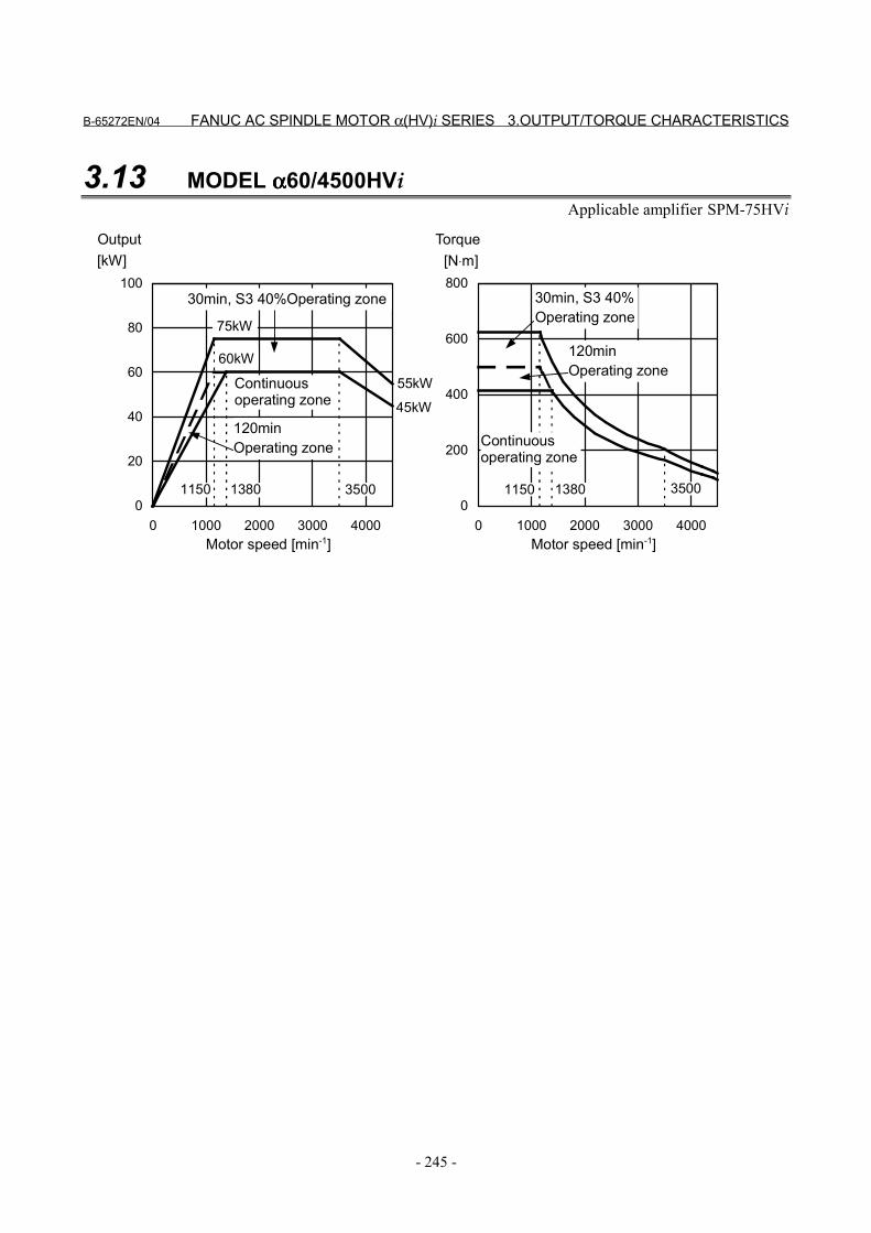
B-65272EN/04 FANUC AC SPINDLE MOTOR α(HV)i SERIES 3.OUTPUT/TORQUE CHARACTERISTICS
- 245 -
3.13 MODEL αααα60/4500HViApplicable amplifier SPM-75HVi
0
200
400
600
800
0 1000 2000 3000 40000
20
40
60
80
100
0 1000 2000 3000 4000
[kW] [N⋅m]
Motor speed [min-1]
Output
Continuousoperating zone
30min, S3 40%Operating zone
Motor speed [min-1]
Torque
30min, S3 40%Operating zone
Continuousoperating zone
55kW
75kW
60kW
45kW
11501150 350035001380 1380
120minOperating zone
120minOperating zone
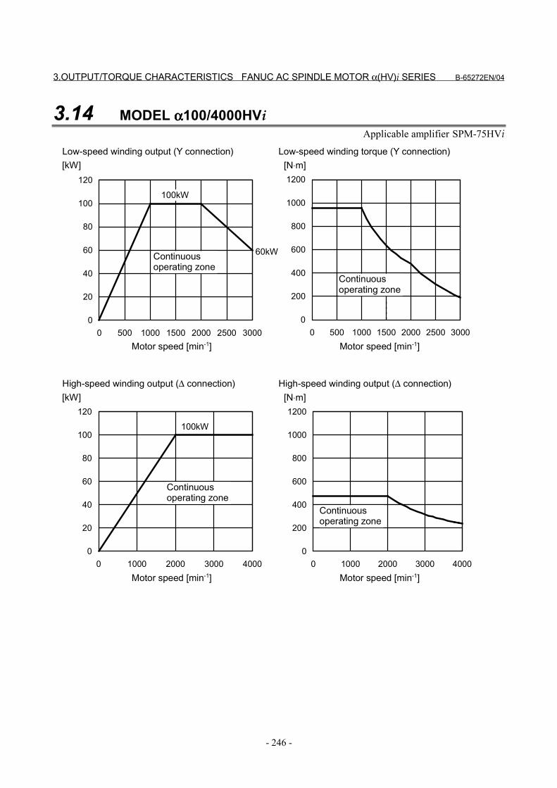
3.OUTPUT/TORQUE CHARACTERISTICS FANUC AC SPINDLE MOTOR α(HV)i SERIES B-65272EN/04
- 246 -
3.14 MODEL αααα100/4000HViApplicable amplifier SPM-75HVi
0
200
400
600
800
1000
1200
0 1000 2000 3000 40000
20
40
60
80
100
120
0 1000 2000 3000 4000
100kW
0
200
400
600
800
1000
1200
0 500 1000 1500 2000 2500 30000
20
40
60
80
100
120
0 500 1000 1500 2000 2500 3000
60kW
100kW
[kW] [N⋅m]
[kW] [N⋅m]
Motor speed [min-1]
Continuousoperating zone
Motor speed [min-1]
Continuousoperating zone
Low-speed winding output (Y connection) Low-speed winding torque (Y connection)
Motor speed [min-1]
Continuousoperating zone
Motor speed [min-1]
Continuousoperating zone
High-speed winding output (∆ connection) High-speed winding output (∆ connection)

B-65272EN/04 FANUC AC SPINDLE MOTOR α(HV)i SERIES 4.CONNECTIONS
- 247 -
4 CONNECTIONS
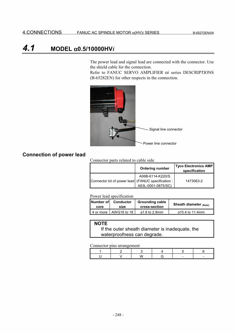
4.CONNECTIONS FANUC AC SPINDLE MOTOR α(HV)i SERIES B-65272EN/04
- 248 -
4.1 MODEL αααα0.5/10000HVi
The power lead and signal lead are connected with the connector. Usethe shield cable for the connection.Refer to FANUC SERVO AMPLIFIER αi series DESCRIPTIONS(B-65282EN) for other respects in the connection.
Power line connector
Signal line connector
Connection of power leadConnector parts related to cable side
Ordering number Tyco Electronics AMPspecification
Connector kit of power leadA06B-6114-K220/S
(FANUC specification :A63L-0001-0875/SC)
1473063-2
Power lead specificationNumber of
coreConductor
sizeGrounding cable
cross-section Sheath diameter (Note)
4 or more AWG16 to 18 φ1.8 to 2.8mm φ10.4 to 11.4mm
NOTEIf the outer sheath diameter is inadequate, thewaterproofness can degrade.
Connector pins arrangement1 2 3 4 5 6U V W G - -
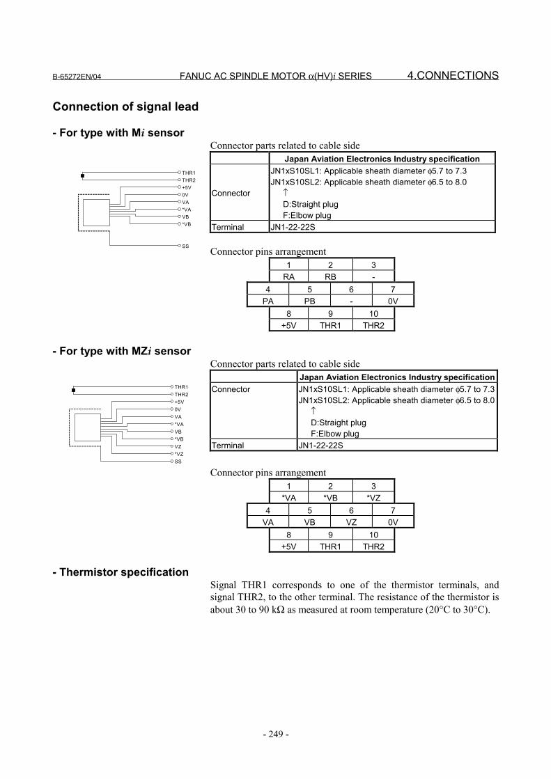
B-65272EN/04 FANUC AC SPINDLE MOTOR α(HV)i SERIES 4.CONNECTIONS
- 249 -
Connection of signal lead
- For type with Mi sensorConnector parts related to cable side
Japan Aviation Electronics Industry specification
Connector
JN1xS10SL1: Applicable sheath diameter φ5.7 to 7.3JN1xS10SL2: Applicable sheath diameter φ6.5 to 8.0 ↑ D:Straight plug F:Elbow plug
Terminal JN1-22-22S
Connector pins arrangement1 2 3
RA RB -4 5 6 7
PA PB - 0V8 9 10
+5V THR1 THR2
- For type with MZi sensorConnector parts related to cable side
Japan Aviation Electronics Industry specificationConnector JN1xS10SL1: Applicable sheath diameter φ5.7 to 7.3
JN1xS10SL2: Applicable sheath diameter φ6.5 to 8.0 ↑ D:Straight plug F:Elbow plug
Terminal JN1-22-22S
Connector pins arrangement1 2 3
*VA *VB *VZ4 5 6 7
VA VB VZ 0V8 9 10
+5V THR1 THR2
- Thermistor specificationSignal THR1 corresponds to one of the thermistor terminals, andsignal THR2, to the other terminal. The resistance of the thermistor isabout 30 to 90 kΩ as measured at room temperature (20°C to 30°C).
THR1THR2+5V0VVA*VAVB*VB
SS
THR1THR2+5V0VVA*VAVB*VBVZ*VZSS
4.CONNECTIONS FANUC AC SPINDLE MOTOR α(HV)i SERIES B-65272EN/04
- 250 -
4.2 MODELS αααα1/10000HVi TO αααα100/4000HVi
Cables of primary winding and fan motor are connected to theterminal block.Mi sensor or MZi sensor signal or thermistor signal use a connectormanufactured by Tyco Electronics AMP.The connector housing and the connector are attached to the motor.
Power lead Fan motor Fan motorSize of screws used inthe terminal
blockModel
U,V,W,G X,Y,Z FMU,FMV,FMW FMU,FMV
α1/10000HVi to α1.5/10000HVi M5 - - M4α2/10000HVi to α3/10000HVi M5 - - Screw-less terminal blockα6/10000HVi to α22/7000HVi M5 - Screw-less terminal block -α30/6000HVi to α40/6000HVi M10 - Screw-less terminal block -
α60/4500HVi M10 - M3.5 -α100/4000HVi M8 M8 M3.5 -
Cable for the power leadFor the power lead cable specification, refer to "FANUC SERVOAMPLIFIER αi series DESCRIPTIONS (B-65282EN)".
Cable for the fan motorFor the fan motor current value and cable specifications, refer toSection I.4.3, "FAN MOTOR CONNECTION" in this manual.

B-65272EN/04 FANUC AC SPINDLE MOTOR α(HV)i SERIES 4.CONNECTIONS
- 251 -
4.3 CONNECTION OF SIGNAL LEAD
Connector attachment for a motor with a built-in Mi sensorConnector pins arrangement
Number B1 B2 B3 B4 B5 B6ColorSignal RA RB 0V THR2
Number A1 A2 A3 A4 A5 A6ColorSignal +5V PA PB SS THR1
Connector attachment for a motor with a built-in MZi sensor Connector pins arrangement
Number B1 B2 B3 B4 B5 B6ColorSignal *VA *VB *VZ 0V THR2
Number A1 A2 A3 A4 A5 A6ColorSignal +5V VA VB VZ SS THR1
- Connector housing and contact specificationsConnector and contact :Tyco Electronics AMP specification D-3000 series
Motor side Cable side
FANUC specification Manufacturespecification FANUC specification Manufacture
specificationHousing A63L-0001-0535/121KDF 178964-6 A63L-0001-0460/121KD 178289-6Contact A63L-0001-0456/ASMT 175288-2 A63L-0001-0456/ASM 1-175217-2
Crimping tool : 91559-1 Extractor : 234168-1
- Thermistor specificationSignal THR1 corresponds to one of the thermistor terminals, andsignal THR2, to the other terminal. The resistance of the thermistor isabout 30 to 90 kΩ as measured at room temperature (20°C to 30°C).
TH R 1TH R 2+ 5V0VP AP BR AR BS S
TH R1TH R2+5V0VV A*V AV B*V BV Z*V ZS S
5.ALLOWABLE RADIAL LOADFANUC AC SPINDLE MOTOR α(HV)i SERIES B-65272EN/04
- 252 -
5 ALLOWABLE RADIAL LOADUse the motor output shaft below the allowable radial loads shown inthe table below.
Allowable radial load (kgf)Model At output shaft
endAt output shaft
centerα0.5/10000HVi 294N (30kgf) 323N (33kgf)α1/10000HVi 392N (40kgf) 441N (45kgf)
α1.5/10000HVi 882N (90kgf) 980N (100kgf)α2/10000HVi 882N (90kgf) 999N (102kgf)α3/10000HVi 1470N (150kgf) 1607N (164kgf)α6/10000HVi 1960N (200kgf) 2205N (225kgf)α8/8000HVi 2940N (300kgf) 3371N (344kgf)
α12/7000HVi, α15/7000HVi 2940N (300kgf) 3410N (348kgf)α22/7000HVi 4410N (450kgf) 4988N (509kgf)
α30/6000HVi, α40/6000HVi 5390N (550kgf) 6134N (626kgf)α60/4500HVi - 19600N (2000kgf)
α100/4000HVi Direct connection to the spindle
NOTE1 When using a belt, adjust the tension so the
allowable loads indicated above are not exceeded.If an excessive load is applied, consider the use ofa support bearing on the machine side to maintainthe long-term reliability of the motor. (If anexcessive load is applied, it is possible that anabnormal sound may occur.)
2 When the belt tension is maximized at a pointoutside the output shaft end, the allowable loadsare less than those at the output shaft end.
3 If a thrust load is applied when a helical gear isused, the shaft moves in the direction of the thrust.So, as a general rule, never apply a thrust load.

B-65272EN/04 FANUC AC SPINDLE MOTOR α(HV)i SERIES 6.ASSEMBLING ACCURACY
- 253 -
6 ASSEMBLING ACCURACYModel
Itemαααα0.5HVi to
αααα22HViαααα30HVi to
αααα60HVi αααα100HVi Measuring method
Run-out at the end of theoutput shaft 20µm or less 20µm or less 40µm or less
1/2 the outputshaft length
Run-out of the faucet jointfor mounting the flangeagainst the core of theshaft (for flange type or
foot flange type)
40µm or less 60µm or less 200µm or less 10
Run-out of the flangemounting surface againstthe core of the shaft (forflange type or foot flange
type)
80µm or less 100µm or less 200µm or less 10
7.EXTERNAL DIMENSIONS FANUC AC SPINDLE MOTOR α(HV)i SERIES B-65272EN/04
- 254 -
7 EXTERNAL DIMENSIONSModel name Section
Model α0.5/10000HVi (flange mounting type) 7.1Model α1/10000HVi (flange mounting type) 7.2Model α1/10000HVi (foot mounting type) 7.3Model α1.5/10000HVi (flange mounting type) 7.4Model α1.5/10000HVi (foot mounting type) 7.5Model α2/10000HVi (flange mounting type) 7.6Model α2/10000HVi (foot mounting type) 7.7Model α3/10000HVi (flange mounting type) 7.8Model α3/10000HVi (foot mounting type) 7.9Model α6/10000HVi (flange mounting type) 7.10Model α6/10000HVi (foot mounting type) 7.11Model α8/8000HVi (flange mounting type) 7.12Model α8/8000HVi (foot mounting type) 7.13Model α12/7000HVi (flange mounting type) 7.14Model α12/7000HVi (foot mounting type) 7.15Model α15/7000HVi (flange mounting type) 7.16Model α15/7000HVi (foot mounting type) 7.17Model α22/7000HVi (flange mounting type) 7.18Model α22/7000HVi (foot mounting type) 7.19Model α30/6000HVi (flange mounting type) 7.20Model α30/6000HVi (foot mounting type) 7.21Model α40/6000HVi (flange mounting type) 7.22Model α40/6000HVi (foot mounting type) 7.23Model α60/4500HVi (flange mounting type) 7.24Model α60/4500HVi (foot mounting type) 7.25Model α100/4000HVi (foot flange mounting type) 7.26
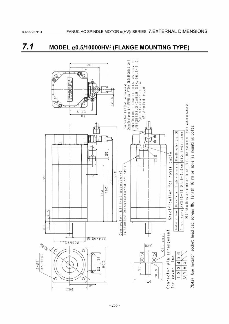
B-65272EN/04 FANUC AC SPINDLE MOTOR α(HV)i SERIES 7.EXTERNAL DIMENSIONS
- 255 -
7.1 MODEL αααα0.5/10000HVi (FLANGE MOUNTING TYPE)
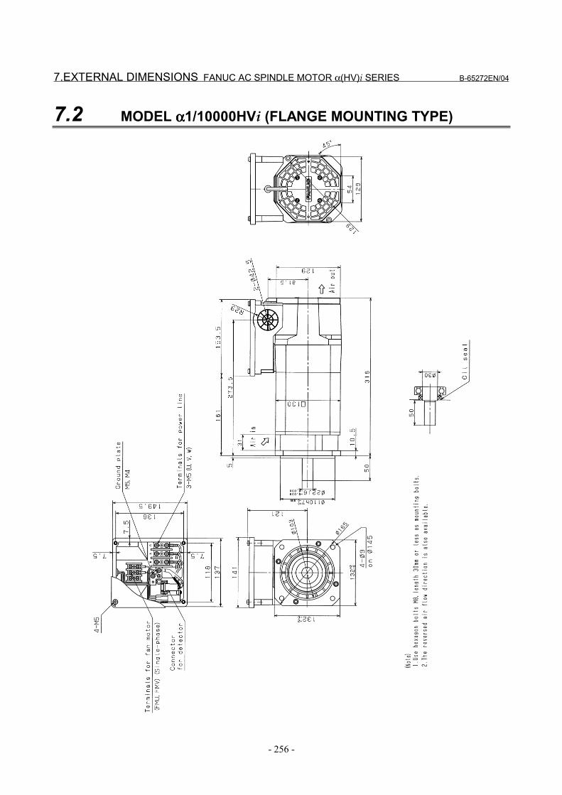
7.EXTERNAL DIMENSIONS FANUC AC SPINDLE MOTOR α(HV)i SERIES B-65272EN/04
- 256 -
7.2 MODEL αααα1/10000HVi (FLANGE MOUNTING TYPE)
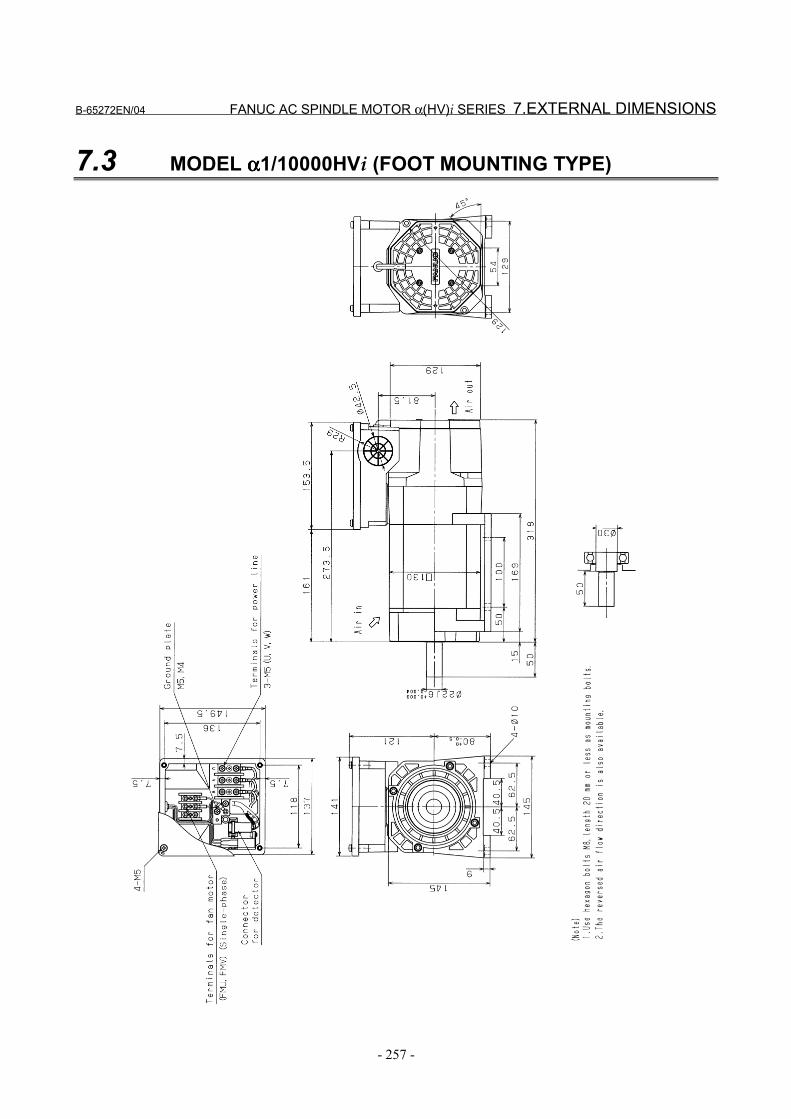
B-65272EN/04 FANUC AC SPINDLE MOTOR α(HV)i SERIES 7.EXTERNAL DIMENSIONS
- 257 -
7.3 MODEL αααα1/10000HVi (FOOT MOUNTING TYPE)
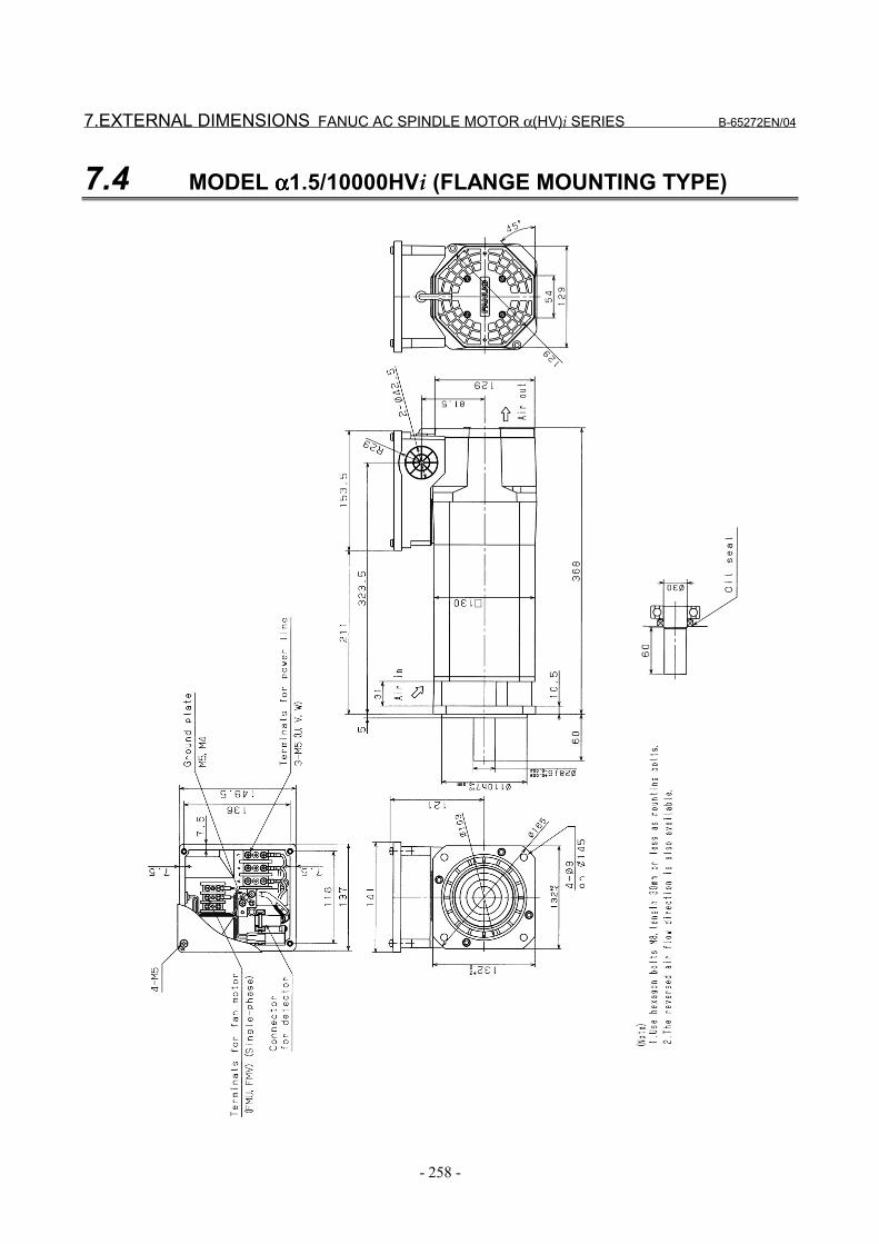
7.EXTERNAL DIMENSIONS FANUC AC SPINDLE MOTOR α(HV)i SERIES B-65272EN/04
- 258 -
7.4 MODEL αααα1.5/10000HVi (FLANGE MOUNTING TYPE)

B-65272EN/04 FANUC AC SPINDLE MOTOR α(HV)i SERIES 7.EXTERNAL DIMENSIONS
- 259 -
7.5 MODEL αααα1.5/10000HVi (FOOT MOUNTING TYPE)
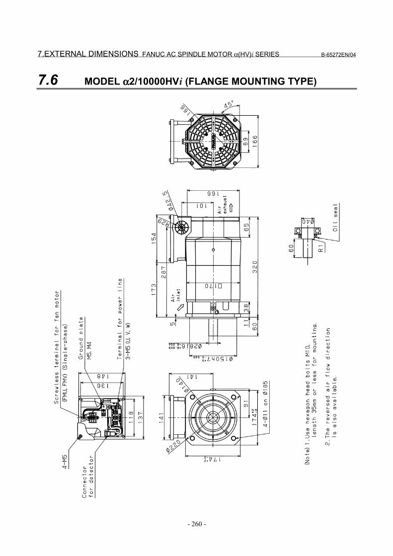
7.EXTERNAL DIMENSIONS FANUC AC SPINDLE MOTOR α(HV)i SERIES B-65272EN/04
- 260 -
7.6 MODEL αααα2/10000HVi (FLANGE MOUNTING TYPE)
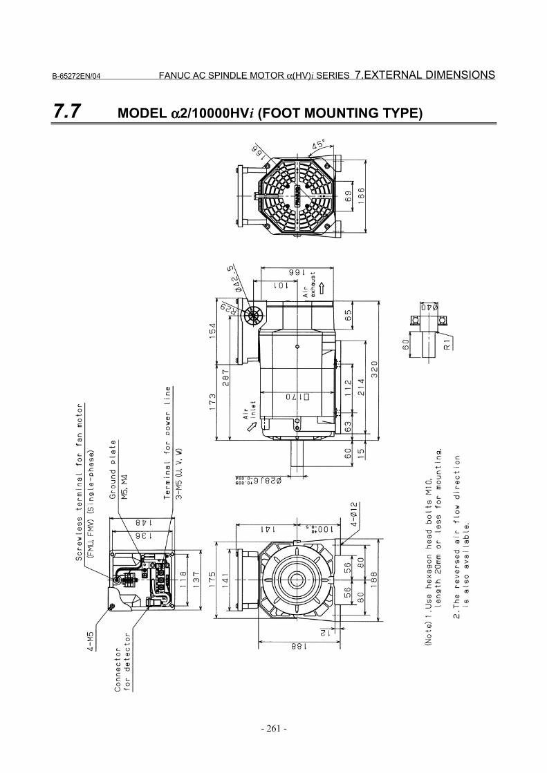
B-65272EN/04 FANUC AC SPINDLE MOTOR α(HV)i SERIES 7.EXTERNAL DIMENSIONS
- 261 -
7.7 MODEL αααα2/10000HVi (FOOT MOUNTING TYPE)
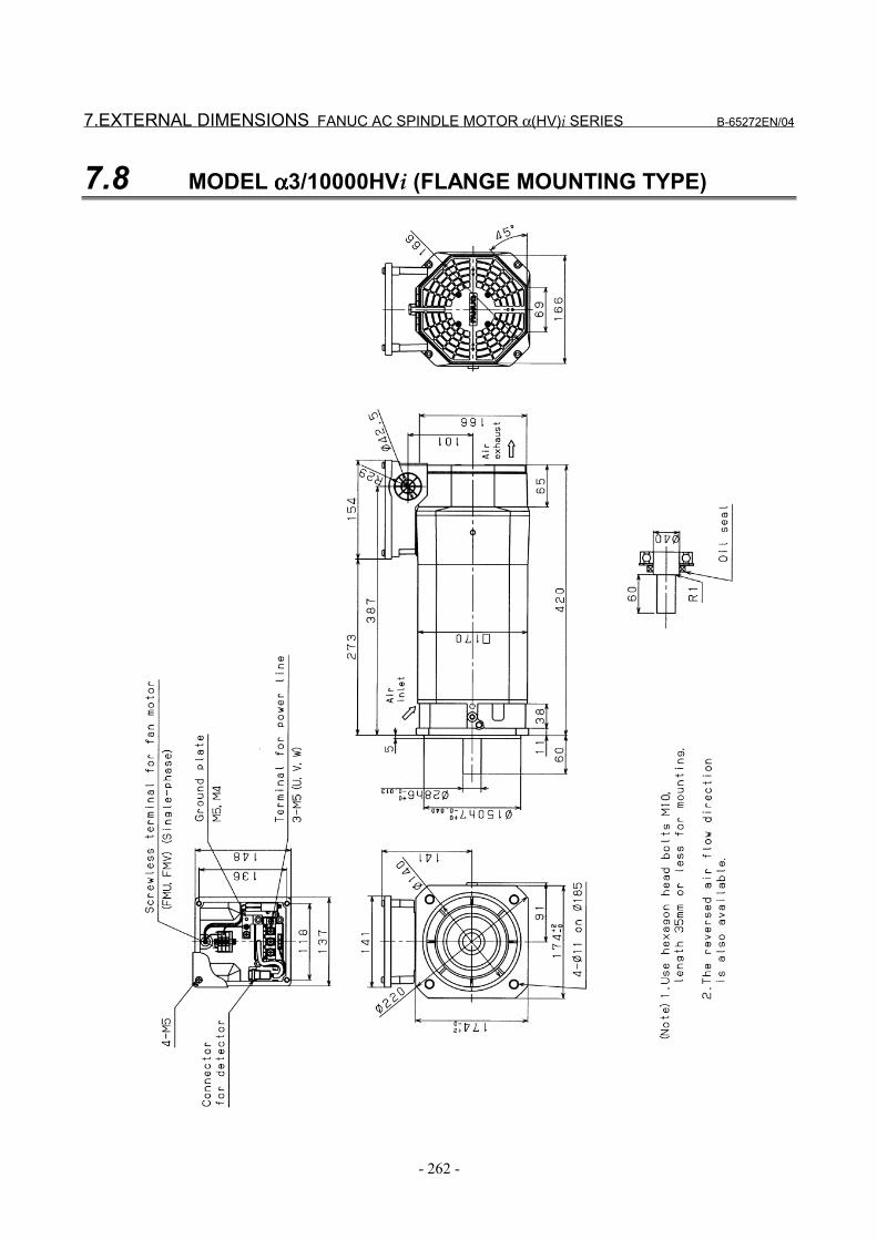
7.EXTERNAL DIMENSIONS FANUC AC SPINDLE MOTOR α(HV)i SERIES B-65272EN/04
- 262 -
7.8 MODEL αααα3/10000HVi (FLANGE MOUNTING TYPE)
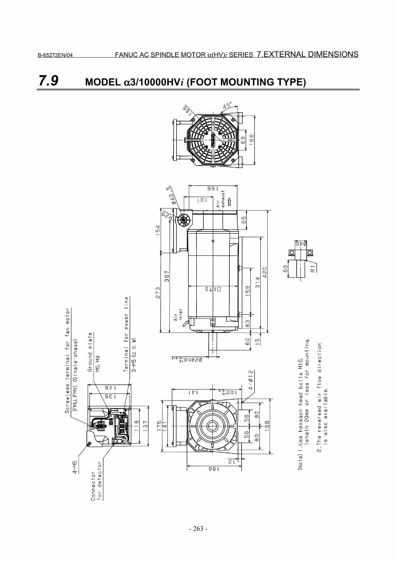
B-65272EN/04 FANUC AC SPINDLE MOTOR α(HV)i SERIES 7.EXTERNAL DIMENSIONS
- 263 -
7.9 MODEL αααα3/10000HVi (FOOT MOUNTING TYPE)
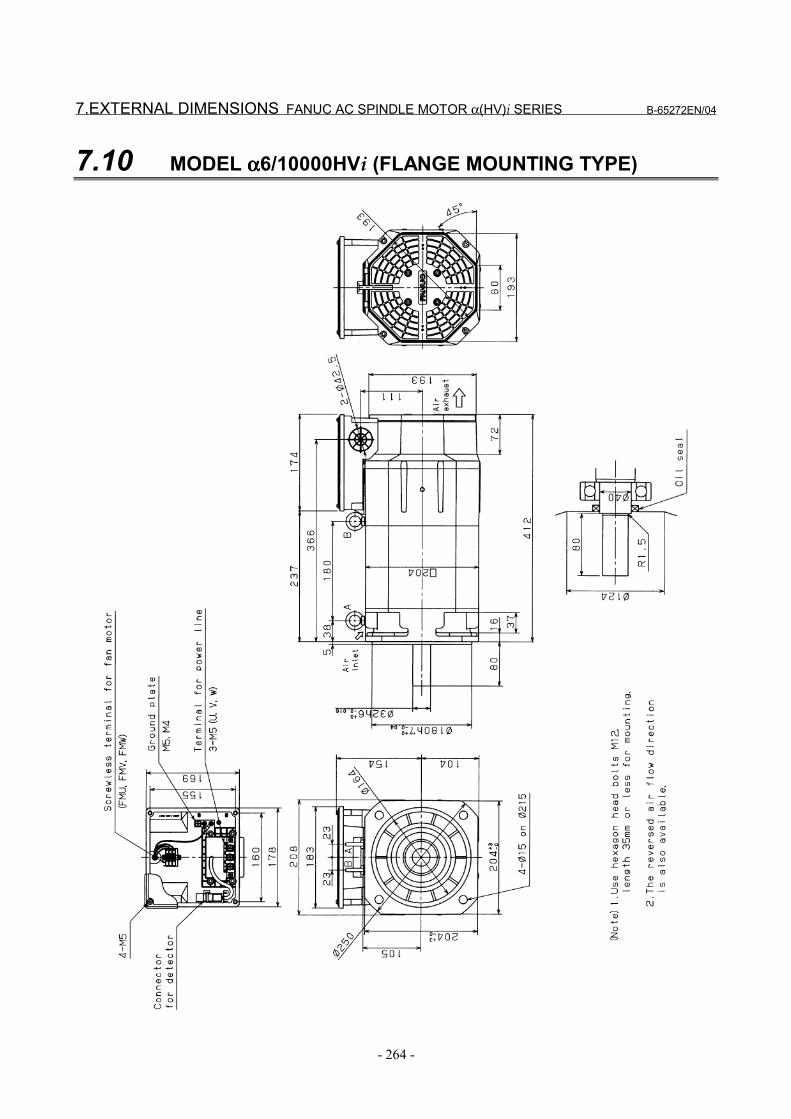
7.EXTERNAL DIMENSIONS FANUC AC SPINDLE MOTOR α(HV)i SERIES B-65272EN/04
- 264 -
7.10 MODEL αααα6/10000HVi (FLANGE MOUNTING TYPE)
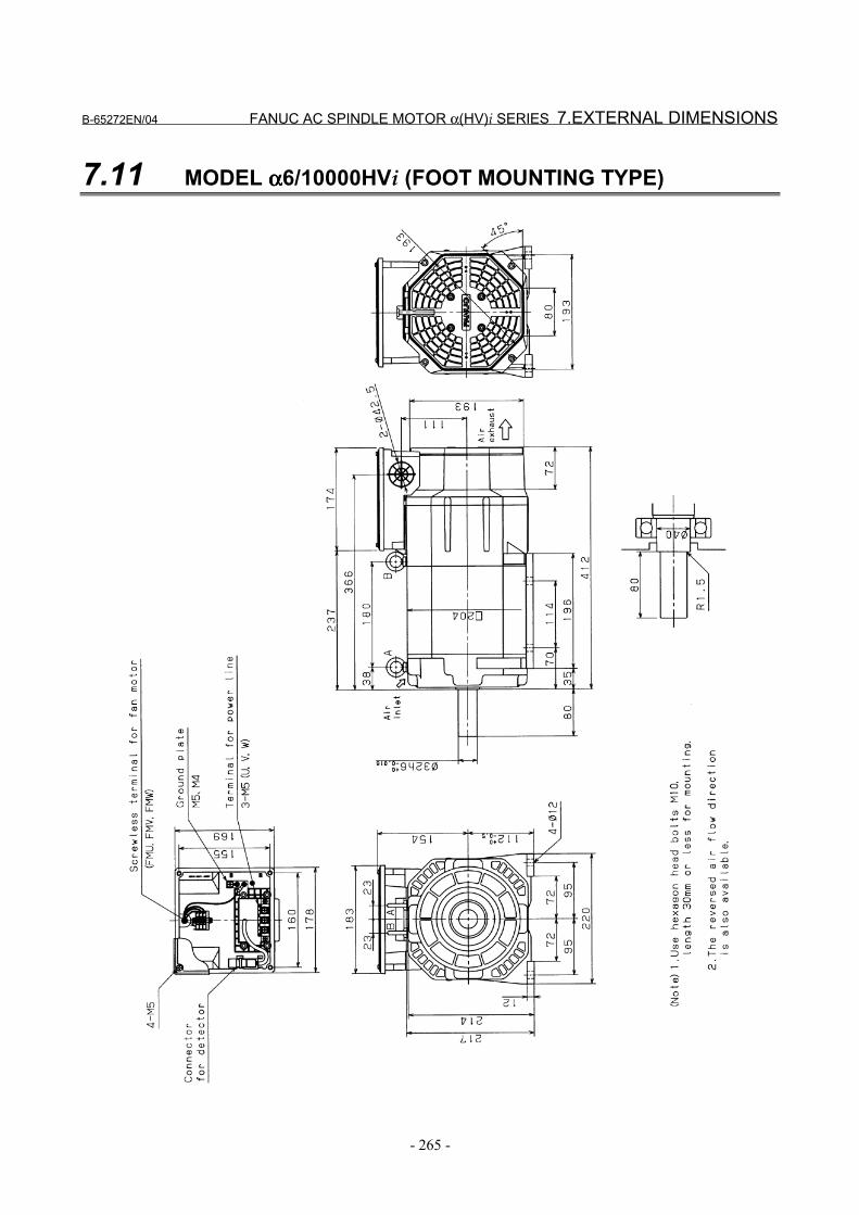
B-65272EN/04 FANUC AC SPINDLE MOTOR α(HV)i SERIES 7.EXTERNAL DIMENSIONS
- 265 -
7.11 MODEL αααα6/10000HVi (FOOT MOUNTING TYPE)
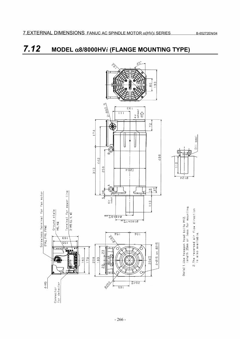
7.EXTERNAL DIMENSIONS FANUC AC SPINDLE MOTOR α(HV)i SERIES B-65272EN/04
- 266 -
7.12 MODEL αααα8/8000HVi (FLANGE MOUNTING TYPE)
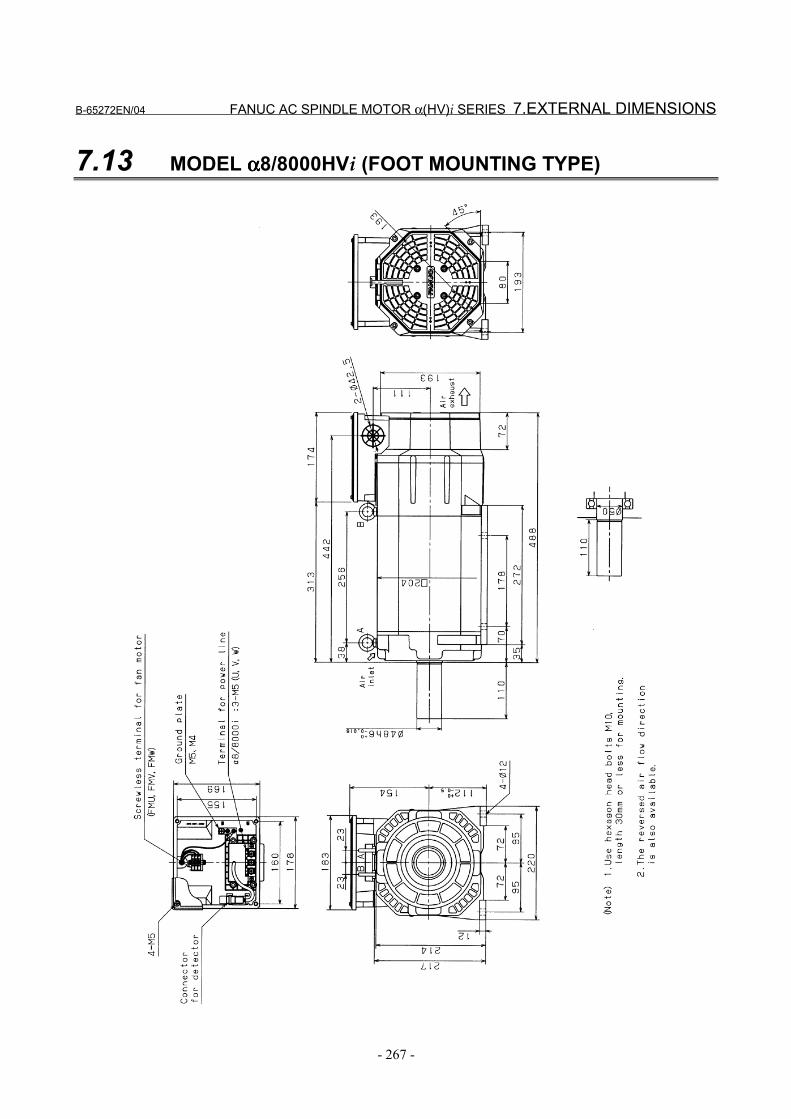
B-65272EN/04 FANUC AC SPINDLE MOTOR α(HV)i SERIES 7.EXTERNAL DIMENSIONS
- 267 -
7.13 MODEL αααα8/8000HVi (FOOT MOUNTING TYPE)
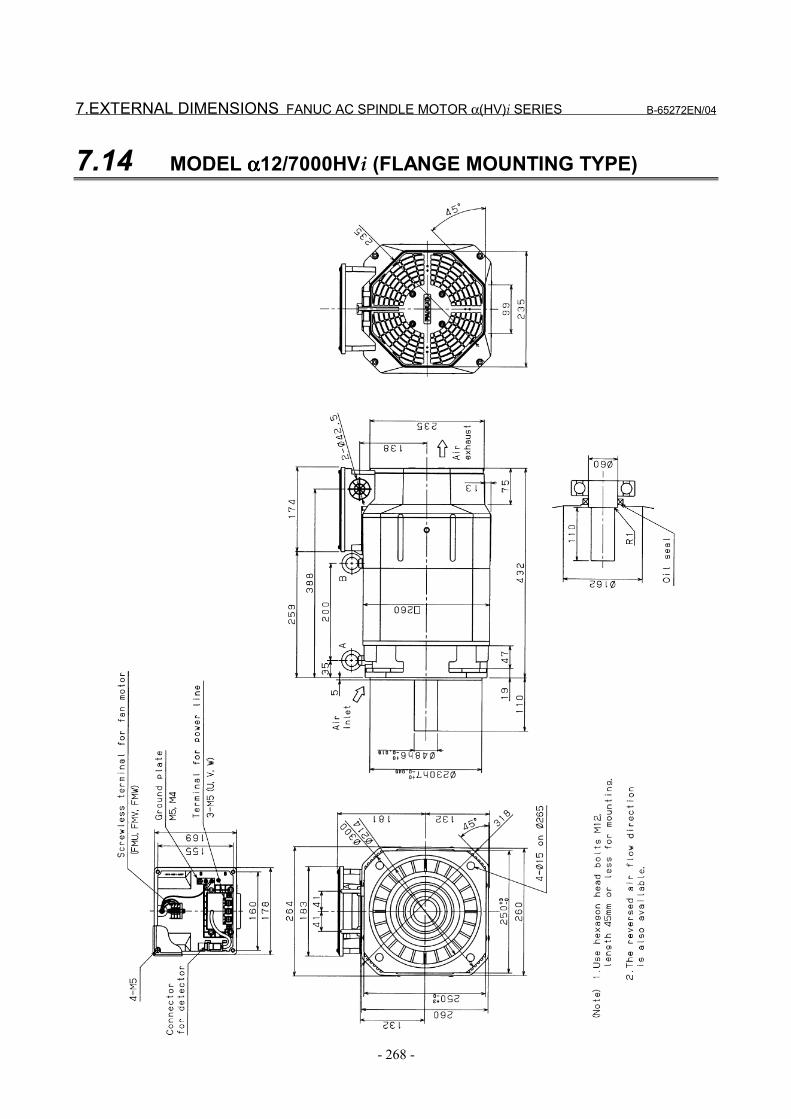
7.EXTERNAL DIMENSIONS FANUC AC SPINDLE MOTOR α(HV)i SERIES B-65272EN/04
- 268 -
7.14 MODEL αααα12/7000HVi (FLANGE MOUNTING TYPE)

B-65272EN/04 FANUC AC SPINDLE MOTOR α(HV)i SERIES 7.EXTERNAL DIMENSIONS
- 269 -
7.15 MODEL αααα12/7000HVi (FOOT MOUNTING TYPE)
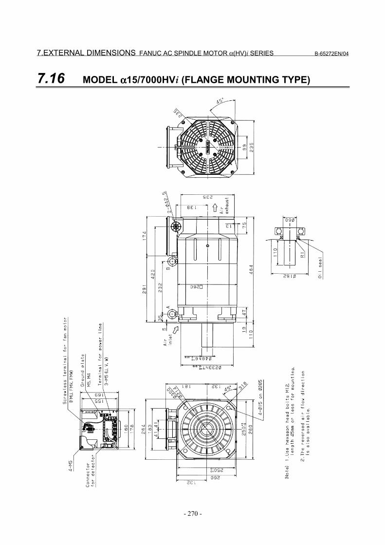
7.EXTERNAL DIMENSIONS FANUC AC SPINDLE MOTOR α(HV)i SERIES B-65272EN/04
- 270 -
7.16 MODEL αααα15/7000HVi (FLANGE MOUNTING TYPE)

B-65272EN/04 FANUC AC SPINDLE MOTOR α(HV)i SERIES 7.EXTERNAL DIMENSIONS
- 271 -
7.17 MODEL αααα15/7000HVi (FOOT MOUNTING TYPE)

7.EXTERNAL DIMENSIONS FANUC AC SPINDLE MOTOR α(HV)i SERIES B-65272EN/04
- 272 -
7.18 MODEL αααα22/7000HVi (FLANGE MOUNTING TYPE)
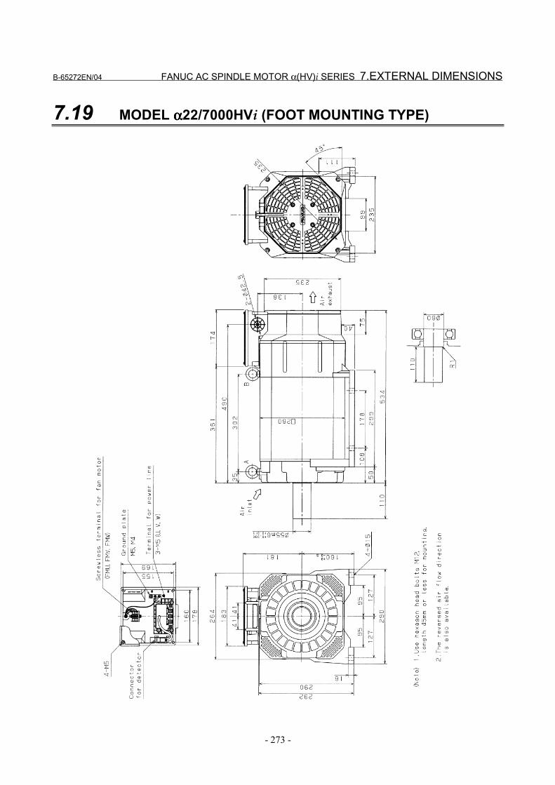
B-65272EN/04 FANUC AC SPINDLE MOTOR α(HV)i SERIES 7.EXTERNAL DIMENSIONS
- 273 -
7.19 MODEL αααα22/7000HVi (FOOT MOUNTING TYPE)
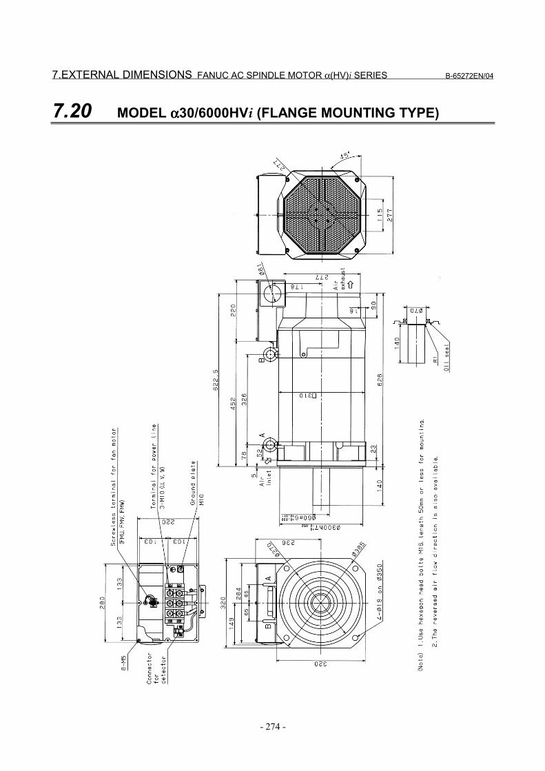
7.EXTERNAL DIMENSIONS FANUC AC SPINDLE MOTOR α(HV)i SERIES B-65272EN/04
- 274 -
7.20 MODEL αααα30/6000HVi (FLANGE MOUNTING TYPE)
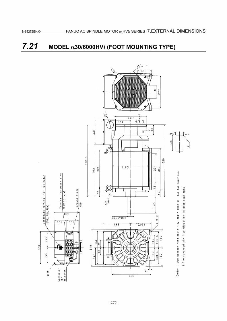
B-65272EN/04 FANUC AC SPINDLE MOTOR α(HV)i SERIES 7.EXTERNAL DIMENSIONS
- 275 -
7.21 MODEL αααα30/6000HVi (FOOT MOUNTING TYPE)

7.EXTERNAL DIMENSIONS FANUC AC SPINDLE MOTOR α(HV)i SERIES B-65272EN/04
- 276 -
7.22 MODEL αααα40/6000HVi (FLANGE MOUNTING TYPE)
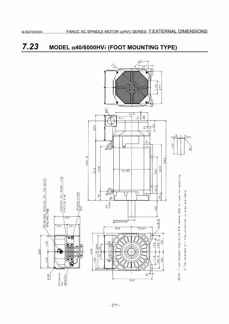
B-65272EN/04 FANUC AC SPINDLE MOTOR α(HV)i SERIES 7.EXTERNAL DIMENSIONS
- 277 -
7.23 MODEL αααα40/6000HVi (FOOT MOUNTING TYPE)
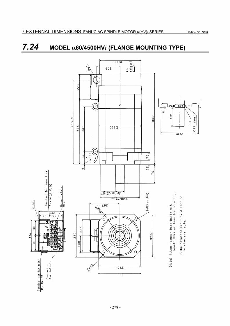
7.EXTERNAL DIMENSIONS FANUC AC SPINDLE MOTOR α(HV)i SERIES B-65272EN/04
- 278 -
7.24 MODEL αααα60/4500HVi (FLANGE MOUNTING TYPE)
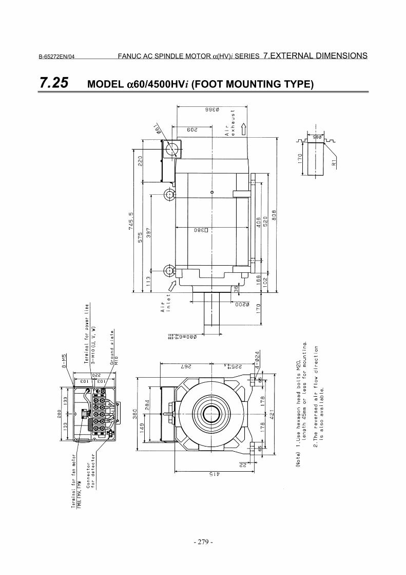
B-65272EN/04 FANUC AC SPINDLE MOTOR α(HV)i SERIES 7.EXTERNAL DIMENSIONS
- 279 -
7.25 MODEL αααα60/4500HVi (FOOT MOUNTING TYPE)
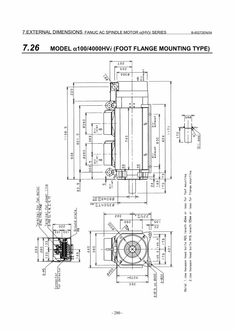
7.EXTERNAL DIMENSIONS FANUC AC SPINDLE MOTOR α(HV)i SERIES B-65272EN/04
- 280 -
7.26 MODEL αααα100/4000HVi (FOOT FLANGE MOUNTING TYPE)
VII. FANUC AC SPINDLE MOTOR αααα(HV)iP SERIES


B-65272EN/04 FANUC AC SPINDLE MOTOR α(HV)iP SERIES 1.GENERAL
- 283 -
1 GENERALFANUC AC spindle motor α(HV)iP series is suitable for structuralsimplification by eliminating the machine spindle gear box.
Features - As the rated output range is wide from 1:10 to 1:16 , a gear box
structure for speed change is not required, thereby allowing thestructure of the machine to be simplified.Accordingly, vibration and noise caused by the gear boxstructure is also eliminated.
- Improvement in efficiency of construction equipmentUnnecessary use of time is reduced because it is not necessary tostop the spindle when switching the gear.
- Despite a compact configuration, a large low-speed torque canbe obtained.
- The method of fan exhaust can be selected from either a exhaustfront type or exhaust rear type, thus preventing heat deformationof the machine.
- Waterproof and pressure-proof design conforming to theinternational standard (IEC) is employed to improve reliabilityand make it resistant to most environments.

2.SPECIFICATIONS FANUC AC SPINDLE MOTOR α(HV)iP SERIES B-65272EN/04
- 284 -
2 SPECIFICATIONS
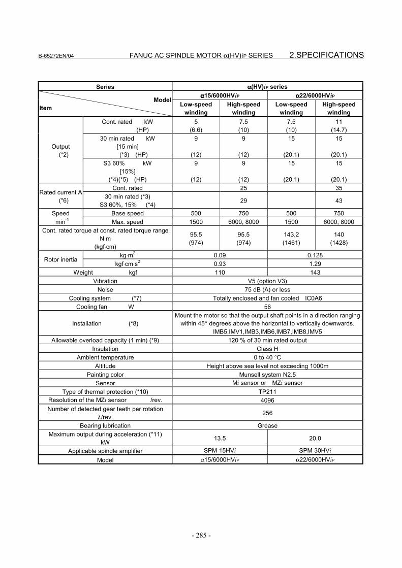
B-65272EN/04 FANUC AC SPINDLE MOTOR α(HV)iP SERIES 2.SPECIFICATIONS
- 285 -
Series αααα(HV)iP seriesαααα15/6000HViP αααα22/6000HViP
ModelItem Low-speed
windingHigh-speed
windingLow-speed
windingHigh-speed
windingCont. rated kW
(HP)5
(6.6)7.5(10)
7.5(10)
11(14.7)
30 min rated kW[15 min]
(*3) (HP)
9
(12)
9
(12)
15
(20.1)
15
(20.1)Output (*2)
S3 60% kW[15%]
(*4)(*5) (HP)
9
(12)
9
(12)
15
(20.1)
15
(20.1)Cont. rated 25 35
Rated current A (*6) 30 min rated (*3)
S3 60%, 15% (*4) 29 43
Speed Base speed 500 750 500 750 min-1 Max. speed 1500 6000, 8000 1500 6000, 8000
Cont. rated torque at const. rated torque rangeN⋅m
(kgf⋅cm)
95.5(974)
95.5(974)
143.2(1461)
140(1428)
kg⋅m2 0.09 0.128Rotor inertia
kgf⋅cm⋅s2 0.93 1.29Weight kgf 110 143
Vibration V5 (option V3)Noise 75 dB (A) or less
Cooling system (*7) Totally enclosed and fan cooled IC0A6Cooling fan W 56
Installation (*8)Mount the motor so that the output shaft points in a direction ranging
within 45° degrees above the horizontal to vertically downwards.IMB5,IMV1,IMB3,IMB6,IMB7,IMB8,IMV5
Allowable overload capacity (1 min) (*9) 120 % of 30 min rated outputInsulation Class H
Ambient temperature 0 to 40 °CAltitude Height above sea level not exceeding 1000m
Painting color Munsell system N2.5Sensor Mi sensor or MZi sensor
Type of thermal protection (*10) TP211Resolution of the MZi sensor /rev. 4096Number of detected gear teeth per rotation
λ/rev. 256
Bearing lubrication GreaseMaximum output during acceleration (*11)
kW 13.5 20.0
Applicable spindle amplifier SPM-15HVi SPM-30HViModel α15/6000HViP α22/6000HViP
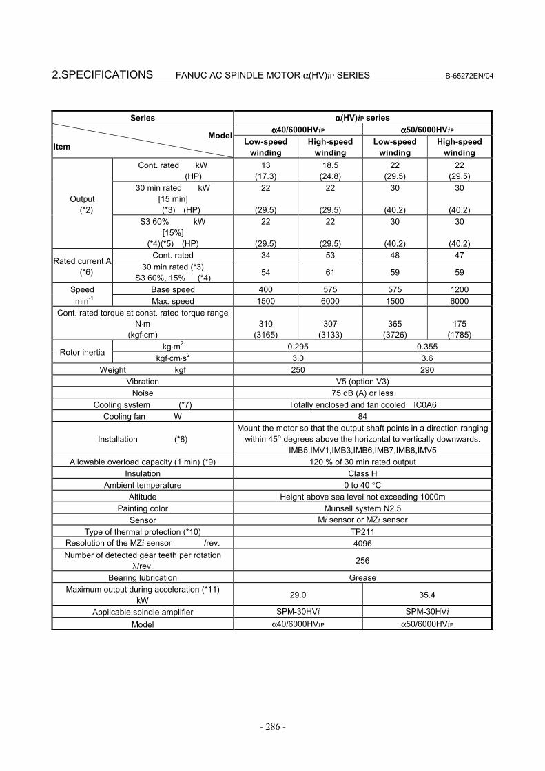
2.SPECIFICATIONS FANUC AC SPINDLE MOTOR α(HV)iP SERIES B-65272EN/04
- 286 -
Series αααα(HV)iP seriesαααα40/6000HViP αααα50/6000HViP
ModelItem Low-speed
windingHigh-speed
windingLow-speed
windingHigh-speed
windingCont. rated kW
(HP)13
(17.3)18.5
(24.8)22
(29.5)22
(29.5)30 min rated kW
[15 min] (*3) (HP)
22
(29.5)
22
(29.5)
30
(40.2)
30
(40.2)Output (*2)
S3 60% kW[15%]
(*4)(*5) (HP)
22
(29.5)
22
(29.5)
30
(40.2)
30
(40.2)Cont. rated 34 53 48 47
Rated current A (*6) 30 min rated (*3)
S3 60%, 15% (*4) 54 61 59 59
Speed Base speed 400 575 575 1200 min-1 Max. speed 1500 6000 1500 6000
Cont. rated torque at const. rated torque rangeN⋅m
(kgf⋅cm)310
(3165)307
(3133)365
(3726)175
(1785)kg⋅m2 0.295 0.355
Rotor inertiakgf⋅cm⋅s2 3.0 3.6
Weight kgf 250 290Vibration V5 (option V3)
Noise 75 dB (A) or lessCooling system (*7) Totally enclosed and fan cooled IC0A6
Cooling fan W 84
Installation (*8)Mount the motor so that the output shaft points in a direction ranging
within 45° degrees above the horizontal to vertically downwards.IMB5,IMV1,IMB3,IMB6,IMB7,IMB8,IMV5
Allowable overload capacity (1 min) (*9) 120 % of 30 min rated outputInsulation Class H
Ambient temperature 0 to 40 °CAltitude Height above sea level not exceeding 1000m
Painting color Munsell system N2.5Sensor Mi sensor or MZi sensor
Type of thermal protection (*10) TP211Resolution of the MZi sensor /rev. 4096Number of detected gear teeth per rotation
λ/rev. 256
Bearing lubrication GreaseMaximum output during acceleration (*11)
kW 29.0 35.4
Applicable spindle amplifier SPM-30HVi SPM-30HViModel α40/6000HViP α50/6000HViP
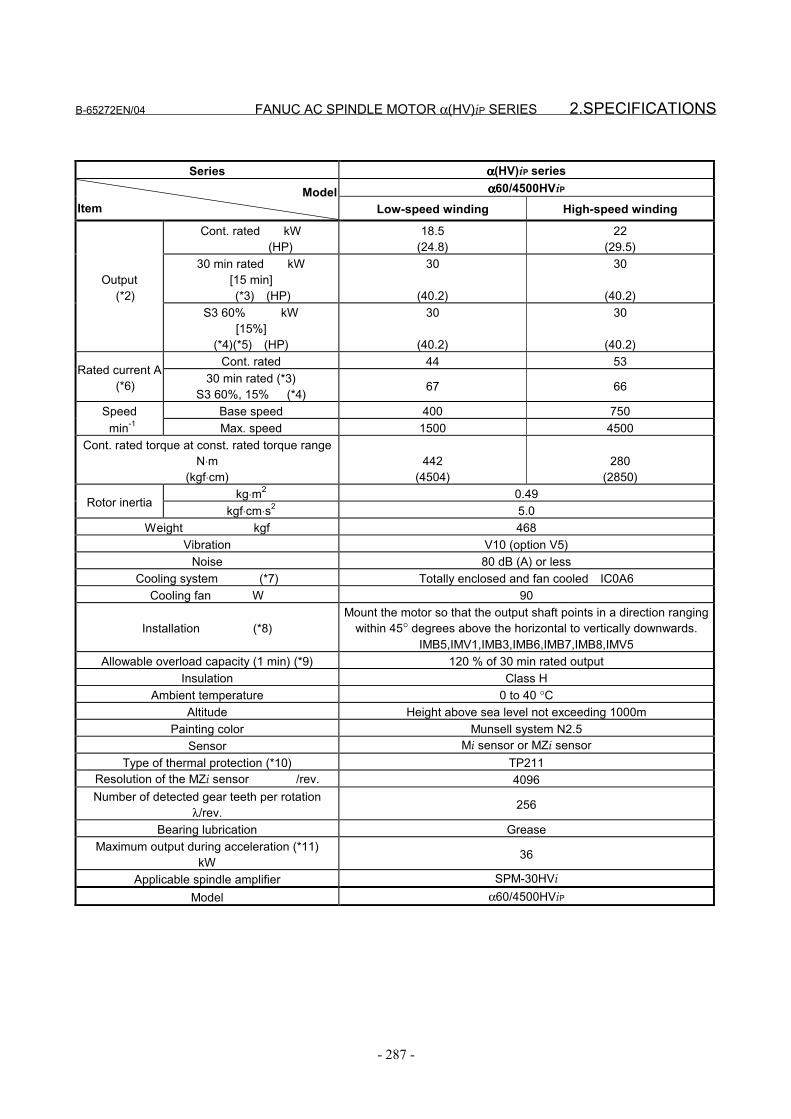
B-65272EN/04 FANUC AC SPINDLE MOTOR α(HV)iP SERIES 2.SPECIFICATIONS
- 287 -
Series αααα(HV)iP seriesαααα60/4500HViPModel
Item Low-speed winding High-speed winding
Cont. rated kW (HP)
18.5(24.8)
22(29.5)
30 min rated kW[15 min]
(*3) (HP)
30
(40.2)
30
(40.2)Output (*2)
S3 60% kW[15%]
(*4)(*5) (HP)
30
(40.2)
30
(40.2)Cont. rated 44 53
Rated current A (*6) 30 min rated (*3)
S3 60%, 15% (*4) 67 66
Speed Base speed 400 750 min-1 Max. speed 1500 4500
Cont. rated torque at const. rated torque rangeN⋅m
(kgf⋅cm)442
(4504)280
(2850)kg⋅m2 0.49
Rotor inertiakgf⋅cm⋅s2 5.0
Weight kgf 468Vibration V10 (option V5)
Noise 80 dB (A) or lessCooling system (*7) Totally enclosed and fan cooled IC0A6
Cooling fan W 90
Installation (*8)Mount the motor so that the output shaft points in a direction ranging
within 45° degrees above the horizontal to vertically downwards.IMB5,IMV1,IMB3,IMB6,IMB7,IMB8,IMV5
Allowable overload capacity (1 min) (*9) 120 % of 30 min rated outputInsulation Class H
Ambient temperature 0 to 40 °CAltitude Height above sea level not exceeding 1000m
Painting color Munsell system N2.5Sensor Mi sensor or MZi sensor
Type of thermal protection (*10) TP211Resolution of the MZi sensor /rev. 4096Number of detected gear teeth per rotation
λ/rev. 256
Bearing lubrication GreaseMaximum output during acceleration (*11)
kW 36
Applicable spindle amplifier SPM-30HViModel α60/4500HViP
2.SPECIFICATIONS FANUC AC SPINDLE MOTOR α(HV)iP SERIES B-65272EN/04
- 288 -
(*1) When the output switch function is used, the CNC soft optionand switching magnetic contactor unit associated with theoutput switch function (Y-∆ switch) are required.See FANUC SERVO AMPLIFIER αi series DESCRIPTIONS(B-65282EN) for details of the output switch control.
(*2) The rated output is guaranteed at the rated voltage.(Amplifier input: 400/480VAC +10% -15%, 50/60 Hz ±1Hz)If the input voltage fluctuates, it is possible that the rated outputcannot be obtained even when such fluctuations are within theallowable fluctuation range.
(*3) The output for low-speed winding models other thanα50/6000HViP and α60/4500HViP is 15 min rated.
(*4) S3 15% for low-speed winding models other thanα50/6000HViP and α60/4500HViP.S3 25% for low-speed winding of α50/6000HViP andα60/4500HViP
(*5) The cycle time is 10 minutes, S3 60%: ON 6 minutes, OFF 4minutes, S3 25%: ON 2.5 minutes, OFF 7.5 minutes and S315%: ON 1.5 minutes, OFF 8.5 minutes.
(*6) The rated current is not a guaranteed value but a guideline forthe maximum current at each rated output.
(*7) IC code conforms to IEC 34-6.(*8) IM code conforms to IEC 34-7.(*9) This is not a guaranteed value but a guideline for the maximum
motor output at a rated supply voltage.(*10) Type conforms to IEC 34-11.(*11) These values are to be used only as guidance for selecting a
power supply module and are not guaranteed.(*12) Degree of protection:
with oil seal: IP54, without oil seal: IP40.

B-65272EN/04 FANUC AC SPINDLE MOTOR α(HV)iP SERIES 3.OUTPUT/TORQUE CHARACTERISTICS
- 289 -
3 OUTPUT/TORQUE CHARACTERISTICSReferenceCalculation for torque
Torque T can be obtained by the following equation.
T[N⋅m]=P[kW]×1000/0.1047/N[min-1]P[kW]: Motor outputN[min-1]: Motor speed
When the unit of T is [kgf⋅m],T[kgf⋅m]=P[kW]×1000/1.0269/N[min-1]
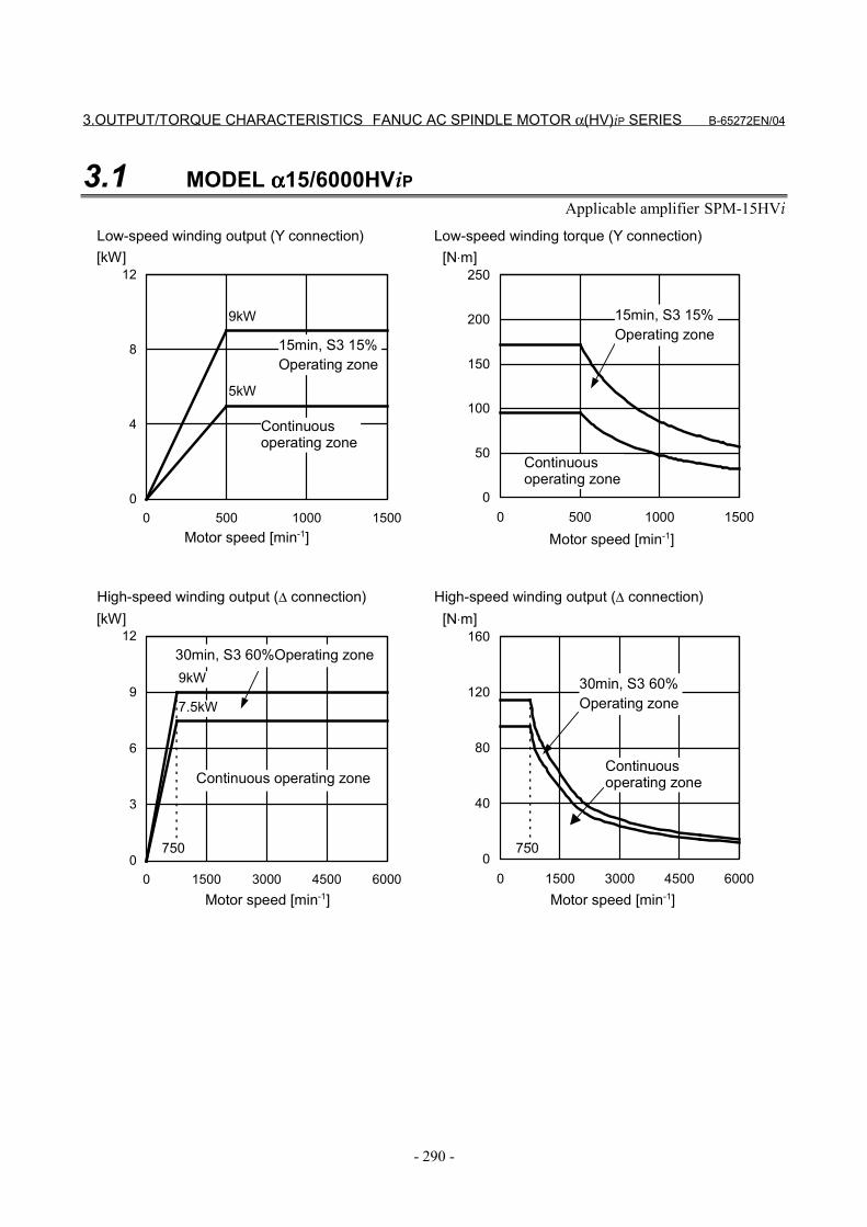
3.OUTPUT/TORQUE CHARACTERISTICS FANUC AC SPINDLE MOTOR α(HV)iP SERIES B-65272EN/04
- 290 -
3.1 MODEL αααα15/6000HViPApplicable amplifier SPM-15HVi
0
4
8
12
0 500 1000 1500
[kW]
0
50
100
150
200
250
0 500 1000 1500
[N⋅m]
9kW
0
3
6
9
12
0 1500 3000 4500 6000
[kW]
0
40
80
120
160
0 1500 3000 4500 6000
[N⋅m]
9kW
7.5kW
5kW
750750
Motor speed [min-1]
Continuousoperating zone
15min, S3 15%Operating zone
Motor speed [min-1]
15min, S3 15%Operating zone
Continuousoperating zone
Low-speed winding output (Y connection) Low-speed winding torque (Y connection)
Motor speed [min-1]
Continuous operating zone
30min, S3 60%Operating zone
Motor speed [min-1]
30min, S3 60%Operating zone
Continuousoperating zone
High-speed winding output (∆ connection) High-speed winding output (∆ connection)
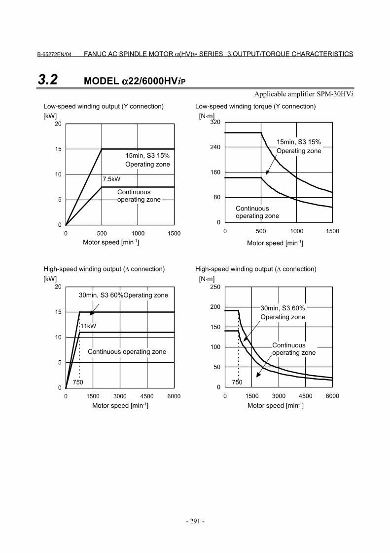
B-65272EN/04 FANUC AC SPINDLE MOTOR α(HV)iP SERIES 3.OUTPUT/TORQUE CHARACTERISTICS
- 291 -
3.2 MODEL αααα22/6000HViPApplicable amplifier SPM-30HVi
0
5
10
15
20
0 500 1000 1500
[kW]
0
80
160
240
320
0 500 1000 1500
[N⋅m]
0
5
10
15
20
0 1500 3000 4500 6000
[kW]
0
50
100
150
200
250
0 1500 3000 4500 6000
[N⋅m]
11kW
7.5kW
750750
Motor speed [min-1]
Continuousoperating zone
15min, S3 15%Operating zone
Motor speed [min-1]
15min, S3 15%Operating zone
Continuousoperating zone
Low-speed winding output (Y connection) Low-speed winding torque (Y connection)
Motor speed [min-1]
Continuous operating zone
30min, S3 60%Operating zone
Motor speed [min-1]
30min, S3 60%Operating zone
Continuousoperating zone
High-speed winding output (∆ connection) High-speed winding output (∆ connection)
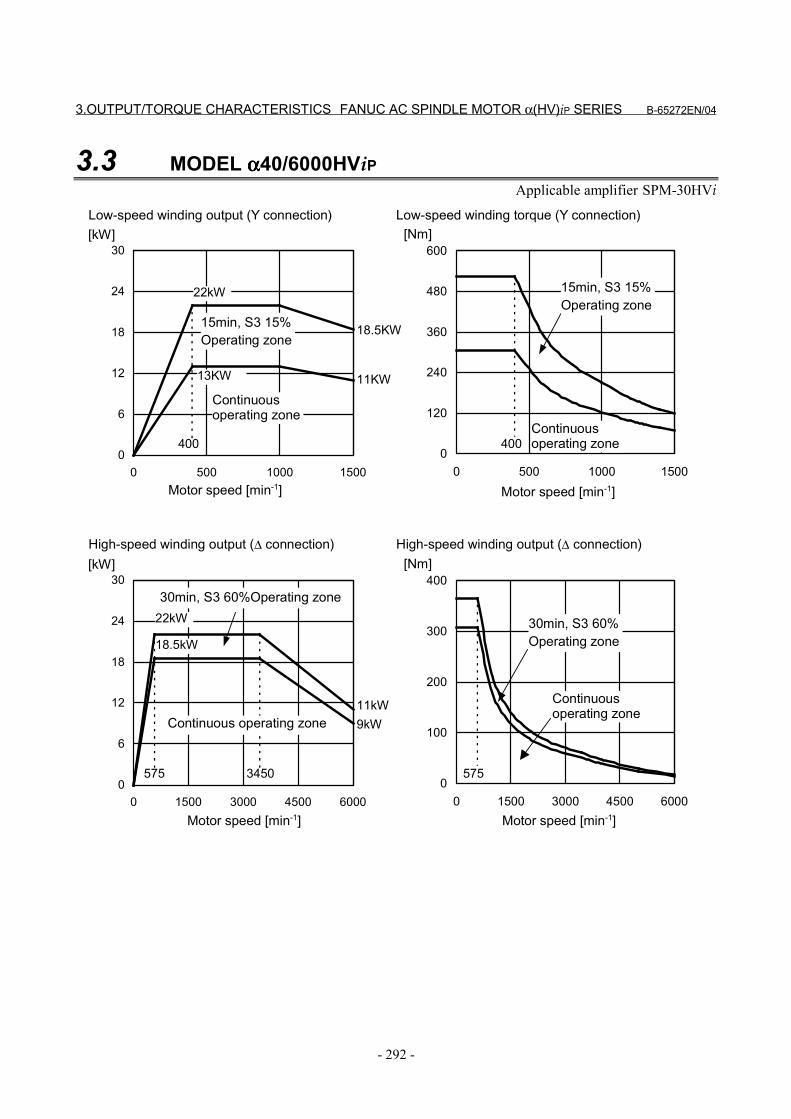
3.OUTPUT/TORQUE CHARACTERISTICS FANUC AC SPINDLE MOTOR α(HV)iP SERIES B-65272EN/04
- 292 -
3.3 MODEL αααα40/6000HViPApplicable amplifier SPM-30HVi
0
6
12
18
24
30
0 500 1000 1500
[kW]
0
120
240
360
480
600
0 500 1000 1500
[Nm]
22kW
0
6
12
18
24
30
0 1500 3000 4500 6000
[kW]
0
100
200
300
400
0 1500 3000 4500 6000
[Nm]
22kW
18.5kW
13KW
575575
400 400
3450
11kW9kW
Motor speed [min-1]
Continuousoperating zone
15min, S3 15%Operating zone
Motor speed [min-1]
15min, S3 15%Operating zone
Continuousoperating zone
Low-speed winding output (Y connection) Low-speed winding torque (Y connection)
Motor speed [min-1]
Continuous operating zone
30min, S3 60%Operating zone
Motor speed [min-1]
30min, S3 60%Operating zone
Continuousoperating zone
High-speed winding output (∆ connection) High-speed winding output (∆ connection)
11KW
18.5KW
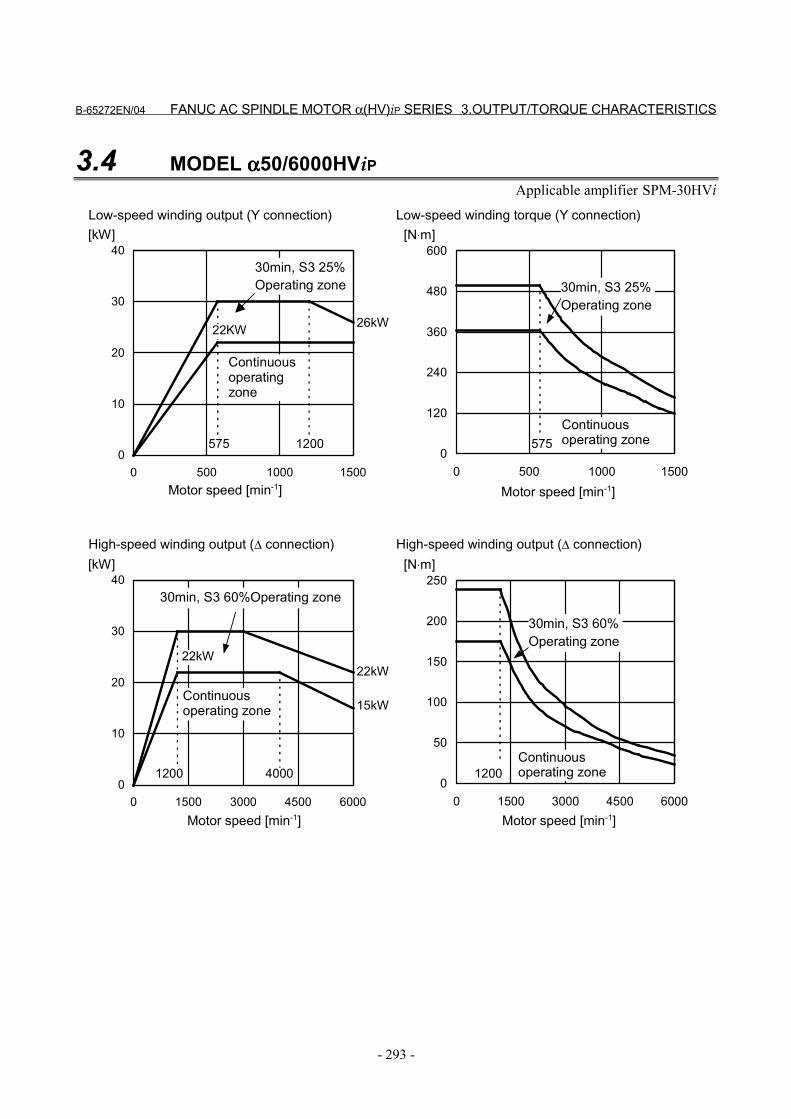
B-65272EN/04 FANUC AC SPINDLE MOTOR α(HV)iP SERIES 3.OUTPUT/TORQUE CHARACTERISTICS
- 293 -
3.4 MODEL αααα50/6000HViPApplicable amplifier SPM-30HVi
0
10
20
30
40
0 500 1000 1500
[kW]
0
120
240
360
480
600
0 500 1000 1500
[N⋅m]
0
10
20
30
40
0 1500 3000 4500 6000
[kW]
0
50
100
150
200
250
0 1500 3000 4500 6000
[N⋅m]
22kW
22KW
12001200
575 575
4000
22kW
15kW
26kW
1200
Motor speed [min-1]
Continuousoperatingzone
30min, S3 25%Operating zone
Motor speed [min-1]
30min, S3 25%Operating zone
Continuousoperating zone
Low-speed winding output (Y connection) Low-speed winding torque (Y connection)
Motor speed [min-1]
Continuousoperating zone
30min, S3 60%Operating zone
Motor speed [min-1]
30min, S3 60%Operating zone
Continuousoperating zone
High-speed winding output (∆ connection) High-speed winding output (∆ connection)
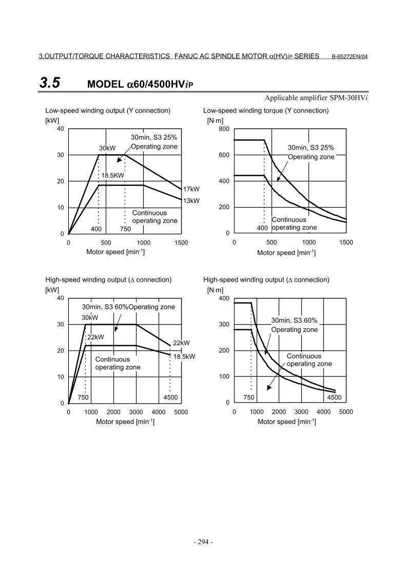
3.OUTPUT/TORQUE CHARACTERISTICS FANUC AC SPINDLE MOTOR α(HV)iP SERIES B-65272EN/04
- 294 -
3.5 MODEL αααα60/4500HViPApplicable amplifier SPM-30HVi
0
10
20
30
40
0 500 1000 1500
[kW]
0
200
400
600
800
0 500 1000 1500
[N⋅m]
30kW
0
10
20
30
40
0 1000 2000 3000 4000 5000
[kW]
0
100
200
300
400
0 1000 2000 3000 4000 5000
[N⋅m]
22kW
18.5kW
18.5KW
750750
400 400
4500
30kW
22kW
17kW
13kW
750
4500
Motor speed [min-1]
Continuousoperating zone
30min, S3 25%Operating zone
Motor speed [min-1]
30min, S3 25%Operating zone
Continuousoperating zone
Low-speed winding output (Y connection) Low-speed winding torque (Y connection)
Motor speed [min-1]
Continuousoperating zone
30min, S3 60%Operating zone
Motor speed [min-1]
30min, S3 60%Operating zone
Continuousoperating zone
High-speed winding output (∆ connection) High-speed winding output (∆ connection)

B-65272EN/04 FANUC AC SPINDLE MOTOR α(HV)iP SERIES 4.CONNECTIONS
- 295 -
4 CONNECTIONS
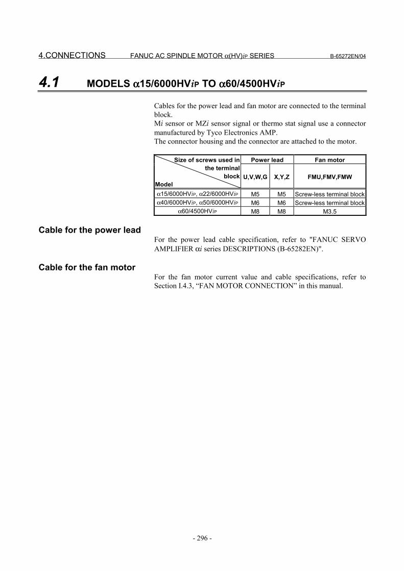
4.CONNECTIONS FANUC AC SPINDLE MOTOR α(HV)iP SERIES B-65272EN/04
- 296 -
4.1 MODELS αααα15/6000HViP TO αααα60/4500HViP
Cables for the power lead and fan motor are connected to the terminalblock.Mi sensor or MZi sensor signal or thermo stat signal use a connectormanufactured by Tyco Electronics AMP.The connector housing and the connector are attached to the motor.
Power lead Fan motorSize of screws used inthe terminal
blockModel
U,V,W,G X,Y,Z FMU,FMV,FMW
α15/6000HViP, α22/6000HViP M5 M5 Screw-less terminal blockα40/6000HViP, α50/6000HViP M6 M6 Screw-less terminal block
α60/4500HViP M8 M8 M3.5
Cable for the power leadFor the power lead cable specification, refer to "FANUC SERVOAMPLIFIER αi series DESCRIPTIONS (B-65282EN)".
Cable for the fan motorFor the fan motor current value and cable specifications, refer toSection I.4.3, “FAN MOTOR CONNECTION” in this manual.

B-65272EN/04 FANUC AC SPINDLE MOTOR α(HV)iP SERIES 4.CONNECTIONS
- 297 -
4.2 CONNECTION OF SIGNAL LEAD
Connector attachment for a motor with a built-in Mi sensorConnector pins arrangement
Number B1 B2 B3 B4 B5 B6ColorSignal RA RB 0V THR2
Number A1 A2 A3 A4 A5 A6ColorSignal +5V PA PB SS THR1
Connector attachment for a motor with a built-in MZi sensor Connector pins arrangement
Number B1 B2 B3 B4 B5 B6ColorSignal *VA *VB *VZ 0V THR2
Number A1 A2 A3 A4 A5 A6ColorSignal +5V VA VB VZ SS THR1
- Connector housing and contact specificationsConnector and contact :Tyco Electronics AMP specification D-3000 series
Motor side Cable side
FANUC specification Manuafacturespecification FANUC specification Manuafacture
specificationHousing A63L-0001-0535/121KDF 178964-6 A63L-0001-0460/121KD 178289-6Contact A63L-0001-0456/ASMT 175288-2 A63L-0001-0456/ASM 1-175217-2
Crimping tool : 91559-1 Extractor : 234168-1
- Thermistor specificationSignal THR1 corresponds to one of the thermistor terminals, andsignal THR2, to the other terminal. The resistance of the thermistor isabout 30 to 90 kΩ as measured at room temperature (20°C to 30°C).
TH R 1TH R 2+ 5V0VP AP BR AR BS S
TH R1TH R2+5V0VV A*V AV B*V BV Z*V ZS S
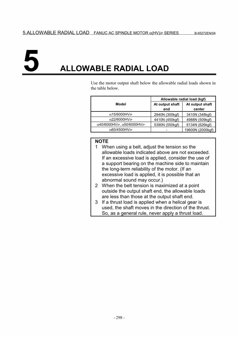
5.ALLOWABLE RADIAL LOAD FANUC AC SPINDLE MOTOR α(HV)iP SERIES B-65272EN/04
- 298 -
5 ALLOWABLE RADIAL LOADUse the motor output shaft below the allowable radial loads shown inthe table below.
Allowable radial load (kgf)Model At output shaft
endAt output shaft
centerα15/6000HViP 2940N (300kgf) 3410N (348kgf)α22/6000HViP 4410N (450kgf) 4988N (509kgf)
α40/6000HViP, α50/6000HViP 5390N (550kgf) 6134N (626kgf)α60/4500HViP - 19600N (2000kgf)
NOTE1 When using a belt, adjust the tension so the
allowable loads indicated above are not exceeded.If an excessive load is applied, consider the use ofa support bearing on the machine side to maintainthe long-term reliability of the motor. (If anexcessive load is applied, it is possible that anabnormal sound may occur.)
2 When the belt tension is maximized at a pointoutside the output shaft end, the allowable loadsare less than those at the output shaft end.
3 If a thrust load is applied when a helical gear isused, the shaft moves in the direction of the thrust.So, as a general rule, never apply a thrust load.
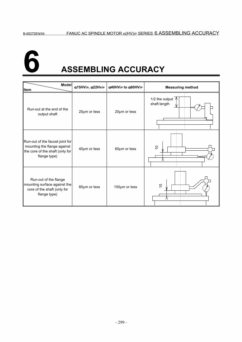
B-65272EN/04 FANUC AC SPINDLE MOTOR α(HV)iP SERIES 6.ASSEMBLING ACCURACY
- 299 -
6 ASSEMBLING ACCURACYModel
Item αααα15HViP, αααα22HviP αααα40HViP to αααα60HViP Measuring method
Run-out at the end of theoutput shaft 20µm or less 20µm or less
1/2 the outputshaft length
Run-out of the faucet joint formounting the flange againstthe core of the shaft (only for
flange type)
40µm or less 60µm or less 10
Run-out of the flangemounting surface against the
core of the shaft (only forflange type)
80µm or less 100µm or less 10
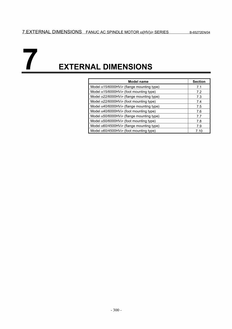
7.EXTERNAL DIMENSIONS FANUC AC SPINDLE MOTOR α(HV)iP SERIES B-65272EN/04
- 300 -
7 EXTERNAL DIMENSIONSModel name Section
Model α15/6000HViP (flange mounting type) 7.1Model α15/6000HViP (foot mounting type) 7.2Model α22/6000HViP (flange mounting type) 7.3Model α22/6000HViP (foot mounting type) 7.4Model α40/6000HViP (flange mounting type) 7.5Model α40/6000HViP (foot mounting type) 7.6Model α50/6000HViP (flange mounting type) 7.7Model α50/6000HViP (foot mounting type) 7.8Model α60/4500HViP (flange mounting type) 7.9Model α60/4500HViP (foot mounting type) 7.10
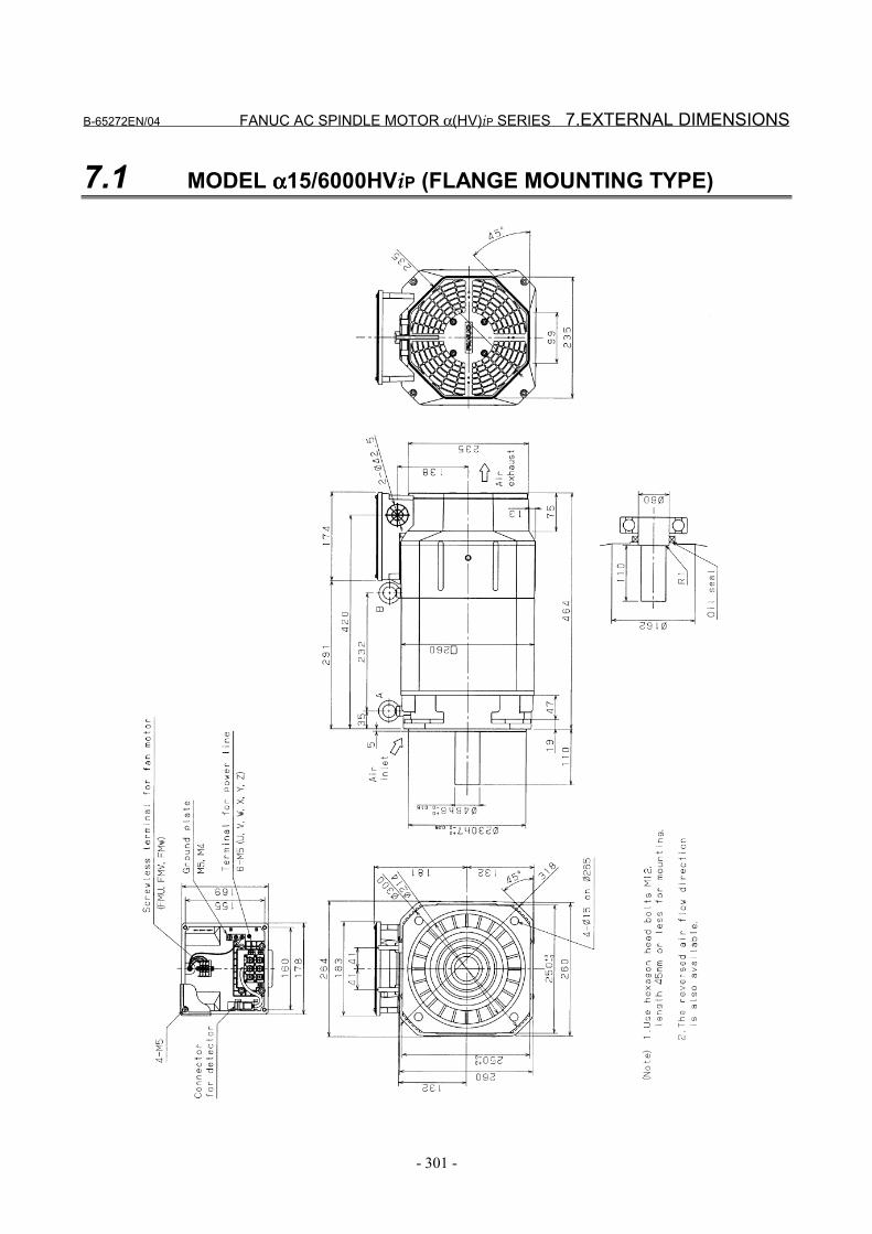
B-65272EN/04 FANUC AC SPINDLE MOTOR α(HV)iP SERIES 7.EXTERNAL DIMENSIONS
- 301 -
7.1 MODEL αααα15/6000HViP (FLANGE MOUNTING TYPE)

7.EXTERNAL DIMENSIONS FANUC AC SPINDLE MOTOR α(HV)iP SERIES B-65272EN/04
- 302 -
7.2 MODEL αααα15/6000HViP (FOOT MOUNTING TYPE)

B-65272EN/04 FANUC AC SPINDLE MOTOR α(HV)iP SERIES 7.EXTERNAL DIMENSIONS
- 303 -
7.3 MODEL αααα22/6000HViP (FLANGE MOUNTING TYPE)

7.EXTERNAL DIMENSIONS FANUC AC SPINDLE MOTOR α(HV)iP SERIES B-65272EN/04
- 304 -
7.4 MODEL αααα22/6000HViP (FOOT MOUNTING TYPE)
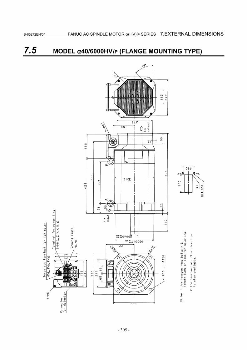
B-65272EN/04 FANUC AC SPINDLE MOTOR α(HV)iP SERIES 7.EXTERNAL DIMENSIONS
- 305 -
7.5 MODEL αααα40/6000HViP (FLANGE MOUNTING TYPE)
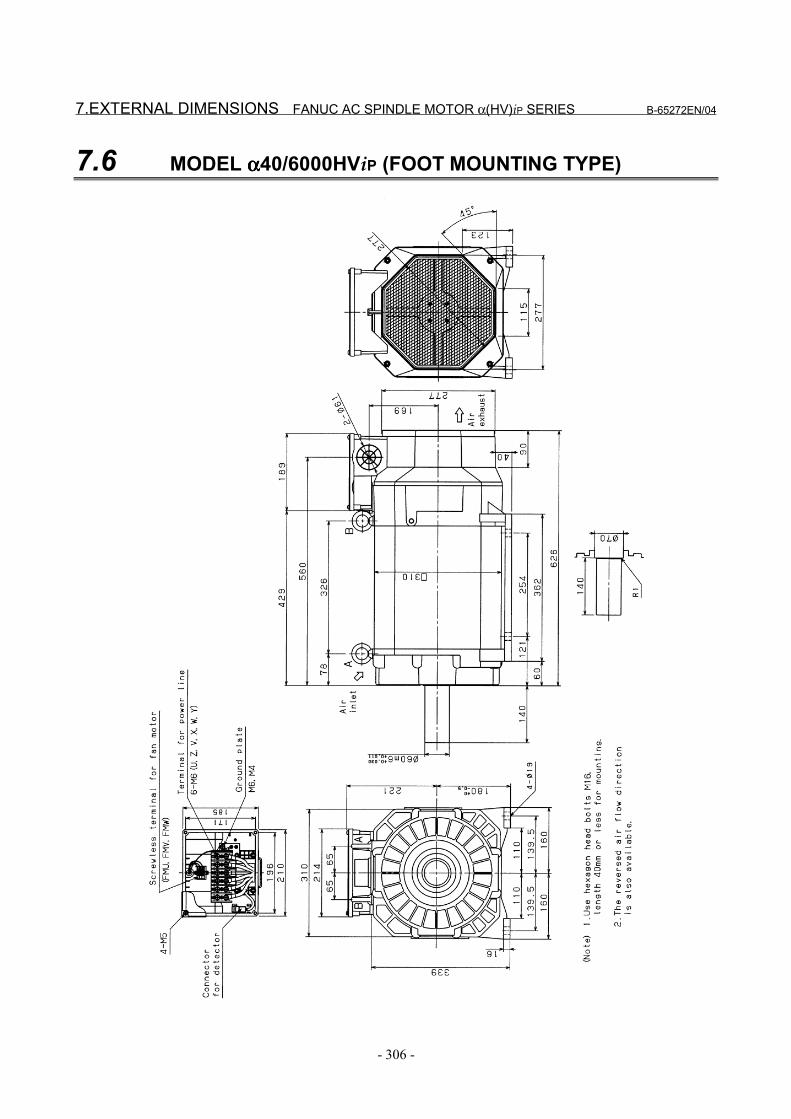
7.EXTERNAL DIMENSIONS FANUC AC SPINDLE MOTOR α(HV)iP SERIES B-65272EN/04
- 306 -
7.6 MODEL αααα40/6000HViP (FOOT MOUNTING TYPE)

B-65272EN/04 FANUC AC SPINDLE MOTOR α(HV)iP SERIES 7.EXTERNAL DIMENSIONS
- 307 -
7.7 MODEL αααα50/6000HViP (FLANGE MOUNTING TYPE)

7.EXTERNAL DIMENSIONS FANUC AC SPINDLE MOTOR α(HV)iP SERIES B-65272EN/04
- 308 -
7.8 MODEL αααα50/6000HViP (FOOT MOUNTING TYPE)
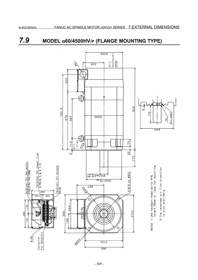
B-65272EN/04 FANUC AC SPINDLE MOTOR α(HV)iP SERIES 7.EXTERNAL DIMENSIONS
- 309 -
7.9 MODEL αααα60/4500HViP (FLANGE MOUNTING TYPE)
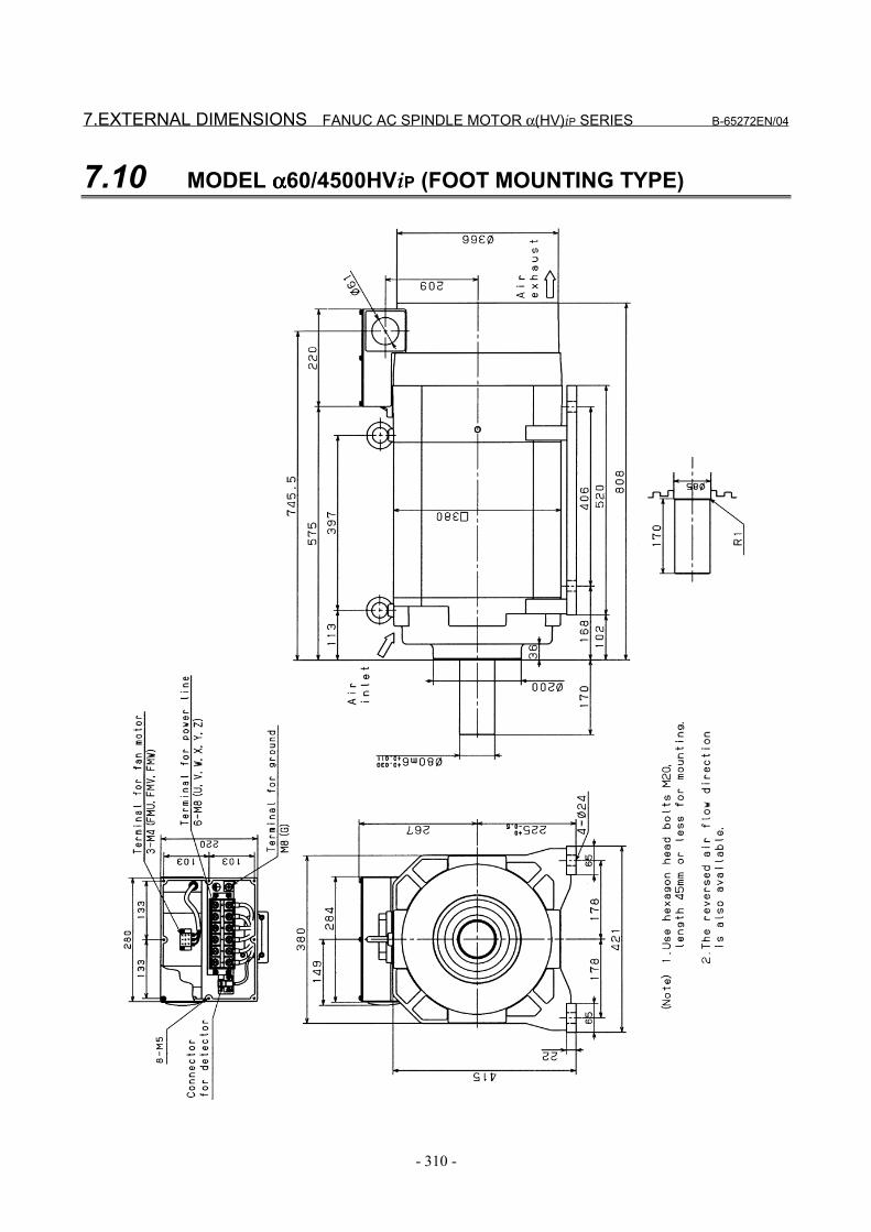
7.EXTERNAL DIMENSIONS FANUC AC SPINDLE MOTOR α(HV)iP SERIES B-65272EN/04
- 310 -
7.10 MODEL αααα60/4500HViP (FOOT MOUNTING TYPE)

VIII. FANUC AC SPINDLE MOTOR αααα(HV)iT SERIES

B-65272EN/04 FANUC AC SPINDLE MOTOR α(HV)iT SERIES 1.GENERAL
- 313 -
1 GENERALThe FANUC AC Spindle Motor α(HV)iT series includes spindlemotors (hollow shaft), which can be driven by 400 to 480VACwithout a step-down transformer(*1).(*1) For models α1.5HViT, α2HViT, and α3HViT, however, a single-
phase step-down transformer for fan motors is required when480VAC is applied.
Features - For features of a spindle that is directly connected to a motor,
see the αiT series section.

2.SPECIFICATIONS FANUC AC SPINDLE MOTOR α(HV)iT SERIES B-65272EN/04
- 314 -
2 SPECIFICATIONS
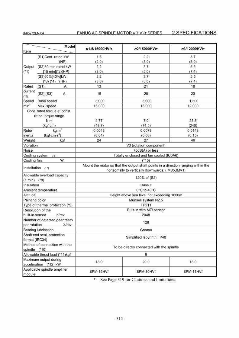
B-65272EN/04 FANUC AC SPINDLE MOTOR α(HV)iT SERIES 2.SPECIFICATIONS
- 315 -
ModelItem αααα1.5/15000HViT αααα2/15000HViT αααα3/12000HViT
(S1)Cont. rated kW (HP)
1.5(2.0)
2.2(3.0)
3.7(5.0)
(S2)30 min rated kW [15 min](*2)(HP)
2.2(3.0)
3.7(5.0)
5.5(7.4)
Output(*1)
(S3)60%[40%]kW (*3) (*4) (HP)
2.2(3.0)
3.7(5.0)
5.5(7.4)
(S1) A 13 21 18Ratedcurrent(*5)
(S2),(S3) A 16 28 23
Speed Base speed 3,000 3,000 1,500min-1 Max. speed 15,000 15,000 12,000
Cont. rated torque at const.rated torque range
N⋅m(kgf⋅cm)
4.77(48.7)
7.0(71.5)
23.5(240)
Rotorinertia
kg⋅m2
(kgf⋅cm⋅s2)0.0043(0.04)
0.0078(0.08)
0.0148(0.15)
Weight kgf 24 27 46Vibration V3 (rotation component)Noise 75dB(A) or lessCooling system (*6) Totally enclosed and fan cooled (IC0A6)Cooling fan W (*15)
Installation (*7)Mount the motor so that the output shaft points in a direction ranging within the
horizontally to vertically downwards. (IMB5,IMV1)Allowable overload capacity(1 min) (*8) 120% of (S2)
Insulation Class HAmbient temperature 0°C to 40°CAltitude Height above sea level not exceeding 1000mPainting color Munsell system N2.5Type of thermal protection (*9) TP211Resolution of thebuilt-in sensor p/rev
Built-in with MZi sensor2048
Number of detected gear teethper rotation λ/rev. 128
Bearing lubrication GreaseShaft end seal, protectionformat (IEC34) Simplified labyrinth: IP40
Method of connection with thespindle (*10) To be directly connected with the spindle
Allowable thrust load (*11)kgf 6Maximum output duringacceleration (*12) kW 13.0 20.0 13.0
Applicable spindle amplifiermodule
SPM-15HVi SPM-30HVi SPM-11HVi
* See Page 319 for Cautions and limitations.
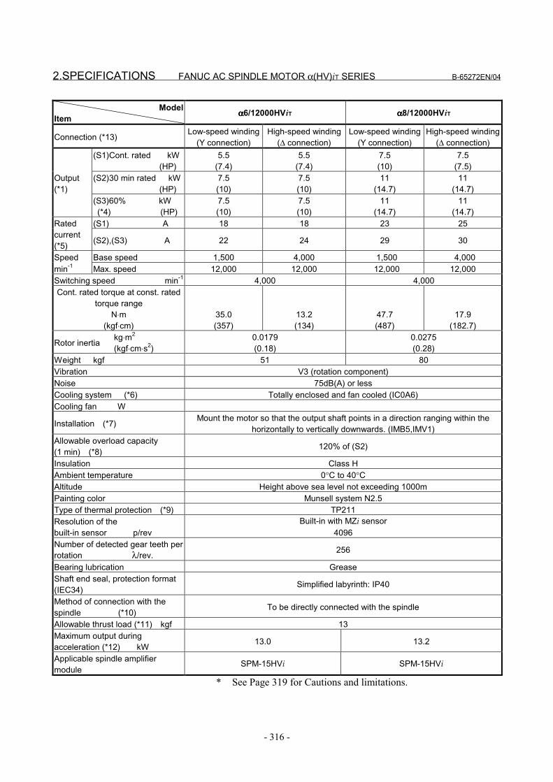
2.SPECIFICATIONS FANUC AC SPINDLE MOTOR α(HV)iT SERIES B-65272EN/04
- 316 -
ModelItem αααα6/12000HViT αααα8/12000HViT
Connection (*13) Low-speed winding(Y connection)
High-speed winding(∆ connection)
Low-speed winding(Y connection)
High-speed winding(∆ connection)
(S1)Cont. rated kW (HP)
5.5(7.4)
5.5(7.4)
7.5(10)
7.5(7.5)
(S2)30 min rated kW (HP)
7.5(10)
7.5(10)
11(14.7)
11(14.7)
Output(*1)
(S3)60% kW (*4) (HP)
7.5(10)
7.5(10)
11(14.7)
11(14.7)
(S1) A 18 18 23 25Ratedcurrent(*5) (S2),(S3) A 22 24 29 30
Speed Base speed 1,500 4,000 1,500 4,000min-1 Max. speed 12,000 12,000 12,000 12,000Switching speed min-1 4,000 4,000Cont. rated torque at const. rated
torque rangeN⋅m
(kgf⋅cm)35.0(357)
13.2(134)
47.7(487)
17.9(182.7)
Rotor inertia kg⋅m2
(kgf⋅cm⋅s2)0.0179(0.18)
0.0275(0.28)
Weight kgf 51 80Vibration V3 (rotation component)Noise 75dB(A) or lessCooling system (*6) Totally enclosed and fan cooled (IC0A6)Cooling fan W
Installation (*7) Mount the motor so that the output shaft points in a direction ranging within thehorizontally to vertically downwards. (IMB5,IMV1)
Allowable overload capacity(1 min) (*8) 120% of (S2)
Insulation Class HAmbient temperature 0°C to 40°CAltitude Height above sea level not exceeding 1000mPainting color Munsell system N2.5Type of thermal protection (*9) TP211Resolution of thebuilt-in sensor p/rev
Built-in with MZi sensor4096
Number of detected gear teeth perrotation λ/rev. 256
Bearing lubrication GreaseShaft end seal, protection format(IEC34) Simplified labyrinth: IP40
Method of connection with thespindle (*10) To be directly connected with the spindle
Allowable thrust load (*11) kgf 13Maximum output duringacceleration (*12) kW 13.0 13.2
Applicable spindle amplifiermodule
SPM-15HVi SPM-15HVi
* See Page 319 for Cautions and limitations.

B-65272EN/04 FANUC AC SPINDLE MOTOR α(HV)iT SERIES 2.SPECIFICATIONS
- 317 -
ModelItem αααα8/15000HViT αααα15/10000HViT
Connection (*13) Low-speed winding(Y connection)
High-speed winding(∆ connection)
Low-speed winding(Y connection)
High-speed winding(∆ connection)
(S1)Cont. rated kW (HP)
7.5(10)
7.5(10)
15(20.1)
15(20.1)
(S2)30 min rated kW (HP)
11(14.7)
11(14.7)
18.5(24.8)
18.5(24.8)
(S2) 10 min rated kW (HP)
15.0(20.1)
15.0(20.1) - -
Output(*1)
(S3)60% kW (*4) (HP) - - 18.5
(24.8)18.5
(24.8)(S1) A 35 37 37 36Rated
current(*5) (S2),(S3) A 55 53 45 41
Speed Base speed 1,500 4,000 1,500 4,000min-1 Max. speed 4,000 15,000 10,000 10,000Switching speedmin-1 4,000 4,000
Cont. rated torque at const.rated torque range
N⋅m(kgf⋅cm)
47.7(487)
17.9(182)
95.4(974)
35.8(365)
Rotor inertia kg⋅m2
(kgf⋅cm⋅s2)0.0275(0.28)
0.09(0.93)
Weight kgf 80 110Vibration V3 (rotation component)Noise 75dB(A) or lessCooling system (*6) Totally enclosed and fan cooled (IC0A6)Cooling fan W
Installation (*7) Mount the motor so that the output shaft points in a direction ranging within thehorizontally to vertically downwards. (IMB5,IMV1)
Allowable overload capacity(1 min) (*8) 120% of (S2)
Insulation Class HAmbient temperature 0°C to 40°CAltitude Height above sea level not exceeding 1000mPainting color Munsell system N2.5Type of thermal protection (*9) TP211Resolution of thebuilt-in sensor p/rev
Built-in with MZi sensor4096
Number of detected gear teethper rotation λ/rev. 256
Bearing lubrication GreaseShaft end seal, protectionformat (IEC34) Simplified labyrinth: IP40
Method of connection with thespindle (*10) To be directly connected with the spindle
Allowable thrust load (*11) kgf 13Maximum output duringacceleration (*12) kW 28.0 22.2
Applicable spindle amplifiermodule
SPM-30HVi SPM-30HVi
* See Page 319 for Cautions and limitations.
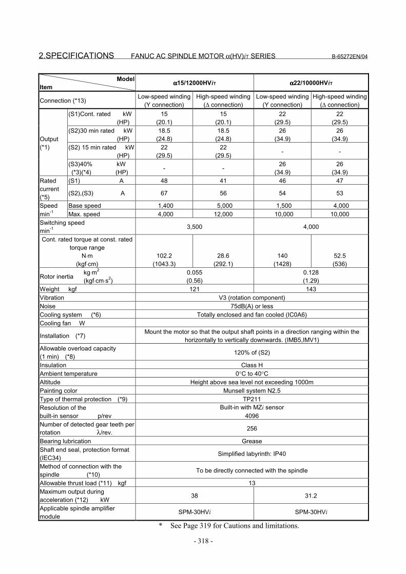
2.SPECIFICATIONS FANUC AC SPINDLE MOTOR α(HV)iT SERIES B-65272EN/04
- 318 -
ModelItem αααα15/12000HViT αααα22/10000HViT
Connection (*13) Low-speed winding(Y connection)
High-speed winding(∆ connection)
Low-speed winding(Y connection)
High-speed winding(∆ connection)
(S1)Cont. rated kW (HP)
15(20.1)
15(20.1)
22(29.5)
22(29.5)
(S2)30 min rated kW (HP)
18.5(24.8)
18.5(24.8)
26(34.9)
26(34.9)
(S2) 15 min rated kW (HP)
22(29.5)
22(29.5) - -
Output(*1)
(S3)40% kW (*3)(*4) (HP) - - 26
(34.9)26
(34.9)(S1) A 48 41 46 47Rated
current(*5) (S2),(S3) A 67 56 54 53
Speed Base speed 1,400 5,000 1,500 4,000min-1 Max. speed 4,000 12,000 10,000 10,000Switching speedmin-1 3,500 4,000
Cont. rated torque at const. ratedtorque range
N⋅m(kgf⋅cm)
102.2(1043.3)
28.6(292.1)
140(1428)
52.5(536)
Rotor inertia kg⋅m2
(kgf⋅cm⋅s2)0.055(0.56)
0.128(1.29)
Weight kgf 121 143Vibration V3 (rotation component)Noise 75dB(A) or lessCooling system (*6) Totally enclosed and fan cooled (IC0A6)Cooling fan W
Installation (*7) Mount the motor so that the output shaft points in a direction ranging within thehorizontally to vertically downwards. (IMB5,IMV1)
Allowable overload capacity(1 min) (*8) 120% of (S2)
Insulation Class HAmbient temperature 0°C to 40°CAltitude Height above sea level not exceeding 1000mPainting color Munsell system N2.5Type of thermal protection (*9) TP211Resolution of thebuilt-in sensor p/rev
Built-in with MZi sensor4096
Number of detected gear teeth perrotation λ/rev. 256
Bearing lubrication GreaseShaft end seal, protection format(IEC34) Simplified labyrinth: IP40
Method of connection with thespindle (*10) To be directly connected with the spindle
Allowable thrust load (*11) kgf 13Maximum output duringacceleration (*12) kW 38 31.2
Applicable spindle amplifiermodule
SPM-30HVi SPM-30HVi
* See Page 319 for Cautions and limitations.
B-65272EN/04 FANUC AC SPINDLE MOTOR α(HV)iT SERIES 2.SPECIFICATIONS
- 319 -
Cautions and limitations(*1) The rated output is guaranteed at the rated voltage.
(Amplifier input: 400/480VAC +10%, -15%, 50/60Hz±1Hz)If the input voltage fluctuates, it is possible that the rated outputcannot be obtained even when such fluctuations are within theallowable fluctuation range.
(*2) The output for α1.5/15000HViT and α2/15000HViT is 15 minrated.
(*3) 40% for α1.5/15000HViT, α2/15000HViT, and α22/10000HViT(*4) The cycle time is 10 minutes, S3 60%: ON 6 minutes, OFF 4
minutes and S3 40%: ON 4 minutes, OFF 6 minutes(*5) The rated current is the maximum current for each rated output.(*6) IC code conforms to IEC 34-6.(*7) IM code conforms to IEC 34-7.(*8) This is not a guaranteed value but a guideline for the maximum
motor output at a rated supply voltage.(*9) Type conforms to IEC 34-11.(*10)When assembling a motor with the machine, align the motor
shaft with the spindle so that the vibration acceleration of themotor does not exceed 0.5 G (at maximum speed).(Before shipping machines, check that the vibration accelerationis 0.5 G or less for all motors.)
(*11)Select a coupling that does not apply a thrust load onto themotor shaft for a cause such as coolant pressure when thetemperature rises.Note that in the direction in which the motor shaft is pushedtoward the inside of the motor, the allowable load is 0 kgf.(If a gear coupling or Oldham coupling is used, the motor shaftcan be left pushed into the inside of the motor when the motorshaft is inserted into the spindle. So, measure the distancebetween the mounting face for a rotation joint support housingand the flinger rear end face before and after insertion, and checkthat the two measured values are identical.For details, see Section V-9.4 "COUPLING SELECTION".)
(*12)These values are to be used only as guidance for selecting apower supply module and are not guaranteed.
(*13)Switching method of power lead is Y-∆ switching.Required are the CNC software option related to the outputswitching function and the switching magnetic connection unit.Refer to FANUC SERVO AMPLIFIER αi seriesDESCRIPTIONS (B-65282EN) for output switching control.
(*14)The protection grade (IEC34-5) is IP40. However, the grade isIP54 when the labyrinth seal on the front side of the output axisand the flinger seal on the rear side are excluded.Ensure that the labyrinth seal and flinger seal are not directlyexposed to coolant and mist.
(*15)The input power requirements of the fan motor forα1.5/15000HViT, α2/15000HViT, or α3/15000HViT are:200/230VAC +10% -15%, single-phase, and 50/60 Hz±1Hz.
3.OUTPUT/TORQUE CHARACTERISTICS FANUC AC SPINDLE MOTOR α(HV)iT SERIES B-65272EN/04
- 320 -
3 OUTPUT/TORQUE CHARACTERISTICSReferenceCalculation for torque
Torque T can be obtained by the following equation.
T[N⋅m]=P[kW]×1000/0.1047/N[min-1]P[kW]: Motor outputN[min-1]: Motor speed
When the unit of T is [kgf⋅m],T[kgf⋅m]=P[kW]×1000/1.0269/N[min-1]

B-65272EN/04 FANUC AC SPINDLE MOTOR α(HV)iT SERIES 3.OUTPUT/TORQUE CHARACTERISTICS
- 321 -
3.1 MODEL αααα1.5/15000HViT Applicable amplifier SPM-15HVi
0
0.5
1
1.5
2
2.5
0 3000 6000 9000 12000 150000
2
4
6
8
10
0 3000 6000 9000 12000 15000
1.5kW
2.2kW
0
3
6
9
12
15
0 3000 6000 9000 12000 15000
8000
12kW
[kW] [N⋅m]
Motor speed [min-1]
Continuousoperating zone
15min, S3 40%Operating zone
Motor speed [min-1]
15min, S3 40%Operating zone
Continuousoperating zone
Output Torque
Acceleration output
Motor speed [min-1]
13kW (Maximum output during acceleration)
NOTEAcceleration output is used as a measure tocalculate the acceleration or deceleration time.Acceleration output is not an assured value.
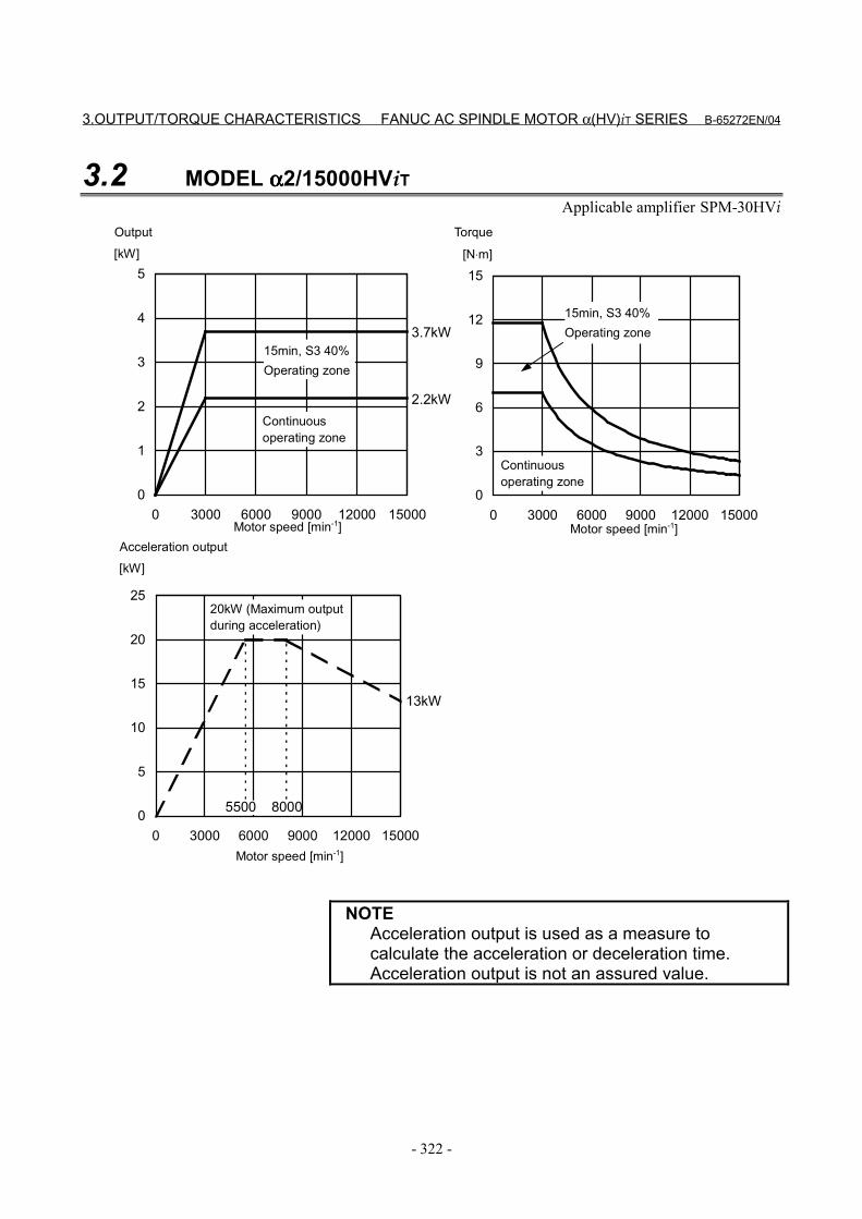
3.OUTPUT/TORQUE CHARACTERISTICS FANUC AC SPINDLE MOTOR α(HV)iT SERIES B-65272EN/04
- 322 -
3.2 MODEL αααα2/15000HViTApplicable amplifier SPM-30HVi
0
1
2
3
4
5
0 3000 6000 9000 12000 150000
3
6
9
12
15
0 3000 6000 9000 12000 15000
2.2kW
3.7kW
0
5
10
15
20
25
0 3000 6000 9000 12000 15000
8000
13kW
5500
[kW] [N⋅m]
Motor speed [min-1]
Continuousoperating zone
15min, S3 40%Operating zone
Motor speed [min-1]
15min, S3 40%Operating zone
Continuousoperating zone
Output Torque
[kW]Acceleration output
Motor speed [min-1]
20kW (Maximum outputduring acceleration)
NOTEAcceleration output is used as a measure tocalculate the acceleration or deceleration time.Acceleration output is not an assured value.

B-65272EN/04 FANUC AC SPINDLE MOTOR α(HV)iT SERIES 3.OUTPUT/TORQUE CHARACTERISTICS
- 323 -
3.3 MODEL αααα3/12000HViTApplicable amplifier SPM-11HVi
0
2
4
6
8
0 3000 6000 9000 120000
10
20
30
40
0 3000 6000 9000 12000
3.7kW
5.5kW
15001500
0
4
8
12
16
0 3000 6000 9000 12000
7000
9.5kW
[kW] [N⋅m]
Motor speed [min-1]
Continuousoperating zone
30min, S3 60%Operating zone
Motor speed [min-1]
30min, S3 60%Operating zone
Continuous operating zone
Output Torque
Acceleration output
Motor speed [min-1]
13kW (Maximum outputduring acceleration)
[kW]
NOTEAcceleration output is used as a measure tocalculate the acceleration or deceleration time.Acceleration output is not an assured value.
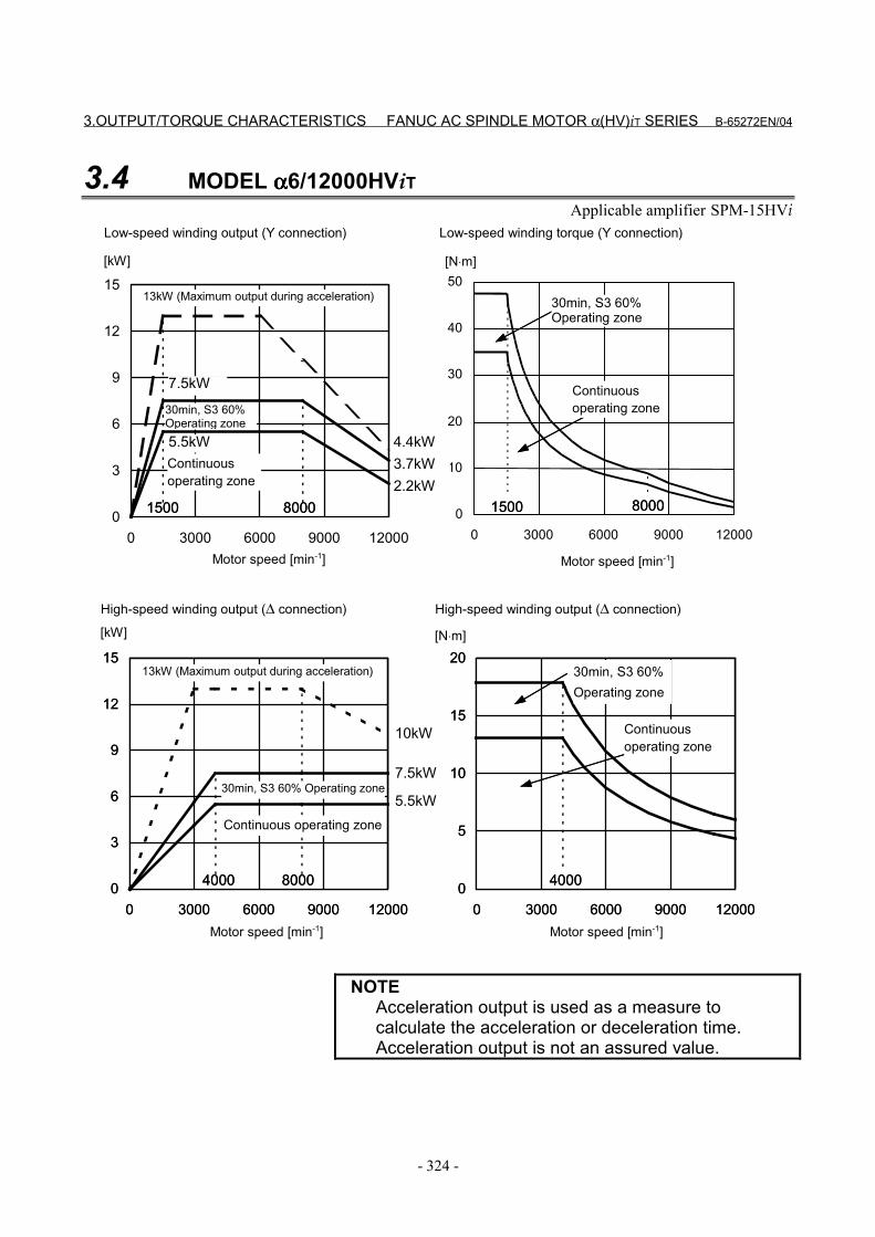
3.OUTPUT/TORQUE CHARACTERISTICS FANUC AC SPINDLE MOTOR α(HV)iT SERIES B-65272EN/04
- 324 -
3.4 MODEL αααα6/12000HViTApplicable amplifier SPM-15HVi
0
3
6
9
12
15
0 3000 6000 9000 12000
0
3
6
9
12
15
0 3000 6000 9000 120000
5
10
15
20
0 3000 6000 9000 120000
3
6
9
12
15
0 3000 6000 9000 12000
0
10
20
30
40
50
0 3000 6000 9000 12000
15002.2kW3.7kW4.4kW
1500
5.5kW
7.5kW
80008000
0
5
10
15
20
0 3000 6000 9000 12000
4000
5.5kW
4000
7.5kW
8000
10kW
15002.2kW3.7kW4.4kW
1500
5.5kW
7.5kW
80008000
4000
5.5kW
4000
7.5kW
8000
10kW
[kW] [N⋅m]
Motor speed [min-1]
Continuousoperating zone
30min, S3 60%Operating zone
Motor speed [min-1]
30min, S3 60%Operating zone
Continuousoperating zone
Motor speed [min-1]
[kW]
Low-speed winding output (Y connection) Low-speed winding torque (Y connection)
High-speed winding output (∆ connection) High-speed winding output (∆ connection)
13kW (Maximum output during acceleration)
13kW (Maximum output during acceleration) 30min, S3 60%Operating zone
Continuousoperating zone
[N⋅m]
Motor speed [min-1]
Continuous operating zone
30min, S3 60% Operating zone
NOTEAcceleration output is used as a measure tocalculate the acceleration or deceleration time.Acceleration output is not an assured value.
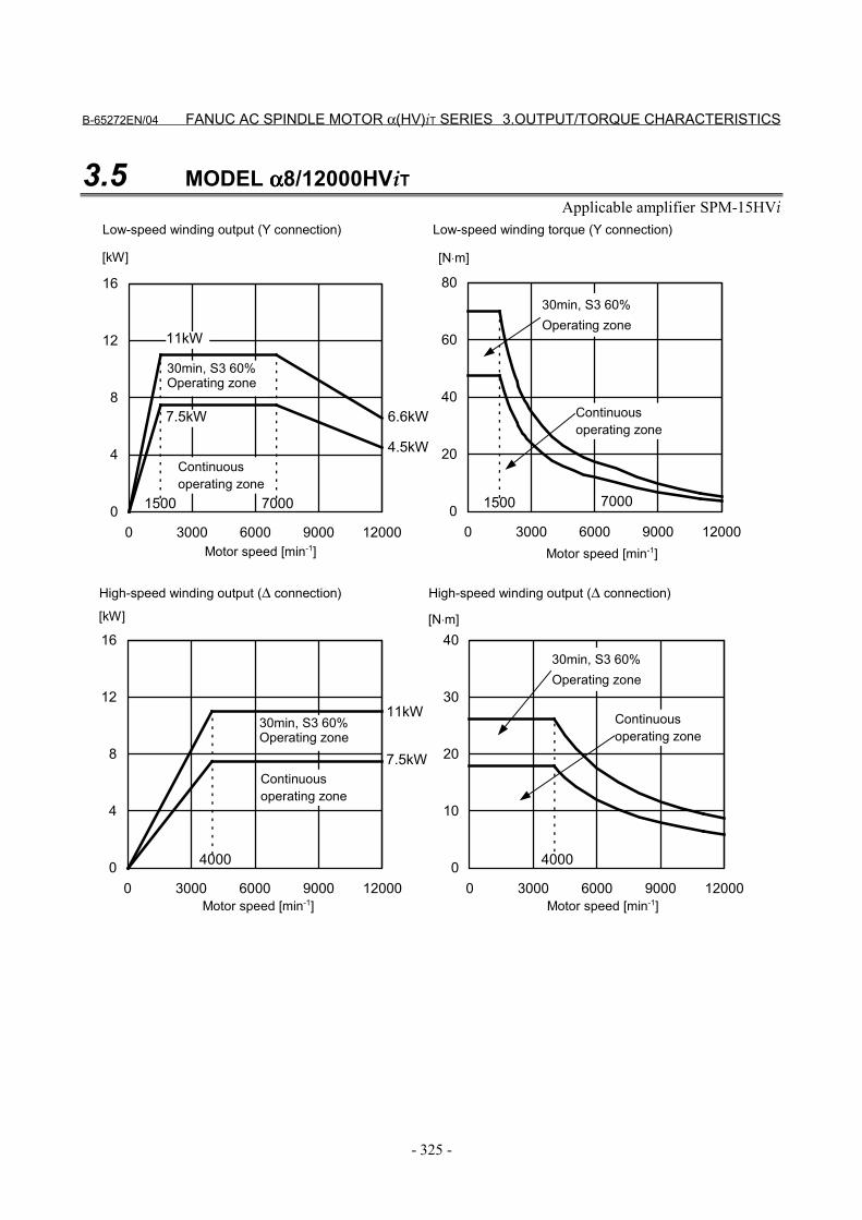
B-65272EN/04 FANUC AC SPINDLE MOTOR α(HV)iT SERIES 3.OUTPUT/TORQUE CHARACTERISTICS
- 325 -
3.5 MODEL αααα8/12000HViTApplicable amplifier SPM-15HVi
0
20
40
60
80
0 3000 6000 9000 120000
4
8
12
16
0 3000 6000 9000 12000
1500
4.5kW
6.6kW
15007000
7.5kW
11kW
7000
0
10
20
30
40
0 3000 6000 9000 12000
40000
4
8
12
16
0 3000 6000 9000 12000
7.5kW
11kW
4000
[kW] [N⋅m]
Motor speed [min-1]
Continuousoperating zone
30min, S3 60%Operating zone
Motor speed [min-1]
30min, S3 60%Operating zone
Continuousoperating zone
Motor speed [min-1]
[kW]
Low-speed winding output (Y connection) Low-speed winding torque (Y connection)
High-speed winding output (∆ connection) High-speed winding output (∆ connection)
30min, S3 60%Operating zone
Continuousoperating zone
[N⋅m]
Motor speed [min-1]
Continuousoperating zone
30min, S3 60%Operating zone
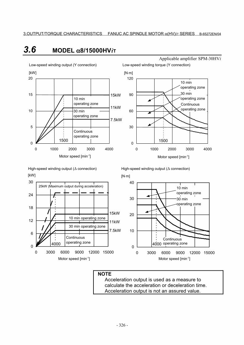
3.OUTPUT/TORQUE CHARACTERISTICS FANUC AC SPINDLE MOTOR α(HV)iT SERIES B-65272EN/04
- 326 -
3.6 MODEL αααα8/15000HViTApplicable amplifier SPM-30HVi
0
30
60
90
120
0 1000 2000 3000 40000
5
10
15
20
0 1000 2000 3000 4000
1500
7.5kW
11kW
15kW
1500
0
10
20
30
40
0 3000 6000 9000 12000 15000
40000
6
12
18
24
30
0 3000 6000 9000 12000 15000
7.5kW
11kW
4000
15kW
[kW] [N⋅m]
Motor speed [min-1]
Continuousoperating zone
Motor speed [min-1]
Motor speed [min-1]
[kW]
Low-speed winding output (Y connection) Low-speed winding torque (Y connection)
High-speed winding output (∆ connection) High-speed winding output (∆ connection)
25kW (Maximum output during acceleration)
[N⋅m]
Motor speed [min-1]
10 minoperating zone
30 minoperating zone
Continuousoperating zone
10 minoperating zone30 minoperating zone
Continuousoperating zone
10 minoperating zone30 minoperating zone
Continuousoperating zone
10 min operating zone
30 min operating zone
NOTEAcceleration output is used as a measure tocalculate the acceleration or deceleration time.Acceleration output is not an assured value.
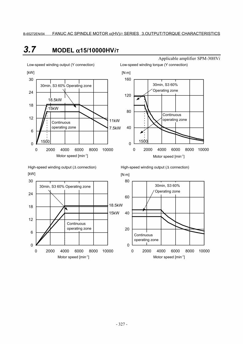
B-65272EN/04 FANUC AC SPINDLE MOTOR α(HV)iT SERIES 3.OUTPUT/TORQUE CHARACTERISTICS
- 327 -
3.7 MODEL αααα15/10000HViTApplicable amplifier SPM-30HVi
0
40
80
120
160
0 2000 4000 6000 8000 100000
6
12
18
24
30
0 2000 4000 6000 8000 10000
1500
7.5kW
11kW
1500
15kW
18.5kW
0
20
40
60
80
0 2000 4000 6000 8000 100000
6
12
18
24
30
0 2000 4000 6000 8000 10000
15kW
18.5kW
[kW] [N⋅m]
Motor speed [min-1]
Continuousoperating zone
30min, S3 60% Operating zone
Motor speed [min-1]
30min, S3 60%Operating zone
Continuousoperating zone
Motor speed [min-1]
[kW]
Low-speed winding output (Y connection) Low-speed winding torque (Y connection)
High-speed winding output (∆ connection) High-speed winding output (∆ connection)
30min, S3 60%Operating zone
Continuousoperating zone
[N⋅m]
Motor speed [min-1]
30min, S3 60% Operating zone
Continuousoperating zone
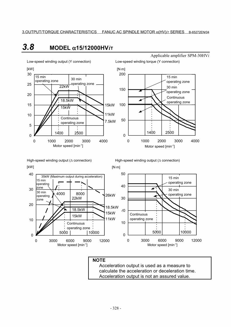
3.OUTPUT/TORQUE CHARACTERISTICS FANUC AC SPINDLE MOTOR α(HV)iT SERIES B-65272EN/04
- 328 -
3.8 MODEL αααα15/12000HViTApplicable amplifier SPM-30HVi
0
10
20
30
40
50
0 3000 6000 9000 120000
10
20
30
40
0 3000 6000 9000 12000
0
5
10
15
20
25
30
0 1000 2000 3000 4000
1400
7.5kW
11kW
15kW
0
50
100
150
200
0 1000 2000 3000 4000
14002500
15kW
18.5kW
22kW
2500
18.5kW
11kW
5000
15kW
10000
[N⋅m]
26kW
15kW18.5kW
22kW
5000 10000
[kW] [N⋅m]
Motor speed [min-1]
Continuousoperating zone
Motor speed [min-1]
Motor speed [min-1]
[kW]
Low-speed winding output (Y connection) Low-speed winding torque (Y connection)
High-speed winding output (∆ connection) High-speed winding output (∆ connection)
35kW (Maximum output during acceleration)
Motor speed [min-1]
30 minoperating zone
15 minoperating zone
Continuousoperating zone
30 minoperating zone
15 minoperating zone
Continuousoperating zone
15 minoperatingzone
Continuousoperating zone
30 minoperating zone
15 minoperating zone
30 minoperatingzone
4000 8000
NOTEAcceleration output is used as a measure tocalculate the acceleration or deceleration time.Acceleration output is not an assured value.

B-65272EN/04 FANUC AC SPINDLE MOTOR α(HV)iT SERIES 3.OUTPUT/TORQUE CHARACTERISTICS
- 329 -
3.9 MODEL αααα22/10000HViTApplicable amplifier SPM-30HVi
0
50
100
150
200
0 2000 4000 6000 8000 100000
10
20
30
40
0 2000 4000 6000 8000 10000
1500
13kW16kW
1500
22kW26kW
0
20
40
60
80
0 2000 4000 6000 8000 100000
10
20
30
40
0 2000 4000 6000 8000 10000
22kW
26kW
[kW] [N⋅m]
Motor speed [min-1]
Continuousoperating zone
30min, S3 40%Operating zone
Motor speed [min-1]
30min, S3 40%Operating zone
Continuousoperating zone
Motor speed [min-1]
[kW]
Low-speed winding output (Y connection) Low-speed winding torque (Y connection)
High-speed winding output (∆ connection) High-speed winding output (∆ connection)
30min, S3 40% Operating zone
Continuousoperating zone
[N⋅m]
Motor speed [min-1]
Continuousoperating zone
30min, S3 40% Operating zone
4.CONFIGURATION AND ORDERING NUMBER FANUC AC SPINDLE MOTOR α(HV)iT SERIES B-65272EN/04
- 330 -
4 CONFIGURATION AND ORDERINGNUMBER
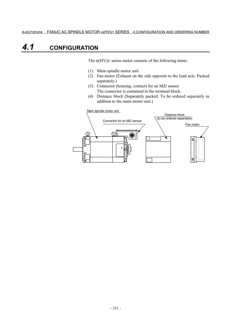
B-65272EN/04 FANUC AC SPINDLE MOTOR α(HV)iT SERIES 4.CONFIGURATION AND ORDERING NUMBER
- 331 -
4.1 CONFIGURATION
The α(HV)iT series motor consists of the following items:
(1) Main spindle motor unit(2) Fan motor (Exhaust on the side opposite to the load axis. Packed
separately.)(3) Connector (housing, contact) for an MZi sensor
The connector is contained in the terminal block.(4) Distance block (Separately packed. To be ordered separately in
addition to the main motor unit.)
Connector for an MZi sensor
Main spindle motor unitDistance block
(to be ordered separately)
Fan motor
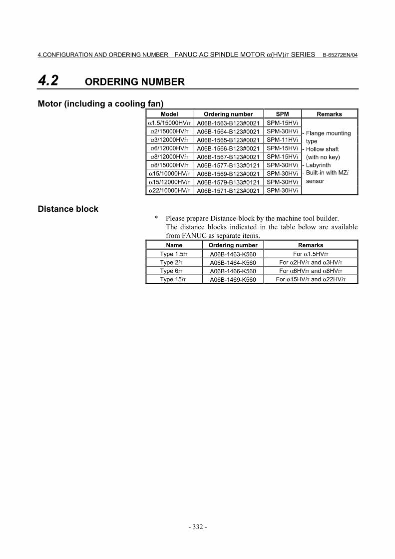
4.CONFIGURATION AND ORDERING NUMBER FANUC AC SPINDLE MOTOR α(HV)iT SERIES B-65272EN/04
- 332 -
4.2 ORDERING NUMBER
Motor (including a cooling fan)Model Ordering number SPM Remarks
α1.5/15000HViT A06B-1563-B123#0021 SPM-15HViα2/15000HViT A06B-1564-B123#0021 SPM-30HViα3/12000HViT A06B-1565-B123#0021 SPM-11HViα6/12000HViT A06B-1566-B123#0021 SPM-15HViα8/12000HViT A06B-1567-B123#0021 SPM-15HViα8/15000HViT A06B-1577-B133#0121 SPM-30HVi
α15/10000HViT A06B-1569-B123#0021 SPM-30HViα15/12000HViT A06B-1579-B133#0121 SPM-30HViα22/10000HViT A06B-1571-B123#0021 SPM-30HVi
- Flange mountingtype
- Hollow shaft(with no key)
- Labyrinth- Built-in with MZi
sensor
Distance block * Please prepare Distance-block by the machine tool builder.
The distance blocks indicated in the table below are availablefrom FANUC as separate items.Name Ordering number Remarks
Type 1.5iT A06B-1463-K560 For α1.5HViTType 2iT A06B-1464-K560 For α2HViT and α3HViTType 6iT A06B-1466-K560 For α6HViT and α8HViTType 15iT A06B-1469-K560 For α15HViT and α22HViT

B-65272EN/04 FANUC AC SPINDLE MOTOR α(HV)iT SERIES 5.CONNECTIONS
- 333 -
5 CONNECTIONS
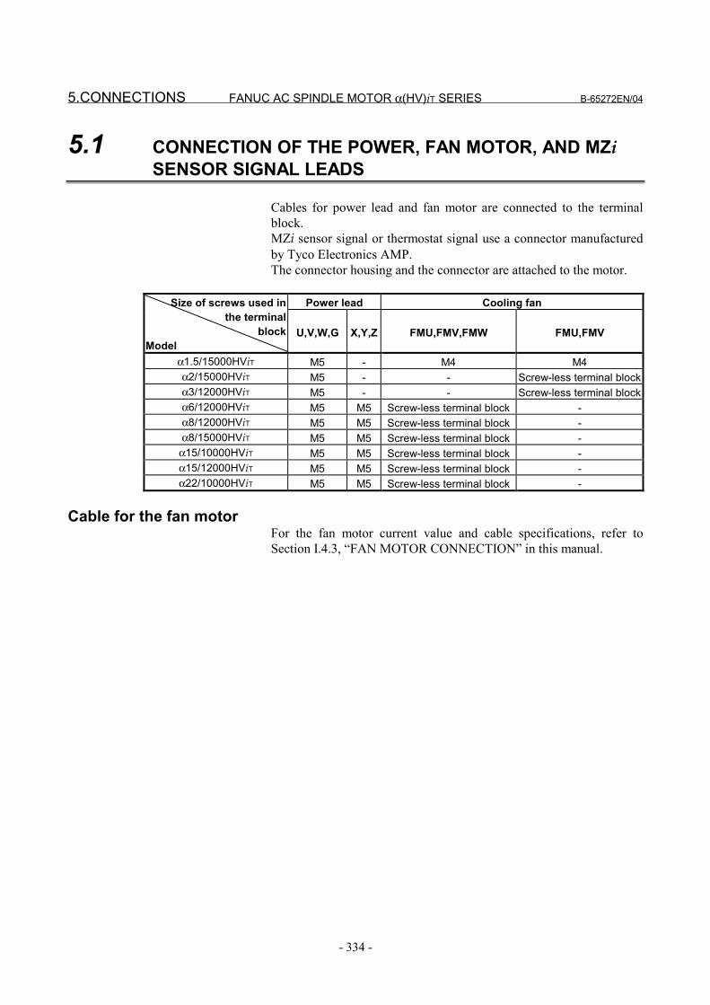
5.CONNECTIONS FANUC AC SPINDLE MOTOR α(HV)iT SERIES B-65272EN/04
- 334 -
5.1 CONNECTION OF THE POWER, FAN MOTOR, AND MZiSENSOR SIGNAL LEADS
Cables for power lead and fan motor are connected to the terminalblock.MZi sensor signal or thermostat signal use a connector manufacturedby Tyco Electronics AMP.The connector housing and the connector are attached to the motor.
Power lead Cooling fanSize of screws used inthe terminal
blockModel
U,V,W,G X,Y,Z FMU,FMV,FMW FMU,FMV
α1.5/15000HViT M5 - M4 M4α2/15000HViT M5 - - Screw-less terminal blockα3/12000HViT M5 - - Screw-less terminal blockα6/12000HViT M5 M5 Screw-less terminal block -α8/12000HViT M5 M5 Screw-less terminal block -α8/15000HViT M5 M5 Screw-less terminal block -
α15/10000HViT M5 M5 Screw-less terminal block -α15/12000HViT M5 M5 Screw-less terminal block -α22/10000HViT M5 M5 Screw-less terminal block -
Cable for the fan motorFor the fan motor current value and cable specifications, refer toSection I.4.3, “FAN MOTOR CONNECTION” in this manual.
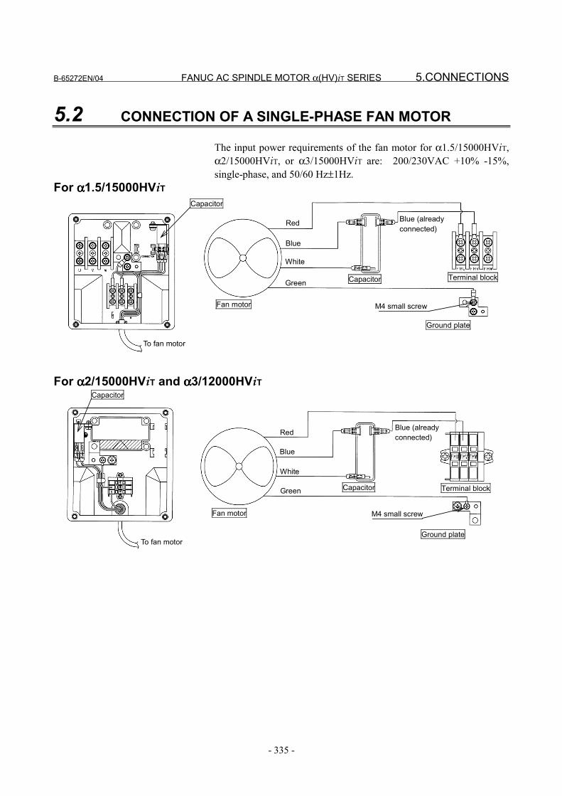
B-65272EN/04 FANUC AC SPINDLE MOTOR α(HV)iT SERIES 5.CONNECTIONS
- 335 -
5.2 CONNECTION OF A SINGLE-PHASE FAN MOTOR
The input power requirements of the fan motor for α1.5/15000HViT,α2/15000HViT, or α3/15000HViT are: 200/230VAC +10% -15%,single-phase, and 50/60 Hz±1Hz.
For αααα1.5/15000HViT
White
To fan motor
Fan motor
Red
Blue
Green
Blue (alreadyconnected)
Capacitor Terminal block
Ground plate
M4 small screw
Capacitor
For αααα2/15000HViT and αααα3/12000HViT
To fan motor
Fan motor
Red
Blue
Green
Blue (alreadyconnected)
Capacitor Terminal block
Ground plate
M4 small screw
White
Capacitor
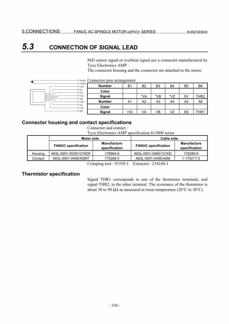
5.CONNECTIONS FANUC AC SPINDLE MOTOR α(HV)iT SERIES B-65272EN/04
- 336 -
5.3 CONNECTION OF SIGNAL LEAD
MZi sensor signal or overheat signal use a connector manufactured byTyco Electronics AMP .The connector housing and the connector are attached to the motor.
Connector pins arrangementNumber B1 B2 B3 B4 B5 B6
ColorSignal *VA *VB *VZ 0V THR2
Number A1 A2 A3 A4 A5 A6ColorSignal +5V VA VB VZ SS THR1
Connector housing and contact specificationsConnector and contact :Tyco Electronics AMP specification D-3000 series
Motor side Cable side
FANUC specification Manufacturespecification FANUC specification Manufacture
specificationHousing A63L-0001-0535/121KDF 178964-6 A63L-0001-0460/121KD 178289-6Contact A63L-0001-0456/ASMT 175288-2 A63L-0001-0456/ASM 1-175217-2
Crimping tool : 91559-1 Extractor : 234168-1
Thermistor specificationSignal THR1 corresponds to one of the thermistor terminals, andsignal THR2, to the other terminal. The resistance of the thermistor isabout 30 to 90 kΩ as measured at room temperature (20°C to 30°C).
TH R1TH R2+5V0VV A*V AV B*V BV Z*V ZS S
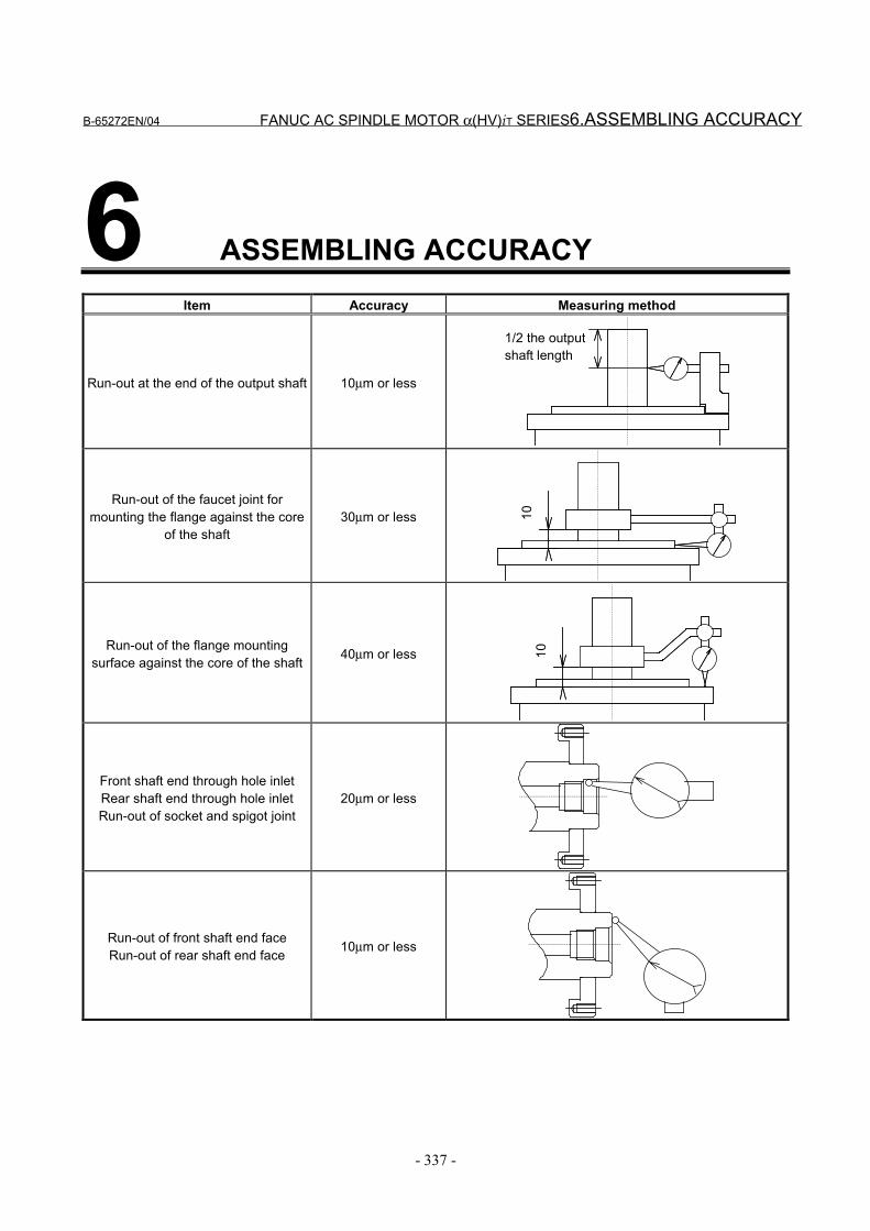
B-65272EN/04 FANUC AC SPINDLE MOTOR α(HV)iT SERIES6.ASSEMBLING ACCURACY
- 337 -
6 ASSEMBLING ACCURACYItem Accuracy Measuring method
Run-out at the end of the output shaft 10µm or less
1/2 the outputshaft length
Run-out of the faucet joint formounting the flange against the core
of the shaft30µm or less 10
Run-out of the flange mountingsurface against the core of the shaft 40µm or less 10
Front shaft end through hole inletRear shaft end through hole inletRun-out of socket and spigot joint
20µm or less
Run-out of front shaft end faceRun-out of rear shaft end face 10µm or less
7.EXTERNAL DIMENSIONS FANUC AC SPINDLE MOTOR α(HV)iT SERIES B-65272EN/04
- 338 -
7 EXTERNAL DIMENSIONSModel name Section
Model α1.5/15000HViT 7.1Model α2/15000HViT 7.2Model α3/12000HViT 7.3Model α6/12000HViT 7.4Models α8/12000HViT and α8/15000HViT 7.5Model α15/10000HViT 7.6Model α15/12000HViT 7.7Model α22/10000HViT 7.8
* For a distance block, see the αiT series section.
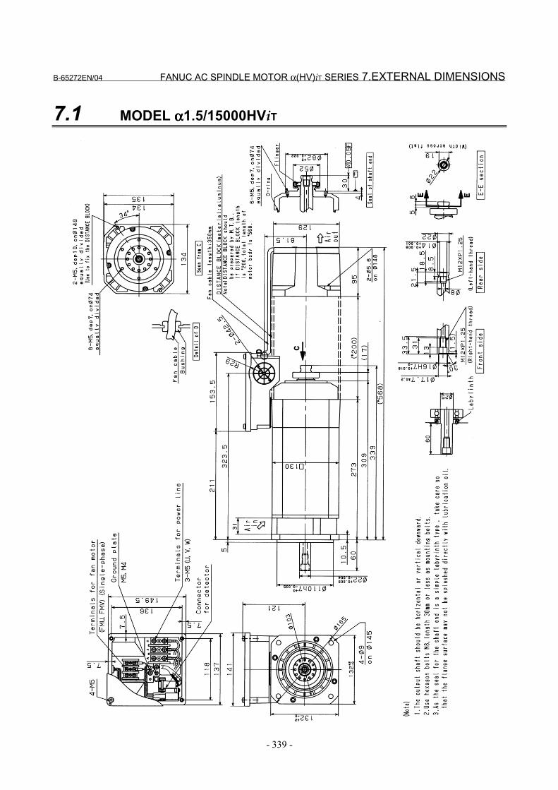
B-65272EN/04 FANUC AC SPINDLE MOTOR α(HV)iT SERIES 7.EXTERNAL DIMENSIONS
- 339 -
7.1 MODEL αααα1.5/15000HViT
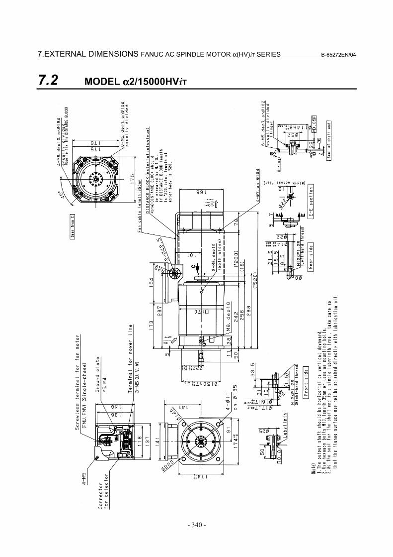
7.EXTERNAL DIMENSIONS FANUC AC SPINDLE MOTOR α(HV)iT SERIES B-65272EN/04
- 340 -
7.2 MODEL αααα2/15000HViT
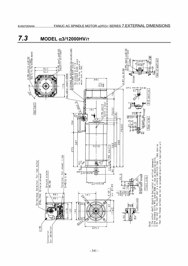
B-65272EN/04 FANUC AC SPINDLE MOTOR α(HV)iT SERIES 7.EXTERNAL DIMENSIONS
- 341 -
7.3 MODEL αααα3/12000HViT
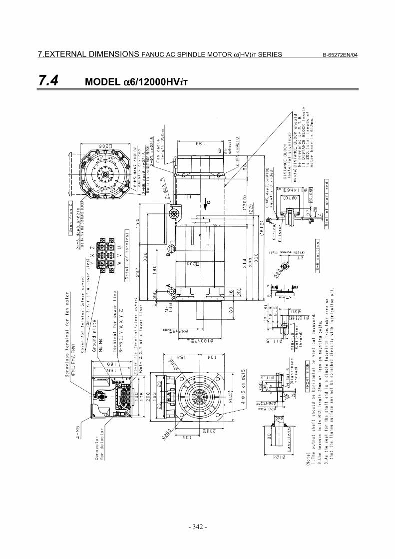
7.EXTERNAL DIMENSIONS FANUC AC SPINDLE MOTOR α(HV)iT SERIES B-65272EN/04
- 342 -
7.4 MODEL αααα6/12000HViT
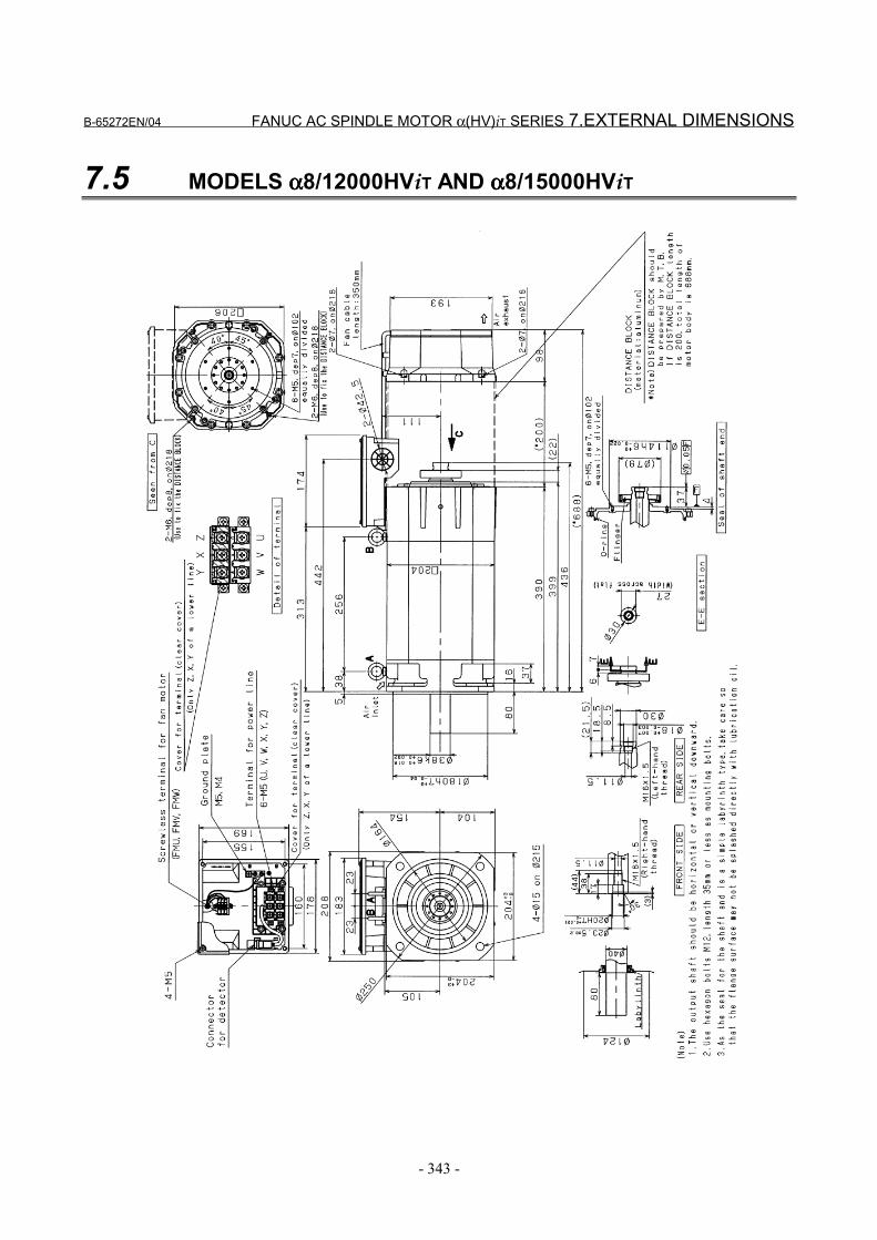
B-65272EN/04 FANUC AC SPINDLE MOTOR α(HV)iT SERIES 7.EXTERNAL DIMENSIONS
- 343 -
7.5 MODELS αααα8/12000HViT AND αααα8/15000HViT
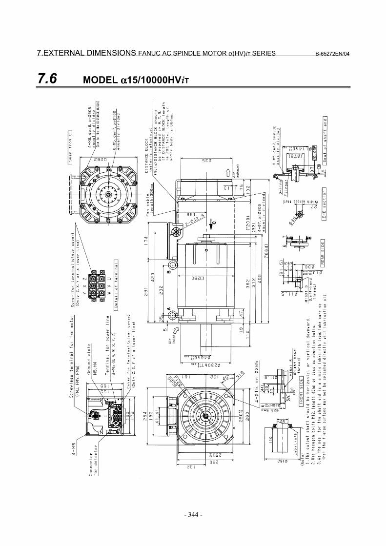
7.EXTERNAL DIMENSIONS FANUC AC SPINDLE MOTOR α(HV)iT SERIES B-65272EN/04
- 344 -
7.6 MODEL αααα15/10000HViT
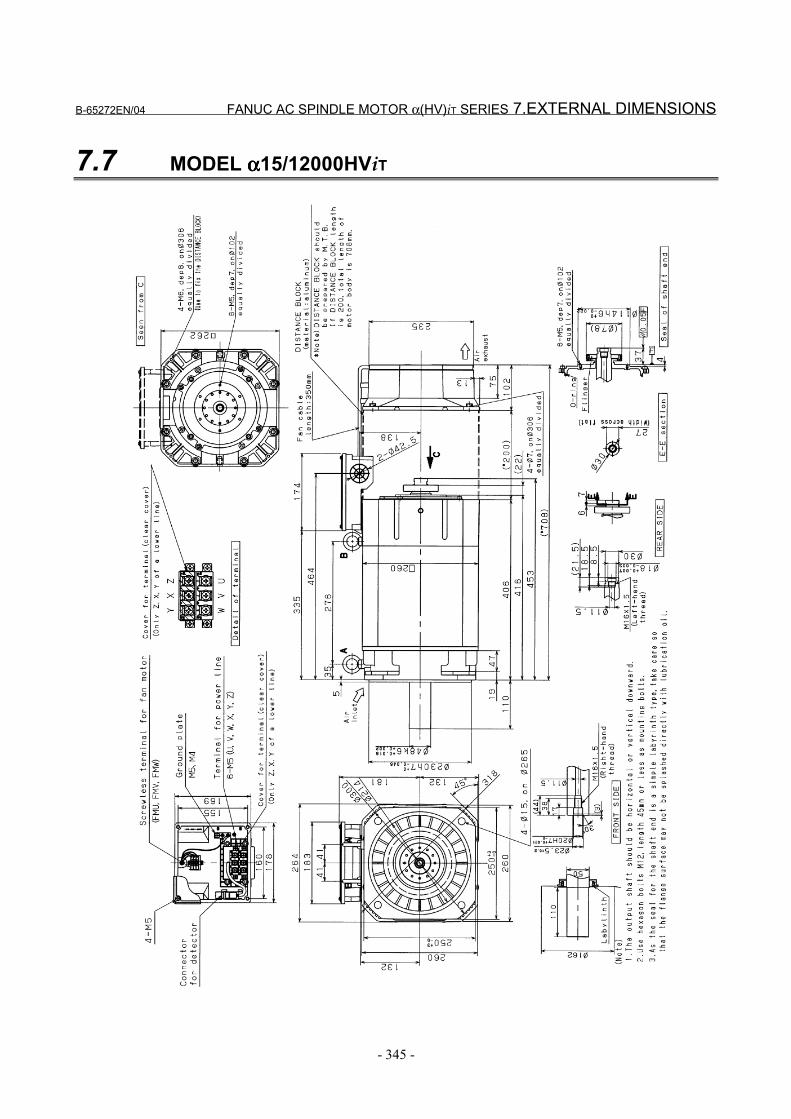
B-65272EN/04 FANUC AC SPINDLE MOTOR α(HV)iT SERIES 7.EXTERNAL DIMENSIONS
- 345 -
7.7 MODEL αααα15/12000HViT
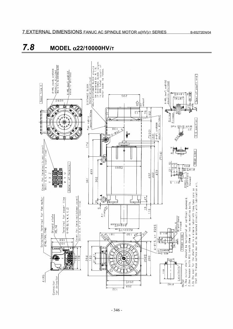
7.EXTERNAL DIMENSIONS FANUC AC SPINDLE MOTOR α(HV)iT SERIES B-65272EN/04
- 346 -
7.8 MODEL αααα22/10000HViT
IX. FANUC AC SPINDLE MOTOR αααα(HV)iL SERIES

B-65272EN/04 FANUC AC SPINDLE MOTOR α(HV)iL SERIES 1.GENERAL
- 349 -
1 GENERALThe FANUC AC spindle motor α(HV)iL series is liquid-cooledmotors that can be energized at 400 to 480 V without using a step-down transformer. They feature low temperature rise, high-speed,high torque at low speed, and low vibration.Coupling an α(HV)iL series motor directly to the spindle of amachining center makes it possible to realize gear-less, high-precisionoperation.The motor shaft has a through hole, through which center-throughcoolant can be passed.
Features(1) Thermal conduction to the spindle head and heat radiation to the
machine column are reduced by cooling the front flange andmotor case with a unique conduit structure (granted Japanesepatent No. 2105-445 and US patent No. 5,084,642).
(2) A high torque at low rotation speed is realized by achievinghigh-efficient cooling based on liquid coolant and employing anoutput switching function (Y-∆ switching).
(3) High-speed rotation is supported with grease-based lubrication.
(4) A vibration class of V3 (rotation component) is attained by strictrotor balance adjustments.
(5) The motor shaft is provided with a through hole for center-through coolant.
(6) The MZi sensor signal incorporated in the motor can be used inperforming orientation and rigid tapping, so there is no need tomount a detector on the machine tool.
• See descriptions about the αiT series for the features of thespindle coupled directly to the motor, the points of the directcoupling structure, and cautions for mounting the motor.

2.SPECIFICATIONS FANUC AC SPINDLE MOTOR α(HV)iL SERIES B-65272EN/04
- 350 -
2 SPECIFICATIONS
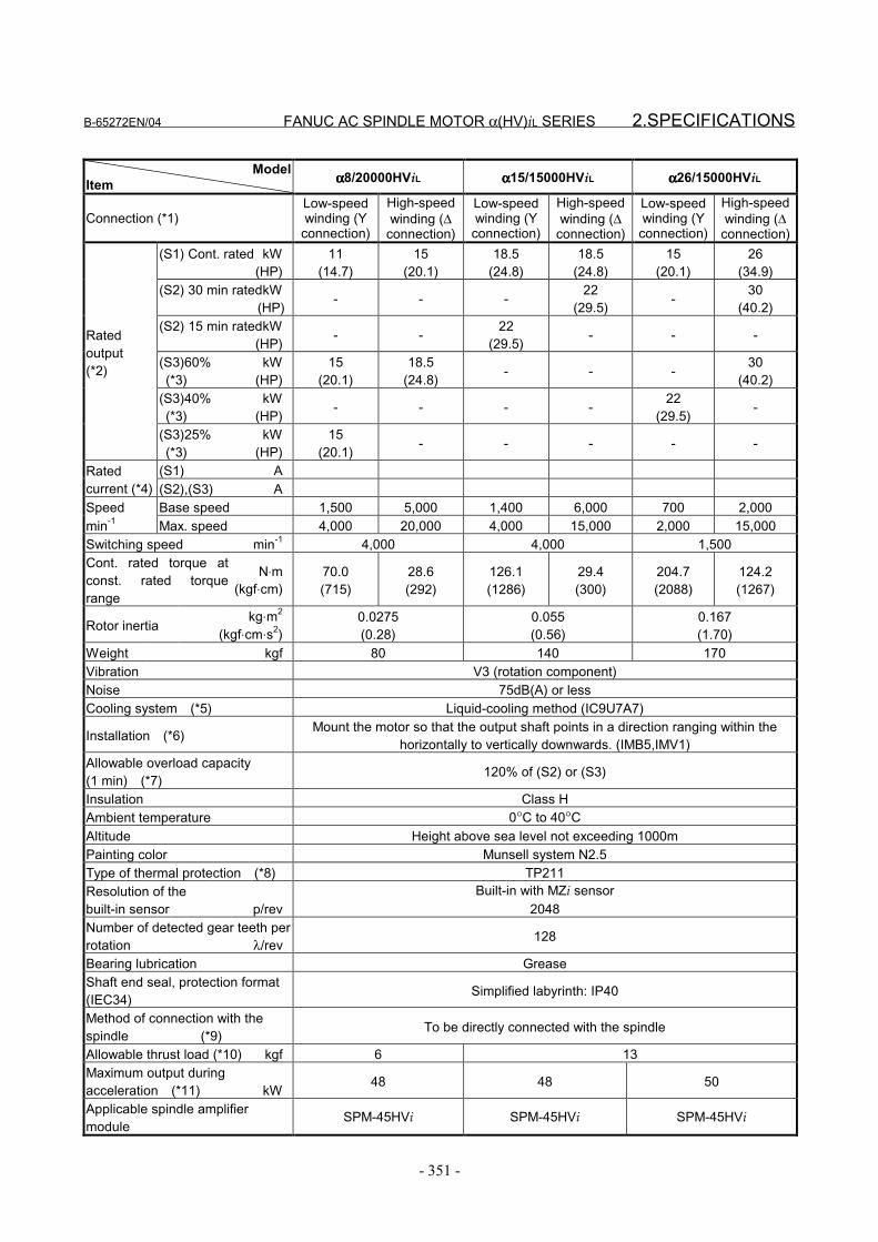
B-65272EN/04 FANUC AC SPINDLE MOTOR α(HV)iL SERIES 2.SPECIFICATIONS
- 351 -
ModelItem αααα8/20000HViL αααα15/15000HViL αααα26/15000HViL
Connection (*1)Low-speedwinding (Y
connection)
High-speedwinding (∆
connection)
Low-speedwinding (Y
connection)
High-speedwinding (∆
connection)
Low-speedwinding (Y
connection)
High-speedwinding (∆
connection)(S1) Cont. rated kW
(HP)11
(14.7)15
(20.1)18.5
(24.8)18.5
(24.8)15
(20.1)26
(34.9)(S2) 30 min ratedkW (HP) - - - 22
(29.5) - 30(40.2)
(S2) 15 min ratedkW(HP) - - 22
(29.5) - - -
(S3)60% kW (*3) (HP)
15(20.1)
18.5(24.8) - - - 30
(40.2)(S3)40% kW (*3) (HP) - - - - 22
(29.5) -
Ratedoutput(*2)
(S3)25% kW (*3) (HP)
15(20.1) - - - - -
(S1) ARatedcurrent (*4) (S2),(S3) ASpeed Base speed 1,500 5,000 1,400 6,000 700 2,000min-1 Max. speed 4,000 20,000 4,000 15,000 2,000 15,000Switching speed min-1 4,000 4,000 1,500Cont. rated torque atconst. rated torquerange
N⋅m(kgf⋅cm)
70.0(715)
28.6(292)
126.1(1286)
29.4(300)
204.7(2088)
124.2(1267)
Rotor inertiakg⋅m2
(kgf⋅cm⋅s2)0.0275(0.28)
0.055(0.56)
0.167(1.70)
Weight kgf 80 140 170Vibration V3 (rotation component)Noise 75dB(A) or lessCooling system (*5) Liquid-cooling method (IC9U7A7)
Installation (*6) Mount the motor so that the output shaft points in a direction ranging within thehorizontally to vertically downwards. (IMB5,IMV1)
Allowable overload capacity(1 min) (*7) 120% of (S2) or (S3)
Insulation Class HAmbient temperature 0°C to 40°CAltitude Height above sea level not exceeding 1000mPainting color Munsell system N2.5Type of thermal protection (*8) TP211Resolution of thebuilt-in sensor p/rev
Built-in with MZi sensor2048
Number of detected gear teeth perrotation λ/rev 128
Bearing lubrication GreaseShaft end seal, protection format(IEC34) Simplified labyrinth: IP40
Method of connection with thespindle (*9) To be directly connected with the spindle
Allowable thrust load (*10) kgf 6 13Maximum output duringacceleration (*11) kW 48 48 50
Applicable spindle amplifiermodule
SPM-45HVi SPM-45HVi SPM-45HVi
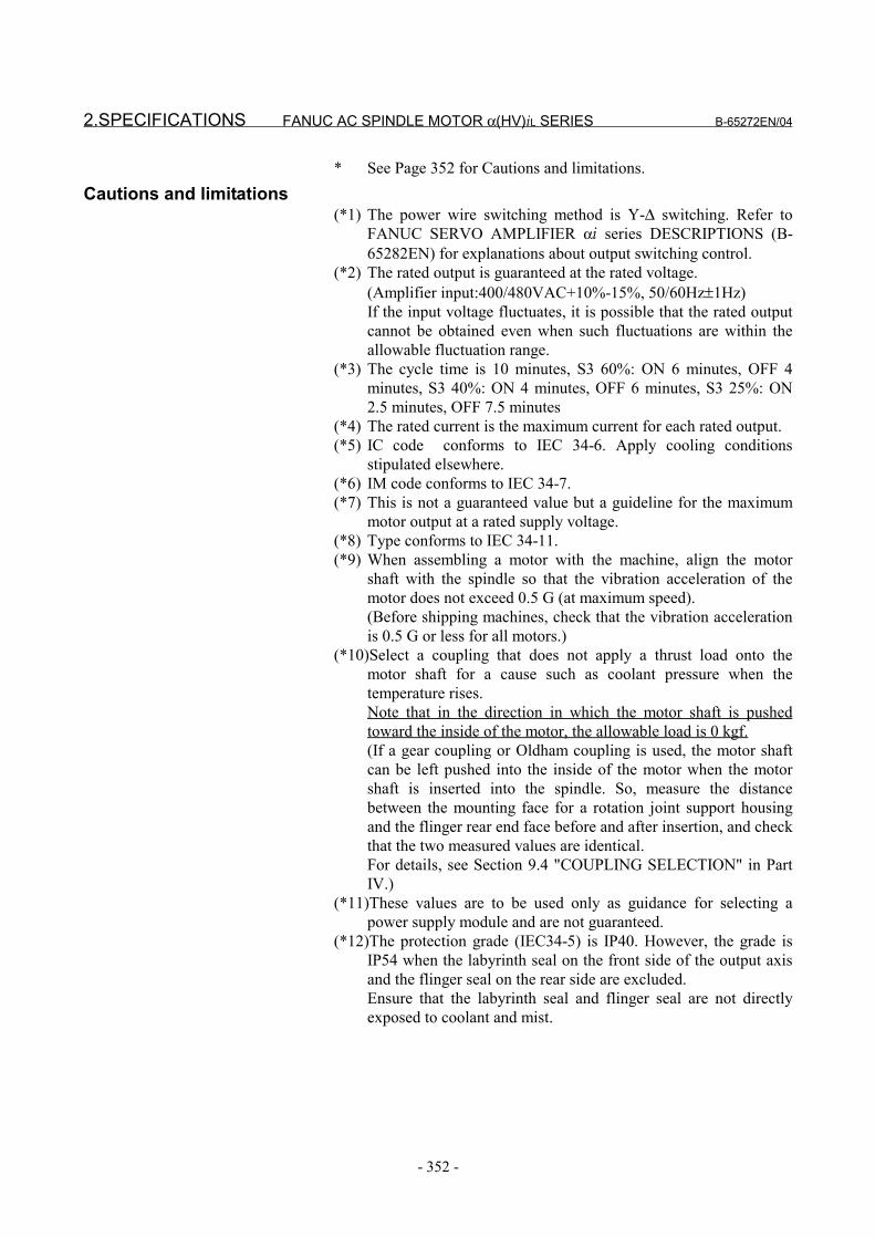
2.SPECIFICATIONS FANUC AC SPINDLE MOTOR α(HV)iL SERIES B-65272EN/04
- 352 -
* See Page 352 for Cautions and limitations.Cautions and limitations
(*1) The power wire switching method is Y-∆ switching. Refer toFANUC SERVO AMPLIFIER αi series DESCRIPTIONS (B-65282EN) for explanations about output switching control.
(*2) The rated output is guaranteed at the rated voltage.(Amplifier input:400/480VAC+10%-15%, 50/60Hz±1Hz)If the input voltage fluctuates, it is possible that the rated outputcannot be obtained even when such fluctuations are within theallowable fluctuation range.
(*3) The cycle time is 10 minutes, S3 60%: ON 6 minutes, OFF 4minutes, S3 40%: ON 4 minutes, OFF 6 minutes, S3 25%: ON2.5 minutes, OFF 7.5 minutes
(*4) The rated current is the maximum current for each rated output.(*5) IC code conforms to IEC 34-6. Apply cooling conditions
stipulated elsewhere.(*6) IM code conforms to IEC 34-7.(*7) This is not a guaranteed value but a guideline for the maximum
motor output at a rated supply voltage.(*8) Type conforms to IEC 34-11.(*9) When assembling a motor with the machine, align the motor
shaft with the spindle so that the vibration acceleration of themotor does not exceed 0.5 G (at maximum speed).(Before shipping machines, check that the vibration accelerationis 0.5 G or less for all motors.)
(*10)Select a coupling that does not apply a thrust load onto themotor shaft for a cause such as coolant pressure when thetemperature rises.Note that in the direction in which the motor shaft is pushedtoward the inside of the motor, the allowable load is 0 kgf.(If a gear coupling or Oldham coupling is used, the motor shaftcan be left pushed into the inside of the motor when the motorshaft is inserted into the spindle. So, measure the distancebetween the mounting face for a rotation joint support housingand the flinger rear end face before and after insertion, and checkthat the two measured values are identical.For details, see Section 9.4 "COUPLING SELECTION" in PartIV.)
(*11)These values are to be used only as guidance for selecting apower supply module and are not guaranteed.
(*12)The protection grade (IEC34-5) is IP40. However, the grade isIP54 when the labyrinth seal on the front side of the output axisand the flinger seal on the rear side are excluded.Ensure that the labyrinth seal and flinger seal are not directlyexposed to coolant and mist.

B-65272EN/04 FANUC AC SPINDLE MOTOR α(HV)iL SERIES 3.OUTPUT/TORQUE CHARACTERISTICS
- 353 -
3 OUTPUT/TORQUE CHARACTERISTICSReferenceCalculation for torque
Torque T can be obtained by the following equation.
T[N⋅m]=P[kW]×1000/0.1047/N[min-1]P[kW]: Motor outputN[min-1]: Motor speed
When the unit of T is [kgf⋅m],T[kgf⋅m]=P[kW]×1000/1.0269/N[min-1]
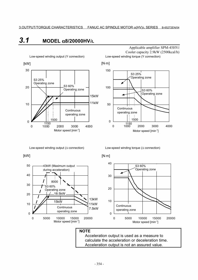
3.OUTPUT/TORQUE CHARACTERISTICS FANUC AC SPINDLE MOTOR α(HV)iL SERIES B-65272EN/04
- 354 -
3.1 MODEL αααα8/20000HViLApplicable amplifier SPM-45HVi
Cooler capacity 2.9kW (2500kcal/h)
0
10
20
30
40
50
0 5000 10000 15000 200000
10
20
30
40
0 5000 10000 15000 20000
0
10
20
30
0 1000 2000 3000 40000
50
100
150
0 2000 3000 4000
[kW] [N⋅m]
[N⋅m][kW]
1500
11kW
15kW
11501500
1150
7.5kW11kW13kW
Motor speed [min-1]
Continuousoperating zone
Motor speed [min-1]
S3 25%Operating zone
Continuousoperating zone
Low-speed winding output (Y connection) Low-speed winding torque (Y connection)
S3 25%Operating zone
S3 60%Operating zone S3 60%
Operating zone
Motor speed [min-1]
Continuousoperating zone
Motor speed [min-1]
Continuousoperating zone
Low-speed winding output (∆ connection) Low-speed winding torque (∆ connection)
S3 60%Operating zone
43kW (Maximum outputduring acceleration)
S3 60%Operating zone
1000
8000
15kW
18.5kW
NOTEAcceleration output is used as a measure tocalculate the acceleration or deceleration time.Acceleration output is not an assured value.
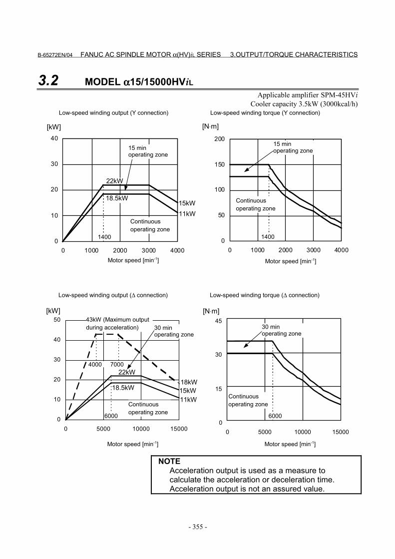
B-65272EN/04 FANUC AC SPINDLE MOTOR α(HV)iL SERIES 3.OUTPUT/TORQUE CHARACTERISTICS
- 355 -
3.2 MODEL αααα15/15000HViLApplicable amplifier SPM-45HVi
Cooler capacity 3.5kW (3000kcal/h)
0
10
20
30
40
0 1000 2000 3000 4000
1400
18.5kW
22kW
15kW11kW
0
50
100
150
200
0 1000 2000 3000 4000
1400
0
10
20
30
40
50
0 5000 10000 150000
15
30
45
0 5000 10000 15000
6000
4000
18.5kW
22kW
11kW15kW18kW
6000
7000
[kW] [N⋅m]
[N⋅m][kW]
Motor speed [min-1]
Continuousoperating zone
Motor speed [min-1]
Low-speed winding output (Y connection) Low-speed winding torque (Y connection)
15 minoperating zone
Motor speed [min-1]
Continuousoperating zone
Motor speed [min-1]
Continuousoperating zone
Low-speed winding output (∆ connection) Low-speed winding torque (∆ connection)
43kW (Maximum outputduring acceleration)
15 minoperating zone
30 minoperating zone
30 minoperating zone
Continuousoperating zone
NOTEAcceleration output is used as a measure tocalculate the acceleration or deceleration time.Acceleration output is not an assured value.
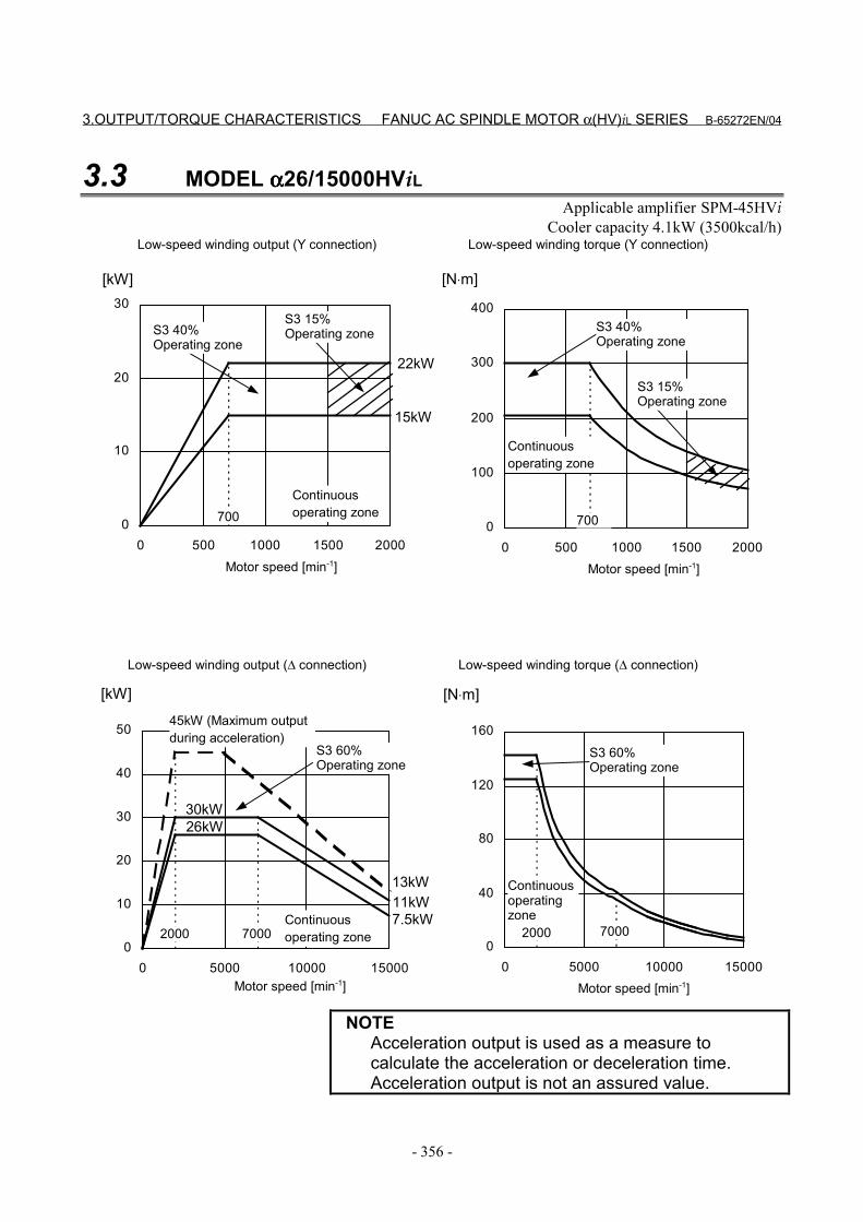
3.OUTPUT/TORQUE CHARACTERISTICS FANUC AC SPINDLE MOTOR α(HV)iL SERIES B-65272EN/04
- 356 -
3.3 MODEL αααα26/15000HViLApplicable amplifier SPM-45HVi
Cooler capacity 4.1kW (3500kcal/h)
0
40
80
120
160
0 5000 10000 150000
10
20
30
40
50
0 5000 10000 15000
20007.5kW11kW
26kW30kW
20007000
13kW
7000
0
100
200
300
400
0 500 1000 1500 2000
0
10
20
30
0 500 1000 1500 2000
700
15kW
22kW
700
[kW] [N⋅m]
[N⋅m][kW]
Motor speed [min-1]
Continuousoperating zone
Motor speed [min-1]
S3 40%Operating zone
Continuousoperating zone
Low-speed winding output (Y connection) Low-speed winding torque (Y connection)
S3 40%Operating zone
S3 15%Operating zone
S3 15%Operating zone
Motor speed [min-1]
Continuousoperating zone
Motor speed [min-1]
Continuousoperatingzone
Low-speed winding output (∆ connection) Low-speed winding torque (∆ connection)
S3 60%Operating zone
45kW (Maximum outputduring acceleration)
S3 60%Operating zone
NOTEAcceleration output is used as a measure tocalculate the acceleration or deceleration time.Acceleration output is not an assured value.

B-65272EN/04 FANUC AC SPINDLE MOTOR α(HV)iL SERIES 4.CONNECTIONS
- 357 -
4 CONNECTIONS
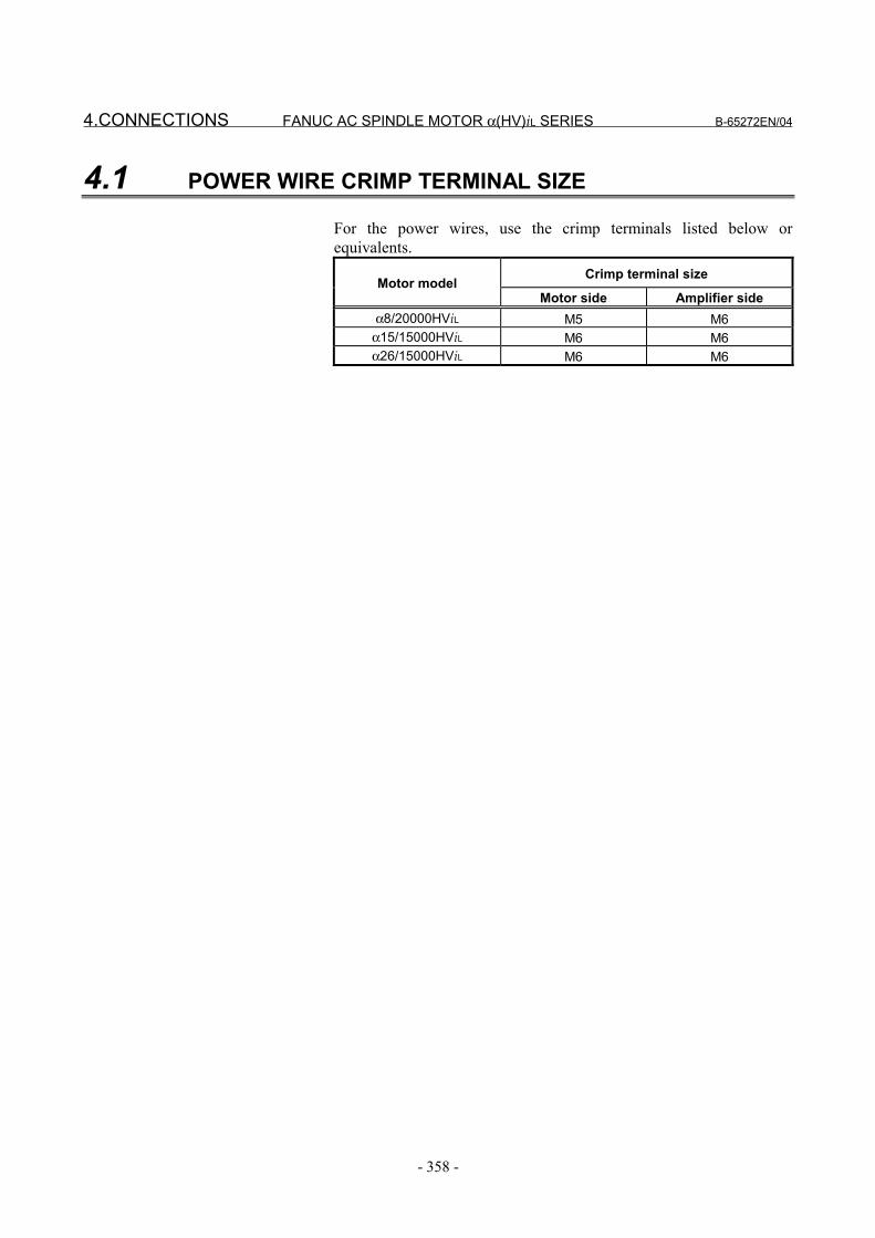
4.CONNECTIONS FANUC AC SPINDLE MOTOR α(HV)iL SERIES B-65272EN/04
- 358 -
4.1 POWER WIRE CRIMP TERMINAL SIZE
For the power wires, use the crimp terminals listed below orequivalents.
Crimp terminal sizeMotor modelMotor side Amplifier side
α8/20000HViL M5 M6α15/15000HViL M6 M6α26/15000HViL M6 M6

B-65272EN/04 FANUC AC SPINDLE MOTOR α(HV)iL SERIES 4.CONNECTIONS
- 359 -
4.2 CONNECTION OF SIGNAL LEAD
MZi sensor signal or overheat signal use a connector manufactured byTyco Electronics AMP.The connector housing and the connector are attached to the motor.
Connector pins arrangementNumber B1 B2 B3 B4 B5 B6
ColorSignal *VA *VB *VZ 0V THR2
Number A1 A2 A3 A4 A5 A6ColorSignal +5V VA VB VZ SS THR1
Connector housing and contact specificationsConnector and contact :Tyco Electronics AMP specification D-3000 series
Motor side Cable side
FANUC specification Manufacturespecification FANUC specification Manufacture
specificationHousing A63L-0001-0535/121KDF 178964-6 A63L-0001-0460/121KD 178289-6Contact A63L-0001-0456/ASMT 175288-2 A63L-0001-0456/ASM 1-175217-2
Crimping tool : 91559-1 Extractor : 234168-1
Thermistor specificationSignal THR1 corresponds to one of the thermistor terminals, andsignal THR2, to the other terminal. The resistance of the thermistor isabout 30 to 90 kΩ as measured at room temperature (20°C to 30°C).
T H R 1T H R 2+5V0VV A*V AV B*V BV Z*V ZS S
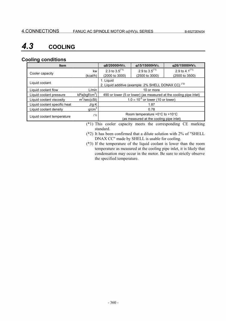
4.CONNECTIONS FANUC AC SPINDLE MOTOR α(HV)iL SERIES B-65272EN/04
- 360 -
4.3 COOLING
Cooling conditionsItem αααα8/20000HViL αααα15/15000HViL αααα26/15000HViL
Cooler capacity kw(kcal/h)
2.3 to 3.5(*1)
(2000 to 3000)2.9 to 3.5(*1)
(2500 to 3000)2.9 to 4.1(*1)
(2500 to 3500)
Liquid coolant 1. Liquid 2. Liquid additive (example: 2% SHELL DONAX CC) (*2)
Liquid coolant flow L/min 10 or moreLiquid coolant pressure kPa(kgf/cm2) 490 or lower (5 or lower) (as measured at the cooling pipe inlet)Liquid coolant viscosity m2/sec(cSt) 1.0 × 10⁻⁵ or lower (10 or lower)Liquid coolant specific heat J/g⋅K 1.87Liquid coolant density g/cm3 0.78
Liquid coolant temperature (*3) Room temperature +0°C to +10°C(as measured at the cooling pipe inlet)
(*1) This cooler capacity meets the corresponding CE markingstandard.
(*2) It has been confirmed that a dilute solution with 2% of "SHELLDNAX CC" made by SHELL is usable for cooling.
(*3) If the temperature of the liquid coolant is lower than the roomtemperature as measured at the cooling pipe inlet, it is likely thatcondensation may occur in the motor. Be sure to strictly observethe specified temperature.
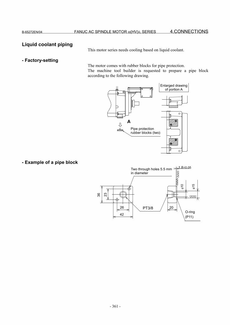
B-65272EN/04 FANUC AC SPINDLE MOTOR α(HV)iL SERIES 4.CONNECTIONS
- 361 -
Liquid coolant pipingThis motor series needs cooling based on liquid coolant.
- Factory-settingThe motor comes with rubber blocks for pipe protection.The machine tool builder is requested to prepare a pipe blockaccording to the following drawing.
Pipe protectionrubber blocks (two)
Enlarged drawingof portion A
A
- Example of a pipe block
42
26 PT3/8
36 23
1.8±0.05Two through holes 5.5 mmin diameter
φ10
φ15
20O-ring(P11)
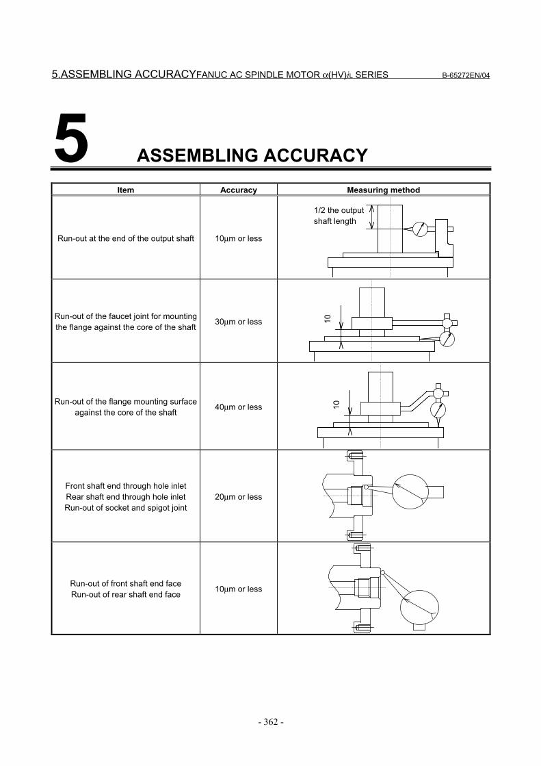
5.ASSEMBLING ACCURACYFANUC AC SPINDLE MOTOR α(HV)iL SERIES B-65272EN/04
- 362 -
5 ASSEMBLING ACCURACYItem Accuracy Measuring method
Run-out at the end of the output shaft 10µm or less
1/2 the outputshaft length
Run-out of the faucet joint for mountingthe flange against the core of the shaft 30µm or less 10
Run-out of the flange mounting surfaceagainst the core of the shaft 40µm or less 10
Front shaft end through hole inletRear shaft end through hole inletRun-out of socket and spigot joint
20µm or less
Run-out of front shaft end faceRun-out of rear shaft end face 10µm or less
B-65272EN/04 FANUC AC SPINDLE MOTOR α(HV)iL SERIES6.EXTERNAL DIMENSIONS
- 363 -
6 EXTERNAL DIMENSIONSModel name Section
Model α8/20000HViL 6.1Model α15/15000HViL 6.2Model α26/15000HViL 6.3
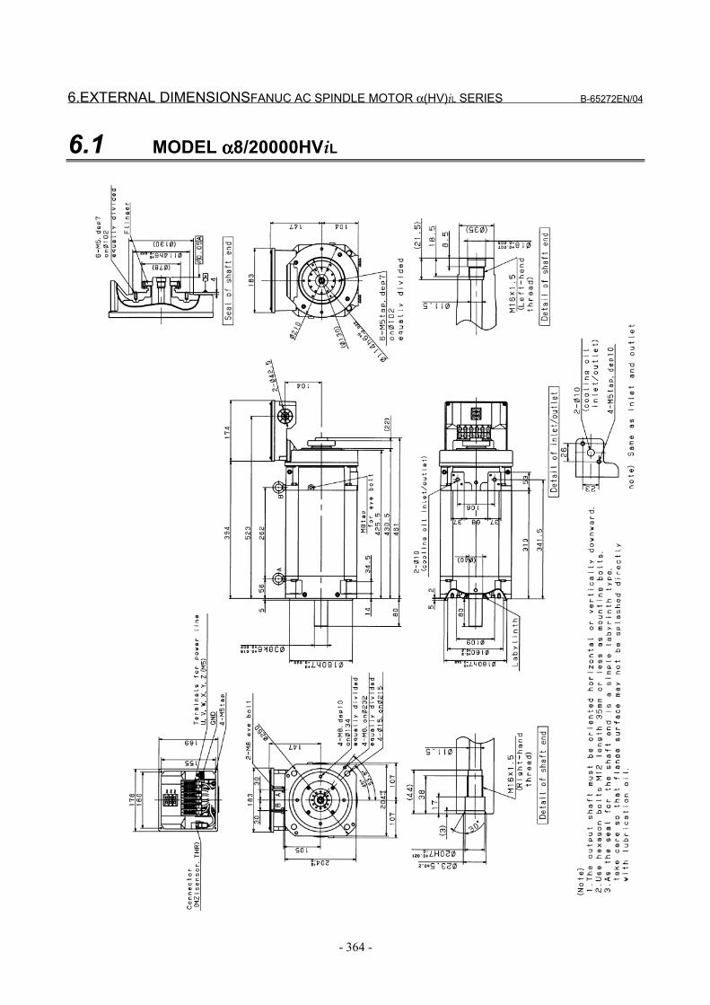
6.EXTERNAL DIMENSIONSFANUC AC SPINDLE MOTOR α(HV)iL SERIES B-65272EN/04
- 364 -
6.1 MODEL αααα8/20000HViL
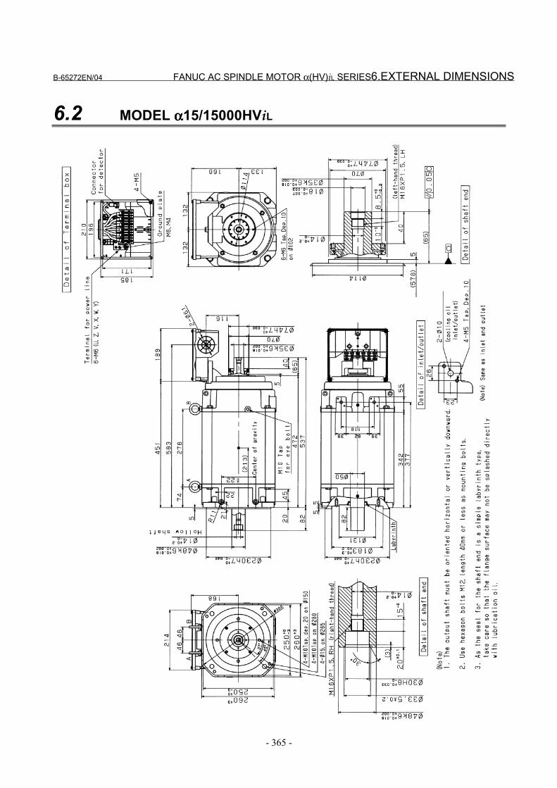
B-65272EN/04 FANUC AC SPINDLE MOTOR α(HV)iL SERIES6.EXTERNAL DIMENSIONS
- 365 -
6.2 MODEL αααα15/15000HViL
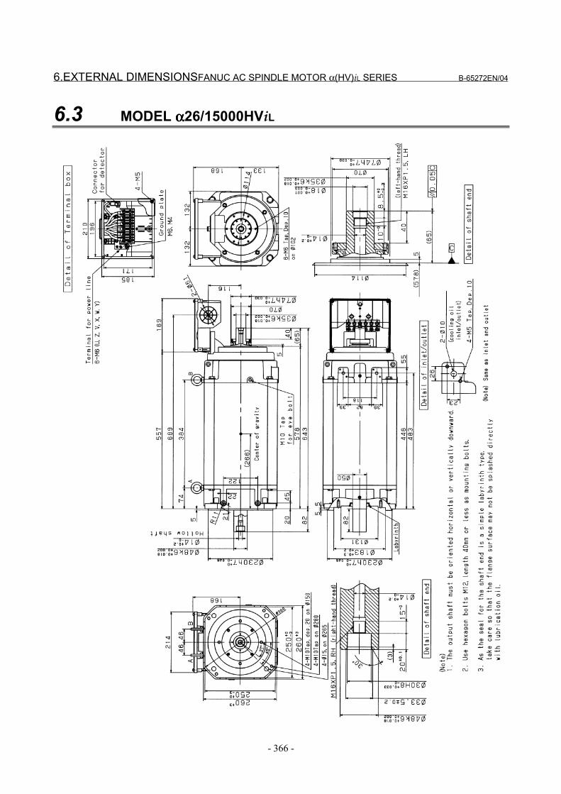
6.EXTERNAL DIMENSIONSFANUC AC SPINDLE MOTOR α(HV)iL SERIES B-65272EN/04
- 366 -
6.3 MODEL αααα26/15000HViL
B-65272EN/04 INDEX
i-1
INDEX<A>
ALLOWABLE RADIAL LOAD............ 79, 136, 252, 298
ASSEMBLING ACCURACY
.......................... 80, 137, 180, 223, 253, 299, 337, 362
<C>CENTERING USING CENTERING PLATES............ 197
CHECKING MOTOR VIBRATION (TO SEE WHETHER
CENTERING IS SUCCESSFUL).......................... 198
COMMON........................................................................ 8
CONFIGURATION.............................................. 174, 331
CONFIGURATION AND ORDERING NUMBER
........................................................................ 173, 330CONFIGURATION OF THE αi SERIES ........................ 5
CONNECTION OF A SINGLE-PHASE FAN MOTOR
................................................................................ 335
CONNECTION OF SIGNAL LEAD
.......................... 78, 135, 179, 220, 251, 297, 336, 359
CONNECTION OF THE POWER, FAN MOTOR, ANDMZi SENSOR SIGNAL LEADS ................... 177, 334
CONNECTIONS .... 74, 133, 176, 217, 247, 295, 333, 357
COOLANT JOINT ....................................................... 203
COOLING ............................................................ 221, 360
COUPLING SELECTION............................................ 199
<D>DETERMINING THE ACCELERATION TIME .......... 33
DETERMINING THE ALLOWABLE DUTY CYCLE. 39
DISPOSAL OF SPINDLE MOTORS BY MATERIAL
TYPE........................................................................ 42
<E>EXTERNAL DIMENSIONS
.......................... 81, 138, 181, 224, 254, 300, 338, 363
<F>FAN MOTOR CONNECTION ...................................... 24
<H>HIGHER-PRECISION MOUNTING FLANGE AND
SHAFT ................................................................... 196
<M>MOTOR TYPES............................................................... 6
<N>NOTES ON INSTALLATION ......................................... 7
NOTES ON MOTOR INSTALLATION...................... 195
NOTES ON OPERATION ............................................. 32
<O>ORDERING NUMBER........................................ 175, 332
OUTPUT/TORQUE CHARACTERISTICS
.......................... 56, 120, 163, 213, 238, 289, 320, 353
<P>POINTS ABOUT DIRECT CONNECTION
STRUCTURE......................................................... 194
POWER LEAD CONNECTION .................................... 19
POWER WIRE CRIMP TERMINAL SIZE ................. 358
<R>ROTATION JOINT...................................................... 202
ROTATION JOINT SUPPORT HOUSING................. 205
<S>SIZE OF POWER LEAD ............................................. 219
SPECIFICATIONS
.......................... 46, 114, 157, 210, 232, 284, 314, 350
<T>TOTAL CONNECTION DIAGRAM........................... 218
<W>WHEN A MOTOR IS CONNECTED TO A SPINDLE
VIA A BELT ............................................................ 27
WHEN A MOTOR IS CONNECTED TO A SPINDLE
VIA A GEAR ........................................................... 30
WHEN A MOTOR IS DIRECTLY CONNECTED TO A
SPINDLE VIA A COUPLING................................. 31

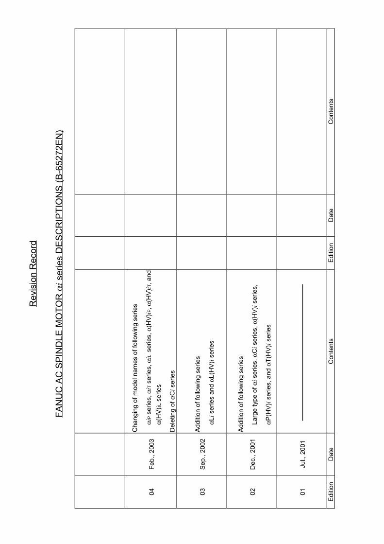
Rev
isio
n R
ecor
d
FAN
UC
AC
SPI
ND
LE M
OTO
R αi s
erie
s D
ESC
RIP
TIO
NS
(B-6
5272
EN)
04Fe
b., 2
003
Cha
ngin
g of
mod
el n
ames
of f
ollo
win
g se
ries
αiP
serie
s, αiT
ser
ies,
αiL
ser
ies,
α(H
V)iP
, α(H
V)iT
, and
α(H
V)iL
ser
ies
Del
etin
g of
αCi s
erie
s
03Se
p., 2
002
Addi
tion
of fo
llow
ing
serie
s
αLi s
erie
s an
d αL
(HV)i s
erie
s
02D
ec.,
2001
Addi
tion
of fo
llow
ing
serie
s
Larg
e ty
pe o
f αi s
erie
s, α
Ci s
erie
s, α
(HV)i s
erie
s,
αP(H
V)i s
erie
s, a
nd α
T(H
V)i s
erie
s
01Ju
l., 2
001
Editi
onD
ate
Con
tent
sEd
ition
Dat
eC
onte
nts

Related Documents