AC SERVO DRIVES SERIES JQA-EM0202 JQA-0422 Certified for ISO9001 and ISO14001

Welcome message from author
This document is posted to help you gain knowledge. Please leave a comment to let me know what you think about it! Share it to your friends and learn new things together.
Transcript

AC SERVO DRIVESSERIES
JQA-EM0202JQA-0422
Certified for
ISO9001 and
ISO14001

Everyone’s preferred choice of Servo Drives
Series of AC Servo Drives
Since the release of the first series of Servo Drives in 1984, Yaskawa Electric has
consistently made innovations to existing technologies to find solutions for problems
that users experience. Users have always sought high-speed, high-accuracy, and
easy-to-use products, and this demand rises every year.
In 2013, the series of Servo Drives evolved into the Servo Drives, which provides
users with the ultimate experience in seven key areas and delivers the optimal solutions
that only Yaskawa can offer. With the superlative performance and outstanding ease of
use of the series, Yaskawa can offer solutions that will make the Servo Drives
the preferred choice of customers at any point in the life cycle of their systems.
See pages M-6 and M-7 for examples of
the high performance of the series in
“pick and place” applications. Contact
Yaskawa for details on this and additional
applications.
1Superlative performance with improved
efficiency and speed
pages M-4 to M-7
Attention developers/engineers
Ultimate system performance
You can check the level of performance of actual operations with
the use of demonstrat ion units. Contact Yaskawa for a
demonstration.
2 page M-8
Attention developers/engineers maintenance personnelproduction
Ultimately ease to use
No tuning required with the series upgraded tuning-less
function to achieve stable movement with no vibration.
3 Ultimate environmental performance page M-9
operatorsAttention developers/engineers
Each product has improved specifications to meet even the most
stringent environmental requirements. Servo Drives can now be used in
different countries and regions, and under a variety of conditions.
* : At this altitude, the servo drives will operate at reduced ratings.
Are there any operating environments that you have given up on? The servos
have an increased ability to cope with temperature rises in systems, comply with
the IP67 resistance to water immersion rating, and have greater global support (AC
240 V input and operable at an altitude of 2,000 meters*). Compact and energy
saving systems can also be easily built with the two-axis SERVOPACKs.
2
page M-10
operatorsdevelopers/engineers
4Attention maintenance personnel
Ultimate safety and security
It is absolutely essential to ensure the safety of systems and protect against
temperature increases. The Servo Drives are fully equipped with all the
necessary safety measures, which reduces the amount of work required for
system design and maintenance.
The Servo Drives satisfy the IEC 61508 safety integrity level 3 (SIL 3).
Safety is also ensured with temperature sensors mounted in products.
These Servo Drives can be used as system components with safety guaranteed.
page M-126Attention developers/engineers
Ultimate lineup
Compatible products made by our partner
companies are also available. You can prepare
all the motion devices required for your system
with our one-stop, all-in-one service.
It is now possible to drive rotary, Linear, or
Direct Drive Servomotors using the same SERVOPACK model in the series. This
helps to reduce the number of Servo Drives
that are put in storage.
You can choose from a rich product lineup of the series as well
as from the compatible products of Yaskawa’s partner companies
to easily build just the right system for your needs.
page M-137Attention developers/engineers
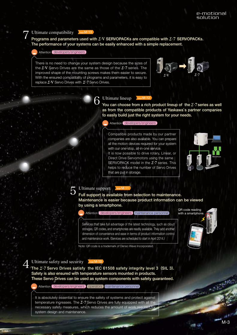
Ultimate compatibility
Programs and parameters used with SERVOPACKs are compatible with SERVOPACKs.
The performance of your systems can be easily enhanced with a simple replacement.
There is no need to change your system design because the sizes of
the Servo Drives are the same as those of the series. The
improved shape of the mounting screws makes them easier to secure.
With the ensured compatibility of programs and parameters, it is easy to
replace Servo Drives with Servo Drives.
QR code readingwith a smartphone.
page M-11
Services that take full advantage of the latest technology, such as cloud
storages, QR codes, and smartphones are readily available. They add another
dimension of convenience and ease in terms of product information control
and maintenance work. (Services are scheduled to start in April 2014.)
5Attention developers/engineers maintenance personnel
Ultimate support
Full support is available from selection to maintenance.
Maintenance is easier because product information can be viewed
by using a smartphone.
Note: QR code is a trademark of Denso Wave Incorporated.
3
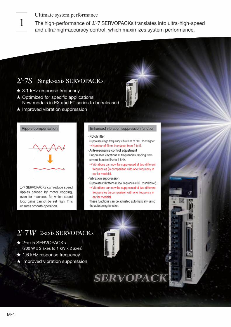
3.1 kHz response frequency
Optimized for specific applications: New models in EX and FT series to be released
Improved vibration suppression
2-axis SERVOPACKs (200 W x 2 axes to 1 kW x 2 axes)
1.6 kHz response frequency
Improved vibration suppression
Ultimate system performance
1
Enhanced vibration suppression functionRipple compensation
Single-axis SERVOPACKs
2-axis SERVOPACKs
Notch filter
Suppresses high-frequency vibrations of 500 Hz or higher.
Number of filters increased from 2 to 5.
Anti-resonance control adjustment
Suppresses vibrations at frequencies ranging from
several hundred Hz to 1 kHz.
Vibrations can now be suppressed at two different
frequencies (in comparison with one frequency in
earlier models).
Vibration suppression
Suppresses vibrations at low frequencies (30 Hz and lower).
Vibrations can now be suppressed at two different
frequencies (in comparison with one frequency in
earlier models).
These functions can be adjusted automatically using
the autotuning function.
The high-performance of SERVOPACKs translates into ultra-high-speed
and ultra-high-accuracy control, which maximizes system performance.
SERVOPACKs can reduce speed
ripples caused by motor cogging,
even for machines for which speed
loop gains cannot be set high. This
ensures smooth operation.
4

Encoder resolution comparison
SGM7A
SGM7J
SGM7P
SGM7G
Model
20 bits =1 million pulses/rev (approx.)
24 bits =16 million pulses/rev (approx.)
50W
50W
100W
300W
7kW
0.75kW
1.5kW
15kW
16 times higher!
Solution for 50-W or greater models.
About 20% reduction intemperature increase!
series series
series series
(under the same conditions)
Compact dimensions (approx. 80% smaller than our earlier models.)
High-resolution 24-bit encoder
incorporated(16,777,216 pulses/rev)
Maximum torque: 350%(small capacity)
Servomotors
High-resolution, 24-bit encoder
High efficiency and low heat generation
Servomotors (50 W or greater) use
encoders with a resolution that are 16 times
higher than those used in Servomotors.
Servomotors use an optimized magnetic
circuit that improves motor efficiency and
reduces heat generation.
(comparison with typical models.)
5

Example
Problem
Issue
Issue
Issue
Issue
Solution
“Pick and place” refers to the actions involved in picking up an object
in one location and placing it in another location.
Reduces system takt times
Solving problems in “pick and place” applications
We need to reduce takt times.Issue 1
Case 1 Case 2
Vibration occurs after servo
gain is increased.
Servo gain was successfully increased
by first using the anti-resonance
control adjustment, and then vibration
occurred at a different frequency.
Servo gain can be increased
by using the enhanced
anti-resonance control
adjustment function.
Without anti-resonance
control adjustment
With anti-resonance
control adjustment
With improved anti-resonance
control adjustment
Horizontal axis 1(widthwise direction)
Horizontal axis 2(lengthwise direction)
A Position deviation
B Torque reference
C Positioning Completion signal
A
B
C
A
B
C
A
B
C
How can we reduce takt times?
How can we improve positioning
accuracy?
How can we suppress vibration
created by speed acceleration?
How can we achieve stable
operation with or without
workpieces?
6
Issue 3
Solution
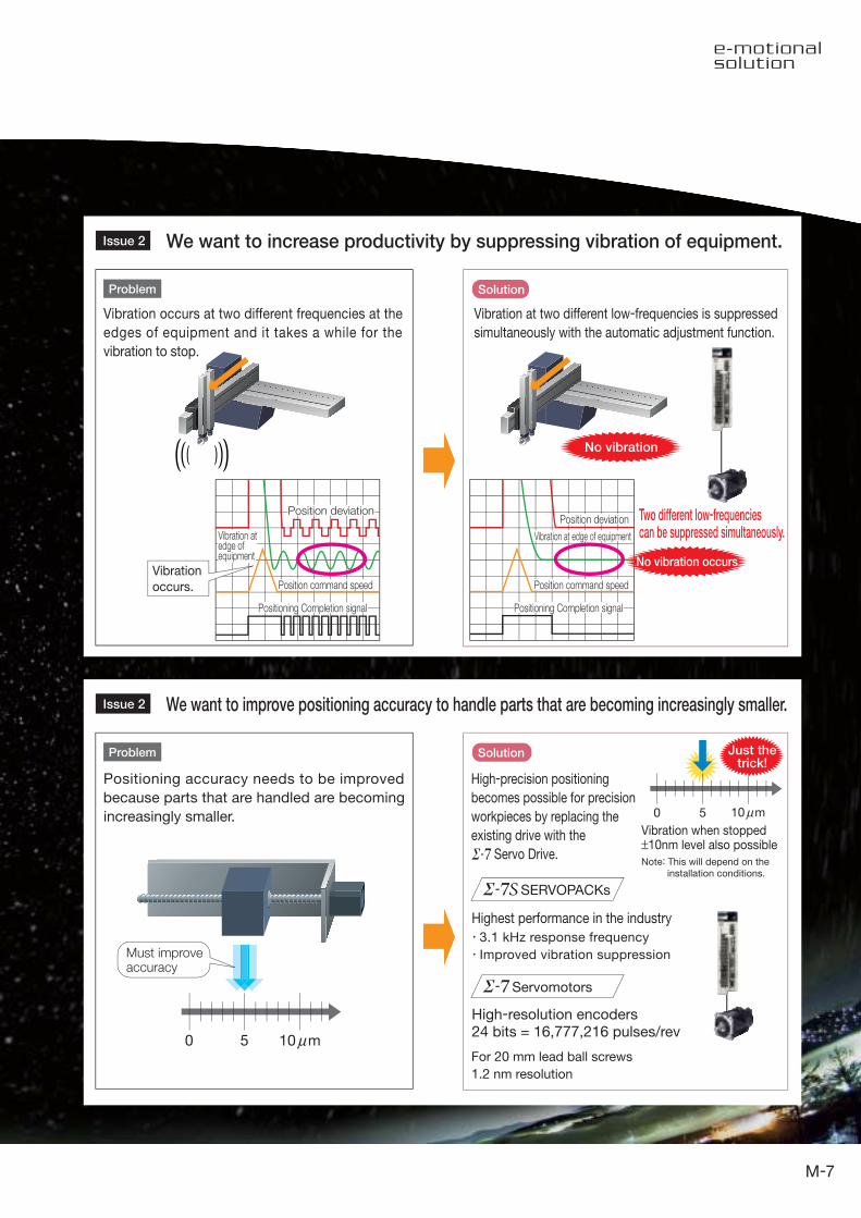
We want to increase productivity by suppressing vibration of equipment.Issue 2
We want to improve positioning accuracy to handle parts that are becoming increasingly smaller.Issue 2
Solution
3.1 kHz response frequency
Improved vibration suppression
0 5
Highest performance in the industry
For 20 mm lead ball screws
1.2 nm resolution
High-resolution encoders24 bits = 16,777,216 pulses/rev
No vibration
Two different low-frequenciescan be suppressed simultaneously.
Vibration
occurs.
SERVOPACKs
Servomotors
Positioning accuracy needs to be improved
because parts that are handled are becoming
increasingly smaller.
High-precision positioning
becomes possible for precision
workpieces by replacing the
existing drive with the
Servo Drive.
Must improveaccuracy
10 mμ
Just thetrick!
0 5 10 mμVibration when stopped±10nm level also possible
Note: This will depend on the installation conditions.
Vibration occurs at two different frequencies at the
edges of equipment and it takes a while for the
vibration to stop.
Vibration at two different low-frequencies is suppressed
simultaneously with the automatic adjustment function.
Position deviationPosition deviation
Vibration at edge of equipment
Position command speed
Positioning Completion signal
Position command speed
Positioning Completion signal
Vibration atedge ofequipment
No vibration occurs
Problem
Problem
7
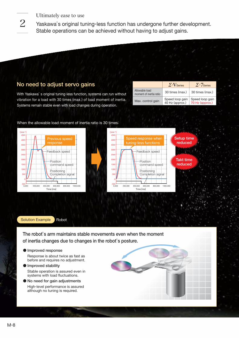
No need to adjust servo gains
When the allowable load moment of inertia ratio is 30 times:
Yaskawa’s original tuning-less function has undergone further development.
Stable operations can be achieved without having to adjust gains.2
Allowable load moment of inertia ratio
30 times (max.)
Series Series
Max. control gainSpeed loop gain 40 Hz (approx.)
30 times (max.)
Speed loop gain 70 Hz (approx.)
Takt timereduced
Setup timereduced
RobotSolution Example
0,000 200,000 400,000 600,000 800,000 1000,000
4500
4000
3500
3000
2500
2000
1500
1000
500
0
-500
Time [ms]
Previous speedresponse
0,000 200,000 400,000 600,000 800,000 1000,000
4500
4000
3500
3000
2500
2000
1500
1000
500
0
-500
Time [ms]
Speed response when
tuning-less functions
Feedback speed
PositioningCompletion signal
Positioncommand speed
Feedback speed
PositioningCompletion signal
Positioncommand speed
Feedback speed
PositioningCompletion signal
Positioncommand speed
Feedback speed
PositioningCompletion signal
Positioncommand speed
With Yaskawa’s original tuning-less function, systems can run without
vibration for a load with 30 times (max.) of load moment of inertia.
Systems remain stable even with load changes during operation.
The robot’s arm maintains stable movements even when the moment
of inertia changes due to changes in the robot’s posture.
Improved response
Response is about twice as fast as before and requires no adjustment.
Improved stability
Stable operation is assured even in systems with load fluctuations.
No need for gain adjustments
High-level performance is assured although no tuning is required.
Ultimately ease to use
[min-1] [min-1]
8
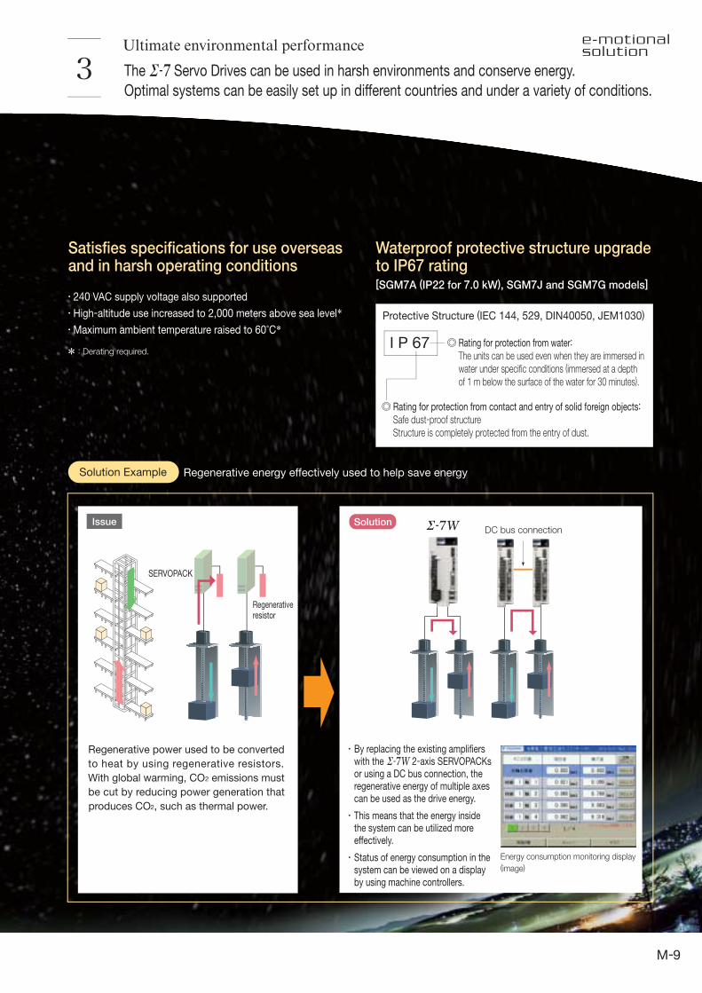
Waterproof protective structure upgradeto IP67 rating[SGM7A (IP22 for 7.0 kW), SGM7J and SGM7G models]
Satisfies specifications for use overseasand in harsh operating conditions
3
Protective Structure (IEC 144, 529, DIN40050, JEM1030)
I P 67* : Derating required.
Regenerativeresistor
SERVOPACK
DC bus connection
Energy consumption monitoring display
(image)
Regenerative energy effectively used to help save energySolution Example
SolutionIssue
240 VAC supply voltage also supported
High-altitude use increased to 2,000 meters above sea level*Maximum ambient temperature raised to 60°C*
Rating for protection from water:
The units can be used even when they are immersed in water under specific conditions (immersed at a depth of 1 m below the surface of the water for 30 minutes).
Rating for protection from contact and entry of solid foreign objects:
Safe dust-proof structureStructure is completely protected from the entry of dust.
Ultimate environmental performance
Regenerative power used to be converted
to heat by using regenerative resistors.
With global warming, CO2 emissions must
be cut by reducing power generation that
produces CO2, such as thermal power.
The Servo Drives can be used in harsh environments and conserve energy.
Optimal systems can be easily set up in different countries and under a variety of conditions.
By replacing the existing amplifiers with the 2-axis SERVOPACKs or using a DC bus connection, the regenerative energy of multiple axes can be used as the drive energy.
This means that the energy inside the system can be utilized more effectively.
Status of energy consumption in the system can be viewed on a display by using machine controllers.
9
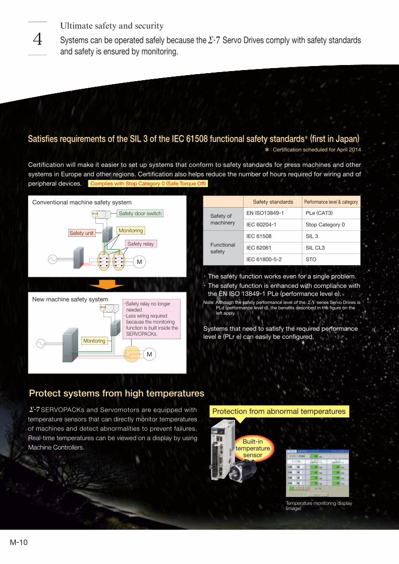
Systems can be operated safely because the Servo Drives comply with safety standards
and safety is ensured by monitoring.4
Satisfies requirements of the SIL 3 of the IEC 61508 functional safety standards* (first in Japan)
*:Certification scheduled for April 2014
Conventional machine safety system
New machine safety system
EN ISO13849-1
IEC 60204-1
IEC 61508
IEC 62061
IEC 61800-5-2
Safety standards
Safety of
machinery
Functional
safety
Performance level & category
PLe (CAT3)
Stop Category 0
SIL 3
SIL CL3
STO
Temperature monitoring display(image)
Built-intemperature
sensor
Protection from abnormal temperatures
Ultimate safety and security
Protect systems from high temperatures
SERVOPACKs and Servomotors are equipped with
temperature sensors that can directly monitor temperatures
of machines and detect abnormalities to prevent failures.
Real-time temperatures can be viewed on a display by using
Machine Controllers.
Certification will make it easier to set up systems that conform to safety standards for press machines and other
systems in Europe and other regions. Certification also helps reduce the number of hours required for wiring and of
peripheral devices.
Safety door switch
Safety unit
Safety relay
Monitoring
Monitoring
-Safety relay no longer needed
-Less wiring required because the monitoring function is built inside the SERVOPACKs.
Complies with Stop Category 0 (Safe Torque Off)
The safety function works even for a single problem.
The safety function is enhanced with compliance with
the EN ISO 13849-1 PLe (performance level e).
Note: Although the safety performance level of the series Servo Drives is PLd (performance level d), the benefits described in the figure on the left apply.
Systems that need to satisfy the required performance
level e (PLr e) can easily be configured.
10
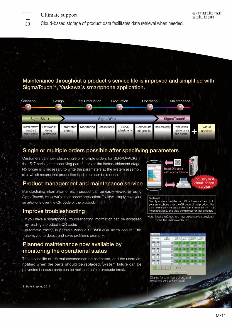
Customers can now place single or multiple orders for SERVOPACKs in
the series after specifying parameters at the factory shipment stage.
No longer is it necessary to write the parameters at the system assembly
site, which means that production lead times can be reduced.
Features: Simply access the MechatroCloud service* and hold your smartphone over the QR code of the product. You c a n a c c es s t h e p ro d u c t d a t a s t o re d i n t h e MechatroCloud, and view the manual for that product.
Ultimate support
Cloud-based storage of product data facilitates data retrieval when needed. 5
Single or multiple orders possible after specifying parameters
Industry firstcloud-based
service
Maintenance throughout a product’s service life is improved and simplified with
SigmaTouch!*, Yaskawa’s smartphone application.
Selection
SigmaSize+ SigmaWin+ SigmaTouch!
Design Trial Production Production Operation Maintenance
Electrical machineryproducts and
capacity selection
Provision ofdesign
information
Parameter
setting
Monitoring Test operation Servoadjustments
Service life
diagnosis
Troubleshooting Productionmaintenanceand control
Cloud
service*
Display for total hours of use andremaining service life (image)
Product management and maintenance service
Manufacturing information of each product can be easily viewed by using
SigmaTouch!, Yaskawa’s smartphone application. To view, simply hold your
smartphone over the QR code of the product.
Improve troubleshooting
If you have a smartphone, troubleshooting information can be accessed
by reading a product’s QR code.
Automatic tracing is possible when a SERVOPACK alarm occurs. This
allows you to detect and solve problems promptly.
Planned maintenance now available by
monitoring the operational status
The service life of the maintenance can be estimated, and the users are
notified when the parts should be replaced. System failure can be
prevented because parts can be replaced before products break.
Read QR codewith a smartphone
* Starts in spring 2014
Note: MechatroCloud is a new colud service provided
by the the Yaskawa Electric.
11
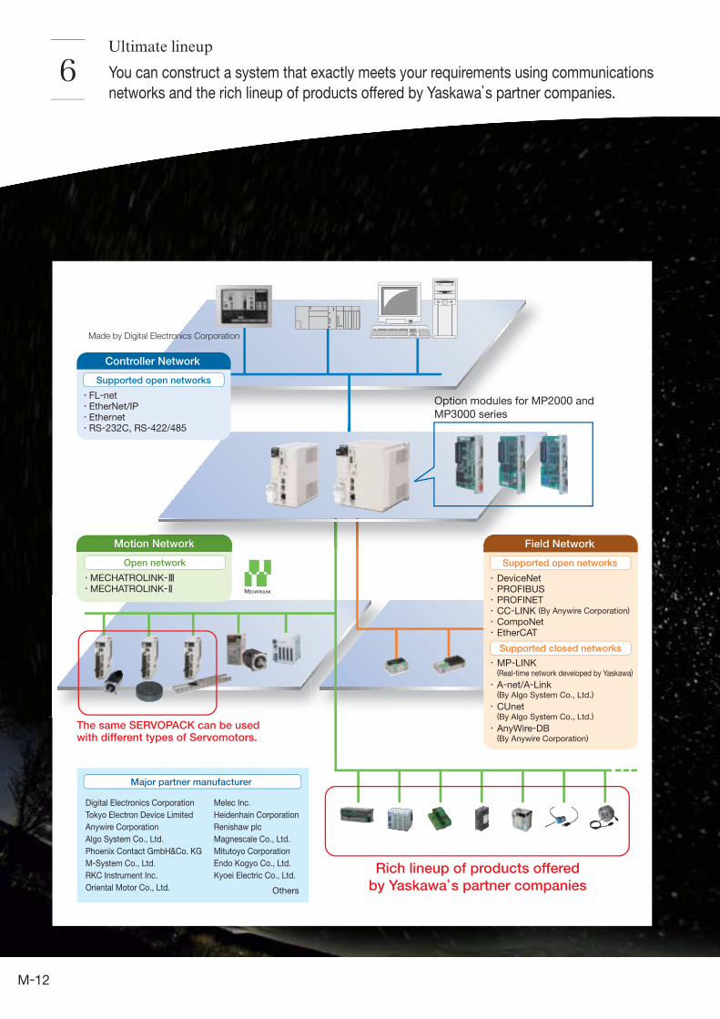
You can construct a system that exactly meets your requirements using communications
networks and the rich lineup of products offered by Yaskawa’s partner companies.6
Motion Network
Open network
Major partner manufacturer
Rich lineup of products offered
by Yaskawa’s partner companies
The same SERVOPACK can be usedwith different types of Servomotors.
Made by Digital Electronics Corporation
Melec Inc.
Heidenhain Corporation
Renishaw plc
Magnescale Co., Ltd.
Mitutoyo Corporation
Endo Kogyo Co., Ltd.
Kyoei Electric Co., Ltd.
Others
MECHATROLINK-MECHATROLINK-
Digital Electronics Corporation
Tokyo Electron Device Limited
Anywire Corporation
Algo System Co., Ltd.
Phoenix Contact GmbH&Co. KG
M-System Co., Ltd.
RKC Instrument Inc.
Oriental Motor Co., Ltd.
DeviceNetPROFIBUSPROFINETCC-LINK (By Anywire Corporation)
CompoNetEtherCAT
MP-LINK(Real-time network developed by Yaskawa)
A-net/A-Link(By Algo System Co., Ltd.)
CUnet(By Algo System Co., Ltd.)
AnyWire-DB(By Anywire Corporation)
Supported closed networks
Field Network
Supported open networks
Network Field Net
Option modules for MP2000 and
MP3000 series
Controller Network
FL-netEtherNet/IPEthernetRS-232C, RS-422/485
Supported open networks
Ultimate lineup
12

7
SERVOPACK
Servomotor
Mounting holes on topMounting holes on top
Mounting holes on bottomMounting holes on bottom
200 W 60 mm200 W 60 mm
Ultimate compatibility
Installation interchangeability with the models in
the SERVOPOACK having the same capacity
is featured for the SERVOPACKs.
The SERVOPACKs have improved shapes for
mounting holes. With this new shape, it’s much
easier to insert a screwdriver.
A parameter conversion mode is provided.
The parameters of the SERVOPACKs
can be used with the SERVOPACKs,
when using the SigmaWin+ parameter
converter.
Compatibility with earlier series is assured. You can improve the performance
of your system by replacing devices currently used with Servo Drives.
The SERVOPACKs are compatible with models of
the same capacity in the series SERVOPACKs.
13
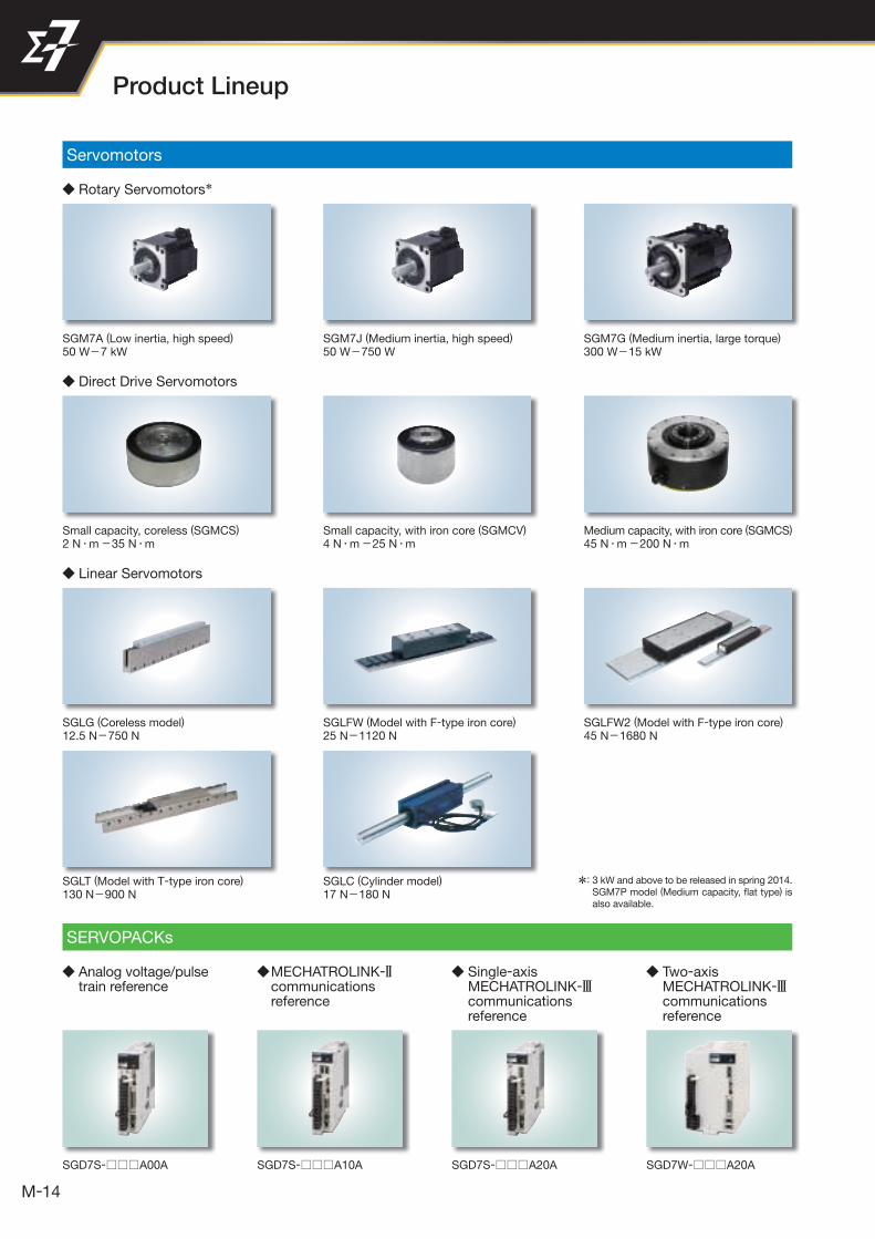
*: 3 kW and above to be released in spring 2014. SGM7P model (Medium capacity, fl at type) is also available.
Product Lineup
14
Servomotors
SERVOPACKs
Rotary Servomotors*
Analog voltage/pulse train reference
MECHATROLINK-2 communications reference
Single-axis MECHATROLINK-3 communications reference
Two-axis MECHATROLINK-3 communications reference
Direct Drive Servomotors
Linear Servomotors
SGM7A (Low inertia, high speed)
50 W-7 kW
SGD7S- A00A SGD7W- A20ASGD7S- A20ASGD7S- A10A
Small capacity, coreless (SGMCS)
2 N・m -35 N・m
SGLG (Coreless model)
12.5 N-750 N
SGLT (Model with T-type iron core)
130 N-900 N
SGM7J (Medium inertia, high speed)
50 W-750 W
Small capacity, with iron core (SGMCV)
4 N・m -25 N・m
SGLFW (Model with F-type iron core)
25 N-1120 N
SGLC (Cylinder model)
17 N-180 N
SGM7G (Medium inertia, large torque)
300 W-15 kW
Medium capacity, with iron core (SGMCS)
45 N・m -200 N・m
SGLFW2 (Model with F-type iron core)
45 N-1680 N

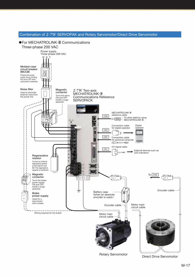
I/O signal cable
External devices such as LED indicators
CN1
CN6
CN3
CN7
CN8
CN2
Digitaloperator
Connection cablefor personal computer
Note: When not using the safety function, use the SERVOPACK with the safety function jumper connector inserted.
Motor maincircuit cable
Direct Drive Servomotor
Encoder cableBrake power supply
Motor maincircuit cable
Encoder cable
Battery case(when an absoluteencoder is used.)
Magnetic contactor
Regenerativeresistor
Noise filter
Molded-casecircuit breaker(MCCB)
Magnetic contactor
R S T
Turns the servoON and OFF.Install a surge absorber.
Turns the brake power supplyON and OFF.Install a surge absorber.
Used for a servomotor with a brake.
(Wiring required for the brake)
Power supplyThree-phase 200 VAC
Protects the power supply line by shutting the circuit OFF when overcurrent is detected.
Used to eliminateexternal noise fromthe power line.
Connect an external regenerative resistor to terminals B1 and B2 if the regenerative capacity is insufficient.
To
MECHATROLINK-reference cable
Connection cablefor digital operator
Connection cable for safety function devices
To other stations using MECHATROLINK- .
Rotary Servomotor
Single-axis MECHATROLINK-Communications Reference SERVOPACK
15
System Confi guration Example
Combination of SERVOPACK and Rotary Servomotor/Direct Drive Servomotor
1For MECHATROLINK-3 Communications
Three-phase 200 VAC

Power supplyThree-phase 200 VAC
R S T
Linear Servomotor
Linear encoder(To be provided by customers.)
Connection cable for hall sensor
Encoder cable
Main circuit cable for Linear Servomotor
Serial converter unit
Connection cable for serial converter unit
Noise filter
Molded-casecircuit breaker(MCCB)
Protects the power supply line by shutting the circuit OFF when overcurrent is detected.
Used to eliminateexternal noise fromthe power line.
Magnetic contactor
Turns the servoON and OFF.Install a surge absorber.
Single-axis MECHATROLINK-Communications Reference SERVOPACK
CN1
CN6
CN3
CN7
CN8
MECHATROLINK-reference cable
To other stations using MECHATROLINK- .
Connection cablefor digital operator
Digitaloperator
Connection cablefor personal computer
I/O signal cable
External devices such as LED indicators
Connection cable for safety function devices
Note: When not using the safety function, use the SERVOPACK with the safety function jumper connector inserted.
Regenerativeresistor
Connect an external regenerative resistor to terminals B1 and B2 if the regenerative capacity is insufficient.
回転形サーボドライブ
16
System Confi guration Example
Combination of SERVOPACK and Linear Servomotor
1For MECHATROLINK-3 Communications
Three-phase 200 VAC
CN1
CN6
CN3
CN7
Digitaloperator
I/O signal cable
External devices such as LED indicators
Brake power supply
Magnetic contactor
Regenerativeresistor
Turns the brake power supplyON and OFF.Install a surge absorber.
Used for a servomotor with a brake.
Connect an external regenerative resistor to terminals B1 and B2 if the regenerative capacity is insufficient.
R S T
Power supplyThree-phase 200 VAC
Noise filter
Molded-casecircuit breaker(MCCB)
Protects the power supply line by shutting the circuit OFF when overcurrent is detected.
Used to eliminateexternal noise fromthe power line.
Magnetic contactor
Turns the servoON and OFF.Install a surge absorber.
Two-axis MECHATROLINK-Communications Reference SERVOPACK
MECHATROLINK-reference cable
To other stations using MECHATROLINK- .
Connection cablefor digital operator
Connection cablefor personal computer
(Wiring required for the brake)
Battery case(when an absoluteencoder is used.)
Encoder cable
Encoder cable
Motor maincircuit cable
Motor maincircuit cable
Rotary ServomotorDirect Drive Servomotor
CN2To
回転形サーボドライブ
17
Combination of SERVOPAK and Rotary Servomotor/Direct Drive Servomotor
1For MECHATROLINK-3 Communications
Three-phase 200 VAC

18
Series Combination
Rotary Servomotor Model Rated OutputSERVOPACK Model
SGD7S- SGD7W-
SGM7A (Low inertia, high speed)
3000 min-1
SGM7A-A5A 50 W R70A 1R6A
SGM7A-01A 100 W R90A 1R6A
SGM7A-C2A 150 W1R6A
SGM7A-02A 200 W
SGM7A-04A 400 W 2R8A
SGM7A-06A 600 W5R5A
SGM7A-08A 750 W
SGM7A-10A 1.0 kW120A
−SGM7A-15A 1.5 kW
SGM7A-20A 2.0 kW 180A
SGM7A-25A 2.5 kW200A
SGM7A-30A 3.0 kW
SGM7J(Medium inertia, high speed)
3000 min-1
SGM7J-A5A 50 W R70A 1R6A
SGM7J-01A 100 W R90A 1R6A
SGM7J-C2A 150 W 1R6A
SGM7J-02A 200 W 1R6A
SGM7J-04A 400 W 2R8A
SGM7J-06A 600 W5R5A
SGM7J-08A 750 W
SGM7G (Medium inertia, large torque)
1500 min-1
SGM7G-03A 300 W3R8A 5R5A
SGM7G-05A 450 W
SGM7G-09A 850 W 7R6A
SGM7G-13A 1.3 kW 120A −SGM7G-20A 1.8 kW 180A
Direct Drive Servomotor ModelRated Torque
N・m
Instantaneous
Peak Torque
N・m
SERVOPACK Model
SGD7S- SGD7W-
Small capacity, coreless(SGMCS)
SGMCS-02B 2 6
2R8A
SGMCS-05B 5 15
SGMCS-07B 7 21
SGMCS-04C 4 12
SGMCS-10C 10 30
SGMCS-14C 14 42
SGMCS-08D 8 24
SGMCS-17D 17 51
SGMCS-25D 25 75
SGMCS-16E 16 485R5A
SGMCS-35E 35 105
Medium capacity, with iron core(SGMCS)
SGMCS-45M 45 135 7R6A
SGMCS-80M 80 240120A
−SGMCS-80N 80 240
SGMCS-1AM 110 330 180A
SGMCS-1EN 150 450200A
SGMCS-2ZN 200 600
Small capacity, with iron core(SGMCV)
SGMCV-04B 4 122R8A
SGMCV-10B 10 30
SGMCV-14B 14 42 5R5A
SGMCV-08C 8 24 2R8A
SGMCV-17C 17 51 5R5A
SGMCV-25C 25 75 7R6A
1Combination of Rotary Servomotors and SERVOPACKs
1Combination of Direct Drive Servomotors and SERVOPACKs
19
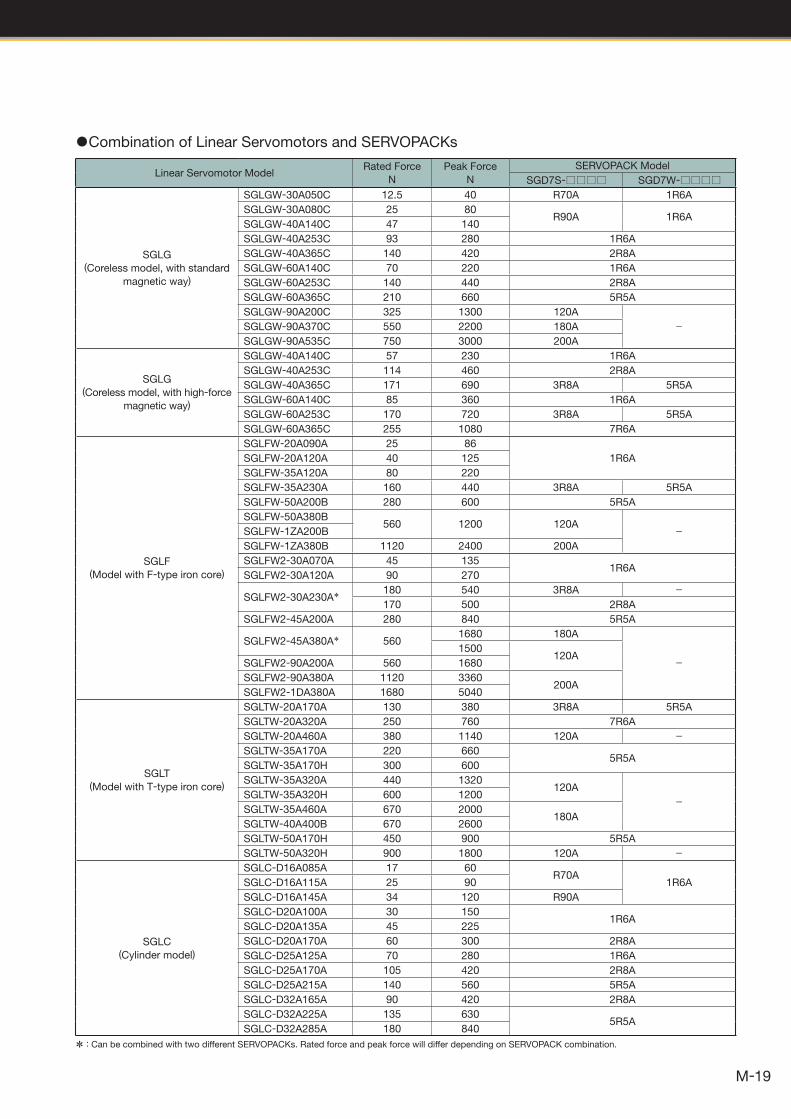
Linear Servomotor ModelRated Force
N
Peak Force
N
SERVOPACK Model
SGD7S- SGD7W-
SGLG (Coreless model, with standard
magnetic way)
SGLGW-30A050C 12.5 40 R70A 1R6A
SGLGW-30A080C 25 80R90A 1R6A
SGLGW-40A140C 47 140
SGLGW-40A253C 93 280 1R6A
SGLGW-40A365C 140 420 2R8A
SGLGW-60A140C 70 220 1R6A
SGLGW-60A253C 140 440 2R8A
SGLGW-60A365C 210 660 5R5A
SGLGW-90A200C 325 1300 120A
−SGLGW-90A370C 550 2200 180A
SGLGW-90A535C 750 3000 200A
SGLG (Coreless model, with high-force
magnetic way)
SGLGW-40A140C 57 230 1R6A
SGLGW-40A253C 114 460 2R8A
SGLGW-40A365C 171 690 3R8A 5R5A
SGLGW-60A140C 85 360 1R6A
SGLGW-60A253C 170 720 3R8A 5R5A
SGLGW-60A365C 255 1080 7R6A
SGLF(Model with F-type iron core)
SGLFW-20A090A 25 86
1R6ASGLFW-20A120A 40 125
SGLFW-35A120A 80 220
SGLFW-35A230A 160 440 3R8A 5R5A
SGLFW-50A200B 280 600 5R5A
SGLFW-50A380B560 1200 120A −SGLFW-1ZA200B
SGLFW-1ZA380B 1120 2400 200A
SGLFW2-30A070A 45 1351R6A
SGLFW2-30A120A 90 270
SGLFW2-30A230A*180 540 3R8A −170 500 2R8A
SGLFW2-45A200A 280 840 5R5A
SGLFW2-45A380A* 5601680 180A
−1500
120ASGLFW2-90A200A 560 1680
SGLFW2-90A380A 1120 3360200A
SGLFW2-1DA380A 1680 5040
SGLT(Model with T-type iron core)
SGLTW-20A170A 130 380 3R8A 5R5A
SGLTW-20A320A 250 760 7R6A
SGLTW-20A460A 380 1140 120A −SGLTW-35A170A 220 660
5R5ASGLTW-35A170H 300 600
SGLTW-35A320A 440 1320120A
−SGLTW-35A320H 600 1200
SGLTW-35A460A 670 2000180A
SGLTW-40A400B 670 2600
SGLTW-50A170H 450 900 5R5A
SGLTW-50A320H 900 1800 120A −
SGLC (Cylinder model)
SGLC-D16A085A 17 60R70A
1R6ASGLC-D16A115A 25 90
SGLC-D16A145A 34 120 R90A
SGLC-D20A100A 30 1501R6A
SGLC-D20A135A 45 225
SGLC-D20A170A 60 300 2R8A
SGLC-D25A125A 70 280 1R6A
SGLC-D25A170A 105 420 2R8A
SGLC-D25A215A 140 560 5R5A
SGLC-D32A165A 90 420 2R8A
SGLC-D32A225A 135 6305R5A
SGLC-D32A285A 180 840
1Combination of Linear Servomotors and SERVOPACKs
* : Can be combined with two different SERVOPACKs. Rated force and peak force will differ depending on SERVOPACK combination.

20
◆ Incremental Linear Encoder : Possible − : Not possible
◆Absolute Linear Encoder
◆Absolute Rotary Encoder
Output Signal ManufacturerEncoder
Type
Model Scale
Pitch
μm
Resolution
bit/rev
Maximum
Speed*3
min-1
Linear
Motor
Fully-closed
Loop
ControlScale
Sensor
Head
Interpolator (serial
converter unit)
Applicable for
Yaskawa’s
Serial Interface
Magnescale
Co., Ltd.
Sealed
Type
RU77-4096ADF − 20 2000 −
RU77-4096AFFT01 − 22 2000 −
Output Signal ManufacturerEncoder
Type
Model Scale
Pitch
μm
Resolution
nm
Maximum
Speed*3
m/s
Hall
Sensor
Input
Linear
Motor
Fully-closed
Loop
ControlScale
Sensor
Head
Interpolator (serial
converter unit)
Applicable for
Yaskawa’s
Serial
Interface*2
Magnescale
Co., Ltd.
Sealed
Type
SR77-□□□□□LF − 80 9.8 3.33 −SR77-□□□□□MF − 80 78.1 3.33 −SR87-□□□□□LF − 80 9.8 3.33 −SR87-□□□□□MF − 80 78.1 3.33 −
Mitutoyo
Corporation
Open
Type
ST781A − 256 500 5 −ST782A − 256 500 5 −ST783A − 51.2 100 5 −ST784A − 51.2 100 5 −ST788A − 51.2 100 5 −
ST789A*6 − 25.6 50 5 −Heidenhain
Corporation
Open
TypeLIC4100 series EIB339IY − 5 5 −
*1: The use of Yaskawa serial converter units is required. Output signals are divided into 256 (8-bits multiplier) or 4096 (12-bits multiplier) in the serial converter units.
*2: Each linear scale has a different multiplier (number of divisions). Before use, write the parameters of the linear servomotors into the linear scales.
*3: The maximum speed shown is for the linear scale when combined with a Yaskawa SERVOPACK.Either the maximum speed of the linear servomotor or that of the linear scale in this table limits the maximum speed.
*4: If the zero-point signal is used with the Renishaw linear scale, the accuracy might be affected, and the zero point might be detected as being at a different position. If so, use BID and DIR signals to send the zero point in one direction.
*5: Contact your Yaskawa representative.
*6: For details, contact Mitutoyo Corporation.Note: Before using the linear scales, contact the manufacturer of the scale for specifications including accuracy, dimensions, and recommended
operating conditions.
Recommended Linear Encoders
Output Signal ManufacturerEncoder
Type
Model Scale
Pitch
μm
Resolution
nm
Maximum
Speed*3
m/s
Hall
Sensor
Input
Linear
Motor
Fully-closed
Loop
ControlScale
Sensor
Head
Interpolator (serial
converter unit)
1Vp-p
Analog
Voltage*1
Heidenhain
Corporation
Open
Type
LIDA48(JZDP-D003/-D006)
2078.1 5
(JZDP-G003/-G006) 4.9 2 −
LIF48(JZDP-D003/-D006)
415.6 1
(JZDP-G003/-G006) 1.0 0.4 *5 −
Renishaw plc*4Open
TypeRGS20 RGH22B
(JZDP-D005/-D008)20
78.1 5
(JZDP-G005/-G008) 4.9 2 −
Applicable for
Yaskawa’s
Serial
Interface*2
Magnescale
Co., Ltd.
Open
TypeSL7 0
PL101-RY800 97.7 5
−PL101 MJ620-T13 −
Sealed
Type
SR75- LF − 80 9.8 3.33 −SR75- MF − 80 78.1 3.33 −SR85- LF − 80 9.8 3.33 −SR85- MF − 80 78.1 3.33 −
21
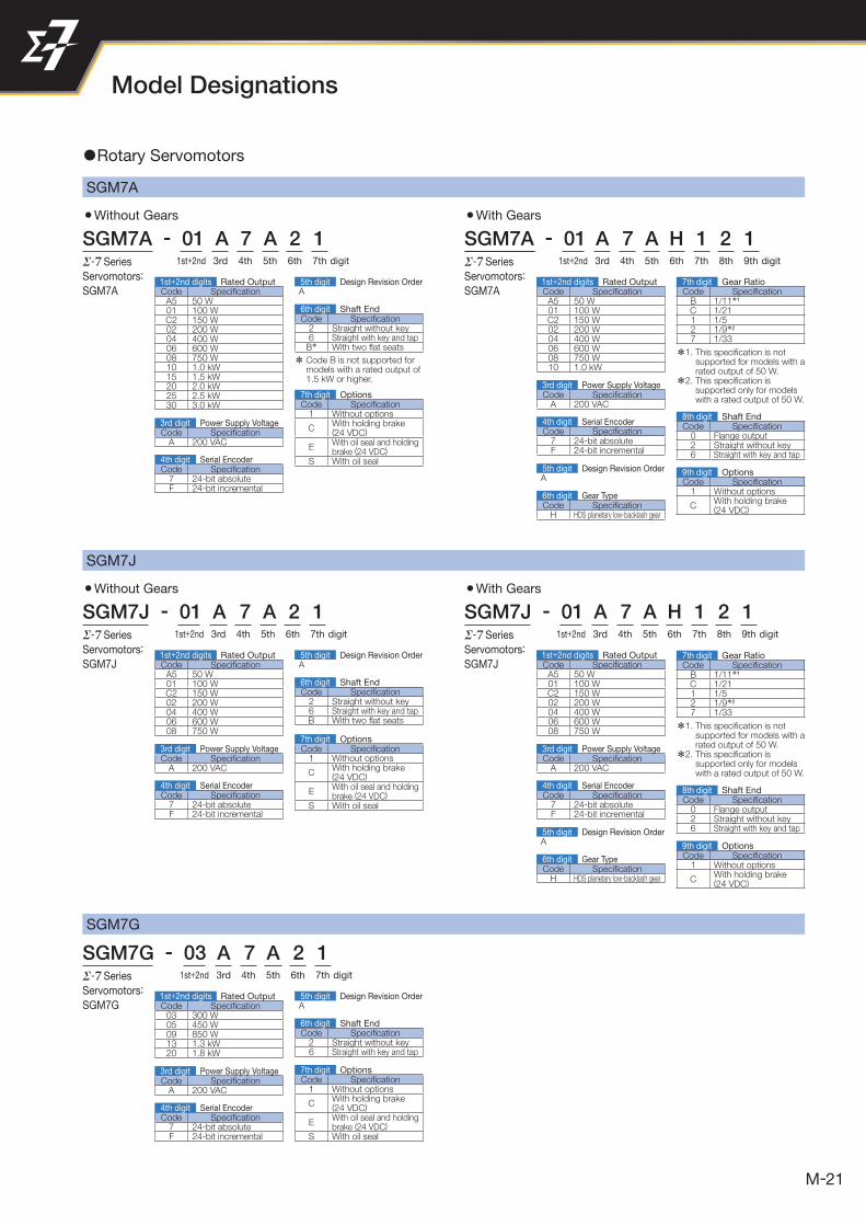
Model Designations
SGM7J
3Without Gears 3With Gears
SGM7J - 01 A 7 A 2 1 SGM7J - 01 A 7 A H 1 2 1Series
Servomotors:
SGM7J
Series
Servomotors:
SGM7J
SGM7A
3Without Gears 3With Gears
SGM7A - 01 A 7 A 2 1 SGM7A - 01 A 7 A H 1 2 1Series
Servomotors:
SGM7A
Series
Servomotors:
SGM7ACode Specifi cationA5 50 W01 100 WC2 150 W02 200 W04 400 W06 600 W08 750 W10 1.0 kW15 1.5 kW20 2.0 kW25 2.5 kW30 3.0 kW
1st+2nd digits Rated Output
Code Specifi cationA 200 VAC
3rd digit Power Supply Voltage
Code Specifi cationH HDS planetary low-backlash gear
6th digit Gear Type
Code Specifi cation7 24-bit absoluteF 24-bit incremental
4th digit Serial Encoder
Code Specifi cationA 200 VAC
3rd digit Power Supply Voltage
Code Specifi cation7 24-bit absoluteF 24-bit incremental
4th digit Serial Encoder
Code Specifi cationA 200 VAC
3rd digit Power Supply Voltage
Code Specifi cation7 24-bit absoluteF 24-bit incremental
4th digit Serial Encoder
Code Specifi cationA 200 VAC
3rd digit Power Supply Voltage
Code Specifi cation7 24-bit absoluteF 24-bit incremental
4th digit Serial Encoder
Code Specifi cation2 Straight without key6 Straight with key and tap
B* With two fl at seats
6th digit Shaft End
Code Specifi cation2 Straight without key6 Straight with key and tapB With two fl at seats
6th digit Shaft End
Code Specifi cation0 Flange output2 Straight without key6 Straight with key and tap
8th digit Shaft End
Code Specifi cation0 Flange output2 Straight without key6 Straight with key and tap
8th digit Shaft End
Code Specifi cation1 Without options
CWith holding brake(24 VDC)
EWith oil seal and holding brake (24 VDC)
S With oil seal
7th digit Options
Code Specifi cation1 Without options
CWith holding brake(24 VDC)
EWith oil seal and holding brake (24 VDC)
S With oil seal
7th digit Options
Code Specifi cation2 Straight without key6 Straight with key and tap
6th digit Shaft End
Code Specifi cation1 Without options
CWith holding brake(24 VDC)
EWith oil seal and holding brake (24 VDC)
S With oil seal
7th digit Options
Code Specifi cation1 Without options
CWith holding brake(24 VDC)
9th digit Options
Code Specifi cation1 Without options
CWith holding brake(24 VDC)
9th digit Options
Code Specifi cationB 1/11*1
C 1/211 1/52 1/9*2
7 1/33
7th digit Gear Ratio
Code Specifi cationB 1/11*1
C 1/211 1/52 1/9*2
7 1/33
7th digit Gear Ratio
*1. This specifi cation is not supported for models with a rated output of 50 W.
*2. This specifi cation is supported only for models with a rated output of 50 W.
*1. This specifi cation is not supported for models with a rated output of 50 W.
*2. This specifi cation is supported only for models with a rated output of 50 W.
* Code B is not supported for models with a rated output of 1.5 kW or higher.
1st+2nd 3rd 4th 5th 6th1st+2nd 3rd 4th 5th 6th 7th digit digit7th 8th 9th
1st+2nd 3rd 4th 5th 6th 7th digit
1st+2nd 3rd 4th 5th 6th 7th digit
1st+2nd 3rd 4th 5th 6th digit7th 8th 9th
SGM7G
SGM7G - 03 A 7 A 2 1Series
Servomotors:
SGM7G
1Rotary Servomotors
Code Specifi cationA5 50 W01 100 WC2 150 W02 200 W04 400 W06 600 W08 750 W10 1.0 kW
1st+2nd digits Rated Output
Code Specifi cationA5 50 W01 100 WC2 150 W02 200 W04 400 W06 600 W08 750 W
1st+2nd digits Rated Output
Code Specifi cation03 300 W05 450 W09 850 W13 1.3 kW20 1.8 kW
1st+2nd digits Rated Output
Code Specifi cationA 200 VAC
3rd digit Power Supply Voltage
Code Specifi cation7 24-bit absoluteF 24-bit incremental
4th digit Serial Encoder
Code Specifi cationA5 50 W01 100 WC2 150 W02 200 W04 400 W06 600 W08 750 W
1st+2nd digits Rated Output
5th digit Design Revision OrderA
5th digit Design Revision OrderA
5th digit Design Revision OrderA
5th digit Design Revision OrderA
Code Specifi cationH HDS planetary low-backlash gear
6th digit Gear Type
5th digit Design Revision OrderA
22
Model Designations
Note: Direct Drive Servomotors are not available with holding brakes.
3Moving Coil 3Magnetic Way
S G L G M - 30 108 A Linear
Series
Linear
Servomotors
Code Specifi cation090 90 mm108 108 mm216 216 mm225 225 mm252 252 mm360 360 mm405 405 mm432 432 mm450 450 mm504 504 mm
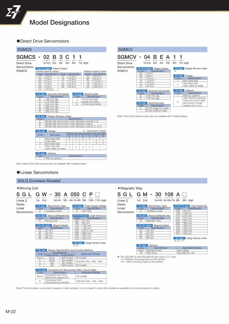
1 Direct Drive Servomotors
1 Linear Servomotors
SGMCS
SGLG (Coreless Models)
SGMCV
SGMCS - 02 B 3 C 1 1
S G L G W - 30 A 050 C P
SGMCV - 04 B E A 1 1Direct Drive
Servomotors:
SGMCS
Linear
Series
Linear
Servomotors
Direct Drive
Servomotors:
SGMCV3Small-capacity Series 3Medium-capacity Series
Code Specifi cation Code Specifi cation Code Specifi cation02 2 N· m 14 14 N ·m 45 45 N · m04 4 N ·m 16 16 N ·m 80 80 N· m05 5 N ·m 17 17 N ·m 1A 110 N· m07 7 N ·m 25 25 N ·m 1E 150 N · m08 8 N ·m 35 35 N ·m 2Z 200 N · m10 10 N ·m
Code Specifi cation04 4 N· m08 8 N ·m10 10 N ·m14 14 N ·m17 17 N ·m25 25 N ·m
Code Specifi cationB 135-mm dia.C 175-mm dia.D 230-mm dia.E 290-mm dia.M 280-mm dia.N 360-mm dia.
Code Specifi cationA Model with servomotor outer diameter code M or NB Model with servomotor outer diameter code EC Model with servomotor outer diameter code B, C, or D
CodeSpecifi cations
Applicable ModelsPolarity Sensor Cooling Method
None None Self-cooled All modelsC None Air-cooled
SGLGW-40A, -60A, -90AH Yes Air-cooledP Yes Self-cooled All models
Code Specifi cation Applicable ModelsNone Standard-force All m.odels-M High-force SGLGM-40, -60
5th digit Design Revision OrderA
Code Specifi cation
3 20-bit absolutesingle-turn data
D 20-bit incremental
Code MountingServomotor Outer Diameter Code (3rd Digit)
B C D E M N
1Non-load side - -Load side - - - -
3 Non-load side - - - -
4 Non-load side(with cable on side) - -
: Applicable models.
Note: Direct Drive Servomotors are not available with holding brakes.
Note: This information is provided to explain model numbers. It is not meant to imply that models are available for all combinations of codes.
9th digit Design Revision OrderA, B · · ·
* The SGLGM-40 and SGLGM-60 also have a CT code.・C = Without mounting holes on the bottom・CT = With mounting holes on the bottom
3rd digit Servomotor Outer Diameter Code Specifi cationB 135-mm dia.C 175-mm dia.
3rd digit Servomotor Outer Diameter
Code Specifi cationE 20-bit single-turn dataI 22-bit multiturn data
4th digit Serial Encoder
4th digit Serial Encoder
5th digit Design Revision Order
Code Specifi cation1 Without options
7th digit Options
1st+2nd 3rd 4th 5th 6th 7th digit 1st+2nd 3rd 4th 5th 6th 7th digit
1st+2nd digits Rated Output
6th digit Flange
Code Specifi cation1 Non-load side
4 Non-load side(with cable on side)
6th digit Flange
Code Specifi cation1 Without options
5
High machine precision (runout at end of shaft and runout of shaft surface: 0.01 mm)
7th digit Options
1st+2nd digits Rated Output
3rd+4th2nd1st 5th 9th6th+7th+8th 10th digit11th 3rd+4th2nd1st 5th+6th+7th 8th digit9th
Code Specifi cationG Coreless model
1st digit Servomotor Type
Code Specifi cationW Moving Coil
2nd digit Moving Coil/Magnetic Way
Code Specifi cationA 200 VAC
5th digit Power Supply Voltage
Code Specifi cation30 30 mm40 40 mm60 60 mm90 86 mm
3rd+4th digits Magnet Height
Code Specifi cationG Coreless model
1st digit Servomotor Type
Code Specifi cationM Magnetic Way
2nd digit Moving Coil/Magnetic Way
Code Specifi cation30 30 mm40 40 mm60 60 mm90 86 mm
3rd+4th digits Magnet Height
Code Specifi cation050 50 mm080 80 mm140 140 mm200 199 mm253 252.5 mm365 365 mm370 367 mm535 535 mm
6th+7th+8th digits Length of Moving Coil
8th digit Design Revision OrderA, B , C *· · ·
5th+6th+7th digits Length of Magnetic Way
10th digit Sensor Specifi cation and Cooling Method
9th digit Options
Code Specifi cation Applicable Models
NoneConnector from TycoElectronics Japan G.K.
All models
DConnector fromInterconnectron GmbH
SGLGW-30A, -40A, -60A
11th digit Connector for Servomotor Main Circuit Cable

23
SGLFW (Models with F-type Iron Cores)
3Magnetic Way3Moving Coil
S G L F W - 20 A 090 A P S G L F M - 20 324 A Linear
Series
Linear
Servomotors
Linear
Series
Linear
Servomotors
3rd+4th2nd1st 5th 9th6th+7th+8th 10th digit11th
3rd+4th2nd1st 5th 9th6th+7th+8th 10th digit11th
9th digit Design Revision OrderA, B · · ·
8th digit Design Revision OrderA, B · · ·
Code Specifi cationF With F-type iron core
1st digit Servomotor TypeCode Specifi cation
F With F-type iron core
1st digit Servomotor Type
Code Specifi cationW Moving Coil
2nd digit Moving Coil/Magnetic WayCode Specifi cation
M Magnetic Way
2nd digit Moving Coil/Magnetic Way
Code Specifi cationA 200 VAC
5th digit Voltage
Code Specifi cation20 20 mm35 36 mm50 47.5 mm1Z 95 mm
3rd+4th digits Magnet HeightCode Specifi cation
20 20 mm35 36 mm50 47.5 mm1Z 95 mm
3rd+4th digits Magnet Height
Code Specifi cationF With F-type iron core
1st digit Servomotor Type
Code Specifi cationM Magnetic Way
2nd digit Moving Coil/Magnetic Way
Code Specifi cation30 30 mm45 45 mm90 90 mm1D 135 mm
3rd+4th digits Magnet Height
8th digit Design Revision OrderA
Code Specifi cation270 270 mm306 306 mm450 450 mm510 510 mm630 630 mm714 714 mm
10th digit Sensor Specifi cation
Code Specifi cation Applicable Models
NoneConnector from TycoElectronics Japan G.K.
All models
DConnector fromInterconnectron GmbH
SGLFW-35, -50, -1Z 200B
11th digit Connector for Servomotor Main Circuit Cable
Code Specifi cationP With polarity sensor
None Without polarity sensor
Code Specifi cationF With F-type iron core
1st digit Servomotor Type
Code Specifi cationW Moving Coil
2nd digit Moving Coil/Magnetic Way
Code Specifi cationA 200 VAC
5th digit Power Supply Voltage
Code Specifi cation30 30 mm45 45 mm90 90 mm1D 135 mm
3rd+4th digits Magnet Height
9th digit Design Revision OrderA
Code Specifi cation070 70 mm120 125 mm200 205 mm230 230 mm380 384 mm
10th digit Sensor Specifi cationCode Specifi cation
T Without polarity sensor, with thermal protectorS With polarity sensor and thermal protector
9th digit OptionsCode Specifi cationNone Without options
C With magnet cover
3rd+4th2nd1st 5th+6th+7th 8th digit9th
3rd+4th2nd1st 5th+6th+7th digit8th
5th+6th+7thdigits
Length of Magnetic Way
Code Specifi cation324 324 mm405 405 mm540 540 mm675 675 mm756 756 mm945 945 mm
6th+7th+8thdigits
Length of Moving Coil
5th+6th+7thdigits
Length of Magnetic Way
6th+7th+8thdigits
Length of Moving Coil
Code Specifi cation090 91 mm120 127 mm200 215 mm230 235 mm380 395 mm
1 Linear Servomotors
Note: This information is provided to explain model numbers. It is not meant to imply that models are available for all combinations of codes.
11th digit Cooling MethodCode Specifi cationNone Self-cooled
L Water-cooled*
SGLFW2 (Models with F-type Iron Cores)
3Magnetic Way3Moving Coil
S G L F W2 - 30 A 070 A T S G L F M2 - 30 270 ALinear
Series
Linear
Servomotors
Linear
Series
Linear
Servomotors
* Contact your Yaskawa representative for information on water-cooled models.
Note: This information is provided to explain model numbers. It is not meant to imply that models are available for all combinations of codes.
24
Model Designations
3Moving Coil 3Magnetic Way
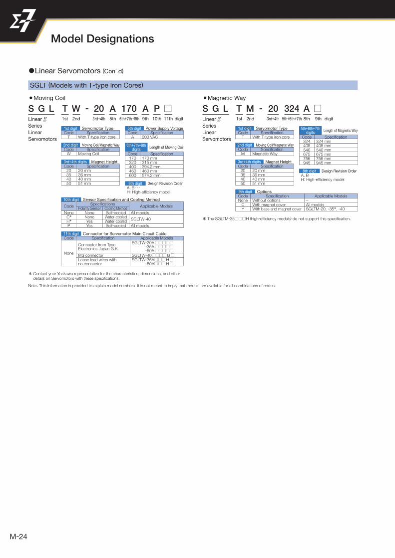
S G L T M - 20 324 A Linear
Series
Linear
Servomotors
3rd+4th2nd1st 5th 9th6th+7th+8th 10th digit11th 3rd+4th2nd1st 5th+6th+7th 8th digit9th
Code Specifi cationA 200 VAC
5th digit Power Supply VoltageCode Specifi cation
T With T-type iron core
1st digit Servomotor Type
Code Specifi cationW Moving Coil
2nd digit Moving Coil/Magnetic Way
Code Specifi cation20 20 mm35 36 mm40 40 mm50 51 mm
3rd+4th digits Magnet Height
6th+7th+8thdigits
Length of Moving Coil
5th+6th+7thdigits
Length of Magnetic WayCode Specifi cation
T With T-type iron core
1st digit Servomotor Type
Code Specifi cationM Magnetic Way
2nd digit Moving Coil/Magnetic Way
Code Specifi cation20 20 mm35 36 mm40 40 mm50 51 mm
3rd+4th digits Magnet Height
9th digit Design Revision OrderA, B · · · H: High-effi ciency model
Code Specifi cation170 170 mm320 315 mm400 394.2 mm460 460 mm600 574.2 mm
CodeSpecifi cations
Applicable ModelsPolarity Sensor Cooling Method
None None Self-cooled All modelsC* None Water-cooled
SGLTW-40H* Yes Water-cooledP Yes Self-cooled All models
10th digit Sensor Specifi cation and Cooling Method
11th digit Connector for Servomotor Main Circuit Cable
8th digit Design Revision OrderA, B · · · H: High-effi ciency model
Code Specifi cation324 324 mm405 405 mm540 540 mm675 675 mm756 756 mm945 945 mm
SGLT (Models with T-type Iron Cores)
S G L T W - 20 A 170 A P Linear
Series
Linear
Servomotors
Code Specifi cation Applicable Models
None
Connector from TycoElectronics Japan G.K.
SGLTW -20A-35A-50A
MS connector SGLTW -40 BLoose lead wires withno connector
SGLTW -35A H-50A H
9th digit OptionsCode Specifi cation Applicable ModelsNone Without options −
C With magnet cover All modelsY With base and magnet cover SGLTM-20, -35*, -40
* Contact your Yaskawa representative for the characteristics, dimensions, and other details on Servomotors with these specifi cations.
Note: This information is provided to explain model numbers. It is not meant to imply that models are available for all combinations of codes.
* The SGLTM-35 H (high-effi ciency models) do not support this specifi cation.
1 Linear Servomotors (Con’ d)

25
3rd+4th+5th2nd1st 6th 10th7th+8th+9th digit11th 3rd+4th+5th2nd1st 6th+7th+8th digit9th
Code Specifi cationA 200 VAC
5th digit Power Supply Voltage
(Same as above combinations.)6th digit Power Supply Voltage
Code Specifi cationW Moving Coil
2nd digit Moving Coil/Magnetic Way
Code Specifi cationC Cylinder type
1st digit Servomotor Type
Code Specifi cationC Cylinder type
1st digit Servomotor TypeCode Specifi cation
C Cylinder type
1st digit Servomotor Type
Code Specifi cationP With polarity sensor
10th digit Sensor Specifi cation
(Same as above combinations.)11th digit Sensor Specifi cation
Code Specifi cationD16 16 mmD20 20 mmD25 25 mmD32 32 mm
2nd+3rd+4thdigits
Outer Diameter of Magnetic Way*1
Code Specifi cationExternal Dimension
Code of Magnetic Way085 85 mm D16100 100 mm D20115 115 mm D16125 125 mm D25135 135 mm D20145 145 mm D16165 165 mm D32170 170 mm D20, D25215 215 mm D25225 225 mm D32285 285 mm D32
6th+7th+8thdigits
Length of Moving Coil*1
7th+8th+9thdigits
Length of Moving Coil
(Same as above combinations.)6th+7th+8th
digitsLength of Magnetic Way
(Same as above combinations.)
3rd+4th+5thdigits
Outer Diameter of Magnetic Way
(Same as above combinations.)
3rd+4th+5thdigits
Outer Diameter of Magnetic Way
(Same as above combinations.)
Code Specifi cationM Magnetic Way
2nd digit Moving Coil/Magnetic Way
9th digitDesign Revision Order of Moving Coil
A, B · · ·
10th digit Design Revision OrderA, B · · · 9th digit Design Revision Order
A, B · · ·
14th digit Design Revision Order of Magnetic WayA, B · · ·
digit14th1st 5th 9th6th+7th+8th 11th+12th+13th2nd+3rd+4th 10th
SGLC (Cylinder Models)
S G L C W - D16 A 085 A P S G L C M - D16 750 A
S G L C - D16 A 085 A P - 750 A
Linear
Series
Linear
Servomotors
Linear
Series
Linear
Servomotors
Linear
Series
Linear
Servomotors
*1. There are restrictions in the allowable combinations. Refer to List of Models (page 178) for details.
*2. Contact your Yaskawa representative when you make a special order.
Note: This information is provided to explain model numbers. It is not meant to imply that models are available for all combinations of codes.
Note: This code contains four digits if the length of the Magnetic Way is 1,000 or longer.
Note: 1. Order the Moving Coil and Magnetic Way as a set. Contact your Yaskawa representative before purchasing a Moving Coil and Magnetic Way separately.2. This information is provided to explain model numbers. It is not meant to imply that models are available for all combinations of codes.
3Combination of Moving Coil and Magnetic Way
11th+12th+13th digits Length of Magnetic Way*1
Code Specifi cation Special Orders*2
300 300 mm 240 mm to 420 mm (in 30-mm increments)350 350 mm 280 mm to 490 mm (in 35-mm increments)450 450 mm 360 mm to 630 mm (in 45-mm increments)510 510 mm 480 mm to 750 mm (in 30-mm increments)590 590 mm 555 mm to 870 mm (in 35-mm increments)600 600 mm 480 mm to 840 mm (in 60-mm increments)
750 750 mm
For Magnetic Way with outer diameter of 16 mm: 480 mm to 750 mm (in 30-mm increments)
For Magnetic Way with outer diameter of 25 mm: 705 mm to 1,110 mm (in 45-mm increments)
870 870 mm 555 mm to 870 mm (in 35-mm increments)1020 1020 mm 960 mm to 1,500 mm (in 60-mm increments)1110 1110 mm 705 mm to 1,110 mm (in 45-mm increments)1500 1500 mm 960 mm to 1,500 mm (in 60-mm increments)
3Moving Coil 3Magnetic Way

26
Model Designations
1st+2nd+3rd digit4th 7th 8th+9th+10th5th+6th
1st+2nd+3rd digit4th 7th 8th+9th+10th5th+6th
1st+2nd+3rddigits
Maximum ApplicableMotor Capacity Code Specifi cation
A 200 VAC
4th digit Voltage
5th+6th digits Interface*Code Specifi cation
00 Analog voltage/pulse train referance
10 MECHATROLINK-2 communication reference
20 MECHATROLINK-3 communication reference
Code Specifi cationA 200 VAC
4th digit Voltage
5th+6th digits Interface*Code Specifi cation
20 MECHATROLINK-3 communication reference
7th digit Design Revision OrderA
8th+9th+10th digits Hardware Options Specifi cation
Code Specifi cation Applicable Models
None Without optionsAll models001 Rack-mounted
002 Varnished
1 SERVOPACKs
Model
Model
SGD7S - R70 A 00 A 001
SGD7W - 1R6 A 20 A 001
* The same SERVOPACKs are used for both Rotary Servomotors and Linear Servomotors.
* The same SERVOPACKs are used for both Rotary Servomotors and Linear Servomotors.
Voltage Code Specifi cation
Three-phase,200 V
R70 0.05 kWR90 0.1 kW1R6 0.2 kW2R8 0.4 kW3R8 0.5 kW5R5 0.75 kW7R6 1.0 kW120 1.5 kW180 2.0 kW200 3.0 kW
7th digit Design Revision OrderA
8th+9th+10th digits Hardware Options Specifi cation
Code Specifi cation Applicable Models
None Without optionsAll models001 Rack-mounted
002 Varnished008 Single-phase, 200 V power input 1.5 kW00A Varnished and single-phase power input All models
Series
SERVOPACKs:
Models
Series
SERVOPACKs:
ModelsVoltage Code Specifi cation
Three-phase,200 V
1R6 0.2 kW2R8 0.4 kW5R5 0.75 kW7R6 1.0 kW
1st+2nd+3rddigits
Maximum ApplicableMotor Capacity per Axis
1
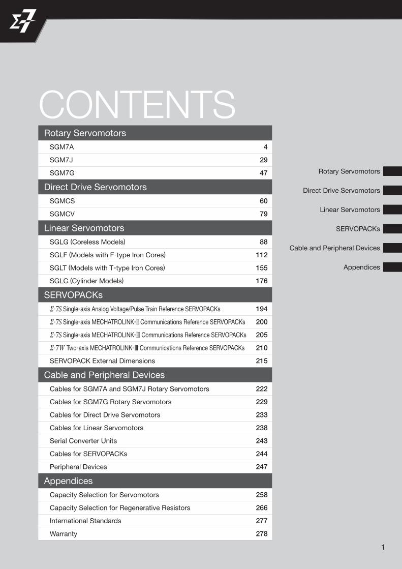
Rotary Servomotors
CONTENTS
Direct Drive Servomotors
Linear Servomotors
SERVOPACKs
Cable and Peripheral Devices
Appendices
Rotary Servomotors
SGM7A 4
SGM7J 29
SGM7G 47
Direct Drive Servomotors
SGMCS 60
SGMCV 79
Linear Servomotors
SGLG (Coreless Models) 88
SGLF (Models with F-type Iron Cores) 112
SGLT (Models with T-type Iron Cores) 155
SGLC (Cylinder Models) 176
SERVOPACKs
Single-axis Analog Voltage/Pulse Train Reference SERVOPACKs 194
Single-axis MECHATROLINK-2 Communications Reference SERVOPACKs 200
Single-axis MECHATROLINK-3 Communications Reference SERVOPACKs 205
Two-axis MECHATROLINK-3 Communications Reference SERVOPACKs 210
SERVOPACK External Dimensions 215
Cable and Peripheral Devices
Cables for SGM7A and SGM7J Rotary Servomotors 222
Cables for SGM7G Rotary Servomotors 229
Cables for Direct Drive Servomotors 233
Cables for Linear Servomotors 238
Serial Converter Units 243
Cables for SERVOPACKs 244
Peripheral Devices 247
Appendices
Capacity Selection for Servomotors 258
Capacity Selection for Regenerative Resistors 266
International Standards 277
Warranty 278

2

SGM7A ................................................................... 4
SGM7J ................................................................. 29
SGM7G ................................................................. 47
Rotary Servomotors
Rotary Servomotors
4
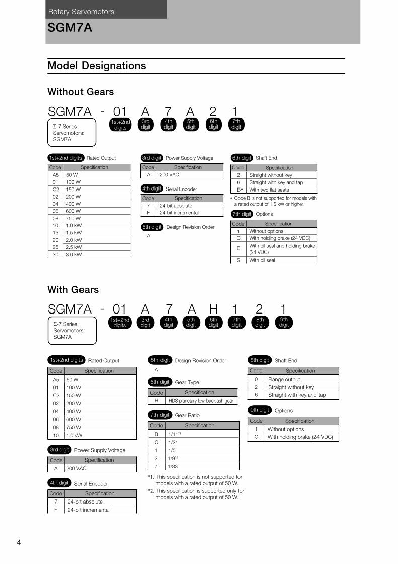
SGM7A
Model Designations
Without Gears
With Gears
1
C
E
S
7
F
2
B*6
A
A 200 VAC
SGM7A - 01 A 7 A 2 1
A5
01
C2
02 200 W
50 W
04 400 W
06 600 W
08 750 W
15
20 2.0 kW
25 2.5 kW
30 3.0 kW
10
*
100 W
150 W
1.0 kW
1.5 kW
1st+2nd digits
1st+2nd digits 3rd digitRated Output Power Supply Voltage
4th digit Serial Encoder
5th digit Design Revision Order
7th digit Options
Code Specification
Without options
With holding brake (24 VDC)
With oil seal and holding brake
(24 VDC)
With oil seal
6th digit Shaft End
Straight without key
Straight with key and tap
With two flat seats
Code B is not supported for models with
a rated output of 1.5 kW or higher.
Code Specification Code Specification
Code Specification
24-bit absolute
24-bit incremental
Code Specification
3rd digit
4th digit
5th digit
6th digit
7th digitΣ-7 Series
Servomotors:
SGM7A
A5 50 W
01 100 W
C2
02 200 W
04 400 W
08 750 W
06 600 W
10 1.0 kW
SGM7A - 01 A 7 A H 1 2 1
0
2
6
1
CB 1/11*1
C 1/21
1 1/5
2 1/9*2
7 1/33
H
7
F
A 200 VAC
Specification A
150 W
1st+2nd digits
1st+2nd digits
Σ-7 Series
Servomotors:
SGM7A
Rated Output 5th digit Design Revision Order 8th digit Shaft End
9th digit Options
Code Specification
Flange output
Code Specification
Without options
With holding brake (24 VDC)
Straight without key
Straight with key and tap
6th digit Gear Type
7th digit Gear Ratio
Specification
HDS planetary low-backlash gear
Code
Specification
*1. This specification is not supported for
models with a rated output of 50 W.
*2. This specification is supported only for
models with a rated output of 50 W.
Code
3rd digit Power Supply Voltage
4th digit Serial Encoder
Code Specification
Code Specification
24-bit absolute
24-bit incremental
Code
3rd digit
4th digit
5th digit
6th digit
7th digit
8th digit
9th digit
Rotary Servomotors SGM7A
5
Ro
tary
Serv
om
oto
rs
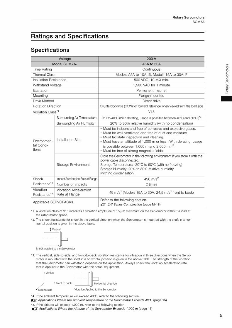
Ratings and Specifications
Specifications
*1. A vibration class of V15 indicates a vibration amplitude of 15 μm maximum on the Servomotor without a load at
the rated motor speed.
*2. The shock resistance for shock in the vertical direction when the Servomotor is mounted with the shaft in a hor-
izontal position is given in the above table.
*3. The vertical, side-to-side, and front-to-back vibration resistance for vibration in three directions when the Servo-
motor is mounted with the shaft in a horizontal position is given in the above table. The strength of the vibration
that the Servomotor can withstand depends on the application. Always check the vibration acceleration rate
that is applied to the Servomotor with the actual equipment.
*4. If the ambient temperature will exceed 40°C, refer to the following section.
Applications Where the Ambient Temperature of the Servomotor Exceeds 40°C (page 15)
*5. If the altitude will exceed 1,000 m, refer to the following section.
Applications Where the Altitude of the Servomotor Exceeds 1,000 m (page 15)
Voltage 200 V
Model SGM7A- A5A to 30A
Time Rating Continuous
Thermal Class Models A5A to 10A: B, Models 15A to 30A: F
Insulation Resistance 500 VDC, 10 MΩ min.
Withstand Voltage 1,500 VAC for 1 minute
Excitation Permanent magnet
Mounting Flange-mounted
Drive Method Direct drive
Rotation Direction Counterclockwise (CCW) for forward reference when viewed from the load side
Vibration Class*1 V15
Environmen-
tal Condi-
tions
Surrounding Air Temperature 0°C to 40°C (With derating, usage is possible between 40°C and 60°C.)*4
Surrounding Air Humidity 20% to 80% relative humidity (with no condensation)
Installation Site
• Must be indoors and free of corrosive and explosive gases.
• Must be well-ventilated and free of dust and moisture.
• Must facilitate inspection and cleaning.
• Must have an altitude of 1,000 m or less. (With derating, usage
is possible between 1,000 m and 2,000 m.)*5
• Must be free of strong magnetic fields.
Storage Environment
Store the Servomotor in the following environment if you store it with the
power cable disconnected.
Storage Temperature: -20°C to 60°C (with no freezing)
Storage Humidity: 20% to 80% relative humidity
(with no condensation)
Shock
Resistance*2Impact Acceleration Rate at Flange 490 m/s2
Number of Impacts 2 times
Vibration
Resistance*3Vibration Acceleration
Rate at Flange 49 m/s2 (Models 15A to 30A: 24.5 m/s2 front to back)
Applicable SERVOPACKs Refer to the following section.
Σ-7 Series Combination (page M-18)
Vertical
Shock Applied to the Servomotor
Vertical
Front to back Horizontal direction
Vibration Applied to the ServomotorSide to side
Rotary ServomotorsSGM7A
6
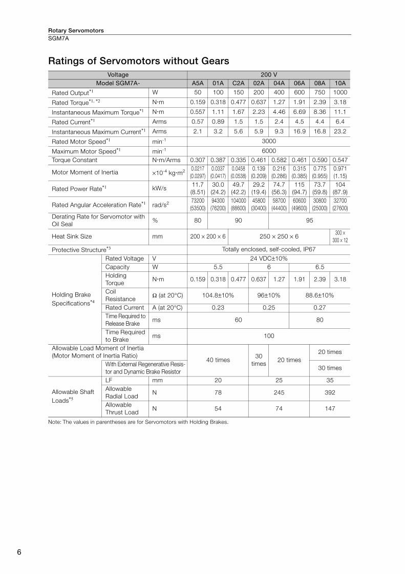
Ratings of Servomotors without Gears
Note: The values in parentheses are for Servomotors with Holding Brakes.
Voltage 200 VModel SGM7A- A5A 01A C2A 02A 04A 06A 08A 10A
Rated Output*1 W 50 100 150 200 400 600 750 1000
Rated Torque*1, *2 N m 0.159 0.318 0.477 0.637 1.27 1.91 2.39 3.18
Instantaneous Maximum Torque*1 N m 0.557 1.11 1.67 2.23 4.46 6.69 8.36 11.1
Rated Current*1 Arms 0.57 0.89 1.5 1.5 2.4 4.5 4.4 6.4
Instantaneous Maximum Current*1 Arms 2.1 3.2 5.6 5.9 9.3 16.9 16.8 23.2
Rated Motor Speed*1 min-1 3000
Maximum Motor Speed*1 min-1 6000
Torque Constant N m/Arms 0.307 0.387 0.335 0.461 0.582 0.461 0.590 0.547
Motor Moment of Inertia ×10-4 kg m20.0217
(0.0297)
0.0337
(0.0417)
0.0458
(0.0538)
0.139
(0.209)
0.216
(0.286)
0.315
(0.385)
0.775
(0.955)
0.971
(1.15)
Rated Power Rate*1 kW/s11.7
(8.51)
30.0
(24.2)
49.7
(42.2)
29.2
(19.4)
74.7
(56.3)
115
(94.7)
73.7
(59.8)
104
(87.9)
Rated Angular Acceleration Rate*1 rad/s273200
(53500)
94300
(76200)
104000
(88600)
45800
(30400)
58700
(44400)
60600
(49600)
30800
(25000)
32700
(27600)
Derating Rate for Servomotor with
Oil Seal % 80 90 95
Heat Sink Size mm 200 × 200 × 6 250 × 250 × 6300 ×
300 × 12
Protective Structure*3 Totally enclosed, self-cooled, IP67
Holding Brake
Specifications*4
Rated Voltage V 24 VDC±10%
Capacity W 5.5 6 6.5
Holding
Torque N m 0.159 0.318 0.477 0.637 1.27 1.91 2.39 3.18
Coil
Resistance Ω (at 20°C) 104.8±10% 96±10% 88.6±10%
Rated Current A (at 20°C) 0.23 0.25 0.27
Time Required to
Release Brakems 60 80
Time Required
to Brake ms 100
Allowable Load Moment of Inertia
(Motor Moment of Inertia Ratio) 40 times
30
times20 times
20 times
With External Regenerative Resis-
tor and Dynamic Brake Resistor 30 times
Allowable Shaft
Loads*5
LF mm 20 25 35
Allowable
Radial Load N 78 245 392
Allowable
Thrust Load N 54 74 147
Rotary Servomotors SGM7A
7
Ro
tary
Serv
om
oto
rs
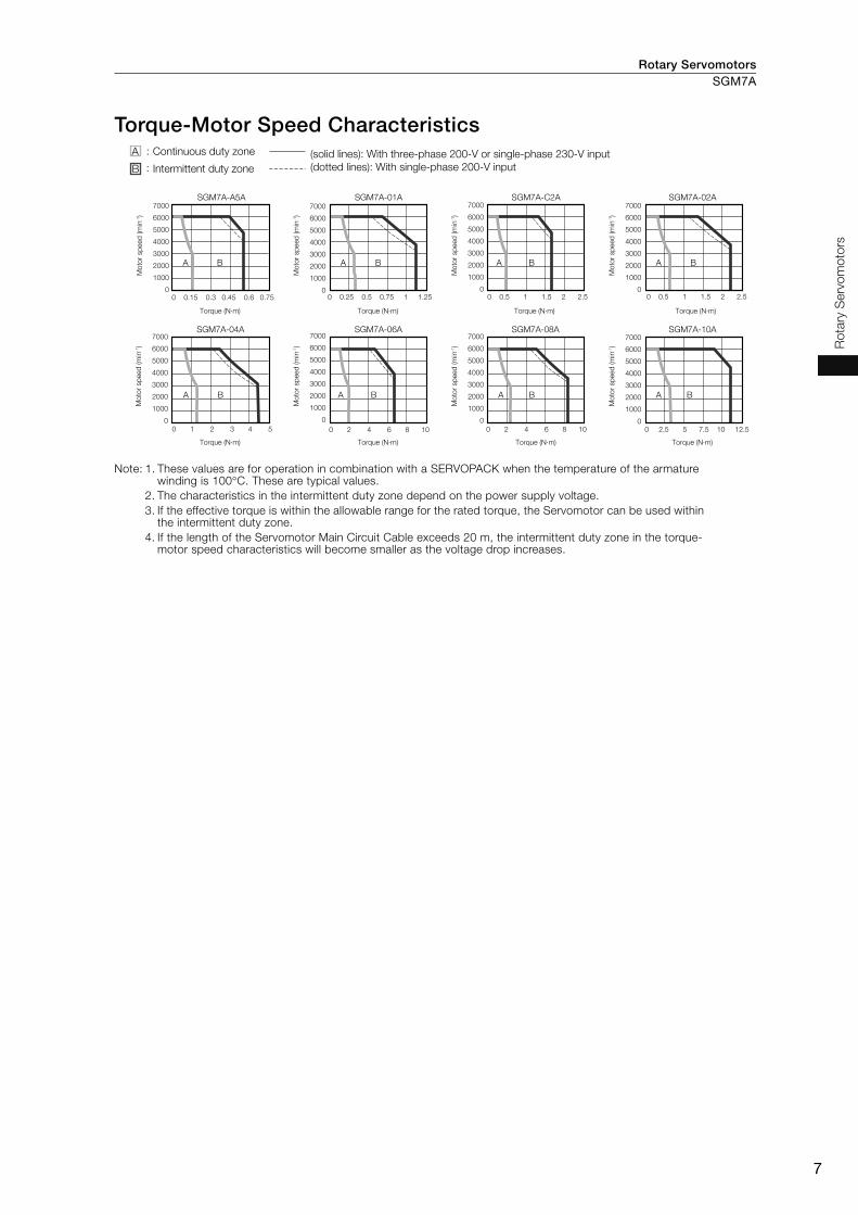
Torque-Motor Speed Characteristics
Note: 1. These values are for operation in combination with a SERVOPACK when the temperature of the armature winding is 100°C. These are typical values.
2. The characteristics in the intermittent duty zone depend on the power supply voltage.
3. If the effective torque is within the allowable range for the rated torque, the Servomotor can be used within the intermittent duty zone.
4. If the length of the Servomotor Main Circuit Cable exceeds 20 m, the intermittent duty zone in the torque-motor speed characteristics will become smaller as the voltage drop increases.
SGM7A-A5A
A B
SGM7A-01A
A B
SGM7A-C2A
A B
SGM7A-04A
A B
SGM7A-06A
A B
SGM7A-08A
A B
SGM7A-02A
A B
SGM7A-10A
A B
A :
B :
7000
6000
5000
4000
3000
2000
1000
00 0.15 0.3 0.45 0.6 0.75 0 0.25 0.5 0.75 1 1.25
0 1 2 3 4 5 0 2 4 6 8 10 0 2 4 6 8 10 0 2.5 5 7.5 10 12.5
0 0.5 1 1.5 2 2.5 0 0.5 1 1.5 2 2.5
Continuous duty zone (solid lines): With three-phase 200-V or single-phase 230-V input
(dotted lines): With single-phase 200-V inputIntermittent duty zone
Mo
tor sp
eed
(m
in-1)
Torque (N·m)
Torque (N·m) Torque (N·m) Torque (N·m) Torque (N·m)
Torque (N·m) Torque (N·m) Torque (N·m)
7000
6000
5000
4000
3000
2000
1000
0
Mo
tor sp
eed
(m
in-1)
7000
6000
5000
4000
3000
2000
1000
0
Mo
tor sp
eed
(m
in-1)
7000
6000
5000
4000
3000
2000
1000
0
Mo
tor sp
eed
(m
in-1)
7000
6000
5000
4000
3000
2000
1000
0
Mo
tor sp
eed
(m
in-1)
7000
6000
5000
4000
3000
2000
1000
0M
oto
r sp
eed
(m
in-1)
7000
6000
5000
4000
3000
2000
1000
0
Mo
tor sp
eed
(m
in-1)
7000
6000
5000
4000
3000
2000
1000
0
Mo
tor sp
eed
(m
in-1)
Rotary ServomotorsSGM7A
8
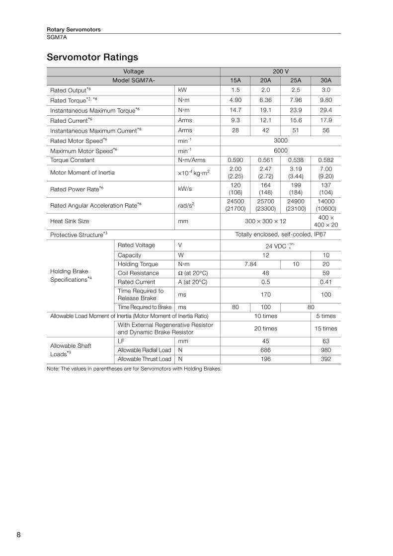
Servomotor Ratings
Note: The values in parentheses are for Servomotors with Holding Brakes.
Voltage 200 V
Model SGM7A- 15A 20A 25A 30A
Rated Output*6 kW 1.5 2.0 2.5 3.0
Rated Torque*2, *6 N m 4.90 6.36 7.96 9.80
Instantaneous Maximum Torque*6 N m 14.7 19.1 23.9 29.4
Rated Current*6 Arms 9.3 12.1 15.6 17.9
Instantaneous Maximum Current*6 Arms 28 42 51 56
Rated Motor Speed*6 min-1 3000
Maximum Motor Speed*6 min-1 6000
Torque Constant N m/Arms 0.590 0.561 0.538 0.582
Motor Moment of Inertia ×10-4 kg m22.00
(2.25)
2.47
(2.72)
3.19
(3.44)
7.00
(9.20)
Rated Power Rate*6 kW/s120
(106)
164
(148)
199
(184)
137
(104)
Rated Angular Acceleration Rate*6 rad/s224500
(21700)
25700
(23300)
24900
(23100)
14000
(10600)
Heat Sink Size mm 300 × 300 × 12400 ×
400 × 20
Protective Structure*3 Totally enclosed, self-cooled, IP67
Holding Brake
Specifications*4
Rated Voltage V 24 VDC
Capacity W 12 10
Holding Torque N m 7.84 10 20
Coil Resistance Ω (at 20°C) 48 59
Rated Current A (at 20°C) 0.5 0.41
Time Required to
Release Brake ms 170 100
Time Required to Brake ms 80 100 80
Allowable Load Moment of Inertia (Motor Moment of Inertia Ratio) 10 times 5 times
With External Regenerative Resistor
and Dynamic Brake Resistor 20 times 15 times
Allowable Shaft
Loads*5
LF mm 45 63
Allowable Radial Load N 686 980
Allowable Thrust Load N 196 392
+10%
0
Rotary Servomotors SGM7A
9
Ro
tary
Serv
om
oto
rs
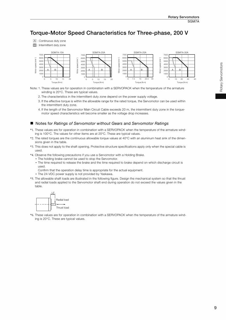
Torque-Motor Speed Characteristics for Three-phase, 200 V
Note: 1. These values are for operation in combination with a SERVOPACK when the temperature of the armature
winding is 20°C. These are typical values.
2. The characteristics in the intermittent duty zone depend on the power supply voltage.
3. If the effective torque is within the allowable range for the rated torque, the Servomotor can be used within
the intermittent duty zone.
4. If the length of the Servomotor Main Circuit Cable exceeds 20 m, the intermittent duty zone in the torque-
motor speed characteristics will become smaller as the voltage drop increases.
Notes for Ratings of Servomotor without Gears and Servomotor Ratings
*1. These values are for operation in combination with a SERVOPACK when the temperature of the armature wind-
ing is 100°C. The values for other items are at 20°C. These are typical values.
*2. The rated torques are the continuous allowable torque values at 40°C with an aluminum heat sink of the dimen-
sions given in the table.
*3. This does not apply to the shaft opening. Protective structure specifications apply only when the special cable is
used.
*4. Observe the following precautions if you use a Servomotor with a Holding Brake.
• The holding brake cannot be used to stop the Servomotor.
• The time required to release the brake and the time required to brake depend on which discharge circuit is
used.
Confirm that the operation delay time is appropriate for the actual equipment.
• The 24-VDC power supply is not provided by Yaskawa.
*5. The allowable shaft loads are illustrated in the following figure. Design the mechanical system so that the thrust
and radial loads applied to the Servomotor shaft end during operation do not exceed the values given in the
table.
*6. These values are for operation in combination with a SERVOPACK when the temperature of the armature wind-
ing is 20°C. These are typical values.
A :
B :
SGM7A-15A
A B
SGM7A-20A
A B
SGM7A-25A
A B
SGM7A-30A
A B
Continuous duty zone
Torque (N·m) Torque (N·m) Torque (N·m) Torque (N·m)
Intermittent duty zone
7000
6000
5000
4000
3000
2000
1000
0
0 5 10 15 20
Moto
r sp
eed
(m
in-1)
7000
6000
5000
4000
3000
2000
1000
0
0 5 10 15 20
Mo
tor sp
eed
(m
in-1)
7000
6000
5000
4000
3000
2000
1000
0
Mo
tor sp
eed
(m
in-1)
7000
6000
5000
4000
3000
2000
1000
0
0 10 20 30 40
Mo
tor sp
eed
(m
in-1)
0 7.5 15 22.5 30
LF
Radial load
Thrust load

Rotary ServomotorsSGM7A
10
Ratings of Servomotors with Gears
*1. The gear output torque is expressed by the following formula.
The gear efficiency depends on operating conditions such as the output torque, motor speed, and temperature.
The values in the table are typical values for the rated torque, rated motor speed, and a surrounding air temper-
ature of 25°C. They are reference values only.
*2. When using an SGM7A-A5A, SGM7A-01A, or SGM7A-C2A Servomotor with a gear ratio of 1/5 or an SGM7A-
C2A Servomotor with a gear ratio of 1/11, maintain an 85% maximum effective load ratio. For an SGM7A-C2A
Servomotor with a gear ratio of 1/21 or 1/33, maintain a 90% maximum effective load ratio. The values in the
table take the effective load ratio into consideration.
*3. The instantaneous maximum torque is 300% of the rated torque.
All Models Gear Mechanism Protective Structure Lost Motion [arc-min]
Planetary gear mechanism Totally enclosed, self-cooled, IP55
(except for shaft opening) 3 max.
Servomotor Model SGM7A-
Servomotor Gear Output
Rated Output
[W]
Rated Motor Speed [min-1]
Maxi-mum Motor Speed [min-1]
Rated Torque [N⋅m]
Instan-taneous Maxi-mum
Torque [N⋅m]
Gear Ratio
Rated Torque/Efficiency*1
[N⋅m/%]
Instanta-neous Maxi-mum
Torque [N⋅m]
Rated Motor Speed [min-1]
Maxi-mum Motor Speed [min-1]
A5A AH1
50 3000 6000 0.159 0.557
1/5 0.433/64*2 2.37 600 1200
A5A AH2 1/9 1.12/78 3.78*3 333 667
A5A AHC 1/21 2.84/85 10.6 143 286
A5A AH7 1/33 3.68/70 15.8 91 182
01A AH1
100 3000 6000 0.318 1.11
1/5 1.06/78*2 4.96 600 1200
01A AHB 1/11 2.52/72 10.7 273 545
01A AHC 1/21 5.35/80 20.8 143 286
01A AH7 1/33 7.35/70 32.7 91 182
C2A AH1
150 3000 6000 0.477 1.67
1/5 1.68/83*2 7.80 600 1200
C2A AHB 1/11 3.53/79*2 16.9 273 545
C2A AHC 1/21 6.30/70*2 31.0 143 286
C2A AH7 1/33 11.2/79*2 49.7 91 182
02A AH1
200 3000 6000 0.637 2.23
1/5 2.39/75 9.80 600 1200
02A AHB 1/11 5.74/82 22.1 273 545
02A AHC 1/21 10.2/76 42.1 143 286
02A AH7 1/33 17.0/81 67.6 91 182
04A AH1
400 3000 6000 1.27 4.46
1/5 5.35/84 20.1 600 1200
04A AHB 1/11 11.5/82 45.1 273 545
04A AHC 1/21 23.0/86 87.0 143 286
04A AH7 1/33 34.0/81 135 91 182
06A AH1
600 3000 6000 1.91 6.69
1/5 7.54/79 30.5 600 1200
06A AHB 1/11 18.1/86 68.6 273 545
06A AHC 1/21 32.1/80 129 143 286
06A AH7 1/33 53.6/85 206 91 182
08A AH1
750 3000 6000 2.39 8.36
1/5 10.0/84 38.4 600 1200
08A AHB 1/11 23.1/88 86.4 273 545
08A AHC 1/21 42.1/84 163 143 286
08A AH7 1/33 69.3/88 259 91 182
10A AH1
1000 3000 6000 3.18 11.1
1/5 13.7/86 52.5 600 1200
10A AHB 1/11 29.1/83 111 273 545
10A AHC 1/21 58.2/87 215 143 286
10A AH7 1/33 94.5/90 296*3 91 182
1Gear output torque = Servomotor output torque ×
Gear ratio× Efficiency

Rotary Servomotors SGM7A
11
Ro
tary
Serv
om
oto
rs
Note: 1. The gears that are mounted to Yaskawa Servomotors have not been broken in.
Break in the Servomotor if necessary. First, operate the Servomotor at low speed with no load. If no prob-
lems occur, gradually increase the speed and load.
2. The no-load torque for a Servomotor with a Gear is high immediately after the Servomotor starts, and it
then decreases and becomes stable after a few minutes. This is a common phenomenon caused by grease
circulation in the gears and it does not indicate faulty gears.
3. Contact your Yaskawa representative about Servomotors with Gears with a rated output of 1.5 kW or
higher.
4. Other specifications are the same as those for Servomotors without Gears.
* The moment of inertia for the Servomotor and gear is the value without a holding brake. You can calculate the
moment of inertia for a Servomotor with a Gear and Holding Brake with the following formula.
Motor moment of inertia for a Servomotor with a Holding Brake from Ratings of Servomotors without Gears on page 6 + Moment of inertia for the gear from the above table.
The SERVOPACK speed control range is 5,000:1. If you use Servomotors at extremely low speeds
(0.02 min-1 or lower at the gear output shaft), if you use Servomotors with a one-pulse feed refer-
ence for extended periods, or under some other operating conditions, the gear bearing lubrication
may be insufficient. That may cause deterioration of the bearing or increase the load ratio.
Contact your Yaskawa representative if you use a Servomotor under these conditions.
Servomotor Model SGM7A-
Moment of Inertia [×10-4 kg⋅m2] With Gears
Reference Diagram Shaft Output Flange Output Allowable
Radial Load [N]
Allowable Thrust Load [N]
LF[mm]Motor*
+ Gear Gear Motor* + Gear Gear
A5A AH1 0.0277 0.006 0.0267 0.005 95 431 37
A5A AH2 0.0247 0.003 0.0247 0.003 113 514 37
A5A AHC 0.0257 0.004 0.0257 0.004 146 663 37
A5A AH7 0.0667 0.045 0.0667 0.045 267 1246 53
01A AH1 0.0397 0.006 0.0387 0.005 95 431 37
01A AHB 0.0937 0.060 0.0927 0.059 192 895 53
01A AHC 0.0837 0.050 0.0837 0.050 233 1087 53
01A AH7 0.0987 0.065 0.0977 0.064 605 2581 75
C2A AH1 0.0518 0.006 0.0508 0.005 95 431 37
C2A AHB 0.106 0.060 0.105 0.059 192 895 53
C2A AHC 0.156 0.110 0.154 0.108 528 2254 75
C2A AH7 0.111 0.065 0.110 0.064 605 2581 75
02A AH1 0.346 0.207 0.340 0.201 152 707 53
02A AHB 0.332 0.193 0.331 0.192 192 895 53
02A AHC 0.629 0.490 0.627 0.488 528 2254 75
02A AH7 0.589 0.450 0.588 0.449 605 2581 75
04A AH1 0.423 0.207 0.417 0.201 152 707 53
04A AHB 0.786 0.570 0.776 0.560 435 1856 75
04A AHC 0.706 0.490 0.704 0.488 528 2254 75
04A AH7 0.836 0.620 0.826 0.610 951 4992 128
06A AH1 1.02 0.700 0.975 0.660 343 1465 75
06A AHB 0.885 0.570 0.875 0.560 435 1856 75
06A AHC 1.16 0.840 1.14 0.820 830 4359 128
06A AH7 0.935 0.620 0.925 0.610 951 4992 128
08A AH1 1.48 0.700 1.44 0.660 343 1465 75
08A AHB 1.38 0.600 1.37 0.590 435 1856 75
08A AHC 3.78 3.00 3.76 2.98 830 4359 128
08A AH7 3.58 2.80 3.57 2.79 951 4992 128
10A AH1 1.67 0.700 1.63 0.660 343 1465 75
10A AHB 4.37 3.40 4.31 3.34 684 3590 128
10A AHC 3.97 3.00 3.95 2.98 830 4359 128
10A AH7 3.77 2.80 3.76 2.79 951 4992 128
Important
LF
Shaft Output
Radial load
Thrust load
Flange Output
Radial load
Thrust load
LF

Rotary ServomotorsSGM7A
12
Servomotor Overload Protection Characteristics The overload detection level is set for hot start conditions with a Servomotor ambient temperature
of 40°C.
Note: The above overload protection characteristics do not mean that you can perform continuous duty operation
with an output of 100% or higher. Use the Servomotor so that the effective torque remains within the contin-
uous duty zone given in Torque-Motor Speed Characteristics on page 7 or in Torque-Motor Speed Character-istics for Three-phase, 200 V on page 9.
During operation, the gear generates the loss at the gear mechanism and oil seal. The loss depends on the
torque and motor speed conditions. The temperature rise depends on the loss and heat dissipation condi-
tions. For the heat dissipation conditions, always refer to the following table and check the gear and motor
temperatures with the actual equipment. If the temperature is too high, implement the following measures.
• Decrease the load ratio.
• Change the heat dissipation conditions.
• Use forced-air cooling for the motor with a cooling fan or other means.
Important
• A: 250 mm × 250 mm × 6 mm, aluminum plate
• B: 300 mm × 300 mm × 12 mm, aluminum plate
• C: 350 mm × 350 mm × 12 mm, aluminum plate
ModelHeat Sink Size
1/5 1/9 or 1/11 1/21 1/33
SGM7A-A5 A
SGM7A-01
BSGM7A-C2
SGM7A-02
SGM7A-04
SGM7A-06
CSGM7A-08
SGM7A-10A
SGM7A-A5, -01, -C2, -02, -04, -06, -08, and -10
0 50 100 150 200 300250 350
10000
1000
100
10
1
Dete
ctio
n t
ime (s)
Motor speed of 10 min-1 or higher
Motor speed of 10 min-1 or lower
Torque reference (percent of rated torque) (%)
SGM7A-15, -20, -25, and -30
0 50 100 150 200 250 300
10000
1000
100
10
1
Dete
ctio
n t
ime (s)
Torque reference (percent of rated torque) (%)
SGM7A-15, -20, -25, and -30

Rotary Servomotors SGM7A
13
Ro
tary
Serv
om
oto
rs
Load Moment of Inertia The load moment of inertia indicates the inertia of the load. The larger the load moment of inertia,
the worse the response.
The allowable size of the load moment of inertia (JL) for the Servomotor is restricted. Refer to Rat-ings of Servomotors without Gears on page 6 or to Servomotor Ratings on page 8. This value is
provided strictly as a guideline and results depend on Servomotor driving conditions.
An Overvoltage Alarm (A.400) is likely to occur during deceleration if the load moment of inertia
exceeds the allowable load moment of inertia. SERVOPACKs with a built-in regenerative resistor
may generate a Regenerative Overload Alarm (A.320). Perform one of the following steps if this
occurs.
• Reduce the torque limit.
• Reduce the deceleration rate.
• Reduce the maximum motor speed.
• Install an external regenerative resistor if the alarm cannot be cleared using the above steps.
Regenerative resistors are not built into SERVOPACKs for 400-W Servomotors or smaller Servomo-
tors. Even for SERVOPACKs with built-in regenerative resistors, an external regenerative resistor is
required if the energy that results from the regenerative driving conditions exceeds the allowable
loss capacity (W) of the built-in regenerative resistor.
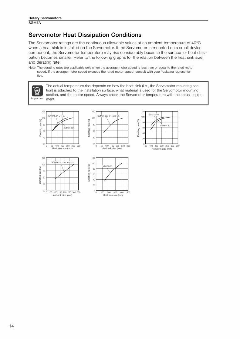
Rotary ServomotorsSGM7A
14
Servomotor Heat Dissipation Conditions The Servomotor ratings are the continuous allowable values at an ambient temperature of 40°C
when a heat sink is installed on the Servomotor. If the Servomotor is mounted on a small device
component, the Servomotor temperature may rise considerably because the surface for heat dissi-
pation becomes smaller. Refer to the following graphs for the relation between the heat sink size
and derating rate.
Note: The derating rates are applicable only when the average motor speed is less than or equal to the rated motor
speed. If the average motor speed exceeds the rated motor speed, consult with your Yaskawa representa-
tive.
The actual temperature rise depends on how the heat sink (i.e., the Servomotor mounting sec-
tion) is attached to the installation surface, what material is used for the Servomotor mounting
section, and the motor speed. Always check the Servomotor temperature with the actual equip-
ment. Important
Dera
ting r
ate
(%
)D
era
ting r
ate
(%
)
Dera
ting r
ate
(%
)
Heat sink size (mm)
Heat sink size (mm) Heat sink size (mm)
Heat sink size (mm) Heat sink size (mm)
Dera
ting r
ate
(%
)
Dera
ting r
ate
(%
)100
80
120 120
60
40
200
100
80
60
40
20150 250 300200100500 150 250 300 35020010050150 250 30020010050
100
80
120
60
40
200 150 250 35030020010050
0
20
40
60
80
100
120
300 50040020010000
20
40
60
80
100
120
SGM7A-A5 and -01
SGM7A-C2
SGM7A-02, -04, and -06
SGM7A-15, -20, and -25
SGM7A-30
SGM7A-08
SGM7A-10

Rotary Servomotors SGM7A
15
Ro
tary
Serv
om
oto
rs
Applications Where the Ambient Temperature of the Servomotor Exceeds 40°C The Servomotor ratings are the continuous allowable values at an ambient temperature of 40°C. If
you use a Servomotor at an ambient temperature that exceeds 40°C (60°C max.), apply a suitable
derating rate from the following graphs.
Note: The derating rates are applicable only when the average motor speed is less than or equal to the rated motor
speed. If the average motor speed exceeds the rated motor speed, consult with your Yaskawa representa-
tive.
Applications Where the Altitude of the Servomotor Exceeds 1,000 m The Servomotor ratings are the continuous allowable values at an altitude of 1,000 m or less. If you
use a Servomotor at an altitude that exceeds 1,000 m (2,000 m max.), the heat dissipation effect of
the air is reduced. Apply the appropriate derating rate from the following graphs.
Note: The derating rates are applicable only when the average motor speed is less than or equal to the rated motor
speed. If the average motor speed exceeds the rated motor speed, consult with your Yaskawa representa-
tive.
Dera
ting
rate
(%
)D
era
ting
rate
(%
)
Dera
ting
rate
(%
)D
era
ting
rate
(%
)
Dera
ting
rate
(%
)
Ambient temperature (°C)Ambient temperature (°C)Ambient temperature (°C)
Ambient temperature (°C) Ambient temperature (°C)
0
20
40
60
80
100
120
0
20
40
60
80
100
120
0
20
40
60
80
100
120
0
20
40
60
80
100
120
0
20
40
60
80
100
120
0 10 20 30 40 50 60 70 0 10 20 30 40 50 60 70
0 10 20 30 40 50 60 70 0 10 20 30 40 50 60 70 0 10 20 30 40 50 60 70
SGM7A-A5, -01, and -C2
SGM7A-15, -20, and -25
SGM7A-02 and -04
SGM7A-06
SGM7A-30
SGM7A-08 and -10
Dera
ting
rate
(%
)D
era
ting
rate
(%
)
Dera
ting
rate
(%
)D
era
ting
rate
(%
)
Altitude (m)
Altitude (m) Altitude (m)
Altitude (m) Altitude (m)
Dera
ting
rate
(%
)
0
20
40
60
80
100
120
0
0
20
40
60
80
100
120
0
20
40
60
80
100
120
20
40
60
80
100
120
0
20
40
60
80
100
120
0 500 1000 1500 25002000 0 500 1000 1500 25002000
0 500 1000 1500 25002000 0 500 1000 1500 25002000
0 500 1000 1500 25002000
SGM7A-08
SGM7A-10SGM7A-02, -04, and -06
SGM7A-30SGM7A-15, -20, and -25
SGM7A-A5, -01, and -C2

Rotary ServomotorsSGM7A
16
External Dimensions
Servomotors without Gears
SGM7A-A5, -01, and -C2
Note: 1. The values in parentheses are for Servomotors with Holding Brakes.
2. Refer to the following section for detailed shaft end specifications.
Shaft End Specifications for SGM7A-A5 to -10 (page 18)
Specifications of Options • Oil Seal
Model SGM7A- L LL LM LB S Approx. Mass [kg]
A5A A281.5
(122)
56.5
(97)37.9 30 8
0.3
(0.6)
01A A293.5
(134)
68.5
(109)49.9 30 8
0.4
(0.7)
C2A A2105.5
(153.5)
80.5
(128.5)61.9 30 8
0.5
(0.8)
5
46 dia.S
dia
.
14
16.1170.6
LM 2.5
25LL
L
0.8
25.8
40
8.8
20.5
0.02
0.04 A
A
LB
dia
.
0.04 dia. A
2 × 4.3 dia.Unit: mm
Notation
: Square dimensions
0
-0.021
0
-0.009
0
-0.021
0
-0.009
0
-0.021
0
-0.009
1.5
7.5
30
d
ia.
29
.8 d
ia.
Oil seal cover Unit: mm
0
- 0
.02
1

Rotary Servomotors SGM7A
17
Ro
tary
Serv
om
oto
rs
SGM7A-02 to -10
Note: 1. The values in parentheses are for Servomotors with Holding Brakes.
2. Refer to the following section for detailed shaft end specifications.
Shaft End Specifications for SGM7A-A5 to -10 (page 18)
Specifications of Options • Oil Seal
Model SGM7A- L LL LMFlange Dimensions
SLR LE LG LC LA LB LZ
02A A299.5
(140)
69.5
(110)51.2 30 3 6 60 70 50 5.5 14
04A A2115.5
(156)
85.5
(126)67.2 30 3 6 60 70 50 5.5 14
06A A2137.5
(191.5)
107.5
(161.5)89.2 30 3 6 60 70 50 5.5 14
08A A2137
(184)
97
(144)78.5 40 3 8 80 90 70 7 19
10A A2162
(209)
122
(169)103.5 40 3 8 80 90 70 7 19
Model SGM7A- MD MW MH ML Approx. Mass [kg]
02A A2 8.5 28.7 14.7 17.10.8
(1.4)
04A A2 8.5 28.7 14.7 17.11.2
(1.8)
06A A2 8.5 28.7 14.7 17.11.6
(2.2)
08A A2 8.5 38 14.7 19.32.3
(2.9)
10A A2 8.5 38 14.7 19.33.1
(3.7)
Model SGM7A-Dimensions with Oil Seal
E1 E2 LS1 LS2
02A, 04A, 06A 35 47 5.2 10
08A, 10A 47 61 5.5 11
14
0.6 17 LG
LE
LRLL
L
LB
dia
.
S d
ia.
LC
LA d
ia.
ML
MH
MW
LM
MD
20.5
0.04 A
A
0.02
0.04 dia. A
4 × LZ dia. Unit: mm
0
-0.025
0
-0.011
0
-0.025
0
-0.011
0
-0.025
0
-0.011
0
-0.030
0
-0.013
0
-0.030
0
-0.013
E2
dia
.
E1
dia
.
LE
LS1LS2
Oil seal cover Unit: mm
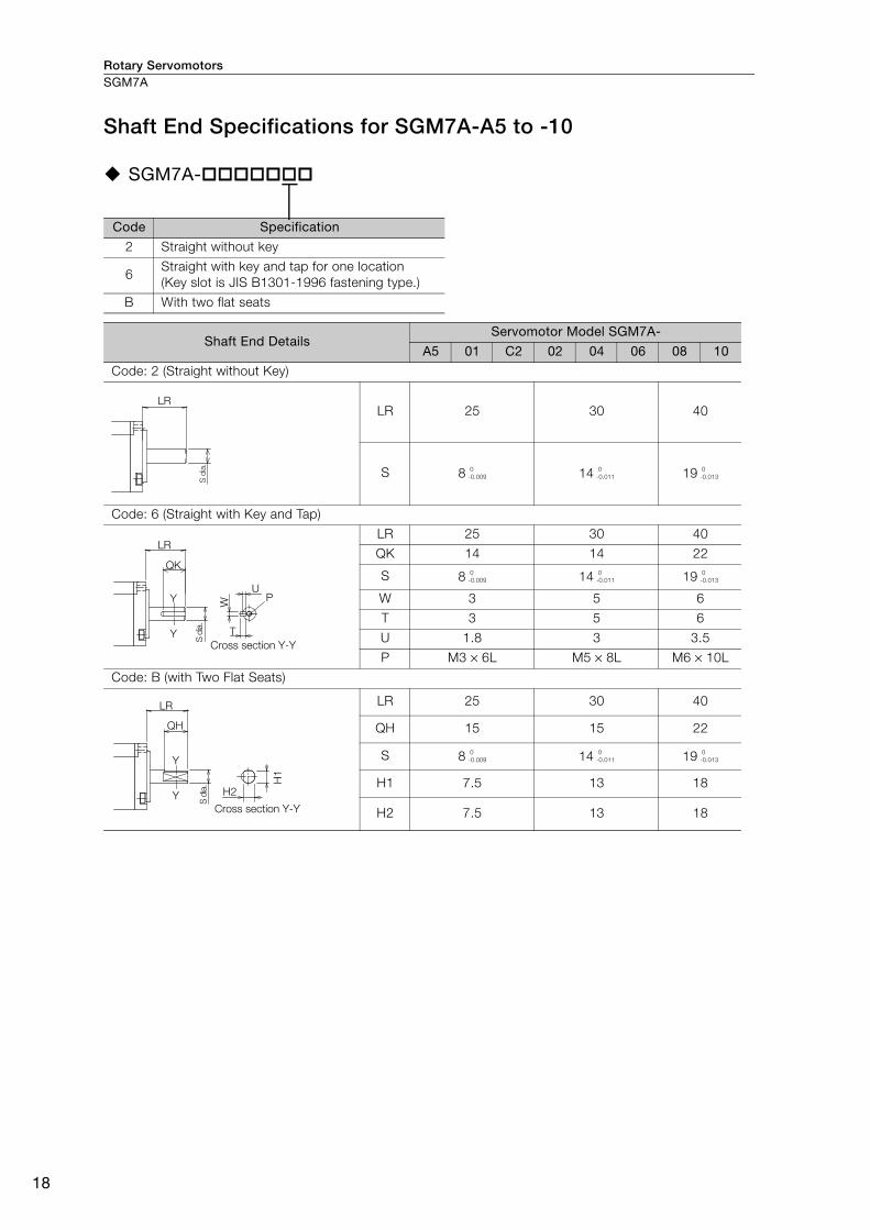
Rotary ServomotorsSGM7A
18
Shaft End Specifications for SGM7A-A5 to -10
SGM7A-
Code Specification
2 Straight without key
6Straight with key and tap for one location
(Key slot is JIS B1301-1996 fastening type.)
B With two flat seats
Shaft End Details Servomotor Model SGM7A-
A5 01 C2 02 04 06 08 10
Code: 2 (Straight without Key)
LR 25 30 40
S 8 14 19
Code: 6 (Straight with Key and Tap)
LR 25 30 40
QK 14 14 22
S 8 14 19
W 3 5 6
T 3 5 6
U 1.8 3 3.5
P M3 × 6L M5 × 8L M6 × 10L
Code: B (with Two Flat Seats)
LR 25 30 40
QH 15 15 22
S 8 14 19
H1 7.5 13 18
H2 7.5 13 18
S d
ia.
LR
0
-0.009
0
-0.011
0
-0.013
QK
S d
ia.
Y
Y
LR
W
T
UP
Cross section Y-Y
0
-0.009
0
-0.011
0
-0.013
S d
ia.
QH
Y
Y
LR
H1
H2
Cross section Y-Y
0
-0.009
0
-0.011
0
-0.013
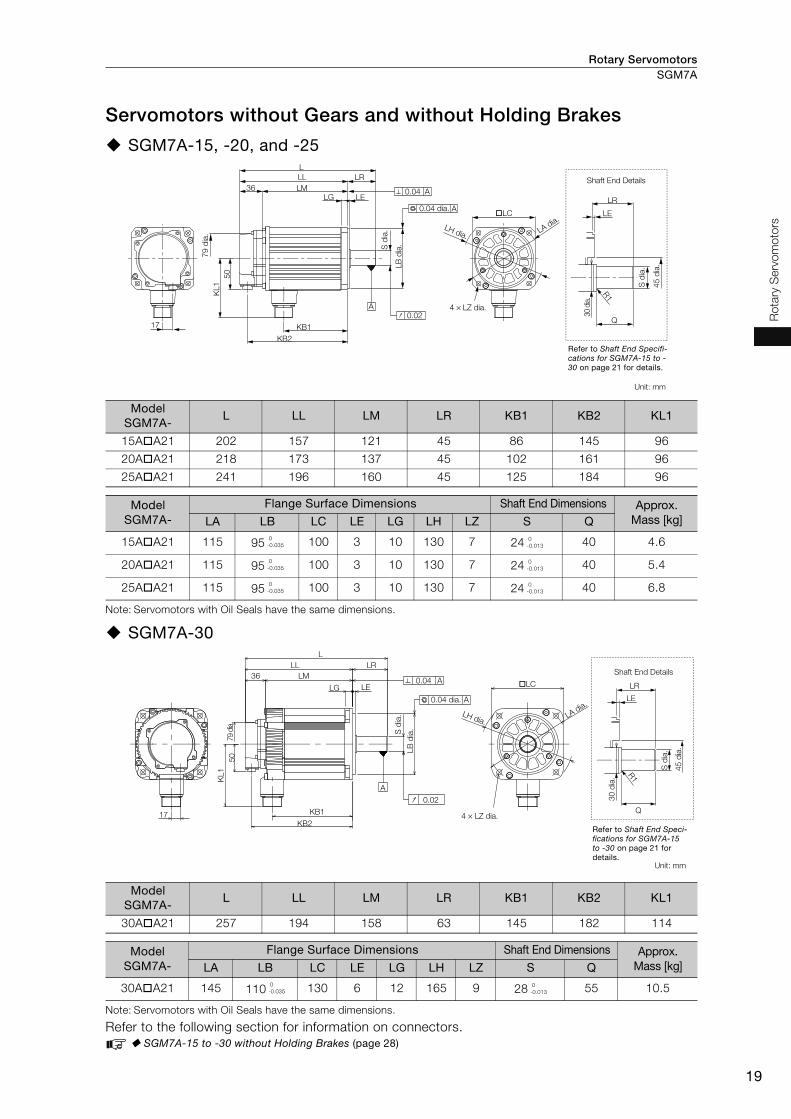
Rotary Servomotors SGM7A
19
Ro
tary
Serv
om
oto
rs
Servomotors without Gears and without Holding Brakes
SGM7A-15, -20, and -25
Note: Servomotors with Oil Seals have the same dimensions.
SGM7A-30
Note: Servomotors with Oil Seals have the same dimensions.
Refer to the following section for information on connectors.
SGM7A-15 to -30 without Holding Brakes (page 28)
Model SGM7A-
L LL LM LR KB1 KB2 KL1
15A A21 202 157 121 45 86 145 96
20A A21 218 173 137 45 102 161 96
25A A21 241 196 160 45 125 184 96
Model SGM7A-
Flange Surface Dimensions Shaft End Dimensions Approx. Mass [kg] LA LB LC LE LG LH LZ S Q
15A A21 115 95 100 3 10 130 7 24 40 4.6
20A A21 115 95 100 3 10 130 7 24 40 5.4
25A A21 115 95 100 3 10 130 7 24 40 6.8
Model SGM7A-
L LL LM LR KB1 KB2 KL1
30A A21 257 194 158 63 145 182 114
Model SGM7A-
Flange Surface Dimensions Shaft End Dimensions Approx. Mass [kg] LA LB LC LE LG LH LZ S Q
30A A21 145 110 130 6 12 165 9 28 55 10.5
17
R1
Q
LA dia.
LH dia.
LG LE
LB
dia
.S d
ia.
KB1
50
KL1
KB2
S d
ia.
30 d
ia.
LE
LR
LC
L
36 LM
LL LR
4 × LZ dia.A
79
dia
.
45
dia
.
0.02
0.04 A
0.04 dia. A
Unit: mm
Shaft End Details
Refer to Shaft End Specifi-cations for SGM7A-15 to -30 on page 21 for details.
0
-0.035
0
-0.013
0
-0.035
0
-0.013
0
-0.035
0
-0.013
LA dia.
LC
LH dia.
36
79 d
ia.
17
50
LELG
LM
LL
L
KL1
KB1
KB2
LB
dia
.S d
ia.
LR
4 × LZ dia.
A
0.02
0.04 dia. A
0.04 A
R1
Q
S d
ia.
30
dia
.
LE
LR4
5 d
ia.
Shaft End Details
Unit: mm
Refer to Shaft End Speci-fications for SGM7A-15 to -30 on page 21 for details.
0
-0.035
0
-0.013
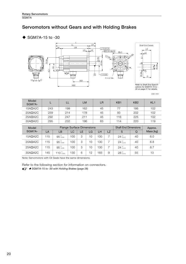
Rotary ServomotorsSGM7A
20
Servomotors without Gears and with Holding Brakes
SGM7A-15 to -30
Note: Servomotors with Oil Seals have the same dimensions.
Refer to the following section for information on connectors.
SGM7A-15 to -30 with Holding Brakes (page 28)
Model SGM7A-
L LL LM LR KB1 KB2 KL1
15A A2C 243 198 162 45 77 186 102
20A A2C 259 214 178 45 93 202 102
25A A2C 292 247 211 45 116 225 102
30A A2C 295 232 196 63 114 220 119
Model SGM7A-
Flange Surface Dimensions Shaft End Dimensions Approx. Mass [kg]LA LB LC LE LG LH LZ S Q
15A A2C 115 95 100 3 10 130 7 24 40 6.0
20A A2C 115 95 100 3 10 130 7 24 40 6.8
25A A2C 115 95 100 3 10 130 7 24 40 8.7
30A A2C 145 110 130 6 12 165 9 28 55 13
Q30
dia
.
R1
S d
ia.
LE
LR36
L
LL LR
LELG
LM
LB
dia
.S d
ia.
50
KB2
1711 KB1
KL1
A
45
dia
.79
dia
.
0.02
A
0.04
0.04 dia.
A
LA dia.
LH dia.
4 × LZ dia.
LC
Shaft End Details
Unit: mm
Refer to Shaft End Specifi-cations for SGM7A-15 to -30 on page 21 for details.
0
-0.035
0
-0.013
0
-0.035
0
-0.013
0
-0.035
0
-0.013
0
-0.035
0
-0.013

Rotary Servomotors SGM7A
21
Ro
tary
Serv
om
oto
rs
Shaft End Specifications for SGM7A-15 to -30
SGM7A-
Code Specification
2 Straight without key
6Straight with key and tap for one location
(Key slot is JIS B1301-1996 fastening type.)
Shaft End DetailsServomotor Model SGM7A-
15 20 25 30
Code: 2 (Straight without Key)
LR 45 63
Q 40 55
S 24 28
Code: 6 (Straight with Key and Tap)
LR 45 63
Q 40 55
QK 32 50
S 24 28
W 8
T 7
U 4
P M8 screw, Depth: 16
LR
Q
R1S dia.
0
-0.013
0
-0.013
LR
Q
QK
U
R1
P
T
W
S d
ia.
0
-0.013
0
-0.013
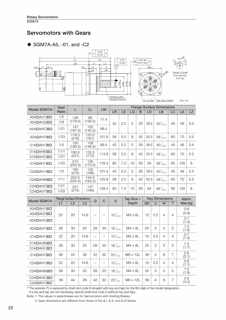
Rotary ServomotorsSGM7A
22
Servomotors with Gears
SGM7A-A5, -01, and -C2
* The asterisk (*) is replaced by shaft end code 6 (straight with key and tap) for the 8th digit of the model designation.
If a key and tap are not necessary, specify shaft end code 2 (without key and tap).
Note: 1. The values in parentheses are for Servomotors with Holding Brakes.
2. Gear dimensions are different from those of the Σ-I, Σ-II, and Σ-III Series.
Model SGM7A-Gear Ratio
L LL LMFlange Surface Dimensions
LR LE LG B LD LB LC LA LZ
A5A AH1 1/5 138(178.5)
96(136.5)
77.4
42 2.2 5 29 39.5 40 40 46 3.4A5A AH2 1/9
A5A AHC 1/21147
(187.5)105
(145.5)86.4
A5A AH7 1/33178.5(219)
120.5(161)
101.9 58 2.5 8 40 55.5 56 60 70 5.5
01A AH1 1/5150
(190.5)108
(148.5)89.4 42 2.2 5 29 39.5 40 40 46 3.4
01A AHB 1/11 190.5(231)
132.5(173)
113.9 58 2.5 8 40 55.5 56 60 70 5.501A AHC 1/21
01A AH7 1/33215
(255.5)135
(175.5)116.4 80 7.5 10 59 84 85 90 105 9
C2A AH1 1/5162(210)
120(168)
101.4 42 2.2 5 29 39.5 40 40 46 3.4
C2A AHB 1/11202.5(250.5)
144.5(192.5)
125.9 58 2.5 8 40 55.5 56 60 70 5.5
C2A AHC 1/21 227(275)
147(195)
128.4 80 7.5 10 59 84 85 90 105 9C2A AH7 1/33
Model SGM7A-Flange Surface Dimensions
Q C STap Size ×
Depth Key Dimensions Approx.
Mass [kg]L1 L2 L3 QK U W T
A5A AH1
22 20 14.6 − − 10 M3 × 6L 15 2.5 4 4
0.6
(0.9)A5A AH2
A5A AHC0.7(1.0)
A5A AH7 28 30 20 28 20 16 M4 × 8L 25 3 5 51.3(1.6)
01A AH1 22 20 14.6 − − 10 M3 × 6L 15 2.5 4 40.7(1.0)
01A AHB28 30 20 28 20 16 M4 × 8L 25 3 5 5
1.4(1.7)01A AHC
01A AH7 36 44 26 42 32 25 M6 × 12L 36 4 8 72.8(3.1)
C2A AH1 22 20 14.6 − − 10 M3 × 6L 15 2.5 4 40.8(1.1)
C2A AHB 28 30 20 28 20 16 M4 × 8L 25 3 5 51.5(1.8)
C2A AHC36 44 26 42 32 25 M6 × 12L 36 4 8 7
2.9(3.2)C2A AH7
16.1170.6
LL
LM
LG
LE
L
QK
QL3
L1 L2
C d
ia.
B d
ia.
LD d
ia.
LB d
ia.
S d
ia.
14
14.7
LA dia.
LC
LR
A
4 × LZ dia.
0.04
(0.03)
0.06
(0.05)A
A0.05 dia.
(0.04 dia.)
T
W
U
Details of Shaft
End with Key
and Tap
Rotating parts
(Shaded section) Tap size × Depth Unit: mm
�* 0
-0.025�*
�*
�* 0
-0.030
�* 0
-0.025
�* 0
-0.030
�*
�* 0
-0.035
�* 0
-0.025
�* 0
-0.030
�* 0
-0.035
�*
�* 0
-0.015�*
�*
�* 0
-0.018
�* 0
-0.015
�* 0
-0.018
�*
�* 0
-0.021
�* 0
-0.015
�* 0
-0.018
�* 0
-0.021
�*
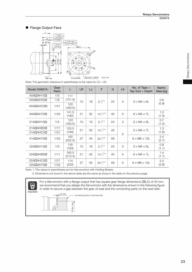
Rotary Servomotors SGM7A
23
Ro
tary
Serv
om
oto
rs
Flange Output Face
Note: The geometric tolerance in parentheses is the value for LC = 40.
Note: 1. The values in parentheses are for Servomotors with Holding Brakes.
2. Dimensions not found in the above table are the same as those in the table on the previous page.
Model SGM7A-Gear Ratio
L LR LJ F G LKNo. of Taps ×
Tap Size × Depth Approx.
Mass [kg]
A5A AH10 1/5 111
(151.5)15 18 5 24 3 3 × M4 × 6L
0.6
(0.9)
A5A AH20 1/9
A5A AHC0 1/21120
(160.5)
A5A AH70 1/33141.5
(182)21 30 14 40 5 6 × M4 × 7L
1.2
(1.5)
01A AH10 1/5123
(163.5)15 18 5 24 3 3 × M4 × 6L
0.7
(1.0)
01A AHB0 1/11 153.5
(194)21 30 14 40
5
3 × M4 × 7L1.3
(1.6)01A AHC0 1/21
01A AH70 1/33162
(202.5)27 45 24 59 6 × M6 × 10L
2.4
(2.7)
02A AH10 1/5135
(183)15 18 5 24 3 3 × M4 × 6L
0.8
(1.1)
02A AHB0 1/11165.5
(213.5)21 30 14 40 5 6 × M4 × 7L
1.4
(1.7)
02A AHC0 1/21 174
(222)27 45 24 59 5 6 × M6 × 10L
2.5
(2.8)02A AH70 1/33
For a Servomotor with a flange output that has square gear flange dimensions ( LC) of 40 mm,
we recommend that you design the Servomotor with the dimensions shown in the following figure
in order to secure a gap between the gear oil seal and the connecting parts on the load side.
LC
LA dia.
LD
dia
.
LB
dia
.
F d
ia.
LJ dia.
LK
L
L3
LE
LR
4 × LZ dia.
A
0.04(0.03)
0.020.05 dia.
A
A0.06(0.05)
(0.04 dia.)
G d
ia.
Tap size × Depth Unit: mm
+0.012
0
+0.018
0
+0.012
0
+0.018
0
+0.021
0
+0.012
0
+0.018
0
+0.021
0
Important0.5 min.
Connecting parts on the load side
24
dia
. m
ax.
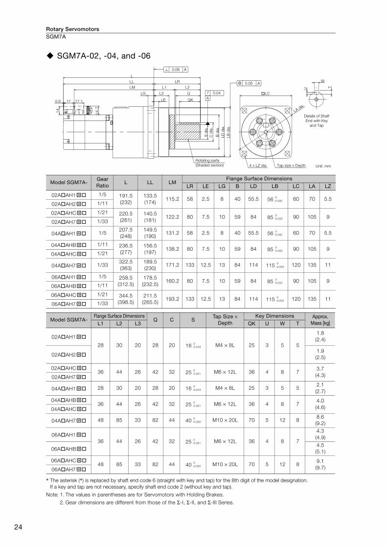
Rotary ServomotorsSGM7A
24
SGM7A-02, -04, and -06
* The asterisk (*) is replaced by shaft end code 6 (straight with key and tap) for the 8th digit of the model designation.
If a key and tap are not necessary, specify shaft end code 2 (without key and tap).
Note: 1. The values in parentheses are for Servomotors with Holding Brakes.
2. Gear dimensions are different from those of the Σ-I, Σ-II, and Σ-III Series.
Model SGM7A-Gear Ratio
L LL LMFlange Surface Dimensions
LR LE LG B LD LB LC LA LZ
02A AH1 1/5 191.5
(232)
133.5
(174)115.2 58 2.5 8 40 55.5 56 60 70 5.5
02A AH2 1/11
02A AHC 1/21 220.5
(261)
140.5
(181)122.2 80 7.5 10 59 84 85 90 105 9
02A AH7 1/33
04A AH1 1/5207.5
(248)
149.5
(190)131.2 58 2.5 8 40 55.5 56 60 70 5.5
04A AHB 1/11 236.5
(277)
156.5
(197)138.2 80 7.5 10 59 84 85 90 105 9
04A AHC 1/21
04A AH7 1/33322.5
(363)
189.5
(230)171.2 133 12.5 13 84 114 115 120 135 11
06A AH1 1/5 258.5
(312.5)
178.5
(232.5)160.2 80 7.5 10 59 84 85 90 105 9
06A AHB 1/11
06A AHC 1/21 344.5
(398.5)
211.5
(265.5)193.2 133 12.5 13 84 114 115 120 135 11
06A AH7 1/33
Model SGM7A-Flange Surface Dimensions
Q C STap Size ×
Depth Key Dimensions Approx.
Mass [kg]L1 L2 L3 QK U W T
02A AH1
28 30 20 28 20 16 M4 × 8L 25 3 5 5
1.8
(2.4)
02A AH21.9
(2.5)
02A AHC36 44 26 42 32 25 M6 × 12L 36 4 8 7
3.7
(4.3)02A AH7
04A AH1 28 30 20 28 20 16 M4 × 8L 25 3 5 52.1
(2.7)
04A AHB36 44 26 42 32 25 M6 × 12L 36 4 8 7
4.0
(4.6)04A AHC
04A AH7 48 85 33 82 44 40 M10 × 20L 70 5 12 88.6
(9.2)
06A AH1
36 44 26 42 32 25 M6 × 12L 36 4 8 7
4.3
(4.9)
06A AHB4.5
(5.1)
06A AHC48 85 33 82 44 40 M10 × 20L 70 5 12 8
9.1
(9.7)06A AH7
0.6 17 LE
LG L3
L1
LL
LM
14
.7
14
L
L2
Q
QK
C d
ia.
B d
ia.
LD
dia
.
LB
dia
.
LC
LA dia.
S d
ia.
LR
17.1
4 × LZ dia.
0.06 A
0.04
0.05 A
A
U
W
T
Details of Shaft
End with Key
and Tap
Rotating parts
(Shaded section) Tap size × Depth Unit: mm
�* 0
-0.030
�*�* 0
-0.035
�*
�* 0
-0.030
�* 0
-0.035
�*
�* 0
-0.035
�* 0
-0.035
�*�* 0
-0.035
�*
�* 0
-0.018
�*
�* 0
-0.021
�*
�* 0
-0.018
�* 0
-0.021
�*
�* 0
-0.025
�* 0
-0.021
�*
�* 0
-0.025
�*

Rotary Servomotors SGM7A
25
Ro
tary
Serv
om
oto
rs
Flange Output Face
Note: 1. The values in parentheses are for Servomotors with Holding Brakes.
2. Dimensions not found in the above table are the same as those in the table on the previous page.
Model SGM7A-Gear Ratio
L LR LJ F GNo. of Taps ×
Tap Size × DepthApprox.
Mass [kg]
02A AH10 1/5154.5
(195)21 30 14 40 6 × M4 × 7L
1.7
(2.3)
02A AH20 1/111.8
(2.4)
02A AHC0 1/21 167.5
(208)27 45 24 59 6 × M6 × 10L
3.3
(3.9)02A AH70 1/33
04A AH10 1/5170.5
(211)21 30 14 40 6 × M4 × 7L
2.0
(2.6)
04A AHB0 1/11 183.5
(224)27 45 24 59 6 × M6 × 10L
3.6
(4.2)04A AHC0 1/21
04A AH70 1/33224.5
(265)35 60 32 84 6 × M8 × 12L
7.2
(7.8)
06A AH10 1/5205.5
(259.5)27 45 24 59 6 × M6 × 10L
3.9
(4.5)
06A AHB0 1/114.1
(4.7)
06A AHC0 1/21 246.5
(300.5)35 60 32 84 6 × M8 × 12L
7.7
(8.3)06A AH70 1/33
LE
L
LR
L30.02
A0.06
A
0.04
0.05 dia. A
LC
LA dia.
LJ dia.
4 × LZ dia.5
LB d
ia.
G d
ia.
F d
ia.
LD d
ia.
Tap size × Depth Unit: mm
+0.018
0
+0.021
0
+0.018
0
+0.021
0
+0.025
0
+0.021
0
+0.025
0
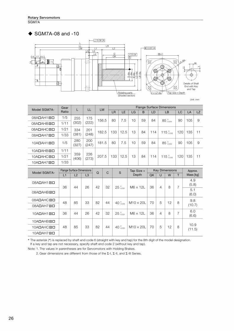
Rotary ServomotorsSGM7A
26
SGM7A-08 and -10
* The asterisk (*) is replaced by shaft end code 6 (straight with key and tap) for the 8th digit of the model designation.
If a key and tap are not necessary, specify shaft end code 2 (without key and tap).
Note: 1. The values in parentheses are for Servomotors with Holding Brakes.
2. Gear dimensions are different from those of the Σ-I, Σ-II, and Σ-III Series.
Model SGM7A-Gear Ratio
L LL LMFlange Surface Dimensions
LR LE LG B LD LB LC LA LZ
08A AH1 1/5 255
(302)
175
(222)156.5 80 7.5 10 59 84 85 90 105 9
08A AHB 1/11
08A AHC 1/21 334
(381)
201
(248)182.5 133 12.5 13 84 114 115 120 135 11
08A AH7 1/33
10A AH1 1/5280
(327)
200
(247)181.5 80 7.5 10 59 84 85 90 105 9
10A AHB 1/11359
(406)
226
(273)207.5 133 12.5 13 84 114 115 120 135 1110A AHC 1/21
10A AH7 1/33
Model SGM7A-Flange Surface Dimensions
Q C STap Size ×
Depth Key Dimensions Approx.
Mass [kg]L1 L2 L3 QK U W T
08A AH1
36 44 26 42 32 25 M6 × 12L 36 4 8 7
4.9
(5.8)
08A AHB5.1
(6.0)
08A AHC48 85 33 82 44 40 M10 × 20L 70 5 12 8
9.8
(10.7)08A AH7
10A AH1 36 44 26 42 32 25 M6 × 12L 36 4 8 76.0
(6.6)
10A AHB
48 85 33 82 44 40 M10 × 20L 70 5 12 810.9
(11.5)10A AHC
10A AH7
17
17
14
0.6 19.3
L
L3
LE
L1 L2LR
QQK
LG
LM
C d
ia.
B d
ia.
LD
dia
.
LB
dia
.
S d
ia.
LL
LA dia.
LC
W
U
T
0.05 A
0.04A
0.06 A
4 × LZ dia.
Details of Shaft
End with Key
and Tap
Rotating parts
(Shaded section)
Tap size × Depth
Unit: mm
�* 0
-0.035
�*
�* 0
-0.035
�*
�* 0
-0.035
�* 0
-0.035�*
�*
�* 0
-0.021
�*
�* 0
-0.025
�*
�* 0
-0.021
�* 0
-0.025�*
�*

Rotary Servomotors SGM7A
27
Ro
tary
Serv
om
oto
rs
Flange Output Face
Note: 1. The values in parentheses are for Servomotors with Holding Brakes.
2. Dimensions not found in the above table are the same as those in the table on the previous page.
Model SGM7A-Gear Ratio
L LR LJ F GNo. of Taps ×
Tap Size × Depth Approx.
Mass [kg]
08A AH10 1/5202
(249)27 45 24 59 6 × M6 × 10L
4.7
(5.3)
08A AHB0 1/114.9
(5.5)
08A AHC0 1/21 236
(283)35 60 32 84 6 × M8 × 12L
8.6
(9.2)08A AH70 1/33
10A AH10 1/5227
(274)27 45 24 59 6 × M6 × 10L
5.6
(6.3)
10A AHB0 1/11261
(308)35 60 32 84 6 × M8 × 12L
9.5
(10.1)10A AHC0 1/21
10A AH70 1/33
LC
LA dia.
LD d
ia.
LB d
ia.
LJ dia.
F d
ia.
G d
ia.
5
LE
L3
LR
L
0.06 A
0.04
0.05 dia. A
4 × LZ dia.
A
0.02
Tap size × Depth Unit: mm
+0.021
0
+0.025
0
+0.021
0
+0.025
0

Rotary ServomotorsSGM7A
28
Connector Specifications
SGM7A-15 to -30 without Holding Brakes• Encoder Connector Specifications (24-bit Encoder)
• Servomotor Connector Specifications
SGM7A-15 to -30 with Holding Brakes• Encoder Connector Specifications (24-bit Encoder)
• Servomotor Connector Specifications
Receptacle: CM10-R10P-D
Applicable plug: Not provided by Yaskawa.
Plug: CM10-AP10S- -D for Right-angle Plug
CM10-SP10S- -D for Straight Plug
( depends on the applicable cable size.)
Manufacturer: DDK Ltd.
Manufacturer: DDK Ltd.
Receptacle: CM10-R10P-D
Applicable plug: Not provided by Yaskawa.
Plug: CM10-AP10S- -D for Right-angle Plug
CM10-SP10S- -D for Straight Plug
( depends on the applicable cable size.)
Manufacturer: DDK Ltd.
Manufacturer: Japan Aviation Electronics Industry, Ltd.
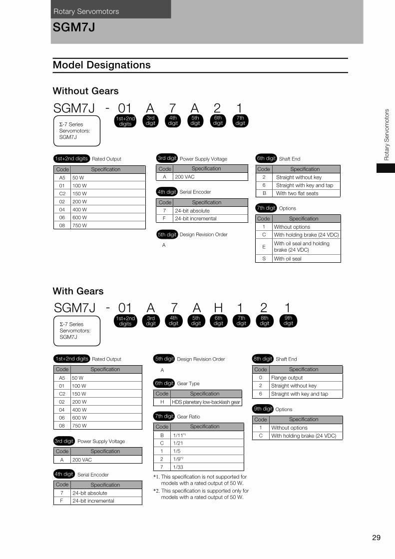
Rotary Servomotors
29
Ro
tary
Serv
om
oto
rs
SGM7J
Model Designations
Without Gears
With Gears
1
C
E
S
7
F
A
2
B
6
A 200 VACA5
01
C2
02 200 W
150 W
50 W
04 400 W
06 600 W
08 750 W
100 W
3rd digit
4th digit
6th digit
Σ-7 Series
Servomotors:
SGM7J
Rated Output
Code Specification Code
Code
Specification
Specification
24-bit absolute
24-bit incremental
Code
Code Specification
Without options
With holding brake (24 VDC)
With oil seal and holding
brake (24 VDC)
With oil seal
Specification
Straight without key
Straight with key and tap
With two flat seats
Power Supply Voltage
Serial Encoder
5th digit Design Revision Order
Shaft End
7th digit Options
1st+2nd digits
SGM7J - 01 A 7 A 2 11st+2nd
digits
3rd digit
4th digit
5th digit
6th digit
7th digit
A5
01
C2
02 200 W
150 W
50 W
04 400 W
06 600 W
08 750 W
0
2
6
1
CB 1/11*1
C 1/21
1 1/5
1/9*22
7
H
7
F
A 200 VAC
A
1/33
100 W
Σ-7 Series
Servomotors:
SGM7J
Rated Output 5th digit Design Revision Order
6th digit Gear Type
7th digit Gear Ratio
3rd digit Power Supply Voltage
4th digit Serial Encoder
SpecificationCode
Specification
24-bit absolute
24-bit incremental
Code
Code Specification
*1. This specification is not supported for
models with a rated output of 50 W.
*2. This specification is supported only for
models with a rated output of 50 W.
9th digit Options
Without options
With holding brake (24 VDC)
Code Specification
Code Specification
Flange output
Straight without key
Straight with key and tapCode Specification
HDS planetary low-backlash gear
Code Specification
8th digit Shaft End1st+2nd digits
SGM7J - 01 A 7 A H 1 2 11st+2nd
digits3rd digit
4th digit
5th digit
6th digit
7th digit
8th digit
9th digit
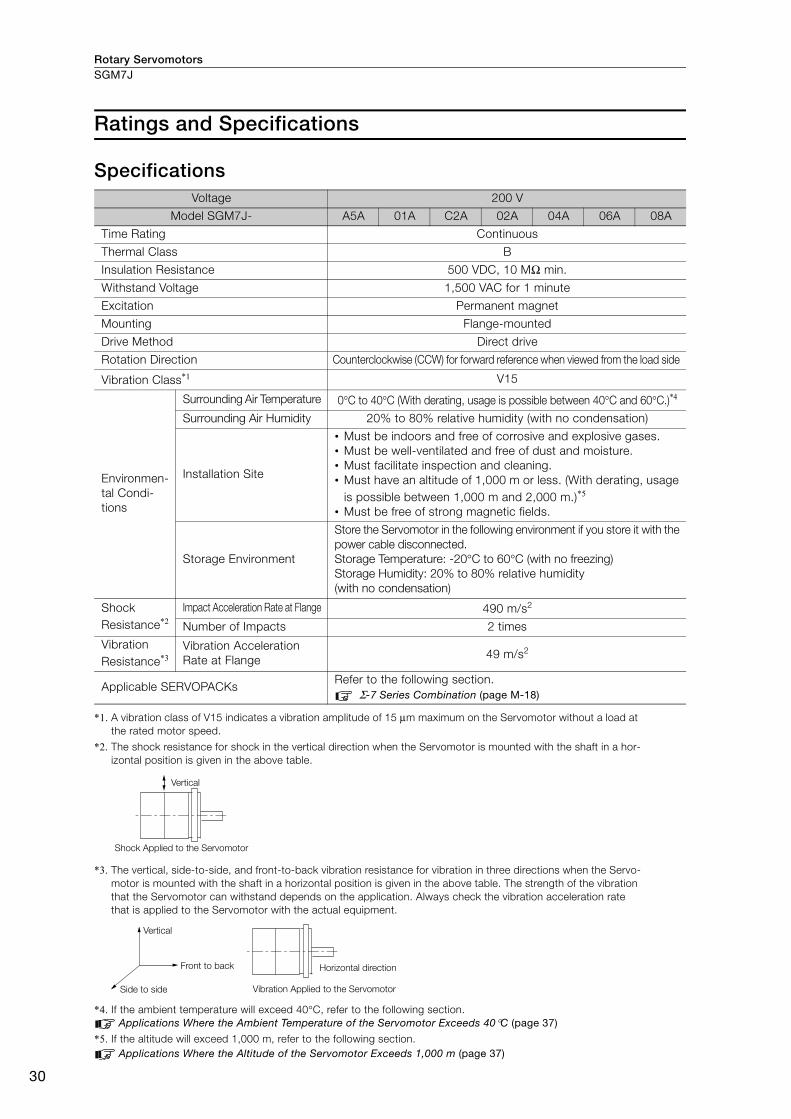
Rotary ServomotorsSGM7J
30
Ratings and Specifications
Specifications
*1. A vibration class of V15 indicates a vibration amplitude of 15 μm maximum on the Servomotor without a load at
the rated motor speed.
*2. The shock resistance for shock in the vertical direction when the Servomotor is mounted with the shaft in a hor-
izontal position is given in the above table.
*3. The vertical, side-to-side, and front-to-back vibration resistance for vibration in three directions when the Servo-
motor is mounted with the shaft in a horizontal position is given in the above table. The strength of the vibration
that the Servomotor can withstand depends on the application. Always check the vibration acceleration rate
that is applied to the Servomotor with the actual equipment.
*4. If the ambient temperature will exceed 40°C, refer to the following section.
Applications Where the Ambient Temperature of the Servomotor Exceeds 40°C (page 37)
*5. If the altitude will exceed 1,000 m, refer to the following section.
Applications Where the Altitude of the Servomotor Exceeds 1,000 m (page 37)
Voltage 200 V
Model SGM7J- A5A 01A C2A 02A 04A 06A 08A
Time Rating Continuous
Thermal Class B
Insulation Resistance 500 VDC, 10 MΩ min.
Withstand Voltage 1,500 VAC for 1 minute
Excitation Permanent magnet
Mounting Flange-mounted
Drive Method Direct drive
Rotation Direction Counterclockwise (CCW) for forward reference when viewed from the load side
Vibration Class*1 V15
Environmen-
tal Condi-
tions
Surrounding Air Temperature 0°C to 40°C (With derating, usage is possible between 40°C and 60°C.)*4
Surrounding Air Humidity 20% to 80% relative humidity (with no condensation)
Installation Site
• Must be indoors and free of corrosive and explosive gases.
• Must be well-ventilated and free of dust and moisture.
• Must facilitate inspection and cleaning.
• Must have an altitude of 1,000 m or less. (With derating, usage
is possible between 1,000 m and 2,000 m.)*5
• Must be free of strong magnetic fields.
Storage Environment
Store the Servomotor in the following environment if you store it with the
power cable disconnected.
Storage Temperature: -20°C to 60°C (with no freezing)
Storage Humidity: 20% to 80% relative humidity
(with no condensation)
Shock
Resistance*2Impact Acceleration Rate at Flange 490 m/s2
Number of Impacts 2 times
Vibration
Resistance*3Vibration Acceleration
Rate at Flange 49 m/s2
Applicable SERVOPACKs Refer to the following section.
Σ-7 Series Combination (page M-18)
Vertical
Shock Applied to the Servomotor
Vertical
Side to side
Front to back Horizontal direction
Vibration Applied to the Servomotor
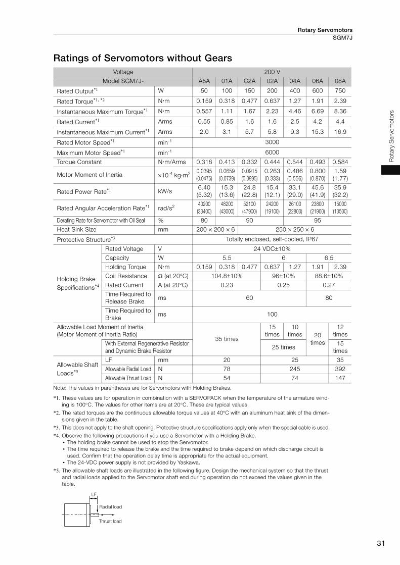
Rotary Servomotors SGM7J
31
Ro
tary
Serv
om
oto
rs
Ratings of Servomotors without Gears
Note: The values in parentheses are for Servomotors with Holding Brakes.
*1. These values are for operation in combination with a SERVOPACK when the temperature of the armature wind-
ing is 100°C. The values for other items are at 20°C. These are typical values.
*2. The rated torques are the continuous allowable torque values at 40°C with an aluminum heat sink of the dimen-
sions given in the table.
*3. This does not apply to the shaft opening. Protective structure specifications apply only when the special cable is used.
*4. Observe the following precautions if you use a Servomotor with a Holding Brake.
• The holding brake cannot be used to stop the Servomotor.
• The time required to release the brake and the time required to brake depend on which discharge circuit is
used. Confirm that the operation delay time is appropriate for the actual equipment.
• The 24-VDC power supply is not provided by Yaskawa.
*5. The allowable shaft loads are illustrated in the following figure. Design the mechanical system so that the thrust
and radial loads applied to the Servomotor shaft end during operation do not exceed the values given in the
table.
Voltage 200 V
Model SGM7J- A5A 01A C2A 02A 04A 06A 08A
Rated Output*1 W 50 100 150 200 400 600 750
Rated Torque*1, *2 N m 0.159 0.318 0.477 0.637 1.27 1.91 2.39
Instantaneous Maximum Torque*1 N m 0.557 1.11 1.67 2.23 4.46 6.69 8.36
Rated Current*1 Arms 0.55 0.85 1.6 1.6 2.5 4.2 4.4
Instantaneous Maximum Current*1 Arms 2.0 3.1 5.7 5.8 9.3 15.3 16.9
Rated Motor Speed*1 min-1 3000
Maximum Motor Speed*1 min-1 6000
Torque Constant N m/Arms 0.318 0.413 0.332 0.444 0.544 0.493 0.584
Motor Moment of Inertia ×10-4 kg m2 0.0395
(0.0475)
0.0659
(0.0739)
0.0915
(0.0995)
0.263
(0.333)
0.486
(0.556)
0.800
(0.870)
1.59
(1.77)
Rated Power Rate*1 kW/s6.40
(5.32)
15.3
(13.6)
24.8
(22.8)
15.4
(12.1)
33.1
(29.0)
45.6
(41.9)
35.9
(32.2)
Rated Angular Acceleration Rate*1 rad/s240200
(33400)
48200
(43000)
52100
(47900)
24200
(19100)
26100
(22800)
23800
(21900)
15000
(13500)
Derating Rate for Servomotor with Oil Seal % 80 90 95
Heat Sink Size mm 200 × 200 × 6 250 × 250 × 6
Protective Structure*3 Totally enclosed, self-cooled, IP67
Holding Brake
Specifications*4
Rated Voltage V 24 VDC±10%
Capacity W 5.5 6 6.5
Holding Torque N m 0.159 0.318 0.477 0.637 1.27 1.91 2.39
Coil Resistance Ω (at 20°C) 104.8±10% 96±10% 88.6±10%
Rated Current A (at 20°C) 0.23 0.25 0.27
Time Required to
Release Brakems 60 80
Time Required to
Brakems 100
Allowable Load Moment of Inertia
(Motor Moment of Inertia Ratio) 35 times
15
times
10
times 20
times
12
times
With External Regenerative Resistor
and Dynamic Brake Resistor25 times
15
times
Allowable Shaft
Loads*5
LF mm 20 25 35
Allowable Radial Load N 78 245 392
Allowable Thrust Load N 54 74 147
LF
Radial load
Thrust load
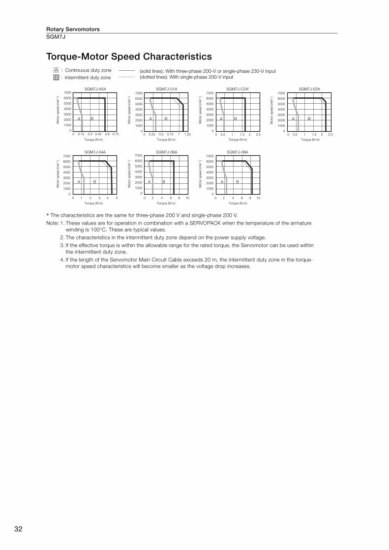
Rotary ServomotorsSGM7J
32
Torque-Motor Speed Characteristics
* The characteristics are the same for three-phase 200 V and single-phase 200 V.
Note: 1. These values are for operation in combination with a SERVOPACK when the temperature of the armature
winding is 100°C. These are typical values.
2. The characteristics in the intermittent duty zone depend on the power supply voltage.
3. If the effective torque is within the allowable range for the rated torque, the Servomotor can be used within
the intermittent duty zone.
4. If the length of the Servomotor Main Circuit Cable exceeds 20 m, the intermittent duty zone in the torque-
motor speed characteristics will become smaller as the voltage drop increases.
SGM7J-A5A
A B
SGM7J-01A
A B
SGM7J-C2A*
A B
SGM7J-04A
A B
SGM7J-06A
A B
SGM7J-08A
A B
SGM7J-02A
A B
Continuous duty zone
Mo
tor sp
eed
(m
in-1)
Mo
tor sp
eed
(m
in-1)
Mo
tor sp
eed
(m
in-1)
Mo
tor sp
eed
(m
in-1)
Mo
tor sp
eed
(m
in-1)
Torque (N·m)
Torque (N·m) Torque (N·m) Torque (N·m)
Torque (N·m) Torque (N·m) Torque (N·m)
Mo
tor sp
eed
(m
in-1)
Mo
tor sp
eed
(m
in-1)
Intermittent duty zone
(solid lines): With three-phase 200-V or single-phase 230-V input
(dotted lines): With single-phase 200-V input
7000
6000
5000
4000
3000
2000
1000
00 0.15 0.3 0.45 0.6 0.75 0 0.25 0.5 0.75 1 1.25
0 1 2 3 4 5 0 2 4 6 8 10 0 2 4 6 8 10
0 0.5 1 1.5 2 2.5 0 0.5 1 1.5 2 2.5
7000
6000
5000
4000
3000
2000
1000
0
7000
6000
5000
4000
3000
2000
1000
0
7000
6000
5000
4000
3000
2000
1000
0
7000
6000
5000
4000
3000
2000
1000
0
7000
6000
5000
4000
3000
2000
1000
0
7000
6000
5000
4000
3000
2000
1000
0
A :
B :
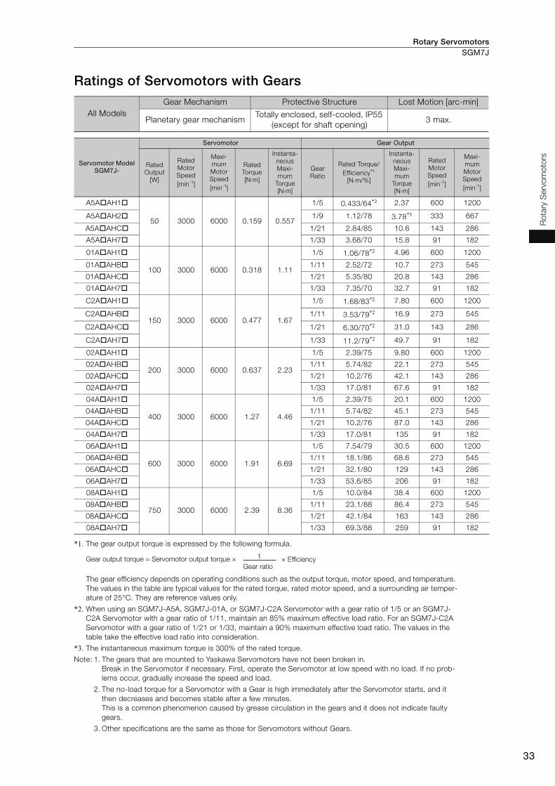
Rotary Servomotors SGM7J
33
Ro
tary
Serv
om
oto
rs
Ratings of Servomotors with Gears
*1. The gear output torque is expressed by the following formula.
The gear efficiency depends on operating conditions such as the output torque, motor speed, and temperature.
The values in the table are typical values for the rated torque, rated motor speed, and a surrounding air temper-
ature of 25°C. They are reference values only.
*2. When using an SGM7J-A5A, SGM7J-01A, or SGM7J-C2A Servomotor with a gear ratio of 1/5 or an SGM7J-
C2A Servomotor with a gear ratio of 1/11, maintain an 85% maximum effective load ratio. For an SGM7J-C2A
Servomotor with a gear ratio of 1/21 or 1/33, maintain a 90% maximum effective load ratio. The values in the
table take the effective load ratio into consideration.
*3. The instantaneous maximum torque is 300% of the rated torque.
Note: 1. The gears that are mounted to Yaskawa Servomotors have not been broken in.
Break in the Servomotor if necessary. First, operate the Servomotor at low speed with no load. If no prob-
lems occur, gradually increase the speed and load.
2. The no-load torque for a Servomotor with a Gear is high immediately after the Servomotor starts, and it
then decreases and becomes stable after a few minutes.
This is a common phenomenon caused by grease circulation in the gears and it does not indicate faulty
gears.
3. Other specifications are the same as those for Servomotors without Gears.
All Models
Gear Mechanism Protective Structure Lost Motion [arc-min]
Planetary gear mechanism Totally enclosed, self-cooled, IP55
(except for shaft opening) 3 max.
Servomotor Model SGM7J-
Servomotor Gear Output
Rated
Output
[W]
Rated
Motor
Speed
[min-1]
Maxi-
mum
Motor
Speed
[min-1]
Rated
Torque
[N⋅m]
Instanta-
neous
Maxi-
mum
Torque
[N⋅m]
Gear
Ratio
Rated Torque/
Efficiency*1
[N⋅m/%]
Instanta-
neous
Maxi-
mum
Torque
[N⋅m]
Rated
Motor
Speed
[min-1]
Maxi-
mum
Motor
Speed
[min-1]
A5A AH1
50 3000 6000 0.159 0.557
1/5 0.433/64*2 2.37 600 1200
A5A AH2 1/9 1.12/78 3.78*3 333 667
A5A AHC 1/21 2.84/85 10.6 143 286
A5A AH7 1/33 3.68/70 15.8 91 182
01A AH1
100 3000 6000 0.318 1.11
1/5 1.06/78*2 4.96 600 1200
01A AHB 1/11 2.52/72 10.7 273 545
01A AHC 1/21 5.35/80 20.8 143 286
01A AH7 1/33 7.35/70 32.7 91 182
C2A AH1
150 3000 6000 0.477 1.67
1/5 1.68/83*2 7.80 600 1200
C2A AHB 1/11 3.53/79*2 16.9 273 545
C2A AHC 1/21 6.30/70*2 31.0 143 286
C2A AH7 1/33 11.2/79*2 49.7 91 182
02A AH1
200 3000 6000 0.637 2.23
1/5 2.39/75 9.80 600 1200
02A AHB 1/11 5.74/82 22.1 273 545
02A AHC 1/21 10.2/76 42.1 143 286
02A AH7 1/33 17.0/81 67.6 91 182
04A AH1
400 3000 6000 1.27 4.46
1/5 2.39/75 20.1 600 1200
04A AHB 1/11 5.74/82 45.1 273 545
04A AHC 1/21 10.2/76 87.0 143 286
04A AH7 1/33 17.0/81 135 91 182
06A AH1
600 3000 6000 1.91 6.69
1/5 7.54/79 30.5 600 1200
06A AHB 1/11 18.1/86 68.6 273 545
06A AHC 1/21 32.1/80 129 143 286
06A AH7 1/33 53.6/85 206 91 182
08A AH1
750 3000 6000 2.39 8.36
1/5 10.0/84 38.4 600 1200
08A AHB 1/11 23.1/88 86.4 273 545
08A AHC 1/21 42.1/84 163 143 286
08A AH7 1/33 69.3/88 259 91 182
1Gear output torque = Servomotor output torque × × EfficiencyGear ratio
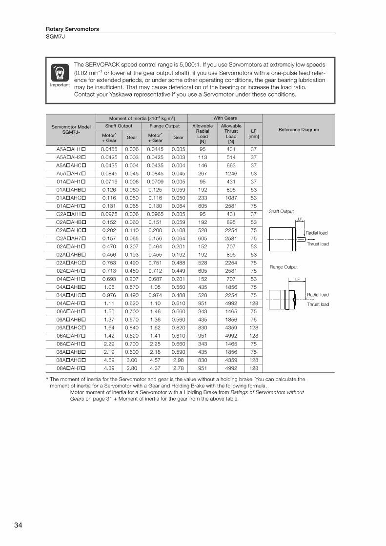
Rotary ServomotorsSGM7J
34
* The moment of inertia for the Servomotor and gear is the value without a holding brake. You can calculate the
moment of inertia for a Servomotor with a Gear and Holding Brake with the following formula.
Motor moment of inertia for a Servomotor with a Holding Brake from Ratings of Servomotors without Gears on page 31 + Moment of inertia for the gear from the above table.
The SERVOPACK speed control range is 5,000:1. If you use Servomotors at extremely low speeds
(0.02 min-1 or lower at the gear output shaft), if you use Servomotors with a one-pulse feed refer-
ence for extended periods, or under some other operating conditions, the gear bearing lubrication
may be insufficient. That may cause deterioration of the bearing or increase the load ratio.
Contact your Yaskawa representative if you use a Servomotor under these conditions.
Servomotor Model SGM7J-
Moment of Inertia [×10-4 kg⋅m2] With Gears
Reference Diagram Shaft Output Flange Output Allowable
Radial Load [N]
Allowable Thrust Load [N]
LF [mm]Motor*
+ GearGear Motor*
+ GearGear
A5A AH1 0.0455 0.006 0.0445 0.005 95 431 37
A5A AH2 0.0425 0.003 0.0425 0.003 113 514 37
A5A AHC 0.0435 0.004 0.0435 0.004 146 663 37
A5A AH7 0.0845 0.045 0.0845 0.045 267 1246 53
01A AH1 0.0719 0.006 0.0709 0.005 95 431 37
01A AHB 0.126 0.060 0.125 0.059 192 895 53
01A AHC 0.116 0.050 0.116 0.050 233 1087 53
01A AH7 0.131 0.065 0.130 0.064 605 2581 75
C2A AH1 0.0975 0.006 0.0965 0.005 95 431 37
C2A AHB 0.152 0.060 0.151 0.059 192 895 53
C2A AHC 0.202 0.110 0.200 0.108 528 2254 75
C2A AH7 0.157 0.065 0.156 0.064 605 2581 75
02A AH1 0.470 0.207 0.464 0.201 152 707 53
02A AHB 0.456 0.193 0.455 0.192 192 895 53
02A AHC 0.753 0.490 0.751 0.488 528 2254 75
02A AH7 0.713 0.450 0.712 0.449 605 2581 75
04A AH1 0.693 0.207 0.687 0.201 152 707 53
04A AHB 1.06 0.570 1.05 0.560 435 1856 75
04A AHC 0.976 0.490 0.974 0.488 528 2254 75
04A AH7 1.11 0.620 1.10 0.610 951 4992 128
06A AH1 1.50 0.700 1.46 0.660 343 1465 75
06A AHB 1.37 0.570 1.36 0.560 435 1856 75
06A AHC 1.64 0.840 1.62 0.820 830 4359 128
06A AH7 1.42 0.620 1.41 0.610 951 4992 128
08A AH1 2.29 0.700 2.25 0.660 343 1465 75
08A AHB 2.19 0.600 2.18 0.590 435 1856 75
08A AHC 4.59 3.00 4.57 2.98 830 4359 128
08A AH7 4.39 2.80 4.37 2.78 951 4992 128
Important
LF
Shaft Output
Radial load
Thrust load
LF
Flange Output
Radial load
Thrust load
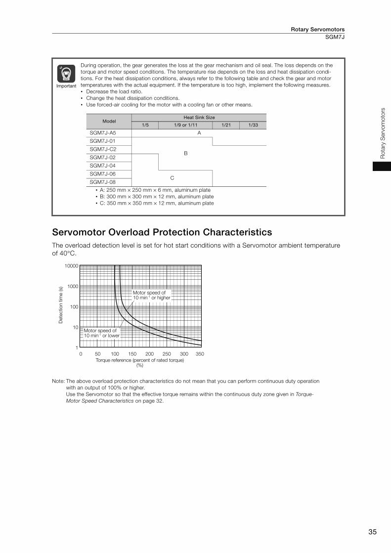
Rotary Servomotors SGM7J
35
Ro
tary
Serv
om
oto
rs
Servomotor Overload Protection Characteristics The overload detection level is set for hot start conditions with a Servomotor ambient temperature
of 40°C.
Note: The above overload protection characteristics do not mean that you can perform continuous duty operation
with an output of 100% or higher.
Use the Servomotor so that the effective torque remains within the continuous duty zone given in Torque-Motor Speed Characteristics on page 32.
During operation, the gear generates the loss at the gear mechanism and oil seal. The loss depends on the
torque and motor speed conditions. The temperature rise depends on the loss and heat dissipation condi-
tions. For the heat dissipation conditions, always refer to the following table and check the gear and motor
temperatures with the actual equipment. If the temperature is too high, implement the following measures.
• Decrease the load ratio.
• Change the heat dissipation conditions.
• Use forced-air cooling for the motor with a cooling fan or other means.
Important
• A: 250 mm × 250 mm × 6 mm, aluminum plate
• B: 300 mm × 300 mm × 12 mm, aluminum plate
• C: 350 mm × 350 mm × 12 mm, aluminum plate
Model Heat Sink Size
1/5 1/9 or 1/11 1/21 1/33
SGM7J-A5 A
SGM7J-01
BSGM7J-C2
SGM7J-02
SGM7J-04
SGM7J-06C
SGM7J-08
0 50 100 150 200 250 300 350
10000
1000
100
10
1
Dete
ctio
n t
ime (s)
Motor speed of 10 min-1 or higher
Motor speed of 10 min-1 or lower
Torque reference (percent of rated torque) (%)
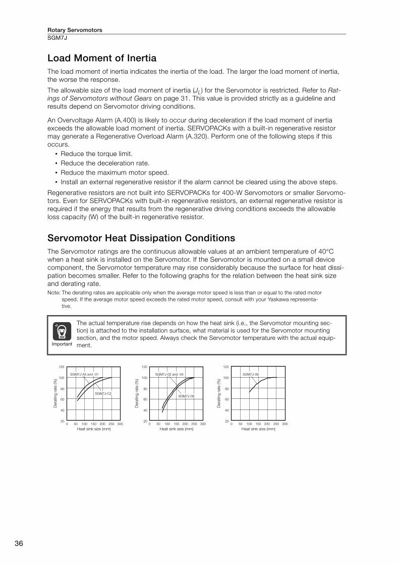
Rotary ServomotorsSGM7J
36
Load Moment of Inertia The load moment of inertia indicates the inertia of the load. The larger the load moment of inertia,
the worse the response.
The allowable size of the load moment of inertia (JL) for the Servomotor is restricted. Refer to Rat-ings of Servomotors without Gears on page 31. This value is provided strictly as a guideline and
results depend on Servomotor driving conditions.
An Overvoltage Alarm (A.400) is likely to occur during deceleration if the load moment of inertia
exceeds the allowable load moment of inertia. SERVOPACKs with a built-in regenerative resistor
may generate a Regenerative Overload Alarm (A.320). Perform one of the following steps if this
occurs.
• Reduce the torque limit.
• Reduce the deceleration rate.
• Reduce the maximum motor speed.
• Install an external regenerative resistor if the alarm cannot be cleared using the above steps.
Regenerative resistors are not built into SERVOPACKs for 400-W Servomotors or smaller Servomo-
tors. Even for SERVOPACKs with built-in regenerative resistors, an external regenerative resistor is
required if the energy that results from the regenerative driving conditions exceeds the allowable
loss capacity (W) of the built-in regenerative resistor.
Servomotor Heat Dissipation Conditions The Servomotor ratings are the continuous allowable values at an ambient temperature of 40°C
when a heat sink is installed on the Servomotor. If the Servomotor is mounted on a small device
component, the Servomotor temperature may rise considerably because the surface for heat dissi-
pation becomes smaller. Refer to the following graphs for the relation between the heat sink size
and derating rate.
Note: The derating rates are applicable only when the average motor speed is less than or equal to the rated motor
speed. If the average motor speed exceeds the rated motor speed, consult with your Yaskawa representa-
tive.
The actual temperature rise depends on how the heat sink (i.e., the Servomotor mounting sec-
tion) is attached to the installation surface, what material is used for the Servomotor mounting
section, and the motor speed. Always check the Servomotor temperature with the actual equip-
ment. Important
100
80
120 120
60
40
200
100
80
60
40
20150 250 300200100500
120
100
80
60
40
20150 250 300200100500
SGM7J-A5 and -01
SGM7J-C2
SGM7J-08
150 250 30020010050
SGM7J-02 and -04
SGM7J-06
Dera
ting
rate
(%
)
Heat sink size (mm) Heat sink size (mm) Heat sink size (mm)
Dera
ting
rate
(%
)
Dera
ting
rate
(%
)

Rotary Servomotors SGM7J
37
Ro
tary
Serv
om
oto
rs
Applications Where the Ambient Temperature of the Servomotor Exceeds 40°C The Servomotor ratings are the continuous allowable values at an ambient temperature of 40°C. If
you use a Servomotor at an ambient temperature that exceeds 40°C (60°C max.), apply a suitable
derating rate from the following graphs.
Note: The derating rates are applicable only when the average motor speed is less than or equal to the rated motor
speed. If the average motor speed exceeds the rated motor speed, consult with your Yaskawa representa-
tive.
Applications Where the Altitude of the Servomotor Exceeds 1,000 m The Servomotor ratings are the continuous allowable values at an altitude of 1,000 m or less. If you
use a Servomotor at an altitude that exceeds 1,000 m (2,000 m max.), the heat dissipation effect of
the air is reduced. Apply the appropriate derating rate from the following graphs.
Note: The derating rates are applicable only when the average motor speed is less than or equal to the rated motor
speed. If the average motor speed exceeds the rated motor speed, consult with your Yaskawa representa-
tive.
100
80
120 120
60
40
00
100
80
60
40
0
20 20
10 20 30 40 50 60 70 0 10 20 30 40 50 60 70
SGM7J-01 and -C2
SGM7J-A5
SGM7J-02 and -04
SGM7J-06 and -08
Dera
ting
rate
(%
)
Dera
ting
rate
(%
)
Ambient temperature (°C) Ambient temperature (°C)
100
80
120 120
60
40
0
100
80
60
40
0
20 20
0 500 1000 1500 2000 2500 0 500 1000 1500 2000 2500
SGM7J-A5, -01, and -C2
SGM7J-02, -04, and -06
SGM7J-08
Dera
ting
rate
(%
)
Altitude (m) Altitude (m)
Dera
ting
rate
(%
)
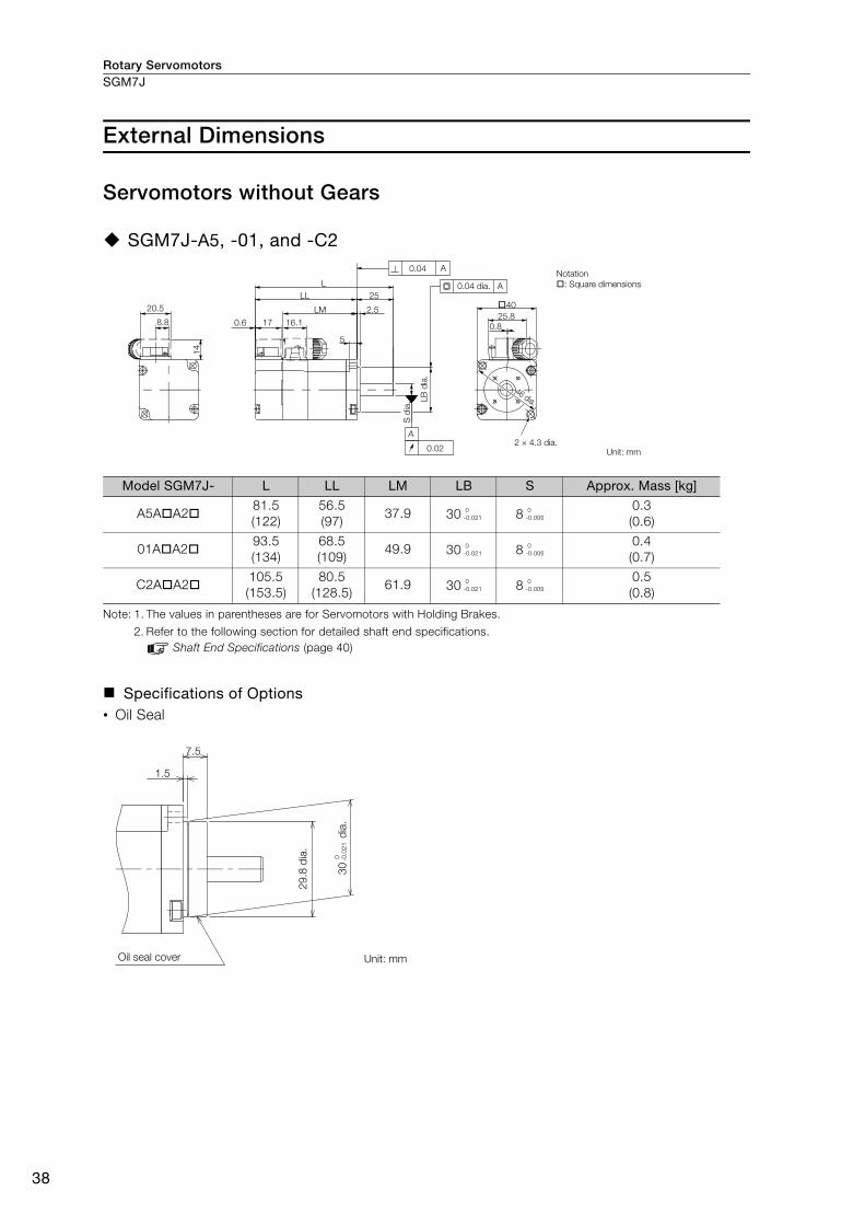
Rotary ServomotorsSGM7J
38
External Dimensions
Servomotors without Gears
SGM7J-A5, -01, and -C2
Note: 1. The values in parentheses are for Servomotors with Holding Brakes.
2. Refer to the following section for detailed shaft end specifications.
Shaft End Specifications (page 40)
Specifications of Options • Oil Seal
Model SGM7J- L LL LM LB S Approx. Mass [kg]
A5A A281.5
(122)
56.5
(97)37.9 30 8
0.3
(0.6)
01A A293.5
(134)
68.5
(109)49.9 30 8
0.4
(0.7)
C2A A2105.5
(153.5)
80.5
(128.5)61.9 30 8
0.5
(0.8)
5
14
16.1170.6
LM 2.5
25LL
L
0.8
25.8
40
8.8
20.5
0.02
0.04 A
A
A0.04 dia.
2 × 4.3 dia.Unit: mm
LB
dia
.
S d
ia.
46 dia.
Notation
: Square dimensions
0
-0.021
0
-0.009
0
-0.021
0
-0.009
0
-0.021
0
-0.009
1.5
7.5
30
dia
.
29
.8 d
ia.
Oil seal cover Unit: mm
0 -0.0
21

Rotary Servomotors SGM7J
39
Ro
tary
Serv
om
oto
rs
SGM7J-02, -04, -06, and -08
Note: 1. The values in parentheses are for Servomotors with Holding Brakes.
2. Refer to the following section for detailed shaft end specifications.
Shaft End Specifications (page 40)
Specifications of Options • Oil Seal
Model SGM7J- L LL LMFlange Dimensions
SLR LE LG LC LA LB LZ
02A A299.5
(140)
69.5
(110)51.2 30 3 6 60 70 50 5.5 14
04A A2115.5
(156)
85.5
(126)67.2 30 3 6 60 70 50 5.5 14
06A A2137.5
(191.5)
107.5
(161.5)89.2 30 3 6 60 70 50 5.5 14
08A A2137
(184)
97
(144)78.5 40 3 8 80 90 70 7 19
Model SGM7J- MD MW MH ML Approx. Mass [kg]
02A A2 8.5 28.7 14.7 17.10.8
(1.4)
04A A2 8.5 28.7 14.7 17.11.1
(1.7)
06A A2 8.5 28.7 14.7 17.11.6
(2.2)
08A A2 8.5 38 14.7 19.32.2
(2.8)
Model SGM7J- Dimensions with Oil Seal
E1 E2 LS1 LS2
02A, 04A, 06A 35 47 5.2 10
08A 47 61 5.5 11
14
0.6 17 LG
LE
LRLL
L
LCML
MH
MW
LM
MD
20.5
0.04 A
A
0.02
A0.04 dia.
4 × LZ dia. Unit: mm
LB
dia
.
S d
ia. L
A d
ia.
0
-0.025
0
-0.011
0
-0.025
0
-0.011
0
-0.025
0
-0.011
0
-0.030
0
-0.013
LE
LS1
LS2
E1
dia
.
E2
dia
.
Oil seal cover Unit: mm

Rotary ServomotorsSGM7J
40
Shaft End Specifications
SGM7J-
Code Specification
2 Straight without key
6Straight with key and tap for one location
(Key slot is JIS B1301-1996 fastening type.)
B With two flat seats
Shaft End Details Servomotor Model SGM7J-
A5 01 C2 02 04 06 08
Code: 2 (Straight without Key)
LR 25 30 40
S 8 14 19
Code: 6 (Straight with Key and Tap)
LR 25 30 40
QK 14 14 22
S 8 14 19
W 3 5 6
T 3 5 6
U 1.8 3 3.5
P M3 × 6L M5 × 8L M6 × 10L
Code: B (with Two Flat Seats)
LR 25 30 40
QH 15 15 22
S 8 14 19
H1 7.5 13 18
H2 7.5 13 18
LR
S d
ia.
0
-0.009
0
-0.011
0
-0.013
QK
Y
Y
LR
W
T
UP
S d
ia.
Cross section Y-Y
0
-0.009
0
-0.011
0
-0.013
QH
Y
Y
LR
H1
H2
S d
ia.
Cross section Y-Y
0
-0.009
0
-0.011
0
-0.013
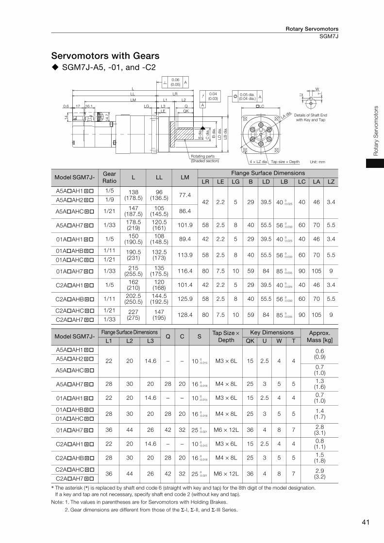
Rotary Servomotors SGM7J
41
Ro
tary
Serv
om
oto
rs
Servomotors with Gears SGM7J-A5, -01, and -C2
* The asterisk (*) is replaced by shaft end code 6 (straight with key and tap) for the 8th digit of the model designation.
If a key and tap are not necessary, specify shaft end code 2 (without key and tap).
Note: 1. The values in parentheses are for Servomotors with Holding Brakes.
2. Gear dimensions are different from those of the Σ-I, Σ-II, and Σ-III Series.
Model SGM7J- Gear Ratio
L LL LMFlange Surface Dimensions
LR LE LG B LD LB LC LA LZ
A5A AH1 1/5 138(178.5)
96(136.5)
77.4
42 2.2 5 29 39.5 40 40 46 3.4A5A AH2 1/9
A5A AHC 1/21147
(187.5)105
(145.5)86.4
A5A AH7 1/33178.5(219)
120.5(161)
101.9 58 2.5 8 40 55.5 56 60 70 5.5
01A AH1 1/5150
(190.5)108
(148.5)89.4 42 2.2 5 29 39.5 40 40 46 3.4
01A AHB 1/11 190.5(231)
132.5(173)
113.9 58 2.5 8 40 55.5 56 60 70 5.501A AHC 1/21
01A AH7 1/33215
(255.5)135
(175.5)116.4 80 7.5 10 59 84 85 90 105 9
C2A AH1 1/5162(210)
120(168)
101.4 42 2.2 5 29 39.5 40 40 46 3.4
C2A AHB 1/11202.5(250.5)
144.5(192.5)
125.9 58 2.5 8 40 55.5 56 60 70 5.5
C2A AHC 1/21 227(275)
147(195)
128.4 80 7.5 10 59 84 85 90 105 9C2A AH7 1/33
Model SGM7J- Flange Surface Dimensions
Q C STap Size ×
Depth Key Dimensions Approx.
Mass [kg]L1 L2 L3 QK U W T
A5A AH1
22 20 14.6 − − 10 M3 × 6L 15 2.5 4 4
0.6(0.9)A5A AH2
A5A AHC0.7(1.0)
A5A AH7 28 30 20 28 20 16 M4 × 8L 25 3 5 51.3(1.6)
01A AH1 22 20 14.6 − − 10 M3 × 6L 15 2.5 4 40.7(1.0)
01A AHB28 30 20 28 20 16 M4 × 8L 25 3 5 5
1.4(1.7)01A AHC
01A AH7 36 44 26 42 32 25 M6 × 12L 36 4 8 72.8(3.1)
C2A AH1 22 20 14.6 − − 10 M3 × 6L 15 2.5 4 40.8(1.1)
C2A AHB 28 30 20 28 20 16 M4 × 8L 25 3 5 51.5(1.8)
C2A AHC36 44 26 42 32 25 M6 × 12L 36 4 8 7
2.9(3.2)C2A AH7
16.1170.6
LL
LM
LG
LE
L
QK
QL3
L1 L2
14
14.7
LC
LR
A
0.04
(0.03)
0.06
(0.05)A
A
T
W
U0.05 dia.
Details of Shaft End
with Key and Tap
Rotating parts
(Shaded section) 4 × LZ dia. Tap size × Depth Unit: mm
LB
dia
.
LD
dia
.
B d
ia.
C d
ia.
S d
ia.
(0.04 dia.)
LA dia.
�* 0
-0.025�*
�*
�* 0
-0.030
�* 0
-0.025
�* 0
-0.030
�*
�* 0
-0.035
�* 0
-0.025
�* 0
-0.030
�* 0
-0.035
�*
�* 0
-0.015�*
�*
�* 0
-0.018
�* 0
-0.015
�* 0
-0.018
�*
�* 0
-0.021
�* 0
-0.015
�* 0
-0.018
�* 0
-0.021
�*
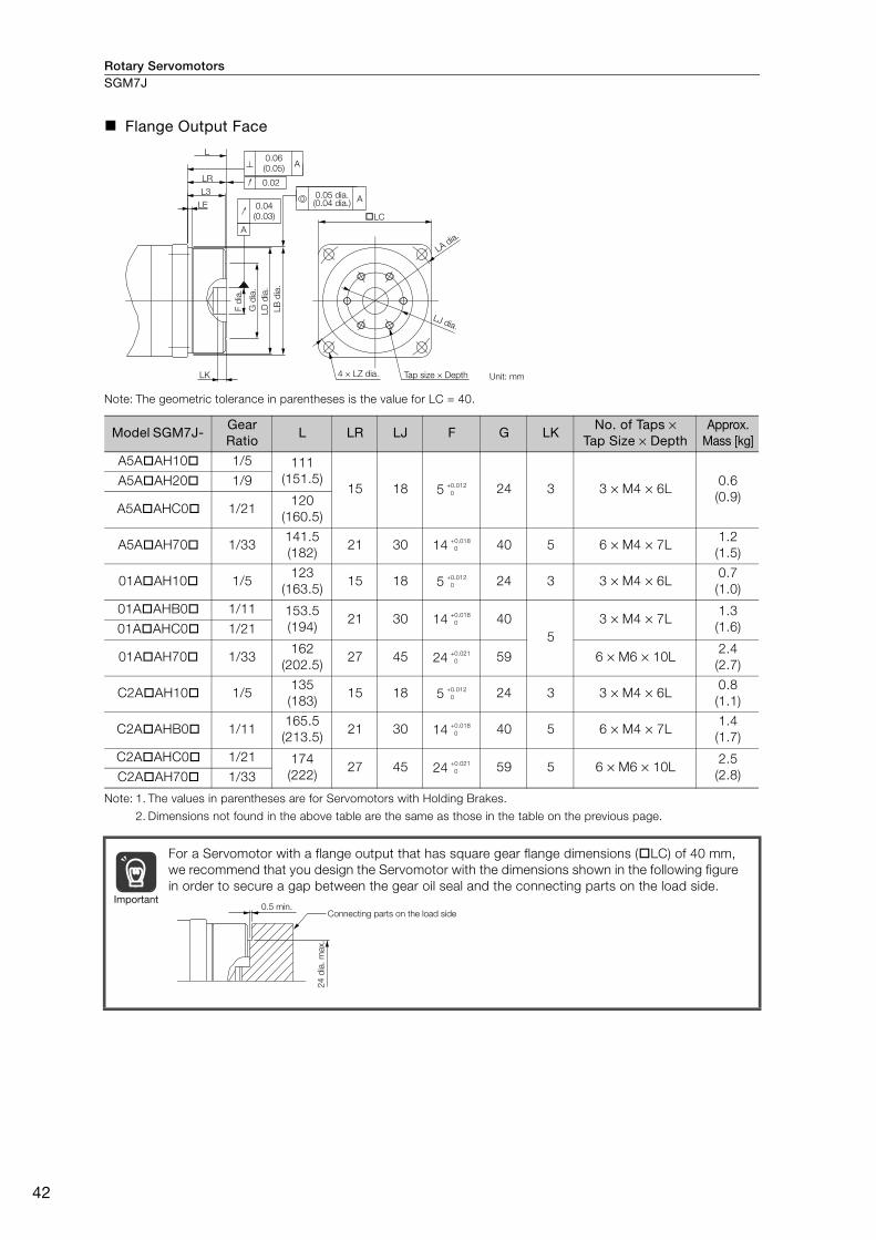
Rotary ServomotorsSGM7J
42
Flange Output Face
Note: The geometric tolerance in parentheses is the value for LC = 40.
Note: 1. The values in parentheses are for Servomotors with Holding Brakes.
2. Dimensions not found in the above table are the same as those in the table on the previous page.
Model SGM7J- Gear Ratio
L LR LJ F G LKNo. of Taps ×
Tap Size × Depth Approx.
Mass [kg]
A5A AH10 1/5 111
(151.5)15 18 5 24 3 3 × M4 × 6L
0.6
(0.9)
A5A AH20 1/9
A5A AHC0 1/21120
(160.5)
A5A AH70 1/33141.5
(182)21 30 14 40 5 6 × M4 × 7L
1.2
(1.5)
01A AH10 1/5123
(163.5)15 18 5 24 3 3 × M4 × 6L
0.7
(1.0)
01A AHB0 1/11 153.5
(194)21 30 14 40
5
3 × M4 × 7L1.3
(1.6)01A AHC0 1/21
01A AH70 1/33162
(202.5)27 45 24 59 6 × M6 × 10L
2.4
(2.7)
C2A AH10 1/5135
(183)15 18 5 24 3 3 × M4 × 6L
0.8
(1.1)
C2A AHB0 1/11165.5
(213.5)21 30 14 40 5 6 × M4 × 7L
1.4
(1.7)
C2A AHC0 1/21 174
(222)27 45 24 59 5 6 × M6 × 10L
2.5
(2.8)C2A AH70 1/33
For a Servomotor with a flange output that has square gear flange dimensions ( LC) of 40 mm,
we recommend that you design the Servomotor with the dimensions shown in the following figure
in order to secure a gap between the gear oil seal and the connecting parts on the load side.
LC
LK
L3
LE
LR
L
A
0.04
(0.03)
0.02
A
A0.06
(0.05)
0.05 dia.(0.04 dia.)
4 × LZ dia.
LB
dia
.
LD
dia
.
G d
ia.
F d
ia.
Tap size × Depth Unit: mm
LJ dia.
LA dia.
+0.012
0
+0.018
0
+0.012
0
+0.018
0
+0.021
0
+0.012
0
+0.018
0
+0.021
0
Important0.5 min.
Connecting parts on the load side
24
dia
. m
ax.

Rotary Servomotors SGM7J
43
Ro
tary
Serv
om
oto
rs
SGM7J-02, -04, and -06
* The asterisk (*) is replaced by shaft end code 6 (straight with key and tap) for the 8th digit of the model designation.
If a key and tap are not necessary, specify shaft end code 2 (without key and tap).
Note: 1. The values in parentheses are for Servomotors with Holding Brakes.
2. Gear dimensions are different from those of the Σ-I, Σ-II, and Σ-III Series.
Model SGM7J- Gear Ratio
L LL LMFlange Surface Dimensions
LR LE LG B LD LB LC LA LZ
02A AH1 1/5 191.5
(232)
133.5
(174)115.2 58 2.5 8 40 55.5 56 60 70 5.5
02A AH2 1/11
02A AHC 1/21 220.5
(261)
140.5
(181)122.2 80 7.5 10 59 84 85 90 105 9
02A AH7 1/33
04A AH1 1/5207.5
(248)
149.5
(190)131.2 58 2.5 8 40 55.5 56 60 70 5.5
04A AHB 1/11 236.5
(277)
156.5
(197)138.2 80 7.5 10 59 84 85 90 105 9
04A AHC 1/21
04A AH7 1/33322.5
(363)
189.5
(230)171.2 133 12.5 13 84 114 115 120 135 11
06A AH1 1/5 258.5
(312.5)
178.5
(232.5)160.2 80 7.5 10 59 84 85 90 105 9
06A AHB 1/11
06A AHC 1/21 344.5
(398.5)
211.5
(265.5)193.2 133 12.5 13 84 114 115 120 135 11
06A AH7 1/33
Model SGM7J- Flange Surface Dimensions
Q C STap Size ×
Depth Key Dimensions Approx.
Mass [kg]L1 L2 L3 QK U W T
02A AH1
28 30 20 28 20 16 M4 × 8L 25 3 5 5
1.8
(2.4)
02A AH21.9
(2.5)
02A AHC36 44 26 42 32 25 M6 × 12L 36 4 8 7
3.7
(4.3)02A AH7
04A AH1 28 30 20 28 20 16 M4 × 8L 25 3 5 52.1
(2.7)
04A AHB36 44 26 42 32 25 M6 × 12L 36 4 8 7
4.0
(4.6)04A AHC
04A AH7 48 85 33 82 44 40 M10 × 20L 70 5 12 88.6
(9.2)
06A AH1
36 44 26 42 32 25 M6 × 12L 36 4 8 7
4.3
(4.9)
06A AHB4.5
(5.1)
06A AHC48 85 33 82 44 40 M10 × 20L 70 5 12 8
9.1
(9.7)06A AH7
0.6 17 LE
LG L3
L1
LL
LM
14
.7
14
L
L2
Q
QK
LC
LR
17.1
0.06 A
0.04
0.05 A
A
U
W
T
Details of Shaft End
with Key and Tap
LB
dia
.
LD
dia
.
B d
ia.
C d
ia.
S d
ia.
Unit: mmTap size × Depth4 × LZ dia.
Rotating parts
(Shaded section)
LA dia.
�* 0
-0.030
�*
�* 0
-0.035
�*
�* 0
-0.030
�* 0
-0.035
�*
�* 0
-0.035
�* 0
-0.035
�*
�* 0
-0.035
�*
�* 0
-0.018
�*
�* 0
-0.021
�*
�* 0
-0.018
�* 0
-0.021
�*
�* 0
-0.025
�* 0
-0.021
�*
�* 0
-0.025
�*
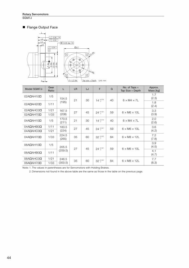
Rotary ServomotorsSGM7J
44
Flange Output Face
Note: 1. The values in parentheses are for Servomotors with Holding Brakes.
2. Dimensions not found in the above table are the same as those in the table on the previous page.
Model SGM7J- Gear Ratio
L LR LJ F GNo. of Taps ×
Tap Size × Depth Approx.
Mass [kg]
02A AH10 1/5154.5
(195)21 30 14 40 6 × M4 × 7L
1.7
(2.3)
02A AH20 1/111.8
(2.4)
02A AHC0 1/21 167.5
(208)27 45 24 59 6 × M6 × 10L
3.3
(3.9)02A AH70 1/33
04A AH10 1/5170.5
(211)21 30 14 40 6 × M4 × 7L
2.0
(2.6)
04A AHB0 1/11 183.5
(224)27 45 24 59 6 × M6 × 10L
3.6
(4.2)04A AHC0 1/21
04A AH70 1/33224.5
(265)35 60 32 84 6 × M8 × 12L
7.2
(7.8)
06A AH10 1/5205.5
(259.5)27 45 24 59 6 × M6 × 10L
3.9
(4.5)
06A AHB0 1/114.1
(4.7)
06A AHC0 1/21 246.5
(300.5)35 60 32 84 6 × M8 × 12L
7.7
(8.3)06A AH70 1/33
LC
5
LE
LR
L
L3A
0.06 A
A
0.04
0.02
0.05 dia.
Unit: mmTap size × Depth4 × LZ dia.
LB
dia
.
LD
dia
.
G d
ia.
F d
ia.
LJ dia.
LA dia.
+0.018
0
+0.021
0
+0.018
0
+0.021
0
+0.025
0
+0.021
0
+0.025
0

Rotary Servomotors SGM7J
45
Ro
tary
Serv
om
oto
rs
SGM7J-08
* The asterisk (*) is replaced by shaft end code 6 (straight with key and tap) for the 8th digit of the model designation.
If a key and tap are not necessary, specify shaft end code 2 (without key and tap).
Note: 1. The values in parentheses are for Servomotors with Holding Brakes.
2. Gear dimensions are different from those of the Σ-I, Σ-II, and Σ-III Series.
Model SGM7J- Gear Ratio
L LL LMFlange Surface Dimensions
LR LE LG B LD LB LC LA LZ
08A AH1 1/5 255
(302)
175
(222)156.5 80 7.5 10 59 84 85 90 105 9
08A AHB 1/11
08A AHC 1/21 334
(381)
201
(248)182.5 133 12.5 13 84 114 115 120 135 11
08A AH7 1/33
Model SGM7J- Flange Surface Dimensions
Q C STap Size ×
Depth Key Dimensions Approx.
Mass [kg]L1 L2 L3 QK U W T
08A AH1
36 44 26 42 32 25 M6 × 12L 36 4 8 7
5.1
(5.7)
08A AHB5.3
(5.9)
08A AHC48 85 33 82 44 40 M10 × 20L 70 5 12 8
10
(10.6)08A AH7
17
17
14
0.6 19.3
L
L3
LE
L1 L2LR
QQK
LG
LM
C d
ia.
B d
ia.
LD
dia
.
LB
dia
.
S d
ia.
LL
LA dia.
LC
W
U T
0.05 A
0.04A
0.06 A
4 × LZ dia.
Details of Shaft End with Key and Tap
Unit: mm
Tap size × DepthRotating parts
(Shaded section)
�* 0
-0.035
�*
�* 0
-0.035
�*
�* 0
-0.021
�*
�* 0
-0.025
�*

Rotary ServomotorsSGM7J
46
Flange Output Face
Note: 1. The values in parentheses are for Servomotors with Holding Brakes.
2. Dimensions not found in the above table are the same as those in the table on the previous page.
Model SGM7J- Gear Ratio L LR LJ F GNo. of Taps ×
Tap Size × Depth Approx.
Mass [kg]
08A AH101 1/5202
(249)27 45 24 59 6 × M6 × 10L
4.7
(5.3)
08A AHB01 1/114.9
(5.5)
08A AHC01 1/21 236
(283)35 60 32 84 6 × M8 × 12L
8.6
(9.2)08A AH701 1/33
LC
5
LE
LR
L
L3A
0.06 A
A
0.04
0.02
0.05 dia.
Unit: mmTap size × Depth4 × LZ dia.
LB
dia
.
LD
dia
.
G d
ia.
F d
ia.
LA dia.
LJ dia.
+0.021
0
+0.025
0
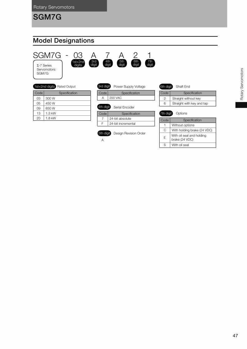
Rotary Servomotors
47
Ro
tary
Serv
om
oto
rs
SGM7G
Model Designations
1
7
F
03 300 W
05 450 W
09 850 W
13 1.3 kW
20 1.8 kW
2
6
A
3rd digit Power Supply Voltage
4th digit Serial Encoder
5th digit Design Revision Order
Code
24-bit absolute
24-bit incremental
Specification
Code Specification
6th digit Shaft End
7th digit Options
Without options
With holding brake (24 VDC)
With oil seal and holding
brake (24 VDC)
With oil seal
Straight without key
Code Specification
Straight with key and tap
Code SpecificationCode Specification
C
E
S
A 200 VAC
1st+2nd digits Rated Output
Σ-7 Series
Servomotors:
SGM7G
SGM7G - 03 A 7 A 2 11st+2nd
digits
3rd digit
4th digit
5th digit
6th digit
7th digit

Rotary ServomotorsSGM7G
48
Ratings and Specifications
Specifications
*1. A vibration class of V15 indicates a vibration amplitude of 15 μm maximum on the Servomotor without a load at
the rated motor speed.
*2. The shock resistance for shock in the vertical direction when the Servomotor is mounted with the shaft in a hor-
izontal position is given in the above table.
*3. The vertical, side-to-side, and front-to-back vibration resistance for vibration in three directions when the Servo-
motor is mounted with the shaft in a horizontal position is given in the above table. The strength of the vibration
that the Servomotor can withstand depends on the application. Always check the vibration acceleration rate
that is applied to the Servomotor with the actual equipment.
*4. If the ambient temperature will exceed 40°C, refer to the following section.
Applications Where the Ambient Temperature of the Servomotor Exceeds 40°C (page 52)
*5. If the altitude will exceed 1,000 m, refer to the following section.
Applications Where the Altitude of the Servomotor Exceeds 1,000 m (page 53)
Voltage 200 V
Model SGM7G- 03A 05A 09A 13A 20A
Time Rating Continuous
Thermal Class F
Insulation Resistance 500 VDC, 10 MΩ min.
Withstand Voltage 1,500 VAC for 1 minute
Excitation Permanent magnet
Mounting Flange-mounted
Drive Method Direct drive
Rotation Direction Counterclockwise (CCW) for forward reference when viewed from the load side
Vibration Class*1 V15
Environmen-
tal Condi-
tions
Surrounding Air Temperature 0°C to 40°C (With derating, usage is possible between 40°C and 60°C.)*4
Surrounding Air Humidity 20% to 80% relative humidity (with no condensation)
Installation Site
• Must be indoors and free of corrosive and explosive gases.
• Must be well-ventilated and free of dust and moisture.
• Must facilitate inspection and cleaning.
• Must have an altitude of 1,000 m or less. (With derating, usage
is possible between 1,000 m and 2,000 m.)*5
• Must be free of strong magnetic fields.
Storage Environment
Store the Servomotor in the following environment if you store it with the
power cable disconnected.
Storage Temperature: -20°C to 60°C (with no freezing)
Storage Humidity: 20% to 80% relative humidity
(with no condensation)
Shock
Resistance*2Impact Acceleration Rate at Flange 490 m/s2
Number of Impacts 2 times
Vibration
Resistance*3Vibration Acceleration
Rate at Flange49 m/s2 (24.5 m/s2 front to back)
Applicable SERVOPACKs Refer to the following section.
Σ-7 Series Combination (page M-18)
Vertical
Shock Applied to the Servomotor
Vertical
Horizontal direction
Vibration Applied to the Servomotor
Front to back
Side to side
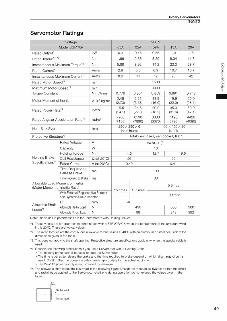
Rotary Servomotors SGM7G
49
Ro
tary
Serv
om
oto
rs
Servomotor Ratings
Note: The values in parentheses are for Servomotors with Holding Brakes.
*1. These values are for operation in combination with a SERVOPACK when the temperature of the armature wind-
ing is 20°C. These are typical values.
*2. The rated torques are the continuous allowable torque values at 40°C with an aluminum or steel heat sink of the
dimensions given in the table.
*3. This does not apply to the shaft opening. Protective structure specifications apply only when the special cable is
used.
*4. Observe the following precautions if you use a Servomotor with a Holding Brake.
• The holding brake cannot be used to stop the Servomotor.
• The time required to release the brake and the time required to brake depend on which discharge circuit is
used. Confirm that the operation delay time is appropriate for the actual equipment.
• The 24-VDC power supply is not provided by Yaskawa.
*5. The allowable shaft loads are illustrated in the following figure. Design the mechanical system so that the thrust
and radial loads applied to the Servomotor shaft end during operation do not exceed the values given in the
table.
Voltage 200 V
Model SGM7G- 03A 05A 09A 13A 20A
Rated Output*1 kW 0.3 0.45 0.85 1.3 1.8
Rated Torque*1, *2 N m 1.96 2.86 5.39 8.34 11.5
Instantaneous Maximum Torque*1 N m 5.88 8.92 14.2 23.3 28.7
Rated Current*1 Arms 2.8 3.8 6.9 10.7 16.7
Instantaneous Maximum Current*1 Arms 8.0 11 17 28 42
Rated Motor Speed*1 min-1 1500
Maximum Motor Speed*1 min-1 3000
Torque Constant N m/Arms 0.776 0.854 0.859 0.891 0.748
Motor Moment of Inertia ×10-4 kg m22.48
(2.73)
3.33
(3.58)
13.9
(16.0)
19.9
(22.0)
26.0
(28.1)
Rated Power Rate*1 kW/s15.5
(14.1)
24.6
(22.8)
20.9
(18.2)
35.0
(31.6)
50.9
(47.1)
Rated Angular Acceleration Rate*1 rad/s2 7900
(7180)
8590
(7990)
3880
(3370)
4190
(3790)
4420
(4090)
Heat Sink Size mm250 × 250 × 6
(aluminum)
400 × 400 × 20
(steel)
Protective Structure*3 Totally enclosed, self-cooled, IP67
Holding Brake
Specifications*4
Rated Voltage V 24 VDC
Capacity W 10
Holding Torque N m 4.5 12.7 19.6
Coil Resistance Ω (at 20°C) 56 59
Rated Current A (at 20°C) 0.42 0.41
Time Required to
Release Brake ms 100
Time Required to Brake ms 80
Allowable Load Moment of Inertia
(Motor Moment of Inertia Ratio) 15 times 15 times
5 times
With External Regenerative Resistor
and Dynamic Brake Resistor10 times
Allowable Shaft
Loads*5
LF mm 40 58
Allowable Radial Load N 490 686 980
Allowable Thrust Load N 98 343 392
+10%
0
LF
Radial load
Thrust load
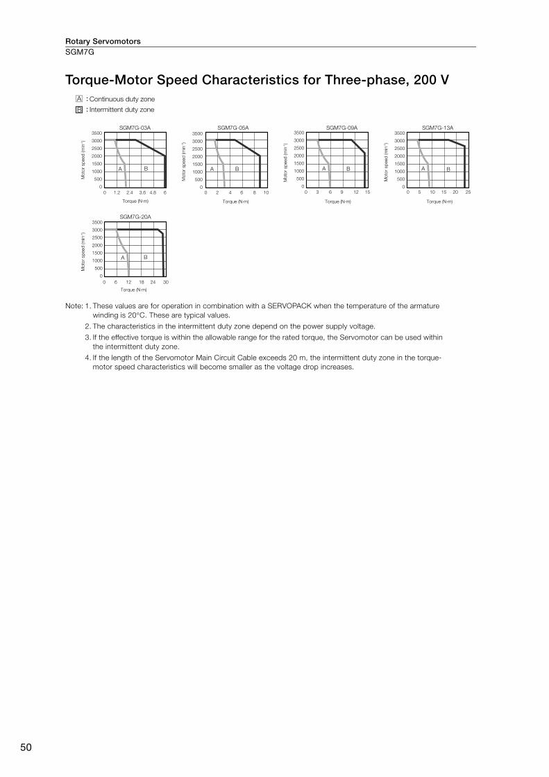
Rotary ServomotorsSGM7G
50
Torque-Motor Speed Characteristics for Three-phase, 200 V
Note: 1. These values are for operation in combination with a SERVOPACK when the temperature of the armature
winding is 20°C. These are typical values.
2. The characteristics in the intermittent duty zone depend on the power supply voltage.
3. If the effective torque is within the allowable range for the rated torque, the Servomotor can be used within
the intermittent duty zone.
4. If the length of the Servomotor Main Circuit Cable exceeds 20 m, the intermittent duty zone in the torque-
motor speed characteristics will become smaller as the voltage drop increases.
SGM7G-03A SGM7G-05A SGM7G-09A
SGM7G-20A
SGM7G-13A
:
:
A B
A B A B A B
Continuous duty zone
Torque (N·m) Torque (N·m) Torque (N·m) Torque (N·m)
Intermittent duty zone
3500
3000
2500
2000
1500
1000
500
0
0 1.2 2.4 3.6 4.8 6
Mo
tor sp
eed
(m
in-1)
Mo
tor sp
eed
(m
in-1)
Mo
tor sp
eed
(m
in-1)
Mo
tor sp
eed
(m
in-1)
Mo
tor sp
eed
(m
in-1)
Torque (N·m)
0 2 4 6 8 10
3500
3000
2500
2000
1500
1000
500
0
3500
3000
2500
2000
1500
1000
500
0
0 3 6 9 12 15
3500
3000
2500
2000
1500
1000
500
0
3500
3000
2500
2000
1500
1000
500
0
0 5 10 15 20 25
A B
0 6 12 18 24 30
A :
B :
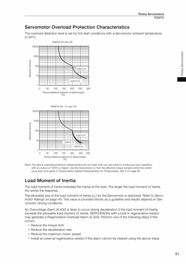
Rotary Servomotors SGM7G
51
Ro
tary
Serv
om
oto
rs
Servomotor Overload Protection Characteristics The overload detection level is set for hot start conditions with a Servomotor ambient temperature
of 40°C.
Note: The above overload protection characteristics do not mean that you can perform continuous duty operation
with an output of 100% or higher. Use the Servomotor so that the effective torque remains within the contin-
uous duty zone given in Torque-Motor Speed Characteristics for Three-phase, 200 V on page 50.
Load Moment of Inertia The load moment of inertia indicates the inertia of the load. The larger the load moment of inertia,
the worse the response.
The allowable size of the load moment of inertia (JL) for the Servomotor is restricted. Refer to Servo-motor Ratings on page 49. This value is provided strictly as a guideline and results depend on Ser-
vomotor driving conditions.
An Overvoltage Alarm (A.400) is likely to occur during deceleration if the load moment of inertia
exceeds the allowable load moment of inertia. SERVOPACKs with a built-in regenerative resistor
may generate a Regenerative Overload Alarm (A.320). Perform one of the following steps if this
occurs.
• Reduce the torque limit.
• Reduce the deceleration rate.
• Reduce the maximum motor speed.
• Install an external regenerative resistor if the alarm cannot be cleared using the above steps.
SGM7G-03 and -05
0 50 100 150 200 250 300
10000
1000
100
10
1
SGM7G-09, -13, and -20
0 50 100 150 200 250 300
10000
1000
100
10
1
Dete
ctio
n t
ime (s)
Dete
ctio
n t
ime (s)
Torque reference (percent of rated torque) (%)
Torque reference (percent of rated torque) (%)
SGM7G-05
SGM7G-03
SGM7G-09
SGM7G-13
SGM7G-20

Rotary ServomotorsSGM7G
52
Servomotor Heat Dissipation Conditions The Servomotor ratings are the continuous allowable values at an ambient temperature of 40°C
when a heat sink is installed on the Servomotor. If the Servomotor is mounted on a small device
component, the Servomotor temperature may rise considerably because the surface for heat dissi-
pation becomes smaller. Refer to the following graphs for the relation between the heat sink size
and derating rate.
Note: The derating rates are applicable only when the average motor speed is less than or equal to the rated motor
speed. If the average motor speed exceeds the rated motor speed, consult with your Yaskawa representa-
tive.
Applications Where the Ambient Temperature of the Servomotor Exceeds 40°C The Servomotor ratings are the continuous allowable values at an ambient temperature of 40°C. If
you use a Servomotor at an ambient temperature that exceeds 40°C (60°C max.), apply a suitable
derating rate from the following graphs.
Note: The derating rates are applicable only when the average motor speed is less than or equal to the rated motor
speed. If the average motor speed exceeds the rated motor speed, consult with your Yaskawa representa-
tive.
The actual temperature rise depends on how the heat sink (i.e., the Servomotor mounting sec-
tion) is attached to the installation surface, what material is used for the Servomotor mounting
section, and the motor speed. Always check the Servomotor temperature with the actual equip-
ment.Important
0 150 250 30020010050 0 300 400200100
Dera
ting
rate
(%
)
Heat sink size (mm) Heat sink size (mm)
Dera
ting
rate
(%
)
100
80
120
60
40
20
0
SGM7G-03 and -05 SGM7G-09, -13, and -20
100
80
120
60
40
20
0
Ambient temperature (°C)
0 30 50 60402010
Dera
ting
rate
(%
)
Dera
ting
rate
(%
)
100
80
120
60
40
20
0
SGM7G-03 and -05 SGM7G-09, -13, and -20
100
80
120
60
40
20
0
Ambient temperature (°C)
70 0 30 50 60402010 70

Rotary Servomotors SGM7G
53
Ro
tary
Serv
om
oto
rs
Applications Where the Altitude of the Servomotor Exceeds 1,000 m The Servomotor ratings are the continuous allowable values at an altitude of 1,000 m or less. If you
use a Servomotor at an altitude that exceeds 1,000 m (2,000 m max.), the heat dissipation effect of
the air is reduced. Apply the appropriate derating rate from the following graphs.
Note: The derating rates are applicable only when the average motor speed is less than or equal to the rated motor
speed. If the average motor speed exceeds the rated motor speed, consult with your Yaskawa representa-
tive.
Altitude (m)
0 1500 20001000500
Dera
ting
rate
(%
)
Dera
ting
rate
(%
)
SGM7G-03 and -05 SGM7G-09, -13, and -20
100
80
120
60
40
20
0
Altitude (m)
25000 1500 20001000500
100
80
120
60
40
20
02500

Rotary ServomotorsSGM7G
54
External Dimensions
Servomotors without Holding Brakes
SGM7G-03 and -05
Note: Servomotors with Oil Seals have the same dimensions.
* The L, LR, S, and Q dimensions of these Servomotors are different from those of the Σ-V-series SGMGV Servomotors.
Models that have the same installation dimensions as the SGMGV Servomotors are also available. Contact your
Yaskawa representative for details.
Refer to the following section for information on connectors.
SGM7G-03 and -05 without Holding Brakes (page 57)
SGM7G-09, -13, and -20
Note: Servomotors with Oil Seals have the same dimensions.
* The S dimensions of these Servomotors are different from those of the Σ-V-series SGMGV Servomotors.
Models that have the same installation dimensions as the SGMGV Servomotors are also available. Contact your
Yaskawa representative for details.
Refer to the following section for information on connectors.
SGM7G-09, -13, and -20 without Holding Brakes (page 57)
Model SGM7G-
L LL LM LR KB1 KB2 LBShaft End Dimensions Approx.
Mass [kg]S Q
03A A21 166* 126 90 40* 75 114 80 16 * 30* 2.6
05A A21 179 139 103 40 88 127 80 16 30 3.2
Model SGM7G-
L LL LM LR KB1 KB2 IE KL1Flange Surface Dimensions
Shaft End Dimensions Approx.
Mass [kg]LA LB LC LE LG LH LZ S Q
09A A21 195 137 101 58 83 125 − 104 145 110 130 6 12 165 9 24 * 40 5.5
13A A21 211 153 117 58 99 141 − 104 145 110 130 6 12 165 9 24 * 40 7.1
20A A21 229 171 135 58 117 159 − 104 145 110 130 6 12 165 9 24 40 8.6
R1
Q
5
LR
90
50
1738
LLL
LM36LR
510
KB1
KB2
70
A
A
A
0.02
0.04 dia.
79
dia
.
4 × 6.6 dia.
Shaft End Details
Unit: mm
0.04
S d
ia.
18
dia
.
S d
ia.
35
dia
.
LB
dia
.
120 dia.
100 dia.
Notation
: Square dimensions
Refer to Shaft End Specifications
on page 56 for details.
0-0.030
0
-0.011
0-0.030
0-0.011
17
36
L
LL LR
LM
LG LE
50
KL1
KB1
KB2
IE
0.04 A
A
0.02
A
LC
R1
LR
LE
Q
79 d
ia.
S d
ia.
LB
dia
.
S d
ia.
45
dia
.
0.04 dia.
4 × LZ dia.
Unit: mm
Shaft End Details
LH dia.
LA dia.
28
dia
.
Refer to Shaft End Specifications
on page 56 for details.
0-0.035
0
-0.013
0-0.035
0
-0.013
0-0.035
0
-0.013

Rotary Servomotors SGM7G
55
Ro
tary
Serv
om
oto
rs
Servomotors with Holding Brakes
SGM7G-03 and -05
Note: Servomotors with Oil Seals have the same dimensions.
* The L, LR, S, and Q dimensions of these Servomotors are different from those of the Σ-V-series SGMGV Servomotors.
Models that have the same installation dimensions as the SGMGV Servomotors are also available. Contact your
Yaskawa representative for details.
Refer to the following section for information on connectors.
SGM7G-03 and -05 with Holding Brakes (page 57)
SGM7G-09, -13, and -20
Note: Servomotors with Oil Seals have the same dimensions.
* The S dimensions of these Servomotors are different from those of the Σ-V-series SGMGV Servomotors.
Models that have the same installation dimensions as the SGMGV Servomotors are also available. Contact your
Yaskawa representative for details.
Refer to the following section for information on connectors.
SGM7G-09, -13, and -20 with Holding Brakes (page 58)
Model SGM7G-
L LL LM LR KB1 KB2 LBShaft End Dimensions Approx.
Mass [kg]S Q
03A A2C 199* 159 123 40* 75 147 80 16 * 30* 3.6
05A A2C 212 172 136 40 88 160 80 16 30 4.2
Model SGM7G-
L LL LM LR KB1 KB2 KB3 IE KL1 KL3Flange Surface Dimensions
Shaft End Dimensions Approx.
Mass [kg]LA LB LC LE LG LH LZ S Q
09A A2C 231 173 137 58 83 161 115 − 104 80 145 110 130 6 12 165 9 24 * 40 7.5
13A A2C 247 189 153 58 99 177 131 − 104 80 145 110 130 6 12 165 9 24 * 40 9.0
20A A2C 265 207 171 58 117 195 149 − 104 80 145 110 130 6 12 165 9 24 40 11.0
R1
S d
ia.
Q 18
dia
.
5
LR90
KB1
KB2
10 5LM
LL
L
LR36
70 5
0
1738
A
0.04 A
A
0.02
79
dia
.0.04 dia.
4 × 6.6 dia.
Shaft End Details
Unit: mm
120 dia.
100 dia.
LB
dia
.
35
dia
.
S d
ia.
Refer to Shaft End Specifications
on page 56 for details.
0-0.030
0-0.011
0-0.030
0-0.011
LE
LR
Q
R1
36
1711
IE
LELG
LL
L
LR
LM
KB1
KB3
KB2
KL1
KL3 5
0
0.02
A
0.04 A
ALC
79
dia
.
S d
ia.
LB
dia
.
28
dia
.
S d
ia.
45
dia
.
0.04 dia.
4 × LZ dia.
Unit: mm
Shaft End Details
LH dia.
LA dia.
Refer to Shaft End Specifications
on page 56 for details.
0-0.035
0
-0.013
0-0.035
0
-0.013
0-0.035
0
-0.013

Rotary ServomotorsSGM7G
56
Shaft End Specifications
SGM7G-
* The shaft end dimensions of these Servomotors are different from those of the Σ-V-series SGMGV Servomotors.
Models that have the same installation dimensions as the SGMGV Servomotors are also available. Contact your
Yaskawa representative for details.
Code Specification
2 Straight without key
6Straight with key and tap for one location
(Key slot is JIS B1301-1996 fastening type.)
Shaft End Details Servomotor Model SGM7G-
03 05 09 13 20
Code: 2 (Straight without Key)
LR 40* 40 58 58 58
Q 30* 30 40 40 40
S 16 * 16 24 * 24 * 24
Code: 6 (Straight with Key and Tap)
LR 40* 40 58 58 58
Q 30* 30 40 40 40
QK 20* 20 25 25 25
S 16 * 16 24 * 24 * 24
W 5 5 8* 8* 8
T 5 5 7* 7* 7
U 3 3 4* 4* 4
P M5 screw, Depth: 12
LR
Q
R1S dia.
0-0.011
0-0.011
0-0.013
0-0.013
0-0.013
LR
Q
QK
UR1
P
T
W
S d
ia.
0-0.011
0-0.011
0-0.013
0-0.013
0-0.013
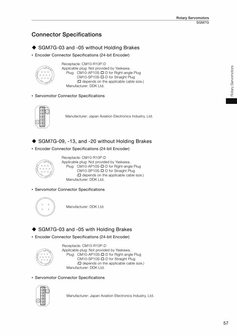
Rotary Servomotors SGM7G
57
Ro
tary
Serv
om
oto
rs
Connector Specifications
SGM7G-03 and -05 without Holding Brakes • Encoder Connector Specifications (24-bit Encoder)
• Servomotor Connector Specifications
SGM7G-09, -13, and -20 without Holding Brakes • Encoder Connector Specifications (24-bit Encoder)
• Servomotor Connector Specifications
SGM7G-03 and -05 with Holding Brakes • Encoder Connector Specifications (24-bit Encoder)
• Servomotor Connector Specifications
Receptacle: CM10-R10P-D
Applicable plug: Not provided by Yaskawa.
Plug: CM10-AP10S- -D for Right-angle Plug
CM10-SP10S- -D for Straight Plug
( depends on the applicable cable size.)
Manufacturer: DDK Ltd.
Manufacturer: Japan Aviation Electronics Industry, Ltd.
Receptacle: CM10-R10P-D
Applicable plug: Not provided by Yaskawa.
Plug: CM10-AP10S- -D for Right-angle Plug
CM10-SP10S- -D for Straight Plug
( depends on the applicable cable size.)
Manufacturer: DDK Ltd.
Manufacturer: DDK Ltd.
Receptacle: CM10-R10P-D
Applicable plug: Not provided by Yaskawa.
Plug: CM10-AP10S- -D for Right-angle Plug
CM10-SP10S- -D for Straight Plug
( depends on the applicable cable size.)
Manufacturer: DDK Ltd.
Manufacturer: Japan Aviation Electronics Industry, Ltd.

Rotary ServomotorsSGM7G
58
SGM7G-09, -13, and -20 with Holding Brakes • Encoder Connector Specifications (24-bit Encoder)
• Servomotor Connector Specifications
• Brake Connector Specifications
Receptacle: CM10-R10P-D
Applicable plug: Not provided by Yaskawa.
Plug: CM10-AP10S- -D for Right-angle Plug
CM10-SP10S- -D for Straight Plug
( depends on the applicable cable size.)
Manufacturer: DDK Ltd.
Manufacturer: DDK Ltd.
Receptacle: CM10-R2P-D
Applicable plug: Not provided by Yaskawa.
Plug: CM10-AP2S- -D for Right-angle Plug
CM10-SP2S- -D for Straight Plug
( depends on the applicable cable size.)
Manufacturer: DDK Ltd.

SGMCS ................................................................ 60
SGMCV ................................................................. 79
Direct Drive Servomotors
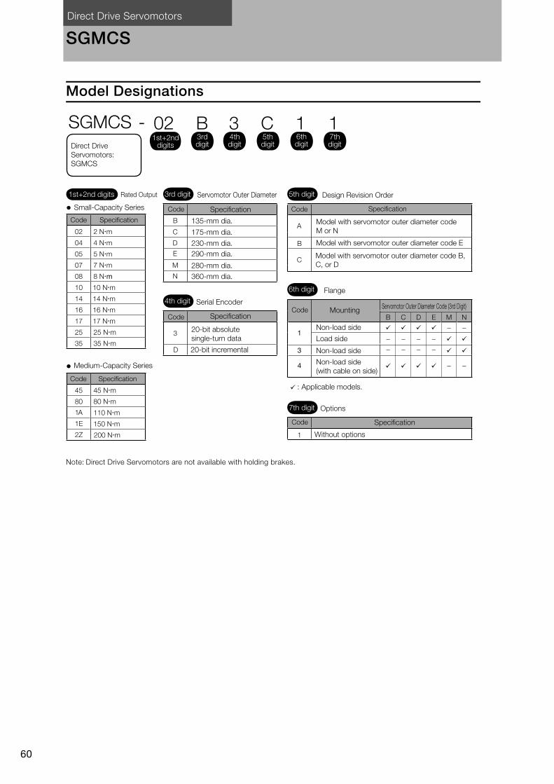
Direct Drive Servomotors
60
SGMCS
Model Designations
Note: Direct Drive Servomotors are not available with holding brakes.
A
B
C
B
C
D
E
M
N
3
D
B
−−
C
−−
D
−−
E
−−
M
−
−
N
−
−
1
3
4
1
02 2 N m
04 4 N m
05 5 N m
07 7 N m
08 8 N m
10 10 N m
14 14 N m
16 16 N m
17 17 N m
25 25 N m
35 35 N m
45 45 N m
80 80 N m
1A 110 N m
1E 150 N m
2Z 200 N m
3rd digit 5th digit
6th digit
7th digit
Small-Capacity Series
Medium-Capacity Series
Model with servomotor outer diameter code
M or N
Model with servomotor outer diameter code E
Model with servomotor outer diameter code B,
C, or D
135-mm dia.
Specification
175-mm dia.
230-mm dia.
290-mm dia.
280-mm dia.
360-mm dia.
Servomotor Outer Diameter
4th digit Serial Encoder
Specification
20-bit absolute
single-turn data
20-bit incremental
Design Revision Order
Flange
Mounting
Non-load side
Load side
Non-load side
Non-load side
(with cable on side)
: Applicable models.
Options
Without options
Servomotor Outer Diameter Code (3rd Digit)
SGMCS - 02 B 3 C 1 11st+2nd
digits
1st+2nd digits Rated Output
Specification
Code Specification
3rd digit
4th digit
5th digit
6th digit
7th digitDirect Drive
Servomotors:
SGMCS
Code
Code Specification
SpecificationCode
Code
Code
Code
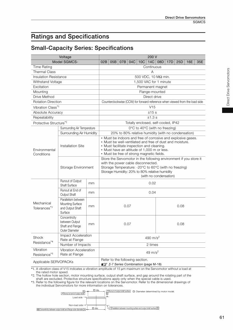
Direct Drive Servomotors SGMCS
61
Direct
Drive S
erv
om
oto
rs
Ratings and Specifications
Small-Capacity Series: Specifications
*1. A vibration class of V15 indicates a vibration amplitude of 15 μm maximum on the Servomotor without a load at the rated motor speed.
*2. The hollow hole section, motor mounting surface, output shaft surface, and gap around the rotating part of the shaft are excluded. Protective structure specifications apply only when the special cable is used.
*3. Refer to the following figure for the relevant locations on the Servomotor. Refer to the dimensional drawings of the individual Servomotors for more information on tolerances.
Voltage 200 VModel SGMCS- 02B 05B 07B 04C 10C 14C 08D 17D 25D 16E 35E
Time Rating Continuous
Thermal Class A
Insulation Resistance 500 VDC, 10 MΩ min.
Withstand Voltage 1,500 VAC for 1 minute
Excitation Permanent magnet
Mounting Flange-mounted
Drive Method Direct drive
Rotation Direction Counterclockwise (CCW) for forward reference when viewed from the load side
Vibration Class*1 V15
Absolute Accuracy ±15 s
Repeatability ±1.3 s
Protective Structure*2 Totally enclosed, self-cooled, IP42
Environmental
Conditions
Surrounding Air Temperature 0°C to 40°C (with no freezing)
Surrounding Air Humidity 20% to 80% relative humidity (with no condensation)
Installation Site
• Must be indoors and free of corrosive and explosive gases. • Must be well-ventilated and free of dust and moisture. • Must facilitate inspection and cleaning. • Must have an altitude of 1,000 m or less.• Must be free of strong magnetic fields.
Storage Environment
Store the Servomotor in the following environment if you store it
with the power cable disconnected.
Storage Temperature: -20°C to 60°C (with no freezing)
Storage Humidity: 20% to 80% relative humidity
(with no condensation)
Mechanical
Tolerances*3
Runout of Output
Shaft Surface mm 0.02
Runout at End of
Output Shaft mm 0.04
Parallelism between
Mounting Surface
and Output Shaft
Surface
mm 0.07 0.08
Concentricity
between Output
Shaft and Flange
Outer Diameter
mm 0.07 0.08
Shock
Resistance*4
Impact Acceleration
Rate at Flange490 m/s2
Number of Impacts 2 times
Vibration
Resistance*5Vibration Acceleration
Rate at Flange49 m/s2
Applicable SERVOPACKs Refer to the following section.
Σ-7 Series Combination (page M-18)
A
AB
B
dia.
dia.
Runout of output shaft surface
Parallelism between mounting surface and output shaft surface
Runout at end of output shaft
Load side
Non-load side
Concentricity between output shaft and flange outer diameter
: Diameter determined by motor model.
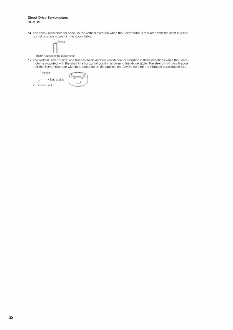
Direct Drive ServomotorsSGMCS
62
*4. The shock resistance for shock in the vertical direction when the Servomotor is mounted with the shaft in a hor-izontal position is given in the above table.
*5. The vertical, side-to-side, and front-to-back vibration resistance for vibration in three directions when the Servo-motor is mounted with the shaft in a horizontal position is given in the above table. The strength of the vibration that the Servomotor can withstand depends on the application. Always confirm the vibration acceleration rate.
Vertical
Shock Applied to the Servomotor
Vertical
Front to back
Side to side
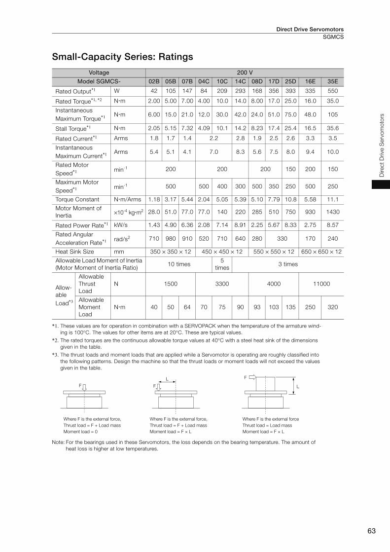
Direct Drive Servomotors SGMCS
63
Direct
Drive S
erv
om
oto
rs
Small-Capacity Series: Ratings
*1. These values are for operation in combination with a SERVOPACK when the temperature of the armature wind-
ing is 100°C. The values for other items are at 20°C. These are typical values.
*2. The rated torques are the continuous allowable torque values at 40°C with a steel heat sink of the dimensions
given in the table.
*3. The thrust loads and moment loads that are applied while a Servomotor is operating are roughly classified into
the following patterns. Design the machine so that the thrust loads or moment loads will not exceed the values
given in the table.
Note: For the bearings used in these Servomotors, the loss depends on the bearing temperature. The amount of
heat loss is higher at low temperatures.
Voltage 200 V
Model SGMCS- 02B 05B 07B 04C 10C 14C 08D 17D 25D 16E 35E
Rated Output*1 W 42 105 147 84 209 293 168 356 393 335 550
Rated Torque*1, *2 N m 2.00 5.00 7.00 4.00 10.0 14.0 8.00 17.0 25.0 16.0 35.0
Instantaneous
Maximum Torque*1 N m 6.00 15.0 21.0 12.0 30.0 42.0 24.0 51.0 75.0 48.0 105
Stall Torque*1 N m 2.05 5.15 7.32 4.09 10.1 14.2 8.23 17.4 25.4 16.5 35.6
Rated Current*1 Arms 1.8 1.7 1.4 2.2 2.8 1.9 2.5 2.6 3.3 3.5
Instantaneous
Maximum Current*1 Arms 5.4 5.1 4.1 7.0 8.3 5.6 7.5 8.0 9.4 10.0
Rated Motor
Speed*1 min-1 200 200 200 150 200 150
Maximum Motor
Speed*1 min-1 500 500 400 300 500 350 250 500 250
Torque Constant N m/Arms 1.18 3.17 5.44 2.04 5.05 5.39 5.10 7.79 10.8 5.58 11.1
Motor Moment of
Inertia×10-4 kg m2 28.0 51.0 77.0 77.0 140 220 285 510 750 930 1430
Rated Power Rate*1 kW/s 1.43 4.90 6.36 2.08 7.14 8.91 2.25 5.67 8.33 2.75 8.57
Rated Angular
Acceleration Rate*1 rad/s2 710 980 910 520 710 640 280 330 170 240
Heat Sink Size mm 350 × 350 × 12 450 × 450 × 12 550 × 550 × 12 650 × 650 × 12
Allowable Load Moment of Inertia
(Motor Moment of Inertia Ratio)10 times
5
times3 times
Allow-
able
Load*3
Allowable
Thrust
Load
N 1500 3300 4000 11000
Allowable
Moment
Load
N m 40 50 64 70 75 90 93 103 135 250 320
F
F
LF
L
Where F is the external force,
Thrust load = F + Load mass
Moment load = 0
Where F is the external force
Thrust load = Load mass
Moment load = F × L
Where F is the external force,
Thrust load = F + Load mass
Moment load = F × L
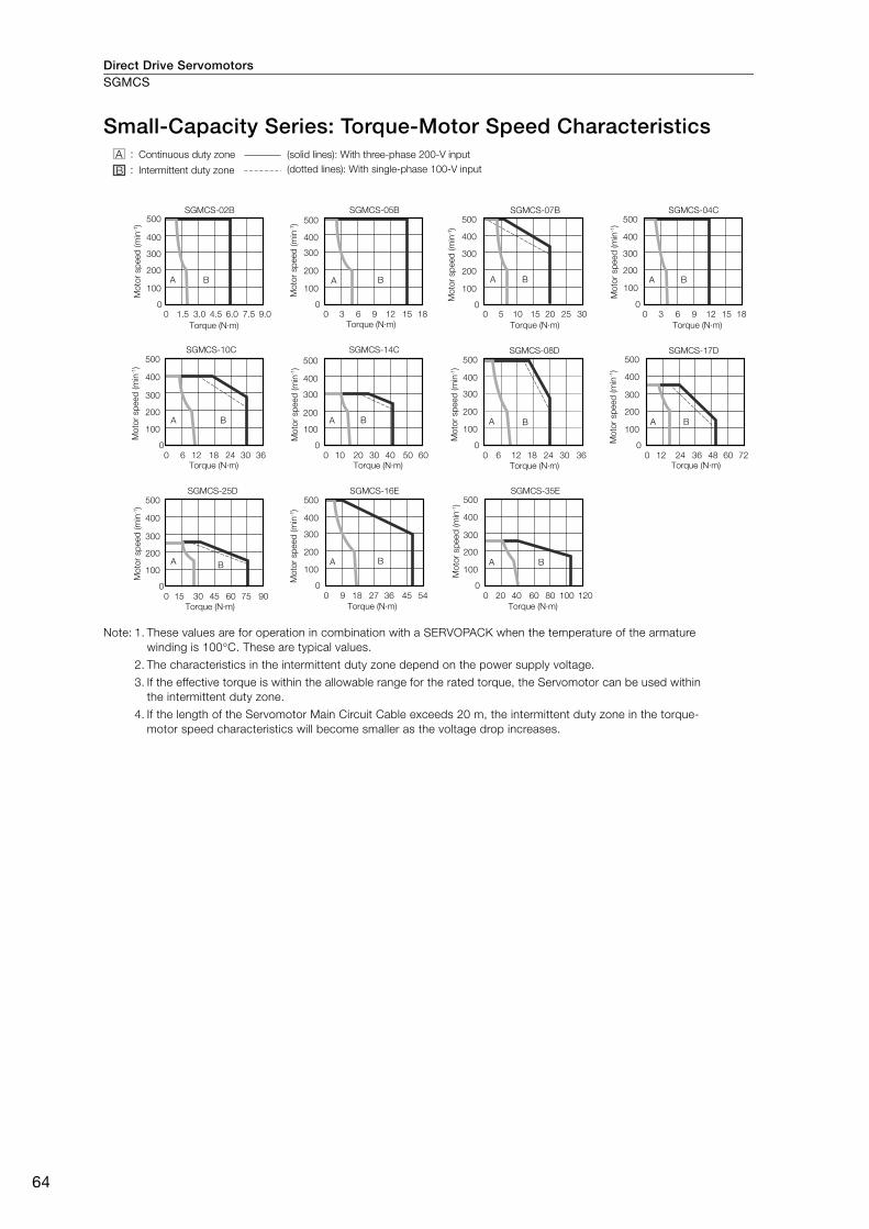
Direct Drive ServomotorsSGMCS
64
Small-Capacity Series: Torque-Motor Speed Characteristics
Note: 1. These values are for operation in combination with a SERVOPACK when the temperature of the armature
winding is 100°C. These are typical values.
2. The characteristics in the intermittent duty zone depend on the power supply voltage.
3. If the effective torque is within the allowable range for the rated torque, the Servomotor can be used within
the intermittent duty zone.
4. If the length of the Servomotor Main Circuit Cable exceeds 20 m, the intermittent duty zone in the torque-
motor speed characteristics will become smaller as the voltage drop increases.
SGMCS-02B
A
00
100
1.5 3.0 4.5 6.0 7.5 9.0
200
300
400
500
B
SGMCS-05B
A
00
100
3 6 9 12 15 18
200
300
400
500
B
SGMCS-07B
A
00
100
5 10 15 20 25 30
200
300
400
500
B
SGMCS-04C
A
0
0
100
3 6 9 12 15 18
200
300
400
500
B
SGMCS-10C
A
0
0
100
6 12 18 24 30 36
200
300
400
500
B
SGMCS-14C
A
0
0
100
10 20 30 40 50 60
200
300
400
500
B100
200
300
400
500SGMCS-08D
0
0
100
6 12 18 24 30 36
200
300
400
500SGMCS-17D
A
0
0
12 24 36 48 60 72
B
100
200
300
400
500SGMCS-16E
A
0
0
100
9 18 27 36 45 54
200
300
400
500
B
SGMCS-35E
A
0
0
20 40 60 80 100 120
B
SGMCS-25D
A
0
0
100
15 30 45 60 75 90
200
300
400
500
B
A B
Torque (N·m)
Mo
tor sp
eed
(m
in-1)
Torque (N·m) Torque (N·m)
Torque (N·m)Torque (N·m) Torque (N·m)
Torque (N·m)
Torque (N·m)
Torque (N·m)Torque (N·m)Torque (N·m)
Mo
tor sp
eed
(m
in-1)
Mo
tor sp
eed
(m
in-1)
Mo
tor sp
eed
(m
in-1)
Mo
tor sp
eed
(m
in-1)
Mo
tor sp
eed
(m
in-1)
Mo
tor sp
eed
(m
in-1)
Mo
tor sp
eed
(m
in-1)
Mo
tor sp
eed
(m
in-1)
Mo
tor sp
eed
(m
in-1)
Mo
tor sp
eed
(m
in-1)
A :
B :
Continuous duty zone (solid lines): With three-phase 200-V input
(dotted lines): With single-phase 100-V inputIntermittent duty zone
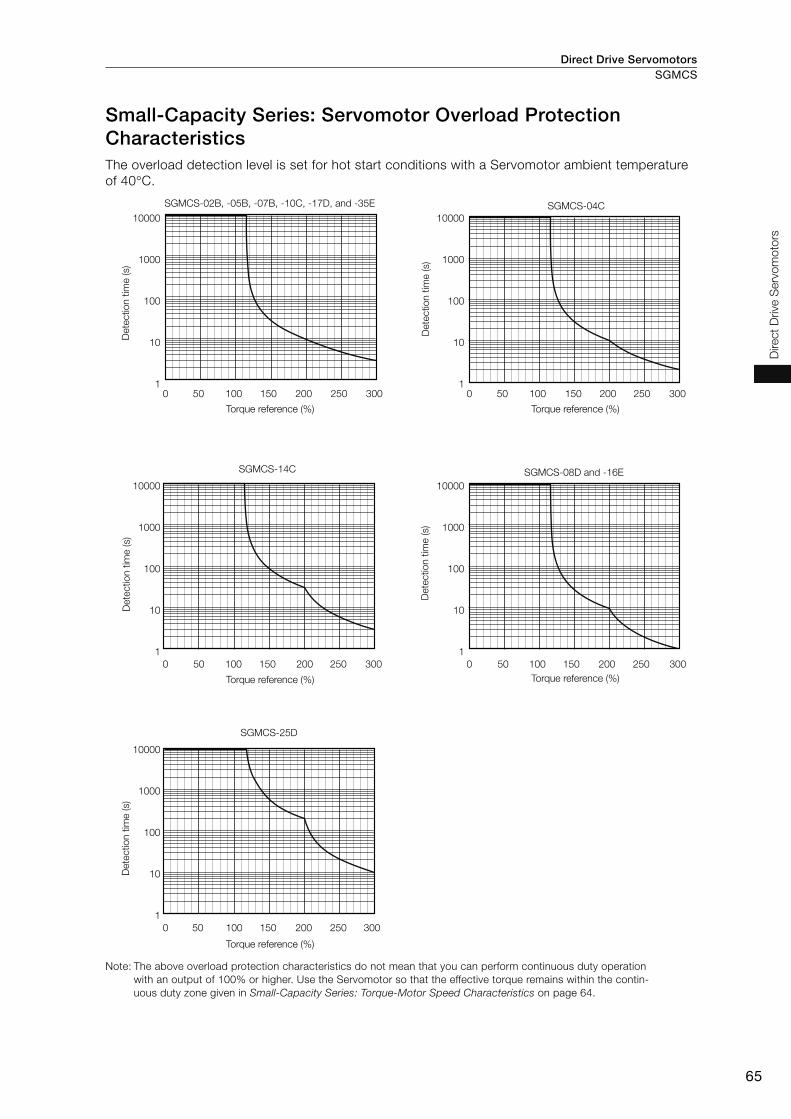
Direct Drive Servomotors SGMCS
65
Direct
Drive S
erv
om
oto
rs
Small-Capacity Series: Servomotor Overload Protection Characteristics The overload detection level is set for hot start conditions with a Servomotor ambient temperature
of 40°C.
Note: The above overload protection characteristics do not mean that you can perform continuous duty operation
with an output of 100% or higher. Use the Servomotor so that the effective torque remains within the contin-
uous duty zone given in Small-Capacity Series: Torque-Motor Speed Characteristics on page 64.
SGMCS-02B, -05B, -07B, -10C, -17D, and -35E
0 50 100 150 200 250 300
10000
1000
100
10
1
SGMCS-04C
0 50 100 150 200 250 300
10000
1000
100
10
1
SGMCS-14C
0 50 100 150 200 250 300
10000
1000
100
10
1
SGMCS-25D
0 50 100 150 200 250 300
10000
1000
100
10
1
SGMCS-08D and -16E
0 50 100 150 200 250 300
10000
1000
100
10
1
Dete
ctio
n t
ime (s)
Torque reference (%)
Dete
ctio
n t
ime (s)
Dete
ctio
n t
ime (s)
Dete
ctio
n t
ime (s)
Dete
ctio
n t
ime (s)
Torque reference (%)
Torque reference (%) Torque reference (%)
Torque reference (%)

Direct Drive ServomotorsSGMCS
66
Medium-Capacity Series: Specifications
*1. A vibration class of V15 indicates a vibration amplitude of 15 μm maximum on the Servomotor without a load at
the rated motor speed.
*2. This does not apply to the shaft opening. Protective structure specifications apply only when the special cable is
used.
Voltage 200 VModel SGMCS- 45M 80M 1AM 80N 1EN 2ZN
Time Rating Continuous
Thermal Class F
Insulation Resistance 500 VDC, 10 MΩ min.
Withstand Voltage 1,500 VAC for 1 minute
Excitation Permanent magnet
Mounting Flange-mounted
Drive Method Direct drive
Rotation Direction Counterclockwise (CCW) for forward reference when viewed from
the load side
Vibration Class*1 V15
Absolute Accuracy ±15 s
Repeatability ±1.3 s
Protective Structure*2 Totally enclosed, self-cooled, IP44
Environmental
Conditions
Surrounding Air Temperature 0°C to 40°C (with no freezing)
Surrounding Air Humidity 20% to 80% relative humidity (with no condensation)
Installation Site
• Must be indoors and free of corrosive and explosive gases.
• Must be well-ventilated and free of dust and moisture.
• Must facilitate inspection and cleaning.
• Must have an altitude of 1,000 m or less.
• Must be free of strong magnetic fields.
Storage Environment
Store the Servomotor in the following environment if you store it with
the power cable disconnected.
Storage Temperature: -20°C to 60°C (with no freezing)
Storage Humidity: 20% to 80% relative humidity
(with no condensation)
Mechanical
Tolerances*3
Runout of Output
Shaft Surfacemm 0.02
Runout at End of
Output Shaftmm 0.04
Parallelism between
Mounting Surface and
Output Shaft Surface
mm −
Concentricity between
Output Shaft and
Flange Outer Diameter
mm 0.08
Perpendicularity
between Mounting Sur-
face and Output Shaft
mm 0.08
Shock
Resistance*4
Impact Acceleration
Rate at Flange490 m/s2
Number of Impacts 2 times
Vibration
Resistance*5Vibration Acceleration
Rate at Flange24.5 m/s2
Applicable SERVOPACKs Refer to the following section.
Σ-7 Series Combination (page M-18)
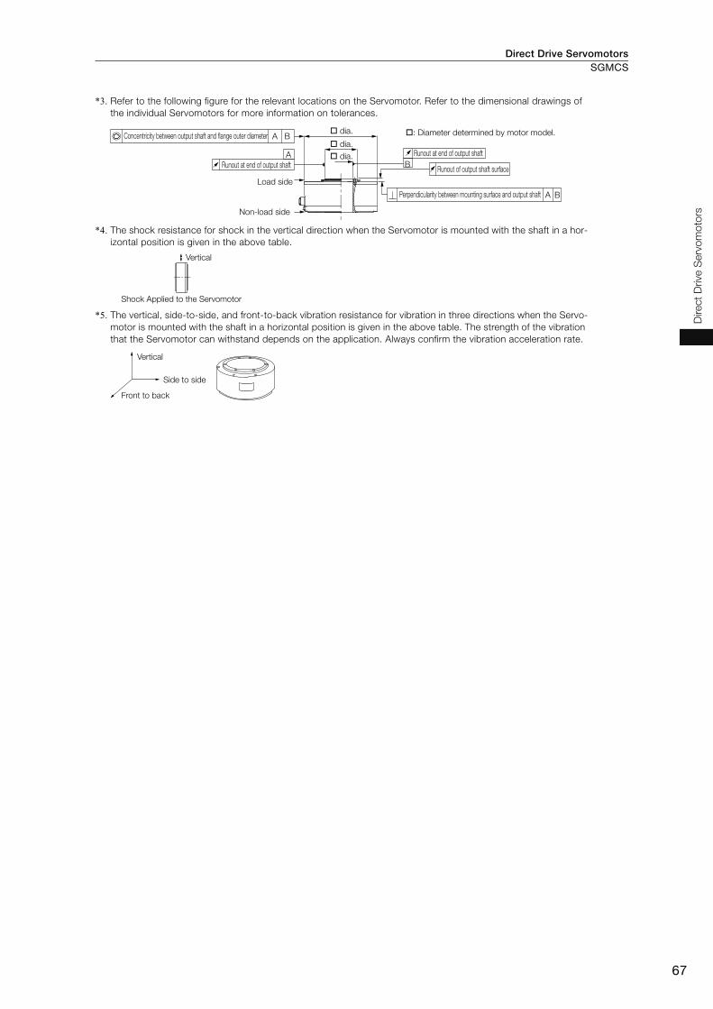
Direct Drive Servomotors SGMCS
67
Direct
Drive S
erv
om
oto
rs
*3. Refer to the following figure for the relevant locations on the Servomotor. Refer to the dimensional drawings of
the individual Servomotors for more information on tolerances.
*4. The shock resistance for shock in the vertical direction when the Servomotor is mounted with the shaft in a hor-
izontal position is given in the above table.
*5. The vertical, side-to-side, and front-to-back vibration resistance for vibration in three directions when the Servo-
motor is mounted with the shaft in a horizontal position is given in the above table. The strength of the vibration
that the Servomotor can withstand depends on the application. Always confirm the vibration acceleration rate.
B
A
A
A B
B
Runout at end of output shaft
Runout of output shaft surface
Perpendicularity between mounting surface and output shaft
Concentricity between output shaft and flange outer diameter
Runout at end of output shaft
Load side
Non-load side
dia. : Diameter determined by motor model.
dia.
dia.
Vertical
Shock Applied to the Servomotor
Side to side
Front to back
Vertical

Direct Drive ServomotorsSGMCS
68
Medium-Capacity Series: Ratings
*1. These values are for operation in combination with a SERVOPACK when the temperature of the armature wind-
ing is 20°C. These are typical values.
*2. The rated torques are the continuous allowable torque values at 40°C with a steel heat sink of the dimensions
given in the table.
*3. The thrust loads and moment loads that are applied while a Servomotor is operating are roughly classified into
the following patterns. Design the machine so that the thrust loads or moment loads will not exceed the values
given in the table.
Note: For the bearings used in these Servomotors, the loss depends on the bearing temperature. The amount of
heat loss is higher at low temperatures.
Voltage 200 V
Model SGMCS- 45M 80M 1AM 80N 1EN 2ZN
Rated Output*1 W 707 1260 1730 1260 2360 3140
Rated Torque*1, *2 N m 45.0 80.0 110 80.0 150 200
Instantaneous Maximum Torque*1 N m 135 240 330 240 450 600
Stall Torque*1 N m 45.0 80.0 110 80.0 150 200
Rated Current*1 Arms 5.8 9.7 13.4 9.4 17.4 18.9
Instantaneous Maximum Current*1 Arms 17.0 28.0 42.0 28.0 56.0 56.0
Rated Motor Speed*1 min-1 150 150
Maximum Motor Speed*1 min-1 300 300 250
Torque Constant N m/Arms 8.39 8.91 8.45 9.08 9.05 11.5
Motor Moment of Inertia ×10-4 kg m2 388 627 865 1360 2470 3060
Rated Power Rate*1 kW/s 52.2 102 140 47.1 91.1 131
Rated Angular Acceleration Rate*1 rad/s2 1160 1280 1270 588 607 654
Heat Sink Size mm 750 × 750 × 45
Allowable Load Moment of Inertia
(Motor Moment of Inertia Ratio) 3 times
Allowable
Load*3
A mm 33 37.5
Allowable Thrust Load N 9000 16000
Allowable Moment Load N m 180 350
F F
L F
L
Where F is the external force,
Thrust load = F + Load mass
Moment load = 0
Where F is the external force,
Thrust load = F + Load mass
Moment load = F × L
Where F is the external force,
Thrust load = Load mass
Moment load = F × (L + A)
A (Refer to the
values in the
table.)
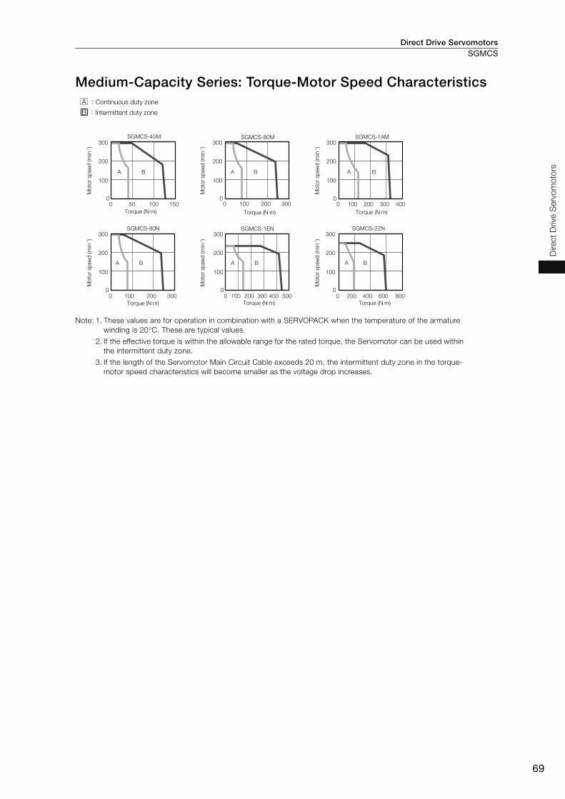
Direct Drive Servomotors SGMCS
69
Direct
Drive S
erv
om
oto
rs
Medium-Capacity Series: Torque-Motor Speed Characteristics
Note: 1. These values are for operation in combination with a SERVOPACK when the temperature of the armature
winding is 20°C. These are typical values.
2. If the effective torque is within the allowable range for the rated torque, the Servomotor can be used within
the intermittent duty zone.
3. If the length of the Servomotor Main Circuit Cable exceeds 20 m, the intermittent duty zone in the torque-
motor speed characteristics will become smaller as the voltage drop increases.
A
0 50 100 1500
100
200
300
B A
0 100 200 3000
100
200
300
B
SGMCS-45M SGMCS-80M
A
0 100 200 300 4000
100
200
300
B
A
0 100 200 3000
100
200
300
B
SGMCS-1AM
SGMCS-80N
A
0 100 200 300 400 5000
100
200
300
B A
0 200 400 600 8000
100
200
300
B
SGMCS-1EN SGMCS-2ZN
A :
B :
Continuous duty zone
Intermittent duty zone
Mo
tor sp
eed
(m
in-1)
Torque (N⋅m) Torque (N⋅m) Torque (N⋅m)
Torque (N⋅m)Torque (N⋅m)Torque (N⋅m)
Mo
tor sp
eed
(m
in-1)
Mo
tor sp
eed
(m
in-1)
Mo
tor sp
eed
(m
in-1)
Mo
tor sp
eed
(m
in-1)
Mo
tor sp
eed
(m
in-1)
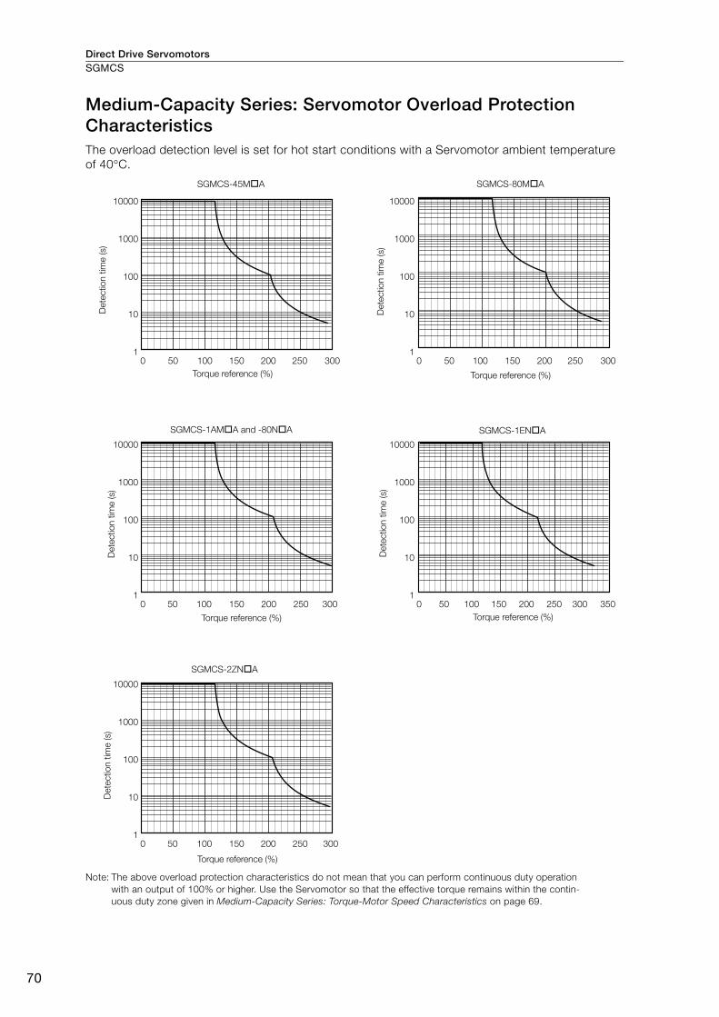
Direct Drive ServomotorsSGMCS
70
Medium-Capacity Series: Servomotor Overload Protection Characteristics The overload detection level is set for hot start conditions with a Servomotor ambient temperature
of 40°C.
Note: The above overload protection characteristics do not mean that you can perform continuous duty operation
with an output of 100% or higher. Use the Servomotor so that the effective torque remains within the contin-
uous duty zone given in Medium-Capacity Series: Torque-Motor Speed Characteristics on page 69.
10000
1000
100
10
1
10000
1000
100
10
1
10000
1000
100
10
1
10000
1000
100
10
1
10000
1000
100
10
1
SGMCS-45M A SGMCS-80M A
SGMCS-1AM A and -80N A
SGMCS-2ZN A
SGMCS-1EN A
0 50 100 150 200 250 300 0 50 100 150 200 250 300
0 50 100 150 200 250 300
0 50 100 150 200 250 300
0 50 100 150 200 250 300 350
Dete
ctio
n t
ime (s)
Torque reference (%)D
ete
ctio
n t
ime (s)
Torque reference (%)
Dete
ctio
n t
ime (s)
Torque reference (%)
Dete
ctio
n t
ime (s)
Torque reference (%)
Dete
ctio
n t
ime (s)
Torque reference (%)

Direct Drive Servomotors SGMCS
71
Direct
Drive S
erv
om
oto
rs
External Dimensions
Small-Capacity Series
SGMCS- B• Flange Specification: 1
*1. The shaded section indicates the rotating parts.
*2. The hatched section indicates the non-rotating parts.
Note: Values in parentheses are reference dimensions.
• Flange Specification: 4
*1. The shaded section indicates the rotating parts.
*2. The hatched section indicates the non-rotating parts.
Note: Values in parentheses are reference dimensions.
Refer to the following section for information on connectors.
Connector Specifications (page 77)
Model SGMCS- L (LL) LB LH LA Approx. Mass [kg]
02B C11 59 51 120 20 100 4.8
05B C11 88 80 120 20 100 5.8
07B C11 128 120 120 20 100 8.2
Model SGMCS- L (LL) LB LH LA Approx. Mass [kg]
02B C41 59 51 120 20 100 4.8
05B C41 88 80 120 20 100 5.8
07B C41 128 120 120 20 100 8.2
0.04A
B0.02
A
0.07 B4 (LL)
L
*1
*1
*2
4±0.9
(9)(1)
90°
R26
25.4
23.4
6 × M4 × 8 (Divided into equal sections at 60°.)
0.07 dia.
6 × M4 × 8 (Divided into equal sections at 60°.)
Unit: mm
(0.5: bolt section)
13
5 d
ia.
LH
dia
.
(70
dia
.)
R40.5 max. connector area
LB
dia
.
LA
dia
.
90 d
ia.
90 dia.
Notation
: Square dimensions
0
-0.035
+0.4
0
0
-0.035
0
-0.035
+0.4
0
0
-0.035
0
-0.035
+0.4
0
0
-0.035
4
20
(LL)
L
(1)0.1
(35)
300±50
4±0.9
30
50
(22
)10
0.07 B
A
B0.02
A0.04
*1
*1
*2
6 × M4 × 8
(Divided into equal sections at 60°.)
6 × M4 × 8
(Divided into equal sections at 60°.)
0.07 dia.
Unit: mm
13
5 d
ia.
(70
dia
.)
(80
dia
.)
90 dia.
(0.5: bolt section)LB
dia
.
LA
dia
.
LH
dia
.
90 d
ia.
0
-0.035
+0.4
0
0
-0.035
0
-0.035
+0.4
0
0
-0.035
0
-0.035
+0.4
0
0
-0.035

Direct Drive ServomotorsSGMCS
72
SGMCS- C• Flange Specification: 1
*1. The shaded section indicates the rotating parts.
*2. The hatched section indicates the non-rotating parts.
Note: Values in parentheses are reference dimensions.
• Flange Specification: 4
*1. The shaded section indicates the rotating parts.
*2. The hatched section indicates the non-rotating parts.
Note: Values in parentheses are reference dimensions.
Refer to the following section for information on connectors.
Connector Specifications (page 77)
Model SGMCS- L (LL) LB LH LA Approx. Mass [kg]
04C C11 69 59 160 35 130 7.2
10C C11 90 80 160 35 130 10.2
14C C11 130 120 160 35 130 14.2
Model SGMCS- L (LL) LB LH LA Approx. Mass [kg]
04C C41 69 59 160 35 130 7.2
10C C41 90 80 160 35 130 10.2
14C C41 130 120 160 35 130 14.2
60°
5 (LL)
L
5±0.9
(9)
*1
*2 (1) *1R36.5
25.423.4
B0.02
A
0.07
0.04
A
B6 × M5 × 8
(Divided into equal sections at 60°.)0.07 dia.
(2 × M5 × 8)
(For use by Yaskawa)
6 × M5 × 8 (Divided into equal sections at 60°.)
(2 × M5 × 8 )
(For use by
Yaskawa)
Unit: mm
(1: bolt section)
17
5 d
ia.
LB
dia
.
(10
0 d
ia.)
LA
dia
.130 dia.
120 d
ia.
R51 max. connector area
LH
dia
.
0
-0.040
+0.4
0
0
-0.040
0
-0.040
+0.4
0
0
-0.040
0
-0.040
+0.4
0
0
-0.040
5
20
(LL)
L
0.1
(35)
(1)
30
50
(22
)10
0.07 B
A
B
0.02
A
0.04
300±50
5±0.9
*1
*2*1
6 × M5 × 8
(Divided
into equal
sections at
60°.)
130 dia.
(2 × M5 × 8)
(For use by
Yaskawa)(2 × M5 × 8)
(For use by
Yaskawa)
Unit: mm
6 × M5 × 8
(Divided into equal sections at 60°.)
(1: bolt section)
17
5 d
ia.
(10
0 d
ia.) (1
00
dia
.)
0.07 dia.
LB
dia
.
LA
dia
.
120 d
ia.
LH
dia
.
0
-0.040
+0.4
0
0
-0.040
0
-0.040
+0.4
0
0
-0.040
0
-0.040
+0.4
0
0
-0.040
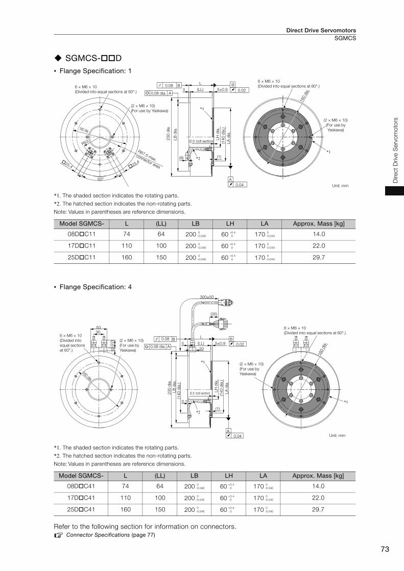
Direct Drive Servomotors SGMCS
73
Direct
Drive S
erv
om
oto
rs
SGMCS- D• Flange Specification: 1
*1. The shaded section indicates the rotating parts.
*2. The hatched section indicates the non-rotating parts.
Note: Values in parentheses are reference dimensions.
• Flange Specification: 4
*1. The shaded section indicates the rotating parts.
*2. The hatched section indicates the non-rotating parts.
Note: Values in parentheses are reference dimensions.
Refer to the following section for information on connectors.
Connector Specifications (page 77)
Model SGMCS- L (LL) LB LH LA Approx. Mass [kg]
08D C11 74 64 200 60 170 14.0
17D C11 110 100 200 60 170 22.0
25D C11 160 150 200 60 170 29.7
Model SGMCS- L (LL) LB LH LA Approx. Mass [kg]
08D C41 74 64 200 60 170 14.0
17D C41 110 100 200 60 170 22.0
25D C41 160 150 200 60 170 29.7
(LL)
L
5 5±0.9
60°
R53
*1
*2(9) (1)
25.4 23.4
A
0.08 B B
0.02
0.04
A
*1
6 × M6 × 10
(Divided into equal sections at 60°.)
160 dia.
R67.5 max.
connector area
(2 × M6 × 10)
(For use by Yaskawa)
6 × M6 × 10
(Divided into equal sections at 60°.)
(2 × M6 × 10)
(For use by
Yaskawa)
Unit: mm
160 d
ia.
(0.5: bolt section)
23
0 d
ia.
(14
0 d
ia.)
0.08 dia.
LB
dia
.
LA
dia
.
LH
dia
.
0
-0.046
+0.4
0
0
-0.040
0
-0.046
+0.4
0
0
-0.040
0
-0.046
+0.4
0
0
-0.040
5
20
(LL)
L
0.1
(1)
5±0.9
300±50
(35)
3050
(22
)10
*1
*1
*2
B
0.02
0.08 B
A
A
0.04
6 × M6 × 10
(Divided into
equal sections
at 60°.)
160 dia.
(2 × M6 × 10)
(For use by
Yaskawa)
(2 × M6 × 10)
(For use by
Yaskawa)
6 × M6 × 10
(Divided into equal sections at 60°.)
Unit: mm
160 d
ia.
0.08 dia.
(0.5: bolt section)
(14
0 d
ia.)
(14
0 d
ia.)
23
0 d
ia.
LB
dia
.
LA
dia
.
LH
dia
.
0
-0.046
+0.4
0
0
-0.040
0
-0.046
+0.4
0
0
-0.040
0
-0.046
+0.4
0
0
-0.040

Direct Drive ServomotorsSGMCS
74
SGMCS- E• Flange Specification: 1
*1. The shaded section indicates the rotating parts.
*2. The hatched section indicates the non-rotating parts.
Note: Values in parentheses are reference dimensions.
• Flange Specification: 4
*1. The shaded section indicates the rotating parts.
*2. The hatched section indicates the non-rotating parts.
Note: Values in parentheses are reference dimensions.
Refer to the following section for information on connectors.
Connector Specifications (page 77)
Model SGMCS- L (LL) LB LH LA Approx. Mass [kg]
16E B11 88 76 260 75 220 26.0
35E B11 112 100 260 75 220 34.0
Model SGMCS- L (LL) LB LH LA Approx. Mass [kg]
16E B41 88 76 260 75 220 26.0
35E B41 112 100 260 75 220 34.0
60°
*2
*1
R65
(LL)
L
6
(9) (1)
(4)
A
0.08 B B
0.02
0.04
A
25.4 23.4
200 dia.
6±1.6
*1
6 × M8 × 14
(Divided into equal sections at 60°.)
29
0 d
ia.
(2 × M8 × 14)
(For use by
Yaskawa)
(2 × M8 × 14)
(For use by
Yaskawa)
6 × M8 × 14
(Divided into equal sections at 60°.)
Unit: mm
200 d
ia.
(280
dia.)
(18
0 d
ia.)
0.08 dia.
R80 max.
connector areaLB
dia
.
LA
dia
.
LH
dia
.
0
-0.052
+0.4
0
0
-0.046
0
-0.052
+0.4
0
0
-0.046
300±50
(35)
6 (LL)
L
0.1
(1)
(4)
*1
*1
*2
30
50
(22
)1
0
0.08 B
A
B
0.02
A
0.04
20
6±1.6
(2 × M8 × 14)
(For use by
Yaskawa)
(16
0 d
ia.)
200 d
ia.
(280
dia.)
(18
0 d
ia.)
29
0 d
ia.
0.08 dia.
(2 × M8 × 14)
(For use by
Yaskawa)
6 × M8 × 14
(Divided into equal sections at 60°.)
Unit: mm
200 dia.
6 × M8 × 14
(Divided into equal
sections at 60°.)
LB
dia
.
LA
dia
.
LH
dia
.
0
-0.052
+0.4
0
0
-0.046
0
-0.052
+0.4
0
0
-0.046

Direct Drive Servomotors SGMCS
75
Direct
Drive S
erv
om
oto
rs
Medium-Capacity Series
SGMCS- M• Flange Specification: 1
* The shaded section indicates the rotating parts.
• Flange Specification: 3
* The shaded section indicates the rotating parts.
Refer to the following section for information on connectors.
Connector Specifications (page 77)
Model SGMCS- LL KB1 KB2 LB LH LA Approx. Mass [kg]
45M A11 141 87.5 122 280 75 110 38
80M A11 191 137.5 172 280 75 110 45
1AM A11 241 187.5 222 280 75 110 51
Model SGMCS- L LL KB1 KB2 LB LH LA Approx. Mass [kg]
45M A31 150 135 102.5 137 248 75 110 38
80M A31 200 185 152.5 187 248 75 110 45
1AM A31 250 235 202.5 237 248 75 110 51
A
15
14
7 18
2
41
0.04
0.04
B
A B
0.08 A B30°
KB2
KB1
LL
6
51.5
*
*
**
11
5 d
ia.
75
.2 d
ia.
28
0 ±
0.5
dia
.
14
0 d
ia.
(rotating part)
Rotating part
15 (280 dia. range)
0.08 dia.
12 × M6 × 15 (Divided into equal sections.)
12 × M6 × 18 (Divided into equal sections.) Unit: mm
88 dia.
264
dia.
25
0 d
ia.
LB
dia
.
LH
dia
.
LA
dia
.
0-0.052
15 (75 dia. range)+0.019 0
0
-0.052
+0.019
0
0
-0.035
0
-0.052
+0.019
0
0
-0.035
0
-0.052
+0.019
0
0
-0.035
5
18
2
15LL6
KB2
KB1
L
41
1.5
0.08 C
*
*
A B
10°
14
7
C
0.02
A
0.04
B
0.04
*
*
12 × M6 × 15
(Divided into
equal sections.)
264 d
ia.
0.08 dia.
(rotating part)
12 × M6 × 18
(Divided into
equal sections.)
88 dia.
Unit: mm
11
5 d
ia.
75
.2 d
ia.
14
0 d
ia.
28
0 d
ia.
LB
dia
.
LH
dia
.
LA
dia
.
15 (75 dia. range)+0.019 0
0
-0.046
+0.019
0
0
-0.035
0
-0.046
+0.019
0
0
-0.035
0
-0.046
+0.019
0
0
-0.035

Direct Drive ServomotorsSGMCS
76
SGMCS- N• Flange Specification: 1
* The shaded section indicates the rotating parts.
• Flange Specification: 3
* The shaded section indicates the rotating parts.
Refer to the following section for information on connectors.
Connector Specifications (page 77)
Model SGMCS- LL KB1 KB2 LB LH LA Approx. Mass [kg]
80N A11 151 98 132 360 118 160 50
1EN A11 201 148 182 360 118 160 68
2ZN A11 251 198 232 360 118 160 86
Model SGMCS- L LL KB1 KB2 LB LH LA Approx. Mass [kg]
80N A31 160 145 113 147 323 118 160 50
1EN A31 210 195 163 197 323 118 160 68
2ZN A31 260 245 213 247 323 118 160 86
A
30°
15
0.04
0.04
B
A B
0.08 A B
22
2
41
18
6
KB2
KB1
5
LL
6
1.5
*
*
*
*
32
5 d
ia.
16
6 d
ia.
11
8.2
dia
.
19
0 d
ia.
36
0 ±
0.5
dia
.
Rotating part
(rotating part)
0.08 dia.
344
dia
.
12 × M8 × 15
(Divided into equal sections.)
12 × M8 × 20 (Divided into equal sections.)
135 d
ia.
Unit: mm
LB
dia
.
LA
dia
.
LH
dia
.
15 (360 dia. range) 0-0.057
15 (118 dia. range)+0.022 0
0
-0.057
+0.022
0
0
-0.040
0
-0.057
+0.022
0
0
-0.040
0
-0.057
+0.022
0
0
-0.040
10°
22
2
41
1.5
5
LL 156
KB2
KB1
L
18
6
*
*
0.08 C C
0.02
B
0.04
A
0.04
A B
*
*
12 × M8 × 15 (Divided into equal sections.)
36
0 d
ia.
11
8.2
dia
.
19
0 d
ia.
16
6 d
ia.
344 d
ia.
0.08 dia.
12 × M8 × 20
(Divided into
equal sections.)
135 d
ia.
(rotating part)
Unit: mm
LB
dia
.
LA
dia
.
LH
dia
.
15 (118 dia. range)+0.022 0
0
-0.057
+0.022
0
0
-0.040
0
-0.057
+0.022
0
0
-0.040
0
-0.057
+0.022
0
0
-0.040
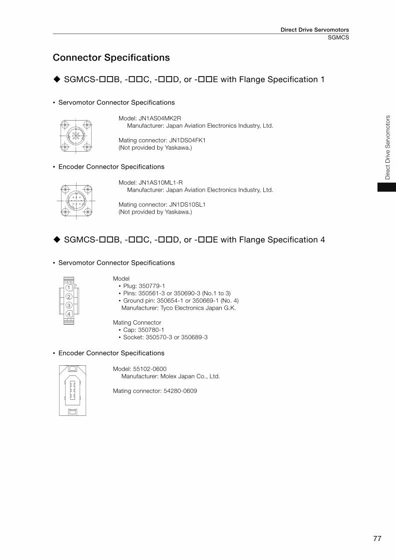
Direct Drive Servomotors SGMCS
77
Direct
Drive S
erv
om
oto
rs
Connector Specifications
SGMCS- B, - C, - D, or - E with Flange Specification 1
• Servomotor Connector Specifications
• Encoder Connector Specifications
SGMCS- B, - C, - D, or - E with Flange Specification 4
• Servomotor Connector Specifications
• Encoder Connector Specifications
Model: JN1AS04MK2R
Manufacturer: Japan Aviation Electronics Industry, Ltd.
Mating connector: JN1DS04FK1
(Not provided by Yaskawa.)
Model: JN1AS10ML1-R
Manufacturer: Japan Aviation Electronics Industry, Ltd.
Mating connector: JN1DS10SL1
(Not provided by Yaskawa.)
Model
• Plug: 350779-1
• Pins: 350561-3 or 350690-3 (No.1 to 3)
• Ground pin: 350654-1 or 350669-1 (No. 4)
Manufacturer: Tyco Electronics Japan G.K.
Mating Connector
• Cap: 350780-1
• Socket: 350570-3 or 350689-3
Model: 55102-0600
Manufacturer: Molex Japan Co., Ltd.
Mating connector: 54280-0609
1
2
3
4

Direct Drive ServomotorsSGMCS
78
SGMCS- M or - N with Flange Specification 1 or 3 • Servomotor Connector Specifications
• Encoder Connector Specifications
Model: CE05-2A18-10PD
Manufacturer: DDK Ltd.
Mating Connector
Plug: CE05-6A18-10SD-B-BSS
Cable clamp: CE3057-10A- (D265)
Model: JN1AS10ML1
Manufacturer: Japan Aviation Electronics Industry, Ltd.
Mating connector: JN1DS10SL1

Direct Drive Servomotors
79
Direct
Drive S
erv
om
oto
rs
SGMCV
Model Designations
Note: Direct Drive Servomotors are not available with holding brakes.
B
C
E
I
1
5
1
4
4th digit 6th digit
3rd digit
7th digit
Mounting
Non-load side
Non-load side (with cable on side)
Options
Without options
High machine precision (runout at end of shaft
and runout of shaft surface: 0.01 mm)
22-bit single-turn data
22-bit multiturn data
A
5th digit Design Revision Order
Servomotor Outer Diameter
135-mm dia.
175-mm dia.
Serial Encoder Flange
SGMCV - 04 B E A 1 11st+2nd
digits
1st+2nd digits Rated Output
04 4 N m
08 8 N m
10 10 N m
14 14 N m
17 17 N m
25 25 N m
Code Specification
3rd digit
4th digit
5th digit
6th digit
7th digitDirect Drive
Servomotors:
SGMCV
Code Code
Code
Code
Specification
Specification
Specification
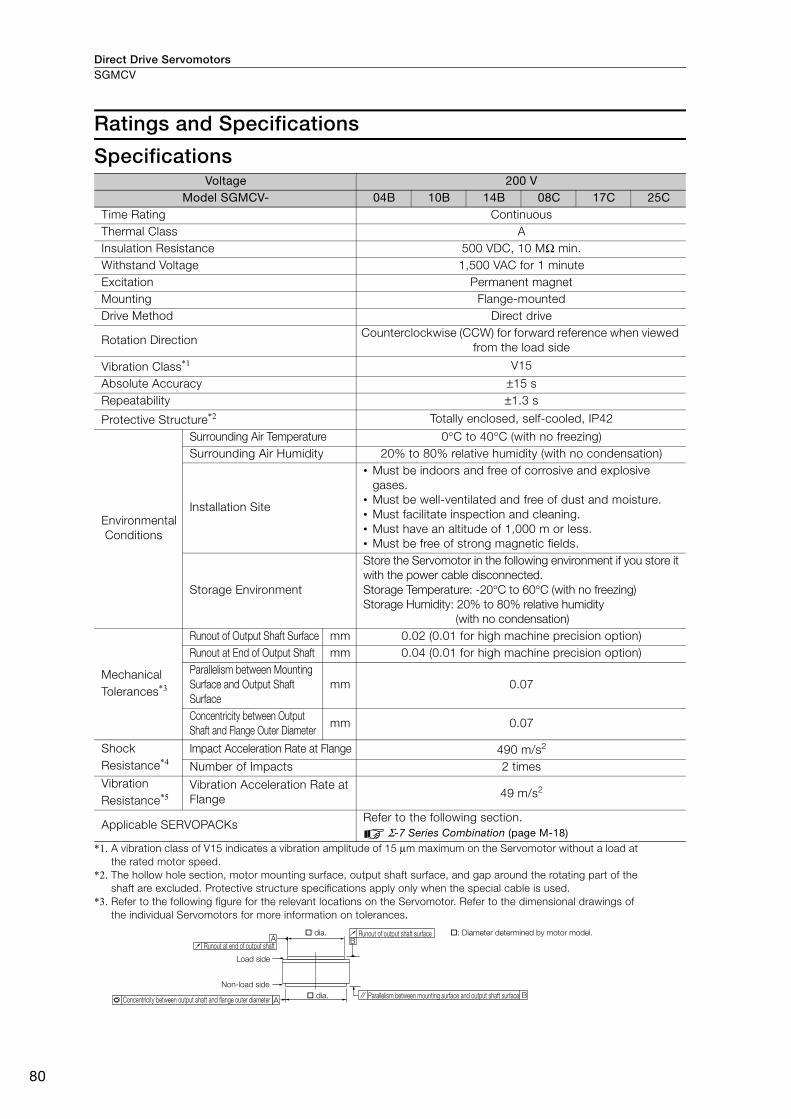
Direct Drive ServomotorsSGMCV
80
Ratings and Specifications
Specifications
*1. A vibration class of V15 indicates a vibration amplitude of 15 μm maximum on the Servomotor without a load at
the rated motor speed.
*2. The hollow hole section, motor mounting surface, output shaft surface, and gap around the rotating part of the
shaft are excluded. Protective structure specifications apply only when the special cable is used.
*3. Refer to the following figure for the relevant locations on the Servomotor. Refer to the dimensional drawings of
the individual Servomotors for more information on tolerances.
Voltage 200 VModel SGMCV- 04B 10B 14B 08C 17C 25C
Time Rating Continuous
Thermal Class A
Insulation Resistance 500 VDC, 10 MΩ min.
Withstand Voltage 1,500 VAC for 1 minute
Excitation Permanent magnet
Mounting Flange-mounted
Drive Method Direct drive
Rotation Direction Counterclockwise (CCW) for forward reference when viewed
from the load side
Vibration Class*1 V15
Absolute Accuracy ±15 s
Repeatability ±1.3 s
Protective Structure*2 Totally enclosed, self-cooled, IP42
Environmental
Conditions
Surrounding Air Temperature 0°C to 40°C (with no freezing)
Surrounding Air Humidity 20% to 80% relative humidity (with no condensation)
Installation Site
• Must be indoors and free of corrosive and explosive
gases.
• Must be well-ventilated and free of dust and moisture.
• Must facilitate inspection and cleaning.
• Must have an altitude of 1,000 m or less.
• Must be free of strong magnetic fields.
Storage Environment
Store the Servomotor in the following environment if you store it
with the power cable disconnected.
Storage Temperature: -20°C to 60°C (with no freezing)
Storage Humidity: 20% to 80% relative humidity
(with no condensation)
Mechanical
Tolerances*3
Runout of Output Shaft Surface mm 0.02 (0.01 for high machine precision option)
Runout at End of Output Shaft mm 0.04 (0.01 for high machine precision option)
Parallelism between Mounting
Surface and Output Shaft
Surface
mm 0.07
Concentricity between Output
Shaft and Flange Outer Diametermm 0.07
Shock
Resistance*4Impact Acceleration Rate at Flange 490 m/s2
Number of Impacts 2 times
Vibration
Resistance*5Vibration Acceleration Rate at
Flange 49 m/s2
Applicable SERVOPACKs Refer to the following section.
Σ-7 Series Combination (page M-18)
A
A B
B
Runout at end of output shaft
dia.
Load side
Non-load side
Concentricity between output shaft and flange outer diameter dia. Parallelism between mounting surface and output shaft surface
Runout of output shaft surface : Diameter determined by motor model.
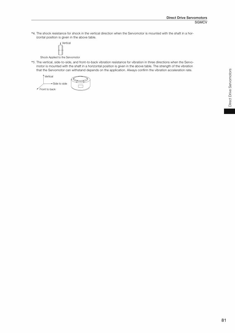
Direct Drive Servomotors SGMCV
81
Direct
Drive S
erv
om
oto
rs
*4. The shock resistance for shock in the vertical direction when the Servomotor is mounted with the shaft in a hor-
izontal position is given in the above table.
*5. The vertical, side-to-side, and front-to-back vibration resistance for vibration in three directions when the Servo-
motor is mounted with the shaft in a horizontal position is given in the above table. The strength of the vibration
that the Servomotor can withstand depends on the application. Always confirm the vibration acceleration rate.
Vertical
Shock Applied to the Servomotor
Vertical
Side to side
Front to back
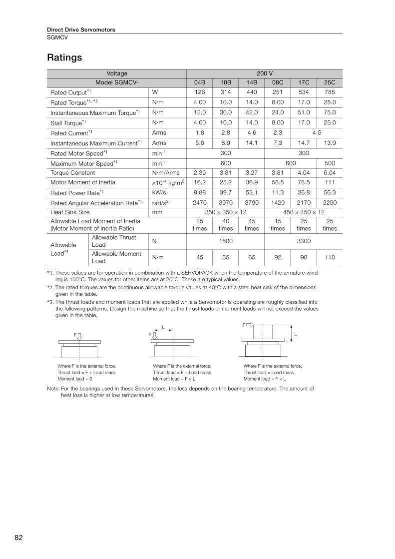
Direct Drive ServomotorsSGMCV
82
Ratings
*1. These values are for operation in combination with a SERVOPACK when the temperature of the armature wind-
ing is 100°C. The values for other items are at 20°C. These are typical values.
*2. The rated torques are the continuous allowable torque values at 40°C with a steel heat sink of the dimensions
given in the table.
*3. The thrust loads and moment loads that are applied while a Servomotor is operating are roughly classified into
the following patterns. Design the machine so that the thrust loads or moment loads will not exceed the values
given in the table.
Note: For the bearings used in these Servomotors, the loss depends on the bearing temperature. The amount of
heat loss is higher at low temperatures.
Voltage 200 V
Model SGMCV- 04B 10B 14B 08C 17C 25C
Rated Output*1 W 126 314 440 251 534 785
Rated Torque*1, *2 N m 4.00 10.0 14.0 8.00 17.0 25.0
Instantaneous Maximum Torque*1 N m 12.0 30.0 42.0 24.0 51.0 75.0
Stall Torque*1 N m 4.00 10.0 14.0 8.00 17.0 25.0
Rated Current*1 Arms 1.8 2.8 4.6 2.3 4.5
Instantaneous Maximum Current*1 Arms 5.6 8.9 14.1 7.3 14.7 13.9
Rated Motor Speed*1 min-1 300 300
Maximum Motor Speed*1 min-1 600 600 500
Torque Constant N m/Arms 2.39 3.81 3.27 3.81 4.04 6.04
Motor Moment of Inertia ×10-4 kg m2 16.2 25.2 36.9 56.5 78.5 111
Rated Power Rate*1 kW/s 9.88 39.7 53.1 11.3 36.8 56.3
Rated Angular Acceleration Rate*1 rad/s2 2470 3970 3790 1420 2170 2250
Heat Sink Size mm 350 × 350 × 12 450 × 450 × 12
Allowable Load Moment of Inertia
(Motor Moment of Inertia Ratio)
25
times
40
times
45
times
15
times
25
times
25
times
Allowable
Load*3
Allowable Thrust
Load N 1500 3300
Allowable Moment
Load N m 45 55 65 92 98 110
F
F
LF
L
Where F is the external force,
Thrust load = F + Load mass
Moment load = 0
Where F is the external force,
Thrust load = F + Load mass
Moment load = F × L
Where F is the external force,
Thrust load = Load mass
Moment load = F × L
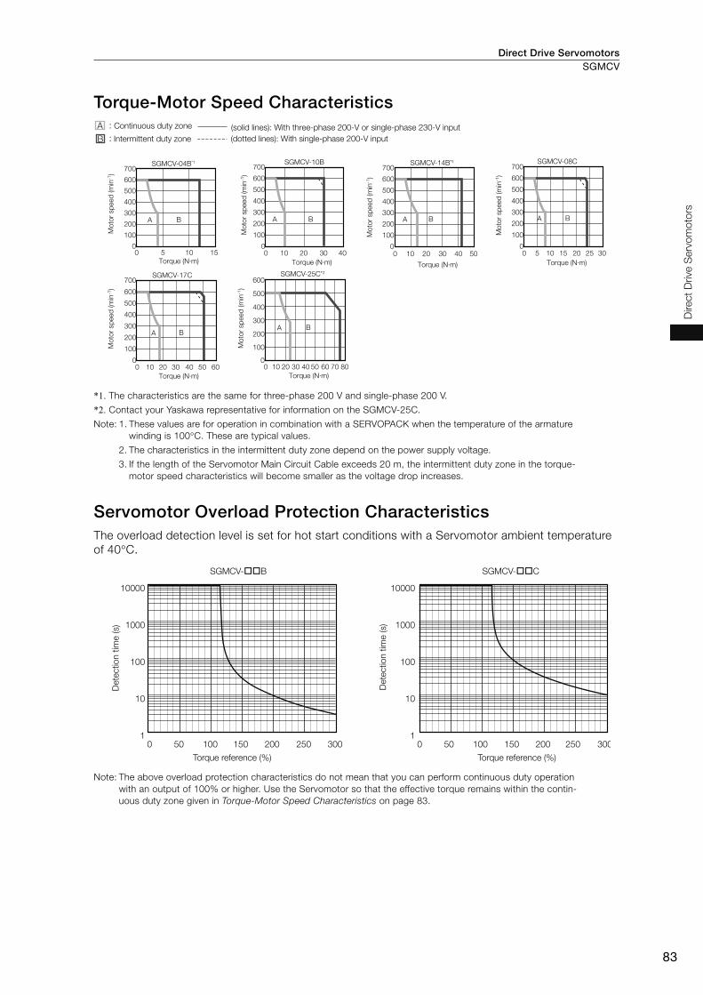
Direct Drive Servomotors SGMCV
83
Direct
Drive S
erv
om
oto
rs
Torque-Motor Speed Characteristics
*1. The characteristics are the same for three-phase 200 V and single-phase 200 V.
*2. Contact your Yaskawa representative for information on the SGMCV-25C.
Note: 1. These values are for operation in combination with a SERVOPACK when the temperature of the armature
winding is 100°C. These are typical values.
2. The characteristics in the intermittent duty zone depend on the power supply voltage.
3. If the length of the Servomotor Main Circuit Cable exceeds 20 m, the intermittent duty zone in the torque-
motor speed characteristics will become smaller as the voltage drop increases.
Servomotor Overload Protection Characteristics The overload detection level is set for hot start conditions with a Servomotor ambient temperature
of 40°C.
Note: The above overload protection characteristics do not mean that you can perform continuous duty operation
with an output of 100% or higher. Use the Servomotor so that the effective torque remains within the contin-
uous duty zone given in Torque-Motor Speed Characteristics on page 83.
A :
B :
SGMCV-17C
0 10 20 30 40 50 600
100
200
300
400
500
600
700
A B
SGMCV-04B*1
0
100
200
300
400
500
600
700
0 5 10 15
A B
SGMCV-25C*2
0 10 20 30 40 50 60 70 800
100
200
300
400
500
600
A B
SGMCV-10B
0 10 20 30 400
100
200
300
400
500
600
700
A B
SGMCV-14B*1
0 10 20 30 40 500
100
200
300
400
500
600
700
A B
SGMCV-08C
0 5 10 15 20 25 300
100
200
300
400
500
600
700
A B
Torque (N·m)
(solid lines): With three-phase 200-V or single-phase 230-V input
(dotted lines): With single-phase 200-V inputIntermittent duty zone
Moto
r sp
eed
(m
in-1
)
Continuous duty zone
Torque (N·m)
Moto
r sp
eed
(m
in-1
)
Torque (N·m)
Moto
r sp
eed
(m
in-1
)
Torque (N·m)
Moto
r sp
eed
(m
in-1
)
Torque (N·m)
Moto
r sp
eed
(m
in-1
)
Torque (N·m)
Moto
r sp
eed
(m
in-1
)
10000
1000
100
10
1
10000
1000
100
10
1
SGMCV- B SGMCV- C
0 50 100 150 200 250 300 0 50 100 150 200 250 300
Dete
ctio
n t
ime (s)
Torque reference (%) Torque reference (%)
Dete
ctio
n t
ime (s)
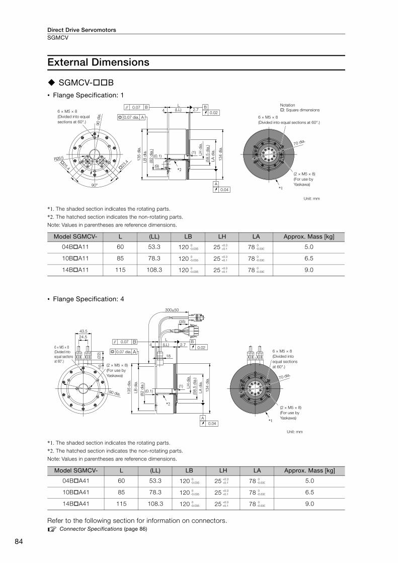
Direct Drive ServomotorsSGMCV
84
External Dimensions
SGMCV- B• Flange Specification: 1
*1. The shaded section indicates the rotating parts.
*2. The hatched section indicates the non-rotating parts.
Note: Values in parentheses are reference dimensions.
• Flange Specification: 4
*1. The shaded section indicates the rotating parts.
*2. The hatched section indicates the non-rotating parts.
Note: Values in parentheses are reference dimensions.
Refer to the following section for information on connectors.
Connector Specifications (page 86)
Model SGMCV- L (LL) LB LH LA Approx. Mass [kg]
04B A11 60 53.3 120 25 78 5.0
10B A11 85 78.3 120 25 78 6.5
14B A11 115 108.3 120 25 78 9.0
Model SGMCV- L (LL) LB LH LA Approx. Mass [kg]
04B A41 60 53.3 120 25 78 5.0
10B A41 85 78.3 120 25 78 6.5
14B A41 115 108.3 120 25 78 9.0
23.425.4
(1)
2.74
90°
R26.5
(LL)L
(9)
(0.1)
A
0.04
B
0.02
A
0.07 B
*1
*2
6 × M5 × 8
(Divided into equal
sections at 60°.)
(82
dia
.)
13
4 d
ia.
(58
.5 d
ia.)
LB
dia
.
13
5 d
ia.
0.07 dia. 6 × M5 × 8
(Divided into equal sections at 60°.)
(2 × M5 × 8)
(For use by
Yaskawa)
70 dia.
Unit: mm
90 d
ia.
LA
dia
.
LH
dia
.
Notation
: Square dimensions
0
-0.035
+0.3
+0.1
0
-0.030
0
-0.035
+0.3
+0.1
0
-0.030
0
-0.035
+0.3
+0.1
0
-0.030
(1)
2.7(LL)
L
300±50
(35)
18
4
(0.1)
43.5
24.5
10
(22
)
A
0.04
B
0.02
0.07 B
A
90 dia.
*1
*2
6 × M5 × 8
(Divided into
equal sections
at 60°.)
0.07 dia.
(2 × M5 × 8)
(For use by
Yaskawa)
13
4 d
ia.
(58
.5 d
ia.)
LH
dia
.
(82
dia
.)
13
5 d
ia.
6 × M5 × 8
(Divided into
equal sections
at 60°.)
(2 × M5 × 8)
(For use by
Yaskawa)
Unit: mm
70 dia.
LB
dia
.
LA
dia
.
0
-0.035
+0.3
+0.1
0
-0.030
0
-0.035
+0.3
+0.1
0
-0.030
0
-0.035
+0.3
+0.1
0
-0.030
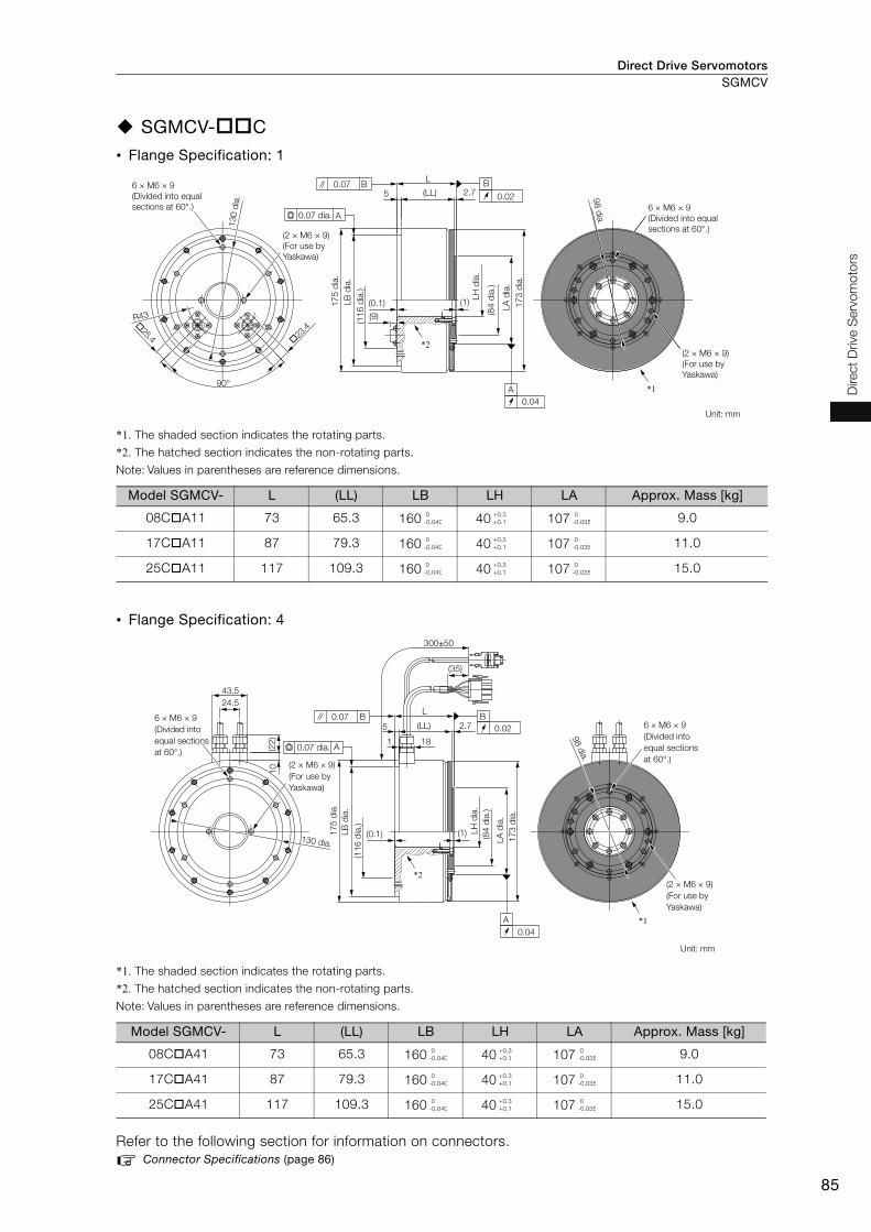
Direct Drive Servomotors SGMCV
85
Direct
Drive S
erv
om
oto
rs
SGMCV- C
• Flange Specification: 1
*1. The shaded section indicates the rotating parts.
*2. The hatched section indicates the non-rotating parts.
Note: Values in parentheses are reference dimensions.
• Flange Specification: 4
*1. The shaded section indicates the rotating parts.
*2. The hatched section indicates the non-rotating parts.
Note: Values in parentheses are reference dimensions.
Refer to the following section for information on connectors.
Connector Specifications (page 86)
Model SGMCV- L (LL) LB LH LA Approx. Mass [kg]
08C A11 73 65.3 160 40 107 9.0
17C A11 87 79.3 160 40 107 11.0
25C A11 117 109.3 160 40 107 15.0
Model SGMCV- L (LL) LB LH LA Approx. Mass [kg]
08C A41 73 65.3 160 40 107 9.0
17C A41 87 79.3 160 40 107 11.0
25C A41 117 109.3 160 40 107 15.0
23.425.4
2.75
R43
(0.1) (1)
90°
L
(LL)
(9)
B
0.02
A
0.04
0.07 B
A
17
3 d
ia.
*1
*2
130 d
ia.
6 × M6 × 9
(Divided into equal
sections at 60°.)
98 d
ia.
(2 × M6 × 9)
(For use by
Yaskawa)
Unit: mm
(2 × M6 × 9)
(For use by
Yaskawa)
LA
dia
.
(84
dia
.)
(11
6 d
ia.)
17
5 d
ia.
0.07 dia.
LB
dia
.
LH
dia
.
6 × M6 × 9
(Divided into equal
sections at 60°.)
0
-0.040
+0.3
+0.1
0
-0.035
0
-0.040
+0.3
+0.1
0
-0.035
0
-0.040
+0.3
+0.1
0
-0.035
B
0.022.75
1
(0.1) (1)
L
18
300±50
(LL)
24.5
(22
)
43.5
10
(35)
0.07 B
A
A
0.04
*1
*2
6 × M6 × 9
(Divided into
equal sections
at 60°.)
(2 × M6 × 9)
(For use by
Yaskawa)
17
3 d
ia.
(84
dia
.)
17
5 d
ia.
130 dia.
6 × M6 × 9
(Divided into
equal sections
at 60°.)
98 d
ia.
(2 × M6 × 9)
(For use by
Yaskawa)
Unit: mm
(11
6 d
ia.)
0.07 dia.
LB
dia
.
LH
dia
.
LA
dia
.
0
-0.040
+0.3
+0.1
0
-0.035
0
-0.040
+0.3
+0.1
0
-0.035
0
-0.040
+0.3
+0.1
0
-0.035

Direct Drive ServomotorsSGMCV
86
Connector Specifications
Flange Specification 1 • Servomotor Connector Specifications
• Encoder Connector Specifications
Flange Specification 4 • Servomotor Connector Specifications
• Encoder Connector Specifications
Model: JN1AS04MK2R
Manufacturer: Japan Aviation Electronics Industry, Ltd.
Mating connector: JN1DS04FK1
(Not provided by Yaskawa.)
Model: JN1AS10ML1-R
Manufacturer: Japan Aviation Electronics Industry, Ltd.
Mating connector: JN1DS10SL1
(Not provided by Yaskawa.)
Model
• Plug: 350779-1
• Pins: 350561-3 or 350690-3 (No.1 to 3)
• Ground pin: 350654-1 or 350669-1 (No. 4)
Manufacturer: Tyco Electronics Japan G.K.
Mating Connector
• Cap: 350780-1
• Socket: 350570-3 or 350689-3
Model: 55102-0600
Manufacturer: Molex Japan Co., Ltd.
Mating connector: 54280-0609
1
2
3
4
SGLG (Coreless Models) ...................................... 88
SGLF (Models with F-type Iron Cores) ...............112
SGLT (Models with T-type Iron Cores) ................155
SGLC (Cylinder Models) ......................................176
Linear Servomotors

Linear Servomotors
88
SGLG (Coreless Models)
Model Designations
Moving Coil
Note: This information is provided to explain model numbers. It is not meant to imply that models are available for all
combinations of codes.
Magnetic Way
* The SGLGM-40 and SGLGM-60 also have a CT code.
• C = Without mounting holes on the bottom
• CT = With mounting holes on the bottom
Note: This information is provided to explain model numbers. It is not meant to imply that models are available for all
combinations of codes.
050
080
140
200
253
365
370
535
S G L G W - 30 A 050 C P
30 30 mm
40 40 mm
60 60 mm
90 86 mm
A 200 VAC
SGLGW
-40A, -60A, -90A
SGLGW
-30A, -40A, -60A
G
W 50 mm
80 mm
140 mm
199 mm
252.5 mm
365 mm
367 mm
535 mmD
C
H
P
Servomotor Type Power Supply Voltage Sensor Specification and Cooling Method
Connector for Servomotor Main Circuit Cable
NoneConnector from Tyco Electronics Japan G.K.
All models
Connector from Interconnectron GmbH
None None Self-cooled All models
All models
Air-cooled
Air-cooled
Self-cooled
None
Yes
Yes
Polarity Sensor
Cooling Method
Length of Moving Coil
Design Revision Order
Coreless model
Magnet Height
Moving Coil
Moving Coil/Magnetic Way
1st digit
3rd+4th digits
2nd digit
11th digit
9th digit
6th+7th+8th digits
5th digit 10th digit
3rd+4th digits
SpecificationCode
1st digitLinear Σ Series
Linear Servomotors
2nd digit
5th digit
6th+7th+8th digits
9th digit
10th digit
11th digit
Code
Code
Code
Code
Code
Code
Specification Specifications
Specification
SpecificationSpecification
Specification
Applicable Models
Applicable Models
A, B...
090
108
216
225
252
360
405
432
450
504
S G L G M - 30 108 A
(Same as for the Moving Coil.)
Magnetic Way
(Same as for the Moving Coil.)
Length of Magnetic Way Options
Standard-force All models
High-force
9th digit
M
90 mm
108 mm
216 mm
225 mm
252 mm
360 mm
405 mm
432 mm
450 mm
504 mm
Servomotor Type
None
Design Revision Order
Magnet Height
Moving Coil/Magnetic Way
1st digit
3rd+4th digits
2nd digit
8th digit
3rd+4th digits
SpecificationCode
1st digitLinear Σ Series
Linear Servomotors
2nd digit
9th digit
8th digit
Code CodeSpecification Specification Applicable Models
A, B, C*...
5th+6th+7th digits
-M
5th+6th+7th digits
SGLGM-40, -60
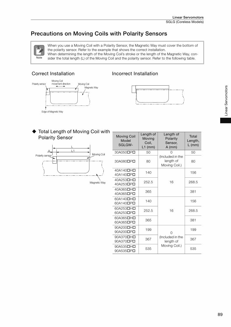
Linear Servomotors SGLG (Coreless Models)
89
Line
ar S
ervo
mot
ors
Precautions on Moving Coils with Polarity Sensors
When you use a Moving Coil with a Polarity Sensor, the Magnetic Way must cover the bottom of
the polarity sensor. Refer to the example that shows the correct installation.
When determining the length of the Moving Coil’s stroke or the length of the Magnetic Way, con-
sider the total length (L) of the Moving Coil and the polarity sensor. Refer to the following table.
Correct Installation Incorrect Installation
Total Length of Moving Coil with Polarity Sensor
Note
Polarity sensor
Edge of Magnetic Way
Magnetic Way
Moving Coil
Moving Coil
movement direction
L1A
L
Polarity sensor
Magnetic Way
Moving Coil
Moving Coil Model
SGLGW-
Length of Moving
Coil, L1 (mm)
Length of Polarity Sensor, A (mm)
Total Length, L (mm)
30A050 P 50 0
(Included in the
length of
Moving Coil.)
50
30A080 P 80 80
40A140 H
40A140 P140
16
156
40A253 H
40A253 P252.5 268.5
40A365 H
40A365 P365 381
60A140 H
60A140 P140
16
156
60A253 H
60A253 P252.5 268.5
60A365 H
60A365 P365 381
90A200 H
90A200 P199
0
(Included in the
length of
Moving Coil.)
199
90A370 H
90A370 P367 367
90A535 H
90A535 P535 535
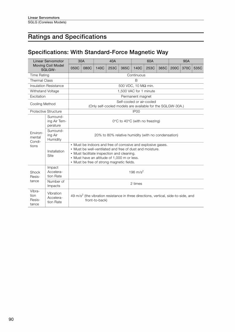
Linear ServomotorsSGLG (Coreless Models)
90
Ratings and Specifications
Specifications: With Standard-Force Magnetic Way Linear Servomotor Moving Coil Model
SGLGW-
30A 40A 60A 90A
050C 080C 140C 253C 365C 140C 253C 365C 200C 370C 535C
Time Rating Continuous
Thermal Class B
Insulation Resistance 500 VDC, 10 MΩ min.
Withstand Voltage 1,500 VAC for 1 minute
Excitation Permanent magnet
Cooling Method Self-cooled or air-cooled
(Only self-cooled models are available for the SGLGW-30A.)
Protective Structure IP00
Environ-
mental
Condi-
tions
Surround-
ing Air Tem-
perature
0°C to 40°C (with no freezing)
Surround-
ing Air
Humidity
20% to 80% relative humidity (with no condensation)
Installation
Site
• Must be indoors and free of corrosive and explosive gases.
• Must be well-ventilated and free of dust and moisture.
• Must facilitate inspection and cleaning.
• Must have an altitude of 1,000 m or less.
• Must be free of strong magnetic fields.
Shock
Resis-
tance
Impact
Accelera-
tion Rate
196 m/s2
Number of
Impacts 2 times
Vibra-
tion
Resis-
tance
Vibration
Accelera-
tion Rate
49 m/s2 (the vibration resistance in three directions, vertical, side-to-side, and
front-to-back)
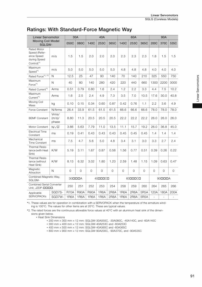
Linear Servomotors SGLG (Coreless Models)
91
Line
ar S
ervo
mot
ors
Ratings: With Standard-Force Magnetic Way
*1. These values are for operation in combination with a SERVOPACK when the temperature of the armature wind-
ing is 100°C. The values for other items are at 20°C. These are typical values.
*2. The rated forces are the continuous allowable force values at 40°C with an aluminum heat sink of the dimen-
sions given below.
• Heat Sink Dimensions
• 200 mm × 300 mm × 12 mm: SGLGW-30A050C, -30A080C, -40A140C, and -60A140C
• 300 mm × 400 mm × 12 mm: SGLGW-40A253C and -60A253C
• 400 mm × 500 mm × 12 mm: SGLGW-40A365C and -60A365C
• 800 mm × 900 mm × 12 mm: SGLGW-90A200C, -90A370C, and -90A535C
Linear Servomotor Moving Coil Model
SGLGW-
30A 40A 60A 90A
050C 080C 140C 253C 365C 140C 253C 365C 200C 370C 535C
Rated Motor
Speed (Refer-
ence Speed
during Speed
Control)*1
m/s 1.5 1.5 2.0 2.0 2.0 2.3 2.3 2.3 1.8 1.5 1.5
Maximum
Speed*1 m/s 5.0 5.0 5.0 5.0 5.0 4.8 4.8 4.8 4.0 4.0 4.0
Rated Force*1, *2 N 12.5 25 47 93 140 70 140 210 325 550 750
Maximum
Force*1 N 40 80 140 280 420 220 440 660 1300 2200 3000
Rated Current*1 Arms 0.51 0.79 0.80 1.6 2.4 1.2 2.2 3.3 4.4 7.5 10.2
Maximum
Current*1 Arms 1.6 2.5 2.4 4.9 7.3 3.5 7.0 10.5 17.6 30.0 40.8
Moving Coil
Mass kg 0.10 0.15 0.34 0.60 0.87 0.42 0.76 1.1 2.2 3.6 4.9
Force Constant N/Arms 26.4 33.9 61.5 61.5 61.5 66.6 66.6 66.6 78.0 78.0 78.0
BEMF Constant
Vrms/
(m/s)/
phase
8.80 11.3 20.5 20.5 20.5 22.2 22.2 22.2 26.0 26.0 26.0
Motor Constant N/ 3.66 5.63 7.79 11.0 13.5 11.1 15.7 19.2 26.0 36.8 45.0
Electrical Time
Constant ms 0.19 0.41 0.43 0.43 0.43 0.45 0.45 0.45 1.4 1.4 1.4
Mechanical
Time Constantms 7.5 4.7 5.6 5.0 4.8 3.4 3.1 3.0 3.3 2.7 2.4
Thermal Resis-
tance (with Heat
Sink)
K/W 5.19 3.11 1.67 0.87 0.58 1.56 0.77 0.51 0.39 0.26 0.22
Thermal Resis-
tance (without
Heat Sink)
K/W 8.13 6.32 3.02 1.80 1.23 2.59 1.48 1.15 1.09 0.63 0.47
Magnetic
AttractionN 0 0 0 0 0 0 0 0 0 0 0
Combined Magnetic Way,
SGLGM- 30 A 40 C 60 C 90 A
Combined Serial Converter
Unit, JZDP- - 250 251 252 253 254 258 259 260 264 265 266
Applicable
SERVOPACKs
SGD7S- R70A R90A R90A 1R6A 2R8A 1R6A 2R8A 5R5A 120A 180A 200A
SGD7W- 1R6A 1R6A 1R6A 1R6A 2R8A 1R6A 2R8A 5R5A - - -
W
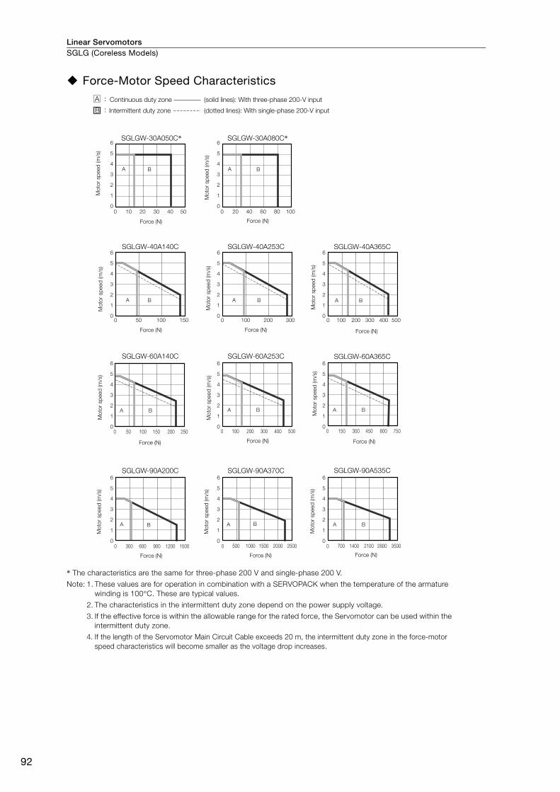
Linear ServomotorsSGLG (Coreless Models)
92
Force-Motor Speed Characteristics
* The characteristics are the same for three-phase 200 V and single-phase 200 V.
Note: 1. These values are for operation in combination with a SERVOPACK when the temperature of the armature
winding is 100°C. These are typical values.
2. The characteristics in the intermittent duty zone depend on the power supply voltage.
3. If the effective force is within the allowable range for the rated force, the Servomotor can be used within the
intermittent duty zone.
4. If the length of the Servomotor Main Circuit Cable exceeds 20 m, the intermittent duty zone in the force-motor
speed characteristics will become smaller as the voltage drop increases.
SGLGW-40A365C
0 100 200 300 400 500
A B
SGLGW-40A140C
0 15050 100
A B
SGLGW-40A253C
0 300200100
A B
SGLGW-30A050C*6
5
4
3
2
1
0
6
5
4
3
2
1
0
6
5
4
3
2
1
0
6
5
4
3
2
1
0
6
5
4
3
2
1
0
6
5
4
3
2
1
0
6
5
4
3
2
1
0
6
5
4
3
2
1
0
6
5
4
3
2
1
0
6
5
4
3
2
1
0
6
5
4
3
2
1
0
0 10 20 30 40 50
A B
SGLGW-30A080C*
20 40 60 80 1000
A B
SGLGW-60A365C
750600450150 3000
A B
SGLGW-60A140C
250150 20050 1000
A B
SGLGW-60A253C
0
A B
SGLGW-90A200C
0
A B
SGLGW-90A370C
0
A B A B
SGLGW-90A535C
100 200 300 400 500
15001200900600300 2500200015001000500 0 3500280021001400700
Continuous duty zone
Intermittent duty zone
Mo
tor sp
eed
(m
/s)
Force (N) Force (N) Force (N)
Force (N)Force (N)Force (N)
Force (N) Force (N) Force (N)
Force (N) Force (N)
(solid lines): With three-phase 200-V input
(dotted lines): With single-phase 200-V input
Mo
tor sp
eed
(m
/s)
Mo
tor sp
eed
(m
/s)
Mo
tor sp
eed
(m
/s)
Mo
tor sp
eed
(m
/s)
Mo
tor sp
eed
(m
/s)
Mo
tor sp
eed
(m
/s)
Mo
tor sp
eed
(m
/s)
Mo
tor sp
eed
(m
/s)
Mo
tor sp
eed
(m
/s)
Mo
tor sp
eed
(m
/s)
A :
B :
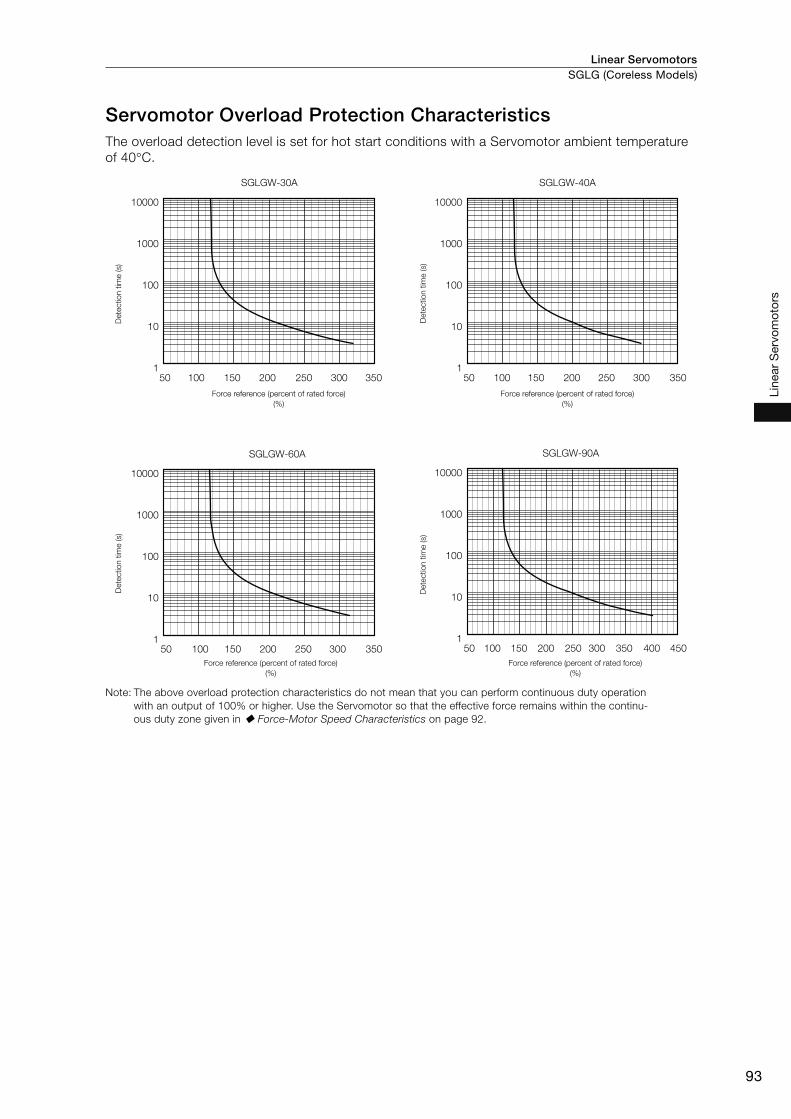
Linear Servomotors SGLG (Coreless Models)
93
Line
ar S
ervo
mot
ors
Servomotor Overload Protection Characteristics The overload detection level is set for hot start conditions with a Servomotor ambient temperature
of 40°C.
Note: The above overload protection characteristics do not mean that you can perform continuous duty operation
with an output of 100% or higher. Use the Servomotor so that the effective force remains within the continu-
ous duty zone given in Force-Motor Speed Characteristics on page 92.
SGLGW-30A
10000
1000
100
10
135050 100 150 200 250 300
SGLGW-40A
35050 100 150 200 250 300
10000
1000
100
10
1
35050 100 150 200 250 300 450350 40050 100 150 200 250 300
SGLGW-90A
10000
1000
100
10
1
SGLGW-60A
10000
1000
100
10
1
Dete
ctio
n t
ime (s)
Force reference (percent of rated force)
(%)
Dete
ctio
n t
ime (s)
Force reference (percent of rated force)
(%)
Dete
ctio
n t
ime (s)
Force reference (percent of rated force)
(%)
Dete
ctio
n t
ime (s)
Force reference (percent of rated force)
(%)

Linear ServomotorsSGLG (Coreless Models)
94
Specifications: With High-Force Magnetic Way
Ratings: With High-Force Magnetic Way
*1. These values are for operation in combination with a SERVOPACK when the temperature of the armature wind-
ing is 100°C. The values for other items are at 20°C. These are typical values.
*2. The rated forces are the continuous allowable force values at 40°C with an aluminum heat sink of the dimen-
sions given below.
• Heat Sink Dimensions
• 200 mm × 300 mm × 12 mm: SGLGW-40A140C and -60A140C
• 300 mm × 400 mm × 12 mm: SGLGW-40A253C and -60A253C
• 400 mm × 500 mm × 12 mm: SGLGW-40A365C and -60A365C
Linear Servomotor Moving Coil Model SGLGW-
40A 60A
140C 253C 365C 140C 253C 365C
Time Rating Continuous
Thermal Class B
Insulation Resistance 500 VDC, 10 MΩ min.
Withstand Voltage 1,500 VAC for 1 minute
Excitation Permanent magnet
Cooling Method Self-cooled or air-cooled
Protective Structure IP00
Environmental
Conditions
Surrounding Air Temperature 0°C to 40°C (with no freezing)
Surrounding Air Humidity 20% to 80% relative humidity (with no condensation)
Installation Site
• Must be indoors and free of corrosive and explosive gases.
• Must be well-ventilated and free of dust and moisture.
• Must facilitate inspection and cleaning.
• Must have an altitude of 1,000 m or less.
• Must be free of strong magnetic fields.
Shock
Resistance
Impact Acceleration Rate 196 m/s2
Number of Impacts 2 times
Vibration
Resistance Vibration Acceleration Rate
49 m/s2 (the vibration resistance in three directions, vertical,
side-to-side, and front-to-back)
Linear Servomotor Moving Coil Model SGLGW-
40A 60A
140C 253C 365C 140C 253C 365C
Rated Motor Speed (Reference
Speed during Speed Control)*1 m/s 1.0 1.0 1.0 1.0 1.0 1.0
Maximum Speed*1 m/s 4.2 4.2 4.2 4.2 4.2 4.2
Rated Force*1, *2 N 57 114 171 85 170 255
Maximum Force*1 N 230 460 690 360 720 1080
Rated Current*1 Arms 0.80 1.6 2.4 1.2 2.2 3.3
Maximum Current*1 Arms 3.2 6.5 9.7 5.0 10.0 14.9
Moving Coil Mass kg 0.34 0.60 0.87 0.42 0.76 1.1
Force Constant N/Arms 76.0 76.0 76.0 77.4 77.4 77.4
BEMF Constant Vrms/(m/s)/
phase 25.3 25.3 25.3 25.8 25.8 25.8
Motor Constant N/ 9.62 13.6 16.7 12.9 18.2 22.3
Electrical Time Constant ms 0.43 0.43 0.43 0.45 0.45 0.45
Mechanical Time Constant ms 3.7 3.2 3.1 2.5 2.3 2.2
Thermal Resistance (with Heat Sink) K/W 1.67 0.87 0.58 1.56 0.77 0.51
Thermal Resistance (without Heat Sink) K/W 3.02 1.80 1.23 2.59 1.48 1.15
Magnetic Attraction N 0 0 0 0 0 0
Combined Magnetic Way, SGLGM- 40 C -M 60 C -M
Combined Serial Converter Unit, JZDP- - 255 256 257 261 262 263
Applicable SERVOPACKs SGD7S- 1R6A 2R8A 3R8A 1R6A 3R8A 7R6A
SGD7W- 1R6A 2R8A 5R5A 1R6A 5R5A 7R6A
W
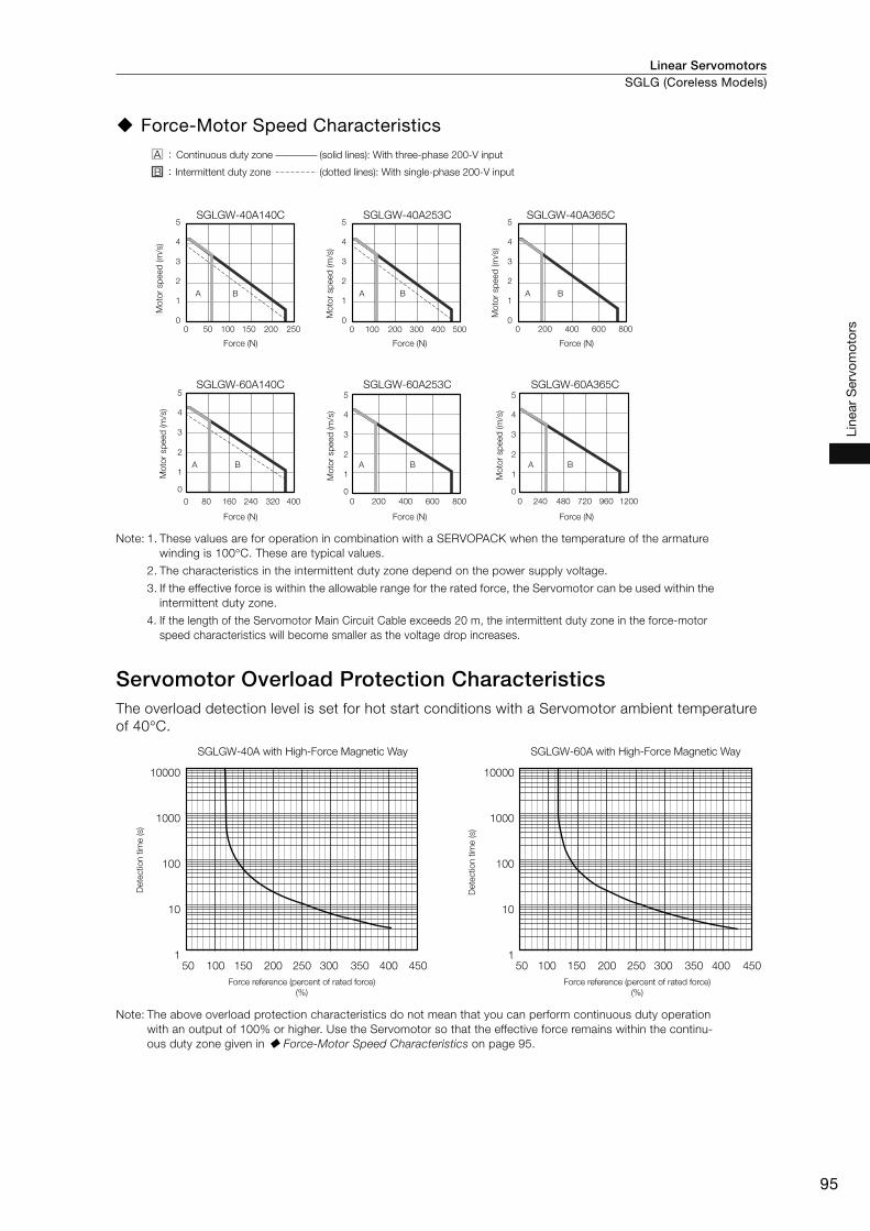
Linear Servomotors SGLG (Coreless Models)
95
Line
ar S
ervo
mot
ors
Force-Motor Speed Characteristics
Note: 1. These values are for operation in combination with a SERVOPACK when the temperature of the armature
winding is 100°C. These are typical values.
2. The characteristics in the intermittent duty zone depend on the power supply voltage.
3. If the effective force is within the allowable range for the rated force, the Servomotor can be used within the
intermittent duty zone.
4. If the length of the Servomotor Main Circuit Cable exceeds 20 m, the intermittent duty zone in the force-motor
speed characteristics will become smaller as the voltage drop increases.
Servomotor Overload Protection Characteristics The overload detection level is set for hot start conditions with a Servomotor ambient temperature
of 40°C.
Note: The above overload protection characteristics do not mean that you can perform continuous duty operation
with an output of 100% or higher. Use the Servomotor so that the effective force remains within the continu-
ous duty zone given in Force-Motor Speed Characteristics on page 95.
SGLGW-40A140C
0
1
2
3
4
5
0
A B
A B A B A B
A B A B
SGLGW-40A253C
0
1
2
3
4
5
0
SGLGW-40A365C
0
1
2
3
4
5
0 200 400 600 800
200 400 600 800
SGLGW-60A253CSGLGW-60A140C5
4
3
2
1
0
0
SGLGW-60A365C5
4
3
2
1
0
0
5
4
3
2
1
0
0
250150 20050 100
400240 32080 160
100 200 300 400 500
240 480 720 960 1200
(dotted lines): With single-phase 200-V input
Force (N) Force (N)Force (N)
Force (N) Force (N)Force (N)
Mo
tor sp
eed
(m
/s)
(solid lines): With three-phase 200-V input
Intermittent duty zone
Continuous duty zone
Mo
tor sp
eed
(m
/s)
Mo
tor sp
eed
(m
/s)
Mo
tor sp
eed
(m
/s)
Mo
tor sp
eed
(m
/s)
Mo
tor sp
eed
(m
/s)
A :
B :
450350 40050 100 150 200 250 300
10000
1000
100
10
1450350 40050 100 150 200 250 300
10000
1000
100
10
1
SGLGW-40A with High-Force Magnetic Way SGLGW-60A with High-Force Magnetic Way
Dete
ctio
n t
ime (s)
Force reference (percent of rated force)
(%)
Force reference (percent of rated force)
(%)
Dete
ctio
n t
ime (s)
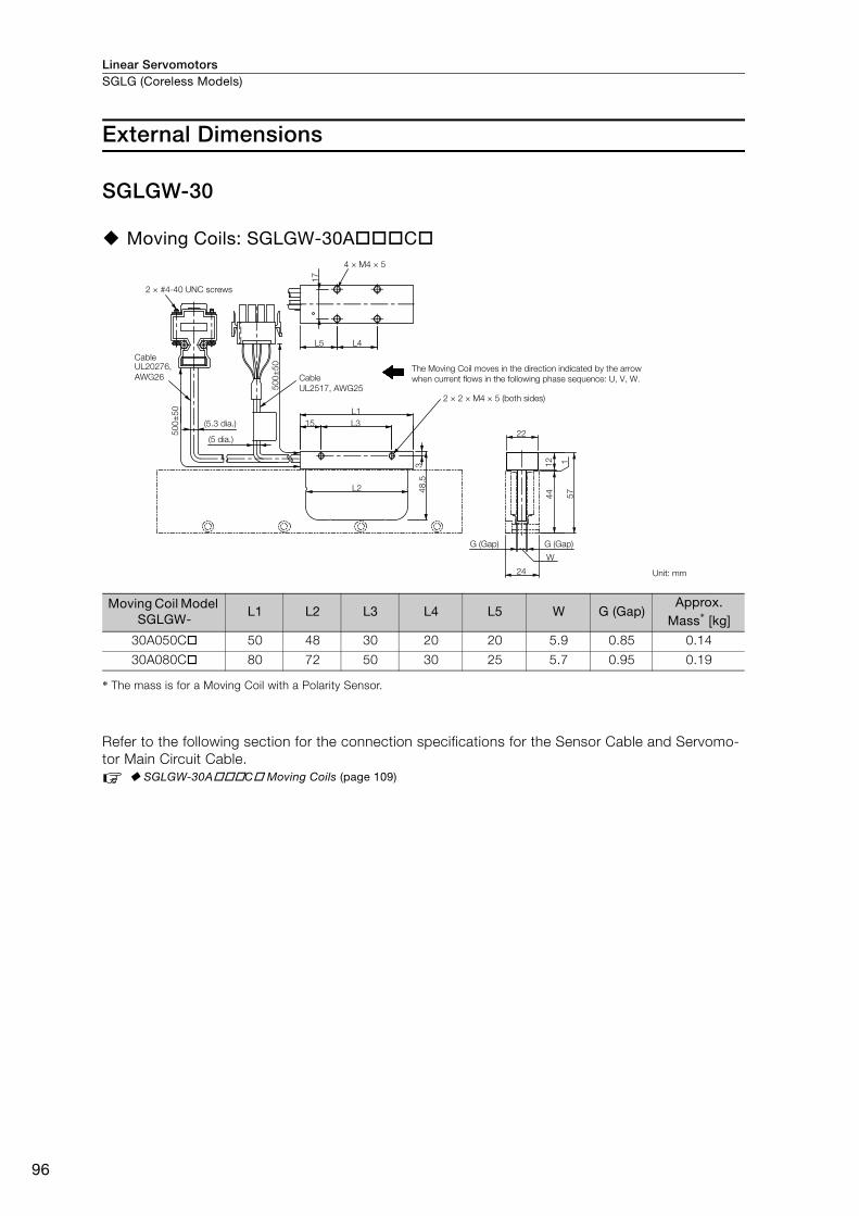
Linear ServomotorsSGLG (Coreless Models)
96
External Dimensions
SGLGW-30
Moving Coils: SGLGW-30A C
* The mass is for a Moving Coil with a Polarity Sensor.
Refer to the following section for the connection specifications for the Sensor Cable and Servomo-
tor Main Circuit Cable.
SGLGW-30A C Moving Coils (page 109)
Moving Coil Model SGLGW-
L1 L2 L3 L4 L5 W G (Gap)Approx.
Mass* [kg]
30A050C 50 48 30 20 20 5.9 0.85 0.14
30A080C 80 72 50 30 25 5.7 0.95 0.19
3 1
17
4 × M4 × 5
L5 L4
50
0±
50
50
0±
50
22
57
24
444
8.5
15
L1
L3
L2
G (Gap) G (Gap)
W1
2
UL20276,
AWG26
2 × #4-40 UNC screws
Cable
(5.3 dia.)
Cable
UL2517, AWG25
The Moving Coil moves in the direction indicated by the arrow
when current flows in the following phase sequence: U, V, W.
2 × 2 × M4 × 5 (both sides)
Unit: mm
(5 dia.)
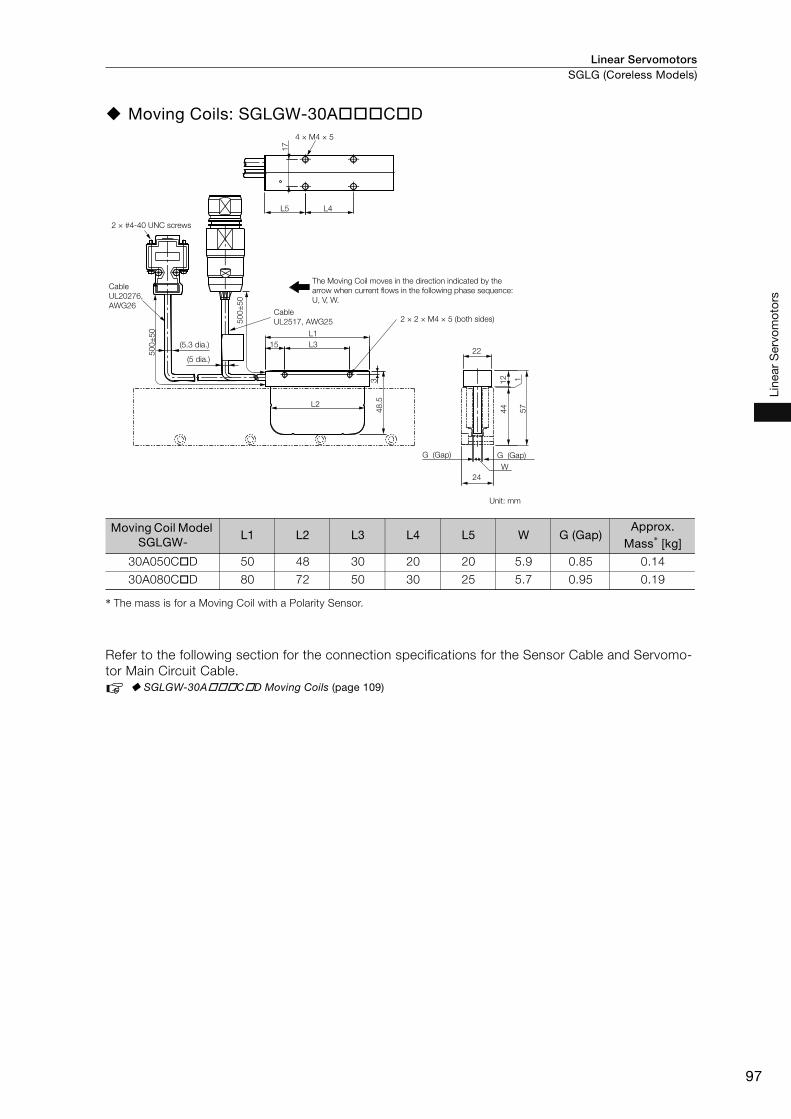
Linear Servomotors SGLG (Coreless Models)
97
Line
ar S
ervo
mot
ors
Moving Coils: SGLGW-30A C D
* The mass is for a Moving Coil with a Polarity Sensor.
Refer to the following section for the connection specifications for the Sensor Cable and Servomo-
tor Main Circuit Cable.
SGLGW-30A C D Moving Coils (page 109)
Moving Coil Model SGLGW-
L1 L2 L3 L4 L5 W G (Gap)Approx.
Mass* [kg]
30A050C D 50 48 30 20 20 5.9 0.85 0.14
30A080C D 80 72 50 30 25 5.7 0.95 0.19
3
22
24
48
.5
15
50
0±
50
50
0±
50
L1
L3
L2
G (Gap)G (Gap)
17
4 × M4 × 5
L5 L4
15
7
44
W
12
2 × #4-40 UNC screws
Cable
UL20276,
AWG26
(5.3 dia.)
(5 dia.)
The Moving Coil moves in the direction indicated by the
arrow when current flows in the following phase sequence:
U, V, W.
Cable
UL2517, AWG25 2 × 2 × M4 × 5 (both sides)
Unit: mm
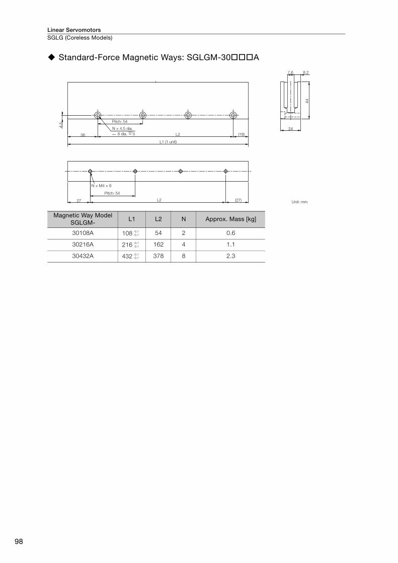
Linear ServomotorsSGLG (Coreless Models)
98
Standard-Force Magnetic Ways: SGLGM-30 A
Magnetic Way Model SGLGM-
L1 L2 N Approx. Mass [kg]
30108A 108 54 2 0.6
30216A 216 162 4 1.1
30432A 432 378 8 2.3
27 (27)
44
7.6 8.2
N × M4 × 6
24
L2
4.5
36 (18)L2
Pitch: 54
L1 (1 unit)
Pitch: 54
Unit: mm
8 dia. 5
N × 4.5 dia.
-0.1
-0.1
-0.1
-0.1
-0.1
-0.1
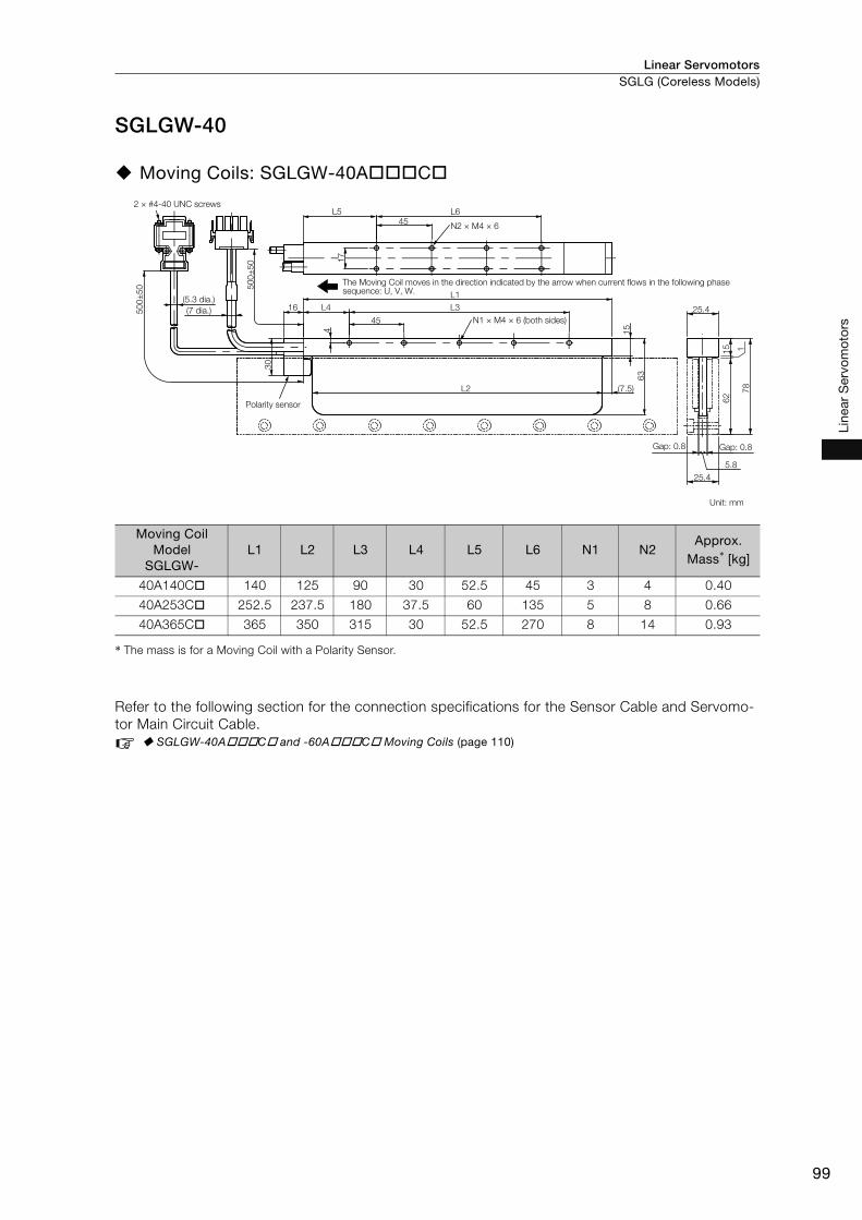
Linear Servomotors SGLG (Coreless Models)
99
Line
ar S
ervo
mot
ors
SGLGW-40
Moving Coils: SGLGW-40A C
* The mass is for a Moving Coil with a Polarity Sensor.
Refer to the following section for the connection specifications for the Sensor Cable and Servomo-
tor Main Circuit Cable.
SGLGW-40A C and -60A C Moving Coils (page 110)
Moving Coil Model
SGLGW-L1 L2 L3 L4 L5 L6 N1 N2
Approx. Mass* [kg]
40A140C 140 125 90 30 52.5 45 3 4 0.40
40A253C 252.5 237.5 180 37.5 60 135 5 8 0.66
40A365C 365 350 315 30 52.5 270 8 14 0.93
N2 × M4 × 6
15
63
30
4
(7.5)
17
L5 L6
45
L1
L316 L4
45
L2
50
0±
50 5
00
±5
0
15 1
25.4
Gap: 0.8Gap: 0.8
25.4
78
62
5.8
2 × #4-40 UNC screws
(5.3 dia.)
(7 dia.)
Polarity sensor
The Moving Coil moves in the direction indicated by the arrow when current flows in the following phase sequence: U, V, W.
N1 × M4 × 6 (both sides)
Unit: mm

Linear ServomotorsSGLG (Coreless Models)
100
Moving Coils: SGLGW-40A C D
* The mass is for a Moving Coil with a Polarity Sensor.
Refer to the following section for the connection specifications for the Sensor Cable and Servomo-
tor Main Circuit Cable.
SGLGW-40A C D and -60A C D Moving Coils (page 110)
Moving Coil Model
SGLGW-L1 L2 L3 L4 L5 L6 N1 N2
Approx. Mass* [kg]
40A140C D 140 125 90 30 52.5 45 3 4 0.40
40A253C D 252.5 237.5 180 37.5 60 135 5 8 0.66
40A365C D 365 350 315 30 52.5 270 8 14 0.93
N2 × M4 × 6
15
633
0
4
(7.5)
17
L5 L645
L1
L3
L2
16 L4
45
50
0±
50 5
00
±5
0
15 1
25.4
Gap: 0.8Gap: 0.8
25.4
78
62
5.8
2 × #4-40 UNC screws
Polarity sensor
The Moving Coil moves in the direction indicated by the arrow when current flows in the following phase sequence: U, V, W.
N1 × M4 × 6 (both sides)
Unit: mm
(7 dia.)
(5.3 dia.)

Linear Servomotors SGLG (Coreless Models)
101
Line
ar S
ervo
mot
ors
Standard-Force Magnetic Ways: SGLGM-40 C (without Mounting Holes on the Bottom) SGLGM-40 CT (with Mounting Holes on the Bottom)
Type Magnetic Way Model SGLGM- L1 L2 N Approx. Mass [kg]
Standard-Force
40090C or 40090CT 90 45 2 0.8
40225C or 40225CT 225 180 5 2.0
40360C or 40360CT 360 315 8 3.1
40405C or 40405CT 405 360 9 3.5
40450C or 40450CT 450 405 10 3.9
7
L222.5
L222.5
N × M5 × 13
X
X
(22.5)
(22.5)
5.4
9
62
7.4
25.4
X-X
9
12.7
62
5.4
(13
)
7.4
25.4
X-X
X
XSGLGM-
40 C
SGLGM-
40 CT
10 dia. 5.4
L1 (1 unit)
( SGLGM- CT only)Unit: mm
5.5
dia
.
10
dia
.
5.5
dia
.
10
dia
.
Pitch: 45
N × 5.5 dia.
Pitch: 45
-0.1
-0.3
-0.1
-0.3
-0.1
-0.3
-0.1
-0.3
-0.1
-0.3
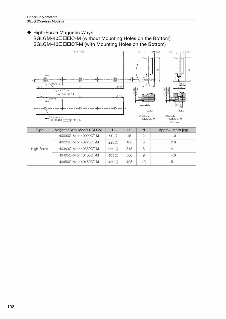
Linear ServomotorsSGLG (Coreless Models)
102
High-Force Magnetic Ways: SGLGM-40 C-M (without Mounting Holes on the Bottom) SGLGM-40 CT-M (with Mounting Holes on the Bottom)
Type Magnetic Way Model SGLGM- L1 L2 N Approx. Mass [kg]
High-Force
40090C-M or 40090CT-M 90 45 2 1.0
40225C-M or 40225CT-M 225 180 5 2.6
40360C-M or 40360CT-M 360 315 8 4.1
40405C-M or 40405CT-M 405 360 9 4.6
40450C-M or 40450CT-M 450 405 10 5.1
L222.5
22.5 (22.5)
(22.5)
L2
7
62
62
12.27.4
31.815.9
12.2
31.8
7.4
X
X
X
X
5.4
(13
)5.4
X-X X-X
N × M5 × 13SGLGM-
40 C-M
SGLGM-
40 CT-M
L1 (1 unit)
( SGLGM- CT-M only)Unit: mm
5.5
dia
.
10
dia
.
5.5
dia
.
10
dia
.
Pitch: 45
10 dia. 5.4
N × 5.5 dia.
Pitch: 45
-0.1
-0.3
-0.1
-0.3
-0.1
-0.3
-0.1
-0.3
-0.1
-0.3
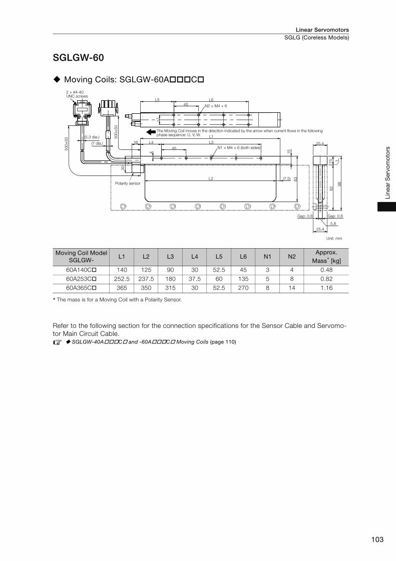
Linear Servomotors SGLG (Coreless Models)
103
Line
ar S
ervo
mot
ors
SGLGW-60
Moving Coils: SGLGW-60A C
* The mass is for a Moving Coil with a Polarity Sensor.
Refer to the following section for the connection specifications for the Sensor Cable and Servomo-
tor Main Circuit Cable.
SGLGW-40A C and -60A C Moving Coils (page 110)
Moving Coil ModelSGLGW-
L1 L2 L3 L4 L5 L6 N1 N2Approx.
Mass* [kg]
60A140C 140 125 90 30 52.5 45 3 4 0.48
60A253C 252.5 237.5 180 37.5 60 135 5 8 0.82
60A365C 365 350 315 30 52.5 270 8 14 1.16
2 × #4-40 UNC screws
N2 × M4 × 6
15
83
L6
45
L5
30
50
0±
50
16 L4
45
L1
L3
(7.5)L2
50
0±
50
4
17
15 1
25.4
Gap: 0.8Gap: 0.8
25.4
98
82
5.8
(5.3 dia.)
(7 dia.)
Polarity sensor
The Moving Coil moves in the direction indicated by the arrow when current flows in the following phase sequence: U, V, W.
N1 × M4 × 6 (both sides)
Unit: mm

Linear ServomotorsSGLG (Coreless Models)
104
Moving Coils: SGLGW-60A C D
* The mass is for a Moving Coil with a Polarity Sensor.
Refer to the following section for the connection specifications for the Sensor Cable and Servomo-
tor Main Circuit Cable.
SGLGW-40A C D and -60A C D Moving Coils (page 110)
Moving Coil ModelSGLGW-
L1 L2 L3 L4 L5 L6 N1 N2Approx.
Mass* [kg]
60A140C D 140 125 90 30 52.5 45 3 4 0.48
60A253C D 252.5 237.5 180 37.5 60 135 5 8 0.82
60A365C D 365 350 315 30 52.5 270 8 14 1.16
N2 × M4 × 6
15
83
L6
45
L5
30
50
0±
50
16 L4
45
L1
L3
(7.5)L2
50
0±
50
4
17
15 1
25.4
Gap: 0.8Gap: 0.8
25.4
98
82
5.8
The Moving Coil moves in the direction indicated by the arrow when current flows in the following phase sequence: U, V, W.
Polarity sensor
Unit: mm
N1 × M4 × 6 (both sides)(7 dia.)
(5.3 dia.)
2 × #4-40
UNC screws
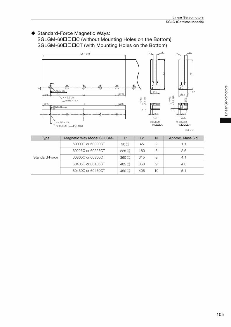
Linear Servomotors SGLG (Coreless Models)
105
Line
ar S
ervo
mot
ors
Standard-Force Magnetic Ways: SGLGM-60 C (without Mounting Holes on the Bottom) SGLGM-60 CT (with Mounting Holes on the Bottom)
Type Magnetic Way Model SGLGM- L1 L2 N Approx. Mass [kg]
Standard-Force
60090C or 60090CT 90 45 2 1.1
60225C or 60225CT 225 180 5 2.6
60360C or 60360CT 360 315 8 4.1
60405C or 60405CT 405 360 9 4.6
60450C or 60450CT 450 405 10 5.1
22.5
7
L2
L2
N × M5 × 13
22.5
X
(22.5)
(22.5)X
X
X
5.4
9
82
5.5
dia
.
7.4
25.4
X-X
12.7
82
5.4
(13
)
7.4
25.4
9
X-X
SGLGM-
60 C
SGLGM-
60 CT
10 dia. 5.4
N × 5.5 dia.
L1 (1 unit)
Unit: mm
10
dia
.
5.5
dia
.
10
dia
.
Pitch: 45
( SGLGM- CT only)
Pitch: 45
-0.1
-0.3
-0.1
-0.3
-0.1
-0.3
-0.1
-0.3
-0.1
-0.3

Linear ServomotorsSGLG (Coreless Models)
106
High-Force Magnetic Ways: SGLGM-60 C-M (without Mounting Holes on the Bottom) SGLGM-60 CT-M (with Mounting Holes on the Bottom)
Type Magnetic Way Model SGLGM- L1 L2 N Approx. Mass [kg]
High-Force
60090C-M or 60090CT-M 90 45 2 1.3
60225C-M or 60225CT-M 225 180 5 3.3
60360C-M or 60360CT-M 360 315 8 5.2
60405C-M or 60405CT-M 405 360 9 5.9
60450C-M or 60450CT-M 450 405 10 6.6
L222.5 (22.5)
(22.5)22.5 L2
N × M5 × 13
7
82
82
12.27.4
31.815.9
12.2
31.8
7.4
SGLGM-
60 C-M
SGLGM-
60 CT-M
X
X
X
X
5.4
(13
)
5.4
X-X X-X
10 dia. 5.4
( SGLGM- CT-M only)Unit: mm
Pitch: 45
N × 5.5 dia.
10
dia
.
5.5
dia
.
10
dia
.
5.5
dia
.
Pitch: 45
L1 (1 unit)
-0.1
-0.3
-0.1
-0.3
-0.1
-0.3
-0.1
-0.3
-0.1
-0.3
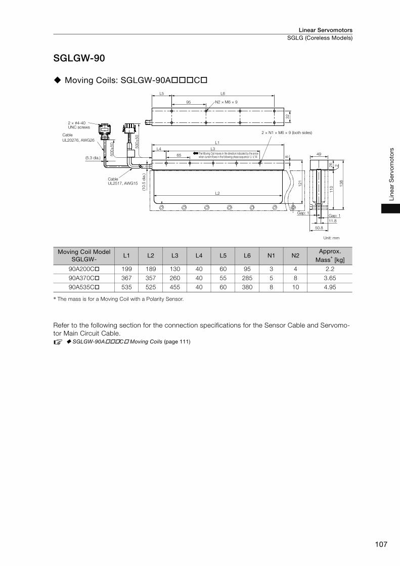
Linear Servomotors SGLG (Coreless Models)
107
Line
ar S
ervo
mot
ors
SGLGW-90
Moving Coils: SGLGW-90A C
* The mass is for a Moving Coil with a Polarity Sensor.
Refer to the following section for the connection specifications for the Sensor Cable and Servomo-
tor Main Circuit Cable.
SGLGW-90A C Moving Coils (page 111)
Moving Coil ModelSGLGW-
L1 L2 L3 L4 L5 L6 N1 N2Approx.
Mass* [kg]
90A200C 199 189 130 40 60 95 3 4 2.2
90A370C 367 357 260 40 55 285 5 8 3.65
90A535C 535 525 455 40 60 380 8 10 4.95
2
50.8
Gap: 1Gap: 1
11.8
26
49
13
8
11
0
32
50
0±
50
L2
95
8
12
1
50
0±
50
65
L3L4
L1UL20276, AWG26
L6L5
N2 × M6 × 9
2 × #4-40 UNC screws
The Moving Coil moves in the direction indicated by the arrow when current flows in the following phase sequence: U, V, W.
2 × N1 × M6 × 9 (both sides)
Unit: mm
Cable
(5.3 dia.)
(10
.5 d
ia.)
Cable UL2517, AWG15

Linear ServomotorsSGLG (Coreless Models)
108
Standard-Force Magnetic Ways: SGLGM-90 A
Magnetic Way ModelSGLGM-
L1 L2 N Approx. Mass [kg]
90252A 252 189 4 7.3
90504A 504 441 8 14.7
X-X
6.5
50.8
11
0
13.8 18.5
X
X
L2
L231.5 (31.5)
N × M6 × 14.5
8.5
19 (44)
L1 (1 unit)
Pitch: 63
N × 6.6 dia.
Pitch: 63 12
dia
.
6.6
dia
.
Unit: mm
12 dia. 6.5
-0.1
-0.3
-0.1
-0.3

Linear Servomotors SGLG (Coreless Models)
109
Line
ar S
ervo
mot
ors
Connector Specifications
SGLGW-30A C Moving Coils • Servomotor Connector
• Polarity Sensor Connector
• Polarity Sensor Output Signal
SGLGW-30A C D Moving Coils • Servomotor Connector
• Polarity Sensor Connector
• Polarity Sensor Output Signal
Plug: 350779-1
Pins: 350924-1 or 770672-1
From Tyco Electronics Japan G.K.
Mating Connector
Cap: 350780-1
Socket: 350925-1 or 770673-1
Pin connector: 17JE-23090-02 (D8C)
From DDK Ltd.
Mating Connector
Socket connector: 17JE-13090-02 (D8C)
Studs: 17L-002C or 17L-002C1
The figure on the right shows the relationship between the Su, Sv,
and Sw polarity sensor output signals and the inverse power of
each motor phase Vu, Vv, and Vw when the Moving Coil moves in
the direction indicated by the arrow in the dimensional drawings of
the Moving Coil.
Extension: SROC06JMSCN169
Pins: 021.423.1020
From Interconnectron GmbH
Mating Connector
Plug: SPUC06KFSDN236
Socket: 020.030.1020
Pin connector: 17JE-23090-02 (D8C)
From DDK Ltd.
Mating Connector
Socket connector: 17JE-13090-02 (D8C)
Studs: 17L-002C or 17L-002C1
The figure on the right shows the relationship between the Su, Sv,
and Sw polarity sensor output signals and the inverse power of
each motor phase Vu, Vv, and Vw when the Moving Coil moves in
the direction indicated by the arrow in the dimensional drawings of
the Moving Coil.
Vu
Vv
Vw
Su
Sv
Sw
0 180 360 540
Electrical angle (°)
Invers
e p
ow
er
(V)
Vu
Vv
Vw
Su
Sv
Sw
0 180 360 540
Electrical angle (°)
Invers
e p
ow
er
(V)
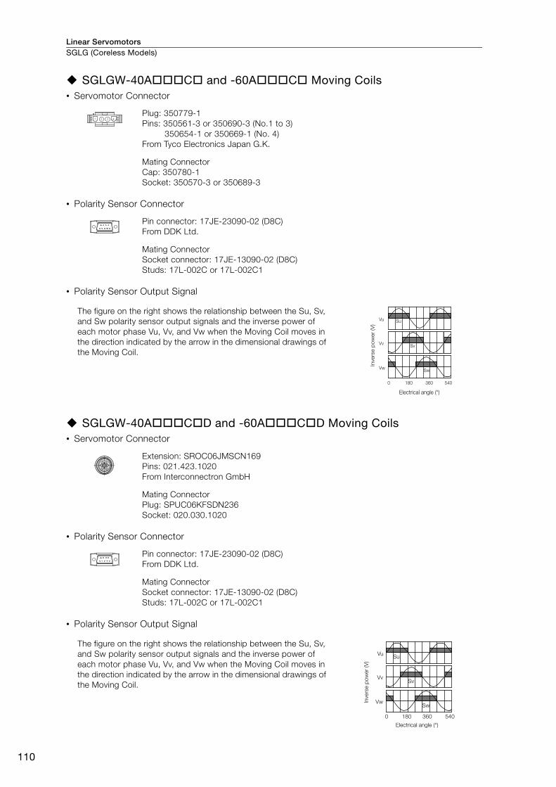
Linear ServomotorsSGLG (Coreless Models)
110
SGLGW-40A C and -60A C Moving Coils • Servomotor Connector
• Polarity Sensor Connector
• Polarity Sensor Output Signal
SGLGW-40A C D and -60A C D Moving Coils • Servomotor Connector
• Polarity Sensor Connector
• Polarity Sensor Output Signal
Plug: 350779-1
Pins: 350561-3 or 350690-3 (No.1 to 3)
350654-1 or 350669-1 (No. 4)
From Tyco Electronics Japan G.K.
Mating Connector
Cap: 350780-1
Socket: 350570-3 or 350689-3
Pin connector: 17JE-23090-02 (D8C)
From DDK Ltd.
Mating Connector
Socket connector: 17JE-13090-02 (D8C)
Studs: 17L-002C or 17L-002C1
The figure on the right shows the relationship between the Su, Sv,
and Sw polarity sensor output signals and the inverse power of
each motor phase Vu, Vv, and Vw when the Moving Coil moves in
the direction indicated by the arrow in the dimensional drawings of
the Moving Coil.
Extension: SROC06JMSCN169
Pins: 021.423.1020
From Interconnectron GmbH
Mating Connector
Plug: SPUC06KFSDN236
Socket: 020.030.1020
Pin connector: 17JE-23090-02 (D8C)
From DDK Ltd.
Mating Connector
Socket connector: 17JE-13090-02 (D8C)
Studs: 17L-002C or 17L-002C1
The figure on the right shows the relationship between the Su, Sv,
and Sw polarity sensor output signals and the inverse power of
each motor phase Vu, Vv, and Vw when the Moving Coil moves in
the direction indicated by the arrow in the dimensional drawings of
the Moving Coil.
Vu
Vv
Vw
Su
Sv
Sw
0 180 360 540
Electrical angle (°)
Invers
e p
ow
er
(V)
Vu
Vv
Vw
Su
Sv
Sw
0 180 360 540
Electrical angle (°)
Invers
e p
ow
er
(V)

Linear Servomotors SGLG (Coreless Models)
111
Line
ar S
ervo
mot
ors
SGLGW-90A C Moving Coils • Servomotor Connector
• Polarity Sensor Connector
• Polarity Sensor Output Signal
Plug: 350779-1
Pins: 350218-3 or 350547-3 (No.1 to 3)
350654-1 or 350669-1 (No. 4)
From Tyco Electronics Japan G.K.
Mating Connector
Cap: 350780-1
Socket: 350537-3 or 350550-3
Pin connector: 17JE-23090-02 (D8C)
From DDK Ltd.
Mating Connector
Socket connector: 17JE-13090-02 (D8C)
Stud: 17L-002C or 17L-002C1
The figure on the right shows the relationship between the Su, Sv,
and Sw polarity sensor output signals and the inverse power of
each motor phase Vu, Vv, and Vw when the Moving Coil moves in
the direction indicated by the arrow in the dimensional drawings of
the Moving Coil.
Vu
Vv
Vw
Su
Sv
Sw
0 180 360 540
Electrical angle (°)
Invers
e p
ow
er
(V)

Linear Servomotors
112
SGLF (Models with F-type Iron Cores)
Model Designations
SGLFW2 Models
Moving Coil
Note: This information is provided to explain model numbers. It is not meant to imply that models are available for all
combinations of codes.
* Contact your Yaskawa representative for information on water-cooled models.
Magnetic Way
S G L F W 2 - 30 A 070 A T
F A
W
30
45
90
1D
30 mm
45 mm
90 mm
135 mm
070
120
200
230
380
70 mm
125 mm
205 mm
230 mm
384 mm
T
S
L
Sensor Specification
With F-type iron core Without polarity sensor, with thermal protector
With polarity sensor and Thermal Protector
Cooling Method
Moving Coil
None Self-cooled
Water-cooled*
200 VAC
Servomotor Type Power Supply Voltage
Length of Moving Coil
Design Revision Order
Magnet Height
Moving Coil/Magnetic Way
1st digit
3rd+4th digits
2nd digit
11th digit
9th digit
6th+7th+8th digits
5th digit 10th digit
3rd+4th digits
1st digitLinear Σ Series
Linear Servomotors
2nd digit
5th digit
6th+7th+8th digits
9th digit
10th digit
11th digit
Code Specification
A
Code Specification
Code Specification
Code Specification
Code Specification
Code Specification
Code Specification
270
306
450
510
630
714
M
S G L F M 2 - 30 270 A
(Same as for the Moving Coil.)
(Same as for the Moving Coil.)
Magnetic Way
270 mm
306 mm
450 mm
510 mm
630 mm
714 mm
Servomotor TypeLength of Magnetic Way
Design Revision Order
Magnet Height
Moving Coil/Magnetic Way
1st digit
3rd+4th digits
2nd digit
8th digit
5th+6th+7th digits
3rd+4th digits
1st digitLinear Σ Series
Linear Servomotors
2nd digit
5th+6th+7th digits
8th digit
Code Specification
A
Code Specification
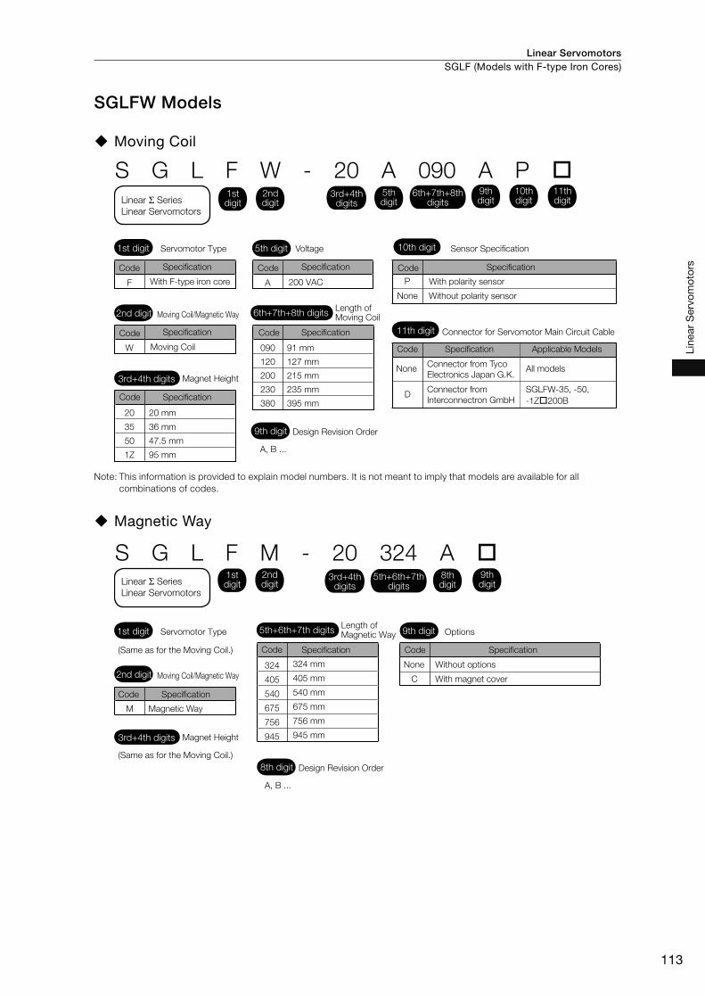
Linear Servomotors SGLF (Models with F-type Iron Cores)
113
Line
ar S
ervo
mot
ors
SGLFW Models
Moving Coil
Note: This information is provided to explain model numbers. It is not meant to imply that models are available for all
combinations of codes.
Magnetic Way
S G L F W - 20 A 090 A P
F A
W
20
35
50
1Z
20 mm
36 mm
47.5 mm
95 mm
090
120
200
230
380
91 mm
127 mm
215 mm
235 mm
395 mm
SGLFW-35, -50,
-1Z 200B
Connector for Servomotor Main Circuit Cable
Connector from Tyco
Electronics Japan G.K.All models
Connector from
Interconnectron GmbH
Applicable Models
None
Moving Coil
With polarity sensor
Without polarity sensorNone
With F-type iron core
Voltage
P
D
Sensor Specification
200 VAC
Servomotor Type
Length of Moving Coil
Design Revision Order
Magnet Height
Moving Coil/Magnetic Way
1st digit
3rd+4th digits
2nd digit
11th digit
9th digit
6th+7th+8th digits
5th digit 10th digit
3rd+4th digits
1st digitLinear Σ Series
Linear Servomotors
2nd digit
5th digit
6th+7th+8th digits
9th digit
10th digit
11th digit
Code Specification
A, B ...
Code Specification
Code SpecificationCode Specification
Code Specification Code Specification Code Specification
324
405
540
675
756
945
M
S G L F M - 20 324 A
Without options
With magnet cover
Options
(Same as for the Moving Coil.)
Magnetic Way
(Same as for the Moving Coil.)
324 mm
405 mm
540 mm
675 mm
756 mm
945 mm
None
C
Servomotor TypeLength of Magnetic Way
Design Revision Order
Magnet Height
Moving Coil/Magnetic Way
1st digit
3rd+4th digits
2nd digit
8th digit
5th+6th+7th digits 9th digit
3rd+4th digits
1st digitLinear Σ Series
Linear Servomotors
2nd digit
8th digit
5th+6th+7th digits
9th digit
A, B ...
Code Specification
Code Specification
Code Specification
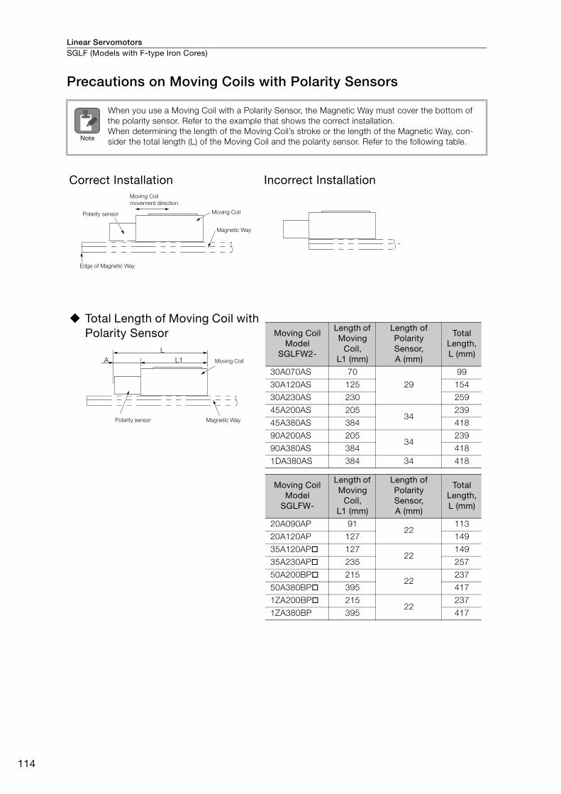
Linear ServomotorsSGLF (Models with F-type Iron Cores)
114
Precautions on Moving Coils with Polarity Sensors
When you use a Moving Coil with a Polarity Sensor, the Magnetic Way must cover the bottom of
the polarity sensor. Refer to the example that shows the correct installation.
When determining the length of the Moving Coil’s stroke or the length of the Magnetic Way, con-
sider the total length (L) of the Moving Coil and the polarity sensor. Refer to the following table.
Correct Installation Incorrect Installation
Total Length of Moving Coil with Polarity Sensor
Note
Polarity sensor
Moving Coil
movement direction
Magnetic Way
Moving Coil
Edge of Magnetic Way
L
L1A Moving Coil
Magnetic WayPolarity sensor
Moving Coil Model
SGLFW2-
Length of Moving
Coil, L1 (mm)
Length of Polarity Sensor, A (mm)
Total Length, L (mm)
30A070AS 70
29
99
30A120AS 125 154
30A230AS 230 259
45A200AS 20534
239
45A380AS 384 418
90A200AS 20534
239
90A380AS 384 418
1DA380AS 384 34 418
Moving Coil Model
SGLFW-
Length of Moving
Coil, L1 (mm)
Length of Polarity Sensor, A (mm)
Total Length, L (mm)
20A090AP 9122
113
20A120AP 127 149
35A120AP 12722
149
35A230AP 235 257
50A200BP 21522
237
50A380BP 395 417
1ZA200BP 21522
237
1ZA380BP 395 417

Linear Servomotors SGLF (Models with F-type Iron Cores)
115
Line
ar S
ervo
mot
ors
Ratings and Specifications: SGLFW2 Models
Specifications
* Contact your Yaskawa representative for information on water-cooled models.
Linear Servomotor Moving Coil Model SGLFW2-
30A 45A 90A 1DA
070A 120A 230A 200A 380A 200A 380A 380A
Time Rating Continuous
Thermal Class B
Insulation Resistance 500 VDC, 10 MΩ min.
Withstand Voltage 1,500 VAC for 1 minute
Excitation Permanent magnet
Cooling Method Self-cooled and water-cooled*
Protective Structure IP00
Environ-
mental
Condi-
tions
Surrounding Air Tem-
perature 0°C to 40°C (with no freezing)
Surrounding Air
Humidity 20% to 80% relative humidity (with no condensation)
Installation Site
• Must be indoors and free of corrosive and explosive gases.
• Must be well-ventilated and free of dust and moisture.
• Must facilitate inspection and cleaning.
• Must have an altitude of 1,000 m or less.
• Must be free of strong magnetic fields.
Shock
Resis-
tance
Impact Acceleration Rate 196 m/s2
Number of Impacts 2 times
Vibra-
tion
Resis-
tance
Vibration Accelera-
tion Rate
49 m/s2 (the vibration resistance in three directions, vertical, side-to-side,
and front-to-back)
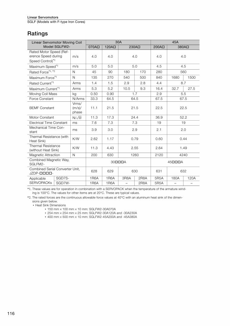
Linear ServomotorsSGLF (Models with F-type Iron Cores)
116
Ratings
*1. These values are for operation in combination with a SERVOPACK when the temperature of the armature wind-
ing is 100°C. The values for other items are at 20°C. These are typical values.
*2. The rated forces are the continuous allowable force values at 40°C with an aluminum heat sink of the dimen-
sions given below.
• Heat Sink Dimensions
• 150 mm × 100 mm × 10 mm: SGLFW2-30A070A
• 254 mm × 254 mm × 25 mm: SGLFW2-30A120A and -30A230A
• 400 mm × 500 mm × 10 mm: SGLFW2-45A200A and -45A380A
Linear Servomotor Moving Coil Model SGLFW2-
30A 45A070A 120A 230A 200A 380A
Rated Motor Speed (Ref-
erence Speed during
Speed Control)*1m/s 4.0 4.0 4.0 4.0 4.0
Maximum Speed*1 m/s 5.0 5.0 5.0 4.5 4.5
Rated Force*1, *2 N 45 90 180 170 280 560
Maximum Force*1 N 135 270 540 500 840 1680 1500
Rated Current*1 Arms 1.4 1.5 2.9 2.8 4.4 8.7
Maximum Current*1 Arms 5.3 5.2 10.5 9.3 16.4 32.7 27.5
Moving Coil Mass kg 0.50 0.90 1.7 2.9 5.5
Force Constant N/Arms 33.3 64.5 64.5 67.5 67.5
BEMF Constant
Vrms/
(m/s)/
phase
11.1 21.5 21.5 22.5 22.5
Motor Constant N/ 11.3 17.3 24.4 36.9 52.2
Electrical Time Constant ms 7.6 7.3 7.3 19 19
Mechanical Time Con-
stant ms 3.9 3.0 2.9 2.1 2.0
Thermal Resistance (with
Heat Sink) K/W 2.62 1.17 0.79 0.60 0.44
Thermal Resistance
(without Heat Sink)K/W 11.3 4.43 2.55 2.64 1.49
Magnetic Attraction N 200 630 1260 2120 4240
Combined Magnetic Way,
SGLFM2- 30 A 45 A
Combined Serial Converter Unit,
JZDP- - 628 629 630 631 632
Applicable
SERVOPACKs
SGD7S- 1R6A 1R6A 3R8A 2R8A 5R5A 180A 120A
SGD7W- 1R6A 1R6A − 2R8A 5R5A − −
W
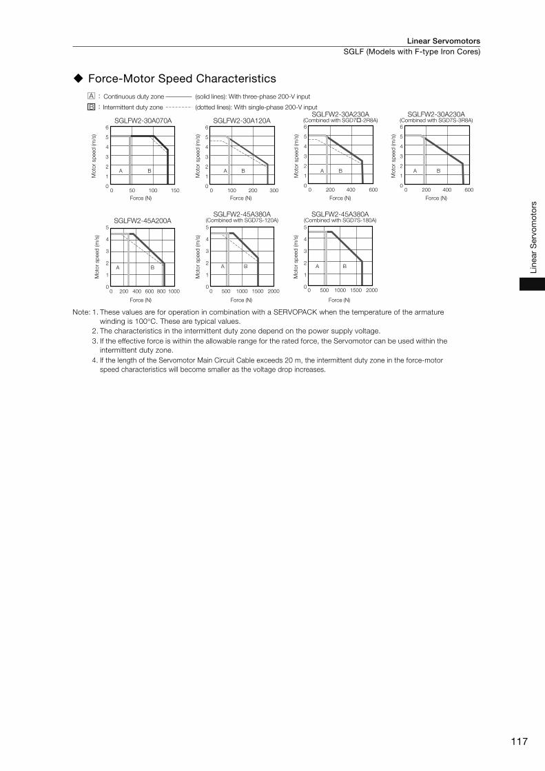
Linear Servomotors SGLF (Models with F-type Iron Cores)
117
Line
ar S
ervo
mot
ors
Force-Motor Speed Characteristics
Note: 1. These values are for operation in combination with a SERVOPACK when the temperature of the armature
winding is 100°C. These are typical values.
2. The characteristics in the intermittent duty zone depend on the power supply voltage.
3. If the effective force is within the allowable range for the rated force, the Servomotor can be used within the
intermittent duty zone.
4. If the length of the Servomotor Main Circuit Cable exceeds 20 m, the intermittent duty zone in the force-motor
speed characteristics will become smaller as the voltage drop increases.
SGLFW2-30A070A
SGLFW2-45A200A
SGLFW2-30A120A6
5
4
3
2
1
00 50 100 150
A B
6
5
4
3
2
1
00 100 200 300
A B A B
6
5
4
3
2
1
00 200 400 600
A B
6
5
4
3
2
1
00 200 400 600
A B
5
4
3
2
1
00 1000800600400200
5
4
3
2
1
00 200015001000500
A B
5
4
3
2
1
00 200015001000500
A B
SGLFW2-30A230A (Combined with SGD7 -2R8A)
SGLFW2-30A230A (Combined with SGD7S-3R8A)
Mo
tor sp
eed
(m
/s)
Force (N) Force (N) Force (N)
Force (N) Force (N) Force (N)
SGLFW2-45A380A (Combined with SGD7S-120A)
SGLFW2-45A380A (Combined with SGD7S-180A)
Force (N)
Mo
tor sp
eed
(m
/s)
Mo
tor sp
eed
(m
/s)
Mo
tor sp
eed
(m
/s)
Mo
tor sp
eed
(m
/s)
Mo
tor sp
eed
(m
/s)
Mo
tor sp
eed
(m
/s)
Continuous duty zone
Intermittent duty zone
(solid lines): With three-phase 200-V input
(dotted lines): With single-phase 200-V input
A :
B :
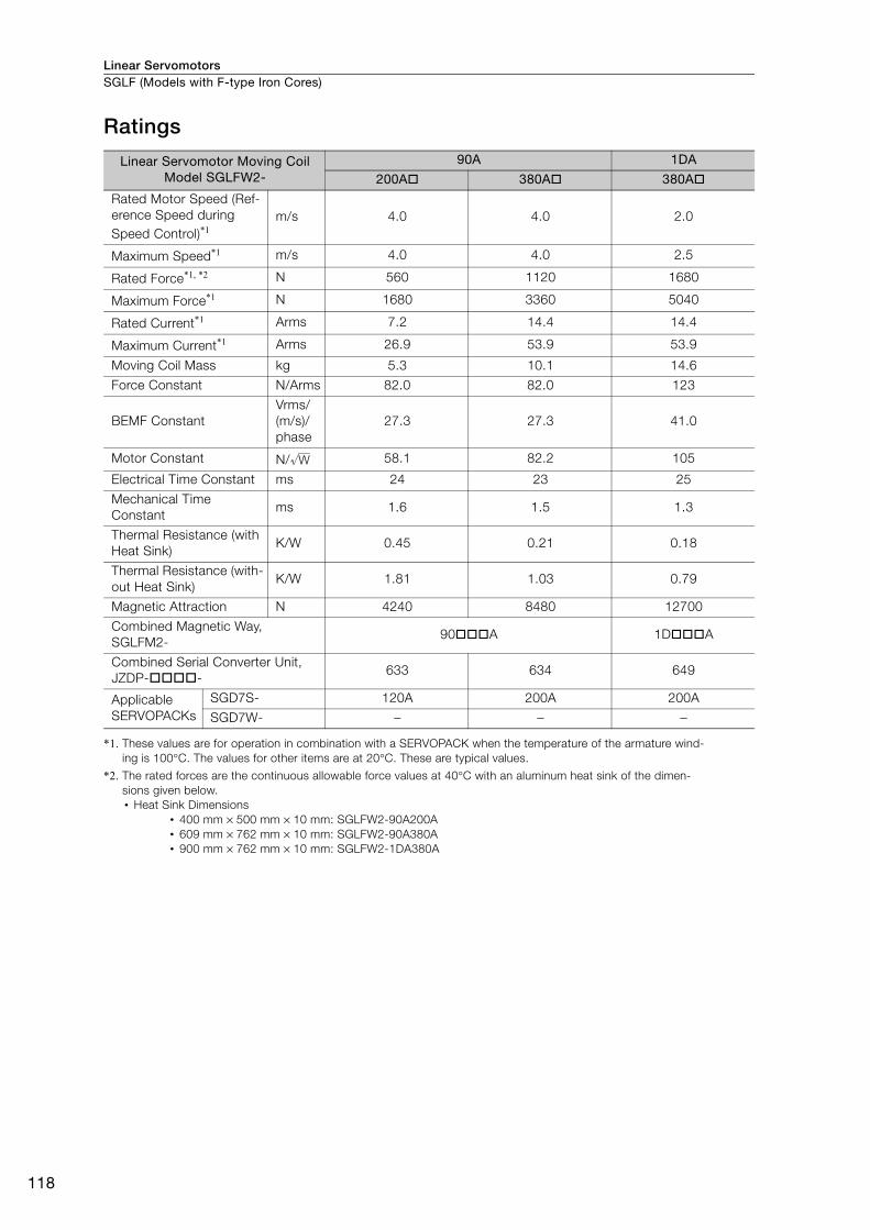
Linear ServomotorsSGLF (Models with F-type Iron Cores)
118
Ratings
*1. These values are for operation in combination with a SERVOPACK when the temperature of the armature wind-
ing is 100°C. The values for other items are at 20°C. These are typical values.
*2. The rated forces are the continuous allowable force values at 40°C with an aluminum heat sink of the dimen-
sions given below.
• Heat Sink Dimensions
• 400 mm × 500 mm × 10 mm: SGLFW2-90A200A
• 609 mm × 762 mm × 10 mm: SGLFW2-90A380A
• 900 mm × 762 mm × 10 mm: SGLFW2-1DA380A
Linear Servomotor Moving Coil Model SGLFW2-
90A 1DA
200A 380A 380A
Rated Motor Speed (Ref-
erence Speed during
Speed Control)*1m/s 4.0 4.0 2.0
Maximum Speed*1 m/s 4.0 4.0 2.5
Rated Force*1, *2 N 560 1120 1680
Maximum Force*1 N 1680 3360 5040
Rated Current*1 Arms 7.2 14.4 14.4
Maximum Current*1 Arms 26.9 53.9 53.9
Moving Coil Mass kg 5.3 10.1 14.6
Force Constant N/Arms 82.0 82.0 123
BEMF Constant
Vrms/
(m/s)/
phase
27.3 27.3 41.0
Motor Constant N/ 58.1 82.2 105
Electrical Time Constant ms 24 23 25
Mechanical Time
Constantms 1.6 1.5 1.3
Thermal Resistance (with
Heat Sink)K/W 0.45 0.21 0.18
Thermal Resistance (with-
out Heat Sink)K/W 1.81 1.03 0.79
Magnetic Attraction N 4240 8480 12700
Combined Magnetic Way,
SGLFM2-90 A 1D A
Combined Serial Converter Unit,
JZDP- -633 634 649
Applicable
SERVOPACKs
SGD7S- 120A 200A 200A
SGD7W- − − −
W

Linear Servomotors SGLF (Models with F-type Iron Cores)
119
Line
ar S
ervo
mot
ors
Force-Motor Speed Characteristics
Note: 1. These values are for operation in combination with a SERVOPACK when the temperature of the armature
winding is 100°C. These are typical values.
2. The characteristics in the intermittent duty zone depend on the power supply voltage.
3. If the effective force is within the allowable range for the rated force, the Servomotor can be used within the
intermittent duty zone.
4. If the length of the Servomotor Main Circuit Cable exceeds 20 m, the intermittent duty zone in the force-motor
speed characteristics will become smaller as the voltage drop increases.
SGLFW2-90A200A SGLFW2-90A380A SGLFW2-1DA380A5
4
3
2
1
00 200015001000500
A B
5
4
3
2
1
00 4000300020001000
A BA B
3
2.5
2
1.5
1
0.5
00 2000 4000 6000
Force (N) Force (N) Force (N)
Mo
tor sp
eed
(m
/s)
Mo
tor sp
eed
(m
/s)
Mo
tor sp
eed
(m
/s)
Continuous duty zone
Intermittent duty zone
(solid lines): With three-phase 200-V input
(dotted lines): With single-phase 200-V input
A :
B :

Linear ServomotorsSGLF (Models with F-type Iron Cores)
120
Servomotor Overload Protection CharacteristicsThe overload detection level is set for hot start conditions with a Servomotor ambient temperature
of 40°C.
Note: The above overload protection characteristics do not mean that you can perform continuous duty operation
with an output of 100% or higher. Use the Servomotor so that the effective force remains within the continu-
ous duty zone given in Force-Motor Speed Characteristics on page 117 and on page 119.
40035050 100 150 200 250 300
SGLFW2-30A070A
10000
1000
100
10
1
40035050 100 150 200 250 300
10000
1000
100
10
1
40035050 100 150 200 250 300
SGLFW2-30A120A and -230A
10000
1000
100
10
1
SGLFW2-45A, -90A, and -1DA
Dete
ctio
n t
ime (s)
Force reference (percent of rated force)
(%)
Force reference (percent of rated force)
(%)
Force reference (percent of rated force)
(%)
Dete
ctio
n t
ime (s)
Dete
ctio
n t
ime (s)

Linear Servomotors SGLF (Models with F-type Iron Cores)
121
Line
ar S
ervo
mot
ors
Ratings and Specifications: SGLFW Models
Specifications
Linear Servomotor Moving Coil Model SGLFW-
20A 35A 50A 1ZA
090A 120A 120A 230A 200B 380B 200B 380B
Time Rating Continuous
Thermal Class B
Insulation Resistance 500 VDC, 10 MΩ min.
Withstand Voltage 1,500 VAC for 1 minute
Excitation Permanent magnet
Cooling Method Self-cooled
Protective Structure IP00
Environmen-
tal Condi-
tions
Surrounding Air Temperature 0°C to 40°C (with no freezing)
Surrounding Air Humidity 20% to 80% relative humidity (with no condensation)
Installation Site
• Must be indoors and free of corrosive and explosive gases.
• Must be well-ventilated and free of dust and moisture.
• Must facilitate inspection and cleaning.
• Must have an altitude of 1,000 m or less.
• Must be free of strong magnetic fields.
Shock
Resistance
Impact Acceleration Rate 196 m/s2
Number of Impacts 2 times
Vibration
ResistanceVibration Acceleration Rate
49 m/s2 (the vibration resistance in three directions, vertical,
side-to-side, and front-to-back)

Linear ServomotorsSGLF (Models with F-type Iron Cores)
122
Ratings
*1. These values are for operation in combination with a SERVOPACK when the temperature of the armature wind-
ing is 100°C. The values for other items are at 20°C. These are typical values.
*2. The rated forces are the continuous allowable force values at 40°C with an aluminum heat sink of the dimen-
sions given below.
• Heat Sink Dimensions
• 125 mm × 125 mm × 13 mm: SGLFW-20A090A and -20A120A
• 254 mm × 254 mm × 25 mm: SGLFW-35A120A and -35A230A
• 400 mm × 500 mm × 40 mm: SGLFW-50A200B, 50A380B, and -1ZA200B
• 600 mm × 762 mm × 50 mm: SGLFW-1ZA380B
Linear Servomotor Moving Coil Model SGLFW-
20A 35A 50A 1ZA
090A 120A 120A 230A 200B 380B 200B 380B
Rated Motor Speed
(Reference Speed during
Speed Control)*1m/s 5.0 3.5 2.5 3.0 1.5 1.5 1.5 1.5
Maximum Speed*1 m/s 5.0 5.0 5.0 5.0 5.0 5.0 4.9 4.9
Rated Force*1, *2 N 25 40 80 160 280 560 560 1120
Maximum Force*1 N 86 125 220 440 600 1200 1200 2400
Rated Current*1 Arms 0.70 0.80 1.4 2.8 5.0 10.0 8.7 17.5
Maximum Current*1 Arms 3.0 2.9 4.4 8.8 12.4 25.0 21.6 43.6
Moving Coil Mass kg 0.70 0.90 1.3 2.3 3.5 6.9 6.4 12
Force Constant N/Arms 36.0 54.0 62.4 62.4 60.2 60.2 69.0 69.0
BEMF ConstantVrms/(m/s)/
phase12.0 18.0 20.8 20.8 20.1 20.1 23.0 23.0
Motor Constant N/ 7.95 9.81 14.4 20.4 34.3 48.5 52.4 74.0
Electrical Time Constant ms 3.2 3.3 3.6 3.6 16 16 18 18
Mechanical Time Constant ms 11 9.4 6.3 5.5 3.0 2.9 2.3 2.1
Thermal Resistance
(with Heat Sink)K/W 4.35 3.19 1.57 0.96 0.56 0.38 0.47 0.20
Thermal Resistance
(without Heat Sink)K/W 7.69 5.02 4.10 1.94 1.65 0.95 1.30 0.73
Magnetic Attraction N 310 460 810 1590 1650 3260 3300 6520
Combined Magnetic Way, SGLFM- 20 A 35 A 50 A 1Z A
Combined Serial Converter Unit,
JZDP- -017 018 019 020 181 182 183 184
Applicable
SERVOPACKs
SGD7S- 1R6A 1R6A 1R6A 3R8A 5R5A 120A 120A 200A
SGD7W- 1R6A 1R6A 1R6A 5R5A 5R5A − − −
W
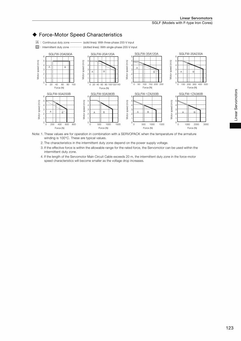
Linear Servomotors SGLF (Models with F-type Iron Cores)
123
Line
ar S
ervo
mot
ors
Force-Motor Speed Characteristics
Note: 1. These values are for operation in combination with a SERVOPACK when the temperature of the armature
winding is 100°C. These are typical values.
2. The characteristics in the intermittent duty zone depend on the power supply voltage.
3. If the effective force is within the allowable range for the rated force, the Servomotor can be used within the
intermittent duty zone.
4. If the length of the Servomotor Main Circuit Cable exceeds 20 m, the intermittent duty zone in the force-motor
speed characteristics will become smaller as the voltage drop increases.
SGLFW-20A090A6
5
4
3
2
1
0
6
5
4
3
2
1
0
6
5
4
3
2
1
0
6
5
4
3
2
1
0
6
5
4
3
2
1
0
6
5
4
3
2
1
0
6
5
4
3
2
1
0
6
5
4
3
2
1
0
0 10080604020
A B
SGLFW-50A200B SGLFW-50A380B
0 200 400 600 800 0 500 1000 1500
SGLFW-1ZA200B SGLFW-1ZA380B
0 500 1000 1500 0 1000 2000 3000
A AB B A B A B
SGLFW-35A120A
0 25020015010050
A
B
SGLFW-35A230A
0 500400300200100
A B
SGLFW-20A120A
0 20 40 60 80 100 120140
A B
Mo
tor sp
eed
(m
/s)
Force (N) Force (N) Force (N) Force (N)
Force (N) Force (N) Force (N) Force (N)
Mo
tor sp
eed
(m
/s)
Mo
tor sp
eed
(m
/s)
Mo
tor sp
eed
(m
/s)
Mo
tor sp
eed
(m
/s)
Mo
tor sp
eed
(m
/s)
Mo
tor sp
eed
(m
/s)
Mo
tor sp
eed
(m
/s)
Continuous duty zone
Intermittent duty zone
(solid lines): With three-phase 200-V input
(dotted lines): With single-phase 200-V input
A :
B :

Linear ServomotorsSGLF (Models with F-type Iron Cores)
124
Servomotor Overload Protection Characteristics The overload detection level is set for hot start conditions with a Servomotor ambient temperature
of 40°C.
Note: The above overload protection characteristics do not mean that you can perform continuous duty operation
with an output of 100% or higher. Use the Servomotor so that the effective force remains within the continu-
ous duty zone given in Force-Motor Speed Characteristics on page 123.
SGLFW-50A and -1ZA
50 100 150 200 250 300
10000
1000
100
10
1
SGLFW-35A
35050 100 150 200 250 300
10000
1000
100
10
1450350 40050 100 150 200 250 300
SGLFW-20A
10000
1000
100
10
1
Force reference (percent of rated force)
(%)
Force reference (percent of rated force)
(%)
Force reference (percent of rated force)
(%)
Dete
ctio
n t
ime (s)
Dete
ctio
n t
ime (s)
Dete
ctio
n t
ime (s)

Linear Servomotors SGLF (Models with F-type Iron Cores)
125
Line
ar S
ervo
mot
ors
External Dimensions
SGLFW2-30
Moving Coil with Polarity Sensor: SGLFW2-30A070AS
Refer to the following section for the connection specifications for the Sensor Cable and Servomo-
tor Main Circuit Cable.
Moving Coils with Polarity Sensors: SGLFW2-30 and -45 (page 150)
SGLFW2-30A070AS
40±0.12020
70
29
50 min.
5.812.2
31
15
14
29
40
18 20
3 × M4 × 8
(12)
300±50
300±50
29±0.1
Polarity sensor
Magnetic WayThermostat relay connector
(Molex Japan Co., Ltd.)
Receptacle housing: 5557-02R
Plug housing: 5559-02P
Polarity sensor and thermostat
cable
UL20276, AWG28
2 × #4-40
UNC screws
Polarity sensor and
thermostat connectorServomotor connector
(7 dia.)
Refer to the following figure .
Servomotor Main Circuit Cable
The Moving Coil moves in the
direction indicated by the
arrow when current flows in
the following phase
sequence: U, V, W.Thermostat cable
UL1333, AWG20
Thermostat relay cable
UL1333, AWG22
Approx. mass: 0.5 kg
Unit: mm
50 min.
51.7
(27.5)
0.2
1.5
Gap: 0.8
(10.2)
(6)
12
.5±0
.1
(1.5
)(5
5) (27
.5)
(27
.5) 5431
15
14
(9)

Linear ServomotorsSGLF (Models with F-type Iron Cores)
126
Moving Coils with Polarity Sensors: SGLFW2-30A AS
Refer to the following section for the connection specifications for the Sensor Cable and Servomo-
tor Main Circuit Cable.
Moving Coils with Polarity Sensors: SGLFW2-30 and -45 (page 150)
Moving Coil Model SGLFW2- L1 L2 L3 Approx. Mass [kg]
30A120AS 125 52.5 105.9 0.9
30A230AS 230 157.5 210.9 1.7
SGLFW2-30A120AS SGLFW2-30A230AS
(27.5
)(2
7.5
)
(27.5) 1.5
(55)
(0.5
)15 5
0
12
(6)
29±0.1
15
26.7 L2
L3
(33.2)
L1
12.5
±0.1
(10.2)
2740±0.1
31
(7)
7.5
12.6
0.2
Gap 0.8
300±50
300±50
15
31
12
7.5 39.3 52.5
27
15
31
12
7.5 39.3 52.5
27
4 × M4 × 8 8 × M4 × 8
157.5 (52.5 × 3)
Thermostat relay connector (Molex Japan Co., Ltd.)
Polarity sensor
Polarity sensor and
thermostat cable
UL20276, AWG28
2 × #4-40 UNC
screws
Thermostat relay cable
UL1333, AWG22
Thermostat cable
UL1333, AWG20
(7 dia.)
50 min.
Servomotor Main Circuit Cable
UL2586, AWG19
Refer to the following figures and .
The Moving Coil moves in the
direction indicated by the arrow
when current flows in the following
phase sequence: U, V, W.
Unit: mm
Polarity sensor and
thermostat connector
Servomotor
connector
Magnetic Way
50 min.
Receptacle housing: 5557-02RPlug housing: 5559-02P

Linear Servomotors SGLF (Models with F-type Iron Cores)
127
Line
ar S
ervo
mot
ors
Moving Coil without Polarity Sensor: SGLFW2-30A070AT
Refer to the following section for the connection specifications for the Sensor Cable and Servomo-
tor Main Circuit Cable.
Moving Coils without Polarity Sensors: SGLFW2-30 and -45 (page 151)
SGLFW2-30A070AT
(27
.5)
(27
.5)
(27.5) 1.5
(55
)
15
(6)
40±0.1
29±0.1
12
.5±
0.1
(10.2)
54
14
20
70(1
.5)
31
(9)
20 (12)
0.2
100±10Gap: 0.8300±50
5.812.2
31
15
14
29
40
18 20
3 × M4 × 8
51.7
Magnetic Way
50 min.
Servomotor Main Circuit Cable
UL2586, AWG19
Refer to the following figure .
Thermostat cable
UL1333, AWG20
Thermostat connector
The Moving Coil moves in the
direction indicated by the arrow
when current flows in the following
phase sequence: U, V, W.
Approx. mass: 0.5 kg
Unit: mm
Servomotor connector
(7 d
ia.)

Linear ServomotorsSGLF (Models with F-type Iron Cores)
128
Moving Coils without Polarity Sensors: SGLFW2-30A AT
Refer to the following section for the connection specifications for the Sensor Cable and Servomo-
tor Main Circuit Cable.
Moving Coils without Polarity Sensors: SGLFW2-30 and -45 (page 151)
Moving Coil Model SGLFW2- L1 L2 L3 Approx. Mass [kg]
30A120AT 125 52.5 105.9 0.9
30A230AT 230 157.5 210.9 1.7
SGLFW2-30A120AT SGLFW2-30A230AT
(27
.5)
(27
.5)
(27.5) 1.5
(55
)
(0.5
)1
5 50
12
(6)
29±0.1
15
7.5
26.7 L2
L3
(33.2)
L1
12.5
±0.1
(10.2)
40±0.1
31
(7)
12.6
50 min.
0.2
Gap: 0.8
100±10300±50
15
31
12
7.5 39.3 52.5
27
15
31
12
7.5 39.3 52.5
27
4 × M4 × 8 8 × M4 × 8
157.5 (52.5 × 3)
Magnetic Way
Servomotor Main Circuit Cable
UL2586, AWG19
Thermostat cable
UL1333, AWG20
Thermostat connector
Servomotor connector
The Moving Coil moves in the direction
indicated by the arrow when current
flows in the following phase sequence:
U, V, W.
Unit: mm
Refer to the following figures and .
(7 d
ia.)

Linear Servomotors SGLF (Models with F-type Iron Cores)
129
Line
ar S
ervo
mot
ors
Magnetic Ways: SGLFM2-30 A
Note: More than one Magnetic Way can be connected. Connect the Magnetic Ways so that the reference marks on
them are aligned in the same direction as shown in the figure.
Magnetic Way Model SGLFM2-
L1 ± 0.1 L2 N Approx. Mass [kg]
30270A 270 225 (45 × 5) 6 0.9
30450A 450 405 (45 × 9) 10 1.5
30630A 630 585 (45 × 13) 14 2.0
N S N SN S55
45
22.5±0.1 (22.5)
(45)
L2
(27
.5)
27
.5
45
(5)
5
6
L1±0.1
4.2
10.2±0.1
0.2
2 × N, 4.8-dia. mounting holes
Reference mark
Height of screw head: 4.2 max.
Mounting Section Details
(There are two, approx. 4-dia. indentations.)
(Reference mark)
Unit: mm
8.5 dia. 0.4

Linear ServomotorsSGLF (Models with F-type Iron Cores)
130
SGLFW2-45
Moving Coils with Polarity Sensors: SGLFW2-45A AS
Refer to the following section for the connection specifications for the Sensor Cable and Servomo-
tor Main Circuit Cable.
Moving Coils with Polarity Sensors: SGLFW2-30 and -45 (page 150)
Moving Coil Model SGLFW2- L1 L2 L3 Flatness Approx. Mass
[kg]
45A200AS 205 89.5 187 0.2 2.9
45A380AS 384 268.5 365.5 0.3 5.5
Thermostat relay connector (Molex Japan Co., Ltd.)
50 min.
Polarity sensor
Polarity sensor and thermostat cable
UL20276, AWG28
Magnetic
Way
Refer to the following table. 50 min.
Servomotor Main Circuit Cable
UL2586, AWG15
Thermostat cable
UL1333, AWG20
Thermostat relay cable
UL1333, AWG22
Refer to the following figures and .
The Moving Coil moves in the direction
indicated by the arrow when current flows
in the following phase sequence: U, V, W.
Unit: mm
2 × #4-40
UNC screws
Polarity sensor and
thermostat connector
Servomotor connector
(9.1
dia.)
Receptacle housing: 5557-02R
Plug housing: 5559-02P
8 × M6 × 11.5
268.5 (89.5 × 3)
4 × M6 × 11.5
SGLFW2-45A200AS SGLFW2-45A380AS
11
(36) 2
23
(6)
(37
.5)
(37
.5)
48.5 (55)
L1
L3
L250±0.1
(75
)
38±0.1(11.2)
32
(9)
46
15
±0
.1
(0.5
)
69
.5
14
.52
2.5
Gap: 0.8
12
300±50
300±50
46
23
11
13
.5 60.5 89.5
36
46
23
13
.5 11
60.5 89.5
36

Linear Servomotors SGLF (Models with F-type Iron Cores)
131
Line
ar S
ervo
mot
ors
Moving Coils without Polarity Sensors: SGLFW2-45A AT
Refer to the following section for the connection specifications for the Sensor Cable and Servomo-
tor Main Circuit Cable.
Moving Coils without Polarity Sensors: SGLFW2-30 and -45 (page 151)
Moving Coil Model SGLFW2- L1 L2 L3 FlatnessApprox. Mass
[kg]
45A200AT 205 89.5 187 0.2 2.9
45A380AT 384 268.5 365.5 0.3 5.5
SGLFW2-45A200AT SGLFW2-45A380AT
11
(36) 2
22
.5 23
(6)
(37
.5)
(37
.5)
46
(9)
69
.5
48.5 (55)
L1
L2
L3
50±0.1
(75
)
14
.5
38±0.1
(0.5
)
15±
0.1
(11.2)
12
Gap: 0.8
100±10
300±50
Magnetic Way 50 min.
Servomotor Main Circuit Cable
UL2586, AWG15
Refer to the following table.
Servomotor connector
Thermostat connector
Thermostat cable
UL1333, AWG20
Refer to the following figures and .
The Moving Coil moves in the direction
indicated by the arrow when current flows
in the following phase sequence: U, V, W.
Unit: mm
(9.1
dia.)
46
23
11
13
.5 60.5 89.5
36
268.5 (89.5×3)
46
23
13
.5 11
60.5 89.5
36
8 × M6 × 11.54 × M6 × 11.5
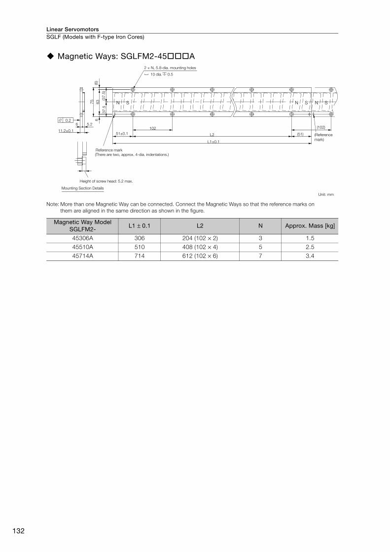
Linear ServomotorsSGLF (Models with F-type Iron Cores)
132
Magnetic Ways: SGLFM2-45 A
Note: More than one Magnetic Way can be connected. Connect the Magnetic Ways so that the reference marks on
them are aligned in the same direction as shown in the figure.
Magnetic Way Model SGLFM2-
L1 ± 0.1 L2 N Approx. Mass [kg]
45306A 306 204 (102 × 2) 3 1.5
45510A 510 408 (102 × 4) 5 2.5
45714A 714 612 (102 × 6) 7 3.4
N S N S N S
6102
(37
.5)
63
(6)
6
75
L2 (51)
L1±0.1
(102)5.2
11.2±0.151±0.1
0.2
37
.5
2 × N, 5.8-dia. mounting holes
10 dia. 0.5
(Reference
mark)
Unit: mm
Reference mark
(There are two, approx. 4-dia. indentations.)
Height of screw head: 5.2 max.
Mounting Section Details
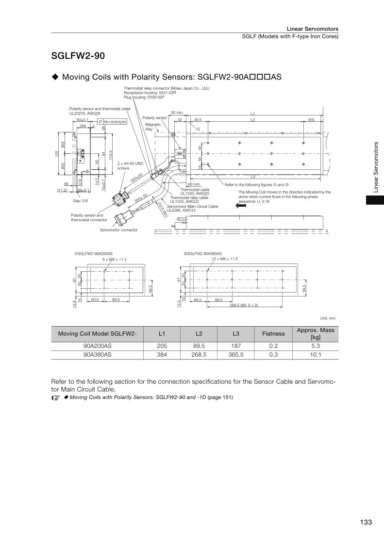
Linear Servomotors SGLF (Models with F-type Iron Cores)
133
Line
ar S
ervo
mot
ors
SGLFW2-90
Moving Coils with Polarity Sensors: SGLFW2-90A AS
Refer to the following section for the connection specifications for the Sensor Cable and Servomo-
tor Main Circuit Cable.
Moving Coils with Polarity Sensors: SGLFW2-90 and -1D (page 151)
Moving Coil Model SGLFW2- L1 L2 L3 FlatnessApprox. Mass
[kg]
90A200AS 205 89.5 187 0.2 5.3
90A380AS 384 268.5 365.5 0.3 10.1
SGLFW2-90A200AS SGLFW2-90A380AS
(60
)(6
0)
12
0
(11.2) 38±0.1
45
14
.5
91
15
±0
.1
11
4.5
(6)
L1
L3
48.5 L2
15
30
30
50±0.1
2(36)
(55)32
(0.5
)
(9)
300± 50
12
Gap: 0.8
300±50
91
15
13
.5
60.5 89.5
58
.5
30
30
6 × M6 × 11.5
91
13
.5
58
.560.5 89.5
268.5 (89. 5 × 3)
30
30
15
12 × M6 × 11.5
Thermostat relay connector (Molex Japan Co., Ltd.)
Receptacle housing: 5557-02R
Plug housing: 5559-02P
Polarity sensor and thermostat cable
UL20276, AWG28
Refer to the following table.
50 min.
Polarity sensor
Magnetic
Way
2 × #4-40 UNC
screws
60 min. Refer to the following figures and .
The Moving Coil moves in the direction indicated by the
arrow when current flows in the following phase
sequence: U, V, W.
Thermostat cableUL1333, AWG20
Thermostat relay cableUL1333, AWG22
Polarity sensor and
thermostat connector
Servomotor connector
Servomotor Main Circuit CableUL2586, AWG12
Unit: mm
(10.5
dia.)
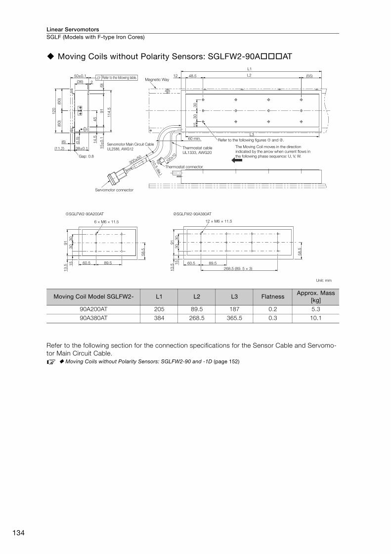
Linear ServomotorsSGLF (Models with F-type Iron Cores)
134
Moving Coils without Polarity Sensors: SGLFW2-90A AT
Refer to the following section for the connection specifications for the Sensor Cable and Servomo-
tor Main Circuit Cable.
Moving Coils without Polarity Sensors: SGLFW2-90 and -1D (page 152)
Moving Coil Model SGLFW2- L1 L2 L3 FlatnessApprox. Mass
[kg]
90A200AT 205 89.5 187 0.2 5.3
90A380AT 384 268.5 365.5 0.3 10.1
SGLFW2-90A200AT SGLFW2-90A380AT
(60
)
12
0
(11.2) 38±0.1
45
14
.5
91
15
±0
.1
11
4.5
(6)
L1
48.5 L2
15
30
30
50±0.1
2(36)
(55)(0
.5)
(9)
12
60 min.
300±50Gap: 0.8
100±10
91
15
13
.5
60.5 89.5
58
.5
30
30
6 × M6 × 11.5
91
13
.5
58.5
60.5 89.5
268.5 (89. 5 × 3)
30
30
15
12 × M6 × 11.5
L3
(60
)
Refer to the following table.Magnetic Way
Servomotor Main Circuit Cable
UL2586, AWG12 Thermostat cable
UL1333, AWG20
(10.5
dia.)
Refer to the following figures and .
The Moving Coil moves in the direction
indicated by the arrow when current flows in
the following phase sequence: U, V, W.
Unit: mm
Thermostat connector
Servomotor connector
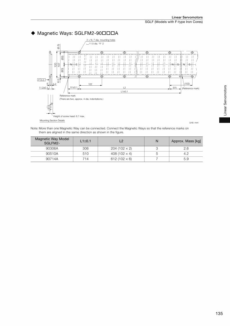
Linear Servomotors SGLF (Models with F-type Iron Cores)
135
Line
ar S
ervo
mot
ors
Magnetic Ways: SGLFM2-90 A
Note: More than one Magnetic Way can be connected. Connect the Magnetic Ways so that the reference marks on
them are aligned in the same direction as shown in the figure.
Magnetic Way Model SGLFM2-
L1±0.1 L2 N Approx. Mass [kg]
90306A 306 204 (102 × 2) 3 2.6
90510A 510 408 (102 × 4) 5 4.2
90714A 714 612 (102 × 6) 7 5.9
L2
2 × N, 7-dia. mounting holes
11.5 dia. 2
Reference mark
(There are two, approx. 4-dia. indentations.)
Height of screw head: 6.7 max.
Mounting Section Details
(Reference mark)
Unit: mm
(51)
(102)
N N SSN S
102
51±0.1
L1±0.1
11.2±0.1
0.3
6 5.2
6.5
(6.5
)
(60)
(60)
107
120

Linear ServomotorsSGLF (Models with F-type Iron Cores)
136
SGLFW2-1D
Moving Coil with Polarity Sensor: SGLFW2-1DA380AS
Refer to the following section for the connection specifications for the Sensor Cable and Servomo-
tor Main Circuit Cable.
Moving Coils with Polarity Sensors: SGLFW2-90 and -1D (page 151)
SGLFW2-1DA380AS
(87
.5)
(87
.5)
17
5
(11.2)
67
.5
20
±0
.11
36
160
15
50±0.1
2(36)
38±0.1
(6)
(55)48.5 89.5 89.5 89.5
365.5
384
22
.5
32
(5)
45
45
(9)
300±50
0.3
12
Gap: 0.8
UL20276, AWG28
300±50
12 × M8 × 16
89.560.5
81
.5
45
45
22
.5
13
61
4
268.5 (89.5 × 3)
Thermostat relay connector (Molex Japan Co., Ltd.)
Receptacle housing: 5557-02RPlug housing: 5559-02P
50 min.
Polarity sensor
Magnetic Way
Polarity sensor and
thermostat cable
2 × #4-40 UNC
screws
Polarity sensor and
thermostat connector
Servomotor connector
60 min.
Thermostat cable
UL1333, AWG20
Thermostat relay cable
UL1333, AWG22
Refer to the following figure .
Servomotor Main Circuit Cable
UL2586, AWG12
The Moving Coil moves in the direction indicated
by the arrow when current flows in the following
phase sequence: U, V, W.
Approx. mass: 14.6 kg
Unit: mm
(10.5
dia.)
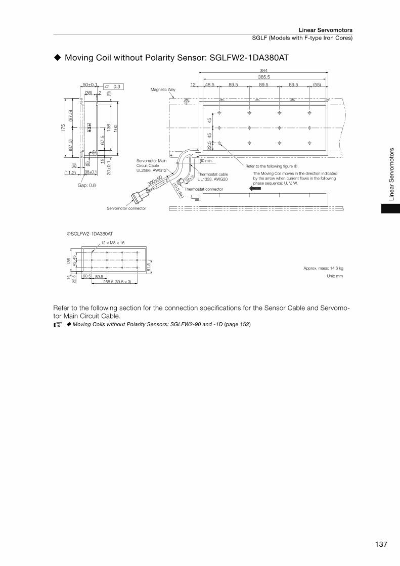
Linear Servomotors SGLF (Models with F-type Iron Cores)
137
Line
ar S
ervo
mot
ors
Moving Coil without Polarity Sensor: SGLFW2-1DA380AT
Refer to the following section for the connection specifications for the Sensor Cable and Servomo-
tor Main Circuit Cable.
Moving Coils without Polarity Sensors: SGLFW2-90 and -1D (page 152)
SGLFW2-1DA380AT
(87
.5)
(87
.5)
17
5
(11.2)
67
.5
20
±0
.11
36
16
0
15
50±0.1
2(36)
38±0.1
(6)
22
.5
(5)
45
45
(9)
300±50
0.3
Gap: 0.8100±10
(55)48.5 89.5 89.5 89.5
365.5
384
12
12 × M8 × 16
89.560.5
81
.5
45
45
22
.5
13
61
4
268.5 (89.5 × 3)
Magnetic Way
Servomotor Main
Circuit Cable
UL2586, AWG12
Servomotor connector
60 min.
Refer to the following figure .
Thermostat cable
UL1333, AWG20
Thermostat connector
(10.5
dia.)
The Moving Coil moves in the direction indicated
by the arrow when current flows in the following
phase sequence: U, V, W.
Approx. mass: 14.6 kg
Unit: mm
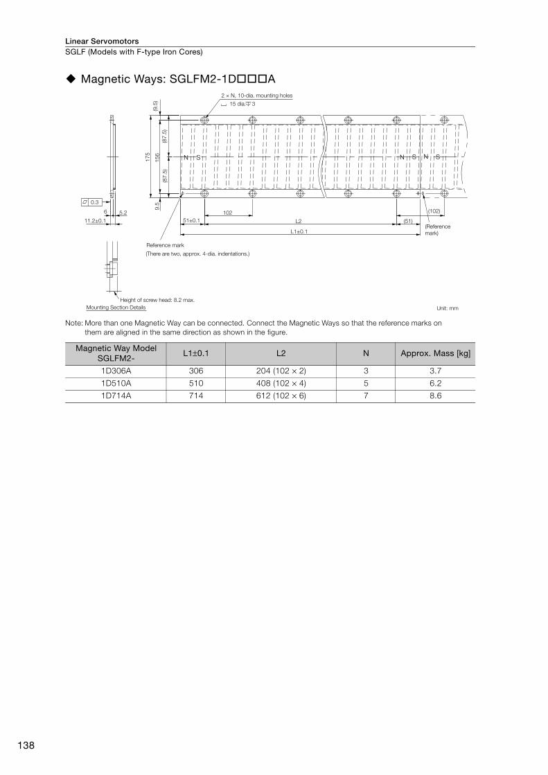
Linear ServomotorsSGLF (Models with F-type Iron Cores)
138
Magnetic Ways: SGLFM2-1D A
Note: More than one Magnetic Way can be connected. Connect the Magnetic Ways so that the reference marks on
them are aligned in the same direction as shown in the figure.
Magnetic Way Model SGLFM2-
L1±0.1 L2 N Approx. Mass [kg]
1D306A 306 204 (102 × 2) 3 3.7
1D510A 510 408 (102 × 4) 5 6.2
1D714A 714 612 (102 × 6) 7 8.6
L2
17
5
(87
.5)
9.5
15
6(9
.5)
(87
.5)
N S N SN S
102
51±0.1 (51)
(102)6
L1±0.1
5.2
11.2±0.1
0.3
2 × N, 10-dia. mounting holes
15 dia. 3
(Reference
mark)
Unit: mm
Reference mark
(There are two, approx. 4-dia. indentations.)
Height of screw head: 8.2 max.
Mounting Section Details
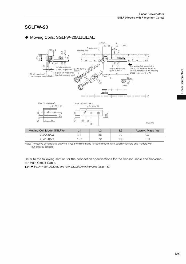
Linear Servomotors SGLF (Models with F-type Iron Cores)
139
Line
ar S
ervo
mot
ors
SGLFW-20
Moving Coils: SGLFW-20A A
Note: The above dimensional drawing gives the dimensions for both models with polarity sensors and models with-
out polarity sensors.
Refer to the following section for the connection specifications for the Sensor Cable and Servomo-
tor Main Circuit Cable.
SGLFW-20A A and -35A A Moving Coils (page 152)
Moving Coil Model SGLFW- L1 L2 L3 Approx. Mass [kg]
20A090A 91 36 72 0.7
20A120A 127 72 108 0.9
2
5.5
22
.5
40
17
.5
12
.5
45±0.1
34
(44
)
(22
)(2
2)
(32)
0.5
(6)
(20)
22
2 × M4 × 5.5
�SGLFW-20A090A�
3 × M4 × 5.5
�SGLFW-20A120A�
50 min.
Polarity sensor
Magnetic Way
(10.2 with magnet cover)
(4.2 with magnet cover)
(4 without magnet cover)
(Gap: 0.8 with magnet cover)
(Gap: 1 without magnet cover)
2 × #4-40 UNC screws
30 min.
Refer to the following figures � and �.
The Moving Coil moves in the
direction indicated by the arrow
when current flows in the following
phase sequence: U, V, W.
Unit: mm
(4.2 dia.)
(6.1
dia.)
(10 without magnet cover)12
A-A
500±50
500±50 L3 7
8
(12
)
2.5
5.5
L1
L2 (25)3030
(7.5
)
36
(10
)
(12
.5)
20
22
.5
22
.5 2020
12
.5
12
.5
30 3630 36
72
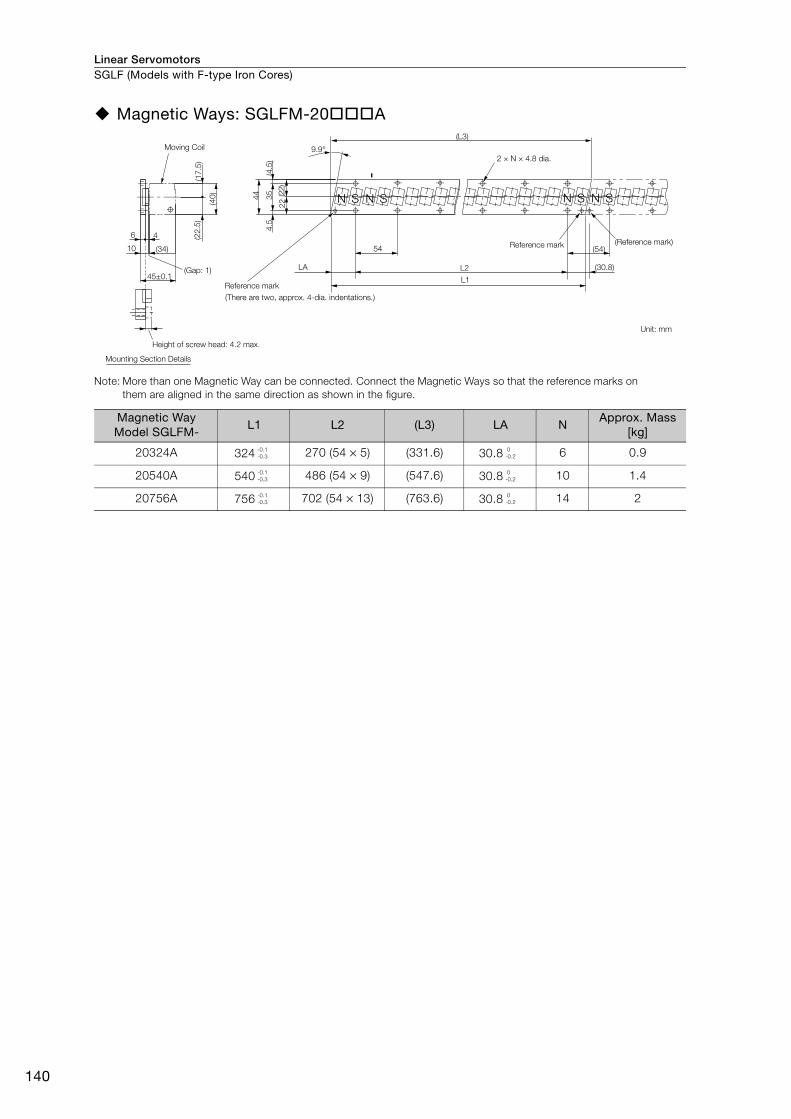
Linear ServomotorsSGLF (Models with F-type Iron Cores)
140
Magnetic Ways: SGLFM-20 A
Note: More than one Magnetic Way can be connected. Connect the Magnetic Ways so that the reference marks on
them are aligned in the same direction as shown in the figure.
Magnetic Way Model SGLFM-
L1 L2 (L3) LA NApprox. Mass
[kg]
20324A 324 270 (54 × 5) (331.6) 30.8 6 0.9
20540A 540 486 (54 × 9) (547.6) 30.8 10 1.4
20756A 756 702 (54 × 13) (763.6) 30.8 14 2
(Gap: 1)
SNSN
6
9.9°
10
4
(40
)
(22
.5)
(17
.5)
(34)
4.5
35
44
(4.5
)
(22)
22
54
LA
L1
L2
(L3)
(54)
(30.8)
SNSN
45±0.1
Moving Coil
2 × N × 4.8 dia.
Reference mark
(There are two, approx. 4-dia. indentations.)
Height of screw head: 4.2 max.
Mounting Section Details
Reference mark (Reference mark)
Unit: mm
-0.1
-0.3
0
-0.2
-0.1
-0.3
0
-0.2
-0.1
-0.3
0
-0.2

Linear Servomotors SGLF (Models with F-type Iron Cores)
141
Line
ar S
ervo
mot
ors
SGLFW-35
Moving Coils: SGLFW-35A A
Note: The above dimensional drawing gives the dimensions for both models with polarity sensors and models with-
out polarity sensors.
Refer to the following section for the connection specifications for the Sensor Cable and Servomo-
tor Main Circuit Cable.
SGLFW-20A A and -35A A Moving Coils (page 152)
Moving Coil Model SGLFW- L1 L2 L3 Approx. Mass [kg]
35A120A 127 72 108 1.3
35A230A 235 180 216 2.3
A-A
12
500±50
500±50
A A
7
L1
30
5.5
(10
.5)2
5.5
8
(12
.5)
(7.5
)3
5
L3
L2
S
30
45±0.1
34
(32)
0.5
(6)
2.5
(25)
36
55
30
25
12
.5
(30
)(3
0)
(8.5
)1
8
(60
)
(35
)
37
6 × M4 × 5.5
35
18
30
8.5
12
.5
72
SGLFW-35A120A
12 × M4 × 5.5
35
18
8.5
12
.5 30 36
180 (36×5)
30
SGLFW-35A230A
50 min.
Polarity sensorMagnetic Way
(10.2 with magnet cover)
(10 without magnet cover)
(4.2 with magnet cover)
(4 without magnet cover)
(Gap: 0.8 with magnet cover)
(Gap: 1 without magnet cover)
2 × #4-40 UNC
screwsRefer to the following figures and .
The Moving Coil moves in the
direction indicated by the arrow
when current flows in the following
phase sequence: U, V, W.
Unit: mm
30 min.
(4.2 dia.)
(6.1
dia.)
30 36
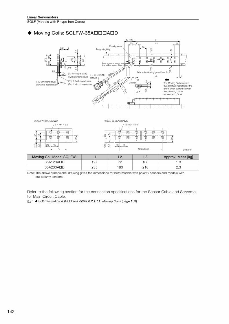
Linear ServomotorsSGLF (Models with F-type Iron Cores)
142
Moving Coils: SGLFW-35A A D
Note: The above dimensional drawing gives the dimensions for both models with polarity sensors and models with-
out polarity sensors.
Refer to the following section for the connection specifications for the Sensor Cable and Servomo-
tor Main Circuit Cable.
SGLFW-35A A D and -50A B D Moving Coils (page 153)
Moving Coil Model SGLFW- L1 L2 L3 Approx. Mass [kg]
35A120A D 127 72 108 1.3
35A230A D 235 180 216 2.3
A-A
12
500±50
500±50
A A
7
L1
30
5.5
(10
.5)2
5.5
8
(12
.5)
(7.5
)3
5
L3
L230
45±0.1
34
(32)
0.5
(6)
2.5
25
36
55
30
25
12
.5
(30
)(3
0)
(8.5
)1
8
(60
)
(35
)
37
6 × M4 × 5.5
35
18
30
8.5
12
.5 30 36
72
SGLFW-35A120A D
12 × M4 × 5.5
35
18
8.5
12
.5 30 36
180 (36×5)
30
SGLFW-35A230A D
50 min.
Polarity sensor
Magnetic Way
2 × #4-40 UNC
screws
Refer to the following figures and .
The Moving Coil moves in
the direction indicated by the
arrow when current flows in
the following phase
sequence: U, V, W.
Unit: mm
(10.2 with magnet cover)
(4.2 with magnet cover)
(4 without magnet cover)
(Gap: 0.8 with magnet cover)
(Gap: 1 without magnet cover)
(4.2 dia.)
(6.1
dia.)
30 min.(10 without magnet cover)
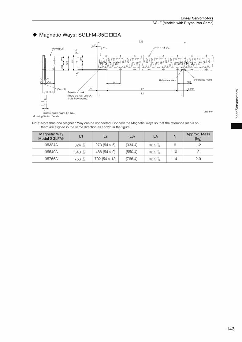
Linear Servomotors SGLF (Models with F-type Iron Cores)
143
Line
ar S
ervo
mot
ors
Magnetic Ways: SGLFM-35 A
Note: More than one Magnetic Way can be connected. Connect the Magnetic Ways so that the reference marks on
them are aligned in the same direction as shown in the figure.
Magnetic Way Model SGLFM-
L1 L2 (L3) LA NApprox. Mass
[kg]
35324A 324 270 (54 × 5) (334.4) 32.2 6 1.2
35540A 540 486 (54 × 9) (550.4) 32.2 10 2
35756A 756 702 (54 × 13) (766.4) 32.2 14 2.9
L1
L2(Gap: 1)
(34)
S SNS SNNN
(L3)
6
10
4
45±0.1
60
51
30
(30
)
(4.5
)4
.5
(55
)
(30)
(25
)
9.9°
LA
54 (54)
(32.2)
2 × N × 4.8 dia.
Reference mark
Reference mark
(There are two, approx.
4-dia. indentations.)
Height of screw head: 4.2 max.
Mounting Section Details
(Reference mark)
Unit: mm
Moving Coil
-0.1
-0.3
0
-0.2
-0.1
-0.3
0
-0.2
-0.1
-0.3
0
-0.2

Linear ServomotorsSGLF (Models with F-type Iron Cores)
144
SGLFW-50
Moving Coils: SGLFW-50A B
Note: The above dimensional drawing gives the dimensions for both models with polarity sensors and models with-
out polarity sensors.
Refer to the following section for the connection specifications for the Sensor Cable and Servomo-
tor Main Circuit Cable.
SGLFW-50A B Moving Coils (page 153)
Moving Coil ModelSGLFW-
L1 L2 L3 Approx. Mass [kg]
50A200B 215 120 180 3.5
50A380B 395 300 360 6.9
7
(40)
(37
.5)
33
3.7
53
7.7
5 71
.5
(37
.5)(75
)
0.5(9)
43±0.05
58±0.1
(5.2)
(48
)
(64
.5)
25 L3
L2 (40)
60
55
L1
30
23
.5
10
(15
)(1
2)
500±50
500±50
6 × M5 × 9.5
48
23
.51
2
14
55 60
120
SGLFW-50A200B
12 × M5 × 9.5
48
23.5
12
14 55 60
300 (60 × 5)
SGLFW-50A380B
50 min.
Polarity sensorMagnetic Way
(14.2 with magnet cover)
(5.2 with magnet cover)
(5 without magnet cover)
(Gap: 0.8 with magnet cover)
(Gap: 1 without magnet cover)
2 × #4-40 UNC
screwsRefer to the following figures and .
The Moving Coil moves in the direction indicated by the arrow when current flows in the following phase sequence: U, V, W.
Unit: mm
50 min.(4.2 dia.) (7.4
dia.)
(14 without magnet cover)

Linear Servomotors SGLF (Models with F-type Iron Cores)
145
Line
ar S
ervo
mot
ors
Moving Coils: SGLFW-50A B D
Note: The above dimensional drawing gives the dimensions for both models with polarity sensors and models with-
out polarity sensors.
Refer to the following section for the connection specifications for the Sensor Cable and Servomo-
tor Main Circuit Cable.
SGLFW-35A A D and -50A B D Moving Coils (page 153)
Moving Coil ModelSGLFW-
L1 L2 L3 Approx. Mass [kg]
50A200B D 215 120 180 3.5
50A380B D 395 300 360 6.9
50
.5
33
.75
37
.75
7
71
.5
14
3
(37
.5)(75
) (37
.5)
(40)
43
58±0.1
0.5(9)
500±50
500±50
10
30
(15
)
L3
L2
L1
25
55 40
60
(12
)2
3.5
48
6 × M5 × 9.5
48
23
.51
2
14
55 60
120
(48
)
SGLFW-50A200B D
12 × M5 × 9.5
48
23
.51
2
14 55 60
300 (60 × 5)
SGLFW-50A380B D
50 min.
Polarity sensorMagnetic Way
2 × #4-40
UNC screws
Refer to the following figures and .
The Moving Coil moves in the direction indicated by the arrow when current flows in the following phase sequence: U, V, W.
Unit: mm
50 min.(5.2 with magnet cover)
(Gap: 0.8 with magnet cover)
(14.2 with magnet cover)
(14 without magnet cover)
(Gap: 1 without magnet cover)
(4.2 dia.)
(7.4
dia.)
(5 without magnet cover)
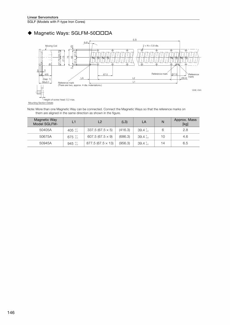
Linear ServomotorsSGLF (Models with F-type Iron Cores)
146
Magnetic Ways: SGLFM-50 A
Note: More than one Magnetic Way can be connected. Connect the Magnetic Ways so that the reference marks on
them are aligned in the same direction as shown in the figure.
Magnetic Way Model SGLFM-
L1 L2 (L3) LA NApprox. Mass
[kg]
50405A 405 337.5 (67.5 × 5) (416.3) 39.4 6 2.8
50675A 675 607.5 (67.5 × 9) (686.3) 39.4 10 4.6
50945A 945 877.5 (67.5 × 13) (956.3) 39.4 14 6.5
(Gap: 1)
2 × N × 5.8 dia.
S SSNS NNN
67.5
9 5
58±0.1
14 (43)
(5)
5
75
65
37
.5(3
7.5
)
(37
.75
)
(71
.5)(33
.75
)
8.6°
LA
L1
L2
(L3)
(67.5)
(39.4)
Moving Coil
Reference mark
Height of screw head: 5.2 max.
Mounting Section Details
(There are two, approx. 4-dia. indentations.)
Reference mark (Reference mark)
Unit: mm
-0.1
-0.3
0
-0.2
-0.1
-0.3
0
-0.2
-0.1
-0.3
0
-0.2
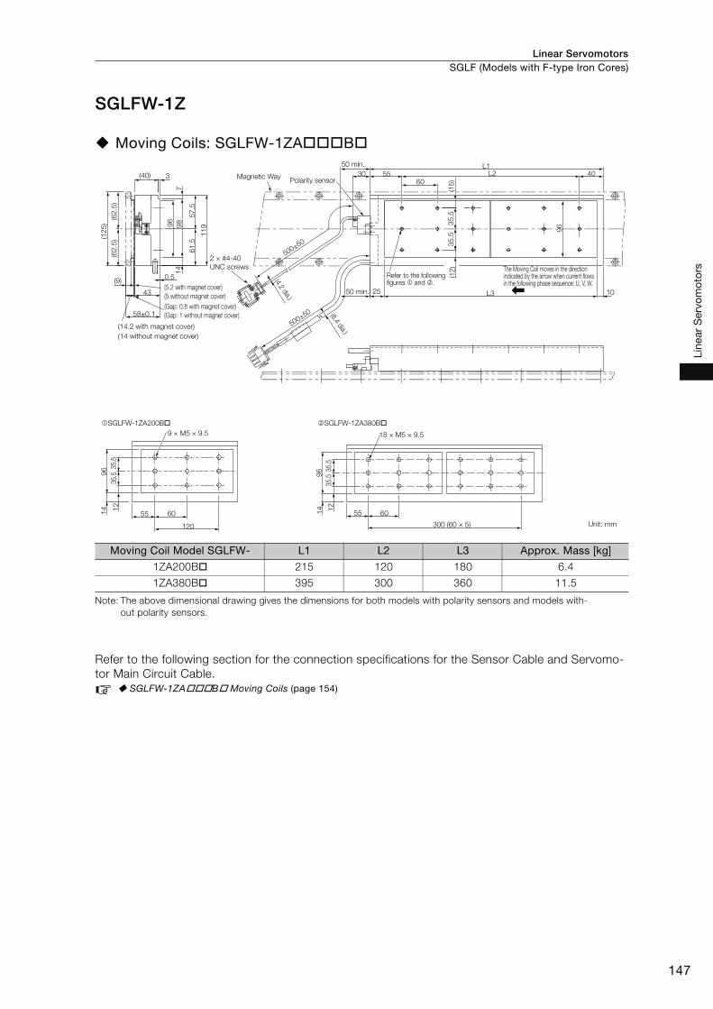
Linear Servomotors SGLF (Models with F-type Iron Cores)
147
Line
ar S
ervo
mot
ors
SGLFW-1Z
Moving Coils: SGLFW-1ZA B
Note: The above dimensional drawing gives the dimensions for both models with polarity sensors and models with-
out polarity sensors.
Refer to the following section for the connection specifications for the Sensor Cable and Servomo-
tor Main Circuit Cable.
SGLFW-1ZA B Moving Coils (page 154)
Moving Coil Model SGLFW- L1 L2 L3 Approx. Mass [kg]
1ZA200B 215 120 180 6.4
1ZA380B 395 300 360 11.5
9 × M5 × 9.5
96 3
5.5
35.5
12
14
55 60
120
SGLFW-1ZA200B
500±50
500±50
60
(15
)
10L325
96
(12
)
L1L25530
96 35
.53
5.5
409
8
11
9
57
.56
1.5
(62
.5)
(62
.5)
(12
5)
3(40)7
14
43
58±0.1
0.5(9)
18 × M5 × 9.5
96 3
5.5
35.5
12
14
55 60
300 (60 × 5)
SGLFW-1ZA380B
Magnetic WayPolarity sensor
2 × #4-40
UNC screws
(5.2 with magnet cover)
(5 without magnet cover)
(Gap: 0.8 with magnet cover)
(Gap: 1 without magnet cover)
(14.2 with magnet cover)
(14 without magnet cover)
50 min.
The Moving Coil moves in the direction indicated by the arrow when current flows in the following phase sequence: U, V, W.
Unit: mm
Refer to the following figures and .
50 min.
(8.4 dia.)
(4.2 dia.)
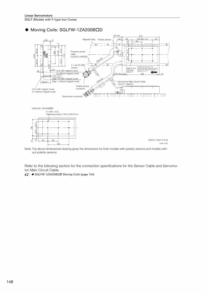
Linear ServomotorsSGLF (Models with F-type Iron Cores)
148
Moving Coils: SGLFW-1ZA200B D
Note: The above dimensional drawing gives the dimensions for both models with polarity sensors and models with-
out polarity sensors.
Refer to the following section for the connection specifications for the Sensor Cable and Servomo-
tor Main Circuit Cable.
SGLFW-1ZA200B D Moving Coils (page 154)
43±0.05
(9)0.5
(62
.5)
(62
.5)
(12
5)
3(40)
11
9
61
.55
7.5
7
60
(96
)
(11
2)
4030
(15
)
215
120 (60 × 2)55
25 10180
35
.53
5.5
60
120
96 3
5.5
35
.5
14 12 55
58±0.1 500±50
500±50
0.2
9 × M5 × 9.5L
SGLFW-1ZA200B D
Magnetic Way
Proximity sensor
cable
UL20276, AWG28
Servomotor Main Circuit Cable
UL2517, AWG15
Refer to the following figure .
The Moving Coil moves in the direction indicated by the arrow when current flows in the following phase sequence: U, V, W.
2 × #4-40 UNC
screws
50 min.
(5.2 with magnet cover)
(Gap: 0.8 with magnet cover)
(14.2 with magnet cover)
(14 without magnet cover)
(Gap: 1 without magnet cover)
Polarity sensor
connector
(4.2
dia.)
(8.4 dia.)
Servomotor connector
Tightening torque: 750 to 850 N⋅cm
Approx. mass: 6.4 kg
Unit: mm
(5 without magnet cover)
Polarity sensor
50 min.
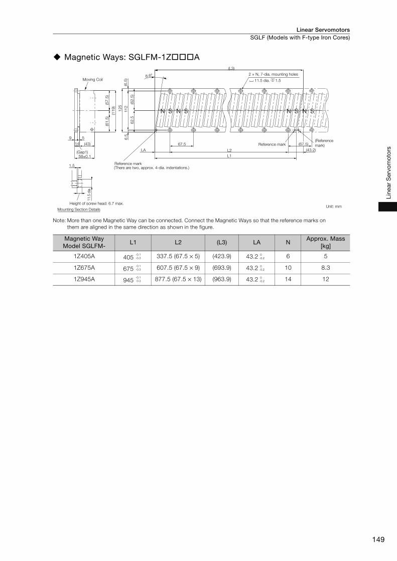
Linear Servomotors SGLF (Models with F-type Iron Cores)
149
Line
ar S
ervo
mot
ors
Magnetic Ways: SGLFM-1Z A
Note: More than one Magnetic Way can be connected. Connect the Magnetic Ways so that the reference marks on
them are aligned in the same direction as shown in the figure.
Magnetic Way Model SGLFM-
L1 L2 (L3) LA NApprox. Mass
[kg]
1Z405A 405 337.5 (67.5 × 5) (423.9) 43.2 6 5
1Z675A 675 607.5 (67.5 × 9) (693.9) 43.2 10 8.3
1Z945A 945 877.5 (67.5 × 13) (963.9) 43.2 14 12
12
5
11
26
.5(6
.5)
(62
.5)
62
.5
(61
.5)
(57
.5)
(11
9)
(43.2)
67.514
9 5
58±0.1
(43)
(Gap1)
S
(There are two, approx. 4-dia. indentations.)
S SS NNNN
8.6°
LA
L1
L2
(L3)
1.5
11.5
dia
.
(67.5)
Moving Coil
2 × N, 7-dia. mounting holes
11.5 dia. 1.5
Reference mark(Reference
mark)
Height of screw head: 6.7 max.
Mounting Section DetailsUnit: mm
Reference mark
-0.1
-0.3
0
-0.2
-0.1
-0.3
0
-0.2
-0.1
-0.3
0
-0.2
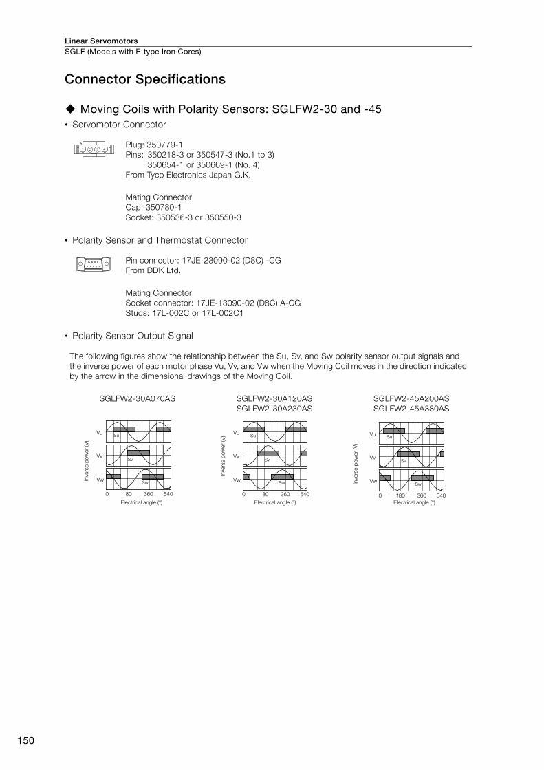
Linear ServomotorsSGLF (Models with F-type Iron Cores)
150
Connector Specifications
Moving Coils with Polarity Sensors: SGLFW2-30 and -45• Servomotor Connector
• Polarity Sensor and Thermostat Connector
• Polarity Sensor Output Signal
Plug: 350779-1
Pins: 350218-3 or 350547-3 (No.1 to 3)
350654-1 or 350669-1 (No. 4)
From Tyco Electronics Japan G.K.
Mating Connector
Cap: 350780-1
Socket: 350536-3 or 350550-3
Pin connector: 17JE-23090-02 (D8C) -CG
From DDK Ltd.
Mating Connector
Socket connector: 17JE-13090-02 (D8C) A-CG
Studs: 17L-002C or 17L-002C1
The following figures show the relationship between the Su, Sv, and Sw polarity sensor output signals and
the inverse power of each motor phase Vu, Vv, and Vw when the Moving Coil moves in the direction indicated
by the arrow in the dimensional drawings of the Moving Coil.
SGLFW2-30A070AS SGLFW2-30A120AS
SGLFW2-30A230AS
SGLFW2-45A200AS
SGLFW2-45A380AS
Vu
Vv
Vw
Su
Sv
Sw
0 180 360 540
Invers
e p
ow
er
(V)
Electrical angle (°)
Vu
Vv
Vw
Su
Sv
Sw
0 180 360 540
Electrical angle (°)
Invers
e p
ow
er
(V) Vu
Vv
Vw
Su
Sv
Sw
0 180 360 540
Electrical angle (°)
Invers
e p
ow
er
(V)

Linear Servomotors SGLF (Models with F-type Iron Cores)
151
Line
ar S
ervo
mot
ors
Moving Coils without Polarity Sensors: SGLFW2-30 and -45• Servomotor Connector
• Thermostat Connector
Moving Coils with Polarity Sensors: SGLFW2-90 and -1D• Servomotor Connector
• Polarity Sensor and Thermostat Connector
• Polarity Sensor Output Signal
Plug: 350779-1
Pins: 350218-3 or 350547-3 (No.1 to 3)
350654-1 or 350669-1 (No. 4)
From Tyco Electronics Japan G.K.
Mating Connector
Cap: 350780-1
Socket: 350536-3 or 350550-3
Receptacle housing: 5557-02R
Terminals: 5556T or 5556TL
From Molex Japan Co., Ltd.
Mating Connector
Plug housing: 5559-02P
Terminals: 5558T or 5558TL
Tab housing: 1-917808-2
Contacts: 917803-2 (A1, A2, and B1)
84695-1 (B2)
From Tyco Electronics Japan G.K.
Mating Connector
Receptacle housing: 1-917807-2
Contacts: 179956-2
Pin connector: 17JE-23090-02 (D8C) -CG
From DDK Ltd.
Mating Connector
Socket connector: 17JE-13090-02 (D8C) A-CG
Studs: 17L-002C or 17L-002C1
The figure on the right shows the relationship between the Su, Sv,
and Sw polarity sensor output signals and the inverse power of
each motor phase Vu, Vv, and Vw when the Moving Coil moves in
the direction indicated by the arrow in the dimensional drawings of
the Moving Coil.
A1
B1 B2
A2
Vu
Vv
Vw
Su
Sv
Sw
0 180 360 540
Electrical angle (°)
Invers
e p
ow
er
(V)
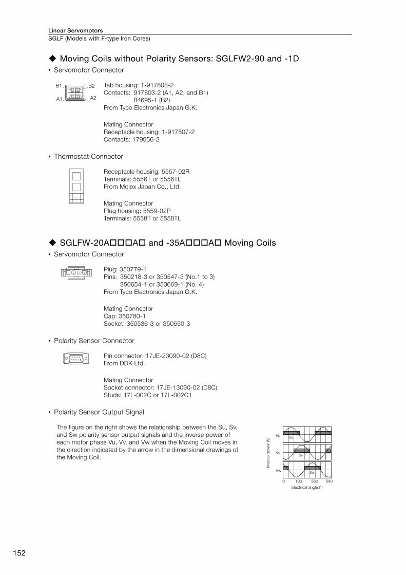
Linear ServomotorsSGLF (Models with F-type Iron Cores)
152
Moving Coils without Polarity Sensors: SGLFW2-90 and -1D• Servomotor Connector
• Thermostat Connector
SGLFW-20A A and -35A A Moving Coils• Servomotor Connector
• Polarity Sensor Connector
• Polarity Sensor Output Signal
Tab housing: 1-917808-2
Contacts: 917803-2 (A1, A2, and B1)
84695-1 (B2)
From Tyco Electronics Japan G.K.
Mating Connector
Receptacle housing: 1-917807-2
Contacts: 179956-2
Receptacle housing: 5557-02R
Terminals: 5556T or 5556TL
From Molex Japan Co., Ltd.
Mating Connector
Plug housing: 5559-02P
Terminals: 5558T or 5558TL
Plug: 350779-1
Pins: 350218-3 or 350547-3 (No.1 to 3)
350654-1 or 350669-1 (No. 4)
From Tyco Electronics Japan G.K.
Mating Connector
Cap: 350780-1
Socket: 350536-3 or 350550-3
Pin connector: 17JE-23090-02 (D8C)
From DDK Ltd.
Mating Connector
Socket connector: 17JE-13090-02 (D8C)
Studs: 17L-002C or 17L-002C1
The figure on the right shows the relationship between the Su, Sv,
and Sw polarity sensor output signals and the inverse power of
each motor phase Vu, Vv, and Vw when the Moving Coil moves in
the direction indicated by the arrow in the dimensional drawings of
the Moving Coil.
A2A1
B2B1
Vu
Vv
Vw
Su
Sv
Sw
0 180 360 540
Electrical angle (°)
Invers
e p
ow
er
(V)
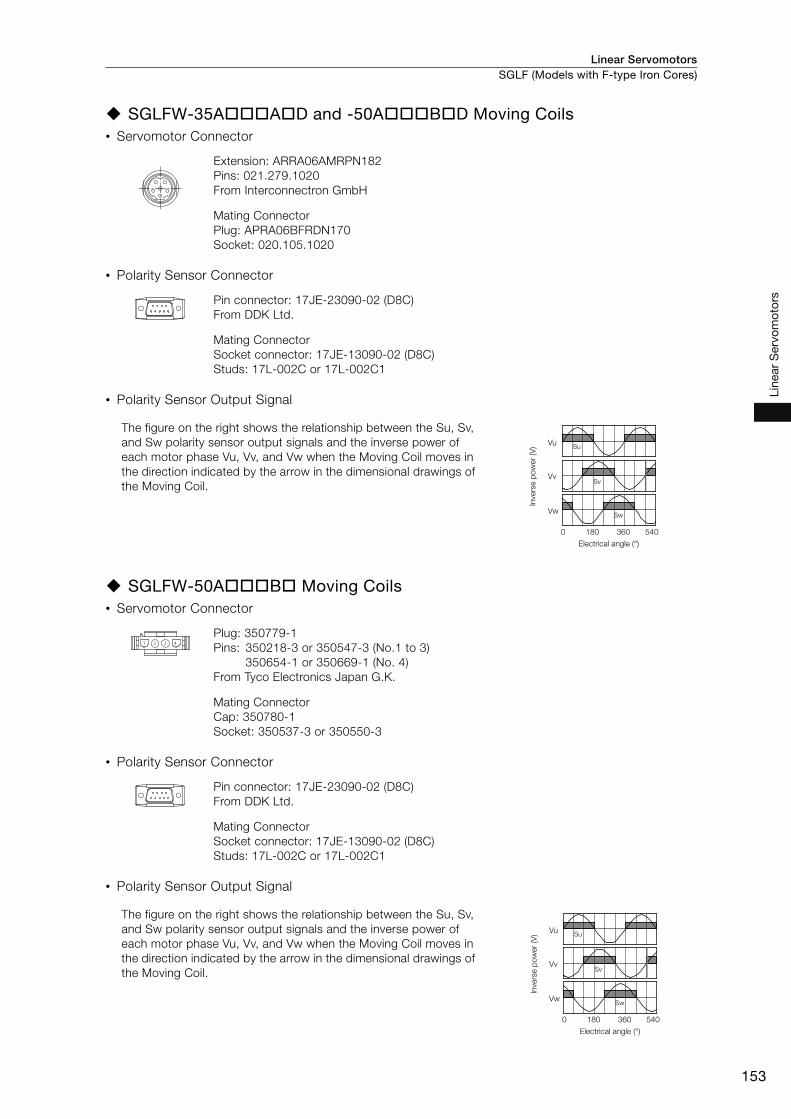
Linear Servomotors SGLF (Models with F-type Iron Cores)
153
Line
ar S
ervo
mot
ors
SGLFW-35A A D and -50A B D Moving Coils• Servomotor Connector
• Polarity Sensor Connector
• Polarity Sensor Output Signal
SGLFW-50A B Moving Coils• Servomotor Connector
• Polarity Sensor Connector
• Polarity Sensor Output Signal
Extension: ARRA06AMRPN182
Pins: 021.279.1020
From Interconnectron GmbH
Mating Connector
Plug: APRA06BFRDN170
Socket: 020.105.1020
Pin connector: 17JE-23090-02 (D8C)
From DDK Ltd.
Mating Connector
Socket connector: 17JE-13090-02 (D8C)
Studs: 17L-002C or 17L-002C1
The figure on the right shows the relationship between the Su, Sv,
and Sw polarity sensor output signals and the inverse power of
each motor phase Vu, Vv, and Vw when the Moving Coil moves in
the direction indicated by the arrow in the dimensional drawings of
the Moving Coil.
Plug: 350779-1
Pins: 350218-3 or 350547-3 (No.1 to 3)
350654-1 or 350669-1 (No. 4)
From Tyco Electronics Japan G.K.
Mating Connector
Cap: 350780-1
Socket: 350537-3 or 350550-3
Pin connector: 17JE-23090-02 (D8C)
From DDK Ltd.
Mating Connector
Socket connector: 17JE-13090-02 (D8C)
Studs: 17L-002C or 17L-002C1
The figure on the right shows the relationship between the Su, Sv,
and Sw polarity sensor output signals and the inverse power of
each motor phase Vu, Vv, and Vw when the Moving Coil moves in
the direction indicated by the arrow in the dimensional drawings of
the Moving Coil.
Vu
Vv
Vw
Su
Sv
Sw
0 180 360 540
Electrical angle (°)
Invers
e p
ow
er
(V)
Vu
Vv
Vw
Su
Sv
Sw
0 180 360 540
Electrical angle (°)
Invers
e p
ow
er
(V)
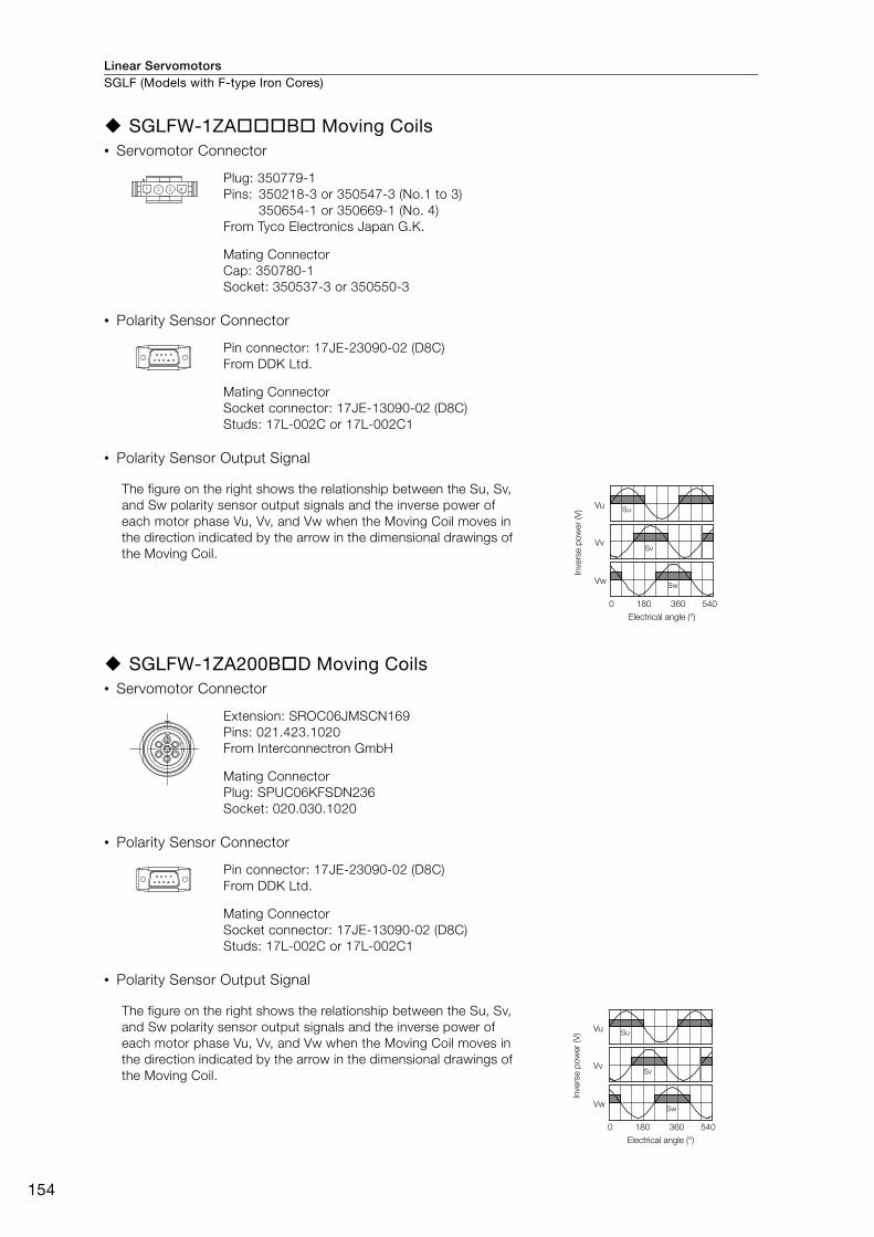
Linear ServomotorsSGLF (Models with F-type Iron Cores)
154
SGLFW-1ZA B Moving Coils• Servomotor Connector
• Polarity Sensor Connector
• Polarity Sensor Output Signal
SGLFW-1ZA200B D Moving Coils• Servomotor Connector
• Polarity Sensor Connector
• Polarity Sensor Output Signal
Plug: 350779-1
Pins: 350218-3 or 350547-3 (No.1 to 3)
350654-1 or 350669-1 (No. 4)
From Tyco Electronics Japan G.K.
Mating Connector
Cap: 350780-1
Socket: 350537-3 or 350550-3
Pin connector: 17JE-23090-02 (D8C)
From DDK Ltd.
Mating Connector
Socket connector: 17JE-13090-02 (D8C)
Studs: 17L-002C or 17L-002C1
The figure on the right shows the relationship between the Su, Sv,
and Sw polarity sensor output signals and the inverse power of
each motor phase Vu, Vv, and Vw when the Moving Coil moves in
the direction indicated by the arrow in the dimensional drawings of
the Moving Coil.
Extension: SROC06JMSCN169
Pins: 021.423.1020
From Interconnectron GmbH
Mating Connector
Plug: SPUC06KFSDN236
Socket: 020.030.1020
Pin connector: 17JE-23090-02 (D8C)
From DDK Ltd.
Mating Connector
Socket connector: 17JE-13090-02 (D8C)
Studs: 17L-002C or 17L-002C1
The figure on the right shows the relationship between the Su, Sv,
and Sw polarity sensor output signals and the inverse power of
each motor phase Vu, Vv, and Vw when the Moving Coil moves in
the direction indicated by the arrow in the dimensional drawings of
the Moving Coil.
Vu
Vv
Vw
Su
Sv
Sw
0 180 360 540
Electrical angle (°)
Invers
e p
ow
er
(V)
Vu
Vv
Vw
Su
Sv
Sw
0 180 360 540
Electrical angle (°)
Invers
e p
ow
er
(V)

Linear Servomotors
155
Line
ar S
ervo
mot
ors
SGLT (Models with T-type Iron Cores)
Model Designations
Moving Coil
* Contact your Yaskawa representative for the characteristics, dimensions, and other details on Servomotors with
these specifications.
Note: This information is provided to explain model numbers. It is not meant to imply that models are available for all
combinations of codes.
Magnetic Way
* The SGLTM-35 H (high-efficiency models) do not support this specification.
Note: This information is provided to explain model numbers. It is not meant to imply that models are available for all
combinations of codes.
10th digit Sensor Specification and Cooling Method
Code Specification
5th digit Power Supply Voltage1st digit Servomotor Type
6th+7th+8th digitsLength of
Moving Coil2nd digit Moving Coil/Magnetic Way
S G L T W - 20 A 170 A P
11th digit Connector for Servomotor Main Circuit Cable
Code
T With T-type iron core A 200 VAC
Specification
Code
W Moving Coil
Specification
3rd+4th digits Magnet Height
Code
20
35
40
50
20 mm
36 mm
40 mm
51 mm
Specification
Code
170
320
400
460
600
170 mm
315 mm
394.2 mm
460 mm
574.2 mm
Specification
A, B …
H: High-efficiency model
9th digit Design Revision Order
Code
None Self-cooledNone
Specifications
Polarity
SensorCooling Method
Applicable Models
All models
Code
Connector from Tyco
Electronics Japan G.K.
MS connector
Loose lead wires with
no connector
Specification Applicable Models
SGLTW-20A
-35A
-50A
SGLTW-40 B
SGLTW-35A H
-50A H
3rd+4th digits
1st digit
2nd digit
5th digit
6th+7th+8th digits
9th digit
10th digit
11th digit
C*H*P
None
Yes
Yes
Water-cooled
Water-cooled
Self-cooled
SGLTW-40
All models
None
Linear Σ Series Linear Servomotors
9th digit
Code
324
405
540
675
756
945
1st digitLength of
Magnetic WayServomotor Type
8th digit Design Revision Order
S G L T M - 20 324 A
3rd+4th digits
5th+6th+7th digits
Specification
2nd digit Moving Coil/Magnetic Way
Magnet Height
Code
M Magnetic Way
Specification
A, B …
H: High-efficiency model
Code
Without options
With magnet cover
With base and
magnet cover
Specification Applicable Models
3rd+4th digits
1st digit
2nd digit
5th+6th+7th digits
8th digit
9th digit
(Same as for the Moving Coil.)
(Same as for the Moving Coil.)
324 mm
405 mm
540 mm
675 mm
756 mm
945 mm
Options
None
C
Y
−
All models
SGLTM-20, -35*, -40
Linear Σ Series Linear Servomotors

Linear ServomotorsSGLT (Models with T-type Iron Cores)
156
Precautions on Moving Coils with Polarity Sensors
When you use a Moving Coil with a Polarity Sensor, the Magnetic Way must cover the bottom of
the polarity sensor. Refer to the example that shows the correct installation.
When determining the length of the Moving Coil’s stroke or the length of the Magnetic Way, con-
sider the total length of the Moving Coil and the polarity sensor. Refer to the following table.
Correct Installation Incorrect Installation
Total Length of Moving Coil with Polarity Sensor
Note
Moving CoilPolarity sensor
Magnetic Way
Moving Coil
movement direction
Edge of Magnetic Way
L
L1A
Magnetic Way
Polarity sensorMoving Coil
Moving Coil Model
SGLTW-
Length of Moving Coil,
L1 (mm)
Length of Polarity Sensor, A (mm)
Total Length, L (mm)
20A170AP 170
34
204
20A320AP 315 349
20A460AP 460 494
35A170AP 170
34
204
35A320AP 315 349
35A460AP 460 494
35A170HP 17034
204
35A320HP 315 349
50A170HP 17034
204
50A320HP 315 349
40A400BH
40A400BP394.2 26 420.2
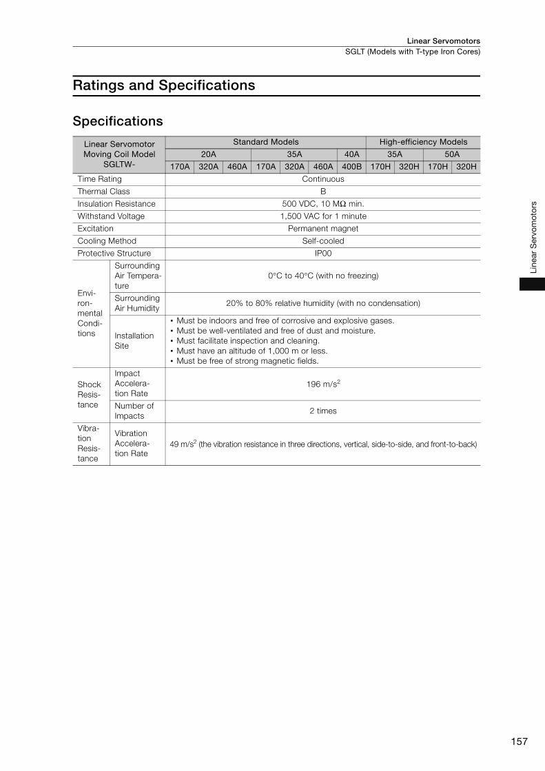
Linear Servomotors SGLT (Models with T-type Iron Cores)
157
Line
ar S
ervo
mot
ors
Ratings and Specifications
Specifications
Linear Servomotor Moving Coil Model
SGLTW-
Standard Models High-efficiency Models
20A 35A 40A 35A 50A
170A 320A 460A 170A 320A 460A 400B 170H 320H 170H 320H
Time Rating Continuous
Thermal Class B
Insulation Resistance 500 VDC, 10 MΩ min.
Withstand Voltage 1,500 VAC for 1 minute
Excitation Permanent magnet
Cooling Method Self-cooled
Protective Structure IP00
Envi-
ron-
mental
Condi-
tions
Surrounding
Air Tempera-
ture
0°C to 40°C (with no freezing)
Surrounding
Air Humidity20% to 80% relative humidity (with no condensation)
Installation
Site
• Must be indoors and free of corrosive and explosive gases.
• Must be well-ventilated and free of dust and moisture.
• Must facilitate inspection and cleaning.
• Must have an altitude of 1,000 m or less.
• Must be free of strong magnetic fields.
Shock
Resis-
tance
Impact
Accelera-
tion Rate
196 m/s2
Number of
Impacts2 times
Vibra-
tion
Resis-
tance
Vibration
Accelera-
tion Rate
49 m/s2 (the vibration resistance in three directions, vertical, side-to-side, and front-to-back)
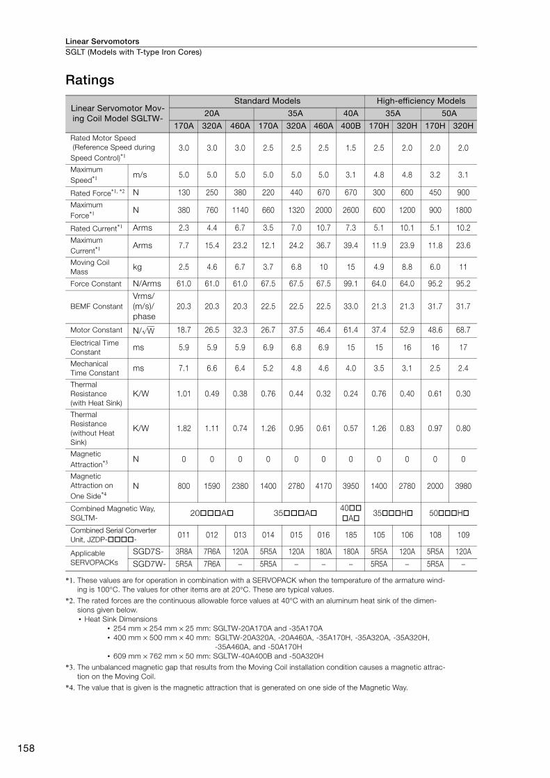
Linear ServomotorsSGLT (Models with T-type Iron Cores)
158
Ratings
*1. These values are for operation in combination with a SERVOPACK when the temperature of the armature wind-
ing is 100°C. The values for other items are at 20°C. These are typical values.
*2. The rated forces are the continuous allowable force values at 40°C with an aluminum heat sink of the dimen-
sions given below.
• Heat Sink Dimensions
• 254 mm × 254 mm × 25 mm: SGLTW-20A170A and -35A170A
• 400 mm × 500 mm × 40 mm: SGLTW-20A320A, -20A460A, -35A170H, -35A320A, -35A320H,
-35A460A, and -50A170H
• 609 mm × 762 mm × 50 mm: SGLTW-40A400B and -50A320H
*3. The unbalanced magnetic gap that results from the Moving Coil installation condition causes a magnetic attrac-
tion on the Moving Coil.
*4. The value that is given is the magnetic attraction that is generated on one side of the Magnetic Way.
Linear Servomotor Mov-ing Coil Model SGLTW-
Standard Models High-efficiency Models
20A 35A 40A 35A 50A
170A 320A 460A 170A 320A 460A 400B 170H 320H 170H 320HRated Motor Speed
(Reference Speed during
Speed Control)*13.0 3.0 3.0 2.5 2.5 2.5 1.5 2.5 2.0 2.0 2.0
Maximum
Speed*1 m/s 5.0 5.0 5.0 5.0 5.0 5.0 3.1 4.8 4.8 3.2 3.1
Rated Force*1, *2 N 130 250 380 220 440 670 670 300 600 450 900
Maximum
Force*1 N 380 760 1140 660 1320 2000 2600 600 1200 900 1800
Rated Current*1 Arms 2.3 4.4 6.7 3.5 7.0 10.7 7.3 5.1 10.1 5.1 10.2
Maximum
Current*1 Arms 7.7 15.4 23.2 12.1 24.2 36.7 39.4 11.9 23.9 11.8 23.6
Moving Coil
Masskg 2.5 4.6 6.7 3.7 6.8 10 15 4.9 8.8 6.0 11
Force Constant N/Arms 61.0 61.0 61.0 67.5 67.5 67.5 99.1 64.0 64.0 95.2 95.2
BEMF Constant
Vrms/
(m/s)/
phase
20.3 20.3 20.3 22.5 22.5 22.5 33.0 21.3 21.3 31.7 31.7
Motor Constant N/ 18.7 26.5 32.3 26.7 37.5 46.4 61.4 37.4 52.9 48.6 68.7
Electrical Time
Constantms 5.9 5.9 5.9 6.9 6.8 6.9 15 15 16 16 17
Mechanical
Time Constantms 7.1 6.6 6.4 5.2 4.8 4.6 4.0 3.5 3.1 2.5 2.4
Thermal
Resistance
(with Heat Sink)
K/W 1.01 0.49 0.38 0.76 0.44 0.32 0.24 0.76 0.40 0.61 0.30
Thermal
Resistance
(without Heat
Sink)
K/W 1.82 1.11 0.74 1.26 0.95 0.61 0.57 1.26 0.83 0.97 0.80
Magnetic
Attraction*3 N 0 0 0 0 0 0 0 0 0 0 0
Magnetic
Attraction on
One Side*4N 800 1590 2380 1400 2780 4170 3950 1400 2780 2000 3980
Combined Magnetic Way,
SGLTM-20 A 35 A
40
A35 H 50 H
Combined Serial Converter
Unit, JZDP- -011 012 013 014 015 016 185 105 106 108 109
Applicable
SERVOPACKs
SGD7S- 3R8A 7R6A 120A 5R5A 120A 180A 180A 5R5A 120A 5R5A 120A
SGD7W- 5R5A 7R6A − 5R5A − − − 5R5A − 5R5A −
W
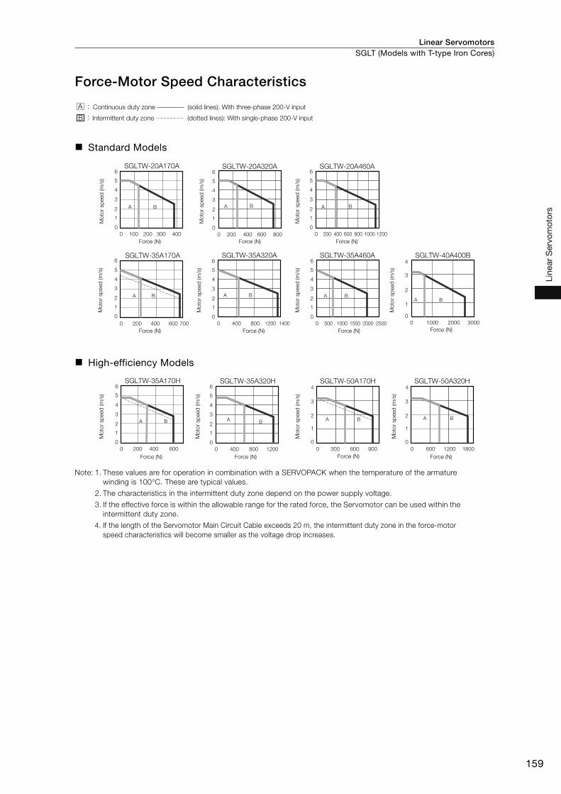
Linear Servomotors SGLT (Models with T-type Iron Cores)
159
Line
ar S
ervo
mot
ors
Force-Motor Speed Characteristics
Standard Models
High-efficiency Models
Note: 1. These values are for operation in combination with a SERVOPACK when the temperature of the armature
winding is 100°C. These are typical values.
2. The characteristics in the intermittent duty zone depend on the power supply voltage.
3. If the effective force is within the allowable range for the rated force, the Servomotor can be used within the
intermittent duty zone.
4. If the length of the Servomotor Main Circuit Cable exceeds 20 m, the intermittent duty zone in the force-motor
speed characteristics will become smaller as the voltage drop increases.
Continuous duty zone
Intermittent duty zone
(solid lines): With three-phase 200-V input
(dotted lines): With single-phase 200-V input
A :
B :
6
5
4
3
2
1
0
6
5
4
3
2
1
0
0 100 200 300 400
0 200 400 600 700
A B
A B
SGLTW-20A170A
SGLTW-35A170A
Mo
tor sp
eed
(m
/s)
Mo
tor sp
eed
(m
/s)
Mo
tor sp
eed
(m
/s)
Force (N) Force (N) Force (N)
Force (N) Force (N) Force (N) Force (N)
Mo
tor sp
eed
(m
/s)
Mo
tor sp
eed
(m
/s)
Mo
tor sp
eed
(m
/s)
Mo
tor sp
eed
(m
/s)
A B
6
5
4
3
2
1
0
0 400 800 1200 1400
SGLTW-35A320A
A B
6
5
4
3
2
1
0
0 500 1000 1500 2000 2500
SGLTW-35A460A
A B
4
3
2
1
0
0 1000 2000 3000
SGLTW-40A400B
A B
6
5
4
3
2
1
0
0 200 400 600 800
SGLTW-20A320A
A B
6
5
4
3
2
1
0
0 200 400 600 800 1000 1200
SGLTW-20A460A
6
5
4
3
2
1
0
4
3
2
1
0
0 400200 600 0 600300 900
BA BA
4
3
2
1
0
0 1200600 1800
BA
SGLTW-35A170H SGLTW-50A170H
Mo
tor sp
eed
(m
/s)
Force (N) Force (N) Force (N) Force (N)
Mo
tor sp
eed
(m
/s)
Mo
tor sp
eed
(m
/s)
Mo
tor sp
eed
(m
/s)
A B
6
5
4
3
2
1
0
0 400 800 1200
SGLTW-35A320H SGLTW-50A320H
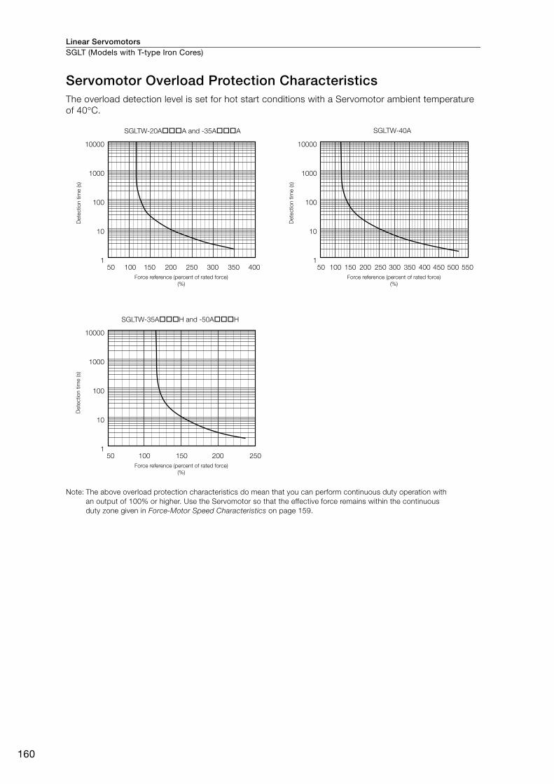
Linear ServomotorsSGLT (Models with T-type Iron Cores)
160
Servomotor Overload Protection CharacteristicsThe overload detection level is set for hot start conditions with a Servomotor ambient temperature
of 40°C.
Note: The above overload protection characteristics do mean that you can perform continuous duty operation with
an output of 100% or higher. Use the Servomotor so that the effective force remains within the continuous
duty zone given in Force-Motor Speed Characteristics on page 159.
SGLTW-40A
50 100 150 200 250 300 350 400 450 550500
10000
1000
100
10
1
SGLTW-35A H and -50A H
25050 100 150 200
10000
1000
100
10
1
40035050 100 150 200 250 300
SGLTW-20A A and -35A A
10000
1000
100
10
1
Dete
ctio
n t
ime (s)
Force reference (percent of rated force)
(%)
Dete
ctio
n t
ime (s)
Force reference (percent of rated force)
(%)
Dete
ctio
n t
ime (s)
Force reference (percent of rated force)
(%)
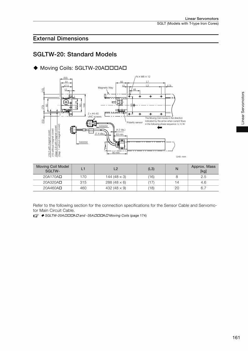
Linear Servomotors SGLT (Models with T-type Iron Cores)
161
Line
ar S
ervo
mot
ors
External Dimensions
SGLTW-20: Standard Models
Moving Coils: SGLTW-20A A
Refer to the following section for the connection specifications for the Sensor Cable and Servomo-
tor Main Circuit Cable.
SGLTW-20A A and -35A A Moving Coils (page 174)
Moving Coil Model SGLTW-
L1 L2 (L3) NApprox. Mass
[kg]
20A170A 170 144 (48 × 3) (16) 8 2.5
20A320A 315 288 (48 × 6) (17) 14 4.6
20A460A 460 432 (48 × 9) (18) 20 6.7
47.51
00
60
80
28
20
(15
)(1
5)
(70
)
(55)
500±50
500±50
12
51
(L3)
L1
1
L210
48
50
60
N × M6 × 12
Magnetic Way
2 × #4-40
UNC screws
(Gap
: 1 w
ithout
magnet
cover)
(Gap
: 0.8
with m
agnet
cover)
(19 w
ithout
magnet
cover)
(19.2
with m
agnet
cover)
Polarity sensor
The Moving Coil moves in the direction
indicated by the arrow when current flows
in the following phase sequence: U, V, W.
(4.2 dia.)
63 min.(7.4 dia.)
90 min.
Unit: mm
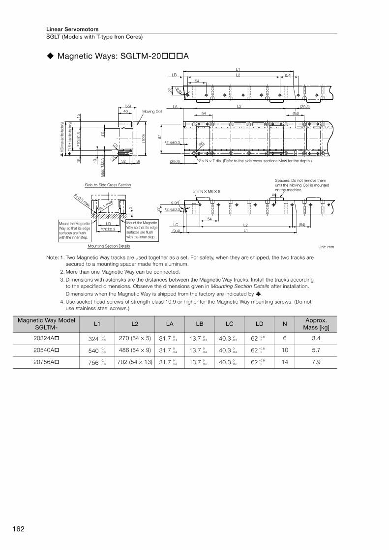
Linear ServomotorsSGLT (Models with T-type Iron Cores)
162
Magnetic Ways: SGLTM-20 A
Note: 1. Two Magnetic Way tracks are used together as a set. For safety, when they are shipped, the two tracks are
secured to a mounting spacer made from aluminum.
2. More than one Magnetic Way can be connected.
3. Dimensions with asterisks are the distances between the Magnetic Way tracks. Install the tracks according
to the specified dimensions. Observe the dimensions given in Mounting Section Details after installation.
Dimensions when the Magnetic Way is shipped from the factory are indicated by .
4. Use socket head screws of strength class 10.9 or higher for the Magnetic Way mounting screws. (Do not
use stainless steel screws.)
2 × N × M6 × 8
C1
C1
(54)
L2
54
9.9°
L2
54
(29.3)
(54)
R6
(54)
8
LC L2
54
(29.3)
L1
L1
LA
LB
(9.4)
9.9°
*2.4±0.3
*2.4±0.3
32 (8)
(55)
40
27
87
27
(1)
(10
0)
19
Gap
: 1±0
.3
15
15
*70±0
.3
*70±0.3
LD
3
Moving Coil
2 × N × 7 dia. (Refer to the side cross-sectional view for the depth.)
Spacers: Do not remove them
until the Moving Coil is mounted
on the machine.
Unit: mm
Mount the Magnetic
Way so that its edge
surfaces are flush
with the inner step.
Mount the Magnetic
Way so that its edge
surfaces are flush
with the inner step.
R: 0.5 max.
R: 1 m
ax.
71.5
±1 (a
t the
fact
ory)
103
max
.(at t
he fa
ctor
y)
Mounting Section Details
Side-to-Side Cross Section
Magnetic Way Model SGLTM-
L1 L2 LA LB LC LD NApprox.
Mass [kg]
20324A 324 270 (54 × 5) 31.7 13.7 40.3 62 6 3.4
20540A 540 486 (54 × 9) 31.7 13.7 40.3 62 10 5.7
20756A 756 702 (54 × 13) 31.7 13.7 40.3 62 14 7.9
-0.1
-0.3
0
-0.2
0
-0.2
0
-0.2
+0.6
0
-0.1
-0.3
0
-0.2
0
-0.2
0
-0.2
+0.6
0
-0.1
-0.3
0
-0.2
0
-0.2
0
-0.2
+0.6
0
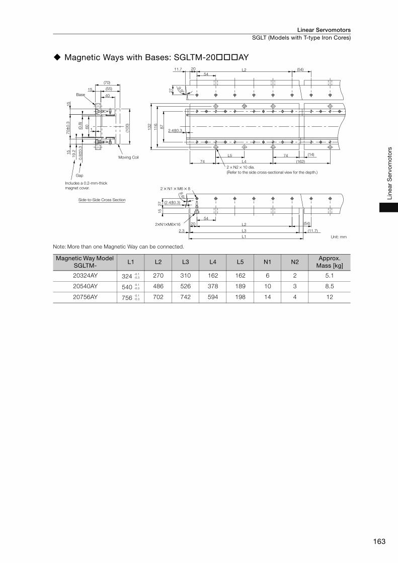
Linear Servomotors SGLT (Models with T-type Iron Cores)
163
Line
ar S
ervo
mot
ors
Magnetic Ways with Bases: SGLTM-20 AY
Note: More than one Magnetic Way can be connected.
Magnetic Way Model SGLTM-
L1 L2 L3 L4 L5 N1 N2Approx.
Mass [kg]
20324AY 324 270 310 162 162 6 2 5.1
20540AY 540 486 526 378 189 10 3 8.5
20756AY 756 702 742 594 198 14 4 12
Gap
27
15
(2.4±0.3)
13
2
11
6
87
2.4±0.3
L3
L4
L5
(0.8
)0
.8±0
.3
19
.2
70±0
.3
L1
(11.7)
(54)
2.3
20
54
L2
9.9°
74 (14)
(162)74
(54)11.7 L254
20
27
9.9°
1
60
15
15
(10
0)
(70)
(55)
40
15
DATE
2 × N1 × M6 × 8
2×N1×M6×16
Base
Moving Coil
2 × N2 × 10 dia.
(Refer to the side cross-sectional view for the depth.)
Unit: mm
Includes a 0.2-mm-thick
magnet cover.
Side-to-Side Cross Section
-0.1
-0.3
-0.1
-0.3
-0.1
-0.3

Linear ServomotorsSGLT (Models with T-type Iron Cores)
164
SGLTW-35: Standard Models
Moving Coils: SGLTW-35A A
Refer to the following section for the connection specifications for the Sensor Cable and Servomo-
tor Main Circuit Cable.
SGLTW-20A A and -35A A Moving Coils (page 174)
Moving Coil Model SGLTW-
L1 L2 (L3) NApprox. Mass
[kg]
35A170A 170 144 (48 × 3) (16) 8 3.7
35A320A 315 288 (48 × 6) (17) 14 6.8
35A460A 460 432 (48 × 9) (18) 20 10
55
10
0
60
28
20
(70)
66
12
500±50
500±50
50
60
(70
)(1
5)
(L3)
L1
80
1
10
48
L2
(15
)
N × M6 × 12
Magnetic Way
2 × #4-40
UNC screws
(8.4 dia.)(4.2 dia.)
Polarity sensor
63 min.
Unit: mm100 min.
The Moving Coil moves in the direction
indicated by the arrow when current flows
in the following phase sequence: U, V, W.
(Gap
: 1
witho
ut
mag
net
co
ver)
(Gap
: 0
.8 w
ith m
ag
net
co
ver)
(19
witho
ut
mag
net
co
ver)
(19
.2 w
ith m
ag
net
co
ver)
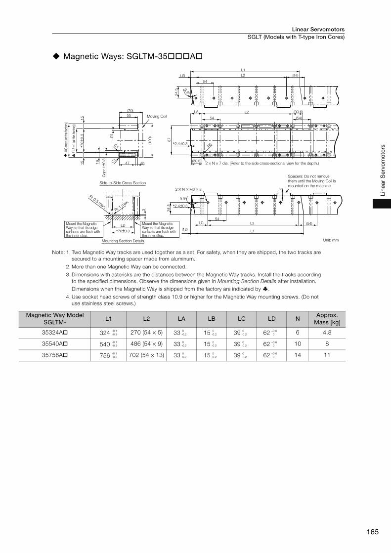
Linear Servomotors SGLT (Models with T-type Iron Cores)
165
Line
ar S
ervo
mot
ors
Magnetic Ways: SGLTM-35 A
Note: 1. Two Magnetic Way tracks are used together as a set. For safety, when they are shipped, the two tracks are
secured to a mounting spacer made from aluminum.
2. More than one Magnetic Way can be connected.
3. Dimensions with asterisks are the distances between the Magnetic Way tracks. Install the tracks according
to the specified dimensions. Observe the dimensions given in Mounting Section Details after installation.
Dimensions when the Magnetic Way is shipped from the factory are indicated by .
4. Use socket head screws of strength class 10.9 or higher for the Magnetic Way mounting screws. (Do not
use stainless steel screws.)
(54)
L2
54
L1
LB
2 × N × M6 × 8
C1
C1
47 (8)
(70)
55
(1)
(10
0)
19
Gap
: 1±0
.3
15
15
*70±0
.3
*70±0.3
LD(54)LC L2
54
L1(12)
9.9°9.9°
*2.4±0.3
34
.5
L2
54
(30.6)
(54)
R6
(30.6)
LA
87
34
.5
*2.4±0.33
4
Moving Coil
2 × N × 7 dia. (Refer to the side cross-sectional view for the depth.)
Mount the Magnetic Way so that its edge surfaces are flush with the inner step.
Mount the Magnetic Way so that its edge surfaces are flush with the inner step.
Spacers: Do not remove
them until the Moving Coil is
mounted on the machine.
R: 0.5 max.
R: 1 m
ax.
Unit: mm
103
max
.(at t
he fa
ctor
y)
71.5
±1 (a
t the
fact
ory)
Side-to-Side Cross Section
Mounting Section Details
Magnetic Way Model SGLTM-
L1 L2 LA LB LC LD NApprox.
Mass [kg]
35324A 324 270 (54 × 5) 33 15 39 62 6 4.8
35540A 540 486 (54 × 9) 33 15 39 62 10 8
35756A 756 702 (54 × 13) 33 15 39 62 14 11
-0.1
-0.3
0
-0.2
0
-0.2
0
-0.2
+0.6
0
-0.1
-0.3
0
-0.2
0
-0.2
0
-0.2
+0.6
0
-0.1
-0.3
0
-0.2
0
-0.2
0
-0.2
+0.6
0

Linear ServomotorsSGLT (Models with T-type Iron Cores)
166
Magnetic Ways with Bases: SGLTM-35 AY
Note: More than one Magnetic Way can be connected.
Magnetic Way Model SGLTM-
L1 L2 L3 L4 L5 N1 N2Approx.
Mass [kg]
35324AY 324 270 310 162 162 6 2 6.4
35540AY 540 486 526 378 189 10 3 11
35756AY 756 702 742 594 198 14 4 15
Gap
34
.51
5
(2.4±0.3)
(54)
9.9°
2.4±0.3
L5
L4
L3
13
2
11
6
87
0.8
±0.3
19
.2
70±0
.3
(54)
9.9°34
.5
13 L2
54
(162)74
74
1
54
L2
L1
60
(10
0)
15
55
(85)
(70)
1
15
15
2 × N1 × M6 × 8
2 × N1 × M6 × 16
(13)
20
(14)
20(0
.8)
Base
Moving Coil
2 × N2 × 10 dia.
(Refer to the side cross-sectional view for the depth.)
Unit: mm
Includes a 0.2-mm-thick
magnet cover.
Side-to-Side Cross Section
-0.1
-0.3
-0.1
-0.3
-0.1
-0.3
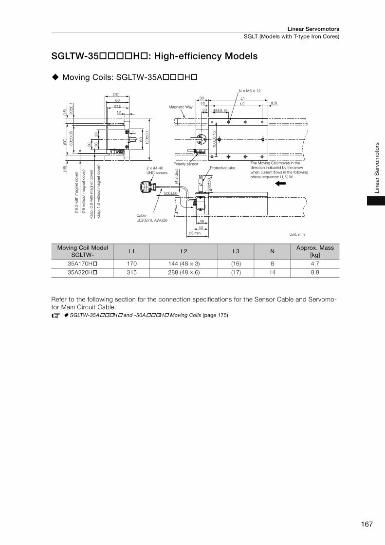
Linear Servomotors SGLT (Models with T-type Iron Cores)
167
Line
ar S
ervo
mot
ors
SGLTW-35 H : High-efficiency Models
Moving Coils: SGLTW-35A H
Refer to the following section for the connection specifications for the Sensor Cable and Servomo-
tor Main Circuit Cable.
SGLTW-35A H and -50A H Moving Coils (page 175)
Moving Coil Model SGLTW-
L1 L2 L3 NApprox. Mass
[kg]
35A170H 170 144 (48 × 3) (16) 8 4.7
35A320H 315 288 (48 × 6) (17) 14 8.8
12
1
60
28
30
62.5
66
(70)
(L3)
(90
)(1
5)
(15
)
3080±0
.05
12
0±0
.1
500±50
35
43
50
0±5
0
20±0
.1
10
0±0
.15
48±0.1520
10
30 L1
N × M6 × 12
L2Magnetic Way
2 × #4-40
UNC screws
Polarity sensorProtective tube
The Moving Coil moves in the
direction indicated by the arrow
when current flows in the following
phase sequence: U, V, W.
Cable
UL20276, AWG28
63 min. Unit: mm
(4.2
dia
.)
(Gap
: 1
.0 w
itho
ut
mag
net
co
ver)
(Gap
: 0
.8 w
ith m
ag
net
co
ver)
(19
witho
ut
mag
net
co
ver)
(19
.2 w
ith m
ag
net
co
ver)
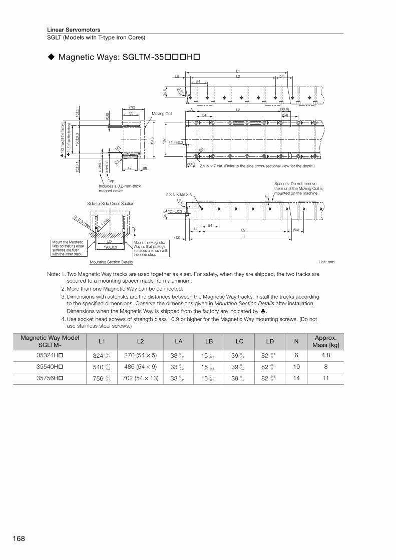
Linear ServomotorsSGLT (Models with T-type Iron Cores)
168
Magnetic Ways: SGLTM-35 H
Note: 1. Two Magnetic Way tracks are used together as a set. For safety, when they are shipped, the two tracks are
secured to a mounting spacer made from aluminum.
2. More than one Magnetic Way can be connected.
3. Dimensions with asterisks are the distances between the Magnetic Way tracks. Install the tracks according
to the specified dimensions. Observe the dimensions given in Mounting Section Details after installation.
Dimensions when the Magnetic Way is shipped from the factory are indicated by .
4. Use socket head screws of strength class 10.9 or higher for the Magnetic Way mounting screws. (Do not
use stainless steel screws.)
Moving Coil
Includes a 0.2-mm-thick
magnet cover.
2 × N × 7 dia. (Refer to the side cross-sectional view for the depth.)
Spacers: Do not remove
them until the Moving Coil is
mounted on the machine.
Unit: mm
Mount the Magnetic Way so that its edge surfaces are flush with the inner step.
Mount the Magnetic Way so that its edge surfaces are flush with the inner step.
R: 0.5 max. R
: 1 m
ax.
91.5
±1 (a
t the
fact
ory)
123
max
.(at t
he fa
ctor
y)
Side-to-Side Cross Section
Mounting Section Details
3
LD
*90±0.3
(120)
(70)(0
.8)
47
0.8
±0.3
4.2
±0.1
15±0
.1*9
0±0
.315±0
.1
(8)
55
C1
C1
Gap
9.9°9.9°
*2.4±0.3
*2.4±0.3
34.5
107
2 × N × M6 × 8
34.5
(12)
L2LC
L1
(54)
(4)
54
O/N
S/N
MADE IN JAPANDATE
YASKAWA
TYPE:
(30.6)
R6
(54)
(54)
54
54
L2
L2LB
L1
(30.6)LA
Magnetic Way Model SGLTM-
L1 L2 LA LB LC LD NApprox.
Mass [kg]
35324H 324 270 (54 × 5) 33 15 39 82 6 4.8
35540H 540 486 (54 × 9) 33 15 39 82 10 8
35756H 756 702 (54 × 13) 33 15 39 82 14 11
-0.1
-0.3
0
-0.2
0
-0.2
0
-0.2
+0.6
0
-0.1
-0.3
0
-0.2
0
-0.2
0
-0.2
+0.6
0
-0.1
-0.3
0
-0.2
0
-0.2
0
-0.2
+0.6
0
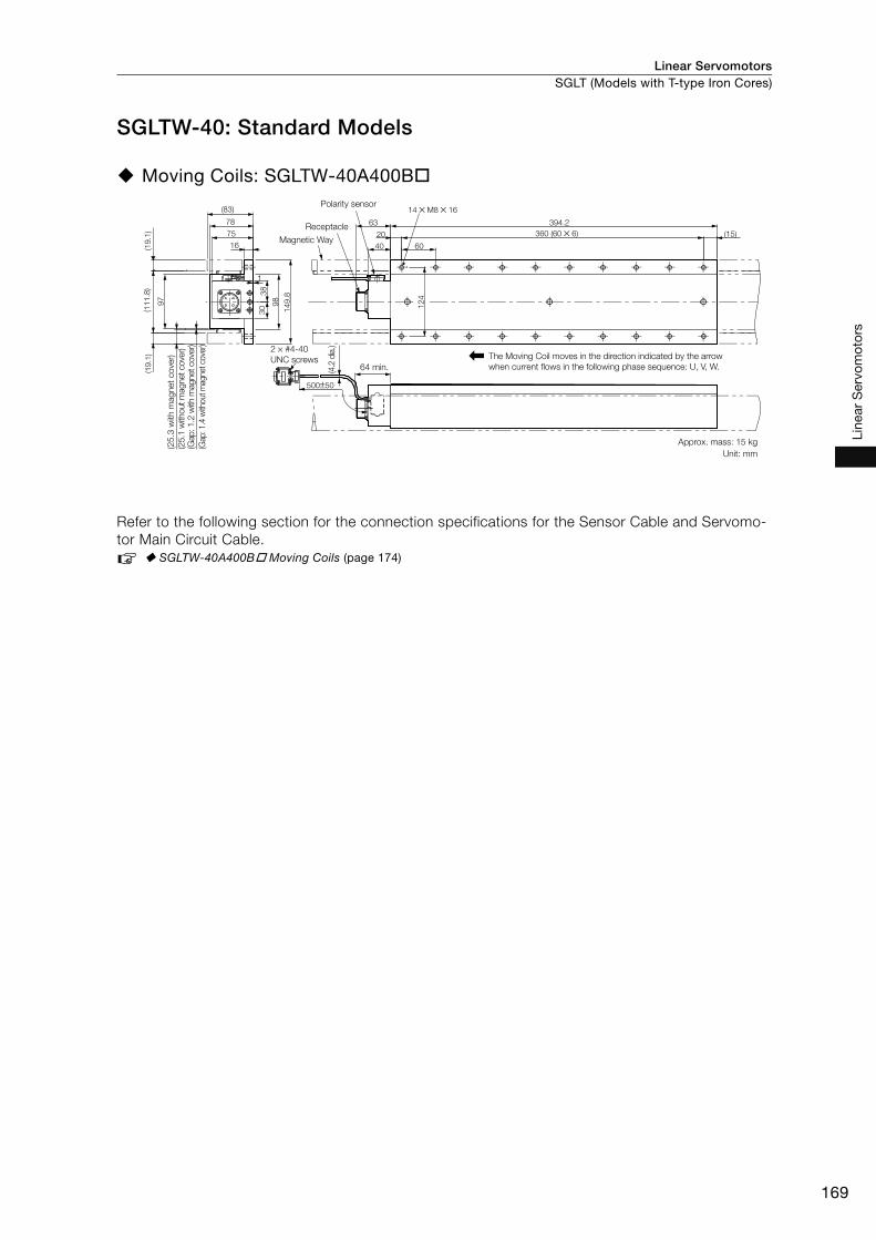
Linear Servomotors SGLT (Models with T-type Iron Cores)
169
Line
ar S
ervo
mot
ors
SGLTW-40: Standard Models
Moving Coils: SGLTW-40A400B
Refer to the following section for the connection specifications for the Sensor Cable and Servomo-
tor Main Circuit Cable.
SGLTW-40A400B Moving Coils (page 174)
500±50
75
(83)
78
16
(15)20
63 394.2
360 (60 × 6)
40 60(19.1
)(1
11.8
)
97
1
30
38
98
124
149.8
(19.1
)
14 × M8 × 16Polarity sensor
Receptacle
Magnetic Way
2 × #4-40
UNC screws64 min.
The Moving Coil moves in the direction indicated by the arrow
when current flows in the following phase sequence: U, V, W.
Approx. mass: 15 kg
Unit: mm
(4.2
dia
.)
(Gap
: 1.4
with
out m
agnet
cove
r)
(Gap: 1.2
with
magnet cove
r)(2
5.1
with
out m
agnet cove
r)
(25
.3 w
ith m
ag
net
co
ver)

Linear ServomotorsSGLT (Models with T-type Iron Cores)
170
Magnetic Ways: SGLTM-40 A
Note: 1. Two Magnetic Way tracks are used together as a set. For safety, when they are shipped, the two tracks are
secured to a mounting spacer made from aluminum.
2. More than one Magnetic Way can be connected.
3. Dimensions with asterisks are the distances between the Magnetic Way tracks. Install the tracks according
to the specified dimensions. Observe the dimensions given in Mounting Section Details after installation.
Dimensions when the Magnetic Way is shipped from the factory are indicated by .
4. Use socket head screws of strength class 10.9 or higher for the Magnetic Way mounting screws. (Do not
use stainless steel screws.)
MADE IS/NO/N
TYPE:YASKAWA
2 × N × M8 × 10
C1
(67.5)LC L2
67.5
L1(7.6)
*1.4±0.3
39
*111.8±0.3
LD
48 (15)
(83)
63
(1.4
)
(150)
131
25.1 C1
Gap
: 1.4
±0.3
19.1
19.1
*111.8
±0.3
L2
67.5
(36.1)
(67.5)
(36.1)
LA
R7
*1.4±0.3
(67.5)L2
67.5
5.6°
L1
LB
39
4
5.6°
6
Moving Coil
Mount the Magnetic Way so that its edge surfaces are flush with the inner step.
Mount the Magnetic Way so that its edge surfaces are flush with the inner step.
Unit: mm
R: 0.5 max.R: 1
max.
2 × N × 9 dia. (Refer to the side cross-sectional view for the depth.)
Spacers: Do not remove them until the Moving Coil is mounted on the machine.
113 ±
1 (at th
e facto
ry)
153 m
ax.
(at th
e facto
ry)
Side-to-Side Cross Section
Mounting Section Details
Magnetic Way Model SGLTM-
L1 L2 LA LB LC LD NApprox.
Mass [kg]
40405A 405 337.5 (67.5 × 5) 37.5 15 52.5 100 6 9
40675A 675 607.5 (67.5 × 9) 37.5 15 52.5 100 10 15
40945A 945 877.5 (67.5 × 13) 37.5 15 52.5 100 14 21
-0.1
-0.3
0
-0.2
0
-0.2
0
-0.2
+0.6
0
-0.1
-0.3
0
-0.2
0
-0.2
0
-0.2
+0.6
0
-0.1
-0.3
0
-0.2
0
-0.2
0
-0.2
+0.6
0
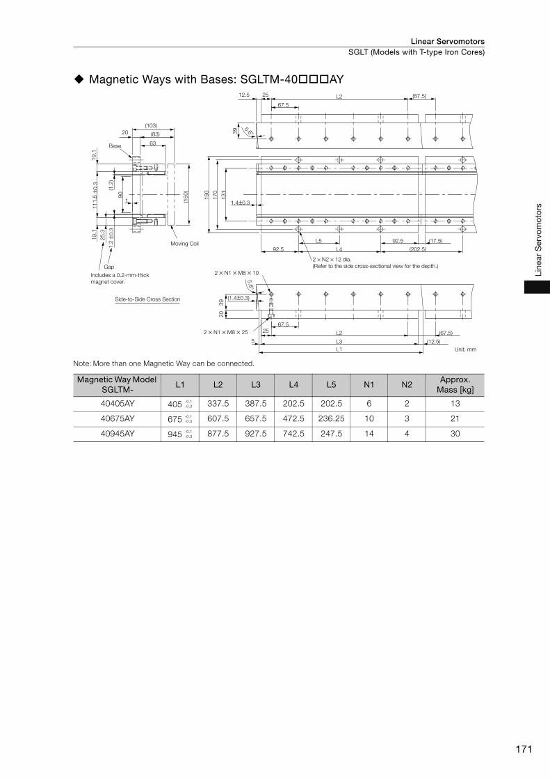
Linear Servomotors SGLT (Models with T-type Iron Cores)
171
Line
ar S
ervo
mot
ors
Magnetic Ways with Bases: SGLTM-40 AY
Note: More than one Magnetic Way can be connected.
Magnetic Way Model SGLTM-
L1 L2 L3 L4 L5 N1 N2Approx.
Mass [kg]
40405AY 405 337.5 387.5 202.5 202.5 6 2 13
40675AY 675 607.5 657.5 472.5 236.25 10 3 21
40945AY 945 877.5 927.5 742.5 247.5 14 4 30
Gap
Base
(1.4±0.3)
L1
(12.5)L35
25 L2 (67.5)
67.5
5.6°
(202.5)92.5 L4
L5 92.5 (17.5)
17
0
19
0
13
12
03
9
1.4±0.3
(83)
(103)
1
(1.2
)
90
19
.1
25
.3
±0.3
11
1.8
±0.3
1.2
5.6°39
12.5 25 (67.5)
67.5
L2
63
20
19
.1
(15
0)
2 × N1 × M8 × 10
2 × N1 × M8 × 25
Moving Coil
2 × N2 × 12 dia.
(Refer to the side cross-sectional view for the depth.)
Unit: mm
Includes a 0.2-mm-thick
magnet cover.
Side-to-Side Cross Section
-0.1
-0.3
-0.1
-0.3
-0.1
-0.3
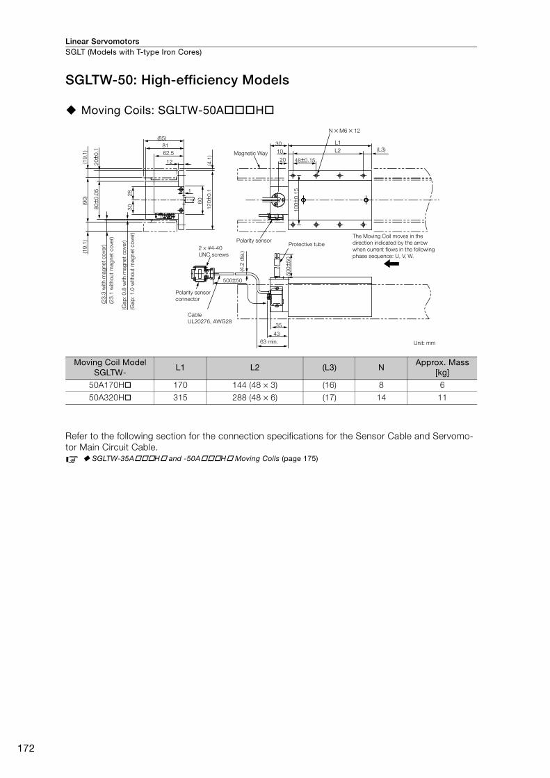
Linear ServomotorsSGLT (Models with T-type Iron Cores)
172
SGLTW-50: High-efficiency Models
Moving Coils: SGLTW-50A H
Refer to the following section for the connection specifications for the Sensor Cable and Servomo-
tor Main Circuit Cable.
SGLTW-35A H and -50A H Moving Coils (page 175)
Moving Coil Model SGLTW-
L1 L2 (L3) NApprox. Mass
[kg]
50A170H 170 144 (48 × 3) (16) 8 6
50A320H 315 288 (48 × 6) (17) 14 11
28
30
1
(4.1
)
(90
)
(85)
(19
.1)
80±0
.05
12
0±0
.1
500±50
35
43
20±0
.1
50
0±5
0
10
0±0
.15
(L3)
48±0.1520
10
30 L1
N × M6 × 12
L2
(19
.1)
12
60
81
62.5 Magnetic Way
2 × #4-40
UNC screws
Polarity sensor
connector
Cable
UL20276, AWG28
(4.2
dia
.)Polarity sensor
Protective tube
63 min. Unit: mm
The Moving Coil moves in the
direction indicated by the arrow
when current flows in the following
phase sequence: U, V, W.
(Gap
: 1
.0 w
itho
ut
mag
net
co
ver)
(Gap
: 0
.8 w
ith m
ag
net
co
ver)
(23
.1 w
itho
ut
mag
net
co
ver)
(23
.3 w
ith m
ag
net
co
ver)
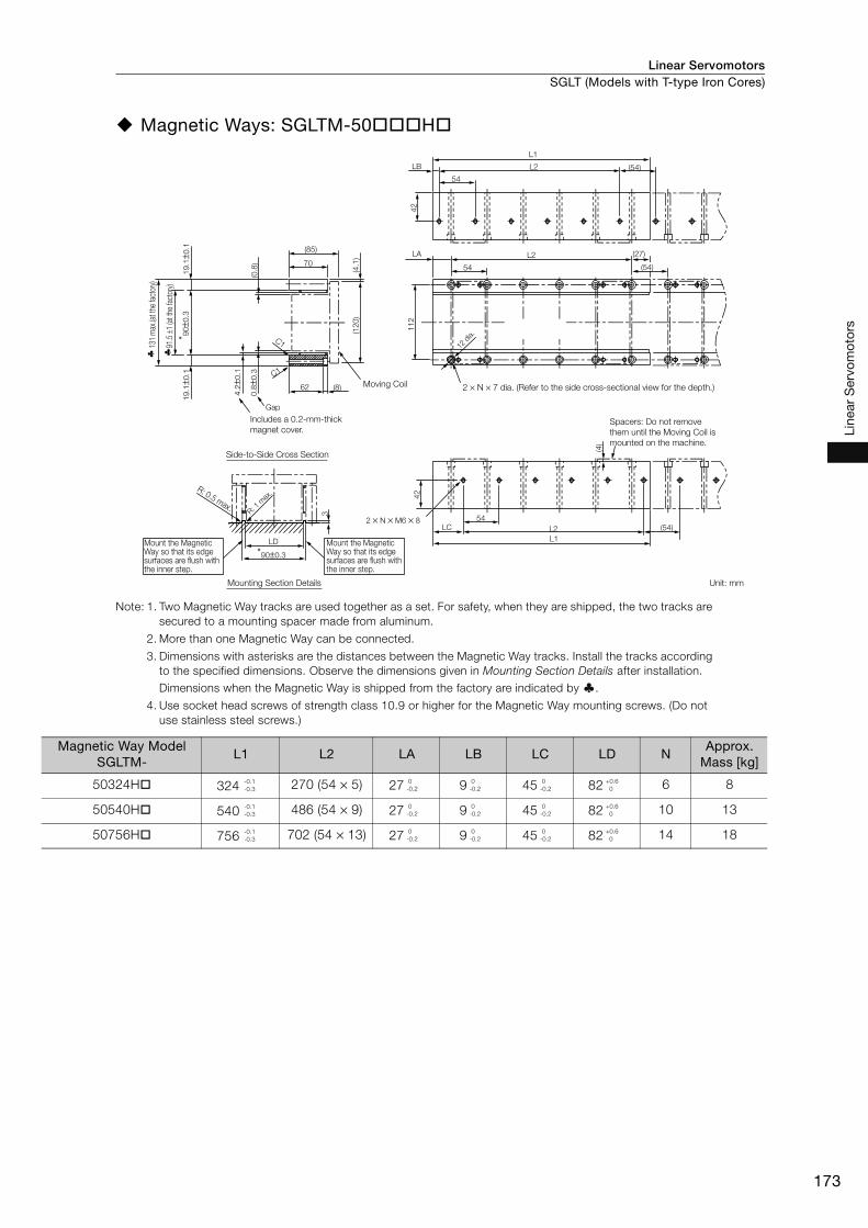
Linear Servomotors SGLT (Models with T-type Iron Cores)
173
Line
ar S
ervo
mot
ors
Magnetic Ways: SGLTM-50 H
Note: 1. Two Magnetic Way tracks are used together as a set. For safety, when they are shipped, the two tracks are
secured to a mounting spacer made from aluminum.
2. More than one Magnetic Way can be connected.
3. Dimensions with asterisks are the distances between the Magnetic Way tracks. Install the tracks according
to the specified dimensions. Observe the dimensions given in Mounting Section Details after installation.
Dimensions when the Magnetic Way is shipped from the factory are indicated by .
4. Use socket head screws of strength class 10.9 or higher for the Magnetic Way mounting screws. (Do not
use stainless steel screws.)
3
LD
*90±0.3
(120)
(4.1
)
(85)(0
.8)
62
0.8
±0.3
4.2
±0.1
19.1
±0.1
* 90±0
.319.1
±0.1
(8)
70
C1
C1
Gap
2 × N × M6 × 8
(4)
(54)LC L2
L1
L1
54
112
42
42
(54)
(54)
54
L2LB
(27)
54
LA L2
91.5
±1 (a
t the
fact
ory)
Moving Coil
R: 0.5 max.R: 1
max
.
2 × N × 7 dia. (Refer to the side cross-sectional view for the depth.)
Spacers: Do not remove
them until the Moving Coil is
mounted on the machine.
Unit: mm
12 d
ia.
Includes a 0.2-mm-thick
magnet cover.
Mount the Magnetic Way so that its edge surfaces are flush with the inner step.
Mount the Magnetic Way so that its edge surfaces are flush with the inner step.
131
max
.(at t
he fa
ctor
y)
Side-to-Side Cross Section
Mounting Section Details
Magnetic Way Model SGLTM-
L1 L2 LA LB LC LD NApprox.
Mass [kg]
50324H 324 270 (54 × 5) 27 9 45 82 6 8
50540H 540 486 (54 × 9) 27 9 45 82 10 13
50756H 756 702 (54 × 13) 27 9 45 82 14 18
-0.1
-0.3
0
-0.2
0
-0.2
0
-0.2
+0.6
0
-0.1
-0.3
0
-0.2
0
-0.2
0
-0.2
+0.6
0
-0.1
-0.3
0
-0.2
0
-0.2
0
-0.2
+0.6
0
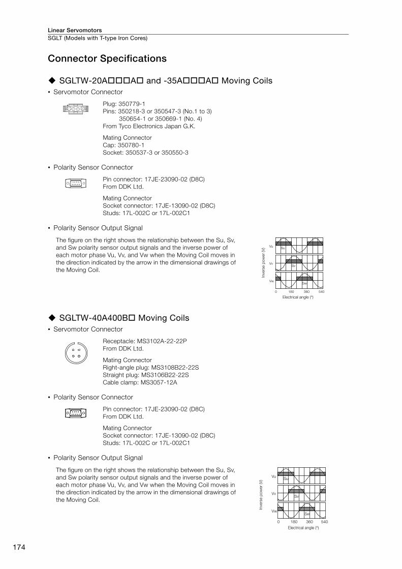
Linear ServomotorsSGLT (Models with T-type Iron Cores)
174
Connector Specifications
SGLTW-20A A and -35A A Moving Coils• Servomotor Connector
• Polarity Sensor Connector
• Polarity Sensor Output Signal
SGLTW-40A400B Moving Coils• Servomotor Connector
• Polarity Sensor Connector
• Polarity Sensor Output Signal
Plug: 350779-1
Pins: 350218-3 or 350547-3 (No.1 to 3)
350654-1 or 350669-1 (No. 4)
From Tyco Electronics Japan G.K.
Mating Connector
Cap: 350780-1
Socket: 350537-3 or 350550-3
Pin connector: 17JE-23090-02 (D8C)
From DDK Ltd.
Mating Connector
Socket connector: 17JE-13090-02 (D8C)
Studs: 17L-002C or 17L-002C1
The figure on the right shows the relationship between the Su, Sv,
and Sw polarity sensor output signals and the inverse power of
each motor phase Vu, Vv, and Vw when the Moving Coil moves in
the direction indicated by the arrow in the dimensional drawings of
the Moving Coil.
Receptacle: MS3102A-22-22P
From DDK Ltd.
Mating Connector
Right-angle plug: MS3108B22-22S
Straight plug: MS3106B22-22S
Cable clamp: MS3057-12A
Pin connector: 17JE-23090-02 (D8C)
From DDK Ltd.
Mating Connector
Socket connector: 17JE-13090-02 (D8C)
Studs: 17L-002C or 17L-002C1
The figure on the right shows the relationship between the Su, Sv,
and Sw polarity sensor output signals and the inverse power of
each motor phase Vu, Vv, and Vw when the Moving Coil moves in
the direction indicated by the arrow in the dimensional drawings of
the Moving Coil.
Vu
Vv
Vw
Su
Sv
Sw
0 180 360 540
Invers
e p
ow
er
(V)
Electrical angle (°)
Vu
Vv
Vw
Su
Sv
Sw
0 180 360 540
Invers
e p
ow
er
(V)
Electrical angle (°)
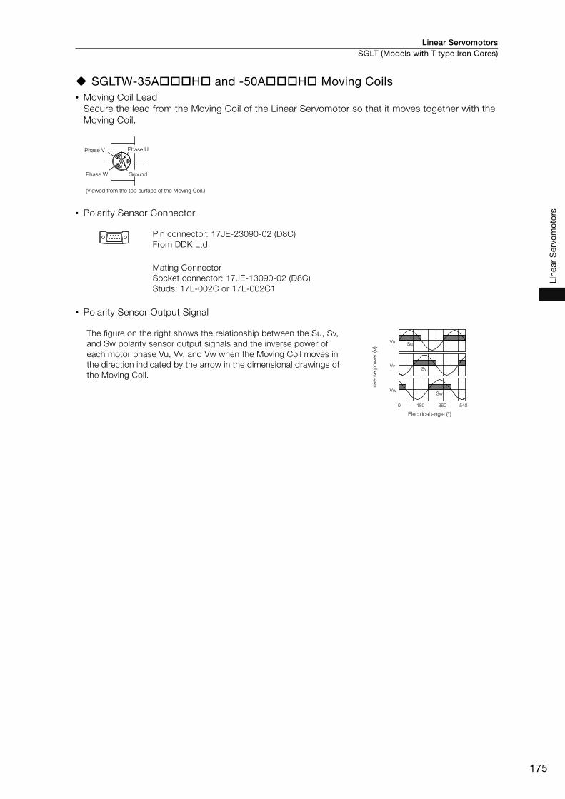
Linear Servomotors SGLT (Models with T-type Iron Cores)
175
Line
ar S
ervo
mot
ors
SGLTW-35A H and -50A H Moving Coils• Moving Coil Lead
Secure the lead from the Moving Coil of the Linear Servomotor so that it moves together with the
Moving Coil.
• Polarity Sensor Connector
• Polarity Sensor Output Signal
Pin connector: 17JE-23090-02 (D8C)
From DDK Ltd.
Mating Connector
Socket connector: 17JE-13090-02 (D8C)
Studs: 17L-002C or 17L-002C1
The figure on the right shows the relationship between the Su, Sv,
and Sw polarity sensor output signals and the inverse power of
each motor phase Vu, Vv, and Vw when the Moving Coil moves in
the direction indicated by the arrow in the dimensional drawings of
the Moving Coil.
Phase V Phase U
GroundPhase W
(Viewed from the top surface of the Moving Coil.)
Vu
Vv
Vw
Su
Sv
Sw
0 180 360 540
Invers
e p
ow
er
(V)
Electrical angle (°)
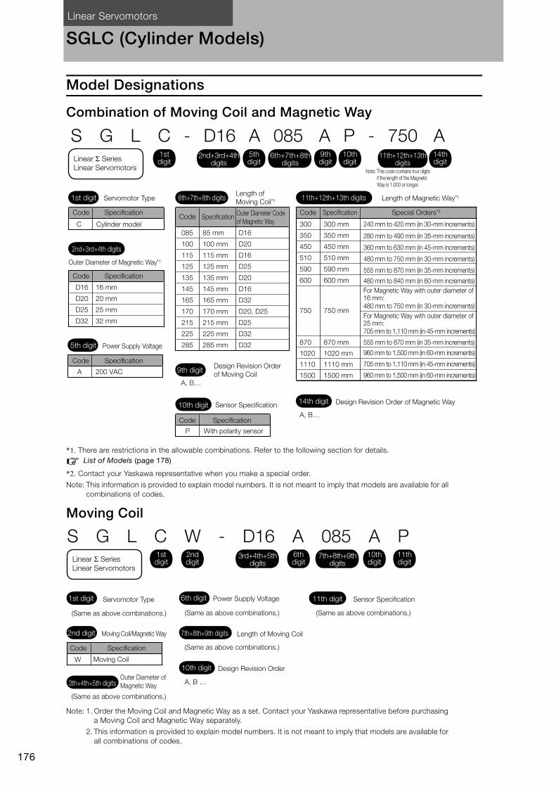
Linear Servomotors
176
SGLC (Cylinder Models)
Model Designations
Combination of Moving Coil and Magnetic Way
*1. There are restrictions in the allowable combinations. Refer to the following section for details.
List of Models (page 178)
*2. Contact your Yaskawa representative when you make a special order.
Note: This information is provided to explain model numbers. It is not meant to imply that models are available for all
combinations of codes.
Moving Coil
Note: 1. Order the Moving Coil and Magnetic Way as a set. Contact your Yaskawa representative before purchasing
a Moving Coil and Magnetic Way separately.
2. This information is provided to explain model numbers. It is not meant to imply that models are available for
all combinations of codes.
S G L C - D16 A 085 A P - 750 A
C
A 200 VAC
P
D16
D20
D25
D32
16 mm
20 mm
25 mm
32 mm
085
100
115
125
135
145
165
170
215
225
285
85 mm
100 mm
115 mm
125 mm
135 mm
145 mm
165 mm
170 mm
215 mm
225 mm
285 mm
D16
D20
D16
D25
D20
D16
D32
D20, D25
D25
D32
D32
A, B…
A, B…
300 mm
350 mm
450 mm
510 mm
590 mm
600 mm
750 mm
870 mm
1020 mm
1110 mm
1500 mm
300
350
450
510
590
600
750
870
1020
1110
1500
Servomotor Type
Outer Diameter of Magnetic Way*1
Power Supply Voltage
Design Revision Order
of Moving Coil
Sensor Specification Design Revision Order of Magnetic Way
Code Specification
With polarity sensor
Code
Code Specification
Specification
Code SpecificationCode Specification
Outer Diameter Code
of Magnetic Way
Code Specification Special Orders*2
240 mm to 420 mm (in 30-mm increments)
280 mm to 490 mm (in 35-mm increments)
360 mm to 630 mm (in 45-mm increments)
480 mm to 750 mm (in 30-mm increments)
555 mm to 870 mm (in 35-mm increments)
480 mm to 840 mm (in 60-mm increments)
For Magnetic Way with outer diameter of 16 mm:
For Magnetic Way with outer diameter of 25 mm:
705 mm to 1,110 mm (in 45-mm increments)
555 mm to 870 mm (in 35-mm increments)
960 mm to 1,500 mm (in 60-mm increments)
705 mm to 1,110 mm (in 45-mm increments)
960 mm to 1,500 mm (in 60-mm increments)
480 mm to 750 mm (in 30-mm increments)
Cylinder model
Length of
Moving Coil*1 Length of Magnetic Way*11st digit
2nd+3rd+4th digits
5th digit
9th digit
10th digit14th digit
6th+7th+8th digits 11th+12th+13th digits
Note: This code contains four digits
if the length of the Magnetic
Way is 1,000 or longer.
1st digit
5th digit
6th+7th+8th digits
9th digit
10th digit
14th digit
11th+12th+13th digits
2nd+3rd+4th digits
Linear Σ Series Linear Servomotors
W
S G L C W - D16 A 085 A P
A, B …
1st digit
2nd digit
3rd+4th+5th digits
6th digit
7th+8th+9th digits
10th digit
11th digit
Servomotor Type Power Supply Voltage
Length of Moving Coil
Sensor Specification
(Same as above combinations.)
(Same as above combinations.)
Design Revision Order
(Same as above combinations.)
Moving Coil/Magnetic Way
Code Specification
Moving Coil
Outer Diameter of
Magnetic Way
(Same as above combinations.)
(Same as above combinations.)
1st digit 6th digit 11th digit
7th+8th+9th digits
10th digit
2nd digit
3th+4th+5th digits
Linear Σ Series Linear Servomotors

Linear Servomotors SGLC (Cylinder Models)
177
Line
ar S
ervo
mot
ors
Magnetic Way
Note: 1. Order the Moving Coil and Magnetic Way as a set. Contact your Yaskawa representative before purchasing
a Moving Coil and Magnetic Way separately.
2. This information is provided to explain model numbers. It is not meant to imply that models are available for
all combinations of codes.
S G L C M - D16 750 A
Servomotor Type
Moving Coil/Magnetic Way
Code Specification
Magnetic Way
(Same as above combinations.)
M
A, B …
Outer Diameter of Magnetic Way
Length of Magnetic Way
(Same as above combinations.)
Design Revision Order
(Same as above combinations.)
1st digit
2nd digit
3rd+4th+5th digits
9th digit
6th+7th+8th digits
1st digit 3th+4th+5th digits
6th+7th+8th digits
9th digit
2nd digit
Linear Σ Series Linear Servomotors

Linear ServomotorsSGLC (Cylinder Models)
178
List of Models
* The characteristics given in Force-Motor Speed Characteristics on page 181 will not be met when the Moving Coil
is outside of applicable force range.
Model SGLC- Outer diameter of Magnetic Way [mm]
Length of Moving
Coil [mm]
Length of Magnetic Way [mm]
Position of Support Sec-
tion [mm]
Outside of Appli-cable Force Range* [mm]
Effective Stroke [mm]
D16A085AP-300A
16 85
300 30 37.5 140
D16A085AP-510A 510 45 52.5 320
D16A085AP-750A 750 45 52.5 560
D16A115AP-300A
16 115
300 30 37.5 110
D16A115AP-510A 510 45 52.5 290
D16A115AP-750A 750 45 52.5 530
D16A145AP-300A
16 145
300 30 37.5 80
D16A145AP-510A 510 45 52.5 260
D16A145AP-750A 750 45 52.5 500
D20A100AP-350A
20 100
350 35 45 160
D20A100AP-590A 590 50 60 370
D20A100AP-870A 870 50 60 650
D20A135AP-350A
20 135
350 35 45 125
D20A135AP-590A 590 50 60 335
D20A135AP-870A 870 50 60 615
D20A170AP-350A
20 170
350 35 45 90
D20A170AP-590A 590 50 60 300
D20A170AP-870A 870 50 60 580
D25A125AP-450A
25 125
450 45 57.5 210
D25A125AP-750A 750 60 72.5 480
D25A125AP-1110A 1110 60 72.5 840
D25A170AP-450A
25 170
450 45 57.5 165
D25A170AP-750A 750 60 72.5 435
D25A170AP-1110A 1110 60 72.5 795
D25A215AP-450A
25 215
450 45 57.5 120
D25A215AP-750A 750 60 72.5 390
D25A215AP-1110A 1110 60 72.5 750
D32A165AP-600A
32 165
600 60 75 285
D32A165AP-1020A 1020 90 105 645
D32A165AP-1500A 1500 90 105 1125
D32A225AP-600A
32 225
600 60 75 225
D32A225AP-1020A 1020 90 105 585
D32A225AP-1500A 1500 90 105 1065
D32A285AP-600A
32 285
600 60 75 165
D32A285AP-1020A 1020 90 105 525
D32A285AP-1500A 1500 90 105 1005
Length of Magnetic Way
Applicable force range
Outside of applicable
force range*
Outer diameter of
Magnetic Way
Position of support section
Length of
Moving Coil
Effective
Stroke
Outside of applicable
force range*
Position of support section

Linear Servomotors SGLC (Cylinder Models)
179
Line
ar S
ervo
mot
ors
Ratings and Specifications
Specifications
Linear Servomotor Model SGLC-
D16A D20A D25A D32A
085A 115A 145A 100A 135A 170A 125A 170A 215A 165A 225A 285A
Time Rating Continuous
Thermal Class B
Insulation Resistance 500 VDC, 10 MΩ min.
Withstand Voltage 1,500 VAC for 1 minute
Excitation Permanent magnet
Cooling Method Self-cooled
Protective Structure IP00
Environ-
mental
Condi-
tions
Surround-
ing Air
Tempera-
ture
0°C to 40°C (with no freezing)
Surround-
ing Air
Humidity
20% to 80% relative humidity (with no condensation)
Installation
Site
• Must be indoors and free of corrosive and explosive gases.
• Must be well-ventilated and free of dust and moisture.
• Must facilitate inspection and cleaning.
• Must have an altitude of 1,000 m or less.
• Must be free of strong magnetic fields.
Shock
Resis-
tance
Impact
Accelera-
tion Rate
98 m/s2
Number of
Impacts2 times
Vibration
Resis-
tance
Vibration
Accelera-
tion Rate
Moving Coil: 24.5 m/s2 (the vibration resistance in three directions, vertical, side-to-
side, and front-to-back)
Magnetic Way: 24.5 m/s2 (the vibration resistance in the direction of the shaft)
4.9 m/s2 (the vertical and horizontal vibration resistance)
Combined Magnetic
Way, SGLCM-D16 A D20 A D25 A D32 A
Combined Serial
Converter Unit,
JZDP- -
354 373 356 357 358 359 360 374 362 363 364 365
Applica-
ble SER-
VOPACKs
SGD7S- R70A R70A R90A 1R6A 1R6A 2R8A 1R6A 2R8A 5R5A 2R8A 5R5A 5R5A
SGD7W- 1R6A 1R6A 1R6A 1R6A 1R6A 2R8A 1R6A 2R8A 5R5A 2R8A 5R5A 5R5A
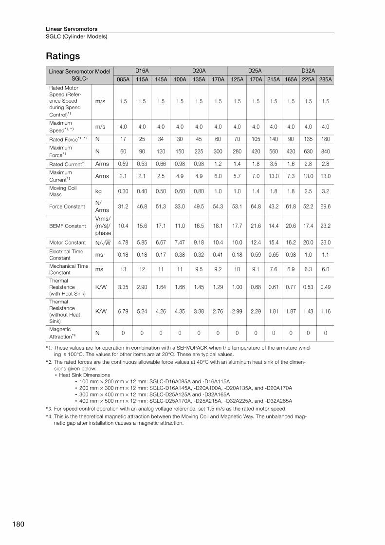
Linear ServomotorsSGLC (Cylinder Models)
180
Ratings
*1. These values are for operation in combination with a SERVOPACK when the temperature of the armature wind-
ing is 100°C. The values for other items are at 20°C. These are typical values.
*2. The rated forces are the continuous allowable force values at 40°C with an aluminum heat sink of the dimen-
sions given below.
• Heat Sink Dimensions
• 100 mm × 200 mm × 12 mm: SGLC-D16A085A and -D16A115A
• 200 mm × 300 mm × 12 mm: SGLC-D16A145A, -D20A100A, -D20A135A, and -D20A170A
• 300 mm × 400 mm × 12 mm: SGLC-D25A125A and -D32A165A
• 400 mm × 500 mm × 12 mm: SGLC-D25A170A, -D25A215A, -D32A225A, and -D32A285A
*3. For speed control operation with an analog voltage reference, set 1.5 m/s as the rated motor speed.
*4. This is the theoretical magnetic attraction between the Moving Coil and Magnetic Way. The unbalanced mag-
netic gap after installation causes a magnetic attraction.
Linear Servomotor Model SGLC-
D16A D20A D25A D32A
085A 115A 145A 100A 135A 170A 125A 170A 215A 165A 225A 285ARated Motor
Speed (Refer-
ence Speed
during Speed
Control)*1
m/s 1.5 1.5 1.5 1.5 1.5 1.5 1.5 1.5 1.5 1.5 1.5 1.5
Maximum
Speed*1, *3 m/s 4.0 4.0 4.0 4.0 4.0 4.0 4.0 4.0 4.0 4.0 4.0 4.0
Rated Force*1, *2 N 17 25 34 30 45 60 70 105 140 90 135 180
Maximum
Force*1 N 60 90 120 150 225 300 280 420 560 420 630 840
Rated Current*1 Arms 0.59 0.53 0.66 0.98 0.98 1.2 1.4 1.8 3.5 1.6 2.8 2.8
Maximum
Current*1 Arms 2.1 2.1 2.5 4.9 4.9 6.0 5.7 7.0 13.0 7.3 13.0 13.0
Moving Coil
Masskg 0.30 0.40 0.50 0.60 0.80 1.0 1.0 1.4 1.8 1.8 2.5 3.2
Force ConstantN/
Arms31.2 46.8 51.3 33.0 49.5 54.3 53.1 64.8 43.2 61.8 52.2 69.6
BEMF Constant
Vrms/
(m/s)/
phase
10.4 15.6 17.1 11.0 16.5 18.1 17.7 21.6 14.4 20.6 17.4 23.2
Motor Constant N/ 4.78 5.85 6.67 7.47 9.18 10.4 10.0 12.4 15.4 16.2 20.0 23.0
Electrical Time
Constant ms 0.18 0.18 0.17 0.38 0.32 0.41 0.18 0.59 0.65 0.98 1.0 1.1
Mechanical Time
Constantms 13 12 11 11 9.5 9.2 10 9.1 7.6 6.9 6.3 6.0
Thermal
Resistance
(with Heat Sink)
K/W 3.35 2.90 1.64 1.66 1.45 1.29 1.00 0.68 0.61 0.77 0.53 0.49
Thermal
Resistance
(without Heat
Sink)
K/W 6.79 5.24 4.26 4.35 3.38 2.76 2.99 2.29 1.81 1.87 1.43 1.16
Magnetic
Attraction*4 N 0 0 0 0 0 0 0 0 0 0 0 0
W

Linear Servomotors SGLC (Cylinder Models)
181
Line
ar S
ervo
mot
ors
Force-Motor Speed Characteristics
* The characteristics are the same for three-phase 200 V and single-phase 200 V.
Note: 1. These values are for operation in combination with a SERVOPACK when the temperature of the armature
winding is 100°C. These are typical values.
2. The characteristics in the intermittent duty zone depend on the power supply voltage.
3. If the effective force is within the allowable range for the rated force, the Servomotor can be used within the
intermittent duty zone.
4. If the length of the Servomotor Main Circuit Cable exceeds 20 m, the intermittent duty zone in the force-motor
speed characteristics will become smaller as the voltage drop increases.
Continuous duty zone
Intermittent duty zone
(solid lines): With three-phase 200-V input
(dotted lines): With single-phase 200-V input
A :
B :
00
1
2
3
4
5SGLC-D16A085AP *
20 40 60 80 0 25 50 75 100
SGLC-D16A115AP
0
SGLC-D16A145AP
50 100 150
0
SGLC-D20A100AP *
50 100 150 200
SGLC-D20A135AP
0
SGLC-D20A170AP
100 200 300 400
SGLC-D25A125AP
0
SGLC-D25A170AP
100 200 300 400 500
SGLC-D25A215AP
0
SGLC-D32A165AP
100 200 300 400 500 0
SGLC-D32A225AP
200 400 600 800
0 100 200 300
0 100 200 300 0 200 400 600
0
SGLC-D32A285AP
250 500 750 1000
A B
A B
A B A B A B
A B A B A B
A B A B
A B A B
0
1
2
3
4
5
0
1
2
3
4
5
0
1
2
3
4
5
0
1
2
3
4
5
0
1
2
3
4
5
0
1
2
3
4
5
0
1
2
3
4
5
0
1
2
3
4
5
0
1
2
3
4
5
0
1
2
3
4
5
0
1
2
3
4
5
Mo
tor sp
eed
(m
/s)
Force (N)
Force (N) Force (N) Force (N)
Force (N)Force (N)
Force (N)
Force (N) Force (N) Force (N)
Force (N) Force (N)
Mo
tor sp
eed
(m
/s)
Mo
tor sp
eed
(m
/s)
Mo
tor sp
eed
(m
/s)
Mo
tor sp
eed
(m
/s)
Mo
tor sp
eed
(m
/s)
Mo
tor sp
eed
(m
/s)
Mo
tor sp
eed
(m
/s)
Mo
tor sp
eed
(m
/s)
Mo
tor sp
eed
(m
/s)
Mo
tor sp
eed
(m
/s)
Mo
tor sp
eed
(m
/s)

Linear ServomotorsSGLC (Cylinder Models)
182
Servomotor Overload Protection CharacteristicsThe overload detection level is set for hot start conditions with a Servomotor ambient temperature
of 40°C.
Note: The above overload protection characteristics do not mean that you can perform continuous duty operation
with an output of 100% or higher.
Use the Servomotor so that the effective force remains within the continuous duty zone given in Force-Motor Speed Characteristics on page 181.
SGLCW-D25A
50 100 150 200 250 300 400350 450
10000
1000
100
10
150050 100 150 200 250 300 350 400 450
40035050 100 150 200 250 300
SGLCW-D16A
10000
1000
100
10
1
SGLCW-D32A
10000
1000
100
10
1
SGLCW-D20A
50 100 150 200 250 300 350 400 450 550500
10000
1000
100
10
1
Dete
ctio
n t
ime (s)
Dete
ctio
n t
ime (s)
Force reference (percent of rated force)
(%)
Force reference (percent of rated force)
(%)
Dete
ctio
n t
ime (s)
Force reference (percent of rated force)
(%)
Force reference (percent of rated force)
(%)
Dete
ctio
n t
ime (s)
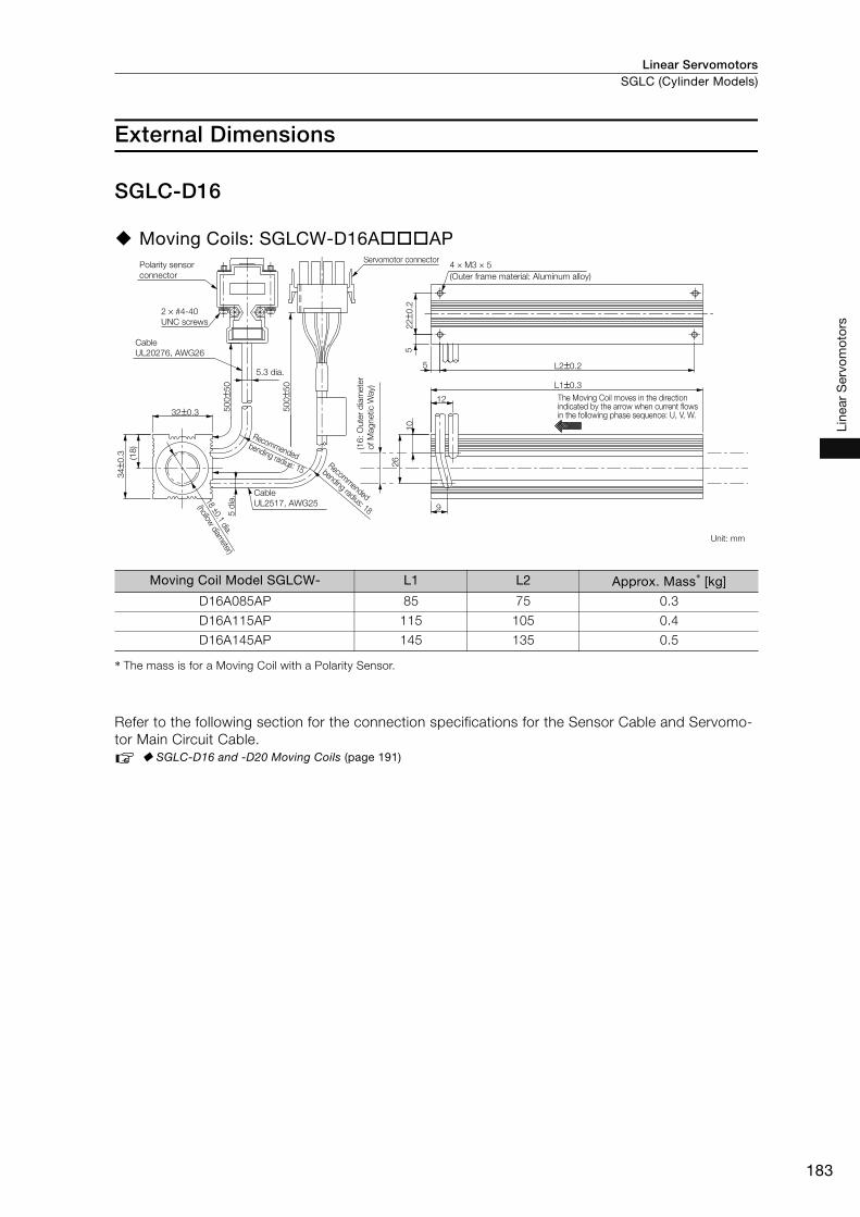
Linear Servomotors SGLC (Cylinder Models)
183
Line
ar S
ervo
mot
ors
External Dimensions
SGLC-D16
Moving Coils: SGLCW-D16A AP
* The mass is for a Moving Coil with a Polarity Sensor.
Refer to the following section for the connection specifications for the Sensor Cable and Servomo-
tor Main Circuit Cable.
SGLC-D16 and -D20 Moving Coils (page 191)
Moving Coil Model SGLCW- L1 L2 Approx. Mass* [kg]
D16A085AP 85 75 0.3
D16A115AP 115 105 0.4
D16A145AP 145 135 0.5
12
9
5
5
50
0±5
0
50
0±5
0
26
10
34±0
.3
32±0.3
(18
)
4 × M3 × 5
(Outer frame material: Aluminum alloy)
22±0
.2
L2±0.2
L1±0.3
Polarity sensor
connector
Recommended
bending radius: 15Recom
mended
bending radius: 18
2 × #4-40
UNC screws
Cable
UL20276, AWG26
5.3 dia.
The Moving Coil moves in the direction indicated by the arrow when current flows in the following phase sequence: U, V, W.
Unit: mm
(16
: O
ute
r d
iam
ete
r
of M
ag
netic W
ay)
Servomotor connector
Cable
UL2517, AWG25
5 d
ia.18 ±0.1 dia.
(hollow diam
eter)
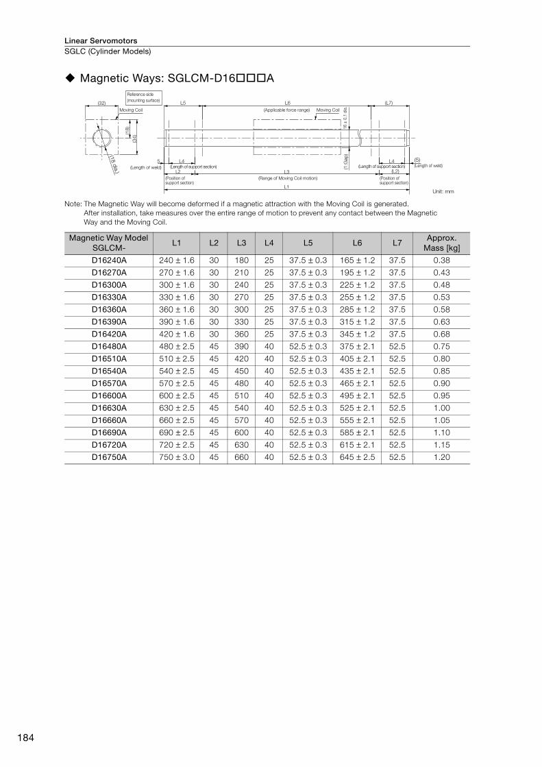
Linear ServomotorsSGLC (Cylinder Models)
184
Magnetic Ways: SGLCM-D16 A
Note: The Magnetic Way will become deformed if a magnetic attraction with the Moving Coil is generated.
After installation, take measures over the entire range of motion to prevent any contact between the Magnetic
Way and the Moving Coil.
Magnetic Way Model SGLCM-
L1 L2 L3 L4 L5 L6 L7Approx.
Mass [kg]
D16240A 240 ± 1.6 30 180 25 37.5 ± 0.3 165 ± 1.2 37.5 0.38
D16270A 270 ± 1.6 30 210 25 37.5 ± 0.3 195 ± 1.2 37.5 0.43
D16300A 300 ± 1.6 30 240 25 37.5 ± 0.3 225 ± 1.2 37.5 0.48
D16330A 330 ± 1.6 30 270 25 37.5 ± 0.3 255 ± 1.2 37.5 0.53
D16360A 360 ± 1.6 30 300 25 37.5 ± 0.3 285 ± 1.2 37.5 0.58
D16390A 390 ± 1.6 30 330 25 37.5 ± 0.3 315 ± 1.2 37.5 0.63
D16420A 420 ± 1.6 30 360 25 37.5 ± 0.3 345 ± 1.2 37.5 0.68
D16480A 480 ± 2.5 45 390 40 52.5 ± 0.3 375 ± 2.1 52.5 0.75
D16510A 510 ± 2.5 45 420 40 52.5 ± 0.3 405 ± 2.1 52.5 0.80
D16540A 540 ± 2.5 45 450 40 52.5 ± 0.3 435 ± 2.1 52.5 0.85
D16570A 570 ± 2.5 45 480 40 52.5 ± 0.3 465 ± 2.1 52.5 0.90
D16600A 600 ± 2.5 45 510 40 52.5 ± 0.3 495 ± 2.1 52.5 0.95
D16630A 630 ± 2.5 45 540 40 52.5 ± 0.3 525 ± 2.1 52.5 1.00
D16660A 660 ± 2.5 45 570 40 52.5 ± 0.3 555 ± 2.1 52.5 1.05
D16690A 690 ± 2.5 45 600 40 52.5 ± 0.3 585 ± 2.1 52.5 1.10
D16720A 720 ± 2.5 45 630 40 52.5 ± 0.3 615 ± 2.1 52.5 1.15
D16750A 750 ± 3.0 45 660 40 52.5 ± 0.3 645 ± 2.5 52.5 1.20
(34)
(32)
(18)
L2
L1
(L2)L3
(1:G
ap
)
5 L4 L4
L5 L6 (L7)
Reference side
(Applicable force range) Moving Coil
16
± 0
.1 d
ia.
(mounting surface)
(18 d
ia.)
Moving Coil
(Length of weld)
(Position of support section)
(Range of Moving Coil motion) (Position of support section)
(5) (Length of weld)
Unit: mm
(Length of support section) (Length of support section)

Linear Servomotors SGLC (Cylinder Models)
185
Line
ar S
ervo
mot
ors
SGLC-D20
Moving Coils: SGLCW-D20A AP
* The mass is for a Moving Coil with a Polarity Sensor.
Refer to the following section for the connection specifications for the Sensor Cable and Servomo-
tor Main Circuit Cable.
SGLC-D16 and -D20 Moving Coils (page 191)
Moving Coil Model SGLCW- L1 L2 Approx. Mass* [kg]
D20A100AP 100 90 0.6
D20A135AP 135 125 0.8
D20A170AP 170 160 1.0
5
15
11
6
50
0±5
0
50
0±5
0
34
12
44±0
.3
42±0.3
(23
)
4 × M4 × 7
(Outer frame material: Aluminum alloy)
30±0
.2
L2±0.2
L1±0.3
Polarity sensor
connector
Servomotor
connector
The Moving Coil moves in the direction
indicated by the arrow when current flows in
the following phase sequence: U, V, W.
Unit: mm
Cable
UL2517, AWG25
5 d
ia.
22.5 ±0.1 dia.
(hollow diam
eter)
Recommended
bending radius: 15 Recomm
ended
bending radius: 18
(20: O
ute
r d
iam
ete
r
of M
agnetic
Way)
5.3 dia.
2 × #4-40
UNC screws
Cable
UL20276, AWG26

Linear ServomotorsSGLC (Cylinder Models)
186
Magnetic Ways: SGLCM-D20 A
Note: The Magnetic Way will become deformed if a magnetic attraction with the Moving Coil is generated.
After installation, take measures over the entire range of motion to prevent any contact between the Magnetic
Way and the Moving Coil.
Magnetic Way Model SGLCM-
L1 L2 L3 L4 L5 L6 L7Approx.
Mass [kg]
D20280A 280 ± 1.6 35 210 30 45 ± 0.3 190 ± 1.2 45 0.68
D20315A 315 ± 1.6 35 245 30 45 ± 0.3 225 ± 1.2 45 0.77
D20350A 350 ± 1.6 35 280 30 45 ± 0.3 260 ± 1.2 45 0.86
D20385A 385 ± 1.6 35 315 30 45 ± 0.3 295 ± 1.2 45 0.95
D20420A 420 ± 1.6 35 350 30 45 ± 0.3 330 ± 1.2 45 1.00
D20455A 455 ± 1.6 35 385 30 45 ± 0.3 365 ± 1.2 45 1.10
D20490A 490 ± 1.6 35 420 30 45 ± 0.3 400 ± 1.2 45 1.20
D20555A 555 ± 2.5 50 455 45 60 ± 0.3 435 ± 2.1 60 1.35
D20590A 590 ± 2.5 50 490 45 60 ± 0.3 470 ± 2.1 60 1.45
D20625A 625 ± 2.5 50 525 45 60 ± 0.3 505 ± 2.1 60 1.55
D20660A 660 ± 2.5 50 560 45 60 ± 0.3 540 ± 2.1 60 1.60
D20695A 695 ± 2.5 50 595 45 60 ± 0.3 575 ± 2.1 60 1.70
D20730A 730 ± 2.5 50 630 45 60 ± 0.3 610 ± 2.1 60 1.80
D20765A 765 ± 2.5 50 665 45 60 ± 0.3 645 ± 2.1 60 1.90
D20800A 800 ± 2.5 50 700 45 60 ± 0.3 680 ± 2.1 60 2.00
D20835A 835 ± 2.5 50 735 45 60 ± 0.3 715 ± 2.1 60 2.10
D20870A 870 ± 3.0 50 770 45 60 ± 0.3 750 ± 2.5 60 2.20
(44)
(42)
(23)
L1
(L2)L3
(1.2
5:G
ap
)2
0±0
.1 d
ia.
5 (5)L4
L2
L4
L5 L6 (L7)
Reference side
(Applicable force range) Moving Coil
(mounting surface)
Moving Coil
(Length of weld)
(Position of
support section)
(Range of Moving Coil motion)
(Length of weld)
Unit: mm
(Position of support section)
(22.5
dia
.)
(Length of support section) (Length of support section)
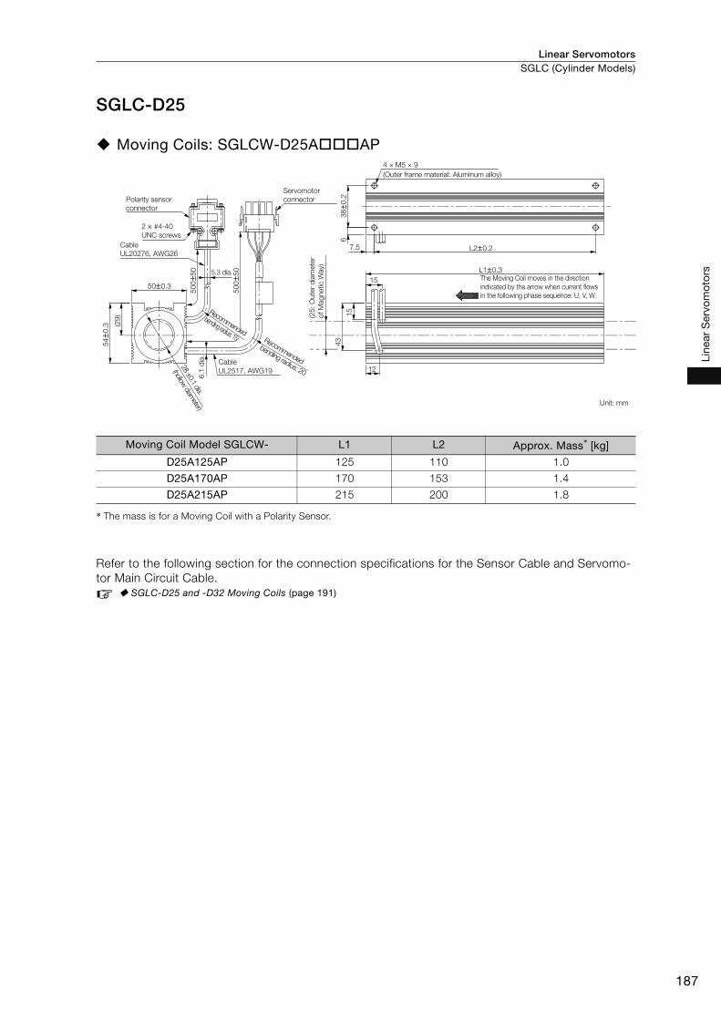
Linear Servomotors SGLC (Cylinder Models)
187
Line
ar S
ervo
mot
ors
SGLC-D25
Moving Coils: SGLCW-D25A AP
* The mass is for a Moving Coil with a Polarity Sensor.
Refer to the following section for the connection specifications for the Sensor Cable and Servomo-
tor Main Circuit Cable.
SGLC-D25 and -D32 Moving Coils (page 191)
Moving Coil Model SGLCW- L1 L2 Approx. Mass* [kg]
D25A125AP 125 110 1.0
D25A170AP 170 153 1.4
D25A215AP 215 200 1.8
15
12
7.5
6
50
0±5
0
50
0±5
0
43
15
54±0
.3
50±0.3
(29
)
4 × M5 × 9
(Outer frame material: Aluminum alloy)
38±0
.2
L2±0.2
L1±0.3
Polarity sensor
connector
Servomotor
connector
The Moving Coil moves in the direction
indicated by the arrow when current flows
in the following phase sequence: U, V, W.
Unit: mm
(25
: O
ute
r d
iam
ete
r
of M
ag
netic W
ay)
5.3 dia.
Cable
UL20276, AWG26
2 × #4-40
UNC screws
Cable
UL2517, AWG19
6.1
dia
.
28 ±0.1 dia.
(hollow diam
eter)
Recommended
bending radius: 15 Recommended
bending radius: 20

Linear ServomotorsSGLC (Cylinder Models)
188
Magnetic Ways: SGLCM-D25 A
Note: The Magnetic Way will become deformed if a magnetic attraction with the Moving Coil is generated.
After installation, take measures over the entire range of motion to prevent any contact between the Magnetic
Way and the Moving Coil.
Magnetic Way Model SGLCM-
L1 L2 L3 L4 L5 L6 L7Approx. Mass
[kg]
D25360A 360 ± 1.6 45 270 37 57.5 ± 0.3 245 ± 1.2 57.5 1.50
D25405A 405 ± 1.6 45 315 37 57.5 ± 0.3 290 ± 1.2 57.5 1.65
D25450A 450 ± 1.6 45 360 37 57.5 ± 0.3 335 ± 1.2 57.5 1.80
D25495A 495 ± 1.6 45 405 37 57.5 ± 0.3 380 ± 1.2 57.5 1.95
D25540A 540 ± 1.6 45 450 37 57.5 ± 0.3 425 ± 1.2 57.5 2.10
D25585A 585 ± 1.6 45 495 37 57.5 ± 0.3 470 ± 1.2 57.5 2.25
D25630A 630 ± 1.6 45 540 37 57.5 ± 0.3 515 ± 1.2 57.5 2.40
D25705A 705 ± 2.5 60 585 52 72.5 ± 0.3 560 ± 2.1 72.5 2.85
D25750A 750 ± 2.5 60 630 52 72.5 ± 0.3 605 ± 2.1 72.5 3.00
D25795A 795 ± 2.5 60 675 52 72.5 ± 0.3 650 ± 2.1 72.5 3.15
D25840A 840 ± 2.5 60 720 52 72.5 ± 0.3 695 ± 2.1 72.5 3.30
D25885A 885 ± 2.5 60 765 52 72.5 ± 0.3 740 ± 2.1 72.5 3.45
D25930A 930 ± 2.5 60 810 52 72.5 ± 0.3 785 ± 2.1 72.5 3.60
D25975A 975 ± 2.5 60 855 52 72.5 ± 0.3 830 ± 2.1 72.5 3.75
D251020A 1020 ± 2.5 60 900 52 72.5 ± 0.3 875 ± 2.1 72.5 3.90
D251065A 1065 ± 2.5 60 945 52 72.5 ± 0.3 920 ± 2.1 72.5 4.05
D251110A 1110 ± 3.0 60 990 52 72.5 ± 0.3 965 ± 2.5 72.5 4.20
(54)
(50)
(29)
L1
(L2)L3
(1.5
:Gap
)φ2
5±0
.1
8 (8)L4
L2
L4
L5 L6 (L7)
Reference side
(Applicable force range) Moving Coil
(Position of support section)
(Range of Moving Coil motion)(Position of support section)
(Length of weld)
(28 d
ia.)
(Length of weld)
Unit: mm
(mounting surface)
Moving Coil
(Length of support section)(Length of support section)
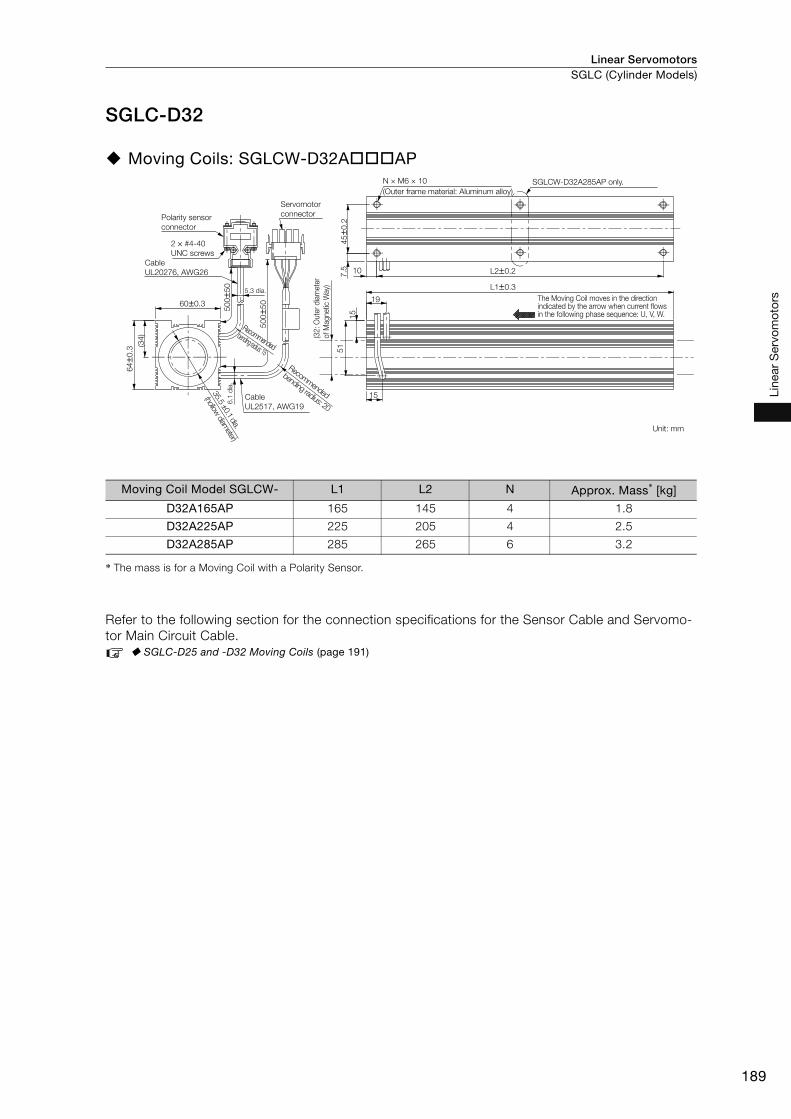
Linear Servomotors SGLC (Cylinder Models)
189
Line
ar S
ervo
mot
ors
SGLC-D32
Moving Coils: SGLCW-D32A AP
* The mass is for a Moving Coil with a Polarity Sensor.
Refer to the following section for the connection specifications for the Sensor Cable and Servomo-
tor Main Circuit Cable.
SGLC-D25 and -D32 Moving Coils (page 191)
Moving Coil Model SGLCW- L1 L2 N Approx. Mass* [kg]
D32A165AP 165 145 4 1.8
D32A225AP 225 205 4 2.5
D32A285AP 285 265 6 3.2
19
15
10
7.5
50
0±5
0
50
0±5
0
51
15
64±0
.3
60±0.3
(34
)
N × M6 × 10
(Outer frame material: Aluminum alloy)
45±0
.2
L2±0.2
L1±0.3
Polarity sensor
connector
Servomotor
connector
Recommended
bending radius: 15
Recomm
ended
bending radius: 20
35.5 ±0.1 dia.
(hollow diam
eter)
(32:
Oute
r d
iam
ete
r
of M
agnetic
Way)5.3 dia.
SGLCW-D32A285AP only.
The Moving Coil moves in the direction indicated by the arrow when current flows in the following phase sequence: U, V, W.
Unit: mm
2 × #4-40
UNC screws
Cable
UL2517, AWG19
6.1
dia
.
Cable
UL20276, AWG26
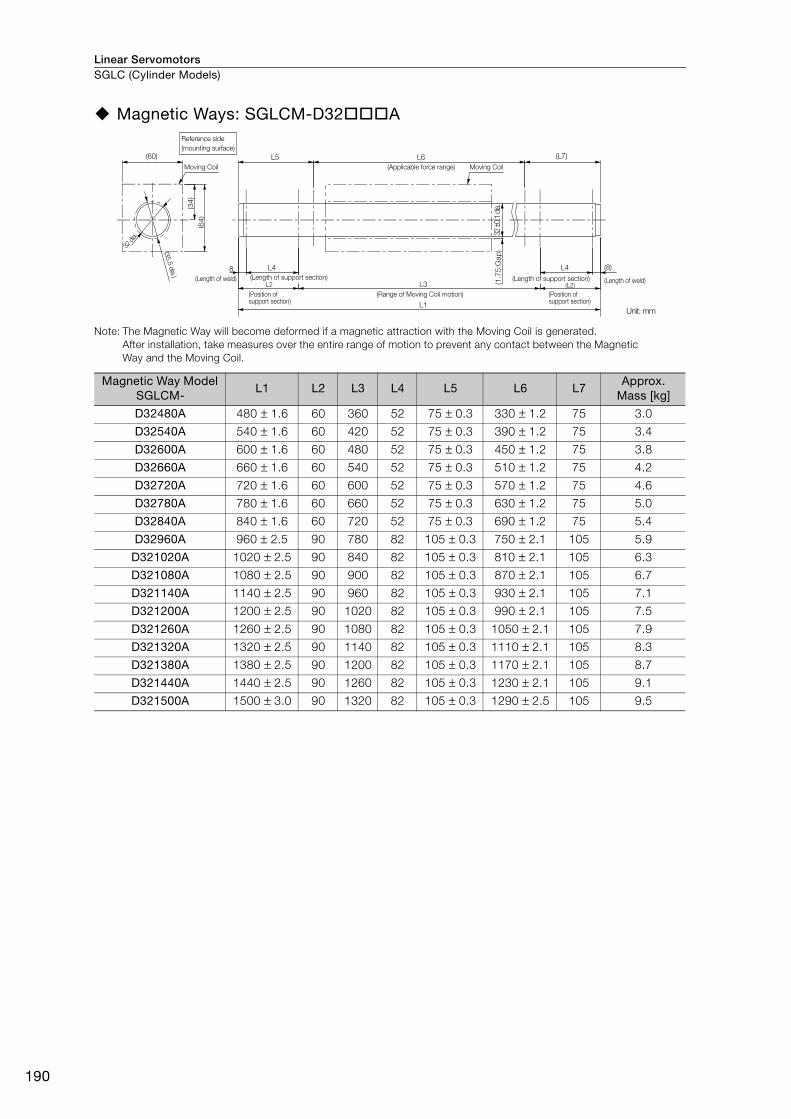
Linear ServomotorsSGLC (Cylinder Models)
190
Magnetic Ways: SGLCM-D32 A
Note: The Magnetic Way will become deformed if a magnetic attraction with the Moving Coil is generated.
After installation, take measures over the entire range of motion to prevent any contact between the Magnetic
Way and the Moving Coil.
Magnetic Way Model SGLCM-
L1 L2 L3 L4 L5 L6 L7Approx.
Mass [kg]
D32480A 480 ± 1.6 60 360 52 75 ± 0.3 330 ± 1.2 75 3.0
D32540A 540 ± 1.6 60 420 52 75 ± 0.3 390 ± 1.2 75 3.4
D32600A 600 ± 1.6 60 480 52 75 ± 0.3 450 ± 1.2 75 3.8
D32660A 660 ± 1.6 60 540 52 75 ± 0.3 510 ± 1.2 75 4.2
D32720A 720 ± 1.6 60 600 52 75 ± 0.3 570 ± 1.2 75 4.6
D32780A 780 ± 1.6 60 660 52 75 ± 0.3 630 ± 1.2 75 5.0
D32840A 840 ± 1.6 60 720 52 75 ± 0.3 690 ± 1.2 75 5.4
D32960A 960 ± 2.5 90 780 82 105 ± 0.3 750 ± 2.1 105 5.9
D321020A 1020 ± 2.5 90 840 82 105 ± 0.3 810 ± 2.1 105 6.3
D321080A 1080 ± 2.5 90 900 82 105 ± 0.3 870 ± 2.1 105 6.7
D321140A 1140 ± 2.5 90 960 82 105 ± 0.3 930 ± 2.1 105 7.1
D321200A 1200 ± 2.5 90 1020 82 105 ± 0.3 990 ± 2.1 105 7.5
D321260A 1260 ± 2.5 90 1080 82 105 ± 0.3 1050 ± 2.1 105 7.9
D321320A 1320 ± 2.5 90 1140 82 105 ± 0.3 1110 ± 2.1 105 8.3
D321380A 1380 ± 2.5 90 1200 82 105 ± 0.3 1170 ± 2.1 105 8.7
D321440A 1440 ± 2.5 90 1260 82 105 ± 0.3 1230 ± 2.1 105 9.1
D321500A 1500 ± 3.0 90 1320 82 105 ± 0.3 1290 ± 2.5 105 9.5
(64
)
(60)
(34
)
L1
(L2)L3 (1.7
5:G
ap
)
(8)L48
L2
L4
L5 L6 (L7)
Reference side
(mounting surface)
(Applicable force range) Moving Coil
32 ±0
.1 d
ia.
Moving Coil
(Length of weld)
(Position of support section)
(Range of Moving Coil motion) (Position of support section)
(Length of weld)
Unit: mm
32 d
ia.
(35.5
dia
.) (Length of support section) (Length of support section)
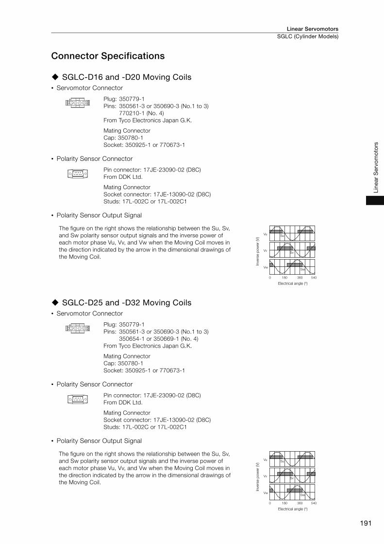
Linear Servomotors SGLC (Cylinder Models)
191
Line
ar S
ervo
mot
ors
Connector Specifications
SGLC-D16 and -D20 Moving Coils• Servomotor Connector
• Polarity Sensor Connector
• Polarity Sensor Output Signal
SGLC-D25 and -D32 Moving Coils• Servomotor Connector
• Polarity Sensor Connector
• Polarity Sensor Output Signal
Plug: 350779-1
Pins: 350561-3 or 350690-3 (No.1 to 3)
770210-1 (No. 4)
From Tyco Electronics Japan G.K.
Mating Connector
Cap: 350780-1
Socket: 350925-1 or 770673-1
Pin connector: 17JE-23090-02 (D8C)
From DDK Ltd.
Mating Connector
Socket connector: 17JE-13090-02 (D8C)
Studs: 17L-002C or 17L-002C1
The figure on the right shows the relationship between the Su, Sv,
and Sw polarity sensor output signals and the inverse power of
each motor phase Vu, Vv, and Vw when the Moving Coil moves in
the direction indicated by the arrow in the dimensional drawings of
the Moving Coil.
Plug: 350779-1
Pins: 350561-3 or 350690-3 (No.1 to 3)
350654-1 or 350669-1 (No. 4)
From Tyco Electronics Japan G.K.
Mating Connector
Cap: 350780-1
Socket: 350925-1 or 770673-1
Pin connector: 17JE-23090-02 (D8C)
From DDK Ltd.
Mating Connector
Socket connector: 17JE-13090-02 (D8C)
Studs: 17L-002C or 17L-002C1
The figure on the right shows the relationship between the Su, Sv,
and Sw polarity sensor output signals and the inverse power of
each motor phase Vu, Vv, and Vw when the Moving Coil moves in
the direction indicated by the arrow in the dimensional drawings of
the Moving Coil.
Vu
Vv
Vw
Su
Sv
Sw
0 180 360 540
Invers
e p
ow
er
(V)
Electrical angle (°)
Vu
Vv
Vw
Su
Sv
Sw
0 180 360 540
Invers
e p
ow
er
(V)
Electrical angle (°)

192
MEMO

Σ-7S Single-axis Analog Voltage/Pulse Train Reference SERVOPACKs ....................................194
Σ-7S Single-axis MECHATROLINK-II Communications Reference SERVOPACKs ........200
Σ-7S Single-axis MECHATROLINK-III Communications Reference SERVOPACKs ........205
Σ-7W Two-axis MECHATROLINK-III Communications Reference SERVOPACKs ........210
SERVOPACK External Dimensions .....................215
SERVOPACKs
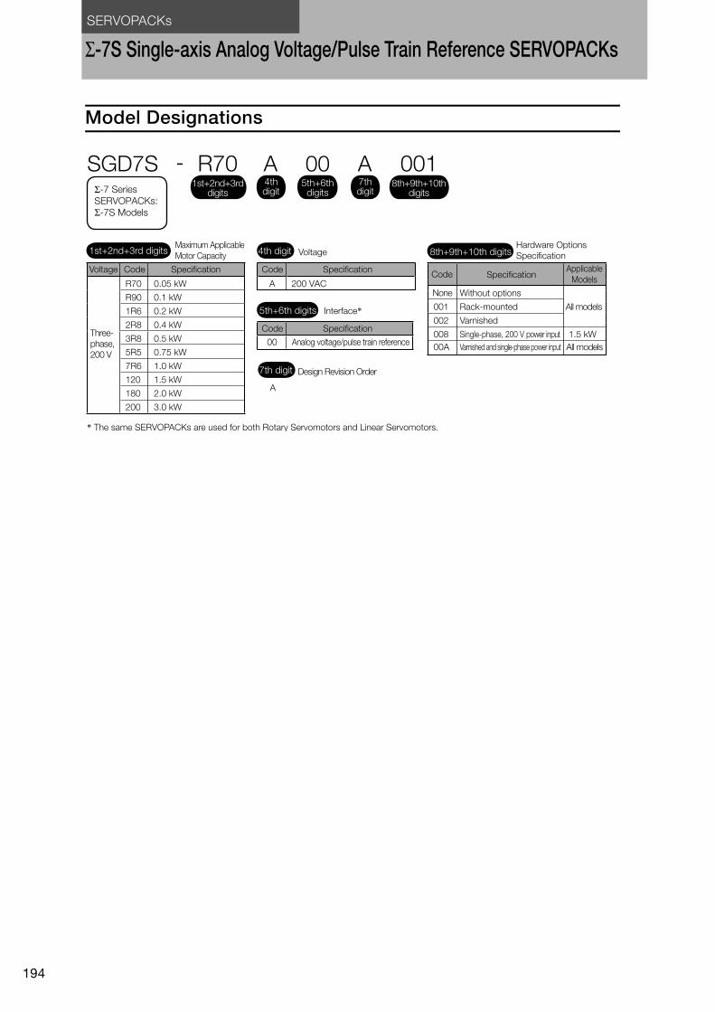
SERVOPACKs
194
Σ-7S Single-axis Analog Voltage/Pulse Train Reference SERVOPACKs
Model Designations
A 200 VACR70
R90
1R6
2R8
3R8
5R5
7R6
120
180
200
0.05 kW
0.1 kW
0.2 kW
0.4 kW
0.5 kW
0.75 kW
1.0 kW
1.5 kW
2.0 kW
3.0 kW
00
SGD7S - R70 A 00 A 001
A
1.5 kW
Maximum Applicable
Motor Capacity Voltage
Interface*
Code
Code
SpecificationCode
None
Specification
Without options
Rack-mounted
Varnished
All models
All models
Single-phase, 200 V power input
Varnished and single-phase power input
Applicable
Models
Specification
Analog voltage/pulse train reference
Design Revision Order
Hardware Options
Specification
Voltage Code Specification
* The same SERVOPACKs are used for both Rotary Servomotors and Linear Servomotors.
Three-
phase,
200 V
1st+2nd+3rd digits 4th digit
5th+6th digits
7th digit
8th+9th+10th digits
Σ-7 Series SERVOPACKs:
Σ-7S Models
4th digit
1st+2nd+3rd digits
5th+6th digits
8th+9th+10th digits
7th digit
001
002
008
00A
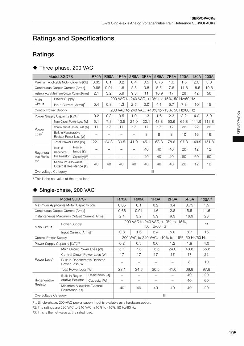
SERVOPACKs Σ-7S Single-axis Analog Voltage/Pulse Train Reference SERVOPACKs
195
SE
RV
OP
AC
Ks
Ratings and Specifications
Ratings
Three-phase, 200 VAC
* This is the net value at the rated load.
Single-phase, 200 VAC
*1. Single-phase, 200-VAC power supply input is available as a hardware option.
*2. The ratings are 220 VAC to 240 VAC, +10% to -15%, 50 Hz/60 Hz
*3. This is the net value at the rated load.
Model SGD7S- R70A R90A 1R6A 2R8A 3R8A 5R5A 7R6A 120A 180A 200A
Maximum Applicable Motor Capacity [kW] 0.05 0.1 0.2 0.4 0.5 0.75 1.0 1.5 2.0 3.0
Continuous Output Current [Arms] 0.66 0.91 1.6 2.8 3.8 5.5 7.6 11.6 18.5 19.6
Instantaneous Maximum Output Current [Arms] 2.1 3.2 5.9 9.3 11 16.9 17 28 42 56
Main
Circuit
Power Supply 200 VAC to 240 VAC, +10% to -15%, 50 Hz/60 Hz
Input Current [Arms]* 0.4 0.8 1.3 2.5 3.0 4.1 5.7 7.3 10 15
Control Power Supply 200 VAC to 240 VAC, +10% to -15%, 50 Hz/60 Hz
Power Supply Capacity [kVA]* 0.2 0.3 0.5 1.0 1.3 1.6 2.3 3.2 4.0 5.9
Power
Loss*
Main Circuit Power Loss [W] 5.1 7.3 13.5 24.0 20.1 43.8 53.6 65.8 111.9 113.8
Control Circuit Power Loss [W] 17 17 17 17 17 17 17 22 22 22
Built-in Regenerative
Resistor Power Loss [W] − − − − 8 8 8 10 16 16
Total Power Loss [W] 22.1 24.3 30.5 41.0 45.1 68.8 78.6 97.8 149.9 151.8
Regenera-
tive Resis-
tor
Built-In
Regenera-
tive Resistor
Resis-
tance [Ω]− − − − 40 40 40 20 12 12
Capacity [W] − − − − 40 40 40 60 60 60
Minimum Allowable
External Resistance [Ω]40 40 40 40 40 40 40 20 12 12
Overvoltage Category III
Model SGD7S- R70A R90A 1R6A 2R8A 5R5A 120A*1
Maximum Applicable Motor Capacity [kW] 0.05 0.1 0.2 0.4 0.75 1.5
Continuous Output Current [Arms] 0.66 0.91 1.6 2.8 5.5 11.6
Instantaneous Maximum Output Current [Arms] 2.1 3.2 5.9 9.3 16.9 28
Main CircuitPower Supply
200 VAC to 240 VAC, +10% to -15%,
50 Hz/60 Hz*2
Input Current [Arms]*3 0.8 1.6 2.4 5.0 8.7 16
Control Power Supply 200 VAC to 240 VAC, +10% to -15%, 50 Hz/60 Hz
Power Supply Capacity [kVA]*3 0.2 0.3 0.6 1.2 1.9 4.0
Power Loss*3
Main Circuit Power Loss [W] 5.1 7.3 13.5 24.0 43.8 65.8
Control Circuit Power Loss [W] 17 17 17 17 17 22
Built-in Regenerative Resistor
Power Loss [W]− − − − 8 10
Total Power Loss [W] 22.1 24.3 30.5 41.0 68.8 97.8
Regenerative
Resistor
Built-In Regen-
erative Resistor
Resistance [Ω] − − − − 40 20
Capacity [W] − − − − 40 60
Minimum Allowable External
Resistance [Ω]40 40 40 40 40 20
Overvoltage Category III
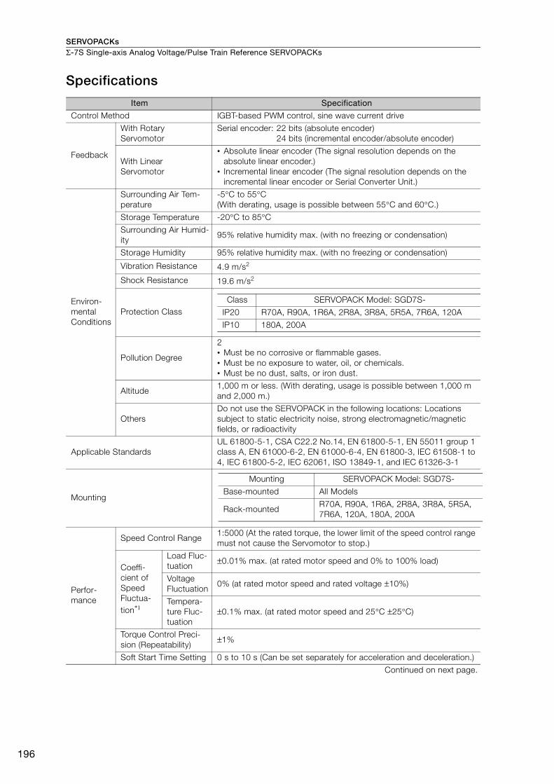
SERVOPACKsΣ-7S Single-axis Analog Voltage/Pulse Train Reference SERVOPACKs
196
Specifications
Item Specification
Control Method IGBT-based PWM control, sine wave current drive
Feedback
With Rotary
Servomotor
Serial encoder: 22 bits (absolute encoder)
24 bits (incremental encoder/absolute encoder)
With Linear
Servomotor
• Absolute linear encoder (The signal resolution depends on the
absolute linear encoder.)
• Incremental linear encoder (The signal resolution depends on the
incremental linear encoder or Serial Converter Unit.)
Environ-
mental
Conditions
Surrounding Air Tem-
perature
-5°C to 55°C
(With derating, usage is possible between 55°C and 60°C.)
Storage Temperature -20°C to 85°C
Surrounding Air Humid-
ity95% relative humidity max. (with no freezing or condensation)
Storage Humidity 95% relative humidity max. (with no freezing or condensation)
Vibration Resistance 4.9 m/s2
Shock Resistance 19.6 m/s2
Protection Class
I
Pollution Degree
2
• Must be no corrosive or flammable gases.
• Must be no exposure to water, oil, or chemicals.
• Must be no dust, salts, or iron dust.
Altitude1,000 m or less. (With derating, usage is possible between 1,000 m
and 2,000 m.)
Others
Do not use the SERVOPACK in the following locations: Locations
subject to static electricity noise, strong electromagnetic/magnetic
fields, or radioactivity
Applicable Standards
UL 61800-5-1, CSA C22.2 No.14, EN 61800-5-1, EN 55011 group 1
class A, EN 61000-6-2, EN 61000-6-4, EN 61800-3, IEC 61508-1 to
4, IEC 61800-5-2, IEC 62061, ISO 13849-1, and IEC 61326-3-1
Mounting
Perfor-
mance
Speed Control Range 1:5000 (At the rated torque, the lower limit of the speed control range
must not cause the Servomotor to stop.)
Coeffi-
cient of
Speed
Fluctua-
tion*1
Load Fluc-
tuation±0.01% max. (at rated motor speed and 0% to 100% load)
Voltage
Fluctuation0% (at rated motor speed and rated voltage ±10%)
Tempera-
ture Fluc-
tuation
±0.1% max. (at rated motor speed and 25°C ±25°C)
Torque Control Preci-
sion (Repeatability)±1%
Soft Start Time Setting 0 s to 10 s (Can be set separately for acceleration and deceleration.)
Continued on next page.
Class SERVOPACK Model: SGD7S-
IP20 R70A, R90A, 1R6A, 2R8A, 3R8A, 5R5A, 7R6A, 120A
IP10 180A, 200A
Mounting SERVOPACK Model: SGD7S-
Base-mounted All Models
Rack-mountedR70A, R90A, 1R6A, 2R8A, 3R8A, 5R5A,
7R6A, 120A, 180A, 200A
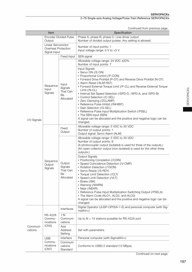
SERVOPACKs Σ-7S Single-axis Analog Voltage/Pulse Train Reference SERVOPACKs
197
SE
RV
OP
AC
Ks
I/O Signals
Encoder Divided Pulse
Output
Phase A, phase B, phase C: Line-driver output
Number of divided output pulses: Any setting is allowed.
Linear Servomotor
Overheat Protection
Signal Input
Number of input points: 1
Input voltage range: 0 V to +5 V
Sequence
Input
Signals
Fixed Input SEN signal
Input
Signals
That Can
Be
Allocated
Allowable voltage range: 24 VDC ±20%
Number of input points: 7
Input Signals
• Servo ON (/S-ON)
• Proportional Control (/P-CON)
• Forward Drive Prohibit (P-OT) and Reverse Drive Prohibit (N-OT)
• Alarm Reset (/ALM-RST)
• Forward External Torque Limit (/P-CL) and Reverse External Torque
Limit (/N-CL)
• Internal Set Speed Selection (/SPD-D, /SPD-A, and /SPD-B)
• Control Selection (/C-SEL)
• Zero Clamping (/ZCLAMP)
• Reference Pulse Inhibit (/INHIBIT)
• Gain Selection (/G-SEL)
• Reference Pulse Input Multiplication Switch (/PSEL)
• The SEN input (SEN)
A signal can be allocated and the positive and negative logic can be
changed.
Sequence
Output
Signals
Fixed
Output
Allowable voltage range: 5 VDC to 30 VDC
Number of output points: 1
Output signal: Servo Alarm (ALM)
Output
Signals
That Can
Be
Allocated
Allowable voltage range: 5 VDC to 30 VDC
Number of output points: 6
(A photocoupler output (isolated) is used for three of the outputs.)
(An open-collector output (non-isolated) is used for the other three
outputs.)
Output Signals
• Positioning Completion (/COIN)
• Speed Coincidence Detection (/V-CMP)
• Rotation Detection (/TGON)
• Servo Ready (/S-RDY)
• Torque Limit Detection (/CLT)
• Speed Limit Detection (/VLT)
• Brake (/BK)
• Warning (/WARN)
• Near (/NEAR)
• Reference Pulse Input Multiplication Switching Output (/PSELA)
• The Alarm Code (ALO1, ALO2, and ALO3)
A signal can be allocated and the positive and negative logic can be
changed.
Communi-
cations
RS-422A
Commu-
nications
(CN3)
InterfacesDigital Operator (JUSP-OP05A-1-E) and personal computer (with Sig-
maWin+)
1:N
Communi-
cations
Up to N = 15 stations possible for RS-422A port
Axis
Address
Setting
Set with parameters.
USB
Commu-
nications
(CN7)
Interface Personal computer (with SigmaWin+)
Communi-
cations
Standard
Conforms to USB2.0 standard (12 Mbps).
Continued on next page.
Continued from previous page.
Item Specification

SERVOPACKsΣ-7S Single-axis Analog Voltage/Pulse Train Reference SERVOPACKs
198
Displays/Indicators CHARGE indicator and five-digit seven-segment display
Panel Operator Four push switches
Analog Monitor (CN5)
Number of points: 2
Output voltage range: ±10 VDC (effective linearity range: ±8 V)
Resolution: 16 bits
Accuracy: ±20 mV (Typ)
Maximum output current: ±10 mA
Settling time (±1%): 1.2 ms (Typ)
Dynamic Brake (DB)Activated when a servo alarm or overtravel (OT) occurs, or when the
power supply to the main circuit or servo is OFF.
Regenerative Processing Built-in
Overtravel (OT) PreventionStopping with dynamic brake, deceleration to a stop, or coast to a
stop at P-OT or N-OT input.
Protective FunctionsOvercurrent, overvoltage, low voltage, overload, regeneration error,
etc.
Utility Functions Gain adjustment, alarm history, jogging, origin search, etc.
Safety
Functions
Inputs /HWBB1 and /HWBB2: Base block signals for Power Modules
Output EDM1: Monitors the status of built-in safety circuit (fixed output).
Applicable Standards*2 ISO13849-1 PLe (Category 3) and IEC61508 SIL3
Co
ntr
ols
Sp
eed
Co
ntr
ol
Soft Start Time Setting 0 s to 10 s (Can be set separately for acceleration and deceleration.)
Input
Signal
Reference
Voltage
• Maximum input voltage: ±12 V (forward motor rotation for positive reference).
• 6 VDC at rated speed (default setting). Input gain setting can be changed.
Input
ImpedanceApprox. 14 kΩ
Circuit
Time
Constant
30 μs
Internal
Set
Speed
Control
Rotation
Direction
Selection
With Proportional Control signal
Speed
Selection
With Forward/Reverse External Torque Limit signals (speed 1 to 3
selection).
Servomotor stops or another control method is used when both sig-
nals are OFF.
Po
sitio
n C
on
tro
l
Feedforward
Compensation0% to 100%
Output Signal Position-
ing Completed Width
Setting
0 to 1,073,741,824 reference units
Inp
ut
Sig
nals
Refe
ren
ce p
uls
es
Reference
Pulse Form
One of the following is selected:
Sign + pulse train, CW + CCW pulse trains, and two-phase pulse
trains with 90° phase differential
Input Form Line driver or open collector
Maximum
Input
Frequency
• Line Driver
Sign + pulse train or CW + CCW pulse trains: 4 Mpps
Two-phase pulse trains with 90° phase differential: 1 Mpps
• Open Collector
Sign + pulse train or CW + CCW pulse trains: 200 kpps
Two-phase pulse trains with 90° phase differential: 200 kpps
Input
Multiplication
Switching
1 to 100 times
Clear SignalPosition deviation clear
Line driver or open collector
Continued on next page.
Continued from previous page.
Item Specification
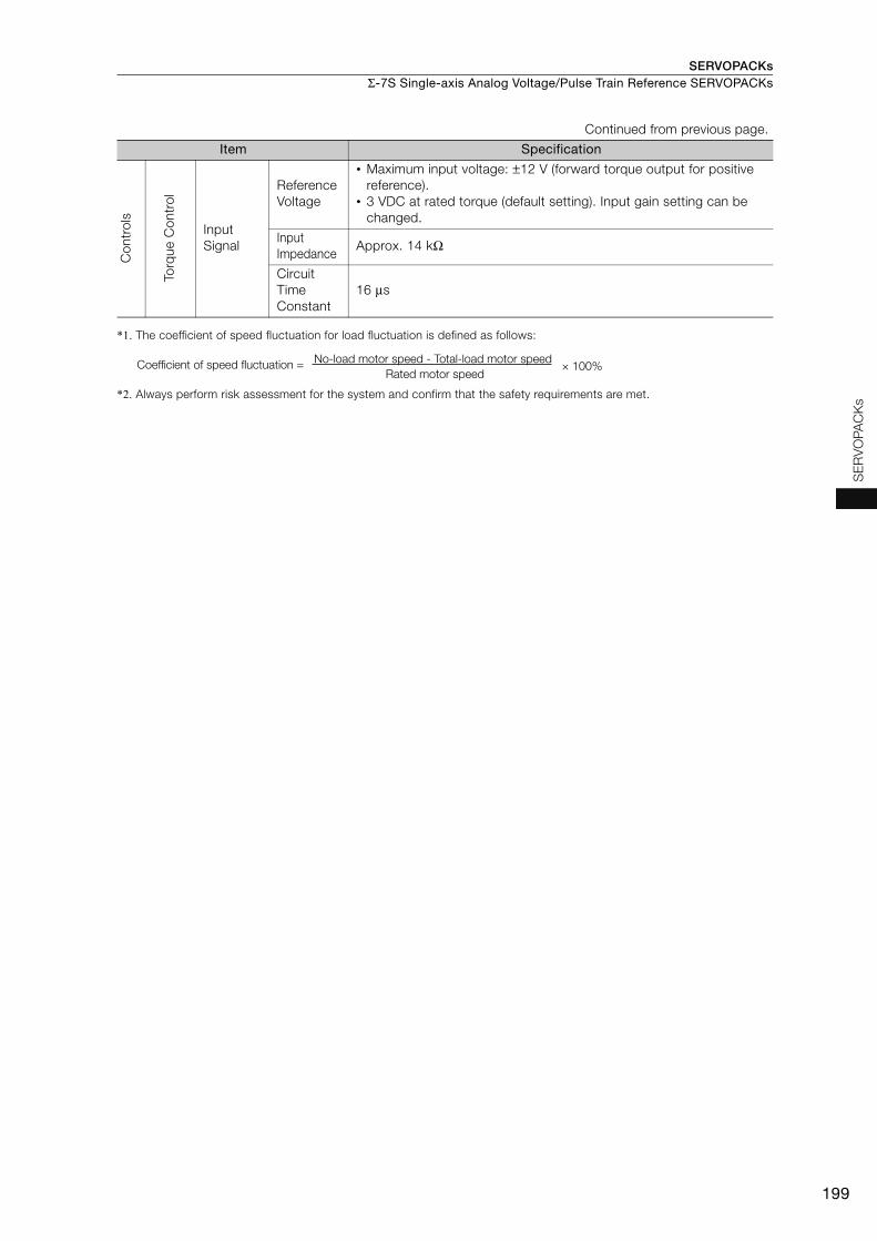
SERVOPACKs Σ-7S Single-axis Analog Voltage/Pulse Train Reference SERVOPACKs
199
SE
RV
OP
AC
Ks
*1. The coefficient of speed fluctuation for load fluctuation is defined as follows:
*2. Always perform risk assessment for the system and confirm that the safety requirements are met.
Co
ntr
ols
To
rque C
ontr
ol
Input
Signal
Reference
Voltage
• Maximum input voltage: ±12 V (forward torque output for positive
reference).
• 3 VDC at rated torque (default setting). Input gain setting can be
changed.
Input
ImpedanceApprox. 14 kΩ
Circuit
Time
Constant
16 μs
Continued from previous page.
Item Specification
× 100%Coefficient of speed fluctuation =No-load motor speed - Total-load motor speed
Rated motor speed
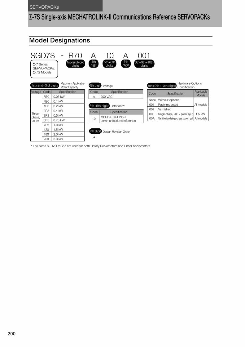
SERVOPACKs
200
Σ-7S Single-axis MECHATROLINK-II Communications Reference SERVOPACKs
Model Designations
10
A
Interface*
Code Specification
MECHATROLINK-II
communications reference
Design Revision Order
5th+6th digits
7th digit
A 200 VACR70
R90
1R6
2R8
3R8
5R5
7R6
120
180
200
0.05 kW
0.1 kW
0.2 kW
0.4 kW
0.5 kW
0.75 kW
1.0 kW
1.5 kW
2.0 kW
3.0 kW
SGD7S - R70 A 10 A 001
1.5 kW
Maximum Applicable
Motor Capacity Voltage
Code SpecificationCode
None
Specification
Without options
Rack-mounted
Varnished
All models
All models
Single-phase, 200 V power input
Varnished and single-phase power input
Applicable
Models
Hardware Options
Specification
Voltage Code Specification
* The same SERVOPACKs are used for both Rotary Servomotors and Linear Servomotors.
Three-
phase,
200 V
1st+2nd+3rd digits 4th digit 8th+9th+10th digits
Σ-7 Series SERVOPACKs:
Σ-7S Models
4th digit
1st+2nd+3rd digits
5th+6th digits
8th+9th+10th digits
7th digit
001
002
008
00A
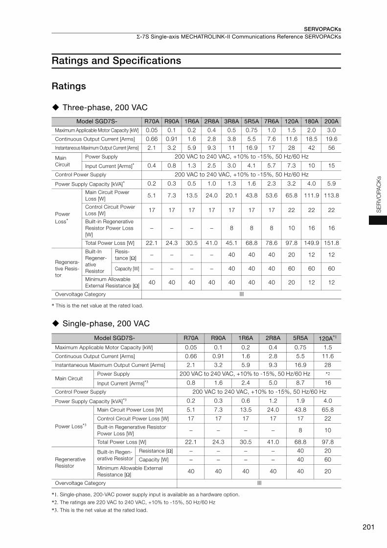
SERVOPACKs Σ-7S Single-axis MECHATROLINK-II Communications Reference SERVOPACKs
201
SE
RV
OP
AC
Ks
Ratings and Specifications
Ratings
Three-phase, 200 VAC
* This is the net value at the rated load.
Single-phase, 200 VAC
*1. Single-phase, 200-VAC power supply input is available as a hardware option.
*2. The ratings are 220 VAC to 240 VAC, +10% to -15%, 50 Hz/60 Hz
*3. This is the net value at the rated load.
Model SGD7S- R70A R90A 1R6A 2R8A 3R8A 5R5A 7R6A 120A 180A 200A
Maximum Applicable Motor Capacity [kW] 0.05 0.1 0.2 0.4 0.5 0.75 1.0 1.5 2.0 3.0
Continuous Output Current [Arms] 0.66 0.91 1.6 2.8 3.8 5.5 7.6 11.6 18.5 19.6
Instantaneous Maximum Output Current [Arms] 2.1 3.2 5.9 9.3 11 16.9 17 28 42 56
Main
Circuit
Power Supply 200 VAC to 240 VAC, +10% to -15%, 50 Hz/60 Hz
Input Current [Arms]* 0.4 0.8 1.3 2.5 3.0 4.1 5.7 7.3 10 15
Control Power Supply 200 VAC to 240 VAC, +10% to -15%, 50 Hz/60 Hz
Power Supply Capacity [kVA]* 0.2 0.3 0.5 1.0 1.3 1.6 2.3 3.2 4.0 5.9
Power
Loss*
Main Circuit Power
Loss [W]5.1 7.3 13.5 24.0 20.1 43.8 53.6 65.8 111.9 113.8
Control Circuit Power
Loss [W]17 17 17 17 17 17 17 22 22 22
Built-in Regenerative
Resistor Power Loss
[W]
− − − − 8 8 8 10 16 16
Total Power Loss [W] 22.1 24.3 30.5 41.0 45.1 68.8 78.6 97.8 149.9 151.8
Regenera-
tive Resis-
tor
Built-In
Regener-
ative
Resistor
Resis-
tance [Ω]− − − − 40 40 40 20 12 12
Capacity [W] − − − − 40 40 40 60 60 60
Minimum Allowable
External Resistance [Ω]40 40 40 40 40 40 40 20 12 12
Overvoltage Category III
Model SGD7S- R70A R90A 1R6A 2R8A 5R5A 120A*1
Maximum Applicable Motor Capacity [kW] 0.05 0.1 0.2 0.4 0.75 1.5
Continuous Output Current [Arms] 0.66 0.91 1.6 2.8 5.5 11.6
Instantaneous Maximum Output Current [Arms] 2.1 3.2 5.9 9.3 16.9 28
Main CircuitPower Supply 200 VAC to 240 VAC, +10% to -15%, 50 Hz/60 Hz *2
Input Current [Arms]*3 0.8 1.6 2.4 5.0 8.7 16
Control Power Supply 200 VAC to 240 VAC, +10% to -15%, 50 Hz/60 Hz
Power Supply Capacity [kVA]*3 0.2 0.3 0.6 1.2 1.9 4.0
Power Loss*3
Main Circuit Power Loss [W] 5.1 7.3 13.5 24.0 43.8 65.8
Control Circuit Power Loss [W] 17 17 17 17 17 22
Built-in Regenerative Resistor
Power Loss [W]− − − − 8 10
Total Power Loss [W] 22.1 24.3 30.5 41.0 68.8 97.8
Regenerative
Resistor
Built-In Regen-
erative Resistor
Resistance [Ω] − − − − 40 20
Capacity [W] − − − − 40 60
Minimum Allowable External
Resistance [Ω]40 40 40 40 40 20
Overvoltage Category III
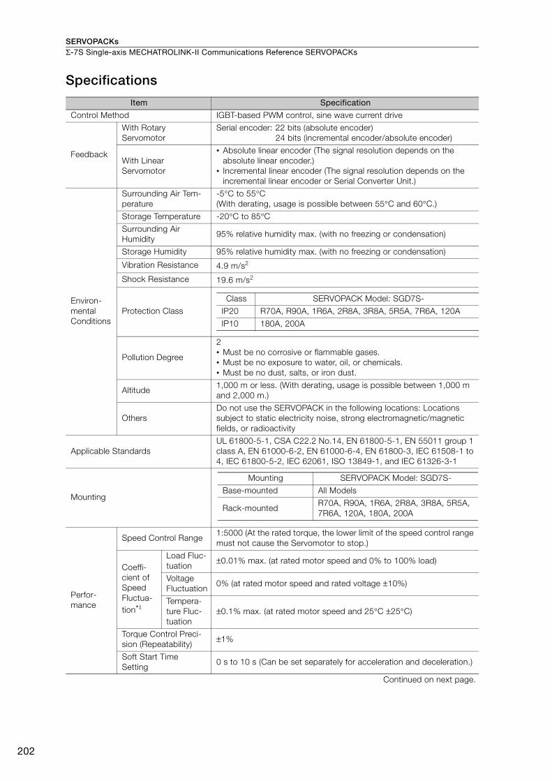
SERVOPACKsΣ-7S Single-axis MECHATROLINK-II Communications Reference SERVOPACKs
202
Specifications
Item Specification
Control Method IGBT-based PWM control, sine wave current drive
Feedback
With Rotary
Servomotor
Serial encoder: 22 bits (absolute encoder)
24 bits (incremental encoder/absolute encoder)
With Linear
Servomotor
• Absolute linear encoder (The signal resolution depends on the
absolute linear encoder.)
• Incremental linear encoder (The signal resolution depends on the
incremental linear encoder or Serial Converter Unit.)
Environ-
mental
Conditions
Surrounding Air Tem-
perature
-5°C to 55°C
(With derating, usage is possible between 55°C and 60°C.)
Storage Temperature -20°C to 85°C
Surrounding Air
Humidity95% relative humidity max. (with no freezing or condensation)
Storage Humidity 95% relative humidity max. (with no freezing or condensation)
Vibration Resistance 4.9 m/s2
Shock Resistance 19.6 m/s2
Protection Class
I
Pollution Degree
2
• Must be no corrosive or flammable gases.
• Must be no exposure to water, oil, or chemicals.
• Must be no dust, salts, or iron dust.
Altitude1,000 m or less. (With derating, usage is possible between 1,000 m
and 2,000 m.)
Others
Do not use the SERVOPACK in the following locations: Locations
subject to static electricity noise, strong electromagnetic/magnetic
fields, or radioactivity
Applicable Standards
UL 61800-5-1, CSA C22.2 No.14, EN 61800-5-1, EN 55011 group 1
class A, EN 61000-6-2, EN 61000-6-4, EN 61800-3, IEC 61508-1 to
4, IEC 61800-5-2, IEC 62061, ISO 13849-1, and IEC 61326-3-1
Mounting
Perfor-
mance
Speed Control Range1:5000 (At the rated torque, the lower limit of the speed control range
must not cause the Servomotor to stop.)
Coeffi-
cient of
Speed
Fluctua-
tion*1
Load Fluc-
tuation±0.01% max. (at rated motor speed and 0% to 100% load)
Voltage
Fluctuation0% (at rated motor speed and rated voltage ±10%)
Tempera-
ture Fluc-
tuation
±0.1% max. (at rated motor speed and 25°C ±25°C)
Torque Control Preci-
sion (Repeatability)±1%
Soft Start Time
Setting0 s to 10 s (Can be set separately for acceleration and deceleration.)
Continued on next page.
Class SERVOPACK Model: SGD7S-
IP20 R70A, R90A, 1R6A, 2R8A, 3R8A, 5R5A, 7R6A, 120A
IP10 180A, 200A
Mounting SERVOPACK Model: SGD7S-
Base-mounted All Models
Rack-mountedR70A, R90A, 1R6A, 2R8A, 3R8A, 5R5A,
7R6A, 120A, 180A, 200A
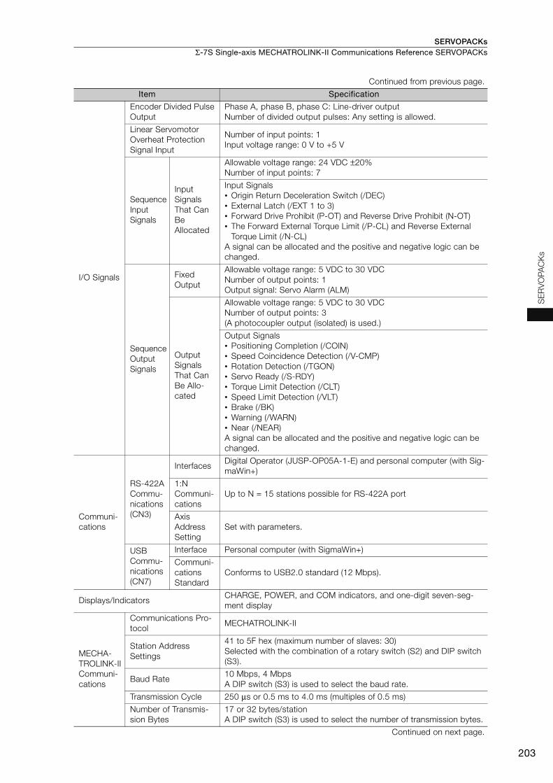
SERVOPACKs Σ-7S Single-axis MECHATROLINK-II Communications Reference SERVOPACKs
203
SE
RV
OP
AC
Ks
I/O Signals
Encoder Divided Pulse
Output
Phase A, phase B, phase C: Line-driver output
Number of divided output pulses: Any setting is allowed.
Linear Servomotor
Overheat Protection
Signal Input
Number of input points: 1
Input voltage range: 0 V to +5 V
Sequence
Input
Signals
Input
Signals
That Can
Be
Allocated
Allowable voltage range: 24 VDC ±20%
Number of input points: 7
Input Signals
• Origin Return Deceleration Switch (/DEC)
• External Latch (/EXT 1 to 3)
• Forward Drive Prohibit (P-OT) and Reverse Drive Prohibit (N-OT)
• The Forward External Torque Limit (/P-CL) and Reverse External
Torque Limit (/N-CL)
A signal can be allocated and the positive and negative logic can be
changed.
Sequence
Output
Signals
Fixed
Output
Allowable voltage range: 5 VDC to 30 VDC
Number of output points: 1
Output signal: Servo Alarm (ALM)
Output
Signals
That Can
Be Allo-
cated
Allowable voltage range: 5 VDC to 30 VDC
Number of output points: 3
(A photocoupler output (isolated) is used.)
Output Signals
• Positioning Completion (/COIN)
• Speed Coincidence Detection (/V-CMP)
• Rotation Detection (/TGON)
• Servo Ready (/S-RDY)
• Torque Limit Detection (/CLT)
• Speed Limit Detection (/VLT)
• Brake (/BK)
• Warning (/WARN)
• Near (/NEAR)
A signal can be allocated and the positive and negative logic can be
changed.
Communi-
cations
RS-422A
Commu-
nications
(CN3)
InterfacesDigital Operator (JUSP-OP05A-1-E) and personal computer (with Sig-
maWin+)
1:N
Communi-
cations
Up to N = 15 stations possible for RS-422A port
Axis
Address
Setting
Set with parameters.
USB
Commu-
nications
(CN7)
Interface Personal computer (with SigmaWin+)
Communi-
cations
Standard
Conforms to USB2.0 standard (12 Mbps).
Displays/IndicatorsCHARGE, POWER, and COM indicators, and one-digit seven-seg-
ment display
MECHA-
TROLINK-II
Communi-
cations
Communications Pro-
tocolMECHATROLINK-II
Station Address
Settings
41 to 5F hex (maximum number of slaves: 30)
Selected with the combination of a rotary switch (S2) and DIP switch
(S3).
Baud Rate 10 Mbps, 4 Mbps
A DIP switch (S3) is used to select the baud rate.
Transmission Cycle 250 μs or 0.5 ms to 4.0 ms (multiples of 0.5 ms)
Number of Transmis-
sion Bytes
17 or 32 bytes/station
A DIP switch (S3) is used to select the number of transmission bytes.
Continued on next page.
Continued from previous page.
Item Specification

SERVOPACKsΣ-7S Single-axis MECHATROLINK-II Communications Reference SERVOPACKs
204
*1. The coefficient of speed fluctuation for load fluctuation is defined as follows:
*2. Always perform risk assessment for the system and confirm that the safety requirements are met.
Reference
Method
PerformancePosition, speed, or torque control with MECHATROLINK-II communi-
cations
Reference InputMECHATROLINK-I or MECHATROLINK-II commands (sequence,
motion, data setting, data access, monitoring, adjustment, etc.)
MECHATROLINK-II Communica-
tions Setting Switches
Rotary switch (S2) positions: 16
Number of DIP switch (S3) pins: 4
Analog Monitor (CN5)
Number of points: 2
Output voltage range: ±10 VDC (effective linearity range: ±8 V)
Resolution: 16 bits
Accuracy: ±20 mV (Typ)
Maximum output current: ±10 mA
Settling time (±1%): 1.2 ms (Typ)
Dynamic Brake (DB)Activated when a servo alarm or overtravel (OT) occurs, or when the
power supply to the main circuit or servo is OFF.
Regenerative Processing Built-in
Overtravel (OT) PreventionStopping with dynamic brake, deceleration to a stop, or coast to a
stop at P-OT or N-OT input.
Protective FunctionsOvercurrent, overvoltage, low voltage, overload, regeneration error,
etc.
Utility Functions Gain adjustment, alarm history, jogging, origin search, etc.
Safety
Functions
Inputs /HWBB1 and /HWBB2: Base block signals for Power Modules
Output EDM1: Monitors the status of built-in safety circuit (fixed output).
Applicable
Standards*2 ISO13849-1 PLe (Category 3), IEC61508 SIL3
Continued from previous page.
Item Specification
× 100%Coefficient of speed fluctuation =No-load motor speed - Total-load motor speed
Rated motor speed
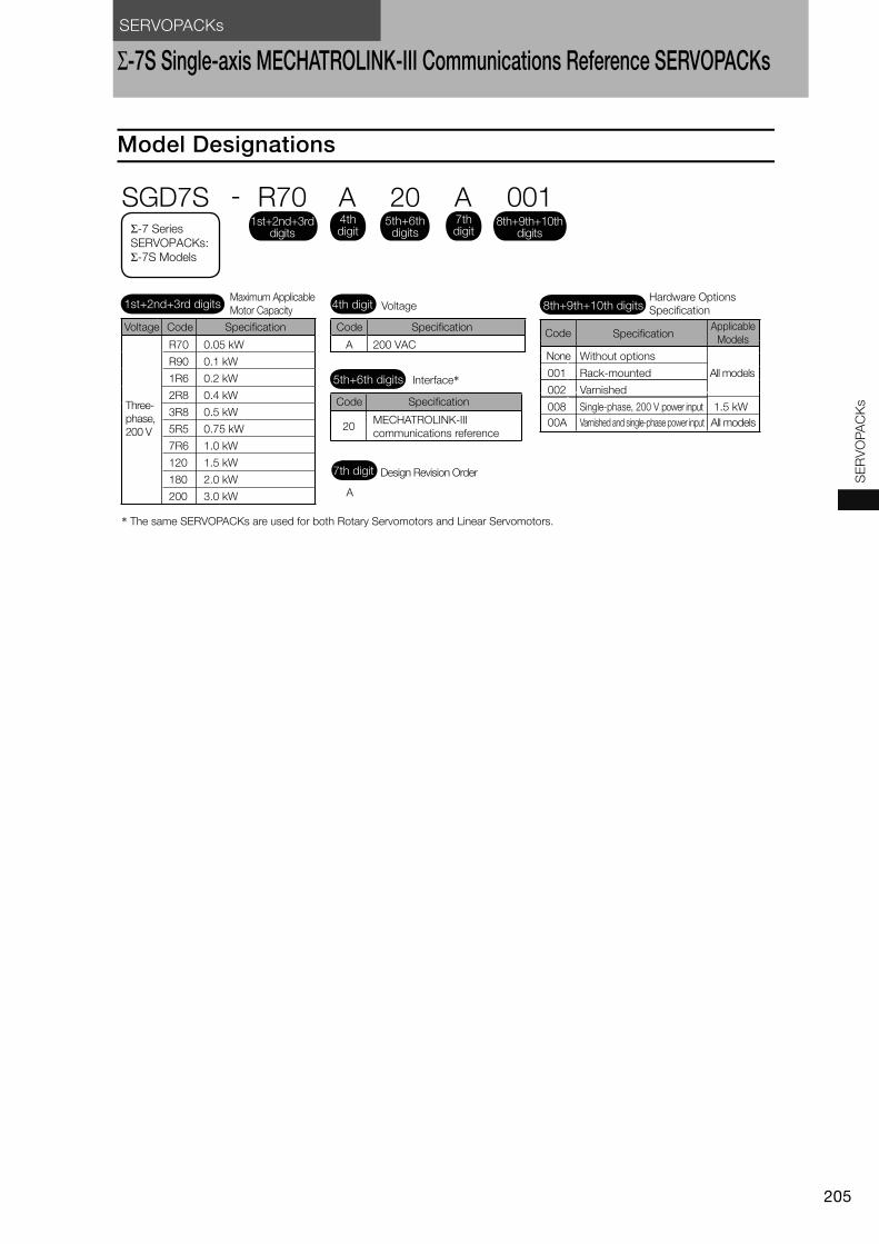
SERVOPACKs
205
SE
RV
OP
AC
Ks
Σ-7S Single-axis MECHATROLINK-III Communications Reference SERVOPACKs
Model Designations
20
A
Interface*
Code Specification
MECHATROLINK-III
communications reference
Design Revision Order
5th+6th digits
7th digit
A 200 VACR70
R90
1R6
2R8
3R8
5R5
7R6
120
180
200
0.05 kW
0.1 kW
0.2 kW
0.4 kW
0.5 kW
0.75 kW
1.0 kW
1.5 kW
2.0 kW
3.0 kW
SGD7S - R70 A 20 A 001
1.5 kW
Maximum Applicable
Motor Capacity Voltage
Code SpecificationCode
None
Specification
Without options
Rack-mounted
Varnished
All models
All models
Single-phase, 200 V power input
Varnished and single-phase power input
Applicable
Models
Hardware Options
Specification
Voltage Code Specification
* The same SERVOPACKs are used for both Rotary Servomotors and Linear Servomotors.
Three-
phase,
200 V
1st+2nd+3rd digits 4th digit 8th+9th+10th digits
Σ-7 Series SERVOPACKs:
Σ-7S Models
4th digit
1st+2nd+3rd digits
5th+6th digits
8th+9th+10th digits
7th digit
001
002
008
00A
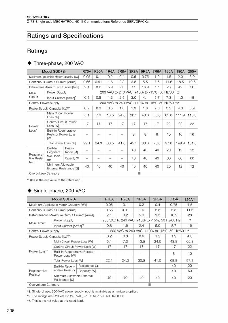
SERVOPACKsΣ-7S Single-axis MECHATROLINK-III Communications Reference SERVOPACKs
206
Ratings and Specifications
Ratings
Three-phase, 200 VAC
* This is the net value at the rated load.
Single-phase, 200 VAC
*1. Single-phase, 200-VAC power supply input is available as a hardware option.
*2. The ratings are 220 VAC to 240 VAC, +10% to -15%, 50 Hz/60 Hz
*3. This is the net value at the rated load.
Model SGD7S- R70A R90A 1R6A 2R8A 3R8A 5R5A 7R6A 120A 180A 200A
Maximum Applicable Motor Capacity [kW] 0.05 0.1 0.2 0.4 0.5 0.75 1.0 1.5 2.0 3.0
Continuous Output Current [Arms] 0.66 0.91 1.6 2.8 3.8 5.5 7.6 11.6 18.5 19.6
Instantaneous Maximum Output Current [Arms] 2.1 3.2 5.9 9.3 11 16.9 17 28 42 56
Main
Circuit
Power Supply 200 VAC to 240 VAC, +10% to -15%, 50 Hz/60 Hz
Input Current [Arms]* 0.4 0.8 1.3 2.5 3.0 4.1 5.7 7.3 1.0 15
Control Power Supply 200 VAC to 240 VAC, +10% to -15%, 50 Hz/60 Hz
Power Supply Capacity [kVA]* 0.2 0.3 0.5 1.0 1.3 1.6 2.3 3.2 4.0 5.9
Power
Loss*
Main Circuit Power
Loss [W]5.1 7.3 13.5 24.0 20.1 43.8 53.6 65.8 111.9 113.8
Control Circuit Power
Loss [W]17 17 17 17 17 17 17 22 22 22
Built-in Regenerative
Resistor Power Loss
[W]
− − − − 8 8 8 10 16 16
Total Power Loss [W] 22.1 24.3 30.5 41.0 45.1 68.8 78.6 97.8 149.9 151.8
Regenera-
tive Resis-
tor
Built-In
Regenera-
tive Resis-
tor
Resis-
tance [Ω]− − − − 40 40 40 20 12 12
Capacity [W] − − − − 40 40 40 60 60 60
Minimum Allowable
External Resistance [Ω] 40 40 40 40 40 40 40 20 12 12
Overvoltage Category III
Model SGD7S- R70A R90A 1R6A 2R8A 5R5A 120A*1
Maximum Applicable Motor Capacity [kW] 0.05 0.1 0.2 0.4 0.75 1.5
Continuous Output Current [Arms] 0.66 0.91 1.6 2.8 5.5 11.6
Instantaneous Maximum Output Current [Arms] 2.1 3.2 5.9 9.3 16.9 28
Main CircuitPower Supply 200 VAC to 240 VAC, +10% to -15%, 50 Hz/60 Hz *2
Input Current [Arms]*3 0.8 1.6 2.4 5.0 8.7 16
Control Power Supply 200 VAC to 240 VAC, +10% to -15%, 50 Hz/60 Hz
Power Supply Capacity [kVA]*3 0.2 0.3 0.6 1.2 1.9 4.0
Power Loss*3
Main Circuit Power Loss [W] 5.1 7.3 13.5 24.0 43.8 65.8
Control Circuit Power Loss [W] 17 17 17 17 17 22
Built-in Regenerative Resistor
Power Loss [W]− − − − 8 10
Total Power Loss [W] 22.1 24.3 30.5 41.0 68.8 97.8
Regenerative
Resistor
Built-In Regen-
erative Resistor
Resistance [Ω] − − − − 40 20
Capacity [W] − − − − 40 60
Minimum Allowable External
Resistance [Ω] 40 40 40 40 40 20
Overvoltage Category III
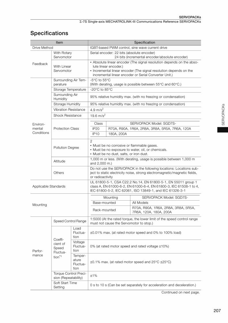
SERVOPACKs Σ-7S Single-axis MECHATROLINK-III Communications Reference SERVOPACKs
207
SE
RV
OP
AC
Ks
Specifications
Item Specification
Drive Method IGBT-based PWM control, sine wave current drive
Feedback
With Rotary
Servomotor
Serial encoder: 22 bits (absolute encoder)
24 bits (incremental encoder/absolute encoder)
With Linear
Servomotor
• Absolute linear encoder (The signal resolution depends on the abso-
lute linear encoder.)
• Incremental linear encoder (The signal resolution depends on the
incremental linear encoder or Serial Converter Unit.)
Environ-
mental
Conditions
Surrounding Air Tem-
perature
-5°C to 55°C
(With derating, usage is possible between 55°C and 60°C.)
Storage Temperature -20°C to 85°C
Surrounding Air
Humidity 95% relative humidity max. (with no freezing or condensation)
Storage Humidity 95% relative humidity max. (with no freezing or condensation)
Vibration Resistance 4.9 m/s2
Shock Resistance 19.6 m/s2
Protection Class
I
Pollution Degree
2
• Must be no corrosive or flammable gases.
• Must be no exposure to water, oil, or chemicals.
• Must be no dust, salts, or iron dust.
Altitude 1,000 m or less. (With derating, usage is possible between 1,000 m
and 2,000 m.)
Others
Do not use the SERVOPACK in the following locations: Locations sub-
ject to static electricity noise, strong electromagnetic/magnetic fields,
or radioactivity
Applicable Standards
UL 61800-5-1, CSA C22.2 No.14, EN 61800-5-1, EN 55011 group 1
class A, EN 61000-6-2, EN 61000-6-4, EN 61800-3, IEC 61508-1 to 4,
IEC 61800-5-2, IEC 62061, ISO 13849-1, and IEC 61326-3-1
Mounting
Perfor-
mance
Speed Control Range 1:5000 (At the rated torque, the lower limit of the speed control range
must not cause the Servomotor to stop.)
Coeffi-
cient of
Speed
Fluctua-
tion*1
Load
Fluctua-
tion
±0.01% max. (at rated motor speed and 0% to 100% load)
Voltage
Fluctua-
tion
0% (at rated motor speed and rated voltage ±10%)
Temper-
ature
Fluctua-
tion
±0.1% max. (at rated motor speed and 25°C ±25°C)
Torque Control Preci-
sion (Repeatability) ±1%
Soft Start Time
Setting 0 s to 10 s (Can be set separately for acceleration and deceleration.)
Continued on next page.
Class SERVOPACK Model: SGD7S-
IP20 R70A, R90A, 1R6A, 2R8A, 3R8A, 5R5A, 7R6A, 120A
IP10 180A, 200A
Mounting SERVOPACK Model: SGD7S-
Base-mounted All Models
Rack-mounted R70A, R90A, 1R6A, 2R8A, 3R8A, 5R5A,
7R6A, 120A, 180A, 200A
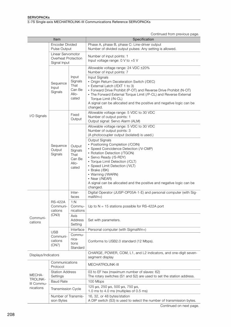
SERVOPACKsΣ-7S Single-axis MECHATROLINK-III Communications Reference SERVOPACKs
208
I/O Signals
Encoder Divided
Pulse Output
Phase A, phase B, phase C: Line-driver output
Number of divided output pulses: Any setting is allowed.
Linear Servomotor
Overheat Protection
Signal Input
Number of input points: 1
Input voltage range: 0 V to +5 V
Sequence
Input
Signals
Input
Signals
That
Can Be
Allo-
cated
Allowable voltage range: 24 VDC ±20%
Number of input points: 7
Input Signals
• Origin Return Deceleration Switch (/DEC)
• External Latch (/EXT 1 to 3)
• Forward Drive Prohibit (P-OT) and Reverse Drive Prohibit (N-OT)
• The Forward External Torque Limit (/P-CL) and Reverse External
Torque Limit (/N-CL)
A signal can be allocated and the positive and negative logic can be
changed.
Sequence
Output
Signals
Fixed
Output
Allowable voltage range: 5 VDC to 30 VDC
Number of output points: 1
Output signal: Servo Alarm (ALM)
Output
Signals
That
Can Be
Allo-
cated
Allowable voltage range: 5 VDC to 30 VDC
Number of output points: 3
(A photocoupler output (isolated) is used.)
Output Signals
• Positioning Completion (/COIN)
• Speed Coincidence Detection (/V-CMP)
• Rotation Detection (/TGON)
• Servo Ready (/S-RDY)
• Torque Limit Detection (/CLT)
• Speed Limit Detection (/VLT)
• Brake (/BK)
• Warning (/WARN)
• Near (/NEAR)
A signal can be allocated and the positive and negative logic can be
changed.
Communi-
cations
RS-422A
Communi-
cations
(CN3)
Inter-
faces
Digital Operator (JUSP-OP05A-1-E) and personal computer (with Sig-
maWin+)
1:N
Commu-
nications
Up to N = 15 stations possible for RS-422A port
Axis
Address
Setting
Set with parameters.
USB
Communi-
cations
(CN7)
Interface Personal computer (with SigmaWin+)
Commu-
nica-
tions
Standard
Conforms to USB2.0 standard (12 Mbps).
Displays/Indicators CHARGE, POWER, COM, L1, and L2 indicators, and one-digit seven-
segment display
MECHA-
TROLINK-
III Commu-
nications
Communications
Protocol MECHATROLINK-III
Station Address
Settings
03 to EF hex (maximum number of slaves: 62)
The rotary switches (S1 and S2) are used to set the station address.
Baud Rate 100 Mbps
Transmission Cycle 125 μs, 250 μs, 500 μs, 750 μs,
1.0 ms to 4.0 ms (multiples of 0.5 ms)
Number of Transmis-
sion Bytes
16, 32, or 48 bytes/station
A DIP switch (S3) is used to select the number of transmission bytes.
Continued on next page.
Continued from previous page.
Item Specification

SERVOPACKs Σ-7S Single-axis MECHATROLINK-III Communications Reference SERVOPACKs
209
SE
RV
OP
AC
Ks
*1. The coefficient of speed fluctuation for load fluctuation is defined as follows:
*2. Always perform risk assessment for the system and confirm that the safety requirements are met.
Reference
Method
PerformancePosition, speed, or torque control with MECHATROLINK-III communi-
cations
Reference Input MECHATROLINK-III commands (sequence, motion, data setting, data
access, monitoring, adjustment, etc.)
ProfileMECHATROLINK-III standard servo profile
MECHATROLINK-II-compatible profile
MECHATROLINK-III Communica-
tions Setting Switches
Rotary switch (S1 and S2) positions: 16
Number of DIP switch (S3) pins: 4
Analog Monitor (CN5)
Number of points: 2
Output voltage range: ±10 VDC (effective linearity range: ±8 V)
Resolution: 16 bits
Accuracy: ±20 mV (Typ)
Maximum output current: ±10 mA
Settling time (±1%): 1.2 ms (Typ)
Dynamic Brake (DB)Activated when a servo alarm or overtravel (OT) occurs, or when the
power supply to the main circuit or servo is OFF.
Regenerative Processing Built-in
Overtravel (OT) Prevention Stopping with dynamic brake, deceleration to a stop, or coast to a stop
at P-OT or N-OT input.
Protective Functions Overcurrent, overvoltage, low voltage, overload, regeneration error, etc.
Utility Functions Gain adjustment, alarm history, jogging, origin search, etc.
Safety
Functions
Inputs /HWBB1 and /HWBB2: Base block signals for Power Modules
Output EDM1: Monitors the status of built-in safety circuit (fixed output).
Applicable
Standards*2 ISO13849-1 PLe (Category 3), IEC61508 SIL3
Continued from previous page.
Item Specification
× 100%Coefficient of speed fluctuation =No-load motor speed - Total-load motor speed
Rated motor speed

SERVOPACKs
210
Σ-7W Two-axis MECHATROLINK-III Communications Reference SERVOPACKs
Model Designations
SGD7W - 1R6 A 20 A 001Σ-7 Series SERVOPACKs:
Σ-7W Models
4th digit
1st+2nd+3rd digits
5th+6th digits
8th+9th+10th digits
7th digit
Maximum Applicable
Motor Capacity per Axis
* The same SERVOPACKs are used for both Rotary Servomotors and Linear Servomotors.
A 200 VAC
Voltage
Code Specification
1R6
2R8
5R5
7R6
0.2 kW
0.4 kW
0.75 kW
1.0 kW
Voltage Code Specification
Three-
phase,
200 V
1st+2nd+3rd digits 4th digit
Code
None
Specification
Without options
Rack-mounted
Varnished
All models
Applicable
Models
Hardware Options
Specification8th+9th+10th digits
001
002
20
A
Interface*
Code Specification
MECHATROLINK-III
communications reference
Design Revision Order
5th+6th digits
7th digit
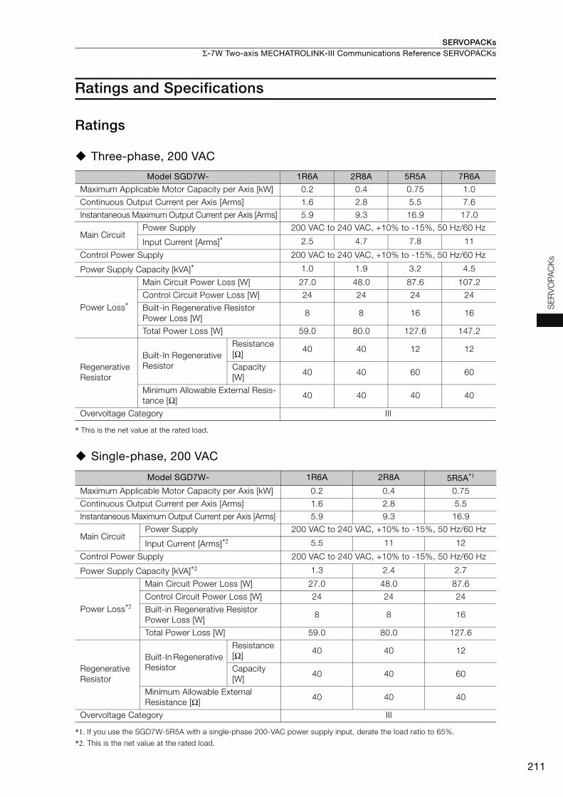
SERVOPACKs Σ-7W Two-axis MECHATROLINK-III Communications Reference SERVOPACKs
211
SE
RV
OP
AC
Ks
Ratings and Specifications
Ratings
Three-phase, 200 VAC
* This is the net value at the rated load.
Single-phase, 200 VAC
*1. If you use the SGD7W-5R5A with a single-phase 200-VAC power supply input, derate the load ratio to 65%.
*2. This is the net value at the rated load.
Model SGD7W- 1R6A 2R8A 5R5A 7R6A
Maximum Applicable Motor Capacity per Axis [kW] 0.2 0.4 0.75 1.0
Continuous Output Current per Axis [Arms] 1.6 2.8 5.5 7.6
Instantaneous Maximum Output Current per Axis [Arms] 5.9 9.3 16.9 17.0
Main Circuit Power Supply 200 VAC to 240 VAC, +10% to -15%, 50 Hz/60 Hz
Input Current [Arms]* 2.5 4.7 7.8 11
Control Power Supply 200 VAC to 240 VAC, +10% to -15%, 50 Hz/60 Hz
Power Supply Capacity [kVA]* 1.0 1.9 3.2 4.5
Power Loss*
Main Circuit Power Loss [W] 27.0 48.0 87.6 107.2
Control Circuit Power Loss [W] 24 24 24 24
Built-in Regenerative Resistor
Power Loss [W] 8 8 16 16
Total Power Loss [W] 59.0 80.0 127.6 147.2
Regenerative
Resistor
Built-In Regenerative
Resistor
Resistance
[Ω] 40 40 12 12
Capacity
[W] 40 40 60 60
Minimum Allowable External Resis-
tance [Ω] 40 40 40 40
Overvoltage Category III
Model SGD7W- 1R6A 2R8A 5R5A*1
Maximum Applicable Motor Capacity per Axis [kW] 0.2 0.4 0.75
Continuous Output Current per Axis [Arms] 1.6 2.8 5.5
Instantaneous Maximum Output Current per Axis [Arms] 5.9 9.3 16.9
Main Circuit Power Supply 200 VAC to 240 VAC, +10% to -15%, 50 Hz/60 Hz
Input Current [Arms]*2 5.5 11 12
Control Power Supply 200 VAC to 240 VAC, +10% to -15%, 50 Hz/60 Hz
Power Supply Capacity [kVA]*2 1.3 2.4 2.7
Power Loss*2
Main Circuit Power Loss [W] 27.0 48.0 87.6
Control Circuit Power Loss [W] 24 24 24
Built-in Regenerative Resistor
Power Loss [W] 8 8 16
Total Power Loss [W] 59.0 80.0 127.6
Regenerative
Resistor
Built-In Regenerative
Resistor
Resistance
[Ω] 40 40 12
Capacity
[W] 40 40 60
Minimum Allowable External
Resistance [Ω] 40 40 40
Overvoltage Category III
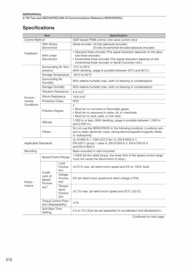
SERVOPACKsΣ-7W Two-axis MECHATROLINK-III Communications Reference SERVOPACKs
212
Specifications
Item Specification
Control Method IGBT-based PWM control, sine wave current drive
Feedback
With Rotary
Servomotor
Serial encoder: 22 bits (absolute encoder)
24 bits (incremental encoder/absolute encoder)
With Linear
Servomotor
• Absolute linear encoder (The signal resolution depends on the abso-
lute linear encoder.)
• Incremental linear encoder (The signal resolution depends on the
incremental linear encoder or Serial Converter Unit.)
Environ-
mental
Conditions
Surrounding Air Tem-
perature
-5°C to 55°C
(With derating, usage is possible between 55°C and 60°C.)
Storage Temperature -20°C to 85°C
Surrounding Air
Humidity 95% relative humidity max. (with no freezing or condensation)
Storage Humidity 95% relative humidity max. (with no freezing or condensation)
Vibration Resistance 4.9 m/s2
Shock Resistance 19.6 m/s2
Protection Class IP20
Pollution Degree
2
• Must be no corrosive or flammable gases.
• Must be no exposure to water, oil, or chemicals.
• Must be no dust, salts, or iron dust.
Altitude1,000 m or less. (With derating, usage is possible between 1,000 m
and 2,000 m.)
Others
Do not use the SERVOPACK in the following locations: Locations sub-
ject to static electricity noise, strong electromagnetic/magnetic fields,
or radioactivity
Applicable Standards
UL 61800-5-1, CSA C22.2 No.14, EN 61800-5-1,
EN 55011 group 1 class A, EN 61000-6-2, EN 61000-6-4,
and EN 61800-3
Mounting Base-mounted or rack-mounted
Perfor-
mance
Speed Control Range 1:5000 (At the rated torque, the lower limit of the speed control range
must not cause the Servomotor to stop.)
Coeffi-
cient of
Speed
Fluctua-
tion*
Load
Fluctua-
tion
±0.01% max. (at rated motor speed and 0% to 100% load)
Voltage
Fluctua-
tion
0% (at rated motor speed and rated voltage ±10%)
Temper-
ature
Fluctua-
tion
±0.1% max. (at rated motor speed and 25°C ±25°C)
Torque Control Preci-
sion (Repeatability) ±1%
Soft Start Time
Setting 0 s to 10 s (Can be set separately for acceleration and deceleration.)
Continued on next page.
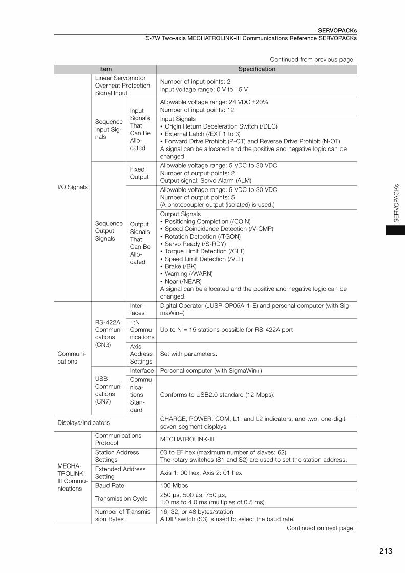
SERVOPACKs Σ-7W Two-axis MECHATROLINK-III Communications Reference SERVOPACKs
213
SE
RV
OP
AC
KsI/O Signals
Linear Servomotor
Overheat Protection
Signal Input
Number of input points: 2
Input voltage range: 0 V to +5 V
Sequence
Input Sig-
nals
Input
Signals
That
Can Be
Allo-
cated
Allowable voltage range: 24 VDC ±20%
Number of input points: 12
Input Signals
• Origin Return Deceleration Switch (/DEC)
• External Latch (/EXT 1 to 3)
• Forward Drive Prohibit (P-OT) and Reverse Drive Prohibit (N-OT)
A signal can be allocated and the positive and negative logic can be
changed.
Sequence
Output
Signals
Fixed
Output
Allowable voltage range: 5 VDC to 30 VDC
Number of output points: 2
Output signal: Servo Alarm (ALM)
Output
Signals
That
Can Be
Allo-
cated
Allowable voltage range: 5 VDC to 30 VDC
Number of output points: 5
(A photocoupler output (isolated) is used.)
Output Signals
• Positioning Completion (/COIN)
• Speed Coincidence Detection (/V-CMP)
• Rotation Detection (/TGON)
• Servo Ready (/S-RDY)
• Torque Limit Detection (/CLT)
• Speed Limit Detection (/VLT)
• Brake (/BK)
• Warning (/WARN)
• Near (/NEAR)
A signal can be allocated and the positive and negative logic can be
changed.
Communi-
cations
RS-422A
Communi-
cations
(CN3)
Inter-
faces
Digital Operator (JUSP-OP05A-1-E) and personal computer (with Sig-
maWin+)
1:N
Commu-
nications
Up to N = 15 stations possible for RS-422A port
Axis
Address
Settings
Set with parameters.
USB
Communi-
cations
(CN7)
Interface Personal computer (with SigmaWin+)
Commu-
nica-
tions
Stan-
dard
Conforms to USB2.0 standard (12 Mbps).
Displays/IndicatorsCHARGE, POWER, COM, L1, and L2 indicators, and two, one-digit
seven-segment displays
MECHA-
TROLINK-
III Commu-
nications
Communications
Protocol MECHATROLINK-III
Station Address
Settings
03 to EF hex (maximum number of slaves: 62)
The rotary switches (S1 and S2) are used to set the station address.
Extended Address
Setting Axis 1: 00 hex, Axis 2: 01 hex
Baud Rate 100 Mbps
Transmission Cycle 250 μs, 500 μs, 750 μs,
1.0 ms to 4.0 ms (multiples of 0.5 ms)
Number of Transmis-
sion Bytes
16, 32, or 48 bytes/station
A DIP switch (S3) is used to select the baud rate.
Continued on next page.
Continued from previous page.
Item Specification
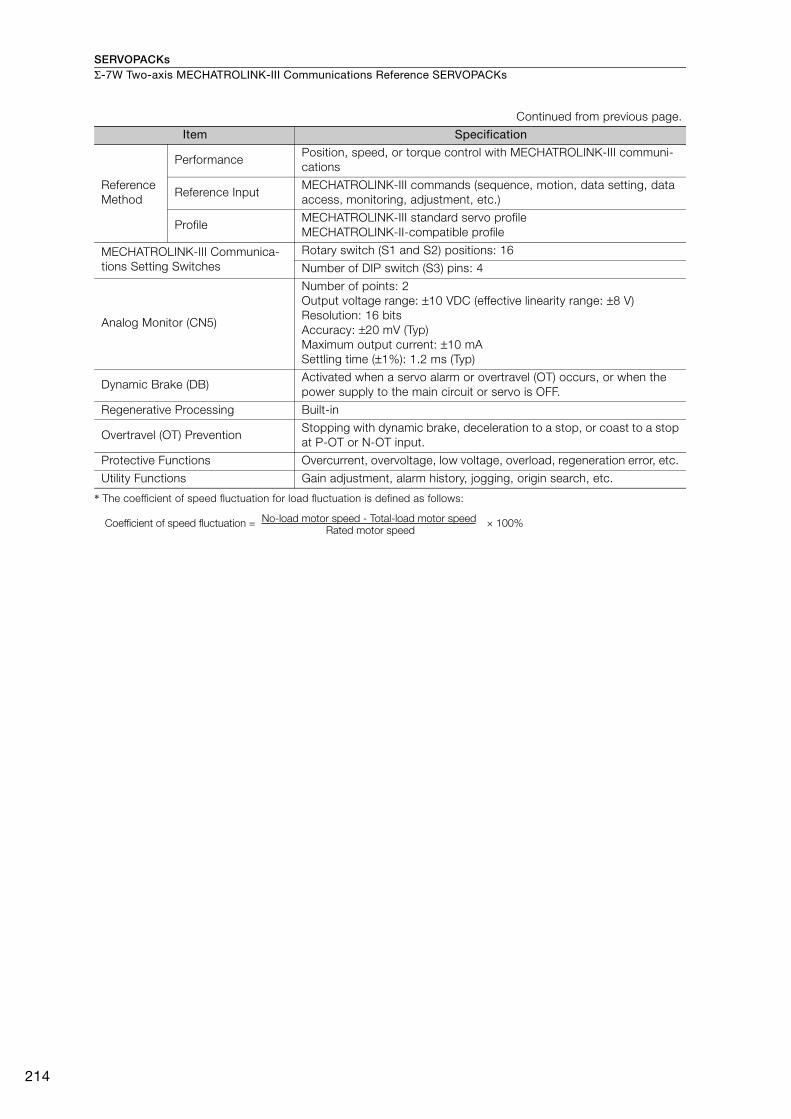
SERVOPACKsΣ-7W Two-axis MECHATROLINK-III Communications Reference SERVOPACKs
214
* The coefficient of speed fluctuation for load fluctuation is defined as follows:
Reference
Method
Performance Position, speed, or torque control with MECHATROLINK-III communi-
cations
Reference Input MECHATROLINK-III commands (sequence, motion, data setting, data
access, monitoring, adjustment, etc.)
Profile MECHATROLINK-III standard servo profile
MECHATROLINK-II-compatible profile
MECHATROLINK-III Communica-
tions Setting Switches
Rotary switch (S1 and S2) positions: 16
Number of DIP switch (S3) pins: 4
Analog Monitor (CN5)
Number of points: 2
Output voltage range: ±10 VDC (effective linearity range: ±8 V)
Resolution: 16 bits
Accuracy: ±20 mV (Typ)
Maximum output current: ±10 mA
Settling time (±1%): 1.2 ms (Typ)
Dynamic Brake (DB) Activated when a servo alarm or overtravel (OT) occurs, or when the
power supply to the main circuit or servo is OFF.
Regenerative Processing Built-in
Overtravel (OT) Prevention Stopping with dynamic brake, deceleration to a stop, or coast to a stop
at P-OT or N-OT input.
Protective Functions Overcurrent, overvoltage, low voltage, overload, regeneration error, etc.
Utility Functions Gain adjustment, alarm history, jogging, origin search, etc.
Continued from previous page.
Item Specification
× 100%Coefficient of speed fluctuation =No-load motor speed - Total-load motor speed
Rated motor speed
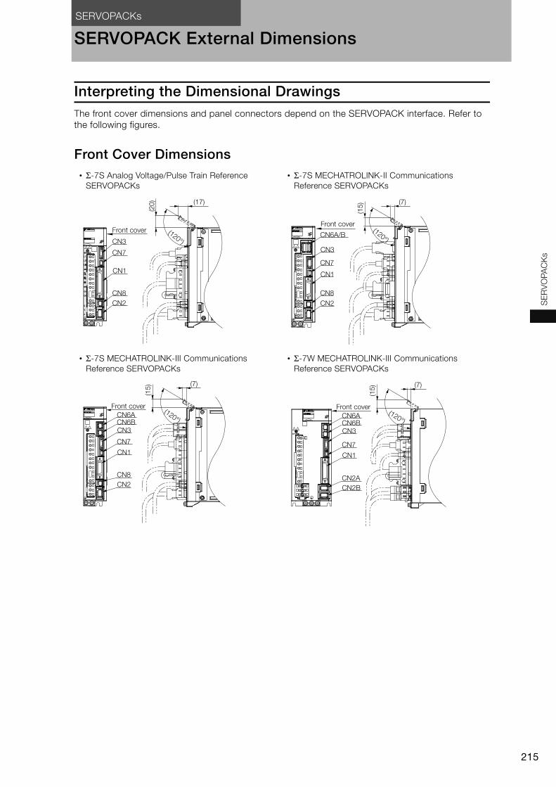
SERVOPACKs
215
SE
RV
OP
AC
Ks
SERVOPACK External Dimensions
Interpreting the Dimensional DrawingsThe front cover dimensions and panel connectors depend on the SERVOPACK interface. Refer to
the following figures.
Front Cover Dimensions • Σ-7S Analog Voltage/Pulse Train Reference
SERVOPACKs
• Σ-7S MECHATROLINK-II Communications
Reference SERVOPACKs
• Σ-7S MECHATROLINK-III Communications
Reference SERVOPACKs
• Σ-7W MECHATROLINK-III Communications
Reference SERVOPACKs
Front cover
CN3
CN7
CN1
CN8
CN2
(17)
(120°)
(20
)
Front cover
CN7
CN3
CN1
CN8
CN2
CN6A/B
(7)
(15
)
(120°)
Front cover
CN3
CN7
CN1
CN8
CN2
CN6ACN6B
(7)
(15
)
(120°)
Front cover
CN3
CN7
CN1
CN2A
CN2B
CN6ACN6B
(7)
(15
)
(120°)
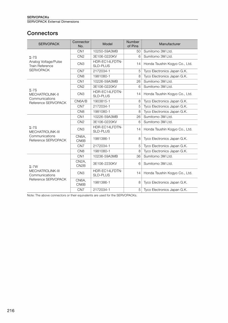
SERVOPACKsSERVOPACK External Dimensions
216
Connectors
Note: The above connectors or their equivalents are used for the SERVOPACKs.
SERVOPACK Connector
No. Model
Number of Pins
Manufacturer
Σ-7S
Analog Voltage/Pulse
Train Reference
SERVOPACK
CN1 10250-59A3MB 50 Sumitomo 3M Ltd.
CN2 3E106-0220KV 6 Sumitomo 3M Ltd.
CN3HDR-EC14LFDTN-
SLD-PLUS14 Honda Tsushin Kogyo Co., Ltd.
CN7 2172034-1 5 Tyco Electronics Japan G.K.
CN8 1981080-1 8 Tyco Electronics Japan G.K.
Σ-7S
MECHATROLINK-II
Communications
Reference SERVOPACK
CN1 10226-59A3MB 26 Sumitomo 3M Ltd.
CN2 3E106-0220KV 6 Sumitomo 3M Ltd.
CN3HDR-EC14LFDTN-
SLD-PLUS14 Honda Tsushin Kogyo Co., Ltd.
CN6A/B 1903815-1 8 Tyco Electronics Japan G.K.
CN7 2172034-1 5 Tyco Electronics Japan G.K.
CN8 1981080-1 8 Tyco Electronics Japan G.K.
Σ-7S
MECHATROLINK-III
Communications
Reference SERVOPACK
CN1 10226-59A3MB 26 Sumitomo 3M Ltd.
CN2 3E106-0220KV 6 Sumitomo 3M Ltd.
CN3HDR-EC14LFDTN-
SLD-PLUS14 Honda Tsushin Kogyo Co., Ltd.
CN6A,
CN6B1981386-1 8 Tyco Electronics Japan G.K.
CN7 2172034-1 5 Tyco Electronics Japan G.K.
CN8 1981080-1 8 Tyco Electronics Japan G.K.
Σ-7W
MECHATROLINK-III
Communications
Reference SERVOPACK
CN1 10236-59A3MB 36 Sumitomo 3M Ltd.
CN2A,
CN2B3E106-2230KV 6 Sumitomo 3M Ltd.
CN3HDR-EC14LFDTN-
SLD-PLUS14 Honda Tsushin Kogyo Co., Ltd.
CN6A,
CN6B1981386-1 8 Tyco Electronics Japan G.K.
CN7 2172034-1 5 Tyco Electronics Japan G.K.
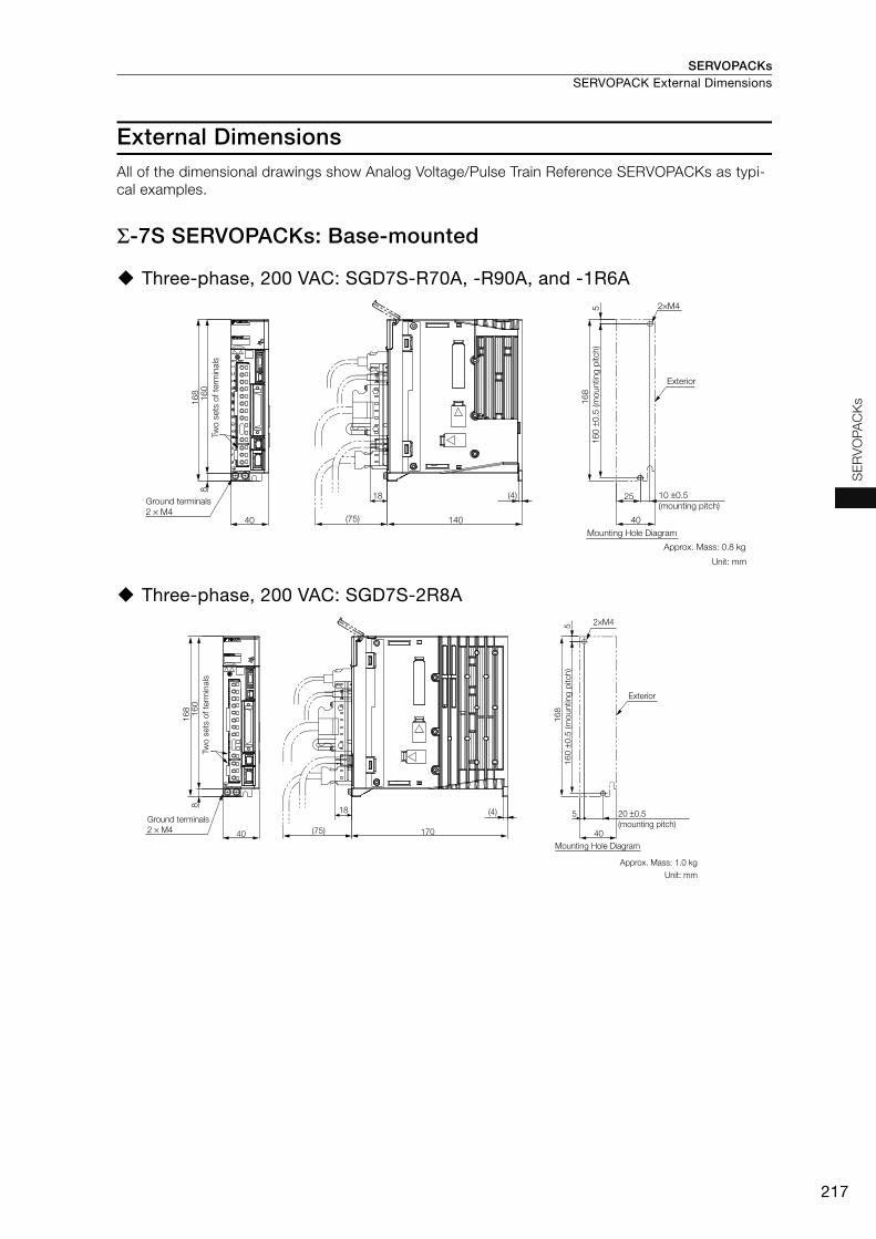
SERVOPACKs SERVOPACK External Dimensions
217
SE
RV
OP
AC
Ks
External Dimensions All of the dimensional drawings show Analog Voltage/Pulse Train Reference SERVOPACKs as typi-
cal examples.
Σ-7S SERVOPACKs: Base-mounted
Three-phase, 200 VAC: SGD7S-R70A, -R90A, and -1R6A
Three-phase, 200 VAC: SGD7S-2R8A
2×M4
16
01
68
8
40 (75) 140
18 (4)
16
8
5
25
40
Two
sets
of te
rmin
als
Ground terminals
2 × M4
16
0 ±
0.5
(m
ounting
pitch)
Exterior
10 ±0.5
(mounting pitch)
Mounting Hole Diagram
Approx. Mass: 0.8 kg
Unit: mm
16
01
68
8
40 170
18 (4)
(75)
16
8
5 2×M4
40
5
Tw
o s
ets
of te
rmin
als
Ground terminals
2 × M4
16
0 ±
0.5
(m
ounting
pitch)
Exterior
20 ±0.5
(mounting pitch)
Mounting Hole Diagram
Approx. Mass: 1.0 kg
Unit: mm
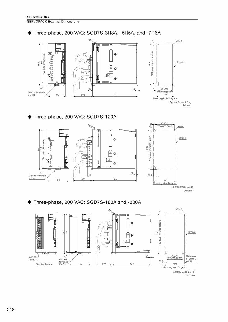
SERVOPACKsSERVOPACK External Dimensions
218
Three-phase, 200 VAC: SGD7S-3R8A, -5R5A, and -7R6A
Three-phase, 200 VAC: SGD7S-120A
Three-phase, 200 VAC: SGD7S-180A and -200A
16
0
16
8
8
70 180(75)
18 (4)
70
6
16
8
3×M45
Two
sets
of te
rmin
als
Ground terminals
2 × M4
16
0 ±
0.5
(m
ounting
pitch)
Exterior
58 ±0.5
(mounting pitch)
Mounting Hole Diagram
Approx. Mass: 1.6 kg
Unit: mm
16
01
68
8
90 180(75)
18(4)
16
8
5 3×M4
90
12.5
5
Two
sets
of te
rmin
als
Ground terminals
2 × M4
16
0 ±
0.5
(m
ounting
pitch)
80 ±0.5
(mounting pitch)
Exterior
Mounting Hole Diagram
Approx. Mass: 2.2 kg
Unit: mm
18
08
100 180 100
12.5
(4)
(75)
18
8
18
8
5
3×M4
Terminals
14 × M4
Terminal Details
Ground terminals2 × M4
18
0 ±
0.5
(m
ounting
pitch)
Exterior
75 ±0.5 (mounting pitch)
82.5 ±0.5
(mounting
pitch)
Mounting Hole Diagram
Approx. Mass: 2.7 kg
Unit: mm
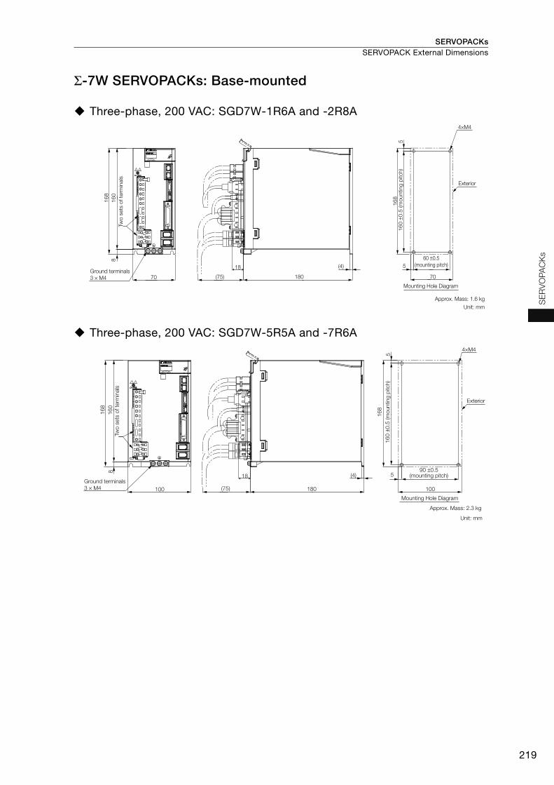
SERVOPACKs SERVOPACK External Dimensions
219
SE
RV
OP
AC
Ks
Σ-7W SERVOPACKs: Base-mounted
Three-phase, 200 VAC: SGD7W-1R6A and -2R8A
Three-phase, 200 VAC: SGD7W-5R5A and -7R6A
70 (75) 180
16
8
(4)
16
0
16
85
5
70
8
18
Tw
o s
ets
of te
rmin
als
Ground terminals
3 × M4
16
0 ±
0.5
(m
ounting
pitch)
Exterior
60 ±0.5
(mounting pitch)
Mounting Hole Diagram
Approx. Mass: 1.6 kg
Unit: mm
4×M4
100 (75) 180
(4)
16
0
16
8
5
5
100
8
18
16
8
Two
sets
of te
rmin
als
Ground terminals
3 × M4
16
0 ±
0.5
(m
ounting
pitch)
Exterior
90 ±0.5 (mounting pitch)
Mounting Hole Diagram
Approx. Mass: 2.3 kg
Unit: mm
4×M4

220
MEMO
Cables for SGM7A and SGM7J Rotary Servomotors ...............................222
Cables for SGM7G Rotary Servomotors .............229
Cables for Direct Drive Servomotors ..................233
Cables for Linear Servomotors ...........................238
Serial Converter Units .........................................243
Cables for SERVOPACKs ....................................244
Peripheral Devices ..............................................247
Cables and Peripheral Devices

Cables and Peripheral Devices
222
Cables for SGM7A and SGM7J Rotary Servomotors
System Configurations
Note: 1. Cables with connectors on both ends that are compliant with an IP67 protective structure and European
Safety Standards are not available from Yaskawa for the SGM7A-15A to SGM7A-30A Servomotors. You
must make such a cable yourself. Use the Connectors specified by Yaskawa for these Servomotors. (These
Connectors are compliant with the standards.) Yaskawa does not specify what wiring materials to use.
2. If the cable length exceeds 20 m, be sure to use a Relay Encoder Cable.
3. If the length of the Servomotor Main Circuit Cable exceeds 20 m, the intermittent duty zone in the torque-
motor speed characteristics will become smaller because the voltage drop increases.
4. Refer to the Σ-7 Series AC Servo Drive Peripheral Device Selection Manual (Manual No. SIEP S800001 32)
for the following information.
• Cable dimensional drawings and cable connection specifications
• Order numbers and specifications of individual connectors for cables
• Order numbers and specifications for wiring materials
Encoder Cable of 20 m or Less Encoder Cable of 30 m to 50 m (Relay Cable)
For the following Servomotor models, there are different order numbers for the Servomotor Main
Circuit Cables and Encoder Cables depending on the cable installation direction. Confirm the
order numbers before you order.
• All SGM7J models
• SGM7A models SGM7A-A5 to SGM7A-10
SERVOPACK
Encoder Cable
Servomotor Main Circuit Cable
Servomotor
Battery Case
(Required when an
absolute encoder is used.)
SERVOPACK
Relay Encoder Cable
Cable with a Battery Case (Required when an absolute encoder is used.)
Cable with Connectors on Both Ends
Encoder-end CableServomotor Main Circuit Cable
Servomotor
Important
Cable Installed toward Load Cable Installed away from Load
U
V
W
G
U
V
W
G
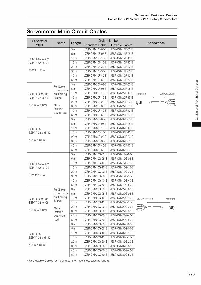
Cables and Peripheral Devices Cables for SGM7A and SGM7J Rotary Servomotors
223
Cab
les a
nd
Perip
hera
l D
evic
es
Servomotor Main Circuit Cables
Servomotor Model
Name LengthOrder Number
AppearanceStandard Cable Flexible Cable*
SGM7J-A5 to -C2
SGM7A-A5 to -C2
50 W to 150 W
For Servo-
motors with-
out Holding
Brakes
Cable
installed
toward load
3 m JZSP-C7M10F-03-E JZSP-C7M12F-03-E
5 m JZSP-C7M10F-05-E JZSP-C7M12F-05-E
10 m JZSP-C7M10F-10-E JZSP-C7M12F-10-E
15 m JZSP-C7M10F-15-E JZSP-C7M12F-15-E
20 m JZSP-C7M10F-20-E JZSP-C7M12F-20-E
30 m JZSP-C7M10F-30-E JZSP-C7M12F-30-E
40 m JZSP-C7M10F-40-E JZSP-C7M12F-40-E
50 m JZSP-C7M10F-50-E JZSP-C7M12F-50-E
SGM7J-02 to -06
SGM7A-02 to -06
200 W to 600 W
3 m JZSP-C7M20F-03-E JZSP-C7M22F-03-E
5 m JZSP-C7M20F-05-E JZSP-C7M22F-05-E
10 m JZSP-C7M20F-10-E JZSP-C7M22F-10-E
15 m JZSP-C7M20F-15-E JZSP-C7M22F-15-E
20 m JZSP-C7M20F-20-E JZSP-C7M22F-20-E
30 m JZSP-C7M20F-30-E JZSP-C7M22F-30-E
40 m JZSP-C7M20F-40-E JZSP-C7M22F-40-E
50 m JZSP-C7M20F-50-E JZSP-C7M22F-50-E
SGM7J-08
SGM7A-08 and -10
750 W, 1.0 kW
3 m JZSP-C7M30F-03-E JZSP-C7M32F-03-E
5 m JZSP-C7M30F-05-E JZSP-C7M32F-05-E
10 m JZSP-C7M30F-10-E JZSP-C7M32F-10-E
15 m JZSP-C7M30F-15-E JZSP-C7M32F-15-E
20 m JZSP-C7M30F-20-E JZSP-C7M32F-20-E
30 m JZSP-C7M30F-30-E JZSP-C7M32F-30-E
40 m JZSP-C7M30F-40-E JZSP-C7M32F-40-E
50 m JZSP-C7M30F-50-E JZSP-C7M32F-50-E
SGM7J-A5 to -C2
SGM7A-A5 to -C2
50 W to 150 W
For Servo-
motors with-
out Holding
Brakes
Cable
installed
away from
load
3 m JZSP-C7M10G-03-E JZSP-C7M12G-03-E
5 m JZSP-C7M10G-05-E JZSP-C7M12G-05-E
10 m JZSP-C7M10G-10-E JZSP-C7M12G-10-E
15 m JZSP-C7M10G-15-E JZSP-C7M12G-15-E
20 m JZSP-C7M10G-20-E JZSP-C7M12G-20-E
30 m JZSP-C7M10G-30-E JZSP-C7M12G-30-E
40 m JZSP-C7M10G-40-E JZSP-C7M12G-40-E
50 m JZSP-C7M10G-50-E JZSP-C7M12G-50-E
SGM7J-02 to -06
SGM7A-02 to -06
200 W to 600 W
3 m JZSP-C7M20G-03-E JZSP-C7M22G-03-E
5 m JZSP-C7M20G-05-E JZSP-C7M22G-05-E
10 m JZSP-C7M20G-10-E JZSP-C7M22G-10-E
15 m JZSP-C7M20G-15-E JZSP-C7M22G-15-E
20 m JZSP-C7M20G-20-E JZSP-C7M22G-20-E
30 m JZSP-C7M20G-30-E JZSP-C7M22G-30-E
40 m JZSP-C7M20G-40-E JZSP-C7M22G-40-E
50 m JZSP-C7M20G-50-E JZSP-C7M22G-50-E
SGM7J-08
SGM7A-08 and -10
750 W, 1.0 kW
3 m JZSP-C7M30G-03-E JZSP-C7M32G-03-E
5 m JZSP-C7M30G-05-E JZSP-C7M32G-05-E
10 m JZSP-C7M30G-10-E JZSP-C7M32G-10-E
15 m JZSP-C7M30G-15-E JZSP-C7M32G-15-E
20 m JZSP-C7M30G-20-E JZSP-C7M32G-20-E
30 m JZSP-C7M30G-30-E JZSP-C7M32G-30-E
40 m JZSP-C7M30G-40-E JZSP-C7M32G-40-E
50 m JZSP-C7M30G-50-E JZSP-C7M32G-50-E
* Use Flexible Cables for moving parts of machines, such as robots.
Motor end SERVOPACK end
U
V
W
G
L
SERVOPACK end Motor end
U
V
W
G
L

Cables and Peripheral DevicesCables for SGM7A and SGM7J Rotary Servomotors
224
* Use Flexible Cables for moving parts of machines, such as robots.
SGM7J-A5 to -C2
SGM7A-A5 to -C2
50 W to 150 W
For Servo-
motors with
Holding
Brakes
Cable
installed
toward load
3 m JZSP-C7M13F-03-E JZSP-C7M14F-03-E
5 m JZSP-C7M13F-05-E JZSP-C7M14F-05-E
10 m JZSP-C7M13F-10-E JZSP-C7M14F-10-E
15 m JZSP-C7M13F-15-E JZSP-C7M14F-15-E
20 m JZSP-C7M13F-20-E JZSP-C7M14F-20-E
30 m JZSP-C7M13F-30-E JZSP-C7M14F-30-E
40 m JZSP-C7M13F-40-E JZSP-C7M14F-40-E
50 m JZSP-C7M13F-50-E JZSP-C7M14F-50-E
SGM7J-02 to -06
SGM7A-02 to -06
200 W to 600 W
3 m JZSP-C7M23F-03-E JZSP-C7M24F-03-E
5 m JZSP-C7M23F-05-E JZSP-C7M24F-05-E
10 m JZSP-C7M23F-10-E JZSP-C7M24F-10-E
15 m JZSP-C7M23F-15-E JZSP-C7M24F-15-E
20 m JZSP-C7M23F-20-E JZSP-C7M24F-20-E
30 m JZSP-C7M23F-30-E JZSP-C7M24F-30-E
40 m JZSP-C7M23F-40-E JZSP-C7M24F-40-E
50 m JZSP-C7M23F-50-E JZSP-C7M24F-50-E
SGM7J-08
SGM7A-08 and -10
750 W, 1.0 kW
3 m JZSP-C7M33F-03-E JZSP-C7M34F-03-E
5 m JZSP-C7M33F-05-E JZSP-C7M34F-05-E
10 m JZSP-C7M33F-10-E JZSP-C7M34F-10-E
15 m JZSP-C7M33F-15-E JZSP-C7M34F-15-E
20 m JZSP-C7M33F-20-E JZSP-C7M34F-20-E
30 m JZSP-C7M33F-30-E JZSP-C7M34F-30-E
40 m JZSP-C7M33F-40-E JZSP-C7M34F-40-E
50 m JZSP-C7M33F-50-E JZSP-C7M34F-50-E
SGM7J-A5 to -C2
SGM7A-A5 to -C2
50 W to 150 W
For Servo-
motors with
Holding
Brakes
Cable
installed
away from
load
3 m JZSP-C7M13G-03-E JZSP-C7M14G-03-E
5 m JZSP-C7M13G-05-E JZSP-C7M14G-05-E
10 m JZSP-C7M13G-10-E JZSP-C7M14G-10-E
15 m JZSP-C7M13G-15-E JZSP-C7M14G-15-E
20 m JZSP-C7M13G-20-E JZSP-C7M14G-20-E
30 m JZSP-C7M13G-30-E JZSP-C7M14G-30-E
40 m JZSP-C7M13G-40-E JZSP-C7M14G-40-E
50 m JZSP-C7M13G-50-E JZSP-C7M14G-50-E
SGM7J-02 to -06
SGM7A-02 to -06
200 W to 600 W
3 m JZSP-C7M23G-03-E JZSP-C7M24G-03-E
5 m JZSP-C7M23G-05-E JZSP-C7M24G-05-E
10 m JZSP-C7M23G-10-E JZSP-C7M24G-10-E
15 m JZSP-C7M23G-15-E JZSP-C7M24G-15-E
20 m JZSP-C7M23G-20-E JZSP-C7M24G-20-E
30 m JZSP-C7M23G-30-E JZSP-C7M24G-30-E
40 m JZSP-C7M23G-40-E JZSP-C7M24G-40-E
50 m JZSP-C7M23G-50-E JZSP-C7M24G-50-E
SGM7J-08
SGM7A-08 and -10
750 W, 1.0 kW
3 m JZSP-C7M33G-03-E JZSP-C7M34G-03-E
5 m JZSP-C7M33G-05-E JZSP-C7M34G-05-E
10 m JZSP-C7M33G-10-E JZSP-C7M34G-10-E
15 m JZSP-C7M33G-15-E JZSP-C7M34G-15-E
20 m JZSP-C7M33G-20-E JZSP-C7M34G-20-E
30 m JZSP-C7M33G-30-E JZSP-C7M34G-30-E
40 m JZSP-C7M33G-40-E JZSP-C7M34G-40-E
50 m JZSP-C7M33G-50-E JZSP-C7M34G-50-E
Servomotor Model
Name LengthOrder Number
AppearanceStandard Cable Flexible Cable*
Motor end SERVOPACK end
U
V
G
B
B
L
U
V
W
G
B
B
L
SERVOPACK end Motor end
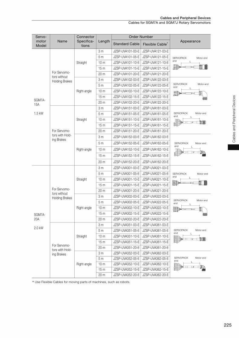
Cables and Peripheral Devices Cables for SGM7A and SGM7J Rotary Servomotors
225
Cab
les a
nd
Perip
hera
l D
evic
es
Servo-motor Model
NameConnector Specifica-
tionsLength
Order Number Appearance
Standard Cable Flexible Cable*
SGM7A-
15A
1.5 kW
For Servomo-
tors without
Holding Brakes
Straight
3 m JZSP-UVA101-03-E JZSP-UVA121-03-E
5 m JZSP-UVA101-05-E JZSP-UVA121-05-E
10 m JZSP-UVA101-10-E JZSP-UVA121-10-E
15 m JZSP-UVA101-15-E JZSP-UVA121-15-E
20 m JZSP-UVA101-20-E JZSP-UVA121-20-E
Right-angle
3 m JZSP-UVA102-03-E JZSP-UVA122-03-E
5 m JZSP-UVA102-05-E JZSP-UVA122-05-E
10 m JZSP-UVA102-10-E JZSP-UVA122-10-E
15 m JZSP-UVA102-15-E JZSP-UVA122-15-E
20 m JZSP-UVA102-20-E JZSP-UVA122-20-E
For Servomo-
tors with Hold-
ing Brakes
Straight
3 m JZSP-UVA151-03-E JZSP-UVA161-03-E
5 m JZSP-UVA151-05-E JZSP-UVA161-05-E
10 m JZSP-UVA151-10-E JZSP-UVA161-10-E
15 m JZSP-UVA151-15-E JZSP-UVA161-15-E
20 m JZSP-UVA151-20-E JZSP-UVA161-20-E
Right-angle
3 m JZSP-UVA152-03-E JZSP-UVA162-03-E
5 m JZSP-UVA152-05-E JZSP-UVA162-05-E
10 m JZSP-UVA152-10-E JZSP-UVA162-10-E
15 m JZSP-UVA152-15-E JZSP-UVA162-15-E
20 m JZSP-UVA152-20-E JZSP-UVA162-20-E
SGM7A-
20A
2.0 kW
For Servomo-
tors without
Holding Brakes
Straight
3 m JZSP-UVA301-03-E JZSP-UVA321-03-E
5 m JZSP-UVA301-05-E JZSP-UVA321-05-E
10 m JZSP-UVA301-10-E JZSP-UVA321-10-E
15 m JZSP-UVA301-15-E JZSP-UVA321-15-E
20 m JZSP-UVA301-20-E JZSP-UVA321-20-E
Right-angle
3 m JZSP-UVA302-03-E JZSP-UVA322-03-E
5 m JZSP-UVA302-05-E JZSP-UVA322-05-E
10 m JZSP-UVA302-10-E JZSP-UVA322-10-E
15 m JZSP-UVA302-15-E JZSP-UVA322-15-E
20 m JZSP-UVA302-20-E JZSP-UVA322-20-E
For Servomo-
tors with Hold-
ing Brakes
Straight
3 m JZSP-UVA351-03-E JZSP-UVA361-03-E
5 m JZSP-UVA351-05-E JZSP-UVA361-05-E
10 m JZSP-UVA351-10-E JZSP-UVA361-10-E
15 m JZSP-UVA351-15-E JZSP-UVA361-15-E
20 m JZSP-UVA351-20-E JZSP-UVA361-20-E
Right-angle
3 m JZSP-UVA352-03-E JZSP-UVA362-03-E
5 m JZSP-UVA352-05-E JZSP-UVA362-05-E
10 m JZSP-UVA352-10-E JZSP-UVA362-10-E
15 m JZSP-UVA352-15-E JZSP-UVA362-15-E
20 m JZSP-UVA352-20-E JZSP-UVA362-20-E
* Use Flexible Cables for moving parts of machines, such as robots.
L
SERVOPACK
end
Motor end
L
SERVOPACK
end
Motor end
L
SERVOPACK
end
Motor end
L
SERVOPACK
end
Motor end
L
SERVOPACK
end
Motor end
L
SERVOPACK
end
Motor end
L
SERVOPACK
end
Motor end
L
SERVOPACK
end
Motor end
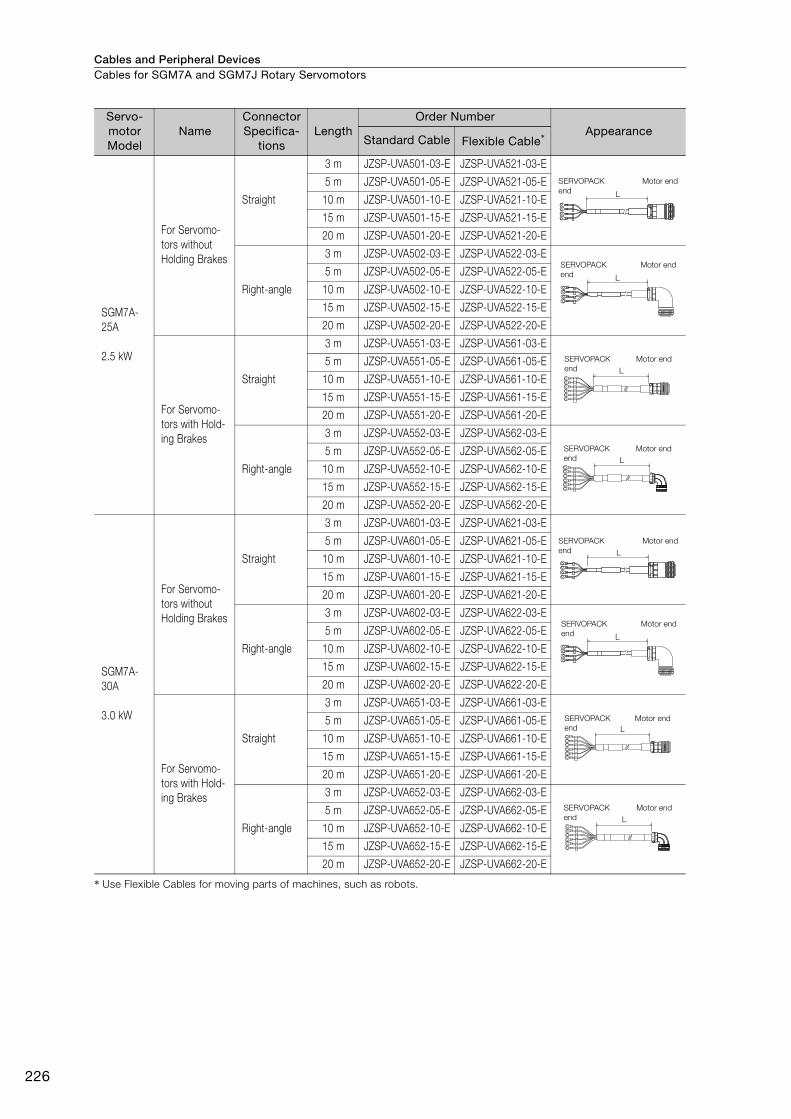
Cables and Peripheral DevicesCables for SGM7A and SGM7J Rotary Servomotors
226
* Use Flexible Cables for moving parts of machines, such as robots.
SGM7A-
25A
2.5 kW
For Servomo-
tors without
Holding Brakes
Straight
3 m JZSP-UVA501-03-E JZSP-UVA521-03-E
5 m JZSP-UVA501-05-E JZSP-UVA521-05-E
10 m JZSP-UVA501-10-E JZSP-UVA521-10-E
15 m JZSP-UVA501-15-E JZSP-UVA521-15-E
20 m JZSP-UVA501-20-E JZSP-UVA521-20-E
Right-angle
3 m JZSP-UVA502-03-E JZSP-UVA522-03-E
5 m JZSP-UVA502-05-E JZSP-UVA522-05-E
10 m JZSP-UVA502-10-E JZSP-UVA522-10-E
15 m JZSP-UVA502-15-E JZSP-UVA522-15-E
20 m JZSP-UVA502-20-E JZSP-UVA522-20-E
For Servomo-
tors with Hold-
ing Brakes
Straight
3 m JZSP-UVA551-03-E JZSP-UVA561-03-E
5 m JZSP-UVA551-05-E JZSP-UVA561-05-E
10 m JZSP-UVA551-10-E JZSP-UVA561-10-E
15 m JZSP-UVA551-15-E JZSP-UVA561-15-E
20 m JZSP-UVA551-20-E JZSP-UVA561-20-E
Right-angle
3 m JZSP-UVA552-03-E JZSP-UVA562-03-E
5 m JZSP-UVA552-05-E JZSP-UVA562-05-E
10 m JZSP-UVA552-10-E JZSP-UVA562-10-E
15 m JZSP-UVA552-15-E JZSP-UVA562-15-E
20 m JZSP-UVA552-20-E JZSP-UVA562-20-E
SGM7A-
30A
3.0 kW
For Servomo-
tors without
Holding Brakes
Straight
3 m JZSP-UVA601-03-E JZSP-UVA621-03-E
5 m JZSP-UVA601-05-E JZSP-UVA621-05-E
10 m JZSP-UVA601-10-E JZSP-UVA621-10-E
15 m JZSP-UVA601-15-E JZSP-UVA621-15-E
20 m JZSP-UVA601-20-E JZSP-UVA621-20-E
Right-angle
3 m JZSP-UVA602-03-E JZSP-UVA622-03-E
5 m JZSP-UVA602-05-E JZSP-UVA622-05-E
10 m JZSP-UVA602-10-E JZSP-UVA622-10-E
15 m JZSP-UVA602-15-E JZSP-UVA622-15-E
20 m JZSP-UVA602-20-E JZSP-UVA622-20-E
For Servomo-
tors with Hold-
ing Brakes
Straight
3 m JZSP-UVA651-03-E JZSP-UVA661-03-E
5 m JZSP-UVA651-05-E JZSP-UVA661-05-E
10 m JZSP-UVA651-10-E JZSP-UVA661-10-E
15 m JZSP-UVA651-15-E JZSP-UVA661-15-E
20 m JZSP-UVA651-20-E JZSP-UVA661-20-E
Right-angle
3 m JZSP-UVA652-03-E JZSP-UVA662-03-E
5 m JZSP-UVA652-05-E JZSP-UVA662-05-E
10 m JZSP-UVA652-10-E JZSP-UVA662-10-E
15 m JZSP-UVA652-15-E JZSP-UVA662-15-E
20 m JZSP-UVA652-20-E JZSP-UVA662-20-E
Servo-motor Model
NameConnector Specifica-
tionsLength
Order Number Appearance
Standard Cable Flexible Cable*
L
SERVOPACK
end
Motor end
L
SERVOPACK
end
Motor end
L
SERVOPACK
end
Motor end
L
SERVOPACK
end
Motor end
L
SERVOPACK
end
Motor end
L
SERVOPACK
end
Motor end
L
SERVOPACK
end
Motor end
L
SERVOPACK
end
Motor end
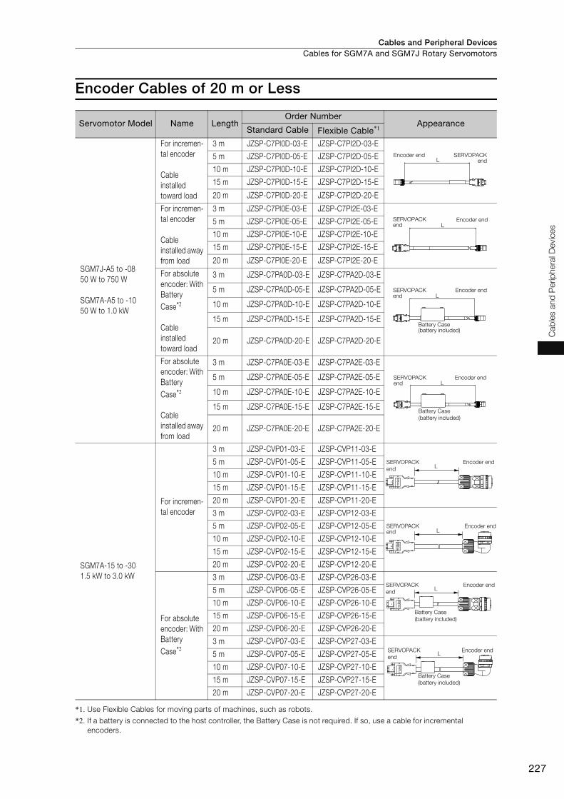
Cables and Peripheral Devices Cables for SGM7A and SGM7J Rotary Servomotors
227
Cab
les a
nd
Perip
hera
l D
evic
es
Encoder Cables of 20 m or Less
*1. Use Flexible Cables for moving parts of machines, such as robots.
*2. If a battery is connected to the host controller, the Battery Case is not required. If so, use a cable for incremental
encoders.
Servomotor Model Name LengthOrder Number
Appearance Standard Cable Flexible Cable*1
SGM7J-A5 to -08
50 W to 750 W
SGM7A-A5 to -10
50 W to 1.0 kW
For incremen-
tal encoder
Cable
installed
toward load
3 m JZSP-C7PI0D-03-E JZSP-C7PI2D-03-E
5 m JZSP-C7PI0D-05-E JZSP-C7PI2D-05-E
10 m JZSP-C7PI0D-10-E JZSP-C7PI2D-10-E
15 m JZSP-C7PI0D-15-E JZSP-C7PI2D-15-E
20 m JZSP-C7PI0D-20-E JZSP-C7PI2D-20-E
For incremen-
tal encoder
Cable
installed away
from load
3 m JZSP-C7PI0E-03-E JZSP-C7PI2E-03-E
5 m JZSP-C7PI0E-05-E JZSP-C7PI2E-05-E
10 m JZSP-C7PI0E-10-E JZSP-C7PI2E-10-E
15 m JZSP-C7PI0E-15-E JZSP-C7PI2E-15-E
20 m JZSP-C7PI0E-20-E JZSP-C7PI2E-20-E
For absolute
encoder: With
Battery
Case*2
Cable
installed
toward load
3 m JZSP-C7PA0D-03-E JZSP-C7PA2D-03-E
5 m JZSP-C7PA0D-05-E JZSP-C7PA2D-05-E
10 m JZSP-C7PA0D-10-E JZSP-C7PA2D-10-E
15 m JZSP-C7PA0D-15-E JZSP-C7PA2D-15-E
20 m JZSP-C7PA0D-20-E JZSP-C7PA2D-20-E
For absolute
encoder: With
Battery
Case*2
Cable
installed away
from load
3 m JZSP-C7PA0E-03-E JZSP-C7PA2E-03-E
5 m JZSP-C7PA0E-05-E JZSP-C7PA2E-05-E
10 m JZSP-C7PA0E-10-E JZSP-C7PA2E-10-E
15 m JZSP-C7PA0E-15-E JZSP-C7PA2E-15-E
20 m JZSP-C7PA0E-20-E JZSP-C7PA2E-20-E
SGM7A-15 to -30
1.5 kW to 3.0 kW
For incremen-
tal encoder
3 m JZSP-CVP01-03-E JZSP-CVP11-03-E
5 m JZSP-CVP01-05-E JZSP-CVP11-05-E
10 m JZSP-CVP01-10-E JZSP-CVP11-10-E
15 m JZSP-CVP01-15-E JZSP-CVP11-15-E
20 m JZSP-CVP01-20-E JZSP-CVP11-20-E
3 m JZSP-CVP02-03-E JZSP-CVP12-03-E
5 m JZSP-CVP02-05-E JZSP-CVP12-05-E
10 m JZSP-CVP02-10-E JZSP-CVP12-10-E
15 m JZSP-CVP02-15-E JZSP-CVP12-15-E
20 m JZSP-CVP02-20-E JZSP-CVP12-20-E
For absolute
encoder: With
Battery
Case*2
3 m JZSP-CVP06-03-E JZSP-CVP26-03-E
5 m JZSP-CVP06-05-E JZSP-CVP26-05-E
10 m JZSP-CVP06-10-E JZSP-CVP26-10-E
15 m JZSP-CVP06-15-E JZSP-CVP26-15-E
20 m JZSP-CVP06-20-E JZSP-CVP26-20-E
3 m JZSP-CVP07-03-E JZSP-CVP27-03-E
5 m JZSP-CVP07-05-E JZSP-CVP27-05-E
10 m JZSP-CVP07-10-E JZSP-CVP27-10-E
15 m JZSP-CVP07-15-E JZSP-CVP27-15-E
20 m JZSP-CVP07-20-E JZSP-CVP27-20-E
Encoder end SERVOPACKendL
SERVOPACK end
Encoder endL
SERVOPACK end
Encoder end
Battery Case (battery included)
L
LSERVOPACK end
Encoder end
Battery Case
(battery included)
L
mole
x
SERVOPACK
end
Encoder end
L
mol
ex
SERVOPACK end
Encoder end
L
mole
x
SERVOPACK
end
Encoder end
Battery Case
(battery included)
L
mole
x
SERVOPACK
end
Encoder end
Battery Case
(battery included)
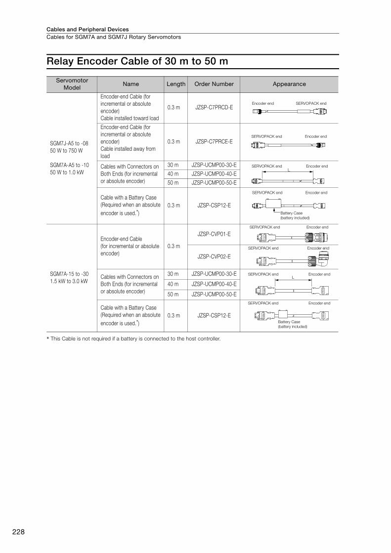
Cables and Peripheral DevicesCables for SGM7A and SGM7J Rotary Servomotors
228
Relay Encoder Cable of 30 m to 50 m
* This Cable is not required if a battery is connected to the host controller.
Servomotor Model
Name Length Order Number Appearance
SGM7J-A5 to -08
50 W to 750 W
SGM7A-A5 to -10
50 W to 1.0 kW
Encoder-end Cable (for
incremental or absolute
encoder)
Cable installed toward load
0.3 m JZSP-C7PRCD-E
Encoder-end Cable (for
incremental or absolute
encoder)
Cable installed away from
load
0.3 m JZSP-C7PRCE-E
Cables with Connectors on
Both Ends (for incremental
or absolute encoder)
30 m JZSP-UCMP00-30-E
40 m JZSP-UCMP00-40-E
50 m JZSP-UCMP00-50-E
Cable with a Battery Case
(Required when an absolute
encoder is used.*)
0.3 m JZSP-CSP12-E
SGM7A-15 to -30
1.5 kW to 3.0 kW
Encoder-end Cable
(for incremental or absolute
encoder)
0.3 m
JZSP-CVP01-E
JZSP-CVP02-E
Cables with Connectors on
Both Ends (for incremental
or absolute encoder)
30 m JZSP-UCMP00-30-E
40 m JZSP-UCMP00-40-E
50 m JZSP-UCMP00-50-E
Cable with a Battery Case
(Required when an absolute
encoder is used.*)
0.3 m JZSP-CSP12-E
Encoder end SERVOPACK end
SERVOPACK end Encoder end
LSERVOPACK end Encoder end
SERVOPACK end Encoder end
Battery Case
(battery included)
mole
x
SERVOPACK end Encoder end
mole
x
SERVOPACK end Encoder end
L
mole
x
molex
SERVOPACK end Encoder end
molex
mole
x
SERVOPACK end Encoder end
Battery Case
(battery included)
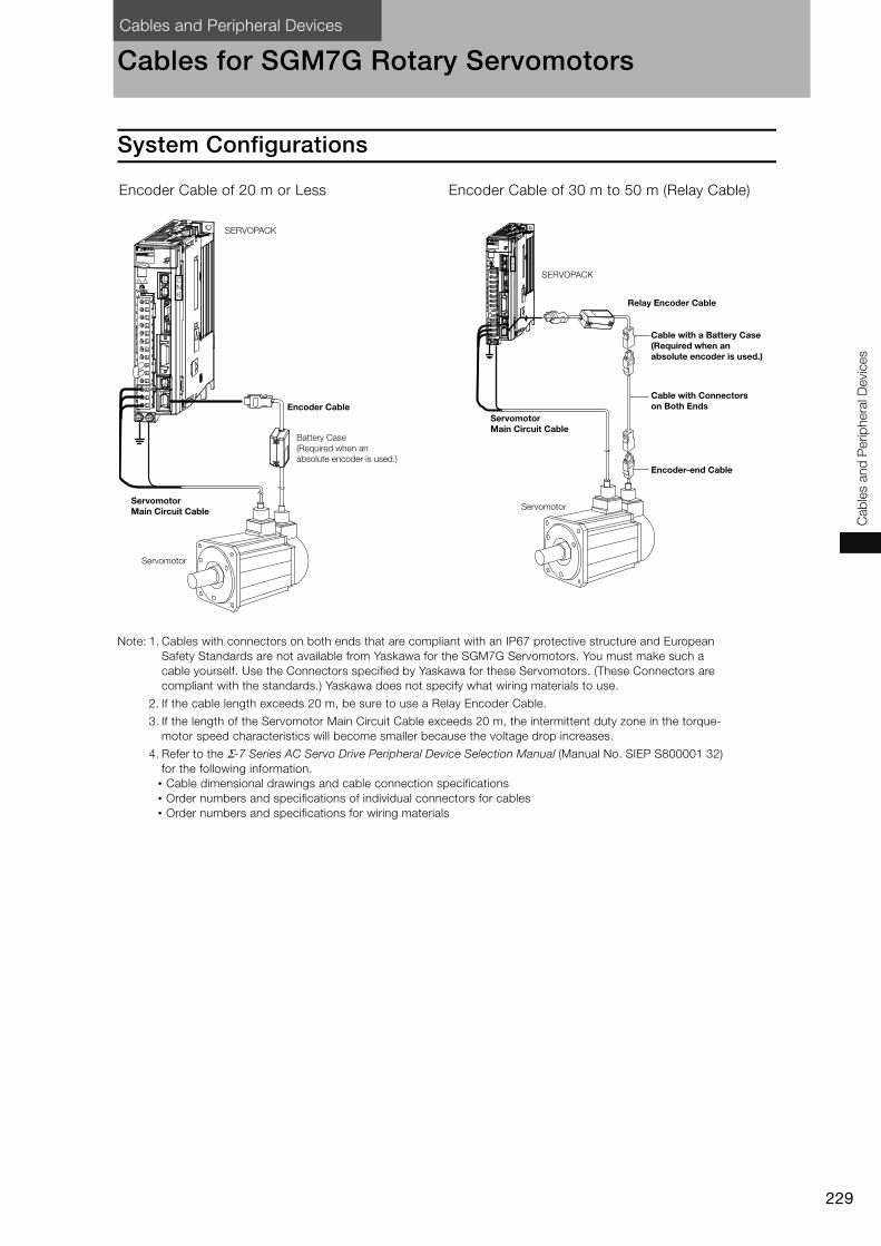
Cables and Peripheral Devices
229
Cab
les a
nd
Perip
hera
l D
evic
es
Cables for SGM7G Rotary Servomotors
System Configurations
Note: 1. Cables with connectors on both ends that are compliant with an IP67 protective structure and European
Safety Standards are not available from Yaskawa for the SGM7G Servomotors. You must make such a
cable yourself. Use the Connectors specified by Yaskawa for these Servomotors. (These Connectors are
compliant with the standards.) Yaskawa does not specify what wiring materials to use.
2. If the cable length exceeds 20 m, be sure to use a Relay Encoder Cable.
3. If the length of the Servomotor Main Circuit Cable exceeds 20 m, the intermittent duty zone in the torque-
motor speed characteristics will become smaller because the voltage drop increases.
4. Refer to the Σ-7 Series AC Servo Drive Peripheral Device Selection Manual (Manual No. SIEP S800001 32)
for the following information.
• Cable dimensional drawings and cable connection specifications
• Order numbers and specifications of individual connectors for cables
• Order numbers and specifications for wiring materials
Encoder Cable of 20 m or Less Encoder Cable of 30 m to 50 m (Relay Cable)
CN6
SERVOPACK
Encoder Cable
Battery Case
(Required when an
absolute encoder is used.)
Servomotor Main Circuit Cable
Servomotor
CN6
SERVOPACK
Relay Encoder Cable
Cable with a Battery Case (Required when an absolute encoder is used.)
Cable with Connectors on Both Ends
Encoder-end Cable
Servomotor Main Circuit Cable
Servomotor
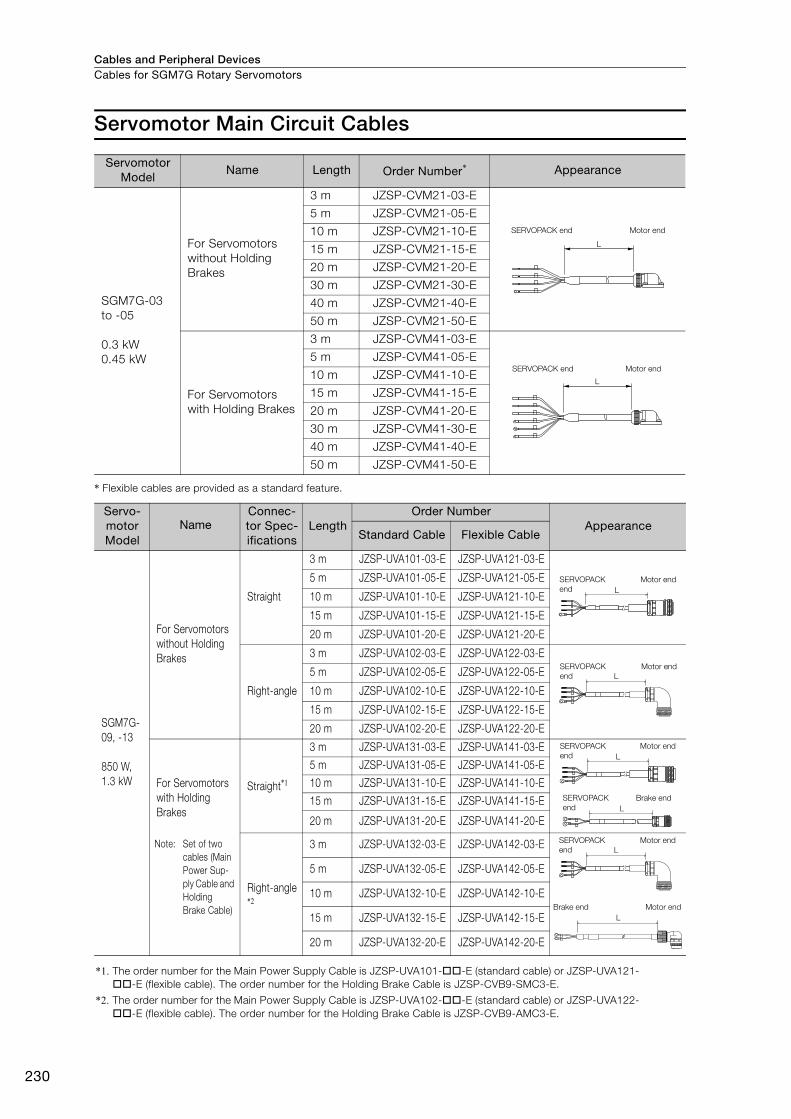
Cables and Peripheral DevicesCables for SGM7G Rotary Servomotors
230
Servomotor Main Circuit Cables
* Flexible cables are provided as a standard feature.
Servomotor Model
Name Length Order Number* Appearance
SGM7G-03
to -05
0.3 kW
0.45 kW
For Servomotors
without Holding
Brakes
3 m JZSP-CVM21-03-E
5 m JZSP-CVM21-05-E
10 m JZSP-CVM21-10-E
15 m JZSP-CVM21-15-E
20 m JZSP-CVM21-20-E
30 m JZSP-CVM21-30-E
40 m JZSP-CVM21-40-E
50 m JZSP-CVM21-50-E
For Servomotors
with Holding Brakes
3 m JZSP-CVM41-03-E
5 m JZSP-CVM41-05-E
10 m JZSP-CVM41-10-E
15 m JZSP-CVM41-15-E
20 m JZSP-CVM41-20-E
30 m JZSP-CVM41-30-E
40 m JZSP-CVM41-40-E
50 m JZSP-CVM41-50-E
Servo-motor Model
Name Connec-tor Spec-ifications
LengthOrder Number
Appearance Standard Cable Flexible Cable
SGM7G-
09, -13
850 W,
1.3 kW
For Servomotors
without Holding
Brakes
Straight
3 m JZSP-UVA101-03-E JZSP-UVA121-03-E
5 m JZSP-UVA101-05-E JZSP-UVA121-05-E
10 m JZSP-UVA101-10-E JZSP-UVA121-10-E
15 m JZSP-UVA101-15-E JZSP-UVA121-15-E
20 m JZSP-UVA101-20-E JZSP-UVA121-20-E
Right-angle
3 m JZSP-UVA102-03-E JZSP-UVA122-03-E
5 m JZSP-UVA102-05-E JZSP-UVA122-05-E
10 m JZSP-UVA102-10-E JZSP-UVA122-10-E
15 m JZSP-UVA102-15-E JZSP-UVA122-15-E
20 m JZSP-UVA102-20-E JZSP-UVA122-20-E
For Servomotors
with Holding
Brakes
Note: Set of two
cables (Main
Power Sup-
ply Cable and
Holding
Brake Cable)
Straight*1
3 m JZSP-UVA131-03-E JZSP-UVA141-03-E
5 m JZSP-UVA131-05-E JZSP-UVA141-05-E
10 m JZSP-UVA131-10-E JZSP-UVA141-10-E
15 m JZSP-UVA131-15-E JZSP-UVA141-15-E
20 m JZSP-UVA131-20-E JZSP-UVA141-20-E
Right-angle *2
3 m JZSP-UVA132-03-E JZSP-UVA142-03-E
5 m JZSP-UVA132-05-E JZSP-UVA142-05-E
10 m JZSP-UVA132-10-E JZSP-UVA142-10-E
15 m JZSP-UVA132-15-E JZSP-UVA142-15-E
20 m JZSP-UVA132-20-E JZSP-UVA142-20-E
*1. The order number for the Main Power Supply Cable is JZSP-UVA101- -E (standard cable) or JZSP-UVA121-
-E (flexible cable). The order number for the Holding Brake Cable is JZSP-CVB9-SMC3-E.
*2. The order number for the Main Power Supply Cable is JZSP-UVA102- -E (standard cable) or JZSP-UVA122-
-E (flexible cable). The order number for the Holding Brake Cable is JZSP-CVB9-AMC3-E.
L
SERVOPACK end Motor end
L
SERVOPACK end Motor end
L
SERVOPACK
end
Motor end
L
SERVOPACK
end
Motor end
L
SERVOPACK
end
Motor end
L
SERVOPACK
end
Brake end
L
SERVOPACK
end
Motor end
L
Brake end Motor end

Cables and Peripheral Devices Cables for SGM7G Rotary Servomotors
231
Cab
les a
nd
Perip
hera
l D
evic
es
Note: If you need a Cable with a length of 20 m to 50 m, consider the operating conditions and specify a suitable
length.
*1. The order number for the Main Power Supply Cable is JZSP-UVA301- -E (standard cable) or JZSP-UVA321-
-E (flexible cable). The order number for the Holding Brake Cable is JZSP-CVB9-SMC3-E.
*2. The order number for the Main Power Supply Cable is JZSP-UVA302- -E (standard cable) or JZSP-UVA322-
-E (flexible cable). The order number for the Holding Brake Cable is JZSP-CVB9-AMC3-E.
SGM7G-
20
1.8 kW
For Servomotors
without Holding
Brakes
Straight
3 m JZSP-UVA301-03-E JZSP-UVA321-03-E
5 m JZSP-UVA301-05-E JZSP-UVA321-05-E
10 m JZSP-UVA301-10-E JZSP-UVA321-10-E
15 m JZSP-UVA301-15-E JZSP-UVA321-15-E
20 m JZSP-UVA301-20-E JZSP-UVA321-20-E
Right-angle
3 m JZSP-UVA302-03-E JZSP-UVA322-03-E
5 m JZSP-UVA302-05-E JZSP-UVA322-05-E
10 m JZSP-UVA302-10-E JZSP-UVA322-10-E
15 m JZSP-UVA302-15-E JZSP-UVA322-15-E
20 m JZSP-UVA302-20-E JZSP-UVA322-20-E
For Servomotors
with Holding
Brakes
Note: Set of two
cables (Main
Power Sup-
ply Cable and
Holding
Brake Cable)
Straight*1
3 m JZSP-UVA331-03-E JZSP-UVA341-03-E
5 m JZSP-UVA331-05-E JZSP-UVA341-05-E
10 m JZSP-UVA331-10-E JZSP-UVA341-10-E
15 m JZSP-UVA331-15-E JZSP-UVA341-15-E
20 m JZSP-UVA331-20-E JZSP-UVA341-20-E
Right-angle *2
3 m JZSP-UVA332-03-E JZSP-UVA342-03-E
5 m JZSP-UVA332-05-E JZSP-UVA342-05-E
10 m JZSP-UVA332-10-E JZSP-UVA342-10-E
15 m JZSP-UVA332-15-E JZSP-UVA342-15-E
20 m JZSP-UVA332-20-E JZSP-UVA342-20-E
Servo-motor Model
Name Connec-tor Spec-ifications
LengthOrder Number
Appearance Standard Cable Flexible Cable
L
SERVOPACK
end
Motor end
L
SERVOPACK
end
Motor end
L
SERVOPACK
end
Motor end
L
SERVOPACK
end
Brake end
L
SERVOPACK
end
Motor end
L
Brake end Motor end
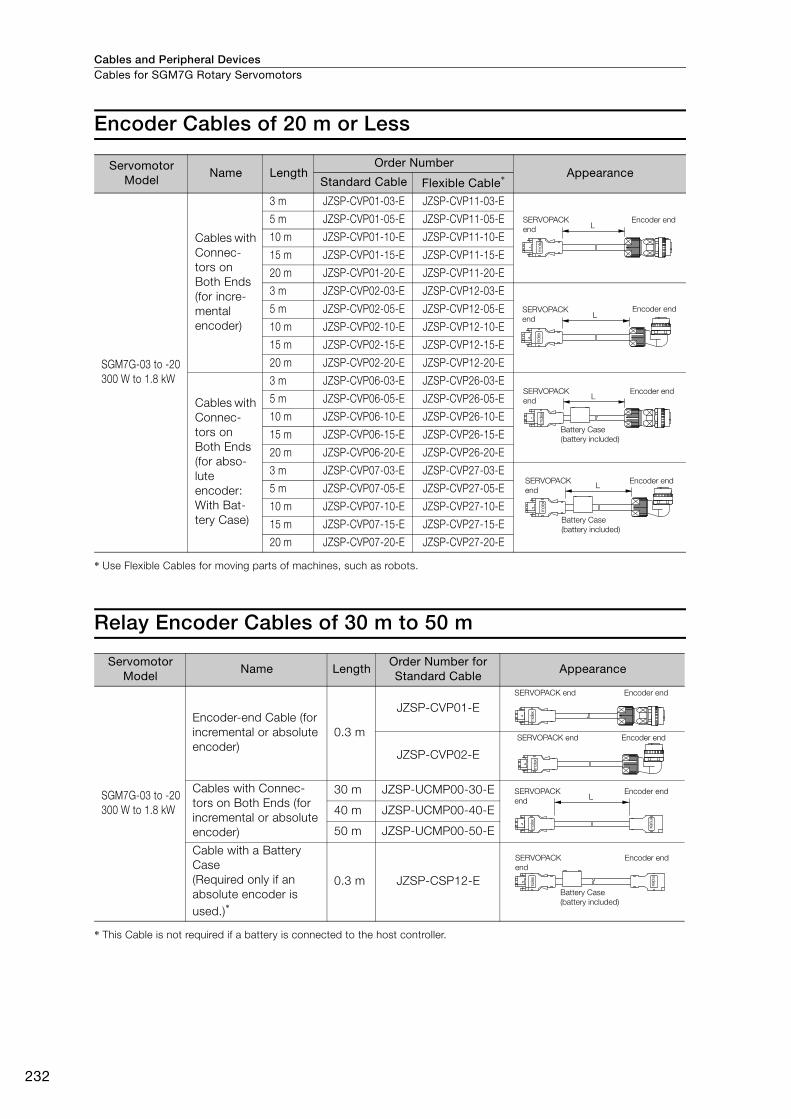
Cables and Peripheral DevicesCables for SGM7G Rotary Servomotors
232
Encoder Cables of 20 m or Less
* Use Flexible Cables for moving parts of machines, such as robots.
Relay Encoder Cables of 30 m to 50 m
* This Cable is not required if a battery is connected to the host controller.
Servomotor Model
Name LengthOrder Number
AppearanceStandard Cable Flexible Cable*
SGM7G-03 to -20
300 W to 1.8 kW
Cables with
Connec-
tors on
Both Ends
(for incre-
mental
encoder)
3 m JZSP-CVP01-03-E JZSP-CVP11-03-E
5 m JZSP-CVP01-05-E JZSP-CVP11-05-E
10 m JZSP-CVP01-10-E JZSP-CVP11-10-E
15 m JZSP-CVP01-15-E JZSP-CVP11-15-E
20 m JZSP-CVP01-20-E JZSP-CVP11-20-E
3 m JZSP-CVP02-03-E JZSP-CVP12-03-E
5 m JZSP-CVP02-05-E JZSP-CVP12-05-E
10 m JZSP-CVP02-10-E JZSP-CVP12-10-E
15 m JZSP-CVP02-15-E JZSP-CVP12-15-E
20 m JZSP-CVP02-20-E JZSP-CVP12-20-E
Cables with
Connec-
tors on
Both Ends
(for abso-
lute
encoder:
With Bat-
tery Case)
3 m JZSP-CVP06-03-E JZSP-CVP26-03-E
5 m JZSP-CVP06-05-E JZSP-CVP26-05-E
10 m JZSP-CVP06-10-E JZSP-CVP26-10-E
15 m JZSP-CVP06-15-E JZSP-CVP26-15-E
20 m JZSP-CVP06-20-E JZSP-CVP26-20-E
3 m JZSP-CVP07-03-E JZSP-CVP27-03-E
5 m JZSP-CVP07-05-E JZSP-CVP27-05-E
10 m JZSP-CVP07-10-E JZSP-CVP27-10-E
15 m JZSP-CVP07-15-E JZSP-CVP27-15-E
20 m JZSP-CVP07-20-E JZSP-CVP27-20-E
Servomotor Model
Name LengthOrder Number for Standard Cable
Appearance
SGM7G-03 to -20
300 W to 1.8 kW
Encoder-end Cable (for
incremental or absolute
encoder)
0.3 m
JZSP-CVP01-E
JZSP-CVP02-E
Cables with Connec-
tors on Both Ends (for
incremental or absolute
encoder)
30 m JZSP-UCMP00-30-E
40 m JZSP-UCMP00-40-E
50 m JZSP-UCMP00-50-E
Cable with a Battery
Case
(Required only if an
absolute encoder is
used.)*
0.3 m JZSP-CSP12-E
L
mole
x
SERVOPACK
end
Encoder end
SERVOPACK
endL
mole
x
Encoder end
L
mole
x
SERVOPACK
end
Encoder end
Battery Case
(battery included)
L
mole
x
SERVOPACK
end
Encoder end
Battery Case
(battery included)m
ole
x
SERVOPACK end Encoder end
mole
x
SERVOPACK end Encoder end
L
mole
x
molex
SERVOPACK
end
Encoder end
molex
mole
x
SERVOPACK
end
Encoder end
Battery Case
(battery included)
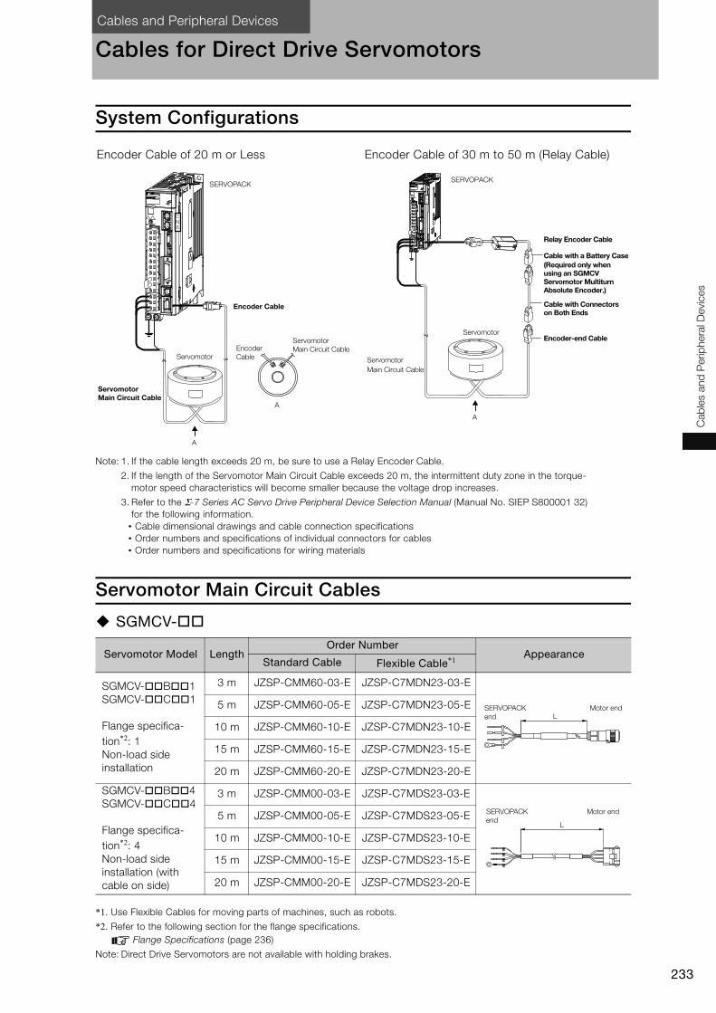
Cables and Peripheral Devices
233
Cab
les a
nd
Perip
hera
l D
evic
es
Cables for Direct Drive Servomotors
System Configurations
Note: 1. If the cable length exceeds 20 m, be sure to use a Relay Encoder Cable.
2. If the length of the Servomotor Main Circuit Cable exceeds 20 m, the intermittent duty zone in the torque-
motor speed characteristics will become smaller because the voltage drop increases.
3. Refer to the Σ-7 Series AC Servo Drive Peripheral Device Selection Manual (Manual No. SIEP S800001 32)
for the following information.
• Cable dimensional drawings and cable connection specifications
• Order numbers and specifications of individual connectors for cables
• Order numbers and specifications for wiring materials
Servomotor Main Circuit Cables
SGMCV-
*1. Use Flexible Cables for moving parts of machines, such as robots.
*2. Refer to the following section for the flange specifications.
Flange Specifications (page 236)
Note: Direct Drive Servomotors are not available with holding brakes.
Encoder Cable of 20 m or Less Encoder Cable of 30 m to 50 m (Relay Cable)
Servomotor Model LengthOrder Number
AppearanceStandard Cable Flexible Cable*1
SGMCV- B 1
SGMCV- C 1
Flange specifica-
tion*2: 1
Non-load side
installation
3 m JZSP-CMM60-03-E JZSP-C7MDN23-03-E
5 m JZSP-CMM60-05-E JZSP-C7MDN23-05-E
10 m JZSP-CMM60-10-E JZSP-C7MDN23-10-E
15 m JZSP-CMM60-15-E JZSP-C7MDN23-15-E
20 m JZSP-CMM60-20-E JZSP-C7MDN23-20-E
SGMCV- B 4
SGMCV- C 4
Flange specifica-
tion*2: 4
Non-load side
installation (with
cable on side)
3 m JZSP-CMM00-03-E JZSP-C7MDS23-03-E
5 m JZSP-CMM00-05-E JZSP-C7MDS23-05-E
10 m JZSP-CMM00-10-E JZSP-C7MDS23-10-E
15 m JZSP-CMM00-15-E JZSP-C7MDS23-15-E
20 m JZSP-CMM00-20-E JZSP-C7MDS23-20-E
A
A
CN6
SERVOPACK
Encoder Cable
Encoder
CableServomotor
Servomotor Main Circuit Cable
Servomotor
Main Circuit Cable
A
CN6
SERVOPACK
Relay Encoder Cable
Cable with a Battery Case(Required only when using an SGMCV Servomotor Multiturn Absolute Encoder.)
Cable with Connectors on Both Ends
Encoder-end CableServomotor
Servomotor
Main Circuit Cable
L
SERVOPACK
end
Motor end
L
SERVOPACK
end
Motor end
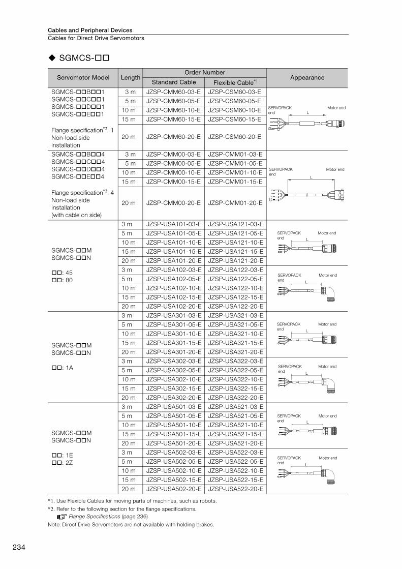
Cables and Peripheral DevicesCables for Direct Drive Servomotors
234
SGMCS-
*1. Use Flexible Cables for moving parts of machines, such as robots.
*2. Refer to the following section for the flange specifications.
Flange Specifications (page 236)
Note: Direct Drive Servomotors are not available with holding brakes.
Servomotor Model LengthOrder Number
AppearanceStandard Cable Flexible Cable*1
SGMCS- B 1
SGMCS- C 1
SGMCS- D 1
SGMCS- E 1
Flange specification*2: 1
Non-load side
installation
3 m JZSP-CMM60-03-E JZSP-CSM60-03-E
5 m JZSP-CMM60-05-E JZSP-CSM60-05-E
10 m JZSP-CMM60-10-E JZSP-CSM60-10-E
15 m JZSP-CMM60-15-E JZSP-CSM60-15-E
20 m JZSP-CMM60-20-E JZSP-CSM60-20-E
SGMCS- B 4
SGMCS- C 4
SGMCS- D 4
SGMCS- E 4
Flange specification*2: 4
Non-load side
installation
(with cable on side)
3 m JZSP-CMM00-03-E JZSP-CMM01-03-E
5 m JZSP-CMM00-05-E JZSP-CMM01-05-E
10 m JZSP-CMM00-10-E JZSP-CMM01-10-E
15 m JZSP-CMM00-15-E JZSP-CMM01-15-E
20 m JZSP-CMM00-20-E JZSP-CMM01-20-E
SGMCS- M
SGMCS- N
: 45
: 80
3 m JZSP-USA101-03-E JZSP-USA121-03-E
5 m JZSP-USA101-05-E JZSP-USA121-05-E
10 m JZSP-USA101-10-E JZSP-USA121-10-E
15 m JZSP-USA101-15-E JZSP-USA121-15-E
20 m JZSP-USA101-20-E JZSP-USA121-20-E
3 m JZSP-USA102-03-E JZSP-USA122-03-E
5 m JZSP-USA102-05-E JZSP-USA122-05-E
10 m JZSP-USA102-10-E JZSP-USA122-10-E
15 m JZSP-USA102-15-E JZSP-USA122-15-E
20 m JZSP-USA102-20-E JZSP-USA122-20-E
SGMCS- M
SGMCS- N
: 1A
3 m JZSP-USA301-03-E JZSP-USA321-03-E
5 m JZSP-USA301-05-E JZSP-USA321-05-E
10 m JZSP-USA301-10-E JZSP-USA321-10-E
15 m JZSP-USA301-15-E JZSP-USA321-15-E
20 m JZSP-USA301-20-E JZSP-USA321-20-E
3 m JZSP-USA302-03-E JZSP-USA322-03-E
5 m JZSP-USA302-05-E JZSP-USA322-05-E
10 m JZSP-USA302-10-E JZSP-USA322-10-E
15 m JZSP-USA302-15-E JZSP-USA322-15-E
20 m JZSP-USA302-20-E JZSP-USA322-20-E
SGMCS- M
SGMCS- N
: 1E
: 2Z
3 m JZSP-USA501-03-E JZSP-USA521-03-E
5 m JZSP-USA501-05-E JZSP-USA521-05-E
10 m JZSP-USA501-10-E JZSP-USA521-10-E
15 m JZSP-USA501-15-E JZSP-USA521-15-E
20 m JZSP-USA501-20-E JZSP-USA521-20-E
3 m JZSP-USA502-03-E JZSP-USA522-03-E
5 m JZSP-USA502-05-E JZSP-USA522-05-E
10 m JZSP-USA502-10-E JZSP-USA522-10-E
15 m JZSP-USA502-15-E JZSP-USA522-15-E
20 m JZSP-USA502-20-E JZSP-USA522-20-E
L
SERVOPACK
end
Motor end
L
SERVOPACK
end
Motor end
L
SERVOPACK
end
Motor end
L
SERVOPACK
end
Motor end
L
SERVOPACK
end
Motor end
L
SERVOPACK
end
Motor end
L
SERVOPACK
end
Motor end
L
SERVOPACK
end
Motor end
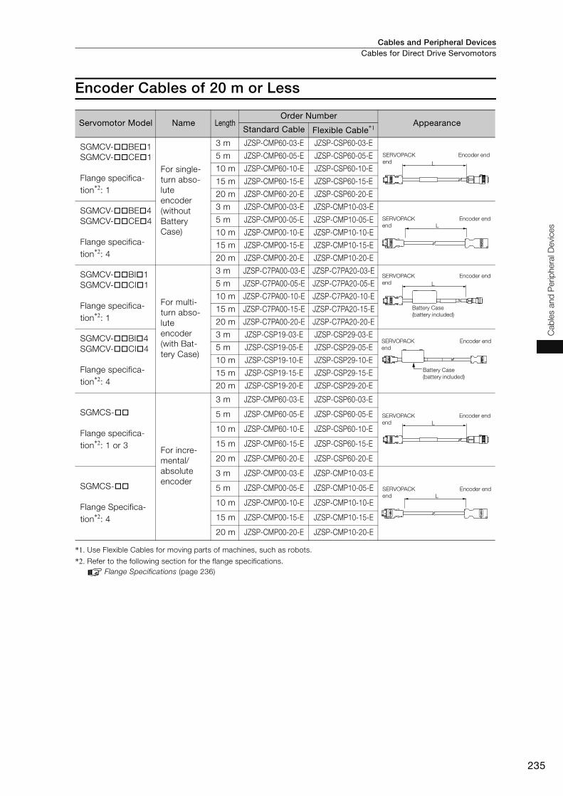
Cables and Peripheral Devices Cables for Direct Drive Servomotors
235
Cab
les a
nd
Perip
hera
l D
evic
es
Encoder Cables of 20 m or Less
*1. Use Flexible Cables for moving parts of machines, such as robots.
*2. Refer to the following section for the flange specifications.
Flange Specifications (page 236)
Servomotor Model Name LengthOrder Number
AppearanceStandard Cable Flexible Cable*1
SGMCV- BE 1
SGMCV- CE 1
Flange specifica-
tion*2: 1
For single-
turn abso-
lute
encoder
(without
Battery
Case)
3 m JZSP-CMP60-03-E JZSP-CSP60-03-E
5 m JZSP-CMP60-05-E JZSP-CSP60-05-E
10 m JZSP-CMP60-10-E JZSP-CSP60-10-E
15 m JZSP-CMP60-15-E JZSP-CSP60-15-E
20 m JZSP-CMP60-20-E JZSP-CSP60-20-E
SGMCV- BE 4
SGMCV- CE 4
Flange specifica-
tion*2: 4
3 m JZSP-CMP00-03-E JZSP-CMP10-03-E
5 m JZSP-CMP00-05-E JZSP-CMP10-05-E
10 m JZSP-CMP00-10-E JZSP-CMP10-10-E
15 m JZSP-CMP00-15-E JZSP-CMP10-15-E
20 m JZSP-CMP00-20-E JZSP-CMP10-20-E
SGMCV- BI 1
SGMCV- CI 1
Flange specifica-
tion*2: 1
For multi-
turn abso-
lute
encoder
(with Bat-
tery Case)
3 m JZSP-C7PA00-03-E JZSP-C7PA20-03-E
5 m JZSP-C7PA00-05-E JZSP-C7PA20-05-E
10 m JZSP-C7PA00-10-E JZSP-C7PA20-10-E
15 m JZSP-C7PA00-15-E JZSP-C7PA20-15-E
20 m JZSP-C7PA00-20-E JZSP-C7PA20-20-E
SGMCV- BI 4
SGMCV- CI 4
Flange specifica-
tion*2: 4
3 m JZSP-CSP19-03-E JZSP-CSP29-03-E
5 m JZSP-CSP19-05-E JZSP-CSP29-05-E
10 m JZSP-CSP19-10-E JZSP-CSP29-10-E
15 m JZSP-CSP19-15-E JZSP-CSP29-15-E
20 m JZSP-CSP19-20-E JZSP-CSP29-20-E
SGMCS-
Flange specifica-
tion*2: 1 or 3 For incre-
mental/
absolute
encoder
3 m JZSP-CMP60-03-E JZSP-CSP60-03-E
5 m JZSP-CMP60-05-E JZSP-CSP60-05-E
10 m JZSP-CMP60-10-E JZSP-CSP60-10-E
15 m JZSP-CMP60-15-E JZSP-CSP60-15-E
20 m JZSP-CMP60-20-E JZSP-CSP60-20-E
SGMCS-
Flange Specifica-
tion*2: 4
3 m JZSP-CMP00-03-E JZSP-CMP10-03-E
5 m JZSP-CMP00-05-E JZSP-CMP10-05-E
10 m JZSP-CMP00-10-E JZSP-CMP10-10-E
15 m JZSP-CMP00-15-E JZSP-CMP10-15-E
20 m JZSP-CMP00-20-E JZSP-CMP10-20-E
L
SERVOPACK
end
Encoder end
L
SERVOPACK
end
Encoder end
L
SERVOPACK
end
Encoder end
Battery Case
(battery included)
SERVOPACK
end
Encoder end
Battery Case
(battery included)
L
SERVOPACK
end
Encoder end
L
SERVOPACK
end
Encoder end
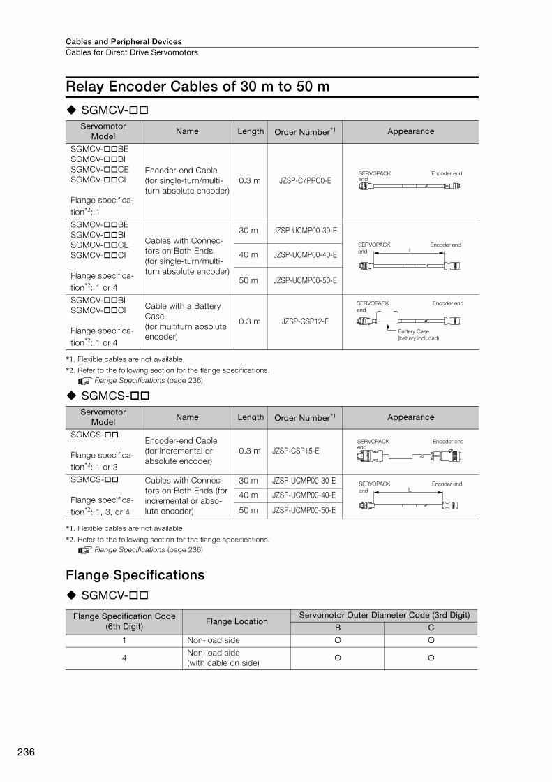
Cables and Peripheral DevicesCables for Direct Drive Servomotors
236
Relay Encoder Cables of 30 m to 50 m
SGMCV-
*1. Flexible cables are not available.
*2. Refer to the following section for the flange specifications.
Flange Specifications (page 236)
SGMCS-
*1. Flexible cables are not available.
*2. Refer to the following section for the flange specifications.
Flange Specifications (page 236)
Flange SpecificationsSGMCV-
Servomotor Model
Name Length Order Number*1 Appearance
SGMCV- BE
SGMCV- BI
SGMCV- CE
SGMCV- CI
Flange specifica-
tion*2: 1
Encoder-end Cable
(for single-turn/multi-
turn absolute encoder)
0.3 m JZSP-C7PRC0-E
SGMCV- BE
SGMCV- BI
SGMCV- CE
SGMCV- CI
Flange specifica-
tion*2: 1 or 4
Cables with Connec-
tors on Both Ends
(for single-turn/multi-
turn absolute encoder)
30 m JZSP-UCMP00-30-E
40 m JZSP-UCMP00-40-E
50 m JZSP-UCMP00-50-E
SGMCV- BI
SGMCV- CI
Flange specifica-
tion*2: 1 or 4
Cable with a Battery
Case
(for multiturn absolute
encoder)
0.3 m JZSP-CSP12-E
Servomotor Model
Name Length Order Number*1 Appearance
SGMCS-
Flange specifica-
tion*2: 1 or 3
Encoder-end Cable
(for incremental or
absolute encoder)
0.3 m JZSP-CSP15-E
SGMCS-
Flange specifica-
tion*2: 1, 3, or 4
Cables with Connec-
tors on Both Ends (for
incremental or abso-
lute encoder)
30 m JZSP-UCMP00-30-E
40 m JZSP-UCMP00-40-E
50 m JZSP-UCMP00-50-E
Flange Specification Code (6th Digit)
Flange LocationServomotor Outer Diameter Code (3rd Digit)
B C
1 Non-load side
4Non-load side
(with cable on side)
SERVOPACK end
Encoder end
LSERVOPACK
end
Encoder end
SERVOPACK
end
Encoder end
Battery Case
(battery included)
SERVOPACK end
Encoder end
LSERVOPACK
end
Encoder end
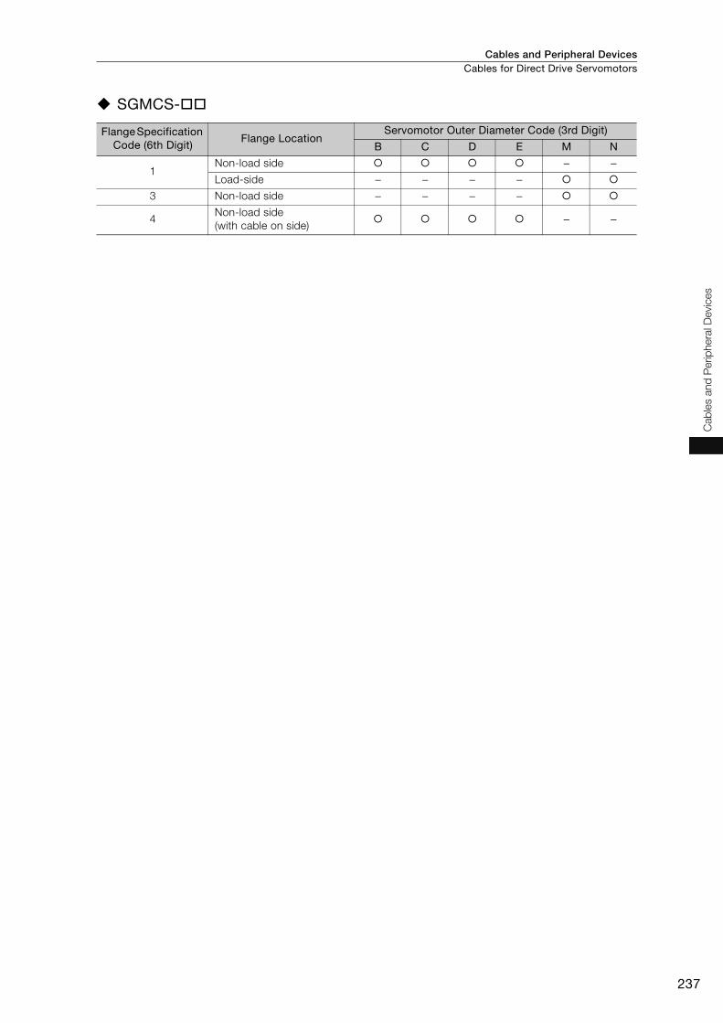
Cables and Peripheral Devices Cables for Direct Drive Servomotors
237
Cab
les a
nd
Perip
hera
l D
evic
es
SGMCS-
Flange Specification Code (6th Digit)
Flange LocationServomotor Outer Diameter Code (3rd Digit)
B C D E M N
1Non-load side − −Load-side − − − −
3 Non-load side − − − −
4Non-load side
(with cable on side)− −
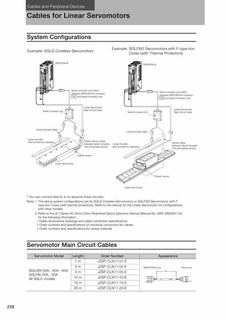
Cables and Peripheral Devices
238
Cables for Linear Servomotors
System Configurations
* You can connect directly to an absolute linear encoder.
Note: 1. The above system configurations are for SGLG Coreless Servomotors or SGLFW2 Servomotors with F-
type Iron Cores (with thermal protectors). Refer to the manual for the Linear Servomotor for configurations
with other models.
2. Refer to the Σ-7 Series AC Servo Drive Peripheral Device Selection Manual (Manual No. SIEP S800001 32)
for the following information.
• Cable dimensional drawings and cable connection specifications
• Order numbers and specifications of individual connectors for cables
• Order numbers and specifications for wiring materials
Servomotor Main Circuit Cables
Example: SGLG Coreless ServomotorsExample: SGLFW2 Servomotors with F-type Iron
Cores (with Thermal Protectors)
Servomotor Model Length Order Number Appearance
SGLGW-30A, -40A, -60A
SGLFW-20A, -35A
All SGLC models
1 m JZSP-CLN11-01-E
3 m JZSP-CLN11-03-E
5 m JZSP-CLN11-05-E
10 m JZSP-CLN11-10-E
15 m JZSP-CLN11-15-E
20 m JZSP-CLN11-20-E
CN6
SERVOPACK
Serial Converter Unit Cable*
(between SERVOPACK connector
CN2 and Serial Converter Unit)
Linear Servomotor
Main Circuit Cable
Polarity Sensor Cable
(between Serial Converter
Unit and polarity sensor)
Polarity sensor
Serial Converter Unit
Linear Encoder Cable
Linear encoder
(Not provided by Yaskawa.)
Linear Servomotor
CN6
SERVOPACK
Serial Converter Unit Cable*
(between SERVOPACK connector
CN2 and Serial Converter Unit)
Linear Servomotor
Main Circuit Cable
Sensor Cable
(between Serial Converter
Unit and polarity sensor)
Serial Converter Unit
Linear Encoder Cable
Linear Encoder
(Not provided by Yaskawa.)
Polarity sensor
Linear Servomotor
L
*1
SERVOPACK end Motor end
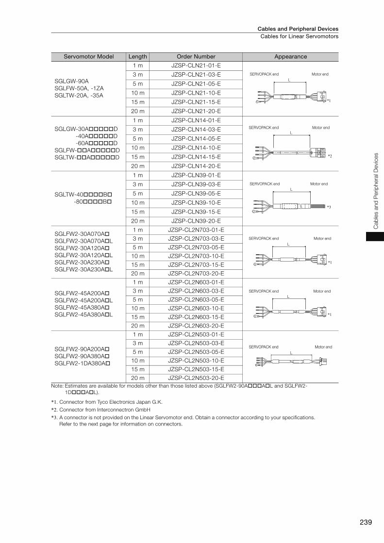
Cables and Peripheral Devices Cables for Linear Servomotors
239
Cab
les a
nd
Perip
hera
l D
evic
es
Note: Estimates are available for models other than those listed above (SGLFW2-90A A L and SGLFW2-
1D A L).
*1. Connector from Tyco Electronics Japan G.K.
*2. Connector from Interconnectron GmbH
*3. A connector is not provided on the Linear Servomotor end. Obtain a connector according to your specifications.
Refer to the next page for information on connectors.
SGLGW-90A
SGLFW-50A, -1ZA
SGLTW-20A, -35A
1 m JZSP-CLN21-01-E
3 m JZSP-CLN21-03-E
5 m JZSP-CLN21-05-E
10 m JZSP-CLN21-10-E
15 m JZSP-CLN21-15-E
20 m JZSP-CLN21-20-E
SGLGW-30A D
-40A D
-60A D
SGLFW- A D
SGLTW- A D
1 m JZSP-CLN14-01-E
3 m JZSP-CLN14-03-E
5 m JZSP-CLN14-05-E
10 m JZSP-CLN14-10-E
15 m JZSP-CLN14-15-E
20 m JZSP-CLN14-20-E
SGLTW-40 B
-80 B
1 m JZSP-CLN39-01-E
3 m JZSP-CLN39-03-E
5 m JZSP-CLN39-05-E
10 m JZSP-CLN39-10-E
15 m JZSP-CLN39-15-E
20 m JZSP-CLN39-20-E
SGLFW2-30A070A
SGLFW2-30A070A L
SGLFW2-30A120A
SGLFW2-30A120A L
SGLFW2-30A230A
SGLFW2-30A230A L
1 m JZSP-CL2N703-01-E
3 m JZSP-CL2N703-03-E
5 m JZSP-CL2N703-05-E
10 m JZSP-CL2N703-10-E
15 m JZSP-CL2N703-15-E
20 m JZSP-CL2N703-20-E
SGLFW2-45A200A
SGLFW2-45A200A L
SGLFW2-45A380A
SGLFW2-45A380A L
1 m JZSP-CL2N603-01-E
3 m JZSP-CL2N603-03-E
5 m JZSP-CL2N603-05-E
10 m JZSP-CL2N603-10-E
15 m JZSP-CL2N603-15-E
20 m JZSP-CL2N603-20-E
SGLFW2-90A200A
SGLFW2-90A380A
SGLFW2-1DA380A
1 m JZSP-CL2N503-01-E
3 m JZSP-CL2N503-03-E
5 m JZSP-CL2N503-05-E
10 m JZSP-CL2N503-10-E
15 m JZSP-CL2N503-15-E
20 m JZSP-CL2N503-20-E
Servomotor Model Length Order Number Appearance
L
*1
SERVOPACK end Motor end
L
*2
SERVOPACK end Motor end
L
*3
SERVOPACK end Motor end
L
*1
SERVOPACK end Motor end
L
*1
SERVOPACK end Motor end
L
SERVOPACK end Motor end
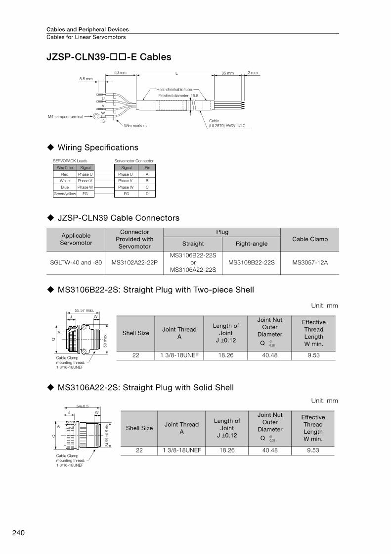
Cables and Peripheral DevicesCables for Linear Servomotors
240
JZSP-CLN39- -E Cables
Wiring Specifications
JZSP-CLN39 Cable Connectors
MS3106B22-2S: Straight Plug with Two-piece Shell
MS3106A22-2S: Straight Plug with Solid Shell
Applicable Servomotor
Connector Provided with Servomotor
PlugCable Clamp
Straight Right-angle
SGLTW-40 and -80 MS3102A22-22P
MS3106B22-22S
or
MS3106A22-22S
MS3108B22-22S MS3057-12A
Unit: mm
Unit: mm
L 35 mm 2 mm
8.5 mm
U
V
W
G
50 mm
M4 crimped terminal
Wire markers
Heat-shrinkable tube
Finished diameter: 15.8
Cable
(UL2570) AWG11/4C
A
B
C
DFGFG
SERVOPACK Leads
Wire Color
Red
White
Blue
Green/yellow
Signal Signal
Phase U
Phase V
Phase W
Pin
Phase U
Phase V
Phase W
Servomotor Connector
J W
A
Q
55.57 max.
Cable Clamp
mounting thread:
1 3/16-18UNEF
50
max. Shell Size
Joint ThreadA
Length of Joint
J ±0.12
Joint NutOuter
Diameter
Q
Effective Thread LengthW min.
22 1 3/8-18UNEF 18.26 40.48 9.53
+0
-0.38
A
54±0.5
J
Q
W
Cable Clamp
mounting thread:
1 3/16-18UNEF
34.9
9 ±
0.5
dia
.
Shell SizeJoint Thread
A
Length of Joint
J ±0.12
Joint Nut Outer
Diameter
Q
Effective Thread Length W min.
22 1 3/8-18UNEF 18.26 40.48 9.53
+0
-0.38
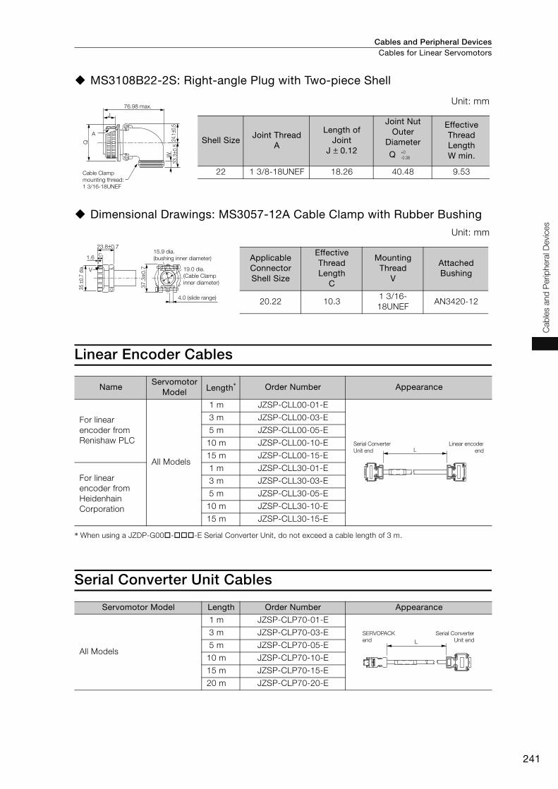
Cables and Peripheral Devices Cables for Linear Servomotors
241
Cab
les a
nd
Perip
hera
l D
evic
es
MS3108B22-2S: Right-angle Plug with Two-piece Shell
Dimensional Drawings: MS3057-12A Cable Clamp with Rubber Bushing
Linear Encoder Cables
* When using a JZDP-G00 - -E Serial Converter Unit, do not exceed a cable length of 3 m.
Serial Converter Unit Cables
Unit: mm
Unit: mm
NameServomotor
Model Length* Order Number Appearance
For linear
encoder from
Renishaw PLC
All Models
1 m JZSP-CLL00-01-E
3 m JZSP-CLL00-03-E
5 m JZSP-CLL00-05-E
10 m JZSP-CLL00-10-E
15 m JZSP-CLL00-15-E
For linear
encoder from
Heidenhain
Corporation
1 m JZSP-CLL30-01-E
3 m JZSP-CLL30-03-E
5 m JZSP-CLL30-05-E
10 m JZSP-CLL30-10-E
15 m JZSP-CLL30-15-E
Servomotor Model Length Order Number Appearance
All Models
1 m JZSP-CLP70-01-E
3 m JZSP-CLP70-03-E
5 m JZSP-CLP70-05-E
10 m JZSP-CLP70-10-E
15 m JZSP-CLP70-15-E
20 m JZSP-CLP70-20-E
24.1
±0.5
W
J
A
Q
33.3
±0.5
76.98 max.
Cable Clamp
mounting thread:
1 3/16-18UNEF
Shell SizeJoint Thread
A
Length of Joint
J ± 0.12
Joint Nut Outer
Diameter
Q
Effective Thread LengthW min.
22 1 3/8-18UNEF 18.26 40.48 9.53
+0
-0.38
37
.3±0
.7
23.8±0.7
V
1.6C
35 ±
0.7
dia
.
15.9 dia.
(bushing inner diameter)
19.0 dia.
(Cable Clamp
inner diameter)
4.0 (slide range)
Applicable Connector Shell Size
Effective Thread Length
C
Mounting Thread
V
Attached Bushing
20.22 10.31 3/16-
18UNEFAN3420-12
LSerial Converter
Unit end
Linear encoder
end
L
SERVOPACK
end
Serial Converter
Unit end
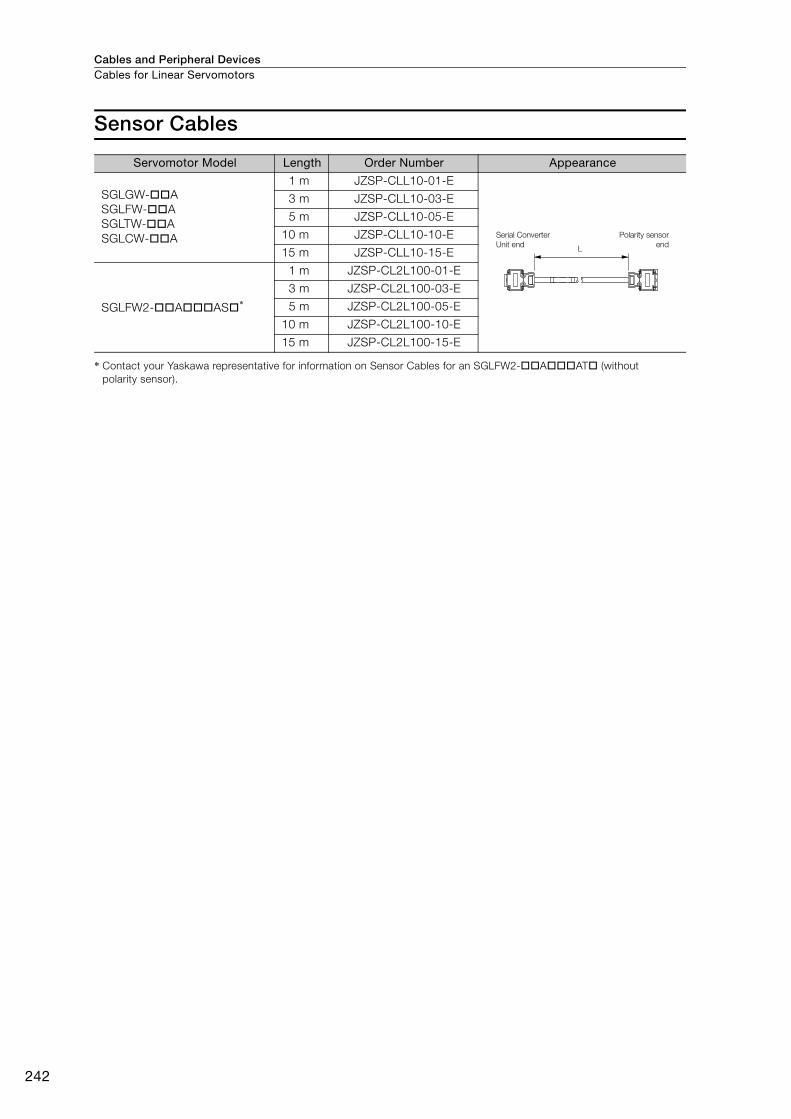
Cables and Peripheral DevicesCables for Linear Servomotors
242
Sensor Cables
* Contact your Yaskawa representative for information on Sensor Cables for an SGLFW2- A AT (without
polarity sensor).
Servomotor Model Length Order Number Appearance
SGLGW- A
SGLFW- A
SGLTW- A
SGLCW- A
1 m JZSP-CLL10-01-E
3 m JZSP-CLL10-03-E
5 m JZSP-CLL10-05-E
10 m JZSP-CLL10-10-E
15 m JZSP-CLL10-15-E
SGLFW2- A AS *
1 m JZSP-CL2L100-01-E
3 m JZSP-CL2L100-03-E
5 m JZSP-CL2L100-05-E
10 m JZSP-CL2L100-10-E
15 m JZSP-CL2L100-15-E
L
Serial Converter
Unit end
Polarity sensor
end

Cables and Peripheral Devices
243
Cab
les a
nd
Perip
hera
l D
evic
es
Serial Converter Units
Selection Table (Model Designations)
Note: Refer to the Σ-7 Series AC Servo Drive Peripheral Device Selection Manual (Manual No. SIEP S800001 32) for
details on the Serial Converter Units.
JZDP - �00� - ���
Serial Converter Unit Model
Code Appearance
Applicable
Linear
Encoder Po
larity
Sen
so
r
Tem
pera
ture
Sen
so
r
H003
J003
From
Heidenhain
Corp.
None None
H005
J005
From
Renishaw
PLC
None None
H006
J006
From
Heidenhain
Corp.
Yes Yes
H008
J008
From
Renishaw
PLC
Yes Yes
Applicable Linear Servomotor
Servomotor Model Code Servomotor Model Code
SGLGW -
(coreless
models)
For Stan-
dard-force
Magnetic
Way
30A050C 250
SGLTW-
(models
with T-
type iron
cores)
20A170A 011
30A080C 251 20A320A 012
40A140C 252 20A460A 013
40A253C 253 35A170A 014
40A365C 254 35A320A 015
60A140C 258 35A460A 016
60A253C 259 35A170H 105
60A365C 260 35A320H 106
90A200C 264 50A170H 108
90A370C 265 50A320H 109
90A535C 266 40A400B 185
SGLGW -
+
SGLGM -
-M
(coreless
models)
For High-
force Mag-
netic Way
40A140C 255 40A600B 186
40A253C 256 80A400B 187
40A365C 257 80A600B 188
60A140C 261
SGLC-
(cylinder
models)
D16A085AP 354
60A253C 262 D16A115AP 373
60A365C 263 D16A145AP 356
SGLFW-
(models
with F-type
iron cores)
20A090A 017 D20A100AP 357
20A120A 018 D20A135AP 358
35A120A 019 D20A170AP 359
35A230A 020 D25A125AP 360
50A200B 181 D25A170AP 374
50A380B 182 D25A215AP 362
1ZA200B 183 D32A165AP 363
1ZA380B 184 D32A225AP 364
SGLFW2-
(models
with F-type
iron cores)
30A070A 628 D32A285AP 365
30A120A 629
30A230A 630
45A200A 631
45A380A 632
90A200A 633
90A380A 634
1DA380A 649
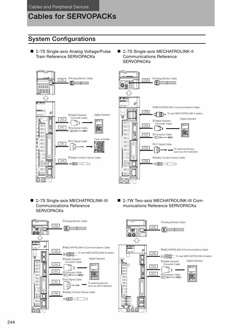
Cables and Peripheral Devices
244
Cables for SERVOPACKs
System Configurations
Σ-7S Single-axis Analog Voltage/Pulse Train Reference SERVOPACKs
Σ-7S Single-axis MECHATROLINK-II Communications Reference SERVOPACKs
Σ-7S Single-axis MECHATROLINK-III Communications Reference SERVOPACKs
Σ-7W Two-axis MECHATROLINK-III Com-munications Reference SERVOPACKs
CN3
I/O Signal Cable
Digital OperatorDigital Operator
Converter Cable
Analog Monitor Cable
Safety Function Device Cable
CN7
CN1
CN8
Computer Cable
Host controller
CN5
JZSP-CVS06-02-E
Digital Operator
Converter Cable
Safety Function Device Cable
Analog Monitor Cable
I/O Signal Cable
To next MECHATROLINK-II station
MECHATROLINK-II Communications Cable
To external devices,
such as LED indicators
CN1
CN5
CN6
CN3
CN7
CN8
Digital Operator
Computer CableJZSP-CVS06-02-E
Digital Operator
Converter Cable
Safety Function Device Cable
Analog Monitor Cable
JZSP-CVS06-02-E
I/O Signal Cable
To next MECHATROLINK-III station
MECHATROLINK-III Communications Cable
To external devices,
such as LED indicators
CN1
CN5
CN6
CN3
CN7
CN8
Digital Operator
Computer Cable
Digital Operator
Converter Cable
Analog Monitor Cable
JZSP-CVS06-02-E
To next MECHATROLINK-III station
MECHATROLINK-III Communications Cable
CN5
CN6
CN3
CN7
Digital Operator
Computer Cable

Cables and Peripheral Devices Cables for SERVOPACKs
245
Cab
les a
nd
Perip
hera
l D
evic
es
Selection Table
Note: Refer to the Σ-7 Series AC Servo Drive Peripheral Device Selection Manual (Manual No. SIEP S800001 32) for
the following information.
• Cable dimensional drawings and cable connection specifications
• Order numbers and specifications of individual connectors for cables
1. Use the cable specified by Yaskawa for the Computer Cable. Operation may not be depend-
able with any other cable.
2. Use the cable specified by Yaskawa for the MECHATROLINK Communications Cables. Opera-
tion may not be dependable due to low noise resistance with any other cable.
Code Name Length Order Number Appearance
Analog Monitor Cable 1 m JZSP-CA01-E
Digital Operator Converter
Cable0.3 m
JZSP-CVS05-A3-E*1
JZSP-CVS07-A3-E*2
Computer Cable 2.5 m JZSP-CVS06-02-E
I/O Signal
Cables
Soldered Connector Kit JZSP-CSI9-1-E
Connector-
Terminal
Block Con-
verter Unit
(with cable)
0.5 m JUSP-TA50PG-E
1 m JUSP-TA50PG-1-E
2 m JUSP-TA50PG-2-E
Cable with
Loose Wires
at One End
(loose wires
on peripheral
device end)
1 m JZSP-CSI01-1-E
2 m JZSP-CSI01-2-E
3 m JZSP-CSI01-3-E
I/O Signal
Cables
Soldered Connector Kit JZSP-CSI9-2-E
Connector-
Terminal
Block Con-
verter Unit
(with cable)
0.5 m JUSP-TA26P-E
1 m JUSP-TA26P-1-E
2 m JUSP-TA26P-2-E
Cable with
Loose Wires
at One End
(loose wires
on peripheral
device end)
1 m JZSP-CSI02-1-E
2 m JZSP-CSI02-2-E
3 m JZSP-CSI02-3-E
Safety
Function
Device
Cable
Cables with
Connectors*31 m JZSP-CVH03-01-E
3 m JZSP-CVH03-03-E
Connector Kit*4
Contact Tyco Electronics Japan G.K.
Product name: Industrial Mini I/O D-shape Type 1 Plug Con-
nector Kit
Model number: 2013595-1
Important
3M
10
31
4 JZSP-CVS05-A3-E
JZSP-CVS07-A3-E
JZSP-CVS06-02-E
1
19
33
16
32
50
1
1
2
49
50
40
391
2
B20A20
B1A1
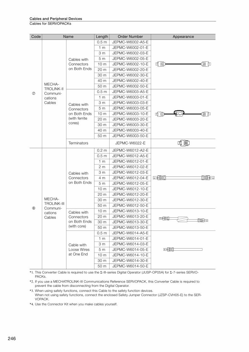
Cables and Peripheral DevicesCables for SERVOPACKs
246
*1. This Converter Cable is required to use the Σ-III-series Digital Operator (JUSP-OP05A) for Σ-7-series SERVO-
PACKs.
*2. If you use a MECHATROLINK-III Communications Reference SERVOPACK, this Converter Cable is required to
prevent the cable from disconnecting from the Digital Operator.
*3. When using safety functions, connect this Cable to the safety function devices.
When not using safety functions, connect the enclosed Safety Jumper Connector (JZSP-CVH05-E) to the SER-
VOPACK.
*4. Use the Connector Kit when you make cables yourself.
MECHA-
TROLINK-II
Communi-
cations
Cables
Cables with
Connectors
on Both Ends
0.5 m JEPMC-W6002-A5-E
1 m JEPMC-W6002-01-E
3 m JEPMC-W6002-03-E
5 m JEPMC-W6002-05-E
10 m JEPMC-W6002-10-E
20 m JEPMC-W6002-20-E
30 m JEPMC-W6002-30-E
40 m JEPMC-W6002-40-E
50 m JEPMC-W6002-50-E
Cables with
Connectors
on Both Ends
(with ferrite
cores)
0.5 m JEPMC-W6003-A5-E
1 m JEPMC-W6003-01-E
3 m JEPMC-W6003-03-E
5 m JEPMC-W6003-05-E
10 m JEPMC-W6003-10-E
20 m JEPMC-W6003-20-E
30 m JEPMC-W6003-30-E
40 m JEPMC-W6003-40-E
50 m JEPMC-W6003-50-E
Terminators JEPMC-W6022-E
MECHA-
TROLINK-III
Communi-
cations
Cables
Cables with
Connectors
on Both Ends
0.2 m JEPMC-W6012-A2-E
0.5 m JEPMC-W6012-A5-E
1 m JEPMC-W6012-01-E
2 m JEPMC-W6012-02-E
3 m JEPMC-W6012-03-E
4 m JEPMC-W6012-04-E
5 m JEPMC-W6012-05-E
10 m JEPMC-W6012-10-E
20 m JEPMC-W6012-20-E
30 m JEPMC-W6012-30-E
50 m JEPMC-W6012-50-E
Cables with
Connectors
on Both Ends
(with core)
10 m JEPMC-W6013-10-E
20 m JEPMC-W6013-20-E
30 m JEPMC-W6013-30-E
50 m JEPMC-W6013-50-E
Cable with
Loose Wires
at One End
0.5 m JEPMC-W6014-A5-E
1 m JEPMC-W6014-01-E
3 m JEPMC-W6014-03-E
5 m JEPMC-W6014-05-E
10 m JEPMC-W6014-10-E
30 m JEPMC-W6014-30-E
50 m JEPMC-W6014-50-E
Code Name Length Order Number Appearance
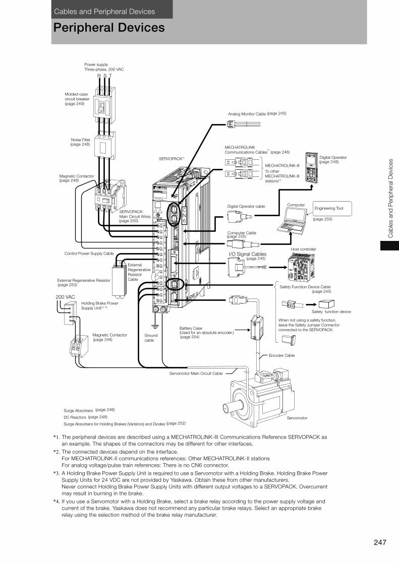
Cables and Peripheral Devices
247
Cab
les a
nd
Perip
hera
l D
evic
es
Peripheral Devices
*1. The peripheral devices are described using a MECHATROLINK-III Communications Reference SERVOPACK as
an example. The shapes of the connectors may be different for other interfaces.
*2. The connected devices depend on the interface.
For MECHATROLINK-II communications references: Other MECHATROLINK-II stations
For analog voltage/pulse train references: There is no CN6 connector.
*3. A Holding Brake Power Supply Unit is required to use a Servomotor with a Holding Brake. Holding Brake Power
Supply Units for 24 VDC are not provided by Yaskawa. Obtain these from other manufacturers.
Never connect Holding Brake Power Supply Units with different output voltages to a SERVOPACK. Overcurrent
may result in burning in the brake.
*4. If you use a Servomotor with a Holding Brake, select a brake relay according to the power supply voltage and
current of the brake. Yaskawa does not recommend any particular brake relays. Select an appropriate brake
relay using the selection method of the brake relay manufacturer.
I/O Signal Cables
R S T
200 VAC
MECHATROLINK-III
CN6
Power supply
Three-phase, 200 VAC
Molded-case
circuit breaker
Noise Filter
Magnetic Contactor
SERVOPACK*1
Analog Monitor Cable
MECHATROLINK
Communications Cables*1
To other
MECHATROLINK-III
stations*2
Digital Operator cable
Computer Cable
Host controller
SERVOPACK
Main Circuit Wires
Control Power Supply Cable
External
Regenerative
Resistor
CableExternal Regenerative Resistor
Holding Brake Power
Supply Unit*3, *4
Magnetic Contactor Ground
cable
Battery Case(Used for an absolute encoder.)
When not using a safety function,
leave the Safety Jumper Connector
connected to the SERVOPACK.
Encoder Cable
Servomotor
Servomotor Main Circuit Cable
Surge Absorbers
DC Reactors
Surge Absorbers for Holding Brakes (Varistors) and Diodes
Safety function device
Safety Function Device Cable
ComputerEngineering Tool
Digital Operator
(page 249)
(page 248)
(page 248)
(page 248)
(page 248)
(page 252)
(page 248)
(page 250)
(page 246)
(page 248)
(page 245)
(page 245)
(page 245)
(page 254)
(page 245)
(page 253)
(page 255)
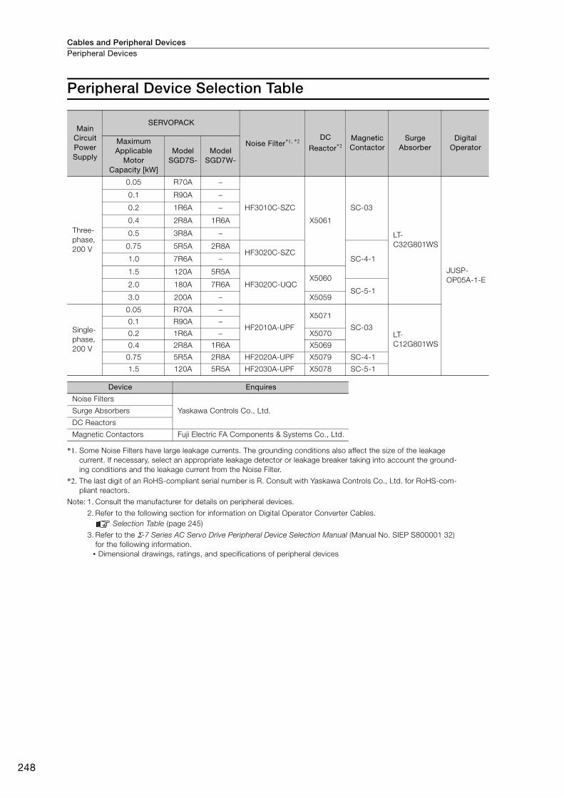
Cables and Peripheral DevicesPeripheral Devices
248
Peripheral Device Selection Table
*1. Some Noise Filters have large leakage currents. The grounding conditions also affect the size of the leakage
current. If necessary, select an appropriate leakage detector or leakage breaker taking into account the ground-
ing conditions and the leakage current from the Noise Filter.
*2. The last digit of an RoHS-compliant serial number is R. Consult with Yaskawa Controls Co., Ltd. for RoHS-com-
pliant reactors.
Note: 1. Consult the manufacturer for details on peripheral devices.
2. Refer to the following section for information on Digital Operator Converter Cables.
Selection Table (page 245)
3. Refer to the Σ-7 Series AC Servo Drive Peripheral Device Selection Manual (Manual No. SIEP S800001 32)
for the following information.
• Dimensional drawings, ratings, and specifications of peripheral devices
Main Circuit Power Supply
SERVOPACK
Noise Filter*1, *2 DC Reactor*2
Magnetic Contactor
Surge Absorber
Digital Operator
Maximum Applicable
Motor Capacity [kW]
Model SGD7S-
Model SGD7W-
Three-
phase,
200 V
0.05 R70A −
HF3010C-SZC
X5061
SC-03
LT-
C32G801WS
JUSP-
OP05A-1-E
0.1 R90A −
0.2 1R6A −
0.4 2R8A 1R6A
0.5 3R8A −
0.75 5R5A 2R8AHF3020C-SZC
SC-4-11.0 7R6A −
1.5 120A 5R5A
HF3020C-UQCX5060
2.0 180A 7R6ASC-5-1
3.0 200A − X5059
Single-
phase,
200 V
0.05 R70A −
HF2010A-UPF
X5071
SC-03LT-
C12G801WS
0.1 R90A −0.2 1R6A − X5070
0.4 2R8A 1R6A X5069
0.75 5R5A 2R8A HF2020A-UPF X5079 SC-4-1
1.5 120A 5R5A HF2030A-UPF X5078 SC-5-1
Device Enquires
Noise Filters
Yaskawa Controls Co., Ltd.Surge Absorbers
DC Reactors
Magnetic Contactors Fuji Electric FA Components & Systems Co., Ltd.
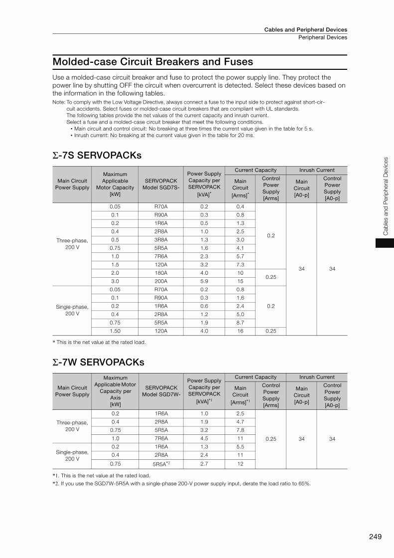
Cables and Peripheral Devices Peripheral Devices
249
Cab
les a
nd
Perip
hera
l D
evic
es
Molded-case Circuit Breakers and FusesUse a molded-case circuit breaker and fuse to protect the power supply line. They protect the
power line by shutting OFF the circuit when overcurrent is detected. Select these devices based on
the information in the following tables.
Note: To comply with the Low Voltage Directive, always connect a fuse to the input side to protect against short-cir-
cuit accidents. Select fuses or molded-case circuit breakers that are compliant with UL standards.
The following tables provide the net values of the current capacity and inrush current.
Select a fuse and a molded-case circuit breaker that meet the following conditions.
• Main circuit and control circuit: No breaking at three times the current value given in the table for 5 s.
• Inrush current: No breaking at the current value given in the table for 20 ms.
Σ-7S SERVOPACKs
* This is the net value at the rated load.
Σ-7W SERVOPACKs
*1. This is the net value at the rated load.
*2. If you use the SGD7W-5R5A with a single-phase 200-V power supply input, derate the load ratio to 65%.
Main Circuit Power Supply
Maximum Applicable
Motor Capacity [kW]
SERVOPACK Model SGD7S-
Power Supply Capacity per SERVOPACK
[kVA]*
Current Capacity Inrush Current
Main Circuit
[Arms]*
Control Power Supply [Arms]
Main Circuit [A0-p]
Control Power Supply [A0-p]
Three-phase,
200 V
0.05 R70A 0.2 0.4
0.2
34 34
0.1 R90A 0.3 0.8
0.2 1R6A 0.5 1.3
0.4 2R8A 1.0 2.5
0.5 3R8A 1.3 3.0
0.75 5R5A 1.6 4.1
1.0 7R6A 2.3 5.7
1.5 120A 3.2 7.3
2.0 180A 4.0 10 0.25
3.0 200A 5.9 15
Single-phase,
200 V
0.05 R70A 0.2 0.8
0.2
0.1 R90A 0.3 1.6
0.2 1R6A 0.6 2.4
0.4 2R8A 1.2 5.0
0.75 5R5A 1.9 8.7
1.50 120A 4.0 16 0.25
Main Circuit Power Supply
Maximum Applicable Motor
Capacity per Axis [kW]
SERVOPACK Model SGD7W-
Power Supply Capacity per SERVOPACK
[kVA]*1
Current Capacity Inrush Current
Main Circuit
[Arms]*1
Control Power Supply [Arms]
Main Circuit [A0-p]
Control Power Supply [A0-p]
Three-phase,
200 V
0.2 1R6A 1.0 2.5
0.25 34 34
0.4 2R8A 1.9 4.7
0.75 5R5A 3.2 7.8
1.0 7R6A 4.5 11
Single-phase,
200 V
0.2 1R6A 1.3 5.5
0.4 2R8A 2.4 11
0.75 5R5A*2 2.7 12
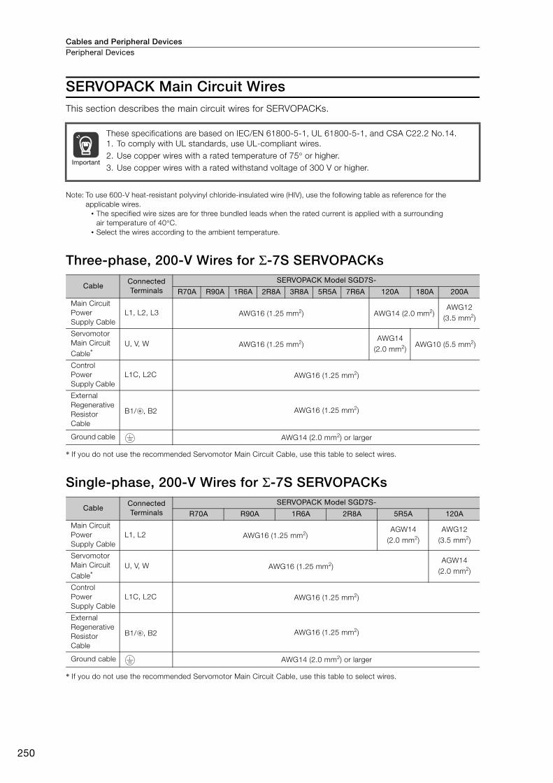
Cables and Peripheral DevicesPeripheral Devices
250
SERVOPACK Main Circuit WiresThis section describes the main circuit wires for SERVOPACKs.
Note: To use 600-V heat-resistant polyvinyl chloride-insulated wire (HIV), use the following table as reference for the
applicable wires.
• The specified wire sizes are for three bundled leads when the rated current is applied with a surrounding
air temperature of 40°C.
• Select the wires according to the ambient temperature.
Three-phase, 200-V Wires for Σ-7S SERVOPACKs
* If you do not use the recommended Servomotor Main Circuit Cable, use this table to select wires.
Single-phase, 200-V Wires for Σ-7S SERVOPACKs
* If you do not use the recommended Servomotor Main Circuit Cable, use this table to select wires.
These specifications are based on IEC/EN 61800-5-1, UL 61800-5-1, and CSA C22.2 No.14.
1. To comply with UL standards, use UL-compliant wires.
2. Use copper wires with a rated temperature of 75° or higher.
3. Use copper wires with a rated withstand voltage of 300 V or higher.
CableConnected Terminals
SERVOPACK Model SGD7S-
R70A R90A 1R6A 2R8A 3R8A 5R5A 7R6A 120A 180A 200A
Main Circuit
Power
Supply Cable
L1, L2, L3 AWG16 (1.25 mm2) AWG14 (2.0 mm2)AWG12
(3.5 mm2)
Servomotor
Main Circuit
Cable*U, V, W AWG16 (1.25 mm2)
AWG14
(2.0 mm2)AWG10 (5.5 mm2)
Control
Power
Supply Cable
L1C, L2C AWG16 (1.25 mm2)
External
Regenerative
Resistor
Cable
B1/ , B2 AWG16 (1.25 mm2)
Ground cable AWG14 (2.0 mm2) or larger
Cable Connected Terminals
SERVOPACK Model SGD7S-
R70A R90A 1R6A 2R8A 5R5A 120A
Main Circuit
Power
Supply Cable
L1, L2 AWG16 (1.25 mm2)AGW14
(2.0 mm2)
AWG12
(3.5 mm2)
Servomotor
Main Circuit
Cable*U, V, W AWG16 (1.25 mm2)
AGW14
(2.0 mm2)
Control
Power
Supply Cable
L1C, L2C AWG16 (1.25 mm2)
External
Regenerative
Resistor
Cable
B1/ , B2 AWG16 (1.25 mm2)
Ground cable AWG14 (2.0 mm2) or larger
Important

Cables and Peripheral Devices Peripheral Devices
251
Cab
les a
nd
Perip
hera
l D
evic
es
Three-phase, 200-V Wires for Σ-7W SERVOPACKs
* If you do not use the recommended Servomotor Main Circuit Cable, use this table to select wires.
Single-phase, 200-V Wires for Σ-7W SERVOPACKs
* If you do not use the recommended Servomotor Main Circuit Cable, use this table to select wires.
Wire Types The following table shows the wire sizes and allowable currents for three bundled leads.
* This is reference data based on JIS C3317 600-V-grade heat-resistant polyvinyl chloride-insulated wires (HIV).
Cable Connected Terminals
SERVOPACK Model SGD7W-
1R6A 2R8A 5R5A 7R6A
Main Circuit
Power
Supply Cable
L1, L2, L3 AWG16 (1.25 mm2) AWG14 (2.0 mm2)
Servomotor
Main Circuit
Cable*
UA, VA, WA,
UB, VB, WBAWG16 (1.25 mm2)
Control
Power
Supply Cable
L1C, L2C AWG16 (1.25 mm2)
External
Regenerative
Resistor
Cable
B1/ , B2 AWG16 (1.25 mm2) AWG14 (2.0 mm2)
Ground cable AWG14 (2.0 mm2) or larger
Cable Connected Terminals
SERVOPACK Model SGD7W-
1R6A 2R8A 5R5A
Main Circuit
Power
Supply Cable
L1, L2 AWG16 (1.25 mm2) AWG14 (2.0 mm2)
Servomotor
Main Circuit
Cable*
UA, VA, WA,
UB, VB, WBAWG16 (1.25 mm2)
Control
Power
Supply Cable
L1C, L2C AWG16 (1.25 mm2)
External
Regenerative
Resistor
Cable
B1/ , B2 AWG16 (1.25 mm2) AWG14 (2.0 mm2)
Ground cable AWG14 (2.0 mm2) or larger
HIV Specifications* Allowable Current at Ambient Temperatures [Arms]
Nominal Cross-sectional Area [mm2]
Configuration [Wires/mm2]
30°C 40°C 50°C
0.9 37/0.18 15 13 11
1.25 50/0.18 16 14 12
2.0 7/0.6 23 20 17
3.5 7/0.8 32 28 24
5.5 7/1.0 42 37 31
8.0 7/1.2 52 46 39
14.0 7/1.6 75 67 56
22.0 7/2.0 98 87 73

Cables and Peripheral DevicesPeripheral Devices
252
Surge Absorbers for Holding Brakes (Varistors) and Diodes
Surge Absorbers for Holding Brakes (Varistors)Select an appropriate Surge Absorber for the power supply voltage and current of the brake. Surge
absorbers are not provided by Yaskawa.
Diodes for Holding Brakes Select a diode for a holding brake with a rated current that is greater than that of the brake and with
the recommended withstand voltage given in the following table. Diodes are not provided by
Yaskawa.
Brake Power Supply Voltage 24 VDC
Surge Absorber Manufacturer Nippon Chemi-Con Corporation SEMITEC Corporation
Brake Rated Current
1 A max. TNR5V121K Z5D121
2 A max. TNR7V121K Z7D121
4 A max. TNR10V121K Z10D121
8 A max. TNR14V121K Z15D121
Holding Brake Power Supply Unit Specifications Withstand Voltage
Rated Output Voltage Input Voltage
24 VDC 200 V 100 V to 200 V

Cables and Peripheral Devices Peripheral Devices
253
Cab
les a
nd
Perip
hera
l D
evic
es
Regenerative Resistors
Types of Regenerative ResistorsThe following regenerative resistors can be used.
• Built-in regenerative resistors: Some models of SERVOPACKs have regenerative resistors built
into them.
• External regenerative resistors: These resistors are used when the smoothing capacitor and built-
in regenerative resistor in the SERVOPACK cannot consume all of the regenerative power.
Use Yaskawa’s SigmaJunmaSize+, an AC Servo drive capacity selection program, to determine if
a regenerative resistor is required.
Note: If you use an external regenerative resistor, you must change the setting of parameter Pn600.
Selection Table
* Use Yaskawa's SigmaJunmaSize+, an AC Servo drive capacity selection program, to select an external regenera-
tive resistor.
Built-In Regenerative ResistorThe following table gives the specifications of the built-in regenerative resistors in the SERVOPACKs
and the amount of regenerative power (average values) that they can process.
External Regenerative Resistors
Note: 1. Consult Yaskawa Controls Co., Ltd. if you require a RoHS-compliant resistor.
2. Consult Yaskawa Controls Co., Ltd. for the model numbers and specifications of resistors with thermostats.
SERVOPACK Model Built-In Regen-erative Resistor
External Regen-erative Resistor
Contents SGD7S- SGD7W-
R70A, R90A,
1R6A, 2R8A− None
Basically not
required
There is no built-in regenerative resistor, but nor-
mally an external regenerative resistor is not
required.
Install an external regenerative resistor when the
smoothing capacitor in the SERVOPACK cannot
process all the regenerative power.*
3R8A, 5R5A,
7R6A, 120A,
180A, 200A
1R6A, 2R8A,
5R5A, 7R6AStandard feature
Basically not
required
A built-in regenerative resistor is provided as a
standard feature. Install an external regenerative
resistor when the built-in regenerative resistor
cannot process all the regenerative power.*
SERVOPACK Model Built-In Regenerative
Resistor Regenerative Power
Processing Capacity of Built-In Regenerative Resistor
[W]
Minimum Allowable
Resistance[Ω]SGD7S- SGD7W-
Resistance[Ω]
Capacity[W]
R70A, R90A, 1R6A, 2R8A − − − − 40
3R8A, 5R5A, 7R6A 1R6A, 2R8A 40 40 8 40
120A − 20 60 10 20
180A, 200A 5R5A, 7R6A 12 60 16 12
Model Specification Enquires Manufacturer
RH120 70 W, 1 Ω to 100 Ω
Yaskawa Controls Co., Ltd. Iwaki Musen Kenkyusho
Co., Ltd.
RH150 90 W, 1 Ω to 100 ΩRH220 120 W, 1 Ω to 100 ΩRH300C 200 W, 1 kΩ to 10 kΩRH500 300 W, 10 Ω to 30 Ω
RH120 10Ω
K
J
H
±10%
±5%
±3%
J
Model Resistance Resistance Tolerance
Code Specification
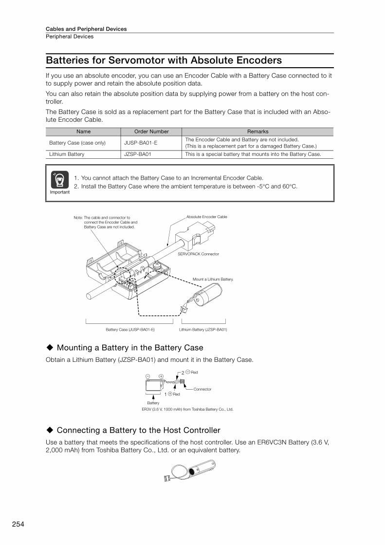
Cables and Peripheral DevicesPeripheral Devices
254
Batteries for Servomotor with Absolute EncodersIf you use an absolute encoder, you can use an Encoder Cable with a Battery Case connected to it
to supply power and retain the absolute position data.
You can also retain the absolute position data by supplying power from a battery on the host con-
troller.
The Battery Case is sold as a replacement part for the Battery Case that is included with an Abso-
lute Encoder Cable.
Mounting a Battery in the Battery CaseObtain a Lithium Battery (JZSP-BA01) and mount it in the Battery Case.
Connecting a Battery to the Host ControllerUse a battery that meets the specifications of the host controller. Use an ER6VC3N Battery (3.6 V,
2,000 mAh) from Toshiba Battery Co., Ltd. or an equivalent battery.
Name Order Number Remarks
Battery Case (case only) JUSP-BA01-EThe Encoder Cable and Battery are not included.
(This is a replacement part for a damaged Battery Case.)
Lithium Battery JZSP-BA01 This is a special battery that mounts into the Battery Case.
1. You cannot attach the Battery Case to an Incremental Encoder Cable.
2. Install the Battery Case where the ambient temperature is between -5°C and 60°C.Important
Note: The cable and connector to
connect the Encoder Cable and
Battery Case are not included.
Absolute Encoder Cable
SERVOPACK Connector
Mount a Lithium Battery.
Battery Case (JUSP-BA01-E) Lithium Battery (JZSP-BA01)
1
2
ER3V (3.6 V, 1000 mAh) from Toshiba Battery Co., Ltd.
Red
Connector
Red
Battery
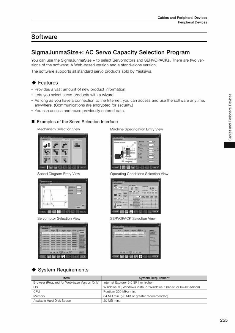
Cables and Peripheral Devices Peripheral Devices
255
Cab
les a
nd
Perip
hera
l D
evic
es
Software
SigmaJunmaSize+: AC Servo Capacity Selection ProgramYou can use the SigmaJunmaSize + to select Servomotors and SERVOPACKs. There are two ver-
sions of the software: A Web-based version and a stand-alone version.
The software supports all standard servo products sold by Yaskawa.
Features• Provides a vast amount of new product information.
• Lets you select servo products with a wizard.
• As long as you have a connection to the Internet, you can access and use the software anytime,
anywhere. (Communications are encrypted for security.)
• You can access and reuse previously entered data.
Examples of the Servo Selection Interface
System Requirements
Mechanism Selection View Machine Specification Entry View
Speed Diagram Entry View Operating Conditions Selection View
Servomotor Selection View SERVOPACK Selection View
Item System RequirementBrowser (Required for Web-base Version Only) Internet Explorer 5.0 SP1 or higher
OS Windows XP, Windows Vista, or Windows 7 (32-bit or 64-bit edition)
CPU Pentium 200 MHz min.
Memory 64 MB min. (96 MB or greater recommended)
Available Hard Disk Space 20 MB min.
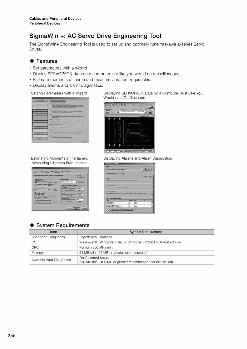
Cables and Peripheral DevicesPeripheral Devices
256
SigmaWin +: AC Servo Drive Engineering Tool The SigmaWin+ Engineering Tool is used to set up and optimally tune Yaskawa Σ-series Servo
Drives.
Features • Set parameters with a wizard.
• Display SERVOPACK data on a computer just like you would on a oscilloscope.
• Estimate moments of inertia and measure vibration frequencies.
• Display alarms and alarm diagnostics.
System Requirements
Setting Parameters with a Wizard Displaying SERVOPACK Data on a Computer Just Like You
Would on a Oscilloscope
Estimating Moments of Inertia and
Measuring Vibration Frequencies
Displaying Alarms and Alarm Diagnostics
Item System Requirement
Supported Languages English and Japanese
OS Windows XP, Windows Vista, or Windows 7 (32-bit or 64-bit edition)
CPU Pentium 200 MHz min.
Memory 64 MB min. (96 MB or greater recommended)
Available Hard Disk SpaceFor Standard Setup:
350 MB min. (400 MB or greater recommended for installation)
Capacity Selection for Servomotors ...................258
Capacity Selection for Regenerative Resistors ..266
International Standards ......................................277
Warranty ..............................................................278
Appendices

Appendices
258
Capacity Selection for Servomotors
Selecting the Servomotor CapacityUse Yaskawa's SigmaJunmaSize+, an AC servo drive capacity selection program, to select the Ser-
vomotor capacity. With the SigmaJunmaSize+, you can find the optimum Servomotor capacity by
simply selecting and entering information according to instructions from a wizard.
If you select a Servomotor capacity with a formula, refer to the following selection examples.
Capacity Selection Example for a Rotary Servomotor: For Speed Control
1. Mechanical Specifications
2. Speed Diagram
3. Motor Speed
4. Load Torque
Item Code Value Item Code Value
Load Speed υL 15 m/minGear and Coupling
Moment of Inertia JG 0.40 × 10⁻⁴ kg m2
Linear Motion
Section Massm 250 kg
Number of Feeding
Operations n 40 rotations/min
Ball Screw Length B 1.0 m Feeding Distance 0.275 m
Ball Screw Diameter dB 0.02 m Feeding Time tm 1.2 s max.
Ball Screw Lead PB 0.01 m Friction Coefficient μ 0.2
Ball Screw Material
Densityρ 7.87 × 10³ kg/m3 Mechanical Efficiency η 0.9 (90%)
Gear Ratio R 2 (gear ratio: 1/2)
External Force on
Linear Motion SectionF 0 N
• Load shaft speed
• Motor shaft speed nM = nL · R = 1,500 × 2 = 3,000 (min-1)
υL
Linear motion sectionServomotor
Coupling
GearBall screw
tcta td(m/min)
tm
t
15
υL
Motor Speed
Time (s)
t = = = 1.5 (s)
ta = tm − = 1.2 − = 1.2 − 1.1 = 0.1 (s)
tc = 1.2 − 0.1 × 2 = 1.0 (s)
60 6040
60 × 0.275
15
60υL
If ta = td,
nL = = = 1,500 (min-1)PB15
0.01
υL
TL = = = 0.43 (N�m)2πR �
(9.8 � � m + F) � PB2π × 2 × 0.9
(9.8 × 0.2 × 250 + 0) × 0.01
ημ
Appendices Capacity Selection for Servomotors
259
Ap
pend
ices
5. Load Moment of Inertia
6. Load Moving Power
7. Load Acceleration Power
8. Servomotor Provisional Selection
Selection Conditions• TL ≤ Motor rated torque
•
• nM ≤ Rated motor speed
• JL ≤ Allowable load moment of inertia
The following Servomotor meets the selection conditions.
• SGM7J-02A Servomotor
Specifications of the Provisionally Selected Servomotor
9. Verification of the Provisionally Selected Servomotor• Verification of required acceleration torque:
• Verification of required deceleration torque:
• Linear motion section
• Ball screw
• Coupling JG = 0.40 × 10⁻⁴ (kg⋅m2)
• Load moment of inertia at motor shaft
JL = JL1 + JB + JG = (1.58 + 0.31 + 0.40) × 10-4 = 2.29 × 10⁻⁴ (kg m2)
Item Value
Rated Output 200 (W)
Rated Motor Speed 3,000 (min-1)
Rated Torque 0.637 (N m)
Instantaneous Maximum Torque 2.23 (N m)
Motor Moment of Inertia 0.263 × 10⁻⁴ (kg m2)
Allowable Load Moment of Inertia 0.263 × 10-4 × 15 = 3.94 × 10⁻⁴ (kg m2)
JL1 = m = 250 × = 1.58 × 10⁻⁴ (kg�m2)
2
2πRPB
2
2π × 2
0.01
JB = � B � dB4 � = × 7.87 × 103 × 1.0 × (0.02)4 � = 0.31 × 10⁻⁴ (kg�m2)
R2
1
32
π22
1
32
πρ
PO = = = 135 (W)60
2πnM � TL60
2π × 3,000 × 0.43
Pa = = × × = 226 (W)nM
2
60
2πtaJL
3,000
2
60
2π0.1
2.29 × 10⁻⁴
< Provisionally selected Servomotor rated output < (Po + Pa)2
(Po + Pa)
TP = + TL = + 0.4360ta 60 × 0.1
2π × 3,000 × (0.263 + 2.29) × 10-4
≈ 1.23 (N m) < Maximum instantaneous torque...Satisfactory
2πnM (JM + JL)
TS = − TL = − 0.4360td 60 × 0.1
2π × 3,000 × (0.263 + 2.29) × 10-4
≈ 0.37 (N m) < Maximum instantaneous torque...Satisfactory
2πnM (JM + JL)

AppendicesCapacity Selection for Servomotors
260
• Verification of effective torque value:
10.Result It has been verified that the provisionally selected Servomotor is applicable.
The torque diagram is shown below.
Capacity Selection Example for a Rotary Servomotor: For Posi-tion Control1. Mechanical Specifications
2. Speed Diagram
Item Code Value Item Code Value
Load Speed υL 15 m/min Coupling Outer Diameter dC 0.03 m
Linear Motion Section
Massm 80 kg
Number of Feeding
Operationsn 40 rotation/min
Ball Screw Length B 0.8 m Feeding Distance 0.25 m
Ball Screw Diameter dB 0.016 m Feeding Time tm 1.2 s max.
Ball Screw Lead PB 0.005 mElectrical Stopping
Precision δ ±0.01 mm
Ball Screw Material
Densityρ 7.87 × 10³ kg/m3 Friction Coefficient μ 0.2
External Force on
Linear Motion SectionF 0 N Mechanical Efficiency η 0.9 (90%)
Coupling Mass mC 0.3 kg
Trms = =t 1.5
(1.23)2 × 0.1 + (0.43)2 × 1.0 + (0.37)2 × 0.1
≈ 0.483 (N m) < Rated torque...Satisfactory
TP2 ta + TL
2 tc + Ts2 td
(N m)
0.1
1.5
1.00.1
-0.37
0
0.43
1.23
TorqueMotor Speed
υL
Linear motion section Servomotor
Ball screw
Coupling
(m/min)
tm
15
tcta td ts
t
υL
Motor Speed
Reference pulses
Load speed
Time (s)
t = = = 1.5 (s)
ta = tm − ts − = 1.2 − 0.1 − = 0.1 (s)
tc = 1.2 − 0.1 − 0.1 × 2 = 0.9 (s)
60 60
40
60 × 0.2515
60
If ta = td and ts = 0.1 (s),
υL

Appendices Capacity Selection for Servomotors
261
Ap
pend
ices
3. Motor Speed
4. Load Torque
5. Load Moment of Inertia
6. Load Moving Power
7. Load Acceleration Power
8. Servomotor Provisional Selection
Selection Conditions• TL ≤ Motor rated torque
•
• nM ≤ Rated motor speed
• JL ≤ Allowable load moment of inertia
The following Servomotor meets the selection conditions.
• SGM7J-01A Servomotor
Specifications of the Provisionally Selected Servomotor
• Load shaft speed
• Motor shaft speed Direct coupling gear ratio 1/R = 1/1
Therefore, nM = nL ⋅ R = 3,000 × 1 = 3,000 (min-1)
• Linear motion section
• Ball screw
• Coupling
• Load moment of inertia at motor shaft
JL = JL1 + JB + Jc = 1.25 × 10⁻⁴ (kg m2)
Item Value
Rated Output 100 (W)
Rated Motor Speed 3,000 (min-1)
Rated Torque 0.318 (N m)
Instantaneous Maximum Torque 1.11 (N m)
Motor Moment of Inertia 0.0659 × 10⁻⁴ (kg m2)
Allowable Load Moment of Inertia 0.0659 × 10-4 × 35 = 2.31 × 10⁻⁴ (kg m2)
Encoder Resolution 24 bits (16,777,216 pulses/rev)
nL = = = 3,000 (min-1)PB
150.005
υL
TL = = = 0.139 (N�m)2πR �
(9.8 � m + F ) � PB2π × 1 × 0.9
(9.8 × 0.2 × 80 + 0) × 0.005μη
JL1 = m = 80 × = 0.507 × 10⁻⁴ (kg�m2)
2
2πR
PB2
2π × 1
0.005
JB = � B � dB4 = × 7.87 × 103 × 0.8 × (0.016)4 = 0.405 × 10⁻⁴ (kg�m2)
32
π32
πρ
Jc = mC � dC2 = × 0.3 × (0.03)2 = 0.338 × 10⁻⁴ (kg�m2)
8
1
8
1
PO = = = 43.7 (W)60
2πnM � TL60
2π × 3,000 × 0.139
Pa = = × × = 123.4 (W)nM
2
60
2πta
JL 3,000
2
60
2π0.1
1.25 × 10⁻⁴
< Provisionally selected Servomotor rated output < (Po + Pa)2
(Po + Pa)
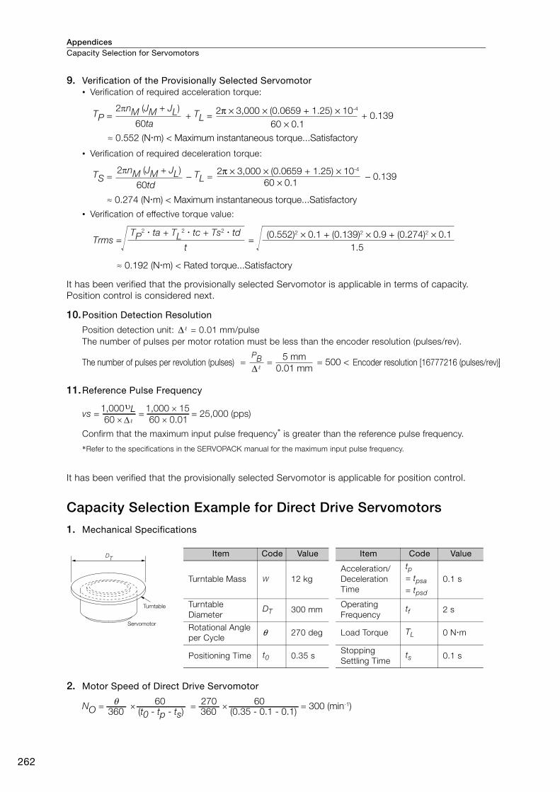
AppendicesCapacity Selection for Servomotors
262
9. Verification of the Provisionally Selected Servomotor• Verification of required acceleration torque:
• Verification of required deceleration torque:
• Verification of effective torque value:
It has been verified that the provisionally selected Servomotor is applicable in terms of capacity.
Position control is considered next.
10.Position Detection Resolution
Position detection unit: = 0.01 mm/pulse
The number of pulses per motor rotation must be less than the encoder resolution (pulses/rev).
11.Reference Pulse Frequency
Confirm that the maximum input pulse frequency* is greater than the reference pulse frequency.
*Refer to the specifications in the SERVOPACK manual for the maximum input pulse frequency.
It has been verified that the provisionally selected Servomotor is applicable for position control.
Capacity Selection Example for Direct Drive Servomotors
1. Mechanical Specifications
2. Motor Speed of Direct Drive Servomotor
TP = + TL = + 0.139
≈ 0.552 (N m) < Maximum instantaneous torque...Satisfactory 60ta 60 × 0.1
2π × 3,000 × (0.0659 + 1.25) × 10-42πnM (JM + JL)
TS = − TL = − 0.13960td 60 × 0.1
2π × 3,000 × (0.0659 + 1.25) × 10-4
≈ 0.274 (N m) < Maximum instantaneous torque...Satisfactory
2πnM (JM + JL)
Trms = =t
TP2 ta + TL
2 tc + Ts2 td (0.552)2 × 0.1 + (0.139)2 × 0.9 + (0.274)2 × 0.1
1.5
≈ 0.192 (N m) < Rated torque...Satisfactory
Δ
= = = 500 < Δ 0.01 mm
5 mmPBThe number of pulses per revolution (pulses) Encoder resolution [16777216 (pulses/rev)]
vs = = = 25,000 (pps)60 ×
1,000υL60 × 0.01
1,000 × 15
Δ
Turntable
Servomotor
DTItem Code Value Item Code Value
Turntable Mass W 12 kg
Acceleration/
Deceleration
Time
tp= tpsa= tpsd
0.1 s
Turntable
DiameterDT 300 mm
Operating
Frequency tf 2 s
Rotational Angle
per Cycleθ 270 deg Load Torque TL 0 N m
Positioning Time t0 0.35 sStopping
Settling Timets 0.1 s
NO = × = × = 300 (min-1) 360 (t0 - tp - ts)
θ360 (0.35 - 0.1 - 0.1)270 6060
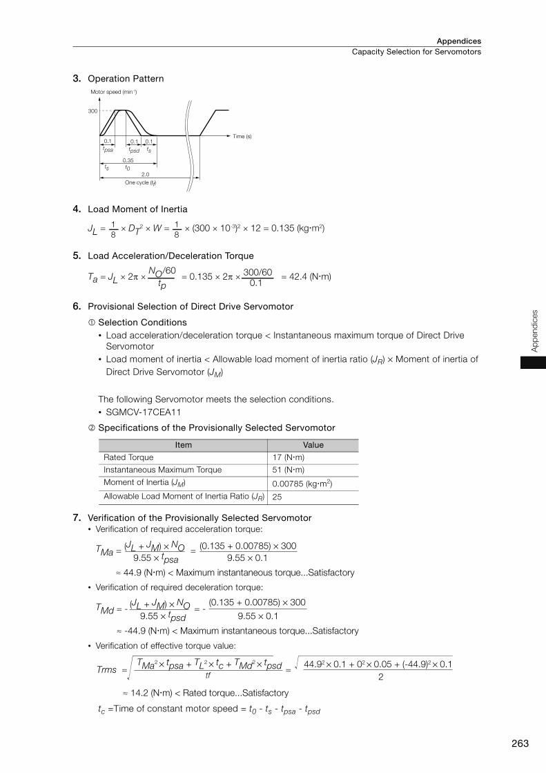
Appendices Capacity Selection for Servomotors
263
Ap
pend
ices
3. Operation Pattern
4. Load Moment of Inertia
5. Load Acceleration/Deceleration Torque
6. Provisional Selection of Direct Drive Servomotor
Selection Conditions• Load acceleration/deceleration torque < Instantaneous maximum torque of Direct Drive
Servomotor
• Load moment of inertia < Allowable load moment of inertia ratio (JR) × Moment of inertia of
Direct Drive Servomotor (JM)
The following Servomotor meets the selection conditions.
• SGMCV-17CEA11
Specifications of the Provisionally Selected Servomotor
7. Verification of the Provisionally Selected Servomotor• Verification of required acceleration torque:
• Verification of required deceleration torque:
• Verification of effective torque value:
tc =Time of constant motor speed = t0 - ts - tpsa - tpsd
Item Value
Rated Torque 17 (N m)
Instantaneous Maximum Torque 51 (N m)
Moment of Inertia (JM) 0.00785 (kg m2)
Allowable Load Moment of Inertia Ratio (JR) 25
300
0.1 0.1 0.1
ts
2.0
0.35
Motor speed (min-1)
Time (s)
One cycle (tf)
t0ts
tpsdtpsa
8
1
8
1JL = × DT2 × W = × (300 × 10-3)2 × 12 = 0.135 (kg�m2)
Ta = JL × 2π × = 0.135 × 2π × = 42.4 (N�m) NO/60
tp300/60
0.1
TMa = =
≈ 44.9 (N m) < Maximum instantaneous torque...Satisfactory
(JL + JM) × NO9.55 × tpsa
(0.135 + 0.00785) × 300
9.55 × 0.1
TMd = - = -
≈ -44.9 (N m) < Maximum instantaneous torque...Satisfactory
(JL + JM) × NO9.55 × tpsd
(0.135 + 0.00785) × 300
9.55 × 0.1
Trms = =TMa2 × tpsa + TL2 × tc + TMd2 × tpsd
2
44.92 × 0.1 + 02 × 0.05 + (-44.9)2 × 0.1
≈ 14.2 (N m) < Rated torque...Satisfactory
tf
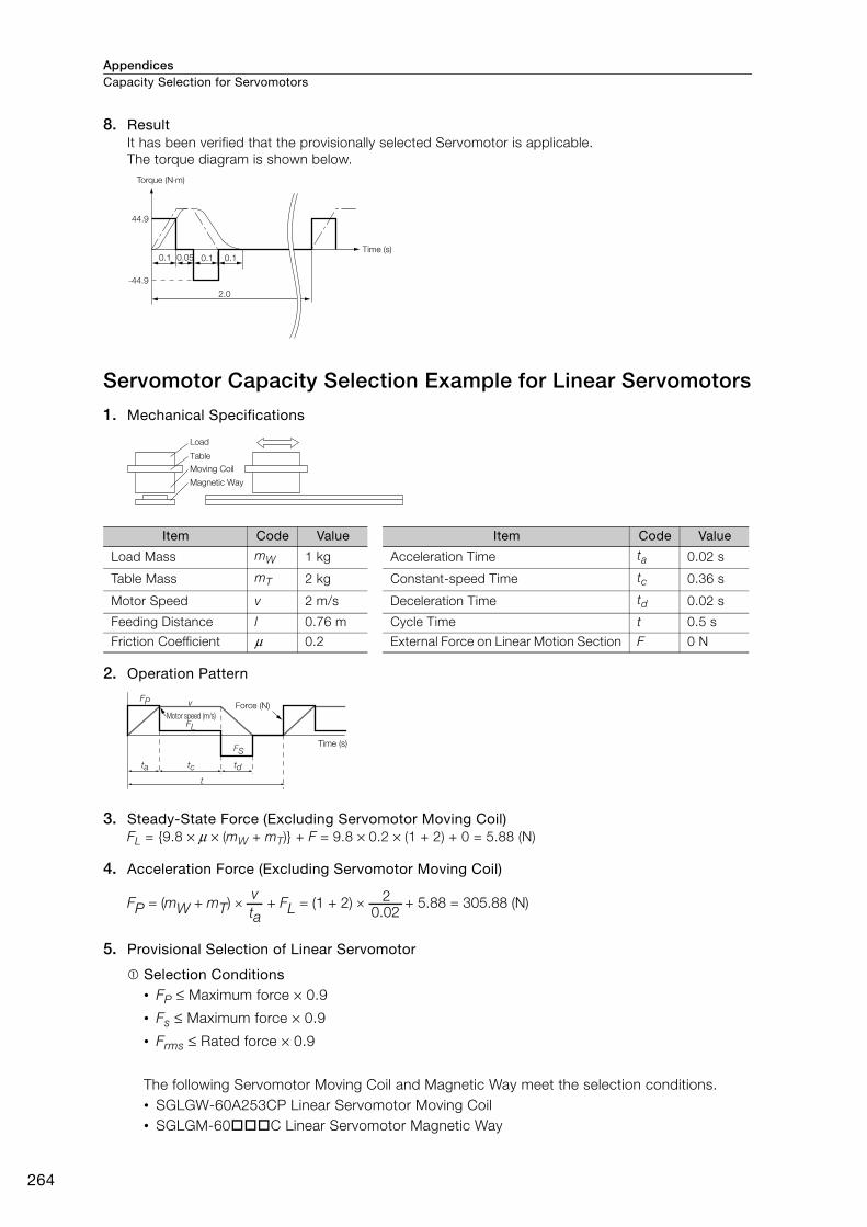
AppendicesCapacity Selection for Servomotors
264
8. Result It has been verified that the provisionally selected Servomotor is applicable.
The torque diagram is shown below.
Servomotor Capacity Selection Example for Linear Servomotors
1. Mechanical Specifications
2. Operation Pattern
3. Steady-State Force (Excluding Servomotor Moving Coil)FL = {9.8 × μ × (mW + mT)} + F = 9.8 × 0.2 × (1 + 2) + 0 = 5.88 (N)
4. Acceleration Force (Excluding Servomotor Moving Coil)
5. Provisional Selection of Linear Servomotor
Selection Conditions• FP ≤ Maximum force × 0.9
• Fs ≤ Maximum force × 0.9
• Frms ≤ Rated force × 0.9
The following Servomotor Moving Coil and Magnetic Way meet the selection conditions.
• SGLGW-60A253CP Linear Servomotor Moving Coil
• SGLGM-60 C Linear Servomotor Magnetic Way
Item Code Value Item Code Value
Load Mass mW 1 kg Acceleration Time ta 0.02 s
Table Mass mT 2 kg Constant-speed Time tc 0.36 s
Motor Speed v 2 m/s Deceleration Time td 0.02 s
Feeding Distance l 0.76 m Cycle Time t 0.5 s
Friction Coefficient μ 0.2 External Force on Linear Motion Section F 0 N
Torque (N⋅m)
Time (s)
-44.9
0.05
44.9
0.1 0.1 0.1
2.0
Load
Table
Moving Coil
Magnetic Way
v
t
Motor speed (m/s)
Force (N)
Time (s)
ta
FP
FL
FS
tc td
vta
20.02
FP = (mW + mT) × + FL = (1 + 2) × + 5.88 = 305.88 (N)

Appendices Capacity Selection for Servomotors
265
Ap
pend
ices
Specifications of the Provisionally Selected Servomotor
6. Verification of the Provisionally Selected Servomotor • Steady-State Force
FL = μ {9.8 × (mW + mT + mM) + Fatt} = 0.2 {9.8 × (1 + 2 + 0.82) + 0} = 7.5 (N)
• Verification of Acceleration Force
• Verification of Deceleration Force
• Verification of Effective Force
7. ResultIt has been verified that the provisionally selected Servomotor is applicable.
Item Value
Maximum Force 440 (N)
Rated Force 147 (N)
Moving Coil Mass (mM) 0.82 (kg)
Servomotor Magnetic Attraction (Fatt) 0 (N)
taFP = (mW + mT + mM) × + FL = (1 + 2 + 0.82) × + 7.5
= 389.5 (N) ≤ × 0.9 (= 396 N)…
20.02
Maximum force Satisfactory
taFS = (mW + mT + mM) × − FL = (1 + 2 + 0.82) × − 7.5
= 374.5 (N) ≤ × 0.9 (= 396 N)…Maximum force Satisfactory
20.02
Frms = =t
FP2 ∙ ta + FL
2 ∙ tc + Fs2 ∙ td
0.5
389.52 × 0.02 + 7.52 × 0.36 + 374.52 × 0.02
= 108.3 (N) ≤ × 0.9 (= 132.3 N)…Rated force Satisfactory
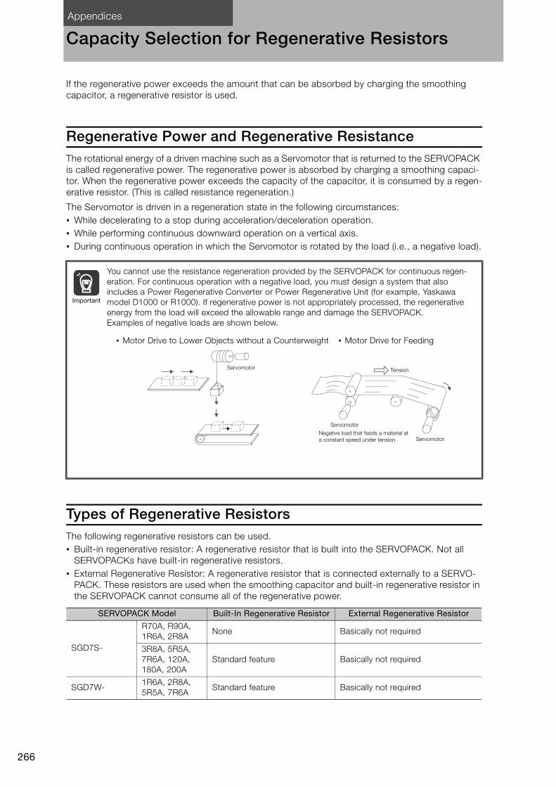
Appendices
266
Capacity Selection for Regenerative Resistors
If the regenerative power exceeds the amount that can be absorbed by charging the smoothing
capacitor, a regenerative resistor is used.
Regenerative Power and Regenerative ResistanceThe rotational energy of a driven machine such as a Servomotor that is returned to the SERVOPACK
is called regenerative power. The regenerative power is absorbed by charging a smoothing capaci-
tor. When the regenerative power exceeds the capacity of the capacitor, it is consumed by a regen-
erative resistor. (This is called resistance regeneration.)
The Servomotor is driven in a regeneration state in the following circumstances:
• While decelerating to a stop during acceleration/deceleration operation.
• While performing continuous downward operation on a vertical axis.
• During continuous operation in which the Servomotor is rotated by the load (i.e., a negative load).
Types of Regenerative ResistorsThe following regenerative resistors can be used.
• Built-in regenerative resistor: A regenerative resistor that is built into the SERVOPACK. Not all
SERVOPACKs have built-in regenerative resistors.
• External Regenerative Resistor: A regenerative resistor that is connected externally to a SERVO-
PACK. These resistors are used when the smoothing capacitor and built-in regenerative resistor in
the SERVOPACK cannot consume all of the regenerative power.
You cannot use the resistance regeneration provided by the SERVOPACK for continuous regen-
eration. For continuous operation with a negative load, you must design a system that also
includes a Power Regenerative Converter or Power Regenerative Unit (for example, Yaskawa
model D1000 or R1000). If regenerative power is not appropriately processed, the regenerative
energy from the load will exceed the allowable range and damage the SERVOPACK.
Examples of negative loads are shown below.
SERVOPACK Model Built-In Regenerative Resistor External Regenerative Resistor
SGD7S-
R70A, R90A,
1R6A, 2R8ANone Basically not required
3R8A, 5R5A,
7R6A, 120A,
180A, 200A
Standard feature Basically not required
SGD7W-1R6A, 2R8A,
5R5A, 7R6AStandard feature Basically not required
Important
• Motor Drive to Lower Objects without a Counterweight • Motor Drive for Feeding
Tension
Servomotor
Servomotor
ServomotorNegative load that feeds a material at
a constant speed under tension
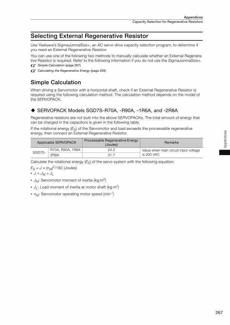
Appendices Capacity Selection for Regenerative Resistors
267
Ap
pend
ices
Selecting External Regenerative ResistorUse Yaskawa’s SigmaJunmaSize+, an AC servo drive capacity selection program, to determine if
you need an External Regenerative Resistor.
You can use one of the following two methods to manually calculate whether an External Regenera-
tive Resistor is required. Refer to the following information if you do not use the SigmaJunmaSize+.
Simple Calculation (page 267)
Calculating the Regenerative Energy (page 269)
Simple CalculationWhen driving a Servomotor with a horizontal shaft, check if an External Regenerative Resistor is
required using the following calculation method. The calculation method depends on the model of
the SERVOPACK.
SERVOPACK Models SGD7S-R70A, -R90A, -1R6A, and -2R8ARegenerative resistors are not built into the above SERVOPACKs. The total amount of energy that
can be charged in the capacitors is given in the following table.
If the rotational energy (ES) of the Servomotor and load exceeds the processable regenerative
energy, then connect an External Regenerative Resistor.
Calculate the rotational energy (ES) of the servo system with the following equation:
ES = J × (nM)2/182 (Joules)
• J = JM + JL
• JM: Servomotor moment of inertia (kg⋅m2)
• JL: Load moment of inertia at motor shaft (kg⋅m2)
• nM: Servomotor operating motor speed (min-1)
Applicable SERVOPACKProcessable Regenerative Energy
(Joules)Remarks
SGD7S-R70A, R90A, 1R6A 24.2 Value when main circuit input voltage
is 200 VAC2R8A 31.7
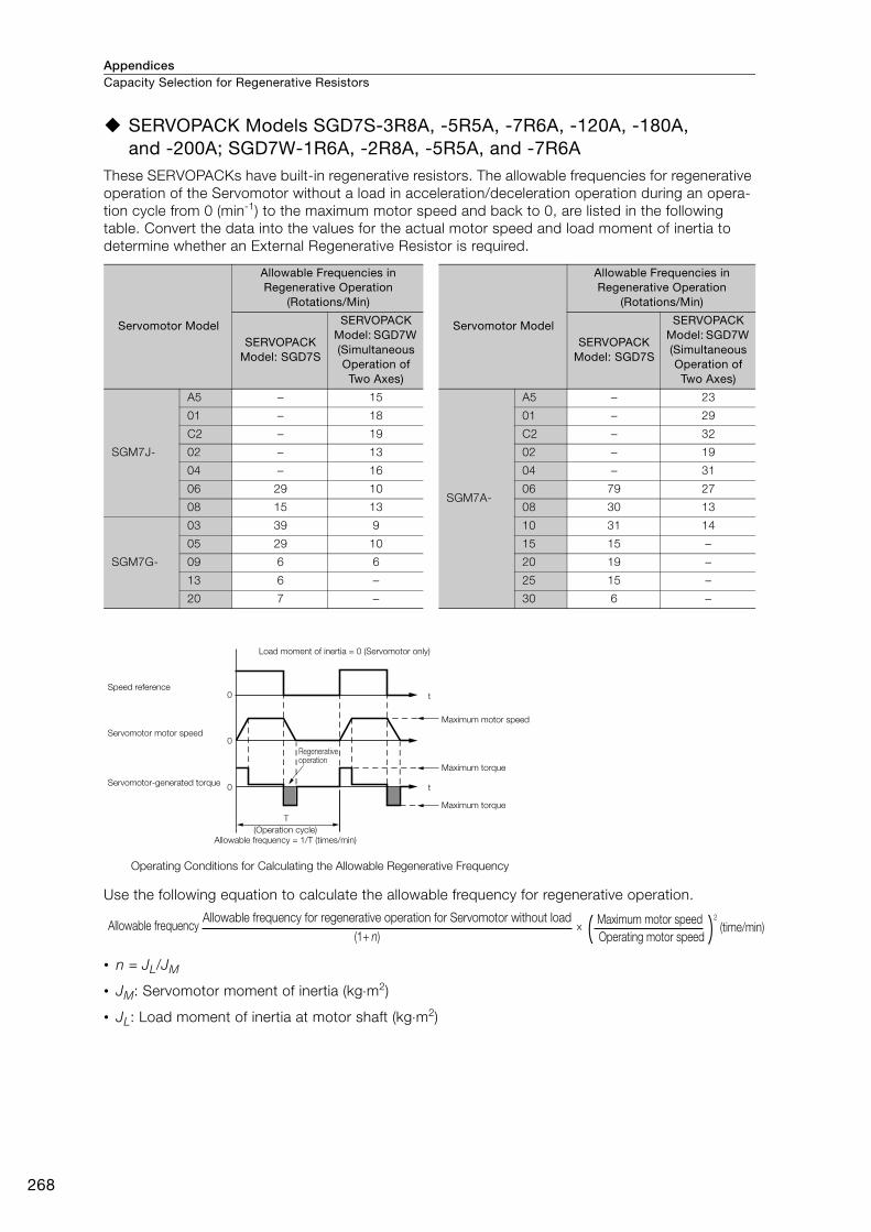
AppendicesCapacity Selection for Regenerative Resistors
268
SERVOPACK Models SGD7S-3R8A, -5R5A, -7R6A, -120A, -180A, and -200A; SGD7W-1R6A, -2R8A, -5R5A, and -7R6A
These SERVOPACKs have built-in regenerative resistors. The allowable frequencies for regenerative
operation of the Servomotor without a load in acceleration/deceleration operation during an opera-
tion cycle from 0 (min-1) to the maximum motor speed and back to 0, are listed in the following
table. Convert the data into the values for the actual motor speed and load moment of inertia to
determine whether an External Regenerative Resistor is required.
Use the following equation to calculate the allowable frequency for regenerative operation.
• n = JL/JM
• JM: Servomotor moment of inertia (kg⋅m2)
• JL: Load moment of inertia at motor shaft (kg⋅m2)
Servomotor Model
Allowable Frequencies in Regenerative Operation
(Rotations/Min)
Servomotor Model
Allowable Frequencies in Regenerative Operation
(Rotations/Min)
SERVOPACK Model: SGD7S
SERVOPACK Model: SGD7W (Simultaneous Operation of Two Axes)
SERVOPACK Model: SGD7S
SERVOPACK Model: SGD7W (Simultaneous Operation of Two Axes)
SGM7J-
A5 − 15
SGM7A-
A5 − 23
01 − 18 01 − 29
C2 − 19 C2 − 32
02 − 13 02 − 19
04 − 16 04 − 31
06 29 10 06 79 27
08 15 13 08 30 13
SGM7G-
03 39 9 10 31 14
05 29 10 15 15 −09 6 6 20 19 −13 6 − 25 15 −20 7 − 30 6 −
0
0
0
T
t
t
Load moment of inertia = 0 (Servomotor only)
Speed reference
Servomotor motor speed
Servomotor-generated torque
Maximum motor speed
Maximum torque
Maximum torque
(Operation cycle)
Allowable frequency = 1/T (times/min)
Operating Conditions for Calculating the Allowable Regenerative Frequency
Regenerative operation
(1+ n)× Allowable frequency
Allowable frequency for regenerative operation for Servomotor without load
Operating motor speed
Maximum motor speed 2
(time/min)

Appendices Capacity Selection for Regenerative Resistors
269
Ap
pend
ices
Calculating the Regenerative EnergyThis section shows how to calculate the regenerative resistor capacity for the acceleration/deceler-
ation operation shown in the following figure.
• Calculation Procedure for Regenerative Resistor Capacity
* EG (joules): Energy for continuous period of regenerative operation
EG = (2π/60) nMGTGtG• TG: Servomotor’s generated torque in continuous period of regenerative operation (N⋅m)
• nMG: Servomotor’s motor speed for same operation period as above (min-1)
• tG: Same operation period as above (s)
Note: 1. The 0.2 in the equation for calculating WK is the value when the regenerative resistor’s utilized load ratio is
20%.
2. The units for the various symbols are given in the following table.
If the value of WK does not exceed the capacity of the built-in regenerative resistor of the SERVO-
PACK, an External Regenerative Resistor is not required. For details on the built-in regenerative
resisters, refer to the SERVOPACK specifications. If the value of WK exceeds the capacity of the
built-in regenerative resistor, install an External Regenerative Resistor with a capacity equal to the
value for W calculated above.
Step Item Code Formula
1Calculate the rotational energy of the Servo-
motor.ES ES = JnM
2/182
2Calculate the energy consumed by load loss
during the deceleration periodEL
EL = (π/60) nMTLtDNote: If the load loss is unknown, calculate
the value with EL set to 0.
3Calculate the energy lost from Servomotor
winding resistance.EM
(Value calculated from the graphs in Servo-motor Winding Resistance Loss on page 271)
× tD
4Calculate the energy that can be absorbed
by the SERVOPACK.EC
Calculate from the graphs in SERVOPACK-absorbable Energy on page 270
5Calculate the energy consumed by the
regenerative resistor.EK
EK = ES − (EL + EM + EC)
EK = ES − (EL + EM + EC) + EG*
Note: Use this formula if there will be con-
tinuous periods of regenerative oper-
ation, such as for a vertical axis.
6Calculate the required regenerative resistor
capacity (W).WK WK = EK/(0.2 × T)
Code Description Code Description
ES to EK Energy in joules (J) TL Load torque (N⋅m)
WK Required regenerative resistor capacity (W) tD Deceleration stopping time (s)
J = JM + JL (kg m2) T Servomotor repeat operation cycle (s)
nM Servomotor motor speed (min-1)
T
0
0
tD
nM: Motor speed
Motor speed
Motor torque
TL: Load torque
Regenerative torque

AppendicesCapacity Selection for Regenerative Resistors
270
SERVOPACK-absorbable EnergyThe following figures show the relationship between the SERVOPACK’s input power supply voltage
and its absorbable energy.
R70A, R90A, 1R6A
2R8A
3R8A
5R5A and 7R6A
1R6A
2R8A
5R5A
7R6A
170 180 190 200 210 220 230 240 250 260 270
Model: SGD7S- Model: SGD7S-
120A (three-phase)
120A (single-phase), 180A, and 200A
Abso
rbab
le e
nerg
y (J)
Abso
rbab
le e
nerg
y (J)
Input voltage (Vrms)
Model: SGD7W-
Abso
rbab
le e
nerg
y (J)
Input voltage (Vrms)
Input voltage (Vrms)
180
160
140
120
100
80
60
40
20
0
80
70
60
50
40
30
20
10
0
120
100
80
60
40
20
0
170 180 190 200 210 220 230 240 250 260 270170 180 190 200 210 220 230 240 250 260 270

Appendices Capacity Selection for Regenerative Resistors
271
Ap
pend
ices
Servomotor Winding Resistance LossThe following figures show the relationship for each Servomotor between the Servomotor’s gener-
ated torque and the winding resistance loss.
SGM7J Rotary Servomotors
SGM7A Rotary Servomotors
03002001000
03002001000
450
400
350
300
250
200
150
100
50
400
350
300
250
200
150
100
50
Model: SGM7J- Model: SGM7J-
Win
din
g R
esis
tance L
oss (W
)Torque (%)
Win
din
g R
esis
tance L
oss (W
)
Torque (%)
04A
06A
08A
A5A
01A
C2A
02A
03002001000
03002001000
000
200 3001000
300200100
600
500
400
300
200
100
1600
1400
1200
1000
800
600
400
200
1400
1200
1000
800
600
400
200
Model: SGM7A-
Win
din
g R
esis
tance L
oss (W
)
Torque (%)
Model: SGM7A-
Win
din
g R
esis
tance L
oss (W
)
Torque (%)
Model: SGM7A-
Win
din
g R
esis
tance L
oss (W
)
Torque (%)
Model: SGM7A-
Win
din
g R
esis
tance L
oss (W
)
Torque (%)
A5A
01A
C2A
02A
04A
06A
08A
10A
15A
20A
25A30A
400
350
300
250
200
150
100
50
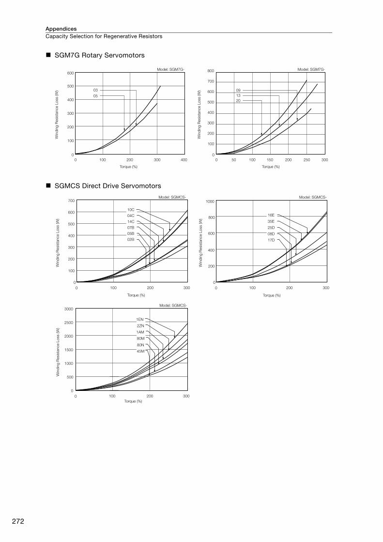
AppendicesCapacity Selection for Regenerative Resistors
272
SGM7G Rotary Servomotors
SGMCS Direct Drive Servomotors
0
0
100
200
300
400
500
600
100 200 300 400
0
100 200500 150 250 300
Model: SGM7G-
Win
din
g R
esis
tance L
oss (W
)
Torque (%)
Model: SGM7G-
Win
din
g R
esis
tance L
oss (W
)
Torque (%)
800
700
600
500
400
300
200
100
03
05
09
13
20
0
0 100 200 300
100
300
200
400
500
600
700
10C
14C
04C
07B
05B
02B
0
0 100 200 300
200
600
400
800
1000
35E
16E
25D
17D
08D
Model: SGMCS- Model: SGMCS-
Torque (%)
Win
din
g R
esis
tance L
oss (W
)
Torque (%)
Win
din
g R
esis
tance L
oss (W
)
0
0 100 200 300
1000
500
1500
2000
2500
3000
2ZN
1EN
80N
45M
1AM
80M
Model: SGMCS-
Win
din
g R
esis
tance L
oss (W
)
Torque (%)

Appendices Capacity Selection for Regenerative Resistors
273
Ap
pend
ices
SGMCV Direct Drive Servomotors
SGLGW Linear Servomotors
Model: SGMCV-
Win
din
g R
esis
tance L
oss (W
)
Torque (%)
Model: SGMCV-
Win
din
g R
esis
tance L
oss (W
)
Torque (%)
700
600
500
400
300
200
100
600
500
400
300
200
100
0
0 100 200 300
0
0 100 200 300
08C
17C
25C
04B
10B
14B
0 100 200 300 4000
200
400
600
800
1000
1200
365C
253C
140C
0 100 200 300 400 500
0
500
1000
1500
2000
2500
365C -M
253C -M
140C -M
0 100 200 300 4000
200
400
600
800
1000
1200
1400
365C
253C
140C
00
500
1000
1500
2000
2500
3000
100 200 300 400 500
365C -M
253C -M
140C -M
00
1000
2000
3000
4000
5000
6000
100 200 300 400 500
535C
370C
200C
0 100 200 300 400
0
50
100
150
200
250
080C
050C
Model: SGLGW-30A
Win
din
g R
esis
tance L
oss (W
)
Force (%)
Model: SGLGW-40AW
ind
ing
Resis
tance L
oss (W
)
Force (%)
Model: SGLGW-40A
Win
din
g R
esis
tance L
oss (W
)
Force (%)
Model: SGLGW-60A
Win
din
g R
esis
tance L
oss (W
)
Force (%)
Model: SGLGW-60A
Win
din
g R
esis
tance L
oss (W
)
Force (%)
Model: SGLGW-90A
Win
din
g R
esis
tance L
oss (W
)
Force (%)
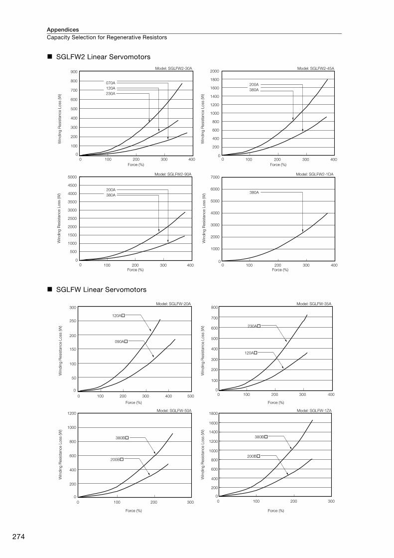
AppendicesCapacity Selection for Regenerative Resistors
274
SGLFW2 Linear Servomotors
SGLFW Linear Servomotors
100 200 300 4000
100 200 300 400100 200 300 400
0
0
0 0
0100 200 300 400
0
0
900
800
700
600
500
400
300
200
100
5000
4500
4000
3500
3000
2500
2000
1500
1000
500
2000
1800
1600
1400
1200
1000
800
600
400
200
7000
6000
5000
4000
3000
2000
1000
070A
120A
230A
200A
380A
200A
380A
380A
Model: SGLFW2-30A
Win
din
g R
esis
tance L
oss (W
)
Force (%)
Model: SGLFW2-45A
Win
din
g R
esis
tance L
oss (W
)
Force (%)
Model: SGLFW2-90A
Win
din
g R
esis
tance L
oss (W
)
Force (%)
Model: SGLFW2-1DA
Win
din
g R
esis
tance L
oss (W
)
Force (%)
0
0
100 200 300 400 500
50
100
150
200
250
300
120A
090A
0
0
100 200 300 400
100
200
300
400
500
600
700
800
230A
120A
0
0
200
400
600
800
1000
1200
100 200 300
200B
380B
0
0
100 200 300
200
400
600
800
1000
1200
1400
1600
1800
380B
200B
Model: SGLFW-20A
Win
din
g R
esis
tance L
oss (W
)
Force (%)
Model: SGLFW-35A
Win
din
g R
esis
tance L
oss (W
)
Force (%)
Model: SGLFW-50A
Win
din
g R
esis
tance L
oss (W
)
Force (%)
Model: SGLFW-1ZA
Win
din
g R
esis
tance L
oss (W
)
Force (%)
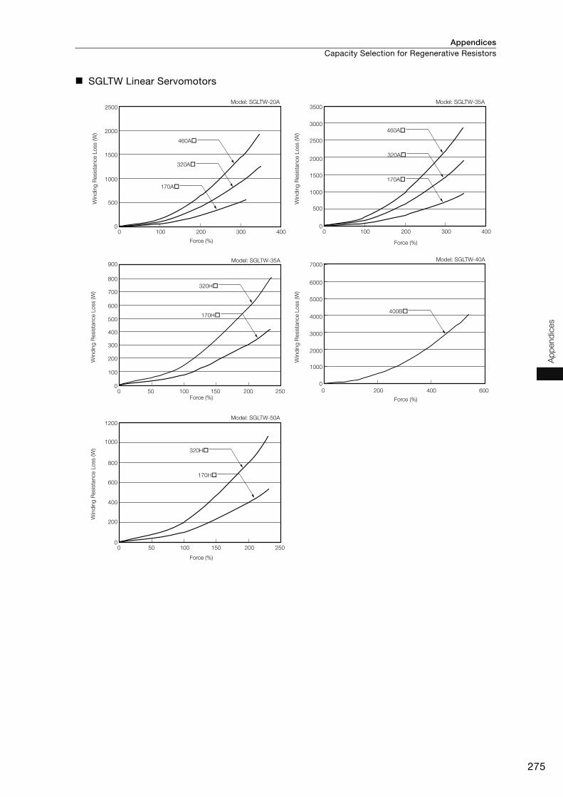
Appendices Capacity Selection for Regenerative Resistors
275
Ap
pend
ices
SGLTW Linear Servomotors
0 100 200 300 4000
500
1000
1500
2000
2500
170A
460A
320A
0 100 200 300 4000
1000
500
1500
2000
2500
3000
3500
170A
460A
320A
0 50 100 150 200 2500
400
300
200
100
500
600
700
800
900
170H
320H
0 200 400 600
400B
0
1000
2000
3000
4000
5000
7000
6000
0 50 100 150 200 2500
200
400
600
800
1000
1200
170H
320H
Model: SGLTW-20A
Win
din
g R
esis
tance L
oss (W
)
Force (%)
Model: SGLTW-35A
Force (%)
Model: SGLTW-35A
Win
din
g R
esis
tance L
oss (W
)
Win
din
g R
esis
tance L
oss (W
)
Force (%)
Model: SGLTW-50A
Win
din
g R
esis
tance L
oss (W
)
Force (%)
Model: SGLTW-40A
Force (%)
Win
din
g R
esis
tance L
oss (W
)

AppendicesCapacity Selection for Regenerative Resistors
276
SGLC Linear Servomotors
0
50
0
100
150
200
250
300
350
400
100 200 300 400 500
145AP
115AP
085AP
0
200
400
600
800
1000
1200
0 200 400 600
170AP
135AP
100AP
0 100 200 300 400 500
0
400
200
600
800
1000
1200
1400
1600
215AP
170AP
125AP
0 100 200 300 400 500
0
400
200
600
800
1000
1200
1400
1600
285AP
225AP
165AP
Model: SGLC-D16A
Win
din
g R
esis
tance L
oss (W
)
Force (%)
Model: SGLC-D20A
Win
din
g R
esis
tance L
oss (W
)
Force (%)
Model: SGLC-D25A
Win
din
g R
esis
tance L
oss (W
)
Force (%)
Model: SGLC-D32A
Win
din
g R
esis
tance L
oss (W
)
Force (%)

Appendices
277
Ap
pend
ices
International Standards
*1. Estimates are provided for RoHS-compliant products. The model numbers have an “-E” suffix.
*2. CE Marking certification has not yet been received for SGMCS- M and SGMCS- N Direct Drive Servomo-
tors.
CE Marking certification has been received for the following Direct Drive Servomotors: SGMCS- B, SGMCS-
C, SGMCS- D, and SGMCS- E. Contact your Yaskawa representative if the CE Marking label is
required.
*3. The model numbers of the Magnetic Ways of Linear Servomotors are given in parentheses.
*4. CE Marking certification has been received. Contact your Yaskawa representative if the CE Marking label is
required.
: Certified, – : Not Certified
Product Model
UL/CSA Standards CE Marking KC Mark
RoHS
Directive
SERVOPACKs
SGD7S Scheduled for 2014Scheduled for
2014
Scheduled for
2014
SGD7W Scheduled for 2014Scheduled for
2014
Scheduled for
2014
Product Model
UL/CSA Standards CE Marking
RoHS Directive
Rotary Servomotors
SGM7J Scheduled for 2014Scheduled for
2014
SGM7G Scheduled for 2014 Scheduled for
2014
SGM7A Scheduled for 2014Scheduled for
2014
Direct Drive
Servomotors
SGMCS − *2 *1
SGMCV Scheduled for 2014Scheduled for
2014
Linear Servomotors
SGLGW
(SGLGM) *3 − *4
SGLFW
(SGLFM)*3 − *4
SGLFW2
(SGLFM2)*3 Scheduled for 2015Scheduled for
2015
SGLTW
(SGLTM)*3 − *4
SGLC − *4

Appendices
278
Warranty
Details of Warranty
Warranty Period
The warranty period for a product that was purchased (hereinafter called the “delivered product”) is
one year from the time of delivery to the location specified by the customer or 18 months from the
time of shipment from the Yaskawa factory, whichever is sooner.
Warranty Scope
Yaskawa shall replace or repair a defective product free of charge if a defect attributable to Yaskawa
occurs during the above warranty period.
This warranty does not cover defects caused by the delivered product reaching the end of its ser-
vice life and replacement of parts that require replacement or that have a limited service life.
This warranty does not cover failures that result from any of the following causes.
• Improper handling, abuse, or use in unsuitable conditions or in environments not described in
product catalogs or manuals, or in any separately agreed-upon specifications
• Causes not attributable to the delivered product itself
• Modifications or repairs not performed by Yaskawa
• Use of the delivered product in a manner in which it was not originally intended
• Causes that were not foreseeable with the scientific and technological understanding at the time
of shipment from Yaskawa
• Events for which Yaskawa is not responsible, such as natural or human-made disasters
Limitations of Liability• Yaskawa shall in no event be responsible for any damage or loss of opportunity to the customer
that arises due to failure of the delivered product.
• Yaskawa shall not be responsible for any programs (including parameter settings) or the results of
program execution of the programs provided by the user or by a third party for use with program-
mable Yaskawa products.
• The information described in product catalogs or manuals is provided for the purpose of the cus-
tomer purchasing the appropriate product for the intended application. The use thereof does not
guarantee that there are no infringements of intellectual property rights or other proprietary rights
of Yaskawa or third parties, nor does it construe a license.
• Yaskawa shall not be responsible for any damage arising from infringements of intellectual prop-
erty rights or other proprietary rights of third parties as a result of using the information described
in catalogs or manuals.
Suitability for Use• It is the customer’s responsibility to confirm conformity with any standards, codes, or regulations
that apply if the Yaskawa product is used in combination with any other products.
• The customer must confirm that the Yaskawa product is suitable for the systems, machines, and
equipment used by the customer.
• Consult with Yaskawa to determine whether use in the following applications is acceptable. If use
in the application is acceptable, use the product with extra allowance in ratings and specifications,
and provide safety measures to minimize hazards in the event of failure.
• Outdoor use, use involving potential chemical contamination or electrical interference, or use in
conditions or environments not described in product catalogs or manuals
• Nuclear energy control systems, combustion systems, railroad systems, aviation systems, vehi-
cle systems, medical equipment, amusement machines, and installations subject to separate
industry or government regulations
• Systems, machines, and equipment that may present a risk to life or property
• Systems that require a high degree of reliability, such as systems that supply gas, water, or
electricity, or systems that operate continuously 24 hours a day
• Other systems that require a similar high degree of safety

Appendices Warranty
279
Ap
pend
ices
• Never use the product for an application involving serious risk to life or property without first
ensuring that the system is designed to secure the required level of safety with risk warnings and
redundancy, and that the Yaskawa product is properly rated and installed.
• The circuit examples and other application examples described in product catalogs and manuals
are for reference. Check the functionality and safety of the actual devices and equipment to be
used before using the product.
• Read and understand all use prohibitions and precautions, and operate the Yaskawa product cor-
rectly to prevent accidental harm to third parties.
Specifications ChangeThe names, specifications, appearance, and accessories of products in product catalogs and man-
uals may be changed at any time based on improvements and other reasons. The next editions of
the revised catalogs or manuals will be published with updated code numbers. Consult with your
Yaskawa representative to confirm the actual specifications before purchasing a product.

280
MEMO

SERIES
LITERATURE NO. KAEP S800001 23A
13-6-9Published in Japan February 2014 14-2
In the event that the end user of this product is to be the military and said product is to be employed in any weapons systems or the manufacture thereof, the export will fall under the relevant regulations as stipulated in the Foreign Exchange and Foreign Trade Regulations. Therefore, be sure to follow all procedures and submit all relevant documentation according to any and all rules, regulations and laws that may apply.
Specifications are subject to change without notice for ongoing product modifications and improvements.
© 2014 YASKAWA ELECTRIC CORPORATION. All rights reserved.
YASKAWA ELECTRIC CORPORATION
IRUMA BUSINESS CENTER (SOLUTION CENTER)480, Kamifujisawa, Iruma, Saitama 358-8555, Japan
Phone 81-4-2962-5151 Fax 81-4-2962-6138
http://www.yaskawa.co.jp
YASKAWA AMERICA, INC.2121 Norman Drive South, Waukegan, IL 60085, U.S.A.
Phone 1-800-YASKAWA (927-5292) or 1-847-887-7000 Fax 1-847-887-7310
http://www.yaskawa.com
YASKAWA ELÉTRICO DO BRASIL LTDA.Avenida Piraporinha 777, Diadema, São Paulo, 09950-000, Brazil
Phone 55-11-3585-1100 Fax 55-11-3585-1187
http://www.yaskawa.com.br
YASKAWA EUROPE GmbHHauptstrabe 185, Eschborn 65760, Germany
Phone 49-6196-569-300 Fax 49-6196-569-398
http://www.yaskawa.eu.com
YASKAWA ELECTRIC KOREA CORPORATION9F, Kyobo Securities Bldg., 26-4, Yeouido-dong, Yeongdeungpo-gu, Seoul, 150-737, Korea
Phone 82-2-784-7844 Fax 82-2-784-8495
http://www.yaskawa.co.kr
YASKAWA ELECTRIC (SINGAPORE) PTE. LTD.151 Lorong Chuan, #04-02A, New Tech Park 556741, Singapore
Phone 65-6282-3003 Fax 65-6289-3003
http://www.yaskawa.com.sg
YASKAWA ELECTRIC (CHINA) CO., LTD.12F, Carlton Bldg., No.21 HuangHe Road, HuangPu District, Shanghai 200003, China
Phone 86-21-5385-2200 Fax 86-21-5385-3299
http://www.yaskawa.com.cn
YASKAWA ELECTRIC (CHINA) CO., LTD. BEIJING OFFICERoom 1011, Tower W3 Oriental Plaza, No.1 East Chang An Ave.,
Dong Cheng District, Beijing 100738, China
Phone 86-10-8518-4086 Fax 86-10-8518-4082
YASKAWA ELECTRIC TAIWAN CORPORATION9F, 16, Nanking E. Rd., Sec. 3, Taipei 104, Taiwan
Phone 886-2-2502-5003 Fax 886-2-2505-1280
http://www.yaskawa-taiwan.com.tw
Related Documents