© www.anoopmathew.110mb.com 1 AC Regulators Anoop Mathew Head of the Dept; Electronics and Communication Engg. Vedavyasa Institute of Tech.

Welcome message from author
This document is posted to help you gain knowledge. Please leave a comment to let me know what you think about it! Share it to your friends and learn new things together.
Transcript
© www.anoopmathew.110mb.com
1
AC Regulators
Anoop MathewHead of the Dept;Electronics and Communication Engg.Vedavyasa Institute of Tech.
© www.anoopmathew.110mb.com
2
AC Regulatorsp Alternatively called as AC voltage controllers
p RMS value of the output is varied by using a semiconductor switch.
p No need of extra commutation circuitry-Natural commutation
p Fixed AC to Variable AC
p Output frequency = input frequency
p Implemented by AC switch
p AC switch – Bidirectional switch
© www.anoopmathew.110mb.com
3
Applications
p Lighting control
p Industrial heating
p Resistance welding
p On-load transformer tap change
p Speed control of IM
© www.anoopmathew.110mb.com
4
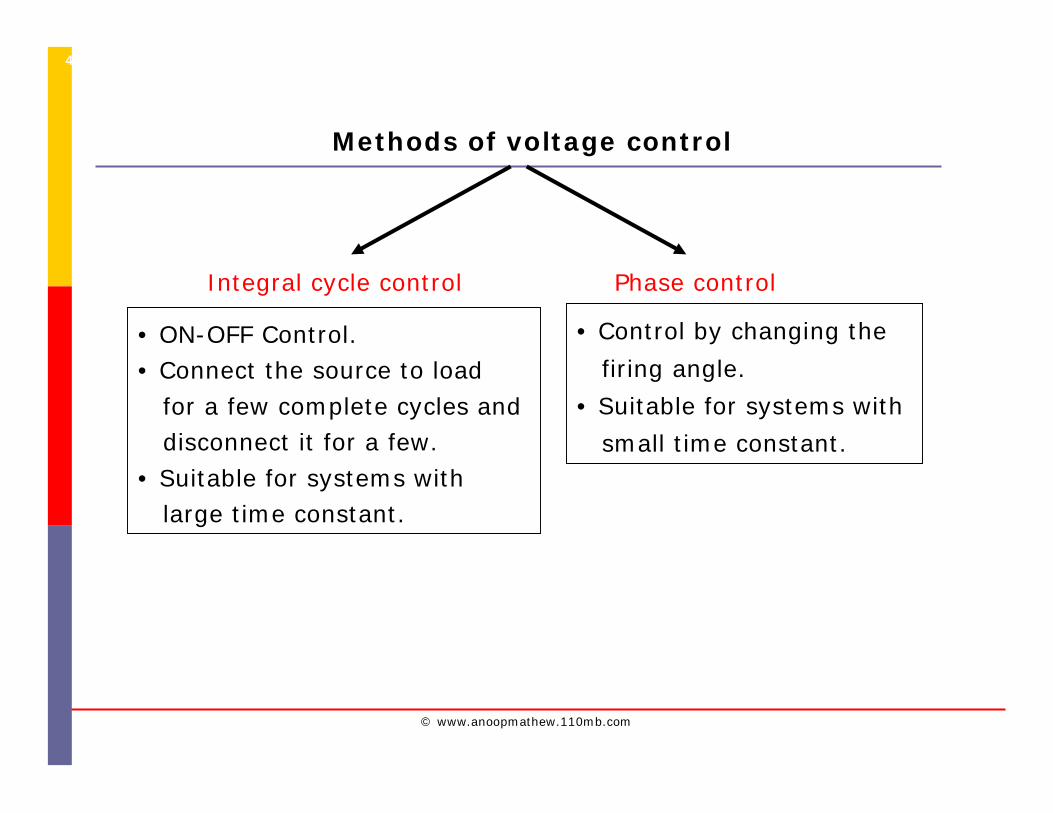
Methods of voltage control
Integral cycle control Phase control
• ON-OFF Control.• Connect the source to load
for a few complete cycles and disconnect it for a few.
• Suitable for systems with large time constant.
• Control by changing the
firing angle.
• Suitable for systems with
small time constant.
© www.anoopmathew.110mb.com
5
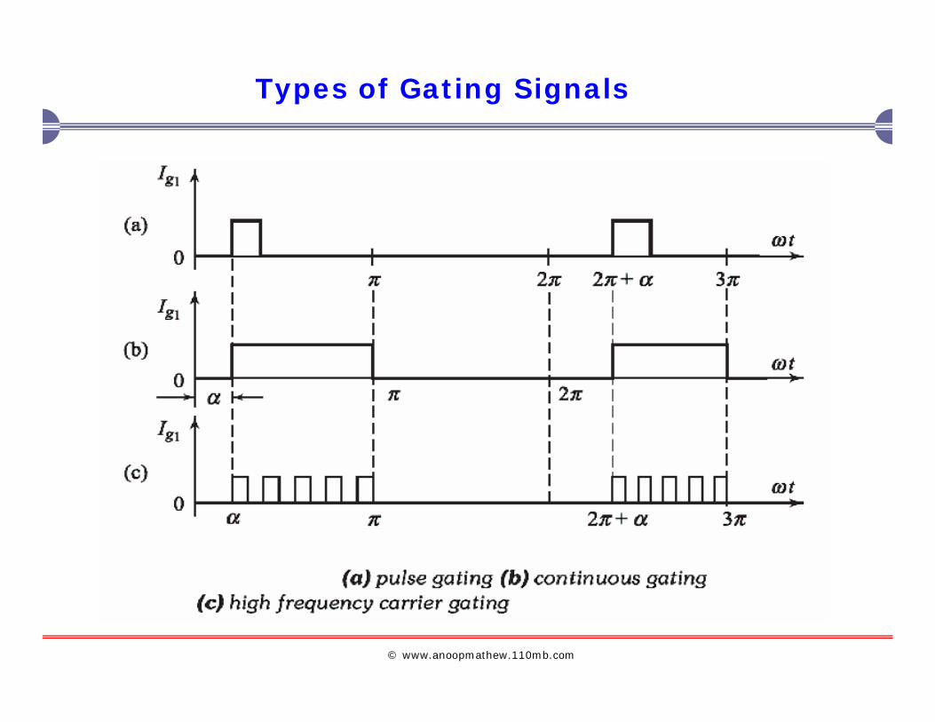
Types of Gating Signals
© www.anoopmathew.110mb.com
6
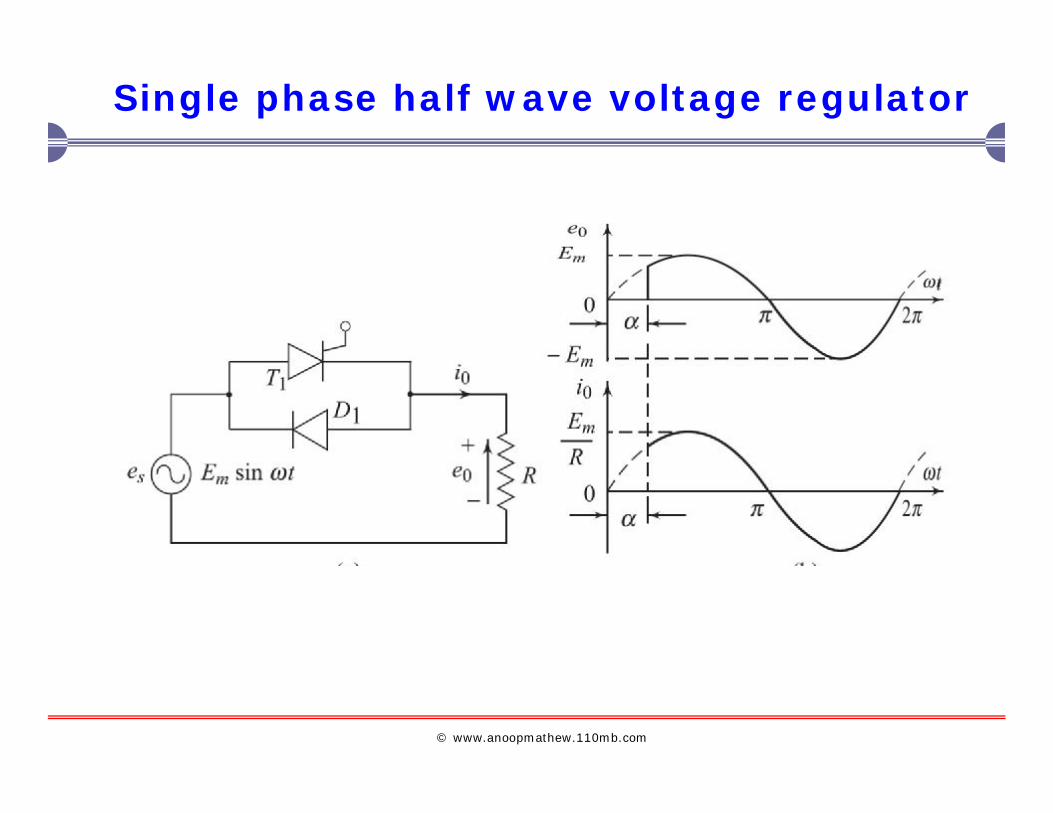
Single phase half wave voltage regulator
© www.anoopmathew.110mb.com
7
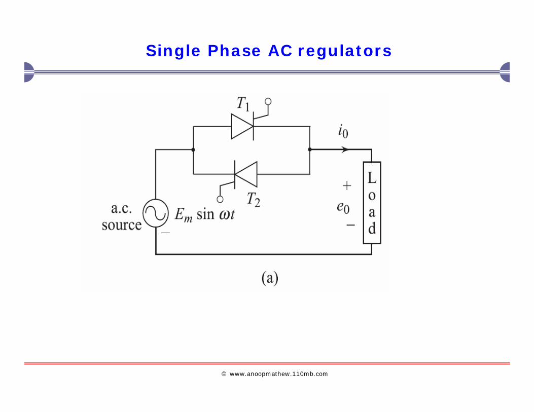
Single Phase AC regulators
© www.anoopmathew.110mb.com
8
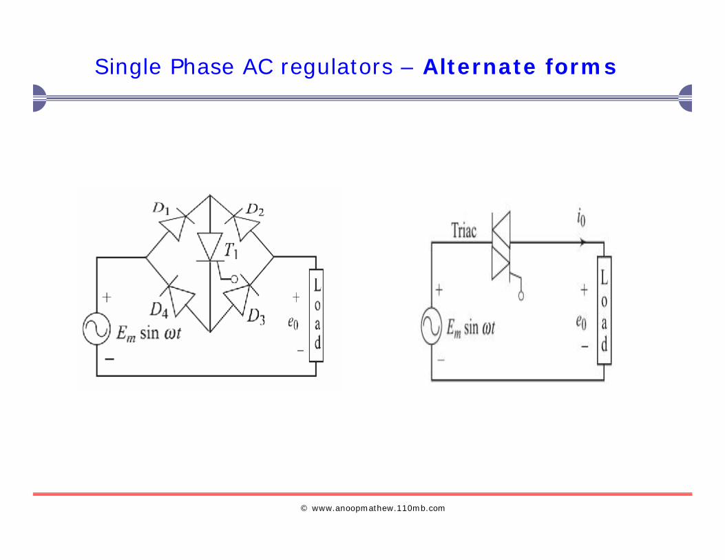
Single Phase AC regulators – Alternate forms
© www.anoopmathew.110mb.com
9
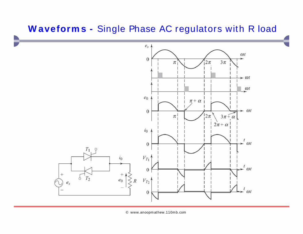
Waveforms - Single Phase AC regulators with R load

© www.anoopmathew.110mb.com
10
Class Work.......
? Find RMS and DC value of the output current and voltage
© www.anoopmathew.110mb.com
11
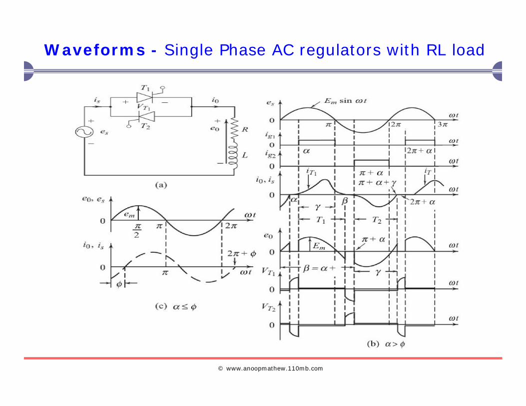
Waveforms - Single Phase AC regulators with RL load
© www.anoopmathew.110mb.com
12
Class Work.......
? Find RMS and DC value of the output current and voltage
© www.anoopmathew.110mb.com
13
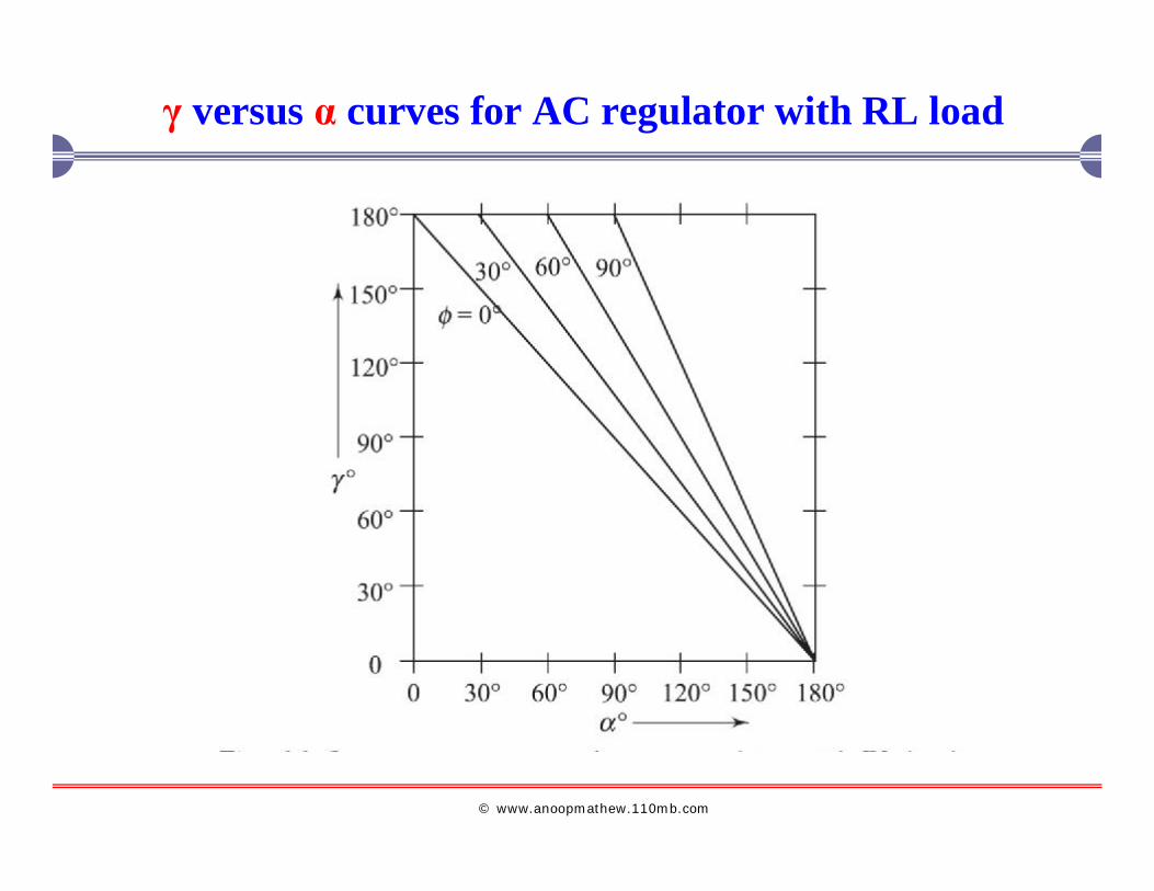
γ versus α curves for AC regulator with RL load
© www.anoopmathew.110mb.com
14
Sequence Controlp To improve system p.f and reduction of
harmonics in the source and load current.
p Two or more stages of voltage controllers are
used in parallel.
p Parallel voltage regulators are triggered in proper
sequence to get desired output.
p Sequence controlled AC regulators are also called
as synchronous tap changers or transformer tap
changers.
© www.anoopmathew.110mb.com
15
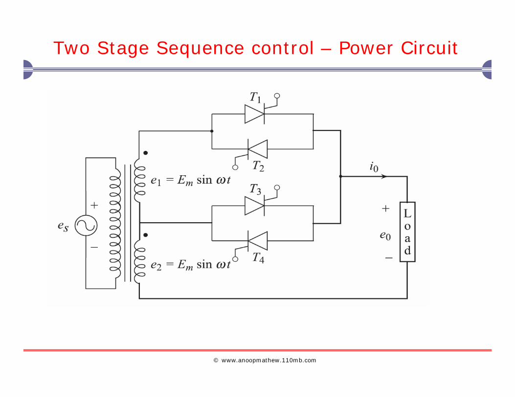
Two Stage Sequence control – Power Circuit
© www.anoopmathew.110mb.com
16
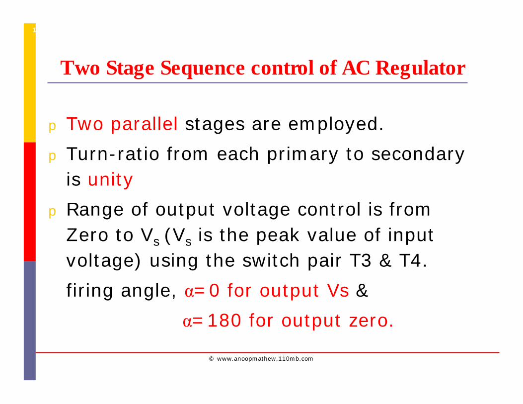
Two Stage Sequence control of AC Regulator
p Two parallel stages are employed.
p Turn-ratio from each primary to secondary is unity
p Range of output voltage control is from Zero to Vs (Vs is the peak value of input voltage) using the switch pair T3 & T4.
firing angle, α=0 for output Vs &
α=180 for output zero.
© www.anoopmathew.110mb.com
17
Two-stage AC regulator
p Using the switch pair T1 & T2.
firing angle, α=0 for output 2Vs &
α=180 for output Vs.

© www.anoopmathew.110mb.com
18
Waveforms - Two-stage AC regulator with R-load
© www.anoopmathew.110mb.com
19
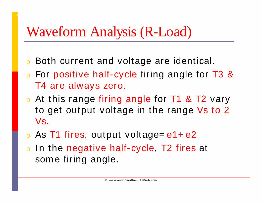
Waveform Analysis (R-Load)
p Both current and voltage are identical.p For positive half-cycle firing angle for T3 &
T4 are always zero.p At this range firing angle for T1 & T2 vary
to get output voltage in the range Vs to 2 Vs.
p As T1 fires, output voltage=e1+e2p In the negative half-cycle, T2 fires at
some firing angle.
© www.anoopmathew.110mb.com
20
Class Work.......
? Find RMS and DC value of the output
current and voltage
© www.anoopmathew.110mb.com
21
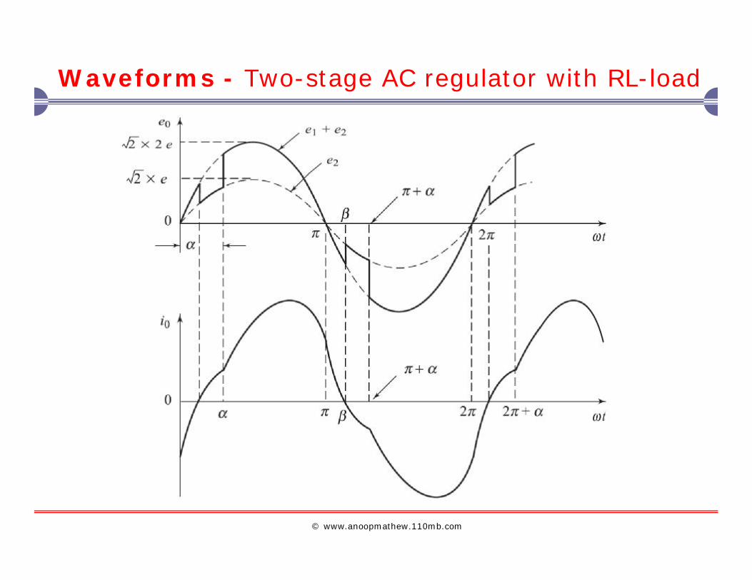
Waveforms - Two-stage AC regulator with RL-load
© www.anoopmathew.110mb.com
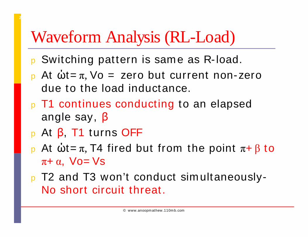
22
Waveform Analysis (RL-Load)p Switching pattern is same as R-load.p At ώt=π, Vo = zero but current non-zero
due to the load inductance.p T1 continues conducting to an elapsed
angle say, βp At β, T1 turns OFFp At ώt=π, T4 fired but from the point π+β to π+α, Vo=Vs
p T2 and T3 won’t conduct simultaneously-No short circuit threat.
© www.anoopmathew.110mb.com
23
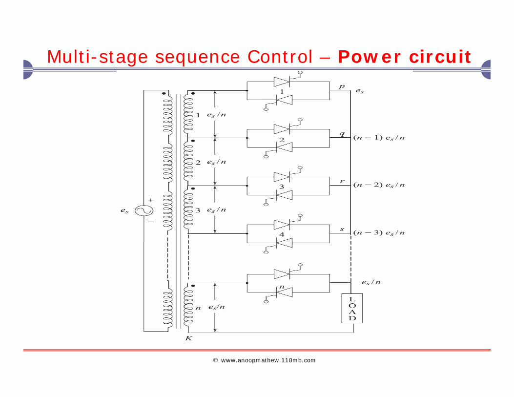
Multi-stage sequence Control – Power circuit
© www.anoopmathew.110mb.com
24
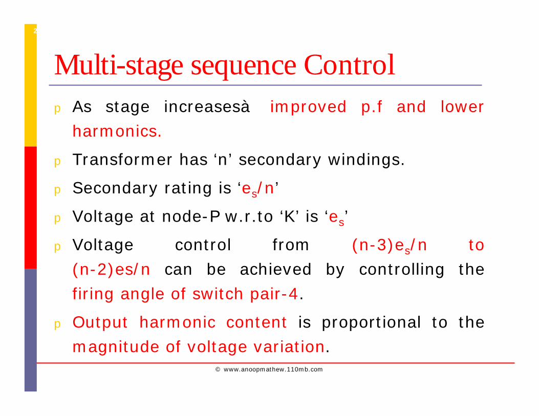
Multi-stage sequence Controlp As stage increasesà improved p.f and lower
harmonics.
p Transformer has ‘n’ secondary windings.
p Secondary rating is ‘es/n’
p Voltage at node-P w.r.to ‘K’ is ‘es’
p Voltage control from (n-3)es/n to (n-2)es/n can be achieved by controlling the firing angle of switch pair-4.
p Output harmonic content is proportional to the magnitude of voltage variation.
© www.anoopmathew.110mb.com
25
References
[1] A. Maamoun, “A review on semiconductor voltage controllers”, IEEE Trans. 2003.
[2] Ned Mohan et al, “Power Electronics”, Weily publications 2005
[3] M.D. Singh & K.B Khanjandani, “Power Electronics”, TMH 2006
[4] Cyril W. Lander “ Power Electronics”, McGraw Hill International Editions 2007
[5] Rashid M.H “ Power Electronics”, printice Hall Int. 2001
[6] Krein “Elements of Power Electronics”, Oxford Press 2005
Related Documents