URC Utility Relay Company ac-pro ® i-ac-pro-QT ac trip unit

Welcome message from author
This document is posted to help you gain knowledge. Please leave a comment to let me know what you think about it! Share it to your friends and learn new things together.
Transcript
7/27/2019 AC-PRO - Trip Unit - Instruction Manual - 2-2006 and Later
http://slidepdf.com/reader/full/ac-pro-trip-unit-instruction-manual-2-2006-and-later 1/31
URC Utility Relay Company
ac-pro®
i-ac-pro-QT ac trip unit
7/27/2019 AC-PRO - Trip Unit - Instruction Manual - 2-2006 and Later
http://slidepdf.com/reader/full/ac-pro-trip-unit-instruction-manual-2-2006-and-later 2/31
AC-PROTM
With QUICK-TRIPTM
Instruction Manual www.utilityrelay.com
Page 1
Manual Rev 1.1
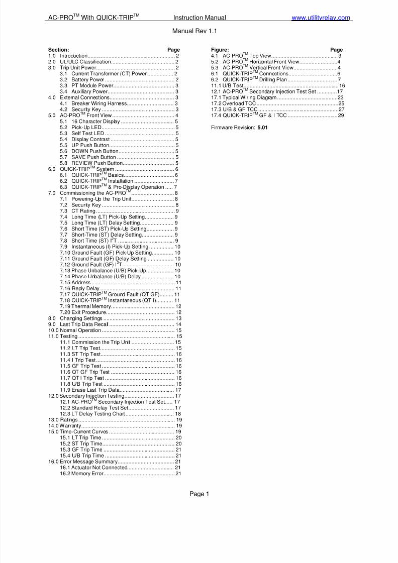
Section: Page1.0 Introduction.......................................................... 22.0 UL/ULC Classification.......................................... 23.0 Trip Unit Power.................................................... 2
3.1 Current Transformer (CT) Power ................. 23.2 Battery Power .............................................. 23.3 PT Module Power........................................ 33.4 Auxiliary Power............................................ 3
4.0 External Connections........................................... 34.1 Breaker Wiring Harness............................... 34.2 Security Key ................................................ 3
5.0 AC-PROTM Front View......................................... 45.1 16 Character Display ................................... 55.2 Pick-Up LED................................................ 55.3 Self Test LED .............................................. 55.4 Display Contrast .......................................... 55.5 UP Push Button........................................... 55.6 DOWN Push Button..................................... 55.7 SAVE Push Button ...................................... 55.8 REVIEW Push Button.................................. 5
6.0 QUICK-TRIPTM System ....................................... 66.1 QUICK-TRIPTM Basics................................. 66.2 QUICK-TRIPTM Installation .......................... 76.3 QUICK-TRIP
TM& Pro-Display Operation ..... 7
7.0 Commissioning the AC-PROTM
............................ 8
7.1 Powering-Up the Trip Unit............................ 87.2 Security Key ................................................ 87.3 CT Rating .................................................... 97.4 Long Time (LT) Pick-Up Setting................... 97.5 Long Time (LT) Delay Setting...................... 97.6 Short Time (ST) Pick-Up Setting.................. 97.7 Short-Time (ST) Delay Setting..................... 97.8 Short Time (ST) I2T ..................................... 97.9 Instantaneous (I) Pick-Up Setting ................ 107.10 Ground Fault (GF) Pick-Up Setting.............. 107.11 Ground Fault (GF) Delay Setting ................. 107.12 Ground Fault (GF) I
2T.................................. 10
7.13 Phase Unbalance (U/B) Pick-Up.................. 107.14 Phase Unbalance (U/B) Delay ..................... 107.15 Address ....................................................... 117.16 Reply Delay ................................................. 11
7.17 QUICK-TRIPTM
Ground Fault (QT GF)......... 117.18 QUICK-TRIPTM Instantaneous (QT I)........... 117.19 Thermal Memory.......................................... 127.20 Exit Procedure............................................. 12
8.0 Changing Settings ............................................... 139.0 Last Trip Data Recall ........................................... 1410.0 Normal Operation ................................................ 1511.0 Testing ................................................................ 15
11.1 Commission the Trip Unit ............................ 1511.2 LT Trip Test................................................. 1511.3 ST Trip Test................................................. 1611.4 I Trip Test .................................................... 1611.5 GF Trip Test ................................................ 1611.6 QT GF Trip Test .......................................... 1611.7 QT I Trip Test .............................................. 1611.8 U/B Trip Test ............................................... 1611.9 Erase Last Trip Data.................................... 17
12.0 Secondary Injection Testing................................. 1712.1 AC-PRO
TMSecondary Injection Test Set..... 17
12.2 Standard Relay Test Set.............................. 1712.3 LT Delay Testing Chart ................................ 18
13.0 Ratings ................................................................ 1914.0 Warranty.............................................................. 1915.0 Time-Current Curves ........................................... 19
15.1 LT Trip Time ................................................ 2015.2 ST Trip Time................................................ 2015.3 GF Trip Time ............................................... 2115.4 U/B Trip Time .............................................. 21
16.0 Error Message Summary..................................... 2116.1 Actuator Not Connected............................... 2116.2 Memory Error............................................... 21
Figure: Page4.1 AC-PRO
TMTop View............................................3
5.2 AC-PROTM
Horizontal Front View.........................45.3 AC-PRO
TMVertical Front View.............................4
6.1 QUICK-TRIPTM
Connections................................66.2 QUICK-TRIPTM Drilling Plan .................................711.1 U/B Test...............................................................1612.1 AC-PROTM Secondary Injection Test Set .............17
17.1 Typical Wiring Diagram........................................2317.2 Overload TCC......................................................2517.3 U/B & GF TCC .....................................................2717.4 QUICK-TRIPTM GF & I TCC .................................29
Firmware Revision: 5.01
7/27/2019 AC-PRO - Trip Unit - Instruction Manual - 2-2006 and Later
http://slidepdf.com/reader/full/ac-pro-trip-unit-instruction-manual-2-2006-and-later 3/31
Utility Relay Company
Page 2
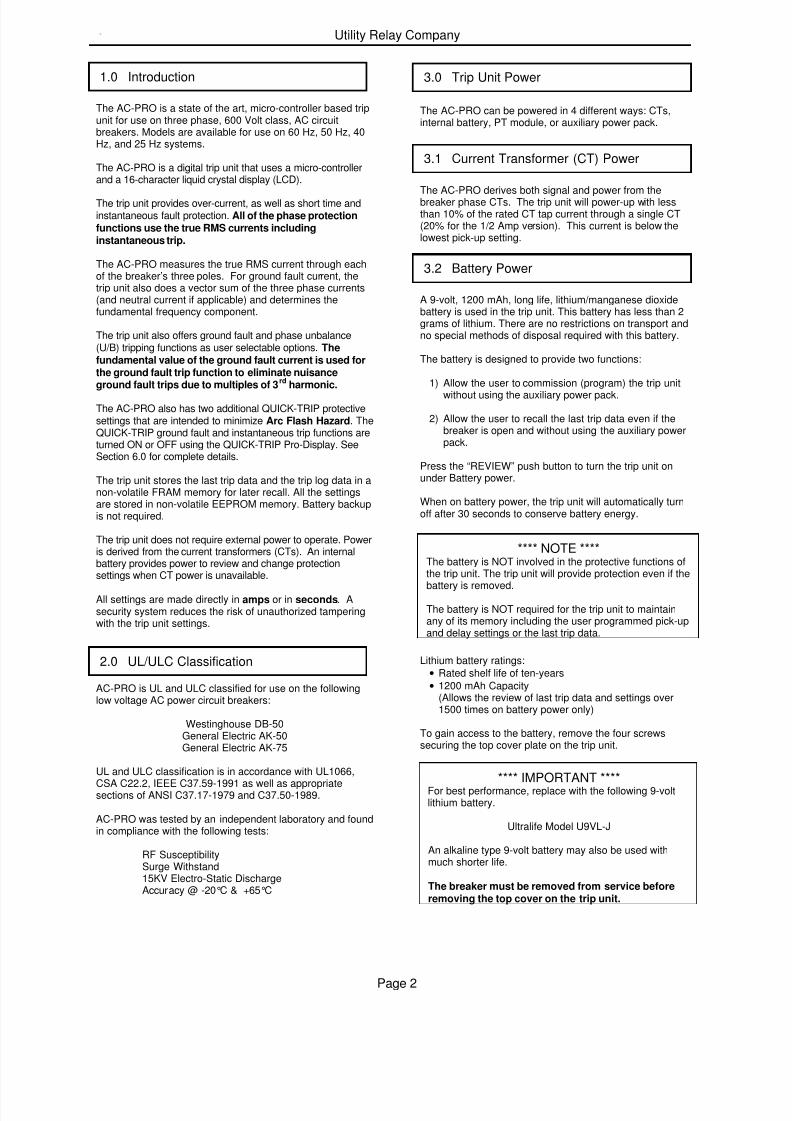
The AC-PRO is a state of the art, micro-controller based tripunit for use on three phase, 600 Volt class, AC circuitbreakers. Models are available for use on 60 Hz, 50 Hz, 40Hz, and 25 Hz systems.
The AC-PRO is a digital trip unit that uses a micro-controllerand a 16-character liquid crystal display (LCD).
The trip unit provides over-current, as well as short time andinstantaneous fault protection. All of the phase protectionfunctions use the true RMS currents includinginstantaneous trip.
The AC-PRO measures the true RMS current through eachof the breaker’s three poles. For ground fault current, thetrip unit also does a vector sum of the three phase currents(and neutral current if applicable) and determines thefundamental frequency component.
The trip unit also offers ground fault and phase unbalance(U/B) tripping functions as user selectable options. Thefundamental value of the ground fault current is used forthe ground fault trip function to eliminate nuisanceground fault trips due to multiples of 3
rdharmonic.
The AC-PRO also has two additional QUICK-TRIP protectivesettings that are intended to minimize Arc Flash Hazard. TheQUICK-TRIP ground fault and instantaneous trip functions areturned ON or OFF using the QUICK-TRIP Pro-Display. SeeSection 6.0 for complete details.
The trip unit stores the last trip data and the trip log data in anon-volatile FRAM memory for later recall. All the settingsare stored in non-volatile EEPROM memory. Battery backupis not required.
The trip unit does not require external power to operate. Poweris derived from the current transformers (CTs). An internalbattery provides power to review and change protectionsettings when CT power is unavailable.
All settings are made directly in amps or in seconds. Asecurity system reduces the risk of unauthorized tamperingwith the trip unit settings.
AC-PRO is UL and ULC classified for use on the followinglow voltage AC power circuit breakers:
Westinghouse DB-50General Electric AK-50General Electric AK-75
UL and ULC classification is in accordance with UL1066,
CSA C22.2, IEEE C37.59-1991 as well as appropriatesections of ANSI C37.17-1979 and C37.50-1989.
AC-PRO was tested by an independent laboratory and foundin compliance with the following tests:
RF SusceptibilitySurge Withstand15KV Electro-Static DischargeAccuracy @ -20°C & +65°C
The AC-PRO can be powered in 4 different ways: CTs,internal battery, PT module, or auxiliary power pack.
The AC-PRO derives both signal and power from thebreaker phase CTs. The trip unit will power-up with lessthan 10% of the rated CT tap current through a single CT(20% for the 1/2 Amp version). This current is below thelowest pick-up setting.
A 9-volt, 1200 mAh, long life, lithium/manganese dioxidebattery is used in the trip unit. This battery has less than 2grams of lithium. There are no restrictions on transport andno special methods of disposal required with this battery.
The battery is designed to provide two functions:
1) Allow the user to commission (program) the trip unit
without using the auxiliary power pack.
2) Allow the user to recall the last trip data even if thebreaker is open and without using the auxiliary powerpack.
Press the “REVIEW” push button to turn the trip unit onunder Battery power.
When on battery power, the trip unit will automatically turnoff after 30 seconds to conserve battery energy.
**** NOTE ****The battery is NOT involved in the protective functions ofthe trip unit. The trip unit will provide protection even if the
battery is removed.
The battery is NOT required for the trip unit to maintainany of its memory including the user programmed pick-upand delay settings or the last trip data.
Lithium battery ratings:
• Rated shelf life of ten-years
• 1200 mAh Capacity(Allows the review of last trip data and settings over1500 times on battery power only)
To gain access to the battery, remove the four screwssecuring the top cover plate on the trip unit.
**** IMPORTANT ****For best performance, replace with the following 9-voltlithium battery.
Ultralife Model U9VL-J
An alkaline type 9-volt battery may also be used withmuch shorter life.
The breaker must be removed from service beforeremoving the top cover on the trip unit.
1.0 Introduction
2.0 UL/ULC Classification
3.0 Trip Unit Power
3.1 Current Transformer (CT) Power
3.2 Battery Power
7/27/2019 AC-PRO - Trip Unit - Instruction Manual - 2-2006 and Later
http://slidepdf.com/reader/full/ac-pro-trip-unit-instruction-manual-2-2006-and-later 4/31
AC-PROTM
With QUICK-TRIPTM
Instruction Manual www.utilityrelay.com
Page 3
The AC-PRO+ is the communication version of the AC-PROand has a connection for a PT module.
The PT module provides breaker 3-Phase voltageinformation and also provides power for the trip unitindependently from the CTs. See the CommunicationInstruction Manual for more information.
Auxiliary power is optional. It can be used to change orreview the trip unit settings without using the internal battery.
Plug the 24-VAC auxiliary power pack into the auxiliarypower jack on the top of the trip unit.
The power pack is available from Utility Relay Company aspart number T-390.
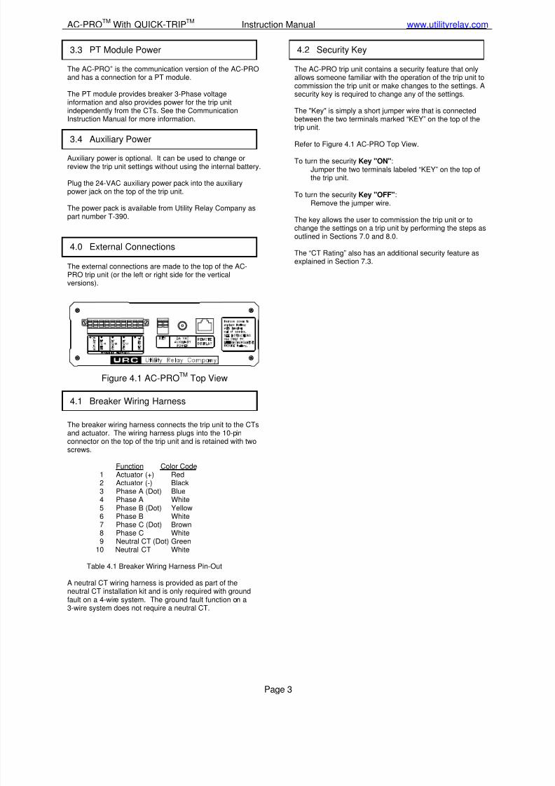
The external connections are made to the top of the AC-
PRO trip unit (or the left or right side for the verticalversions).
Figure 4.1 AC-PROTM
Top View
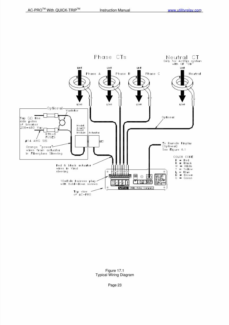
The breaker wiring harness connects the trip unit to the CTsand actuator. The wiring harness plugs into the 10-pinconnector on the top of the trip unit and is retained with twoscrews.
Function Color Code1 Actuator (+) Red2 Actuator (-) Black3 Phase A (Dot) Blue4 Phase A White5 Phase B (Dot) Yellow6 Phase B White7 Phase C (Dot) Brown8 Phase C White9 Neutral CT (Dot) Green
10 Neutral CT White
Table 4.1 Breaker Wiring Harness Pin-Out
A neutral CT wiring harness is provided as part of theneutral CT installation kit and is only required with groundfault on a 4-wire system. The ground fault function on a3-wire system does not require a neutral CT.
The AC-PRO trip unit contains a security feature that onlyallows someone familiar with the operation of the trip unit tocommission the trip unit or make changes to the settings. Asecurity key is required to change any of the settings.
The "Key" is simply a short jumper wire that is connectedbetween the two terminals marked “KEY” on the top of thetrip unit.
Refer to Figure 4.1 AC-PRO Top View.
To turn the security Key "ON":Jumper the two terminals labeled “KEY” on the top ofthe trip unit.
To turn the security Key "OFF":Remove the jumper wire.
The key allows the user to commission the trip unit or tochange the settings on a trip unit by performing the steps asoutlined in Sections 7.0 and 8.0.
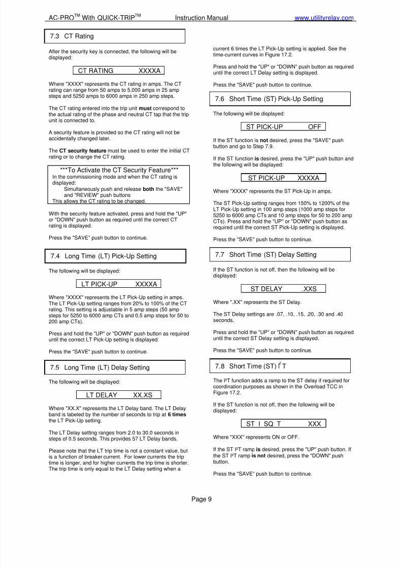
The “CT Rating” also has an additional security feature asexplained in Section 7.3.
3.3 PT Module Power
3.4 Auxiliary Power
4.0 External Connections
4.1 Breaker Wiring Harness
4.2 Security Key
7/27/2019 AC-PRO - Trip Unit - Instruction Manual - 2-2006 and Later
http://slidepdf.com/reader/full/ac-pro-trip-unit-instruction-manual-2-2006-and-later 5/31
Utility Relay Company
Page 4
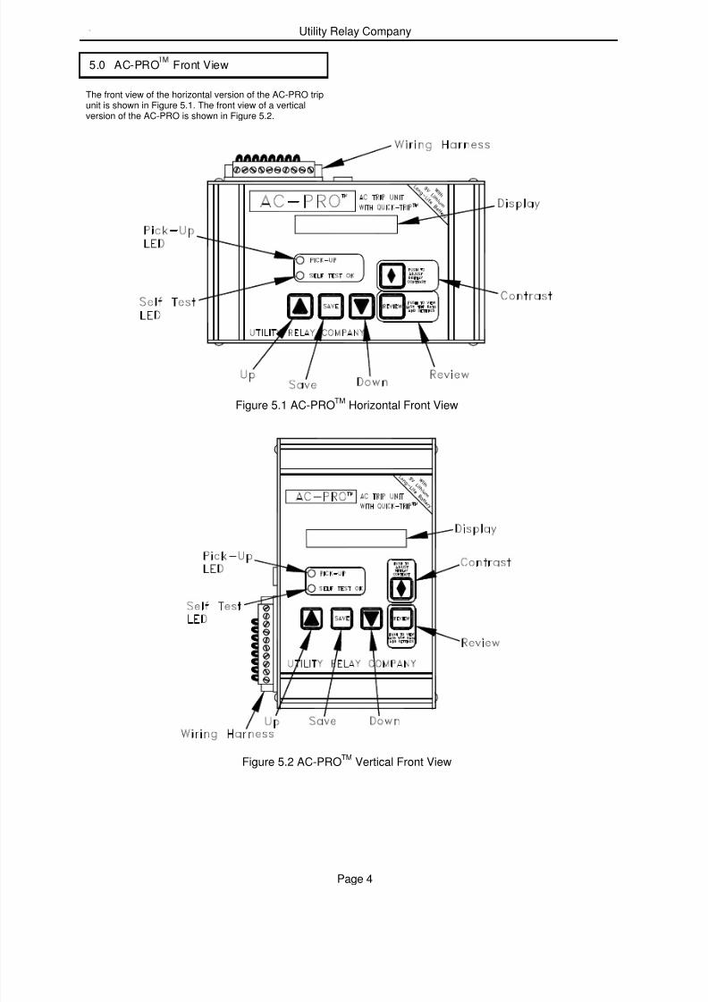
The front view of the horizontal version of the AC-PRO tripunit is shown in Figure 5.1. The front view of a verticalversion of the AC-PRO is shown in Figure 5.2.
Figure 5.1 AC-PROTM
Horizontal Front View
Figure 5.2 AC-PROTM
Vertical Front View
5.0 AC-PRO Front View
7/27/2019 AC-PRO - Trip Unit - Instruction Manual - 2-2006 and Later
http://slidepdf.com/reader/full/ac-pro-trip-unit-instruction-manual-2-2006-and-later 6/31
AC-PROTM
With QUICK-TRIPTM
Instruction Manual www.utilityrelay.com
Page 5
A 16-character dot matrix liquid crystal display (LCD)provides information to the user.
The LCD is used for the following purposes:
1) Entering the CT rating and making the pick-up and timedelay settings with prompts from the display.
2) Displaying, on demand, the CT rating and the variouspick-up and delay settings.
3) Displaying, on demand, the reason for the last trip andthe currents at the time of trip.
4) Continuously displaying the actual 3-phase AC currentson the breaker.
The Pick-Up LED is normally off. It will turn on wheneverthe breaker current is above the LT Pick-up setting.
The Self Test LED is normally on. It will turn off under thefollowing conditions:
1) The actuator is not connected. The LCD will alsodisplay an error message.
2) There is a checksum error in the micro-controller. TheLCD will also display an error message.
The contrast level of the LCD can be adjusted by pressingthis push button.
When the contrast push button is pressed and held, thedisplay will begin to get either darker or lighter. To changedirection, release the push button for more than one second,then press and the hold the push button until the desiredcontrast is achieved.
Use this push button to increase the setting values duringcommissioning. When the “UP” push button is held longerthan one second, the settings are increased in fast mode.
When the maximum setting value is reached, the “UP” pushbutton will have no further effect on the setting value.
Use this push button to decrease the setting values duringcommissioning. When the “DOWN” push button is heldlonger than one second, the settings are decreased in fastmode.
When the minimum setting value is reached, the “DOWN”push button will have no further effect on the setting value.Save
Use this push button to step though the settings when in thecommissioning mode.
Holding this push button has no effect.
Use this push button to step though the settings in thesettings review mode. Also use this push button to turn thetrip unit on using battery power.
Hold this push button down to review trip counts during thesettings review.
5.1 16 Character Display
5.2 Pick-Up LED
5.3 Self Test LED
5.4 Display Contrast
5.5 UP Push Button
5.6 DOWN Push Button
5.7 SAVE Push Button
5.8 REVIEW Push Button

7/27/2019 AC-PRO - Trip Unit - Instruction Manual - 2-2006 and Later
http://slidepdf.com/reader/full/ac-pro-trip-unit-instruction-manual-2-2006-and-later 7/31
Utility Relay Company
Page 6
Figure 6.1
QUICK-TRIP
TM
Connections
The QUICK-TRIP system is a manually controlled ZoneSelective Interlock (ZSI) system. It can reduce trip timeswhen turned on and allows selective coordination betweencircuit breakers when turned off.
If maintenance personnel must work on energizedequipment, they will first turn the QUICK-TRIP system on atthe breaker feeding the equipment. If a fault now occurs, theupstream breaker will trip quickly based on the QUICK-TRIPsettings reducing the Arc Flash Hazard to personnel.
When the work is done, the QUICK-TRIP system is turnedoff and the original selective coordination is back in effect.
The QUICK-TRIP system consists of the followingcomponents:
1. AC-PRO trip unit with QUICK-TRIP.2. Pro-Display with a “QUICK-TRIP ON“ LED.3. Padlocking selector switch mounted near the Pro-
Display that is used to turn QUICK-TRIP on and off.
When QUICK-TRIP is on, the following settings are enabled:
• GF QUICK-TRIP (GF QT)
• I QUICK-TRIP (I QT)All other settings remain in effect.
The “QUICK-TRIP ON LED” provides positive indicat ion thatthe QUICK-TRIP settings are active if the LED is on.
The extra contact block on the QUICK-TRIP selector switchcan be used for local or remote indication of the QUICK-TRIP selector switch setting.
**** IMPORTANT ****A qualified engineer must determine the QUICK-TRIPsettings, calculate the incident energy levels anddetermine the Hazard Risk Categories (HRC).
If an older Pro-Display without the “QUICK-TRIP ON”LED is plugged into an AC-PRO with QUICK-TRIP, theQUICK-TRIP settings will always be on.
6.0 Quick-Trip System
6.1 Quick-Trip Basics
7/27/2019 AC-PRO - Trip Unit - Instruction Manual - 2-2006 and Later
http://slidepdf.com/reader/full/ac-pro-trip-unit-instruction-manual-2-2006-and-later 8/31
AC-PROTM
With QUICK-TRIPTM
Instruction Manual www.utilityrelay.com
Page 7
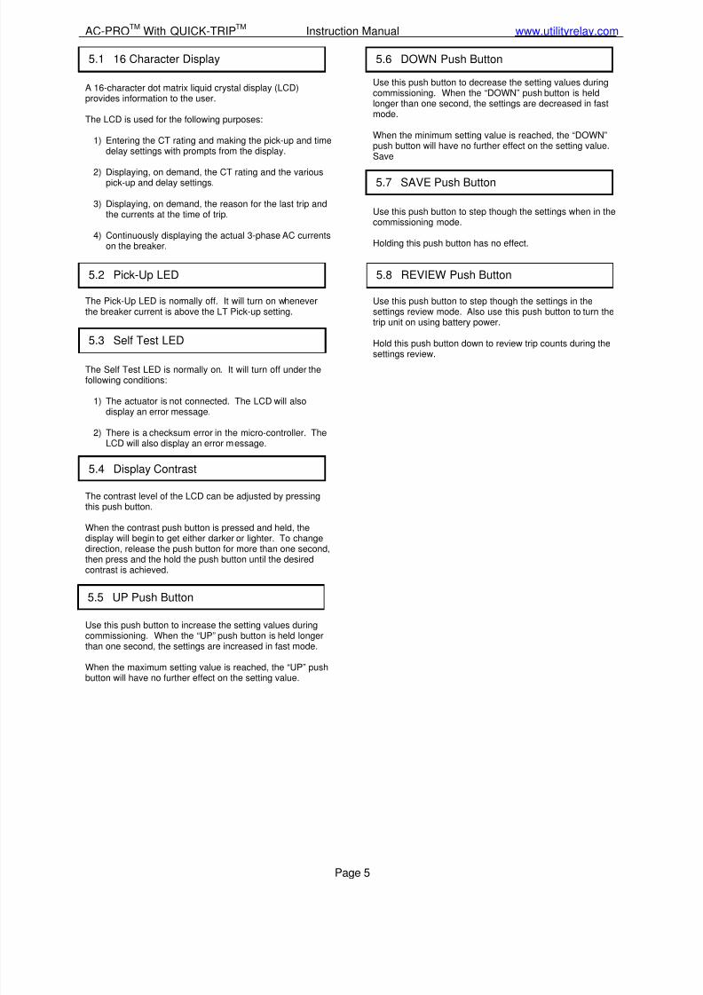
Figure 6.2QUICK-TRIP
TMDrilling Plan
The QUICK-TRIP system is easy to install on the front of thebreaker cubicle door.
To install the Pro-Display:
1. Find a suitable location on the cubicle door and mark
the location of the three (3) holes using the dimensionsin Figure 6.2.2. Drill two (2) 13/64” mounting holes.3. For the center hole, cut a 1-11/16” diameter hole using a
hole saw or alternately, use a 1-1/4” conduit knockoutpunch.
4. Attach the Pro-Display to the front of the cubicle doorusing two (2) 10-32 x 3/8 R.H. screws and lock washers.
5. Connect the Pro-Display to the AC-PRO trip unit byplugging one end of the shielded modular cableprovided into the jack on the back of the Pro-Display.Plug the other end of the cable into the “RemoteDisplay” jack on the top of the AC-PRO.
6. Route the cable so it does not interfere with the openingor closing of the cubical door or with the racking of thebreaker between connect and disconnect positions. Usecable ties and holders to hold the cable in position.
To install the on/off selector switch:
1. Use a 22mm switch knock out punch to make a hole inthe cubicle door for the selector switch. The selectorswitch should be located near the remote display.
2. Attach the selector switch, padlock attachment andcontact blocks to the cubicle door.
3. Plug the cable from the switch into the back of the Pro-Display.
The Pro-Display will display the same messages as thedisplay on the AC-PRO. It provides the capability of viewingthe breaker currents and reviewing the settings and the lasttrip data without opening the breaker cubicle door.
For security reasons, it is not possible to change any settings from the Pro-Display.
When the display on the Pro-Display is off, push the“REVIEW” button to power the Pro-Display from the internalbattery in the AC-PRO. The following information will beavailable:
• Last trip data including the type of trip and the currents
• Pushing the “REVIEW” button will display the trip log
• Continuing to push the “REVIEW” button will stepthrough the settings
• The “SELF TEST OK” LED will indicate proper operation
• The “QUICK-TRIP ON” LED will indicate the on/offstatus of the QUICK-TRIP settings
When the display on the Pro-Display is on, the phasecurrents will be displayed (if greater than 10% of the CTtap). The following information will also be available:
• The “PICK-UP” LED will indicate if phase currents areabove the Long Time pick-up setting
• The “SELF TEST OK” LED will indicate proper operation
• The “QUICK-TRIP ON” LED will indicate the on/offstatus of the QUICK-TRIP settings
Pushing the “REVIEW” button will display:
• Last trip data including the type of trip and the currents
• Pushing the “REVIEW” button will display the trip log
• Continuing to push the “REVIEW” button will stepthrough the settings
6.2 Quick-Trip Installation 6.3 Quick-Trip & Pro-Display Operation
7/27/2019 AC-PRO - Trip Unit - Instruction Manual - 2-2006 and Later
http://slidepdf.com/reader/full/ac-pro-trip-unit-instruction-manual-2-2006-and-later 9/31
Utility Relay Company
Page 8
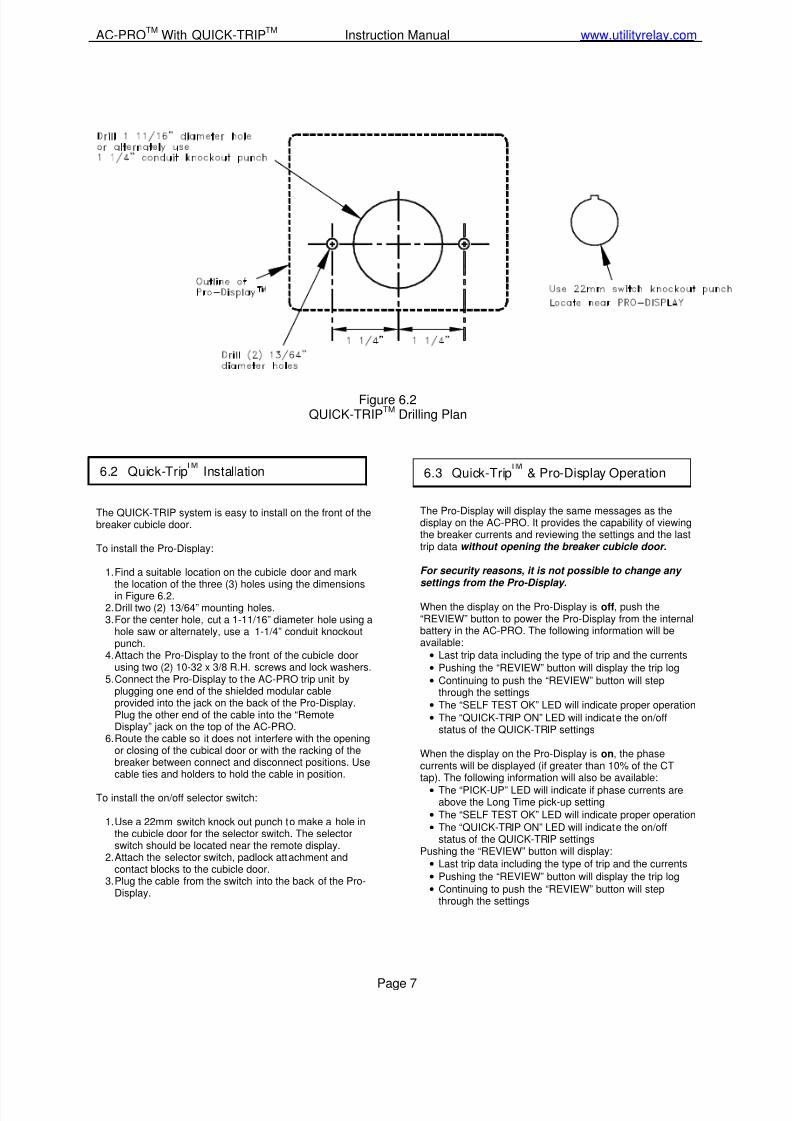
Before the AC-PRO trip unit is put into service, it must firstbe commissioned so it will function. This requires the user toenter all of the pick-up and delay settings into the unit.
The commissioning process normally takes less than a fewminutes to complete.
**** IMPORTANT ****
The trip unit will NOT FUNCTION as it is shipped fromthe factory. The user must first COMMISSION the unit asoutlined in this Section to make it functional.
After the AC-PRO is installed on the breaker, it must becommissioned as follows:
1) Connect the security key (see Section 4.2)
2) Push the "REVIEW" push button to power-up the tripunit. The trip unit will alternately display the following:
ENTER DATA
SERIAL # XXXXXXX
Press the “SAVE” push button. The following will bedisplayed:
PROD: H4.50F5.00
Press the “SAVE” push button to begin the commissioningprocess.
3) Enter the appropriate CT tap, pick-up and delaysettings using the "UP", "DOWN" and "SAVE" pushbuttons.
4) Remove the security key (see Section 4.2).
Sections 7.1 through 7.7 go over the commissioning processin greater detail.
****NOTE****An additional security feature is provided to avoidaccidentally changing the CT tap setting. See Section 7.3.
In normal service, the AC-PRO trip unit is powered directlyfrom the breaker mounted CTs.
For commissioning, the AC-PRO trip unit can be powered-up in either of the following two ways.
1) Internal Battery
Press the "REVIEW" button to power-up the trip unitusing the internal battery.
The trip unit is designed to shut off automatically ifnone of the 4 lower push buttons on the face of the unitare pressed for 30 seconds. It is best to have all thedesired settings readily available before commissioningthe unit when using the battery.
If the unit shuts down before the commissioningprocess is completed, the process must be startedagain from the beginning.
2) External Power
Apply 24 VAC to the "auxiliary power" jack located onthe top of the trip unit using the Utility Relay auxiliary
power pack.(Utility Relay Company part number T-390).
By applying external power, the unit will stay energizedas long as necessary to complete the commissioningprocess.
The following will be displayed if the security key is notalready connected:
SECURITY KEY OFF
Connect the security key to continue the commissioning
process. See Section 4.2.
7.0 Commissioning the AC-PRO
7.1 Powering-Up the Trip Unit
7.2 Security Key
7/27/2019 AC-PRO - Trip Unit - Instruction Manual - 2-2006 and Later
http://slidepdf.com/reader/full/ac-pro-trip-unit-instruction-manual-2-2006-and-later 10/31
7/27/2019 AC-PRO - Trip Unit - Instruction Manual - 2-2006 and Later
http://slidepdf.com/reader/full/ac-pro-trip-unit-instruction-manual-2-2006-and-later 11/31
Utility Relay Company
Page 10
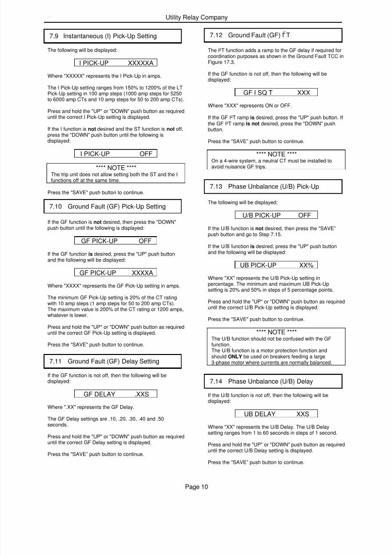
The following will be displayed:
I PICK-UP XXXXXA
Where "XXXXX" represents the I Pick-Up in amps.
The I Pick-Up setting ranges from 150% to 1200% of the LTPick-Up setting in 100 amp steps (1000 amp steps for 5250to 6000 amp CTs and 10 amp steps for 50 to 200 amp CTs).
Press and hold the "UP" or "DOWN" push button as requireduntil the correct I Pick-Up setting is displayed.
If the I function is not desired and the ST function is not off,press the "DOWN" push button until the following isdisplayed:
I PICK-UP OFF
**** NOTE ****The trip unit does not allow setting both the ST and the Ifunctions off at the same time.
Press the "SAVE" push button to continue.
If the GF function is not desired, then press the "DOWN"push button until the following is displayed:
GF PICK-UP OFF
If the GF function is desired, press the "UP" push buttonand the following will be displayed:
GF PICK-UP XXXXA
Where "XXXX" represents the GF Pick-Up setting in amps.
The minimum GF Pick-Up setting is 20% of the CT ratingwith 10 amp steps (1 amp steps for 50 to 200 amp CTs).The maximum value is 200% of the CT rating or 1200 amps,whatever is lower.
Press and hold the "UP" or "DOWN" push button as requireduntil the correct GF Pick-Up setting is displayed.
Press the "SAVE" push button to continue.
If the GF function is not off, then the following will bedisplayed:
GF DELAY .XXS
Where ".XX" represents the GF Delay.
The GF Delay settings are .10, .20, .30, .40 and .50seconds.
Press and hold the "UP" or "DOWN" push button as requireduntil the correct GF Delay setting is displayed.
Press the "SAVE” push button to continue.
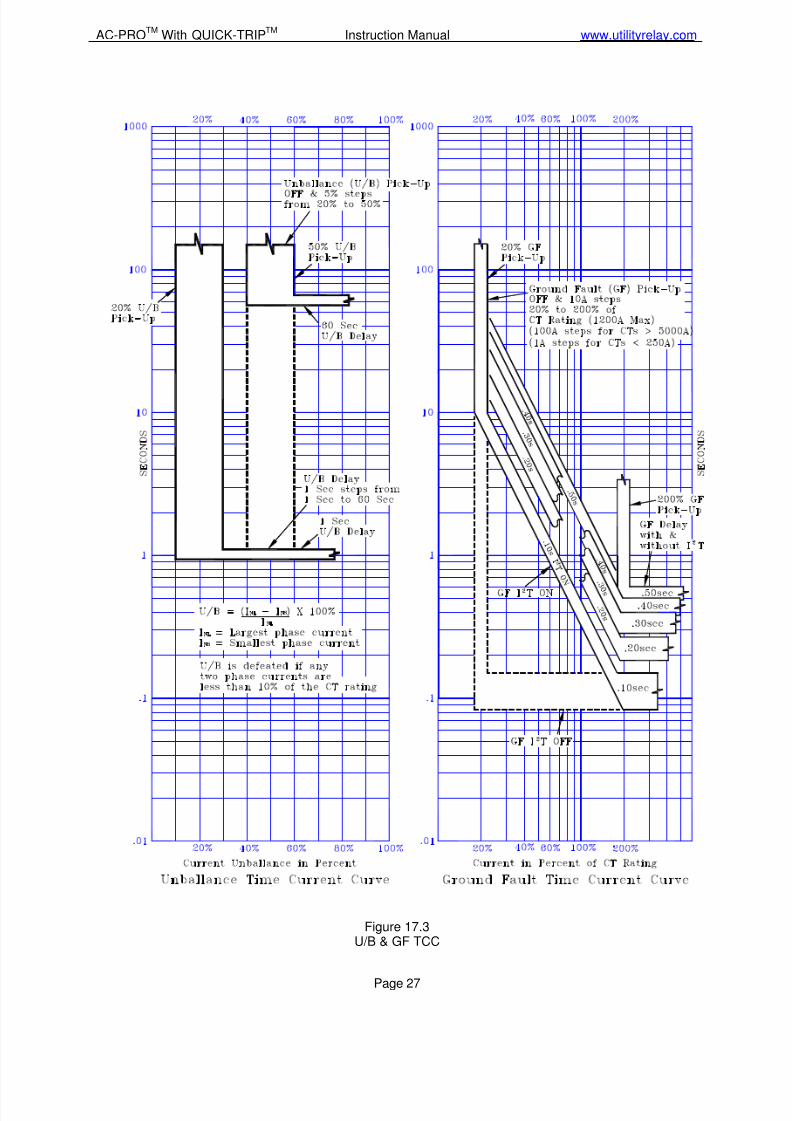
The I²T function adds a ramp to the GF delay if required forcoordination purposes as shown in the Ground Fault TCC inFigure 17.3.
If the GF function is not off, then the following will bedisplayed:
GF I SQ T XXX
Where "XXX" represents ON or OFF.
If the GF I²T ramp is desired, press the "UP" push button. Ifthe GF I²T ramp is not desired, press the "DOWN" pushbutton.
Press the "SAVE” push button to continue.
**** NOTE ****On a 4-wire system, a neutral CT must be installed toavoid nuisance GF trips.
The following will be displayed:
U/B PICK-UP OFF
If the U/B function is not desired, then press the "SAVE”push button and go to Step 7.15.
If the U/B function is desired, press the "UP" push buttonand the following will be displayed:
UB PICK-UP XX%
Where "XX" represents the U/B Pick-Up setting inpercentage. The minimum and maximum UB Pick-Up
setting is 20% and 50% in steps of 5 percentage points.
Press and hold the "UP" or "DOWN" push button as requireduntil the correct U/B Pick-Up setting is displayed.
Press the "SAVE" push button to continue.
**** NOTE ****The U/B function should not be confused with the GFfunction.The U/B function is a motor protection function andshould ONLY be used on breakers feeding a large3-phase motor where currents are normally balanced.
If the U/B function is not off, then the following will bedisplayed:
UB DELAY XXS
Where "XX" represents the U/B Delay. The U/B Delaysetting ranges from 1 to 60 seconds in steps of 1 second.
Press and hold the "UP" or "DOWN" push button as requireduntil the correct U/B Delay setting is displayed.
Press the "SAVE” push button to continue.
7.9 Instantaneous (I) Pick-Up Setting
7.10 Ground Fault (GF) Pick-Up Setting
7.11 Ground Fault (GF) Delay Setting
7.12 Ground Fault (GF) I T
7.13 Phase Unbalance (U/B) Pick-Up
7.14 Phase Unbalance (U/B) Delay
7/27/2019 AC-PRO - Trip Unit - Instruction Manual - 2-2006 and Later
http://slidepdf.com/reader/full/ac-pro-trip-unit-instruction-manual-2-2006-and-later 12/31
AC-PROTM
With QUICK-TRIPTM
Instruction Manual www.utilityrelay.com
Page 11
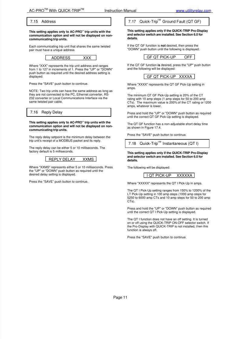
This setting applies only to AC-PRO+
trip units with thecommunication option and will not be displayed on non-communicating trip units.
Each communicating trip unit that shares the same twistedpair must have a unique address.
ADDRESS XXXWhere "XXX" represents the trip unit address and rangesfrom 1 to 127 in increments of 1. Press the "UP" or "DOWN"push button as required until the desired address setting isdisplayed.
Press the "SAVE” push button to continue.
NOTE: Two trip units can have the same address as long asthey are not connected to the PC, Ethernet converter, RS-232 converter or Local Communications Interface via thesame twisted pair cable.
This setting applies only to AC-PRO+
trip units with thecommunication option and will not be displayed on non-communicating trip units.
The reply delay setpoint is the minimum delay between thetrip unit’s receipt of a MODBUS packet and its reply.
The reply delay can be either 5 or 10 milliseconds. Thefactory default is 5 milliseconds.
REPLY DELAY XXMS
Where "XXMS" represents either 5 or 10 milliseconds. Pressthe "UP" or "DOWN" push button as required until thedesired delay setting is displayed.
Press the "SAVE” push button to continue.
This setting applies only if the QUICK-TRIP Pro-Displayand selector switch are installed. See Section 6.0 fordetails.
If the QT GF function is not desired, then press the"DOWN" push button until the following is displayed:
GF QT PICK-UP OFF
If the QT GF function is desired, press the "UP" push buttonand the following will be displayed:
GF QT PICK-UP XXXXA
Where "XXXX" represents the QT GF Pick-Up setting inamps.
The minimum QT GF Pick-Up setting is 20% of the CTrating with 10 amp steps (1 amp steps for 50 to 200 ampCTs). The maximum value is 200% of the CT rating or 1200amps, whatever is lower.
Press and hold the "UP" or "DOWN" push button as requireduntil the correct QT GF Pick-Up setting is displayed.
The QT GF function has a non-adjustable short delay timeas shown in Figure 17.4.
Press the "SAVE" push button to continue.
This setting applies only if the QUICK-TRIP Pro-Displayand selector switch are installed. See Section 6.0 fordetails.
The following will be displayed:
I QT PICK-UP XXXXXA
Where "XXXXX" represents the QT I Pick-Up in amps.
The QT I Pick-Up setting ranges from 150% to 1200% of theLT Pick-Up setting in 100 amp steps (1000 amp steps for5250 to 6000 amp CTs and 10 amp steps for 50 to 200 ampCTs).
Press and hold the "UP" or "DOWN" push button as requireduntil the correct QT I Pick-Up setting is displayed.
The QT I function does not have an off setting. It is turnedon or off using the QUICK-TRIP ON-OFF selector switch. Ifthe Pro-Display with QUICK-TRIP is not installed, then thisfunction is always off.
Press the "SAVE" push button to continue.
7.17 Quick-Trip Ground Fault (QT GF)
7.18 Quick-Trip Instantaneous (QT I)
7.15 Address
7.16 Reply Delay
7/27/2019 AC-PRO - Trip Unit - Instruction Manual - 2-2006 and Later
http://slidepdf.com/reader/full/ac-pro-trip-unit-instruction-manual-2-2006-and-later 13/31
Utility Relay Company
Page 12
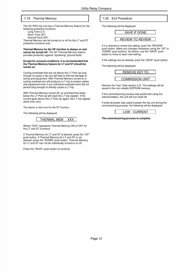
The AC-PRO trip unit has a Thermal Memory feature for thefollowing protective functions:
Long Time (LT)Short Time (ST)Ground Fault (GF)
Thermal Memory can be turned on or off for the LT and STprotective functions only.
Thermal Memory for the GF function is always on andcannot be turned off. The GF Thermal Memory featureprovides protection against “sputtering” ground faults.
Except for unusual conditions, it is recommended thatthe Thermal Memory feature for LT and ST should beturned on.
Cycling overloads that are not above the LT Pick-Up longenough to cause a trip can still lead to thermal damage towiring and equipment. With Thermal Memory turned on acycling overload can still produce a LT trip to protect cablesand equipment even if any individual overload event did notpersist long enough to directly cause a LT trip.
With Thermal Memory turned off, an overload that drops
below the LT Pick-Up will reset the LT trip register. If thecurrent goes above the LT Pick-Up again, the LT trip registerstarts from zero.
The above is also true for the ST function.
The following will be displayed:
THERMAL MEM XXX
Where "XXX" represents Thermal Memory ON or OFF forthe LT and ST functions.
If Thermal Memory for LT and ST is desired, press the "UP"push button. If Thermal Memory for LT and ST is not desired, press the "DOWN" push button. Thermal Memory
for LT and ST can not be individually turned on or off.
Press the "SAVE” push button to continue.
The following will be displayed:
SAVE IF DONE
REVIEW TO REVIEW
If it is desired to review the setting, push the “REVIEW”push button. Make any changes necessary using the “UP” or“DOWN” push buttons. As before, use the “SAVE” pushbutton to move to each new setting.
If the settings are as desired, push the “SAVE” push button.
The following will be displayed:
REMOVE KEY TO
COMMISSION UNIT
Remove the “key” (See section 4.2). The settings will besaved in the non-volatile EEPROM memory.
If the commissioning process was performed using theinternal battery, the unit will turn itself off.
If external power was used to power the trip unit during thecommissioning process, the following will be displayed:
LOW CURRENT
The commissioning process is complete.
7.20 Exit Procedure
7.19 Thermal Memory
7/27/2019 AC-PRO - Trip Unit - Instruction Manual - 2-2006 and Later
http://slidepdf.com/reader/full/ac-pro-trip-unit-instruction-manual-2-2006-and-later 14/31
AC-PROTM
With QUICK-TRIPTM
Instruction Manual www.utilityrelay.com
Page 13
**** IMPORTANT ****While it is possible to make changes to the settings withthe breaker in service, it is strongly recommended thatthe breaker must be removed from service whilemaking these changes since the breaker is energizedand the trip unit will not provide protection during a smallpart of this process.
After the trip unit is commissioned, settings can easily bechanged in the following manner.
Connect the security key. See Section 4.2.
Power up the trip unit by pressing "REVIEW" or by applyingexternal power as described in Section 7.1.
Press the “REVIEW” push button. The following will bedisplayed:
ENTER DATA
SERIAL # XXXXXXX
Press the "SAVE” push button.
Make any necessary changes using the "UP" or "DOWN"push buttons. Use the "SAVE" push button to move to eachnew setting.
**** IMPORTANT ****The CT rating entered in the trip unit must match therating of the CT the trip unit is connected to.
A security feature protects against accidentally changingthe CT rating. See Section 7.3.
After going through all the settings, the following will bedisplayed.
SAVE IF DONE
REVIEW TO REVIEW
If it is desired to review the setting, push the "REVIEW"push button. Make any changes necessary using the "UP"or "DOWN" push buttons. As before, use the "SAVE" pushbutton to move to each new setting.
If the settings are as desired, push the "SAVE” push button.The following will be displayed:
REMOVE KEY TO
COMMISSION UNIT
Remove the security key (See Section 4.2). The settings willbe saved in the non-volatile EEPROM memory.
The Settings have been changed.
Remember, if the trip unit loses power during this process,the old settings will be retained and the process must berepeated.
8.0 Changing Settings
7/27/2019 AC-PRO - Trip Unit - Instruction Manual - 2-2006 and Later
http://slidepdf.com/reader/full/ac-pro-trip-unit-instruction-manual-2-2006-and-later 15/31
Utility Relay Company
Page 14
The AC-PRO has an especially useful last trip data recalland trip counter feature.
After a breaker trip, the trip unit will be able to display thetype of trip (i.e. LT, ST, I, GF, U/B, GF QT or I QT asapplicable) along with the currents at the time of trip. Thisinformation is saved in the non-volatile FLASH memory andis available immediately after a trip or anytime thereafter.
**** NOTE ****Only the complete data from the last trip is saved. Thesecond time the breaker trips, the new trip data is writtenover the first trip data. The trip counter is also updated atthis time.
Push the “Review” push button to recall the Last Trip Dataand settings. The following will be displayed if there was no last trip:
NO LAST TRIP
If there was a last trip, the following messages willalternately display showing the cause of the trip and thecurrents at the time of trip. The messages alternate at a onesecond interval rate:
LAST TRIP XXXX
PHASE A XXXXXA
PHASE B XXXXXA
PHASE C XXXXXA
GF XXXXXA
If GF current is greater than 2 times the CT Rating, thefollowing will be displayed for GF:
GF>2XCT RATING
Only those phase currents greater than 10% of the CTRating will be displayed.
U/B YY%
The U/B percentage will be displayed if on and the U/B isgreater than 4%.
The text “XXXX” is the type of tripping event (i.e. LT, ST, I,GF, U/B, GF QT or I QT as applicable) and “XXXXX” is themagnitude of the current at the time of trip for each phase.The text “YY” is the percentage of unbalance at trip.
Press the “REVIEW” push button again to view the followingmessage:
HOLD <REVIEW> TO
VIEW TRIP COUNTS
If the “REVIEW” button is pushed again and held down forlonger than 2 seconds, each type of trip is displayed alongwith the number of times that trip has occurred. If the“REVIEW” button is pressed, but not held for 2 seconds, thetrip count is skipped and the settings are displayed.
INST TRIPS: XX
Push the “REVIEW” Button.
LT TRIPS: XX
Push the “REVIEW” Button.
ST TRIPS: XX
Push the “REVIEW” Button.
GF TRIPS: XX
Push the “REVIEW” Button.
U/B TRIPS: XX
Push the “REVIEW” Button.
GF QT TRIPS: XX
Push the “REVIEW” Button.
I QT TRIPS: XX
The text “XX” is the number of trips since last commissionedor reset.
By pressing the "REVIEW" push button the present settingsprogrammed in the trip unit can be stepped through insequence.
**** NOTE ****Pushing the "SAVE", "UP" or "DOWN" push buttonsduring last trip data recall has no effect because the key isnot installed.
When pushing "REVIEW” after the last setting, the trip unitwill turn it self off.
If the "REVIEW" push button is not pressed for about 30seconds, the trip unit will also turn off.
9.0 Last Trip Data Recall
7/27/2019 AC-PRO - Trip Unit - Instruction Manual - 2-2006 and Later
http://slidepdf.com/reader/full/ac-pro-trip-unit-instruction-manual-2-2006-and-later 16/31
AC-PROTM
With QUICK-TRIPTM
Instruction Manual www.utilityrelay.com
Page 15
Breaker Current Less than about 8% of CT Rating:
With all phase currents less than about 8%, the trip unit isnot receiving enough energy from the CTs to operate andthe display will be blank (Except for the communicationversion with a PT module).
Breaker Current Less than 12.5% of CT Rating:
When the currents are greater than 8% but less than 12.5%of the CT rating, the display will show the following:
LOW CURRENT
Breaker Current Greater than 12.5% of CT Rating:
If the breaker current is greater than 12.5% of the CT ratingbut less than the LT pick-up value, the following will bealternately displayed on the LCD at one second intervals:
PHASE A XXXXA
PHASE B XXXXA
PHASE C XXXXA
GF XXXXA
Where "XXXX" is the current in amps for that phase orground fault current.
Only those currents above 12.5% will be displayed. The GFcurrent will only be displayed if the GF function is on.
Breaker Current Greater than the LT pick-up:
When the trip unit detects a phase overload situation, the“PICK-UP” LED on the front of the trip unit will go on, and
the following will alternately be displayed on the LCD at onesecond intervals:
OVERLOAD
PHASE A XXXXA
PHASE B XXXXA
PHASE C XXXXA
GF XXXXA
Where "XXXX" is the current in amps for that phase orground fault current.
Only those currents above 12.5% will be displayed. The GFcurrent will only be displayed if the GF function is on.
A "primary injection" test is recommended as the final test ofthe AC-PRO retrofit.
It is not necessary to turn off the Unbalance (U/B) functionwhen doing a single-phase primary injection test.
If used, GF must be temporarily turned off when testing the
other trip functions.
Before proceeding with the normal primary injection tests,the trip unit must be commissioned to make it functional.See Section 7.0 for the commissioning procedure.
It is best to use the final pick-up and time delay settings ifthey are known. If not, use typical settings for the primaryinjection test.
Make sure GF is temporarily turned off. The U/B functioncan be left on if desired.
Make sure GF is temporarily turned off. The U/B functioncan be left on.
To test the LT Pick-Up, increase the current until the “Pick-Up” LED illuminates.
The injected current should correspond to the programmedLT Pick-Up setting. Verify that the correct phase is indicatedon the LCD display.
To test the LT trip time, first calculate the trip time based onthe value of the test current that will be applied. Use theformula in Section 15.1 or the chart in Section 12.3..
**** NOTE ****A simple shortcut is to note that the trip time (centerof the curve) at 3 times the LT pick-up current is 4times the LT Delay setting.For example:
If LT Pick-Up is 1600A and Delay is 10.0S, then thetrip time at 4800A (3 times 1600A) is 40 sec. (4 times10 sec).
10.0 Normal Operations 11.0 Testing
11.1 Commission the Trip Unit
11.2 LT Trip Test

7/27/2019 AC-PRO - Trip Unit - Instruction Manual - 2-2006 and Later
http://slidepdf.com/reader/full/ac-pro-trip-unit-instruction-manual-2-2006-and-later 17/31
Utility Relay Company
Page 16
Make sure GF is temporarily turned off. The U/B functioncan be left on.
To test the ST Pick-Up, temporarily set ST I2T off and applya short pulse of current that is 10% or 20% less than the STPick-Up setting. Continue applying short pulses of currentwhile increasing the current for each pulse until a ST trip
occurs. The first current where a ST trip occurred is the STPick-Up.
To test the ST Delay, turn ST I2T on again (if applicable) andapply a current that is at least 10% greater than the ST Pick-Up current.
The trip time should fall within the time band shown on theTime-Current curves.
Make sure GF is temporarily turned off. The U/B functioncan be left on.
Test the Instantaneous Pick-Up and trip time in the samemanner as ST in Section 11.3.
With GF Pick-Up and Delay set to the required values,testing any one of the three poles will provide a GF trip.
Test the GF Pick-Up and trip time in the same manner asST in Section 11.3.
To test QT GF the Pro-Display with QUICK-TRIP must be
connected to the AC-PRO trip unit and the QUICK-TRIPON-OFF selector switch must also be connected as shownin Figure 6.1.
With QT GF Pick-Up set to the required value and theQUICK-TRIP selector switch turned to the on position,testing any one of the three poles will provide a QT GF trip.
Test the QT GF Pick-Up and trip time in the same manneras the normal GF function.
To test QT I the Pro-Display with QUICK-TRIP must beconnected to the AC-PRO trip unit and the QUICK-TRIPON-OFF selector switch must also be connected as shownin Figure 6.1.
With QT I Pick-Up set to the required value and the QUICK-TRIP selector switch turned to the on position, test all threebreaker poles in the same manner as the normal I function.
The U/B trip function is not easy to test with a single phase,high current test set.
Figure 11.1 illustrates a method to test the U/B trip function.It requires using cable or bus to jumper the breaker poles asshown. This generates an unbalanced current of 50% orslightly more depending on how equally the current is split
between the two poles.
It is only necessary to inject a current equal to 20% or 30%of the CT rating for this test. It is only possible to test theU/B trip time and not the U/B Pick-Up with this method.
Figure 11.1 U/B Test
11.3 ST Trip Test
11.4 I Trip Test
11.5 GF Trip Test
11.6 QT GF Trip Test
11.7 QT I Trip Test
11.8 U/B Trip Test
7/27/2019 AC-PRO - Trip Unit - Instruction Manual - 2-2006 and Later
http://slidepdf.com/reader/full/ac-pro-trip-unit-instruction-manual-2-2006-and-later 18/31
AC-PROTM
With QUICK-TRIPTM
Instruction Manual www.utilityrelay.com
Page 17
After completing the primary or secondary injection tests, itis important to erase the last trip data from the memory ofthe trip unit.
**** IMPORTANT ****Erase the last trip data from the memory of the trip unitafter completing the primary or secondary injection tests.
To erase the memory in the trip unit after completing theprimary or secondary injection tests, use the followingmethod:
1) The trip unit can be can be either off or powered-up.
2) Push the "REVIEW" button to display the last tripdata.
3) While the last trip data is flashing, push and hold boththe "UP" and "DOWN" push buttons.
4) Continue to hold the "UP" and "DOWN" buttons andpush the "SAVE" button. Release all buttons. Thefollowing will be displayed:
NO LAST TRIP
**** IMPORTANT ****If the last trip data is not erased after the primary orsecondary injection test, the operating personnel may laterassume that the breaker interrupted a fault at some time inthe past when they recall the last trip data. The trip counterwill also have misleading data.
Although primary injection testing is the preferred method totest an AC-PRO installation, secondary injection testing canalso be used.
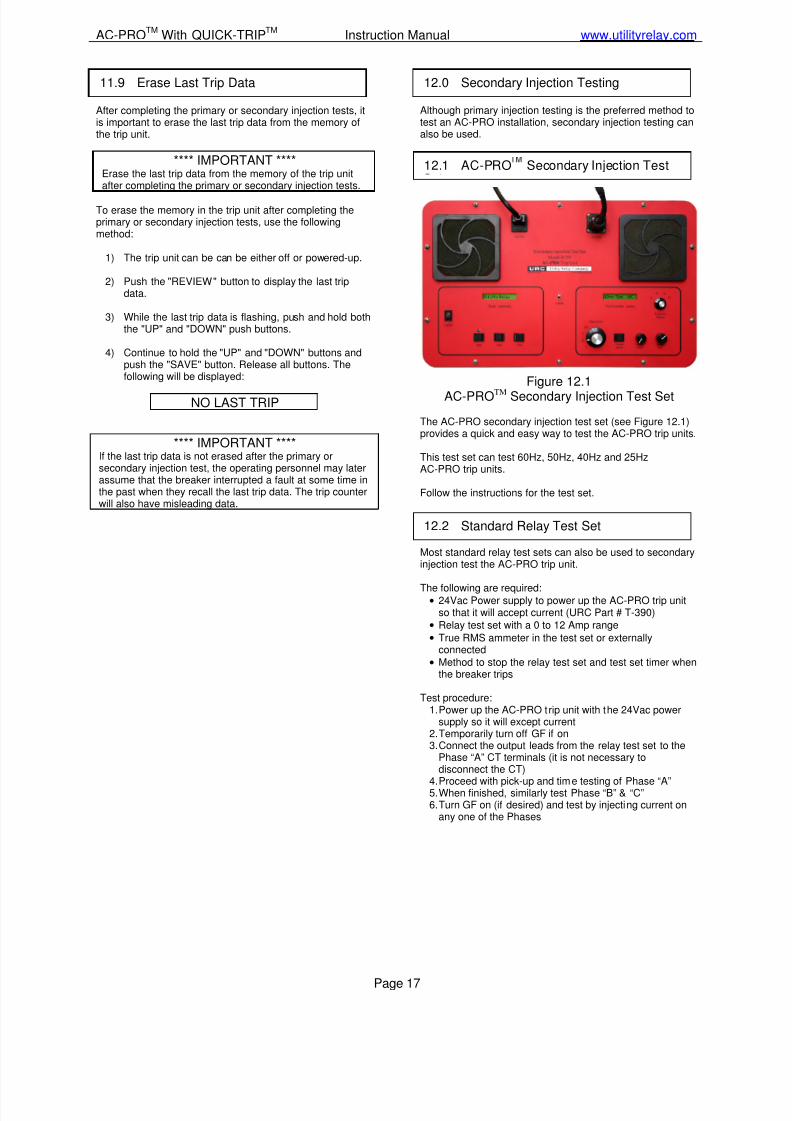
Figure 12.1
AC-PROTM Secondary Injection Test Set
The AC-PRO secondary injection test set (see Figure 12.1)provides a quick and easy way to test the AC-PRO trip units.
This test set can test 60Hz, 50Hz, 40Hz and 25HzAC-PRO trip units.
Follow the instructions for the test set.
Most standard relay test sets can also be used to secondaryinjection test the AC-PRO trip unit.
The following are required:• 24Vac Power supply to power up the AC-PRO trip unit
so that it will accept current (URC Part # T-390)
• Relay test set with a 0 to 12 Amp range
• True RMS ammeter in the test set or externallyconnected
• Method to stop the relay test set and test set timer whenthe breaker trips
Test procedure:1. Power up the AC-PRO trip unit with the 24Vac power
supply so it will except current2. Temporarily turn off GF if on3. Connect the output leads from the relay test set to the
Phase “A” CT terminals (it is not necessary todisconnect the CT)
4. Proceed with pick-up and time testing of Phase “A”5. When finished, similarly test Phase “B” & “C”6. Turn GF on (if desired) and test by injecting current on
any one of the Phases
11.9 Erase Last Trip Data
12.0 Secondary Injection Testing
12.1 AC-PRO Secondary Injection Test
12.2 Standard Relay Test Set
7/27/2019 AC-PRO - Trip Unit - Instruction Manual - 2-2006 and Later
http://slidepdf.com/reader/full/ac-pro-trip-unit-instruction-manual-2-2006-and-later 19/31
Utility Relay Company
Page 18
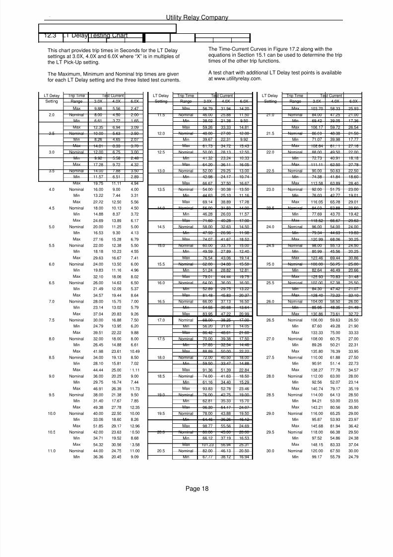
This chart provides trip times in Seconds for the LT Delaysettings at 3.0X, 4.0X and 6.0X where “X” is in multiples ofthe LT Pick-Up setting.
The Maximum, Minimum and Nominal trip times are givenfor each LT Delay setting and the three listed test currents.
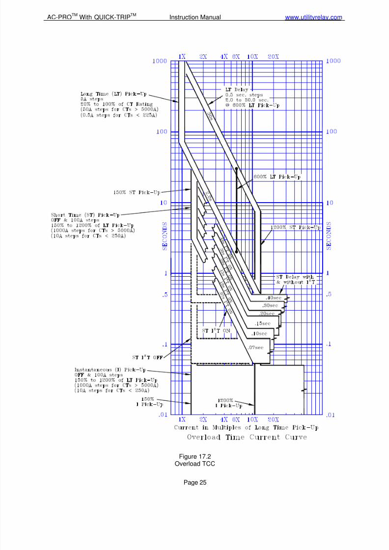
The Time-Current Curves in Figure 17.2 along with theequations in Section 15.1 can be used to determine the triptimes of the other trip functions.
A test chart with additional LT Delay test points is availableat www.utilityrelay.com.
12.3 LT Delay Testing Chart
LT Delay Trip Time Test Current LT Delay Trip Time Test Current LT Delay Trip Time Test CurrentSetting Range 3.0X 4.0X 6.0X Setting Range 3.0X 4.0X 6.0X Setting Range 3.0X 4.0X 6.0X
Max 9.88 5.56 2.47 Max 56.79 31.94 14.20 Max 103.70 58.33 25.93
2.0 Nominal 8.00 4.50 2.00 11.5 Nominal 46.00 25.88 11.50 21.0 Nominal 84.00 47.25 21.00
Min 6.61 3.72 1.65 Min 38.02 21.38 9.50 Min 69.42 39.05 17.36
Max 12.35 6.94 3.09 Max 59.26 33.33 14.81 Max 106.17 59.72 26.54
2.5 Nominal 10.00 5.63 2.50 12.0 Nominal 48.00 27.00 12.00 21.5 Nominal 86.00 48.38 21.50
Min 8.26 4.65 2.07 Min 39.67 22.31 9.92 Min 71.07 39.98 17.77
Max 14.81 8.33 3.70 Max 61.73 34.72 15.43 Max 108.64 61.11 27.16
3.0 Nominal 12.00 6.75 3.00 12.5 Nominal 50.00 28.13 12.50 22.0 Nominal 88.00 49.50 22.00
Min 9.92 5.58 2.48 Min 41.32 23.24 10.33 Min 72.73 40.91 18.18
Max 17.28 9.72 4.32 Max 64.20 36.11 16.05 Max 111.11 62.50 27.78
3.5 Nominal 14.00 7.88 3.50 13.0 Nominal 52.00 29.25 13.00 22.5 Nominal 90.00 50.63 22.50
Min 11.57 6.51 2.89 Min 42.98 24.17 10.74 Min 74.38 41.84 18.60
Max 19.75 11.11 4.94 Max 66.67 37.50 16.67 Max 113.58 63.89 28.40
4.0 Nominal 16.00 9.00 4.00 13.5 Nominal 54.00 30.38 13.50 23.0 Nominal 92.00 51.75 23.00
Min 13.22 7.44 3.31 Min 44.63 25.10 11.16 Min 76.03 42.77 19.01
Max 22.22 12.50 5.56 Max 69.14 38.89 17.28 Max 116.05 65.28 29.01
4.5 Nominal 18.00 10.13 4.50 14.0 Nominal 56.00 31.50 14.00 23.5 Nominal 94.00 52.88 23.50
Min 14.88 8.37 3.72 Min 46.28 26.03 11.57 Min 77.69 43.70 19.42
Max 24.69 13.89 6.17 Max 71.60 40.28 17.90 Max 118.52 66.67 29.63
5.0 Nominal 20.00 11.25 5.00 14.5 Nominal 58.00 32.63 14.50 24.0 Nominal 96.00 54.00 24.00
Min 16.53 9.30 4.13 Min 47.93 26.96 11.98 Min 79.34 44.63 19.83
Max 27.16 15.28 6.79 Max 74.07 41.67 18.52 Max 120.99 68.06 30.25
5.5 Nominal 22.00 12.38 5.50 15.0 Nominal 60.00 33.75 15.00 24.5 Nominal 98.00 55.13 24.50
Min 18.18 10.23 4.55 Min 49.59 27.89 12.40 Min 80.99 45.56 20.25
Max 29.63 16.67 7.41 Max 76.54 43.06 19.14 Max 123.46 69.44 30.86
6.0 Nominal 24.00 13.50 6.00 15.5 Nominal 62.00 34.88 15.50 25.0 Nominal 100.00 56.25 25.00
Min 19.83 11.16 4.96 Min 51.24 28.82 12.81 Min 82.64 46.49 20.66
Max 32.10 18.06 8.02 Max 79.01 44.44 19.75 Max 125.93 70.83 31.48
6.5 Nominal 26.00 14.63 6.50 16.0 Nominal 64.00 36.00 16.00 25.5 Nominal 102.00 57.38 25.50
Min 21.49 12.09 5.37 Min 52.89 29.75 13.22 Min 84.30 47.42 21.07
Max 34.57 19.44 8.64 Max 81.48 45.83 20.37 Max 128.40 72.22 32.10
7.0 Nominal 28.00 15.75 7.00 16.5 Nominal 66.00 37.13 16.50 26.0 Nominal 104.00 58.50 26.00
Min 23.14 13.02 5.79 Min 54.55 30.68 13.64 Min 85.95 48.35 21.49
Max 37.04 20.83 9.26 Max 83.95 47.22 20.99 Max 130.86 73.61 32.72
7.5 Nominal 30.00 16.88 7.50 17.0 Nominal 68.00 38.25 17.00 26.5 Nominal 106.00 59.63 26.50
Min 24.79 13.95 6.20 Min 56.20 31.61 14.05 Min 87.60 49.28 21.90
Max 39.51 22.22 9.88 Max 86.42 48.61 21.60 Max 133.33 75.00 33.33
8.0 Nominal 32.00 18.00 8.00 17.5 Nominal 70.00 39.38 17.50 27.0 Nominal 108.00 60.75 27.00
Min 26.45 14.88 6.61 Min 57.85 32.54 14.46 Min 89.26 50.21 22.31
Max 41.98 23.61 10.49 Max 88.89 50.00 22.22 Max 135.80 76.39 33.95
8.5 Nominal 34.00 19.13 8.50 18.0 Nominal 72.00 40.50 18.00 27.5 Nominal 110.00 61.88 27.50
Min 28.10 15.81 7.02 Min 59.50 33.47 14.88 Min 90.91 51.14 22.73
Max 44.44 25.00 11.11 Max 91.36 51.39 22.84 Max 138.27 77.78 34.57
9.0 Nominal 36.00 20.25 9.00 18.5 Nominal 74.00 41.63 18.50 28.0 Nominal 112.00 63.00 28.00
Min 29.75 16.74 7.44 Min 61.16 34.40 15.29 Min 92.56 52.07 23.14
Max 46.91 26.39 11.73 Max 93.83 52.78 23.46 Max 140.74 79.17 35.199.5 Nominal 38.00 21.38 9.50 19.0 Nominal 76.00 42.75 19.00 28.5 Nominal 114.00 64.13 28.50
Min 31.40 17.67 7.85 Min 62.81 35.33 15.70 Min 94.21 53.00 23.55
Max 49.38 27.78 12.35 Max 96.30 54.17 24.07 Max 143.21 80.56 35.80
10.0 Nominal 40.00 22.50 10.00 19.5 Nominal 78.00 43.88 19.50 29.0 Nominal 116.00 65.25 29.00
Min 33.06 18.60 8.26 Min 64.46 36.26 16.12 Min 95.87 53.93 23.97
Max 51.85 29.17 12.96 Max 98.77 55.56 24.69 Max 145.68 81.94 36.42
10.5 Nominal 42.00 23.63 10.50 20.0 Nominal 80.00 45.00 20.00 29.5 Nominal 118.00 66.38 29.50
Min 34.71 19.52 8.68 Min 66.12 37.19 16.53 Min 97.52 54.86 24.38
Max 54.32 30.56 13.58 Max 101.23 56.94 25.31 Max 148.15 83.33 37.04
11.0 Nominal 44.00 24.75 11.00 20.5 Nominal 82.00 46.13 20.50 30.0 Nominal 120.00 67.50 30.00
Min 36.36 20.45 9.09 Min 67.77 38.12 16.94 Min 99.17 55.79 24.79
7/27/2019 AC-PRO - Trip Unit - Instruction Manual - 2-2006 and Later
http://slidepdf.com/reader/full/ac-pro-trip-unit-instruction-manual-2-2006-and-later 20/31
AC-PROTM
With QUICK-TRIPTM
Instruction Manual www.utilityrelay.com
Page 19
Ambient Temperature:Trip Unit:-4°F (-20°C) to 150°F (65°C)LCD Display:Standard Temp, Super Twist32°F (0°C) to 122°F (50°C)
Humidity:95% non-condensing
Conformal Coating:Acrylic conformal coating,HumiSeal type 1B15HorKonform type AR2000
Enclosure:AC-PRO trip unit:Extruded aluminum housingNominal overall dimensions:6.76 X 3.84 X 2.28 inches172 X 100 X 58 millimeters
Pro-Display:
Extruded aluminum housingNominal overall dimensions:4.13 X 3.35 X 0.892 inches105 X 85 X 22.7 millimeters
Battery:Ultralife Model U9VL-J1200 mAh Lithium/Manganese DioxideTen-year rated shelf lifeNon-Rechargeable
A conditional 2-year warranty is offered with each AC-PRO trip unit and Pro-Display.
Contact Utility Relay Company for full details.
The Time-Current curves are shown inFigures 17.2, 17.3 and 17.4.
For all the functions except U/B, the curves are shown onlog-log graph with seconds in the vertical direction andcurrent in the horizontal direction.
Overload and fault currents are shown as multiples of the LTpick-up setting. Ground fault current is shown as apercentage of the CT rating.
For I and QT I pick-up settings below 150% of the CT rating,trip unit power-up time must be added to the InstantaneousTime-Current curve (if the trip unit is not already poweredup). The allowance for 3-phase time is shown as a dottedline on the upper right hand Time-Current curve in Figure17.4.
For QT GF pick-up settings below 120% of the CT rating,trip unit power-up time must be added to the QT GF Time-Current curve (if the trip unit is not already powered up). Theallowance of 1-phase time is shown as a dotted line in theQT GF Time-Current curve in Figure 17.4.
Tolerances for the Pick-Up bands are ± 10% in the currentdirection. Tolerance for LT, ST I2 T and GF I2 T trip timesare + 23% and -17% in the time direction.
The curves for the following time bands:LTST I²TGF I²T
are based on the following equation:
I²T = Constant
Where: I is current in ampsT is time to trip in seconds (center of the band)
The curves for the U/B function are shown on a semi-log
graph with seconds in the vertical direction and unbalance inpercent in the horizontal direction.
Tolerance for U/B function is given inSection 15.4.
When performing trip-timing tests using a primary injectiontest set, the trip time at various test currents can bedetermined by calculation as explained in Sections 15.1,15.2 and 15.3.
13.0 Ratings
14.0 Warranty
15.0 Time-Current Curves
7/27/2019 AC-PRO - Trip Unit - Instruction Manual - 2-2006 and Later
http://slidepdf.com/reader/full/ac-pro-trip-unit-instruction-manual-2-2006-and-later 21/31
Utility Relay Company
Page 20
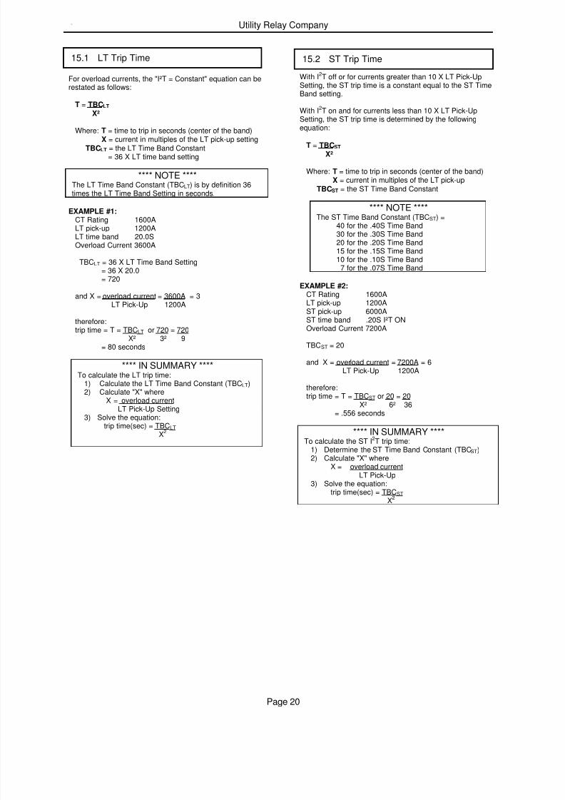
For overload currents, the "I²T = Constant" equation can berestated as follows:
T = TBCLT
X²
Where: T = time to trip in seconds (center of the band)
X = current in multiples of the LT pick-up settingTBCLT = the LT Time Band Constant
= 36 X LT time band setting
**** NOTE ****The LT Time Band Constant (TBCLT) is by definition 36times the LT Time Band Setting in seconds.
EXAMPLE #1:CT Rating 1600ALT pick-up 1200ALT time band 20.0SOverload Current 3600A
TBCLT = 36 X LT Time Band Setting= 36 X 20.0
= 720
and X = overload current = 3600A = 3LT Pick-Up 1200A
therefore:trip time = T = TBCLT or 720 = 720
X² 3² 9= 80 seconds
**** IN SUMMARY ****To calculate the LT trip time:
1) Calculate the LT Time Band Constant (TBCLT)2) Calculate "X" where
X = overload currentLT Pick-Up Setting
3) Solve the equation:trip time(sec) = TBCLT X2
With I2T off or for currents greater than 10 X LT Pick-UpSetting, the ST trip time is a constant equal to the ST TimeBand setting.
With I2T on and for currents less than 10 X LT Pick-UpSetting, the ST trip time is determined by the followingequation:
T = TBCST
X²
Where: T = time to trip in seconds (center of the band)X = current in multiples of the LT pick-up
TBCST = the ST Time Band Constant
**** NOTE ****The ST Time Band Constant (TBCST) =
40 for the .40S Time Band30 for the .30S Time Band20 for the .20S Time Band15 for the .15S Time Band10 for the .10S Time Band
7 for the .07S Time Band
EXAMPLE #2:CT Rating 1600ALT pick-up 1200AST pick-up 6000AST time band .20S I²T ONOverload Current 7200A
TBCST = 20
and X = overload current = 7200A = 6LT Pick-Up 1200A
therefore:trip time = T = TBCST or 20 = 20
X² 6² 36= .556 seconds
**** IN SUMMARY ****To calculate the ST I2T trip time:
1) Determine the ST Time Band Constant (TBCST)2) Calculate "X" where
X = overload currentLT Pick-Up
3) Solve the equation:trip time(sec) = TBCST
X2
15.1 LT Trip Time
15.2 ST Trip Time

7/27/2019 AC-PRO - Trip Unit - Instruction Manual - 2-2006 and Later
http://slidepdf.com/reader/full/ac-pro-trip-unit-instruction-manual-2-2006-and-later 22/31
AC-PROTM
With QUICK-TRIPTM
Instruction Manual www.utilityrelay.com
Page 21
With I2T off or for ground fault currents greater than 2 timesthe CT rating, the GF trip time is a constant equal to the GFTime Band setting.
With I2T on and for currents less than 2 times the CT rating,the GF trip time is determined by the following equation:
T = TBCGF XGF²
Where: T = time to trip in seconds (center of the band)
XGF = ground fault currentCT rating
TBCGF = the GF Time Band Constant
**** NOTE ****The GF Time Band Constant (TBCGF) =
2.0 for the .50S Time Band1.6 for the .40S Time Band1.2 for the .30S Time Band0.8 for the .20S Time Band0.4 for the .10S Time Band
EXAMPLE #3:CT Rating 1600ALT pick-up 1200AGF pick-up 640AGF time band .20S I²T ONGround Fault Current 800A
TBCGF = 0.8
and XGF = ground fault current = 800ACT Rating 1600A
= 0.5
therefore:trip time = T = TBCGF or 0.8 = 0.8
XGF² (0.5)² .25= 3.20 sec
**** IN SUMMARY ****To calculate the GF I2T trip time:
1) Determine the GF Time Band Constant (TBCGF)2) Calculate "XGF" where
XGF = ground fault currentCT Rating
3) Solve the equation:trip time(sec) = TBCGF
XGF2
U/B is calculated as follows:
U/B = (INL - INS) X 100%INL
Where:INL = Largest Phase currentINS = Smallest Phase current
The U/B function is defeated if any two phase currents areless than 10% of the CT rating.
The tolerance for the U/B Pick-Up is ± 10 percentage points.An U/B Pick-Up of 20% would have a tolerance of 10% to30% unbalance. An U/B Pick-Up of 50% would have atolerance of 40% to 60% unbalance.
The U/B trip time is a definite time as shown on the U/BTCC in Figure 17.3
The tolerance for the U/B trip time is ± 10% of the setting.
The following is a summary of the possible error messagesand what action is necessary to correct the problem.
When the actuator is not connected or is open circuited, thefollowing message will be displayed:
NO ACTUATOR
All push buttons are disabled. To return to normaloperation, a functioning actuator must be connected.
The micro-controller continuously monitors its memory.When a discrepancy occurs, the following message will bedisplayed:
MEMORY ERROR
All push buttons are disabled. The micro-controller must bereplaced. Contact Utility Relay Company for moreinformation.
15.3 GF Trip Time
15.4 U/B Trip Time
16.0 Error Message Summary
16.1 Actuator Not Connected
16.2 Memory Error
7/27/2019 AC-PRO - Trip Unit - Instruction Manual - 2-2006 and Later
http://slidepdf.com/reader/full/ac-pro-trip-unit-instruction-manual-2-2006-and-later 23/31
Utility Relay Company
Page 22
INTENTIONALLY LEFT BLANK
7/27/2019 AC-PRO - Trip Unit - Instruction Manual - 2-2006 and Later
http://slidepdf.com/reader/full/ac-pro-trip-unit-instruction-manual-2-2006-and-later 24/31
AC-PROTM
With QUICK-TRIPTM
Instruction Manual www.utilityrelay.com
Page 23
Figure 17.1Typical Wiring Diagram

7/27/2019 AC-PRO - Trip Unit - Instruction Manual - 2-2006 and Later
http://slidepdf.com/reader/full/ac-pro-trip-unit-instruction-manual-2-2006-and-later 25/31
Utility Relay Company
Page 24
INTENTIONALLY LEFT BLANK
7/27/2019 AC-PRO - Trip Unit - Instruction Manual - 2-2006 and Later
http://slidepdf.com/reader/full/ac-pro-trip-unit-instruction-manual-2-2006-and-later 26/31
AC-PROTM
With QUICK-TRIPTM
Instruction Manual www.utilityrelay.com
Page 25
Figure 17.2Overload TCC
7/27/2019 AC-PRO - Trip Unit - Instruction Manual - 2-2006 and Later
http://slidepdf.com/reader/full/ac-pro-trip-unit-instruction-manual-2-2006-and-later 27/31
Utility Relay Company
Page 26
INTENTIONALLY LEFT BLANK
7/27/2019 AC-PRO - Trip Unit - Instruction Manual - 2-2006 and Later
http://slidepdf.com/reader/full/ac-pro-trip-unit-instruction-manual-2-2006-and-later 28/31
AC-PROTM
With QUICK-TRIPTM
Instruction Manual www.utilityrelay.com
Page 27
Figure 17.3U/B & GF TCC
7/27/2019 AC-PRO - Trip Unit - Instruction Manual - 2-2006 and Later
http://slidepdf.com/reader/full/ac-pro-trip-unit-instruction-manual-2-2006-and-later 29/31
Utility Relay Company
Page 28
INTENTIONALLY LEFT BLANK

7/27/2019 AC-PRO - Trip Unit - Instruction Manual - 2-2006 and Later
http://slidepdf.com/reader/full/ac-pro-trip-unit-instruction-manual-2-2006-and-later 30/31
AC-PROTM
With QUICK-TRIPTM
Instruction Manual www.utilityrelay.com
Page 29
Figure 17.4QUICK-TRIP
TMGround Fault & Instantaneous TCC
7/27/2019 AC-PRO - Trip Unit - Instruction Manual - 2-2006 and Later
http://slidepdf.com/reader/full/ac-pro-trip-unit-instruction-manual-2-2006-and-later 31/31
Related Documents


![Motor Protection Circuit Breakers - cselectric.co.in · Test trip device for checks of the ... Switching of 3 phase AC motor, AC-2, AC-3 3-phase [kW] ... Motor Protection (Standard)](https://static.cupdf.com/doc/110x72/5b735ab67f8b9a4b6b8e100b/motor-protection-circuit-breakers-test-trip-device-for-checks-of-the-switching.jpg)


