1 AC MOTOR DRIVE Operation manual RM6F2 series

Welcome message from author
This document is posted to help you gain knowledge. Please leave a comment to let me know what you think about it! Share it to your friends and learn new things together.
Transcript

1
AC MOTOR DRIVE
Operation manual
RM6F2 series

2
Quality․Satisfaction․Improvement․Innovation
http://www.rhymebus.com.tw 2015.04.22 Edition 2015.08.06 Revised

3
Thank you for using RHYMEBUS RM6F2 series drive. For proper operations and
safety purposes, please do read and follow specific instructions contained in this
manual before using the product. The manual shall be placed on the top of the
machine, and all the setup parameters and reference numbers must be properly
recorded to facilitate future maintenance and repairs.
PREFACE

4
Please read this manual thoroughly and pay attention to the safety precautions marked with “ DANGER ” or “ CAUTION ” before the installation, wiring, maintenance, or troubleshooting.
Only the qualified personnel may proceed with the installation, wiring, testing, troubleshooting, or other tasks.
※ Qualified Personnel: Must be familiar with the fundamentals, structures, characteristics, operating procedures, and installation, and this personnel must read the manual in details and follow the steps of security measures to prevent possible dangers.
DANGER
User may cause the casualty or serious damages if user does not abide by the instructions of the manual to execute the tasks.
CAUTION
User may cause injuries to the people or damage the equipment if user does not abide by the instructions of the manual to execute the tasks.
※Although the “ ” mark may indicate minor damages, serious damages or
injuries may be possibly incurred if the caution is not under user’s attention.
Installation
CAUTION
1. The installation shall take place only on top of the metal surface or any material with the fire resistant. Any place or location of high temperature, moist, oil and gas, cotton fiber, metal powder and erosive gas shall be avoided.
2. If the product specification indicates IP00 (the protective level of the equipment structure), any human contact is forbidden to avoid the electric shock. The option of installing AC reactor(ACL) or DC reactor(DCL) shall be very cautious, too.
3. Please note the surrounding temperature shall not exceed 50°C (or 40°C for RM5P) when the installation needs to be placed inside the control panel.
4. For the environment of storage and installation, please follow the instructions of the environmental conditions illustrated in the sections of the common specification of RMF2.
SAFETY PRECAUTION

5
Wiring
DANGER a. Do Not conduct any wiring during the system power ON to avoid the electric shock. b. R/L1,S/L2,T/L3 are power inputs (electric source terminals) and U/T1,V/T2,W/T3
are drive’s outputs connecting to a motor. Please Do Not connect these input and output terminals to P, P○+ , N, N○- , P1 and PR terminals.
c. Once the wiring is completed, the cover of the drive must be put back and must seal the drive to avoid other’s accidental contact.
d. 100V or 200V series drives must not be connected to the electric source of 346/380/415/440/460/480V.
e. The main circuit and multi-function terminals cannot connect to ground terminal(PE).
f. PE terminal must be exactly grounded. Ground the drive in compliance with
the NEC standard or local electrical code. g. Please refer to the “section Description of Terminals” for the screwing torque
of the wiring terminal. h. Please refer to the national or local electric code for the appropriate spec. of the
cords and wires.
i. Please install the thermal relay between the individual motor and the drive when using one drive to propel several motors.
j. Do Not connect power factor leading capacitor, surge absorber, or non-three-phase motor to drive’s U/T1,V/T2,W/T3 side.
k. AC reactor (ACL) installation is required when the power capacity exceeds 500kVA or 10 times or more than the drive rated capacity.
l. After power off (30HP below models must wait at least 5 minutes; 40HP~75HP models must wait at least 10 minutes; 100HP above models must wait at least 20 minutes). Do Not touch the drive or perform any unwiring actions before drive indicator light (CHARGE) turns off. Use a multimeter with the DC voltage stage to measure the cross voltage between P(+) and N(-) ports (DC bus voltage must be less than 25V).
m. When the motor do the voltage-proof, insulation testing, unwiring the U/T1,V/T2,W/T3 terminal of drive at first.
CAUTION a. The RM6F2 series are designed to drive a three-phase induction motor. Do Not
use for single-phase motor or other purposes. b. The main circuit and control circuit must be wired separately; control circuit must
use a shielded or twisted-pair shielded wires to avoid possible interferences.
6
Operation
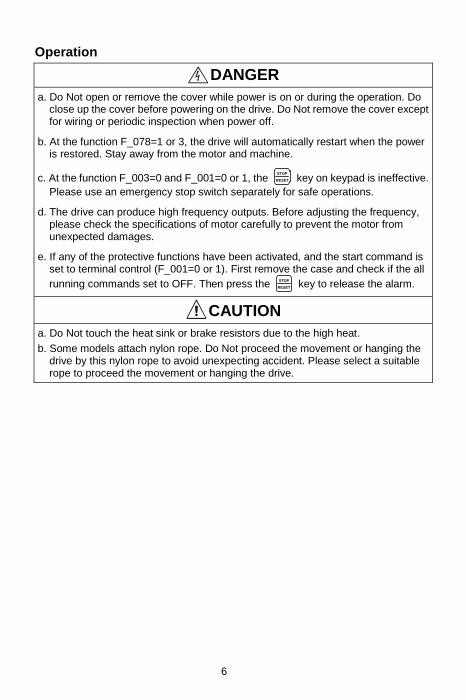
DANGER a. Do Not open or remove the cover while power is on or during the operation. Do
close up the cover before powering on the drive. Do Not remove the cover except for wiring or periodic inspection when power off.
b. At the function F_078=1 or 3, the drive will automatically restart when the power is restored. Stay away from the motor and machine.
c. At the function F_003=0 and F_001=0 or 1, the STOP
RESET key on keypad is ineffective.
Please use an emergency stop switch separately for safe operations.
d. The drive can produce high frequency outputs. Before adjusting the frequency, please check the specifications of motor carefully to prevent the motor from unexpected damages.
e. If any of the protective functions have been activated, and the start command is set to terminal control (F_001=0 or 1). First remove the case and check if the all
running commands set to OFF. Then press the STOP
RESET key to release the alarm.
CAUTION a. Do Not touch the heat sink or brake resistors due to the high heat.
b. Some models attach nylon rope. Do Not proceed the movement or hanging the drive by this nylon rope to avoid unexpecting accident. Please select a suitable rope to proceed the movement or hanging the drive.
7
Chapter 1 Cautions Before Installation
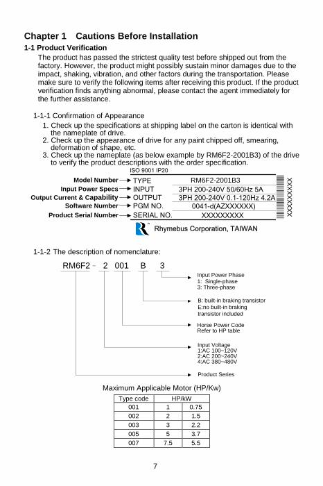
1-1 Product Verification
The product has passed the strictest quality test before shipped out from the factory. However, the product might possibly sustain minor damages due to the impact, shaking, vibration, and other factors during the transportation. Please make sure to verify the following items after receiving this product. If the product verification finds anything abnormal, please contact the agent immediately for the further assistance.
1-1-1 Confirmation of Appearance
1. Check up the specifications at shipping label on the carton is identical with the nameplate of drive.
2. Check up the appearance of drive for any paint chipped off, smearing, deformation of shape, etc.
3. Check up the nameplate (as below example by RM6F2-2001B3) of the drive to verify the product descriptions with the order specification.
Rhymebus Corporation, TAIWAN
SERIAL NO.
PGM NO.
OUTPUT
INPUT
TYPEModel Number
Input Power Specs
Output Current & CapabilitySoftware Number
Product Serial Number
ISO 9001 IP20
XXXXXXXXX
0041-d(AZXXXXXX)
3PH 200-240V 0.1-120Hz 4.2A
3PH 200-240V 50/60Hz 5A
RM6F2-2001B3
XX
XX
XX
XX
X
1-1-2 The description of nomenclature:
RM6F2– 2 001 B 3
Horse Power CodeRefer to HP table
Input Voltage1:AC 100~120V2:AC 200~240V4:AC 380~480V
Product Series
Input Power Phase1: Single-phase3: Three-phase
B: built-in braking transistor
E:no built-in braking
transistor included
Maximum Applicable Motor (HP/Kw)
Type code HP/kW
001 1 0.75
002 2 1.5
003 3 2.2
005 5 3.7
007 7.5 5.5

8
1-1-3 Confirmation of Accessories
One operation manual is inclusive. Please verify other accessories inclusively such as braking resistor, AC reactor, etc..
※Please refer to the standard specifications to verify the product
specifications with your requirements.
1-2 RM6F2 Standard Specifications
1-2-1 Single-Phase 100V Series
Model name
(RM6F2-□□□□B1) 10P5 1001 1002※1 1003※1
Maximum applicable motor (HP / kW)
0.5/0.4 1/0.75 2/1.5 3/2.2
Rated output capability (kVA)
1.0 1.6 2.9 3.8
Rated output current (A) 2.5 4.2 7.5 10
Rated output voltage (V) Three-phase 200~240V
Range of output frequency (Hz)
0.1~400.00Hz
Power source (ψ, V, Hz) Single-phase 100~120 50/60Hz
Input current (A) 9.1 15.3 30 40
Permissible AC power source fluctuation
88V~132V 50/60Hz / ±5%
Overload protection 150% of drive rated output current for 1 min
Cooling method Nature cooling Fan cooling
Applicable safety standards -
Protective structure IP20
Weight / Mass(kg) 1.1 1.2 2.5 2.5
※1: This model is batch production

9
1-2-2 Single-Phase 200V Series
Model name
(RM6F2-□□□□B1) 20P5 2001 2002 2003※1
Maximum applicable motor
(HP / kW) 0.5/0.4 1/0.75 2/1.5 3/2.2
Rated output capability (kVA) 1.1 1.6 2.9 3.8
Rated output current (A) 3 4.2 7.5 10
Rated output voltage (V) Three-phase 200V~240V
Range of output frequency (Hz) 0.1~400.00Hz
Power source (ψ, V, Hz) Single-phase 200~240V 50/60Hz
Input current (A) 5.8 7.7 13.7 20
Permissible AC power source fluctuation
176~264V 50/60Hz / ±5%
Overload protection 150% of drive rated output current for 1 min.
Cooling method Nature
cooling Fan cooling
Applicable safety standards -
Protective structure IP20
Weight / Mass(kg) 1.1 1.2 1.2 2.5
※1: This model is batch production
1-2-3 Three-Phase 200V Series
Model name
(RM6F2-□□□□B3) 20P5 2001 21P5 2002
Maximum applicable motor
(HP / kW) 0.5/0.4 1/0.75 1.5/1.1 2/1.5
Rated output capability (kVA) 1.1 1.6 2.3 3
Rated output current (A) 3 4.2 6 8
Rated output voltage (V) Three-phase 200~240V
Range of output frequency (Hz) 0.1~400.00Hz
Power source (ψ, V, Hz) Three-phase 200~240V 50/60Hz
Input current (A) 3.2 4.4 6.3 8.4
Permissible AC power source fluctuation
176~264V 50/60Hz / ±5%
Overload protection 120% of drive rated output current for 1 min.
Cooling method Fan cooling
Applicable safety standards -
Protective structure IP20
Weight / Mass(kg) 1.1 1.1 1.1 1.2

10
Model name
(RM6F2-□□□□B3) 2003 2004※1 2005※1
Maximum applicable motor
(HP / kW) 3/2.2 4/3 5/3.7
Rated output capability (kVA) 3.8 5 6.5
Rated output current (A) 10 13 17
Rated output voltage (V) Three-phase 200~240V
Range of output frequency (Hz) 0.1~400.00Hz
Power source (ψ, V, Hz) Three-phase 200~240V 50/60Hz
Input current (A) 11.5 15 19
Permissible AC power source fluctuation
176~264V 50/60Hz / ±5%
Overload protection 150% of drive rated output current for 1 min.
Cooling method Fan cooling
Applicable safety standards -
Protective structure IP20
Weight / Mass(kg) 1.2 2.5 2.5
※1: This model is batch production
1-2-4 Three-Phase 400V Series
Model name (RM6F2-□□□□B3)
4001 4002 4003 4005※1 4007※1
Maximum applicable motor (HP / kW)
1/0.75 2/1.5 3/2.2 5/3.7 7.5/5.5
Rated output capability (kVA)
1.9 3 4.2 6.9 11
Rated output current (A) 2.5 4 5.5 9 14
Rated output voltage (V) Three-phase 380~480V
Range of output frequency (Hz)
0.1~400.00Hz
Power source (ψ, V, Hz) Three-phase 380~480V 50/60Hz
Input current (A) 2.8 4.4 6.1 10.3 16
Permissible AC power source fluctuation
332V~528V 50/60Hz / ±5%
Overload protection 150% of drive rated output current for 1 min.
Cooling method Nature cooling
Fan cooling
Applicable safety standards -
Protective structure IP20
Weight / Mass(kg) 1.1 1.2 1.2 2.5 2.5
※1: This model is batch production

11
Chapter 2 Descriptions of Terminal and Wiring Diagarm
2-1 Wiring Diagram
RM6F2
SINK SOURCE
X1
X2
X3
X4
V+
AI
GND
Tc
FM
PR P N
P
P
VR 1KΩ
Multi-function Input 1
(-)
(+)
Multi-function Outputs(Relay Type)(AC 250V/0.2A,COSθ=0.3)
GND
Analog Output
DC 0~20mADC 0~10V
COM
Analog InputsDC 0~10V(0~20mA)DC 2~10V(4~20mA)
JP2
Multi-function Input 2
Multi-function Input 3
Multi-function Input 4
IM
R/L1
S/L2
W/T3
V/T2
U/T1
T/L3
R/L1
S/L2
T/L3
I V
JP1
ON
1
DSW1
KP-207
Connection
Port
FMI FMV
JP3
Ta
24V 12VJP4
P
Tb
X5
X6
Three-phase, 50/60Hz
AC power input:(Single Phase-Only
R/L1, S/L2 Terminals)
Main Circuit Terminals
Control Terminals
Braking Resistor (option)
Induction Motor
Multi-function Input 5
Multi-function Input 6
Shielded
Wire
Twisted-Pair
Shielded Wire
※JP1: I/V Selection:
“I” position: AI-GND terminal is inputted with the current signal.(Defult Value). “V” position: AI-GND terminal is inputted with the voltage signal.
※JP2: SINK / SOURCE selection;
The signal input selection of multi-function input terminal.
※JP3: FMI / FMV signal selection;
“FMI” position: Output current signal. “FMV” position: Output voltage signal.(Default Value)
※JP4: 24V / 12V signal selection;
“24V” position: Output DC24V between V+ and GND terminals.(Default Value) “12V” position: Output DC12V between V+ and GND terminals.
※DSW1: The terminal resistor selection of Modbus communication(the internal
resistance is 100Ω).
※Tightening torque of control terminal:
TB1: 1.5 kgf-cm (1.3 Ib-in);TB2: 5.1 kgf-cm (4.4 Ib-in)。

12
2-2 Description of Terminals
1. Terminals of Main Circuit
Type Symbol Function Description
Power Source
R/L1,S/L2,T/L3 AC power
source input terminals
Three-phase; sinusoidal power source input terminal. For the single-phase power source 110/220V, please connect only R/L1,S/L2 terminals.
Motor U/T1,V/T2,W/T3 Drive outputs
to motor terminals
The terminals output three phase variable frequency and voltage to motor.
Power and Brake
P○+, N○-
Dynamic braking unit connecting
terminal
The terminals between P⊕and N○─
connect dynamic braking unit(option).
P○+, PR
External braking resistor
connecting terminal
The terminals between P⊕and PR
connect external braking resistor (option).
Grounding Grounding terminal
Ground the drive in compliance with the NEC standard or local electrical code.

13
2. Main Circuit Connection
(1) 100/200V single-phase AC power
Model number
Screw size of main circuit
terminal (except for grounding
terminal)
Tightening torque of main circuit terminal
screw Ib-in(kgf-cm)
Screw size of
grounding terminal
Tightening torque of grounding
terminal screw Ib-in(kgf-cm)
RM6F2-_______B1
10P2, 10P5, 1001;
20P2, 20P5, 2001, 2002
M3.5 8.5 (9.8) M4 15.6 (18)
RM6F2-_______B1
1002, 1003, 2003 M4 15.6 (18) M4 15.6 (18)
(2) 200/400V Three-phase AC power
Model number
Screw size of main circuit
terminal (except for grounding
terminal)
Tightening torque of main circuit terminal
screw Ib-in(kgf-cm)
Screw size of
grounding terminal
Tightening torque of grounding
terminal screw Ib-in(kgf-cm)
RM6F2-_______B3
20P5, 2001, 21P5, 2002, 2003;
4001, 4002, 4003
M3.5 8.5 (9.8) M4 15.6 (18)
RM6F2-_______B3
2004, 2005;
4005, 4007
M4 15.6 (18) M4 15.6 (18)
14
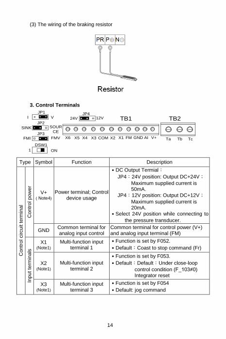
(3) The wiring of the braking resistor
3. Control Terminals
ON1
DSW1
X4 TcTa
JP1
JP2
JP3
TB1 TB2
X3 COM X2 X1 FM GND AI V+
JP4
X5X6 Tb
12V24VVI
SINK SOUR
CE
FMI FMV
Type Symbol Function Description
Contr
ol circuit t
erm
inal
Contr
ol pow
er
V+ ( Note4)
Power terminal; Control device usage
․DC Output Termial:
JP4:24V position: Output DC+24V;
Maximum supplied current is 50mA.
JP4:12V position: Output DC+12V;
Maximum supplied current is 20mA.
․Select 24V position while connecting to
the pressure transducer.
GND Common terminal for analog input control
Common terminal for control power (V+) and analog input terminal (FM)
Input te
rmin
als
X1 (Note1)
Multi-function input terminal 1
․Function is set by F052.
․Default:Coast to stop command (Fr)
X2 (Note1)
Multi-function input terminal 2
․Function is set by F053.
․Default:Default:Under close-loop
control condition (F_103≠0) Integrator reset
X3 (Note1)
Multi-function input terminal 3
․Function is set by F054
․Default: jog command
15
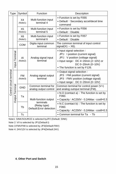
Type Symbol Function Description
X4 (Note1)
Multi-function input terminal 4
․Function is set by F055
․Default:Secondary accel/decel time
command
X5 (Note1)
Multi-function input terminal 5
․Function is set by F056
․Default:Disable
X6 (Note1)
Multi-function input terminal 6
․Function is set by F057
․Default:Disable
COM Digita input common
terminal The common terminal of input control signal(X1 ~ X6).
Contr
ol circuit t
erm
inal
Input
Te
rmin
al
AI (Note2)
Analog signal input terminal
․Input signal selection:
JP1﹕I position (current signal)
JP1﹕V position (voltage signal)
․Input range﹕DC 4~20mA (2~10V) or
DC 0~20mA (0~10V)
․The function is set by F126.
Outp
ut T
erm
inal
FM (Note3)
Analog signal output terminal
․Output signal selection:
JP3:FMI position (current signal)
JP3:FMV position (voltage signal)
․Input range﹕DC 0~20mA (0~10V)
GND Common terminal for analog output control
Common terminal for control power (V+) and analog outnput terminal (FM).
Ta Multi-function output
terminals (Relay type)
Default:Error detection
․N.O (comtact a);The function is set by F060.
․Capacity:AC250V,0.2AMax,cosθ=0.3
Tb
․N.C (comtact b);The function is set by
F060.
․Capacity:AC250V,0.2AMax,cosθ=0.3
Tc ․Common terminal for Ta 、Tb
Note1: SINK/SOURCE is selected byJP2 (Default: SINK)
Note 2: V/I is selected by JP1(Default:I)
Note 3:FMV/FMI is selected by JP3(Default:FMV)
Note 4: 24V/12V is selected by JP4(Default:24V)
4. Other Port and Switch

16
Type Symbol Function Description
RJ-45 CN1
Control of parallel
multiple drive /
Connection for the
Remote keypad Port
․
8 1
․Enable to connect KP-207。
․Connect multiple drives by transmission cable
when the drives parallel control multiple pumps. ․Maximum parallel units:2 units
Pin Description
1 Communication
transmission terminal (DX+)
Differential input of RS-485 *Note 1 Modbus (RS-485) communication only uses pin1, 2.
2 Communication
transmission terminal (DX-)
3 Power terminal of
KP(+15V) Only for KP linking
4 Auto-detect terminal
of KP Only for KP linking
5 Reserved Reserved
6
7 Common ports of KP power(0V)
Only for KP linking 8
DIP switch
DSW1
Terminal
resistor switch
․Switch the DSW1 to “ON” position for first
and last drives, when multiple drives parallel
control multi-pump.
․Terminal resistance: 100Ω
Note 1: The cable length from the controllers(PC, PLC) to the last drive cannot exceed 500m.

17
2-3 Wiring Diagram and Setting for Single-pump and Multi-pump Applications
2-3-1 Single Pump Control
Wiring Method
Drive #0
I V
Pressure
Transducer
(4~20mA)
JP1
AI V+
ON
DSW1
1
24V 12VJP4
CN1
+ -
Parameter setting
Drive(#0)
Setting Description Content
Func.
F015 (Selection of Parallel Control Mode)
=1(Single pump)
F016 (Set Drive’s No. in Parallel Control)
=0(Drive#0)
F126 Select the range of AI =0(4~20mA)
JP1/JP4
Selection
JP1 Input signal type selection of AI (Voltage/Current)
I position
JP4
Seclect output Voltage(V+)
(24V:output DC+24V;
12V:output DC+12V)
24V
Terminal Resistor Switch
DSW1 ON position

18
2-3-2 Multi-pump Control
Wiring Method (Standard wiring)
Driver #1
I VJP1
AI V+
ON
DSW1
1
24V 12VJP4
CN1
Driver #0
I V
Pressure
Transmitter
(4~20mA)
JP1
AI V+
ON
DSW1
1
24V 12VJP4
CN1
+ - + -
Pressure
Transmitter
(4~20mA)
Parameter setting
Drive (#0)
Setting Description Content
Func.
F015 (Selection of Parallel Control Mode)
=2 (E-mode) or
=3 (F-mode) or
=4 (M-mode)
F016 (Set Drive’s No. for Parallel Control)
=0(Drive#0)
F126 Select the range of AI =0(4~20mA)
JP1/JP4
Selection
JP1 Input signal type selection of AI (Voltage/Current)
I position
JP4 Seclect output Voltage(V+) (24V:output DC+24V; 12V:output DC+12V)
24V
Terminal Resistor Switch
DSW1 ON position
Auxiliary Drive (#1)
Setting Description Content
Func.
F015 (Selection of Parallel Control Mode)
=2 (E-mode) or =3 (F-mode) or =4 (M-mode)
F016 (Set Drive’s No. for Parallel Control)
=1
F126 Select the range of AI =0(4~20mA)
JP1/JP4
Selection
JP1 Input signal type selection of AI (Voltage/Current)
I position
JP4 Seclect output Voltage(V+) (24V:output DC+24V; 12V:output DC+12V)
24V
Terminal Resistor Switch
DSW1 ON position

19
Wiring Method (Special wiring)
Driver #1
I VJP1
AI V+
ON
DSW1
1
24V 12VJP4
CN1
Driver #0
I VJP1
AI V+
ON
DSW1
1
24V 12VJP4
CN1
Pressure
Transmitter
(4~20mA)
+ -
Parameter setting
Drive (#0)
Setting Description Content
Func.
F015 (Selection of Parallel Control Mode)
=2 (E-mode)or
=3 (F-mode)or
=4 (M-mode)
F016 (Set Drive’s No. for Parallel Cntrol)
=0(Drive)
F126 Select the range of AI =0(4~20mA)
JP1/JP4
Selection
JP1 Input signal type selection of AI (Voltage/Current)
I position
JP4 Seclect output Voltage(V+) (24V:output DC+24V; 12V:output DC+12V)
24V
Terminal Resistor Switch
DSW1 ON position
Auxiliary Drive (#1)
Setting Description Content
Func
F015 (Selection of Parallel Control Mode)
=2 (E-mode)or
=3 (F-mode)or
=4 (M-mode)
F016 (Set Drive’s No. for Parallel Cntrol)
=1
Terminal Resistor Switch
DSW1 ON position

20
Wiring Method(Special wiring 2)
Driver #1
I VJP1
AI
ON
DSW1
1
24V 12VJP4
CN1
Driver #0
I VJP1
AI
ON
DSW1
1
24V 12VJP4
CN1
Pressure
Transmitter
(4~20mA)
V+ GNDGND V+
+ -
Parameter setting
Drive (#0)
Setting Description Content
Func.
F015 (Selection of Parallel Control Mode)
=2 (E-mode)or =3 (F-mode)or =4 (M-mode)
F016 (Set Drive’s No. for Parallel Cntrol)
=0(Drive)
F126 Select the range of AI =0(4~20mA)
JP1/JP4
Selection
JP1 Input signal type selection of AI (Voltage/Current)
I position
JP4 Seclect output Voltage(V+) (24V:output DC+24V; 12V:output DC+12V)
24V
Terminal Resistor Switch
DSW1 ON position
Auxiliary Drive (#1)
Setting Description Content
Func.
F015 (Selection of Parallel Control Mode)
=2 (E-mode)or =3 (F-mode)or =4 (M-mode)
F016 (Set Drive’s No. for Parallel Cntrol)
=1
F126 Select the range of AI =0(2~10V)
JP1/JP4
Selection
JP1 Input signal type selection of AI (Voltage/Current)
V position
JP4 Seclect output Voltage(V+) (24V:output DC+24V; 12V:output DC+12V)
24V
Terminal Resistor Switch
DSW1 ON position
21
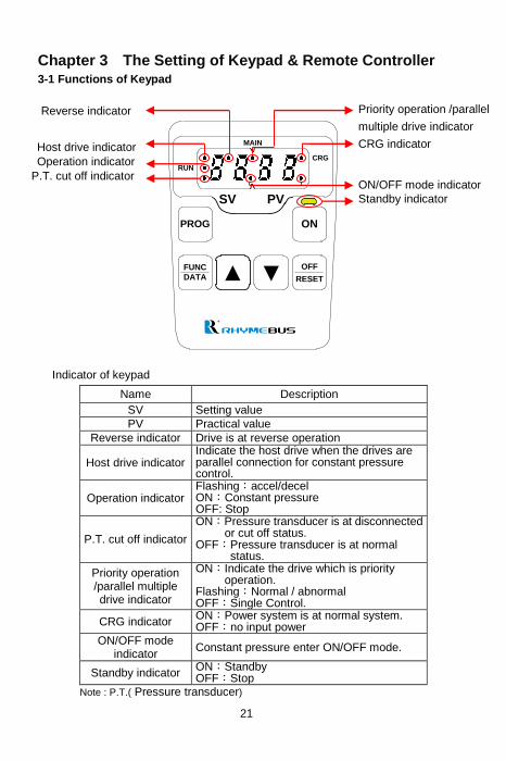
Chapter 3 The Setting of Keypad & Remote Controller 3-1 Functions of Keypad
PROG ON
▼FUNC
DATA
OFF
RESET
RUN
CRG
MAIN
▼
SV PV
Indicator of keypad
Name Description
SV Setting value
PV Practical value
Reverse indicator Drive is at reverse operation
Host drive indicator Indicate the host drive when the drives are parallel connection for constant pressure control.
Operation indicator Flashing:accel/decel ON:Constant pressure OFF: Stop
P.T. cut off indicator
ON:Pressure transducer is at disconnected or cut off status.
OFF:Pressure transducer is at normal status.
Priority operation /parallel multiple drive indicator
ON:Indicate the drive which is priority operation.
Flashing:Normal / abnormal OFF:Single Control.
CRG indicator ON:Power system is at normal system. OFF:no input power
ON/OFF mode indicator
Constant pressure enter ON/OFF mode.
Standby indicator ON:Standby OFF:Stop
Note : P.T.( Pressure transducer)
Priority operation /parallel
multiple drive indicator
CRG indicator
ON/OFF mode indicator
Standby indicator
Reverse indicator
Host drive indicator
Operation indicator
P.T. cut off indicator

22
PROG ON
▼FUNC
DATA
OFF
RESET
RUN
CRG
MAIN
▼
SV PV
Keys of Keypad
Symbol Name Description
PROG
Program key
1. Enter the function setting mode. 2. Back to the monitor mode.
FUNC
DATA
Function/Data key
1. Enter the parameter setting mode. 2. Back to the function setting mode. 3.Switch monitor mode.
▲
Up key
Change functions and parameters.
▼
Down key
ON
Start key Start the drive.
OFF
RESET
Off/Reset key
1. Stop the drive(Cut off U/T1,V/T2,W/T3 Output
signal).
2. Fault reset.
PROG key
FUNC/DATA key
UP key
Start key
OFF/RESET key
Down key

23
3-2 The Operation of Keypad and Monitor Mode
3-2-1 Operation of Keypad
The operation of the digital keypad includes fault messages and three modes. The switching methods are shown as below figure:
Monitor mode Function setting mode Parameter setting mode
Fault message
FUNC
DATA
PROGFUNC
DATA
OFF
RESET
PROG
PROG
RUN
CRG
MAIN
SV PV
RUN
CRG
MAIN
SV PV
RUN
CRG
MAIN
SV PV
RUN
CRG
MAIN
SV PV
Determine one of seven displays as the main display according
to the application. When the parameter of function is completed
without pressing key, the drive will automatically switch back to
the main display after 3 minute.
The operation steps are shown as below table (by default setting)
Operation Steps Display
1.Start the drive and enter the monitor mode. RUN
CRG
MAIN
SV PV
2.Press PROG key and enter the function setting mode. RUN
CRG
MAIN
SV PV
3.Press FUN
DATA key and enter the parameter setting mode. RUN
CRG
MAIN
SV PV
4.Press FUN
DATA key and return to the function setting mode. RUN
CRG
MAIN
SV PV
5.Press PROG key and return to the monitor mode. RUN
CRG
MAIN
SV PV
Error message display:
Operation Steps Display
The fault message displayed during the drive operation RUN
CRG
MAIN
SV PV
1.After the error is troubleshooted, press OFF
RESET key to
clear the fault and return to the monitor mode.
RUN
CRG
MAIN
SV PV 3-2-2 Description of Monitor Mode
There are seven displays can be selected in the monitor mode. Press FUN
DATA
24
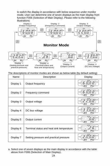
to switch the display in accordance with below sequence under monitor mode. User can determine one of seven displays as the main display from function F006 (Selection of Main Display). Please refer to the following illustrations:
Display 1(Output Frequency)
Display 2(Frequency Command)
Display 3(Output Voltage)
Display 5
(Output Current)
Display 6
(Terminal status and
heat sink temperature)
Display 7
(Setting pressure and
practical pressure)
Monitor Mode
Display 4
(DC bus Voltage)
FUNC
DATA
FUNC
DATA
FUNC
DATA
FUNC
DATA
FUNC
DATA
FUNC
DATA
RUN
CRG
MAIN
SV PV
RUN
CRG
MAIN
SV PV
RUN
CRG
MAIN
SV PV
RUN
CRG
MAIN
SV PV
RUN
CRG
MAIN
SV PV
RUN
CRG
MAIN
SV PV
RUN
CRG
MAIN
SV PV
FUNC
DATA
The descriptions of monitor modes are shown as below table (by default setting)
Name Description Display
Display 1 Output frequency RUN
CRG
MAIN
SV PV
Display 2 Frequency command RUN
CRG
MAIN
SV PV
Display 3 Output voltage RUN
CRG
MAIN
SV PV
Display 4 DC bus voltage RUN
CRG
MAIN
SV PV
Display 5 Output current RUN
CRG
MAIN
SV PV
Display 6 Terminal status and heat sink temperature RUN
CRG
MAIN
SV PV
Display 7 Setting pressure and practical pressure RUN
CRG
MAIN
SV PV a. Select one of seven displays as the main display in accordance with the table
above from F006 (Selection of Main Display).
25
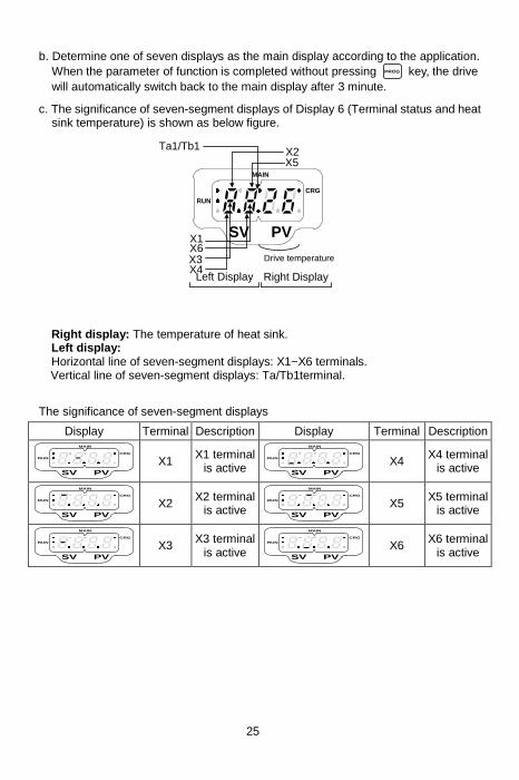
b. Determine one of seven displays as the main display according to the application.
When the parameter of function is completed without pressing PROG
key, the drive
will automatically switch back to the main display after 3 minute.
c. The significance of seven-segment displays of Display 6 (Terminal status and heat sink temperature) is shown as below figure.
RUN
CRG
MAIN
SV PVX1X6X3
Ta1/Tb1X2
Drive temperature
Left Display Right DisplayX4
X5
Right display: The temperature of heat sink. Left display: Horizontal line of seven-segment displays: X1~X6 terminals. Vertical line of seven-segment displays: Ta/Tb1terminal.
The significance of seven-segment displays
Display Terminal Description Display Terminal Description
RUN
CRG
MAIN
SV PV
X1 X1 terminal
is active RUN
CRG
MAIN
SV PV
X4 X4 terminal
is active
RUN
CRG
MAIN
SV PV
X2 X2 terminal
is active RUN
CRG
MAIN
SV PV
X5 X5 terminal
is active
RUN
CRG
MAIN
SV PV
X3 X3 terminal
is active RUN
CRG
MAIN
SV PV
X6 X6 terminal
is active

26
3-2-3 Description of Function Setting Mode
In function setting mode, there are 155 functions (F000 ~ F154) can be selected, and the setting steps are as below:
Operation Steps Display
1.In the monitor mode, press PROG key to enter
function setting mode.
RUN
CRG
MAIN
SV PV
2.Press ▲ key to increase the function number. RUN
CRG
MAIN
SV PV
3.Press ▼ key to decrease the function number. RUN
CRG
MAIN
SV PV
3-2-4 Description of Parameter Setting Mode
In parameter setting mode, the setting range for every function is shown in Parameter List.
Operation Steps Display
1.Select F001 (Start Command Selection) as the example.
RUN
CRG
MAIN
SV PV
2.Press FUN
DATA key to enter parameter setting mode. RUN
CRG
MAIN
SV PV
3.Press ▼ key to decrease the value of F001 from
3 (default value) to 2.
RUN
CRG
MAIN
SV PV
4.Press FUN
DATA key and return to function setting mode. RUN
CRG
MAIN
SV PV
3-2-5 Operation at Moniter Mode
In monitor mode, user can change the value of setting pressure (SV). The operation steps are shown as below. (by default display)
Operation Steps Display
1. In monitor mode, the display of setting pressure(SV) and practical pressure(PV) as right figure.
RUN
CRG
MAIN
SV PV
2. Press ▲ key for several times or keep pressing
the ▲ to increase the setting value of pressure
to 2.5.
RUN
CRG
MAIN
SV PV
3. After completing the setting, press FUN
DATA key within 5 seconds (the setting
value is under blinking status) to save the setting value or waiting for the drive to save the setting value automatically.

27
3-3 Parameter Copy ; Restore Default Value; Save/Restore Setting Value
a. Parameter Copy﹕
Including writing and reading out functions. Parameter settings of two drives can
be copied by “ ” and “ ” functions via keypad
a-1. (Parameter Read Out: Drive parameter Keypad)
Operation steps Display
1.In the monitor mode, press PROG key to enter
function setting mode.
2.Press ▼ or ▲ key to select the function to F154
(Default Setting) and then press FUN
DATA key to enter
parameter setting mode.
RUN
CRG
MAIN
SV PV
3.Press ▲ key and then select
parameter and then press FUN
DATA key to execute the
parameter readout.
RUN
CRG
MAIN
SV PV
4.Drive will start to copy the parameters to keypad, and then display the copy process on keypad.
RUN
CRG
MAIN
SV PV
5.After completing the copy, the keypad will display
message and automatically back to
function setting mode.
RUN
CRG
MAIN
SV PV
a-2. (Parameter Write In: Keypad parameter Drive)
Operation steps Display
1.In the monitor mode, press PROG key to enter
function setting mode.
2.Press ▼ or ▲ key to select the function to F154
(Default Setting) and then press FUN
DATA key to enter
parameter setting mode.
3.Press ▲ key and then select
parameter and then press FUN
DATA key to execute the
writing.
RUN
CRG
MAIN
SV PV
4.Keypad will start to copy the parameters to drive, and then display the copy process on keypad.
RUN
CRG
MAIN
SV PV
5.After completing the copy, the keypad will display
message and automatically back to
function setting mode.
RUN
CRG
MAIN
SV PV
RUN
CRG
MAIN
SV PV
RUN
CRG
MAIN
SV PV
RUN
CRG
MAIN
SV PV

28
※Do Not execute the copy for different software version, otherwise the parameters will occur error and the keypad will displaymessage.
a-3. (Parameter Copy: Master Slaves) Except for two methods described above a1 and a2, It also can use the operation panel of lead drive, through the control wire copy parameter to other auxiliary drive. It allows parameter settings to be easily copied from the drive.
Operation steps Display
1.Through the indicator of lead drive (KEAYPAD) to
distinguish location of lead drive. When the indicator
becomes brighter ,and the inverter represent for the
lead drive.
RUN
CRG
MAIN
SV PV
2. Press PROG key to enter function setting mode. RUN
CRG
MAIN
SV PV
3. Press ▼ or ▲ key to select the function to
F154 (Default Setting) and then press FUNC
DATA key to
enter parameter setting mode.
4. Press ▲ key to select and then
press FUNC
DATA key to copy the parameters.
RUN
CRG
MAIN
SV PV
5. After completing the copy, the keypad will display
message and automatically back to
function setting mode.
RUN
CRG
MAIN
SV PV
※When using copy parameter function, please note F015、F016、F091
parameter content can’t copy to the slave.
b. Restore Default Value﹕
RM6F2 series drive provide four default values for using. According to the demand to restore default values.
(Restore the default value of drive for 60Hz)
(Restore the default value of single constant pressure pump control
application with 60Hz power source)
(Restore the default value of machine tools control application with
60Hz power source)
(Restore the default value of multiple pump constant pressure
control application with 60Hz power source)
(Restore the default value of single pump constant pressure control
application with 50Hz power source)
※Be cautious of the usage of this parameter! This parameter will clear the saved
setting value via parameter.
RUN
CRG
MAIN
SV PV

29
Select the parameter as an example, and the operation steps as
below:
Operation steps Display
1. Press ▼ or ▲ key selecting the function to
F154 (Default Setting) and then press FUN
DATA key to
enter parameter setting mode.
RUN
CRG
MAIN
SV PV
2. Press ▲ key to select parameter, and
then press FUN
DATA key to execute the restoring.
RUN
CRG
MAIN
SV PV
3. After completing the restoring, the keypad will
display message and automatically back
to the function setting mode.
c. Save / Restore Setting Value﹕
(Save the setting value)
Operation Steps Display
1. Press ▼ or ▲ key to select the function to F154
(Default Setting) and then press FUN
DATA key to enter
parameter setting mode.
RUN
CRG
MAIN
SV PV
2. Press ▲ key to select parameter, and
then press FUN
DATA key to execute the saving.
RUN
CRG
MAIN
SV PV
3. After completing the saving, the keypad will display
message and back to the function setting
mode.
RUN
CRG
MAIN
SV PV
(Restore the setting value)
Operation Steps Display
1.Press ▼ or ▲ key to select the function to F154
(Default Setting) and then press FUN
DATA key to enter
parameter setting mode.
RUN
CRG
MAIN
SV PV
2.Press ▲ key to select parameter, and
then press FUN
DATA key to execute the restoring.
RUN
CRG
MAIN
SV PV
3.After completing the restoring, the keypad will
display message and automatically back
to function setting mode.
RUN
CRG
MAIN
SV PV
Note﹕“Restore” parameter is activation when the setting value is saved by
“Save” parameter.
RUN
CRG
MAIN
SV PV

30
Chapter 4 Parameter List
Func. Name Description Range of Setting
Unit Def50 Note
F000 Drive
Information
0: Software version (6F2.d) 1: Drive model number 2: Drive running hours 3: Drive power supplying time 4: Software checksum code 5: Reserved
─ ─ ─
F001 Start
Command Selection
Start command Rotation direction
command
0~4 ─ 3
0: FWD or REV
terminal FWD or REV
terminal
1: FWD terminal REV terminal
2:
Keypad “RUN” key
FWD, REV terminal
3: Forward direction
4: Reverse direction
F002 Selection of Command
0: Frequency command by analog signal via terminal.
1: Frequency command by keypad.
2: Pressure command by keypad.
0~2 ─ 2
F003 Selection of “STOP” Key
Validity
0: Start command by terminal, “STOP” key disabled.
1: Start command by terminal, “STOP” key enabled.
0,1 ─ 1
F004
Setting Value (SV)
Change Selection
Under F002=1
0: In the monitor mode, setting value cannot be changed.
1: In the monitor mode, setting value can be changeable.
0,1 ─ 1
F005
Selection of Setting Value
Auto-Storing
0: In the monitor mode, setting value auto-storing disable.
1: In the monitor mode, setting value auto-storing after 3 minutes.
0,1 ─ 1
F006 Selection of
Main Display
Select 1 of 7 “monitor modes” as the main display.
1~7 ─ 7
F007 Pressure
Transducer Setting
Set upper limit value of pressure in accordance with pressure transducer specification.(pressure setting value is corresponding to maximum voltage or current.)
0.0~99.9 0.1bar 10.0
F008 Maximum
Operational Pressure
Set the maximum operational pressure value (F007*F008) in accordance with the specification of pump.
0~100 1% 100
F009 Starting
Frequency The starting frequency of drive. 0.1~10.0 0.1Hz 0.5
function can be set during the operation. / Gray words: The setting use default value.

31
Func. Name Description Range of Setting
Unit Def50 Note
F010 Starting Voltage
The voltage correspond to the starting frequency.
0.1~50.0 0.1V
8.0 (Note1,2)
0.1~100.0 12.0
(Note3)
F011 Base
Frequency The frequency correspond to the base voltage in V/F pattern.
0.1~400.0 0.1Hz 60.0
F012 Base
Voltage The voltage correspond to the base frequency in V/F pattern.
0.1~255.0 0.1V
220.0 (Note1,2)
0.1~510.0 380.0
(Note3)
F013
(Parallel
Control)
Pump
Exchange
Operation
Selection
0: Disable.
1: Shift the pump operation after the operating time (F_024).
2: Shift the pump operation after a drive stops.
3: Both 1 and 2 enable.
0~3 ─ 3
F015
Pump Parallel Control Mode
0: Disable the functions related to pump. 1: Single pump application. 2: Multi-pump applications;( E-mode) 3: Multi-pump applications; (F-mode ) 4: Multi-pump applications;( M-mode )
0~4 ─ 1
F016
Set Drive’s No. for Parallel Control
Set the individual number for every drive. #0 is the host drive to command others.
0~3 ─ 0
F017 Maximum
Output Frequency
The maximum output frequency of drive. 0.1~ 400.0
0.1Hz 60.0
F018
Reference Frequency
of Accel/Decel
Time
The frequency corresponding to accel/decel time.
0.01~ 400.00
0.01 Hz
60.00
F019 Primary
Acceleration Time
The acceleration time from stop to reference frequency.
0.0~ 3200.0
0.1
sec 1.0
F020 Primary
Deceleration Time
The deceleration time from reference frequency to stop.
0.0~ 3200.0
0.1
sec 1.0
F021
Detection Time of Parallel Control
In multi-pump control systems, set the detection time to startup the auxiliary drive when the pressure drops.
0.0~25.0 0.1 sec
6.0
F022
Detection Level of Parallel Control
In multi-pump control systems, set the detection level to startup the auxiliary drive when the pressure drops.
0.2~25.0 0.1bar 0.4
F023
Cut-off Frequency of Parallel
Control
In multi-pump control systems, set the cut-off frequency to cut off the pump operation.
0.0~60.0 0.1Hz 50.0
function can be set during the operation. / Gray words: The setting use default value.
32
Func. Name Description Range of Setting
Unit Def50 Note
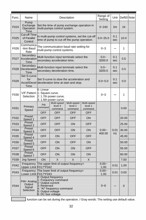
F024
Pump Exchange Operation
Time
Set the time of pump exchange operation in multi-pumps control system. 0~240 1hr 24
F025 Cut-off Time of Parallel
Control
In multi-pump control systems, set the cut-off time of pump to cut off the pump operation.
0.0~25.0 0.1 sec
10.0
F026 Communica -tion Baud
Rate
The communication baud rate setting for multi-pump control systems.
0~3 ─ 1
F027 Secondary
Acceleration Time
Multi-function input terminals select the secondary acceleration time.
0.0~ 3200.0
0.1 sec
0.5
F028 Secondary
Deceleration Time
Multi-function input terminals select the secondary deceleration time.
0.0~ 3200.0
0.1 sec
0.5
F029
Set S-curve for
Accel/Decel Time
Set S-curve to slow the acceleration and deceleration time at start and stop.
0.0~5.0 0.1 sec
0.0
F030 V/F Pattern Selection
0: Linear 1: Square curve. 2: 1.7th power curve. 3: 1.5th power curve.
0~3 ─ 1
F031 Primary Speed
Jog command
Multi-speed level 3
command
Multi-speed level 2
command
Multi-speed level 1
command
0.00~ 400.00
0.01 Hz
0.00
OFF OFF OFF OFF
F032 Preset
Speed 1 OFF OFF OFF ON 20.00
F033 Preset
Speed 2 OFF OFF ON OFF 25.00
F034 Preset
Speed 3 OFF OFF ON ON 30.00
F035 Preset
Speed 4 OFF ON OFF OFF 45.00
F036 Preset
Speed 5 OFF ON OFF ON 50.00
F037 Preset
Speed 6 OFF ON ON OFF 55.00
F038 Preset
Speed 7 OFF ON ON ON 60.00
F039 Jog Speed ON X X X 7.00
F042 Frequency Upper Limit
The upper limit of output frequency= F017*F042
0.00~ 1.00
0.01 1.00
F043 Frequency Lower Limit
The lower limit of output frequency= F017*F043
0.00~ 1.00
0.01 0.00
F044
FM+ Analog Output Signal
Selection
0: Output frequency 1: Frequency command 2: Output current 3: Reserved 4: “AI” frequency command 5: Output voltage 6: DC bus voltage
0~6 ─ 0
function can be set during the operation. / Gray words: The setting use default value.
33
Func. Name Description Range of Setting
Unit Def50 Note
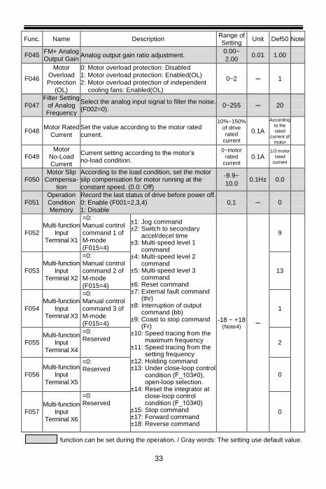
F045 FM+ Analog Output Gain
Analog output gain ratio adjustment. 0.00~
2.00 0.01 1.00
F046
Motor Overload Protection
(OL)
0: Motor overload protection: Disabled 1: Motor overload protection: Enabled(OL) 2: Motor overload protection of independent
cooling fans: Enabled(OL)
0~2 ─ 1
F047 Filter Setting
of Analog Frequency
Select the analog input signal to filter the noise. (F002=0).
0~255 ─ 20
F048 Motor Rated
Current Set the value according to the motor rated current.
10%~150% of drive rated
current
0.1A
According
to the
rated
current of
motor
F049 Motor
No-Load Current
Current setting according to the motor’s no-load condition.
0~motor rated
current 0.1A
1/3 motor
rated
current
F050 Motor Slip
Compensa- tion
According to the load condition, set the motor slip compensation for motor running at the constant speed. (0.0: Off)
-9.9~
10.0 0.1Hz 0.0
F051 Operation Condition Memory
Record the last status of drive before power off. 0: Enable (F001=2,3,4) 1: Disable
0,1 ─ 0
F052 Multi-function
Input Terminal X1
=0: Manual control command 1 of M-mode (F015=4)
±1: Jog command ±2: Switch to secondary
accel/decel time ±3: Multi-speed level 1
command ±4: Multi-speed level 2
command ±5: Multi-speed level 3
command ±6: Reset command ±7: External fault command
(thr) ±8: Interruption of output
command (bb) ±9: Coast to stop command
(Fr) ±10: Speed tracing from the
maximum frequency ±11: Speed tracing from the
setting frequency ±12: Holding command ±13: Under close-loop control
condition (F_103≠0), open-loop selection.
±14: Reset the integrator at close-loop control condition (F_103≠0)
±15: Stop command ±17: Forward command ±18: Reverse command
-18 ~ +18 (Note4)
─
9
F053 Multi-function
Input Terminal X2
=0: Manual control command 2 of M-mode (F015=4)
13
F054 Multi-function
Input Terminal X3
=0: Manual control command 3 of M-mode (F015=4)
1
F055 Multi-function
Input Terminal X4
=0: Reserved
2
F056 Multi-function
Input Terminal X5
=0: Reserved
0
F057 Multi-function
Input Terminal X6
=0: Reserved
0
function can be set during the operation. / Gray words: The setting use default value.

34
Func. Name Description Range of Setting
Unit Def50 Note
F060
Multi-function Output
Terminal Ta,Tb1
0: Disable ±1: Running detection ±2: Constant speed detection ±3: Zero speed detection ±4: Frequency range detection ±5: System overload detection (OLO) ±6: Stall prevention detection ±7: Low voltage detection (LE) ±8: Braking detection ±9: Restart after instantaneous power failure
detection ±10: Restart after error condition detection ±11: Error detection ±12: Overheating warning detection (Ht) ±13: Over pressure detection (OP) ±14: Standby detection
-14 ~ +14 (Note4)
─ -11
F062 Frequency Detection
Range
Set the bandwidth of frequency detection range.
0.0~10.0 0.1Hz 2.0
F063 Frequency Detection
Level
Set the frequency detection level of multi-function output terminal.
0.0~400.0 0.1Hz 0.0
F064
Automatic Torque
Compensa- tion
According to the load condition, adjust the output voltage of the V/F Pattern. (0.0: Off)
0.0~25.5 0.1 1.0
F065
System Overload Detection
(OLO)
0: Disable 1: Enable(OLO)
0,1 ─ 0
F066
System Overload Detecting Selection
0: Detection during constant speed only 1: Detection during operation only
0,1 ─ 0
F067
Output Setting after
System Overload
0: Drive keeps operation when the overload is detected
1: Drive trips to protection when the overload is detected
0,1 ─ 0
F068
System Overload Detection
Level
Set the level of the current for overload detection.
30%~200% of drive
rated current
1% 160
F069
System Overload Detection
Time
When rhe output current is larger than the level (F068) and exceeds the time interval of the overload detection,the drive trips to protect.
0.1~25.0 0.1
sec 2.0
F070
Stall Prevention
Level at Acceleration
If stall is occurred during acceleration, the motor keeps running at the constant speed. (200%: Off)
30%~200% of drive rated
current
1% 170
function can be set during the operation. / Gray words: The setting use default value.

35
Func. Name Description Range of Setting
Unit Def50 Note
F071
Stall Prevention
Level at Constant Speed
While the stall is occurred during constant speed running condition, the prevention of stall is to decrease the speed of motor.
30%~200% of drive rated
current
1% 160
F072
Acceleration Time Setting
after Stall Prevention at Constant
Speed
Set the acceleration time to recover to the constant speed from stall prevention.
0.1~ 3200.0
0.1 sec
3.0 (note3)
F073
Deceleration Time Setting
for Stall Prevention at Constant
Speed
Set the deceleration time to recover to the constant speed from stall prevention
0.1~
3200.0
0.1
sec 3.0
(note3)
F074
Stall Prevention Setting at
Deceleration
0: Disable 1: Enable
0, 1 ─ 1
F075 DC Braking
Level Set the current level of DC braking.
0~150%
of drive
rated
current
1% 50
F076 Time of DC
Braking after Stop
Set the time for DC braking after drive stopped.
0.0~20.0 0.1
sec 0.2
F077 Time of DC
Braking before Start
Set the time for DC braking before drive starts.
0.0~20.0 0.1
sec 0.0
F078
Operation Selection at Instantane- ous Power
Failure
0: Drive cannot be restarted 1: Drive can be restarted 0,1 ─ 0
F079
Auto- Restart
Selection of Error Trip
0: Short time interval to restart automatically according to the setting of F_080 (OC,OE,GF only).
1: Long time interval to restart automatically according to the setting value of F_080, F_083 (all errors except Fb Lo).
0,1 ─ 1
F080
Numbers of Auto-Restart
at Drive’s Error Trip
Set the counting number for drive restart automatically when errors occur.
0~16 1 10
F081 Switching Frequency
The setting value is higher and the motor noise is lower.
0~6 ─ 6
F082 Stop Mode 0: Ramp to stop 1: Coast to stop 2: Coast to stop + DC braking
0~2 ─ 0
F083 Time Interval
before Auto-Restart
Set the time interval before drive restarts automatically (F079=1) when the drive trips to stop.
1~200 10sec 6
function can be set during the operation. / Gray words: The setting use default value.
36
Func. Name Description Range of Setting
Unit Def50 Note
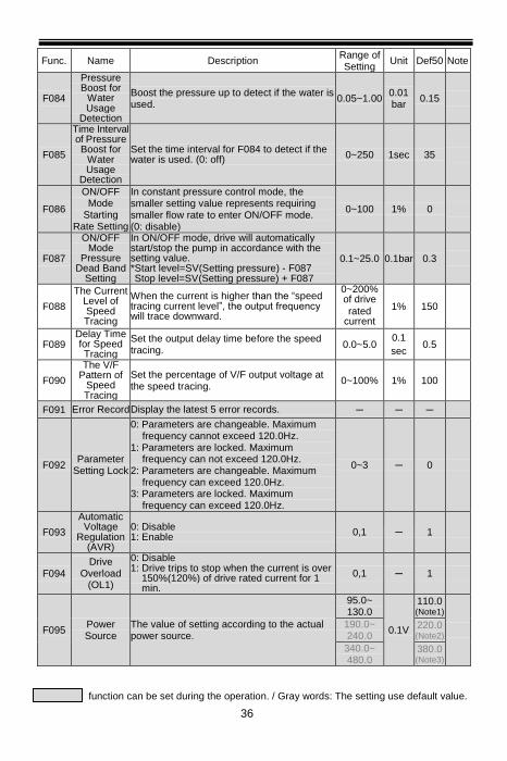
F084
Pressure Boost for
Water Usage
Detection
Boost the pressure up to detect if the water is used.
0.05~1.00 0.01 bar
0.15
F085
Time Interval of Pressure Boost for
Water Usage
Detection
Set the time interval for F084 to detect if the water is used. (0: off) 0~250 1sec 35
F086
ON/OFF Mode
Starting Rate Setting
In constant pressure control mode, the smaller setting value represents requiring smaller flow rate to enter ON/OFF mode. (0: disable)
0~100 1% 0
F087
ON/OFF Mode
Pressure Dead Band
Setting
In ON/OFF mode, drive will automatically start/stop the pump in accordance with the setting value. *Start level=SV(Setting pressure) - F087 Stop level=SV(Setting pressure) + F087
0.1~25.0 0.1bar 0.3
F088
The Current Level of Speed Tracing
When the current is higher than the “speed tracing current level”, the output frequency will trace downward.
0~200% of drive
rated current
1% 150
F089 Delay Time for Speed Tracing
Set the output delay time before the speed tracing.
0.0~5.0 0.1
sec 0.5
F090
The V/F Pattern of
Speed Tracing
Set the percentage of V/F output voltage at the speed tracing.
0~100% 1% 100
F091 Error Record Display the latest 5 error records. ─ ─ ─
F092 Parameter
Setting Lock
0: Parameters are changeable. Maximum frequency cannot exceed 120.0Hz.
1: Parameters are locked. Maximum frequency can not exceed 120.0Hz.
2: Parameters are changeable. Maximum frequency can exceed 120.0Hz.
3: Parameters are locked. Maximum frequency can exceed 120.0Hz.
0~3 ─ 0
F093
Automatic Voltage
Regulation (AVR)
0: Disable 1: Enable
0,1 ─ 1
F094 Drive
Overload (OL1)
0: Disable 1: Drive trips to stop when the current is over
150%(120%) of drive rated current for 1 min.
0,1 ─ 1
F095 Power Source
The value of setting according to the actual power source.
95.0~ 130.0
0.1V
110.0 (Note1)
190.0~ 240.0
220.0 (Note2)
340.0~ 480.0
380.0 (Note3)
function can be set during the operation. / Gray words: The setting use default value.

37
Func. Name Description Range of Setting
Unit Def50 Note
F096 Analog
Frequency Dead Band
When the signal noise is large, appropriately increase the dead band to stabilize the frequency. But it will reduce the tuning linearity.
0.00~2.55 0.01
Hz 0.00
F097 Digital Input Response
Time
When the digital input signal is under the setting time, program will not be activated.
1~255 1ms 10
F098
Grounding Fault
Protection (GF)
0: Disable 1: Enable(GF)
0,1 ─ 1
F102 PID
Compensa- tion Gain
Compensate the gain for pressure command control under constant pressure control.
0.1~8.0 ─ 1.0
F103 PID Control
Mode Selection
0: Open-loop operation 1: Forward control; D postposition 2: Forward control; D preposition 3: Reverse control; D postposition 4: Reverse control; D preposition
0~4 ─ 1
F104 P Selection 0: P postposition 1: P preposition
0,1 ─ 1
F105 Proportional
Gain(P) Set the gain value for deviation adjustment. (0.0: P control disabled)
0.0~25.0 0.1 3.0
F106 Integration
Time(I) Set the integration time for deviation adjustment. (0.0: I control disabled)
0.0~25.0 0.1
sec 1.2
F107 Derivative
Time(D)
Set the derivative time for deviation
adjustment. (0.00: D control disabled) 0.00~2.50
0.01
sec 0.00
F108 Derivative Time of
Feedback Set the derivative time for feedback signal. 0.00~2.50
0.01
sec 0.00
F109 Integration
Upper Limitation
Set the upper limitation value of integrator. 0~200%
of maximum frequency
1% 100
F110 Integration
Lower Limitation
Set the lower limitation value of integrator. -100~100% of maximum frequency
1% 0
F111
Offset Adjustment
for Integration
Time
Adjust the Integration Time offset. -100~100% of maximum frequency
1% 65
F112 PID Buffer
Space Set the buffer space of PID output value. 0~255 ─ 2
F113 Feedback
Signal Filter Filter the feedback signal. 0~255 ─ 10
F114 Feedback Signal Trip Detection
0: Disable 1: Enable (at F126=0)
0,1 ─ 1
F115
Acceleration Time of
Pressure Boost
Set the time of F084 (Pressure Boost for Water Usage Detection) to detect if the water is used.
0.1~25.0 ─ 0.6
function can be set during the operation. / Gray words: The setting use default value.

38
Func. Name Description Range of Setting
Unit Def50 Note
F116 Function Display
Selection
0: F000 ~ F134 1: F000 ~ F154
0,1 ─ 0
F117 PID Start
Range
When the drive at standby status, the level of PID start.(F103≠0) Start level: SV-F117
0.0~10.0 0.1bar 0.3
F118
Selection of Water
Shortage Detection
0: Disable 1: Trip (Fb Lo): Press “RESET” key to reset. 2: Trip (Fb Lo): Power ON again to reset. 3: Trip (Fb Lo): Drive will automatically restart
according to the setting of F122 (Drive Shutdown Time for Water Shortage)
0~3 ─ 1
F119
Water Shortage
Detection by Pressure
Level
Set the pressure level to detect if pump suffers from water shortage conditions. (0: Disable)
0~100% of
pressure command
1% 40
F120
Water Shortage
Detection by Current Level
Set the current level to detect if pump suffers from water shortage conditions. (0: Disable)
0~100% of motor
rated current
1% 0
F121
Time of Water
Shortage Detection
Set the detection time for F119 and F120 to detect if a pump suffers from water shortage.
0~250 1sec 60
F122
Drive Shutdown Time for Water
Shortage
Drive will automatically restart after the time setting, when a pump suffers from water shortage and F118 is set to 3. (0:off)
0~65 1min 5
F124
Proportion Type of
Pressure Transducer
0: Direct proportion signal. 1: Inverse proportion signal.
0,1 ─ 0
F125
Frequency Command Selection
under Close- Loop
Condition
In the close-loop control, select the frequency command source when the feedback signal temporarily bypasses. 0: Multi-fuction input terminal or preset speed. 1: Primary speed (F031) or preset speed. Preset speed(primary speed、preset speed
1~7 and jog speed )
0,1 ─ 1
F126 AI Range Selection
0: 4~20mA (2~10V) 1: 0~20mA (0~10V)
0,1 ─ 0
F127 AI Gain (Analog Input)
The gain ratio of analog input terminal AI. 0.00~2.00 0.01 1.00
F128 AI Bias (Analog Input)
The bias ratio of analog input terminal AI. -1.00~
1.00 0.01 0.00
F131
Constant Speed
Detection Range
Set the bandwidth of constant speed detection range.
0.0~10.0 0.1Hz 2.0
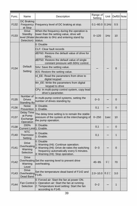
39
Func. Name Description Range of Setting
Unit Def50 Note
F132 DC Braking Frequency
at Stop Frequency level of DC braking at stop. 0.1~60.0 0.1Hz 0.5
F133
Drive Standby
level (Water Detection)
When the frequency during the operation is lower than the setting value, drive will decelerate to 0Hz and entering stand by status.
0~120 1Hz 10
F134 Default
Setting
0: Disable
─ ─ 0
CLF: Clear fault records
dEF60: Restore the default value of drive for
60Hz.
dEF50: Restore the default value of single constant pressure with 60Hz control.
SAv: Save the setting value.
rES: Restore the setting value.
rd_EE: Read the parameters from drive to
digital keypad
Wr_EE: Write the parameters from digital
keypad to drive
CPy: In multi-pump control system, copy lead
drive’s parameter.
F135 Number of
Drives Standing By
In multi-pump control systems, setting the number of drives standing by.
0~3 ─ 0
F136 Noise
Prevention 0: Disable. 1: Enable.
0,1 ─ 0
F137
Delay Time at Pump
Exchange Operation
The delay time setting is to remain the stable pressure of the system at the interchanging of the pump operation.
0~250 1sec 10
F138 200%
Current Limit 0: Disable. 1: Enable.
0,1 ─ 0
F140 NTC
Thermistor Setting
0: Disable. 1: Enable.
0,1 ─ 1
F141
Drive
Overheating Warning Selection
0: Disable 1: Warning (Ht): Continue operation. 2: Warning (Ht): Drive de-rates the switching
frequency automatically every 5 minutes. 3: Warning (Ht): Stop operation.
0~3 ─ 0
F142
Drive Overheating
Warning Level
Set the warning level to prevent drive overheating.
45~85 1℃ 70
F143 Drive
Overheating Dead Band
Set the temperature dead band of F142 and F145.
2.0~10.0 0.1℃ 3.0
F144 Fan Control Selection
0: Forced air: Start the fan at power ON. 1: Operation air: Start the fan at running. 2: Temperature level setting: Start the fan
according to F145.
0~2 ─ 1
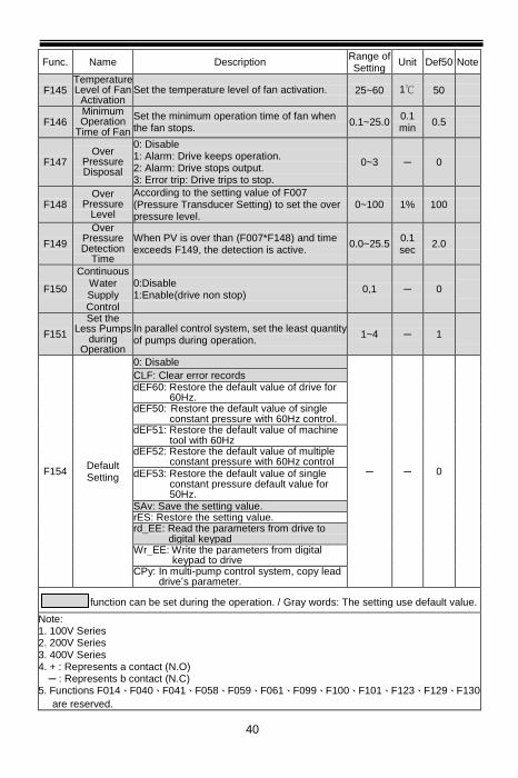
40
Func. Name Description Range of Setting
Unit Def50 Note
F145 Temperature Level of Fan
Activation Set the temperature level of fan activation. 25~60 1℃ 50
F146 Minimum Operation
Time of Fan
Set the minimum operation time of fan when the fan stops.
0.1~25.0 0.1 min
0.5
F147 Over
Pressure Disposal
0: Disable 1: Alarm: Drive keeps operation. 2: Alarm: Drive stops output. 3: Error trip: Drive trips to stop.
0~3 ─ 0
F148 Over
Pressure Level
According to the setting value of F007 (Pressure Transducer Setting) to set the over pressure level.
0~100 1% 100
F149
Over Pressure Detection
Time
When PV is over than (F007*F148) and time exceeds F149, the detection is active.
0.0~25.5 0.1 sec
2.0
F150
Continuous Water Supply Control
0:Disable 1:Enable(drive non stop)
0,1 ─ 0
F151
Set the Less Pumps
during Operation
In parallel control system, set the least quantity of pumps during operation.
1~4 ─ 1
F154 Default Setting
0: Disable
─ ─ 0
CLF: Clear error records dEF60: Restore the default value of drive for
60Hz. dEF50: Restore the default value of single
constant pressure with 60Hz control. dEF51: Restore the default value of machine
tool with 60Hz dEF52: Restore the default value of multiple
constant pressure with 60Hz control dEF53: Restore the default value of single
constant pressure default value for 50Hz.
SAv: Save the setting value. rES: Restore the setting value. rd_EE: Read the parameters from drive to
digital keypad Wr_EE: Write the parameters from digital
keypad to drive CPy: In multi-pump control system, copy lead
drive’s parameter.
function can be set during the operation. / Gray words: The setting use default value.
Note: 1. 100V Series 2. 200V Series 3. 400V Series 4. + : Represents a contact (N.O)
─ : Represents b contact (N.C) 5. Functions F014、F040、F041、F058、F059、F061、F099、F100、F101、F123、F129、F130
are reserved.
41
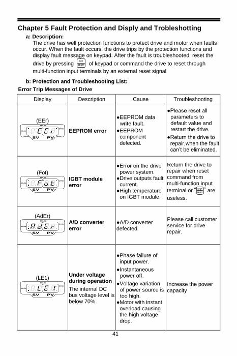
Chapter 5 Fault Protection and Disply and Trobleshotting
a: Description: The drive has well protection functions to protect drive and motor when faults occur. When the fault occurs, the drive trips by the protection functions and display fault message on keypad. After the fault is troubleshooted, reset the
drive by pressing OFF
RESET of keypad or command the drive to reset through
multi-function input terminals by an external reset signal
b: Protection and Troubleshooting List:
Error Trip Messages of Drive
Display Description Cause Troubleshooting
(EEr)
RUN
CRG
MAIN
SV PV
EEPROM error
●EEPROM data write fault.
●EEPROM component defected.
●Please reset all parameters to default value and restart the drive.
●Return the drive to repair,when the fault can’t be eliminated.
(Fot)
RUN
CRG
MAIN
SV PV
IGBT module error
●Error on the drive power system.
●Drive outputs fault current.
●High temperature on IGBT module.
Return the drive to repair when reset command from multi-function input
terminal or “STOP
RESET” are
useless.
(AdEr)
RUN
CRG
MAIN
SV PV
A/D converter error
●A/D converter defected.
Please call customer service for drive repair.
(LE1)
RUN
CRG
MAIN
SV PV
Under voltage during operation
The internal DC bus voltage level is below 70%.
●Phase failure of input power.
●Instantaneous power off.
●Voltage variation of power source is too high.
●Motor with instant overload causing the high voltage drop.
Increase the power capacity

42
Error Trip Messages of Drive
Display Description Cause Troubleshooting
(OC)
RUN
CRG
MAIN
SV PV
Drive over current
The output current of drive during operation exceeds 220% of drive’s rated current.
●The output terminals of drive are short.
●The load is too heavy.
●The acceleration time is too short.
●Drive starts at zero speed while the motor is still running in rotation condition.
●Wrong wiring or bad insulation.
●Starting voltage is too high.
●The motor terminal installs an advance-phase or filter capacitor.
●Check wires of U/T1,V/T2,W/T3 terminals to verify if there is short between terminals.
●Check the motor and drive compatibility.
●Check for possible over loading condition at the motor
●Check if the the acceleration time is too short.
(GF)
RUN
CRG
MAIN
SV PV
Grounding fault
●The three-phase output current is unbalance and exceeding the detection level of grounding fault.
●Grounding fault protection: F098
Check for possible bad insulation at motor’s output side or wire.
Check the insulation value of motor’s wire and motor.
(OE)
RUN
CRG
MAIN
SV PV
Over voltage ●The internal DC
bus voltage of drive is over the protection level.
●100V / 200V series: About DC410V. ●400V series: About DC820V.
●The deceleration time of motor is too short causing the regeneration voltage on DC bus too high.
●Power voltage is too high.
●Surge voltage occurs in drive’s input power side.
●Increase deceleration time.
●Add dynamic brake
unit.
●Check if the power input is within drive’s rated input range.
●Add AC reactor at power input terminal.

43
Error Trip Messages of Drive
Display Description Cause Troubleshooting
(Hv)
RUN
CRG
MAIN
SV PV
Power source over voltage
The internal DC bus voltage of drive is over the protection level during stop.
Power voltage is too high.
Check if the input power is within drive’s rated range.
(db)
RUN
CRG
MAIN
SV PV
Braking transistor is active
The internal DC bus voltage of drive is over the protection level.
DC bus voltage is too high .
Check if the input power is within drive’s rated input range
(OH)
RUN
CRG
MAIN
SV PV
Drive overheat
The temperature of drive’s heat sink reaches the trip level.
●The surrounding temperature is too high.
●The heat sink has foreign body.
●The cooling fan of drive is fault.
●Improve the ventilation.
●Clean the dust on the heat sink.
●Return the drive to replace the cooling fan.
(OL)
RUN
CRG
MAIN
SV PV
Motor overload Operation current
exceeds 150% of
motor’s rated
current and
reaches the motor
overload protection
time.
●Motor overload.
●The voltage setting of V/F pattern is too high or too low.
●The setting value of motor’s rated current is not appropriate.
●Check whether the motor is overloaded.
●Check whether the acceleration or the deceleration is too short.
●Check whether the V/F setting is appropriate.
●Check whether the rated current setting is appropriate.
(OL1)
RUN
CRG
MAIN
SV PV
Drive overload
Operation current exceeds 150% of drive’s rated current and continues for 1minute.
●Motor overload. ●The voltage setting
of V/F pattern is too high or too low.
●Drive’s capacity is not enough.
●Check whether the motor is overloaded.
●Check the load of motor if overload.
●Check whether the acceleration or deceleration time is too short.

44
Error Trip Messages of Drive
Display Description Cause Troubleshooting
●Check if V/F setting is proper.
●Select the higher capacity of drive.
(OL2)
RUN
CRG
MAIN
SV PV
Drive current limit
Operation current exceeds 200% of drive’s rated current.
●Motor overload. ●Acceleration time
is too short. ●Immediately
restart after coasting to stop
●Check whether the motor is matched with drive.
●Check for possible over loading condition at the motor
(OLO)
RUN
CRG
MAIN
SV PV
System overload
●Load is too heavy and the operation current reaches the active level.
●Detection level:
F068。
●Detection time: F069。
--- Check the usage of mechanical equipment.
(thr)
RUN
CRG
MAIN
SV PV
External fault
The multi-function terminal receives the external fault signal.
Clear the external fault and then press
OFF
RESET key.
(ntCF)
RUN
CRG
MAIN
SV PV
NTC thermistor sensor fault
●NTC thermistor sensor broke down.
●The wiring connection of the NTC thermistor sensor is loose.
●Check whether the NTC thermistor sensor is normal.
●Check whether the wire of NTC thermistor sensor is normal.
(PAdF)
RUN
CRG
MAIN
SV PV
Keypad interruption during copy
●The connecting wire of the keypad is loose.
●The keypad jack of the drive is oxidized.
Check the connecting wire of keypad.
(noFb)
RUN
CRG
MAIN
SV PV
PID feedback signal error
The feedback signal wire is disconnected.
Check the feedback signal wire.

45
Error Trip Messages of Drive
Display Description Cause Troubleshooting
(OP)
RUN
CRG
MAIN
SV PV
Over pressure
●Over Pressure Level: F148.
●Over Pressure Detection Time: F149。
●Pump oulet pressure is too high.
●The water valve shut down immediately.
●The pressure sensor is abnormal.
●Check whether the setting value of F148 is appropriate.
●Check whether the pressure of water pipe is normal.
●Check whether the pressure sensor is normal.
(FbLo)
RUN
CRG
MAIN
SV PV
Water shortage ●Water Shortage Detection by
Pressure Level:
F119。
●Water Shortage Detection by Current Level:
F120。
●Time of Water Shortage
Detection: F121。
●Outflow is greater than inflow.
●Pump cannot suck up any water.
●The inlet of pump is blocked.
●Check whether the water usage is under the normal condition.
●Check whether the water storage tank is lack of water.
●Check whether the inlet is blocked .

46
Warning Messages of Drive *When the drive displays below messages, drive stops output. If the abnormal condition is removed, the drive automatically recovers the normal operation.
Display Description Cause Troubleshooting
(LE)
RUN
CRG
MAIN
SV PV
Power source under voltage
The internal DC bus voltage level is below 70%.
The voltage of power source is too low.
Check if the voltage of power source is appropriate.
(bb)
RUN
CRG
MAIN
SV PV
Drive output interruption
Drive stops the output when the output interruption command is activated.
Clear drive output interruption command.
(Fr)
RUN
CRG
MAIN
SV PV
Coast to stop
Drive stops the output when the coast to stop command is activated.
Clear “coast to stop” command.
(db)
RUN
CRG
MAIN
SV PV
Braking transistor is active
The internal DC bus voltage of drive is over the protection level.
DC bus voltage is too high .
Check if the input power is within drive’s rated input range
(PrEr)
RUN
CRG
MAIN
SV PV
Program fault --- Check the software version of drive.
(Ht)
RUN
CRG
MAIN
SV PV
Drive overheat
●The temperature of drive’s heat sink reaches the warning level.
●Warning level: F142.
●The surrounding temperature is too high.
●The heat sink has foreign body.
●The cooling fan of drive is fault.
●Improve the system ventilation.
●Clean the foreign body on the heat sink.
●Return the drive to replace the cooling fan.
(Err 00)
SV
KEYPAD
設定值
PV
實際值Running
Err_00: Keypad cable trip before connecting
●The connecting wire of the keypad is loose.
●The keypad jack of the drive is
Check the wire between the keypad and drive.

47
Display Description Cause Troubleshooting
(Err 01)
SV
KEYPAD
設定值
PV
實際值Running
Err_01: Keypad cable trip during operation
oxidized.
(dtF)
RUN
CRG
MAIN
SV PV
Direction command error
Forward and reverse commands are inputted to the drive simultaneously.
Check the direction command.
(WrF)
RUN
CRG
MAIN
SV PV
Different software version inter-copy
The software version of drive is different.
Check the software version.
(OP)
RUN
CRG
MAIN
SV PV
Over pressure
●Over pressure Level: F148。
●Over Pressure Detection Time: F149。
●The setting value of F148 is not appropriate.
●Pump oulet pressure is too high.
●The water valve shut down immediately.
●The pressure sensor is abnormal.
●Check whether the setting value of F148 is appropriate.
●Check whether the pressure of water pipe is normal.
●Check whether the pressure sensor is normal.
(CPyF)
RUN
CRG
MAIN
SV PV
Copy parameter fault
In the parallel control, the software version of auxiliary drive do not correspond with the host drive.
The software version of auxiliary drives must be correspond with the host drive.

Chapter 6 Outline Dimension Drawing of Drive
Model Number: RM6F2-10P5B1 ~ RM6F2-1001B1;
RM6F2-20P5B1 ~ RM6F2-2002B1;
RM6F2-20P5B3 ~ RM6F2-2003B3;
RM6F2-4001B3 ~ RM6F2-4003B3
2-M4螺絲
14
6
76
88
15
8
ψ5-2
138
47.5
70 81 1
23
.5
(Unit: mm)
Model Number: RM6F2-1002B1 ~ RM6F2-1003B1;
RM6F2-2003B1;
RM6F2-2004B3 ~ RM6F2-2005B3;
RM6F2-4005B3 ~ RM6F2-4007B3
116.5
17
8.4
4-M4螺絲
128
18
9.5
ψ5.2-2
69.5
139
89
.6
10
5.8
12
0
(Unit: mm)

49
Chapter 7 Warning Messages of Drive
Error Trip Messages of Drive
Display Description Display Description
(EEr)
RUN
CRG
MAIN
SV PV
EEPROM error
(OL1)
RUN
CRG
MAIN
SV PV
Drive overload protection-
Accumulated heat protection
(Fot)
RUN
CRG
MAIN
SV PV
IGBT module error
(OL2)
RUN
CRG
MAIN
SV PV
Drive overload protection-
Drive current limit
(AdEr)
RUN
CRG
MAIN
SV PV
A/D converter error
(OLO)
RUN
CRG
MAIN
SV PV
System overload
(LE1)
RUN
CRG
MAIN
SV PV
Under voltage during operation
(thr)
RUN
CRG
MAIN
SV PV
External fault
(OC)
RUN
CRG
MAIN
SV PV
Drive over current
(ntCF)
RUN
CRG
MAIN
SV PV
NTC Thermistor sensor fault
(GF)
RUN
CRG
MAIN
SV PV
Grounding fault
(PAdF)
RUN
CRG
MAIN
SV PV
Keypad interruption during copy
(OE)
RUN
CRG
MAIN
SV PV
Over voltage
(noFb)
RUN
CRG
MAIN
SV PV
PID feedback signal error
(Hv)
RUN
CRG
MAIN
SV PV
Power source over voltage
(OP)
RUN
CRG
MAIN
SV PV
Over pressure
(db)
RUN
CRG
MAIN
SV PV
Braking transistor is active
(FbLo)
RUN
CRG
MAIN
SV PV
Water shortage
(OH)
RUN
CRG
MAIN
SV PV
Drive overheat - -
(OL)
RUN
CRG
MAIN
SV PV
Motor overload - -

50
Warning Messages of Drive
*When the drive displays below messages, drive will stop output. If the abnormal condition is removed, the drive will restart automatically.
Display Description Display Description
(LE)
RUN
CRG
MAIN
SV PV
Power source under voltage
(Err_00)
SV
KEYPAD
設定值
PV
實際值Running
(Err_01)
SV
KEYPAD
設定值
PV
實際值Running
Err_00: Keypad cable trip before connecting
Err_01: Keypad cable trip during operation
(bb)
RUN
CRG
MAIN
SV PV
Drive output interruption
(dtF)
RUN
CRG
MAIN
SV PV
Direction command error
(Fr)
RUN
CRG
MAIN
SV PV
Coast to stop
(Wr_F)
RUN
CRG
MAIN
SV PV
Different software version inter-copy
(db)
RUN
CRG
MAIN
SV PV
Braking transistor is active
(OP)
RUN
CRG
MAIN
SV PV
Over pressure
(PrEr)
RUN
CRG
MAIN
SV PV
Software fault
(CPyF)
RUN
CRG
MAIN
SV PV
Copy parameter fault
(Ht)
RUN
CRG
MAIN
SV PV
Drive overheating - -
Related Documents