AC MOTOR DRIVE Operation Manual RM5G series ISO 9001:2008

Welcome message from author
This document is posted to help you gain knowledge. Please leave a comment to let me know what you think about it! Share it to your friends and learn new things together.
Transcript

AC MOTOR DRIVE
Operation Manual
RM5G series
ISO 9001:2008

Quality․Satisfaction․Improvement․Innovation
http://www.rhymebus.com.tw 2004.01.09 Edition 2014.12.08 Revised

Thank you for using RHYMEBUS RM5G/P series drive. For proper operations and
safety purposes, please do read and follow specific instructions contained in this
manual before using the product. The manual shall be placed on the top of the
machine, and all the setup parameters and reference numbers must be properly
recorded in Attachment 2 to facilitate future maintenance and repairs.
PREFACE

Please read this manual thoroughly and pay attention to the safety precautions marked with ― DANGER ‖ or ― CAUTION ‖ before the installation, wiring, maintenance, or troubleshooting.
Only the qualified personnel may proceed with the installation, wiring, testing, troubleshooting, or other tasks.
※Qualified Personnel: Must be familiar with the fundamentals, structures,
characteristics, operating procedures, and installation, and this personnel must read the manual in details and follow the steps of security measures to prevent possible dangers.
DANGER
User may cause the casualty or serious damages if user does not abide by the instructions of the manual to execute the tasks.
CAUTION
User may cause injuries to the people or damage the equipment if user does not abide by the instructions of the manual to execute the tasks.
※Although the ― ‖ mark may indicate minor damages, serious damages or
injuries may be possibly incurred if the caution is not under user’s attention.
Installation
CAUTION
a. The installation shall take place only on top of the metal surface or any material with the fire resistant. Any place or location of high temperature, moist, oil and gas, cotton fiber, metal powder and erosive gas shall be avoided.
b. If the product specification indicates IP00 (the protective level of the equipment structure), any human contact is forbidden to avoid the electric shock. The option of installing AC reactor(ACL) or DC reactor(DCL) shall be very cautious, too.
c. Please note the surrounding temperature shall not exceed 50°C (or 40°C for RM5P) when the installation needs to be placed inside the control panel.
d. For the environment of storage and installation, please follow the instructions of the environmental conditions illustrated in the sections of the common specification of RM5G and RM5P.
SAFETY PRECAUTION
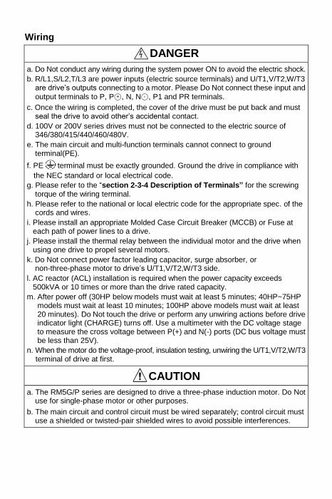
Wiring
DANGER a. Do Not conduct any wiring during the system power ON to avoid the electric shock. b. R/L1,S/L2,T/L3 are power inputs (electric source terminals) and U/T1,V/T2,W/T3
are drive’s outputs connecting to a motor. Please Do Not connect these input and
output terminals to P, P○+ , N, N○- , P1 and PR terminals. c. Once the wiring is completed, the cover of the drive must be put back and must
seal the drive to avoid other’s accidental contact. d. 100V or 200V series drives must not be connected to the electric source of
346/380/415/440/460/480V. e. The main circuit and multi-function terminals cannot connect to ground
terminal(PE).
f. PE terminal must be exactly grounded. Ground the drive in compliance with
the NEC standard or local electrical code. g. Please refer to the ―section 2-3-4 Description of Terminals” for the screwing
torque of the wiring terminal. h. Please refer to the national or local electric code for the appropriate spec. of the
cords and wires.
i. Please install an appropriate Molded Case Circuit Breaker (MCCB) or Fuse at each path of power lines to a drive.
j. Please install the thermal relay between the individual motor and the drive when using one drive to propel several motors.
k. Do Not connect power factor leading capacitor, surge absorber, or non-three-phase motor to drive’s U/T1,V/T2,W/T3 side.
l. AC reactor (ACL) installation is required when the power capacity exceeds 500kVA or 10 times or more than the drive rated capacity.
m. After power off (30HP below models must wait at least 5 minutes; 40HP~75HP models must wait at least 10 minutes; 100HP above models must wait at least 20 minutes). Do Not touch the drive or perform any unwiring actions before drive indicator light (CHARGE) turns off. Use a multimeter with the DC voltage stage to measure the cross voltage between P(+) and N(-) ports (DC bus voltage must be less than 25V).
n. When the motor do the voltage-proof, insulation testing, unwiring the U/T1,V/T2,W/T3 terminal of drive at first.
CAUTION a. The RM5G/P series are designed to drive a three-phase induction motor. Do Not
use for single-phase motor or other purposes. b. The main circuit and control circuit must be wired separately; control circuit must
use a shielded or twisted-pair shielded wires to avoid possible interferences.
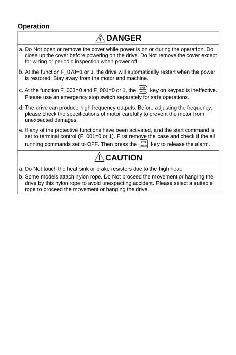
Operation
DANGER a. Do Not open or remove the cover while power is on or during the operation. Do
close up the cover before powering on the drive. Do Not remove the cover except for wiring or periodic inspection when power off.
b. At the function F_078=1 or 3, the drive will automatically restart when the power is restored. Stay away from the motor and machine.
c. At the function F_003=0 and F_001=0 or 1, the STOP
RESET key on keypad is ineffective.
Please use an emergency stop switch separately for safe operations.
d. The drive can produce high frequency outputs. Before adjusting the frequency, please check the specifications of motor carefully to prevent the motor from unexpected damages.
e. If any of the protective functions have been activated, and the start command is set to terminal control (F_001=0 or 1). First remove the case and check if the all
running commands set to OFF. Then press the STOP
RESET key to release the alarm.
CAUTION a. Do Not touch the heat sink or brake resistors due to the high heat.
b. Some models attach nylon rope. Do Not proceed the movement or hanging the drive by this nylon rope to avoid unexpecting accident. Please select a suitable rope to proceed the movement or hanging the drive.

Compliance with UL standards and CSA standards (cUL-listed for Canada)
CAUTION 1. "Risk of Electric Shock"
Before starting or inspection, turn OFF the power and wait at least 5 minutes,
and check for residual voltage between terminal P and N with a multimeter or
similar instrument has dropped to the safe level (50VDC or below), to avoid a
hazard of electric shock.
2. These devices are intended for use in Pollution Degree 2 environments.
3. Maximum surrounding air temperature is 50C for RM5G series and 40C for
RM5P series.
4. Short circuit rating
"Suitable For Use On A Circuit Capable Of Delivering Not More Than 5000 rms
Symmetrical Amperes, 240V Maximum for 200V class." Models RM5G, RM5P
rated for 200V class input.
"Suitable For Use On A Circuit Capable Of Delivering Not More Than 5000 rms
Symmetrical Amperes, 480V Maximum for 400V class." Models RM5G, RM5P
rated for 400V class input.
"Integral solid state short circuit protection does not provide branch circuit
protection. Branch circuit protection must be provided in accordance with the
National Electrical Code and any additional local codes."
5. Install UL certified branch circuit fuse between the power supply and the drive,
referring to the table below.
Single-Phase 200V Series
Model number Fuse type Fuse current rating (A)
RM5G-2001/2-1PH Class RK5
(250Vac, 200kA I.R.)
10
RM5G-2001-1PH 20
RM5G-2002-1PH 50

Compliance with UL standards and CSA standards (cUL-listed for Canada) (continued)
CAUTION Three-Phase 200V Series
Model number Fuse type Fuse current rating (A) RM5G-2001/2
Class RK5
(250Vac, 200kA I.R.)
5
RM5G-2001 10 RM5G-2002 15 RM5G-2003 20 RM5G-2005 30
RM5G-2007
Class T
(300Vac, 200kA I.R.)
50
RM5G-2010 80
RM5G-2015 100
RM5P-2010 80
RM5P-2015 100
Three-Phase 400V Series
Model number Fuse type Fuse current rating (A) RM5G-4001
Class RK5 (600Vac, 200kA I.R.)
5
RM5G-4002 10
RM5G-4003 15
RM5G-4005 20
RM5G-4007
Class T (600Vac, 200kA I.R.)
30
RM5G-4010 30
RM5G-4015 40
RM5G-4020 60
RM5P-4010 30
RM5P-4015 40
RM5P-4020 60
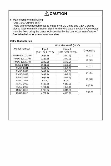
CAUTION 6. Main circuit terminal wiring
"Use 75C Cu wire only." ―Field wiring connection must be made by a UL Listed and CSA Certified closed loop terminal connector sized for the wire gauge involved. Connector must be fixed using the crimp tool specified by the connector manufacturer.‖ See table below for main circuit wire size.
200V Class Series
Model number
Wire size AWG (mm2)
Input
(R/L1, S/L2, T/L3)
Output
(U/T1, V/T2, W/T3) Grounding
RM5G-2001/2-1PH 16 (1.3) 16 (1.3) 16 (1.3)
RM5G-2001-1PH 12 (3.3) 16 (1.3) 12 (3.3)
RM5G-2002-1PH 12 (3.3) 16 (1.3)
RM5G-2001/2 16 (1.3) 16 (1.3) 16 (1.3)
RM5G-2001 16 (1.3) 16 (1.3)
RM5G-2002 14 (2.1) 16 (1.3) 14 (2.1)
RM5G-2003 14 (2.1) 14 (2.1)
RM5G-2005 10 (5.3) 10 (5.3) 10 (5.3)
RM5G-2007 8 (8.4) 8 (8.4)
RM5G-2010 6 (13.3) 6 (13.3) 8 (8.4)
RM5G-2015 4 (21.1) 4 (21.1)
RM5P-2010 6 (13.3) 6 (13.3) 8 (8.4)
RM5P-2015 4 (21.1) 4 (21.1)
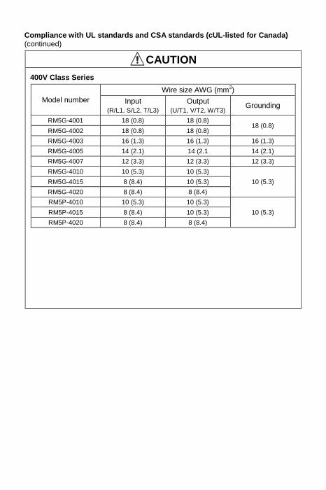
Compliance with UL standards and CSA standards (cUL-listed for Canada) (continued)
CAUTION 400V Class Series
Model number
Wire size AWG (mm2)
Input
(R/L1, S/L2, T/L3)
Output
(U/T1, V/T2, W/T3) Grounding
RM5G-4001 18 (0.8) 18 (0.8) 18 (0.8)
RM5G-4002 18 (0.8) 18 (0.8)
RM5G-4003 16 (1.3) 16 (1.3) 16 (1.3)
RM5G-4005 14 (2.1) 14 (2.1 14 (2.1)
RM5G-4007 12 (3.3) 12 (3.3) 12 (3.3)
RM5G-4010 10 (5.3) 10 (5.3)
10 (5.3) RM5G-4015 8 (8.4) 10 (5.3)
RM5G-4020 8 (8.4) 8 (8.4)
RM5P-4010 10 (5.3) 10 (5.3)
10 (5.3) RM5P-4015 8 (8.4) 10 (5.3)
RM5P-4020 8 (8.4) 8 (8.4)

No Text on This Page
Features
a. RM5G series are suitable for the constant torque load, like mixer, conveyor, etc.
b. RM5P series are suitable for variable torque load, like fan, pump, etc.
c. RM5G series designed for heavy-duty load applications. Overload capability is 150% drive’s rated output current for 1 min.
d. RM5P series designed for light-duty load applications. Overload capability is 120% drive’s rated output current for 1 min.
e. Energy-saving setting for light-duty load.
f. The analog input signal filter has the adjustable function.
g. The analog input signal with addition, subtraction, and multiplication functions can select V or F for the independent adjustment.
h. The responding time of the digital input signal is adjustable (5 ~ 16 ms).
i. 6 digit 7-segment display can exhibit 8 different statuses (frequency, speed, voltage, current, etc.).
j. Programmable input and output terminals. The input signal can be switched as SINK/SOURCE mode.
k. Two sets of programmable relays.
l. Two types of keypads. (digital type: KP-201C; analog type: KP-202)
m. Drive can connect 3 sets of individual display (DM-501) to display operating status.
n. Running hours and supply power time of drive can be recorded.
o. The drive can control and start the synchronous motor.
p. The switching frequency can be adjusted between 800Hz ~ 16kHz.
q. Adjustable accel/decel time from 0.015sec up to 222days.
INTRODUCTIONS
Chapter 1 Cautions Before Installation ..................................... 1
1-1 Product Verification .................................................................................... 1 1-1-1 Confirmation of Appearance .................................................................. 1 1-1-2 The description of nomenclature: ........................................................... 1 1-1-3 Confirmation of Accessories .................................................................. 2
1-2 RM5G Standard Specifications................................................................... 2 1-2-1 Single-Phase 100V Series ..................................................................... 2 1-2-2 Single-Phase 200V Series ..................................................................... 3 1-2-3 Three-Phase 200V Series ...................................................................... 3 1-2-4 Three-Phase 400V Series ...................................................................... 5
1-3 RM5P Standard Specifications ................................................................... 7 1-3-1 Three-Phase 200V Series ...................................................................... 7 1-3-2 Three-Phase 400V Series ...................................................................... 8
1-4 The Features of Control and Operation ................................................... 11 1-4-1 RM5G Series ....................................................................................... 11 1-4-2 RM5P Series ....................................................................................... 14
Chapter 2 Installation and Confirmation ................................. 18 2-1 Basic Equipment ....................................................................................... 18 2-2 Installing the Drive .................................................................................... 18 2-3 Descriptions of Terminal and Wiring Diagram ........................................ 22
2-3-1 Wiring Diagram .................................................................................... 22 2-3-2 SINK / SOURCE Definition .................................................................. 30 2-3-3 Using a PLC Circuit ............................................................................. 30 2-3-4 Description of Terminals ...................................................................... 31 2-3-5 Control Board ...................................................................................... 38 2-3-6 Wiring Cautions and Specifications ...................................................... 40
Chapter 3 The Setting of Keypad ............................................ 44 3-1 Digital Type Keypad (KP-201C) for RM5G/P ............................................ 44 3-2 Analog Type Keypad (KP-202) for RM5G/P .............................................. 44
3-2-1 Description of Switches and Pot Knob ................................................. 45 3-2-2 Description of DIP Switches ................................................................. 47
3-3 Status of Multi-Function Input/Output Terminals and DIP Switch .......... 47 3-3-1 DIP Switch ........................................................................................... 47 3-3-2 Multi-function Input/Output Terminals ................................................... 47
3-4 The Operation of Keypad (KP-201C) and Monitor Mode ......................... 48 3-4-1 Operation of Keypad ............................................................................ 48 3-4-2 Description of Monitor Mode ................................................................ 49 3-4-3 Description of Function Setting Mode ................................................... 50 3-4-4 Description of Parameter Setting Mode ................................................ 50 3-4-5 Operation at Monitor Mode .................................................................. 51 3-4-6 Start / Stop Operation of Drive ............................................................. 51 3-4-7 Parameter Copy; Restore Default Value; Save/Restore Setting Value . 52
Chapter 4 Parameter List.......................................................... 56 Chapter 5 Parameter Setting Description ............................... 67
A. The Keypad Setup ............................................................... 67
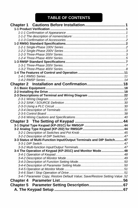
TABLE OF CONTENTS

B. Preset Speed Setup ............................................................. 73 C. Multi-Speed Accel./Decel. Time Setup .............................. 75 D. V/F Pattern Setup ................................................................. 77 E. Analog Input Command Setup ........................................... 79 F. The Upper and Lower Frequency Limit Setup .................. 84 G. Analog Output Setup .......................................................... 85 H. Motor Protection Setup ....................................................... 87 I. Multi-Function Input Setup................................................... 88 J. Multi-Function Outputs Setup ............................................ 95 K. Frequency Detection ......................................................... 100 L. Automatic Torque Compensation .................................... 100 M. Overload Detection Setup ................................................ 100 N. Stall Prevention Setup ...................................................... 102 O. DC Braking Setup .............................................................. 103 P. Drive Status after Power Failure ...................................... 104 Q. Jump Frequency ................................................................ 106 R. Speed Tracing .................................................................... 106 S. Holding Frequency and Time Interval ............................. 107 T. External Indicators ............................................................. 107 U. Other Functions ................................................................. 108 V. Function Selection of KP-202 Keypad ............................. 112
Chapter 6 Operation Procedures and Fault Protection ....... 116 6-1 Operation Procedures ............................................................................. 116 6-2 Fault Protection Display and Troubleshooting ...................................... 118
Appendix A Peripheral Equipment of Drive ......................... 125 Appendix B Motor Selection and Insulation Measurement 126
a. Standard Motor .......................................................................................... 126 b. Special Motors ........................................................................................... 126 c. Insulation Measurement of Drive and Motor ............................................ 127
1. Measure the drive insulation impedance ................................................. 127 2. Measure the motor insulation impedance ................................................ 127
Appendix C Instruction of Drive Charging ........................... 128 Appendix D Dynamic Brake Unit and Braking Resistor ...... 129
a. Braking transistor is installed in the following models .......................... 129 b. Outline of braking resistor (option) .......................................................... 129 c. Rated specification of braking resistor .................................................... 129 d. Recommending specification of braking resistor ................................... 130
AC 200V Series .......................................................................................... 130 AC 400V Series .......................................................................................... 131
e. Recommending specification of dynamic brake unit (DBU6) and braking resistor ...................................................................................................... 132 AC 200V Series .......................................................................................... 132 AC 400V Series .......................................................................................... 132

f. Wiring Diagram of External Braking Resistor and Thermal Switch ........ 133 g. Wiring Diagram of External Dynamic Brake Unit(DBU6) and Thermal
Switch ........................................................................................................ 135
Appendix E Selection of Reactor .......................................... 137 AC Reactor (ACL) Specifications ................................................................. 138 DC Reactor (DCL) Specifications ................................................................. 139 Outline dimensions of AC reactor (ACL) ..................................................... 140 Outline dimensions of DC reactor (DCL) ..................................................... 141
Appendix F Selection of Zero-Phase Radio Frequency Filter ..................................................................................................... 142 Appendix G Selection of EMC Filter ...................................... 146 Appendix H Instruction of Remote Controller and External Display ........................................................................................ 148
a. Remote controller ...................................................................................... 148 b. External display: DM-501 .......................................................................... 150
Appendix I Outline Dimension Drawing of Drives ............... 151 Appendix J Auxiliary Controller (ACE-S Series) .................. 155 Attachment 1 Dimension of Keypad (KP-201C, KP-202) ..... 158 Attachment 2 Setting Memo ................................................... 159 Attachment 3 Fault Display .................................................... 162
Chapter 1 Cautions Before Installation
1 1
Chapter 1 Cautions Before Installation
1-1 Product Verification
The product has passed the strictest quality test before shipped out from the factory. However, the product might possibly sustain minor damages due to the impact, shaking, vibration, and other factors during the transportation. Please make sure to verify the following items after receiving this product. If the product verification finds anything abnormal, please contact the agent immediately for the further assistance.
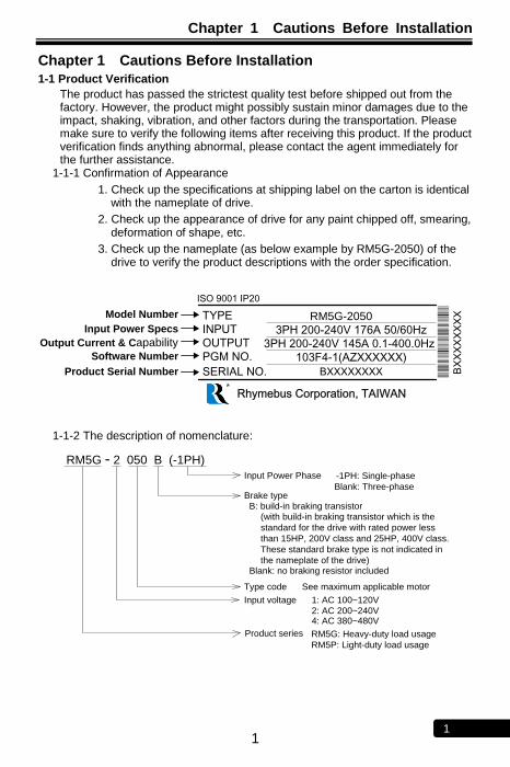
1-1-1 Confirmation of Appearance
1. Check up the specifications at shipping label on the carton is identical with the nameplate of drive.
2. Check up the appearance of drive for any paint chipped off, smearing, deformation of shape, etc.
3. Check up the nameplate (as below example by RM5G-2050) of the drive to verify the product descriptions with the order specification.
Rhymebus Corporation, TAIWAN
BXXXXXXXX
103F4-1(AZXXXXXX)
3PH 200-240V 145A 0.1-400.0Hz
3PH 200-240V 176A 50/60Hz
RM5G-2050
SERIAL NO.
PGM NO.
OUTPUT
INPUT
TYPEModel Number
Input Power Specs
Output Current & CapabilitySoftware Number
Product Serial Number
ISO 9001 IP20
BX
XX
XX
XX
X
1-1-2 The description of nomenclature:
RM5G - 2 050 B (-1PH)
Input Power Phase
Brake type
Type code See maximum applicable motor
Input voltage 1: AC 100~120V
Blank: Three-phase
-1PH: Single-phase
B: build-in braking transistor(with build-in braking transistor which is the
standard for the drive with rated power less
than 15HP, 200V class and 25HP, 400V class.
These standard brake type is not indicated in
the nameplate of the drive)Blank: no braking resistor included
2: AC 200~240V
Product series RM5G: Heavy-duty load usage
RM5P: Light-duty load usage
4: AC 380~480V
Chapter 1 Cautions Before Installation
2 1
Maximum Applicable Motor (HP/Kw)
Type code
Horse power
Type code
Horse power
Type code
Horse power
Type code
Horse power
001/2 0.5 015 15 075 75 300 300
001 1 020 20 100 100 350 350
002 2 025 25 125 125 420 420
003 3 030 30 150 150 500 500
005 5 040 40 175 175 600 600
007 7.5 050 50 200 200 700 700
010 10 060 60 250 250 - -
1-1-3 Confirmation of Accessories
One operation manual is inclusive. Please verify other accessories inclusively such as braking resistor, AC reactor, etc..
※Please refer to the standard specifications to verify the product
specifications with your requirements.
1-2 RM5G Standard Specifications
1-2-1 Single-Phase 100V Series
Model name (RM5G-□□□□-1PH)
1001/2 1001 1002
Maximum applicable motor (HP / kW) 0.5/0.4 1/0.75 1.5/1.1
Rated output capability (kVA) 1 1.6 2.3
Rated output current (A) 2.5 4.2 6
Rated output voltage (V) Three-phase 200~240V
Range of output frequency (Hz) 0.1~400.00Hz
Power source (ψ, V, Hz) Single-phase 100~120V 50/60Hz
Input current (A) 8.8 18 24
Permissible AC power source fluctuation
90~132V 50/60Hz / ±5%
Overload protection 150% of drive rated output current for 1 min.
Cooling method Nature cooling Fan cooling
Applicable safety standards —
Protective structure IP20
Weight / Mass(kg) 1.7 1.8 1.8

Chapter 1 Cautions Before Installation
3 1
1-2-2 Single-Phase 200V Series
Model name (RM5G-□□□□-1PH)
2001/2 2001 2002
Maximum applicable motor (HP / kW) 0.5/0.4 1/0.75 2/1.5
Rated output capability (kVA) 1.1 1.9 3
Rated output current (A) 3 5 8
Rated output voltage (V) Three-phase 200~240V
Range of output frequency (Hz) 0.1~400.00Hz
Power source (ψ, V, Hz) Single-phase 200~240V 50/60Hz
Input current (A) 7 13.5 19
Permissible AC power source fluctuation
176~264V 50/60Hz / ±5%
Overload protection 150% of drive rated output current for 1 min.
Cooling method Nature cooling Fan cooling
Applicable safety standards UL508C, CSA C22.2 No. 14-05
Protective structure IP20, UL open type
Weight / Mass(kg) 1.8 1.9 2
※Please refer to page 116 for the single-phase application of 220V.
1-2-3 Three-Phase 200V Series
Model name (RM5G-□□□□)
2001/2 2001 2002 2003 2005 2007 2010 2015
Maximum applicable motor (HP / kW)
0.5/0.4 1/0.75 2/1.5 3/2.2 5/3.7 7.5/5.5 10/7.5 15/11
Rated output capability (kVA)
1.1 1.9 3 4.2 6.5 9.5 13 18
Rated output current (A) 3 5 8 11 17 25 33 46
Rated output voltage (V) Three-phase 200~240V
Range of output frequency (Hz)
0.1~400.00Hz
Power source (ψ, V, Hz) Three-phase 200~240V 50/60Hz
Input current (A) 5 6 10 14 18 30 40 60
Permissible AC power source fluctuation
176~264V 50/60Hz / ±5%
Overload protection 150% of drive rated output current for 1 min.
Cooling method Nature cooling Fan cooling
Applicable safety standards
UL508C, CSA C22.2 No.14-05 - UL508C,
CSA C22.2 No.14-05
Protective structure IP20, UL open type IP20 IP20, UL open type
Weight / Mass(kg) 1.8 1.8 1.9 2 2.1 3.0 5.4 5.7
Chapter 1 Cautions Before Installation
4 1
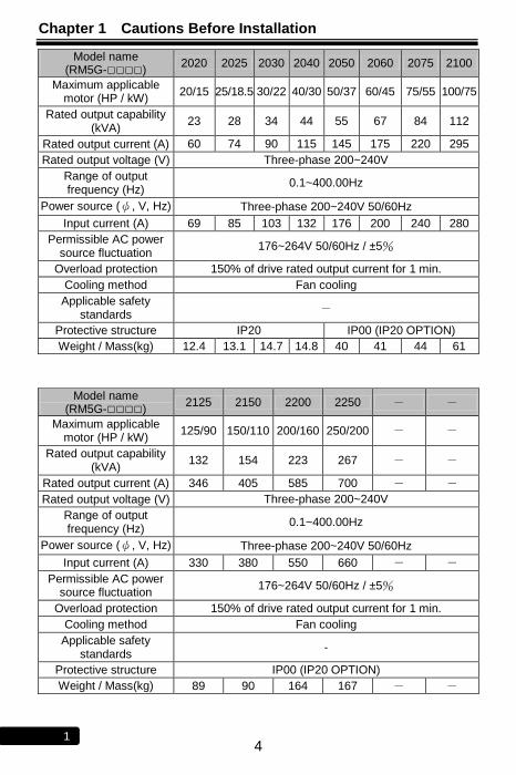
Model name (RM5G-□□□□)
2020 2025 2030 2040 2050 2060 2075 2100
Maximum applicable motor (HP / kW)
20/15 25/18.5 30/22 40/30 50/37 60/45 75/55 100/75
Rated output capability (kVA)
23 28 34 44 55 67 84 112
Rated output current (A) 60 74 90 115 145 175 220 295
Rated output voltage (V) Three-phase 200~240V
Range of output frequency (Hz)
0.1~400.00Hz
Power source (ψ, V, Hz) Three-phase 200~240V 50/60Hz
Input current (A) 69 85 103 132 176 200 240 280
Permissible AC power source fluctuation
176~264V 50/60Hz / ±5%
Overload protection 150% of drive rated output current for 1 min.
Cooling method Fan cooling
Applicable safety standards
-
Protective structure IP20 IP00 (IP20 OPTION)
Weight / Mass(kg) 12.4 13.1 14.7 14.8 40 41 44 61
Model name (RM5G-□□□□)
2125 2150 2200 2250 - -
Maximum applicable motor (HP / kW)
125/90 150/110 200/160 250/200 - -
Rated output capability (kVA)
132 154 223 267 - -
Rated output current (A) 346 405 585 700 - - Rated output voltage (V) Three-phase 200~240V
Range of output frequency (Hz)
0.1~400.00Hz
Power source (ψ, V, Hz) Three-phase 200~240V 50/60Hz
Input current (A) 330 380 550 660 - - Permissible AC power
source fluctuation 176~264V 50/60Hz / ±5%
Overload protection 150% of drive rated output current for 1 min.
Cooling method Fan cooling
Applicable safety standards
-
Protective structure IP00 (IP20 OPTION)
Weight / Mass(kg) 89 90 164 167 - -

Chapter 1 Cautions Before Installation
5 1
1-2-4 Three-Phase 400V Series
Model name (RM5G-□□□□)
4001 4002 4003 4005 4007 4010 4015 4020
Maximum applicable motor (HP / kW)
1/0.75 2/1.5 3/2.2 5/3.7 7.5/5.5 10/7.5 15/11 20/15
Rated output capability (kVA)
1.9 3 4.6 6.9 11 14 18 23
Rated output current (A) 2.5 4 6 9 14 18 24 30
Rated output voltage (V) Three-phase 380~480V
Range of output frequency (Hz)
0.1~400.00Hz
Power source (ψ, V, Hz) Three-phase 380~480V 50/60Hz
Input current (A) 3.5 5 8 12 16 22 28 38
Permissible AC power source fluctuation
332~528V 50/60Hz / ±5%
Overload protection 150% of drive rated output current for 1 min.
Cooling method Nature cooling
Fan cooling
Applicable safety standards
UL508C UL508C,
CSA C22.2 No.14-05
Protective structure IP20, UL open type
Weight / Mass(kg) 1.8 1.9 2 2 5.3 5.4 5.6 5.7
Model name
(RM5G-□□□□) 4025 4030 4040 4050 4060 4075 4100 4125
Maximum applicable motor (HP / kW)
25/18.5 30/22 40/30 50/37 60/45 75/55 100/75 125/90
Rated output capability (kVA)
30 34 46 56 66 84 114 134
Rated output current (A) 39 45 61 73 87 110 150 176
Rated output voltage (V) Three-phase 380~480V
Range of output frequency (Hz)
0.1~400.00Hz
Power source (ψ, V, Hz) Three-phase 380~480V 50/60Hz
Input current (A) 45 52 70 84 100 130 155 177
Permissible AC power source fluctuation
332~528V 50/60Hz / ±5%
Overload protection 150% of drive rated output current for 1 min.
Cooling method Fan cooling
Applicable safety standards
-
Protective structure IP20 IP00 (IP20 OPTION)
Weight / Mass(kg) 5.8 12.8 12.9 15 15.3 44 45 47
Chapter 1 Cautions Before Installation
6 1
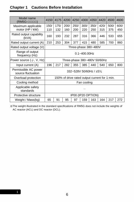
Model name (RM5G-□□□□)
4150 4175 4200 4250 4300 4350 4420 4500 4600
Maximum applicable motor (HP / kW)
150/
110
175/
132
200/
160
250/
200
300/
220
350/
250
420/
315
500/
375
600/
450
Rated output capability (kVA)
160 193 232 287 316 366 446 533 655
Rated output current (A) 210 253 304 377 415 480 585 700 860
Rated output voltage (V) Three-phase 380~480V
Range of output frequency (Hz)
0.1~400.00Hz
Power source (ψ, V, Hz) Three-phase 380~480V 50/60Hz
Input current (A) 196 217 282 355 385 440 540 650 800
Permissible AC power source fluctuation
332~528V 50/60Hz / ±5%
Overload protection 150% of drive rated output current for 1 min.
Cooling method Fan cooling
Applicable safety standards
-
Protective structure IP00 (IP20 OPTION)
Weight / Mass(kg) 65 91 95 97 159 163 164 217 272
※The weight illustrated in the standard specifications of RM5G does not include the weights of
AC reactor (ACL) and DC reactor (DCL).
Chapter 1 Cautions Before Installation
7 1
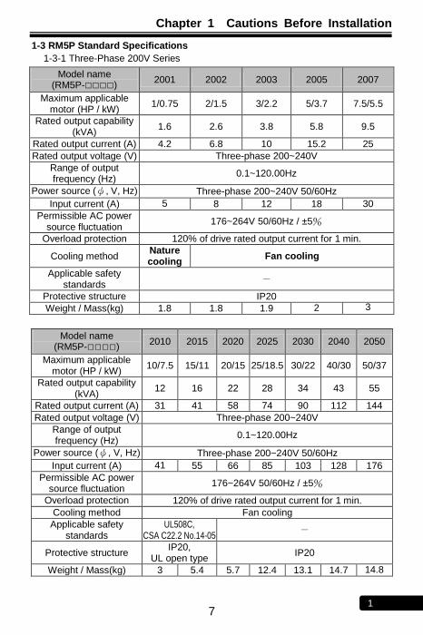
1-3 RM5P Standard Specifications
1-3-1 Three-Phase 200V Series
Model name (RM5P-□□□□)
2001 2002 2003 2005 2007
Maximum applicable motor (HP / kW)
1/0.75 2/1.5 3/2.2 5/3.7 7.5/5.5
Rated output capability (kVA)
1.6 2.6 3.8 5.8 9.5
Rated output current (A) 4.2 6.8 10 15.2 25
Rated output voltage (V) Three-phase 200~240V
Range of output frequency (Hz)
0.1~120.00Hz
Power source (ψ, V, Hz) Three-phase 200~240V 50/60Hz
Input current (A) 5 8 12 18 30
Permissible AC power source fluctuation
176~264V 50/60Hz / ±5%
Overload protection 120% of drive rated output current for 1 min.
Cooling method Nature cooling
Fan cooling
Applicable safety standards
-
Protective structure IP20
Weight / Mass(kg) 1.8 1.8 1.9 2 3
Model name
(RM5P-□□□□) 2010 2015 2020 2025 2030 2040 2050
Maximum applicable motor (HP / kW)
10/7.5 15/11 20/15 25/18.5 30/22 40/30 50/37
Rated output capability (kVA)
12 16 22 28 34 43 55
Rated output current (A) 31 41 58 74 90 112 144
Rated output voltage (V) Three-phase 200~240V
Range of output frequency (Hz)
0.1~120.00Hz
Power source (ψ, V, Hz) Three-phase 200~240V 50/60Hz
Input current (A) 41 55 66 85 103 128 176
Permissible AC power source fluctuation
176~264V 50/60Hz / ±5%
Overload protection 120% of drive rated output current for 1 min.
Cooling method Fan cooling
Applicable safety standards
UL508C, CSA C22.2 No.14-05
-
Protective structure IP20,
UL open type IP20
Weight / Mass(kg) 3 5.4 5.7 12.4 13.1 14.7 14.8
Chapter 1 Cautions Before Installation
8 1
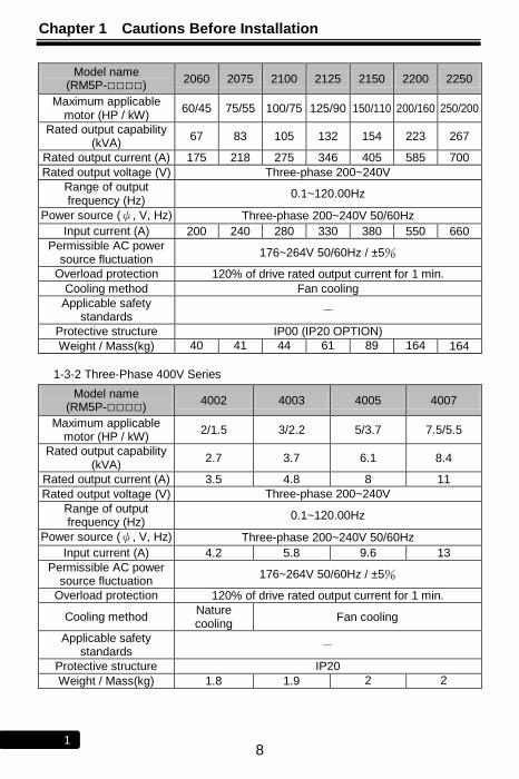
Model name (RM5P-□□□□)
2060 2075 2100 2125 2150 2200 2250
Maximum applicable motor (HP / kW)
60/45 75/55 100/75 125/90 150/110 200/160 250/200
Rated output capability (kVA)
67 83 105 132 154 223 267
Rated output current (A) 175 218 275 346 405 585 700
Rated output voltage (V) Three-phase 200~240V
Range of output frequency (Hz)
0.1~120.00Hz
Power source (ψ, V, Hz) Three-phase 200~240V 50/60Hz
Input current (A) 200 240 280 330 380 550 660
Permissible AC power source fluctuation
176~264V 50/60Hz / ±5%
Overload protection 120% of drive rated output current for 1 min.
Cooling method Fan cooling
Applicable safety standards
-
Protective structure IP00 (IP20 OPTION)
Weight / Mass(kg) 40 41 44 61 89 164 164
1-3-2 Three-Phase 400V Series
Model name (RM5P-□□□□)
4002 4003 4005 4007
Maximum applicable motor (HP / kW)
2/1.5 3/2.2 5/3.7 7.5/5.5
Rated output capability (kVA)
2.7 3.7 6.1 8.4
Rated output current (A) 3.5 4.8 8 11
Rated output voltage (V) Three-phase 200~240V
Range of output frequency (Hz)
0.1~120.00Hz
Power source (ψ, V, Hz) Three-phase 200~240V 50/60Hz
Input current (A) 4.2 5.8 9.6 13
Permissible AC power source fluctuation
176~264V 50/60Hz / ±5%
Overload protection 120% of drive rated output current for 1 min.
Cooling method Nature cooling
Fan cooling
Applicable safety standards
-
Protective structure IP20
Weight / Mass(kg) 1.8 1.9 2 2
Chapter 1 Cautions Before Installation
9 1
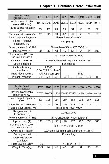
Model name
(RM5P-□□□□) 4010 4015 4020 4025 4030 4040 4050 4060
Maximum applicable motor (HP / kW)
10/7.5 15/11 20/15 25/18.5 30/22 40/30 50/37 60/45
Rated output capability (kVA)
13 17 23 28 34 43 56 66
Rated output current (A) 17 22 30 37 45 56 73 87
Rated output voltage (V) Three-phase 380~480V
Range of output frequency (Hz)
0.1~120.00Hz
Power source (ψ, V, Hz) Three-phase 380~480V 50/60Hz
Input current (A) 20 25 43 45 52 64 84 100
Permissible AC power source fluctuation
332~528V 50/60Hz / ±5%
Overload protection 120% of drive rated output current for 1 min.
Cooling method Fan cooling
Applicable safety standards
UL508C,
CSA C22.2 No.14-05 -
Protective structure IP20, UL open type IP20
Weight / Mass(kg) 5.3 5.4 5.6 5.7 5.8 12.8 12.9 15
Model name (RM5P-□□□□)
4075 4100 4125 4150 4175 4200 4250 4300
Maximum applicable motor (HP / kW)
75/55 100/75 125/90 150/110 175/132 200/160 250/200 300/220
Rated output capability (kVA)
82 105 134 160 193 232 287 316
Rated output current (A) 108 138 176 210 253 304 377 415
Rated output voltage (V) Three-phase 380~480V
Range of output frequency (Hz)
0.1~120.00Hz
Power source (ψ, V, Hz) Three-phase 380~480V 50/60Hz
Input current (A) 130 155 177 196 217 282 355 385
Permissible AC power source fluctuation
332~528V 50/60Hz / ±5%
Overload protection 120% of drive rated output current for 1 min.
Cooling method Fan cooling
Applicable safety standards
-
Protective structure IP20 IP00 (IP20 OPTION)
Weight / Mass(kg) 15.3 44 45 47 65 91 95 97
Chapter 1 Cautions Before Installation
10 1
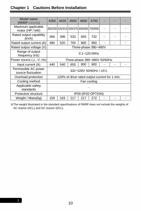
Model name (RM5P-□□□□)
4350 4420 4500 4600 4700 - - -
Maximum applicable motor (HP / kW)
350/250 420/315 500/375 600/450 700/500 - - -
Rated output capability (kVA)
366 396 533 655 732 - - -
Rated output current (A) 480 520 700 860 960 - - -
Rated output voltage (V) Three-phase 380~480V
Range of output frequency (Hz)
0.1~120.00Hz
Power source (ψ, V, Hz) Three-phase 380~480V 50/60Hz
Input current (A) 440 540 650 800 900 - - -
Permissible AC power source fluctuation
332~528V 50/60Hz / ±5%
Overload protection 120% of drive rated output current for 1 min.
Cooling method Fan cooling
Applicable safety standards
-
Protective structure IP00 (IP20 OPTION)
Weight / Mass(kg) 159 163 217 217 272 - - -
※The weight illustrated in the standard specifications of RM5P does not include the weights of
AC reactor (ACL) and DC reactor (DCL).
Chapter 1 Cautions Before Installation
11 1
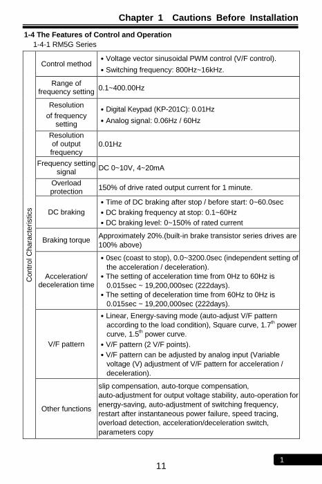
1-4 The Features of Control and Operation
1-4-1 RM5G Series
Contr
ol C
hara
cte
ristics
Control method ․Voltage vector sinusoidal PWM control (V/F control).
․Switching frequency: 800Hz~16kHz.
Range of frequency setting
0.1~400.00Hz
Resolution
of frequency setting
․Digital Keypad (KP-201C): 0.01Hz
․Analog signal: 0.06Hz / 60Hz
Resolution of output frequency
0.01Hz
Frequency setting signal
DC 0~10V, 4~20mA
Overload protection
150% of drive rated output current for 1 minute.
DC braking
․Time of DC braking after stop / before start: 0~60.0sec
․DC braking frequency at stop: 0.1~60Hz
․DC braking level: 0~150% of rated current
Braking torque Approximately 20%.(built-in brake transistor series drives are
100% above)
Acceleration/ deceleration time
․0sec (coast to stop), 0.0~3200.0sec (independent setting of
the acceleration / deceleration).
․The setting of acceleration time from 0Hz to 60Hz is
0.015sec ~ 19,200,000sec (222days).
․The setting of deceleration time from 60Hz to 0Hz is
0.015sec ~ 19,200,000sec (222days).
V/F pattern
․Linear, Energy-saving mode (auto-adjust V/F pattern
according to the load condition), Square curve, 1.7th power
curve, 1.5th power curve.
․V/F pattern (2 V/F points).
․V/F pattern can be adjusted by analog input (Variable
voltage (V) adjustment of V/F pattern for acceleration /
deceleration).
Other functions
slip compensation, auto-torque compensation,
auto-adjustment for output voltage stability, auto-operation for
energy-saving, auto-adjustment of switching frequency,
restart after instantaneous power failure, speed tracing,
overload detection, acceleration/deceleration switch,
parameters copy
Chapter 1 Cautions Before Installation
12 1
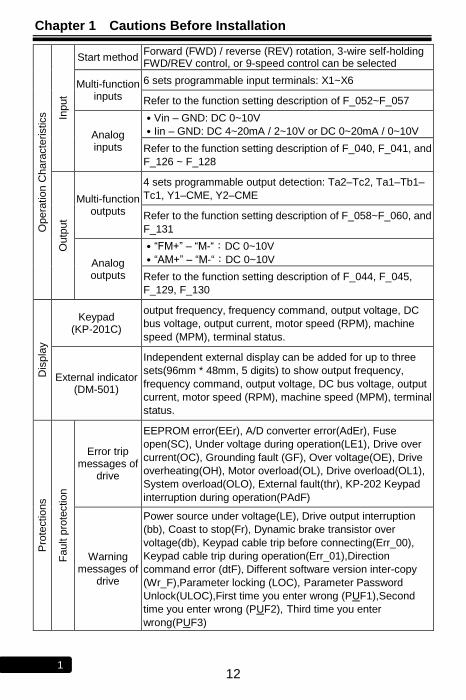
Opera
tio
n C
hara
cte
ristics
Input
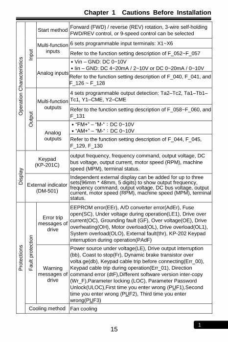
Start method Forward (FWD) / reverse (REV) rotation, 3-wire self-holding FWD/REV control, or 9-speed control can be selected
Multi-function inputs
6 sets programmable input terminals: X1~X6
Refer to the function setting description of F_052~F_057
Analog inputs
․Vin – GND: DC 0~10V
․Iin – GND: DC 4~20mA / 2~10V or DC 0~20mA / 0~10V
Refer to the function setting description of F_040, F_041, and
F_126 ~ F_128
Outp
ut
Multi-function outputs
4 sets programmable output detection: Ta2–Tc2, Ta1–Tb1–
Tc1, Y1–CME, Y2–CME
Refer to the function setting description of F_058~F_060, and
F_131
Analog outputs
․―FM+‖ – ―M-―:DC 0~10V
․―AM+‖ – ―M-―:DC 0~10V
Refer to the function setting description of F_044, F_045,
F_129, F_130
Dis
pla
y
Keypad (KP-201C)
output frequency, frequency command, output voltage, DC
bus voltage, output current, motor speed (RPM), machine
speed (MPM), terminal status.
External indicator (DM-501)
Independent external display can be added for up to three
sets(96mm * 48mm, 5 digits) to show output frequency,
frequency command, output voltage, DC bus voltage, output
current, motor speed (RPM), machine speed (MPM), terminal
status.
Pro
tectio
ns
Fa
ult p
rote
ctio
n
Error trip messages of
drive
EEPROM error(EEr), A/D converter error(AdEr), Fuse
open(SC), Under voltage during operation(LE1), Drive over
current(OC), Grounding fault (GF), Over voltage(OE), Drive
overheating(OH), Motor overload(OL), Drive overload(OL1),
System overload(OLO), External fault(thr), KP-202 Keypad
interruption during operation(PAdF)
Warning messages of
drive
Power source under voltage(LE), Drive output interruption
(bb), Coast to stop(Fr), Dynamic brake transistor over
voltage(db), Keypad cable trip before connecting(Err_00),
Keypad cable trip during operation(Err_01),Direction
command error (dtF),Different software version inter-copy
(Wr_F),Parameter locking (LOC), Parameter Password
Unlock(ULOC),First time you enter wrong (PUF1),Second
time you enter wrong (PUF2), Third time you enter
wrong(PUF3)
Chapter 1 Cautions Before Installation
13 1
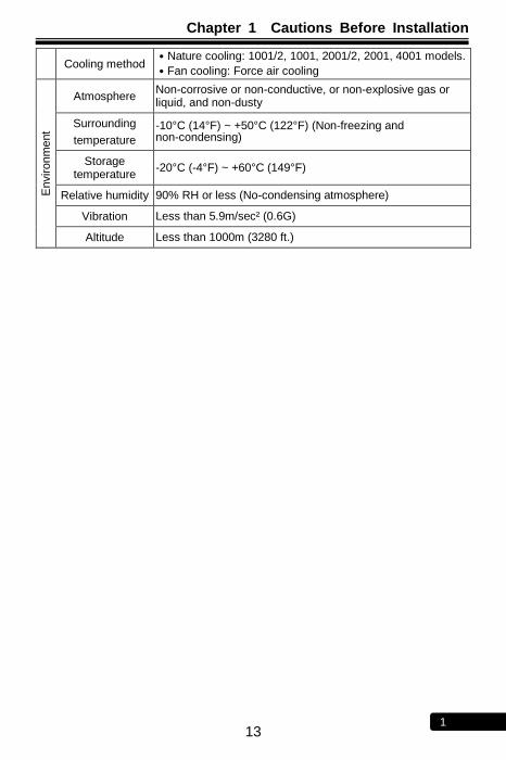
Cooling method ․Nature cooling: 1001/2, 1001, 2001/2, 2001, 4001 models.
․Fan cooling: Force air cooling
Environm
ent
Atmosphere Non-corrosive or non-conductive, or non-explosive gas or liquid, and non-dusty
Surrounding
temperature
-10°C (14°F) ~ +50°C (122°F) (Non-freezing and non-condensing)
Storage temperature
-20°C (-4°F) ~ +60°C (149°F)
Relative humidity 90% RH or less (No-condensing atmosphere)
Vibration Less than 5.9m/sec² (0.6G)
Altitude Less than 1000m (3280 ft.)
Chapter 1 Cautions Before Installation
14 1
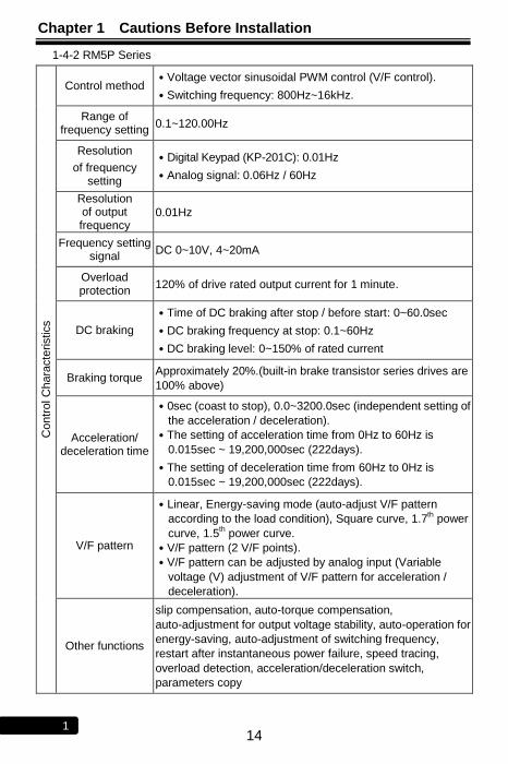
1-4-2 RM5P Series C
ontr
ol C
hara
cte
ristics
Control method ․Voltage vector sinusoidal PWM control (V/F control).
․Switching frequency: 800Hz~16kHz.
Range of frequency setting
0.1~120.00Hz
Resolution
of frequency setting
․Digital Keypad (KP-201C): 0.01Hz
․Analog signal: 0.06Hz / 60Hz
Resolution of output frequency
0.01Hz
Frequency setting signal
DC 0~10V, 4~20mA
Overload protection
120% of drive rated output current for 1 minute.
DC braking
․Time of DC braking after stop / before start: 0~60.0sec
․DC braking frequency at stop: 0.1~60Hz
․DC braking level: 0~150% of rated current
Braking torque Approximately 20%.(built-in brake transistor series drives are
100% above)
Acceleration/ deceleration time
․0sec (coast to stop), 0.0~3200.0sec (independent setting of
the acceleration / deceleration).
․The setting of acceleration time from 0Hz to 60Hz is
0.015sec ~ 19,200,000sec (222days).
․The setting of deceleration time from 60Hz to 0Hz is
0.015sec ~ 19,200,000sec (222days).
V/F pattern
․Linear, Energy-saving mode (auto-adjust V/F pattern
according to the load condition), Square curve, 1.7th power
curve, 1.5th power curve.
․V/F pattern (2 V/F points).
․V/F pattern can be adjusted by analog input (Variable
voltage (V) adjustment of V/F pattern for acceleration /
deceleration).
Other functions
slip compensation, auto-torque compensation,
auto-adjustment for output voltage stability, auto-operation for
energy-saving, auto-adjustment of switching frequency,
restart after instantaneous power failure, speed tracing,
overload detection, acceleration/deceleration switch,
parameters copy
Chapter 1 Cautions Before Installation
15 1
Opera
tio
n C
hara
cte
ristics
Input
Start method Forward (FWD) / reverse (REV) rotation, 3-wire self-holding
FWD/REV control, or 9-speed control can be selected
Multi-function inputs
6 sets programmable input terminals: X1~X6
Refer to the function setting description of F_052~F_057
Analog inputs
․Vin – GND: DC 0~10V
․Iin – GND: DC 4~20mA / 2~10V or DC 0~20mA / 0~10V
Refer to the function setting description of F_040, F_041, and
F_126 ~ F_128
Outp
ut
Multi-function outputs
4 sets programmable output detection: Ta2–Tc2, Ta1–Tb1–
Tc1, Y1–CME, Y2–CME
Refer to the function setting description of F_058~F_060, and
F_131
Analog outputs
․―FM+‖ – ―M-―:DC 0~10V
․―AM+‖ – ―M-―:DC 0~10V
Refer to the function setting description of F_044, F_045,
F_129, F_130
Dis
pla
y
Keypad (KP-201C)
output frequency, frequency command, output voltage, DC
bus voltage, output current, motor speed (RPM), machine
speed (MPM), terminal status.
External indicator (DM-501)
Independent external display can be added for up to three sets(96mm * 48mm, 5 digits) to show output frequency, frequency command, output voltage, DC bus voltage, output current, motor speed (RPM), machine speed (MPM), terminal status.
Pro
tectio
ns
Fa
ult p
rote
ctio
n
Error trip messages of
drive
EEPROM error(EEr), A/D converter error(AdEr), Fuse
open(SC), Under voltage during operation(LE1), Drive over
current(OC), Grounding fault (GF), Over voltage(OE), Drive
overheating(OH), Motor overload(OL), Drive overload(OL1),
System overload(OLO), External fault(thr), KP-202 Keypad
interruption during operation(PAdF)
Warning messages of
drive
Power source under voltage(LE), Drive output interruption
(bb), Coast to stop(Fr), Dynamic brake transistor over
volta.ge(db), Keypad cable trip before connecting(Err_00),
Keypad cable trip during operation(Err_01), Direction
command error (dtF),Different software version inter-copy
(Wr_F),Parameter locking (LOC), Parameter Password
Unlock(ULOC),First time you enter wrong (PUF1),Second
time you enter wrong (PUF2), Third time you enter
wrong(PUF3)
Cooling method Fan cooling

Chapter 1 Cautions Before Installation
16 1
Environm
ent
Atmosphere Non-corrosive or non-conductive, or non-explosive gas or liquid, and non-dusty
Surrounding
temperature
-10°C (14°F) ~ +40°C (104°F) (Non-freezing and non-condensing)
Storage temperature
-20°C (-4°F) ~ +60°C (149°F)
Relative humidity 90% RH or less (No-condensing atmosphere)
Vibration Less than 5.9m/sec² (0.6G)
Altitude Less than 1000m (3280 ft.)

Chapter 1 Cautions Before Installation
17 1
No Text on This Page
Chapter 2 Installation and Confirmation
18 2
Chapter 2 Installation and Confirmation
2-1 Basic Equipment
The drive needs the several components for the conjunctive operation. These components are called ―basic equipment‖, listed in the following:
2-1-1 Power Source: The voltage with three-phase or single-phase of the power source must meet the drive specifications.
2-1-2 MCCB or NFB: MCCB (Molded Case Circuit Breaker) or NFB (No Fuse Breaker) can withstand the inrush current at instant power ON and providing the overload and over-current protection to the drive.
2-1-3 Drive: The main device of motor control. The rated current of motors are variance when the number of motor poles or rated voltage of motor are variance. Base on the rated voltage or rated current of motor to select the drive. Do Not refer to the horse power of motor to select the drive(please refer to the lists of standard specifications of drives).
2-1-4 Motor: The specifications of motor are determined from the requirement. Please be cautious to the motor rated current that must not exceed the drive current.
2-2 Installing the Drive
For the safe operation of the drive, please be cautious to the environmental conditions where the drive is going to be installed.
2-2-1 AC Power: AC power input must be complied with the AC power input specification of the drive.(see RM5G/P standard specifications)
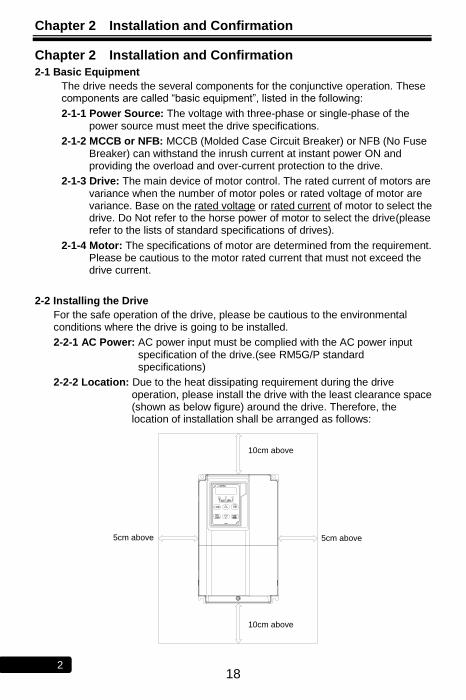
2-2-2 Location: Due to the heat dissipating requirement during the drive operation, please install the drive with the least clearance space (shown as below figure) around the drive. Therefore, the location of installation shall be arranged as follows:
10cm above
5cm above
10cm above
5cm above
Chapter 2 Installation and Confirmation
19 2
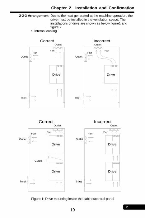
2-2-3 Arrangement: Due to the heat generated at the machine operation, the drive must be installed in the ventilation space. The installations of drive are shown as below figure1 and figure 2:
a. Internal cooling
Outlet
Fan
Outlet
Fan
Intlet
RM5G/P
Driver
RM5G/P
Driver
Outlet
Fan
Outlet
Fan
Intlet
Drive Drive
Correct Incorrect
Inlet Inlet
Outlet
Intlet
Outlet
FanFan
Guide
RM5G/P
Driver
RM5G/P
Driver
Outlet
Intlet
Outlet
FanFan
RM5G/P
Driver
RM5G/P
Driver
Drive
Drive
Drive
Drive
Correct Incorrect
InletInlet
Figure 1: Drive mounting inside the cabinet/control panel
Chapter 2 Installation and Confirmation
20 2
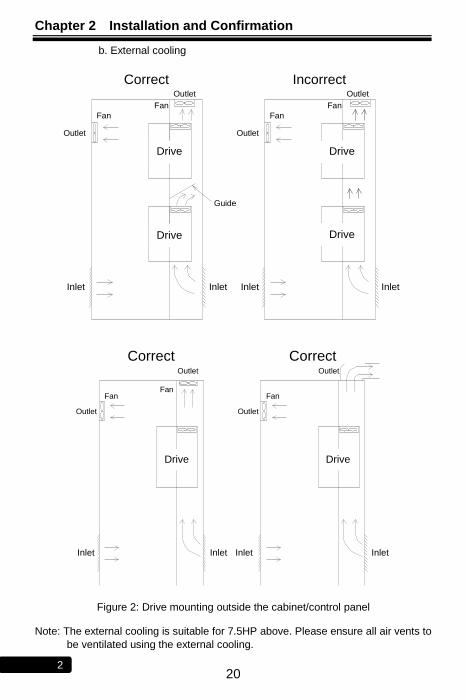
b. External cooling
Outlet
Outlet
Fan
Fan
Intlet Intlet
Guide
RM5G/P
Drive
RM5G/P
Drive
Outlet
Outlet
Fan
Fan
Intlet Intlet
RM5G/P
Drive
RM5G/P
Drive
Drive
Drive Drive
Drive
Correct Incorrect
Inlet InletInlet Inlet
Outlet
Outlet
Intlet Intlet
RM5G/P
Drive
FanFan
Outlet
Intlet Intlet
RM5G/P
Drive
Fan
Outlet
Correct Correct
Drive Drive
Inlet Inlet Inlet Inlet
Figure 2: Drive mounting outside the cabinet/control panel
Note: The external cooling is suitable for 7.5HP above. Please ensure all air vents to
be ventilated using the external cooling.
Chapter 2 Installation and Confirmation
21 2
2-2-4 Specifications of Associated Accessories: The specifications of the accessories must be according to the specifications of the drive. Otherwise, the drive will be damaged and the life span of the drive will be shorten.
Do Not add any power factor leading capacitor(RC, LC or other capacitance
component) between the drive and motor to avoid any accidents.
2-2-5 Cleaning of Environment: The installed location of drive must consider
the ventilation, cleanliness and moisture. 2-2-6 Operator: Only the qualified personnel can perform the operation and
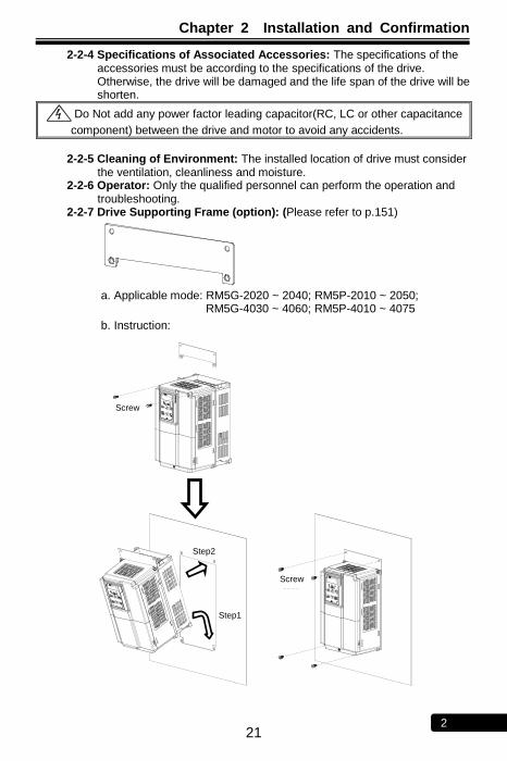
troubleshooting. 2-2-7 Drive Supporting Frame (option): (Please refer to p.151)
a. Applicable mode: RM5G-2020 ~ 2040; RM5P-2010 ~ 2050;
RM5G-4030 ~ 4060; RM5P-4010 ~ 4075
b. Instruction:
M5-2
Screw
M5-4
Screw
Step2
Step1
Screw
Screw
Chapter 2 Installation and Confirmation
22 2
2-3 Descriptions of Terminal and Wiring Diagram
2-3-1 Wiring Diagram
Model: RM5G-1001/2-1PH ~ RM5G-1002-1PH; RM5G-2001/2-1PH ~ RM5G-2002-1PH
RM5G
IM
SINK
SOURCE
I
V
FWD
REV
X1
X2
X3
X4
12V
Vin
Iin
GND CME
Y2
Y1
Tc1
Tb1
Ta1
Tc2
Ta2
FM+
AM+
R
S
W
V
G
U
PR P N
Shielded
WireTwisted-Pair
Shielded WireP
P P P
VR 1KΩ,1/4W
Forward
Reverse
Multi-function Input Terminal 1
Single-Phase, 50/60Hz
AC Power Input
Induction Motor
(-)
(+)
(+)
Multi-function Output Terminal(Relay Type)(AC 250V/0.5A COSθ=0.3)
Multi-function Output Terminal(Open collector)(DC 48V/50mA)
Main Circuit Terminals
Control Terminals
※2
Braking Resistor(option)
GND
Analog Output Terminal (DC 0~10V)
※1
COM
R
S
Current Input for Frequency Setting(Default: DC 4~20mA)
Voltage Input for Frequency Setting
(Default: DC 0~10V)
SW1
SW2
Multi-function Input Terminal 2
Multi-function Input Terminal 3
Multi-function Input Terminal 4
X5
X6
Multi-function Input Terminal 5
Multi-function Input Terminal 6
G
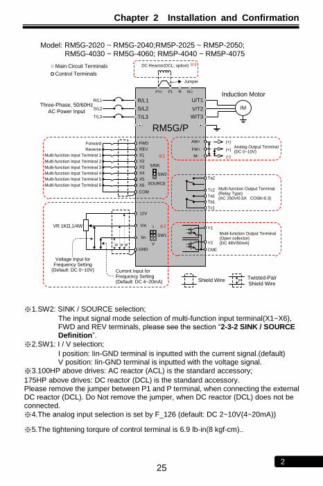
※1.SW2: SINK / SOURCE selection;
The input signal mode selection of multi-function input terminal(X1~X6), FWD and REV terminals, please see the section ―2-3-2 SINK / SOURCE Definition‖.
※2.SW1: I / V selection;
I position: Iin-GND terminal is inputted with the current signal.(default) V position: Iin-GND terminal is inputted with the voltage signal.
※3.The analog input selection is set by F_126 (default: DC 2~10V(4~20mA))
※4.The tightening torqure of control terminal is 5 lb-in(5.7 kgf-cm).
Chapter 2 Installation and Confirmation
23 2
Model: RM5G-2001/2 ~ RM5G-2005; RM5G-4001 ~ RM5G-4005 RM5P-2001~RM5P-2005; RM5P-4002~RM5P-4007
RM5G
IM
SINK
SOURCE
I
V
FWD
REV
X1
X2
X3
X4
12V
Vin
Iin
GND CME
Y2
Y1
Tc1
Tb1
Ta1
Tc2
Ta2
FM+
AM+
R/L1
S/L2
W/T3
V/T2
G
U/T1
PR P N
Shielded
WireTwisted-Pair
Shielded WireP
P P P
VR 1KΩ,1/4W
Forward
Reverse
Multi-function Input Terminal 1
Three-Phase,
50/60Hz AC
Power Input
Induction Motor
(-)
(+)
(+)
Multi-function Output Terminal(Relay Type)(AC 250V/0.5A COSθ=0.3)
Multi-function Output Terminal(Open collector)(DC 48V/50mA)
Main Circuit Terminals
Control Terminals
※2
T/L3
Braking Resistor(option)
GND
Analog Output Terminal (DC 0~10V)
※1
COM
R/L1
S/L2
Current Input for Frequency Setting(Default: DC 4~20mA)
Voltage Input for Frequency Setting
(Default: DC 0~10V)
SW1
SW2
Multi-function Input Terminal 2
Multi-function Input Terminal 3
Multi-function Input Terminal 4
X5
X6
Multi-function Input Terminal 5
Multi-function Input Terminal 6
G
T/L3
※1.SW2: SINK / SOURCE selection;
The input signal mode selection of multi-function input terminal(X1~X6), FWD and REV terminals, please see the section ―2-3-2 SINK / SOURCE Definition‖.
※2.SW1: I / V selection;
I position: Iin-GND terminal is inputted with the current signal.(default) V position: Iin-GND terminal is inputted with the voltage signal.
※3.The analog input selection is set by F_126 (default: DC 2~10V(4~20mA))
※4.The tightening torqure of control terminal is 5 lb-in(5.7 kgf-cm).
Chapter 2 Installation and Confirmation
24 2
Model: RM5G-2007 ~ RM5G-2015; RM5P-2010 ~ RM5P-2020; RM5G-4007 ~ RM5G-4025; RM5P-4010 ~ RM5P-4030
RM5G/P
IM
I
V
12V
Vin
Iin
GND CME
Y2
Y1
Tc1
Tb1
Ta1
Tc2
Ta2
FM+
AM+
R/L1
S/L2
W/T3
V/T2
U/T1
Shield Wire Twisted-Pair Shield Wire
P
P P P
VR 1KΩ,1/4W
Three-Phase, 50/60Hz
AC Power Input
Induction Motor
(-)
(+)
(+)
Multi-function Output Terminal(Relay Type)(AC 250V/0.5A COSθ=0.3)
Multi-function Output Terminal(Open collector)(DC 48V/50mA)
Main Circuit Terminals
Control Terminals
※2
T/L3
M-
Analog Output Terminal (DC 0~10V)
R/L1
S/L2
Current Input for Frequency Setting(Default: DC 4~20mA)
Voltage Input for Frequency Setting
(Default: DC 0~10V)
T/L3
N
Braking Resistor(option) Jumper
P( )+PR P1
DC Reactor(DCL; option)
SW1
SINK
FWD
REV
X1
X2
X3
X4
Forward
Reverse
Multi-function Input Terminal 1
COM
Multi-function Input Terminal 2
Multi-function Input Terminal 3
Multi-function Input Terminal 4
X5
X6
Multi-function Input Terminal 5
Multi-function Input Terminal 6
※1
SOURCE
SW2
※3
※1.SW2: SINK / SOURCE selection;
The input signal mode selection of multi-function input terminal(X1~X6), FWD and REV terminals, please see the section ―2-3-2 SINK / SOURCE Definition‖.
※2.SW1: I / V selection;
I position: Iin-GND terminal is inputted with the current signal.(default) V position: Iin-GND terminal is inputted with the voltage signal.
※3.100HP above drives: AC reactor (ACL) is the standard accessory;
175HP above drives: DC reactor (DCL) is the standard accessory. Please remove the jumper between P1 and P terminal, when connecting the external DC reactor (DCL). Do Not remove the jumper, when DC reactor (DCL) does not be connected.
※4.The analog input selection is set by F_126 (default: DC 2~10V(4~20mA))
※5.The tightening torqure of control terminal is 6.9 lb-in(8 kgf-cm).
Chapter 2 Installation and Confirmation
25 2
Model: RM5G-2020 ~ RM5G-2040;RM5P-2025 ~ RM5P-2050; RM5G-4030 ~ RM5G-4060; RM5P-4040 ~ RM5P-4075
RM5G/P
IM
I
V
12V
Vin
Iin
GND CME
Y2
Y1
Tc1
Tb1
Ta1
Tc2
Ta2
FM+
AM+
R/L1
S/L2
W/T3
V/T2
U/T1
Shield Wire Twisted-Pair Shield Wire
P
P P P
VR 1KΩ,1/4W
Three-Phase, 50/60Hz
AC Power Input
Induction Motor
(-)
(+)
(+)
Multi-function Output Terminal(Relay Type)(AC 250V/0.5A COSθ=0.3)
Multi-function Output Terminal(Open collector)(DC 48V/50mA)
Main Circuit Terminals
Control Terminals
※2
T/L3
M-
Analog Output Terminal (DC 0~10V)
R/L1
S/L2
Current Input for Frequency Setting(Default: DC 4~20mA)
Voltage Input for Frequency Setting
(Default: DC 0~10V)
T/L3
N
Jumper
P( )+ P1
DC Reactor(DCL; option)
SW1
SINK
FWD
REV
X1
X2
X3
X4
Forward
Reverse
Multi-function Input Terminal 1
COM
Multi-function Input Terminal 2
Multi-function Input Terminal 3
Multi-function Input Terminal 4
X5
X6
Multi-function Input Terminal 5
Multi-function Input Terminal 6
※1
SOURCE
SW2
※3
※1.SW2: SINK / SOURCE selection;
The input signal mode selection of multi-function input terminal(X1~X6), FWD and REV terminals, please see the section ―2-3-2 SINK / SOURCE Definition‖.
※2.SW1: I / V selection;
I position: Iin-GND terminal is inputted with the current signal.(default) V position: Iin-GND terminal is inputted with the voltage signal.
※3.100HP above drives: AC reactor (ACL) is the standard accessory;
175HP above drives: DC reactor (DCL) is the standard accessory. Please remove the jumper between P1 and P terminal, when connecting the external DC reactor (DCL). Do Not remove the jumper, when DC reactor (DCL) does not be connected.
※4.The analog input selection is set by F_126 (default: DC 2~10V(4~20mA))
※5.The tightening torqure of control terminal is 6.9 lb-in(8 kgf-cm)..
Chapter 2 Installation and Confirmation
26 2
Model: RM5G-2020B ~ RM5G-2040B;RM5P-2025B ~ RM5P-2050B; RM5G-4030B ~ RM5G-4060B; RM5P-4040B ~ RM5P-4075B
RM5G/P
IM
I
V
12V
Vin
Iin
GND CME
Y2
Y1
Tc1
Tb1
Ta1
Tc2
Ta2
FM+
AM+
R/L1
S/L2
W/T3
V/T2
U/T1
Shield Wire Twisted-Pair Shield Wire
P
P P P
VR 1KΩ,1/4W
Three-Phase, 50/60Hz
AC Power Input
Induction Motor
(-)
(+)
(+)
Multi-function Output Terminal(Relay Type)(AC 250V/0.5A COSθ=0.3)
Multi-function Output Terminal(Open collector)(DC 48V/50mA)
Main Circuit Terminals
Control Terminals
※2
T/L3
M-
Analog Output Terminal (DC 0~10V)
R/L1
S/L2
Current Input for Frequency Setting(Default: DC 4~20mA)
Voltage Input for Frequency Setting
(Default: DC 0~10V)
T/L3
N
Braking Resistor(option)Jumper
P( )+PR P1
DC Reactor(DCL; option)
SW1
SINK
FWD
REV
X1
X2
X3
X4
Forward
Reverse
Multi-function Input Terminal 1
COM
Multi-function Input Terminal 2
Multi-function Input Terminal 3
Multi-function Input Terminal 4
X5
X6
Multi-function Input Terminal 5
Multi-function Input Terminal 6
※1
SOURCE
SW2
※3
※1.SW2: SINK / SOURCE selection;
The input signal mode selection of multi-function input terminal(X1~X6), FWD and REV terminals, please see the section ―2-3-2 SINK / SOURCE Definition‖.
※2.SW1: I / V selection;
I position: Iin-GND terminal is inputted with the current signal.(default) V position: Iin-GND terminal is inputted with the voltage signal.
※3.100HP above drives: AC reactor (ACL) is the standard accessory;
175HP above drives: DC reactor (DCL) is the standard accessory. Please remove the jumper between P1 and P terminal, when connecting the external DC reactor (DCL). Do Not remove the jumper, when DC reactor (DCL) does not be connected.
※4.The analog input selection is set by F_126 (default: DC 2~10V(4~20mA))
※5.The tightening torqure of control terminal is 6.9 lb-in(8 kgf-cm)..

Chapter 2 Installation and Confirmation
27 2
Model: RM5G-2050 ~ RM5G-2075; RM5P-2060 ~ RM5P-2100; RM5G-4075 ; RM5P-4100
RM5G/P
IM
I
V
12V
Vin
Iin
GND
CME
Y2
Y1
Tc1
Tb1
Ta1
Tc2
Ta2
FM+
AM+
R/L1
S/L2
W/T3
V/T2
PE
U/T1
Shielded
WireTwisted-Pair
Shielded WireP
P P P
VR 1KΩ,1/4W
Three-Phase,
50/60Hz AC
Power Input
Induction Motor
(-)
(+)
(+)
Multi-function Output Terminal(Relay Type)(AC 250V/0.5A COSθ=0.3)
Multi-function Output Terminal(Open collector)(DC 48V/50mA)
Main Circuit Terminals
Control Terminals
※2
T/L3
M-
Analog Output Terminal (DC 0~10V)
R/L1
S/L2
Current Input for Frequency Setting(Default: DC 4~20mA)
Voltage Input for Frequency Setting
(Default: DC 0~10V)
JP4
PE
T/L3
P♁ P1 N
SINK
FWD
REV
X1
X2
X3
X4
Forward
Reverse
Multi-function Input Terminal 1
COM
Multi-function Input Terminal 2
Multi-function Input Terminal 3
Multi-function Input Terminal 4
X5
X6
Multi-function Input Terminal 5
Multi-function Input Terminal 6
※1
SOURCE
SW2
DC Reactor(DCL;option)
Jumper
※3
※1.SW2: SINK / SOURCE selection;
The input signal mode selection of multi-function input terminal(X1~X6), FWD and REV terminals, please see the section ―2-3-2 SINK / SOURCE Definition‖.
※2.SW1: I / V selection;
I position: Iin-GND terminal is inputted with the current signal.(default) V position: Iin-GND terminal is inputted with the voltage signal.
※3.100HP above drives: AC reactor (ACL) is the standard accessory;
175HP above drives: DC reactor (DCL) is the standard accessory. Please remove the jumper between P1 and P terminal, when connecting the external DC reactor (DCL). Do Not remove the jumper, when DC reactor (DCL) does not be connected.
※4.The analog input selection is set by F_126 (default: DC 2~10V(4~20mA))
※5.The tightening torqure of control terminal is 5 lb-in(5.7 kgf-cm).
Chapter 2 Installation and Confirmation
28 2
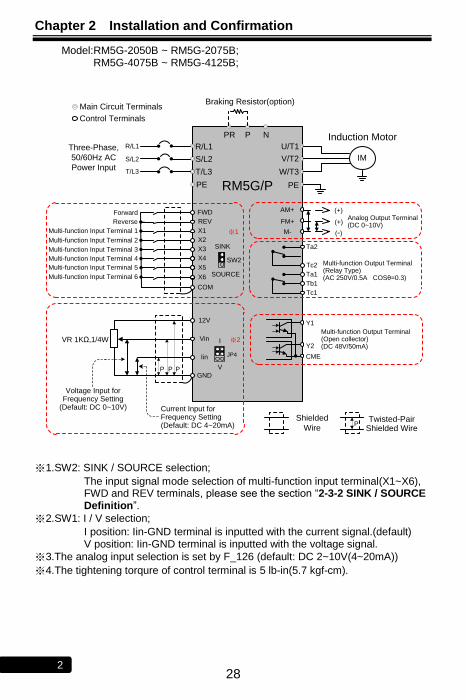
Model:RM5G-2050B ~ RM5G-2075B; RM5G-4075B ~ RM5G-4125B;
RM5G/P
IM
I
V
12V
Vin
Iin
GND
CME
Y2
Y1
Tc1
Tb1
Ta1
Tc2
Ta2
FM+
AM+
R/L1
S/L2
W/T3
V/T2
PE
U/T1
Shielded
WireTwisted-Pair
Shielded WireP
P P P
VR 1KΩ,1/4W
Three-Phase,
50/60Hz AC
Power Input
Induction Motor
(-)
(+)
(+)
Multi-function Output Terminal(Relay Type)(AC 250V/0.5A COSθ=0.3)
Multi-function Output Terminal(Open collector)(DC 48V/50mA)
Main Circuit Terminals
Control Terminals
※2
T/L3
M-
Analog Output Terminal (DC 0~10V)
R/L1
S/L2
Current Input for Frequency Setting(Default: DC 4~20mA)
Voltage Input for Frequency Setting
(Default: DC 0~10V)
JP4
PE
T/L3
PR P N
Braking Resistor(option)
SINK
FWD
REV
X1
X2
X3
X4
Forward
Reverse
Multi-function Input Terminal 1
COM
Multi-function Input Terminal 2
Multi-function Input Terminal 3
Multi-function Input Terminal 4
X5
X6
Multi-function Input Terminal 5
Multi-function Input Terminal 6
※1
SOURCE
SW2
※1.SW2: SINK / SOURCE selection;
The input signal mode selection of multi-function input terminal(X1~X6), FWD and REV terminals, please see the section ―2-3-2 SINK / SOURCE Definition‖.
※2.SW1: I / V selection;
I position: Iin-GND terminal is inputted with the current signal.(default) V position: Iin-GND terminal is inputted with the voltage signal.
※3.The analog input selection is set by F_126 (default: DC 2~10V(4~20mA))
※4.The tightening torqure of control terminal is 5 lb-in(5.7 kgf-cm).
Chapter 2 Installation and Confirmation
29 2
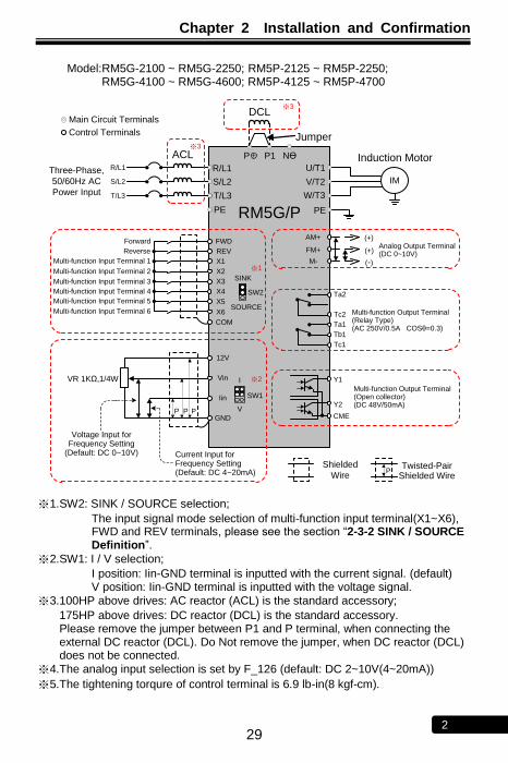
Model:RM5G-2100 ~ RM5G-2250; RM5P-2125 ~ RM5P-2250;
RM5G-4100 ~ RM5G-4600; RM5P-4125 ~ RM5P-4700
RM5G/P
IM
I
V
12V
Vin
Iin
GND CME
Y2
Y1
Tc1
Tb1
Ta1
Tc2
Ta2
FM+
AM+
R/L1
S/L2
W/T3
V/T2
PE
U/T1
P P1 NӨ
Shielded
WireTwisted-Pair
Shielded WireP
P P P
VR 1KΩ,1/4W
Three-Phase,
50/60Hz AC
Power Input
Induction Motor
(-)
(+)
(+)
Multi-function Output Terminal(Relay Type)(AC 250V/0.5A COSθ=0.3)
Multi-function Output Terminal(Open collector)(DC 48V/50mA)
Main Circuit Terminals
Control Terminals
※2
T/L3
M-
Analog Output Terminal (DC 0~10V)
※1
Current Input for Frequency Setting(Default: DC 4~20mA)
Voltage Input for Frequency Setting
(Default: DC 0~10V)
PE
R/L1
S/L2
T/L3
DCL
※3
ACL
Jumper
※3
+
SINK
SOURCE
FWD
REV
X1
X2
X3
X4
Forward
Reverse
Multi-function Input Terminal 1
COM
SW1
SW2
Multi-function Input Terminal 2
Multi-function Input Terminal 3
Multi-function Input Terminal 4
X5
X6
Multi-function Input Terminal 5
Multi-function Input Terminal 6
※1.SW2: SINK / SOURCE selection;
The input signal mode selection of multi-function input terminal(X1~X6), FWD and REV terminals, please see the section ―2-3-2 SINK / SOURCE Definition‖.
※2.SW1: I / V selection;
I position: Iin-GND terminal is inputted with the current signal. (default) V position: Iin-GND terminal is inputted with the voltage signal.
※3.100HP above drives: AC reactor (ACL) is the standard accessory;
175HP above drives: DC reactor (DCL) is the standard accessory. Please remove the jumper between P1 and P terminal, when connecting the external DC reactor (DCL). Do Not remove the jumper, when DC reactor (DCL) does not be connected.
※4.The analog input selection is set by F_126 (default: DC 2~10V(4~20mA))
※5.The tightening torqure of control terminal is 6.9 lb-in(8 kgf-cm).
Chapter 2 Installation and Confirmation
30 2
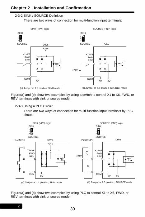
2-3-2 SINK / SOURCE Definition
There are two ways of connection for multi-function input terminals:
SINK
SOURCE
SINK (NPN) logic
X1~X6
COM
FWD
REV
Drive
+24V
0V
SINK
SOURCE
SOURCE (PNP) logic
COM
Drive
+24V
(a) Jumper at 1,2 position; SINK mode (b) Jumper at 2,3 position; SOURCE mode
X1~X6
FWD
REV
0V 0V
12
3
12
3
Figure(a) and (b) show two examples by using a switch to control X1 to X6, FWD, or REV terminals with sink or source mode.
2-3-3 Using a PLC Circuit
There are two ways of connection for multi-function input terminals by PLC circuit:
SINK (NPN) logic
X1~X6
COM
FWD
REV
Drive
+24V
0V
SOURCE (PNP) logic
X1~X6
COM
FWD
REV
Drive
+24V
(a) Jumper at 1,2 position; SINK mode (b) Jumper at 2,3 position; SOURCE mode
PLC(NPN) PLC(PNP)
0V 0V
SINK
SOURCE
SINK
SOURCE
12
3
12
3
Figure(a) and (b) show two examples by using PLC to control X1 to X6, FWD, or REV terminals with sink or source mode.

Chapter 2 Installation and Confirmation
31 2
2-3-4 Description of Terminals
a. Main Circuit Terminals
Type Symbol Function Description
Power Source
R,S AC power
source input terminals
Single-phase; sinusoidal power source input terminals.
R,S,T (L1,L2,L3)
Three-phase; sinusoidal power source input terminals.
○+, N○- DC power
source input terminals
External DC power source terminal. ※Only 2007 ~ 2015, 4007 ~ 4020 models
have the terminal.
Motor U,V,W
(T1,T2,T3)
Drive outputs to motor terminals
Output three-phase variable frequency and voltage to motor.
Power and
Braking
P(+), N○-
Dynamic brake unit terminal
The terminals can connect to dynamic braking unit (option).
P○+, N○-
P, N
P, PR
External braking resistor
terminal
The terminals can connect to external brake resistor (option).
P(+), PR
P○+, PR
P(+), P1 External reactor terminal
The terminal can connect to DC reactor (DCL) for improving power factor. The default setting is connected by a jumper. P○+, P1
Grounding PE(or G)
Grounding terminal
Ground the drive in compliance with the NEC standard or local electrical code.
Chapter 2 Installation and Confirmation
32 2
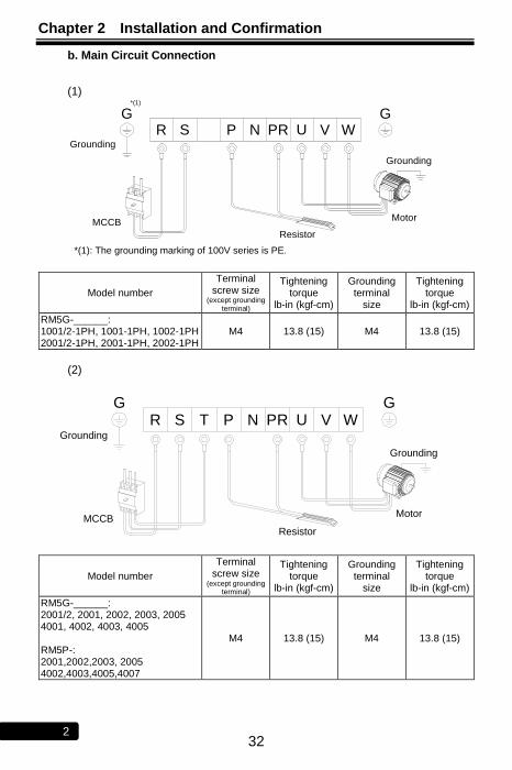
b. Main Circuit Connection
(1)
NS
GR P VRP U W
Grounding
MCCB
Resistor
Motor
Grounding
G*(1)
*(1): The grounding marking of 100V series is PE.
Model number
Terminal screw size
(except grounding terminal)
Tightening torque
lb-in (kgf-cm)
Grounding terminal
size
Tightening torque
lb-in (kgf-cm)
RM5G-______: 1001/2-1PH, 1001-1PH, 1002-1PH 2001/2-1PH, 2001-1PH, 2002-1PH
M4 13.8 (15) M4 13.8 (15)
(2)
NSG
R T P VRP U WGrounding
MCCB
Resistor
Motor
Grounding
G
Model number
Terminal screw size
(except grounding terminal)
Tightening torque
lb-in (kgf-cm)
Grounding terminal
size
Tightening torque
lb-in (kgf-cm)
RM5G-______: 2001/2, 2001, 2002, 2003, 2005 4001, 4002, 4003, 4005 RM5P-: 2001,2002,2003, 2005 4002,4003,4005,4007
M4 13.8 (15) M4 13.8 (15)

Chapter 2 Installation and Confirmation
33 2
(3)
Grounding
MCCB
Grounding
Resistor
+
-
Motor
Jumper
Model number
Terminal screw size
(except grounding terminal)
Tightening torque
lb-in (kgf-cm)
Grounding terminal
size
Tightening torque
lb-in (kgf-cm)
RM5G-: 2007,2010,2015 4007,4010,4015,4020
RM5P-: 2010,2015, 4010,4015,4020
M5 20.8 (80) M4 13.8 (15)
(4)
S/L2R/L1
P1 P +( )
+T/L3
U/T1-N V/T2 W/T3
Motor
Jumper
Grounding
MCCB
Model number
Terminal screw size
(except grounding terminal)
Tightening torque
lb-in (kgf-cm)
Grounding terminal
size
Tightening torque
lb-in (kgf-cm)
RM5G-: 2020, 2025, 2030, 2040; 4025,4030, 4040, 4050, 4060
RM5P-: 2020,2025,2030, 2040, 2050; 4025,4030,4040, 4050, 4060, 4075
M8 69.4 (80) M5 20.8 (24)

Chapter 2 Installation and Confirmation
34 2
(5)
Grounding
MCCB
Grounding
Resistor
+
-
Motor
Jumper
Model number
Terminal screw size
(except grounding terminal)
Tightening torque
lb-in (kgf-cm)
Grounding terminal
size
Tightening torque
lb-in (kgf-cm)
RM5G-: 2020B, 2025B, 2030B, 2040B; 4030B, 4040B, 4050B, 4060B RM5P-: 2025B,2030B, 2040B, 2050B; 4040B, 4050B, 4060B, 4075B
M8 69.4 (80) M5 20.8 (24)
(6)
PE EP
Grounding
MCCB
Motor
Grounding
TS/L3/L2
R/L1
W/T3
U/T1 /T2
V-N P
+P1
Model number
Terminal screw size
(except grounding terminal)
Tightening torque
lb-in (kgf-cm)
Grounding terminal
size
Tightening torque
lb-in (kgf-cm)
RM5G-: 2050, 2060, 2075; 4075, 4100, 4125
RM5P-: 2060, 2075, 2100; 4075, 4100, 4125, 4150
M8 104 (120) M8 104 (120)
Chapter 2 Installation and Confirmation
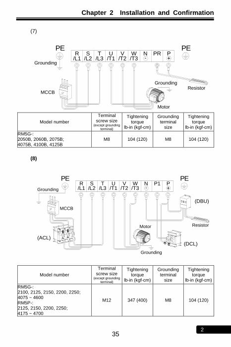
35 2
(7)
EP PE
MCCBResistor
Motor
Grounding
Grounding
P+
W/T3
V-N PRTS
/L3/L2U
/T1R
/L1 /T2
Model number
Terminal screw size
(except grounding terminal)
Tightening torque
lb-in (kgf-cm)
Grounding terminal
size
Tightening torque
lb-in (kgf-cm)
RM5G-: 2050B, 2060B, 2075B; 4075B, 4100B, 4125B
M8 104 (120) M8 104 (120)
(8)
PEEP
Grounding
Motor
Grounding
Resistor
ACL
DBU
DCL
/L1R TS
/L2 /L3P1
/T3VU
/T1 /T2W N
-P+
MCCB
(DBU)
(ACL)
(DCL)
Model number
Terminal screw size
(except grounding terminal)
Tightening torque
lb-in (kgf-cm)
Grounding terminal
size
Tightening torque
lb-in (kgf-cm)
RM5G-: 2100, 2125, 2150, 2200, 2250; 4075 ~ 4600 RM5P-: 2125, 2150, 2200, 2250; 4175 ~ 4700
M12 347 (400) M8 104 (120)
Chapter 2 Installation and Confirmation
36 2
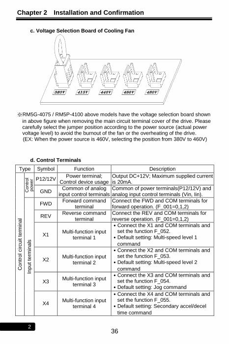
c. Voltage Selection Board of Cooling Fan
※RM5G-4075 / RM5P-4100 above models have the voltage selection board shown
in above figure when removing the main circuit terminal cover of the drive. Please carefully select the jumper position according to the power source (actual power voltage level) to avoid the burnout of the fan or the overheating of the drive. (EX: When the power source is 460V, selecting the position from 380V to 460V)
d. Control Terminals
Type Symbol Function Description
Contr
ol circuit t
erm
inal
Contr
ol
pow
er P12/12V
Power terminal; Control device usage
Output DC+12V; Maximum supplied current is 20mA.
GND Common of analog
input control terminals Common of power terminals(P12/12V) and analog input control terminals (Vin, Iin).
Input te
rmin
als
FWD Forward command
terminal Connect the FWD and COM terminals for forward operation. (F_001=0,1,2)
REV Reverse command
terminal Connect the REV and COM terminals for reverse operation. (F_001=0,1,2)
X1 Multi-function input
terminal 1
․Connect the X1 and COM terminals and set the function F_052.
․Default setting: Multi-speed level 1
command
X2 Multi-function input
terminal 2
․Connect the X2 and COM terminals and set the function F_053.
․Default setting: Multi-speed level 2
command
X3 Multi-function input
terminal 3
․Connect the X3 and COM terminals and set the function F_054.
․Default setting: Jog command
X4 Multi-function input
terminal 4
․Connect the X4 and COM terminals and set the function F_055.
․Default setting: Secondary accel/decel
time command
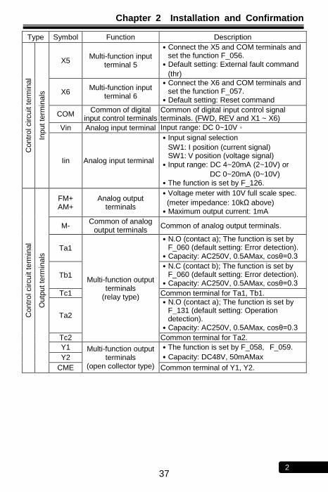
Chapter 2 Installation and Confirmation
37 2
Type Symbol Function Description
Contr
ol circuit t
erm
inal
Input te
rmin
als
X5 Multi-function input
terminal 5
․Connect the X5 and COM terminals and set the function F_056.
․Default setting: External fault command
(thr)
X6 Multi-function input
terminal 6
․Connect the X6 and COM terminals and set the function F_057.
․Default setting: Reset command
COM Common of digital
input control terminals Common of digital input control signal terminals. (FWD, REV and X1 ~ X6)
Vin Analog input terminal Input range: DC 0~10V。
Iin Analog input terminal
․Input signal selection
SW1: I position (current signal) SW1: V position (voltage signal)
․Input range: DC 4~20mA (2~10V) or
DC 0~20mA (0~10V) ․The function is set by F_126.
Contr
ol circuit t
erm
inal
Outp
ut te
rmin
als
FM+ AM+
Analog output terminals
․Voltage meter with 10V full scale spec.
(meter impedance: 10kΩ above) ․Maximum output current: 1mA
M- Common of analog
output terminals Common of analog output terminals.
Ta1
Multi-function output terminals
(relay type)
․N.O (contact a); The function is set by F_060 (default setting: Error detection).
․Capacity: AC250V, 0.5AMax, cosθ=0.3
Tb1
․N.C (contact b); The function is set by F_060 (default setting: Error detection).
․Capacity: AC250V, 0.5AMax, cosθ=0.3
Tc1 Common terminal for Ta1, Tb1.
Ta2
․N.O (contact a); The function is set by F_131 (default setting: Operation detection).
․Capacity: AC250V, 0.5AMax, cosθ=0.3
Tc2 Common terminal for Ta2.
Y1 Multi-function output terminals
(open collector type)
․The function is set by F_058, F_059.
․Capacity: DC48V, 50mAMax Y2
CME Common terminal of Y1, Y2.
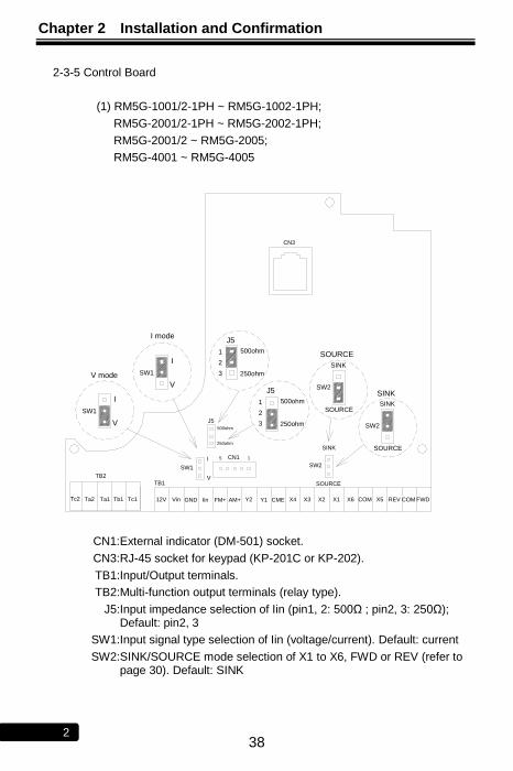
Chapter 2 Installation and Confirmation
38 2
2-3-5 Control Board
(1) RM5G-1001/2-1PH ~ RM5G-1002-1PH;
RM5G-2001/2-1PH ~ RM5G-2002-1PH;
RM5G-2001/2 ~ RM5G-2005;
RM5G-4001 ~ RM5G-4005
250ohm
500ohm
GFD
ILD
TB2
Tc2 Ta2 Ta1 Tb1
V
I
5I CN1
SW1
GND
TB1
12VTc1 Vin FM+Iin
V
AM+
V
I
J5
250ohm
500ohm
3
2
J5
1
COM
1
CMEY2 Y1 X4
SOURCE
X3 X2
SW2
X1 X6
SINK
FWDREVX5 COM
CN3
V mode
I mode
SW1
SW1
SINK
SOURCE
SINK
SW2
SOURCE
SOURCE
SINK
SW2
500ohm
250ohm
J5
1
2
3
CN1: External indicator (DM-501) socket.
CN3: RJ-45 socket for keypad (KP-201C or KP-202).
TB1: Input/Output terminals.
TB2: Multi-function output terminals (relay type).
J5: Input impedance selection of Iin (pin1, 2: 500Ω ; pin2, 3: 250Ω); Default: pin2, 3
SW1: Input signal type selection of Iin (voltage/current). Default: current
SW2: SINK/SOURCE mode selection of X1 to X6, FWD or REV (refer to page 30). Default: SINK

Chapter 2 Installation and Confirmation
39 2
(2) RM5G-2007 ~ RM5G-2250; RM5P-2010 ~ RM5P-2250;
RM5G-4007 ~ RM5G-4600; RM5P-4010 ~ RM5P-4700
51
SINK
SOURCE250ohm
500ohm
CN1
TB1
X3
Vin REV
X4X1FM+ Y1
GND
CME
Iin FWD
Y2
Ta1
X6
Tb1 Tc1
X2M-
X5
COM
COMAM+ 12V COM
Tc2Ta2
SW2
SW1
CN2
ILD
GFD
JP3
I
V
SW1
I
V
V
SW1
V
I
I
SINK
SOURCE
SINK
SW2
SINK
SOURCE
SOURCE
SW2
J5
2
3
1 500ohm
250ohm
J5
2
3
1
250ohm
500ohm
CN1: External indicator (DM-501) socket.
CN2: RJ-45 socket for keypad (KP-201C or KP-202).
TB1: Input/Output terminals.
J5: Input impedance selection of Iin (pin1, 2: 500Ω ; pin2, 3: 250Ω); Default: pin2, 3
SW1: Input signal type selection of Iin (voltage/current). Default: current
SW2: SINK/SOURCE mode selection of X1 to X6, FWD or REV (refer to page 30). Default: SINK
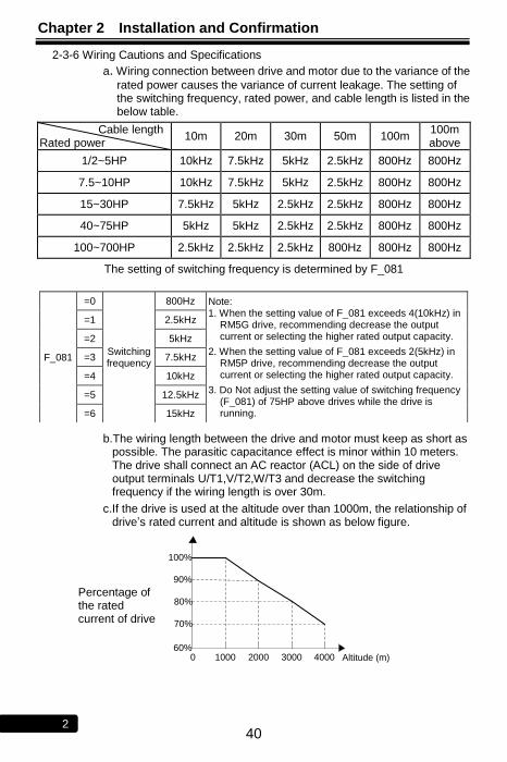
Chapter 2 Installation and Confirmation
40 2
2-3-6 Wiring Cautions and Specifications
a. Wiring connection between drive and motor due to the variance of the
rated power causes the variance of current leakage. The setting of the switching frequency, rated power, and cable length is listed in the below table.
Cable length Rated power
10m 20m 30m 50m 100m 100m above
1/2~5HP 10kHz 7.5kHz 5kHz 2.5kHz 800Hz 800Hz
7.5~10HP 10kHz 7.5kHz 5kHz 2.5kHz 800Hz 800Hz
15~30HP 7.5kHz 5kHz 2.5kHz 2.5kHz 800Hz 800Hz
40~75HP 5kHz 5kHz 2.5kHz 2.5kHz 800Hz 800Hz
100~700HP 2.5kHz 2.5kHz 2.5kHz 800Hz 800Hz 800Hz
The setting of switching frequency is determined by F_081
b.The wiring length between the drive and motor must keep as short as possible. The parasitic capacitance effect is minor within 10 meters. The drive shall connect an AC reactor (ACL) on the side of drive output terminals U/T1,V/T2,W/T3 and decrease the switching frequency if the wiring length is over 30m.
c.If the drive is used at the altitude over than 1000m, the relationship of drive’s rated current and altitude is shown as below figure.
Altitude (m)60%
0 1000 2000 3000 4000
70%
90%
80%
100%
F_081
=0
Switching frequency
800Hz Note: 1. When the setting value of F_081 exceeds 4(10kHz) in
RM5G drive, recommending decrease the output current or selecting the higher rated output capacity.
2. When the setting value of F_081 exceeds 2(5kHz) in RM5P drive, recommending decrease the output current or selecting the higher rated output capacity.
3. Do Not adjust the setting value of switching frequency (F_081) of 75HP above drives while the drive is running.
=1 2.5kHz
=2 5kHz
=3 7.5kHz
=4 10kHz
=5 12.5kHz
=6 15kHz
Percentage of the rated current of drive
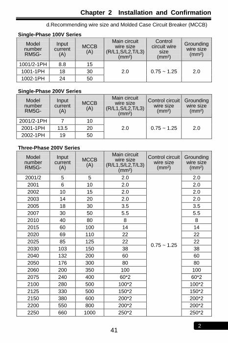
Chapter 2 Installation and Confirmation
41 2
d.Recommending wire size and Molded Case Circuit Breaker (MCCB)
Single-Phase 100V Series
Model number RM5G-
Input current
(A)
MCCB (A)
Main circuit wire size
(R/L1,S/L2,T/L3) (mm²)
Control circuit wire
size (mm²)
Grounding wire size
(mm²)
1001/2-1PH 8.8 15
2.0 0.75 ~ 1.25 2.0 1001-1PH 18 30
1002-1PH 24 50
Single-Phase 200V Series
Model number RM5G-
Input current
(A)
MCCB (A)
Main circuit wire size
(R/L1,S/L2,T/L3) (mm²)
Control circuit wire size
(mm²)
Grounding wire size
(mm²)
2001/2-1PH 7 10
2.0 0.75 ~ 1.25 2.0 2001-1PH 13.5 20
2002-1PH 19 50
Three-Phase 200V Series
Model number RM5G-
Input current
(A)
MCCB (A)
Main circuit wire size
(R/L1,S/L2,T/L3) (mm²)
Control circuit wire size
(mm²)
Grounding wire size
(mm²)
2001/2 5 5 2.0
0.75 ~ 1.25
2.0
2001 6 10 2.0 2.0
2002 10 15 2.0 2.0
2003 14 20 2.0 2.0
2005 18 30 3.5 3.5
2007 30 50 5.5 5.5
2010 40 80 8 8
2015 60 100 14 14
2020 69 110 22 22
2025 85 125 22 22
2030 103 150 38 38
2040 132 200 60 60
2050 176 300 80 80
2060 200 350 100 100
2075 240 400 60*2 60*2
2100 280 500 100*2 100*2
2125 330 500 150*2 150*2
2150 380 600 200*2 200*2
2200 550 800 200*2 200*2
2250 660 1000 250*2 250*2
Chapter 2 Installation and Confirmation
42 2
Three-Phase 400V Series
Model number RM5G-
Input current
(A)
MCCB (A)
Main circuit wire size
(R/L1,S/L2,T/L3) (mm²)
Control circuit wire size
(mm²)
Grounding wire size
(mm²)
4001 3.5 5 2.0
0.75 ~ 1.25
2.0
4002 5 10 2.0 2.0
4003 8 15 2.0 2.0
4005 12 20 3.5 3.5
4007 16 30 3.5 3.5
4010 22 30 5.5 5.5
4015 28 40 8.0 8.0
4020 38 60 8.0 8.0
4025 45 70 14 14
4030 52 90 22 22
4040 70 100 22 22
4050 84 125 22 22
4060 100 150 38 38
4075 130 200 60 60
4100 155 250 80 80
4125 177 300 100 100
4150 196 300 60*2 60*2
4175 217 350 100*2 100*2
4200 282 400 100*2 100*2
4250 355 600 150*2 150*2
4300 385 600 200*2 200*2
4350 440 700 250*2 250*2
4420 540 800 250*2 250*2
4500 650 1000 325*2 325*2
4600 800 1200 325*2 325*2
Notes: i. Please refer to the local electrical code with respect to the wiring(the loading
and continuity, the wire capability for the current and temperature, the length of wiring, and the surrounding temperature must be all considered in order to add or reduce the size of the wire).
ii. Please use the cable that is suitable for 600V, 75℃ above. iii. This table is only for reference.
Chapter 2 Installation and Confirmation
43 2
No Text on This Page
Chapter 3 The Setting of Keypad
44 3
Chapter 3 The Setting of Keypad
3-1 Digital Type Keypad (KP-201C) for RM5G/P
1. T.S: Indicate the status
of terminals
2. Unit indicator
Blinking: Under acceleration or decelerationON: Constant speedOFF: Stop
Drive start key
Up/down key of changing
functions and parameters
1. Drive stops(cut off output
frequency of drive)
2. Fault reset
1. Enter parameter setting mode
2. Back to function setting mode
3. Switch monitor mode
1. Enter function setting mode
2. Back to monitor mode
1. ON: Primary frequency command is set by keypad or UP/DOWN terminal2. OFF: Primary frequency command is set by multi-function input terminals
Note: KP-201C transmission cable can select 8-pin telephone cable (flat) or network cable (AMP)
8-pin telephone cable: The length must be within 5 meters.
Network cable (AMP): The length can be over 5 meters (the longest length is 25 meters)
There are 6 length of specifications of network cable (1M, 2M, 3M, 5M, 7M, 10M).
3-2 Analog Type Keypad (KP-202) for RM5G/P
The indicators of ADJ 1 ~
ADJ 6 will be lighted when
the RSW is switched to the
corresponding position.
Blinking: Under acceleration or decelerationON: Constant speedOFF: Stop
1. Drive stops(cut off output
frequency of drive)
2. Fault reset
Pot knob
1. ON: Primary frequency command is set by keypad or UP/DOWN terminal2. OFF: Primary frequency command is set by multi-function input
terminals
Note: KP-202 transmission cable can select 8-pin telephone cable (flat) or network cable (AMP)
8-pin telephone cable: The length must be within 5 meters.
Network cable (AMP): The length must be within 5 meters.
Chapter 3 The Setting of Keypad
45 3
3-2-1 Description of Switches and Pot Knob
a. Control function
RSW Function Corresponding
VR Range Default setting Page
Output frequency N/A ---- ---- ----
Starting voltage
0.1~127.5V 8.0V (200V class) 12.0V (400V class)
112 & 109
Primary acceleration time
0.0~165.0sec 0.5~5HP: 5.0sec. 7.5~30HP: 15.0sec. 40HP above: 30.0sec.
112 & 109
Primary deceleration time
0.0~165.0sec 0.5~5HP: 5.0sec. 7.5~30HP: 15.0sec. 40HP above: 30.0sec.
112 & 109
Preset speed 1
0.0~120.0Hz 10.0Hz 112 & 109
Maximum output frequency
0.0~120.0Hz 60.0Hz 112 & 109
Secondary accel/decel time
0.0~165.0sec 0.5~5HP: 5.0sec. 7.5~30HP: 15.0sec. 40HP above: 30.0sec.
112 & 109
Primary speed
0.0~120.0Hz ---- 112 & 109
Note: The function of RSW associated with VR can be changed, except for ADJ1~ADJ3.
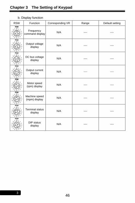
Chapter 3 The Setting of Keypad
46 3
b. Display function
RSW Function Corresponding VR Range Default setting
Frequency command display
N/A ---- ----
Output voltage display
N/A ---- ----
DC bus voltage display
N/A ---- ----
Output current display
N/A ---- ----
Motor speed (rpm) display
N/A ---- ----
Machine speed (mpm) display
N/A ---- ----
Terminal status display
N/A ---- ----
DIP status display
N/A ---- ----
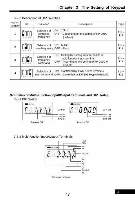
Chapter 3 The Setting of Keypad
47 3
3-2-2 Description of DIP Switches
Switch number
DIP Function Description Page
1
ON
1 2 3 4
Selection of switching frequency
ON:10kHz
OFF:Depending on the setting of KP-201C
(default)
114~ 111
2
ON
1 2 3 4
Selection of base frequency
ON:50Hz
OFF:60Hz 114~ 111
3
ON
1 2 3 4
Selection of frequency command
ON:Setting by analog input terminals of
multi-function input terminal OFF:According to the setting of KP-201C or
KP-202 KP-202
114~ 111
4
ON
1 2 3 4
Selection of start command
ON:Controlled by FWD / REV terminals.
OFF:Controlled by KP-202 keypad (default) 114~ 111
3-3 Status of Multi-Function Input/Output Terminals and DIP Switch
3-3-1 DIP Switch
DIP4 OFF
DIP3 OFF
DIP2 OFF
DIP1 OFF
Status of DIP Status of DIP
KEYPADKEYPAD
DIP4 ON
DIP3 ON
DIP2 ON
DIP1 ON
3-3-2 Multi-function Input/Output Terminals
X6X5
REVFWD
Ta1,Tb1
X4
Y2X2
Y1X1Ta2/Tc2
X3
Status of terminal
KEYPAD
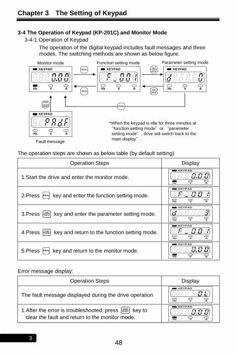
Chapter 3 The Setting of Keypad
48 3
3-4 The Operation of Keypad (KP-201C) and Monitor Mode
3-4-1 Operation of Keypad
The operation of the digital keypad includes fault messages and three modes. The switching methods are shown as below figure:
Monitor mode Function setting mode Parameter setting mode
Fault message
FUN
DATA
PROGFUN
DATA
STOP
RESET
PROG
PROG
KEYPAD
Hz V A
KEYPAD
Hz V A
KEYPAD
Hz V A
KEYPAD
Hz V A
*When the keypad is idle for three minutes at
“function setting mode”or “parameter
setting mode”, drive will switch back to the
main display”.
The operation steps are shown as below table (by default setting)
Operation Steps Display
1.Start the drive and enter the monitor mode.
KEYPAD
Hz V A
2.Press PROG key and enter the function setting mode.
KEYPAD
Hz V A
3.Press FUN
DATA key and enter the parameter setting mode.
KEYPAD
Hz V A
4.Press FUN
DATA key and return to the function setting mode.
KEYPAD
Hz V A
5.Press PROG key and return to the monitor mode.
KEYPAD
Hz V A
Error message display:
Operation Steps Display
The fault message displayed during the drive operation
KEYPAD
Hz V A
1.After the error is troubleshooted, press STOP
RESET key to
clear the fault and return to the monitor mode.
KEYPAD
Hz V A
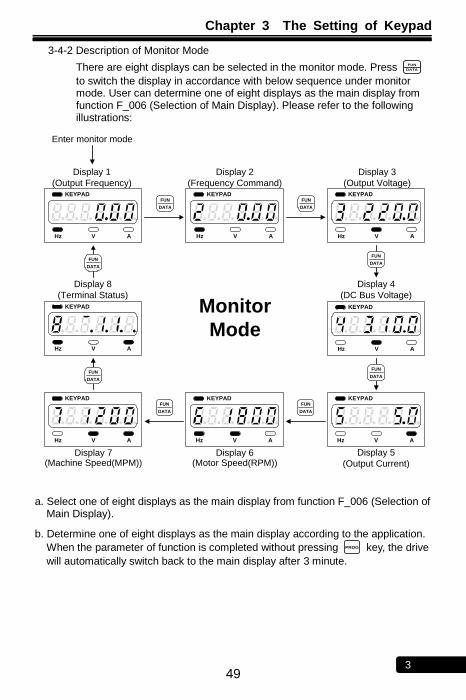
Chapter 3 The Setting of Keypad
49 3
3-4-2 Description of Monitor Mode
There are eight displays can be selected in the monitor mode. Press FUN
DATA to switch the display in accordance with below sequence under monitor mode. User can determine one of eight displays as the main display from function F_006 (Selection of Main Display). Please refer to the following illustrations:
Display 1
(Output Frequency)
Display 2
(Frequency Command)
Display 3
(Output Voltage)
Display 5
(Output Current)
Display 6(Motor Speed(RPM))
Monitor
Mode
Display 4
(DC Bus Voltage)
FUN
DATA
FUN
DATA
KEYPAD
Hz V A
KEYPAD
Hz V A
KEYPAD
Hz V A
KEYPAD
Hz V A
KEYPAD
Hz V A
FUN
DATA
FUN
DATA
KEYPAD
Hz V A
FUN
DATA
FUN
DATA
KEYPAD
Hz V A
KEYPAD
Hz V A
Display 7(Machine Speed(MPM))
Display 8
(Terminal Status)
FUN
DATA
FUN
DATA
Enter monitor mode
a. Select one of eight displays as the main display from function F_006 (Selection of
Main Display).
b. Determine one of eight displays as the main display according to the application.
When the parameter of function is completed without pressing PROG
key, the drive
will automatically switch back to the main display after 3 minute.
Chapter 3 The Setting of Keypad
50 3
3-4-3 Description of Function Setting Mode
In function setting mode, there are 135 functions (F_000 ~ F_134) can be selected for RM5G/P series drive, and the setting steps are as below:
Operation Steps Display
1.In the monitor mode, press PROG key to enter
function setting mode.
KEYPAD
Hz V A
2.Press ▲ key to increase the function number.
KEYPAD
Hz V A
3.Press ▼ key to decrease the function number.
KEYPAD
Hz V A
3-4-4 Description of Parameter Setting Mode
In parameter setting mode, the setting range for every function is shown in Chapter 4 - Parameter List.
Operation Steps Display
1.Select F_001 (Start Command Selection) as the example.
KEYPAD
Hz V A
2.Press FUN
DATA key to enter parameter setting mode.
KEYPAD
Hz V A
3.Press ▼ key to decrease the value of F_001 from
3 (default value) to 2.
KEYPAD
Hz V A
4.Press FUN
DATA key to save the setting value and return
to function setting mode.
KEYPAD
Hz V A
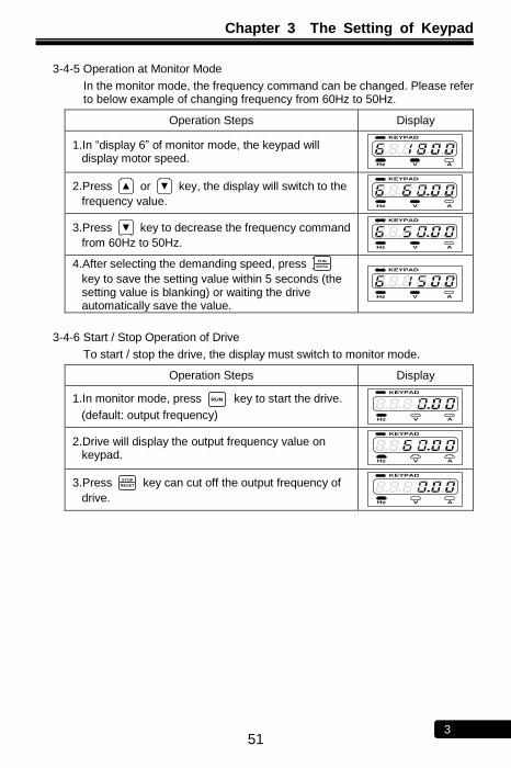
Chapter 3 The Setting of Keypad
51 3
3-4-5 Operation at Monitor Mode
In the monitor mode, the frequency command can be changed. Please refer to below example of changing frequency from 60Hz to 50Hz.
Operation Steps Display
1.In ―display 6‖ of monitor mode, the keypad will display motor speed.
KEYPAD
Hz V A
2.Press ▲ or ▼ key, the display will switch to the
frequency value.
KEYPAD
Hz V A
3.Press ▼ key to decrease the frequency command
from 60Hz to 50Hz.
KEYPAD
Hz V A 4.After selecting the demanding speed, press FUN
DATA
key to save the setting value within 5 seconds (the setting value is blanking) or waiting the drive automatically save the value.
KEYPAD
Hz V A
3-4-6 Start / Stop Operation of Drive
To start / stop the drive, the display must switch to monitor mode.
Operation Steps Display
1.In monitor mode, press RUN key to start the drive.
(default: output frequency)
KEYPAD
Hz V A
2.Drive will display the output frequency value on keypad.
KEYPAD
Hz V A
3.Press STOP
RESET key can cut off the output frequency of
drive.
KEYPAD
Hz V A
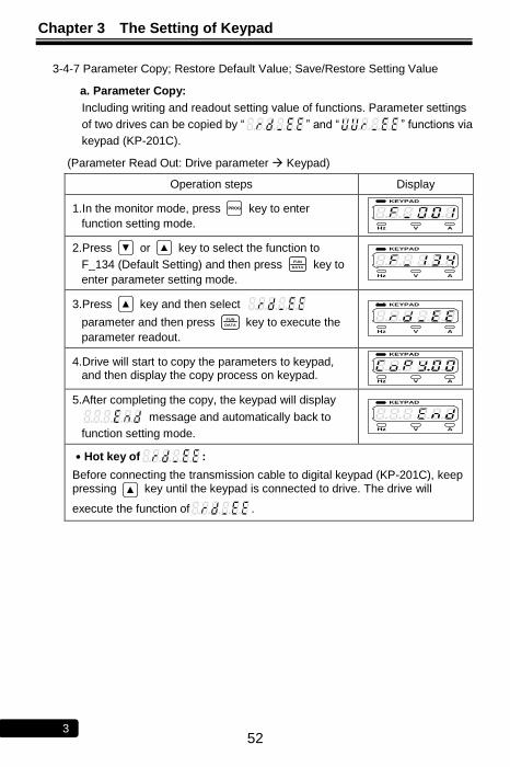
Chapter 3 The Setting of Keypad
52 3
3-4-7 Parameter Copy; Restore Default Value; Save/Restore Setting Value
a. Parameter Copy:
Including writing and readout setting value of functions. Parameter settings
of two drives can be copied by ― ‖ and ― ‖ functions via
keypad (KP-201C).
(Parameter Read Out: Drive parameter Keypad)
Operation steps Display
1.In the monitor mode, press PROG key to enter
function setting mode.
KEYPAD
Hz V A
2.Press ▼ or ▲ key to select the function to
F_134 (Default Setting) and then press FUN
DATA key to
enter parameter setting mode.
KEYPAD
Hz V A
3.Press ▲ key and then select
parameter and then press FUN
DATA key to execute the
parameter readout.
KEYPAD
Hz V A
4.Drive will start to copy the parameters to keypad, and then display the copy process on keypad.
KEYPAD
Hz V A
5.After completing the copy, the keypad will display
message and automatically back to
function setting mode.
KEYPAD
Hz V A
․Hot key of :
Before connecting the transmission cable to digital keypad (KP-201C), keep pressing ▲ key until the keypad is connected to drive. The drive will
execute the function of .
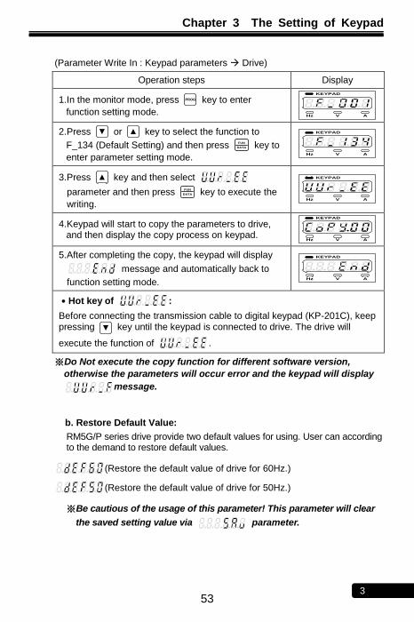
Chapter 3 The Setting of Keypad
53 3
(Parameter Write In : Keypad parameters Drive)
Operation steps Display
1.In the monitor mode, press PROG key to enter
function setting mode.
KEYPAD
Hz V A
2.Press ▼ or ▲ key to select the function to
F_134 (Default Setting) and then press FUN
DATA key to
enter parameter setting mode.
KEYPAD
Hz V A
3.Press ▲ key and then select
parameter and then press FUN
DATA key to execute the
writing.
KEYPAD
Hz V A
4.Keypad will start to copy the parameters to drive, and then display the copy process on keypad.
KEYPAD
Hz V A
5.After completing the copy, the keypad will display
message and automatically back to
function setting mode.
KEYPAD
Hz V A
․Hot key of :
Before connecting the transmission cable to digital keypad (KP-201C), keep pressing ▼ key until the keypad is connected to drive. The drive will
execute the function of .
※Do Not execute the copy function for different software version,
otherwise the parameters will occur error and the keypad will display
message.
b. Restore Default Value:
RM5G/P series drive provide two default values for using. User can according to the demand to restore default values.
(Restore the default value of drive for 60Hz.)
(Restore the default value of drive for 50Hz.)
※Be cautious of the usage of this parameter! This parameter will clear
the saved setting value via parameter.
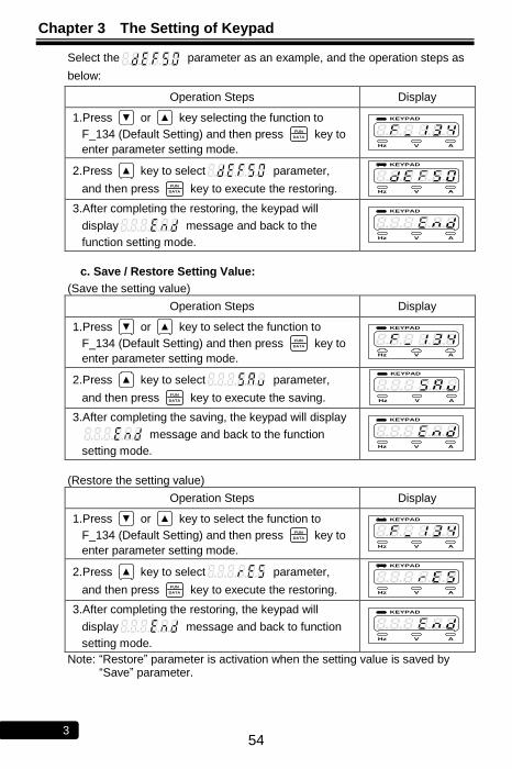
Chapter 3 The Setting of Keypad
54 3
Select the parameter as an example, and the operation steps as
below:
Operation Steps Display
1.Press ▼ or ▲ key selecting the function to
F_134 (Default Setting) and then press FUN
DATA key to
enter parameter setting mode.
KEYPAD
Hz V A
2.Press ▲ key to select parameter,
and then press FUN
DATA key to execute the restoring.
KEYPAD
Hz V A
3.After completing the restoring, the keypad will
display message and back to the
function setting mode.
KEYPAD
Hz V A
c. Save / Restore Setting Value:
(Save the setting value)
Operation Steps Display
1.Press ▼ or ▲ key to select the function to
F_134 (Default Setting) and then press FUN
DATA key to
enter parameter setting mode.
KEYPAD
Hz V A
2.Press ▲ key to select parameter,
and then press FUN
DATA key to execute the saving.
KEYPAD
Hz V A
3.After completing the saving, the keypad will display
message and back to the function
setting mode.
KEYPAD
Hz V A
(Restore the setting value)
Operation Steps Display
1.Press ▼ or ▲ key to select the function to
F_134 (Default Setting) and then press FUN
DATA key to
enter parameter setting mode.
KEYPAD
Hz V A
2.Press ▲ key to select parameter,
and then press FUN
DATA key to execute the restoring.
KEYPAD
Hz V A
3.After completing the restoring, the keypad will
display message and back to function
setting mode.
KEYPAD
Hz V A
Note: ―Restore‖ parameter is activation when the setting value is saved by ―Save‖ parameter.

Chapter 3 The Setting of Keypad
55 3
No Text on This Page
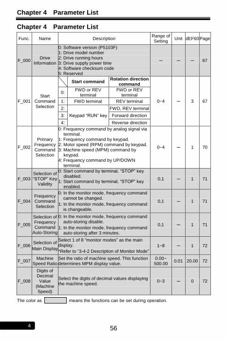
Chapter 4 Parameter List
56 4
Chapter 4 Parameter List
Func. Name Description Range of Setting
Unit dEF60 Page
F_000 Drive
Information
0: Software version (P5103F) 1: Drive model number 2: Drive running hours 3: Drive supply power time 4: Software checksum code 5: Reserved
─ ─ ─ 67
F_001 Start
Command
Selection
Start command Rotation direction
command
0~4 ─ 3 67
0: FWD or REV
terminal FWD or REV
terminal
1: FWD terminal REV terminal
2:
Keypad ―RUN‖ key
FWD, REV terminal
3: Forward direction
4: Reverse direction
F_002
Primary Frequency Command Selection
0: Frequency command by analog signal via terminal.
1: Frequency command by keypad. 2: Motor speed (RPM) command by keypad. 3: Machine speed (MPM) command by
keypad. 4: Frequency command by UP/DOWN
terminal.
0~4 ─ 1 70
F_003 Selection of ―STOP‖ Key
Validity
0: Start command by terminal, ―STOP‖ key disabled.
1: Start command by terminal, ―STOP‖ key enabled.
0,1 ─ 1 71
F_004 Frequency Command Selection
0: In the monitor mode, frequency command cannot be changed.
1: In the monitor mode, frequency command is changeable.
0,1 ─ 1 71
F_005
Selection of Frequency Command
Auto-Storing
0: In the monitor mode, frequency command auto-storing disable.
1: In the monitor mode, frequency command auto-storing after 3 minutes.
0,1 ─ 1 71
F_006 Selection of
Main Display
Select 1 of 8 ―monitor modes‖ as the main display.
*Refer to ―3-4-2 Description of Monitor Mode‖
1~8 ─ 1 72
F_007 Machine
Speed Ratio Set the ratio of machine speed. This function determines MPM display value.
0.00~ 500.00
0.01 20.00 72
F_008
Digits of Decimal Value
(Machine Speed)
Select the digits of decimal values displaying the machine speed.
0~3 ─ 0 72
The color as means the functions can be set during operation.
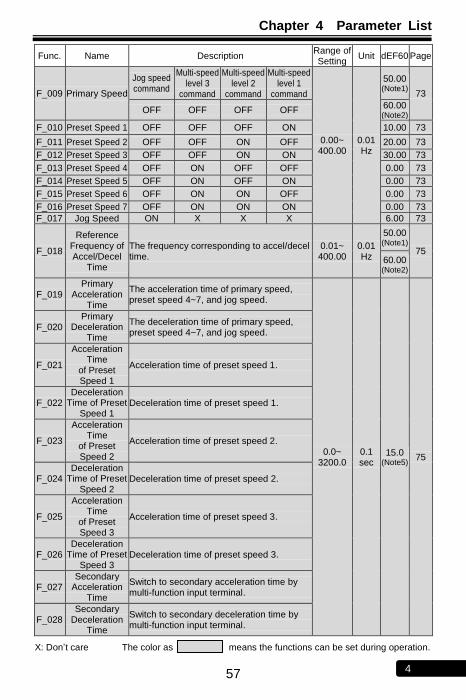
Chapter 4 Parameter List
57 4
Func. Name Description Range of Setting
Unit dEF60 Page
F_009 Primary Speed
Jog speed command
Multi-speed level 3
command
Multi-speed level 2
command
Multi-speed level 1
command
0.00~ 400.00
0.01 Hz
50.00 (Note1)
73
OFF OFF OFF OFF 60.00 (Note2)
F_010 Preset Speed 1 OFF OFF OFF ON 10.00 73
F_011 Preset Speed 2 OFF OFF ON OFF 20.00 73
F_012 Preset Speed 3 OFF OFF ON ON 30.00 73
F_013 Preset Speed 4 OFF ON OFF OFF 0.00 73
F_014 Preset Speed 5 OFF ON OFF ON 0.00 73
F_015 Preset Speed 6 OFF ON ON OFF 0.00 73
F_016 Preset Speed 7 OFF ON ON ON 0.00 73
F_017 Jog Speed ON X X X 6.00 73
F_018
Reference Frequency of Accel/Decel
Time
The frequency corresponding to accel/decel time.
0.01~ 400.00
0.01 Hz
50.00 (Note1)
75 60.00 (Note2)
F_019 Primary
Acceleration Time
The acceleration time of primary speed, preset speed 4~7, and jog speed.
0.0~ 3200.0
0.1 sec
15.0 (Note5)
75
F_020 Primary
Deceleration Time
The deceleration time of primary speed, preset speed 4~7, and jog speed.
F_021
Acceleration Time
of Preset Speed 1
Acceleration time of preset speed 1.
F_022 Deceleration
Time of Preset Speed 1
Deceleration time of preset speed 1.
F_023
Acceleration Time
of Preset Speed 2
Acceleration time of preset speed 2.
F_024 Deceleration
Time of Preset Speed 2
Deceleration time of preset speed 2.
F_025
Acceleration Time
of Preset Speed 3
Acceleration time of preset speed 3.
F_026 Deceleration
Time of Preset Speed 3
Deceleration time of preset speed 3.
F_027 Secondary
Acceleration Time
Switch to secondary acceleration time by multi-function input terminal.
F_028 Secondary
Deceleration Time
Switch to secondary deceleration time by multi-function input terminal.
X: Don’t care The color as means the functions can be set during operation.
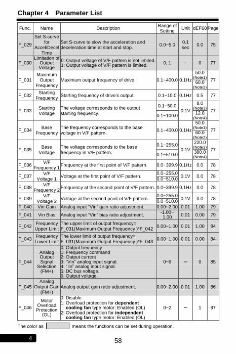
Chapter 4 Parameter List
58 4
Func. Name Description Range of Setting
Unit dEF60 Page
F_029
Set S-curve for
Accel/Decel Time
Set S-curve to slow the acceleration and deceleration time at start and stop.
0.0~5.0 0.1 sec
0.0 75
F_030 Limitation of
Output Voltage
0: Output voltage of V/F pattern is not limited. 1: Output voltage of V/F pattern is limited.
0, 1 ─ 0 77
F_031 Maximum
Output Frequency
Maximum output frequency of drive. 0.1~400.0 0.1Hz
50.0 (Note1)
77 60.0
(Note2)
F_032 Starting
Frequency Starting frequency of drive’s output. 0.1~10.0 0.1Hz 0.5 77
F_033 Starting Voltage
The voltage corresponds to the output starting frequency.
0.1~50.0 0.1V
8.0 (Note3)
77 0.1~100.0
12.0 (Note4)
F_034 Base
Frequency The frequency corresponds to the base voltage in V/F pattern.
0.1~400.0 0.1Hz
50.0 (Note1)
77 60.0
(Note2)
F_035 Base
Voltage The voltage corresponds to the base frequency in V/F pattern.
0.1~255.0 0.1V
220.0 (Note3)
77 0.1~510.0
380.0 (Note4)
F_036 V/F
Frequency 1 Frequency at the first point of V/F pattern. 0.0~399.9 0.1Hz 0.0 78
F_037 V/F
Voltage 1 Voltage at the first point of V/F pattern.
0.0~255.0 0.1V 0.0 78
0.0~510.0
F_038 V/F
Frequency 2 Frequency at the second point of V/F pattern. 0.0~399.9 0.1Hz 0.0 78
F_039 V/F
Voltage 2 Voltage at the second point of V/F pattern.
0.0~255.0 0.1V 0.0 78
0.0~510.0
F_040 Vin Gain Analog input ―Vin‖ gain ratio adjustment. 0.00~2.00 0.01 1.00 79
F_041 Vin Bias Analog input ―Vin‖ bias ratio adjustment. -1.00~ 1.00 0.01 0.00 79
F_042 Frequency Upper Limit
The upper limit of output frequency= F_031(Maximum Output Frequency )*F_042
0.00~1.00 0.01 1.00 84
F_043 Frequency Lower Limit
The lower limit of output frequency= F_031(Maximum Output Frequency )*F_043
0.00~1.00 0.01 0.00 84
F_044
Analog Output Signal
Selection (FM+)
0: Output frequency 1: Frequency command 2: Output current 3: ―Vin‖ analog input signal. 4: ―Iin‖ analog input signal. 5: DC bus voltage. 6. Output voltage.
0~6 ─ 0 85
F_045 Analog
Output Gain (FM+)
Analog output gain ratio adjustment. 0.00~2.00 0.01 1.00 86
F_046
Motor Overload Protection
(OL)
0: Disable 1: Overload protection for dependent
cooling fan type motor: Enabled (OL) 2: Overload protection for independent
cooling fan type motor: Enabled (OL)
0~2 ─ 1 87
The color as means the functions can be set during operation.

Chapter 4 Parameter List
59 4
Func. Name Description Range of Setting
Unit dEF60 Page
F_047 Filter Setting
of Analog Input Signal
Filter the analog input signal when the frequency command is controlled by analog input terminal. (F_002=0).
0~255 ─ 20 84
F_048 Motor Rated
Current Set the value according to the motor rated current.
10%~150% of drive rated
current
0.1A
According to the rated
current of motor
87
F_049 Motor
No-Load Current
Current setting according to the motor’s no-load condition.
0~motor rated
current 0.1A
1/3 motor rated
current
87
F_050 Motor Slip
Compensa- tion
According to the load condition, set the motor slip compensation for motor running at constant speed. (0.0: off)
-9.9~10.0 0.1Hz 0.0 87
F_051 Number of
Motor Poles Determinate the RPM display value of monitor mode.
2~10 2P 4P 87
F_052
Multi-function Input
Terminal (X1)
=0: UP/DOWN frequency command enter key
±1: Jog command
±2: Secondary
accel/decel time
command
±3: Multi-speed level 1
command
±4: Multi-speed level 2
command
±5: Multi-speed level 3
command
±6: Reset command
±7: External fault
command (thr)
±8: Interruption of output
command (bb)
±9: Coast to stop
command (Fr)
±10: Speed tracing from
the maximum
frequency
±11: Speed tracing from
the setting
frequency
±12: Holding command
±13: UP command
±14: DOWN command
±15: Clear UP/DOWN
frequency
command
±16: Analog input source
selection
-16 ~ +16 (Note 7)
─
3
88
F_053
Multi-function Input
Terminal (X2)
=0: DC braking enable (at stop)
4
F_054
Multi-function Input
Terminal (X3)
=0: Current limit enable
1
F_055
Multi-function Input
Terminal (X4)
=0: Selection of primary or secondary frequency command (ON: secondary frequency command)
2
F_056
Multi-function Input
Terminal (X5)
=0: Stop command with 3-wire start/stop circuit (N.O; contact a)
7
F_057
Multi-function Input
Terminal (X6)
=0: Stop command with 3-wire start/stop circuit (N.C; contact b)
6
The color as means the functions can be set during operation.
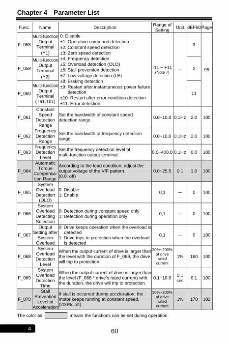
Chapter 4 Parameter List
60 4
Func. Name Description Range of Setting
Unit dEF60 Page
F_058
Multi-function Output
Terminal
(Y1)
0: Disable
±1: Operation command detection
±2: Constant speed detection
±3: Zero speed detection
±4: Frequency detection
±5: Overload detection (OLO)
±6: Stall prevention detection
±7: Low voltage detection (LE)
±8: Braking detection
±9: Restart after instantaneous power failure detection
±10: Restart after error condition detection
±11: Error detection
-11 ~ +11 (Note 7)
─
3
95 F_059
Multi-function Output
Terminal
(Y2)
2
F_060
Multi-function Output
Terminal (Ta1,Tb1)
11
F_061
Constant Speed
Detection Range
Set the bandwidth of constant speed detection range.
0.0~10.0 0.1Hz 2.0 100
F_062 Frequency Detection
Range
Set the bandwidth of frequency detection range.
0.0~10.0 0.1Hz 2.0 100
F_063 Frequency Detection
Level
Set the frequency detection level of multi-function output terminal.
0.0~400.0 0.1Hz 0.0 100
F_064
Automatic Torque
Compensa- tion Range
According to the load condition, adjust the output voltage of the V/F pattern. (0.0: off)
0.0~25.5 0.1 1.0 100
F_065
System Overload Detection
(OLO)
0: Disable 1: Enable
0,1 ─ 0 100
F_066
System Overload Detecting Selection
0: Detection during constant speed only 1: Detection during operation only
0,1 ─ 0 100
F_067
Output Setting after
System Overload
0: Drive keeps operation when the overload is detected
1: Drive trips to protection when the overload is detected
0,1 ─ 0 100
F_068
System Overload Detection
Level
When the output current of drive is larger than the level with the duration of F_069, the drive will trip to protection.
30%~200% of drive rated
current
1% 160 100
F_069
System Overload Detection
Time
When the output current of drive is larger than the level (F_068 * drive’s rated current) with the duration, the drive will trip to protection.
0.1~10.0 0.1 sec
0.1 100
F_070
Stall Prevention
Level at Acceleration
If stall is occurred during acceleration, the motor keeps running at constant speed. (200%: off)
30%~200% of drive rated
current
1% 170 102
The color as means the functions can be set during operation.
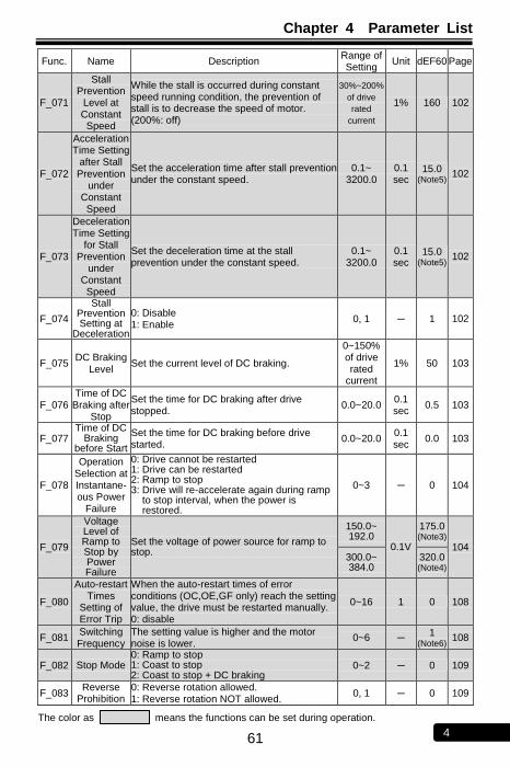
Chapter 4 Parameter List
61 4
Func. Name Description Range of Setting
Unit dEF60 Page
F_071
Stall Prevention
Level at Constant Speed
While the stall is occurred during constant speed running condition, the prevention of stall is to decrease the speed of motor. (200%: off)
30%~200%
of drive
rated
current
1% 160 102
F_072
Acceleration Time Setting
after Stall Prevention
under Constant Speed
Set the acceleration time after stall prevention under the constant speed.
0.1~ 3200.0
0.1 sec
15.0 (Note5)
102
F_073
Deceleration Time Setting
for Stall Prevention
under Constant Speed
Set the deceleration time at the stall prevention under the constant speed.
0.1~ 3200.0
0.1 sec
15.0 (Note5)
102
F_074
Stall Prevention Setting at
Deceleration
0: Disable 1: Enable
0, 1 ─ 1 102
F_075 DC Braking
Level Set the current level of DC braking.
0~150% of drive rated
current
1% 50 103
F_076 Time of DC
Braking after Stop
Set the time for DC braking after drive stopped.
0.0~20.0 0.1 sec
0.5 103
F_077 Time of DC
Braking before Start
Set the time for DC braking before drive started.
0.0~20.0 0.1 sec
0.0 103
F_078
Operation Selection at Instantane- ous Power
Failure
0: Drive cannot be restarted 1: Drive can be restarted 2: Ramp to stop 3: Drive will re-accelerate again during ramp
to stop interval, when the power is restored.
0~3 ─ 0 104
F_079
Voltage Level of Ramp to Stop by Power Failure
Set the voltage of power source for ramp to stop.
150.0~ 192.0
0.1V
175.0 (Note3)
104 300.0~ 384.0
320.0 (Note4)
F_080
Auto-restart Times
Setting of Error Trip
When the auto-restart times of error conditions (OC,OE,GF only) reach the setting value, the drive must be restarted manually. 0: disable
0~16 1 0 108
F_081 Switching Frequency
The setting value is higher and the motor noise is lower.
0~6 ─ 1
(Note6) 108
F_082 Stop Mode 0: Ramp to stop 1: Coast to stop 2: Coast to stop + DC braking
0~2 ─ 0 109
F_083 Reverse
Prohibition 0: Reverse rotation allowed. 1: Reverse rotation NOT allowed.
0, 1 ─ 0 109
The color as means the functions can be set during operation.

Chapter 4 Parameter List
62 4
Func. Name Description Range of Setting
Unit dEF60 Page
F_084 Jump
Frequency 1 Avoid mechanical resonance point 1. 0.0~400.0 0.1Hz 0.0 106
F_085 Jump
Frequency 2 Avoid mechanical resonance point 2. 0.0~400.0 0.1Hz 0.0 106
F_086 Jump
Frequency 3 Avoid mechanical resonance point 3. 0.0~400.0 0.1Hz 0.0 106
F_087 Jump
Frequency Range
Set the range of the jump frequency 1, 2, 3. 0.0~25.5 0.1Hz 0.0 106
F_088
The Current Level of Speed Tracing
When the current is higher than the ―speed tracing current level‖, the output frequency will trace downward.
0~200% of drive rated
current
1% 150 106
F_089
Delay Time before Speed Tracing
Set the output delay time before the speed tracing.
0.1~5.0 0.1
sec 0.5 106
F_090
The V/F Pattern of
Speed Tracing
Set the percentage of V/F output voltage at the speed tracing.
0~100% 1% 100 106
F_091 Error Record Display the latest 5 error records. ─ ─ ─ 109
F_092 Parameter
Setting Lock
0: Parameters are changeable. Maximum frequency cannot exceed 120.0Hz.
1: Parameters are locked. Maximum
frequency cannot exceed 120.0Hz.
2: Parameters are changeable. Maximum frequency can exceed 120.0Hz.
3: Parameters are locked. Maximum frequency can exceed 120.0Hz.
0~3 ─ 0 109
F_093
Automatic Voltage
Regulation (AVR)
0: Disable
1: Enable 0,1 ─ 1 109
F_094
Drive Overload
(OL1)
0: Disable
1: Thermal protection
2: Current limit overload protection
3: Both 1 and 2 enable
0~3 ─ 3 110
F_095 Power Source
The value of setting according to the actual power source.
190.0~ 240.0
0.1V
220.0 (Note3)
110 340.0~ 480.0
380.0 (Note4)
F_096 Holding
Frequency The drive accelerates to the holding frequency and running at constant speed.
0.0~400.0 0.1Hz 0.5 107
F_097 Holding
Time Interval
The drive runs at holding frequency by constant speed and running the time interval.
0.0~25.5 0.1
sec 0.0 107
F_098
Grounding Fault
Protection (GF)
0: Disable
1: Enable (GF) 0, 1 ─ 1 110
The color as means the functions can be set during operation.
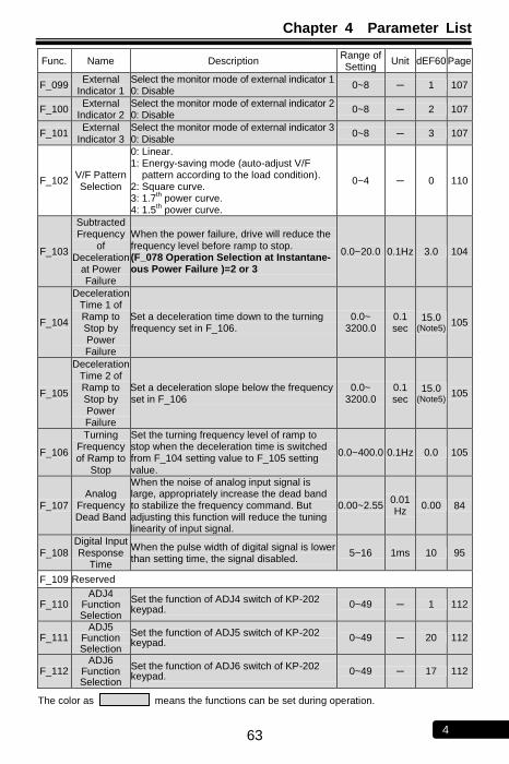
Chapter 4 Parameter List
63 4
Func. Name Description Range of Setting
Unit dEF60 Page
F_099 External
Indicator 1 Select the monitor mode of external indicator 1 0: Disable
0~8 ─ 1 107
F_100 External
Indicator 2 Select the monitor mode of external indicator 2 0: Disable
0~8 ─ 2 107
F_101 External
Indicator 3 Select the monitor mode of external indicator 3 0: Disable
0~8 ─ 3 107
F_102 V/F Pattern Selection
0: Linear. 1: Energy-saving mode (auto-adjust V/F
pattern according to the load condition). 2: Square curve. 3: 1.7
th power curve.
4: 1.5th power curve.
0~4 ─ 0 110
F_103
Subtracted Frequency
of Deceleration
at Power Failure
When the power failure, drive will reduce the frequency level before ramp to stop. (F_078 Operation Selection at Instantane- ous Power Failure )=2 or 3
0.0~20.0 0.1Hz 3.0 104
F_104
Deceleration Time 1 of Ramp to Stop by Power Failure
Set a deceleration time down to the turning frequency set in F_106.
0.0~ 3200.0
0.1 sec
15.0 (Note5)
105
F_105
Deceleration Time 2 of Ramp to Stop by Power Failure
Set a deceleration slope below the frequency set in F_106
0.0~ 3200.0
0.1 sec
15.0 (Note5)
105
F_106
Turning Frequency of Ramp to
Stop
Set the turning frequency level of ramp to stop when the deceleration time is switched from F_104 setting value to F_105 setting value.
0.0~400.0 0.1Hz 0.0 105
F_107 Analog
Frequency Dead Band
When the noise of analog input signal is large, appropriately increase the dead band to stabilize the frequency command. But adjusting this function will reduce the tuning linearity of input signal.
0.00~2.55 0.01 Hz
0.00 84
F_108 Digital Input Response
Time
When the pulse width of digital signal is lower than setting time, the signal disabled.
5~16 1ms 10 95
F_109 Reserved
F_110 ADJ4
Function Selection
Set the function of ADJ4 switch of KP-202 keypad.
0~49 ─ 1 112
F_111 ADJ5
Function Selection
Set the function of ADJ5 switch of KP-202 keypad.
0~49 ─ 20 112
F_112 ADJ6
Function Selection
Set the function of ADJ6 switch of KP-202 keypad.
0~49 ─ 17 112
The color as means the functions can be set during operation.
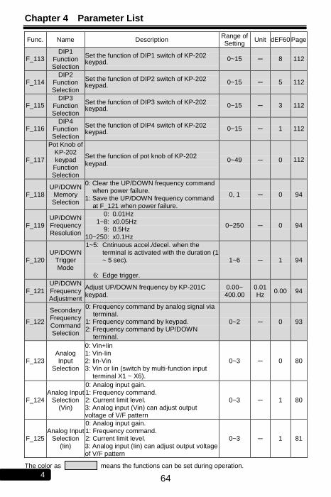
Chapter 4 Parameter List
64 4
Func. Name Description Range of Setting
Unit dEF60 Page
F_113 DIP1
Function Selection
Set the function of DIP1 switch of KP-202 keypad.
0~15 ─ 8 112
F_114 DIP2
Function Selection
Set the function of DIP2 switch of KP-202 keypad.
0~15 ─ 5 112
F_115 DIP3
Function Selection
Set the function of DIP3 switch of KP-202 keypad.
0~15 ─ 3 112
F_116 DIP4
Function Selection
Set the function of DIP4 switch of KP-202 keypad.
0~15 ─ 1 112
F_117
Pot Knob of KP-202 keypad
Function Selection
Set the function of pot knob of KP-202 keypad.
0~49 ─ 0 112
F_118 UP/DOWN
Memory Selection
0: Clear the UP/DOWN frequency command when power failure.
1: Save the UP/DOWN frequency command at F_121 when power failure.
0, 1 ─ 0 94
F_119 UP/DOWN Frequency Resolution
0: 1~8:
9: 10~250:
0.01Hz x0.05Hz 0.5Hz x0.1Hz
0~250 ─ 0 94
F_120 UP/DOWN
Trigger Mode
1~5:
6:
Cntinuous accel./decel. when the terminal is activated with the duration (1 ~ 5 sec). Edge trigger.
1~6 ─ 1 94
F_121 UP/DOWN Frequency Adjustment
Adjust UP/DOWN frequency by KP-201C keypad.
0.00~ 400.00
0.01 Hz
0.00 94
F_122
Secondary Frequency Command Selection
0: Frequency command by analog signal via terminal.
1: Frequency command by keypad. 2: Frequency command by UP/DOWN
terminal.
0~2 ─ 0 93
F_123 Analog Input
Selection
0: Vin+Iin 1: Vin-Iin 2: Iin-Vin 3: Vin or Iin (switch by multi-function input
terminal X1 ~ X6).
0~3 ─ 0 80
F_124 Analog Input
Selection (Vin)
0: Analog input gain. 1: Frequency command. 2: Current limit level. 3: Analog input (Vin) can adjust output voltage of V/F pattern
0~3 ─ 1 80
F_125 Analog Input
Selection (Iin)
0: Analog input gain. 1: Frequency command. 2: Current limit level. 3: Analog input (Iin) can adjust output voltage of V/F pattern
0~3 ─ 1 81
The color as means the functions can be set during operation.
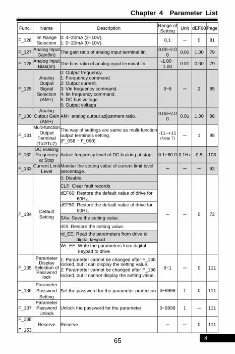
Chapter 4 Parameter List
65 4
Func. Name Description Range of Setting
Unit dEF60 Page
F_126 Iin Range Selection
0: 4~20mA (2~10V). 1: 0~20mA (0~10V).
0,1 ─ 0 81
F_127 Analog Input
Gain(Iin) The gain ratio of analog input terminal Iin.
0.00~2.00
0.01 1.00 79
F_128 Analog Input
Bias(Iin) The bias ratio of analog input terminal Iin.
-1.00~ 1.00
0.01 0.00 79
F_129
Analog Output Signal
Selection (AM+)
0: Output frequency. 1: Frequency command. 2: Output current. 3: Vin frequency command. 4: Iin frequency command. 5: DC bus voltage 6: Output voltaga
0~6 ─ 2 85
F_130 Analog
Output Gain (AM+)
AM+ analog output adjustment ratio. 0.00~2.0
0 0.01 1.00 86
F_131
Multi-function Output
Terminal (Ta2/Tc2)
The way of settings are same as multi-function output terminals setting. (F_058 ~ F_060)
-11~+11 (Note 7)
─ 1 95
F_132 DC Braking Frequency
at Stop Active frequency level of DC braking at stop. 0.1~60.0 0.1Hz 0.5 103
F_133 Current Limit
Level Monitor the setting value of current limit level percentage.
─ ─ ─ 92
F_134 Default Setting
0: Disable
─ ─ 0 72
CLF: Clear fault records
dEF60: Restore the default value of drive for
60Hz.
dEF50: Restore the default value of drive for
50Hz.
SAv: Save the setting value.
rES: Restore the setting value.
rd_EE: Read the parameters from drive to
digital keypad
Wr_EE: Write the parameters from digital
keypad to drive
F_135
Parameter Display
Selection of Password
lock
1: Paramerter cannot be changed after F_136 locked, but it can display the setting value. 2: Paramerter cannot be changed after F_136
locked, but it cannot display the setting value.
0~1 ─ 0 111
F_136
Parameter
Password
Setting
Set the password for the parameter protection 0~9999 1 0 111
F_137 Parameter Password
Unlock Unlock the password for the parameter. 0~9999 1 ─ 111
F_138 |
F_153 Reserve Reserve ─ ─ 0 111

Chapter 4 Parameter List
66 4
F_154 Default Setting
0: Disable
─ ─ 111
CLF: Clear fault records
dEF60: Restore the default value of drive for
60Hz.
dEF50: Restore the default value of drive for
50Hz.
SAv: Save the setting value.
rES: Restore the setting value.
rd_EE: Read the parameters from drive to
digital keypad
Wr_EE: Write the parameters from digital
keypad to drive
The color as means the functions can be set during operation.
Note: 1. Default value of 50Hz. 2. Default value of 60Hz. 3. Specification of 200V series. 4. Specification of 400V series. 5. 0.5 ~ 5HP: 5sec
7.5 ~ 30HP: 15sec 40HP above: 30sec
6. RM5G series: When switching frequency setting exceeds 4, the drive must be de-rating or selecting higher capacity.
RM5P series: When switching frequency setting exceeds 2, the drive must be de-rating or selecting higher capacity.
7. +: Represents a contact (N.O)
-: Represents b contact (N.C)
No Text on This Page
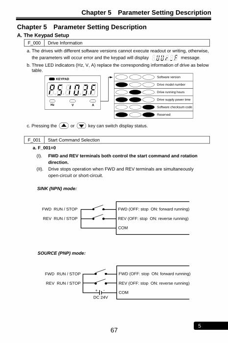
Chapter 5 Parameter Setting Description
67 5
Chapter 5 Parameter Setting Description
A. The Keypad Setup
F_000 Drive Information
a. The drives with different software versions cannot execute readout or writing, otherwise,
the parameters will occur error and the keypad will display message.
b. Three LED indicators (Hz, V, A) replace the corresponding information of drive as below table.
Software version
Reserved
Software checksum code
Drive supply power time
Drive running hours
Drive model number
KEYPAD
Hz V A
c. Pressing the or key can switch display status.
F_001 Start Command Selection
a. F_001=0
(I). FWD and REV terminals both control the start command and rotation
direction.
(II). Drive stops operation when FWD and REV terminals are simultaneously
open-circuit or short-circuit.
SINK (NPN) mode:
FWD (OFF: stop ON: forward running)
COM
REV (OFF: stop ON: reverse running)
FWD RUN / STOP
REV RUN / STOP
SOURCE (PNP) mode:
FWD (OFF: stop ON: forward running)
COM
REV (OFF: stop ON: reverse running)
FWD RUN / STOP
REV RUN / STOP
-+
DC 24V
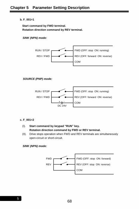
Chapter 5 Parameter Setting Description
68 5
b. F_001=1
Start command by FWD terminal.
Rotation direction command by REV terminal.
SINK (NPN) mode:
FWD (OFF: stop ON: running)
COM
REV (OFF: forward ON: reverse)
RUN / STOP
REV / FWD
SOURCE (PNP) mode:
FWD (OFF: stop ON: running)
COM
REV (OFF: forward ON: reverse)
RUN / STOP
REV / FWD
-+
DC 24V
c. F_001=2
(I). Start command by keypad “RUN” key.
Rotation direction command by FWD or REV terminal.
(II). Drive stops operation when FWD and REV terminals are simultaneously
open-circuit or short-circuit.
SINK (NPN) mode:
FWD (OFF: stop ON: forward)
COM
REV (OFF: stop ON: reverse)
FWD
REV

Chapter 5 Parameter Setting Description
69 5
SOURCE (PNP) mode:
FWD (OFF: stop ON: forward)
COM
REV (OFF: stop ON: reverse)
FWD
REV
-+
DC 24V
d. F_001=3
Start command by the keypad “RUN” key. Motor rotates at the forward direction (clockwise).
e. F_001=4
(I). Start command by keypad “RUN” key. Motor rotates at the reverse direction (counterclockwise).
(II). The most left digit of output frequency will show ―-―.
Note: 1.When F_001 set to 0 or 2 and FWD-COM and REV-COM are simultaneously
open-circuit, the monitor mode will display blanking ― ― (except ―Display
8-terminal status‖). If FWD-COM and REV-COM are simultaneously short-circuit, the
monitor mode will display blanking ― ‖ (except ―Display 8-terminal status‖).
2.The definition of rotation direction is according to IEC (International Electrotechnical Commission) standard. Observing the motor from axle center side, not the fan side. The standard rotation direction (Forward) is clockwise
U/T1 V/T2 W/T3
DRIVE
FWD
REV
COM
DRIVE
FWD
REV
COM
U/T1 V/T2 W/T3
U/T1 V/T2 W/T3
U/T1 V/T2 W/T3
Figure A Figure B
EX: F_001=0,
Forward (FWD) rotation is clockwise (Figure A).
Reverse (REV) rotation is counter-clockwise (Figure B).
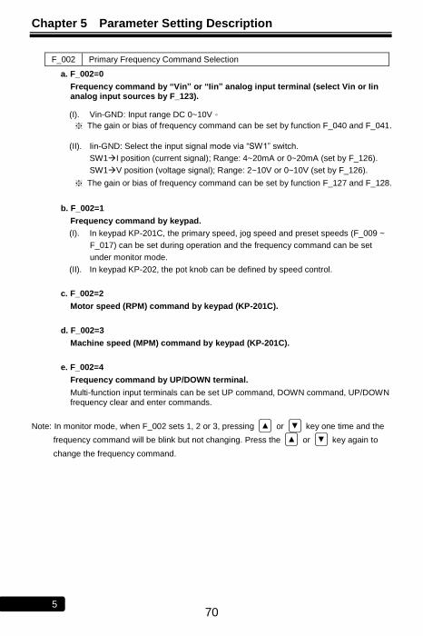
Chapter 5 Parameter Setting Description
70 5
F_002 Primary Frequency Command Selection
a. F_002=0
Frequency command by “Vin” or “Iin” analog input terminal (select Vin or Iin analog input sources by F_123).
(I). Vin-GND: Input range DC 0~10V。
※ The gain or bias of frequency command can be set by function F_040 and F_041.
(II). Iin-GND: Select the input signal mode via ―SW1‖ switch.
SW1I position (current signal); Range: 4~20mA or 0~20mA (set by F_126).
SW1V position (voltage signal); Range: 2~10V or 0~10V (set by F_126).
※ The gain or bias of frequency command can be set by function F_127 and F_128.
b. F_002=1
Frequency command by keypad.
(I). In keypad KP-201C, the primary speed, jog speed and preset speeds (F_009 ~
F_017) can be set during operation and the frequency command can be set
under monitor mode.
(II). In keypad KP-202, the pot knob can be defined by speed control.
c. F_002=2
Motor speed (RPM) command by keypad (KP-201C).
d. F_002=3
Machine speed (MPM) command by keypad (KP-201C).
e. F_002=4
Frequency command by UP/DOWN terminal.
Multi-function input terminals can be set UP command, DOWN command, UP/DOWN frequency clear and enter commands.
Note: In monitor mode, when F_002 sets 1, 2 or 3, pressing ▲ or ▼ key one time and the
frequency command will be blink but not changing. Press the ▲ or ▼ key again to
change the frequency command.

Chapter 5 Parameter Setting Description
71 5
F_003 Selection of ―STOP‖ Key Validity
a. F_003=0
When the start command by terminal, the ―STOP
RESET ‖ key of keypad disabled.
b. F_003=1
When the start command by terminal, the ―STOP
RESET ‖ key of keypad enabled.
c. The applications of “STOP” key.
(I). Emergency stop:
When the start and frequency command are both controlled by multi-function input
terminal (F_001=0 or 1), the output frequency will be decreased to 0Hz and
displaying on keypad by pressing ―STOP
RESET ‖ key during operation.
If the drive needs to be restarted, cut off the wire between the terminals of the start
command (FWD or REV) and COM and restart the drive again.
(II). Normal stop:
F_001=2 or 3, the start command by ― RUN ‖ key of keypad KP-201C and the stop is
controlled by ― STOP
RESET ‖ key.
F_004 Frequency Command Selection
a. F_004=0
In the monitor mode, the frequency command cannot be changed by KP-201C keypad to avoid possible mistakes and errors.
b. F_004=1
In the monitor mode, the frequency command can be changed by KP-201C keypad.
F_005 Selection of Frequency Command Auto-Storing
a. F_005=0
In the monitor mode, the frequency command will not be saved automatically.
b. F_005=1
In the monitor mode, the frequency command will be saved automatically after 3 minutes.
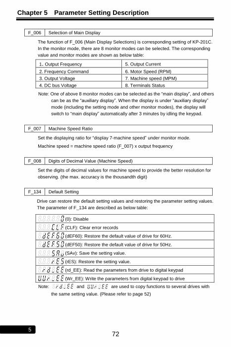
Chapter 5 Parameter Setting Description
72 5
F_006 Selection of Main Display
The function of F_006 (Main Display Selections) is corresponding setting of KP-201C.
In the monitor mode, there are 8 monitor modes can be selected. The corresponding
value and monitor modes are shown as below table:
1. Output Frequency 5. Output Current
2. Frequency Command 6. Motor Speed (RPM)
3. Output Voltage 7. Machine speed (MPM)
4. DC bus Voltage 8. Terminals Status
Note: One of above 8 monitor modes can be selected as the ―main display‖, and others
can be as the ―auxiliary display‖. When the display is under ―auxiliary display‖
mode (including the setting mode and other monitor modes), the display will
switch to ―main display‖ automatically after 3 minutes by idling the keypad.
F_007 Machine Speed Ratio
Set the displaying ratio for ―display 7-machine speed‖ under monitor mode.
Machine speed = machine speed ratio (F_007) x output frequency
F_008 Digits of Decimal Value (Machine Speed)
Set the digits of decimal values for machine speed to provide the better resolution for
observing. (the max. accuracy is the thousandth digit)
F_134 Default Setting
Drive can restore the default setting values and restoring the parameter setting values.
The parameter of F_134 are described as below table:
(0): Disable
(CLF): Clear error records
(dEF60): Restore the default value of drive for 60Hz.
(dEF50): Restore the default value of drive for 50Hz.
(SAv): Save the setting value.
(rES): Restore the setting value.
(rd_EE): Read the parameters from drive to digital keypad
(Wr_EE): Write the parameters from digital keypad to drive
Note: and are used to copy functions to several drives with
the same setting value. (Please refer to page 52)

Chapter 5 Parameter Setting Description
73 5
B. Preset Speed Setup
F_009 Primary Speed
F_010 Preset Speed 1
F_011 Preset Speed 2
F_012 Preset Speed 3
F_013 Preset Speed 4
F_014 Preset Speed 5
F_015 Preset Speed 6
F_016 Preset Speed 7
F_017 Jog Speed
a. Related functions:
(I) The setting of acceleration and deceleration time (F_018 ~ F_029).
(II) The setting of multi-function input terminals (F_052 ~ F_057).
b. Switch of jog speed, primary speed and preset speeds.
※ The ON/OFF conditions as below table are “contact a (N.O)” setting of
functions.
Jog speed
command
Multi-speed level 3 command
Multi-speed level 2 command
Multi-speed level 1 command
Command Description
ON X X X Jog speed
OFF OFF OFF OFF Primary speed
OFF OFF OFF ON Preset speed 1
OFF OFF ON OFF Preset speed 2
OFF OFF ON ON Preset speed 3
OFF ON OFF OFF Preset speed 4
OFF ON OFF ON Preset speed 5
OFF ON ON OFF Preset speed 6
OFF ON ON ON Preset speed 7
Note: 1. ― X ― : Don’t care
2. Jog speed has the highest priority. That is, when the jog speed is activated, other speed commands disabled.
3. Jog speed command and the multi-speed commands are programmed by the multi-function input terminals (X1 ~ X6) by functions (F_052 ~ F057). ON / OFF the terminal in accordance with above table to switch the speed.
4. ― ON ― : The terminal is short-circuit at contact a (N.O) setting. The terminal is open-circuit at contact b (N.C) setting.
― OFF ‖ : The terminal is open-circuit at contact a (N.O) setting The terminal is short-circuit at contact b (N.C) setting.
5. The priority of speed command: Jog speed>Multi-sped>primary speed
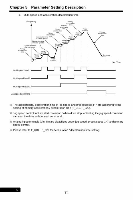
Chapter 5 Parameter Setting Description
74 5
c. Multi-speed and acceleration/deceleration time
Primary acceleration
time
Time
Frequency
Primary
speed
Multi-speed level 2
Multi-speed level 1
Multi-speed level 3
Acceleration time of preset speed 1
Preset speed 1
Jog speed command
Deceleration time of preset speed 2
Preset speed 2
Acceleration time of preset speed 3
Preset speed 3
Preset speed 4
Primary acceleration
time
Preset speed 5
Preset speed 6
Primary acceleration
time
Preset speed 7
Primary deceleration
time
Jog speed
Primary acceleration
timePrimary
acceleration time
※ The acceleration / deceleration time of jog speed and preset speed 4~7 are according to the setting of primary acceleration / deceleration time (F_019, F_020).
※ Jog speed control include start command. When drive stop, activating the jog speed command can start the drive without start command.
※ Analog input terminals (Vin, Iin) are disabilities under jog speed, preset speed 1~7 and primary speed control.
※ Please refer to F_018 ~ F_029 for acceleration / deceleration time setting.
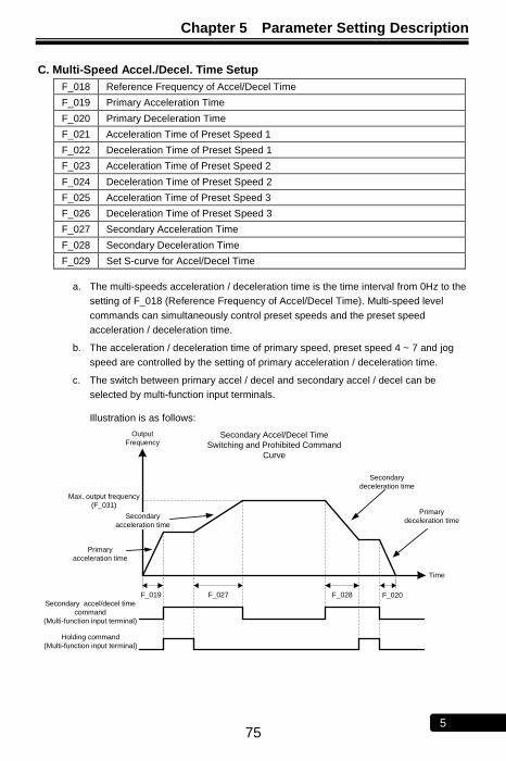
Chapter 5 Parameter Setting Description
75 5
C. Multi-Speed Accel./Decel. Time Setup
F_018 Reference Frequency of Accel/Decel Time
F_019 Primary Acceleration Time
F_020 Primary Deceleration Time
F_021 Acceleration Time of Preset Speed 1
F_022 Deceleration Time of Preset Speed 1
F_023 Acceleration Time of Preset Speed 2
F_024 Deceleration Time of Preset Speed 2
F_025 Acceleration Time of Preset Speed 3
F_026 Deceleration Time of Preset Speed 3
F_027 Secondary Acceleration Time
F_028 Secondary Deceleration Time
F_029 Set S-curve for Accel/Decel Time
a. The multi-speeds acceleration / deceleration time is the time interval from 0Hz to the
setting of F_018 (Reference Frequency of Accel/Decel Time). Multi-speed level
commands can simultaneously control preset speeds and the preset speed
acceleration / deceleration time.
b. The acceleration / deceleration time of primary speed, preset speed 4 ~ 7 and jog
speed are controlled by the setting of primary acceleration / deceleration time.
c. The switch between primary accel / decel and secondary accel / decel can be
selected by multi-function input terminals.
Illustration is as follows:
Max. output frequency
(F_031)
Time
Secondary
acceleration time
Secondary accel/decel time
command
(Multi-function input terminal)
F_019 F_027 F_028 F_020
Secondary Accel/Decel Time
Switching and Prohibited Command
Curve
Primary
acceleration time
Secondary
deceleration time
Primary
deceleration time
Output
Frequency
Holding command
(Multi-function input terminal)
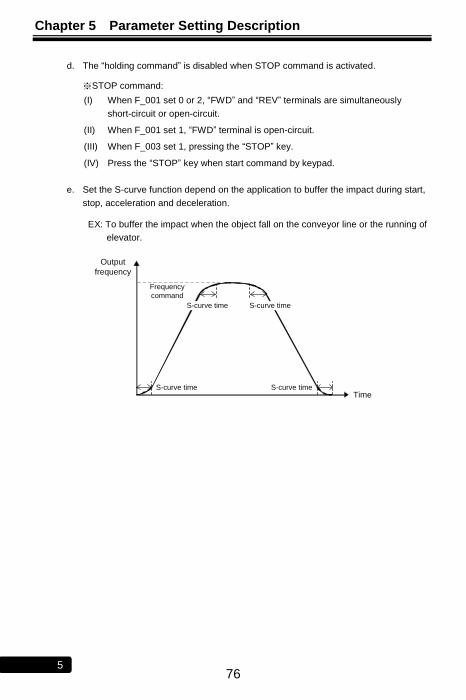
Chapter 5 Parameter Setting Description
76 5
d. The ―holding command‖ is disabled when STOP command is activated.
※STOP command:
(I) When F_001 set 0 or 2, ―FWD‖ and ―REV‖ terminals are simultaneously
short-circuit or open-circuit.
(II) When F_001 set 1, ―FWD‖ terminal is open-circuit.
(III) When F_003 set 1, pressing the ―STOP‖ key.
(IV) Press the ―STOP‖ key when start command by keypad.
e. Set the S-curve function depend on the application to buffer the impact during start,
stop, acceleration and deceleration.
EX: To buffer the impact when the object fall on the conveyor line or the running of
elevator.
Frequency
command
Time
Output
frequency
S-curve time
S-curve timeS-curve time
S-curve time
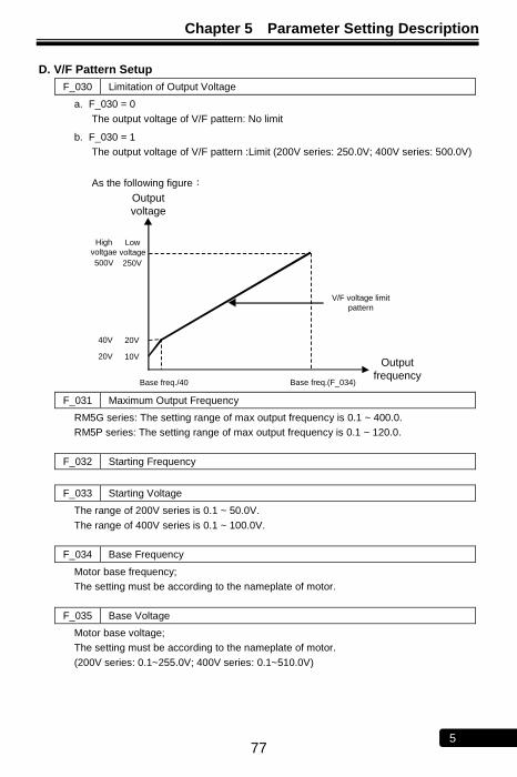
Chapter 5 Parameter Setting Description
77 5
D. V/F Pattern Setup
F_030 Limitation of Output Voltage
a. F_030 = 0
The output voltage of V/F pattern: No limit
b. F_030 = 1
The output voltage of V/F pattern :Limit (200V series: 250.0V; 400V series: 500.0V)
As the following figure:
Base freq./40 Base freq.(F_034)
V/F voltage limit
pattern
Output
frequency
Output
voltage
250V
20V
10V
Low
voltage
500V
40V
20V
High
voltgae
F_031 Maximum Output Frequency
RM5G series: The setting range of max output frequency is 0.1 ~ 400.0.
RM5P series: The setting range of max output frequency is 0.1 ~ 120.0.
F_032 Starting Frequency
F_033 Starting Voltage
The range of 200V series is 0.1 ~ 50.0V.
The range of 400V series is 0.1 ~ 100.0V.
F_034 Base Frequency
Motor base frequency;
The setting must be according to the nameplate of motor.
F_035 Base Voltage
Motor base voltage;
The setting must be according to the nameplate of motor.
(200V series: 0.1~255.0V; 400V series: 0.1~510.0V)
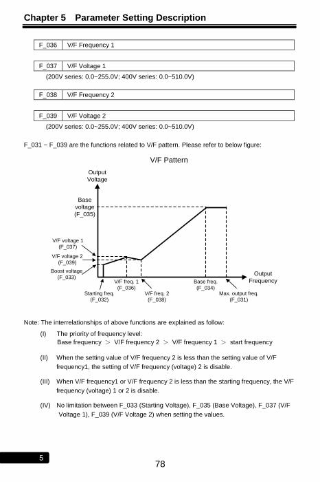
Chapter 5 Parameter Setting Description
78 5
F_036 V/F Frequency 1
F_037 V/F Voltage 1
(200V series: 0.0~255.0V; 400V series: 0.0~510.0V)
F_038 V/F Frequency 2
F_039 V/F Voltage 2
(200V series: 0.0~255.0V; 400V series: 0.0~510.0V)
F_031 ~ F_039 are the functions related to V/F pattern. Please refer to below figure:
V/F voltage 2
(F_039)
V/F voltage 1
(F_037)
Boost voltage
(F_033)
V/F freq. 2
(F_038)
V/F freq. 1
(F_036)Starting freq.
(F_032)
Output
Frequency
Output
Voltage
V/F Pattern
Base freq.
(F_034)Max. output freq.
(F_031)
Base
voltage
(F_035)
Note: The interrelationships of above functions are explained as follow:
(I) The priority of frequency level:
Base frequency > V/F frequency 2 > V/F frequency 1 > start frequency
(II) When the setting value of V/F frequency 2 is less than the setting value of V/F
frequency1, the setting of V/F frequency (voltage) 2 is disable.
(III) When V/F frequency1 or V/F frequency 2 is less than the starting frequency, the V/F
frequency (voltage) 1 or 2 is disable.
(IV) No limitation between F_033 (Starting Voltage), F_035 (Base Voltage), F_037 (V/F
Voltage 1), F_039 (V/F Voltage 2) when setting the values.

Chapter 5 Parameter Setting Description
79 5
E. Analog Input Command Setup
The analog input terminals:
―Vin‖ – ―GND‖: 0~10V;
―Iin‖ – ―GND‖: 4~20mA (2~10V) or 0~20mA (0~10V)
F_040 Vin Gain
F_127 Analog Input Gain (Iin)
a. The corresponding frequency command value of analog command = Maximum output frequency (F_031) x Analog input gain (F_040 or F_127)
EX: If analog input bias (F_041 or F_128) = 0.00
Maximum output frequency = 60.0Hz Maximum output frequency = 60.0Hz
Analog input gain = 1.20 Analog input gain = 0.80
Output
Frequency
Analog
Command
60.0Hz
48.0Hz
0Hz 0Hz
0V(4mA) 0V(4mA) 10V(20mA)
Analog
Command
Output
Frequency
10V(20mA)8.3V(17.3mA)
Gain=1
Gain=1.2
Gain=1
Gain=0.8
60.0Hz
F_041 Vin Bias
F_128 Analog Input Bias (Iin)
a. The corresponding frequency command value of analog command =
maximum output freq. (F_031) x analog input bias (F_041 or F_128)
b.
command analog of v alue commandf requency ingcorrespond The C.V*
C.Vcommand) (Analog20mA) (or10V
C.V) - command f req. (Max. command Freq.

Chapter 5 Parameter Setting Description
80 5
EX: If analog input gain (F_040 or F_127) = 1.00
Maximum output frequency = 60.0Hz Maximum output frequency = 60.0Hz
Analog input bias = 0.05 Analog input bias = -0.05
Analog
Command
60.0Hz 60.0Hz
3.0Hz
-3.0Hz0V(4mA)
0V(4mA)0.5V(4.8mA)
10V(20mA)
Output
Frequency
Analog
Command
Output
Frequency
Bias=1
Bias=0.05
Bias=-0.05
Bias=1
10V(20mA)
Example of reverse control application:
Max. output freq.=60.0Hz
Analog input gain=0.00
Analog input bias=1.00
Analog command
0V(4mA) 10V(20mA)
60.0Hz
0Hz
Frequencycommand
F_123 Analog Input Selection
0: Vin+Iin
1: Vin-Iin
2: Iin-Vin
3: Vin or Iin (switch by multi-function input terminal X1 ~ X6)
F_124 Analog Input Selection (Vin)
0: Analog input gain
1: Frequency command
2: Current limit level The level setting range is 1 ~150%. (the setting value displays at F_133)
3: Analog input (Vin) can adjust output voltage of V/F pattern
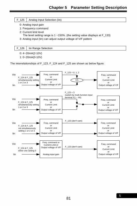
Chapter 5 Parameter Setting Description
81 5
F_125 Analog Input Selection (Iin)
0: Analog input gain
1: Frequency command
2: Current limit level The level setting range is 1 ~150%. (the setting value displays at F_133)
3: Analog input (Iin) can adjust output voltage of V/F pattern
F_126 Iin Range Selection
0: 4~20mA(2-10V)
1: 0~20mA(0-10V)
The interrelationships of F_123, F_124 and F_125 are shown as below figure:
Vin
Iin
F_123 = 0, 1, 2
Vin
Iin
Vin
Iin
+/-
Vin
Iin
Freq. command
or
Current Limit
or
Output voltage of V/F
F_124 & F_125
simultaneously setting
1 or 2 or 3
F_123 (don’t care)
Freq. command
or
Current Limit
or
Output voltage of V/F
Freq. command
or
Current Limit
or
Output voltage of V/F
Freq. command
or
Current Limit
or
Output voltage of V/F
Freq. command
or
Current Limit
or
Output voltage of V/F
F_123 = 3
(switch by multi-function input
terminal X1 ~ X6)
F_123 (don’t care)
Freq. command
or
Current Limit
or
Output voltage of V/F
Freq. command
or
Current Limit
or
Output voltage of V/F
Freq. command or
Current Limit or
Output voltage of V/F
Analog input gain
F_124 & F_125
simultaneously setting
1 or 2 or 3
F_124 & F_125
not simultaneously
setting 1 or 2 or 3
F_124 & F_125
either one setting 0
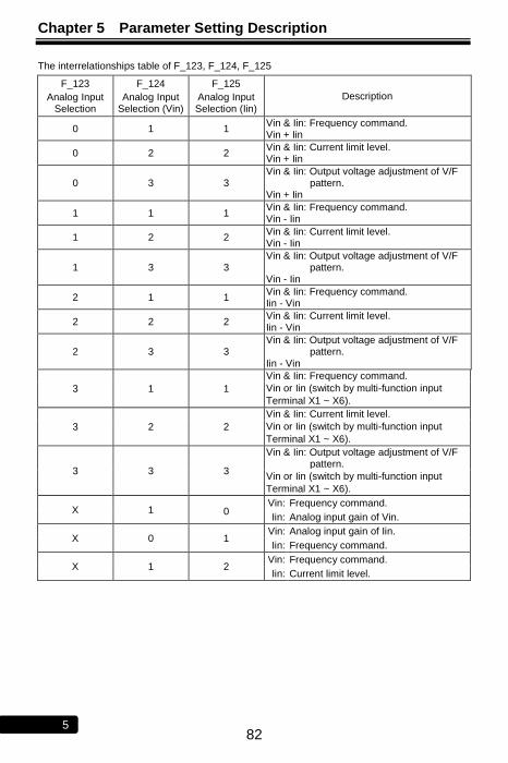
Chapter 5 Parameter Setting Description
82 5
The interrelationships table of F_123, F_124, F_125
F_123
Analog Input Selection
F_124
Analog Input Selection (Vin)
F_125
Analog Input Selection (Iin)
Description
0 1 1 Vin & Iin: Frequency command. Vin + Iin
0 2 2 Vin & Iin: Current limit level. Vin + Iin
0 3 3 Vin & Iin: Output voltage adjustment of V/F
pattern. Vin + Iin
1 1 1 Vin & Iin: Frequency command. Vin - Iin
1 2 2 Vin & Iin: Current limit level. Vin - Iin
1 3 3 Vin & Iin: Output voltage adjustment of V/F
pattern. Vin - Iin
2 1 1 Vin & Iin: Frequency command. Iin - Vin
2 2 2 Vin & Iin: Current limit level. Iin - Vin
2 3 3 Vin & Iin: Output voltage adjustment of V/F
pattern. Iin - Vin
3 1 1
Vin & Iin: Frequency command.
Vin or Iin (switch by multi-function input
Terminal X1 ~ X6).
3 2 2
Vin & Iin: Current limit level.
Vin or Iin (switch by multi-function input
Terminal X1 ~ X6).
3 3 3
Vin & Iin: Output voltage adjustment of V/F pattern.
Vin or Iin (switch by multi-function input
Terminal X1 ~ X6).
X 1 0 Vin: Frequency command.
Iin: Analog input gain of Vin.
X 0 1 Vin: Analog input gain of Iin.
Iin: Frequency command.
X 1 2 Vin: Frequency command.
Iin: Current limit level.
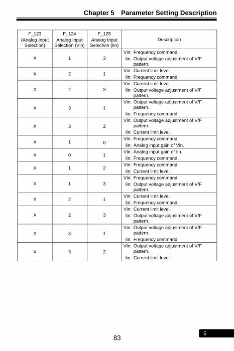
Chapter 5 Parameter Setting Description
83 5
F_123
(Analog Input Selection)
F_124
Analog Input Selection (Vin)
F_125
Analog Input Selection (Iin)
Description
X 1 3
Vin: Frequency command.
Iin: Output voltage adjustment of V/F pattern.
X 2 1 Vin: Current limit level.
Iin: Frequency command.
X 2 3
Vin: Current limit level.
Iin: Output voltage adjustment of V/F pattern.
X 3 1
Vin: Output voltage adjustment of V/F pattern.
Iin: Frequency command.
X 3 2
Vin: Output voltage adjustment of V/F pattern.
Iin: Current limit level.
X 1 0 Vin: Frequency command.
Iin: Analog input gain of Vin.
X 0 1 Vin: Analog input gain of Iin.
Iin: Frequency command.
X 1 2 Vin: Frequency command.
Iin: Current limit level.
X 1 3
Vin: Frequency command.
Iin: Output voltage adjustment of V/F pattern.
X 2 1 Vin: Current limit level.
Iin: Frequency command.
X 2 3
Vin: Current limit level.
Iin: Output voltage adjustment of V/F pattern.
X 3 1
Vin: Output voltage adjustment of V/F pattern.
Iin: Frequency command
X 3 2
Vin: Output voltage adjustment of V/F pattern.
Iin: Current limit level.
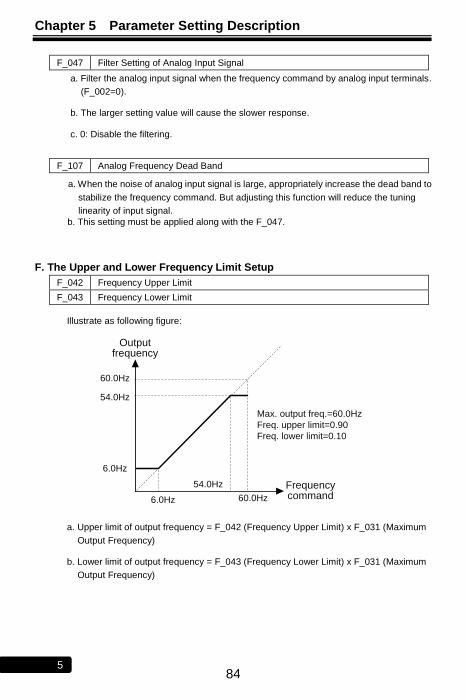
Chapter 5 Parameter Setting Description
84 5
F_047 Filter Setting of Analog Input Signal
a. Filter the analog input signal when the frequency command by analog input terminals.
(F_002=0).
b. The larger setting value will cause the slower response.
c. 0: Disable the filtering.
F_107 Analog Frequency Dead Band
a. When the noise of analog input signal is large, appropriately increase the dead band to
stabilize the frequency command. But adjusting this function will reduce the tuning
linearity of input signal.
b. This setting must be applied along with the F_047.
F. The Upper and Lower Frequency Limit Setup
F_042 Frequency Upper Limit
F_043 Frequency Lower Limit
Illustrate as following figure:
Output frequency
Frequency command
60.0Hz
60.0Hz
54.0Hz
54.0Hz
6.0Hz
6.0Hz
Max. output freq.=60.0Hz
Freq. upper limit=0.90
Freq. lower limit=0.10
a. Upper limit of output frequency = F_042 (Frequency Upper Limit) x F_031 (Maximum
Output Frequency)
b. Lower limit of output frequency = F_043 (Frequency Lower Limit) x F_031 (Maximum
Output Frequency)
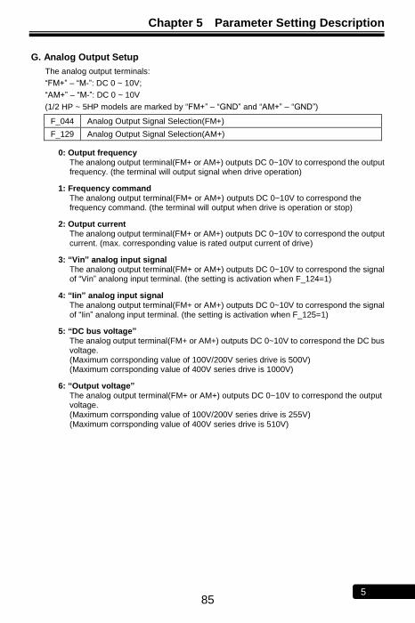
Chapter 5 Parameter Setting Description
85 5
G. Analog Output Setup
The analog output terminals:
―FM+‖ – ―M-‖: DC 0 ~ 10V;
―AM+‖ – ―M-‖: DC 0 ~ 10V
(1/2 HP ~ 5HP models are marked by ―FM+‖ – ―GND‖ and ―AM+‖ – ―GND‖)
F_044 Analog Output Signal Selection(FM+)
F_129 Analog Output Signal Selection(AM+)
0: Output frequency The analong output terminal(FM+ or AM+) outputs DC 0~10V to correspond the output frequency. (the terminal will output signal when drive operation)
1: Frequency command The analong output terminal(FM+ or AM+) outputs DC 0~10V to correspond the frequency command. (the terminal will output when drive is operation or stop)
2: Output current The analong output terminal(FM+ or AM+) outputs DC 0~10V to correspond the output current. (max. corresponding value is rated output current of drive)
3: “Vin” analog input signal The analong output terminal(FM+ or AM+) outputs DC 0~10V to correspond the signal of ―Vin‖ analong input terminal. (the setting is activation when F_124=1)
4: “Iin” analog input signal The analong output terminal(FM+ or AM+) outputs DC 0~10V to correspond the signal of ―Iin‖ analong input terminal. (the setting is activation when F_125=1)
5: “DC bus voltage” The analog output terminal(FM+ or AM+) outputs DC 0~10V to correspond the DC bus voltage. (Maximum corrsponding value of 100V/200V series drive is 500V) (Maximum corrsponding value of 400V series drive is 1000V)
6: “Output voltage” The analog output terminal(FM+ or AM+) outputs DC 0~10V to correspond the output voltage. (Maximum corrsponding value of 100V/200V series drive is 255V) (Maximum corrsponding value of 400V series drive is 510V)

Chapter 5 Parameter Setting Description
86 5
F_045 Analog Output Gain(FM+)
F_130 Analog Output Gain(AM+)
a. Analog output gain =Maximum output freq.
Output freq. (freq. command)or
Drive rated current
Output current
b. Analog output curve
Maximum output freq. = 60.0Hz
Analog output signal selection = 0, 1
Analog output gain = 1.20
10V
0V
21.25A
17AOutput current
8V
10V
0V
0.0Hz 60.0Hz
50.0Hz
Output freq.
or
Freq. command
Analog output
10V
0V 50.0HzVin freq. setting
10V
0V
8V
60.0Hz
60.0Hz
Driver rated current = 17A
Analog output signal selection = 2
Analog output gain = 0.80
Analog output
Maximum output freq. = 60.0Hz
Analog output signal selection = 3
Analog output gain = 1.20
Analog output Analog output
Maximum output freq. = 60.0Hz
Analog output signal selection = 4
Analog output gain = 0.08
Iin freq. setting
60.0Hz
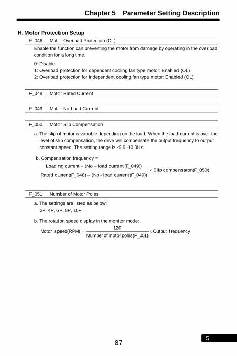
Chapter 5 Parameter Setting Description
87 5
H. Motor Protection Setup
F_046 Motor Overload Protection (OL)
Enable the function can preventing the motor from damage by operating in the overload
condition for a long time.
0: Disable
1: Overload protection for dependent cooling fan type motor: Enabled (OL)
2: Overload protection for independent cooling fan type motor: Enabled (OL)
F_048 Motor Rated Current
F_049 Motor No-Load Current
F_050 Motor Slip Compensation
a. The slip of motor is variable depending on the load. When the load current is over the
level of slip compensation, the drive will compensate the output frequency to output
constant speed. The setting range is -9.9~10.0Hz.
b. Compensation frequency =
on(F_050)compensati Slip(F_049)) current load-No(048)current(F_ Rated
(F_049)) current loadNo(current Loading
F_051 Number of Motor Poles
a. The settings are listed as below:
2P, 4P, 6P, 8P, 10P
b. The rotation speed display in the monitor mode:
f requency Output1)poles(F_05 motor of Number
120 speed(RPM) Motor
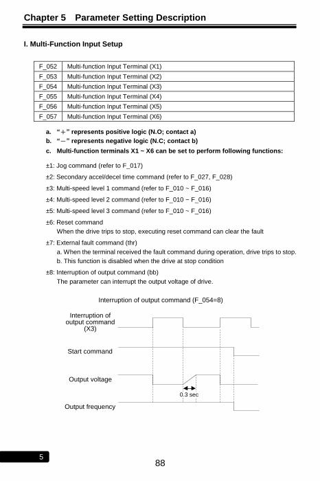
Chapter 5 Parameter Setting Description
88 5
I. Multi-Function Input Setup
F_052 Multi-function Input Terminal (X1)
F_053 Multi-function Input Terminal (X2)
F_054 Multi-function Input Terminal (X3)
F_055 Multi-function Input Terminal (X4)
F_056 Multi-function Input Terminal (X5)
F_057 Multi-function Input Terminal (X6)
a. “+” represents positive logic (N.O; contact a)
b. “-” represents negative logic (N.C; contact b)
c. Multi-function terminals X1 ~ X6 can be set to perform following functions:
±1: Jog command (refer to F_017)
±2: Secondary accel/decel time command (refer to F_027, F_028)
±3: Multi-speed level 1 command (refer to F_010 ~ F_016)
±4: Multi-speed level 2 command (refer to F_010 ~ F_016)
±5: Multi-speed level 3 command (refer to F_010 ~ F_016)
±6: Reset command
When the drive trips to stop, executing reset command can clear the fault
±7: External fault command (thr)
a. When the terminal received the fault command during operation, drive trips to stop.
b. This function is disabled when the drive at stop condition
±8: Interruption of output command (bb)
The parameter can interrupt the output voltage of drive.
Interruption of output command (F_054=8)
Output voltage
Output frequency
Interruption of output command
(X3)
Start command
0.3 sec
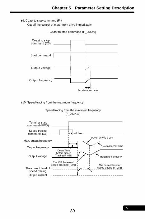
Chapter 5 Parameter Setting Description
89 5
±9: Coast to stop command (Fr)
Cut off the control of motor from drive immediately.
Coast to stop command (F_055=9)
Output voltage
Acceleration time
Output frequency
Coast to stop command (X3)
Start command
±10: Speed tracing from the maximum frequency
Speed tracing from the maximum frequency
(F_053=10)
Terminal start command (FWD)
Decel. time is 2 sec
Delay Time before Speed
Tracing(F_089)
The current level of speed tracing (F_088)
Normal accel. time
> 0.1secSpeed tracing
command (X1)
Max. output frequency
Output frequency
Output voltage
Output current
The V/F Pattern of Speed Tracing(F_090)
Return to normal V/F
The current level of speed tracing
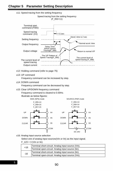
Chapter 5 Parameter Setting Description
90 5
±11: Speed tracing from the setting frequency
Speed tracing from the setting frequency
(F_053=11)
Terminal start command (FWD)
Decel. time is 2 sec
Delay Time before Speed
Tracing(F_089)
The current level of speed tracing (F_088)
Normal accel. time
> 0.1secSpeed tracing
command (X1)
Setting frequency
Output frequency
Output voltage
Output current
The V/F Pattern of Speed Tracing(F_090)
Return to normal V/F
The current level of speed tracing
±12: Holding command (refer to page 75)
±13: UP command
Frequency command can be increased by step.
±14: DOWN command
Frequency command can be decreased by step.
±15: Clear UP/DOWN frequency command
Frequency command is cleared to 0.00Hz.
Illustrate as below figures:
UP
DOWN
CLEAR
F_055=13
F_056=14
X4
X5
X6
COM
F_057=15
SINK (NPN) mode SOURCE (PNP) mode
F_055=13
F_056=14
F_057=15
+ -
DC 24V
UP
DOWN
CLEAR
X4
X5
X6
COM
±16: Analog input source selection
Select one of analog input sources(Vin or Iin) as the input signal.
F_123 = 3 (Vin or Iin)
+16 Terminal short-circuit: Analog input source (Vin).
Terminal open-circuit: Analog input source (Iin).
-16 Terminal short-circuit: Analog input source (Iin).
Terminal open-circuit: Analog input source (Vin).
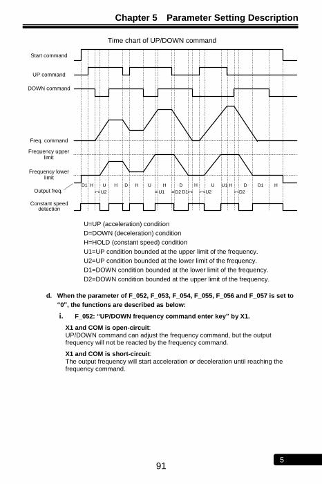
Chapter 5 Parameter Setting Description
91 5
D1 H U H D H U H D
D1
H U U1 H D H
Start command
DOWN command
UP command
Frequency upper limit
Constant speed detection
Output freq.
Frequency lower limit
Freq. command
U2 D2U2 U1 D2
D1
Time chart of UP/DOWN command
U=UP (acceleration) condition
D=DOWN (deceleration) condition
H=HOLD (constant speed) condition
U1=UP condition bounded at the upper limit of the frequency.
U2=UP condition bounded at the lower limit of the frequency.
D1=DOWN condition bounded at the lower limit of the frequency.
D2=DOWN condition bounded at the upper limit of the frequency.
d. When the parameter of F_052, F_053, F_054, F_055, F_056 and F_057 is set to
“0”, the functions are described as below:
i. F_052: “UP/DOWN frequency command enter key” by X1.
X1 and COM is open-circuit: UP/DOWN command can adjust the frequency command, but the output frequency will not be reacted by the frequency command.
X1 and COM is short-circuit:
The output frequency will start acceleration or deceleration until reaching the frequency command.

Chapter 5 Parameter Setting Description
92 5
ii. F_053: “DC braking enable (at stop)” by X2
1. The terminal is activated and the drive is at stop condition: DC braking enabled.
2. When the DC braking is activated, the output current is according to the setting
of F_075 (DC Braking Level).
3. The DC braking command will be cleared and the motor runs to the setting
frequency when the start or jog command enabled.
4. The output frequency is decreased to the setting value of F_132 (DC Braking
Frequency at Stop) and DC braking enabled, when the start command or jog
command is disabled.
DC
braking
active
Starting
frequency
F_032
DC braking
frequency at
stop F_132
Output freq.
Time
Start
command
DC braking
enable
DC
braking
active
iii. F_054: “Current limit enable” by X3
Monitor the current limit level percentage by F_133 (Current Limit Level)
Use KP-201C keypad:
a. X3 and COM is short-circuit:
Analog terminal sets the current limit level: Enable
When F_124 (Analog Input Selection (Vin)) or F_125 (Analog Input Selection
(Iin)) is set to 2, the user can set the current limit level from analog input
terminal and monitoring the setting value at F_133 (range: 1~150%).
※The function is disable before stall occurring during acceleration and
constant speed.
b. X3 and COM is open-circuit:
Analog terminal sets the current limit level: Disable
The setting value of current limit level is according to F_071(Stall Prevention
Level at Constant Speed). (range: 30~200%)
Use KP-202 keypad:
a. X3 and COM is short-circuit:
The current limit enabled when the function of pot knob of KP-202 is
defined as current limit. (range: 1~150%)
b. X3 and COM is open-circuit: The current limit disabled.
EX: F_054=0; X3 and COM is short-circuit; F_124=2, F_125=1
(Input 0~10V to Vin terminal will corresponding to the setting of 1~150% of drive
rated current)
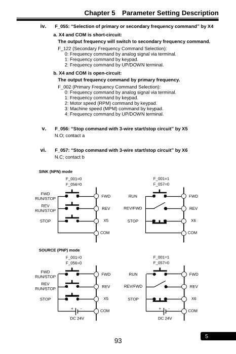
Chapter 5 Parameter Setting Description
93 5
iv. F_055: “Selection of primary or secondary frequency command” by X4
a. X4 and COM is short-circuit:
The output frequency will switch to secondary frequency command.
F_122 (Secondary Frequency Command Selection): 0: Frequency command by analog signal via terminal. 1: Frequency command by keypad. 2: Frequency command by UP/DOWN terminal.
b. X4 and COM is open-circuit:
The output frequency command by primary frequency.
F_002 (Primary Frequency Command Selection): 0: Frequency command by analog signal via terminal. 1: Frequency command by keypad. 2: Motor speed (RPM) command by keypad. 3: Machine speed (MPM) command by keypad. 4: Frequency command by UP/DOWN terminal.
v. F_056: “Stop command with 3-wire start/stop circuit” by X5
N.O; contact a
vi. F_057: “Stop command with 3-wire start/stop circuit” by X6
N.C; contact b
FWD
RUN/STOP
REV
RUN/STOP
STOP
F_001=0
F_056=0
FWD
REV
X5
COM
SINK (NPN) mode
F_001=1
F_057=0
+ -
DC 24V
RUN
REV/FWD
STOP
FWD
REV
X6
COM
RUN
REV/FWD
STOP
FWD
REV
X6
COM
+ -
DC 24V
FWD
RUN/STOP
REV
RUN/STOP
STOP
FWD
REV
X5
COM
F_001=0
F_056=0
SOURCE (PNP) mode
F_001=1
F_057=0
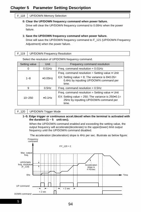
Chapter 5 Parameter Setting Description
94 5
F_118 UP/DOWN Memory Selection
0: Clear the UP/DOWN frequency command when power failure.
Drive will clear the UP/DOWN frequency command to 0.00Hz when the power
failure.
1: Save the UP/DOWN frequency command when power failure.
Drive will save the UP/DOWN frequency command to F_121 (UP/DOWN Frequency
Adjustment) when the power failure.
F_119 UP/DOWN Frequency Resolution
Select the resolution of UP/DOWN frequency command.
Setting value Unit Frequency command resolution
0 0.01Hz Freq. command resolution = 0.01Hz
1~8 ×0.05Hz
Freq. command resolution = Setting value × Unit
EX: Setting value = 8; The variance is 8×0.05= 0.4Hz by inputting UP/DOWN command per time.
9 0.5Hz Freq. command resolution = 0.5Hz
10~250 ×0.1Hz
Freq. command resolution = Setting value × Unit
EX: Setting value = 250; The variance is 250×0.1= 25Hz by inputting UP/DOWN command per time.
F_120 UP/DOWN Trigger Mode
1~5: Edge trigger or continuous accel./decel/ when the terminal is activated with the duration (1 ~ 5 unit:sec).
When the UP/DOWN command enabled and exceeding the setting value, the output frequency will accelerate(decelerate) to the upper(lower) limit output frequency until the UP/DOWN command disabled.
The acceleration (deceleration) slope is 4Hz per sec. Illustrate as below figure:
Time
Frequency command
DOWN command
UP command
Max. output freq.
< 2 sec
> 2 sec
UP/DOWN freq. resolution
(F_119)Acceleration
slope is 4 Hz/sec
If F_120 = 2
0Hz
Chapter 5 Parameter Setting Description
95 5
6: Edge trigger.
UP/DOWN signal triggers the drive during the transition of the signal(01 or 10).
The signal response time is 30ms.
F_121 UP/DOWN Frequency Adjustment
Directly use KP-201C keypad to input the UP/DOWN frequency command.
Enter the parameter setting mode of F_121 to adjust the frequency command. The drive will output the frequency according to the setting value.
The drive will save the setting value to F_121 after 5 sec when the frequency command is changed.
F_108 Digital Input Response Time
a. Setting the input response time of multi-function terminals (X1~X6, FWD and REV)
(digital debouncing).
b. If the signal width of digital inputs is smaller than the digital input response time, the
program of drive will reject the input signal and do no process to input signal.
J. Multi-Function Outputs Setup
F_058 Multi-function Output Terminal (Y1)
F_059 Multi-function Output Terminal (Y2)
F_060 Multi-function Output Terminal (Ta1,Tb1)
F_131 Multi-function Output Terminal (Ta2/Tc2)
a. Y1 and Y2 are open-collector output terminals. The maximum output specification is below DC48V / 50mA.
b. Ta1, Ta2 (N.O) and Tb1 (N.C) are relay output terminals.
The maximum output specification is AC 250V / 0.5A, cosθ=0.3.
c. “+” represents positive logic (N.O; contact a)
“-” represents negative logic (N.C; contact b)
d. Y1, Y2, Ta1, Ta2, and Tb1 can be set as below functions: 0: Disable (No function operated at terminals)
±1: Operation command detection. (Detection when start command is inputted)
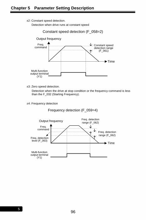
Chapter 5 Parameter Setting Description
96 5
±2: Constant speed detection.
Detection when drive runs at constant speed
Constant speed detection (F_058=2)
Freq. command
Constant speed detection range
(F_061)
Multi-function output terminal
(Y1)
Time
Output frequency
±3: Zero speed detection.
Detection when the drive at stop condition or the frequency command is less than the F_032 (Starting Frequency).
±4: Frequency detection
Freq. detection
range (F_062)Freq. detection level (F_063)
Frequency detection (F_059=4)
Freq. command
Multi-function output terminal
(Y1)
Time
Output frequencyFreq. detection
range (F_062)
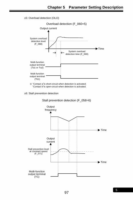
Chapter 5 Parameter Setting Description
97 5
±5: Overload detection (OLO)
Overload detection (F_060=5)
System overload
detection level
(F_068)
System overload
detection time (F_069)
Multi-function
output terminal
(Ta1 or Ta2)
Time
Output current
Multi-function
output terminal
(Tb1)
※ ―Contact a‖is short-circuit when detection is activated;
―Contact b‖is open-circuit when detection is activated.
±6: Stall prevention detection
Stall prevention detection (F_058=6)
Stall prevention level at constant speed
(F_071)
Multi-function output terminal
(Y1)
Time
Time
Output
current
Output
frequency
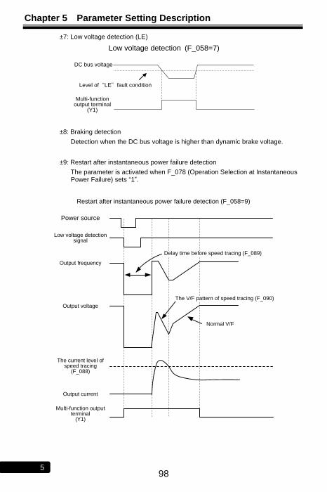
Chapter 5 Parameter Setting Description
98 5
±7: Low voltage detection (LE)
Low voltage detection (F_058=7)
DC bus voltage
Multi-function output terminal
(Y1)
Level of“LE”fault condition
±8: Braking detection
Detection when the DC bus voltage is higher than dynamic brake voltage.
±9: Restart after instantaneous power failure detection
The parameter is activated when F_078 (Operation Selection at Instantaneous Power Failure) sets ―1‖.
Restart after instantaneous power failure detection (F_058=9)
Power source
Low voltage detection signal
Output frequency
Output voltage
The current level of speed tracing
(F_088)
Output current
Multi-function output terminal
(Y1)
Normal V/F
The V/F pattern of speed tracing (F_090)
Delay time before speed tracing (F_089)
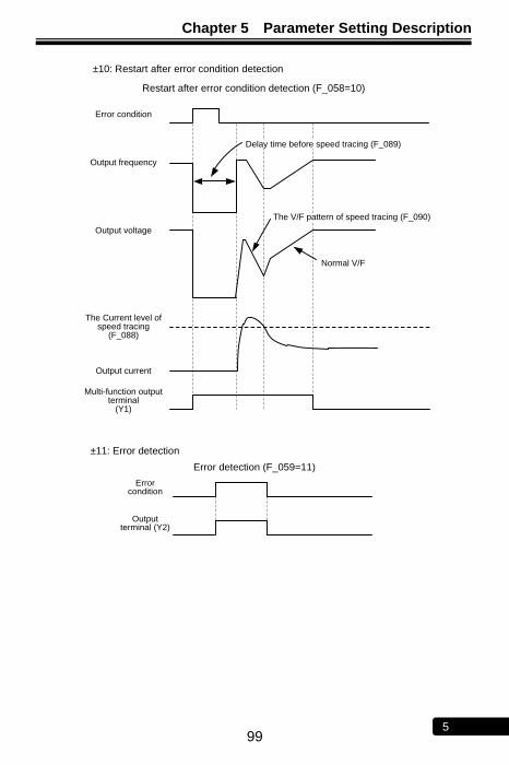
Chapter 5 Parameter Setting Description
99 5
±10: Restart after error condition detection
Restart after error condition detection (F_058=10)
Error condition
Output frequency
Output voltage
The Current level of speed tracing
(F_088)
Output current
Multi-function output terminal
(Y1)
Normal V/F
The V/F pattern of speed tracing (F_090)
Delay time before speed tracing (F_089)
±11: Error detection
Error detection (F_059=11)
Output terminal (Y2)
Error condition
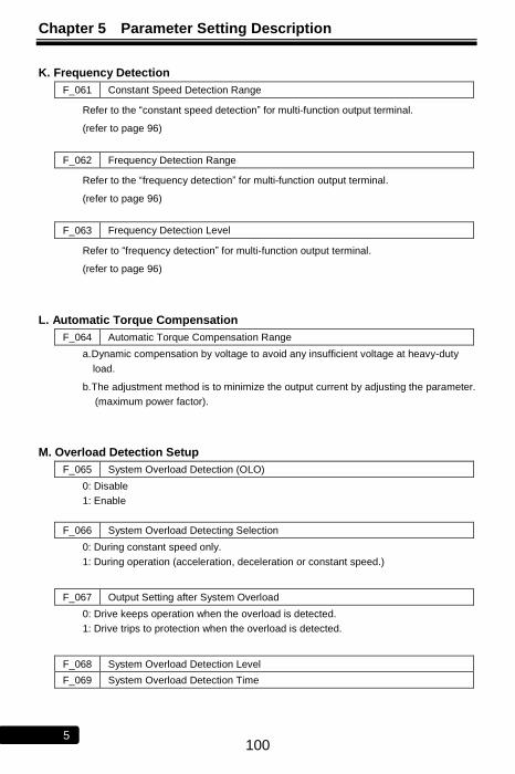
Chapter 5 Parameter Setting Description
100 5
K. Frequency Detection
F_061 Constant Speed Detection Range
Refer to the ―constant speed detection‖ for multi-function output terminal.
(refer to page 96)
F_062 Frequency Detection Range
Refer to the ―frequency detection‖ for multi-function output terminal.
(refer to page 96)
F_063 Frequency Detection Level
Refer to ―frequency detection‖ for multi-function output terminal.
(refer to page 96)
L. Automatic Torque Compensation
F_064 Automatic Torque Compensation Range
a. Dynamic compensation by voltage to avoid any insufficient voltage at heavy-duty
load.
b. The adjustment method is to minimize the output current by adjusting the parameter.
(maximum power factor).
M. Overload Detection Setup
F_065 System Overload Detection (OLO)
0: Disable
1: Enable
F_066 System Overload Detecting Selection
0: During constant speed only.
1: During operation (acceleration, deceleration or constant speed.)
F_067 Output Setting after System Overload
0: Drive keeps operation when the overload is detected.
1: Drive trips to protection when the overload is detected.
F_068 System Overload Detection Level
F_069 System Overload Detection Time
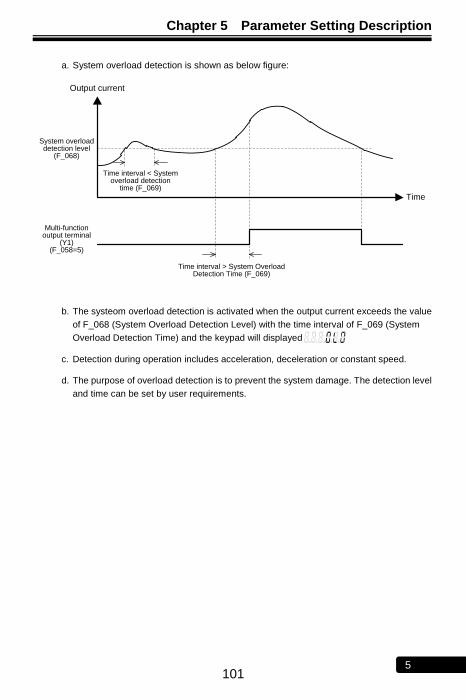
Chapter 5 Parameter Setting Description
101 5
a. System overload detection is shown as below figure:
Multi-function output terminal
(Y1) (F_058=5)
System overload detection level
(F_068)
Time interval < System overload detection
time (F_069)
Time interval > System Overload Detection Time (F_069)
Output current
Time
b. The systeom overload detection is activated when the output current exceeds the value
of F_068 (System Overload Detection Level) with the time interval of F_069 (System
Overload Detection Time) and the keypad will displayed
c. Detection during operation includes acceleration, deceleration or constant speed.
d. The purpose of overload detection is to prevent the system damage. The detection level
and time can be set by user requirements.
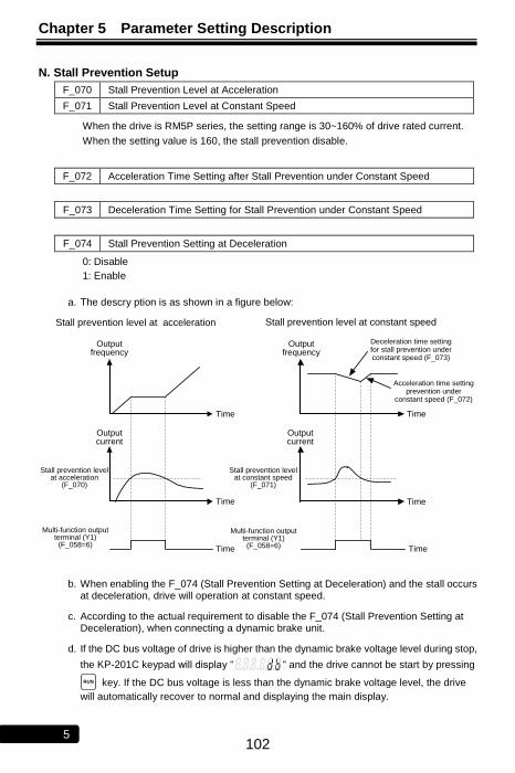
Chapter 5 Parameter Setting Description
102 5
N. Stall Prevention Setup
F_070 Stall Prevention Level at Acceleration
F_071 Stall Prevention Level at Constant Speed
When the drive is RM5P series, the setting range is 30~160% of drive rated current.
When the setting value is 160, the stall prevention disable.
F_072 Acceleration Time Setting after Stall Prevention under Constant Speed
F_073 Deceleration Time Setting for Stall Prevention under Constant Speed
F_074 Stall Prevention Setting at Deceleration
0: Disable
1: Enable
a. The descry ption is as shown in a figure below:
Time Time
Output frequency
Output frequency
Stall prevention level at constant speed
Stall prevention level at acceleration
(F_070)
Multi-function output terminal (Y1) (F_058=6)
Stall prevention level at constant speed
(F_071)
Stall prevention level at acceleration
Multi-function output terminal (Y1) (F_058=6)
Deceleration time setting for stall prevention under constant speed (F_073)
Acceleration time setting prevention under
constant speed (F_072)
Time
Output current
Output current
Time Time
Time
b. When enabling the F_074 (Stall Prevention Setting at Deceleration) and the stall occurs at deceleration, drive will operation at constant speed.
c. According to the actual requirement to disable the F_074 (Stall Prevention Setting at Deceleration), when connecting a dynamic brake unit.
d. If the DC bus voltage of drive is higher than the dynamic brake voltage level during stop,
the KP-201C keypad will display ― ― and the drive cannot be start by pressing
RUN key. If the DC bus voltage is less than the dynamic brake voltage level, the drive
will automatically recover to normal and displaying the main display.

Chapter 5 Parameter Setting Description
103 5
O. DC Braking Setup
F_075 DC Braking Level
The current level setting of DC braking.
F_076 Time of DC Braking after Stop
F_077 Time of DC Braking before Start
F_132 DC Braking Frequency at Stop
a. DC braking after stop is to prevent the motor from coasting.
b. DC braking before start is to prevent the motor from rotation due to external force at
start.
DC Braking
Start command
Time of DC braking before start (F_077)
Output
frequency
DC braking frequency at stop (F_132)
Time
Time of DC braking after stop (F_076)
Time
※ If the frequency command is set below F_032 (Starting Frequency) during operation
and the output frequency is below the starting frequency, the DC braking will be
activated. The setting value of F_132 is disable at the moment.
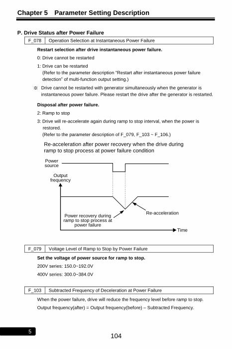
Chapter 5 Parameter Setting Description
104 5
P. Drive Status after Power Failure
F_078 Operation Selection at Instantaneous Power Failure
Restart selection after drive instantaneous power failure.
0: Drive cannot be restarted
1: Drive can be restarted
(Refer to the parameter description ―Restart after instantaneous power failure
detection‖ of multi-function output setting.)
※ Drive cannot be restarted with generator simultaneously when the generator is
instantaneous power failure. Please restart the drive after the generator is restarted.
Disposal after power failure.
2: Ramp to stop
3: Drive will re-accelerate again during ramp to stop interval, when the power is
restored.
(Refer to the parameter description of F_079, F_103 ~ F_106.)
Power source
Time
Output frequency
Re-accelerationPower recovery during ramp to stop process at
power failure
Re-acceleration after power recovery when the drive during
ramp to stop process at power failure condition
F_079 Voltage Level of Ramp to Stop by Power Failure
Set the voltage of power source for ramp to stop.
200V series: 150.0~192.0V
400V series: 300.0~384.0V
F_103 Subtracted Frequency of Deceleration at Power Failure
When the power failure, drive will reduce the frequency level before ramp to stop.
Output frequency(after) = Output frequency(before) – Subtracted Frequency.

Chapter 5 Parameter Setting Description
105 5
F_104 Deceleration Time 1 of Ramp to Stop by Power Failure
F_105 Deceleration Time 2 of Ramp to Stop by Power Failure
F_106 Turning Frequency of Ramp to Stop
Set the turning frequency level of ramp to stop when the deceleration time is switched
from F_104 setting value to F_105 setting value.
Ramp to stop at power failure
Power source
Turning frequency of ramp to stop
(F_106)
Subtracted frequency of deceleration at power failure (F_103)
Deceleration time 1 of ramp to stop by
power failure (F_104)
Time
Output frequency
Deceleration Time 2 of ramp to stop by
power failure (F_105)
※ The ramp to stop at power failure function is suitable for the inertia load.
CAUTION
At the function F_078=1 or 3, the drive will automatically restart when the power is restored. Stay away from the motor and machine.
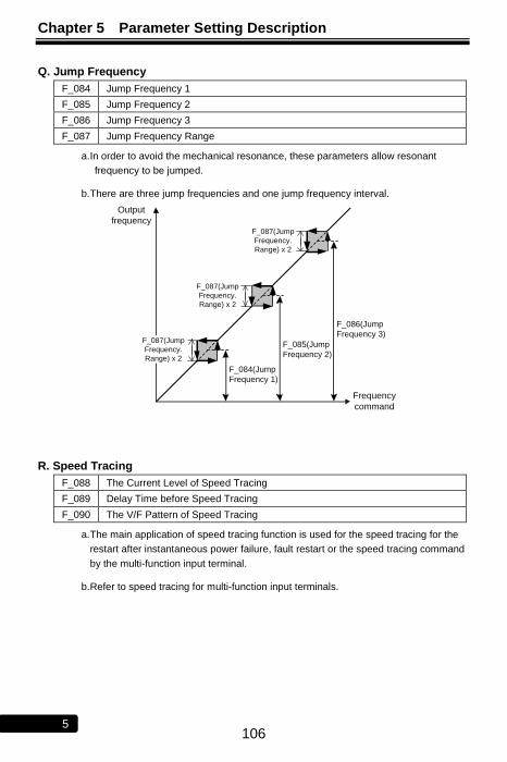
Chapter 5 Parameter Setting Description
106 5
Q. Jump Frequency
F_084 Jump Frequency 1
F_085 Jump Frequency 2
F_086 Jump Frequency 3
F_087 Jump Frequency Range
a. In order to avoid the mechanical resonance, these parameters allow resonant
frequency to be jumped.
b. There are three jump frequencies and one jump frequency interval.
F_084(Jump
Frequency 1)
F_087(Jump
Frequency.
Range) x 2
Output
frequency
Frequency
command
F_087(Jump
Frequency.
Range) x 2
F_087(Jump
Frequency.
Range) x 2
F_085(Jump
Frequency 2)
F_086(Jump
Frequency 3)
R. Speed Tracing
F_088 The Current Level of Speed Tracing
F_089 Delay Time before Speed Tracing
F_090 The V/F Pattern of Speed Tracing
a. The main application of speed tracing function is used for the speed tracing for the
restart after instantaneous power failure, fault restart or the speed tracing command
by the multi-function input terminal.
b. Refer to speed tracing for multi-function input terminals.
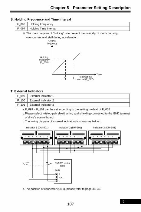
Chapter 5 Parameter Setting Description
107 5
S. Holding Frequency and Time Interval
F_096 Holding Frequency
F_097 Holding Time Interval
※ The main purpose of ―holding‖ is to prevent the over slip of motor causing
over-current and stall during acceleration.
Holding frequency (F_096)
Holding time interval (F_097)
Output
frequency
Time
T. External Indicators
F_099 External Indicator 1
F_100 External Indicator 2
F_101 External Indicator 3
a. F_099 ~ F_101 can be set according to the setting method of F_006.
b. Please select twisted-pair shield wiring and shielding connected to the GND terminal
of drive’s control board.
c. The wiring diagram of external indicators is shown as below:
5
CN1
1
Indicator 1 (DM-501)
RM5G/P control
board
Indicator 2 (DM-501) Indicator 3 (DM-501)
GND
1234567 1234567 1234567
d. The position of connecter (CN1), please refer to page 38, 39.
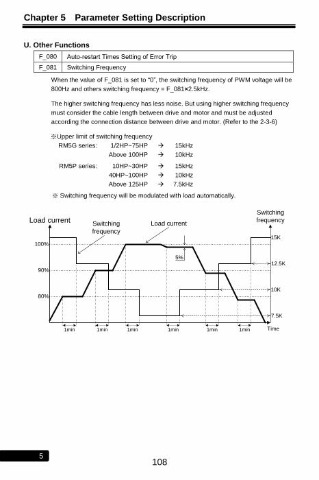
Chapter 5 Parameter Setting Description
108 5
U. Other Functions
F_080 Auto-restart Times Setting of Error Trip
F_081 Switching Frequency
When the value of F_081 is set to ―0‖, the switching frequency of PWM voltage will be
800Hz and others switching frequency = F_081×2.5kHz.
The higher switching frequency has less noise. But using higher switching frequency
must consider the cable length between drive and motor and must be adjusted
according the connection distance between drive and motor. (Refer to the 2-3-6)
※Upper limit of switching frequency
RM5G series: 1/2HP~75HP 15kHz
Above 100HP 10kHz
RM5P series: 10HP~30HP 15kHz
40HP~100HP 10kHz
Above 125HP 7.5kHz
※ Switching frequency will be modulated with load automatically.
1min
Load current
80%
90%
100%
Switching
frequency
15K
12.5K
10K
7.5K
Time
5%
1min 1min 1min 1min 1min
Switching
frequency
Load current
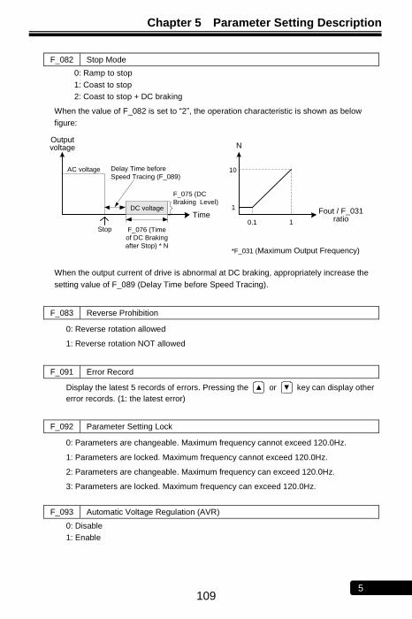
Chapter 5 Parameter Setting Description
109 5
F_082 Stop Mode
0: Ramp to stop
1: Coast to stop
2: Coast to stop + DC braking
When the value of F_082 is set to ―2‖, the operation characteristic is shown as below
figure:
DC voltageTime
Output voltage N
Fout / F_031 ratio0.1 1
F_075 (DC
Braking Level)
Delay Time before
Speed Tracing (F_089)10
1
F_076 (Time
of DC Braking
after Stop) * N
Stop
AC voltage
*F_031 (Maximum Output Frequency)
When the output current of drive is abnormal at DC braking, appropriately increase the
setting value of F_089 (Delay Time before Speed Tracing).
F_083 Reverse Prohibition
0: Reverse rotation allowed
1: Reverse rotation NOT allowed
F_091 Error Record
Display the latest 5 records of errors. Pressing the ▲ or ▼ key can display other
error records. (1: the latest error)
F_092 Parameter Setting Lock
0: Parameters are changeable. Maximum frequency cannot exceed 120.0Hz.
1: Parameters are locked. Maximum frequency cannot exceed 120.0Hz.
2: Parameters are changeable. Maximum frequency can exceed 120.0Hz.
3: Parameters are locked. Maximum frequency can exceed 120.0Hz.
F_093 Automatic Voltage Regulation (AVR)
0: Disable
1: Enable
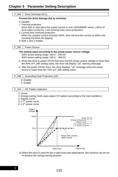
Chapter 5 Parameter Setting Description
110 5
F_094 Drive Overload (OL1)
Prevent the drive damage due to overload.
0: Disable. 1: Thermal protection.
Drive trips to stop when the output current is over 150%(RM5P series: 120%) of drive rated current for 1 min.(inverse time curve protection)
2: Current limit overload protection. When the outuput current exceeds 200%, drive will limit the current to 200% and counting the times for tripping.
3: Both 1 and 2 enable.
F_095 Power Source
The setting value according to the actual power source voltage.
200V series setting range: 190.0 ~ 240.0V; 400V series setting range: 340.0 ~ 480.0V.
a. When the drive is power ON for first time and the power source voltage is lower than the 90% of F_095 setting value, the drive will display ―LE‖ warning message.
b. After the power ON for drive, the drive displays ―LE‖ message when the power source is lower than the 70% of F_095 setting value.
F_098 Grounding Fault Protection (GF)
0: Disable
1: Enable
F_102 V/F Pattern Selection
0: Linear. 1: Energy-saving mode (auto-adjust V/F pattern according to the load condition.) 2: Square curve. 3: 1.7
th power curve.
4: 1.5th power curve.
Base freq.
Output voltage
Output freq.
70%
100%
Below 50% of drive rated current
Linear
Energy saving
Square of 2 curve
Square of 1.7 curve
Square of 1.5 curve
※ When the drive is used for fan or light-duty load applications, this function can be set
to achieve the energy-saving purpose.
Linear Energy-saving mode
Square curve 1.7
th power curve
1.5th power curve
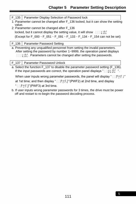
Chapter 5 Parameter Setting Description
111 5
1: Paramerter cannot be changed after F_136 locked, but it can show the setting value.
2: Paramerter cannot be changed after F_136
locked, but it cannot display the setting value, it will show
(Except for F_000、F_051、F_091、F_133、F_134、F_154 can not be set)
a. Preventing any unqualified personnel from setting the invalid parameters. After setting the password by number 1~9999, the operation panel displays
. Parameters cannot be changed after setting the passwords.
a. Select the function F_137 to disable the parameter password setting (F_136).
If the input passwords are correct, the operation panel displays ― ―.
When user inputs wrong parameter passwords, the panel will display ― ‖
at 1st time; and then display ― ‖(PWF2) at 2nd time, and display
― ‖(PWF3) at 3rd time.
b. If user inputs wrong parameter passwords for 3 times, the drive must be power off and restart to re-begin the password decoding process.
F_135 Parameter Display Selection of Password lock
F_136 Parameter Password Setting
F_137 Parameter Passoword Unlock
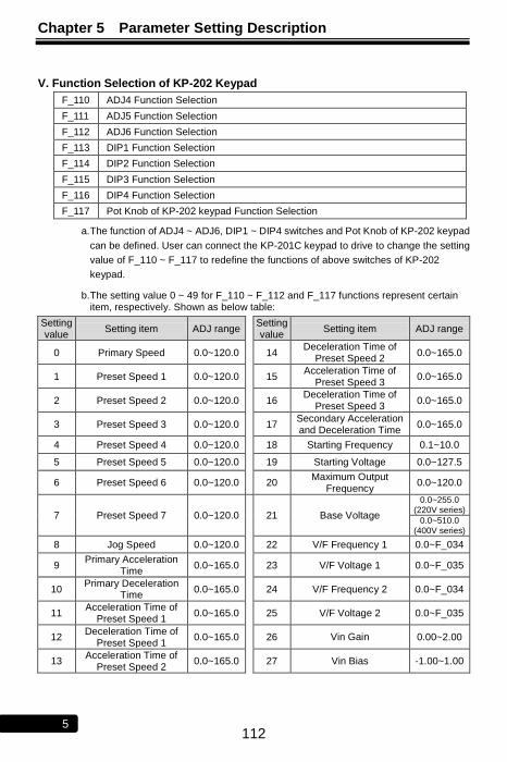
Chapter 5 Parameter Setting Description
112 5
V. Function Selection of KP-202 Keypad
F_110 ADJ4 Function Selection
F_111 ADJ5 Function Selection
F_112 ADJ6 Function Selection
F_113 DIP1 Function Selection
F_114 DIP2 Function Selection
F_115 DIP3 Function Selection
F_116 DIP4 Function Selection
F_117 Pot Knob of KP-202 keypad Function Selection
a. The function of ADJ4 ~ ADJ6, DIP1 ~ DIP4 switches and Pot Knob of KP-202 keypad
can be defined. User can connect the KP-201C keypad to drive to change the setting
value of F_110 ~ F_117 to redefine the functions of above switches of KP-202
keypad.
b. The setting value 0 ~ 49 for F_110 ~ F_112 and F_117 functions represent certain item, respectively. Shown as below table:
Setting value
Setting item ADJ range Setting value
Setting item ADJ range
0 Primary Speed 0.0~120.0 14 Deceleration Time of
Preset Speed 2 0.0~165.0
1 Preset Speed 1 0.0~120.0 15 Acceleration Time of
Preset Speed 3 0.0~165.0
2 Preset Speed 2 0.0~120.0 16 Deceleration Time of
Preset Speed 3 0.0~165.0
3 Preset Speed 3 0.0~120.0 17 Secondary Acceleration and Deceleration Time
0.0~165.0
4 Preset Speed 4 0.0~120.0 18 Starting Frequency 0.1~10.0
5 Preset Speed 5 0.0~120.0 19 Starting Voltage 0.0~127.5
6 Preset Speed 6 0.0~120.0 20 Maximum Output
Frequency 0.0~120.0
7 Preset Speed 7 0.0~120.0 21 Base Voltage
0.0~255.0 (220V series)
0.0~510.0 (400V series)
8 Jog Speed 0.0~120.0 22 V/F Frequency 1 0.0~F_034
9 Primary Acceleration
Time 0.0~165.0 23 V/F Voltage 1 0.0~F_035
10 Primary Deceleration
Time 0.0~165.0 24 V/F Frequency 2 0.0~F_034
11 Acceleration Time of
Preset Speed 1 0.0~165.0 25 V/F Voltage 2 0.0~F_035
12 Deceleration Time of
Preset Speed 1 0.0~165.0 26 Vin Gain 0.00~2.00
13 Acceleration Time of
Preset Speed 2 0.0~165.0 27 Vin Bias -1.00~1.00
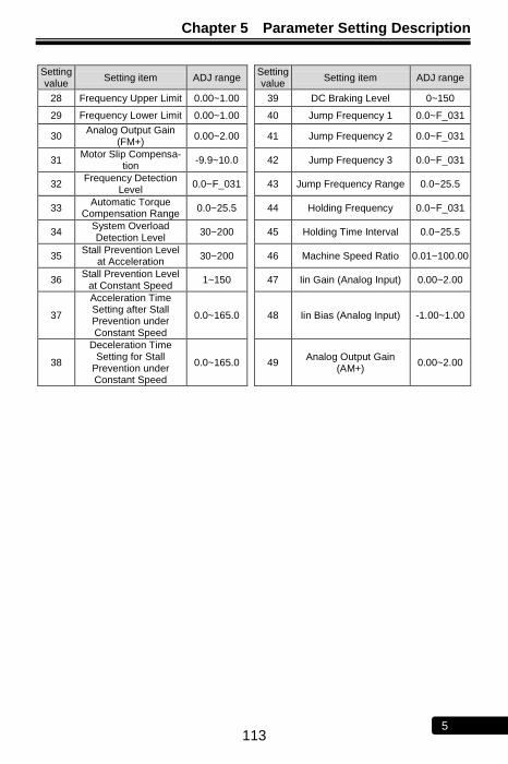
Chapter 5 Parameter Setting Description
113 5
Setting value
Setting item ADJ range Setting value
Setting item ADJ range
28 Frequency Upper Limit 0.00~1.00 39 DC Braking Level 0~150
29 Frequency Lower Limit 0.00~1.00 40 Jump Frequency 1 0.0~F_031
30 Analog Output Gain
(FM+) 0.00~2.00 41 Jump Frequency 2 0.0~F_031
31 Motor Slip Compensa-
tion -9.9~10.0 42 Jump Frequency 3 0.0~F_031
32 Frequency Detection
Level 0.0~F_031 43 Jump Frequency Range 0.0~25.5
33 Automatic Torque
Compensation Range 0.0~25.5 44 Holding Frequency 0.0~F_031
34 System Overload Detection Level
30~200 45 Holding Time Interval 0.0~25.5
35 Stall Prevention Level
at Acceleration 30~200 46 Machine Speed Ratio 0.01~100.00
36 Stall Prevention Level
at Constant Speed 1~150 47 Iin Gain (Analog Input) 0.00~2.00
37
Acceleration Time Setting after Stall Prevention under Constant Speed
0.0~165.0 48 Iin Bias (Analog Input) -1.00~1.00
38
Deceleration Time Setting for Stall
Prevention under Constant Speed
0.0~165.0 49 Analog Output Gain
(AM+) 0.00~2.00
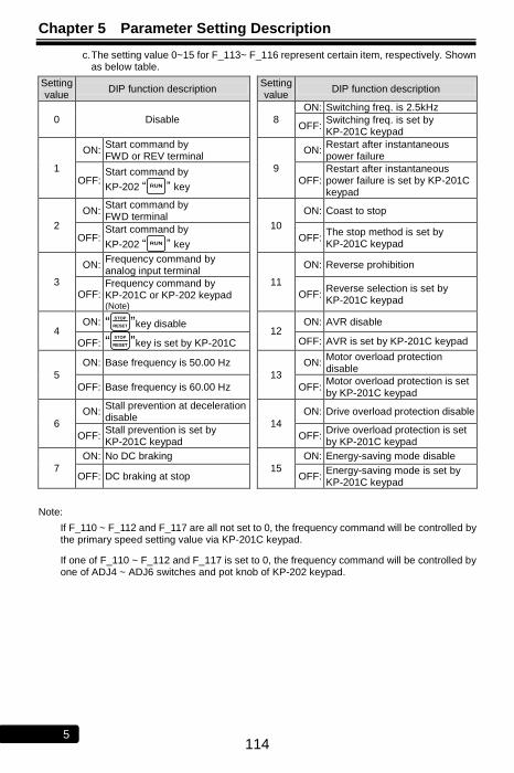
Chapter 5 Parameter Setting Description
114 5
c. The setting value 0~15 for F_113~ F_116 represent certain item, respectively. Shown as below table.
Setting value
DIP function description Setting value
DIP function description
0 Disable 8
ON: Switching freq. is 2.5kHz
OFF: Switching freq. is set by KP-201C keypad
1
ON: Start command by FWD or REV terminal
9
ON: Restart after instantaneous power failure
OFF: Start command by
KP-202 ― RUN ‖ key OFF:
Restart after instantaneous power failure is set by KP-201C keypad
2
ON: Start command by FWD terminal
10
ON: Coast to stop
OFF: Start command by
KP-202 ― RUN ‖ key OFF:
The stop method is set by KP-201C keypad
3
ON: Frequency command by analog input terminal
11
ON: Reverse prohibition
OFF: Frequency command by KP-201C or KP-202 keypad
(Note) OFF:
Reverse selection is set by KP-201C keypad
4 ON: ―
STOP
RESET ‖key disable 12
ON: AVR disable
OFF: ―STOP
RESET ‖key is set by KP-201C OFF: AVR is set by KP-201C keypad
5
ON: Base frequency is 50.00 Hz
13
ON: Motor overload protection disable
OFF: Base frequency is 60.00 Hz OFF: Motor overload protection is set by KP-201C keypad
6
ON: Stall prevention at deceleration disable
14
ON: Drive overload protection disable
OFF: Stall prevention is set by KP-201C keypad
OFF: Drive overload protection is set by KP-201C keypad
7
ON: No DC braking
15
ON: Energy-saving mode disable
OFF: DC braking at stop OFF: Energy-saving mode is set by KP-201C keypad
Note:
If F_110 ~ F_112 and F_117 are all not set to 0, the frequency command will be controlled by the primary speed setting value via KP-201C keypad.
If one of F_110 ~ F_112 and F_117 is set to 0, the frequency command will be controlled by one of ADJ4 ~ ADJ6 switches and pot knob of KP-202 keypad.

Chapter 5 Parameter Setting Description
115 5
No Text on This Page
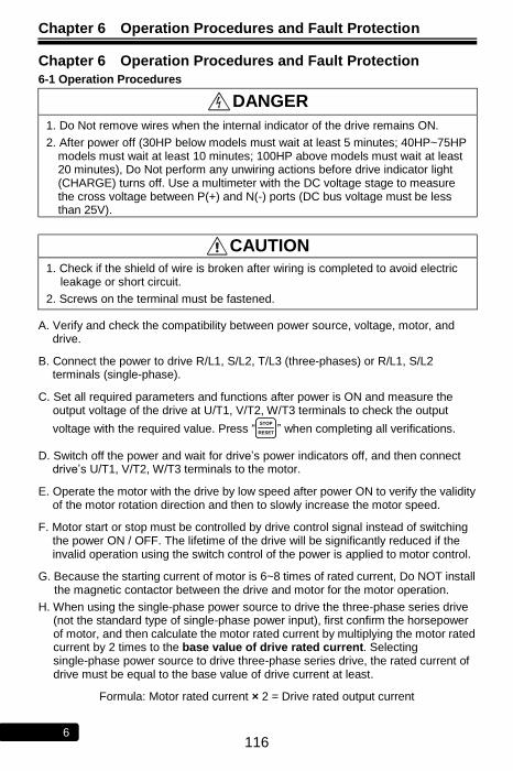
Chapter 6 Operation Procedures and Fault Protection
116 6
Chapter 6 Operation Procedures and Fault Protection
6-1 Operation Procedures
DANGER 1. Do Not remove wires when the internal indicator of the drive remains ON.
2. After power off (30HP below models must wait at least 5 minutes; 40HP~75HP models must wait at least 10 minutes; 100HP above models must wait at least 20 minutes), Do Not perform any unwiring actions before drive indicator light (CHARGE) turns off. Use a multimeter with the DC voltage stage to measure the cross voltage between P(+) and N(-) ports (DC bus voltage must be less than 25V).
CAUTION 1. Check if the shield of wire is broken after wiring is completed to avoid electric
leakage or short circuit.
2. Screws on the terminal must be fastened.
A. Verify and check the compatibility between power source, voltage, motor, and drive.
B. Connect the power to drive R/L1, S/L2, T/L3 (three-phases) or R/L1, S/L2 terminals (single-phase).
C. Set all required parameters and functions after power is ON and measure the output voltage of the drive at U/T1, V/T2, W/T3 terminals to check the output
voltage with the required value. Press ―STOP
RESET ‖ when completing all verifications.
D. Switch off the power and wait for drive’s power indicators off, and then connect drive’s U/T1, V/T2, W/T3 terminals to the motor.
E. Operate the motor with the drive by low speed after power ON to verify the validity of the motor rotation direction and then to slowly increase the motor speed.
F. Motor start or stop must be controlled by drive control signal instead of switching the power ON / OFF. The lifetime of the drive will be significantly reduced if the invalid operation using the switch control of the power is applied to motor control.
G. Because the starting current of motor is 6~8 times of rated current, Do NOT install the magnetic contactor between the drive and motor for the motor operation.
H. When using the single-phase power source to drive the three-phase series drive (not the standard type of single-phase power input), first confirm the horsepower of motor, and then calculate the motor rated current by multiplying the motor rated current by 2 times to the base value of drive rated current. Selecting single-phase power source to drive three-phase series drive, the rated current of drive must be equal to the base value of drive current at least.
Formula: Motor rated current × 2 = Drive rated output current

Chapter 6 Operation Procedures and Fault Protection
117 6
Example:
a. Drive selection:
Motor specification: 220Vac, 1HP ; Rated current: 3.1A
Base value of drive rated current =3.1 (A) × 2 times = 6.2 (A)
Drive specifications: 220Vac, 1HP drive = 5A (rated output current) 2HP drive = 8A (rated output current)
Select 2HP drive for 1HP AC motor. b. Connect the single-phase power line to R/L1, S/L2 terminals. c. Parameter settings:
Please reset below functions. If the parameters are not modified, the motor and drive could be possibly damaged.
F_048 Motor Rated Current = 3.1A (the setting must be based on the motor rated current)
F_068 System Overload Detection Level = 80 (the half of the default setting value 160%)
F_071 Stall Prevention Level at Constant Speed = 80 (the half of the default setting value 160%)

Chapter 6 Operation Procedures and Fault Protection
118 6
6-2 Fault Protection Display and Troubleshooting
a: Description: The drive has well protection functions to protect drive and motor when faults occur. When the fault occurs, the drive trips by the protection functions and display fault message on keypad. After the fault is troubleshooting, reset the
drive by pressing STOP
RESET of keypad or commanding the drive to reset through
multi-function input terminals by external reset signal
b: Protection and Troubleshooting List:
Error Trip Messages of Drive
Display Description Cause Troubleshooting
(EEr) KEYPAD
Hz V A
EEPROM error ●EEPROM data write fault.
●EEPROM component defected.
●Please restore the parameter to the default values and reset the drive.
●Return the drive to repair, when the fault cannot be eliminated.
(AdEr) KEYPAD
Hz V A
A/D converter error
--- Please call customer service for drive repair.
(SC) KEYPAD
Hz V A
Fuse open ●Drive internal fuse open.
●IGBT power module damage.
Please call customer service for drive repair.
(LE1) KEYPAD
Hz V A
Under voltage during operation
The internal DC bus voltage level is below 70%.
●Phase failure of input power.
●Instantaneous power off.
●Voltage variation of power source is too high.
●The equipment instantaneous overload causing the high voltage drop at power source.
Increase the power capacity.

Chapter 6 Operation Procedures and Fault Protection
119 6
Error Trip Messages of Drive
Display Description Cause Troubleshooting
(OC) KEYPAD
Hz V A
Drive over current
The output current of drive during operation exceeds 220% of drive’s rated current.
●The output terminals of drive are short.
●The load is too heavy.
●The acceleration time is too short.
●Drive starts running from zero speed when the motor is under rotation condition.
●Wrong wiring or improper insulation value of motor.
●Starting voltage is too high.
●Power factor leading capacitor or filtering capacitor is conntected on
motor terminal.
●Check wires of U/T1,V/T2,W/T3 terminals to verify if there is short between terminals.
●Check the motor and drive compatibility.
●Check if the motor operated in over-rated condition.
●Check the setting of acceleration time.
(GF) KEYPAD
Hz V A
Grounding fault ●The output
terminal of drive is grounding and the grounding current exceeds the 70% of drive’s rated current.
●Grounding fault protection: F_098
The insulation value of motor or motor’s wire is improer.
Check the insulation value of motor and the shield of motor’s wire.
(OE) KEYPAD
Hz V A
Over voltage ●The internal DC
bus voltage of drive is over the protection level.
●100V / 200V series: About DC410V.
●400V series: About DC820V.
●The deceleration time of motor is too short causing the regeneration on DC bus voltage too high.
●Power source voltage is too high.
●Surge voltage conduct in drive’s input power side.
●Increase the value of ―deceleration time‖.
●Add dynamic brake unit.
●Check if the input power is within drive’s rated input range.
●Add AC relactor at power input site.
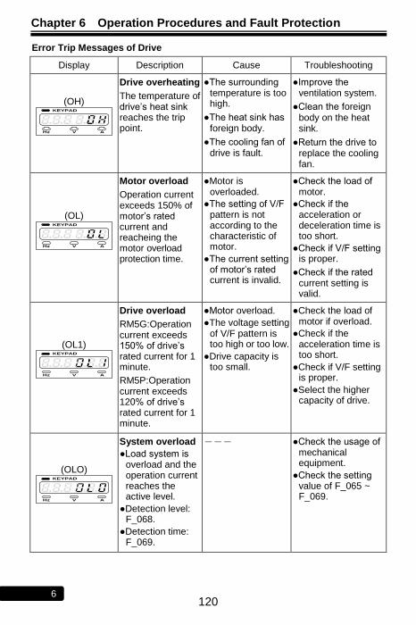
Chapter 6 Operation Procedures and Fault Protection
120 6
Error Trip Messages of Drive
Display Description Cause Troubleshooting
(OH) KEYPAD
Hz V A
Drive overheating
The temperature of drive’s heat sink reaches the trip point.
●The surrounding temperature is too high.
●The heat sink has foreign body.
●The cooling fan of drive is fault.
●Improve the ventilation system.
●Clean the foreign body on the heat sink.
●Return the drive to replace the cooling fan.
(OL) KEYPAD
Hz V A
Motor overload
Operation current exceeds 150% of motor’s rated current and reacheing the motor overload protection time.
●Motor is overloaded.
●The setting of V/F pattern is not according to the characteristic of motor.
●The current setting of motor’s rated current is invalid.
●Check the load of motor.
●Check if the acceleration or deceleration time is too short.
●Check if V/F setting is proper.
●Check if the rated current setting is valid.
(OL1) KEYPAD
Hz V A
Drive overload
RM5G:Operation current exceeds 150% of drive’s rated current for 1 minute.
RM5P:Operation current exceeds 120% of drive’s rated current for 1 minute.
●Motor overload.
●The voltage setting of V/F pattern is too high or too low.
●Drive capacity is too small.
●Check the load of motor if overload.
●Check if the acceleration time is too short.
●Check if V/F setting is proper.
●Select the higher capacity of drive.
(OLO) KEYPAD
Hz V A
System overload
●Load system is overload and the operation current reaches the active level.
●Detection level: F_068.
●Detection time: F_069.
--- ●Check the usage of mechanical equipment.
●Check the setting value of F_065 ~ F_069.
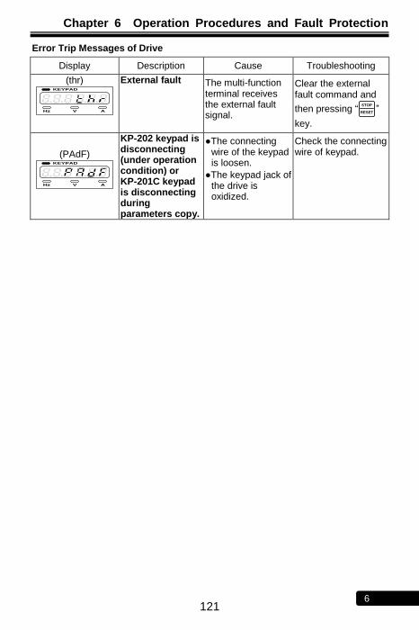
Chapter 6 Operation Procedures and Fault Protection
121 6
Error Trip Messages of Drive
Display Description Cause Troubleshooting
(thr) KEYPAD
Hz V A
External fault The multi-function terminal receives the external fault signal.
Clear the external fault command and
then pressing ―STOP
RESET ‖
key.
(PAdF) KEYPAD
Hz V A
KP-202 keypad is disconnecting (under operation condition) or KP-201C keypad is disconnecting during parameters copy.
●The connecting wire of the keypad is loosen.
●The keypad jack of the drive is oxidized.
Check the connecting wire of keypad.
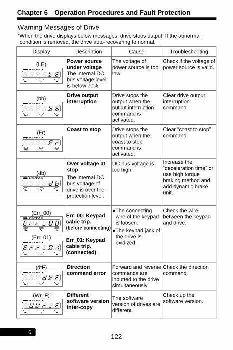
Chapter 6 Operation Procedures and Fault Protection
122 6
Warning Messages of Drive
*When the drive displays below messages, drive stops output. If the abnormal condition is removed, the drive auto-recovering to normal.
Display Description Cause Troubleshooting
(LE) KEYPAD
Hz V A
Power source under voltage The internal DC bus voltage level is below 70%.
The voltage of power source is too low.
Check if the voltage of power source is valid.
(bb) KEYPAD
Hz V A
Drive output interruption
Drive stops the output when the output interruption command is activated.
Clear drive output interruption command.
(Fr) KEYPAD
Hz V A
Coast to stop Drive stops the output when the coast to stop command is activated.
Clear ―coast to stop‖ command.
(db) KEYPAD
Hz V A
Over voltage at stop
The internal DC bus voltage of drive is over the protection level.
DC bus voltage is too high.
Increase the ―deceleration time‖ or use high torque braking method and add dynamic brake unit.
(Err_00) KEYPAD
Hz V A (Err_01)
KEYPAD
Hz V A
Err_00: Keypad cable trip. (before connecting) Err_01: Keypad cable trip. (connected)
●The connecting wire of the keypad is loosen.
●The keypad jack of the drive is oxidized.
Check the wire between the keypad and drive.
(dtF) KEYPAD
Hz V A
Direction command error
Forward and reverse commands are inputted to the drive simultaneously
Check the direction command.
(Wr_F) KEYPAD
Hz V A
Different software version inter-copy
The software version of drives are different.
Check up the software version.
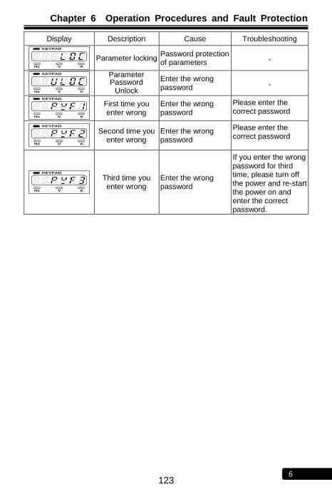
Chapter 6 Operation Procedures and Fault Protection
123 6
Display Description Cause Troubleshooting KEYPAD
Hz V A
Parameter locking Password protection of parameters -
KEYPAD
Hz V A
Parameter Password
Unlock
Enter the wrong password -
KEYPAD
Hz V A
First time you enter wrong
Enter the wrong password
Please enter the correct password
KEYPAD
Hz V A
Second time you enter wrong
Enter the wrong password
Please enter the correct password
KEYPAD
Hz V A
Third time you enter wrong
Enter the wrong password
If you enter the wrong password for third time, please turn off the power and re-start the power on and enter the correct password.

Chapter 6 Operation Procedures and Fault Protection
124 6
No Text on This Page
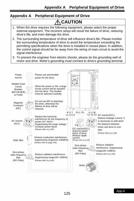
Appendix A Peripheral Equipment of Drive
125 App.A
Appendix A Peripheral Equipment of Drive
CAUTION 1. When the drive requires the following equipment, please select the proper
external equipment. The incorrect setup will result the failure of drive, reducing drive’s life, and even damage the drive.
2. The surrounding temperature of drive will influence drive’s life. Please monitor the surrounding temperature of drive to avoid the temperature exceeding the permitting specifications when the drive is installed in closed place. In addition, the control signal should be far away from the wiring of main circuit to avoid the signal interference.
3. To prevent the engineer from electric shocks, please do the grounding well of motor and drive. Motor’s grounding must connect to drive’s grounding terminal.
Molded Case
Circuit
Breaker
(MCCB;NFB)
or FUSE
Magnetic
Contactor
(MC)
AC reactor
(ACL)
EMC filter
Zero-phase
radio frequency
filter
(RFI Filter)
Power
source
Please use permissible
power for the drive.
When the power is ON, a large inrush current will be inputted into the drive. The breaker must be selected carefully.
Do not use MC to start/stop the drive, otherwise the lifetime of drive will be reduced.
Reduce the harmonic interference for low frequency of power.(10~1kHz); Suppressing the surge voltage;Increase power factor(Please refer to p.135)
Reduce conduction interference. Suppressing range(1M~100MHz)(Please refer to page 144)
Reduce radiation interference.
Suppressing range(1M~10MHz)
(Please refer to p.140)
R S TL1 L2 L3
U V WT1 T2 T3
P(+) P1
DC reactor(DCL) Improve power factor of drive.Reduce ripple current(Please refer to p.135)
AC reactor(ACL)
Reduce leakage current. It
is necessary to add when
the distance between
motor and drive is over
30m
(Please refer to p.135)
Reduce radiation
interference. Suppressing
range(1M~10MHz)
(Please refer to p.140)
Motor
Zero-phase
radio frequency
filter
(RFI Filter)
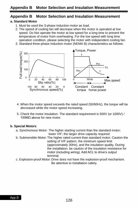
Appendix B Motor Selection and Insulation Measurement
126 App.B
Appendix B Motor Selection and Insulation Measurement
a. Standard Motor
1. Must be used the 3-phase induction motor as load. 2. The speed of cooling fan will decrease when the motor is operated at low
speed. Do Not operate the motor at low speed for a long time to prevent the temperature of motor from overheating. For the low speed with long time operation condition, please selecting the motor with independent cooling fan.
3. Standard three-phase induction motor (NEMA B) characteristics as follows:
4. When the motor speed exceeds the rated speed (50/60Hz), the torque will be decreased while the motor speed increasing.
5. Check the motor insulation. The standard requirement is 500V (or 1000V) / 100MΩ above for new motor.
b. Special Motors
a. Synchronous Motor: The higher starting current than the standard motor; lower V/F; the larger drive capacity required.
b. Submersible Motor: The higher rated current than standard motor; Caution the setting of V/F pattern, the minimum speed limit (approximately 30Hz), and the insulation quality. During the installation, be caution of the insulation resistance for motor (including wiring). Add ACL to drive’s output terminal.
c. Explosion-proof Motor: Drive does not have the explosion-proof mechanism. Be attentive to installation safety.

Appendix B Motor Selection and Insulation Measurement
127 App.B
c. Insulation Measurement of Drive and Motor
1. Measure the drive insulation impedance
1.) Please be extremely caution to following steps to test the main circuit insulation of drive. Any incaution operations while testing the drive insulation may possibly harm operating personnel and cause serious damages to drive.
2.) Remove all wiring at main circuit terminal and control circuit terminal before the testing is performed. Please follow the below diagram to wire all power terminals in parallel with an insulation tester for drive insulation test.
3.) Using an insulation tester with DC500V to test the insulation value of drive. The drive insulation impedance must be greater than 20MΩ. If drive insulation impedance is below 20MΩ, replace a drive and contact the customer support for repair service of drive.
Insulation
tester
Drive
Drive Insulation Impedance Measurement
2. Measure the motor insulation impedance
a. Remove the cables of motor from U/T1, V/T2, W/T3 terminals of drive before measuring the motor insulation impedance, and then measure the motor insulation impedance (including motor cables) using the insulation tester with DC500V. The motor insulation impedance (including motor cables) must be greater than 20MΩ when connecting to the drive.
b. If motor insulation impedance is less than 20MΩ, Do Not connect motor with a drive or the drive lifetime may be shorten or the drive may be possibly damaged due to insufficient motor insulation.
c. Please follow the below connection diagram for motor insulation test. Motor cables must be connected in parallel to the insulation tester with DC500V to test the insulation, and the motor insulation impedance must be greater than 20MΩ to connect the drive.
Insulation
tester Motor
Motor
cable
Motor Insulation Impedance Measurement (including motor cables)
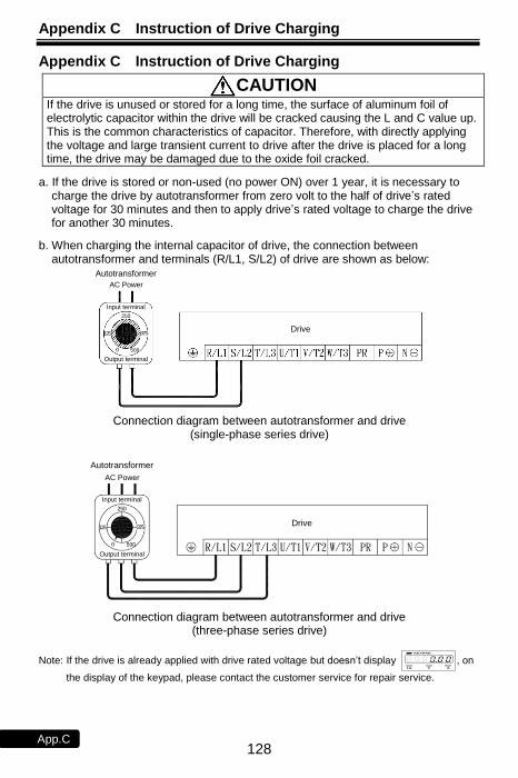
Appendix C Instruction of Drive Charging
128 App.C
Appendix C Instruction of Drive Charging
CAUTION
If the drive is unused or stored for a long time, the surface of aluminum foil of electrolytic capacitor within the drive will be cracked causing the L and C value up. This is the common characteristics of capacitor. Therefore, with directly applying the voltage and large transient current to drive after the drive is placed for a long time, the drive may be damaged due to the oxide foil cracked.
a. If the drive is stored or non-used (no power ON) over 1 year, it is necessary to charge the drive by autotransformer from zero volt to the half of drive’s rated voltage for 30 minutes and then to apply drive’s rated voltage to charge the drive for another 30 minutes.
b. When charging the internal capacitor of drive, the connection between autotransformer and terminals (R/L1, S/L2) of drive are shown as below:
Autotransformer
AC Power
0
375125Drive
500
Output terminal
Input terminal
250
Connection diagram between autotransformer and drive
(single-phase series drive)
Autotransformer
AC Power
0
375125Drive
500
Output terminal
Input terminal
250
Connection diagram between autotransformer and drive
(three-phase series drive)
Note: If the drive is already applied with drive rated voltage but doesn’t display KEYPAD
Hz V A
, on
the display of the keypad, please contact the customer service for repair service.
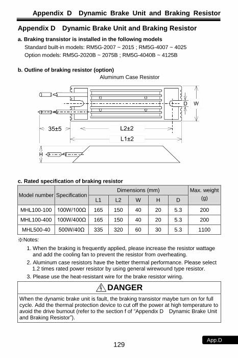
Appendix D Dynamic Brake Unit and Braking Resistor
129 App.D
Appendix D Dynamic Brake Unit and Braking Resistor
a. Braking transistor is installed in the following models
Standard built-in models: RM5G-2007 ~ 2015 ; RM5G-4007 ~ 4025
Option models: RM5G-2020B ~ 2075B ; RM5G-4040B ~ 4125B
b. Outline of braking resistor (option)
Aluminum Case Resistor
c. Rated specification of braking resistor
Model number Specification Dimensions (mm) Max. weight
(g) L1 L2 W H D
MHL100-100 100W/100Ω 165 150 40 20 5.3 200
MHL100-400 100W/400Ω 165 150 40 20 5.3 200
MHL500-40 500W/40Ω 335 320 60 30 5.3 1100
※Notes:
1. When the braking is frequently applied, please increase the resistor wattage and add the cooling fan to prevent the resistor from overheating.
2. Aluminum case resistors have the better thermal performance. Please select 1.2 times rated power resistor by using general wirewound type resistor.
3. Please use the heat-resistant wire for the brake resistor wiring.
DANGER When the dynamic brake unit is fault, the braking transistor maybe turn on for full cycle. Add the thermal protection device to cut off the power at high temperature to avoid the drive burnout (refer to the section f of ―Appendix D Dynamic Brake Unit and Braking Resistor‖).
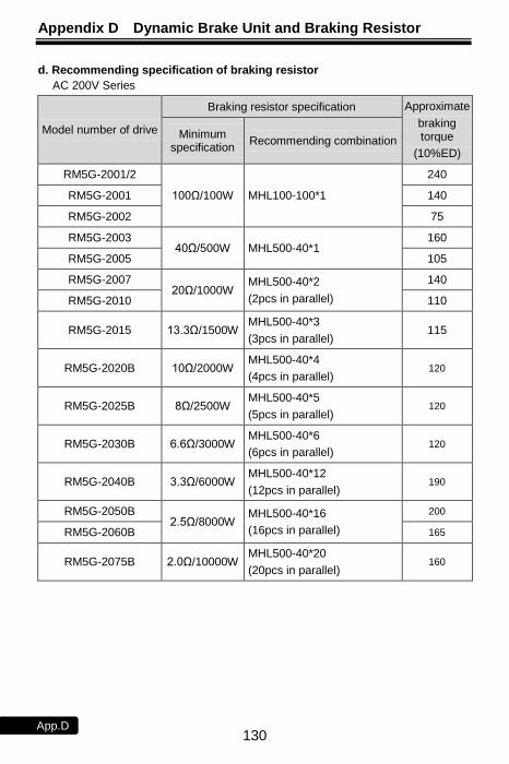
Appendix D Dynamic Brake Unit and Braking Resistor
130 App.D
d. Recommending specification of braking resistor
AC 200V Series
Model number of drive
Braking resistor specification Approximate
braking torque
(10%ED)
Minimum specification
Recommending combination
RM5G-2001/2
100Ω/100W MHL100-100*1
240
RM5G-2001 140
RM5G-2002 75
RM5G-2003 40Ω/500W MHL500-40*1
160
RM5G-2005 105
RM5G-2007 20Ω/1000W
MHL500-40*2
(2pcs in parallel)
140
RM5G-2010 110
RM5G-2015 13.3Ω/1500W MHL500-40*3
(3pcs in parallel) 115
RM5G-2020B 10Ω/2000W MHL500-40*4
(4pcs in parallel) 120
RM5G-2025B 8Ω/2500W MHL500-40*5
(5pcs in parallel) 120
RM5G-2030B 6.6Ω/3000W MHL500-40*6
(6pcs in parallel) 120
RM5G-2040B 3.3Ω/6000W MHL500-40*12
(12pcs in parallel) 190
RM5G-2050B 2.5Ω/8000W
MHL500-40*16
(16pcs in parallel)
200
RM5G-2060B 165
RM5G-2075B 2.0Ω/10000W MHL500-40*20
(20pcs in parallel) 160
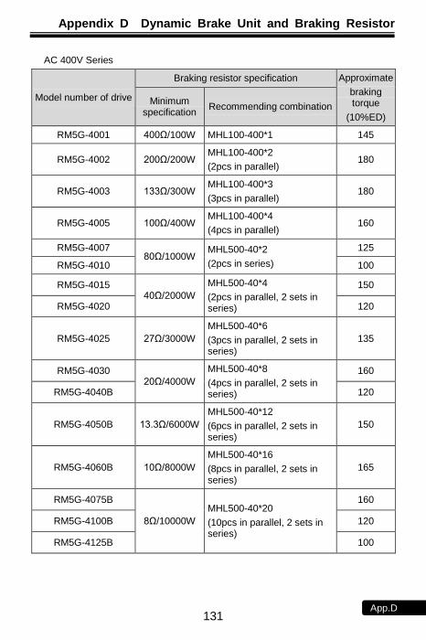
Appendix D Dynamic Brake Unit and Braking Resistor
131 App.D
AC 400V Series
Model number of drive
Braking resistor specification Approximate
braking torque
(10%ED)
Minimum specification
Recommending combination
RM5G-4001 400Ω/100W MHL100-400*1 145
RM5G-4002 200Ω/200W MHL100-400*2
(2pcs in parallel) 180
RM5G-4003 133Ω/300W MHL100-400*3
(3pcs in parallel) 180
RM5G-4005 100Ω/400W MHL100-400*4
(4pcs in parallel) 160
RM5G-4007 80Ω/1000W
MHL500-40*2
(2pcs in series)
125
RM5G-4010 100
RM5G-4015 40Ω/2000W
MHL500-40*4
(2pcs in parallel, 2 sets in series)
150
RM5G-4020 120
RM5G-4025 27Ω/3000W
MHL500-40*6
(3pcs in parallel, 2 sets in series)
135
RM5G-4030 20Ω/4000W
MHL500-40*8
(4pcs in parallel, 2 sets in series)
160
RM5G-4040B 120
RM5G-4050B 13.3Ω/6000W
MHL500-40*12
(6pcs in parallel, 2 sets in series)
150
RM5G-4060B 10Ω/8000W
MHL500-40*16
(8pcs in parallel, 2 sets in series)
165
RM5G-4075B
8Ω/10000W
MHL500-40*20
(10pcs in parallel, 2 sets in series)
160
RM5G-4100B 120
RM5G-4125B 100
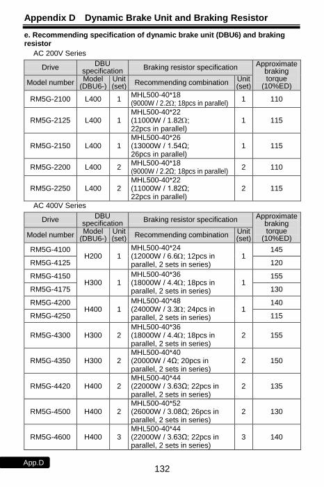
Appendix D Dynamic Brake Unit and Braking Resistor
132 App.D
e. Recommending specification of dynamic brake unit (DBU6) and braking resistor
AC 200V Series
Drive DBU
specification Braking resistor specification Approximate
braking torque
(10%ED) Model number
Model (DBU6-)
Unit (set)
Recommending combination Unit (set)
RM5G-2100 L400 1 MHL500-40*18 (9000W / 2.2; 18pcs in parallel)
1 110
RM5G-2125 L400 1 MHL500-40*22 (11000W / 1.82; 22pcs in parallel)
1 115
RM5G-2150 L400 1 MHL500-40*26 (13000W / 1.54Ω; 26pcs in parallel)
1 115
RM5G-2200 L400 2 MHL500-40*18 (9000W / 2.2Ω; 18pcs in parallel)
2 110
RM5G-2250 L400 2 MHL500-40*22 (11000W / 1.82Ω; 22pcs in parallel)
2 115
AC 400V Series
Drive DBU
specification Braking resistor specification Approximate
braking torque
(10%ED) Model number Model
(DBU6-) Unit (set)
Recommending combination Unit (set)
RM5G-4100 H200 1
MHL500-40*24 (12000W / 6.6; 12pcs in parallel, 2 sets in series)
1 145
RM5G-4125 120
RM5G-4150 H300 1
MHL500-40*36 (18000W / 4.4; 18pcs in parallel, 2 sets in series)
1 155
RM5G-4175 130
RM5G-4200 H400 1
MHL500-40*48 (24000W / 3.3; 24pcs in parallel, 2 sets in series)
1 140
RM5G-4250 115
RM5G-4300 H300 2 MHL500-40*36 (18000W / 4.4; 18pcs in parallel, 2 sets in series)
2 155
RM5G-4350 H300 2 MHL500-40*40 (20000W / 4Ω; 20pcs in parallel, 2 sets in series)
2 150
RM5G-4420 H400 2 MHL500-40*44 (22000W / 3.63Ω; 22pcs in parallel, 2 sets in series)
2 135
RM5G-4500 H400 2 MHL500-40*52 (26000W / 3.08Ω; 26pcs in parallel, 2 sets in series)
2 130
RM5G-4600 H400 3 MHL500-40*44 (22000W / 3.63Ω; 22pcs in parallel, 2 sets in series)
3 140
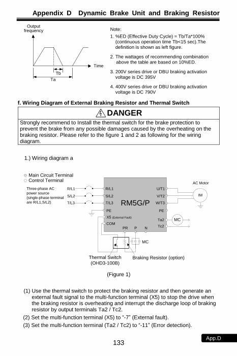
Appendix D Dynamic Brake Unit and Braking Resistor
133 App.D
Time
Output frequency
Tb
Ta f. Wiring Diagram of External Braking Resistor and Thermal Switch
DANGER Strongly recommend to Install the thermal switch for the brake protection to prevent the brake from any possible damages caused by the overheating on the braking resistor. Please refer to the figure 1 and 2 as following for the wiring diagram.
1.) Wiring diagram a
RM5G/P
IM
Tc2
Ta2
R/L1
S/L2
T/L3 W/T3
V/T2
PE
U/T1
PR P N
Main Circuit TerminalControl Terminal
PE
R/L1
S/L2
T/L3
MCX5 (External Fault)
COM
MC
Braking Resistor (option)
Three-phase AC
power source
(single-phase terminal
are R/L1,S/L2)
Thermal Switch
(OHD3-100B)
AC Motor
(Figure 1)
(1) Use the thermal switch to protect the braking resistor and then generate an external fault signal to the multi-function terminal (X5) to stop the drive when the braking resistor is overheating and interrupt the discharge loop of braking resistor by output terminals Ta2 / Tc2.
(2) Set the multi-function terminal (X5) to ―-7‖ (External fault).
(3) Set the multi-function terminal (Ta2 / Tc2) to ―-11‖ (Error detection).
Note:
1. %ED (Effective Duty Cycle) = Tb/Ta*100% (continuous operation time Tb<15 sec).The definition is shown as left figure.
2. The wattages of recommending combination above the table are based on 10%ED.
3. 200V series drive or DBU braking activation voltage is DC 395V
4. 400V series drive or DBU braking activation voltage is DC 790V
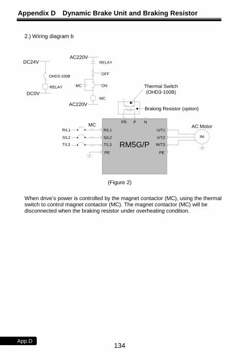
Appendix D Dynamic Brake Unit and Braking Resistor
134 App.D
2.) Wiring diagram b
RM5G/P
IM
R/L1
S/L2
T/L3 W/T3
V/T2
PE
U/T1
PR P N
AC Motor
PE
Braking Resistor (option)
R/L1
S/L2
T/L3
MC
RELAY
OFF
ON
MC
MC
AC220V
AC220V
RELAY
DC24V
DC0V
Thermal Switch
(OHD3-100B)
OHD3-100B
(Figure 2)
When drive’s power is controlled by the magnet contactor (MC), using the thermal switch to control magnet contactor (MC). The magnet contactor (MC) will be disconnected when the braking resistor under overheating condition.
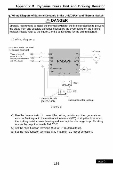
Appendix D Dynamic Brake Unit and Braking Resistor
135 App.D
g. Wiring Diagram of External Dynamic Brake Unit(DBU6) and Thermal Switch
DANGER Strongly recommend to install the thermal switch for the brake protection to prevent the brake from any possible damages caused by the overheating on the braking resistor. Please refer to the figure 1 and 2 as following for the wiring diagram.
1.) Wiring diagram a
RM5G/P
IM
Tc2
Ta2
R/L1
S/L2
T/L3 W/T3
V/T2
PE
U/T1
PR P N
Main Circuit TerminalControl Terminal
PE
R/L1
S/L2
T/L3
MCX5 (External Fault)
COM
Braking Resistor (option)
Three-phase AC
power source
(single-phase terminal
are R/L1,S/L2)
AC Motor
P N
RB1 RB2
MC
DBU6
Thermal Switch
(OHD3-100B)
(Figure 1)
(1) Use the thermal switch to protect the braking resistor and then generate an external fault signal to the multi-function terminal (X5) to stop the drive when the braking resistor is overheating and interrupt the discharge loop of braking resistor by output terminals Ta2 / Tc2.
(2) Set the multi-function terminals (X5) to ―-7‖ (External fault).
(3) Set the multi-function terminals (Ta2 / Tc2) to ―-11‖ (Error detection).
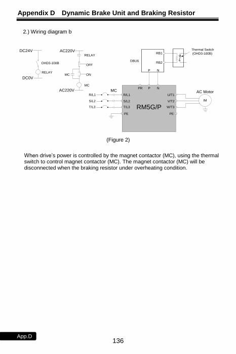
Appendix D Dynamic Brake Unit and Braking Resistor
136 App.D
2.) Wiring diagram b
P N
RB1
RB2DBU6
Thermal Switch
(OHD3-100B)
RM5G/P
IM
R/L1
S/L2
T/L3 W/T3
V/T2
PE
U/T1
PR P N
AC Motor
PE
R/L1
S/L2
T/L3
MC
RELAY
OFF
ON
MC
MC
AC220V
AC220V
RELAY
DC24V
DC0V
OHD3-100B
(Figure 2)
When drive’s power is controlled by the magnet contactor (MC), using the thermal switch to control magnet contactor (MC). The magnet contactor (MC) will be disconnected when the braking resistor under overheating condition.
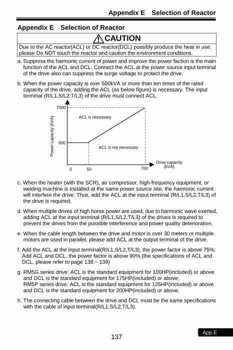
Appendix E Selection of Reactor
137 App.E
Appendix E Selection of Reactor
CAUTION Due to the AC reactor(ACL) or DC reactor(DCL) possibly produce the heat in use, please Do NOT touch the reactor and caution the environment conditions.
a. Suppress the harmonic current of power and improve the power faction is the main function of the ACL and DCL. Connect the ACL at the power source input terminal of the drive also can suppress the surge voltage to protect the drive.
b. When the power capacity is over 500kVA or more than ten times of the rated capacity of the drive, adding the ACL (as below figure) is necessary. The input terminal (R/L1,S/L2,T/L3) of the drive must connect ACL.
Drive capacity(kVA)
ACL is necessary
7000
500
Po
we
r ca
pa
city (
kV
A)
0 50 700
ACL is not necessary
c. When the heater (with the SCR), air compressor, high-frequency equipment, or welding machine is installed at the same power source site, the harmonic current will interfere the drive. Thus, add the ACL at the input terminal (R/L1,S/L2,T/L3) of the drive is required.
d. When multiple drives of high horse power are used, due to harmonic wave exerted, adding ACL at the input terminal (R/L1,S/L2,T/L3) of the drives is required to prevent the drives from the possible interference and power quality deterioration.
e. When the cable length between the drive and motor is over 30 meters or multiple motors are used in parallel, please add ACL at the output terminal of the drive.
f. Add the ACL at the input terminal(R/L1,S/L2,T/L3), the power factor is above 75%; Add ACL and DCL, the power factor is above 90%.(the specifications of ACL and DCL, please refer to page 138 ~ 139)
g. RM5G series drive: ACL is the standard equipment for 100HP(included) or above and DCL is the standard equipment for 175HP(included) or above; RM5P series drive: ACL is the standard equipment for 125HP(included) or above and DCL is the standard equipment for 200HP(included) or above.
h. The connecting cable between the drive and DCL must be the same specifications with the cable of input terminal(R/L1,S/L2,T/L3).

Appendix E Selection of Reactor
138 App.E
AC Reactor (ACL) Specifications
Drive model number
Input
(R/L1,S/L2,T/L3)
Output
(U/T1,V/T2,W/T3) Drive model
number
Input
(R/L1,S/L2,T/L3)
Output
(U/T1,V/T2,W/T3)
(mH) (A) (mH) (A) (mH) (A) (mH) (A)
RM5G-2001/2 0.45 15 0.45 15 RM5G-4001 0.45 15 0.45 15
RM5G-2001 0.45 15 0.45 15 RM5G-4002 0.45 15 0.45 15
RM5G-2002 0.45 15 0.45 15 RM5G-4003 0.45 15 0.45 15
RM5G-2003 0.45 15 0.45 15 RM5G-4005 0.45 15 0.45 15
RM5G-2005 0.2 30 0.2 30 RM5G-4007 0.2 30 0.2 30
RM5G-2007 0.2 30 0.13 50 RM5G-4010 0.2 30 0.2 30
RM5G-2010 0.13 50 0.13 50 RM5G-4015 0.2 30 0 .13 50
RM5G-2015 0.13 50 0.07 75 RM5G-4020 0.13 50 0 .13 50
RM5G-2020 0.07 75 0.05 100 RM5G-4025 0.13 50 0.13 50
RM5G-2025 0.05 100 0.05 100 RM5G-4030 0.13 50 0.07 75
RM5G-2030 0.05 100 0.035 150 RM5G-4040 0.07 75 0.05 100
RM5G-2040 0.035 150 0.025 200 RM5G-4050 0.05 100 0.05 100
RM5G-2050 0.025 200 0.025 200 RM5G-4060 0.05 100 0.035 150
RM5G-2060 0.025 200 0.015 300 RM5G-4075 0.035 150 0.025 200
RM5G-2075 0.015 300 0.013 400 RM5G-4100 0.025 200 0.025 200
RM5G-2100 0.013 400 0.013 400 RM5G-4125 0.025 200 0.015 300
RM5G-2125 0.013 400 0.01 600 RM5G-4150 0.015 300 0.015 300
RM5G-2150 0.01 600 0.01 600 RM5G-4175 0.015 300 0.013 400
RM5G-2200 0.006 800 0.006 800 RM5G-4200 0.013 400 0.013 400
RM5G-2250 0.006 800 0.005 1000 RM5G-4250 0.013 400 0.01 600
- - - - - RM5G-4300 0.01 600 0.01 600
- - - - - RM5G-4350 0.01 600 0.006 800
- - - - - RM5G-4420 0.006 800 0.006 800
- - - - - RM5G-4500 0.006 800 0.005 1000
- - - - - RM5G-4600 0.005 1000 0.005 1000
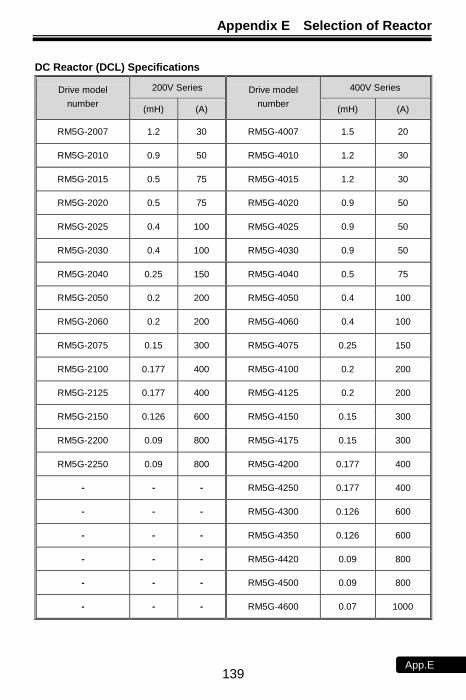
Appendix E Selection of Reactor
139 App.E
DC Reactor (DCL) Specifications
Drive model
number
200V Series Drive model
number
400V Series
(mH) (A) (mH) (A)
RM5G-2007 1.2 30 RM5G-4007 1.5 20
RM5G-2010 0.9 50 RM5G-4010 1.2 30
RM5G-2015 0.5 75 RM5G-4015 1.2 30
RM5G-2020 0.5 75 RM5G-4020 0.9 50
RM5G-2025 0.4 100 RM5G-4025 0.9 50
RM5G-2030 0.4 100 RM5G-4030 0.9 50
RM5G-2040 0.25 150 RM5G-4040 0.5 75
RM5G-2050 0.2 200 RM5G-4050 0.4 100
RM5G-2060 0.2 200 RM5G-4060 0.4 100
RM5G-2075 0.15 300 RM5G-4075 0.25 150
RM5G-2100 0.177 400 RM5G-4100 0.2 200
RM5G-2125 0.177 400 RM5G-4125 0.2 200
RM5G-2150 0.126 600 RM5G-4150 0.15 300
RM5G-2200 0.09 800 RM5G-4175 0.15 300
RM5G-2250 0.09 800 RM5G-4200 0.177 400
- - - RM5G-4250 0.177 400
- - - RM5G-4300 0.126 600
- - - RM5G-4350 0.126 600
- - - RM5G-4420 0.09 800
- - - RM5G-4500 0.09 800
- - - RM5G-4600 0.07 1000
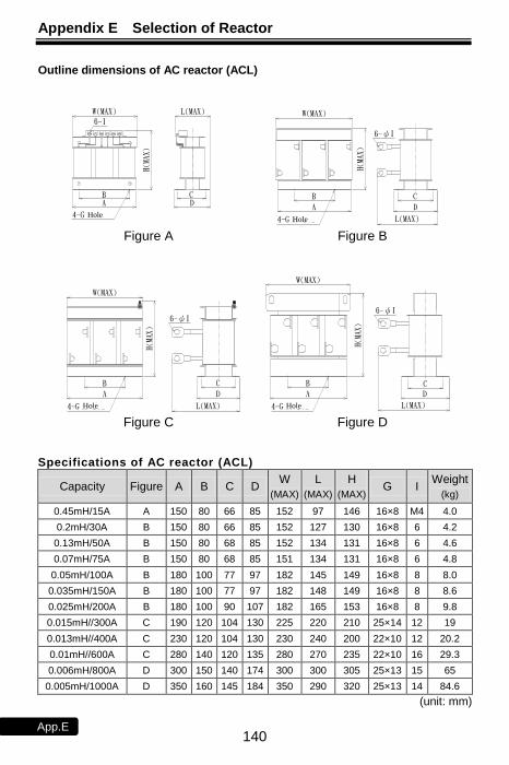
Appendix E Selection of Reactor
140 App.E
Outline dimensions of AC reactor (ACL)
Specifications of AC reactor (ACL)
Capacity Figure A B C D W
(MAX)
L
(MAX)
H
(MAX) G I
Weight
(kg)
0.45mH/15A A 150 80 66 85 152 97 146 16×8 M4 4.0
0.2mH/30A B 150 80 66 85 152 127 130 16×8 6 4.2
0.13mH/50A B 150 80 68 85 152 134 131 16×8 6 4.6
0.07mH/75A B 150 80 68 85 151 134 131 16×8 6 4.8
0.05mH/100A B 180 100 77 97 182 145 149 16×8 8 8.0
0.035mH/150A B 180 100 77 97 182 148 149 16×8 8 8.6
0.025mH/200A B 180 100 90 107 182 165 153 16×8 8 9.8
0.015mH//300A C 190 120 104 130 225 220 210 25×14 12 19
0.013mH//400A C 230 120 104 130 230 240 200 22×10 12 20.2
0.01mH//600A C 280 140 120 135 280 270 235 22×10 16 29.3
0.006mH/800A D 300 150 140 174 300 300 305 25×13 15 65
0.005mH/1000A D 350 160 145 184 350 290 320 25×13 14 84.6
(unit: mm)
H(MAX)
H(MAX)
A
A
W(MAX)
W(MAX)
H(MAX)
A
D
C
W(MAX)
A
圖C
D
圖D
L(MAX)
D
圖A 圖B
6-ψI
CB
H(MAX)
C
L(MAX)
6-ψI
B
固定孔4-G
6-ψI
L(MAX)
B CD
L(MAX)
B
W(MAX)
6-I
固定孔4-G
4-G固定孔固定孔4-G
Figure A Figure B
Figure C Figure D
HoleHole
HoleHole
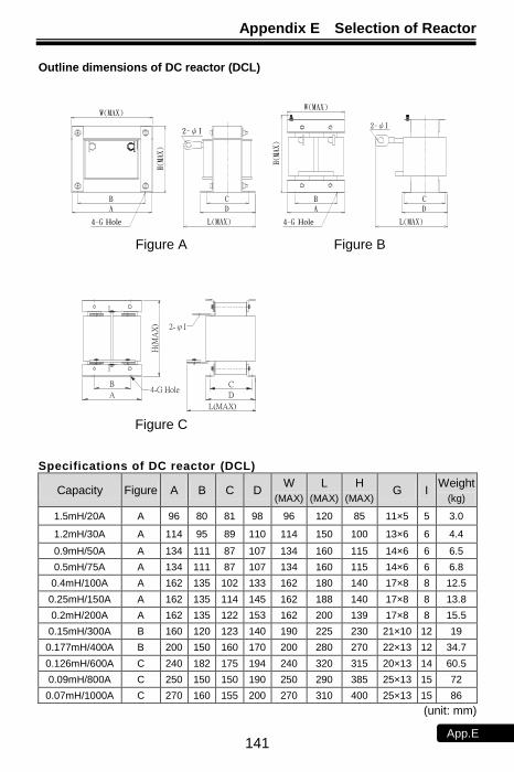
Appendix E Selection of Reactor
141 App.E
Outline dimensions of DC reactor (DCL)
圖A
A D
圖BW(MAX)
A D
圖C
C
D
B
L(MAX)
H(M
AX)
W(MAX)
A
2-ψI
固定孔4-G
B C
2-ψI
H(M
AX)
H(MA
X)
W(MAX)
固定孔4-G
B C
L(MAX)
L(MAX)
2-ψI
圖A 圖B
圖C
Figure A Figure B
Figure C
Hole Hole
L(MAX)
D
C
2-φI
B
A4-G Hole
H(M
AX
)
Specifications of DC reactor (DCL)
Capacity Figure A B C D W
(MAX)
L
(MAX)
H
(MAX) G I
Weight
(kg)
1.5mH/20A A 96 80 81 98 96 120 85 11×5 5 3.0
1.2mH/30A A 114 95 89 110 114 150 100 13×6 6 4.4
0.9mH/50A A 134 111 87 107 134 160 115 14×6 6 6.5
0.5mH/75A A 134 111 87 107 134 160 115 14×6 6 6.8
0.4mH/100A A 162 135 102 133 162 180 140 17×8 8 12.5
0.25mH/150A A 162 135 114 145 162 188 140 17×8 8 13.8
0.2mH/200A A 162 135 122 153 162 200 139 17×8 8 15.5
0.15mH/300A B 160 120 123 140 190 225 230 21×10 12 19
0.177mH/400A B 200 150 160 170 200 280 270 22×13 12 34.7
0.126mH/600A C 240 182 175 194 240 320 315 20×13 14 60.5
0.09mH/800A C 250 150 150 190 250 290 385 25×13 15 72
0.07mH/1000A C 270 160 155 200 270 310 400 25×13 15 86
(unit: mm)

Appendix F Selection of Zero-Phase Radio Frequency Filter
142 App.F
Wind all 3-phase power cords around RFI filter in same direction with same coil numbers, and then connect to the power input terminal of the drive. Caution: Do Not exceed 4 coils to prevent overheating of RFI filter. Note: The ground wire or the four-core cable with ground wire cannot pass through RFI filter, otherwise the filtration effect will be reduced.
Appendix F Selection of Zero-Phase Radio Frequency Filter
Please read this manual carefully to understand the correct and safety operations before using the product to prevent possible personnel injuries caused by false operations.
CAUTION (1) Do Not touch zero-phase radio frequency filter(RFI Filter) to prevent the scald
burn from the extreme high temperature when the drive is during running. (2) Move the product with proper method and please be more caution of the sharp
parts to avoid possible injuries. (3) Wiring or inspection must be done by qualified professional technicians.
By installing the RFI filter(s), it can reduce the radio frequency interference generated by drive. 1. Specification of product:
Model RM5G/P
Environm
enta
l C
onditio
n
Use Place
(1) Clean place without high temperature, high humidity, or flammable/corrosive gases.
(2) If the zero-phase radio frequency filter is installed inside the power distribution panel, the surrounding temperature should not exceed the range(-10 ~ +50℃).
(3) The heat will be generated in the zero-phase radio frequency filter, so the space should be reserved for heat dissipation.
Surrounding Temperature
-10 ~ +50℃(Non-freezing and non-condensing)
Relative Humidity 90%RH or less (No-condensing atmosphere)
Vibration Less than 5.9m/sec2 (0.6G)
2. Wiring for RFI: Connect the RFI filter in accordance with the following wiring diagram.
(1) Install the RFI filter at the power source site of the drive
R/L1S/L2T/L3
RFI filter
RFI filter
Power
Power
Ex. 2
Ex. 1
R/L1S/L2T/L3
電源
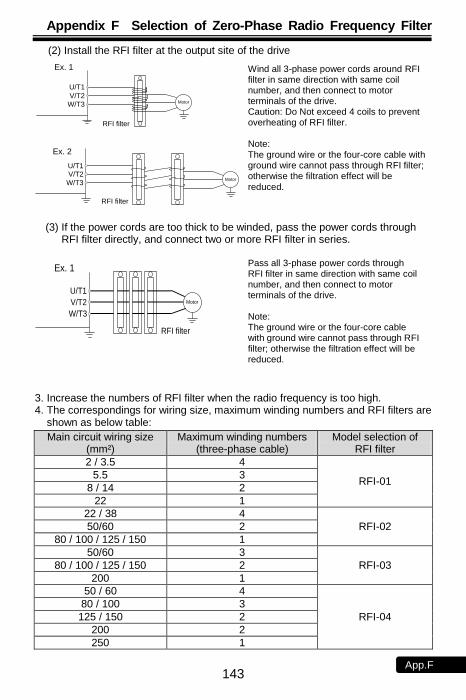
Appendix F Selection of Zero-Phase Radio Frequency Filter
143 App.F
Pass all 3-phase power cords through RFI filter in same direction with same coil number, and then connect to motor terminals of the drive. Note: The ground wire or the four-core cable with ground wire cannot pass through RFI filter; otherwise the filtration effect will be reduced.
Wind all 3-phase power cords around RFI filter in same direction with same coil number, and then connect to motor terminals of the drive. Caution: Do Not exceed 4 coils to prevent overheating of RFI filter. Note: The ground wire or the four-core cable with ground wire cannot pass through RFI filter; otherwise the filtration effect will be reduced.
(2) Install the RFI filter at the output site of the drive
RFI filter
RFI filter
Motor
U/T1
V/T2
W/T3 Motor
Ex. 1
Ex. 2
U/T1V/T2
W/T3
(3) If the power cords are too thick to be winded, pass the power cords through
RFI filter directly, and connect two or more RFI filter in series.
RFI filter
U/T1
V/T2
W/T3
Motor
Ex. 1
3. Increase the numbers of RFI filter when the radio frequency is too high. 4. The correspondings for wiring size, maximum winding numbers and RFI filters are
shown as below table:
Main circuit wiring size (mm²)
Maximum winding numbers (three-phase cable)
Model selection of RFI filter
2 / 3.5 4
RFI-01 5.5 3
8 / 14 2
22 1
22 / 38 4
RFI-02 50/60 2
80 / 100 / 125 / 150 1
50/60 3
RFI-03 80 / 100 / 125 / 150 2
200 1
50 / 60 4
RFI-04
80 / 100 3
125 / 150 2
200 2
250 1
電源
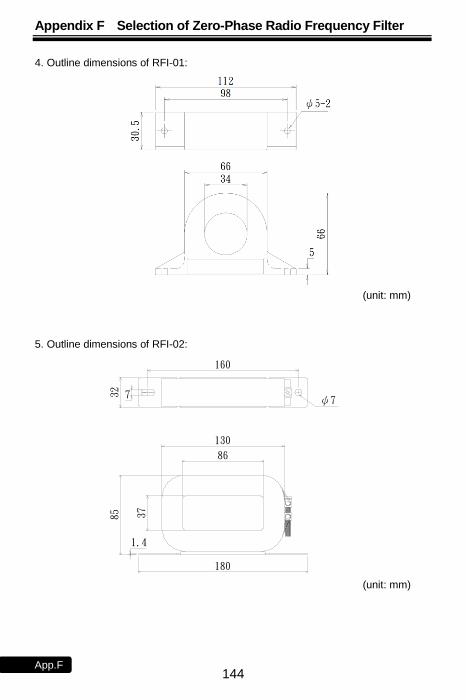
Appendix F Selection of Zero-Phase Radio Frequency Filter
144 App.F
4. Outline dimensions of RFI-01:
(unit: mm) 5. Outline dimensions of RFI-02:
ψ7
160
7
130
86
37
1.4
180
8532
(unit: mm)
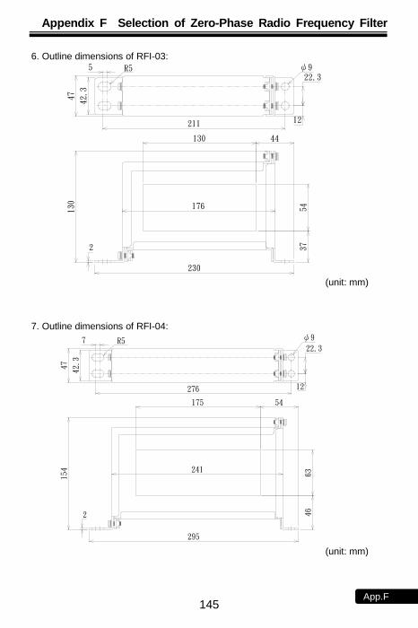
Appendix F Selection of Zero-Phase Radio Frequency Filter
145 App.F
6. Outline dimensions of RFI-03:
211
130
R55
44
37
12
22.3ψ9
42.3
230
2
4713
0
54176
(unit: mm)
7. Outline dimensions of RFI-04:
276
175
7 R5
54
63
46
12
22.3
ψ9
295
42.3
2
47
241
154
(unit: mm)
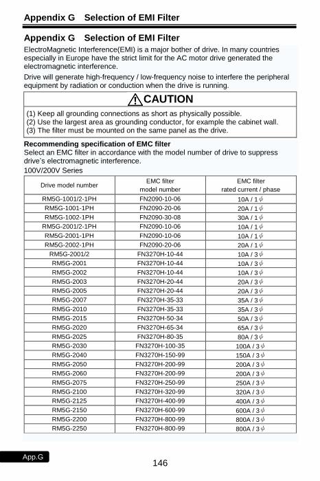
Appendix G Selection of EMI Filter
146 App.G
Appendix G Selection of EMI Filter
ElectroMagnetic Interference(EMI) is a major bother of drive. In many countries especially in Europe have the strict limit for the AC motor drive generated the electromagnetic interference.
Drive will generate high-frequency / low-frequency noise to interfere the peripheral equipment by radiation or conduction when the drive is running.
CAUTION (1) Keep all grounding connections as short as physically possible. (2) Use the largest area as grounding conductor, for example the cabinet wall. (3) The filter must be mounted on the same panel as the drive.
Recommending specification of EMC filter Select an EMC filter in accordance with the model number of drive to suppress drive’s electromagnetic interference.
100V/200V Series
Drive model number EMC filter
model number
EMC filter
rated current / phase
RM5G-1001/2-1PH FN2090-10-06 10A / 1ψ
RM5G-1001-1PH FN2090-20-06 20A / 1ψ
RM5G-1002-1PH FN2090-30-08 30A / 1ψ
RM5G-2001/2-1PH FN2090-10-06 10A / 1ψ
RM5G-2001-1PH FN2090-10-06 10A / 1ψ
RM5G-2002-1PH FN2090-20-06 20A / 1ψ
RM5G-2001/2 FN3270H-10-44 10A / 3ψ
RM5G-2001 FN3270H-10-44 10A / 3ψ
RM5G-2002 FN3270H-10-44 10A / 3ψ
RM5G-2003 FN3270H-20-44 20A / 3ψ
RM5G-2005 FN3270H-20-44 20A / 3ψ
RM5G-2007 FN3270H-35-33 35A / 3ψ
RM5G-2010 FN3270H-35-33 35A / 3ψ
RM5G-2015 FN3270H-50-34 50A / 3ψ
RM5G-2020 FN3270H-65-34 65A / 3ψ
RM5G-2025 FN3270H-80-35 80A / 3ψ
RM5G-2030 FN3270H-100-35 100A / 3ψ
RM5G-2040 FN3270H-150-99 150A / 3ψ
RM5G-2050 FN3270H-200-99 200A / 3ψ
RM5G-2060 FN3270H-200-99 200A / 3ψ
RM5G-2075 FN3270H-250-99 250A / 3ψ
RM5G-2100 FN3270H-320-99 320A / 3ψ
RM5G-2125 FN3270H-400-99 400A / 3ψ
RM5G-2150 FN3270H-600-99 600A / 3ψ
RM5G-2200 FN3270H-800-99 800A / 3ψ
RM5G-2250 FN3270H-800-99 800A / 3ψ
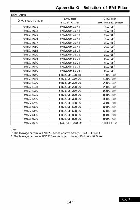
Appendix G Selection of EMI Filter
147 App.F
400V Series
Drive model number EMC filter
model number
EMC filter
rated current / phase
RM5G-4001 FN3270H-10-44 10A / 3ψ
RM5G-4002 FN3270H-10-44 10A / 3ψ
RM5G-4003 FN3270H-10-44 10A / 3ψ
RM5G-4005 FN3270H-10-44 10A / 3ψ
RM5G-4007 FN3270H-20-44 20A / 3ψ
RM5G-4010 FN3270H-20-44 20A / 3ψ
RM5G-4015 FN3270H-35-33 35A / 3ψ
RM5G-4020 FN3270H-35-33 35A / 3ψ
RM5G-4025 FN3270H-50-34 50A / 3ψ
RM5G-4030 FN3270H-50-34 50A / 3ψ
RM5G-4040 FN3270H-65-34 65A / 3ψ
RM5G-4050 FN3270H-80-35 80A / 3ψ
RM5G-4060 FN3270H-100-35 100A / 3ψ
RM5G-4075 FN3270H-150-99 150A / 3ψ
RM5G-4100 FN3270H-200-99 200A / 3ψ
RM5G-4125 FN3270H-200-99 200A / 3ψ
RM5G-4150 FN3270H-250-99 250A / 3ψ
RM5G-4175 FN3270H-320-99 320A / 3ψ
RM5G-4200 FN3270H-320-99 320A / 3ψ
RM5G-4250 FN3270H-400-99 400A / 3ψ
RM5G-4300 FN3270H-600-99 600A / 3ψ
RM5G-4350 FN3270H-600-99 600A / 3ψ
RM5G-4420 FN3270H-800-99 800A / 3ψ
RM5G-4500 FN3270H-800-99 800A / 3ψ
RM5G-4600 FN3270H-1000-99 1000A / 3ψ
Note: 1: The leakage current of FN2090 series approximately 0.5mA ~ 1.02mA 2: The leakage current of FN3270 series approximately 26.4mA ~ 59.5mA
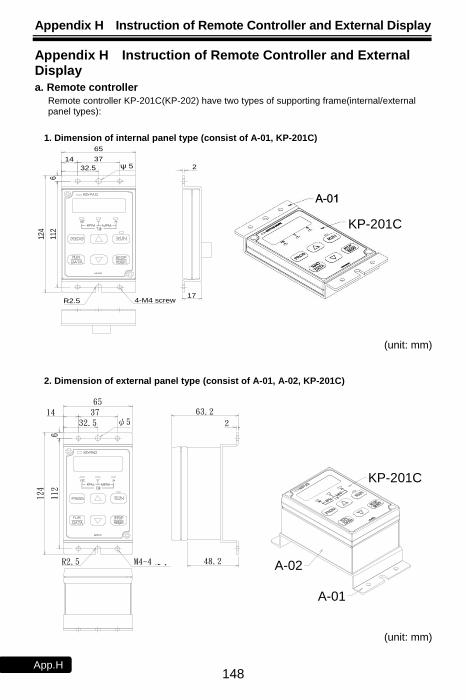
Appendix H Instruction of Remote Controller and External Display
148 App.H
R2.5 M4-4攻牙
ψ532.5
65
14 37 63.2
2
48.2
124
112
6
A-01
A-02的底座
KP-201C
Appendix H Instruction of Remote Controller and External Display
a. Remote controller
Remote controller KP-201C(KP-202) have two types of supporting frame(internal/external panel types):
1. Dimension of internal panel type (consist of A-01, KP-201C)
(unit: mm)
2. Dimension of external panel type (consist of A-01, A-02, KP-201C)
(unit: mm)
124
112
17
65
3714
6
232.5 ψ 5
R2.5 4-M4 screw
KP-207
KP-201C
KP-201C
A-02
A-01
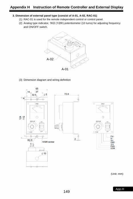
Appendix H Instruction of Remote Controller and External Display
149 App.H
A-01
A-02
3. Dimension of external panel type (consist of A-01, A-02, RAC-01)
(1) RAC-01 is used for the remote independent control or control panel.
(2) Analog type indicator, 1KΩ (1/2W) potentiometer (10 turns) for adjusting frequency
and ON/OFF switch.
(3) Dimension diagram and wiring definition
(Unit: mm)
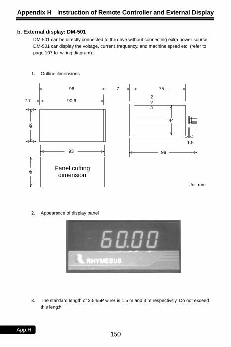
Appendix H Instruction of Remote Controller and External Display
150 App.H
b. External display: DM-501
DM-501 can be directly connected to the drive without connecting extra power source.
DM-501 can display the voltage, current, frequency, and machine speed etc. (refer to
page 107 for wiring diagram).
1. Outline dimensions
2.7 90.6
96
98
75
44
7
1.5
2
Unit:mm
Panel cutting
dimension
93
45
48
2. Appearance of display panel
3. The standard length of 2.54/5P wires is 1.5 m and 3 m respectively. Do not exceed
this length.
Appendix I Outline Dimension Drawing of Drives
151 App.I
Appendix I Outline Dimension Drawing of Drives
Model Number: RM5G-1001/2-1PH ~ RM5G -1002-1PH;
RM5G -2001/2-1PH ~ RM5G -2002-1PH;
RM5G -2001/2 ~ RM5G -2005;
RM5G -4001 ~ RM5G -4005
1281
00
11
0
85
13
8
15
1.5
6.5
13
85.5
128
142 135
46
5.5
2-ψ6 hole
2-M4 screw
(unit: mm)
Model Number: RM5G-2007 ~ RM5G-2015;RM5P-2010 ~ RM5P-2020;
RM5G-4007 ~ RM5G-4025;RM5P-4010 ~ RM5P-4030
Internal cooling type External cooling type
2-ψ6 hole
Supporting frame accessory (M1031383)
(Model: A0006804 V1.1)
27
6.5
29
0.0
5.8
6.5
2-ψ35
3-ψ23
162.0
180.0
68.6
4-M5
Screw3-ψ23
2-ψ35
8.9
200.02-ψ6.6 hole
32
8.8
31
3.0
180.0
162.0200.0
74.02
90
.0
162.0
177.0
148.0 14.5
Panel
cutting
dimension 31
3.0
29
0.0
4-M5
Screw
20
.0
162.0
27
7.0
5.8
62.6
7
8
7.5 10
(unit: mm)
Appendix I Outline Dimension Drawing of Drives
152 App.I
Model Number: RM5G-2020 ~ RM5G-2040;RM5P-2025 ~ RM5P-2050;
RM5G-4030 ~ RM5G-4060;RM5P-4040 ~ RM5P-4075
Internal cooling type External cooling type
Supporting frame accessory(M1031515)(Model: A0007500 V1.1)
250.09
5.7
9.0
250.0
39
9.6
103.22-ψ9 hole
2-ψ23
ψ35 2-ψ50 ψ35
2-ψ232-ψ50
2-ψ9 hole
4-M8
Screw
230.0
38
0.0
35
9.9
250.0
138.0
230.0
250.0
230.0
380
.0
40
0.0
42
8.0
9.0
44
8.2
8.5
230.0
247.0
4-M8 Screw
11
.53
96
.0
42
7.0
29
.0
211.0 18.0
Panel
cutting
dimension
9.5
(unit: mm)
Model Number: RM5G-2050 ~ RM5G-2250; RM5P-2060 ~ RM5P-2250; RM5G-4075 ~ RM5G-4600; RM5P-4100 ~ RM5P-4700
Internal cooling type External cooling type
H2
H1
H
D2
d
H1
W3
W
W3
W1
h1
D0
D1 h2
H3
H4
D2
W4
W3
HH1
H2
d
W1
W
W3 h1
D0
D1 h2
2-ψ d hole 2-ψ d hole
4 screw 4 screw
Panel
cutting
dimension
Internal cooling type External cooling type
ψ 15 ψ 15
*Refer to below table for outline dimension
4-M8
Screw
Appendix I Outline Dimension Drawing of Drives
153 App.I
RM
5G/R
M5P
200V
serie
s
Scre
w
(mm
)
M8
M10
M12
Dim
ensio
n (
mm
)
d1
3
3
3
3
d
10
12
15
15
D2
242
246
257
294
D1
170
172
183
224
D0
325
334
366
405
h3
10
12
12
18
h2
25
30
35
39
h1
11
14
19
15
H4
545
634
758
936
H3
564
662
788
978
H2
539
630
751
929
H1
562
660
785
974
H
584
685
818
100
0
W4
365
427
487
657
W3
275
275
275
580
W1
361
418
479
654
W
386
446
508
696
Mod
el nu
mbe
r
RM
5G
-205
0
RM
5G
-206
0
RM
5G
-207
5
RM
5P
-20
60
RM
5P
-20
75
RM
5P
-21
00
RM
5G
-210
0
RM
5P
-21
25
RM
5G
-212
5
RM
5G
-215
0
RM
5P
-21
50
RM
5G
-220
0
RM
5G
-225
0
RM
5P
-22
00
RM
5P
-22
50
Appendix I Outline Dimension Drawing of Drives
154 App.I
RM
5G/R
M5P
400V
serie
s
Scre
w
(mm
)
M8
M10
M12
Dim
ensio
n (
mm
)
d1
3
3
3
3
3
d
10
12
15
15
15
D2
242
246
257
294
308
D1
170
172
183
224
235
D0
325
334
366
405
419
h3
10
12
12
18
19
h2
25
30
35
39
39
h1
11
14
19
15
15
H4
545
634
758
936
968
H3
564
662
788
978
100
7
H2
539
630
751
929
963
H1
562
660
785
974
100
3
H
584
685
818
100
0
103
0
W4
365
427
487
657
958
W3
275
275
275
580
710
W1
361
418
479
654
954
W
386
446
508
696
992
Mod
el nu
mbe
r
RM
5G
-407
5
RM
5G
-410
0
RM
5G
-412
5
RM
5P
-41
00
RM
5P
-41
25
RM
5P
-41
50
RM
5G
-415
0
RM
5P
-41
75
RM
5G
-417
5
RM
5G
-420
0
RM
5G
-425
0
RM
5P
-42
00
RM
5P
-42
50
RM
5P
-43
00
RM
5G
-430
0
RM
5G
-435
0
RM
5G
-442
0
RM
5P
-43
50
RM
5P
-44
20
RM
5G
-450
0
RM
5G
-460
0
RM
5P
-45
00
RM
5P
-46
00
RM
5P
-47
00

Appendix J Auxiliary Controller (ACE-S Series)
155 App.J
Appendix J Auxiliary Controller (ACE-S Series)
Type Name Application
ACE-S02/02B/02C DEVIATION DETECTOR
Convert the angle deviation which is detected by ADD-02 (SYNCHRO) into DC voltage signal. The deviation detector can control the drive operation by switching the aligned-speed, synchronized, and constantly tensile operations.
The built-in tilt circuit for output signal can slow the acceleration/deceleration time and reduce the mechanical impact.
ACE-S04/06 RATIO / DIFFERENTIAL
CONTROLLER
The controller can select ratio (ACE-S04) or differential (ACE-S06) control mode. One set controller can connect with 6 set of drivers, when the controller is set to ratio or differential mode. (Default setting is ratio control mode(ACE-S04)).
The built-in tilt circuit for output signal can slow the acceleration/deceleration time and reduce the mechanical impact.
ACE-S08/09
SPEED SIGNAL TRANSFER
/ FEEDBACK
CONTROLLER
Convert the rotation speed of motor into DC voltage by tachogenerator or photo-interrupter pulse generator as the frequency control signal or feedback signal of rotation speed to the drive.
The controller can match with the potentiometer or deviation detector to enable constant tension, constantly liner speed and slack of winding for cloth, wire or plastic applications. The controller can match with tachogenerator to enable constantly linear speed or constant speed control for motor.
The built-in tilt circuit for output signal can slow the acceleration/deceleration time and reduce the mechanical impact.
ACE-S10 MULTI-FUNCTION
CONTROLLER
Multi-place control: The drive can be started, accelerated, decelerated, and stopped by remote control, and the drive can auto-storing the operation frequency when the power failure by using multi-function controller.
Traverse control: Used in the occasion of making silk thread move around by traverse winding equipment.
Sequential operation control with multi-speed: Execute the sequential control in accordance with the setting speed, and supporting the circulation operation.
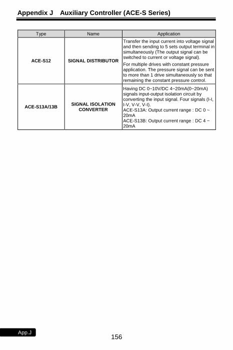
Appendix J Auxiliary Controller (ACE-S Series)
156 App.J
Type Name Application
ACE-S12 SIGNAL DISTRIBUTOR
Transfer the input current into voltage signal and then sending to 5 sets output terminal in simultaneously (The output signal can be switched to current or voltage signal).
For multiple drives with constant pressure application. The pressure signal can be sent to more than 1 drive simultaneously so that remaining the constant pressure control.
ACE-S13A/13B SIGNAL ISOLATION
CONVERTER
Having DC 0~10V/DC 4~20mA(0~20mA) signals input-output isolation circuit by converting the input signal. Four signals (I-I, I-V, V-V, V-I). ACE-S13A: Output current range : DC 0 ~ 20mA ACE-S13B: Output current range : DC 4 ~ 20mA
Appendix J Auxiliary Controller (ACE-S Series)
157 App.J
No Text on This Page

Attachment 1 Dimension of Keypad (KP-201C, KP-202)
158 App.J
Attachment 1 Dimension of Keypad (KP-201C, KP-202)
60
16 23
55
85
23
48
23x23
ψ30
2-M3 screw
96
+1
0
66+1 0
Scale: 1:1 Unit: mm
16 23
16x16
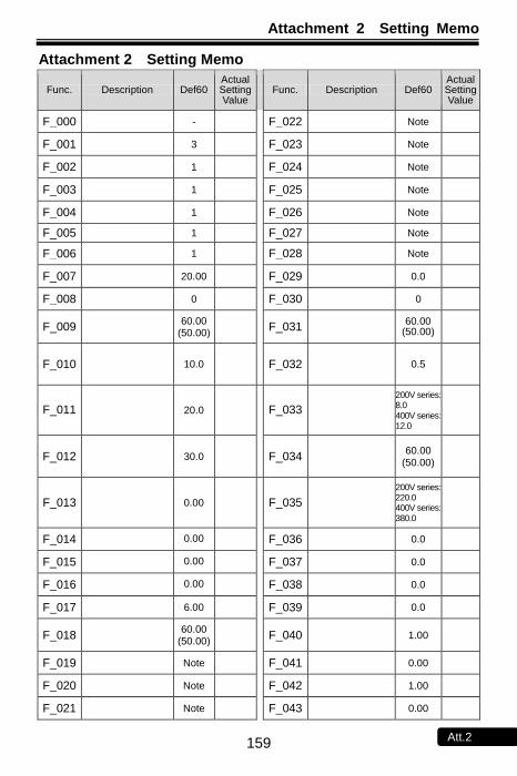
Attachment 2 Setting Memo
159 Att.2
Attachment 2 Setting Memo
Func. Description Def60 Actual Setting Value
Func. Description Def60 Actual Setting Value
F_000 - F_022 Note
F_001 3 F_023 Note
F_002 1 F_024 Note
F_003 1 F_025 Note
F_004 1 F_026 Note
F_005 1 F_027 Note
F_006 1 F_028 Note
F_007 20.00 F_029 0.0
F_008 0 F_030 0
F_009 60.00
(50.00) F_031
60.00 (50.00)
F_010 10.0 F_032 0.5
F_011 20.0 F_033
200V series: 8.0
400V series: 12.0
F_012 30.0 F_034 60.00
(50.00)
F_013 0.00 F_035
200V series: 220.0 400V series:
380.0
F_014 0.00 F_036 0.0
F_015 0.00 F_037 0.0
F_016 0.00 F_038 0.0
F_017 6.00 F_039 0.0
F_018 60.00
(50.00) F_040 1.00
F_019 Note F_041 0.00
F_020 Note F_042 1.00
F_021 Note F_043 0.00
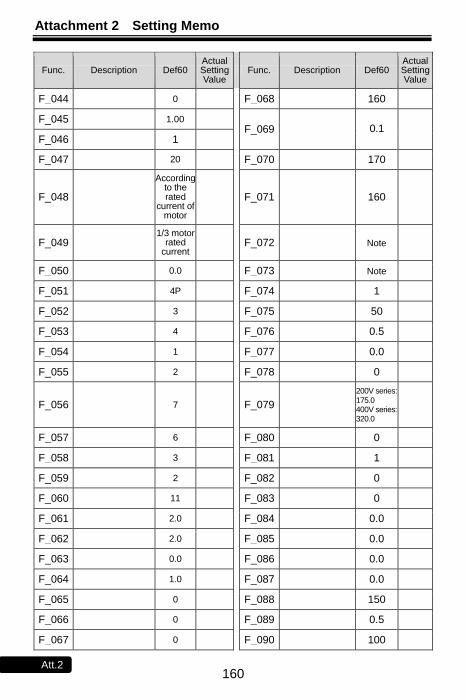
Attachment 2 Setting Memo
160 Att.2
Func. Description Def60 Actual Setting Value
Func. Description Def60 Actual Setting Value
F_044 0 F_068 160
F_045 1.00 F_069 0.1
F_046 1
F_047 20 F_070 170
F_048
According to the rated
current of motor
F_071 160
F_049 1/3 motor
rated current
F_072 Note
F_050 0.0 F_073 Note
F_051 4P F_074 1
F_052 3 F_075 50
F_053 4 F_076 0.5
F_054 1 F_077 0.0
F_055 2 F_078 0
F_056 7 F_079
200V series:
175.0 400V series: 320.0
F_057 6 F_080 0
F_058 3 F_081 1
F_059 2 F_082 0
F_060 11 F_083 0
F_061 2.0 F_084 0.0
F_062 2.0 F_085 0.0
F_063 0.0 F_086 0.0
F_064 1.0 F_087 0.0
F_065 0 F_088 150
F_066 0 F_089 0.5
F_067 0 F_090 100

Attachment 2 Setting Memo
161 Att.2
Func. Description Def60 Actual Setting Value
Func. Description Def60 Actual Setting Value
F_091 - F_114 5
F_092 0 F_115 3
F_093 1 F_116 1
F_094 3 F_117 0
F_095
200V series: 220.0 400V series:
380.0
F_118 0
F_096 0.5 F_119 0
F_097 0.0 F_120 1
F_098 1 F_121 0.00
F_099 1 F_122 0
F_100 2 F_123 0
F_101 3 F_124 1
F_102 0 F_125 1
F_103 3.0 F_126 0
F_104 Note F_127 1.00
F_105 Note F_128 0.00
F_106 0.0 F_129 2
F_107 0.00 F_130 1.00
F_108 10 F_131 1
F_109 0 F_132 0.5
F_110 1 F_133 -
F_111 20 F_134 -
F_112 17
F_113 8
Note: The setting of value depends on the horse power (HP) of drive:
0.5 ~ 5HP → 5 sec 7.5 ~ 30HP → 15 sec 40HP above → 30 sec
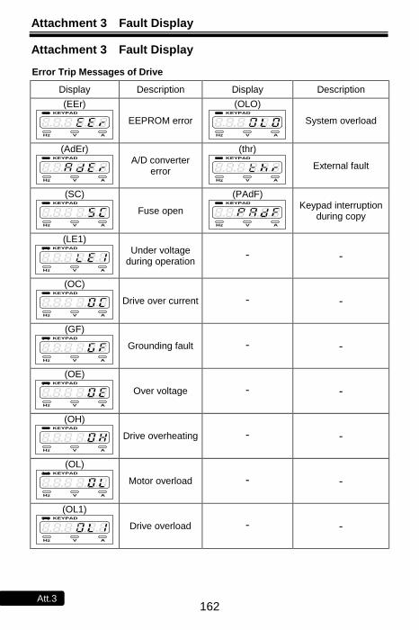
Attachment 3 Fault Display
162 Att.3
Attachment 3 Fault Display
Error Trip Messages of Drive
Display Description Display Description
(EEr) KEYPAD
Hz V A
EEPROM error
(OLO) KEYPAD
Hz V A
System overload
(AdEr) KEYPAD
Hz V A
A/D converter error
(thr) KEYPAD
Hz V A
External fault
(SC) KEYPAD
Hz V A
Fuse open
(PAdF) KEYPAD
Hz V A
Keypad interruption during copy
(LE1) KEYPAD
Hz V A
Under voltage during operation
- -
(OC) KEYPAD
Hz V A
Drive over current - -
(GF) KEYPAD
Hz V A
Grounding fault - -
(OE) KEYPAD
Hz V A
Over voltage - -
(OH) KEYPAD
Hz V A
Drive overheating - -
(OL) KEYPAD
Hz V A
Motor overload - -
(OL1) KEYPAD
Hz V A
Drive overload - -
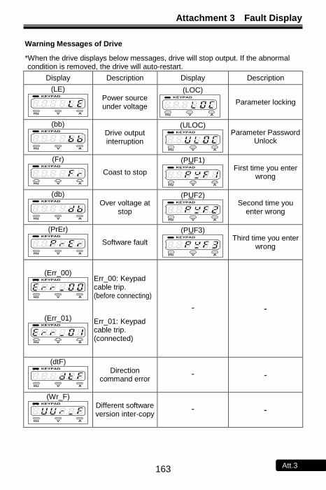
Attachment 3 Fault Display
163 Att.3
Warning Messages of Drive
*When the drive displays below messages, drive will stop output. If the abnormal condition is removed, the drive will auto-restart.
Display Description Display Description
(LE) KEYPAD
Hz V A
Power source under voltage
(LOC) KEYPAD
Hz V A
Parameter locking
(bb) KEYPAD
Hz V A
Drive output interruption
(ULOC) KEYPAD
Hz V A
Parameter Password Unlock
(Fr) KEYPAD
Hz V A
Coast to stop
(PUF1) KEYPAD
Hz V A
First time you enter wrong
(db) KEYPAD
Hz V A
Over voltage at stop
(PUF2) KEYPAD
Hz V A
Second time you enter wrong
(PrEr) KEYPAD
Hz V A
Software fault
(PUF3) KEYPAD
Hz V A
Third time you enter wrong
(Err_00)
KEYPAD
Hz V A
(Err_01)
KEYPAD
Hz V A
Err_00: Keypad cable trip. (before connecting) Err_01: Keypad cable trip. (connected)
- -
(dtF) KEYPAD
Hz V A
Direction command error
- -
(Wr_F) KEYPAD
Hz V A
Different software version inter-copy
- -
Note
164 Note

Note
165 Note
Note
166 Note
Related Documents