A.C Circuit Fundamentals of alternating current 1. The variation of a quantity such as voltage or current shown on a graph is known as ___________ a) Waveform b) Peak value c) Instantaneous value d) Period 2. The variation of a quantity such as voltage or current shown on a graph is known as period – false 3. The variation of a quantity such as voltage or current shown on a graph is known as frequency – false 4. The duration of one cycle known as _________ a) Waveform b) Peak value c) Instantaneous value d) Period 5. Duration of one cycle known as peak value – false 6. The repetition of a variable quantity, recurring at equal intervals, is known as ___________ a) Waveform b) Instantaneous value c) Cycle d) Period 7. The value of a given waveform at any instant time is termed as ___________ a) Waveform b) Instantaneous value c) Cycle d) Period

Welcome message from author
This document is posted to help you gain knowledge. Please leave a comment to let me know what you think about it! Share it to your friends and learn new things together.
Transcript
A.C Circuit
Fundamentals of alternating current
1. The variation of a quantity such as voltage or current shown on a graph is known as
___________
a) Waveform
b) Peak value
c) Instantaneous value
d) Period
2. The variation of a quantity such as voltage or current shown on a graph is known as
period – false
3. The variation of a quantity such as voltage or current shown on a graph is known as
frequency – false
4. The duration of one cycle known as _________
a) Waveform
b) Peak value
c) Instantaneous value
d) Period
5. Duration of one cycle known as peak value – false
6. The repetition of a variable quantity, recurring at equal intervals, is known as
___________
a) Waveform
b) Instantaneous value
c) Cycle
d) Period
7. The value of a given waveform at any instant time is termed as ___________
a) Waveform
b) Instantaneous value
c) Cycle
d) Period
8. The maximum instantaneous value measured from zero value is known as?
a) Peak value
b) Peak to peak value
c) Cycle
d) Period
9. The maximum variation between the maximum positive and the maximum negative value
is known as?
a) Peak value
b) Peak to peak value
c) Cycle
d) Period
10. The value of a given waveform at any instant time is termed as instantaneous value – true
11. Find the average value of current when the current that are equidistant are 4A, 5A and
6A.
a) 5A
b) 6A
c) 15A
d) 10A
12. The average value of current is the sum of all the currents divided by the number of
currents. - true
13. The average value of current is the sum of all the currents multiplied by the number of
currents. – false
14. RMS stands for ________
a) Root Mean Square
b) Root Mean Sum
c) Root Maximum sum
d) Root Minimum Sum
15. RMS stands for Root Mean Sum – false
16. RMS stands for Root Minimum Square – false
17. What is the type of current obtained by finding the square of the currents and then finding
their average and then fining the square root?
a) RMS current
b) Average current
c) Instantaneous current
d) Total current
18. RMS value of current is obtained by squaring all the current values, finding the average
and then finding the square root. – true
19. What is the effective value of current?
a) RMS current
b) Average current
c) Instantaneous current
d) Total current
20. RMS current is also known as the effective current – true
21. In a sinusoidal wave, average current is always _______ rms current.
a) Greater than
b) Less than
c) Equal to
d) Not related
22. In a sinusoidal wave, RMS current is greater than average current. – true
23. In a sinusoidal wave ,Average current is greater than RMS current – false
24. For a rectangular wave, average current is ______ rms current.
a) Greater than
b) Less than
c) Equal to
d) Not related
25. For a rectangular wave, average and the rms values are the same – true
26. For a rectangular wave, average and the rms values are the different – false
27. Peak value divided by the rms value gives us?
a) Peak factor
b) Crest factor
c) Both peak and crest factor
d) Neither peak nor crest factor
28. Peak and crest factor both mean the same thing. – true
29. Peak value divided by the rms value gives us Average value – false
30. Peak value divided by the rms value gives us peak factor – true
31. Calculate the peak factor if the peak value of current is 10A and the rms value is 2A.
a) 5
b) 10
c) 5A
d) 10A
32. If maximum value of current is 5√2 A, what will be the value of RMS current?
a) 10 A
b) 5 A
c) 15 A
d) 25 A
33. If Im is the maximum value of a sinusoidal voltage, what is the instantaneous value?
a) i=Im/2
b) i=Imsinθ
c) i=Imcosθ
d) i=Imsinθ or i=Imcosθ
34. Average value of current over a half cycle is?
a) 0.67Im
b) 0.33Im
c) 6.7Im
d) 3.3Im
35. What is the correct expression for the rms value of current?
a) Irms=Im/2
b) Irms=Im/√2
c) Irms=Im/4
d) Irms=Im
36. The expression for the rms value of current is Irms=Im/√2 – true
37. The expression for the rms value of current is Irms=Im/2 – false
38. Average value of current over a full cycle is?
a) 0.67Im
b) 0
c) 6.7Im
d) 3.3Im
39. Average value of current over a full cycle is zero – true
40. What is the correct expression for the form factor?
a) Irms * Iav
b) Irms / Iav
c) Irms + Iav
d) Irms – Iav
41. The correct expression for form factor is Irms/Iav - true
42. For a direct current, the rms current is ________ the mean current.
a) Greater than
b) Less than
c) Equal to
d) Not related to
43. For a direct current, the rms voltage is equal to the mean voltage – true
44. What is the value of the form factor for sinusoidal current?
a) π/2
b) π/4
c) 2π
d) π/√2
45. For addition and subtraction of phasors, we use the _________ form.
a) Rectangular
b) Polar
c) Either rectangular or polar
d) Neither rectangular nor polar
46. For addition and subtraction of phasors, we use the rectangular form – true
47. For multiplication and division of phasors, we use ____________ form.
a) Rectangular
b) Polar
c) Either rectangular or polar
d) Neither rectangular nor polar
48. For multiplication and division of phasors, we use the polar form – true
49. If a voltage of 2+5j and another voltage of 3+ 6j flows through two different resistors,
connected in series, in a circuit, find the total voltage in the circuit.
a) 2+5j V
b) 3+6j V
c) 5+11j V
d) 5+10j V
50. Find the total current in the circuit if two currents of 4+5j flow in the circuit.
a) 4+5j A
b) 4A
c) 5A
d) 8+10j A
Ac series circuit
1. Instantaneous voltage is the product of resistance and _____________ current in a
resistive circuit.
a) Instantaneous
b) Average
c) RMS
d) Peak
2. Find the value of the instantaneous voltage if the resistance is 2 ohm and the
instantaneous current in the circuit is 5A.
a) 5V
b) 2V
c) 10V
d) 2.5V
3. The power for a purely resistive circuit is zero when?
a) Current is zero
b) Voltage is zero
c) Both current and voltage are zero
d) Either current or voltage is zero
4. The power for a purely resistive circuit is zero when either and voltage are zero – false
5. The power for a purely resistive circuit is zero when either current or voltage is zero –
true
6. Calculate the resistance in the circuit if the rms voltage is 20V and the rms current is 2A.
a) 2 ohm
b) 5 ohm
c) 10 ohm
d) 20 ohm
7. The correct expression for the instantaneous current in a resistive circuit is?
a) i=Vm(sint)/R
b) i=Vm(cost)/R
c) i=V(sint)/R
d) i=V(cost)/R
8. The correct expression for the instantaneous current if instantaneous voltage is Vm(sint)
in an inductive circuit is?
a) i = Vm(sint)/XL
b) i = Vm(cost)/XL
c) i = -Vm(sint)/XL
d) i = -Vm(cost)/XL
9. Inductor does not allow sudden changes in?
a) Voltage
b) Current
c) Resistance
d) Inductance
10. The inductor does not allow sudden changes in current – true
11. Inductance is _____________________ to number of turns in the coil.
a) directly proportional
b) inversely proportional
c) equal
d) not related
12. Inductance is inversely proportional to number of turns in the coil. – true
13. Choke involve use of _____________
a) Resistor
b) Capacitor
c) Inductor
d) Transistor
14. Choke is a type of coil so it involves use of inductor – true
15. Capacitors cannot be used in choke coil- true
16. What is the value of current in an inductive circuit when there is no applied voltage?
a) Minimum
b) Maximum
c) Zero
d) Cannot be determined
17. The current in an inductive circuit is zero or minimum when the value of the applied
voltage is maximum. – true
18. In a pure inductive circuit the voltage leads the current and the current lags the voltage by
a phase difference of 90 degrees. – true
19. In an inductive circuit, the voltage_______ the current?
a) Leads
b) Lags
c) Is greater than
d) Is less than
20. In an inductive circuit, the current________ the voltage?
a) Leads
b) Lags
c) Is greater than
d) Is less than
21. In which device inductor cannot be used?
a) filter circuit
b) transformer
c) choke
d) dielectric
22. A resistance of 7 ohm is connected in series with an inductance of 31.8mH. The circuit is
connected to a 100V 50Hz sinusoidal supply. Calculate the current in the circuit.
a) 2.2A
b) 4.2A
c) 6.2A
d) 8.2A
23. A resistance of 7 ohm is connected in series with an inductance of 31.8mH. The circuit is
connected to a 100V 50Hz sinusoidal supply. Calculate the voltage across the resistor.
a) 31.8V
b) 57.4V
c) 67.3V
d) 78.2V
24. A resistance of 7 ohm is connected in series with an inductance of 31.8mH. The circuit is
connected to a 100V 50Hz sinusoidal supply. Calculate the voltage across the inductor.
a) 52V
b) 82V
c) 65V
d) 76V
25. A resistance of 7 ohm is connected in series with an inductance of 31.8mH. The circuit is
connected to a x V 50Hz sinusoidal supply. The current in the circuit is 8.2A. Calculate
the value of x.
a) 10V
b) 50V
c) 100V
d) 120V
26. Which, among the following, is the correct expression for φ.
a) φ=tan-1
(XL/R)
b) φ=tan-1
(R/XL)
c) φ=tan-1
(XL*R)
d) φ=cos-1
(XL/R)
27. For a series resistance and inductance circuit the phase angle is always a negative value –
true
28. For an RL circuit, the phase angle is always ________
a) Positive
b) Negative
c) 0
d) 90
29. For a series resistance and inductance circuit the phase angle is always a positive value-
false
30. What is sinϕ from impedance triangle?
a) XL/R
b) XL/Z
c) R/Z
d) Z/R
31. What is the resonance frequency of ac circuit?
a) 1/√LC
b) √(L/C)
c) √LC
d) LC
32. What is the value of impedance at resonance?
a) XL
b) XC
c) R
d) 0
33. The current is in phase with the voltage when the capacitive reactance is in equal to the
inductive reactance. This is known as resonance condition. – trie
34. What is the resonance condition?
a) When XL>XC
b) When XL<XC
c) When XL=XC
d) When XC=infinity
35. At resonance condition, the frequency is maximum – true
36. Resistance offered to alternating current by inductor or capacitor is known as reactance –
true
37. Resistance offered to alternating current by inductor or capacitor is known as
conductance – false
38. The combination of resistance and reactance is known as impedance – true
39. The combination of resistance and reactance is known as admittance – false
40. What is the relation between reactance, resistance and impedance?
a) Z=R+jX
b) Z=R+X
c) Z=R-X
d) Z=R-jX
41. The combination of resistance and reactance is known as impedance. Z=R+jX where Z is
impedance, R is resistance and X is reactance. R is real part of Z. – true
42. The combination of resistance and reactance is known as impedance. Z=R+jX where Z is
impedance, R is resistance and X is reactance. X is imaginary part of Z. – true
43. Only direct current can be stored in the capacitor – true
44. If in an alternating current circuit, resistance is 5 ohm, capacitive reactance is 12 ohm,
what is the impedance?
a) 5 ohm
b) 10 ohm
c) 12 ohm
d) 13 ohm
45. In an RLC circuit, the voltage is always used as a reference – true
46. In an RLC circuit, the power factor is always ____________
a) Positive
b) Negative
c) Depends on the circuit
d) Zero
47. In an RLC series phasor diagram, we start drawing the phasor from the quantity which is
common to all three components, that is the current. – true
48. In an RLC series phasor diagram, we start drawing the phasor from the quantity which is
common to all three components, that is the voltage. – false
49. Which of the following is not ac waveform?
a) sinusoidal
b) square
c) constant
d) triangular
50. What is not a frequency for ac current?
a) 50 Hz
b) 55 Hz
c) 0Hz
d) 60 Hz
AC Parallel circuit
1. In a parallel circuit, we consider _____________ instead of impedance.
a) Resistance
b) Capacitance
c) Inductance
d) Admittance
2. In a parallel circuit, we consider admittance instead of impedance – true
3. In a parallel circuit, we consider reactance instead of impedance – false
4. In a parallel circuit, we consider admittance instead of _________
a) Resistance
b) Capacitance
c) Inductance
d) Impedance
5. Which, among the following is the correct expression for impedance?
a) Z=Y
b) Z=1/Y
c) Z=Y2
d) Z=1/Y2
6. We know that impedance is the reciprocal of admittance – true
7. Which, among the following is the correct expression for admittance?
a) Y=Z
b) Y=1/Z
c) Y=Z2
d) Y=1/Z2
8. We know that admittance is the reciprocal of Reactance – false
9. We know that admittance is the reciprocal of impedance – true
10. What is the unit of admittance?
a) ohm
b) henry
c) farad
d) ohm-1
11. The unit for admittance is ohm-1 -
true
12. The unit for admittance is ohm – false
13. As the impedance increases, the admittance ____________
a) Increases
b) Decreases
c) Remains the same
d) Becomes zero
14. As the impedance increases, the admittance decreases – true
15. if the impedance of a system is 4 ohm, calculate its admittance.
a) 0.25 ohm-1
b) 4 ohm-1
c) 25 ohm-1
d) 0.4 ohm-1
16. The admittance of a system is 10 ohm-1
, calculate its impedance.
a) 10 ohm
b) 0.1 ohm
c) 1 ohm
d) 1.1 ohm
17. In A parallel circuit, with any number of impedances, The voltage across each impedance
is?
a) equal
b) divided equally
c) divided proportionaly
d) zero
18. In parallel circuits, the current across the circuits vary whereas the voltage remains the
same – true
19. In parallel circuits, the voltage across the circuits vary whereas the current remains the
same – false
20. In a parallel circuit, current in each impedance is_____________
a) equal
b) different
c) zero
d) infinite
21. In a parallel circuit, current in each impedance is equal – true
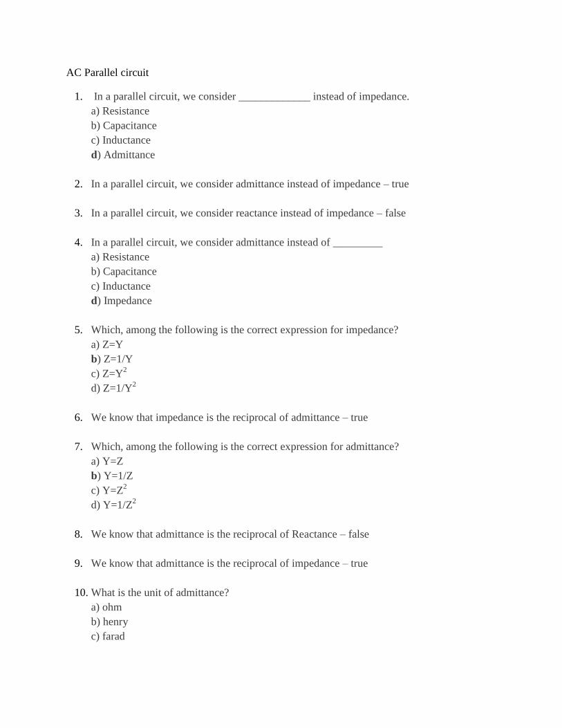
22. From the given circuit, find the value of IR.
a) 0
b) V/I
c) V/R
d) Cannot be determined
23. What is the relation between IR and V in the following circuit?
a) IR leads V
b) IR lags V
c) IR and V are in phase
d) No relation
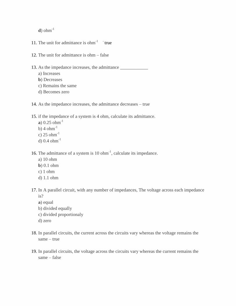
24. What is the expression for the current in the inductor from the following circuit?
a) V/I
b) V/XL
c) 0
d) Cannot be determined
25. What is the phase relation between IL and V from the following circuit?
a) IL lags V
b) IL leads V
c) IL and V are in phase
d) No relation
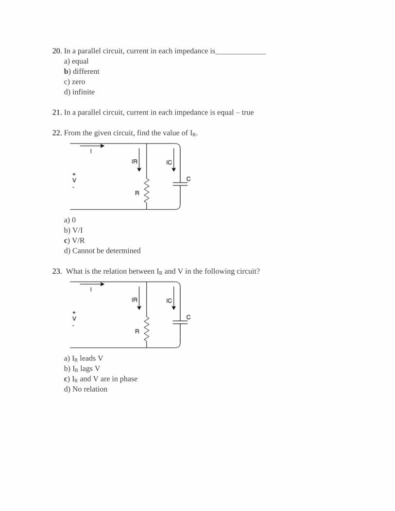
26. Find the expression for the current I from the given circuit.
a) I=IC
b) I=IR
c) I=IC+IR
d) I=0
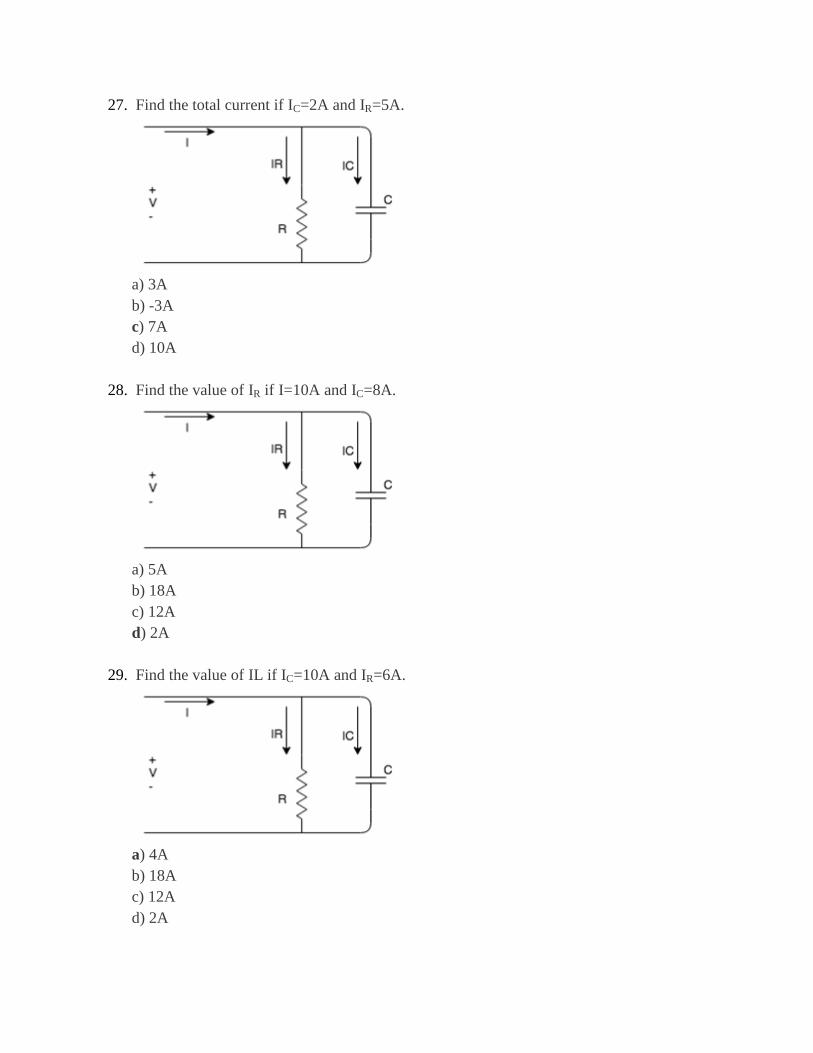
27. Find the total current if IC=2A and IR=5A.
a) 3A
b) -3A
c) 7A
d) 10A
28. Find the value of IR if I=10A and IC=8A.
a) 5A
b) 18A
c) 12A
d) 2A
29. Find the value of IL if IC=10A and IR=6A.
a) 4A
b) 18A
c) 12A
d) 2A
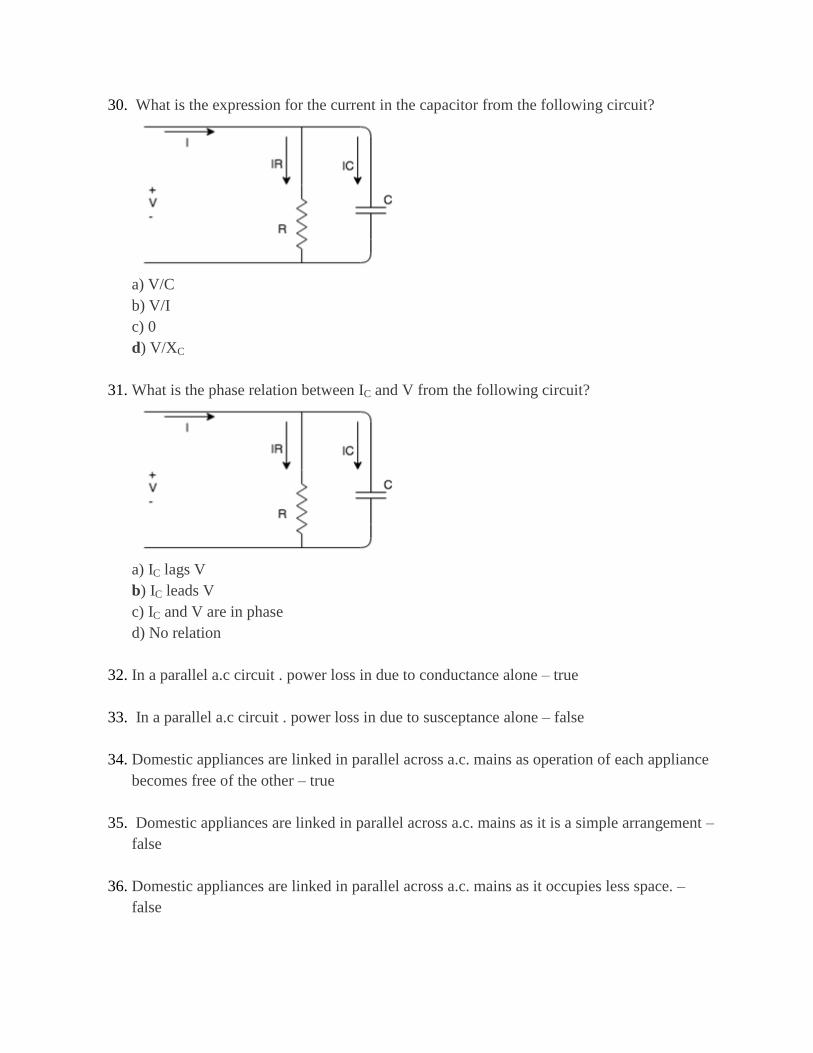
30. What is the expression for the current in the capacitor from the following circuit?
a) V/C
b) V/I
c) 0
d) V/XC
31. What is the phase relation between IC and V from the following circuit?
a) IC lags V
b) IC leads V
c) IC and V are in phase
d) No relation
32. In a parallel a.c circuit . power loss in due to conductance alone – true
33. In a parallel a.c circuit . power loss in due to susceptance alone – false
34. Domestic appliances are linked in parallel across a.c. mains as operation of each appliance
becomes free of the other – true
35. Domestic appliances are linked in parallel across a.c. mains as it is a simple arrangement –
false
36. Domestic appliances are linked in parallel across a.c. mains as it occupies less space. –
false
37. The conductance and susceptance components of admittance are series elements – false
38. The conductance and susceptance components of admittance are parallel elements – true
39. The conductance and susceptance components of admittance are series-parallel elements-
false
40. The active component in an impedance parallel circuit will __________ the voltage.
a) Leads
b) Lags
c) Be in phase with
d) Either leads or lags
41. The active component in an impedance parallel network will always be in phase with the
voltage in the circuit. – true
42. The quadrature component is also known as?
a) Active component
b) Reactive component
c) Either active or reactive component
d) Neither active nor reactive component
43. The quadrature component is also known as the reactive component because the reactive
component forms a quadrature with the voltage. – true
44. Change in circuit voltage will affect current – true
45. Change in circuit voltage will affect frequency – false
46. In an impedance parallel network the reactive component will either lead or lag the voltage
by 90 degrees. – true
47. In an impedance parallel network, the reactive component will ____________ the voltage
by 90 degrees.
a) Lead
b) Lag
c) Either lead or lag
d) Depends on the circuit
48. In an impedance parallel network the reactive component will lag the voltage by 90 degrees
– false
49. In an impedance parallel network, the reactive component will either lead or lag the voltage
by _________ degrees.
a) 0
b) 90
c) 45
d) 180
50. In an impedance parallel network the reactive component will either lead or lag the voltage
by 90 degrees. – true
Poly phase circuit
1. The power generated by a machine increases _____________ percent from single phase
to two phase.
a) 40.4
b) 41.4
c) 42.4
d) 43.4
2. The power generated by machine increases 41.4 percent from single phase to two phase.
– true
3. The power generated by machine increases 44.1 percent from single phase to two phase.
–false
4. In an ac system it is possible to connect two or more number of individual circuits to a
common poly phase source – true
5. In an ac system it is not possible to connect two or more number of individual circuits to
a common poly phase source – false
6. The percentage of power increased from single phase to three phase is?
a) 50
b) 100
c) 150
d) 200
7. The percentage of power increased from single phase to three phase is 50%- true
8. Beyond three phase the maximum possible increase is only seven percent but the
complications are many.- true
9. The percentage of power increased from single phase to three phase is 70% - false
10. Beyond three phase the maximum possible increase is only two percent but the
complications are many- false
11. When the power factor is __________ the power becomes zero 100 times a second in a
50Hz supply.
a) 0
b) 1
c) 2
d) 3
12. The power in a single phase circuit is pulsating – true
13. When the power factor is one, the power becomes zero 100 times a second in a 50Hz
supply. Therefore single phase motors have a pulsating torque. – true
14. Three phase motors are more easily started than single phase motors – true
15. Single phase motors are more easily started than three phase motors- false
16. Three phase motors are called self-starting motors.- true
17. Which motors are called self-starting motors?
a) single phase
b) two phase
c) three phase
d) four phase
18. Single phase or two phase or four phase motors are not called self-starting motors. – true
19. In three phase system, the three voltages (currents) differ in phase by
__________electrical degrees from each other in a particular sequence.
a) 30
b) 60
c) 90
d) 120
20. In general a three phase system of voltages is merely a combination of three single phase
systems of voltages - true
21. In three phase system, the three voltages (currents) differ in phase by 60⁰ from each other
in a particular sequence. – false
22. In three phase system at any given instant, the algebraic sum of three voltages must be?
a) 0
b) 1
c) 2
d) 3
23. Algebraic sum of three voltages = 0. – true
24. Phase sequence depends on the?
a) field
b) rotation of the field
c) armature
d) rotation of the armature
25. The sequence of voltages in the three phases undergo changes one after the other abd this
is called phase sequence. – true
26. Phase sequence depends on the rotation of the field not on rotation of armature or on field
or on armature. – true
27. If RR‘, YY
‘ and BB
‘ constitutes three phase sequence if V
‘RR = Vmsinωt its corresponding
field magnets are in clockwise direction, then V‘YY =?
a) Vmsinωt
b) Vmsin(ωt+120⁰)
c) Vmsin(ωt-120⁰)
d) Vmsin(ωt-240⁰)
28. If RR‘, YY
‘ and BB
‘ constitutes three phase sequence if V
‘RR = Vmsinωt its
corresponding field magnets are in clockwise direction ,V‘BB ?
a) Vmsin(ωt-240⁰)
b) Vmsin(ωt-120⁰)
c) Vmsin(ωt+240⁰)
d) Vmsinωt
29. Polyphase System is a combination of two or more than two voltages having same
magnitude and frequency but displaced from each other by an equal electrical angle. –
true
30. The angular displacement between the adjacent voltages is called a Phase Difference and
depends upon the number of phases.- true
31. Polyphase or we can say Three Phase System is universally adopted for a generation,
transmission and distribution of electric power – true
32. 3 Phase system requires more copper and aluminium for the transmission system in
comparison to a single phase transmission system. – false
33. Three phase circuit is the polyphase system where three phases are send together from the
generator to the load. – true
34. The power in three phase system is continuous as all the three phases are involved in
generating the total power. – true
35. In unbalance system the magnitude of voltage in all the three phases becomes different. –
true
36. In unbalance system the magnitude of voltage in all the three phases becomes same.-
false
37. In wye or star connection, ______________ of the three phases are joined together within
the alternator.
a) similar ends
b) opposite ends
c) one similar end, two opposite ends
d) one opposite end, two opposite ends
38. The voltage between __________ and ___________ is called phase voltage.
a) line and line
b) line and reference
c) neutral point and reference
d) line and neutral point
39. The voltage between line and line is called phase voltage. – false
40. the voltage between line and line is called line voltage.- true
41. The voltage between line and neutral point is called phase voltage. – true
42. The voltage between line and neutral point is called line voltage. – false
43. The voltage between ______________ is called line voltage.
a) line and neutral point
b) line and reference
c) line and line
d) neutral point and reference
44. The currents flowing through the phases are called the phase currents – true
45. The currents flowing through the phases are called the line currents-false
46. In the Delta or Mesh connection, there will be __________ number of common
terminals.
a) 1
b) 2
c) 3
d) 0
47. In the Delta or Mesh connection, there will be zero number of common terminals. – true
48. In the Delta or Mesh connection, there will be one number of common terminals.- false
49. The relation between line voltage and phase voltage in Delta or Mesh connection is?
a) Vphase > Vline
b) Vphase < Vline
c) Vphase = Vline
d) Vphase >= Vline
50. Which of the following voltage is a phase voltage in delta connection?
a) VRN
b) VBR
c) VYN
d) VBN
Power measurement in ac networks
1. The equation of the average power (Pavg) is?
a) (VmIm/2)cosθ
b) (VmIm/2)sinθ
c) VmImcosθ
d) VmImsinθ
2. Average power (Pavg) =?
a) VeffImcosθ
b) VeffIeffcosθ
c) VmImcosθ
d) VmIeffcosθ
3. To get average power we have to take the product of the effective values of both voltage
and current multiplied by cosine of the phase angle between the voltage and current. - true
4. In case of purely resistive circuit, the average power is?
a) VmIm
b) VmIm/2
c) VmIm/4
d) VmIm/8
5. In case of purely resistive circuit, the phase angle between the voltage and current is zero
– true
6. In case of purely capacitive circuit, average power = ____ and θ=___
a) 0, 0⁰
b) 1, 0⁰
c) 1, 90⁰
d) 0, 90⁰
7. In case of purely capacitive circuit, the phase angle between the voltage and current is 90⁰
- true
8. In case of purely capacitive circuit, the phase angle between the voltage and current is
120⁰ - false
9. In case of purely resistive circuit, the phase angle between the voltage and current is 90⁰-
false
10. In case of purely inductive circuit, average power = ____ and θ=___
a) 0, 90⁰
b) 1, 90⁰
c) 1, 0⁰
d) 0, 0⁰
11. If a circuit has complex impedance, the average power is ______
a) power stored in inductor only
b) power stored in capacitor only
c) power dissipated in resistor only
d) power stored in inductor and power dissipated in resistor
12. If a circuit has complex impedance, the average power is power dissipated in resistor only
and is not stored in capacitor or inductor.- true
13. A voltage v (t) = 100sinωt is applied to a circuit. The current flowing through the circuit is
i(t) = 15sin( ωt-30⁰). Find the effective value of voltage.
a) 70
b) 71
c) 72
d) 73
14. A voltage v (t) = 100sinωt is applied to a circuit. The current flowing through the circuit is
i(t) = 15sin( ωt-30⁰). Find the effective value of current
a) 9
b) 10
c) 11
d) 12
15. Determine the average power delivered to the circuit consisting of an impedance Z = 5+j8
when the current flowing through the circuit is I = 5∠30⁰.
a) 61.5
b) 62.5
c) 63.5
d) 64.5
16. The highest power factor will be?
a) 1
b) 2
c) 3
d) 4
17. The power factor is useful in determining the useful power transferred to a load. – true
18. If power factor = 1, then the current to the load is ______ with the voltage across it.
a) out of phase
b) in phase
c) 90⁰ out of phase
d) 45⁰ out of phase
19. If power factor = 1, then the current to the load is in phase with the voltage across it –true
20. If power factor = 0, then the current to the load is in phase with the voltage across it- false
21. In case of resistive load, the power factor =?
a) 4
b) 3
c) 2
d) 1
22. In case of resistive load, the power factor = 1 as the current to the load is in phase with the
voltage across it. – true
23. In case of resistive load, the power factor = 0.5 as the current to the load is in phase with
the voltage across it.- false
24. If power factor = 0, then the current to a load is ______ with the voltage.
a) in phase
b) out of phase
c) 45⁰ out of phase
d) 90⁰ out of phase
25. If the power factor = 0, then the current to a load is 90⁰ out of phase with the voltage and
it happens in case of reactive load. – true
26. If the power factor = 0, then the current to a load is 90⁰ out of phase with the voltage and
it happens in case of resistive load.- false
27. For reactive load, the power factor is equal to?
a) 0
b) 1
c) 2
d) 3
28. Average power is also called?
a) apparent power
b) reactive power
c) true power
d) instantaneous power
29. Average power is also called apparent power – false
30. Average power is also called reactive power –false
31. Average power is also called active power – true
32. If we apply a sinusoidal voltage to a circuit, the product of voltage and current is?
a) true power
b) apparent power
c) average power
d) reactive power
33. The apparent power is expressed in volt amperes - true
34. The active power is expressed in volt amperes – false
35. The power factor=?
a) sinθ
b) cosθ
c) tanθ
d) secθ
36. As the phase angle between the voltage and the current increases the power factor
decreases. – true
37. As the phase angle between the voltage and the current increases the power factor
increases. – false
38. The power factor is the ratio of ________ power to the ______ power.
a) average, apparent
b) apparent, reactive
c) reactive, average
d) apparent, average
39. The power factor is the ratio of average power to the apparent power.- true
40. The power factor is the ratio of apparent power to the average power – false
41. The power factor is called leading power factor in case of ____ circuits.
a) LC
b) RC
c) RL
d) RLC
42. The term lagging power factor is used in which circuits?
a) RLC
b) RC
c) RL
d) LC
43. The power factor is called leading power factor in case of RL circuits- false
44. The power factor is called leading power factor in case of RC circuits – true
45. The term lagging power factor is used in RL circuits – true
46. Reactive power is expressed in?
a) Watts (W)
b) Volt Amperes Reactive (VAR)
c) Volt Ampere (VA)
d) No units
47. Reactive power is expressed in Volt Amperes Reactive (VAR) – true
48. The reactive power equation (Pr) is?
a) Ieff2 (ωL)sin2(ωt+θ)
b) Ieff2 (ωL)cos2(ωt+θ)
c) Ieff2 (ωL)sin(ωt+θ)
d) Ieff2 (ωL)cos(ωt+θ)
49. The term lagging power factor is used in RC circuits – false
50. A sinusoidal voltage v = 50sinωt is applied to a series RL circuit. The current in the circuit
is given by I = 25sin (ωt-53⁰). Determine the apparent power (VA).
a) 620
b) 625
c) 630
d) 635
Three phase circuit with unbalance load
1. If the system is a three-wire system, the currents flowing towards the load in the three
lines must add to ___ at any given instant.
a) 1
b) 2
c) 3
d) zero
2. If the system is a three-wire system, the currents flowing towards the load in the three
lines must add to zero at any given instant. – true
3. If the system is a three-wire system, the currents flowing towards the load in the three
lines must add to maximum at any given instant. – false
4. The three impedances Z1 = 20∠30⁰Ω, Z2 = 40∠60⁰Ω, Z3 = 10∠-90⁰Ω are delta-connected
to a 400V, 3 – Ø system. Determine the phase current IR.
a) (17.32-j10) A
b) (-17.32-j10) A
c) (17.32+j10) A
d) (-17.32+j10) A
5. The three impedances Z1 = 20∠30⁰Ω, Z2 = 40∠60⁰Ω, Z3 = 10∠-90⁰Ω are delta-connected
to a 400V, 3 – Ø system. Find the phase current IY.
a) (10-j0) A
b) (10+j0) A
c) (-10+j0) A
d) (-10-j0) A
6. The three impedances Z1 = 20∠30⁰Ω, Z2 = 40∠60⁰Ω, Z3 = 10∠-90⁰Ω are delta-connected
to a 400V, 3 – Ø system. Find the phase current IB.
a) (34.64-j20) A
b) (34.64+j20) A
c) (-34.64+j20) A
d) (-34.64-j20) A
7. The three impedances Z1 = 20∠30⁰Ω, Z2 = 40∠60⁰Ω, Z3 = 10∠-90⁰Ω are delta-connected
to a 400V, 3 – Ø system, find the line current I1.
a) (-51.96-j10) A
b) (-51.96+j10) A
c) (51.96+j10) A
d) (51.96+j10) A
8. The three impedances Z1 = 20∠30⁰Ω, Z2 = 40∠60⁰Ω, Z3 = 10∠-90⁰Ω are delta-connected
to a 400V, 3 – Ø system, find the line current I2.
a) (-27.32+j10) A
b) (27.32+j10) A
c) (-27.32-j10) A
d) (27.32-j10) A
9. The three impedances Z1 = 20∠30⁰Ω, Z2 = 40∠60⁰Ω, Z3 = 10∠-90⁰Ω are delta-connected
to a 400V, 3 – Ø system, find the line current I3.
a) (24.646+j20) A
b) (-24.646+j20) A
c) (-24.646-j20) A
d) (24.646-j20) A
10. The term power is defined as the product of square of current and the impedance- true
11. The term power is defined as the product of square of voltage and the impedance- false
12. The term power is defined as the product of square of current and the reactance – false
13. If the load impedance is Z∠Ø, the current (IR ) is?
a) (V/Z)∠-Ø
b) (V/Z)∠Ø
c) (V/Z)∠90-Ø
d) (V/Z)∠-90+Ø
14. If a resistor ZR is connected between R and N, ZBR between R and B, ZRY between R and
Y and ZBY between B and Y form a delta connection, then after transformation to star, the
impedance at R is?
a) (ZBRZBY)/(ZRY+ZBY+ZBR)
b) (ZRYZBR)/(ZRY+ZBY+ZBR)
c) (ZRYZBY)/(ZRY+ZBY+ZBR)
d) (ZRY)/(ZRY+ZBY+ZBR)
15. If a resistor ZR is connected between R and N, ZBR between R and B, ZRY between R and
Y and ZBY between B and Y form a delta connection, then after transformation to star, the
impedance at Y is?
a) (ZBRZBY)/(ZRY+ZBY+ZBR)
b) (ZRYZBR)/(ZRY+ZBY+ZBR)
c) (ZRYZBY)/(ZRY+ZBY+ZBR)
d) (ZRY)/(ZRY+ZBY+ZBR)
16. If a resistor ZR is connected between R and N, ZBR between R and B, ZRY between R and
Y and ZBY between B and Y form a delta connection, then after transformation to star, the
impedance at B is?
a) (ZBRZBY)/(ZRY+ZBY+ZBR)
b) (ZRYZBR)/(ZRY+ZBY+ZBR)
c) (ZRYZBY)/(ZRY+ZBY+ZBR)
d) (ZRY)/(ZRY+ZBY+ZBR)
17. If the resistors of star connected system are ZR, ZY, ZB then the impedance ZRY in delta
connected system will be?
a) (ZRZY+ ZYZB+ ZBZR)/ZB
b) (ZRZY+ ZYZB+ ZBZR)/ZY
c) (ZRZY+ ZYZB+ ZBZR)/ZR
d) (ZRZY+ ZYZB+ ZBZR)/(ZR+ZY )
18. After transformation to delta, the impedance ZRY in delta connected system will be
(ZRZY+ ZYZB+ ZBZR)/ZB. – true
19. If the resistors of star connected system are ZR, ZY, ZB then the impedance ZBY in delta
connected system will be?
a) (ZRZY+ ZYZB+ ZBZR)/(ZB+ZY )
b) (ZRZY+ ZYZB+ ZBZR)/ZB
c) (ZRZY+ ZYZB+ ZBZR)/ZY
d) (ZRZY+ ZYZB+ ZBZR)/ZR
20. After transformation to delta, the impedance ZBY in delta connected system will be (Z_R
(ZRZY+ ZYZB+ ZBZR)/ZR. – true
21. If the resistors of star connected system are ZR, ZY, ZB then the impedance ZBR in delta
connected system will be?
a) (ZRZY+ ZYZB+ ZBZR)/ZY
b) (ZRZY+ ZYZB+ ZBZR)/R
c) (ZRZY+ ZYZB+ ZBZR)/ZB
d) (ZRZY+ ZYZB+ ZBZR)/(ZB+ZR )
22. If a star connected system has equal impedances Z1, then after converting into delta
connected system having equal impedances Z2, then?
a) Z2 = Z1
b) Z2 = 2Z1
c) Z2 = 3Z1
d) Z2 = 4Z1
23. If a star connected system has equal impedances Z1, then after converting into delta
connected system having equal impedances Z2, then Z2 = 3Z1. – true
24. If a star connected system has equal impedances Z1, then after converting into delta
connected system having equal impedances Z2, then Z2 = Z1. – false
25. A symmetrical three-phase, three-wire 440V supply is connected to star-connected load.
The impedances in each branch are ZR = (2+j3) Ω, ZY = (1-j2) Ω, ZB = (3+j4) Ω. Find
ZRY.
a) (5.22-j0.82) Ω
b) (-3.02+j8) Ω
c) (3.8-j0.38) Ω
d) (-5.22+j0.82) Ω
26. A symmetrical three-phase, three-wire 440V supply is connected to star-connected load.
The impedances in each branch are ZR = (2+j3) Ω, ZY = (1-j2) Ω, ZB = (3+j4) Ω. Find
ZBY.
a) (5.22-j0.82) Ω
b) (-3.02+j8) Ω
c) (3.8-j0.38) Ω
d) (-5.22+j0.82) Ω
27. A symmetrical three-phase, three-wire 440V supply is connected to star-connected load.
The impedances in each branch are ZR = (2+j3) Ω, ZY = (1-j2) Ω, ZB = (3+j4) Ω. Find
ZBR.
a) (5.22-j0.82) Ω
b) (-3.02+j8) Ω
c) (3.8-j0.38) Ω
d) (-5.22+j0.82) Ω
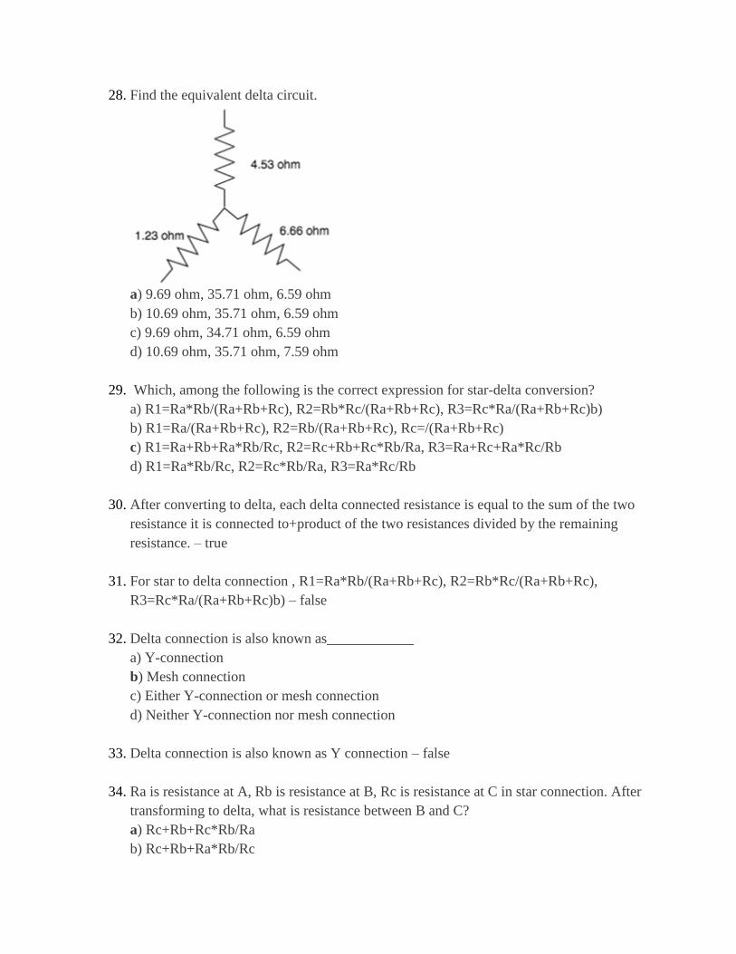
28. Find the equivalent delta circuit.
a) 9.69 ohm, 35.71 ohm, 6.59 ohm
b) 10.69 ohm, 35.71 ohm, 6.59 ohm
c) 9.69 ohm, 34.71 ohm, 6.59 ohm
d) 10.69 ohm, 35.71 ohm, 7.59 ohm
29. Which, among the following is the correct expression for star-delta conversion?
a) R1=Ra*Rb/(Ra+Rb+Rc), R2=Rb*Rc/(Ra+Rb+Rc), R3=Rc*Ra/(Ra+Rb+Rc)b)
b) R1=Ra/(Ra+Rb+Rc), R2=Rb/(Ra+Rb+Rc), Rc=/(Ra+Rb+Rc)
c) R1=Ra+Rb+Ra*Rb/Rc, R2=Rc+Rb+Rc*Rb/Ra, R3=Ra+Rc+Ra*Rc/Rb
d) R1=Ra*Rb/Rc, R2=Rc*Rb/Ra, R3=Ra*Rc/Rb
30. After converting to delta, each delta connected resistance is equal to the sum of the two
resistance it is connected to+product of the two resistances divided by the remaining
resistance. – true
31. For star to delta connection , R1=Ra*Rb/(Ra+Rb+Rc), R2=Rb*Rc/(Ra+Rb+Rc),
R3=Rc*Ra/(Ra+Rb+Rc)b) – false
32. Delta connection is also known as____________
a) Y-connection
b) Mesh connection
c) Either Y-connection or mesh connection
d) Neither Y-connection nor mesh connection
33. Delta connection is also known as Y connection – false
34. Ra is resistance at A, Rb is resistance at B, Rc is resistance at C in star connection. After
transforming to delta, what is resistance between B and C?
a) Rc+Rb+Rc*Rb/Ra
b) Rc+Rb+Ra*Rb/Rc
c) Ra+Rb+Ra*Rc/Rb
d) Rc+Rb+Rc*Ra/Rb
35. Ra is resistance at A, Rb is resistance at B, Rc is resistance at C in star connection. After
transforming to delta, what is resistance between A and C?
a) Ra+Rb+Ra*Rb/Rc
b) Ra+Rc+Ra*Rc/Rb
c) Ra+Rb+Ra*Rc/Ra
d) Ra+Rc+Ra*Rb/Rc
36. Ra is resistance at A, Rb is resistance at B, Rc is resistance at C in star connection. After
transforming to delta, what is resistance between A and B?
a) Rc+Rb+Ra*Rb/Rc
b) Ra+Rb+Ra*Rc/Rb
c) Ra+Rb+Ra*Rb/Rc
d) Ra+Rc+Ra*Rc/Rb
37. If a 1ohm 2ohm and 32/3ohm resistor is connected in star, find the equivalent delta
connection.
a) 34 ohm, 18.67 ohm, 3.19 ohm
b) 33 ohm, 18.67 ohm, 3.19 ohm
c) 33 ohm, 19.67 ohm, 3.19 ohm
d) 34 ohm, 19.67 ohm, 3.19 ohm
38. If an 8/9ohm, 4/3ohm and 2/3ohm resistor is connected in star, find its delta equivalent.
a) 4ohm, 3ohm, 2ohm
b) 1ohm, 3ohm, 2ohm
c) 4ohm, 1ohm, 2ohm
d) 4ohm, 3ohm, 1ohm
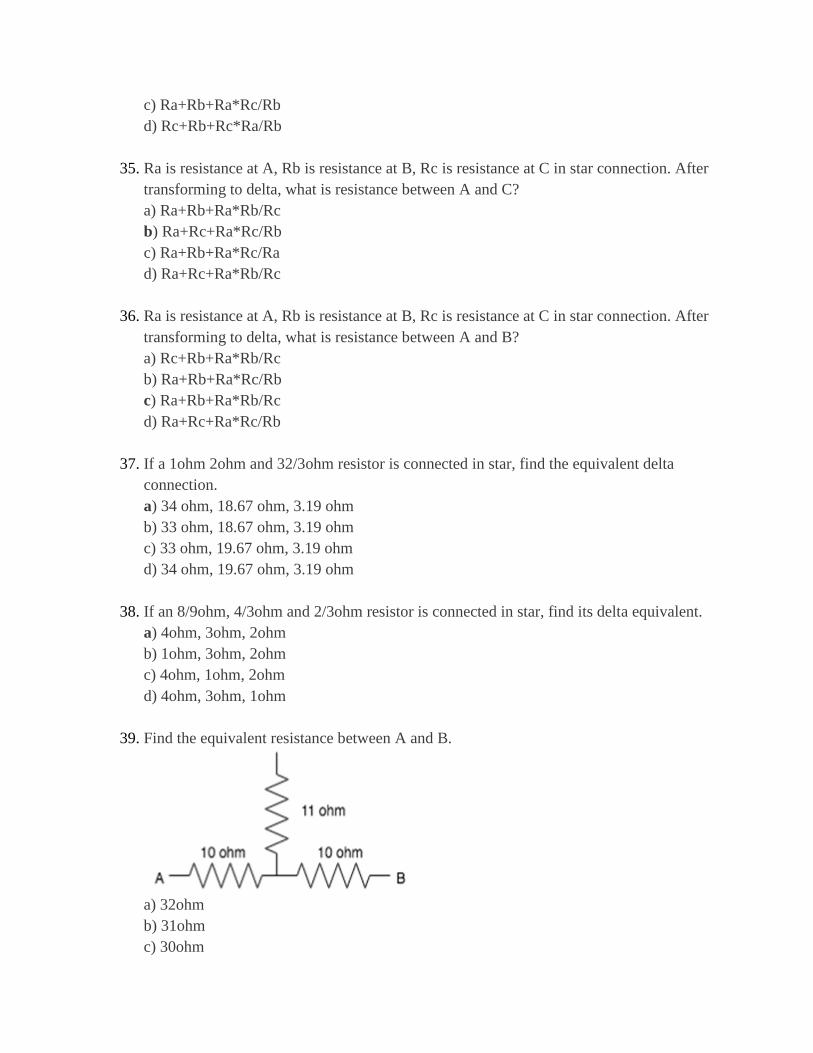
39. Find the equivalent resistance between A and B.
a) 32ohm
b) 31ohm
c) 30ohm
d) 29ohm
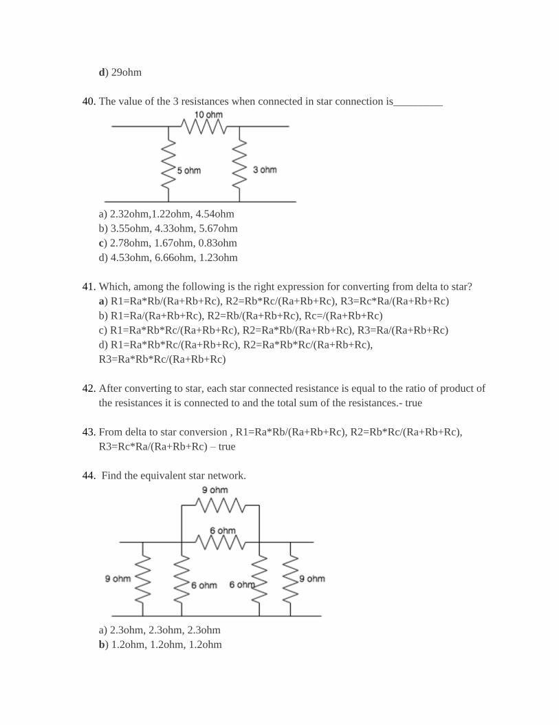
40. The value of the 3 resistances when connected in star connection is_________
a) 2.32ohm,1.22ohm, 4.54ohm
b) 3.55ohm, 4.33ohm, 5.67ohm
c) 2.78ohm, 1.67ohm, 0.83ohm
d) 4.53ohm, 6.66ohm, 1.23ohm
41. Which, among the following is the right expression for converting from delta to star?
a) R1=Ra*Rb/(Ra+Rb+Rc), R2=Rb*Rc/(Ra+Rb+Rc), R3=Rc*Ra/(Ra+Rb+Rc)
b) R1=Ra/(Ra+Rb+Rc), R2=Rb/(Ra+Rb+Rc), Rc=/(Ra+Rb+Rc)
c) R1=Ra*Rb*Rc/(Ra+Rb+Rc), R2=Ra*Rb/(Ra+Rb+Rc), R3=Ra/(Ra+Rb+Rc)
d) R1=Ra*Rb*Rc/(Ra+Rb+Rc), R2=Ra*Rb*Rc/(Ra+Rb+Rc),
R3=Ra*Rb*Rc/(Ra+Rb+Rc)
42. After converting to star, each star connected resistance is equal to the ratio of product of
the resistances it is connected to and the total sum of the resistances.- true
43. From delta to star conversion , R1=Ra*Rb/(Ra+Rb+Rc), R2=Rb*Rc/(Ra+Rb+Rc),
R3=Rc*Ra/(Ra+Rb+Rc) – true
44. Find the equivalent star network.
a) 2.3ohm, 2.3ohm, 2.3ohm
b) 1.2ohm, 1.2ohm, 1.2ohm
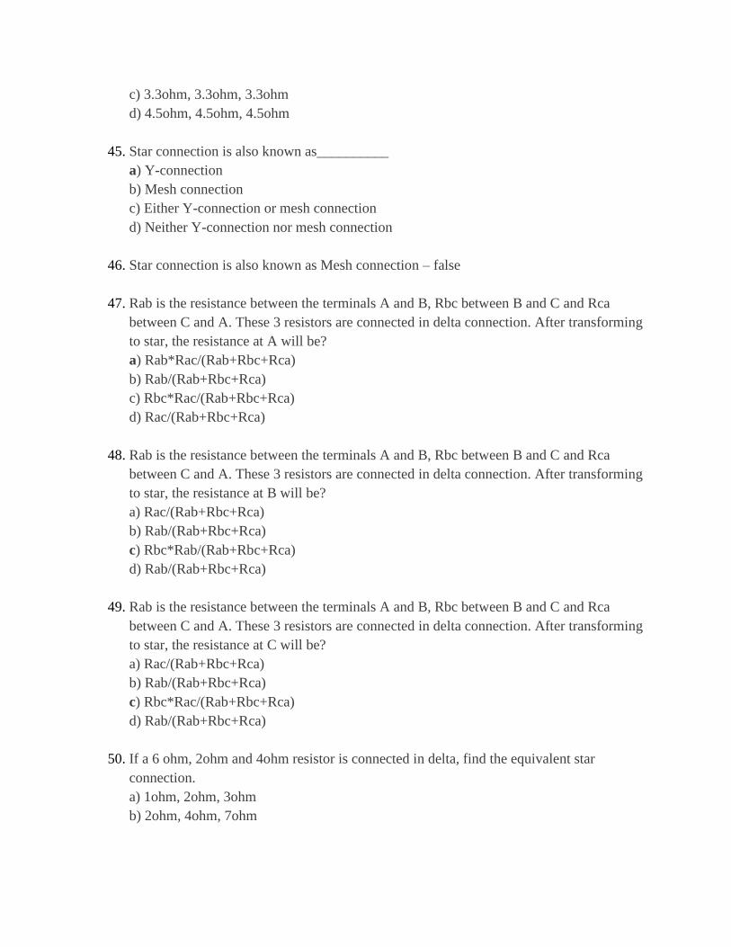
c) 3.3ohm, 3.3ohm, 3.3ohm
d) 4.5ohm, 4.5ohm, 4.5ohm
45. Star connection is also known as__________
a) Y-connection
b) Mesh connection
c) Either Y-connection or mesh connection
d) Neither Y-connection nor mesh connection
46. Star connection is also known as Mesh connection – false
47. Rab is the resistance between the terminals A and B, Rbc between B and C and Rca
between C and A. These 3 resistors are connected in delta connection. After transforming
to star, the resistance at A will be?
a) Rab*Rac/(Rab+Rbc+Rca)
b) Rab/(Rab+Rbc+Rca)
c) Rbc*Rac/(Rab+Rbc+Rca)
d) Rac/(Rab+Rbc+Rca)
48. Rab is the resistance between the terminals A and B, Rbc between B and C and Rca
between C and A. These 3 resistors are connected in delta connection. After transforming
to star, the resistance at B will be?
a) Rac/(Rab+Rbc+Rca)
b) Rab/(Rab+Rbc+Rca)
c) Rbc*Rab/(Rab+Rbc+Rca)
d) Rab/(Rab+Rbc+Rca)
49. Rab is the resistance between the terminals A and B, Rbc between B and C and Rca
between C and A. These 3 resistors are connected in delta connection. After transforming
to star, the resistance at C will be?
a) Rac/(Rab+Rbc+Rca)
b) Rab/(Rab+Rbc+Rca)
c) Rbc*Rac/(Rab+Rbc+Rca)
d) Rab/(Rab+Rbc+Rca)
50. If a 6 ohm, 2ohm and 4ohm resistor is connected in delta, find the equivalent star
connection.
a) 1ohm, 2ohm, 3ohm
b) 2ohm, 4ohm, 7ohm

c) 5ohm, 4ohm, 2ohm
d) 1ohm, 2ohm, 2/3ohm
Related Documents


