PROPOSED NATIONAL BANK OF KENYA LTD, MOMBASA POLYTECHNIC UNIVERSITY COLLEGE BRANCH-MOMBASA. FOR NATIONAL BANK OF KENYA LTD P.O. BOX 72866-00200 NAIROBI. MECHANICAL ENGINEERING SERVICES SUB – CONTRACT CONDITIONS, SPECIFICATIONS AND BILLS OF QUANTITIES FOR AIR CONDITIONING AND MECHANICAL VENTILATION NAME OF TENDERER: .....................................................................…. ………………………………………………………………………… ELECTRICAL/MECHANICAL ENGINEERS’ ARCHITECTS SYNCHROCONSULT ASSOCI ATES LTD BOUNDLESS ARCHTECTS P. O. BOX 79626 00200 P.O. BOX 9668-00100 NAIROBI NAIROBI QUANTITY SURVEYORS NDERITU CONSULTANTS P.O.BOX 62405-00200 NAIROBI STRUCTUENGINEERS XENOCON CONSLTINGNGI P.O00200

Welcome message from author
This document is posted to help you gain knowledge. Please leave a comment to let me know what you think about it! Share it to your friends and learn new things together.
Transcript
7/28/2019 Ac and Mech Ventillations Specs NBK
http://slidepdf.com/reader/full/ac-and-mech-ventillations-specs-nbk 1/31
PROPOSED NATIONAL BANK OF KENYA LTD, MOMBASA
POLYTECHNIC UNIVERSITY COLLEGE BRANCH-MOMBASA.
FOR
NATIONAL BANK OF KENYA LTDP.O. BOX 72866-00200
NAIROBI.
MECHANICAL ENGINEERING SERVICES SUB – CONTRACT
CONDITIONS, SPECIFICATIONS AND BILLS OF QUANTITIES
FOR AIR CONDITIONING AND MECHANICAL VENTILATION
NAME OF TENDERER: .....................................................................….
…………………………………………………………………………
ELECTRICAL/MECHANICAL ENGINEERS’ ARCHITECTS
SYNCHROCONSULT ASSOCIATES LTD BOUNDLESS ARCHTECTS
P. O. BOX 79626 00200 P.O. BOX 9668-00100
NAIROBI NAIROBI
QUANTITY SURVEYORS
NDERITU CONSULTANTS
P.O.BOX 62405-00200
NAIROBI
STRUCTUENGINEERS
XENOCON CONSLTINGNGI P.O00200
7/28/2019 Ac and Mech Ventillations Specs NBK
http://slidepdf.com/reader/full/ac-and-mech-ventillations-specs-nbk 2/31
MAY 2012
INSTRUCTIONS TO TENDERERS
1. Tenders shall be submitted on the form of tender attached and all blanks in this space are to
be filled.
2. The tenderer and all other recipients of this document are to treat it as private andconfidential.
3. The employer does not bind himself to accept the lowest or any tender and will not be
responsible for paying any expenses of losses which may be incurred by any tenderer in the
preparation of his tender.
4. The tender and all accompanying documents shall be enclosed in a plain sealed envelope
marked:
“ Proposed National Bank of Kenya Ltd Mombasa Polytechnic University
College Branch-Mombasa
The sub-contract will deem to have been awarded when formal notice is given to thetenderer that the employer has accepted the tenderers proposals.
5. The tender must be received at the address given below not later than 12.00 noon on the
day stated in the covering letter :-
NATIONAL BANK OF KENYA LTD
P.O. BOX 72866-00200
NAIROBI.
2
7/28/2019 Ac and Mech Ventillations Specs NBK
http://slidepdf.com/reader/full/ac-and-mech-ventillations-specs-nbk 3/31
FORM OF TENDER
MECHANICAL SERVICES
TO: NATIONAL BANK OF KENYA LTD
P. O. BOX 72866-00200NAIROBI
1. I/We understand that works, the subject of this tender, are covered by a prime cost of
provisional sum in the main contract entered into by the main contractor.
I/We shall become a Nominated sub-Contractor, that is to say, a sub-contractor nominated
by the Architects under the terms and conditions of the current form of agreement and
schedule of conditions, of Building Contract published by the Architects Association of
Kenya (latest edition with quantities).
2. It is confirmed that I/we have notice of all the provisions of the main contract including the
detailed prices of the contract in the schedule and Bill of Quantities.I/We undertake in accordance with the particulars set out in the preliminaries and to the
satisfaction of the Architects, to execute and complete the sub-contract works as described
in the specification and drawings for the sum of KENYA SHILLINGS
.................................................................................................................................
..................................................................................................................................only
(KSH............................................/=)
3. I/We confirm that this Tender is subject to adjustments by any variation ordered by theArchitects in accordance with the terms of the main contract.
4. I/We undertake to commence the works within 7 days from the date of official confirmation
of the acceptance of the Tender.
5. I/We further undertake to complete the work in accordance with the Main Contractors
programme.
6. I/We agree that this Tender shall be open for acceptance by the Architects within 90 days
from the date given below.
6. I/We understand that you are not bound to accept the lowest or any tender
7. Completion period ……………Days……………………………Weeks.
For and on behalf of:
..........................................................................................................................……………..
................................................................................................................................................
......................................................................................................................................……..
Signature/Official Stamp: …….............................................................................……....
3
7/28/2019 Ac and Mech Ventillations Specs NBK
http://slidepdf.com/reader/full/ac-and-mech-ventillations-specs-nbk 4/31
Date:................................................
CONTENTS PAGE:
CONTENTS PAGE
FURTHER INSTRUCTIONS TO TENDERERS 5
DEFINITIONS 5- 6
ABREVIATIONS 7
PART A- PRELIMINARIES 8-13
PART B –GENERAL SPECIFICATIONS 14-23
PART C – PARTICULAR SPECIFICATION 24-29
PART D – BILLS OF QUANTITIES 30
SUMMARY OF PRICES D/5
4
7/28/2019 Ac and Mech Ventillations Specs NBK
http://slidepdf.com/reader/full/ac-and-mech-ventillations-specs-nbk 5/31
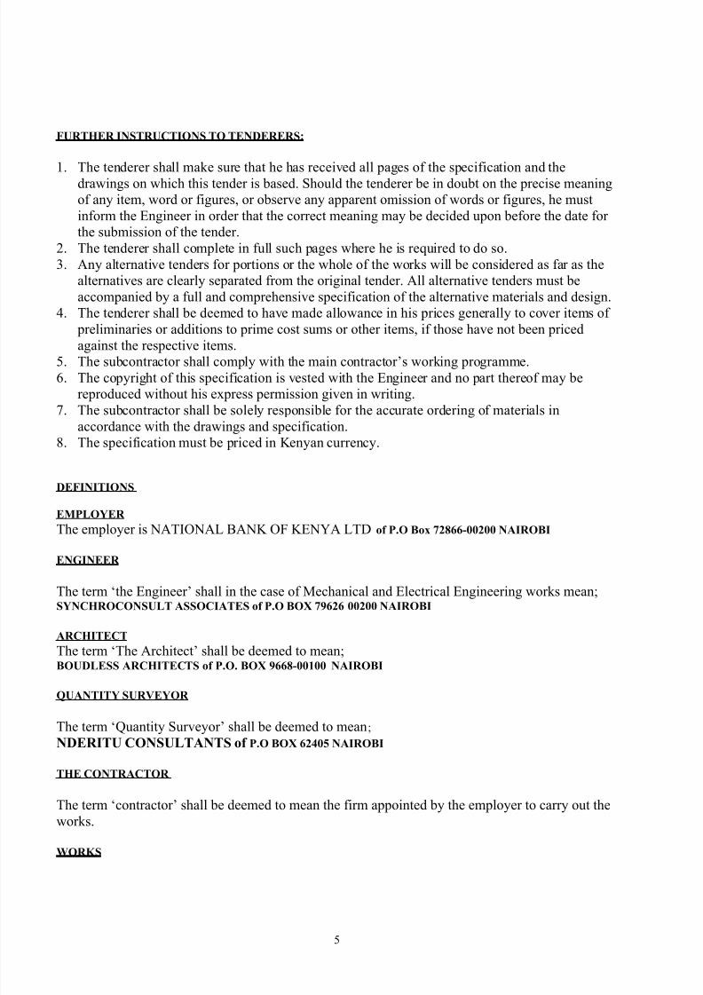
FURTHER INSTRUCTIONS TO TENDERERS:
1. The tenderer shall make sure that he has received all pages of the specification and thedrawings on which this tender is based. Should the tenderer be in doubt on the precise meaning
of any item, word or figures, or observe any apparent omission of words or figures, he must
inform the Engineer in order that the correct meaning may be decided upon before the date for
the submission of the tender.
2. The tenderer shall complete in full such pages where he is required to do so.
3. Any alternative tenders for portions or the whole of the works will be considered as far as the
alternatives are clearly separated from the original tender. All alternative tenders must be
accompanied by a full and comprehensive specification of the alternative materials and design.
4. The tenderer shall be deemed to have made allowance in his prices generally to cover items of
preliminaries or additions to prime cost sums or other items, if those have not been priced
against the respective items.5. The subcontractor shall comply with the main contractor’s working programme.
6. The copyright of this specification is vested with the Engineer and no part thereof may be
reproduced without his express permission given in writing.
7. The subcontractor shall be solely responsible for the accurate ordering of materials in
accordance with the drawings and specification.
8. The specification must be priced in Kenyan currency.
DEFINITIONS
EMPLOYER
The employer is NATIONAL BANK OF KENYA LTD of P.O Box 72866-00200 NAIROBI
ENGINEER
The term ‘the Engineer’ shall in the case of Mechanical and Electrical Engineering works mean;SYNCHROCONSULT ASSOCIATES of P.O BOX 79626 00200 NAIROBI
ARCHITECT
The term ‘The Architect’ shall be deemed to mean;BOUDLESS ARCHITECTS of P.O. BOX 9668-00100 NAIROBI
QUANTITY SURVEYOR
The term ‘Quantity Surveyor’ shall be deemed to mean;
NDERITU CONSULTANTS of P.O BOX 62405 NAIROBI
THE CONTRACTOR
The term ‘contractor’ shall be deemed to mean the firm appointed by the employer to carry out the
works.
WORKS
5
7/28/2019 Ac and Mech Ventillations Specs NBK
http://slidepdf.com/reader/full/ac-and-mech-ventillations-specs-nbk 6/31
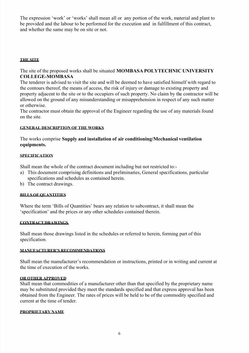
The expression ‘work’ or ‘works’ shall mean all or any portion of the work, material and plant to
be provided and the labour to be performed for the execution and in fulfillment of this contract,
and whether the same may be on site or not.
THE SITE
The site of the proposed works shall be situated MOMBASA POLYTECHNIC UNIVERSITY
COLLEGE-MOMBASA
The tenderer is advised to visit the site and will be deemed to have satisfied himself with regard to
the contours thereof, the means of access, the risk of injury or damage to existing property and
property adjacent to the site or to the occupiers of such property. No claim by the contractor will be
allowed on the ground of any misunderstanding or misapprehension in respect of any such matter
or otherwise.
The contractor must obtain the approval of the Engineer regarding the use of any materials found
on the site.
GENERAL DESCRIPTION OF THE WORKS
The works comprise Supply and installation of air conditioning/Mechanical ventilation
equipments.
SPECIFICATION
Shall mean the whole of the contract document including but not restricted to:-
a) This document comprising definitions and preliminaries, General specifications, particular
specifications and schedules as contained herein.
b) The contract drawings.
BILLS OF QUANTITIES
Where the term ‘Bills of Quantities’ bears any relation to subcontract, it shall mean the
‘specification’ and the prices or any other schedules contained therein.
CONTRACT DRAWINGS
Shall mean those drawings listed in the schedules or referred to herein, forming part of this
specification.
MANUFACTURER’S RECOMMENDATIONS
Shall mean the manufacturer’s recommendation or instructions, printed or in writing and current at
the time of execution of the works.
OR OTHER APPROVED
Shall mean that commodities of a manufacturer other than that specified by the proprietary name
may be substituted provided they meet the standards specified and that express approval has been
obtained from the Engineer. The rates of prices will be held to be of the commodity specified and
current at the time of tender.
PROPRIETARY NAME
6
7/28/2019 Ac and Mech Ventillations Specs NBK
http://slidepdf.com/reader/full/ac-and-mech-ventillations-specs-nbk 7/31
The phrase ‘or other approved’ shall be deemed to be included in every case where commodities
are specified by proprietary name.
APPROVED, DIRECTED AND SELECTED
Shall mean approved, directed or selected by the Engineer and shall not be binding unless put in
writing and signed by the Engineer.
ABBREVIATIONS
No - shall mean number
m - shall mean metre
LM - shall mean linear metre
mm - shall mean millimetre
kg - shall mean kilogramme
Ltr. - shall mean litre
S.S - shall mean stainless steel
G.M.S - shall mean galvanized mild steelM.O.P.W- shall mean ministry of public works
B.S - shall mean the Current British standards specification published by
the British standard Institution
C.P - shall mean the current British standard code of practice published
together with the B.S
I.E.E - shall mean the Institute of Electrical Engineers, Savoy Place,
London.
I.S.O - shall mean the International organization for standardization
K.B.S - shall mean the Kenya Bureau of Standards.
Ditto - shall mean the whole of the preceding description except as qualified
in the description in which it occurs.
7
7/28/2019 Ac and Mech Ventillations Specs NBK
http://slidepdf.com/reader/full/ac-and-mech-ventillations-specs-nbk 8/31
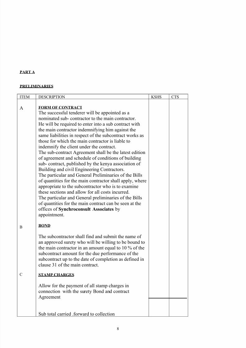
PART A
PRELIMINARIES
ITEM DESCRIPTION KSHS CTS
A
B
C
FORM OF CONTRACT
The successful tenderer will be appointed as a
nominated sub- contractor to the main contractor.
He will be required to enter into a sub contract with
the main contractor indemnifying him against the
same liabilities in respect of the subcontract works as
those for which the main contractor is liable to
indemnify the client under the contract.
The sub-contract Agreement shall be the latest edition
of agreement and schedule of conditions of building
sub- contract, published by the kenya association of
Building and civil Engineering Contractors.
The particular and General Preliminaries of the Bills
of quantities for the main contractor shall apply, whereappropriate to the subcontractor who is to examine
these sections and allow for all costs incurred.
The particular and General preliminaries of the Bills
of quantities for the main contract can be seen at the
offices of Synchroconsult Associates by
appointment.
BOND
The subcontractor shall find and submit the name of
an approved surety who will be willing to be bound tothe main contractor in an amount equal to 10 % of the
subcontract amount for the due performance of the
subcontract up to the date of completion as defined in
clause 31 of the main contract.
STAMP CHARGES
Allow for the payment of all stamp charges in
connection with the surety Bond and contract
Agreement
Sub total carried .forward to collection
8
7/28/2019 Ac and Mech Ventillations Specs NBK
http://slidepdf.com/reader/full/ac-and-mech-ventillations-specs-nbk 9/31
PRELIMINARIES
ITEM DESCRIPTION KSHS CTS
D
E
F
G
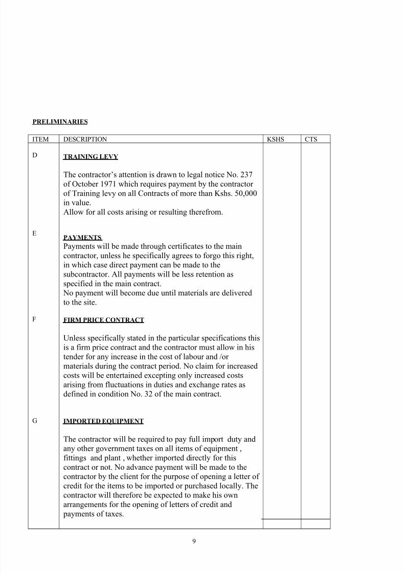
TRAINING LEVY
The contractor’s attention is drawn to legal notice No. 237
of October 1971 which requires payment by the contractor
of Training levy on all Contracts of more than Kshs. 50,000
in value.Allow for all costs arising or resulting therefrom.
PAYMENTS
Payments will be made through certificates to the main
contractor, unless he specifically agrees to forgo this right,
in which case direct payment can be made to the
subcontractor. All payments will be less retention as
specified in the main contract.
No payment will become due until materials are delivered
to the site.
FIRM PRICE CONTRACT
Unless specifically stated in the particular specifications this
is a firm price contract and the contractor must allow in his
tender for any increase in the cost of labour and /or
materials during the contract period. No claim for increased
costs will be entertained excepting only increased costs
arising from fluctuations in duties and exchange rates as
defined in condition No. 32 of the main contract.
IMPORTED EQUIPMENT
The contractor will be required to pay full import duty and
any other government taxes on all items of equipment ,
fittings and plant , whether imported directly for this
contract or not. No advance payment will be made to the
contractor by the client for the purpose of opening a letter of
credit for the items to be imported or purchased locally. The
contractor will therefore be expected to make his own
arrangements for the opening of letters of credit and payments of taxes.
9
7/28/2019 Ac and Mech Ventillations Specs NBK
http://slidepdf.com/reader/full/ac-and-mech-ventillations-specs-nbk 10/31
Sub total c.f to collection
PRELIMINARIES
ITEM DESCRIPTION KSHS CTS
A
B
C
D
E
F
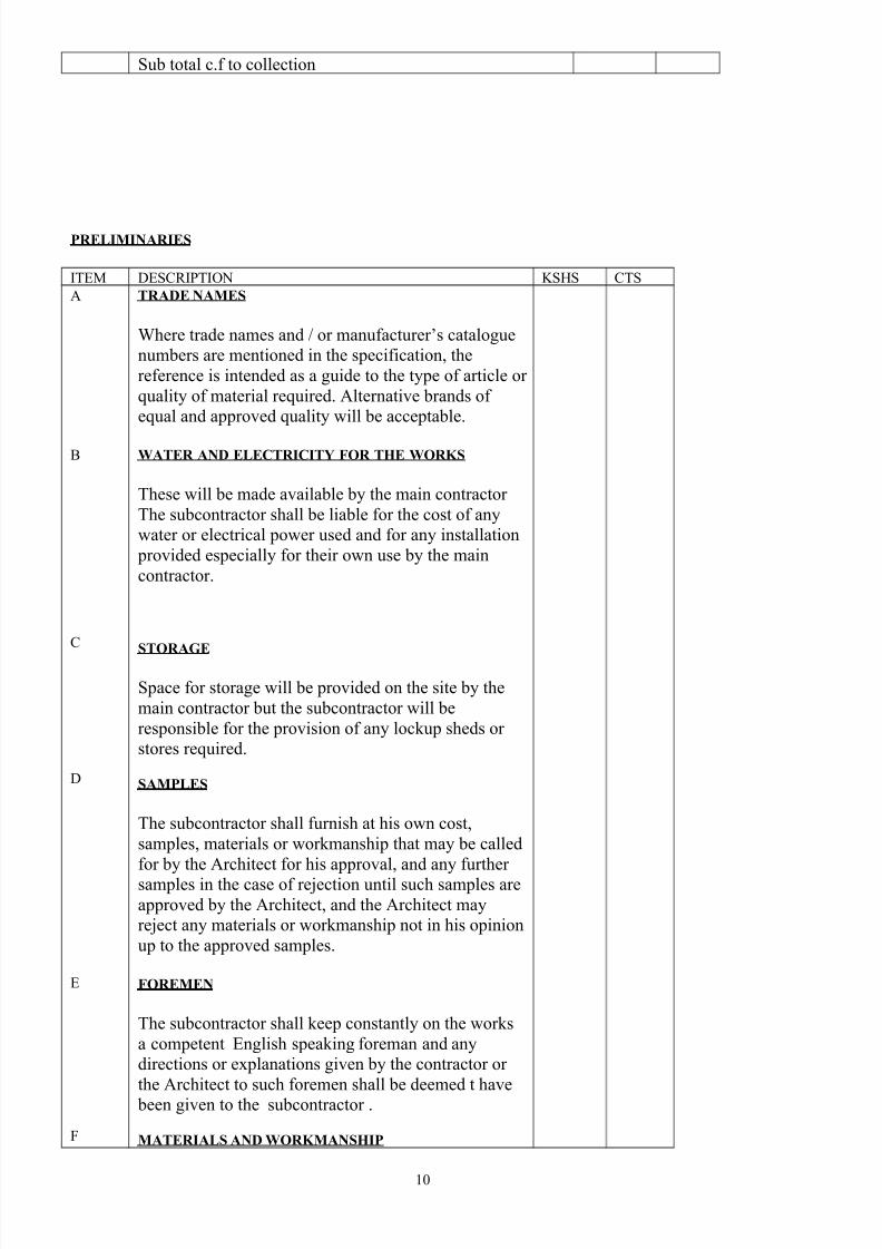
TRADE NAMES
Where trade names and / or manufacturer’s catalogue
numbers are mentioned in the specification, the
reference is intended as a guide to the type of article or
quality of material required. Alternative brands of
equal and approved quality will be acceptable.
WATER AND ELECTRICITY FOR THE WORKS
These will be made available by the main contractor
The subcontractor shall be liable for the cost of any
water or electrical power used and for any installation
provided especially for their own use by the main
contractor.
STORAGE
Space for storage will be provided on the site by the
main contractor but the subcontractor will be
responsible for the provision of any lockup sheds or
stores required.
SAMPLES
The subcontractor shall furnish at his own cost,
samples, materials or workmanship that may be called
for by the Architect for his approval, and any further
samples in the case of rejection until such samples are
approved by the Architect, and the Architect may
reject any materials or workmanship not in his opinion
up to the approved samples.
FOREMEN
The subcontractor shall keep constantly on the works
a competent English speaking foreman and any
directions or explanations given by the contractor or
the Architect to such foremen shall be deemed t have
been given to the subcontractor .
MATERIALS AND WORKMANSHIP
10
7/28/2019 Ac and Mech Ventillations Specs NBK
http://slidepdf.com/reader/full/ac-and-mech-ventillations-specs-nbk 11/31
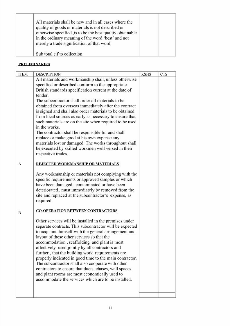
All materials shall be new and in all cases where the
quality of goods or materials is not described or
otherwise specified ,is to be the best quality obtainable
in the ordinary meaning of the word ‘best’ and not
merely a trade signification of that word.
Sub total c.f to collection
PRELIMINARIES
ITEM DESCRIPTION KSHS CTS
A
B
All materials and workmanship shall, unless otherwise
specified or described conform to the appropriate
British standards specification current at the date of
tender.
The subcontractor shall order all materials to be
obtained from overseas immediately after the contract
is signed and shall also order materials to be obtained
from local sources as early as necessary to ensure that
such materials are on the site when required to be used
in the works.
The contractor shall be responsible for and shall
replace or make good at his own expense any
materials lost or damaged. The works throughout shall
be executed by skilled workmen well versed in their
respective trades.
REJECTED WORKMANSHIP OR MATERIALS
Any workmanship or materials not complying with the
specific requirements or approved samples or which
have been damaged , contaminated or have been
deteriorated , must immediately be removed from the
site and replaced at the subcontractor’s expense, as
required.
CO-OPERATION BETWEEN CONTRACTORS
Other services will be installed in the premises under
separate contracts. This subcontractor will be expectedto acquaint himself with the general arrangement and
layout of these other services so that the
accommodation , scaffolding and plant is most
effectively used jointly by all contractors and
further , that the building work requirements are
properly indicated in good time to the main contractor.
The subcontractor shall also cooperate with other
contractors to ensure that ducts, chases, wall spaces
and plant rooms are most economically used to
accommodate the services which are to be installed.
11
7/28/2019 Ac and Mech Ventillations Specs NBK
http://slidepdf.com/reader/full/ac-and-mech-ventillations-specs-nbk 12/31
Sub total c.f to collection
PRELIMINARIES
ITEM DESCRIPTION KSHS CTS
A
B
C
D
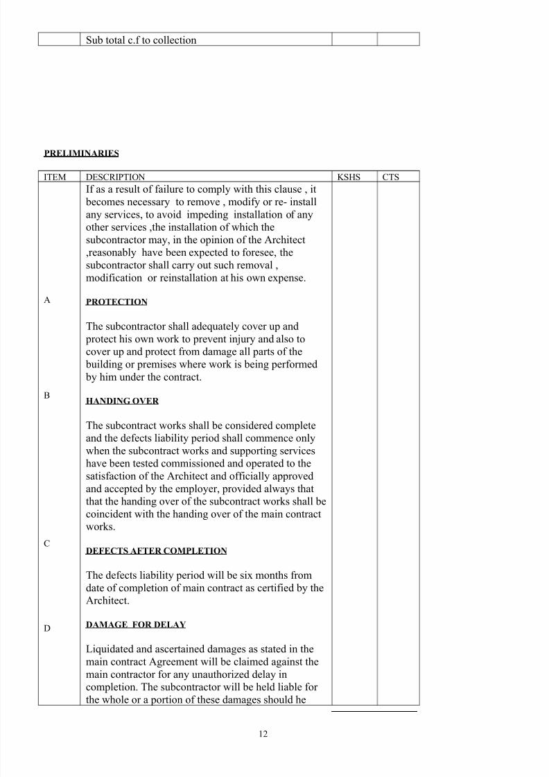
If as a result of failure to comply with this clause , it
becomes necessary to remove , modify or re- install
any services, to avoid impeding installation of any
other services ,the installation of which the
subcontractor may, in the opinion of the Architect
,reasonably have been expected to foresee, the
subcontractor shall carry out such removal ,
modification or reinstallation at his own expense.
PROTECTION
The subcontractor shall adequately cover up and
protect his own work to prevent injury and also to
cover up and protect from damage all parts of the
building or premises where work is being performed
by him under the contract.
HANDING OVER
The subcontract works shall be considered complete
and the defects liability period shall commence only
when the subcontract works and supporting services
have been tested commissioned and operated to the
satisfaction of the Architect and officially approved
and accepted by the employer, provided always that
that the handing over of the subcontract works shall be
coincident with the handing over of the main contract
works.
DEFECTS AFTER COMPLETION
The defects liability period will be six months from
date of completion of main contract as certified by the
Architect.
DAMAGE FOR DELAY
Liquidated and ascertained damages as stated in the
main contract Agreement will be claimed against the
main contractor for any unauthorized delay in
completion. The subcontractor will be held liable for
the whole or a portion of these damages should he
12
7/28/2019 Ac and Mech Ventillations Specs NBK
http://slidepdf.com/reader/full/ac-and-mech-ventillations-specs-nbk 13/31
cause delay in completion.
Sub total c.f to collection
PRELIMINARIES
ITEM DESCRIPTION KSHS CTS
A
B
C
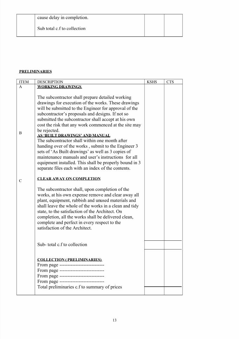
WORKING DRAWINGS
The subcontractor shall prepare detailed working
drawings for execution of the works. These drawings
will be submitted to the Engineer for approval of the
subcontractor’s proposals and designs. If not so
submitted the subcontractor shall accept at his owncost the risk that any work commenced at the site may
be rejected.AS ‘BUILT DRAWINGS’ AND MANUAL
The subcontractor shall within one month after
handing over of the works , submit to the Engineer 3
sets of ‘As Built drawings’ as well as 3 copies of
maintenance manuals and user’s instructions for all
equipment installed. This shall be properly bound in 3
separate files each with an index of the contents.
CLEAR AWAY ON COMPLETION
The subcontractor shall, upon completion of the
works, at his own expense remove and clear away all
plant, equipment, rubbish and unused materials and
shall leave the whole of the works in a clean and tidy
state, to the satisfaction of the Architect. On
completion, all the works shall be delivered clean,
complete and perfect in every respect to the
satisfaction of the Architect.
Sub- total c.f to collection
COLLECTION ( PRELIMINARIES)
From page ----------------------------
From page ----------------------------
From page ----------------------------
From page ----------------------------
Total preliminaries c.f to summary of prices
13
7/28/2019 Ac and Mech Ventillations Specs NBK
http://slidepdf.com/reader/full/ac-and-mech-ventillations-specs-nbk 14/31
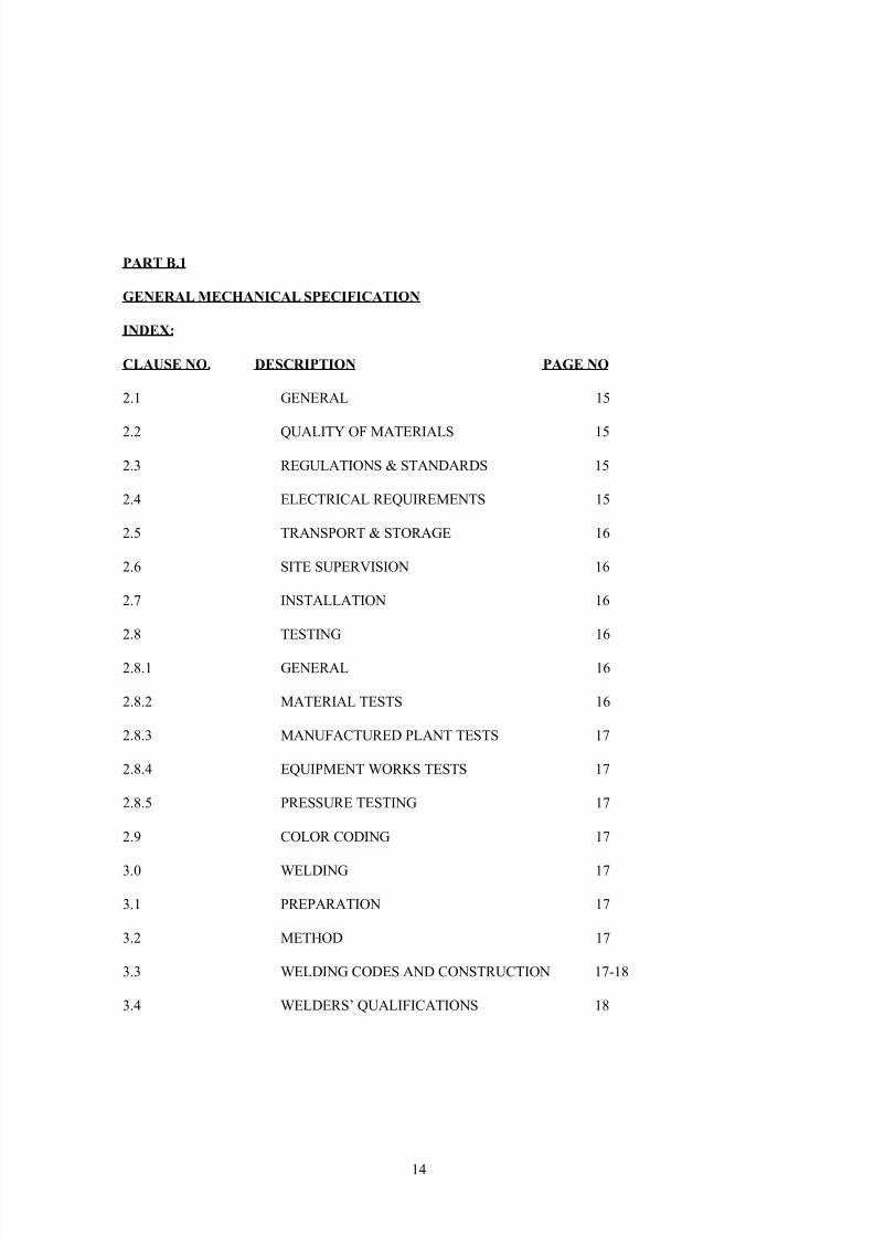
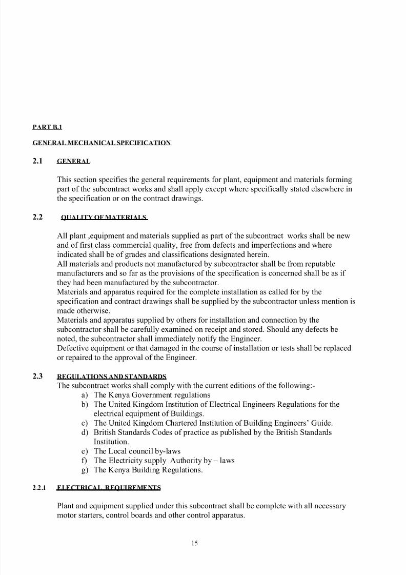
PART B.1
GENERAL MECHANICAL SPECIFICATION
INDEX:
CLAUSE NO. DESCRIPTION PAGE NO
2.1 GENERAL 15
2.2 QUALITY OF MATERIALS 15
2.3 REGULATIONS & STANDARDS 15
2.4 ELECTRICAL REQUIREMENTS 15
2.5 TRANSPORT & STORAGE 16
2.6 SITE SUPERVISION 16
2.7 INSTALLATION 16
2.8 TESTING 16
2.8.1 GENERAL 16
2.8.2 MATERIAL TESTS 16
2.8.3 MANUFACTURED PLANT TESTS 17
2.8.4 EQUIPMENT WORKS TESTS 17
2.8.5 PRESSURE TESTING 17
2.9 COLOR CODING 17
3.0 WELDING 17
3.1 PREPARATION 17
3.2 METHOD 17
3.3 WELDING CODES AND CONSTRUCTION 17-18
3.4 WELDERS’ QUALIFICATIONS 18
14
7/28/2019 Ac and Mech Ventillations Specs NBK
http://slidepdf.com/reader/full/ac-and-mech-ventillations-specs-nbk 15/31
7/28/2019 Ac and Mech Ventillations Specs NBK
http://slidepdf.com/reader/full/ac-and-mech-ventillations-specs-nbk 16/31
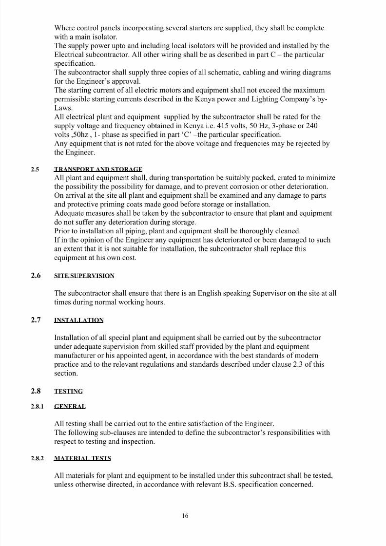
Where control panels incorporating several starters are supplied, they shall be complete
with a main isolator.
The supply power upto and including local isolators will be provided and installed by the
Electrical subcontractor. All other wiring shall be as described in part C – the particular
specification.
The subcontractor shall supply three copies of all schematic, cabling and wiring diagrams
for the Engineer’s approval.
The starting current of all electric motors and equipment shall not exceed the maximum
permissible starting currents described in the Kenya power and Lighting Company’s by-
Laws.
All electrical plant and equipment supplied by the subcontractor shall be rated for the
supply voltage and frequency obtained in Kenya i.e. 415 volts, 50 Hz, 3-phase or 240
volts ,50hz , 1- phase as specified in part ‘C’ –the particular specification.
Any equipment that is not rated for the above voltage and frequencies may be rejected by
the Engineer.
2.5 TRANSPORT AND STORAGE
All plant and equipment shall, during transportation be suitably packed, crated to minimize
the possibility the possibility for damage, and to prevent corrosion or other deterioration.
On arrival at the site all plant and equipment shall be examined and any damage to parts
and protective priming coats made good before storage or installation.
Adequate measures shall be taken by the subcontractor to ensure that plant and equipment
do not suffer any deterioration during storage.
Prior to installation all piping, plant and equipment shall be thoroughly cleaned.
If in the opinion of the Engineer any equipment has deteriorated or been damaged to such
an extent that it is not suitable for installation, the subcontractor shall replace this
equipment at his own cost.
2.6 SITE SUPERVISION
The subcontractor shall ensure that there is an English speaking Supervisor on the site at all
times during normal working hours.
2.7 INSTALLATION
Installation of all special plant and equipment shall be carried out by the subcontractor
under adequate supervision from skilled staff provided by the plant and equipment
manufacturer or his appointed agent, in accordance with the best standards of modern
practice and to the relevant regulations and standards described under clause 2.3 of this
section.
2.8 TESTING
2.8.1 GENERAL
All testing shall be carried out to the entire satisfaction of the Engineer.
The following sub-clauses are intended to define the subcontractor’s responsibilities with
respect to testing and inspection.
2.8.2 MATERIAL TESTS
All materials for plant and equipment to be installed under this subcontract shall be tested,unless otherwise directed, in accordance with relevant B.S. specification concerned.
16
7/28/2019 Ac and Mech Ventillations Specs NBK
http://slidepdf.com/reader/full/ac-and-mech-ventillations-specs-nbk 17/31
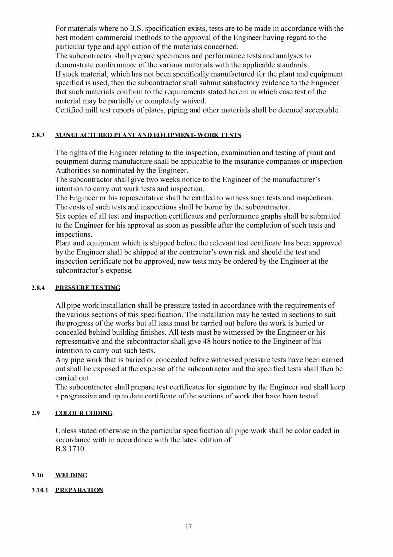
For materials where no B.S. specification exists, tests are to be made in accordance with the
best modern commercial methods to the approval of the Engineer having regard to the
particular type and application of the materials concerned.
The subcontractor shall prepare specimens and performance tests and analyses to
demonstrate conformance of the various materials with the applicable standards.
If stock material, which has not been specifically manufactured for the plant and equipment
specified is used, then the subcontractor shall submit satisfactory evidence to the Engineer
that such materials conform to the requirements stated herein in which case test of the
material may be partially or completely waived.
Certified mill test reports of plates, piping and other materials shall be deemed acceptable.
2.8.3 MANUFACTURED PLANT AND EQUIPMENT- WORK TESTS
The rights of the Engineer relating to the inspection, examination and testing of plant and
equipment during manufacture shall be applicable to the insurance companies or inspection
Authorities so nominated by the Engineer.
The subcontractor shall give two weeks notice to the Engineer of the manufacturer’s
intention to carry out work tests and inspection.
The Engineer or his representative shall be entitled to witness such tests and inspections.The costs of such tests and inspections shall be borne by the subcontractor.
Six copies of all test and inspection certificates and performance graphs shall be submitted
to the Engineer for his approval as soon as possible after the completion of such tests and
inspections.
Plant and equipment which is shipped before the relevant test certificate has been approved
by the Engineer shall be shipped at the contractor’s own risk and should the test and
inspection certificate not be approved, new tests may be ordered by the Engineer at the
subcontractor’s expense.
2.8.4 PRESSURE TESTING
All pipe work installation shall be pressure tested in accordance with the requirements of
the various sections of this specification. The installation may be tested in sections to suit
the progress of the works but all tests must be carried out before the work is buried or
concealed behind building finishes. All tests must be witnessed by the Engineer or his
representative and the subcontractor shall give 48 hours notice to the Engineer of his
intention to carry out such tests.
Any pipe work that is buried or concealed before witnessed pressure tests have been carried
out shall be exposed at the expense of the subcontractor and the specified tests shall then be
carried out.
The subcontractor shall prepare test certificates for signature by the Engineer and shall keepa progressive and up to date certificate of the sections of work that have been tested.
2.9 COLOUR CODING
Unless stated otherwise in the particular specification all pipe work shall be color coded in
accordance with in accordance with the latest edition of
B.S 1710.
3.10 WELDING
3.10.1 PREPARATION
17
7/28/2019 Ac and Mech Ventillations Specs NBK
http://slidepdf.com/reader/full/ac-and-mech-ventillations-specs-nbk 18/31
Joints to be made by welding shall be accurately cut to size with edges sheared, flame cut
or machined to suit the required type of joint.
The prepared surfaces shall be free from all visible defects such as laminations, surface
imperfections due to shearing, flame cutting operation etc., and shall be free from rust,
scale, grease and other foreign matter.
3.10.2 METHOD
All welding shall be carried out by the electric arc process using covered electrodes inaccordance with B.S 639.
Gas welding may be employed in certain circumstances providing that prior approval is
obtained from the Engineer.
3.10.3 WELDING CODES AND CONSTRUCTION
All welded joints shall be carried out in accordance with the following specification:-
a) Pipe welding
All pipe welds shall be carried out in accordance with the requirements of B.S 806.
b) General welding
All welding of mild steel components other than pipe work shall comply with the generalrequirements of B.S 5135: 1974.
3.10.4 WELDER’S QUALIFICATIONS
Any welder employed on this subcontract shall have passed the trade tests as laid down by
the government of Kenya.
The Engineer may require seeing the appropriate certificate obtained by any welder and
should it be proved that the welder does not have the necessary qualifications, the Engineer
may instruct the subcontractor to replace him/her by a qualified welder.
18
7/28/2019 Ac and Mech Ventillations Specs NBK
http://slidepdf.com/reader/full/ac-and-mech-ventillations-specs-nbk 19/31
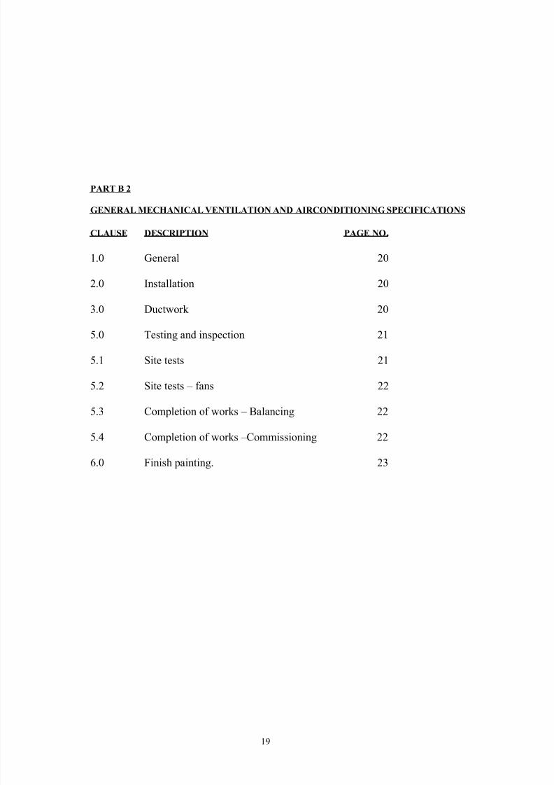
PART B 2
GENERAL MECHANICAL VENTILATION AND AIRCONDITIONING SPECIFICATIONS
CLAUSE DESCRIPTION PAGE NO .
1.0 General 20
2.0 Installation 20
3.0 Ductwork 20
5.0 Testing and inspection 21
5.1 Site tests 21
5.2 Site tests – fans 22
5.3 Completion of works – Balancing 22
5.4 Completion of works –Commissioning 22
6.0 Finish painting. 23
19
7/28/2019 Ac and Mech Ventillations Specs NBK
http://slidepdf.com/reader/full/ac-and-mech-ventillations-specs-nbk 20/31
1.0 GENERAL
This section specifies the general requirements for mechanical ventilation and air
conditioning plant, equipment and materials forming part of the subcontract works and
shall apply except where specifically stated elsewhere in the specification or on the
contract drawings.
2.0 INSTALLATION
Installation of all ductwork, plant and equipment shall be carried out under adequate
supervision from skilled staff to the relevant Codes and Standards specified herein.
The subcontractor shall be responsible for ensuring that sufficient provisions are made to
prevent the transmission of vibration from the equipment to the supporting structure. In the
case of fans, this shall be done by rot and vermin- proof flexible connections and
antivibration mountings of an approved type.
The subcontractor shall ensure that all ducting systems are provided with sufficient access
hatches complete with covers, for maintenance purposes.
Dampers and other user equipment shall be installed with adequate access for operation and
maintenance. Where dampers and other operational equipment are unavoidably installed
beyond normal reach, and in such a position as to be difficult to reach from a short step
ladder, extension spindles shall be provided.
The variety and type of supports for ducts and fans shall be kept to a minimum and their
design shall be such as to facilitate quick and secure fixing to metal, concrete, brickwork
and wood.
Where the design of the structure is in reinforced concrete, supports shall be secured to the
structure by means of redheads, raw bolts or other approved means.
Where the subcontractor proposes to secure his supports by other means than to the main
structural concrete, he shall consult with the Engineer before proceeding.
3.0 DUCTWORK
The subcontractor shall supply, deliver and erect all ductwork as shown on the contract
drawings.
All ductwork shall be manufactured in accordance with the Heating and ventilation
contractors Association 9H.V.C.A.0 specification DW/142. 1982 except where stated
otherwise.
Ductwork shall be manufactured from galvanized mild steel sheet unless specified
otherwise. All external ductwork shall be manufactured from black mild steel sheet which
shall be galvanized after manufacture.
All seams shall be lock form type. All ductwork systems shall be complete with all
necessary dampers, bends, tees, tapers, transformation and special pieces.Where removal is required for access or maintenance, ducting shall be provided with steel
angle flanged joints suitably painted and protected against rust.
20
7/28/2019 Ac and Mech Ventillations Specs NBK
http://slidepdf.com/reader/full/ac-and-mech-ventillations-specs-nbk 21/31
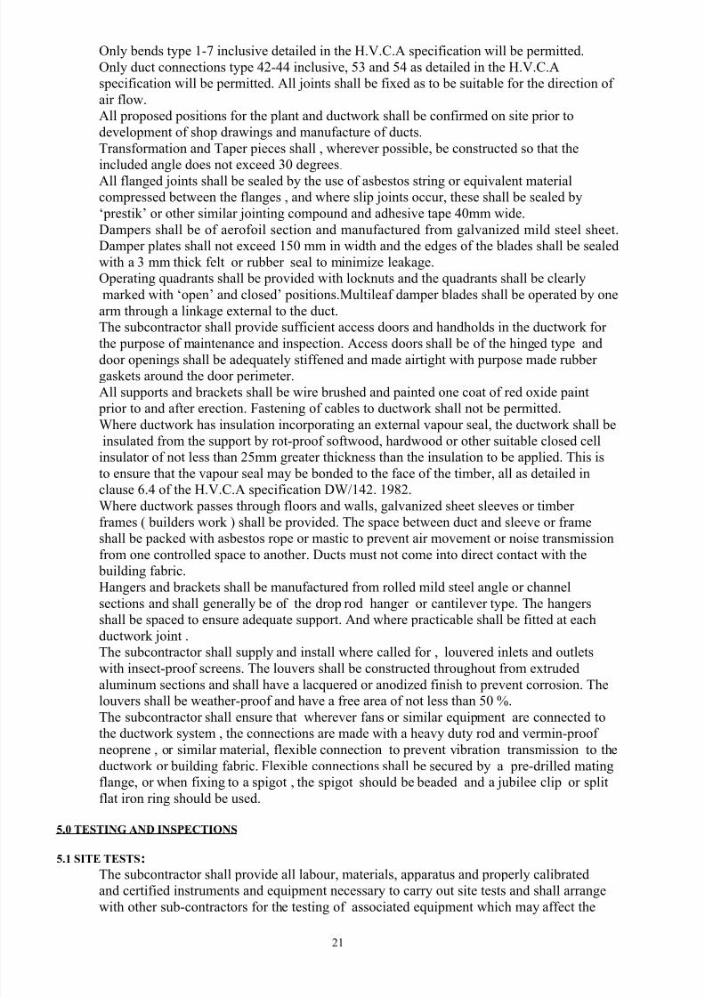
Only bends type 1-7 inclusive detailed in the H.V.C.A specification will be permitted.
Only duct connections type 42-44 inclusive, 53 and 54 as detailed in the H.V.C.A
specification will be permitted. All joints shall be fixed as to be suitable for the direction of
air flow.
All proposed positions for the plant and ductwork shall be confirmed on site prior to
development of shop drawings and manufacture of ducts.
Transformation and Taper pieces shall , wherever possible, be constructed so that the
included angle does not exceed 30 degrees.
All flanged joints shall be sealed by the use of asbestos string or equivalent material
compressed between the flanges , and where slip joints occur, these shall be sealed by
‘prestik’ or other similar jointing compound and adhesive tape 40mm wide.
Dampers shall be of aerofoil section and manufactured from galvanized mild steel sheet.
Damper plates shall not exceed 150 mm in width and the edges of the blades shall be sealed
with a 3 mm thick felt or rubber seal to minimize leakage.
Operating quadrants shall be provided with locknuts and the quadrants shall be clearly
marked with ‘open’ and closed’ positions.Multileaf damper blades shall be operated by one
arm through a linkage external to the duct.
The subcontractor shall provide sufficient access doors and handholds in the ductwork for
the purpose of maintenance and inspection. Access doors shall be of the hinged type anddoor openings shall be adequately stiffened and made airtight with purpose made rubber
gaskets around the door perimeter.
All supports and brackets shall be wire brushed and painted one coat of red oxide paint
prior to and after erection. Fastening of cables to ductwork shall not be permitted.
Where ductwork has insulation incorporating an external vapour seal, the ductwork shall be
insulated from the support by rot-proof softwood, hardwood or other suitable closed cell
insulator of not less than 25mm greater thickness than the insulation to be applied. This is
to ensure that the vapour seal may be bonded to the face of the timber, all as detailed in
clause 6.4 of the H.V.C.A specification DW/142. 1982.
Where ductwork passes through floors and walls, galvanized sheet sleeves or timber
frames ( builders work ) shall be provided. The space between duct and sleeve or frameshall be packed with asbestos rope or mastic to prevent air movement or noise transmission
from one controlled space to another. Ducts must not come into direct contact with the
building fabric.
Hangers and brackets shall be manufactured from rolled mild steel angle or channel
sections and shall generally be of the drop rod hanger or cantilever type. The hangers
shall be spaced to ensure adequate support. And where practicable shall be fitted at each
ductwork joint .
The subcontractor shall supply and install where called for , louvered inlets and outlets
with insect-proof screens. The louvers shall be constructed throughout from extruded
aluminum sections and shall have a lacquered or anodized finish to prevent corrosion. The
louvers shall be weather-proof and have a free area of not less than 50 %.The subcontractor shall ensure that wherever fans or similar equipment are connected to
the ductwork system , the connections are made with a heavy duty rod and vermin-proof
neoprene , or similar material, flexible connection to prevent vibration transmission to the
ductwork or building fabric. Flexible connections shall be secured by a pre-drilled mating
flange, or when fixing to a spigot , the spigot should be beaded and a jubilee clip or split
flat iron ring should be used.
5.0 TESTING AND INSPECTIONS
5.1 SITE TESTS:
The subcontractor shall provide all labour, materials, apparatus and properly calibratedand certified instruments and equipment necessary to carry out site tests and shall arrange
with other sub-contractors for the testing of associated equipment which may affect the
21
7/28/2019 Ac and Mech Ventillations Specs NBK
http://slidepdf.com/reader/full/ac-and-mech-ventillations-specs-nbk 22/31
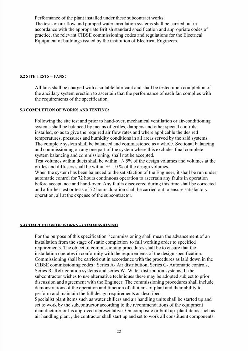
Performance of the plant installed under these subcontract works.
The tests on air flow and pumped water circulation systems shall be carried out in
accordance with the appropriate British standard specification and appropriate codes of
practice, the relevant CIBSE commissioning codes and regulations for the Electrical
Equipment of buildings issued by the institution of Electrical Engineers.
5.2 SITE TESTS – FANS:
All fans shall be charged with a suitable lubricant and shall be tested upon completion of
the ancillary system erection to ascertain that the performance of each fan complies with
the requirements of the specification.
5.3 COMPLETION OF WORKS AND TESTING:
Following the site test and prior to hand-over, mechanical ventilation or air-conditioningsystems shall be balanced by means of grilles, dampers and other special controls
installed, so as to give the required air flow rates and where applicable the desired
temperatures, pressures and humidity conditions in all areas served by the said systems.
The complete system shall be balanced and commissioned as a whole. Sectional balancing
and commissioning on any one part of the system where this excludes final complete
system balancing and commissioning, shall not be accepted.
Test volumes within ducts shall be within +/- 5% of the design volumes and volumes at the
grilles and diffusers shall be within +/- 10 % of the design volumes.
When the system has been balanced to the satisfaction of the Engineer, it shall be run under
automatic control for 72 hours continuous operation to ascertain any faults in operation
before acceptance and hand-over. Any faults discovered during this time shall be correctedand a further test or tests of 72 hours duration shall be carried out to ensure satisfactory
operation, all at the expense of the subcontractor.
5.4 COMPLETION OF WORKS - COMMISSIONING
For the purpose of this specification ‘commissioning shall mean the advancement of an
installation from the stage of static completion to full working order to specified
requirements. The object of commissioning procedures shall be to ensure that theinstallation operates in conformity with the requirements of the design specification.
Commissioning shall be carried out in accordance with the procedures as laid down in the
CIBSE commissioning codes : Series A- Air distribution, Series C- Automatic controls,
Series R- Refrigeration systems and series W- Water distribution systems. If the
subcontractor wishes to use alternative techniques these may be adopted subject to prior
discussion and agreement with the Engineer. The commissioning procedures shall include
demonstrations of the operation and function of all items of plant and their ability to
perform and maintain the full design requirements as described.
Specialist plant items such as water chillers and air handling units shall be started up and
set to work by the subcontractor according to the recommendations of the equipment
manufacturer or his approved representative. On composite or built up plant items such as
air handling plant , the contractor shall start up and set to work all constituent components.
22
7/28/2019 Ac and Mech Ventillations Specs NBK
http://slidepdf.com/reader/full/ac-and-mech-ventillations-specs-nbk 23/31
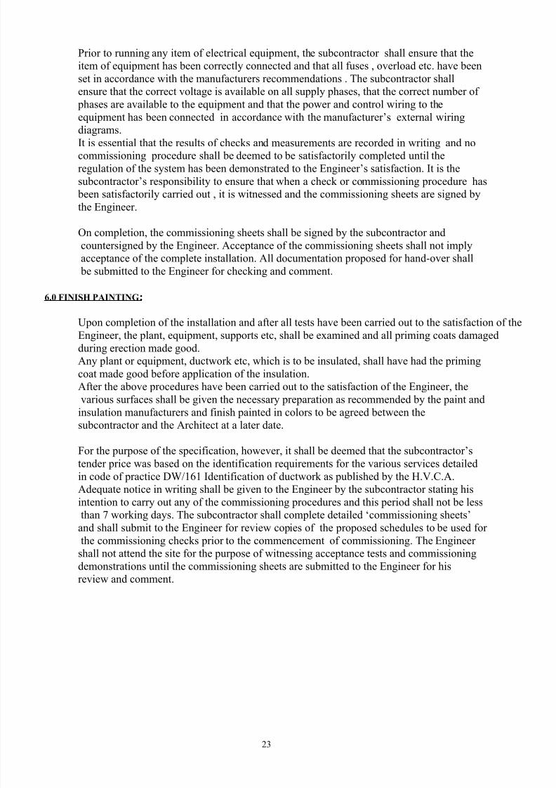
Prior to running any item of electrical equipment, the subcontractor shall ensure that the
item of equipment has been correctly connected and that all fuses , overload etc. have been
set in accordance with the manufacturers recommendations . The subcontractor shall
ensure that the correct voltage is available on all supply phases, that the correct number of
phases are available to the equipment and that the power and control wiring to the
equipment has been connected in accordance with the manufacturer’s external wiring
diagrams.
It is essential that the results of checks and measurements are recorded in writing and no
commissioning procedure shall be deemed to be satisfactorily completed until the
regulation of the system has been demonstrated to the Engineer’s satisfaction. It is the
subcontractor’s responsibility to ensure that when a check or commissioning procedure has
been satisfactorily carried out , it is witnessed and the commissioning sheets are signed by
the Engineer.
On completion, the commissioning sheets shall be signed by the subcontractor and
countersigned by the Engineer. Acceptance of the commissioning sheets shall not imply
acceptance of the complete installation. All documentation proposed for hand-over shall
be submitted to the Engineer for checking and comment.
6.0 FINISH PAINTING :
Upon completion of the installation and after all tests have been carried out to the satisfaction of the
Engineer, the plant, equipment, supports etc, shall be examined and all priming coats damaged
during erection made good.
Any plant or equipment, ductwork etc, which is to be insulated, shall have had the priming
coat made good before application of the insulation.
After the above procedures have been carried out to the satisfaction of the Engineer, the
various surfaces shall be given the necessary preparation as recommended by the paint and
insulation manufacturers and finish painted in colors to be agreed between thesubcontractor and the Architect at a later date.
For the purpose of the specification, however, it shall be deemed that the subcontractor’s
tender price was based on the identification requirements for the various services detailed
in code of practice DW/161 Identification of ductwork as published by the H.V.C.A.
Adequate notice in writing shall be given to the Engineer by the subcontractor stating his
intention to carry out any of the commissioning procedures and this period shall not be less
than 7 working days. The subcontractor shall complete detailed ‘commissioning sheets’
and shall submit to the Engineer for review copies of the proposed schedules to be used for
the commissioning checks prior to the commencement of commissioning. The Engineer
shall not attend the site for the purpose of witnessing acceptance tests and commissioningdemonstrations until the commissioning sheets are submitted to the Engineer for his
review and comment.
23
7/28/2019 Ac and Mech Ventillations Specs NBK
http://slidepdf.com/reader/full/ac-and-mech-ventillations-specs-nbk 24/31
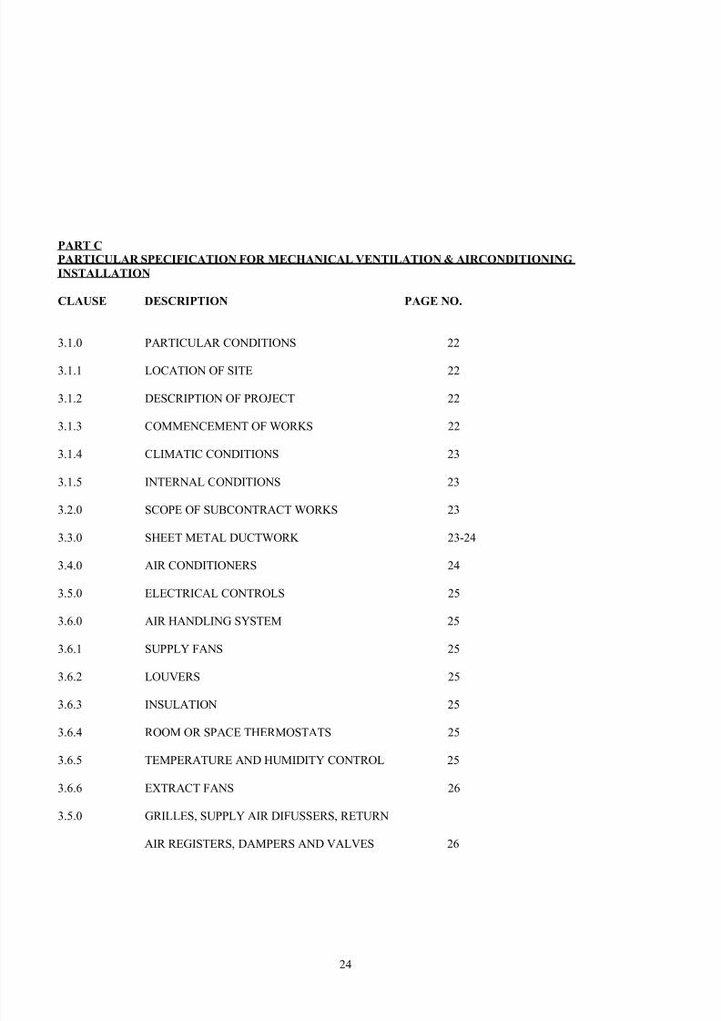
PART C
PARTICULAR SPECIFICATION FOR MECHANICAL VENTILATION & AIRCONDITIONING
INSTALLATION
CLAUSE DESCRIPTION PAGE NO.
3.1.0 PARTICULAR CONDITIONS 22
3.1.1 LOCATION OF SITE 22
3.1.2 DESCRIPTION OF PROJECT 22
3.1.3 COMMENCEMENT OF WORKS 22
3.1.4 CLIMATIC CONDITIONS 23
3.1.5 INTERNAL CONDITIONS 23
3.2.0 SCOPE OF SUBCONTRACT WORKS 23
3.3.0 SHEET METAL DUCTWORK 23-24
3.4.0 AIR CONDITIONERS 24
3.5.0 ELECTRICAL CONTROLS 25
3.6.0 AIR HANDLING SYSTEM 25
3.6.1 SUPPLY FANS 25
3.6.2 LOUVERS 25
3.6.3 INSULATION 25
3.6.4 ROOM OR SPACE THERMOSTATS 25
3.6.5 TEMPERATURE AND HUMIDITY CONTROL 25
3.6.6 EXTRACT FANS 26
3.5.0 GRILLES, SUPPLY AIR DIFUSSERS, RETURN
AIR REGISTERS, DAMPERS AND VALVES 26
24
7/28/2019 Ac and Mech Ventillations Specs NBK
http://slidepdf.com/reader/full/ac-and-mech-ventillations-specs-nbk 25/31
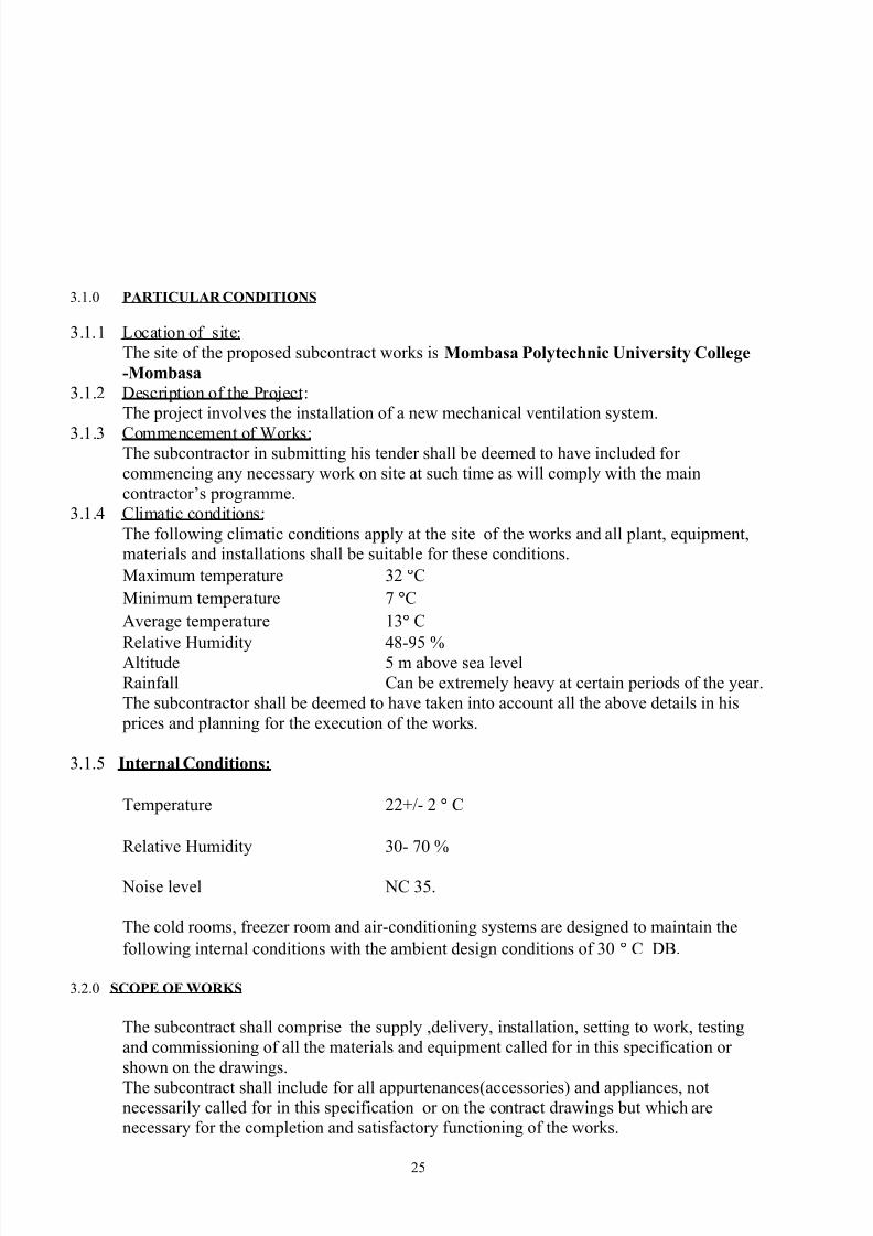
3.1.0 PARTICULAR CONDITIONS
3.1.1 Location of site:
The site of the proposed subcontract works is Mombasa Polytechnic University College
-Mombasa
3.1.2 Description of the Project:
The project involves the installation of a new mechanical ventilation system.
3.1.3 Commencement of Works:The subcontractor in submitting his tender shall be deemed to have included for
commencing any necessary work on site at such time as will comply with the main
contractor’s programme.
3.1.4 Climatic conditions:
The following climatic conditions apply at the site of the works and all plant, equipment,
materials and installations shall be suitable for these conditions.
Maximum temperature 32 °C
Minimum temperature 7 °C
Average temperature 13° C
Relative Humidity 48-95 %Altitude 5 m above sea level
Rainfall Can be extremely heavy at certain periods of the year.
The subcontractor shall be deemed to have taken into account all the above details in his
prices and planning for the execution of the works.
3.1.5 Internal Conditions:
Temperature 22+/- 2 ° C
Relative Humidity 30- 70 %
Noise level NC 35.
The cold rooms, freezer room and air-conditioning systems are designed to maintain the
following internal conditions with the ambient design conditions of 30 ° C DB.
3.2.0 SCOPE OF WORKS
The subcontract shall comprise the supply ,delivery, installation, setting to work, testing
and commissioning of all the materials and equipment called for in this specification or
shown on the drawings.
The subcontract shall include for all appurtenances(accessories) and appliances, notnecessarily called for in this specification or on the contract drawings but which are
necessary for the completion and satisfactory functioning of the works.
25
7/28/2019 Ac and Mech Ventillations Specs NBK
http://slidepdf.com/reader/full/ac-and-mech-ventillations-specs-nbk 26/31
No claims for extra payments will be accepted from the subcontractor because of his
noncompliance with the above requirements.
If in the opinion of the subcontractor, there is a difference between the requirements of the
specification and the contract drawings, he shall clarify this difference with the Engineer
before tendering.
All works shall be performed in a straight forward manner by competent workmen under
skilled supervision to the entire satisfaction of the Engineer.
It is deemed that the tenderer has based his tender on equipment which is similar in
design ,performance and manufacture to that stated in this specification. If the tenderer
wishes to offer suitable alternative equipment to that specified , he may do so under a
separate covering letter and justification of such alternative.
Submission of the above will be under the tenderers own initiative and in no case will any
expenses incurred in preparation and documentation of such alternative be reimbursed. The
employer reserves the right of accepting any alternative to the specification.
The alternative equipment shall not form part of the main tender which must be based on
the equipment specified.
The works to be installed under the subcontract shall comprise but not restricted to the
following installations:-
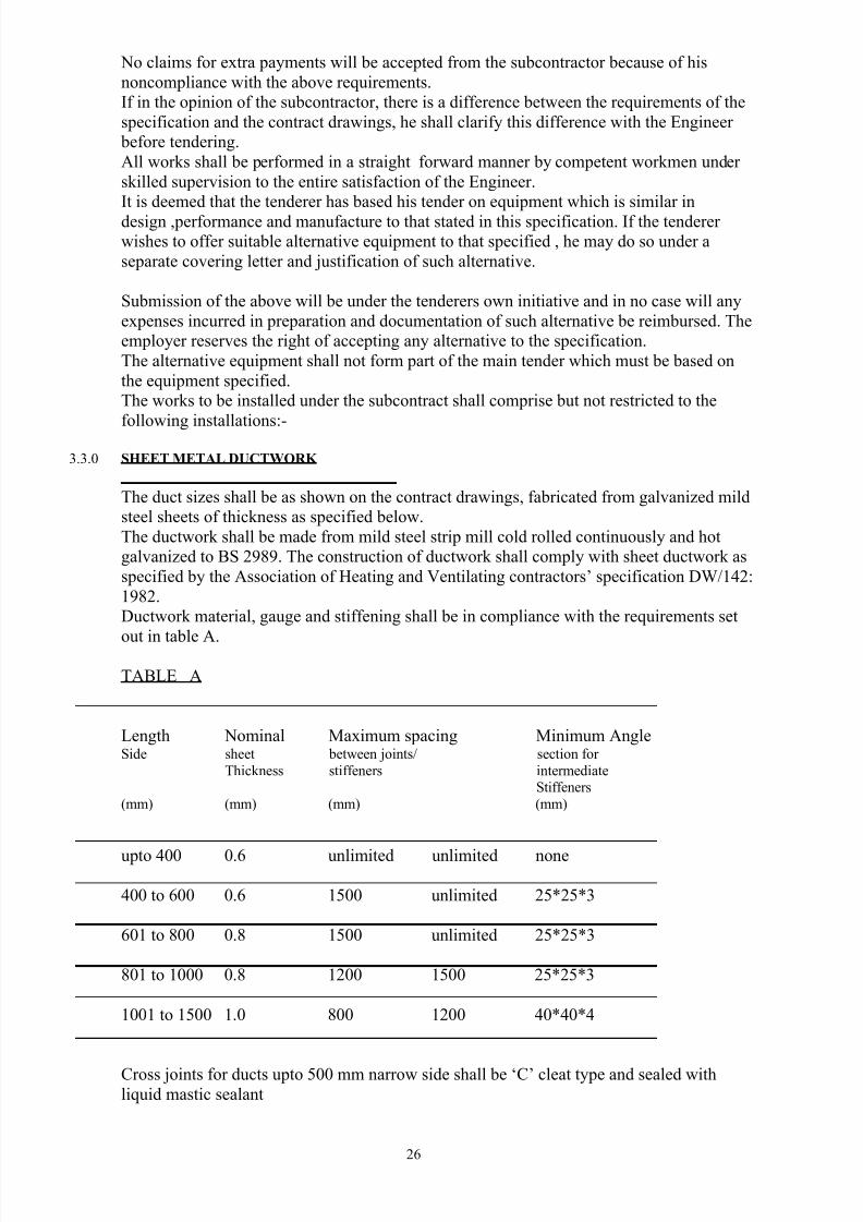
3.3.0 SHEET METAL DUCTWORK
The duct sizes shall be as shown on the contract drawings, fabricated from galvanized mild
steel sheets of thickness as specified below.
The ductwork shall be made from mild steel strip mill cold rolled continuously and hot
galvanized to BS 2989. The construction of ductwork shall comply with sheet ductwork as
specified by the Association of Heating and Ventilating contractors’ specification DW/142:
1982.
Ductwork material, gauge and stiffening shall be in compliance with the requirements set
out in table A.
TABLE A
Length Nominal Maximum spacing Minimum AngleSide sheet between joints/ section for
Thickness stiffeners intermediateStiffeners
(mm) (mm) (mm) (mm)
upto 400 0.6 unlimited unlimited none
400 to 600 0.6 1500 unlimited 25*25*3
601 to 800 0.8 1500 unlimited 25*25*3
801 to 1000 0.8 1200 1500 25*25*3
1001 to 1500 1.0 800 1200 40*40*4
Cross joints for ducts upto 500 mm narrow side shall be ‘C’ cleat type and sealed withliquid mastic sealant
26
7/28/2019 Ac and Mech Ventillations Specs NBK
http://slidepdf.com/reader/full/ac-and-mech-ventillations-specs-nbk 27/31
Cross joints for ducts with narrow side in excess of 500 mm shall be reinforced standing
seam.
Longitudinal seams shall be of the lock form type riveted spot/plug welded ap seams . The
subcontractor shall ensure that the joints are completely airtight.
All bends shall have a centerline radius of one and half times the width of the duct.
Transformation and Taper pieces shall where the cross sectional area is unchanged have a
minimum slope of 22.5 degrees and where the cross sectional area is reduced upto 20 % ,
the maximum slope shall be 15 degrees.
3.4.0 AIRCONDITIONERS:
The air conditioning units shall be completely factory assembled and tested, piped and
internally wired fully charged with R-22 and compressor oil. All units shall be suitable for
ground installation inside plant rooms with ducts fitted to run to the supply areas.
The equipment shall be fully tropicalised. The external casing of the equipment shall be
phosphatised , Zinc coated steel with epoxy resin primer and baked enamel finish .The
screws shall be coated with Zinc plus Zinc chromate and with neoprene washers where
sealing is required.Hinged access doors shall provide access to control components, filters, outside and return
air dampers, evaporator coil and supply the exhaust fan sections. All access doors shall be
lined with gaskets and mat faced fiberglass insulation.
The condenser section shall be provided with drain points. Each unit shall have lifting lugs
to accept chains or cables for rigging.
The air conditioning unit (split type) shall be as Trane Model RAC 075 + BPH 0.75 with a
cooling capacity of 30.8 kw and an air flow rate of 0.817 m/ sec
3.5.0 ELECTRICAL CONTROLS
The units shall be suitable for use on 3 phase, 415 volts, and 50HZ power supply. It shall be
the responsibility of others to provide all electrical wiring upto the isolator. The
subcontractor shall be responsible for all electrical wiring between the isolator and all items
of equipment.
The subcontractor shall also provide all electrical control panels and shall be responsible
for their fixing and satisfactory operation.
The control and power cables shall be run in firmly fixed steel conduits where concrete
encased conduits are not provided.
The control shall include for oil safety, supply and exhaust fan overload protectors, fuses
for supply, exhaust air and condenser fans, compressor fuses and dead front panels. Eachcontrol item shall have an identifiable tag.
3.6.0 AIR HANDLING SYSTEM
3.6.1 SUPPLY FANS
All fans shall be statically and dynamically balanced in the Factory. Fan shaft shall be
capable of self alignment.
Air filters shall be provided within the unit. The filters shall fit in slide –in racks for ease of
change out.
3.6.2 LOUVRES
27
7/28/2019 Ac and Mech Ventillations Specs NBK
http://slidepdf.com/reader/full/ac-and-mech-ventillations-specs-nbk 28/31
Discharge and fresh air intake louvers shall be similar or equal to type WG/EF as
manufactured by Waterloo CO. Ltd.
They shall be manufactured from robust Aluminum alloy extrusions with lacquered finish.
An insect screen shall be fixed to the back of the louvers. All louvers shall have a minimum
of 50 % free area.
3.6.3 INSULATION
Any external ductwork shall be wrapped with roofing felt properly lapped to ensure a
waterproof covering. All cooled air ducts shall be insulated with either expanded
polystyrene sheet or sprayed polyurethane foam without gaps using suitable adhesive and
plastic impingement pines attached to ductwork.
3.6.4 ROOM OR SPACE THERMOSTATS
These shall be located in the extract duct immediately after the air-conditioned space andwired to the air conditioner control system. The thermometer shall have a range of 15 ° C to
35 °C. The thermostat shall be set at the required room temperature and should maintain the
temperature with a differential of 1°C.
3.6.5 TEMPERATURE AND HUMIDITY CONTROL
The temperature and humidity control, overriding on humidity shall be affected from
detectors mounted on the return air duct. The resultant signal from the control unit shall
cause the motorized step controller on A-C unit to step up or down accordingly.
3.6.6 EXTRACT FANSThe extract fans shall be duct-mounted continuously rated axial flow fans as ‘woods’
Aerofoil axial flow fans double stage or equal and approved.
The case work of both the bowler unit (BPH) and condenser (RAC) shall be galvanized
steel with polyester paint finish. The evaporator coil in BPH shall be manufactured from
copper tube mechanically bounded or expanded into aluminum fins.
The compressor shall be of robust construction and high reliability. It shall be suitable for
use with refrigerant R22.
The condenser shall be of steel / copper tube with aluminum fins.
3.6.8 SUPPLY AIR DIFFUSERSShall be aluminum extruded four way rectangular or circular complete with dampers and
adjusters. They should be suitable for ceiling mounting. The sizes shall be as shown in the
bill of quantities.
3.6.9 RETURN AIR REGISTERS
Shall be aluminum with enamel finish: 4 way with opposed blade dampers.
3.7.0 DOOR TRANSFER GRILLES
Shall be similar to return air registers with paint to architect’s approval.
3.7.1 FLAP VALVES (NON RETURN AIR REGISTERS)
This shall be self closing dampers with minimum resistance to air flow under runningconditions and maximum resistance under reverse air flow conditions. Resilient strips or
28
7/28/2019 Ac and Mech Ventillations Specs NBK
http://slidepdf.com/reader/full/ac-and-mech-ventillations-specs-nbk 29/31
other purpose made devices shall be provided to prevent rattling and for air sealing under
reverse flow.
3.7.2 BALANCING DAMPERS
The balancing dampers shall be provided and fixed at appropriate positions indicated on the
contract drawings. Damper blades shall be of rigid construction without sharp edges and
shall be substantially airtight. The dampers shall be multi-leaf type and be constructed indemountable ductwork sections, which shall extend beyond the swing of the blades.
Provisions shall be made for linkages to connect the multiple extended spindles. The
‘open’ and ‘closed’ positions shall be clearly marked on all dampers.
3.7.3 FLOW MEASURING POINTS
There shall be adequate flow measuring points in the ductwork to enable the proportional
balancing of the systems to be done. These shall be incorporated with volume control
dampers .
3.7.4 FIRE DAMPERS
Fire dampers shall be provided where indicated on the contract drawings. They shall besingle plate top hinged type . Each damper plate shall be held in the open position by a
fusible device set to release at a temperature of 72 °C.
3.7.5 FLEXIBLE CONNECTIONS
Flexible connections shall be provided where indicated on contract drawings.
The connections shall be made of tough tear-resistant and fire-resistant materials.
29
7/28/2019 Ac and Mech Ventillations Specs NBK
http://slidepdf.com/reader/full/ac-and-mech-ventillations-specs-nbk 30/31
4.00 CONTRACT DRAWINGS
SCA/NBK/MOM 2012/AC/01
SCA/NBK/MOM/2012/AC/02
30
7/28/2019 Ac and Mech Ventillations Specs NBK
http://slidepdf.com/reader/full/ac-and-mech-ventillations-specs-nbk 31/31
PART D
BILLS OF QUANTITIES
Related Documents


