2010 International Conference on Indoor Positioning and Indoor Navigation Abstract Volume September 15-17, 2010 Campus Science City, ETH Zurich

Welcome message from author
This document is posted to help you gain knowledge. Please leave a comment to let me know what you think about it! Share it to your friends and learn new things together.
Transcript

2010International Conference on
Indoor Positioning and Indoor Navigation
AbstractVolume
September 15-17, 2010Campus Science City, ETH Zurich

2010
International Conference on
Indoor Positioning and Indoor Navigation
IPIN
September 15 – 17, 2010
Campus Science City, ETH Zurich, Switzerland
Abstract Volume
Edited by:
Rainer Mautz, Melanie Kunz, and Hilmar Ingensand

Content
RF RSS (ZigBee, FM, General RF), Fingerprinting ............................................ 17
A Single Anchor Direction of Arrival Positioning System Augmenting Standard Wireless
Communication Technology .................................................................................................... 19
Stefano Maddio, Luca Bencini, Alessandro Cidronali, Gianfranco Manes
Enabling Low-power Localization for Mobile Sensor Nodes ...................................................... 21
Jorge Juan Robles, Sebastian Tromer, Monica Quiroga and Ralf Lehnert
A Novel 5-Dimensions RF Signal Strength Indoor Localization Method Based on Multipath
Propagation ............................................................................................................................ 23
Lujia Wang, Chao Hu, Longqiang Tian and Max Q.-H Meng
DALE: A Range-Free, Adaptive Indoor Localization System Enhanced by Limited Fingerprinting 25
Olga E. Segou, Stelios A. Mitilineos and Stelios C.A. Thomopoulos
Ad-hoc Networks Aiding Indoor Calibrations Of Heterogeneous Devices for Fingerprinting
Applications ........................................................................................................................... 27
Francescantonio Della Rosa, Helena Leppäkoski, Stefano Biancullo, and Jari Nurmi
Real time calibration for RSS indoor positioning systems ......................................................... 29
Ana M. Bernardos, José R. Casar, Paula Tarrío
A Model-Switching Sequential Monte Carlo Algorithm for Indoor Tracking with Experimental RSS
Data ....................................................................................................................................... 31
Katrin Achutegui, Javier Rodas, Carlos J. Escudero, Joaquín Míguez
An Environment Adaptive ZigBee-based Indoor Positioning Algorithm ..................................... 33
Janire Larranaga, Leire Muguira, Juan-Manuel Lopez-Garde, Juan-Ignacio Vazquez
Low Power Location Protocol based on ZigBee ........................................................................ 35
Luís Brás, Marco Oliveira, Pedro Pinho, Nuno Borges Carvalho
Improving ZigBee 2D5 localization in large buildings using Metric Description Graphs .............. 37
Juan Carlos García, Jesús Ureña, Jesús García
User Positioning by means of pre-computed Attenuation Maps ............................................... 39
Ada Vittoria Bosisio
Indoor positioning using off-the-shelf FM radio devices ........................................................... 41
Andrei Papliatseyeu, Aleksandar Matic, Venet Osmani, Oscar Mayora-Ibarra
RSSI localization with sensors placed on the user ..................................................................... 43
Paolo Barsocchi, Francesco Furfari, Paolo Nepa, Francesco Potortì
Indoor Positioning Using Received Signal Strength of Iridium Satellites .................................... 45
Siavash Hosseiny Alamdary, Mortaza Nikravesh, Mohammad A. Rajabi, Hossein Sahabi
WLAN RSS (Signal Strength Based Methods), Fingerprinting ......................... 47
RSSI-based Euclidean Distance Algorithm for Indoor Positioning adapted for the use in
dynamically changing WLAN environments and multi-level buildings ....................................... 49
Sebastian Gansemer, Uwe Großmann
Indoor Positioning Using WLAN Coverage Area Estimates ........................................................ 51
Laura Koski, Tommi Perälä and Robert Piché
Algorithmic Strategies for Adapting 802.11 Location Fingerprinting to Environmental Changes 53
René Hansen, Rico Wind, Christian S. Jensen, Bent Thomsen
Fault Tolerant Positioning using WLAN Signal Strength Fingerprints ......................................... 55
Christos Laoudias, Michalis P. Michaelides, Christos G. Panayiotou
Implementation of Hyperbolic Location Estimation Using RSSI in WLANs ................................. 57
Jakhongir Narzullaev, Anvar Narzullaev, Yongwan Park, Kook-Yeol Yoo
A Perspective on Robustness and Deployment Complexity for RSS-based Indoor Positioning .... 59
Kamran Sayrafian
Wi-Fi Positioning: System Considerations and Device Calibration ............................................. 61
Thorsten Vaupel, Jochen Seitz, Frédéric Kiefer, Stephan Haimerl, Jörn Thielecke
An Indoor Location Based Service Using Access Points as Signal Strength Data Collectors ......... 63
I-En Liao, Kuo-Fong Kao, Jia-Siang Lyu
Wi-Fi-Based Indoor Positioning: Basic Techniques, Hybrid Algorithms and Open Software
Platform ................................................................................................................................. 65
Matteo Cypriani, Philippe Canalda, Frédéric Lassabe, François Spies
A sector-based campus-wide indoor positioning system .......................................................... 67
Thomas Gallagher, Binghao Li, Andrew G Dempster, Chris Rizos
Multiple Wireless Technologies Fusion for Indoor Location Estimation ..................................... 69
Pedro Mestre, Hugo Pinto, João Matias, João Moura, Paula Oliveira, and Carlos Serôdio
Resolving the Fingerprinting Problem: Comparison of Propagation Modelling and Machine
Learning Approach .................................................................................................................. 71
Widyawan
Optimization Model for an Indoor WLAN-based Positioning System ......................................... 73
You Zheng, Oumaya Baala, Alexandre Caminada
Effect of Environmental Changes on Accuracy of IEEE 802.11 Indoor Fingerprinting Positioning
System WifiLOC ...................................................................................................................... 75
Peter Brida, Juraj Machaj, Jozef Benikovsky
A Model – Based Approach for WLAN Localization in Indoor Parking Areas ............................. 77
Paolo Addesso, Luigi Bruno, Roberto Garufi, Maurizio Longo, Rocco Restaino, Anton Luca
Robustelli
Fingerprinting Localization in Indoor Wi-Fi Networks Based on Received Signal Strength .......... 79
Shih-Hau Fang and Tsung-Nan Lin
TOF, TDOA based Localization ....................................................................... 81
IEEE 802.11 Ranging and Multi-lateration for a Software-defined Positioning Receiver ............. 83
F. Tappero, B. Merminod, M. Ciurana
On the Minimization of Different Sources of Error for an RTT-Based Indoor Localization System
without any Calibration Stage ................................................................................................. 85
Javier Prieto, Santiago Mazuelas, Alfonso Bahillo, Patricia Fernández, Rubén M. Lorenzo,
Evaristo J. Abril
Maximum Likelihood 3-D Positioning with a Priori Knowledge of Nodes Topology for UWB Based
Human Motion Tracking ......................................................................................................... 87
Z. W. Mekonnen, C. Steiner, H. Luecken, A. Wittneben
A Mathematical Model for a Polarisation Based Orientation Measurement Principle in Time of
Arrival Radio Localisation Systems .......................................................................................... 89
Andreas Eidloth, Jörn Thielecke
Performance stability of software TOA-based ranging in WLAN ............................................... 91
Marc Ciurana, Domenico Giustiniano, Albert Neira, Francisco Barcelo-Arroyo, Israel Martin-
Escalona
Hardware Implementation of a Particle Filter for Location Estimation ...................................... 93
Daniel Froß, Jan Langer, André Froß, Marko Rößler, Ulrich Heinkel
High Accuracy WLAN Positioning using Sparse Estimation Techniques ...................................... 95
Khalid Nur, Cong Ling and Washington Ochieng
Ad hoc Indoor Peer-to-peer Tracking using Relative Location Estimation .................................. 97
Dohyung Park, Joonsung Kang, and Eung Sun Kim
Direction Estimation for Cellular Enhanced Cell-ID Positioning Using Multiple Sector
Observations .......................................................................................................................... 99
Jiyun SHEN, Yasuhiro ODA
Localization, Algorithms for WSN ................................................................ 101
A comparison of multidimensional scaling and non-linear regression for positioning applications.
............................................................................................................................................. 103
Carl Ellis, Mike Hazas
Cooperative Indoor Position Location ..................................................................................... 105
R. Michael Buehrer, Benton Thompson, and Tao Jia
Hybrid RSS-RTT Localization Scheme for Wireless Networks.................................................... 107
Alfonso Bahillo, Santiago Mazuelas, Javier Prieto, Patricia Fernández, Rubén M. Lorenzo and
Evaristo J. Abril
pVoted: A Progressive On-Line Algorithm for Robust Real-Time Localization and Tracking in spite
of Faulty Distance Information ............................................................................................... 109
Marcel Baunach
Localization Services in Hybrid Self-organizing Networks ........................................................ 111
Anna Maria Vegni, Marco Carli, Alessandro Neri
On Distance Estimation based on Radio Propagation Models and Outlier Detection for Indoor
Localization in Wireless Geosensor Networks ......................................................................... 113
Alexander Bo, Frank Niemeyer, Mario Schwiede and Ralf Bill
Theoretical Analysis and Validation Experiments of the Localization-by-Superposing-Beats
Procedure .............................................................................................................................. 115
Matthias Schneider, Ralf Salomon
A Cross-layer Design of an Anycast-based Routing Protocol for Fast Indoor Localization .......... 117
Anthony Lo, Tim Bauge and Dave Harmer
The Impact of Location Errors on Geographic Routing in Realistic WSNs .................................. 119
Bo Peng and Andrew H. Kemp
Survivability of Mobile Sensor Network using Security Adaptation Reference Monitor (SARM) 121
Tewfiq EL-MALIKI, Jean-Marc SEIGNEUR
Hybrid active and passive localization for small targets ........................................................... 123
Luca Reggiani, Roberto Morichetti
Linear Antenna Array, Ranging and Accelerometer for 3D GPS-Less Localization of Wireless
Sensors ................................................................................................................................. 125
Patryk Mazurkiewicz and Kin K. Leung
Hybrid IMU Pedestrian Navigation 1 ........................................................... 127
A Modular and Mobile System for Indoor Localization ............................................................ 129
Lasse Klingbeil, Michailas Romanovas, Patrick Schneider, Martin Traechtler, Yiannos Manoli
Self-Contained Indoor Positioning on off-the-shelf mobile Devices .......................................... 131
Dominik Gusenbauer, Carsten Isert and Jens Krösche
Pedestrian Smartphone-Based Indoor Navigation Using Ultra Portable Sensory Equipment ..... 133
Christian Lukianto, Christian Hönniger, Harald Sternberg
A low cost navigation unit for position estimation of personnel after loss of GPS position ....... 135
Kim Mathiassen, Leif Hanssen, Oddvar Hallingstad
A GPS/INS-based architecture for rescue team monitoring ..................................................... 137
Alberto Croci, Mattia De Agostino, Ambrogio Manzino
Hybrid positioning system combining angle-based localization, pedestrian dead reckoning, and
map-filtering ......................................................................................................................... 139
Paul Kemppi, Juuso Pajunen, Ville Ranki, Fabio Belloni, Terhi Rautiainen
Indoor Localization in Multi-story Buildings Using a Human Operated Backpack System .......... 141
George Chen, Timothy Liu, Matthew Carlberg, John Kua, Avideh Zakhor
Hybrid Indoor/Outdoor Positioning Using Particle Filters and Multiple Sensors on a Personal
Transporter ........................................................................................................................... 143
Jan Oberländer, Marcus Strand, Felix Kreuter, J. Marius Zöllner and Rüdiger Dillmann
Improved Vehicle Positioning for Indoor Navigation in Parking Garages Through Commercially
Available Maps ...................................................................................................................... 145
Johannes Wagner, Carsten Isert, Arne Purschwitz, Arnold Kistner
Tracking Persons with an Autarkic Radio-Based Multi-Sensor System ...................................... 147
Enrico Köppe, Heiko Will, Achim Liers, Jochen Schiller
Set-Up of a Combined Indoor and Outdoor Positioning Solution and Experimental Results ...... 149
Lars Johannes, Jonas Degener, Wolfgang Niemeier
Hybrid IMU Pedestrian Navigation 2 ........................................................... 151
Infrastructure-independent person localization with IEEE 802.15.4 WSN ................................. 153
Johannes Schmid, Wilhelm Stork, Klaus D. Müller-Glaser
RSSI-based Indoor Positioning using Diversity and Inertial Navigation ..................................... 155
Andreas Fink, Helmut Beikirch, Matthias Voß, Christian Schröder
Calibration of the Accelerometer Triad of an Inertial Measurement Unit, Maximum Likelihood
Estimation and Cramér-Rao Bound ......................................................................................... 157
G. Panahandeh, I. Skog, M. Jansson
Joint calibration of an inertial measurement unit and coordinate transformation parameters
using a monocular camera ..................................................................................................... 159
Dave Zachariah and Magnus Jansson
DCM based Attitude Estimation Using Low-cost IMU Aided by Distributed Accelerometers and
Magnetometers ..................................................................................................................... 161
Ezzaldeen Edwan, Fernando Suarez, Jieying Zhang, Otmar Loffeld
UWB/IMU Tracking Validation using an Optical System .......................................................... 163
Jeroen D. Hol and Maaike Elzinga
Performance Evaluation of an Hybrid RSSI-Inertial Localization Algorithm in IEEE 802.15.4
Wireless Sensor Networks ..................................................................................................... 165
Paolo Gamba, Emanuele Goldoni, Alberto Savioli
Foot Mounted Pedestrian Navigation .......................................................... 167
A High Precision Reference Data Set for Pedestrian Navigation using Foot-Mounted Inertial
Sensors ................................................................................................................................. 169
Michael Angermann, Patrick Robertson, Thomas Kemptner, Mohammed Khider
Evaluation of Zero-Velocity Detectors for Foot-Mounted Inertial Navigation Systems .............. 171
Isaac Skog, John-Olof Nilsson, and Peter Händel
Comparison and Evaluation of Acceleration Based Step Length Estimators for Handheld Devices
............................................................................................................................................. 173
Jasper Jahn, Jochen Seitz, Lucila Patino-Studencka, Ulrich Batzer, Javier Gutiérrez Boronat
An improved shoe-mounted inertial navigation system .......................................................... 175
Nadir Castaneda, Sylvie Lamy-Perbal
Context-Adaptive Algorithms to Improve Indoor Positioning with Inertial Sensors .................. 177
Ulrich Walder, Thomas Bernoulli, Gerald Glanzer, Thomas Wießflecker
Dual IMU Indoor Navigation with Particle Filter based Map-Matching on a Smartphone ......... 179
C. Ascher, C. Kessler, M. Wankerl, G.F. Trommer
Design choices, filter parameter tuning, and calibration of zero-velocity update aided inertial
navigation systems for pedestrian navigation ......................................................................... 181
John-Olof Nilsson, Isaac Skog, and Peter Händel
Pedestrian Indoor Navigation by aiding a Foot-mounted IMU with RFID Signal Strength
Measurements ...................................................................................................................... 183
Antonio R. Jiménez, Fernando Seco, J. Carlos Prieto and Jorge Guevara
On the use of foot-mounted INS, UWB-ranging and opportunistic cooperation in high-accuracy
indoor positioning systems .................................................................................................... 185
Peter Strömbäck, Jouni Rantakokko, Erika Emilsson
Frameworks for Hybrid Positioning ............................................................. 187
Tracking Framework for Heterogeneous Sensor Sources ......................................................... 189
Mareike Kritzler, Antonio Krüger
A Fusion Component for location management in mobile devices ........................................... 191
Eduardo Metola, Ana M. Bernardos, Henar Martín, José R. Casar
Detecting Visibility in Heterogeneous Simulated Environments for Positioning Purposes ......... 193
Magda CHELLY and Nel SAMAMA
Indoor Navigation Integration Platform for Firefighting Purposes ........................................... 195
Kai Marcus Stübbe, Uwe Rüppel
Combined Indoor and Outdoor DOP Criteria helpful to Position and Dimension ...................... 197
Soumaya Zirari, Philippe Canalda, Hakim Mabed and François Spies
Generic architectural framework for hybrid positioning .......................................................... 199
Pieter Becue, Jen Rossey, Pieter De Mil, Ingrid Moerman
A Localization Framework for Wireless Mesh Networks .......................................................... 201
Bastian Blywis, Mesut Güneş, Felix Juraschek, Steffen Gliech
Industrial Metrology & Geodetic Systems, iGPS (Nikon) .............................. 203
Performance Evaluation of iGPS for Industrial Applications ..................................................... 205
Robert Schmitt, Susanne Nisch, Alexander Schönberg, Francky Demeester, Steven Renders
Indoor navigation of machines and measuring devices with iGPS ............................................ 207
Julia Schwendemann, Tilman Müller, Robert Krautschneider
Path Tracking with iGPS ......................................................................................................... 209
Claudia Depenthal
Locata: A new high accuracy indoor positioning system .......................................................... 211
Chris Rizos, Gethin Roberts, Joel Barnes, Dave Small, Nunzio Gambale
New Approaches in Laser Tracker Based High-Accuracy Indoor Navigation .............................. 213
Burkhard Boeckem
Positioning of robots by determining 6DOF ............................................................................ 215
Christoph Herrmann, Maria Hennes
The Use of Kalman Filtering in Combination With an Electronic Tacheometer.......................... 217
Sonja Gamse, Thomas A. Wunderlich, Peter Wasmeier, Dušan Kogoj
User Requirements ..................................................................................... 219
User Requirements for Localization and Tracking Technology ................................................. 221
Jouni Rantakokko, Peter Händel, Michael Fredholm
Mass market considerations for indoor positioning and navigation ......................................... 223
Lauri Wirola, Tommi Laine and Jari Syrjärinne
Requirements for positioning and navigation in underground constructions .......................... 225
Christian Waldvogel, Oliver Schneider
GNSS Indoor, Pseudolites ............................................................................ 227
A new Navigation System for Indoor Positioning (InLite) ......................................................... 229
Andreas Schmitz-Peiffer, Andre Nuckelt, Maik Middendorf, Michael Burazanis
Indoor Multipath Mitigation .................................................................................................. 231
Kostas Dragūnas, Kai Borre
Indoor Positioning Using GPS transmitters: Experimental results ............................................ 233
Anca Fluerasu, Alexandre Vervisch-Picois, Nel Samama, Gianluca Boiero, Giorgio Ghinamo, Piero
Lovisolo
An Indoor positioning system using GPS signals ...................................................................... 235
Kerem Ozsoy, Ayhan Bozkurt and Ibrahim Tekin
Pseudolite Indoor Localization Using Multiple Receivers - Performance Analysis of Increasing
Receivers and Transmitters ................................................................................................... 237
Yoshihiro Sakamoto, Haruhiko Niwa, Takuji Ebinuma, Kenjiro Fujii,and Shigeki Sugano
High Sensitive GNSS .................................................................................... 239
DINGPOS: High Sensitivity GNSS platform for deep indoor scenarios ....................................... 241
Herbert Niedermeier, Bernd Eissfeller
Deeply Integrated GPS for Indoor Navigation ......................................................................... 243
Andrey Soloviev, T. Jeffrey Dickman
Doppler Rate Measurements in Standard and High Sensitivity (HS) GPS Receivers: Theoretical
Analysis and Comparison ....................................................................................................... 245
Nadezda Sokolova, Daniele Borio, Börje Forssell, Gérard Lachapelle
On the state-of-the-art of GNSS signal acquisition – a comparison of time and frequency domain
methods ................................................................................................................................ 247
Thomas Pany, Eckart Göhler, Markus Irsigler and Jón Winkel
Galileo / GPS Indoor Navigation & Positioning for SAR and Tracking Applications ................... 249
Erwin Löhnert, Wolfgang Bär, Eckart Göhler, Jochen Möllmer
GNSS Positioning in Adverse Conditions ................................................................................. 251
Klemen Kozmus Trajkovski, Oskar Sterle, Bojan Stopar
Composite GNSS Signal Acquisition in Presence of Data Sign Transition .................................. 253
Kewen Sun
Evaluation of a Peer-to-Peer Kalman Filter in Weak-Signal Areas using a Software GNSS-Signal-
Simulator .............................................................................................................................. 255
Isabelle Kraemer, Iva Bartunkova, Bernd Eissfeller
Pulse shaping investigation for the applicability of future GNSS signals in indoor environments
............................................................................................................................................. 257
Danai Skournetou, Elena-Simona Lohan
Indoor positioning using low cost GPS receivers: tests and statistical analyses ........................ 259
Marco Piras, Alberto Cina
Applications of Location Awareness ............................................................ 261
Evaluating the Behaviour of Museum Visitors using RFID ........................................................ 263
Thomas Kälin, Lothar Müller, Michael Rüegg
CCD Camera and IGPS Tracking of Geophysical Sensors for Visualization of Buried Explosive
Devices .................................................................................................................................. 265
Motoyuki Sato, Ahmed Gaber, Yuya Yokota, Mark Grasmueck, and Pierpaolo Marchesini
Ultrawideband-based location awareness towards smart industrial applications .................... 267
Jaouhar Jemai
Indoor Positioning Aware Radiation Measurement (IPARM) ................................................... 269
Julius Tuomisto, Jolanta Garlacz, Harald Haslinger
Tracking Patients ................................................................................................................... 271
Dorothy Curtis
Realizing an Emergency Call System on a Real-time Location Application Platform for Healthcare
............................................................................................................................................. 273
Wolfgang Rob, Manfred Griesser, Andreas Gereke
Optical Systems ........................................................................................... 275
Towards Real-Time Camera Egomotion Estimation and Three-Dimensional Scene Acquisition
from Monocular Image Streams ............................................................................................. 277
Dominik Aufderheide, Werner Krybus
Learning Efficient Vision-based Navigation ............................................................................. 279
Armin Hornung, Maren Bennewitz, Wolfram Burgard
DAEDALUS: A versatile usable digital clip-on measuring system for total stations .................... 281
Beat Bürki, Sébastien Guillaume, Paul Sorber, Hanspeter Oesch
Visual Tracking for Augmented Reality ................................................................................... 283
Manfred Klopschitz, Gerhard Schall, Dieter Schmalstieg, Gerhard Reitmayr
Range Imaging Sensors and their Opportunity for Real-time Indoor Positioning ...................... 285
Tobias K. Kohoutek, Rainer Mautz, Andreas Donaubauer
CLIPS – A Novel Optical Indoor Positioning System ................................................................. 287
Sebastian Tilch, Rainer Mautz
Optical Indoor Positioning using a camera phone ................................................................... 289
Verena Willert
Context Detection & Awareness .................................................................. 291
An Energy-Aware Indoor Positioning System for AAL Environments ........................................ 293
Frank Köhler, Marcus Thoss, Alexander Aring
Using Context Information to Improve Indoor Localization ..................................................... 295
Paolo Barsocchi, Stefano Chessa, Francesco Furfari
Situation-Aware Indoor Tracking with High-Density, Large-Scale Wireless Sensor Networks .... 297
Davide Merico, Roberto Bisiani
Automatic Context Detection of a Mobile User ....................................................................... 299
Uta Christoph, Karl-Heinz Krempels, Janno von Stülpnagel, Christoph Terwelp
Indoor-Navigation with Landmarks ........................................................................................ 301
Uta Christoph, Karl-Heinz Krempels, Janno von Stülpnagel, Christoph Terwelp
Indoor Navigation Approach Based on Approximate Positions ................................................ 303
Ory Chowaw-Liebman, Uta Christoph, Karl-Heinz Krempels, Christoph Terwelp
Navigation Based on Symbolic Space Models.......................................................................... 305
Karolina Baras, Adriano Moreira, Filipe Meneses
Indoor Location Services and Context-Sensitive Applications in Wireless Networks ................. 307
Róbert Schulcz, Gábor Varga
Geolocation Server – Coordinates become context aware ....................................................... 309
Thore Fechner, Mareike Kritzler, Antonio Krüger
Passive RFID ................................................................................................ 311
Accurate Indoor Position Estimation by the Swift-Communication Range Recognition (S-CRR)
Method in Passive RFID systems ............................................................................................ 313
Norie Uchitomi, Atsuki Inada, Manato Fujimoto, Tomotaka Wada, Kouichi Mutsuura, Hiromi
Okada
Concrete Embedded RFID for Way-Point Positioning ............................................................... 315
Donnacha Daly, Thomas Melia and Gerard Baldwin
A New Approach for an RFID Indoor Positioning System Without Fixed Coordinates for Visually
Impaired and Blind People ..................................................................................................... 317
Martijn Kiers, Elmar Krajnc, Werner Bischof, Markus Dornhofer
A new paradigm of passive-RFID based localization systems ................................................... 319
Emidio Di Giampaolo
RFID Tag Localization Using Pattern Matching ........................................................................ 321
Yingliang Lu, Yaokai Feng, Hao Yu
Active & General RFID ................................................................................. 323
Simple Navigation with RFID-enabled cell phones ................................................................... 325
Andreas Loeffler, Simon Heisler
An Investigation of 3D GIS-Aided RFID Indoor Positioning Algorithms ..................................... 327
Ming Zhu, Kefei Zhang, William Cartwright
Improving RFID-Based Indoor Positioning Accuracy Using Gaussian Processes ......................... 329
Fernando Seco, Christian Plagemann, Antonio R. Jiménez, Wolfram Burgard
Experiences with Time-of-Flight Positioning ........................................................................... 331
Alejandro Ramirez, Christian Schwingenschlögl
TraceMe – A Tool for Safety and Security in Clinical Governance using RFID and Integration of
Location Services in a Hospital Environment ........................................................................... 333
Maximino Paralta, Pedro Mestre, Rafael Caldeirinha,Jorge Rodrigues and Carlos Serôdio
Mapping, SLAM ........................................................................................... 335
Simultaneous Mobile Robot and Radio Node Localization in Wireless Sensor Networks .......... 337
Juergen Graefenstein, Amos Albert, Peter Biber, Andreas Schilling

Modeling and Simulating Assistive Environments in 3-D with the YAMAMOTO Toolkit ............ 339
Christoph Stahl, Tim Schwartz
Automated Localization of a Laser Scanner in Indoor Environments Using Planar Objects ........ 341
Kourosh Khoshelham
UWB SLAM with Rao-Blackwellized Monte Carlo Data Association .......................................... 343
Tobias Deißler, Jörn Thielecke
Developing an Integrated Software Environment for Mobile Robot Navigation and Control .... 345
Zoltán Tuza, János Rudan, Gábor Szederkényi
Indoor Pedestrian Simultaneous Localization and Mapping .................................................... 347
Esteban Tobias Bayro Kaiser
Creation of an Urban Spatial Model for In-City Positioning Using Laser-Scanning ..................... 349
UWB (Ultra Wide Band) .............................................................................. 351
Low Power ASIC transmitter for UWB-IR radio communication and positioning ....................... 353
Ch. Robert, P. Tomé, R. Merz, C. Botteron, A. Blatter and P.-A. Farine
UWB Sequential Monte Carlo Positioning using Virtual Anchors ............................................. 355
Paul Meissner, Thomas Gigl and Klaus Witrisal
An accurate UWB radar imaging method using indoor multipath echoes for targets in shadow
regions .................................................................................................................................. 357
Shuhei Fujita, Takuya Sakamoto, Toru Sato
An Impulse Radio UWB Transceiver with High-Precision TOA Measurement Unit .................... 359
Gunter Fischer, Oleksiy Klymenko, Denys Martynenko
Experimental Validation of a TOA UWB Ranging Platform with the Energy Detection Receiver 361
Michal M. Pietrzyk, Thomas von der Gruen
UWB Positioning Using Known Indoor Features – Environment Comparison ............................ 363
Jan Kietlinski-Zaleski, Takaya Yamazato
Improving Non-Line-of-Sight Performance of UWB Localization Systems Using Neural Networks
............................................................................................................................................. 365
Sivanand Krishnan, Lim Khoon Seong and Jefnaj Al Afif
Ultra-Wideband System-Level Simulator for Positioning and Tracking (U-SPOT) ...................... 367
Thomas Gigl, Paul Meissner, Josef Preishuber-Pfluegl, and Klaus Witrisal
Advancement in UWB Positioning Performance through Mobile Robot Systems ..................... 369
Amanda Prorok, Alexander Bahr, Alcherio Martinoli
Experimental Demonstration of Self-Localized Ultra Wideband Indoor Mobile Robot Navigation
System .................................................................................................................................. 371
Marcelo Segura, Hossein Hashemi, Cristian Sisterna and Vicente Mut
Evaluation of requirements for UWB localisation systems in home-entertainment applications
............................................................................................................................................. 373
R. Zetik, G. Shen and R. Thomä
UWB-based Local Positioning System: from a small-scale Experimental Platform to a large-scale
Deployable System ................................................................................................................ 375
P. Tomé, C. Robert, R. Merz, C. Botteron, A. Blatter and P.-A. Farine
On benefits and challenges of person localisation using UWB sensors ..................................... 377
R. Herrmann, J. Sachs, F. Bonitz
Accuracy Considerations of UWB Localization Systems Dedicated for Large-Scale Applications 379
Lukasz Zwirello, Malgorzata Janson, Christian Ascher, Ulrich Schwesinger,Gert F. Trommer and
Thomas Zwick
A system level approach for node localization in IEEE 802.15.4a WSNs .................................... 381
Francesco Chiti, Enrico Del Re, Romano Fantacci, Simone Morosi, Lorenzo Niccolai, Raffaele
Tucci
Performance assessment of a new calibration method used for clock synchronization on impulse
radio based Ultra-Wideband receivers ................................................................................... 383
S. A. Kumar, P. Tomé, R. Merz, C. Robert, C. Botteron and P.-A. Farine
Indoor Ultra Wideband Location Fingerprinting ...................................................................... 385
Harald Kröll, Christoph Steiner
Multilevel Complementary Sets of Sequences and their application in UWB ........................... 387
Enrique García, Juan Jesús García, Jesús Ureña, M. Carmen Pérez, Daniel Ruiz
Magnetic Localization ................................................................................. 389
Position Estimation Using Artificial Generated Magnetic Fields ............................................... 391
Jörg Blankenbach, Abdelmoumen Norrdine
Multi-targets’ Localization and Orientation Algorithm ............................................................ 393
Shuang Song, Chao Hu, Mao Li, Wanan Yang and Max Q.-H Meng
Innovative Systems ..................................................................................... 395
Wireless Acoustic Tracking for Extended Range Telepresence ................................................. 397
Ferdinand Packi, Frederik Beutler, and Uwe D. Hanebeck
Self-Localization Application for iPhone using only Ambient Sound Signals ............................. 399
Thomas Janson, Christian Schindelhauer, and Johannes Wendeberg
A Novel Technique for Mobile Phone Localization for Search and Rescue Applications ............ 401
Stefan Zorn, Richard Rose, Alexander Götz, Robert Weigel
Pedestrian Indoor Positioning Method Using Fluorescent Light Communication and Autonomous
Navigation ............................................................................................................................. 403
Hideo Makino, Daigo Ito, Kentaro Nishimori, Makoto Kobayashi, Daisuke Wakatsuki

Basic Study of Indoor Robot Control Using Fluorescent Light Communications ........................ 405
Eri Umino, Hideo Makino, Kentaro Nishimori, Takayuki Kaneda, Makoto Kobayashi, Daisuke
Wakatsuki
Indoor Location Estimation Using Visible Light Communication: Practicality and Expandability 407
Xiaohan Liu, Hideo Makino, Kenichi Mase
Advances in Thermal Infrared Localization: Challenges and Solutions ...................................... 409
Daniel Hauschildt and Nicolaj Kirchhof
Indoor IR Azimuth Sensor using a Linear Polarizer................................................................... 411
Keita ATSUUMI and Manabu SANO
Ultra Sound Systems ................................................................................... 413
Indoor Position Sensing Using Broadband Ultrasound ............................................................. 415
Mohammed Alloulah, Mike Hazas,
LOSNUS: An Ultrasonic System Enabling High Accuracy and Secure TDoA Locating of Numerous
Devices .................................................................................................................................. 417
Herbert Schweinzer
Accurate indoor positioning for mobile phones using ultrasound ............................................ 419
Viacheslav Filonenko, Charlie Cullen, James D. Carswell
Robust ultrasonic indoor positioning using transmitter arrays................................................. 421
Sverre Holm and Carl-Inge C. Nilsen
Fast and Accurate Ultrasonic 3D Localization Using the TSaT–MUSIC Algorithm ...................... 423
Kyohei Mizutani, Toshio Ito, Masanori Sugimoto, Hiromichi Hashizume
A tag-free solution to unobtrusive indoor tracking using wall-mounted ultrasonic transducers 425
Eric A. Wan and Anindya S. Paul
An Accurate Technique for Simultaneous Measurement of 3D Position and Velocity of a Moving
Object Using a Single Ultrasonic Receiver Unit ........................................................................ 427
Shigeki Nakamura, Tomohiko Sato, Masanori Sugimoto, Hiromichi Hashizume
Ultrasonic LPS: architecture, signal processing, positioning and implementation ..................... 430
Álvaro Hernández, María C. Pérez, José M. Villadangos, Ana Jiménez, Cristina Diego, Rubén Trejo
Analysis of the Performance of an Ultrasonic Local Positioning System based on the emission of
Kasami codes ......................................................................................................................... 432
F. J. Álvarez, T. Aguilera, J. A. Fernández, J. A. Moreno and A. Gordillo
Ultrasonic LPS: Autocalibration and mobile robot navigation .................................................. 434
Jesús Ureña, Daniel Ruiz, Juan Carlos García, Juan Jesus García, Enrique García
Study of Blue Whale: The Novel Methodology for Indoor Positioning ...................................... 436
Md. Ahsan Habib, Tasbirun Nahian Upal
The iLoc ultrasound indoor localisation system with interactive badges .................................. 438
Stefan Knauth, Jan S. Hussmann, Christian Jost and Alexander Klapproth
Radar Systems ............................................................................................. 441
Use of Homodyne Methods of Microwave Phase Measurements in a Task of Precision Indoor
Positioning ............................................................................................................................ 443
Igor Shirokov
Power Level Surveillance for an FMCW-based Local Positioning System .................................. 445
Reimar Pfeil, Markus Pichler, Philipp Scherz, Andreas Stelzer, Günter Stelzhammer
Non-Stochastic Multipath Simulations for an Indoor Local Positioning System ........................ 447
Silvan Wehrli, Heinz Jäckel
Input Amplifier for Sensitivity Improvement in an M-Sequence Radar Front-End ..................... 449
Markus Robens, Ralf Wunderlich, Stefan Heinen

17
RF RSS (ZigBee, FM, General RF), Fingerprinting
Auditorium G7
Wednesday, September 15, 10:30 – 11:45 & 13:15 – 15:30

19
A Single Anchor Direction of Arrival Positioning System Augmenting
Standard Wireless Communication Technology
Stefano Maddio, Luca Bencini, Alessandro Cidronali, Gianfranco Manes
Dept. of Electronics and Telecomm., University of Florence, I-50139 Florence, ITALY
1 Summary
This paper presents an effective, compact and easy to deploy system for Direction of Arrival
(DoA) indoor localization techniques. It is based on a Switched Beam Antenna (SBA) a
signal multiplexer and the Received Signal Strength Indicator (RSSI); it is fully compatible
with available commercial transceivers [1].
We describe the system architecture as well as the approach adopted for the DoA estimation
which is a derivation of the widely adopted MUSIC technique [1]. We also propose a
demonstration of its characteristics and by the exploitation of the indoor positing features in a
realistic indoor environment of about 25 square meters, for which the SBA is the single
anchor placed in the centre of the room ceiling. The system is capable to localize a target
node with a precision of about 50 cm in the area below the SBA, while an error within 1 m is
observed in a region covering about the 90% of the test area of the room. The system is
capable to locate a target node and due to its effectiveness to track the motion within the
room, finally it is also suitable as part of application layer for the most of the wireless access
technologies.
2 Introduction
Nowadays wireless positioning is becoming a critical issue of many distributed systems to full
satisfy the needs of context-aware applications.
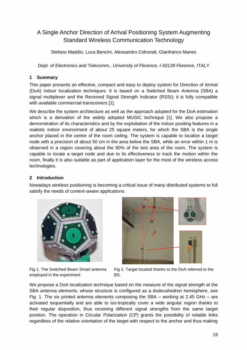
Fig 1. The Switched Beam Smart antenna
employed in the experiment
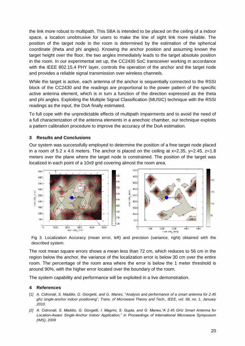
Fig 2. Target located thanks to the DoA referred to the
BS.
We propose a DoA localization technique based on the measure of the signal strength at the
SBA antenna elements, whose structure is configured as a dodecahedron hemisphere, see
Fig. 1. The six printed antenna elements composing the SBA – working at 2.45 GHz – are
activated sequentially and are able to iso-tropically cover a wide angular region thanks to
their regular disposition, thus receiving different signal strengths from the same target
position. The operation in Circular Polarization (CP) grants the possibility of reliable links
regardless of the relative orientation of the target with respect to the anchor and thus making
20
the link more robust to multipath. This SBA is intended to be placed on the ceiling of a indoor
space, a location unobtrusive for users to make the line of sight link more reliable. The
position of the target node in the room is determined by the estimation of the spherical
coordinate (theta and phi angles). Knowing the anchor position and assuming known the
target height over the floor, the two angles immediately leads to the target absolute position
in the room. In our experimental set up, the CC2430 SoC transceiver working in accordance
with the IEEE 802.15.4 PHY layer, controls the operation of the anchor and the target node
and provides a reliable signal transmission over wireless channels.
While the target is active, each antenna of the anchor is sequentially connected to the RSSI
block of the CC2430 and the readings are proportional to the power pattern of the specific
active antenna element, which is in turn a function of the direction expressed as the theta
and phi angles. Exploiting the Multiple Signal Classification (MUSIC) technique with the RSSI
readings as the input, the DoA finally estimated.
To full cope with the unpredictable effects of multipath impairments and to avoid the need of
a full characterization of the antenna elements in a anechoic chamber, our technique exploits
a pattern calibration procedure to improve the accuracy of the DoA estimation.
3 Results and Conclusions
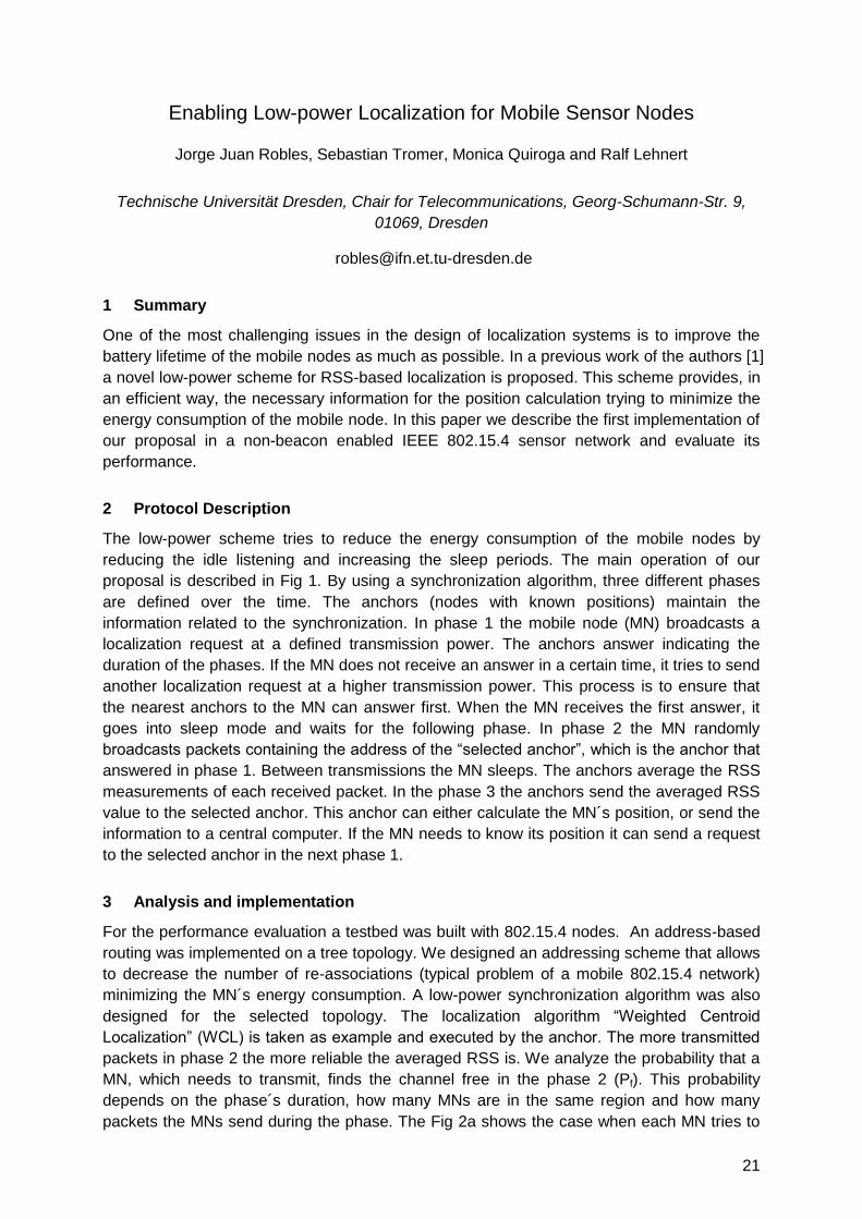
Our system was successfully employed to determine the position of a free target node placed
in a room of 5.2 x 4.6 meters. The anchor is placed on the ceiling at x=2.35, y=2.45, z=1.8
meters over the plane where the target node is constrained. The position of the target was
localized in each point of a 10x9 grid covering almost the room area.
Fig 3. Localization Accuracy (mean error, left) and precision (variance, right) obtained with the
described system.
The root mean square errors shows a mean less than 72 cm, which reduces to 56 cm in the
region below the anchor, the variance of the localization error is below 30 cm over the entire
room. The percentage of the room area where the error is below the 1 meter threshold is
around 90%, with the higher error located over the boundary of the room.
The system capability and performance will be exploited in a live demonstration.
4 References
[1] A. Cidronali, S. Maddio, G. Giorgetti, and G. Manes, ―Analysis and performance of a smart antenna for 2.45
ghz single-anchor indoor positioning”, Trans. of Microwave Theory and Tech., IEEE, vol. 58, no. 1, January
2010.
[2] A. Cidronali, S. Maddio, G. Giorgetti, I. Magrini, S. Gupta, and G. Manes,“A 2.45 GHz Smart Antenna for
Location-Aware Single-Anchor Indoor Application,” in Proceedings of International Microwave Symposium
(IMS), 2009
21
Enabling Low-power Localization for Mobile Sensor Nodes
Jorge Juan Robles, Sebastian Tromer, Monica Quiroga and Ralf Lehnert
Technische Universität Dresden, Chair for Telecommunications, Georg-Schumann-Str. 9,
01069, Dresden
1 Summary
One of the most challenging issues in the design of localization systems is to improve the
battery lifetime of the mobile nodes as much as possible. In a previous work of the authors [1]
a novel low-power scheme for RSS-based localization is proposed. This scheme provides, in
an efficient way, the necessary information for the position calculation trying to minimize the
energy consumption of the mobile node. In this paper we describe the first implementation of
our proposal in a non-beacon enabled IEEE 802.15.4 sensor network and evaluate its
performance.
2 Protocol Description
The low-power scheme tries to reduce the energy consumption of the mobile nodes by
reducing the idle listening and increasing the sleep periods. The main operation of our
proposal is described in Fig 1. By using a synchronization algorithm, three different phases
are defined over the time. The anchors (nodes with known positions) maintain the
information related to the synchronization. In phase 1 the mobile node (MN) broadcasts a
localization request at a defined transmission power. The anchors answer indicating the
duration of the phases. If the MN does not receive an answer in a certain time, it tries to send
another localization request at a higher transmission power. This process is to ensure that
the nearest anchors to the MN can answer first. When the MN receives the first answer, it
goes into sleep mode and waits for the following phase. In phase 2 the MN randomly
broadcasts packets containing the address of the ―selected anchor‖, which is the anchor that
answered in phase 1. Between transmissions the MN sleeps. The anchors average the RSS
measurements of each received packet. In the phase 3 the anchors send the averaged RSS
value to the selected anchor. This anchor can either calculate the MN´s position, or send the
information to a central computer. If the MN needs to know its position it can send a request
to the selected anchor in the next phase 1.
3 Analysis and implementation
For the performance evaluation a testbed was built with 802.15.4 nodes. An address-based
routing was implemented on a tree topology. We designed an addressing scheme that allows
to decrease the number of re-associations (typical problem of a mobile 802.15.4 network)
minimizing the MN´s energy consumption. A low-power synchronization algorithm was also
designed for the selected topology. The localization algorithm ―Weighted Centroid
Localization‖ (WCL) is taken as example and executed by the anchor. The more transmitted
packets in phase 2 the more reliable the averaged RSS is. We analyze the probability that a
MN, which needs to transmit, finds the channel free in the phase 2 (Pf). This probability
depends on the phase´s duration, how many MNs are in the same region and how many
packets the MNs send during the phase. The Fig 2a shows the case when each MN tries to
22
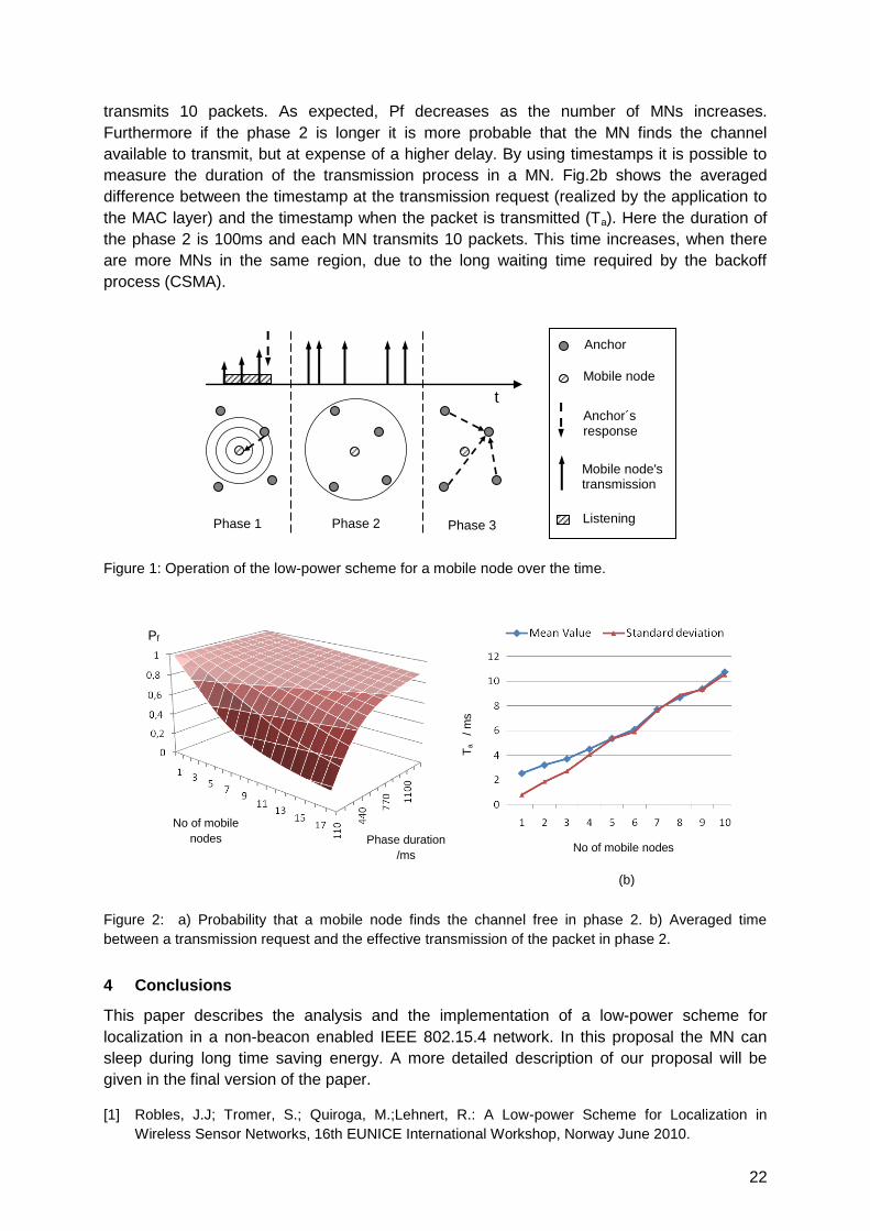
transmits 10 packets. As expected, Pf decreases as the number of MNs increases.
Furthermore if the phase 2 is longer it is more probable that the MN finds the channel
available to transmit, but at expense of a higher delay. By using timestamps it is possible to
measure the duration of the transmission process in a MN. Fig.2b shows the averaged
difference between the timestamp at the transmission request (realized by the application to
the MAC layer) and the timestamp when the packet is transmitted (Ta). Here the duration of
the phase 2 is 100ms and each MN transmits 10 packets. This time increases, when there
are more MNs in the same region, due to the long waiting time required by the backoff
process (CSMA).
Figure 1: Operation of the low-power scheme for a mobile node over the time.
Figure 2: a) Probability that a mobile node finds the channel free in phase 2. b) Averaged time
between a transmission request and the effective transmission of the packet in phase 2.
4 Conclusions
This paper describes the analysis and the implementation of a low-power scheme for
localization in a non-beacon enabled IEEE 802.15.4 network. In this proposal the MN can
sleep during long time saving energy. A more detailed description of our proposal will be
given in the final version of the paper.
[1] Robles, J.J; Tromer, S.; Quiroga, M.;Lehnert, R.: A Low-power Scheme for Localization in
Wireless Sensor Networks, 16th EUNICE International Workshop, Norway June 2010.
Anchor´s response
Mobile node
Anchor
Phase 1
Mobile node's transmission
Listening
period
t
Phase 2 Phase 3
T
a
/ m
s
(b)
No of mobile nodes
Pf
No of mobile
nodes Phase duration
/ms
(a)
23
A Novel 5-Dimensions RF Signal Strength Indoor Localization Method
Based on Multipath Propagation*
Lujia Wang, Chao Hu, Longqiang Tian and Max Q.-H Meng
Shenzhen Institutes of Advanced Technology, Chinese Academy of Sciences, Shenzhen
The Chinese University of Hong Kong, Hong Kong, China
[email protected]; {chao.hu, lq.tian}@siat.ac.cn; [email protected]
1 Summary
The radio received signal strength (RSS) method is widely applied for indoor localization and
navigation systems. In order to realize it and get the optimal performance, we have to
analyze some factors such as choosing the initial value for the Levenberg-Marquardt (LM)
nonlinear optimization method, the placement of the RF receivers relative to the source
transmitter, the estimation of the noise in the environment, and especially the multipath
fading of the electromagnetic wave. The simulation experiments show the feasibility and anti-
noise property of the proposed localization method.
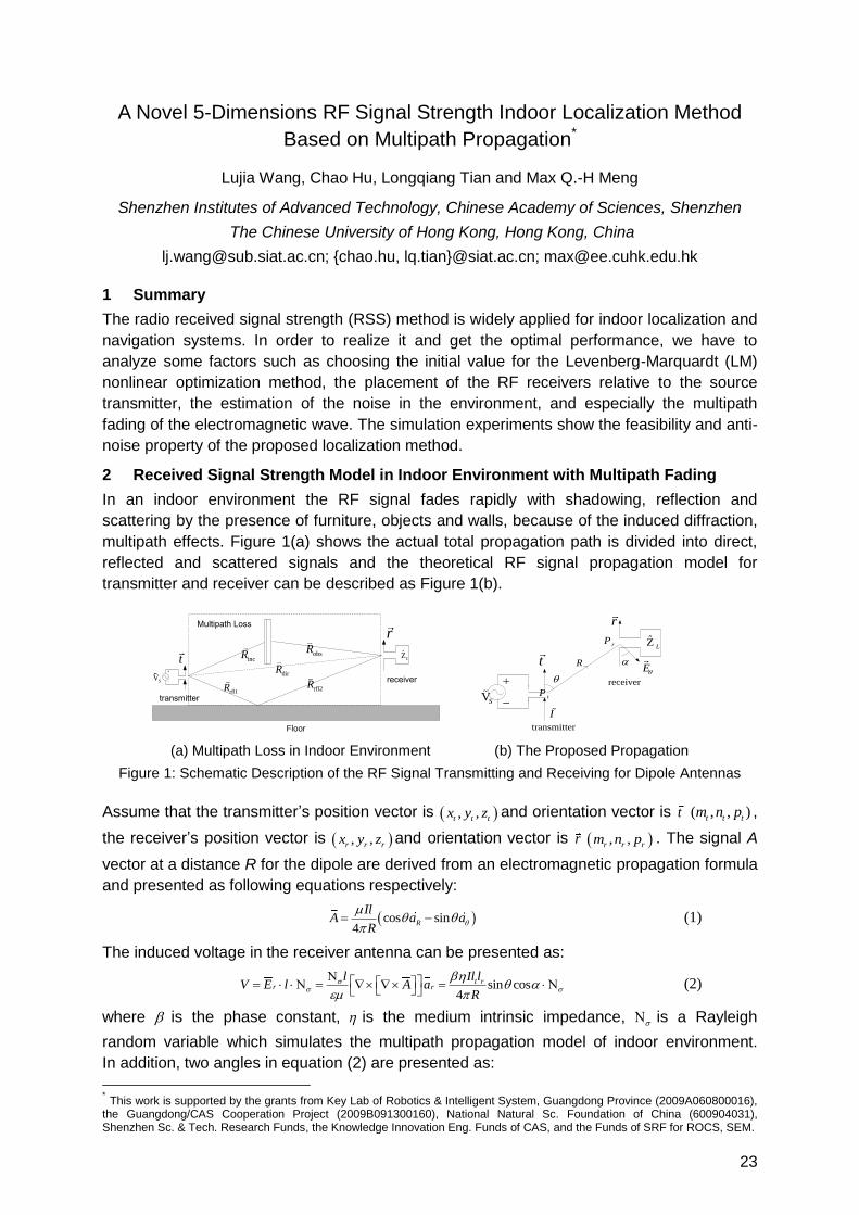
2 Received Signal Strength Model in Indoor Environment with Multipath Fading
In an indoor environment the RF signal fades rapidly with shadowing, reflection and
scattering by the presence of furniture, objects and walls, because of the induced diffraction,
multipath effects. Figure 1(a) shows the actual total propagation path is divided into direct,
reflected and scattered signals and the theoretical RF signal propagation model for
transmitter and receiver can be described as Figure 1(b).
ZL
VS
transmitter
receiver
incRt
robsR
dirR
Floor
rfl1R rfl2R
Multipath Loss
Z L
VS
transmitter
receiver
E
R
I
t
r
tP
rP
(a) Multipath Loss in Indoor Environment (b) The Proposed Propagation
Figure 1: Schematic Description of the RF Signal Transmitting and Receiving for Dipole Antennas
Assume that the transmitter‘s position vector is , ,t t tx y z and orientation vector is t ( , , )t t tm n p ,
the receiver‘s position vector is , ,r r rx y z and orientation vector is r , ,r r rm n p . The signal A
vector at a distance R for the dipole are derived from an electromagnetic propagation formula
and presented as following equations respectively:
cos sin4
R
IlA a a
R
(1)
The induced voltage in the receiver antenna can be presented as:
sin cos4
t rr r
l Il lV E l A a
R
(2)
where is the phase constant, is the medium intrinsic impedance, is a Rayleigh
random variable which simulates the multipath propagation model of indoor environment.
In addition, two angles in equation (2) are presented as:
* This work is supported by the grants from Key Lab of Robotics & Intelligent System, Guangdong Province (2009A060800016),
the Guangdong/CAS Cooperation Project (2009B091300160), National Natural Sc. Foundation of China (600904031), Shenzhen Sc. & Tech. Research Funds, the Knowledge Innovation Eng. Funds of CAS, and the Funds of SRF for ROCS, SEM.
24
2 2 2
cost r t t r t t r t
r t r t r t
m x x n y y p z zR t
R x x y y z z
(3)
2 2 2
sinr r t r r t r r t
r t r t r t
m x x n y y p z zR r
R x x y y z z
(4)
3 Localization Model
Provided that the number of receivers placed around the object is N ( 5N ), the position
and orientation of an object and receivers are 0 0 0 0 0 0, , , , ,x y z m n p , , , , , ,i i i i i ix y z m n p 1,2,i N
respectively. Since , , , ,x y z m n is the solving solution for 0 0 0 0 0, , , ,x y z m n , then the object
localization function can be expressed as:
22 22 2
2
61
minN i i i i i i i i i i i
i
i i
k R m x x n y y p z z R m x x n y y p z zV
R
(5)
where 2 2 2
0 0 0( ) ( ) ( )i i i iR x x y y z z , 4t rk Il l .
The localization model in equation (5) is nonlinear and the Levenberg-Marquardt (LM)
optimization method can be applied to solve this problem for practicality.
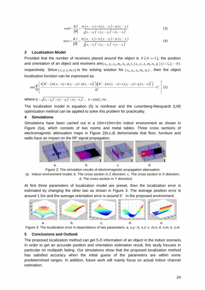
4 Simulations
Simulations have been carried out in a 10m×10m×3m indoor environment as shown in
Figure 2(a), which consists of two rooms and metal tables. Three cross sections of
electromagnetic attenuation maps in Figure 2(b,c,d) demonstrate that floor, furniture and
walls have an impact on the RF signal propagation.
a. b. c. d.
Figure 2: The simulation results of electromagnetic propagation attenuation
(a. Indoor environment model; b. The cross section in Z direction; c. The cross section in X direction;
d. The cross section in Y direction)
At first three parameters of localization model are preset, then the localization error is
estimated by changing the other two as shown in Figure 3. The average position error is
around 1.5m and the average orientation error is around 5°in the proposed environment.
a. b. c. d. e.
Figure 3: The localization error in dependance of two parameters: a. x,y ; b. x,z; c. m,n; d. x,m; e. z,m
5 Conclusions and Outlook
The proposed localization method can get 5-D information of an object in the indoor scenario.
In order to get an accurate position and orientation estimation result, this study focuses in
particular on multipath fading. Our simulations show that the proposed localization method
has satisfied accuracy when the initial guess of the parameters are within some
predetermined ranges. In addition, future work will mainly focus on actual indoor channel
estimation.
25
DALE: A Range-Free, Adaptive Indoor Localization System Enhanced by
Limited Fingerprinting
Olga E. Segou[1], Stelios A. Mitilineos[2] and Stelios C.A. Thomopoulos[3]
National Center for Scientific Research “Demokritos”,
Institute of Informatics and Telecommunications,
P. Grigoriou 1 & Neapoleos, Ag. Paraskevi, Athens 153 10, GREECE
[1][email protected] [2][email protected] [3][email protected]
1 Summary
A novel range-free algorithm is presented in this paper. DALE (DALE is Adaptive Localization
with Enhancements) includes a two-stage algorithm and it is described as adaptive in the
sense that it is able to incorporate fingerprints of specific locations when available in order to
enhance localization accuracy. The proposed method is aimed in indoor environments and
requires a strategic placement of nodes in each room. It is easily scalable to a large number
of rooms and adaptable to rooms with complex geometry. Based on plain RSSI
measurements, which are easily collected on inexpensive hardware, the range-free method
returns an area wherein the mobile node lies, instead of a specific position fix. Simulation
results are derived in order to evaluate the proposed algorithm and compared to relative
research results in the literature, indicating that the proposed scheme achieves superior
robustness and accuracy, while being less computationally extensive and using fewer
beacons.
2 Extended Abstract
The rapid development of wireless communications along with the increasing interest in
pervasive computing has made localization algorithms a research area of significant interest
for many scientists and engineers. However, many indoor localization systems rely either on
a costly and time consuming fingerprinting process to produce a wireless mapping of a room
[1], complex hardware [2] or a large number of beacons [3].
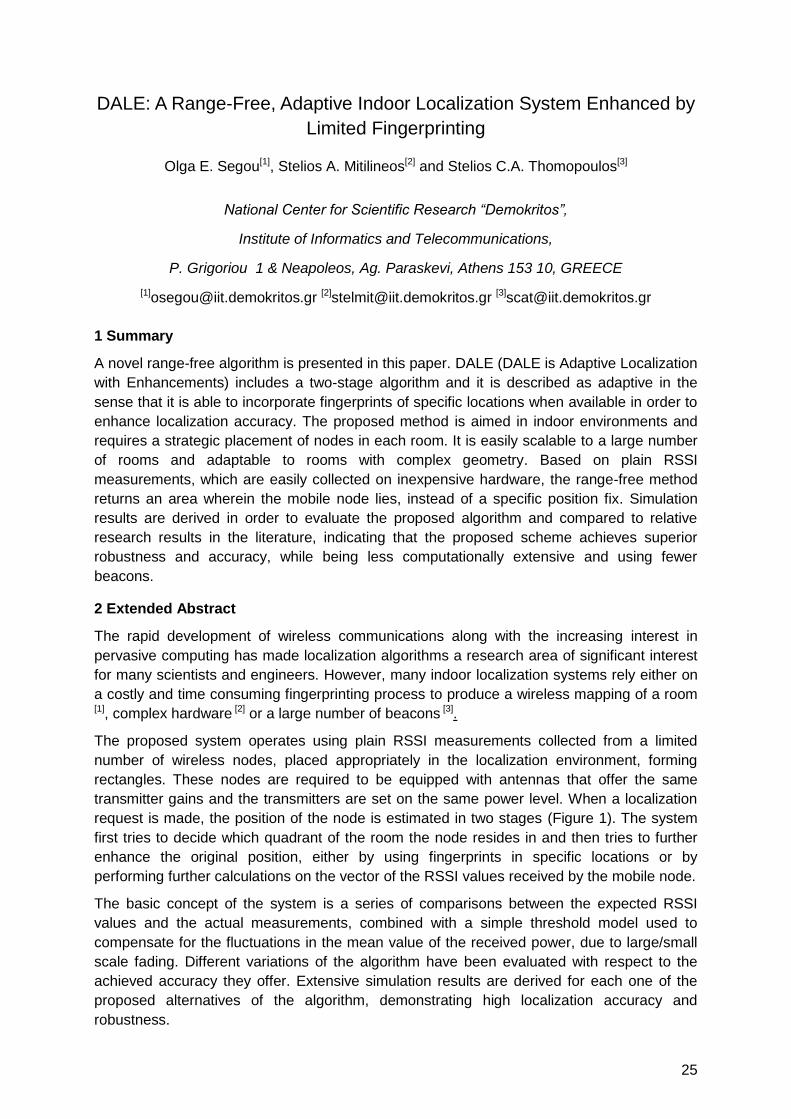
The proposed system operates using plain RSSI measurements collected from a limited
number of wireless nodes, placed appropriately in the localization environment, forming
rectangles. These nodes are required to be equipped with antennas that offer the same
transmitter gains and the transmitters are set on the same power level. When a localization
request is made, the position of the node is estimated in two stages (Figure 1). The system
first tries to decide which quadrant of the room the node resides in and then tries to further
enhance the original position, either by using fingerprints in specific locations or by
performing further calculations on the vector of the RSSI values received by the mobile node.
The basic concept of the system is a series of comparisons between the expected RSSI
values and the actual measurements, combined with a simple threshold model used to
compensate for the fluctuations in the mean value of the received power, due to large/small
scale fading. Different variations of the algorithm have been evaluated with respect to the
achieved accuracy they offer. Extensive simulation results are derived for each one of the
proposed alternatives of the algorithm, demonstrating high localization accuracy and
robustness.

26
Figure 1: Overview of the proposed algorithm.
4 Conclusion and future work
The proposed solution tries to estimate the smallest possible area of the localization
environment where the mobile node resides in. The accuracy of the algorithm is therefore
dependent not only on the propagation characteristics of the specific space, but also on the
dimensions of each room where the system is set up.
Results have shown a mean localization error of 70cm in a 5m-by-5m room, dropping to
60cm with an addition of five fingerprints. An adaptive, fully range-free version of the
proposed system is also being explored, eliminating any need for fingerprinting. The system
is also undergoing extensive testing in an in-house developed localization platform, namely,
the WAX-ROOM system, in order to evaluate its‘ performance in real conditions [4].
This work is supported by (a) the ―EMERGE‖ (EMERGE-IST-FP6-2006-045056), the
―DITSEF‖ (DITSEF-FP7-ICT-SEC-2007-1-225404) and the ―HMFM‖ (HMFM-FP6-AAL-2008-
1/ΓΓΕΤ: 13591-07/07/2009) EU research projects, which are funded in part under by the
European Commission and in part by the General Secretariat of Research and Technology
(GSRT) of the Ministry of Development, Greece, (b) by a Ph.D. Fellowship of NCSR
Demokritos and the Ministry of Development and (c) by a Post-Doctoral Fellowship of NCSR
Demokritos and the Ministry of Development.
References
[1] ―Modeling of Indoor Positioning Systems Based on Location Fingerprinting‖, K. Kaemarungsi, P.
Krishnamurthy, Proc. IEEE INFOCOM 2004.
[2] ―The Cricket Location-Support System‖, Nissanka B. Priyantha, Anit Chakraborty, and Hari
Balakrishnan, 6th ACM International Conference on Mobile Computing and Networking (ACM
MOBICOM), Boston, MA, August 2000
[3] ―Range-Free Localization and its‘ Impact on Large Scale Sensor Networks‖, Tian He, Chengdu
Huang, Brian M. Blum, John N. Stankovic, Tarek F. Abdelzaher, ACM Transactions on
Embedded Computing Systems, Volume 4, Issue 4, November 2005.
[4] ―An Indoor WSN-based Localization Platform Using XBee Radios and Arduino Microcontrollers,
Incorporating Three Different Localization Techniques and an Optimal Fusion Rule‖, Stelios A.
Mitilineos, John N. Goufas, Olga E. Segou, and Stelios C.A. Thomopoulos, SPIE Defense,
Security and Sensing Symposium, Orlando, USA, April 2010.
27
Ad-hoc Networks Aiding Indoor Calibrations
Of Heterogeneous Devices for Fingerprinting Applications
Francescantonio Della Rosa, Helena Leppäkoski, Stefano Biancullo, and Jari Nurmi
Tampere University of Technology, Department of Computer Systems,
Korkeakoulunkatu 1 G 308, FIN-33720 Tampere, Finland
1 Extended Abstract
Fingerprinting approaches are based on experimental models which relate the measured
Received Signal Strength (RSS) values directly to the position of the calibration points.
These models are generated with the use of data collected off-line from several locations
(calibration points) covering the area where positioning service is performed. Compared to
other RSS-based methods, fingerprinting algorithms are more robust against the signal
propagation fluctuations (Fig.1 and Fig. 2) and attenuations generated by environment
characteristics, since they make use of location-dependent errors of radio signals. Even if
more robust, the calibration phase of the fingerprinting is a very laborious and time
consuming approach, especially if it has to be performed for heterogeneous devices with
different wireless cards. Hence it represents a huge limitation when implementing mass
market positioning applications for devices with vendor-related hardware characteristics,
because different vendors produce different chipsets with different Radio Frequency (RF)
modules developed with their own accuracy, range of power, sensitivity and scaling, which
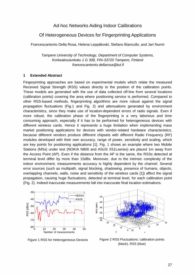
are key points for positioning applications [1]. Fig. 1 shows an example where two Mobile
Stations (MSs) under test (NOKIA N800 and ASUS X51Lseries) are placed 1m away from
the Access Point (AP). Even if the distance from the AP is the same, the RSSs detected at
terminal level differ by more than 15dBs. Moreover, due to the intrinsic complexity of the
indoor environment, measurements accuracy is highly dependent by the channel. Several
error sources (such as multipath, signal blocking, shadowing, presence of humans, objects,
overlapping channels, walls, noise and sensitivity of the wireless cards [1]) affect the signal
propagation, causing huge fluctuations, detected at terminal level, for each calibration point
(Fig. 2). Indeed inaccurate measurements fall into inaccurate final location estimations.
Figure 1 RSS for Heterogeneous Devices
Figure 2 RSS Fluctuations: calibration points
(black), RSS (blue)
0 10 20 30 40 50-80
-70
-60
-50
-40
-30
Number of measurements
RS
S [
dB
m]
NOKIA
ASUS
28
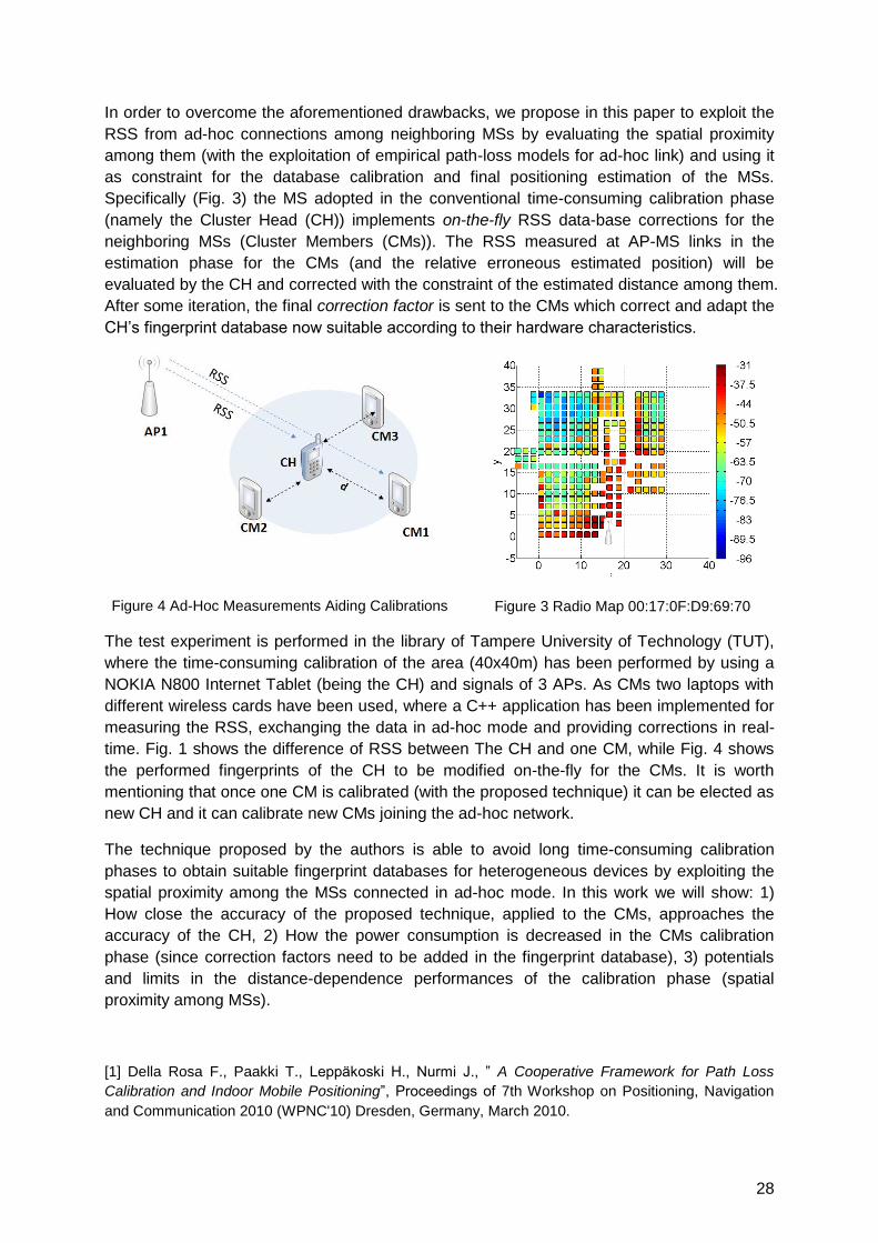
In order to overcome the aforementioned drawbacks, we propose in this paper to exploit the
RSS from ad-hoc connections among neighboring MSs by evaluating the spatial proximity
among them (with the exploitation of empirical path-loss models for ad-hoc link) and using it
as constraint for the database calibration and final positioning estimation of the MSs.
Specifically (Fig. 3) the MS adopted in the conventional time-consuming calibration phase
(namely the Cluster Head (CH)) implements on-the-fly RSS data-base corrections for the
neighboring MSs (Cluster Members (CMs)). The RSS measured at AP-MS links in the
estimation phase for the CMs (and the relative erroneous estimated position) will be
evaluated by the CH and corrected with the constraint of the estimated distance among them.
After some iteration, the final correction factor is sent to the CMs which correct and adapt the
CH‘s fingerprint database now suitable according to their hardware characteristics.
Figure 4 Ad-Hoc Measurements Aiding Calibrations
Figure 3 Radio Map 00:17:0F:D9:69:70
The test experiment is performed in the library of Tampere University of Technology (TUT),
where the time-consuming calibration of the area (40x40m) has been performed by using a
NOKIA N800 Internet Tablet (being the CH) and signals of 3 APs. As CMs two laptops with
different wireless cards have been used, where a C++ application has been implemented for
measuring the RSS, exchanging the data in ad-hoc mode and providing corrections in real-
time. Fig. 1 shows the difference of RSS between The CH and one CM, while Fig. 4 shows
the performed fingerprints of the CH to be modified on-the-fly for the CMs. It is worth
mentioning that once one CM is calibrated (with the proposed technique) it can be elected as
new CH and it can calibrate new CMs joining the ad-hoc network.
The technique proposed by the authors is able to avoid long time-consuming calibration
phases to obtain suitable fingerprint databases for heterogeneous devices by exploiting the
spatial proximity among the MSs connected in ad-hoc mode. In this work we will show: 1)
How close the accuracy of the proposed technique, applied to the CMs, approaches the
accuracy of the CH, 2) How the power consumption is decreased in the CMs calibration
phase (since correction factors need to be added in the fingerprint database), 3) potentials
and limits in the distance-dependence performances of the calibration phase (spatial
proximity among MSs).
[1] Della Rosa F., Paakki T., Leppäkoski H., Nurmi J., ‖ A Cooperative Framework for Path Loss
Calibration and Indoor Mobile Positioning‖, Proceedings of 7th Workshop on Positioning, Navigation
and Communication 2010 (WPNC'10) Dresden, Germany, March 2010.
29
Real time calibration for RSS indoor positioning systems
Ana M. Bernardos, José R. Casar, Paula Tarrío
Universidad Politécnica de Madrid, Telecommunications School,
Av. Complutense 30, Madrid, Spain
1 Summary
Most current indoor localization systems usually work with received signal strength (RSS)
measurements gathered from different wireless technologies (WiFi, Bluetooth, ZigBee, etc.). The RSS
signal random nature makes that most of the systems, either map-based or channel model based,
need an off-line calibration phase, at least when starting the location system for the first time.
Calibration usually is a resource and time consuming task, and its validity expires after a period of time,
mainly due to continuous and unavoidable physical variations of the environment (e.g. changing
people flow during the day, open or closed doors, furniture redistributions, etc.). In this contribution we
present an algorithm which allows dynamic calibration of a channel model-based localization
technique. The algorithm uses a Least Mean Squares technique to adaptively estimate the constants
of the propagation model, using reference beacons, aiming at minimizing the error of a hyperbolic
triangulation method. Simulated and real data show that the location error is effectively minimized after
a number of training samples, making possible to avoid manual calibration and recalibration
procedures when deploying a localization system.
2 Fundamentals: Localization scenario
We consider an indoor space covered by a network of anchor nodes (e.g. WiFi access points or
Zigbee motes) which measure the RSS of a mobile node to be localized. Our localization system is
based on using a propagation channel modeling to compute each distance mobile-anchor node and
perform hyperbolic triangulation. The most popular channel model for RSS-based localization is the
lognormal model:
),0(log10)()(0
Nd
dAdBmPdBmP TXRX (1)
where and PTX and PRX are the transmitted and received power (at the transmitting and receiving
nodes, respectively), d is the distance between transmitter and receiver, A and η are the parameters of
the channel model and N is a zero-mean Gaussian random variable with standard deviation σ.
Using eq. 1, given A and η, the system estimates the distances d from the received PRX (in practice
the RSS), at least to three anchor nodes. To complete the real-time localization, a hyperbolic
triangulation is used to localize the mobile node (detailed formulation is available in e.g. [1]).
However, in practice, both A and η need to be off-line experimentally determined and continually
updated or calibrated (bad estimations of A and η might result in significant localization errors). A
number of strategies dealing with this problem from different perspectives have been proposed (see
[2], as an example).
In this context, our objective is to avoid any off-line experimental determination of A and η constants 1)
to minimize the complexity of the calibration tasks when getting the location system to work for the first
time and 2) to adapt the system‘s performance to real time environmental variations. To do so, we
define a number of beacon or reference points in given geographic locations. These beacon points,
easy to deploy (practical considerations will be described in the full paper), will be situated in
waypoints (e.g. doors), attached to static objects (e.g. a printer in an office), or situated as part of the
communications network. The anchor nodes continuously measure the RSS of the signals coming
from these static beacon points and use the algorithm presented in the next section to compute A and
η in real time.
3 The Least Mean Square (LMS) algorithm
The algorithm uses the measurements taken from the calibration points to iterative calculate the
optimal values of A and and η, i.e. those that minimize the error between the estimated and the
(known) real position of the beacons
30
22
)()()()()(
nynynxnxn (2)
Assuming that a single channel model is used (in the final paper, results using not a single but several
channel models will be included), the LMS algorithm is formulated as:
d
ndnnn
dA
ndnnAnnAnA AA
)()()1()(
)()()1()()1()(
..... (3)
where µs are the filter step sizes. After detailed computation (basically derivations and simplifications)
on the formulas of hyperbolic triangulation the following expressions for A(n) and η(n) are obtained
(details in the final paper):
N
i
iii
N
i
iii
N
i
ii
N
i
iiA
ndndndndDnyny
ndndndndcnxnx
n
knn
ndndDnynyndndcnxnxn
knAnA
2
1
2
1
2
2
1
2
1
2
2
22
1
2
22
1
)(log)()(log)()()(
)(log)()(log)()()(
)1(
10)1()(
)()()()()()()()()1(
)1()(
(4)
where:
10det
10ln16k , )1(10
)1(
10
n
RSSnA
i
i
d , NNiNii yxyxyyyxc 22
22
2, and
NNiNii yxyxxxxyD 22
22
2 (5)
4 Preliminary results and practical issues
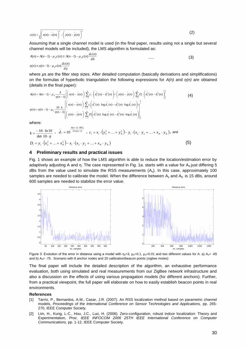
Fig. 1 shows an example of how the LMS algorithm is able to reduce the location/estimation error by
adaptively adjusting A and η. The case represented in Fig. 1a. starts with a value for A0 just differing 5
dBs from the value used to simulate the RSS measurements (As). In this case, approximately 100
samples are needed to calibrate the model. When the difference between As and A0 is 15 dBs, around
600 samples are needed to stabilize the error value.
Figure 3: Evolution of the error in distance using a model with η0=3, µA=0.1, µη=0.01 and two different values for A: a) A0= -65
and b) A0= -75. Scenario with 8 anchor nodes and 20 calibration/beacon points (zigbee motes)
The final paper will include the detailed description of the algorithm, an exhaustive performance
evaluation, both using simulated and real measurements from our ZigBee network infrastructure and
also a discussion on the effects of using various propagation models (for different anchors). Further,
from a practical viewpoint, the full paper will elaborate on how to easily establish beacon points in real
environments.
References
[1] Tarrío, P., Bernardos, A.M., Casar, J.R. (2007). An RSS localization method based on parametric channel models, Proceedings of the International Conference on Sensor Technologies and Applications, pp. 265-270, IEEE Computer Society.
[2] Lim, H., Kung, L-C., Hou, J.C., Luo, H. (2006). Zero-configuration, robust indoor localization: Theory and Experimentation, Proc. IEEE INFOCOM 2006 25TH IEEE International Conference on Computer Communications, pp. 1-12, IEEE Computer Society.
50 100 150 200 250 300 350 400 450 500
0
0.5
1
1.5
2
2.5
3
3.5
4
4.5
no. samples
Distance error
200 400 600 800 1000 1200 14000
1
2
3
4
5
no. samples
Distance error
31
A Model-Switching Sequential Monte Carlo Algorithm for Indoor Tracking
with Experimental RSS Data
Katrin Achutegui*, Javier Rodas†, Carlos J. Escudero†, Joaquín Míguez*
*Department of Signal Theory and Communications, Universidad Carlos III de Madrid, Spain †Department of Electronics and Systems, Universidade da Coruña, Spain
{kachutegui,jmiguez}@tsc.uc3m.es ; {jrodas,escudero}@udc.es.
1 Introduction
In this paper we address the problem of indoor tracking using received signal strength (RSS)
as position-dependent data. This type of measurements are very appealing because they
can be easily obtained with a variety of (inexpensive) wireless technologies. However, the
extraction of accurate location information from RSS in indoor scenarios is not an easy task.
Due to the multipath propagation, it is hard to adequately model the correspondence
between the received power and the transmitter-to-receiver distance. For that reason, we
propose the use of a compound model that combines several sub-models, whose
parameters are adjusted to different propagation environments. This methodology, called
Interacting Multiple Models (IMM), has been used in the past either for modeling the motion
of maneuvering targets [2] or the relationship between target position and the observations
[1]. Here, we extend its application to handle both types of uncertainty, in the target dynamics
and the RSS observations, and we refer to the resulting state-space model as a generalized
IMM (GIMM) system. The flexibility of the GIMM approach is attained at the expense of an
increase in the number of random processes that must be accurately tracked. To overcome
this difficulty, we introduce a Rao-Blackwellized sequential Monte Carlo tracking algorithm
that exhibits good performance both with synthetic and experimental data.
2 System Model
Dynamic Model: We formally represent the target dynamic state at time over a two
dimensional region as a real vector , - , where the real vectors and
provide the target position and velocity, respectively. Each one contains two real scalars,
, - and , -
, which are the coordinates of the position, , and velocity, ,
in the plane. denotes the variation, in radians, of the angle of the velocity at time
. The subscript in is used to indicate the state vector dimension. A popular dynamic
model for is the so-called ―coordinated turn'' (CT) model [2], which completely
characterizes the ability of the target to turn. By selecting different distributions for one can
devise different motion models. Hence, we introduce an additional state variable, * +,
such that implies that is generated according to the -th motion model. Finally, the
state vector , - evolves according to the IMM equation
( | ) ( | ) ( ) The transition matrix ( ) is
a function of the turning angle , determines the covariance of the dynamic noise and
the conditional pdf ( | - - ) and the pmf ( | ) are assumed known.
Measurement Models: We propose a scheme where RSS observations are collected from
sensors. The measurement provided by the -th sensor at time is denoted as . We
represent the relationship between the observed RSS, , and the target position, , with
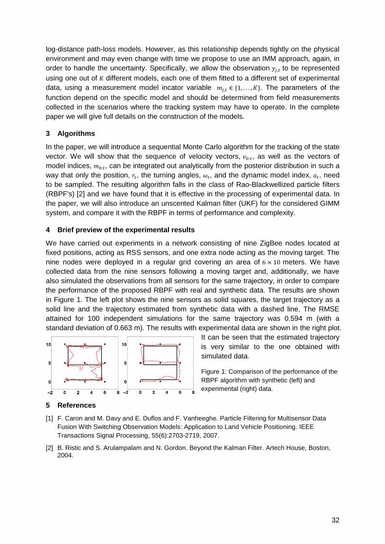
32
log-distance path-loss models. However, as this relationship depends tightly on the physical
environment and may even change with time we propose to use an IMM approach, again, in
order to handle the uncertainty. Specifically, we allow the observation to be represented
using one out of different models, each one of them fitted to a different set of experimental
data, using a measurement model incator variable * +. The parameters of the
function depend on the specific model and should be determined from field measurements
collected in the scenarios where the tracking system may have to operate. In the complete
paper we will give full details on the construction of the models.
3 Algorithms
In the paper, we will introduce a sequential Monte Carlo algorithm for the tracking of the state
vector. We will show that the sequence of velocity vectors, , as well as the vectors of
model indices, , can be integrated out analytically from the posterior distribution in such a
way that only the position, , the turning angles, , and the dynamic model index, , need
to be sampled. The resulting algorithm falls in the class of Rao-Blackwellized particle filters
(RBPF's) [2] and we have found that it is effective in the processing of experimental data. In
the paper, we will also introduce an unscented Kalman filter (UKF) for the considered GIMM
system, and compare it with the RBPF in terms of performance and complexity.
4 Brief preview of the experimental results
We have carried out experiments in a network consisting of nine ZigBee nodes located at
fixed positions, acting as RSS sensors, and one extra node acting as the moving target. The
nine nodes were deployed in a regular grid covering an area of meters. We have
collected data from the nine sensors following a moving target and, additionally, we have
also simulated the observations from all sensors for the same trajectory, in order to compare
the performance of the proposed RBPF with real and synthetic data. The results are shown
in Figure 1. The left plot shows the nine sensors as solid squares, the target trajectory as a
solid line and the trajectory estimated from synthetic data with a dashed line. The RMSE
attained for 100 independent simulations for the same trajectory was 0.594 m (with a
standard deviation of 0.663 m). The results with experimental data are shown in the right plot.
It can be seen that the estimated trajectory
is very similar to the one obtained with
simulated data.
Figure 1: Comparison of the performance of the
RBPF algorithm with synthetic (left) and
experimental (right) data.
5 References
[1] F. Caron and M. Davy and E. Duflos and F. Vanheeghe. Particle Filtering for Multisensor Data
Fusion With Switching Observation Models: Application to Land Vehicle Positioning. IEEE
Transactions Signal Processing, 55(6):2703-2719, 2007.
[2] B. Ristic and S. Arulampalam and N. Gordon. Beyond the Kalman Filter. Artech House, Boston, 2004.
33
An Environment Adaptive ZigBee-based Indoor Positioning Algorithm
Janire Larranaga, Leire Muguira, Juan-Manuel Lopez-Garde, Juan-Ignacio Vazquez
MoreLab, DeustoTech, Avenida de las Universidades 24, 48007 Bilbao Spain
[email protected], [email protected], [email protected],
1 Summary
We have developed and implemented an indoor positioning system that is able to carry out
wireless sensor node location in real time and automatically adapts to changes in the
environment. We present a descent gradient iteration algorithm, in order to calculate the
blind node's position in the most accurate way. It is based on several matrices that can be
dynamically updated with the information received from the reference nodes. The algorithm
is running at a central server due to the computational limitations of this type of node and, as
it is based on the measured RSSI levels, no extra hardware is required. The selected
platform is a Texas Instruments' CC2430 WSN (Wireless Sensor Network) and the location
estimation is calculated over ZigBee communication technology.
2 Introduction
Nowadays, indoor location is an unresolved issue many research groups are working on
intensively. There are several techniques that have been developed seeking a solution;
however, a definitive approach has yet to be found.
One of the most reliable existing solutions is fingerprinting, based on an RSSI calibration
method, where several measurements are taken in order to describe the signal's propagation
pattern in a particular scenario before the location phase begins. This technique needs a lot
of pre-processing work though, and furthermore, the method is not useful when there are
changes in the environment. Whenever changes take place, the RSSI fingerprint has to be
built up again since all the previous measurements become useless.
Therefore, if we wish to obtain an accurate location, it is not enough to simply perform an
initial calibration process. This calibration must be updated dynamically whenever location
needs to be determined.
In order to accomplish this goal, we have developed a robust, easy-to-deploy and flexible
positioning system based on ZigBee WSN. The reason why a ZigBee network has been
chosen is that it is a low-cost, low-power, wireless mesh networking proprietary standard. It is
important to note that the mesh networking provides high reliability, a wider range and also
makes it easier to deploy the ZigBee nodes.
Our system consists of two main phases: calibration and location. The requested node's
location is computed in the central server, and then it can be distributed to the network.
Should a blind node need to be located, the system performs the calibration, so that changes
in the environment are taken into account in the location phase, and thus making the system
more robust and accurate.
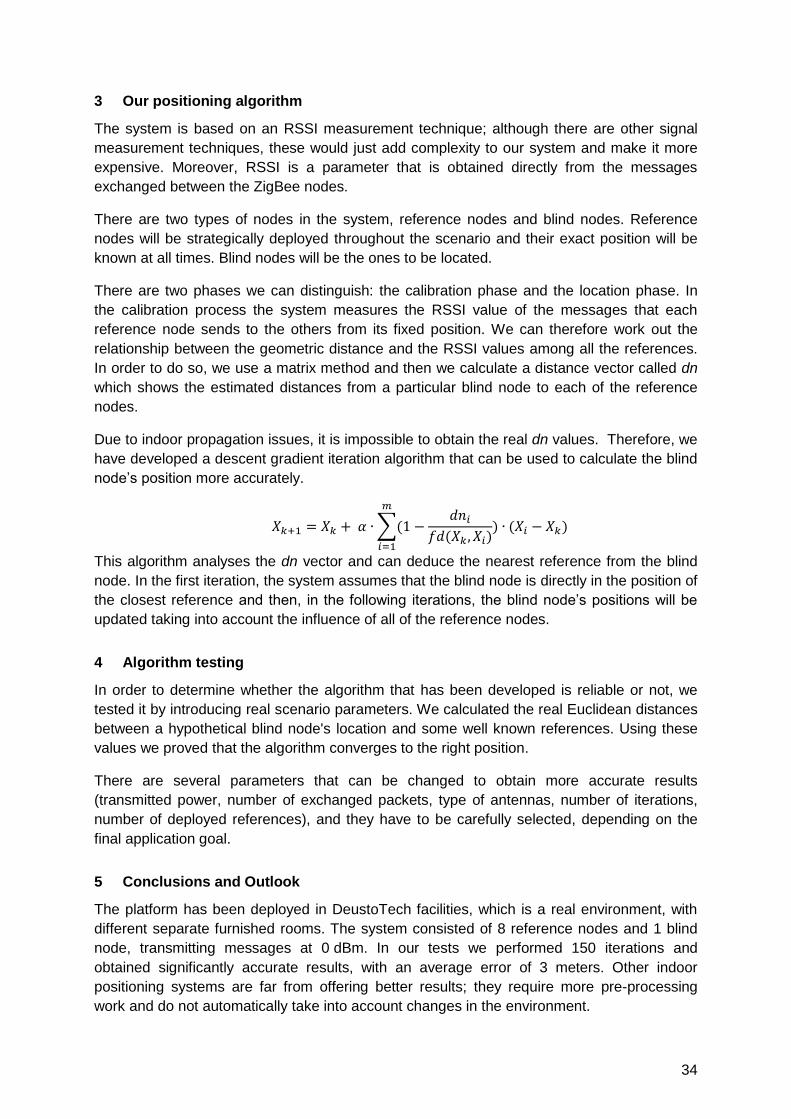
34
3 Our positioning algorithm
The system is based on an RSSI measurement technique; although there are other signal
measurement techniques, these would just add complexity to our system and make it more
expensive. Moreover, RSSI is a parameter that is obtained directly from the messages
exchanged between the ZigBee nodes.
There are two types of nodes in the system, reference nodes and blind nodes. Reference
nodes will be strategically deployed throughout the scenario and their exact position will be
known at all times. Blind nodes will be the ones to be located.
There are two phases we can distinguish: the calibration phase and the location phase. In
the calibration process the system measures the RSSI value of the messages that each
reference node sends to the others from its fixed position. We can therefore work out the
relationship between the geometric distance and the RSSI values among all the references.
In order to do so, we use a matrix method and then we calculate a distance vector called dn
which shows the estimated distances from a particular blind node to each of the reference
nodes.
Due to indoor propagation issues, it is impossible to obtain the real dn values. Therefore, we
have developed a descent gradient iteration algorithm that can be used to calculate the blind
node‘s position more accurately.
∑(
( )
) ( )
This algorithm analyses the dn vector and can deduce the nearest reference from the blind
node. In the first iteration, the system assumes that the blind node is directly in the position of
the closest reference and then, in the following iterations, the blind node‘s positions will be
updated taking into account the influence of all of the reference nodes.
4 Algorithm testing
In order to determine whether the algorithm that has been developed is reliable or not, we
tested it by introducing real scenario parameters. We calculated the real Euclidean distances
between a hypothetical blind node's location and some well known references. Using these
values we proved that the algorithm converges to the right position.
There are several parameters that can be changed to obtain more accurate results
(transmitted power, number of exchanged packets, type of antennas, number of iterations,
number of deployed references), and they have to be carefully selected, depending on the
final application goal.
5 Conclusions and Outlook
The platform has been deployed in DeustoTech facilities, which is a real environment, with
different separate furnished rooms. The system consisted of 8 reference nodes and 1 blind
node, transmitting messages at 0 dBm. In our tests we performed 150 iterations and
obtained significantly accurate results, with an average error of 3 meters. Other indoor
positioning systems are far from offering better results; they require more pre-processing
work and do not automatically take into account changes in the environment.
35
Low Power Location Protocol based on ZigBee
Luís Brás, Marco Oliveira, Pedro Pinho, Nuno Borges Carvalho
Instituto de Telecomunicações, Universidade de Aveiro,
Campus Universitário de Santiago, Aveiro, Portugal
In typical ZigBee location applications, end devices are listening network messages for
configuration and synchronization. These listening intervals often consume more than the
transmission process reducing significantly the battery life time of the end devices. This
paper describes a ZigBee communication protocol which has been implemented and
provides a reduced power consumption of end devices. This is achieved by a simplification of
the end devices firmware in order to increase their sleeping time and a proper development
of routers and coordinator firmware.
This developed protocol allows two different forms of location estimation: proximity-based,
where the position of the end device is related to its nearest reference node location; and
multi-RSSI reference detection, which provides several neighbours RSSI values, being the
base for more complex algorithms such as triangulation and fingerprinting.
The coordinator acts as a gateway of the network, allowing a communication between the
wireless sensor network and the PC by a serial port. This device forwards the received
messages by the ZigBee network to the serial port, and incoming messages on the serial
port to the ZigBee network. Blind-Node is the end device (mobile node) whose position is
desired to be estimated. After being registered in the network it will start an infinite loop
where it falls asleep for a pre-defined interval and wakes up only in order to send a set of
blast messages (broadcast messages of null APS payload and radius 1), followed by an end
of transmission identification message.
The Ref-Nodes provide the location support, remaining in a permanent pooling mode,
listening for messages. They listen for location messages from Blind-Nodes, configuration
messages from coordinator and forwarding messages from other Ref-Nodes, processing
them according to its individual role. These nodes represent the major system responsibility
for messages processing on the network.
Through the high level application the user can choose a location based on proximity, where
it is possible to identify all BlindNodes located in the area by matching the Blind-Node ID with
the Ref-Node ID that detected its higher RSSI value. The other mode, called multi-RSSI
reference detection, provides the base for a more precise location process, where a
message with all Ref-Node IDs and the corresponding RSSI values of chosen Blind-Nodes
will be sent to the coordinator. These location modes and their corresponding messages
contents are described in Figure 1.
The selection of the location mode is managed by a graphical interface based on Java
language, with the characteristic of easy and intuitive use. The developed interface provides
the user with the visualization of Blind-Nodes based on the proximity or a more precise
location based in a neural network. It also provides the configuration of the communication
route and an identification of communication failures.
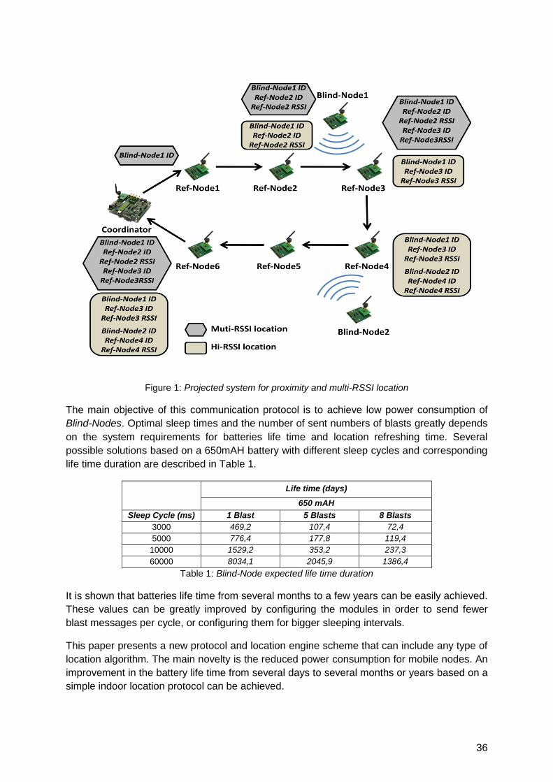
36
Figure 1: Projected system for proximity and multi-RSSI location
The main objective of this communication protocol is to achieve low power consumption of
Blind-Nodes. Optimal sleep times and the number of sent numbers of blasts greatly depends
on the system requirements for batteries life time and location refreshing time. Several
possible solutions based on a 650mAH battery with different sleep cycles and corresponding
life time duration are described in Table 1.
Life time (days)
650 mAH
Sleep Cycle (ms) 1 Blast 5 Blasts 8 Blasts
3000 469,2 107,4 72,4
5000 776,4 177,8 119,4
10000 1529,2 353,2 237,3
60000 8034,1 2045,9 1386,4
Table 1: Blind-Node expected life time duration
It is shown that batteries life time from several months to a few years can be easily achieved.
These values can be greatly improved by configuring the modules in order to send fewer
blast messages per cycle, or configuring them for bigger sleeping intervals.
This paper presents a new protocol and location engine scheme that can include any type of
location algorithm. The main novelty is the reduced power consumption for mobile nodes. An
improvement in the battery life time from several days to several months or years based on a
simple indoor location protocol can be achieved.

37
Improving ZigBee 2D5 localization in large buildings
using Metric Description Graphs
Juan Carlos García, Jesús Ureña, Jesús García
Electronics Department, University of Alcala, Campus Universitario,
28805 Alcala de Henares (Madrid)
1 Summary
This work will propose a way of improving location estimations of a ZigBee RSSI based
Indoor Localization System (ILS) in large buildings. ILS beacons are a network of fixed
sensor nodes, linked with the ZigBee protocol, installed in convenient locations. A set of
unknown objects, equipped also with ZigBee devices (blind nodes), can be located and
tracked by the ILS. The localization system will provide 2.5 dimensions data (2D5) about
blind nodes location: 2D metric information (X and Y axis) in every floor plus an indication of
the floor number in height Z. The positioning of blind nodes is improved by fitting initial
estimations into a building metric description graph which include connectivity among rooms
and relative distances between graph nodes.
2 ZigBee Sensor Networks as Indoor Location Systems
In modern buildings a distributed Sensor Network (SN) allows to collect important information
from any room of it: occupancy, temperature, lighting status, and many others. ZigBee based
sensor nodes are a perfect way to deploy such a network with a minimum of installation
efforts even while refurbishing old buildings.
This kind of sensory structure can be used as an Indoor Localization System (ILS) as well.
Many other systems use the information sent or received from a set of RF beacons to extract
sufficient parameters in order to determine the location of an unknown device inside their
coverage area. ZigBee based beacons are a good and cost effective option to construct such
an ILS.
Figure 1: Experimental arrangement of ZigBee ILS beacons in the 3rd
floor of the Electronics
Department building.

38
However, ZigBee devices have been conceived as a low-cost, low-power and low-rate
wireless communication system, although both processing power and RF stage are not
optimized for location purposes. Nevertheless, RSSI from ZigBee devices is widely used as
input for several algorithms suitable to provide useful location information. In the Electronics
Department of the University of Alcala a layered ILS system has been installed in two
consecutive floors (2nd and 3rd). This arrangement allows testing the ZigBee ILS performance
for the purpose of locating devices including the height information inside a complex 3D RF
field. An overview of one of the experimental setups is shown in Figure 1.
3 Improving ILS estimation: Metric Description Graph
In practical ILS too many external factors influence the theoretical signal propagation field
and degrade the location estimation, mainly when radio ILS is used to locate pedestrians.
One of the major error sources is the human body itself, making it extremely difficult to model
such a dynamic system with sufficient accuracy in some applications: some kind of
environment description should be added to the ILS in order to get the desired performance.
The central element of our proposal is a Metric Description Graph (MDG) which includes
both metric and connectivity information about the environment where the ILS is deployed.
The MDG allow integrating easily the information given by an ILS with other sources of
information or services to users. Using the MDG as a framework, the RSSI measurements
can be fused with additional knowledge about the location problem to be solved.
Here we present some results about locating and tracking people just using RSSI data from
a ZigBee SN and a simplified dynamic model of pedestrian behaviour. Figure 2 show a
sample run through a section of the map shown in figure 1. A pedestrian enters this section
from the left side, goes for a while to a restroom and then continues walking along the
corridor. In figure 2 the MDG (routes map) and two set of data can be seen: initial
estimations coming from a ZigBee ILS; and the result of fitting ILS data to MDG with a
simplified pedestrian dynamic model. The initial estimations were obtained from the X-Y
outputs from the Location Engine of the CC2431 chip (Texas Instruments), improved by
prefiltering of beacons‘ RSSI. The pedestrian dynamic model includes a maximum speed of
1m/s. Even such a simplified model helps to limit the variations along the map, leading to a
more realistic and useful description of movements.
Figure 2: Tracking of a pedestrian walk, showing the initial set of position estimations and the fitted
ones over the Metric Description Graph.
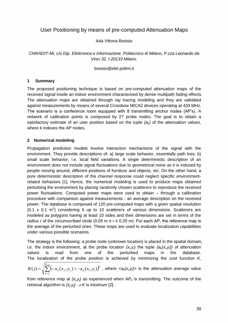
39
User Positioning by means of pre-computed Attenuation Maps
Ada Vittoria Bosisio
CNR/IEIIT-Mi, c/o Dip. Elettronica e Informazione, Politecnico di Milano, P.zza Leonardo da
Vinci 32, I-20133 Milano.
1 Summary
The proposed positioning technique is based on pre-computed attenuation maps of the
received signal inside an indoor environment characterized by dense multipath fading effects.
The attenuation maps are obtained through ray tracing modeling and they are validated
against measurements by means of several Crossbow MICA2 devices operating at 433 MHz.
The scenario is a conference room equipped with 8 transmitting anchor nodes (AP‘s). A
network of calibration points is composed by 27 probe nodes. The goal is to obtain a
satisfactory estimate of an user position based on the tuple {ak} of the attenuation values,
where k indexes the AP nodes.
2 Numerical modeling
Propagation prediction models involve interaction mechanisms of the signal with the
environment. They provide descriptions of: a) large scale behavior, essentially path loss; b)
small scale behavior, i.e. local field variations. A single deterministic description of an
environment does not include signal fluctuations due to geometrical noise as it is induced by
people moving around, different positions of furniture and objects, etc. On the other hand, a
pure deterministic description of the channel response could neglect specific environment-
related behaviors [1]. Hence, the numerical modeling is used to produce maps obtained
perturbing the environment by placing randomly chosen scatterers to reproduce the received
power fluctuations. Computed power maps were used to obtain – through a calibration
procedure with comparison against measurements - an average description on the received
power. The database is composed of 120 pre-computed maps with a given spatial resolution
(0.1 x 0.1 m2) considering 5 up to 10 scatterers of various dimensions. Scatterers are
modeled as polygons having at least 10 sides and their dimensions are set in terms of the
radius r of the circumscribed circle (0.05 m ≤ r ≤ 0.25 m). For each AP, the reference map is
the average of the perturbed ones. These maps are used to evaluate localization capabilities
under various possible scenarios.
The strategy is the following: a probe node (unknown location) is placed in the spatial domain,
i.e. the indoor environment, at the probe location (xi,yi) the tuple {ak(xi,yi)} of attenuation
values is read from one of the perturbed maps in the database.
The localization of the probe position is achieved by minimizing the cost function K,
APN
k
iijj yxyxjK1
2
kk ),(a),(a)( , where <ak(xi,yi)> is the attenuation average value
from reference map at (xj,yj) as experienced when APk is transmitting. The outcome of the
retrieval algorithm is (xj,yj) K is minimum [2].
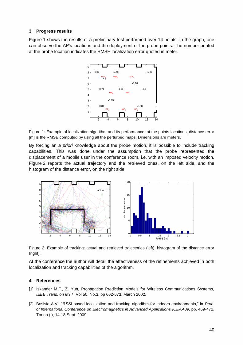
40
3 Progress results
Figure 1 shows the results of a preliminary test performed over 14 points. In the graph, one
can observe the AP‘s locations and the deployment of the probe points. The number printed
at the probe location indicates the RMSE localization error quoted in meter.
Figure 1: Example of localization algorithm and its performance: at the points locations, distance error
[m] is the RMSE computed by using all the perturbed maps. Dimensions are meters.
By forcing an a priori knowledge about the probe motion, it is possible to include tracking
capabilities. This was done under the assumption that the probe represented the
displacement of a mobile user in the conference room, i.e. with an imposed velocity motion,
Figure 2 reports the actual trajectory and the retrieved ones, on the left side, and the
histogram of the distance error, on the right side.
Figure 2: Example of tracking: actual and retrieved trajectories (left); histogram of the distance error
(right).
At the conference the author will detail the effectiveness of the refinements achieved in both
localization and tracking capabilities of the algorithm.
4 References
[1] Iskander M.F., Z. Yun, Propagation Prediction Models for Wireless Communications Systems,
IEEE Trans. on MTT, Vol.50, No.3, pp 662-673, March 2002.
[2] Bosisio A.V., ―RSSI-based localization and tracking algorithm for indoors environments,‖ in Proc.
of International Conference on Electromagnetics in Advanced Applications ICEAA09, pp. 469-472,
Torino (I), 14-18 Sept. 2009.
2 4 6 8 10 12 14
1
2
3
4
5
6
7
8
9
AP1
AP2
AP3
AP4
AP5
AP6
AP7
AP8
0.98
1.19
0.31
0.81
1.18
0.96 0.48 1.45
0.71
0.65
1.9
2 4 6 8 10 12 14
1
2
3
4
5
6
7
8
9
actual
0 0.5 1 1.5 2 2.5 30
5
10
15
20
RMSE [m]
No o
f occurr
ences
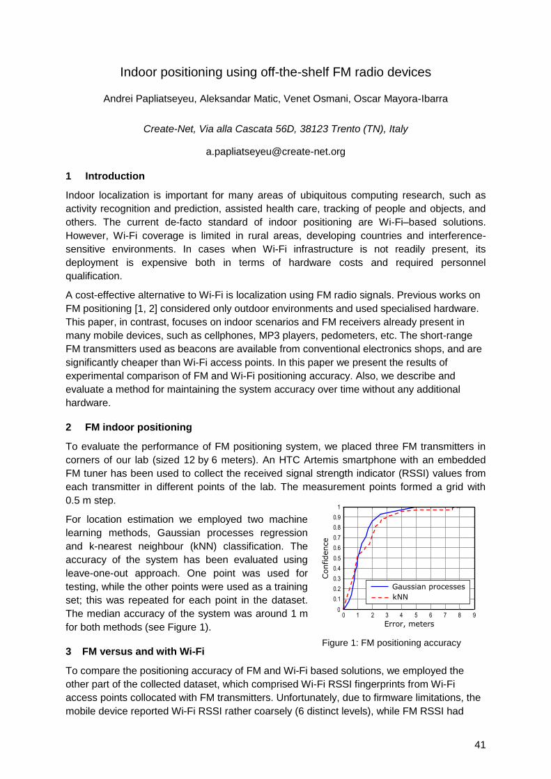
41
Indoor positioning using off-the-shelf FM radio devices
Andrei Papliatseyeu, Aleksandar Matic, Venet Osmani, Oscar Mayora-Ibarra
Create-Net, Via alla Cascata 56D, 38123 Trento (TN), Italy
1 Introduction
Indoor localization is important for many areas of ubiquitous computing research, such as
activity recognition and prediction, assisted health care, tracking of people and objects, and
others. The current de-facto standard of indoor positioning are Wi-Fi–based solutions.
However, Wi-Fi coverage is limited in rural areas, developing countries and interference-
sensitive environments. In cases when Wi-Fi infrastructure is not readily present, its
deployment is expensive both in terms of hardware costs and required personnel
qualification.
A cost-effective alternative to Wi-Fi is localization using FM radio signals. Previous works on
FM positioning [1, 2] considered only outdoor environments and used specialised hardware.
This paper, in contrast, focuses on indoor scenarios and FM receivers already present in
many mobile devices, such as cellphones, MP3 players, pedometers, etc. The short-range
FM transmitters used as beacons are available from conventional electronics shops, and are
significantly cheaper than Wi-Fi access points. In this paper we present the results of
experimental comparison of FM and Wi-Fi positioning accuracy. Also, we describe and
evaluate a method for maintaining the system accuracy over time without any additional
hardware.
2 FM indoor positioning
To evaluate the performance of FM positioning system, we placed three FM transmitters in
corners of our lab (sized 12 by 6 meters). An HTC Artemis smartphone with an embedded
FM tuner has been used to collect the received signal strength indicator (RSSI) values from
each transmitter in different points of the lab. The measurement points formed a grid with
0.5 m step.
For location estimation we employed two machine
learning methods, Gaussian processes regression
and k-nearest neighbour (kNN) classification. The
accuracy of the system has been evaluated using
leave-one-out approach. One point was used for
testing, while the other points were used as a training
set; this was repeated for each point in the dataset.
The median accuracy of the system was around 1 m
for both methods (see Figure 1).
3 FM versus and with Wi-Fi
To compare the positioning accuracy of FM and Wi-Fi based solutions, we employed the
other part of the collected dataset, which comprised Wi-Fi RSSI fingerprints from Wi-Fi
access points collocated with FM transmitters. Unfortunately, due to firmware limitations, the
mobile device reported Wi-Fi RSSI rather coarsely (6 distinct levels), while FM RSSI had
Figure 1: FM positioning accuracy
0
0.1
0.2
0.3
0.4
0.5
0.6
0.7
0.8
0.9
1
Error, meters
Confidence
0 1 2 3 4 5 6 7 8 9
Gaussian processes
kNN
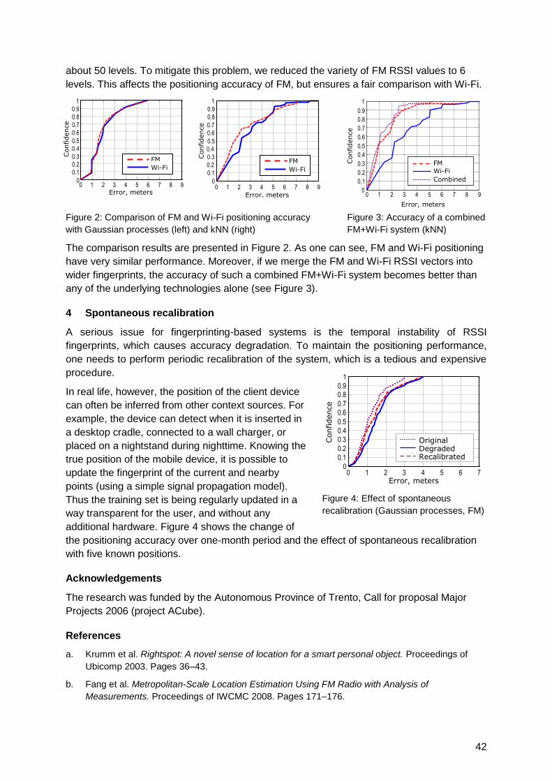
42
about 50 levels. To mitigate this problem, we reduced the variety of FM RSSI values to 6
levels. This affects the positioning accuracy of FM, but ensures a fair comparison with Wi-Fi.
Figure 2: Comparison of FM and Wi-Fi positioning accuracy
with Gaussian processes (left) and kNN (right)
Figure 3: Accuracy of a combined
FM+Wi-Fi system (kNN)
The comparison results are presented in Figure 2. As one can see, FM and Wi-Fi positioning
have very similar performance. Moreover, if we merge the FM and Wi-Fi RSSI vectors into
wider fingerprints, the accuracy of such a combined FM+Wi-Fi system becomes better than
any of the underlying technologies alone (see Figure 3).
4 Spontaneous recalibration
A serious issue for fingerprinting-based systems is the temporal instability of RSSI
fingerprints, which causes accuracy degradation. To maintain the positioning performance,
one needs to perform periodic recalibration of the system, which is a tedious and expensive
procedure.
In real life, however, the position of the client device
can often be inferred from other context sources. For
example, the device can detect when it is inserted in
a desktop cradle, connected to a wall charger, or
placed on a nightstand during nighttime. Knowing the
true position of the mobile device, it is possible to
update the fingerprint of the current and nearby
points (using a simple signal propagation model).
Thus the training set is being regularly updated in a
way transparent for the user, and without any
additional hardware. Figure 4 shows the change of
the positioning accuracy over one-month period and the effect of spontaneous recalibration
with five known positions.
Acknowledgements
The research was funded by the Autonomous Province of Trento, Call for proposal Major
Projects 2006 (project ACube).
References
a. Krumm et al. Rightspot: A novel sense of location for a smart personal object. Proceedings of
Ubicomp 2003. Pages 36–43.
b. Fang et al. Metropolitan-Scale Location Estimation Using FM Radio with Analysis of
Measurements. Proceedings of IWCMC 2008. Pages 171–176.
Figure 4: Effect of spontaneous
recalibration (Gaussian processes, FM)
0
0.1
0.2
0.3
0.4
0.5
0.6
0.7
0.8
0.9
1
Error, meters
Confidence
0 1 2 3 4 5 6 7 8 9
FM
Wi-Fi
0
0.1
0.2
0.3
0.4
0.5
0.6
0.7
0.8
0.9
1
Error, meters C
onfidence
0 1 2 3 4 5 6 7 8 9
FM
Wi-Fi
0 1 2 3 4 5 6 7 8 9 0
0.1 0.2
0.3
0.4
0.5
0.6
0.7
0.8
0.9
1
Error, meters
Confidence
FM
Wi-Fi
Combined
0 1 2 3 4 5 6 7 0
0.1
0.2
0.3
0.4
0.5
0.6
0.7
0.8 0.9
1
Error, meters
Confidence
Original Degraded Recalibrated
43
RSSI localization with sensors placed on the user
Paolo Barsocchi *, Francesco Furfari *, Paolo Nepa †, Francesco Potortì *
* ISTI-CNR, Pisa Research Area, Via G.Moruzzi 1, 56124 Pisa, Italy
† Dept. of Information Engineering, University of Pisa, Pisa, Italy
1 Extended Abstract
The presence of prospective high number of wireless transmitters in indoor spaces has
motivated researchers to investigate whether their built-in received signal strength indicator
(RSSI) could be exploited to gain information on the relative position of a receiver with
respect to a number of transmitters. For this reason the RSSI range-based localization
systems that use inexpensive, non-dedicated wireless devices have gathered great attention
in the last years. Even though RSSI meters are not built to this end, but rather to give
information to the higher communication protocol layers about the status of the
communication link, their usage is highly attractive, because the information they give is
obtained almost ―for free‖. As a consequence, many studies exist which, analytically, through
simulations or through real measurements, analyse how a mobile can use RSSI relative to
multiple wireless transmitters (anchors) to compute its position [1, 2]. This approach is
popular because no additional hardware is required on the nodes for localization. In [3] the
authors find that range-based methods perform better than connection-based ones under a
given set of conditions. We find that these conclusions are consistent with the results
sketched in our preliminary work. In [4] we concentrated on a single nomadic mobile,
concluding that a Maximum Likelihood approach is able to exploit all available information,
and has proven to be a powerful method to evaluate RSSI based localization methods.
The goal of this work is to expand the work in [4] by using a detailed ray-tracing simulation, in
order to investigate the performance of indoor, single-room localization when multiple sensor
nodes are placed on the mobile. This study does not lend itself to practical implementation of
a localization method, but rather provides insight into performance assessment by using
either one or more sensor nodes placed on the user. In other words, this study aims at
answering the following questions: How does the localization performance increase by using
multiple sensors placed on the user? Is it possible to determine the direction where the user
is facing? We answer these questions by using a parameter estimation approach and by
comparing three scenarios. The first scenario is based on only one sensor per user, and the
other two scenarios with two and three sensors, respectively. Preliminary results show that
the localization error decreases when passing from one to two sensors per user, but the
performance does not significantly increase when using three sensors. This is expected,
because the maximum likelihood method we use is able to take advantage of any added
information. This means that adding receivers will certainly improve the accuracy of
localization. However, since the method requires a precise map of the power distribution in
the room and non-trivial computations, it is not directly applicable in practice. Its usefulness
lies in its capacity to compare different solutions and put a high boundary on the ability of a
given configuration to provide accurate localisation.
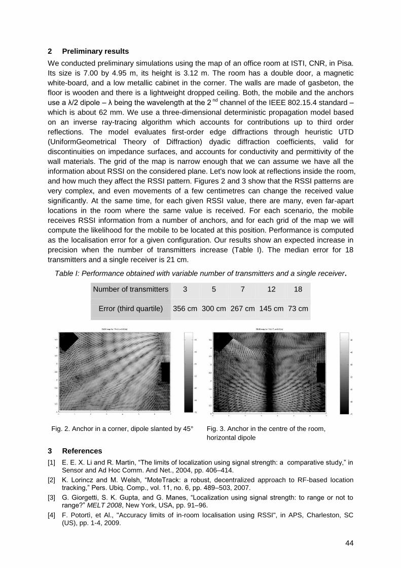
44
2 Preliminary results
We conducted preliminary simulations using the map of an office room at ISTI, CNR, in Pisa.
Its size is 7.00 by 4.95 m, its height is 3.12 m. The room has a double door, a magnetic
white-board, and a low metallic cabinet in the corner. The walls are made of gasbeton, the
floor is wooden and there is a lightweight dropped ceiling. Both, the mobile and the anchors
use a λ/2 dipole – λ being the wavelength at the 2 nd channel of the IEEE 802.15.4 standard –
which is about 62 mm. We use a three-dimensional deterministic propagation model based
on an inverse ray-tracing algorithm which accounts for contributions up to third order
reflections. The model evaluates first-order edge diffractions through heuristic UTD
(UniformGeometrical Theory of Diffraction) dyadic diffraction coefficients, valid for
discontinuities on impedance surfaces, and accounts for conductivity and permittivity of the
wall materials. The grid of the map is narrow enough that we can assume we have all the
information about RSSI on the considered plane. Let's now look at reflections inside the room,
and how much they affect the RSSI pattern. Figures 2 and 3 show that the RSSI patterns are
very complex, and even movements of a few centimetres can change the received value
significantly. At the same time, for each given RSSI value, there are many, even far-apart
locations in the room where the same value is received. For each scenario, the mobile
receives RSSI information from a number of anchors, and for each grid of the map we will
compute the likelihood for the mobile to be located at this position. Performance is computed
as the localisation error for a given configuration. Our results show an expected increase in
precision when the number of transmitters increase (Table I). The median error for 18
transmitters and a single receiver is 21 cm.
Table I: Performance obtained with variable number of transmitters and a single receiver.
Number of transmitters 3 5 7 12 18
Error (third quartile) 356 cm 300 cm 267 cm 145 cm 73 cm
3 References
[1] E. E. X. Li and R. Martin, ―The limits of localization using signal strength: a comparative study,‖ in Sensor and Ad Hoc Comm. And Net., 2004, pp. 406–414.
[2] K. Lorincz and M. Welsh, ―MoteTrack: a robust, decentralized approach to RF-based location tracking,‖ Pers. Ubiq. Comp., vol. 11, no. 6, pp. 489–503, 2007.
[3] G. Giorgetti, S. K. Gupta, and G. Manes, ―Localization using signal strength: to range or not to range?‖ MELT 2008, New York, USA, pp. 91–96.
[4] F. Potortì, et Al., "Accuracy limits of in-room localisation using RSSI", in APS, Charleston, SC (US), pp. 1-4, 2009.
Fig. 2. Anchor in a corner, dipole slanted by 45° Fig. 3. Anchor in the centre of the room,
horizontal dipole

45
Indoor Positioning Using Received Signal Strength of Iridium Satellites
Siavash Hosseiny Alamdarya, Mortaza Nikraveshb, Mohammad A. Rajabic, Hossein Sahabia
aGeodynamics Division, National Cartographic Center, Azadi sq.,Tehran,13185-1684, Iran
Tel: +98 21 66386496 Fax: +98 21 88802219
bDept. of Electrical Eng., AmirKabir University of Technology, Tehran,13597-45778, Iran
Tel: +98 21 64543300, Fax: +98 21 66406469
cDept. of Geomatics Eng., University of Tehran, Tehran, 14665-331, Iran, www.ut.ac.ir
Tel: +98 21 88334341, Fax: +98 21 88008837, [email protected]
1 Summary
Iridium as one of Low Earth Orbiting (LEO) satellites emit high power signals which can
easily pass into buildings. Therefore, one can receive its signals where no other signals can
be reached. This paper tries to use signal strength of Iridium Satellites for indoor positioning.
The main idea in this paper is based on the determination of the user‘s position by measuring
the signal power. At first the signal power pattern of iridium satellites in the building is
simulated. Then, it is matched with the measured signal power in the receiver. Finally, the
user‘s position is estimated with a specific level of precision. At the end, the self sufficiency of
this method is discussed.
2 Introduction
Low Earth Orbiting (LEO) satellite signals can pass into high-rises and tall buildings. These
signals pass through roof, walls, and windows to reach user‘s receiver and to transfer the
information. However, the signal attenuation pattern is obviously different for each signal
paths. But one can provide a specific signal power pattern inside a specific building.
From variety of LEO satellites, iridium satellites have been studied in this paper due to their
high signal power and availability. Iridium satellites are orbiting the Earth at elevation of
approximately 781 km. Moreover, the constellation has been designated to have excellent
satellite visibility and service coverage at the North and South poles. These advantages
make the iridium satellites useful for indoor positioning.
3 Methodology
In this paper, the signal strength or equivalently signal to noise ratio, is used for positioning.
Furthermore, it is assumed that the map of the building is available for the user. The user can
estimate the signal propagation pattern by using the map inside the building. Therefore, by
matching the signal propagation pattern with the measured signal power, the user can be
located with a specific level of precision.
In order to locate the user inside a building, there are some questions should be addressed.
The first question is if the signal power pattern depends exclusively on the shape of building?
In other words the question is if the position of satellite affects the pattern? The second
question is if the signal power is different in different floors? If yes, then the user can be
easily located within floors. Last but not least, the third question is about the level of precision
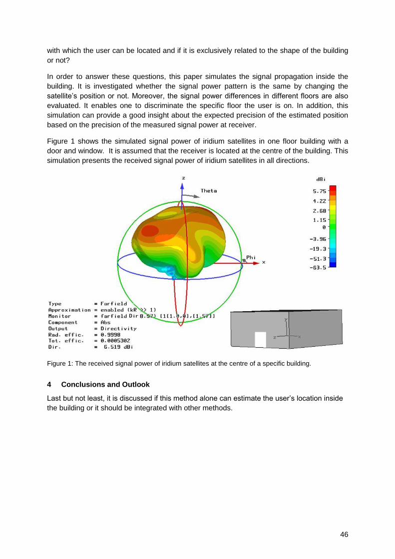
46
with which the user can be located and if it is exclusively related to the shape of the building
or not?
In order to answer these questions, this paper simulates the signal propagation inside the
building. It is investigated whether the signal power pattern is the same by changing the
satellite‘s position or not. Moreover, the signal power differences in different floors are also
evaluated. It enables one to discriminate the specific floor the user is on. In addition, this
simulation can provide a good insight about the expected precision of the estimated position
based on the precision of the measured signal power at receiver.
Figure 1 shows the simulated signal power of iridium satellites in one floor building with a
door and window. It is assumed that the receiver is located at the centre of the building. This
simulation presents the received signal power of iridium satellites in all directions.
Figure 1: The received signal power of iridium satellites at the centre of a specific building.
4 Conclusions and Outlook
Last but not least, it is discussed if this method alone can estimate the user‘s location inside
the building or it should be integrated with other methods.

47
WLAN RSS (Signal Strength Based Methods), Fingerprinting
Auditorium G7
Wednesday, September 15, 16:00 – 18:00
Thursday, September 16, 08:15 – 09:45 & 10:15 – 11:45

49
RSSI-based Euclidean Distance Algorithm for Indoor Positioning adapted
for the use in dynamically changing WLAN environments and multi-level
buildings
Sebastian Gansemer, Uwe Großmann
FH Dortmund, FES Mobile Business – Mobile Systems, Emil-Figge-Str. 44, 44227 Dortmund,
Germany, {sebastian.gansemer; uwe.grossmann}@fh-dortmund.de
1 Summary
This paper presents a fingerprinting positioning algorithm for WLAN environments based on
Euclidean Distance (EDA). The adapted algorithm can be used in large and dynamically
changing environments and multi-level buildings. Evaluation results show a reduction of
median location estimation error (LEE) from 12m using standard EDA to 2.12m when the
adapted EDA is used. The discrete vertical z-coordinate could be estimated correctly in
97.45% of cases. Moreover, it is shown that the calibration effort can be reduced clearly by
using larger calibration grids with an acceptable increase of LEE.
2 Introduction
For indoor localization in WLAN environments Received Signal Strength Index (RSSI) based
methods may be used to determine the current position by fingerprinting and Euclidean
distance algorithm ([5]). In large areas of measurement or in dynamically changing
environments the basic Euclidean Distance algorithm shows large location estimation errors.
This paper presents an adapted and improved algorithm for the use in dynamically changing
environments.
3 Related Work
The RADAR System ([1]) uses EDA with affixed set of base stations (BS) together with a
signal propagation model. A positioning system for industrial automation with automatic
calibration was developed by Ivanov ([4]). This system is able to perform automatic
measurement and model calibration so that no manual measurements are necessary. The
Ekahau Positioning Engine ([2]) is a commercially available software using RSSI based
WLAN indoor positioning. Another approach for getting reasonable accuracy in positioning as
well as accurate continuous information about the current position on the z-axis is shown in
Woodman and Harle ([6]). They use a foot-mounted inertial sensor combined with WLAN
based RSSI algorithms.
4 Algorithm
Within permanent environments where all base stations can be received at all calibration
points the number of received base stations n is constant. The basic Euclidean Distance
algorithm can be used with a location estimation error of 2.33m ([3]). Within dynamically
changing environments the basic EDA shows a drastically increased LEE. Dynamically
changing environment means either sets of base stations varying from calibration phase to
positioning phase for one specific calibration point or varying sets of received BS between
neighbouring calibration points.
Within dynamically changing environments four specific problem cases are identified:
50
Case 1: A BS is measured in calibration phase but not in positioning phase,
Case 2: A BS is measured in positioning phase but not in calibration phase,
Case 3: Number of matching BS within calibration and positioning tuple too low,
Case 4: RSSI-values of positioning and calibration tuples too low.
The algorithm is adapted to handle these four different cases by not considering specific
RSSI-values which either exceed specific threshold values or meet specific circumstances
(e.g. BS measured in calibration phase but not in positioning phase). Therefore three
different threshold values are introduced.
5 Evaluation and Results
Results from a series of measurements over three storeys in a building at University of
Applied Sciences and Arts in Dortmund show that the number of matching BS (BS with valid
value in calibration and positioning tuple) must be four or larger to receive adequate results.
With lower numbers of matching BS estimation‘s quality worsens significantly.
The standard Euclidean distance algorithm shows very poor results with a median LEE of
12m. Using the adapted EDA leads to a decrease of median LEE to 2.12m.
The improved algorithm is evaluated using single position estimation values and with a
moving median filter. With moving median the n last estimated positions are used to
calculate a median from the position coordinates. The median LEE with single values and
moving median are nearly identical (2.12 and 2.06m) with the advanced algorithm. The 90%
value of LEE however decreases from 7.00m to 5.25m, the 95% LEE decreases from 9.25m
to 7.00m. The maximum LEE shows the most dramatic changes. It decreases from 45.04m
to 10.51m. The discrete vertical z-coordinate is estimated correctly in 97.45% of cases.
For the reduction of calibration effort different grid sizes are simulated using a subset of
calibration points with basic 1m x 1m grid. When using a less dense calibration grid the
median LEE increases from 2.12m (1m x 1m) to 3.35m (3m x 3m) and 3.64m (6m x 6m).
6 Conclusions
This paper shows that the presented adapted Euclidean distance algorithm can deal with
dynamically changing WLAN environments and shows reasonable results. Three threshold
parameters must be set correctly to receive reasonable results. This leads to additional
calibration effort. It is shown that the calibration effort can be reduced clearly by using larger
calibration grids with an acceptable increase of location estimation error.
7 List of References
[1] Bahl, P.; Padmanabhan, VN.: ―RADAR: An In Building RF-based User Location and Tracking System‖, Proceedings of IEEE INFOCOM 2000, April 2000.
[2] Ekahau, "Ekahau positioning engine 2.0; 802.11 based wireless LAN positioning system", Ekahau Technology Document, 2002.
[3] Grossmann, U.; Gansemer, S.; Suttorp, O.: RSSI-Based WLAN Indoor Positioning Within a Digital Museum Guide, International Journal of Computing, Volume 7, Issue 2, July 2008.
[4] Ivanov, S.; Nett, E.; Schemmer, S.; ―Automatic WLAN Localization for Industrial Automation‖, Proceedings of Wireless Factory Communication Systems 2008, , pp. 93-96, Dresden, Germany, 2008.
[5] Kolodziej, KW; Hjelm, J., ―Local Positioning Systems – LBS Applications and Services‖, Taylor & Francis, 2006.
[6] Woodman, O.; Harle, R.; ―Pedestrian Localisation for Indoor Enviroments‖, Proceedings of UbiComp 2008 Conference, pp. 114-122, Seoul, S. Korea, 2008.
51
Indoor Positioning Using WLAN Coverage Area Estimates
Laura Koski, Tommi Perälä and Robert Piché
Tampere University of Technology, Finland
Location fingerprinting is a positioning method that determines the location of a Mobile
Terminal (MT) using a database of radio characteristics. Fingerprinting methods have been
widely studied in indoor positioning and they have been reported to provide adequate
accuracy for most location based services in indoor environments. The state of the art
methods in indoor positioning collect WLAN Received Signal Strength Indicators (RSSI) at
predefined locations and use Weighted K-Nearest Neighbor (WKNN) to estimate the position
of MT. The fingerprints are collected during the calibration phase and each fingerprint
consists of a list of heard WLAN Access Point (AP) Media Access Control (MAC) addresses,
corresponding signal strengths and the coordinates of the fingerprint. The scheme is
straightforward, but there are several difficulties. First, the calibration phase is very laborious,
and large (in some cases extremely large) databases need to be constructed and processed.
Secondly, these methods are based on variations of RSSI values as a function of position.
However, WLAN chipset vendors use different RSSI definitions and the scales of different
RSSI values vary from one chipset to another. As a result, RSSI values collected with
different types of MTs are not comparable with each other. Thirdly, even small changes in
the environment may have a huge effect on RSSI values, and the positioning performance
degrades if the fingerprint database is not up-to-date. Finally, if the positioning calculations
are carried out in MT, the amount of data transmitted between the network and MT might be
too much even if the data is compressed using kernel approximations.
In this paper, the fingerprint data are compressed into coverage area estimates. In our
approach, the collected fingerprints are divided into location reports by MAC addresses. For
every MAC address there is a list of location reports, where the location reports are the
coordinates at which an AP is hearable by MT. These location reports are used to estimate
the coverage area of an AP. The coverage area estimates are assumed to be ellipse-shaped
and only require the storage of five floating point numbers, and thus are easy to store in a
database and to transmit to MT. The parameters of the coverage area are the location and
shape parameters of the coverage area distribution and the parameters are assumed to be
random variables. Location reports are assumed to follow a multivariate normal distribution,
and the unknown parameters of the coverage area are found by calculating the posterior
distribution of the parameters. The Bayesian approach is used because it allows fast
recursive estimation and update of the coverage area estimates, and the use of a Bayesian
prior, which models the subjective information about a typical coverage area. This
information is especially important when there are only a few location reports from WLAN AP.
In the positioning phase the MT reports the MAC addresses of the heard APs and uses the
coverage area estimates as measurements. The idea is to find the most probable location of
MT given the detected APs. The distribution of the location can be derived using Bayes‘ rule.
The distribution of the location follows a normal distribution, where the mean is a weighted
average of the location parameters of the coverage areas and the weights are determined by
the shape parameters of the coverage areas.
52
Integration of map information is one obvious way to enhance the positioning accuracy
indoors. Digital floor plans are nowadays available for many significant buildings, such as
hospitals, shopping malls and airports, and they can be easily used to improve the
positioning accuracy indoors. It is known that map matching (i.e. projecting the positioning
result to an indoor location) can be used to improve the performance of indoor positioning
systems. The floor plan can also be used to restrict the location‘s probability distribution. The
algorithms can utilize the outer walls of the buildings, or more detailed floor plan information
can be used.
Positioning filters are applied in order to combine the new measurements with the past
measurements and the motion model of MT. The Kalman Filter (KF) has been studied and
applied extensively in positioning applications. KF assumes linear measurement function,
Gaussian initial distribution, and mutually independent Gaussian measurement and motion
model noises that are independent of the initial state. If these assumptions are met, KF offers
a closed form solution for the posterior distribution of the state. If the distribution of position is
restricted, the assumptions of KF are no longer valid and the posterior distribution of position
cannot be calculated analytically. In situations like this, it is possible to use Particle Filters
(PF), which use weighted particles to approximate the posterior distribution. PF usually
produces a good estimate for the posterior distribution, but it requires a lot of computation
compared to KF. One solution is to approximate the restricted posterior distribution with a
Gaussian and use KF, or with a mixture of Gaussians and use Gaussian Mixture Filter (GMF).
This paper introduces different ways to use a floor plan in indoor navigation. Different
methods are tested with real data collected from WLAN APs. The static location estimation
method is compared with KF. We also investigate how the floor plan improves the position
estimate and use PF and GMF for the position calculation. We also estimate the restricted
posterior distribution of the state with Gaussian and use KF. This approach does not give as
good estimate for the posterior as mixture of Gaussians, but it requires less computation than
GMF and PF.
Results show that the location accuracy can be improved by limiting the number of heard
access points during data collection and positioning. If only the strongest access points are
taken into account during data collection, the coverage area estimates become smaller and
lead to a more accurate position estimate. The filtering framework gives a more accurate
position estimate than the static method. The floor plan also improves the positioning
accuracy. The results indicate that PF gives the best positioning performance. KF and GMF,
however, achieve almost the same accuracy as PF with smaller computational load.
Altogether, the coverage area based positioning does not achieve the same accuracy as the
traditional location fingerprinting. This method, however, compresses the fingerprint data into
coverage area estimates. Thus the coverage area based method could also be used for
large-scale solutions. Also, the Bayesian approach allows the use of recursive update
formula of the coverage area estimates. Moreover, this coverage area based positioning
method does not need RSSI values and thus it can be used with all types of MTs.
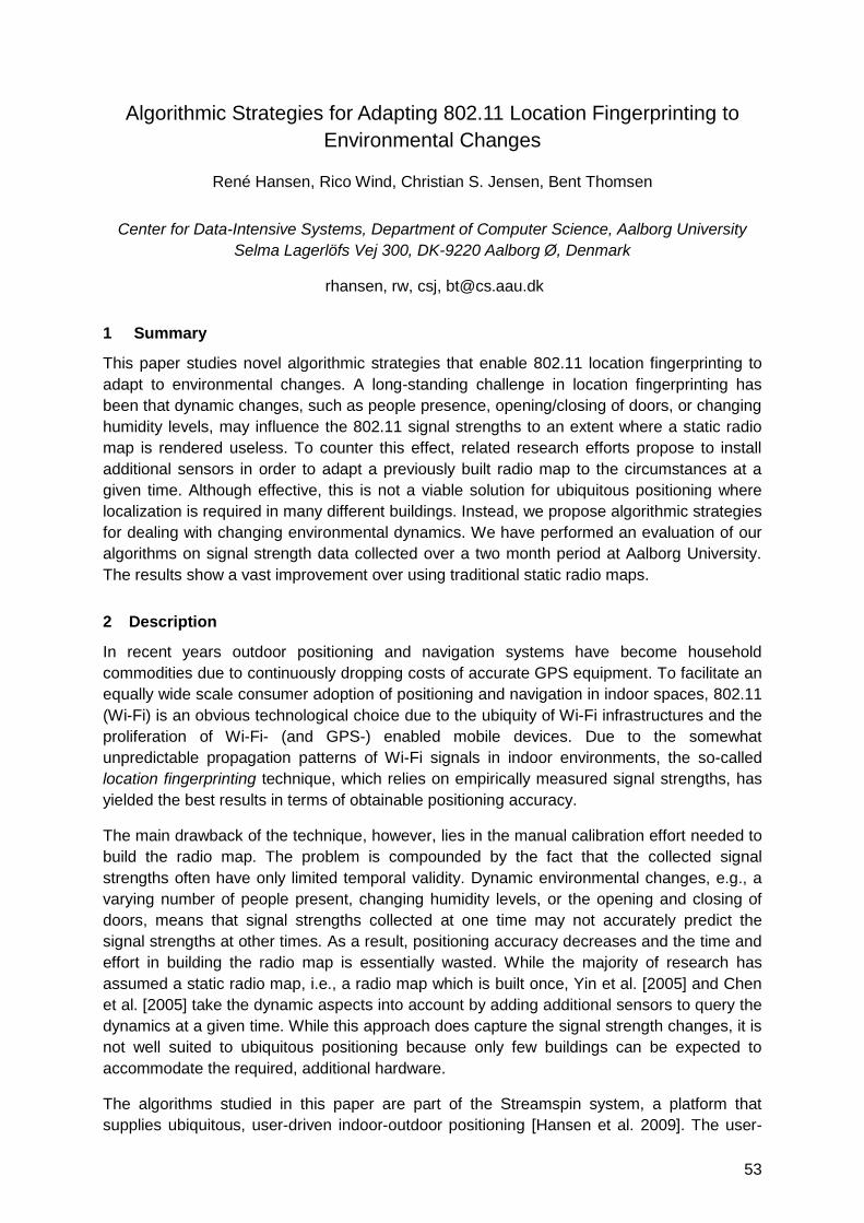
53
Algorithmic Strategies for Adapting 802.11 Location Fingerprinting to
Environmental Changes
René Hansen, Rico Wind, Christian S. Jensen, Bent Thomsen
Center for Data-Intensive Systems, Department of Computer Science, Aalborg University
Selma Lagerlöfs Vej 300, DK-9220 Aalborg Ø, Denmark
rhansen, rw, csj, [email protected]
1 Summary
This paper studies novel algorithmic strategies that enable 802.11 location fingerprinting to
adapt to environmental changes. A long-standing challenge in location fingerprinting has
been that dynamic changes, such as people presence, opening/closing of doors, or changing
humidity levels, may influence the 802.11 signal strengths to an extent where a static radio
map is rendered useless. To counter this effect, related research efforts propose to install
additional sensors in order to adapt a previously built radio map to the circumstances at a
given time. Although effective, this is not a viable solution for ubiquitous positioning where
localization is required in many different buildings. Instead, we propose algorithmic strategies
for dealing with changing environmental dynamics. We have performed an evaluation of our
algorithms on signal strength data collected over a two month period at Aalborg University.
The results show a vast improvement over using traditional static radio maps.
2 Description
In recent years outdoor positioning and navigation systems have become household
commodities due to continuously dropping costs of accurate GPS equipment. To facilitate an
equally wide scale consumer adoption of positioning and navigation in indoor spaces, 802.11
(Wi-Fi) is an obvious technological choice due to the ubiquity of Wi-Fi infrastructures and the
proliferation of Wi-Fi- (and GPS-) enabled mobile devices. Due to the somewhat
unpredictable propagation patterns of Wi-Fi signals in indoor environments, the so-called
location fingerprinting technique, which relies on empirically measured signal strengths, has
yielded the best results in terms of obtainable positioning accuracy.
The main drawback of the technique, however, lies in the manual calibration effort needed to
build the radio map. The problem is compounded by the fact that the collected signal
strengths often have only limited temporal validity. Dynamic environmental changes, e.g., a
varying number of people present, changing humidity levels, or the opening and closing of
doors, means that signal strengths collected at one time may not accurately predict the
signal strengths at other times. As a result, positioning accuracy decreases and the time and
effort in building the radio map is essentially wasted. While the majority of research has
assumed a static radio map, i.e., a radio map which is built once, Yin et al. [2005] and Chen
et al. [2005] take the dynamic aspects into account by adding additional sensors to query the
dynamics at a given time. While this approach does capture the signal strength changes, it is
not well suited to ubiquitous positioning because only few buildings can be expected to
accommodate the required, additional hardware.
The algorithms studied in this paper are part of the Streamspin system, a platform that
supplies ubiquitous, user-driven indoor-outdoor positioning [Hansen et al. 2009]. The user-
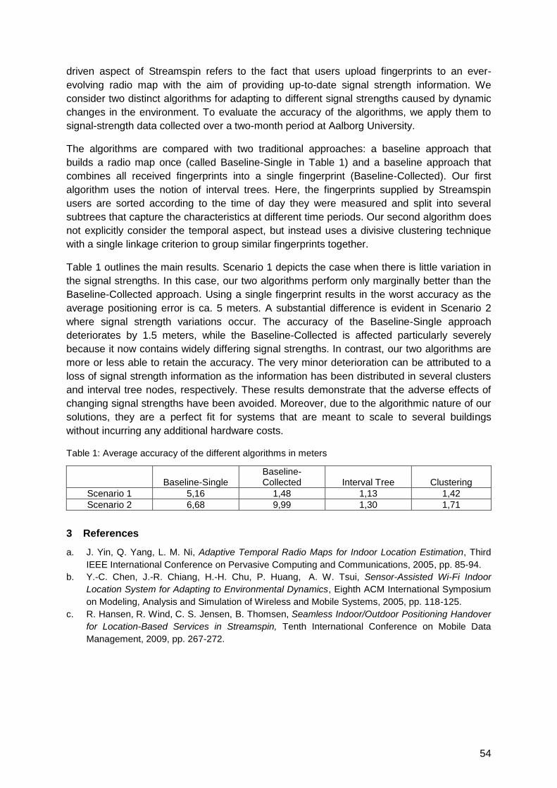
54
driven aspect of Streamspin refers to the fact that users upload fingerprints to an ever-
evolving radio map with the aim of providing up-to-date signal strength information. We
consider two distinct algorithms for adapting to different signal strengths caused by dynamic
changes in the environment. To evaluate the accuracy of the algorithms, we apply them to
signal-strength data collected over a two-month period at Aalborg University.
The algorithms are compared with two traditional approaches: a baseline approach that
builds a radio map once (called Baseline-Single in Table 1) and a baseline approach that
combines all received fingerprints into a single fingerprint (Baseline-Collected). Our first
algorithm uses the notion of interval trees. Here, the fingerprints supplied by Streamspin
users are sorted according to the time of day they were measured and split into several
subtrees that capture the characteristics at different time periods. Our second algorithm does
not explicitly consider the temporal aspect, but instead uses a divisive clustering technique
with a single linkage criterion to group similar fingerprints together.
Table 1 outlines the main results. Scenario 1 depicts the case when there is little variation in
the signal strengths. In this case, our two algorithms perform only marginally better than the
Baseline-Collected approach. Using a single fingerprint results in the worst accuracy as the
average positioning error is ca. 5 meters. A substantial difference is evident in Scenario 2
where signal strength variations occur. The accuracy of the Baseline-Single approach
deteriorates by 1.5 meters, while the Baseline-Collected is affected particularly severely
because it now contains widely differing signal strengths. In contrast, our two algorithms are
more or less able to retain the accuracy. The very minor deterioration can be attributed to a
loss of signal strength information as the information has been distributed in several clusters
and interval tree nodes, respectively. These results demonstrate that the adverse effects of
changing signal strengths have been avoided. Moreover, due to the algorithmic nature of our
solutions, they are a perfect fit for systems that are meant to scale to several buildings
without incurring any additional hardware costs.
Table 1: Average accuracy of the different algorithms in meters
Baseline-Single Baseline-Collected Interval Tree Clustering
Scenario 1 5,16 1,48 1,13 1,42
Scenario 2 6,68 9,99 1,30 1,71
3 References
a. J. Yin, Q. Yang, L. M. Ni, Adaptive Temporal Radio Maps for Indoor Location Estimation, Third
IEEE International Conference on Pervasive Computing and Communications, 2005, pp. 85-94.
b. Y.-C. Chen, J.-R. Chiang, H.-H. Chu, P. Huang, A. W. Tsui, Sensor-Assisted Wi-Fi Indoor
Location System for Adapting to Environmental Dynamics, Eighth ACM International Symposium
on Modeling, Analysis and Simulation of Wireless and Mobile Systems, 2005, pp. 118-125.
c. R. Hansen, R. Wind, C. S. Jensen, B. Thomsen, Seamless Indoor/Outdoor Positioning Handover
for Location-Based Services in Streamspin, Tenth International Conference on Mobile Data
Management, 2009, pp. 267-272.
55
Fault Tolerant Positioning using WLAN Signal Strength Fingerprints
Christos Laoudias, Michalis P. Michaelides, Christos G. Panayiotou
KIOS Research Center for Intelligent Systems and Networks, University of Cyprus, Nicosia
{laoudias, michalism, christosp}@ucy.ac.cy
1 Summary
In this extended abstract we present our ongoing research on WLAN positioning. Our focus
is on the fault tolerance of positioning methods, rather than the absolute accuracy in case of
no faults. We introduce several fault models to capture the effect of AP malfunctions or
malicious attacks during positioning and describe how these models can be applied in
practice. We compare some well-known algorithms in terms of fault tolerance and present
preliminary experimental results on their accuracy degradation as the percentage of faulty
APs increases.
2 Fault Models for Positioning
A wide variety of fingerprint-based methods have been proposed that rely on Received
Signal Strength (RSS) samples from available Access Points (AP). The focus of these
methods so far has been on improving accuracy. In real world, however, APs can fail or
exhibit erroneous behaviour, thus compromising the performance of these methods. For
instance, RSS attack models are considered in [3] that perturb the original samples by an
attenuation or amplification constant. Fault tolerance is an important issue that has not been
addressed adequately. Our main contribution is to define realistic fault models, study the
performance of positioning algorithms in the presence of faults and motivate future research
in this direction.
First, we consider the case where several APs used in the training phase are not available
during positioning. This can be caused by random AP failures, e.g. due to power outages, or
when an adversary cuts off the power supply of some APs. Under this Fault Model, denoted
as FMa, we remove faulty APs from the original test data. Our second model (FMb) captures
the effect of relocating a set of APs and thus a faulty AP is detected inside an area that is
different than the expected one. We simulate FMb by replacing the RSS readings of the
corrupt AP in the test data with the values of a randomly selected AP. In another case, an AP
may no longer be detected in some locations inside its original Region of Coverage (RoC),
e.g. due to an obstacle that blocks the propagation path. Note that such an obstacle could be
placed by an attacker in front of the AP antenna. This can be modelled by ignoring valid RSS
readings for a set of APs in some test fingerprints (FMc). Finally, an AP may be detected in
locations outside its original RoC, e.g. by deliberately increasing the AP transmit power or by
impersonating an existing AP. We model this by injecting random RSS values to some test
fingerprints for a set of APs that would otherwise be undetected in those test points (FMd).
3 Experimental Results and Conclusions
We used a typical 100x45m office setup with 31 APs installed in total and identified 107
reference points, while each point is covered by 9.7 APs on average. As a training set, we
collected 30 fingerprints per reference point using a smart phone. We also recorded 192
fingerprints by walking on a path and sampled the same path 3 times, as test data. The
reference points and the points inside the RoC of a single AP with the RSS levels are
depicted in Fig. 1.
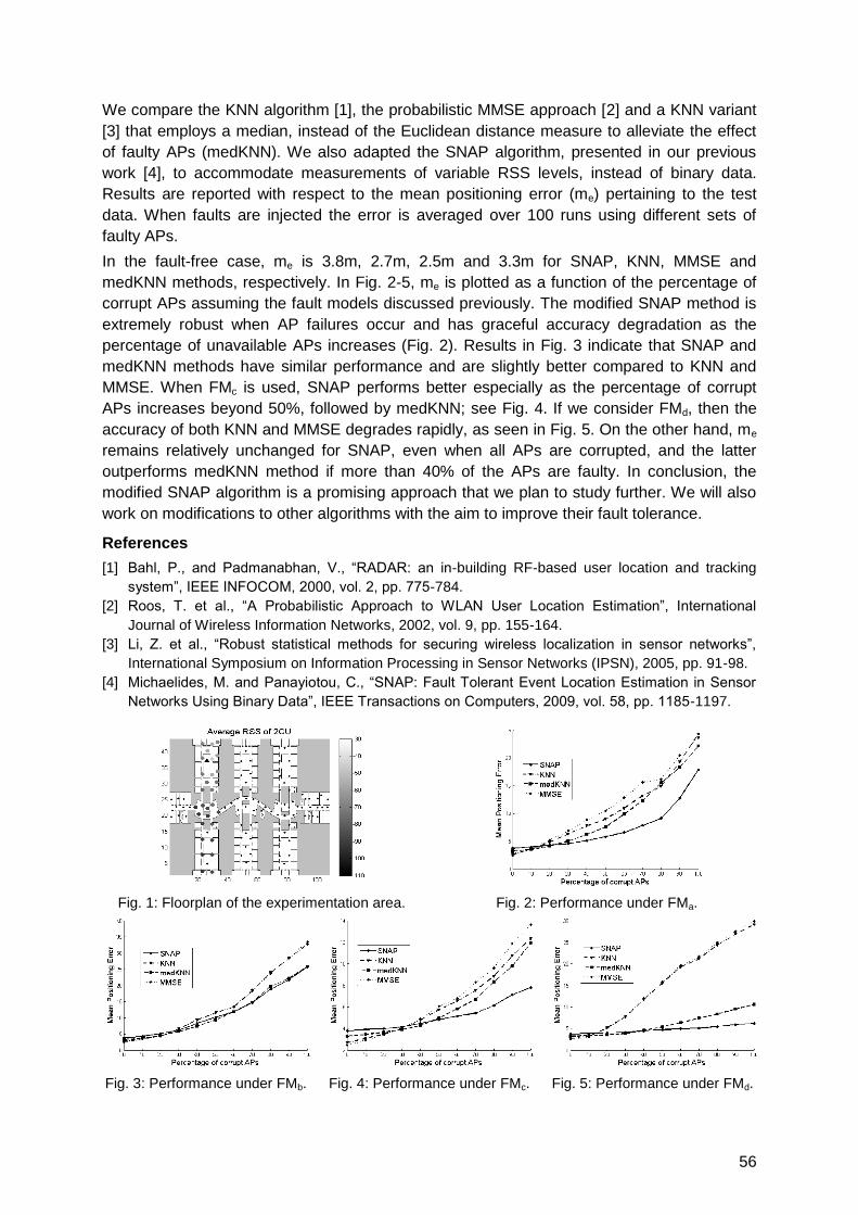
56
We compare the KNN algorithm [1], the probabilistic MMSE approach [2] and a KNN variant
[3] that employs a median, instead of the Euclidean distance measure to alleviate the effect
of faulty APs (medKNN). We also adapted the SNAP algorithm, presented in our previous
work [4], to accommodate measurements of variable RSS levels, instead of binary data.
Results are reported with respect to the mean positioning error (me) pertaining to the test
data. When faults are injected the error is averaged over 100 runs using different sets of
faulty APs.
In the fault-free case, me is 3.8m, 2.7m, 2.5m and 3.3m for SNAP, KNN, MMSE and
medKNN methods, respectively. In Fig. 2-5, me is plotted as a function of the percentage of
corrupt APs assuming the fault models discussed previously. The modified SNAP method is
extremely robust when AP failures occur and has graceful accuracy degradation as the
percentage of unavailable APs increases (Fig. 2). Results in Fig. 3 indicate that SNAP and
medKNN methods have similar performance and are slightly better compared to KNN and
MMSE. When FMc is used, SNAP performs better especially as the percentage of corrupt
APs increases beyond 50%, followed by medKNN; see Fig. 4. If we consider FMd, then the
accuracy of both KNN and MMSE degrades rapidly, as seen in Fig. 5. On the other hand, me
remains relatively unchanged for SNAP, even when all APs are corrupted, and the latter
outperforms medKNN method if more than 40% of the APs are faulty. In conclusion, the
modified SNAP algorithm is a promising approach that we plan to study further. We will also
work on modifications to other algorithms with the aim to improve their fault tolerance.
References
[1] Bahl, P., and Padmanabhan, V., ―RADAR: an in-building RF-based user location and tracking
system‖, IEEE INFOCOM, 2000, vol. 2, pp. 775-784.
[2] Roos, T. et al., ―A Probabilistic Approach to WLAN User Location Estimation‖, International
Journal of Wireless Information Networks, 2002, vol. 9, pp. 155-164.
[3] Li, Z. et al., ―Robust statistical methods for securing wireless localization in sensor networks‖,
International Symposium on Information Processing in Sensor Networks (IPSN), 2005, pp. 91-98.
[4] Michaelides, M. and Panayiotou, C., ―SNAP: Fault Tolerant Event Location Estimation in Sensor
Networks Using Binary Data‖, IEEE Transactions on Computers, 2009, vol. 58, pp. 1185-1197.
Fig. 1: Floorplan of the experimentation area. Fig. 2: Performance under FMa.
Fig. 3: Performance under FMb. Fig. 4: Performance under FMc. Fig. 5: Performance under FMd.
57
Implementation of Hyperbolic Location Estimation Using RSSI in WLANs
Jakhongir Narzullaev*, Anvar Narzullaev, Yongwan Park, Kook-Yeol Yoo
Information & Communication Engineering Department, Yeungnam University, Gyeongsan,
Republic of Korea, 712-749
1 Summary
As the deployment of Wireless Local Area Networks (WLAN) in dense-urban areas is
growing rapidly, it can be a perfect supplement for providing location information of users in
indoor environments and metropolitan areas, where other positioning techniques such as
GPS, are not much effective. In this study, we propose a new WLAN positioning method that
combines Received Signal Strength Indication (RSSI) fingerprinting and Time Difference-of-
Arrival (TDOA) positioning techniques, which will provide reliable location accuracy and does
not require any additional changes on actual WLAN infrastructure.
2 Proposed Algorithm
The RSSI-based indoor localization systems are growing in importance among other indoor
positioning techniques, because of its availability on all existing WLAN equipments. The
RSSI fingerprinting algorithm is normally organized by two steps: calibration and online
tracking [1]. The calibration process builds RSSI fingerprint database of a target site in each
location. During online tracking, the location of the mobile user is determined, by matching
the RSSI value of the received signal to the closest fingerprint value.
In order to increase the location accuracy, we approached to online tracking phase differently,
by applying TDOA positioning technique. Several studies have been proposed for applying
TDOA positioning technique in WLANs [2]. Since the access points in IEEE 802.11 based
WLANs do not provide timing information between user equipments, the implementation of
TDOA needed changes on actual WLAN infrastructure to estimate the distances from access
point (AP) to mobile station (MS). We approached the estimation of these distances by
building RSSI fingerprint database and applying obtained values on one-slope prediction
model (OSM) to calculate them with higher accuracy. The OSM assumes a linear
dependence between path loss and logarithm of distance (d) from MS to AP [3] i.e.:
0 0( )[ ] ( ) 10 log10( / )PL d dB PL d d d (1)
where, PL(d) is the RSSI value at the mobile station and the PL(d0) is the closest reference
point at distance d0 (distance from AP to reference point) which we obtained during the
calibration process. And, specifies the path loss behaviour for a particular type of building
[3]. From this equation we can derive the distance (d) between MS and AP:
00
( ) ( )10
10
PL d PL dd d
(2)
Since the PL(d), PL(d0) and d0 are known, we can use (2) to calculate the distances between
m number of available APs and the MS. In general, distance estimation using OSM produces
huge errors; however, we minimized the error by utilizing the data collected from target area.

58
After calculating all available distance information from each AP to MS, we make the n
number of 3-AP combinations from all APs. Then, we apply Chan‘s three-sensor based
hyperbolic location estimator [4] to each of these combinations and get n number of
estimated location coordinates. On the final stage of our algorithm, we apply least median of
squares (LMS) estimation technique [5] to select the best MS position from obtained set of
coordinates.
3 Experimental Results
To evaluate our new algorithm, we built a test field at the Regional Innovation Centre (RIC)
building of Yeungnam University (South Korea) with the total size of 1460m2. During the
calibration process, we collected RSSI data every 2 meters of the test area and measured
distances from APs to MS using this data (1x). Next, we calculated these distances with two,
four and five times reduced number (1/2x, 1/4x, 1/5x) of reference points to compare the
accuracy. Figure 1(a) shows the estimated distance accuracies from 5 selected APs to
multiple MS positions located in the building. As we can see from this figure, the proposed
algorithm can provide 4-6 meters accuracy within the 70% of time even with the reduced
number of reference points. On the positioning phase of the algorithm, we used obtained
distance information to locate mobile stations. Figure 1(b) displays the comparison of
location accuracy of proposed algorithm and the original fingerprinting algorithm. It shows
that, the proposed algorithm can provide a higher accuracy compared to the original
fingerprinting method. On the other hand, it can also provide almost the same accuracy as
conventional method, while reducing the number of reference points by 5 times. Thus, there
is a trade-off between the number of reference points and the location estimation accuracy.
Figure 1. Field test results
References
[1] S. H. Fang, T.N. Lin, K.C. Lee, ―A Novel Algorithm for Multipath Fingerprinting in Indoor WLAN
Environments‖, IEEE Trans. on Wireless Comm., vol. 7, pp. 3579-3588, Sept. 2008.
[2] R. Yamasaki, A. Ogino, T. Tamaki, T. Uta, N. Matsuzawa, T. Kato, ―TDOA Location System for
IEEE 802.11b WLAN‖, in Proc. WCNC‘05, pp. 2338-2343, vol. 4., 2005
[3] A. Borelli, C. Monti, M. Vari, ―Channel Models for IEEE 802.11b Indoor System Design‖, IEEE
ICC 2004, 20-24 June, 2004.
[4] Y.T. Chan, K.C. Ho, ―A Simple and Efficient Estimator for Hyperbolic Location‖, IEEE
Transactions on Signal Processing, vol. 42, pp. 1905-1915, 1994.
[5] R. Casas, A. Marco, J.J. Guerrero, J. Falco, ―Robust Estimator for Non-line-of-Sight Error
Mitigation in Indoor Localization‖, EURASIP Journal on Applied Signal Processing, 2006.
59
A Perspective on Robustness and Deployment Complexity for RSS-
based Indoor Positioning
Kamran Sayrafian
Information Technology Laboratory, National Institute of Standards & Technology,
Gaithersburg, MD 20852, USA
1 Summary
There are two major issues with practical deployment of RSS-based indoor positioning
systems. These issues are coverage design (or equivalently reference node placement
strategy) and development of the measurement-based radio-map. In this research, each
problem is described and possible techniques that can simplify each problem are suggested.
In the process, it shown that there is an elegant trade-off between these issues where
simpler coverage design could lead to a higher complexity radio-map and vice versa. Various
experiments and simulations are provided to demonstrate the results.
2 RSS-based Indoor Positioning Algorithms
Techniques based on the Received Signal Strength (RSS) have been extensively studied in
the literature. These techniques, although, sometimes less accurate compared to more
complex range-based techniques, are very simple to implement and offer low cost and
effective alternatives for some applications. The core idea is to establish a relation between
the received signal strengths from a few reference nodes and the current position of the
mobile.
In order to provide location-based services with reasonable accuracy at indoor environments,
the mobile needs to have the visibility of at least three reference nodes (i.e. anchor nodes) at
all desired locations throughout the service area at all times. This is a much more
complicated coverage design problem than its WLAN (i.e. data communication services)
counterpart. This visibility must be maintained all throughout the service area. Since the
building layout, construction material of the walls and other objects in the environment as
well as maximum transmission power directly impact the coverage area of each node,
reference nodes placement could have a great impact on the system performance. The
placement strategy is a difficult coverage design problem, which currently does not have a
straightforward or automated solution.
One solution to this problem is using reference nodes that are capable of acquiring multi-
dimensional information from the received signal. This information could be RSS versus AoA
(i.e. Angle of Arrival). For example, if the reference node can measure RSS from various
directions, then the triple-coverage requirement problem can be avoided. This is achieved at
the expense of a more complicated radio map generation process. Various simulations and
experiments that show the accuracy and coverage effectiveness of this approach are
presented.
Another drawback of most RSS-based techniques is the need for a measurement-based
training phase, during which the radio map of the environment is created. These
measurements need to be carried out prior to the normal operation of the system and are
often necessary to be updated to compensate for changes in the environment. This radio
60
map essentially contains the received signal strength from all reference nodes throughout the
service area. The process to generate a radio map is not only labor-intensive and costly, but
also very sensitive to possible sources of interference in the building. Therefore, there is a
need for robust methodologies to eliminate this offline training phase that could be an
obstacle in the practical implementation of these systems. Here, a novel idea that employs a
model-based radio-map generation (based on ray-tracing) is presented and the performance
of the proposed system (at NIST/ITL) is discussed.
3 Trade-off between Coverage Design and Radio-Map Development Complexity
Looking at the two issues discussed in the previous sections, there seems to be a trade-off
between coverage design (or equivalently reference node placement complexity) and
robustness against model-based radio map. Consider reference node density to be the
average number of reference nodes per unit area. On one hand, it is desirable to have low
reference node density to enable sufficient coverage for positioning services; while on the
other hand, higher reference node density could provide a level of protection in the mobile
signature that represents its position. This is analogous to the channel coding problem where
redundancies are added to the raw information in order to combat adverse effect of the
channel. By adding the redundancy, each codeword will be able to tolerate more channel
impairment and as a result the system will exhibit lower average error.
Methodologies that can achieve high degree of robustness while maintaining low reference
node density would be preferable candidates for easily deployable commercial applications.
Although, our results show that simultaneous achievement of both objectives might not be
possible, the methodologies presented in our research provide solutions that exhibit
reasonable accuracies for low complexity indoor positioning services. Various results from
experiments and simulations (with WLAN and Zigbee-based sensor networks) are provided
to demonstrate the conclusions.
4 Conclusions and Outlook
Although, the requirements of a particular application could impact the choice of the
architecture for a positioning system, for most commercial applications, it is desirable to have
a system that is easily deployable and exhibits robustness against changes in the
environments, interference and propagation model imperfections. Eliminating the offline
measurement-based training phase is an essential step in providing robust methodologies
that are implementable on low cost, low complexity infrastructure. This is an obstacle in
practical implementation of positioning systems that are quickly deployable on commodity
networks such as 802.11-based technology or sensor networks. Further research and
studies need to be done before such systems can have widespread applications in our daily
life.
61
Wi-Fi Positioning: System Considerations and Device Calibration
Thorsten Vaupel¹, Jochen Seitz², Frédéric Kiefer¹, Stephan Haimerl¹, Jörn Thielecke²
¹ Fraunhofer Institute for Integrated Circuits IIS, Germany
² Friedrich-Alexander University of Erlangen-Nuremberg, Germany
1 Summary
Due to the increasing number of public and private access points in indoor and urban
environments, Wi-Fi® positioning becomes more and more attractive for pedestrian
navigation. In the last ten years different approaches and solutions have been developed. In
this article influences of the surrounding environment, the Wi-Fi infrastructure and hardware
characteristics are presented and evaluated with a focus on the so called Wi-Fi fingerprinting
technique for positioning. Based on this analysis a calibration approach for Wi-Fi devices is
proposed and conclusions are drawn.
2 Wi-Fi Positioning and Testbed
Wi-Fi positioning is done by correlating received signal strength (RSS) measurements with
entries of a fingerprinting database. The database is created by previously obtained RSS
measurements and referenced with the coordinates of the position where they have been
observed. As a testbed for positioning the metropolitan area of Nuremberg, Fürth and
Erlangen is used. The comprehensive database contains about 50,000 fingerprints. About
60,000 unique access points have been observed.
3 Influences of Environment and Infrastructure
Each environment has characteristical signal propagation. The RSS at a specific position
depends on the path loss, shadowing by objects and multipath propagation. The higher the
density of shadowing objects, the higher is the accuracy of Wi-Fi positioning, as different
fingerprints are less similar in signal space. Therefore, indoors Wi-Fi positioning works very
well because of the building structure and furniture. Outdoors, especially on large squares
the database correlation results in multiple ambiguities. Changes of the environment and
moving shadowing objects, like cars, persons and the user, are not considered and therefore
limit the accuracy and can lead to temporarily high positioning errors.
One advantage of Wi-Fi positioning in urban environments is that the infrastructure is already
set up. Existing private and public access points can be used. Therefore, the infrastructure
cannot be controlled. Positioning suffers from unobserved changes over time and the
number of available access points varies from one place to another. To get meaningful
positioning results at least three access points must have been observed. In areas with Wi-Fi
coverage the average number of access points per fingerprint within the testbed is 12.6.
4 Characteristics of Mobile Wi-Fi Devices
Various Wi-Fi modules have found their way into many flavours of standard consumer
hardware, like mobile phones, laptops, personal digital assistants and MP3 players. As Wi-Fi
positioning relies on measured absolute RSS values, the characteristics of the different
modules have to be considered. In Figure 1 the measured discrete RSS values of four
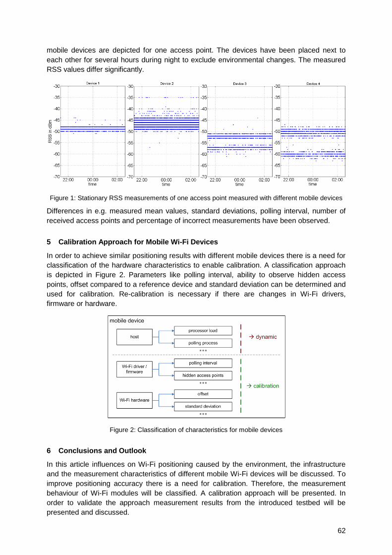
62
mobile devices are depicted for one access point. The devices have been placed next to
each other for several hours during night to exclude environmental changes. The measured
RSS values differ significantly.
Figure 1: Stationary RSS measurements of one access point measured with different mobile devices
Differences in e.g. measured mean values, standard deviations, polling interval, number of
received access points and percentage of incorrect measurements have been observed.
5 Calibration Approach for Mobile Wi-Fi Devices
In order to achieve similar positioning results with different mobile devices there is a need for
classification of the hardware characteristics to enable calibration. A classification approach
is depicted in Figure 2. Parameters like polling interval, ability to observe hidden access
points, offset compared to a reference device and standard deviation can be determined and
used for calibration. Re-calibration is necessary if there are changes in Wi-Fi drivers,
firmware or hardware.
Figure 2: Classification of characteristics for mobile devices
6 Conclusions and Outlook
In this article influences on Wi-Fi positioning caused by the environment, the infrastructure
and the measurement characteristics of different mobile Wi-Fi devices will be discussed. To
improve positioning accuracy there is a need for calibration. Therefore, the measurement
behaviour of Wi-Fi modules will be classified. A calibration approach will be presented. In
order to validate the approach measurement results from the introduced testbed will be
presented and discussed.
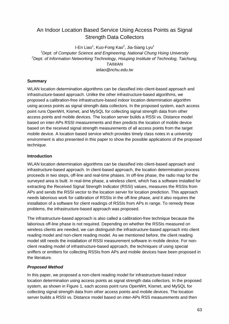
63
An Indoor Location Based Service Using Access Points as Signal
Strength Data Collectors
I-En Liao1, Kuo-Fong Kao2, Jia-Siang Lyu1 1Dept. of Computer Science and Engineering, National Chung Hsing University
2Dept. of Information Networking Technology, Hsiuping Institute of Technolog, Taichung,
TAIWAN
Summary
WLAN location determination algorithms can be classified into client-based approach and
infrastructure-based approach. Unlike the other infrastructure-based algorithms, we
proposed a calibration-free infrastructure-based indoor location determination algorithm
using access points as signal strength data collectors. In the proposed system, each access
point runs OpenWrt, Kismet, and MySQL for collecting signal strength data from other
access points and mobile devices. The location server builds a RSSI vs. Distance model
based on inter-APs RSSI measurements and then predicts the location of mobile device
based on the received signal strength measurements of all access points from the target
mobile device. A location based service which provides timely class notes in a university
environment is also presented in this paper to show the possible applications of the proposed
technique.
Introduction
WLAN location determination algorithms can be classified into client-based approach and
infrastructure-based approach. In client-based approach, the location determination process
proceeds in two steps, off-line and real-time phases. In off-line phase, the radio map for the
surveyed area is built. In real-time phase, a wireless client, which has a software installed for
extracting the Received Signal Strength Indicator (RSSI) values, measures the RSSIs from
APs and sends the RSSI vector to the location server for location prediction. This approach
needs laborious work for calibration of RSSIs in the off-line phase, and it also requires the
installation of a software for client readings of RSSIs from APs in range. To remedy these
problems, the infrastructure-based approach was proposed.
The infrastructure-based approach is also called a calibration-free technique because the
laborious off-line phase is not required. Depending on whether the RSSIs measured on
wireless clients are needed, we can distinguish the infrastructure-based approach into client
reading model and non-client reading model. As we mentioned before, the client reading
model still needs the installation of RSSI measurement software in mobile device. For non-
client reading model of infrastructure-based approach, the techniques of using special
sniffers or emitters for collecting RSSIs from APs and mobile devices have been proposed in
the literature.
Proposed Method
In this paper, we proposed a non-client reading model for infrastructure-based indoor
location determination using access points as signal strength data collectors. In the proposed
system, as shown in Figure 1, each access point runs OpenWrt, Kismet, and MySQL for
collecting signal strength data from other access points and mobile devices. The location
server builds a RSSI vs. Distance model based on inter-APs RSS measurements and then
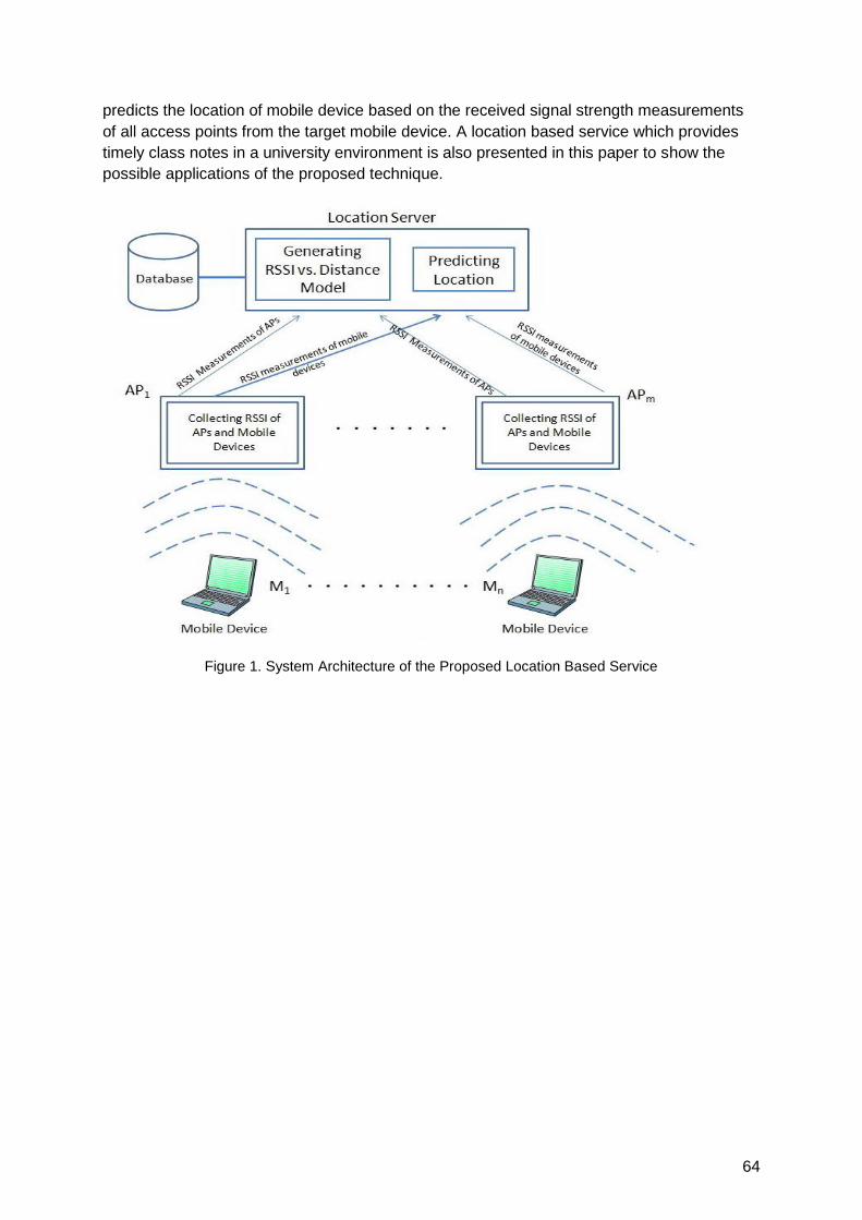
64
predicts the location of mobile device based on the received signal strength measurements
of all access points from the target mobile device. A location based service which provides
timely class notes in a university environment is also presented in this paper to show the
possible applications of the proposed technique.
Figure 1. System Architecture of the Proposed Location Based Service
65
Wi-Fi-Based Indoor Positioning: Basic Techniques, Hybrid Algorithms
and Open Software Platform
Matteo Cypriani¹, Philippe Canalda¹, Frédéric Lassabe², François Spies¹
¹ University of Franche-Comté, Computer Science Laboratory (LIFC)
1 cours Louis Leprince-Ringuet 25200 Montbéliard, France
² University of Technology of Belfort-Montbéliard, Laboratory Systems & Transports (SeT)
Rue Thierry Mieg, 90010 Belfort cedex, France
1 Summary
802.11 networks democratisation, combined with new mobility and needs, makes us
interested in continuity of innovative services. The need for contextual knowledge grows,
based on the availability of positioning services. It takes account of environmental dynamic
changes and exploits Wi-Fi-based sensors from the market.
After state of the art reveals the need, considering characteristics of indoor and outdoor
heterogeneous environment, we briefly introduce the initial system OWLPS-0.8 with the
description of basic components, positioning algorithms and very first elements of expertise.
We then present a set of new contributions from a topological model, a history memorisation
algorithm derived from Viterbi and its implementation in positioning algorithms from the
literature. We also propose a new design platform (OWLPS-1.0) addressing the dynamic
changes in the environment and composing new algorithms to reduce the calibration and
cartography cost as well as to minimise the distortion of signal strength dynamic variations in
modern buildings.
2 State of the art
While outdoor positioning is widely treated and achieved by the GPS, indoor positioning is
currently under development. Wi-Fi indoor positioning can be divided into two main families.
One family is based on wave propagation and resorts on computing distances between
mobile devices and points whose coordinates are known. The second family is based on
mapping between signal strength measurements and geographical coordinates, called signal
strength (SS) map. Locating a mobile device with a SS map consists in matching a
measurement with some point of SS map. Measurements matching is either deterministic
[Bahl00] or probabilistic [Ekahau02].
Propagation-based family is quick and easy to set up but lacks of accuracy. SS map family is
accurate but is expensive to set up. Therefore, an efficient system would use both families
strengths and suffer less drawbacks. In particular, propagation-based systems problems are
bound to topology heterogeneity in buildings so a hybrid system has to address topology.
3 Base data
To build a hybrid, topology-aware, indoor positioning system, several base data are required:
66
A minimal SS map, at least one point in each room. It allows a first, coarse,
positioning of mobile device.
A propagation model, for example FBCM. This model is calibrated and used locally,
after coarse positioning based on SS map.
A topology model, either discrete or continuous. Such model aims at refining
positioning process with device tracking. It eliminates ambiguous locations based on
past movements. A Viterbi-like algorithm performs elimination of all candidate points
but one. It requires to store several candidate locations for each positioning iteration.
4 Algorithms
Base algorithms
Two base algorithms exist, above which complex techniques are developed. One performs
search of k nearest points in a SS map, given a measurement. The other one, Friis-Based
Calibrated Model (FBCM) [Lassabe09], consists in calibrating a propagation model with a
priori measurements. Calibration determines which weight to give to transmitter-receiver
distance in a Friis-like formula. It aims at computing accurately distances between mobile
device and access points.
Contributions
From these base algorithms, we derive refinement techniques that combine a SS
cartography, as in [Bahl00], and multilateration using FBCM. We called these techniques
FBCM and Reference-Based Hybrid Model (FRBHM).
Furthermore, we can take into account the building topology. Describing precisely the room
layout, we are then able to estimate the real distance between two points, instead of use a
simple euclidean distance. Two variants of the FRBHM use the topology, combined with a
Viterbi-like algorithm that uses the past positions of the mobile to compute the current
position. The implementation of this Viterbi-like algorithm is an optimisation called Fast
Viterbi-Like.
All these base and new algorithms are implemented in the Open Wireless Positioning
System (OWLPS) [Cypriani09]. We are currently achieving a community version of the
system, and plane to carry out new experiments within the next months, in order to confirm
the previous results, better determine the accuracy in function of the SS map granularity and
the radio environment alteration. We will also extend our experiments to new contexts and
conditions such as the combination with other positioning services [Zirari10] at the periphery
of buildings.
References
[Bahl00] P. Bahl, V. N. Padmanabhan, "RADAR: An in-building RF-based user location and tracking system‖, in INFOCOM (2), pp. 775-784, 2000.
[Cypriani09] M. Cypriani, F. Lassabe, P. Canalda, F. Spies, ―Open Wireless Positionning System: a Wi-Fi-Based Indoor Positionning System‖, VTC-fall 2009, 70th IEEE Vehicular Technologie Conference, 5 pages, September 2009.
[Ekahau02] R. Roos, P. Myllymäki, H. Tirri, P. Misikangas, J. Sievänen, "A Probabilistic Approach to WLAN User Location Estimation", International Journal of Wireless Information Networks, vol. 9, no. 3, pp. 155-164, July 2002.
[Lassabe09] F. Lassabe, P. Canalda, P. Chatonnay, F. Spies, ―Indoor Wi-Fi Positioning: Techniques and Systems‖, Annals of telecommunications, 64(9/10):651-664, September 2009.
[Zirari10] S. Zirari, P. Canalda, F. Spies, ―WiFi GPS based Combined positioning Algorithm‖, in WCNIS'10, IEEE Int. Conf. on Wireless Communications, Networking and Information Security, 5 pages (to appear), June 2010.

67
A sector-based campus-wide indoor positioning system
Thomas Gallagher, Binghao Li, Andrew G Dempster, Chris Rizos
School Of Surveying & Spatial Information Systems, University of New South Wales, Sydney,
Australia
Recently, the demand for Location Based Services (LBS) has grown exponentially, reflecting
the increasing quality of mapping tools available to general users, such as Google Maps© or
Google Earth©, and the rapid expansion of the smart phone market. Phones such as the
Apple iPhone©, or HTC Dream©, are now small computer terminals with embed GPS
(Global Positioning Systems), Wi-Fi (wireless fidelity), Bluetooth and 3G enabled chips, in
addition of their basic mobile telephony capabilities. GPS is a reliable, generally available
and comparatively accurate positioning technology, able to operate anywhere across the
globe. However, it is also well known that GPS performance deteriorates very rapidly when
the receiver loses view of the satellites, which typically occurs in indoor environments. In
such environments, the majority of receivers do not function, and even the high sensitivity
receivers have difficulties in providing coordinates with acceptable accuracies.
The general expectation of users of accurate positioning anywhere they go, and the inherent
limitations of GPS availability and accuracy in indoor environments, have led researchers to
investigate alternative technologies able to replicate GPS performance indoors. In this
context, using Wi-Fi signals for positioning offers many advantages. First, the user doesn‘t
need any additional hardware as most mobile phones are now equipped with Wi-Fi. Second,
there is no need to deploy an extra dedicated network as Wi-Fi signals from at least a few
access points (APs) can be detected in the majority of areas of interest, due to the
proliferation of wireless networks, especially in areas where GPS is weak (indoors). Finally,
Wi-Fi positioning technology can deliver room-level accuracy, which is usually good enough
for a lot of applications, including asset tracking, location-based advertisement, location-
based information for users, etc.
The purpose of this paper is to describe a campus-wide indoor and outdoor positioning
system developed at the School of Surveying and Spatial Information Systems at the
University of New South Wales, Australia. The system aims to provide students and staff with
software able to guide them between any two locations on the university main campus, either
indoors or outdoors, and, subsequently, to support other LBS applications. The development
platform chosen is the Android©-powered HTC Dream© smart phone. This platform was
chosen because the Dream© is equipped with Wi-Fi and GPS, the two technologies used for
positioning, and because the Android© platform is open-source and provides an extensive
API. The Wi-Fi positioning technique used is known as fingerprinting, described in numerous
papers. This technique first requires the building up of a database of signal strengths (SS)
from different APs taken at different points across the area of interest. Then, the user wishing
to find his or her position scans the SS in the wireless network and sends the results to the
database which will find the closest match in the database, and return the likeliest location of
the smart phone.
The requirements for this system are: cost effectiveness, ease of deployment and
maintenance, and room-level accuracy indoors. We believe that cost effectiveness and ease
68
of use are very important issues any indoor-positioning system should try to address, in order
for them to be more widely used. Ultra-wideband technology for instance, delivers
centimetre-level accuracies but its very high-cost of initial implementation is a major
drawback for its widespread development. Using Wi-Fi signals for trilateration suffers from
poor accuracies, and needs the exact position of the access points to work, a piece of
information not always easy to access. In this paper, we show that a relatively simple system,
with minimal costs of deployment, delivers accuracies that would allow useful LBS to be
developed for students and staff. The database generation and maintenance costs are the
main disadvantages of the fingerprinting technique as they require time and labour, and
when the environment changes significantly (for instance after a major building renovation),
the database must be accordingly updated. For the system to be usable and used by
students and staff, this issue has to be addressed. This paper investigates different
approaches to database generation, and their impact on system performance. We show for
instance that doing a quicker survey with fewer fingerprints does not impact performance as
much as may have been expected. In such a survey, a five level university building was
surveyed in less than one hour, keeping the projected database generation costs at an
acceptable level.
This paper also investigates different algorithms used in the positioning phase, when the SS
scan results sent by the user are matched to the database entries. The most basic one is the
Nearest Neighbour (NN) algorithm, where the matching criterion is the distance in signal
space between the scan result and each fingerprint entry in the database. We show that
using more advanced algorithms can significantly improve performance, while keeping the
computational cost at a reasonable level. For instance, while a simple NN algorithm returned
the correct sector only 40% of the time, a more advanced algorithm returned the correct
sector 60% of the time.
To conclude, our paper demonstrates the feasibility of a very cost-efficient Wi-Fi positioning
system based on fingerprinting, with a minimal database generation cost, delivering
accuracies which can be used to develop a large range of useful services for students and
staff. Students could use this system to navigate through the campus of course, but also to
locate friends for instance, or to gain access to information about the university‘s facilities
depending on their location. Location of critical staff members such as security guards, or
facilities management staff could also be useful information for the university.
69
Multiple Wireless Technologies Fusion for Indoor Location Estimation
Pedro Mestre1, Hugo Pinto2, João Matias3, João Moura2, Paula Oliveira2, and Carlos Serôdio1
1CITAB-Centre for the Research and Technology of Agro-Environment and Biological
Sciences, University of Trás-os-Montes and Alto Douro, 5000-801 Vila Real, Portugal
2 University of Trás-os-Montes and Alto Douro, 5000-801 Vila Real, Portugal
3 Centre for Mathematics, University of Trás-os-Montes and Alto Douro,
5000-801 Vila Real, Portugal
[email protected], [email protected], [email protected],
jpmoura@utad.,pt, [email protected], [email protected]
Summary
Results from the analysis of electromagnetic signals are a possible source of information to
feed the input of an indoor location system, as wireless communications are becoming more
and more ubiquitous and widely available in consumer electronic devices. In this work a
fingerprinting-based solution for indoor location that uses information from multiple
communication technologies is presented. For testing and proof of concept purposes the
authors used IEEE802.15.4 and IEEE802.11 as wireless communications technologies.
When using multiple sources of information (technologies) to do location estimation two
approaches can be used to integrate them: use each one separately, in layers, where each
technology adds a detail level based on its coverage area, or, merge data collected from
several technologies and thread them all together. In this work we use both approaches.
Indoor Localization
For indoor localisation using electromagnetic waves, the use of time properties to do location
estimation can be very difficult, due to the fact that distances are very short and waves
propagate at the speed of light. Therefore the use of techniques like TDoA (Time Difference
of Arrival) or ToA (Time of Arrival) is very difficult and can be very expensive.
Another property of the signal that can be used for localisation purposes is the signal power
at the receiver. It can be used to determine the signal attenuation over the radio link or it can
be used for scene analysis. In the first case the distance between the mobile terminal and a
set of references can be estimated using propagation models, and therefore, the location of
the mobile terminal can be estimated. In the second case, the strength of the signal received
from several references are compared against reference values stored in a database,
searching for a match and trying to estimate the mobile terminal location.
In this work fingerprinting, which is a scene analysis technique is used. As communications
technologies IEEE802.11 and IEEE802.15.4 were chosen to do the tests in our University
Campus. The first was chosen due to its presence in almost the whole campus and the
second due the fact that it is a very short range wireless technology and it is widely used in
Wireless Sensors Networks (WSN). Another key factor for the choice of these two
70
technologies is the fact that wireless reference nodes are easily discovered by other nodes
and, in a very short time that in the worst case depends on the beaconing interval.
Experimental Work
Experimental work was split into two phases: 1. The off-line phase that uses data from the
existing scenario, recorded into a database. Each record consists in the RSSI (Received
Signal Strength Indication) value, the location of the sampling point and the MAC (Medium
Access Control) address of the wireless reference. 2. The on-line phase, where the
localisation is made, it is based on data gathered in the previous phase and on the location
where the algorithms (Nearest Neighbour, k-Nearest Neighbour and Weighted k Nearest
Neighbour) were tested.
The present work is based on a multi-zone, multi-resolution approach that uses different
range technologies to locate terminals in certain types of areas. Using wide range
communications it is possible to locate the main zone where the terminal is, for example the
building. This will enable a first estimation of the zone where the terminal is, and therefore we
can eliminate all the references from the next analysis that do not belong to the zone. The
number of layers in this approach depends on the number of different technologies used, and
the zone size depends on the type of technology, geographical distribution or the type of the
zones to be detected (e.g., Campus, building).
Experimental data was collected in two types of scenarios, the first using IEEE802.11 where
the FM of the main hall of several buildings was built, in the second scenario the FM of a
classroom (located near the main hall of one of the buildings) was built using both
IEEE802.11 and IEEE802.15.4.
In the on-line phase of the experimental work the first step was to detect the building, which
occurred without any problem. After detecting the building correctly, the next step was to
determine the location inside that zone, in this case, inside a classroom. This was done by
using both technologies. In the first test, using IEEE802.11 a precision of approximately
0,83 m and an accuracy of 77 % was achieved. When IEEE802.15.4 was used the obtained
precision was approximately 0,72 m with an accuracy of 93 %.
To enhance the location several technologies can be combined and the search for the mobile
terminal location is done using the fingerprint map information from more than one
technology. Using both IEEE802.11 and IEEE802.15.4 a precision of about 0.46 m and a
accuracy of 73 % was achieved. Although there is a degradation of the accuracy, the
precision is much better.
Conclusions
In this work we propose the use of multiple technologies to locate users and objects in an
indoor environment, based on the fingerprinting technique. To eliminate possible error
sources and even to reduce the computational time needed to correctly estimate the position,
a multiphase/multilayer approach is presented. At each phase a different technology is used,
starting with the wider coverage range technology and ending in the lower range technology.
Shorter range of wireless technologies has better spatial resolution of it. So, a typical
wireless communications network based on IEEE802.11 will achieve a worse spatial
resolution than IEEE802.15.4, because the last solution needs more wireless nodes to
achieve the same spatial coverage.
71
Resolving the Fingerprinting Problem: Comparison of Propagation
Modelling and Machine Learning Approach
Widyawan
Gadjah Mada University, Department of Electrical Engineering and Information Technology,
2 Grafika, Yogyakarta, Indonesia
1 Summary
A major drawback of indoor localization based on RSS (Received Signal Strength)
measurements is the necessity to generate a fingerprint. Generating a fingerprint database is
an exhaustive, time consuming and cumbersome effort. Furthermore, a fingerprint is also
bound to the indoor environment description and infrastructure at the time the fingerprint was
generated.
Therefore, major changes in the environment (movement of large pieces of furniture or
appliances, adding or removing walls) will render a current fingerprint inaccurate and require
re-building of a new fingerprint. In other words, the current approach still has poor usability,
judged from the effort that is needed to install and maintain it.
This disadvantage makes the indoor localization system inoperable as a localization system.
This work explores two main approaches to overcome this problem: fingerprint prediction
with a propagation model and fingerprint modelling with a machine learning approach.
The propagation model is used to predict the signal strength throughout the coverage area
from access points to predict the fingerprint. There are two propagation models that can be
used, namely the One Slope Model (OSM) and the Multi Wall Model (MWM). A particle filter
is used as a filtering algorithm to estimate the user position.
The Support Vector Machine (SVM) is one of the machine learning algorithms that is used to
model the complete fingerprint from few training data. As a pattern recognition algorithm,
SVM will also be utilized to estimate the user position.
The evaluation among the fingerprinting approaches is conducted in a localization test-bed
using WLAN technology. The fingerprinting prediction model with propagation and machine
learning approach will be compared to the manual fingerprinting collection.
2 Propagation Model and Machine Learning Approach
Figure 1 shows an example of a fingerprint prediction with the OSM model. The signal loss in OSM is given by:
)log(101 dnLL
where L is a signal loss, 1L (dB) is a reference loss value of 1m distance, n is a power
decay factor (path loss exponent) defining slope, and d is the distance in meters.

72
Figure 1 OSM Prediction of a Fingerprint
The principal advantage of fingerprint prediction is its speed in predicting the fingerprint. In the machine learning approach, a sizeable training database is collected and subsequently used to train the system to estimate the complete fingerprint database. SVM uses a fingerprint as its training data to build a classification model. During the training phase, SVM constructs a classifier termed as hyper-plane which in turn is used to estimate the target location.
3 Particle Filter
The Particle Filter is a non-parametric implementation of the Bayes‘ filter. It approximates the
posterior probability by a finite number of discrete samples with associated weights, called
particles. The Particle Filter is used as a filtering algorithm to estimate the user position.
Figure 2 illustrates an example when the Particle Filter algorithm was used to estimate the
user position.
Figure 2 The Particle Filter for state estimation
4 Results
The fingerprinting prediction with a propagation model and the machine learning approach
will be compared to the manual fingerprinting collection. Table 1 shows an example of the
localization error with manually collected fingerprints in the test-bed. It is based on the
Kalman Filter (KF) and the Particle Filter (PF) as the localization algorithm. The localization
error is the distance between the true position and the estimated location in the test-bed. It
shows the average error (μ) and standard deviation (σ) in metres.
Table 1: Localization Error (metres)
Fingerprinting KF PF
Manual Fingerprint μ =4.67
σ =3.84
μ = 3.25
σ =1.91
73
Optimization Model for an Indoor WLAN-based Positioning System
You Zheng, Oumaya Baala, Alexandre Caminada
SeT Lab., University of Technology of Belfort-Montbéliard, 90010 Belfort Cedex, France
{you.zheng, oumaya.baala, alexandre.caminada}@utbm.fr
1 Summary
We propose an innovative approach where WLAN planning and positioning error reduction
are modeled as an optimization problem and tackled together during the WLAN planning
process.
2 Introduction
Positioning systems using Wireless Local Area Networks (WLANs) have been suggested as
a viable alternative to provide location information for indoor areas. But, an increase of the
density of Access Points (AP) can improve the system accuracy and precision, whereas the
communication quality (due to frequency interferences) and the installation costs are
increasing too. These are major drawbacks! This paper attempts to answer the relevant
question: how can a WLAN be deployed in order to guarantee the requested Quality of
Service (QoS) and meanwhile reducing the location error? Such a problem includes two
aspects: WLAN planning and positioning error reduction. To provide users an optimal
wireless access to their local network, WLAN planning not only consists of selecting a
location for each transmitter and setting the parameters of all sites, but also of allocating one
of the available frequencies to each selected AP. Once the Received Signal Strengths (RSSs)
from all visible APs are measured and entered, the location is estimated and outputted using
the RSS distribution and machine learning technique. We propose a new approach where
WLAN planning and positioning error reduction are modeled as an optimization problem and
tackled together during WLAN planning process.
3 Modeling and problem optimization
To find a feasible AP configuration satisfying QoS and positioning error constrains, we
proposed a formal model which describes the whole problem parameters and which defines,
in a precise way, an estimation of the costs, throughput of a network and the positioning
accuracy.
1. AP model: Since different types of APs have different parameter values (azimuth, emitted
power and frequency), we predefine a list of AP types for the users‘ choice. Furthermore, we
predefine a finite set of candidate sites where an AP may be assigned.
2. Received Signal Strength model: RSS is the main parameter used for bit rate
calculation and positioning estimation. We define three kinds of RSS thresholds
corresponding to interference level, positioning level and communication level.
3. Traffic and positioning model: The traffic and positioning model of the network defines
how to represent the demand for network load or positioning accuracy. The building is
meshed, and the desired QoS and the desired accuracy are expressed by polygons covering
service areas of the building. A pixel associated with QoS is called Test Point (TP) and a
pixel associated with the accuracy is called Reference Point (RP).
74
Our optimization problem aims to determine the decision variables (site, transmission power,
azimuth and frequency) in order to minimize positioning error and QoS lack under some
constraints. To evaluate the accuracy and QoS, the proposed fitness consists of three terms.
The first term is the network installation cost; the second term is the cost of unsatisfied
demands on QoS and the third term is the cost of unsatisfied demands on positioning. The
QoS is evaluated by the Signal to Interference plus the Noise Ratio (SINR) indicator. The
positioning accuracy is estimated by a defined indicator called Refined Specific Error Ratio
(RSER). Mathematically, the objective function is formulated by
RP
rp
TP
rpC Site
Site ,
where, CSite is the network installation cost of a site. β is the penalty coefficient assigned to
the TP. Δtp is the deviation between the required bit rate and the real bit rate. γ is the penalty
coefficient assigned to the RP. Εrp is the magnitude of the positioning error. To solve this
optimization problem, a Meta-Heuristic algorithm is implemented.
4 Experiments and performance analysis
To evaluate the performance of the location system, we carried out two experiments in the
same experimental environment. The test scenario for performance evaluation took place at
the first and the second floor of the library building in the UTBM campus. Each floor covers
an experimental area of approximately 150 m x 40 m with more than 30 classrooms and
offices of different sizes. We constrain that the maximum number of AP is 30 and the desired
bit rate for each user is 500 kbps. The obtained results are shown in Figure 1.
Figure.1: The variation of total Δtp and total Εrp by different γ to β ratio in each improvement.
In Figure 1, we vary the γ to β ratio to study the relationship between QoS and the
positioning accuracy. Figure 1 clearly shows that a high γ to β ratio of 1000 can guarantee a
small positioning error while high total Δtp. In the same way, a low γ to β ratio of 0.01 only
guarantees a low total Δtp. With an appropriate value of 0.1 for the γ to β ratio, our approach
can find an AP configuration which can provide a good QoS demand and positioning
accuracy.
5 Conclusions and Outlook
In this paper, we provide a solution where WLAN planning and positioning error reduction are
dealt with simultaneously in form of an optimization problem. We have done the performance
evaluation of our approach and the results indicate that our approach is able to achieve a
WLAN planning which provides the required QoS demand and positioning accuracy. Further
work will focus on multi-objective optimization.
75
Effect of Environmental Changes on Accuracy of IEEE 802.11 Indoor
Fingerprinting Positioning System WifiLOC
Peter Brida, Juraj Machaj, Jozef Benikovsky
University of Zilina, FEE, Department of Telecommunications and Multimedia, Univerzitna 1,
010 26 Zilina, Slovakia
{peter.brida, juraj.machaj, jozef.benikovsky}@fel.uniza.sk
1 Summary
The performance of our indoor positioning system based on IEEE 802.11 is evaluated for
real environments. We call the system WifiLOC and it is implemented as a mobile assisted
positioning system. The architecture and fundamental principles of the system are presented.
The positioning system is based on the fingerprinting method, which utilizes signal strength
information for position estimation. A lot of factors influence the propagation of radio signals
in indoor environments. Therefore it is complicated to clearly model the properties of the
signal propagation. This fact has also significant impact on particular properties of a RSSI
based positioning system. In this paper, the impact of the positioning accuracy is presented
taking into account various conditions such as moving objects in the observed area or the
type of indoor environment, e.g. corridor, office and room. The influence of different
conditions during the off-line and the on-line phase of fingerprinting positioning method on
the positioning accuracy is also investigated. The observed facts are very important for
successful implementation of location based services.
2 Motivation and Results
In the past, most attention was paid to research of positioning in outdoor environments. The
utilization of GNSS (Global Navigation Satellite System) seems to be the best solution
outdoors, but its limits become evident in urban canyons and especially in indoor
environments. The increasing demand for indoor LBSs (Location Based Services) raised the
interest of many research groups in indoor positioning. There are many typical examples of
indoor LBSs: car navigation in garage buildings, patient position monitoring in a hospital or
hospice. It could also be used in various shopping centres, galleries or airports for personal
navigation. The purposes are different, but the user position should be known in all cases.
Various positioning systems based on wireless platforms were proposed in [1 - 3]. We
decided to propose our solution based on an IEEE 802.11 platform, because it is widespread.
The basic idea results from the utilization of the platform apart from its main purpose, which
is mainly to cover user data communication. Our approach adds value to the IEEE 802.11
communication platform by providing user positioning.
As mentioned above, our positioning solution is based on the IEEE 802.11 communication
platform, is called ―WifiLOC‖. WifiLOC was designed as part of global modular positioning
system, which supports LBS everywhere. It means the localization is supported by various
independent positioning systems in all environments, i.e. indoors and outdoors. Positioning
system with the most suitable current conditions for positioning is used for final position
estimation. It is based on a client - server architecture, which is shown in Figure 1.
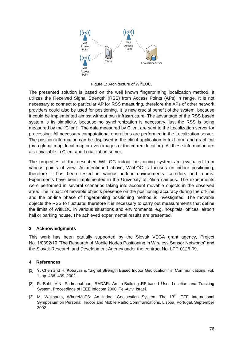
76
ClientLocalization Server
Wifi
Access
Point
Wifi
Access
Point
Wifi
Access
Point
Figure 1: Architecture of WifiLOC.
The presented solution is based on the well known fingerprinting localization method. It
utilizes the Received Signal Strength (RSS) from Access Points (APs) in range. It is not
necessary to connect to particular AP for RSS measuring, therefore the APs of other network
providers could also be used for positioning. It is new crucial benefit of the system, because
it could be implemented almost without own infrastructure. The advantage of the RSS based
system is its simplicity, because no synchronization is necessary, just the RSS is being
measured by the ―Client‖. The data measured by Client are sent to the Localization server for
processing. All necessary computational operations are performed in the Localization server.
The position information can be displayed in the client application in text form and graphical
(by a global map, local map or even images of the current location). All these information are
also available in Client and Localization server.
The properties of the described WifiLOC indoor positioning system are evaluated from
various points of view. As mentioned above, WifiLOC is focuses on indoor positioning,
therefore it has been tested in various indoor environments: corridors and rooms.
Experiments have been implemented in the University of Zilina campus. The experiments
were performed in several scenarios taking into account movable objects in the observed
area. The impact of movable objects presence on the positioning accuracy during the off-line
and the on-line phase of fingerprinting positioning method is investigated. The movable
objects the RSS to fluctuate, therefore it is necessary to carry out measurements that define
the limits of WifiLOC in various situations and environments, e.g. hospitals, offices, airport
hall or parking house. The achieved experimental results are presented.
3 Acknowledgments
This work has been partially supported by the Slovak VEGA grant agency, Project
No. 1/0392/10 ―The Research of Mobile Nodes Positioning in Wireless Sensor Networks‖ and
the Slovak Research and Development Agency under the contract No. LPP-0126-09.
4 References
[1] Y. Chen and H. Kobayashi, ―Signal Strength Based Indoor Geolocation,‖ in Communications, vol.
1, pp. 436–439, 2002.
[2] P. Bahl, V.N. Padmanabhan, RADAR: An In-Building RF-based User Location and Tracking
System, Proceedings of IEEE Infocom 2000, Tel-Aviv, Israel.
[3] M. Wallbaum, WhereMoPS: An Indoor Geolocation System, The 13th IEEE International
Symposium on Personal, Indoor and Mobile Radio Communications, Lisboa, Portugal, September
2002.
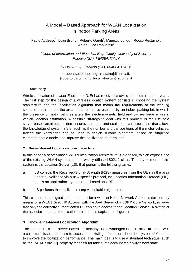
77
A Model – Based Approach for WLAN Localization
in Indoor Parking Areas
Paolo Addesso1, Luigi Bruno1, Roberto Garufi2, Maurizio Longo1, Rocco Restaino1,
Anton Luca Robustelli2
1 Dept. of Information and Electrical Eng. (DIIIE), University of Salerno,
Fisciano (SA), I-84084, ITALY
2 CoRiTeL Italy, Fisciano (SA), I-84084, ITALY
{paddesso,lbruno,longo,restaino}@unisa.it;
{roberto.garufi, antonluca.robustelli}@coritel.it
1 Summary
Wireless location of a User Equipment (UE) has received growing attention in recent years.
The first step for the design of a wireless location system consists in choosing the system
architecture and the localization algorithm that match the requirements of the working
scenario. In this paper the area of interest is represented by an indoor parking lot, in which
the presence of motor vehicles alters the electromagnetic field and causes large errors in
vehicle location estimation. A possible strategy to deal with this problem is the use of a
server-based architecture, that ensures a secure and scalable architecture and that allows
the knowledge of system state, such as the number and the positions of the motor vehicles.
Indeed this knowledge can be used to design suitable algorithm, based on simplified
electromagnetic models, to improve the localization performance.
2 Server-based Localization Architecture
In this paper a server-based WLAN localization architecture is proposed, wihich exploits one
of the existing WLAN systems in the widely diffused 802.11 class. The key element of this
system is the Location Server (LS), that performs the following tasks.
a. LS collects the Received-Signal-Strength (RSS) measures from the UE‘s in the area
under surveillance via a new specific protocol, the Location Information Protocol (LIP),
that is an application layer protocol based on UDP.
b. LS performs the localization step via suitable algorithms.
This element is designed to interoperate both with an Home Network Authenticator and, by
means of a WLAN Direct IP Access, with the AAA Server of a 3GPP Core Network, in order
that only the correctly authenticated UE can have access to the Location Service. A sketch of
the association and authentication procedure is depicted in Figure 1.
3 Knowledge-based Localization Algorithm
The adoption of a server-based philosophy is advantageous not only to deal with
architectural issues, but also to access the existing information about the system state so as
to improve the localization performance. The main idea is to use a standard technique, such
as the RADAR one [1], properly modified for taking into account the environment state.
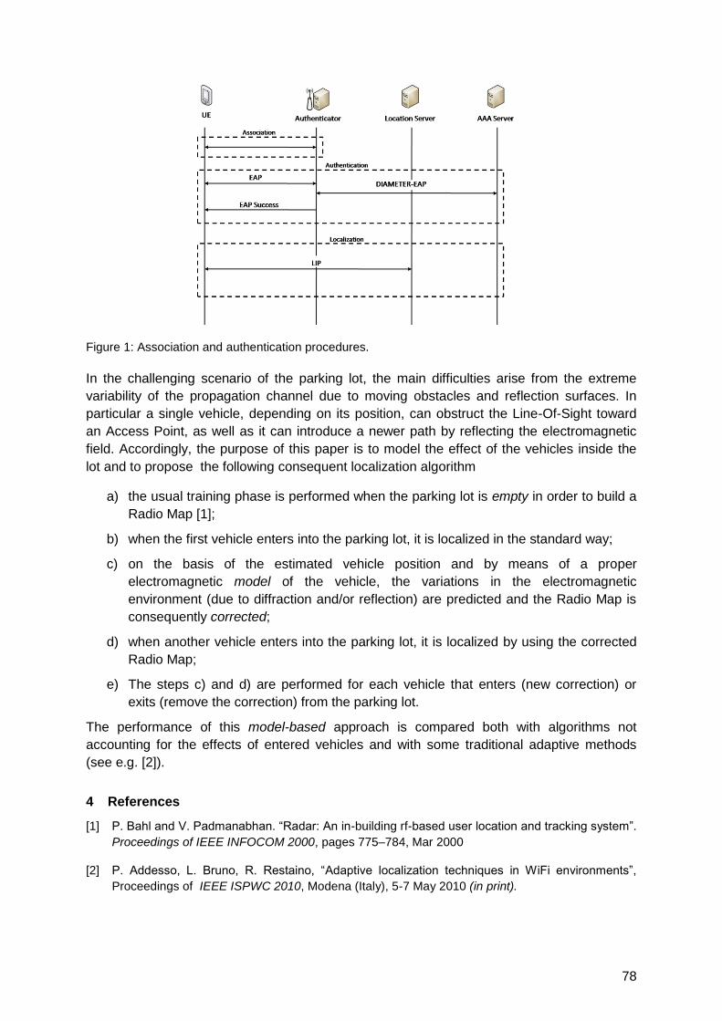
78
Figure 1: Association and authentication procedures.
In the challenging scenario of the parking lot, the main difficulties arise from the extreme
variability of the propagation channel due to moving obstacles and reflection surfaces. In
particular a single vehicle, depending on its position, can obstruct the Line-Of-Sight toward
an Access Point, as well as it can introduce a newer path by reflecting the electromagnetic
field. Accordingly, the purpose of this paper is to model the effect of the vehicles inside the
lot and to propose the following consequent localization algorithm
a) the usual training phase is performed when the parking lot is empty in order to build a
Radio Map [1];
b) when the first vehicle enters into the parking lot, it is localized in the standard way;
c) on the basis of the estimated vehicle position and by means of a proper
electromagnetic model of the vehicle, the variations in the electromagnetic
environment (due to diffraction and/or reflection) are predicted and the Radio Map is
consequently corrected;
d) when another vehicle enters into the parking lot, it is localized by using the corrected
Radio Map;
e) The steps c) and d) are performed for each vehicle that enters (new correction) or
exits (remove the correction) from the parking lot.
The performance of this model-based approach is compared both with algorithms not
accounting for the effects of entered vehicles and with some traditional adaptive methods
(see e.g. [2]).
4 References
[1] P. Bahl and V. Padmanabhan. ―Radar: An in-building rf-based user location and tracking system‖.
Proceedings of IEEE INFOCOM 2000, pages 775–784, Mar 2000
[2] P. Addesso, L. Bruno, R. Restaino, ―Adaptive localization techniques in WiFi environments‖,
Proceedings of IEEE ISPWC 2010, Modena (Italy), 5-7 May 2010 (in print).
79
Fingerprinting Localization in Indoor Wi-Fi Networks Based on Received
Signal Strength
Shih-Hau Fang and Tsung-Nan Lin*
Department of Electrical Engineering, Yuan Ze University, Taiwan
Graduate Institute of Communication Engineering, National Taiwan University, Taiwan*
[email protected]; [email protected]*
1 Summary
This paper considers the problem of fingerprinting localization in indoor Wi-Fi networks
based on received signal strength. When a mobile device request services, a fingerprinting
system compares the measurement with the values stored in a database to determine the
location. This study investigates several factors impacting the location accuracy. First, we
compare different fingerprinting algorithms, such as Bayesian, Support Vector Regression,
and weighted-k-nearest-neighbor, to construct different relationships between the user‘s
location and the measured RSS. Next, the compared positioning algorithms are performed
on different transformed signal spaces to examine the performance by on-site experiments.
The transformation is determined by different criteria, including principal component analysis
(PCA), and multiple discriminate analysis (MDA). The former is known for preserving the
most descriptive features while the latter is known for capturing the most discriminant ones
after transformation. This study also examines the distribution of RSS, and the analyses of
complexity.
2 Experimental Setup and Results
The proposed algorithm is evaluated on a realistic indoor environment. The measurements are collected on the fifth floor of BL building in NTU, as shown in Figure 1.
Figure 1: The fifth floor plane of the BL building, where we performed the experiments. The dots
represent the reference locations.
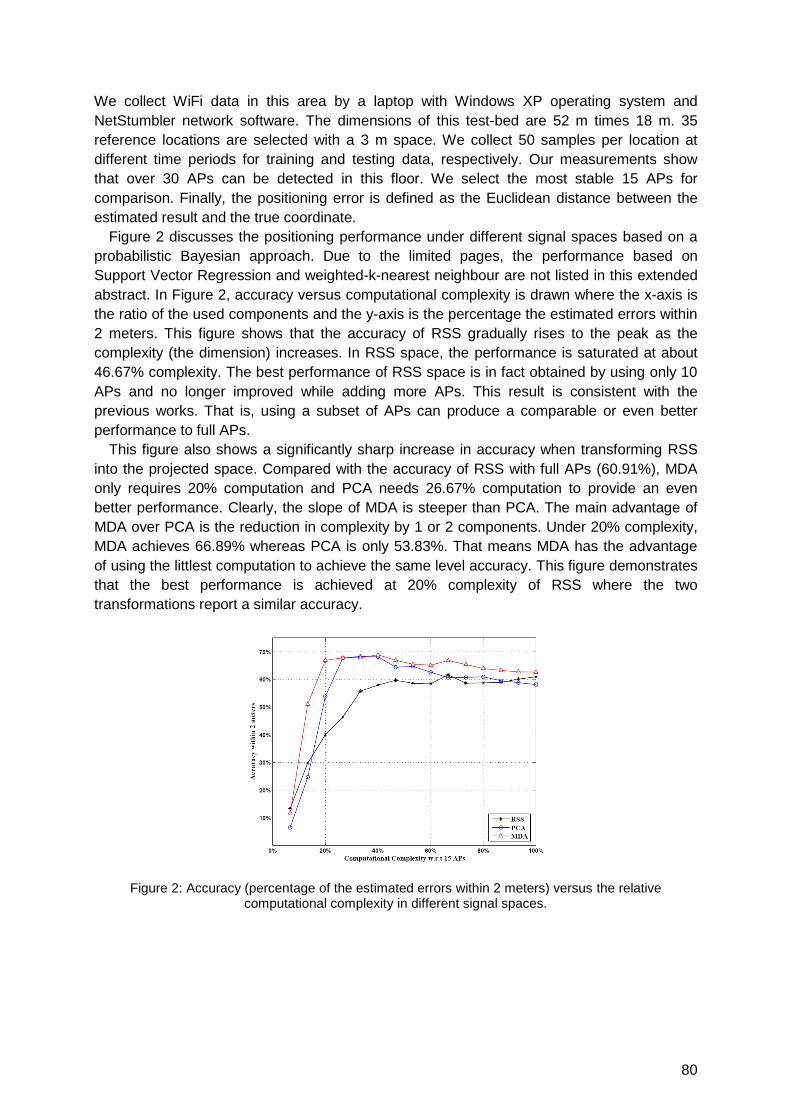
80
We collect WiFi data in this area by a laptop with Windows XP operating system and
NetStumbler network software. The dimensions of this test-bed are 52 m times 18 m. 35
reference locations are selected with a 3 m space. We collect 50 samples per location at
different time periods for training and testing data, respectively. Our measurements show
that over 30 APs can be detected in this floor. We select the most stable 15 APs for
comparison. Finally, the positioning error is defined as the Euclidean distance between the
estimated result and the true coordinate.
Figure 2 discusses the positioning performance under different signal spaces based on a
probabilistic Bayesian approach. Due to the limited pages, the performance based on
Support Vector Regression and weighted-k-nearest neighbour are not listed in this extended
abstract. In Figure 2, accuracy versus computational complexity is drawn where the x-axis is
the ratio of the used components and the y-axis is the percentage the estimated errors within
2 meters. This figure shows that the accuracy of RSS gradually rises to the peak as the
complexity (the dimension) increases. In RSS space, the performance is saturated at about
46.67% complexity. The best performance of RSS space is in fact obtained by using only 10
APs and no longer improved while adding more APs. This result is consistent with the
previous works. That is, using a subset of APs can produce a comparable or even better
performance to full APs.
This figure also shows a significantly sharp increase in accuracy when transforming RSS
into the projected space. Compared with the accuracy of RSS with full APs (60.91%), MDA
only requires 20% computation and PCA needs 26.67% computation to provide an even
better performance. Clearly, the slope of MDA is steeper than PCA. The main advantage of
MDA over PCA is the reduction in complexity by 1 or 2 components. Under 20% complexity,
MDA achieves 66.89% whereas PCA is only 53.83%. That means MDA has the advantage
of using the littlest computation to achieve the same level accuracy. This figure demonstrates
that the best performance is achieved at 20% complexity of RSS where the two
transformations report a similar accuracy.
Figure 2: Accuracy (percentage of the estimated errors within 2 meters) versus the relative computational complexity in different signal spaces.

81
TOF, TDOA based Localization
Auditorium G7
Thursday, September 16, 13:15 – 15:00 & 15:30 – 16:45

83
IEEE 802.11 Ranging and Multi-lateration for a Software-defined
Positioning Receiver
F. Tappero 1, B. Merminod 1, M. Ciurana 2
1 Ecole Polytechnique Fédérale de Lausanne (EPFL), Lausanne, Switzerland 2 Aerospace Research and Technology Centre, CTAE, Barcelona, Spain
Summary
The implementation of a ranging exploitation method over the IEEE 802.11 signal standard
for a software-defined radio architecture is presented. We propose the current wireless local
access network (WLAN) as standard assistive infrastructure for ubiquitous localisation and
positioning. The paper describes the architecture of a localisation receiver built around a
FPGA. The described receiver can process GNSS signals, available for any number of
satellites, together with IEEE 802.11 signals available from surrounding access points to infer
its own position. The single ranging method, the hybrid GPS and IEEE 802.11 multi-
lateration positioning calculation method and their implementation in a single software-
defined receiver are discussed.
Motivations and results
Satellite-based navigation systems like GPS experience significant accuracy degradation
when used indoors. Alternative wireless indoor localisation systems have been proposed to
amend this [1]. The most popular wireless radio technologies include IEEE 802.11 WLAN,
UWB and RFID systems.
Certain wireless radio localisation technologies are more suitable to be scaled up and
employed for areas larger than a one-room space. Current state-of-the-art location methods
for a building-floor area or a multi-floor environment use received signal strength indicators
(RSSI) for ranging. [2] presents the first location method based on WLAN RSSI. Currently
there are several commercial solutions based on this technology.
Location and tracking solutions based on wireless signal time of flight (TOF), similar to GPS,
are considered superior to RSSI because such measurements scale linearly with the
propagation distance and with better reliability. Recent works like [3,4] present interesting
methods to implement TOF measurements over the RTS/CTS MAC layer of IEEE 802.11
signal standard. Furthermore [5] presents how such TOF ranging techniques could be
implemented for a simple triangulation for localisation over an office space.
There is one aspect common to most of the literature on this topic: the effort to build methods,
techniques and sometimes small hardware [4], that can allow standard WLAN hardware
(WiFi communication cards) to infer the user's position within a standard WLAN network.
This paper takes a different angle and considers the implications of GNSS receivers being
currently integrated into millions of mobile phones worldwide. The concept of a software-
defined GNSS receiver capable of processing GNSS signals as well as IEEE 802.11 signal is
presented. Via the use of a soft-core implementation, we present the idea of harvesting the
large computational power of GNSS receivers to compute terrestrial signals like the IEEE
802.11 for indoor/outdoor localisation via a software-defined radio architecture [6,7].
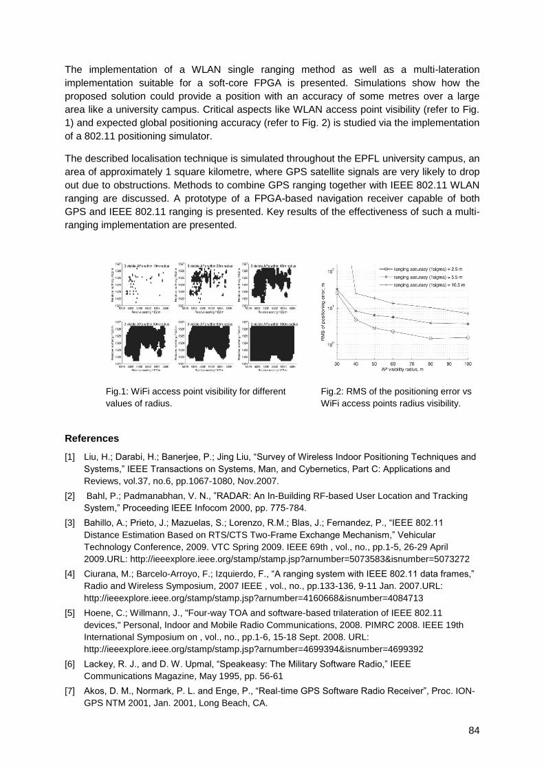
84
The implementation of a WLAN single ranging method as well as a multi-lateration
implementation suitable for a soft-core FPGA is presented. Simulations show how the
proposed solution could provide a position with an accuracy of some metres over a large
area like a university campus. Critical aspects like WLAN access point visibility (refer to Fig.
1) and expected global positioning accuracy (refer to Fig. 2) is studied via the implementation
of a 802.11 positioning simulator.
The described localisation technique is simulated throughout the EPFL university campus, an
area of approximately 1 square kilometre, where GPS satellite signals are very likely to drop
out due to obstructions. Methods to combine GPS ranging together with IEEE 802.11 WLAN
ranging are discussed. A prototype of a FPGA-based navigation receiver capable of both
GPS and IEEE 802.11 ranging is presented. Key results of the effectiveness of such a multi-
ranging implementation are presented.
Fig.1: WiFi access point visibility for different
values of radius.
Fig.2: RMS of the positioning error vs
WiFi access points radius visibility.
References
[1] Liu, H.; Darabi, H.; Banerjee, P.; Jing Liu, ―Survey of Wireless Indoor Positioning Techniques and
Systems,‖ IEEE Transactions on Systems, Man, and Cybernetics, Part C: Applications and
Reviews, vol.37, no.6, pp.1067-1080, Nov.2007.
[2] Bahl, P.; Padmanabhan, V. N., ‖RADAR: An In-Building RF-based User Location and Tracking
System,‖ Proceeding IEEE Infocom 2000, pp. 775-784.
[3] Bahillo, A.; Prieto, J.; Mazuelas, S.; Lorenzo, R.M.; Blas, J.; Fernandez, P., ―IEEE 802.11
Distance Estimation Based on RTS/CTS Two-Frame Exchange Mechanism,‖ Vehicular
Technology Conference, 2009. VTC Spring 2009. IEEE 69th , vol., no., pp.1-5, 26-29 April
2009.URL: http://ieeexplore.ieee.org/stamp/stamp.jsp?arnumber=5073583&isnumber=5073272
[4] Ciurana, M.; Barcelo-Arroyo, F.; Izquierdo, F., ―A ranging system with IEEE 802.11 data frames,‖
Radio and Wireless Symposium, 2007 IEEE , vol., no., pp.133-136, 9-11 Jan. 2007.URL:
http://ieeexplore.ieee.org/stamp/stamp.jsp?arnumber=4160668&isnumber=4084713
[5] Hoene, C.; Willmann, J., "Four-way TOA and software-based trilateration of IEEE 802.11
devices," Personal, Indoor and Mobile Radio Communications, 2008. PIMRC 2008. IEEE 19th
International Symposium on , vol., no., pp.1-6, 15-18 Sept. 2008. URL:
http://ieeexplore.ieee.org/stamp/stamp.jsp?arnumber=4699394&isnumber=4699392
[6] Lackey, R. J., and D. W. Upmal, ―Speakeasy: The Military Software Radio,‖ IEEE
Communications Magazine, May 1995, pp. 56-61
[7] Akos, D. M., Normark, P. L. and Enge, P., ―Real-time GPS Software Radio Receiver‖, Proc. ION-
GPS NTM 2001, Jan. 2001, Long Beach, CA.
85
On the Minimization of Different Sources of Error for an RTT-Based
Indoor Localization System without any Calibration Stage
Javier Prieto1, Santiago Mazuelas2, Alfonso Bahillo3, Patricia Fernández1, Rubén M.
Lorenzo1, Evaristo J. Abril1
1Departamento de Teoría de la Señal y Comunicaciones e Ingeniería Telemática,
Universidad de Valladolid, Paseo Belén 15, 47011 Valladolid (SPAIN) 2Laboratory for Information and Decision Systems (LIDS), Massachusetts Institute of
Technology, 77 Massachusetts Avenue, Cambridge, MA 02139 USA 3CEDETEL (Center for the Development of Telecommunications), Edificio Solar,
ParqueTecnológico de Boecillo, 47151 Boecillo (SPAIN)
[email protected], [email protected]
1 Extended Abstract
In previous essays, a system that measures the round-trip time (RTT) between a mobile user
(MU) and several access points (AP) in an IEEE 802.11 wireless network was used to
estimate the distance between them and obtain the MU‘s position by means of a trilateration
technique [1]. However, different sources of error disturb the range estimates obtained
previously to the trilateration process. As a consequence, the range accuracy, i.e. the degree
of closeness to the actual distance, and the range precision, i.e. the variability of the range
estimates, will be negatively affected. Moreover, after the trilateration stage, the estimation of
the two-dimensional coordinates of the MU‘s position includes a random error that decreases
the precision of this estimation. These sources of error appear whichever the technology and
the environment selected, however, they acquire more importance in cluttered environments,
such as indoor or dense urban scenarios, where the non-line-of-sight (NLOS) is more
relevant.
The aim of this paper is to combine several error mitigation techniques in order to improve
the final accuracy and precision of the RTT-based indoor localization system. The final
accuracy is affected by systematic error, mainly due to the resolution of the measuring
system and the number and distribution of the APs, whereas the precision is influenced by
the random error, i.e. by experimental uncertainties such as electronic errors or multipath
signal reflection. Furthermore, the NLOS error that characterizes the cluttered environment,
introduces a bias in the RTT measurements that varies even for short periods of time,
affecting not only the accuracy but also the precision.
The starting point is the RTT-based system depicted in [1], which first takes a set of RTT
measurements between the MU and each AP in range, and then obtains the distance
through a linear transformation of the Weibull‘s scale parameter taken from the RTT
measurements [1]. The MU‘s position estimate is thus obtained by a trilateration technique
based on the radical axis [1]. The next step is to mitigate the systematic error introduced by
the NLOS in the range estimates prior to the trilateration stage. In order to do so, the prior
NLOS measurements correction (PNMC) method, presented in [2], is implemented. In this
way, NLOS is detected, quantified and reduced from the range estimates.

86
After subtracting the bias error, the random behavior remains on the range estimates, whose
elimination entails a filtering problem. For this purpose, a linear-Gaussian motion model with
a vector state which includes distance and velocity is considered. However, the error
resulting from the PNMC stage leads to a non-Gaussian measurement model [1], thus, a
simple Kalman filter (KF) is not adequate for this problem. Therefore, a better option is to use
a particle filter (PF) to reduce the random error. The likelihood function for this filter has to be
obtained from the set of RTT measurements at each MU‘s position instead of from a single
bias-corrected range estimate, which is the output of the PNMC method. If the relationship
between the distance and the RTT measurements were linear, the NLOS bias obtained by
the PNMC method could be removed from each individual RTT and the likelihood could be
derived from the bias-corrected RTT measurements. Although this is not the case of
Weibull‘s scale parameter, in [3], the error in assuming this linear dependence was
measured to be three orders of magnitude smaller than the resolution of the measuring
system. Then, the PF can be applied by computing the likelihood function from the RTT
distribution obtained after subtracting the NLOS bias from each individual measurement
without loss of performance. Finally, after the trilateration process, the two coordinates of the
position estimates present a random error which has been verified to be Gaussian by means
of a Kolmogorov-Smirnov test. Being both motion and measurement models linear-Gaussian,
a simple KF can be applied to the resulting position estimates.
The main contribution of this paper is that instead of applying a PF to the ranges estimates,
and a KF to the position estimates, an RTT-only tracking filter which directly relates the
position with the RTT measurements to each AP (after applying PNMC) is likewise proposed.
Since in this case, the error in the measurement model is not Gaussian, a PF with a dynamic
likelihood function is implemented. This filter will have the ability to handle the uncertain
information in the process. This procedure has three main advantages compared to the
previous scheme: first, soft decisions are made during the process and hard decisions are
only made in the final position choice. Second, this filter has not to be restarted when any of
the APs is not in range. And third, the processing time is reduced since distance estimation
and trilateration steps are omitted and an only filter is needed, whereas, in the previous case,
one PF per AP for range filtering and one KF for position tracking are implemented.
The root-mean-squared-error (RMSE) quantifies both the systematic (the bias) and random
(the variance) errors. With the presented approach, based on soft decisions and RTT-only
tracking, the RMSE, for a MU who covers a 40x15 m route in an indoor scenario with eight
APs, is 3.86 m. This leads to a final reduction of 55% of the starting RMSE with no error
reduction technique. Moreover, this result is the lowest error achieved with the different
approaches discussed in this paper, and other common Kalman-based techniques with
which it has been compared. It is worth mentioning that neither of these error mitigation steps
nor the measuring system needs any calibration stage.
2 References
[1] A. Bahillo et al., ―Accurate and Integrated Localization System for Indoor Environments Based on
IEEE 802.11 Round-Trip Time Measurements,‖ EURASIP Journal on Wireless Communications
and Networking, accepted for publication, 2010.
[2] S. Mazuelas et al., ―Prior NLOS Measurements Correction for Positioning in Cellular Wireless
Networks,‖ IEEE Transactions on Vehicular Technology, vol. 58, no. 5, pp. 673– 680, June 2009.
[3] J. Prieto et al., ―NLOS mitigation prior to range estimation smoothing for wireless location
systems,‖ IEEE International Conference on Communications, Cape Town, May 2010.
87
Maximum Likelihood 3-D Positioning with a Priori Knowledge of Nodes
Topology for UWB Based Human Motion Tracking
Z. W. Mekonnen, C. Steiner, H. Luecken, A. Wittneben
Communication Technology Laboratory, ETH Zurich, 8092 Zurich, Switzerland
1 Summary
In this paper we analyze an ultra-wideband (UWB) based wearable human motion tracking
system. A maximum likelihood (ML) estimator, which incorporates the UWB distance
measurements and the a priori knowledge of nodes topology to localize a node, is presented.
The result of measurement campaigns is compared with computer simulation results to
evaluate the performance of the proposed scheme. Based on this performance evaluation, it
is shown that taking into account a priori knowledge given by the topology of the nodes can
improve localization accuracy in harsh environments (i.e. in the case of multipath
propagation and when enough number of line-of-sight (LOS) distance measurements are not
available to perform lateration). Moreover, it reduces the required number of anchors to
localize a node.
2 Introduction
Human motion tracking is the process of estimating the position of different body parts in real
time. It has many applications in the fields ranging from medicine to virtual reality [1]. In the
field of medicine, it has been used to assist patients who undergo a stroke rehabilitation
process; in sports science, motion tracking can be used to analyze athlete‘s training and
exercise; in the entertainment industry, the motion of human actors and animals can be
recorded to create an avatar animation.
Currently, there exist several commercial motion tracking systems which employ optical,
inertial and magnetic sensing technologies (or a combination of them). Optical systems, even
if they provide a reliable tracking, require dedicated laboratories, complex settings and highly
skilled operators [2]. Inertial and magnetic systems, on the other hand, do not have LOS
restriction but they are prone to drift errors and interferences from nearby ferromagnetic
materials, respectively. In [3], a wearable full-body motion capture system with
interconnected electronic sensors as an intrinsic part of a cloth is proposed as a low-cost and
low-power solution.
It is known that at least four LOS distance measurements from anchors are required to
localize a point in 3-D using lateration [3]. However, due to the anatomy of the human body,
it is difficult to get so many LOS measurements when both the anchors and agents are
located on the body (which is the case for wearable motion tracking systems). In this work,
we analyze a scheme which utilizes the available LOS measurements along with a priori
knowledge of nodes topology to improve positioning accuracy. An ML estimator which
exploits the underlying geometric constraint is derived and its performance is evaluated. Note
however that, even if we apply the approach to the human motion tracking problem, the
proposed scheme is generic and can be readily applied to similar problems.
3 System Description
Figure 1-a shows an exemplary network of nodes which are attached on the human body to
track the positions of the limbs. The position of the anchors is assumed to be known and
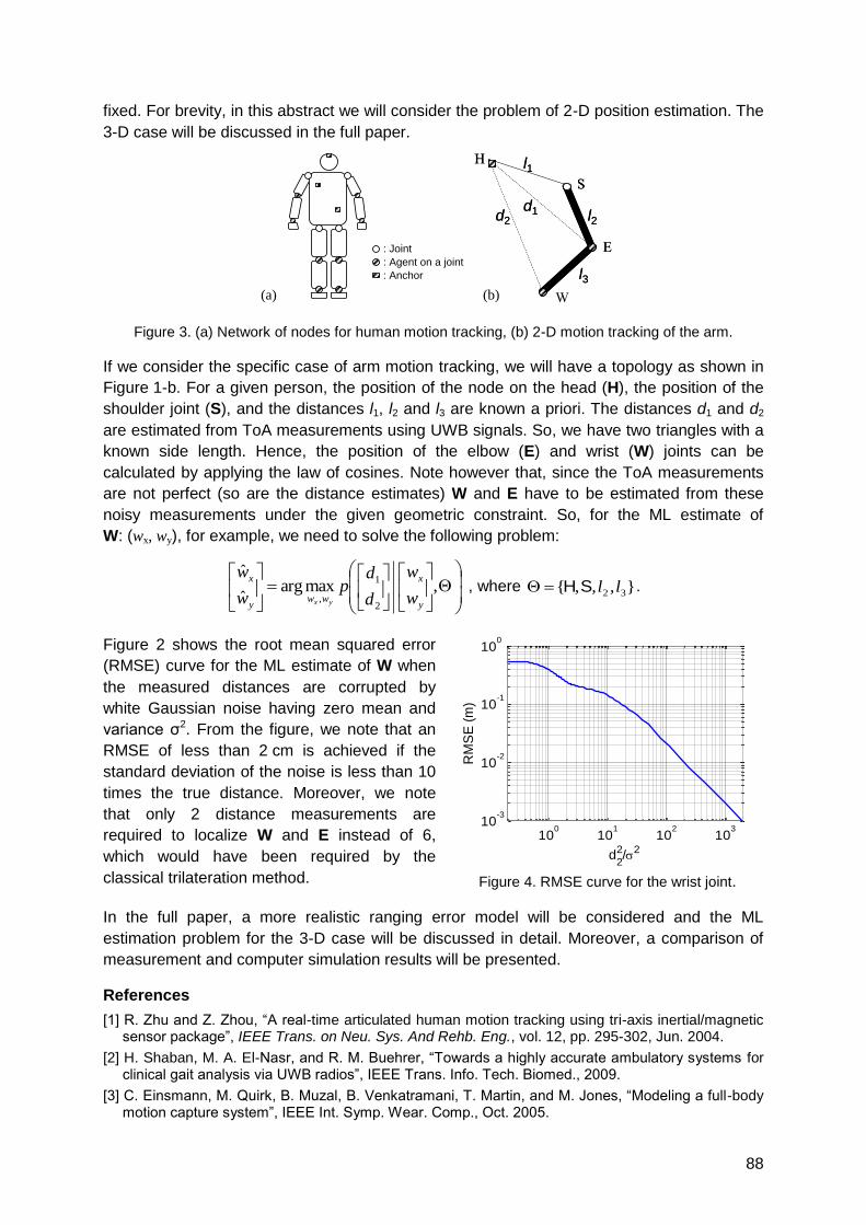
88
fixed. For brevity, in this abstract we will consider the problem of 2-D position estimation. The
3-D case will be discussed in the full paper.
Figure 3. (a) Network of nodes for human motion tracking, (b) 2-D motion tracking of the arm.
If we consider the specific case of arm motion tracking, we will have a topology as shown in
Figure 1-b. For a given person, the position of the node on the head (H), the position of the
shoulder joint (S), and the distances l1, l2 and l3 are known a priori. The distances d1 and d2
are estimated from ToA measurements using UWB signals. So, we have two triangles with a
known side length. Hence, the position of the elbow (E) and wrist (W) joints can be
calculated by applying the law of cosines. Note however that, since the ToA measurements
are not perfect (so are the distance estimates) W and E have to be estimated from these
noisy measurements under the given geometric constraint. So, for the ML estimate of
W: (wx, wy), for example, we need to solve the following problem:
,maxarg
ˆ
ˆ
2
1
,y
x
wwy
x
w
w
d
dp
w
w
yx
, where },,,{ 32 llSH .
Figure 2 shows the root mean squared error
(RMSE) curve for the ML estimate of W when
the measured distances are corrupted by
white Gaussian noise having zero mean and
variance σ2. From the figure, we note that an
RMSE of less than 2 cm is achieved if the
standard deviation of the noise is less than 10
times the true distance. Moreover, we note
that only 2 distance measurements are
required to localize W and E instead of 6,
which would have been required by the
classical trilateration method.
Figure 4. RMSE curve for the wrist joint.
In the full paper, a more realistic ranging error model will be considered and the ML
estimation problem for the 3-D case will be discussed in detail. Moreover, a comparison of
measurement and computer simulation results will be presented.
References
[1] R. Zhu and Z. Zhou, ―A real-time articulated human motion tracking using tri-axis inertial/magnetic sensor package‖, IEEE Trans. on Neu. Sys. And Rehb. Eng., vol. 12, pp. 295-302, Jun. 2004.
[2] H. Shaban, M. A. El-Nasr, and R. M. Buehrer, ―Towards a highly accurate ambulatory systems for clinical gait analysis via UWB radios‖, IEEE Trans. Info. Tech. Biomed., 2009.
[3] C. Einsmann, M. Quirk, B. Muzal, B. Venkatramani, T. Martin, and M. Jones, ―Modeling a full-body motion capture system‖, IEEE Int. Symp. Wear. Comp., Oct. 2005.
d2
d1 l2
S
E
l3
l1H
d2
d1 l2
S
E
l3
l1H
: Joint
: Agent on a joint
: Anchor
(a) W(b)
100
101
102
103
10-3
10-2
10-1
100
d2
2/
2
RM
SE
(m
)
89
A Mathematical Model for a Polarisation Based Orientation Measurement
Principle in Time of Arrival Radio Localisation Systems
Andreas Eidloth, Jörn Thielecke
Fraunhofer IIS, Institute for Integrated Circuits, Nordostpark 93, D-90411 Nuremberg
University of Erlangen-Nuremberg, Am Wolfsmantel 33, D-91058 Erlangen
1 Introduction
There are different types of orientation measurement principles for localisation systems
known in literature. In most cases sensors are used to measure the gravitation and magnetic
field vectors of the earth [1]. From these two vectors the orientation of the object to be
localised can be calculated. Without using sensors it is possible to measure the heading of
an object as tangent to its route. But this method fails, if the localised object is stationary.
Two or more receiver-lines are necessary in time of arrival (TOA) radio localisation systems
to gain orientation information. The relative positions of the receive antennas have to be
known. With two antennas only a direction vector can be calculated; for determination of
orientation at least three antennas are necessary [2].
The rotation around the transmitter-receiver-axis can be measured by a suitable choice of
the antennas at both sides. In GPS right-hand circularly polarised (RHCP) antennas are used
for transmission and reception. Carrier phase measurements show both, changes in distance
and direction, if the GPS-receiver is rotated around the aforementioned axis. Frequency drift,
clock errors and atmospherics are assumed to be eliminated beforehand. To derive
orientation information, the carrier phase measurements have to be decomposed into its
components for changes in distance and orientation. This can be done by using the two GPS
carrier frequencies L1 and L2 [3].
Another approach [4] uses one linearly polarised antenna at the transmitter and two in
opposite direction circularly polarised antennas at the receiver, in order to measure rotations
around the transmitter-receiver-axis simultaneously with changes in distance. It was shown
that distance and rotation components of the measurements can be separated for a special
case, for which only movements along or around the aforementioned axis are considered.
Based on this antenna configuration, a generic model will be given here, utilising the electro-
magnetic field theory. In Section 2 the measurement principle and setup will be explained for
completeness. The theoretical model will be given in Section 3.
2 Measurement Principle and Setup
Figure 5 shows the principle system setup, which is capable of measuring rotations around
the transmitter-receiver-axis. A linearly polarised antenna is mounted on the transmitter at
the left side of the figure. On the right-hand side a localisation receiver with two receiver lines
is placed. One line is connected to a RHCP, the other line to a left-hand circularly polarised
(LHCP) antenna. Both receiver lines are assumed to be synchronised with the transmitter. If
carrier phase measurements are taken at both receiver lines, changes in distance alter the
measured phase angles in the same way. If the transmitter, and therefore the polarisation
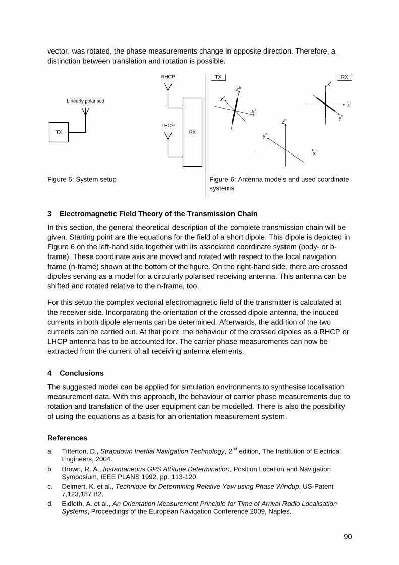
90
vector, was rotated, the phase measurements change in opposite direction. Therefore, a
distinction between translation and rotation is possible.
Figure 5: System setup
Figure 6: Antenna models and used coordinate
systems
3 Electromagnetic Field Theory of the Transmission Chain
In this section, the general theoretical description of the complete transmission chain will be
given. Starting point are the equations for the field of a short dipole. This dipole is depicted in
Figure 6 on the left-hand side together with its associated coordinate system (body- or b-
frame). These coordinate axis are moved and rotated with respect to the local navigation
frame (n-frame) shown at the bottom of the figure. On the right-hand side, there are crossed
dipoles serving as a model for a circularly polarised receiving antenna. This antenna can be
shifted and rotated relative to the n-frame, too.
For this setup the complex vectorial electromagnetic field of the transmitter is calculated at
the receiver side. Incorporating the orientation of the crossed dipole antenna, the induced
currents in both dipole elements can be determined. Afterwards, the addition of the two
currents can be carried out. At that point, the behaviour of the crossed dipoles as a RHCP or
LHCP antenna has to be accounted for. The carrier phase measurements can now be
extracted from the current of all receiving antenna elements.
4 Conclusions
The suggested model can be applied for simulation environments to synthesise localisation
measurement data. With this approach, the behaviour of carrier phase measurements due to
rotation and translation of the user equipment can be modelled. There is also the possibility
of using the equations as a basis for an orientation measurement system.
References
a. Titterton, D., Strapdown Inertial Navigation Technology, 2nd
edition, The Institution of Electrical Engineers, 2004.
b. Brown, R. A., Instantaneous GPS Attitude Determination, Position Location and Navigation Symposium, IEEE PLANS 1992, pp. 113-120.
c. Deimert, K. et al., Technique for Determining Relative Yaw using Phase Windup, US-Patent 7,123,187 B2.
d. Eidloth, A. et al., An Orientation Measurement Principle for Time of Arrival Radio Localisation Systems, Proceedings of the European Navigation Conference 2009, Naples.
Linearly polarised
RHCP
LHCP
TX RX
TX RX
xn
yn
zn
xb
yb
zbx
r
yr
zr
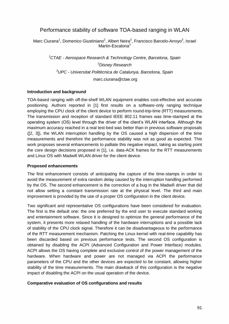
91
Performance stability of software TOA-based ranging in WLAN
Marc Ciurana1, Domenico Giustiniano2, Albert Neira3, Francisco Barcelo-Arroyo3, Israel Martin-Escalona3
1CTAE - Aerospace Research & Technology Centre, Barcelona, Spain
2Disney Research
3UPC - Universitat Politècnica de Catalunya, Barcelona, Spain
Introduction and background
TOA-based ranging with off-the-shelf WLAN equipment enables cost-effective and accurate
positioning. Authors reported in [1] first results on a software-only ranging technique
employing the CPU clock of the client device to perform round-trip-time (RTT) measurements.
The transmission and reception of standard IEEE 802.11 frames was time-stamped at the
operating system (OS) level through the driver of the client‘s WLAN interface. Although the
maximum accuracy reached in a real test-bed was better than in previous software proposals
([2, 3]), the WLAN interruption handling by the OS caused a high dispersion of the time
measurements and therefore the performance stability was not as good as expected. This
work proposes several enhancements to palliate this negative impact, taking as starting point
the core design decisions proposed in [1], i.e. data-ACK frames for the RTT measurements
and Linux OS with Madwifi WLAN driver for the client device.
Proposed enhancements
The first enhancement consists of anticipating the capture of the time-stamps in order to
avoid the measurement of extra random delay caused by the interruption handling performed
by the OS. The second enhancement is the correction of a bug in the Madwifi driver that did
not allow setting a constant transmission rate at the physical level. The third and main
improvement is provided by the use of a proper OS configuration in the client device.
Two significant and representative OS configurations have been considered for evaluation.
The first is the default one: the one preferred by the end user to execute standard working
and entertainment software. Since it is designed to optimize the general performance of the
system, it presents more relaxed handling of the hardware interruptions and a possible lack
of stability of the CPU clock signal. Therefore it can be disadvantageous to the performance
of the RTT measurement mechanism. Patching the Linux kernel with real-time capability has
been discarded based on previous performance tests. The second OS configuration is
obtained by disabling the ACPI (Advanced Configuration and Power Interface) modules.
ACPI allows the OS having complete and exclusive control of the power management of the
hardware. When hardware and power are not managed via ACPI the performance
parameters of the CPU and the other devices are expected to be constant, allowing higher
stability of the time measurements. The main drawback of this configuration is the negative
impact of disabling the ACPI on the usual operation of the device.
Comparative evaluation of OS configurations and results
92
The performance of the enhanced ranging method considering the different OS
configurations is comparatively evaluated. The off-the-shelf employed hardware for the tests
consists of the ranging client device (laptop with a 2 GHz CPU, an Atheros-based WLAN
card, the modified Madwifi driver and the ranging software) and a Netgear D-Link AP. A large
number of series of 1000 RTT measurements are carried out in multiple indoor and outdoor
environments and distances, always with the same conditions for both configurations in order
to guarantee a fair comparison. A first analysis of the measurements corroborates the bigger
time dispersion for the measurements with the default configuration: around 800 CPU clock
cycles for the no-ACPI configuration and around 5500 for the default one.
In order to assess the stability of the RTT statistical parameters, 50 series of measurements
are repeated at different instants of time with the same conditions. The figure depicts the
obtained average values in CPU clock cycles for each series of RTT measurements (i.e.
series 1 to 50 in the abscissa axis). It can be observed that disabling the ACPI allows much
better stability: the deviation of the 50 averages with no-ACPI is 38.869 CPU clock cycles,
involving a maximum ranging error of only 2.59 m. can be caused by the system instability
(four times smaller than with the default configuration). The complete report also
demonstrates that the ranging accuracy is better with the no-ACPI configuration.
Obtained results show that the proposed enhancements employing a no-ACPI OS
configuration allow overcoming the critical and inherent aspect of performance instability in
TOA-based WLAN ranging at OS level. This result opens the challenge of achieving the
same good performance but with the default OS configuration, in order to improve the
practical applicability of the method. The researched approach to achieve this consists of
mitigating the RTT measurement noise due to the ACPI operation, which is demonstrated to
be feasible characterizing this noise by comparing the measurements of both configurations
as first step.
References
[1] M. Ciurana, D. López and F. Barcelo-Arroyo, ―SofTOA: Software Ranging for TOA-Based
Positioning of WLAN Terminals‖, in Proceedings of the International Symposium on Location and
Context Awareness 2009, pp. 207-221.
[2] A. Günther and C. Hoene, ―Measuring Round Trip Times to Determine the Distance Between
WLAN Nodes‖, in Proceedings of Networking 2005, pp. 768-779.
[3] A. Bose and C. H. Foh, "A Practical Path Loss Model for Indoor WiFi Positioning Enhancement,"
in Proceedings of the International Conference on Information, Communications & Signal
Processing (ICICS) 2007, pp. 1-5.
93
Hardware Implementation of a Particle Filter for Location Estimation
Daniel Froß, Jan Langer, André Froß, Marko Rößler, Ulrich Heinkel
Chemnitz University of Technology, Chair for Circuit and System Design, D-09126 Chemnitz
{daniel.fross | jan.langer | andre.fross | marko.roessler | ulrich.heinkel}@etit.tu-chemnitz.de
1 Summary
In this paper we present the hardware implementation of a particle filter for location
estimation. Based on distance information to static network nodes, the filter estimates the
three-dimensional position of a mobile network node. The design has been derived from a
set of formal operation properties and synthesized for an FPGA prototype platform.
Accessed through a serial interface, it can be used as a location estimation core from
microcontrollers with low computational power. The implemented models for state transition
and measurements can be re-parameterized during operation. Due to the chosen design
approach these models can also easily be modified or exchanged in order to match the
application needs. The correct functionality of the implementation has been shown using real
time-of-flight based distance measurements. Therefore, the prototype platform has been
integrated in an existing IEEE 802.15.4a compliant wireless network infrastructure.
2 Introduction
Location awareness is a more and more important issue in wireless networks. Without
additional localization hardware, e.g. GPS receivers, the node's positions need to be inferred
from network internal signal strength, time of flight or angular measurements. Because of the
inherent uncertainty of such measurements, robust estimation techniques have to be applied.
A common method for estimating a system‘s state from noisy observations are Bayes Filters,
where both state and observations are considered as probabilistic functions. Kalman Filters
are a very efficient and popular implementation of the Bayes filter algorithm, modelling state
and observations as unimodal Gaussian distributions. As a drawback, they are limited to
Gaussian errors and systems with linear state transition and observation models. Another
implementation of Bayes filters are particle filters [1]. In contrast to Kalman Filters, arbitrary
distributions can be approximated by a set of random state samples (particles). For reasons
of approximation accuracy, the number of particles has to be large. The resulting
computational effort and memory consumption is not feasible for low power microcontrollers
that are commonly used in wireless sensor networks. In such cases it is desirable to have
computational expensive parts as dedicated hardware components.
3 Filter Implementation
We present a hardware implementation of a particle filter for estimating the 3D position of a
mobile node by incorporating distance information to reference points of known position
(anchor points). The following update is cyclically performed by the filter:
1. Predict a hypothetical position for each particle based on its former position. This step
involves an application specific motion model. In our implementation the mobile node is
assumed to move without any favoured direction. This fact is considered by adding
normal distributed noise with adjustable variance on the expected particle positions.
94
2. Calculate a weight for each particle involving a sensor specific measurement model. In
our case, this model describes the probability of measuring a given distance at the
particular particle position. We consider uncertainties relating to measurement noise and
multipath effects under line-of-sight conditions using a quadratic decreasing weight
function with separately adjustable slew rates for positive and negative distance errors.
3. Generate the final particle set through a low variance resampling procedure of the
hypothetical set from step 1. The probability of drawing each particle is given by its
corresponding weight. This step duplicates particles with large weights while less
important particles are replaced. Thus, the resulting particle set is focused on regions
with high probability.
4. Extract statistical parameters from the resulting particle set. Since we assume unimodal
distributions, mean and covariance parameters over all particles are calculated.
The steps above represent the computational framework of the particle filter. The given
models can be re-parameterized during operation and easily adapted to other application
specific models. The design has been implemented using operation properties, an alternative,
and in some application areas more convenient, design approach [2]. Our tool vhisyn derives
a cycle-accurate register transfer model from a given specification based on a set of
operation properties. The resulting VHDL design description has been synthesized and run
on a Virtex-II Pro (xc2vp30) FPGA platform. The design is connected via the processor local
bus to the embedded Power PC, which implements the serial user interface. The processor
feeds the arriving distance measurements and reference positions into the weight calculation
unit and reads the estimated position mean and covariance values from the design.
4 Results
The correct functionality of the implementation has been shown using real time-of-flight
based distance measurements. Therefore the prototype platform has been integrated in an
existing IEEE 802.15.4a compliant wireless network infrastructure. Distances between a
mobile and several static network nodes of known position are cyclically measured and
evaluated by the filter. The estimated position is read out and visualized using the 3D
rendering library Panda3D. In our setup, we reach typical estimation accuracies of about 1m.
The design runs at a maximum clock frequency of 25 MHz. With 8192 particles and 3 clock
cycles processing delay per particle on average, a filter update is performed within less than
1 millisecond. In contrast, the comparable update performed by the reference software
implementation on an ARM7 microcontroller needs 660 milliseconds. The design uses 6011
of 13696 slices, that is 43% of the FPGA resources.
5 Acknowledgements
This research work was supported in part by the German Federal Ministry of Education and
Research (Bundesministerium für Bildung und Forschung) in the project HERKULES under
the contract number 01 M 3082 and the project InnoProfile under contract number 03 IP 505.
6 References
[1] S. Thrun, W. Burgard, D. Fox, Probabilistic Robotics. MIT Press 2005, ch. 4.3, pp. 96-113.
[2] J. Langer, U. Heinkel, High Level Synthesis using Operational Properties, 2009, Forum on
Specification and Design Languages (FDL).
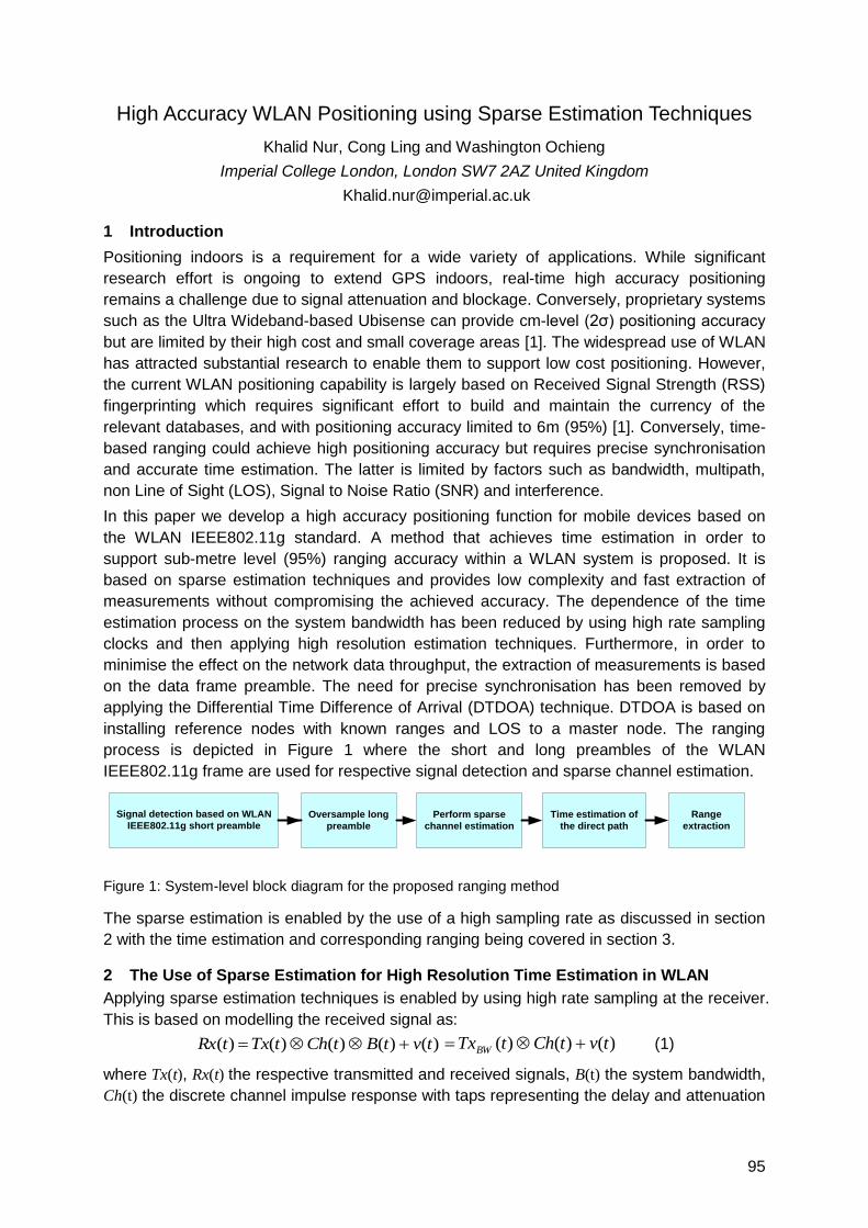
95
High Accuracy WLAN Positioning using Sparse Estimation Techniques
Khalid Nur, Cong Ling and Washington Ochieng
Imperial College London, London SW7 2AZ United Kingdom
1 Introduction
Positioning indoors is a requirement for a wide variety of applications. While significant
research effort is ongoing to extend GPS indoors, real-time high accuracy positioning
remains a challenge due to signal attenuation and blockage. Conversely, proprietary systems
such as the Ultra Wideband-based Ubisense can provide cm-level (2σ) positioning accuracy
but are limited by their high cost and small coverage areas [1]. The widespread use of WLAN
has attracted substantial research to enable them to support low cost positioning. However,
the current WLAN positioning capability is largely based on Received Signal Strength (RSS)
fingerprinting which requires significant effort to build and maintain the currency of the
relevant databases, and with positioning accuracy limited to 6m (95%) [1]. Conversely, time-
based ranging could achieve high positioning accuracy but requires precise synchronisation
and accurate time estimation. The latter is limited by factors such as bandwidth, multipath,
non Line of Sight (LOS), Signal to Noise Ratio (SNR) and interference.
In this paper we develop a high accuracy positioning function for mobile devices based on
the WLAN IEEE802.11g standard. A method that achieves time estimation in order to
support sub-metre level (95%) ranging accuracy within a WLAN system is proposed. It is
based on sparse estimation techniques and provides low complexity and fast extraction of
measurements without compromising the achieved accuracy. The dependence of the time
estimation process on the system bandwidth has been reduced by using high rate sampling
clocks and then applying high resolution estimation techniques. Furthermore, in order to
minimise the effect on the network data throughput, the extraction of measurements is based
on the data frame preamble. The need for precise synchronisation has been removed by
applying the Differential Time Difference of Arrival (DTDOA) technique. DTDOA is based on
installing reference nodes with known ranges and LOS to a master node. The ranging
process is depicted in Figure 1 where the short and long preambles of the WLAN
IEEE802.11g frame are used for respective signal detection and sparse channel estimation.
Perform sparse
channel estimation
Oversample long
preamble
Signal detection based on WLAN
IEEE802.11g short preambleTime estimation of
the direct path
Range
extraction
Figure 1: System-level block diagram for the proposed ranging method
The sparse estimation is enabled by the use of a high sampling rate as discussed in section
2 with the time estimation and corresponding ranging being covered in section 3.
2 The Use of Sparse Estimation for High Resolution Time Estimation in WLAN
Applying sparse estimation techniques is enabled by using high rate sampling at the receiver.
This is based on modelling the received signal as:
)()()()()( tvtBtChtTxtRx )()()( tvtChtTxBW (1)
where Tx(t), Rx(t) the respective transmitted and received signals, B(t) the system bandwidth,
Ch(t) the discrete channel impulse response with taps representing the delay and attenuation
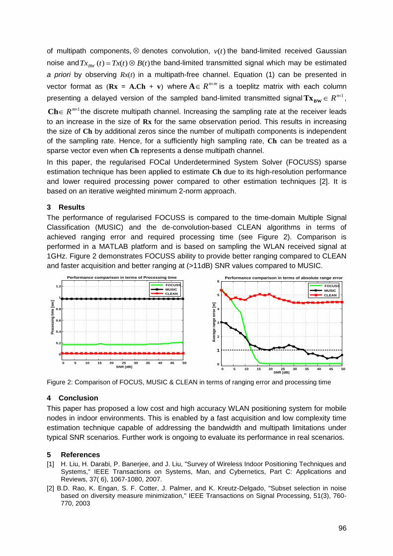
96
of multipath components, denotes convolution, )(tv the band-limited received Gaussian
noise and )()()( tBtTxtTxBW the band-limited transmitted signal which may be estimated
a priori by observing Rx(t) in a multipath-free channel. Equation (1) can be presented in
vector format as (Rx = A.Ch + v) wheremnR A is a toeplitz matrix with each column
presenting a delayed version of the sampled band-limited transmitted signal1 nRBWTx ,
1 mRCh the discrete multipath channel. Increasing the sampling rate at the receiver leads
to an increase in the size of Rx for the same observation period. This results in increasing
the size of Ch by additional zeros since the number of multipath components is independent
of the sampling rate. Hence, for a sufficiently high sampling rate, Ch can be treated as a
sparse vector even when Ch represents a dense multipath channel.
In this paper, the regularised FOCal Underdetermined System Solver (FOCUSS) sparse
estimation technique has been applied to estimate Ch due to its high-resolution performance
and lower required processing power compared to other estimation techniques [2]. It is
based on an iterative weighted minimum 2-norm approach.
3 Results
The performance of regularised FOCUSS is compared to the time-domain Multiple Signal
Classification (MUSIC) and the de-convolution-based CLEAN algorithms in terms of
achieved ranging error and required processing time (see Figure 2). Comparison is
performed in a MATLAB platform and is based on sampling the WLAN received signal at
1GHz. Figure 2 demonstrates FOCUSS ability to provide better ranging compared to CLEAN
and faster acquisition and better ranging at (>11dB) SNR values compared to MUSIC.
0 5 10 15 20 25 30 35 40 45 50
0
0.2
0.4
0.6
0.8
1
1.2
SNR [dB]
Pro
cess
ing
tim
e [s
ec]
FOCUSS
MUSIC
CLEAN
Performance comparison in terms of Processing time
0 5 10 15 20 25 30 35 40 45 50
0
1
2
3
4
5
6
SNR [dB]
Av
era
ge
ra
ng
e e
rro
r [m
]
FOCUSS
MUSIC
CLEAN
Performance comparison in terms of absolute range error
Figure 2: Comparison of FOCUS, MUSIC & CLEAN in terms of ranging error and processing time
4 Conclusion
This paper has proposed a low cost and high accuracy WLAN positioning system for mobile
nodes in indoor environments. This is enabled by a fast acquisition and low complexity time
estimation technique capable of addressing the bandwidth and multipath limitations under
typical SNR scenarios. Further work is ongoing to evaluate its performance in real scenarios.
5 References
[1] H. Liu, H. Darabi, P. Banerjee, and J. Liu, "Survey of Wireless Indoor Positioning Techniques and Systems," IEEE Transactions on Systems, Man, and Cybernetics, Part C: Applications and Reviews, 37( 6), 1067-1080, 2007.
[2] B.D. Rao, K. Engan, S. F. Cotter, J. Palmer, and K. Kreutz-Delgado, "Subset selection in noise based on diversity measure minimization," IEEE Transactions on Signal Processing, 51(3), 760-770, 2003
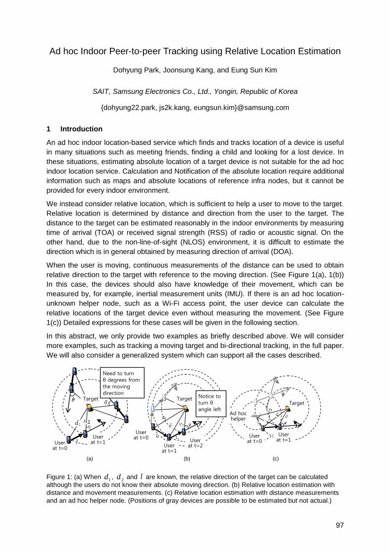
97
Ad hoc Indoor Peer-to-peer Tracking using Relative Location Estimation
Dohyung Park, Joonsung Kang, and Eung Sun Kim
SAIT, Samsung Electronics Co., Ltd., Yongin, Republic of Korea
{dohyung22.park, js2k.kang, eungsun.kim}@samsung.com
1 Introduction
An ad hoc indoor location-based service which finds and tracks location of a device is useful
in many situations such as meeting friends, finding a child and looking for a lost device. In
these situations, estimating absolute location of a target device is not suitable for the ad hoc
indoor location service. Calculation and Notification of the absolute location require additional
information such as maps and absolute locations of reference infra nodes, but it cannot be
provided for every indoor environment.
We instead consider relative location, which is sufficient to help a user to move to the target.
Relative location is determined by distance and direction from the user to the target. The
distance to the target can be estimated reasonably in the indoor environments by measuring
time of arrival (TOA) or received signal strength (RSS) of radio or acoustic signal. On the
other hand, due to the non-line-of-sight (NLOS) environment, it is difficult to estimate the
direction which is in general obtained by measuring direction of arrival (DOA).
When the user is moving, continuous measurements of the distance can be used to obtain
relative direction to the target with reference to the moving direction. (See Figure 1(a), 1(b))
In this case, the devices should also have knowledge of their movement, which can be
measured by, for example, inertial measurement units (IMU). If there is an ad hoc location-
unknown helper node, such as a Wi-Fi access point, the user device can calculate the
relative locations of the target device even without measuring the movement. (See Figure
1(c)) Detailed expressions for these cases will be given in the following section.
In this abstract, we only provide two examples as briefly described above. We will consider
more examples, such as tracking a moving target and bi-directional tracking, in the full paper.
We will also consider a generalized system which can support all the cases described.
Figure 1: (a) When 1d ,
2d and l are known, the relative direction of the target can be calculated
although the users do not know their absolute moving direction. (b) Relative location estimation with
distance and movement measurements. (c) Relative location estimation with distance measurements
and an ad hoc helper node. (Positions of gray devices are possible to be estimated but not actual.)
Notice to turn θ angle left
(a)
(a)a
)
(b)
(a)a
)
(c)
(a)a
)
User at t=0
User at t=1
Target
Need to turn θ degrees from
the moving direction
Target
User at t=0
User
at t=1
User at t=0
User at t=1
Ad hoc helper
Target
User at t=2
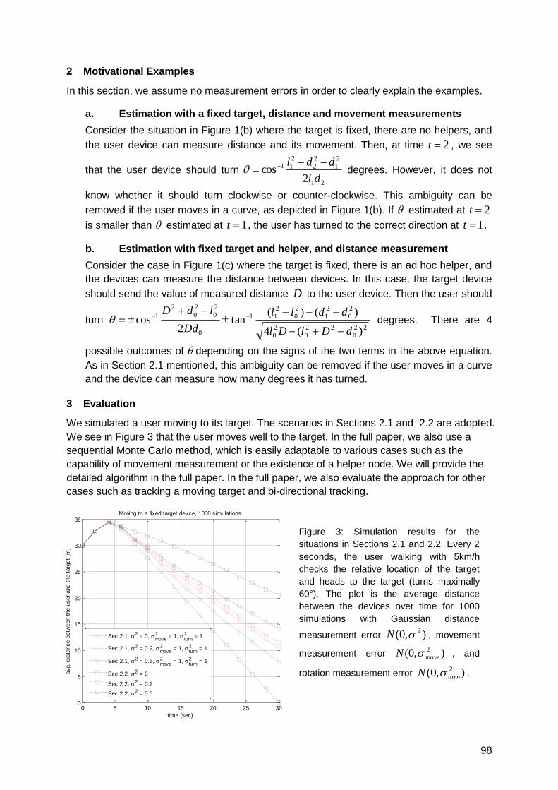
98
2 Motivational Examples
In this section, we assume no measurement errors in order to clearly explain the examples.
a. Estimation with a fixed target, distance and movement measurements
Consider the situation in Figure 1(b) where the target is fixed, there are no helpers, and
the user device can measure distance and its movement. Then, at time 2t , we see
that the user device should turn 21
2
1
2
2
2
11
2cos
dl
ddl degrees. However, it does not
know whether it should turn clockwise or counter-clockwise. This ambiguity can be
removed if the user moves in a curve, as depicted in Figure 1(b). If estimated at 2t
is smaller than estimated at 1t , the user has turned to the correct direction at 1t .
b. Estimation with fixed target and helper, and distance measurement
Consider the case in Figure 1(c) where the target is fixed, there is an ad hoc helper, and
the devices can measure the distance between devices. In this case, the target device
should send the value of measured distance D to the user device. Then the user should
turn 22
0
22
0
2
0
2
0
2
1
2
0
2
11
0
2
0
2
0
2
1
)(4
)()(tan
2cos
dDlDl
ddll
Dd
ldD
degrees. There are 4
possible outcomes of depending on the signs of the two terms in the above equation.
As in Section 2.1 mentioned, this ambiguity can be removed if the user moves in a curve
and the device can measure how many degrees it has turned.
3 Evaluation
We simulated a user moving to its target. The scenarios in Sections 2.1 and 2.2 are adopted.
We see in Figure 3 that the user moves well to the target. In the full paper, we also use a
sequential Monte Carlo method, which is easily adaptable to various cases such as the
capability of movement measurement or the existence of a helper node. We will provide the
detailed algorithm in the full paper. In the full paper, we also evaluate the approach for other
cases such as tracking a moving target and bi-directional tracking.
0 5 10 15 20 25 300
5
10
15
20
25
30
35
avg.
dis
tance b
etw
een t
he u
ser
and t
he t
arg
et
(m)
time (sec)
Moving to a fixed target device, 1000 simulations
Sec 2.1, 2 = 0, move2 = 1,
turn2 = 1
Sec 2.1, 2 = 0.2, move2 = 1,
turn2 = 1
Sec 2.1, 2 = 0.5, move2 = 1,
turn2 = 1
Sec 2.2, 2 = 0
Sec 2.2, 2 = 0.2
Sec 2.2, 2 = 0.5
Figure 3: Simulation results for the
situations in Sections 2.1 and 2.2. Every 2
seconds, the user walking with 5km/h
checks the relative location of the target
and heads to the target (turns maximally
60°). The plot is the average distance
between the devices over time for 1000
simulations with Gaussian distance
measurement error ),0( 2N , movement
measurement error ),0( 2
moveN , and
rotation measurement error ),0( 2
turnN .
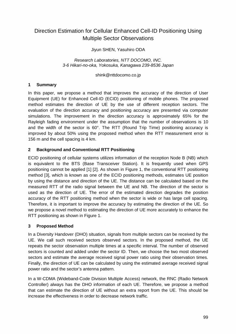
99
Direction Estimation for Cellular Enhanced Cell-ID Positioning Using
Multiple Sector Observations
Jiyun SHEN, Yasuhiro ODA
Research Laboratories, NTT DOCOMO, INC. 3-6 Hikari-no-oka, Yokosuka, Kanagawa 239-8536 Japan
1 Summary
In this paper, we propose a method that improves the accuracy of the direction of User
Equipment (UE) for Enhanced Cell-ID (ECID) positioning of mobile phones. The proposed
method estimates the direction of UE by the use of different reception sectors. The
evaluation of the direction accuracy and positioning accuracy are presented via computer
simulations. The improvement in the direction accuracy is approximately 65% for the
Rayleigh fading environment under the assumption that the number of observations is 10
and the width of the sector is 60°. The RTT (Round Trip Time) positioning accuracy is
improved by about 50% using the proposed method when the RTT measurement error is
156 m and the cell spacing is 4 km.
2 Background and Conventional RTT Positioning
ECID positioning of cellular systems utilizes information of the reception Node B (NB) which
is equivalent to the BTS (Base Transceiver Station). It is frequently used when GPS
positioning cannot be applied [1] [2]. As shown in Figure 1, the conventional RTT positioning
method [3], which is known as one of the ECID positioning methods, estimates UE position
by using the distance and direction of the UE. The distance can be calculated based on the
measured RTT of the radio signal between the UE and NB. The direction of the sector is
used as the direction of UE. The error of the estimated direction degrades the position
accuracy of the RTT positioning method when the sector is wide or has large cell spacing.
Therefore, it is important to improve the accuracy by estimating the direction of the UE. So
we propose a novel method to estimating the direction of UE more accurately to enhance the
RTT positioning as shown in Figure 1.
3 Proposed Method
In a Diversity Handover (DHO) situation, signals from multiple sectors can be received by the
UE. We call such received sectors observed sectors. In the proposed method, the UE
repeats the sector observation multiple times at a specific interval. The number of observed
sectors is counted and added under the sector ID. Then, we choose the two most observed
sectors and estimate the average received signal power ratio using their observation times.
Finally, the direction of UE can be calculated by using the estimated average received signal
power ratio and the sector‘s antenna pattern.
In a W-CDMA (Wideband-Code Division Multiple Access) network, the RNC (Radio Network
Controller) always has the DHO information of each UE. Therefore, we propose a method
that can estimate the direction of UE without an extra report from the UE. This should be
increase the effectiveness in order to decrease network traffic.
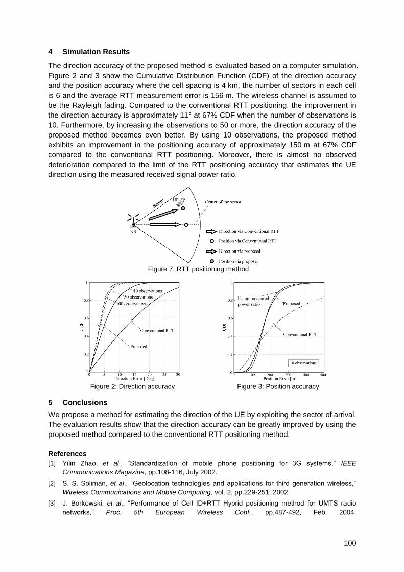
100
4 Simulation Results
The direction accuracy of the proposed method is evaluated based on a computer simulation.
Figure 2 and 3 show the Cumulative Distribution Function (CDF) of the direction accuracy
and the position accuracy where the cell spacing is 4 km, the number of sectors in each cell
is 6 and the average RTT measurement error is 156 m. The wireless channel is assumed to
be the Rayleigh fading. Compared to the conventional RTT positioning, the improvement in
the direction accuracy is approximately 11° at 67% CDF when the number of observations is
10. Furthermore, by increasing the observations to 50 or more, the direction accuracy of the
proposed method becomes even better. By using 10 observations, the proposed method
exhibits an improvement in the positioning accuracy of approximately 150 m at 67% CDF
compared to the conventional RTT positioning. Moreover, there is almost no observed
deterioration compared to the limit of the RTT positioning accuracy that estimates the UE
direction using the measured received signal power ratio.
Figure 7: RTT positioning method
Figure 2: Direction accuracy Figure 3: Position accuracy
5 Conclusions
We propose a method for estimating the direction of the UE by exploiting the sector of arrival.
The evaluation results show that the direction accuracy can be greatly improved by using the
proposed method compared to the conventional RTT positioning method.
References
[1] Yilin Zhao, et al., ―Standardization of mobile phone positioning for 3G systems,‖ IEEE
Communications Magazine, pp.108-116, July 2002.
[2] S. S. Soliman, et al., ―Geolocation technologies and applications for third generation wireless,‖
Wireless Communications and Mobile Computing, vol. 2, pp.229-251, 2002.
[3] J. Borkowski, et al., ―Performance of Cell ID+RTT Hybrid positioning method for UMTS radio
networks,‖ Proc. 5th European Wireless Conf., pp.487-492, Feb. 2004.

101
Localization, Algorithms for WSN
Auditorium G7
Friday, September 17, 08:15 – 09:45 & 10:15 – 12:00
Beschreibung

103
A comparison of multidimensional scaling and non-linear regression for
positioning applications.
Carl Ellis, Mike Hazas
Computing Department, Infolab21, South Drive, Lancaster Univerisity, Lancaster, LA1 4WA
United Kingdom
{carl.ellis, hazas}@comp.lancs.ac.uk
For locating a set of stationary devices, algorithms such as MDS-MAP have been favoured
by the sensor network community [4,5] because of their low computational complexity. Whilst
comparisons for complexity and performance have been done for other algorithms, non-
linear regression has been neglected. The authors find that it is not much more expensive,
and can yield significantly better accuracy for sensor network localisation.
Algorithms. MDS-MAP [4] takes a block of measurements and calculates the NxN matrix of
dissimilarities, which is the distances between each pair of devices. Those which are
missing (i.e. which are not available via direct sensor measurement) are then filled in using a
shortest-path algorithm, such as Floyd-Warshall. Once the dissimilarity matrix is complete,
multidimensional scaling is performed which reduces the NxN matrix into a 2xN coordinate
space using a form of isotonic regression.
Non-linear regression is a model-based fitting algorithm which takes the given
measurements by a device and then, using a minimisation function such as Levenburg-
Marquardt [3], performs non-linear least squares to produce a solution which best fits the
model. This works by iteratively regressing the solution until the residual squared error is
lower than a given threshold. For our localisation scenarios we have found the number of
iterations to be between 3 and 7.
Complexity. MDS-MAP requires two main operations: computing shortest paths, and
multidimensional scaling. If we take k as the number of devices in a neighbourhood, the
complexity of the Floyd-Warshall shortest path algorithm is 2k3 + 6k2 + 6k + 2.
Multidimensional scaling has a time complexity of 36k3 + 110k2 +114k + 39, mostly stemming
from eigenvalue decomposition. This brings the overall time complexity of MDS-MAP to 38k3
+ 116k2 + 120k + 41 as found by Bischoff et al [1].
Non-linear regression using Levenburg-Marquardt can be implemented efficiently using well-
known algorithms, such as those outlined in Numerical Recipes in C. Using code analysis,
the time complexity was found to be 276k3 – 460k2 +756k – 287, where k is the number of
nodes in the neighbourhood.
From the above comparison it is easy to see that non-linear regression is almost 8 times
more expensive than MDS-MAP, in terms of the total number of operations required. But it is
worth noting that MDS-MAP is limited to distance measures only. Non-linear regression uses
parametric modelling and as such can use any mixture of metrics, such as range (time
difference of arrival), pseudorange (time of arrival), and bearing (angle of arrival), to augment
its solution.
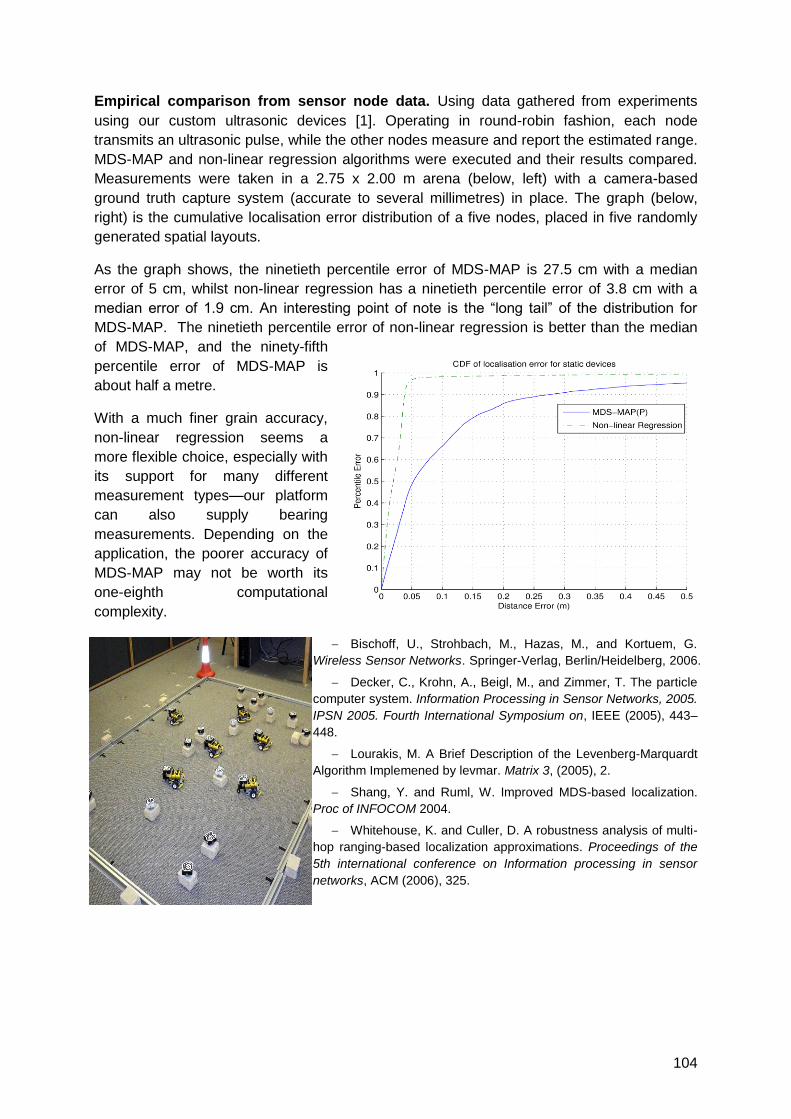
104
Empirical comparison from sensor node data. Using data gathered from experiments
using our custom ultrasonic devices [1]. Operating in round-robin fashion, each node
transmits an ultrasonic pulse, while the other nodes measure and report the estimated range.
MDS-MAP and non-linear regression algorithms were executed and their results compared.
Measurements were taken in a 2.75 x 2.00 m arena (below, left) with a camera-based
ground truth capture system (accurate to several millimetres) in place. The graph (below,
right) is the cumulative localisation error distribution of a five nodes, placed in five randomly
generated spatial layouts.
As the graph shows, the ninetieth percentile error of MDS-MAP is 27.5 cm with a median
error of 5 cm, whilst non-linear regression has a ninetieth percentile error of 3.8 cm with a
median error of 1.9 cm. An interesting point of note is the ―long tail‖ of the distribution for
MDS-MAP. The ninetieth percentile error of non-linear regression is better than the median
of MDS-MAP, and the ninety-fifth
percentile error of MDS-MAP is
about half a metre.
With a much finer grain accuracy,
non-linear regression seems a
more flexible choice, especially with
its support for many different
measurement types—our platform
can also supply bearing
measurements. Depending on the
application, the poorer accuracy of
MDS-MAP may not be worth its
one-eighth computational
complexity.
Bischoff, U., Strohbach, M., Hazas, M., and Kortuem, G.
Wireless Sensor Networks. Springer-Verlag, Berlin/Heidelberg, 2006.
Decker, C., Krohn, A., Beigl, M., and Zimmer, T. The particle
computer system. Information Processing in Sensor Networks, 2005.
IPSN 2005. Fourth International Symposium on, IEEE (2005), 443–
448.
Lourakis, M. A Brief Description of the Levenberg-Marquardt
Algorithm Implemened by levmar. Matrix 3, (2005), 2.
Shang, Y. and Ruml, W. Improved MDS-based localization.
Proc of INFOCOM 2004.
Whitehouse, K. and Culler, D. A robustness analysis of multi-
hop ranging-based localization approximations. Proceedings of the
5th international conference on Information processing in sensor
networks, ACM (2006), 325.
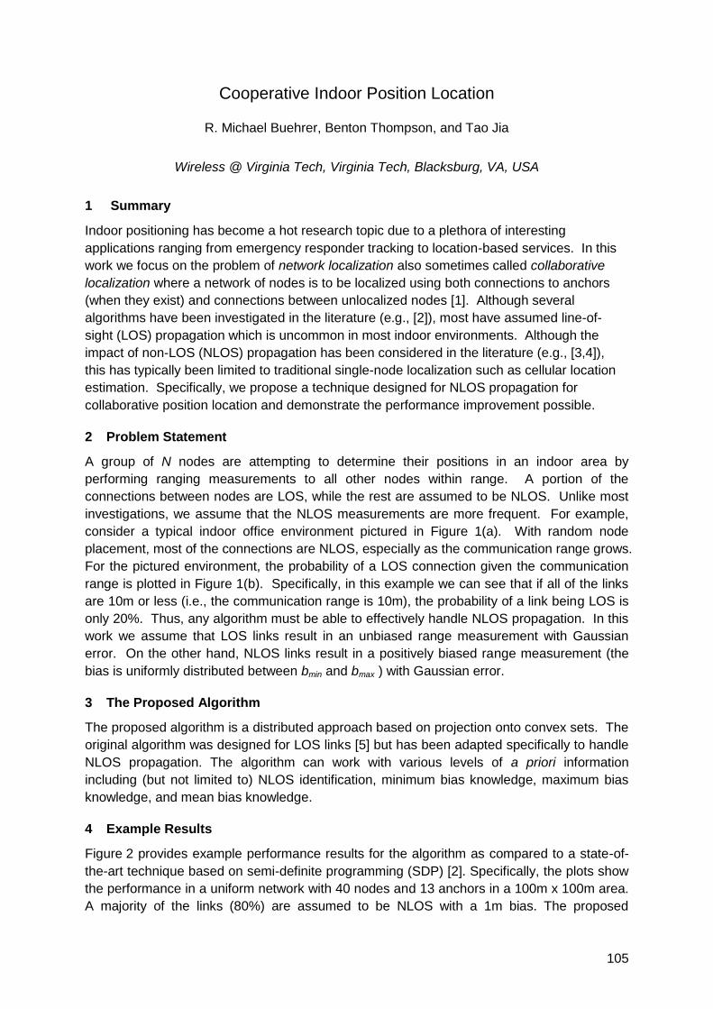
105
Cooperative Indoor Position Location
R. Michael Buehrer, Benton Thompson, and Tao Jia
Wireless @ Virginia Tech, Virginia Tech, Blacksburg, VA, USA
1 Summary
Indoor positioning has become a hot research topic due to a plethora of interesting
applications ranging from emergency responder tracking to location-based services. In this
work we focus on the problem of network localization also sometimes called collaborative
localization where a network of nodes is to be localized using both connections to anchors
(when they exist) and connections between unlocalized nodes [1]. Although several
algorithms have been investigated in the literature (e.g., [2]), most have assumed line-of-
sight (LOS) propagation which is uncommon in most indoor environments. Although the
impact of non-LOS (NLOS) propagation has been considered in the literature (e.g., [3,4]),
this has typically been limited to traditional single-node localization such as cellular location
estimation. Specifically, we propose a technique designed for NLOS propagation for
collaborative position location and demonstrate the performance improvement possible.
2 Problem Statement
A group of N nodes are attempting to determine their positions in an indoor area by
performing ranging measurements to all other nodes within range. A portion of the
connections between nodes are LOS, while the rest are assumed to be NLOS. Unlike most
investigations, we assume that the NLOS measurements are more frequent. For example,
consider a typical indoor office environment pictured in Figure 1(a). With random node
placement, most of the connections are NLOS, especially as the communication range grows.
For the pictured environment, the probability of a LOS connection given the communication
range is plotted in Figure 1(b). Specifically, in this example we can see that if all of the links
are 10m or less (i.e., the communication range is 10m), the probability of a link being LOS is
only 20%. Thus, any algorithm must be able to effectively handle NLOS propagation. In this
work we assume that LOS links result in an unbiased range measurement with Gaussian
error. On the other hand, NLOS links result in a positively biased range measurement (the
bias is uniformly distributed between bmin and bmax ) with Gaussian error.
3 The Proposed Algorithm
The proposed algorithm is a distributed approach based on projection onto convex sets. The
original algorithm was designed for LOS links [5] but has been adapted specifically to handle
NLOS propagation. The algorithm can work with various levels of a priori information
including (but not limited to) NLOS identification, minimum bias knowledge, maximum bias
knowledge, and mean bias knowledge.
4 Example Results
Figure 2 provides example performance results for the algorithm as compared to a state-of-
the-art technique based on semi-definite programming (SDP) [2]. Specifically, the plots show
the performance in a uniform network with 40 nodes and 13 anchors in a 100m x 100m area.
A majority of the links (80%) are assumed to be NLOS with a 1m bias. The proposed
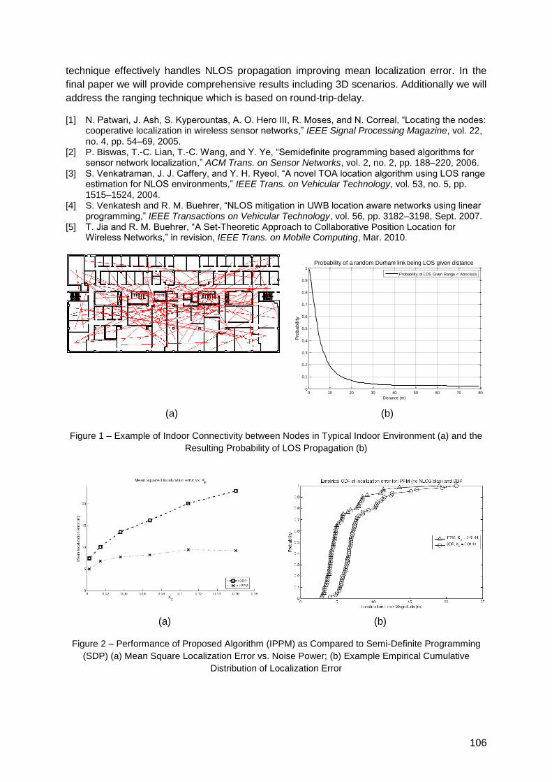
106
technique effectively handles NLOS propagation improving mean localization error. In the
final paper we will provide comprehensive results including 3D scenarios. Additionally we will
address the ranging technique which is based on round-trip-delay.
[1] N. Patwari, J. Ash, S. Kyperountas, A. O. Hero III, R. Moses, and N. Correal, ―Locating the nodes: cooperative localization in wireless sensor networks,‖ IEEE Signal Processing Magazine, vol. 22, no. 4, pp. 54–69, 2005.
[2] P. Biswas, T.-C. Lian, T.-C. Wang, and Y. Ye, ―Semidefinite programming based algorithms for sensor network localization,‖ ACM Trans. on Sensor Networks, vol. 2, no. 2, pp. 188–220, 2006.
[3] S. Venkatraman, J. J. Caffery, and Y. H. Ryeol, ―A novel TOA location algorithm using LOS range estimation for NLOS environments,‖ IEEE Trans. on Vehicular Technology, vol. 53, no. 5, pp. 1515–1524, 2004.
[4] S. Venkatesh and R. M. Buehrer, ―NLOS mitigation in UWB location aware networks using linear programming,‖ IEEE Transactions on Vehicular Technology, vol. 56, pp. 3182–3198, Sept. 2007.
[5] T. Jia and R. M. Buehrer, ―A Set-Theoretic Approach to Collaborative Position Location for Wireless Networks,‖ in revision, IEEE Trans. on Mobile Computing, Mar. 2010.
(a) (b)
Figure 1 – Example of Indoor Connectivity between Nodes in Typical Indoor Environment (a) and the
Resulting Probability of LOS Propagation (b)
(a) (b)
Figure 2 – Performance of Proposed Algorithm (IPPM) as Compared to Semi-Definite Programming
(SDP) (a) Mean Square Localization Error vs. Noise Power; (b) Example Empirical Cumulative
Distribution of Localization Error
0 10 20 30 40 50 60 70 800
0.1
0.2
0.3
0.4
0.5
0.6
0.7
0.8
0.9
1
Distance (m)
Pro
ba
bility
Probability of a random Durham link being LOS given distance
Probability of LOS Given Range < Abscissa
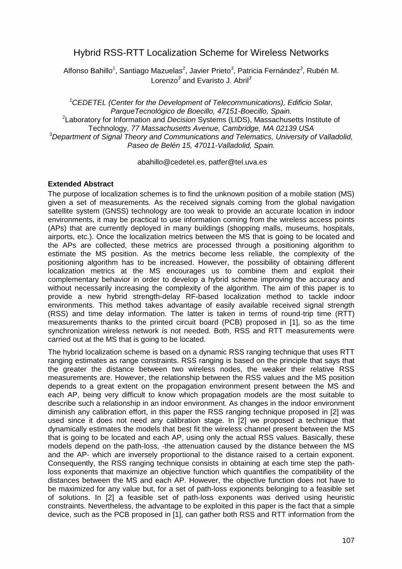
107
Hybrid RSS-RTT Localization Scheme for Wireless Networks
Alfonso Bahillo1, Santiago Mazuelas2, Javier Prieto3, Patricia Fernández3, Rubén M.
Lorenzo3 and Evaristo J. Abril3
1CEDETEL (Center for the Development of Telecommunications), Edificio Solar, ParqueTecnológico de Boecillo, 47151-Boecillo, Spain.
2Laboratory for Information and Decision Systems (LIDS), Massachusetts Institute of Technology, 77 Massachusetts Avenue, Cambridge, MA 02139 USA
3Department of Signal Theory and Communications and Telematics, University of Valladolid, Paseo de Belén 15, 47011-Valladolid, Spain.
[email protected], [email protected]
Extended Abstract
The purpose of localization schemes is to find the unknown position of a mobile station (MS) given a set of measurements. As the received signals coming from the global navigation satellite system (GNSS) technology are too weak to provide an accurate location in indoor environments, it may be practical to use information coming from the wireless access points (APs) that are currently deployed in many buildings (shopping malls, museums, hospitals, airports, etc.). Once the localization metrics between the MS that is going to be located and the APs are collected, these metrics are processed through a positioning algorithm to estimate the MS position. As the metrics become less reliable, the complexity of the positioning algorithm has to be increased. However, the possibility of obtaining different localization metrics at the MS encourages us to combine them and exploit their complementary behavior in order to develop a hybrid scheme improving the accuracy and without necessarily increasing the complexity of the algorithm. The aim of this paper is to provide a new hybrid strength-delay RF-based localization method to tackle indoor environments. This method takes advantage of easily available received signal strength (RSS) and time delay information. The latter is taken in terms of round-trip time (RTT) measurements thanks to the printed circuit board (PCB) proposed in [1], so as the time synchronization wireless network is not needed. Both, RSS and RTT measurements were carried out at the MS that is going to be located.
The hybrid localization scheme is based on a dynamic RSS ranging technique that uses RTT ranging estimates as range constraints. RSS ranging is based on the principle that says that the greater the distance between two wireless nodes, the weaker their relative RSS measurements are. However, the relationship between the RSS values and the MS position depends to a great extent on the propagation environment present between the MS and each AP, being very difficult to know which propagation models are the most suitable to describe such a relationship in an indoor environment. As changes in the indoor environment diminish any calibration effort, in this paper the RSS ranging technique proposed in [2] was used since it does not need any calibration stage. In [2] we proposed a technique that dynamically estimates the models that best fit the wireless channel present between the MS that is going to be located and each AP, using only the actual RSS values. Basically, these models depend on the path-loss, -the attenuation caused by the distance between the MS and the AP- which are inversely proportional to the distance raised to a certain exponent. Consequently, the RSS ranging technique consists in obtaining at each time step the path-loss exponents that maximize an objective function which quantifies the compatibility of the distances between the MS and each AP. However, the objective function does not have to be maximized for any value but, for a set of path-loss exponents belonging to a feasible set of solutions. In [2] a feasible set of path-loss exponents was derived using heuristic constraints. Nevertheless, the advantage to be exploited in this paper is the fact that a simple device, such as the PCB proposed in [1], can gather both RSS and RTT information from the
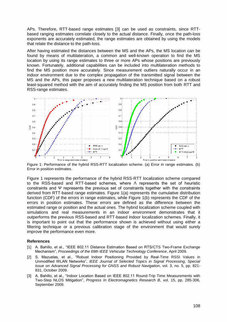
108
APs. Therefore, RTT-based range estimates [3] can be used as constraints, since RTT-based ranging estimates correlate closely to the actual distance. Finally, once the path-loss exponents are accurately estimated, the range estimates are obtained by using the models that relate the distance to the path-loss.
After having estimated the distances between the MS and the APs, the MS location can be found by means of multilateration, a common and well-known operation to find the MS location by using its range estimates to three or more APs whose positions are previously known. Fortunately, additional capabilities can be included into multilateration methods to find the MS position more accurately. Since measurement outliers naturally occur in an indoor environment due to the complex propagation of the transmitted signal between the MS and the APs, this paper proposes a new multilateration technique based on a robust least-squared method with the aim of accurately finding the MS position from both RTT and RSS-range estimates.
Figure 1: Performance of the hybrid RSS-RTT localization scheme. (a) Error in range estimates. (b) Error in position estimates.
Figure 1 represents the performance of the hybrid RSS-RTT localization scheme compared to the RSS-based and RTT-based schemes, where Λ represents the set of heuristic constraints and Ψ represents the previous set of constraints together with the constraints derived from RTT-based range estimates. Figure 1(a) represents the cumulative distribution function (CDF) of the errors in range estimates, while Figure 1(b) represents the CDF of the errors in position estimates. These errors are defined as the difference between the estimated range or position and the actual ones. The hybrid localization scheme coupled with simulations and real measurements in an indoor environment demonstrates that it outperforms the previous RSS-based and RTT-based indoor localization schemes. Finally, it is important to point out that the performance shown is achieved without using either a filtering technique or a previous calibration stage of the environment that would surely improve the performance even more. References
[1] A. Bahillo, et al., ―IEEE 802.11 Distance Estimation Based on RTS/CTS Two-Frame Exchange Mechanism‖, Proceedings of the 69th IEEE Vehicular Technology Conference, April 2009.
[2] S. Mazuelas, et al., ―Robust Indoor Positioning Provided by Real-Time RSSI Values in Unmodified WLAN Networks‖, IEEE Journal of Selected Topics in Signal Processing, Special issue on Advanced Signal Processing for GNSS and Robust Navigation, vol. 3, no. 5, pp. 821-831, October 2009.
[3] A. Bahillo, et al., ―Indoor Location Based on IEEE 802.11 Round-Trip Time Measurements with Two-Step NLOS Mitigation‖, Progress In Electromagnetics Research B, vol. 15, pp. 285-306, September 2009.
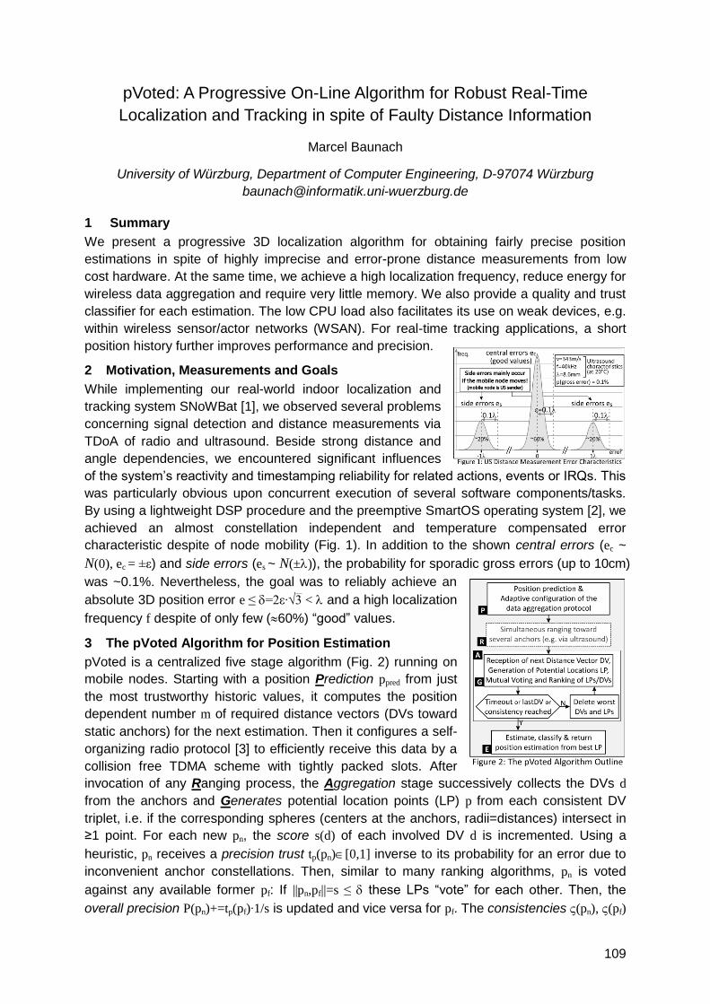
109
pVoted: A Progressive On-Line Algorithm for Robust Real-Time
Localization and Tracking in spite of Faulty Distance Information
Marcel Baunach
University of Würzburg, Department of Computer Engineering, D-97074 Würzburg
1 Summary
We present a progressive 3D localization algorithm for obtaining fairly precise position
estimations in spite of highly imprecise and error-prone distance measurements from low
cost hardware. At the same time, we achieve a high localization frequency, reduce energy for
wireless data aggregation and require very little memory. We also provide a quality and trust
classifier for each estimation. The low CPU load also facilitates its use on weak devices, e.g.
within wireless sensor/actor networks (WSAN). For real-time tracking applications, a short
position history further improves performance and precision.
2 Motivation, Measurements and Goals
While implementing our real-world indoor localization and
tracking system SNoWBat [1], we observed several problems
concerning signal detection and distance measurements via
TDoA of radio and ultrasound. Beside strong distance and
angle dependencies, we encountered significant influences
of the system‘s reactivity and timestamping reliability for related actions, events or IRQs. This
was particularly obvious upon concurrent execution of several software components/tasks.
By using a lightweight DSP procedure and the preemptive SmartOS operating system [2], we
achieved an almost constellation independent and temperature compensated error
characteristic despite of node mobility (Fig. 1). In addition to the shown central errors (ec ~
N(0), ec = ±ε) and side errors (es ~ N(±)), the probability for sporadic gross errors (up to 10cm)
was ~0.1%. Nevertheless, the goal was to reliably achieve an
absolute 3D position error e ≤ =2ε∙√3 < and a high localization
frequency f despite of only few (60%) ―good‖ values.
3 The pVoted Algorithm for Position Estimation
pVoted is a centralized five stage algorithm (Fig. 2) running on
mobile nodes. Starting with a position Prediction ppred from just
the most trustworthy historic values, it computes the position
dependent number m of required distance vectors (DVs toward
static anchors) for the next estimation. Then it configures a self-
organizing radio protocol [3] to efficiently receive this data by a
collision free TDMA scheme with tightly packed slots. After
invocation of any Ranging process, the Aggregation stage successively collects the DVs d
from the anchors and Generates potential location points (LP) p from each consistent DV
triplet, i.e. if the corresponding spheres (centers at the anchors, radii=distances) intersect in
≥1 point. For each new pn, the score s(d) of each involved DV d is incremented. Using a
heuristic, pn receives a precision trust tp(pn)[0,1] inverse to its probability for an error due to
inconvenient anchor constellations. Then, similar to many ranking algorithms, pn is voted
against any available former pf: If ||pn,pf||=s ≤ these LPs ―vote‖ for each other. Then, the
overall precision P(pn)+=tp(pf)∙1/s is updated and vice versa for pf. The consistencies (pn), (pf)
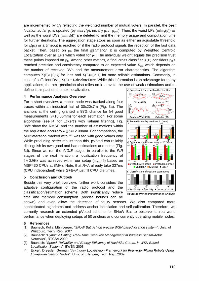
110
are incremented by 1/s reflecting the weighted number of mutual voters. In parallel, the best
location so far pB is updated (by max (p), initially pB := ppred). Then, the worst LPs (min (p)) as
well as the worst DVs (min s(d)) are deleted to limit the memory usage and computation time
for further iterations. The aggregation stage stops as soon as either an adjustable threshold
for (pB) or a timeout is reached or if the radio protocol signals the reception of the last data
packet. Then, based on pB the final Estimation E is computed by Weighted Centroid
Localization over all LPs which voted for pB. The individual weight equals the precision trust
these points imposed on pB. Among other metrics, a final cross classifier X(E) considers pB‘s
reached precision and consistency compared to an expected value Xexp which depends on
the number of received DVs and the measurement error characteristics. The algorithm
computes X(E)[0,½) for less and X(E)[½,1] for more reliable estimations. Commonly, in
case of sufficient DVs, X(E) ~ 1/absoluteError. While this information is an advantage for many
applications, the next prediction also relies on it to avoid the use of weak estimations and to
define its impact on the next localization.
4 Performance Analysis Overview
For a short overview, a mobile node was tracked along four
traces within an industrial hall of 30x20x7m (Fig. 3a). The
anchors at the ceiling granted a 99% chance for ≥4 good
measurements (ε=±0.86mm) for each estimation. For some
algorithms (see [4] for Eckert‘s with Kalman filtering), Fig.
3b/c show the RMSE and the number of estimations within
the requested accuracy e ≤ =±2.98mm. For comparison, the
Multilateration marked with ―*‖ was fed with good values only.
While producing better results than this, pVoted can reliably
distinguish its own good and bad estimations at runtime (Fig.
3d). Since we run the A/G/E stages in parallel to the P/R
stages of the next iteration, a localization frequency of
f 2.9Hz was achieved within our setup (mmax=9) based on
MSP430 CPUs at 8MHz. Note, that R+A already take 337ms
(CPU independent) while G+E+P just fill CPU idle times.
5 Conclusion and Outlook
Beside this very brief overview, further work considers the
adaptive configuration of the radio protocol and the
classification/estimation scheme. Both significantly reduce
time and memory consumption (precise bounds can be
shown) and even allow the detection of faulty sensors. We also compared more
sophisticated algorithms and address anchor installation and self-calibration. Therefore, we
currently research an extended pVoted scheme for SNoW Bat to observe its real-world
performance when deploying setups of 50 anchors and concurrently operating mobile nodes.
6 References [1] Baunach, Kolla, Mühlberger: ―SNoW Bat: A high precise WSN based location system‖, Univ. of
Würzburg, Tech. Rep. 2007 [2] Baunach: ―Dynamic Hinting: Real-Time Resource Management in Wireless Sensor/Actor
Networks‖, RTCSA 2009 [3] Baunach: ―Speed, Reliability and Energy Efficiency of HashSlot Comm. in WSN Based
Localization Systems‖, EWSN 2008 [4] Eckert, Dressler, German: ―An Indoor Localization Framework for Four-rotor Flying Robots Using
Low-power Sensor Nodes‖, Univ. of Erlangen, Tech. Rep. 2009

111
Localization Services in Hybrid Self-organizing Networks
Anna Maria Vegni, Marco Carli, Alessandro Neri
University of Roma TRE, Department of Applied Electronics, Rome 00146, Italy
1 Summary
In this paper we present a localization technique for self-organizing hybrid networks, where
both indoor and outdoor scenarios coexist. In the proposed framework, outdoor anchor
nodes act as reference nodes for estimating the position of mobile nodes which are moving
in an indoor scenario. The reference nodes are equipped with both IEEE 802.16e and GPS
network interface cards. The mobile nodes share some location information for estimating
their own position by using flooding communication scheme. The accuracy of localization
measurement is assessed in terms of Dilution of Precision, which is strictly depending on
nodes topology. To minimize position and speed estimation errors of each node, an
Extended Kalman Filtering technique is adopted. Simulation results demonstrate the
effectiveness of the proposed approach, in terms of position and speed uncertainty.
2 Introduction
Localization information sharing is an essential task to support mobility in new generation
networks. Mobile Ad-hoc NETworks (MANETs) are peer to peer self-configuring wireless ad-
hoc networks, composed by mobile nodes placed in an arbitrary topology. Traditional
MANET applications are in the military field, as well as in disaster recovery (i.e. emergency
operations, flooding, earthquakes, and so forth). To assure end-to-end communications, due
to lack of existing infrastructure, in self-organizing mobile networks it is necessary to estimate
and monitor nodes‘ positions.
The emerging class of services Location Based Services allows the tracking and the
navigation of a user in a location-aided environment, configured as point-to-multipoint, mesh,
or ad hoc network. Several methods have been proposed in literature for estimating indoor
position, i.e. Time of Arrivals, Time Difference of Arrivals, or the Direction of Arrival. Moreover,
in indoor scenario where a drastic reduction in signal penetration and multipath occur, most
of the location techniques fail to provide a sufficiently accurate position. As a consequence
our vision is to introduce outdoor environment to support, and enhance indoor local
positioning.
In this paper we extend the localization technique proposed in [1], used for traditional IEEE
802.11 indoor networks, to hybrid environments (i.e. both indoor, and outdoor networks),
where a set of outdoor Reference Nodes (RNs) work to track and localize indoor Mobile
Nodes (MNs). RNs are GPS-assisted, so that temporal synchronization is solved according
to ranging mechanism as proposed in [1]. In our approach the positioning estimation is
optimized by adopting an Extended Kalman Filtering (EKF) technique. Dilution of Position
(DOP) factor has been evaluated as position accuracy monitoring during simulations for
dynamical node configurations, both in a mesh topology and centralized architecture.
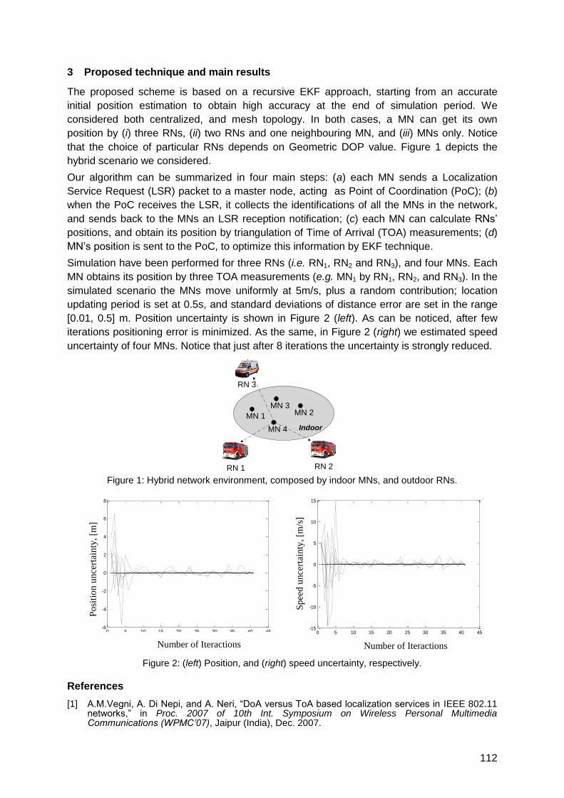
112
3 Proposed technique and main results
The proposed scheme is based on a recursive EKF approach, starting from an accurate
initial position estimation to obtain high accuracy at the end of simulation period. We
considered both centralized, and mesh topology. In both cases, a MN can get its own
position by (i) three RNs, (ii) two RNs and one neighbouring MN, and (iii) MNs only. Notice
that the choice of particular RNs depends on Geometric DOP value. Figure 1 depicts the
hybrid scenario we considered.
Our algorithm can be summarized in four main steps: (a) each MN sends a Localization
Service Request (LSR) packet to a master node, acting as Point of Coordination (PoC); (b)
when the PoC receives the LSR, it collects the identifications of all the MNs in the network,
and sends back to the MNs an LSR reception notification; (c) each MN can calculate RNs‘
positions, and obtain its position by triangulation of Time of Arrival (TOA) measurements; (d)
MN‘s position is sent to the PoC, to optimize this information by EKF technique.
Simulation have been performed for three RNs (i.e. RN1, RN2 and RN3), and four MNs. Each
MN obtains its position by three TOA measurements (e.g. MN1 by RN1, RN2, and RN3). In the
simulated scenario the MNs move uniformly at 5m/s, plus a random contribution; location
updating period is set at 0.5s, and standard deviations of distance error are set in the range
[0.01, 0.5] m. Position uncertainty is shown in Figure 2 (left). As can be noticed, after few
iterations positioning error is minimized. As the same, in Figure 2 (right) we estimated speed
uncertainty of four MNs. Notice that just after 8 iterations the uncertainty is strongly reduced.
Figure 1: Hybrid network environment, composed by indoor MNs, and outdoor RNs.
Figure 2: (left) Position, and (right) speed uncertainty, respectively.
References
[1] A.M.Vegni, A. Di Nepi, and A. Neri, ―DoA versus ToA based localization services in IEEE 802.11 networks,‖ in Proc. 2007 of 10th Int. Symposium on Wireless Personal Multimedia Communications (WPMC’07), Jaipur (India), Dec. 2007.
Po
siti
on
un
cert
ain
ty, [m
]
0 5 10 15 20 25 30 35 40 45-6
-4
-2
0
2
4
6
8
Number of iteractions
Positio
n u
ncert
ain
ty,
[m]
Number of Iteractions
Sp
eed
un
cert
ain
ty,
[m/s
]
Number of Iteractions
0 5 10 15 20 25 30 35 40 45-15
-10
-5
0
5
10
15
Number of iteractions
Speed u
ncert
ain
ty,
[m]
Indoor
RN 1
RN 3
RN 2
MN 1 MN 2MN 3
MN 4
113
On Distance Estimation based on Radio Propagation Models and Outlier
Detection for Indoor Localization in Wireless Geosensor Networks
Alexander Born, Member IEEE, Frank Niemeyer, Mario Schwiede and Ralf Bill
Rostock University, Faculty for Agricultural and Environmental Sciences, Chair of Geodesy
and Geoinformatics, Justus-von-Liebig-Weg 6, D-18059 Rostock
1 Summary
The determination of a precise position in wireless geosensor networks requires the use of
e.g. distance measurements. These distance observations derived by Received Signal
Strength (RSS) measurements are inherently inaccurate. Furthermore, in general, the
distance observations using RSS do not take obstacles into account. In this paper we
present a new approach for indoor positioning to correct erroneous RSS measurements
affected by obstacles. This technique is combined with the known ―Anomaly Correction in
Localization‖ (ACL) algorithm where sensor measurements are used to detect and eliminate
outliers and therefore to improve the determined highly energy limited sensor node positions.
2 Background and Algorithm Description
In Reichenbach et al. the ―Anomaly Correction in Localization‖ algorithm (ACL) was proposed
[1]. This algorithm uses spatial information inherent in sensor measurements. The principal
idea used is as follows: Usually a sensor network contains redundant beacons. Using simple
trilateration, to reduce the energy consumption of the sensor nodes for localization, different
positions can be estimated followed by the determination and elimination of outliers. For this
elimination, the object of interest will be subdivided into sensor intervals where these
intervals represent the physical parameter to be monitored. The expected range of sensor
values will be modeled based on a priori information on the basis of e.g. floor plans and
stored as a footprint map on the sensor nodes. During the localization process, the
determined position will be adopted one-to-one into the footprint map. The sensor then
measures the physical parameter and compares the measured value with the expected one
on the footprint map for the calculated position. If the position on the map matches the
sensor measurement it will be marked as valid and used for the final localization. If not it will
be marked and deleted as an outlier. Here, only raw distances are used. There are many
factors affecting the distance estimation. One of the major problems is the signal propagation
through the medium between the emitting and the receiving node and accordingly the
attenuation of the signal. Several models exist in literature to take these problems into
account [2]. In our approach we investigate different models mainly based on the
―Shadowing Model‖ [2]. Common models are based on deterministic functions and presume
an ideal transmission range. The ―Attenuation Factor Model‖ takes signal fading caused by
obstacles into account and is therefore more realistic. In first simulations we used the
―Attenuation Factor Model‖ which approximates obstacles by extending the ―Shadowing
Model‖ by a material characteristic factor. In our approach this algorithm will be extended by
a method which corrects deviations caused by obstacles in the signal path. For this, the
footprint map is extended by additional geographical information such as walls and possible
obstacles (closets, desks, etc.) including their characteristic material factor. After the sensor
node detects an outlier using ACL, the corresponding distances will be evaluated by
comparing with obstacles marked in the footprint map. If the distance is obstructed, the
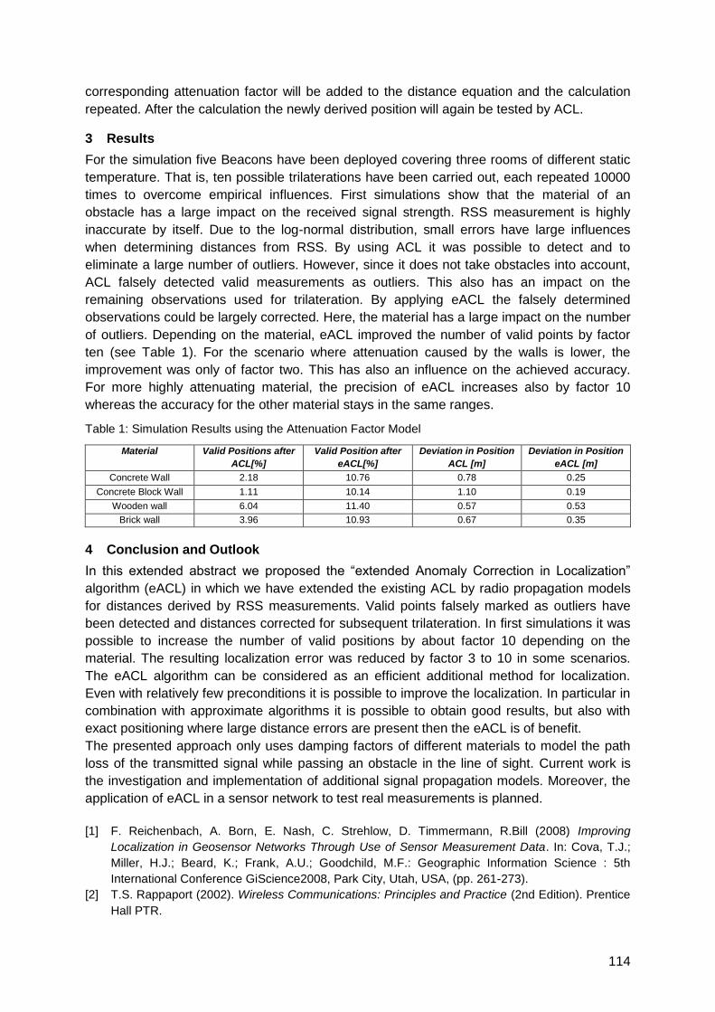
114
corresponding attenuation factor will be added to the distance equation and the calculation
repeated. After the calculation the newly derived position will again be tested by ACL.
3 Results
For the simulation five Beacons have been deployed covering three rooms of different static
temperature. That is, ten possible trilaterations have been carried out, each repeated 10000
times to overcome empirical influences. First simulations show that the material of an
obstacle has a large impact on the received signal strength. RSS measurement is highly
inaccurate by itself. Due to the log-normal distribution, small errors have large influences
when determining distances from RSS. By using ACL it was possible to detect and to
eliminate a large number of outliers. However, since it does not take obstacles into account,
ACL falsely detected valid measurements as outliers. This also has an impact on the
remaining observations used for trilateration. By applying eACL the falsely determined
observations could be largely corrected. Here, the material has a large impact on the number
of outliers. Depending on the material, eACL improved the number of valid points by factor
ten (see Table 1). For the scenario where attenuation caused by the walls is lower, the
improvement was only of factor two. This has also an influence on the achieved accuracy.
For more highly attenuating material, the precision of eACL increases also by factor 10
whereas the accuracy for the other material stays in the same ranges.
Table 1: Simulation Results using the Attenuation Factor Model
Material Valid Positions after
ACL[%]
Valid Position after
eACL[%]
Deviation in Position
ACL [m]
Deviation in Position
eACL [m]
Concrete Wall 2.18 10.76 0.78 0.25
Concrete Block Wall 1.11 10.14 1.10 0.19
Wooden wall 6.04 11.40 0.57 0.53
Brick wall 3.96 10.93 0.67 0.35
4 Conclusion and Outlook
In this extended abstract we proposed the ―extended Anomaly Correction in Localization‖
algorithm (eACL) in which we have extended the existing ACL by radio propagation models
for distances derived by RSS measurements. Valid points falsely marked as outliers have
been detected and distances corrected for subsequent trilateration. In first simulations it was
possible to increase the number of valid positions by about factor 10 depending on the
material. The resulting localization error was reduced by factor 3 to 10 in some scenarios.
The eACL algorithm can be considered as an efficient additional method for localization.
Even with relatively few preconditions it is possible to improve the localization. In particular in
combination with approximate algorithms it is possible to obtain good results, but also with
exact positioning where large distance errors are present then the eACL is of benefit.
The presented approach only uses damping factors of different materials to model the path
loss of the transmitted signal while passing an obstacle in the line of sight. Current work is
the investigation and implementation of additional signal propagation models. Moreover, the
application of eACL in a sensor network to test real measurements is planned.
[1] F. Reichenbach, A. Born, E. Nash, C. Strehlow, D. Timmermann, R.Bill (2008) Improving
Localization in Geosensor Networks Through Use of Sensor Measurement Data. In: Cova, T.J.;
Miller, H.J.; Beard, K.; Frank, A.U.; Goodchild, M.F.: Geographic Information Science : 5th
International Conference GiScience2008, Park City, Utah, USA, (pp. 261-273).
[2] T.S. Rappaport (2002). Wireless Communications: Principles and Practice (2nd Edition). Prentice
Hall PTR.

115
Theoretical Analysis and Validation Experiments
of the Localization-by-Superposing-Beats Procedure
Matthias Schneider, Ralf Salomon
University of Rostock, 18051 Rostock, Germany
[email protected] [email protected]
1 Summary
Many everyday life activities require precise localization information. Navigation by means of
global positioning system (GPS) is a well-known example, but this localization method
cannot be utilized in all application areas. Logistics, factory and laboratory automation, as
well as warehouse management, for example, require a low-cost localization of various
objects with precision of few centimetres, particularly in indoor environments. For this
application domain, this paper proposes a new procedure, called the Localization-by-
Superposing-Beats (LSB) Procedure, to measures the relative distance of a receiver
between two points, i.e., the transmitters. The LSB procedure is based on the superposition
of particularly parametrized beats, and is characterized by very low resources demands. This
paper presents a description of the procedure, a preliminary theoretical analysis, as well as
some laboratory experiments.
2 Introduction
The Localization-by-Superposing-Beats (LSB) procedure detects the phase-shift of two high-
frequency radio signals from one received signal through the evaluation of a low-frequency
radio signal. Even though the high-frequency transmission signals might assume some MHz
or even GHz, the analysis can be done on a signal that has only a few Hz. The high-
frequency radio signals determine the resolution of a measurement that can be as small as a
few centimeter. But since the evaluation has to be done on a few periods of the low-
frequency signal, a detector can be realized in a low-cost implementation.
3 The Procedure: Description and Analysis
The LSB procedure is based on the superposition of simple beats. A beat arises through the
superposition of two signals s1/2 = sin(2πf1/2t) with similar frequencies f1 ≈ f2. A receiver will be
reading the beat r(t) = s1(t) + s2(t). The beat r(t) is enveloped with the low-frequency flow=(f1-
f2)/2. If in this very same configuration, i.e., both transmitter remain at fixed locations, the
receiver is moved by Δx, a (theoretical) phase-shift Δφ occurs between the envelopes with
respect to the original position. This phase-shift can be used to derive the distance Δx of the
first and second receiver position. However, in order to make use of this phase-shift, the
receiver would require some global timing information to calculate the phase-shift by two
independent measurements. With respect to the realization of a proper measurement system,
it might be useful to note that the phase-shift can be directly derived at the low-frequency
enveloped signal. The LSB procedure assumes the same physical setup as already
described, but the transmitters emit beats of the form bk(t) = sin(2πfkt)cos(2πfmt) with slightly
varying carrier frequencies fk but identical envelopes cos(2πfmt). The major effect of properly
configured beats is that its superposition leads to an interference signal, r(t) = ba(t) + bb(t),
with a shape that uniquely depends on receiver's position.
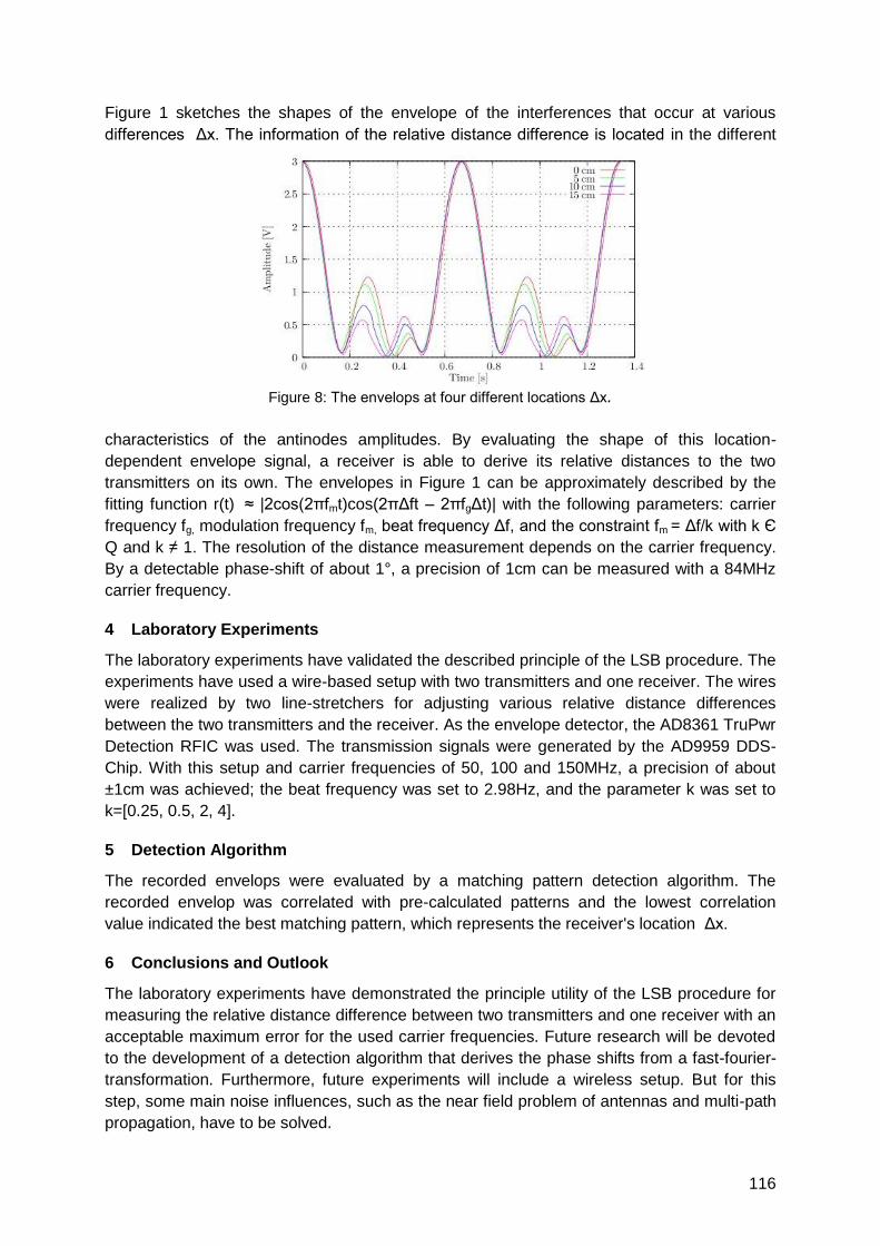
116
Figure 1 sketches the shapes of the envelope of the interferences that occur at various
differences Δx. The information of the relative distance difference is located in the different
characteristics of the antinodes amplitudes. By evaluating the shape of this location-
dependent envelope signal, a receiver is able to derive its relative distances to the two
transmitters on its own. The envelopes in Figure 1 can be approximately described by the
fitting function r(t) ≈ |2cos(2πfmt)cos(2πΔft – 2πfgΔt)| with the following parameters: carrier
frequency fg, modulation frequency fm, beat frequency Δf, and the constraint fm = Δf/k with k Є
Q and k ≠ 1. The resolution of the distance measurement depends on the carrier frequency.
By a detectable phase-shift of about 1°, a precision of 1cm can be measured with a 84MHz
carrier frequency.
4 Laboratory Experiments
The laboratory experiments have validated the described principle of the LSB procedure. The
experiments have used a wire-based setup with two transmitters and one receiver. The wires
were realized by two line-stretchers for adjusting various relative distance differences
between the two transmitters and the receiver. As the envelope detector, the AD8361 TruPwr
Detection RFIC was used. The transmission signals were generated by the AD9959 DDS-
Chip. With this setup and carrier frequencies of 50, 100 and 150MHz, a precision of about
±1cm was achieved; the beat frequency was set to 2.98Hz, and the parameter k was set to
k=[0.25, 0.5, 2, 4].
5 Detection Algorithm
The recorded envelops were evaluated by a matching pattern detection algorithm. The
recorded envelop was correlated with pre-calculated patterns and the lowest correlation
value indicated the best matching pattern, which represents the receiver's location Δx.
6 Conclusions and Outlook
The laboratory experiments have demonstrated the principle utility of the LSB procedure for
measuring the relative distance difference between two transmitters and one receiver with an
acceptable maximum error for the used carrier frequencies. Future research will be devoted
to the development of a detection algorithm that derives the phase shifts from a fast-fourier-
transformation. Furthermore, future experiments will include a wireless setup. But for this
step, some main noise influences, such as the near field problem of antennas and multi-path
propagation, have to be solved.
Figure 8: The envelops at four different locations Δx.
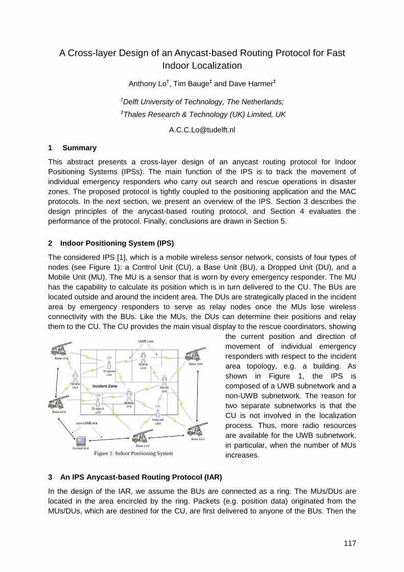
117
A Cross-layer Design of an Anycast-based Routing Protocol for Fast
Indoor Localization
Anthony Lo†, Tim Bauge‡ and Dave Harmer‡
†Delft University of Technology, The Netherlands;
‡Thales Research & Technology (UK) Limited, UK
1 Summary
This abstract presents a cross-layer design of an anycast routing protocol for Indoor
Positioning Systems (IPSs). The main function of the IPS is to track the movement of
individual emergency responders who carry out search and rescue operations in disaster
zones. The proposed protocol is tightly coupled to the positioning application and the MAC
protocols. In the next section, we present an overview of the IPS. Section 3 describes the
design principles of the anycast-based routing protocol, and Section 4 evaluates the
performance of the protocol. Finally, conclusions are drawn in Section 5.
2 Indoor Positioning System (IPS)
The considered IPS [1], which is a mobile wireless sensor network, consists of four types of
nodes (see Figure 1): a Control Unit (CU), a Base Unit (BU), a Dropped Unit (DU), and a
Mobile Unit (MU). The MU is a sensor that is worn by every emergency responder. The MU
has the capability to calculate its position which is in turn delivered to the CU. The BUs are
located outside and around the incident area. The DUs are strategically placed in the incident
area by emergency responders to serve as relay nodes once the MUs lose wireless
connectivity with the BUs. Like the MUs, the DUs can determine their positions and relay
them to the CU. The CU provides the main visual display to the rescue coordinators, showing
the current position and direction of
movement of individual emergency
responders with respect to the incident
area topology, e.g. a building. As
shown in Figure 1, the IPS is
composed of a UWB subnetwork and a
non-UWB subnetwork. The reason for
two separate subnetworks is that the
CU is not involved in the localization
process. Thus, more radio resources
are available for the UWB subnetwork,
in particular, when the number of MUs
increases.
3 An IPS Anycast-based Routing Protocol (IAR)
In the design of the IAR, we assume the BUs are connected as a ring. The MUs/DUs are
located in the area encircled by the ring. Packets (e.g. position data) originated from the
MUs/DUs, which are destined for the CU, are first delivered to anyone of the BUs. Then the
Figure 1: Indoor Positioning System
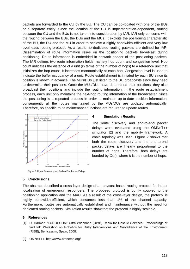
118
packets are forwarded to the CU by the BU. The CU can be co-located with one of the BUs
or a separate entity. Since the location of the CU is implementation-dependent, routing
between the CU and the BUs is not taken into consideration by IAR. IAR only concerns with
the routing between the BUs, the DUs and the MUs. It exploits the positioning characteristic
of the BU, the DU and the MU in order to achieve a highly bandwidth-efficient and very low
overheads routing protocol. As a result, no dedicated routing packets are defined for IAR.
Dissemination of route information relies on the positioning packets broadcast during
positioning. Route information is embedded in network header of the positioning packets.
The IAR defines two route information fields, namely hop count and congestion level. Hop
count indicates the distance of a unit (in terms of the number of hops) to a reference unit that
initializes the hop count. It increases monotonically at each hop. Congestion level is used to
indicate the buffer occupancy of a unit. Route establishment is initiated by each BU since its
position is known in advance. The MUs/DUs just listen to the BU broadcasts since they need
to determine their positions. Once the MUs/DUs have determined their positions, they also
broadcast their positions and include the routing information. In the route establishment
process, each unit only maintains the next-hop routing information of the broadcaster. Since
the positioning is a repeated process in order to maintain up-to-date position information,
consequently all the routes maintained by the MUs/DUs are updated automatically.
Therefore, no specific route maintenance functions are required to update routes.
4 Simulation Results
The route discovery and end-to-end packet
delays were evaluated using the OMNeT++
simulator [2] and the mobility framework. A
chain topology was used. Figure 2 shows that
both the route discovery and the end-to-end
packet delays are linearly proportional to the
number of hops. Therefore, both delays are
bonded by O(h), where h is the number of hops.
5 Conclusions
The abstract described a cross-layer design of an anycast-based routing protocol for indoor
localization of emergency responders. The proposed protocol is tightly coupled to the
positioning application and the MAC. As a result of the cross-layer design, the protocol is
highly bandwidth-efficient, which consumes less than 1% of the channel capacity.
Furthermore, routes are automatically established and maintenance without the need for
dedicated routing packets. Simulation results show that the protocol is highly scalable.
6 References
[1] D. Harmer, ―EUROPCOM‖ Ultra Wideband (UWB) Radio for Rescue Services‖, Proceedings of
2nd Int‘l Workshop on Robotics for Risky Interventions and Surveillance of the Environment
(RISE), Benicassim, Spain, 2008.
[2] OMNeT++, http://www.omnetpp.org/
0 10 20 30 40 50 600
5
10
15
20
25
30
35
40
45
Network Diameter (Number of hops)
Nu
mb
er
of S
up
erf
ram
es
Route Discovery Delay
End-to-End Packet Delay
Figure 2: Route Discovery and End-to-End Packet Delays
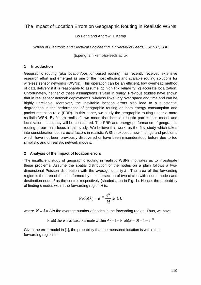
119
The Impact of Location Errors on Geographic Routing in Realistic WSNs
Bo Peng and Andrew H. Kemp
School of Electronic and Electrical Engineering, University of Leeds, LS2 9JT, U.K.
{b.peng, a.h.kemp}@leeds.ac.uk
1 Introduction
Geographic routing (aka location/position-based routing) has recently received extensive
research effort and emerged as one of the most efficient and scalable routing solutions for
wireless sensor networks (WSNs). This operation can be an efficient, low overhead method
of data delivery if it is reasonable to assume: 1) high link reliability; 2) accurate localization.
Unfortunately, neither of these assumptions is valid in reality. Previous studies have shown
that in real sensor network deployments, wireless links vary over space and time and can be
highly unreliable. Moreover, the inevitable location errors also lead to a substantial
degradation in the performance of geographic routing on both energy consumption and
packet reception ratio (PRR). In this paper, we study the geographic routing under a more
realistic WSN. By ―more realistic‖, we mean that both a realistic packet loss model and
localization inaccuracy will be considered. The PRR and energy performance of geographic
routing is our main focus in this study. We believe this work, as the first study which takes
into consideration both crucial factors in realistic WSNs, exposes new findings and problems
which have not been previously discovered or have been misunderstood before due to too
simplistic and unrealistic network models.
2 Analysis of the impact of location errors
The insufficient study of geographic routing in realistic WSNs motivates us to investigate
these problems. Assume the spatial distribution of the nodes on a plain follows a two-
dimensional Poisson distribution with the average density . The area of the forwarding
region is the area of the lens formed by the intersection of two circles with source node i and
destination node d as the centre, respectively (shaded area in Fig. 1). Hence, the probability
of finding k nodes within the forwarding region A is:
0,!
)(Prob kk
ekN
N
where AN is the average number of nodes in the forwarding region. Thus, we have
NekA 1)0(Prob1}withinnodeoneleastatisthere{Prob
Given the error model in [1], the probability that the measured location is within the
forwarding region is:
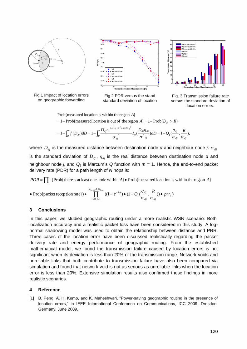
120
),,(1)(1)(1
}{Prob1}regiontheofoutislocationmeasured{Prob1
}theregionwithinislocationmeasured{Prob
1202
2/)(222
djdj
dj
dj
djdj
Rdj
D
dj
Rdj
dj
RQdD
DI
eDdDDf
RDA
A
djdjdj
where djD is the measured distance between destination node d and neighbour node j. dj
is the standard deviation of djD , dj is the real distance between destination node d and
neighbour node j, and Q1 is Marcum‘s Q function with m = 1. Hence, the end-to-end packet
delivery rate (PDR) for a path length of N hops is:
hopshops NN
ji
ij
djdj
djA prrR
Qe
AAPDR
,1
1,0
1 ))),(1()1((})ratereceptionpacket{Prob
}regionthewithinislocationmeasured{Prob}withinnodeoneleastatisthere{Prob(
3 Conclusions
In this paper, we studied geographic routing under a more realistic WSN scenario. Both,
localization accuracy and a realistic packet loss have been considered in this study. A log-
normal shadowing model was used to obtain the relationship between distance and PRR.
Three cases of the location error have been discussed realistically regarding the packet
delivery rate and energy performance of geographic routing. From the established
mathematical model, we found the transmission failure caused by location errors is not
significant when its deviation is less than 20% of the transmission range. Network voids and
unreliable links that both contribute to transmission failure have also been compared via
simulation and found that network void is not as serious as unreliable links when the location
error is less than 20%. Extensive simulation results also confirmed these findings in more
realistic scenarios.
4 Reference
[1] B. Peng, A. H. Kemp, and K. Maheshwari, ―Power-saving geographic routing in the presence of
location errors,‖ in IEEE International Conference on Communications, ICC 2009, Dresden,
Germany, June 2009.
i
r
dA
jP'
jPjd
jdD
near side
far side
iR
Fig.2 PDR versus the stand standard deviation of location
Fig. 3 Transmission failure rate versus the standard deviation of
location errors.
Fig.1 Impact of location errors on geographic forwarding
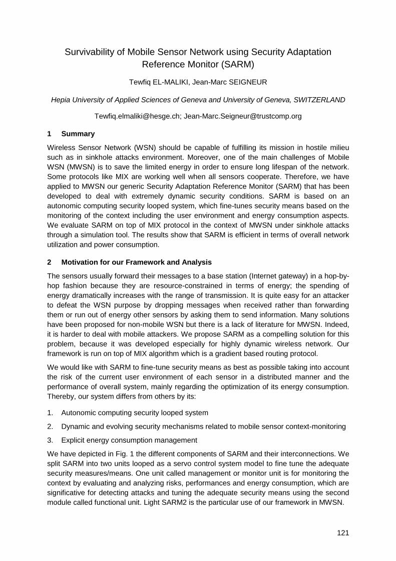
121
Survivability of Mobile Sensor Network using Security Adaptation
Reference Monitor (SARM)
Tewfiq EL-MALIKI, Jean-Marc SEIGNEUR
Hepia University of Applied Sciences of Geneva and University of Geneva, SWITZERLAND
[email protected]; [email protected]
1 Summary
Wireless Sensor Network (WSN) should be capable of fulfilling its mission in hostile milieu
such as in sinkhole attacks environment. Moreover, one of the main challenges of Mobile
WSN (MWSN) is to save the limited energy in order to ensure long lifespan of the network.
Some protocols like MIX are working well when all sensors cooperate. Therefore, we have
applied to MWSN our generic Security Adaptation Reference Monitor (SARM) that has been
developed to deal with extremely dynamic security conditions. SARM is based on an
autonomic computing security looped system, which fine-tunes security means based on the
monitoring of the context including the user environment and energy consumption aspects.
We evaluate SARM on top of MIX protocol in the context of MWSN under sinkhole attacks
through a simulation tool. The results show that SARM is efficient in terms of overall network
utilization and power consumption.
2 Motivation for our Framework and Analysis
The sensors usually forward their messages to a base station (Internet gateway) in a hop-by-
hop fashion because they are resource-constrained in terms of energy; the spending of
energy dramatically increases with the range of transmission. It is quite easy for an attacker
to defeat the WSN purpose by dropping messages when received rather than forwarding
them or run out of energy other sensors by asking them to send information. Many solutions
have been proposed for non-mobile WSN but there is a lack of literature for MWSN. Indeed,
it is harder to deal with mobile attackers. We propose SARM as a compelling solution for this
problem, because it was developed especially for highly dynamic wireless network. Our
framework is run on top of MIX algorithm which is a gradient based routing protocol.
We would like with SARM to fine-tune security means as best as possible taking into account
the risk of the current user environment of each sensor in a distributed manner and the
performance of overall system, mainly regarding the optimization of its energy consumption.
Thereby, our system differs from others by its:
1. Autonomic computing security looped system
2. Dynamic and evolving security mechanisms related to mobile sensor context-monitoring
3. Explicit energy consumption management
We have depicted in Fig. 1 the different components of SARM and their interconnections. We
split SARM into two units looped as a servo control system model to fine tune the adequate
security measures/means. One unit called management or monitor unit is for monitoring the
context by evaluating and analyzing risks, performances and energy consumption, which are
significative for detecting attacks and tuning the adequate security means using the second
module called functional unit. Light SARM2 is the particular use of our framework in MWSN.
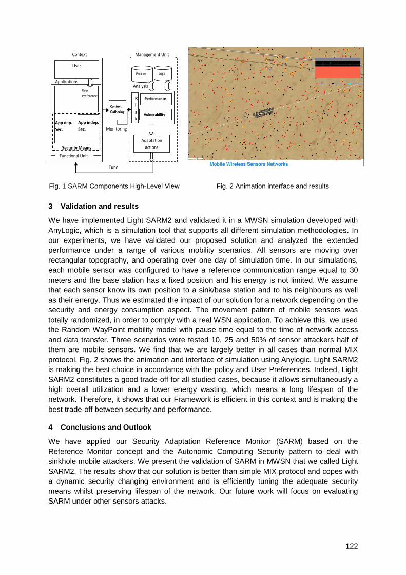
122
Fig. 1 SARM Components High-Level View Fig. 2 Animation interface and results
3 Validation and results
We have implemented Light SARM2 and validated it in a MWSN simulation developed with
AnyLogic, which is a simulation tool that supports all different simulation methodologies. In
our experiments, we have validated our proposed solution and analyzed the extended
performance under a range of various mobility scenarios. All sensors are moving over
rectangular topography, and operating over one day of simulation time. In our simulations,
each mobile sensor was configured to have a reference communication range equal to 30
meters and the base station has a fixed position and his energy is not limited. We assume
that each sensor know its own position to a sink/base station and to his neighbours as well
as their energy. Thus we estimated the impact of our solution for a network depending on the
security and energy consumption aspect. The movement pattern of mobile sensors was
totally randomized, in order to comply with a real WSN application. To achieve this, we used
the Random WayPoint mobility model with pause time equal to the time of network access
and data transfer. Three scenarios were tested 10, 25 and 50% of sensor attackers half of
them are mobile sensors. We find that we are largely better in all cases than normal MIX
protocol. Fig. 2 shows the animation and interface of simulation using Anylogic. Light SARM2
is making the best choice in accordance with the policy and User Preferences. Indeed, Light
SARM2 constitutes a good trade-off for all studied cases, because it allows simultaneously a
high overall utilization and a lower energy wasting, which means a long lifespan of the
network. Therefore, it shows that our Framework is efficient in this context and is making the
best trade-off between security and performance.
4 Conclusions and Outlook
We have applied our Security Adaptation Reference Monitor (SARM) based on the
Reference Monitor concept and the Autonomic Computing Security pattern to deal with
sinkhole mobile attackers. We present the validation of SARM in MWSN that we called Light
SARM2. The results show that our solution is better than simple MIX protocol and copes with
a dynamic security changing environment and is efficiently tuning the adequate security
means whilst preserving lifespan of the network. Our future work will focus on evaluating
SARM under other sensors attacks.
Context
R
i
s
k
User
Performance
Vulnerability
Adaptation
actions
Functional Unit
User
Preferences
Analysis
Monitoring
Tune
Policies Logs
Applications
App dep.
Sec.
Security Means
App indep.
Sec.
Context
Gathering
Management Unit
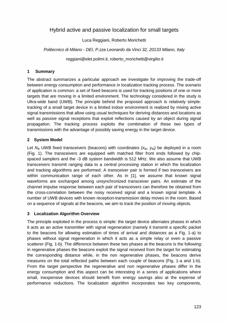
123
Hybrid active and passive localization for small targets
Luca Reggiani, Roberto Morichetti
Politecnico di Milano - DEI, P.zza Leonardo da Vinci 32, 20133 Milano, Italy
[email protected], [email protected]
1 Summary
The abstract summarizes a particular approach we investigate for improving the trade-off
between energy consumption and performance in localization tracking process. The scenario
of application is common: a set of fixed beacons is used for tracking positions of one or more
targets that are moving in a limited environment. The technology considered in the study is
Ultra-wide band (UWB). The principle behind the proposed approach is relatively simple:
tracking of a small target device in a limited indoor environment is realized by mixing active
signal transmissions that allow using usual techniques for deriving distances and locations as
well as passive signal receptions that exploit reflections caused by an object during signal
propagation. The tracking process exploits the combination of these two types of
transmissions with the advantage of possibly saving energy in the target device.
2 System Model
Let NB UWB fixed transceivers (beacons) with coordinates (xBi, yBi) be deployed in a room
(Fig. 1). The transceivers are equipped with matched filter front ends followed by chip-
spaced samplers and the -3 dB system bandwidth is 512 MHz. We also assume that UWB
transceivers transmit ranging data to a central processing station in which the localization
and tracking algorithms are performed. A transceiver pair is formed if two transceivers are
within communication range of each other. As in [1], we assume that known signal
waveforms are exchanged among unsynchronized transceiver pairs. An estimate of the
channel impulse response between each pair of transceivers can therefore be obtained from
the cross-correlation between the noisy received signal and a known signal template. A
number of UWB devices with known reception-transmission delay moves in the room. Based
on a sequence of signals at the beacons, we aim to track the position of moving objects.
3 Localization Algorithm Overview
The principle exploited in the process is simple: the target device alternates phases in which
it acts as an active transmitter with signal regeneration (namely it transmit a specific packet
to the beacons for allowing estimation of times of arrival and distances as a Fig. 1-a) to
phases without signal regeneration in which it acts as a simple relay or even a passive
scatterer (Fig. 1-b). The difference between these two phases at the beacons is the following:
in regenerative phases the beacons exploit the signal received from the target for estimating
the corresponding distance while, in the non regenerative phases, the beacons derive
measures on the total reflected paths between each couple of beacons (Fig. 1-a and 1-b).
From the target perspective the regenerative and non regenerative phases differ in the
energy consumption and this aspect can be interesting in a series of applications where
small, inexpensive devices should benefit from energy savings also at the expense of
performance reductions. The localization algorithm incorporates two key components,
124
ranging in regenerative and non-regenerative phases and tracking, operated by a bank of
Extended Kalman Filters (EKFs):
1. Ranging: when the target is in the regenerative state, the i-th beacon estimates the direct
distance di to the target. On the other hand, when the target is in the non-regenerative
phase, each couple of beacons, i and j, is interested by the measure of the reflected path,
di + dj. If a soft algorithm is used [1], several distances associated to their likelihoods can
be collected for each sampling time.
2. Tracking: a bank of EKFs is used for updating the mobile target(s) locations. The bank is
necessary when tracking more targets or/and when managing multiple measures and
likelihoods associated to a single distance; in this latter case a metric is built and
updated for selecting the most likely trajectories in a hypothesis tree [2]. Obviously the
measures coming from regenerative and non-regenerative steps are subject to different
update steps implemented into the EKFs, which realize a fusion of the measures.
3 Numerical simulations
In the system we exploit ranging algorithms based on times of arrival and characterized by
soft detection techniques that have demonstrated performance advantages w.r.t. other
approaches [1] [2]. Numerical results will be focused on the trade-off between mean squared
error (MSE) and the ratio λ between the number of measures derived by non-regenerative
and regenerative phases.
4 Conclusions
In this work (°), we study the trade-off between localization performance and the ratio between
regenerative and non regenerative steps in the signal processing of a tracking application.
This simple principle is developed for obtaining energy savings in indoor localization.
References
[1] M. Rydstrom, L. Reggiani, E. G. Strom, A. Svensson, ―Sub-optimal Soft Range Estimators with
Applications in UWB Sensor Networks‖, IEEE Trans. On Signal Processing, vol. 56, no. 10, pp.
4856-4866, Oct. 2008.
[2] L. Reggiani, M. Rydstrom, G. Tiberi, E. G. Strom, A. Monorchio, ―Ultra-Wide Band Sensor
Networks for Tracking Point Scatterers or Relays‖, IEEE ISWCS 2009, Siena (Italy).
Figure 1: Combination of regenerative (a) and non regenerative (b) measures.
(°) This work was supported by the European Commission within FP7 Network of Excellence in Wireless COMmunications NEWCOM++ (contract no. 216715).
B1
(xB1,yB1)
d1 d3
d2
B2
(xB2,yB2)
B3
(a)
B1
d1 + d3
d1 + d2
B2
B3
(b)
125
Linear Antenna Array, Ranging and Accelerometer for 3D GPS-Less
Localization of Wireless Sensors
Patryk Mazurkiewicz and Kin K. Leung
Imperial College, Exhibition Road, SW7 2BT London, U.K.
[email protected], [email protected]
1 Introduction
Localization capability is required in many applications of wireless sensor networks (WSN).
For example, monitoring WSN of any type requires node location awareness in order to
stamp the measurements with the location (and also with timestamp), otherwise the
measurement is of no meaning for the infrastructure owner. A particularly interesting indoor
localization scenario is node positioning for automated building monitoring. The goal here is
to greatly reduce the human-generated mistakes and errors, and the overhead of manual
work during deployment by automatising the localization process. Nodes should set up the
network automatically, including positioning of the nodes.
There are several challenges for localization in WSNs that monitor structures. Firstly, the
network is installed in an unknown environment. The network is therefore most probably
multi-hop and the reference nodes may not be globally available to all other nodes in the
network. Secondly, the connectivity (that is the number of neighbours) may become relatively
low locally in some passages in the structure. We propose a localization algorithm which is
multi-hop, scalable and robust. Our algorithm uses the hardware that is capable of ranging
and elevation-type Angle-Of-Arrival (AOA) which are backed up with earth gravity direction
awareness.
Literature covers a variety of possible localization algorithms. Some algorithms use only one
type of measurements, like ranging alone (lateration based algorithms, e.g. Cricket) or AOA
only. However, one can obtain more robust results by using more than just one source of
information, such as the combination of ranging and AOA.
In our previous work we proposed a localization algorithm which was using ranging,
accelerometer (for earth gravity direction) and 3-D AOA. 3-D AOA requires at least a
4-element antenna array (or 3-element antenna array if we have the means to deal with the
ambiguity problem). Such complex hardware returns a complete position vector to the
observed sensor and enables localization of every single node that is connected (e.g. when a
wireless node has as little as one neighbour). However, this antenna hardware may also be
expensive and may require more electric power than simpler antenna solutions while power
is an issue in WSNs. We found a way of using the reduced number of antenna elements
effectively and keeping the AOA functional. In this work we present the localization system
which uses ranging, an accelerometer and a 2-element antenna array.
2 Position calculations
All wireless sensors in the network are equipped with the ranging device, accelerometer and
linear antenna array (comprising of 2 antenna elements). (The antenna elements can also
126
be just switched antennas with programmable phase shifter connected serially with one of
the elements. This is a simple beam former.)
The localization algorithm will be formulated here as an optimization problem.
Input values.
0P - node's given position (reference node or node which acquired this knowledge),
id , i - measured values: distance to i-th node and elevation-type angle to i-th node,
n - the direction of 0i dependent on the orientation of the antenna elements.
Calculated parameters needed for the final problem formulation.
u - unitary vector s.t. If 1ˆˆ xn then nxnu ˆˆˆˆ else nynu ˆˆˆˆ . In other words,
u is an arbitrary but unconstrained (any) vector which is to n .
unv ˆˆˆ - a vector perpendicular to n and to u ,
iii dr sin - distance of i-th node to the axis that comprises n ,
iii d cosˆ0 nPC - a projection of a position of an unknown node on n -axis.
Final formulation of a parametric equation of position of an observed node.
vuCP ˆsinˆcos 00
iiiiii rr , where 0
i is an unknown parameter.
Optimization problem.
For n viewpoints ni ..1 one can compose the set of n equations, where the
parameter 0
i solves the i-th equation.
2
min iPP , where P is an average of all iP ‘s.
3 Main results
In this chapter we summarize some of the results obtained from the research of the proposed
localization algorithm.
1. Minimum connectivity required. This result tells how many nodes that are location aware
are needed in order to transform one unknown node which is their neighbour into a
localized node. We have found that the problem formulated in chapter 2 (4.) can be
solved for as little as 2 independent viewpoints (2 reference nodes connected to an
unknown node) if n vector of one node is non-parallel to this of the other node.
Generally 3 viewpoints suffice.
2. Simulation scenario where all nodes were located on a plane. We have found that for
certain arrangement of nodes the advantage of having the AOA capability becomes
insignificant. This occurs when n vector of each node is perpendicular to the plane
where all nodes of WSN are placed. This case can be solved using 2-D equally
accurately as using trilateration with the assumption that the plane with which nodes
coincide is known. In real scenarios this plane may sometimes be easily determinable in
large one-storey buildings as e.g. floor.
.

127
Hybrid IMU Pedestrian Navigation 1
Auditorium G3
Wednesday, September 15, 10:30 – 11:45 & 13:15 – 16:00

129
A Modular and Mobile System for Indoor Localization
Lasse Klingbeil1, Michailas Romanovas1, Patrick Schneider1, Martin Traechtler1,
Yiannos Manoli1,2
1Hahn-Schickard-Gesellschaft
Institute of Microsystems and Information Technology (HSG-IMIT)
Wilhelm-Schickard-Straße 10, 78052 Villingen-Schwenningen, Germany
2University of Freiburg, Department of Microsystems Engineering (IMTEK)
Chair or Microelectronics
Georges-Köhler-Allee 101, 79110 Freiburg, Germany
email: [email protected]
Summary
The work presents a system for sensor data and complementary information fusion for
localization in indoor environments. The system is based on modular sensor units, which can
be attached to a person and contains various sensors, such as range sensors, inertial and
magnetic sensors, a GPS receiver and a barometer. The measurements are processed
using Bayesian Recursive Estimation algorithms and combined with available a priori
knowledge such as map information or human motion models and constraints. The
processing can be done locally, since all necessary data is available on the mobile unit. This
system provides a platform for implementation, combination and evaluation of various
localization principles and can be used for a variety of applications, such as indoor and
outdoor pedestrian navigation, localization of other objects such as vehicles as well as
robotics applications.
1 Motivation
There are numerous localization methods and techniques, including inertial navigation,
multilateration or multiangulation based on radio or acoustic signals and optical methods,
such as computer vision or laser range scanning. Most of these methods, when used stand
alone, are able to provide sufficient performance only for special types of applications within
controlled or restricted environments. Especially radio based methods usually suffer from
significant errors induced by multipath wave propagation in indoor environments. We follow
the approach that a robust and usable indoor localization system combines various
complementary sensor data and any other information available to provide a reliable position
estimate. Therefore a wearable, modular and extendible sensor system was developed,
which enables simultaneous usage of different sensing modalities.
2 System Description
The basic concept of the proposed system is shown in Fig. 1 (left). Several PCBs, each
designed to fulfill a certain task (e.g. providing power, enabling wireless communication, data
processing, input/output capability) or to contain a specific sensor group (e.g. inertial sensors,
GPS, ultrasound sensors), are stacked together to form a setup best fitting the requirements
of a particular application. Fig. 1 (middle) shows the subset of the system, which is used in
our current experiments on indoor localization. It contains a radio ranging module for
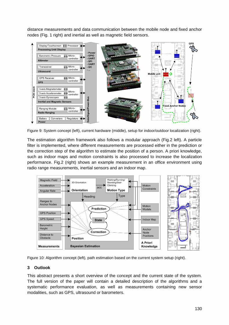
130
distance measurements and data communication between the mobile node and fixed anchor
nodes (Fig. 1 right) and inertial as well as magnetic field sensors.
Figure 9: System concept (left), current hardware (middle), setup for indoor/outdoor localization (right).
The estimation algorithm framework also follows a modular approach (Fig.2 left). A particle
filter is implemented, where different measurements are processed either in the prediction or
the correction step of the algorithm to estimate the position of a person. A priori knowledge,
such as indoor maps and motion constraints is also processed to increase the localization
performance. Fig.2 (right) shows an example measurement in an office environment using
radio range measurements, inertial sensors and an indoor map.
Figure 10: Algorithm concept (left), path estimation based on the current system setup (right).
3 Outlook
This abstract presents a short overview of the concept and the current state of the system.
The full version of the paper will contain a detailed description of the algorithms and a
systematic performance evaluation, as well as measurements containing new sensor
modalities, such as GPS, ultrasound or barometers.
131
Self-Contained Indoor Positioning on off-the-shelf mobile Devices
Dominik Gusenbauer2, Carsten Isert1 and Jens Krösche2
1 BMW Group Research and Technology, Hanauer Straße 46, D-80992 Munich, [email protected]
2 Upper Austria University of Applied Sciences, Campus Hagenberg, Department of Mobile Computing,
A-4232 Hagenberg, [email protected], [email protected]
1 Introduction
From pedestrian navigation and innovative location based services to medical studies, rescue or E-911 services, the knowledge of human displacements through space has many applications. For this reason we introduce a self-contained seamless positioning system for indoor and outdoor environments, based on off-the-shelf mobile devices. Position information is deduced from a combination of GNSS where available, combined with Dead Reckoning (DR) utilizing inertial measurements and context-aware activity based map-matching. In remaining independent from any external infrastructure, accurate localization is also possible in environments, where the installation and maintenance of such infrastructure does not make sense or is simply not affordable – e.g. in large parking garages to guide a user to an exit or back to his car.
Typical personal positioning strategies rely on the combination of GNSS with either map-matching (outdoor) or an INS/PDR approach (indoor, ubiquitous positioning). One of the first projects within the scope of inertial dead reckoning were the Personal Dead Reckoning Module (DRM) from the Point Research Corporation [1] and the Pedestrian Navigation Module (PNM) from the Laboratoire de Topometrie at the Ecole Polytechnique Fédérale de Lausanne (EPFL) [5]. Other projects like the NAVIO [7] or the UCPNAVI [6] project developed at the Vienna University of Technology extend investigations to route guidance strategies or the integration of additional positioning technologies based on RFID beacons or WLAN.
2 Inertial Position Sensing
The availability of GPS, acceleration sensors and an electronic compass in actual smartphones like for example the Nokia N97 or the iPhone 3GS establishes a powerful basis for inertial positioning. The proposed Pedestrian Dead Reckoning approach heavily exploits the kinematics of human movement by detecting steps, estimating each step‘s length and propagating a relative position using a heading measurement (fig. 1), while being comparatively robust against inaccurate measurements and disturbances as well as flexible regarding the exact placement and attitude of the device.
Estimation of the travelled distance is realized using the tri-axial acceleration signal of the device measured at a rate of 20 Hz. To improve the results of step detection and step length estimation according to the status of actual movement pattern, we introduced an activity classification procedure to differentiate between eight patterns. Step detection is implemented based upon a slightly modified version of a sliding window peak detection algorithm as proposed by Sun et al. [8]. Concerning the length calculation of a detected step, which is more or less a time-varying process and approximated as a function of several parameters like the acceleration signal variance, the step frequency and some scale factors computed by linear regression with respect to the actual movement pattern, we rely on the results of investigations by Ladetto [3], Ladetto et al. [4] and Kim et al. [2]. Since the raw sensor measurements from the
Figure 1: DR based inertial position estimation model processing acceleration sensor and compass readings.
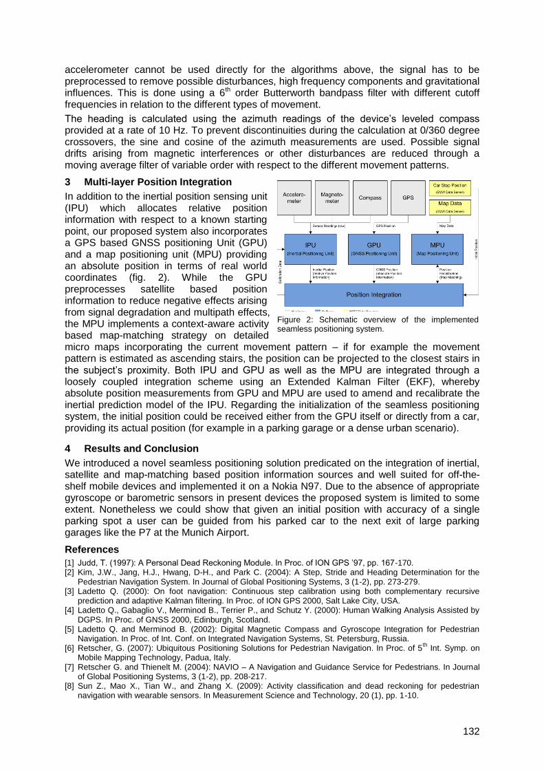
132
accelerometer cannot be used directly for the algorithms above, the signal has to be preprocessed to remove possible disturbances, high frequency components and gravitational influences. This is done using a 6th order Butterworth bandpass filter with different cutoff frequencies in relation to the different types of movement.
The heading is calculated using the azimuth readings of the device‘s leveled compass provided at a rate of 10 Hz. To prevent discontinuities during the calculation at 0/360 degree crossovers, the sine and cosine of the azimuth measurements are used. Possible signal drifts arising from magnetic interferences or other disturbances are reduced through a moving average filter of variable order with respect to the different movement patterns.
3 Multi-layer Position Integration
In addition to the inertial position sensing unit (IPU) which allocates relative position information with respect to a known starting point, our proposed system also incorporates a GPS based GNSS positioning Unit (GPU) and a map positioning unit (MPU) providing an absolute position in terms of real world coordinates (fig. 2). While the GPU preprocesses satellite based position information to reduce negative effects arising from signal degradation and multipath effects, the MPU implements a context-aware activity based map-matching strategy on detailed micro maps incorporating the current movement pattern – if for example the movement pattern is estimated as ascending stairs, the position can be projected to the closest stairs in the subject‘s proximity. Both IPU and GPU as well as the MPU are integrated through a loosely coupled integration scheme using an Extended Kalman Filter (EKF), whereby absolute position measurements from GPU and MPU are used to amend and recalibrate the inertial prediction model of the IPU. Regarding the initialization of the seamless positioning system, the initial position could be received either from the GPU itself or directly from a car, providing its actual position (for example in a parking garage or a dense urban scenario).
4 Results and Conclusion
We introduced a novel seamless positioning solution predicated on the integration of inertial, satellite and map-matching based position information sources and well suited for off-the-shelf mobile devices and implemented it on a Nokia N97. Due to the absence of appropriate gyroscope or barometric sensors in present devices the proposed system is limited to some extent. Nonetheless we could show that given an initial position with accuracy of a single parking spot a user can be guided from his parked car to the next exit of large parking garages like the P7 at the Munich Airport.
References
[1] Judd, T. (1997): A Personal Dead Reckoning Module. In Proc. of ION GPS ‘97, pp. 167-170. [2] Kim, J.W., Jang, H.J., Hwang, D-H., and Park C. (2004): A Step, Stride and Heading Determination for the
Pedestrian Navigation System. In Journal of Global Positioning Systems, 3 (1-2), pp. 273-279. [3] Ladetto Q. (2000): On foot navigation: Continuous step calibration using both complementary recursive
prediction and adaptive Kalman filtering. In Proc. of ION GPS 2000, Salt Lake City, USA. [4] Ladetto Q., Gabaglio V., Merminod B., Terrier P., and Schutz Y. (2000): Human Walking Analysis Assisted by
DGPS. In Proc. of GNSS 2000, Edinburgh, Scotland. [5] Ladetto Q. and Merminod B. (2002): Digital Magnetic Compass and Gyroscope Integration for Pedestrian
Navigation. In Proc. of Int. Conf. on Integrated Navigation Systems, St. Petersburg, Russia. [6] Retscher, G. (2007): Ubiquitous Positioning Solutions for Pedestrian Navigation. In Proc. of 5
th Int. Symp. on
Mobile Mapping Technology, Padua, Italy. [7] Retscher G. and Thienelt M. (2004): NAVIO – A Navigation and Guidance Service for Pedestrians. In Journal
of Global Positioning Systems, 3 (1-2), pp. 208-217. [8] Sun Z., Mao X., Tian W., and Zhang X. (2009): Activity classification and dead reckoning for pedestrian
navigation with wearable sensors. In Measurement Science and Technology, 20 (1), pp. 1-10.
Figure 2: Schematic overview of the implemented seamless positioning system.
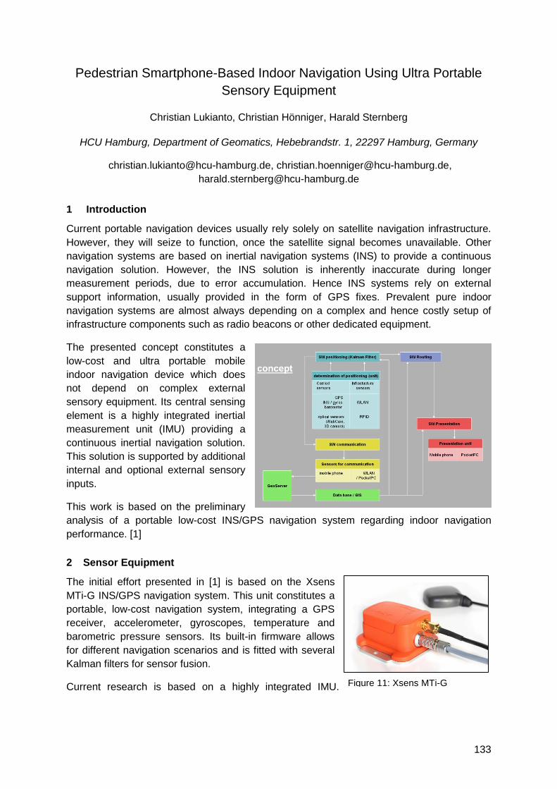
133
Pedestrian Smartphone-Based Indoor Navigation Using Ultra Portable
Sensory Equipment
Christian Lukianto, Christian Hönniger, Harald Sternberg
HCU Hamburg, Department of Geomatics, Hebebrandstr. 1, 22297 Hamburg, Germany
[email protected], [email protected],
1 Introduction
Current portable navigation devices usually rely solely on satellite navigation infrastructure.
However, they will seize to function, once the satellite signal becomes unavailable. Other
navigation systems are based on inertial navigation systems (INS) to provide a continuous
navigation solution. However, the INS solution is inherently inaccurate during longer
measurement periods, due to error accumulation. Hence INS systems rely on external
support information, usually provided in the form of GPS fixes. Prevalent pure indoor
navigation systems are almost always depending on a complex and hence costly setup of
infrastructure components such as radio beacons or other dedicated equipment.
The presented concept constitutes a
low-cost and ultra portable mobile
indoor navigation device which does
not depend on complex external
sensory equipment. Its central sensing
element is a highly integrated inertial
measurement unit (IMU) providing a
continuous inertial navigation solution.
This solution is supported by additional
internal and optional external sensory
inputs.
This work is based on the preliminary
analysis of a portable low-cost INS/GPS navigation system regarding indoor navigation
performance. [1]
2 Sensor Equipment
The initial effort presented in [1] is based on the Xsens
MTi-G INS/GPS navigation system. This unit constitutes a
portable, low-cost navigation system, integrating a GPS
receiver, accelerometer, gyroscopes, temperature and
barometric pressure sensors. Its built-in firmware allows
for different navigation scenarios and is fitted with several
Kalman filters for sensor fusion.
Current research is based on a highly integrated IMU. Figure 11: Xsens MTi-G
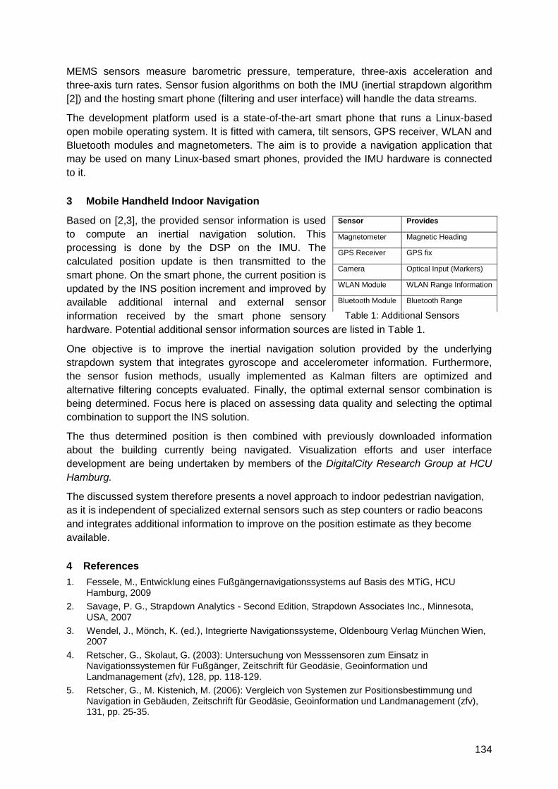
134
MEMS sensors measure barometric pressure, temperature, three-axis acceleration and
three-axis turn rates. Sensor fusion algorithms on both the IMU (inertial strapdown algorithm
[2]) and the hosting smart phone (filtering and user interface) will handle the data streams.
The development platform used is a state-of-the-art smart phone that runs a Linux-based
open mobile operating system. It is fitted with camera, tilt sensors, GPS receiver, WLAN and
Bluetooth modules and magnetometers. The aim is to provide a navigation application that
may be used on many Linux-based smart phones, provided the IMU hardware is connected
to it.
3 Mobile Handheld Indoor Navigation
Based on [2,3], the provided sensor information is used
to compute an inertial navigation solution. This
processing is done by the DSP on the IMU. The
calculated position update is then transmitted to the
smart phone. On the smart phone, the current position is
updated by the INS position increment and improved by
available additional internal and external sensor
information received by the smart phone sensory
hardware. Potential additional sensor information sources are listed in Table 1.
One objective is to improve the inertial navigation solution provided by the underlying
strapdown system that integrates gyroscope and accelerometer information. Furthermore,
the sensor fusion methods, usually implemented as Kalman filters are optimized and
alternative filtering concepts evaluated. Finally, the optimal external sensor combination is
being determined. Focus here is placed on assessing data quality and selecting the optimal
combination to support the INS solution.
The thus determined position is then combined with previously downloaded information
about the building currently being navigated. Visualization efforts and user interface
development are being undertaken by members of the DigitalCity Research Group at HCU
Hamburg.
The discussed system therefore presents a novel approach to indoor pedestrian navigation,
as it is independent of specialized external sensors such as step counters or radio beacons
and integrates additional information to improve on the position estimate as they become
available.
4 References
1. Fessele, M., Entwicklung eines Fußgängernavigationssystems auf Basis des MTiG, HCU Hamburg, 2009
2. Savage, P. G., Strapdown Analytics - Second Edition, Strapdown Associates Inc., Minnesota, USA, 2007
3. Wendel, J., Mönch, K. (ed.), Integrierte Navigationssysteme, Oldenbourg Verlag München Wien, 2007
4. Retscher, G., Skolaut, G. (2003): Untersuchung von Messsensoren zum Einsatz in Navigationssystemen für Fußgänger, Zeitschrift für Geodäsie, Geoinformation und Landmanagement (zfv), 128, pp. 118-129.
5. Retscher, G., M. Kistenich, M. (2006): Vergleich von Systemen zur Positionsbestimmung und Navigation in Gebäuden, Zeitschrift für Geodäsie, Geoinformation und Landmanagement (zfv), 131, pp. 25-35.
Sensor Provides
Magnetometer Magnetic Heading
GPS Receiver GPS fix
Camera Optical Input (Markers)
WLAN Module WLAN Range Information
Bluetooth Module Bluetooth Range
Table 1: Additional Sensors
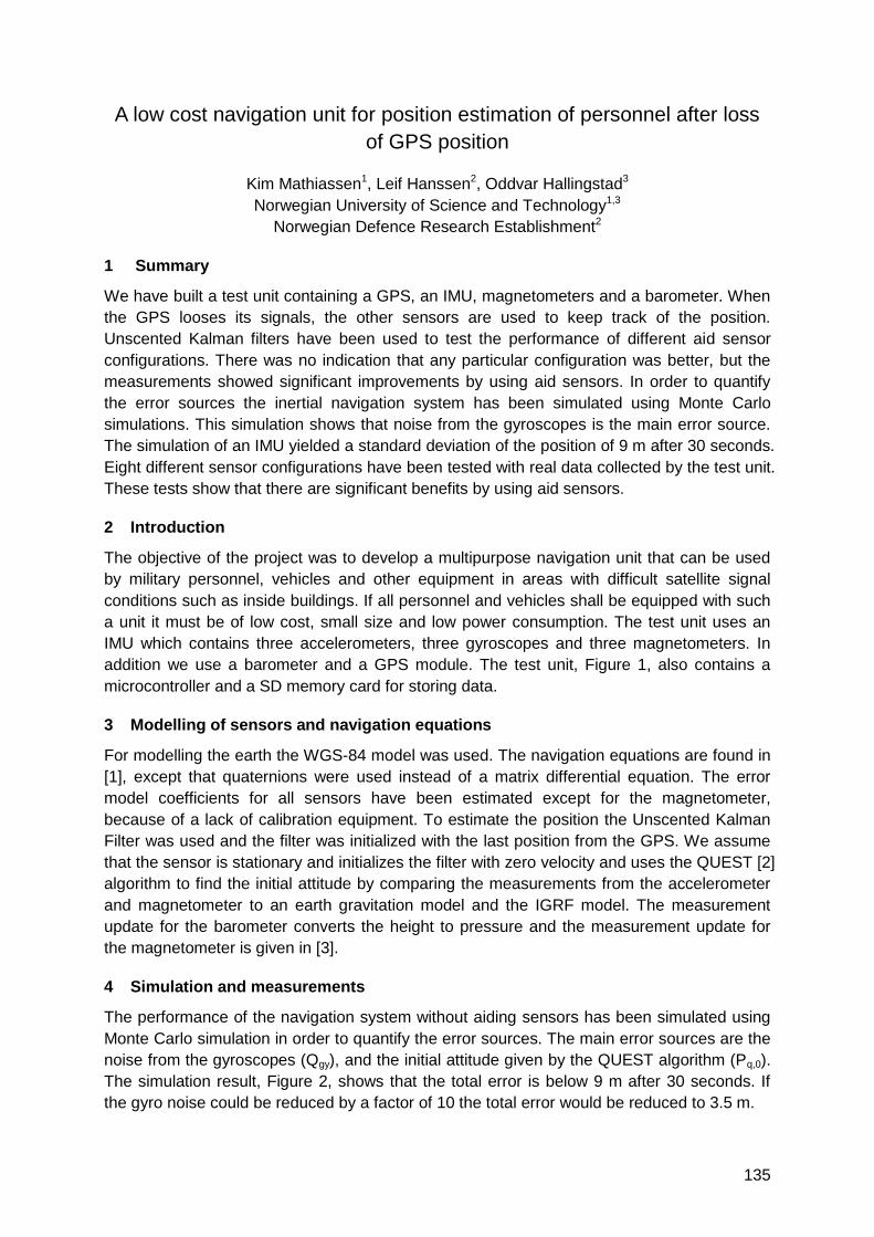
135
A low cost navigation unit for position estimation of personnel after loss
of GPS position
Kim Mathiassen1, Leif Hanssen2, Oddvar Hallingstad3
Norwegian University of Science and Technology1,3
Norwegian Defence Research Establishment2
1 Summary
We have built a test unit containing a GPS, an IMU, magnetometers and a barometer. When
the GPS looses its signals, the other sensors are used to keep track of the position.
Unscented Kalman filters have been used to test the performance of different aid sensor
configurations. There was no indication that any particular configuration was better, but the
measurements showed significant improvements by using aid sensors. In order to quantify
the error sources the inertial navigation system has been simulated using Monte Carlo
simulations. This simulation shows that noise from the gyroscopes is the main error source.
The simulation of an IMU yielded a standard deviation of the position of 9 m after 30 seconds.
Eight different sensor configurations have been tested with real data collected by the test unit.
These tests show that there are significant benefits by using aid sensors.
2 Introduction
The objective of the project was to develop a multipurpose navigation unit that can be used
by military personnel, vehicles and other equipment in areas with difficult satellite signal
conditions such as inside buildings. If all personnel and vehicles shall be equipped with such
a unit it must be of low cost, small size and low power consumption. The test unit uses an
IMU which contains three accelerometers, three gyroscopes and three magnetometers. In
addition we use a barometer and a GPS module. The test unit, Figure 1, also contains a
microcontroller and a SD memory card for storing data.
3 Modelling of sensors and navigation equations
For modelling the earth the WGS-84 model was used. The navigation equations are found in
[1], except that quaternions were used instead of a matrix differential equation. The error
model coefficients for all sensors have been estimated except for the magnetometer,
because of a lack of calibration equipment. To estimate the position the Unscented Kalman
Filter was used and the filter was initialized with the last position from the GPS. We assume
that the sensor is stationary and initializes the filter with zero velocity and uses the QUEST [2]
algorithm to find the initial attitude by comparing the measurements from the accelerometer
and magnetometer to an earth gravitation model and the IGRF model. The measurement
update for the barometer converts the height to pressure and the measurement update for
the magnetometer is given in [3].
4 Simulation and measurements
The performance of the navigation system without aiding sensors has been simulated using
Monte Carlo simulation in order to quantify the error sources. The main error sources are the
noise from the gyroscopes (Qgy), and the initial attitude given by the QUEST algorithm (Pq,0).
The simulation result, Figure 2, shows that the total error is below 9 m after 30 seconds. If
the gyro noise could be reduced by a factor of 10 the total error would be reduced to 3.5 m.
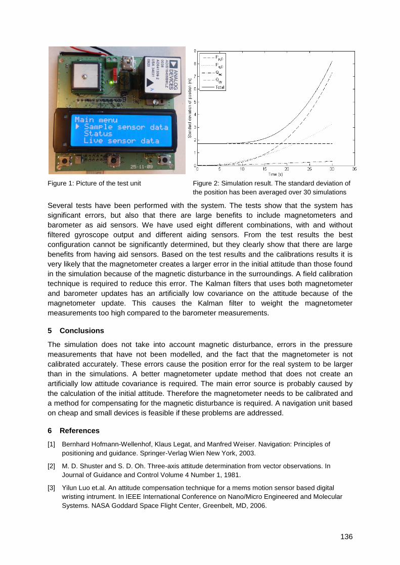
136
Figure 1: Picture of the test unit Figure 2: Simulation result. The standard deviation of
the position has been averaged over 30 simulations
Several tests have been performed with the system. The tests show that the system has
significant errors, but also that there are large benefits to include magnetometers and
barometer as aid sensors. We have used eight different combinations, with and without
filtered gyroscope output and different aiding sensors. From the test results the best
configuration cannot be significantly determined, but they clearly show that there are large
benefits from having aid sensors. Based on the test results and the calibrations results it is
very likely that the magnetometer creates a larger error in the initial attitude than those found
in the simulation because of the magnetic disturbance in the surroundings. A field calibration
technique is required to reduce this error. The Kalman filters that uses both magnetometer
and barometer updates has an artificially low covariance on the attitude because of the
magnetometer update. This causes the Kalman filter to weight the magnetometer
measurements too high compared to the barometer measurements.
5 Conclusions
The simulation does not take into account magnetic disturbance, errors in the pressure
measurements that have not been modelled, and the fact that the magnetometer is not
calibrated accurately. These errors cause the position error for the real system to be larger
than in the simulations. A better magnetometer update method that does not create an
artificially low attitude covariance is required. The main error source is probably caused by
the calculation of the initial attitude. Therefore the magnetometer needs to be calibrated and
a method for compensating for the magnetic disturbance is required. A navigation unit based
on cheap and small devices is feasible if these problems are addressed.
6 References
[1] Bernhard Hofmann-Wellenhof, Klaus Legat, and Manfred Weiser. Navigation: Principles of
positioning and guidance. Springer-Verlag Wien New York, 2003.
[2] M. D. Shuster and S. D. Oh. Three-axis attitude determination from vector observations. In
Journal of Guidance and Control Volume 4 Number 1, 1981.
[3] Yilun Luo et.al. An attitude compensation technique for a mems motion sensor based digital
wristing intrument. In IEEE International Conference on Nano/Micro Engineered and Molecular
Systems. NASA Goddard Space Flight Center, Greenbelt, MD, 2006.
137
A GPS/INS-based architecture for rescue team monitoring
Alberto Croci, Mattia De Agostino, Ambrogio Manzino
Politecnico di Torino, Corso Duca degli Abruzzi 24, IT-10129 Turin
[email protected], [email protected], [email protected]
1 Summary
The present work shows the obtained results using a low-cost pedestrian system made up of
a GPS receiver and an inertial platform. This positioning system can be used by rescue
teams to locate hazard zones and escape routes. Our study shows how multiple sensors can
be used in a non-traditional way: the inertial platform is used as an odometer (step counter)
in which the magnetometers allow the estimation of gyroscope drifts. The GPS receiver,
however, is used to correct the bias when the GPS observables are sufficiently reliable.
Particular focus will be given to the estimation of sensor errors and the reliability of the entire
system, which is a critical problem of these equipments.
2 Introduction
The aim of the our study is to achieve a low cost pedestrian positioning system, that is based
on a metrical reliability and accuracy and suitable for particularly difficult environments such
as burning buildings, devastated villages, etc.
The positioning system is based on the integration of an inertial sensor (XSens MTi), that
includes accelerometers, gyros and magnetometers, and a high sensitivity GPS receiver (u-
blox 5H), specifically designed for indoor positioning applications.
Due to compact size and low weight, all the used sensors are particularly suitable to become
an integral part of rescue teams‘ equipment, for example by mounting the GPS antenna on
the top of a rescuers‘ helmet and the inertial sensor near to the barycentre of the body.
3 The realized pedestrian navigation system
A low-cost pedestrian navigation system requires a proper positioning algorithm that must be
specifically developed and calibrated with respect to the quality of the involved sensors and
to the final applications. Using the traditional algorithms concerning the GPS/INS integration,
indeed, the solution can be inaccurate and often unreliable. The problems are in particular
related to the accelerometer and gyro drifts, to the high inertial measurement noise and to
the high noise and multipath of the received GPS signal.
For these reasons, the proposed solution relies on using the inertial sensor measurements
like a ―step odometer‖, not directly measuring the travelled distance but the time when a well-
known distance (e.g., the step length) is accomplished, and the attitude (e.g., the heading
angle) of the body at the same time. This approach, well known in pedestrian applications, is
therefore solved using the information collected by all the sensors included into the IMU
platform.
The inertial positioning solution is coupled with the data of the GPS receiver, after a careful
data filtering based on a previous analysis of the GPS signal in indoor environments.
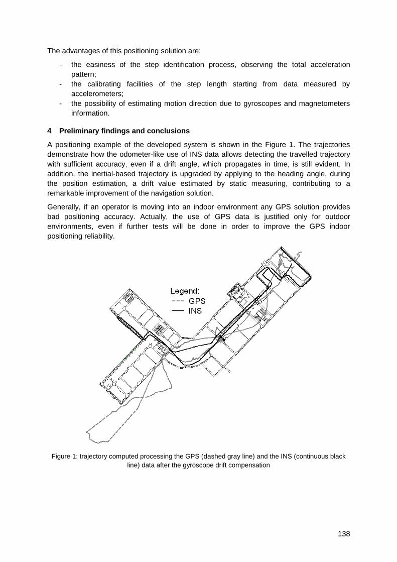
138
The advantages of this positioning solution are:
- the easiness of the step identification process, observing the total acceleration
pattern;
- the calibrating facilities of the step length starting from data measured by
accelerometers;
- the possibility of estimating motion direction due to gyroscopes and magnetometers
information.
4 Preliminary findings and conclusions
A positioning example of the developed system is shown in the Figure 1. The trajectories
demonstrate how the odometer-like use of INS data allows detecting the travelled trajectory
with sufficient accuracy, even if a drift angle, which propagates in time, is still evident. In
addition, the inertial-based trajectory is upgraded by applying to the heading angle, during
the position estimation, a drift value estimated by static measuring, contributing to a
remarkable improvement of the navigation solution.
Generally, if an operator is moving into an indoor environment any GPS solution provides
bad positioning accuracy. Actually, the use of GPS data is justified only for outdoor
environments, even if further tests will be done in order to improve the GPS indoor
positioning reliability.
Figure 1: trajectory computed processing the GPS (dashed gray line) and the INS (continuous black
line) data after the gyroscope drift compensation
139
Hybrid positioning system combining angle-based localization,
pedestrian dead reckoning, and map-filtering
Paul Kemppi1), Juuso Pajunen1), Ville Ranki2), Fabio Belloni2), Terhi Rautiainen2)
1) VTT Technical Research Center of Finland, Espoo, Finland
2) Nokia Research Center, Helsinki, Finland
1 Summary
We present a hybrid indoor positioning solution combining angle-based localization,
pedestrian dead reckoning, and map-filtering. The angle-based localization system provides
absolute location fixes in large, open indoor areas. While the main purpose of these location
fixes is to update the user location, they are also used to adjust the parameters of a
pedestrian dead reckoning (PDR) module that estimates the relative movement of the user
i.e. shape and length of the traversed route. In areas covered by the angle-based localization
system, the user location is a combination of absolute location fixes, PDR estimates, and
map information, which is used to limit the possible movement trajectories of the user within
the building. In other areas, the user location is based on only the PDR estimates and map
information. The hybrid positioning system is evaluated in a trial that is carried out in an office
building that consists of large open areas, office rooms, and connecting corridors.
2 Hybrid positioning system
The Global Positioning System (GPS) provides reliable positioning and navigation to
worldwide users in outdoor environments, but satellite based positioning will not be a realistic
solution for deep indoor spaces due to increasing signal attenuation through building
structures and signal degradation due to multipath propagation. While accurate, commercial
solutions for indoor positioning already exist, they often involve costly and time-consuming
setup phase or require a complex installation of expensive infrastructure.
In this paper, we present a hybrid indoor positioning solution combining location information
from various sources. Absolute positioning estimates are obtained from a novel angle-based
localization system covering a large, open indoor area by using only two transmitters.
Relative positioning information is obtained from a pedestrian dead reckoning (PDR) module
utilizing inertial sensors. In addition, map information (floor plan) is used to limit the possible
movement of a pedestrian within the building.
The angle-of-departure of a communication packet from the transmitter is resolved at the
receiver using the information of antenna array geometry and calibrations. Data received
from a single transmitter is already enough to determine the receiver‘s 2D location when the
height of the receiver is known. In practice the height of the transmitter is assumed to be
around 1.2−1.4m, that is, the height where most people hold their mobile phones. Concurrent
data from several multi-antenna transmitters yield naturally a more accurate location
estimate.
The implemented PDR method uses step detection and step length estimation to
approximate travelled distance. Step detection is based on peak detection of total linear
acceleration (total acceleration minus gravity), and step length estimation is based on
assumption that there exists a relation between time elapsed between two consecutive steps,
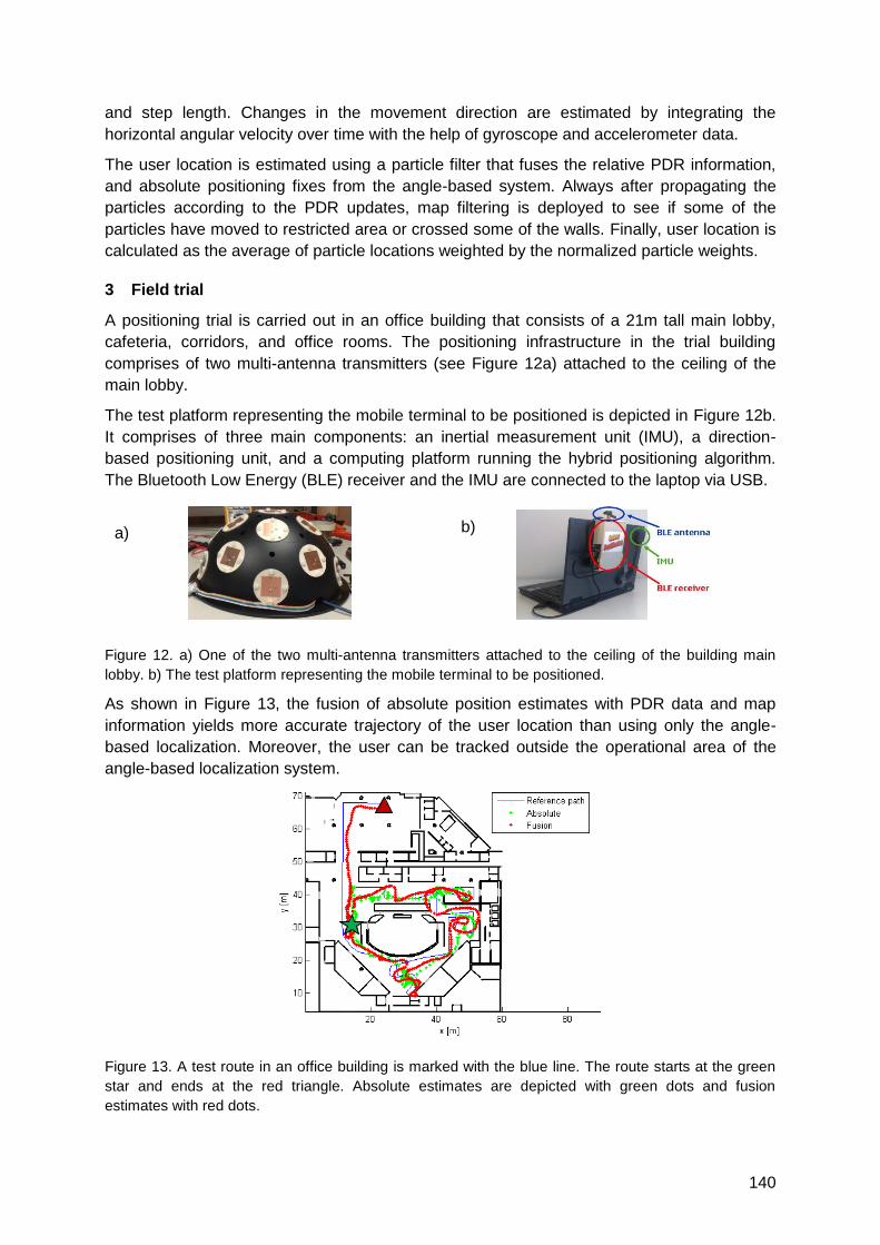
140
and step length. Changes in the movement direction are estimated by integrating the
horizontal angular velocity over time with the help of gyroscope and accelerometer data.
The user location is estimated using a particle filter that fuses the relative PDR information,
and absolute positioning fixes from the angle-based system. Always after propagating the
particles according to the PDR updates, map filtering is deployed to see if some of the
particles have moved to restricted area or crossed some of the walls. Finally, user location is
calculated as the average of particle locations weighted by the normalized particle weights.
3 Field trial
A positioning trial is carried out in an office building that consists of a 21m tall main lobby,
cafeteria, corridors, and office rooms. The positioning infrastructure in the trial building
comprises of two multi-antenna transmitters (see Figure 12a) attached to the ceiling of the
main lobby.
The test platform representing the mobile terminal to be positioned is depicted in Figure 12b.
It comprises of three main components: an inertial measurement unit (IMU), a direction-
based positioning unit, and a computing platform running the hybrid positioning algorithm.
The Bluetooth Low Energy (BLE) receiver and the IMU are connected to the laptop via USB.
Figure 12. a) One of the two multi-antenna transmitters attached to the ceiling of the building main
lobby. b) The test platform representing the mobile terminal to be positioned.
As shown in Figure 13, the fusion of absolute position estimates with PDR data and map
information yields more accurate trajectory of the user location than using only the angle-
based localization. Moreover, the user can be tracked outside the operational area of the
angle-based localization system.
Figure 13. A test route in an office building is marked with the blue line. The route starts at the green
star and ends at the red triangle. Absolute estimates are depicted with green dots and fusion
estimates with red dots.
a) b)
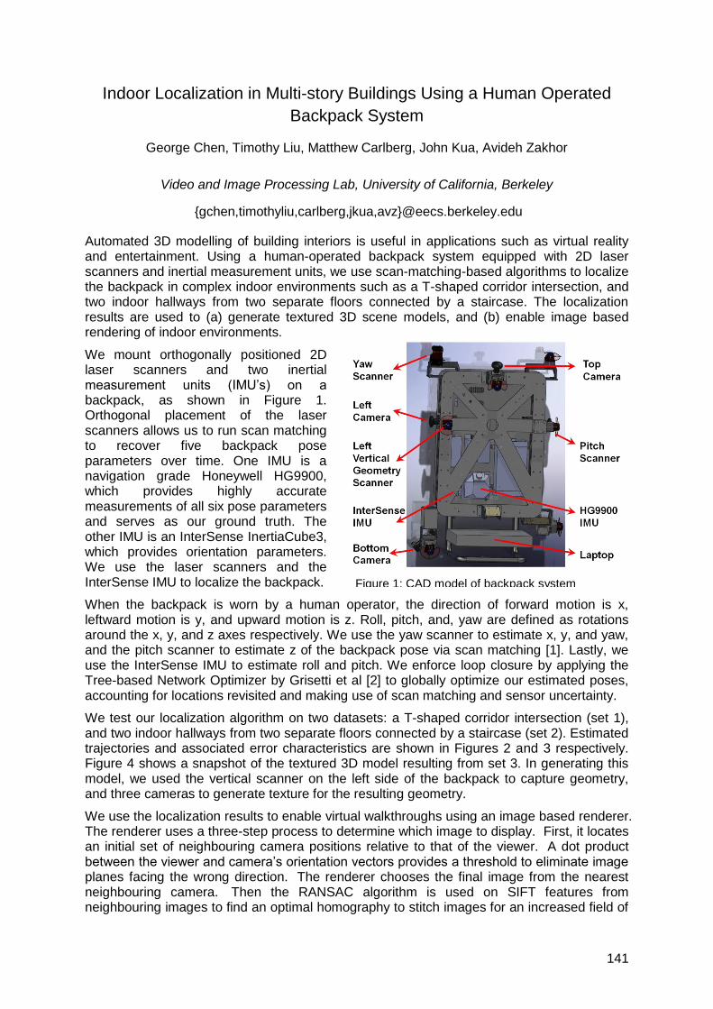
141
Indoor Localization in Multi-story Buildings Using a Human Operated
Backpack System
George Chen, Timothy Liu, Matthew Carlberg, John Kua, Avideh Zakhor
Video and Image Processing Lab, University of California, Berkeley
{gchen,timothyliu,carlberg,jkua,avz}@eecs.berkeley.edu
Automated 3D modelling of building interiors is useful in applications such as virtual reality and entertainment. Using a human-operated backpack system equipped with 2D laser scanners and inertial measurement units, we use scan-matching-based algorithms to localize the backpack in complex indoor environments such as a T-shaped corridor intersection, and two indoor hallways from two separate floors connected by a staircase. The localization results are used to (a) generate textured 3D scene models, and (b) enable image based rendering of indoor environments.
We mount orthogonally positioned 2D laser scanners and two inertial measurement units (IMU‘s) on a backpack, as shown in Figure 1. Orthogonal placement of the laser scanners allows us to run scan matching to recover five backpack pose parameters over time. One IMU is a navigation grade Honeywell HG9900, which provides highly accurate measurements of all six pose parameters and serves as our ground truth. The other IMU is an InterSense InertiaCube3, which provides orientation parameters. We use the laser scanners and the InterSense IMU to localize the backpack.
When the backpack is worn by a human operator, the direction of forward motion is x, leftward motion is y, and upward motion is z. Roll, pitch, and, yaw are defined as rotations around the x, y, and z axes respectively. We use the yaw scanner to estimate x, y, and yaw, and the pitch scanner to estimate z of the backpack pose via scan matching [1]. Lastly, we use the InterSense IMU to estimate roll and pitch. We enforce loop closure by applying the Tree-based Network Optimizer by Grisetti et al [2] to globally optimize our estimated poses, accounting for locations revisited and making use of scan matching and sensor uncertainty.
We test our localization algorithm on two datasets: a T-shaped corridor intersection (set 1), and two indoor hallways from two separate floors connected by a staircase (set 2). Estimated trajectories and associated error characteristics are shown in Figures 2 and 3 respectively. Figure 4 shows a snapshot of the textured 3D model resulting from set 3. In generating this model, we used the vertical scanner on the left side of the backpack to capture geometry, and three cameras to generate texture for the resulting geometry.
We use the localization results to enable virtual walkthroughs using an image based renderer. The renderer uses a three-step process to determine which image to display. First, it locates an initial set of neighbouring camera positions relative to that of the viewer. A dot product between the viewer and camera‘s orientation vectors provides a threshold to eliminate image planes facing the wrong direction. The renderer chooses the final image from the nearest neighbouring camera. Then the RANSAC algorithm is used on SIFT features from neighbouring images to find an optimal homography to stitch images for an increased field of
Figure 1: CAD model of backpack system
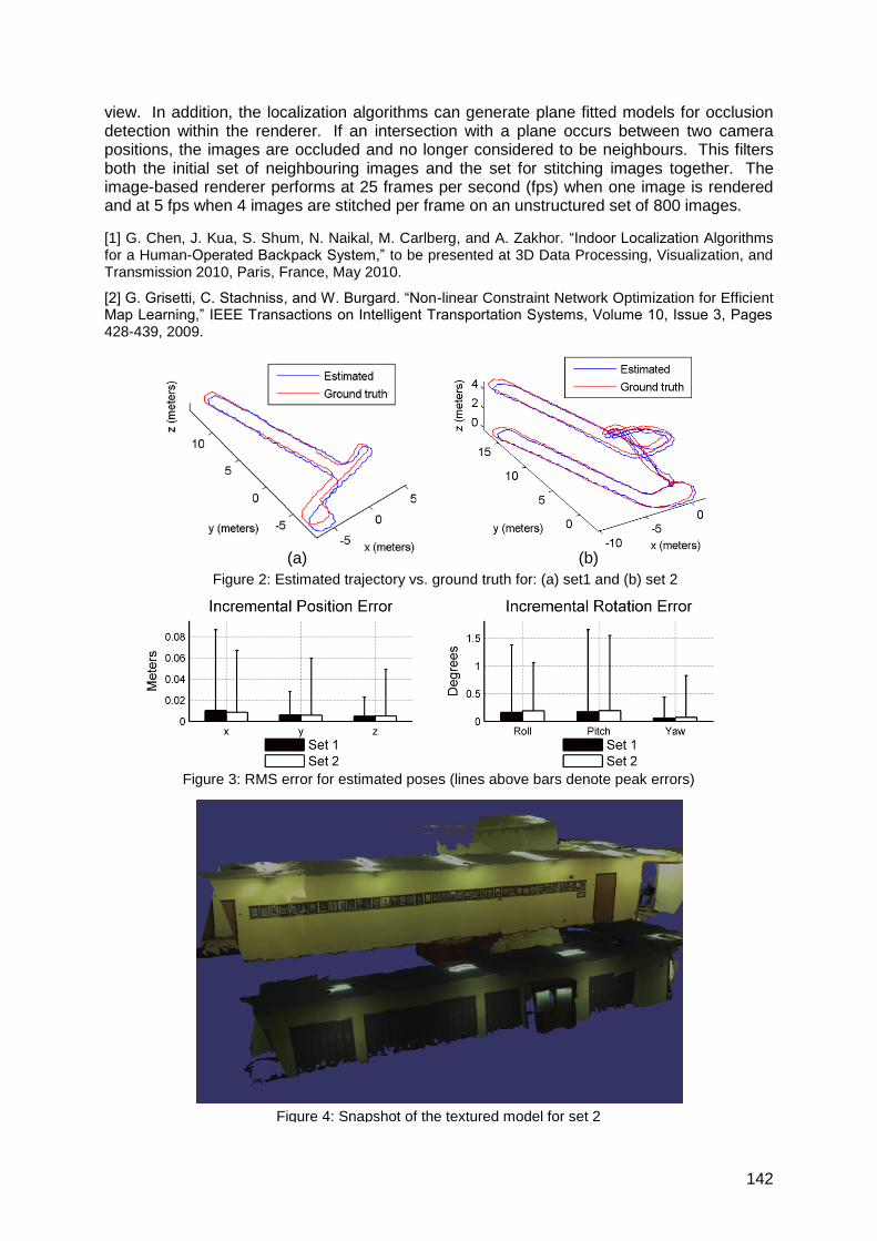
142
view. In addition, the localization algorithms can generate plane fitted models for occlusion detection within the renderer. If an intersection with a plane occurs between two camera positions, the images are occluded and no longer considered to be neighbours. This filters both the initial set of neighbouring images and the set for stitching images together. The image-based renderer performs at 25 frames per second (fps) when one image is rendered and at 5 fps when 4 images are stitched per frame on an unstructured set of 800 images.
[1] G. Chen, J. Kua, S. Shum, N. Naikal, M. Carlberg, and A. Zakhor. ―Indoor Localization Algorithms for a Human-Operated Backpack System,‖ to be presented at 3D Data Processing, Visualization, and Transmission 2010, Paris, France, May 2010.
[2] G. Grisetti, C. Stachniss, and W. Burgard. ―Non-linear Constraint Network Optimization for Efficient Map Learning,‖ IEEE Transactions on Intelligent Transportation Systems, Volume 10, Issue 3, Pages 428-439, 2009.
Figure 2: Estimated trajectory vs. ground truth for: (a) set1 and (b) set 2
Figure 4: Snapshot of the textured model for set 2
(b) (a)
Figure 3: RMS error for estimated poses (lines above bars denote peak errors)
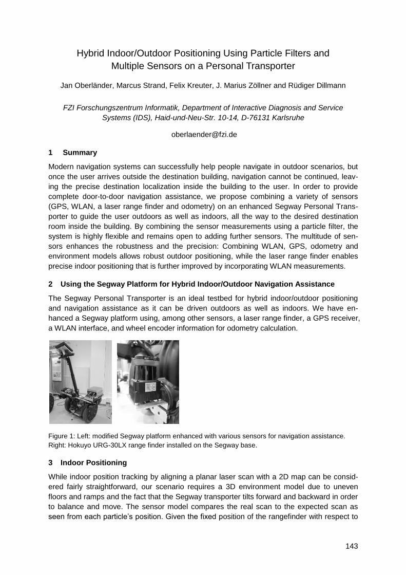
143
Hybrid Indoor/Outdoor Positioning Using Particle Filters and
Multiple Sensors on a Personal Transporter
Jan Oberländer, Marcus Strand, Felix Kreuter, J. Marius Zöllner and Rüdiger Dillmann
FZI Forschungszentrum Informatik, Department of Interactive Diagnosis and Service
Systems (IDS), Haid-und-Neu-Str. 10-14, D-76131 Karlsruhe
1 Summary
Modern navigation systems can successfully help people navigate in outdoor scenarios, but
once the user arrives outside the destination building, navigation cannot be continued, leav-
ing the precise destination localization inside the building to the user. In order to provide
complete door-to-door navigation assistance, we propose combining a variety of sensors
(GPS, WLAN, a laser range finder and odometry) on an enhanced Segway Personal Trans-
porter to guide the user outdoors as well as indoors, all the way to the desired destination
room inside the building. By combining the sensor measurements using a particle filter, the
system is highly flexible and remains open to adding further sensors. The multitude of sen-
sors enhances the robustness and the precision: Combining WLAN, GPS, odometry and
environment models allows robust outdoor positioning, while the laser range finder enables
precise indoor positioning that is further improved by incorporating WLAN measurements.
2 Using the Segway Platform for Hybrid Indoor/Outdoor Navigation Assistance
The Segway Personal Transporter is an ideal testbed for hybrid indoor/outdoor positioning
and navigation assistance as it can be driven outdoors as well as indoors. We have en-
hanced a Segway platform using, among other sensors, a laser range finder, a GPS receiver,
a WLAN interface, and wheel encoder information for odometry calculation.
Figure 1: Left: modified Segway platform enhanced with various sensors for navigation assistance.
Right: Hokuyo URG-30LX range finder installed on the Segway base.
3 Indoor Positioning
While indoor position tracking by aligning a planar laser scan with a 2D map can be consid-
ered fairly straightforward, our scenario requires a 3D environment model due to uneven
floors and ramps and the fact that the Segway transporter tilts forward and backward in order
to balance and move. The sensor model compares the real scan to the expected scan as
seen from each particle‘s position. Given the fixed position of the rangefinder with respect to
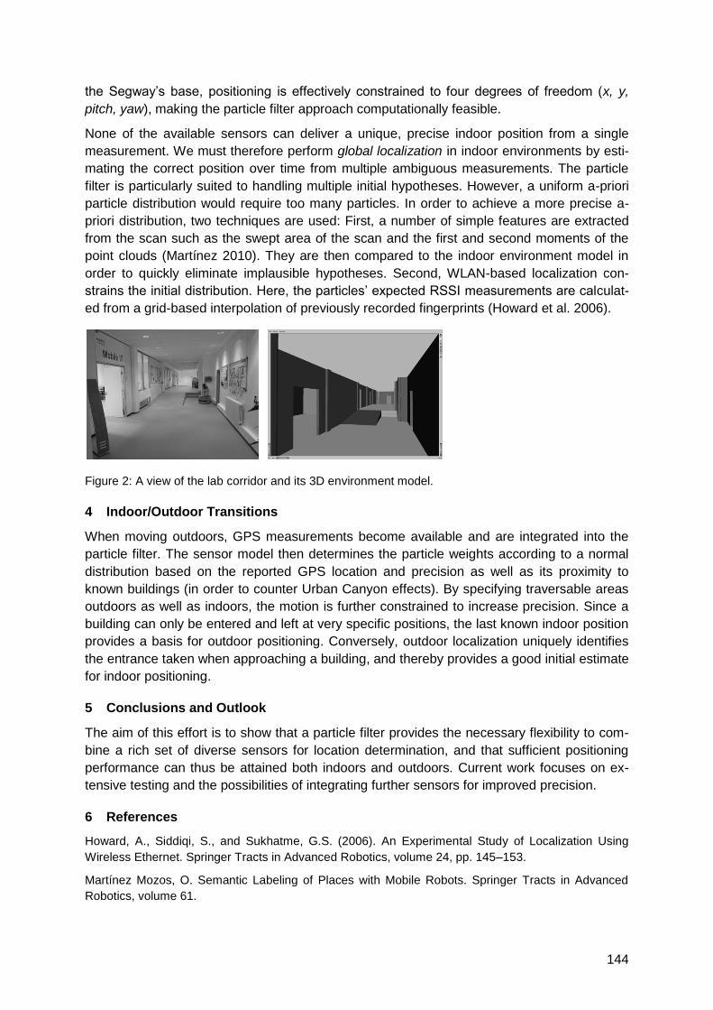
144
the Segway‘s base, positioning is effectively constrained to four degrees of freedom (x, y,
pitch, yaw), making the particle filter approach computationally feasible.
None of the available sensors can deliver a unique, precise indoor position from a single
measurement. We must therefore perform global localization in indoor environments by esti-
mating the correct position over time from multiple ambiguous measurements. The particle
filter is particularly suited to handling multiple initial hypotheses. However, a uniform a-priori
particle distribution would require too many particles. In order to achieve a more precise a-
priori distribution, two techniques are used: First, a number of simple features are extracted
from the scan such as the swept area of the scan and the first and second moments of the
point clouds (Martínez 2010). They are then compared to the indoor environment model in
order to quickly eliminate implausible hypotheses. Second, WLAN-based localization con-
strains the initial distribution. Here, the particles‘ expected RSSI measurements are calculat-
ed from a grid-based interpolation of previously recorded fingerprints (Howard et al. 2006).
Figure 2: A view of the lab corridor and its 3D environment model.
4 Indoor/Outdoor Transitions
When moving outdoors, GPS measurements become available and are integrated into the
particle filter. The sensor model then determines the particle weights according to a normal
distribution based on the reported GPS location and precision as well as its proximity to
known buildings (in order to counter Urban Canyon effects). By specifying traversable areas
outdoors as well as indoors, the motion is further constrained to increase precision. Since a
building can only be entered and left at very specific positions, the last known indoor position
provides a basis for outdoor positioning. Conversely, outdoor localization uniquely identifies
the entrance taken when approaching a building, and thereby provides a good initial estimate
for indoor positioning.
5 Conclusions and Outlook
The aim of this effort is to show that a particle filter provides the necessary flexibility to com-
bine a rich set of diverse sensors for location determination, and that sufficient positioning
performance can thus be attained both indoors and outdoors. Current work focuses on ex-
tensive testing and the possibilities of integrating further sensors for improved precision.
6 References
Howard, A., Siddiqi, S., and Sukhatme, G.S. (2006). An Experimental Study of Localization Using
Wireless Ethernet. Springer Tracts in Advanced Robotics, volume 24, pp. 145–153.
Martínez Mozos, O. Semantic Labeling of Places with Mobile Robots. Springer Tracts in Advanced
Robotics, volume 61.

145
Improved Vehicle Positioning for Indoor Navigation in Parking Garages
Through Commercially Available Maps
Johannes Wagner(1), Carsten Isert(1), Arne Purschwitz(1), Arnold Kistner(2)
(1) BMW Group Research and Technology, Hanauerstr. 46, 80992 München
(2) Institut für Angewandte und Experimentelle Mechanik, Universität Stuttgart, Pfaffenwaldring 9, 70569 Stuttgart
[email protected], [email protected], [email protected]
1 Introduction
Large parking garages are often a challenge for drivers as orientation in complex
environments is especially difficult. Consequently, appropriate guidance is needed to assist
the driver in tasks such as finding an individual parking spot or guidance to the right exit. In
this context, precise positioning is essential. Accurate vehicle positioning is also a starting
point for seamlessly continued navigation, e.g. with pedestrian navigation devices.
Conventional vehicle navigation devices typically use a cascaded filter algorithm (e.g.
Retscher [1]). In a first step, an Extended Kalman-Filter (EKF) fuses data from dead
reckoning (DR) based on inertial sensors with measurements from a Global Navigation
Satellite System (GNSS). The resulting position estimate is then matched to a digital map. In
absence of GNSS measurements, however, sensor bias and drift cause the fidelity of the
estimation to decrease quickly.
Therefore, we present a method that allows precise vehicle positioning independent of GNSS
and instead using DR and a digital map of the parking garage. No additional hardware or
infrastructure is needed, since the used inertial sensors and odometry are available in
current premium series vehicles. Only additional map data for parking garages is required,
which can be gathered with current technology available at map companies.
2 Map Data and Map Matching
The map data used was based on the standard NAVTEQ core map in RDF format and was
extended with data for the parking garages. This data was gathered in part by NAVTEQ with
IMU equipped vehicles with relative accuracy below 5m and some was generated from
building plans and transferred into RDF format with relative accuracy below 1m.
The used map matching algorithm uses a position estimate to determine the most likely map
segment by calculating a matching probability measure for each segment in range, based on
position, heading, speed, link connectivity and basic traffic rules. It yields a projection of the
position estimate onto the segment as well as additional information, e.g. the probability
measure and the distance to the closest intersection.
3 Data Fusion
The key idea in our approach is to use the matched position as an additional measurement,
similar to a GNSS measurement. Thus, high positioning precision is maintained even where
GNSS signals are unavailable. An overview of the filter is shown in Fig. 1. In a first step, data
from odometry and inertial sensors is processed in an EKF using an extended single-track
vehicle model and sensor bias compensation. The central EKF fuses the resulting position
updates with map-matched positions from previous estimates and optionally with GNSS data.
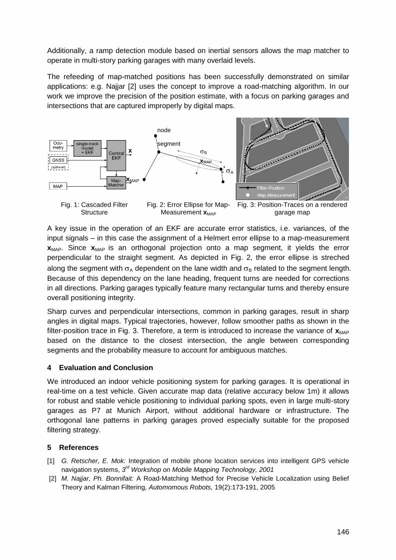
146
Additionally, a ramp detection module based on inertial sensors allows the map matcher to
operate in multi-story parking garages with many overlaid levels.
The refeeding of map-matched positions has been successfully demonstrated on similar
applications: e.g. Najjar [2] uses the concept to improve a road-matching algorithm. In our
work we improve the precision of the position estimate, with a focus on parking garages and
intersections that are captured improperly by digital maps.
Fig. 1: Cascaded Filter
Structure Fig. 2: Error Ellipse for Map-
Measurement xMAP Fig. 3: Position-Traces on a rendered
garage map
A key issue in the operation of an EKF are accurate error statistics, i.e. variances, of the
input signals – in this case the assignment of a Helmert error ellipse to a map-measurement
xMAP. Since xMAP is an orthogonal projection onto a map segment, it yields the error
perpendicular to the straight segment. As depicted in Fig. 2, the error ellipse is streched
along the segment with A dependent on the lane width and B related to the segment length.
Because of this dependency on the lane heading, frequent turns are needed for corrections
in all directions. Parking garages typically feature many rectangular turns and thereby ensure
overall positioning integrity.
Sharp curves and perpendicular intersections, common in parking garages, result in sharp
angles in digital maps. Typical trajectories, however, follow smoother paths as shown in the
filter-position trace in Fig. 3. Therefore, a term is introduced to increase the variance of xMAP
based on the distance to the closest intersection, the angle between corresponding
segments and the probability measure to account for ambiguous matches.
4 Evaluation and Conclusion
We introduced an indoor vehicle positioning system for parking garages. It is operational in
real-time on a test vehicle. Given accurate map data (relative accuracy below 1m) it allows
for robust and stable vehicle positioning to individual parking spots, even in large multi-story
garages as P7 at Munich Airport, without additional hardware or infrastructure. The
orthogonal lane patterns in parking garages proved especially suitable for the proposed
filtering strategy.
5 References
[1] G. Retscher, E. Mok: Integration of mobile phone location services into intelligent GPS vehicle
navigation systems, 3rd
Workshop on Mobile Mapping Technology, 2001
[2] M. Najjar, Ph. Bonnifait: A Road-Matching Method for Precise Vehicle Localization using Belief
Theory and Kalman Filtering, Automomous Robots, 19(2):173-191, 2005
A
B
xMAP
xMAP
x
node
segment
147
Tracking Persons with an Autarkic Radio-Based Multi-Sensor System
Enrico Köppe, Heiko Will, Achim Liers, Jochen Schiller
Fachgruppe VIII.1 Mess- und Prüftechnik; Sensorik
BAM, Bundesanstalt für Materialforschung und -prüfung, Unter den Eichen 87, 12205 Berlin
Arbeitsgruppe "Computer Systems & Telematics" Fachbereich Mathematik und Informatik
Freie Universität Berlin, Takustr. 9, 14195 Berlin
[email protected] [hwill],[liers],[schiller]@inf.fu-berlin.de
1 Summary
The combination of different sensors from different areas of technology, including software
analysis and parameterisation led to an innovative indoor tracking system based on a
wireless sensor network. The new hardware platform represents the outcome of sensor
fusion with three-dimensional motion vector pattern recognition. The measured data of the
individual sensors is evaluated in respect to the physical quantities and additionally to their
weighted quality indicators. This quality assessment reduces the influence of external
environmental parameters on the motion vector and is used for an enhanced position
estimation. In addition to the motion-sensor data, the information from the radio transceiver is
exploited for the recognition of the environment. This enables gradual reconstruction of the
environmental scenario. The fusion of all the information obtained using hardware and
software minimises the relative average deviation to about ± 2 m for a spatial coverage of
100 m.
2 The BodyGuard System
The research of wireless sensor networks often focuses on algorithms and simulation. Our
system focuses on the accuracy of the gathered sensor data and the robustness of the
sensor network.
Table 1: Components
Name/Manufacturer Function Application
MSP430F2618 / TI Microcontroller Processing and pattern recognition of sensor data
PAN2355 / Panasonic, TI Transceiver, CC1101 Wireless Data Communications / Building Reconstruction
MMA7260 / Freescale Triple Axis Accelerometer Transaction Data
EMC-03RC / Murata Gyroscopes Rotation data
FSA03 / Falcom, u-Blox GPS-Receiver, UBX-G5010 Absolute position determination (Outdoor)
HMC6352 / Honeywell Two Axis Compass Absolute angle determination
MS5540 / Intersema Barometer Altitude change / environment condition
SHT15 / Sensirion Humidity & Temp Sensor Environmental condition
RMCM01 / Polar Heart Rate Receiver Vital signs
1. The design objectives for the newly developed hardware platform were the
miniaturization of the 3D sensor and the interaction and combination of each other. The
hardware platform consists of a microcontroller from the MSP430 series (Texas
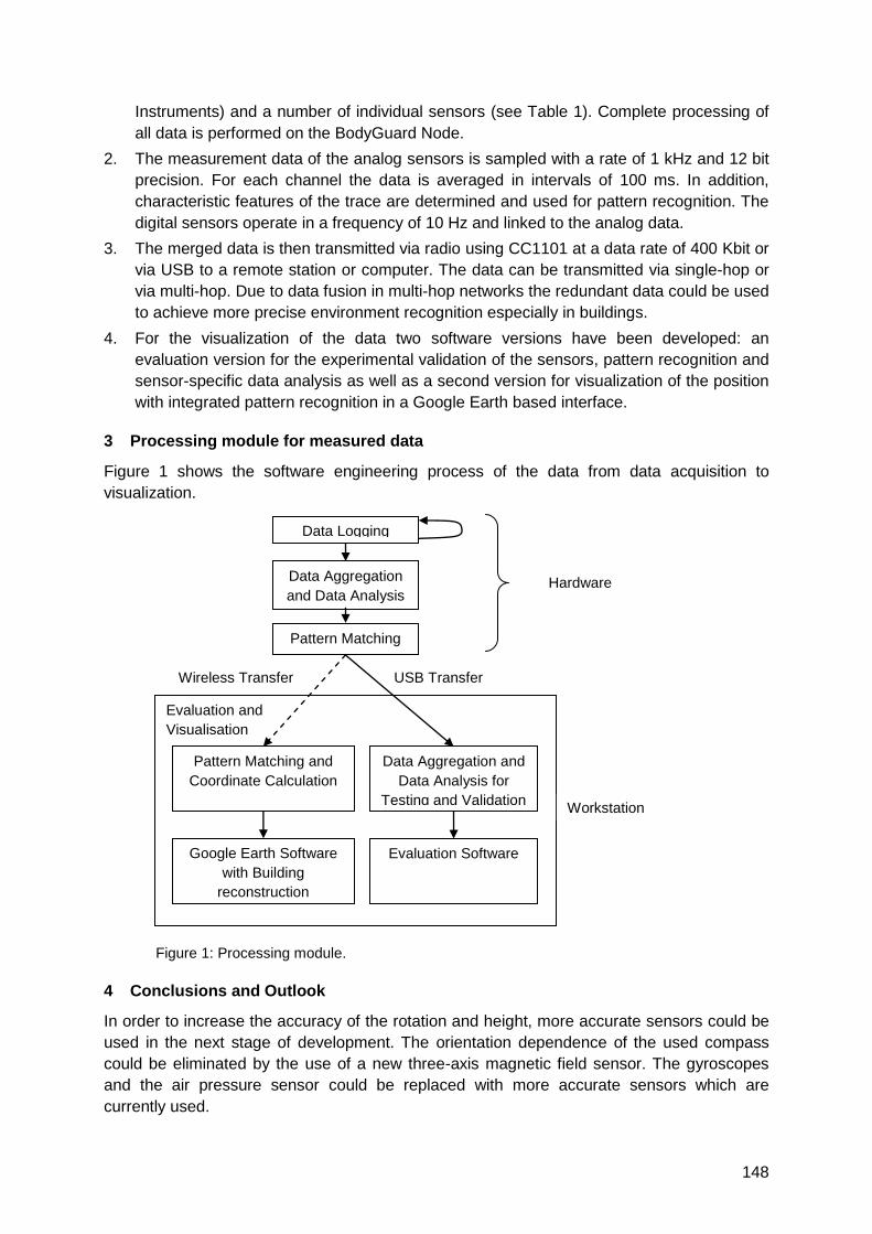
148
Instruments) and a number of individual sensors (see Table 1). Complete processing of
all data is performed on the BodyGuard Node.
2. The measurement data of the analog sensors is sampled with a rate of 1 kHz and 12 bit
precision. For each channel the data is averaged in intervals of 100 ms. In addition,
characteristic features of the trace are determined and used for pattern recognition. The
digital sensors operate in a frequency of 10 Hz and linked to the analog data.
3. The merged data is then transmitted via radio using CC1101 at a data rate of 400 Kbit or
via USB to a remote station or computer. The data can be transmitted via single-hop or
via multi-hop. Due to data fusion in multi-hop networks the redundant data could be used
to achieve more precise environment recognition especially in buildings.
4. For the visualization of the data two software versions have been developed: an
evaluation version for the experimental validation of the sensors, pattern recognition and
sensor-specific data analysis as well as a second version for visualization of the position
with integrated pattern recognition in a Google Earth based interface.
3 Processing module for measured data
Figure 1 shows the software engineering process of the data from data acquisition to
visualization.
Figure 1: Processing module.
4 Conclusions and Outlook
In order to increase the accuracy of the rotation and height, more accurate sensors could be
used in the next stage of development. The orientation dependence of the used compass
could be eliminated by the use of a new three-axis magnetic field sensor. The gyroscopes
and the air pressure sensor could be replaced with more accurate sensors which are
currently used.
Evaluation and
Visualisation
Hardware
Plattform
Data Aggregation
and Data Analysis
Google Earth Software
with Building
reconstruction
Data Aggregation and
Data Analysis for
Testing and Validation
Data Logging
Wireless Transfer
Workstation
Pattern Matching
USB Transfer
Pattern Matching and
Coordinate Calculation
Evaluation Software

149
Set-Up of a Combined Indoor and Outdoor Positioning Solution and
Experimental Results
Lars Johannes, Jonas Degener, Wolfgang Niemeier
TU Braunschweig, Institut für Geodäsie und Photogrammetrie, Gauss-Str. 22, D-38106
Braunschweig
[email protected], [email protected], [email protected]
1 Introduction
Within an European research project, our main task is the development of a combined indoor
and outdoor positioning solution. The objective of this hybrid system is to improve the safety
of workers on construction sites. Therefore it is important to know the position of workers at
all times without latency in a central coordination office. The aim is to develop a robust
methodology which covers indoor and outdoor scenarios, where the current 3D position of
every worker is available for himself and in a central risk management office.
2 Requirements for the Positioning Solution
The developed system can be applied in all industrial environments. Construction sites are
most challenging, as the buildings are raised up or demolished, walls will be mounted or
removed. Signal propagation in such an environment makes the positioning to a challenging
task. Construction sites can be subdivided into indoor, outdoor and boundary areas
(Figure 1).
Figure 1: Indoor, outdoor and boundary areas on a construction site. Photo by Dave Piper (CC)
The requirements are: accuracy up to 0.5 m, position update rate 2 Hz or higher, reliability
and robustness: close to 100%, to be carried at working clothes: small and light components
and multi-directional data communication. A good compromise between costs and workers
safety must be found.
3 Proposed System
Our approach is a hybrid system, consisting of an UWB and RFID system mainly for indoor
and a DGNSS used for outdoor environments, see Table 2. The positioning system may be
supported by additional hardware like barometric sensors and Inertial Measurement Units
(IMU). ZigBee communication nodes in mesh configuration will be used for data transfer,
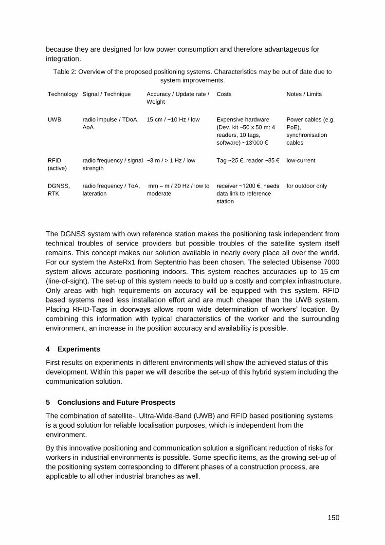
150
because they are designed for low power consumption and therefore advantageous for
integration.
Table 2: Overview of the proposed positioning systems. Characteristics may be out of date due to
system improvements.
Technology Signal / Technique Accuracy / Update rate /
Weight
Costs Notes / Limits
UWB radio impulse / TDoA,
AoA
15 cm / ~10 Hz / low Expensive hardware
(Dev. kit ~50 x 50 m: 4
readers, 10 tags,
software) ~13'000 €
Power cables (e.g.
PoE),
synchronisation
cables
RFID
(active)
radio frequency / signal
strength
~3 m / > 1 Hz / low Tag ~25 €, reader ~85 € low-current
DGNSS,
RTK
radio frequency / ToA,
lateration
mm – m / 20 Hz / low to
moderate
receiver ~1200 €, needs
data link to reference
station
for outdoor only
The DGNSS system with own reference station makes the positioning task independent from
technical troubles of service providers but possible troubles of the satellite system itself
remains. This concept makes our solution available in nearly every place all over the world.
For our system the AsteRx1 from Septentrio has been chosen. The selected Ubisense 7000
system allows accurate positioning indoors. This system reaches accuracies up to 15 cm
(line-of-sight). The set-up of this system needs to build up a costly and complex infrastructure.
Only areas with high requirements on accuracy will be equipped with this system. RFID
based systems need less installation effort and are much cheaper than the UWB system.
Placing RFID-Tags in doorways allows room wide determination of workers‘ location. By
combining this information with typical characteristics of the worker and the surrounding
environment, an increase in the position accuracy and availability is possible.
4 Experiments
First results on experiments in different environments will show the achieved status of this
development. Within this paper we will describe the set-up of this hybrid system including the
communication solution.
5 Conclusions and Future Prospects
The combination of satellite-, Ultra-Wide-Band (UWB) and RFID based positioning systems
is a good solution for reliable localisation purposes, which is independent from the
environment.
By this innovative positioning and communication solution a significant reduction of risks for
workers in industrial environments is possible. Some specific items, as the growing set-up of
the positioning system corresponding to different phases of a construction process, are
applicable to all other industrial branches as well.

151
Hybrid IMU Pedestrian Navigation 2
Auditorium G3
Wednesday, September 15, 16:00 – 18:00

153
Infrastructure-independent person localization with IEEE 802.15.4 WSN
Johannes Schmid (corresponding author), Wilhelm Stork, Klaus D. Müller-Glaser
Karlsruhe Institute of Technology (KIT), Institute for Information Processing Technology
(ITIV), Vincenz-Prießnitz-Str.1, 76131 Karlsruhe, GERMANY, [email protected]
1 Summary and system concept
In this paper, a new concept for infrastructure independent person localization by means of a
wireless sensor network (WSN) in combination with a pedestrian dead reckoning device
(PDR) is proposed. In an arbitrary in- and outdoor environment, each nodes position
estimation is initialized upon its deployment by means of a MEMS based PDR device if no
GPS signal is available at the deployment position and time (anchor node deployment).
Every anchor node broadcasts its (estimated) position as well as an uncertainty parameter in
regular intervals, and mobile nodes without inertial navigation capabilities (carried on the
body of moving persons in the area of interest, on-body nodes) estimate their positions
based on the received signal strength (RSS) and uncertainty information of all received
packets. Additionally, a GPS-equipped subset of the anchor nodes allows for an
improvement of the position estimation as soon as a GPS fix can be obtained at the
deployment position. The uncertain position estimation of the networked nodes is enhanced
during runtime based on the RSS values of packets received from neighbouring nodes within
one hop communication range.
2 Motivation and state of the art
A system that allows the localization of mobile persons and that can be used in both in- and
outdoor environments and does not require advance knowledge of the surroundings of the
area of interest, could be applied in a variety of different fields. The tracking of fire-fighters
that enter a burning building or a complex of buildings, the coordination of a police operation
or also the supervision of Alzheimer patients in the compounds of a retirement facility are
some example applications in which an ad-hoc localization system could be of significant
help. The considered requirements of such a system include scalability in terms of number
nodes and covered area (which necessitates a low-cost implementation of the nodes),
robustness against changing influences in varying environments and accuracy in the range
of several meters. The combination of a pedestrian inertial navigation unit with a WSN seems
to be an interesting approach to these exigencies.
There has been some work on integration of an IMU with WSN technology [1] for localization
purposes and some approaches to the simultaneous localization and map building (SLAM)
problem within the field of robotics seem to be comparable to a certain degree [2], but to our
knowledge there are currently no comparable approaches to ad-hoc person localization.
3 System aspects overview
Three main areas of interest are explored within the project and further explained in the
paper:
PDR: combination of sensor node and inertial measurement unit (IMU): the PDR
consists of a combination of a commercially available IMU with a proprietary sensor
154
node. This node can thus use pre-processed alignment information (data-fusion of 3
gyros, 3 accelerometers and a 3-axial magnetometer, processed in a digital signal
processor), to establish information about the movement direction of the person
carrying the node. The covered distance is then estimated from a step counter
(acceleration sensor) in combination with the available information from other sensor
nodes within communication range (data fusion).
ZigBee-based ad-hoc network deployment: the use of the ZigBee protocol stack
for the development of the required network and communication infrastructure allows
a quick implementation of the desired functionality. The current system provides a
robust localization and implements the mentioned functionalities.
Received signal strength (RSS) position estimation: the position estimation
algorithm for on-body nodes has to be computable on the limited resources of a low-
cost microcontroller (MCU) and has to be robust against RSS fluctuations and
systematic errors caused by the changing environment and position of the on-body
node. A very simple localization approach to cope with these impediments has been
designed and seems to allow reasonable accurate position estimation.
4 Current development status and outlook
So far, the implementation of the outlined network and localization functions and the
development of the required hardware components (cheap and extensible sensor nodes,
connection platform for inertial measurement unit) have been completed. First experiments
with the developed RSS-based localization system show promising results for the localization
of on-body nodes in an outdoor environment if the anchor nodes have known positions.
At the moment, further in- and outdoor experiments are carried out to collect a
comprehensive real-world database for the development and test of localization algorithms
that provide a robust functionality independent of the environment. Based on this database,
the simulation model will then be tuned and a numeric optimization of localization with
estimated (inaccurate) anchor node positions can be started. The next steps include the
development of the described PDR and the implementation of the node deployment process.
5 Conclusions and paper topic
The proposed system seems to be a promising approach to infrastructure independent ad-
hoc person localization in WSN. The paper includes a detailed description of the outlined
system and the current state of the development.
6 References
[1] L. Klingbeil and T. Wark, ―A wireless sensor network for real-time indoor localisation and motion
monitoring,‖ in Proceedings of the 7th international conference on Information processing in
sensor networks. IEEE Computer Society, 2008, pp. 39–50.
[2] H. Durrant-Whyte and T. Bailey, ―Simultaneous localisation and mapping (SLAM): Part I the
essential algorithms,‖ Robotics and Automation Magazine, vol. 13, no. 2, pp. 99–110, 2006.
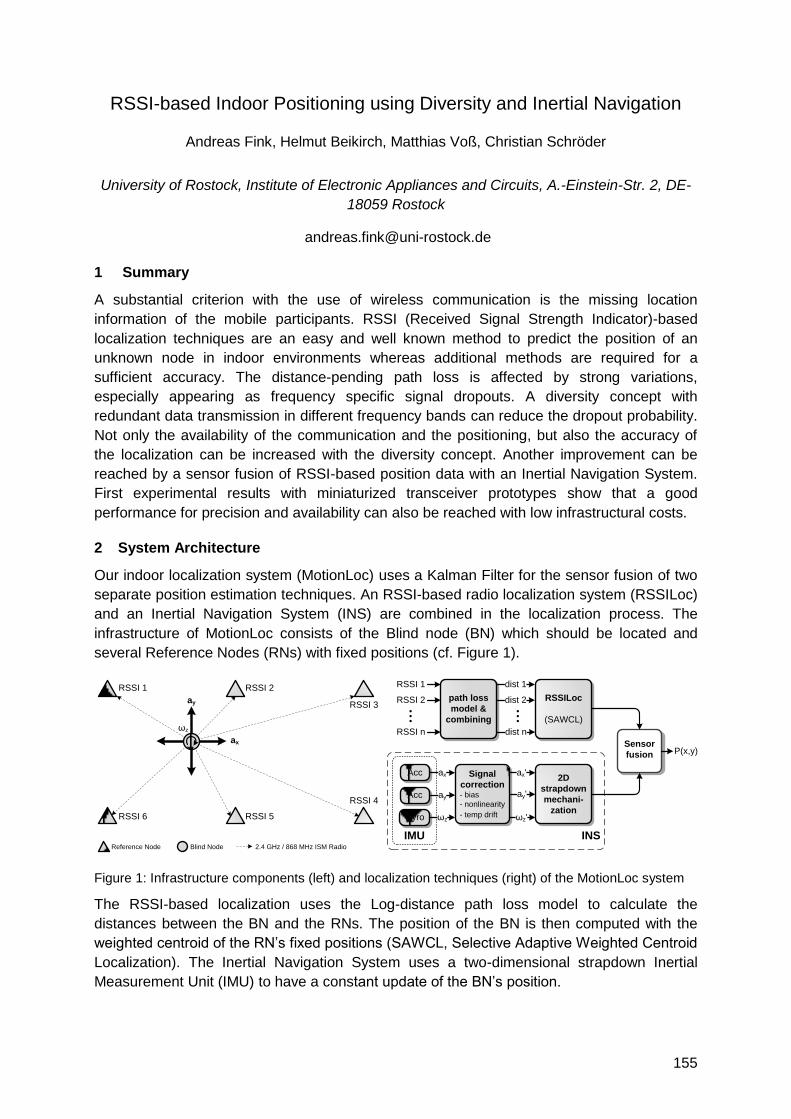
155
RSSI-based Indoor Positioning using Diversity and Inertial Navigation
Andreas Fink, Helmut Beikirch, Matthias Voß, Christian Schröder
University of Rostock, Institute of Electronic Appliances and Circuits, A.-Einstein-Str. 2, DE-
18059 Rostock
1 Summary
A substantial criterion with the use of wireless communication is the missing location
information of the mobile participants. RSSI (Received Signal Strength Indicator)-based
localization techniques are an easy and well known method to predict the position of an
unknown node in indoor environments whereas additional methods are required for a
sufficient accuracy. The distance-pending path loss is affected by strong variations,
especially appearing as frequency specific signal dropouts. A diversity concept with
redundant data transmission in different frequency bands can reduce the dropout probability.
Not only the availability of the communication and the positioning, but also the accuracy of
the localization can be increased with the diversity concept. Another improvement can be
reached by a sensor fusion of RSSI-based position data with an Inertial Navigation System.
First experimental results with miniaturized transceiver prototypes show that a good
performance for precision and availability can also be reached with low infrastructural costs.
2 System Architecture
Our indoor localization system (MotionLoc) uses a Kalman Filter for the sensor fusion of two
separate position estimation techniques. An RSSI-based radio localization system (RSSILoc)
and an Inertial Navigation System (INS) are combined in the localization process. The
infrastructure of MotionLoc consists of the Blind node (BN) which should be located and
several Reference Nodes (RNs) with fixed positions (cf. Figure 1).
Figure 1: Infrastructure components (left) and localization techniques (right) of the MotionLoc system
The RSSI-based localization uses the Log-distance path loss model to calculate the
distances between the BN and the RNs. The position of the BN is then computed with the
weighted centroid of the RN‘s fixed positions (SAWCL, Selective Adaptive Weighted Centroid
Localization). The Inertial Navigation System uses a two-dimensional strapdown Inertial
Measurement Unit (IMU) to have a constant update of the BN‘s position.
RSSI 1 RSSI 2
RSSI 3
RSSI 4
RSSI 5RSSI 6
ax
ay
ωz
Reference Node Blind Node 2.4 GHz / 868 MHz ISM Radio
RSSILoc
(SAWCL)
path loss
model &
combining
RSSI 1
RSSI n
dist 1
dist n
RSSI 2 dist 2...
2D
strapdown
mechani-
zation
Sensor
fusion P(x,y)
INS
Acc
Acc
Gyro
ax
ωz
ay
IMU
...
Signal
correction- bias
- nonlinearity
- temp drift
ax'
ay'
ωz'
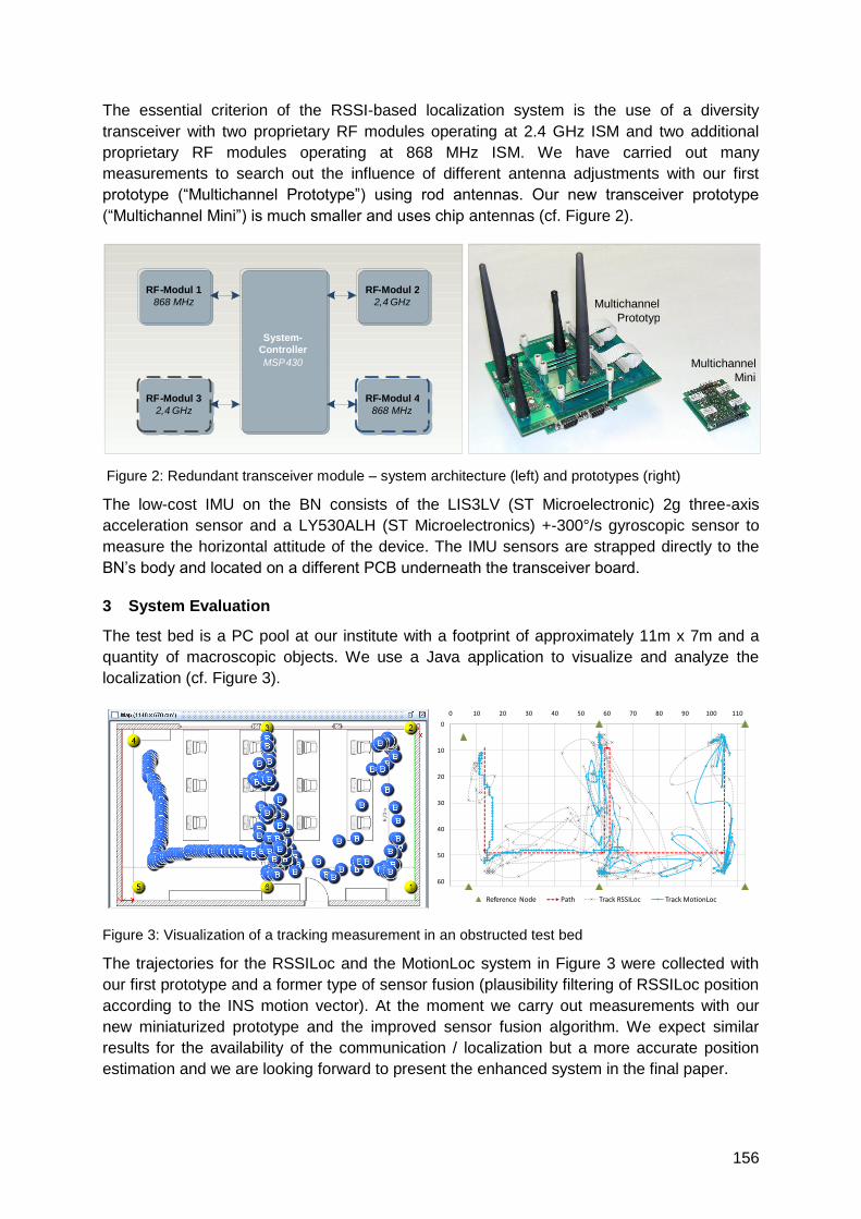
156
The essential criterion of the RSSI-based localization system is the use of a diversity
transceiver with two proprietary RF modules operating at 2.4 GHz ISM and two additional
proprietary RF modules operating at 868 MHz ISM. We have carried out many
measurements to search out the influence of different antenna adjustments with our first
prototype (―Multichannel Prototype‖) using rod antennas. Our new transceiver prototype
(―Multichannel Mini‖) is much smaller and uses chip antennas (cf. Figure 2).
Figure 2: Redundant transceiver module – system architecture (left) and prototypes (right)
The low-cost IMU on the BN consists of the LIS3LV (ST Microelectronic) 2g three-axis
acceleration sensor and a LY530ALH (ST Microelectronics) +-300°/s gyroscopic sensor to
measure the horizontal attitude of the device. The IMU sensors are strapped directly to the
BN‘s body and located on a different PCB underneath the transceiver board.
3 System Evaluation
The test bed is a PC pool at our institute with a footprint of approximately 11m x 7m and a
quantity of macroscopic objects. We use a Java application to visualize and analyze the
localization (cf. Figure 3).
Figure 3: Visualization of a tracking measurement in an obstructed test bed
The trajectories for the RSSILoc and the MotionLoc system in Figure 3 were collected with
our first prototype and a former type of sensor fusion (plausibility filtering of RSSILoc position
according to the INS motion vector). At the moment we carry out measurements with our
new miniaturized prototype and the improved sensor fusion algorithm. We expect similar
results for the availability of the communication / localization but a more accurate position
estimation and we are looking forward to present the enhanced system in the final paper.
0
10
20
30
40
50
60
0 10 20 30 40 50 60 70 80 90 100 110
Reference Node Path Track RSSILoc Track MotionLoc
RF - Modul 1 868 MHz
RF - Modul 2 2 , 4 GHz
RF - Modul 3 2 , 4 GHz
System - Controller MSP 430
RF - Modul 4 868 MHz
Multichannel Mini
Multichannel Prototyp
157
Calibration of the Accelerometer Triad of an Inertial Measurement Unit,
Maximum Likelihood Estimation and Cramér-Rao Bound
G. Panahandeh, I. Skog, M. Jansson
ACCESS Linnaeus Center, Electrical Engineering, Signal Processing Lab, KTH-Royal
Institute of Technology, Stockholm, Sweden
{ghazaleh.panahandeh, isaac.skog, magnus.jansson}@ee.kth.se
1 Summary
In this paper, a simple method to calibrate the accelerometer cluster of an inertial measurement unit (IMU) is proposed. The proposed method does not rely on using a mechanical calibration platform that rotates the IMU into different precisely controlled orientations. Although the IMU is rotated in different orientations, these orientations do not need to be known. Assuming that the IMU is stationary at each orientation, the norm of the input is considered equal to the gravity acceleration. As the orientations of the IMU are unknown, the calibration of the accelerometer cluster is stated as blind system identification problem where only the norm of the input to the system is known. Under the assumption that the sensor noises have white Gaussian distribution the system identification problem is solved using the maximum likelihood estimation method. The accuracy of the proposed calibration method is compared with the Cramér-Rao bound for the considered calibration problem.
2 Introduction
Traditionally the calibration of an IMU has been done using a mechanical platform that turns the IMU into several precisely controlled orientations. At each orientation, the outputs of the accelerometer cluster and the gyroscope cluster are observed and compared with pre-calculated gravity force vector and rotational velocities, respectively. However, many times the cost of a mechanical calibration platform exceeds the cost of developing a low-cost IMU. Therefore, different calibration methods have been proposed that do not require a mechanical platform. Most of these calibration methods utilize the fact that for an ideal (noise free) IMU, the norm of the measured output of the accelerometer should be equal to the magnitude of the gravity force vector. However, using such an assumption, the optimization of the corresponding criterion function typically leads to a biased estimate of the calibration parameters. To avoid this, we solve the system identification problem using maximum likelihood estimation (MLE) framework. This leads to an unbiased estimator that is asymptotically minimum variance. Then the performance of the calibration algorithm is compared with the Cramér-Rao bound. This bound sets the lower limit for the variance of the estimation error for all unbiased estimators.
3 The Proposed Method
A nine-parameter sensor model of the accelerometer cluster is considered; the three scale
factors, the three misalignment angles, and three biases. To estimate the nine unknown
calibration parameters, the IMU requires to be rotated in different orientations. Each time the
IMU is placed in a new orientation two new unknown rotational angles that need to be
simultaneously estimated together with calibration parameters are introduced. The
uncertainty in the rotational angles which appears in the input force of the system makes our
calibration problem a blind identification problem.
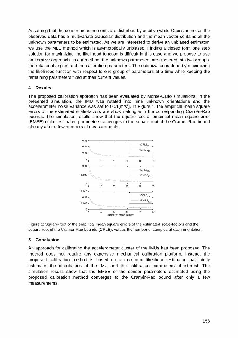
158
Assuming that the sensor measurements are disturbed by additive white Gaussian noise, the
observed data has a multivariate Gaussian distribution and the mean vector contains all the
unknown parameters to be estimated. As we are interested to derive an unbiased estimator,
we use the MLE method which is asymptotically unbiased. Finding a closed form one step
solution for maximizing the likelihood function is difficult in this case and we propose to use
an iterative approach. In our method, the unknown parameters are clustered into two groups,
the rotational angles and the calibration parameters. The optimization is done by maximizing
the likelihood function with respect to one group of parameters at a time while keeping the
remaining parameters fixed at their current values.
4 Results
The proposed calibration approach has been evaluated by Monte-Carlo simulations. In the presented simulation, the IMU was rotated into nine unknown orientations and the accelerometer noise variance was set to 0.01[m/s2]. In Figure 1, the empirical mean square errors of the estimated scale-factors are shown along with the corresponding Cramér-Rao bounds. The simulation results show that the square-root of empirical mean square error (EMSE) of the estimated parameters converges to the square-root of the Cramér-Rao bound already after a few numbers of measurements.
Figure 1: Square-root of the empirical mean square errors of the estimated scale-factors and the
square-root of the Cramér-Rao bounds (CRLB), versus the number of samples at each orientation.
5 Conclusion
An approach for calibrating the accelerometer cluster of the IMUs has been proposed. The
method does not require any expensive mechanical calibration platform. Instead, the
proposed calibration method is based on a maximum likelihood estimator that jointly
estimates the orientations of the IMU and the calibration parameters of interest. The
simulation results show that the EMSE of the sensor parameters estimated using the
proposed calibration method converges to the Cramér-Rao bound after only a few
measurements.
0 10 20 30 40 500
0.01
0.02
0.03
CRLBKx
EMSEKx
0 10 20 30 40 500
0.005
0.01
CRLBKy
EMSEKy
0 10 20 30 40 500
0.005
0.01
0.015
Number of measurement
CRLBKz
EMSEKz

159
Joint calibration of an inertial measurement unit and coordinate
transformation parameters using a monocular camera
Dave Zachariah* and Magnus Jansson
Signal Processing Lab, ACCESS Linnaeus Centre, Royal Institute of Technology (KTH),
Stockholm, Sweden
1 Summary
An estimation procedure for calibration of a low-cost inertial measurement unit (IMU), using a
rigidly mounted monocular camera, is presented. The parameters of a sensor model that
captures misalignments, scale and offset errors are estimated jointly with the IMU-camera
coordinate transformation parameters using a recursive Sigma-Point Kalman Filter. The
method requires only a simple visual calibration pattern and moreover provides figures of
merit of the estimates. A simulation study indicates the filter's ability to reach subcentimeter
and subdegree accuracy.
2 Introduction
Developments in micro-electro-mechanical systems (MEMS) have enabled the use of low-
cost inertial measurement units in applications ranging from navigation to augmented reality.
Many of these are highly dependent on the accuracy of the inertial sensors, hence the need
for calibration. Cost factors motivate calibration procedures that do not require mechanical
platforms and rotation tables. The proposed method uses a monocular camera, which is
inexpensive and can be rigidly mounted to a 6 DOF IMU with relative ease, along with a
simple visual calibration pattern. This amounts to a joint sensor model and IMU-camera
parameter estimation problem where the latter parameters are in themselves useful for
applications that fuse visual and inertial information [1,2].
3 Sensor model
An inertial sensor that provides a digitized measurement of specific force or angular velocity
is subject to errors that arise from unmodeled nonlinearities, manufacturing imperfections,
quantization noise, etc. Ideally a cluster of three accelerometer sensitivity axes should be
mutually orthogonal and their outputs of equal scale. Similarly, the cluster of gyroscopes
should be orthogonal and placed in relation to the accelerometer cluster. We let an affine
mapping between the sensor output and the sought physical quantity capture misalignments;
scale errors; offset error; and random noise arising from quantization [3].
160
4 Estimation framework
The estimation framework exploits the inertial navigation system (INS) equations in a
feedback approach to estimate the IMU sensor model parameters as well as the
transformation parameters between the inertial and camera coordinate frames. A simple
calibration pattern, normally used to calibrate the internal camera parameters, is placed on a
horizontal plane perpendicular to the gravitational field. The observed feature points of the
pattern are pixel measurements on the image plane, fed into a recursive Sigma-Point
Kalman Filter that estimates the sought parameters. The diagonal elements of the square
root error covariance matrix provide figures of merit of the estimates.
5 Results and conclusions
An evaluation of the proposed estimation procedure was performed by means of Monte
Carlo simulations [4]: A trajectory of an IMU, with a rigidly mounted monocular camera, was
generated moving above and facing a 12x12 cm calibration pattern which consisted of an
array of 4x4 feature points. These were projected using a pinhole camera model and subject
to measurement noise with a standard deviation of 2 pixels.
The IMU-camera transformation parameters were estimated to subdegree and subcentimeter
accuracy. The misalignments of the accelerometer and gyroscope clusters were estimated to
subdegree precision, and the scale factors differed by at most 0.1 percentage points. The
accuracy, quality and rate of convergence of the estimates are dependent on exciting
sufficient motion of the system. The results suggest an inexpensive procedure for calibrating
low-cost IMUs without the need for mechanical platforms.
6 References
[1] J.D. Hol, T.B. Schön and F. Gustafsson, ―A New Algorithm for Calibrating a Combined Camera
and IMU Sensor Unit‖, Proc. of Control, Automation, Robotics and Vision, 2008. ICARCV 2008,
Hanoi, Vietnam, Dec. 2008.
[2] D. Zachariah and M. Jansson, ―Camera-aided inertial navigation using epipolar points‖, Proc. of
Position Location and Navigation Symposium, PLANS 2010, Palm Springs, USA, May 2010.
[3] I. Skog and P. Händel, ‖Calibration of a MEMS Inertial Measurement Unit‖, Proc. of IMEKO 2006,
Rio de Janerio, Brazil, Sept. 2006.
[4] F.M. Mirzaei and S.I. Roumeliotis, ―A Kalman Filter-Based Algorithm for IMU-Camera Calibration:
Observability Analysis and Performance Evaluation‖, IEEE Trans. on Robotics, vol. 24, no. 5, Oct.
2008.
161
DCM based Attitude Estimation Using Low-cost IMU Aided by Distributed
Accelerometers and Magnetometers
Ezzaldeen Edwan, Fernando Suarez, Jieying Zhang, Otmar Loffeld
Center for Sensor Systems (ZESS), Paul Bonatz Str. 9-11, 57068 Siegen, Germany
1 Summary
In this paper, we describe the development and analyze the performance of a low-cost
attitude and heading reference system (AHRS) realized through micro electrical mechanical
system (MEMS) inertial sensors and magnetometers. Due to the poor performance of low-
cost MEMS gyros and accelerometers, we aid a traditional inertial measurement unit (IMU)
with low-cost distributed accelerometers. By doing so, we get two achievements: the first is
an improvement in the angular rate knowledge because of the angular information computed
from distributed accelerometers. The second improvement is in the acceleration knowledge
as a result of the redundancy of accelerometers. Two cascaded filters will be used to
estimate the attitude. The first filter fuses the angular information coming from the distributed
accelerometers and the gyros and returns the angular rate. The second filter fuses the
angular rate, specific force and magnetometer measurements and returns the estimated
elements of the direction cosine matrix (DCM). Simulation results and real time experiments
will be used to verify the efficiency of our approach.
2 Structure of AHRS and traditional IMU
The AHRS is a device that provides attitude and heading information for many applications.
Nowadays, we have a wide range of applications that require knowledge of attitude
information such as navigation, aerospace and robotics. The advantage of inertial navigation
systems (INS) over other navigation systems is that they are self-contained and hence do not
require any interaction with the external environment in order to operate. An IMU consists of
three mutually orthogonal accelerometers and gyroscopes. For the static case, a set of low-
cost accelerometer triad can provide the accurate tilt angles (roll and pitch) while the
remaining heading angle can be found using a magnetometer triad. Tilt angles are found by
measuring the projection of the local gravity vector, which should be exactly known, on the
body frame axis using three mounted accelerometers. For the dynamic case, the angular
rates from the gyros are integrated over time to update attitude. Since magnetometer and
accelerometers allow for direct measurement of the attitude, Kalman filtering methods can be
used to correct the accumulating errors due to the integration of gyros‘ outputs.
3 Angular information from distributed accelerometer triads
Generally, accelerometers are less costly, less weight and less power consuming than
comparable gyros which have typically the disadvantage of complicated manufacturing
techniques, high cost, high power consumption, large weight, large volume, and limited
dynamic range. Hence, research efforts are conducted on the use of accelerometers in order
to infer the angular motion. Using certain configurations that consist of twelve separate
mono-axial accelerometers produces an angular information vector (AIV) that consists of a
3D angular acceleration vector and six quadratic terms of angular velocities [1]. Distributed
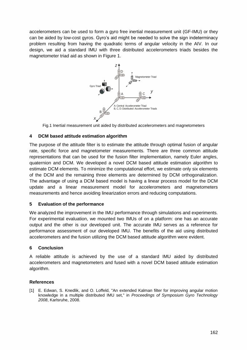
162
accelerometers can be used to form a gyro free inertial measurement unit (GF-IMU) or they
can be aided by low-cost gyros. Gyro‘s aid might be needed to solve the sign indeterminacy
problem resulting from having the quadratic terms of angular velocity in the AIV. In our
design, we aid a standard IMU with three distributed accelerometers triads besides the
magnetometer triad aid as shown in Figure 1.
C
D
A
B
x
z
y
Gyro Triad
Magnetometer Triad
A: Central Accelerometer TriadB, C, D: Distributed Accelerometer Triads
Fig.1 Inertial measurement unit aided by distributed accelerometers and magnetometers
4 DCM based attitude estimation algorithm
The purpose of the attitude filter is to estimate the attitude through optimal fusion of angular
rate, specific force and magnetometer measurements. There are three common attitude
representations that can be used for the fusion filter implementation, namely Euler angles,
quaternion and DCM. We developed a novel DCM based attitude estimation algorithm to
estimate DCM elements. To minimize the computational effort, we estimate only six elements
of the DCM and the remaining three elements are determined by DCM orthogonalization.
The advantage of using a DCM based model is having a linear process model for the DCM
update and a linear measurement model for accelerometers and magnetometers
measurements and hence avoiding linearization errors and reducing computations.
5 Evaluation of the performance
We analyzed the improvement in the IMU performance through simulations and experiments.
For experimental evaluation, we mounted two IMUs of on a platform: one has an accurate
output and the other is our developed unit. The accurate IMU serves as a reference for
performance assessment of our developed IMU. The benefits of the aid using distributed
accelerometers and the fusion utilizing the DCM based attitude algorithm were evident.
6 Conclusion
A reliable attitude is achieved by the use of a standard IMU aided by distributed
accelerometers and magnetometers and fused with a novel DCM based attitude estimation
algorithm.
References
[1] E. Edwan, S. Knedlik, and O. Loffeld, "An extended Kalman filter for improving angular motion knowledge in a multiple distributed IMU set," in Proceedings of Symposium Gyro Technology 2008, Karlsruhe, 2008.
163
UWB/IMU Tracking Validation using an Optical System
Jeroen D. Hol and Maaike Elzinga
Xsens Technologies B.V., Enschede, the Netherlands
1 Abstract
In this paper we report the results of a validation study of a 6DOF tracking system combining
Ultra-Wideband measurements with low-cost MEMS inertial measurements. The tightly
coupled system estimates position as well as orientation of the sensor unit. The comparison
with the results from an optical system show robust and continuous tracking in a realistic
indoor positioning scenario.
2 Introduction
Commercially available Ultra-Wideband (UWB) systems typically consist of a network of
synchronized UWB receivers which track a large number of small, battery powered and
inexpensive UWB transmitters. Reported indoor position accuracies lie in the order of
decimetres, but suffer from multipath effects and non-line-of-sight (NLOS) conditions. These
effects are most prominent while tracking moving objects or persons and give rise to
distorted and bumpy trajectories. Although the obtained performance is often sufficient for
the aforementioned applications, many potential application areas have higher performance
requirements.
To improve the tracking performance (especially the positioning accuracy) we propose to
combine UWB with a low-cost micro electro mechanical system (MEMS) inertial
measurement unit (IMU) consisting of a 3D rate gyroscope and a 3D accelerometer. The
main justification for adding an IMU — providing accurate position tracking for short periods
of time, but drift prone for longer timescales — is to obtain a robust system, capable of
detecting and rejecting multipath effects and NLOS situations. Additional benefits of adding
an IMU include improved tracking results, especially for dynamic quantities like velocity, and
that the orientation becomes observable as well. This results in a system providing a 6
degrees of freedom (DOF) general purpose tracking solution for indoor applications.
In our previous work 1 we reported a full 6DOF tracker estimating both position and
orientation based on tightly coupled fusion of UWB and inertial sensors. In this paper we
present the results of a comparison with an optical system.
3 Results
The UWB/IMU tracking system setup has been used in a room of 8 x 8 x 3 m in size, in
which also an optical tracking system (Vicon) is present. The UWB setup consisted of a total
of 10 receivers; 5 are placed on the floor and 5 are mounted to the ceiling. The inertial
sensor with integrated UWB transmitter has been equipped with an optical cluster. Hence the
1 J. D. Hol, F. Dijkstra, H. Luinge, and T. B. Schön. Tightly coupled UWB/IMU pose estimation. In Proceedings of
IEEE International Conference on Ultra-Wideband, pages 688-692, Vancouver, Canada, Sept. 2009
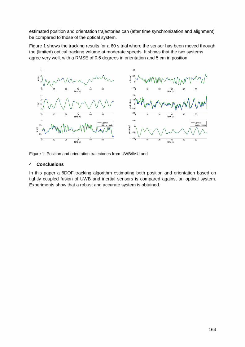
164
estimated position and orientation trajectories can (after time synchronization and alignment)
be compared to those of the optical system.
Figure 1 shows the tracking results for a 60 s trial where the sensor has been moved through
the (limited) optical tracking volume at moderate speeds. It shows that the two systems
agree very well, with a RMSE of 0.6 degrees in orientation and 5 cm in position.
Figure 1: Position and orientation trajectories from UWB/IMU and
4 Conclusions
In this paper a 6DOF tracking algorithm estimating both position and orientation based on
tightly coupled fusion of UWB and inertial sensors is compared against an optical system.
Experiments show that a robust and accurate system is obtained.
165
Performance Evaluation of an Hybrid RSSI-Inertial Localization Algorithm
in IEEE 802.15.4 Wireless Sensor Networks
Paolo Gamba, Emanuele Goldoni, Alberto Savioli
University of Pavia, dept. of Electronics, via Ferrata 1 – 27100 Pavia, ITALY
{name.surname}@unipv.it
1 Summary
In this work we present an evaluation of the performance of a range-based hybrid localization
algorithm based on the Received Signal Strength Indicator (RSSI) and inertial data applied in
a real world WSN. As can be found in literature, RSSI-based localization algorithms exhibit
low accuracy due to the variability of the radio signal. Adding inertial information, such as
accelerations values obtained by an Inertial Measurement Unit (IMU), in combination with an
implementation of a dedicated data-fusion algorithm, it can provide a higher level of accuracy.
In order to evaluate the accuracy gain, we compared the results obtained in the field using
only RSSI data against the values provided with a hybrid localization system in the same
environment.
2 Localization Algorithm
Many techniques might be used for the estimation of the position of an unknown target node
in a WSN, such as a Global Positioning System, a laser, infrared or acoustic waves, but all
these methods are not energy efficient due the need of external hardware [1]. To overcome
this limitation, the RSSI index – that can be read without any external hardware – is often
used to estimate the distance between the target and the references, followed by a
computation of the position of the target with appropriate algorithms [2]. Some of the well
known algorithms are based on geometric considerations, such as Multilateration or Min-
Max, while others rely on statistical considerations such as the Maximum Likelihood method.
Due to the small computational power of WSNs nodes, we decided to use the Min-Max
algorithm for our tests.
On the other hand, inertial data have been used to estimate the position of a target node
starting from the acceleration value obtained by the accelerometers, and performing a double
numerical integration. Unfortunately, such readings are affected by noise – and by the double
integration, the error grows quadratically over time. To bound this error, the integration is
usually calculated over small amount of time only. The position provided by the IMU is then
fused with the position from the RSSI estimation by an appropriate filter that is able to keep
track of the past positions measured by the target node for the estimation of the subsequent
position. In order to perform the data fusion we implemented a simple, steady state Kalman
filter [3], where the position estimated by RSSI measurements is used to correct the position
that is computed with those obtained by the IMU. Due to the low amount of energy
disposable in a sensor node, we decided to use a MEMS IMU that is low power demanding,
small, cheap and sufficiently accurate for this purpose.
3 Experimental Results
The nodes of the WSN deployed for our tests are based on the Arduino Diecimila
development board, the Digi‘s XBee IEEE 802.15.4 compliant transceiver; the IMU uses the
ADXL330 triaxial MEMS accelerometer. The WSN has been deployed in an indoor scenario,
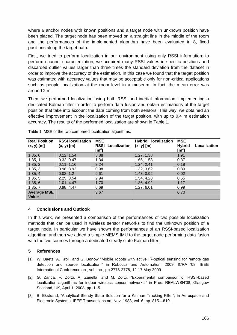
166
where 6 anchor nodes with known positions and a target node with unknown position have
been placed. The target node has been moved on a straight line in the middle of the room
and the performances of the implemented algorithm have been evaluated in 8, fixed
positions along the target path.
First, we tried to perform localization in our environment using only RSSI information: to
perform channel characterization, we acquired many RSSI values in specific positions and
discarded outlier values larger than three times the standard deviation from the dataset in
order to improve the accuracy of the estimation. In this case we found that the target position
was estimated with accuracy values that may be acceptable only for non-critical applications
such as people localization at the room level in a museum. In fact, the mean error was
around 2 m.
Then, we performed localization using both RSSI and inertial information, implementing a
dedicated Kalman filter in order to perform data fusion and obtain estimations of the target
position that take into account the data coming from both sensors. This way, we obtained an
effective improvement in the localization of the target position, with up to 0.4 m estimation
accuracy. The results of the performed localization are shown in Table 1.
Table 1: MSE of the two compared localization algorithms.
Real Position (x, y) [m]
RSSI localization (x, y) [m]
MSE RSSI Localization [m
2]
Hybrid localization (x, y) [m]
MSE Hybrid Localization [m
2]
1.35, 0 0.12, 1.54 3.88 1.27, 1.38 1.91 1.35, 1 0.32, 0.47 1.34 1.65, 1.53 0.37 1.35, 2 0.11, 1.16 2.24 1.24, 2.41 0.18 1.35, 3 0.98, 3.92 0.98 1.32, 3.62 0.39 1.35, 4 0.02, 1.2 9.61 1.48, 3.92 0.02 1.35, 5 2.25, 3.54 2.94 1.54, 4.28 0.55 1.35, 6 1.01, 4.47 1.70 1.36, 4.92 1.17 1.35, 7 0.98, 4.47 6.69 1.27, 6.01 0.99
Average MSE Value
3.67 0.70
4 Conclusions and Outlook
In this work, we presented a comparison of the performances of two possible localization
methods that can be used in wireless sensor networks to find the unknown position of a
target node. In particular we have shown the performances of an RSSI-based localization
algorithm, and then we added a simple MEMS IMU to the target node performing data-fusion
with the two sources through a dedicated steady state Kalman filter.
5 References
[1] W. Baetz, A. Kroll, and G. Bonow ―Mobile robots with active IR-optical sensing for remote gas
detection and source localization,‖ in Robotics and Automation, 2009. ICRA '09. IEEE
International Conference on , vol., no., pp.2773-2778, 12-17 May 2009
[2] G. Zanca, F. Zorzi, A. Zanella, and M. Zorzi, ―Experimental comparison of RSSI-based
localization algorithms for indoor wireless sensor networks,‖ in Proc. REALWSN‘08, Glasgow
Scotland, UK, April 1, 2008, pp. 1–5.
[3] B. Ekstrand, ―Analytical Steady State Solution for a Kalman Tracking Filter‖, in Aerospace and
Electronic Systems, IEEE Transactions on, Nov. 1983, vol. 6, pp. 815—819.

167
Foot Mounted Pedestrian Navigation
Auditorium G3
Thursday, September 16, 08:15 – 09:45 & 10:15 – 11:45

169
A High Precision Reference Data Set for Pedestrian Navigation using
Foot-Mounted Inertial Sensors
Michael Angermann, Patrick Robertson, Thomas Kemptner, Mohammed Khider
German Aerospace Center (DLR),
Institute for Communications and Navigation,
D-82234 Oberpfaffenhofen, Germany
Email: [email protected]
1 Summary
In this paper we will describe a data collection methodology and reference data set that can
be used by the indoor navigation community to verify and improve algorithms based on foot
mounted inertial sensors. The data set is collected using a high precision optical reference
system that is traditionally used in the film industry for human motion capturing or in
specialist applications such as analysis of human motion in sports and medical rehabilitation.
The data provides synchronous 6 degrees of freedom inertial measurement sensor readings
from a foot mounted MEMS sensor array as well as the high resolution data from the optical
tracking system providing location and orientation ground truth. We will also provide the
results of algorithms that identify the rest phase during the human gait cycle which is an
essential part of pedestrian dead reckoning systems for positioning.
2 Motivation and Description of the Data Collection Process
Recent years have seen many advances in pedestrian localisation in GPS denied
environments [1-4]. In particular, work has focussed on the sensor fusion approach drawing
on sensor data such as inertial sensor data (IMUs), barometers, and magnetometers in
conjunction with non linear estimation techniques such as particle filtering. An important
building block is so-called human odometry or dead reckoning which tries to estimate the
individual steps of a pedestrian while he or she is walking in the environment. Estimates of
the steps which are obtained in a relative coordinate system are then combined with other
sensor data such as wireless positioning or information such as the building floor plans [2-4].
Foxlin pioneered the use of a Kalman filter and Zero Velocity Updates (ZUPTs) to estimate
the step vector from step to step with a very high degree of accuracy, especially in the
distance travelled [1, 5]. Critical is the correct identification of the rest phase of the foot from
the IMU raw data (accelerometers and giros). During a ZUPT the integration of the inertial
navigation system (INS) is reset and the Kalman filter operating in the INS error domain can
estimate some of the IMU error states, significantly reducing the error build up over time.
However, practical experience has shown that the ZUPT is dependent on circumstances
such as the composition of the floor material (e.g. soft carpets vs. hard surfaces), the shoes
worn by the pedestrian, as well as the kind of motion (e.g. walking, running, unusual
movement). Furthermore, it is difficult to verify the performance of human odometry at the
macro scale where one compares the ground truth of the user‘s location with perhaps 0.5 m
accuracy against the algorithm output. This is compounded by the fact that the sensors are
not necessarily co-located on the user‘s body. To address this we propose to use an optical
170
reference system that can provide extremely high accuracy reference information about the
position and orientation of the actual sensor array.
Our measurement setup consists of eight infrared (IR) cameras and IR strobe lamps that
provide a full and redundant coverage of a volume of space (room sized) within which the
experiments are conducted. The user equipment (i.e. the foot mounted IMU) is tracked with
the aid of a number of firmly attached small IR reflectors. The measurement computer
processes the camera signals and provides highly accurate measurements of the marked
user equipment in terms of its location and orientation at a rate of about 200 Hz.
3 Experimental Scenarios
The resulting reference data is very simple to describe and to use. It consists of time-
stamped ground truth data as well as the readings from the IMU and the co-located 3 axis
magnetometer. A video will accompany each data set. To provide a rich data set we will
document human steps under different conditions:
1. Different floor surfaces such as firm and soft carpets and hard floors.
2. Different shoes worn by different peoples from different age groups and of different
gender.
3. A variety of walking modes, such as slow and fast walking, turns, walking backwards,
running, and transitions.
We believe that reference data on short segments of motion that are possible within a room
are sufficient to evaluate different algorithms, because the ground truth is so accurate. In this
way researchers can concentrate on how their algorithms detect individual phase of the
human stride as well as the errors that occur during INS processing. For some of the data
sets we will also provide evaluations of our own simple ZUPT algorithms and Kalman filter
position estimates for comparison purposes.
The resulting data set and our evaluations will be available for free download.
4 References
[1] E. Foxlin, ―Pedestrian tracking with shoe-mounted inertial sensors,‖ IEEE Computer Graphics and
Applications, Vol. 25, no. 6, Nov. 2005.
[2] S. Beauregard, Widyawan, and M. Klepal, ―Indoor PDR performance enhancement using minimal
map information and particle filters,‖ in Proc. of the IEEE/ION PLANS 2008, Monterey, USA, May
2008.
[3] B. Krach and P. Robertson, ―Cascaded estimation architecture for integration of foot-mounted
inertial sensors,‖ in Proc. of the IEEE/ION, PLANS 2008, Monterey, USA, May 2008.
[4] O. Woodman and R. Harle, ―Pedestrian localisation for indoor environments,‖ in Proc. of the
UbiComp 2008, Seoul, South Korea, Sept. 2008.
[5] E. Foxlin and S. Wan, ―Improved pedestrian navigation based on drift-reduced MEMS IMU chip,‖
in Proc. of the 2010 ION International Technical Meeting, San Diego, California, USA, Jan. 2010.
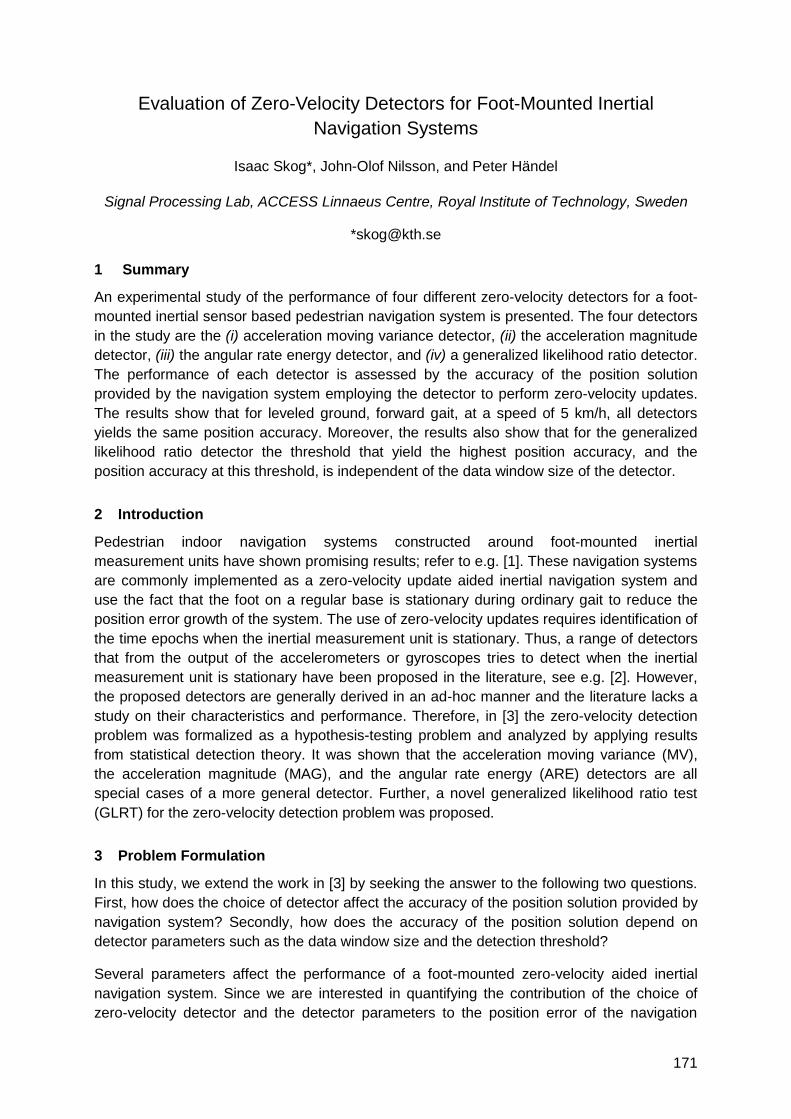
171
Evaluation of Zero-Velocity Detectors for Foot-Mounted Inertial
Navigation Systems
Isaac Skog*, John-Olof Nilsson, and Peter Händel
Signal Processing Lab, ACCESS Linnaeus Centre, Royal Institute of Technology, Sweden
1 Summary
An experimental study of the performance of four different zero-velocity detectors for a foot-
mounted inertial sensor based pedestrian navigation system is presented. The four detectors
in the study are the (i) acceleration moving variance detector, (ii) the acceleration magnitude
detector, (iii) the angular rate energy detector, and (iv) a generalized likelihood ratio detector.
The performance of each detector is assessed by the accuracy of the position solution
provided by the navigation system employing the detector to perform zero-velocity updates.
The results show that for leveled ground, forward gait, at a speed of 5 km/h, all detectors
yields the same position accuracy. Moreover, the results also show that for the generalized
likelihood ratio detector the threshold that yield the highest position accuracy, and the
position accuracy at this threshold, is independent of the data window size of the detector.
2 Introduction
Pedestrian indoor navigation systems constructed around foot-mounted inertial
measurement units have shown promising results; refer to e.g. [1]. These navigation systems
are commonly implemented as a zero-velocity update aided inertial navigation system and
use the fact that the foot on a regular base is stationary during ordinary gait to reduce the
position error growth of the system. The use of zero-velocity updates requires identification of
the time epochs when the inertial measurement unit is stationary. Thus, a range of detectors
that from the output of the accelerometers or gyroscopes tries to detect when the inertial
measurement unit is stationary have been proposed in the literature, see e.g. [2]. However,
the proposed detectors are generally derived in an ad-hoc manner and the literature lacks a
study on their characteristics and performance. Therefore, in [3] the zero-velocity detection
problem was formalized as a hypothesis-testing problem and analyzed by applying results
from statistical detection theory. It was shown that the acceleration moving variance (MV),
the acceleration magnitude (MAG), and the angular rate energy (ARE) detectors are all
special cases of a more general detector. Further, a novel generalized likelihood ratio test
(GLRT) for the zero-velocity detection problem was proposed.
3 Problem Formulation
In this study, we extend the work in [3] by seeking the answer to the following two questions.
First, how does the choice of detector affect the accuracy of the position solution provided by
navigation system? Secondly, how does the accuracy of the position solution depend on
detector parameters such as the data window size and the detection threshold?
Several parameters affect the performance of a foot-mounted zero-velocity aided inertial
navigation system. Since we are interested in quantifying the contribution of the choice of
zero-velocity detector and the detector parameters to the position error of the navigation
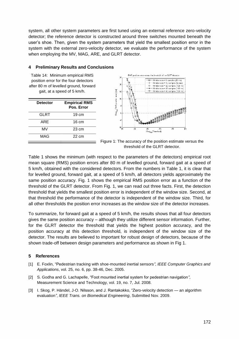
172
system, all other system parameters are first tuned using an external reference zero-velocity
detector; the reference detector is constructed around three switches mounted beneath the
user‘s shoe. Then, given the system parameters that yield the smallest position error in the
system with the external zero-velocity detector, we evaluate the performance of the system
when employing the MV, MAG, ARE, and GLRT detector.
4 Preliminary Results and Conclusions
Table 14: Minimum empirical RMS
position error for the four detectors
after 80 m of levelled ground, forward
gait, at a speed of 5 km/h.
Detector Empirical RMS Pos. Error
GLRT 19 cm
ARE 16 cm
MV 23 cm
MAG 22 cm
Figure 1: The accuracy of the position estimate versus the
threshold of the GLRT detector.
Table 1 shows the minimum (with respect to the parameters of the detectors) empirical root
mean square (RMS) position errors after 80 m of levelled ground, forward gait at a speed of
5 km/h, obtained with the considered detectors. From the numbers in Table 1, it is clear that
for levelled ground, forward gait, at a speed of 5 km/h, all detectors yields approximately the
same position accuracy. Fig. 1 shows the empirical RMS position error as a function of the
threshold of the GLRT detector. From Fig. 1, we can read out three facts. First, the detection
threshold that yields the smallest position error is independent of the window size. Second, at
that threshold the performance of the detector is independent of the window size. Third, for
all other thresholds the position error increases as the window size of the detector increases.
To summarize, for forward gait at a speed of 5 km/h, the results shows that all four detectors
gives the same position accuracy – although they utilize different sensor information. Further,
for the GLRT detector the threshold that yields the highest position accuracy, and the
position accuracy at this detection threshold, is independent of the window size of the
detector. The results are believed to important for robust design of detectors, because of the
shown trade-off between design parameters and performance as shown in Fig 1.
5 References
[1] E. Foxlin, ―Pedestrian tracking with shoe-mounted inertial sensors”, IEEE Computer Graphics and
Applications, vol. 25, no. 6, pp. 38-46, Dec. 2005.
[2] S. Godha and G. Lachapelle, ―Foot mounted inertial system for pedestrian navigation”,
Measurement Science and Technology, vol. 19, no. 7, Jul. 2008.
[3] I. Skog, P. Händel, J-O. Nilsson, and J. Rantakokko, ―Zero-velocity detection — an algorithm
evaluation”, IEEE Trans. on Biomedical Engineering, Submitted Nov. 2009.
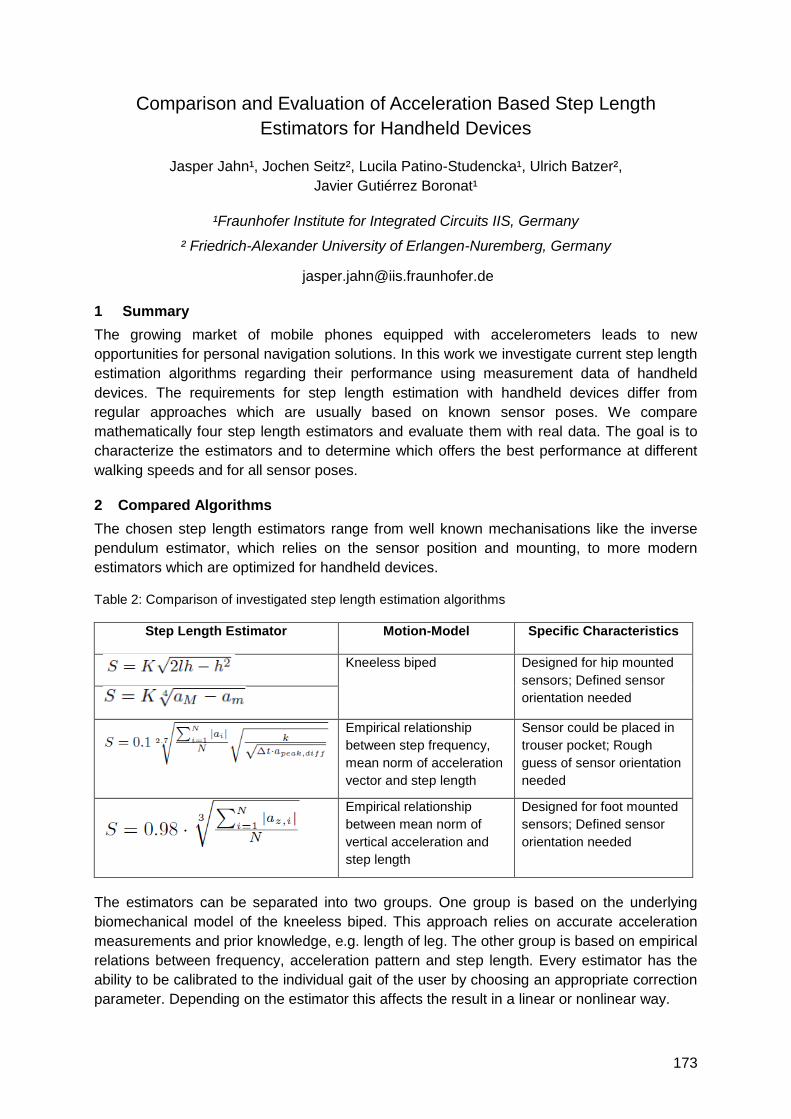
173
Comparison and Evaluation of Acceleration Based Step Length
Estimators for Handheld Devices
Jasper Jahn¹, Jochen Seitz², Lucila Patino-Studencka¹, Ulrich Batzer²,
Javier Gutiérrez Boronat¹
¹Fraunhofer Institute for Integrated Circuits IIS, Germany
² Friedrich-Alexander University of Erlangen-Nuremberg, Germany
1 Summary
The growing market of mobile phones equipped with accelerometers leads to new
opportunities for personal navigation solutions. In this work we investigate current step length
estimation algorithms regarding their performance using measurement data of handheld
devices. The requirements for step length estimation with handheld devices differ from
regular approaches which are usually based on known sensor poses. We compare
mathematically four step length estimators and evaluate them with real data. The goal is to
characterize the estimators and to determine which offers the best performance at different
walking speeds and for all sensor poses.
2 Compared Algorithms
The chosen step length estimators range from well known mechanisations like the inverse
pendulum estimator, which relies on the sensor position and mounting, to more modern
estimators which are optimized for handheld devices.
Table 2: Comparison of investigated step length estimation algorithms
Step Length Estimator Motion-Model Specific Characteristics
Kneeless biped Designed for hip mounted
sensors; Defined sensor
orientation needed
Empirical relationship
between step frequency,
mean norm of acceleration
vector and step length
Sensor could be placed in
trouser pocket; Rough
guess of sensor orientation
needed
Empirical relationship
between mean norm of
vertical acceleration and
step length
Designed for foot mounted
sensors; Defined sensor
orientation needed
The estimators can be separated into two groups. One group is based on the underlying
biomechanical model of the kneeless biped. This approach relies on accurate acceleration
measurements and prior knowledge, e.g. length of leg. The other group is based on empirical
relations between frequency, acceleration pattern and step length. Every estimator has the
ability to be calibrated to the individual gait of the user by choosing an appropriate correction
parameter. Depending on the estimator this affects the result in a linear or nonlinear way.
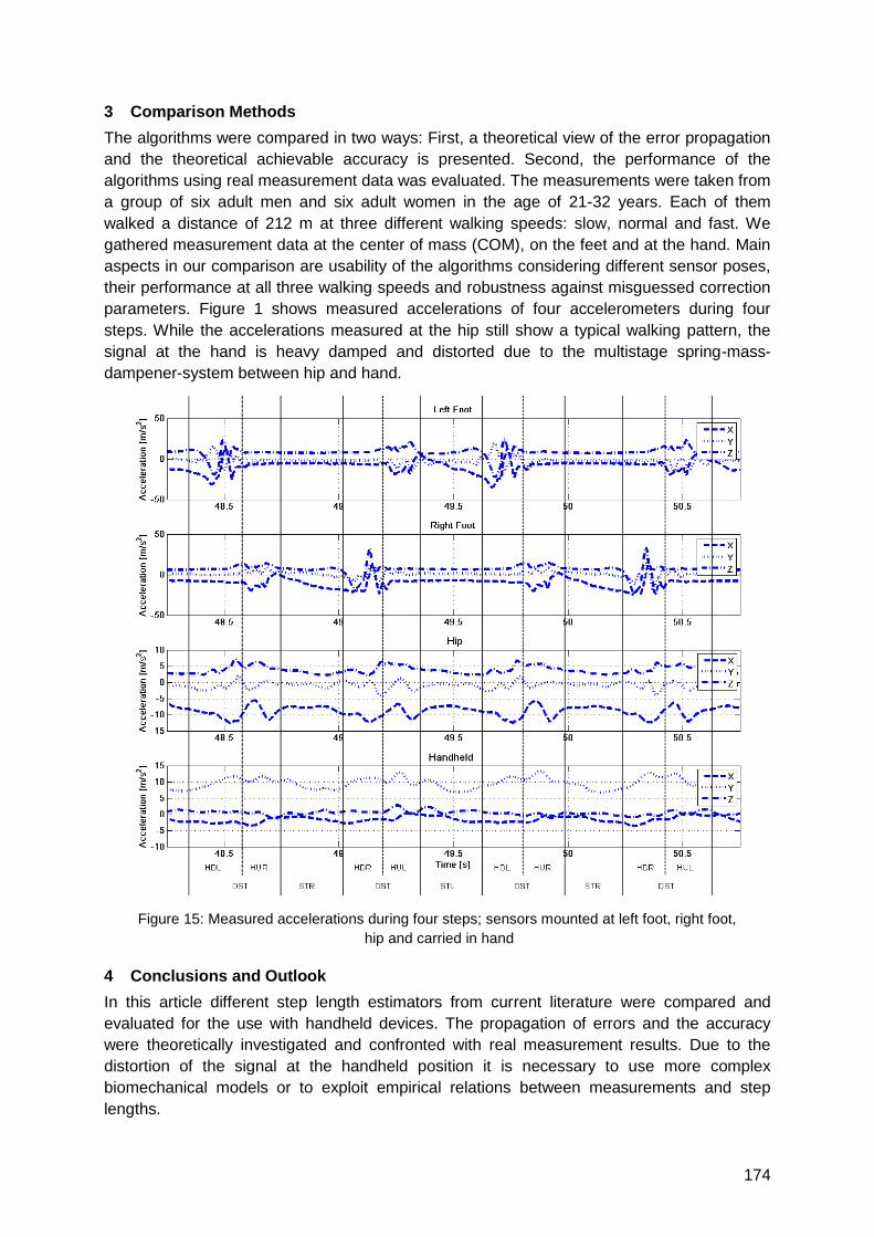
174
3 Comparison Methods
The algorithms were compared in two ways: First, a theoretical view of the error propagation
and the theoretical achievable accuracy is presented. Second, the performance of the
algorithms using real measurement data was evaluated. The measurements were taken from
a group of six adult men and six adult women in the age of 21-32 years. Each of them
walked a distance of 212 m at three different walking speeds: slow, normal and fast. We
gathered measurement data at the center of mass (COM), on the feet and at the hand. Main
aspects in our comparison are usability of the algorithms considering different sensor poses,
their performance at all three walking speeds and robustness against misguessed correction
parameters. Figure 1 shows measured accelerations of four accelerometers during four
steps. While the accelerations measured at the hip still show a typical walking pattern, the
signal at the hand is heavy damped and distorted due to the multistage spring-mass-
dampener-system between hip and hand.
Figure 15: Measured accelerations during four steps; sensors mounted at left foot, right foot,
hip and carried in hand
4 Conclusions and Outlook
In this article different step length estimators from current literature were compared and
evaluated for the use with handheld devices. The propagation of errors and the accuracy
were theoretically investigated and confronted with real measurement results. Due to the
distortion of the signal at the handheld position it is necessary to use more complex
biomechanical models or to exploit empirical relations between measurements and step
lengths.

175
An improved shoe-mounted inertial navigation system
Nadir Castaneda, Sylvie Lamy-Perbal
CEA, LIST, 92265 Fontenay-Aux-Roses, France
1 Summary
This paper proposes an improved shoe-mounted inertial navigation system for pedestrian
tracking. The improvements consist of a fuzzy logic (FL) procedure for better foot stance
phase detection and an indirect Kalman filter (IKF) for drift correction based on the typical
zero-updating (ZUPT) measurement and our proposed angular updating (AUPT) pseudo-
measurement. We illustrate our findings using a real time implementation of the proposed
approach.
2 Angular Updating (AUPT) pseudo-measurement
Typically, shoe-mounted inertial navigation systems estimate and correct drift errors in
position, velocity and orientation via an assisted zero-velocity updating indirect Kalman filter
(IKF). The procedure consists in detecting the foot stance phase in order to build a zero-
velocity-based pseudo-measurement which is delivered to the IKF to estimate drift errors
[1,2]. Following this idea, and since the inertial measurement unit (IMU) is rigidly attached to
the shoe in a known space configuration (see [1]), we propose to built an attitude pseudo-
measurement at the foot stance phase. In what follows the symbols used are consistent with
those of [1]. Thus, let suppose that the attitude‘s pseudo-measurement model may be written
as
ny (1)
where T is the vector containing the true IMU‘s roll , pitch and yaw and
n ~ ),0( QN with ),,( 222
diagQ . Since in this paper the attitude is represented as
a unit quaternion we must establish a quaternion pseudo-measurement instead. Hence,
using eq. (1) and the equations relating to unit quaternions i.e. non-linear equations of the
form )( fq , we can write after a Taylor series expansion and some algebraic
manipulations the quaternion pseudo-measurement qy as
nJqqLyq )()ˆ( (2)
where q is the IMU‘s attitude computed by the strapdown inertial computer, q is the error
quaternion, )(J is the Jacobian /f and )(L is an operator letting to express a
quaternion product into a matrix product. Finally, using the error quaternion definition
qqLq 1)ˆ( and Tqq 1 , where q is the true IMU‘s attitude, we may write the IKF
AUPT measurement model as
wqz q (3) where w ~ ),0( qRN
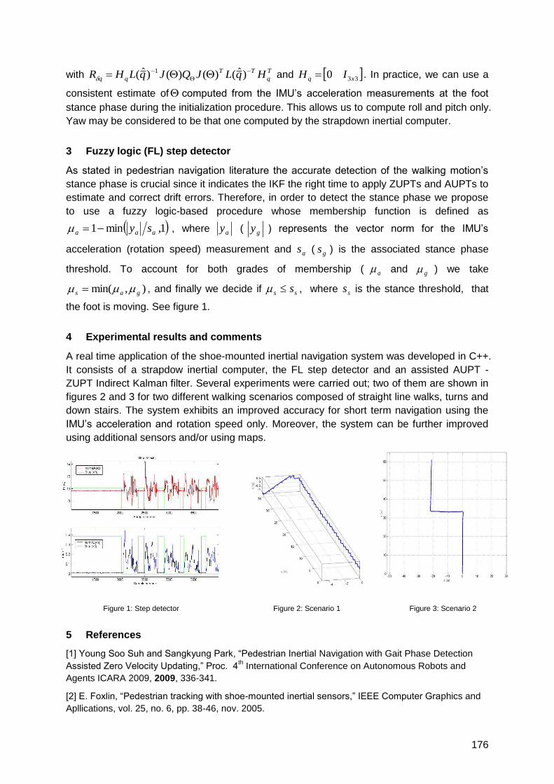
176
with T
q
TT
qq HqLJQJqLHR
)ˆ()()()ˆ( 1
and 330 xq IH . In practice, we can use a
consistent estimate of computed from the IMU‘s acceleration measurements at the foot
stance phase during the initialization procedure. This allows us to compute roll and pitch only.
Yaw may be considered to be that one computed by the strapdown inertial computer.
3 Fuzzy logic (FL) step detector
As stated in pedestrian navigation literature the accurate detection of the walking motion‘s
stance phase is crucial since it indicates the IKF the right time to apply ZUPTs and AUPTs to
estimate and correct drift errors. Therefore, in order to detect the stance phase we propose
to use a fuzzy logic-based procedure whose membership function is defined as
1,min1 aaa sy , where ay ( gy ) represents the vector norm for the IMU‘s
acceleration (rotation speed) measurement and as ( gs ) is the associated stance phase
threshold. To account for both grades of membership ( a and g ) we take
),min( gas , and finally we decide if ss s , where ss is the stance threshold, that
the foot is moving. See figure 1.
4 Experimental results and comments
A real time application of the shoe-mounted inertial navigation system was developed in C++.
It consists of a strapdow inertial computer, the FL step detector and an assisted AUPT -
ZUPT Indirect Kalman filter. Several experiments were carried out; two of them are shown in
figures 2 and 3 for two different walking scenarios composed of straight line walks, turns and
down stairs. The system exhibits an improved accuracy for short term navigation using the
IMU‘s acceleration and rotation speed only. Moreover, the system can be further improved
using additional sensors and/or using maps.
Figure 1: Step detector Figure 2: Scenario 1 Figure 3: Scenario 2
5 References
[1] Young Soo Suh and Sangkyung Park, ―Pedestrian Inertial Navigation with Gait Phase Detection
Assisted Zero Velocity Updating,‖ Proc. 4th International Conference on Autonomous Robots and
Agents ICARA 2009, 2009, 336-341.
[2] E. Foxlin, ―Pedestrian tracking with shoe-mounted inertial sensors,‖ IEEE Computer Graphics and
Apllications, vol. 25, no. 6, pp. 38-46, nov. 2005.
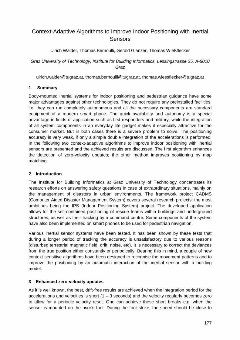
177
Context-Adaptive Algorithms to Improve Indoor Positioning with Inertial
Sensors
Ulrich Walder, Thomas Bernoulli, Gerald Glanzer, Thomas Wießflecker
Graz University of Technology, Institute for Building Informatics, Lessingstrasse 25, A-8010
Graz
[email protected], [email protected], [email protected]
1 Summary
Body-mounted inertial systems for indoor positioning and pedestrian guidance have some
major advantages against other technologies. They do not require any preinstalled facilities,
i.e. they can run completely autonomous and all the necessary components are standard
equipment of a modern smart phone. The quick availability and autonomy is a special
advantage in fields of application such as first responders and military, while the integration
of all system components in an everyday life gadget makes it especially attractive for the
consumer market. But in both cases there is a severe problem to solve: The positioning
accuracy is very weak, if only a simple double integration of the accelerations is performed.
In the following two context-adaptive algorithms to improve indoor positioning with inertial
sensors are presented and the achieved results are discussed. The first algorithm enhances
the detection of zero-velocity updates; the other method improves positioning by map
matching.
2 Introduction
The Institute for Building Informatics at Graz University of Technology concentrates its
research efforts on answering safety questions in case of extraordinary situations, mainly on
the management of disasters in urban environments. The framework project CADMS
(Computer Aided Disaster Management System) covers several research projects; the most
ambitious being the IPS (Indoor Positioning System) project. The developed application
allows for the self-contained positioning of rescue teams within buildings and underground
structures, as well as their tracking by a command centre. Some components of the system
have also been implemented on smart phones to be used for pedestrian navigation.
Various inertial sensor systems have been tested. It has been shown by these tests that
during a longer period of tracking the accuracy is unsatisfactory due to various reasons
(disturbed terrestrial magnetic field, drift, noise, etc). It is necessary to correct the deviances
from the true position either constantly or periodically. Bearing this in mind, a couple of new
context-sensitive algorithms have been designed to recognise the movement patterns and to
improve the positioning by an automatic interaction of the inertial sensor with a building
model.
3 Enhanced zero-velocity updates
As it is well known, the best, drift-free results are achieved when the integration period for the
accelerations and velocities is short (1 – 3 seconds) and the velocity regularly becomes zero
to allow for a periodic velocity reset. One can achieve these short breaks e.g. when the
sensor is mounted on the user‘s foot. During the foot strike, the speed should be close to
178
zero for a short time. It is very important to detect this certain moment, but it is difficult,
because it is dependent on the movement type of the person, its velocity, the type of the
ground, the measuring accuracy and where the sensor is mounted. Time (between zero
velocity updates, ZUPT) and velocity dependent algorithms have been developed for foot
mounted sensors, as well as for body mounted systems where ZUPTs are replaced by a drift
control. They will be presented in detail in the full paper and during the conference.
4 Sensor – Building Model Interaction
Though the improvement of the position calculation by better integration algorithms is
considerable it can‘t compensate systematic errors, like deviations of the terrestrial magnetic
field, e.g. by electrical installations or steel structures.
For this reason a newly developed building map-sensor interaction has been implemented.
This core element of the IPS continually analyses the plausibility of the position provided by
the sensor algorithms by exploiting the information of the building model. Depending on the
deviation of the derived position, the location presented to the user is adapted and shifted
towards the most likely position. Typical types of inaccuracy include the pedestrian‘s route
intersecting a wall or the missing of doors and stair cases. The corrections have to take into
account the current local situation within the building (Fig. 1).
The algorithms have been evaluated intensively. Test runs with an overall travelled distance
of more than 6 km have been carried out. This involved buildings with various construction
styles and occupancies, numerous test persons and different test equipment and ways of
moving (walking, running, crawling, ascending stairs, etc.). The statistical evaluation yields
an accuracy of 1 – 2 metres for over 95 % of the covered path inside the buildings. This
complies with the demands for indoor navigation in the field of application for first responders.
5 Conclusions and Outlook
The development of CADMS has been supported by civil first responder organisations, the
Swiss and Austrian Armies and well-known companies from the security industry. The
practical implementation in some of these organisations is planned at the end of 2010.
Meanwhile research is going on, especially in the field of user interfaces for such a system
and in the wireless networking of a greater number of systems during the deployment.
Results obtained with the context adaptive position correction
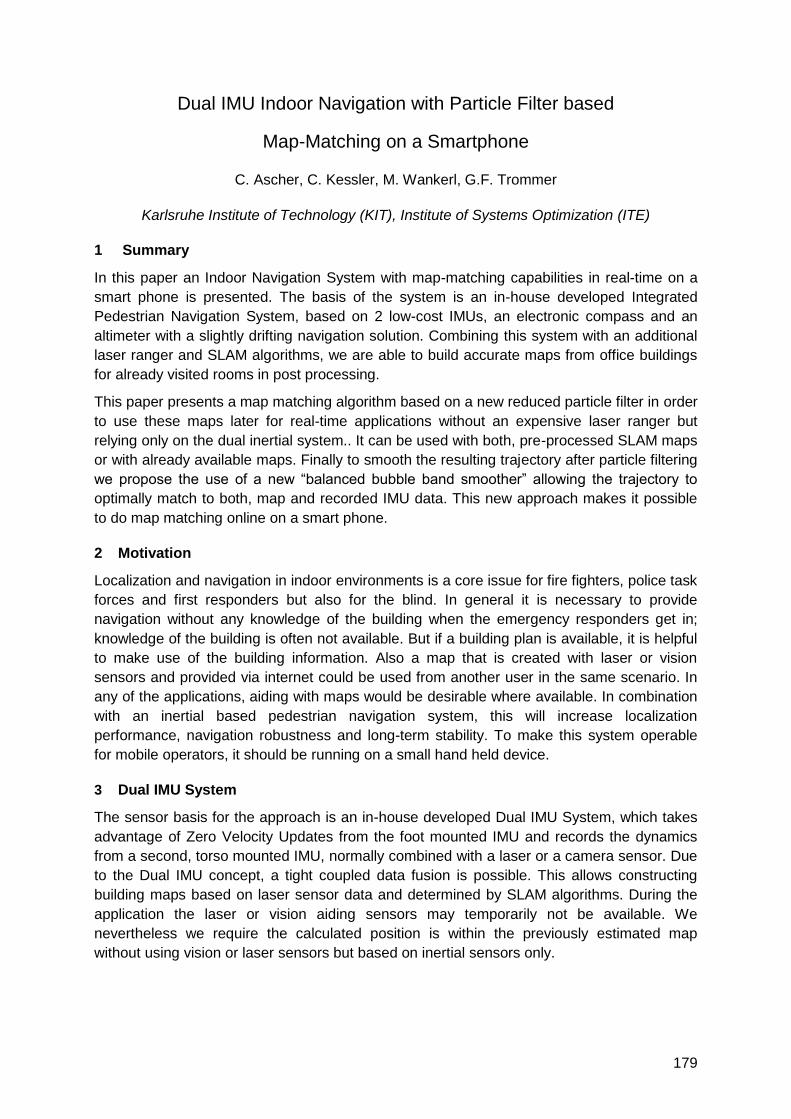
179
Dual IMU Indoor Navigation with Particle Filter based
Map-Matching on a Smartphone
C. Ascher, C. Kessler, M. Wankerl, G.F. Trommer
Karlsruhe Institute of Technology (KIT), Institute of Systems Optimization (ITE)
1 Summary
In this paper an Indoor Navigation System with map-matching capabilities in real-time on a
smart phone is presented. The basis of the system is an in-house developed Integrated
Pedestrian Navigation System, based on 2 low-cost IMUs, an electronic compass and an
altimeter with a slightly drifting navigation solution. Combining this system with an additional
laser ranger and SLAM algorithms, we are able to build accurate maps from office buildings
for already visited rooms in post processing.
This paper presents a map matching algorithm based on a new reduced particle filter in order
to use these maps later for real-time applications without an expensive laser ranger but
relying only on the dual inertial system.. It can be used with both, pre-processed SLAM maps
or with already available maps. Finally to smooth the resulting trajectory after particle filtering
we propose the use of a new ―balanced bubble band smoother‖ allowing the trajectory to
optimally match to both, map and recorded IMU data. This new approach makes it possible
to do map matching online on a smart phone.
2 Motivation
Localization and navigation in indoor environments is a core issue for fire fighters, police task
forces and first responders but also for the blind. In general it is necessary to provide
navigation without any knowledge of the building when the emergency responders get in;
knowledge of the building is often not available. But if a building plan is available, it is helpful
to make use of the building information. Also a map that is created with laser or vision
sensors and provided via internet could be used from another user in the same scenario. In
any of the applications, aiding with maps would be desirable where available. In combination
with an inertial based pedestrian navigation system, this will increase localization
performance, navigation robustness and long-term stability. To make this system operable
for mobile operators, it should be running on a small hand held device.
3 Dual IMU System
The sensor basis for the approach is an in-house developed Dual IMU System, which takes
advantage of Zero Velocity Updates from the foot mounted IMU and records the dynamics
from a second, torso mounted IMU, normally combined with a laser or a camera sensor. Due
to the Dual IMU concept, a tight coupled data fusion is possible. This allows constructing
building maps based on laser sensor data and determined by SLAM algorithms. During the
application the laser or vision aiding sensors may temporarily not be available. We
nevertheless we require the calculated position is within the previously estimated map
without using vision or laser sensors but based on inertial sensors only.
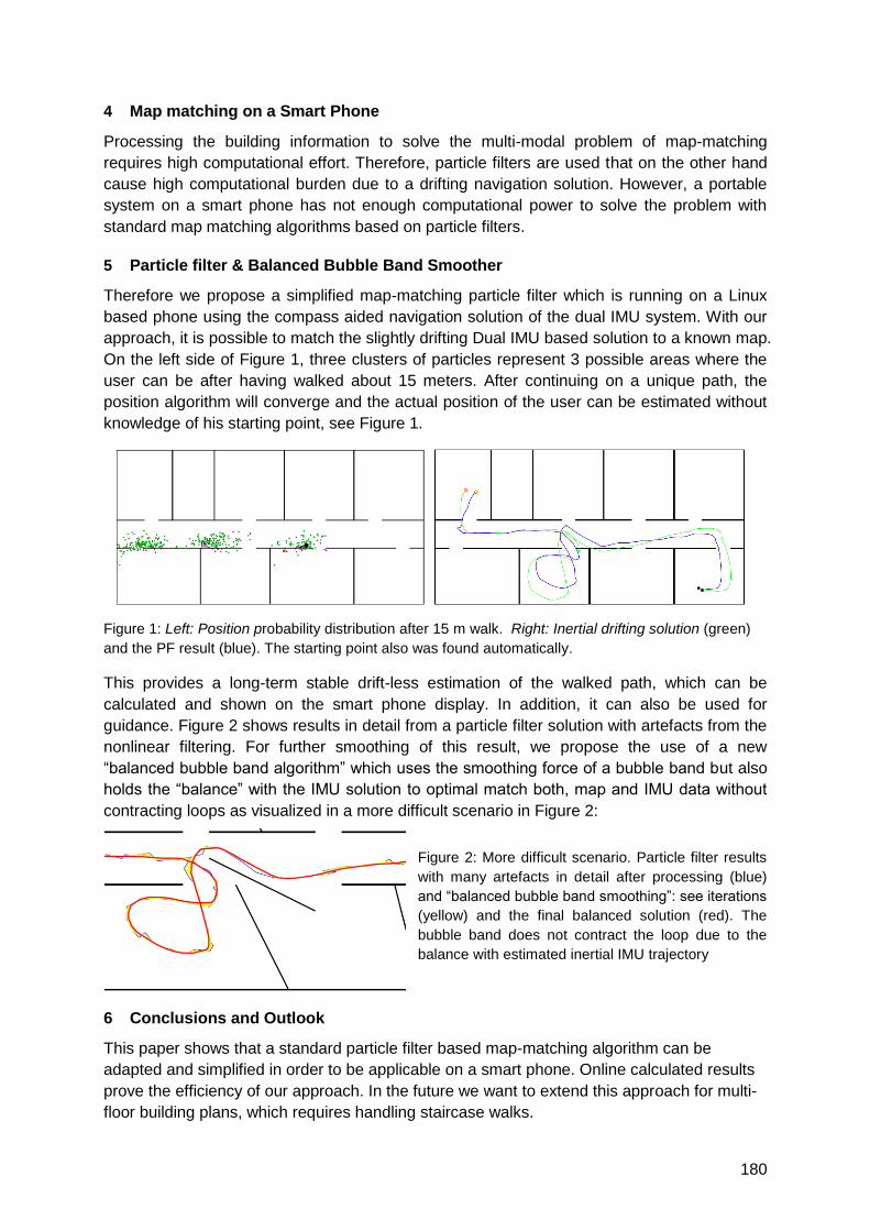
180
4 Map matching on a Smart Phone
Processing the building information to solve the multi-modal problem of map-matching
requires high computational effort. Therefore, particle filters are used that on the other hand
cause high computational burden due to a drifting navigation solution. However, a portable
system on a smart phone has not enough computational power to solve the problem with
standard map matching algorithms based on particle filters.
5 Particle filter & Balanced Bubble Band Smoother
Therefore we propose a simplified map-matching particle filter which is running on a Linux
based phone using the compass aided navigation solution of the dual IMU system. With our
approach, it is possible to match the slightly drifting Dual IMU based solution to a known map.
On the left side of Figure 1, three clusters of particles represent 3 possible areas where the
user can be after having walked about 15 meters. After continuing on a unique path, the
position algorithm will converge and the actual position of the user can be estimated without
knowledge of his starting point, see Figure 1.
Figure 1: Left: Position probability distribution after 15 m walk. Right: Inertial drifting solution (green)
and the PF result (blue). The starting point also was found automatically.
This provides a long-term stable drift-less estimation of the walked path, which can be
calculated and shown on the smart phone display. In addition, it can also be used for
guidance. Figure 2 shows results in detail from a particle filter solution with artefacts from the
nonlinear filtering. For further smoothing of this result, we propose the use of a new
―balanced bubble band algorithm‖ which uses the smoothing force of a bubble band but also
holds the ―balance‖ with the IMU solution to optimal match both, map and IMU data without
contracting loops as visualized in a more difficult scenario in Figure 2:
Figure 2: More difficult scenario. Particle filter results
with many artefacts in detail after processing (blue)
and ―balanced bubble band smoothing‖: see iterations
(yellow) and the final balanced solution (red). The
bubble band does not contract the loop due to the
balance with estimated inertial IMU trajectory
6 Conclusions and Outlook
This paper shows that a standard particle filter based map-matching algorithm can be
adapted and simplified in order to be applicable on a smart phone. Online calculated results
prove the efficiency of our approach. In the future we want to extend this approach for multi-
floor building plans, which requires handling staircase walks.
181
Design choices, filter parameter tuning, and calibration of zero-velocity
update aided inertial navigation systems for pedestrian navigation
John-Olof Nilsson*, Isaac Skog, and Peter Händel
Signal Processing Lab, ACCESS Linnaeus Centre, Royal Institute of Technology, Sweden
1 Summary
Inertial navigation systems (INSs) placed on the foot of the carrier together with a zero-
velocity detector providing so-called zero-velocity-updates (ZUPTs) is a promising technique
for infrastructure free, pedestrian indoor navigation. The ZUPTs aid the INS to limit its error
growth; without the ZUPTs the errors growth is such that the system becomes useless after
only a few seconds. When implementing the ZUPT-aided INS numerous design choices
have to be made and multiple parameters tuned. This together with the high dynamic and
frequency component ranges of the motion of the foot makes the system hard to optimize.
In this study, we look at what design choices and tuning parameters of a ZUPT-aided INS
there are. A heuristic approach to handling the large number of design choices and
parameters is suggested. Based on analysis and experimental data we argue how the design
choice should be made and the parameters set. The parameter settings are in clear contrast
to many of the one found in the literature. Correct settings are shown to give a significant
performance gain.
2 Introduction
A popular sensor type for indoor pedestrian navigation is micro-electro-mechanical system
(MEMS) inertial measurement units (IMUs), which together with navigation equations make
up an INS. Unfortunately, due to its integrative nature, a standalone INS based on a MEMS
IMU can only be used during a few seconds before the position errors is in the order of
several meters. Hence, additional information about the systems motion is needed to limit the
error growth of the INS. Such additional information can be acquired from additional sensors
or from models of the motion and the environment. Building an accurate and general model
for the full motion of a person on foot is difficult. However, placing the IMU on the foot let us
use a simple but general model of the motion; the foot is either stationary or in motion.
Various detectors working on the inertial measurements can then be used to determine when
the system is stationary. Via standard techniques of aided INS, these ZUPTs together with
an extended Kalman filter (EKF) can be used to estimate the errors in the navigation solution
of the INS. The estimated errors are then used to correct the navigation solution of the INS
and limit the error growth rate of the system. A large number of recent publications of such
systems exist in the literature; refer to e.g. [1] [2].
In the construction of a ZUPT-aided INS there are many design choices to be made and
parameters to tune. Changing between design choices is typically too laborious and the
parameters are too many for it to be feasible to make a global search for the optimal design
choice and parameter values. Moreover, the optimal design choice and parameter values will
depend on the conditions under which the system is intended to work.
182
3 Contribution
In this paper, we look at what the design choices and tuning parameters of a ZUPT-aided
INS are and suggest a way of dividing them into subsets. We then look closer at two out of
three subsets, namely (1) the design choices connected to hardware setup, e.g., sensor
placement and sensor specifications and (2) the design choices and calibration parameters
connected to the EKF, e.g., what errors to estimate, how to model the ZUPT, and filter noise
parameters. Hardware design choices are made and motivated, and carried over to a ZUPT-
aided INS implementation. Cost functions are constructed and used in the tuning process of
the system. Remaining design choices are analyzed and set. This and the tuning are done
with the support of a large number of independent data sets recorded under specified
conditions. To facilitate the construction of a marginal cost function of the filter parameters an
independent zero-velocity detector based on pressure sensors is constructed and described.
Finally, statistical performance figures of the tuned system are given. The third subset of the
suggested division, the design choices and parameters of the detector, is studied in a
companion paper.
4 Preliminary results
A marginal cost function for the first subset of parameters can be constructed based on
measures on the raw data in time and frequency domain. Experimental data show that the
needed dynamic range of the IMU is higher than that of many standard units on the market
and that the preferable placement of the sensor is below the foot. Analysis of the second
parameter set show that, in contrast to many publications and systems featuring aided INS,
accelerometer biases should not be modeled. Tuning with experimental data, together with
the pressure sensor zero-velocity detector, show that the accelerometer process noise
should have a standard deviation of 0.1-1m/s2 and that the gyroscope process noise should
have a standard deviation of 0.1-0.01°/s. Finally, calibration results show that the tuned
system has a mean-square position error of 0.1-1% of the travelled distance depending on
operational conditions. This can be put in relation to reported errors of 0.3-15% in the
literature [1].
5 Conclusion
The optimizations of a ZUPT-aided INS system for pedestrian navigation can be handled
approximately by heuristically dividing the parameters into three subsets and then optimizing
the performance with respect to one parameter set at the time. The performance gain of
carful design choices and parameter settings is substantial and a systematic treatment of
them is advisable.
6 References
[1] A.R. Jiménez, F. Seco, J.C. Prieto, and J. Guevara ―Indoor pedestrian navigation using an
INS/EKF framework for yaw drift reduction and a foot-mounted IMU‖ In Proc. of the 7th Workshop
on Positioning, Navigation and Communication, March 2010.
[2] Ö. Bebek, M.A. Suster, S. Rajgopal, M.J. Fu, X. Huang, M.C. Cavusoglu, D.J. Young, M.
Mehregany, A.J. van den Bogert, and C.H. Mastrangelo. ‖Personal navigation via high resolution
gait-corrected inertial measurement units‖ IEEE Trans. on Instrumentation and Measurements,
To appear 2010.
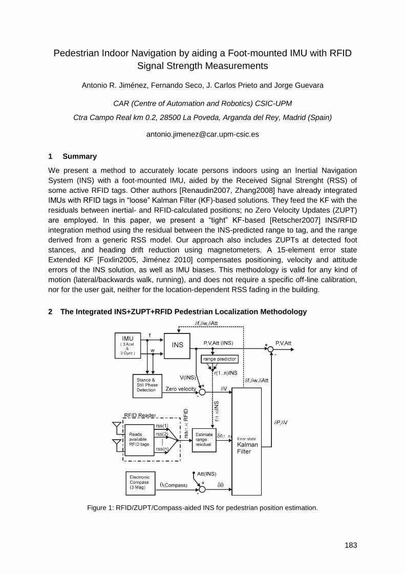
183
Pedestrian Indoor Navigation by aiding a Foot-mounted IMU with RFID
Signal Strength Measurements
Antonio R. Jiménez, Fernando Seco, J. Carlos Prieto and Jorge Guevara
CAR (Centre of Automation and Robotics) CSIC-UPM
Ctra Campo Real km 0.2, 28500 La Poveda, Arganda del Rey, Madrid (Spain)
1 Summary
We present a method to accurately locate persons indoors using an Inertial Navigation
System (INS) with a foot-mounted IMU, aided by the Received Signal Strenght (RSS) of
some active RFID tags. Other authors [Renaudin2007, Zhang2008] have already integrated
IMUs with RFID tags in ―loose‖ Kalman Filter (KF)-based solutions. They feed the KF with the
residuals between inertial- and RFID-calculated positions; no Zero Velocity Updates (ZUPT)
are employed. In this paper, we present a ―tight‖ KF-based [Retscher2007] INS/RFID
integration method using the residual between the INS-predicted range to tag, and the range
derived from a generic RSS model. Our approach also includes ZUPTs at detected foot
stances, and heading drift reduction using magnetometers. A 15-element error state
Extended KF [Foxlin2005, Jiménez 2010] compensates positioning, velocity and attitude
errors of the INS solution, as well as IMU biases. This methodology is valid for any kind of
motion (lateral/backwards walk, running), and does not require a specific off-line calibration,
nor for the user gait, neither for the location-dependent RSS fading in the building.
2 The Integrated INS+ZUPT+RFID Pedestrian Localization Methodology
Figure 1: RFID/ZUPT/Compass-aided INS for pedestrian position estimation.
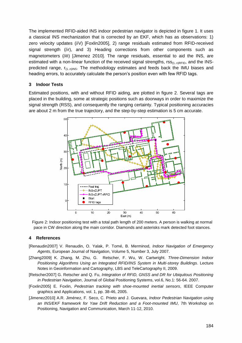
184
The implemented RFID-aided INS indoor pedestrian navigator is depicted in figure 1. It uses
a classical INS mechanization that is corrected by an EKF, which has as observations: 1)
zero velocity updates (V) [Foxlin2005], 2) range residuals estimated from RFID-received
signal strength (r), and 3) Heading corrections from other components such as
magnetometers () [Jimenez 2010]. The range residuals, essential to aid the INS, are
estimated with a non-linear function of the received signal strengths, rss(1..n)RFID, and the INS-
predicted range, r(1..n)INS. The methodology estimates and feeds back the IMU biases and
heading errors, to accurately calculate the person‘s position even with few RFID tags.
3 Indoor Tests
Estimated positions, with and without RFID aiding, are plotted in figure 2. Several tags are
placed in the building, some at strategic positions such as doorways in order to maximize the
signal strength (RSS), and consequently the ranging certainty. Typical positioning accuracies
are about 2 m from the true trajectory, and the step-by-step estimation is 5 cm accurate.
Figure 2: Indoor positioning test with a total path length of 200 meters. A person is walking at normal
pace in CW direction along the main corridor. Diamonds and asterisks mark detected foot stances.
4 References
[Renaudin2007] V. Renaudin, O. Yalak, P. Tomé, B. Merminod, Indoor Navigation of Emergency
Agents, European Journal of Navigation, Volume 5, Number 3, July 2007.
[Zhang2009] K. Zhang, M. Zhu, G. Retscher, F. Wu, W. Cartwright. Three-Dimension Indoor
Positioning Algorithms Using an Integrated RFID/INS System in Multi-storey Buildings. Lecture
Notes in Geoinformation and Cartography, LBS and TeleCartography II, 2009.
[Retscher2007] G. Retscher and Q. Fu, Integration of RFID, GNSS and DR for Ubiquitous Positioning
in Pedestrian Navigation, Journal of Global Positioning Systems, vol.6, No.1: 56-64. 2007.
[Foxlin2005] E. Foxlin, Pedestrian tracking with shoe-mounted inertial sensors, IEEE Computer
graphics and Applications, vol. 1, pp. 38-46, 2005.
[Jimenez2010] A.R. Jiménez, F. Seco, C. Prieto and J. Guevara, Indoor Pedestrian Navigation using
an INS/EKF framework for Yaw Drift Reduction and a Foot-mounted IMU, 7th Workshop on
Positioning, Navigation and Communication, March 11-12, 2010.

185
On the use of foot-mounted INS, UWB-ranging and opportunistic
cooperation in high-accuracy indoor positioning systems
Peter Strömbäck, Jouni Rantakokko, Erika Emilsson
Swedish Defense Research Agency, FOI
1 Summary
In order to achieve an accurate, robust indoor localization system it is anticipated that a
multi-sensor system approach is required. High-sensitivity GPS (HSGPS) receivers, inertial
sensors, and local radio-based ranging are natural choices. These sensors may need to be
complemented with e.g. barometric altimeters, magnetometers ultra-sonic sensors or soft
information such as (full or partial) building floor-plans. In this paper we focus on examining
the performance of a sub-set of the full system, namely foot-mounted inertial measurement
units (IMUs) in combination with ultra-wideband impulse-radio (IR-UWB) ranging between
cooperating soldiers. Experimental data is collected with two persons moving inside a
building, where each individual is equipped with foot-mounted IMUs and UWB-ranging
devices. In conjunction to ranging, the UWB-units are used to convey position and error
estimates, which are used to improve the position accuracy. The increased accuracy
obtained through cooperation will be evaluated for different movement scenarios.
2 Introduction
An accurate, reliable indoor positioning system can significantly increase the safety of
military personnel and first responders. A soldier and first responder positioning system
should be light-weight, small, inexpensive and power efficient, and still provide metre-level
accuracy during extended indoor operations. The main technical challenge lies in creating a
system that yields metre-level accuracies in GPS-denied environments.
In order to achieve an accurate, robust indoor localization system it is anticipated that a
multi-sensor system approach is required. High sensitivity GPS (HSGPS) receivers, inertial
sensors, and local radio-based ranging are natural choices. These sensors may need to be
complemented with barometric altimeters, magnetometers and possibly also ultra-sonic
sensors. Furthermore, imaging sensors may increase localization accuracy in indoor
scenarios, as well as providing an estimate of the building layout to the command and control
system [1]. Finally, if up-to-date accurate building floor-plans, or even just partial map-
information, are available the positioning accuracy can be significantly improved.
In this paper we focus on examining the performance of foot-mounted inertial measurement
units (IMUs) in combination with ultra-wideband impulse-radio (IR-UWB) ranging between
cooperating soldiers. Through inter-nodal ranging and transfer of position estimates and error
covariances, as shown in Figure 1, it is possible to significantly improve the positioning
accuracy.
3 Scope
We are currently performing measurements on the performance of the cooperative
positioning approach examined in [2]. In that work, the potential benefits of cooperation was
clearly shown, as illustrated in Figure 3. Two units are equipped with foot-mounted

186
MicroStrain 3DM-GX3 IMUs, and UWB-ranging is performed with the TimeDomain PulsOn
220. We will show the performance of the foot-mounted inertial navigation utilizing ZUPT and
statistical stance-phase detection algorithms. However, the main focus of the paper is on
evaluating the effects of introducing opportunistic cooperation under different scenarios.
Figure 1: Illustration of opportunistic cooperative positioning between units equipped with locally-worn
positioning sensors.
Figure 2: Illustration of cooperative positioning as an integral part of a soldier positioning system.
Radio-based ranging is combined with transfer of position and error estimates, between units moving
inside building as well as out to vehicle-mounted transceivers outside.
Figure 3: Left: Foot-mounted INS with ZUPT but without use of cooperative navigation. Heading errors
are affecting the position solution. Right: Cooperative navigation is able to improve the end result as
well as the whole trajectory significantly.
4 References
[1] J. Rydell and T. Andersson, ―Camera-based Navigation, Mapping and 3D Model Generation for
Indoor Environments,‖ Proc. of ION ITM, San Diego, USA, January 2010.
[2] J. Rantakokko et al,Foot-Mounted Inertial Navigation and Cooperative Sensor Fusion for Indoor
Positioning, Proc. of ION ITM, San Diego, USA, January 2010.

187
Frameworks for Hybrid Positioning
Auditorium G3
Thursday, September 16, 13:15 – 15:00


189
Tracking Framework for Heterogeneous Sensor Sources
Mareike Kritzler, Antonio Krüger
WWU Münster, Institute for Geoinformatics, Weseler Str. 253, D-48149 Münster
DFKI GmbH, Stuhlsatzenhausweg 3, Campus D3 2, D-66123 Saarbrücken
[email protected], [email protected]
1 Summary
We describe a scale-independent (space and time) tracking framework for moving items (objects,
animals, humans). Different sizes and characteristics of the items are considered as well as
different tracking environments / contexts. This work enables the integration and processing of
spatial temporal data obtained by heterogeneous sensor sources. The framework does not rely
upon one tracking / positioning technology but instead considers the combination of several
technologies to calculate the best positioning result. The data is processed in a core and
provided by different internal and external interfaces. The framework consists of different
applications. One application is used for visualization of the context and tracked items. Other
applications analyze large amounts of data e.g. via machine learning techniques. Two different
use cases (laboratory mice / service technicians) were used to develop the framework.
2 Introduction
Tracking and localization technologies are used to gather spatial temporal data of moving
items to obtain information about behavior or to support them with location-based information.
Problem: Tracked items and/or their environments are equipped with sensors to get spatial
temporal data. Depending upon the tracked items, tracking environments and the project in
question, many different technologies may be in use simultaneously. This leads to a variety
of sensors and spatial temporal data without a standardized format, processing or analysis.
Motivation: To enable the integration and combination of heterogeneous tracking data so that
a useful synthesis of the information involved can be obtained. Prototypical industrial
applications include assisting in work flows and providing information. Furthermore, this work
enables interdisciplinary scientific tools for the support of experimental scientists by allowing
them to collect and process large quantities of moving item data.
Background: The idea is based on the tracking of laboratory mice [6] (1st use case) via RFID-
technology, weight scale and camera. The aim is to find movement and behavior patterns. In the
second use case, service technicians are tracked indoor in an industrial environment via RFID, UWB
(Ubisense2), WiFi fingerprints and keystroke sensors to support them in their maintenance work.
3 Related Work
Many applications focus on tracking and localization [3]: AAMPL [7] or Redpin [2] combine
different technologies in mobile devices to get precise locations. Opportunistic localization
using smart phones with WiFi, GSM, GPS and accelerometers has been developed [8]. The
StarTrack framework provides a set of operations to ease the development and deployment
of track-based applications [1]. The EnTracked system is based on estimation and prediction
of system conditions and mobility to minimize energy consumption and optimize robustness
[5]. The location stack is a 6-layer design framework that establishes clearly defined
abstractions, building from data to context aware computing [4]. Problems of scalability to
large environments and uncertainty due to environmental symmetry have also been
considered [9].
2 Ubisense homepage latest update 2010-06-02: http://www.ubisense.net/en
190
4 Implementation
The concept behind the framework is divided into 4 parts, 3 of them are already implemented:
Architecture of the tracking framework: The architecture of the framework consists of four
different levels: sensor sources, databases, a processing core and various applications. The
framework and its modules have different well-defined internal and external interfaces for the
import and export of data. This architecture allows for the integration of different applications.
Modeling of the environment: It is possible to display 3D models of the environment with
integrated sensors as one application. The required attributes for a scale invariant 3D modeling
of sensors have been taken into consideration. They are used for the extension of a scene graph
model with sensor nodes (VRML and Java 3D) and to provide context information. The software
allows for the positioning of sensors integrated in the environment to be changed, added or
deleted by users. A tracking component allows the display of moving items in the environment.
Sensor fusion: Different levels of instrumentation of the environment and of the tracked items
are taken into consideration. The modeling of heterogeneous data sources is necessary, as
well as a standardized data model for the gathered data. This enables the framework to
integrate various data sources (in this work RFID, UWB (Ubisense), WiFi fingerprinting and
keystroke sensors are in use) into the application. The generalized data model determines
which data is gathered and stored for positioning and tracking. The data model is easily
extensible for more sensor sources. A database schema for the storage of the data has been
designed as well as a schema for metadata of tracking technologies. Information about tracked
objects can be obtained, and a format has been defined in which data are delivered for further
analysis.
5 Conclusions and Outlook
This abstract proposes a tracking framework for moving items based upon heterogeneous
data sources. A modular architecture and well defined interfaces make it possible to integrate
different applications. In the future, different analysis modules will be established to obtain
information: Machine learning will classify patterns without domain knowledge. An expert can
add meaning to the patterns and they can be verified in the data. Similarity matching of
attribute-labeled related graphs can be used to find predefined patterns (template graphs) in
collected data (data graph). Template graphs (designed by a domain expert) can be used to
define certain patterns. The aims are to find patterns in movement and behavior, classify
observed items and to learn about individual items for the prediction of future behavior.
References
[1] Ananthanarayanan, G., Haridasan, M., Mohomed, I., Terry, D., and Thekkath, C. A.:‖ StarTrack: a framework for enabling track-based applications‖. In Proceedings of the 7th international Conference on MobiSys '09. ACM, New York, NY, 207-220
[2] Bolliger, P.: ―Redpin - Adaptive, Zero-Configuration Indoor Localization through User Collaboration‖.MELT'08 Proceedings. ACM, San Francisco, California, USA (2008)
[3] Hightower, J., Borriello, G.: ―Location Systems for Ubiquitous Computing‖. IEEE Computer, Vol. 34, No. 8., pp. 57-66, August 2001.
[4] Hightower, J., Brumitt, B. and Borriello, G.: "The Location Stack: A Layered Model for Location in Ubiquitous Computing", in Proceedings of the 4th IEEE Workshop on Mobile Computing Systems & Applications (WMCSA 2002), (Callicoon, NY), June 2002.
[5] Kjærgaard, M. B., Langdal, J., Godsk, T., and Toftkjær, T.: ―EnTracked: energy-efficient robust position tracking for mobile devices‖. In Proceedings of the 7th international Conference on Mobile Systems, Applications, and Services (Kraków, Poland, June 22 - 25, 2009). MobiSys '09. ACM, New York, NY, 221-234
[6] Kritzler, M., Raubal, M., Krüger, A.: "A GIS framework for spatio-temporal analysis and visualization of laboratory mice tracking data." Transactions in GIS, 11(5). Blackwell Publishers, USA (2007)
[7] Ofstad, A., Nicholas, E., Szcodronski, R., Choudhury, R. R.: AAMPL: Accelerometer Augmented Mobile Phone Localization. MELT'08 Proceedings. ACM, San Francisco, California, USA (2008)
[8] Weyn, M., Klepal, M., Widyawn: ―Adaptive Motion Model for a Smart Phone based Opportunistic Localisation System‖. Ref.: in proc. MELT‘09, International Workshop on Mobile Entity Localization and Tracking in GPS-less Environments, Florida,2009
[9] Woodman, O., Harle, R.: ―RF-Based Initialisation for Inertial Pedestrian Tracking‖. Pervasive, Series Lecture Notes in Computer Science, Volume 5538/2009, Pages 238-255, Springer Berlin / Heidelberg, May 2009.
191
A Fusion Component for location management in mobile devices
Eduardo Metola, Ana M. Bernardos, Henar Martín, José R. Casar Universidad Politécnica de Madrid, Telecommunications School,
Av. Complutense 30, Madrid, Spain [email protected]
1. Summary and objetives
When indoors, several positioning technologies and systems may coexist (e.g. WiFi,
Bluetooth, ZigBee, HF-RFID or bidi codes serving as beacons, cellular networks, etc.); each
of them delivering its location estimates with a given accuracy at a given computational cost.
In this paper, we describe a Mobile Fusion Component (MFC) -prepared to run in a mobile
device- which aims at optimizing the selection of the available positioning systems by
handling Quality-of-Location (QoL). The objective of the MFC is to offer the (best) location
estimation which fulfills the consumer applications‘ QoL needs, at the same time that
minimizes resource consumption in the mobile device. Additionally, the MFC will provide
seamless hand-off among location technologies and allow the user to establish his own
privacy level for location data sharing. The MFC is part of a service-oriented mobile
framework which offers ‗Context Acquisition Services anD Reasoning Algorithms‘
(CASanDRA Mobile) to accelerate the development of context-aware applications.
2. A fusion algorithm for the MFC
The fusion algorithm for the MFC handles a Quality-of-Location [1] tuple which gathers
information about the accuracy, availability and freshness of the location estimation provided
by the available localization systems. ‗Accuracy‘ refers to the mean error in the location
estimate; ‗availability‘ includes data from the electromagnetic visibility of relevant
components of the localization infrastructure (e.g. number of available access points); finally,
‗freshness‘ gathers the age of the estimate.
The MFC is dynamically configured to adjust its output to the consumer application‘s
requirements in terms of QoL. It compares the available location estimates from different
sources, provides the application with the estimate that better fits its needs, and initiates or
stops sensors to optimize resource consumption. The QoL tuple is provided by the available
location systems, together with the location estimate. When different technologies are
available, the MFC prioritizes those offering better accuracy whenever the ‗availability‘ in
terms of visible infrastructure is enough and the estimation is recent enough (‗freshness‘) to
fulfill the application‘s needs.
In order to prototype our MFC, we consider that GPS and Cell-ID positioning are available
when outdoors, and the latter also when indoors. Additionally, in closed environments (such
as our laboratory), we assume that a deployment of WiFi and Bluetooth access points may
be used to locate a mobile device [2] [3]. Moreover, some HF RFID tags will be situated in
waypoints to be read from a mobile device. Each of these location systems may offer a given
QoL, being the RFID method the most accurate (cms) but offering non-continuous location
(event-based) (the full paper will describe the information flow to make the estimator‘s
choice). Another important issue to consider for the MFC is how to handle hand-offs between
localization systems, always guaranteeing seamless transfer and resource consumption
optimization. The ‗availability‘ information in the QoL parameter is used to start additional
sensors and to adjust periodic wake-up of slept sensors.
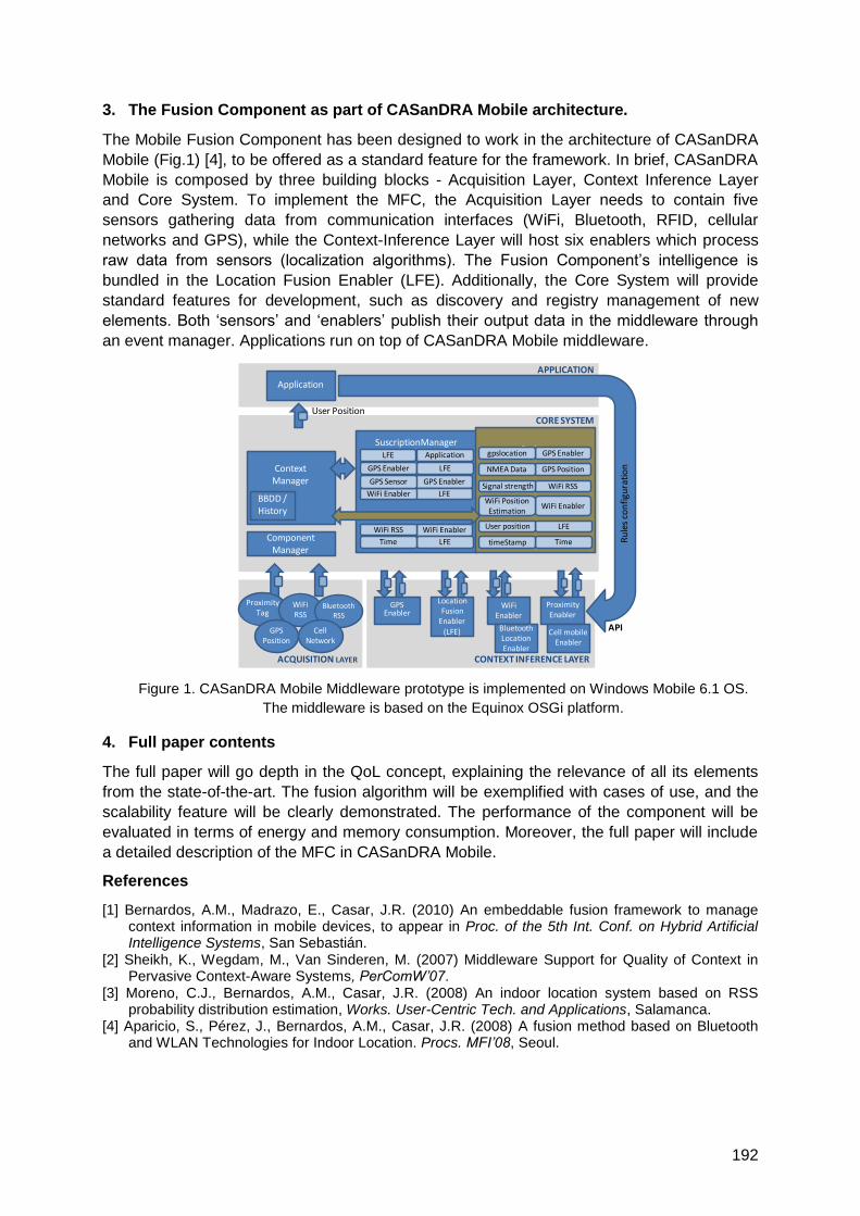
192
3. The Fusion Component as part of CASanDRA Mobile architecture.
The Mobile Fusion Component has been designed to work in the architecture of CASanDRA
Mobile (Fig.1) [4], to be offered as a standard feature for the framework. In brief, CASanDRA
Mobile is composed by three building blocks - Acquisition Layer, Context Inference Layer
and Core System. To implement the MFC, the Acquisition Layer needs to contain five
sensors gathering data from communication interfaces (WiFi, Bluetooth, RFID, cellular
networks and GPS), while the Context-Inference Layer will host six enablers which process
raw data from sensors (localization algorithms). The Fusion Component‘s intelligence is
bundled in the Location Fusion Enabler (LFE). Additionally, the Core System will provide
standard features for development, such as discovery and registry management of new
elements. Both ‗sensors‘ and ‗enablers‘ publish their output data in the middleware through
an event manager. Applications run on top of CASanDRA Mobile middleware.
Figure 1. CASanDRA Mobile Middleware prototype is implemented on Windows Mobile 6.1 OS.
The middleware is based on the Equinox OSGi platform.
4. Full paper contents
The full paper will go depth in the QoL concept, explaining the relevance of all its elements
from the state-of-the-art. The fusion algorithm will be exemplified with cases of use, and the
scalability feature will be clearly demonstrated. The performance of the component will be
evaluated in terms of energy and memory consumption. Moreover, the full paper will include
a detailed description of the MFC in CASanDRA Mobile.
References
[1] Bernardos, A.M., Madrazo, E., Casar, J.R. (2010) An embeddable fusion framework to manage context information in mobile devices, to appear in Proc. of the 5th Int. Conf. on Hybrid Artificial Intelligence Systems, San Sebastián.
[2] Sheikh, K., Wegdam, M., Van Sinderen, M. (2007) Middleware Support for Quality of Context in Pervasive Context-Aware Systems, PerComW’07.
[3] Moreno, C.J., Bernardos, A.M., Casar, J.R. (2008) An indoor location system based on RSS probability distribution estimation, Works. User-Centric Tech. and Applications, Salamanca.
[4] Aparicio, S., Pérez, J., Bernardos, A.M., Casar, J.R. (2008) A fusion method based on Bluetooth and WLAN Technologies for Indoor Location. Procs. MFI’08, Seoul.
CORE SYSTEM
ACQUISITION LAYER CONTEXT INFERENCE LAYER
SuscriptionManager
ContextManager
ComponentManager
BBDD / History
RegistryGPS Enablergpslocation
GPS Enabler
LFE
LFEWiFi Enabler
ProximityTag
GPS Enabler
APPLICATION
Application
User Position
ProximityEnabler
APIR
ule
s co
nfi
gura
tio
n
WiFiEnabler
LocationFusion
Enabler(LFE)
WiFi RSSSignal strength
WiFi EnablerWiFi Position Estimation
LFEUser position
TimetimeStamp
WiFi EnablerWiFi RSS
LFETime
WiFiRSS
GPSPosition
BluetoothLocationEnabler
Cell mobileEnabler
GPS PositionNMEA Data
Application
GPS Enabler LFE
GPS Sensor
BluetoothRSS
CellNetwork

193
Detecting Visibility in Heterogeneous Simulated Environments for
Positioning Purposes
Magda CHELLY and Nel SAMAMA
Institut Telecom, Telecom SudParis, 9 rue Charles Fourier, 91000 Evry, France
Introduction
In previous research, we elaborated positioning systems based on heterogeneous data, such
as GNSS and Wi-Fi, in order to calculate a 3D geographical position of mobile equipments.
The results were quite interesting and encouraged us to study a more automatic positioning
system with a transparent migration between different environments and equipments, without
implementing any additional infrastructure. The aim of the paper is to describe the simulation
system through the following steps:
Simulating a 3D environment with equipments using different technologies of mobile communication.
Elaborating mobility models towards these environments with a transparent transition between indoors and outdoors.
Developing and studying the concept of visibility of the equipments using different mathematical and physical methods.
Applying the previous steps towards a global positioning model taking advantage of telecommunication networks.
Approaches and methods
The term ―visibility‖ means ―detection of equipments for a given technology‖ in our
approaches. The visibility is thus defined by different types of methods. For instance, the
visibility of two equipments is achieved
if they are in radio range. The coverage area could differ, according to the real environment.
if the distance between them is lower than a given distance. This distance is calculated using the Friis Formula, depending on the environment.
if the signal strength received is inferior to a predetermined threshold.
by studying the time of signal arrival.
if the number of hops between them is inferior to a threshold.
Today, equipments include multiple sensors, enabling them connections to different kinds of
networks (the IPhone is a typical example). Our approach aims at evaluating the possibility to
use these multiple data for positioning purposes. The proposed system was simulated with
―Matlab‖. The paper also gives details on the 3D description of our building and its
environment. Then, we developed simulating modules for the different technologies: GPS,
Wi-Fi, GSM and Bluetooth. These modules simulate the interactions between networks. The
figure below presents the organization chart of the system.
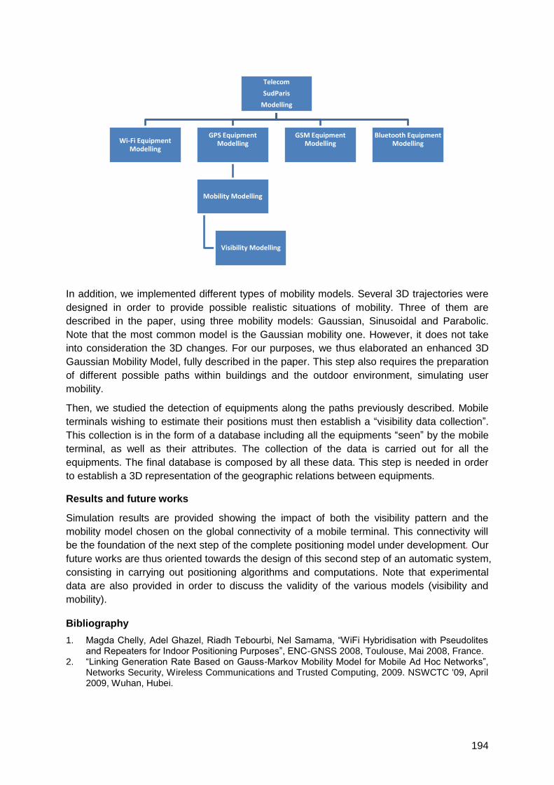
194
In addition, we implemented different types of mobility models. Several 3D trajectories were
designed in order to provide possible realistic situations of mobility. Three of them are
described in the paper, using three mobility models: Gaussian, Sinusoidal and Parabolic.
Note that the most common model is the Gaussian mobility one. However, it does not take
into consideration the 3D changes. For our purposes, we thus elaborated an enhanced 3D
Gaussian Mobility Model, fully described in the paper. This step also requires the preparation
of different possible paths within buildings and the outdoor environment, simulating user
mobility.
Then, we studied the detection of equipments along the paths previously described. Mobile
terminals wishing to estimate their positions must then establish a ―visibility data collection‖.
This collection is in the form of a database including all the equipments ―seen‖ by the mobile
terminal, as well as their attributes. The collection of the data is carried out for all the
equipments. The final database is composed by all these data. This step is needed in order
to establish a 3D representation of the geographic relations between equipments.
Results and future works
Simulation results are provided showing the impact of both the visibility pattern and the
mobility model chosen on the global connectivity of a mobile terminal. This connectivity will
be the foundation of the next step of the complete positioning model under development. Our
future works are thus oriented towards the design of this second step of an automatic system,
consisting in carrying out positioning algorithms and computations. Note that experimental
data are also provided in order to discuss the validity of the various models (visibility and
mobility).
Bibliography
1. Magda Chelly, Adel Ghazel, Riadh Tebourbi, Nel Samama, ―WiFi Hybridisation with Pseudolites and Repeaters for Indoor Positioning Purposes‖, ENC-GNSS 2008, Toulouse, Mai 2008, France.
2. ―Linking Generation Rate Based on Gauss-Markov Mobility Model for Mobile Ad Hoc Networks‖, Networks Security, Wireless Communications and Trusted Computing, 2009. NSWCTC '09, April 2009, Wuhan, Hubei.
Telecom
SudParis
Modelling
Wi-Fi Equipment Modelling
GPS Equipment Modelling
Mobility Modelling
Visibility Modelling
GSM Equipment Modelling
Bluetooth Equipment Modelling

195
Indoor Navigation Integration Platform for Firefighting Purposes
Kai Marcus Stübbe, Uwe Rüppel
Technische Universität Darmstadt, Institute of Numerical Methods and Informatics in Civil
Engineering, Petersenstraße 13, D-64287 Darmstadt
[email protected], [email protected]
1 Summary
In Germany about eighteen fire fighters loose their lives and more than 16.000 accidents
happen on duty every year. One of the main problems is the orientation inside of complex
buildings during operations especially if rooms are full of smoke. Route cards (printed on
paper) to find fire detectors in buildings, are means, which often do not meet all requirements
with regard to orientation and up-to-datedness. The aim of the presented research project
―Context Sensitive Indoor-Emergency-Navigation-System for Complex Buildings‖ is to
develop a solution for response and recovery to support rescuers in finding the shortest way
within a complex building. Existing Building Information Models (BIM) are exported and used
for displaying plans on mobile devices and for routing purposes. The Indoor Navigation is
based on Wireless LAN, Ultra-Wide-Band and Radio Frequency Identification (RFID).
2 Introduction
Within the presented research project – which is funded by the German Federal Ministry of
Transport, Building and Urban Affairs – a system using mobile devices and Real-Time
Location Systems (RTLS) is developed. Graphs for route calculation generated from BIM-
data (Building Information Model) guide fire fighters to the triggered fire detector. Additionally,
important information, e. g., about sprinkler systems and dangerous goods, is displayed
according to the position of the fire fighter within the building.
Related work in the area of Indoor-Navigation for fire fighters is done by [1], [2], [3] and [4].
These Projects focus mainly on one technology for Position sensing in emergency cases or
on communication platforms. The approach presented in this abstract is based on the
integration of different existing RTLS, integrating them in a Multi-method-Approach (MMA)
and using BIM-Data to generate route graphs to guide fire fighters in buildings.
3 Claimed content in detail
Complex buildings like airports have many different environments and one single indoor
positioning system does not work for all environments [5]. Due to this reason three systems
have been chosen (see Figure 1). The MMA uses most of the existing technical infrastructure
and requires additional navigation infrastructure only where necessary.
Ultra Wide Band (UWB) is appropriate for position sensing in halls. UWB is less influenced
by metals and high humidity than other radio communication technologies and is therefore
chosen for passenger and baggage halls.
Existing Wireless LAN networks can be used for position sensing in office areas. Wireless
LAN is capable of being influenced by human beings walking by or by structural measures.
On this account active RFID-tags are added.
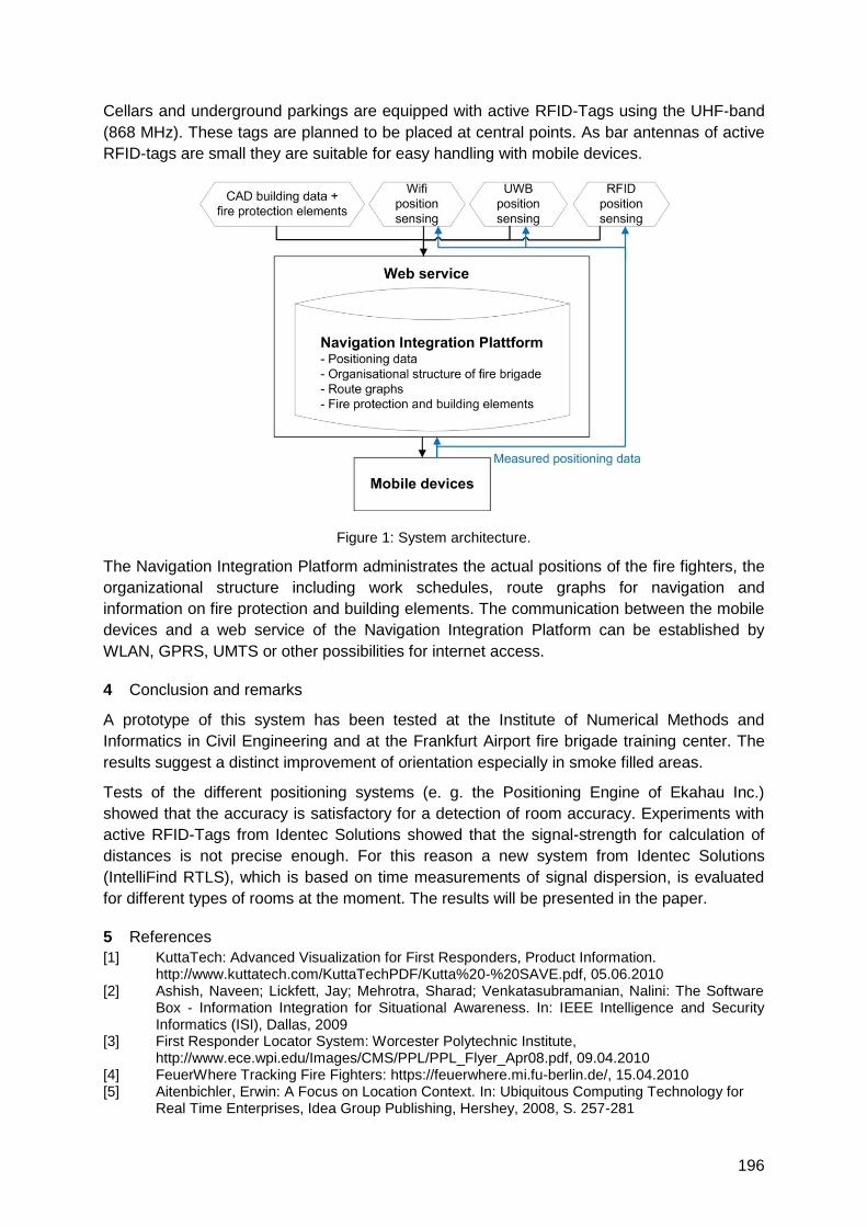
196
Cellars and underground parkings are equipped with active RFID-Tags using the UHF-band
(868 MHz). These tags are planned to be placed at central points. As bar antennas of active
RFID-tags are small they are suitable for easy handling with mobile devices.
Figure 1: System architecture.
The Navigation Integration Platform administrates the actual positions of the fire fighters, the
organizational structure including work schedules, route graphs for navigation and
information on fire protection and building elements. The communication between the mobile
devices and a web service of the Navigation Integration Platform can be established by
WLAN, GPRS, UMTS or other possibilities for internet access.
4 Conclusion and remarks
A prototype of this system has been tested at the Institute of Numerical Methods and
Informatics in Civil Engineering and at the Frankfurt Airport fire brigade training center. The
results suggest a distinct improvement of orientation especially in smoke filled areas.
Tests of the different positioning systems (e. g. the Positioning Engine of Ekahau Inc.)
showed that the accuracy is satisfactory for a detection of room accuracy. Experiments with
active RFID-Tags from Identec Solutions showed that the signal-strength for calculation of
distances is not precise enough. For this reason a new system from Identec Solutions
(IntelliFind RTLS), which is based on time measurements of signal dispersion, is evaluated
for different types of rooms at the moment. The results will be presented in the paper.
5 References
[1] KuttaTech: Advanced Visualization for First Responders, Product Information. http://www.kuttatech.com/KuttaTechPDF/Kutta%20-%20SAVE.pdf, 05.06.2010 [2] Ashish, Naveen; Lickfett, Jay; Mehrotra, Sharad; Venkatasubramanian, Nalini: The Software
Box - Information Integration for Situational Awareness. In: IEEE Intelligence and Security Informatics (ISI), Dallas, 2009
[3] First Responder Locator System: Worcester Polytechnic Institute, http://www.ece.wpi.edu/Images/CMS/PPL/PPL_Flyer_Apr08.pdf, 09.04.2010 [4] FeuerWhere Tracking Fire Fighters: https://feuerwhere.mi.fu-berlin.de/, 15.04.2010 [5] Aitenbichler, Erwin: A Focus on Location Context. In: Ubiquitous Computing Technology for
Real Time Enterprises, Idea Group Publishing, Hershey, 2008, S. 257-281
197
Combined Indoor and Outdoor DOP Criteria helpful to Position and
Dimension
Soumaya Zirari, Philippe Canalda, Hakim Mabed and François Spies
Computer Science Laboratory of Franche Comté (LIFC EA 4269),
1 cours leprince-ringuet 25200 Montbéliard
[email protected], [email protected], [email protected]
fcomte.fr, [email protected]
1 Summary
The democratization of wireless networks, combined with the emergence of increasingly
autonomous and efficient mobile devices, leads to new services. Positioning services
become pervasive. The accuracy is the main criterion applied in the assessment of
positioning systems. But high accuracy cannot be guaranteed because it depends on the
environment where the user is located and on the positioning systems used (GNSS, GSM or
Wi-Fi). To overcome this disadvantage, hybridization or combination is the best solution. In
this paper, we first introduce the hybrid dilution of precision criteria that allows the free choice
of the system for positioning in indoor and outdoor environments. Secondly and finally, we
present an algorithm for combined positioning.
2 Introduction
Recently positioning has become an essential and integral feature of any system of mobility.
Indeed, with the appearance of positioning capabilities, applications have emerged and
multiplied. Mobile tracking and games are only two of many markets that can benefit from
getting positioning information. The bulk supply of positioning is provided by wireless
systems such as Global Navigation Satellite System (GNSS), GSM, Wi-Fi, sensors, etc. and
their combinations.
Navigation satellite systems can guarantee an overall accuracy of about three meters when
the user is in an open area or when the visibility of satellites provides good reception of more
than four direct signals with the minimal noise. As soon as we move to a closed environment
like an alley or building, the accuracy can decrease significantly. Environments that are well
managed by networks, such as Wi-Fi that now prevail in the positioning indoor market, or
GSM that has become a repository for assistance applications.
The characteristics and the performances of positioning technologies are defined by the
three main dimensions: accuracy, coverage and cost.
The control of those criteria allows increasing the accuracy of the location, ensuring
continuity of service and providing better quality of service. Indeed, we need a coefficient that
quantifies the quality of these three criteria.
In this paper we first propose different dilution of precision criteria to estimate the accuracy of
various positioning systems. Secondly we propose an algorithm for a combined positioning
system based on GPS/Galileo and Wi-Fi. Finally, we use an evolutionary algorithm to
optimise the combined DOP using the best terrestrial access point positions.
198
3 Contribution
In order to estimate the accuracy and the coverage in the GNSS domain we tend to use the
Geometric Dilution Of Precision (GDOP) to measure the contribution of satellite's geometry
to positioning accuracy. With the emergence of other positioning systems such as GSM,
researchers tried to adapt the GDOP to those systems extending it to a more Combined
Dilution Of Precision. Gondran et al. provide a geometric indicator for WLAN planning which
is based on the study of the covered area by a Basic Service Set (BSS), where a cell relative
to an antenna is a set of pixels associated to a given base station.
The first factor we propose is dedicated to WLAN based on signal strength, the number of
visible access points and their disposal to assess the accuracy of the computed position.
The second dilution of precision criterion that we present is dedicated to combined
positioning systems (indoors and outdoors), which use visible satellites, access points and
the visible BTS as indicators. The criterion is differing for hybrid positioning systems.
Unfortunately there is no efficient positioning solution for all situations and environments. For
this reason, hybridization or combination appears to be the best solution to overcome the
problems of service discontinuity or the lack of positioning in some environments.
Finally, we present a combined positioning system based on GPS and Wi-Fi. We propose to
complement the GPS equation system using pseudorange measurements with Signal
Strength measurements from 802.11 networks.
4 Results and conclusion
The results of experiments show that the GPS by itself does not guarantee good accuracy
regardless of time and environment. Indeed, the values of the indicator reach infinite values
when the receiver does not intercept non-noisy signals from GPS, while the contribution of
additional data for this indicator leads to better values.
Where the mobile moves from an environment with perfect visibility of the satellites to
another with no visible satellites, as it is the case when entering a building (assuming there is
at least one visible access point), the hybrid/combined dilution of precision criterion, follows
the environmental changes and allows estimating the quality of positioning in both, indoors
and outdoors.
The other simulation with a combined positioning system, shows that the combination is
more suitable for a positioning system with a high accuracy.
In this paper, we illustrate the trade-off that is to be made by choosing the proper positioning
system and the features. First, we introduce the equivalent dilution of precision criterion for
each system. Then, we present an algorithm for combined positioning. Finally, we analyse
the results obtained from the simulation and the emulation of various scenarios.
5 Bibliography
1- GONDRAN, A., BAALA, O., CAMINADA A., MABED H., ―3-D BSS geometric indicator for WLAN
planning‖ Software, Telecommunications and Computer Networks, 2007. SoftCOM 2007. 15th
International Conference on Volume , Issue , 27-29 Sept. 2007 Page(s):1 – 5
2- Soumaya Zirari, Philippe Canalda, and François Spies. WiFi GPS based Combined positioning
Algorithm. In WCNIS'10, IEEE Int. Conf. on Wireless Communications, Networking and
Information Security, Beijing, China, pages ***--***, June 2010. Note: 5 pages.
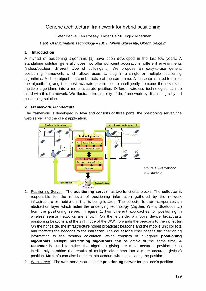
199
Generic architectural framework for hybrid positioning
Pieter Becue, Jen Rossey, Pieter De Mil, Ingrid Moerman
Dept. Of Information Technology – IBBT, Ghent University, Ghent, Belgium
1 Introduction
A myriad of positioning algorithms [1] have been developed in the last few years. A
standalone solution generally does not offer sufficient accuracy in different environments
(indoor/outdoor, different type of buildings…). We propose an easy-to-use generic
positioning framework, which allows users to plug in a single or multiple positioning
algorithms. Multiple algorithms can be active at the same time. A reasoner is used to select
the algorithm giving the most accurate position or to intelligently combine the results of
multiple algorithms into a more accurate position. Different wireless technologies can be
used with this framework. We illustrate the usability of the framework by discussing a hybrid
positioning solution.
2 Framework Architecture
The framework is developed in Java and consists of three parts: the positioning server, the
web server and the client application.
Figure 1: Framework
architecture
1. Positioning Server - The positioning server has two functional blocks. The collector is
responsible for the retrieval of positioning information gathered by the network
infrastructure or mobile unit that is being located. The collector further incorporates an
abstraction layer which hides the underlying technology (ZigBee, Wi-Fi, Bluetooth …)
from the positioning server. In figure 1, two different approaches for positioning in
wireless sensor networks are shown. On the left side, a mobile device broadcasts
positioning beacons and the sink node of the WSN forwards the beacons to the collector.
On the right side, the infrastructure nodes broadcast beacons and the mobile unit collects
and forwards the beacons to the collector. The collector further passes the positioning
information to the position calculator, which consists of pluggable positioning
algorithms. Multiple positioning algorithms can be active at the same time. A
reasoner is used to select the algorithm giving the most accurate position or to
intelligently combine the results of multiple algorithms into a more accurate (hybrid)
position. Map info can also be taken into account when calculating the position.
2. Web server - The web server can poll the positioning server for the user‘s position.
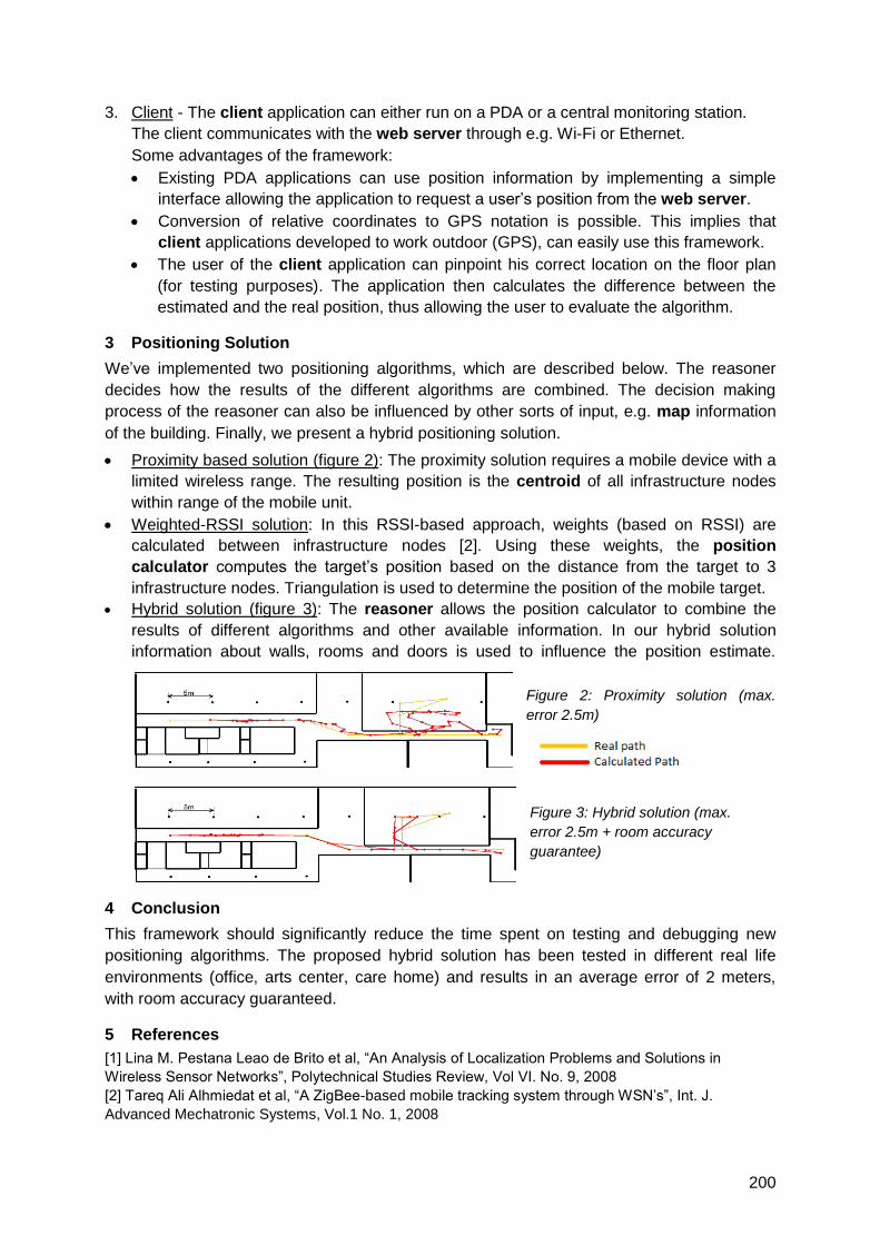
200
3. Client - The client application can either run on a PDA or a central monitoring station.
The client communicates with the web server through e.g. Wi-Fi or Ethernet.
Some advantages of the framework:
Existing PDA applications can use position information by implementing a simple
interface allowing the application to request a user‘s position from the web server.
Conversion of relative coordinates to GPS notation is possible. This implies that
client applications developed to work outdoor (GPS), can easily use this framework.
The user of the client application can pinpoint his correct location on the floor plan
(for testing purposes). The application then calculates the difference between the
estimated and the real position, thus allowing the user to evaluate the algorithm.
3 Positioning Solution
We‘ve implemented two positioning algorithms, which are described below. The reasoner
decides how the results of the different algorithms are combined. The decision making
process of the reasoner can also be influenced by other sorts of input, e.g. map information
of the building. Finally, we present a hybrid positioning solution.
Proximity based solution (figure 2): The proximity solution requires a mobile device with a
limited wireless range. The resulting position is the centroid of all infrastructure nodes
within range of the mobile unit.
Weighted-RSSI solution: In this RSSI-based approach, weights (based on RSSI) are
calculated between infrastructure nodes [2]. Using these weights, the position
calculator computes the target‘s position based on the distance from the target to 3
infrastructure nodes. Triangulation is used to determine the position of the mobile target.
Hybrid solution (figure 3): The reasoner allows the position calculator to combine the
results of different algorithms and other available information. In our hybrid solution
information about walls, rooms and doors is used to influence the position estimate.
Figure 2: Proximity solution (max.
error 2.5m)
Figure 3: Hybrid solution (max.
error 2.5m + room accuracy
guarantee)
4 Conclusion
This framework should significantly reduce the time spent on testing and debugging new
positioning algorithms. The proposed hybrid solution has been tested in different real life
environments (office, arts center, care home) and results in an average error of 2 meters,
with room accuracy guaranteed.
5 References
[1] Lina M. Pestana Leao de Brito et al, ―An Analysis of Localization Problems and Solutions in
Wireless Sensor Networks‖, Polytechnical Studies Review, Vol VI. No. 9, 2008
[2] Tareq Ali Alhmiedat et al, ―A ZigBee-based mobile tracking system through WSN‘s‖, Int. J.
Advanced Mechatronic Systems, Vol.1 No. 1, 2008
201
A Localization Framework for Wireless Mesh Networks
Bastian Blywis, Mesut Güneş, Felix Juraschek, Steffen Gliech
Distributed Embedded Systems, Computer Systems and Telematics, Institute of Computer
Science, Freie Universität Berlin, Germany
{blywis, guenes, jurasch, gliech}@inf.fu-berlin.de
1 Summary
Indoor localization is a service that could be provided by many already deployed IEEE
802.11 wireless networks and enable to find people, printers, or rooms in large office
buildings without any additional costs. For this, we developed a framework for the study of
various localization algorithms in a testbed environment. The Anchor-Free Distributed
Localization-Algorithm (AFL) [1] was implemented as a proof of concept. We discuss several
problems that arose when an algorithms that has been previously studied only in simulation
environments is transferred into a real world scenario. An initial experiment series was run in
the DES-Testbed [2], a multi-transceiver mesh network and highlighted many issues due to
under-specification or problems that do not arise with abstract models in simulations.
2 Motivation
Localization algorithms can be classified based on many properties. One particular
classification considers how many nodes in the network know their physical location. Either
all nodes are position-aware, a subset (for example log(n) nodes) knows their coordinates, or
in the most extreme case none of them. The last class is known as anchor-free algorithms
and is particular interesting for indoor localization using common network devices without
specialized hardware; an application scenario where GPS is not available. Although it is only
possible to create a relative coordinate system with no relation to geographic positions,
several applications already benefit from this. The localization of people, devices, or rooms
as well as firefighters and paramedics searching for victims are possible.
For applications in wireless mesh networks (WMNs) there is currently limited support
available. We implemented the Localisation Framework for Testbeds (DES-LOFT) that
enables the configuration, execution, visualization, and evaluation of experiments. We focus
on scenarios where a precision of about 1 to 2 ―normal sized'' rooms is sufficient. In contrast
to some wireless sensor networks or specialized localization systems, we assume that only
IEEE 802.11 WLAN transceivers are available and the nodes are sparsely deployed creating
a random network with varying node degree.
3 Localization Framework
The Localisation Framework for Testbeds (DES-LOFT) consists of three major parts. The
Node Agent is a daemon that runs on the mesh routers that enables the communication
between the nodes, network-wide configuration and probing of the current state. A Proxy is
run on a gateway node that provides access to all nodes in the network and caches data for
subsequent queries to take load off the nodes. As last and depicted in Figure 1, a GUI
provides a management interface with a 3D view of the network showing two different
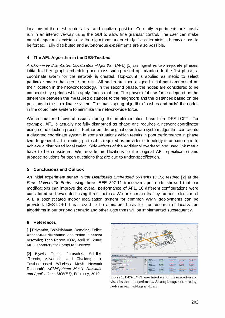
202
locations of the mesh routers: real and localized position. Currently experiments are mostly
run in an interactive-way using the GUI to allow fine granular control. The user can make
crucial important decisions for the algorithms under study if a deterministic behavior has to
be forced. Fully distributed and autonomous experiments are also possible.
4 The AFL Algorithm in the DES-Testbed
Anchor-Free Distributed Localization-Algorithm (AFL) [1] distinguishes two separate phases:
initial fold-free graph embedding and mass-spring based optimization. In the first phase, a
coordinate sytem for the network is created. Hop-count is applied as metric to select
particular nodes that create the axis. All nodes are then asigned initial positions based on
their location in the network topology. In the second phase, the nodes are considered to be
connected by springs which apply forces to them. The power of these forces depend on the
difference between the measured distances to the neighbors and the distances based on the
positions in the coordinate system. The mass-spring algorithm ―pushes and pulls‖ the nodes
in the coordinate system to minimize the network-wide force.
We encountered several issues during the implementation based on DES-LOFT. For
example, AFL is actually not fully distributed as phase one requires a network coordinator
using some election process. Further on, the original coordinate system algorithm can create
a distorted coordinate system in some situations which results in poor performance in phase
two. In general, a full routing protocol is required as provider of topology information and to
achieve a distributed localization. Side-effects of the additional overhead and used link metric
have to be considered. We provide modifications to the original AFL specification and
propose solutions for open questions that are due to under-specification.
5 Conclusions and Outlook
An initial experiment series in the Distributed Embedded Systems (DES) testbed [2] at the
Freie Universität Berlin using three IEEE 802.11 tranceivers per node showed that our
modifcations can improve the overall performance of AFL. 16 different configurations were
considered and evaluated using three metrics. We are certain that by further extension of
AFL a sophisticated indoor localization system for common WMN deployments can be
provided. DES-LOFT has proved to be a mature basis for the research of localization
algorithms in our testbed scenario and other algorithms will be implemented subsequently.
6 References
[1] Priyantha, Balakrishnan, Demaine, Teller;
Anchor-free distributed localization in sensor
networks; Tech Report #892, April 15, 2003;
MIT Laboratory for Computer Science
[2] Blywis, Günes, Juraschek, Schiller:
"Trends, Advances, and Challenges in
Testbed-based Wireless Mesh Network
Research", ACM/Springer Mobile Networks
and Applications (MONET), February, 2010. Figure 1: DES-LOFT user interface for the execution and
visualization of experiments. A sample experiment using
nodes in one building is shown.

203
Industrial Metrology & Geodetic Systems, iGPS (Nikon)
Auditorium G3
Friday, September 17, 08:15 – 09:45 & 10:15 – 12:00

205
Performance Evaluation of iGPS for Industrial Applications
Robert Schmitta, Susanne Nischa, Alexander Schönberga,
Francky Demeesterb, Steven Rendersb
a RWTH Aachen University, Laboratory for Machine Tools and Production Engineering WZL,
Chair of Metrology and Quality Management, Steinbachstraße 19, 52074 Aachen, Germany
b Nikon Metrology NV, Geldenaaksebaan 329, 3001 Leuven, Belgium
1 Summary
Precise measurements in large volumes will be a key technology in tomorrow‘s industrial
applications. The iGPS system of Nikon Metrology is a measuring system, which represents
a suitable compromise for measurement uncertainty, scalable work area and potential
number of measuring points. This advantage is used at WZL to show the use of iGPS in
industrial applications with two cooperating robots to allow absolutely precise movements.
The measurement uncertainty of the iGPS-System influences its possible applications.
Already performed analyses show an uneven distribution of the measurement uncertainty.
The objective of these analyses is the definition of areas with minimized measurement
uncertainty and building up a basis for the robot control. Currently a basic control loop is
implemented to identify and roadmap further development topics. The control loops extend
the Adaptive Robot Control (ARC) delivered by Nikon Metrology and show the possibility to
use them in dynamic industrial applications.
2 Large-Volume
metrology in production
environments
The term „Large-Volume
Metrology― summarizes a whole
class of mobile, optical
measuring systems, which
particularly meet requirements of
very large or only heavily to
handle work pieces [1,2]. iGPS
is a measuring system, which
represents a suitable
compromise for measurement uncertainty, scalable work area and potential number of
measuring points. The main advantages of the system are the possibility to have as many
receivers in the iGPS as needed and a superior scaling capability. This advantage is used at
WZL in a robotic cell with two cooperating robots to allow precise absolute movements of the
robots needed to use them for directly performed offline programs, cooperating tasks or
measurement applications.
3 Performance Evaluation of iGPS
The measurement uncertainty of the iGPS-System influences importantly its possible
applications. Already performed analyses based on comparative measurements with laser
KUKA KR60 KUKA KR16iGPS
Transmitter
iGPS
Receiver
iGPS
Scalebar
206
tracking interferometer have showed an uneven distribution of the measurement uncertainty
in the volume of the iGPS measuring system [3]. Especially, there is a strong dependence
between the position of the Transmitter and the measurement uncertainty [4]. The iGPS
setup at the WZL is analysed concerning local measurement errors. Therefore, comparative
measurements with tracking interferometer are performed. The reflector for the tracking
interferometer is fixed on the robot, as well as the Sensors of iGPS system, with known offset.
The measured coordinates from the iGPS in the movement volume of the robots are
compared with the results of the tracking interferometer measurements. Results are a 3D-
matrix of local measurement errors in the volume of the iGPS system. By repeating
measurements under different environmental conditions a variance of local errors is
detectable. The objective of these analyses is the definition of areas with minimized
measurement uncertainty independent of environmental caused variances building up a
basis for the robot control.
4 Absolutely precise robot movements
iGPS may be used for the calibration and control of robots. Currently a basic control loop is
implemented to identify and roadmap further research topics. The control loops extend the
Adaptive Robot Control (ARC) delivered by Nikon Metrology. This system is able to statically
correct positioning of robots within 0.4 millimetres independent of working piece weight or
other external influences. Control gains have to be kept low in order to avoid instability
mainly caused by high latency and noise of the iGPS. The control parameters therefore limit
the system dynamics of the iGPS-controlled robots and will lead to further research topics.
5 Conclusions and Outlook
The influence of Large-Volume metrology systems is going to be stronger due to the rising
complexity and flexibility of future production systems. iGPS provides synchronized
measurement data in a globally aligned coordinate system, making it a possible candidate for
this purpose. Current evaluations show the strength and weaknesses of iGPS and may be
used to address further research topics to broaden the suitability for industrial applications.
6 References
[1] Puttock, M.J.: Large-Scale Metrology. In: Annals of CIRP, Vol. 27, No. 1, 1978. pp. 351-356
[2] Estlera, W.T.; Edmundson, K.L.; Peggs, G.N.; Parker, D.H.: Large-Scale Metrology – An Update.
In: CIRP Annals - Manufacturing Technology, Vol. 51, No. 2, 2002. 587-609
[3] Muelaner, J. E., Wang, Z., Martin, O., Jamshidi, J., Maropoulos, P. G.: Estimation of uncertainty
in three dimensional coordinate measurement by comparison with calibrated points.
Measurement Science and Technology, Volume 21 (2), 2010.
[4] Depenthal, C., Schwendemann, J.: IGPS – A new system for static and kinematic measurements,
In: Grün, A. / Kahmen, H. (eds.), Optical 3-D Measurement Techniques IX, Vol. II, Vienna /
Austria, Jul. 1-3, 2009, pp. 131-140, 2009.
207
Indoor navigation of machines and measuring devices with iGPS
Julia Schwendemann, Tilman Müller, Robert Krautschneider
Hochschule Karlsruhe – Technik und Wirtschaft, Moltkestr. 30, 76133 Karlsruhe
VMT GmbH, Stegwiesenstr. 24, 76646 Bruchsal
Introduction
Depending on the application in the industrial measurement segment, the requirements for appropriate large volume metrology systems are often very challenging. Fast, reliable and accurate measurements of points and geometric features or positioning of moving parts in real-time are required. iGPS, a measurement system developed by Nikon Metrology, can handle these requirements more flexible than many other metrology systems. The research project ―USOFI – Untersuchung und Systemoptimierung für iGPS‖ and other research projects investigate the capabilities of this promising technology for further optimization of hardware and software. In this paper the focus will be on two case studies that have contradictory requirements and therefore demonstrate some of the versatility of iGPS.
Concept of iGPS
Static transmitters send infrared signals into the local workspace that can be received by multiple sensors in line of sight. The horizontal and vertical angle from sensor to transmitter is determined based on the arrival time of the transmitter signals that can also be used to synchronize all sensors. Any sensor position with angle measurements to at least two transmitters can be determined along the concept of triangulation. The transmitter positions have to be determined beforehand by bundle adjustment using known reference points or at least one scale bar. Measurements with multiple synchronized sensors also allow the determination of orientations or deformations of work pieces in real-time. Standard deviations of approx. 0.1 mm per 10 m diameter of the working area can be expected for three-dimensional point determination of typical iGPS configurations with four transmitters in a controlled environment.
Feature inspection with a laser scanner integrated into iGPS
Many tasks especially in quality management, involve the determination of geometric features. These measurements often can be performed in a static mode, but require high accuracy, full automation, and a very short measurement period. Instead of investigating the iGPS capabilities on feature inspection itself, a laser scanner was set up, providing more information especially when measuring free form surfaces. If the size of a work piece exceeds the scanners working area, it has to be repositioned several times, while each of the scans requires an overlapping scan area with distinctive features or additional identification marks, either on the work piece itself or on a fixed frame. Even if there are only some small areas of interest on a large object, more scans have to be taken to relate the isolated scans to each other. With iGPS providing a higher-level coordinate frame, it is possible to determine the position and orientation of the scanner itself in the iGPS coordinate system (Figure 1). The goal is to provide a method with combined three dimensional point accuracy of the scanner and iGPS that matches the accuracy of relating scans to each other by best-fitting, but is more flexible and faster.

208
Figure 1: Scanner operating in iGPS provided measurement cell
Therefore a rigid structure was created that can be fixed on the scanner and includes four or six iGPS sensors. The position and orientation of the iGPS sensors on the structure is known through calibration. Each time, the scanner is repositioned, its position and orientation is determined to transform the scans directly into the iGPS coordinate frame.
Kinematic measurements in tunnel navigation of road headers
In comparison to the first application, the accuracy needed in navigation of tunneling
machines is lower, but the requirements are different. Apart from difficult environmental
conditions, for example dust and vibrations, the road header can move very fast.
Furthermore the concept of navigating a tunneling machine with iGPS has to compensate for
the small range of up to 55 m of the transmitters in this scope of application. Transmitters
have to be repositioned every 20 m due to the security distance to the road header that is at
least 20 m. This half-automated repositioning (leap frog) of the transmitters uses additional
sensors on the tunnel wall, which are measured before and after the leap frog, so that all
transmitters can be transformed into a common coordinate system. With each leap frog
additional errors arise that can sum up rapidly. Simulations that evaluate the combined
accuracy of multiple leap frogs and kinematic measurements at different ranges support the
feasibility of the navigation concept. Depending on measurement conditions more than seven
leap frogs (equivalent to 140 m tunneling) can be performed until 10 mm accuracy level is
reached. Studies in cooperation with VMT GmbH under real tunnel conditions support the
simulation results. Based on the Server-Client-Structure of the iGPS software, a client was
developed and integrated in VMT‘s navigation software for tunnel excavation. This client
software simplifies the setup, leap frog and measurements with iGPS, and communicates the
iGPS measurements to the tunnel navigation software SLS.
Figure 2: Data flow of the Server-Client-Structure
Conclusion and Outlook
Examinations of iGPS promise good accuracy and reliability in controlled environment and
under difficult conditions, though the two applications have to be proven in practice currently.
With further developments of software and hardware, iGPS can be integrated in many
applications where high flexibility, high accuracy and the possibility to track multiple sensors
or the orientation of objects are required.
iGPS Server
provides iGPS
measurements
SLS
Tunnel navigation
software
Interface client
Half automated leap frog
and simplified operation
209
Path Tracking with iGPS
Claudia Depenthal
Karlsruhe Institute of Technology (KIT), Geodetic Institute, Englerstr. 7, D-76131 Karlsruhe
1 Summary
iGPS technology is a laser-based indoor system with optical sensors and transmitters to
determine the 3D position of static or moving objects. The technology is based on internal
time measurements related to spatial rays that intersect at sensors in the measuring volume.
Due to the measurement principle of iGPS, tracking measurements can cause a delay time
which will lead to deviations in spatiotemporal positioning. Utilizing the new Digital Input
Module it is possible to analyze the kinematic performance of the iGPS metrology system
with the time-referenced 4D test and calibration system. By using the latest equipment and
Surveyor software it was possible to show that the iGPS system has made significant
improvement in tracking capability. In this experimental set-up, the system could collect and
process data up to object velocities of 3 m/s. At this high velocity, the tracking deviations for
the 3D position were less than 0.3 mm and the 4D tracking deviations were less than 1.5 mm.
2 Path Tracking with iGPS
The typical components of an iGPS network are at least two transmitters, a mini-vector bar
with two sensors, an amplifier as analog-digital converter and the position calculation engine
(PCE) that measures the arrival time of each signal with an internal clock and manages the
communication with the host PC. Each iGPS transmitter emits two different types of signals,
the strobe signal and two fan-shaped beams which are projected from the rotating head of
the transmitter. Each sensor in the working volume receives signals from each visible
transmitter and the arrival time is measured. Based on these time measurements and the fan
beam‘s geometry, the angle values (azimuth, elevation) from transmitter to sensor are
determined. The location of the sensor may be calculated using the process of triangulation
in an analogous manner to a theodolite network. iGPS can be used for static or kinematic
measurements. With the new PCE Digital Input Module (DIM) it is possible to synchronize an
external digital input signal with iGPS data. To analyze the 4D kinematic performance of
iGPS time-referenced measurements are strictly necessary. For tracking optical measuring
systems of any kind a time-referenced 4D test and calibration system was developed at the
Geodetic Institute at Karlsruhe Institute of Technology (KIT). This system consists of a tiltable
rotating arm with a length of 2 m. A rotary direct drive is used as primary mover of the
rotating arm and a real-time multi-axis servo motion controller is used for position and
velocity control of the direct drive.
The kinematic measurements were executed in July 2009 in the Geodetic Laboratory of KIT.
Four iGPS transmitters were arranged around the rotating arm and a 1 m scale bar was used
for bundling (system calibration). A mini-vector bar was fixed on one end of the rotating arm.
A frequency generator delivered the input for the DIM and the test equipment. The iGPS
Surveyor software version 1.2.30 was used. For independent measurements a Leica laser
tracker LTD 500 was employed, which was triggered also by the frequency generator. The
rotating arm was placed in three different positions: horizontal, slant and vertical. Each time
new transmitter network positions were calculated through a bundling calibration procedure.
For the coordinate transformation a static reference measurement with both systems – iGPS
and laser tracker – was carried out. Within the kinematic mode the laser tracker could only
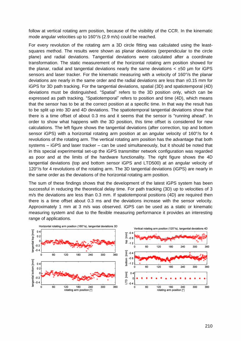
210
follow at vertical rotating arm position, because of the visibility of the CCR. In the kinematic
mode angular velocities up to 160°/s (2.9 m/s) could be reached.
For every revolution of the rotating arm a 3D circle fitting was calculated using the least-
squares method. The results were shown as planar deviations (perpendicular to the circle
plane) and radial deviations. Tangential deviations were calculated after a coordinate
transformation. The static measurement of the horizontal rotating arm position showed for
the planar, radial and tangential deviations nearly the same deviations < ±50 µm for iGPS
sensors and laser tracker. For the kinematic measuring with a velocity of 160°/s the planar
deviations are nearly in the same order and the radial deviations are less than ±0.15 mm for
iGPS for 3D path tracking. For the tangential deviations, spatial (3D) and spatiotemporal (4D)
deviations must be distinguished. ―Spatial‖ refers to the 3D position only, which can be
expressed as path tracking. ―Spatiotemporal‖ refers to position and time (4D), which means
that the sensor has to be at the correct position at a specific time. In that way the result has
to be split up into 3D and 4D deviations. The spatiotemporal tangential deviations show that
there is a time offset of about 0.3 ms and it seems that the sensor is "running ahead". In
order to show what happens with the 3D position, this time offset is considered for new
calculations. The left figure shows the tangential deviations (after correction, top and bottom
sensor iGPS) with a horizontal rotating arm position at an angular velocity of 160°/s for 4
revolutions of the rotating arm. The vertical rotating arm position has the advantage that both
systems – iGPS and laser tracker – can be used simultaneously, but it should be noted that
in this special experimental set-up the iGPS transmitter network configuration was regarded
as poor and at the limits of the hardware functionality. The right figure shows the 4D
tangential deviations (top and bottom sensor iGPS and LTD500) at an angular velocity of
120°/s for 4 revolutions of the rotating arm. The 3D tangential deviations (iGPS) are nearly in
the same order as the deviations of the horizontal rotating arm position.
The sum of these findings shows that the development of the latest iGPS system has been
successful in reducing the theoretical delay time. For path tracking (3D) up to velocities of 3
m/s the deviations are less than 0.3 mm. If spatiotemporal positions (4D) are required then
there is a time offset about 0.3 ms and the deviations increase with the sensor velocity.
Approximately 1 mm at 3 m/s was observed. iGPS can be used as a static or kinematic
measuring system and due to the flexible measuring performance it provides an interesting
range of applications.
211
Locata: A new high accuracy indoor positioning system
Chris Rizos1, Gethin Roberts2, Joel Barnes1,3, Dave Small3, Nunzio Gambale3
1School Of Surveying & Spatial Information Systems, University of New South Wales,
Sydney, Australia
2Institute of Engineering Surveying & Space Geodesy, University of Nottingham, Nottingham,
United Kingdom
3Locata Corporation Pty Ltd, 111 Canberra Ave, Griffith ACT 2603 Australia
The Global Positioning System (GPS) is a reliable, versatile, generally available and
comparatively accurate positioning technology, able to operate anywhere across the globe.
GPS is, in fact, the most effective general-purpose navigation tool ever developed because
of its ability to address a wide variety of applications: air, sea, land, and space navigation;
precise timing; geodesy; surveying and mapping; machine guidance/control; military and
emergency services operations; hiking and other leisure activities; personal location; and
location-based services. These varied applications use different and appropriate receiver
instrumentation, operational procedures, and data processing techniques. But all require
signal availability from a minimum of four GPS satellites for three-dimensional fixes.
In the coming decade a number of other Global Navigation Satellite Systems (GNSS), and
regional systems and augmentations, will be launched. The number of satellites and
transmitted signals suitable for centimetre-level accuracy positioning will at least triple.
However, the most severe limitation of GPS performance will still remain; the accuracy of
positioning deteriorates very rapidly when the user receiver loses direct view of the satellites,
which typically occurs indoors or in severely obstructed urban environments. In such
environments, the majority of receivers do not function at all, and even the high-sensitivity
receivers have difficulty in providing coordinates with sub-dekametre level accuracies.
Accurate indoor positioning is required for a variety of commercial applications, including
warehouse automation, asset tracking, emergency first-responders, and others. In fact, the
general expectation of users today is for ―GPS-like‖ positioning performance anywhere they
go. The inherent limitations of GPS signal availability indoors and in satellite-occluded
environments, however, has forced researchers to investigate alternative technologies which
may be able to replicate GPS/GNSS performance indoors. Inertial navigation systems (INS)
are useful but no panacea because positioning accuracy degrades rapidly with time due to
the drift errors of the gyroscopes and accelerometers. Laser or optical-based systems suffer
from line-of-sight restrictions, whereas traditional radionavigation-based systems are affected
by multipath and time synchronisation challenges.
The University of New South Wales, with a number of academic partners including the
University of Nottingham, has conducted pseudolite research for many years in an effort to
overcome problems found in GPS-occluded or denied environments. Experiments have
included pseudolites in non-synchronous and synchronised modes for a variety of
applications, using both the GPS L1 frequency as well as the 2.4GHz ISM band. (A
"pseudolite" is a GPS-like signal transmitted by a ground-based transmitter, or "pseudo-
satellite"). The extensive research directed at addressing these GPS challenges has
concluded that pseudolites have fundamental technical problems that, even in a controlled or
lab environment, are extremely difficult to overcome. In the real world the challenges of
212
optimally siting pseudolites, controlling transmission power levels, trying to ensure extremely
high levels of synchronisation, configuring special antennas, and designing the ―field of
operations‖ such that GNSS and pseudolites can work together (or at least not interfere with
each other) have been largely insurmountable.
A new terrestrial RF-based distance measurement technology, trademarked ―Locata‖, has
overcome the enormous technical challenges required to create ―a localised autonomous
terrestrial replica of GNSS‖. Locata requires ground-based transceivers - called LocataLites -
that cover an area with strong time-synchronised ranging signals to form ―a LocataNet‖. It
should be noted that a LocataLite is not a pseudolite in the traditional sense – it is true that
both transmit signals on the ground but beyond this similarity the underlying synchronisation
technology (which is vital for positioning) is fundamentally different. When a receiver uses
four or more Locata ranging signals it computes high-accuracy carrier phase-based positions
entirely independent of GNSS or INS. In relatively open outdoor environments such as open-
cut mining, construction sites, ports, etc, LocataNets are providing real-time stand-alone
kinematic positioning (without differential base stations) at centimetre-level accuracy
(equivalent to RTK or survey-grade GPS).
Locata has developed many advanced features over a period of almost 15 years, through
several technology generations. They include the LocataNet time-synchronised positioning
network, network propagation to many LocataLites, improved signal penetration, changes of
transmitting frequency or signal structure, and spatial and frequency diversity. However, the
most difficult technical challenge for high-accuracy positioning indoors is multipath.
Throughout the history of radiopositioning this problem has been the nemesis and the bane
of accurate and reliable results. Locata has therefore worked for over 8 years on the
development of a completely new type of antenna which would allow industrial-grade, cm-
level positioning indoors. The result of this extensive development – the Small TimeTenna –
is now approaching commercial release.
This technical paper describes indoor positioning results with the latest generation of Locata
positioning devices incorporating the new TimeTenna technology. In order to test Locata‘s
TimeTenna technology a LocataNet was set up in an all-steel warehouse environment. This
paper will present for the first time the results of trials comparing Locata‘s positioning
solutions with a robotic total station set up as a truth system. The results demonstrate that
Locata‘s TimeTenna enables cm-level positioning in severe multipath environments where
conventional high-accuracy radiopositioning has previously been impossible.
213
New Approaches in Laser Tracker Based
High-Accuracy Indoor Navigation
Burkhard Boeckem
Leica Geosystems AG, Metrology Products, Moenchmattweg 5, CH-5035 Unterentfelden
1 Summary
Laser trackers are capable of high-accuracy indoor navigation by tracking reflectors in 3D
object space. Currently these navigation tasks, e.g. building applications, can be executed
with high-dynamic absolute interferometer (AIFM) based laser trackers or also most recently
with absolute distance meter (ADM) only trackers with automated target recognition (ATR)
technology.
However, if a true 6 degree of freedom (6DoF) approach is required, e.g. for position and
orientation determination simultaneously, a high-dynamic absolute tracker can be equipped
with a special vision system. These aforementioned technologies delivering dynamic high-
accuracy 6D data can be used for navigating tactile devices for probing or sensors for object
scanning. Furthermore, these laser trackers based indoor navigation systems are then
capable of positioning, guiding and controlling of robots and machines.
Within this presentation a selection of the new technological concepts of laser tracker based
indoor navigation will be presented and their direct benefits and new potentials in various
applications will be discussed.
2 Introduction
For large-scale and high-accuracy measuring tasks in automotive and aerospace industries
laser trackers have become the standard metrology solution. With the recent progress in
laser tracker technology, positioning, guiding and controlling applicatiosn can be executed
with high efficiency.
3 Indoor navigation by high-dynamic absolute trackers
The core sensor for this kind of navigation is the laser tracker, or since the introduction of
absolute interferometer (AIFM) technology the so-called absolute tracker. An high-dynamic
absolute tracker consisting of two rotation axes equipped with angle encoders and drives, an
AIFM, and a position sensitive device (PSD), is capable in closed-loop control of tracking a
moving retro-reflector and determining the 3D coordinates of this retro-reflector in real-time.
Furthermore, Leica AT901 absolute trackers are equipped with built-in vision systems,
enabling the reflector to be located and locked-on to. This functionality called ―PowerLock‖
increases the efficiency of this optical positioning technology.
4 New approach: ATR based tracking
Whereas standard laser trackers base on PSD technology, the Leica AT401 is based on
vision systems, i.e. the ATR. The benefit of having an extended field of view of the vision

214
system is that the retro-reflector is tracked within the imaging sequence. This technology
allows for tracking behind obstacles such as pillars or bars, increasing the ease of use in
indoor navigation in an industrial environment. Figure 1 shows the Leica AT410 and in
figure 2 a typical jig building application is depicted.
Figure 1: Leica AT401 Figure 2: Leica AT401 building jig application
5 T-MAC and Automation: 6DoF Tracking
By combining an AT901 absolute tracker with a high-speed camera system (T-CAM) for
additional orientation measurements true 6DoF tracking becomes possible. This is used for
navigating tactile devices for probing or sensors for object scanning. Furthermore, these
laser trackers based indoor navigation systems are then capable of positioning, guiding and
controlling of robots and machines when used with a T-MAC probe type as seen in figure 4.
Figure 3: Leica AT901 equipped with T-CAM Figure 4: T-MAC on robot
6 Conclusions and Outlook
Nowadays, absolute trackers are fully integrated systems, i.e. even the basic 3D absolute
tracker is equipped with a multitude of sensors and vision systems which allow for new
applications and approaches towards laser tracker based indoor navigation.
Most recent technologies make now inline-inspections and real-time positioning possible.
Combining laser tracker technology with different 6DoF based probes and scanners will be
the next step in meeting the demands for laser tracker based indoor navigation.
215
Positioning of robots by determining 6DOF
Christoph Herrmann, Maria Hennes
KIT, Geodetic Institute, Englerstr. 7, D-76131 Karlsruhe
7 Introduction
Within the ―Sonderforschungsbereich Transregio 10‖ a process chain for flexible production
and machining of extruded aluminum profiles is developed and put into practice. The project
is a co-operation of the Karlsruhe Institute of Technology (KIT), the University Munich and
the University Dortmund. The process chain includes robots for fully automated handling of
the profiles. To guarantee the correct form of the extruded profile the robots have to be
precisely aligned with it. Therefore their tool centre points (TCPs) have to be known exactly.
A method is presented, which delivers the TCPs using 6DOF equipment.
8 Measurement tools
For the accurate surveying of the robots the Geodetic Institute of KIT used two of Leica‘s
laser trackers – the LTD 500 and the Absolute Tracker AT 901 in combination with T-Cam
and T-Probe. This device determines position as well as orientation (6-DOF) of an object,
which is equipped with the T-probe. The T-Probe incorporates a CCR and IR-diodes. The
position is measured conventionally by the laser tracker. Furthermore, a camera which is
mounted on top of the AT 901 (T-Cam) takes images of T-Probe‘s IR diodes.
Photogrammetric methods in the calculation routine analyze the spatial distribution of the IR
diodes and determine the three orientation angles of the T-Probe. Although different styli can
be attached to the probe to determine surface points we use the probe (instead of the regular
T-Mac) for determining the orientation of the robot‘s tool adapter, to which it is attached.
9 Procedures and results
All measurements were carried out in a coordinate system based on the extruding press. The
goal was to align the robot‘s tools exactly with the centre of the extruded aluminum. To reach
that goal it was necessary to determine the tool-centre-point (TCP) of each tool.
Unfortunately it was not possible to physically measure the actual TCP with tactile or
reflector-less measuring methods. With the help of Leica‘s 6DOF measurement tool T-Probe
the task was fulfilled nevertheless. The T-Probe was attached to the tool and a calibration
routine determined the probe‘s tip in the coordinate system of the probe itself. During that
routine the robot moved around its TCP. The result of this procedure was a virtual stylus
definition with the tip of the T-Probe being the actual TCP. Hence every measurement with
this virtual stylus delivers the actual position of the TCP. The accuracy of the tip‘s definition is
influenced by the measurement accuracy of the T-Probe and the accuracy of the robot‘s
movements during the calibration routine. The accuracy of the final tip definition was
approximately 0.2 mm. By accurately determining the TCP it was possible to align the robot
and the tool, respectively, with the centre of the extruded aluminum. Furthermore this
procedure allowed to verifying the robot‘s accuracy.
216
For determining the robots synchronization measurements with both trackers at the same
time were carried out. Each tracker observed one robot. Therefore a trigger signal from the
robot‘s controller was sent to the trackers. By that, the trackers measured the robots
coordinates with the same frequency and at the same time as the controller recorded the
robots movements, i.e. the data is fully synchronized. To ensure the laser beam would not
break during the measurements cat-eye reflectors were used. They provide a much wider
aperture angle than the standard CCRs. First results of synchronized measuring with two
trackers will be presented.
10 Conclusions and Outlook
If laser trackers are able to react on a trigger pulse, they a predestinated for spatiotemporal
surveys of (cooperating) robots. Furthermore, the tip-calibration procedure of the T-Probe of
Leica laser trackers can be efficiently used for virtual TCP-calibration. With these tools,
calibration information for the robot‘s control can be derived.
217
The Use of Kalman Filtering in Combination With an Electronic
Tacheometer
Sonja Gamse1, Thomas A. Wunderlich2, Peter Wasmeier2, Dušan Kogoj1
1 Faculty of Civil and Geodetic Engineering, Chair of Geodesy, Jamova 2, 1000 Ljubljana,
Slovenia
2 Technical University Munich, Chair of Geodesy, Arcisstraße 21, D-80333 Munich, Germany
1 Summary
Modern electronic tacheometers offer the possibility to capture kinematic processes in real
time. In case the kinematic process is observed with only one measurement system, we
have no possibility to perform redundant observations that would enable the accuracy
estimation of observations and computed values. The Kalman filter represents a method of
advanced geodetic analysis and as such adjusts the redundant data in an optimum way. In
combination with a Global Positioning System the use of Kalman filtering is wide spread and
well known. Incorporating a time component directly into a processing of terrestrial kinematic
observations demands good knowledge about the electronic tacheometer capabilities and
also a procedure of processing kinematic terrestrial observations. For this purpose the
developed model of Kalman filter for processing kinematic terrestrial observations was tested
on the reference trajectory in the Geodetic Laboratory of the Technical University Munich.
2 Measurement System
The main idea of the work was to:
- perform kinematic processes,
- observe the process with an electronic tacheometer,
- develop an evaluation model for assessing the kinematic instrumental capability and
estimating the kinematic position of the moving reflector,
- control the developed model within an independent reference frame.
The kinematic process was simulated on the known reference trajectory of 15 m length,
providing an installation accuracy of 1 mm in horizontal and in vertical position respectively.
The geometry of the reference trajectory was defined with the theodolite measurement
system ECDS3. The kinematic measurements were carried out with an electronic
tacheometer – TCRA1201 Leica Geosytems. On the trolley, the GRZ4 Leica Geosystems
360°-reflector was used. Sets of kinematic observations were carried out for different trolley
velocities. The communication with the instrument was established with a (Visual Basic)
Leica Geosytems GeoCOM interface.
3 Wiener Process Acceleration Model
The measurements were processed with a linear Kalman filter (KF) model, incorporating the
law on propagation of variances and covariances. Because of high frequency of
measurements, we assume in our work, that the movement of the prism can be described as
a movement with approximately constant acceleration during each sampling period.

218
Consequently, the discrete third-order kinematic or discrete Wiener process acceleration
model, DWPAM, which is three-dimensional per coordinate, was developed. The advantage
of such model is that the process noise intensity can be well related to physical
characteristics of the motion (acceleration). The same model was used for all three
dimensions.
4 Evaluation of the model
The verification of DWPA model with the law of propagation of variances and covariances
was basically controlled with:
- indicators of inner confidence,
- statistical methods and parameters and
- known reference trajectory.
The model of KF gives us on its own accord some indicators that enable the evaluation of
outputs. Because these values are computed through the KF process they can only be used
as indicators of inner confidence (observability, controllability, properties of the posterior
system state covariance matrix and Kalman gain matrix). The next step is to implement
statistical methods and parameters, which show the reliability of the model and computed
values (σ-bound, consistency in the domain of the measurements, consistency in the system
state domain). In our work, an additional, completely independent evaluation was performed
with the known reference trajectory.
By observing the model through several numerical repetitions the best value of process noise
parameters could be successfully defined. The results are related to those experiments,
where no gross errors were present and where the movement of the trolley was
approximately uniform, with no sudden changes in velocity.
5 Conclusions and Outlook
In our work the -bound was taken as a limit for defining too big deviations. This value
was defined after several experimental tests for different Leica Geosystems GeoCOM
functions and according to the reflector inclination. The adequacy of developed DWPAM and
statements of the work can be summarized in the following paragraphs:
- According to different tests on the trajectory, the expected accuracy of the reflector
position depends mostly on the velocity of the trolley and the Leica Geoystems
measurement function or program used.
- All evaluation tests showed the same outliers in the observations.
- The advantage of such a reference frame, i.e. reference trajectory, is the evaluation of the
model and capabilities of the instrument at the same time.
- In each project the accuracy of measurements and output variables have to be defined.
Consequently, the advantages and shortcomings of static and kinematic measurements
have also been researched.
- The results of the numerical tests confirmed the appropriateness of the model for
evaluation of geodetic kinematic measurements, where no redundant observations are
available.
- The preceding simulations, when possible preceding measurements, are suggested for
each project. According to preceding works the measurement accuracy can be estimated,
and the best prior input values of KF can be defined.

219
User Requirements
Auditorium D2
Wednesday, September 15, 10:30 – 11:45


221
User Requirements for Localization and Tracking Technology
Jouni Rantakokko1, Peter Händel2, Michael Fredholm2
1 Swedish Defense Research Agency, Department of Communication Systems, Linköping,
Sweden
2 Royal Institute of Technology, ACCESS Linnaeus Center, Stockholm, Sweden
1 Summary
Current advances in localization and tracking technology [1] have the potential to develop
into much-needed tools for the saving of lives in emergency response and rescue missions,
and for the safe-keeping of lives in rescue missions as well as military operations. However,
different users face different environments and consequently have different user
requirements [2]. This paper aims to survey the different requirements for localization and
tracking technology by mission type, so that researchers, industry and user groups can more
easily determine their specific technology needs. Although primarily aimed to describe
requirements for military personnel, law enforcement officers, and firefighters, needs and
constraints for several types of civilian operations are covered as well. Despite differences in
requirements, it makes sense to develop technologies that will serve not only one but all of
these groups.
2 Essential User Requirements
While law enforcement officers, firefighters, and military personnel have different
requirements for localization and tracking systems, all three groups share certain key
requirements. These are:
1. Stringent location accuracy, in the horizontal plane of no greater error than one meter in any environment so that the commander can determine the specific room in a building that the person occupies.
2. Stringent location accuracy in the vertical plane of no greater error than two meters so as to be able to determine the specific story in a building that the person occupies.
3. Constant accessibility for those who need the positioning data. 4. Robustness so that the system will operate reliably even under harsh conditions, including
extreme temperatures and humidity, for instance by relying on a peer-to-peer communications system that can continue in operation even if the base station is lost (the Swedish RAKEL public safety network provides a common, encrypted communications platform for, among others, law enforcement, emergency response, and military units).
5. Encrypted communications and data transfer. 6. Integrity monitoring, with automatic estimation of localization errors (uncertainty) and detection
of and warning in case of deliberate ECM. 7. Positioning data to be compatible to and integrated with other information, in particular
personal health status (physiological monitoring) but also real-time map-building capability in the form of simultaneous localization and mapping (SLAM) of any unknown building as the team moves through it; SLAM should be automatic, without the need for user interaction (i.e. without the need for the team members to aim cameras and sensors in various directions).
8. The system should not depend on bulky antennas; antenna and cables should be incorporated into the individual‘s uniform or equipment.
9. Weight of personal localization and tracking gear (including processing unit and visualization interface) to be less than 1 kg, and not bulky.
10. The system must be energy-efficient, with battery power to last for at least 24 hours but preferably up to a week, depending on type of mission.

222
11. Presentation of positioning data to be intuitive and easy to understand, in particular for the personnel actually carrying out the operation.
12. A modular system would be most useful, since even the same user may face different challenges on different missions and occasionally have no real need for positioning data (research results show that different users differ on this need; law enforcement officers tends to prefer a modular system, while military users and firefighters instead expect always to carry the system as part of personal gear and activate it whenever needed).
13. Pre-installation of the localization system should not be needed. 14. In any armed operation, the system should present heading of own troops and in particular the
heading of individual weapons. Data for distance and direction to targets and threats should also be presented.
3 Mission-specific User Requirements
In addition to the essential user requirements already described, there will be additional
needs and constraints in localization and tracking capability. System requirements will differ
depending on user and type of operation. For mission critical and life saving operations,
some users will need Safety-of-Life critical systems in which accuracy and accessibility are
more important than cost. These include military Special Forces personnel, police special
weapons and tactics (SWAT) teams, and firefighters.
Other users, including regular military, law enforcement officers, and (in at least some
countries, including those of the European Union) private security guards will find accuracy,
accessibility, and cost of roughly equal importance when deciding upon a localization and
tracking system.
The range of operations in which localization and tracking capability would provide an edge
is wide. The most common types are listed in the full paper. These will be described in some
detail.
4 Concluding Remarks
As has become clear from this survey of localization and tracking technology requirements,
there is no doubt that military personnel, law enforcement officers, and firefighters despite
their different mission types face very similar needs. It makes sense to develop technologies
that will serve not only one but all of these groups. To facilitate this, we suggest the
establishment of a joint facility for development of requirements together with representatives
from these various branches and evaluation of existing and emerging localization and
tracking systems. Such a facility would benefit from a pre-installed high-accuracy system
against which new stand-alone technologies can be compared and evaluated.
5 References
[3] C Fischer, H Gellersen, Location and Navigation Support for Emergency Responders: A Survey,
Pervasive Computing, January-March. 2010, pp 38-47.
[4] J. Rantakokko, P. Händel, Positioning of incident responders scenarios, user requirements and
technological enablers, Precision Indoor Personnel Location and Tracking for Emergency
Responders Technology Workshop, presented at, Worcester Polytechnic Institute, Worcester, MA,
2007.
223
Mass market considerations for indoor positioning and navigation
Lauri Wirola, Tommi Laine and Jari Syrjärinne of Nokia Inc., Finland
An aspect that is often neglected in research in the field of location services is that in order to
have a solution that can be deployed in the mass market, the actual positioning algorithm is
only a small piece of the puzzle. This paper looks at the indoor positioning and navigation
problem from the architectural and system level point of view and highlights sectors, which
may not directly relate to positioning, but need to be solved before indoor positioning can be
taken to the mass market.
The success of GNSS-based positioning in mass market applications including navigation is
firstly due to the self-consistent and controlled nature of the underlying positioning
technology and secondly due to the availability of cost-effective map material. For example,
in case of GPS there is a single organization controlling and taking responsibility for the
system performance. Moreover, the GPS system itself provides all the information (orbits,
clocks) required for positioning. Secondly, the availability of global cost-effective map
material means that position information can be utilized in a meaningful manner to enrich
peoples‘ everyday life. The question is how a similar performance could be achieved indoors.
Several solutions have been proposed for indoor positioning, ranging from RF fingerprint
methods to distributing specific positioning tags, such as RFID tags, in the areas of interest.
In addition, at least inertial sensors, magnetic fields, vision-based and WLAN-/UWB-ranging
solutions have been proposed for indoor positioning and navigation.
While beacons specifically deployed for positioning purposes can be utilized in small scale
deployments, they cannot be a backbone for global mass market indoor positioning solution
due to scalability and cost issues. It is also not plausible to assume that a new type of a radio
dedicated solely for positioning would be deployed across the variety of mobile device
categories due to cost and size reasons. Therefore, it turns out that the mass market indoor
positioning solutions must be based on utilizing the existing infrastructure (such as WLAN),
commonly available measurements (such as signal strengths) and existing capabilities in the
mobile devices (such as commercial-grade accelerometers, magnetometers and cameras).
When relying on the existing infrastructure it in fact turns out that the common aspect for all
of these requirements is that there is no single authority maintaining the potential positioning
infrastructure, such as WLAN nodes. Thus, the global players need to collect and maintain
databases that store a variety of information relevant for positioning, e.g. fingerprints and
indoor maps, in order to provide the service. For outdoors cases there already are a variety
of commercial solutions – multiple industry players collect and maintain WLAN node
databases that are based on crowd-sourcing WLAN measurement information tagged with
GPS positions.
The same should now be done indoors. However, obviously the GPS-based data collection
fails indoors and thus research efforts are greatly needed in the area of indoor data collection
and how to make it as automated as possible. The challenges are manifold. The lack of an
independent source of position information is the most serious one and a learning solution
requiring significant human interaction does not scale and is error-prone. Moreover, the
range of devices collecting data as well as the range of devices that need to be positioned is
huge. As simple matter as signal strength values might not be directly comparable between
devices due to various hardware and software issues. With a wide range of devices, it is also
224
not feasible to have a positioning algorithm that would need to be tuned for each device.
Thus achieving device-independency is one clear need in the future research.
The data collection using the user base is not a trivial task. The amount of data flowing into
the server system is huge and thus the majority of the incoming data needs to be discarded –
only relevant information should pass for further processing due to performance and storage
reasons. Also the amount of false observations is high. Such false measurements may
originate from hardware and software failures and malfunctions as well as from deliberate
spoofing. Thus, especial emphasis needs to be put on the outlier detection in the learning
algorithms. The same also applies to the positioning algorithms in order to guarantee the
integrity of the position solution, which aspect is especially critical in emergency call
positioning. Thus, the stringent quality control, potentially based on information from a variety
of sensors, is a priority aspect for the indoor positioning research.
Not only the data collection is challenging, but also the positioning process itself involves
some fundamental choices even before the position is estimated. These choices directly
relate to the user experience in terms of either speed of positioning or accuracy. To
exemplify, one such choice includes the location of the position determination. In device-
assisted positioning the device reports the set of appropriate measurements to the server.
From the integrity and accuracy point-of-view this may be a preferred choice, because the
server should always have the most up-to-date information. However, the speed suffers due
to the network and database latencies and the requirement to have connectivity is
problematic due to possible data transfer costs and when bandwidth-constrained networks
are used.
The speed aspect can, of course, be addressed by having the positioning assistance
database in the device. It should be noted that this is in any case required for indoor
navigation in order to provide continuous position fixes at high rate. When the database is in
the device, the response time is minimal and no connectivity is required. However, a
potentially large database must have been transferred to the device beforehand. The
question then for the algorithms developed for the devices is how to select the data that is
maintained in the device and when the data is to be updated from the master database.
Lastly, yet another interesting perspective to the current discussion is the relationship
between the indoor maps and indoor positioning. So far the de-facto approach has been the
architectural separation of maps and positioning. The research, however, shows that
accuracy can be improved by taking the floor plan information into account in the position
estimation. This shows that the architectural choices made for the GNSS-based mass market
solutions may not hold in the indoor case. However, the maps used for representing the user
position may have quite different requirements from the ones used for positioning. Thus, it
would be essential to understand, what needs to be embedded in the indoor maps in order to
make them suitable to assist indoor positioning as well as how to collect such data. Another
issue of course is how indoor maps itself could be collected with the help of the large user
base, because indoor positioning and navigation capability without indoor maps is useless.
In summary the discussion shows that taking indoor positioning and navigation to the mass
market is a wider challenge than simply a set of beacons and algorithms. Challenges arise
from the uncontrolled positioning infrastructure in large scale, the wide range of devices used
in the data collection and positioning as well as from the database maintenance and lack of
indoor maps. The paper identifies several key areas, where research and development effort
is required before indoor positioning and navigation is mature for the mass market adoption.

225
Requirements for positioning and navigation in
underground constructions
Christian Waldvogel, Oliver Schneider
Amberg Technologies AG, Trockenloostrasse 21, CH-8105 Regensdorf
[email protected], [email protected]
1 Summary
Today‘s underground construction challenges with ever more complex project demands and
massive capital investment on the one hand and steadily growing pressure on price and
completion deadlines on the other hand. Therefore, successful tunnel builders increasingly
rely on intelligent surveying solutions as an integral part of their tunnelling equipment.
Currently positioning is still a big challenge in an underground project. Amberg Technologies
offers a surveying solution that sets new benchmarks in measurement and automation for
conventional tunnelling. The actual surveying solution uses total station and laser scanning
technologies. In this abstract the requirements for a positioning and navigation system for
underground construction are explained.
2 Typical surveying tasks in underground projects
The network measurements in underground projects are often done with conventional total
stations. For bigger projects additional gyroscope measurements are carried out in
combination with total station surveying. The heading process (construction surveying) is
usually guided with total station systems and/or alignment lasers. The system which is used
for the heading process must be user friendly so that foremen and surveyors can use the
system.
Typical surveying tasks in an underground project are:
Surveying task Accuracy [mm] Job done by Data latency
Heading guidance 10 – 50 Foreman real-time
Deformation analysis 1 – 5 Surveyor real-time/post process
Machine guidance 10 – 50 Foreman real-time
Profile control 5 – 50 Foreman/Surveyor real-time
3 Environment
Underground projects have some special characteristics compared to civil engineering
construction sites. Especially the environment with darkness, dust, humidity and the lack of
space requires special work flows to optimise the construction process.
Requirements and challenges for such a system are:
- No intervisibility necessary between the sensors lack of space, many obstacles
- Required accuracy between 1 mm – 50 mm depending on the task

226
- Power supply permanent availability
- Real-time data evaluation just in time control
- Robust hardware damages caused by ongoing construction (e.g. drill & blast)
4 Examples of surveying routines with TMS Solution
The operating concept of the tunnel measuring system (TMS) enables the foremen to
perform routine surveying tasks themselves. Once the tunnel surveyor has set up the system,
the crew can operate independently, using the total station as a motorised tunnel laser. That
enables a highly flexible and productive work flow with less time on-site for the surveyor.
As easy as using a mobile phone, the tunnelling foreman can do the routine surveying tasks
using the TMS SetOut Plus automatic functions in Production mode. Guided by the project-
specific menu display, the tunnelling foreman selects a task rapidly and directly by pressing
the function keys on the total station remote control.
Automatic set out of
drilling points and
orientation of the drilling
carriage
Automatic, continuous
display of the excavation
profile
Immediate excavation
checks and automatic
visualisation of profile
anomalies
Spot-on positioning of the
arch formwork and setting
out joint strips
5 Conclusions
Efficiency from the first round of advance to finished lining is the goal of any tunnel
construction project. A key factor for project success is accurate excavation profile. Another
key factor is to have a stable system with low maintenance work in a tough environment
(changes in temperature, dust, humidity and vibrations).
One of the biggest benefits of total stations is that they can measure reflectorless.
Additionally, the total stations used (e.g. Leica TPS1200) are sufficiently robust for this
special environment. The total station is often mounted on a console which is located closely
to the tunnel face (e.g. 10 m away). A big advantage is also the radio communication
between the total station and the remote control. Therefore no additional cables are needed.
Furthermore the receiver (prism) for a total station system doesn‘t need any power supply.
However, the flexibility and the achieved accuracy of some indoor positioning systems are
impressive. To become viable alternatives to total stations in underground surveying in the
future, they will have to meet the special requirements of the underground construction
environment.

227
GNSS Indoor, Pseudolites
Auditorium D2
Wednesday, September 15, 13:15 – 15:30

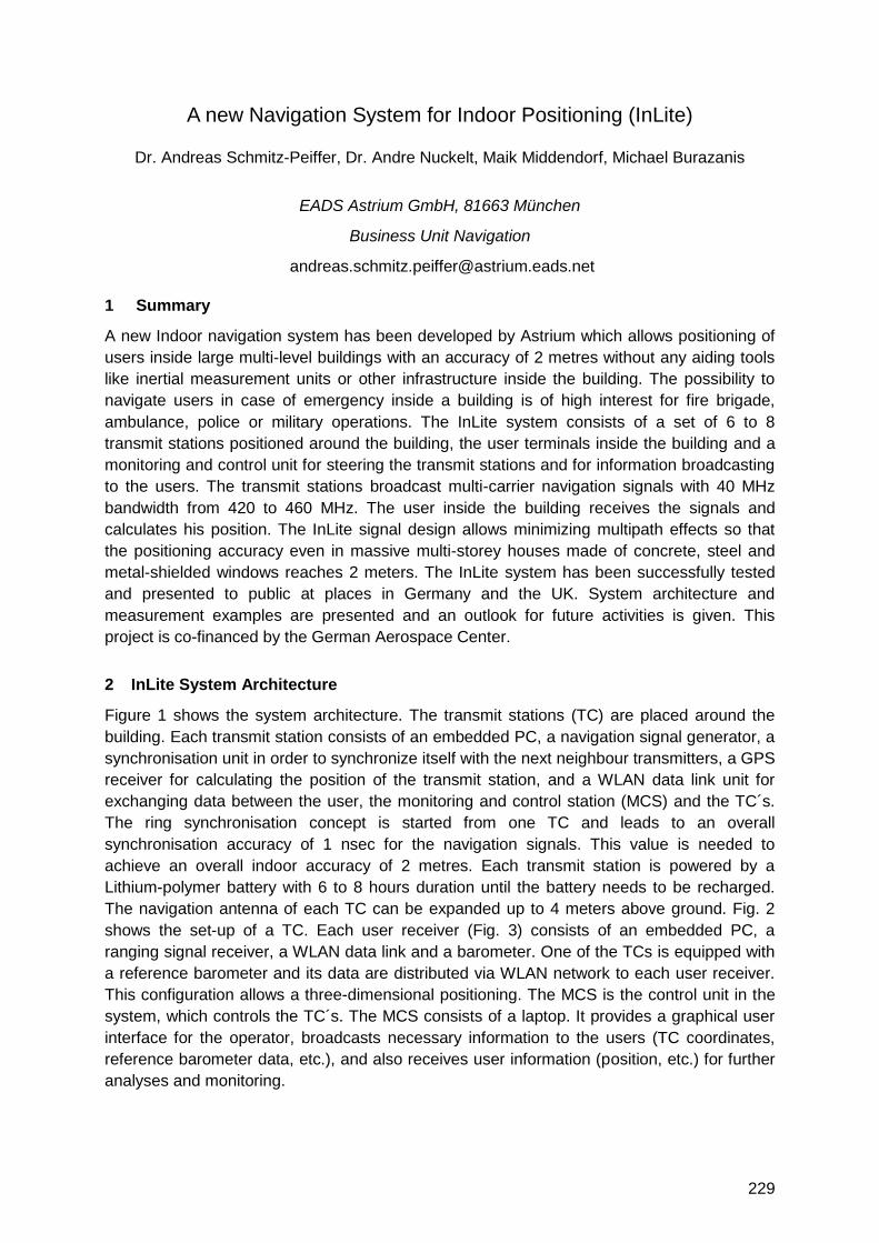
229
A new Navigation System for Indoor Positioning (InLite)
Dr. Andreas Schmitz-Peiffer, Dr. Andre Nuckelt, Maik Middendorf, Michael Burazanis
EADS Astrium GmbH, 81663 München
Business Unit Navigation
1 Summary
A new Indoor navigation system has been developed by Astrium which allows positioning of
users inside large multi-level buildings with an accuracy of 2 metres without any aiding tools
like inertial measurement units or other infrastructure inside the building. The possibility to
navigate users in case of emergency inside a building is of high interest for fire brigade,
ambulance, police or military operations. The InLite system consists of a set of 6 to 8
transmit stations positioned around the building, the user terminals inside the building and a
monitoring and control unit for steering the transmit stations and for information broadcasting
to the users. The transmit stations broadcast multi-carrier navigation signals with 40 MHz
bandwidth from 420 to 460 MHz. The user inside the building receives the signals and
calculates his position. The InLite signal design allows minimizing multipath effects so that
the positioning accuracy even in massive multi-storey houses made of concrete, steel and
metal-shielded windows reaches 2 meters. The InLite system has been successfully tested
and presented to public at places in Germany and the UK. System architecture and
measurement examples are presented and an outlook for future activities is given. This
project is co-financed by the German Aerospace Center.
2 InLite System Architecture
Figure 1 shows the system architecture. The transmit stations (TC) are placed around the
building. Each transmit station consists of an embedded PC, a navigation signal generator, a
synchronisation unit in order to synchronize itself with the next neighbour transmitters, a GPS
receiver for calculating the position of the transmit station, and a WLAN data link unit for
exchanging data between the user, the monitoring and control station (MCS) and the TC´s.
The ring synchronisation concept is started from one TC and leads to an overall
synchronisation accuracy of 1 nsec for the navigation signals. This value is needed to
achieve an overall indoor accuracy of 2 metres. Each transmit station is powered by a
Lithium-polymer battery with 6 to 8 hours duration until the battery needs to be recharged.
The navigation antenna of each TC can be expanded up to 4 meters above ground. Fig. 2
shows the set-up of a TC. Each user receiver (Fig. 3) consists of an embedded PC, a
ranging signal receiver, a WLAN data link and a barometer. One of the TCs is equipped with
a reference barometer and its data are distributed via WLAN network to each user receiver.
This configuration allows a three-dimensional positioning. The MCS is the control unit in the
system, which controls the TC´s. The MCS consists of a laptop. It provides a graphical user
interface for the operator, broadcasts necessary information to the users (TC coordinates,
reference barometer data, etc.), and also receives user information (position, etc.) for further
analyses and monitoring.
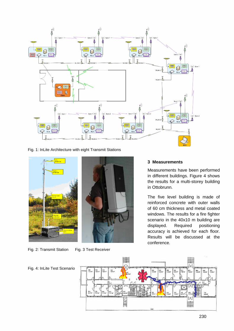
230
Fig. 1: InLite Architecture with eight Transmit Stations
Fig. 2: Transmit Station Fig. 3 Test Receiver
Fig. 4: InLite Test Scenario
3 Measurements
Measurements have been performed
in different buildings. Figure 4 shows
the results for a multi-storey building
in Ottobrunn.
The five level building is made of
reinforced concrete with outer walls
of 60 cm thickness and metal coated
windows. The results for a fire fighter
scenario in the 40x10 m building are
displayed. Required positioning
accuracy is achieved for each floor.
Results will be discussed at the
conference.

231
Indoor Multipath Mitigation
Kostas Dragūnas, prof. Kai Borre
Aalborg University, Denmark
Today multipath errors constitute a limiting factor for the accuracy obtainable by satellite
based positioning. Multipath depends on the environment. It cannot easily be predicted.
Knowledge about the location can be helpful. In outdoor environment several secondary
paths are arriving at the antenna. Multipath is not too difficult to mitigate outdoors.
Indoors the situation is different, and the signals are weaker. Moreover, we cannot always
expect the direct signal to be present. So we cannot consistently remove all secondary
signals in indoor positioning.
The research in the field is not yet mature. The research of indoor multipath error became a
major scientific field about five years ago when the first high sensitivity receivers appeared.
Most of the current algorithms for mitigation of multipath are not suitable in situations where
we have more than three secondary paths and/or no line of sight (LOS) signal.
The present paper surveys what can be done to mitigate multipath indoors and describes
some of the available techniques. We look for techniques which allow us to not just find the
LOS signal, but also to extract all or at least the majority of secondary paths for further
analysis.
The present study shows that out of approximately 40 known techniques, there are some
useful ones which may be capable of dealing with indoor situations. Particularly we are
interested in multipath mitigation techniques based on deconvolution. The main advantage of
using this technique is that it is capable of distinguishing closely spaced secondary paths,
under the assumption that enough samples of the signal are available. The more samples we
have (or the higher sampling rate we use) the more clearly we can distinguish between two
adjacent signals. This is an important property because the indoor secondary signal paths
are close to each other in the time domain.
The scope of this paper is to show how the LOS signal can be better estimated and how to
separate multiple paths indoors, even if they are closely spaced. We demonstrate this by
using a controlled environment setup, e.g. using simulated signals. The usual deconvolution
algorithm is modified such that it better identifies the individual multipath signals and yields
an improved estimate of their time delay.
We tested the algorithm in various scenarios by differentiating each one using different SNR
levels, changing the number of multipath signals, and changing the distances between
separate signal replicas. The numerical examples demonstrate a much better performance of
the modified algorithm compared to the traditional one. The results exceeded our initial
expectations, because we found that we can separate secondary paths even at a very low
SNR level when acquisition has difficulties in finding the signal at all. Knowing the number of
secondary path signal replicas that are present in the channel and the distance between
them will help to analyze how severe the multipath is, and adjust the situation accordingly.
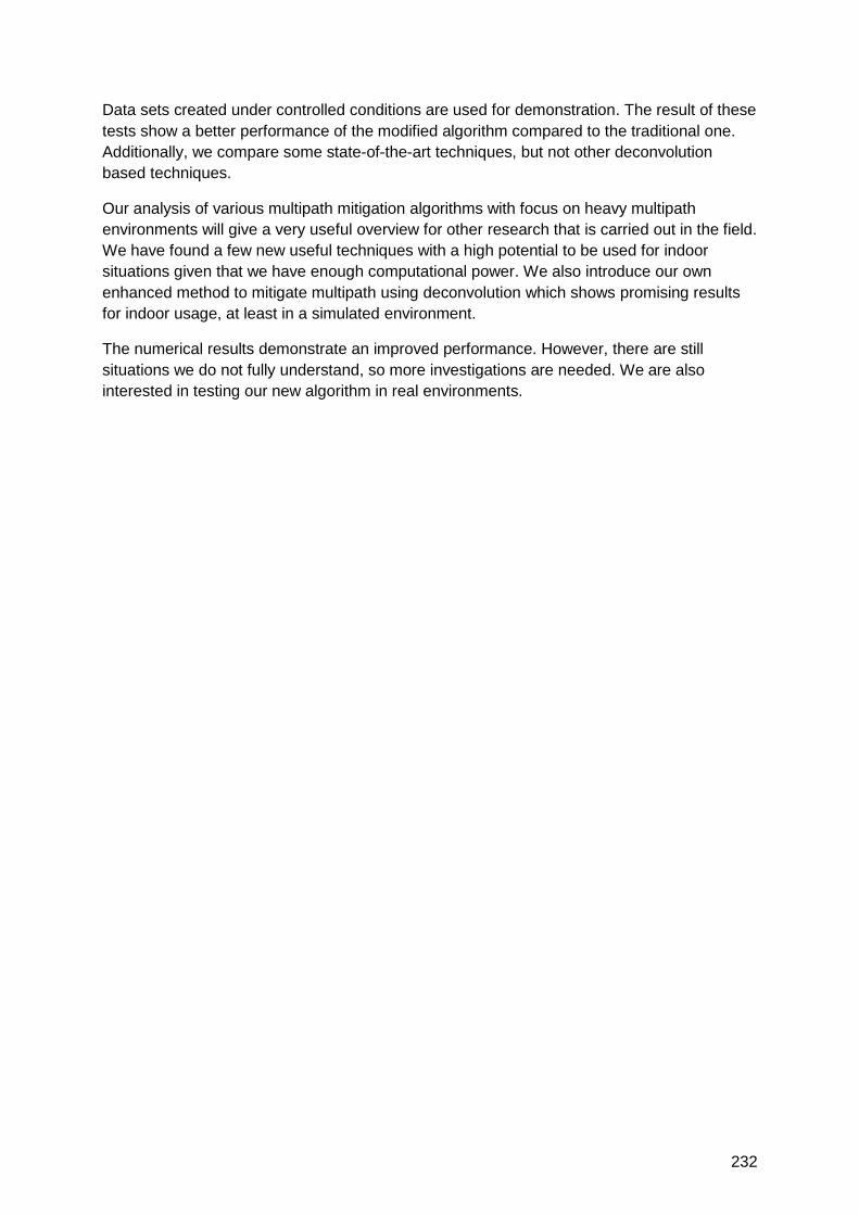
232
Data sets created under controlled conditions are used for demonstration. The result of these
tests show a better performance of the modified algorithm compared to the traditional one.
Additionally, we compare some state-of-the-art techniques, but not other deconvolution
based techniques.
Our analysis of various multipath mitigation algorithms with focus on heavy multipath
environments will give a very useful overview for other research that is carried out in the field.
We have found a few new useful techniques with a high potential to be used for indoor
situations given that we have enough computational power. We also introduce our own
enhanced method to mitigate multipath using deconvolution which shows promising results
for indoor usage, at least in a simulated environment.
The numerical results demonstrate an improved performance. However, there are still
situations we do not fully understand, so more investigations are needed. We are also
interested in testing our new algorithm in real environments.
233
Indoor Positioning Using GPS transmitters: Experimental results
Anca Fluerasu, Alexandre Vervisch-Picois, Nel Samama
Institut Telecom, Telecom SudParis, 9 rue Charles Fourier, 91000 Evry, France
[email protected], [email protected], [email protected]
Gianluca Boiero, Giorgio Ghinamo, Piero Lovisolo
Telecom Italia, Via Guglielmo Reiss Romoli, 274, 10148 Torino, Italy
[email protected], [email protected],
1 Summary
The paper presents the results of an experimental campaign of the GNSS transmitter based
approach for indoor positioning. Details on the chosen setup are given and the main features
of the system are fully described. Comments on the positioning obtained accuracies,
together with the description of the real environment are provided and an in-depth analysis of
the performance of the system is proposed.
For the next years the continuity of the positioning service indoors appears as a real
challenge. GNSS, sensor networks or WLAN approaches are proposed in order to provide
this continuity. The GNSS based approaches aim at making a better exploitation of the
satellite signal on the receiver side. Unfortunately, techniques like HS-GPS or A-GPS do not
seem to provide a definitive solution. Local infrastructure based solutions can aid to establish
a final system with good accuracy and a large coverage: the approach described in the paper
uses GPS transmitters that make GPS signals available indoors.
2 Experimental setup
The system was deployed in Torino in the Telecom Italia premises. The GNSS repeater
based approach, already described in previous papers, was used. The main features of the
system are the following ones: a GSS6560 Spirent Generator is used to feed a set of four
antennas located indoors, the so-called ―repeaters‖. This transmission is performed through
coaxial cables, with no other treatment than amplification. Once the signals are received by
the repeaters, they are retransmitted indoors by the repeater antennas. Since the
simultaneous transmission would clearly create artificial multipath, a sequential approach is
implemented, with only one repeater transmitting at a given time. A full cycle is obtained
when all the four repeaters have broadcast the signal once. At the exact instant of the
transition from one repeater to the next, a variation of the distance between the transmitting
repeater and the indoor receiver occurs. After a complete cycle, one has four such
differences available and may carry out the indoor 2D/3D location computations.
3 Modelling of the environment
A complete description of the indoor environment is made in order to define the best
locations of the indoor antennas. It is then used to carry out propagation simulations that help
us for the future analysis of the results, mainly in terms of importance of multipath for any
given indoor receiver location. These simulations are carried out using the Ergospace tool
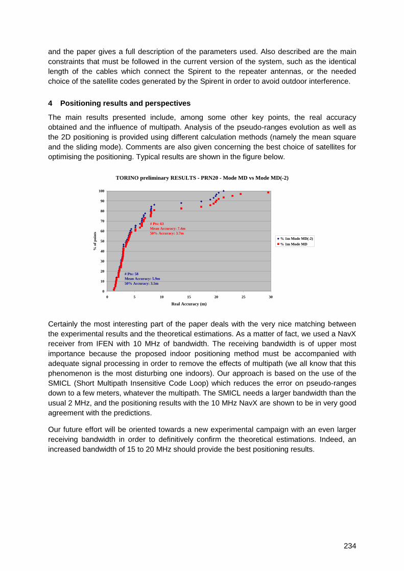
234
and the paper gives a full description of the parameters used. Also described are the main
constraints that must be followed in the current version of the system, such as the identical
length of the cables which connect the Spirent to the repeater antennas, or the needed
choice of the satellite codes generated by the Spirent in order to avoid outdoor interference.
4 Positioning results and perspectives
The main results presented include, among some other key points, the real accuracy
obtained and the influence of multipath. Analysis of the pseudo-ranges evolution as well as
the 2D positioning is provided using different calculation methods (namely the mean square
and the sliding mode). Comments are also given concerning the best choice of satellites for
optimising the positioning. Typical results are shown in the figure below.
Certainly the most interesting part of the paper deals with the very nice matching between
the experimental results and the theoretical estimations. As a matter of fact, we used a NavX
receiver from IFEN with 10 MHz of bandwidth. The receiving bandwidth is of upper most
importance because the proposed indoor positioning method must be accompanied with
adequate signal processing in order to remove the effects of multipath (we all know that this
phenomenon is the most disturbing one indoors). Our approach is based on the use of the
SMICL (Short Multipath Insensitive Code Loop) which reduces the error on pseudo-ranges
down to a few meters, whatever the multipath. The SMICL needs a larger bandwidth than the
usual 2 MHz, and the positioning results with the 10 MHz NavX are shown to be in very good
agreement with the predictions.
Our future effort will be oriented towards a new experimental campaign with an even larger
receiving bandwidth in order to definitively confirm the theoretical estimations. Indeed, an
increased bandwidth of 15 to 20 MHz should provide the best positioning results.
TORINO preliminary RESULTS - PRN20 - Mode MD vs Mode MD(-2)
0
10
20
30
40
50
60
70
80
90
100
0 5 10 15 20 25 30
Real Accuracy (m)
% o
f p
oin
ts
% 1m Mode MD(-2)
% 1m Mode MD
# Pts: 58
Mean Accuracy: 5.9m
50% Accuracy: 3.5m
# Pts: 63
Mean Accuracy: 7.4m
50% Accuracy: 3.7m
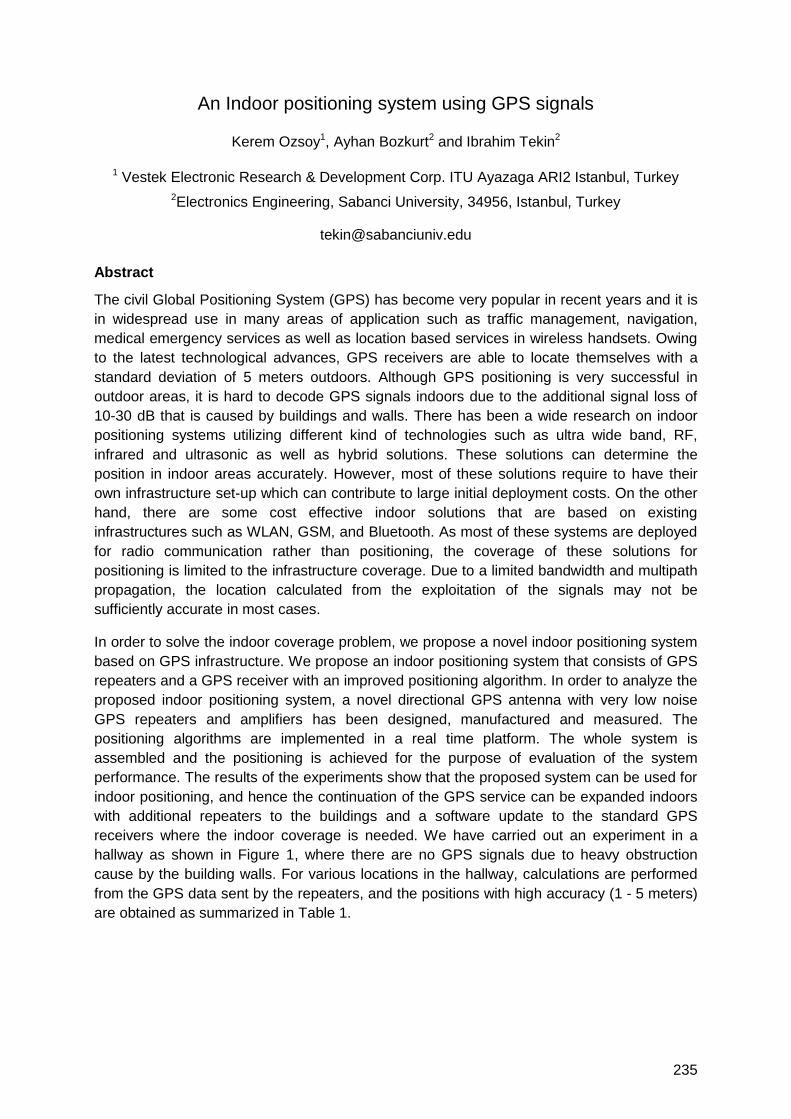
235
An Indoor positioning system using GPS signals
Kerem Ozsoy1, Ayhan Bozkurt2 and Ibrahim Tekin2
1 Vestek Electronic Research & Development Corp. ITU Ayazaga ARI2 Istanbul, Turkey
2Electronics Engineering, Sabanci University, 34956, Istanbul, Turkey
Abstract
The civil Global Positioning System (GPS) has become very popular in recent years and it is
in widespread use in many areas of application such as traffic management, navigation,
medical emergency services as well as location based services in wireless handsets. Owing
to the latest technological advances, GPS receivers are able to locate themselves with a
standard deviation of 5 meters outdoors. Although GPS positioning is very successful in
outdoor areas, it is hard to decode GPS signals indoors due to the additional signal loss of
10-30 dB that is caused by buildings and walls. There has been a wide research on indoor
positioning systems utilizing different kind of technologies such as ultra wide band, RF,
infrared and ultrasonic as well as hybrid solutions. These solutions can determine the
position in indoor areas accurately. However, most of these solutions require to have their
own infrastructure set-up which can contribute to large initial deployment costs. On the other
hand, there are some cost effective indoor solutions that are based on existing
infrastructures such as WLAN, GSM, and Bluetooth. As most of these systems are deployed
for radio communication rather than positioning, the coverage of these solutions for
positioning is limited to the infrastructure coverage. Due to a limited bandwidth and multipath
propagation, the location calculated from the exploitation of the signals may not be
sufficiently accurate in most cases.
In order to solve the indoor coverage problem, we propose a novel indoor positioning system
based on GPS infrastructure. We propose an indoor positioning system that consists of GPS
repeaters and a GPS receiver with an improved positioning algorithm. In order to analyze the
proposed indoor positioning system, a novel directional GPS antenna with very low noise
GPS repeaters and amplifiers has been designed, manufactured and measured. The
positioning algorithms are implemented in a real time platform. The whole system is
assembled and the positioning is achieved for the purpose of evaluation of the system
performance. The results of the experiments show that the proposed system can be used for
indoor positioning, and hence the continuation of the GPS service can be expanded indoors
with additional repeaters to the buildings and a software update to the standard GPS
receivers where the indoor coverage is needed. We have carried out an experiment in a
hallway as shown in Figure 1, where there are no GPS signals due to heavy obstruction
cause by the building walls. For various locations in the hallway, calculations are performed
from the GPS data sent by the repeaters, and the positions with high accuracy (1 - 5 meters)
are obtained as summarized in Table 1.
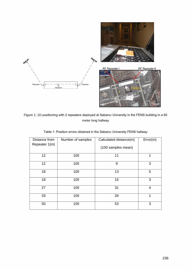
236
Figure 1: 1D positioning with 2 repeaters deployed at Sabancı University in the FENS building in a 60
meter long hallway
Table 1: Position errors obtained in the Sabancı University FENS hallway
Distance from
Repeater 1(m)
Number of samples Calculated distance(m)
(100 samples mean)
Error(m)
12 100 11 1
12 100 9 3
18 100 13 5
18 100 15 3
27 100 31 4
33 100 34 1
50 100 53 3
237
Pseudolite Indoor Localization Using Multiple Receivers
- Performance Analysis of Increasing Receivers and Transmitters –
Yoshihiro Sakamoto(1), Haruhiko Niwa(2), Takuji Ebinuma(3), Kenjiro Fujii(4),
and Shigeki Sugano(1)
(1) Waseda University, Japan (2) Wabot House Laboratory of Waseda University, Japan
(3) University of Tokyo, Japan (4) Hitachi Industrial Equipment Systems Co., Ltd., Japan
1 Summary
The pseudolite has the potential to become one of the best solutions for indoor positioning
due to its compatibility with GPS and its positioning accuracy. However, since cycle slips
occur frequently indoors and their occurrence being difficult to predict, it is not easy to retain
a sufficient number of consistent observation equations for the determination of position.
There are two possible methods to avoid this problem: a) increasing the number of
transmitters, which is known as an effective way for outdoor GPS, and b) increasing the
number of receivers. In this paper, we evaluate the performance of these two methods for
indoor positioning in terms of positioning success rates and the achievable accuracy. Our
experiment shows that increasing the number of receivers is more effective than increasing
the number of transmitters.
2 Introduction
Recently, GPS is the de facto standard for outdoor positioning because of its accuracy and
availability. The advantage of using pseudolites is their compatibility with GPS; they can be
built based on GPS devices, which have already been pervasive, with a minor change of
their firmware. The goal of our research is to develop a pseudolite system that will achieve
stable indoor positioning at centimeter-level accuracy. To accomplish this, one of the most
appropriate techniques is real time kinematic (RTK) positioning. However, the RTK is subject
to cycle slips, that are failures of the carrier phase tracking of the incoming signals. In our
previous research, we proposed a method, that uses multiplex receivers as a solution for the
cycle slip problem. This idea is similar to the increase of visible satellites for GPS in terms of
the increase of the number of observation equations. This is not a direct solution for the cycle
slip problem but the result is a higher redundancy that will improve the Positioning Success
Rate (PSR). (PSR is the ratio between the time in which positioning is successfully done and
the total measurement duration.) In this paper, we analyze the performance by increasing the
number of receivers and transmitters for indoor positioning.
3 Pseudolite
Figure 1 shows the appearance of a pseudolite transmitter and receiver. The carrier
frequency used in our system is 1575.42 MHz, which is the same as the GPS L1 band, and
the PRN code numbers are 33 to 44. In order to keep the level under the Japanese license
requirement, we set the output power from the transmitter's antenna to less than -70 dBm,.
We used the SUPERSTAR IITM receiver from NovAtel Inc. as its hardware and
OpenSourceGPS developed by Clifford Kelley et al. as its software. We multiplexed ten
receivers - eight were used for the rover and two for the base station.
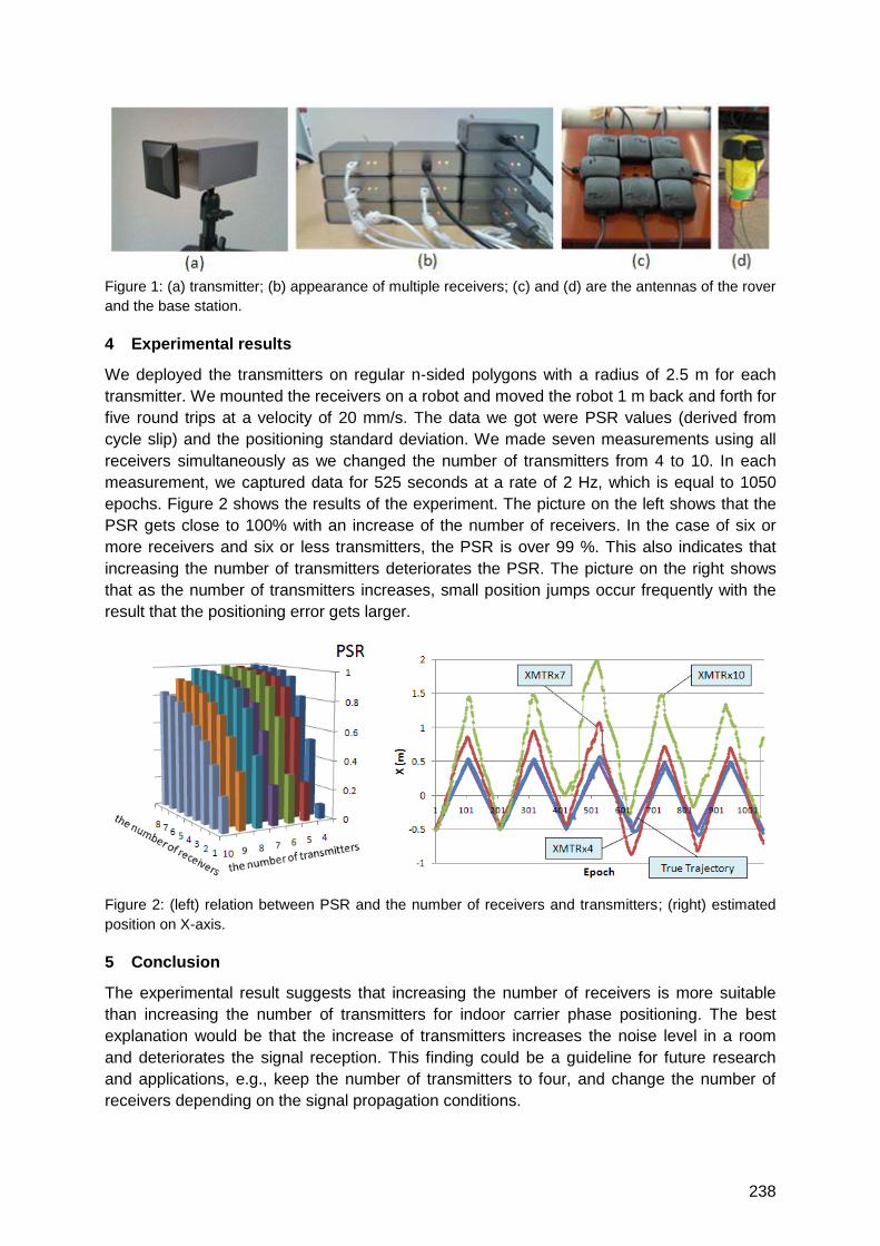
238
Figure 1: (a) transmitter; (b) appearance of multiple receivers; (c) and (d) are the antennas of the rover
and the base station.
4 Experimental results
We deployed the transmitters on regular n-sided polygons with a radius of 2.5 m for each
transmitter. We mounted the receivers on a robot and moved the robot 1 m back and forth for
five round trips at a velocity of 20 mm/s. The data we got were PSR values (derived from
cycle slip) and the positioning standard deviation. We made seven measurements using all
receivers simultaneously as we changed the number of transmitters from 4 to 10. In each
measurement, we captured data for 525 seconds at a rate of 2 Hz, which is equal to 1050
epochs. Figure 2 shows the results of the experiment. The picture on the left shows that the
PSR gets close to 100% with an increase of the number of receivers. In the case of six or
more receivers and six or less transmitters, the PSR is over 99 %. This also indicates that
increasing the number of transmitters deteriorates the PSR. The picture on the right shows
that as the number of transmitters increases, small position jumps occur frequently with the
result that the positioning error gets larger.
Figure 2: (left) relation between PSR and the number of receivers and transmitters; (right) estimated
position on X-axis.
5 Conclusion
The experimental result suggests that increasing the number of receivers is more suitable
than increasing the number of transmitters for indoor carrier phase positioning. The best
explanation would be that the increase of transmitters increases the noise level in a room
and deteriorates the signal reception. This finding could be a guideline for future research
and applications, e.g., keep the number of transmitters to four, and change the number of
receivers depending on the signal propagation conditions.

239
High Sensitive GNSS
Auditorium D2
Wednesday, September 15, 16:00 – 18:00
Thursday, September 16, 08:15 – 09:45

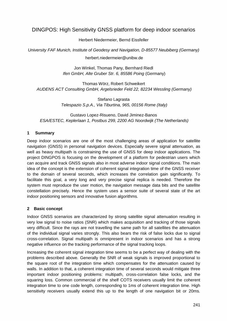
241
DINGPOS: High Sensitivity GNSS platform for deep indoor scenarios
Herbert Niedermeier, Bernd Eissfeller
University FAF Munich, Institute of Geodesy and Navigation, D-85577 Neubiberg (Germany)
Jon Winkel, Thomas Pany, Bernhard Riedl
Ifen GmbH, Alte Gruber Str. 6, 85586 Poing (Germany)
Thomas Wörz, Robert Schweikert
AUDENS ACT Consulting GmbH, Argelsrieder Feld 22, 82234 Wessling (Germany)
Stefano Lagrasta
Telespazio S.p.A., Via Tiburtina, 965, 00156 Rome (Italy)
Gustavo Lopez-Risueno, David Jiminez-Banos
ESA/ESTEC, Keplerlaan 1, Postbus 299, 2200 AG Noordwijk (The Netherlands)
1 Summary
Deep indoor scenarios are one of the most challenging areas of application for satellite
navigation (GNSS) in personal navigation devices. Especially severe signal attenuation, as
well as heavy multipath is constraining the use of GNSS for deep indoor applications. The
project DINGPOS is focusing on the development of a platform for pedestrian users which
can acquire and track GNSS signals also in most adverse indoor signal conditions. The main
idea of the concept is the extension of coherent signal integration time of the GNSS receiver
to the domain of several seconds, which increases the correlation gain significantly. To
facilitate this goal, a very long and very precise signal replica is needed. Therefore the
system must reproduce the user motion, the navigation message data bits and the satellite
constellation precisely. Hence the system uses a sensor suite of several state of the art
indoor positioning sensors and innovative fusion algorithms.
2 Basic concept
Indoor GNSS scenarios are characterized by strong satellite signal attenuation resulting in
very low signal to noise ratios (SNR) which makes acquisition and tracking of those signals
very difficult. Since the rays are not travelling the same path for all satellites the attenuation
of the individual signal varies strongly. This also bears the risk of false locks due to signal
cross-correlation. Signal multipath is omnipresent in indoor scenarios and has a strong
negative influence on the tracking performance of the signal tracking loops.
Increasing the coherent signal integration time seems to be a perfect way of dealing with the
problems described above. Generally the SNR of weak signals is improved proportional to
the square root of the integration time which compensates for the attenuation caused by
walls. In addition to that, a coherent integration time of several seconds would mitigate three
important indoor positioning problems: multipath, cross-correlation false locks, and the
squaring loss. Common commercial of the shelf COTS receivers usually limit the coherent
integration time to one code length, corresponding to 1ms of coherent integration time. High
sensitivity receivers usually extend this up to the length of one navigation bit or 20ms.

242
Therefore a theoretical gain of up to 15dB and more could be expected by applying a very
long coherent integration.
Nevertheless several aspects also prevent the use of very long integration times. Since data
bit transitions can occur every 20ms, assistance data must be provided to the system and a
reference station with open sky conditions must be available. In addition the internal clock
often is not stable enough to provide sufficient accuracy for the replica construction due to
oscillator jitter, if long coherent replicas are formed. Therefore a stable oscillator (OCXO) is
necessary. The most challenging part is the reproduction of the user antenna motion with
high accuracy to compensate the nonlinear dynamics on the pseudo-range and the signal
Doppler frequency. The standard solution implies an inertial navigation system to reproduce
the user motion during the integration interval. It turned out that current COTS micro electro-
mechanical system (MEMS) type inertial sensors do not provide the stability to fulfill this task
sufficiently, especially if they are aided by non-precise indoor position updates. Therefore an
innovative algorithm had to be developed to reproduce the user motion by coupling a
pedestrian navigation system with a modified inertial navigation system, called ―micro-
trajectory generator‖.
3 System Components
The DINGPOS platform contains several components and sensor subsystems to accomplish
the tasks described above. The main integrating element of the entire system is a software
GNSS receiver. The receiver integrates all additional sensors and subsystems and provides
interfaces to a RF-front end, a MEMS type inertial measurement unit, a barometric sensor, a
WiFi connection, a ZigBee connector and a precise OCXO type oscillator. Dead reckoning is
performed by a pedestrian navigation system (PNS). The PNS uses the inertial
measurement unit as main sensor, but also the built-in magnetometers and a barometric
sensor. In the µ-trajectory generator the user motion is reconstructed to create the signal
replica. Additional position updates are provided by the INPOS ZigBee based positioning
system provided by Telespazio, as well as a custom WiFi based positioning system. The
sensor readings are merged in an integrating Kalman filter to obtain a consolidated position
solution.
4 Focus of the paper
The paper will give an overview on the developed DINGPOS sensor platform and its
elements. This will include the sensors used in DINGPOS, as well as the subsystems and
the algorithms merging the individual results. Several aspects of the algorithms will be
highlighted. The performance of the unit has been tested in simulation and practical test
campaigns. Since the project will be finished by the time of the conference, a final view on
the concept and the performance of the unit can be provided.
The described work has been performed in the ESA funded contract: DINGPOS, ESTEC Ctr.
No. 20834.
243
Deeply Integrated GPS for Indoor Navigation
Andrey Soloviev, University of Florida
T. Jeffrey Dickman, Northrop Grumman, Navigation Systems Division
It is widely recognized that the world has become reliant on Global Navigation Satellite
Systems (GNSS) and specifically GPS for positioning and timing. It is also widely recognized
that GPS availability and continuity cannot be assured when the signal is obstructed, for
example, in urban canyons or indoors. Inertial navigation is seen as a critical system
component when GPS is not available since it provides excellent short-term performance,
but requires periodic external updates from various sources. Alternative GNSS technologies
that can be applied for providing these periodic updates include electro-optic vision, human
motion models, pseudolites, signals of opportunity and others. The obvious question
remains, ―what if the state-of-the-art GPS receiver technology is advanced such that precise
GPS measurements can be extracted where they are unavailable today?‖
The deeply integrated GPS receiver technology has been developed to enhance the
robustness of GPS signal processing by implementing GPS/inertial sensor fusion at the
signal processing level. As a result, this technology is capable of maintaining a complete
tracking status (i.e., code phase, Doppler frequency and carrier phase) even for extremely
week signals such as GPS signals that are attenuated by 30 dB from their open sky
conditions. This paper will discuss the results of a feasibility study that was performed to
provide precise (sub-centimeter-level) carrier phase GPS measurement indoors. The study
was conducted using real data collected from actual GPS hardware in indoor scenarios.
The paper will overview deeply integrated receiver approach and then present results of the
indoor GPS signal evaluation. Evaluation results will be presented for static and dynamic
scenarios and will include characterization of the satellite availability, quality of GPS signal
measurements (code phase and carrier phase) and identification of direct and multipath
signals.
Three key components of the deeply integrated GPS receiver include:
1) Long coherent integration (on the order of one second) without any type of external aiding;
2) Open loop estimation of GPS signal parameters to enable rapid and robust tracking; and,
3) Identification of direct and multipath signal for mobile platforms with the subsequent capability to constructively utilize multipath signal reflections for navigation.
The deep integration eliminates conventional tracking loops and starts fusion of GPS and
inertial data at the earliest processing stage possible by combining radio-frequency (RF)
GPS samples with sampled inertial measurements. Inertial data provide the dynamic
reference trajectory for the GPS signal integration inside GPS receiver correlators.
Particularly, parameters of the internally generated replica GPS signal are adjusted for
dynamic changes using the inertial aiding. Coherent signal integration over a one second
interval is applied to recover very weak GPS signals (at a 15 dB-Hz level). The coherent
integration time of one second exceeds the duration of data bits (20 milliseconds) in the GPS
navigation message. A bit wipe-off is thus required to avoid energy losses during signal
accumulation. A computationally efficient algorithm was therefore developed to search
through possible bit combinations and choose the combination that maximizes the signal
244
energy. The maximum energy bit combination is then applied to wipe-off navigation data bits.
No external bit aiding is thus required.
Indoor applications are generally characterized by severe multipath conditions. On one hand,
it is critical to distinguish between direct signal and multipath for robust localization. On the
other hand, multipath reflections can be used as an additional source of navigation
information, especially, for those cases where the number of direct path satellites is limited:
i.e., instead of simply mitigating multipath reflections as it is done by conventional GPS
receivers; these reflections can be used constructively for navigation purposes. In order to
utilize multipath reflections in the GPS receiver architecture, multipath signal processing
must be separated from processing of direct GPS signals. In indoor environments, accurate
separation of direct and multipath signals using the code phase is generally not feasible due
to close proximity of reflecting objects. On the other hand, instantaneous frequencies of
multipath signals received by a mobile user can differ significantly from the instantaneous
frequency of the direct path signal. These differences are primarily due to two factors: a non-
zero receiver velocity, and significantly different line-of-sight (LOS) vectors from the satellite
vehicle (SV) to the receiver and from the reflecting object to the receiver. As a result,
frequency separation of direct and multipath signals can be efficiently utilized for independent
processing of these signal components and subsequent use of multipath reflections in the
navigation processor.
Deeply integrated technology was tested in three types of indoor environments: benign (e.g.,
a hallway outside an office with a window), moderate (e.g., a hallway away from windows),
and difficult (e.g., deep inside a ground floor and away from windows). The experiments were
conducted in two phases: one without motion (i.e., a static platform) and one with a moving
platform. In the moving cases, in addition to direct signal evaluation, signal reflections from
the floor and walls were identified and characterized.
Test results obtained indicate that GPS signal parameters can be reliably estimated in
benign and moderate indoor environments. For the difficult environment, no satellites were
detected using the current implantation; however, it is anticipated that signals might be found
if the signal-to-noise ratio is improved via multi-platform and/or multi-satellite signal
accumulation. Test results further indicate that the indoor satellite availability is generally
quite sparse: i.e. a satellite can be available over a few-second interval after which it may
disappear and then reappear again. As a result, GPS cannot be used as a sole mean of
indoor navigation. However, the availability of even spares GPS measurements (carrier
phase in particular) is extremely beneficial for the calibration of inertial error states and for
improving robustness of other navigation aids (for example, for the initialization of depth of
monocular video images). Therefore, deeply integrated GPS receiver is viewed as a key
component of the multi-sensor fusion solution for indoor navigation.
245
Doppler Rate Measurements in Standard and High Sensitivity (HS) GPS
Receivers: Theoretical Analysis and Comparison
Nadezda Sokolova1, Daniele Borio2, Börje Forssell1, Gérard Lachapelle2
1 Radio Systems Group, Norwegian University of Science and Technology, Norway, 2Department of Geomatics Engineering, University of Calgary, Canada
Due to the capability of the Global Positioning System (GPS) to provide accurate, stable
long-term navigation information, the use of a GPS receiver as an acceleration sensor has
gained an increasing research interest. The receiver acceleration is typically computed from
the Doppler rate measurements provided by the receiver carrier tracking loops. This leads to
acceleration measurements with accuracies of a few mm/s2 [1].
In addition to this, Doppler rate measurements can be used to improve tracking loop
performance as suggested in [2]. In this case, Doppler rate information is used to aid the
Numerically Controlled Oscillator (NCO) in order to produce a linearly varying local carrier
frequency. This reduces the losses in the accumulated signal power. These losses are
introduced by the mismatch between locally generated and incoming signals due to user
dynamics. This is especially valuable in the case of High-Sensitivity (HS) GPS receivers
where loops employing long integration time and low update rates are used [2].
There exist three different ways to estimate Doppler rate in GPS carrier tracking loops. The
first option is to use the raw Doppler rate measurements obtained directly at the FLL filter
output. The other two involve the use of a differentiator in order to derive Doppler rate
measurements from other GPS observables such as carrier phase or, alternatively, raw
Doppler measurements both provided by the Phase Lock Loop (PLL) [1], [3]. Thus, since
Doppler rate measurements are obtained by processing the output of the carrier tracking
loop, parameters such as the loop type and order, integration time and loop bandwidth
strongly impact their quality.
The receiver acceleration can be obtained using either a Least Squares (LS) or Kalman Filter
(KF) approach that extract the user acceleration from Doppler rate measurements. Thus, the
final quality of the acceleration observations depends on the variance of the Doppler rate
measurements and on the approach used for the acceleration computation. It is therefore
desirable to be able to predict the quality of Doppler rate measurements, not only for quality
control and for estimating the uncertainty of this information, but also for properly weighting
the measurements in the LS and KF solution.
In this paper, a cohesive analysis describing the noise propagation process from the input of
the tracking loops to the final Doppler rate and acceleration observations is provided. A
theoretical model, allowing the evaluation of the Doppler rate accuracy is introduced and
variance and bias of Doppler rate measurements are related to the carrier-to-noise density
ratio (C/N0), the user dynamics and the carrier tracking loop parameters. This type of
approach is new and represents one of the main contributions of the paper. More specifically,
a tracking loop can be approximated as a linear device extracting Doppler rate
measurements from the input samples. The linear transfer function from the input noise to
the final Doppler rate estimate is derived and the concept of Doppler rate bandwidth
introduced. Doppler rate bandwidth parameter quantifies the portion of noise transferred from
the input signal to the frequency rate estimates. The provided model is a generalization of
246
the analysis provided in [4] where only Doppler frequency and velocity measurements were
considered.
In order to get a complete model, all three types of Doppler rate measurements are
considered. Moreover, the developed theoretical model is general and can be applied to
different types of receiver architectures. To demonstrate this, this paper considers traditional
sequential carrier tracking loops as well as a HSGPS receiver architecture adopting block
processing techniques.
In addition to this, most of the studies in the area of Doppler rate/acceleration determination
using GPS have been essentially limited to hardware receivers [1]. Hardware receivers do
not provide any insight on how Doppler rate measurements are formed, preventing an
accurate analysis at the tracking loop level. In this way, only the relationships between carrier
phase or raw Doppler and acceleration have been investigated. Therefore, a Software
Defined Radio (SDR) GPS receiver is used here as a fundamental tool for the analysis of the
process of Doppler rate estimation. Given the benefits provided by a SDR GPS receiver, it
was possible to achieve a deeper insight on the Doppler rate estimation process.
The SDR GPS receiver was used to support the validity of the developed theoretical
framework that has been tested using live GPS data collected in various GPS operating
environments. Both standard sequential and HS block processing architectures have been
considered. Empirical results have been compared against the ones obtained using the
developed theoretical model and in all cases the theoretical values were within 1σ of the
mean of the empirical data.
References
a. Bruton, A.M. (2000) Improving the Accuracy and Resolution of SINS/DGPS Airborne Gravimetry.
Ph.D. Thesis, Report No. 20145, Department of Geomatics Engineering, University of Calgary.
b. Kazemi, P.L., C. O'Driscoll and G. Lachapelle (2009) Digital Phase Locked Loop with Frequency Rate Feedback. Proceedings of GNSS09 (Savannah, GA, 22-25 Sep, Session A3), the Institute of Navigation, 8 pp.
c. Serrano L., Kim D. and Langley R. B. (2004) A single GPS receiver as a real-time, accurate velocity and acceleration sensor. Proceedings of ION/GNSS, Long Beach, CA, pp. 2021–2034.
d. Sokolova, N. (2009) Doppler Measurements and Velocity Estimation: Comparison of Standard
and High Sensitivity Receivers. MSc Thesis, published as Report No. 20299, Department of
Geomatics Engineering, The University of Calgary, Canada.
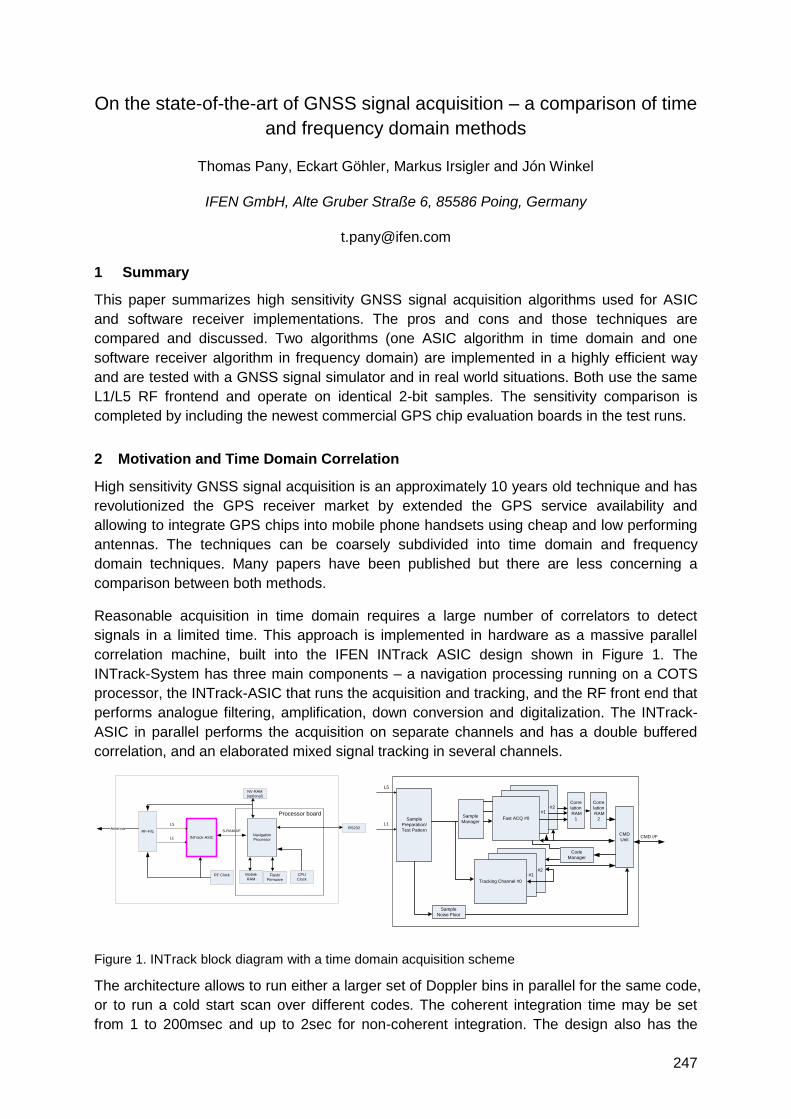
247
On the state-of-the-art of GNSS signal acquisition – a comparison of time
and frequency domain methods
Thomas Pany, Eckart Göhler, Markus Irsigler and Jón Winkel
IFEN GmbH, Alte Gruber Straße 6, 85586 Poing, Germany
1 Summary
This paper summarizes high sensitivity GNSS signal acquisition algorithms used for ASIC
and software receiver implementations. The pros and cons and those techniques are
compared and discussed. Two algorithms (one ASIC algorithm in time domain and one
software receiver algorithm in frequency domain) are implemented in a highly efficient way
and are tested with a GNSS signal simulator and in real world situations. Both use the same
L1/L5 RF frontend and operate on identical 2-bit samples. The sensitivity comparison is
completed by including the newest commercial GPS chip evaluation boards in the test runs.
2 Motivation and Time Domain Correlation
High sensitivity GNSS signal acquisition is an approximately 10 years old technique and has
revolutionized the GPS receiver market by extended the GPS service availability and
allowing to integrate GPS chips into mobile phone handsets using cheap and low performing
antennas. The techniques can be coarsely subdivided into time domain and frequency
domain techniques. Many papers have been published but there are less concerning a
comparison between both methods.
Reasonable acquisition in time domain requires a large number of correlators to detect
signals in a limited time. This approach is implemented in hardware as a massive parallel
correlation machine, built into the IFEN INTrack ASIC design shown in Figure 1. The
INTrack-System has three main components – a navigation processing running on a COTS
processor, the INTrack-ASIC that runs the acquisition and tracking, and the RF front end that
performs analogue filtering, amplification, down conversion and digitalization. The INTrack-
ASIC in parallel performs the acquisition on separate channels and has a double buffered
correlation, and an elaborated mixed signal tracking in several channels.
INTrack-ASIC
L5
L1Navigation
Processor
S-RAM-I/F
Mobile
RAM
RS232
NV-RAM
(optional)
Flash/
Firmware
RF Clock
RF-F/E
CPU
Clock
Antenna
Processor board
Sample
Preparation/
Test Pattern
L5
L1
CMD
UnitCMD I/F
Fast ACQ #2Fast ACQ #1
Fast ACQ #0
Fast ACQ #2Fast ACQ #1
Tracking Channel #0
Corre
lation
RAM
1
Sample
Noise Floor
Sample
Manager
Code
Manager
Corre
lation
RAM
2
Figure 1. INTrack block diagram with a time domain acquisition scheme
The architecture allows to run either a larger set of Doppler bins in parallel for the same code,
or to run a cold start scan over different codes. The coherent integration time may be set
from 1 to 200msec and up to 2sec for non-coherent integration. The design also has the
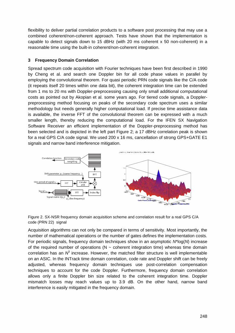
248
flexibility to deliver partial correlation products to a software post processing that may use a
combined coherent/non-coherent approach. Tests have shown that the implementation is
capable to detect signals down to 15 dBHz (with 20 ms coherent x 50 non-coherent) in a
reasonable time using the built-in coherent/non-coherent integration.
3 Frequency Domain Correlation
Spread spectrum code acquisition with Fourier techniques have been first described in 1990
by Cheng et al. and search one Doppler bin for all code phase values in parallel by
employing the convolutional theorem. For quasi periodic PRN code signals like the C/A code
(it repeats itself 20 times within one data bit), the coherent integration time can be extended
from 1 ms to 20 ms with Doppler-preprocessing causing only small additional computational
costs as pointed out by Akopian et al. some years ago. For tiered code signals, a Doppler-
preprocessing method focusing on peaks of the secondary code spectrum uses a similar
methodology but needs generally higher computational load. If precise time assistance data
is available, the inverse FFT of the convolutional theorem can be expressed with a much
smaller length, thereby reducing the computational load. For the IFEN SX Navigation
Software Receiver an efficient implementation of the Doppler-preprocessing method has
been selected and is depicted in the left part Figure 2; a 17 dBHz correlation peak is shown
for a real GPS C/A code signal. We used 200 x 16 ms, cancellation of strong GPS+GATE E1
signals and narrow band interference mitigation.
Figure 2. SX-NSR frequency domain acquisition scheme and correlation result for a real GPS C/A
code (PRN 22) signal
Acquisition algorithms can not only be compared in terms of sensitivity. Most importantly, the
number of mathematical operations or the number of gates defines the implementation costs.
For periodic signals, frequency domain techniques show in an asymptotic N*log(N) increase
of the required number of operations (N ~ coherent integration time) whereas time domain
correlation has an N3 increase. However, the matched filter structure is well implementable
on an ASIC. In the INTrack time domain correlation, code rate and Doppler shift can be freely
adjusted, whereas frequency domain techniques use post-correlation compensation
techniques to account for the code Doppler. Furthermore, frequency domain correlation
allows only a finite Doppler bin size related to the coherent integration time. Doppler
mismatch losses may reach values up to 3.9 dB. On the other hand, narrow band
interference is easily mitigated in the frequency domain.
249
Galileo / GPS Indoor Navigation & Positioning
for SAR and Tracking Applications
Erwin Löhnert, Wolfgang Bär, Eckart Göhler, Jochen Möllmer
IFEN GmbH, Alte Gruber Strasse 6, D-85586 Poing, Germany
1 Summary
―INDOOR‖ is a German research project for providing a combined outdoor/indoor navigation
capability for location based services of security-sensitive applications (SAR) as well as for
important professional logistic or tracking applications, e.g. asset/child tracking. The project
consortium is built of nine partners from industry, research institutes and universities with
IFEN GmbH being the coordinator of the project. The work is funded by the German
Aerospace Center DLR to support future applications for outdoor/indoor scenarios with a
focus on the combination of GPS and Galileo, accompanied by assisted information. The
activities undertaken in the project follow a three phase approach, consisting of phase 1 Core
Technologies – Concept & Evaluation, phase 2 Core Components – Development &
Verification and finally phase 3 Application / Demonstration, planned to take place by the end
of year 2011.
2 Abstract
―INDOOR‖ is a joint research project consisting of nine German partners led by IFEN GmbH
for providing a GNSS based outdoor/indoor navigation solution for location based services of
security-sensitive applications (SAR) as well as for important professional logistic or tracking
applications, e.g. asset/child tracking. The project INDOOR (http://www.indoor-navigation.de)
is funded by the German Aerospace Center (Deutsches Zentrum für Luft- und Raumfahrt,
DLR) with financial resources of the German Ministry of Economics and Technology (BMWi)
under grant no. 50 NA 0504.
The motivation for the project was the fact that Galileo/GPS satellite infrastructure mainly
addresses the navigation markets with direct line of sight (outdoor area) to the satellites.
Many professional applications need positioning and navigation also inside buildings, halls
etc. (indoor area), without direct line of sight to the satellites. Thus, a combined
outdoor/indoor navigation capability is the key technology for location based services of
security-sensitive applications (police, search and rescue, fire brigades etc.) as well as for
professional location-based services, e.g. asset/child tracking. However, positioning and
navigation inside buildings (indoor) or in „indoor-like― outdoor environments with bad visibility,
signal damping, severe multipath etc. are very challenging for Galileo/GPS receivers.
Therefore one main driver in the frame of the project is to develop a Galileo/GPS satellite
navigation based solution, the INDOOR INTrack ASIC, which is small enough for mobile
applications and having the power to get position results even under heavily deteriorated
signal conditions, accompanied by external information like assisted data, inertial MEMS
sensors etc.
The project is divided into three main phases, which are outlined in the paper.

250
Phase 1 Core Technologies – Concept & Evaluation: Here GNSS high-sensitivity
technologies, assisted-GNSS & hybridisation in communication networks, modelling and
calibration of INDOOR channel as well as combined information & hybrid sensors are
investigated.
Phase 2 Core Components – Development & Verification: This phase analyses appropriate
development platforms, antenna & HF-frontend, digital baseband processing, navigation
algorithms, external sensors etc. Also the required verification tools: an IF-signal simulator, a
HF-INDOOR signal generator using raytracing with 3D building models to generate realistic
indoor multipath conditions and a SUPL 2.0 based assisted-Galileo server are investigated.
Verification of the tools takes place in the GATE testbed in Berchtesgaden.
Finally, in the frame of the third phase, a selection of the developed prototype hardware and
software is utilized to support two defined INDOOR demonstrations, a SAR Demonstration
with the fire brigade of the Munich Airport and a child tracking demonstration with Disney
Germany.
The paper gives an overview on the different activities of the project and presents first results
of the 3D multipath simulator processing data of test buildings at the Munich Airport
demonstration site. Furthermore, design and functionalities of two mobile positioning
terminals, a PDA based user terminal with the INDOOR INTrack ASIC core development and
a small-size low power GNSS based child tracking module will be presented in the paper.
Finally, information on the planned demonstration scenarios will be given, i.e. the SAR
demonstration with fire brigades of the Munich Airport using the PDA based user terminals
and the child tracking demonstration at an event/location organised by Disney Germany,
using the GNSS based child tracking modules.
251
GNSS Positioning in Adverse Conditions
Klemen Kozmus Trajkovski, Oskar Sterle, Bojan Stopar
University of Ljubljana, Faculty of Civil and Geodetic Engineering, Jamova 2, SI-1000
Ljubljana, Slovenia
1 Summary
High Sensitivity GNSS has made satellite navigation possible even in those environments
which do not favour satellite signals. In environments such as forests, urban canyons, and
even some building interiors, GNSS signals are not entirely obstructed, but rather attenuated.
GNSS positioning is based either on the receiver‘s internal solution or on the processing of
raw observation data. In adverse conditions, basic code-based solutions can cause major
errors in the estimated position, primarily due to multipath effects. Positioning performance
can be improved however, using appropriate processing of code and Doppler observations.
Besides the common procedures for estimating the receiver‘s position, robust estimation
methods have been used to minimise the effects of gross observation errors. Differential
GNSS, elevation and SNR-dependent weighting do not perform well in adverse conditions
where signal reception is poor.
2 High Sensitivity GNSS
High Sensitivity GNSS (HS GNSS) receivers are able to track very weak GNSS signals by
employing a large number of correlators and by integrating the received signal over longer
intervals than is common for regular GNSS receivers.
Most HS GNSS instruments output their processed data via NMEA messages; only a few of
them are able to output raw observation data. All current HS GNSS receivers are only able to
track GPS satellite signals on the L1 frequency. The processed observations are usually
code pseudo-range, carrier phase and Doppler observables. A value for the signal-to-noise
ratio (SNR) is usually available.
Determining the receiver clock offset and 3 coordinate unknowns is the goal of processing
the raw observation data. The most common method of estimating an unknown position is
the least square adjustment. The position and the clock offset of each satellite are derived
from the navigation message. The basic positioning mode is autonomous, using only the
code pseudo-ranges. Even under normal conditions, the error budget of a pseudo-range can
exceed 10 metres. Differential GNSS (DGNSS) can mitigate some of the ionospheric delays
and effects on the observations. However, DGNSS presumes similar conditions in the
proximity of the base and the rover receiver. In other words, DGNSS does not significantly
improve the rover‘s position when the rover is in an unfavourable environment for signal
reception.
3 HS GNSS Raw Data Processing and Test Results
The custom developed processing procedures were tested on u-blox 4 and 5 series of HS
GPS evaluation kits. The u-blox 4 series is only able to perform carrier-phase observations

252
from strong signals. Therefore, the processing of raw data was limited to code and Doppler
observations only.
Positioning based on code pseudo-ranges can cause large position errors in adverse
conditions. Doppler observations point to changes in the range between the receiver and the
satellite, hence reference ranges are required. Doppler measurements have similar
characteristics to carrier-phase observations with some additional advantages, namely that
cycle slips, which occur frequently in carrier-phase observations in adverse conditions, are of
no consequence. Doppler positioning yields better results than code-only solutions, although
it is not without its weaknesses. The most evident defect of the Doppler-only solution is a
change of path-scale.
The developed solution is based on a combination of code and Doppler observations. The
receiver clock offset is determined by Doppler observations only, thus protecting the offset
determination from the sudden jumps which significantly affect code observations. The
position is determined afterwards using the code pseudo-ranges and Doppler observables.
Both types of observables are assigned the same weight. A robust estimation using the L1-
norm weight function is applied, thus minimising the effects of gross observation error.
The tests were performed under different conditions, from good to partially adverse
conditions, heavy multipath environments and even indoors. DGNSS does not work well in
adverse environments. A weighting function which depends on the elevation and the SNR
can work well in some instances, however, in other instances it can also cause large errors in
the solution.
4 Conclusions and Outlook
By using HS receivers, GNSS navigation is possible in environments with a high degree of
attenuation and multipath. Basic code-based positioning can cause large errors in the
position and is therefore not particularly suitable to conditions that do not favour signal
reception. Multipath is the main contributor to the error budget for code-only observations.
Improvements in the final solution can be achieved using a proper method of raw data
processing by combining code pseudo-ranges and Doppler observations. The effects of
gross errors on the estimated position can be significantly reduced by using robust
estimation methods. The most critical aspect is the initial position which has to be determined
by code pseudo-ranges only.
Further research includes the acquisition of a better initial position. This could be achieved by
using DGNSS if the survey were to begin under normal conditions. DGNSS could also be
used in any part of a survey in a certain mode. GNSS could be combined with other
positioning technologies to achieve seamless navigation and improved results. The most
promising technology for such a combination would be to use ultra-wideband positioning
systems.
253
Composite GNSS Signal Acquisition in Presence of Data Sign Transition
Kewen Sun
Politecnico di Torino, Department of Electronics, Corso Duca degli Abruzzi 24, 10129 Turin
Italy
Personal navigation and location based services using GNSS have gained worldwide
popularity and extensive exploitation in recent years. This has been fueled by an increase in
the number of consumer electronic devices in the marketplace, such as mobile phones,
PDAs and popular in-car navigation systems that come equipped with GNSS receivers. As
these devices become increasingly popular, their uses and applications will inevitably extend
towards more challenging and harsh environments such as shopping malls, urban canyons
and office buildings, where signal attenuations are introduced because of the existence of
blocking obstacles (e.g. walls, floors, etc.). Consequently, high-sensitivity (HS)-GNSS
receivers become essential to cope with such a severe impairment while still providing
precise positioning information even though the radio environment is far from ideal at urban
and indoor locations where extremely low power signals dominate. Location information of
navigation devices in indoor environments has become a key issue for many emerging
applications.
In the context of GNSS receiver design, the most critical part is related to signal acquisition
for initial synchronization particularly in harsh environments. The signal acquisition provides
coarse code epoch and Doppler shift estimates that will have to be refined later by
subsequent signal tracking modules. For the particular case of HS-GNSS receivers, stringent
requirements are imposed on the GNSS receiver sensitivity with the aim of reliable and
robust signal acquisition at very low C/N0 values.
The new ranging signals broadcast by modern Global Navigation Satellite Systems, such as
the European Galileo, the modernized GPS and the Chinese Compass, exhibit several
modulation novelties to meet the growing demand of location, navigation and positioning
services. Among the several modulation novelties and new signals design, the presence of
two channels, the data and pilot components, the adoption of tired codes obtained by
cascading secondary and primary codes are just two examples of these innovations. These
new modulations will allow for the development of more sophisticated and innovative
techniques specifically to acquire the new composite GNSS signals.
Galileo will provide a navigation message at a higher bit rate with a consequent possibility of
a bit sign transition in every spreading code period. Therefore, the bit sign transition could
possibly occur in any primary code period. In this case, if FFT‘s are used to perform the
circular correlation, the bit sign transition occurring within an integration time may cause a
splitting of the CAF main peak into two smaller lobes along the Doppler shift axis.
In this paper, the bit sign transition problem is analyzed in detail and the CAF peak splitting
effect dependent on the bit sign transition position in the signal segment is also deeply
investigated. It has been proved that the presence of bit sign transition does not destroy the
information on the presence of the satellite in view, but it introduces an erroneous Doppler
frequency shift estimation. The main effect of the CAF peak splitting along the Doppler
frequency shift axis is an erroneous frequency estimation, while as far as the code phase
254
delay is concerned, this CAF peak splitting produces a correlation amplitude reduction,
without changing its correct peak position. In this paper the two steps signal acquisition
scheme will be exploited in order to deal with such a CAF peak splitting effect. The main idea
of the two steps acquisition scheme is to take advantage of these two disjoint effects
affecting the CAF peak along the code phase delay and Doppler shift axes, respectively. The
algorithm first try to recover the code phase delay in the first acquisition step so as to roughly
remove the bit sign transition in the received signal and then to recover the correct estimate
of the Doppler shift in the second acquisition step. In order to speed up both acquisition steps
the fast acquisition approach based on FFT‘s has been adopted.
Due to the availability of data and pilot components separately broadcast in the new
composite GNSS signals, the drawback of using only single channel independently is that
half of the transmitted power is lost. When acquiring composite GNSS signals, such as the
Galileo E1 OS modulation, if ignoring the pilot channel and processing only the data channel
signal, only half of the useful signal is exploited and the GNSS receiver could not acquire
signals that would be easily processed if all the useful signal power were used. This loss can
be particularly troublesome at the acquisition stage especially in weak signal environment. In
order to overcome the power loss problem and also to mitigate the CAF peak impairments,
novel non-coherent, coherent and differentially coherent channels combining techniques
employing the two steps acquisition scheme have been firstly proposed for jointly combining
both data and pilot components to recover all the transmitted power from both channels.
In this paper, the aforementioned channels combining techniques for the joint acquisition of
data and pilot components of the new composite GNSS signals have been deeply
characterized from a statistical point of view. In particular, the false alarm and detection
probabilities are given for each channels combining strategy. In order to support the
theoretical analysis, Monte Carlo simulation campaigns have been performed on the
simulated Galileo E1 OS signals to evaluate the performances of the proposed techniques.
These simulation results have revealed that the proposed two steps based channels
combining techniques provide much improved performance with respect to the conventional
single channel acquisition and the single channel two steps acquisition approaches, which
prove the advantages and effectiveness of the developed techniques. These proposed
techniques solve the CAF peak splitting problem in presence of bit sign transitions and also
enhance the acquisition sensitivity specifically adapting to weak signal environment.
In summary in this paper the novel channels combining techniques based on two steps
acquisition scheme have been proposed for effectively recovering all the transmitted power
in both available data and pilot channels and dealing with the bit sign transitions problem to
fit the new GNSS signal modulation requirements. The proposed innovative acquisition
techniques improve the performance and provide more reliable signal detection even in weak
signal environment, which can be applied to the new composite GNSS signals where the
secondary codes could change the relative polarity every primary code period. It is important
to emphasize that a greater computational load is generally required to perform the
acquisition process for each channels combining strategy when two steps acquisition
scheme is adopted.
255
Evaluation of a Peer-to-Peer Kalman Filter in Weak-Signal Areas using a
Software GNSS-Signal-Simulator
Isabelle Kraemer, Iva Bartunkova, Prof. Dr. Bernd Eissfeller
University FAF Munich, Institute of Geodesy and Navigation, Werner-Heisenberg-Weg 39, D-
85577 Neubiberg
[email protected] [email protected] [email protected]
1 Extended Abstract
Since December 2005 95% of a network operator‘s in-service phones in North America must
be Enhanced-911 (E911) compliant as induced by the E911 mandate from the U.S. Federal
Communications Commission (FCC). E911 requires a position fix as soon as an emergency
call is placed by a mobile phone. At the beginning mainly radiolocation techniques like Angle
of Arrival (AoA) or Time Difference of Arrival (TDoA) were favored but this mandate soon
became a major boost for integrating GNSS chips into all kinds of mobile devices. 30 % of all
mobile phones that have been and will be sold between 2009 and 2011 are equipped with a
GNSS chip [1]. This also changed the way satellite navigation is used today. Compared to
May 2000 when the selective availability (SA) had been turned off and car navigation via
satellite signals started to be interesting for civil users, many people today use their GNSS-
enabled mobile phone or PDA also for pedestrian navigation. But this means that satellite
navigation has to provide a position also in areas where it has traditionally not been intended
to work like urban canyons or even indoors.
This development paved the way for Assisted-GNSS (A-GNSS). A server attached to a
reference station provides assistance data (ephemeris, Doppler frequency etc.) to clients
within an ambit of 100 km [2]. Although the number of mobile devices that are not able to
apply assistance data is decreasing, the majority of mobile phones are still not equipped with
a suitable unit. The usage of A-GNSS is also a matter of increased traffic load and costs for
the necessary data transmission, which is paid by the user. In cases when decoding of the
navigation data is not possible due to the low C/N0 the assistance data facilitates the
computation of position. Nevertheless the device at least must be able to track the satellite
signals. In deep indoors not even this might be possible.
To avoid these drawbacks an approach was introduced for devices equipped with a compass
or magnetometer, a pedometer and GNSS chip in [3] and [4] which favors local, temporal ad-
hoc networks between mobile devices instead of requesting assistance data from a distant
server. As soon as the mobile device is not able to acquire or track satellite signals it begins
navigating by means of dead reckoning. The position estimated by dead reckoning can be
improved by a Kalman Filter mutually applied on two or more users‘ devices. As the inertial
computed position deteriorates with time each reacquisition of GNSS improves the users'
position to standard GNSS error range again and can, thanks to the mutual Kalman Filtering,
increase the precision of the users in the neighborhood. The simulations in [3] and [4]
revealed some promising results but do not address a realistic view on the signal strength
within buildings. The intention of this paper is to evaluate the peer-to-peer Kalman Filter as
256
introduced in [3] and [4] using a Software-GNSS-signal-simulator to emulate an indoor area
in a more realistic way.
The signal simulator has been developed at the Institute of Geodesy and Navigation and
deploys well-known models for outdoor signal decay, the Lutz-Jahn model [5] and indoor
signal fading, the adjusted Saleh-Valenzuela [6] model. It provides a complete model of
satellite-to-indoor channel and generates a ―signal map‖ for different positions in a prototype
building. Based on this map the performance of the peer-to-peer Kalman Filter is examined.
A prototype building is emulated characterized by various parameters (e.g. levels, material
etc.). In this building the movement of a number of users, here called peers, is simulated.
The main focus of this paper is to verify the requirements of the simulation as described in [3]
and [4] and to check whether this approach also proves of value when tested in a more
realistic environment. Different scenarios are emulated and the practicability of the peer-to-
peer Kalman Filter regarding position accuracy is examined. The modeling and simulation of
the signals indoors offer a better view on the possibilities of pedestrian navigation in buildings.
2 References
[1] F. van Diggelen: A-GPS Assisted GPS, GNSS and SBAS, Artech House, 2009
[2] G. Lachapelle: GNSS Indoor Location Technologies, Journal of Global Positioning Systems, 2004,
Vol. 3
[3] I. Kraemer, B. Eissfeller: A Peer-to-Peer Kalman Filter for Pedestrian Navigation, ION-GNSS
September 2009, Savannah, GA, USA
[4] I. Kraemer, B. Eissfeller: Navigation Assistance in Peer-to-Peer Ad-Hoc Networks, Toulouse
Space Show 2010, Toulouse, France
[5] E. Lutz, D. Cygan, M. Dippold, F. Dolainsky, and W. Papke: The Land Mobile Satellite
Communication Channel-Recording, Statistics, and Channel Model, IEEE TRANSACTIONS ON
VEHICULAR TECHNOLOGY, VOL. 40. NO. 2, MAY 1991
[6] M.Paonni, A.Teuber, V.Kropp: A New Statistical Model of the Indoor Propagation Channel for
Satellite Navigation, ION-GNSS September 2008, Savannah, GA, USA
257
Pulse shaping investigation for the applicability of future GNSS signals in
indoor environments
Danai Skournetou, Elena-Simona Lohan
Tampere University of Technology, Dept. of Communications Engineering, Tampere, 33720,
Finland
[email protected], [email protected]
Abstract
One of the greatest challenges in Global Navigation Satellite Systems (GNSSs) is to provide
users with sufficiently accurate position information in indoor environments where multipath
propagation effects constitute a dominant source of error. So far, the majority of the satellite-
based positioning methods are designed and optimized for outdoor scenarios and whenever
indoor positioning is required, the use of assisted information by a mobile network is typically
considered. While the use of satellite signals for indoor positioning has been regarded
particularly challenging (i.e., due to the highly attenuated signal power), the introduction of
new GNSS signals with improved characteristics acts as our ignition to study further their
applicability indoors.
Depending on the receiver device and the positioning requirements, the carrier phase or the
code delay of the signal can be used for estimating the distance between a satellite and the
receiver. More precisely, carrier-phase based positioning is advantageous for applications
with high demands on positioning accuracy since it can provide range measurements of sub-
centimetre level. For devices in which cost is the main driver (e.g., mass-market Global
Positioning System (GPS) receivers), the less complex alternative of code-based positioning
is utilized. Carrier-phase information can be also incorporated in code-based range
measurements (e.g., for smoothing) for improved performance, while keeping the
implementation complexity at moderate level.
Regardless of the type in use (i.e., carrier-, code- based or their combination), the aim of
enhancing further the positioning performance is a common denominator. A proactive
approach is the one focusing on the optimization of the signal characteristics upon
generation. For example, for GNSS signals such characteristics can be the modulation type
(e.g., Binary Offset Carrier (BOC), Multiplexed BOC (MBOC) or other BOC variants), the
Pseudo Random Noise (PRN) code and the pulse shape. While the first two have been
extensively investigated in the literature, studies on the choice of the optimum pulse shape
for the new Galileo and modernized GPS signals are modest. More precisely, the adoption of
BOC modulation in the future GNSS signals introduces new challenges in the tracking stage
which have not been considered in the traditional Code Division Multiple Access (CDMA)
systems. Compared to the Binary Phase Shift Keying (BPSK) modulation used in GPS, with
only one triangular shaped peak in the envelope of the AutoCorrelation Function (ACF) (if
unlimited bandwidth is assumed), BOC modulation results in more complex shape of the
ACF due to the presence of multiple peaks (e.g., the possibility to track a wrong peak is
higher).
258
In this paper, we study the impact of different pulse shapes in the estimation of the signal‘s
code delay and the carrier phase. The Cramer Rao Lower Bound (CRLB) has been chosen
for the performance comparison. More precisely, we employ two types of bounds, both of
which have been derived by the authors in a different research paper (submitted in
International Journal of Satellite Communications and Networking). The first one, called
single CRLB (sCRLB), represents the CRLB for a single parameter vector (i.e., code delay or
carrier phase) that contains the values of each channel path and assuming that the other
parameter is ignored (e.g., it is perfectly estimated). The second type, called joint CRLB
(jCRLB) is used in the case where the code delay and the carrier phase are jointly estimated.
The reason for employing both single and joint CRLB is to explore the impact of the various
pulse shapes in each of the three cases (i.e., code-only, phase-only and code-phase
combination) since all can be encountered when modelling a GNSS receiver. The novelty of
this paper consists in applying the above-mentioned model created by the authors to various
pulse shapes (rectangular, Root Raised Cosine (RRC), sinc and triangular) in order to find
out the requirements for the best GNSS pulse shape in terms of delay tracking accuracy.
In order to test the performance with various pulses, we apply a semi-analytical approach,
where the theoretical derivations are combined with Monte Carlo type of simulations. We
focus on the future Galileo Open Service (OS) signals which, according to the latest
standards are using Composite BOC (CBOC) modulation (i.e., a variant of MBOC
modulation). Regarding the channel setup, we will focus on the static multipath channel
because we would like to investigate the maximum achievable performance, and because
modelling the phases in fading channels introduces additional errors. The channel model
follows a decaying Power Delay Profile (PDP), where the number of channel paths varies
between 1 and 4 and the carrier phase offset of each path is uniformly distributed between
−π and π. The time separation between successive paths is chosen in such a way, that it
covers three cases of path separation: closely-spaced (i.e., more likely to be encountered in
indoor scenarios), moderately-spaced and distant-spaced. At the receiver side, both infinite
and finite bandwidth cases are considered; the former for reference purpose and the latter for
realistic representation.
We expect the simulation results to shed light upon the impact of various pulse shapes in the
estimation of the signal‘s synchronization parameters. Also, the results will indicate what the
best choice of pulse shape is for indoor environments and whether we need to employ
different shapes when dealing with code-based or carrier phase-based estimation. Such a
way of optimizing the performance of the receiver‘s synchronization module is one of the
several methods we study in our endeavour into mitigating the effects of multipath
propagation, which is our main longer-term research direction.
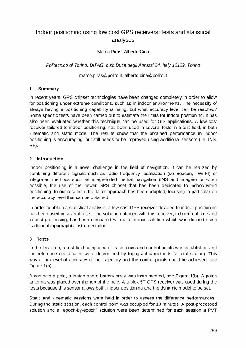
259
Indoor positioning using low cost GPS receivers: tests and statistical
analyses
Marco Piras, Alberto Cina
Politecnico di Torino, DITAG, c.so Duca degli Abruzzi 24, Italy 10129, Torino
[email protected], [email protected]
1 Summary
In recent years, GPS chipset technologies have been changed completely in order to allow
for positioning under extreme conditions, such as in indoor environments. The necessity of
always having a positioning capability is rising, but what accuracy level can be reached?
Some specific tests have been carried out to estimate the limits for indoor positioning. It has
also been evaluated whether this technique can be used for GIS applications. A low cost
receiver tailored to indoor positioning, has been used in several tests in a test field, in both
kinematic and static mode. The results show that the obtained performance in indoor
positioning is encouraging, but still needs to be improved using additional sensors (i.e. INS,
RF).
2 Introduction
Indoor positioning is a novel challenge in the field of navigation. It can be realized by
combining different signals such as radio frequency localization (i.e Beacon, Wi-FI) or
integrated methods such as image-aided inertial navigation (INS and images) or when
possible, the use of the newer GPS chipset that has been dedicated to indoor/hybrid
positioning. In our research, the latter approach has been adopted, focusing in particular on
the accuracy level that can be obtained.
In order to obtain a statistical analysis, a low cost GPS receiver devoted to indoor positioning
has been used in several tests. The solution obtained with this receiver, in both real time and
in post-processing, has been compared with a reference solution which was defined using
traditional topographic instrumentation.
3 Tests
In the first step, a test field composed of trajectories and control points was established and
the reference coordinates were determined by topographic methods (a total station). This
way a mm-level of accuracy of the trajectory and the control points could be achieved, see
Figure 1(a).
A cart with a pole, a laptop and a battery array was instrumented, see Figure 1(b). A patch
antenna was placed over the top of the pole. A u-blox 5T GPS receiver was used during the
tests because this sensor allows both, indoor positioning and the dynamic model to be set.
Static and kinematic sessions were held in order to assess the difference performances,.
During the static session, each control point was occupied for 10 minutes. A post-processed
solution and a ―epoch-by-epoch‖ solution were been determined for each session a PVT
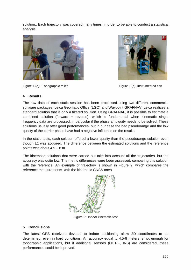
260
solution,. Each trajectory was covered many times, in order to be able to conduct a statistical
analysis.
Figure 1 (a): Topographic relief Figure 1 (b): Instrumented cart
4 Results
The raw data of each static session has been processed using two different commercial
software packages: Leica Geomatic Office (LGO) and Waypoint GRAFNAV. Leica realizes a
standard solution that is only a filtered solution. Using GRAFNAF, it is possible to estimate a
combined solution (forward + reverse), which is fundamental when kinematic single
frequency data are processed, in particular if the phase ambiguity needs to be solved. These
solutions usually offer good performances, but in our case the bad pseudorange and the low
quality of the carrier phase have had a negative influence on the results.
In the static tests, each solution offered a lower quality than the pseudorange solution even
though L1 was acquired. The difference between the estimated solutions and the reference
points was about 4.5 – 8 m.
The kinematic solutions that were carried out take into account all the trajectories, but the
accuracy was quite low. The metric differences were been assessed, comparing this solution
with the reference. An example of trajectory is shown in Figure 2, which compares the
reference measurements with the kinematic GNSS ones
Figure 2: Indoor kinematic test
5 Conclusions
The latest GPS receivers devoted to indoor positioning allow 3D coordinates to be
determined, even in hard conditions. An accuracy equal to 4.5-8 meters is not enough for
topographic applications, but if additional sensors (i.e RF, INS) are considered, these
performances could be improved.

261
Applications of Location Awareness
Auditorium D2
Thursday, September 16, 10:15 – 11:45

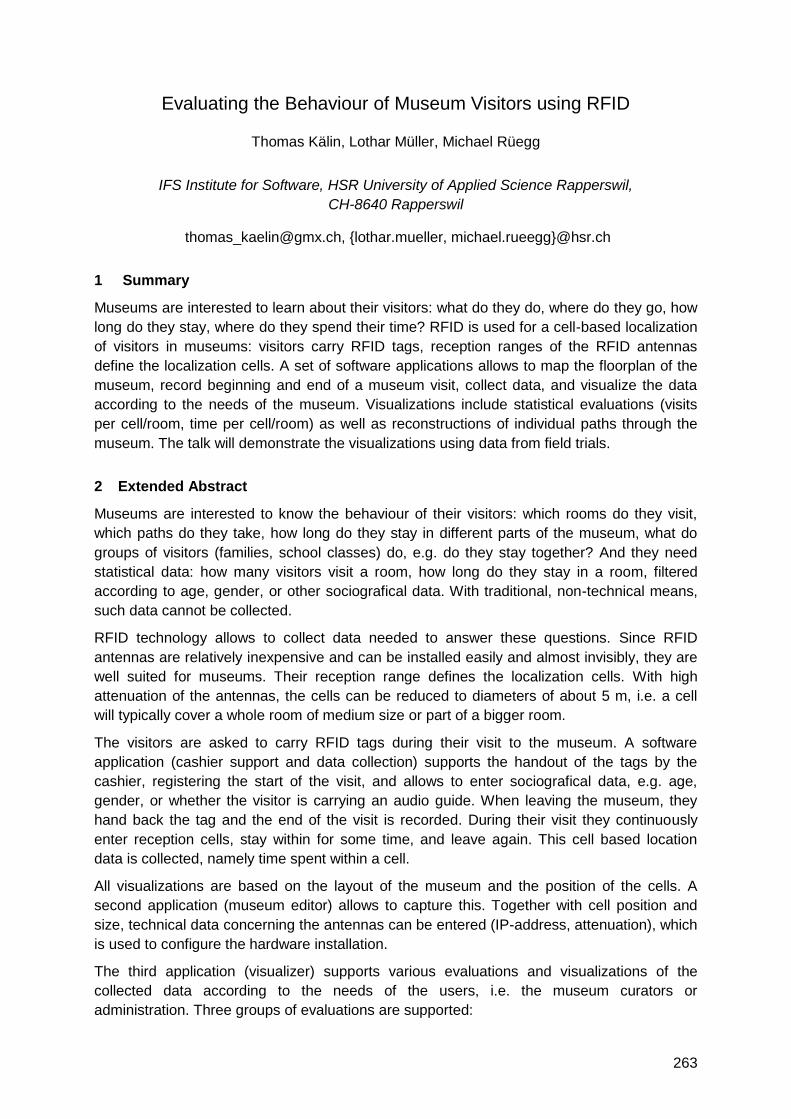
263
Evaluating the Behaviour of Museum Visitors using RFID
Thomas Kälin, Lothar Müller, Michael Rüegg
IFS Institute for Software, HSR University of Applied Science Rapperswil,
CH-8640 Rapperswil
[email protected], {lothar.mueller, michael.rueegg}@hsr.ch
1 Summary
Museums are interested to learn about their visitors: what do they do, where do they go, how
long do they stay, where do they spend their time? RFID is used for a cell-based localization
of visitors in museums: visitors carry RFID tags, reception ranges of the RFID antennas
define the localization cells. A set of software applications allows to map the floorplan of the
museum, record beginning and end of a museum visit, collect data, and visualize the data
according to the needs of the museum. Visualizations include statistical evaluations (visits
per cell/room, time per cell/room) as well as reconstructions of individual paths through the
museum. The talk will demonstrate the visualizations using data from field trials.
2 Extended Abstract
Museums are interested to know the behaviour of their visitors: which rooms do they visit,
which paths do they take, how long do they stay in different parts of the museum, what do
groups of visitors (families, school classes) do, e.g. do they stay together? And they need
statistical data: how many visitors visit a room, how long do they stay in a room, filtered
according to age, gender, or other sociografical data. With traditional, non-technical means,
such data cannot be collected.
RFID technology allows to collect data needed to answer these questions. Since RFID
antennas are relatively inexpensive and can be installed easily and almost invisibly, they are
well suited for museums. Their reception range defines the localization cells. With high
attenuation of the antennas, the cells can be reduced to diameters of about 5 m, i.e. a cell
will typically cover a whole room of medium size or part of a bigger room.
The visitors are asked to carry RFID tags during their visit to the museum. A software
application (cashier support and data collection) supports the handout of the tags by the
cashier, registering the start of the visit, and allows to enter sociografical data, e.g. age,
gender, or whether the visitor is carrying an audio guide. When leaving the museum, they
hand back the tag and the end of the visit is recorded. During their visit they continuously
enter reception cells, stay within for some time, and leave again. This cell based location
data is collected, namely time spent within a cell.
All visualizations are based on the layout of the museum and the position of the cells. A
second application (museum editor) allows to capture this. Together with cell position and
size, technical data concerning the antennas can be entered (IP-address, attenuation), which
is used to configure the hardware installation.
The third application (visualizer) supports various evaluations and visualizations of the
collected data according to the needs of the users, i.e. the museum curators or
administration. Three groups of evaluations are supported:
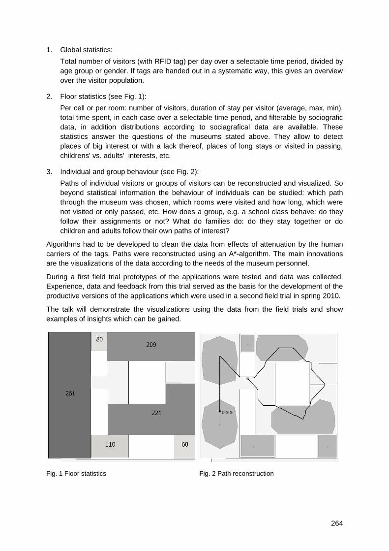
264
1. Global statistics:
Total number of visitors (with RFID tag) per day over a selectable time period, divided by
age group or gender. If tags are handed out in a systematic way, this gives an overview
over the visitor population.
2. Floor statistics (see Fig. 1):
Per cell or per room: number of visitors, duration of stay per visitor (average, max, min),
total time spent, in each case over a selectable time period, and filterable by sociografic
data, in addition distributions according to sociagrafical data are available. These
statistics answer the questions of the museums stated above. They allow to detect
places of big interest or with a lack thereof, places of long stays or visited in passing,
childrens' vs. adults' interests, etc.
3. Individual and group behaviour (see Fig. 2):
Paths of individual visitors or groups of visitors can be reconstructed and visualized. So
beyond statistical information the behaviour of individuals can be studied: which path
through the museum was chosen, which rooms were visited and how long, which were
not visited or only passed, etc. How does a group, e.g. a school class behave: do they
follow their assignments or not? What do families do: do they stay together or do
children and adults follow their own paths of interest?
Algorithms had to be developed to clean the data from effects of attenuation by the human
carriers of the tags. Paths were reconstructed using an A*-algorithm. The main innovations
are the visualizations of the data according to the needs of the museum personnel.
During a first field trial prototypes of the applications were tested and data was collected.
Experience, data and feedback from this trial served as the basis for the development of the
productive versions of the applications which were used in a second field trial in spring 2010.
The talk will demonstrate the visualizations using the data from the field trials and show
examples of insights which can be gained.
Fig. 1 Floor statistics Fig. 2 Path reconstruction
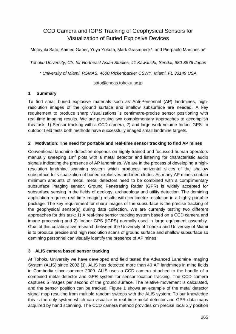
265
CCD Camera and IGPS Tracking of Geophysical Sensors for
Visualization of Buried Explosive Devices
Motoyuki Sato, Ahmed Gaber, Yuya Yokota, Mark Grasmueck*, and Pierpaolo Marchesini*
Tohoku University, Ctr. for Northeast Asian Studies, 41 Kawauchi, Sendai, 980-8576 Japan
* University of Miami, RSMAS, 4600 Rickenbacker CSWY, Miami, FL 33149 USA
1 Summary
To find small buried explosive materials such as Anti-Personnel (AP) landmines, high-
resolution images of the ground surface and shallow subsurface are needed. A key
requirement to produce sharp visualizations is centimetre-precise sensor positioning with
real-time imaging results. We are pursuing two complementary approaches to accomplish
this task: 1) Sensor tracking with a CCD camera, 2) and large work volume Indoor GPS. In
outdoor field tests both methods have successfully imaged small landmine targets.
2 Motivation: The need for portable and real-time sensor tracking to find AP mines
Conventional landmine detection depends on highly trained and focussed human operators
manually sweeping 1m2 plots with a metal detector and listening for characteristic audio
signals indicating the presence of AP landmines. We are in the process of developing a high-
resolution landmine scanning system which produces horizontal slices of the shallow
subsurface for visualization of buried explosives and inert clutter. As many AP mines contain
minimum amounts of metal, metal detectors need to be combined with a complimentary
subsurface imaging sensor. Ground Penetrating Radar (GPR) is widely accepted for
subsurface sensing in the fields of geology, archaeology and utility detection. The demining
application requires real-time imaging results with centimetre resolution in a highly portable
package. The key requirement for sharp images of the subsurface is the precise tracking of
the geophysical sensor(s) during data collection. We are currently testing two different
approaches for this task: 1) A real-time sensor tracking system based on a CCD camera and
image processing and 2) Indoor GPS (IGPS) normally used in large equipment assembly.
Goal of this collaborative research between the University of Tohoku and University of Miami
is to produce precise and high resolution scans of ground surface and shallow subsurface so
demining personnel can visually identify the presence of AP mines.
3 ALIS camera based sensor tracking
At Tohoku University we have developed and field tested the Advanced Landmine Imaging
System (ALIS) since 2002 [1]. ALIS has detected more than 40 AP landmines in mine fields
in Cambodia since summer 2009. ALIS uses a CCD camera attached to the handle of a
combined metal detector and GPR system for sensor location tracking. The CCD camera
captures 5 images per second of the ground surface. The relative movement is calculated,
and the sensor position can be tracked. Figure 1 shows an example of the metal detector
signal map resulting from multiple random sweeps with the ALIS system. To our knowledge
this is the only system which can visualize in real time metal detector and GPR data maps
acquired by hand scanning. The CCD camera method provides cm precise local x,y position
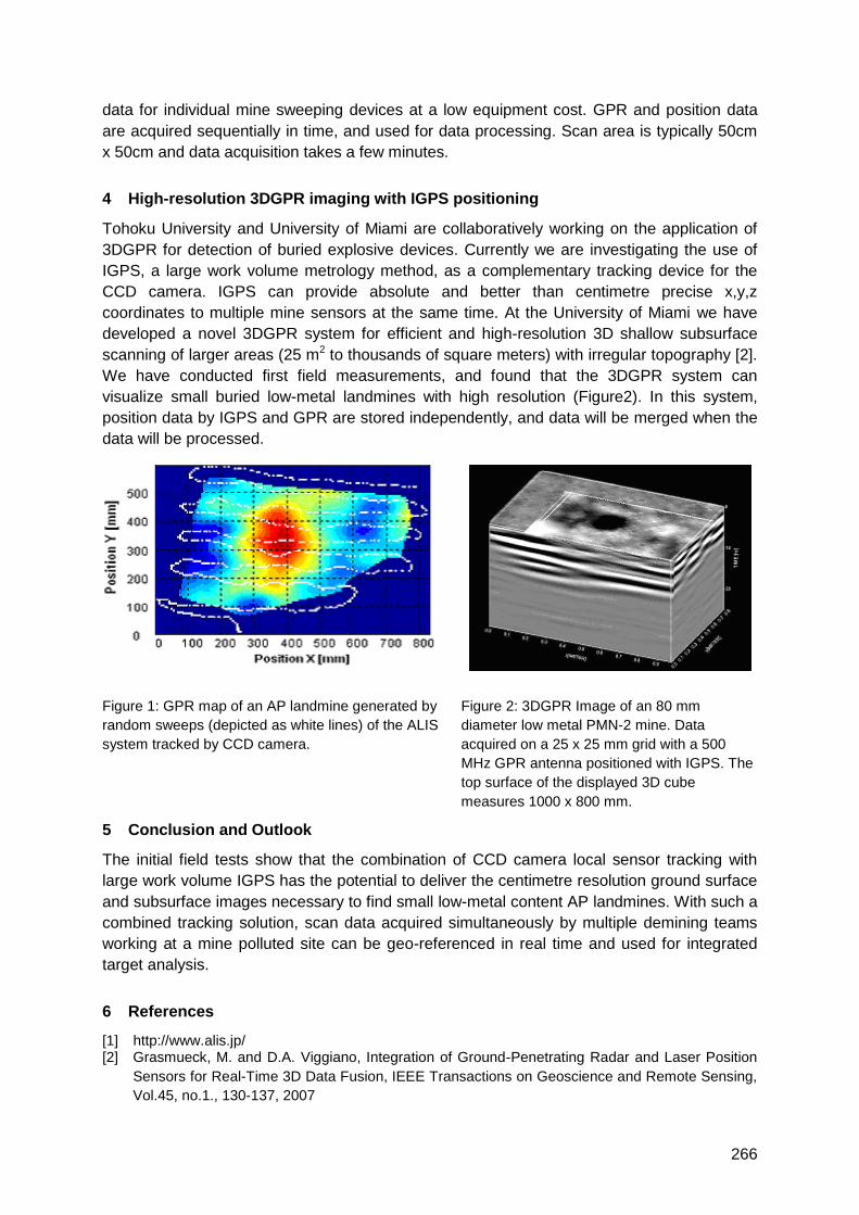
266
data for individual mine sweeping devices at a low equipment cost. GPR and position data
are acquired sequentially in time, and used for data processing. Scan area is typically 50cm
x 50cm and data acquisition takes a few minutes.
4 High-resolution 3DGPR imaging with IGPS positioning
Tohoku University and University of Miami are collaboratively working on the application of
3DGPR for detection of buried explosive devices. Currently we are investigating the use of
IGPS, a large work volume metrology method, as a complementary tracking device for the
CCD camera. IGPS can provide absolute and better than centimetre precise x,y,z
coordinates to multiple mine sensors at the same time. At the University of Miami we have
developed a novel 3DGPR system for efficient and high-resolution 3D shallow subsurface
scanning of larger areas (25 m2 to thousands of square meters) with irregular topography [2].
We have conducted first field measurements, and found that the 3DGPR system can
visualize small buried low-metal landmines with high resolution (Figure2). In this system,
position data by IGPS and GPR are stored independently, and data will be merged when the
data will be processed.
Figure 1: GPR map of an AP landmine generated by
random sweeps (depicted as white lines) of the ALIS
system tracked by CCD camera.
Figure 2: 3DGPR Image of an 80 mm
diameter low metal PMN-2 mine. Data
acquired on a 25 x 25 mm grid with a 500
MHz GPR antenna positioned with IGPS. The
top surface of the displayed 3D cube
measures 1000 x 800 mm.
5 Conclusion and Outlook
The initial field tests show that the combination of CCD camera local sensor tracking with
large work volume IGPS has the potential to deliver the centimetre resolution ground surface
and subsurface images necessary to find small low-metal content AP landmines. With such a
combined tracking solution, scan data acquired simultaneously by multiple demining teams
working at a mine polluted site can be geo-referenced in real time and used for integrated
target analysis.
6 References
[1] http://www.alis.jp/ [2] Grasmueck, M. and D.A. Viggiano, Integration of Ground-Penetrating Radar and Laser Position
Sensors for Real-Time 3D Data Fusion, IEEE Transactions on Geoscience and Remote Sensing,
Vol.45, no.1., 130-137, 2007
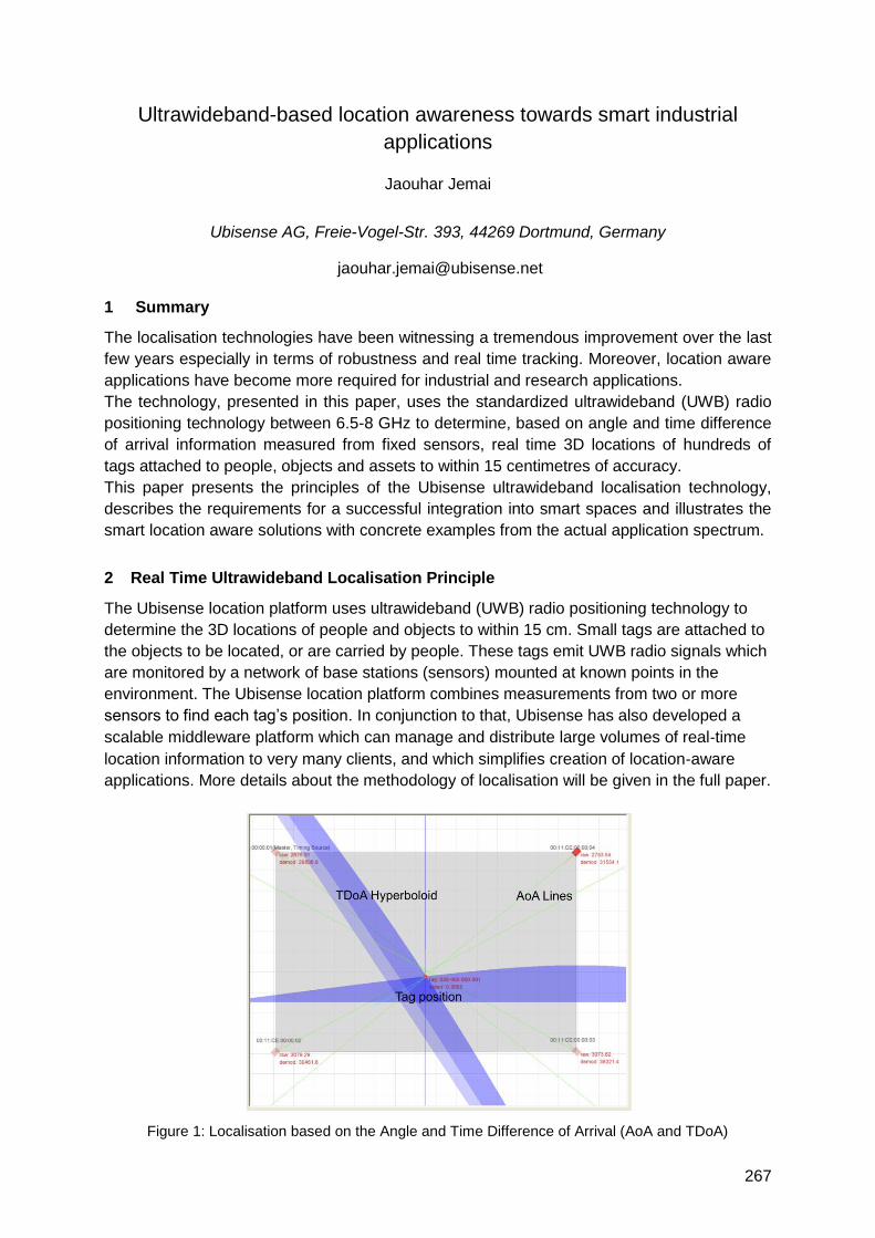
267
Ultrawideband-based location awareness towards smart industrial
applications
Jaouhar Jemai
Ubisense AG, Freie-Vogel-Str. 393, 44269 Dortmund, Germany
1 Summary
The localisation technologies have been witnessing a tremendous improvement over the last
few years especially in terms of robustness and real time tracking. Moreover, location aware
applications have become more required for industrial and research applications.
The technology, presented in this paper, uses the standardized ultrawideband (UWB) radio
positioning technology between 6.5-8 GHz to determine, based on angle and time difference
of arrival information measured from fixed sensors, real time 3D locations of hundreds of
tags attached to people, objects and assets to within 15 centimetres of accuracy.
This paper presents the principles of the Ubisense ultrawideband localisation technology,
describes the requirements for a successful integration into smart spaces and illustrates the
smart location aware solutions with concrete examples from the actual application spectrum.
2 Real Time Ultrawideband Localisation Principle
The Ubisense location platform uses ultrawideband (UWB) radio positioning technology to
determine the 3D locations of people and objects to within 15 cm. Small tags are attached to
the objects to be located, or are carried by people. These tags emit UWB radio signals which
are monitored by a network of base stations (sensors) mounted at known points in the
environment. The Ubisense location platform combines measurements from two or more
sensors to find each tag‘s position. In conjunction to that, Ubisense has also developed a
scalable middleware platform which can manage and distribute large volumes of real‐time
location information to very many clients, and which simplifies creation of location‐aware
applications. More details about the methodology of localisation will be given in the full paper.
Figure 1: Localisation based on the Angle and Time Difference of Arrival (AoA and TDoA)
268
3 Smart location awareness applications
There are many RF tagging systems on the market which provide some kind of location
capability. But different systems differ hugely in capability and cost. Ultimately it is the
applications and the benefits they provide in the short term and longer term that count. The
measure of a location tagging system is the applications that it enables. Ubisense has developed a platform for building Smart Space applications. It addresses the
key requirements for building accurate 3D positioning, scalable real‐time performance, and
development and deployment tools. This section deepens the key requirements and
describes how the location platform components meet them.
The advanced sensing and middleware technology has been adapted towards smart
solutions, including especially car manufacturing (smart factory), security, logistics and
military training. The end applications for the location‐aware technology in these markets are
varied and range from tool assistance systems (at the car assembly line) to monitoring and
results analyzing systems for military trainings with simulation devices. Some of the most
important factors to be addressed when considering the deployment of location‐aware
systems include:
1. Value: This represents the most important factor. In order to be successful, a technology
must address a real need. Most of the effort is needed in identifying real‐world situations,
where location‐awareness can bring a considerable return on Investment (ROI).
Examples include the smart factory (tool assistance system at the car assembly line),
which will be described in the full paper version.
2. Robustness: Besides the ROI, a successful location aware solution must solve the
customer problems robustly anywhere and anytime. Robustness must be considered at
all stages of the design and implementation of location sensing hardware and processing
software.
3. Infrastructure: There is obviously a cost involved with installing infrastructure in an
environment, but this cost can be reduced by appropriate design and quantified before
the system installation. A properly‐designed infrastructure will have minimal maintenance
requirements once installed. Some practical examples from industrial and research
applications will be given in the full paper.
4. Technology for scalable solutions: With several practical applications of location
awareness, the same UWB-based location technology can satisfy the requirements of a
number of different markets involving in-building tracking.
5. Standardization: In the long term, an integrated standard for location and low‐rate
communication could create huge value.
4 Conclusions and Outlook
Location‐awareness can solve real problems for which there is no existing effective solution.
UWB offers a compromise between good accuracy inside buildings, reasonably low levels of
infrastructure, good performance outdoors, small tag size and fairly low power consumption.
However, each of the existing radio frequency localisation systems, such as vision, GPS,
thermography, inertial navigation…, has its own strengths and it may be appropriate for
some sites to use a hybrid solution with the fusion of different sensing technologies.

269
Indoor Positioning Aware Radiation Measurement (IPARM)
Julius Tuomisto, Jolanta Garlacz, Harald Haslinger
Laurea University of Applied Sciences, Vanha maantie 9, 02650 Espoo, Finland
[email protected], [email protected], [email protected]
Tarja Ilander
Finnish Radiation and Nuclear Safety Authority STUK, Laippatie 4, 08800 Helsinki, Finland
1 Summary
The IPARM research project was started in order to develop methods for collecting and
synchronizing indoor positioning data with radiation measurement data collected by using the
portable measurement unit VASIKKA, developed by the Finnish Radiation and Nuclear
Safety Authority STUK.
2 VASIKKA
VASIKKA, a portable measuring unit for radiation measurement, is Java software running on
a small notebook with radiation measuring detectors for collecting radiation measurements. It
can be easily carried in a backpack and accessed through a Bluetooth enabled mobile
device such as a mobile phone. Apart from collecting general radiation measurement data,
VASIKKA can also identify the nuclide in question. This is important in making real-time
evaluations about whether the collected information is within the naturally occurring limits of
such radiation.
3 LINSSI
The data collected through VASIKKA is sent to LINSSI. LINSSI – LINux System for Spectral
Information is SQL (Structured Query Language) database designed by STUK and its
Partners (Ihantola, 2009).
4 Ekahau Positioning Engine (EPE)
In order to take use of IPARM, the person carrying a VASIKKA has to activate and carry a
suitable Ekahau Wi-Fi positioning tag with them while performing the radiation survey. The
EPE server collects and analyses the data it receives from the Wi-Fi tag in order to offer an
approximation of the location of the surveyor.
5 Indoor Positioning Aware Radiation Measurement (IPARM)
In its current form, VASIKKA has not been integrated with any indoor positioning technology.
Because such functionality is highly desirable from usability point-of-view, a joint research
and development project called IPARM (Indoor Positioning Aware Radiation Measurement)
was initiated between STUK and Laurea University of Applied Sciences in 2008.
IPARM is a Java application that, in its current revision, connects to an available Ekahau
Positioning Engine (EPE) server in order to fetch relevant positioning data. This data is then
270
processed by IPARM into a suitable format and written in to the corresponding field in the
LINSSI database. Meanwhile, VASIKKA enters its radiation measurement findings in to the
same database tables. The data is synchronized via time-stamp information available in both
feeds (Garlacz, 2009).
6 Mobile Measurements
The collected data can be subjected to further analysis in a STUK-created specialized
mapping program called Mobile Measurements. Within the program, visualizations created
from the relevant LINSSI database entries can be observed. These are displayed in a
simple-to-understand movie-like time-line and present positioning information in relation to
any abnormal radiation measurement data collected during the survey. Any surveyed
abnormalities can be clicked upon and analyzed thoroughly. The analysis can be done on-
site or off-site.
7 Conclusions and outlooks
During the ongoing IPARM project, we have created a Java application that collects indoor
positioning data from an Ekahau EPE server and processes and inputs the collected data
into the LINSSI database, created and used for collecting radiation measurement data. This
data is then used for creating informative visualizations that make rapid assessment and
analysis of the radiation measurement data intuitive.
IPARM, coupled with the portable radiation measurement unit VASIKKA, promise to enable
national authorities like STUK (the Finnish Radiation and Nuclear Safety Authority) to carry
out safety related radiation measurement surveys in a more efficient fashion, reduce the
chance of human error in the collection and marking down of relevant positioning data and
make analysis of the collected data more simple and intuitive.
In the future, we plan to append the IPARM system to include support to other available
indoor positioning technologies. In addition to using WI-FI based positioning, we have been
testing a system based on step length and orientation information (Ilander et al. 2010).
Supporting multiple platforms in collecting relevant positioning data can be foreseen to offer
major benefits to the applicability of IPARM on the field. We are also investigating the
possibility of supporting the applicability of displaying indoor positioning data in real-time
visualizations similar to those described in chapter 6.
8 References
Ihantola, S. (2009). Surface Sampling Methods for Non-destructive Radionuclide Analysis. MSc thesis,
Helsinki University of Technology.
Garlacz, J. (2009). Indoor Positioning for Nuclear Security. MSc thesis, University of the West of
Scotland.
Ilander, T., Toivonen, H., Meriheinä, U. and Garlacz, J. (2010). Indoor Positioning for Nuclear Security.
Poster presentation. Proceedings of Third European IRPA Congress 2010 June 14−16, Helsinki,
Finland
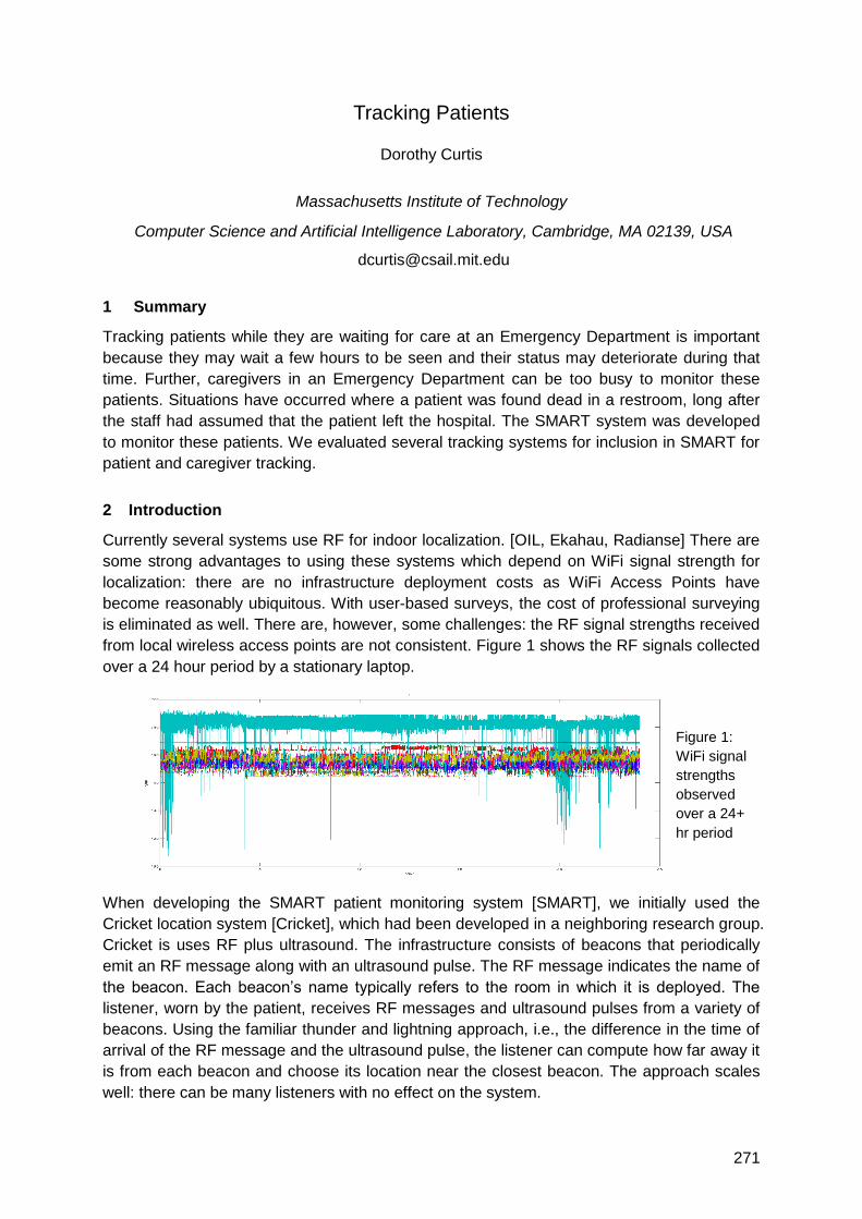
271
Tracking Patients
Dorothy Curtis
Massachusetts Institute of Technology
Computer Science and Artificial Intelligence Laboratory, Cambridge, MA 02139, USA
1 Summary
Tracking patients while they are waiting for care at an Emergency Department is important
because they may wait a few hours to be seen and their status may deteriorate during that
time. Further, caregivers in an Emergency Department can be too busy to monitor these
patients. Situations have occurred where a patient was found dead in a restroom, long after
the staff had assumed that the patient left the hospital. The SMART system was developed
to monitor these patients. We evaluated several tracking systems for inclusion in SMART for
patient and caregiver tracking.
2 Introduction
Currently several systems use RF for indoor localization. [OIL, Ekahau, Radianse] There are
some strong advantages to using these systems which depend on WiFi signal strength for
localization: there are no infrastructure deployment costs as WiFi Access Points have
become reasonably ubiquitous. With user-based surveys, the cost of professional surveying
is eliminated as well. There are, however, some challenges: the RF signal strengths received
from local wireless access points are not consistent. Figure 1 shows the RF signals collected
over a 24 hour period by a stationary laptop.
Figure 1:
WiFi signal
strengths
observed
over a 24+
hr period
When developing the SMART patient monitoring system [SMART], we initially used the
Cricket location system [Cricket], which had been developed in a neighboring research group.
Cricket is uses RF plus ultrasound. The infrastructure consists of beacons that periodically
emit an RF message along with an ultrasound pulse. The RF message indicates the name of
the beacon. Each beacon‘s name typically refers to the room in which it is deployed. The
listener, worn by the patient, receives RF messages and ultrasound pulses from a variety of
beacons. Using the familiar thunder and lightning approach, i.e., the difference in the time of
arrival of the RF message and the ultrasound pulse, the listener can compute how far away it
is from each beacon and choose its location near the closest beacon. The approach scales
well: there can be many listeners with no effect on the system.

272
Unfortunately, one problem with the Cricket approach is that it can be difficult to match up
ultrasound pulses with their corresponding RF messages, so, from time to time patients
appear to ―fly‖ across the room. We speculated that some filtering might cause the estimates
to be more stable. Due to time pressures to begin an extensive study with real patients and
other pragmatic issues related to packaging for the beacons, we chose to evaluate some
commercially available options.
The system we eventually chose was Sonitor [Sonitor]. This system is based on patients
wearing tags that emit ultrasound messages while the patients are moving and for a short
time after they stop moving. Each tag‘s message contains its unique ID and its battery status.
Ultrasound detectors are placed on the walls and relay tag sightings to a central computer.
These messages include the amplitude of the message received by the detector as well as
the tag‘s ID. The central computer assigns the patient‘s location to be near the detector that
received the message with the highest amplitude for the patient‘s tag.
The SMART system was deployed for eighteen months at the Brigham and Women‘s
Hospital in Boston, Massachusetts, USA. It was used to monitor and track 145 patients who
presented with shortness of breath or chest pains.
3 Open Questions
While the deployment of the Smart system with the Sonitor Indoor Positioning subsystem
was successful, there are several open questions: Can the processing of RF signal strengths
be improved to get better accuracy? Can RF signals be augmented with other signals to
improve accuracy? Are there strategies for using ultrasound for tracking people in crowded
situations?
4 Acknowledgements
I would like to thank David Lambeth and Seth Teller‘s Organic Indoor Localization group at
MIT‘s Computer Science and artificial Intelligence Laboratory and Nokia for Figure 1 and for
many interesting discussions about indoor localization issues. This work was supported in
part by the National Library of Medicine, N01LM33509.
5 References
[OIL] Growing an Organic Indoor Location System. J Park, B Charrow, D Curtis, J Battat, E
Minkov, J Hicks, S Teller, J Ledlie. To be published in the proceeding of MobiSys 2010.
[Ekahau] http://ekahau.com
[Radianse] http://radianse.com
[SMART] SMART -- An Integrated, Wireless System for Monitoring Unattended Patients Curtis
DW, Pino EJ, Bailey JM, Shih EI, Waterman J, Vinterbo SA, Stair TO, Guttag JV,
Greenes RA, Ohno-Machado L. http://smart.csail.mit.edu
[Cricket] The Cricket Location-Support System NB Priyantha, A Chakraborty, H Balakrishnan 6th
ACM MOBICOM, Boston, MA, August 2000. http://cricket.csail.mit.edu
[Sonitor] http://www.sonitor.com

273
Realizing an Emergency Call System on a Real-time Location
Application Platform for Healthcare
Dr. Wolfgang Rob, Manfred Griesser, Andreas Gereke
ITH icoserve technology for healthcare GmbH, Innsbruck, Austria
1. Summary
In modern hospitals, opposing forces between cutting costs and demands on service quality,
growing workloads versus staff reductions, stimulate the need for systems that automatically
support procedures in the background.
Intelligent real-time positioning solutions can partially fill the gap. The ProAct® application
platform addresses the common needs of Real-time location applications in healthcare. It
enables the rapid development of rule-driven, location-based solutions for different problem
domains. It is designed for multiple healthcare application areas including patient and staff
security, asset management, clinical process analysis and context-sensitive information
provision and guidance.
This contribution will introduce the real-time location application platform ProAct and how it is
used to realize an emergency call system in a psychiatric department.
2. Extended Abstract
Cost containment is an issue of increasing priority in healthcare. Healthcare facilities try to
reduce personnel expenses as the most important cost factor. On the other side expectations
and requirements are continuously growing driven by stakeholders, legislation and quality
standards. To meet all these demands either more personnel is needed or intelligent
systems must be found which can decisively support clinical workflows. Such systems should
be able to assist personnel in daily procedures by continuously assessing situations in terms
of: what happened? – where and when did it happen? – who did it? – what has to be done?
We call this kind of applications Intelligent Real-time Location (iRtL) Solutions. Common
needs of iRtL applications in healthcare have been identified and generalized into concepts
and services of the ProAct® application platform:
o Monitoring and visualizing the real-time location and state of tracked persons or assets.
Applications differ in types of tracked entities (e.g. patient, nurse, IV pump), in state
domains, in sets of alert types and vary in visual presentations by symbols and terminology.
o Data secrecy. Applications have varying standards of data secrecy and data lifetime limits,
particularly if the tracked entities are persons. The platform must support fine-grained data
secrecy rules in order to adapt to application-specific privacy policies.
o Classifying state and generating events. An iRtL application must be able to distinguish
important state from ordinary state. The criteria that render state important are typically
application-specific depending on properties of the current location, the organizational unit,
the tracked entities, and on temporal, spatial or more complex relationships between
tracked entities. The ProAct platform permits to define high-level, semantically rich events
when designing an application. A generated event can trigger pre-defined actions like
raising alerts, collecting real-time data or controlling electronic devices (cameras etc.).
274
o Multi-channel, multi-level notification of alerts. Application design includes the definition of
different types of system- and application-level alerts. Notifications can be delivered to
receivers by an extendible collection of protocols or channels, like pager, popup window, e-
mail or third-party systems. A setup defines who is to be notified and when depending on
alert origin and type. Multi-level notification rules of first-level and escalation-level message
receivers can be specified.
o Clinical process data collection and analysis require the collection and processing of
operational data. Application events can trigger the counting of certain events, the
measuring of time durations and relate that data to locations, entity types, organizational
units or procedures. The platform provides basic tools to view and analyse the collected
data at different aggregation levels. Moreover the data should be accessible by third-party
analytical processing tools.
o Integration into hospital information systems. Healthcare applications require the exchange
of patient or asset data with ERP and clinical information systems. Depending on the
application requirements and the existing system landscape it might be necessary to link
data from different systems. E.g. patient master data and medical case data has to be
merged to achieve specific application objectives.
o Self-monitoring and malfunction detection is important especially in patient and staff
security applications that rely on the high availability of the system. Therefore, it is essential
that the system detects any faulty state of involved components and notifies reduced
reliability to everybody concerned.
o Independence of positioning technology. Positioning data can be obtained from a variety of
real-time location providers, using different sensing technologies, both hardware and
software. Pros and cons of each technology need to be balanced depending on specific
application requirements, characteristics of the installation site (regarding other medical
equipment, building layout etc.) or pre-existing investments of the customer (e.g. Wi-Fi
environment ready). ProAct applications are largely independent from specific positioning
technologies. The most appropriate alternative can be selected in each case.
The staff of psychiatric hospitals is often exposed to the risk of being attacked by patients.
The need for an emergency call system is evident. The core function is the notification of pre-
defined receivers like attendants, physicians, security staff etc., that help is needed and
where it is needed. The help request could easily be communicated by simple radio
equipment, but the information where it is needed isn‘t that easy to collect. An important
constraint of the system is the minimum positioning accuracy.
Many non-technical aspects have to be considered: Individuals are concerned when their
behaviour is potentially under surveillance and might decline such a system. Another issue is
the indistinct anxiety of radiation from sensing technologies. To make the system widely
accepted it is essential to take employee‘s concerns seriously.
This paper will introduce to the Intelligent Real-time Location Application Platform ProAct by
the example of an emergency call system at the Psychiatric Department of the University
Hospital of Innsbruck. It will present requirements, considerations and concerns we had to
balance to realize an appropriate solution in the special environment of clinical practice.

275
Optical Systems
Auditorium D2
Thursday, September 16, 13:15 – 15:00 & 15:30 – 16:45

277
Towards Real-Time Camera Egomotion Estimation and Three-
Dimensional Scene Acquisition from Monocular Image Streams
Dominik Aufderheide, Werner Krybus
South Westphalia University of Applied Sciences – Institute for Computer Science, -Vision
and Computational Intelligence (CV&CI), Lübecker Ring 2, 59494 Soest, Germany
{aufderheide, krybus}@fh-swf.de
1 Summary
The estimation of a camera‘s egomotion is a highly desirable goal in many different
application fields such as Augmented Reality (AR), visual navigation, robotics or
entertainment. Especially for real-time modelling the former estimation of the camera
trajectory is an elementary step towards the generation of three dimensional scene models.
Based on ideas recently introduced in the field of Simultaneous Localisation and Mapping
(SLAM) and classical Structure from Motion algorithms (SfM), which were derived from basic
principles of photogrammetry, this paper presents a framework for simultaneous recovery of
scene structure and camera motion by combining visual and inertial cues (Inertial Aided SfM).
For this purpose two different system designs are proposed: a loosely-coupled system, which
follows a classical approach for solving the five-point relative orientation problem for
estimating the camera trajectory, and a monolithic design, which adapts ideas from non-
linear state estimation as Extended Kalman Filtering (EKF) for structure and motion recovery.
2 Motivation for Inertial Aided Structure from Motion
The self-acting estimation of cameras ego-motion has been a fundamental problem of
computer vision for decades. Especially for Augmented Reality (AR) applications the vision-
based recovery of camera trajectories has become an important problem and many different
solutions were proposed in recent years. Those vision-based techniques for 3D scene or
object modeling are already introduced, but their usage in real-world applications is still
limited due to several problems with robustness and computational costs. Since all SfM-
algorithms are based on finding corresponding distinctive features in subsequent frames of a
video sequence the accuracy of those methods are mainly influenced by the robustness of
the used feature extraction and matching procedures. Thus the concept of aided-SfM (aSfM)
was established in recent years to overcome the typical drawbacks of SfM. This paper will
introduce a general concept for the development of a Visual-Inertial Scene Acquisition (VISA)
device which realizes robust recovery of cameras egomotion and scene structure in real time.
This is achieved by implementing a prototype of a loosely-coupled system. In this
constellation a visual- and an inertial-route are running almost independently from each other.
In contrast to that it is contemplated to combine the measurements of both devices in a
monolithic inertial-visual system. In this concept non-linear state estimation methods are
implemented in a single filtering-stage for estimating structure and motion.
3 Loosely-Coupled System Design
The first milestone in the development of an inertial aSfM device is the implementation of a
loosely-coupled system. Here both tracks (visual and inertial) are run almost separately in
such a way that there are two ego-motion estimates from the inertial route (InR) and from the

278
visual route (VisR). As shown in Figure 1 it is possible to establish several interfaces
between both routes to improve the results of the overall system in terms of accuracy,
robustness, long-time stability and computational efficiency. One example for such an
interface is a pre-warping-scheme which is based on estimated homographies for increasing
the robustness and reliability of matching corresponding points by extracted texture-patches.
Also the drift-error, which is a logical consequence of double-integrating signals in the InR,
can be compensated by incorporating the trajectory-model from the visual information.
Figure 1: Loosely-Coupled System Design with visual and inertial route
4 Monolithic System Design
Based on the findings from the loosely-coupled system a single monolithic system for SfM is
proposed which fuses not only results from SfM and strapdown navigation but also the
measurements of the IMU and the vision-sensor directly in a single system. Those systems
are always based on non-linear state-estimators for fusing the measurements from two or
more sensors with the goal of predicting (hidden) states of the system. The following figure is
visualizing a setup for the monolithic system design which incorporates EKF for estimation of
the camera‘s egomotion and scene structure.
Figure 2: Monolithic system design
5 Conclusions and Outlook
Towards the development of a handheld scene acquisition device the usage of aSfM-
algorithm which incorporates inertial measurements is able to overcome typical limitations
and drawbacks of systems which rely only on visual-information. Future work will consist of
the implementation of the proposed framework on embedded hardware and the
corresponding considerations regarding parallelization and multi-rate sensor fusion.

279
Learning Efficient Vision-based Navigation
Armin Hornung, Maren Bennewitz, Wolfram Burgard
Department of Computer Science, University of Freiburg, Germany
1 Summary
Cameras are popular sensors for robot navigation tasks as they are inexpensive, lightweight,
and provide rich data. However, fast movements of a mobile robot typically increase motion
noise and reduce the performance of vision-based navigation due to motion blur. In this work,
we present a reinforcement learning approach to choose appropriate actions for vision-based
navigation. The learned policy chooses actions so as to minimize the time to reach the
navigation goal and implicitly mitigates the impact of motion blur on observations. Our
system integrates odometry and visual features in an unscented Kalman filter for localization.
Extensive simulated and real-world experiments with wheeled and legged robots
demonstrate that our learned policy significantly outperforms policies using hand-optimized
navigation strategies.
2 Introduction
Completing navigation tasks reliably and efficiently is one of the most essential objectives for
a mobile robot. For this, the robot needs to know its pose (location and orientation) with
respect to the environment. Cameras are popular sensors used for localization as they are
relatively inexpensive, lightweight, and provide rich data. However, in particular in low-light
indoor environments, the movements of the robot typically affect its camera images with
motion blur. The faster the robot moves, the more its perception will be degraded by motion
blur (see Fig. 1), which potentially leads to a wrong pose estimate. On the other hand, by
moving slowly, the robot can avoid motion blur but will not reach its goal efficiently. Thus, the
robot needs to learn how to trade off a fast velocity against an accurate localization. In this
work, we present our approach for efficient vision-based navigation for wheeled [Hornung et
al. 2009, 2010] and humanoid robots [Oßwald et al. 2010] that implicitly takes the influence
of motion blur into account by learning a policy to reach the goal reliably and efficiently.
3 Vision-based Localization
The robot‘s pose is estimated in an unscented Kalman filter. Hereby, odometry information
from the robot‘s wheel encoders or its walking algorithm serves as control input. As
observations, we extract Speeded-Up Robust Features [Bay et al. 2006] from the images of
the cameras which observe the floor in front of the robot. The descriptors of these features
are then matched to a map of landmarks which was constructed beforehand.
Figure 1: Wheeled robotic platform and camera image with detected features at 0.05 m/s, 0.4
m/s, and 1.0 m/s (from left to right)
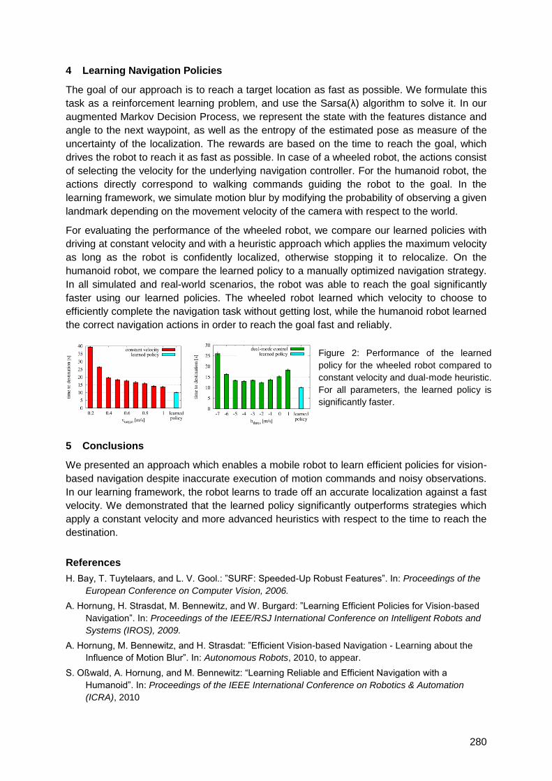
280
4 Learning Navigation Policies
The goal of our approach is to reach a target location as fast as possible. We formulate this
task as a reinforcement learning problem, and use the Sarsa(λ) algorithm to solve it. In our
augmented Markov Decision Process, we represent the state with the features distance and
angle to the next waypoint, as well as the entropy of the estimated pose as measure of the
uncertainty of the localization. The rewards are based on the time to reach the goal, which
drives the robot to reach it as fast as possible. In case of a wheeled robot, the actions consist
of selecting the velocity for the underlying navigation controller. For the humanoid robot, the
actions directly correspond to walking commands guiding the robot to the goal. In the
learning framework, we simulate motion blur by modifying the probability of observing a given
landmark depending on the movement velocity of the camera with respect to the world.
For evaluating the performance of the wheeled robot, we compare our learned policies with
driving at constant velocity and with a heuristic approach which applies the maximum velocity
as long as the robot is confidently localized, otherwise stopping it to relocalize. On the
humanoid robot, we compare the learned policy to a manually optimized navigation strategy.
In all simulated and real-world scenarios, the robot was able to reach the goal significantly
faster using our learned policies. The wheeled robot learned which velocity to choose to
efficiently complete the navigation task without getting lost, while the humanoid robot learned
the correct navigation actions in order to reach the goal fast and reliably.
5 Conclusions
We presented an approach which enables a mobile robot to learn efficient policies for vision-
based navigation despite inaccurate execution of motion commands and noisy observations.
In our learning framework, the robot learns to trade off an accurate localization against a fast
velocity. We demonstrated that the learned policy significantly outperforms strategies which
apply a constant velocity and more advanced heuristics with respect to the time to reach the
destination.
References
H. Bay, T. Tuytelaars, and L. V. Gool.: ‖SURF: Speeded-Up Robust Features‖. In: Proceedings of the
European Conference on Computer Vision, 2006.
A. Hornung, H. Strasdat, M. Bennewitz, and W. Burgard: ‖Learning Efficient Policies for Vision-based
Navigation‖. In: Proceedings of the IEEE/RSJ International Conference on Intelligent Robots and
Systems (IROS), 2009.
A. Hornung, M. Bennewitz, and H. Strasdat: ‖Efficient Vision-based Navigation - Learning about the
Influence of Motion Blur‖. In: Autonomous Robots, 2010, to appear.
S. Oßwald, A. Hornung, and M. Bennewitz: ―Learning Reliable and Efficient Navigation with a
Humanoid‖. In: Proceedings of the IEEE International Conference on Robotics & Automation
(ICRA), 2010
Figure 2: Performance of the learned
policy for the wheeled robot compared to
constant velocity and dual-mode heuristic.
For all parameters, the learned policy is
significantly faster.
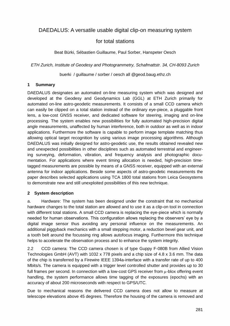
281
DAEDALUS: A versatile usable digital clip-on measuring system
for total stations
Beat Bürki, Sébastien Guillaume, Paul Sorber, Hanspeter Oesch
ETH Zurich, Institute of Geodesy and Photogrammetry, Schafmattstr. 34, CH-8093 Zurich
buerki / guillaume / sorber / oesch all @geod.baug.ethz.ch
1 Summary
DAEDALUS designates an automated on-line measuring system which was designed and
developed at the Geodesy and Geodynamics Lab (GGL) at ETH Zurich primarily for
automated on-line astro-geodetic measurements. It consists of a small CCD camera which
can easily be clipped on a total station instead of the ordinary eye-piece, a pluggable front
lens, a low-cost GNSS receiver, and dedicated software for steering, imaging and on-line
processing. The system enables new possibilities for fully automated high-precision digital
angle measurements, unaffected by human interference, both in outdoor as well as in indoor
applications. Furthermore the software is capable to perform image template matching thus
allowing optical target recognition by using various image processing algorithms. Although
DAEDALUS was initially designed for astro-geodetic use, the results obtained revealed new
and unexpected possibilities in other disciplines such as automated terrestrial and engineer-
ing surveying, deformation, vibration, and frequency analysis and photographic docu-
mentation. For applications where event timing allocation is needed, high-precision time-
tagged measurements are possible by means of a GNSS receiver, equipped with an external
antenna for indoor applications. Beside some aspects of astro-geodetic measurements the
paper describes selected applications using TCA 1800 total stations from Leica Geosystems
to demonstrate new and still unexploited possibilities of this new technique.
2 System description
a. Hardware: The system has been designed under the constraint that no mechanical
hardware changes to the total station are allowed and to use it as a clip-on tool in connection
with different total stations. A small CCD camera is replacing the eye-piece which is normally
needed for human observations. This configuration allows replacing the observers‘ eye by a
digital image sensor thus avoiding any personal influence on the measurements. An
additional piggyback mechanics with a small stepping motor, a reduction bevel gear unit, and
a tooth belt around the focussing ring allows autofocus imaging. Furthermore this technique
helps to accelerate the observation process and to enhance the system integrity.
2.2 CCD camera: The CCD camera chosen is of type Guppy F-080B from Allied Vision
Technologies GmbH (AVT) with 1032 x 778 pixels and a chip size of 4.8 x 3.6 mm. The data
of the chip is transferred by a Firewire IEEE 1394a-interface with a transfer rate of up to 400
Mbits/s. The camera is equipped with a trigger level controlled shutter and provides up to 30
full frames per second. In connection with a low-cost GPS receiver from -blox offering event
handling, the system performance allows time tagging of the exposures (epochs) with an
accuracy of about 200 microseconds with respect to GPS/UTC.
Due to mechanical reasons the delivered CCD camera does not allow to measure at
telescope elevations above 45 degrees. Therefore the housing of the camera is removed and
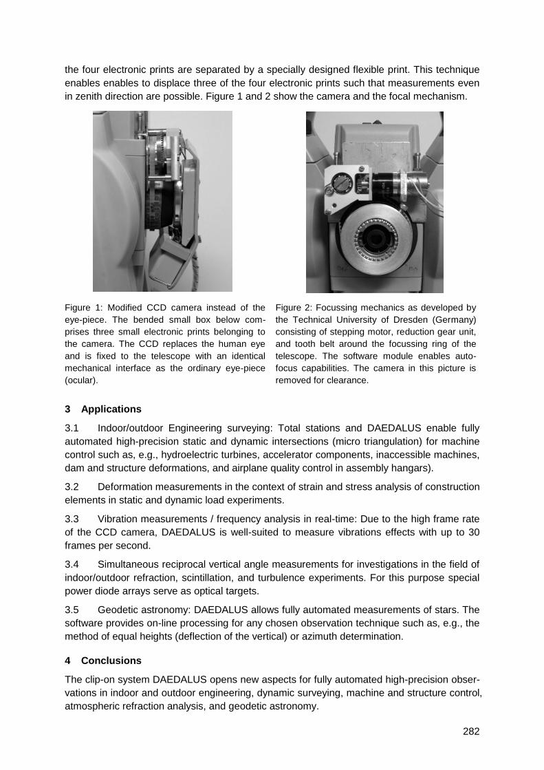
282
the four electronic prints are separated by a specially designed flexible print. This technique
enables enables to displace three of the four electronic prints such that measurements even
in zenith direction are possible. Figure 1 and 2 show the camera and the focal mechanism.
Figure 1: Modified CCD camera instead of the
eye-piece. The bended small box below com-
prises three small electronic prints belonging to
the camera. The CCD replaces the human eye
and is fixed to the telescope with an identical
mechanical interface as the ordinary eye-piece
(ocular).
Figure 2: Focussing mechanics as developed by
the Technical University of Dresden (Germany)
consisting of stepping motor, reduction gear unit,
and tooth belt around the focussing ring of the
telescope. The software module enables auto-
focus capabilities. The camera in this picture is
removed for clearance.
3 Applications
3.1 Indoor/outdoor Engineering surveying: Total stations and DAEDALUS enable fully
automated high-precision static and dynamic intersections (micro triangulation) for machine
control such as, e.g., hydroelectric turbines, accelerator components, inaccessible machines,
dam and structure deformations, and airplane quality control in assembly hangars).
3.2 Deformation measurements in the context of strain and stress analysis of construction
elements in static and dynamic load experiments.
3.3 Vibration measurements / frequency analysis in real-time: Due to the high frame rate
of the CCD camera, DAEDALUS is well-suited to measure vibrations effects with up to 30
frames per second.
3.4 Simultaneous reciprocal vertical angle measurements for investigations in the field of
indoor/outdoor refraction, scintillation, and turbulence experiments. For this purpose special
power diode arrays serve as optical targets.
3.5 Geodetic astronomy: DAEDALUS allows fully automated measurements of stars. The
software provides on-line processing for any chosen observation technique such as, e.g., the
method of equal heights (deflection of the vertical) or azimuth determination.
4 Conclusions
The clip-on system DAEDALUS opens new aspects for fully automated high-precision obser-
vations in indoor and outdoor engineering, dynamic surveying, machine and structure control,
atmospheric refraction analysis, and geodetic astronomy.
283
Visual Tracking for Augmented Reality
Manfred Klopschitz, Gerhard Schall, Dieter Schmalstieg, Gerhard Reitmayr
Institute for Computer Graphics and Vision, Graz University of Technology, Austria
{klopschitz, schall, schmalstieg, reitmayr}@icg.tugraz.at
1 Summary
Localization of mobile devices is an essential task in Augmented Reality and has therefore been an
active research topic for many years. Typically, indoor tracking approaches, such as methods based
on infrared or ultra-wide-band, require preparations of the environment and special hardware sensors.
Conversely, image feature tracking approaches can provide orientation estimates without special
tracking hardware installations. With the advent of mobile devices equipped with sensors such as
digital cameras, image based localization gains importance in Augmented Reality. Typically, fiducial
marker tracking was considered as a standard image based localization method. We propose the use
of natural image feature based tracking methods, which are a generalization of the same principals but
do not require the presence of fiducial tracking targets.
2 Vision based Localization for Augmented Reality
Augmented Reality (AR) is a powerful user interface for mobile computing. AR superimposes
registered 3D graphics on the user‘s view of the real world, allowing the user to perceive overlaid
information that is spatially registered to the environment (see Figure 1). In this context, tracking
provides indoor localization to correctly register digital information, e.g. navigational hints, to the user.
Computer Vision-based localization techniques offer great advantages over other localization methods
based on infrared, WLAN/Wi-Fi or ultra-wide-band. Image-based measurements allow very high
precision in the pose estimation and self-contained operation without complex and expensive
infrastructure. In computer vision, the problem of location recognition has been addressed in the past
by a variety of approaches. The most successful methods rely on wide baseline matching techniques
based on sparse features such as scale invariant interest points and local image descriptors. The
basic idea behind these methods is to compute the position of a query image with respect to a
database of registered reference images, planar surfaces or 3D models. Assuming a static scene,
geometric verification can be used to determine the actual pose of the camera with respect to the
exemplary database. Different viewpoints or illumination changes are largely handled by robust feature
descriptors, such as SIFT [5], that provide invariant descriptions of local image patches. Vocabulary
tree based image retrieval and inverted file scoring [2] allows for fast search of large SIFT descriptor
databases.
3 Localization for Mobile Devices
In recent years mobile computing devices and state of the art mobile phones in particular, have seen
immense progress in miniaturization and performance. These devices are well-established and offer a
convincing hardware package containing all components necessary for vision based localization and
information visualization. The first approaches for mobile phone localization were client-server based
where tracking is outsourced to a PC connected via wireless link. But, these approaches suffer from
restricted bandwidth, the imposed infrastructure dependency limiting the scalability in the number of
client devices and high response times. As a consequence server-based approaches are not suitable
for AR.
However, recent approaches have shown that natural feature tracking with 6 Degrees Of Freedom
(DOF) can be realized in real-time using mobile phones [1]. Point based visibility of data base features
are used in this work for reduced computational- and memory requirements. Moreover, Takacs et al.
[3] present an outdoor localization system directly performing keypoint detection and matching.
Features are clustered in a 2D grid and pre-fetched by proximity. Each grid element contains a set of
clustered meta-features representing the most repeatable features. Geometrically consistent meta-
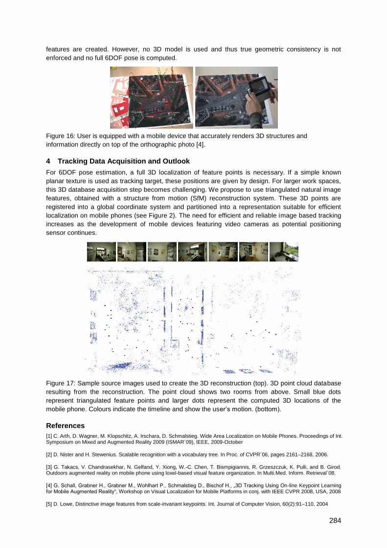
284
features are created. However, no 3D model is used and thus true geometric consistency is not
enforced and no full 6DOF pose is computed.
Figure 16: User is equipped with a mobile device that accurately renders 3D structures and
information directly on top of the orthographic photo [4].
4 Tracking Data Acquisition and Outlook
For 6DOF pose estimation, a full 3D localization of feature points is necessary. If a simple known
planar texture is used as tracking target, these positions are given by design. For larger work spaces,
this 3D database acquisition step becomes challenging. We propose to use triangulated natural image
features, obtained with a structure from motion (SfM) reconstruction system. These 3D points are
registered into a global coordinate system and partitioned into a representation suitable for efficient
localization on mobile phones (see Figure 2). The need for efficient and reliable image based tracking
increases as the development of mobile devices featuring video cameras as potential positioning
sensor continues.
Figure 17: Sample source images used to create the 3D reconstruction (top). 3D point cloud database
resulting from the reconstruction. The point cloud shows two rooms from above. Small blue dots
represent triangulated feature points and larger dots represent the computed 3D locations of the
mobile phone. Colours indicate the timeline and show the user‘s motion. (bottom).
References
[1] C. Arth, D. Wagner, M. Klopschitz, A. Irschara, D. Schmalstieg. Wide Area Localization on Mobile Phones. Proceedings of Int. Symposium on Mixed and Augmented Reality 2009 (ISMAR´09), IEEE, 2009-October
[2] D. Nister and H. Stewenius. Scalable recognition with a vocabulary tree. In Proc. of CVPR´06, pages 2161–2168, 2006.
[3] G. Takacs, V. Chandrasekhar, N. Gelfand, Y. Xiong, W.-C. Chen, T. Bismpigiannis, R. Grzeszczuk, K. Pulli, and B. Girod. Outdoors augmented reality on mobile phone using loxel-based visual feature organization. In Multi.Med. Inform. Retrieval´08.
[4] G. Schall, Grabner H., Grabner M., Wohlhart P., Schmalstieg D., Bischof H., „3D Tracking Using On-line Keypoint Learning for Mobile Augmented Reality―, Workshop on Visual Localization for Mobile Platforms in conj. with IEEE CVPR 2008, USA, 2008
[5] D. Lowe, Distinctive image features from scale-invariant keypoints. Int. Journal of Computer Vision, 60(2):91–110, 2004
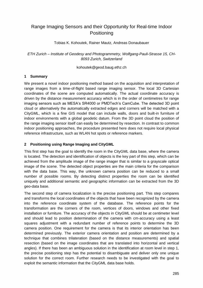
285
Range Imaging Sensors and their Opportunity for Real-time Indoor
Positioning
Tobias K. Kohoutek, Rainer Mautz, Andreas Donaubauer
ETH Zurich – Institute of Geodesy and Photogrammetry, Wolfgang-Pauli-Strasse 15, CH-
8093 Zurich, Switzerland
1 Summary
We present a novel indoor positioning method based on the acquisition and interpretation of
range images from a time-of-flight based range imaging sensor. The local 3D Cartesian
coordinates of the scene are computed automatically. The actual coordinate accuracy is
driven by the distance measurement accuracy which is in the order of centimetres for range
imaging sensors such as MESA‘s SR4000 or PMDTech‘s CamCube. The detected 3D point
cloud or alternatively the automatically extracted edges and corners will be matched with a
CityGML, which is a fine GIS model that can include walls, doors and built-in furniture of
indoor environments with a global geodetic datum. From the 3D point cloud the position of
the range imaging sensor itself can easily be determined by resection. In contrast to common
indoor positioning approaches, the procedure presented here does not require local physical
reference infrastructure, such as WLAN hot spots or reference markers.
2 Positioning using Range Imaging and CityGML
This first step has the goal to identify the room in the CityGML data base, where the camera
is located. The detection and identification of objects is the key part of this step, which can be
achieved from the amplitude image of the range imager that is similar to a grayscale optical
image of the scene. The detected object properties are the main criteria for the comparison
with the data base. This way, the unknown camera position can be reduced to a small
number of possible rooms. By detecting distinct properties the room can be identified
uniquely and additional semantic and geographic information can be extracted from the 3D
geo-data base.
The second step of camera localization is the precise positioning part. This step compares
and transforms the local coordinates of the objects that have been recognized by the camera
into the reference coordinate system of the database. The reference points for the
transformation are the corners of the room, vertices of doors, windows and other fixed
installation or furniture. The accuracy of the objects in CityGML should be at centimeter level
and should lead to position determination of the camera with cm-accuracy using a least
squares adjustment with a redundant number of reference points to determine the 3D
camera position. One requirement for the camera is that its interior orientation has been
determined previously. The exterior camera orientation and position are determined by a
technique that combines trilateration (based on the distance measurements) and spatial
resection (based on the image coordinates that are translated into horizontal and vertical
angles). If there has been an ambiguous solution in the identification at room level in step 1,
the precise positioning step has the potential to disambiguate and deliver only one unique
solution for the correct room. Further research needs to be investigated with the goal to
exploit the semantic information that the CityGML data base holds.
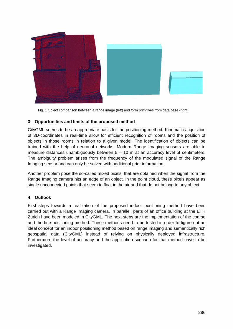
286
Fig. 1 Object comparison between a range image (left) and form primitives from data base (right)
3 Opportunities and limits of the proposed method
CityGML seems to be an appropriate basis for the positioning method. Kinematic acquisition
of 3D-coordinates in real-time allow for efficient recognition of rooms and the position of
objects in those rooms in relation to a given model. The identification of objects can be
trained with the help of neuronal networks. Modern Range Imaging sensors are able to
measure distances unambiguously between 5 – 10 m at an accuracy level of centimeters.
The ambiguity problem arises from the frequency of the modulated signal of the Range
Imaging sensor and can only be solved with additional prior information.
Another problem pose the so-called mixed pixels, that are obtained when the signal from the
Range Imaging camera hits an edge of an object. In the point cloud, these pixels appear as
single unconnected points that seem to float in the air and that do not belong to any object.
4 Outlook
First steps towards a realization of the proposed indoor positioning method have been
carried out with a Range Imaging camera. In parallel, parts of an office building at the ETH
Zurich have been modeled in CityGML. The next steps are the implementation of the coarse
and the fine positioning method. These methods need to be tested in order to figure out an
ideal concept for an indoor positioning method based on range imaging and semantically rich
geospatial data (CityGML) instead of relying on physically deployed infrastructure.
Furthermore the level of accuracy and the application scenario for that method have to be
investigated.
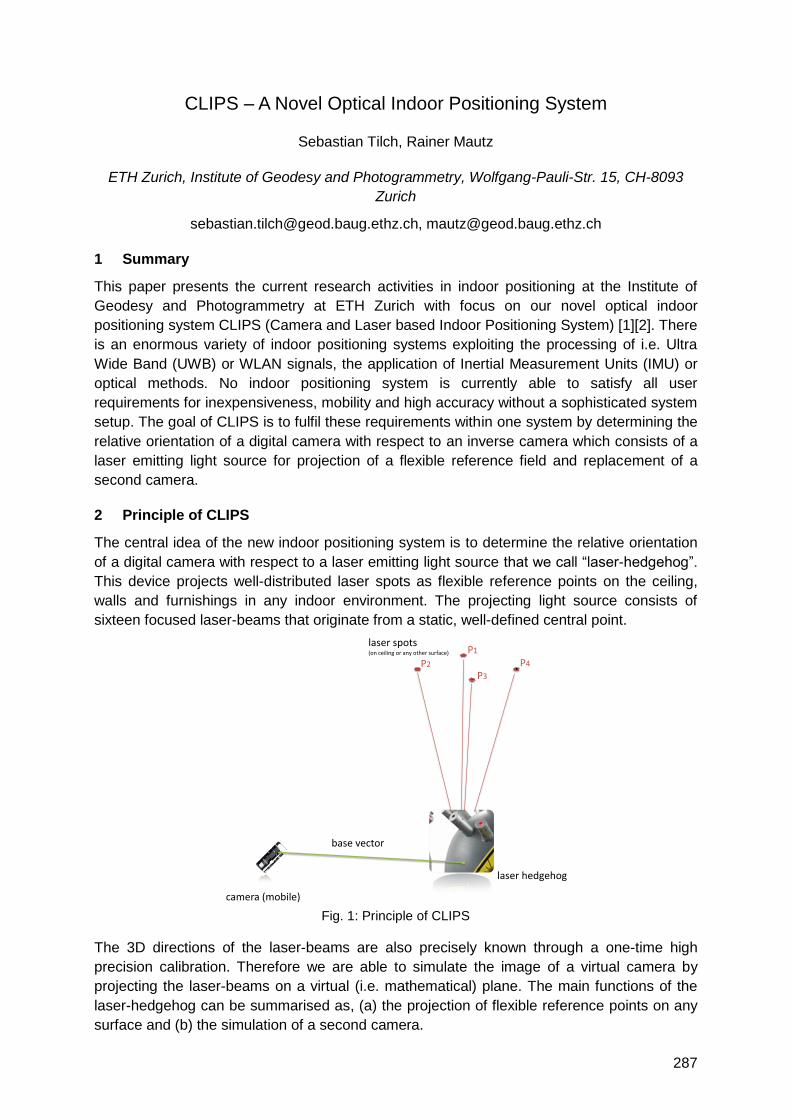
287
CLIPS – A Novel Optical Indoor Positioning System
Sebastian Tilch, Rainer Mautz
ETH Zurich, Institute of Geodesy and Photogrammetry, Wolfgang-Pauli-Str. 15, CH-8093
Zurich
[email protected], [email protected]
1 Summary
This paper presents the current research activities in indoor positioning at the Institute of
Geodesy and Photogrammetry at ETH Zurich with focus on our novel optical indoor
positioning system CLIPS (Camera and Laser based Indoor Positioning System) [1][2]. There
is an enormous variety of indoor positioning systems exploiting the processing of i.e. Ultra
Wide Band (UWB) or WLAN signals, the application of Inertial Measurement Units (IMU) or
optical methods. No indoor positioning system is currently able to satisfy all user
requirements for inexpensiveness, mobility and high accuracy without a sophisticated system
setup. The goal of CLIPS is to fulfil these requirements within one system by determining the
relative orientation of a digital camera with respect to an inverse camera which consists of a
laser emitting light source for projection of a flexible reference field and replacement of a
second camera.
2 Principle of CLIPS
The central idea of the new indoor positioning system is to determine the relative orientation
of a digital camera with respect to a laser emitting light source that we call ―laser-hedgehog‖.
This device projects well-distributed laser spots as flexible reference points on the ceiling,
walls and furnishings in any indoor environment. The projecting light source consists of
sixteen focused laser-beams that originate from a static, well-defined central point.
Fig. 1: Principle of CLIPS
The 3D directions of the laser-beams are also precisely known through a one-time high
precision calibration. Therefore we are able to simulate the image of a virtual camera by
projecting the laser-beams on a virtual (i.e. mathematical) plane. The main functions of the
laser-hedgehog can be summarised as, (a) the projection of flexible reference points on any
surface and (b) the simulation of a second camera.
laser hedgehog
camera (mobile)
base vector
P3
P4P2
P1laser spots(on ceiling or any other surface)
288
The advantages of that approach are twofold. Because of (a), the system is not depending
on an existing field of reference points. Therefore, CLIPS has a high degree of mobility
allowing for quick and immediate application in any indoor environment. Secondly, the
system costs as well as the computational costs can be reduced since one camera is
replaced by the laser-hedgehog. Through camera simulation (b) the steps of point detection
and identification for the virtual picture can be omitted.
3 Determination of the relative Orientation
By observing the projected reference field with the digital camera the relative orientation can
be determined subsequent to point identification by introducing the coplanarity constraints of
epipolar geometry. For this task the 5-point-algorithm by Stewenius & Nister has been
chosen [3]. The two input images consist of the ―virtual image‖ of the laser-hedgehog and the
real camera image. Since the solution of the 5-point-algorithm can consist of up to 10
different possible camera positions (i.e. essential matrices), the correct essential matrix is
identified by embedding the algorithm into a RANSAC framework. The result (i.e. position
and orientation of the camera) is decomposed into a translational vector b and a rotational
matrix R describing the spatial attitude of the camera and finally refined by using more than
the minimal number of 5 points and applying a least-squares minimisation for the
improvement of the relative orientation parameters.
4 Introduction of the System Scale
One challenge is the introduction of the system-scale which cannot be determined by relative
orientation. Out of several options, the simplest option was chosen by directly measuring the
distance (base vector c.f. Fig. 1) between the laser hedgehog and the camera using a
tachymeter. The distance measurements are carried out only for the first four camera
positions. Then, the four 3D vectors between the hedgehog and the camera positions are
computed and the spatial coordinates of the laser points are determined by intersection.
Once the 3D positions of the laser spots are known, the relative orientation parameters for
further camera positions are determined by spatial resection.
5 Conclusions and Outlook
The advantage of the 5-point algorithm for the relative orientation is that the geometry of the
laser spots is not restricted. The algorithm is stable even for geometrically critical surfaces
such as planes. Therefore, the novel system is designed for being independently operable in
any indoor environment. First experiments have shown that the relative orientation of the
camera could be correctly determined in all cases and that our new system has the potential
to achieve mm-level accuracy or better. However, the overall system performance has been
limited so far due to an imprecise determination of the system-scale. In the future, more
practical solutions for determining the system scale will be considered, e.g. the use of two
laser-hedgehogs.
References
[1] Mautz R.,‖Camera and Laser Indoor Positioning System (CLIPS)‖. Proposal to the Swiss National
Science Foundation, (unpublished), 2009.
[2] Tilch S., „Entwicklung eines optischen Innenraum-Positionierungssystems―, Master Thesis,
Institute of Geodesy and Photogrammetry, ETH Zurich, 2010.
[3] Stewénius H., ―Gröbner Basis Methods for Minimal Problems in Computer Vision‖, Ph.D. thesis,
Centre for Mathematical Sciences, Lund Institute of Technology, 2005.

289
Optical Indoor Positioning using a camera phone
Verena Willert
TU Darmstadt, Institute of Geodesy, Petersenstr. 13, DE-64287 Darmstadt
1 Summary
This abstract describes a system for the determination of the user‘s position inside a building
by using a camera phone. For calculating the position only one image of an object that is
known in a local building reference system is required. The spatial resection is used as the
algorithm for the position estimation. Digital cameras are nowadays included in almost every
mobile phone. Therefore, the aim is to develop a system that allows indoor positioning using
a camera phone. In the following, the technical realization of the system is described and first
results of positioning with a camera phone using spatial resection are presented.
2 Technical realization
The basic idea is to determine the position of a person inside a building by using a calibrated
camera phone. First, an object (e.g. a door) signed with a code is photographed. The code
includes unique site-specific information of the door. Then, the photo is sent to a server via
wireless communication technologies. On the server the image coordinates (ui, vi) of the
door‘s corners as well as the code information are extracted by image processing algorithms.
The object coordinates (Xi, Yi, Zi) can be identified from the code information and the
corresponding corners that are stored in a database. With these corresponding points, the
3D-position of the camera phone (P0) can be calculated. Then P0 is displayed in a CAD
model of the building that is also stored on the server. The clipping of the CAD model with
the position information of the camera phone is sent back to the mobile phone. Preconditions
for the mobile phone are: a digital camera with a fixable focus, WiFi – functionality and
programmability.
3 Positioning with spatial resection
Figure 1: configuration of a photo adaption by the camera phone
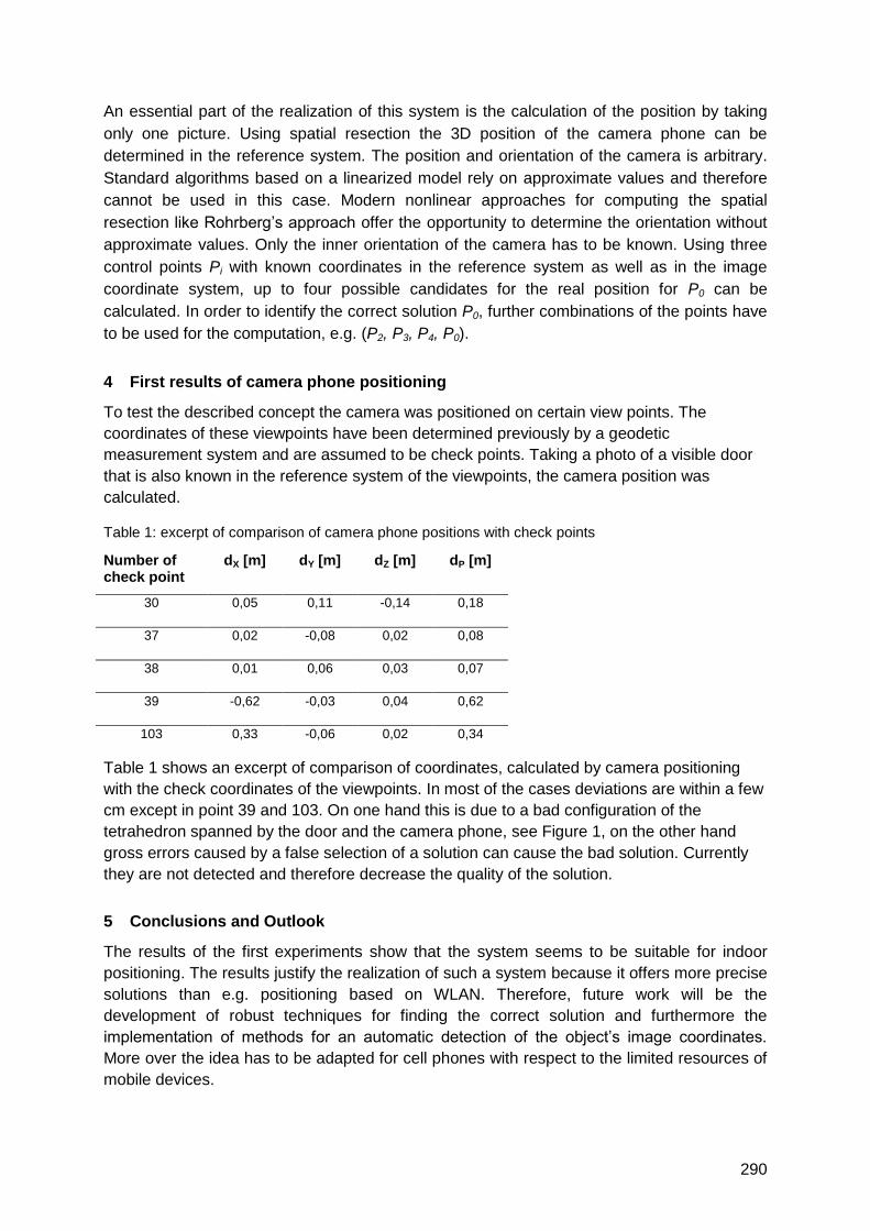
290
An essential part of the realization of this system is the calculation of the position by taking
only one picture. Using spatial resection the 3D position of the camera phone can be
determined in the reference system. The position and orientation of the camera is arbitrary.
Standard algorithms based on a linearized model rely on approximate values and therefore
cannot be used in this case. Modern nonlinear approaches for computing the spatial
resection like Rohrberg‘s approach offer the opportunity to determine the orientation without
approximate values. Only the inner orientation of the camera has to be known. Using three
control points Pi with known coordinates in the reference system as well as in the image
coordinate system, up to four possible candidates for the real position for P0 can be
calculated. In order to identify the correct solution P0, further combinations of the points have
to be used for the computation, e.g. (P2, P3, P4, P0).
4 First results of camera phone positioning
To test the described concept the camera was positioned on certain view points. The
coordinates of these viewpoints have been determined previously by a geodetic
measurement system and are assumed to be check points. Taking a photo of a visible door
that is also known in the reference system of the viewpoints, the camera position was
calculated.
Table 1: excerpt of comparison of camera phone positions with check points
Number of check point
dX [m] dY [m] dZ [m] dP [m]
30 0,05 0,11 -0,14 0,18
37 0,02 -0,08 0,02 0,08
38 0,01 0,06 0,03 0,07
39 -0,62 -0,03 0,04 0,62
103 0,33 -0,06 0,02 0,34
Table 1 shows an excerpt of comparison of coordinates, calculated by camera positioning
with the check coordinates of the viewpoints. In most of the cases deviations are within a few
cm except in point 39 and 103. On one hand this is due to a bad configuration of the
tetrahedron spanned by the door and the camera phone, see Figure 1, on the other hand
gross errors caused by a false selection of a solution can cause the bad solution. Currently
they are not detected and therefore decrease the quality of the solution.
5 Conclusions and Outlook
The results of the first experiments show that the system seems to be suitable for indoor
positioning. The results justify the realization of such a system because it offers more precise
solutions than e.g. positioning based on WLAN. Therefore, future work will be the
development of robust techniques for finding the correct solution and furthermore the
implementation of methods for an automatic detection of the object‘s image coordinates.
More over the idea has to be adapted for cell phones with respect to the limited resources of
mobile devices.

291
Context Detection & Awareness
Auditorium D2
Friday, September 17, 08:15 – 09:45 & 10:15 – 12:00


293
An Energy-Aware Indoor Positioning System for AAL Environments
Frank Köhler, Marcus Thoss, Alexander Aring
RheinMain University of Applied Sciences Wiesbaden Rüsselsheim Geisenheim
{frank.koehler|marcus.thoss}@hs-rm.de, [email protected]
1 Introduction
In the last years, there is a growing demand for new technologies and social systems to
improve the quality of life for all people in all stages of their lives. These research activities
are covered under the topic AAL, Ambient Assisted Living (http://aal-europe.eu/,
http://partner.vde.com/bmbf-aal). A special aspect within the AAL context is the interlinking of
domestic infrastructure like heating, air conditioning or lighting to support every day
household activities. With the increasing number of single person households and more
households with elderly people, another aspect is the need to monitor the activities and
health status of these people. Both aspects require a positioning service which allows indoor
user tracking within a home environment.
The coupling of a positioning solution with AAL applications can be loose, i.e. position
calculation and application are separate architectural subsystems, or tighter by integrating
position evaluation and application-level processing in networked, multi-functional devices.
Our system realises the latter concept in a handheld device that is both the positioning target
and an integral, networked part of an AAL application architecture, exchanging data with
other nodes and presenting contextual information beyond mere positioning data.
In a home setting, installation and operating of positioning appliances becomes a matter of
reliability and accuracy, but also of ease of use, integration and energy consumption. System
designs initially neglecting energy efficiency issues involve the risk of massive redesign when
a low-energy objective is added later in a project. We therefore propose to consider energy
efficiency at an early stage of system design for positioning systems.
We present an approach based on a ultrasound and RF system for three dimensional indoor
positioning and tracking. Main design goals of the system are easy installation within existing
households and very low energy consumption. The positioning algorithm, not focused in this
paper, needs to provide indoor positioning with sub-meter accuracy in the horizontal plane.
2 System Description
Our system uses a TDoA (Time Difference of Arrival) distance measurement approach using
radio packets and ultrasonic pulses, similar to [1]. The system is composed of custom-
engineered wall-mounted nodes with ultrasound transceivers and RF transmitters and mobile
positioning target nodes based on a generic development handheld device enhanced with
ultrasound transceivers and RF receivers. To generate TDoA information, each wall node
sends a radio packet followed by a given delay, followed by a burst of ultrasonic chirps. A
mobile device within reception range detects the radio packet and measures the time delay
until the ultrasonic pulses are received. Thus, distances to all wall nodes within reception
range can eventually be calculated by the mobile device, and it can determine its location
relative to the well-known locations of the wall nodes using a multilateration algorithm.
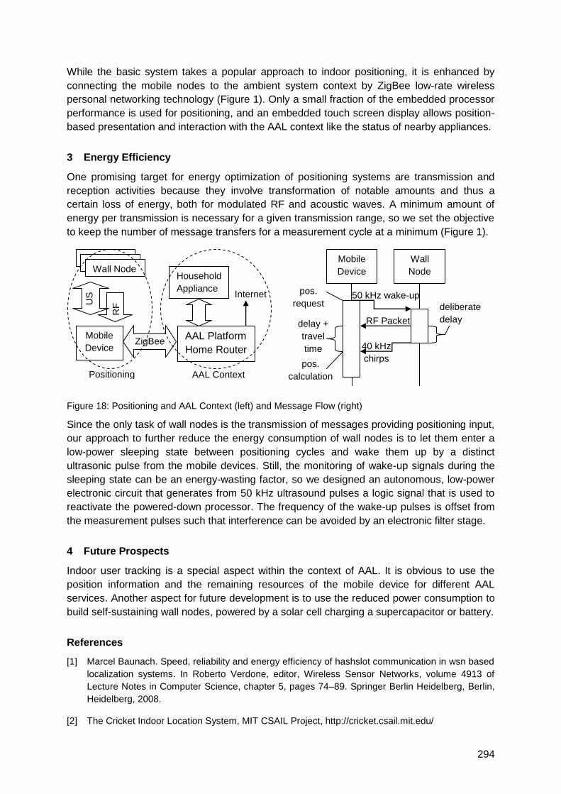
294
While the basic system takes a popular approach to indoor positioning, it is enhanced by
connecting the mobile nodes to the ambient system context by ZigBee low-rate wireless
personal networking technology (Figure 1). Only a small fraction of the embedded processor
performance is used for positioning, and an embedded touch screen display allows position-
based presentation and interaction with the AAL context like the status of nearby appliances.
3 Energy Efficiency
One promising target for energy optimization of positioning systems are transmission and
reception activities because they involve transformation of notable amounts and thus a
certain loss of energy, both for modulated RF and acoustic waves. A minimum amount of
energy per transmission is necessary for a given transmission range, so we set the objective
to keep the number of message transfers for a measurement cycle at a minimum (Figure 1).
Figure 18: Positioning and AAL Context (left) and Message Flow (right)
Since the only task of wall nodes is the transmission of messages providing positioning input,
our approach to further reduce the energy consumption of wall nodes is to let them enter a
low-power sleeping state between positioning cycles and wake them up by a distinct
ultrasonic pulse from the mobile devices. Still, the monitoring of wake-up signals during the
sleeping state can be an energy-wasting factor, so we designed an autonomous, low-power
electronic circuit that generates from 50 kHz ultrasound pulses a logic signal that is used to
reactivate the powered-down processor. The frequency of the wake-up pulses is offset from
the measurement pulses such that interference can be avoided by an electronic filter stage.
4 Future Prospects
Indoor user tracking is a special aspect within the context of AAL. It is obvious to use the
position information and the remaining resources of the mobile device for different AAL
services. Another aspect for future development is to use the reduced power consumption to
build self-sustaining wall nodes, powered by a solar cell charging a supercapacitor or battery.
References
[1] Marcel Baunach. Speed, reliability and energy efficiency of hashslot communication in wsn based
localization systems. In Roberto Verdone, editor, Wireless Sensor Networks, volume 4913 of
Lecture Notes in Computer Science, chapter 5, pages 74–89. Springer Berlin Heidelberg, Berlin,
Heidelberg, 2008.
[2] The Cricket Indoor Location System, MIT CSAIL Project, http://cricket.csail.mit.edu/
50 kHz wake-up
RF Packet
Wall Node
Mobile
Device
RF
US
AAL Platform
Home Router
Household
Appliance
ZigBee
Positioning AAL Context
Mobile
Device
Wall
Node
40 kHz
chirps
deliberate
delay delay +
travel
time
pos.
calculation
pos.
request Internet
295
Using Context Information to Improve Indoor Localization
Paolo Barsocchi * , Stefano Chessa * †, Francesco Furfari *
* ISTI-CNR, Pisa Research Area, Via G.Moruzzi 1, 56124 Pisa, Italy
† Computer Science Department, University of Pisa, Largo Pontecorvo 3, 56127 Pisa, Italy
1 Extended Abstract
Localization is an essential service in many context-aware applications and in ambient
assisted living (AAL). A promising localization approach is based on Wireless Sensor
Networks [1]. These solutions estimate the location of the mobile sensors (also called
mobiles) with respect to a set of fixed sensors (or anchors) whose position is known. In this
work, we consider a range-based localization [2], that exploits measurements of Received
Signal Strength Indicator (RSSI). The use of the RSSI does not require any special hardware
and it is available in most of the standard wireless devices, and it has received considerable
interest in the recent literature [3]. In RSSI based localization, each beacon packet
exchanged between an anchor and a mobile provides an RSSI measure that, by means of a
propagation model, is used to estimate the distance between the two devices. In this work
we consider the one-slope propagation model [4], which assumes a logarithmic dependence
between the path loss (dB) and the distance between the transmitter and the receiver. The
propagation model needs a time consuming calibration procedure that involves several RSSI
measurements in the environment where the localization system is deployed. Context aware
applications (in particular AAL applications) collect a number of information (called context
information) about the users. We observed that some of this information can be used to
refine the localization of a user. For example, when the user turns on the light in a room, this
fact can be use to infer that the user is in that room (or, even better, in front of the light
switch). We exploit such an information showing that the use of the restriction significantly
improves existing RSSI based localization algorithms, such as those based on multilateration
and Least Mean Square (LMS) [4], [5].
In our work we consider two localization algorithms, the Intersection Points (IP), which is
based on multilateration, and the LMS. Given a set of n anchors a1 . . . an , let r1 , . . . rn be
the respective RSSI measurements between each anchor and the mobile. The IP algorithm
first selects the three anchors with a greater RSSI. Without loss of generality, let a1 , a2 , and
a3 be such anchors. Then, for each anchor ai (i [1, 3]) the IP algorithm estimates its
distance from the mobile by applying the propagation model to ri . Anchor ai is the centre of
circle with radius equal to di . The IP algorithm computes the intersection points among the
three circles centred in a1 , a2 , and a3 (note that the intersection points can be up to 6). Then,
it estimates the position of the mobile as the centre of mass between these intersection
points. An example of how the IP algorithm works is shown in Figure 1.
The LMS algorithm exploits an RSSI map of the environment that is computed during the
deployment of the localization system. This map is a list of pairs <coordinate, RSSI tuple>
that express, for a given point of coordinate (x,y) in the environment, a tuple of RSSI
measurements among the anchors a1 , a2 , and an, and that point. Typically, this list is
computed for a regular grid of points in the environment whose granularity depends on the
required precision of the localization (however, beyond a given granularity, the effects on the
localization precision become negligible). At runtime, the LMS algorithm takes the tuple of
measured RSSI RM = < r1 , r2 , . . . rn > and it finds in the list the RSSI_tuple R‘(x,y) = < r’1 ,
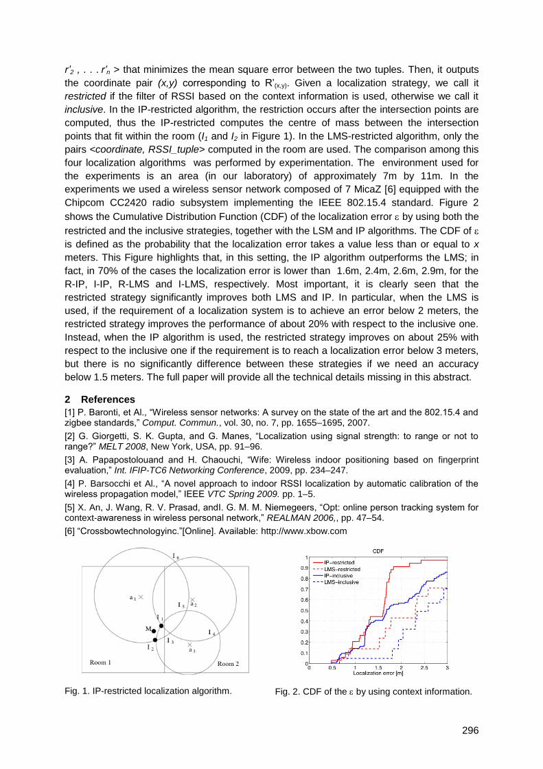
296
r’2 , . . . r’n > that minimizes the mean square error between the two tuples. Then, it outputs
the coordinate pair (x,y) corresponding to R‘(x,y). Given a localization strategy, we call it
restricted if the filter of RSSI based on the context information is used, otherwise we call it
inclusive. In the IP-restricted algorithm, the restriction occurs after the intersection points are
computed, thus the IP-restricted computes the centre of mass between the intersection
points that fit within the room (I1 and I2 in Figure 1). In the LMS-restricted algorithm, only the
pairs <coordinate, RSSI_tuple> computed in the room are used. The comparison among this
four localization algorithms was performed by experimentation. The environment used for
the experiments is an area (in our laboratory) of approximately 7m by 11m. In the
experiments we used a wireless sensor network composed of 7 MicaZ [6] equipped with the
Chipcom CC2420 radio subsystem implementing the IEEE 802.15.4 standard. Figure 2
shows the Cumulative Distribution Function (CDF) of the localization error by using both the
restricted and the inclusive strategies, together with the LSM and IP algorithms. The CDF of
is defined as the probability that the localization error takes a value less than or equal to x
meters. This Figure highlights that, in this setting, the IP algorithm outperforms the LMS; in
fact, in 70% of the cases the localization error is lower than 1.6m, 2.4m, 2.6m, 2.9m, for the
R-IP, I-IP, R-LMS and I-LMS, respectively. Most important, it is clearly seen that the
restricted strategy significantly improves both LMS and IP. In particular, when the LMS is
used, if the requirement of a localization system is to achieve an error below 2 meters, the
restricted strategy improves the performance of about 20% with respect to the inclusive one.
Instead, when the IP algorithm is used, the restricted strategy improves on about 25% with
respect to the inclusive one if the requirement is to reach a localization error below 3 meters,
but there is no significantly difference between these strategies if we need an accuracy
below 1.5 meters. The full paper will provide all the technical details missing in this abstract.
2 References
[1] P. Baronti, et Al., ―Wireless sensor networks: A survey on the state of the art and the 802.15.4 and zigbee standards,‖ Comput. Commun., vol. 30, no. 7, pp. 1655–1695, 2007.
[2] G. Giorgetti, S. K. Gupta, and G. Manes, ―Localization using signal strength: to range or not to range?‖ MELT 2008, New York, USA, pp. 91–96.
[3] A. Papapostolouand and H. Chaouchi, ―Wife: Wireless indoor positioning based on fingerprint evaluation,‖ Int. IFIP-TC6 Networking Conference, 2009, pp. 234–247.
[4] P. Barsocchi et Al., ―A novel approach to indoor RSSI localization by automatic calibration of the wireless propagation model,‖ IEEE VTC Spring 2009. pp. 1–5.
[5] X. An, J. Wang, R. V. Prasad, andI. G. M. M. Niemegeers, ―Opt: online person tracking system for context-awareness in wireless personal network,‖ REALMAN 2006,, pp. 47–54.
[6] ―Crossbowtechnologyinc.‖[Online]. Available: http://www.xbow.com
Fig. 1. IP-restricted localization algorithm. Fig. 2. CDF of the by using context information.

297
Situation-Aware Indoor Tracking with High-Density, Large-Scale Wireless
Sensor Networks
Davide Merico, Roberto Bisiani
NOMADIS Lab, DISCo, viale Sarca 336/14, I-20126 Milan
1 Introduction
Given the continuous technological advances in computing and communication, it seems that
we are rapidly heading towards the realization of paradigms commonly described as
ubiquitous computing [1], pervasive computing, ambient intelligence, Internet of things or,
more recently, "everyware" [2]. These paradigms envision living environments pervaded by a
high number of visible and invisible devices affecting and improving all aspects of our lives.
All these paradigms are substantially based on the need of knowing the physical location of
users.
Outdoor location-aware applications are already widespread and popular today whereas
indoor localization is still an open research problem. In the last few years, several indoor
positioning systems have been proposed [3]; we are more and more capable of computing
precise positions of moving targets, but unfortunately we are rarely capable of exactly
understanding what they are doing.
In this paper we propose an innovative approach to the problem of indoor position estimation
that aims at extending tracking to a new level of ―awareness‖ bringing to bear new ambient
data and opening the possibility of ―reasoning‖ not only on simple positioning but also on the
situation at hand.
The remainder of the paper is organized as follows. Section 2 describes the approach giving
an architectural overview and detailing the components used for its implementation. Section
3 describes the evaluation environment and finally Section 4 draws the conclusions.
2 Situation-Aware Indoor Tracking
We propose an approach to indoor tracking that exploits situation-aware techniques in order
to improve accuracy and precision. The approach is mainly based on: (i) a low-cost and
energy-aware localization infrastructure; (ii) multi-sensor, statistically based, localization
algorithms; (iii) logic-based situation assessment techniques.
In order to validate the described approach, we implemented a positioning system called
Situation-Aware Indoor Tracking (SAIT). The architecture and the main components of the
SAIT system are shown in Figure 1.
The localization infrastructure of SAIT is based on Wireless Sensor Networks (WSN). The
network is organized hierarchically, includes mobile and fixed nodes and implements energy-
aware data-collection algorithms. The WSN nodes have been designed and built expressly
for this system (mostly because nothing suitable was commercially available).
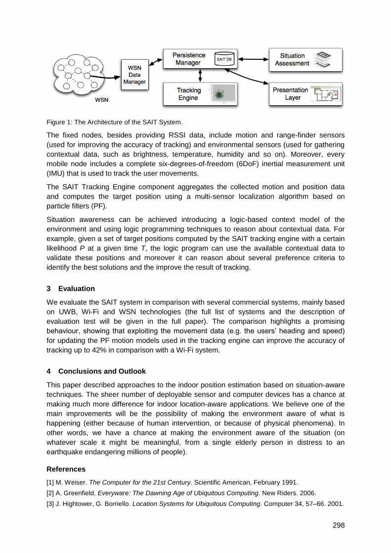
298
Figure 1: The Architecture of the SAIT System.
The fixed nodes, besides providing RSSI data, include motion and range-finder sensors
(used for improving the accuracy of tracking) and environmental sensors (used for gathering
contextual data, such as brightness, temperature, humidity and so on). Moreover, every
mobile node includes a complete six-degrees-of-freedom (6DoF) inertial measurement unit
(IMU) that is used to track the user movements.
The SAIT Tracking Engine component aggregates the collected motion and position data
and computes the target position using a multi-sensor localization algorithm based on
particle filters (PF).
Situation awareness can be achieved introducing a logic-based context model of the
environment and using logic programming techniques to reason about contextual data. For
example, given a set of target positions computed by the SAIT tracking engine with a certain
likelihood P at a given time T, the logic program can use the available contextual data to
validate these positions and moreover it can reason about several preference criteria to
identify the best solutions and the improve the result of tracking.
3 Evaluation
We evaluate the SAIT system in comparison with several commercial systems, mainly based
on UWB, Wi-Fi and WSN technologies (the full list of systems and the description of
evaluation test will be given in the full paper). The comparison highlights a promising
behaviour, showing that exploiting the movement data (e.g. the users‘ heading and speed)
for updating the PF motion models used in the tracking engine can improve the accuracy of
tracking up to 42% in comparison with a Wi-Fi system.
4 Conclusions and Outlook
This paper described approaches to the indoor position estimation based on situation-aware
techniques. The sheer number of deployable sensor and computer devices has a chance at
making much more difference for indoor location-aware applications. We believe one of the
main improvements will be the possibility of making the environment aware of what is
happening (either because of human intervention, or because of physical phenomena). In
other words, we have a chance at making the environment aware of the situation (on
whatever scale it might be meaningful, from a single elderly person in distress to an
earthquake endangering millions of people).
References
[1] M. Weiser. The Computer for the 21st Century. Scientific American, February 1991.
[2] A. Greenfield. Everyware: The Dawning Age of Ubiquitous Computing. New Riders. 2006.
[3] J. Hightower, G. Borriello. Location Systems for Ubiquitous Computing. Computer 34, 57–66. 2001.
299
Automatic Context Detection of a Mobile User
Uta Christoph, Karl-Heinz Krempels,
Janno von Stülpnagel, Christoph Terwelp
RWTH Aachen University, Informatik 4
Intelligent Distributed Systems Group
Ahornstr. 55, D-52074 Aachen
{christoph, krempels, stuelpnagel, terwelp}@nets.rwth-aachen.de
1 Summary
Mobile devices have obtained a significant role in our life providing a large variety of useful
functionalities and features. It is desirable to have an automated adaptation of the behavior
of a mobile device depending on a change of user context to fulfill expectations towards
practical usefulness. To enable mobile devices to adapt their behavior automatically there is
a need to determine the mobile user‘s context.
In this paper we introduce an integrated approach for the automatic detection of a user‘s
context. Therefore, we summarize and discuss existing approaches and technologies and
describe a service architecture that takes into account information from the interaction of the
mobile device with communication networks and positioning systems, from integrated
sensors, and planned behavior of the user from e.g. his calendar or activity list. Additionally
the architecture considers the social network of the user to derive further information about
his context and finally it takes into account the user‘s customs through a behavior model.
2 Introduction
The omnipresence of mobile devices requires the ability to adapt the device‘s capabilities.
Simple implementations of this feature are already in place in most common mobile devices.
So the user can limit the usage of the device‘s interaction features for example muting the
ring tone, deactivating the network interface radio, etc. To simplify the configuration the
settings are often grouped into configuration profiles, so the user only has to select a defined
profile and gets a suitable setup for a situation. In real environments the context continuously
changes and therefore it is desirable to support automatic detection of the user‘s current
context. This would increase the usage comfort due to improved adaptability of the device.
As an additional feature the current context of the user in combination with his current
position can be used to improve the location based services by providing this information to
the service.
In this paper we discuss existing and new approaches to determine a mobile user‘s context.
We analyze their prospects, possible drawbacks and the technical requirements. The paper
introduces some new ideas to determine a mobile user‘s context and describes our vision for
future development.
3 Integrated Context Detection Architecture
Existing approaches only consider a certain aspect or technology to discover a user‘s
context. Thus, we propose that a combination of several approaches is desirable to offer an
overall adaptation to a mobile user‘s context. We also propose that detection of a mobile
300
user‘s context should be provided by the mobile device as a service, so that all applications
can have access to the context information and can adapt their behavior accordingly.
The integration approach of the Context Detection Service is based on a three layer
architecture. The data or signal source layer consists of the available sensors, radio network
interfaces, the built in clock, and or even the connection interface to the user‘s community.
The source layer provides information in form of data or signals which comprise the
information layer. In order to be of use for the Context Detection Service this information
needs to be processed into knowledge which forms the third layer of the architecture. The
transformation of information to knowledge is done by additional Information Processing
Services which map the information events from the source layer to knowledge tags with the
help of suitable patterns defined in the Pattern Repository.
The most significant criteria to determine one‘s mobile context seem to be his geographical
location, the current time, and his planned activities. On one hand all these criteria have a
direct impact on ones context and on the other hand the corresponding technologies, like
calendars, location based directories, and time dependend schedulers are already part of
prevalent mobile applications.
4 Conclusions and Outlook
In our paper we discuss different approaches to automatic context detection and proposed
an integrated service architecture which can combine information from different approaches.
We think this is necessary to gain a precise view on the user‘s context which is the main
preposition to developing context-aware mobile applications. As a basic requirement for an
integrated service the context information from the data or signal source layer is transformed
into knowledge which can be interpreted by the context detection service and then be
provided to mobile applications running on the device or as basis for the device
configuration.
The selection criteria for the most suitable context detection approaches should be on the
one hand pervasiveness of the underlying technology, e.g. UMTS and WLAN networks of the
radio signal approach, and on the other hand the obtainable accuracy for the derived user
context. Today‘s mobile environments are characterized by highly available, pervasive
mobile communication networks, mobile calendar based job itineraries, and mobile devices
with high computational power. Under these preconditions it is recommendable to combine
these with radio based approaches in UMTS/GSM networks for the detection of the user‘s
current geographical region. A rough context of the mobile user can be deduced there from
in combination with the event and activity list from his calendar. This rough context can then
be refined with the help of the radio based approach in WLAN infrastructures that the user
will enter, cross, or leave.
To determine the context of a mobile user in an automated way it is necessary to process
knowledge from several sources and services. Thus, there is need for common ontologies for
the description of the context concept, knowledge description tags characterizing a defined
context, and even the events provided by the signal layer. The next implementation steps for
the proposed context detection architecture are the definition of a suitable context ontology
and the interaction design of the discussed components of a Context Detection Service.

301
Indoor-Navigation with Landmarks
Uta Christoph, Karl-Heinz Krempels,
Janno von Stülpnagel, Christoph Terwelp
RWTH Aachen University, Informatik 4
Intelligent Distributed Systems Group
Ahornstr. 55, D-52074 Aachen
{christoph, krempels, stuelpnagel, terwelp}@cs.rwth-aachen.de
1 Summary
The complexity of large buildings, like airports, and the omnipresence of mobile devices ask
for the ability to navigate people through these buildings with help of their mobile device.
Mobile indoor positioning systems do not provide the accuracy required by common
navigation systems, since they determine the geographical position based on trilateration of
radio signals, e.g. from WiFi or GSM (Global System for Mobile Communication). Also, GPS
(Global Positioning System) is not usable in indoor scenarios because buildings absorb the
signals.
So there is a need for navigation systems, which do not require precise or even any signal
based positioning system. Most people tend to express navigation information as a sequence
of waypoints and navigation commands enriched by using landmarks. Therefore, we
introduce an approach for indoor navigation, which implements the use of landmarks in an
automatic navigation system. The system provides the ability to determine a user‘s position
and guides her to a selected target.
2 Introduction
As determining geographical positions inside buildings is either imprecise or requires special
and expensive hardware, a navigation system for indoor scenarios has to work without or at
most with imprecise position information. In this paper we describe an approach, which uses
human‘s common sense of route description to provide the ability for indoor navigation with
today‘s mobile devices.
In Section 3 we introduce some basic concepts used in the discussion of the approach in
Section 4. Section 5 concludes our work and gives a short outlook on further research.
3 Concepts
Navigation is defined as the control of movement to reach a destination from a known
starting position. In case of a mobile device it means the device offers the user information
that helps her choosing the right way to reach her destination.
The natural human method to describe a route is to use easily recognizable objects to mark
positions and describe headings. These recognizable objects are called landmarks. So such
landmarks may supplement navigation commands.
4 Approach
As base of our approach we use a model for possible movements of the user. This
movement model is a directed graph consisting of nodes that represent positions and edges

302
that represent possible movement directions inside a building. A position in this case is not
an exact geographical position but a certain area of a building. E.g. a position could be a
corridor, an intersection, or a corner of a hall. A navigation route is equal to a path in this
graph.
To communicate these paths to the user and to determine a current position the graph is
annotated with landmarks. Textual descriptions, symbols, or photos can describe these
landmarks. Furthermore, all edges are annotated with their length and a description of their
planar position with respect to each consecutive edge. The length of an edge is given in
meters and the relative planar position of an edge to another consecutive edge with the help
of following discrete relative angle descriptions: ahead, diagonally left ahead, diagonally right
ahead, left, diagonally right, back, diagonally left back, and diagonally left right.
With the help of the length annotations of the edges it is possible to reduce the number of
landmarks required to navigate the user along a route, if landmarks are too close together,
e.g. two shops that are next each other, then only one landmark is needed.
In this way it is possible to produce navigation advices based on two basic commands
―traverseTo:‖ and ―traverseBy:‖. The annotation of relative angles for consecutive edges
provides the possibility to produce navigation advices based on the additional command
―turnTo:‖ and the corresponding discrete direction description of the next landmark, e.g.
―turnTo: left‖.
5 Conclusion and Outlook
The movement model discussed in this paper provides the possibility to navigate a user in
indoor scenarios to her destination with the help of landmarks. The three basic movement
commands combined with landmarks and discrete angle descriptions are sufficient to enable
a user to transfer a path planned out in the movement model to the real surroundings.
Further investigations will be made to generate natural language instructions from the
movement model and to use imprecise positions provided by the users‘ mobile device to
adjust the navigation command generation.
303
Indoor Navigation Approach Based on Approximate Positions
Ory Chowaw-Liebman, Uta Christoph, Karl-Heinz Krempels, Christoph Terwelp
RWTH Aachen University, Informatik 4
Intelligent Distributed Systems Group
Ahornstr. 55, D-52074 Aachen, Germany
{chowaw-liebman, christoph, krempels, terwelp}@nets.rwth-aachen.de
1 Summary
Until now navigation aids have primarily focused on outdoor scenarios, whether driving on
highways or, more recently, walking through cities. These systems use the Global
Positioning System (GPS) for position information. Indoor navigation however cannot rely on
GPS data, as the signals do not penetrate building structure. Thus other techniques were
developed to provide position information indoors, but most of them lack the precision of
GPS. In this article the approach of an indoor navigation system based on imprecise position
information is presented. To compensate the deficit of precision the position information is
combined with a movement model. This movement model is automatically generated from
the maps which are already required for navigation.
2 Introduction
Tools for navigational assistance have become an essential element in today‘s traveling
society. Interactive software, available for mobile phones, is capable of guiding users who
are driving cars, riding bicycles or walking. Until now such tools have focused on outdoor
environments and are hence based on the precise data of the Global Positioning System
(GPS) to determine the current position of the user. But indoor navigation bears several
challenges.
First, GPS positioning information cannot be used for indoor scenarios since GPS radio
signals do not propagate into buildings. Second, within buildings navigation does not rely on
streets or footpaths but on traversable areas and certain connections between such, e.g.
corridors, rooms, staircases and elevators. Thus such areas and also the altitude of the user,
i.e. the floor he is currently standing on, and possible connections to other floors have to be
considered. Third, the description of a path needs to be intuitively understandable for
humans instead of giving precise distance instructions as they are used in cars or other
devices with odometers.
The first issue, a positioning technique for indoor scenarios, was addressed among others
with the Device Whispering technique (Krempels and Krebs, 2008). The third issue on
intuitive navigational instructions is considered for outdoor environments in (Dale et al.,
2003). Based on this state of the art we present a prototype indoor navigation system for a
mobile device, which generates navigational instructions from sectorized building maps with
the help of Voronoi diagrams and imprecise localizations from Device Whispering.
3 Prototype Navigation System
Any navigation system must convey the route to the user, typically using a combination of
graphical map (with highlighted path) and textual instructions. Information about the local
304
geometry is of course required to compute paths. In indoor scenarios it is especially
important to ensure that generated routes do not pass through walls or go outside of the
building.
A convenient way to provide route information to users are natural language instructions
(NLI), which offer rich and flexible means of describing paths. Such descriptions can also be
followed without positioning information, for example cars are equipped with odometers, thus
instructions of the form ―turn after 300 meters‖ are easier to follow than for a pedestrian.
Further, NLI can describe paths inside a ―sector‖, which represents an area inside which
positioning is possibly impossible due to the approximate nature of the Device Whispering
approach. NLI, when created by people, are heavily based on landmarks. Landmarks are
distinctive features of the local geography, e.g. churches, malls, fountains and traffic lights
outdoors, and specific shops, fountains and staircases indoors. One important distinction that
has to be made for indoor scenarios are different floors in a building, which add a third
dimension to the geography of a location. Landmarks can also represent connections
between floors, e.g. stairs and elevators, which cannot be displayed at all in a purely two
dimensional map.
In our decentralized approach every location is responsible for providing the map information
locally, for instance by using the local Wifi infrastructure which can be assumed to be
available since it is used by the Device Whispering technique for localization. Thus, it is not
required to establish a network link to the user‘s mobile provider to equip the mobile devices
with up-to-date geographical data. This is generated by a preprocessor, which also provides
a GUI to create and maintain the data structure of the building maps. Therein, locations are
represented by polygons, inside which the Wifi access points and landmarks are positioned.
The client software is supposed to run on mobile devices, which do not have the
computational power and memory available to notebooks or desktop computers. Therefore, a
preprocessor was developed to perform the computationally intensive tasks beforehand. The
client is left with the tasks of computing routes in the provided building maps, communicating
these routes to the user both graphically and verbally to navigate her through the building.
4 Conclusions and Outlook
Tests of the prototype system uncovered that common network interfaces do not modulate
transmission power as required for Device Whispering, when the interface is instructed to do
so: all access points which are detected already respond to the lowest power request.
Pending further inquiry, we are currently assuming that transmission power modulation is not
implemented, possibly to reduce the chip‘s area. Therefore, an adaptation of the Device
Whispering technique is the objective of ongoing research to address this issue.
The implemented text generation system produces NLI which are quite satisfactory,
especially concerning its minimalistic approach. In both cases, output and generation
complexity, the system compares favorably with CORAL: the generated text is not quite as
eloquent, but is generated with much less effort. This indicates that our approach of
skeletons annotated with landmarks provides adequate information for the NLI generator.
The very simple approach to text generation leaves open many possibilities for extension,
e.g. adding more rules to improve both the natural language as well as for selecting
landmarks to use in the text.
305
Navigation Based on Symbolic Space Models
Karolina Baras1, Adriano Moreira2, Filipe Meneses2
1Exact Sciences and Engineering Competence Centre, University of Madeira, Funchal,
Portugal and 2Algoritmi Research Centre, University of Minho, Guimarães, Portugal
[email protected], 2{ menses, adriano}@dsi.uminho.pt
1 Summary
Existing navigation systems are very appropriate for car navigation, but lack support for
convenient pedestrian navigation and cannot be used indoors due to GPS limitations. In
addition, the creation and the maintenance of the required models are costly and time
consuming, and usually based on proprietary data structures. In this paper we describe a
navigation system based on a human inspired symbolic space model. We argue that
symbolic space models are much easier to create and to maintain, and that they can support
routing applications based on self-locating through the recognition of nearby features. Our
symbolic space model is supported by a federation of servers where the spatial descriptions
are stored, and which provide interfaces for feeding and querying the model. Local models
residing in different servers may be connected between them, thus contributing to the system
scalability.
2 Introduction
In recent years, there has been an effort to extend the convenience of outdoor navigation
systems into the indoor environment. However, resorting to similar space models and routing
algorithms has proved to be difficult and unpractical due to GPS limitations and the lack of
geometric models for buildings. Stahl and Haupert [1] propose a solution based on hybrid
space models and indoor positioning systems. However, as in other approaches, this
solution requires some level of technical expertise, access to CAD drawings and a
considerable amount of time to build the appropriate geometric models.
There are, however, other systems where very simple models are used to assist navigation.
One good example, where a simple topological model is used without any technological
positioning system, is the underground transportation map. It is a graph in which vertices
represent the stations and edges represent connections between them. In this system,
positioning is based on the station names that are advertised at their entrances and inside
the stations in places visible from inside the trains. Each user identifies his/her location
according to the station name and defines a route by visual inspection of the lines connecting
the stations. In this paper we describe a navigation system that exploits human mental
models of spaces and self-location through the recognition of nearby features.
3 A Symbolic Space Model for Indoor Navigation
Human mental spaces are defined as mental constructions consisting of elements and
spatial relations among them [2]. They are created as a result of our interaction with the
environment, as well as of our imagination as we see or hear about places, or of the
combination of both. Similarly, our space model consists of objects and relations between
objects [3]. Each object represents a place (a building, a room, or an elevator), and is
306
characterized by a name, a type, a URI, and a set of attributes. Relations connect objects
within a specific semantic context, such as Is_Near, Is_In, Is_Next_To, or
Is_Accessible_From. Each relation can also be characterized by an arbitrary set of attributes.
Our symbolic space model is supported by a federation of servers – Contextualizers – that
store the objects and relations between them, and provide interfaces for feeding and
querying the model. Since relations between objects are defined within a semantic context,
reasoning algorithms are used by the Contextualizers when queries are performed. The
model is continuously updated with data collected from sensor networks [3].
The advantages of this symbolic space model for indoor navigation are manifold. First, it is
much easier to understand by because it is based on the human mental models. Second,
each person can build his/her own model by creating objects and relations between them,
without the need for any geometric reference. Third, each local model can be stored on a
local Contextualizer, and objects in one server can be related with objects in other servers
through their URIs, thus contributing to the system scalability. Fourth, it supports routing
applications that rely on a self-locating approach based on the recognition of visual
landmarks (such as wall colours or door codes) described in the model as objects‘ attributes.
The whole navigation system includes the federation of Contextualizers, a Space Editor, a
Visual Browser for model naviagtion, and a routing application with a web interface. This last
application uses the query interface of the Contextualizer to access the model and retrieve
information about the origin and the destination objects. It then uses the semantics of the
Is_Accessible_From relations, including its eventual symmetry, to compute the shortest path
between two locations. The response to a routing request is an ordered list of places, and its
characteristics, that must be visited sequentially to go from origin to destination.
4 Conclusions and future work
We briefly described an indoor routing platform supported by symbolic space models that
can be created collaboratively by a group of users based on their mental space models. In
the future we plan to exploit other relations, such as Is_Next_To, to improve the route
description provided to the users.
5 References
[1] Christoph Stahl, Jens Haupert, ―Taking Location Modelling to new Levels: A Map Modelling
Toolkit for Intelligent Environments‖, Proceedings of the Second international workshop on
Location- and context-awareness, LoCA 2006, Dublin, Ireland, May 10-11, 2006
[2] Barbara Tversky, ―Remembering spaces‖, In Endel Tulving and Fergus I. M. Craik, editors, The
Oxford handbook of memory, pages 363-378. New York, NY, US: Oxford University Press, 2000
[3] Karolina Baras, Adriano Moreira, ―Symbolic space modeling based on WiFi network data
analysis‖, Proceedings of the INSS2010 - 7th International Conference on Networked Sensing
Systems, June 15-18, 2010, Kassel, Germany

307
Indoor Location Services and Context-Sensitive
Applications in Wireless Networks
Róbert Schulcz, Gábor Varga
Mobile Innovation Centre, Budapest University of Technology and Economics
[email protected], [email protected]
Introduction
Development of context-sensitive applications has become a dynamically evolving area of
information technology. Position as a context can on its own provide valuable information,
but in conjunction with other knowledge bases, it makes services that grow to be integral
parts of our daily lives possible. While outdoors the ability to determine geographic
coordinates has given birth to a whole navigation industry, indoors this revolution is yet to be
achieved. We, engineers, have to come up with solutions that integrate with our usual
behaviour imperceptibly, but are able to provide such extra functions and ease of use that
may change the way we look at our environment. Using indoor location, devices knowing the
position of persons and objects surrounding them may very well realize such a vision.
Research projects and commercial products have been available for multiple years now that
utilize the signals of Wi-Fi networks to calculate people‘s positions inside a building. However
most of the currently used systems are based on the radio fingerprint principle that makes
the thorough survey of the area necessary before deployment and after every change in the
network infrastructure. Realizing this burden, our goal was to develop an algorithm that lifts
this constraint while retaining the accuracy and performance of the previous systems.
On its own, knowing the location of a mobile device or a person only enables us to build
simple applications. By adding semantics to the floor plan, declaring static and dynamic
attributes on persons, devices, groups and locations, and taking into account informations
such as the time of day or even the weather, richer and more powerful services can be
provided. We plan to incorporate these functions into a framework, making information
accessible via a well-defined programming interface, thus allowing upper layer applications
to use context-sensitive and location-sensitive data.
This project started out as a university research at the Mobile Innovation Centre of the
Budapest University of Technology. In cooperation with an industrial partner, it is the subject
of a tender sponsored by the Economic Development Operational Programme of the
Hungarian National Development Agency, partially financed by the European Regional
Development Fund. The goal of the project is to develop a mobile based indoor location and
navigation system usable in office environments, offering a complete solution including the
client, the server infrastructure, the operator interfaces and the location algorithm itself, with
basic context-sensitive navigation services built on the top.
Indoor Location Algorithm
The motivation for developing a new location algorithm is threefold. Albeit being highly
accurate and fast, methods utilizing radio fingerprints are strenuous to deploy and require full
re-surveying every time an access point is replaced or moved. For this reason they are not
well-suited for an ever-changing office environment: a simple wave propagation model based
algorithm would be preferable, where system parameters and access point locations can be
changed independently. Secondly, the new algorithm has to be extremely resource-efficient
in order to scale up to serving a multitude of people simultaneously in real time. It should run
distributed on central servers, so that regular equipment and clients with very low processing
308
power could be used. Thirdly, its accuracy should not be much worse than the currently
existing radio fingerprint technologies, with the option of finer calculation in specified
locations. This is done by integrating the radio fingerprint based principle and the
propagation model, selectively relying on one or the other, having surveyed only the critical
areas of the floor plan.
The selectively surveyed data set is overlaid on the map, and the missing areas are
determined, where a mathematical model is used to calculate the expected signal strength
values. Thus a distribution pattern is generated, much like a radio fingerprint map, so
location-time operation is reduced to the usual nearest neighbour search in a vector space,
using the average of squared differences of signal strength vectors as the distance factor.
This way where accurate survey data exists, it will be used to determine the location, but we
can still use another approach where it is not available. To increase accuracy, we statistically
filter input, taking the median value of the last few measurements. Output is also filtered, its
credibility is tested, and its oscillation is smoothed out. Different device models may be used
simultaneously, since measured signal strength levels can be translated to a common scale.
The recalculation of the expected signal strengths is only necessary when the environment is
changed. Calculated values are stored in a database as a materialized view, merged with the
surveyed data set. In order to achieve fast computation of the propagation model based
algorithm, we chose an equation based on the Motley–Keenan Model, augmented with
factors from the New Empirical Model of Cheung, Sau and Murch. On its own it still would not
be sufficiently accurate, so we added some heuristics to the algorithm taking into account the
floor plan, distribution of walls, previous walking directions and typical indoor movement
patterns, as well as data from G-sensors and digital compasses built into modern handheld
devices. Each of these information sources and the propagation model define a probability
distribution over the map, these layers are then weighted and summarized to get the final
coordinates. To avoid the need to run a lengthy simulated annealing in continuous space at
every iteration, we decided to represent the map as a set of discrete points at the
intersections of a grid over the map. This way calculations can be simplified, each probability
layer can define the points to be evaluated on, and the introduced error is not greater than
half of the grid diagonal, practically the space occupied by a person.
Context-Sensitive Framework
Beside the location of the devices used, special areas of interest can be marked on the map,
and the floor plan is also represented. Attributes are declared on individual persons, devices,
groups of people, device classes and areas. These informations combined in a geometry
model can be used to infer special knowledge: is someone in the same room as another
person, can they see each other, where is the nearest exit, how long does it take for the
nearest repairman to get to a specific place, how often do tracked people stop in front of a
store etc. Data may be entered directly or inferred from other pieces of information by a rule-
based reasoner, and one can use smart database views or custom queries to access
properties associated with individuals either by assignment or in an indirect manner.
We use the geographic functions of Oracle Locator (subset of Oracle Spatial) to interface the
attributes stored in the database with the coordinates and areas on the map. We
implemented the algorithms in the PL/SQL programming language, and created database
views to merge all the context informations belonging directly or indirectly to the entities. The
framework can be queried by the upper layer applications via SOAP requests, thus enabling
local and remote software running on either the server, an operator workstation or a client
device to use the information stored in the database.

309
Geolocation Server – Coordinates become context aware
Thore Fechner1, Mareike Kritzler1, Antonio Krüger2
1WWU Münster, Institute for Geoinformatics, Weseler Str. 253, D-48149 Münster 2DFKI GmbH, 66123 D-Saarbrücken
[email protected], [email protected], [email protected]
1 Summary
This extended abstract describes a geolocation server for indoor environments. Most of the
available tracking or localisation technologies use a coordinate based approach. They
describe the current location through a set of coordinates. Although the position is described
sufficiently with this set of coordinates, the circumjacent context is not. This work describes
an approach to overcome this lack of contextual awareness for an industrial indoor
localization. It introduces a service layer which enriches given coordinates based on existing
blueprints with context information. The identified entities of the circumjacent context of the
coordinates are communicated via a machine readable interface. The interface provides the
logical entities‘ geometry and a set of attributes which can be used to obtain further
information like electrical or mechanical connections.
2 Introduction
Tracking technologies can be classified into symbol based or geometric approaches [4]: use a
predefined reference system and describe the current location through a set of coordinates.
Problem: Detailed knowledge of the used reference system and the context where the
localisation system is active is needed to obtain further information from these coordinates. A
user of the localisation system is not supposed to have this detailed knowledge. A location
which is only described by a set of coordinates is context-free. Information about the
circumjacent context (e.g. object references) of the coordinates is necessary for a LBS.
Motivation: It is possible to create a meaningful localisation for the user and other services by
adding context information to the coordinates. A spatial assistance system which offers
information about surrounding objects can help the user to perform his task more efficiently
or even enable him even if he is unfamiliar with his environment.
Use Case: This work took place with the Siemens AG which has a Smart Automation Center
(SmA) in Nürberg Moorenbrunn. The SmA is a research facility where a LBS is introduced for
service technicians in industrial environments. This LBS serves as a part of a spatial
assistance system. For example service technicians are in front of a switch cabinet to
perform a maintenance task. The hand held device can only provide Cartesian coordinates
obtained by the installed tracking systems. But the knowledge of the raw coordinates is not
giving any context information like blueprints, mechanical / electrical connections, maintenance
instructions or notes regarding the current position. The spatial assistance system needs to have
this translation (geolocation process) from coordinates to the context of switch cabinet.
3 Related work
Most of the work within the research field of indoor localisation and tracking focuses on
concrete technologies for locating ones position. WiFi Fingerprinting [3], Bluetooth [2], RFID
[1] or GSM [6] focus on enabling an indoor localisation without creating additional
infrastructure. Typically the geometrical based systems show one‘s position on available floor
plans on a room level [5]. The ―where‖ is communicated but the surroundings of the ―where‖
are neglected. For the use case the coordinates are supposed to have additional information
e.g. object references of nearby components.
310
4 Concept
A method to assign context information to a specific coordinate has to be developed to
realise a LBS serving context information. This is similar to a standard reverse geocoding
process where coordinates are translated into an address. In this case tracked coordinates
need to be annotated with object references of their surrounding context. This process is
from now on referred to as a geolocation process. The nature of a geolocation process is
geometrical since most of the available indoor localisation systems offer coordinates in a
predefined reference system. It is possible to obtain information about the surroundings of
the coordinates by blending existing blueprints and floor plans with the tracked coordinates in
a common reference system. Annotations in the blueprints point toward additional resources
which can hold functional descriptions or topological information. Within the use case, this
could be electrical / mechanical connections, maintenance instructions or notes form colleagues.
5 Realization
A prototypical implementation of a service like this was deployed by using a WFS and Filter
Encoding (FE). Existing CAD files of the SmA were converted into 2.5D shapefiles and
annotated with URIs pointing toward additional information stored in ontologies. The usage of
FE allows one to query for a set of coordinates with or without buffers. The retrieved context
of the coordinate is transmitted, encoded in the GML and serves the URI along with the
geometry of nearby objects. The URIs can be used to gain additional information of any kind.
This approach allows one to use this LBS - the Geolocation Server - as a machine readable
middleware layer for other applications assisting users at their task.
6 Conclusions and Outlook
This abstract describes the means and development for a more meaningful localisation for
indoor localisation and tracking technologies using current standards. The first realization of
a service like this allows up to 2.5D models of the environment. The usage of well known
standards allows its introduction into any service chain, allowing one to enhance traditional
tracking with context based information. With the introduction of GML 3.0 supporting 3D data,
it is most likely that the standards of the WFS and FE will soon be capable of handling 3D
data as well. This would allow the storage of 3D CAD data directly in a spatial database with
annotations. Thus a full 3D contextual tracking would be possible.
References
[1] Bahl, P.; Padmanabhan, V. (2000): Radar: an in-building rf-based user location and tracking
system. INFOCOM, 2000
[2] Bargh, M. S.; Groote, R. (2008): Indoor localization based on response rate of bluetooth inquiries.
In: Proceedings of the first ACM international workshop on Mobile entity localization and tracking
in GPS-less environments (2008) , ACM
[3] Bolliger, P.; Partridge, K.; Chu, M.; Langheinrich, M. (2009): Improving Location Fingerprinting
through Motion Detection and Asynchronous Interval Labeling. In: Lecture Notes in Computer
Science, Volume 5561/2009, Springer Berlin/Heidelberg
[4] Hightower,J.; Borriello, G. (2001): Location Systems for Ubiquitous Computing. In: IEEE
Computer, Vol. 34, No. 8, IEEE
[5] King, T.; Kopf, S.; Haenselmann, T.; Lubberger, C.; Eelsberg, W. (2006): Compass: A
probabilistic indoor positioning system based on 802.11 and digital compasses. In Proceedings of
the First ACM International Workshop on WiNTECH
[6] Otsason, V; Varshavsky, A.; LaMarca, A.; Lara E. (2005): Accurate GSM Indoor Localization. In:
Lecture Notes in Computer Science, Vol. 3660/2005, 2005, P. 141-158

311
Passive RFID
Auditorium D8
Wednesday, September 15, 10:30 – 11:45

313
Accurate Indoor Position Estimation by the Swift-Communication Range
Recognition (S-CRR) Method in Passive RFID systems
Norie Uchitomi†, Atsuki Inada†, Manato Fujimoto†, Tomotaka Wada†,
Kouichi Mutsuura‡, Hiromi Okada†
†Faculty of Engineering, Kansai University, Japan
‡Faculty of Economics, Shinshu University, Japan
{inada, uchitomi, manato, wada, okada}@jnet.densi.kansai-u.ac.jp
Summary
RFID (Radio Frequency IDentification) systems have become meaningful as a new identification
source that is applicable in ubiquitous environments. One of the important technologies that use
RFID systems is the indoor position estimation of RFID readers. Using conventional methods, the
system needs at least two RFID tags for the accurate indoor position estimation, and the
accuracy itself of position estimation is not so high. In this paper, we propose a new method for
accurate position estimation of passive RFID systems. The proposed method is capable of
accurate position estimation in near real time regardless for large numbers of RFID tags.
1 Introduction
One of the important applications that can make use of the RFID technology is indoor position
estimation. It is used in such a way that the system estimates the location of an RFID reader or
an RFID tag. The performance requirements of most applications using RFID for position
estimation are demanding, e.g. for navigation of a moving robot. Today, there exist already
conventional methods for indoor positioning of RFID readers [1]-[2]. However, using the
conventional methods, the system needs at least two RFID tags for the accurate position
estimation, and the accuracy of the position estimation is not so high. In this paper, we propose a
new method for a more accurate position estimation of passive RFID readers. The proposed
method is capable of the accurate position estimation in near real time regardless for large
numbers of RFID tags and it is based on S-CRR that is one of the position estimation methods for
passive RFID systems.
2 The position estimation of the RFID tag by S-CRR
The position estimation of an RFID tag is one of technologies that has wide applications for
localization of objects [3]. Today, we have already proposed too effective position estimation
methods of RFID tags, Communication Range Recognition (CRR) and Swift-CRR (S-CRR) [4]-[5].
Note that our proposed methods are based on direction antenna. Here, we treat the S-CRR
method.
The S-CRR method is an extended improvement of CRR according to the requirement time for
the position estimation of RFID tags. In the S-CRR, the system detects two communication
boundary angles of RFID reader antenna where the RFID reader is able to communicate with an
RFID tag in one observation point. Thus, the RFID tag‘s position is estimated as the intersection
of two circumferential lines of the communication area model of the RFID reader at the boundary
angles. Since the system can estimate the position of the RFID tag at only one observation point,
S-CRR enables the position estimation of the RFID tag in near real time. Even if a lot of RFID
tags exist, all RFID tags can be recognized by a unique ID. Consequently, the S-CRR method is
much more efficient than CRR.
3 The Proposed Method & Experiments
In the method, we assume that RFID tags are attached at a wall in equidistant intervals. Each
RFID tag contains information of its own position and direction. Moreover, we assume that an
RFID reader is mounted on a mobile robot. The mobile robot is rotating the RFID reader antenna
in a horizontal plane during it‘s moving along corridors of buildings. Doing so, the mobile robot is
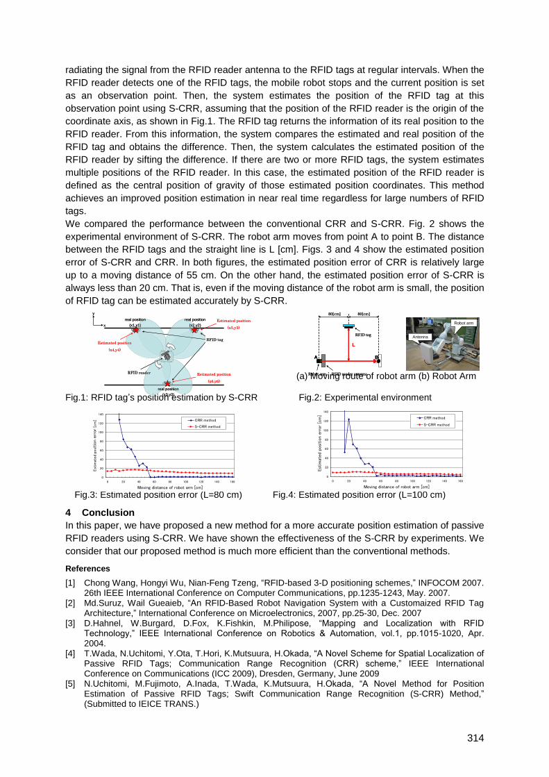
314
radiating the signal from the RFID reader antenna to the RFID tags at regular intervals. When the
RFID reader detects one of the RFID tags, the mobile robot stops and the current position is set
as an observation point. Then, the system estimates the position of the RFID tag at this
observation point using S-CRR, assuming that the position of the RFID reader is the origin of the
coordinate axis, as shown in Fig.1. The RFID tag returns the information of its real position to the
RFID reader. From this information, the system compares the estimated and real position of the
RFID tag and obtains the difference. Then, the system calculates the estimated position of the
RFID reader by sifting the difference. If there are two or more RFID tags, the system estimates
multiple positions of the RFID reader. In this case, the estimated position of the RFID reader is
defined as the central position of gravity of those estimated position coordinates. This method
achieves an improved position estimation in near real time regardless for large numbers of RFID
tags.
We compared the performance between the conventional CRR and S-CRR. Fig. 2 shows the
experimental environment of S-CRR. The robot arm moves from point A to point B. The distance
between the RFID tags and the straight line is L [cm]. Figs. 3 and 4 show the estimated position
error of S-CRR and CRR. In both figures, the estimated position error of CRR is relatively large
up to a moving distance of 55 cm. On the other hand, the estimated position error of S-CRR is
always less than 20 cm. That is, even if the moving distance of the robot arm is small, the position
of RFID tag can be estimated accurately by S-CRR.
(a) Moving route of robot arm (b) Robot Arm
Fig.1: RFID tag‘s position estimation by S-CRR Fig.2: Experimental environment
Fig.3: Estimated position error (L=80 cm) Fig.4: Estimated position error (L=100 cm)
4 Conclusion
In this paper, we have proposed a new method for a more accurate position estimation of passive
RFID readers using S-CRR. We have shown the effectiveness of the S-CRR by experiments. We
consider that our proposed method is much more efficient than the conventional methods.
References
[1] Chong Wang, Hongyi Wu, Nian-Feng Tzeng, ―RFID-based 3-D positioning schemes,‖ INFOCOM 2007. 26th IEEE International Conference on Computer Communications, pp.1235-1243, May. 2007.
[2] Md.Suruz, Wail Gueaieb, ―An RFID-Based Robot Navigation System with a Customaized RFID Tag Architecture,‖ International Conference on Microelectronics, 2007, pp.25-30, Dec. 2007
[3] D.Hahnel, W.Burgard, D.Fox, K.Fishkin, M.Philipose, ―Mapping and Localization with RFID Technology,‖ IEEE International Conference on Robotics & Automation, vol.1, pp.1015-1020, Apr. 2004.
[4] T.Wada, N.Uchitomi, Y.Ota, T.Hori, K.Mutsuura, H.Okada, ―A Novel Scheme for Spatial Localization of Passive RFID Tags; Communication Range Recognition (CRR) scheme,‖ IEEE International Conference on Communications (ICC 2009), Dresden, Germany, June 2009
[5] N.Uchitomi, M.Fujimoto, A.Inada, T.Wada, K.Mutsuura, H.Okada, ―A Novel Method for Position Estimation of Passive RFID Tags; Swift Communication Range Recognition (S-CRR) Method,‖ (Submitted to IEICE TRANS.)
0
20
40
60
80
100
120
140
0 20 40 60 80 100 120 140 160
Moving distance of robot arm [cm]
Est
imat
ed
position
err
or [
cm
] CRR method
S-CRR method
0
20
40
60
80
100
120
140
0 20 40 60 80 100 120 140 160
Moving distance of robot arm [cm]
Est
imat
ed p
ositio
n er
ror
[cm
]
CRR method
S-CRR method
RFID tag
RFID reader
real position
(x2,y2)
real position
(x1,y1)
real position
(x3,y3)
Estimated position
(x4,y4)
Estimated position
(x6,y6)
Estimated position
(x5,y5)x
y
RFID tag
RFID reader
real position
(x2,y2)
real position
(x1,y1)
real position
(x3,y3)
Estimated position
(x4,y4)
Estimated position
(x6,y6)
Estimated position
(x5,y5)x
y
A B
L
Robot arm
RFID tag
80[cm] 80[cm]
RFID reader antenna
A B
L
Robot arm
RFID tag
80[cm] 80[cm]
RFID reader antenna
Antenna
Robot arm
Antenna
Robot arm
315
Concrete Embedded RFID for Way-Point Positioning
Donnacha Dalya, Thomas Meliab and Gerard Baldwinc
[email protected], [email protected], [email protected]
a) Sebastian Mueller AG, Switzerland and Senior Member IEEE b) Silansys Semiconductor Ltd., Ireland
c) Xerenet Ltd., Ireland
1 Short Summary
RFID markers are proving to be a cheap and reliable enabler for indoor positioning in
applications such as warehousing, facility management and guidance for the blind. Motivated
by this we have developed a low-cost concrete embedded RFID marker technology for
robust and long-lasting way-point identification. Embedding passive tags in concrete
significantly reduces their read range and hence, usefulness as markers. By appropriate
modification of the antenna and packaging of passive tags we have extended hand-held
readability to over one meter, a distance previously unachievable for concrete embedded
RFID. This paper details the background research and subsequent development of our
modified tags, including results from our measurement campaign. Some applications of our
technology are also discussed.
2 Extended Abstract
There are many solutions to the indoor positioning problem, ranging from the exotic to the
expensive. In the radio domain, ranging methods include pulse timing of ultra wideband
signals, field strength measurements in Wi-Fi networks, and near-field electromagnetic
ranging, requiring active tags. Non-radio methods include infra-red and other optical systems
such as bar-codes requiring line of sight; ultrasonic methods using microphone arrays and
direction finding; and mechanical dead reckoning systems for simultaneous location and
mapping (SLAM). Of all of these methods, way-point methods using proximity detection of
passive markers are generally the least expensive to install and to maintain.
Way-point positioning and navigation is based on a known grid of identification markers
which are each associated in a database with their location. A good example are the pallet
bays in a warehouse which might be simply labelled A1, A2, B1, B2, etc. This is the simplest
way-point positioning system, and a forklift driver must know where bay B2 is and what
goods are stored there. A more sophisticated way-point system was developed by Georgia
Institute of Technology whereby two distinct radio frequencies are injected into the power-line
grid of a building. Because of the irregular topology of the power-line grid, the
electromagnetic radiation pattern from the injected tones is different in each room, and can
thus be recorded and stored in a database. This way-point system is based on field strength
measurements and a lookup table.
In between these extremes of complexity, passive RFID tags are a prime candidate for way-
point positioning, being both extremely cheap and easy easy to deploy. They don't have the
line-of-sight requirement of bar-codes, making them suitable for all sorts of environment. The
readers which are used as the positioning device can easily access the position database
using Wi-Fi for an indoor deployment. A commercial example of such a solution is the RFID-
woven carpet tile produced by Vorwerk in Germany. These tiles enforce proper cleaning of
316
carpeted facilities by requiring the cleaning equipment to register passing over all carpet tiles
at specified cleaning intervals.
In recognition of the ubiquity of RFID for way-point based indoor positioning we have taken
the concept of Vorwerk to a new level of ruggedness, by embedding RFID tags in concrete
paving stones. There is an academic and industrial track record of concrete embedded RFID
over the last few years, which we review in detail in our paper. We conclude in our review
that use of commercial, off-the-shelf passive tags results in unsatisfactory read ranges and
coverage for positioning applications. This has motivated our work on tag modification for
embedding in concrete.
The first part of our work revolves around the selection and testing of existing hardware (both
readers and tags) for the given application. It is found that the best hand-held read ranges
are reduced by anywhere from 60% – 90% by the embedding process (depending on the tag
type). In order to improve upon these disappointing results, we embark upon some trial and
error tests of various tag-antenna design modifications, underpinned with basic theoretical
results from electro-magnetics and taking account of altered dielectric of the concrete
substrate. Modified tags were successfully embedded in the stones, and thanks to these
improvements we now have low-cost smart-stones, RFID readable to distances of above 1m,
which was our goal.
There are a number of exciting applications for this technology, two of which we highlight
here. The first is in the positioning and navigation of automatic guided vehicles (AGVs) for
logistics applications. These are typically guided by optical navigation, using for example
painted lines on the floor. However, firms such as Scirocco in Sweden, and Auto-Tug in the
UK, have demonstrated AGV positioning using floor mounted RFID markers. In an industrial
environment, ruggedised tags are essential, and our concrete embedded tags should serve
this application well.
A second application is navigation systems for the blind. The Swiss railway network SBB is
currently provided with CARENA paving stones, which have a tactile feature distinguishable
by the visually impaired using a cane. This allows their blind customers to navigate safely
along platforms and throughout stations. Embedding RFID in paving stones at train stations
and other public spaces, will allow RFID enabled hand-held devices act as navigation
systems for blind people through an audio interface. The beauty of this system will be the
discrete nature of the solution, with no visible markers and perhaps even elimination of the
need for a cane.
What we do not cover in this paper are the areas of our ongoing research such as the
optimal distribution of our paving stones for way-point positioning, the design of the database
containing our geographical information system (GIS) and the best design for an application
interface to this system. Our focus is more on the development of enabling technology for
robust way-point positioning rather than the use of that technology.
As an interesting addendum some comment on the future of concrete embeddable
electronics is also presented, such as the use of passive sensors for temperature, vibration
and strain measurement in structural health management. However, these thoughts are
secondary to our main result on the feasibility of concrete embedded RFID for way-point
positioning.
317
A New Approach for an RFID Indoor Positioning System Without Fixed
Coordinates for Visually Impaired and Blind People
Martijn Kiers, Elmar Krajnc, Werner Bischof, Markus Dornhofer
FH JOANNEUM, University of Applied Sciences, Institute of EVU and ITM, Werk VI Str. 46,
A-8605 Kapfenberg, Austria
1 Summary
In the project ―Ways4all‖ passive RFID-tags are used to identify indoor routes, barriers and
means of public transport. The basis for this project is the tactile guidance system where
RFID-tags are placed at strategic spots (entrance, platforms). Those RFID-tags send their
code through an RFID-reader to the user‘s mobile phone. The phone sends the code to an
RFID-database server where all the tags together with some additional information are saved
as location points. For the routing a new navigation software, the so called ―Gerwei-Method‖,
has been developed. Before leaving, the user has to enter his/her destination by which the
server with the ―Gerwei-Method‖ calculates the optimal route. The mobile phone receives
real-time routing information (including interruptions, delays and platform changes) from the
database server. On the phone the routing information will be sent in an acoustic way to the
blind person. This way, the blind person gets his/her indoor route instructions from the
system.
2 The Project “Ways4All” and Related Work
Currently RFID technologies for routing blind people are used in different projects in public
transport and navigation. Example projects are 1) Sesamonet, Italy which uses passive
RFID-tags and a white cane with a built-in RFID-reader for a special route along the
promenade at Lake Maggiore. 2) RouteOnline, the Netherlands which uses active RFID Tags
and a hand held reader to find a route at different stations. 3) BIGS, Korea which uses a
smart floor (each tile of the floor has a passive RFID tag) and the portable terminal unit. 4)
Bus-ID, Germany, uses RFID tags for sending public transport information towards a reader
and a database. 5) RFID Information Grid which uses the RFID tags for indoor routing in the
Campus. The RFID tags are programmed with spatial coordinates and information to
describe the surroundings. No centralized database or wireless infrastructure for
communication is used. Taking these examples into consideration it can be concluded that
different institutes are researching the use of RFID tags to make daily life for visually
impaired and blind people more enjoyable. The project ―Ways4all‖ is using low frequent
passive RFID-tags to indentify indoor routes, barriers and means of public transport.
3 RFID Navigation for Blind People
Most navigation systems require a method to define one‘s absolute position within a closed
system. For example from the Global Position System – GPS – you get the longitude and
latitude. This helps you to get to a target destination, which is also defined with absolute
coordinates. In buildings, satellite based systems are not available and the internal
construction can change very easily.
For an RFID based indoor navigation the following requirements are: a) passive RFID tags b)
no absolute position data stored on the tags, c) simple and cost-friendly distribution of the
RFID tags, d) recording, data-enrichment and storing of the tags in a central database and e)
a mobile application for tag-reading and navigating designed for blind people. The
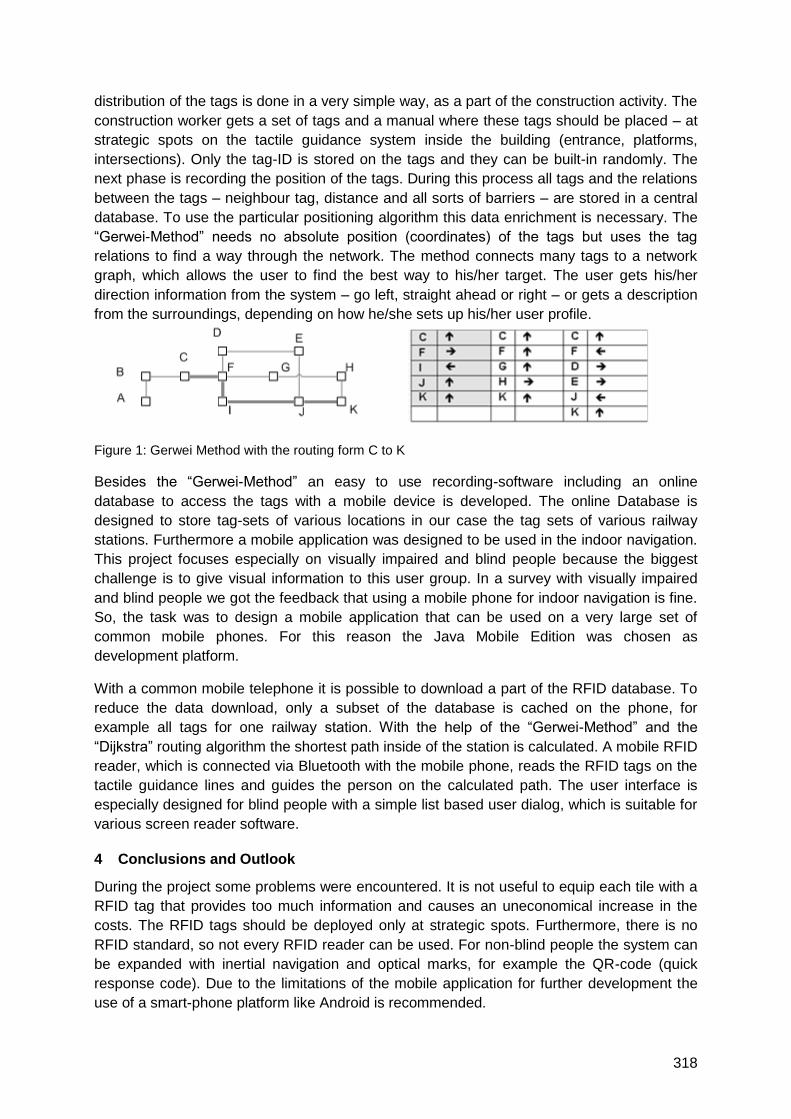
318
distribution of the tags is done in a very simple way, as a part of the construction activity. The
construction worker gets a set of tags and a manual where these tags should be placed – at
strategic spots on the tactile guidance system inside the building (entrance, platforms,
intersections). Only the tag-ID is stored on the tags and they can be built-in randomly. The
next phase is recording the position of the tags. During this process all tags and the relations
between the tags – neighbour tag, distance and all sorts of barriers – are stored in a central
database. To use the particular positioning algorithm this data enrichment is necessary. The
―Gerwei-Method‖ needs no absolute position (coordinates) of the tags but uses the tag
relations to find a way through the network. The method connects many tags to a network
graph, which allows the user to find the best way to his/her target. The user gets his/her
direction information from the system – go left, straight ahead or right – or gets a description
from the surroundings, depending on how he/she sets up his/her user profile.
Figure 1: Gerwei Method with the routing form C to K
Besides the ―Gerwei-Method‖ an easy to use recording-software including an online
database to access the tags with a mobile device is developed. The online Database is
designed to store tag-sets of various locations in our case the tag sets of various railway
stations. Furthermore a mobile application was designed to be used in the indoor navigation.
This project focuses especially on visually impaired and blind people because the biggest
challenge is to give visual information to this user group. In a survey with visually impaired
and blind people we got the feedback that using a mobile phone for indoor navigation is fine.
So, the task was to design a mobile application that can be used on a very large set of
common mobile phones. For this reason the Java Mobile Edition was chosen as
development platform.
With a common mobile telephone it is possible to download a part of the RFID database. To
reduce the data download, only a subset of the database is cached on the phone, for
example all tags for one railway station. With the help of the ―Gerwei-Method‖ and the
―Dijkstra‖ routing algorithm the shortest path inside of the station is calculated. A mobile RFID
reader, which is connected via Bluetooth with the mobile phone, reads the RFID tags on the
tactile guidance lines and guides the person on the calculated path. The user interface is
especially designed for blind people with a simple list based user dialog, which is suitable for
various screen reader software.
4 Conclusions and Outlook
During the project some problems were encountered. It is not useful to equip each tile with a
RFID tag that provides too much information and causes an uneconomical increase in the
costs. The RFID tags should be deployed only at strategic spots. Furthermore, there is no
RFID standard, so not every RFID reader can be used. For non-blind people the system can
be expanded with inertial navigation and optical marks, for example the QR-code (quick
response code). Due to the limitations of the mobile application for further development the
use of a smart-phone platform like Android is recommended.
319
A new paradigm of passive-RFID based localization systems
Emidio Di Giampaolo
Università dell’Aquila, Dipartimento di Ingegneria Elettrica e dell’Informazione, via G. Gronchi,
18, I-67100 L’Aquila
1 Summary
A new localization paradigm based on passive RFID systems with low radiated power is
investigated and simple localization algorithms are presented. A theoretical model has been
developed and tested by means of numerical and experimental analyses. Our model allows a
mobile device with an RFID reader to localize itself with respect to a grid of fixed tags used
as reference anchors. Simple localization algorithms based on a proximity technique allow a
real-time localization. The localization accuracy can be tuned by varying a set of parameters.
Experimental results show both the feasibility and the reliability of the proposed method.
2 System description and experimental results
Various emerging applications of wireless technology like location based services,
emergency services, tourism and people management, healthcare monitoring, logistics and
many more require systems and devices with location sensing capability. While the
technology is well-established for localization in outdoor environments, it is still evolving for
indoor environments. Different technologies with a multiplicity of localization techniques have
been proposed, in particular the Ultra High Frequency (UHF) Radio Frequency Identification
(RFID) technology seems to be promising for some applications whose services are based
on identification and positioning of items and people. Localization systems based on UHF
passive-tags and radio connectivity information (i.e. which tag is detect and which is not)
have the advantage of low cost and simplicity in implementation. They can be deployed
using off-the-shelf technology without additional equipments, hardware modifications and
sensitive calibrations that are required by other localization RFID based systems [1], [2].
Passive-tag based systems however have some drawbacks. Because of the poor sensitivity
of the IC transponder, the interrogating device is required to radiate a high level of power
(1W) to allow tags to reply from long distances. This requirement may be unsuitable for
small readers integrated inside handheld devices having multi-function capability (e.g.
integrating an RFID reader with a cell phone) because their energy source may be quickly
discharged. These systems usually require a high density deployment of tags which may be
impractical and expensive, moreover complex localization algorithms (as those based on
optimization methods) are used for positioning. Finally, passive-tags are very sensitive to
indoor multipath which makes them unreliable for position estimation.
For these reasons a new localization method that allows the use of passive tags, low
radiated power, with simple localization algorithms, coarse grid of tags and multipath-
resistant is investigated. It allows 2D localization of moving users (machines and people). A
simple proximity technique (i.e. the measurement of the nearness to a known set of
reference points) allows a mobile device to localize itself in real-time. A tag is detected when
it enters the so called read region which is a space volume nearby the reader location where
the power collected by the tag exceeds the IC sensitivity and the tag is activated [3]. Each
detected tag, labelled by the unique identification code of its IC, transmits its coordinates to a
handheld interrogating device which handles these data to determine the user‘s position. The
320
proposed localization paradigm exploits both the extension and the shape of the read region
to carry out localization. The shaping is achieved with a suitable design of reader‘s and tag‘s
antennas while the extension is controlled by varying the emitted power. The parameters
affecting the read region (i.e. the power emitted by the reader, the tag sensitivity, the
radiation pattern of both reader‘s and tag‘s antenna, the orientation of antennas and also the
nearby scenario) are encoded into geometrical parameters describing the space volume of
the read region. This permits to transform the localization problem into a geometrical problem
which does not require any kind of measurements except the acquisition of the answers of
the tags. Hence, any possible localization error is attributable to the discrepancy between the
geometrical model of the read region and the actual read region. For this reason, an
evaluation of the practical feasibility of the shaped read region has been developed by
means of a theoretical and an experimental analysis, and the reliability of the localization
paradigm has been evaluated experimentally.
The performance of the proposed system has been experimentally evaluated in terms of
localization and tracking of people. The experiment has been carried out in a laboratory room
that is a highly scattering environment with shelves, desks, chairs, and many instruments.
The experimental setup (at 870 MHz) consists of a reader (CAEN-A948) with a commercial
patch antenna for circular polarized signals. A square mesh grid of ad-hoc designed tags is
deployed on the ceiling (3 m in height). The distance between the tags is 1.2 m. The reader‘s
antenna is kept about 1 m above the floor by the hands of a person that walks along a
prearranged path. During the walk a computer stores the tags‘ readings, determines the
user‘s position and controls the reader‘s parameters. The input power of the reader is 50mW.
Experimental results show that the deviation between the estimated path and the actual path
is lower than 0.5 m.
Our results show both the feasibility and the reliability of the localization method that has
many degrees of freedom (i.e. frequency, input power, design of reader‘s and tag‘s antennas,
IC sensitivity). Our method can be improved in its accuracy and can be tailored for specific
environments. The advantages of the proposed method are manifold. It is suitable for sensor
fusion (e.g. inertial sensors). The low input power permits to integrate the reader inside multi-
utility handheld devices which can exploit the localization information for specific services
using other wireless communication facilities. Passive tags are not sensitive to power
outages. , In case of a electricity failure (e.g. a fire of other emergencies) all the other
networks (e.g. for communications and lights) are cut off but the passive-tag based
localization system remains functional and may help users to find the way out and supports
fire fighters to act more safely. Passive tags are easy and cheap to install while the
maintenance is marginal.
3 References
[1] Sanpechuda, T. Kovavisaruch, L., ―A review of RFID localization: Applications and techniques‖,
Proc. 5th International Conference on Electrical Engineering/ Electronics, Computer,
Telecommunications and Information Technology, 2008. ECTI-CON 2008, Volume: 2, pp. 769-
772, May 2008.
[2] Feifei Guo, Chunkai Zhang, Min Wang, Xiaofei Xu, ―Research of Indoor Location Method Based
on the RFID Technology‖, Proceedings of the 11th Joint Conference on Information Sciences
(2008).
[3] G. Marrocco, E. Di Giampaolo, R. Aliberti ―Estimation of UHF RFID read-regions in real
environments‖, IEEE Antennas and Propagation Magazine Vol. 51, n.6, pp.44-57, doi:
10.1109/MAP.2009.5433096.
321
RFID Tag Localization Using Pattern Matching
Yingliang Lu, Yaokai Feng, Hao Yu
Fujitsu R&D Center CO., LTD., 13/F, Tower A, Ocean International Center No. 56 Dong Si
Huan Zhong Rd, Chaoyang District, Beijing, 100025 P. R. China
Faculty of Information Science and Electrical Engineering,Kyushu University, Japan
1 Summary
In this paper, we investigate the use of passive RFID technology for object localization. Due
to the limitation of a RFID (Radio Frequency IDentification) reader when using a RFID with
traditional methods, a reader can only determine whether the tag is inside or outside its data
transmission range, but cannot necessarily localize the exact position of the specified RFID
tag within the communication range of the RFID reader. However, in order to find the
trajectory and location of a specified tag, we log the trend graphics (Fig. 2) of some tag
reading success ratio in advance, then we provide a pattern matching algorithm in order to
track the reading success ratio of the specified tag. At last, the exact position can be
determined from the trajectory of the specified tag. In our experimental results, a Fujitsu
RFID Reader was used, and the localization was achieved with an accuracy of roughly 10
cm.
2 Introduction
Traditionally, a RFID reader can only determine whether the tag is inside or outside the
transmission range of the RFID reader. Traditional methods cannot localize the exact
position of a RFID tag when the tag is inside the communication area of the RFID reader.
The UHF RFID technologies are used in a wide application area, such as for supply chains.
This technology can support to read multi-tags by a RFID reader. So we need to determine
the exact position of a RFID tag that is in the communication range of a RFID reader.
However, this paper provides a method to track the variation of the success ratio of the
specified RFID tag when it enters the transmission range of a RFID reader in order to find the
exact position of the tag. This method can provide good performance on automatic
localization of the specified tag. Furthermore, the provided algorithm can detect the
orientation of a tag that passes through the transmission range of a RFID reader. Certainly,
we also can locate the RFID reader itself more precise by moving the reader as reported by
[1, 2].
The following steps have been implemented in our algorithm:
1. Training and establishing of a database with the reading success ratio and trajectories.
2. Monitoring of the reading success ratio for a specified tag.
3. Assembly of a sequence of the reading success ratio of the specified tag.
4. Matching of the sequence with the reading success ratio and the trajectory curves which
are retrieved from the database.
5. Compute the most likely position of the specified tag using a pattern matching algorithm.
6. Output the position of the specified tag
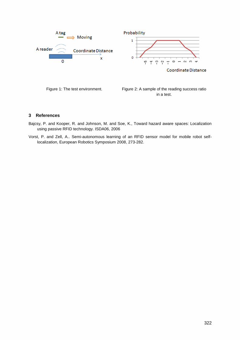
322
Figure 1: The test environment. Figure 2: A sample of the reading success ratio
in a test.
3 References
Bajcsy, P. and Kooper, R. and Johnson, M. and Soe, K., Toward hazard aware spaces: Localization
using passive RFID technology. ISDA06, 2006
Vorst, P. and Zell, A.. Semi-autonomous learning of an RFID sensor model for mobile robot self-
localization, European Robotics Symposium 2008, 273-282.

323
Active & General RFID
Auditorium D8
Wednesday, September 15, 13:15 – 15:30

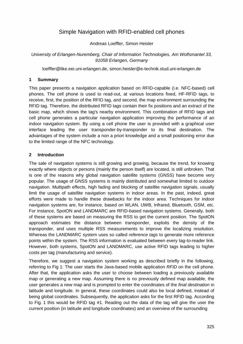
325
Simple Navigation with RFID-enabled cell phones
Andreas Loeffler, Simon Heisler
University of Erlangen-Nuremberg, Chair of Information Technologies, Am Wolfsmantel 33,
91058 Erlangen, Germany
[email protected], [email protected]
1 Summary
This paper presents a navigation application based on RFID-capable (i.e. NFC-based) cell
phones. The cell phone is used to read-out, at various locations fixed, HF-RFID tags, to
receive, first, the position of the RFID tag, and second, the map environment surrounding the
RFID tag. Therefore, the distributed RFID tags contain their fix positions and an extract of the
basic map, which shows the tag's nearby environment. This combination of RFID tags and
cell phone generates a particular navigation application improving the performance of an
indoor navigation system. By using a cell phone the user is provided with a graphical user
interface leading the user transponder-by-transponder to its final destination. The
advantages of the system include a non a priori knowledge and a small positioning error due
to the limited range of the NFC technology.
2 Introduction
The sale of navigation systems is still growing and growing, because the trend, for knowing
exactly where objects or persons (mainly the person itself) are located, is still unbroken. That
is one of the reasons why global navigation satellite systems (GNSS) have become very
popular. The usage of GNSS systems is mainly distributed and somewhat limited to outdoor
navigation. Multipath effects, high fading and blocking of satellite navigation signals, usually
limit the usage of satellite navigation systems in indoor areas. In the past, indeed, great
efforts were made to handle these drawbacks for the indoor area. Techniques for indoor
navigation systems are, for instance, based on WLAN, UWB, Infrared, Bluetooth, GSM, etc.
For instance, SpotON and LANDMARC are RFID-based navigation systems. Generally, both
of these systems are based on measuring the RSS to get the current position. The SpotON
approach estimates the distance between transponder, exploits the density of the
transponder, and uses multiple RSS measurements to improve the localizing resolution.
Whereas the LANDMARC system uses so called reference tags to generate more reference
points within the system. The RSS information is evaluated between every tag-to-reader link.
However, both systems, SpotON and LANDMARC, use active RFID tags leading to higher
costs per tag (manufacturing and service).
Therefore, we suggest a navigation system working as described briefly in the following,
referring to Fig 1: The user starts the Java-based mobile application RFID on the cell phone.
After that, the application asks the user to choose between loading a previously available
map or generating a new map. Assuming there is no previously defined map available, the
user generates a new map and is prompted to enter the coordinates of the final destination in
latitude and longitude. In general, these coordinates could also be local defined, instead of
being global coordinates. Subsequently, the application asks for the first RFID tag. According
to Fig. 1 this would be RFID tag #1. Reading out the data of the tag will give the user the
current position (in latitude and longitude coordinates) and an overview of the surrounding
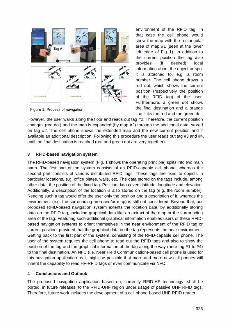
326
environment of the RFID tag. In
that case the cell phone would
show the map with the rectangular
area of map #1 (seen at the lower
left edge of Fig. 1). In addition to
the current position the tag also
provides (if desired) local
information about the object or spot
it is attached to, e.g. a room
number. The cell phone draws a
red dot, which shows the current
position (respectively the position
of the RFID tag) of the user.
Furthermore, a green dot shows
the final destination and a orange
line links the red and the green dot.
However, the user walks along the floor and reads out tag #2. Therefore, the current position
changes (red dot) and the map is expanded (by map #2) through the additional data, stored
on tag #2. The cell phone shows the extended map and the new current position and if
available an additional description. Following this procedure the user reads out tag #3 and #4,
until the final destination is reached (red and green dot are very together).
3 RFID-based navigation system
The RFID-based navigation system (Fig. 1 shows the operating principle) splits into two main
parts. The first part of the system consists of an RFID-capable cell phone, whereas the
second part consists of various distributed RFID tags. These tags are fixed to objects in
particular locations, e.g. office plates, walls, etc. The data stored on the tags include, among
other data, the position of the fixed tag. Position data covers latitude, longitude and elevation.
Additionally, a description of the location is also stored on the tag (e.g. the room number).
Reading such a tag would offer the user only the position and a description of it, whereas the
environment (e.g. the surrounding area and/or map) is still not considered. Beyond that, our
proposed RFID-based navigation system extents the location data, by additionally storing
data on the RFID tag, including graphical data like an extract of the map or the surrounding
area of the tag. Featuring such additional graphical information enables users of these RFID-
based navigation systems to orient themselves in the near environment of the RFID tag or
current position, provided that the graphical data on the tag represents the near environment.
Getting back to the first part of the system, consisting of the RFID-capable cell phone. The
user of the system requires the cell phone to read out the RFID tags and also to show the
position of the tag and the graphical information of the tag along the way (here tag #1 to #4)
to the final destination. An NFC (i.e. Near Field Communication)-based cell phone is used for
this navigation application as it might be possible that more and more new cell phones will
inherit the capability to read HF-RFID tags or even communicate via NFC.
4 Conclusions and Outlook
The proposed navigation application based on, currently RFID-HF technology, shall be
ported, in future releases, to the RFID-UHF region under usage of passive UHF RFID tags.
Therefore, future work includes the development of a cell phone-based UHF-RFID reader.
Figure 1: Process of navigation
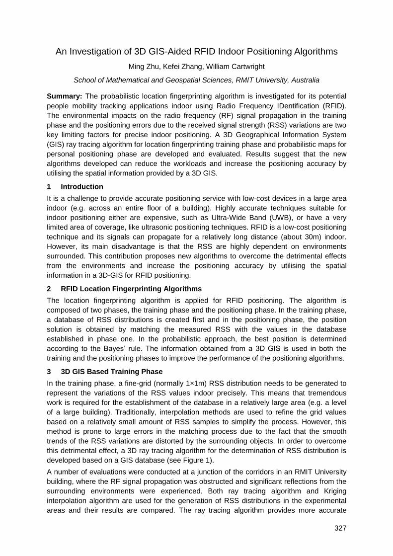
327
An Investigation of 3D GIS-Aided RFID Indoor Positioning Algorithms
Ming Zhu, Kefei Zhang, William Cartwright
School of Mathematical and Geospatial Sciences, RMIT University, Australia
Summary: The probabilistic location fingerprinting algorithm is investigated for its potential
people mobility tracking applications indoor using Radio Frequency IDentification (RFID).
The environmental impacts on the radio frequency (RF) signal propagation in the training
phase and the positioning errors due to the received signal strength (RSS) variations are two
key limiting factors for precise indoor positioning. A 3D Geographical Information System
(GIS) ray tracing algorithm for location fingerprinting training phase and probabilistic maps for
personal positioning phase are developed and evaluated. Results suggest that the new
algorithms developed can reduce the workloads and increase the positioning accuracy by
utilising the spatial information provided by a 3D GIS.
1 Introduction
It is a challenge to provide accurate positioning service with low-cost devices in a large area
indoor (e.g. across an entire floor of a building). Highly accurate techniques suitable for
indoor positioning either are expensive, such as Ultra-Wide Band (UWB), or have a very
limited area of coverage, like ultrasonic positioning techniques. RFID is a low-cost positioning
technique and its signals can propagate for a relatively long distance (about 30m) indoor.
However, its main disadvantage is that the RSS are highly dependent on environments
surrounded. This contribution proposes new algorithms to overcome the detrimental effects
from the environments and increase the positioning accuracy by utilising the spatial
information in a 3D-GIS for RFID positioning.
2 RFID Location Fingerprinting Algorithms
The location fingerprinting algorithm is applied for RFID positioning. The algorithm is
composed of two phases, the training phase and the positioning phase. In the training phase,
a database of RSS distributions is created first and in the positioning phase, the position
solution is obtained by matching the measured RSS with the values in the database
established in phase one. In the probabilistic approach, the best position is determined
according to the Bayes‘ rule. The information obtained from a 3D GIS is used in both the
training and the positioning phases to improve the performance of the positioning algorithms.
3 3D GIS Based Training Phase
In the training phase, a fine-grid (normally 1×1m) RSS distribution needs to be generated to
represent the variations of the RSS values indoor precisely. This means that tremendous
work is required for the establishment of the database in a relatively large area (e.g. a level
of a large building). Traditionally, interpolation methods are used to refine the grid values
based on a relatively small amount of RSS samples to simplify the process. However, this
method is prone to large errors in the matching process due to the fact that the smooth
trends of the RSS variations are distorted by the surrounding objects. In order to overcome
this detrimental effect, a 3D ray tracing algorithm for the determination of RSS distribution is
developed based on a GIS database (see Figure 1).
A number of evaluations were conducted at a junction of the corridors in an RMIT University
building, where the RF signal propagation was obstructed and significant reflections from the
surrounding environments were experienced. Both ray tracing algorithm and Kriging
interpolation algorithm are used for the generation of RSS distributions in the experimental
areas and their results are compared. The ray tracing algorithm provides more accurate
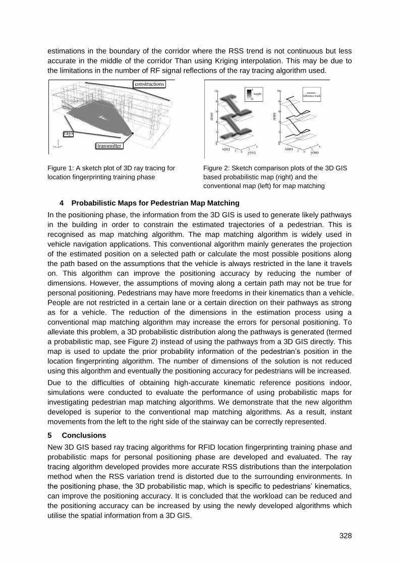
328
estimations in the boundary of the corridor where the RSS trend is not continuous but less
accurate in the middle of the corridor Than using Kriging interpolation. This may be due to
the limitations in the number of RF signal reflections of the ray tracing algorithm used.
Figure 1: A sketch plot of 3D ray tracing for
location fingerprinting training phase
Figure 2: Sketch comparison plots of the 3D GIS
based probabilistic map (right) and the
conventional map (left) for map matching
4 Probabilistic Maps for Pedestrian Map Matching
In the positioning phase, the information from the 3D GIS is used to generate likely pathways
in the building in order to constrain the estimated trajectories of a pedestrian. This is
recognised as map matching algorithm. The map matching algorithm is widely used in
vehicle navigation applications. This conventional algorithm mainly generates the projection
of the estimated position on a selected path or calculate the most possible positions along
the path based on the assumptions that the vehicle is always restricted in the lane it travels
on. This algorithm can improve the positioning accuracy by reducing the number of
dimensions. However, the assumptions of moving along a certain path may not be true for
personal positioning. Pedestrians may have more freedoms in their kinematics than a vehicle.
People are not restricted in a certain lane or a certain direction on their pathways as strong
as for a vehicle. The reduction of the dimensions in the estimation process using a
conventional map matching algorithm may increase the errors for personal positioning. To
alleviate this problem, a 3D probabilistic distribution along the pathways is generated (termed
a probabilistic map, see Figure 2) instead of using the pathways from a 3D GIS directly. This
map is used to update the prior probability information of the pedestrian‘s position in the
location fingerprinting algorithm. The number of dimensions of the solution is not reduced
using this algorithm and eventually the positioning accuracy for pedestrians will be increased.
Due to the difficulties of obtaining high-accurate kinematic reference positions indoor,
simulations were conducted to evaluate the performance of using probabilistic maps for
investigating pedestrian map matching algorithms. We demonstrate that the new algorithm
developed is superior to the conventional map matching algorithms. As a result, instant
movements from the left to the right side of the stairway can be correctly represented.
5 Conclusions
New 3D GIS based ray tracing algorithms for RFID location fingerprinting training phase and
probabilistic maps for personal positioning phase are developed and evaluated. The ray
tracing algorithm developed provides more accurate RSS distributions than the interpolation
method when the RSS variation trend is distorted due to the surrounding environments. In
the positioning phase, the 3D probabilistic map, which is specific to pedestrians‘ kinematics,
can improve the positioning accuracy. It is concluded that the workload can be reduced and
the positioning accuracy can be increased by using the newly developed algorithms which
utilise the spatial information from a 3D GIS.
329
Improving RFID-Based Indoor Positioning Accuracy Using Gaussian
Processes
Fernando Seco*1, Christian Plagemann2, Antonio R. Jiménez1, Wolfram Burgard2
(1) Centro de Automática y Robótica, Consejo Superior de Investigaciones Científicas (CSIC), Ctra.
Campo Real km 0,200, 28500 Arganda del Rey, Madrid, Spain
(2) University of Freiburg, Department for Computer Science, Georges-Koehler-Allee, Geb. 079,
79110 Freiburg, Germany
(*) Corresponding e-mail: [email protected]
1 Bayesian methods for indoor location
Most local positioning systems (LPS) for indoor environments based on radiofrequency
signals lack the capability to measure the range from emitter to receiver, but instead estimate
the location of the mobile user from the received signal strength indicator (RSSI). As the
RSSI depends not only on the range, but is also affected by multipath propagation,
interference, and blocking caused by obstacles, in an essentially unpredictable way, efficient
location estimation can be achieved by Bayesian techniques [Fox03].
In Bayesian localization, the position of the user is considered a random variable, whose
probability density function (pdf) p(x), is updated sequentially from time t-1 to time t:
dxuxxpxpxRSSIpuRSSIxp ttt
x
tttttt ),|()()|(),|( 11 , (1)
where ),|( 1 ttt uxxp is a motion model with the available information tu about the user‘s
displacement (obtained with an odometer or an inertial sensor), and )|( tt xRSSIp is an
observation model which relates the measured signal strength tRSSI to the position tx . This
observation model should fit the experimental distribution of the RSSI as accurately as
possible. For simplicity, it is assumed that the model follows a Gaussian distribution:
))(),(()|( 2 xxNxRSSIp RSSIRSSI . (2)
Simple observation models consider that the signal strength varies only with the range r
between the emitter and the receiver [Koutsou 2007], but this assumption of isotropy sets a
limit to the attainable precision. Gaussian processes (GPs) provide non-parametric,
probabilistic function regression between position x and signal strength RSSI, and have been
applied successfully to RF-based indoor and outdoor localization [Ferris 2006], showing
accuracy comparable to fingerprinting techniques.
2 Preliminary experimental results
We have developed a Radiofrequency Identification (RFID) based LPS [Koutsou 2007], in
which the user carries a reader and determines his position from the RSSI of signals
received from a set of active tags placed at known positions. In the calibration stage, RSSI
measurements for all tags were sampled at 100 random positions; figure 1 shows the results
obtained for one particular tag placed at the corner of our lobby hall, where clearly the signal
strength dependence with position is far from isotropic.

330
Figure 1: Signal strength samples for one
RFID tag (red point) at several calibration
points. RSSI measurements are indicated by
full circles, whose size corresponds to the
obtained RSSI value. Open circles denote
points where the tag was not detected.
Figure 2 shows a GP sensor model (of the form given by eq. 2) learned from the empirical
tag data, reflecting the anisotropic nature of RF signal propagation. The variance of the
estimated RSSI is higher in places where calibration measurements are not available,
indicating larger uncertainty at those points. We are currently evaluating how this GP-based
observation model improves the accuracy obtained with earlier versions of our RFID- LPS.
Future work includes fusion between Bayesian location methods and inertial sensors (INS) to
estimate the user‘s motion (see [Jiménez 2010], presented in this conference).
Figure 2: Gaussian process model prediction for the RSSI distribution on the complete building, based
on the data from figure 1: (a) mean )(xRSSI
; (b) variance )(2 xRSSI
.
References
[Fox 2003] D. Fox, J. Hightower, L. Liao, D. Schulz, and G. Borriello, ―Bayesian filtering for location
estimation,‖ Pervasive computing, vol. 2, no. 3, pp. 24–33, 2003.
[Koutsou 2007] A. Koutsou, F. Seco et al, ―Preliminary localization results with an RFID based indoor
guiding system,‖ in IEEE Int. Symposium on Intelligent Signal Processing, Alcalá de Henares,
2007.
[Ferris 2006] B. Ferris, D. Haehnel, and D. Fox, ―Gaussian processes for signal strength-based
location estimation,‖ in Proc. of Robotics Science and Systems, University of Pennsylvania, 2006.
[Jiménez 2010] A. R. Jiménez et al, ―Pedestrian Indoor Navigation by aiding a Foot-mounted IMU with
RFID Signal Strength Measurements‖, International Conference on Indoor Positioning and Indoor
Navigation (IPIN), Sept 15-17, 2010, Zurich, Switzerland
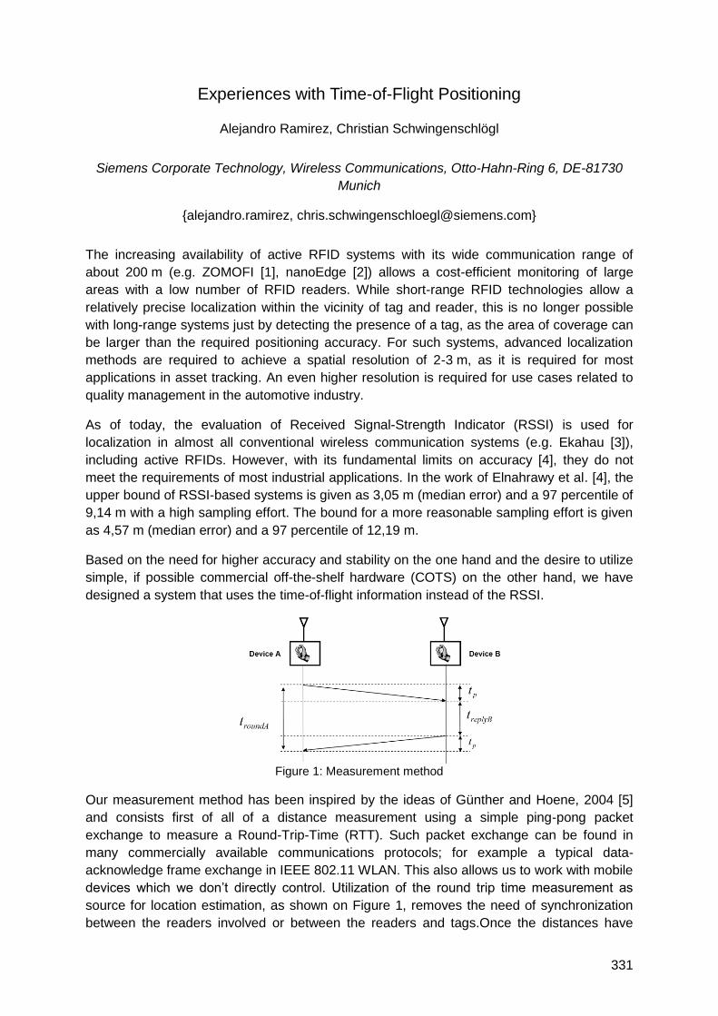
331
Experiences with Time-of-Flight Positioning
Alejandro Ramirez, Christian Schwingenschlögl
Siemens Corporate Technology, Wireless Communications, Otto-Hahn-Ring 6, DE-81730
Munich
{alejandro.ramirez, [email protected]}
The increasing availability of active RFID systems with its wide communication range of
about 200 m (e.g. ZOMOFI [1], nanoEdge [2]) allows a cost-efficient monitoring of large
areas with a low number of RFID readers. While short-range RFID technologies allow a
relatively precise localization within the vicinity of tag and reader, this is no longer possible
with long-range systems just by detecting the presence of a tag, as the area of coverage can
be larger than the required positioning accuracy. For such systems, advanced localization
methods are required to achieve a spatial resolution of 2-3 m, as it is required for most
applications in asset tracking. An even higher resolution is required for use cases related to
quality management in the automotive industry.
As of today, the evaluation of Received Signal-Strength Indicator (RSSI) is used for
localization in almost all conventional wireless communication systems (e.g. Ekahau [3]),
including active RFIDs. However, with its fundamental limits on accuracy [4], they do not
meet the requirements of most industrial applications. In the work of Elnahrawy et al. [4], the
upper bound of RSSI-based systems is given as 3,05 m (median error) and a 97 percentile of
9,14 m with a high sampling effort. The bound for a more reasonable sampling effort is given
as 4,57 m (median error) and a 97 percentile of 12,19 m.
Based on the need for higher accuracy and stability on the one hand and the desire to utilize
simple, if possible commercial off-the-shelf hardware (COTS) on the other hand, we have
designed a system that uses the time-of-flight information instead of the RSSI.
Figure 1: Measurement method
Our measurement method has been inspired by the ideas of Günther and Hoene, 2004 [5]
and consists first of all of a distance measurement using a simple ping-pong packet
exchange to measure a Round-Trip-Time (RTT). Such packet exchange can be found in
many commercially available communications protocols; for example a typical data-
acknowledge frame exchange in IEEE 802.11 WLAN. This also allows us to work with mobile
devices which we don‘t directly control. Utilization of the round trip time measurement as
source for location estimation, as shown on Figure 1, removes the need of synchronization
between the readers involved or between the readers and tags.Once the distances have
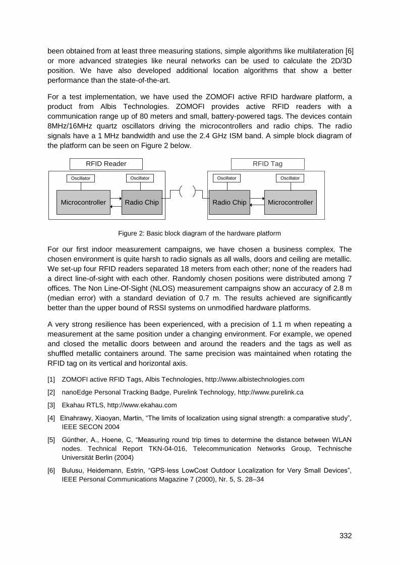
332
been obtained from at least three measuring stations, simple algorithms like multilateration [6]
or more advanced strategies like neural networks can be used to calculate the 2D/3D
position. We have also developed additional location algorithms that show a better
performance than the state-of-the-art.
For a test implementation, we have used the ZOMOFI active RFID hardware platform, a
product from Albis Technologies. ZOMOFI provides active RFID readers with a
communication range up of 80 meters and small, battery-powered tags. The devices contain
8MHz/16MHz quartz oscillators driving the microcontrollers and radio chips. The radio
signals have a 1 MHz bandwidth and use the 2.4 GHz ISM band. A simple block diagram of
the platform can be seen on Figure 2 below.
Microcontroller Radio Chip Radio Chip Microcontroller
Oscillator
RFID TagRFID Reader
Oscillator Oscillator Oscillator
Figure 2: Basic block diagram of the hardware platform
For our first indoor measurement campaigns, we have chosen a business complex. The
chosen environment is quite harsh to radio signals as all walls, doors and ceiling are metallic.
We set-up four RFID readers separated 18 meters from each other; none of the readers had
a direct line-of-sight with each other. Randomly chosen positions were distributed among 7
offices. The Non Line-Of-Sight (NLOS) measurement campaigns show an accuracy of 2.8 m
(median error) with a standard deviation of 0.7 m. The results achieved are significantly
better than the upper bound of RSSI systems on unmodified hardware platforms.
A very strong resilience has been experienced, with a precision of 1.1 m when repeating a
measurement at the same position under a changing environment. For example, we opened
and closed the metallic doors between and around the readers and the tags as well as
shuffled metallic containers around. The same precision was maintained when rotating the
RFID tag on its vertical and horizontal axis.
[1] ZOMOFI active RFID Tags, Albis Technologies, http://www.albistechnologies.com
[2] nanoEdge Personal Tracking Badge, Purelink Technology, http://www.purelink.ca
[3] Ekahau RTLS, http://www.ekahau.com
[4] Elnahrawy, Xiaoyan, Martin, ―The limits of localization using signal strength: a comparative study‖,
IEEE SECON 2004
[5] Günther, A., Hoene, C, ―Measuring round trip times to determine the distance between WLAN
nodes. Technical Report TKN-04-016, Telecommunication Networks Group, Technische
Universität Berlin (2004)
[6] Bulusu, Heidemann, Estrin, ―GPS-less LowCost Outdoor Localization for Very Small Devices‖,
IEEE Personal Communications Magazine 7 (2000), Nr. 5, S. 28–34
333
TraceMe – A Tool for Safety and Security in Clinical Governance using
RFID and Integration of Location Services in a Hospital Environment
Maximino Paralta1, Pedro Mestre2, Rafael Caldeirinha3,Jorge Rodrigues1 and Carlos
Serôdio2
1 ISA – Intelligent Sensing Anywhere, S.A.,
Estádio Cidade de Coimbra, 92 3030-320 Coimbra, Portugal 2CITAB-UTAD, University of Trás-os-Montes and Alto Douro, 5000-801 Vila Real, Portugal
3School of Technology and Management, Polytechnic Institute of Leiria and Instituto de
Telecomunicações, DL-IT, 2401-951 Leiria, Portugal
[email protected], [email protected], [email protected],
[email protected], [email protected]
1 Summary
TraceMe is an indoor location and tracking solution for people and assets, being a valuable
tool that can be used in clinical governance to map, monitor and measure the status and
location of high-value assets. It also provides critical data needed to improve workflows and
processes associated with these assets. Besides its use as a simple location-based system it
can also be used in access control applications for restricted areas, triggering alarms
whenever anomalous situations occur, e.g. when a specific equipment is taken outside its
area, or when a tag is violated. It is now being installed and tested in a hospital in Portugal,
where it is being integrated with other systems such as BabyMatchTM and AIDA (Agency for
Integration, Archive and Diffusion of Medical Information). For hospital administrators,
TraceMe rapid-impact implementation and fully managed service model not only supports
healthcare business processes, but also reduces costs and increases revenue.
2 Introduction
One of the main objectives of this system is to locate Radio Frequency Identification (RFID)
devices with low or no human involvement, with sufficient precision to allow the location
between areas in an indoor environment. Its main features include the ability to visualise
user/assets location in real time, appropriate identification of people and objects, and thus
their tracking between monitored zones, including the generation of alarms and allowing
routes to be recorded and visualized.
The proposed solution comprises of many RFID equipments. These are chosen accordingly
to each specific hospital scenario. For example, DynasysTM for staff, patients, visitors and
equipment, BabyMatchTM for child security control and AIDA to Integration, Archive and
Diffusion of Medical Information. TraceMe, however, being an open platform and device
independent, is able to integrate other hardware and software systems. This feature allows
low cost, quick integration of existing systems already installed in hospitals, such as CCTV
(Closed-Circuit Television), ERP (Enterprise Resource Planning), and clinical software.
TraceMe is currently installed on CHTS (Centro Hospitalar do Tâmega e Sousa, E.P.E.), in
Portugal. This project is the result of a technological partnership between ISA (Intelligent
Sensing Anywhere) and CHTS, in which Hospital Padre Américo is the main supporter. This
project also had the participation of University of Minho in the interaction with AIDA.
334
3 System specification
The physical architecture of the system is based on the active RFID concept. In order to
determine the location of a given tag, a network of readers covering the building where in
which the location has to be determined, is deployed. This network is connected to the
TraceMe Server. Appropriate adjustment of the system precision is done by changing the
position and the number of equipments inside the building.
Each person or object to be tracked has an associated tag that can operate in two modes. In
the first mode, each tag sends a periodic signal, at 868MHz. This beaconing behaviour of the
tags, can be programmed. In the second mode, tags respond (at 868MHz) to a stimulus sent
by readers at 125kHz. When the tag responds to the 125kHz signal, it indicates to which
reader it is responding (information used for location purposes). Whenever a reader receives
information from the tags, it transmits it to the TraceMe server. Based on this data, the server
updates a references database where information about the room, antenna and tag are
cross-checked. While the detection at 125kHz indicates the place where the tag is, the
detection at 868MHz indicates that the tag is in a larger area (e.g. inside the building).
4 Integration with BabyMatchTM
BabyMatchTM is an RFID solution that allows the location and tracking of newborn babies,
using bracelets with anti-opening protection. Communication between bracelets and RFID
readers is done at 433MHz and readers activate the bracelets at 125kHz. Bracelets are
equipped with rechargeable batteries and do not need to be programmed for its activation.
They are activated whenever they are placed on a baby. Providing that BabyMatchTM is a
proprietary closed system, and thus incompatible with other used technologies, it was
necessary to integrate it with TraceMe. To this extent, a specific interface was developed so
that it could receive, send and configure events of devices managed by MabyMatchTM.
5 Integration with AIDA
AIDA is a platform on which the process of problem resolution uses agents or multi agent
systems, to potentiate the archive and the diffusion of complementary diagnosis resources
inside healthcare units. It also allows the integration of legacy systems or possible future
systems, either inside or between health units, using a global approach, avoiding point-to-
point connection of different applications. TraceMe stores a set of information obtained in
AIDA and it generates information that can be used by the hospital and its management
systems. The integration of AIDA has the main objective of avoiding data duplication.
6 Conclusions
TraceMe installed in the CHTS allows the safety and security of people and goods, reducing
the risk of child abduction and loss of patients with dementia. It enables better care of
inpatients and improves comfort of users, visitors and staff. TraceMe aims to process
efficiency through workflow optimization, by collecting workflow data and cross-reference
with indoor location together with the capacity to process large amounts of data, TaceMe is a
Business Intelligence tool capable of extracting information and turning that information into
actionable knowledge. This boosts Cost Management, Productivity and Medical Outcomes.

335
Mapping, SLAM
Auditorium D8
Wednesday, September 15, 16:00 – 18:00

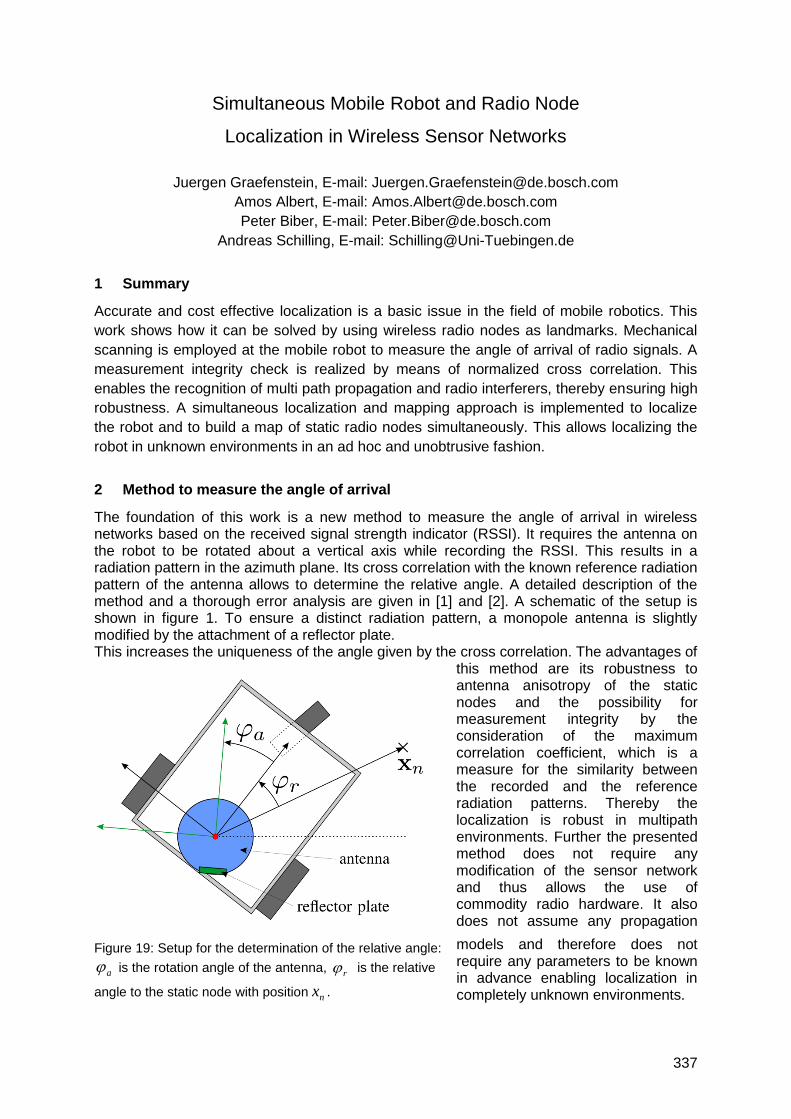
337
Simultaneous Mobile Robot and Radio Node
Localization in Wireless Sensor Networks
Juergen Graefenstein, E-mail: [email protected]
Amos Albert, E-mail: [email protected]
Peter Biber, E-mail: [email protected]
Andreas Schilling, E-mail: [email protected]
1 Summary
Accurate and cost effective localization is a basic issue in the field of mobile robotics. This
work shows how it can be solved by using wireless radio nodes as landmarks. Mechanical
scanning is employed at the mobile robot to measure the angle of arrival of radio signals. A
measurement integrity check is realized by means of normalized cross correlation. This
enables the recognition of multi path propagation and radio interferers, thereby ensuring high
robustness. A simultaneous localization and mapping approach is implemented to localize
the robot and to build a map of static radio nodes simultaneously. This allows localizing the
robot in unknown environments in an ad hoc and unobtrusive fashion.
2 Method to measure the angle of arrival
The foundation of this work is a new method to measure the angle of arrival in wireless networks based on the received signal strength indicator (RSSI). It requires the antenna on the robot to be rotated about a vertical axis while recording the RSSI. This results in a radiation pattern in the azimuth plane. Its cross correlation with the known reference radiation pattern of the antenna allows to determine the relative angle. A detailed description of the method and a thorough error analysis are given in [1] and [2]. A schematic of the setup is shown in figure 1. To ensure a distinct radiation pattern, a monopole antenna is slightly modified by the attachment of a reflector plate. This increases the uniqueness of the angle given by the cross correlation. The advantages of
this method are its robustness to antenna anisotropy of the static nodes and the possibility for measurement integrity by the consideration of the maximum correlation coefficient, which is a measure for the similarity between the recorded and the reference radiation patterns. Thereby the localization is robust in multipath environments. Further the presented method does not require any modification of the sensor network and thus allows the use of commodity radio hardware. It also does not assume any propagation
models and therefore does not require any parameters to be known in advance enabling localization in completely unknown environments.
Figure 19: Setup for the determination of the relative angle:
a is the rotation angle of the antenna, r is the relative
angle to the static node with position nx .
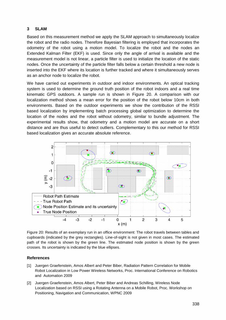
338
3 SLAM
Based on this measurement method we apply the SLAM approach to simultaneously localize
the robot and the radio nodes. Therefore Bayesian filtering is employed that incorporates the
odometry of the robot using a motion model. To localize the robot and the nodes an
Extended Kalman Filter (EKF) is used. Since only the angle of arrival is available and the
measurement model is not linear, a particle filter is used to initialize the location of the static
nodes. Once the uncertainty of the particle filter falls below a certain threshold a new node is
inserted into the EKF where its location is further tracked and where it simultaneously serves
as an anchor node to localize the robot.
We have carried out experiments in outdoor and indoor environments. An optical tracking
system is used to determine the ground truth position of the robot indoors and a real time
kinematic GPS outdoors. A sample run is shown in Figure 20. A comparison with our
localization method shows a mean error for the position of the robot below 10cm in both
environments. Based on the outdoor experiments we show the contribution of the RSSI
based localization by implementing batch processing global optimization to determine the
location of the nodes and the robot without odometry, similar to bundle adjustment. The
experimental results show, that odometry and a motion model are accurate on a short
distance and are thus useful to detect outliers. Complementary to this our method for RSSI
based localization gives an accurate absolute reference.
Figure 20: Results of an exemplary run in an office environment: The robot travels between tables and
cupboards (indicated by the grey rectangles). Line-of-sight is not given in most cases. The estimated
path of the robot is shown by the green line. The estimated node position is shown by the green
crosses. Its uncertainty is indicated by the blue ellipses.
References
[1] Juergen Graefenstein, Amos Albert and Peter Biber, Radiation Pattern Correlation for Mobile
Robot Localization in Low Power Wireless Networks, Proc. International Conference on Robotics
and Automation 2009
[2] Juergen Graefenstein, Amos Albert, Peter Biber and Andreas Schilling, Wireless Node
Localization based on RSSI using a Rotating Antenna on a Mobile Robot, Proc. Workshop on
Positioning, Navigation and Communication, WPNC 2009
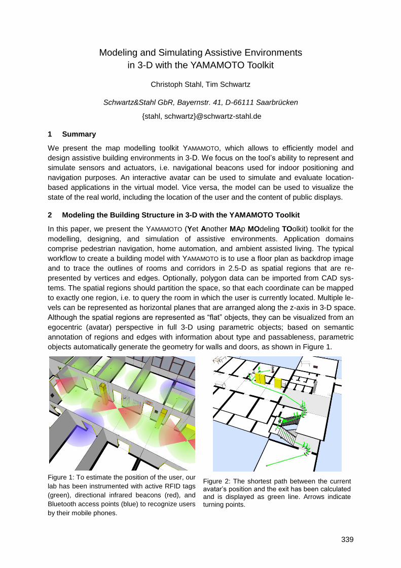
339
Modeling and Simulating Assistive Environments
in 3-D with the YAMAMOTO Toolkit
Christoph Stahl, Tim Schwartz
Schwartz&Stahl GbR, Bayernstr. 41, D-66111 Saarbrücken
{stahl, schwartz}@schwartz-stahl.de
1 Summary
We present the map modelling toolkit YAMAMOTO, which allows to efficiently model and
design assistive building environments in 3-D. We focus on the tool‘s ability to represent and
simulate sensors and actuators, i.e. navigational beacons used for indoor positioning and
navigation purposes. An interactive avatar can be used to simulate and evaluate location-
based applications in the virtual model. Vice versa, the model can be used to visualize the
state of the real world, including the location of the user and the content of public displays.
2 Modeling the Building Structure in 3-D with the YAMAMOTO Toolkit
In this paper, we present the YAMAMOTO (Yet Another MAp MOdeling TOolkit) toolkit for the
modelling, designing, and simulation of assistive environments. Application domains
comprise pedestrian navigation, home automation, and ambient assisted living. The typical
workflow to create a building model with YAMAMOTO is to use a floor plan as backdrop image
and to trace the outlines of rooms and corridors in 2.5-D as spatial regions that are re-
presented by vertices and edges. Optionally, polygon data can be imported from CAD sys-
tems. The spatial regions should partition the space, so that each coordinate can be mapped
to exactly one region, i.e. to query the room in which the user is currently located. Multiple le-
vels can be represented as horizontal planes that are arranged along the z-axis in 3-D space.
Although the spatial regions are represented as ―flat‖ objects, they can be visualized from an
egocentric (avatar) perspective in full 3-D using parametric objects; based on semantic
annotation of regions and edges with information about type and passableness, parametric
objects automatically generate the geometry for walls and doors, as shown in Figure 1.
Figure 1: To estimate the position of the user, our
lab has been instrumented with active RFID tags
(green), directional infrared beacons (red), and
Bluetooth access points (blue) to recognize users
by their mobile phones.
Figure 2: The shortest path between the current avatar‘s position and the exit has been calculated and is displayed as green line. Arrows indicate turning points.
340
In order to represent the rooms‘ furnishing, further 3-D objects can be used to model shelves,
cabinets, and tables, which are specified by their type and dimension. All regions and objects
can be labelled with symbolic identifiers to refer to an external database or ontology.
3 Modelling Instrumented Environments with Sensors and Actuators
Indoor positioning requires an arrangement of sensors and actuators to measure distances
(signal strength or time of flight) or angles in order to estimate the location of the user by
trilateration or triangulation. Therefore the location of the devices must be known to the
positioning system. Figure 1 shows the instrumentation of our lab with RFID and IR beacons,
which are received by a mobile terminal that computes its position based on the known
position of the beacons (Schwartz et al., 2010). The YAMAMOTO toolkit further allows to geo-
reference the model according to known points or aerial photographs (by manual alignment),
so that local (model) coordinates can be converted to geographic (Longitude/Latitude)
coordinates for a seamless transition between indoor and outdoor (GPS) positioning systems.
Modelling buildings in 3-D allows to visually identify obstacles between sender and receiver
units, and to represent geometrically challenging situations, such as staircases. Modelling
the interior of buildings on a high level of detail further helps the designer to plan the
coverage and precision of the positioning infrastructure according to the users‘ activities.
4 Navigational Aid for Pedestrians
Seamless route-finding is supported in indoor and outdoor environments without the need for
explicit modelling of path networks. The YAMAMOTO toolkit includes the PATHFINDER com-
ponent that has been implemented to find shortest paths in multi-level building models. The
semantic annotation of edges (doors or walls) allows the algorithm to perform an A* search
directly on the spatial regions. Figure 2 shows an example route from the first- to ground floor.
5 Simulation and Evaluation of Assistive Environments in VR
The toolkit provides an interface to get and set the state of all modelled objects through
external programs, hence it is possible to visualize the measured position of the user by the
avatar in the virtual model. Vice versa, the avatar can be controlled by the user to simulate a
precise indoor positioning system in VR to evaluate location-based applications. The virtual
display objects implement a video streaming client (VNC) so that any content from an exter-
nal application can be shown in real-time in the 3-D world. Our kiosk-based pedestrian
navigation system VISTO recognizes users via mobile Bluetooth devices. For the simulation,
we implemented virtual proximity sensors; as the avatar enters their range, they send the
user‘s ID to the application and user-adapted output is streamed from real to virtual displays.
6 Conclusions and Outlook
YAMAMOTO has been designed as an easy to learn and efficient modelling toolkit for buildings.
Semantic annotation allows for the automated generation of 3-D geometry and route finding.
The tool also supports the simulation of assistive environments, i.e. for indoor positioning
applications and navigation. For the future, a physical simulation of radio signals, considering
obstacles and materials, would be of interest for the planning of positioning systems.
Schwartz, T., Stahl, C., Baus, J., and Wahlster, W. (2010). Seamless Resource Adaptive Navigation.
In: M. Crocker and J. Siekmann (eds). Resource-Adaptive Cognitive Processes. Cognitive
Technologies Series. Springer Verlag, Berlin, 2010, pp. 239-265
341
Automated Localization of a Laser Scanner in Indoor Environments
Using Planar Objects
Kourosh Khoshelham
Optical and Laser Remote Sensing, Faculty of Aerospace Engineering, Delft University of
Technology, Kluyverweg 1, 2629 HS, Delft, The Netherlands
1 Summary
A method is presented for automated localization of a laser scanner in an indoor environment.
Planar features extracted from the range data undergo a linear plane matching model to
estimate the relative scanner positions in consecutive scans. The performance of the method
is demonstrated using a dataset of six panoramic scans of an interior, and the accuracy
evaluation of the computed positions indicates localization errors of a few centimetres.
2 Introduction
A new trend in terrestrial laser scanning is the development of an autonomous system that is
able to scan an indoor environment from a number of predefined positions, register the scans,
and provide an accurate and complete point cloud of the scene. Such a system would
require the automation of two main processes: scanner localization and the registration of the
scans. In theory, automated registration precedes the localization problem, because a
correct registration of consecutive scans provides the relative position and orientation of the
scanner in every pair of scans. In practice, however, existing registration methods are slow
and iterative, and require an approximate estimate of the transformation between the two
scans. Alternatively, if the motion of the scanner from one scan position to another can be
estimated from the data, it can serve as an initial approximation to perform an iterative fine
registration of the scans, which will in turn lead to an improved accuracy for the localization
of the scanner. In this paper, we describe a new method for the localization of the laser
scanner using planar objects. The method is based on inferring a transformation from a set
of corresponding plane-pairs within a linear least-squares plane matching model. The benefit
of the linear estimation model is that it requires no initial approximations, and leads to a more
efficient search for correspondences. The correspondence problem is approached with an
initiate-and-extend search strategy, which begins with initial correspondence hypotheses and
extends the correspondences when more plane pairs fit into the estimated transformation.
3 Overview of the method
The underlying principle in the plane matching model is that given a minimum of three plane
correspondences in two scans (subject to the condition that the planes intersect in a point), a
similarity transformation between the scans can be estimated such that the norm distance
and difference in the direction of normals between the planes is minimized. Formally, the
plane matching equation is expressed as: 1 T 2
j j H where 1
j and 2
j are planes in the two
scans, and H is a transformation between the scans. Given a number of corresponding
plane-pairs, the plane matching equation is rearranged to form a system of linear equations
wherein H is estimated in a least-squares fashion.
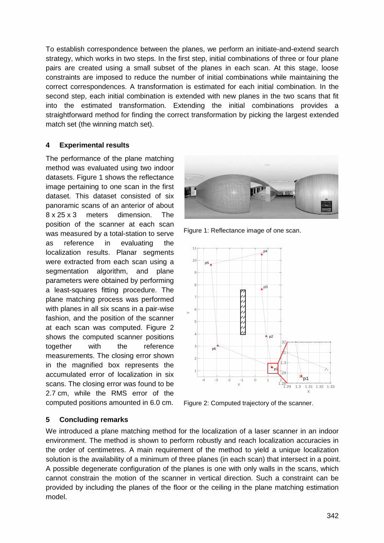
342
To establish correspondence between the planes, we perform an initiate-and-extend search
strategy, which works in two steps. In the first step, initial combinations of three or four plane
pairs are created using a small subset of the planes in each scan. At this stage, loose
constraints are imposed to reduce the number of initial combinations while maintaining the
correct correspondences. A transformation is estimated for each initial combination. In the
second step, each initial combination is extended with new planes in the two scans that fit
into the estimated transformation. Extending the initial combinations provides a
straightforward method for finding the correct transformation by picking the largest extended
match set (the winning match set).
4 Experimental results
The performance of the plane matching
method was evaluated using two indoor
datasets. Figure 1 shows the reflectance
image pertaining to one scan in the first
dataset. This dataset consisted of six
panoramic scans of an anterior of about
8 x 25 x 3 meters dimension. The
position of the scanner at each scan
was measured by a total-station to serve
as reference in evaluating the
localization results. Planar segments
were extracted from each scan using a
segmentation algorithm, and plane
parameters were obtained by performing
a least-squares fitting procedure. The
plane matching process was performed
with planes in all six scans in a pair-wise
fashion, and the position of the scanner
at each scan was computed. Figure 2
shows the computed scanner positions
together with the reference
measurements. The closing error shown
in the magnified box represents the
accumulated error of localization in six
scans. The closing error was found to be
2.7 cm, while the RMS error of the
computed positions amounted in 6.0 cm.
5 Concluding remarks
We introduced a plane matching method for the localization of a laser scanner in an indoor
environment. The method is shown to perform robustly and reach localization accuracies in
the order of centimetres. A main requirement of the method to yield a unique localization
solution is the availability of a minimum of three planes (in each scan) that intersect in a point.
A possible degenerate configuration of the planes is one with only walls in the scans, which
cannot constrain the motion of the scanner in vertical direction. Such a constraint can be
provided by including the planes of the floor or the ceiling in the plane matching estimation
model.
Figure 1: Reflectance image of one scan.
Figure 2: Computed trajectory of the scanner.
1.29 1.3 1.31 1.32 1.331.28
1.29
1.3
1.31
1.32
X
Y
p1-4 -3 -2 -1 0 1 2
1
2
3
4
5
6
7
8
9
10
11
X
Y
p6
p1
p2
p3
p4
p5
343
UWB SLAM with Rao-Blackwellized Monte Carlo Data Association
Tobias Deißler, Jörn Thielecke
Friedrich-Alexander-Universität Erlangen-Nürnberg, Chair of Information Technologies, Am
Wolfsmantel 33, D-91058 Erlangen
1 Introduction
The scenario envisioned in this work is an emergency, where a building is filled with dust and
smoke. A robot should build a map of a building and locate itself on it (simultaneous
localization and mapping, SLAM). In this scenario, conventional means of navigation, i.e.
optical systems, do not work. A bat-type UWB radar array, i.e. two RX antennas and one TX
antenna in the middle, is suitable for this task. The main challenge is data association, the
task of assigning measurements to corresponding landmarks. A solution is presented in this
article using a Rao-Blackwellized particle filter.
2 Related Works
The great advantage of the bat-type UWB radar is the fact that it works without a priori
knowledge of the surroundings and without any kind of infrastructure. This sets it apart from
other means of indoor navigation, for example based on WLAN or RFID. Although those
systems do not have to cope with data association, they are often not suitable for an
emergency scenario as they need infrastructure. UWB is also a good choice for this task as it
can provide additional information like life signs of humans, material characteristics, or even
information about objects inside or behind walls. This work builds upon previously published
results that also deal with the bat-type sensor array.
3 Overview
The bat-type configuration consists of an antenna array with one transmitter in the middle
and two receivers to the left and right. An M-sequence UWB radar is used to measure
impulse responses of the surroundings. By evaluating the peaks in the time-of-flight
measurements at different positions, it is possible to deduce the location of features like walls,
corners or point scatterers. Those features are used as landmarks for navigation and build a
feature-based map of the building. They are tracked using a state-space model and an
Extended Kalman Filter (EKF) to estimate their positions. The state vector x comprises of the
robot pose and the landmark positions in two dimensions:
x=[xrobot, yrobot, φrobot, xlandmark 1, ylandmark 1, …, x landmark n, y landmark n]T
4 Data Association
For the Kalman Filter to work properly it must be known which measured time-of-flight
belongs to which landmark. A basic method to accomplish data association is the Nearest
Neighbor (NN) method. Here, we use the predicted measurements of the EKF. For all
measurements zi we calculate the measurement probability
p(zi|xk-, ci=j)
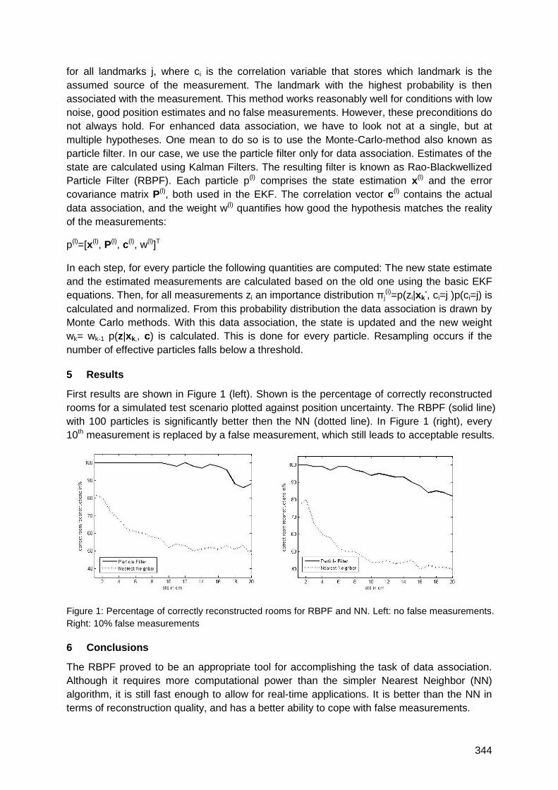
344
for all landmarks j, where ci is the correlation variable that stores which landmark is the
assumed source of the measurement. The landmark with the highest probability is then
associated with the measurement. This method works reasonably well for conditions with low
noise, good position estimates and no false measurements. However, these preconditions do
not always hold. For enhanced data association, we have to look not at a single, but at
multiple hypotheses. One mean to do so is to use the Monte-Carlo-method also known as
particle filter. In our case, we use the particle filter only for data association. Estimates of the
state are calculated using Kalman Filters. The resulting filter is known as Rao-Blackwellized
Particle Filter (RBPF). Each particle p(l) comprises the state estimation x(l) and the error
covariance matrix P(l), both used in the EKF. The correlation vector c(l) contains the actual
data association, and the weight w(l) quantifies how good the hypothesis matches the reality
of the measurements:
p(l)=[x(l), P(l), c(l), w(l)]T
In each step, for every particle the following quantities are computed: The new state estimate
and the estimated measurements are calculated based on the old one using the basic EKF
equations. Then, for all measurements zi an importance distribution πj(i)=p(zi|xk
-, ci=j )p(ci=j) is
calculated and normalized. From this probability distribution the data association is drawn by
Monte Carlo methods. With this data association, the state is updated and the new weight
wk= wk-1 p(z|xk,, c) is calculated. This is done for every particle. Resampling occurs if the
number of effective particles falls below a threshold.
5 Results
First results are shown in Figure 1 (left). Shown is the percentage of correctly reconstructed
rooms for a simulated test scenario plotted against position uncertainty. The RBPF (solid line)
with 100 particles is significantly better then the NN (dotted line). In Figure 1 (right), every
10th measurement is replaced by a false measurement, which still leads to acceptable results.
Figure 1: Percentage of correctly reconstructed rooms for RBPF and NN. Left: no false measurements.
Right: 10% false measurements
6 Conclusions
The RBPF proved to be an appropriate tool for accomplishing the task of data association.
Although it requires more computational power than the simpler Nearest Neighbor (NN)
algorithm, it is still fast enough to allow for real-time applications. It is better than the NN in
terms of reconstruction quality, and has a better ability to cope with false measurements.
345
Developing an Integrated Software Environment
for Mobile Robot Navigation and Control
Zoltán Tuza1, János Rudan1, Gábor Szederkényi1,2
1Pázmány Péter Catholic University, Faculty of Information Technology, Budapest, Hungary 2Computer and Automation Research Institute, Hungarian Academy of Sciences
{tuzzoan, rudanj}@digitus.itk.ppke.hu, [email protected]
1 Summary
A flexible modular robotic software environment based on the popular MRPT toolkit is
reported in this paper that is able to easily integrate path planning, navigation and control
algorithms from several sources. The different modules (responsible for SLAM, trajectory
tracking, sensor and actuator handling, visualization etc.) communicate with each other via a
carefully developed network based protocol set that ensures transparency and robust
operation. The system can also be used as a simulation environment and it is capable for the
comparative benchmarking of different navigation algorithms. The laser scanner based map
building and navigation of an autonomous wheelchair is shown as an application example to
illustrate the features of the developed software environment.
2 Motivation and aims
Currently, there have been numerous navigation and control algorithms and techniques in
the field of indoor mobile robotics. Available robotic software toolkits present several
implemented algorithms, but system-level integration still remains a challenging task. This
inspired us to create a high-level, modular robotic software environment based on a selected
toolkit to handle our special application requirements and significantly extend previous
functionality. Beyond the standard requirements for a robotic software environment such as
robustness and portability, our high-level, integrated system was designed to meet the
following main requirements: a) strongly modular construction, b) multi-host, distributed
architecture, c) probabilistic computational framework, d) such an environment where the
incorporation of new algorithms and features is easy.
3 Basic tools
Our system is based on Mobile Robotic Programming Toolkit (MRPT) [1]. MRPT was
selected because this framework uses a coherent probabilistic approach that is very useful in
solving indoor navigation tasks. Furthermore, it contains a large amount of algorithms and
software tools like SLAM techniques [2], Kalman Filter, Particle Filter, hardware drivers, data
structures for several kinds of maps, visualization, and many auxiliary utilities. Using the
algorithms implemented in MRPT, a set of separate modules were created using codes also
from external sources or from our own implementations.
4 Design principles and properties of the modular system
Each module is responsible for a specific task like SLAM, path planning, trajectory following
control, handling of sensors and actuators, and visualization. Apart from the above tasks,
additional modules were implemented that allow us to use the system as a simulation
environment, too. Such modules are responsible for recording the measured data and
playing it back, and for monitoring the inner state variables of the system. The architecture
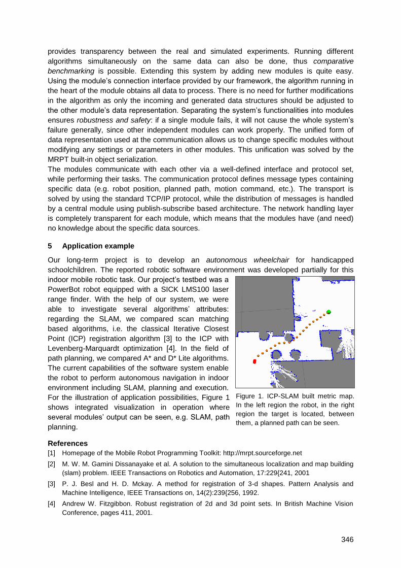
346
provides transparency between the real and simulated experiments. Running different
algorithms simultaneously on the same data can also be done, thus comparative
benchmarking is possible. Extending this system by adding new modules is quite easy.
Using the module‘s connection interface provided by our framework, the algorithm running in
the heart of the module obtains all data to process. There is no need for further modifications
in the algorithm as only the incoming and generated data structures should be adjusted to
the other module‘s data representation. Separating the system‘s functionalities into modules
ensures robustness and safety: if a single module fails, it will not cause the whole system‘s
failure generally, since other independent modules can work properly. The unified form of
data representation used at the communication allows us to change specific modules without
modifying any settings or parameters in other modules. This unification was solved by the
MRPT built-in object serialization.
The modules communicate with each other via a well-defined interface and protocol set,
while performing their tasks. The communication protocol defines message types containing
specific data (e.g. robot position, planned path, motion command, etc.). The transport is
solved by using the standard TCP/IP protocol, while the distribution of messages is handled
by a central module using publish-subscribe based architecture. The network handling layer
is completely transparent for each module, which means that the modules have (and need)
no knowledge about the specific data sources.
5 Application example
Our long-term project is to develop an autonomous wheelchair for handicapped
schoolchildren. The reported robotic software environment was developed partially for this
indoor mobile robotic task. Our project‘s testbed was a
PowerBot robot equipped with a SICK LMS100 laser
range finder. With the help of our system, we were
able to investigate several algorithms‘ attributes:
regarding the SLAM, we compared scan matching
based algorithms, i.e. the classical Iterative Closest
Point (ICP) registration algorithm [3] to the ICP with
Levenberg-Marquardt optimization [4]. In the field of
path planning, we compared A* and D* Lite algorithms.
The current capabilities of the software system enable
the robot to perform autonomous navigation in indoor
environment including SLAM, planning and execution.
For the illustration of application possibilities, Figure 1
shows integrated visualization in operation where
several modules‘ output can be seen, e.g. SLAM, path
planning.
References
[1] Homepage of the Mobile Robot Programming Toolkit: http://mrpt.sourceforge.net
[2] M. W. M. Gamini Dissanayake et al. A solution to the simultaneous localization and map building
(slam) problem. IEEE Transactions on Robotics and Automation, 17:229{241, 2001
[3] P. J. Besl and H. D. Mckay. A method for registration of 3-d shapes. Pattern Analysis and
Machine Intelligence, IEEE Transactions on, 14(2):239{256, 1992.
[4] Andrew W. Fitzgibbon. Robust registration of 2d and 3d point sets. In British Machine Vision
Conference, pages 411, 2001.
Figure 1. ICP-SLAM built metric map.
In the left region the robot, in the right
region the target is located, between
them, a planned path can be seen.
347
Indoor Pedestrian Simultaneous Localization and Mapping
Esteban Tobias Bayro Kaiser
Institute for Computer Science and Information Technology – TZI, University of Bremen,
Am Fallturm 1, Eingang E, D-28359 Bremen Germany
1 Summary
This extended abstract presents a doctoral project in its initial phase. The objective is to
implement a precise localization and mapping system that is able to track a pedestrian in
known and unknown environments. To achieve this, the well-known SLAM (Simultaneous
Localization and Mapping) method will be applied that is already used for mobile robots. The
pedestrian will be equipped with a short-range laser scanner, an inertial measurement unit
(IMU), and a wearable computer for processing purposes. To obtain localization, the sensor
data will be fused and processed with an algorithm based on the Extended Kalman Filter and
Rao-Blackwellized Particle Filters. Mapping will be achieved with grid mapping.
2 Introduction
Localization and tracking of persons, agents, objects, etc. has been the object of significant
studies among research groups over the last years. The pursuit of knowing the position of an
agent, and even tracking it, is of crucial importance in many applications. Localization can be
divided into two different scenarios: outdoor and indoor. These scenarios are addressed in
different ways, and are solved through diverse methods and implementations. Outdoor
localization methods can be obtained with GPS, field strength measurements (WLAN, GSM,
Bluetooth), etc. For a precise indoor localization GPS cannot be used due to attenuation and
scattering of the signals [1]. Preferred methods for indoor localization are the utilization of
pre-installed indoor communication infrastructures, laser, radar, sonar, camera, motion
sensors, etc. Assuming that not all buildings have a pre-installed communication
infrastructure, the field strength measurements methods also cannot be used. For a precise
indoor independent localization, it is important to perform sensor fusion with the above-
mentioned methods [2].
3 SLAM
Simultaneous Localization and Mapping (SLAM) is a well-known solution in the area of
mobile robotics. Many other approaches have been proposed for solving this particular
problem. The most popular algorithms to solve the problem are based on the Extended
Kalman Filter and the Rao-Blackwellized Particle Filters [3]. The problem has been solved in
general, but it probably needs some algorithmic improvement.
This method basically works as follows: The mobile robot is equipped with a laser scanner,
mounted on top of it, to take horizontal measurements. With this laser it is possible to take
measurements of different landmarks, obtaining distances and angles. Landmarks are
basically features in an environment that can be used as reference and for the registration of
multiple scans when combining different measurements from diverse positions. For example,
348
in an indoor environment, landmarks could be lines, walls, corners, edges or more specific
obstacles. The data obtained from the laser are fused with the mobile robots odometry; using
the proposed algorithms it is possible to establish an approximation of the robot position at all
times. At the same time a 2D map is constructed of the environment.
4 Indoor Pedestrian SLAM
The implementation of SLAM for pedestrians is based on [2] for this project. For pedestrians, the SLAM problem must be addressed in a different manner, due to the different movement conditions. Pedestrians have a much more complex odometry than mobile robots: they differ in the type of movements and degrees of freedom. The laser scanner position with mobile robots is stable compared to the surface. This cannot be guaranteed for human beings. Furthermore, the human body is specific to each person, as is motion. Thus, the challenge is to extract the odometry for each pedestrian and to obtain stable laser scanner data.
In this project, the pedestrian will be equipped with a short-range scanner and an Inertial Measurement Sensor (IMU). Positioning of the sensors is crucial to noise reduction and/or incorrect measurements. In mobile robots, the laser scanner is implemented on top of it and is able to scan a horizontal plane. The most stable positions on the human body to place the sensors are the shoulders and hips. To obtain horizontal laser scans, the raw data requires processing with the IMU data and projection onto the horizontal plane. Additionally, to reduce false laser scan readings, the scanner will be regulated with an electro-mechanic stabilizer so
its measurements are always taken horizontally.
To extract odometry from the pedestrian, the data from the Inertial Measurement Unit will be
processed to obtain step length and direction. Thus, by combining pedestrian odometry,
laser scanner data, and using an Extended Kalman Filter or the Rao-Blackwellized Particle
Filters, it is possible to achieve a precise localization.
The mapping can be accomplished by using a grid mapping method. This basically works by
dividing the environment into small grids, and deciding whether that grid is occupied or not by
scanning the environment. If a grid is occupied, then the system assumes that there is a solid
object there; so it is drawn in the map.
Data processing will be accomplished with wearable computing devices, so there will be total
independence of any main computer or network.
5 Conclusions
The proposed method is a different way to address localization of pedestrians. It is
independent from the indoor environment; no a priori information is needed and it is
comfortable to wear.
This tracking and mapping method is not meant to be used by any person, it is rather built for
specific applications, where precise localization and mapping of a pedestrian is needed.
6 References
Stéphane Beauregard. A Helmet-Mounted Pedestrian Dead Reckoning System. IFAWC2006.
Burcu Cinaz and Holger Kenn. Headslam- Head. Mounted simultaneous localization and mapping for wearable computing applications. ISWC 2008.
Durrant-Whyte, H.; Bailey, T. Simultaneous Localization and Mapping (SLAM): The Essential Algorithms. Robotics and Automation Magazine 13: 99–110 2006.
349
Creation of an Urban Spatial Model for In-City Positioning Using Laser-
Scanning
Birutė Ruzgienė
Dept of Geodesy and Cadastre, Vilnius Gediminas Technical University, Saulėtekio al.11,
LT-10223, Lithuania
1. Summary
The investigations are based on the evaluation and the analyzes of high accuracy LIDAR
images taken over Lithuanian cities, thereby taking into account the geodetic control
measurements and foreign expert experience. The progressive aerial laser scanning
approach with combination of digital photogrammetry technology, – a GPS-IMU system and
a digital aerial photography have been used for the creation the urban spatial model. The
application feasibility is investigated. A description of equipment, technological features and
application possibilities is presented.
2. Technological features
Digital photogrammetry technology fused with laser scanning data is analyzed considering
in-city location determination that can be used for indoor positioning, e.g., surveys of
excavation, design of industrial equipments, reconstruction of architectural monuments, etc.
1. LIDAR images. This includes Lithuanian urban areas scanned by Geokosmos (Moscow)
using scanner Optech ALTM 3100 from the airplane Antonov-2. Z-Max GPS receivers for
reference point measurements were used. Geopositioning has been achieved by the inertial
navigation system Trimble 750 GPS - Applanix POS/AV IMU. The spatial coordinates of
reflected laser scans were determined. The ALTM 3100 operates in the infrared spectrum
range, because low signals are reflected from the water surface.
Other flight data: speed: 205 km/h, distance between strips axes – 300 m; side overlap –
30%; laser point density: 3-4 points/m2; average distance between points: 0.5 m. The
accuracy requirement for scanner spatial positioning: standard deviations of less than 5 cm.
Required accuracy for LIDAR measurements: for height points 15 cm, horizontal 30 cm.
Laser scanning data have been filtered, edited and Digital Surface Models were created.
According to the morphological features the DSM was classified into the categories buildings,
vegetation, bridges.
Digital aerial images. The images have been taken separately from the LIDAR flights using
digital aerial camera UltraCamD (Vexcel Imaging, Austria), with a focal length of ck = 101,4
mm, frame size of 7500 x 11500 pixels. The flying height was 600 m. The created digital
orthophotos have a scale of 1:2000.
Spatial city models have been created by fusing LIDAR and orthogonal image data.
3. The accuracy of LIDAR images
The laser scanning accuracy depends on the scanner characteristics, the flight height, the
scan angle, the laser beam frequency and distribution, positioning of the GPS-IMU system,
the reflecting surface properties and some other factors. The LIDAR laser beam measures
ranges to the solid surface with an
A significant systemic error was found.

350
LIDAR pulse point positioning has been investigated in the 24 reference (test) areas with
asphalt covers. In the selected test areas there have been about 1000 control points
identified and measured. Some LIDAR data accuracy analysis results are presented in Table
2.
Table 1: Results of LIDAR point heights accuracy investigation compared with geodetic control
measurement
Reflected surface Number of
control points
Accuracy assessments [m]
Min. Max. Mean deviations RMS
Test area – Kaunas
Asphalt
Field
Field with brushes
74
113
119
-0.05
-0.08
-0.11
0.14
0.17
0.30
0.04
0.10
0.06
0.07
0.11
0.09
Table 2: Some results of laser pulse point position accuracy
Test area/
number of
reference areas
Accuracy assessments according to the reference areas [m]
Height accuracy Horizontal accuracy
Interval of
deviations
RMS Interval of
deviations
RMS
Kaunas/ 3 -0.07 - (+0.06) 0.04; 0.04; 0.03 0.10 - 0.25 0.16; 0.18; 0.18
Vilnius/ 5 -0.10 - (+0.09) 0.09; 0.07; 0.08;
0.08; 0.05
0.10 - 0.22 0.14; 0.17; 0.16; 0.17;
0.12
4. Conclusions
Laser scanning from the aircraft combined with orthophotogrammetric data is useful for
accurate land surface mapping and fulfils the requirements for the creation of spatial city
terrain models.
The LIDAR pulse points positioning accuracy shows that the average standard deviation for
height points is 0.05 - 0.12 m. The horizontal accuracy is 0.25 m when the flying height is
about 1000 m and 1.26 m when the flying height is about 2000 m. The systematic errors can
be reduced by calibration of the GPS, IMU and the scanner. The water surface absorbs
electromagnetic energy significantly, especially when the carrier wavelength is about 1.5 µm.
It can be stated that, under the current accuracy the laser scanning data can be integrated
with the orthophotographic base and is suitable for the creation of spatial 3D models for the
urban surface, relief, buildings and other ground-based objects under large-scale topography
and GIS needs.

351
UWB (Ultra Wide Band)
Auditorium D8
Thursday, September 16
08:15 – 09:45, 10:15 – 11:45, 13:15 – 15:00 & 15:30 – 16:45

353
Low Power ASIC transmitter for UWB-IR radio communication
and positioning
Ch. Robert (1), P. Tomé (1), R. Merz (1), C. Botteron (1), A. Blatter (2) and P.-A. Farine (1)
(1) Ecole Polytechnique Fédérale de Lausanne (EPFL)
Institute of Microengineering, Electronics and Signal Processing Laboratory
Rue A.-L- Breguet 2, Neuchâtel, Switzerland (2) PX Holding S.A., La Chaux-de-Fond, Switzerland
1 Summary
At the Electronics and Signal Processing Laboratory at EPFL (formerly UNINE), an
experimental platform has been designed and built to demonstrate the feasibility of Ultra-
wideband Impulse Radio (UWB-IR) technology applied to indoor positioning [1]. This office-
scale demonstrator has proven to be a valuable research tool, with the flexibility to study, test
and assess the performance of various system architectures and signal processing
algorithms.
Based on this successful experience, a subsequent project was setup to extend the lab‘s
research on certain topics that could not be addressed by the office-scale demonstrator. This
new R&D project pursues two main objectives: a) designing and building a large-scale UWB-
based Local Positioning System (LPS), including installation, calibration and operational
testing in a real industrial environment; b) conceiving and developing Application Specific
Integrated Circuits (ASICs) to target cost-competitive solutions. The details related to the first
objective a) are out of the scope of this paper and can be found in [2].
In turn, this paper focuses on objective b) and presents the design of a Low Power UWB
transmitter ASIC that complies with ECC spectrum regulations for UWB-IR low duty cycle, as
well as with FCC spectrum regulations. This transmitter has been implemented in UMC 180
nanometers CMOS technology and works with a power supply of 1.8V.
2 UWB ASIC transmitter Design
The existing office-scale demonstrator is composed of 4 receivers mounted at given
positions within a room and several mobile, small transmitters. The position of the latter can
be estimated by using time of arrival measurements. For this demonstrator, the transmitters
were built using discrete off-the-shelf components operating in a frequency band below 1
GHz. However, for the large-scale UWB-based LPS currently under development, the
transmitters had to be redesigned to reduce production costs for higher volumes, to decrease
their size, to lower the power consumption, and to be compliant to ECC spectrum regulations.
To achieve these goals, an ASIC has already been developed and successfully tested.
The new transmitters are based on a triangular shaping pulse generator, a local oscillator at
4.1 GHz and a mixer. The frequency band between 3.4 GHz and 4.8GHz can be used
accordingly to the ECC spectrum regulations, provided that the duty cycle is sufficiently low.
In a positioning system, where a sequence of pulses only needs to be transmitted at the
intended position update rate, this restriction can be easily respected.
354
By switching off the pulse generator between two transmission sequences, the power
consumption can be lowered significantly. Additionally, a further reduction can be achieved
by considering another duty-cycle inherent to impulse radio. For this application, a pulse
repetition rate (PRR) of 10 MHz was chosen, corresponding to a 100 ns repetition interval,
and the pulse duration is less than 5 ns. Therefore, we have included in the design some
circuitry that switches off the supply of several blocks, in particular the output power amplifier,
between two pulse transmissions. A wake-up strategy has also been included to ensure the
repeatability of the pulse emission in term of latency, shape, amplitude and polarity.
3 Transmitter test platform
The test of the ASICs was performed in several steps. At first, since the outputs of the chip
are differential, a PCB using an external triggering and a differential SMA output was made.
To characterise the chip, we connected the board to two channels of an oscilloscope and
combined them using the mathematical functions of the oscilloscope to visualize a single
ended signal.
Since most wide band antennas on the market are single ended, a second PCB has been
designed. It includes a ceramic balanced-unbalanced transformer and an on-board 10MHz
triggering to remove the constraint of needing an external triggering signal.
Currently, the pulse generator has been integrated successfully in an ASIC. However it does
not yet contain circuits for the modulation. As the LPS demonstrator is intended to work with
several transmitters [2], each transmitter has to provide identification and hence requires
some modulation or spreading scheme. A future version of the ASIC will include these
required circuits. Adding binary phase shift keying (BPSK) on the ASIC will consist of adding
a multiplexer only, because all the internal signalling is balanced. Other modulations
schemes, such as On-Off-Keying (OOK) and Pulse Position Modulation (PPM) can already
be implemented using a few external components by delaying or suppressing the triggering
pulse.
4 Conclusions
This paper describes in detail the design and realization of a Low Power UWB-IR transmitter
dedicated to position and communication to be used in a UWB-based large-scale deployable
local positioning system. This ASIC version of transmitter have been successfully realized, it
is compliant with current FCC/ECC spectrum mask. The total averaged power consumption
is less than 85uW for a 16-pulse burst at a burst repetition rate of 1Hz. The chip area
including pads is less than 1.5mm2, while the core itself is 0.56mm x 0.4mm. The chip was
implemented in a standard UMC 0.18um CMOS technology.
5 Bibliography
[1] R. Merz, C. Botteron, F. Chastellain and P.-A. Farine (2009) – "A Programmable Receiver for
Communication Systems and Its Application to Impulse Radio", Research Letters in
Communications, Vol. 2009, Article ID 238521, Hindawi Publishing Corporation.
[2] Ph. Tomé, Ch. Robert, R. Merz, C. Botteron, A. Blatter and P.-A. Farine (2010) – ―UWB-based
Local Positioning System: from a small-scale Experimental Platform to a large-scale Deployable
System‖, paper submitted to the 2010 IPIN Conference, September 15-17, 2010, Zurich,
Switzerland.
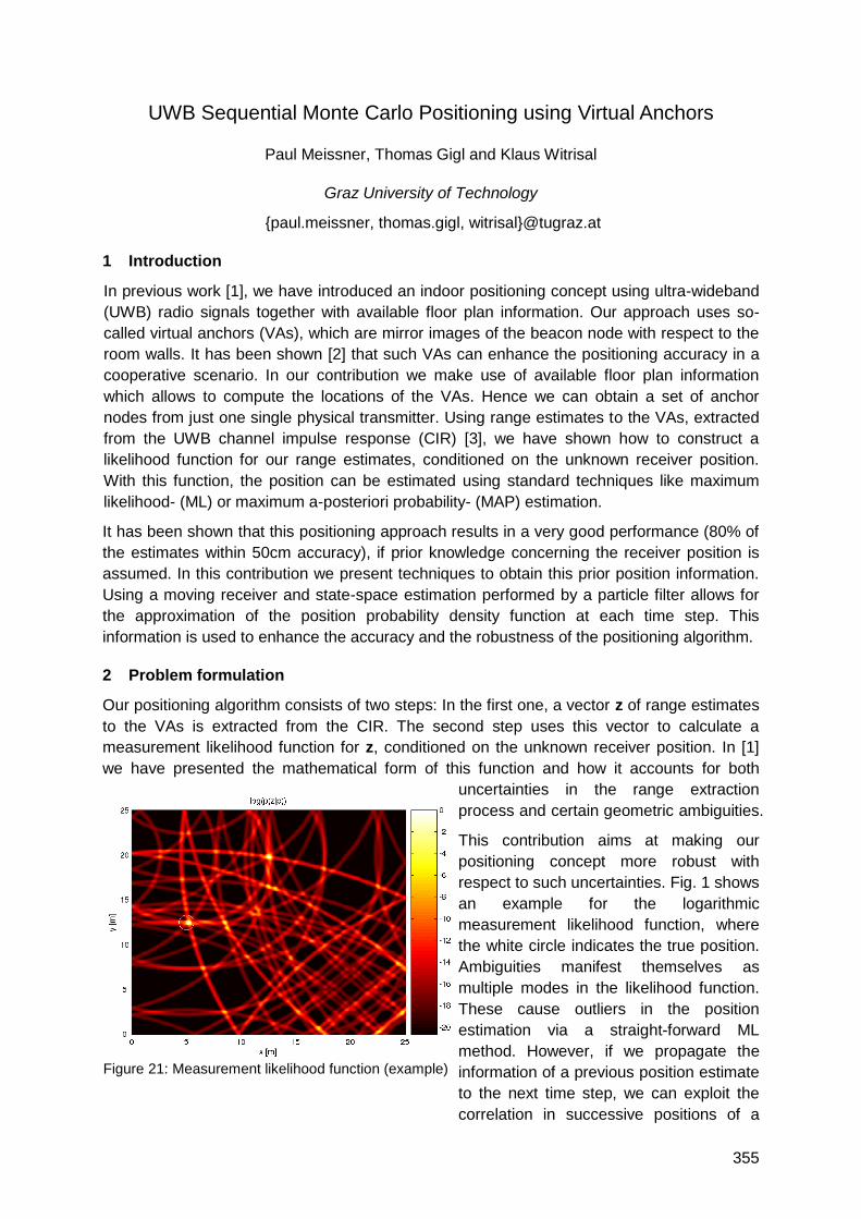
355
UWB Sequential Monte Carlo Positioning using Virtual Anchors
Paul Meissner, Thomas Gigl and Klaus Witrisal
Graz University of Technology
{paul.meissner, thomas.gigl, witrisal}@tugraz.at
1 Introduction
In previous work [1], we have introduced an indoor positioning concept using ultra-wideband
(UWB) radio signals together with available floor plan information. Our approach uses so-
called virtual anchors (VAs), which are mirror images of the beacon node with respect to the
room walls. It has been shown [2] that such VAs can enhance the positioning accuracy in a
cooperative scenario. In our contribution we make use of available floor plan information
which allows to compute the locations of the VAs. Hence we can obtain a set of anchor
nodes from just one single physical transmitter. Using range estimates to the VAs, extracted
from the UWB channel impulse response (CIR) [3], we have shown how to construct a
likelihood function for our range estimates, conditioned on the unknown receiver position.
With this function, the position can be estimated using standard techniques like maximum
likelihood- (ML) or maximum a-posteriori probability- (MAP) estimation.
It has been shown that this positioning approach results in a very good performance (80% of
the estimates within 50cm accuracy), if prior knowledge concerning the receiver position is
assumed. In this contribution we present techniques to obtain this prior position information.
Using a moving receiver and state-space estimation performed by a particle filter allows for
the approximation of the position probability density function at each time step. This
information is used to enhance the accuracy and the robustness of the positioning algorithm.
2 Problem formulation
Our positioning algorithm consists of two steps: In the first one, a vector z of range estimates
to the VAs is extracted from the CIR. The second step uses this vector to calculate a
measurement likelihood function for z, conditioned on the unknown receiver position. In [1]
we have presented the mathematical form of this function and how it accounts for both
uncertainties in the range extraction
process and certain geometric ambiguities.
This contribution aims at making our
positioning concept more robust with
respect to such uncertainties. Fig. 1 shows
an example for the logarithmic
measurement likelihood function, where
the white circle indicates the true position.
Ambiguities manifest themselves as
multiple modes in the likelihood function.
These cause outliers in the position
estimation via a straight-forward ML
method. However, if we propagate the
information of a previous position estimate
to the next time step, we can exploit the
correlation in successive positions of a
Figure 21: Measurement likelihood function (example)
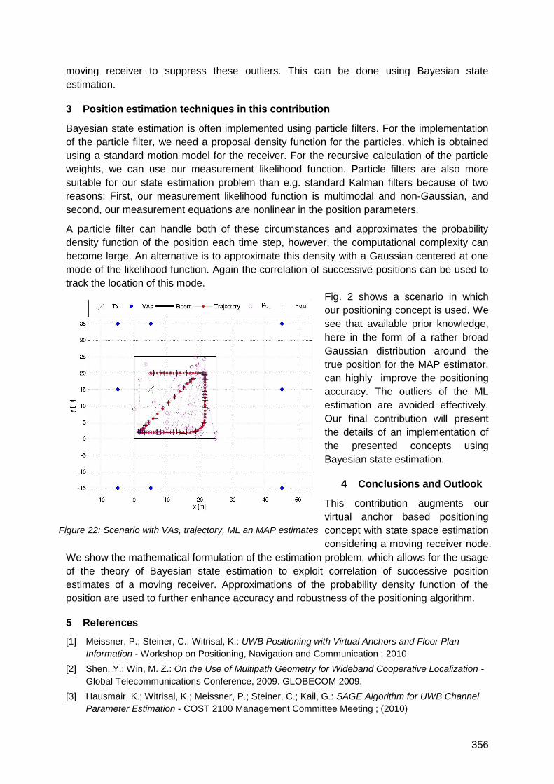
356
moving receiver to suppress these outliers. This can be done using Bayesian state
estimation.
3 Position estimation techniques in this contribution
Bayesian state estimation is often implemented using particle filters. For the implementation
of the particle filter, we need a proposal density function for the particles, which is obtained
using a standard motion model for the receiver. For the recursive calculation of the particle
weights, we can use our measurement likelihood function. Particle filters are also more
suitable for our state estimation problem than e.g. standard Kalman filters because of two
reasons: First, our measurement likelihood function is multimodal and non-Gaussian, and
second, our measurement equations are nonlinear in the position parameters.
A particle filter can handle both of these circumstances and approximates the probability
density function of the position each time step, however, the computational complexity can
become large. An alternative is to approximate this density with a Gaussian centered at one
mode of the likelihood function. Again the correlation of successive positions can be used to
track the location of this mode.
Fig. 2 shows a scenario in which
our positioning concept is used. We
see that available prior knowledge,
here in the form of a rather broad
Gaussian distribution around the
true position for the MAP estimator,
can highly improve the positioning
accuracy. The outliers of the ML
estimation are avoided effectively.
Our final contribution will present
the details of an implementation of
the presented concepts using
Bayesian state estimation.
4 Conclusions and Outlook
This contribution augments our
virtual anchor based positioning
concept with state space estimation
considering a moving receiver node.
We show the mathematical formulation of the estimation problem, which allows for the usage
of the theory of Bayesian state estimation to exploit correlation of successive position
estimates of a moving receiver. Approximations of the probability density function of the
position are used to further enhance accuracy and robustness of the positioning algorithm.
5 References
[1] Meissner, P.; Steiner, C.; Witrisal, K.: UWB Positioning with Virtual Anchors and Floor Plan
Information - Workshop on Positioning, Navigation and Communication ; 2010
[2] Shen, Y.; Win, M. Z.: On the Use of Multipath Geometry for Wideband Cooperative Localization -
Global Telecommunications Conference, 2009. GLOBECOM 2009.
[3] Hausmair, K.; Witrisal, K.; Meissner, P.; Steiner, C.; Kail, G.: SAGE Algorithm for UWB Channel
Parameter Estimation - COST 2100 Management Committee Meeting ; (2010)
Figure 22: Scenario with VAs, trajectory, ML an MAP estimates
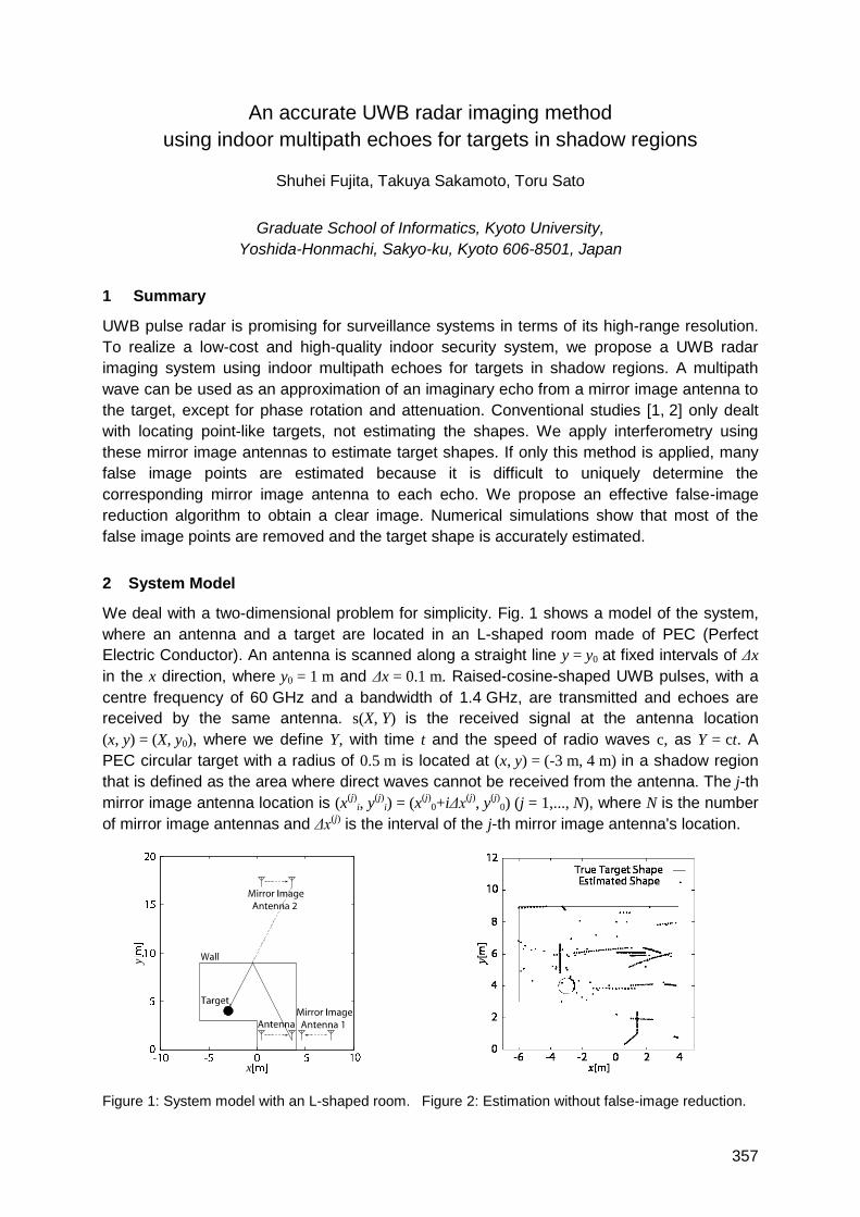
357
An accurate UWB radar imaging method
using indoor multipath echoes for targets in shadow regions
Shuhei Fujita, Takuya Sakamoto, Toru Sato
Graduate School of Informatics, Kyoto University,
Yoshida-Honmachi, Sakyo-ku, Kyoto 606-8501, Japan
1 Summary
UWB pulse radar is promising for surveillance systems in terms of its high-range resolution.
To realize a low-cost and high-quality indoor security system, we propose a UWB radar
imaging system using indoor multipath echoes for targets in shadow regions. A multipath
wave can be used as an approximation of an imaginary echo from a mirror image antenna to
the target, except for phase rotation and attenuation. Conventional studies [1, 2] only dealt
with locating point-like targets, not estimating the shapes. We apply interferometry using
these mirror image antennas to estimate target shapes. If only this method is applied, many
false image points are estimated because it is difficult to uniquely determine the
corresponding mirror image antenna to each echo. We propose an effective false-image
reduction algorithm to obtain a clear image. Numerical simulations show that most of the
false image points are removed and the target shape is accurately estimated.
2 System Model
We deal with a two-dimensional problem for simplicity. Fig. 1 shows a model of the system,
where an antenna and a target are located in an L-shaped room made of PEC (Perfect
Electric Conductor). An antenna is scanned along a straight line y = y0 at fixed intervals of Δx
in the x direction, where y0 = 1 m and Δx = 0.1 m. Raised-cosine-shaped UWB pulses, with a
centre frequency of 60 GHz and a bandwidth of 1.4 GHz, are transmitted and echoes are
received by the same antenna. s(X, Y) is the received signal at the antenna location
(x, y) = (X, y0), where we define Y, with time t and the speed of radio waves c, as Y = ct. A
PEC circular target with a radius of 0.5 m is located at (x, y) = (-3 m, 4 m) in a shadow region
that is defined as the area where direct waves cannot be received from the antenna. The j-th
mirror image antenna location is (x(j)i, y
(j)i) = (x
(j)0+iΔx
(j), y
(j)0) (j = 1,..., N), where N is the number
of mirror image antennas and Δx(j) is the interval of the j-th mirror image antenna's location.
Figure 1: System model with an L-shaped room. Figure 2: Estimation without false-image reduction.
y
x
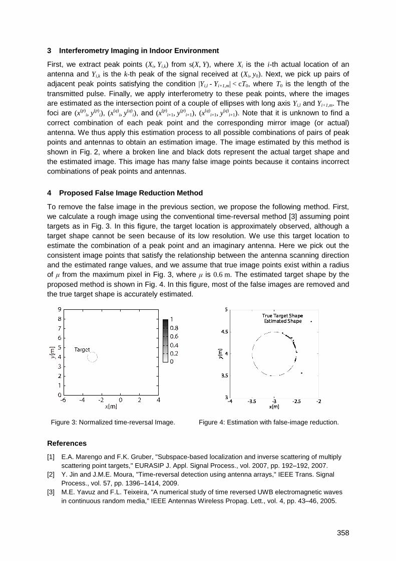
358
3 Interferometry Imaging in Indoor Environment
First, we extract peak points (Xi, Yi,k) from s(X, Y), where Xi is the i-th actual location of an
antenna and Yi,k is the k-th peak of the signal received at (Xi, y0). Next, we pick up pairs of
adjacent peak points satisfying the condition |Yi,l - Yi+1,m| < cT0, where T0 is the length of the
transmitted pulse. Finally, we apply interferometry to these peak points, where the images
are estimated as the intersection point of a couple of ellipses with long axis Yi,l and Yi+1,m. The
foci are (x(p)i, y
(p)i), (x
(q)i, y
(q)i), and (x(p)
i+1, y(p)
i+1), (x(q)
i+1, y(q)
i+1). Note that it is unknown to find a
correct combination of each peak point and the corresponding mirror image (or actual)
antenna. We thus apply this estimation process to all possible combinations of pairs of peak
points and antennas to obtain an estimation image. The image estimated by this method is
shown in Fig. 2, where a broken line and black dots represent the actual target shape and
the estimated image. This image has many false image points because it contains incorrect
combinations of peak points and antennas.
4 Proposed False Image Reduction Method
To remove the false image in the previous section, we propose the following method. First,
we calculate a rough image using the conventional time-reversal method [3] assuming point
targets as in Fig. 3. In this figure, the target location is approximately observed, although a
target shape cannot be seen because of its low resolution. We use this target location to
estimate the combination of a peak point and an imaginary antenna. Here we pick out the
consistent image points that satisfy the relationship between the antenna scanning direction
and the estimated range values, and we assume that true image points exist within a radius
of μ from the maximum pixel in Fig. 3, where μ is 0.6 m. The estimated target shape by the
proposed method is shown in Fig. 4. In this figure, most of the false images are removed and
the true target shape is accurately estimated.
Figure 3: Normalized time-reversal Image. Figure 4: Estimation with false-image reduction.
References
[1] E.A. Marengo and F.K. Gruber, "Subspace-based localization and inverse scattering of multiply
scattering point targets," EURASIP J. Appl. Signal Process., vol. 2007, pp. 192–192, 2007.
[2] Y. Jin and J.M.E. Moura, "Time-reversal detection using antenna arrays," IEEE Trans. Signal
Process., vol. 57, pp. 1396–1414, 2009.
[3] M.E. Yavuz and F.L. Teixeira, "A numerical study of time reversed UWB electromagnetic waves
in continuous random media," IEEE Antennas Wireless Propag. Lett., vol. 4, pp. 43–46, 2005.
x
y
359
An Impulse Radio UWB Transceiver with High-Precision TOA
Measurement Unit
Gunter Fischer, Oleksiy Klymenko, Denys Martynenko
Institut für Innovative Mikroelektronik (IHP), 15236 Frankfurt (Oder), Germany
1 Summary
This paper describes a monolithic integrated transceiver chipset intended for impulse radio
(IR) Ultra-wide band (UWB) applications including indoor communication and indoor
localization. The chipset operates in the higher UWB band centered at 7.68 GHz and it is
optimized for a pulse bandwidth of about 1.5 GHz. The average pulses repetition rate of 60
MHz and an octagonal pulse position modulation (8-PPM) allow for raw data rates up to 180
MBit/sec. The available high bandwidth is used for precise indoor localization employing a
dedicated time-of-arrival (TOA) measurement extension. This unit runs with a system clock
of 3.84 GHz, which allows a measurement accuracy of 260 picoseconds. As demonstrated
this UWB transceiver chipset is well suited for two-way ranging (TWR) potentially in harsh
environments. Under perfect line-of-sight conditions a spatial resolution of about 3.9
centimeter could be achieved.
2 Introduction
Impulse radio (IR) UWB systems are expected to provide the best performance in Time-of-
Arrival (TOA) measurement based localization systems like the Two-Way-Ranging (TWR) [1]
or Differential Time-Difference-of-Arrival (DTDOA) [2]. Impulse radio transceivers require
proper broadband signal design on the RF part as well as high-speed digital circuitry to
achieve the expected sub-nanosecond time resolution for precise indoor localization. Energy
detection receivers benefit from their simple implementation but suffer from the inability to
derive any information about the received signal like pulse center frequency and pulse phase.
This complicates the separation of the desired received signal from interfering signals
caused by multi-user interference (MUI) and multi-path reflections in indoor environments. A
dedicated TOA measurement extension to a typical non-coherent transceiver can overcome
these restrictions by delivering a high-resolution time stamp of the leading edge for the
received signal. The effort inside the transceiver for such a stopwatch can be kept small, if it
runs synchronized to the clock of the baseband processor referring to the same crystal
oscillator.
In the remainder of this paper we will present the extension to a non-coherent transceiver for
precise TOA measurements. First, we start with a description of the overall UWB system,
dedicated for wireless sensor network applications in industrial and logistics environments [3],
[4]. In particular, the localization scheme will be described including their implications on
transceiver and TOA unit design. This will be followed by a detailed overview of the IR-UWB
transceiver architecture and the embedded TOA measurement extension. Finally, we discuss
implementation issues and present recent measurement results. The remaining part of this
extended abstract is limited to important figures, which will be significantly enriched with
detailed descriptions in the upcoming full paper.
3 System Overview and Ranging Results
Fig. 1 shows the basic localization scheme of the presented system. Assuming an industrial
environment, a stationary infrastructure of anchor nodes at known positions is the base of the
localization system. The mobile nodes shall have communication and TOA measurement

360
capabilities to allow independent and autonomous two-way ranging, initiated by the mobile
nodes. This enables the mobile nodes to determine their own position. The advantage of
two-way ranging as basic localization principle is the simplification of the infrastructure by
avoiding expensive cable connections and the unlimited scalability of the system. The figures
2, 3, and 4 show the block diagrams of IR-UWB transmitter, receiver, and the dedicated TOA
measurement unit [5], [6], [7], which finally allows for a hardware raw resolution of 260
picoseconds, corresponding to a spatial accuracy of 7.8 cm.
The two chips (transmitter and receiver) were fabricated using a 0.25µm SiGe:C BiCMOS
technology of the IHP. Under optimal LOS conditions in a laboratory the demonstration
platform could show the expected ranging accuracy, proofing the hardware concept. As
visible in the GUI snapshot (figure 5), there were no drift of ranging results over time.
Keeping the measurement setup static, a ranging accuracy of 3.9 cm could be achieved.
Fig. 1: Localization principle
Fig. 5: Ranging results Fig. 2, 3, 4: Transceiver block diagrams
[1] IEEE Std 802.15.4a-2007 [2] G. Fischer, B. Dietrich, F. Winkler, ―Bluetooth Indoor Localization System‖ in Proc. 1
st Workshop
on Positioning, Navigation and Communication 2004, Hannoversche Beiträge zur Nachrichtentechnik, vol. 0.1, pp. 147-156
[3] H. Luediger, B. Kull, M. D. Perez-Guirao, ―An ultra-wideband approach towards autonomous radio control and positioning systems in manufacturing & logistics processes‖ in Proc. 4
th
Workshop on Positioning, Navigation and Communication 2007, Hannoversche Beiträge zur Nachrichtentechnik, vol. 0.4, pp. 291-296
[4] M. D. Perez-Giurao, K. Jobmann, ―Cognitive resource access scheme for IR-UWB autonomous networks‖ in Proc. 4
th Workshop on Positioning, Navigation and Communication 2007,
Hannoversche Beiträge zur Nachrichtentechnik, vol. 0.4, pp. 267-272 [5] G. Fischer, O. Klymenko, D. Martynenko, ―Time-of-Arrival Measurement Extension to a Non-
Coherent Impulse Radio UWB Transceiver,‖ Positioning, Navigation and Communication, 5th
Workshop, March 2008, pp: 265-270 [6] O. Klymenko, G. Fischer, D. Martynenko, ―A High Band Non-Coherent Impulse Radio UWB
Receiver,‖ Ultra-Wideband, IEEE International Conference 10-12 Sept. 2008 Vol. 3, pp: 25-29 [7] D. Martynenko, G. Fischer, O. Klymenko, ―A High Band Impulse Radio UWB Transmitter for
Communication and Localization,‖ Ultra-Wideband, IEEE International Conference 9-11 Sept. 2009, pp: 359-363
10
DB
CA
16
7
2
9
13
6
8
15
12
1
5
11
14
3
4
1010
DDBB
CCAA
1616
77
22
99
1313
66
88
1515
1212
11
55
1111
1414
33
44
CNT~PFD TOT
CP/
LPF
Tx outPAM in
PPM inCNT~PFD TOT
CP/
LPF
Tx outPAM in
PPM in
ADCRx in
AGC in
RX out
LNA VGA VGA
ADCADCRx in
AGC in
RX out
LNA VGA VGA
CNT~
ADC
TOA out
ReceiverSPIDAC
TOA Reg0
Reg1
MUX
Transmitter
SPI
…
… CNT~
ADCADC
TOA out
ReceiverSPIDACDAC
TOA Reg0
Reg1
MUX
Transmitter
SPI
…
…
361
Experimental Validation of a TOA UWB Ranging Platform with the
Energy Detection Receiver
Michal M. Pietrzyk, Thomas von der Gruen
Fraunhofer Institute for Integrated Circuits, RF and Microwave Design Department,
Nordostpark 93, 90411 Nuremberg, Germany
1 Summary
The ultra-wideband (UWB) technology is recognized as an ideal candidate to provide
accurate localization in challenging indoor environments where other technologies, e.g. WiFi
or ZigBee, cannot yield good accuracy due to their signal bandwidth limitation. The energy
detection receiver is currently one of the most promising low complexity non-coherent
architectures that neither requires high sampling rates nor information about the channel.
This paper presents results of experimental validation of the designed and implemented
UWB ranging platform with the energy detection receiver. Insights into practical limits on the
performance of the platform are provided. These include, among others, an analysis of the
link budget and system parameters. The presented theoretical analysis is validated through
laboratory measurements.
2 Extended Abstract
Ultra-wideband has several attractive properties that mainly stem from the wideband nature
of its signals and include very fine time and spatial resolution, and multipath immunity. This
technology enables precise ranging in challenging indoor environments with accuracies in
the order of centimetres depending on the bandwidth and signal-to-noise ratio.
Despite a vast body of research results on UWB ranging and localization available,
knowledge about practical implementations of the proposed ideas is limited [1]-[4]. Moreover,
most of the implementations [2], [3], [4] are down-scaled versions of real systems with
respect to the operating frequency or, due to the inherent correlation, require very high
sampling rates which obviously are not realistic in practical applications. Furthermore, some
of the platforms require off-line data processing [3], [4].
In this paper, a UWB technology-based ranging platform with real-time signal processing is
experimentally validated. It is based on the time-of-arrival (TOA) method and energy
detection receiver architecture. The ranging platform consists of a signal generator, UWB
pulse generator, sampling oscilloscope, phase-locked loop (PLL) board, and UWB antennas.
All signal processing done by the receiver is performed by a software application written in
Visual Basic and operating real-time on the oscilloscope. Our measurement results indicate
that with our signal processing method being currently in the process of a patent application,
it is possible to achieve accuracy of 1-2 cm with the sampling rate of 500 MS/s and with max.
3 bits of the analog-to-digital (A/D) resolution. It is expected that in the final paper this
method will be explained. Practical limits on the performance of the platform, including the
maximal operational range, are first determined via theoretical analysis. Then, the presented
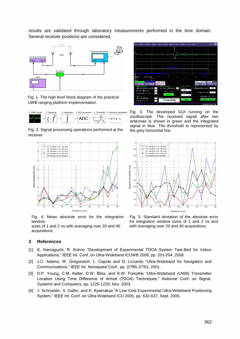
362
results are validated through laboratory measurements performed in the time domain.
Several receiver positions are considered.
3 References
[1] K. Hamaguchi, R. Kohno ―Development of Experimental TDOA System Test-Bed for Indoor
Applications,‖ IEEE Int. Conf. on Ultra-Wideband ICUWB 2008, pp. 201-204, 2008.
[2] J.C. Adams, W. Gregorwich, L. Capots and D. Liccardo ―Ultra-Wideband for Navigation and
Communications,‖ IEEE Int. Aerospace Conf., pp. 2/785-2/791, 2001.
[3] D.P. Young, C.M. Keller, D.W. Bliss, and K.W. Forsythe ―Ultra-Wideband (UWB) Transmitter
Location Using Time Difference of Arrival (TDOA) Techniques,‖ Asilomar Conf. on Signal,
Systems and Computers, pp. 1225-1229, Nov. 2003.
[4] J. Schroeder, S. Galler, and K. Kyamakya ―A Low-Cost Experimental Ultra-Wideband Positioning
System,‖ IEEE Int. Conf. on Ultra-Wideband ICU 2005, pp. 632-637, Sept. 2005.
Fig. 4. Mean absolute error for the integration window sizes of 1 and 2 ns with averaging over 20 and 40 acquisitions.
Fig. 3. The developed GUI running on the oscilloscope. The received signal after two antennas is shown in green and the integrated signal in blue. The threshold is represented by the grey horizontal line. Fig. 2. Signal processing operations performed at the
receiver.
Fig. 1. The high level block diagram of the practical
UWB ranging platform implementation.
ranging platform implementation.
Fig. 5. Standard deviation of the absolute error for integration window sizes of 1 and 2 ns and with averaging over 20 and 40 acquisitions.
10 20 30 40 50 60 70 80 900
0.2
0.4
0.6
0.8
1
1.2
1.4
1.6
1.8
2
Abs
olut
e er
ror
std
dev.
(cm
)
Distance (cm)
Int. window 1 ns, 20 acq.
Int. window 1 ns, 40 acq.
Int. window 2 ns, 20 acq.
Int. window 2 ns, 40 acq.
Sensitivity level change
10 20 30 40 50 60 70 80 900
1
2
3
4
5
6
7
Distance (cm)
Mea
n A
bsol
ute
Err
or (
cm)
Int. window 1 ns, 20 acq.
Int. window 1 ns, 40 acq.
Int. window 2 ns, 20 acq.
Int. window 2 ns, 40 acq.
Sensitivity level change
363
UWB Positioning Using Known Indoor Features –
Environment Comparison
Jan Kietlinski-Zaleski, Takaya Yamazato
Nagoya University, School of Engineering, Furo-cho Chikusa-ku Nagoya-shi 464-8603
JAPAN
1 Summary
In our previous papers, [1] and [2], we presented a novel system using reflections from
known reflectors to allow 3D ToA UWB indoor positioning with two receivers. The system
was verified using measurement campaign data from just one example environment - a
lecture room. Since then we performed measurements in two more common indoor
environments – a cluttered room (laboratory) and a corridor. In this abstract we will present
our positioning system results for the three environments and compare them, drawing
conclusions about strengths and weaknesses of the positioning system, in other words a
short sample of our perspective paper. .
2 3D ToA UWB Positioning With Two Receivers
The used positioning system is described in [2]. We perform positioning of a mobile
transmitter using a network of set-position synchronized receivers. Receivers are able to do
time of arrival (ToA) ranging. They will detect not only the direct path component of the signal
but also distinct multi-path components (MPCs). A two step algorithm is used:
1. Result Circle(RC) calculation: Using direct-path ranges to two receivers, calculate a
circle the transmitter should be close to. Let us call it RC.
2. Find point on RC with maximum likelihood : Assuming that detected MPCs contain
MPCs connected with reflections from known reflectors, assign likelihood to points on
RC, find point with maximum likelihood.
3 Measurement Setup
Measurements were performed at Warsaw University of Technology (PW), Department of
Electronics and Information Theory (EiTI), in cooperation with Dr. Jerzy Kolakowski,
Radiomeasurement Laboratory. The transmitted signal was an impulse corresponding to the
3.4-4.8 GHz band. Three environments were a sparsely furnitured lecture room, 5.6 x 5.2 m,
an extremely cluttered laboratory, 5.4 x 6.2 m, and a cases-lined corridor, 12.8 x 2 m.
4 Measurement Results
Average results achieved by our algorithm are presented in Figs 1 to 4. In the case of the
lecture room, our system is currently achieving better results than standard Assumed Height
for receivers in adjacent corners (Fig.1) and opposite corners. In the case of a much more
cluttered lab, only with receivers in opposite corners (Fig.4) the results were better This is
because in this case Assumed Height algorithm faces 2 possible transmitter positions and
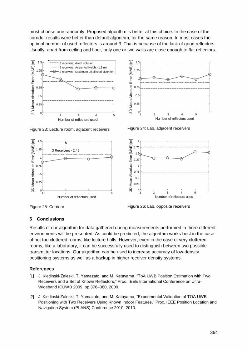
364
must choose one randomly. Proposed algorithm is better at this choice. In the case of the
corridor results were better than default algorithm, for the same reason. In most cases the
optimal number of used reflectors is around 3. That is because of the lack of good reflectors.
Usually, apart from ceiling and floor, only one or two walls are close enough to flat reflectors.
Figure 23: Lecture room, adjacent receivers
Figure 24: Lab, adjacent receivers
Figure 25: Corridor
Figure 26: Lab, opposite receivers
5 Conclusions
Results of our algorithm for data gathered during measurements performed in three different
environments will be presented. As could be predicted, the algorithm works best in the case
of not too cluttered rooms, like lecture halls. However, even in the case of very cluttered
rooms, like a laboratory, it can be successfully used to distinguish between two possible
transmitter locations. Our algorithm can be used to increase accuracy of low-density
positioning systems as well as a backup in higher receiver density systems.
References
[1] J. Kietlinski-Zaleski, T. Yamazato, and M. Katayama, ―ToA UWB Position Estimation with Two
Receivers and a Set of Known Reflectors,‖ Proc. IEEE International Conference on Ultra-
Wideband ICUWB 2009, pp.376–380, 2009.
[2] J. Kietlinski-Zaleski, T. Yamazato, and M. Katayama, ―Experimental Validation of TOA UWB
Positioning with Two Receivers Using Known Indoor Features,‖ Proc. IEEE Position Location and
Navigation System (PLANS) Conference 2010, 2010.
1 2 3 4 50
0.25
0.5
0.75
1
1.25
1.5
3D
Me
an
Ab
so
lute
Err
or
(MA
E)
[m]
Number of reflectors used
3 receivers, direct solution
2 receivers, Assumed Height (1.5 m)
2 receivers, Maximum Likelihood algorithm
1 2 3 4 50
0.25
0.5
0.75
1
1.25
1.5
3D
Me
an
Ab
so
lute
Err
or
(MA
E)
[m]
Number of reflectors used
1 2 3 40
0.25
0.5
0.75
1
1.25
1.5
3D
Me
an
Ab
so
lute
Err
or
(MA
E)
[m]
Number of reflectors used
3 Receivers - 2.48
1 2 3 4 50
0.25
0.5
0.75
1
1.25
1.5
1.75
2
3D
Me
an
Ab
so
lute
Err
or
(MA
E)
[m]
Number of reflectors used
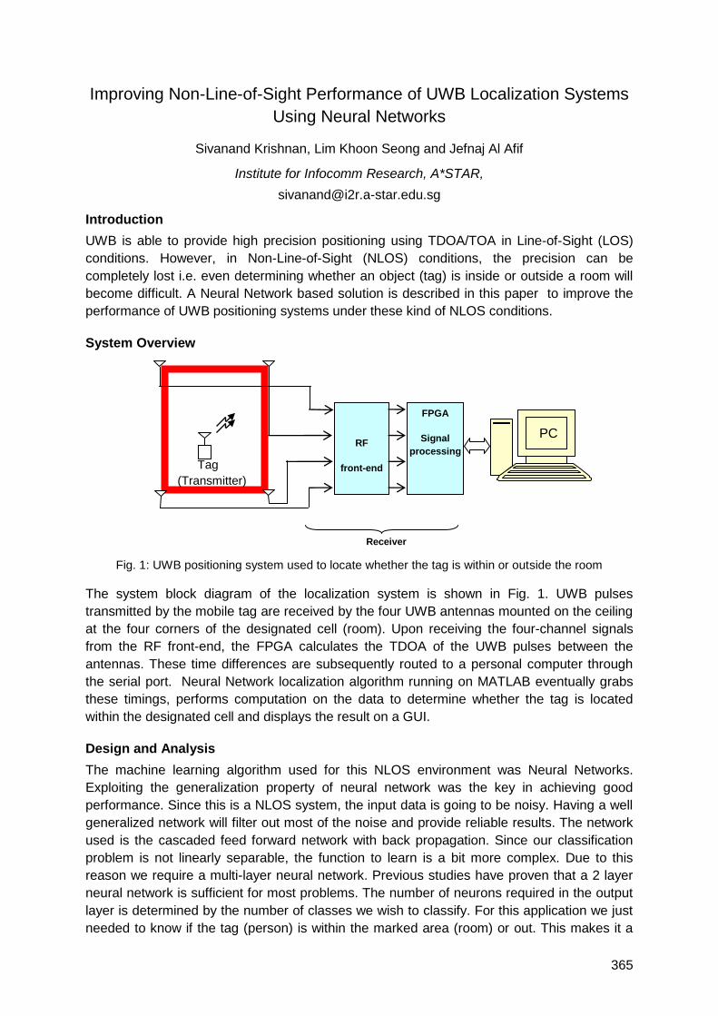
365
Improving Non-Line-of-Sight Performance of UWB Localization Systems
Using Neural Networks
Sivanand Krishnan, Lim Khoon Seong and Jefnaj Al Afif
Institute for Infocomm Research, A*STAR,
Introduction
UWB is able to provide high precision positioning using TDOA/TOA in Line-of-Sight (LOS)
conditions. However, in Non-Line-of-Sight (NLOS) conditions, the precision can be
completely lost i.e. even determining whether an object (tag) is inside or outside a room will
become difficult. A Neural Network based solution is described in this paper to improve the
performance of UWB positioning systems under these kind of NLOS conditions.
System Overview
Fig. 1: UWB positioning system used to locate whether the tag is within or outside the room
The system block diagram of the localization system is shown in Fig. 1. UWB pulses
transmitted by the mobile tag are received by the four UWB antennas mounted on the ceiling
at the four corners of the designated cell (room). Upon receiving the four-channel signals
from the RF front-end, the FPGA calculates the TDOA of the UWB pulses between the
antennas. These time differences are subsequently routed to a personal computer through
the serial port. Neural Network localization algorithm running on MATLAB eventually grabs
these timings, performs computation on the data to determine whether the tag is located
within the designated cell and displays the result on a GUI.
Design and Analysis
The machine learning algorithm used for this NLOS environment was Neural Networks.
Exploiting the generalization property of neural network was the key in achieving good
performance. Since this is a NLOS system, the input data is going to be noisy. Having a well
generalized network will filter out most of the noise and provide reliable results. The network
used is the cascaded feed forward network with back propagation. Since our classification
problem is not linearly separable, the function to learn is a bit more complex. Due to this
reason we require a multi-layer neural network. Previous studies have proven that a 2 layer
neural network is sufficient for most problems. The number of neurons required in the output
layer is determined by the number of classes we wish to classify. For this application we just
needed to know if the tag (person) is within the marked area (room) or out. This makes it a
RF
front-end
FPGA
Signal
processing
Tag
(Transmitter)
Receiver
PC
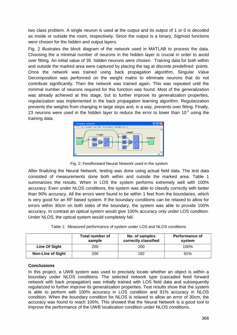
366
two class problem. A single neuron is used at the output and its output of 1 or 0 is decoded
as inside or outside the room, respectively. Since the output is a binary, Sigmoid functions
were chosen for the hidden and output layers.
Fig. 2 illustrates the block diagram of the network used in MATLAB to process the data.
Choosing the a minimal number of neurons in the hidden layer is crucial in order to avoid
over fitting. An initial value of 35 hidden neurons were chosen. Training data for both within
and outside the marked area were captured by placing the tag at discrete predefined points.
Once the network was trained using back propagation algorithm, Singular Value
Decomposition was performed on the weight matrix to eliminate neurons that do not
contribute significantly. Then the network was trained again. This was repeated until the
minimal number of neurons required for this function was found. Most of the generalization
was already achieved at this stage, but to further improve its generalization properties,
regularization was implemented in the back propagation learning algorithm. Regularization
prevents the weights from changing in large steps and, in a way, prevents over fitting. Finally,
23 neurons were used in the hidden layer to reduce the error to lower than 10-2 using the
training data.
Fig. 2: Feedforward Neural Network used in the system
After finalizing the Neural Network, testing was done using actual field data. The test data
consisted of measurements done both within and outside the marked area. Table 1
summarizes the results. When in LOS the system performs extremely well with 100%
accuracy. Even under NLOS conditions, the system was able to classify correctly with better
than 90% accuracy. All the errors were found to be within 1 feet from the boundaries, which
is very good for an RF based system. If the boundary conditions can be relaxed to allow for
errors within 30cm on both sides of the boundary, the system was able to provide 100%
accuracy. In contrast an optical system would give 100% accuracy only under LOS condition.
Under NLOS, the optical system would completely fail.
Table 1: Measured performance of system under LOS and NLOS conditions
Total number of sample
No. of samples correctly classified
Performance of system
Line Of Sight 200 200 100%
Non-Line of Sight 200 182 91%
Conclusions
In this project, a UWB system was used to precisely locate whether an object is within a boundary under NLOS conditions. The selected network type (cascaded feed forward network with back propagation) was initially trained with LOS field data and subsequently regularized to further improve its generalization properties. Test results show that the system is able to perform with 100% accuracy in LOS condition and 91% accuracy in NLOS condition. When the boundary condition for NLOS is relaxed to allow an error of 30cm, the accuracy was found to reach 100%. This showed that the Neural Network is a good tool to improve the performance of the UWB localization condition under NLOS conditions.
367
Ultra-Wideband System-Level Simulator for Positioning and Tracking
(U-SPOT)
Thomas Gigl°*, Paul Meissner°, Josef Preishuber-Pfluegl*, and Klaus Witrisal°
°Graz University of Technology, Austria,
*CISC Semiconductor Design and Consulting GmbH, Austria
{thomas.gigl, paul.meissner, witrisal}@tugraz.at, [email protected]
1 Introduction
Realistic simulation of Ultra-Wideband (UWB) positioning and tracking is a tough and
challenging task. Lots of parameters have a significant impact on the final performance of the
positioning system, such as parameters of transmitted waveform, radio regulations, channel,
receiver, ranging-, positioning- and tracking-algorithm and finally the geometric setup. A
realistic simulation framework is needed to develop and optimize positioning algorithms. This
work proposes a novel framework for realistic UWB positioning simulations. All stages of
influence have been modelled carefully. While ray-tracing simulators focus on a given user
defined scenario, our approach uses statistically defined environments. Random processes
are used to select channel impulse responses from a measurement database, according to
an algorithm that introduces realistic large and small-scale variability with space. In particular,
line-of-sight (LOS) and non-LOS (NLOS) channels are used at a defined ratio.
In this work the application of the simulation framework is demonstrated to compare the
performance of a least-squares (LS) positioning algorithm and standard and extended
Kalman filter (SKF and EKF) tracking algorithm in environments with a large ratio of NLOS
range measurements. Furthermore, the IEEE802.15.4a standard is analyzed with respect to
its positioning performance.
2 Positioning Simulator
In this work, the transmitted signal is generated according to the IEEE802.15.4a preamble,
as the preamble is the most important signal part for a positioning system. Many parameters
are defined in the standard, whose influence on the ranging capabilities has been studied in
[1] [2]. Next, measured channel impulse responses are loaded into the simulator and are
convolved with the preamble sequences. A channel selection algorithm is applied, which
chooses the measured channel impulse responses corresponding to LOS and NLOS
probabilities and from random measurement pools. The transition from one local
measurement pool to another is performed according to a user defined transition probability.
A measurement pool is a set of locally concatenated measurements, which include, small
scale fading. The received signal strength is modelled according to the EC/FCC regulations
[2] and the channel models from [3]. A coherent and a non-coherent receiver are
implemented to evaluate the capabilities of high and low complexity positioning systems.
3 Performance Evaluation
This section shows the performance evaluation with the positioning simulator and compares
an LS positioning algorithm to an SKF and an EKF tracking algorithm in a virtual office
environment with 70% LOS links, using a coherent receiver. The Kalman filters employ a
position, velocity and acceleration model (PVA).
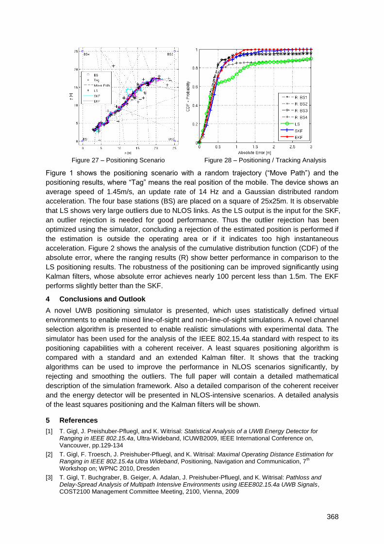
368
Figure 27 – Positioning Scenario Figure 28 – Positioning / Tracking Analysis
Figure 1 shows the positioning scenario with a random trajectory (―Move Path‖) and the
positioning results, where ―Tag‖ means the real position of the mobile. The device shows an
average speed of 1.45m/s, an update rate of 14 Hz and a Gaussian distributed random
acceleration. The four base stations (BS) are placed on a square of 25x25m. It is observable
that LS shows very large outliers due to NLOS links. As the LS output is the input for the SKF,
an outlier rejection is needed for good performance. Thus the outlier rejection has been
optimized using the simulator, concluding a rejection of the estimated position is performed if
the estimation is outside the operating area or if it indicates too high instantaneous
acceleration. Figure 2 shows the analysis of the cumulative distribution function (CDF) of the
absolute error, where the ranging results (R) show better performance in comparison to the
LS positioning results. The robustness of the positioning can be improved significantly using
Kalman filters, whose absolute error achieves nearly 100 percent less than 1.5m. The EKF
performs slightly better than the SKF.
4 Conclusions and Outlook
A novel UWB positioning simulator is presented, which uses statistically defined virtual
environments to enable mixed line-of-sight and non-line-of-sight simulations. A novel channel
selection algorithm is presented to enable realistic simulations with experimental data. The
simulator has been used for the analysis of the IEEE 802.15.4a standard with respect to its
positioning capabilities with a coherent receiver. A least squares positioning algorithm is
compared with a standard and an extended Kalman filter. It shows that the tracking
algorithms can be used to improve the performance in NLOS scenarios significantly, by
rejecting and smoothing the outliers. The full paper will contain a detailed mathematical
description of the simulation framework. Also a detailed comparison of the coherent receiver
and the energy detector will be presented in NLOS-intensive scenarios. A detailed analysis
of the least squares positioning and the Kalman filters will be shown.
5 References
[1] T. Gigl, J. Preishuber-Pfluegl, and K. Witrisal: Statistical Analysis of a UWB Energy Detector for Ranging in IEEE 802.15.4a, Ultra-Wideband, ICUWB2009, IEEE International Conference on, Vancouver, pp.129-134
[2] T. Gigl, F. Troesch, J. Preishuber-Pfluegl, and K. Witrisal: Maximal Operating Distance Estimation for Ranging in IEEE 802.15.4a Ultra Wideband, Positioning, Navigation and Communication, 7
th
Workshop on; WPNC 2010, Dresden
[3] T. Gigl, T. Buchgraber, B. Geiger, A. Adalan, J. Preishuber-Pfluegl, and K. Witrisal: Pathloss and Delay-Spread Analysis of Multipath Intensive Environments using IEEE802.15.4a UWB Signals, COST2100 Management Committee Meeting, 2100, Vienna, 2009
369
Advancement in UWB Positioning Performance through
Mobile Robot Systems
Amanda Prorok, Alexander Bahr, Alcherio Martinoli
EPFL (Lausanne), Institute of Environmental Engineering, Distributed Intelligent Systems
and Algorithms Laboratory (DISAL)
1 Introduction
Recent substantial progress in the domain of indoor positioning systems and a growing
number of indoor location-based applications are creating the need for systematic, efficient,
and precise experimental methods able to assess the localization and perhaps also
navigation performance of a given device.
Our contribution, rather than presenting novel technical methods, aims at showcasing how
mobile robotic platforms can serve as a systematic and precise evaluation tool for indoor
positioning systems, and in turn, how innovative indoor positioning techniques such as those
based on ultra-wideband (UWB) can help mobile robotics improve localization and navigation
performances in indoor settings. In this context, our contribution first presents the miniature
Khepera III mobile robot (12 cm in diameter) integrated in a precise, real-time ground-truth
evaluation system. It then focuses on the benefits of UWB positioning technology as
complementary positioning information for such miniature robots.
2 General Context
In contrast to outdoor navigation, where crude positioning of sub-meter accuracy often
satisfies user needs, indoor applications may require accuracies in the order of a centimeter.
Furthermore, outdoor positioning and navigation has been well explored and standardized,
whereas indoor navigation remains a recent research area which is still in the process of
generating numerous new systems and algorithms.
A growing number of real-life applications that depend on automatic object location detection
and navigation capabilities create the need for efficient and accurate testing methods. Also,
as the miniaturization of application devices poses challenges to the integration of new
technologies, additional test-beds must be considered. In our efforts to help improve indoor
navigation capabilities, we pose the mobile robot as a fundamental tool enabling systematic
testing under controlled conditions.
This research effort is part of a recently launched project which focuses on the
implementation of a novel localization system using impulse-radio UWB (IR-UWB), based on
results which have emerged from the latest phase of the MICS NCCR project [1]. In
comparison with known positioning technologies, and especially in indoor environments, in
absence of global navigation satellite systems (GNSS), the potential strengths of an IR-UWB
localization system become apparent: high precision, high positioning rate, scalability,
reduced sensitivity to line-of-sight (LOS) occlusions, low cost and low power. Also, by
outsourcing the complexity of the positioning algorithms to an external system, an IR-UWB
positioning infrastructure is adapted even to miniature robots, given that the localization
information can be transmitted to the robots through standard narrowband communication
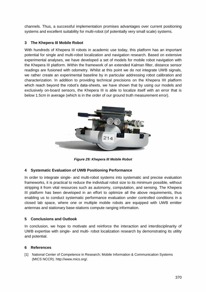
370
channels. Thus, a successful implementation promises advantages over current positioning
systems and excellent suitability for multi-robot (of potentially very small scale) systems.
3 The Khepera III Mobile Robot
With hundreds of Khepera III robots in academic use today, this platform has an important
potential for single and multi-robot localization and navigation research. Based on extensive
experimental analyses, we have developed a set of models for mobile robot navigation with
the Khepera III platform. Within the framework of an extended Kalman filter, distance sensor
readings are fusioned with odometry. Whilst at this point we do not integrate UWB signals,
we rather create an experimental baseline by in particular addressing robot calibration and
characterization. In addition to providing technical precisions on the Khepera IIII platform
which reach beyond the robot‘s data-sheets, we have shown that by using our models and
exclusively on-board sensors, the Khepera III is able to localize itself with an error that is
below 1.5cm in average (which is in the order of our ground truth measurement error).
Figure 29: Khepera III Mobile Robot
4 Systematic Evaluation of UWB Positioning Performance
In order to integrate single- and multi-robot systems into systematic and precise evaluation
frameworks, it is practical to reduce the individual robot size to its minimum possible, without
stripping it from vital resources such as autonomy, computation, and sensing. The Khepera
III platform has been developed in an effort to optimize all the above requirements, thus
enabling us to conduct systematic performance evaluation under controlled conditions in a
closed lab space, where one or multiple mobile robots are equipped with UWB emitter
antennas and stationary base-stations compute ranging information.
5 Conclusions and Outlook
In conclusion, we hope to motivate and reinforce the interaction and interdisciplinarity of
UWB expertise with single- and multi- robot localization research by demonstrating its utility
and potential.
6 References
[1] National Center of Competence in Research; Mobile Information & Communication Systems
(MICS NCCR). http://www.mics.org/.
371
Experimental Demonstration of Self-Localized Ultra Wideband Indoor
Mobile Robot Navigation System
Marcelo Segura*, Hossein Hashemi§, Cristian Sisterna* and Vicente Mut*
(*) Department of Electronic Engineering, National University of San Juan, San Juan, Argentina
(§) Department of Electrical Engineering, University of Southern California, Los Angeles, CA
90089-0271
[email protected], [email protected], [email protected]
1 Summary
A self-localized Ultra-Wide-Band (UWB) system is introduced, that is suitable to navigate
mobile robots (MR) in indoor environments. In impulse-based UWB systems, positional
accuracy is inversely proportional to the signal bandwidth. The Federal Communication
Commission (FCC) has regulated the spectral usage of UWB signals for various applications.
In the current implementation, 2ns pulses having a -10dB bandwidth of approximately 1GHz
have been used primarily due to hardware limitations (unavailability of high-speed ADC at the
time of writing this abstract). We have recently received a faster ADC (1.5GS/s) that allow for
sampling signals with lower pulse-width (increased BW) in order to get better positional
accuracy. In the proposed scheme, a number of anchor nodes are located in fixed positions
in the indoor environment, and transmit synchronized 2ns pulses with Differential Binary
Phase Shift Keying (DBPSK) modulation. This self-localization GPS-like configuration was
used because the final goal consists on run localization and position control algorithms
locally on the MR and estimate the trajectory instead of one position at a time using a
Bayesian method. An UWB receiver mounted on the MR uses Time Difference of Arrival
(TDOA) between pairs of synchronized transmitting anchor nodes for localization. A
prototype non-coherent UWB system using off-the-shelf components is implemented where
signal acquisition and localization algorithms run on a Field Programmable Gate Array
(FPGA). Measurement results indicate sub-15cm positional accuracy with Line Of Sight
(LOS) and Non-Line of Sight (NLOS) conditions relative to fixed anchor nodes in a typical
indoor environment.
2 Introduction
Industrial mobile robots, stock control and logistics in warehouses, mobility assistance for
handicapped people or patient monitoring in hospitals are some scenarios that require
accurate position estimation in indoor environments. Sensors based on ultrasound, lasers,
and cameras are often used for these applications. Optical and ultrasound sensors have
poor performance in low visibility conditions, and harsh or loud environments, respectively.
Radio Frequency (RF) sensors have a wide range of usage as the electromagnetic waves
propagate through most typical environments. Impulse-based ultra wideband transceivers
offer accurate ranging accuracy with low cost. Although the advantages of UWB systems in
ranging and localization have been known, application in indoor positioning in the presence
of multi-path components required further study. In this paper, an indoor navigation system is
introduced that is based on impulse-based UWB technology.
3 System Overview
In the proposed scheme, a number of synchronized anchor nodes are located in fixed
positions in the indoor environment. These anchor nodes transmit synchronized UWB pulses.
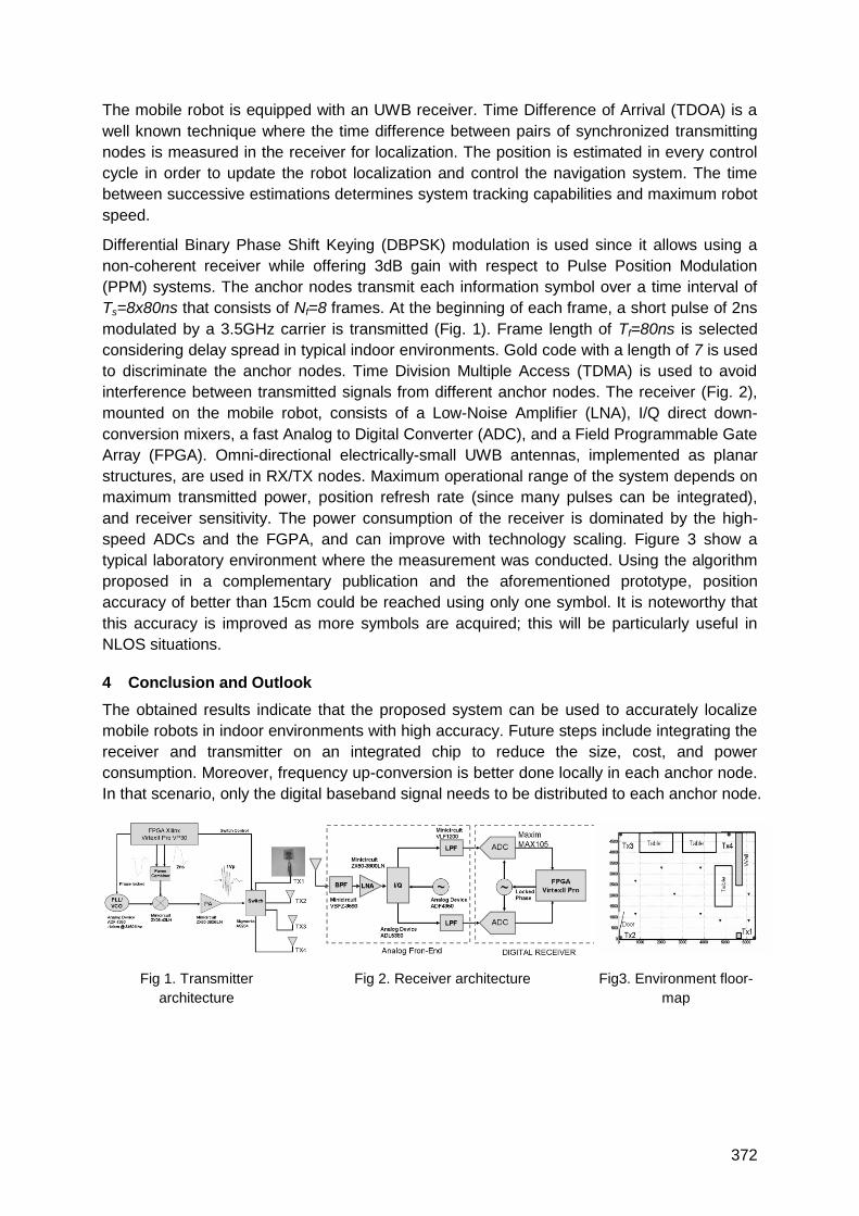
372
The mobile robot is equipped with an UWB receiver. Time Difference of Arrival (TDOA) is a
well known technique where the time difference between pairs of synchronized transmitting
nodes is measured in the receiver for localization. The position is estimated in every control
cycle in order to update the robot localization and control the navigation system. The time
between successive estimations determines system tracking capabilities and maximum robot
speed.
Differential Binary Phase Shift Keying (DBPSK) modulation is used since it allows using a
non-coherent receiver while offering 3dB gain with respect to Pulse Position Modulation
(PPM) systems. The anchor nodes transmit each information symbol over a time interval of
Ts=8x80ns that consists of Nf=8 frames. At the beginning of each frame, a short pulse of 2ns
modulated by a 3.5GHz carrier is transmitted (Fig. 1). Frame length of Tf=80ns is selected
considering delay spread in typical indoor environments. Gold code with a length of 7 is used
to discriminate the anchor nodes. Time Division Multiple Access (TDMA) is used to avoid
interference between transmitted signals from different anchor nodes. The receiver (Fig. 2),
mounted on the mobile robot, consists of a Low-Noise Amplifier (LNA), I/Q direct down-
conversion mixers, a fast Analog to Digital Converter (ADC), and a Field Programmable Gate
Array (FPGA). Omni-directional electrically-small UWB antennas, implemented as planar
structures, are used in RX/TX nodes. Maximum operational range of the system depends on
maximum transmitted power, position refresh rate (since many pulses can be integrated),
and receiver sensitivity. The power consumption of the receiver is dominated by the high-
speed ADCs and the FGPA, and can improve with technology scaling. Figure 3 show a
typical laboratory environment where the measurement was conducted. Using the algorithm
proposed in a complementary publication and the aforementioned prototype, position
accuracy of better than 15cm could be reached using only one symbol. It is noteworthy that
this accuracy is improved as more symbols are acquired; this will be particularly useful in
NLOS situations.
4 Conclusion and Outlook
The obtained results indicate that the proposed system can be used to accurately localize
mobile robots in indoor environments with high accuracy. Future steps include integrating the
receiver and transmitter on an integrated chip to reduce the size, cost, and power
consumption. Moreover, frequency up-conversion is better done locally in each anchor node.
In that scenario, only the digital baseband signal needs to be distributed to each anchor node.
Fig 1. Transmitter
architecture
Fig 2. Receiver architecture Fig3. Environment floor-
map
373
Evaluation of requirements for UWB localisation systems in home-
entertainment applications
R. Zetik, G. Shen and R. Thomä
FG EMT, TU Ilmenau, Max-Planck-Ring 14, 98684 Ilmenau, Germany
1 Summary
This paper discusses basic requirements for a passive ultra-wideband (UWB) localization
system that aims at home-entertainment applications such as a smart audio system, which
can adapt the sound according to the user location, so that an optimum listening experience
is provided to the user. The requirements were evaluated using data measured by a real-
time UWB channel sounder. Over hundred thousands channel impulse responses were
measured in different scenarios by means of two antenna types in different constellations
with a varying number of listeners who were moving along various tracks. The performance
of the passive localization is demonstrated by a selected measurement example.
2 Extended Abstract
Our envisaged application of the passive localisation system assumes that one person in a
living room is to be localised just by electro-magnetic (EM) waves reflected from the body.
Antennas of the UWB localiser are supposed to be integrated in loudspeakers of an audio
system. The obtained position estimates should drive smart audio algorithms, which optimise
and/or direct the sound interactively depending on the listener position. In order to evaluate
basic requirements for such a localisation system, we performed a measurement campaign
using the UWB channel sounder [1]. We used omni-directional (in two dimensions) bi-conical
antennas and directive Vivaldi antennas. The antennas were arranged in 3 different
measurement constellations:
Soundbar – a linear array, about 1 m in length, with one transmitting (Tx) antenna in the
middle and 4 receiving (Rx) antennas,
2-point ambient sound constellation – a larger linear array with one Tx in the middle
and 2 Rx placed in the left corner of the room and 2 Rx in the right corner of the room,
multiple-speaker constellation with the antenna arrangement similar to the 5.1 audio
system – 1Tx at the position of the central speaker and 4 Rx at the position of
loudspeaker satellites located in the corners of a room.
Thousands of channel impulse responses were recorded in real time. During the
measurements, one person was walking through the room along predefined tracks, or sitting
on a couch at different positions. The data were processed by the algorithm described in [2].
The most challenging part is the detection of a person. This is due to the fact that EM waves
reflected from a person are weak in comparison to the direct wave or to reflections from
dominant static objects such as walls. They are almost invisible in unprocessed data (see Fig.
1 left). Therefore, in the first step the raw measurements are processed by a background
subtraction algorithm that eliminates strong time-invariant signals and reveals weak signals
reflected from time-varying targets (see Fig. 1 right). We have defined a signal to clutter ratio
(SCR) as a basic system parameter. This parameter compares the power of the signal
reflected from a person with the power of a clutter signal. In our case, the clutter represents
the strongest signal component present in the received impulse response. Usually, it is the
direct wave that propagates from the Tx antenna to the Rx antenna. In case of a localizer
capable of gating out the direct wave from the measurement, the strongest signal is a
reflection from dominant static objects.
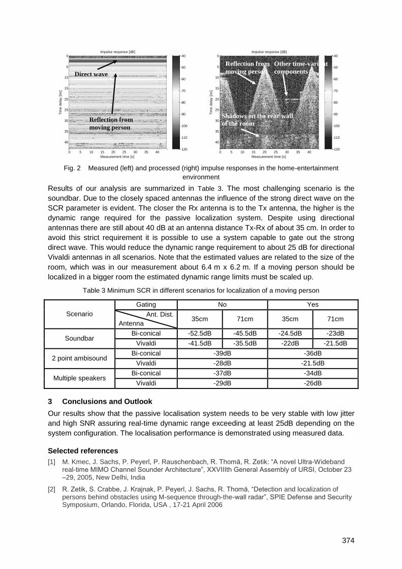
374
Measurement time [s]
Tim
e d
ela
y [
ns]
Impulse response [dB]
0 5 10 15 20 25 30 35 40
0
5
10
15
20
25
30
35
40
-120
-110
-100
-90
-80
-70
-60
-50
-40
Direct wave
Reflection from
moving person
Measurement time [s]
Tim
e d
ela
y [
ns]
Impulse response [dB]
0 5 10 15 20 25 30 35 40
0
5
10
15
20
25
30
35
40
-120
-110
-100
-90
-80
-70
-60
-50
-40
Shadows on the rear wall
of the room
Reflection from
moving person
Other time-variant
components
Fig. 2 Measured (left) and processed (right) impulse responses in the home-entertainment
environment
Results of our analysis are summarized in Table 3. The most challenging scenario is the
soundbar. Due to the closely spaced antennas the influence of the strong direct wave on the
SCR parameter is evident. The closer the Rx antenna is to the Tx antenna, the higher is the
dynamic range required for the passive localization system. Despite using directional
antennas there are still about 40 dB at an antenna distance Tx-Rx of about 35 cm. In order to
avoid this strict requirement it is possible to use a system capable to gate out the strong
direct wave. This would reduce the dynamic range requirement to about 25 dB for directional
Vivaldi antennas in all scenarios. Note that the estimated values are related to the size of the
room, which was in our measurement about 6.4 m x 6.2 m. If a moving person should be
localized in a bigger room the estimated dynamic range limits must be scaled up.
Table 3 Minimum SCR in different scenarios for localization of a moving person
Scenario
Gating No Yes
Ant. Dist.
Antenna 35cm 71cm 35cm 71cm
Soundbar Bi-conical -52.5dB -45.5dB -24.5dB -23dB
Vivaldi -41.5dB -35.5dB -22dB -21.5dB
2 point ambisound Bi-conical -39dB -36dB
Vivaldi -28dB -21.5dB
Multiple speakers Bi-conical -37dB -34dB
Vivaldi -29dB -26dB
3 Conclusions and Outlook
Our results show that the passive localisation system needs to be very stable with low jitter
and high SNR assuring real-time dynamic range exceeding at least 25dB depending on the
system configuration. The localisation performance is demonstrated using measured data.
Selected references
[1] M. Kmec, J. Sachs, P. Peyerl, P. Rauschenbach, R. Thomä, R. Zetik: ―A novel Ultra-Wideband real-time MIMO Channel Sounder Architecture‖, XXVIIIth General Assembly of URSI, October 23 –29, 2005, New Delhi, India
[2] R. Zetik, S. Crabbe, J. Krajnak, P. Peyerl, J. Sachs, R. Thomä, ―Detection and localization of persons behind obstacles using M-sequence through-the-wall radar‖, SPIE Defense and Security Symposium, Orlando, Florida, USA , 17-21 April 2006

375
UWB-based Local Positioning System: from a small-scale
Experimental Platform to a large-scale Deployable System
P. Tomé (1), C. Robert (1), R. Merz (1), C. Botteron (1), A. Blatter (2) and P.-A. Farine (1)
(1) Ecole Polytechnique Fédérale de Lausanne (EPFL)
Institute of Microengineering, Electronics and Signal Processing Laboratory
Rue A.-L- Breguet 2, Neuchâtel, Switzerland (2) PX Holding S.A., La Chaux-de-Fond, Switzerland
1 Summary
At the Electronics and Signal Processing Laboratory at EPFL, an experimental platform has
been designed and built to demonstrate the feasibility of Ultra-wideband (UWB) technology
applied to indoor positioning. This small-scale demonstrator has proven to be a valuable
research tool, with the flexibility to study, test and assess the performance of various system
architectures and signal processing algorithms.
Based on this successful experience, a subsequent project was setup to extend the lab‘s
research on certain topics that could not be addressed by the small-scale demonstrator. This
new R&D project pursues two main objectives: a) designing and building a large-scale UWB-
based Local Positioning System (LPS), including installation, calibration and operational
testing in a real industrial environment; b) conceiving and developing Application Specific
Integrated Circuits (ASICs) to target cost-competitive solutions.
This paper addresses the main design issues analysed during the definition phase of the
large-scale UWB-based LPS requirements, considering that the new system should inherit
whenever possible the design features already existing on the small-scale demonstrator.
2 UWB-based Indoor Location Experimental Platform
The existing demonstrator is composed of 4 receivers and a few transmitters, all of which
were built using discrete components off-the-shelf. The connections between the receivers
and the central PC are based on USB interfaces and the network for the receivers‘ clock
synchronization is performed via coaxial cabling in a daisy chain topology, configuring one of
the receivers to act as the master clock.
The transmitters emit baseband pulses centred at 500 MHz. A unique spreading code
composed of 16 pulses which are Pulse Position Modulated (PPM) with an average Pulse
Repetition Rate (PRR) of 100 KHz is transmitted carrying its identification. The generated
signal covers a -10 dB bandwidth of approximately 750 MHz [1].
On the receiver side, the architecture follows that of a Software Defined Receiver (SDR), i.e.
the signal is first amplified and then directly sampled by an 8-bit ADC at 2.88 GS/s. The
digital signal is then transferred to a FPGA where all signal processing occurs in real-time.
The outcome from these algorithms can be accessed by the central PC using the USB
connection to the receiver. At the PC level, the system software was developed in Matlab
customized to the demonstrator‘s scale (i.e. 4 receivers and a few transmitters) [1].

376
3 Large-scale Deployable Local Positioning System Requirements
As mentioned previously, one of the main objectives of the on-going R&D project is to install
and test a large-scale UWB-based LPS in a real industrial environment. This implies that the
system needs to fulfil fundamental requirements, such as:
- It must be fully compliant with worldwide established UWB regulations; and
- It must be flexible to the point of enabling its scalability to various installation scenarios
(i.e. larger coverage area requiring the installation of additional receivers; more
people/objects to be tracked requiring handling more transmitters, etc.).
This latter requirement implies addressing new challenges, including considering ways to
reduce production and installation costs, simplify onsite calibration procedures without
compromising network clock synchronization accuracy, handle efficiently increased volume
of data communication between receivers and the central PC and increased probability of
collision of transmitters‘ communications, review position computation methods and develop
user-friendly visualisation and configuration Graphical User Interfaces (GUIs).
4 From small to large-scale LPS: Upgrading Design Considerations
To fulfil the two requirements presented before, both the hardware and software of the
system have received important design modifications that will be described in detail in this
paper.
At the hardware level, a new ASIC transmitter has been successfully developed and tested
to be compliant with FCC/ECC regulations. It emits pulses with a -10 dB bandwidth of 750
MHz centred at 4.1 GHz at a maximum achievable PRR of 15 MHz [2]. On the receiver end,
a high sensitivity analogue front-end was developed, tested and added before the high speed
ADC, bringing the new signal centred at 4.1 GHz back to baseband and enabling the reuse
of the already existing design of the experimental platform receiver. Also, the FPGA has
been equipped with a software processor to simplify the development of more refined signal
processing algorithms for demodulation of the transmitters‘ identification and to boost the
receiver‘s sensitivity. Other important modifications to the receiver design have also been
introduced, e.g. at the data communication and clock synchronization networks, power
supply, etc.
Finally, a new software package is being developed for the central PC incorporating user-
friendly GUIs for system configuration and visualization on a map of the transmitters‘ location.
5 Conclusions
This paper describes in detail the major design modifications that were undertaken to
upgrade a small-scale UWB-based indoor position experimental platform into a large-scale
deployable local positioning system, both at the hardware and software levels.
6 References
[1] R. Merz, C. Botteron, F. Chastellain and P.-A. Farine (2009) – "A Programmable Receiver for
Communication Systems and Its Application to Impulse Radio", Research Letters in
Communications, Vol. 2009, Article ID 238521, Hindawi Publishing Corporation.
[2] C. Robert, P. Tomé, R. Merz, C. Botteron, A. Blatter and P.-A. Farine (2010) – "Low Power ASIC
transmitter for UWB-IR communication and positioning radio", paper submitted to the 2010 IPIN
Conference, September 15-17, 2010, Zurich, Switzerland.
377
On benefits and challenges of person localisation using UWB sensors
R. Herrmann1, J. Sachs1, F. Bonitz2
1EMR Lab, TU Ilmenau, Max-Planck-Ring 14, 98684 Ilmenau, Germany
2 MPFA Weimar, Coudraystraße 9, 99423 Weimar, Germany
1 Summary
Precise localisation of persons in their living environment is part of many upcoming
applications such as wireless entertainment systems or home-based medical supervision.
Ultra-wideband (UWB) sensors are especially interesting due to specific advantages over
narrowband solutions. This paper lists some advantages and demonstrates challenges of
implementation with a measurement example. A proposal for robust ECC-conform
localisation concludes the paper.
2 Benefits of UWB sensors for short-range localisation
UWB sensors use a large measurement bandwidth B and therefore provide a high range
resolution δ for separation of close objects. The common relationship[1] is given as δ≈c/2B,
where c is the wave propagation velocity. Sub-dm resolutions are readily possible, but there
are also a number of less obvious advantages. UWB sensors can work in a very flexible
passive (or non-cooperative) mode, where the person does not need to carry any devices.
For convenience and acceptance reasons, this non-interactive scenario is preferred in many
cases. Furthermore, clever device concepts[2] spread the stimulus energy in time as well as
frequency domain. This translates into low power spectral densities and harmless maximum
wave amplitudes promoting license-free operation. ECC regulation is a bit more restrictive
than the American FCC counterpart, but the frequency band 6 - 8.5 GHz is available for
indoor use. Another advantage is low interference with other wireless services. As will be
described in the section below, the high resolution capability cannot always be used to
increase localisation precision. However, UWB sensors are sensitive to even small changes
in the scenario under test and can provide additional information apart from plain position.
Especially for patient supervision, posture of the person might be of interest. It is even
possible to assess basic vital data remotely[3]. In the microwave frequency range, some
materials are penetrated and persons behind obstacles (such as furniture) can be detected,
too. Finally, device concepts like [2] are integration friendly and provide low-cost solutions.
3 Major challenges of UWB localisation
To find the 2D position of one person moving in a room, at least one transmitter and two
receivers are necessary for trilateration. A major issue of data processing is the separation of
static reflections of the environment from the target by background removal techniques. In
most indoor cases, clutter signals from walls or furniture are often much stronger than
backscattering from a person. A common approach is to look for changes in measured data
and assign them to be caused by the moving target. The receivers must provide sufficient
dynamic range to enable detection of small changes despite the presence of strong clutter.
Moreover, a static environment is assumed which is not always the case in frequently used
rooms. Adaptive algorithms are necessary to keep track of slow changes. Even if
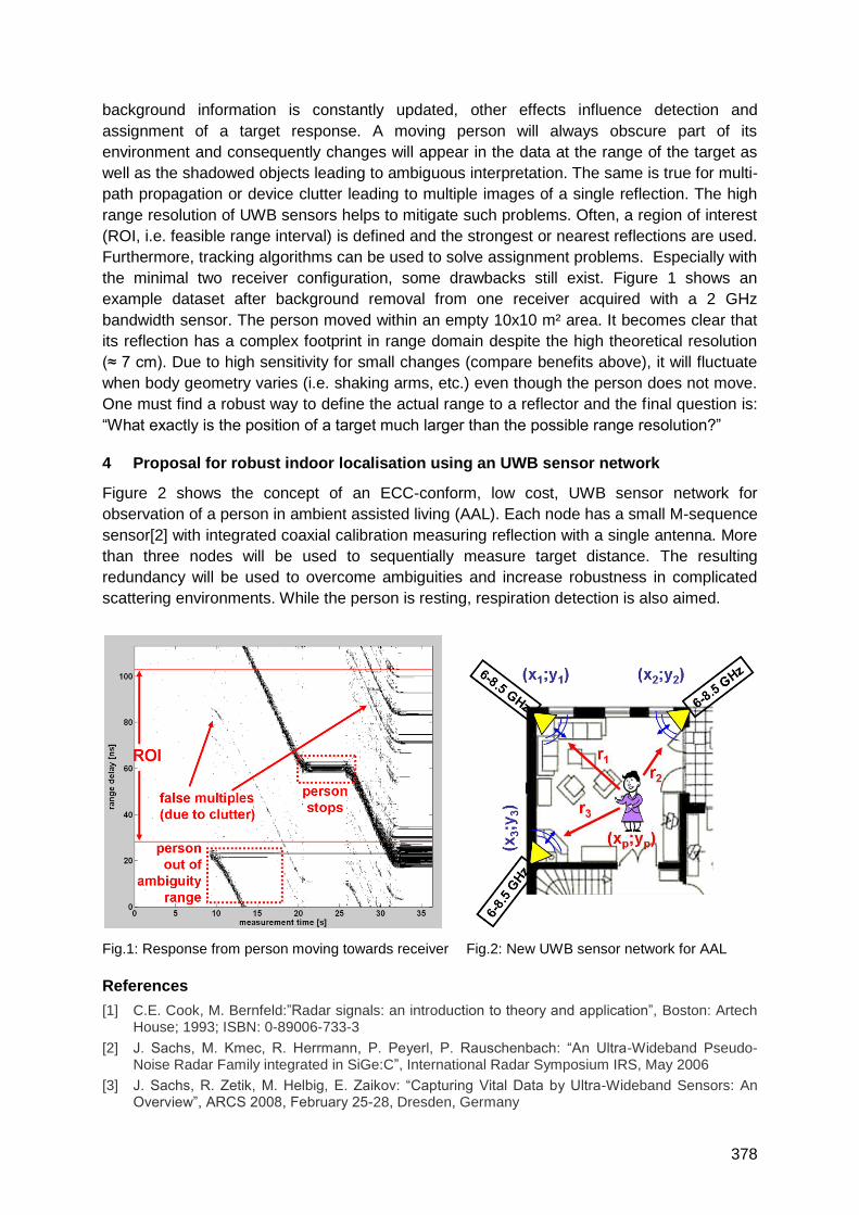
378
background information is constantly updated, other effects influence detection and
assignment of a target response. A moving person will always obscure part of its
environment and consequently changes will appear in the data at the range of the target as
well as the shadowed objects leading to ambiguous interpretation. The same is true for multi-
path propagation or device clutter leading to multiple images of a single reflection. The high
range resolution of UWB sensors helps to mitigate such problems. Often, a region of interest
(ROI, i.e. feasible range interval) is defined and the strongest or nearest reflections are used.
Furthermore, tracking algorithms can be used to solve assignment problems. Especially with
the minimal two receiver configuration, some drawbacks still exist. Figure 1 shows an
example dataset after background removal from one receiver acquired with a 2 GHz
bandwidth sensor. The person moved within an empty 10x10 m² area. It becomes clear that
its reflection has a complex footprint in range domain despite the high theoretical resolution
(≈ 7 cm). Due to high sensitivity for small changes (compare benefits above), it will fluctuate
when body geometry varies (i.e. shaking arms, etc.) even though the person does not move.
One must find a robust way to define the actual range to a reflector and the final question is:
―What exactly is the position of a target much larger than the possible range resolution?‖
4 Proposal for robust indoor localisation using an UWB sensor network
Figure 2 shows the concept of an ECC-conform, low cost, UWB sensor network for
observation of a person in ambient assisted living (AAL). Each node has a small M-sequence
sensor[2] with integrated coaxial calibration measuring reflection with a single antenna. More
than three nodes will be used to sequentially measure target distance. The resulting
redundancy will be used to overcome ambiguities and increase robustness in complicated
scattering environments. While the person is resting, respiration detection is also aimed.
Fig.1: Response from person moving towards receiver Fig.2: New UWB sensor network for AAL
References
[1] C.E. Cook, M. Bernfeld:‖Radar signals: an introduction to theory and application‖, Boston: Artech House; 1993; ISBN: 0-89006-733-3
[2] J. Sachs, M. Kmec, R. Herrmann, P. Peyerl, P. Rauschenbach: ―An Ultra-Wideband Pseudo-Noise Radar Family integrated in SiGe:C‖, International Radar Symposium IRS, May 2006
[3] J. Sachs, R. Zetik, M. Helbig, E. Zaikov: ―Capturing Vital Data by Ultra-Wideband Sensors: An Overview‖, ARCS 2008, February 25-28, Dresden, Germany
379
Accuracy Considerations of UWB Localization Systems Dedicated for
Large-Scale Applications
Lukasz Zwirello1, Malgorzata Janson1, Christian Ascher2, Ulrich Schwesinger1,2, Gert F. Trommer2 and Thomas Zwick1
Institut für Hochfrequenztechnik und Elektronik Institut für Theoretische Elektrotechnik und Systemoptimierung
Karlsruher Institut für Technologie (KIT), Kaiserstr. 12, 76131 Karlsruhe, Germany Email: [email protected]
1 Summary
This contribution considers the accuracy limits of ultra-wideband localization systems
dedicated for large-scale applications. Industrial environments are known for being extremely
difficult in terms of wireless communication, mainly because of high concentration of large
metal objects, like containers or machines; leading to strong multipath propagation. In this
work a detailed 3D model of the warehouse is used for wave propagation simulations. In the
simulation, the transmitter is moving along the predefined path and the receiver infrastructure
consists of eight base stations. The aim is to model the tracking system and asses its
accuracy – firstly the accuracy upper bound is determined for the ideal case and secondly
the precision estimation when including effects of hardware non-idealities is done. Effects
like the the influence of pulse detection methods and geometrical configuration of base-
stations are investigated. The position calculation of the mobile beacon is realized using
Time Difference of Arrival approach. Eventually the accuracy of obtained results and the
theoretical limit are considered based on dilution of precision evaluations.
2 Ray-Tracing simulation and channel parameters
The assembly hall of the Institut für Produktionstechnik at the Karlsruhe Institute of
Technology was chosen to serve as a reference for the simulation of the UWB localization
system. The exact model of the building (800 m2 surface, 9 m height) as well as the inside
facilities has been created and simulated with the Ray-Tracer (RT). RT is a deterministic
wave-propagation simulation tool. The channel transfer function H(t,f) was evaluated in a
frequency range between 2.5 and 11.2 GHz with discrete frequency increment of 3.125 MHz,
hence the unambiguous range of the impulse response is 320 ns. The calculated mean
excess delay for this environment is 50 ns for the probability of 99%. This determinates that
the maximal pulse repetition rate shouldn‘t exceed 20 MHz to avoid inter-symbol-interference.
More detailed frequency and time domain specification of this channel will be presented in
the full paper.
3 Pulse form, noise and threshold detection
The pulse form used in this research is the 5th derivative of the Gaussian pulse with standard
deviation equal to 51 ps and FWHM of approx. 250 ps. This pulse fits the FCC emission
mask well and is realized on chip. The amplitude of the pulse and PRF are optimized for
compliance with the FCC peek power limits, in order to increase SNR at large distances. No
additional interference, apart from thermal noise, is considered. The energy-detection-based
receiver was modelled in Agilent ADS, based on measured data of its components. The
detailed information on this topic, as well as on the threshold determination procedure, will be
given in the full paper.
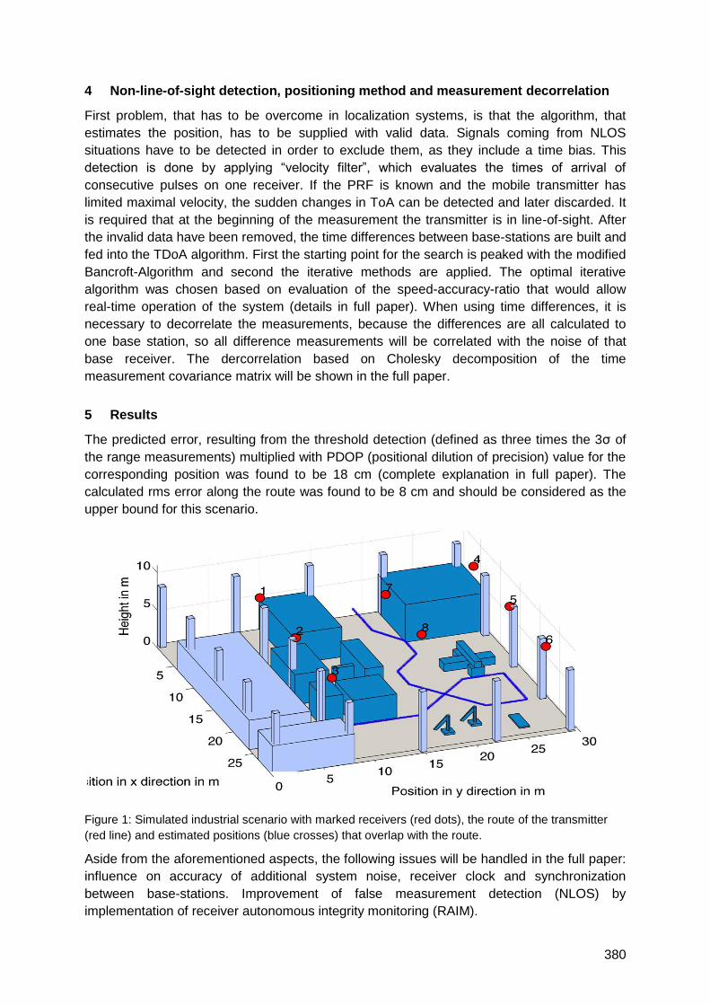
380
4 Non-line-of-sight detection, positioning method and measurement decorrelation
First problem, that has to be overcome in localization systems, is that the algorithm, that
estimates the position, has to be supplied with valid data. Signals coming from NLOS
situations have to be detected in order to exclude them, as they include a time bias. This
detection is done by applying ―velocity filter‖, which evaluates the times of arrival of
consecutive pulses on one receiver. If the PRF is known and the mobile transmitter has
limited maximal velocity, the sudden changes in ToA can be detected and later discarded. It
is required that at the beginning of the measurement the transmitter is in line-of-sight. After
the invalid data have been removed, the time differences between base-stations are built and
fed into the TDoA algorithm. First the starting point for the search is peaked with the modified
Bancroft-Algorithm and second the iterative methods are applied. The optimal iterative
algorithm was chosen based on evaluation of the speed-accuracy-ratio that would allow
real-time operation of the system (details in full paper). When using time differences, it is
necessary to decorrelate the measurements, because the differences are all calculated to
one base station, so all difference measurements will be correlated with the noise of that
base receiver. The dercorrelation based on Cholesky decomposition of the time
measurement covariance matrix will be shown in the full paper.
5 Results
The predicted error, resulting from the threshold detection (defined as three times the 3σ of
the range measurements) multiplied with PDOP (positional dilution of precision) value for the
corresponding position was found to be 18 cm (complete explanation in full paper). The
calculated rms error along the route was found to be 8 cm and should be considered as the
upper bound for this scenario.
Figure 1: Simulated industrial scenario with marked receivers (red dots), the route of the transmitter
(red line) and estimated positions (blue crosses) that overlap with the route.
Aside from the aforementioned aspects, the following issues will be handled in the full paper:
influence on accuracy of additional system noise, receiver clock and synchronization
between base-stations. Improvement of false measurement detection (NLOS) by
implementation of receiver autonomous integrity monitoring (RAIM).
381
A system level approach for node localization in IEEE 802.15.4a WSNs
Francesco Chiti, Enrico Del Re, Romano Fantacci, Simone Morosi, Lorenzo Niccolai,
Raffaele Tucci
Department of Electronics and Telecommunication, University of Florence, via di S. Marta 3,
I-50139 Florence
1 Summary
Node localization in distributed wide area WSNs is a challenging task which is becoming
crucial for both scientific and industrial communities. For this purpose, the IEEE 802.15a
standard has recently been proposed to achieve high accuracy within the ranging phase.
This paper proposes three different algorithms based on the Time of Arrival (ToA) approach
together with a technique that allows the estimation of the outcome‘s reliability.
2 Introduction
Wireless Sensor Network (WSN) applications cover a wide domain of many scenarios such
as industrial processes, home automation, security control, medical monitoring and military
applications. The possible use of mobile nodes allows a high degree of flexibility and
adaptability, paving the way to new fields of applications. In this context, the features of
localization and positioning assume crucial relevance. In 2007, IEEE released the 802.15.4a
standard [1], which defines a novel air interface for low data rate Wireless Personal Area
Networks (WPANs). The leading technology for the PHY layer is based on the Ultra Wide
Band (UWB) transmission, due to low power, low implementation costs and relatively high
data rates communication, but also allowing an improved ranging accuracy, thanks to higher
time resolution.
Aiming at the determination of the upper limits of the localization accuracy, we have up-
sampled the input signals of all the algorithms which are described in the following. This
paper proposes three different algorithms which determine the distance between the nodes
within a network:
1. Clean template: it achieves the ToA estimation through a classic correlation receiver
in order to find the peak of the cross-correlation between a replica of the transmitted
SFD and the corresponding received one.
2. Dirty Templates: the dirty templates basically provide a correlation template made up
with a segment of the received signal, for example a non-modulated symbol [2].
3. Two-Steps Dirty Template: the previous algorithm requires a very high sampling rate
and consequently the storage of a very large correlation template. Hence, a new
version of the Dirty Template algorithm was developed. It consists of two steps: an
initial correlation with a low sampling frequency version of the SFD dirty template in
order to achieve a pulse level precision estimation, followed by a second correlation
performed around the previous estimated time with a high sampled template of a
single received pulse. Both correlation methods use dirty templates.
In order to perform ranging the beginning of the communication frame has to be known: for
this purpose we use the correlation between the transmitted and the received frame.
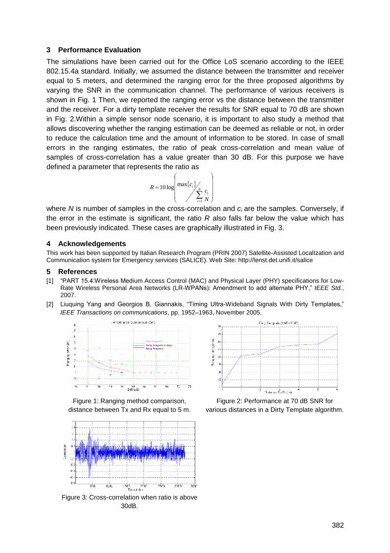
382
3 Performance Evaluation
The simulations have been carried out for the Office LoS scenario according to the IEEE
802.15.4a standard. Initially, we assumed the distance between the transmitter and receiver
equal to 5 meters, and determined the ranging error for the three proposed algorithms by
varying the SNR in the communication channel. The performance of various receivers is
shown in Fig. 1 Then, we reported the ranging error vs the distance between the transmitter
and the receiver. For a dirty template receiver the results for SNR equal to 70 dB are shown
in Fig. 2.Within a simple sensor node scenario, it is important to also study a method that
allows discovering whether the ranging estimation can be deemed as reliable or not, in order
to reduce the calculation time and the amount of information to be stored. In case of small
errors in the ranging estimates, the ratio of peak cross-correlation and mean value of
samples of cross-correlation has a value greater than 30 dB. For this purpose we have
defined a parameter that represents the ratio as
where N is number of samples in the cross-correlation and ci are the samples. Conversely, if
the error in the estimate is significant, the ratio R also falls far below the value which has
been previously indicated. These cases are graphically illustrated in Fig. 3.
4 Acknowledgements
This work has been supported by Italian Research Program (PRIN 2007) Satellite-Assisted LocalIzation and Communication system for Emergency services (SALICE). Web Site: http://lenst.det.unifi.it/salice
5 References
[1] ―PART 15.4:Wireless Medium Access Control (MAC) and Physical Layer (PHY) specifications for Low-Rate Wireless Personal Area Networks (LR-WPANs): Amendment to add alternate PHY,‖ IEEE Std., 2007.
[2] Liuquing Yang and Georgios B. Giannakis, ―Timing Ultra-Wideband Signals With Dirty Templates,‖
IEEE Transactions on communications, pp. 1952–1963, November 2005.
Figure 1: Ranging method comparison,
distance between Tx and Rx equal to 5 m.
Figure 2: Performance at 70 dB SNR for
various distances in a Dirty Template algorithm.
Figure 3: Cross-correlation when ratio is above
30dB.
N
i
i
i
N
cc
R
1
maxlog10
383
Performance assessment of a new calibration method used for clock
synchronization on impulse radio based Ultra-Wideband receivers
S. A. Kumar, P. Tomé, R. Merz, C. Robert, C. Botteron and P.-A. Farine
Ecole Polytechnique Fédérale de Lausanne (EPFL)
Institute of Microengineering, Electronics and Signal Processing Laboratory
Rue A.-L- Breguet 2, Neuchâtel, Switzerland
1 Summary
Some applications, such as Local Positioning Systems (LPS) based on time-of-arrival (TOA)
measurements of a radio signal at several receivers located at known positions, require very
accurate time synchronization of these receivers. One possible approach to estimate the
timing offsets for all the receivers consists on placing a transmitter at a known position and
estimating the TOAs of the signal at the receivers. This approach is used for example in a
LPS demonstrator that has been developed in our laboratory [1]. However, this method
requires an accurate knowledge of the transmitter‘s position. An inaccuracy in the
transmitter‘s position during this system calibration phase results in a systematic error in the
estimation of the receivers‘ time offsets and, hence, in all the following position estimations of
the transmitters during normal system operation. It has been shown that the position
accuracy of our LPS is currently limited by the accuracy of the receivers‘ time
synchronization [2]. In this paper, we present a novel calibration method and assess its
performance by deriving the Cramer Rao Lower Bound (CRLB). The tightness of the bound
is verified by simulations and the achievable accuracy is compared to other existing
calibration methods.
2 Introduction and theory
Ultra-Wideband (UWB) based positioning systems have received an increasing interest over
the last decade. Impulse Radio UWB (IR-UWB) uses very short pulses with duration of less
than few nanoseconds each [3]. Therefore, high resolution ranging can be achieved in the
order of tens of centimeters, which renders this technology very attractive for indoor
positioning.
One of the main issues regarding a TOA-based UWB LPS is the timing synchronization of
the receivers, which has direct impact on the overall positioning performance of the system.
A typical IR-UWB system requires clock synchronization circuits with the accuracy of tens of
picoseconds [4]. To avoid a frequency drift, a convenient approach is to provide a master
clock to each receiver. Due to the propagation delay of the clock signal over the cabling,
each receiver clock is delayed by a specific unknown amount of time. A measurement of
these propagation delays is feasible, for example during the installation of the system, but
may require specialized measurement devices. It is more convenient to use the capabilities
of the LPS itself to estimate these clock offsets. One method is to place the transmitter at a
known position and measure the TOA of the signal at all the receivers. By solving the
equations relating the TOA to the unknown transmission time and the known time of flights
(TOFs), the clock offsets can be estimated. This approach is straightforward and does not
require any extra software and hardware, but operationally it requires a great amount of
preliminary human effort in preparing the grounds for placing the transmitter at known

384
positions within the full coverage area of the system. In other words, it is a time consuming
procedure, especially for large-scale deployable systems.
To tackle this issue of manual calibration of the UWB receivers we propose a novel method
which requires minimal amount of human effort and can be easily implemented. Moreover, it
is more suitable for the case of large-scale deployment of the receivers.
The paper is organized as follows. We first demonstrate analytically the feasibility of our
approach. Then, we derive the CRLB for the estimation of the receivers‘ clock offsets for
each method. The CRLBs are then used to assess the achievable performance of the
different methods and highlight their trade-offs. The tightness of the bounds is also verified
by simulations.
3 Conclusion
In this paper we present a new calibration method used for impulse based ultra wide band
receivers and derive the associated CRLB. Tightness of the bounds are verified by
simulations and compared with other existing methods for calibration.
4 References
[1] Roman Merz, Cyril Botteron, Frédéric Chastellain, and Pierre-André Farine, ―A Programmable
Receiver for Communication Systems and Its Application to Impulse Radio,‖ Research Letters in
Communications, vol. 2009, Article ID 238521, 5 pages, 2009. doi:10.1155/2009/238521.
[2] Roman Merz, Frédéric Chastellain, Cyril Botteron, Andreas Blatter, Pierre-André Farine, “An
Experimental Platform for an Indoor Location and Tracking System”, European Navigation
Conference ENC-GNSS, Toulouse, France, Apr. 2008.
[3] D. Kelly, S. R. Stanley, and M. Einhorn, ‖PulsON second generation timing chip: Enabling UWB
through precise timing,‖ IEEE Conference on Ultra Wideband System and Technologies, pp.
177-122, April 2003.
[4] Saito, Y. and Y. Sanada (2009). "Effect of clock offset on an impulse radio ultra wideband
ranging system with comparators." IET Communications 3(6): 1024-1029.
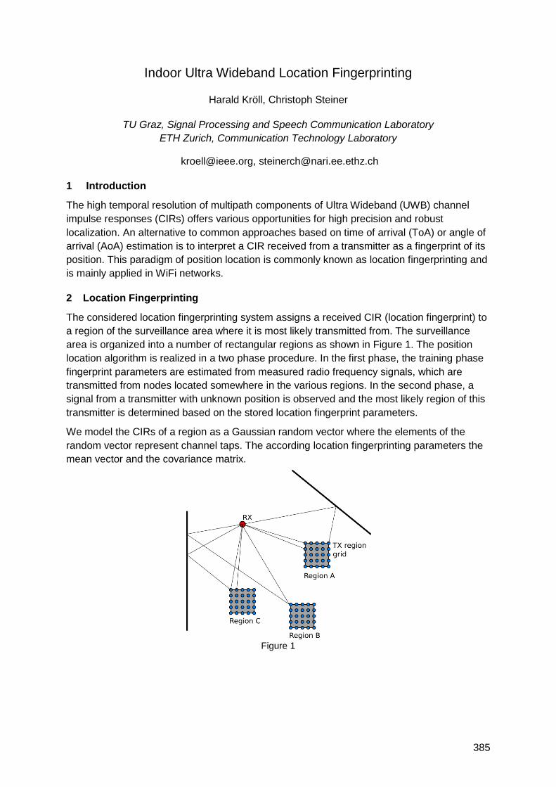
385
Indoor Ultra Wideband Location Fingerprinting
Harald Kröll, Christoph Steiner
TU Graz, Signal Processing and Speech Communication Laboratory
ETH Zurich, Communication Technology Laboratory
[email protected], [email protected]
1 Introduction
The high temporal resolution of multipath components of Ultra Wideband (UWB) channel
impulse responses (CIRs) offers various opportunities for high precision and robust
localization. An alternative to common approaches based on time of arrival (ToA) or angle of
arrival (AoA) estimation is to interpret a CIR received from a transmitter as a fingerprint of its
position. This paradigm of position location is commonly known as location fingerprinting and
is mainly applied in WiFi networks.
2 Location Fingerprinting
The considered location fingerprinting system assigns a received CIR (location fingerprint) to
a region of the surveillance area where it is most likely transmitted from. The surveillance
area is organized into a number of rectangular regions as shown in Figure 1. The position
location algorithm is realized in a two phase procedure. In the first phase, the training phase
fingerprint parameters are estimated from measured radio frequency signals, which are
transmitted from nodes located somewhere in the various regions. In the second phase, a
signal from a transmitter with unknown position is observed and the most likely region of this
transmitter is determined based on the stored location fingerprint parameters.
We model the CIRs of a region as a Gaussian random vector where the elements of the
random vector represent channel taps. The according location fingerprinting parameters the
mean vector and the covariance matrix.
Figure 1
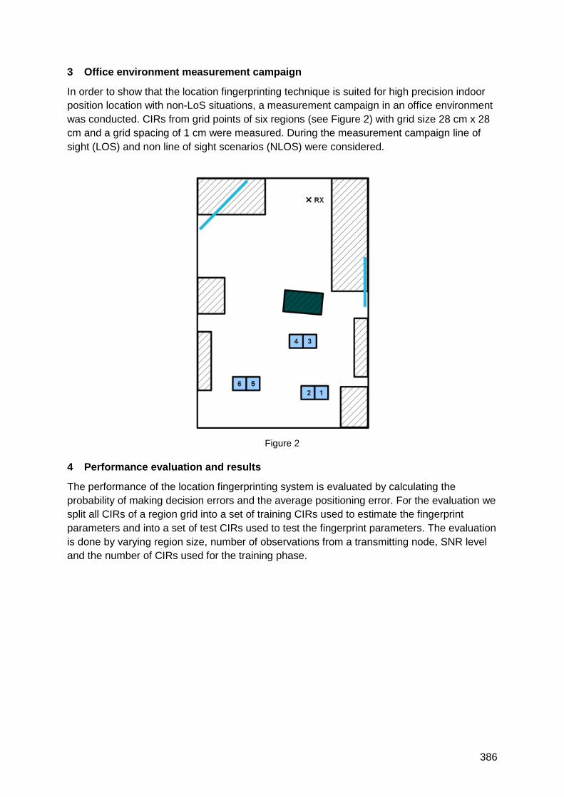
386
3 Office environment measurement campaign
In order to show that the location fingerprinting technique is suited for high precision indoor
position location with non-LoS situations, a measurement campaign in an office environment
was conducted. CIRs from grid points of six regions (see Figure 2) with grid size 28 cm x 28
cm and a grid spacing of 1 cm were measured. During the measurement campaign line of
sight (LOS) and non line of sight scenarios (NLOS) were considered.
4 Performance evaluation and results
The performance of the location fingerprinting system is evaluated by calculating the
probability of making decision errors and the average positioning error. For the evaluation we
split all CIRs of a region grid into a set of training CIRs used to estimate the fingerprint
parameters and into a set of test CIRs used to test the fingerprint parameters. The evaluation
is done by varying region size, number of observations from a transmitting node, SNR level
and the number of CIRs used for the training phase.
Figure 2
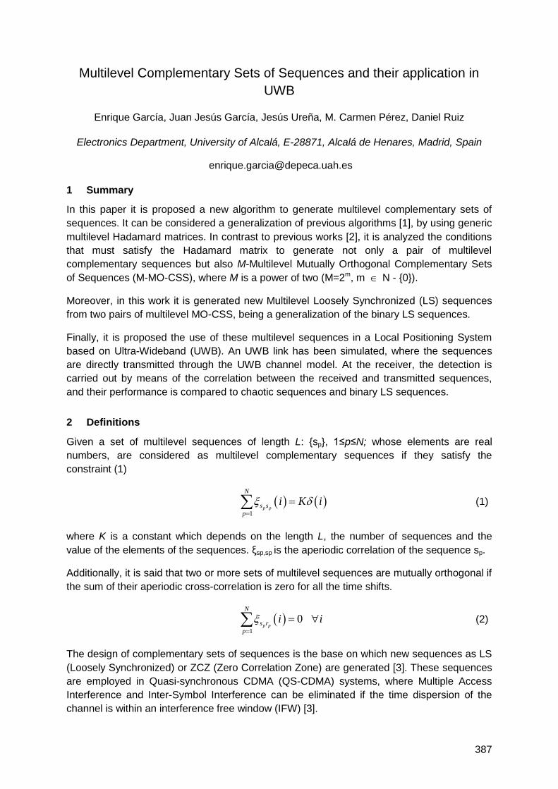
387
Multilevel Complementary Sets of Sequences and their application in
UWB
Enrique García, Juan Jesús García, Jesús Ureña, M. Carmen Pérez, Daniel Ruiz
Electronics Department, University of Alcalá, E-28871, Alcalá de Henares, Madrid, Spain
1 Summary
In this paper it is proposed a new algorithm to generate multilevel complementary sets of
sequences. It can be considered a generalization of previous algorithms [1], by using generic
multilevel Hadamard matrices. In contrast to previous works [2], it is analyzed the conditions
that must satisfy the Hadamard matrix to generate not only a pair of multilevel
complementary sequences but also M-Multilevel Mutually Orthogonal Complementary Sets
of Sequences (M-MO-CSS), where M is a power of two (M=2m, m N - {0}).
Moreover, in this work it is generated new Multilevel Loosely Synchronized (LS) sequences
from two pairs of multilevel MO-CSS, being a generalization of the binary LS sequences.
Finally, it is proposed the use of these multilevel sequences in a Local Positioning System
based on Ultra-Wideband (UWB). An UWB link has been simulated, where the sequences
are directly transmitted through the UWB channel model. At the receiver, the detection is
carried out by means of the correlation between the received and transmitted sequences,
and their performance is compared to chaotic sequences and binary LS sequences.
2 Definitions
Given a set of multilevel sequences of length L: {sp}, 1≤p≤N; whose elements are real
numbers, are considered as multilevel complementary sequences if they satisfy the
constraint (1)
1
p p
N
s s
p
i K i
(1)
where K is a constant which depends on the length L, the number of sequences and the
value of the elements of the sequences. ξsp,sp is the aperiodic correlation of the sequence sp.
Additionally, it is said that two or more sets of multilevel sequences are mutually orthogonal if
the sum of their aperiodic cross-correlation is zero for all the time shifts.
1
0 p p
N
s r
p
i i
(2)
The design of complementary sets of sequences is the base on which new sequences as LS
(Loosely Synchronized) or ZCZ (Zero Correlation Zone) are generated [3]. These sequences
are employed in Quasi-synchronous CDMA (QS-CDMA) systems, where Multiple Access
Interference and Inter-Symbol Interference can be eliminated if the time dispersion of the
channel is within an interference free window (IFW) [3].
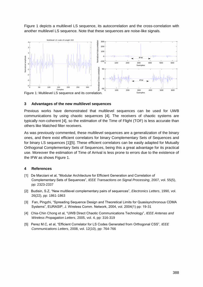
388
0 100 200 300 400 500 600-100
0
100
200
300
Samples
Nor
mal
ized
Aut
ocor
rela
tion
0 100 200 300 400 500 600-50
0
50
Samples
Nor
mal
ized
Cro
ss-c
orre
latio
n
IFW
IFW
0 50 100 150 200 250 300-4
-3
-2
-1
0
1
2
3
4
Samples
Norm
aliz
ed a
mplit
ude
Multilevel LS code of Length 319
Figure 1 depicts a multilevel LS sequence, its autocorrelation and the cross-correlation with
another multilevel LS sequence. Note that these sequences are noise-like signals.
Figure 1: Multilevel LS sequence and its correlation.
3 Advantages of the new multilevel sequences
Previous works have demonstrated that multilevel sequences can be used for UWB
communications by using chaotic sequences [4]. The receivers of chaotic systems are
typically non-coherent [4], so the estimation of the Time of Flight (TOF) is less accurate than
others like Matched filter receivers.
As was previously commented, these multilevel sequences are a generalization of the binary
ones, and there exist efficient correlators for binary Complementary Sets of Sequences and
for binary LS sequences [1][5]. These efficient correlators can be easily adapted for Mutually
Orthogonal Complementary Sets of Sequences, being this a great advantage for its practical
use. Moreover the estimation of Time of Arrival is less prone to errors due to the existence of
the IFW as shows Figure 1.
4 References
[1] De Marziani et al, ―Modular Architecture for Efficient Generation and Correlation of
Complementary Sets of Sequences‖, IEEE Transactions on Signal Processing, 2007, vol. 55(5),
pp: 2323-2337
[2] Budisin, S.Z, ―New multilevel complementary pairs of sequences‖, Electronics Letters, 1990, vol.
26(22), pp: 1861-1863
[3] Fan, Pingzhi, ―Spreading Sequence Design and Theoretical Limits for Quasisynchronous CDMA
Systems‖, EURASIP, J. Wireless Comm. Network, 2004, vol. 2004(1) pp: 19-31
[4] Chia-Chin Chong et al, ―UWB Direct Chaotic Communications Technology‖, IEEE Antenas and
Wireless Propagation Letters, 2005, vol. 4, pp: 316-319
[5] Perez M.C, et al, ―Efficient Correlator for LS Codes Generated from Orthogonal CSS‖, IEEE
Communications Letters, 2008, vol. 12(10), pp: 764-766

389
Magnetic Localization
Auditorium D8
Friday, September 17, 08:15 – 09:45


391
Position Estimation Using Artificial Generated Magnetic Fields
Jörg Blankenbach, Abdelmoumen Norrdine
TU Darmstadt, Institute of Geodesy, Petersenstr. 13, D-64287 Darmstadt
{blankenbach, norrdine}@geod.tu-darmstadt.de
1 Summary
In this abstract a system is introduced which overcomes the limitations of existing indoor
positioning systems by the use of artificial quasi static magnetic fields. The proposed DC
magnetic signals show no special multipath effects and have excellent characteristics for
penetrating various obstacles. In this contribution the theory of coil-based magnetic fields as
well as the basic function principle of the positioning system are described. Furthermore, a
prototype that is currently under development is presented. This includes the hardware
components, the network and software architectures of the entire system as well as the
algorithms for the position and orientation estimation. In addition, the results of first test
measurements and the system‘s calibration in real indoor environments are shown.
2 Motivation
Many indoor localization systems developed in the past years are active systems based on
ultrasound, electromagnetic or optical waves. These systems require a positioning
infrastructure to apply time or angle measurements between the reference and a mobile
station. For performing the measurements between transmitter and receiver wireless
communication technologies are often utilized. As a matter of principle the position
estimation of active systems is negatively affected by several issues in indoor scenarios:
The availability of the systems cannot be guaranteed due to walls, furniture, plants
etc. because the signals are not able to penetrate such obstacles or are weakened.
The systems suffer from multipath, refractions and further wave propagation errors,
especially inside buildings. In result the systems are unreliable.
Because of NLoS (None Line of Sight) errors and due to the used position estimation
techniques many of these systems cannot achieve an accuracy better than several
meters. Furthermore, these proximate techniques mostly allow only the calculation of
2D position.
On the contrary, passive localization systems are independent from any positioning
infrastructure. These autonomous systems normally use inertial sensors in combination with
pedometer, barometer etc. for position estimation. However, these sensors tend to high drift.
This in turn causes inaccurate or unreliable localization so that periodic position updates
delivered by other systems are required. The additional use of multiple sensors results in a
high complexity and a less mobility of these systems due to the caused weight and power
consumption.
3 MILPS – Magnetic Indoor Local Positioning System
The indoor positioning system introduced in this text is based on artificial magnetic fields to
compensate the disadvantages of existing active and passive systems as described above. It
is suggested to utilize alternating DC magnetic signals which show no NLoS errors or
multipath effects. Similar to active systems reference stations consisting of electromagnetic

392
coils are applied that generate periodically static magnetic fields. The magnetic field strength
B declines with the increasing distance r to the coils, as shown by the following equation:
2
1
θπ
μ 2
3
m0 sin3+1r4
p=B (u0 = magnetic permeability, pm = magnetic dipole moment; = elevation angle)
For the position determination a mobile station is equipped with a magnetic field sensor. By
measuring the field strength of at least three reference coils the 3D position can be
determined using trilateration. Utilizing a three-axis sensor, further angles such as the
elevation angle can be determined in order to support the position calculation or to decrease
the number of coils needed. Besides the static positioning, the system is also intended for
position estimation of persons and objects in kinematic applications. By integrating additional
passive sensors all six degrees of freedom (6DoF) of the mobile station can be estimated
without using antenna arrays. Since the mobile station does not interact proactive with the
reference stations, there is no limitation in the number of users. Because of its quasi-static
operation, the system radiates electromagnetic waves with very low frequencies (Hz range)
and causes no interferences with commercial devices. Thus, it can be applied wherever
other positioning systems encounter difficulties, e.g. in mines and tunnels, inside of factories
and buildings, etc.
4 Prototyping and Experimental Results
First range measurements in real indoor environments with self-made coils and commercial
field sensors have shown good results. Figure 1 depicts on the left the raw data of a
measurement example at a distance of 4.20 m between coil and sensor.
Figure 1: Distance measurement example between coil and magnetic sensor
By changing the current direction periodically and subtracting the period‘s mean values the
influence of the earth's magnetic field can be compensated. In this example the measured
distances show deviations of less than 8 cm from true range (Figure 1, right).
5 Conclusions and Outlook
Currently, the development of a prototype is in progress and calibration methods for the coils
and sensors are developed. Extensive measurement experiments will follow and the
algorithms for the position and orientation estimation will be implemented. A further challenge
is the development of a method for the elimination of short period interference fields by
making use of adaptive filter techniques.
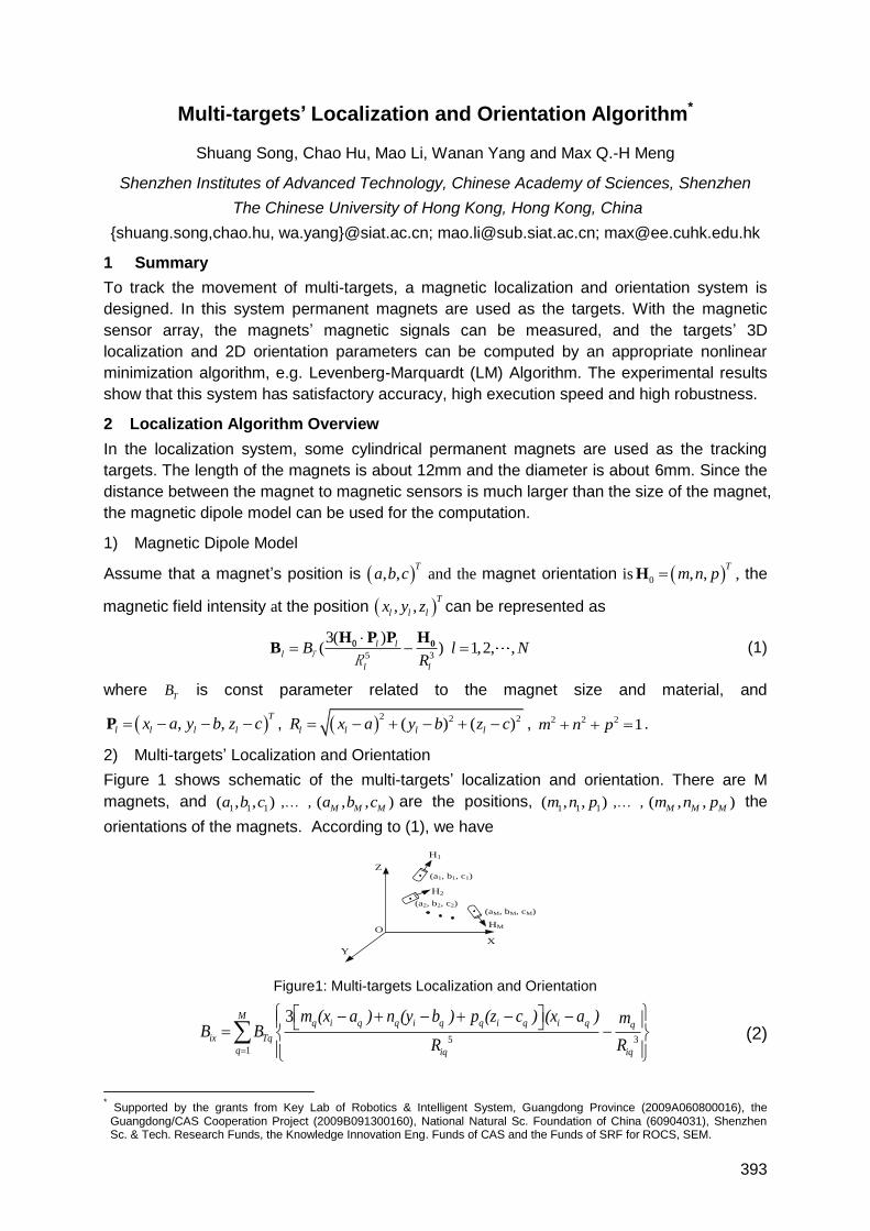
393
Multi-targets’ Localization and Orientation Algorithm*
Shuang Song, Chao Hu, Mao Li, Wanan Yang and Max Q.-H Meng
Shenzhen Institutes of Advanced Technology, Chinese Academy of Sciences, Shenzhen
The Chinese University of Hong Kong, Hong Kong, China
{shuang.song,chao.hu, wa.yang}@siat.ac.cn; [email protected]; [email protected]
1 Summary
To track the movement of multi-targets, a magnetic localization and orientation system is
designed. In this system permanent magnets are used as the targets. With the magnetic
sensor array, the magnets‘ magnetic signals can be measured, and the targets‘ 3D
localization and 2D orientation parameters can be computed by an appropriate nonlinear
minimization algorithm, e.g. Levenberg-Marquardt (LM) Algorithm. The experimental results
show that this system has satisfactory accuracy, high execution speed and high robustness.
2 Localization Algorithm Overview
In the localization system, some cylindrical permanent magnets are used as the tracking
targets. The length of the magnets is about 12mm and the diameter is about 6mm. Since the
distance between the magnet to magnetic sensors is much larger than the size of the magnet,
the magnetic dipole model can be used for the computation.
1) Magnetic Dipole Model
Assume that a magnet‘s position is , ,T
a b c and the magnet orientation is 0 , ,T
m n pH , the
magnetic field intensity at the position , ,T
l l lx y z can be represented as
5 3
3( )( ) 1,2, ,l l
l
l l
B l NR
0H P P H
B TR0 (1)
where TB is const parameter related to the magnet size and material, and
, ,T
l l l lx a y b z c P , 2 2 2( ) ( )l l l lR x a y b z c , 2 2 2 1m n p .
2) Multi-targets‘ Localization and Orientation
Figure 1 shows schematic of the multi-targets‘ localization and orientation. There are M
magnets, and 1 1 1( , , )a b c ,… , ( , , )M M Ma b c are the positions,
1 1 1( , , )m n p ,… , ( , , )M M Mm n p the
orientations of the magnets. According to (1), we have
H1
Z
Y
X
HM
H2
O
(a1, b1, c1)
(a2, b2, c2)(aM, bM, cM)
Figure1: Multi-targets Localization and Orientation
5 31
3Mq i q q i q q i q i q q
ix Tq
q iq iq
m (x a ) n (y b ) p (z c ) (x a ) mB B
R R
(2)
* Supported by the grants from Key Lab of Robotics & Intelligent System, Guangdong Province (2009A060800016), the Guangdong/CAS Cooperation Project (2009B091300160), National Natural Sc. Foundation of China (60904031), Shenzhen Sc. & Tech. Research Funds, the Knowledge Innovation Eng. Funds of CAS and the Funds of SRF for ROCS, SEM.
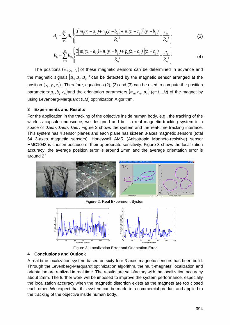
394
5 31
3Mq i q q i q q i q i q q
iy Tq
q iq iq
m (x a ) n (y b ) p (z c ) (y b ) nB B
R R
(3)
5 31
3Mq i q q i q q i q i q q
iz Tq
q iq iq
m (x a ) n (y b ) p (z c ) (z c ) pB B
R R
(4)
The positions iii zyx ,, of these magnetic sensors can be determined in advance and
the magnetic signals Tiziyix BBB can be detected by the magnetic sensor arranged at the
position iii zyx ,, . Therefore, equations (2), (3) and (3) can be used to compute the position
parameters qqq cba ,, and the orientation parameters qqq pnm ,, (q=1…M) of the magnet by
using Levenberg-Marquardt (LM) optimization Algorithm.
3 Experiments and Results
For the application in the tracking of the objective inside human body, e.g., the tracking of the
wireless capsule endoscope, we designed and built a real magnetic tracking system in a
space of 0.5 0.5 0.5m m m . Figure 2 shows the system and the real-time tracking interface.
This system has 4 sensor planes and each plane has sixteen 3-axes magnetic sensors (total
64 3-axes magnetic sensors). Honeywell AMR (Anisotropic Magneto-resistive) sensor
HMC1043 is chosen because of their appropriate sensitivity. Figure 3 shows the localization
accuracy, the average position error is around 2mm and the average orientation error is
around 2°.
Figure 2: Real Experiment System
Figure 3: Localization Error and Orientation Error
4 Conclusions and Outlook
A real time localization system based on sixty-four 3-axes magnetic sensors has been build.
Through the Levenberg-Marquardt optimization algorithm, the multi-magnets‘ localization and
orientation are realized in real time. The results are satisfactory with the localization accuracy
about 2mm. The further work will be imposed to improve the system performance, especially
the localization accuracy when the magnetic distortion exists as the magnets are too closed
each other. We expect that this system can be made to a commercial product and applied to
the tracking of the objective inside human body.
0 20 40 60 80 100 1200
1
2
3
4
5
6
Samples Number
Po
sit
ion
Err
or
(mm
)
0 20 40 60 80 100 1200
1
2
3
4
5
6
7
8
9
Samples Number
Ori
en
tati
on
Err
or
(deg
ree)

395
Innovative Systems
Auditorium D8
Friday, September 17, 10:15 – 12:00

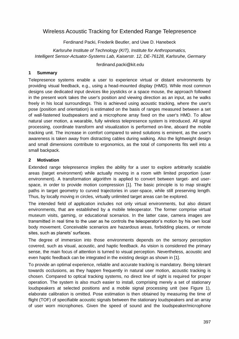
397
Wireless Acoustic Tracking for Extended Range Telepresence
Ferdinand Packi, Frederik Beutler, and Uwe D. Hanebeck
Karlsruhe Institute of Technology (KIT), Institute for Anthropomatics,
Intelligent Sensor-Actuator-Systems Lab, Kaiserstr. 12, DE-76128, Karlsruhe, Germany
1 Summary
Telepresence systems enable a user to experience virtual or distant environments by
providing visual feedback, e.g., using a head-mounted display (HMD). While most common
designs use dedicated input devices like joysticks or a space mouse, the approach followed
in the present work takes the user's position and viewing direction as an input, as he walks
freely in his local surroundings. This is achieved using acoustic tracking, where the user's
pose (position and orientation) is estimated on the basis of ranges measured between a set
of wall-fastened loudspeakers and a microphone array fixed on the user's HMD. To allow
natural user motion, a wearable, fully wireless telepresence system is introduced. All signal
processing, coordinate transform and visualization is performed on-line, aboard the mobile
tracking unit. The increase in comfort compared to wired solutions is eminent, as the user's
awareness is taken away from distracting cables during walking. Also the lightweight design
and small dimensions contribute to ergonomics, as the total of components fits well into a
small backpack.
2 Motivation
Extended range telepresence implies the ability for a user to explore arbitrarily scalable
areas (target environment) while actually moving in a room with limited proportion (user
environment). A transformation algorithm is applied to convert between target- and user-
space, in order to provide motion compression [1]. The basic principle is to map straight
paths in target geometry to curved trajectories in user-space, while still preserving length.
Thus, by locally moving in circles, virtually unlimited target areas can be explored.
The intended field of application includes not only virtual environments, but also distant
environments, that are established by a mobile teleoperator. The former comprise virtual
museum visits, gaming, or educational scenarios. In the latter case, camera images are
transmitted in real time to the user as he controls the teleoperator‘s motion by his own local
body movement. Conceivable scenarios are hazardous areas, forbidding places, or remote
sites, such as planets‘ surfaces.
The degree of immersion into those environments depends on the sensory perception
covered, such as visual, acoustic, and haptic feedback. As vision is considered the primary
sense, the main focus of attention is turned to visual perception. Nevertheless, acoustic and
even haptic feedback can be integrated in the existing design as shown in [1].
To provide an optimal experience, reliable and accurate tracking is mandatory. Being tolerant
towards occlusions, as they happen frequently in natural user motion, acoustic tracking is
chosen. Compared to optical tracking systems, no direct line of sight is required for proper
operation. The system is also much easier to install, comprising merely a set of stationary
loudspeakers at selected positions and a mobile signal processing unit (see Figure 1),
elaborate calibration is omitted. Pose estimation is then obtained by measuring the time of
flight (TOF) of specifiable acoustic signals between the stationary loudspeakers and an array
of user worn microphones. Given the speed of sound and the loudspeaker/microphone
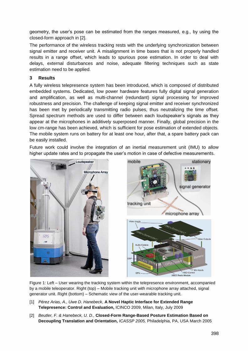
398
geometry, the user‘s pose can be estimated from the ranges measured, e.g., by using the
closed-form approach in [2].
The performance of the wireless tracking rests with the underlying synchronization between
signal emitter and receiver unit. A misalignment in time bases that is not properly handled
results in a range offset, which leads to spurious pose estimation. In order to deal with
delays, external disturbances and noise, adequate filtering techniques such as state
estimation need to be applied.
3 Results
A fully wireless telepresence system has been introduced, which is composed of distributed
embedded systems. Dedicated, low power hardware features fully digital signal generation
and amplification, as well as multi-channel (redundant) signal processing for improved
robustness and precision. The challenge of keeping signal emitter and receiver synchronized
has been met by periodically transmitting radio pulses, thus neutralizing the time offset.
Spread spectrum methods are used to differ between each loudspeaker‘s signals as they
appear at the microphones in additively superposed manner. Finally, global precision in the
low cm-range has been achieved, which is sufficient for pose estimation of extended objects.
The mobile system runs on battery for at least one hour, after that, a spare battery pack can
be easily installed.
Future work could involve the integration of an inertial measurement unit (IMU) to allow
higher update rates and to propagate the user‘s motion in case of defective measurements.
Figure 1: Left – User wearing the tracking system within the telepresence environment, accompanied
by a mobile teleoperator. Right (top) – Mobile tracking unit with microphone array attached, signal
generator unit. Right (bottom) – Schematic view of the user-wearable tracking unit.
[1] Pérez Arias, A., Uwe D. Hanebeck, A Novel Haptic Interface for Extended Range
Telepresence: Control and Evaluation, ICINCO 2009, Milan, Italy, July 2009
[2] Beutler, F. & Hanebeck, U. D., Closed-Form Range-Based Posture Estimation Based on
Decoupling Translation and Orientation, ICASSP 2005, Philadelphia, PA, USA March 2005
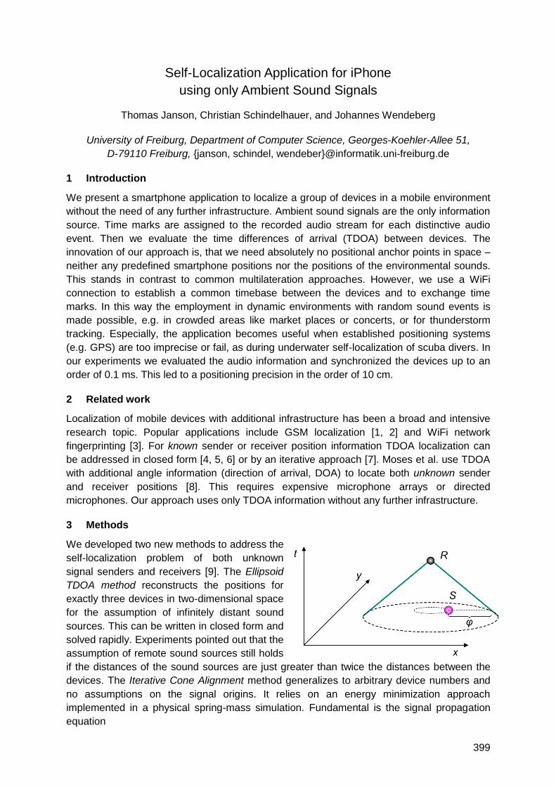
399
Self-Localization Application for iPhone
using only Ambient Sound Signals
Thomas Janson, Christian Schindelhauer, and Johannes Wendeberg
University of Freiburg, Department of Computer Science, Georges-Koehler-Allee 51,
D-79110 Freiburg, {janson, schindel, wendeber}@informatik.uni-freiburg.de
1 Introduction
We present a smartphone application to localize a group of devices in a mobile environment
without the need of any further infrastructure. Ambient sound signals are the only information
source. Time marks are assigned to the recorded audio stream for each distinctive audio
event. Then we evaluate the time differences of arrival (TDOA) between devices. The
innovation of our approach is, that we need absolutely no positional anchor points in space –
neither any predefined smartphone positions nor the positions of the environmental sounds.
This stands in contrast to common multilateration approaches. However, we use a WiFi
connection to establish a common timebase between the devices and to exchange time
marks. In this way the employment in dynamic environments with random sound events is
made possible, e.g. in crowded areas like market places or concerts, or for thunderstorm
tracking. Especially, the application becomes useful when established positioning systems
(e.g. GPS) are too imprecise or fail, as during underwater self-localization of scuba divers. In
our experiments we evaluated the audio information and synchronized the devices up to an
order of 0.1 ms. This led to a positioning precision in the order of 10 cm.
2 Related work
Localization of mobile devices with additional infrastructure has been a broad and intensive
research topic. Popular applications include GSM localization [1, 2] and WiFi network
fingerprinting [3]. For known sender or receiver position information TDOA localization can
be addressed in closed form [4, 5, 6] or by an iterative approach [7]. Moses et al. use TDOA
with additional angle information (direction of arrival, DOA) to locate both unknown sender
and receiver positions [8]. This requires expensive microphone arrays or directed
microphones. Our approach uses only TDOA information without any further infrastructure.
3 Methods
We developed two new methods to address the
self-localization problem of both unknown
signal senders and receivers [9]. The Ellipsoid
TDOA method reconstructs the positions for
exactly three devices in two-dimensional space
for the assumption of infinitely distant sound
sources. This can be written in closed form and
solved rapidly. Experiments pointed out that the
assumption of remote sound sources still holds
if the distances of the sound sources are just greater than twice the distances between the
devices. The Iterative Cone Alignment method generalizes to arbitrary device numbers and
no assumptions on the signal origins. It relies on an energy minimization approach
implemented in a physical spring-mass simulation. Fundamental is the signal propagation
equation
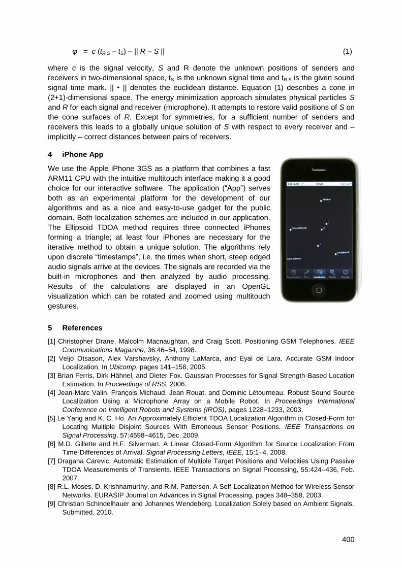
400
φ = c (tR,S – tS) – || R – S || (1)
where c is the signal velocity, S and R denote the unknown positions of senders and
receivers in two-dimensional space, tS is the unknown signal time and tR,S is the given sound
signal time mark. || • || denotes the euclidean distance. Equation (1) describes a cone in
(2+1)-dimensional space. The energy minimization approach simulates physical particles S
and R for each signal and receiver (microphone). It attempts to restore valid positions of S on
the cone surfaces of R. Except for symmetries, for a sufficient number of senders and
receivers this leads to a globally unique solution of S with respect to every receiver and –
implicitly – correct distances between pairs of receivers.
4 iPhone App
We use the Apple iPhone 3GS as a platform that combines a fast
ARM11 CPU with the intuitive multitouch interface making it a good
choice for our interactive software. The application (―App‖) serves
both as an experimental platform for the development of our
algorithms and as a nice and easy-to-use gadget for the public
domain. Both localization schemes are included in our application.
The Ellipsoid TDOA method requires three connected iPhones
forming a triangle; at least four iPhones are necessary for the
iterative method to obtain a unique solution. The algorithms rely
upon discrete ―timestamps‖, i.e. the times when short, steep edged
audio signals arrive at the devices. The signals are recorded via the
built-in microphones and then analyzed by audio processing.
Results of the calculations are displayed in an OpenGL
visualization which can be rotated and zoomed using multitouch
gestures.
5 References
[1] Christopher Drane, Malcolm Macnaughtan, and Craig Scott. Positioning GSM Telephones. IEEE
Communications Magazine, 36:46–54, 1998.
[2] Veljo Otsason, Alex Varshavsky, Anthony LaMarca, and Eyal de Lara. Accurate GSM Indoor
Localization. In Ubicomp, pages 141–158, 2005.
[3] Brian Ferris, Dirk Hähnel, and Dieter Fox. Gaussian Processes for Signal Strength-Based Location
Estimation. In Proceedings of RSS, 2006.
[4] Jean-Marc Valin, François Michaud, Jean Rouat, and Dominic Létourneau. Robust Sound Source
Localization Using a Microphone Array on a Mobile Robot. In Proceedings International
Conference on Intelligent Robots and Systems (IROS), pages 1228–1233, 2003.
[5] Le Yang and K. C. Ho. An Approximately Efficient TDOA Localization Algorithm in Closed-Form for
Locating Multiple Disjoint Sources With Erroneous Sensor Positions. IEEE Transactions on
Signal Processing, 57:4598–4615, Dec. 2009.
[6] M.D. Gillette and H.F. Silverman. A Linear Closed-Form Algorithm for Source Localization From
Time-Differences of Arrival. Signal Processing Letters, IEEE, 15:1–4, 2008.
[7] Dragana Carevic. Automatic Estimation of Multiple Target Positions and Velocities Using Passive
TDOA Measurements of Transients. IEEE Transactions on Signal Processing, 55:424–436, Feb.
2007.
[8] R.L. Moses, D. Krishnamurthy, and R.M. Patterson. A Self-Localization Method for Wireless Sensor
Networks. EURASIP Journal on Advances in Signal Processing, pages 348–358, 2003.
[9] Christian Schindelhauer and Johannes Wendeberg. Localization Solely based on Ambient Signals.
Submitted, 2010.
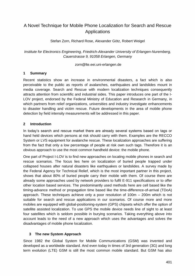
401
A Novel Technique for Mobile Phone Localization for Search and Rescue
Applications
Stefan Zorn, Richard Rose, Alexander Götz, Robert Weigel
Institute for Electronics Engineering, Friedrich-Alexander University of Erlangen-Nuremberg,
Cauerstrasse 9, 91058 Erlangen, Germany
1 Summary
Recent statistics show an increase in environmental disasters, a fact which is also
perceivable to the public as reports of avalanches, earthquakes and landslides mount in
media coverage. Search and Rescue with modern localization techniques consequently
attracts attention from scientific and industrial sides. This paper introduces one part of the I-
LOV project, endorsed by the Federal Ministry of Education and Research in Germany, in
which partners from relief organizations, universities and industry investigate enhancements
to disaster handling and victim rescue. Future developments in the area of mobile phone
detection by field intensity measurements will be addressed in this paper.
2 Introduction
In today‘s search and rescue market there are already several systems based on tags or
hand held devices which persons at risk should carry with them. Examples are the RECCO
System or LVS equipment for avalanche rescue. These localization approaches are suffering
from the fact that only a low percentage of people at risk own such tags. Therefore it is an
obvious approach to use the most common handheld device: the mobile phone.
One part of Project I-LOV is to find new approaches on locating mobile phones in search and
rescue scenarios. The focus lies here on localization of buried people trapped under
collapsed houses after natural disasters like earthquakes or landslides. A survey made by
the Federal Agency for Technical Relief, which is the most important partner in this project,
shows that about 80% of buried people carry their mobile with them. Of course there are
already some approaches used by network providers to fulfil E-911 specifications or to offer
other location based services. The predominantly used methods here are cell based like the
timing-advance method or propagation time based like the time-difference-of-arrival (TDoA)
approach. These techniques achieve only a poor resolution of 100m – 200m which is not
suitable for search and rescue applications in our scenarios. Of course more and more
mobiles are equipped with global-positioning-system (GPS) chipsets which offer the option of
satellite assisted localization. To use GPS the mobile device needs line of sight to at least
four satellites which is seldom possible in burying scenarios. Taking everything above into
account leads to the need of a new approach which uses the advantages and solves the
disadvantages of mobile phone localization.
3 The new System Approach
Since 1982 the Global System for Mobile Communications (GSM) was invented and
developed as a worldwide standard. And even today in times of 3rd generation (3G) and long
term evolution (LTE) GSM is still the most common mobile standard. But GSM has also
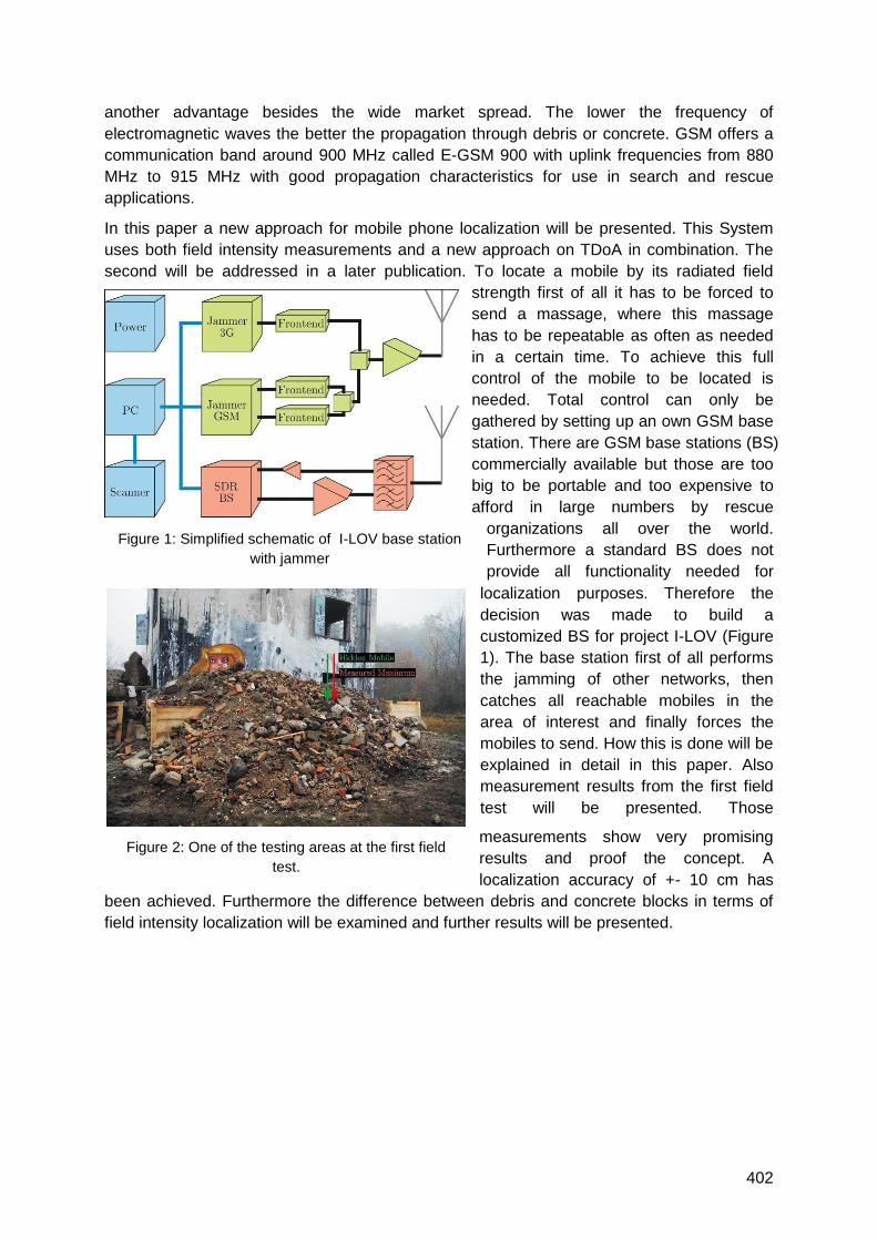
402
Figure 1: Simplified schematic of I-LOV base station
with jammer
Figure 2: One of the testing areas at the first field
test.
another advantage besides the wide market spread. The lower the frequency of
electromagnetic waves the better the propagation through debris or concrete. GSM offers a
communication band around 900 MHz called E-GSM 900 with uplink frequencies from 880
MHz to 915 MHz with good propagation characteristics for use in search and rescue
applications.
In this paper a new approach for mobile phone localization will be presented. This System
uses both field intensity measurements and a new approach on TDoA in combination. The
second will be addressed in a later publication. To locate a mobile by its radiated field
strength first of all it has to be forced to
send a massage, where this massage
has to be repeatable as often as needed
in a certain time. To achieve this full
control of the mobile to be located is
needed. Total control can only be
gathered by setting up an own GSM base
station. There are GSM base stations (BS)
commercially available but those are too
big to be portable and too expensive to
afford in large numbers by rescue
organizations all over the world.
Furthermore a standard BS does not
provide all functionality needed for
localization purposes. Therefore the
decision was made to build a
customized BS for project I-LOV (Figure
1). The base station first of all performs
the jamming of other networks, then
catches all reachable mobiles in the
area of interest and finally forces the
mobiles to send. How this is done will be
explained in detail in this paper. Also
measurement results from the first field
test will be presented. Those
measurements show very promising
results and proof the concept. A
localization accuracy of +- 10 cm has
been achieved. Furthermore the difference between debris and concrete blocks in terms of
field intensity localization will be examined and further results will be presented.
403
Pedestrian Indoor Positioning Method Using Fluorescent Light
Communication and Autonomous Navigation
Hideo Makino*1, Daigo Ito*2, Kentaro Nishimori*1, Makoto Kobayashi*3, Daisuke Wakatsuki*3
*1 Graduate School of Science and Technology, Niigata University, *2 Faculty of Engineering, Niigata University, *3 Tsukuba University of Technology, Japan
Summary We developed an indoor positioning and footstep-width correction method that is
employed while walking. This method employs ordinary indoor illumination apparatuses, i.e.,
fluorescent lights, as a special visible light communication tool. An experimental system
comprises an integrated tri-axis accelerometer and magnetic sensor (Aichi Seiko, AMI603SD), a
gyro-sensor, a specially developed visible light sensor, and a PDA. In the experiments, the
prepared experimental environment is a rectangular shape corridor. There are 15 signal-
transmission-type fluorescent lights installed in the ceiling of the corridor along the experiment
route, and the receiving test is conducted 5 times continuously (5 rounds) in the same corridor.
When error correction is employed, there is no problem due to the accumulation of the error. The
average error is 0.77 m and the maximum error is 3.96 m. In addition, the error in the footsteps is
corrected to less than 5% on average (0.03 m).
1. Introduction
Recently, it has become possible to apply indoor autonomous navigation technology to practical
applications due to the progress in the development of highly precise and miniaturized sensors.
However, to counter the existing problems with this technology such as the need to input the
initial position data or the effect of integrated measuring errors, the navigation system should be
combined with other position measuring technologies. Therefore, we developed an indoor
positioning and footstep-width correction method that is employed while walking. This method
employs ordinary indoor illumination apparatuses, i.e., fluorescent lights, as a special visible light
communication tool. In the following section, a detailed explanation and experimental results in an
actual environment are given.
2. Method
Figure 1 shows the employed system configuration. The system comprises an integrated tri-axis
accelerometer and magnetic sensor (Aichi Seiko, AMI603SD), a gyro-sensor, a specially
developed visible light sensor, and a PDA (Personal Data Assistant, HP iPAQ rx4200). A
description of the measuring method is given hereafter.
2.1 Positioning by dead reckoning
The number of footsteps taken by a pedestrian is calculated using the waveform from the
accelerometer. At the same time, the next moving position is estimated successively based on
the information of the forward direction, which is obtained from the magnetic sensor and the
predetermined single footstep width. In the experiment, the PDA with an accelerometer and
magnetic sensor unit are worn over the midriff of the pedestrian.
2.2 Fluorescent light
1) Basic method: A specially designed fluorescent light is equipped to send unique positional
signals (IDs) using frequency shift keying. Each signal is decoded by an original receiver
equipped with photo sensors. The ID is sent to the PDA through a Bluetooth connection, and
the present position is estimated by accessing a fluorescent light position database in the
PDA.
2) Absolute position correction: The receiving area of the fluorescent light signal is determined
based on the receiving angle of the light at the photo sensor. In the experiment, a relatively
narrow angle (±10 degrees) photo sensor (Hamamatsu Photonics S5821-01) is used as the
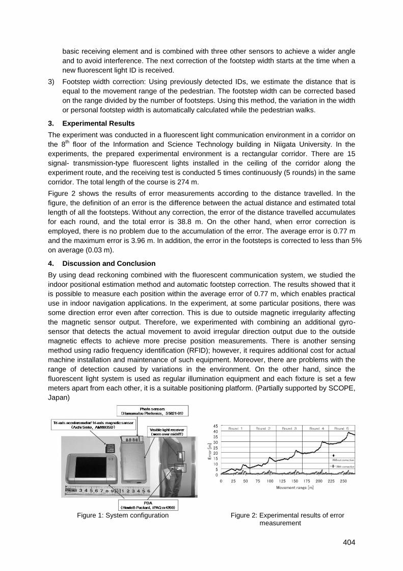
404
basic receiving element and is combined with three other sensors to achieve a wider angle
and to avoid interference. The next correction of the footstep width starts at the time when a
new fluorescent light ID is received.
3) Footstep width correction: Using previously detected IDs, we estimate the distance that is
equal to the movement range of the pedestrian. The footstep width can be corrected based
on the range divided by the number of footsteps. Using this method, the variation in the width
or personal footstep width is automatically calculated while the pedestrian walks.
3. Experimental Results
The experiment was conducted in a fluorescent light communication environment in a corridor on
the 8th floor of the Information and Science Technology building in Niigata University. In the
experiments, the prepared experimental environment is a rectangular corridor. There are 15
signal- transmission-type fluorescent lights installed in the ceiling of the corridor along the
experiment route, and the receiving test is conducted 5 times continuously (5 rounds) in the same
corridor. The total length of the course is 274 m.
Figure 2 shows the results of error measurements according to the distance travelled. In the
figure, the definition of an error is the difference between the actual distance and estimated total
length of all the footsteps. Without any correction, the error of the distance travelled accumulates
for each round, and the total error is 38.8 m. On the other hand, when error correction is
employed, there is no problem due to the accumulation of the error. The average error is 0.77 m
and the maximum error is 3.96 m. In addition, the error in the footsteps is corrected to less than 5%
on average (0.03 m).
4. Discussion and Conclusion
By using dead reckoning combined with the fluorescent communication system, we studied the
indoor positional estimation method and automatic footstep correction. The results showed that it
is possible to measure each position within the average error of 0.77 m, which enables practical
use in indoor navigation applications. In the experiment, at some particular positions, there was
some direction error even after correction. This is due to outside magnetic irregularity affecting
the magnetic sensor output. Therefore, we experimented with combining an additional gyro-
sensor that detects the actual movement to avoid irregular direction output due to the outside
magnetic effects to achieve more precise position measurements. There is another sensing
method using radio frequency identification (RFID); however, it requires additional cost for actual
machine installation and maintenance of such equipment. Moreover, there are problems with the
range of detection caused by variations in the environment. On the other hand, since the
fluorescent light system is used as regular illumination equipment and each fixture is set a few
meters apart from each other, it is a suitable positioning platform. (Partially supported by SCOPE,
Japan)
Figure 1: System configuration Figure 2: Experimental results of error measurement
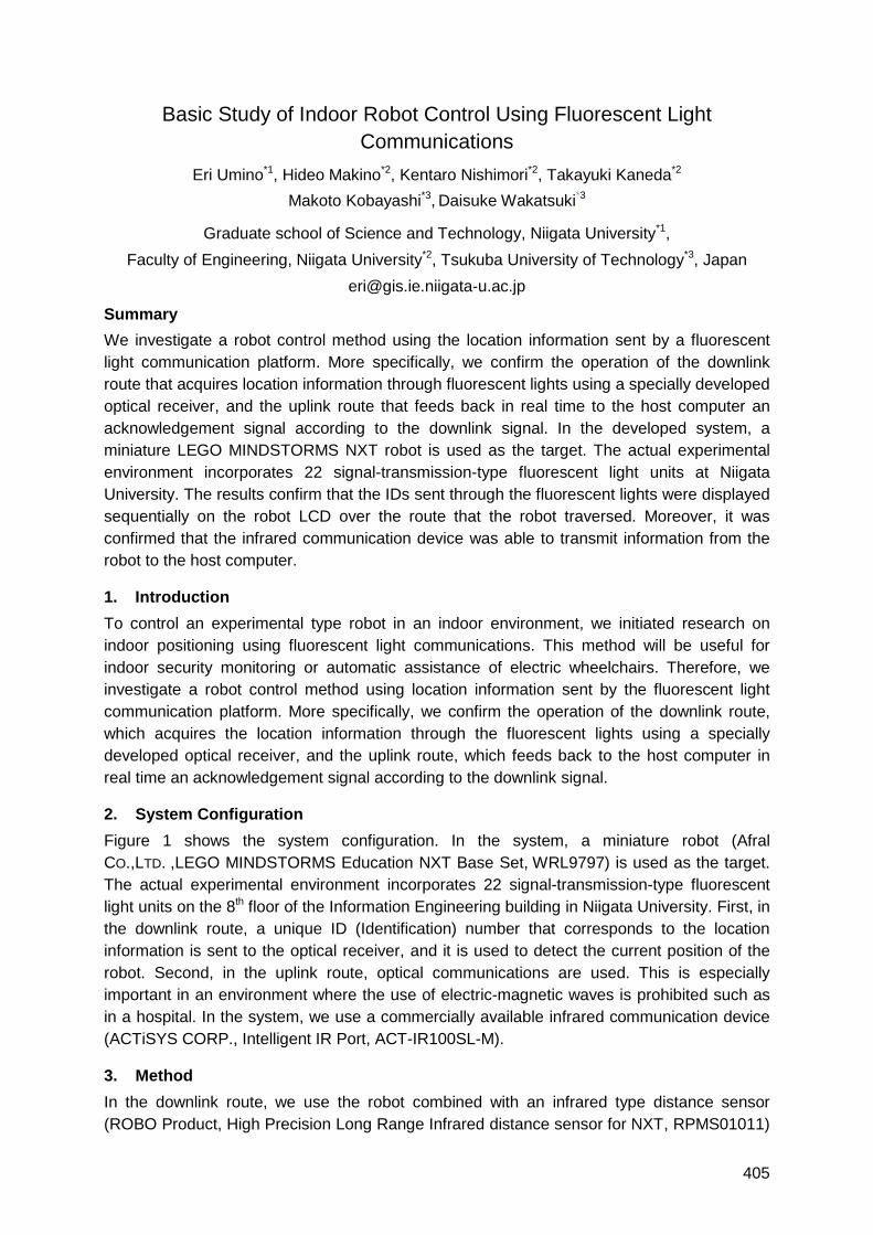
405
Basic Study of Indoor Robot Control Using Fluorescent Light
Communications
Eri Umino*1, Hideo Makino*2, Kentaro Nishimori*2, Takayuki Kaneda*2
Makoto Kobayashi*3, Daisuke Wakatsuki*3
Graduate school of Science and Technology, Niigata University*1,
Faculty of Engineering, Niigata University*2, Tsukuba University of Technology*3, Japan
Summary
We investigate a robot control method using the location information sent by a fluorescent
light communication platform. More specifically, we confirm the operation of the downlink
route that acquires location information through fluorescent lights using a specially developed
optical receiver, and the uplink route that feeds back in real time to the host computer an
acknowledgement signal according to the downlink signal. In the developed system, a
miniature LEGO MINDSTORMS NXT robot is used as the target. The actual experimental
environment incorporates 22 signal-transmission-type fluorescent light units at Niigata
University. The results confirm that the IDs sent through the fluorescent lights were displayed
sequentially on the robot LCD over the route that the robot traversed. Moreover, it was
confirmed that the infrared communication device was able to transmit information from the
robot to the host computer.
1. Introduction
To control an experimental type robot in an indoor environment, we initiated research on
indoor positioning using fluorescent light communications. This method will be useful for
indoor security monitoring or automatic assistance of electric wheelchairs. Therefore, we
investigate a robot control method using location information sent by the fluorescent light
communication platform. More specifically, we confirm the operation of the downlink route,
which acquires the location information through the fluorescent lights using a specially
developed optical receiver, and the uplink route, which feeds back to the host computer in
real time an acknowledgement signal according to the downlink signal.
2. System Configuration
Figure 1 shows the system configuration. In the system, a miniature robot (Afral
CO.,LTD. ,LEGO MINDSTORMS Education NXT Base Set, WRL9797) is used as the target.
The actual experimental environment incorporates 22 signal-transmission-type fluorescent
light units on the 8th floor of the Information Engineering building in Niigata University. First, in
the downlink route, a unique ID (Identification) number that corresponds to the location
information is sent to the optical receiver, and it is used to detect the current position of the
robot. Second, in the uplink route, optical communications are used. This is especially
important in an environment where the use of electric-magnetic waves is prohibited such as
in a hospital. In the system, we use a commercially available infrared communication device
(ACTiSYS CORP., Intelligent IR Port, ACT-IR100SL-M).
3. Method
In the downlink route, we use the robot combined with an infrared type distance sensor
(ROBO Product, High Precision Long Range Infrared distance sensor for NXT, RPMS01011)
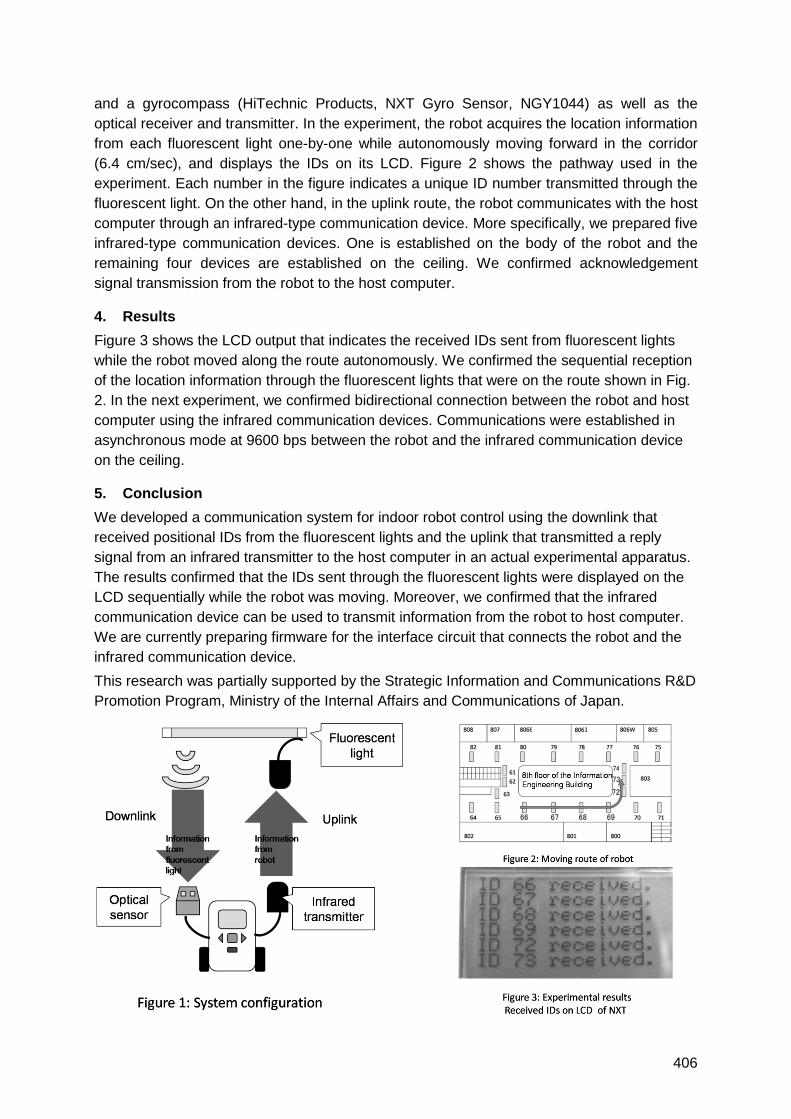
406
and a gyrocompass (HiTechnic Products, NXT Gyro Sensor, NGY1044) as well as the
optical receiver and transmitter. In the experiment, the robot acquires the location information
from each fluorescent light one-by-one while autonomously moving forward in the corridor
(6.4 cm/sec), and displays the IDs on its LCD. Figure 2 shows the pathway used in the
experiment. Each number in the figure indicates a unique ID number transmitted through the
fluorescent light. On the other hand, in the uplink route, the robot communicates with the host
computer through an infrared-type communication device. More specifically, we prepared five
infrared-type communication devices. One is established on the body of the robot and the
remaining four devices are established on the ceiling. We confirmed acknowledgement
signal transmission from the robot to the host computer.
4. Results
Figure 3 shows the LCD output that indicates the received IDs sent from fluorescent lights
while the robot moved along the route autonomously. We confirmed the sequential reception
of the location information through the fluorescent lights that were on the route shown in Fig.
2. In the next experiment, we confirmed bidirectional connection between the robot and host
computer using the infrared communication devices. Communications were established in
asynchronous mode at 9600 bps between the robot and the infrared communication device
on the ceiling.
5. Conclusion
We developed a communication system for indoor robot control using the downlink that
received positional IDs from the fluorescent lights and the uplink that transmitted a reply
signal from an infrared transmitter to the host computer in an actual experimental apparatus.
The results confirmed that the IDs sent through the fluorescent lights were displayed on the
LCD sequentially while the robot was moving. Moreover, we confirmed that the infrared
communication device can be used to transmit information from the robot to host computer.
We are currently preparing firmware for the interface circuit that connects the robot and the
infrared communication device.
This research was partially supported by the Strategic Information and Communications R&D
Promotion Program, Ministry of the Internal Affairs and Communications of Japan.
407
Indoor Location Estimation Using Visible Light Communication:
Practicality and Expandability
Xiaohan Liu, Hideo Makino, Kenichi Mase
Center for Transdisciplinary Research, Niigata University
Summary
We proposed an indoor location estimation method using Visible Light Communication (VLC)
and triangulation. According to the performance of the practical VLC system in Niigata
University, including the tube type fluorescent light system and the compact fluorescent down
light system, we discuss the practicality and expandability on the three components: server
component, light component, and receiver component. Several applications based on the
presented indoor location estimation method such as a robot control system are suggested.
We also give consideration to combining VLC with other technologies such as RFID and
mesh networks.
1 Introduction
Since ubiquitous computing was proposed in 1988, more and more intelligent communication
systems have been developed, and location is considered as the most important parameter
for ubiquitous computing. We established an indoor communication system using Visible
Light Communication in the past seven years. Lightning instruments are installed in many
places indoors, and we found VLC is very convenient for indoor location estimation. As a
new location estimation method, the practicality and expandability are very important.
2 Location Estimation using Visible Light Communication
Figure 1 shows the Visible Light Communication system in Niigata University. The system
concludes three components. In server component, a local network is used to send
information to the control boards which are connected to each fluorescent light; in light
component, Frequency Shift Keying (FSK) is used as the communication method; in the
receiver component, a date receiver (with photo sensor) and a Personal Digital Assistant
(PDA) with Bluetooth functionality are used to acquire essential information. Now three
practical VLC systems are established in Niigata University: tube type fluorescent light
system, compact fluorescent down light system and system for exhibition. LED, which is
considered as next generation light source, could also be used for VLC system.
We used triangulation to calculate the position of the target using VLC. Verification
experiments were performed using 14 compact fluorescent down lights at 20 measuring
points, and 22 tube type fluorescent lights at 39 measuring points. Distance errors of less
than 15 cm are achieved.
3 Practicality
To make the system universal practical, development in the three components are necessary.
(1) In the server component, since the load will become heavy when we send information to
a number of VLC lights, intelligent network should be used to update data. (2) In the light
component, the employed special designed fluorescent lights are all inverter-type enabling
easy signal modulation. (3) In the receiver component, according to our former research, the
recommended receiver is a multi-channel multi-directional photo sensor circuit. The present
receivers are a 9-channel photo sensor receiver (Niigata University) for VLC system using

408
fluorescent light and a charge coupled device (CCD) receiver (Keio University) for VLC
system using LED lights.
Visible Light Communication Consortium (VLCC) is working on the research, development,
plan, and standardization of VLC system with many flagship companies. In addition, IEEE
802.15.7 Visible Light Communication task group is working on the standardization.
4 Expandability
This section discusses related technologies and potential applications of VLC.
(1) Related technologies:
Sensor technology: A multi-channel photo sensor receiver is required to obtain the data
necessary to perform triangulation calculations for location estimation. Also a gyro sensor
and direction sensor technology should be implemented in the receiver component.
Mesh Networks: In Mesh networks, each node acts as an independent router, and this type
of networking could be used in the server component to make VLC system more intelligent.
(2) Potential applications:
Robot control: according to the present location estimation experimental results, it is
convenient to use VLC for indoor robot control. In 2009, we proposed a LEGO NXT robot
control system using VLC in Niigata University.
Combination system: In 2007 we proposed a combination system using VLC, Bluetooth and
Radio Frequency Identification (RFID) for indoor guidance; in 2008 we used VLC and
infrared communication to establish a both-way communication system. These days, since
―Internet of Things‖ becomes more and more popular, combination system with the
applications of different technologies should be an important trend for ubiquitous computing.
In this part, we compare VLC with location estimation systems using ultrasound, IEEE
802.11, RFID, infrared communication, Global Positioning System (GPS) in the aspects of
accuracy, scale, cost and limitations. Compared with other technologies, VLC could cover
most of the indoor environment with least dead points, it is easy to install and the accuracy is
high. This research was partially supported by the Strategic Information and Communications
R&D Promotion Program, Ministry of the internal Affairs and Communications of Japan.
Figure 1 Visible Light Communication System using fluorescent light
409
Advances in Thermal Infrared Localization: Challenges and Solutions
Daniel Hauschildt and Nicolaj Kirchhof
TU Dortmund University, Robotics Research Institute, Otto-Hahn-Str. 8, Dortmund
{daniel.hauschildt, nicolaj.kirchhof}@tu-dortmund.de
1 Introduction
The localization of persons is one of the basic requirements to provide location based
services in home environments. However, no solution exists that meets all the requirements
arising in the field of home automation and Ambient Assisted Living (AAL). Most available
systems are based on technologies like active infrared [1], radio [2], ultrasound [3] or
cameras [4] to acquire the necessary measurements for localization. Unfortunately, the
majority of these technologies require some sort of active transceiver, often referred to as tag
or badge, which has to transmit or receive some kind of reference signal. Technologies that
do not require a tag - like camera based systems - depend on the lightning conditions and
suffer from a lack of consumer acceptance since privacy is being violated.
Thermal Infrared Localization (ThILo) however follows a different approach. In case of ThILo,
no cameras or radio signals, but instead low-resolution thermopile arrays are used. These
thermal infrared sensing sensors measure the thermal radiation emitted by any object in its
field of view relatively to the ambient temperature. Because the human skin temperature
generally differs from the ambient temperature in indoor environments, thermopiles deliver a
great opportunity as basis for an indoor localization system.
Every localization system has its challenges. For ThILo, the challenges have been
formulated in [5] and over the last few years good progress has been made in solving them.
Here, the most important developments will be pointed out and its results are being
summarized. In the full paper, the algorithms will be explained in detail and the most
informative evaluation results will be presented.
2 Challenges and Solutions
By using thermopiles, the only measurable parameter is the thermal radiation. Due to the fact,
that people are not the only source of radiation in home environments, additional heat
sources influence the measurement signal. These influences can be regarded as sources of
disturbance. In general, these disturbances can be divided in four distinct categories:
reflection, occlusion, static and dynamic background radiation. Studying these effects in real
environments is necessary but time consuming and difficult task. That is why; a real-time
thermal infrared simulation environment [6] utilizing state of the art graphics processing unit
capabilities has been developed.
Locating persons is difficult due to the stated reasons. When considering the relaxed
problem with only static background radiation and only one person to track, well known
triangulation algorithms can be applied. Therefore, multiple sensors are deployed throughout
the surveillance region each supplying an angle of arrival that is extracted from the raw
measurement data [7].
410
Considering multiple persons in the surveillance region, simple approaches like triangulation
are not usable anymore. Consequently, more sophisticated multi-target localization and
tracking algorithms need to be employed. Probabilistic Hypothesis Density (PHD) filters yield
an elegant and yet efficient way to solve the multi-target localization and tracking problem
[ref] and have successfully be applied to ThILo. PHD-filters further implicitly handle the
problem of occlusion since missed detections are considered. Analyses of a Sequential
Monte Carlo (SMC) - PHD filter variant have shown a localization accuracy of fewer than 25
cm, for data generated by the simulation environment. Real world measurements have also
confirmed these results. However, the accuracy is slightly worse with approximately 50 cm
when two persons are localized and tracked.
It is a fact that the localization accuracy does not only depend on factors like sensor
resolutions but also on the sensor arrangement within the surveillance region and the
knowledge of the exact sensor pose. Therefore, a semi automatic human assisted calibration
system has been developed that uses the single target localization algorithm as a basis. An
over determined nonlinear least squares optimization problem is formulated and solved
iteratively with the Newton-Raphson method [8]. Evaluation results yield mean position and
orientation errors below 30 cm and 5° respectively.
3 Conclusions and Outlook
The recent developments have shown that ThILo is a promising approach for localization in
home environments. Several issues have been solved the past years and the solutions were
discussed and presented in this paper. However, some issues - like reflection and dynamic
background radiation – remain and are in the focus of current research. In order to eliminate
the influence of dynamic background radiation in the localization process, preliminary
progress has been made.
4 References
[1] Want, R., et al., The Active Badge Location System. Olivetti Research Ltd. (ORL). 1992.
[2] Ekahau., Real-Time Location System (RTLS). 2007.
[3] Balakrishnan, Hari, et al., Lessons from Developing and Deploying the Cricket Indoor Location
System. MIT Computer Science and Artificial Intelligence Laboratory. 2003.
[4] Krumm, John, et al., Multi-Camera Multi-Person Tracking for EasyLiving. Microsoft Research
Vision Technology Group, Microsoft Corporation. 2000.
[5] Kemper, Jürgen and Linde, Holger., "Challenges of Passive Infrared Indoor Localization." 2008.
[6] Kirchhof, Nicolaj, et al., "Real-time Scene Simulator for Thermal Infrared Localization." 2010. To
Be Released. p. 12.
[7] Kemper, Jürgen and Hauschildt, Daniel., "Passive Infrared Localization with a Probability
Hypothesis Density Filter." Dresden : s.n., 2010. 7th Workshop on Positioning, Navigation and
Communication (WPNC), 2010. To Be Released.
[8] Kemper, Jürgen, Linde, Holger and Walter, Markus., "{Human-Assisted Calibration of an
Angulation based Indoor Location System}." 2008.
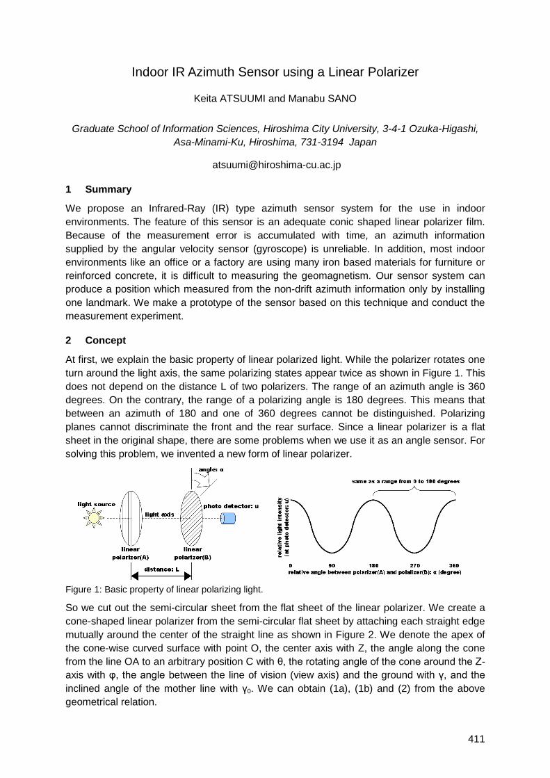
411
Indoor IR Azimuth Sensor using a Linear Polarizer
Keita ATSUUMI and Manabu SANO
Graduate School of Information Sciences, Hiroshima City University, 3-4-1 Ozuka-Higashi,
Asa-Minami-Ku, Hiroshima, 731-3194 Japan
1 Summary
We propose an Infrared-Ray (IR) type azimuth sensor system for the use in indoor
environments. The feature of this sensor is an adequate conic shaped linear polarizer film.
Because of the measurement error is accumulated with time, an azimuth information
supplied by the angular velocity sensor (gyroscope) is unreliable. In addition, most indoor
environments like an office or a factory are using many iron based materials for furniture or
reinforced concrete, it is difficult to measuring the geomagnetism. Our sensor system can
produce a position which measured from the non-drift azimuth information only by installing
one landmark. We make a prototype of the sensor based on this technique and conduct the
measurement experiment.
2 Concept
At first, we explain the basic property of linear polarized light. While the polarizer rotates one
turn around the light axis, the same polarizing states appear twice as shown in Figure 1. This
does not depend on the distance L of two polarizers. The range of an azimuth angle is 360
degrees. On the contrary, the range of a polarizing angle is 180 degrees. This means that
between an azimuth of 180 and one of 360 degrees cannot be distinguished. Polarizing
planes cannot discriminate the front and the rear surface. Since a linear polarizer is a flat
sheet in the original shape, there are some problems when we use it as an angle sensor. For
solving this problem, we invented a new form of linear polarizer.
Figure 1: Basic property of linear polarizing light.
So we cut out the semi-circular sheet from the flat sheet of the linear polarizer. We create a
cone-shaped linear polarizer from the semi-circular flat sheet by attaching each straight edge
mutually around the center of the straight line as shown in Figure 2. We denote the apex of
the cone-wise curved surface with point O, the center axis with Z, the angle along the cone
from the line OA to an arbitrary position C with θ, the rotating angle of the cone around the Z-
axis with φ, the angle between the line of vision (view axis) and the ground with γ, and the
inclined angle of the mother line with γ0. We can obtain (1a), (1b) and (2) from the above
geometrical relation.
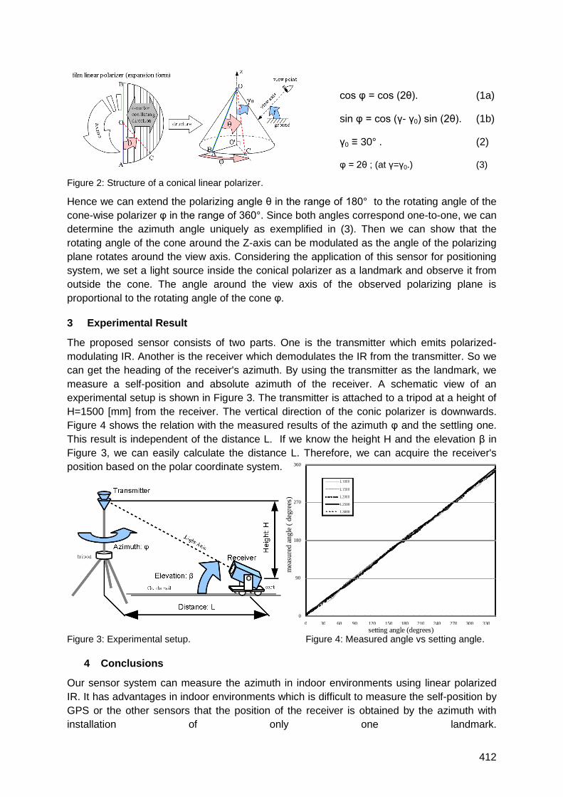
412
0
90
180
270
360
0 30 60 90 120 150 180 210 240 270 300 330
setting angle (degrees)
mea
sure
d a
ng
le (
deg
rees
)
L 1 0 0 0
L 1 5 0 0
L 2 0 0 0
L2500
L3000
cos φ = cos (2θ). (1a)
sin φ = cos (γ- γ0) sin (2θ). (1b)
γ0 ≡ 30° . (2)
φ = 2θ ; (at γ=γ0.) (3)
Figure 2: Structure of a conical linear polarizer.
Hence we can extend the polarizing angle θ in the range of 180° to the rotating angle of the
cone-wise polarizer φ in the range of 360°. Since both angles correspond one-to-one, we can
determine the azimuth angle uniquely as exemplified in (3). Then we can show that the
rotating angle of the cone around the Z-axis can be modulated as the angle of the polarizing
plane rotates around the view axis. Considering the application of this sensor for positioning
system, we set a light source inside the conical polarizer as a landmark and observe it from
outside the cone. The angle around the view axis of the observed polarizing plane is
proportional to the rotating angle of the cone φ.
3 Experimental Result
The proposed sensor consists of two parts. One is the transmitter which emits polarized-
modulating IR. Another is the receiver which demodulates the IR from the transmitter. So we
can get the heading of the receiver's azimuth. By using the transmitter as the landmark, we
measure a self-position and absolute azimuth of the receiver. A schematic view of an
experimental setup is shown in Figure 3. The transmitter is attached to a tripod at a height of
H=1500 [mm] from the receiver. The vertical direction of the conic polarizer is downwards.
Figure 4 shows the relation with the measured results of the azimuth φ and the settling one.
This result is independent of the distance L. If we know the height H and the elevation β in
Figure 3, we can easily calculate the distance L. Therefore, we can acquire the receiver's
position based on the polar coordinate system.
Figure 3: Experimental setup. Figure 4: Measured angle vs setting angle.
4 Conclusions
Our sensor system can measure the azimuth in indoor environments using linear polarized
IR. It has advantages in indoor environments which is difficult to measure the self-position by
GPS or the other sensors that the position of the receiver is obtained by the azimuth with
installation of only one landmark.

413
Ultra Sound Systems
Auditorium J6
Wednesday, September 15, 10:30 – 11:45 & 13:15 – 15:30

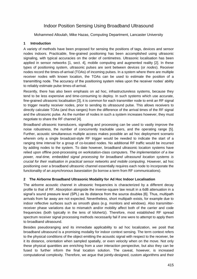
415
Indoor Position Sensing Using Broadband Ultrasound
Mohammed Alloulah, Mike Hazas, Computing Department, Lancaster University
1 Introduction
A variety of methods have been proposed for sensing the positions of tags, devices and sensor
nodes indoors. Practicable, fine-grained positioning has been accomplished using ultrasonic
signaling, with typical accuracies on the order of centimetres. Ultrasonic localisation has been
applied in sensor networks [1, sect. 4], mobile computing and augmented reality [2]. In these
types of positioning system, ultrasonic pulses are sent between devices (or nodes). Receiver
nodes record the times-of-arrival (TOAs) of incoming pulses. In a system where there are multiple
receiver nodes with known location, the TOAs can be used to estimate the position of a
transmitting node. The accuracy of the positioning system relies upon the receiver nodes‘ ability
to reliably estimate pulse times-of-arrival.
Recently, there has also been emphasis on ad hoc, infrastructureless systems, because they
tend to be less expensive and time-consuming to deploy. In such systems which use accurate,
fine-grained ultrasonic localisation [3], it is common for each transmitter node to emit an RF signal
to trigger nearby receiver nodes, prior to sending its ultrasound pulse. This allows receivers to
directly calculate TOAs (and thus ranges) from the difference of the arrival times of the RF signal
and the ultrasonic pulse. As the number of nodes in such a system increases however, they must
negotiate to share the RF channel [4].
Broadband ultrasonic transducers, signalling and processing can be used to vastly improve the
noise robustness, the number of concurrently trackable users, and the operating range [5].
Further, acoustic simultaneous multiple access makes possible an ad hoc deployment scenario
wherein only a single broadcast-style RF trigger would be needed to indicate the start of a
ranging time interval for a group of co-located nodes. No additional RF traffic would be incurred
by adding nodes to the system. To date however, broadband ultrasonic location systems have
relied upon offline post-processing on workstation-class computers. The implementation of a low
power, real-time, embedded signal processing for broadband ultrasound location systems is
crucial for their realisation in practical sensor networks and mobile computing. However, ad hoc
positioning over a broadband ultrasonic channel essentially requires each node to incorporate the
functionality of an asynchronous basestation (to borrow a term from RF communications).
2 The Airborne Broadband Ultrasonic Modality for Ad Hoc Indoor Localisation
The airborne acoustic channel in ultrasonic frequencies is characterized by a different decay
profile to that of RF. Absorption alongside the inverse-square law result in a 6dB attenuation in a
signal‘s sound pressure level (SPL) as its distance from the source doubles [6]. Thus, multipath
arrivals from far away are not expected. Nevertheless, short multipath exists, for example due to
indoor reflective surfaces such as smooth glass (e.g. monitors and windows). Also transmitter-
receiver phase variations due to mismatch and/or mobility affect both of the carrier and code
frequencies (both typically in the tens of kilohertz). Therefore, most established RF spread
spectrum receiver signal processing methods necessarily fail if one were to attempt to apply them
to broadband ultrasound.
Besides pseudoranging and its immediate applicability to ad hoc localization, we posit that
broadband ultrasound is a promising modality for indoor context sensing. The term context refers
to the physical conditions of the object emitting the acoustic signal with respect to the receiver, be
it its distance, orientation when sampled spatially, or even velocity when on the move. Not only
these physical quantities are enriching from a user interaction perspective, but also they can be
fused to further inform the final location solution. The caveat, however, is increased
computational complexity. Therefore, we argue that jointly-designed, custom algorithms and their
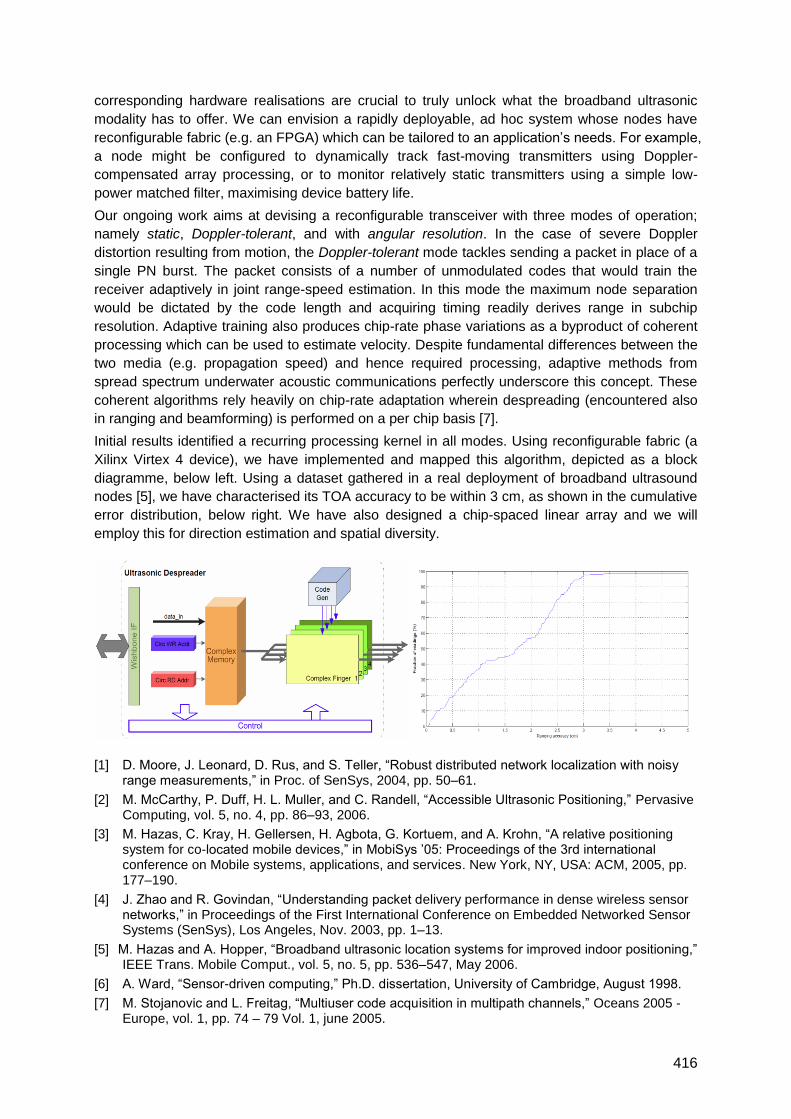
416
corresponding hardware realisations are crucial to truly unlock what the broadband ultrasonic
modality has to offer. We can envision a rapidly deployable, ad hoc system whose nodes have
reconfigurable fabric (e.g. an FPGA) which can be tailored to an application‘s needs. For example,
a node might be configured to dynamically track fast-moving transmitters using Doppler-
compensated array processing, or to monitor relatively static transmitters using a simple low-
power matched filter, maximising device battery life.
Our ongoing work aims at devising a reconfigurable transceiver with three modes of operation;
namely static, Doppler-tolerant, and with angular resolution. In the case of severe Doppler
distortion resulting from motion, the Doppler-tolerant mode tackles sending a packet in place of a
single PN burst. The packet consists of a number of unmodulated codes that would train the
receiver adaptively in joint range-speed estimation. In this mode the maximum node separation
would be dictated by the code length and acquiring timing readily derives range in subchip
resolution. Adaptive training also produces chip-rate phase variations as a byproduct of coherent
processing which can be used to estimate velocity. Despite fundamental differences between the
two media (e.g. propagation speed) and hence required processing, adaptive methods from
spread spectrum underwater acoustic communications perfectly underscore this concept. These
coherent algorithms rely heavily on chip-rate adaptation wherein despreading (encountered also
in ranging and beamforming) is performed on a per chip basis [7].
Initial results identified a recurring processing kernel in all modes. Using reconfigurable fabric (a
Xilinx Virtex 4 device), we have implemented and mapped this algorithm, depicted as a block
diagramme, below left. Using a dataset gathered in a real deployment of broadband ultrasound
nodes [5], we have characterised its TOA accuracy to be within 3 cm, as shown in the cumulative
error distribution, below right. We have also designed a chip-spaced linear array and we will
employ this for direction estimation and spatial diversity.
[1] D. Moore, J. Leonard, D. Rus, and S. Teller, ―Robust distributed network localization with noisy range measurements,‖ in Proc. of SenSys, 2004, pp. 50–61.
[2] M. McCarthy, P. Duff, H. L. Muller, and C. Randell, ―Accessible Ultrasonic Positioning,‖ Pervasive Computing, vol. 5, no. 4, pp. 86–93, 2006.
[3] M. Hazas, C. Kray, H. Gellersen, H. Agbota, G. Kortuem, and A. Krohn, ―A relative positioning system for co-located mobile devices,‖ in MobiSys ‘05: Proceedings of the 3rd international conference on Mobile systems, applications, and services. New York, NY, USA: ACM, 2005, pp. 177–190.
[4] J. Zhao and R. Govindan, ―Understanding packet delivery performance in dense wireless sensor networks,‖ in Proceedings of the First International Conference on Embedded Networked Sensor Systems (SenSys), Los Angeles, Nov. 2003, pp. 1–13.
[5] M. Hazas and A. Hopper, ―Broadband ultrasonic location systems for improved indoor positioning,‖ IEEE Trans. Mobile Comput., vol. 5, no. 5, pp. 536–547, May 2006.
[6] A. Ward, ―Sensor-driven computing,‖ Ph.D. dissertation, University of Cambridge, August 1998.
[7] M. Stojanovic and L. Freitag, ―Multiuser code acquisition in multipath channels,‖ Oceans 2005 - Europe, vol. 1, pp. 74 – 79 Vol. 1, june 2005.
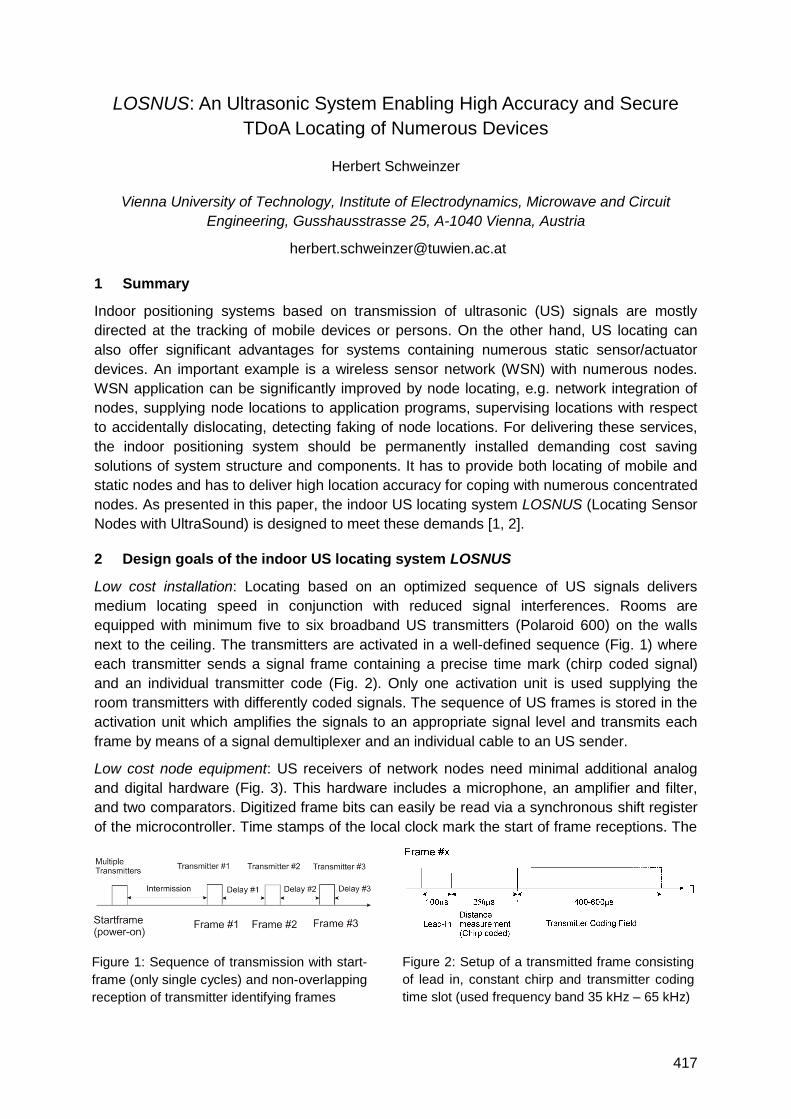
417
Figure 1: Sequence of transmission with start-
frame (only single cycles) and non-overlapping
reception of transmitter identifying frames
Figure 2: Setup of a transmitted frame consisting
of lead in, constant chirp and transmitter coding
time slot (used frequency band 35 kHz – 65 kHz)
LOSNUS: An Ultrasonic System Enabling High Accuracy and Secure
TDoA Locating of Numerous Devices
Herbert Schweinzer
Vienna University of Technology, Institute of Electrodynamics, Microwave and Circuit
Engineering, Gusshausstrasse 25, A-1040 Vienna, Austria
1 Summary
Indoor positioning systems based on transmission of ultrasonic (US) signals are mostly
directed at the tracking of mobile devices or persons. On the other hand, US locating can
also offer significant advantages for systems containing numerous static sensor/actuator
devices. An important example is a wireless sensor network (WSN) with numerous nodes.
WSN application can be significantly improved by node locating, e.g. network integration of
nodes, supplying node locations to application programs, supervising locations with respect
to accidentally dislocating, detecting faking of node locations. For delivering these services,
the indoor positioning system should be permanently installed demanding cost saving
solutions of system structure and components. It has to provide both locating of mobile and
static nodes and has to deliver high location accuracy for coping with numerous concentrated
nodes. As presented in this paper, the indoor US locating system LOSNUS (Locating Sensor
Nodes with UltraSound) is designed to meet these demands [1, 2].
2 Design goals of the indoor US locating system LOSNUS
Low cost installation: Locating based on an optimized sequence of US signals delivers
medium locating speed in conjunction with reduced signal interferences. Rooms are
equipped with minimum five to six broadband US transmitters (Polaroid 600) on the walls
next to the ceiling. The transmitters are activated in a well-defined sequence (Fig. 1) where
each transmitter sends a signal frame containing a precise time mark (chirp coded signal)
and an individual transmitter code (Fig. 2). Only one activation unit is used supplying the
room transmitters with differently coded signals. The sequence of US frames is stored in the
activation unit which amplifies the signals to an appropriate signal level and transmits each
frame by means of a signal demultiplexer and an individual cable to an US sender.
Low cost node equipment: US receivers of network nodes need minimal additional analog
and digital hardware (Fig. 3). This hardware includes a microphone, an amplifier and filter,
and two comparators. Digitized frame bits can easily be read via a synchronous shift register
of the microcontroller. Time stamps of the local clock mark the start of frame receptions. The
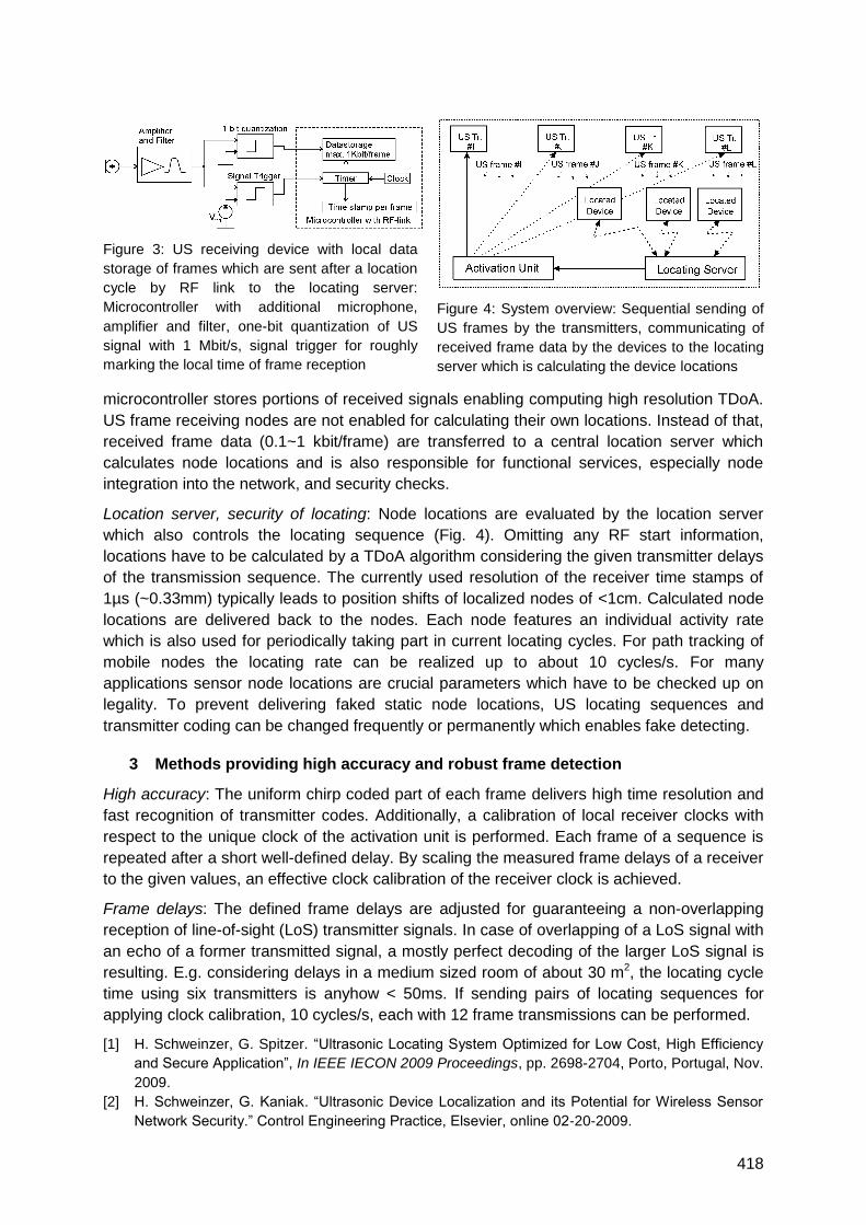
418
microcontroller stores portions of received signals enabling computing high resolution TDoA.
US frame receiving nodes are not enabled for calculating their own locations. Instead of that,
received frame data (0.1~1 kbit/frame) are transferred to a central location server which
calculates node locations and is also responsible for functional services, especially node
integration into the network, and security checks.
Location server, security of locating: Node locations are evaluated by the location server
which also controls the locating sequence (Fig. 4). Omitting any RF start information,
locations have to be calculated by a TDoA algorithm considering the given transmitter delays
of the transmission sequence. The currently used resolution of the receiver time stamps of
1µs (~0.33mm) typically leads to position shifts of localized nodes of <1cm. Calculated node
locations are delivered back to the nodes. Each node features an individual activity rate
which is also used for periodically taking part in current locating cycles. For path tracking of
mobile nodes the locating rate can be realized up to about 10 cycles/s. For many
applications sensor node locations are crucial parameters which have to be checked up on
legality. To prevent delivering faked static node locations, US locating sequences and
transmitter coding can be changed frequently or permanently which enables fake detecting.
3 Methods providing high accuracy and robust frame detection
High accuracy: The uniform chirp coded part of each frame delivers high time resolution and
fast recognition of transmitter codes. Additionally, a calibration of local receiver clocks with
respect to the unique clock of the activation unit is performed. Each frame of a sequence is
repeated after a short well-defined delay. By scaling the measured frame delays of a receiver
to the given values, an effective clock calibration of the receiver clock is achieved.
Frame delays: The defined frame delays are adjusted for guaranteeing a non-overlapping
reception of line-of-sight (LoS) transmitter signals. In case of overlapping of a LoS signal with
an echo of a former transmitted signal, a mostly perfect decoding of the larger LoS signal is
resulting. E.g. considering delays in a medium sized room of about 30 m2, the locating cycle
time using six transmitters is anyhow < 50ms. If sending pairs of locating sequences for
applying clock calibration, 10 cycles/s, each with 12 frame transmissions can be performed.
[1] H. Schweinzer, G. Spitzer. ―Ultrasonic Locating System Optimized for Low Cost, High Efficiency
and Secure Application‖, In IEEE IECON 2009 Proceedings, pp. 2698-2704, Porto, Portugal, Nov.
2009.
[2] H. Schweinzer, G. Kaniak. ―Ultrasonic Device Localization and its Potential for Wireless Sensor
Network Security.‖ Control Engineering Practice, Elsevier, online 02-20-2009.
Figure 3: US receiving device with local data
storage of frames which are sent after a location
cycle by RF link to the locating server:
Microcontroller with additional microphone,
amplifier and filter, one-bit quantization of US
signal with 1 Mbit/s, signal trigger for roughly
marking the local time of frame reception
Figure 4: System overview: Sequential sending of
US frames by the transmitters, communicating of
received frame data by the devices to the locating
server which is calculating the device locations
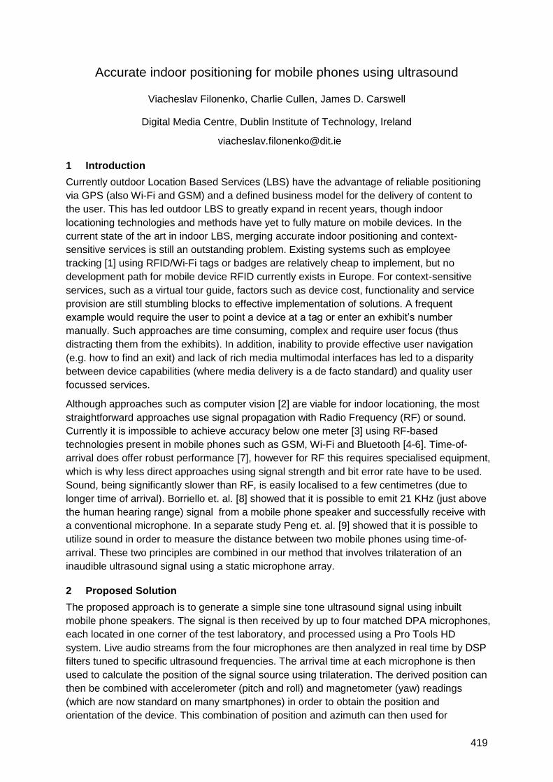
419
Accurate indoor positioning for mobile phones using ultrasound
Viacheslav Filonenko, Charlie Cullen, James D. Carswell
Digital Media Centre, Dublin Institute of Technology, Ireland
1 Introduction
Currently outdoor Location Based Services (LBS) have the advantage of reliable positioning
via GPS (also Wi-Fi and GSM) and a defined business model for the delivery of content to
the user. This has led outdoor LBS to greatly expand in recent years, though indoor
locationing technologies and methods have yet to fully mature on mobile devices. In the
current state of the art in indoor LBS, merging accurate indoor positioning and context-
sensitive services is still an outstanding problem. Existing systems such as employee
tracking [1] using RFID/Wi-Fi tags or badges are relatively cheap to implement, but no
development path for mobile device RFID currently exists in Europe. For context-sensitive
services, such as a virtual tour guide, factors such as device cost, functionality and service
provision are still stumbling blocks to effective implementation of solutions. A frequent
example would require the user to point a device at a tag or enter an exhibit‘s number
manually. Such approaches are time consuming, complex and require user focus (thus
distracting them from the exhibits). In addition, inability to provide effective user navigation
(e.g. how to find an exit) and lack of rich media multimodal interfaces has led to a disparity
between device capabilities (where media delivery is a de facto standard) and quality user
focussed services.
Although approaches such as computer vision [2] are viable for indoor locationing, the most
straightforward approaches use signal propagation with Radio Frequency (RF) or sound.
Currently it is impossible to achieve accuracy below one meter [3] using RF-based
technologies present in mobile phones such as GSM, Wi-Fi and Bluetooth [4-6]. Time-of-
arrival does offer robust performance [7], however for RF this requires specialised equipment,
which is why less direct approaches using signal strength and bit error rate have to be used.
Sound, being significantly slower than RF, is easily localised to a few centimetres (due to
longer time of arrival). Borriello et. al. [8] showed that it is possible to emit 21 KHz (just above
the human hearing range) signal from a mobile phone speaker and successfully receive with
a conventional microphone. In a separate study Peng et. al. [9] showed that it is possible to
utilize sound in order to measure the distance between two mobile phones using time-of-
arrival. These two principles are combined in our method that involves trilateration of an
inaudible ultrasound signal using a static microphone array.
2 Proposed Solution
The proposed approach is to generate a simple sine tone ultrasound signal using inbuilt
mobile phone speakers. The signal is then received by up to four matched DPA microphones,
each located in one corner of the test laboratory, and processed using a Pro Tools HD
system. Live audio streams from the four microphones are then analyzed in real time by DSP
filters tuned to specific ultrasound frequencies. The arrival time at each microphone is then
used to calculate the position of the signal source using trilateration. The derived position can
then be combined with accelerometer (pitch and roll) and magnetometer (yaw) readings
(which are now standard on many smartphones) in order to obtain the position and
orientation of the device. This combination of position and azimuth can then used for
420
directional querying of points of interest (POI) within the environment. The concept of
functional area is introduced in order to describe the size and shape of the area in which the
device can effectively operate. To the best of our knowledge the concepts of functional area
and ultrasound trilateration of a mobile phone have not been attempted in other work, and
thus represent novel contributions to the field.
3 Test Design
Test 1: A test tone emitted from a loudspeaker is used to calibrate the detection algorithms
relative to the output of several current smartphones (e.g. Android, iPhone, Nokia). This will
lead to an initial definition of the concept of functional area, specifying the size and shape of
an area a device can effectively be located within using ultrasound.
Test 2: An emitted tone from a device is detected and processed for intensity and is then
repeatedly measured by emitting the same tone from the device at discrete distance intervals
on both x and y planes (height is maintained to keep the z dimension static). These intervals
will be defined relative to the functional area for each device, as determined in experiment
1.The comparison of these results will lead to the definition of location for the x and y axis of
the test environment using trilateration. This will then be compared to randomised locationing
signals to determine how effectively the algorithm can position the source in a given
environment by using the test data to predict the current position of the device.
4 Conclusions
This paper presents two new concepts: ultrasound trilateration of a mobile phone and
functional area in the context of such positioning system. The first test illustrates the concept
of functional area, which we consider important to practical application of ultrasound
locationing within a given environment. The second test illustrates the concept of ultrasound
trilateration using mobile phone hardware, which is essential to solving the problem of
accurate indoor positioning using a mobile device.
Future work will consider the use of larger calibrated arrays of microphones to determine
azimuth of the signal source. In so doing, the concept of multiple trilateration points will be
investigated to further refine the locationing accuracy of the method. In addition, the notion of
azimuth (direction) of the source will also be investigated using such larger arrays, to
determine whether signal strength (and accelerometers) can be used to determine the
current direction of the device.
1. Ekahau RTLS Overview. Available from: http://www.ekahau.com/products/real-time-location-system/overview.html.
2. Wagner, D., Schmalstieg, D. First Steps Towards Handheld Augmented Reality. in 7th IEEE International Symposium on Wearable Computers. 2003: IEEE Computer Society.
3. Addlesee, M., Curwen, R., Hodges, S., Newman, J., Steggles, P., Ward, A., Hopper, A., Implementing a Sentient Computing System. IEEE Computer, 2001. 34(8): p. 50-56.
4. Otsason, V., Varshavsky, A., LaMarca, A., De Lara, E. Accurate GSM Indoor Localization. in Pervasive and Mobile Computing. 2007.
5. Ferris, B., Hähnel, D., Fox, D. Gaussian Processes for Signal Strength-Based Location Estimation. in Robotics Science and Systems 2006.
6. Hallberg, J., Nilsson, M., Synnes, K. Positioning with Bluetooth. in ICT. 2003.
7. Kolodziej, K., Hjelm, J., Local positioning systems : LBS applications and services. 2006.
8. Borriello, G., Liu, Alan., Offer, T., Palistrant, C., Sharp, R. WALRUS: Wireless Acoustic Location with Room-Level Resolution using Ultrasound. in Mobisys. 2005.
9. Peng, C., Shen, G., Zhang, Y., Li, Y., Tan, K. BeepBeep: A High Accuracy Acoustic Ranging System using COTS Mobile Devices. in SenSys. 2007.
421
Robust ultrasonic indoor positioning using transmitter arrays
Sverre Holm and Carl-Inge C. Nilsen
Department of Informatics, University of Oslo, Norway
1 Summary
As time-delay based ultrasound positioning often is noise sensitive, the goal of the research
reported here is to achieve sub-room ultrasound positioning with other methods. By
combining a portable ultrasound receiver which measures signal strength and Doppler shift
with a transmitter array that sends steered, coded beams inside a room, the tag can
determine which beam it is located in and carry out fine-positioning. The concept is
demonstrated in an experiment using a 40 kHz system with 4-7 transmitter elements.
2 Introduction
Ultrasound positioning systems can be classified according to the need for RF, i.e. whether
they are based on ultrasound alone (1), or hybrid, combining ultrasound and RF (2). They
can also be classified according to the positioning principle: time-delay based (A) or based
on other parameters such as the ability to communicate, signal level and Doppler shift (B).
We have previously developed ultrasound systems using only the ability to communicate as
a positioning criterion (class 1B). These systems have the capability to indicate in which
room a transmitter is located [Holm et al, ICASSP 2005, and Holm, IEEE Ultrason. Symp
2005]. It is now used commercially for tracking of assets and personnel [Greenemeier,
Scientific American, 2008]. Nevertheless it has some shortcomings, the primary one is a
relatively low update rate resulting in a chance to miss items if several objects are to be
located in a short time. A second disadvantage is that portable ultrasound transmitters may
expose human bearers to levels that are near the maximum recommended levels, due to
proximity to the ears. We therefore focus here on a hybrid system with a reversed flow of
ultrasound, so that the portable tag only contains an ultrasound receiver and no transmitter.
In addition there is an RF unit for communicating the data [Holm, IEEE RFID, 2009].
Many hybrid systems of class 2A have been developed, such as Active Bat, Cricket and
Dolphin. They have a high accuracy in the cm-range, but often a very low robustness to
external noise. The experience is that they easily break down in real life. In our view this is
due to the large (+/- 30 dB) variation in the background noise level, see [Holm, IEEE RFID,
2009] for a link budget analysis.
3 Array based system
The goal of our research is to determine how accurately a system can perform in a real-life
environment without relying on time-delay estimation. The required components are a
portable tag with an ultrasound receiver which outputs the Received Signal Strength
Indicator (RSSI) value and the velocity as described in [Holm, IEEE RFID, 2009], and one or
more stationary, array-based ultrasound transmitters.
The new feature of this paper is the array-based transmitter, which can be either 1- or 2-
dimensional. The 1-d array is usually oriented in the horizontal plane, e.g. high up on a wall.
Such an array will send out a beam of approximate width/D (radians), where is the
wavelength and D is the total aperture.
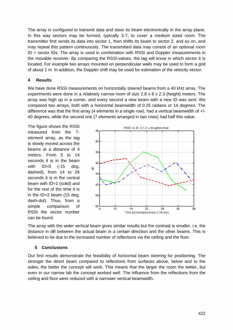
422
The array is configured to transmit data and steer its beam electronically in the array plane.
In this way sectors may be formed, typically 3-7, to cover a medium sized room. The
transmitter first sends its data into sector 1, then shifts its beam to sector 2, and so on, and
may repeat this pattern continuously. The transmitted data may consist of an optional room
ID + sector IDs. The array is used in combination with RSSI and Doppler measurements in
the movable receiver. By comparing the RSSI-values, the tag will know in which sector it is
located. For example two arrays mounted on perpendicular walls may be used to form a grid
of about 1 m. In addition, the Doppler shift may be used for estimation of the velocity vector.
4 Results
We have done RSSI measurements on horizontally steered beams from a 40 kHz array. The
experiments were done in a relatively narrow room of size 2.8 x 8 x 2.3 (height) meters. The
array was high up in a corner, and every second a new beam with a new ID was sent. We
compared two arrays, both with a horizontal beamwidth of 0.25 radians or 14 degrees. The
difference was that the first array (4 elements in a single row), had a vertical beamwidth of +/-
40 degrees, while the second one (7 elements arranged in two rows) had half this value.
The figure shows the RSSI
measured from the 7-
element array, as the tag
is slowly moved across the
beams at a distance of 4
meters. From 5 to 14
seconds it is in the beam
with ID=0 (-15 deg,
dashed), from 14 to 26
seconds it is in the central
beam with ID=1 (solid) and
for the rest of the time it is
in the ID=2 beam (15 deg,
dash-dot). Thus, from a
simple comparison of
RSSI the sector number
can be found.
The array with the wider vertical beam gives similar results but the contrast is smaller, i.e. the
distance in dB between the actual beam in a certain direction and the other beams. This is
believed to be due to the increased number of reflections via the ceiling and the floor.
5 Conclusions
Our first results demonstrate the feasibility of horizontal beam steering for positioning. The
stronger the direct beam compared to reflections from surfaces above, below and to the
sides, the better the concept will work. This means that the larger the room the better, but
even in our narrow lab the concept worked well. The influence from the reflections from the
ceiling and floor were reduced with a narrower vertical beamwidth.
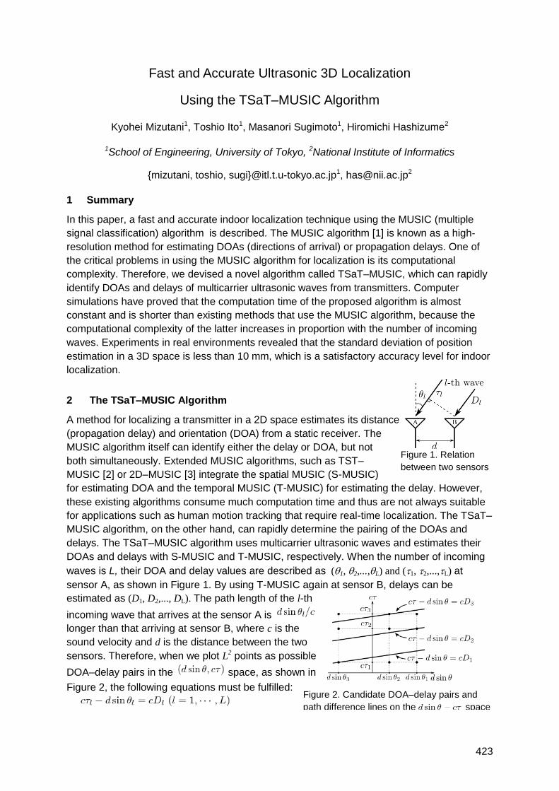
423
Fast and Accurate Ultrasonic 3D Localization
Using the TSaT–MUSIC Algorithm
Kyohei Mizutani1, Toshio Ito1, Masanori Sugimoto1, Hiromichi Hashizume2
1School of Engineering, University of Tokyo, 2National Institute of Informatics
{mizutani, toshio, sugi}@itl.t.u-tokyo.ac.jp1, [email protected]
1 Summary
In this paper, a fast and accurate indoor localization technique using the MUSIC (multiple
signal classification) algorithm is described. The MUSIC algorithm [1] is known as a high-
resolution method for estimating DOAs (directions of arrival) or propagation delays. One of
the critical problems in using the MUSIC algorithm for localization is its computational
complexity. Therefore, we devised a novel algorithm called TSaT–MUSIC, which can rapidly
identify DOAs and delays of multicarrier ultrasonic waves from transmitters. Computer
simulations have proved that the computation time of the proposed algorithm is almost
constant and is shorter than existing methods that use the MUSIC algorithm, because the
computational complexity of the latter increases in proportion with the number of incoming
waves. Experiments in real environments revealed that the standard deviation of position
estimation in a 3D space is less than 10 mm, which is a satisfactory accuracy level for indoor
localization.
2 The TSaT–MUSIC Algorithm
A method for localizing a transmitter in a 2D space estimates its distance
(propagation delay) and orientation (DOA) from a static receiver. The
MUSIC algorithm itself can identify either the delay or DOA, but not
both simultaneously. Extended MUSIC algorithms, such as TST–
MUSIC [2] or 2D–MUSIC [3] integrate the spatial MUSIC (S-MUSIC)
for estimating DOA and the temporal MUSIC (T-MUSIC) for estimating the delay. However,
these existing algorithms consume much computation time and thus are not always suitable
for applications such as human motion tracking that require real-time localization. The TSaT–
MUSIC algorithm, on the other hand, can rapidly determine the pairing of the DOAs and
delays. The TSaT–MUSIC algorithm uses multicarrier ultrasonic waves and estimates their
DOAs and delays with S-MUSIC and T-MUSIC, respectively. When the number of incoming
waves is L, their DOA and delay values are described as (1, 2,...,L) and (1, 2,...,L) at
sensor A, as shown in Figure 1. By using T-MUSIC again at sensor B, delays can be
estimated as (D1, D2,..., DL). The path length of the l-th
incoming wave that arrives at the sensor A is
longer than that arriving at sensor B, where c is the
sound velocity and d is the distance between the two
sensors. Therefore, when we plot L2 points as possible
DOA–delay pairs in the space, as shown in
Figure 2, the following equations must be fulfilled:
Figure 1. Relation
between two sensors
Figure 2. Candidate DOA–delay pairs and
path difference lines on the space
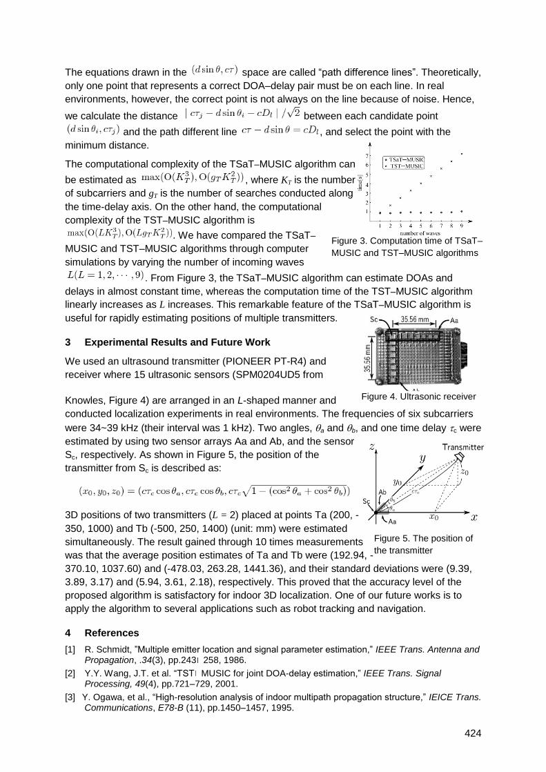
424
The equations drawn in the space are called ―path difference lines‖. Theoretically,
only one point that represents a correct DOA–delay pair must be on each line. In real
environments, however, the correct point is not always on the line because of noise. Hence,
we calculate the distance between each candidate point
and the path different line , and select the point with the
minimum distance.
The computational complexity of the TSaT–MUSIC algorithm can
be estimated as , where KT is the number
of subcarriers and gT is the number of searches conducted along
the time-delay axis. On the other hand, the computational
complexity of the TST–MUSIC algorithm is
. We have compared the TSaT–
MUSIC and TST–MUSIC algorithms through computer
simulations by varying the number of incoming waves
. From Figure 3, the TSaT–MUSIC algorithm can estimate DOAs and
delays in almost constant time, whereas the computation time of the TST–MUSIC algorithm
linearly increases as L increases. This remarkable feature of the TSaT–MUSIC algorithm is
useful for rapidly estimating positions of multiple transmitters.
3 Experimental Results and Future Work
We used an ultrasound transmitter (PIONEER PT-R4) and
receiver where 15 ultrasonic sensors (SPM0204UD5 from
Knowles, Figure 4) are arranged in an L-shaped manner and
conducted localization experiments in real environments. The frequencies of six subcarriers
were 34~39 kHz (their interval was 1 kHz). Two angles, a and b, and one time delay c were
estimated by using two sensor arrays Aa and Ab, and the sensor
Sc, respectively. As shown in Figure 5, the position of the
transmitter from Sc is described as:
3D positions of two transmitters (L = 2) placed at points Ta (200, -
350, 1000) and Tb (-500, 250, 1400) (unit: mm) were estimated
simultaneously. The result gained through 10 times measurements
was that the average position estimates of Ta and Tb were (192.94, -
370.10, 1037.60) and (-478.03, 263.28, 1441.36), and their standard deviations were (9.39,
3.89, 3.17) and (5.94, 3.61, 2.18), respectively. This proved that the accuracy level of the
proposed algorithm is satisfactory for indoor 3D localization. One of our future works is to
apply the algorithm to several applications such as robot tracking and navigation.
4 References
[1] R. Schmidt, ‖Multiple emitter location and signal parameter estimation,‖ IEEE Trans. Antenna and Propagation, .34(3), pp.243 258, 1986.
[2] Y.Y. Wang, J.T. et al. ―TST MUSIC for joint DOA-delay estimation,‖ IEEE Trans. Signal Processing, 49(4), pp.721–729, 2001.
[3] Y. Ogawa, et al., ―High-resolution analysis of indoor multipath propagation structure,‖ IEICE Trans. Communications, E78-B (11), pp.1450–1457, 1995.
Figure 3. Computation time of TSaT–
MUSIC and TST–MUSIC algorithms
Figure 4. Ultrasonic receiver
Figure 5. The position of
the transmitter
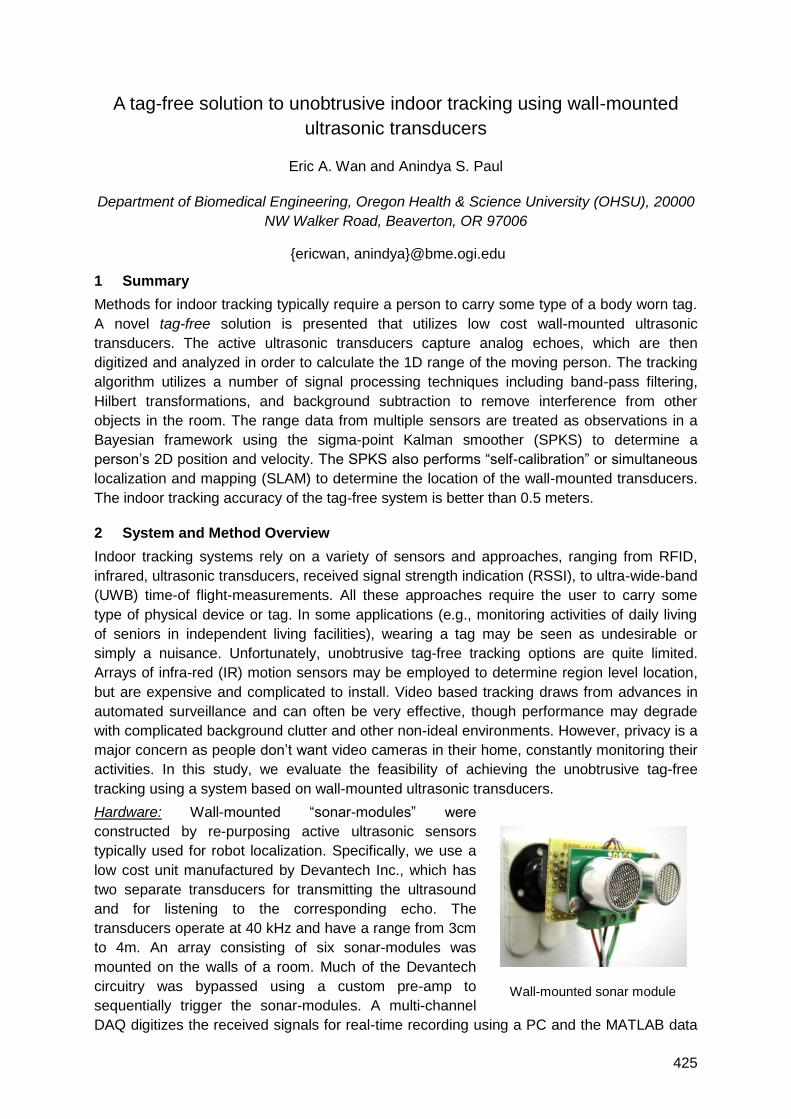
425
A tag-free solution to unobtrusive indoor tracking using wall-mounted
ultrasonic transducers
Eric A. Wan and Anindya S. Paul
Department of Biomedical Engineering, Oregon Health & Science University (OHSU), 20000
NW Walker Road, Beaverton, OR 97006
{ericwan, anindya}@bme.ogi.edu
1 Summary
Methods for indoor tracking typically require a person to carry some type of a body worn tag.
A novel tag-free solution is presented that utilizes low cost wall-mounted ultrasonic
transducers. The active ultrasonic transducers capture analog echoes, which are then
digitized and analyzed in order to calculate the 1D range of the moving person. The tracking
algorithm utilizes a number of signal processing techniques including band-pass filtering,
Hilbert transformations, and background subtraction to remove interference from other
objects in the room. The range data from multiple sensors are treated as observations in a
Bayesian framework using the sigma-point Kalman smoother (SPKS) to determine a
person‘s 2D position and velocity. The SPKS also performs ―self-calibration‖ or simultaneous
localization and mapping (SLAM) to determine the location of the wall-mounted transducers.
The indoor tracking accuracy of the tag-free system is better than 0.5 meters.
2 System and Method Overview
Indoor tracking systems rely on a variety of sensors and approaches, ranging from RFID,
infrared, ultrasonic transducers, received signal strength indication (RSSI), to ultra-wide-band
(UWB) time-of flight-measurements. All these approaches require the user to carry some
type of physical device or tag. In some applications (e.g., monitoring activities of daily living
of seniors in independent living facilities), wearing a tag may be seen as undesirable or
simply a nuisance. Unfortunately, unobtrusive tag-free tracking options are quite limited.
Arrays of infra-red (IR) motion sensors may be employed to determine region level location,
but are expensive and complicated to install. Video based tracking draws from advances in
automated surveillance and can often be very effective, though performance may degrade
with complicated background clutter and other non-ideal environments. However, privacy is a
major concern as people don‘t want video cameras in their home, constantly monitoring their
activities. In this study, we evaluate the feasibility of achieving the unobtrusive tag-free
tracking using a system based on wall-mounted ultrasonic transducers.
Hardware: Wall-mounted ―sonar-modules‖ were
constructed by re-purposing active ultrasonic sensors
typically used for robot localization. Specifically, we use a
low cost unit manufactured by Devantech Inc., which has
two separate transducers for transmitting the ultrasound
and for listening to the corresponding echo. The
transducers operate at 40 kHz and have a range from 3cm
to 4m. An array consisting of six sonar-modules was
mounted on the walls of a room. Much of the Devantech
circuitry was bypassed using a custom pre-amp to
sequentially trigger the sonar-modules. A multi-channel
DAQ digitizes the received signals for real-time recording using a PC and the MATLAB data
Wall-mounted sonar module
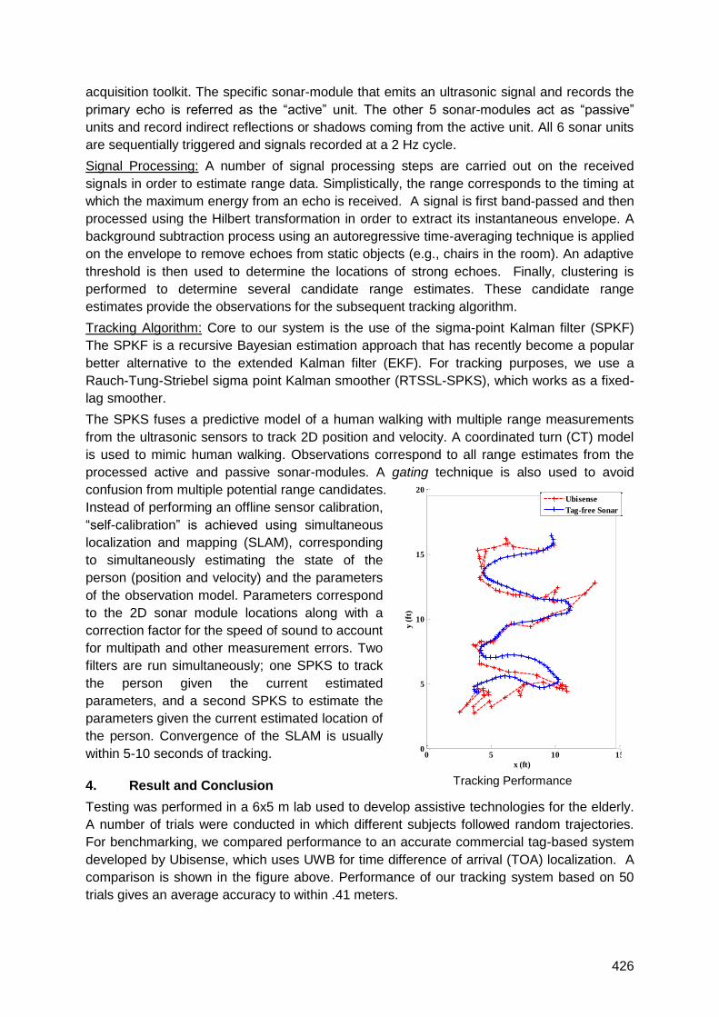
426
acquisition toolkit. The specific sonar-module that emits an ultrasonic signal and records the
primary echo is referred as the ―active‖ unit. The other 5 sonar-modules act as ―passive‖
units and record indirect reflections or shadows coming from the active unit. All 6 sonar units
are sequentially triggered and signals recorded at a 2 Hz cycle.
Signal Processing: A number of signal processing steps are carried out on the received
signals in order to estimate range data. Simplistically, the range corresponds to the timing at
which the maximum energy from an echo is received. A signal is first band-passed and then
processed using the Hilbert transformation in order to extract its instantaneous envelope. A
background subtraction process using an autoregressive time-averaging technique is applied
on the envelope to remove echoes from static objects (e.g., chairs in the room). An adaptive
threshold is then used to determine the locations of strong echoes. Finally, clustering is
performed to determine several candidate range estimates. These candidate range
estimates provide the observations for the subsequent tracking algorithm.
Tracking Algorithm: Core to our system is the use of the sigma-point Kalman filter (SPKF)
The SPKF is a recursive Bayesian estimation approach that has recently become a popular
better alternative to the extended Kalman filter (EKF). For tracking purposes, we use a
Rauch-Tung-Striebel sigma point Kalman smoother (RTSSL-SPKS), which works as a fixed-
lag smoother.
The SPKS fuses a predictive model of a human walking with multiple range measurements
from the ultrasonic sensors to track 2D position and velocity. A coordinated turn (CT) model
is used to mimic human walking. Observations correspond to all range estimates from the
processed active and passive sonar-modules. A gating technique is also used to avoid
confusion from multiple potential range candidates.
Instead of performing an offline sensor calibration,
―self-calibration‖ is achieved using simultaneous
localization and mapping (SLAM), corresponding
to simultaneously estimating the state of the
person (position and velocity) and the parameters
of the observation model. Parameters correspond
to the 2D sonar module locations along with a
correction factor for the speed of sound to account
for multipath and other measurement errors. Two
filters are run simultaneously; one SPKS to track
the person given the current estimated
parameters, and a second SPKS to estimate the
parameters given the current estimated location of
the person. Convergence of the SLAM is usually
within 5-10 seconds of tracking.
4. Result and Conclusion
Testing was performed in a 6x5 m lab used to develop assistive technologies for the elderly.
A number of trials were conducted in which different subjects followed random trajectories.
For benchmarking, we compared performance to an accurate commercial tag-based system
developed by Ubisense, which uses UWB for time difference of arrival (TOA) localization. A
comparison is shown in the figure above. Performance of our tracking system based on 50
trials gives an average accuracy to within .41 meters.
Tracking Performance
0 5 10 150
5
10
15
20
x (ft)
y (
ft)
Ubisense
Tag-free Sonar
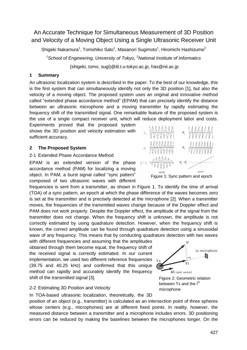
427
An Accurate Technique for Simultaneous Measurement of 3D Position
and Velocity of a Moving Object Using a Single Ultrasonic Receiver Unit
Shigeki Nakamura1, Tomohiko Sato1, Masanori Sugimoto1, Hiromichi Hashizume2
1School of Engineering, University of Tokyo, 2National Institute of Informatics
{shigeki, tomo, sugi}@itl.t.u-tokyo.ac.jp, [email protected]
1 Summary
An ultrasonic localization system is described in the paper. To the best of our knowledge, this
is the first system that can simultaneously identify not only the 3D position [1], but also the
velocity of a moving object. The proposed system uses an original and innovative method
called ―extended phase accordance method‖ (EPAM) that can precisely identify the distance
between an ultrasonic microphone and a moving transmitter by rapidly estimating the
frequency shift of the transmitted signal. One remarkable feature of the proposed system is
the use of a single compact receiver unit, which will reduce deployment labor and costs.
Experiments proved that the proposed system
shows the 3D position and velocity estimation with
sufficient accuracy.
2 The Proposed System
2-1 Extended Phase Accordance Method
EPAM is an extended version of the phase
accordance method (PAM) for localizing a moving
object. In PAM, a burst signal called ―sync pattern‖
composed of two ultrasonic waves with different
frequencies is sent from a transmitter, as shown in Figure 1. To identify the time of arrival
(TOA) of a sync pattern, an epoch at which the phase difference of the waves becomes zero
is set at the transmitter and is precisely detected at the microphone [2]. When a transmitter
moves, the frequencies of the transmitted waves change because of the Doppler effect and
PAM does not work properly. Despite the Doppler effect, the amplitude of the signal from the
transmitter does not change. When the frequency shift is unknown, the amplitude is not
correctly estimated by using quadrature detection. However, when the frequency shift is
known, the correct amplitude can be found through quadrature detection using a sinusoidal
wave of any frequency. This means that by conducting quadrature detection with two waves
with different frequencies and assuming that the amplitudes
obtained through them become equal, the frequency shift of
the received signal is correctly estimated. In our current
implementation, we used two different reference frequencies
(39.75 and 40.25 kHz) and confirmed that this unique
method can rapidly and accurately identify the frequency
shift of the transmitted signal [3].
2-2 Estimating 3D Position and Velocity
In TOA-based ultrasonic localization, theoretically, the 3D
position of an object (e.g., transmitter) is calculated as an intersection point of three spheres
whose centers (e.g., microphones) are at different fixed points. In reality, however, the
measured distance between a transmitter and a microphone includes errors. 3D positioning
errors can be reduced by making the baselines between the microphones longer. On the
Figure 1: Sync pattern and epoch
Figure 2: Geometric relation
between Tx and the ith
microphone
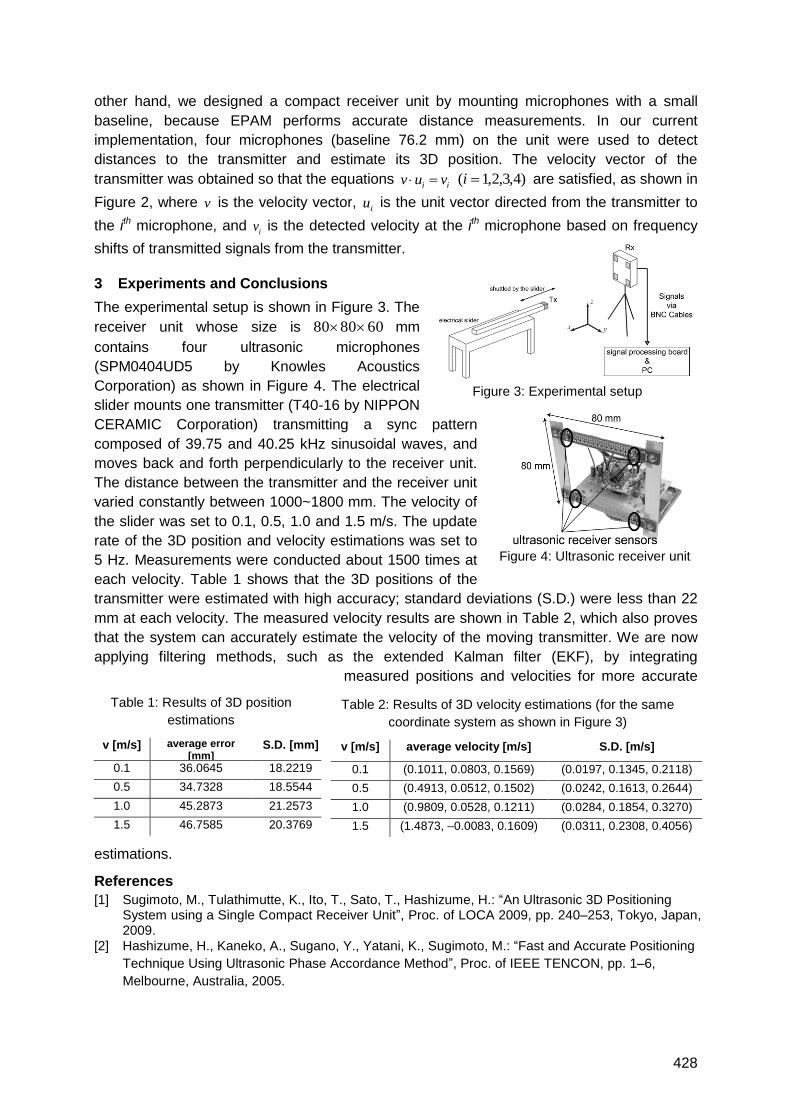
428
other hand, we designed a compact receiver unit by mounting microphones with a small
baseline, because EPAM performs accurate distance measurements. In our current
implementation, four microphones (baseline 76.2 mm) on the unit were used to detect
distances to the transmitter and estimate its 3D position. The velocity vector of the
transmitter was obtained so that the equations i iv u v )4,3,2,1( i are satisfied, as shown in
Figure 2, where v is the velocity vector, iu is the unit vector directed from the transmitter to
the ith microphone, and iv is the detected velocity at the ith microphone based on frequency
shifts of transmitted signals from the transmitter.
3 Experiments and Conclusions
The experimental setup is shown in Figure 3. The
receiver unit whose size is 608080 mm
contains four ultrasonic microphones
(SPM0404UD5 by Knowles Acoustics
Corporation) as shown in Figure 4. The electrical
slider mounts one transmitter (T40-16 by NIPPON
CERAMIC Corporation) transmitting a sync pattern
composed of 39.75 and 40.25 kHz sinusoidal waves, and
moves back and forth perpendicularly to the receiver unit.
The distance between the transmitter and the receiver unit
varied constantly between 1000~1800 mm. The velocity of
the slider was set to 0.1, 0.5, 1.0 and 1.5 m/s. The update
rate of the 3D position and velocity estimations was set to
5 Hz. Measurements were conducted about 1500 times at
each velocity. Table 1 shows that the 3D positions of the
transmitter were estimated with high accuracy; standard deviations (S.D.) were less than 22
mm at each velocity. The measured velocity results are shown in Table 2, which also proves
that the system can accurately estimate the velocity of the moving transmitter. We are now
applying filtering methods, such as the extended Kalman filter (EKF), by integrating
measured positions and velocities for more accurate
estimations.
References
[1] Sugimoto, M., Tulathimutte, K., Ito, T., Sato, T., Hashizume, H.: ―An Ultrasonic 3D Positioning System using a Single Compact Receiver Unit‖, Proc. of LOCA 2009, pp. 240–253, Tokyo, Japan, 2009.
[2] Hashizume, H., Kaneko, A., Sugano, Y., Yatani, K., Sugimoto, M.: ―Fast and Accurate Positioning
Technique Using Ultrasonic Phase Accordance Method‖, Proc. of IEEE TENCON, pp. 1–6,
Melbourne, Australia, 2005.
Table 1: Results of 3D position
estimations
v [m/s] average error [mm]
S.D. [mm]
0.1 36.0645 18.2219
0.5 34.7328 18.5544
1.0 45.2873 21.2573
1.5 46.7585 20.3769
Table 2: Results of 3D velocity estimations (for the same
coordinate system as shown in Figure 3)
v [m/s] average velocity [m/s] S.D. [m/s]
0.1 (0.1011, 0.0803, 0.1569) (0.0197, 0.1345, 0.2118)
0.5 (0.4913, 0.0512, 0.1502) (0.0242, 0.1613, 0.2644)
1.0 (0.9809, 0.0528, 0.1211) (0.0284, 0.1854, 0.3270)
1.5 (1.4873, –0.0083, 0.1609) (0.0311, 0.2308, 0.4056)
Figure 4: Ultrasonic receiver unit
Figure 3: Experimental setup
429
[3] Sato, T., Nakamura, S., Sugimoto, M., Hashizume, H.: ―A Realtime and Accurate Technique for
Estimating Position and Velocity of Moving Node using Ultrasonic Communication‖, Proc. of ICST
2010, Lecce, Italy (to appear).
430
Ultrasonic LPS: architecture, signal processing, positioning and
implementation
Álvaro Hernández, María C. Pérez, José M. Villadangos, Ana Jiménez, Cristina Diego,
Rubén Trejo
Electronics Department, University of Alcalá, E.P.S. Campus universitario s/n,
E-28806 Alcalá de Henares (Madrid), Spain
1 Summary
An ultrasonic Local Positioning System (LPS) is presented, based on five transmitting
beacons to be placed in the environment, whereas a receiver is located onboard a mobile
robot. The ultrasonic transmissions have been encoded by Kasami sequences to improve
system performances and immunity to noise. A Field-Programmable Gate Array (FPGA)-
based implementation of the receiver is proposed to achieve real-time computing in
determining the Differences in Times-Of-Arrival (DTOA) and derive the position coordinates.
2 Global overview
The developed LPS is based on five beacons that are placed at the ceiling as shown in Fig.
1.a. Every beacon consists of a cylindrical PVDF emitter by MSI Inc. and of a conical
reflector, which is used to increase the covered area in the environment. A Kasami code ci of
length L is assigned to each beacon, since the suitable properties of auto- and cross-
correlation among them allow simultaneous emissions from all the beacons every 100ms.
The Kasami code ci is BPSK modulated to focus the transmission m[n] in the maximum
spectral response of transducers (1):
1
0
· · ·L
i c
k
m n c k s n k N M
(1)
In (1) ci[n] is the Kasami code; L is the length of the sequence and s[n] is a symbol formed by
Nc periods of the carrier (fc = 1/Tc), with M samples per period. The parameter M is also the
ratio between the carrier frequency fc and the acquisition fS, so M = fS/fc.
Regarding the receiver, it is based on the Panasonic electret microphone WM-61B and on
the FPGA-based Nexys2 platform by Digilent, Inc. As can be observed in Fig. 1.b, the signal
received by the microphone is amplified and acquired by ADCS7476, and then processed in
Xilinx XC3S1200E FPGA, both are included in the platform mentioned before. The acquired
signal r[n] is BPSK demodulated first according to
· 1
0
·cN M
k
d n r k n s k
. (2)
In (2) d[n] is the output from the demodulation stage; r[n] is the input signal coming from the
acquisition stage and s[n] is the symbol of the demodulation, formed by Nc periods of the
carrier, each one represented by M samples. Note that the parameter M is again M = fS/fc.
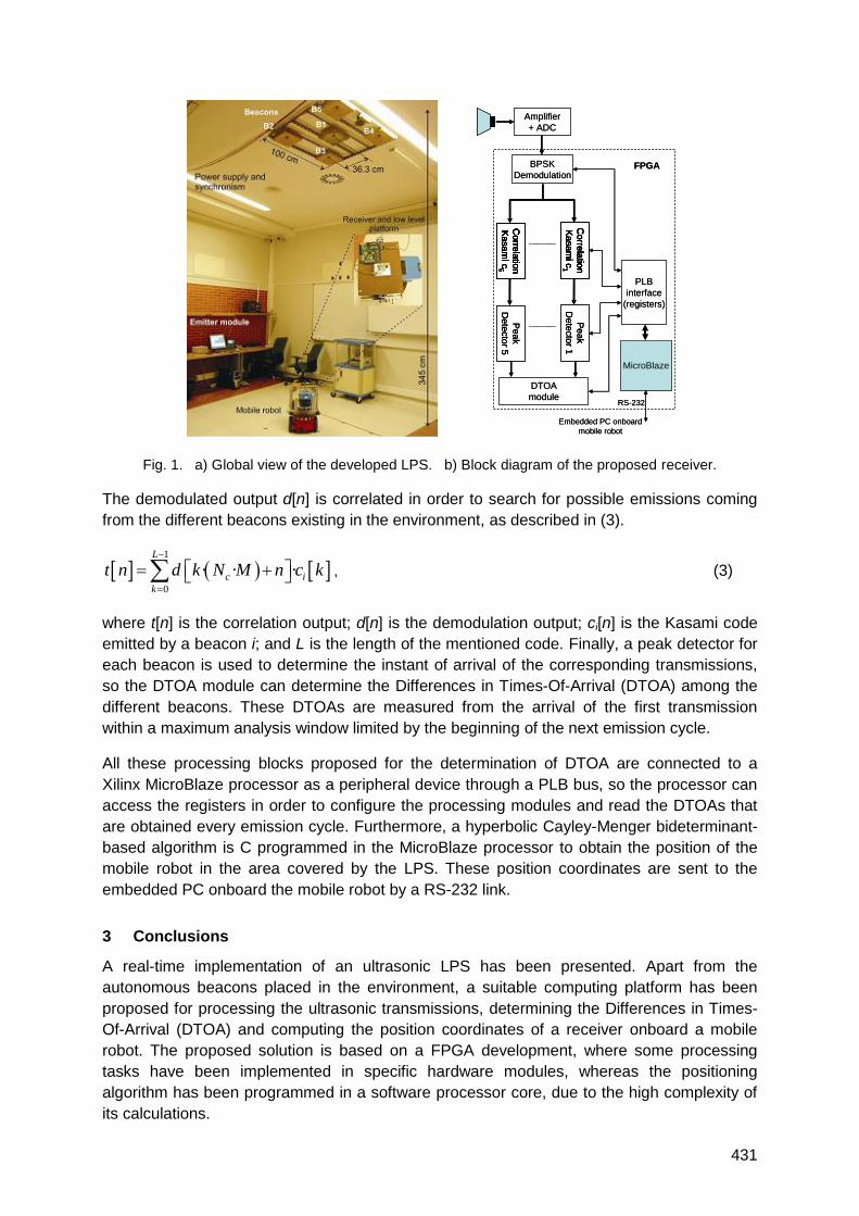
431
Fig. 1. a) Global view of the developed LPS. b) Block diagram of the proposed receiver.
The demodulated output d[n] is correlated in order to search for possible emissions coming
from the different beacons existing in the environment, as described in (3).
1
0
· · ·L
c i
k
t n d k N M n c k
, (3)
where t[n] is the correlation output; d[n] is the demodulation output; ci[n] is the Kasami code
emitted by a beacon i; and L is the length of the mentioned code. Finally, a peak detector for
each beacon is used to determine the instant of arrival of the corresponding transmissions,
so the DTOA module can determine the Differences in Times-Of-Arrival (DTOA) among the
different beacons. These DTOAs are measured from the arrival of the first transmission
within a maximum analysis window limited by the beginning of the next emission cycle.
All these processing blocks proposed for the determination of DTOA are connected to a
Xilinx MicroBlaze processor as a peripheral device through a PLB bus, so the processor can
access the registers in order to configure the processing modules and read the DTOAs that
are obtained every emission cycle. Furthermore, a hyperbolic Cayley-Menger bideterminant-
based algorithm is C programmed in the MicroBlaze processor to obtain the position of the
mobile robot in the area covered by the LPS. These position coordinates are sent to the
embedded PC onboard the mobile robot by a RS-232 link.
3 Conclusions
A real-time implementation of an ultrasonic LPS has been presented. Apart from the
autonomous beacons placed in the environment, a suitable computing platform has been
proposed for processing the ultrasonic transmissions, determining the Differences in Times-
Of-Arrival (DTOA) and computing the position coordinates of a receiver onboard a mobile
robot. The proposed solution is based on a FPGA development, where some processing
tasks have been implemented in specific hardware modules, whereas the positioning
algorithm has been programmed in a software processor core, due to the high complexity of
its calculations.
Amplifier
+ ADC
BPSK
Demodulation
Co
rrela
tion
Ka
sa
mic
1
Co
rrela
tion
Ka
sa
mic
5
Co
rrela
tion
Ka
sa
mic
1
Co
rrela
tion
Ka
sa
mic
5
Pe
ak
De
tecto
r 1
Pe
ak
De
tecto
r 5
DTOA
module
PLB
interface
(registers)
MicroBlaze
RS-232
Embedded PC onboard
mobile robot
FPGA
Amplifier
+ ADC
BPSK
Demodulation
Co
rrela
tion
Ka
sa
mic
1
Co
rrela
tion
Ka
sa
mic
5
Co
rrela
tion
Ka
sa
mic
1
Co
rrela
tion
Ka
sa
mic
5
Pe
ak
De
tecto
r 1
Pe
ak
De
tecto
r 5
Co
rrela
tion
Ka
sa
mic
1
Co
rrela
tion
Ka
sa
mic
5
Co
rrela
tion
Ka
sa
mic
1
Co
rrela
tion
Ka
sa
mic
5
Pe
ak
De
tecto
r 1
Pe
ak
De
tecto
r 5
DTOA
module
PLB
interface
(registers)
MicroBlaze
RS-232
Embedded PC onboard
mobile robot
FPGA
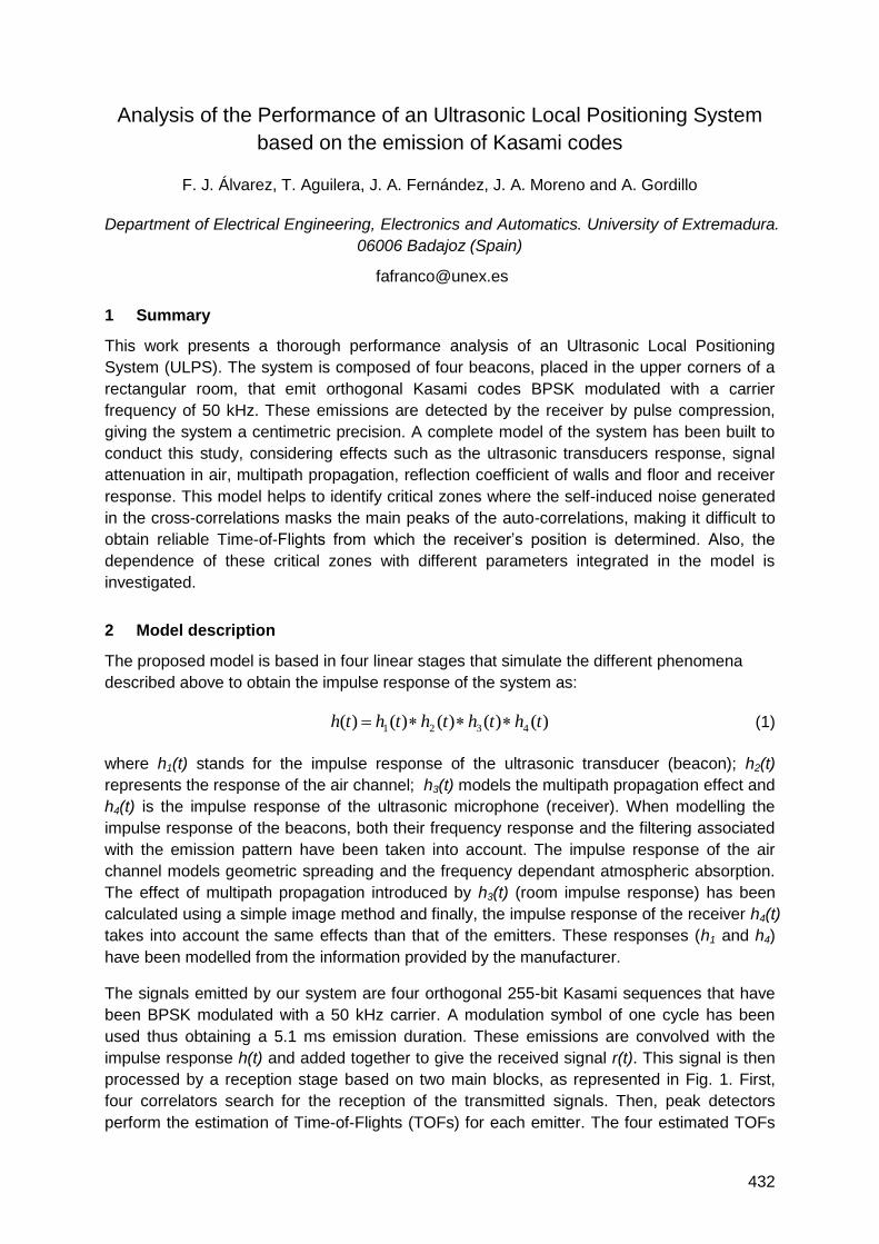
432
Analysis of the Performance of an Ultrasonic Local Positioning System
based on the emission of Kasami codes
F. J. Álvarez, T. Aguilera, J. A. Fernández, J. A. Moreno and A. Gordillo
Department of Electrical Engineering, Electronics and Automatics. University of Extremadura.
06006 Badajoz (Spain)
1 Summary
This work presents a thorough performance analysis of an Ultrasonic Local Positioning
System (ULPS). The system is composed of four beacons, placed in the upper corners of a
rectangular room, that emit orthogonal Kasami codes BPSK modulated with a carrier
frequency of 50 kHz. These emissions are detected by the receiver by pulse compression,
giving the system a centimetric precision. A complete model of the system has been built to
conduct this study, considering effects such as the ultrasonic transducers response, signal
attenuation in air, multipath propagation, reflection coefficient of walls and floor and receiver
response. This model helps to identify critical zones where the self-induced noise generated
in the cross-correlations masks the main peaks of the auto-correlations, making it difficult to
obtain reliable Time-of-Flights from which the receiver‘s position is determined. Also, the
dependence of these critical zones with different parameters integrated in the model is
investigated.
2 Model description
The proposed model is based in four linear stages that simulate the different phenomena
described above to obtain the impulse response of the system as:
)()()()()( 4321 ththththth (1)
where h1(t) stands for the impulse response of the ultrasonic transducer (beacon); h2(t)
represents the response of the air channel; h3(t) models the multipath propagation effect and
h4(t) is the impulse response of the ultrasonic microphone (receiver). When modelling the
impulse response of the beacons, both their frequency response and the filtering associated
with the emission pattern have been taken into account. The impulse response of the air
channel models geometric spreading and the frequency dependant atmospheric absorption.
The effect of multipath propagation introduced by h3(t) (room impulse response) has been
calculated using a simple image method and finally, the impulse response of the receiver h4(t)
takes into account the same effects than that of the emitters. These responses (h1 and h4)
have been modelled from the information provided by the manufacturer.
The signals emitted by our system are four orthogonal 255-bit Kasami sequences that have
been BPSK modulated with a 50 kHz carrier. A modulation symbol of one cycle has been
used thus obtaining a 5.1 ms emission duration. These emissions are convolved with the
impulse response h(t) and added together to give the received signal r(t). This signal is then
processed by a reception stage based on two main blocks, as represented in Fig. 1. First,
four correlators search for the reception of the transmitted signals. Then, peak detectors
perform the estimation of Time-of-Flights (TOFs) for each emitter. The four estimated TOFs
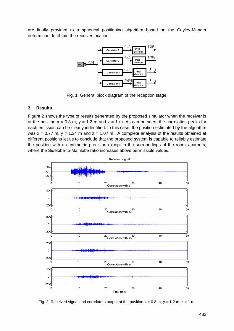
433
are finally provided to a spherical positioning algorithm based on the Cayley-Menger
determinant to obtain the receiver location.
Fig. 1. General block diagram of the reception stage.
3 Results
Figure 2 shows the type of results generated by the proposed simulator when the receiver is
at the position x = 0.8 m, y = 1.2 m and z = 1 m. As can be seen, the correlation peaks for
each emission can be clearly indentified. In this case, the position estimated by the algorithm
was x = 0.77 m, y = 1.24 m and z = 1.07 m. A complete analysis of the results obtained at
different positions let us to conclude that the proposed system is capable to reliably estimate
the position with a centimetric precision except in the surroundings of the room‘s corners,
where the Sidelobe-to-Mainlobe ratio increases above permissible values.
Fig. 2. Received signal and correlators output at the position x = 0.8 m, y = 1.2 m, z = 1 m.
Peakdetector
r[n]
TOF1
MIC
Correlator 1
Peakdetector
TOF3
Correlator 3
Peakdetector
d4[n] TOF4
Correlator 4
Peak
detector
TOF2
Correlator 2
d3[n]
d2[n]
d1[n]
434
Ultrasonic LPS: Autocalibration and mobile robot navigation
Jesús Ureña, Daniel Ruiz, Juan Carlos García, Juan Jesus García, Enrique García
Departament of Electronics. University of Alcala. Spain.
1 Summary
This paper presents an algorithm for mobile robot positioning and navigation using both, the
relative positioning obtained by the on-board dead reckoning and the absolute positioning
computed using an ultrasonic LPS (Local Positioning System). At the beginning of the
process the dead reckoning is used for robot positioning and LPS autocalibration and, after a
predetermined time, the system merges, with an H-∞ filter, the LPS and the dead reckoning
information to navigate. The method has been applied in a configuration of the LPS in which
there are areas with and without LPS coverage. In such a case the algorithm can consider
for positioning the mobile robot both, the dead reckoning and the LPS or only the dead
reckoning. The cumulative error of the dead reckoning is reset each time the LPS is
discovered by the mobile robot in its trajectory.
2 Introduction
In recent years, the research in Local Positioning Systems (LPS) has become important
because of the different applications they facilitate in smart spaces. One of these
applications deals with mobile robot navigation. In most of the systems the positions of the
beacons that compose the LPS are assumed to be known, that is, the coordinates of every
beacon (with respect to the origin of reference) have been previously measured or calculated
and introduced into the system. These calibration process usually needs a long time and
several people taking measurements, making this type of systems slightly portable and
adaptable. For that reason, autocalibration techniques, that allow the system to compute
automatically the position of beacons or fixed devices, are interesting.
In the system presented here, a mobile robot is used to perform the autocalibration at the
same time that it follows a predetermined trajectory. This method takes advantage of the fact
that at the beginning of a trajectory the odometry data are precise and not corrupted by
cumulative errors. The system merges, using a H-∞ filter, the data obtained by the robot
odometry and the distances to the beacons measured with the LPS system. The influence of
each kind of data in the positioning algorithm is dynamically adjusted depending on the time
(if the system is in the phase of autocalibration/navigation or only navigation) and on the
context (if there is –or not- LPS coverage).
3 System overview
The general description of the system and variables shown in Fig. 1 will be used. To apply
the H-∞ filter it is necessary to know both the robot dynamics and the positioning performed
with the LPS.
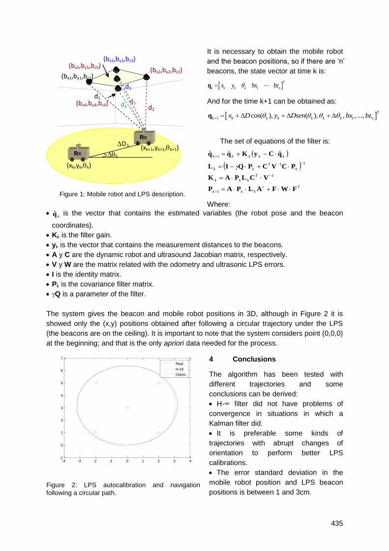
435
It is necessary to obtain the mobile robot
and the beacon positions, so if there are ‗n‘
beacons, the state vector at time k is:
1
T
k k k k nx y bx bzq
And for the time k+1 can be obtained as:
1 1cos( ), ( ), , , ...,T
k k k k k k k nx D y Dsen bx bz q
The set of equations of the filter is:
Tt
kkk
T
kkk
k
T
kk
kkkkk
FWFALPAP
VCLPAK
PCVCPQIL
qCyKqq
1
1
11
1ˆˆˆ
Where:
kq is the vector that contains the estimated variables (the robot pose and the beacon
coordinates).
Kk is the filter gain.
yk is the vector that contains the measurement distances to the beacons.
A y C are the dynamic robot and ultrasound Jacobian matrix, respectively.
V y W are the matrix related with the odometry and ultrasonic LPS errors.
I is the identity matrix.
Pk is the covariance filter matrix.
Q is a parameter of the filter.
The system gives the beacon and mobile robot positions in 3D, although in Figure 2 it is
showed only the (x,y) positions obtained after following a circular trajectory under the LPS
(the beacons are on the ceiling). It is important to note that the system considers point (0,0,0)
at the beginning; and that is the only apriori data needed for the process.
4 Conclusions
The algorithm has been tested with
different trajectories and some
conclusions can be derived:
H-∞ filter did not have problems of
convergence in situations in which a
Kalman filter did.
It is preferable some kinds of
trajectories with abrupt changes of
orientation to perform better LPS
calibrations.
The error standard deviation in the
mobile robot position and LPS beacon
positions is between 1 and 3cm.
Figure 1: Mobile robot and LPS description.
Figure 2: LPS autocalibration and navigation
following a circular path.
(bx2,by2,bz2)
(bx3,by3,bz3)
R
X R
X R
X Rx
X
(bx1,by1,bz1)
d1
d2
d3
d4 d5
R
X R
X R
X Rx
X
(xk,yk,k)
k
D k (xk+1,yk+1,k+1)
(bx5,by5,bz5)
(bx4,by4,bz4)
-4 -3 -2 -1 0 1 2 3 4-1
0
1
2
3
4
5
6
7
Real
H inf.
Odom.
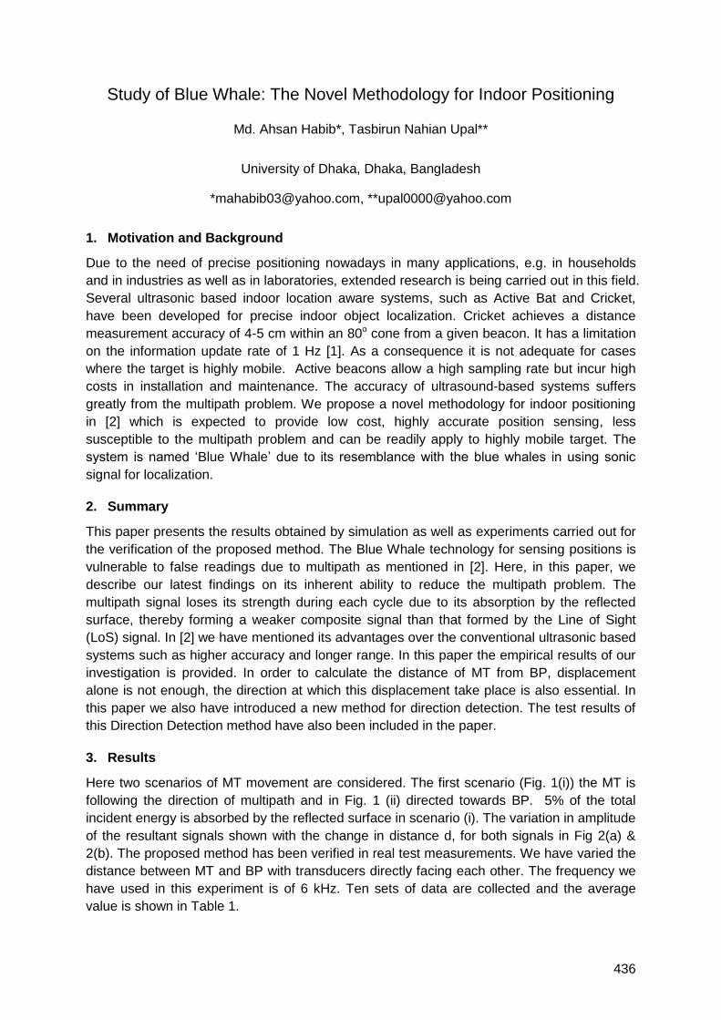
436
Study of Blue Whale: The Novel Methodology for Indoor Positioning
Md. Ahsan Habib*, Tasbirun Nahian Upal**
University of Dhaka, Dhaka, Bangladesh
*[email protected], **[email protected]
1. Motivation and Background
Due to the need of precise positioning nowadays in many applications, e.g. in households
and in industries as well as in laboratories, extended research is being carried out in this field.
Several ultrasonic based indoor location aware systems, such as Active Bat and Cricket,
have been developed for precise indoor object localization. Cricket achieves a distance
measurement accuracy of 4-5 cm within an 80o cone from a given beacon. It has a limitation
on the information update rate of 1 Hz [1]. As a consequence it is not adequate for cases
where the target is highly mobile. Active beacons allow a high sampling rate but incur high
costs in installation and maintenance. The accuracy of ultrasound-based systems suffers
greatly from the multipath problem. We propose a novel methodology for indoor positioning
in [2] which is expected to provide low cost, highly accurate position sensing, less
susceptible to the multipath problem and can be readily apply to highly mobile target. The
system is named ‗Blue Whale‘ due to its resemblance with the blue whales in using sonic
signal for localization.
2. Summary
This paper presents the results obtained by simulation as well as experiments carried out for
the verification of the proposed method. The Blue Whale technology for sensing positions is
vulnerable to false readings due to multipath as mentioned in [2]. Here, in this paper, we
describe our latest findings on its inherent ability to reduce the multipath problem. The
multipath signal loses its strength during each cycle due to its absorption by the reflected
surface, thereby forming a weaker composite signal than that formed by the Line of Sight
(LoS) signal. In [2] we have mentioned its advantages over the conventional ultrasonic based
systems such as higher accuracy and longer range. In this paper the empirical results of our
investigation is provided. In order to calculate the distance of MT from BP, displacement
alone is not enough, the direction at which this displacement take place is also essential. In
this paper we also have introduced a new method for direction detection. The test results of
this Direction Detection method have also been included in the paper.
3. Results
Here two scenarios of MT movement are considered. The first scenario (Fig. 1(i)) the MT is
following the direction of multipath and in Fig. 1 (ii) directed towards BP. 5% of the total
incident energy is absorbed by the reflected surface in scenario (i). The variation in amplitude
of the resultant signals shown with the change in distance d, for both signals in Fig 2(a) &
2(b). The proposed method has been verified in real test measurements. We have varied the
distance between MT and BP with transducers directly facing each other. The frequency we
have used in this experiment is of 6 kHz. Ten sets of data are collected and the average
value is shown in Table 1.
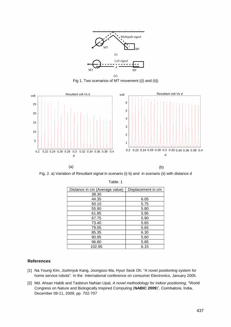
437
Fig 1. Two scenarios of MT movement ((i) and (ii))
(a)
(b)
Fig. 2. a) Variation of Resultant signal in scenario (i) b) and in scenario (ii) with distance d
Table: 1
Distance in cm (Average value) Displacement in cm
38.30
44.35 6.05
50.10 5.75
55.90 5.80
61.85 5.95
67.75 5.90
73.40 5.65
79.05 5.65
85.35 6.30
90.95 5.60
96.80 5.85
102.95 6.15
References
[1] Na Young Kim, Joohnyuk Kang, Joongsoo Ma, Hyun Seok Oh. "A novel positioning system for
home service robots". In the International conference on consumer Electronics, January 2005.
[2] Md. Ahsan Habib and Tasbirun Nahian Upal, A novel methodology for indoor positioning, ―World
Congress on Nature and Biologically Inspired Computing (NABIC 2009)‖, Coimbatore, India,
December 09-11, 2009, pp. 702-707
0.2 0.22 0.24 0.26 0.28 0.3 0.32 0.34 0.36 0.38 0.4
1
2
3
4
5
6
d
volt Resultant volt Vs d
0.2 0.22 0.24 0.26 0.28 0.3 0.32 0.34 0.36 0.38 0.4
5
10
15
20
25
volt Resultant volt Vs d
d
MT BP
LoS signal
d
MT BP
Multipath signal d
(i)
(ii)
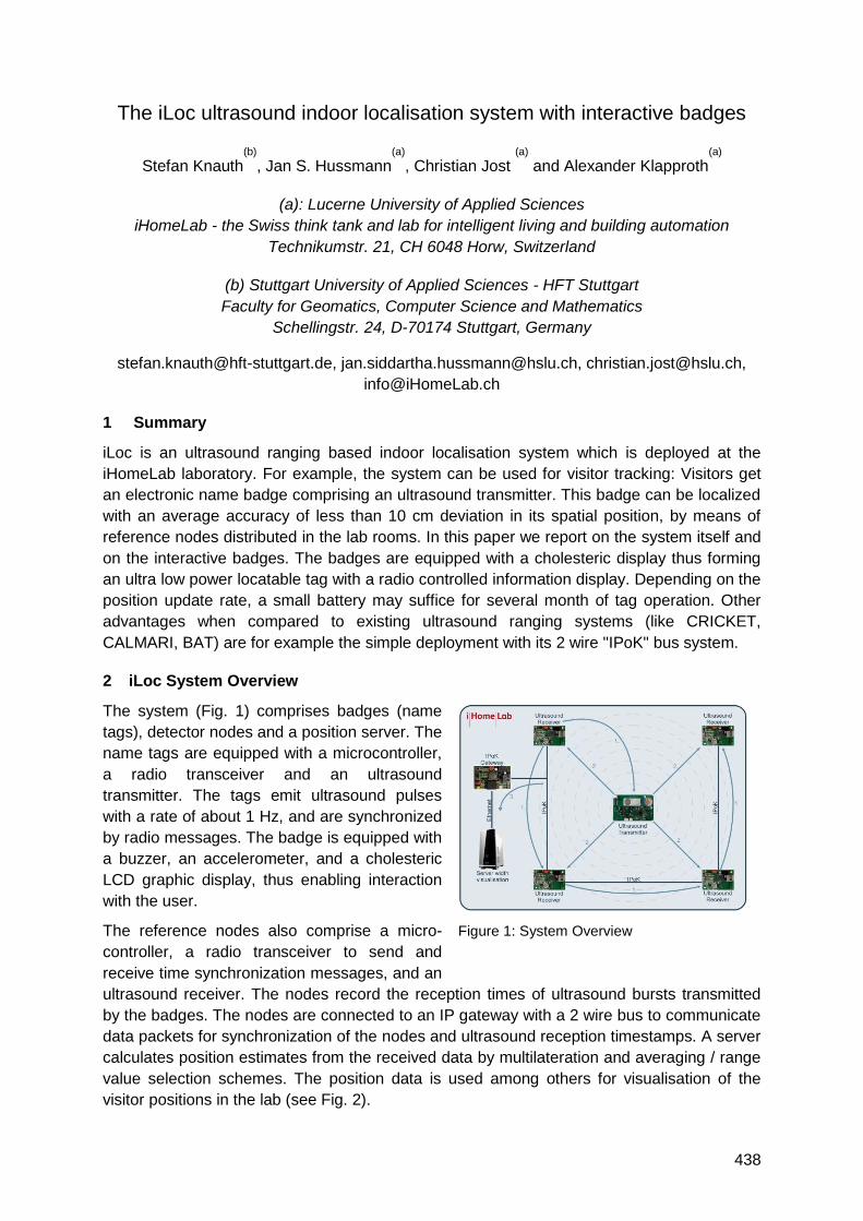
438
The iLoc ultrasound indoor localisation system with interactive badges
Stefan Knauth(b)
, Jan S. Hussmann(a)
, Christian Jost (a)
and Alexander Klapproth(a)
(a): Lucerne University of Applied Sciences
iHomeLab - the Swiss think tank and lab for intelligent living and building automation
Technikumstr. 21, CH 6048 Horw, Switzerland
(b) Stuttgart University of Applied Sciences - HFT Stuttgart
Faculty for Geomatics, Computer Science and Mathematics
Schellingstr. 24, D-70174 Stuttgart, Germany
[email protected], [email protected], [email protected],
1 Summary
iLoc is an ultrasound ranging based indoor localisation system which is deployed at the
iHomeLab laboratory. For example, the system can be used for visitor tracking: Visitors get
an electronic name badge comprising an ultrasound transmitter. This badge can be localized
with an average accuracy of less than 10 cm deviation in its spatial position, by means of
reference nodes distributed in the lab rooms. In this paper we report on the system itself and
on the interactive badges. The badges are equipped with a cholesteric display thus forming
an ultra low power locatable tag with a radio controlled information display. Depending on the
position update rate, a small battery may suffice for several month of tag operation. Other
advantages when compared to existing ultrasound ranging systems (like CRICKET,
CALMARI, BAT) are for example the simple deployment with its 2 wire "IPoK" bus system.
2 iLoc System Overview
The system (Fig. 1) comprises badges (name
tags), detector nodes and a position server. The
name tags are equipped with a microcontroller,
a radio transceiver and an ultrasound
transmitter. The tags emit ultrasound pulses
with a rate of about 1 Hz, and are synchronized
by radio messages. The badge is equipped with
a buzzer, an accelerometer, and a cholesteric
LCD graphic display, thus enabling interaction
with the user.
The reference nodes also comprise a micro-
controller, a radio transceiver to send and
receive time synchronization messages, and an
ultrasound receiver. The nodes record the reception times of ultrasound bursts transmitted
by the badges. The nodes are connected to an IP gateway with a 2 wire bus to communicate
data packets for synchronization of the nodes and ultrasound reception timestamps. A server
calculates position estimates from the received data by multilateration and averaging / range
value selection schemes. The position data is used among others for visualisation of the
visitor positions in the lab (see Fig. 2).
Figure 1: System Overview
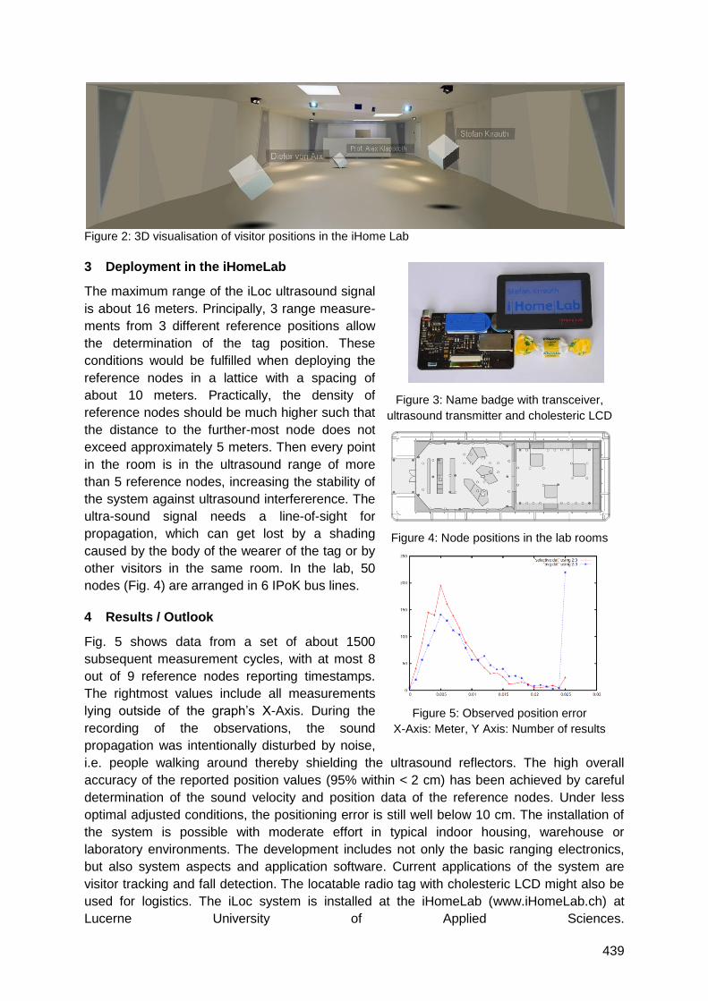
439
Figure 2: 3D visualisation of visitor positions in the iHome Lab
3 Deployment in the iHomeLab
The maximum range of the iLoc ultrasound signal
is about 16 meters. Principally, 3 range measure-
ments from 3 different reference positions allow
the determination of the tag position. These
conditions would be fulfilled when deploying the
reference nodes in a lattice with a spacing of
about 10 meters. Practically, the density of
reference nodes should be much higher such that
the distance to the further-most node does not
exceed approximately 5 meters. Then every point
in the room is in the ultrasound range of more
than 5 reference nodes, increasing the stability of
the system against ultrasound interfererence. The
ultra-sound signal needs a line-of-sight for
propagation, which can get lost by a shading
caused by the body of the wearer of the tag or by
other visitors in the same room. In the lab, 50
nodes (Fig. 4) are arranged in 6 IPoK bus lines.
4 Results / Outlook
Fig. 5 shows data from a set of about 1500
subsequent measurement cycles, with at most 8
out of 9 reference nodes reporting timestamps.
The rightmost values include all measurements
lying outside of the graph‘s X-Axis. During the
recording of the observations, the sound
propagation was intentionally disturbed by noise,
i.e. people walking around thereby shielding the ultrasound reflectors. The high overall
accuracy of the reported position values (95% within < 2 cm) has been achieved by careful
determination of the sound velocity and position data of the reference nodes. Under less
optimal adjusted conditions, the positioning error is still well below 10 cm. The installation of
the system is possible with moderate effort in typical indoor housing, warehouse or
laboratory environments. The development includes not only the basic ranging electronics,
but also system aspects and application software. Current applications of the system are
visitor tracking and fall detection. The locatable radio tag with cholesteric LCD might also be
used for logistics. The iLoc system is installed at the iHomeLab (www.iHomeLab.ch) at
Lucerne University of Applied Sciences.
Figure 3: Name badge with transceiver,
ultrasound transmitter and cholesteric LCD
Figure 4: Node positions in the lab rooms
Figure 5: Observed position error
X-Axis: Meter, Y Axis: Number of results


441
Radar Systems
Auditorium J6
Wednesday, September 15, 16:00 – 18:00

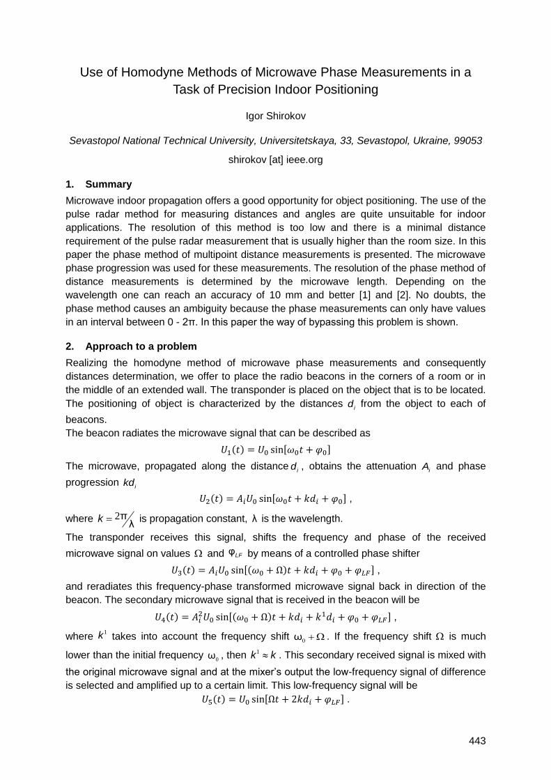
443
Use of Homodyne Methods of Microwave Phase Measurements in a
Task of Precision Indoor Positioning
Igor Shirokov
Sevastopol National Technical University, Universitetskaya, 33, Sevastopol, Ukraine, 99053
shirokov [at] ieee.org
1. Summary
Microwave indoor propagation offers a good opportunity for object positioning. The use of the
pulse radar method for measuring distances and angles are quite unsuitable for indoor
applications. The resolution of this method is too low and there is a minimal distance
requirement of the pulse radar measurement that is usually higher than the room size. In this
paper the phase method of multipoint distance measurements is presented. The microwave
phase progression was used for these measurements. The resolution of the phase method of
distance measurements is determined by the microwave length. Depending on the
wavelength one can reach an accuracy of 10 mm and better [1] and [2]. No doubts, the
phase method causes an ambiguity because the phase measurements can only have values
in an interval between 0 - 2π. In this paper the way of bypassing this problem is shown.
2. Approach to a problem
Realizing the homodyne method of microwave phase measurements and consequently
distances determination, we offer to place the radio beacons in the corners of a room or in
the middle of an extended wall. The transponder is placed on the object that is to be located.
The positioning of object is characterized by the distances id from the object to each of
beacons.
The beacon radiates the microwave signal that can be described as
( ) , -
The microwave, propagated along the distanceid , obtains the attenuation
iA and phase
progression ikd
( ) , - ,
where 2 πλ
k is propagation constant, λ is the wavelength.
The transponder receives this signal, shifts the frequency and phase of the received
microwave signal on values and φLF by means of a controlled phase shifter
( ) ,( ) - ,
and reradiates this frequency-phase transformed microwave signal back in direction of the
beacon. The secondary microwave signal that is received in the beacon will be
( ) ,( )
- ,
where 1k takes into account the frequency shift
0 ω . If the frequency shift is much
lower than the initial frequency 0
ω , then 1 k k . This secondary received signal is mixed with
the original microwave signal and at the mixer‘s output the low-frequency signal of difference
is selected and amplified up to a certain limit. This low-frequency signal will be
( ) , - .
444
The initial frequency and initial phase of origin microwave signal both are subtracted in a
mixer. The only double phase progression of the microwave signal is of interest for the
distance definition.
A low-frequency signal is obtained on the output of each mixer of each beacon, but the
phase shift will be unique for each beacon and will be determined by the each distance id .
These signals are delivered to the signal processing unit and the phases of these signals are
compared with the phase of low-frequency signal reference with the same frequency .
Generally it is possible to measure a phase difference between 0 and 2π. The phase
progression kd will be represented as 2 πn k d , where n is integer. In order to avoid this
problem we serially change the operating frequency of each beacon and we measure the
phase differences. After that we calculate the distance as
( )
( ) .
Certainly, these calculations yield the rough results of distance determination. These
calculations let us obtain the number of phase cycles n and the possibility to determine the
distance in terms of integer numbers of wavelengths. The exact value of distance d can be
obtained by measuring the phase difference k d . Taking into consideration the accuracy of
phase measurements in 1.4° (8 digits) and possible wavelength in 0.2 m, the resolution in
distance determination will be about 1 mm. We must understand the measured distance will
be conditional distance, taking into account antennas‘ phase centers and all feeders‘ lengths.
Further, as each beacon operates as stand alone unit, there is a possibility to measure the
phase difference between beacons‘ mixers‘ output signals. Mentioned opportunity let us
improve the accuracy of coordinate‘s determination, as it was pointed out in [3] and [4].
In this paper the design of the equipment and the algorithm are discussed. The problem of
phase synchronization of low-frequency oscillators is discussed as well.
3. Conclusion
Having defined distances to the object from several beacons (not less than two) and knowing
the exact coordinates of each beacon, by means of the simple software we will calculate
exact coordinates of the object in a room. The time of the object‘s coordinates determination
will be derived from the time of the phase difference measurement at consecutive iterations.
One iteration can last tens or hundreds of milliseconds. The time of the PC computation
cannot be taken into account. We can reduce the measurements and the calculations
accordingly to a minimum by using a tracking mode.
4. References
[1]. V.B. Pestrjakov ―Phase radio engineering systems‖, Moscow, Soviet radio, 1968, 468 p. (in Russian)
[2]. I.B. Shirokov, V.V. Bondjuk ―Distance measurement by a phase method‖ Proc. SVMI named P.S.Nakhimov of Naval Forces of Ukraine, Sevastopol, 2004. Vol.1(4) pp. 152-155. (in Russian)
[3]. I.B. Shirokov ―The Positioning of Space Objects Based on Microwave Angle-of-Arrival Measurements‖ The 4th ESA Int. Workshop on Tracking, Telemetry and Command Systems for Space Applications, September 11-14, 2007, Darmstadt, Germany, pp.1-7.
[4]. I.B. Shirokov, A. Ponyatenko, O.Kulish ―The Measurement of Angle-of-arrival of Microwave in a Task of Precision Landing of Aircraft‖ Progress In Electromagnetics Research Symposium, PIERS‘08, Cambridge, MA, USA, July 2-6, 2008, pp. 153-159.
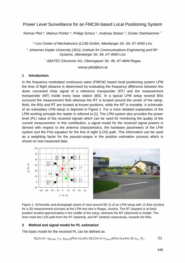
445
Power Level Surveillance for an FMCW-based Local Positioning System
Reimar Pfeil *, Markus Pichler *, Philipp Scherz °, Andreas Stelzer °, Günter Stelzhammer +
* Linz Center of Mechatronics (LCM) GmbH, Altenberger Str. 69, AT-4040 Linz
° Johannes Kepler University (JKU), Institute for Communications Engineering and RF-
Systems, Altenberger Str. 69, AT-4040 Linz
+ ABATEC Electronic AG, Oberregauer Str. 48, AT-4844 Regau
1 Introduction
In the frequency modulated continuous wave (FMCW) based local positioning system LPM
the time of flight distance is determined by evaluating the frequency difference between the
down converted chirp signal of a reference transponder (RT) and the measurement
transponder (MT) inside every base station (BS). In a typical LPM setup several BSs
surround the measurement field whereas the RT is located around the center of the setup.
Both, the BSs and RT are located at known positions, while the MT is movable. A schematic
of an exemplary LPM setup is depicted in Figure 1. For a more detailed explanation of the
LPM working principle the reader is referred to [1]. The LPM system also provides the power
level (PL) value of the received signals which can be used for monitoring the quality of the
current measurement. In this contribution, a signal model for the received signal powers is
derived with respect to the antenna characteristics, the hardware parameters of the LPM
system and the Friis equation for the line of sight (LOS) path. This information can be used
as a weighting factor for the pseudo-ranges in the position estimation process which is
shown on real measured data.
Figure 1: Schematic and photograph (point of view around BS 2) of an LPM setup with 12 BSs (circles)
for a 3D measurement scenario at the LPM test site in Regau, Austria. The RT (square) is at fixed
position located approximately in the middle of the setup, whereas the MT (diamond) is mobile. The
lines mark the LOS path from the RT (dashed), and MT (dotted) respectively, towards the BSs.
2 Method and signal model for PL estimation
The basic model for the received PL can be defined as
,]),[],,[(],[]),[],,[(],[ TCL]TA[][BACLHWSP,R PnmnmnmnmnmnmP mn (1)
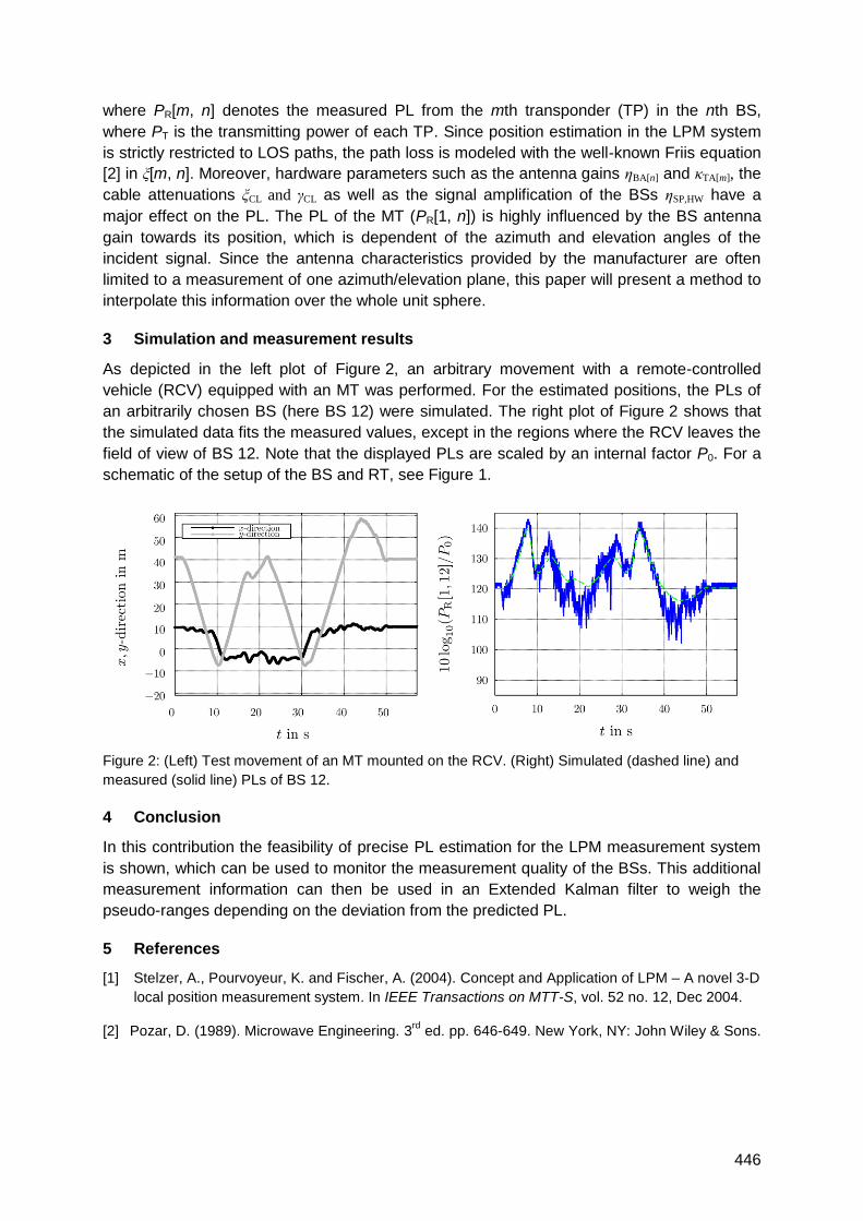
446
where PR[m, n] denotes the measured PL from the mth transponder (TP) in the nth BS,
where PT is the transmitting power of each TP. Since position estimation in the LPM system
is strictly restricted to LOS paths, the path loss is modeled with the well-known Friis equation
[2] in ξ[m, n]. Moreover, hardware parameters such as the antenna gains ηBA[n] and κTA[m], the
cable attenuations ξCL and γCL as well as the signal amplification of the BSs ηSP,HW have a
major effect on the PL. The PL of the MT (PR[1, n]) is highly influenced by the BS antenna
gain towards its position, which is dependent of the azimuth and elevation angles of the
incident signal. Since the antenna characteristics provided by the manufacturer are often
limited to a measurement of one azimuth/elevation plane, this paper will present a method to
interpolate this information over the whole unit sphere.
3 Simulation and measurement results
As depicted in the left plot of Figure 2, an arbitrary movement with a remote-controlled
vehicle (RCV) equipped with an MT was performed. For the estimated positions, the PLs of
an arbitrarily chosen BS (here BS 12) were simulated. The right plot of Figure 2 shows that
the simulated data fits the measured values, except in the regions where the RCV leaves the
field of view of BS 12. Note that the displayed PLs are scaled by an internal factor P0. For a
schematic of the setup of the BS and RT, see Figure 1.
Figure 2: (Left) Test movement of an MT mounted on the RCV. (Right) Simulated (dashed line) and
measured (solid line) PLs of BS 12.
4 Conclusion
In this contribution the feasibility of precise PL estimation for the LPM measurement system
is shown, which can be used to monitor the measurement quality of the BSs. This additional
measurement information can then be used in an Extended Kalman filter to weigh the
pseudo-ranges depending on the deviation from the predicted PL.
5 References
[1] Stelzer, A., Pourvoyeur, K. and Fischer, A. (2004). Concept and Application of LPM – A novel 3-D
local position measurement system. In IEEE Transactions on MTT-S, vol. 52 no. 12, Dec 2004.
[2] Pozar, D. (1989). Microwave Engineering. 3rd
ed. pp. 646-649. New York, NY: John Wiley & Sons.

447
Non-Stochastic Multipath Simulations for an Indoor Local Positioning
System
Silvan Wehrli, Heinz Jäckel
ETH Zurich, Electronics Laboratory, Gloriastrasse 35, CH-8092 Zurich
1 Summary
The measurements of an active pulsed reflector in an indoor local positioning system
revealed that multipath propagation has a large influence on the positioning accuracy. In this
study, a channel model is developed, which calculates the multipath components based on
base station and reflector positions in a room. This model allows identifying correlations
between the reflector position and the distance error. The distance error is correlated to the
channel damping due to multipath propagation with a correlation factor of 0.59. By comparing
the distance errors of one reflector measured by 17 base stations, the reflectors with the
largest standard deviation are close to a wall. The standard deviation of 3400 simulations is
17.19 cm. This is comparable to the measurement results, which resulted in a standard
deviation of 26.6 cm.
2 Introduction
An active pulsed reflector can be used as a backscatter in a FMCW radar based indoor
positioning system [1]. The base stations measure the round-trip time-of-flight by detecting
the frequency difference in the spectrum (Figure 1a). The measurement results revealed that
multipath propagation has a large influence on the positioning accuracy. This paper presents
multipath simulations for the active reflector system and evaluates the influence of the
position of the reflector to the 1D distance error.
3 Channel Model
In wide-band channel models, the propagation channel is modelled with stochastic
parameters. For the simulation of the accuracy of 3D indoor positioning system, these
channel models are not suited, because the propagation channels from different base
stations are correlated. Our channel model assumes a 10x10x3 m3 large room. With the
known position of the base station and the reflector, the multipath and line-of-sight (LOS)
components are calculated. In this paper, we present results for an empty room. This
approximation is valid e.g. for interactive guiding in a museum. With non-empty rooms, the
channel model can still be used, but the calculation of the multipath components will be more
elaborate.
4 Simulation Results
The multipath simulations were conducted with 17 base stations and 200 random reflector
positions. This results in a total of 3400 different propagation channels. For each of these
propagation channels, one distance measurement was simulated. This includes the multipath
propagation, the start-up behaviour of the reflector, and the down-conversion in the base
station with a subsequent zoom-FFT. Figure 1a illustrates the base band spectrum with and
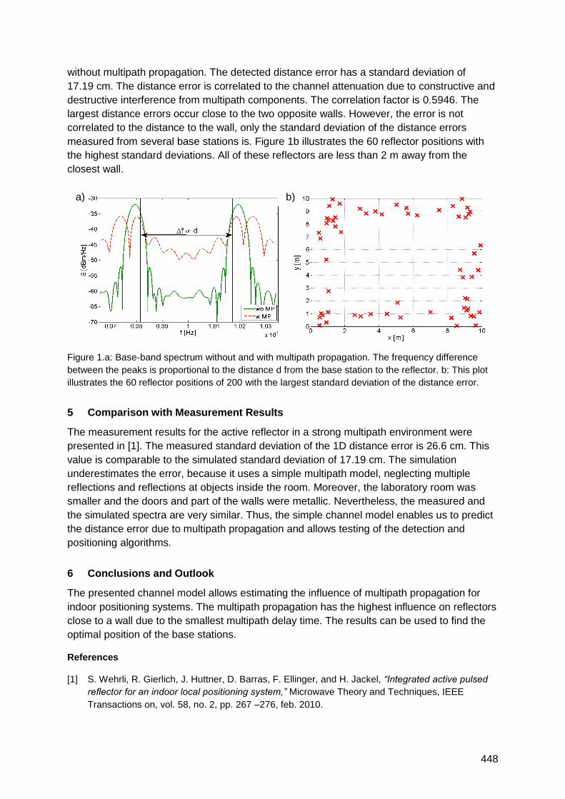
448
without multipath propagation. The detected distance error has a standard deviation of
17.19 cm. The distance error is correlated to the channel attenuation due to constructive and
destructive interference from multipath components. The correlation factor is 0.5946. The
largest distance errors occur close to the two opposite walls. However, the error is not
correlated to the distance to the wall, only the standard deviation of the distance errors
measured from several base stations is. Figure 1b illustrates the 60 reflector positions with
the highest standard deviations. All of these reflectors are less than 2 m away from the
closest wall.
Figure 1.a: Base-band spectrum without and with multipath propagation. The frequency difference
between the peaks is proportional to the distance d from the base station to the reflector. b: This plot
illustrates the 60 reflector positions of 200 with the largest standard deviation of the distance error.
5 Comparison with Measurement Results
The measurement results for the active reflector in a strong multipath environment were
presented in [1]. The measured standard deviation of the 1D distance error is 26.6 cm. This
value is comparable to the simulated standard deviation of 17.19 cm. The simulation
underestimates the error, because it uses a simple multipath model, neglecting multiple
reflections and reflections at objects inside the room. Moreover, the laboratory room was
smaller and the doors and part of the walls were metallic. Nevertheless, the measured and
the simulated spectra are very similar. Thus, the simple channel model enables us to predict
the distance error due to multipath propagation and allows testing of the detection and
positioning algorithms.
6 Conclusions and Outlook
The presented channel model allows estimating the influence of multipath propagation for
indoor positioning systems. The multipath propagation has the highest influence on reflectors
close to a wall due to the smallest multipath delay time. The results can be used to find the
optimal position of the base stations.
References
[1] S. Wehrli, R. Gierlich, J. Huttner, D. Barras, F. Ellinger, and H. Jackel, “Integrated active pulsed
reflector for an indoor local positioning system,” Microwave Theory and Techniques, IEEE
Transactions on, vol. 58, no. 2, pp. 267 –276, feb. 2010.
b) a)
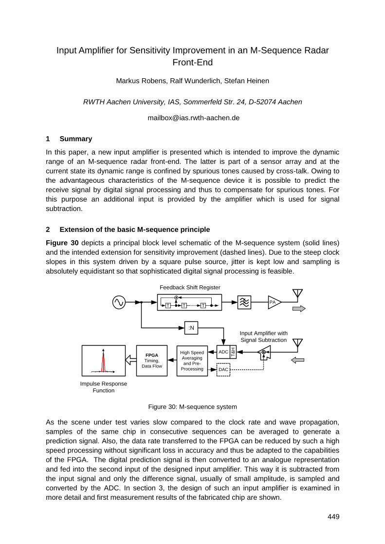
449
Input Amplifier for Sensitivity Improvement in an M-Sequence Radar
Front-End
Markus Robens, Ralf Wunderlich, Stefan Heinen
RWTH Aachen University, IAS, Sommerfeld Str. 24, D-52074 Aachen
1 Summary
In this paper, a new input amplifier is presented which is intended to improve the dynamic
range of an M-sequence radar front-end. The latter is part of a sensor array and at the
current state its dynamic range is confined by spurious tones caused by cross-talk. Owing to
the advantageous characteristics of the M-sequence device it is possible to predict the
receive signal by digital signal processing and thus to compensate for spurious tones. For
this purpose an additional input is provided by the amplifier which is used for signal
subtraction.
2 Extension of the basic M-sequence principle
Figure 30 depicts a principal block level schematic of the M-sequence system (solid lines)
and the intended extension for sensitivity improvement (dashed lines). Due to the steep clock
slopes in this system driven by a square pulse source, jitter is kept low and sampling is
absolutely equidistant so that sophisticated digital signal processing is feasible.
Figure 30: M-sequence system
As the scene under test varies slow compared to the clock rate and wave propagation,
samples of the same chip in consecutive sequences can be averaged to generate a
prediction signal. Also, the data rate transferred to the FPGA can be reduced by such a high
speed processing without significant loss in accuracy and thus be adapted to the capabilities
of the FPGA. The digital prediction signal is then converted to an analogue representation
and fed into the second input of the designed input amplifier. This way it is subtracted from
the input signal and only the difference signal, usually of small amplitude, is sampled and
converted by the ADC. In section 3, the design of such an input amplifier is examined in
more detail and first measurement results of the fabricated chip are shown.
Feedback Shift Register
T T T
:N
ADC
T&
H
PA
DAC
FPGA
Timing,
Data Flow
Input Amplifier with
Signal Subtraction
Impulse Response
Function
High Speed
Averaging
and Pre-
Processing
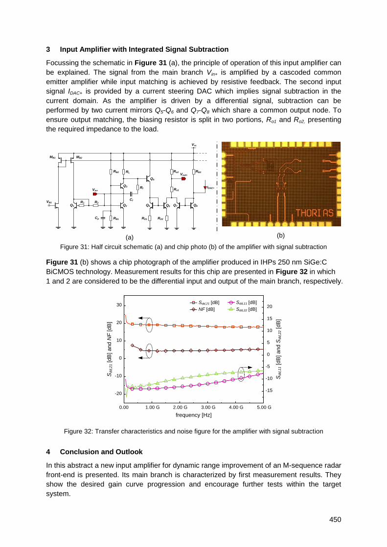
450
3 Input Amplifier with Integrated Signal Subtraction
Focussing the schematic in Figure 31 (a), the principle of operation of this input amplifier can
be explained. The signal from the main branch Vin+ is amplified by a cascoded common
emitter amplifier while input matching is achieved by resistive feedback. The second input
signal IDAC+ is provided by a current steering DAC which implies signal subtraction in the
current domain. As the amplifier is driven by a differential signal, subtraction can be
performed by two current mirrors Q5-Q6 and Q7-Q8 which share a common output node. To
ensure output matching, the biasing resistor is split in two portions, Ro1 and Ro2, presenting
the required impedance to the load.
(a) (b)
Figure 31: Half circuit schematic (a) and chip photo (b) of the amplifier with signal subtraction
Figure 31 (b) shows a chip photograph of the amplifier produced in IHPs 250 nm SiGe:C
BiCMOS technology. Measurement results for this chip are presented in Figure 32 in which
1 and 2 are considered to be the differential input and output of the main branch, respectively.
Figure 32: Transfer characteristics and noise figure for the amplifier with signal subtraction
4 Conclusion and Outlook
In this abstract a new input amplifier for dynamic range improvement of an M-sequence radar
front-end is presented. Its main branch is characterized by first measurement results. They
show the desired gain curve progression and encourage further tests within the target
system.
VB1
-
MB1 MB2
R1 R2
Q1 Q2
Rf
Cf
Q3
Q4
Q5 Q6 Q7 Q8
RL
RB1
RB2
Cp RD1 RD2
Ro1
Ro2 RB3
Vcc
IDAC+Vin+
Vout+
-20
-10
0
10
20
30
0.00 1.00 G 2.00 G 3.00 G 4.00 G 5.00 G
-15
-10
-5
0
5
10
15
20
Sd
d,2
1 [d
B] a
nd
NF
[d
B]
Sd
d,1
1 [d
B] a
nd
Sd
d,2
2 [d
B]
frequency [Hz]
Sdd,21 [dB]
NF [dB]
Sdd,11 [dB]
Sdd,22 [dB]
Related Documents