Abstract ORDON, ROBERT LEWIS. Experimental Investigations Into The Operational Parameters Of a 50 Centimeter Class Pulsejet Engine. (Under the direction of Dr. William L. Roberts.) A hobby scale pulsejet, commercially available from Bailey Machine Services (BMS), is significantly instrumented and tested to develop a theoretical understanding of how various inlets, fuel systems, and exhaust sizes effect the overall performance of the jet. The purposes of these experiments are to aid in the development and optimization of valveless pulsejet engines. A valved inlet running on ethanol is tested as well as valveless inlets running on propane. Valveless inlet diameters and lengths are varied as well as exhaust lengths and compared to acoustic models, namely the Helmholtz resonator and 1/6 wave tube resonator models. Temperatures, average and peak combustion chamber and exit pressures, sound pressure levels and jet operating frequencies were recorded at various fuel flow rates.

Welcome message from author
This document is posted to help you gain knowledge. Please leave a comment to let me know what you think about it! Share it to your friends and learn new things together.
Transcript

Abstract
ORDON, ROBERT LEWIS. Experimental Investigations Into The Operational Parameters Of a 50 Centimeter Class Pulsejet Engine. (Under the direction of Dr. William L. Roberts.)
A hobby scale pulsejet, commercially available from Bailey Machine Services
(BMS), is significantly instrumented and tested to develop a theoretical understanding of
how various inlets, fuel systems, and exhaust sizes effect the overall performance of the jet.
The purposes of these experiments are to aid in the development and optimization of valveless
pulsejet engines. A valved inlet running on ethanol is tested as well as valveless inlets
running on propane. Valveless inlet diameters and lengths are varied as well as exhaust
lengths and compared to acoustic models, namely the Helmholtz resonator and 1/6 wave tube
resonator models. Temperatures, average and peak combustion chamber and exit pressures,
sound pressure levels and jet operating frequencies were recorded at various fuel flow rates.

EXPERIMENTAL INVESTIGATIONS INTO THE OPERATIONAL PARAMETERS OF A 50 CENTIMETER CLASS PULSEJET ENGINE
By Robert Lewis Ordon
A thesis submitted in partial fulfillment of the requirements for the degree of
Masters of Science
Mechanical Engineering
North Carolina State University Raleigh, NC
2006
Approved by:
Dr. William L. Roberts Dr. Andrey V. Kuznetsov
Chair of Supervisory Committee
Co-Chair of Supervisory Committee
Dr. Terry Scharton
Committee Member

ii
Biography
The author was born Robert Lewis Ordon of Pensacola, Florida in May of 1977, son
of Ramon and Mary Ordon. He is the youngest son with a half-brother and half sister,
Howard and Elisa. At age 3 he and his mother moved to Plainsboro, New Jersey. There his
mother married Bruce Meyers. He was enrolled in the West Windsor – Plainsboro school
system until graduating from West Windsor Plainsboro High School in May of 1995.
From high school he went to North Carolina State University in Raleigh, North
Carolina where he earned a degree in Aerospace Engineering with a minor in Chinese
Studies in May of 2000.
Immediately after receiving his degree, Robert took a job in Washington, DC where
he worked as a scientific advisor for program managers at the Defense Advanced Research
Projects Agency (DARPA). It was while working on various programs at DARPA that
Robert decided that he wanted to further his technical education.
Following the deaths of both of his biological parents in late 2002, he decided to
return to school and enter the Masters of Science program for Mechanical Engineering where
he received his degree under the direction of Dr. William L. Roberts.

iii
Acknowledgements
The author would like to acknowledge the Defense Advanced Research Projects
Agency (DARPA), for providing funding that covered most of the research performed in this
study; his advisors, Dr. William L. Roberts, Dr. Terry Scharton, and Dr. Andrey Kuznetzov
for their advice and assistance, Rufus ‘Skip’ Richardson and Mike Breedlove for expediting
part creation, Sean Danby for his computational help, Christian McCalley for his assistance
in conducting experiments and most importantly his father, Bruce Meyers, without whom
this never would have been possible.

iv
Table of Contents
1. Introduction..............................................................................................................................1 1.1 Background and History ................................................................................................1 1.2 Related Work .................................................................................................................8 1.3 Pulsejet Cycle...............................................................................................................10
2. Experimental Apparatus and Setup.....................................................................................13 2.1 Pulsejets .......................................................................................................................13
2.1.1 Bailey Machine Service Valved Jet ..............................................................13 2.1.2 Valveless Jet..................................................................................................14
2.2 Cooling System............................................................................................................15 2.3 Inlets.............................................................................................................................16 2.4 Fuel Delivery ...............................................................................................................17 2.5 Ignition System ............................................................................................................18 2.6 Pressure Measurements................................................................................................19 2.7 Thermocouples.............................................................................................................21 2.8 Sound Pressure Level Meter ........................................................................................22 2.9 Thrust Stand .................................................................................................................23 2.10 Procedures....................................................................................................................23
2.10.1 Starting of the Jet ..........................................................................................23 2.10.2 Data Collection .............................................................................................24
3. Parametrics / Performance ...................................................................................................25 3.1 BMS Valved Tests .......................................................................................................25 3.2 Valveless Tests.............................................................................................................28
4. Helmholtz Resonators and Quarter Wave Tubes ...............................................................49 4.1 Helmholtz Resonators..................................................................................................49 4.2 Quarter-wave Tubes.....................................................................................................49
5. Sound Pressure Levels...........................................................................................................56
6. Conclusion ..............................................................................................................................58
7. Future Work...........................................................................................................................59
References.....................................................................................................................................60

v
List of Figures
Figure 1−1: Schematic of Vapor Pulsejet ‘Pop-Pop’ Boat ..............................................................2 Figure 1−2: Marconnet Valveless Engine ........................................................................................3 Figure 1−3: German V-1 ‘Buzz Bomb’ Pulsejet Powered Cruise Missile .....................................4 Figure 1−4: U-Shape Pulsejet ...........................................................................................................7 Figure 1−5: Escopette valveless pulsejet..........................................................................................9 Figure 1−6: Fuel Injection Location ...............................................................................................10 Figure 1−7: Lenoir Cycle................................................................................................................11 Figure 1−8: Hunphrey Cycle ..........................................................................................................12 Figure 2−1: Standard BMS Pulsejet ...............................................................................................13 Figure 2−2: Dimensions of Experimental Jet.................................................................................14 Figure 2−3: Ports with Water Jackets added to BMS Jet...............................................................16 Figure 2−4: First Set of Steel Inlets ................................................................................................16 Figure 2−5: Hastings Model 40 Flow Meter..................................................................................17 Figure 2−6: Fuel Injector Installed in Jet........................................................................................18 Figure 2−7: Nichrome Ignition (top) and Spark Ignition (bottom) ...............................................19 Figure 2−8: Mercury Manometer ...................................................................................................20 Figure 2−9: Completed Type-B Thermocouple.............................................................................21 Figure 2−10: Taylor Model 9841 Thermometer ............................................................................22 Figure 2−11: Radio Shack SPL Meter............................................................................................22 Figure 3−1: CH* vs. Combustion Chamber Pressure....................................................................26 Figure 3−2: Pressure Plot for Valved Jet........................................................................................27 Figure 3−3: Valved Jet Temperature vs. Time...............................................................................27 Figure 3−4: Lower Throttleability Limit for Various Extension Lengths.....................................31 Figure 3−5: Lower Throttleability Limits for Various Inlets.........................................................32 Figure 3−6: Upper Throttleability for Various Extension Lengths ...............................................33 Figure 3−7: Upper Throttleability for Various Inlet Diameters.....................................................33 Figure 3−8: Temperature vs. Exhaust Length for ½” Inlet (3” Long)...........................................34 Figure 3−9: Temperature vs. Exhaust Length for ½” Inlet (2” long)............................................35 Figure 3−10: Temperature vs. Exhaust Length for 5/8” Inlet........................................................36 Figure 3−11: Temperature vs. Exhaust for 7/8” Inlet ....................................................................36 Figure 3−12: Temperature vs. Exhaust Length for 1” Inlet...........................................................37 Figure 3−13: Jet Temperatures vs. Inlet Diameter +3” Extension, 3” Long Inlet ........................38 Figure 3−14: Jet Temperatures vs. Inlet Diameter +6” Extension, 3” Long Inlet ........................38 Figure 3−15: Jet Temperatures vs. Inlet Diameter +9” Extension, 3” Long Inlet ........................39 Figure 3−16: Throttleability Ranges for Various Inlets at Various Extension Lengths................40 Figure 3−17: Operational Envelope based on Inlet and Exhaust Length......................................41 Figure 3−18: Throttleability Ranges for Various Extension Lengths with Various Inlets ...........41 Figure 3−19: Operating Frequency as a Function of Exhaust Length for Various Inlets.............42 Figure 3−20: Operating Frequency as a Function of Various Inlets at Various Exhaust Lengths43 Figure 3−21: Change in Port 1 Pressure vs. Inlet Diameter...........................................................44 Figure 3−22: Average Port 1 and Port 3 Pressure vs. Inlet Diameter............................................45 Figure 3−23: Average Port 1 and Port 3 Pressure vs. Exhaust Extension Length ........................46

vi
Figure 3−24: 2nd Harmonic Visible in Exhaust Frequency for 1” Inlet .......................................47 Figure 3−25: 2nd Harmonic Visible in Exhaust Frequency for 1/2” Inlet ....................................47 Figure 4−1: Actual vs. Modeled Frequencies for 5/8” Inlet ..........................................................51 Figure 4−2: Actual vs. Modeled Frequencies for 7/8” Inlet ..........................................................51 Figure 4−3: Actual vs. Modeled Frequencies for 1” Inlet .............................................................52 Figure 4−4: Actual vs. Modeled Frequencies as a function of Inlet Diameter for 3” Exhaust.....53 Figure 4−5: Actual vs. Modeled Frequencies as a function of Inlet Diameter for 6” Exhaust.....53 Figure 4−6: Actual vs. Modeled Frequencies as a function of Inlet Diameter for 9” Exhaust.....54 Figure 5−1: SPL vs. Inlet Diameter for Various Lengths..............................................................56 Figure 5−2: SPL vs. Extension Length for Various Inlets.............................................................57

vii
List of Tables
Table 3−1: Overall Test Results ............................................................................................. 29 Table 4−1: Actual Frequency Compared to Calculated......................................................... 55

1
1. Introduction
The investigation into pulse combustion engines was initially funded by the Defense
Advanced Research Projects Agency (DARPA) to explore the scalability of such engines,
particularly for small Unmanned Aerial Vehicle (UAV) propulsion. The design parameters
of pulsejets had not been fully investigated and equations have not been developed to scale
such jets in a highly predictable manner. Deciphering the scaling laws and dominant design
characteristics of the jets in order to have a tool for optimization of the engines was a primary
objective of this work.
1.1 Background and History
The concept of the first pulsed jet can be traced back to an 1882 Publication by
Nikolai Egorovich Zhukovsky. His paper, ‘On the reaction force of in-and-out oscillating
flowing liquid’, is the first reference to the ‘Vapor Pulse Jet’. The subject of the paper was
developed in two subsequent editions published in 1885 and 1908. Stating a general method
used for the determination of the motion of a body and fluid inside it, he investigated
Helmholtz's problem and augmented it by the new problem of the motion of a closed tube
filled with fluid. He studied this last problem with the aid of the theory of pipes of Poiseuille,
and its solution was verified by a special experiment performed by him (Zamyatina, 1986).
In 1891 and 1898 Désiré Thomas Piot obtained British Patents for powering model
boats called ‘Pop-Pop’s’. As seen in Figure 1−1, a vapor pulse jet has two main parts: A
small flash boiler, ‘d’, connected to small diameter condenser tubes. The boiler is filled with
water through the tube opening, ‘h’. It is then placed in some water reservoir and some
source of heat is placed under the boiler, ‘c’. Once the boiler gets hot enough, it flash boils
the water. This increase in pressure forces the boat forward by forcing water out of the pipes.

2
The pressure then drops due to an over expansion and the water returns up the tube with just
enough spilling in to the boiler to flash boil again (Piot, 1898; Le Bot, 2005).
Figure 1−1: Schematic of Vapor Pulsejet ‘Pop-Pop’ Boat
Since 1891, millions of these simple toy boats have been produced. Piot boats are
known to have been originally available from A.W.Gamages, London in 1891. Simple
experiments with this boat showed that the operating frequency was dependant on the length
of the water pipes. Performance varied with the shape of the boiler, but no significant
scientific measurements had been taken (Science, 2005).
3
Nine years later, in 1906, Russian engineer Vladimir V. Karavodin experimented with
pulsejets in basic research to find the effects of varying tube length and diameter had on the
cycle pulse frequency, stability and thrust produced. The jet tube he used was straight and of
constant diameter. He obtained a patent for an air breathing pulse-jet engine. In 1907 he
built a working engine based on his invention (Gwynn, 2005). Basically the system produced
a high velocity pulsed gas jet generated by a cyclic combustion of a liquid hydrocarbon fuel /
air mixture.
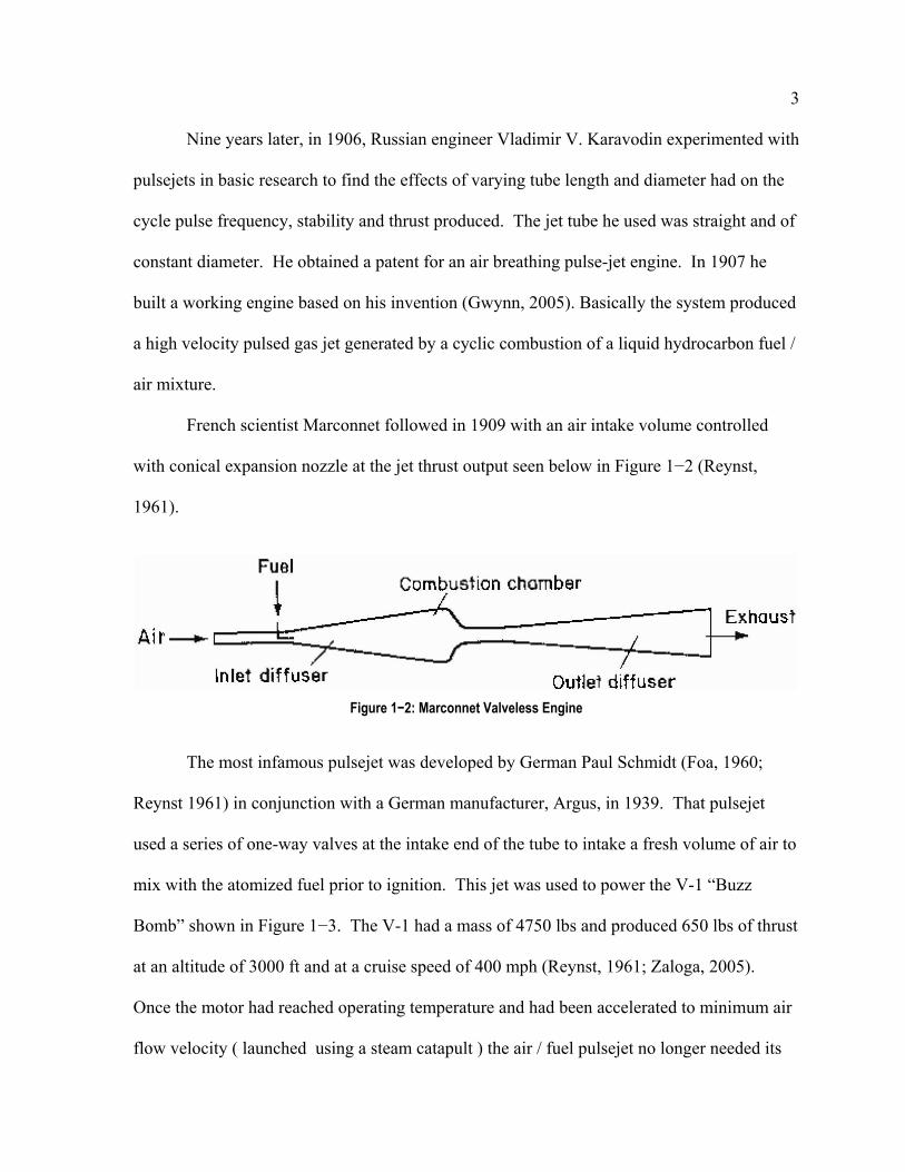
French scientist Marconnet followed in 1909 with an air intake volume controlled
with conical expansion nozzle at the jet thrust output seen below in Figure 1−2 (Reynst,
1961).
Figure 1−2: Marconnet Valveless Engine
The most infamous pulsejet was developed by German Paul Schmidt (Foa, 1960;
Reynst 1961) in conjunction with a German manufacturer, Argus, in 1939. That pulsejet
used a series of one-way valves at the intake end of the tube to intake a fresh volume of air to
mix with the atomized fuel prior to ignition. This jet was used to power the V-1 “Buzz
Bomb” shown in Figure 1−3. The V-1 had a mass of 4750 lbs and produced 650 lbs of thrust
at an altitude of 3000 ft and at a cruise speed of 400 mph (Reynst, 1961; Zaloga, 2005).
Once the motor had reached operating temperature and had been accelerated to minimum air
flow velocity ( launched using a steam catapult ) the air / fuel pulsejet no longer needed its

4
electrical ignition system and continued to run thanks to reflected pressure waves from the jet
output nozzle that opened the valves, compressed the new intake charge, and ignited it.
Figure 1−3: German V-1 ‘Buzz Bomb’ Pulsejet Powered Cruise Missile
The reliability of V-1 jets was very good and directly related to the simplicity of the
design and the minimum number of working parts. The statistical chance of something
breaking or failing to function increases with the number of components and the complexity
of the system. Plus since these were expendable, a cheap technology was desirable. The V-1
pulsejet was first used as a weapon against England on the 13th of June 1944 one week after
the start of the D-Day allied invasion and thus became the first cruise missile (Zaloga, 2005).
Despite the V-1's limitations, the US military was very interested in its capabilities. In
July 1944, captured V-1 components were shipped to Wright-Patterson Field in Ohio for

5
evaluation. Within three weeks, the USAF had built their own V-1, which was designated the
"Jet Bomb 2 (JB-2)" (Goebel, 2005).
In August of 1944, the USAAF placed an order for 1,000 JB-2s, these JB-2s’ had an
improved guidance system when compared with that of the V-1. Ford built the PJ-31 pulse-
jet engine and Republic built the airframe. Other manufacturers built the control systems,
launch rockets, launch frames, and remaining components. At the end of World War II there
where parallel development programs undertaken in Russia, France, and the United States to
produce new pulsejet rockets (Goebel, 2005).
The JB-2s were launched off of a rail with a solid rocket booster, compared to the
steam catapult system that the Germans used. The USAF then experimented with air-
launching the JB-2. Most of the launches were from a B-17 bomber, though some were
performed from B-24s and B-29s. The Air Force was so enthusiastic with the results that they
increased the order for JB-2s to 75,000 in January 1945. However, the end of the war in
August dampened enthusiasm for the weapon, and the program was terminated in September
of that year. 1,200 JB-2’s had been built (Goebel, 2005).
The US Navy also experimented with its own V-1 variant, the "KUW-1 Loon". The
Loon weighed 5000 lbs and cruised at 425 mph. Two submarines, the USS Carbenero and
the USS Cusk, and a surface vessel, the USS Norton Sound, were modified to launch the
KUW-1. In February 1947, the Cusk successfully launched a Loon (Goebel, 2005). The
flying bomb was stored in a watertight hanger on the deck of the submarine, and assembled
and launched by solid rocket boosters while the submarine was on the surface. Today the US
Navy uses Tomahawk cruise missiles in a similar manner; however they are stored in torpedo
tubes or converted ballistic missile tubes.

6
The Russians are also believed to have built copies of the V-1, and the French
operated a target drone based on the V-1 and designated the "Arsenal 5.501" well into the
1950s, though it differed from the original design in having twin tailfins and was radio
controlled (Goebel, 2005).
After World War II was over, there were many new engines to choose from. The jet
age was born. Pulsejets were placed on the shelf as the gas turbine engine took over due to
its reliability and significantly better specific fuel consumption. While the race to the moon
was nearing an end, there was a desire for jetpacks and hovering vehicles. Lockwood and
Hiller performed a small study on the jets.
The Lockwood-Hiller design, a valveless variant, was patented in 1963 (Lockwood,
1963). This variant works off of the same principles of the Marconnet design, however the
tube was bent into a U-shape to have thrust going in the same direction from both the inlet
and exhaust. An example of this can be seen in Figure 1−4.

7
Figure 1−4: U-Shape Pulsejet
The advantage of the Lockwood design is its simplicity, with no moving parts, and
low production cost. With the use of thrust augmenters, sleeves that use the unsteady
operation of the jet to draw in more air and thus increase the mass flux, 9:1 thrust to weight
ratios have been claimed.
However, despite this advantage, pulsejets are currently not considered to be a
practical power plant due to their high fuel consumption, low efficiency, and very high noise
levels. Model pulsejets were produced by Jet Dyne in the US just after the war and called the
Dyna Jet 1. That engine produced 5 lbs of thrust. Today a company called Bailey Machine
Services (BMS) produces a relatively identical pulsejet model for airplane modelers and
hobbyists with the same thrust figures; both are valved models.

8
Pulsejet engines are generally characterized by extreme simplicity, low cost of
construction, high reliability, poor fuel economy and very high noise levels. The high noise
levels make them impractical for applications other than military. However efforts have been
made to reduce these levels. Pulsejets have been used to power tip-driven experimental
helicopters. With the engines attached to the extreme ends of the rotor blades they have the
benefit of not producing the usual reaction torque upon the fuselage, thus the helicopter may
be built without a tail rotor and its associated complexity and weight, greatly simplifying the
aircraft. Pulsejets have also been used in both tethered as well as radio-control aircraft. Even
with all of these achievements, not much research has gone in to the optimization and
understanding of the fundamentals of pulsejet operations.
1.2 Related Work
In 1949, Cornel Aeronautical Laboratory was working on a project for the US Navy,
called Project Squid. The focus of the report was to investigate the operation of valveless
pulsejets. The jets they used are of similar size to that of the experiments performed in this
work. The difference being that the jet was fed a metered amount air, which allowed for the
calculation of thrust. They experimented with different fuels and injection methods.
Methane turned out to be the best fuel to use since it was already in gaseous form and did not
have to overcome the latent heat of vaporization; it also performed better than propane in
some situations. Various tail lengths were tested as well as exit configurations. A
commercially available, liquid fueled, valved version was tested for comparative results.
They then tried to convert it to propane and were unsuccessful. Tailpipe lengths were varied
and showed that there was a minimum TSFC reached at 16 inches in exhaust length for that
configuration. They also note that there were some intermediate lengths were resonance was

9
not achievable. Since both fuel and air were controlled, mixture fractions were also
controlled, it was found that at the lean limit, the pressure was higher, yet the frequency was
lower (Logan 1951).
In October of 1951, Raymond Bertin analyzed an Escopette pulsejet shown in Figure
1−5. An Escopette pulsejet is similar to a Marconnet pulsejet in that it has no valves, and
instead, uses an ‘air diode’ to control the fluid. According to their research of the 1950’s, the
inlet has no preferred frequency; this along with its high reliability and ease of using constant
fuel pressure for feeding made it very attractive. Unfortunately the ‘air diode’ also allows air
to flow back out of it, thus reducing thrust so a 180o bend was placed at the front (Bertin,
1951).
Figure 1−5: Escopette valveless pulsejet
The American Helicopter Company tried to use pulsejets as tip-propulsion for rotors,
thus relaxing the need for an anti-torque tail rotor. Tests were performed at various altitudes
and noise tests were conducted as well. They found that as the altitude was increased and
density decreased, the jet became more and more difficult to start. All data was converted to
‘standard data’ for comparison purposes. As suspected, a decrease in thrust was noted as air
density decreased (Emmerich, 1953).

10
In 1963, Hiller Aircraft Company looked into U-Tube pulsejets. They experimented
with many ways to increase thrust as well for the purpose of making a lightweight engine.
They tested several exit geometries and combustion chamber designs. They found that
changing the combustion chamber shape had a dramatic effect on thrust and efficiency with
TSFC levels less than 2.0 pph/lb. Small inlet lips showed the best results, whereas large bell
mouth inlets did not work that well. They found that fuel injection worked best inside the
combustion chamber next to the edge of the diverging section, shown below in Figure 1−6,
as ‘B (Lockwood, 1963)’.
Figure 1−6: Fuel Injection Location
1.3 Pulsejet Cycle
A pulsejet’s operation can be explained by combining two-cycles: the Lenoir Cycle
which consists of isentropic compression followed by constant volume heat addition and then
adiabatic expansion and the Humphrey Cycle, which operates similarly but has an isentropic
compression added to the cycle. Pulsejets typically have a very small compression ratio that

11
reaches a maximum at around 1.7. The Lenoir three cycle process can be seen below in
Figure 1−7.
Figure 1−7: Lenoir Cycle
The process consists of the intake of air and fuel at point a, isochoric combustion
from a to b, and an adiabatic expansion to c. The Humphrey Cycle is shown below, Figure
1−8 and adds a small amount of compression before combustion, step a to b. This holds true
for both valved and valveless models.

12
Figure 1−8: Humphrey Cycle

13
2. Experimental Apparatus and Setup
The goal of these experiments was to determine the effects of different inlet diameters
as well and inlet and exhaust lengths on valveless jet performance. The fuels used in these
experiments were liquid ethanol and gaseous propane. Starting with liquid in the valved
engine was a good point of departure because this is the conventional configuration.
Modifications were then made to test a valveless version and the fuel was switched to
propane for simplicity as well as superior mixing qualities due to the propane being a
gaseous fuel. Since the jet's purpose was to be involved in computational modeling as well
as scaling down, propane was a logical choice.
2.1 Pulsejets
2.1.1 Bailey Machine Service Valved Jet
A BMS pulsejet, Figure 2−1, was purchased as an off-the-shelf model and then
modified and instrumented for temperature and pressure measurements.
Figure 2−1: Standard BMS Pulsejet
Initially, ports were placed on the jet at three different axial locations. These access
ports were designed to allow for connection of thermocouples as well as pressure transducers
to monitor the jet’s behavior at separate locations during operation. The locations chosen
14
were right behind the valve face, after the converging section, and at the exit plane. Later,
two more ports were added to determine where combustion was taking place as shown in
Figure 2−1. One was placed at the end of the combustion chamber, and the other half way
down the exhaust tube. These access ports needed to be cooled due to the high speed
pressure transducers sensitivity to temperature, so copper tubing was wrapped around them
and water was forced through it. Cooling seemed to be adequate. The jet was then cut 1 ¾”
from the tip of the exhaust so that extensions could be added to increase the length. This was
necessary due to the flaring at the tip. This was done to allow assessment of the jet’s
performance at different lengths. Another data port was placed on the flared tip right before
the flare so that it was possible to collect exit pressure and temperature data.
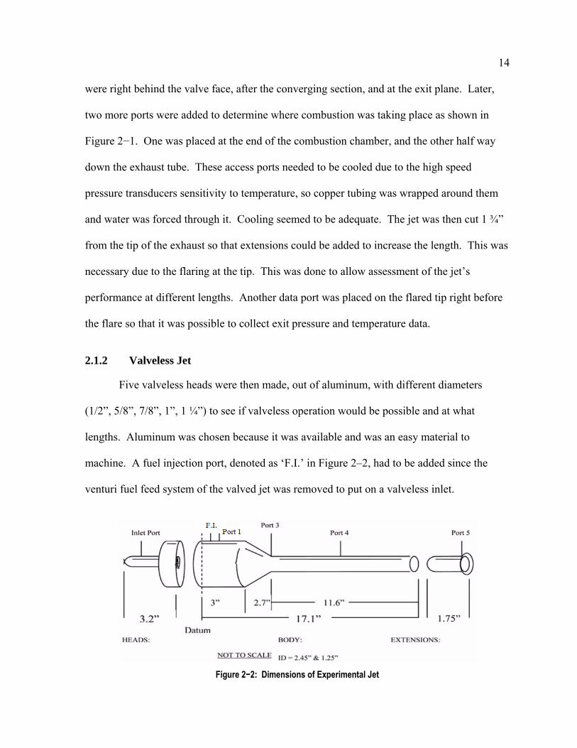
2.1.2 Valveless Jet
Five valveless heads were then made, out of aluminum, with different diameters
(1/2”, 5/8”, 7/8”, 1”, 1 ¼”) to see if valveless operation would be possible and at what
lengths. Aluminum was chosen because it was available and was an easy material to
machine. A fuel injection port, denoted as ‘F.I.’ in Figure 2–2, had to be added since the
venturi fuel feed system of the valved jet was removed to put on a valveless inlet.
Figure 2−2: Dimensions of Experimental Jet

15
The thermal load was too much for the aluminum heads, resulting in the melting of
the threads and run time was severely limited to avoid this problem, so three of the working
inlets were re-made, this time out of steel. After many runs, the jet started to deform due to
thermal stresses, two replacement jets were purchased. One of them had just a fuel injection
port welded on to it, while the other had a fuel injection port as well as eight ports added for
measurements. The new ports were placed in pairs, offset by 90o at the four axial locations
that are shown in Figure 2–2. Note that there is no port 2. This was due to similar data at
ports 1 and 2 along with the determination that the original port 1 was in a recirculation zone
since as a whole, all the pressures were lower. The first pair of ports was placed in the
middle of the original ports 1 and 2, directly downstream of the fuel injector, while the last 3
axial locations remained in the same locations. A computational flow visualization also
showed a recirculation zone right behind the valve face, where port 1 is located.
2.2 Cooling System
A new cooling system was designed for these ports because of the loss of a
thermocouple on a 15 centimeter class pulsejet due to heat exposure. Instead of copper
tubing, water jackets were made to protect the thermocouple, seen in Figure 2−3. These
water jackets provided much better heat transfer since the water was in actual contact with
the port, instead of having a layer of copper in between. At the front of the jet, port 1, it was
necessary to use the old method of copper tubing wrapped around the port. Due to the
proximity of the fuel injector port, there was insufficient room for the copper water jacket, so
tubing was used, this time twice as much.

16
Figure 2−3: Ports with Water Jackets added to BMS Jet
2.3 Inlets
A second set of inlets were made with a fixed diameter of ½” but lengths varying
between 1 and 3 inches in 1 inch increments. After some experimentation a fourth inlet was
made out of steel, with adjustable lengths. This ½” inlet was made with 3 pieces so that the
length could be set at 1”, 2”, and 3”. The inlet selection can be seen below in Figure 2−4.
Figure 2−4: First Set of Steel Inlets

17
2.4 Fuel Delivery
Fuel was fed in to the system, via a precision needle valve and flow rate was
measured with a 0-30 SLPM (air) Hastings Flow Meter and Hastings Instruments Model 40
flow meter (Figure 2−5). This meter was able to measure flow rates up to 25.5 SLPM of
Propane with an accuracy of +/- 0.1 SLPM. This affected the measurement of the upper
throttleability limits of the 7/8” and 1” inlets because they were able to run at higher flow
rates that could not be accurately measured with the flow meter.
Figure 2−5: Hastings Model 40 Flow Meter
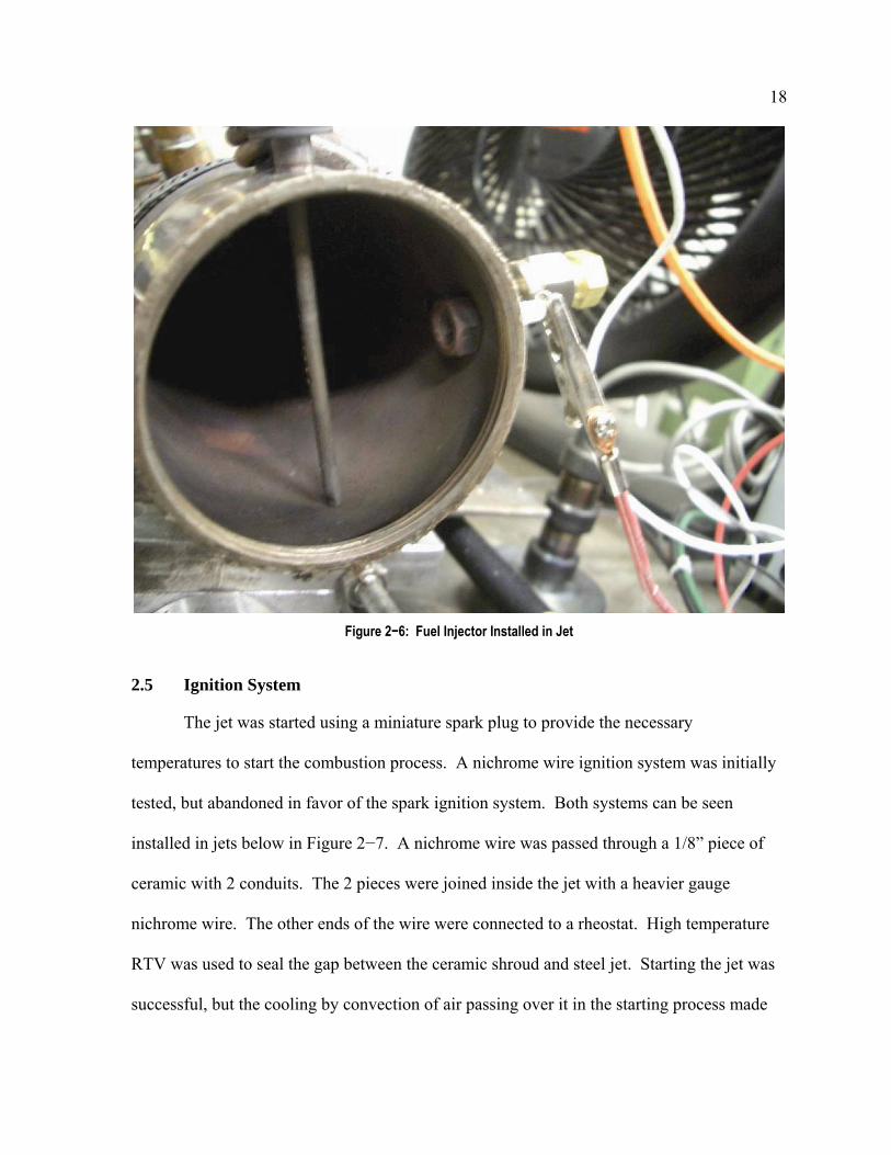
The selected fuel injector was picked from a group of three injectors. The most
reliable one was chosen based on the ability to start the jet run after run. The other injectors
performed better at certain conditions, but the selected injector had the best overall
performance. The chosen injector, shown in Figure 2−6, was made of 1/8” stainless steel and
spanned the entire jet combustion chamber. Twenty 1/16” holes were drilled through parallel
to one another and 180o offset.
18
Figure 2−6: Fuel Injector Installed in Jet
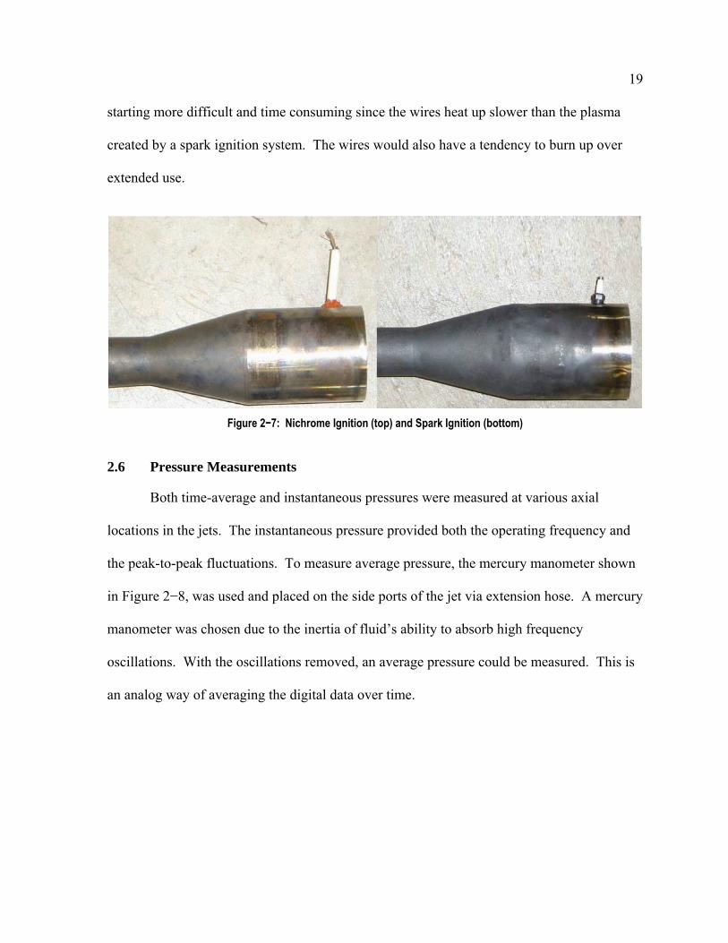
2.5 Ignition System
The jet was started using a miniature spark plug to provide the necessary
temperatures to start the combustion process. A nichrome wire ignition system was initially
tested, but abandoned in favor of the spark ignition system. Both systems can be seen
installed in jets below in Figure 2−7. A nichrome wire was passed through a 1/8” piece of
ceramic with 2 conduits. The 2 pieces were joined inside the jet with a heavier gauge
nichrome wire. The other ends of the wire were connected to a rheostat. High temperature
RTV was used to seal the gap between the ceramic shroud and steel jet. Starting the jet was
successful, but the cooling by convection of air passing over it in the starting process made
19
starting more difficult and time consuming since the wires heat up slower than the plasma
created by a spark ignition system. The wires would also have a tendency to burn up over
extended use.
Figure 2−7: Nichrome Ignition (top) and Spark Ignition (bottom)
2.6 Pressure Measurements
Both time-average and instantaneous pressures were measured at various axial
locations in the jets. The instantaneous pressure provided both the operating frequency and
the peak-to-peak fluctuations. To measure average pressure, the mercury manometer shown
in Figure 2−8, was used and placed on the side ports of the jet via extension hose. A mercury
manometer was chosen due to the inertia of fluid’s ability to absorb high frequency
oscillations. With the oscillations removed, an average pressure could be measured. This is
an analog way of averaging the digital data over time.

20
Figure 2−8: Mercury Manometer
For instantaneous pressure, a Kulite XTE-190-5G pressure transducer was used and
connected to a 12-V battery. A battery was required because the initially used AC to DC
inverter created too much noise in the data and was replaced. This pressure transducer was
connected to an HP54503A Oscilloscope. Data was then transferred to a P2 400MHz
computer via a National Instruments GPIB Card. This allowed for data to be put in to a

21
spreadsheet for analysis. The data was then shifted by an offset so that the average pressure
of a cycle equaled the average pressure measured by the manometer.
2.7 Thermocouples
Type-B thermocouples were used. These thermocouples were custom made, using a
junction of two slightly different types of metal, in this case platinum and platinum /
rhodium. Type-B thermocouples were chosen due to their high temperature capability,
reliably, and ability to withstand the harsh environment of the jet. The junction of two
dissimilar metals produces a temperature dependent voltage. The wires were passed through
ceramic material due to its ability to withstand high temperatures. A 1/4" cap was drilled out
and the ceramic was epoxied so that when installed, the thermocouple would be in the
centerline of the jet. An example is shown below in Figure 2−9. The voltage was measured
with a Pentium 4 computer via a data acquisition card with a maximum input of 4 Hz per
channel. Three thermocouples were used to test the jets temperature at various locations
along the jet. The various lengths were chosen to get the probe in the centerline of the jet.
Figure 2−9: Completed Type-B Thermocouple
Laboratory ambient temperature was measured using a simple thermometer shown in
Figure 2−10.
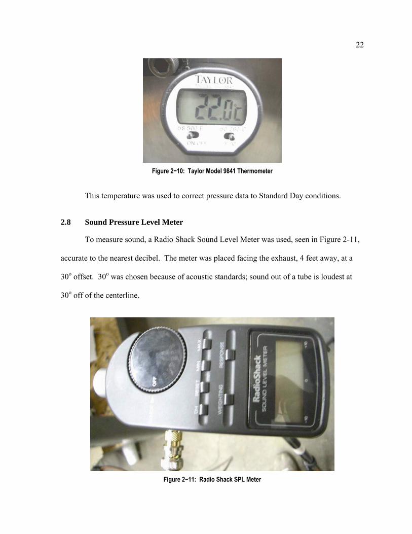
22
Figure 2−10: Taylor Model 9841 Thermometer
This temperature was used to correct pressure data to Standard Day conditions.
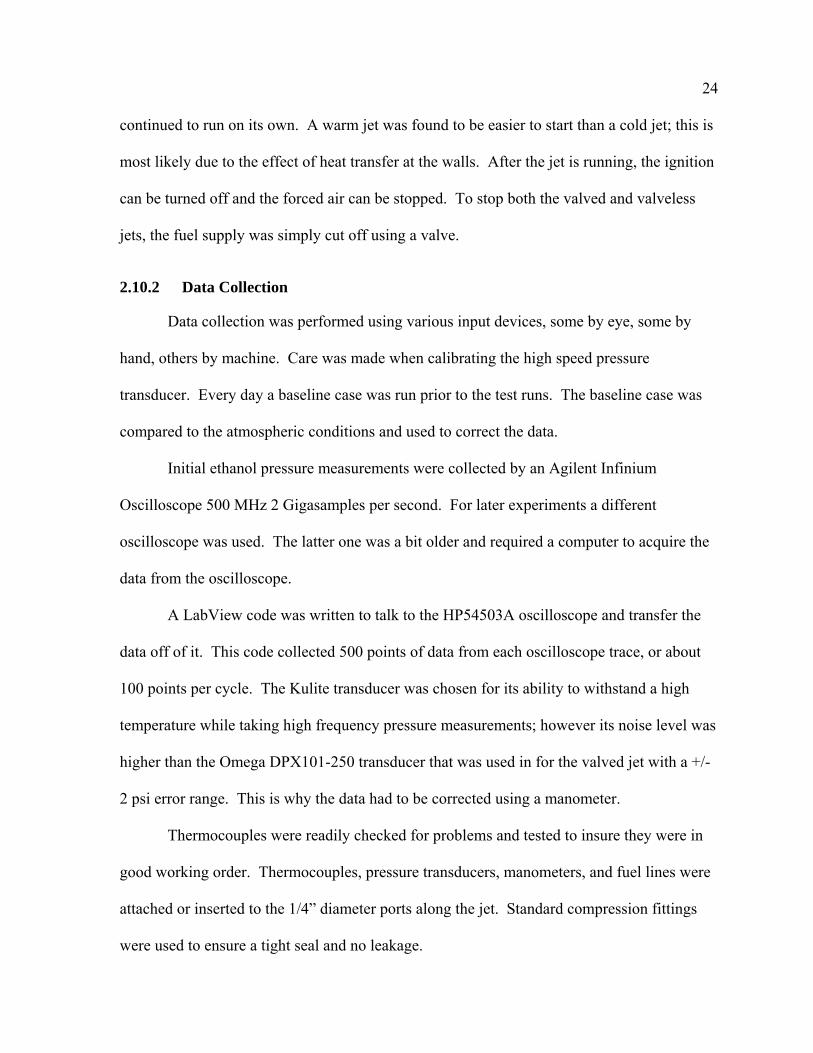
2.8 Sound Pressure Level Meter
To measure sound, a Radio Shack Sound Level Meter was used, seen in Figure 2-11,
accurate to the nearest decibel. The meter was placed facing the exhaust, 4 feet away, at a
30o offset. 30o was chosen because of acoustic standards; sound out of a tube is loudest at
30o off of the centerline.
Figure 2−11: Radio Shack SPL Meter

23
2.9 Thrust Stand
The pulsejet was secured to a low-friction linear bearing assembly made by Tusk with
a custom aluminum plate. Aluminum mounting brackets held the jet to the plate and the jet
was secured to them using steel bands. A linear potentiometer was connected to a steel plate
that was secured to the linear bearing assembly. The other side was connected to the table
via an anchor point. Power was supplied to the potentiometer by a DC Power Supply set to
10 V. Distance versus voltage was then calculated to be 0.4 in/V. A spring with a spring
constant of 1.1 lb/in was used to obtain the force applied. After several failed attempts, it
was decided that thrust could not be measured using the geometry we were testing since it
has two opposing exhaust pipes and the thrust was too small to discern. Various inlets were
tried with the same result. It should be noted that when fed air, the jet would pull itself
toward the air source.
2.10 Procedures
2.10.1 Starting of the Jet
Starting the pulsejet began with two things, the need to supply the first intake of air
and a way to ignite the mix of fuel and air. The valved pulsejet had a fuel delivery system
based off of venturi tubes which utilize Bernoulli’s principle which states that as air velocity
increases, static pressure decreases. This decrease in static pressure caused by the incoming
air pulled fuel through holes tangential to the surface. These small holes created a fine mist
of droplets that entered the combustion chamber, vaporized and mixed with air after passing
over the valves. In the valveless configuration, the fuel used was gaseous propane and was
directly injected in to the combustion chamber behind the inlet. After the mixture entered the
chamber, it was ignited by a spark. After the initial combustion events occur, the engine
24
continued to run on its own. A warm jet was found to be easier to start than a cold jet; this is
most likely due to the effect of heat transfer at the walls. After the jet is running, the ignition
can be turned off and the forced air can be stopped. To stop both the valved and valveless
jets, the fuel supply was simply cut off using a valve.
2.10.2 Data Collection
Data collection was performed using various input devices, some by eye, some by
hand, others by machine. Care was made when calibrating the high speed pressure
transducer. Every day a baseline case was run prior to the test runs. The baseline case was
compared to the atmospheric conditions and used to correct the data.
Initial ethanol pressure measurements were collected by an Agilent Infinium
Oscilloscope 500 MHz 2 Gigasamples per second. For later experiments a different
oscilloscope was used. The latter one was a bit older and required a computer to acquire the
data from the oscilloscope.
A LabView code was written to talk to the HP54503A oscilloscope and transfer the
data off of it. This code collected 500 points of data from each oscilloscope trace, or about
100 points per cycle. The Kulite transducer was chosen for its ability to withstand a high
temperature while taking high frequency pressure measurements; however its noise level was
higher than the Omega DPX101-250 transducer that was used in for the valved jet with a +/-
2 psi error range. This is why the data had to be corrected using a manometer.
Thermocouples were readily checked for problems and tested to insure they were in
good working order. Thermocouples, pressure transducers, manometers, and fuel lines were
attached or inserted to the 1/4” diameter ports along the jet. Standard compression fittings
were used to ensure a tight seal and no leakage.

25
3. Parametrics / Performance
3.1 BMS Valved Tests
Various measurements were taken at different lengths to gather a general
understanding of how the jet operates as well as give a baseline for any comparisons to the
valveless variant. To understand the cycle times of the BMS pulsejet, a HeNe laser was used
to illuminate the valve pedals from the front, and a high speed camera was used to take
images at 2000 Hz. The illumination was needed due to the cameras speed and light
sensitivity. Since the jet operates at around 230 Hz, roughly nine frames per cycle were
obtained. When observed, the valves were open during 33% of the cycle. This means that
the intake of air is happening only 1/3 of the cycle.
In order to gauge the volume and temporal extent of the actual combustion process,
CH* measurements were taken. CH* is an intermediate radical that is only present during
combustion and can be detected by looking at the 433 nm band of the electromagnetic
spectrum. A photomultiplier tube was connected to a fiberoptic cable that was then
connected to each of the ports added to the jet. If CH* was present, combustion was
occurring. It was determined that CH* was detectable up to the converging section of the jet.
After that section, no CH* emission was observed.
CH* was compared to the combustion chamber pressure and is shown below in
Figure 3−1. It shows that combustion is occurring during about 45% of the cycle.

26
Figure 3−1: CH* vs. Combustion Chamber Pressure
Fuel consumption for the valved jet was determined by weighing the fuel as the jet
was running. Data was taken every 30 seconds and was used to compute the average fuel
consumption. This was tested at various lengths. The lowest consumption occurred with a
six inch extension added to the jet, 2.4 g/s. This is compared to the stock length fuel
consumption of 2.5 g/s, and the nine inch extension fuel consumption of 2.6 g/s.
Pressure measurements were taken at two ports along the jet and can be seen in
Figure 3−2. The pressures at ports 1 and 2 were very similar both in shape and in peak
pressure with port 2 being slightly lower. On later jets, they were consolidated in to one port
that was located half way between them.

27
Figure 3−2: Pressure Plot for Valved Jet
Temperature measurements were also taken and can be seen in Figure 3−3. This
figure shows the starting process of the jet as well as part of the cool down phase.
Figure 3−3: Valved Jet Temperature vs. Time

28
The highest temperature is reached in the converging section immediately following
the combustion chamber.
3.2 Valveless Tests
Measurements similar to that of the valved jet were taken, not only at various lengths,
but various inlet diameters as well. The overall test data can be seen in Table 3−1.

29
Table 3−1: Overall Test Results
Inlet Length (in.) 3 3 2 3 3 3 32 3 3 3 3 3
Diameter (in.) 0.625 0.875 0.5 0.5 0.625 0.875 1 0.5 0.5 0.625 0.875 1
Exhaust Extension Length (in.) 3 3 6 6 6 6 6 9 9 9 9 9
High Flow Rate 19.5 18.7 10 10 22.5 >25.5 >25.5 12.5 12 22.7 25.5 25.5
Low Flow Rate 8 11.5 7 7 6.5 10.6 15.5 4.2 3.9 5.5 11.7 16
Range 11.5 7.2 3 3 16 N/A N/A 8.3 8.1 17.2 13.8 9.5
Thro
ttlea
bilit
y
(SLP
M P
ropa
ne)
% of Max 0.41 0.61 0.70 0.70 0.29 N/A N/A 0.34 0.33 0.24 0.46 0.63
High SPL (dB) 114 118 108 112 110 120 121 107 110 116 118 120
Aco
ustic
s
Low SPL (dB) 111 115 108 107 105 109 116 102 105 105 113 115
Test Fuel Flow Rate (SLPM) 14.8 14.8 10 10 14.8 20 20 10 10 14.8 20 20
Operating Frequency (Hz) 220 253 200 183 214 244 259 198 178 196 223 246
SPL (dB) 114 117 108 112 108 118 118 107 110 111 117 118
30
For each inlet a fuel flow was chosen based on throttle range as well as the ability to
compare to other inlets / data analysis. For instance the flow rate for the 1/2” inlet was 10
standard liters per minute (SLPM). This flow rate was chosen due to the ability of the jet to
run at all working inlet lengths, the 2 and the 3 inch, as well as a series of extension lengths.
The 5/8” jet was run at 14.8 SLPM to match with computational data. The 7/8” and 1” inlets
were both run at 20SLPM, except for the 3” exhaust condition where the 1” would not run at
any flow rate and the 7/8” would not run at any rate below 18.7 SLPM. In that case, it was
run at 14.8 SLPM to compare to the 5/8” inlet.
Since the flow meter will not measure past 25.5 SLPM, which is the recorded data for
any condition that reaches it. Those numbers should be taken to read “at least 25.5 SLPM”.
This affected how the throttleability range is depicted. Decibel measurements were taken 4
feet away at a 30o offset and recorded at the highest and lowest throttleability limits with the
intent of correlating these measurements with pressure and indirectly with thrust.
Long term cycle histories were used to determine the average operating frequency
over an average of 40 cycles. Short term cycle histories were recorded initially at 5 ports. It
was determined that ports 1 and 2 yielded similar results so they were consolidated in to one
port, a new port 1, in which its location was in the middle of the two ports when the second
jet was made. The second jet had four ports, and does not have a port 2 due to the
consolidation of the ports mentioned earlier.
Temperatures were recorded at three locations along the centerline for each case. The
inlet temperature was taken by using a thermocouple held directly in front of the inlet, the
second was placed after the converging section of the combustion chamber. In some
instances, the thermocouple in the combustion chamber did not register any temperature,
31
though it was glowing red. It was analyzed and swapped out with a known working
thermocouple and the same results were obtained. In instances where there were no
combustion chamber readings, they are left off of the figures. The final temperature port was
the exhaust exit. The thermocouple was placed ½” in to the exhaust stream, before the flare.
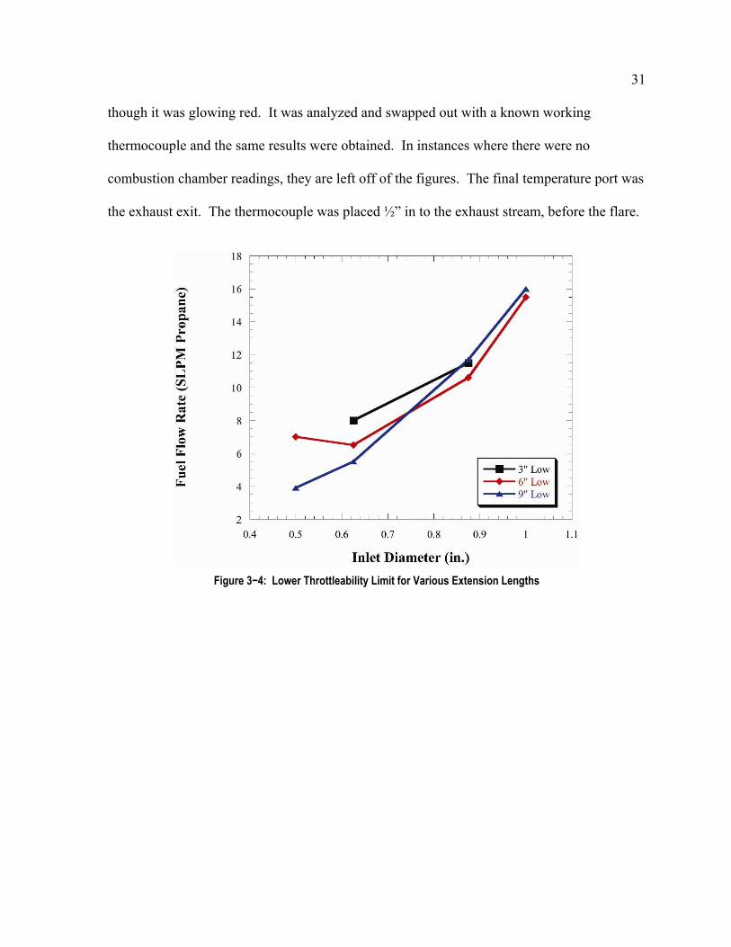
Figure 3−4: Lower Throttleability Limit for Various Extension Lengths

32
Figure 3−5: Lower Throttleability Limits for Various Inlets
Comparing the fuel flow rate to the inlet diameter, shown in Figure 3−4 and Figure
3−5, it shows that as the inlet diameter is increased, more fuel is required to run the jet. This
is due to the amount of air that is ingested in each cycle. Adding various extensions shows
the same trend, which is an increase in fuel required. Longer extensions allow a wider
variety of inlets to operate and allow lower fuel flow rates to be obtained.
When compared with extension length, the required fuel flow rate is also affected,
though not as drastically as it is affected with changes in the inlet diameter. Inlet length is
compared here as well for the ½” Inlet. It was run at 2 and 3 inches in length using 6” and 9”
extensions. The trends are similar with the shorter inlet having a slightly higher, lower limit.
As the inlets increase in diameter, the slope of their lines turns from negative to positive.
The 7/8” inlet seems to have a minimum of 10.3 SLPM at 6” exhaust extension length.

33
Figure 3−6: Upper Throttleability for Various Extension Lengths
Figure 3−7: Upper Throttleability for Various Inlet Diameters

34
Figures 3−6 and 3−7 show that the limits of the flow meter are 25.5 SLPM propane.
Inlets that reach those values should be read as “at least that amount”. Each inlet appears to
plateau at some point, but that could not be tested with the current setup. A larger mass flow
meter would be needed in order to obtain accurate readings. Inlet diameter has a much
greater effect on the upper limit of the flow rate than the inlet length does. This makes sense
due to a larger inlets ability to ingest more air per cycle due to a larger circumference and
cross-sectional area.
At shorter exhaust lengths, only two inlets could be successfully started, as the
exhaust length increased, more inlets were able to be started. The larger inlets tend to have a
larger fall off in the upper limit at shorter lengths. Inlet length has a small effect on the upper
throttleability range with the 2” performing just slightly better than the 3” at longer exhaust
lengths.
Figure 3−8: Temperature vs. Exhaust Length for ½” Inlet (3” Long)
35
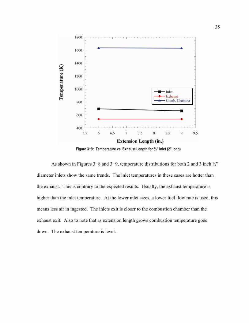
Figure 3−9: Temperature vs. Exhaust Length for ½” Inlet (2” long)
As shown in Figures 3−8 and 3−9, temperature distributions for both 2 and 3 inch ½”
diameter inlets show the same trends. The inlet temperatures in these cases are hotter than
the exhaust. This is contrary to the expected results. Usually, the exhaust temperature is
higher than the inlet temperature. At the lower inlet sizes, a lower fuel flow rate is used, this
means less air in ingested. The inlets exit is closer to the combustion chamber than the
exhaust exit. Also to note that as extension length grows combustion temperature goes
down. The exhaust temperature is level.

36
Figure 3−10: Temperature vs. Exhaust Length for 5/8” Inlet
Figure 3−11: Temperature vs. Exhaust for 7/8” Inlet

37
The 5/8” has the same trends except the exhaust temperature is getting closer to the
inlet temperature as shown in Figure 3−10. The inlet and exhaust temperatures are
unaffected by length. The larger inlets are cooler than the exhaust and this seems to be due
to the large amounts of air that are ingested at higher fuel flow rates. The exhaust
temperature seems to reach a maximum at 6” in length as can be seen in Figure 3−11.
Figure 3−12: Temperature vs. Exhaust Length for 1” Inlet
At 1”, Figure 3−12, the exhaust temperature is much higher than the inlet temperature
and it increases with increasing length. Extensions for a long enough jet were not available
to test these trends fully. It is important to note that in Figures 3−1 and 3−12 the combustion
chamber pressure was not measured. This is due to some anomaly with the flow field in that
location. Different thermocouples were placed in the same location with the same results.

38
Figure 3−13: Jet Temperatures vs. Inlet Diameter +3” Extension, 3” Long Inlet
Figure 3−14: Jet Temperatures vs. Inlet Diameter +6” Extension, 3” Long Inlet
39
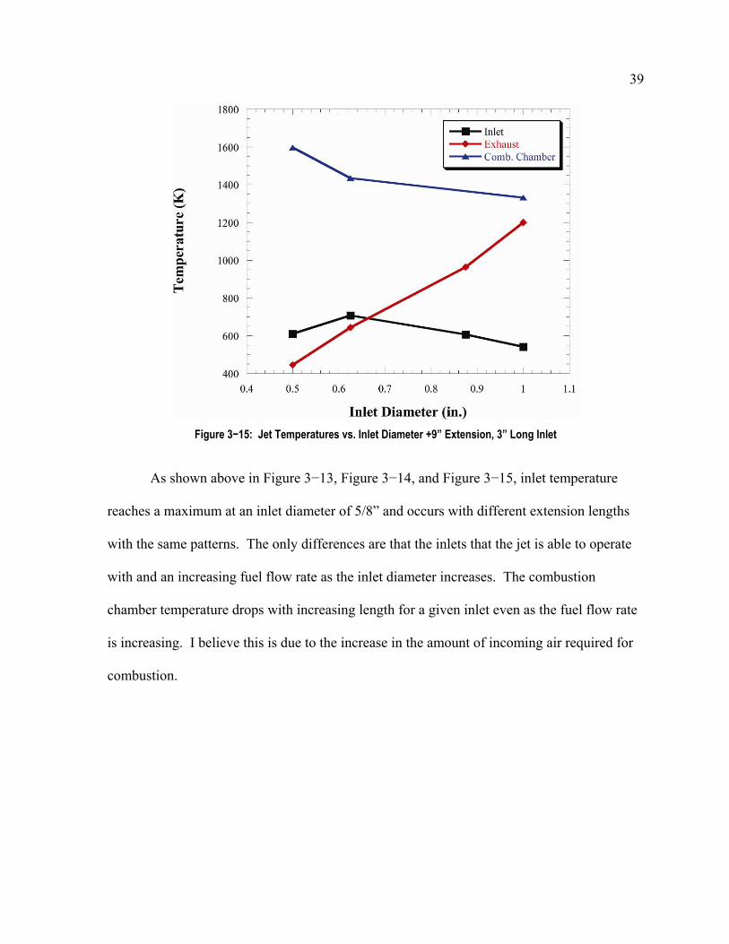
Figure 3−15: Jet Temperatures vs. Inlet Diameter +9” Extension, 3” Long Inlet
As shown above in Figure 3−13, Figure 3−14, and Figure 3−15, inlet temperature
reaches a maximum at an inlet diameter of 5/8” and occurs with different extension lengths
with the same patterns. The only differences are that the inlets that the jet is able to operate
with and an increasing fuel flow rate as the inlet diameter increases. The combustion
chamber temperature drops with increasing length for a given inlet even as the fuel flow rate
is increasing. I believe this is due to the increase in the amount of incoming air required for
combustion.
40
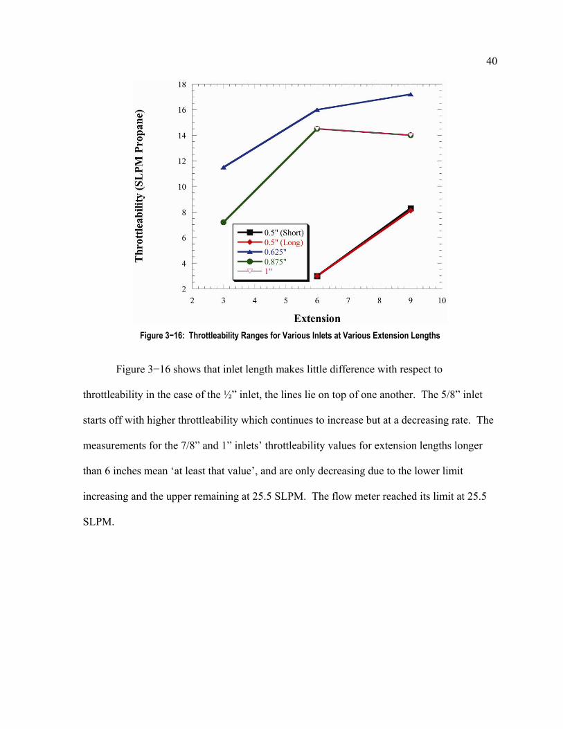
Figure 3−16: Throttleability Ranges for Various Inlets at Various Extension Lengths
Figure 3−16 shows that inlet length makes little difference with respect to
throttleability in the case of the ½” inlet, the lines lie on top of one another. The 5/8” inlet
starts off with higher throttleability which continues to increase but at a decreasing rate. The
measurements for the 7/8” and 1” inlets’ throttleability values for extension lengths longer
than 6 inches mean ‘at least that value’, and are only decreasing due to the lower limit
increasing and the upper remaining at 25.5 SLPM. The flow meter reached its limit at 25.5
SLPM.

41
Figure 3−17: Operational Envelope based on Inlet and Exhaust Length
Figure 3−18: Throttleability Ranges for Various Extension Lengths with Various Inlets

42
In Figure 3−17, the pairs of lines above in each figure represent the upper and lower
limits for each configuration. In Figure 3−18, the ½” Inlet was run with 2 different lengths,
the standard of 3” and on 2 occasions, 2” length. They are denoted in the legend as (2). It
also suggests an initial rise in upper limit with added exhaust length followed by a level
period. Smaller inlets start at longer lengths, as do larger inlets.
Shorter exhaust lengths have tighter envelops, larger inlet diameters are not depicted
correctly due to the limit of the flow meter, but the trend is still seen to be the same as with
the others.
Figure 3−19: Operating Frequency as a Function of Exhaust Length for Various Inlets
As expected, Figure 3−19 shows that the frequency decreases as exhaust length is
increased. This happens in all cases. As the inlets diameter decreases, so does the frequency,
this also expected. This suggests that both play a role in the operational frequency of the jet.

43
Figure 3−20: Operating Frequency as a Function of Various Inlets at Various Exhaust Lengths
The inlet diameter to frequency again shown in Figure 3−20, show a strong relation to
inlet diameter. Length is shown to have a less dramatic effect. Pressure was also measured
from three ports, ports 1, 3, and 5. Data from port 4 was not taken since it was of little value,
other than comparing with computational work at the inception of the project. Ports 1 and 3
are similar, but have slight differences due to a growing effective combustion chamber.

44
Figure 3−21: Change in Port 1 Pressure vs. Inlet Diameter
Figure 3−21 shows the change in port 1 pressure as a function of inlet diameter. Each
line is for a different extension length. The trend shows that as inlet diameter is increased,
the change in pressure reaches a maximum. The 3” extension would only allow half of the
inlets to operate, the 6” shows a decline in ΔP between the largest inlets. For the 9”
extension the decline from 7/8” to 1” inlet is negligible. The longer the inlet, the more stable
the jet, its ΔP is less sensitive to inlet diameter changes. As jet length decreases, the slopes in
the curves get steeper and the operability range of the jet is affected at the low end by the
ability to make enough pressure.
45
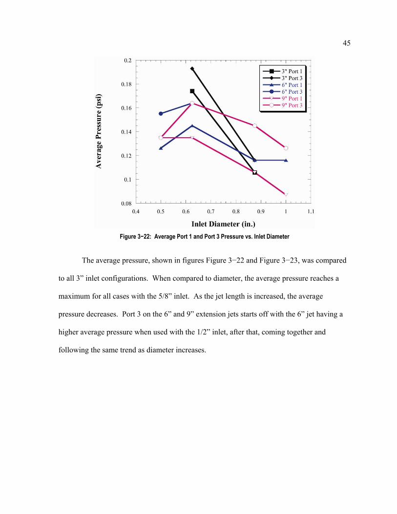
Figure 3−22: Average Port 1 and Port 3 Pressure vs. Inlet Diameter
The average pressure, shown in figures Figure 3−22 and Figure 3−23, was compared
to all 3” inlet configurations. When compared to diameter, the average pressure reaches a
maximum for all cases with the 5/8” inlet. As the jet length is increased, the average
pressure decreases. Port 3 on the 6” and 9” extension jets starts off with the 6” jet having a
higher average pressure when used with the 1/2” inlet, after that, coming together and
following the same trend as diameter increases.
46
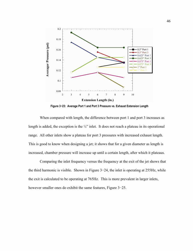
Figure 3−23: Average Port 1 and Port 3 Pressure vs. Exhaust Extension Length
When compared with length, the difference between port 1 and port 3 increases as
length is added, the exception is the ½” inlet. It does not reach a plateau in its operational
range. All other inlets show a plateau for port 3 pressures with increased exhaust length.
This is good to know when designing a jet; it shows that for a given diameter as length is
increased, chamber pressure will increase up until a certain length, after which it plateaus.
Comparing the inlet frequency versus the frequency at the exit of the jet shows that
the third harmonic is visible. Shown in Figure 3−24, the inlet is operating at 255Hz, while
the exit is calculated to be operating at 765Hz. This is more prevalent in larger inlets,
however smaller ones do exhibit the same features, Figure 3−25.

47
Figure 3−24: 2nd Harmonic Visible in Exhaust Frequency for 1” Inlet
Figure 3−25: 2nd Harmonic Visible in Exhaust Frequency for 1/2” Inlet

48
The prevalence in larger inlets is due to a higher fuel flow rate which leads to a higher
sound pressure level. Harmonics are amplified more with higher SPL’s. This is expected
because as sound pressure levels are increased, it increases the amplification of harmonics.
This data was taken using the Kulite pressure transducer, the data has a lot more noise than
the DPX-101 pressure transducer, however it yields more consistent results.

49
4. Helmholtz Resonators and Quarter Wave Tubes
4.1 Helmholtz Resonators
A Helmholtz resonator is a container of gas with an open hole or neck. A volume of
air in and near the open hole vibrates because of the 'springiness' of the air inside. This
applies to containers in which the wavelength of sound is much longer than the dimensions
of the container. The following equation shows that the frequency, f, is inversely
proportional to the square root of the tube length since c, the speed of sound, V, the volume
and S, the area, are constant.
The Helmholtz resonator model was chosen due to the similarities with the inlet of
the jet. The valveless pulsejet’s inlet acts like a resonator since it shares the same
combustion chamber as the exhaust, the combustion chamber acts like a spring or
compliance. Since the volume of the combustion chamber is much larger than the volume of
the inlet, it is a safe assumption.
4.2 Quarter-wave Tubes
A quarter wave tube is defined as a tube with one end sealed off and one end open. It
is similar to a Helmholtz resonator, but different in that it has no cavity behind it. The
equation for its frequency is
The actual pulsejet has a combustion chamber attached to the exhaust so this
compliance alters the equation. After conducting tests with the valved jet, it acted like a

50
mixture between the two resonant cavities. It acts closer to a ‘1/6’ wave tube due to valves
opening and closing in each cycle. A quarter wave tube does a good job at describing the
exhaust, in general, since the changes in frequency mimic that of how the exhaust operates.
The valveless inlet is simulated as a Helmholtz resonator due to its size and relatively small
impact on overall frequency. Neither the ½ nor the ¼ wave model simulate the operation of
the pulsejet due to area changes. Area changes cause reflections of the wave and this is what
determines the frequency of the jet. The 1/6 wave does model the operational frequency very
well at this scale.
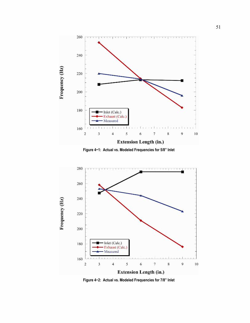
Since both of these equations depend on the speed of sound, they are temperature
dependant. Figures 4−1 and 4−2, actual versus modeled frequencies for 5/8” and 7/8” inlets,
show the calculated Helmholtz and 1/6 wave tube frequencies compared to the actual
operating frequency of the jet. The Helmholtz frequency, shown with squares, increases with
increasing exhaust length and then remains steady after 6” has been added. This is mostly
due to the temperature changes and the effects on the speed of sound. The 1/6 wave tube
frequency, shown with diamonds, decreases as length is added, this is expected. The actual
operating frequency lies in the middle of those two lines and is shown as triangles.
51
Figure 4−1: Actual vs. Modeled Frequencies for 5/8” Inlet
Figure 4−2: Actual vs. Modeled Frequencies for 7/8” Inlet

52
For the 5/8” Inlet there is a point of intersection at the 6” Exhaust Length. That
location is where the model is predicting that both the inlet and exhaust frequencies match
and they match with the measured frequency as well.
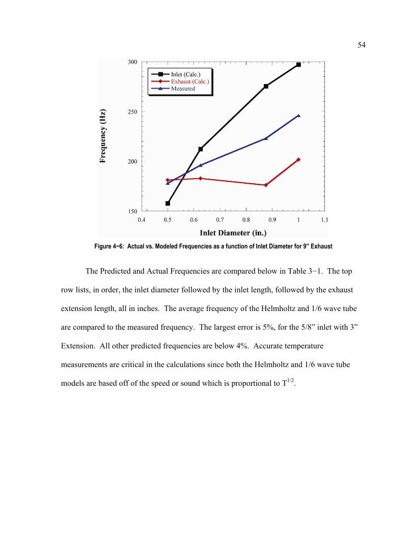
When compared to different lengths, the inlets effect is shown below in Figure’s 4−3,
4−4, 4−5, and 4−6. All Inlets show a similar trend where the theoretical Helmholtz
frequency is increasing as length is added and the theoretical 1/6 wave frequency is
decreasing as length is added. For the smaller inlets there is a point at which they are equal.
For the 1” inlet, they have already passed that point and are growing further from one
another. The average frequency still predicts the jet frequency however.
Figure 4−3: Actual vs. Modeled Frequencies for 1” Inlet

53
Figure 4−4: Actual vs. Modeled Frequencies as a function of Inlet Diameter for 3” Exhaust
Figure 4−5: Actual vs. Modeled Frequencies as a function of Inlet Diameter for 6” Exhaust
54
Figure 4−6: Actual vs. Modeled Frequencies as a function of Inlet Diameter for 9” Exhaust
The Predicted and Actual Frequencies are compared below in Table 3−1. The top
row lists, in order, the inlet diameter followed by the inlet length, followed by the exhaust
extension length, all in inches. The average frequency of the Helmholtz and 1/6 wave tube
are compared to the measured frequency. The largest error is 5%, for the 5/8” inlet with 3”
Extension. All other predicted frequencies are below 4%. Accurate temperature
measurements are critical in the calculations since both the Helmholtz and 1/6 wave tube
models are based off of the speed or sound which is proportional to T1/2.

55
Table 4−1: Actual Frequency Compared to Calculated
5/8 3 3 7/8 3 3 1/2 2 6 1/2 3 6 5/8 3 6 7/8 3 6 1 3 6 1/2 2 9 1/2 3 9 5/8 3 9 7/8 3 9 1 3 9
Inlet frequency Hz 208 247 196 164 213 275 291 192 158 212 275 297
Exhaust frequency Hz 254 258 216 212 214 211 216 187 181 183 176 202
Measured Jet Freq Hz 220 253 200 183 214 244 259 198 178 196 223 246
Average Frequency Hz 231 253 206 188 214 243 253 189 169 198 226 249
Avg/Measured 1.05 1.00 1.03 1.03 1.00 1.00 0.98 0.96 0.95 1.01 1.01 1.01
56
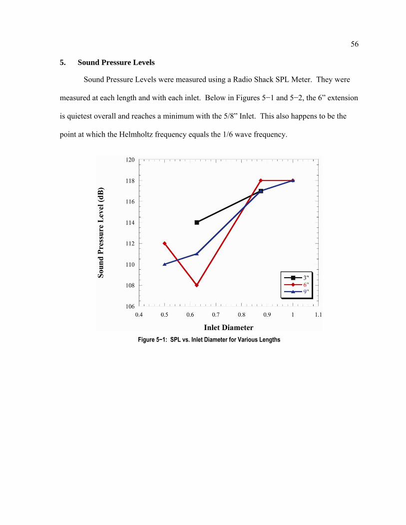
5. Sound Pressure Levels
Sound Pressure Levels were measured using a Radio Shack SPL Meter. They were
measured at each length and with each inlet. Below in Figures 5−1 and 5−2, the 6” extension
is quietest overall and reaches a minimum with the 5/8” Inlet. This also happens to be the
point at which the Helmholtz frequency equals the 1/6 wave frequency.
Figure 5−1: SPL vs. Inlet Diameter for Various Lengths

57
Figure 5−2: SPL vs. Extension Length for Various Inlets

58
6. Conclusion
The effects of lengthening the exhaust tube length on frequency are similar on both
valved and valveless jets. The valveless jet is less sensitive to changes in length than the
valved jet is, this is due to the fact that a valveless jet head behaves more like a Helmholtz
resonator and thus speeds the jet up. It is also noted that the valved jet operates closer to ¼
wave tube than the valveless. By increasing the exhaust length, the throttleability increases
as well. A maximum can be reached for certain inlets in the valveless configuration. Upper
throttleability limits plateau at specific exhaust lengths while the lower throttleability limit
continues to decrease.
The effect of changing the diameter of the inlet is that the frequency increases with
increasing diameter. The change is linear and thus it can be modeled as a Helmholtz
Resonator. The temperature effect of increasing inlet diameter is that the exhaust
temperature rises (due to it being fuel rich) and the inlet temperature decreases (due to
increased air intake).
The current configuration produces little thrust due to the experimental setup that
includes opposing inlet / exits. The exhaust exit geometry is sensitive to shape. A flared tip
is preferred and sometimes required for operation. The 50 centimeter class pulsejet can be
modeled as the average of the inlet’s Helmholtz frequency and the exhaust’s 1/6 wave tube
frequency.
Highest average combustion pressure occurs with 5/8” inlet, this is due to the flow
not fully expanding at high fuel flow rates and combustion occurring in exhaust tube.
Combustion chamber peak pressures are significantly higher for valved jets.

59
7. Future Work
Investigating this phenomenon at different scale sizes is important and should be
verified. The combustion chamber volume should have a sleeve inserted in to it to reduce the
volume and see how it affects the operating frequency. A CH* test should be performed to
check for combustion at the ports downstream of combustion chamber for higher fuel flow
rates. Skin temperatures should be measured axially along the jet to help model the jet
computationally. A U-tube or rearward facing inlet should be used to create measurable
thrust and calculate thrust specific fuel consumption.

60
References
1. Bertin, Raymond, “Overview of the Escopette Pulsejet”, SNECMA Note E.S.VII-29, http://www.pulse-jets.com/phpbb2/files/escopette.pdf, October 1951
2. Emmerich, L., "Development of pulse-jet engines for a helicopter rotor system, summary report," Report No. 163-W-1, American Helicopter Company, January 1953
3. Foa, J. V., Elements of Flight Propulsion, John Wiley & Sons, New York, 1960.
4. Goebel, Greg, “The V-1 Flying Bomb”, http://www.axishistory.com/index.php?id=1362, August 2005
5. Gwynn, John, “The History of the Pulse Jet “, http://waterocket.explorer.free.fr/vlflyingbomb.htm, August 2005
6. Le Bot, Dr. Jean and Gwynn, John, “Désiré Thomas Piot”, http://waterocket.explorer.free.fr/piot.htm, August 2005
7. Lockwood, R. M., "Pulse reactor lift-propulsion system development program, final report", Advanced Research Division Report No. 508, Hiller Aircraft Company, March 1963.
8. Logan, J. G., Jr., “Summary report on valveless pulsejet investigation,” Project SQUID Technical Memo No. CAL-42, Cornell Aeronaut. Laboratory, October 1951.
9. Piot, Désiré Thomas, 1898, “Improvements in Steam Generators applicable for Propelling Boats”, GB189726823
10. Reynst, F. H., “Pulsating firing for steam generators,” Pulsating Combustion, M. W. Thring, ed., Pergamon Press, New York, 1961.
11. Science Toy Maker, http://www.sciencetoymaker.org/boat/index.htm, November 2005
12. Zaloga, Steven, V-1 Flying Bomb 1942-52 : Hitler's Infamous 'Doodlebug', Osprey Publishing, January 2005
13. Zamyatina, L. I., The centenary of N. E. Zhukovsky's memoir "On the motion of a rigid body with cavities filled by a homogeneous fluid", Istor. Metodol. Estestv. Nauk, 1986
Related Documents