ABSTRACT Title of thesis: DESIGN OF AN ANTHROPOMORPHIC ROBOTIC HAND FOR SPACE OPERATIONS Emily Tai, Master of Science, 2007 Thesis directed by: Associate Professor David L. Akin Department of Aerospace Engineering Robotic end-effectors provide the link between machines and the environment. The evolution of end-effector design has traded off between simplistic single-taskers and highly complex multi-function grippers. For future space operations, launch payload weight and the wide range of desired tasks necessitate a highly dexterous design with strength and manipulation capabilities matching those of the suited astronaut using EVA tools. The human hand provides the ideal parallel for a dexterous end-effector design. This thesis discusses efforts to design an anthropomorphic robotic hand, focusing on the detailed design, fabrication, and testing of an individual modular finger with considerations into overall hand configuration. The research first aims to define requirements for anthropomorphism and compare the geometry and motion of the design to that of the human hand. Active and passive ranges of motion are studied along with coupled joint behavior and grasp types. The second objective is to study the benefits and drawbacks of an active versus passive actuation systems. Tradeoffs between controllability and packaging of actuator assemblies are considered. Finally,

Welcome message from author
This document is posted to help you gain knowledge. Please leave a comment to let me know what you think about it! Share it to your friends and learn new things together.
Transcript

ABSTRACT
Title of thesis: DESIGN OF AN ANTHROPOMORPHICROBOTIC HAND FOR SPACE OPERATIONS
Emily Tai, Master of Science, 2007
Thesis directed by: Associate Professor David L. AkinDepartment of Aerospace Engineering
Robotic end-effectors provide the link between machines and the environment.
The evolution of end-effector design has traded off between simplistic single-taskers
and highly complex multi-function grippers. For future space operations, launch
payload weight and the wide range of desired tasks necessitate a highly dexterous
design with strength and manipulation capabilities matching those of the suited
astronaut using EVA tools.
The human hand provides the ideal parallel for a dexterous end-effector design.
This thesis discusses efforts to design an anthropomorphic robotic hand, focusing
on the detailed design, fabrication, and testing of an individual modular finger with
considerations into overall hand configuration. The research first aims to define
requirements for anthropomorphism and compare the geometry and motion of the
design to that of the human hand. Active and passive ranges of motion are studied
along with coupled joint behavior and grasp types. The second objective is to study
the benefits and drawbacks of an active versus passive actuation systems. Tradeoffs
between controllability and packaging of actuator assemblies are considered. Finally,

a kinematic model is developed to predict tendon tensions and tip forces in different
configurations. The results show that the measured forces are consistent with the
predictive model. In addition, the coupled joint motion shows similar behavior to
that of the human hand.

DESIGN OF AN ANTHROPOMORPHICROBOTIC HAND FOR SPACE OPERATIONS
by
Emily Tai
Thesis submitted to the Faculty of the Graduate School of theUniversity of Maryland, College Park in partial fulfillment
of the requirements for the degree ofMaster of Science
2007
Advisory Committee:Associate Professor David L. Akin, Chair/AdvisorAssistant Professor Sean HumbertDr. Mary Bowden

c© Copyright by
Space Systems Laboratory
University of Maryland
2007

DEDICATION
To my mom and dad:
Thank you for giving me the opportunity to succeed and
for always being there along the way.
ii

ACKNOWLEDGMENTS
Along the ever winding and seemingly unending path that was my thesis, I
was extremely fortunate to have so many people that helped me along the way. I
am deeply grateful for everyone who helped me make it to the end.
My first thanks go to the faculty, staff, and students at the Space Systems Lab.
Not only have you helped and supported me over the past few years, you’ve also
made it an amazing environment to work in. You inspire creativity and persistance
and have been the biggest influence on me at Maryland since I started as a lab
undergrad. Thanks to Dave for all the opportunities you’ve given me. Thank
you Dave Hart for making me a reasonably competent person. Thanks to all the
grad students for all your support and for the much-needed distractions. Mike, I’m
impressed we survived putting up with each other for the past 35,000 hours straight.
A special thanks to Madeline, without whom nothing would have gotten done. Kiwi,
thanks for keeping me sane.
My greatest thanks go to my family. Thank you mom and dad for always
believing in me and pushing me to my limits. Thanks to my big sister, who has
been an inspiration my whole life.
Rich, thanks for reminding me to stop for a minute and look up at the sky.
iii

TABLE OF CONTENTS
List of Tables vi
List of Figures vii
List of Abbreviations ix
1 Introduction 11.1 Motivation . . . . . . . . . . . . . . . . . . . . . . . . . . . . . . . . . 11.2 Organization of Thesis . . . . . . . . . . . . . . . . . . . . . . . . . . 4
2 Robotic Hand Designs 52.1 Industrial Grippers . . . . . . . . . . . . . . . . . . . . . . . . . . . . 52.2 Early Hands . . . . . . . . . . . . . . . . . . . . . . . . . . . . . . . . 6
2.2.1 Utah/MIT Hand . . . . . . . . . . . . . . . . . . . . . . . . . 72.2.2 Salisbury Hand . . . . . . . . . . . . . . . . . . . . . . . . . . 8
2.3 Barrett Hand . . . . . . . . . . . . . . . . . . . . . . . . . . . . . . . 92.4 Gifu Hand . . . . . . . . . . . . . . . . . . . . . . . . . . . . . . . . . 112.5 CyberHand . . . . . . . . . . . . . . . . . . . . . . . . . . . . . . . . 122.6 Shadow Hand . . . . . . . . . . . . . . . . . . . . . . . . . . . . . . . 132.7 Robonaut Hand . . . . . . . . . . . . . . . . . . . . . . . . . . . . . . 142.8 SSL Hand . . . . . . . . . . . . . . . . . . . . . . . . . . . . . . . . . 15
3 Design Requirements 173.1 Human Hand Anatomy . . . . . . . . . . . . . . . . . . . . . . . . . . 183.2 Anthropomorphic Requirements . . . . . . . . . . . . . . . . . . . . . 22
3.2.1 Hand Sizing . . . . . . . . . . . . . . . . . . . . . . . . . . . . 223.2.2 Joint Range of Motion . . . . . . . . . . . . . . . . . . . . . . 23
3.3 Grasp Requirements . . . . . . . . . . . . . . . . . . . . . . . . . . . 253.3.1 Grasp Classification . . . . . . . . . . . . . . . . . . . . . . . . 253.3.2 Grasp Force Requirements . . . . . . . . . . . . . . . . . . . . 263.3.3 Grasp Distribution . . . . . . . . . . . . . . . . . . . . . . . . 27
3.4 Joint Torque Requirements . . . . . . . . . . . . . . . . . . . . . . . . 29
4 Hardware Development 314.1 Hand Configuration . . . . . . . . . . . . . . . . . . . . . . . . . . . . 314.2 Finger Skeletal Structure . . . . . . . . . . . . . . . . . . . . . . . . . 32
4.2.1 Compliant Mechanism Development . . . . . . . . . . . . . . . 324.2.2 MP Joint Design . . . . . . . . . . . . . . . . . . . . . . . . . 354.2.3 Phalange Connection . . . . . . . . . . . . . . . . . . . . . . . 37
4.3 Actuation System . . . . . . . . . . . . . . . . . . . . . . . . . . . . . 404.3.1 Actuator Type Selection . . . . . . . . . . . . . . . . . . . . . 404.3.2 Tendon Forces and Motor Selection . . . . . . . . . . . . . . . 444.3.3 Component Selection . . . . . . . . . . . . . . . . . . . . . . . 46
iv

4.3.4 Packaging . . . . . . . . . . . . . . . . . . . . . . . . . . . . . 484.3.5 Passive vs. Active Actuation . . . . . . . . . . . . . . . . . . . 49
4.4 Sensors . . . . . . . . . . . . . . . . . . . . . . . . . . . . . . . . . . . 504.4.1 Position and Force Sensing . . . . . . . . . . . . . . . . . . . . 514.4.2 Tactile Sensing . . . . . . . . . . . . . . . . . . . . . . . . . . 52
5 Kinematics Analysis 545.1 Finger Kinematics . . . . . . . . . . . . . . . . . . . . . . . . . . . . 54
5.1.1 Forward Kinematics . . . . . . . . . . . . . . . . . . . . . . . 545.1.2 Inverse Kinematics . . . . . . . . . . . . . . . . . . . . . . . . 565.1.3 Velocities and Static Forces . . . . . . . . . . . . . . . . . . . 595.1.4 Jacobian Matrix . . . . . . . . . . . . . . . . . . . . . . . . . . 60
5.2 Multifingered Hand Kinematics . . . . . . . . . . . . . . . . . . . . . 625.2.1 Hand Kinematics . . . . . . . . . . . . . . . . . . . . . . . . . 625.2.2 Grasp Quality Considerations . . . . . . . . . . . . . . . . . . 63
6 Testing and Results 666.1 Test Setup . . . . . . . . . . . . . . . . . . . . . . . . . . . . . . . . . 666.2 Data/Results . . . . . . . . . . . . . . . . . . . . . . . . . . . . . . . 69
6.2.1 Coupled Joint Angles . . . . . . . . . . . . . . . . . . . . . . . 696.2.2 Tendon Forces in a Cylindrical Grasp . . . . . . . . . . . . . . 706.2.3 Active Antagonism . . . . . . . . . . . . . . . . . . . . . . . . 72
7 Conclusions & Future Work 767.1 Summary . . . . . . . . . . . . . . . . . . . . . . . . . . . . . . . . . 767.2 Future Work . . . . . . . . . . . . . . . . . . . . . . . . . . . . . . . . 77
7.2.1 Single Finger Development . . . . . . . . . . . . . . . . . . . . 777.2.2 Three-Finger Grasper . . . . . . . . . . . . . . . . . . . . . . . 787.2.3 Five-Finger Hand . . . . . . . . . . . . . . . . . . . . . . . . . 79
A Design Measurements and Calculations 81A.1 Hand Measurements . . . . . . . . . . . . . . . . . . . . . . . . . . . 81A.2 Matlab Code . . . . . . . . . . . . . . . . . . . . . . . . . . . . . . . 83
A.2.1 Leadscrew Selection Calculations . . . . . . . . . . . . . . . . 83A.2.2 Motor/Gearbox Calculations . . . . . . . . . . . . . . . . . . . 84A.2.3 Finger Force-Moment Analysis . . . . . . . . . . . . . . . . . . 85
B Component Drawings 87
C Kinematic Analysis 99C.1 Mathematica Code . . . . . . . . . . . . . . . . . . . . . . . . . . . . 99C.2 Inverse Kinematics . . . . . . . . . . . . . . . . . . . . . . . . . . . . 111
Bibliography 115
v

LIST OF TABLES
3.1 Desired Sizing for Finger Design . . . . . . . . . . . . . . . . . . . . . 23
3.2 Hand Range of Motion Requirements . . . . . . . . . . . . . . . . . . 24
3.3 Force Distribution in Cylindrical Grip[1, 2] . . . . . . . . . . . . . . . 27
3.4 Force Distribution Over Phalanges in Cylindrical Grip[1, 2] . . . . . . 28
3.5 Mean values of force centers . . . . . . . . . . . . . . . . . . . . . . . 29
3.6 Hand Geometry for �2.00′′ Cylindrical Grasp . . . . . . . . . . . . . 29
3.7 20 lb Load Distribution (all values given in lbs) . . . . . . . . . . . . 30
3.8 Joint Torques for a 20 lb Cylindrical Grasp, �2.00′′ . . . . . . . . . . 30
4.1 Comparison of Actuator Types . . . . . . . . . . . . . . . . . . . . . 43
4.2 Peak and Holding Forces for Unweighted Setup . . . . . . . . . . . . 45
5.1 Denavit-Hartenberg Parameters for Finger . . . . . . . . . . . . . . . 55
A.1 Human Forearm and Hand Measurements . . . . . . . . . . . . . . . 81
A.2 Hand Measurements . . . . . . . . . . . . . . . . . . . . . . . . . . . 82
vi

LIST OF FIGURES
1.1 Ranger TSX . . . . . . . . . . . . . . . . . . . . . . . . . . . . . . . . 3
2.1 Pivoting Jaw (top row) and Parallel Jaw (bottom row) Grippers[3] . . 5
2.2 Utah/MIT Hand . . . . . . . . . . . . . . . . . . . . . . . . . . . . . 7
2.3 Stanford/JPL Hand[3] . . . . . . . . . . . . . . . . . . . . . . . . . . 9
2.4 Barrett Hand . . . . . . . . . . . . . . . . . . . . . . . . . . . . . . . 10
2.5 Gifu Hand . . . . . . . . . . . . . . . . . . . . . . . . . . . . . . . . . 11
2.6 CyberHand concept . . . . . . . . . . . . . . . . . . . . . . . . . . . . 12
2.7 Shadow Dexterous Hand . . . . . . . . . . . . . . . . . . . . . . . . . 13
2.8 Robonaut . . . . . . . . . . . . . . . . . . . . . . . . . . . . . . . . . 15
2.9 SSL Hand[4] . . . . . . . . . . . . . . . . . . . . . . . . . . . . . . . . 16
3.1 Bones and Joints of the Hand . . . . . . . . . . . . . . . . . . . . . . 19
3.2 Direction of Joint Motion . . . . . . . . . . . . . . . . . . . . . . . . 20
3.3 Relation Between PIP and DIP Flexion, Right Index Finger[5] . . . . 21
3.4 Bio-Concepts Hand Measurement Chart[6] . . . . . . . . . . . . . . . 22
3.5 Finger joint angle flexion for varying cylinder diameters, averagedover digits II-V . . . . . . . . . . . . . . . . . . . . . . . . . . . . . . 28
4.1 Cross section of compliant hinge . . . . . . . . . . . . . . . . . . . . . 35
4.2 Exploded View of MP Joint . . . . . . . . . . . . . . . . . . . . . . . 36
4.3 Assembled MP Joint . . . . . . . . . . . . . . . . . . . . . . . . . . . 36
4.4 Exploded View of Finger . . . . . . . . . . . . . . . . . . . . . . . . . 39
4.5 Full Finger Assembly (palm not shown) . . . . . . . . . . . . . . . . . 39
4.6 Projected Actuation Tendon Forces . . . . . . . . . . . . . . . . . . . 44
4.7 Experimentally Derived Tendon Forces . . . . . . . . . . . . . . . . . 46
vii

4.8 Actuator Packaging in Forearm . . . . . . . . . . . . . . . . . . . . . 49
5.1 Kinematic Structure of Individual Finger . . . . . . . . . . . . . . . . 54
6.1 Side View & Close-Up of Load Cells/Top Plate . . . . . . . . . . . . 67
6.2 Close-up of Load Cell Attachment and Top Plate . . . . . . . . . . . 68
6.3 PIP-DIP Joint Coupling . . . . . . . . . . . . . . . . . . . . . . . . . 70
6.4 Tendon Tensions for Applied Loads on a 1.25′′ Diameter CylindricalGrasp . . . . . . . . . . . . . . . . . . . . . . . . . . . . . . . . . . . 71
6.5 DIP Flexion for Varying Antagonistic Tendon Tensions . . . . . . . . 73
6.6 PIP Flexion for Varying Antagonistic Tendon Tensions . . . . . . . . 73
6.7 Tip Force vs Joint Torque . . . . . . . . . . . . . . . . . . . . . . . . 74
C.1 Geometric View in Arm Plane . . . . . . . . . . . . . . . . . . . . . . 113
viii

LIST OF ABBREVIATIONS
CATs Crew Aids and ToolsCNS Central Nervous SystemDH Denavit-HartenbergDIP Distal InterphalangealDOF Degrees of FreedomEAP Electroactive PolymerEMG ElectromyographyEVA Extravehicular ActivityIEEM Interchangeable End Effector MechanismIP InterphalangealJPL Jet Propulsion LaboratoryMIT Massachusetts Institute of TechnologyMP MetacarpophalangealPIP Proximal InterphalangealPNS Peripheral Nervous SystemSMA Shape Memory Alloy
ix

Chapter 1
Introduction
Robots have the potential to play a large role in our world. They are currently
widely used in industrial applications for labor-intensive operations that require a
high level of precision and repetition. In addition, robots can be found in the
entertainment industry in the form of toys and animatronics. The function of robots
in society is constantly evolving and current research endeavors to bring them further
into the realm of domestic assistance, medicine, military, search and rescue, and
exploration. In many of these applications, the robot must perform only one specific
task and thus can be designed to handle a single operation. However, as the potential
use for robots grows, so does their need to interact with objects in their environment.
The design of end effectors that can pick up a variety of objects and utilize them as
tools is a significant challenge in robot development.
1.1 Motivation
Single function end effectors such as parallel jaws, tools drives, and specialized
grippers are commonly seen on robotic systems today. These interfaces have the
benefit of simplicity in design and thus increased reliability and reduced maintenance
costs. However, in order to perform multiple tasks, a single robot would need to
have either multiple arms with different end effectors or the ability to swap end
1

effectors. Situations requiring greater flexibility thus need a more universal method
to interact with the environment.
Robots for space exploration applications, such as planetary surface sampling
and extravehicular activity (EVA) operations, typically benefit from a more univer-
sal, high-dexterity end effector. For EVA operations in particular, there are currently
242 crew aids and tools (CATs) and interfaces that are used during tasks performed
outside the space shuttle. Several more exist for other operational purposes and in
developmental stages for future use. Among the many categories of CATs and in-
terfaces are common wrench and cutter type tools, drive tools, power and electrical
equipment, restraints, and adapters[4]. Each of these CATs is designed to be used
by a suited astronaut. For a robot to be of assistance in general EVA operations, it
must be able utilize all the required CATs and interfaces. The options are thus to
design a different robot for each job, provide a single robot with a large set of tool
and gripper attachments, or design an end effector capable of the same grasps as a
suited astronaut.
The Ranger Telerobotic Shuttle Experiment (TSX), developed by the Space
Systems Lab at the University of Maryland, College Park, was designed to demon-
strate on-orbit telerobotic servicing technologies (Figure 1.1). Ranger’s design con-
cept views the end-effector as the tool, rather than the interface to the tool. Thus,
the Ranger TSX arms utilize a specialized set of interchangeable end-effectors that
can use EVA interfaces. The primary weakness in this system is the number of spe-
cialized tools needed to complete a job, particularly on extended servicing missions.
As the number increases, the total cost to design, manufacture, and launch a full
2

set of end-effectors becomes prohibitive. In addition, each individual end-effector is
limited in mobility as the Interchangeable End Effector Mechanism (IEEM) allows
for a maximum of two degrees of freedom (DOF)[7]. Tasks requiring high dexterity
are thus unachievable by this system.
Figure 1.1: Ranger TSX
A final issue with the interchangeable mechanism is the need to swap out
end-effectors between tasks. If the robot is not capable of performing the change
on its own, a human operator must intervene, which either places a human in the
environment or halts work while the robot is removed for exchange. Though Ranger
has demonstrated its ability to perform complex servicing missions, the use of a
single, highly dexterous end-effector would eliminate many of the restrictions of
single function end-effectors.
The human hand is a prime example of a high dexterity end-effectors. The
hand is capable of a multitude of power and precision grasps. It is thus able to pick
up a wide range of objects and utilize them as tools in various fashions. Research
in robotic hand design has ranged from simplified opposing grippers to highly an-
thropomorphic designs. For the purposes of EVA operations, a human hand serves
3

as the basis for all tools and thus makes a good basis for a robotic equivalent.
This research examines the design and analysis of an anthropomorphic end ef-
fector for use in EVA and exploration operations. To achieve these goals, the struc-
ture and use of the human hand as applied to a robotic design is examined. The
scope of this thesis also establishes the requirements for anthropomorphic grasping
of EVA CATs and interfaces and details the design of a finger and it’s configura-
tion within a robotic hand. In addition, a kinematic model is built and testing is
done to demonstrate anthropomorphic geometry and operational capability in EVA
applications.
1.2 Organization of Thesis
The scope of this thesis is to document the design of an anthropomorphic
robotic end effector, compare it’s performance to that of a human hand, and examine
the related kinematics.
Chapter 2 discusses previous robotic end-effector development. Character-
ization of human hand geometry and performance as well as the derived design
requirements are outlined in Chapter 3. Chapter 4 describes the development pro-
cess and final design. The kinematic model is explained in Chapter 5. Chapter 6
details the testing process. Finally, Chapter 7 summarizes the results of testing and
future work to advance the state of the design.
4

Chapter 2
Robotic Hand Designs
2.1 Industrial Grippers
Grasping and manipulation needs have driven end effector development in
various directions. Dedicated task devices such as welders, bolt drivers, and paint
sprayers may be better suited than the human hand to perform specific tasks. In
many cases, these end effectors may be more efficient and economical than complex
hand designs. As a result, dedicated task devices are commonly found in industrial
robotics. However, general use grippers are necessary to advance the field of robotics.
The two leading general end effector designs in the industrial market today are
pivoting finger grippers and parallel jaw grippers (Figure 2.1). Both types are low
dexterity and are thus limited in their applications.
Figure 2.1: Pivoting Jaw (top row) and Parallel Jaw (bottomrow) Grippers[3]
5

Turret and quick-change grippers are utilized in an effort to make up for the
low dexterity of pivoting and parallel grippers. In order to perform a wider range
of tasks, the turret gripper rotates between various individual end effectors. The
turret provides a fast and simple method for alternating between tools, but is large
in size and limited to a finite set of grippers. The quick-change gripper selects
from grippers stored externally on a rack, much like the Ranger IEEM previously
described. While providing a smaller end effector interface than the turret, this
method is still limited by the number of individual tools available.
Industrial end effector design is primarily driven by providing commercially
viable products that can function in an assembly line system. However, as the use
of robots for non-specialized tasks expands, so does the need for a high dexterity
end effector. To achieve this level of robotic sophistication, universities and research
institutions are studying the control, compact design, and kinematics problems that
must be solved to produce a fully anthropomorphic hand.
2.2 Early Hands
The first high dexterity robotic hands were developed in the 1980s. These
initial research-oriented designs utilized various quasi-anthropomorphic configura-
tions and actuation systems. Intended to broaden the study of mechanical design,
kinematics, and control, many of the early hands are still in use in universities and
corporate research departments today. Of these early prototypes, the two most well
known are the Utah/MIT Hand and the Salisbury Hand.
6

2.2.1 Utah/MIT Hand
The Utah/Massachusetts Institute of Technology (MIT) Dexterous Hand, shown
in Figure 2.2 below, was designed by the Center for Engineering Design at the Uni-
versity of Utah in conjunction with the Artificial Intelligence Laboratory at MIT.
Created primarily as a research tool to examine controls, tactile sensing, and anthro-
pomorphic design, it has four fingers and employs a pulley-based tendon drive[8].
Figure 2.2: Utah/MIT Handhttp://www.cs.rochester.edu/u/jag/vision/lab/UtahMIT.jpg
The overall configuration has three modular four DOF fingers mounted par-
allel to the palm plane with a non-anthropomorphic thumb orientation. Unlike the
human hand, the Utah/MIT thumb is mounted near the center of the palm in direct
opposition to the fingers. Joint mobility gives 0-95◦ for the distal hinge joints, ±25◦
for the base yaw of the fingers, and ±45◦ for the base yaw of the thumb. Despite the
non-anthropomorphic configuration, the total joint mobility allows for near natural
interaction between the thumb and fingertips.
The drive system involves 32 individual pneumatic actuators with opposing
tendons for each joint. Flat Dacron and Kevlar tendons are routed throughout the
7

system by a series of axial twists and bends over pulleys. These tendons allow for
actuators to be located remotely. However, the transmission system is prohibitively
large and bulky for practical use outside of laboratory research. The pneumatic
actuators generate 25 lbs of tendon force, resulting in a maximum tip force of 7 lbs.
In addition, the fingers can execute rapid motions at frequencies greater than 10
Hz, the minimum threshold defined by the project to perform dynamic tasks.
Integrated joint angle and tendon tension sensors provide the necessary feed-
back for control system design research. The Utah/MIT Hand utilizes Hall effect
sensors to obtain accurate joint angle information. Initially, designers hoped to place
tendon tension sensors at the joint interface. However, due to packaging problems,
the tendon force transducers were moved to the wrist. These sensors use a semi-
conductor strain gauge bridge to measure beam deflection, which is proportional to
tendon tension.
With its quasi-anthropomorphic configuration, the Utah/MIT Hand, including
its wrist, provides over 25 DOFs. While not suitable for commercial applications,
it provides an excellent research platform. Since its development, control system
experiments studying task definition, manipulation strategies, grasping functions,
and the sensor utilization have been conducted.
2.2.2 Salisbury Hand
The Salisbury Hand, previously known as the Stanford/Jet Propulsion Lab-
oratory (JPL) Hand, was developed by Kenneth Salisbury as part of his doctoral
8

dissertation. This hand also serves primarily as a research tool for studying the de-
sign and control of high dexterity robotic hands[9]. Unlike the Utah/MIT Hand, the
Salisbury Hand does not use an anthropomorphic design. The hand instead consists
of three fingers configured with one in opposition, providing a stable spherical grasp
(Figure 2.3). Each finger has three DOFs and is actuated by four Teflon-coated
cables driven by remotely located servomotors. To help compensate for the fewer
total DOFs, the distal joint of each finger has a wider range of motion than the
human joint, thus making more grasp types possible.
Figure 2.3: Stanford/JPL Hand[3]
The Salisbury Hand is equipped with tendon tension sensors, motor position
encoders, and six-axis fingertip force torque sensors for tactile operations. Maximum
output force is approximately 10 lbs with a minimum force sensing capacity of 0.01
lb. Several research institutions continue to use the Salisbury Hand to explore haptic
models, control systems, and articulated manipulation.
2.3 Barrett Hand
More recently, robotic hand research has produced increasingly dexterous,
commercially available end effectors. While many have tracked towards increasingly
9

humanoid designs, the Barrett Hand is a novel non-anthropomorphic manipulator
with considerable grasp capabilities[10]. Intended for factory usage, the Barrett
Hand is a highly programmable, three-fingered, eight-axis, reconfigurable ”grasper”
(Figure 2.4). The palm and the three articulated fingers are a self-contained unit,
weighing 1.18kg and requiring only a cable for power and communications to oper-
ate. A single motor drives each finger. A fourth motor allows two of the fingers to
spread around the palm, providing the capability to reconfigure itself.
Figure 2.4: Barrett Handhttp://www.barretttechnology.com/robot/customer/CustServ.JPG
The Barrett Hand also utilizes an innovative cable pre-tensioning system. In
order to maintain reliable, high performance of a tendon drive system, the cables
must be pre-tensioned to approximately 50% of the maximum operating tensions.
Most methods used in other cable systems are highly complex and require significant
effort. Barrett Technology endeavored to devise a simple pre-tensioning technique
that could properly tune the cables in a single action by a single person with one
hand and did not require any form of locking device. These goals were achieved
by using a worm drive to relatively counter-rotate a pinion shaft and pinion sleeve
10

relative to one another[11]. With the pinion shaft and sleeve attached to opposing
tension elements, this provides for a method to pretension the cable with the single
motion of turning the worm.
2.4 Gifu Hand
While most hand designs discussed utilize some form of cable drive, the Gifu
hand took the alternative approach of using built-in servomotors. The Gifu hand
is highly anthropomorphic with the total size of thumb, four modular fingers, and
palm being only slightly larger than the human hand. Each of the fingers has four
joints with the thumb providing four DOFs and each finger providing three DOFs.
As with the human hand, the distal finger joints are coupled in the Gifu hand. This
design uses a planar four-bar linkage mechanism to achieve the coupling.
Figure 2.5: Gifu Handhttp://robo.mech.gifu-u.ac.jp/image/title 1.jpg
Six-axis force sensors are integrated into the fingertips of the Gifu hand. In
addition, distributed tactile sensor can be integrated externally over the hand. Com-
bined with a bandwidth greater than that of the human hand, the Gifu hand provides
an excellent test bed for controls research.
11

2.5 CyberHand
Biomechatronics brings a new level of complexity to robotic hand design. The
CyberHand, developed at the Scuola Superiore Sant’Anna in Italy, is one of the
more recent efforts to bring robotic hand design and prosthetics together. For this
design goal, weight and size become a greater priority over high dexterity. Due to
the packaging constraints, the CyberHand uses miniature embedded motors instead
of a tendon system. Two motors per finger are located in the palm. While compact
and robust, this design provides a lower maximum output force than most robotic
hands designed for strict manipulation purposes. This drawback is commonly found
for embedded actuators versus tendon systems.
Figure 2.6: CyberHand concepthttp://www.cyberhand.org/
Prosthetic design also adds a new level of consideration in the field of controls.
Ideally, a prosthetic will involve a highly dexterous robotic hand that can attach
to the human arm and both feel and control naturally. Most previous work in
“natural” control interfaces have typically been limited to using electromyography
(EMG) to read the electrical signals generated by muscle contraction. The human
hand uses efferent neural signals sent from the central nervous system (CNS) to
the peripheral nervous system (PNS), controlling the muscles. Sensory information
12

Figure 2.7: Shadow Dexterous Handhttp://www.shadowrobot.com/media/pictures.shtml
from natural sensors in the hand is then sent back to the CNS by means of afferent
peripheral nerves. The CyberHand is attempting to mimic this process by designing
a neural interface and an efferent neural signal processing technique that combined,
can interface with the natural and artificial world. In addition, work is underway to
develop biomimetric sensors and utilize them to stimulate the afferent nerves, thus
sending tactile and other sensing information back to the CNS[12].
2.6 Shadow Hand
One of the most advanced anthropomorphic robotic hands today is the Shadow
Dexterous Hand. The Shadow hand is highly anthropomorphic in size and shape and
unlike all the previous designs discussed, utilizes air muscles to control the joints.
The hand uses 36 air muscles coupled to the joints by tendons in both opposing
muscle pairs and in single muscle with spring return setups. Designed to provide
comparable force output and sensitivity to the human hand, it can move at only
approximately half the speed.
The Shadow Hand has 20 DOFs, including two wrist DOFs. Each finger has
13
four joints with the distal and middle phalanges coupled, leaving three DOFs. The
thumb has five joints and five DOFs. The final hand DOF is an extra palm joint
by the little finger. A Hall effect sensor system provides information about joint
position. Tactile sensing is embedded in the fingertips and pads. Two large area
tactels are placed on the middle and proximal phalanges while the fingertips contain
34 discrete tactels, providing highly sensitive touch sensing capabilities[13].
2.7 Robonaut Hand
Looking specifically at end effector development for EVA operations, the Robotic
Systems Technology Branch at NASA Johnson Space Center has developed Robo-
naut to work on with external space structures with human interfaces. The Robo-
naut hand, shown in Figure 2.8 below, is a highly anthropomorphic, fourteen DOF
hand. The hand was designed to mimic as closely as possible the size, strength,
and kinematics of a suited astronaut hand. In addition, in order to make the device
EVA compatible, the materials and components were selected to operate under EVA
conditions.
The primary components of the Robonaut hand are the forearm which houses
all fourteen brushless motors and drive electronics, a two DOF wrist, and a five fin-
ger, twelve DOF hand. The hand is split into a dexterous work set for manipulation
and a grasping set used to maintain stable grasps. Two three DOF fingers (pointer
and middle) and a three DOF opposable thumb make up the dexterous set. As
with the previous designs, the PIP and DIP joints of the fingers are coupled. The
14

Figure 2.8: Robonauthttp://media.nasaexplores.com/03-012/robonaut2.jpg
grasping set consists of two one DOF fingers (ring and pinky) and a palm joint. All
fingers are shock mounted to the palm[14].
Flexible drive trains allow for remotely located motors in the forearm. The
motors are coupled to short, sheathed flex shafts connected to small, modular lead-
screw assemblies. The leadscrew assembly includes a load cell for force feedback and
a short cable used to actuate the joints. Yaw joint control is achieved by antagonistic
cables while the pitch joints utilize spring return.
The Robonaut hand has fewer degrees of freedom than the human hand, but
maintains a high level of dexterity. It has demonstrated the capability to manipulate
many of the CATs used by astronauts and perform several EVA tasks.
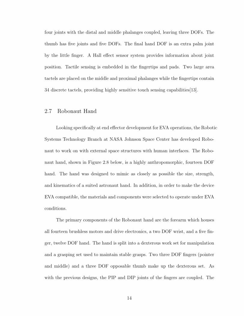
2.8 SSL Hand
Previous work in hand design for EVA applications at the Space Systems Lab
yielded the SSL Hand, a four-finger non-anthropomorphic end effector. Each finger
15
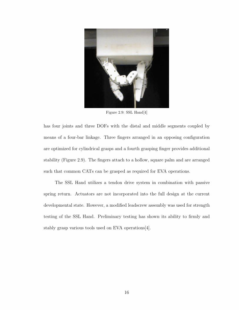
Figure 2.9: SSL Hand[4]
has four joints and three DOFs with the distal and middle segments coupled by
means of a four-bar linkage. Three fingers arranged in an opposing configuration
are optimized for cylindrical grasps and a fourth grasping finger provides additional
stability (Figure 2.9). The fingers attach to a hollow, square palm and are arranged
such that common CATs can be grasped as required for EVA operations.
The SSL Hand utilizes a tendon drive system in combination with passive
spring return. Actuators are not incorporated into the full design at the current
developmental state. However, a modified leadscrew assembly was used for strength
testing of the SSL Hand. Preliminary testing has shown its ability to firmly and
stably grasp various tools used on EVA operations[4].
16

Chapter 3
Design Requirements
The primary objective for the design described in this thesis is to produce a
robotic end effector capable of using EVA tools and interfaces. From the NASA-
STD-3000 Man-Systems Integration Standards, “hand tools shall require an actu-
ation force of less than 89N (20 lbs),” which defines the minimum required grasp
force for the gripper design[15]. In addition, the end effector must be capable of
grasping all EVA tools and have sufficient dexterity to manipulate the CATs and
interfaces.
Most commercially available general use grippers have only one or two DOFs
and thus are not suitable for the required tasks. Innovative non-anthropomorphic
robotic hand configurations have yielded highly dexterous platforms capable of a
wide range of grasps. This provides a balance between the complexity of a fully
anthropomorphic and a simplistic low DOF design. However, as EVA tools are de-
signed specifically for a suited astronaut hand, an anthropomorphic design provides
a greater parallel for EVA compatibility. Matching human hand geometry also en-
sures that the end effector will be able to operate in the same workspace as the
astronauts. The human hand has proven to be highly capable of both strength and
fine motion, making it an ideal model for general use dexterous operations. Thus,
an anthropomorphic approach was selected for the end effector design.
17

3.1 Human Hand Anatomy
In order to design an anthropomorphic hand, it is necessary to study human
osteology and syndesmology to gain an understanding of how the human hand func-
tions. The following section details the skeletal bone structure and joint types of the
human hand. This basic anthropometric description provides a basis for the robotic
hand design configuration and degrees of freedom.
The skeleton of the hand is divided into three groups: carpals, metacarpals,
and phalanges. The carpal, or wrist, bones are eight in number arranged in two
rows of four. The bones of the proximal row (that closest to the center of the body)
are named the scaphoid, lunate, triquetrum, and pisiform. These bones connect to
the two forearm bones, the radius (thumb side) and the ulna (little finger side). The
distal row of bones (those furthest from the center of the body) are the trapezium,
trapezoid, capitate, and hamate. These bones join with the five metacarpal bones
that make up the palm, which connect on the other side to the digits. Fourteen
phalanges comprise the five digits, giving a total of 27 bones in the hand. Each
finger has three phalanges (proximal, middle, and distal) while the thumb has just
two. The digits are typically referred to by the numbers I - V for the thumb, index,
middle, ring, and little fingers respectively. Figure 3.1 details the individual bones
and digit numberings.
A large set of freely movable articulations is formed by the connections of
the bones in the hand. At the wrist joint where the proximal carpals interact
with the radius in the forearm, is a condyloid articulation. In a condyloid joint,
18

Figure 3.1: Bones and Joints of the Handhttp://www.pncl.co.uk/ belcher/handbone.htm
the oval projection of one bone fits against the end of another bone and provides
two DOFs. Thus, the wrist joint is capable of flexion and extension (forward and
backward motion) as well as adduction and abduction (toward and away from the
midline of the hand). The intercarpal articulations of the proximal and distal rows
of wrist bones are arthrodial joints, allowing only for gliding motions between the
bones. However, the mid-carpal joint where the two rows move with respect to one
another has a combination of gliding joints and a cup-shaped cavity that creates
a three DOF ball-and-socket type connection. Intercarpal motion is primarily in
flexion/extension, but unlike the other carpal interactions, a very slight amount of
rotation is also permitted.
19

Figure 3.2: Direction of Joint Motion
Beyond the wrist bones are the carpometacarpal (CMC) articulations. The
joints between the carpus and the II-V metacarpal bones are all arthrodial. A small
amount of gliding motion is permitted, increasing from index to the little finger.
However, the CMC articulation of the thumb enjoys a great freedom of movement
due to its configuration as a saddle joint. Saddle joints also allow two DOFs. In the
case of the thumb CMC joint, movements permitted are flexion/extension in the
palm plane and abduction/adduction in the perpendicular palm plane. For both
saddle and condyloid joints, circumduction, where flexion, extension, abduction,
and adduction movements are combined in sequence, is also possible. The geometry
of the thumb CMC joint in relation to the rest of the hand provides opposition, one
of the primary factors allowing for a wide variety of grasps.
The metacarpophalangeal (MP) joints exist where the metacarpals meet the
proximal phalanges of the digits. For digits II-V, these articulations are condyloids
20

and permit flexion/extension as well as limited abduction/adduction. When the
fingers are flexed, abduction and adduction cannot be performed. The thumb MP
joint is more of a ginglymoid, or hinge, joint. Hinge joints only allow for flexion and
extension.
Interphalangeal (IP) articulations are the final joints of the hand. As with
the thumb MP joint, the IP joints are all hinge joints and only flexion/extension is
permitted. The capability for flexion in these joints is much greater than extension.
While the thumb has only a single IP joint, digits II-V have two separate articu-
lations, the proximal (PIP) and distal (DIP) interphalangeal joint. The motion of
these two joints are coupled together, as shown in Figure 3.3, with flexion at the PIP
joint being more extensive than at the DIP joint of the same digit. The combined
joints of the hand provide three DOFs per finger and four DOFs in the thumb for
a total of 16 DOFs, outside of the wrist. Though the wrist does allow for some
rotation, the amount is small enough that the human wrist is typically modeled as
having two DOFs[16, 17].
Figure 3.3: Relation Between PIP and DIP Flexion, RightIndex Finger[5]
21

3.2 Anthropomorphic Requirements
3.2.1 Hand Sizing
Data from multiple existing anthropometric studies was complied to determine
human hand dimension requirements. The subjects of these studies included both
males and females from various ethnic backgrounds. However, not all datasets
provided the same set of measurements. Anthropometric data was therefore taken
from only the most extensive study, that of American military males[18]. In addition,
further measurements were taken for increased detail on finger geometry. Both left
and right hands for 20 subjects were measured using the measurement chart shown
in Figure 3.4. In addition to values defined in the chart, overall hand length and
breadth were measured.
Figure 3.4: Bio-Concepts Hand Measurement Chart[6]
22
The desired geometry is based on an average American male. Given the EVA
requirement, an upper bound on end-effector sizing is defined based on dimensions
for a 95th percentile American male wearing an EVA glove. The envelope for an
EVA glove over the hand was determined by comparing glove measurements to
anthropometric data and defined as an increase of 35%. Based on the collaborated
data, a basic sizing guideline was developed for the digits (Table 3.1). Although
the dimensions for each digit differ on humans, a single set of measurements was
determined for digits II-V for modularity. The thumb was not made modular to
ensure proper opposition and fingertip interaction. Average and 95th percentile
anthropometric dimensions used as the basis for sizing are detailed in Appendix A.
FINGERS II-V (in) THUMB (in)WIDTH 0.84 1.00
THICKNESS 1.14 1.00PROXIMAL PHALANGE 1.37 2.00
MIDDLE PHALANGE 1.10 1.50DISTAL PHALANGE 1.00 1.25
Table 3.1: Desired Sizing for Finger Design
3.2.2 Joint Range of Motion
In addition to the general structure, the range of motion in each joint must
also be considered. Many hand designs target the approximate active range of
motion for the finger joints (0-90◦). However, the passive range allows for a much
greater hyperextension of the DIP and MP joints. The increased range of motion
can assist grip stability, particularly for pinch grips. Another consideration in an
anthropomorphic design is the variation in joint motion between the four fingers.
23

Generally speaking, the range of motion for the MP and PIP joints increases and
that of the DIP joint decreases from digits II-V. The difference in range of motion
across the digits is greatest at the MP joint (approximately 25◦) while the difference
at the IP joints is less than 10◦ each.
Precise matching of human motion would require five separate sets of range
of motion requirements for the digits. As with sizing, a single set of MP and IP
joint range of motion requirements was defined for digits II-V to allow for modular
fingers. The values for each joint and direction were taken from the maximums
among the four digits. The thumb, which varies the most from the other digits
in both size and motion, was again given a separate requirement set. The range
of motion requirements for the digits and the wrist were derived from multiple
anthropometric studies and are detailed in Tables 3.2 below[5, 19, 17, 20].
DIGITS II-V THUMB WRISTJoint Direction Degrees Joint Direction Degrees Direction Degrees
MP
Flexion 105
CMC
Flexion 45Flexion 80
Extension -30 Extension 0Abduction 25 Abduction 60
Extension -70Adduction -25 Adduction 0
PIPFlexion 110
MPFlexion 56 Radial
20Extension -10 Extension 0 Deviation
DIPFlexion 80
IPFlexion 73 Ulnar
-30Extension -20 Extension -5 Deviation
Table 3.2: Hand Range of Motion Requirements
24

3.3 Grasp Requirements
3.3.1 Grasp Classification
An empirical approach to studying grasping and manipulation uses natural
systems as a model for robotic end-effectors. Currently, artificial hands are far from
matching the capabilities of human and animal hands. Understanding how the hu-
man hand operates and manipulates objects provides a basis for mechanical design
and deviation from anthropomorphism. In addition, research into grasp classifi-
cation and manipulation behavior provides insight into grasp choice for different
objects.
Early studies by Schlesinger (1919) in grasp taxonomy typically divided the
human grasp into six types: cylindrical, fingertip, hook, palmar, spherical, and
lateral. This categorization tended to associate grasps with object shape. However,
in addition to shape, the desired task has great affect on the chosen grasp. Humans
tend to modify grips to adapt to changing force and torque conditions. The concept
of task dependent grasps led to Napier’s classification of grasps as power or precision
grasps. Power grasps typically involve large areas of contact and high stability. On
the other hand, precision grasps fall into the realm of dexterous manipulation.
From this broader definition of grasp type, Cutkosky created a branching tax-
onomy that further subdivided the power and precision classifications into shape
grips based on a wide range of manufacturing tool grips[21]. Previous work on EVA
compatible hands at the SSL used the Cutkosky taxonomy to examine specific hu-
man grasp types used during EVA operations. Pilotte examined a sample Hubble
25

repair mission and found that the majority of operations involved heavy wraps,
pinches, or used a bolt drive tool[22]. Further studies by Foster into grasps for EVA
tools in general showed that about 90% of all CATs used either a cylindrical or
three-finger grip. Using a knowledge-based approach, the hand design should thus
be optimized for these primary expected grasp types and sizes.
3.3.2 Grasp Force Requirements
Necessary grip strength depends upon the type and size of the grasp. For
the purpose of this design, the key grasps to consider are those necessary for EVA
operations. These operations, which use an even distribution of precision and power
grasps, can be broken down into three main grasp requirements: pinch, tripod, and
cylindrical[22]. The cylindrical grasps in particular use a diameter ranging from 0.5
to 2.0 inches[4]. The minimum grip strength as defined by the preliminary design
requirements should thus be considered in these particular conditions.
Actual grip forces of astronauts using EVA tools have not been studied. How-
ever, many existing studies have been performed on human strength in different
grasp configurations. These studies can be used to extrapolate specific force require-
ments based on the NASA-STD-3000 EVA tool design requirements. Wraps, which
account for over 50% of all CATs, are the strongest and most well studied of the
grasp types. Humans are capable of exerting the largest forces, approximately 135
lbs, at �1.25′′. Beyond 1.25′′, grip strength decreases as diameter increases.[23, 1, 2]
To ensure the ability to use all CATs with cylindrical grips, the NASA-STD-3000
26

force requirement for maximum required tool actuation force is applied to the largest
CAT diameter, 2.00′′.
Pinches represent the vast majority of the remaining tools. A study on hand
strength found that on average, humans are only able to produce pinch forces at
25% their peak cylindrical grip capacity. The 20 lbs required wrap force strength
thus corresponds to a minimum pinch strength requirement of 5 lbs.
3.3.3 Grasp Distribution
Grasp shape can also be used to estimate force requirements. Assuming a
grasp geometry that approximates the human grasp, studies on force distribution for
different grasps in humans can be used to understand phalange forces and calculate
tendon forces. Force distribution in a cylindrical grasp is a well-studied subject and,
as analysis of grasp classification has shown, a primary consideration for EVA tool
usage. With the thumb held in opposition, the total grasp force is distributed over
fingers II-V. Individual finger contribution remains consistent regardless of cylinder
size and decreases from the index to the little finger. Table 3.3 below shows the
force distribution over the fingers as found by two separate studies by Amis and Lee
and Rim.
FINGERPERCENTAGE CONTRIBUTIONAmis[1] Lee & Rim[2]
FINGER II 30% 32.5%FINGER III 30% 29.5%FINGER IV 22% 22.6%FINGER V 18% 15.4%
Table 3.3: Force Distribution in Cylindrical Grip[1, 2]
27

In addition to distribution across the fingers, both studies also examined the
separate phalange contribution for each individual finger. Both found that phalange
distribution was consistent over all fingers and cylinder sizes. Table 3.4 displays the
percentage values.
PHALANGEPERCENTAGE CONTRIBUTIONAmis[1] Lee & Rim[2]
PROXIMAL 25% 32%MIDDLE 25% 18%DISTAL 50% 50%
Table 3.4: Force Distribution Over Phalanges in CylindricalGrip[1, 2]
Figure 3.5: Finger joint angle flexion for varying cylinderdiameters, averaged over digits II-V
For a full understanding of the cylindrical grasp, finger geometry must also be
examined. Lee and Rim expanded upon the force distribution research to include a
study on finger joint angles and force centers. They used markers and video analysis
to compare the angles of the MP, PIP, and DIP joints over a range of cylindrical
diameters from one to two inches. The greatest variation was seen in the PIP joint
28

LONG AXIS TRANSVERSE AXISPROXIMAL MIDDLE DISTAL PROXIMAL MIDDLE DISTAL
INDEX 0.51 0.74 0.47 -0.14 0.02 0.02LONG 0.59 0.65 0.44 -0.03 0.08 0.11RING 0.64 0.63 0.48 0.02 0.08 0.15
LITTLE 0.63 0.40 0.63 0.12 0.17 0.13
Table 3.5: Mean values of force centers(long axis > 0.5 = distal, transverse > 0 = radial)[2]
while the DIP was consistently measured at around 40◦ for all fingers and cylinder
sizes. Figure 3.5 details the average joint angle relationships for digits II-V. Force
centers were measured along the long and transverse axes for each finger at each
phalange. Mean values are displayed in Table 3.5.
3.4 Joint Torque Requirements
Based on the required grasp forces and estimated distributions, required joint
torques were calculated for a cylindrical grasp. The maximum EVA tool diameter
of 2.00 inches was used to determine hand geometry parameters (Table 3.6). The
required 20 lb load distributed over the fingers and phalanges as described in the
previous chapter results in the phalange forces shown in Table 3.7.
PROXIMAL MIDDLE DISTALFINGER II 60◦ 55◦ 37.5◦
FINGER III 57.5◦ 55◦ 40◦
FINGER IV 55◦ 52.5◦ 40 ◦
FINGER V 37.5◦ 47.5◦ 37.5◦
Table 3.6: Hand Geometry for �2.00′′ Cylindrical Grasp
Assuming point forces at the phalange centers and a geometry as described
previously, a force-moment analysis was performed on each finger to determine the
29

PROXIMAL MIDDLE DISTAL TOTALFINGER II 2.08 1.17 3.25 6.50FINGER III 1.89 1.06 2.94 5.90FINGER IV 1.45 0.814 2.26 4.52FINGER V 0.986 0.554 1.54 3.08
Table 3.7: 20 lb Load Distribution (all values given in lbs)
DIGIT II DIGIT III DIGIT IV DIGIT VMP 9.82 8.86 7.06 5.06PIP 4.00 3.50 2.83 2.07DIP 1.43 1.34 0.94 0.61
Table 3.8: Joint Torques for a 20 lb Cylindrical Grasp, �2.00′′
All values listed in lb-in
torques at each joint. The results are displayed in Table 3.8. The greatest torque,
9.82 lb-in, is seen at the MP joint of digit II. This value is used as the minimum
required actuation torque per joint. In addition, the estimated torques are used
in actuator selection, which will be expanded upon in Chapter 4. A fully detailed
analysis can be found in Appendix A.
30

Chapter 4
Hardware Development
4.1 Hand Configuration
Each digit can be viewed as a separate serial manipulator. In order to im-
plement a fully dexterous hand, the base of each digit must be configured within a
palm structure to ensure grasp and manipulation capability. The palm design was
simplified by grouping the fingers based on their primary functionality. The thumb
in combination with digits II and III are treated as a dexterous set for manipulation.
In the human hand, these three fingers are the strongest and have the greatest range
of motion. As only three fingers are necessary for a stable spherical grasp and only
one or two fingers necessary for the other primary grasp types, the dexterous set
alone is sufficient for object manipulation. In order to simplify the palm, the two
fingers are mounted at the same level. Digits IV and V provide additional stability
and strength, in particular for cylindrical grasps. These two fingers are mounted
lower than their dexterous equivalents.
An anthropometric parallel of the eight bones in the human wrist requires a
densely packed and complex design. Wrist motion can be simplified down to two
DOFs, abduction/adduction and flexion/extension, with minimal loss of function-
ality for the overall wrist. However, the range of bend in the CMC joints increases
from finger II - V in the human hand. This aids in motions of opposition, in par-
31

ticular cupping motions and the contact of pinky to thumb. In order to simplify
the palm and wrist design, the individual CMC joints are combined in with the two
overall wrist joints. As a result, fingers II - V can move only in the palmar flex-
ion/extension and abduction/adduction planes. To ensure sufficient range of motion
in opposition, the thumb is mounted at a 90◦ angle to the palm, thus moving in a
plane angled to that of the other fingers. In addition, the lower mounting point of
the grasping set increase reachability in opposition.
4.2 Finger Skeletal Structure
Each finger in the human hand has the same kinematic arrangement - a two
DOF joint followed by two single DOF joints in serial. For modularity, all five
fingers use the same joint design. The thumb differs from the other four fingers
only by the phalange sizes. In most previous designs, the IP joints are pin joints
either individually controlled or mechanically coupled together, often by a four-bar
linkage. By using this type of coupling, it is easy to know the behavior of one joint
in relation to the other. However, coupled pin joints are both highly complex to
package in the confines of a small finger and typically lack the ability for motion in
extension.
4.2.1 Compliant Mechanism Development
An alternative to coupled pin joints for the finger framework is the use of com-
pliant mechanisms. Compliant mechanisms use the deflection of flexible members
32

rather than movable joints to gain mobility. This allows for several cost and perfor-
mance advantages. The greatest benefit is the significant reduction in part count,
which may reduce assembly time, simplify the manufacturing process, and reduce
total cost. Compared to traditional rigid-body mechanisms, compliant mechanisms
have fewer movable joints, such as pin and sliding joints. The subsequent reduction
in wear and need for lubrication is a valuable benefit for the limited accessibility
and harsh environment of an EVA application. Compliant mechanisms also have
the advantage of weight reduction and relative ease of miniaturization. For a finger
design, the use of a compliant piece could replace the entire skeleton of the finger
with a single component. In addition, the inherent compliance increases the poten-
tial range of motion in both extension and flexion and lends itself to applications
needing delicate manipulation.
Several challenges and disadvantages exist with compliant mechanisms as well.
The primary difficulty is accurate analysis and modeling. Due to the large deflections
of flexible members, linearized beam equations do not account for the geometric
nonlinearities. Many early compliant mechanisms were designed based on trial and
error approaches to circumvent these difficulties. However, recent theory has been
developed to simplify the analysis and design.
Another challenge is fatigue failure and component strength, particularly for
large angle deflections. Compliant mechanisms are more often applied in small angle
deflections to better balance the trade-off between member strength and material
flexibility. Large angle applications are more likely to face shorter fatigue lives as
increased range of motion is limited by the strength of the deflecting members.
33

While a compliant link can not rotate 360◦ continuously as is possible with a pin
joint, the requirements of the finger design require only limited large angle deflection.
This makes the use of compliant mechanisms possible and may reduce the problems
with fatigue life. Despite the analytical challenges, the use a compliant piece for the
finger framework was chosen to reduce overall design complexity and weight[24].
Material selection is the first step to compliant mechanism development. For
a rectangular cross section, the maximum deflection of the free end, δmax, is given
by:
δmax =2
3
Sy
E
L2
h(4.1)
where Sy is the yield strength, E is the Young’s modulus, L is the length of the
flexible member, and h is the thickness. Thus, the material that will allow the largest
deflection before failure is that with the highest ratio of strength to Young’s modulus.
Although metals generally provide more predictable material properties and fatigue
life, they also have low strength-to-modulus ratios compared to polymers. As this
particular application requires a large angle of deflection, metals were not considered
for compliant mechanism design. Among plastics, polypropylene is a commonly
used polymer in compliant mechanisms. It has a very high strength-to-modulus
ratio and is also both readily available and inexpensive. Polypropylene is also very
ductile, which makes catastrophic failure less likely when yielded. For these reasons,
polypropylene was chosen as the skeletal material for the finger design.
Using the material properties of polypropylene and the calculated moments
34

Figure 4.1: Cross section of compliant hinge
and forces, dimensions for the flexible member were calculated. To minimize buck-
ling problems, a curved cut was selected for the compliant hinge. The use of the
curved cut gives a small flexible member length while still allowing a wide range of
flexure without interference. Based on machining capabilities, the member length
was set at 0.0625 inches. The width was also preset based on hand sizing require-
ments to be 0.7625 inches. From the previously calculated maximum moment and
polypropylene material properties, the thickness was calculated to be 0.03 inches.
4.2.2 MP Joint Design
The MP joint is often approximated by two pin joints mounted perpendicularly
in series. However, a more accurate mechanical model of the human MP joint is a
universal joint. Rather than having two separate pin joints, a universal joint allows
for intersecting axes of rotation. While it is possible to design a two DOF compliant
mechanism, strength and failure concerns are greater at the MP joint than the IP
joints. The MP joint serves as the attachment point to the palm and typically sees
the largest forces. A modified universal joint of aluminum, shown in an exploded
35

view in Figure 4.2 was thus designed to mount within the palm design and attach
to the compliant framework.
Figure 4.2: Exploded View of MP Joint
Figure 4.3: Assembled MP Joint
The joint consists of a central hub containing two bushings to support the
pitch shaft. The pitch shaft runs through the hub and connects on both ends to the
rest of the finger structure, providing motion in the flexion and extension. In order
to make the components more easily machinable, two yaw shaft pieces attach to the
36

hub instead of being integrated into a single hub piece. The yaw shaft components
are supported in the palm structure and provide for abduction/adduction motion.
Figure 4.3 shows the manufactured and assembled MP joint components with a
quarter for size comparison.
4.2.3 Phalange Connection
In the original prototype design, the compliant piece linked to the MP joint
by means of external shell components. The external casings, intended to be man-
ufactured by rapid prototype, were simple block pieces that bolted directly to the
phalange links. The proximal phalange blocks also attached to the flexion shaft of
the MP joint by set screws. Internal cable routing was integrated into the shells.
This particular design had several drawbacks. The structure of the finger was de-
pendent upon the proximal phalange shells used to connect the compliant shaft to
the MP joint. Due to the material, method of manufacturing, and thickness of the
pieces, the shells have several weak points that make it a less than ideal structural
member. In addition, difficulties with producing parts on the rapid prototype ma-
chine made it less desirable to use it to produce structural members. The simple
block design of the initial external casings also resulted in large gaps on the external
phalange surface to allow for full range of motion. The decrease in grasping surface
and increase in internal component exposure to the environment is undesirable.
The second version of the finger design attaches the compliant component
directly to the flexion shaft of the MP joint. This creates a base skeleton of links
37

and joints, leaving the shell pieces serving purely as external casings. Two shells,
split into radial and ulnar halves, are used at each phalange. Instead of the simple
blocks, the modified components fit together with those of the adjacent phalange
in a pin joint fashion. Varying the width over the length of the external shell also
allows for greater coverage of the finger surface while still preserving the full range of
motion. The ends of the middle phalange fit into the ends of the distal and proximal
phalanges. Using this overlap, the components are cut to provide hard stops at the
ends of the joint ranges of motion. This design provides greater stability to the
overall structure and is more anthropomorphic in geometry. An exploded view of
the final phalange and skeletal design is seen in Figure 4.4. An assembled view
including the MP joint hub (excluding the palm connection) is shown in Figure 4.5.
A cable routing groove is cut along the interior of the phalange shell compo-
nents. PVC tubing sits inside this groove, providing a protective sheath through
which the cable can run smooth. Steel pins integrated into the distal and proximal
phalanges serve as termination points.
38

Figure 4.4: Exploded View of Finger
Figure 4.5: Full Finger Assembly (palm not shown)
39

4.3 Actuation System
4.3.1 Actuator Type Selection
Several different options for actuators were considered for the design. The
application and packaging constraints require consideration of the trade-offs between
weight, size, and power. In addition, availability of components was a primary factor
in final actuator selection. The following sections describe the main actuator types
considered.
McKibben muscles (air)
McKibben artificial muscles, also known as air muscles or fluid actuators, are
pneumatic actuators that behave in a similar fashion to real human muscles. An
individual McKibben device consists of an expandable internal bladder surrounded
by a braided sheath. When inflated with compressed air at low pressure, the internal
bladder expands against the sheath. The sheath acts to constrain the expansion,
thus causing the overall length of the actuator to shorten.
McKibben muscles provide a high strength to weight ratio and advantages with
compliance and packaging. Because of the compressibility of their energy source, air,
McKibben muscles demonstrate compliant behavior. Additional compliance is seen
as a result of the dropping force to contraction curve, rendering spring-like behav-
ior. This inherent compliance provides benefits for man-machine interactions and
applications where a soft touch for delicate operations is desired. Another advan-
tage is the flexibility of the actuator that makes it a rugged component. McKibben
40

muscles will work when twisted axially, bent around a corner, and do not require
precise aligning. From a packaging standpoint, this eases the requirement to fit a
high number of actuators in the small volume of the forearm.[25]
Despite their benefits, McKibben muscles present a challenge for use in an
EVA environment. Outside of the general problem of using pneumatics in EVA
operations, the added requirement for a compressor is a drawback. While the actu-
ators themselves can be packaged in a small space, a compressor and air source add
weight and a large external component.
Shape Memory Alloys & Electroactive Polymers
Increasingly complex designs, particularly for humanoid robotics and space
mechanisms, face growing mass, power, size, and cost constraints. To satisfy these
demands, ongoing research examines the use of smart materials as actuators. The
current leading alternative actuators are shape memory alloys (SMA) and electroac-
tive polymers (EAP).
An SMA is a metal that can return to its original shape when heated. This
behavior is a result of the reversible crystalline phase transformation that occurs
between the low temperature (martensite) and high temperature (austenite) phases.
Austenite and martensite are identical in chemical composition, but have different
crystallographic structures. When an SMA is deformed in martensite, the residual
strain can be recovered by heating the material to the austenite phase. This shape
memory effect returns the SMA to its original shape[26].
41

The use of SMAs as actuators has many potential advantages and disadvan-
tages. SMAs exert a large force against external resistance during the martensite-
austenite transformation, thus providing a high strength-to-weight ratio. By train-
ing the material, both the high temperature and low temperature shapes can be
recalled. The two-way shape memory effect behavior makes SMAs a viable option
for robotic actuators. However, precise regulation of position is still a challenge
due to the hysteresis associated with the phase transformation. In addition, SMAs
tend to have a slower speed of actuation, making its use in high bandwidth control
applications difficult[27, 26].
Another alternative actuator is the electroactive polymer. Over the past sev-
eral years, the use of EAPs as artificial muscles has received increasing attention.
EAPs are polymers that respond to an applied voltage with displacement and can
be used as both actuators and sensors. They are light weight with high compliance,
have a fast response time, can be produced at a low cost, and have superior fatigue
characteristics to SMAs. Researchers have designed EAPS to emulate biological
muscles in robotic arms as well as studied their application in the space environ-
ment for various mechanisms and actuation tasks. The performance capabilities of
these polymers make it a promising candidate for inexpensive, low mass, low-power
consuming actuators. However, EAPs can only handle small forces, significantly less
than SMAs[28, 29, 30].
Commercially available SMAs and EAPs are difficult to find. In addition,
SMA performance speed is too slow to match human motion and EAPs lack the
strength capabilities desired. Though novel in concept and attractive from a pack-
42

aging perspective, the primary factors in consideration for actuator type make SMAs
and EAPs undesirable.
DC Motors
DC motors, the final type of actuator considered, are a proven technology with
widespread use in a large range of applications. Although by far the heaviest and
bulkiest of the actuators discussed, they also have high speed and strength capabil-
ities and are commonly commercially available. In addition, brushless DC motors
are often used successfully in space applications. The vast majority of hand designs
to date have used some form of motor and the Robonaut hand, the only current
hand designed for EVA operations, uses brushless motors. DC motors thus provide
a proven, readily availably platform capable of matching the required performance
standards and were therefore chosen as the actuator for the hand design. Table 4.1
summarizes the discussed actuator performances.
MCKIBBEN SMA EAP DC MOTORSize �=6-30mm �=0.018-32mm �=6-44mm
l=150-290mm w=0.013-0.410mm l=20-90mmWeight 10-80g 3-4oz/in3 0.5-1.5oz/in3 2.5-750gForce 7-70kg 700MPa 0.1-3MPaSpeed sec sec to min µsec to sec µsec to sec
Table 4.1: Comparison of Actuator Types
The simplest design would use a direct drive, placing motors locally at pin
joints. This approach presents a challenging packaging problem and does not lend
itself to the compliant mechanism choice. Another option is to remotely locate
the motors and use a tendon system to actuate the joints. In addition to easing
43

packaging problems, it is also easier to protect the drive components in the remote
drive box. This approach, both similar to the way human muscles work and the
basis for many previous hand designs, was chosen to actuate the finger joints. The
motors are housed in the forearm and connect to a leadscrew, which converts the
rotary motion of the motor to linear tendon motion.
4.3.2 Tendon Forces and Motor Selection
Component selection depends upon the expected tendon forces at the maxi-
mum grasp force. From the joint torques determined in Chapter 3, tendon forces
can be calculated based on attachment point geometry. Figure 4.6 shows the rela-
tionship between attachment point distance from the joint and maximum tendon
force. For the previously determined curvature of the compliant mechanism, a 0.25′′
distance allows for full desired range of motion without interference at a maximum
calculated tendon force of 39 lbs.
Figure 4.6: Projected Actuation Tendon Forces
This analysis neglects any friction effects in the tendon lines or impediments
44

to the compliant motion. Previous work at the Space Systems Lab utilized a tendon
driven compliant skeleton embedded within a foam hand mold as an EVA glove test
stand[31]. While this study investigated pressures on the hand, the setup can also be
used to experimentally test tendon forces in a high friction compliant arrangement.
The design utilizes six individual tendons to actuate the five fingers and a palm
DOF. Due to the foam encasement, the compliant mechanism actuation is signifi-
cantly hindered. Measurement of tendon forces in this setup provides a worst-case
approximation of actuation requirements for a compliant framework.
Two separate test cases were run. The first measured the unweighted actuation
force. The original test stand utilized guitar tab tuners to pull on each individual
tendon. In order to measure the tendon forces, the stand was modified and the
guitar tabs were removed and the tendons were extended. Using a Shimpo digital
force gauge, each tendon was pulled until the corresponding finger was fully bent
in. Table 4.2 shows average peak and holding forces for each tendon.
PALM LITTLE RING MIDDLE INDEX THUMBPeak (lb) 12.5 9.25 8.84 10.2 9.97 8.33
Holding (lb) 10.4 8.44 7.39 9.33 9.12 7.98
Table 4.2: Peak and Holding Forces for Unweighted Setup
Tendon forces were also measured under load. The test stand was mounted
in an inverted position and a cylindrical bar positioned within the closed grasp of
the hand. Total load of the bar was increased in two-pound increments by hanging
additional lead weights from the bar. Given the cylindrical grasp shape, only tendon
forces for fingers II-V were measured. The set curvature of the compliant framework
45

design made it unable to hold weights beyond eight pounds without slipping. Results
for the four tendons are plotted below.
Figure 4.7: Experimentally Derived Tendon Forces
A notable outcome is the force distribution between the four fingers. Given
the anthropometric design, the distribution behavior appears to approximate the
expected anthropometric distribution. Applying a linear regression analysis on each
of the four data sets gives the trendlines seen in Figure 4.7. Projecting to the
maximum input load of 20 lbs based on these trendlines results in tendon forces of
36.7, 35.2, 19.9, and 20.6 lbs for fingers II - V respectively. This experimental result
corresponds with the calculated forces, thereby establishing the minimum required
tendon force.
4.3.3 Component Selection
PowerPro Superline, made of braided Spectra fiber and rated for 100 lbs, was
selected for the tendon lines. The weight-to-strength ratio of Spectra cable is ten
times stronger than steel wire, allowing for a reduction in wire diameter and weight.
46

A fiber-based cable is also more easily routed around small radii than metal wire.
The PowerPro line, intended for fishing, functions well in wet, hash environments
and has near zero stretch. This particular line is braided, giving it added resistance
to abrasion.
The tendons attach directly to the leadscrew nut, which thus requires a com-
ponent capable of handling the minimum required tendon force. A 14
′′B-Series Kerk
Motion lead screw assembly with a 50 lb load rating was selected. Torque, power,
and speed calculations were used to select a lead length. The required motor torque
to drive a lead screw assembly is given by Equation 4.2.
TL =Load× Lead
2π × Efficiency(4.2)
rpm =linspd
Lead× 60(4.3)
P = TL × rpm× 0.00074 (4.4)
According to the data specifications from Kerk Motion, the optimum traveling
speed for a nut along a leadscrew with a lead less than 12
′′is 4 in/sec. Motor power
to move the desired load was calculated using Equations 4.3 and 4.4. As lead length
decreases drive torque also decreases. However, required motor power increases
exponentially. Plotting both TL and P versus lead shows that a lead of 0.118′′ lies
both at the knee of the power graph and before a large jump in the torque graph.
This was thus the chosen lead length.
A motor/gearbox combination was then selected to drive the chosen lead screw.
This is an iterative process. Starting with the required output torque and sizing
47

restraints, a gearhead is initially selected. Dividing the maximum available motor
input speed for a potential gearhead by the desired output speed gives the theoretical
reduction ratio. A ratio equal to or less than the theoretical is chosen and multiplied
by the desired output speed to get the actual input motor speed. The new input
torque requirement is then given by:
Mi =Mo
i× η(4.5)
where η is the gearhead efficiency, i is the reduction ratio, Mi is the input torque
needed, and Mo is the required output torque specified. A compatible motor is
then selected that is capable of providing the necessary torque, power, and speed.
This process was repeated for several potential motor/gearbox combinations. A
Faulhaber Series 23/1 Gearhead with a Series 2342 012 CR motor was chosen for
the design. For detailed calculations, see Appendix A.
4.3.4 Packaging
For the selected actuation method of tendon driven joints using motors and
leadscrews, packaging is a significant challenge. The motor leadscrew assemblies
must be fully encased within the space of the forearm and cable routing must en-
sure smooth tendon motion avoiding sharp corners and exposure to elements that
may damage the cables. In addition, the trade-off between active actuation with
increased control capability and passive actuation for packaging and weight is a
significant issue.
48

Figure 4.8: Actuator Packaging in Forearm
For the average male forearm diameter, a maximum of 11 actuator assemblies
can be packaged (Figure 4.8a). However, the overall length can fit two assemblies,
with proper cable routing. This gives a total of 22 actuators, four more than the
total number of DOFs in the fingers and wrist. Increasing the forearm diameter to
that of the 95th percentile male (Figure 4.8b), the housing fits 14 actuator assemblies
in a single layer and 28 total.
4.3.5 Passive vs. Active Actuation
A key concern in the development of the actuation system was the trade-off
between passive and active actuation. The human hand operates using opposing
muscle pairs to actuate a single joint. This type of active opposition in a robotic
design has the potential benefit of increasing dexterous capability, particularly in
regards to speed and small force interactions. However, using active opposition
instead of passive return requires doubling the number of actuators, exacerbating
49

packaging and weight issues. For the fingers and wrist combined, this increases the
number of actuators from 18 to 36, all of which are ideally packaged within the
forearm. Packaging enough actuators for antagonistic pairs at every joint requires
increasing the forearm radius to 2.25 inches, a 12% increase over the 95th percentile
measurement. This fits within the EVA glove envelope restriction of 30%.
No previous hand design allows for active antagonism in all the joints of the
fingers. Typically, the joints are actuated in one direction and use a constant spring
return. Both the Shadow hand and the Robonaut hand use opposing actuator pairs
for the abduction/adduction motions, but only one actuator for the flexion compo-
nent of the other joints. Compliance can be introduced on the control level through
software. However, implementing compliance at a mechanical level creates an in-
trinsic, adaptable behavior that helps ensure system safety. In addition, different
spring constants can be modeled in the system, increasing the potential complexity
of control. The opposing tendon forces can also be used to exert some degree of
control over the two separate IP joints that are coupled together. While a rigid
four-bar linkage allows for only one grasp shape of each finger, the compliant joint
together with an antagonistic actuation system can better fit it’s grasp shape to the
object[32].
4.4 Sensors
Tendon sensors were chosen and integrated into the actuator assembly design.
Selection and integration of other sensors, including joint position and tactile feed-
50

back, were beyond the scope of this thesis. However, consideration of sensor type
and placement are presented in the following section.
4.4.1 Position and Force Sensing
Motor encoders can be used in combination with the leadscrew and hand
geometry to determine joint position. However, the compliance of the framework
and potential slop in the tendons creates a large potential for errors. A preferred
system would measure joint angles directly. Bend sensors provide reliable feedback
and can be laid over the IP joints on the surface of the framework. Integration
of these sensors around the MP joint to measure abduction/adduction presents a
design difficulty. Previous experience with bend sensors at the Space Systems Lab
suggests that bend sensors are not sufficiently robust to be packaged in such a tight
manner.
Fiber optic based joint angle sensing has been studied at the Space Systems
Lab and can be found as an off-the-shelf unit from Fifth Dimension Technologies
(5DT). The 5DT system is a glove with 14 sensors capable of measuring the bend
at each of the IP joints as well as the abduction between fingers. While this glove-
based system is easily integrated, it is unable to measure the bend at the MP joint.
An alternative sensing solution would also be needed to measure wrist motion.
Hall Effect sensors, found in many other robotic hand designs, are the most
viable option for joint position sensing. These sensors are small in size and can
be easily integrated within the framework such that they are protected from the
51

external environment. The main disadvantage to this system is that operation
in a strong magnetic field can produce errors. While the design of the position
sensing system is outside the scope of this thesis, future development must minimize
sensitivity.
Several load cells were considered to measure tendon forces. The selected
sensor was the LC201 subminiature tension/compression load cell, manufactured by
Omega[33]. This load cell has a 50 lb load capacity with resolution of 0.10 lbs. The
size and shape makes this sensor well suited for the application. At �0.75x1.03′′,
this load cell can fit inline with the tendon assembly without requiring more room
axially than the leadscrew itself.
4.4.2 Tactile Sensing
Previous work at the space systems lab utilized FlexiForce single-element load
sensors for pressure sensing applications. These sensors provided a highly econom-
ical solution for discrete point sensing. For initial testing, the FlexiForce compo-
nents could be integrated to provide sensing data on each phalange and within the
palm[34]. Operating on a similar principle is the FingerTPS system, a sensor suite
designed specifically for fingertip force measurement. FingerTPS is capable of up to
eight discrete sensing points per hand[35].
Large, single-point sensors are sufficient for power grasps and low-dexterity ap-
plications. However, a distributed tactile sensor system is a better analog to human
capability and is necessary for high-level manipulation control. For applications
52

requiring high dexterity and particularly soft touch interactions, multiple tactels
per contact surface are desired. Stretchable, conformable tactile array systems are
commercially available and can be used to create a skin around the outer shell of
the mechanical design. Although the use of such a skin would increase dexterous
ability, a key consideration is the greater complexity of the control problem.
53

Chapter 5
Kinematics Analysis
5.1 Finger Kinematics
5.1.1 Forward Kinematics
Solving the forward kinematics problem relates a system pose to the position
and orientation of the end effector. Though several methods exist to describe mech-
anisms, the analysis presented uses methods put forth in Craig[36]. This method
utilizes Denavit-Hartenberg (DH) parameters to describe the links and connections.
The change from joint space to Cartesian space is executed by constructing a trans-
formation that defines the tool tip frame relative to the base frame. This transfor-
mation is a function of the four DH parameters and is derived by examination of
the mechanism kinematic structure.
Figure 5.1: Kinematic Structure of Individual Finger
54

The kinematic layout of an individual finger with frame assignments is shown
in Figure 5.1. The corresponding DH parameters are listed in Table 5.1 where lp,
lm, and ld are the proximal, middle, and distal phalange lengths respectively.
i αi−1 ai−1 di θi
1 0 0 0 θ1
2 π2
0 0 θ2
3 0 lp 0 θ3
4 0 lm 0 θ4
5 0 ld 0 0
Table 5.1: Denavit-Hartenberg Parameters for Finger
The general form of the transformation matrix, shown in Equation (5.2), uses
these link parameters to define frame {i} relative to frame {i − 1}. By the matrix
structure, the 3 x 3 rotation matrix, i−1iR, and the 3 x 1 translation vector, i−1
iP ,
can also be determined.
i−1iT =
cos θi − sin θi 0 ai−1
sin θi cos αi−1 cos θi cos αi−1 − sin αi−1 − sin αi−1di
sin θi sin αi−1 cos θi sin αi−1 cos αi−1 cos αi−1di
0 0 0 1
(5.1)
=
i−1iR
i−1iP
0 0 0 1
(5.2)
The individual link-transformation matrices are then computed using the DH
parameters. Multiplying these link transformations together gives the final trans-
formation from the base frame, 0, to the tool frame, N .
0NT = 0
1T12T
23T . . . N−1
NT (5.3)
55
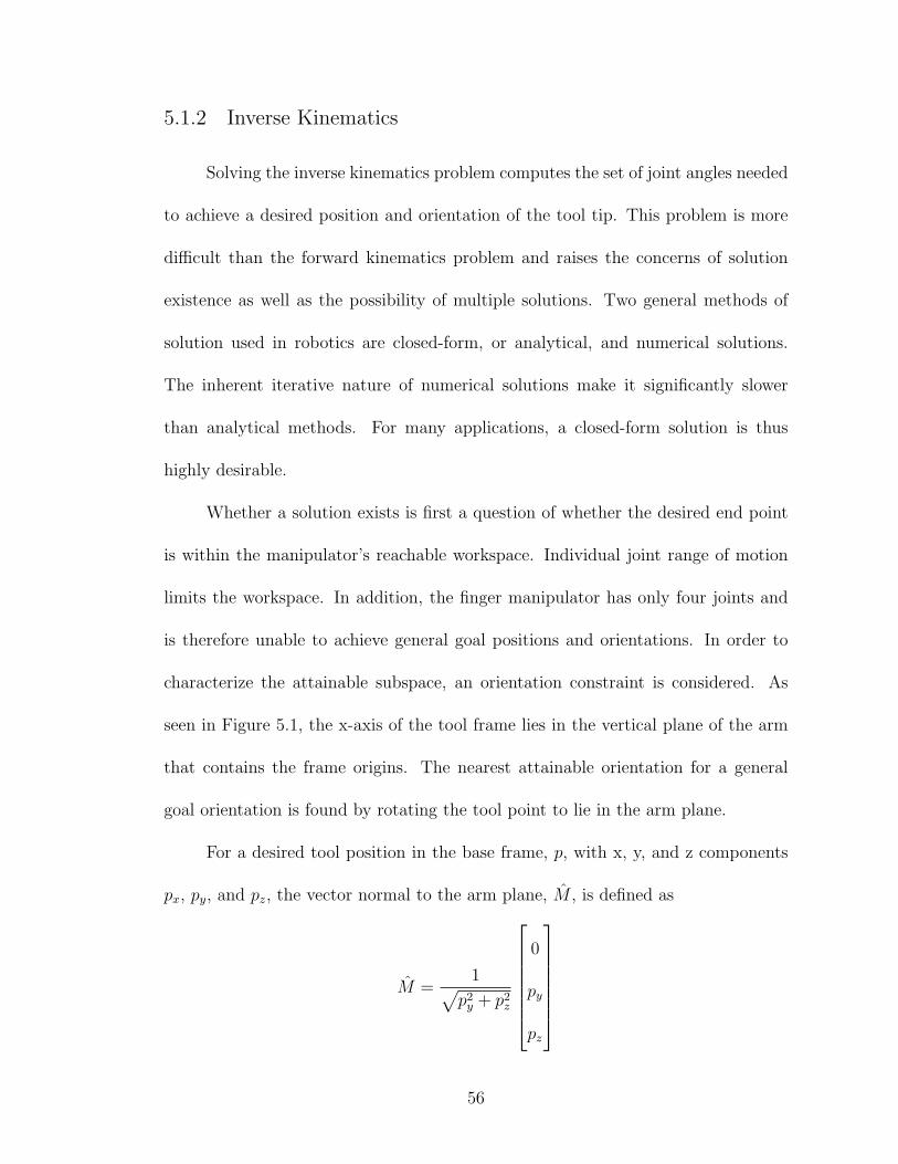
5.1.2 Inverse Kinematics
Solving the inverse kinematics problem computes the set of joint angles needed
to achieve a desired position and orientation of the tool tip. This problem is more
difficult than the forward kinematics problem and raises the concerns of solution
existence as well as the possibility of multiple solutions. Two general methods of
solution used in robotics are closed-form, or analytical, and numerical solutions.
The inherent iterative nature of numerical solutions make it significantly slower
than analytical methods. For many applications, a closed-form solution is thus
highly desirable.
Whether a solution exists is first a question of whether the desired end point
is within the manipulator’s reachable workspace. Individual joint range of motion
limits the workspace. In addition, the finger manipulator has only four joints and
is therefore unable to achieve general goal positions and orientations. In order to
characterize the attainable subspace, an orientation constraint is considered. As
seen in Figure 5.1, the x-axis of the tool frame lies in the vertical plane of the arm
that contains the frame origins. The nearest attainable orientation for a general
goal orientation is found by rotating the tool point to lie in the arm plane.
For a desired tool position in the base frame, p, with x, y, and z components
px, py, and pz, the vector normal to the arm plane, M , is defined as
M =1√
p2y + p2
z
0
py
pz
56

Given the desired pointing direction, XT , of the tool, a new pointing direction, X ′T ,
that lies in the arm plane is found by rotating by some angle, θ, about some vector,
K. K is then given by
K = M × XT
and the new pointing direction is
X ′T = K × M
The amount of rotation is determined from
cos θ = XT · X ′T
sin θ = (XT × X ′T ) · K
and Y ′T is found using Rodriguez’s formula.
Y ′T = cos θYT + sin θ(K × YT ) + (1− cos θ)(K · YT )K
The final column of the new rotation matrix of the tool is determined by the cross
product
Z ′T = X ′
T × Y ′T
Given the general goal orientation projected into the manipulator subspace,
the kinematic equations can then be solved analytically using both algebraic and
geometric approaches. For link lengths of lp, lm, and ld for the proximal, middle,
57

and distal phalanges respectively, the joint angles are given by
θ1 =atan2
(py
px
)
θ2 =
β + α if θ3 > 0,
β − α if θ3 < 0
θ3 = cos−1
(p2 − l2p − l2m
2lplm
)θ4 =φ− θ2 − θ3
where px, py, and pz are the x, y, and z components of the desired position, φ is the
desired orientation of the tool and
p =√
p2x + p2
z
β = atan2
(px
pz
)α = cos−1
(p2 + l2p − l2m
2lpp
)
From this derivation, it is apparant that a solution will not exist where px = 0
or pz = 0. Multiple solutions may exist for θ3 where the positive computed cosine is
less than the absolute value of the extension joint limit. In this case, two solutions
will exist when
cos−1
(p2 − l2p − l2m
2lplm
)≤ ±10◦
A corresponding dual solution exists for θ2 as well. For a detailed derivation of the
inverse kinematic equations, see Appendix C.
58

5.1.3 Velocities and Static Forces
Expanding the analysis beyond static positioning leads to the examination of
manipulator motion as well as static forces. The velocity of any link i + 1 is that of
link i plus the new velocity components added by joint i + 1. Applying Equations
(5.4) and (5.5) successively from link to link, the linear velocity, ν, and angular
velocity, ω, can be propagated from the base to the tool frame. The resultant
velocities can then be rotated back to the base frame using the rotation matrix 0NR.
i+1ωi+1 = i+1iR
iωi + θi+1i+1Zi+1 (5.4)
i+1νi+1 =i+1iR(iνi +iωi ×iPi+1) (5.5)
where i+1Zi+1 is the z-axis unit vector in frame {i + 1} and iPi+1 is the position
vector of frame {i + 1} in terms of frame {i}.
The forces and moments exerted on a manipulator can also be propagated
from one link to the next. For many serial manipulators, a static analysis considers
only a load applied at the free end. However in the case of a finger, loads are
distributed between the links depending on the grasp. Assuming knowledge of the
forces applied at each link, the necessary joint torques to keep the system in static
equilibrium can be solved for. The inward force iteration equations are given in 5.6
and 5.8.
ifi = i+1iR i+1fi+1 + iFi (5.6)
ini = i+1iR i+1ni+1 + iPFi
× iFi + iPi+1 × i+1iR i+1fi+1 (5.7)
where iFi is the applied force on link i and iPFiis the position vector describing the
59
contact point for the applied load on link i. The joint torque needed to maintain
static equilibrium is then given by
τi = inTi
iZi (5.8)
5.1.4 Jacobian Matrix
A Jacobian matrix relates differentials of one coordinate system to another. In
robotics, it is desirable to be able to change between tool space and joint space. Thus
for serial manipulators, the Jacobian is used to relate joint velocities to Cartesian
velocities. In the force domain, the Jacobian transpose is used to map Cartesian
fingertip forces to equivalent joint torques. These relationships are described in
Equations (5.9) and (5.10).
v = iJ(q) q (5.9)
τ = iJT(q) iF (5.10)
where v is the vector of tool velocities, q is the vector of joint velocities, and F is
the vector of fingertip forces and torques.
The structure of the Jacobian matrix depends upon the number of DOFs in
Cartesian space under consideration and the number of joints in the manipulator.
For the finger analysis in three-dimensional space, this leads to a 6 x 4 matrix that
can be broken down into two components, rotational and translational. Equation
(5.11) defines the rotational Jacobian for a manipulator with all revolute joints.
iJrot =
[i1Rz i
2Rz . . . iNRz
](5.11)
60

The most straightforward method to determine the translational Jacobian is
by direct differentiation. Taking the partial derivatives of the position vectors gives
the matrix shown in Equation (5.12).
iJtrans =
∂iPxN
∂θ1
∂iPxN
∂θ2. . . ∂iPxN
∂θN
∂iPyN
∂θ1
∂iPyN
∂θ2. . .
∂iPyN
∂θN
∂iPzN
∂θ1
∂iPzN
∂θ2. . . ∂iPzN
∂θN
(5.12)
Combining the two components, the full Jacobian relating joint velocities to
tip velocities is
J =
Jtrans
Jrot
(5.13)
Reversing the Jacobian relationship to get joint velocities from Cartesian ve-
locities raises singularity concerns. A singular configuration of a manipulator is a
configuration at which the Jacobian becomes rank deficient. For a manipulator with
fewer than six DOFs, this corresponds to fewer DOFs of the end-effector. Near these
configurations, joint velocities required to maintain certain desired end-effector ve-
locities can become extremely large. Likewise, small joint torques can produce large
end-effector forces.
For a square Jacobian, the inverse Jacobian can be used to determine the
reverse relationship between joint and Cartesian velocities. At singular configu-
rations, the inverse is not defined. These conditions can be found by solving for
configurations where the determinant of the Jacobian equals zero.
For a non-square Jacobian, as in the case of the finger manipulator, the inverse
of the Jacobian cannot be used. Instead, the Moore-Penrose pseudoinverse Jacobian
61

is defined to determine joint velocities from end-effector velocities (5.14, 5.15). This
pseudoinverse is not defined at the singular configurations where the rank of the
Jacobian drops[37, 38].
J† = JT (JJT )−1 (5.14)
q = J†v (5.15)
Singular value decomposition (SVD) provides a tool for analyzing singularities
in all possible kinematic structures. Every matrix Am×n with arbitrary dimensions
m× n has an SVD that expresses A in the form
A = UΣV T (5.16)
such that U and V are orthogonal matrices and Σ is an m×n diagonal matrix with
elements σ1 ≥ σ2 ≥ · · · ≥ σm ≥ 0. Matrix A has full rank when σm 6= 0 and loses
rank when σm = 0[39]. Applying SVD to the Jacobian matrix, proximity to singular
configurations can be checked by monitoring the value of σm.
5.2 Multifingered Hand Kinematics
5.2.1 Hand Kinematics
Considering the hand as a whole and the total grasp forces on an object,
it is necessary to determine the transformation to represent the finger forces in a
common frame. To simplify the calculation, the new base frame is located at the
wrist and aligned with frame {0} of fingers II-V. With the exception of the thumb,
the transformations then involve only translation. The rotation of the thumb frame
62

is defined relative to the base frame by a -90◦rotation about the wrist x-axis and a
-45◦rotation about the wrist z-axis. Calculating the rotation matrix for the thumb
and the overall hand geometry, a transformation, W0 Ti, is defined for each finger, i.
Equation (5.17) is then used to determine the forward kinematics from the common
wrist frame, {W}, to the tool frame, {N}.
WN Ti = W
0 Ti0NT (5.17)
With a common base frame to work from, a hand Jacobian can be formed to
determine joint torques for each from given tip forces. The hand Jacobian is based
on the standard Jacobian and is brought together in the form
τ1
τ2
...
τm
=
JT1 0 · · · 0
0 JT2 · · · 0
......
. . ....
0 · · · 0 JTm
ftip1
ftip2
...
ftipm
(5.18)
5.2.2 Grasp Quality Considerations
Further analysis of a multifingered hand focuses on grasp stability. A grasp
is composed of a set of contacts that can be represented by screw systems. By this
representation, the collective forces and moments on a body can be described as
a force along and a moment about a single wrench axis. Likewise, the motion of
the body can be represented as a translation along and a rotation about a twist
axis. For each contact, the twist and wrench systems can be used to describe the
constraints.
63

Without a physical bonding agent, two bodies in contact can only exert forces
in one direction. In addition, for friction contacts to be active, the normal force
must be positive. As a result of these unisense force limitations imposed on an
arbitrary grasp, only a subset of all possible disturbance forces can be resisted by
a grasp. In these cases, if the disturbance forces act to maintain contact between
the fingers and the object and thus the grasp can still be maintained, a condition
of force closure is met. A grasp that can resist arbitrary disturbance wrenches is
said to exhibit form closure. For an object completely restrained by a grasp, there
is a set of internal forces that can be applied to the object without disturbing its
equilibrium.
For a total of n wrenches acting on an object and assuming p of those wrenches
are unisense, the wrench matrix, W6×n, is built as shown in Equation (5.19). To
resist an arbitrarily applied wrench, w, on an object, there must then be a vector,
c, of contact wrench intensities that satisfies Equation (5.20).
W =
[w1 w2 . . . wp wp+1 . . . wn
](5.19)
Wc = w (5.20)
If the wrench matrix W has a rank of six and contains the applied wrench w in
its column space, a grasp may be able to fully constrain an object. However, as a
result of the p unisense wrenches, the first p elements of the c vector must also be
positive. If these elements are not, the wrench w can cause broken contacts or slip
to occur at unisense contact points. The solution to (5.19) can be broken up into
64

the two vectors cp and ch such that
c = cp + λch (5.21)
where cp is the particular solution to (5.19) and ch is the homogeneous solution. If
the first p elements of ch are positive, then for any value of cp, there is some large
value of λ that will result in the first p elements of c to be positive as well. Thus,
ch corresponds to the internal grasp forces that can be increase by a magnitude of
λ to make the contact forces positive[40, 41].
65

Chapter 6
Testing and Results
The previous chapters described the design of a geometrically anthropometric
robotic finger utilizing antagonistic actuator pairs. Studies on human hand motion
and grasp force distributions as well as an analysis describing the expected finger be-
havior were also presented. A kinematic analysis was performed and yields a model
relating opposing tendon tensions and applied loads. This chapter presents exper-
imental strength and position tests and compares the results with the predictive
model.
Position of the PIP and DIP joints were measured over the full range of flexion
and extension. Holding tendon tensions were also measured for varying cylindrical
grasp diameters and weights. Finally, an analysis of the benefit of active antagonism
was performed by measuring tip force resolution and joint positioning for differing
tendon tensions.
6.1 Test Setup
A test stand, shown in Figure 6.1, was developed to actuate a single degree
of freedom in opposition. Two motors are mounted to a cylindrical delrin base. As
with the hand actuator assembly, these motors connect to leadscrews by oldham
couplings with the leadscrew supported by bushings on both ends. Guide rails for
66

Figure 6.1: Side View & Close-Up of Load Cells/Top Plate
the leadscrew nut are bolted to the delrin base. Spectra cable attaches to two sides
of each nut and routes through wire tubing over the edges of the bushing mounts.
Beyond the bushing mount, the spectra cables join to a single line and connect to
a tension/compression force sensor. The other end of the tendon connects from the
sensor up to the actuated joint. Wire tubing and cable restraints were used to guide
the tendons along the links and around corners. The finger mechanism itself mounts
on an interchangeable plate, as shown in Figure 6.2, that allows for simple changing
of test components.
The test setup only allows for actuation of a single degree of freedom at a time.
Initially, the compliant skeleton with phalange shell components was intended to be
the test element. However, due to fabrication problems with the rapid prototype
67

Figure 6.2: Close-up of Load Cell Attachment and Top Plate
machine, the shell components were not completed. For the desired testing goals, it
was deemed sufficient to use only the compliant mechanism. The compliant piece
serves as a skeletal base for the finger and therefore is capable of the necessary
grasps for testing. In addition, investigation of joint positions and the effect of
active antagonism can be effectively executed with the simplified skeletal setup.
For position testing, a goniometer was used to measure PIP and DIP joint
flexion of the 2DOF compliant skeleton. To compare the natural coupling of the
compliant skeleton to expected behavior, only the flexion tendon was used and angles
taken from fully open to fully closed at 116
-inch intervals of linear screw actuation.
In this setup, the flexion tendon was attached at the tip and routed through a
restraint at the mid-point of the middle phalange. Changing from fully open to fully
closed configurations required a linear actuation distance of one inch. In addition
to measuring relative joint angles, flexion tendon tension was also measured using
the tension/compression force sensor for comparison to the model.
Tendon forces relative to grasp load were measured using the test setup in an
inverted mounting position. A single finger was tested in a cylindrical grasp. The
68

total load was increased by attaching weights in a bag to the cylinder and the flexion
tendon force recorded. No extension tendon was used during this testing.
The final set of tests conducted examined the effect of the antagonistic ac-
tuation pair. Joint angle position tests were repeated with the 2DOF compliant
skeleton, this time using the extension tendon in varying levels of tension. Because
the tendon tensions change relative to each other when one side is actuated, these
tests were done by adjusting linear positions. The leadscrew position of the ex-
tension tendon was kept constant while the flexion tendon was actuated from fully
open to fully closed in increments of 116
-inch. Joint angles and tendon tensions were
recorded at each position.
Tip forces were also studied in the antagonistic case. A single DOF joint was
mounted on the test stand and an Omega LC302 button cell compression force sensor
placed such that when fully actuated, the tip touches the center of the sensor. Tip
forces were then measured while varying the relative antagonistic tendon tensions.
6.2 Data/Results
6.2.1 Coupled Joint Angles
Joint coupling behavior is shown in Figure 6.3. The experimental data is
fit to a 2nd order polynomial with an R2 value of 0.92. As seen in the graph,
the experimental behavior is similar to that of the predictive model. The main
difference, seen at the beginning of the flexion motion, is likely due to the fact that
the compliant joint does not return completely to it’s original unbent position. After
69

the joint is initially bent, it tends to have a preferred base position of approximately
10 degrees. While this behavior is consistently repeated, it is not factored into the
model.
Figure 6.3: PIP-DIP Joint Coupling
The coupled joint motion observed also matches well with human finger mo-
tion. The human PIP-DIP coupling is shown as described by Lee and Rim[2]. The
upward shift of the experimental trend line relative to the human line is again likely
due to the initial bend of the DIP joint.
6.2.2 Tendon Forces in a Cylindrical Grasp
Analysis of grip strength was analyzed for a cylindrical grasp. Using a single
finger wrapped around a 1.25′′ diameter aluminum cylinder, tendon tensions were
measured for loads up to 10 lbs. Although the largest EVA tool diameter for testing
is 2.00′′ in diameter, the mounting point of the finger in the test stand creates in a
shortened proximal phalange, thus resulting in a maximum grasp geometry of 1.25′′.
However, by testing beyond the required 20 lb grasp distributed over four fingers,
70

the single finger test can still demonstrate sufficient strength capability.
Lead weights were added to a cordura bag attached by spectra cable to the
grasping cylinder in approximately one-pound increments. The applied weight at
each increment was measured and recorded. The finger was then actuated in flexion
until the cylinder was held securely. Holding tension of the flexion tendon was then
measured. Figure 6.4 shows the flexion tendon forces relative to the total load on
the finger. The calculated tendon tensions, derived from the kinematic model and
based on the geometry of the hand in a 1.25′′ cylindrical grasp, are also displayed
on the graph.
Figure 6.4: Tendon Tensions for Applied Loads on a 1.25′′
Diameter Cylindrical Grasp
As depicted in Figure 6.4, the measured tendon tensions increase linearly with
applied load and appear to correspond with the expected forces. The experimental
values seem to increase at a steeper slope than the calculated, though this can be
attributed to friction in the system. In addition, previous calculations show that
for a distributed cylindrical grasp, a 20 lb total grip force requires a maximum load
71

of 6.50 lbs on a single finger. Testing has proven an individual finger capable of
holding up to a 10 lb load, 50% greater than the required load.
6.2.3 Active Antagonism
The use of opposing actuators affects both joint control and tip forces. Due to
the compliant nature of the skeleton, changing the relative tensions of the flexion and
extension cables creates a level of decoupling between the DIP and PIP joint DOFs.
Figures 6.5 shows DIP joint angles relative to the measured flexion tendon tensions.
Each line represents a constant extension tendon position with varying tension.
Testing shows that for an unloaded finger, the relative flexion and extension forces
remain consistent despite linear position. Thus, the predictive model determines the
DIP joint angle based on the experimentally derived relationship between flexion
force and extension force during actuation. The slopes of the experimental trend
lines verify the model. An upward shift in the data is again seen and can once more
be attributed to the initial bend in the DIP joint.
There is significantly less variation in the PIP joint angle. For a given exten-
sion tendon position, experimental data shows that the PIP joint angle generally
remains constant from open to close (Figure 6.6). When both the extension and flex-
ion tendon positions are more fully actuated, corresponding to significantly greater
forces on both sides, the joint angle begins to vary during actuation. Based on joint
angle calculations done for the DIP joint, this result corresponds to the expected
trend. The location of the attachment point also makes it such that the affect of
72

Figure 6.5: DIP Flexion for Varying Antagonistic TendonTensions
The legend indicates the linear position of the extension tendon in inches from the top of the testsetup.
the extension tendon is greater at the distal versus proximal joint. As a result, it is
possible to gain some level of control over the two coupled joints using an antago-
nistic setup. This is particularly useful for grasps that conform to the shape of the
object, rather than a fixed curve.
Figure 6.6: PIP Flexion for Varying Antagonistic TendonTensions
The legend indicates the linear position of the extension tendon in inches from the top of the testsetup.
Testing on tip forces further demonstrates the benefit of an antagonistic tendon
73

setup. Switching to a single DOF compliant hinge, the test component was fully
flexed to touch a button cell. With the flexion tendon pulled in such that it was
fully actuated, the force on the extension tendon was then increased with the joint
fully flexed. Both tendon tensions as well as subsequent tip force were recorded.
Initially, data was recorded continually while the extension tendon was actu-
ated. However, running the motors resulted in increased noise. The range of forces
measured at the tip was small enough that in combination with the added noise, the
resultant data was inconclusive. Instead, data was recorded in 0.1-pound increments
on the extension tendon. The averaged results are detailed in Figure 6.7.
Figure 6.7: Tip Force vs Joint Torque
Torque was calculated based on the measured opposing tendon tensions. Based
on the kinematic analysis detailed in Chapter 5, the comparative model determined
joint torque over the range of measured tip forces. The tip force was assumed to act
only in the y-axis of the tip with the joint angle fixed at 90◦. The overall results show
slightly smaller than expected forces with greater correlation to the model at higher
74

tip forces. This is largely due to the quality of contact at the load cell. At higher
joint torques and subsequent greater tip forces, there is a more solid contact and the
results closely match the expected values and trend. However, at lower forces where
the contact could be considered more of a ”touch” as opposed to ”pressing” down
on the button cell, the measured tip forces drop of dramatically. At approximately
2.5 in-lbs of torque, the test component lost contact with the force sensor and tip
forces drop to zero.
Chapter 3 previously derived a required pinch grasp force of 5 lbs. Assuming
a two-finger pinch and taking the grasp force as the total force applied to the object
by the tips of both fingers, the maximum measured tip force for the fully actuated
flexion shows the design is capable of satisfying the pinch requirement.
The experimental results further demonstrate the adaptability of the spring
constant in the system. The torsional spring constant is taken from the relationship
in Equation (6.1).
T = kθ (6.1)
The angle, θ, is assumed constant throughout as the test component is kept fully
flexed. Therefore, as the joint torque varies for a constant θ, so does the spring
constant of the system. The compliant hinge was designed with a spring constant
of 4.5 in-lbs/rad. Experimental results with measured contact force provide a range
of spring constants from 1.75-4.45 in-lbs/rad.
75

Chapter 7
Conclusions & Future Work
7.1 Summary
This thesis documents the development of a robotic finger for an anthropomor-
phic hand and details preliminary performance results. The benefits and drawbacks
of different aspects of hand design are examined and insight into effective configu-
rations provided. The research focuses on the detailed design of an actuated finger
with particular interest in studying the use of opposing actuator pairs. A kinematic
model is derived that presents a working analysis of the finger. Preliminary testing
of tendon and tip forces verifies this model. Analysis of joint motion is also com-
pared to human motion and found to correspond with the desired anthropomorphic
behavior.
The work presented is the starting to point to a fully developed and highly
dexterous robotic hand. Design choices consider future sensor integration and basic
palm configuration solutions are proposed. The goal to design a hand component
capable of EVA tool grasps and force requirements has been satisfied.
76
7.2 Future Work
Several avenues of research must be pursued to reach the ultimate goal of a
fully operational hand for EVA tasks. Further development should continue with
the single finger, followed by an intermediary 3-finger grasping manipulator, and
finally a 5-fingered hand. The subsequent sections detail a plan for future work.
7.2.1 Single Finger Development
The first step towards the end goal is a second iteration of the single finger
design. Both tendon attachment and compliant mechanism design should be revis-
ited. One of the primary weaknesses in the current version is the tendon attachment
procedure. From an assembly point of view, cable termination was by far the most
time consuming step. In addition, the knots used were difficult to tie off at the
exact point desire along the tendon line and prone to initial slipping. Methods of
pre-tensioning that do not rely on increasing the linear actuation distance should
also be investigated to ease the packaging constraints of the lead screw assemblies.
In addition to developing the tendon system, a re-design of the compliant
mechanism may greatly improve performance. The current design tends to favor
actuation of the DIP joint over the PIP joint. One branch of further study should
aim to optimize the relative attachment points of the flexion and extension tendons
as well as examine how an asymmetric hinge geometry would affect the compliant
skeleton behavior. Another path of interest is to better characterize the ability
of the compliant mechanism to both conform to grasp shapes and be forced into
77

desired shapes during actuation. Analysis of the compliant behavior is necessary to
demonstrate the benefit of this approach over the typically rigid 4-bar linkage.
With the intial design revisions, a second prototype finger should be man-
ufactured, including the phalange shell components and a basic palm attachment
structure. Ideally, a new version of the MP hub should be manufactured with an
integrated abduction/adduction shaft. Rapid prototyping is still desired for the pha-
lange shell components to enable more complex internal geometries for wire routing
and joint range of motion limitation. The second protype will also require a new
test stand design that can actuate three DOFs. The new test stand should use the
more compact version of the actuator assemblies and look into packaging within the
forearm design.
The second prototype should also work on incorporating Hall effect sensors
for joint angle measurement and a rudimentary tactile sensing system. This next
step in sensor development focuses on packaging within the finger structure and
preliminary signal processing. At this point, work on a controls system for the three
DOF manipulator can begin, particularly improving the model of the compliant
mechanism and antagonistic tendon behavior.
7.2.2 Three-Finger Grasper
The second proposed phase of hand development yields a three-finger grasper.
For Finger V (the thumb), minor modifications will need to be made to increase
link length and width. In addition, a more complex palm design is necessary that
78

fits Finger III, Finger IV, and properly mounts Finger V in opposition. Mechan-
ically, this version can use the existing finger design as a basis and focus on the
palm structure and forearm packaging. Improvement of the sensor system and data
processing can continue on a parallel track.
A three-finger grasper provides an intermediary step to demonstrate grasp ca-
pability and investigate multi-finger interaction on a smaller scale. As shown by
previous studies on grasp classification and EVA tools, three fingers are sufficient
for a stable grasp of all CATs. Research into grasp quality and dexterous manip-
ulation is thus possible with this grasper. Having an end effector with multiple
fingers also allows for a more complex analysis of active antagonism, in particular
which joints benefit the most during dexterous manipulation. The controls system
also becomes increasingly complex and can now research cooperative motion and
optimizing grasps.
7.2.3 Five-Finger Hand
The final step is to build a hand with five fingers and wrist. To achieve this
goal, mechanical design work will focus on completing the palm structure with a two
DOF wrist. The major design consideration is how to best implement the final two
grasping fingers. Trade-offs between making full three DOF fingers versus single or
two DOF ”graspers” should be analyzed. In addition, the necessity of a palm joint
to aid in motions of opposition should be studied.
The production of a full five-fingered hand brings the resesarch to the point
79

of testing the operational use of the end effector. Desired tasks included the ability
to pick up and hand off objects of arbitrary shapes and the use of tools to perform
complex tasks. Continuing development on controlling five cooperative fingers and
determining grasp quality and contact will also be necessary. Beyond the basic
functionality and control of the full hand in a lab setting, it is hoped that the
research can eventually focus on its use in space. The development of a multi-
function end-effector is the first step towards increasing the capability of robots in
space. Future research will look beyond the execution of EVA tasks to human-robot
interaction and planetary exploration.
80

Appendix A
Design Measurements and Calculations
A.1 Hand Measurements
The following table details anthropometric data taken from an existing study
of American military males[18].
DIMENSION MEAN (in) 95th percentile (in)hand breadth 3.48 3.78
hand breadth across thumb 4.05 4.38hand circumference 8.46 9.14
hand circumference including thumb 10.05 10.85hand length 7.57 8.15
hand thickness 1.14 1.28palm length 4.30 4.70
thumb-crotch length 1.96 2.30finger diameter 0.84 0.90
finger II-crotch length 4.97 5.50first phalanx length digit III 2.67 2.9
fist circumference 11.43 12.40grip diameter, inside 1.87 2.1grip diameter, outside 4.08 4.40
elbow-grip length 13.86 14.94elbow-wrist length 11.61 12.57
forearm circumference, flexed 11.44 12.63forearm circumference, relaxed 10.91 11.96
Table A.1: Human Forearm and Hand Measurements
The following table details the results of hand measurements based on the
BioConcepts chart. Ten male and ten female subects were measured using a tailoring
tape measure. Average values for males and females are listed for the left and right
hand separately.
81

DIMENSIONMALE FEMALE
LEFT (in) RIGHT (in) LEFT (in) RIGHT (in)A 6.965 7.013 6.188 6.275A1 6.988 7.075 6.275 6.288B 8.363 8.363 7.375 7.488C 1.938 1.963 1.738 1.763D 2.200 2.200 1.938 2.013E 2.063 2.113 1.850 1.888F 2.488 2.525 2.213 2.100G 2.175 2.263 1.950 1.975H 2.613 2.688 2.313 2.425I 2.238 2.238 1.938 1.975J 2.613 2.625 2.338 2.388K 2.700 2.788 2.388 2.450a 3.675 3.688 3.500 3.488b 4.213 4.163 3.888 3.888c 4.250 4.300 3.925 3.875d 2.500 2.650 2.388 2.413e 2.375 2.425 2.300 2.250f 2.850 2.850 2.850 2.838g 2.938 3.138 3.075 3.075h 2.825 2.863 2.763 2.850i 2.525 2.388 2.338 2.525j 1.063 1.025 1.025 1.038k 0.975 0.975 0.963 0.988l 0.950 0.950 1.013 1.025m 1.200 1.225 1.200 1.188n 1.038 1.038 1.075 1.163
length 7.463 7.425 7.113 7.175breadth 3.475 3.488 3.100 3.113
Table A.2: Hand Measurements
82

A.2 Matlab Code
A.2.1 Leadscrew Selection Calculations
clear all;
close all;
% Kerk Motion 1/4" 4000 Series, Lead-Load Torque Comparison
% define lead screw leads and efficiencies
kerk_lead_array = [0.025 0.0357 0.039 0.039 0.050 0.059 0.0625 0.079
0.100 0.118 0.200 0.250 0.333 0.394 0.400 0.500
0.750 1.000];
kerk_eff_array = [0.30 0.35 0.40 0.33 0.46 0.52 0.52 0.59 .62 0.68
0.65 0.79 0.82 0.78 0.84 0.85 0.86 0.84];
% define maximum and nominal tendon loads
load_max_lb = 41.5;
load_max = load_max_lb*16;
load_nom_lb = 10;
load_nom = load_nom_lb*16;
% calculate torque to move max load
kerk_torque_max = load_max.*kerk_lead_array./(2*pi.*kerk_eff_array);
% calculate torque to move nominal load
kerk_torque_nom = load_nom.*kerk_lead_array./(2*pi.*kerk_eff_array);
% define desired linear speed (in/s)
linspd = 4;
% define rpm for nominal tendon loads
rpm = linspd./kerk_lead_array*60
% calculate motor power for nominal loads
p_nom = kerk_torque_nom.*rpm.*0.00074;
% plot torque vs lead
figure;
plot(kerk_lead_array,kerk_torque_max,’k.’);
xlabel(’Lead (in)’);
ylabel(’Torque to Move Load (oz-in)’);
title(’Lead vs. Load Torque’);
hold on;
plot(kerk_lead_array,kerk_torque_nom,’bx’);
83

legend(’Max’,’Nominal’);
hold off;
% plot power vs lead
figure;
plot(kerk_lead_array,p_nom,’b.’);
xlabel(’Lead (in)’);
ylabel(’Motor Power to Move Nominal Load (W)’);
title(’Lead vs. Motor Power’);
A.2.2 Motor/Gearbox Calculations
clear all;
close all;
% Define BF4000 values
bf4000_lead = 0.118;
bf4000_eff = 0.68;
% Define load requirements
load_max = 40*16;
% Calculate torque to move load [oz-in]
bf4000_torque = load_max*bf4000_lead/(2*pi*bf4000_eff)
% Calculate desired rpm and desired output speed under load
rpm = 4/bf4000_lead*60
nL = rpm/2
% Estimate required power
P = bf4000_torque*0.0071*pi/30*nL
%%%%%% Calculate theoretical reduction ratio
n_gearpermiss = 8000;
itheor = n_gearpermiss/nL
%%%%%% Calculate motor speed
i = 5.4; % nearest lower available reduction ratio
n_motor = i*nL
%%%%%% Define gearhead efficiency
eta_gear = 0.84;
84

% Calculate necessary motor torque
motor_torque = bf4000_torque*0.0071*1000/(i*eta_gear) % [mNm]
% Winding Selection
%%%%%% Calculate no load speed
stgrad = [202 202 202 202]; % from motor selection specs (line 5)
ni = n_motor+(stgrad.*motor_torque);
%%%%%% Calculate theoretical speed constant
U = [24 24 24 24]; % from motor selection specs
kni = ni./U
%%%%%% Power check
Pmotor = [20];
deltap = Pmotor-P
%%%%%% No-load speed check
no = [9500 16500 9500 16500];
deltan = no-ni
%%%%%% Actual speed constant and differnce
kn = [406 704 406 704];
deltak = abs(kni-kn)
%%%%%% Stall torque safety factor
Mh = [48 83 48 83];
sf = Mh./motor_torque
A.2.3 Finger Force-Moment Analysis
clear;
% Define Indices
p = 1; % proximal
m = 2; % middle
d = 3; % distal
% Define Link Lengths
l_prox = 1.1;
l_mid = 1.1;
l_dist = 1.1;
% Define Finger Geometry for 2.00’’ Diameter Grip
angles(2,:) = [60 55 37.5];
85

angles(3,:) = [57.5 55 40];
angles(4,:) = [55 52.5 40];
angles(5,:) = [37.5 47.5 37.5];
% Define Force Center Locations (Long Axis)
centers(2,:) = [0.51 0.74 0.47];
centers(3,:) = [0.59 0.65 0.44];
centers(4,:) = [0.64 0.62 0.48];
centers(5,:) = [0.63 0.40 0.63];
% Define Distributed Phalange Forces
forces(2,:) = [2.08 1.17 3.25];
forces(3,:) = [1.89 1.06 2.94];
forces(4,:) = [1.45 0.814 2.26];
forces(5,:) = [0.986 0.554 1.54];
% Calculate Moments
for i=2:5
l_13 = sqrt(l_prox^2+l_mid^2-2*l_prox*l_mid*...
cosd(180-angles(i,m)));
theta_inner = acosd((l_mid^2-l_prox^2-l_13^2)/(-2*l_prox*l_13));
M_mp(i) = forces(i,p)*centers(i,p)+forces(i,m)*(centers(i,m)
+l_prox*cosd(angles(i,m)))
+forces(i,d)*(centers(i,d)+l_13*cosd(theta_inner));
M_pip(i) = -forces(i,p)*(l_prox-centers(i,p))
+forces(i,m)*centers(i,m)
+forces(i,d)*(centers(i,d)+l_mid*cosd(angles(i,d)));
M_dip(i) = forces(i,d)*centers(i,d)
-forces(i,m)*(l_mid-centers(i,m))
-forces(i,p)*((l_prox-centers(i,p))+l_mid*...
cosd(angles(i,m)));
end
M_mp
M_pip
M_dip
86
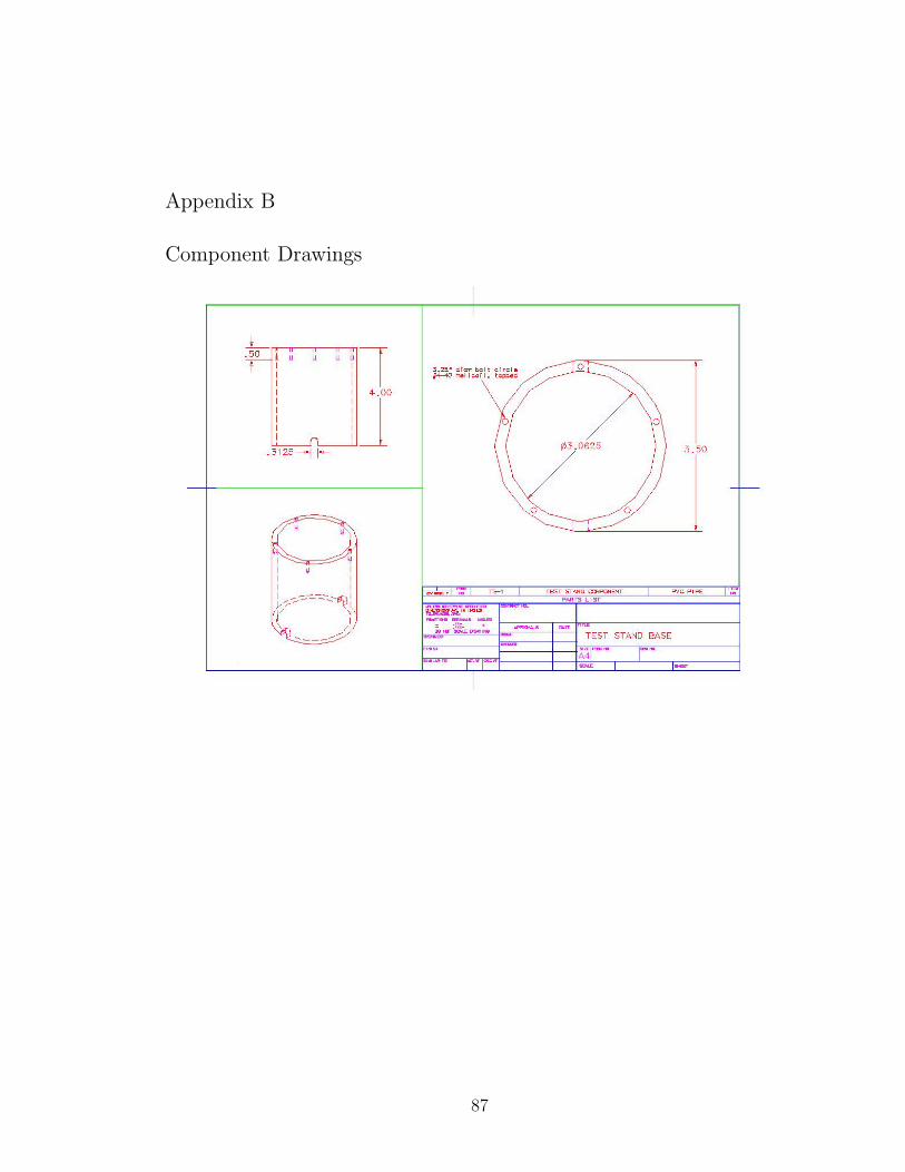
Appendix B
Component Drawings
87

88
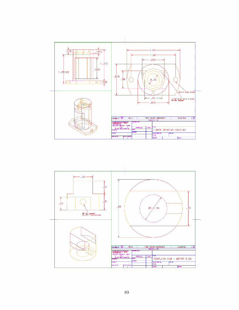
89

90

91

92

93

94

95

96

97

98

Appendix C
Kinematic Analysis
C.1 Mathematica Code
(* CALCULATE FORWARD KINEMATICS *)(* CALCULATE FORWARD KINEMATICS *)(* CALCULATE FORWARD KINEMATICS *)
ClearAll["Global*"];ClearAll["Global*"];ClearAll["Global*"];
(* Define Number of DOFs *)(* Define Number of DOFs *)(* Define Number of DOFs *)
DOF = 4;DOF = 4;DOF = 4;
(*DefineDHParametersandJointType(1 = revolute, 0 = prismatic*)(*DefineDHParametersandJointType(1 = revolute, 0 = prismatic*)(*DefineDHParametersandJointType(1 = revolute, 0 = prismatic*)
α0 = 0; a0 = 0; d1 = 0; θ1 = θ1; jtype[1] = 1;α0 = 0; a0 = 0; d1 = 0; θ1 = θ1; jtype[1] = 1;α0 = 0; a0 = 0; d1 = 0; θ1 = θ1; jtype[1] = 1;
α1 = Pi/2; a1 = 0; d2 = 0; θ2 = θ2; jtype[2] = 1;α1 = Pi/2; a1 = 0; d2 = 0; θ2 = θ2; jtype[2] = 1;α1 = Pi/2; a1 = 0; d2 = 0; θ2 = θ2; jtype[2] = 1;
α2 = 0; a2 = lp; d3 = 0; θ3 = θ3; jtype[3] = 1;α2 = 0; a2 = lp; d3 = 0; θ3 = θ3; jtype[3] = 1;α2 = 0; a2 = lp; d3 = 0; θ3 = θ3; jtype[3] = 1;
α3 = 0; a3 = lm; d4 = 0; θ4 = θ4; jtype[4] = 1;α3 = 0; a3 = lm; d4 = 0; θ4 = θ4; jtype[4] = 1;α3 = 0; a3 = lm; d4 = 0; θ4 = θ4; jtype[4] = 1;
(* Calculate Local Link Transformation *)(* Calculate Local Link Transformation *)(* Calculate Local Link Transformation *)(* Calculate Local Link Transformation *)(* Calculate Local Link Transformation *)(* Calculate Local Link Transformation *)(* Calculate Local Link Transformation *)(* Calculate Local Link Transformation *)(* Calculate Local Link Transformation *)
For[i = 1, i<=DOF, i++,For[i = 1, i<=DOF, i++,For[i = 1, i<=DOF, i++,
T [i] = {{Cos [θi] ,−Sin [θi] , 0, ai−1} ,T [i] = {{Cos [θi] ,−Sin [θi] , 0, ai−1} ,T [i] = {{Cos [θi] ,−Sin [θi] , 0, ai−1} ,
{Sin [θi] ∗ Cos [αi−1] , Cos [θi] ∗ Cos [αi−1] ,−Sin [αi−1] ,−Sin [αi−1] ∗ di} ,{Sin [θi] ∗ Cos [αi−1] , Cos [θi] ∗ Cos [αi−1] ,−Sin [αi−1] ,−Sin [αi−1] ∗ di} ,{Sin [θi] ∗ Cos [αi−1] , Cos [θi] ∗ Cos [αi−1] ,−Sin [αi−1] ,−Sin [αi−1] ∗ di} ,
99

{Sin [θi] ∗ Sin [αi−1] , Cos [θi] ∗ Sin [αi−1] , Cos [αi−1] , Cos [αi−1] ∗ di} ,{Sin [θi] ∗ Sin [αi−1] , Cos [θi] ∗ Sin [αi−1] , Cos [αi−1] , Cos [αi−1] ∗ di} ,{Sin [θi] ∗ Sin [αi−1] , Cos [θi] ∗ Sin [αi−1] , Cos [αi−1] , Cos [αi−1] ∗ di} ,
{0, 0, 0, 1}};{0, 0, 0, 1}};{0, 0, 0, 1}};
R[i] = Part[T [i], {1, 2, 3}, {1, 2, 3}];R[i] = Part[T [i], {1, 2, 3}, {1, 2, 3}];R[i] = Part[T [i], {1, 2, 3}, {1, 2, 3}];
p[i] = {T [i][[1, 4]], T [i][[2, 4]], T [i][[3, 4]]};p[i] = {T [i][[1, 4]], T [i][[2, 4]], T [i][[3, 4]]};p[i] = {T [i][[1, 4]], T [i][[2, 4]], T [i][[3, 4]]};
];];];
(*DefineTransformationfromNtoN + 1(tooltip)*)(*DefineTransformationfromNtoN + 1(tooltip)*)(*DefineTransformationfromNtoN + 1(tooltip)*)
pTN = {ld, 0, 0} ;pTN = {ld, 0, 0} ;pTN = {ld, 0, 0} ;
T [DOF + 1] = {{1, 0, 0, ld} , {0, 1, 0, 0}, {0, 0, 1, 0}, {0, 0, 0, 1}} ;T [DOF + 1] = {{1, 0, 0, ld} , {0, 1, 0, 0}, {0, 0, 1, 0}, {0, 0, 0, 1}} ;T [DOF + 1] = {{1, 0, 0, ld} , {0, 1, 0, 0}, {0, 0, 1, 0}, {0, 0, 0, 1}} ;
Print["LOCAL LINK TRANSFORMATIONS:"];Print["LOCAL LINK TRANSFORMATIONS:"];Print["LOCAL LINK TRANSFORMATIONS:"];
For[i = 1, i<=DOF + 1, i++,For[i = 1, i<=DOF + 1, i++,For[i = 1, i<=DOF + 1, i++,
Print["T[", i, "]=", MatrixForm[T [i]]];Print["T[", i, "]=", MatrixForm[T [i]]];Print["T[", i, "]=", MatrixForm[T [i]]];
];];];
LOCAL LINK TRANSFORMATIONS:
T[1]=
Cos [θ1] −Sin [θ1] 0 0
Sin [θ1] Cos [θ1] 0 0
0 0 1 0
0 0 0 1
T[2]=
Cos [θ2] −Sin [θ2] 0 0
0 0 −1 0
Sin [θ2] Cos [θ2] 0 0
0 0 0 1
100

T[3]=
Cos [θ3] −Sin [θ3] 0 lp
Sin [θ3] Cos [θ3] 0 0
0 0 1 0
0 0 0 1
T[4]=
Cos [θ4] −Sin [θ4] 0 lm
Sin [θ4] Cos [θ4] 0 0
0 0 1 0
0 0 0 1
T[5]=
1 0 0 ld
0 1 0 0
0 0 1 0
0 0 0 1
(* Compute Forward Kinematics *)(* Compute Forward Kinematics *)(* Compute Forward Kinematics *)
TN0 = T [1].T [2].T [3].T [4].T [5];TN0 = T [1].T [2].T [3].T [4].T [5];TN0 = T [1].T [2].T [3].T [4].T [5];
TN0 = Simplify[TN0];TN0 = Simplify[TN0];TN0 = Simplify[TN0];
RN0 = Part[TN0, {1, 2, 3}, {1, 2, 3}];RN0 = Part[TN0, {1, 2, 3}, {1, 2, 3}];RN0 = Part[TN0, {1, 2, 3}, {1, 2, 3}];
pN0 = Part[TN0, {1, 2, 3}, {4}];pN0 = Part[TN0, {1, 2, 3}, {4}];pN0 = Part[TN0, {1, 2, 3}, {4}];
Print["TN0=", MatrixForm[TN0]];Print["TN0=", MatrixForm[TN0]];Print["TN0=", MatrixForm[TN0]];
TN0=
Cos [θ1] Cos [θ2 + θ3 + θ4] −Cos [θ1] Sin [θ2 + θ3 + θ4] Sin [θ1]Cos [θ2 + θ3 + θ4] Sin [θ1] −Sin [θ1] Sin [θ2 + θ3 + θ4] −Cos [θ1]Sin [θ2 + θ3 + θ4] Cos [θ2 + θ3 + θ4] 00 0 0Cos [θ1] (Cos [θ2 + θ3 + θ4] ld + Cos [θ2θ3] lm + Cos [θ2] lp)Sin [θ1] (Cos [θ2 + θ3 + θ4] ld + Cos [θ2 + θ3] lm + Cos [θ2] lp)Sin [θ2 + θ3 + θ4] ld + Sin [θ2 + θ3] lm + Sin [θ2] lp1
(* INVERSE KINEMATICS *)(* INVERSE KINEMATICS *)(* INVERSE KINEMATICS *)
101

For[i = 1, i ≤ DOF + 1, i++,For[i = 1, i ≤ DOF + 1, i++,For[i = 1, i ≤ DOF + 1, i++,
invT[i] = Inverse[T [i]];invT[i] = Inverse[T [i]];invT[i] = Inverse[T [i]];
invT[i] = Simplify[invT[i]];invT[i] = Simplify[invT[i]];invT[i] = Simplify[invT[i]];
];];];
leftM = {{r11, r12, r13, px}, {r21, r22, r23, py}, {r31, r32, r33, pz}, {0, 0, 0, 1}};leftM = {{r11, r12, r13, px}, {r21, r22, r23, py}, {r31, r32, r33, pz}, {0, 0, 0, 1}};leftM = {{r11, r12, r13, px}, {r21, r22, r23, py}, {r31, r32, r33, pz}, {0, 0, 0, 1}};
leftM = invT[1].leftM;leftM = invT[1].leftM;leftM = invT[1].leftM;
leftM = Simplify[leftM];leftM = Simplify[leftM];leftM = Simplify[leftM];
rightM = T [2].T [3].T [4].T [5];rightM = T [2].T [3].T [4].T [5];rightM = T [2].T [3].T [4].T [5];
rightM = Simplify[rightM];rightM = Simplify[rightM];rightM = Simplify[rightM];
Print["leftM=", MatrixForm[leftM]];Print["leftM=", MatrixForm[leftM]];Print["leftM=", MatrixForm[leftM]];
Print["rightM=", MatrixForm[rightM]];Print["rightM=", MatrixForm[rightM]];Print["rightM=", MatrixForm[rightM]];
Print["invT[5]=", MatrixForm[invT[5]]];Print["invT[5]=", MatrixForm[invT[5]]];Print["invT[5]=", MatrixForm[invT[5]]];
p4 = invT[5].{px, py, pz, 1}p4 = invT[5].{px, py, pz, 1}p4 = invT[5].{px, py, pz, 1}
p40 = T [1].T [2].T [3].T [4];p40 = T [1].T [2].T [3].T [4];p40 = T [1].T [2].T [3].T [4];
p40 = Simplify[p40];p40 = Simplify[p40];p40 = Simplify[p40];
Print["p40=", MatrixForm[p40]];Print["p40=", MatrixForm[p40]];Print["p40=", MatrixForm[p40]];
leftM=
0BB@
r11Cos [θ1] + r21Sin [θ1] r12Cos [θ1] + r22Sin [θ1] r13Cos [θ1] + r23Sin [θ1] pxCos [θ1] + pySin [θ1]r21Cos [θ1]− r11Sin [θ1] r22Cos [θ1]− r12Sin [θ1] r23Cos [θ1]− r13Sin [θ1] pyCos [θ1]− pxSin [θ1]r31 r32 r33 pz0 0 0 1
1CCA
rightM=
0BB@
Cos [θ2 + θ3 + θ4] −Sin [θ2 + θ3 + θ4] 0 Cos [θ2 + θ3 + θ4] ld + Cos [θ2 + θ3] lm + Cos [θ2] lp0 0 −1 0Sin [θ2 + θ3 + θ4] Cos [θ2 + θ3 + θ4] 0 Sin [θ2 + θ3 + θ4] ld + Sin [θ2 + θ3] lm + Sin [θ2] lp0 0 0 1
1CCA
invT[5]=
0BB@
1 0 0 −ld0 1 0 00 0 1 00 0 0 1
1CCA
p40=
0BB@
Cos [θ1] Cos [θ2 + θ3 + θ4] −Cos [θ1] Sin [θ2 + θ3 + θ4] Sin [θ1] Cos [θ1]�Cos [θ2 + θ3] lm + Cos [θ2] lp
�Cos [θ2 + θ3 + θ4] Sin [θ1] −Sin [θ1] Sin [θ2 + θ3 + θ4] −Cos [θ1] Sin [θ1]
�Cos [θ2 + θ3] lm + Cos [θ2] lp
�Sin [θ2 + θ3 + θ4] Cos [θ2 + θ3 + θ4] 0 Sin [θ2 + θ3] lm + Sin [θ2] lp0 0 0 1
1CCA
(* VELOCITY PROPAGATION *)(* VELOCITY PROPAGATION *)(* VELOCITY PROPAGATION *)
zhat = {0, 0, 1};zhat = {0, 0, 1};zhat = {0, 0, 1};
102

(* Define Rotational Velocities *)(* Define Rotational Velocities *)(* Define Rotational Velocities *)
dθ1 = dθ1;dθ1 = dθ1;dθ1 = dθ1;
dθ2 = dθ2;dθ2 = dθ2;dθ2 = dθ2;
dθ3 = dθ3;dθ3 = dθ3;dθ3 = dθ3;
dθ4 = dθ4;dθ4 = dθ4;dθ4 = dθ4;
(* Propagate Velocities *)(* Propagate Velocities *)(* Propagate Velocities *)
ω0 = {0, 0, 0};ω0 = {0, 0, 0};ω0 = {0, 0, 0};
ν0 = {0, 0, 0};ν0 = {0, 0, 0};ν0 = {0, 0, 0};
For[i = 1, i<=DOF, i++,For[i = 1, i<=DOF, i++,For[i = 1, i<=DOF, i++,
ωi = Transpose[R[i]].ωi−1 + dθi ∗ zhat;ωi = Transpose[R[i]].ωi−1 + dθi ∗ zhat;ωi = Transpose[R[i]].ωi−1 + dθi ∗ zhat;
ωi = Simplify [ωi] ;ωi = Simplify [ωi] ;ωi = Simplify [ωi] ;
νi = Transpose[R[i]]. (νi−1 + Cross [ωi−1, p[i]]) ;νi = Transpose[R[i]]. (νi−1 + Cross [ωi−1, p[i]]) ;νi = Transpose[R[i]]. (νi−1 + Cross [ωi−1, p[i]]) ;
νi = Simplify [νi] ;νi = Simplify [νi] ;νi = Simplify [νi] ;
Print ["ω", i, "=", MatrixForm [ωi] , " ν", i, "=", MatrixForm [νi]] ;Print ["ω", i, "=", MatrixForm [ωi] , " ν", i, "=", MatrixForm [νi]] ;Print ["ω", i, "=", MatrixForm [ωi] , " ν", i, "=", MatrixForm [νi]] ;
];];];
νDOF+1 = νDOF + Cross [ωDOF, pTN] ;νDOF+1 = νDOF + Cross [ωDOF, pTN] ;νDOF+1 = νDOF + Cross [ωDOF, pTN] ;
νDOF+1 = Simplify[νDOF+1];νDOF+1 = Simplify[νDOF+1];νDOF+1 = Simplify[νDOF+1];
Print ["ν", DOF + 1, "=", MatrixForm [νDOF+1]] ;Print ["ν", DOF + 1, "=", MatrixForm [νDOF+1]] ;Print ["ν", DOF + 1, "=", MatrixForm [νDOF+1]] ;
ω1 =
0
0
dθ1
ν1 =
0
0
0
103

ω2 =
Sin [θ2] dθ1
Cos [θ2] dθ1
dθ2
ν2 =
0
0
0
ω3 =
Sin [θ2 + θ3] dθ1
Cos [θ2 + θ3] dθ1
dθ2 + dθ3
ν3 =
Sin [θ3] dθ2lp
Cos [θ3] dθ2lp
−Cos [θ2] dθ1lp
ω4 =
Sin [θ2 + θ3 + θ4] dθ1
Cos [θ2 + θ3 + θ4] dθ1
dθ2 + dθ3 + dθ4
ν4 =
Sin [θ4] dθ3lm + dθ2 (Sin [θ4] lm + Sin [θ3 + θ4] lp)Cos [θ4] dθ3lm + dθ2 (Cos [θ4] lm + Cos [θ3 + θ4] lp)−dθ1 (Cos [θ2 + θ3] lm + Cos [θ2] lp)
ν5 =
Sin [θ4] dθ3lm + dθ2 (Sin [θ4] lm + Sin [θ3 + θ4] lp)
dθ4ld + dθ3 (ld + Cos [θ4] lm) + dθ2 (ld + Cos [θ4] lm + Cos [θ3 + θ4] lp)
−dθ1 (Cos [θ2 + θ3 + θ4] ld + Cos [θ2 + θ3] lm + Cos [θ2] lp)
(* FORCE PROPAGATION *)(* FORCE PROPAGATION *)(* FORCE PROPAGATION *)
(* Define Link Loads *)(* Define Link Loads *)(* Define Link Loads *)
F1 = {0, 0, 0};F1 = {0, 0, 0};F1 = {0, 0, 0};
F2 = {0, 2.08, 0};F2 = {0, 2.08, 0};F2 = {0, 2.08, 0};
F3 = {0, 1.17, 0};F3 = {0, 1.17, 0};F3 = {0, 1.17, 0};
F4 = {0, 3.25, 0};F4 = {0, 3.25, 0};F4 = {0, 3.25, 0};
(*DefineForceCenters− CurrentValuesBasedonIndexFingerinCylindricalGrip*)(*DefineForceCenters− CurrentValuesBasedonIndexFingerinCylindricalGrip*)(*DefineForceCenters− CurrentValuesBasedonIndexFingerinCylindricalGrip*)
pF[4] = {0.47 ∗ ld, 0, 0.02 ∗ wfinger/ 2} ;pF[4] = {0.47 ∗ ld, 0, 0.02 ∗ wfinger/ 2} ;pF[4] = {0.47 ∗ ld, 0, 0.02 ∗ wfinger/ 2} ;
pF[3] = {0.74 ∗ lm, 0, 0.02 ∗ wfinger/ 2} ;pF[3] = {0.74 ∗ lm, 0, 0.02 ∗ wfinger/ 2} ;pF[3] = {0.74 ∗ lm, 0, 0.02 ∗ wfinger/ 2} ;
pF[2] = {0.51 ∗ lp, 0,−0.14 ∗ wfinger/ 2} ;pF[2] = {0.51 ∗ lp, 0,−0.14 ∗ wfinger/ 2} ;pF[2] = {0.51 ∗ lp, 0,−0.14 ∗ wfinger/ 2} ;
104
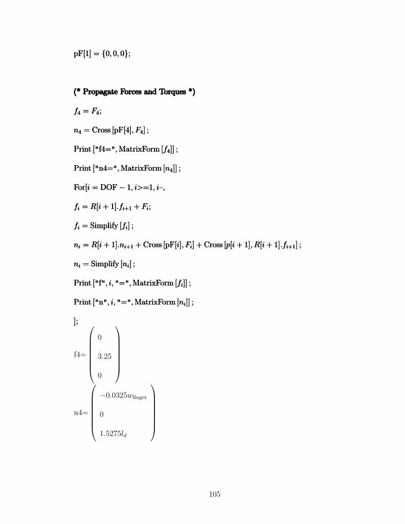
pF[1] = {0, 0, 0};pF[1] = {0, 0, 0};pF[1] = {0, 0, 0};
(* Propagate Forces and Torques *)(* Propagate Forces and Torques *)(* Propagate Forces and Torques *)(* Propagate Forces and Torques *)(* Propagate Forces and Torques *)(* Propagate Forces and Torques *)(* Propagate Forces and Torques *)(* Propagate Forces and Torques *)(* Propagate Forces and Torques *)
f4 = F4;f4 = F4;f4 = F4;
n4 = Cross [pF[4], F4] ;n4 = Cross [pF[4], F4] ;n4 = Cross [pF[4], F4] ;
Print ["f4=", MatrixForm [f4]] ;Print ["f4=", MatrixForm [f4]] ;Print ["f4=", MatrixForm [f4]] ;
Print ["n4=", MatrixForm [n4]] ;Print ["n4=", MatrixForm [n4]] ;Print ["n4=", MatrixForm [n4]] ;
For[i = DOF− 1, i>=1, i–,For[i = DOF− 1, i>=1, i–,For[i = DOF− 1, i>=1, i–,
fi = R[i + 1].fi+1 + Fi;fi = R[i + 1].fi+1 + Fi;fi = R[i + 1].fi+1 + Fi;
fi = Simplify [fi] ;fi = Simplify [fi] ;fi = Simplify [fi] ;
ni = R[i + 1].ni+1 + Cross [pF[i], Fi] + Cross [p[i + 1], R[i + 1].fi+1] ;ni = R[i + 1].ni+1 + Cross [pF[i], Fi] + Cross [p[i + 1], R[i + 1].fi+1] ;ni = R[i + 1].ni+1 + Cross [pF[i], Fi] + Cross [p[i + 1], R[i + 1].fi+1] ;
ni = Simplify [ni] ;ni = Simplify [ni] ;ni = Simplify [ni] ;
Print ["f", i, "=", MatrixForm [fi]] ;Print ["f", i, "=", MatrixForm [fi]] ;Print ["f", i, "=", MatrixForm [fi]] ;
Print ["n", i, "=", MatrixForm [ni]] ;Print ["n", i, "=", MatrixForm [ni]] ;Print ["n", i, "=", MatrixForm [ni]] ;
];];];
f4=
0
3.25
0
n4=
−0.0325wfinger
0
1.5275ld
105

f3 =
−3.25Sin [θ4]
1.17 + 3.25Cos [θ4]
0
n3 =
(−0.0117− 0.0325Cos [θ4]) wfinger
−0.0325Sin [θ4] wfinger
1.5275ld + (0.8658 + 3.25Cos [θ4]) lm
f2 =
(−1.17− 3.25Cos [θ4]) Sin [θ3]− 3.25Cos [θ3] Sin [θ4]
2.08 + Cos [θ3] (1.17 + 3.25Cos [θ4])− 3.25Sin [θ3] Sin [θ4]
0
n2 =
0@
(0.1456 + Cos [θ3] (−0.0117− 0.0325Cos [θ4]) + 0.0325Sin [θ3] Sin [θ4]) wfinger((−0.0117− 0.0325Cos [θ4]) Sin [θ3]− 0.0325Cos [θ3] Sin [θ4]) wfinger1.5275ld + (0.8658 + 3.25Cos [θ4]) lm + (1.0608 + Cos [θ3] (1.17 + 3.25Cos [θ4])− 3.25Sin [θ3] Sin [θ4]) lp
1A
f1 =
0BBBBBBB@
Cos [θ2] ((−1.17− 3.25Cos [θ4]) Sin [θ3]− 3.25Cos [θ3] Sin [θ4]) +Sin [θ2] (−2.08 + Cos [θ3] (−1.17− 3.25Cos [θ4]) + 3.25Sin [θ3] Sin [θ4])
0
Sin [θ2] ((−1.17− 3.25Cos [θ4]) Sin [θ3]− 3.25Cos [θ3] Sin [θ4]) +Cos [θ2] (2.08 + Cos [θ3] (1.17 + 3.25Cos [θ4])− 3.25Sin [θ3] Sin [θ4])
1CCCCCCCA
n1 =
0BBBBBBB@
wfinger (Sin [θ2] ((0.0117 + 0.0325Cos [θ4]) Sin [θ3] + 0.0325Cos [θ3] Sin [θ4])) +wfinger (Cos [θ2] (0.1456 + Cos [θ3] (−0.0117− 0.0325Cos [θ4]) + 0.0325Sin [θ3] Sin [θ4]))
−1.5275ld + (−0.8658− 3.25Cos [θ4]) lm + (−1.0608 + Cos [θ3] (−1.17− 3.25Cos [θ4]) + 3.25Sin [θ3] Sin [θ4]) lp
wfinger (Cos [θ2] ((−0.0117− 0.0325Cos [θ4]) Sin [θ3]− 0.0325Cos [θ3] Sin [θ4])) +wfinger (Sin [θ2] (0.1456 + Cos [θ3] (−0.0117− 0.0325Cos [θ4]) + 0.0325Sin [θ3] Sin [θ4])) wfinger
1CCCCCCCA
(* JOINT TORQUES *)(* JOINT TORQUES *)(* JOINT TORQUES *)
For[i = 1, i ≤ DOF, i++,For[i = 1, i ≤ DOF, i++,For[i = 1, i ≤ DOF, i++,
τi = Dot [ni, zhat] ;τi = Dot [ni, zhat] ;τi = Dot [ni, zhat] ;
Print ["τ", i, "=", τi] ;Print ["τ", i, "=", τi] ;Print ["τ", i, "=", τi] ;
];];];
τ1 = (Cos [θ2] ((−0.0117− 0.0325Cos [θ4]) Sin [θ3]− 0.0325Cos [θ3] Sin [θ4])+
Sin [θ2] (0.1456 + Cos [θ3] (−0.0117− 0.0325Cos [θ4]) + 0.0325Sin [θ3] Sin [θ4]))wfinger
τ2 = 1.5275ld + (0.8658 + 3.25Cos [θ4]) lm + (1.0608 + Cos [θ3] (1.17 + 3.25Cos [θ4]) − 3.25Sin [θ3] Sin [θ4]) lp
τ3 = 1.5275ld + (0.8658 + 3.25Cos [θ4]) lm
106

τ4 = 1.5275ld
(*JACOBIAN*)(*JACOBIAN*)(*JACOBIAN*)
(*Definez − vectors*)(*Definez − vectors*)(*Definez − vectors*)
R0[1] = R[1];R0[1] = R[1];R0[1] = R[1];
z1 = R0[1].zhat;z1 = R0[1].zhat;z1 = R0[1].zhat;
For[i = 2, i ≤ DOF, i++,For[i = 2, i ≤ DOF, i++,For[i = 2, i ≤ DOF, i++,
R0[i] = R0[i− 1].R[i];R0[i] = R0[i− 1].R[i];R0[i] = R0[i− 1].R[i];
zi = R0[i].zhat;zi = R0[i].zhat;zi = R0[i].zhat;
];];];
(*DetermineRotationalJacobian− AssumesAllRevoluteJoints*)(*DetermineRotationalJacobian− AssumesAllRevoluteJoints*)(*DetermineRotationalJacobian− AssumesAllRevoluteJoints*)
Jrot = Table[0, {3}, {DOF}];Jrot = Table[0, {3}, {DOF}];Jrot = Table[0, {3}, {DOF}];
For[i = 1, i<=3, i++,For[i = 1, i<=3, i++,For[i = 1, i<=3, i++,
For[j = 1, j<=DOF, j++,For[j = 1, j<=DOF, j++,For[j = 1, j<=DOF, j++,
Jrot[[i, j]] = zj[[i]];Jrot[[i, j]] = zj[[i]];Jrot[[i, j]] = zj[[i]];
];];];
];];];
Print["Jrot=", MatrixForm[Jrot]];Print["Jrot=", MatrixForm[Jrot]];Print["Jrot=", MatrixForm[Jrot]];
(* Determine Translational Jacobian by Direct Differentiation*)(* Determine Translational Jacobian by Direct Differentiation*)(* Determine Translational Jacobian by Direct Differentiation*)
Jtrans = Table[0, {3}, {DOF}];Jtrans = Table[0, {3}, {DOF}];Jtrans = Table[0, {3}, {DOF}];
For[i = 1, i ≤ 3, i++,For[i = 1, i ≤ 3, i++,For[i = 1, i ≤ 3, i++,
107

Jtrans[[i, 1]] = D [Part[TN0, i, 4], θ1] ;Jtrans[[i, 1]] = D [Part[TN0, i, 4], θ1] ;Jtrans[[i, 1]] = D [Part[TN0, i, 4], θ1] ;
Jtrans[[i, 2]] = D [Part[TN0, i, 4], θ2] ;Jtrans[[i, 2]] = D [Part[TN0, i, 4], θ2] ;Jtrans[[i, 2]] = D [Part[TN0, i, 4], θ2] ;
Jtrans[[i, 3]] = D [Part[TN0, i, 4], θ3] ;Jtrans[[i, 3]] = D [Part[TN0, i, 4], θ3] ;Jtrans[[i, 3]] = D [Part[TN0, i, 4], θ3] ;
Jtrans[[i, 3]] = D [Part[TN0, i, 4], θ4] ;Jtrans[[i, 3]] = D [Part[TN0, i, 4], θ4] ;Jtrans[[i, 3]] = D [Part[TN0, i, 4], θ4] ;
];];];
Jtrans = Simplify[Jtrans];Jtrans = Simplify[Jtrans];Jtrans = Simplify[Jtrans];
Print["Jtrans= ", MatrixForm[Jtrans]];Print["Jtrans= ", MatrixForm[Jtrans]];Print["Jtrans= ", MatrixForm[Jtrans]];
(* Combine Full Jacobian *)(* Combine Full Jacobian *)(* Combine Full Jacobian *)
J = Table[0, {6}, {DOF}];J = Table[0, {6}, {DOF}];J = Table[0, {6}, {DOF}];
For[i = 1, i<=3, i++,For[i = 1, i<=3, i++,For[i = 1, i<=3, i++,
For[j = 1, j<=DOF, j++,For[j = 1, j<=DOF, j++,For[j = 1, j<=DOF, j++,
{J [[i, j]] = Jtrans[[i, j]],{J [[i, j]] = Jtrans[[i, j]],{J [[i, j]] = Jtrans[[i, j]],
J [[i + 3, j]] = Jrot[[i, j]]}J [[i + 3, j]] = Jrot[[i, j]]}J [[i + 3, j]] = Jrot[[i, j]]}
]]]
];];];
Print["J=", MatrixForm[J ]];Print["J=", MatrixForm[J ]];Print["J=", MatrixForm[J ]];
Jrot=
0 Sin [θ1] Sin [θ1] Sin [θ1]
0 −Cos [θ1] −Cos [θ1] −Cos [θ1]
1 0 0 0
Jtrans displayed by column
Jtrans1=
−Sin [θ1] (Cos [θ2 + θ3 + θ4] ld + Cos [θ2 + θ3] lm + Cos [θ2] lp)Cos [θ1] (Cos [θ2 + θ3 + θ4] ld + Cos [θ2 + θ3] lm + Cos [θ2] lp)0
108

Jtrans2=
−Cos [θ1] (Sin [θ2 + θ3 + θ4] ld + Sin [θ2 + θ3] lm + Sin [θ2] lp)−Sin [θ1] (Sin [θ2 + θ3 + θ4] ld + Sin [θ2 + θ3] lm + Sin [θ2] lp)Cos [θ2 + θ3 + θ4] ld + Cos [θ2 + θ3] lm + Cos [θ2] lp
Jtrans3=
−Cos [θ1] Sin [θ2 + θ3 + θ4] ld−Sin [θ1] Sin [θ2 + θ3 + θ4] ldCos [θ2 + θ3 + θ4] ld
Jtrans4=
000
J displayed by column
J1=
−Sin [θ1] (Cos [θ2 + θ3 + θ4] ld + Cos [θ2 + θ3] lm + Cos [θ2] lp)Cos [θ1] (Cos [θ2 + θ3 + θ4] ld + Cos [θ2 + θ3] lm + Cos [θ2] lp)0001
J2=
−Cos [θ1] (Sin [θ2 + θ3 + θ4] ld + Sin [θ2 + θ3] lm + Sin [θ2] lp)−Sin [θ1] (Sin [θ2 + θ3 + θ4] ld + Sin [θ2 + θ3] lm + Sin [θ2] lp)Cos [θ2 + θ3 + θ4] ld + Cos [θ2 + θ3] lm + Cos [θ2] lpSin [θ1]−Cos [θ1]0
J3=
−Cos [θ1] Sin [θ2 + θ3 + θ4] ld−Sin [θ1] Sin [θ2 + θ3 + θ4] ldCos [θ2 + θ3 + θ4] ldSin [θ1]−Cos [θ1]0
J4=
000Sin [θ1]−Cos [θ1]0
(* SINGULARITY ANALYSIS *)(* SINGULARITY ANALYSIS *)(* SINGULARITY ANALYSIS *)
(*θ1 = 0Degree;(*θ1 = 0Degree;(*θ1 = 0Degree;
θ2 = 90Degree;θ2 = 90Degree;θ2 = 90Degree;
θ3 = 0Degree;θ3 = 0Degree;θ3 = 0Degree;
θ4 = 0Degree;θ4 = 0Degree;θ4 = 0Degree;
J ;J ;J ;
Print["J=", MatrixForm[J ]];Print["J=", MatrixForm[J ]];Print["J=", MatrixForm[J ]];
109

MatrixRank[J ]*)MatrixRank[J ]*)MatrixRank[J ]*)
(* MULTIFINGER KINEMATICS *)(* MULTIFINGER KINEMATICS *)(* MULTIFINGER KINEMATICS *)
(* Forward Kinematics to Wrist Frame *)(* Forward Kinematics to Wrist Frame *)(* Forward Kinematics to Wrist Frame *)
ndigits = 5;ndigits = 5;ndigits = 5;
Twrist[1] = {{0.707, 0, 0.707, 0.82}, {−0.707, 0, 0.707,−1.08}, {0,−1, 0, 0.5}, {0, 0, 0, 1}};Twrist[1] = {{0.707, 0, 0.707, 0.82}, {−0.707, 0, 0.707,−1.08}, {0,−1, 0, 0.5}, {0, 0, 0, 1}};Twrist[1] = {{0.707, 0, 0.707, 0.82}, {−0.707, 0, 0.707,−1.08}, {0,−1, 0, 0.5}, {0, 0, 0, 1}};
Twrist[2] = {{1, 0, 0, 4.2}, {0, 1, 0,−1.32}, {0, 0, 1, 0}, {0, 0, 0, 1}};Twrist[2] = {{1, 0, 0, 4.2}, {0, 1, 0,−1.32}, {0, 0, 1, 0}, {0, 0, 0, 1}};Twrist[2] = {{1, 0, 0, 4.2}, {0, 1, 0,−1.32}, {0, 0, 1, 0}, {0, 0, 0, 1}};
Twrist[3] = {{1, 0, 0, 4.2}, {0, 1, 0,−0.45}, {0, 0, 1, 0}, {0, 0, 0, 1}};Twrist[3] = {{1, 0, 0, 4.2}, {0, 1, 0,−0.45}, {0, 0, 1, 0}, {0, 0, 0, 1}};Twrist[3] = {{1, 0, 0, 4.2}, {0, 1, 0,−0.45}, {0, 0, 1, 0}, {0, 0, 0, 1}};
Twrist[4] = {{1, 0, 0, 3.785}, {0, 1, 0, 0.45}, {0, 0, 1, 0}, {0, 0, 0, 1}};Twrist[4] = {{1, 0, 0, 3.785}, {0, 1, 0, 0.45}, {0, 0, 1, 0}, {0, 0, 0, 1}};Twrist[4] = {{1, 0, 0, 3.785}, {0, 1, 0, 0.45}, {0, 0, 1, 0}, {0, 0, 0, 1}};
Twrist[5] = {{1, 0, 0, 3.785}, {0, 1, 0, 1.32}, {0, 0, 1, 0}, {0, 0, 0, 1}};Twrist[5] = {{1, 0, 0, 3.785}, {0, 1, 0, 1.32}, {0, 0, 1, 0}, {0, 0, 0, 1}};Twrist[5] = {{1, 0, 0, 3.785}, {0, 1, 0, 1.32}, {0, 0, 1, 0}, {0, 0, 0, 1}};
For [i = 1, i ≤ ndigits, i++,For [i = 1, i ≤ ndigits, i++,For [i = 1, i ≤ ndigits, i++,
Twn[i] = Twrist[i].TN0;Twn[i] = Twrist[i].TN0;Twn[i] = Twrist[i].TN0;
Twn[i] = Simplify[Twn[i]];Twn[i] = Simplify[Twn[i]];Twn[i] = Simplify[Twn[i]];
Print["Twn[", i, "]=", MatrixForm[Twn[i]]];Print["Twn[", i, "]=", MatrixForm[Twn[i]]];Print["Twn[", i, "]=", MatrixForm[Twn[i]]];
];];];Twn matrices displayed by column
Twn[1]1=
0.707Cos [θ1] Cos [θ2 + θ3 + θ4] + 0.707Sin [θ2 + θ3 + θ4]−0.707Cos [θ1] Cos [θ2 + θ3 + θ4] + 0.707Sin [θ2 + θ3 + θ4]−Cos [θ2 + θ3 + θ4] Sin [θ1]0
Twn[1]2=
0.707Cos [θ2 + θ3 + θ4]− 0.707Cos [θ1] Sin [θ2 + θ3 + θ4]0.707Cos [θ2 + θ3 + θ4] + 0.707Cos [θ1] Sin [θ2 + θ3 + θ4]Sin [θ1] Sin [θ2 + θ3 + θ4]0
Twn[1]3=
0.707Sin [θ1]−0.707Sin [θ1]Cos [θ1]0
110

Twn[1]4=
0.82 + 0.707Cos [θ1] (Cos [θ2 + θ3 + θ4] ld + Cos [θ2 + θ3] lm + Cos [θ2] lp) +0.707 (Sin [θ2 + θ3 + θ4] ld + Sin [θ2 + θ3] lm + Sin [θ2] lp)
−1.08− 0.707Cos [θ1] (Cos [θ2 + θ3 + θ4] ld + Cos [θ2 + θ3] lm + Cos [θ2] lp) +0.707 (Sin [θ2 + θ3 + θ4] ld + Sin [θ2 + θ3] lm + Sin [θ2] lp)
0.5− Sin [θ1] (Cos [θ2 + θ3 + θ4] ld + Cos [θ2 + θ3] lm + Cos [θ2] lp)
1
Twn[2]1,2,3=
Cos [θ1] Cos [θ2 + θ3 + θ4] −Cos [θ1] Sin [θ2 + θ3 + θ4] Sin [θ1]Cos [θ2 + θ3 + θ4] Sin [θ1] −Sin [θ1] Sin [θ2 + θ3 + θ4] −Cos [θ1]Sin [θ2 + θ3 + θ4] Cos [θ2 + θ3 + θ4] 00 0 0
Twn[2]4=
4.2 + Cos [θ1] (Cos [θ2 + θ3 + θ4] ld + Cos [θ2 + θ3] lm + Cos [θ2] lp)−1.32 + Sin [θ1] (Cos [θ2 + θ3 + θ4] ld + Cos [θ2 + θ3] lm + Cos [θ2] lp)Sin [θ2 + θ3 + θ4] ld + Sin [θ2 + θ3] lm + Sin [θ2] lp1
Twn[3]1,2,3=
Cos [θ1] Cos [θ2 + θ3 + θ4] −Cos [θ1] Sin [θ2 + θ3 + θ4] Sin [θ1]Cos [θ2 + θ3 + θ4] Sin [θ1] −Sin [θ1] Sin [θ2 + θ3 + θ4] −Cos [θ1]Sin [θ2 + θ3 + θ4] Cos [θ2 + θ3 + θ4] 00 0 0
Twn[3]4=
4.2 + Cos [θ1] (Cos [θ2 + θ3 + θ4] ld + Cos [θ2 + θ3] lm + Cos [θ2] lp)−0.45 + Sin [θ1] (Cos [θ2 + θ3 + θ4] ld + Cos [θ2 + θ3] lm + Cos [θ2] lp)Sin [θ2 + θ3 + θ4] ld + Sin [θ2 + θ3] lm + Sin [θ2] lp1
Twn[4]1,2,3=
Cos [θ1] Cos [θ2 + θ3 + θ4] −Cos [θ1] Sin [θ2 + θ3 + θ4] Sin [θ1]Cos [θ2 + θ3 + θ4] Sin [θ1] −Sin [θ1] Sin [θ2 + θ3 + θ4] −Cos [θ1]Sin [θ2 + θ3 + θ4] Cos [θ2 + θ3 + θ4] 00 0 0
Twn[4]4=
3.785 + Cos [θ1] (Cos [θ2 + θ3 + θ4] ld + Cos [θ2 + θ3] lm + Cos [θ2] lp)0.45 + Sin [θ1] (Cos [θ2 + θ3 + θ4] ld + Cos [θ2 + θ3] lm + Cos [θ2] lp)Sin [θ2 + θ3 + θ4] ld + Sin [θ2 + θ3] lm + Sin [θ2] lp1
Twn[5]1,2,3=
Cos [θ1] Cos [θ2 + θ3 + θ4] −Cos [θ1] Sin [θ2 + θ3 + θ4] Sin [θ1]Cos [θ2 + θ3 + θ4] Sin [θ1] −Sin [θ1] Sin [θ2 + θ3 + θ4] −Cos [θ1]Sin [θ2 + θ3 + θ4] Cos [θ2 + θ3 + θ4] 00 0 0
Twn[5]4=
3.785 + Cos [θ1] (Cos [θ2 + θ3 + θ4] ld + Cos [θ2 + θ3] lm + Cos [θ2] lp)1.32 + Sin [θ1] (Cos [θ2 + θ3 + θ4] ld + Cos [θ2 + θ3] lm + Cos [θ2] lp)Sin [θ2 + θ3 + θ4] ld + Sin [θ2 + θ3] lm + Sin [θ2] lp1
C.2 Inverse Kinematics
The following analysis uses the abbreviations cx = cos θx, sx = sin θx, cxy =
cos (θx + θy), and sxy = sin (θx + θy). From the forward kinematics, the transforma-
111

tion from the base frame to the tool frame is given by
05T = 0
1T12T
23T
34T
45T
=
c1c234 −c1s234 s1 c1(ldc234 + lmc23 + lpc2)
s1c234 −s1s234 −c1 s1(ldc234 + lmc23 + lpc2)
s234 c234 0 lds234 + lms23 + lps2
0 0 0 1
=
r11 r12 r13 px
r21 r22 r23 py
r31 r32 r33 pz
0 0 0 1
Premultiplying both sides by 0
1T−1 results in
01T
−1 05T = 1
2T23T
34T
45T
where
01T
−1 05T =
c1r11 + s1r21 c1r12 + s1r22 c1r13 + s1r23 c1px + s1py
−s1r11 + c1r21 −s1r12 + c1r22 −s1r13 + c1r23 −s1px + c1py
r31 r32 r33 pz
0 0 0 1
and
15T =
c234 −s234 0 ldc234 + lmc23 + lpc2
0 0 −1 0
s234 c234 0 lds234 + lms23 + lps2
0 0 0 1
112

Analysis begins with an algebraic approach and equates elements (2,4)
−s1px + c1py = 0
which gives us θ1 in terms of the desired goal point coordinates.
θ1 = tan−1
(py
px
)
To solve for angles θ2, θ3, and θ4, a geometric approach is used. Figure C.1 shows the
arm plane with the manipulator is its desired position and orientation, represented
by the point p and the angle φ.
Figure C.1: Geometric View in Arm Plane
Using the law of cosines, θ3 is solved as follows
p =√
p2x + p2
z
p2 = l2p + l2m − 2lplm cos (π + θ3)
p2 = l2p + l2m + 2lplm cos θ3
θ3 = cos−1
(p2 − l2p − l2m
2lplm
)
113
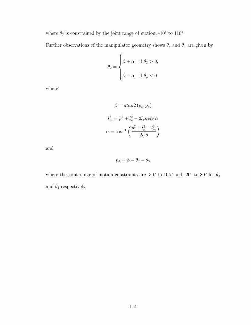
where θ3 is constrained by the joint range of motion, -10◦ to 110◦.
Further observations of the manipulator geometry shows θ2 and θ4 are given by
θ2 =
β + α if θ3 > 0,
β − α if θ3 < 0
where
β = atan2 (px, pz)
l2m = p2 + l2p − 2lpp cos α
α = cos−1
(p2 + l2p − l2m
2lpp
)
and
θ4 = φ− θ2 − θ3
where the joint range of motion constraints are -30◦ to 105◦ and -20◦ to 80◦ for θ2
and θ4 respectively.
114

BIBLIOGRAPHY
[1] Amis, A. Variation of finger forces in maximal isometric grasp tests on a rangeof cylinder diameters. Journal of Biomedical Engineering 9 (1987).
[2] Lee, J. & Rim, K. Measurement of finger joint angles and maximum finger forcesduring cylinder grip activity. Journal of Biomedical Engineering 13 (1991).
[3] Rosheim, M. Robot Evolution: The Development of Anthrobotics (Wiley-Interscience, 1994).
[4] Foster, T. Development of a Four-Fingered Dexterous Robot End Effector forSpace Operations. Master’s thesis, University of Maryland, College Park (2001).
[5] Arbuckle, J. Measurement of the arc of digital flexion and joint movementranges. Journal of Hand Surgery 20 (1995).
[6] BioConcepts, http://www.bio-con.com/PDFs/hand cht.pdf. Hand Measure-ment Chart (1998).
[7] Akin, D. L., Roberts, B., Pilotte, K. & Baker, M. Robotic augmentation of evafor hubble space telescope servicing. In AIAA Space 2003 Conference (LongBeach, CA, 2003).
[8] Jacobsen, S., Iversen, E., Knutti, D., Johnson, R. & Biggers, K. Design of theutah/m.i.t. dextrous hand. In Proceedings of the IEEE International Conferenceon Robotics and Automation, 1520–1532 (1986).
[9] Salisbury, K. Kinematic and force analysis of articulated hands. Ph.D. thesis,Stanford University (1982).
[10] Townsend, W. The barretthand grasper - programmably flexible part handlingand assembly. Industrial Robot 27, 181–188 (2000).
[11] National Aeronautics and Space Administration. Improved Cable-Drive Pre-tensioner, msc-22405 edn.
[12] Carrozza, M. et al. The development of a novel prosthetic hand - ongoingresearch and preiminary results. IEEE/ASME Transactions on Mechatronics7, 108–114 (2002).
[13] Walker, R. Shadow Dextrous Hand Technical Specification. Shadow RobotCompany (2005).
[14] Lovchik, C. The robonaut hand: A deterous robot hand for space. In Proceed-ings of the IEEE International Conference on Robotics and Automation, vol. 2(1999).
[15] NASA-STD-3000. Man-Systems Integration Standards, revision b edn. (1995).
115

[16] Gray, H. Anatomy of the Human Body (Bartleby,http://www.bartleby.com/107, 2000). Electronic version of Gray’s Anatomy,published by Lea and Febiger, 1918.
[17] Luttgens, K. & Wells, K. F. Kinesiology: Scientific Basis of Human Motion(Saunders College Publishing, 1982), 7th edn.
[18] Anthropometric Source Book Volume II: A Handbook of Anthropometric Data(NASA Reference Publication 1024, 1978).
[19] Mallon, W., Brown, H. & Nunley, J. Digital ranges of motion; normal valuesin young adults. Journal of Hand Surgery 16 (1991).
[20] Behnke, R. S. Kinetic Anatomy (Human Kinetics, 2006), 2nd edn.
[21] Cutkosky, M. & Howe, R. Dextrous Robot Hands, chap. Human Grasp Choiceand Robotic Grasp Analysis (Springer-Verlag, 1990).
[22] Pilotte, K. Analysis of Grasp Requirements for Telerobotic Satellite Servicing.Master’s thesis, University of Maryland, College Park (2004).
[23] Kinoshita, H., Murase, T. & Bandou, T. Grip posture and forces during holdingcylindrical objects with circular grasps. Ergonomics 39 (1996).
[24] Howell, L. Compliant Mechanisms (John Wiley & Sons, New York, 2001).
[25] Daerden, F. & Lefeber, D. Pneumatic artificial muscles: Actuators for roboticsand automation. European Journal of Mechanical and Environmental Engi-neering 47, 11–21 (2002).
[26] Ma, N., Song, G. & Lee, H. Position control of shape memory alloy actua-tors with internal electrial resistance feedback using neural networks. SmartMaterials and Structures 13, 777–783 (2004).
[27] Otsuka, K. & Ren, X. Recent developments in the research of shape memoryalloys. Intermetallics 7, 511–528 (1999).
[28] Bar-Cohen, Y., Xue, T., Shahinpoor, M., Simpson, J. & Smith, J. Low-massmuscle actuators using electroactive polymers (eap). In Proceedings of SPIE’s5th Annual International Symposium on Smart Structures and Materials (SanDiego, CA, 1998).
[29] Bar-Cohen, Y. Handbook on Biomimetrics, chap. Electroactive Polymers asArtificial Muscles - Capabilities, Potentials, and Challenges (NTS, 2000).
[30] DeRossi, D. et al. Electro-active polymers for actuation and sensing in spaceapplications. In 55th International Astronautical Congress of the InternationalAstronautical Federation, the International Academy of Astronautics, and theInternational Institute of Space Law (Vancouver, Canada, 2004).
116

[31] Lee, G. R. Development of a Mechanical Test Apparatus for Spacesuit Gloves.Master’s thesis, University of Maryland, College Park (2001).
[32] Beyl, P. et al. Compliant actuation in new robotic applications. In Proceedingsof the 7th National Congress on Theoretical and Applied Mechanics (Belgium,2006).
[33] Omega - Subminiature Tension or Compression Load Cells.http://www.omega.com/Pressure/pdf/LC201.pdf (2007).
[34] Tekscan, Inc. FlexiForce Sensors User Manual (2005).
[35] Pressure Profile Systems, Inc. FingerTPS: Fingertip Tactile Pressure Sensors,User Manual.
[36] Craig, J. J. Introduction to Robotics: Mechanics and Control (Pearson PrenticeHall, 2005), third edn.
[37] Murray, R., Li, Z. & Sastry, S. S. A Mathematical Introduction to RoboticManipulation (CRC Press, 1994).
[38] Wolovich, W. Robotics: Basic Analysis and Design (Holt, Rinehart, and Win-ston, 1986).
[39] Lay, D. Linear Algebra and its Applications (Addison-Wesley, 2003).
[40] Mason, M. T. & Salisbury, J. K. Robot Hands and the Mechanics of Manipu-lation (MIT Press, 1985).
[41] Kerr, J. & Roth, B. Analysis of multifingered hands. International Journal ofRobotics Research 4 (1986).
117
Related Documents