1 AJAY KUMAR GARG ENGINEERING COLLEGE 27 th Km. Stone, Delhi-Hapur Bypass Road, Ghaziabad-201009 A REPORT ON POROUS MEDIUM ENGINE SUBMITTED BY: DEEPAK AGRAWAL III th YEAR MECHANICAL ENGINEERING ROLL NO.:1202740059

Welcome message from author
This document is posted to help you gain knowledge. Please leave a comment to let me know what you think about it! Share it to your friends and learn new things together.
Transcript

1
AJAY KUMAR GARG ENGINEERING COLLEGE
27th Km. Stone, Delhi-Hapur Bypass Road,
Ghaziabad-201009
A
REPORT
ON
POROUS MEDIUM ENGINE
SUBMITTED BY:
DEEPAK AGRAWAL
IIIth YEAR
MECHANICAL ENGINEERING
ROLL NO.:1202740059

2
ABSTRACT
This report describes application of a highly porous open cell structures to
internal combustion engines for supporting mixture formation and combustion processes. Porous structures, materials and their properties for engine
application are discussed in this paper. Especially application to a high temperature combustion processes are considered. Novel concepts for internal
combustion engines based on the application of porous medium technology are presented and discussed. The main attention is focused on the engine concepts
having.
Potential for homogeneous (nearly emissions free) combustion process under
variable engine operational conditions. It is shown that porous media can be used for a great variety of improvements in the combustion process. The key
role for NOx reduction and soot emission elimination is a homogeneous combustion in engine. This can be realized by homo generous mixture
formation, and a 3D ignition preventing from formation of a flame front having a temperature gradient a in the entire combustion volume. All these processes:
gas flow, fuel injection and its spatial distribution, vaporization, mixture homogenization, ignition and combustion can be controlled or positively influenced with the help of porous media/ceramic reactors.
Its use in ICEs is not without problems due to heat transfer during
compression, limited maximum temperature and possibiliy of delayed heat supply to expansion. A simple tool for cycle parameter assessment using
computerized T-s diagram was developed and presented earlier. The preliminary results of it are promising.
As the further step, a CFD model has been developed for an evaluation of a
PM combustion potential and its future optimization. A simulation method based on a moveable-grid, Runge-Kutta finite volume (FV) 2.5-D model
has required the introduction of new source terms concerning spatially distributed heat transfer and momentum sink due to drag in a PM domain. The
geometry of a PM insert is characterized using a “filament” model of its matrix characterized in 3 main directions. The temperature of a PM insert
surface is solved using the Fourier equation with estimated effective thermal conductivity of a solid phase. A combustion model uses momentum and specie sources near to a fuel entry to a PM insert accompanied by very fast
heat release for a part of fuel covered by oxygen available and complex chemical kinetics.

3
The detailed FVM model has provided preliminary results as a base for sensitivity analysis, cycle optimization and engine lay-out changes. Steep
temperature gradients may occur in a PM domain due to a gradual transport of
cylinder charge into a PM and a compression or combustion of pre-heated
gas. NOx formation might be limited only if high temperature occurs in the
zone of a rich mixture. Concerning efficiency, a premature heat supply to gas from a PM during compression is disadvantageous as well as an intensive heat
transfer during combustion. The model will be used in a future optimization of the PM combustion process

4
TABLE OF CONTENTS
1-INTRODUCTION .......................................................................5-6
2- POROUS MEDIUM TCHNOLOGY.............................................6-9
2.1- INTRODUCTION OF POROUS MEDIUM
TECHNOLOGY......................................................................6-7
2.2- HOMOGENEOUS COMBUSTION........................................8-9
3- CONCEPT OF PM ENGINE: IENTERNAL COMBUSTION
ENGINE .........................................................................................10-14
3.1- WITH A CLOSED PM CHAMBER………………………..11-12
3.2- WITH A OPEN PM CHAMBER…………………………...13-14
4- COGNERATION IN PM ENGINE………………………………15-16
5- MATERIAL USED FOR POROUS MEDIUM………………….17-18
6- SELECTION OF AVAILABLE PM MATERIALS ……………..19-22
7- APPLICATION OF PM ENGINE……………………………………23
8- PROBLEMS OF PM COMBUSTION……………………………….24
9- CONCLUSION AND FURTHER RECOMDATIONS……………...25
10- REFERANCES……………………………………………………….26
5
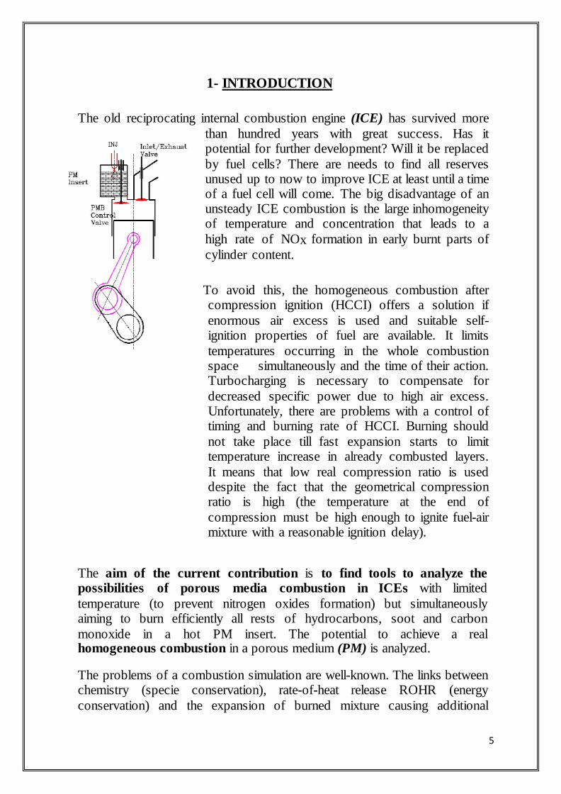
1- INTRODUCTION The old reciprocating internal combustion engine (ICE) has survived more
than hundred years with great success. Has it potential for further development? Will it be replaced
by fuel cells? There are needs to find all reserves unused up to now to improve ICE at least until a time of a fuel cell will come. The big disadvantage of an unsteady ICE combustion is the large inhomogeneity of temperature and concentration that leads to a
high rate of NOx formation in early burnt parts of
cylinder content.
To avoid this, the homogeneous combustion after compression ignition (HCCI) offers a solution if
enormous air excess is used and suitable self-ignition properties of fuel are available. It limits
temperatures occurring in the whole combustion space simultaneously and the time of their action. Turbocharging is necessary to compensate for
decreased specific power due to high air excess. Unfortunately, there are problems with a control of timing and burning rate of HCCI. Burning should
not take place till fast expansion starts to limit temperature increase in already combusted layers.
It means that low real compression ratio is used despite the fact that the geometrical compression ratio is high (the temperature at the end of
compression must be high enough to ignite fuel-air mixture with a reasonable ignition delay).
The aim of the current contribution is to find tools to analyze the possibilities of porous media combustion in ICEs with limited
temperature (to prevent nitrogen oxides formation) but simultaneously aiming to burn efficiently all rests of hydrocarbons, soot and carbon
monoxide in a hot PM insert. The potential to achieve a real homogeneous combustion in a porous medium (PM) is analyzed.
The problems of a combustion simulation are well-known. The links between chemistry (specie conservation), rate-of-heat release ROHR (energy
conservation) and the expansion of burned mixture causing additional

6
acceleration of flame front (momentum conservation) bring about an unstability of numerical algorithm, suppressed currently by both the artificial
or natural damping features of FV numerical schemes. Numerical diffusion is achieved as both artificial, i.e., intentional one or natural, i.e. false one caused
by too rough FV mesh. Unfortunately, the big gradients of concentration and temperature demand fine meshes. The integration requires extraordinary small
time step, moreover, called for by a stiffness of chemical kinetic equations. In this situation, a PM combustion with temperature stabilization due to
overheated solid phase and its damping drag creates a problem that is not interesting only as itself but it may elucidate other problems of a general
flame simulation.

7
2. POROUS MEDIUM TECHNOLOGY
2.1. Introduction to porous medium technology
In this technology a highly porous structures having open cells are considered,
with porosity higher than 80%, and typically higher than 90%. This makes the porous media transparent for gas flow, spray and flame.
Porous medium (PM) technology is here defined as an utilization of specific and unique features of highly porous medium for supporting of individual processes (mixture formation, ignition and combustion) realized in engine.
Most of these processes perform in PM-volume drastically different manner from this observed in a free volume.
Selected features of the porous medium permit its attractive application to the following
En err circulation in engine cycle in the form of hot burned gases recirculation
or combustion energy this may significantly influence thermodynamic properties of the charge in the cylinder and may control the ignitability
(activity) of the charge. This energy recirculation may be performed under different pressure and temperature conditions during the engine cycle.
Additionally, this heat recuperation may be used for controlling the combustion temperature level.
Fuel injection in PM-volume: especially unique features of liquid jet
distribution and homogenization throughout the PM-volume (effect of multi-jet splitting) [3] is very attractive for fast mixture formation in the PM-volume.
Fuel vaporization in PM-volume: combination of large heat capacity of the
PM-material, large specific surface area with excellent heat transfer in PM-volume make the liquid fuel vaporization very fast and complete. Here two
different conditions of the process have to be considered: vaporization with presence and with lack of oxygen.
Mixing and homogenization in PM-volume: unique features of the flow properties inside3D-structures allow very effective mixing and in PM-volume.
3D-thermal-PM-ignition (if PM temperature is at least equal to ignition
temperature under certain thermodynamic properties and mixture composition): there is a new kind of ignition, especially effective if the PM-volume creates
automatically the combustion chamber volume.
Heat release in PM-volume under controlled combustion temperature (properties of homogeneous combustion): there is only one known kind of

8
combustion that permits homogeneous combustion conditions almost
independently of the engine load with possibility of controlling of the
combustion temperature level.
Depending on the application of a porous medium, a combination of
thermal and mechanical properties of the materials as well as their
inner structure and pores size have to separately be chosen and
optimized for supporting of particular engine process. If the porous
medium is used directly for controlling the combustion process under
high pressure conditions, above requirements become especially
critical. The probe presented in figure 1 is characterized by the
following parameters: porosity=91.88%,connection density =0.0311
per mm3 (represents a number of connections or junctions per cubic
millimetre)
For applications considered in this paper typical pore size is higher
than 1mm, and usually is of order of 3mm large. This pore size is
often expressed by the pore density “ppi” – pore per linear inch.
Typical pore density useful for applications reported in this paper is
from 8 to30ppi. The pore shape and pore density depends on the
basic foam used for manufacturing of final foams (e.g. PU-foam for
ceramic foams
The volume of a highly porous structure may be divided in to pore
volume (free volume for gas),
Material volume, hollow tube junctions, and micro porosity
9
2.2 HOMOGENEOUS COMBUSTION
Homogeneous combustion in an IC engine is defined as a process characterized
by a 3Dignition
of the homogeneous charge with simultaneous-volumetric-combustion, hence, ensuring a homogeneous temperature field. According to the definition given
above, three steps of the mixture formation & combustion may be selected that define the
ability of a given combustion system to operate as a homogeneous combustion system:
Homogenization of charge.
Ignition conditions.
Combustion process & temperature field.
Four different ignition techniques may be selected:
Local ignition (e.g., spark plug).
Thermal self-ignition (e.g., compression ignition).
Controlled auto-ignition (e.g., low temperature chemical ignition).
3D-thermal PM self-ignition (3D-grid-structure of a high temperature).
The last considered ignition system has been recently proposed by Durst and Welcas (3) and uses a 3D-structured porous medium (PM) for the volumetric
ignition of homogeneous charge. The PM has homogeneous surface temperature over the most of the PM-volume, higher than the ignition temperature. In this case the PM-volume defines the combustion chamber
volume. Thermodynamically speaking, the porous medium is here characterized by a high heat capacity and by a large specific surface area. As a
model, we could consider the 3D-structure of the porous medium as a large number of “hot spots” homogeneously distributed throughout the combustion
chamber volume. Because of this feature a thermally controlled 3D-ignition can be achieved. Additionally, the porous medium controls the temperature
level of the combustion chamber permitting the NOx level control almost independently of the engine load or of the (A/F) ratio. Let us consider the four
possible combustion modes of a homogeneous charge:
Homogeneous charge with local ignition.
Homogeneous charge with compression ignition.
Homogeneous charge with controlled auto-ignition.
Homogeneous charge with 3D-thermal self-ignition in PM-volume.

10
In the case of local ignition we could not fulfill the requirements of the ignition defined for homogeneous combustion. In this case a flame kernel will be
followed a flame propagation in the combustion chamber. In the case of compression ignition a multi-point ignition can be achieved, except the near-
wall areas. On one hand side, this process (if volumetric) would be related to very high-pressure gradients in the cylinder. On the other hand, any non-
homogeneity of the charge, any hot spots in the combustion chamber, and colder area near the cylinder and piston walls will make the ignition process
not controllable

11
3-CONCEPT OF THE PM-ENGINE: INTERNAL
COMBUSTION ENGINE WITH MIXTURE FORMATION
AND HOMOGENEOUS COMBUSTION IN POROUS
REACTOR
PM-engine is here defined as an internal combustion engine with a homogeneous combustion process realized in a porous medium volume. The
following individual processes of PM engine are realized in porous medium volume: internal heat recuperation, fuel injection, fuel vaporization, mixing
with air, homogenization of charge, 3D-thermal self-ignition, and a homogeneous combustion. The TDC (Top Dead Centre) compression volume is equal to the PM volume which creates the engine combustion
chamber. Outside the PM-volume there is no combustion present in the cylinder. PM-engine may be classified with respect to the timing of heat
recuperation in engine as: � Engine with periodic contact between PM and cylinder (so-called closed
PM-chamber).
� Engine with permanent contact between PM and cylinder (so-called open
PM-chamber).
Another classification criterion concerns the positioning of the PM-reactor in
engine. Here, three possible localizations may be selected: engine head, cylinder, and piston
(Figure). Interesting feature of PM-engine is its ability to operate with different liquid- and gaseous fuels. Independently of the fuel used, this engine is a
3DPM- thermal self-ignition engine. Finally, the PM engine concept may be applied to both two- and four-stroke cycle engines.
Figure: Possible locations of PM-reactor in PM-engine concept

12
3.1-CONCEPT OF THE PM-ENGINE WITH A CLOSED PM
CHAMBER
Let us start this analysis with a case of closed PM chamber, i.e.
engine with a periodic contact between working gas and PM-heat
recuperator (Figure 19). At the end of the expansion stroke (Figure
19e) the valve controlling timing of the PM chamber closes and fuel
may be injected in the PM volume. This chamber is a low pressure
chamber and a long time is available for fuel supply and its
Figure 19: Principle of the PM-engine operation with a closed chamber; 1-intake valve, 2-exhaust valve, 3-PM-chamber valve, 4-fuel injector, 5-piston
vaporization in the PM-volume. Simultaneously, other processes may perform in the cylinder volume. These processes may be continued through exhaust,
intake and compression strokes (Figure 19a). Near the TDC of compression (Figure 19b) the valve in PM-chamber opens
and the compressed air flows from the cylinder to the hot PM containing fuel vapours. Very fast
mixing of both gases occurs before mixture igniting in the whole PM-volume (Figure 19c). The resulting heat release process performs simultaneously in the
whole PM volume. Three necessary conditions for a homogeneous combustion are here fulfilled: homogenization of charge in PM-volume, 3D-thermal self-
ignition in PM-volume and a volumetric combustion with a homogeneous

13
temperature field in PM-volume. Additionally, the PM deals as a heat capacitor and controls the combustion temperature level
3.2- CONCEPT OF THE PM-ENGINE WITH AN OPEN PM
CHAMBER
Another possible realization of the PM-engine is a combustion system characterized by a permanent
contact between working gas and PM-reactor. In this case it is assumed that the PM-combustion chamber is mounted in the engine head, as shown in Figure
20. During the intake stroke it is weak influence of the PM-heat capacitor on the in cylinder air thermodynamic conditions.
Also during early compression stroke, only small amount of air contact the hot
PM. This heat exchange process (non-adiabatic compression) increases with continuing compression timing, and at the TDC the whole combustion air is
closed in the PM volume. Near the TDC of compression the fuel is injected into PM volume and very fast fuel vaporization and mixing with air occur in
3D-structure of PM. E2 E3
PM-Reactor
E1 E4
E5
Figure: Energy balance of PM-reactor in PM-engine with open
chamber: E1=energy supplied from compression; E2=energy supplied with fuel;
E3=energy losses; E4=energy supplied from PM to the air; E5=energy transported with burned gases
14
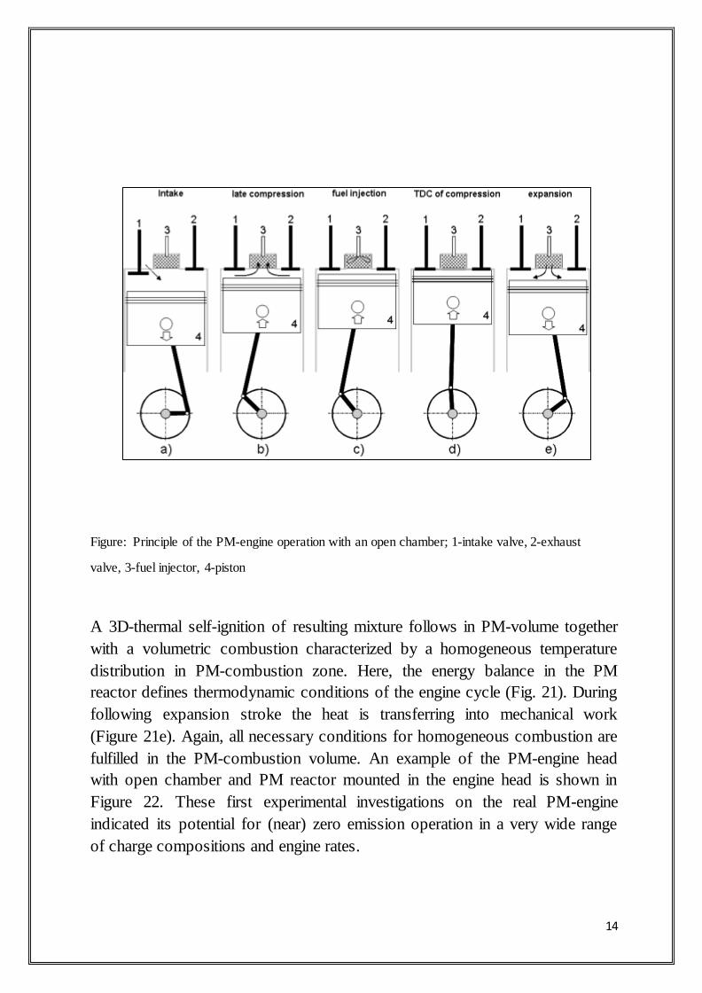
Figure: Principle of the PM-engine operation with an open chamber; 1-intake valve, 2-exhaust
valve, 3-fuel injector, 4-piston
A 3D-thermal self-ignition of resulting mixture follows in PM-volume together
with a volumetric combustion characterized by a homogeneous temperature
distribution in PM-combustion zone. Here, the energy balance in the PM
reactor defines thermodynamic conditions of the engine cycle (Fig. 21). During
following expansion stroke the heat is transferring into mechanical work
(Figure 21e). Again, all necessary conditions for homogeneous combustion are
fulfilled in the PM-combustion volume. An example of the PM-engine head
with open chamber and PM reactor mounted in the engine head is shown in
Figure 22. These first experimental investigations on the real PM-engine
indicated its potential for (near) zero emission operation in a very wide range
of charge compositions and engine rates.
15
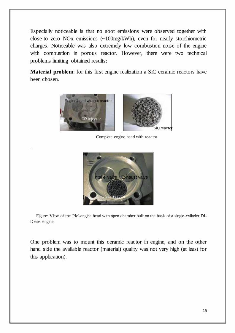
Especially noticeable is that no soot emissions were observed together with
close-to zero NOx emissions (~100mg/kWh), even for nearly stoichiometric
charges. Noticeable was also extremely low combustion noise of the engine
with combustion in porous reactor. However, there were two technical
problems limiting obtained results:
Material problem: for this first engine realization a SiC ceramic reactors have
been chosen.
Engine head without reactor
CR injector
SiC reactor
Complete engine head with reactor
`
Intake valve Exhaust valve
SiC reactor
Figure: View of the PM-engine head with open chamber built on the basis of a single-cylinder DI-
Diesel engine
One problem was to mount this ceramic reactor in engine, and on the other
hand side the available reactor (material) quality was not very high (at least for
this application).

16
4.0 COGENERATION IN PM-ENGINE
During ordinary operation of any engine approximately 70% of the heat value
is lost due to practical and physical limitation. The concept of cogeneration
now a day is quite established and implemented almost in every industry,
where power requirement is accompanied by the industrial process heating
(IPH). The term heat to power ratio is somehow a very interesting topics of
research, as in every industry the load matching is very important for proper
utilization of heat energy. Generally it is seen that the dynamic range to which
Q/W ratio can operate is limited due to certain parameters in working of any
power generation cycle, typical values for certain established systems are given
in the following table
Cogeneration
system
Q/W Power output
Back pressure
Steam Turbine
4.0-14.3 14-22 %
Steam turbine 2.0-10.0 22.0-40.0 %
Gas turbine 1.3-2.0 24-35 %
Combined cycle 1.0-1.7 34-40 %
Ordinary
reciprocating engine
1.1-2.5 33-53 %
PM-engine Yet to be explored Yet to be explored
Table. Efficiencies and dynamic power modulation of some established cogeneration technology
Range of Q/W can be raised by incorporating certain mechanisms in above
given systems like steam bleed or supplementary firing of fuel to match the
IPH requirements. The concept synonymous to supplementary fuel firing can
be used in PM-Engines here the advantage would be that the mechanical power
output is also more for a fixed quantity of fuel. A typical schematic is shown in
(FIG.4.A)

17
Pm with heat exchanger
Figure . A. Principle of the PM-engine cycle with cogeneration.
This concept uses the energy of PM combustion to develop shaft power and
also to make excess heat when its needed in the IPH a typical schematic above
shows the basic working principle of this new concept. Logically if we are able
to transfer heat in the finite time then the temperature of combustion chamber
can be maintained and hence the operation of PM engine is unaffected from
very lean F/A mixture to very high F/A mixture the power range and
operational characteristic remains workable

18
5-MATERIALS USED FOR POROUS MEDIUM
Since this technology depends on high temperature resistant porous
materials hence, identification and survey of such material is also
necessary. The most important material and for porous burner are
SiC (silicon carbide) foams as well as mixer-like structure made of
Al2O3 fibers, ZrO2 foams and C/ SiC structure. In some special
application chromiumiron alloys and nickel base alloys are also used.
Al2O3 and ZrO2 are having different manufacturing properties these
material can be used in temperature range of 1650 o C above, where
as metals and SiC material do not fall in this category, hence they are
used in comparatively low temperature applications. However they
possess outstanding characteristic with regard to thermal shock,
mechanical strength and heat transport capacity etc. The overall
performance of a porous body is strongly dependent on combination
of base material and porous structure itself. Aluminum oxide can be
used to a process temperatures of 1950oC, although the technical
temperature limit is 1700oC. Al2O3 – based materials show an
intermediate heat conductivity ranging from 5W/(m K) at 1000oC to
about 30W/(m K) at 20oC. Also Al2O3 shows an intermediate
thermal expansion and an intermediate resistance to thermal shock
and emissivity of 0.28 at 2000 o K. High quality SiC can be used to a
maximum process temperature 1600oC,a heat conductivity in rang of
20 W/(m K) at 1000 o C and 150 W/(m K) at 20oC,a very good
resistance to thermal shock and a very low thermal expansion and the
overall emissivity at 2000oK is

19
Figure : Examples of different porous structures
about 0.8 to 0.9. Temperature resistant metal alloys may be used for
temperature below 1250oC. Their properties features a high heat conductivity
ranging from 10 W/(m K) at 20oC to about 28 W/(m K) at 1000 o C, extremely
high thermal expansion and extremely good resistance to thermal shock. The
emissivity of metals varies strongly with the surface finish and varies form
0.045 at 200 K to polished nickel of 0.5 in stainless steal. Solid Zirconia present
a highest temperature resistance which ranges up to 2300 o C. Heat
conductivity of solid Zirconia is hardly temperature dependant and in the range
of 2 W/(mK) to 5 W/(m K). Good conduction and heat transport capacity, low
radiations, and intermediate dispersion properties makes it quit suitable from
high temperature application.
20
6-SELECTION OF AVAILABLE PM MATERIALS AND THEIR FEATURES IN APPLICATION TO ENGINE
PROCESSES
As already indicated in this section, there are number of important
parameters that have to be considered in selection of PM materials for
application to combustion processes realized in porous media. On one hand
side, features of PM that are directly related to the heat transfer and
combustion process are very important, e.g. specific surface area, heat
transport properties, heat capacity and transparency for fluid flow and flame
propagation. On the other hand, the thermal resistance and the mechanical
properties of PM structure under high pressures are important for
particular applications. Another parameter which must also be considered
is the pores structure. Generally, the most important parameters of PM for
application to combustion technology in can be selected as follows:
1. specific surface area
2. heat transport properties
3. heat capacity
4. transparency for fluid flow and flame
5. pores size, pores density and pores structure
6. thermal resistance
7. Electrical properties
8. PM material surface properties
6.1 VERY EFFECTIVE HEAT TRANSPORT
PROPERTIES
Heat transport properties of PM are characterized by efficient heat
conductivity and very effective heat radiation inside PM.
These excellent heat transport properties permit for combustion in porous
medium much higher combustion rates than for a free flame (approximately
10 to 20 times higher).
Additionally, there is strong cooling of the reaction zone and in
consequence the thermal NOx formation is significantly reduced (low-
temperature combustion).

21
Figure: Example of flat PM-burner indicating strong heat radiation
of the solid phase (SiC foam, T~1500K)
6.2 LARGE POROSITY AND LOW PRESSURE LOSSES
As already indicated, highly porous materials mean structures of porosity
over approx. 80%. Owing to this large porosity, the PM
materials are transparent for gas and liquid flows as well as for
flames. This transparency permits low pres velocit sure losses in fluid
(gas) flow through the PM volume. Pressure drop over the wire packing
versus bulk y for three different PM lengths (50,100 and 150mm for
constant packing density is shown in Figure 12.
L=50mm
L=100mm
L=150mm
Mean bulk velocity [m/s]
Figure 13: Pressure drop over the ceramic foams of different pore
densities (ppi)

22
6.3 THERMAL PROPERTIES OF PM MATERIALS
One of the most important features of PM materials used in combustion
technology is their high thermal resistance, and especially important
parameters are: maximum temperature,thermo shock resistance and heat
capacity. Example of glowing foam structures being under thermal test is
shown in figure.
Figure: Thermal test of PM reactors for application to engine
Electrically heated foams
A porous structure may also directly be electrically heated, resulting in a
homogeneous temperature field throughout the PM-volume as shown in
figure .
Figure : direct electrical heating of SiC-Reactor (TPM~1200K) (U=12V)
23
7-APPLICATION OF POROUS MEDIUM TECHNOLOGY TO MIXTURE FORMATION AND COMBUSTION IN
ENGINES
Four different concepts concerning applications of PM-technology to mixture
formation and combustion in IC engines are considered in this chapter: New combustion system with mixture formation and homogeneous
combustion in PM-volume, so-called “PM-engine concept”.
New mixture formation system, with heat recuperation, vaporization
and chemical recombination in PM-volume, so-called “MDI- concept”.
“Intelligent engine concept” based on the MDI- system permitting
homogeneous combustion conditions (in a free cylinder volume) in a wide
range of engine operational conditions.
Phased combustion system for conventional DI Diesel, with temporal and
spatial control of mixture composition by utilization of interaction
between Diesel jet and PM-structure, so-called “Two-stage combustion”.
Before describing new engine concepts with porous medium technology (as
applied to combustion process), it is necessary to mention that there is a
number of concepts already reported in the literature which describe
application of PM technology (see also Table 4). Another group of
systems that use a PM in engines concerns internal heat recuperation, but
not combustion process itself. The main goal of such PM application to
internal combustion engines is to influence the thermal efficiency of engine
by internal heat recuperation.
There are also concepts combining the heat regeneration and catalytic
reduction of toxic components, e.g. gaseous and particulates [9,10]. Heat
flux and energy recirculation in such an engine has in detail been described
in. In this case the heat recuperator is attached to a rod and moves inside the
cylinder, synchronized to the piston movement (Figure 17). For most of the
cycle the porous regenerator is located close either to the cylinder head or
to the piston surfaces. During the regenerative heating stroke, the porous
insert moves down, and during the regenerative cooling stroke, the porous
regenerator moves up toward the engine head.
24
8-PROBLEMS OF A PM COMBUSTION Although a PM combustion brings advantages for a steady flame, it is not simple to transfer them to a specific unsteady conditions of an ICE. The
obvious thermodynamic problems associated with the unsteady fast combustion in a limited space of PM insert are the following: The limited maximum gas temperature may decrease thermal efficiency
if the temperature stabilization caused by a PM is not compensated by changes in the thermodynamic cycle pattern.
A heat supply occurs during compression without a controlled access of
gas into a PM. It is generally disadvantageous. The control of compressed gas access into the PM insert (if used according to Fig. 1)
suffers from the vulnerability of the valve exposed to combustion products. Big forces loading its gear create further problems. The irreversibilities due to pressure differences at the valve may decrease
cycle efficiency. From these reasons the control valve is not assumed in this contribution.
The heat accumulated in a porous medium extends a heat supply period
to late expansion, which is generally not welcome in piston engines, if
no use of the enthalpy of exhaust gas is provided.
The combustion duration might be increased with the same result. The
currently achieved rates-of-heat-release in steady flow burners reach the
power density of 35 kW.dm-3 (corrected to a gas density after
compression), whereas diesel combustion chamber rates are one order
more (400-500 kW.m-3) if combustion lasts for usual 45-60 deg of a
crank angle (CA).
High initial gas temperature inside a PM insert may cause extraordinary
high temperature at the end of compression as well.
Heat transfer and thermal stress problems may occur in engine parts
neighboring with a combustion chamber.
The mixture formation concept is limited obviously to an internal one
(injection of fuel or a rich mixture into a PM just before combustion). A sufficient homogeneity of a mixture should be ensured.
After thermodynamics of PM process is optimized, some design problems follow, e.g., thermal stress treatment, cooling and start pre-heating devices.

25
8.0 CONCLUSION AND FURTHER RECOMMENDATIONS
The current research of an unsteady PM combustion has been aimed at checking the relevance and potential of it in the nfurther development of an
ICE considering emissions and efficiency. Simple idealized tools as well as an advanced CFD ones were developed for theoretical sensitivity analysis
They have been used for preliminary simulations aiming to their calibration and future optimization applications.
The experience obtained up to now has shown the following facts:
The cycles with limited maximum temperature and a significant isothermal
heat supply (afterburning) associated with heat storage to a solid body require for a good thermal efficiency.
The main conclusion is that the careful optimization of an uncontrolled
PM burner using well-known results from direct-injection engines should be provided based on the results from developed simulation tools. Lean
mixture and turbo charging seem to be prerequisites for it, a use of high maximum pressures is unavoidable.
For the near future, the current research will continue with
0-D comprehensive simulation using details from the CFD 3-D model
aiming to find an optimum volume and air excess for a PM ICE of a
standard lay-out concerning engine power and efficiency;
The development of a model for unsteady heat transfer to PM filaments (at
high frequency temperature changes) in the 3-D model.

26
9-REFERANCES
1. Adil SMH , Hura V, Mehrotra A ,Khaliq A “Recent Advancements of
Porous Medium Combustion Technology in IC Engines and a New Concept of Cogeneration in PM-Engine”, COGNIZANCE ’04 – Annual Technical
Festival, IIT Roorkee, 19th to 21th March 2004,Roorkee (UA).
2. Balvinder Budania, Virender Bishnoi “A New Concept of
I.C.Engine with Homogeneous Combustion in a Porous Medium”
3. Macek Jan, Polášek Miloš, Josef Božek Research Center, Czech
Technical University in Prague, Czech Republic “Porous medium combustion
in engines may contribute to lower nox emissions” Paper code: F02V147
4. Prof.Dr.-Ing. Miroslaw Weclas Institut für Fahrzeugtechnik Georg-
Simon-Ohm-Fachhochschule Nürnberg Keßlerplatz 12 D-90489 Nürnberg “Potential of porous medium combustion technology as applied to internal
combustion engines”
Related Documents
![[Topic Letter / Abstract Number] [Title of your Abstract]](https://static.cupdf.com/doc/110x72/56816304550346895dd37f56/topic-letter-abstract-number-title-of-your-abstract-56cc09cc2555b.jpg)