Guide for Buckling and Ultimate Strength Assessment for Offshore Structures GUIDE FOR BUCKLING AND ULTIMATE STRENGTH ASSESSMENT FOR OFFSHORE STRUCTURES APRIL 2004 (Updated February 2014 – see next page) American Bureau of Shipping Incorporated by Act of Legislature of the State of New York 1862 Copyright 2004 American Bureau of Shipping ABS Plaza 16855 Northchase Drive Houston, TX 77060 USA

Welcome message from author
This document is posted to help you gain knowledge. Please leave a comment to let me know what you think about it! Share it to your friends and learn new things together.
Transcript
Guide fo r Buck l i ng and U l t imate S t rength Assessment fo r O f f shore S t ruc tu res
GUIDE FOR
BUCKLING AND ULTIMATE STRENGTH ASSESSMENT FOR OFFSHORE STRUCTURES
APRIL 2004 (Updated February 2014 – see next page)
American Bureau of Shipping Incorporated by Act of Legislature of the State of New York 1862
Copyright 2004 American Bureau of Shipping ABS Plaza 16855 Northchase Drive Houston, TX 77060 USA

Updates
February 2014 consolidation includes:
March 2013 version plus Corrigenda/Editorials
March 2013 consolidation includes:
February 2012 version plus Corrigenda/Editorials
February 2012 consolidation includes:
November 2011 version plus Notice No. 2
November 2011 consolidation includes:
July 2011 version plus Notice No. 1
July 2011 consolidation includes:
July 2010 version plus Corrigenda/Editorials
July 2010 consolidation includes:
October 2008 version plus Corrigenda/Editorials
October 2008 consolidation includes:
June 2007 version plus Corrigenda/Editorials
June 2007 consolidation includes:
June 2006 – Corrigenda/Editorials
June 2007 – Corrigenda/Editorials and added list of updates

ABS GUIDE FOR BUCKLING AND ULTIMATE STRENGTH ASSESSMENT FOR OFFSHORE STRUCTURES . 2004 iii
F o r e w o r d
Foreword This Guide for the Buckling and Ultimate Strength Assessment of Offshore Structures is referred to herein as “this Guide”. This Guide provides criteria that can be used in association with specific Rules and Guides issued by ABS for the classification of specific types of Offshore Structures. The specific Rules and Guides that this Guide supplements are the latest editions of the following.
• Rules for Building and Classing Offshore Installations [for steel structure only]
• Rules for Building and Classing Mobile Offshore Drilling Units (MODUs)
• Rules for Building and Classing Single Point Moorings (SPMs)
• Rules for Building and Classing Floating Production Installations (FPIs) [for non ship-type hulls].
In case of conflict between the criteria contained in this Guide and the above-mentioned Rules, the latter will have precedence.
These criteria are not to be applied to ship-type FPIs, which are being reviewed to receive a SafeHull-related Classification Notation. (This includes ship-type FPIs receiving the SafeHull-Dynamic Load Approach Classification Notation) In these vessel-related cases, the criteria based on the contents of Part 5C of the ABS Rules for Building and Classing Steel Vessels (SVR) apply.
The criteria presented in this Guide may also apply in other situations such as the certification or verification of a structural design for compliance with the Regulations of a Governmental Authority. However, in such a case, the criteria specified by the Governmental Authority should be used, but they may not produce a design that is equivalent to one obtained from the application of the criteria contained in this Guide. Where the mandated technical criteria of the cognizant Governmental Authority for certification differ from those contained herein, ABS will consider the acceptance of such criteria as an alternative to those given herein so that, at the Owner or Operator’s request, both certification and classification may be granted to the Offshore Structure.
ABS welcomes questions on the applicability of the criteria contained herein as they may apply to a specific situation and project.
ABS also appreciates the receipt of comments, suggestions and technical and application questions for the improvement of this Guide. For this purpose, enquiries can be sent electronically to [email protected].

iv ABS GUIDE FOR BUCKLING AND ULTIMATE STRENGTH ASSESSMENT FOR OFFSHORE STRUCTURES . 2004
T a b l e o f C o n t e n t s
GUIDE FOR
BUCKLING AND ULTIMATE STRENGTH ASSESSMENT FOR OFFSHORE STRUCTURES
CONTENTS SECTION 1 Introduction ............................................................................................ 1
1 General ............................................................................................... 1 3 Scope of this Guide ............................................................................. 1 5 Tolerances and Imperfections ............................................................. 1 7 Corrosion Wastage ............................................................................. 1 9 Loadings .............................................................................................. 2 11 Maximum Allowable Strength Utilization Factors ................................ 2
SECTION 2 Individual Structural Members .............................................................. 4
1 General ............................................................................................... 4 1.1 Geometries and Properties of Structural Members .......................... 4 1.3 Load Application .............................................................................. 4 1.5 Failure Modes .................................................................................. 5 1.7 Cross Section Classification .......................................................... 10 1.9 Adjustment Factor .......................................................................... 10
3 Members Subjected to a Single Action ............................................. 10 3.1 Axial Tension ................................................................................. 10 3.3 Axial Compression ......................................................................... 11 3.5 Bending Moment............................................................................ 13
5 Members Subjected to Combined Loads .......................................... 15 5.1 Axial Tension and Bending Moment .............................................. 15 5.3 Axial Compression and Bending Moment ...................................... 15
7 Tubular Members Subjected to Combined Loads with Hydrostatic Pressure ............................................................................................ 17 7.1 Axial Tension, Bending Moment and Hydrostatic Pressure ........... 17 7.3 Axial Compression, Bending Moment and Hydrostatic
Pressure ........................................................................................ 17 9 Local Buckling ................................................................................... 19
9.1 Tubular Members Subjected to Axial Compression ....................... 19 9.3 Tubular Members Subjected to Bending Moment .......................... 19 9.5 Tubular Members Subjected to Hydrostatic Pressure .................... 20 9.7 Plate Elements Subjected to Compression and Bending
Moment .......................................................................................... 21
ABS GUIDE FOR BUCKLING AND ULTIMATE STRENGTH ASSESSMENT FOR OFFSHORE STRUCTURES . 2004 v
TABLE 1 Geometries, Properties and Compact Limits of Structural Members ................................................................................... 6
TABLE 2 Effective Length Factor ........................................................... 12 TABLE 3 Minimum Buckling Coefficients under Compression and
Bending Moment, ks ................................................................ 22 FIGURE 1 Load Application on a Tubular Member .................................... 4 FIGURE 2 Effective Length Factor ........................................................... 13 FIGURE 3 Definition of Edge Stresses ..................................................... 21
SECTION 3 Plates, Stiffened Panels and Corrugated Panels ............................... 23
1 General ............................................................................................. 23 1.1 Geometry of Plate, Stiffened Panel and Corrugated Panels.......... 23 1.3 Load Application ............................................................................ 25 1.5 Buckling Control Concepts ............................................................ 26 1.7 Adjustment Factor ......................................................................... 27
3 Plate Panels ...................................................................................... 27 3.1 Buckling State Limit ....................................................................... 27 3.3 Ultimate Strength under Combined In-plane Stresses .................. 30 3.5 Uniform Lateral Pressure ............................................................... 31
5 Stiffened Panels ................................................................................ 31 5.1 Beam-Column Buckling State Limit ............................................... 32 5.3 Flexural-Torsional Buckling State Limit ......................................... 35 5.5 Local Buckling of Web, Flange and Face Plate ............................. 37 5.7 Overall Buckling State Limit ........................................................... 37
7 Girders and Webs ............................................................................. 39 7.1 Web Plate ...................................................................................... 39 7.3 Face Plate and Flange .................................................................. 39 7.5 Large Brackets and Sloping Webs ................................................ 39 7.7 Tripping Brackets .......................................................................... 39 7.9 Effects of Cutouts .......................................................................... 40
9 Stiffness and Proportions .................................................................. 40 9.1 Stiffness of Stiffeners .................................................................... 40 9.3 Stiffness of Web Stiffeners ............................................................ 41 9.5 Stiffness of Supporting Girders ...................................................... 41 9.7 Proportions of Flanges and Faceplates ......................................... 41 9.9 Proportions of Webs of Stiffeners .................................................. 42
11 Corrugated Panels ............................................................................ 42 11.1 Local Plate Panels ......................................................................... 42 11.3 Unit Corrugation ............................................................................ 42 11.5 Overall Buckling ............................................................................ 44
13 Geometric Properties ........................................................................ 45 13.1 Stiffened Panels ............................................................................ 45 13.3 Corrugated Panels ........................................................................ 46
FIGURE 1 Typical Stiffened Panel ........................................................... 24 FIGURE 2 Sectional Dimensions of a Stiffened Panel ............................. 24 FIGURE 3 Typical Corrugated Panel ....................................................... 25

vi ABS GUIDE FOR BUCKLING AND ULTIMATE STRENGTH ASSESSMENT FOR OFFSHORE STRUCTURES . 2004
FIGURE 4 Sectional Dimensions of a Corrugated Panel ......................... 25 FIGURE 5 Primary Loads and Load Effects on Plate and Stiffened
Panel ....................................................................................... 26 FIGURE 6 Failure Modes (‘Levels’) of Stiffened Panel ............................ 27 FIGURE 7 Unsupported Span of Longitudinal .......................................... 34 FIGURE 8 Effective Breadth of Plating sw ................................................. 35 FIGURE 9 Large Brackets and Sloping Webs .......................................... 39 FIGURE 10 Tripping Brackets .................................................................... 39
SECTION 4 Cylindrical Shells .................................................................................. 47
1 General ............................................................................................. 47 1.1 Geometry of Cylindrical Shells ....................................................... 47 1.3 Load Application ............................................................................ 48 1.5 Buckling Control Concepts ............................................................ 48 1.7 Adjustment Factor .......................................................................... 49
3 Unstiffened or Ring-stiffened Cylinders ............................................ 50 3.1 Bay Buckling Limit State ................................................................ 50 3.3 Critical Buckling Stress for Axial Compression or Bending
Moment .......................................................................................... 50 3.5 Critical Buckling Stress for External Pressure ............................... 51 3.7 General Buckling ........................................................................... 52
5 Curved Panels .................................................................................. 53 5.1 Buckling State Limit ....................................................................... 53 5.3 Critical Buckling Stress for Axial Compression or Bending
Moment .......................................................................................... 53 5.5 Critical Buckling Stress under External Pressure .......................... 54
7 Ring and Stringer-stiffened Shells .................................................... 55 7.1 Bay Buckling Limit State ................................................................ 55 7.3 Critical Buckling Stress for Axial Compression or Bending
Moment .......................................................................................... 56 7.5 Critical Buckling Stress for External Pressure ............................... 57 7.7 General Buckling ........................................................................... 58
9 Local Buckling Limit State for Ring and Stringer Stiffeners .............. 58 9.1 Flexural-Torsional Buckling ........................................................... 58 9.3 Web Plate Buckling ........................................................................ 60 9.5 Faceplate and Flange Buckling ..................................................... 60
11 Beam-Column Buckling .................................................................... 60 13 Stress Calculations ........................................................................... 61
13.1 Longitudinal Stress ........................................................................ 61 13.3 Hoop Stress ................................................................................... 62
15 Stiffness and Proportions .................................................................. 63 15.1 Stiffness of Ring Stiffeners ............................................................ 63 15.3 Stiffness of Stringer Stiffeners ....................................................... 64 15.5 Proportions of Webs of Stiffeners .................................................. 64 15.7 Proportions of Flanges and Faceplates ......................................... 64
ABS GUIDE FOR BUCKLING AND ULTIMATE STRENGTH ASSESSMENT FOR OFFSHORE STRUCTURES . 2004 vii
FIGURE 1 Ring and Stringer-stiffened Cylindrical Shell .......................... 47 FIGURE 2 Dimensions of Stiffeners ......................................................... 48 FIGURE 3 Typical Buckling Modes of Ring and Stringer Cylindrical
Shells ...................................................................................... 49 SECTION 5 Tubular Joints ...................................................................................... 65
1 General ............................................................................................. 65 1.1 Geometry of Tubular Joints ........................................................... 65 1.3 Loading Application ....................................................................... 66 1.5 Failure Modes ................................................................................ 66 1.7 Classfication of Tubular Joints ....................................................... 66 1.9 Adjustment Factor ......................................................................... 67
3 Simple Tubular Joints ....................................................................... 67 3.1 Joint Capacity ................................................................................ 67 3.3 Joint Cans ..................................................................................... 69 3.5 Strength State Limit ....................................................................... 70
5 Other Joints ....................................................................................... 70 5.1 Multiplanar Joints .......................................................................... 70 5.3 Overlapping Joints ......................................................................... 71 5.5 Grouted Joints ............................................................................... 71 5.7 Ring-Stiffened Joints ..................................................................... 72 5.9 Cast Joints ..................................................................................... 72
TABLE 1 Strength Factor, Qu .................................................................. 68 FIGURE 1 Geometry of Tubular Joints ..................................................... 65 FIGURE 2 Examples of Tubular Joint Categoriztion ................................ 67 FIGURE 3 Examples of Effective Can Length .......................................... 69 FIGURE 4 Multiplanar Joints .................................................................... 70 FIGURE 5 Grouted Joints ......................................................................... 72
APPENDIX 1 Review of Buckling Analysis by Finite Element Method (FEM) ....... 73
1 General ............................................................................................. 73 3 Engineering Model ............................................................................ 73 5 FEM Analysis Model ......................................................................... 74 7 Solution Procedures .......................................................................... 74 9 Verification and Validation ................................................................ 74

This Page Intentionally Left Blank
ABS GUIDE FOR BUCKLING AND ULTIMATE STRENGTH ASSESSMENT FOR OFFSHORE STRUCTURES . 2004 1
S e c t i o n 1 : I n t r o d u c t i o n
S E C T I O N 1 Introduction
1 General The criteria in this Guide are primarily based on existing methodologies and their attendant safety factors. These methods and factors are deemed to provide an equivalent level of safety, reflecting what is considered to be appropriate current practice.
It is acknowledged that new methods and criteria for design are constantly evolving. For this reason, ABS does not seek to inhibit the use of an alternative technological approach that is demonstrated to produce an acceptable level of safety.
3 Scope of this Guide This Guide provides criteria that should be used on the following structural steel components or assemblages:
• Individual structural members (i.e., discrete beams and columns) [see Section 2]
• Plates, stiffened panels and corrugated panels [see Section 3]
• Stiffened cylindrical shells [see Section 4]
• Tubular joints [see Section 5]
Additionally, Appendix 1 contains guidance on the review of buckling analysis using the finite element method (FEM) to establish buckling capacities.
5 Tolerances and Imperfections The buckling and ultimate strength of structural components are highly dependent on the amplitude and shape of the imperfections introduced during manufacture, storage, transportation and installation.
Typical imperfections causing strength deterioration are:
• Initial distortion due to welding and/or other fabrication-related process
• Misalignments of joined components
In general, the effects of imperfections in the form of initial distortions, misalignments and weld-induced residual stresses are implicitly incorporated in the buckling and ultimate strength formulations. Because of their effect on strength, it is important that imperfections be monitored and repaired, as necessary, not only during construction, but also in the completed structure to ensure that the structural components satisfy tolerance limits. The tolerances on imperfections to which the strength criteria given in this Guide are considered valid are listed, for example, in IACS Recommendation No. 47 “Shipbuilding and Repair Quality Standard”. Imperfections exceeding such published tolerances are not acceptable unless it is shown using a recognized method that the strength capacity and utilization factor of the imperfect structural component are within proper target safety levels.
7 Corrosion Wastage Corrosion wastage is not incorporated into the buckling and ultimate strength formulations provided in this Guide. Therefore, a design corrosion margin need not be deducted from the thickness of the structural components. Similarly, when assessing the strength of existing structures, actual as-gauged minimum thickness is to be used instead of the as-built thickness.
Section 1 Introduction
2 ABS GUIDE FOR BUCKLING AND ULTIMATE STRENGTH ASSESSMENT FOR OFFSHORE STRUCTURES . 2004
9 Loadings Conditions representing all modes of operation of the Offshore Structure are to be considered to establish the most critical loading cases. The ABS Rules and Guides for the classification of various types of Offshore Structures typically define two primary loading conditions. In the ABS Rules for Building and Classing Mobile Offshore Drilling Units (MODU Rules), they are ‘Static Loadings’ and ‘Combined Loadings’, and in the ABS Rules for Building and Classing Offshore Installations (Offshore Installations Rules), the ABS Rules for Building and Classing Single Point Moorings (SPM Rules) and the ABS Rules for Building and Classing Floating Production Installations (FPI Rules) they are ‘Normal Operation’ and ‘Severe Storm’. The component loads of these loading conditions are discussed below. The determination of the magnitudes of each load component and each load effect (i.e., stress, deflection, internal boundary condition, etc.) are to be performed using recognized calculation methods and/or test results and are to be fully documented and referenced. As appropriate, the effects of stress concentrations, secondary stress arising from eccentrically applied loads and member displacements (i.e., P-Δ effects) and additional shear displacements and shear stress in beam elements are to be suitably accounted for in the analysis.
The primary loading conditions to be considered in the MODU Rules are:
i) Static Loadings. Stresses due to static loads only, where the static loads include operational gravity loads and the weight of the unit, with the unit afloat or resting on the seabed in calm water.
ii) Combined Loadings. Stresses due to combined loadings, where the applicable static loads, as described above, are combined with relevant environmental loadings, including acceleration and heeling forces.
The primary loading conditions to be considered in the Offshore Installations Rules, SPM Rules and FPI Rules are:
i) Normal Operations. Stresses due to operating environmental loading combined with dead and maximum live loads appropriate to the function and operations of the structure
ii) Severe Storm. Stresses due to design environmental loading combined with dead and live loads appropriate to the function and operations of the structure during design environmental condition
The buckling and ultimate strength formulations in this Guide are applicable to static/quasi-static loads, Dynamic (e.g., impulsive) loads, such as may result from impact and fluid sloshing, can induce ‘dynamic buckling’, which, in general, is to be dealt with using an appropriate nonlinear analysis.
11 Maximum Allowable Strength Utilization Factors The buckling and ultimate strength equations in this Guide provide an estimate of the average strength of the considered components while achieving the lowest standard deviation when compared with nonlinear analyses and mechanical tests. To ensure the safety of the structural components, maximum allowable strength utilization factors, which are the inverse of safety factors, are applied to the predicted strength. The maximum allowable strength utilization factors will, in general, depend on the given loading condition, the type of structural component and the failure consequence.
The maximum allowable strength utilization factors, η, are based on the factors of safety given in the Offshore Installations Rules, MODU Rules, SPM Rules and FPI Rules, as applicable. The maximum allowable strength utilization factors have the following values.
i) For a loading condition that is characterized as a static loading of a Mobile Offshore Drilling Unit or normal operation of an Offshore Installation, Floating Production Installation and Single Point Mooring:
η = 0.60ψ
ii) For a loading condition that is characterized as a combined loading of a Mobile Offshore Drilling Unit or severe storm of an Offshore Installation, Floating Production Installation and Single Point Mooring:
η = 0.80ψ

Section 1 Introduction
ABS GUIDE FOR BUCKLING AND ULTIMATE STRENGTH ASSESSMENT FOR OFFSHORE STRUCTURES . 2004 3
where
ψ = adjustment factor, as given in subsequent sections of this Guide.
Under the above-mentioned Rules and Guides, it is required that both of the characteristic types of loading conditions (i.e., static and combined, or normal operation and severe storm) are to be applied in the design and assessment of a structure. The loading condition producing the most severe requirement governs the design.
In the Sections that follow concerning specific structural components, different adjustment factors may apply to different types of loading (i.e., tension or bending versus pure compression). To represent the values of η applicable to the different types of load components, subscripts are sometimes added to the symbol η (e.g., in Section 2, η1 and η2, apply, respectively, to axial compression or tension/bending in the individual structural member.).
4 ABS GUIDE FOR BUCKLING AND ULTIMATE STRENGTH ASSESSMENT FOR OFFSHORE STRUCTURES . 2004
S e c t i o n 2 : I n d i v i d u a l S t r u c t u r a l M e m b e r s
S E C T I O N 2 Individual Structural Members
1 General This Section provides strength criteria for individual structural members. The types of members considered in this Section are tubular and non-tubular members with uniform geometric properties along their entire length and made of a single material. The criteria provided in this Section are for tubular and non-tubular elements, but other recognized standards are also acceptable.
The behavior of structural members is influenced by a variety of factors, including sectional shape, material characteristics, boundary conditions, loading types and parameters and fabrication methods.
1.1 Geometries and Properties of Structural Members A structural member with a cross section having at least one axis of symmetry is considered. The geometries and properties of some typical cross sections are illustrated in Section 2, Table 1. For sections which are not listed in Section 2, Table 1, the required geometric properties are to be calculated based on acceptable formulations.
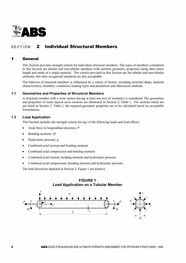
1.3 Load Application This Section includes the strength criteria for any of the following loads and load effects:
• Axial force in longitudinal direction, P
• Bending moment, M
• Hydrostatic pressure, q
• Combined axial tension and bending moment
• Combined axial compression and bending moment
• Combined axial tension, bending moment and hydrostatic pressure
• Combined axial compression, bending moment and hydrostatic pressure
The load directions depicted in Section 2, Figure 1 are positive.
FIGURE 1 Load Application on a Tubular Member
P
M
z
yx
q
L t
P
M
q
z
y
D

Section 2 Individual Structural Members
ABS GUIDE FOR BUCKLING AND ULTIMATE STRENGTH ASSESSMENT FOR OFFSHORE STRUCTURES . 2004 5
1.5 Failure Modes Failure modes for a structural member are categorized as follows:
• Flexural buckling. Bending about the axis of the least resistance.
• Torsional buckling. Twisting about the longitudinal (x) axis. It may occur if the torsional rigidity of the section is low, as for a member with a thin-walled open cross section.
• Lateral-torsional buckling. Synchronized bending and twisting. A member which is bent about its major axis may buckle laterally.
• Local buckling. Buckling of a plate or shell element that is a local part of a member

TABLE 1 Geometries, Properties and Compact Limits of Structural Members
Geometry Sectional Shape Geometrical Parameters Axis Properties* Compact Limits
1. Tubular member
z
y
D
t
D = Outer diameter t = Thickness
N/A
A = π[D2 – (D – 2t)2]/4 Iy, Iz = π[D4 – (D – 2t)4]/64
K = π (D – t)3t/4 Io = π [D4 – (D – 2t)4]/32
Γ = 0
09σE
tD
≤
2. Square or rectangular hollow section
z
y
b
dt
b = Flange width d = Web depth t = Thickness
Major y-y Minor z-z
A = 2(b + d)t Iy = d2t(3b + d)/6
Iz = b2t(b + 3d)/6
K = db
tdb+
222
Io = t(b + d)3/6
Γ = dbbdtdb
+− 222 )(
24
05.1,
σE
td
tb
≤
Section 2
Individual Structural Mem
bers
6 A
BS
GUIDE FOR BUCKLING AND ULTIMATE STRENGTH ASSESSMENT FOR OFFSHORE STRUCTURES . 2004
TABLE 1 (continued) Geometries, Properties and Compact Limits of Structural Members
Geometry Sectional Shape Geometrical Parameters Axis Properties* Compact Limits
3. Welded box shape
z
ytwa
b
b2tf
d
d = Web depth tw = Web thickness b = Flange width tf = Flange thickness b2 = Outstand
Major y-y Minor z-z
A = 2(btf + dtw) Iy = d2(3btf + dtw)/6
Iz = b2(btf + 3dtw)/6
K =
+
wf td
ta
da 222
Io = Iy + Iz
Γ = )(24
)(3223
23223
wf
wf
tdatdb
tdatdb
+
−
05.1,
σE
td
ta
wf≤
0
2 4.0σE
tb
f≤
4. W-shape
z
ytw
tf
b
d
d = Web depth tw = Web thickness b = Flange width tf = Flange thickness
Major y-y Minor z-z
A = 2btf + dtw Iy = d2(6btf + dtw)/12
Iz = b3tf/6 K = (2btf
3 + dtw3)/3
Io = Iy + Iz
Γ = d2b3tf/24
05.1
σE
td
w≤
08.0
σE
tb
f≤
Section 2
Individual Structural Mem
bers
AB
S GUIDE FOR BUCKLING AND ULTIMATE STRENGTH ASSESSMENT FOR OFFSHORE STRUCTURES . 2004
7
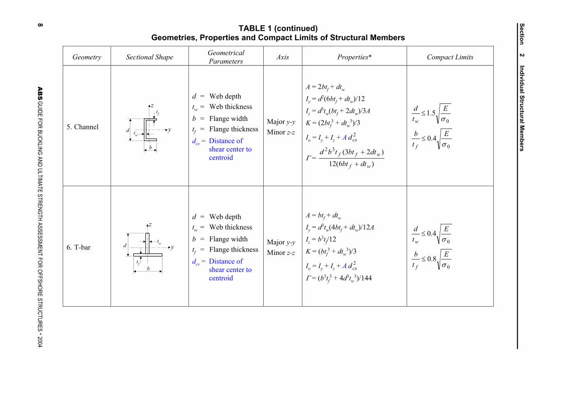
TABLE 1 (continued) Geometries, Properties and Compact Limits of Structural Members
Geometry Sectional Shape Geometrical Parameters Axis Properties* Compact Limits
5. Channel
z
y
tf
twd
b
d = Web depth tw = Web thickness b = Flange width tf = Flange thickness dcs = Distance of
shear center to centroid
Major y-y Minor z-z
A = 2btf + dtw Iy = d2(6btf + dtw)/12
Iz = d3tw(btf + 2dtw)/3A K = (2btf
3 + dtw3)/3
Io = Iy + Iz + A 2csd
Γ = )6(12
)23(32
wf
wff
dtbtdtbttbd
+
+
05.1
σE
td
w≤
04.0
σE
tb
f≤
6. T-bar
z
ytw
tfb
d
d = Web depth tw = Web thickness b = Flange width tf = Flange thickness dcs = Distance of
shear center to centroid
Major y-y Minor z-z
A = btf + dtw
Iy = d3tw(4btf + dtw)/12A Iz = b3tf/12
K = (btf3 + dtw
3)/3
Io = Iy + Iz + A 2csd
Γ = (b3tf3 + 4d3tw
3)/144
04.0
σE
td
w≤
08.0
σE
tb
f≤
Section 2
Individual Structural Mem
bers
8 A
BS
GUIDE FOR BUCKLING AND ULTIMATE STRENGTH ASSESSMENT FOR OFFSHORE STRUCTURES . 2004
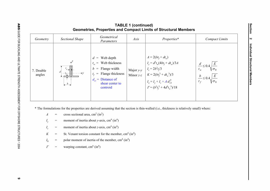
TABLE 1 (continued) Geometries, Properties and Compact Limits of Structural Members
Geometry Sectional Shape Geometrical Parameters Axis Properties* Compact Limits
7. Double angles
z
ytw
b
tfd
d = Web depth tw = Web thickness b = Flange width tf = Flange thickness dcs = Distance of
shear center to centroid
Major y-y Minor z-z
A = 2(btf + dtw) Iy = d3tw(4btf + dtw)/3A
Iz = 2b3tf/3
K = 2(btf3 + dtw
3)/3
Io = Iy + Iz + A 2csd
Γ = (b3tf3 + 4d3tw
3)/18
04.0
σE
td
w≤
04.0
σE
tb
f≤
* The formulations for the properties are derived assuming that the section is thin-walled (i.e., thickness is relatively small) where:
A = cross sectional area, cm2 (in2)
Iy = moment of inertia about y-axis, cm4 (in4)
Iz = moment of inertia about z-axis, cm4 (in4)
K = St. Venant torsion constant for the member, cm4 (in4)
I0 = polar moment of inertia of the member, cm4 (in4)
Γ = warping constant, cm6 (in6)
Section 2
Individual Structural Mem
bers
AB
S GUIDE FOR BUCKLING AND ULTIMATE STRENGTH ASSESSMENT FOR OFFSHORE STRUCTURES . 2004
9
Section 2 Individual Structural Members
10 ABS GUIDE FOR BUCKLING AND ULTIMATE STRENGTH ASSESSMENT FOR OFFSHORE STRUCTURES . 2004
1.7 Cross Section Classification The cross section may be classified as:
i) Compact. A cross section is compact if all compressed components comply with the limits in Section 2, Table 1. For a compact section, the local buckling (plate buckling and shell buckling) can be disregarded because yielding precedes buckling.
ii) Non-Compact. A cross section is non-compact if any compressed component does not comply with the limits in Section 2, Table 1. For a non-compact section, the local buckling (plate or shell buckling) is to be taken into account.
1.9 Adjustment Factor For the maximum allowable strength utilization factors, η, defined in Subsection 1/11, the adjustment factor is to take the following values:
For axial tension and bending [to establish η2 below]:
ψ = 1.0
For axial compression (column buckling or torsional buckling) [to establishη1 below]:
ψ = 0.87 if σEA ≤ Prσ0
= 1 – 0.13 EArP σσ /0 if σEA > Prσ0
where
σEA = elastic buckling stress, as defined in 2/3.3, N/cm2 (kgf/cm2, lbf/in2)
Pr = proportional linear elastic limit of the structure, which may be taken as 0.6 for steel
σ0 = specified minimum yield point, N/cm2 (kgf/cm2, lbf/in2)
For compression (local buckling of tubular members) [to establish ηx and ηθ below]:
ψ = 0.833 if σCi ≤ 0.55σ0
= 0.629 + 0.371σCi/σ0 if σCi > 0.55σ0
where
σCi = critical local buckling stress, representing σCi for axial compression, as specified in 2/9.1, and σCθ for hydrostatic pressure, as specified in 2/9.5, N/cm2 (kgf/cm2, lbf/in2)
σ0 = specified minimum yield point, N/cm2 (kgf/cm2, lbf/in2)
3 Members Subjected to a Single Action
3.1 Axial Tension Members subjected to axial tensile forces are to satisfy the following equation:
σt/η2σ0 ≤ 1
where
σt = axial tensile stress, N/cm2 (kgf/cm2, lbf/in2)
= P/A
σ0 = specified minimum yield point, N/cm2 (kgf/cm2, lbf/in2)
P = axial force, N (kgf, lbf)
A = cross sectional area, cm2 (in2)
η2 = allowable strength utilization factor for tension and bending, as defined in Subsection 1/11 and 2/1.9

Section 2 Individual Structural Members
ABS GUIDE FOR BUCKLING AND ULTIMATE STRENGTH ASSESSMENT FOR OFFSHORE STRUCTURES . 2004 11
3.3 Axial Compression Members subjected to axial compressive forces may fail by flexural or torsional buckling. The buckling limit state is defined by the following equation:
σA/η1σCA ≤ 1
where
σA = axial compressive stress, N/cm2 (kgf/cm2, lbf/in2)
= –P/A
P = axial force, N (kgf, lbf)
σCA = critical buckling stress, N/cm2 (kgf/cm2, lbf/in2)
= ( )
>
−−
≤
FrEAEA
FrrF
FrEAEA
PPP
P
σσσσ
σ
σσσ
if11
if
Pr = proportional linear elastic limit of the structure, which may be taken as 0.6 for steel
σF = σ0 specified minimum yield point for a compact section
= σCx local buckling stress for a non-compact section from Subsection 2/9
σEA = elastic buckling stress, which is the lesser of the solutions of the following quadratic equation, N/cm2 (kgf/cm2, lbf/in2)
0))(( 220 =−−− csEAETEAEEA dAI
σσσσσ η
σEη = Euler buckling stress about minor axis, N/cm2 (kgf/cm2, lbf/in2)
= π2E/(kL/rη)2
σET = ideal elastic torsional buckling stress, N/cm2 (kgf/cm2, lbf/in2)
= 0
2
06.2 IE
kLIEK Γ
+
π
rη = radius of gyration about minor axis, cm (in.)
= AI /η
E = modulus of elasticity, 2.06 × 10⁷ N/cm2 (2.1 × 10⁶ kgf/cm2, 30 × 106 lbf/in2) for steel
A = cross sectional area, cm2 (in2)
Iη = moment of inertia about minor axis, cm4 (in4)
K = St. Venant torsion constant for the member, cm4 (in4)
I0 = polar moment of inertia of the member, cm4 (in4)
Γ = warping constant, cm6 (in6)
dcs = difference of centroid and shear center coordinates along major axis, cm (in.)
L = member’s length, cm (in.)
k = effective length factor, as specified in Section 2, Table 2. When it is difficult to clarify the end conditions, the nomograph shown in Section 2, Figure 2 may be used. The values of G for each end (A and B) of the column are determined:
∑∑=g
g
c
c
LI
LI
G
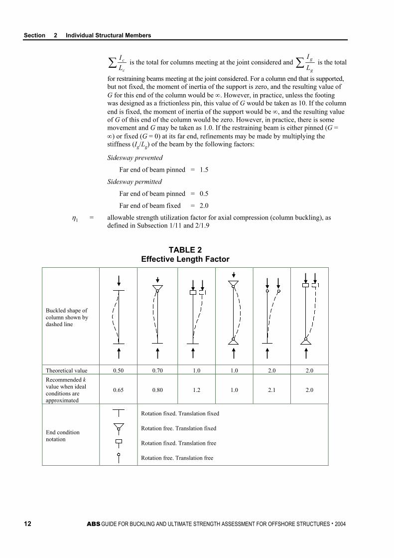
Section 2 Individual Structural Members
12 ABS GUIDE FOR BUCKLING AND ULTIMATE STRENGTH ASSESSMENT FOR OFFSHORE STRUCTURES . 2004
∑c
c
LI
is the total for columns meeting at the joint considered and ∑g
g
LI
is the total
for restraining beams meeting at the joint considered. For a column end that is supported, but not fixed, the moment of inertia of the support is zero, and the resulting value of G for this end of the column would be ∞. However, in practice, unless the footing was designed as a frictionless pin, this value of G would be taken as 10. If the column end is fixed, the moment of inertia of the support would be ∞, and the resulting value of G of this end of the column would be zero. However, in practice, there is some movement and G may be taken as 1.0. If the restraining beam is either pinned (G = ∞) or fixed (G = 0) at its far end, refinements may be made by multiplying the stiffness (Ig/Lg) of the beam by the following factors:
Sidesway prevented
Far end of beam pinned = 1.5
Sidesway permitted
Far end of beam pinned = 0.5
Far end of beam fixed = 2.0
η1 = allowable strength utilization factor for axial compression (column buckling), as defined in Subsection 1/11 and 2/1.9
TABLE 2 Effective Length Factor
Buckled shape of column shown by dashed line
Theoretical value 0.50 0.70 1.0 1.0 2.0 2.0 Recommended k value when ideal conditions are approximated
0.65 0.80 1.2 1.0 2.1 2.0
End condition notation
Rotation fixed. Translation fixed
Rotation free. Translation fixed
Rotation fixed. Translation free
Rotation free. Translation free

Section 2 Individual Structural Members
ABS GUIDE FOR BUCKLING AND ULTIMATE STRENGTH ASSESSMENT FOR OFFSHORE STRUCTURES . 2004 13
FIGURE 2 Effective Length Factor
GA k GB GA k GB
Sidesway Prevented Sidesway Permittted
Note: These alignment charts or nomographs are based on the following assumptions:
1 Behavior is purely elastic.
2 All members have constant cross section.
3 All joints are rigid.
4 For columns in frames with sidesway prevented, rotations at opposite ends of the restraining beams are equal in magnitude and opposite in direction, producing single curvature bending.
5 For columns in frames with sidesway permitted, rotations at opposite ends of the restraining beams are equal in magnitude and direction, producing reverse curvature bending
6 The stiffness parameter L(P/EI)1/2 of all columns is equal.
7 Joint restraint is distributed to the column above and below the joint in proportion to EI/L for the two columns.
8 All columns buckle simultaneously.
9 No significant axial compression force exists in the restraining beams.
Adjustments are required when these assumptions are violated and the alignment charts are still to be used. Reference is made to ANSI/AISC 360-05, Commentary C2.
3.5 Bending Moment A member subjected to bending moment may fail by local buckling or lateral-torsional buckling. The buckling state limit is defined by the following equation:
σb/η2σCB ≤ 1
where
σb = stress due to bending moment
= M/SMe

Section 2 Individual Structural Members
14 ABS GUIDE FOR BUCKLING AND ULTIMATE STRENGTH ASSESSMENT FOR OFFSHORE STRUCTURES . 2004
M = bending moment, N-cm (kgf-cm, lbf-in)
SMe = elastic section modulus, cm3 (in3)
η2 = allowable strength utilization factor for tension and bending
σCB = critical bending strength, as follows:
i) For a tubular member, the critical bending strength is to be obtained from the equation given in 2/9.3.
ii) For a rolled or fabricated-plate section, the critical bending strength is determined by the critical lateral-torsional buckling stress.
The critical lateral-torsional buckling stress is to be obtained from the following equation:
σC(LT) = ( )
>
−−
≤
FrLTELTE
FrrF
FrLTELTE
PPP
P
σσσ
σσ
σσσ
)()(
)()(
if11
if
Pr = proportional linear elastic limit of the structure, which may be taken as 0.6 for steel
σE(LT) = elastic lateral-torsional buckling stress, N/cm2 (kgf/cm2, lbf/in2)
= 2
2
)(kLSM
EIC
c
ηπ
Iη = moment of inertia about minor axis, as defined in Section 2, Table 1, cm4 (in4)
SMe = section modulus of compressive flange, cm3 (in3)
= c
Iξ
ξ
Iξ = moment of inertia about major axis, as defined in Section 2, Table 1, cm4 (in4)
ξc = distance from major neutral axis to compressed flange, cm (in.)
C = 2
2
6.2)(
πΓ
ηη
kLIK
I+
E = modulus of elasticity, 2.06 × 10⁷ N/cm2 (2.1 × 10⁶ kgf/cm2, 30 × 106 lbf/in2) for steel
σF = σ0, specified minimum yield point for a compact section
= σCx, local buckling stress for a non-compact section, as specified in 2/9.7
K = St. Venant torsion constant for the member, cm4 (in4)
Γ = warping constant, cm6 (in6)
L = member’s length, cm (in.)
k = effective length factor, as defined in 2/3.3

Section 2 Individual Structural Members
ABS GUIDE FOR BUCKLING AND ULTIMATE STRENGTH ASSESSMENT FOR OFFSHORE STRUCTURES . 2004 15
5 Members Subjected to Combined Loads
5.1 Axial Tension and Bending Moment Members subjected to combined axial tension and bending moment are to satisfy the following equations at all cross-sections along their length:
For tubular members: 5.0
22
202
1
+
+
CBz
bz
CBy
byt
σσ
σσ
ησησ
≤ 1
For rolled or fabricated-plate sections:
CBz
bz
CBy
byt
σησ
σησ
σησ
2202++ ≤ 1
where
σt = axial tensile stress from 2/3.1, N/cm2 (kgf/cm2, lbf/in2)
σby = bending stress from 2/3.5 about member y-axis, N/cm2 (kgf/cm2, lbf/in2)
σbz = bending stress from 2/3.5 about member z-axis, N/cm2 (kgf/cm2, lbf/in2)
σCBy = critical bending strength corresponding to member’s y-axis from 2/3.5, N/cm2 (kgf/cm2, lbf/in2)
σCBz = critical bending strength corresponding to member’s z-axis from 2/3.5, N/cm2 (kgf/cm2, lbf/in2)
η2 = allowable strength utilization factor for tension and bending, as defined in 1/11 and 2/1.9
5.3 Axial Compression and Bending Moment Members subjected to combined axial compression and bending moment are to satisfy the following equation at all cross sections along their length:
For tubular members:
When σa/σCA > 0.15: 5.0
2
1
2
121 )/(11
)/(111
−
+
−+
Eza
bzmz
CBzEya
bymy
CByCA
a CCσησ
σσσησ
σσηση
σ ≤ 1
When σa/σCA ≤ 0.15: 5.0
22
21
1
+
+
CBz
bz
CBy
by
CA
a
σσ
σσ
ησησ
≤ 1
For rolled or fabricated-plate sections:
When σa/σCA > 0.15:
)/(11
)/(11
12121 Eza
bzmz
CBzEya
bymy
CByCA
a CCσησ
σσησησ
σσηση
σ−
+−
+ ≤ 1
When σa/σCA ≤ 0.15:
CBz
bz
CBy
by
CA
a
σησ
σησ
σησ
221++ ≤ 1

Section 2 Individual Structural Members
16 ABS GUIDE FOR BUCKLING AND ULTIMATE STRENGTH ASSESSMENT FOR OFFSHORE STRUCTURES . 2004
where
σa = axial compressive stress from 2/3.3, N/cm2 (kgf/cm2, lbf/in2)
σby = bending stress from 2/3.5 about member y-axis, N/cm2 (kgf/cm2, lbf/in2)
σbz = bending stress from 2/3.5 about member z-axis, N/cm2 (kgf/cm2, lbf/in2)
σCA = critical axial compressive strength from 2/3.3, N/cm2 (kgf/cm2, lbf/in2)
σCBy = critical bending strength corresponding to member y-axis from 2/3.5, N/cm2 (kgf/cm2, lbf/in2)
σCBz = critical bending strength corresponding to member z-axis from 2/3.5, N/cm2 (kgf/cm2, lbf/in2)
σEy = Euler buckling stress corresponding to member y-axis, N/cm2 (kgf/cm2, lbf/in2)
= π2E/(kyL/ry)2
σEz = Euler buckling stress corresponding to member z-axis, N/cm2 (kgf/cm2, lbf/in2)
= π2E/(kzL/rz)2
E = modulus of elasticity, 2.06 × 10⁷ N/cm2 (2.1 × 10⁶ kgf/cm2, 30 × 106 lbf/in2) for steel
ry, rz = radius of gyration corresponding to the member y- and z-axes, cm (in.)
ky, kz = effective length factors corresponding to member y- and z-axes from 2/3.3
Cmy, Cmz = moment factors corresponding to the member y- and z-axes, as follows:
i) For compression members in frames subjected to joint translation (sidesway):
Cm = 0.85
ii) For restrained compression members in frames braced against joint translation (sidesway) and with no transverse loading between their supports:
Cm = 0.6 – 0.4M1/M2
but not less than 0.4 and limited to 0.85, where M1/M2 is the ratio of smaller to larger moments at the ends of that portion of the member unbraced in the plane of bending under consideration. M1/M2 is positive when the member is bent in reverse curvature, negative when bent in single curvature.
iii) For compression members in frames braced against joint translation in the plane of loading and subject to transverse loading between their supports, the value of Cm may be determined by rational analysis. However, in lieu of such analysis, the following values may be used.
For members whose ends are restrained:
Cm = 0.85
For members whose ends are unrestrained:
Cm = 1.0
η1 = allowable strength utilization factor for axial compression (column buckling), as defined in Subsection 1/11 and 2/1.9
η2 = allowable strength utilization factor for tension and bending, as defined in Subsection 1/11 and 2/1.9
Section 2 Individual Structural Members
ABS GUIDE FOR BUCKLING AND ULTIMATE STRENGTH ASSESSMENT FOR OFFSHORE STRUCTURES . 2004 17
7 Tubular Members Subjected to Combined Loads with Hydrostatic Pressure Appropriate consideration is to be given to the capped-end actions on a structural member subjected to hydrostatic pressure. It should be noted that the equations in this Subsection do not apply unless the criteria of 2/9.5 are satisfied first.
7.1 Axial Tension, Bending Moment and Hydrostatic Pressure The following equation is to be satisfied for tubular members subjected to combined axial tension, bending moment and hydrostatic pressure:
θθ ση
σσ
σησ
CB
bzby
T
tc
2
22
2
++ ≤ 1
where
σtc = calculated axial tensile stress due to forces from actions that include the capped-end actions due to hydrostatic pressure, N/cm2 (kgf/cm2, lbf/in2)
σTθ = axial tensile strength in the presence of hydrostatic pressure, N/cm2 (kgf/cm2, lbf/in2)
= Cqσ0
σCBθ = bending strength in the presence of hydrostatic pressure, N/cm2 (kgf/cm2, lbf/in2)
= CqσCB
σCB = critical bending strength excluding hydrostatic pressure from 2/3.5
Cq = ]3.009.01[ 22 BBB −−+ ξ
B = σθ/(ηθσCθ)
ξ = 5 – 4σCθ/σ0
σθ = hoop stress due to hydrostatic pressure from 2/9.5, N/cm2 (kgf/cm2, lbf/in2)
σCθ = critical hoop buckling strength from 2/9.5, N/cm2 (kgf/cm2, lbf/in2)
σ0 = specified minimum yield point, N/cm2 (kgf/cm2, lbf/in2)
η2 = allowable strength utilization factor for tension and bending, as defined in Subsection 1/11 and 2/1.9
ηθ = allowable strength utilization factor for local buckling in the presence of hydrostatic pressure, as defined in Subsection 1/11 and 2/1.9
7.3 Axial Compression, Bending Moment and Hydrostatic Pressure Tubular members subjected to combined compression, bending moment and external pressure are to satisfy the following equations at all cross sections along their length.
When σac/σCAθ > 0.15 and σac > 0.5σθ:
5.02
1
2
1
21 5.01
5.01
15.0
−−
+
−−
+−
Ez
ac
bzmz
Ey
ac
bymy
CBCA
ac CC
σησσ
σ
σησσ
σσηση
σσθθθθ
θ ≤ 1

Section 2 Individual Structural Members
18 ABS GUIDE FOR BUCKLING AND ULTIMATE STRENGTH ASSESSMENT FOR OFFSHORE STRUCTURES . 2004
When σac/σCAθ ≤ 0.15:
5.022
21
1
+
+
θθθ σσ
σσ
ησησ
CB
bz
CB
by
CA
a ≤ 1
where
σac = calculated compressive axial stress due to axial compression that includes the capped-end actions due to hydrostatic pressure, N/cm2 (kgf/cm2, lbf/in2)
σθ = hoop stress due to hydrostatic pressure from 2/9.5, N/cm2 (kgf/cm2, lbf/in2)
σCBθ = critical bending strength in the presence of hydrostatic pressure from 2/7.1, N/cm2 (kgf/cm2, lbf/in2)
σCAθ = axial compressive strength in the presence of hydrostatic pressure
=
−>Λ−≤
)/1(if)/1(if
FFrEAF
FFrEAEA
PP
σσσσσσσσσσ
θ
θ
σEA = elastic buckling stress in the absence of hydrostatic pressure from 2/3.3, N/cm2 (kgf/cm2, lbf/in2)
Λ = 2/)4( 2 ωζζ ++
ζ = 1 – Pr(1 – Pr)σF/σEA – σθ/σF
ω = 0.5(σθ/σF)(1 – 0.5σθ/σF)
σEy = Euler buckling stress corresponding to member y-axis from 2/5.3, N/cm2 (kgf/cm2, lbf/in2)
σEz = Euler buckling stress corresponding to member z-axis from 2/5.3, N/cm2 (kgf/cm2, lbf/in2)
Cmy, Cmz = moment factors corresponding to the member y- and z-axes from 2/5.3
Pr = proportional linear elastic limit of the structure, which may be taken as 0.6 for steel
E = modulus of elasticity, 2.06 × 10⁷ N/cm2 (2.1 × 10⁶ kgf/cm2, 30 × 106 lbf/in2) for steel
σF = σ0, specified minimum yield point for the compact section
= σCx, local buckling stress for the non-compact section from 2/9.7
η1 = allowable strength utilization factor for axial compression (column buckling), as defined in Subsection 1/11 and 2/1.9
η2 = allowable strength utilization factor for tension and bending, as defined in Subsection 1/11 and 2/1.9
When σx > 0.5ηθσCθ and ηxσx > 0.5ηθσCθ, the following equation is to also be satisfied: 2
5.05.0
+
−−
θθ
θ
θθ
θθ
σησ
σησησησ
CCCxx
Cx ≤ 1
where
σx = maximum compressive axial stress from axial compression and bending moment, which includes the capped-end actions due to the hydrostatic pressure, N/cm2 (kgf/cm2, lbf/in2)
= σac + σb
σac = calculated compressive axial stress due to axial compression from actions that include the capped-end actions due to hydrostatic pressure, N/cm2 (kgf/cm2, lbf/in2)

Section 2 Individual Structural Members
ABS GUIDE FOR BUCKLING AND ULTIMATE STRENGTH ASSESSMENT FOR OFFSHORE STRUCTURES . 2004 19
σb = stress due to bending moment from 2/3.5, N/cm2 (kgf/cm2, lbf/in2)
σCx = critical axial buckling stress from 2/9.1, N/cm2 (kgf/cm2, lbf/in2)
σCθ = critical hoop buckling stress from 2/9.5, N/cm2 (kgf/cm2, lbf/in2)
Cmy, Cmz = moment factors corresponding to the member y- and z-axes, as defined in 2/5.3
ηx = maximum allowable strength utilization factor for axial compression (local buckling), as defined in Subsection 1/11 and 2/1.9
ηθ = maximum allowable strength utilization factor for hydrodynamic pressure (local buckling), as defined in Subsection 1/11 and 2/1.9
9 Local Buckling For a member with a non-compact section, local buckling may occur before the member as a whole becomes unstable or before the yield point of the material is reached. Such behavior is characterized by local distortion of the cross section of the member. When a detailed analysis is not available, the equations given below may be used to evaluate the local buckling stress of a member with a non-compact section.
9.1 Tubular Members Subjected to Axial Compression Local buckling stress of tubular members with D/t ≤ E/(4.5σ0) subjected to axial compression may be obtained from the following equation:
σCx = ( )
>
−−
≤
00
0
0
if11
if
σσσσ
σ
σσσ
rExEx
rr
rExEx
PPP
P
where
Pr = proportional linear elastic limit of the structure, which may be taken as 0.6 for steel
σ0 = specified minimum yield point, N/cm2 (kgf/cm2, lbf/in2)
σEx = elastic buckling stress, N/cm2 (kgf/cm2, lbf/in2)
= 0.6Et/D
D = outer diameter, cm (in.)
t = thickness, cm (in.)
For tubular members with D/t > E/(4.5σ0), the local buckling stress is to be determined from 4/3.3.
9.3 Tubular Members Subjected to Bending Moment Critical bending strength of tubular members with D/t ≤ E/(4.5σ0) subjected to bending moment may be obtained from the following equation:
σCB =
−
−
00
00
0
)/)](/(73.0921.0[
)/)](/(90.1038.1[
)/(
σσ
σσ
σ
ep
ep
ep
SMSMEtD
SMSMEtD
SMSM
10.0)(for
10.0)(02.0for02.0)(for
0
0
0
>≤<
≤
EtDEtD
EtD
σσ
σ
where
SMe = elastic section modulus, cm3 (in3)
= (π/64)[D4 – (D – 2t)4]/(D/2)
SMp = plastic section modulus, cm3 (in3)
= (1/6)[D3 – (D – 2t)3]
D = outer diameter, cm (in.)

Section 2 Individual Structural Members
20 ABS GUIDE FOR BUCKLING AND ULTIMATE STRENGTH ASSESSMENT FOR OFFSHORE STRUCTURES . 2004
t = thickness, cm (in.)
E = modulus of elasticity, 2.06 × 10⁷ N/cm2 (2.1 × 10⁶ kgf/cm2, 30 × 106 lbf/in2) for steel
σ0 = specified minimum yield point
For tubular members with D/t > E/(4.5σ0), the local buckling stress is to be determined from 4/3.3.
9.5 Tubular Members Subjected to Hydrostatic Pressure Tubular members with D/t ≤ E/(4.5σ0) subjected to external pressure are to satisfy the following equation:
σθ/ηθσCθ ≤ 1
where
σθ = hoop stress due to hydrostatic pressure
= qD/(2t)
q = external pressure
σCθ = critical hoop buckling strength, N/cm2 (kgf/cm2, lbf/in2)
= ΦσBθ
Φ = plasticity reduction factor
= 1 for ∆ ≤ 0.55
= 18.045.0+
∆ for 0.55 < ∆ ≤ 1.6
= ∆15.11
31.1+
for 1.6 < ∆ < 6.25
= 1/∆ for ∆ ≥ 6.25
∆ = σEθ/σ0
σEθ = elastic hoop buckling stress
= 2CθEt/D
Cθ = buckling coefficient
= 0.44t/D for µ ≥ 1.6D/t
= 0.44t/D + 0.21(D/t)3/µ4 for 0.825D/t ≤ µ < 1.6D/t
= 0.737/(µ – 0.579) for 1.5 ≤ µ < 0.825D/t
= 0.80 for µ <1.5
µ = geometric parameter
= tDD /2/
= length of tubular member between stiffening rings, diaphragms or end connections
D = outer diameter
t = thickness
E = modulus of elasticity, 2.06 × 10⁷ N/cm2 (2.1 × 10⁶ kgf/cm2, 30 × 106 lbf/in2) for steel
σ0 = specified minimum yield point
ηθ = maximum allowable strength utilization factor for local buckling in the presence of hydrostatic pressure, as defined in Subsection 1/11 and 2/1.9
For tubular members with D/t > E/(4.5σ0), the state limit in 4/3.3 is to be applied.

Section 2 Individual Structural Members
ABS GUIDE FOR BUCKLING AND ULTIMATE STRENGTH ASSESSMENT FOR OFFSHORE STRUCTURES . 2004 21
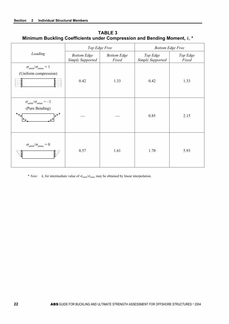
9.7 Plate Elements Subjected to Compression and Bending Moment The critical local buckling of a member with rolled or fabricated plate section may be taken as the smallest local buckling stress of the plate elements comprising the section. The local buckling stress of an element is to be obtained from the following equation with respect to uniaxial compression and in-plane bending moment:
σCx = ( )
>
−−
≤
00
0
0
if11
if
σσσσ
σ
σσσ
rExEx
rr
rExEx
PPP
P
where
Pr = proportional linear elastic limit of the structure, which may be taken as 0.6 for steel
σ0 = specified minimum yield point, N/cm2 (kgf/cm2, lbf/in2)
σEx = elastic buckling stress, N/cm2 (kgf/cm2, lbf/in2)
= 2
2
2
)1(12
− stEks ν
π
E = modulus of elasticity, 2.06 × 10⁷ N/cm2 (2.1 × 10⁶ kgf/cm2, 30 × 106 lbf/in2) for steel
ν = Poisson’s ratio, 0.3 for steel
s = depth of unsupported plate element
t = thickness of plate element
ks = buckling coefficient, as follows:
i) For a plate element with all four edges simply supported, the buckling coefficient is to be obtained from following equation:
ks =
<≤−+−
≤≤+
01for104.66.7
10for1.1
4.8
2 κκκ
κκ
where
κ = ratio of edge stresses, as defined in Section 2, Figure 3
= σamin/σamax
ii) For a plate element with other boundary conditions, the buckling coefficient is obtained from Section 2, Table 3
FIGURE 3 Definition of Edge Stresses
Plate Element
σamax
σamin
σamax
σamin
Section 2 Individual Structural Members
22 ABS GUIDE FOR BUCKLING AND ULTIMATE STRENGTH ASSESSMENT FOR OFFSHORE STRUCTURES . 2004
TABLE 3 Minimum Buckling Coefficients under Compression and Bending Moment, ks *
Loading Top Edge Free Bottom Edge Free
Bottom Edge Simply Supported
Bottom Edge Fixed
Top Edge Simply Supported
Top Edge Fixed
σamin/σamax = 1
(Uniform compression)
0.42 1.33 0.42 1.33
σamin/σamax = –1
(Pure Bending)
0.85 2.15
σamin/σamax = 0
0.57 1.61 1.70 5.93
* Note: ks for intermediate value of σamin/σamax may be obtained by linear interpolation.
ABS GUIDE FOR BUCKLING AND ULTIMATE STRENGTH ASSESSMENT FOR OFFSHORE STRUCTURES . 2004 23
S e c t i o n 3 : P l a t e s , S t i f f e n e d P a n e l s a n d C o r r u g a t e d P a n e l s
S E C T I O N 3 Plates, Stiffened Panels and Corrugated Panels
1 General The formulations provided in this Section are to be used to assess the Buckling and Ultimate Strength Limits of plates, stiffened panels and corrugated panels. Two State Limits for Buckling and Ultimate Strength are normally considered in structural design. The former is based on buckling and the latter is related to collapse.
The criteria provided in this Section apply to Offshore Structures, SPMs, SEDUs, CSDUs and FPIs of the TLP and SPAR types, and it is not in the scope of this Guide to use the criteria with ship-type FPIs. In this latter case, see Chapter 4, Section 2 of the FPI Rules.
The design criteria apply also to stiffened panels for which the moment of inertia for the transverse girders is greater than the moment of inertia of the longitudinal stiffeners. It is not in the scope of this Guide to use the criteria for orthotropically stiffened plate panels.
Alternatively, the buckling and ultimate strength of plates, stiffened panels or corrugated panels may be determined based on either appropriate, well-documented experimental data or on a calibrated analytical approach. When a detailed analysis is not available, the equations provided in this section shall be used to assess the buckling strength.
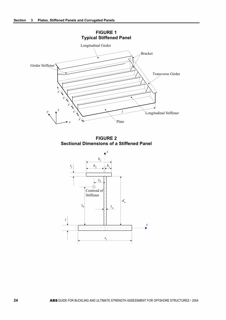
1.1 Geometry of Plate, Stiffened Panel and Corrugated Panels Flat rectangular plates and stiffened panels are depicted in Section 3, Figure 1. Stiffeners in the stiffened panels are usually installed equally spaced, parallel or perpendicular to panel edges in the direction of dominant load and are supported by heavier and more widely-spaced ‘deep supporting members’ (i.e., girders). The given criteria apply to a variety of stiffener profiles, such as flat-bar, built up T-profiles, built up inverted angle profiles and symmetric and non-symmetric bulb profiles. The section dimensions of a stiffener are defined in Section 3, Figure 2. The stiffeners may have strength properties different from those of the plate.
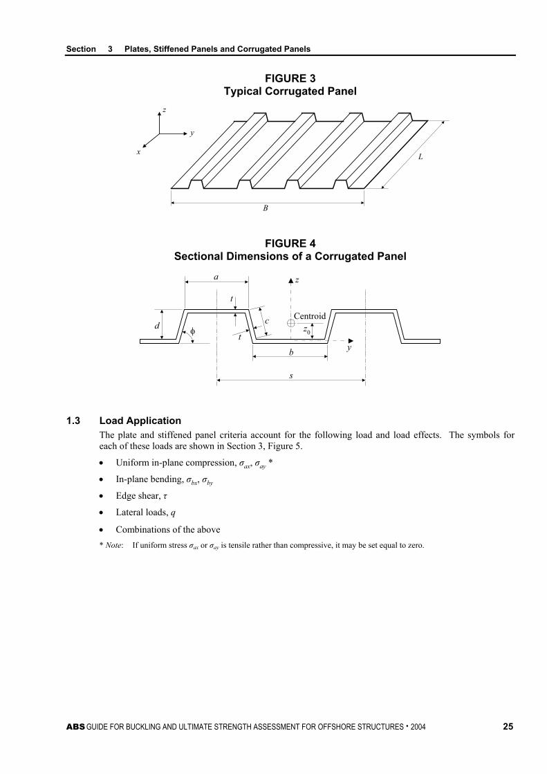
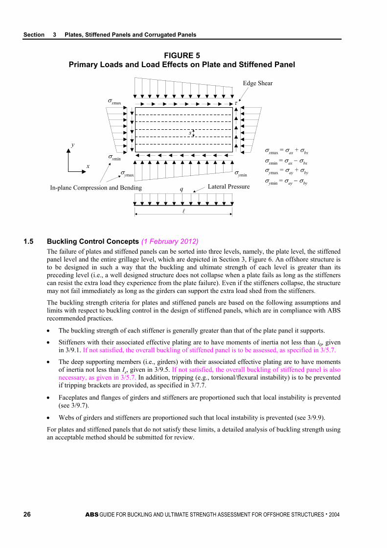
Corrugated panels, as depicted in Section 3, Figure 3, are self-stiffened and are usually corrugated in one direction, supported by stools at the two ends across the corrugation direction. They may act as watertight bulkheads or, when connected with fasteners, they are employed as corrugated shear diaphragms. The dimensions of corrugated panels are defined in Section 3, Figure 4. The buckling strength criteria for corrugated panels given in Subsection 3/11 are applicable to corrugated panels with corrugation angle, φ, between 57 and 90 degrees.
Section 3 Plates, Stiffened Panels and Corrugated Panels
24 ABS GUIDE FOR BUCKLING AND ULTIMATE STRENGTH ASSESSMENT FOR OFFSHORE STRUCTURES . 2004
FIGURE 1 Typical Stiffened Panel
s
s
s
s
y z
x
Girder Stiffener
Longitudinal Girder
Bracket
Transverse Girder
Longitudinal Stiffener
Plate
s
FIGURE 2 Sectional Dimensions of a Stiffened Panel
z
bf
b2 b1tf
y0
dw
twz0
t
se
y
Centroid ofStiffener
Section 3 Plates, Stiffened Panels and Corrugated Panels
ABS GUIDE FOR BUCKLING AND ULTIMATE STRENGTH ASSESSMENT FOR OFFSHORE STRUCTURES . 2004 25
FIGURE 3 Typical Corrugated Panel
z
y
x
B
L
FIGURE 4 Sectional Dimensions of a Corrugated Panel
z0
t
t
c
a
d φ
b
z
y
s
Centroid
1.3 Load Application The plate and stiffened panel criteria account for the following load and load effects. The symbols for each of these loads are shown in Section 3, Figure 5.
• Uniform in-plane compression, σax, σay *
• In-plane bending, σbx, σby
• Edge shear, τ
• Lateral loads, q
• Combinations of the above * Note: If uniform stress σax or σay is tensile rather than compressive, it may be set equal to zero.
Section 3 Plates, Stiffened Panels and Corrugated Panels
26 ABS GUIDE FOR BUCKLING AND ULTIMATE STRENGTH ASSESSMENT FOR OFFSHORE STRUCTURES . 2004
FIGURE 5 Primary Loads and Load Effects on Plate and Stiffened Panel
s
τ
σyminσymax
σxmin
σxmax
q
y
x
Edge Shear
Lateral PressureIn-plane Compression and Bendingσymin = σay − σby
σymax = σay + σby
σxmin = σax − σbx
σxmax = σax + σbx
1.5 Buckling Control Concepts (1 February 2012) The failure of plates and stiffened panels can be sorted into three levels, namely, the plate level, the stiffened panel level and the entire grillage level, which are depicted in Section 3, Figure 6. An offshore structure is to be designed in such a way that the buckling and ultimate strength of each level is greater than its preceding level (i.e., a well designed structure does not collapse when a plate fails as long as the stiffeners can resist the extra load they experience from the plate failure). Even if the stiffeners collapse, the structure may not fail immediately as long as the girders can support the extra load shed from the stiffeners.
The buckling strength criteria for plates and stiffened panels are based on the following assumptions and limits with respect to buckling control in the design of stiffened panels, which are in compliance with ABS recommended practices.
• The buckling strength of each stiffener is generally greater than that of the plate panel it supports.
• Stiffeners with their associated effective plating are to have moments of inertia not less than i0, given in 3/9.1. If not satisfied, the overall buckling of stiffened panel is to be assessed, as specified in 3/5.7.
• The deep supporting members (i.e., girders) with their associated effective plating are to have moments of inertia not less than Is, given in 3/9.5. If not satisfied, the overall buckling of stiffened panel is also necessary, as given in 3/5.7. In addition, tripping (e.g., torsional/flexural instability) is to be prevented if tripping brackets are provided, as specified in 3/7.7.
• Faceplates and flanges of girders and stiffeners are proportioned such that local instability is prevented (see 3/9.7).
• Webs of girders and stiffeners are proportioned such that local instability is prevented (see 3/9.9).
For plates and stiffened panels that do not satisfy these limits, a detailed analysis of buckling strength using an acceptable method should be submitted for review.

Section 3 Plates, Stiffened Panels and Corrugated Panels
ABS GUIDE FOR BUCKLING AND ULTIMATE STRENGTH ASSESSMENT FOR OFFSHORE STRUCTURES . 2004 27
FIGURE 6 Failure Modes (‘Levels’) of Stiffened Panel
Plate Level
Stiffened Panel Level
Deep SupportingMember Level
Section 3, Figure 6 illustrates the collapse shape for each level of failure mode. From a reliability point of view, no individual collapse mode can be 100 percent prevented. Therefore, the buckling control concept used in this Subsection is that the buckling and ultimate strength of each level is greater than its preceding level in order to avoid the collapse of the entire structure.
The failure (‘levels’) modes of a corrugated panel can be categorized as the face/web plate buckling level, the unit corrugation buckling level and the entire corrugation buckling level. In contrast to stiffened panels, corrugated panels will collapse immediately upon reaching any one of these three buckling levels.
1.7 Adjustment Factor
For the maximum allowable strength utilization factors, , defined in Subsection 1/11, the adjustment factor is to take the following value:
= 1.0
3 Plate Panels For rectangular plate panels between stiffeners, buckling is acceptable, provided that the ultimate strength given in 3/3.3 and 3/3.5 of the structure satisfies the specified criteria. Offshore practice demonstrates that only an ultimate strength check is required for plate panels. A buckling check of plate panels is necessary when establishing the attached plating width for stiffened panels. If the plating does not buckle, the full width is to be used. Otherwise, the effective width is to be applied if the plating buckles but does not fail.
3.1 Buckling State Limit For the Buckling State Limit of plates subjected to in-plane and lateral pressure loads, the following strength criterion is to be satisfied:
22
max2
max
CCy
y
Cx
x
1
where
xmax = maximum compressive stress in the longitudinal direction, N/cm2 (kgf/cm2, lbf/in2)
ymax = maximum compressive stress in the transverse direction, N/cm2 (kgf/cm2, lbf/in2)
= edge shear stress, N/cm2 (kgf/cm2, lbf/in2)
Section 3 Plates, Stiffened Panels and Corrugated Panels
28 ABS GUIDE FOR BUCKLING AND ULTIMATE STRENGTH ASSESSMENT FOR OFFSHORE STRUCTURES . 2004
σCx = critical buckling stress for uniaxial compression in the longitudinal direction, N/cm2 (kgf/cm2, lbf/in2)
σCy = critical buckling stress for uniaxial compression in the transverse direction, N/cm2 (kgf/cm2, lbf/in2)
τC = critical buckling stress for edge shear, N/cm2 (kgf/cm2, lbf/in2)
η = maximum allowable strength utilization factor, as defined in Subsection 1/11 and 3/1.7
The critical buckling stresses are specified below.
3.1.1 Critical Buckling Stress for Edge Shear The critical buckling stress for edge shear, τC, may be taken as:
τC = ( )
>
−−
≤
00
0
0
for11
for
τττττ
τττ
rEE
rr
rEE
PPP
P
where
Pr = proportional linear elastic limit of the structure, which may be taken as 0.6 for steel
τ0 = shear strength of plate, N/cm2 (kgf/cm2, lbf/in2)
= 30σ
σ0 = specified minimum yield point of plate, N/cm2 (kgf/cm2, lbf/in2)
τE = elastic shear buckling stress, N/cm2 (kgf/cm2, lbf/in2)
= ( )2
2
2
112
− stEks ν
π
ks = boundary dependent constant
= 1
2
34.50.4 Cs
+
E = modulus of elasticity, 2.06 × 10⁷ N/cm2 (2.1 × 10⁶ kgf/cm2, 30 × 106 lbf/in2) for steel
ν = Poisson’s ratio, 0.3 for steel
= length of long plate edge, cm (in.)
s = length of short plate edge, cm (in.)
t = thickness of plating, cm (in.)
C1 = 1.1 for plate panels between angles or tee stiffeners; 1.0 for plate panels between flat bars or bulb plates; 1.0 for plate elements, web plate of stiffeners and local plate of corrugated panels

Section 3 Plates, Stiffened Panels and Corrugated Panels
ABS GUIDE FOR BUCKLING AND ULTIMATE STRENGTH ASSESSMENT FOR OFFSHORE STRUCTURES . 2004 29
3.1.2 Critical Buckling Stress for Uniaxial Compression and In-plane Bending The critical buckling stress, σCi (i = x or y), for plates subjected to combined uniaxial compression and in-plane bending may be taken as:
σCi = ( )
>
−−
≤
00
0
0
for11
for
σσσσ
σ
σσσ
rEiEi
rr
rEiEi
PPP
P
where
Pr = proportional linear elastic limit of the structure, which may be taken as 0.6 for steel
σEi = elastic buckling stress, N/cm2 (kgf/cm2, lbf/in2)
= ( )2
2
2
112
− stEks ν
π
For loading applied along the short edge of the plating (long plate):
ks =
<≤−+−
≤≤+
01for104.66.7
10for1.1
4.8
21
κκκ
κκC
For loading applied along the long edge of the plating (wide plate):
ks =
( )
( )
( )
≥−
+
><++⋅
−
+⋅
≤≤<++⋅
−
+⋅
31for675.0675.111
2and31for112119110875.1
21and31for1241118110875.1
2
2
2
2
22
2
2
2
κκα
ακα
καα
ακα
καα
C
where
α = aspect ratio
= /s
κ = ratio of edge stresses, as defined in Section 3, Figure 5*
= σimin/σimax
* Note: There are several cases in the calculation of ratio of edge stresses, κ: • If uniform stress σai (i = x, y) < 0 (tensile) and in-plane stress σbi (i = x, y)
= 0, buckling check is not necessary, provided edge shear is zero;
• If uniform stress σai (i = x, y) < 0 (tensile) and in-plane bending stress σbi (i = x, y) ≠ 0, then σimax = σbi and σimin = –σbi, so that κ = –1;
• If uniform stress σai (i = x, y) > 0 (compressive) and in-plane bending stress σbi (i = x, y) = 0, σimax = σimin = σi, then κ = 1;
• If uniform stress σai (i = x, y) >0 (compressive) and in-plane bending stress σbi (i = x, y) ≠ 0, σimax = σai + σbi, σimin = σai – σbi then –1 < κ < 1.
σ0 = specified minimum yield point of plate, N/cm2 (kgf/cm2, lbf/in2)
Section 3 Plates, Stiffened Panels and Corrugated Panels
30 ABS GUIDE FOR BUCKLING AND ULTIMATE STRENGTH ASSESSMENT FOR OFFSHORE STRUCTURES . 2004
E = modulus of elasticity, 2.06 × 10⁷ N/cm2 (2.1 × 10⁶ kgf/cm2, 30 × 106 lbf/in2) for steel
ν = Poisson’s ratio, 0.3 for steel
= length of long plate edge, cm (in.)
s = length of short plate edge, cm (in.)
t = thickness of plating, cm (in.)
C1 = 1.1 for plate panels between angles or tee stiffeners; 1.0 for plate panels between flat bars or bulb plates; 1.0 for plate elements, web plate of stiffeners and local plate of corrugated panels
C2 = 1.2 for plate panels between angles or tee stiffeners; 1.1 for plate panels between flat bars or bulb plates; 1.0 for plate elements and web plates
3.3 Ultimate Strength under Combined In-plane Stresses The ultimate strength for a plate between stiffeners subjected to combined in-plane stresses is to satisfy the following equation:
22maxmaxmax
2max
+
+
−
UUy
y
Uy
y
Ux
x
Ux
x
ηττ
ησσ
ησσ
ησσ
ϕησσ
≤ 1
where
σxmax = maximum compressive stress in the longitudinal direction, N/cm2 (kgf/cm2, lbf/in2)
σymax = maximum compressive stress in the transverse direction, N/cm2 (kgf/cm2, lbf/in2)
τ = edge shear stress, N/cm2 (kgf/cm2, lbf/in2)
ϕ = coefficient to reflect interaction between longitudinal and transverse stresses (negative values are acceptable)
= 1.0-β /2
σUx = ultimate strength with respect to uniaxial stress in the longitudinal direction, N/cm2 (kgf/cm2, lbf/in2)
= Cxσo ≥ σCx
Cx =
≤>−
1for0.11for/1/2 2
ββββ
σUy = ultimate strength with respect to uniaxial stress in the transverse direction, N/cm2 (kgf/cm2, lbf/in2)
= Cyσ0 ≥ σCy
Cy = ( ) 1/1111.022 ≤+
−+⋅ β
ssCx
τU = ultimate strength with respect to edge shear, N/cm2 (kgf/cm2, lbf/in2)
= ( ) ( ) CCC ταατστ ≥++−+2/12
0 1/35.0
σCx = critical buckling stress for uniaxial compression in the longitudinal direction, specified in 3/3.1.2, N/cm2 (kgf/cm2, lbf/in2)
σCy = critical buckling stress for uniaxial compression in the transverse direction, specified in 3/3.1.2, N/cm2 (kgf/cm2, lbf/in2)
Section 3 Plates, Stiffened Panels and Corrugated Panels
ABS GUIDE FOR BUCKLING AND ULTIMATE STRENGTH ASSESSMENT FOR OFFSHORE STRUCTURES . 2004 31
τC = critical buckling stress for edge shear, as specified in 3/3.1.1
β = slenderness ratio
= Et
s 0σ
E = modulus of elasticity, N/cm2 (kgf/cm2, lbf/in2)
= length of long plate edge, cm (in.)
s = length of short plate edge, cm (in.)
t = thickness of plating, cm (in.)
σ0 = yield point of plate, N/cm2 (kgf/cm2, lbf/in2)
η = maximum allowable strength utilization factor, as defined in Subsection 1/11 and 3/1.7.
β, se and e are as defined in 3/3.3. σCx, σCy, σ0, τC and α are as defined in 3/3.1.
3.5 Uniform Lateral Pressure In addition to the buckling/ultimate strength criteria in 3/3.1 through 3/3.3, the ultimate strength of a panel between stiffeners subjected to uniform lateral pressure alone or combined with in-plane stresses is to also satisfy the following equation:
qu ≤ 2
02
2
0 1110.4
−
+
σσ
αση e
st
where
t = plate thickness, cm (in.)
α = aspect ratio
= /s
= length of long plate edge, cm (in.)
s = length of short plate edge, cm (in.)
σ0 = specified minimum yield point of plate, N/cm2 (kgf/cm2, lbf/in2)
σe = equivalent stress according to von Mises, N/cm2 (kgf/cm2, lbf/in2)
= 22maxmaxmax
2max 3τσσσσ ++− yyxx
σxmax = maximum compressive stress in the longitudinal direction, N/cm2 (kgf/cm2, lbf/in2)
σymax = maximum compressive stress in the transverse direction, N/cm2 (kgf/cm2, lbf/in2)
τ = edge shear
η = maximum allowable strength utilization factor, as defined in Subsection 1/11 and 3/1.7
5 Stiffened Panels (1 February 2012) The failure modes of stiffened panels include beam-column buckling, torsion and flexural buckling of stiffeners, local buckling of stiffener web and faceplate, and overall buckling of the entire stiffened panel. The stiffened panel strength against these failure modes is to be checked with the criteria provided in 3/5.1 through 3/5.7. Buckling state limits for a stiffened panel are considered its ultimate state limits.
Section 3 Plates, Stiffened Panels and Corrugated Panels
32 ABS GUIDE FOR BUCKLING AND ULTIMATE STRENGTH ASSESSMENT FOR OFFSHORE STRUCTURES . 2004
5.1 Beam-Column Buckling State Limit The beam-column buckling state limit may be determined as follows:
)/(1[)/( )(0 CEa
bm
eCA
a CAA ησσησ
σησ
σ−
+ ≤ 1
where
σa = nominal calculated compressive stress, N/cm2 (kgf/cm2, lbf/in2)
= P/A
P = total compressive load on stiffener using full width of associated plating, N (kgf, lbf)
σCA = critical buckling stress, N/cm2 (kgf/cm2, lbf/in2)
= σE(C) for σE(C) ≤ Prσ0
=
−−
)(
00 )1(1
CErr PP
σσ
σ for σE(C) > Prσ0
Pr = proportional linear elastic limit of the structure, which may be taken as 0.6 for steel
σE(C) = Euler’s buckling stress
= 2
22
eErπ
A = total sectional area, cm2 (in2)
= As + st
As = sectional area of the longitudinal, excluding the associated plating, cm2 (in2)
Ae = effective sectional area, cm2 (in2)
= As + set
se = effective width, cm (in.)
= s when the buckling state limit of the associated plating from 3/3.1 is satisfied
= CxCyCxys when the buckling state limit of the associated plating from 3/3.1 is not satisfied
Cx =
≤>−
1for0.11for/1/2 2
ββββ
Cy = ( )2
max2max 25.0115.0
−−+
Uy
y
Uy
y
σσ
ϕσ
σϕ *
* Note: A limit for Cy is that the transverse loading should be less than the transverse ultimate strength of the plate panels. The buckling check for stiffeners is not to be performed until the attached plate panels satisfy the ultimate strength criteria.
σymax = maximum compressive stress in the transverse direction, N/cm2 (kgf/cm2, lbf/in2)
σUy = ultimate strength with respect to uniaxial stress in the transverse direction, as specified in 3/3.3, N/cm2 (kgf/cm2, lbf/in2)
Section 3 Plates, Stiffened Panels and Corrugated Panels
ABS GUIDE FOR BUCKLING AND ULTIMATE STRENGTH ASSESSMENT FOR OFFSHORE STRUCTURES . 2004 33
Cxy = 2
01
−
ττ
ϕ = 1.0 – β/2
β = Et
s 0σ
re = radius of gyration of area, Ae, cm (in.)
= e
e
AI
Ie = moment of inertia of longitudinal or stiffener, accounting for the effective width, se, cm4 (in4)
E = modulus of elasticity, 2.06 × 10⁷ N/cm2 (2.1 × 10⁶ kgf/cm2, 30 × 106 lbf/in2) for steel
σ0 = specified minimum yield point of the longitudinal or stiffener under consideration. If there is a large difference between the yield points of a longitudinal or stiffener and the plating, the yield point resulting from the weighting of areas is to be used. N/cm2 (kgf/cm2, lbf/in2)
σb = bending stress, N/cm2 (kgf/cm2, lbf/in2)
= M/SMw
M = maximum bending moment induced by lateral loads, N-cm (kgf-cm, lbf-in)
= qs2/12
Cm = moment adjustment coefficient, which may be taken as 0.75
q = lateral pressure for the region considered, N/cm2 (kgf/cm2, lbf/in2)
s = spacing of the longitudinal, cm (in.)
= unsupported span of the longitudinal or stiffener, cm (in.), as defined in Section 3, Figure 7
SMw = effective section modulus of the longitudinal at flange, accounting for the effective breadth, sw, cm3 (in3)
sw = effective breadth, as specified in Section 3, Figure 8, cm (in.)
η = maximum allowable strength utilization factor, as defined in Subsection 1/11 and 3/1.7

Section 3 Plates, Stiffened Panels and Corrugated Panels
34 ABS GUIDE FOR BUCKLING AND ULTIMATE STRENGTH ASSESSMENT FOR OFFSHORE STRUCTURES . 2004
FIGURE 7 Unsupported Span of Longitudinal
Supported by transverses
Supported by transversesand flat bar stiffeners
Supported by transverses,flat bar stiffenersand brackets
Transverse
Flat Bar
dw/2
dw
a)
b)
c)
Transverse
Transverse Transverse
Flat Bar
Flat Bar Flat Bar
Transverse Transverse

Section 3 Plates, Stiffened Panels and Corrugated Panels
ABS GUIDE FOR BUCKLING AND ULTIMATE STRENGTH ASSESSMENT FOR OFFSHORE STRUCTURES . 2004 35
FIGURE 8 Effective Breadth of Plating sw
c
Bending Moment
Longitudinal
c/s 1.5 2 2.5 3 3.5 4 4.5 and greater sw/s 0.58 0.73 0.83 0.90 0.95 0.98 1.0
5.3 Flexural-Torsional Buckling State Limit In general, the flexural-torsional buckling state limit of stiffeners or longitudinals is to satisfy the ultimate state limit given below:
CT
a
ησσ
≤ 1
where
σa = nominal axial compressive stress of stiffener and its associated plating, N/cm2 (kgf/cm2, lbf/in2)
σCT = critical torsional/flexural buckling stress with respect to axial compression of a stiffener, including its associated plating, which may be obtained from the following equations:
= ( )
>
−−
≤
00
0
0
if11
if
σσσσ
σ
σσσ
rETET
rr
rETET
PPP
P
Pr = proportional linear elastic limit of the structure, which may be taken as 0.6 for steel
σET = elastic flexural-torsional-buckling stress with respect to the axial compression of a stiffener, including its associated plating, N/cm2 (kgf/cm2, lbf/in2)
= E
nC
I
nECnK
cL
20
0
20
2
6.2
+
+
+
πσ
πΓπ

Section 3 Plates, Stiffened Panels and Corrugated Panels
36 ABS GUIDE FOR BUCKLING AND ULTIMATE STRENGTH ASSESSMENT FOR OFFSHORE STRUCTURES . 2004
K = St. Venant torsion constant for the stiffener cross section, excluding the associated plating, cm4 (in4)
= 3
33wwff tdtb +
I0 = polar moment of inertia of the stiffener, excluding the associated plating (considered at the intersection of the web and plate), cm4 (in4)
= Iy + mIz + As(y02 + z0
2)
Iy, Iz = moment of inertia of the stiffener about the y- and z-axis, respectively, through the centroid of the longitudinal, excluding the plating (x-axis perpendicular to the y-z plane shown in Section 3, Figure 2), cm4 (in4)
m =
−−
f
w
bd
u 1.07.00.1
u = fb
b121− , unsymmetrical factor
y0 = horizontal distance between centroid of stiffener, As, and web plate centerline (see Section 3, Figure 2), cm (in.)
z0 = vertical distance between centroid of stiffener, As, and its toe (see Section 3, Figure 2), cm (in.)
dw = depth of the web, cm (in.)
tw = thickness of the web, cm (in.)
bf = total width of the flange/face plate, cm (in.)
b1 = smaller outstand dimension of flange/face plate with respect to web’s centerline, cm (in.)
tf = thickness of the flange/face, cm (in.)
C0 = s
Et3
3
Γ ≅ warping constant, cm6 (in6)
≅ 36
332 wwwzf
tddmI +
Ixf =
+
s
wwff
Atdubt 23
0.30.112
, cm4 (in4)
σcL = critical buckling stress for associated plating corresponding to n-half waves, N/cm2 (kgf/cm2, lbf/in2)
= ( )2
222
112 ν
αα
π
−
+
st
nnE
α = s
n = number of half-waves that yield the smallest σET
Section 3 Plates, Stiffened Panels and Corrugated Panels
ABS GUIDE FOR BUCKLING AND ULTIMATE STRENGTH ASSESSMENT FOR OFFSHORE STRUCTURES . 2004 37
E = modulus of elasticity, 2.06 × 10⁷ N/cm2 (2.1 × 10⁶ kgf/cm2, 30 × 106 lbf/in2) for steel
ν = Poisson’s ratio, 0.3 for steel
σ0 = specified minimum yield point of the material, N/cm2 (kgf/cm2, lbf/in2)
s = spacing of longitudinal/stiffeners, cm (in.)
As = sectional area of the longitudinal or stiffener, excluding the associated plating, cm2 (in2)
t = thickness of the plating, cm (in.)
= unsupported span of the longitudinal or stiffener, cm (in.)
η = maximum allowable strength utilization factor, as defined in Subsection 1/11 and 3/1.7
5.5 Local Buckling of Web, Flange and Face Plate The local buckling of stiffeners is to be assessed if the proportions of stiffeners specified in Subsection 3/9 are not satisfied.
5.5.1 Web Critical buckling stress can be obtained from 3/3.1 by replacing s with the web depth and with the unsupported span, and taking:
ks = 4Cs
where
Cs = 1.0 for angle or tee bar
= 0.33 for bulb plates
= 0.11 for flat bar
5.5.2 Flange and Face Plate Critical buckling stress can be obtained from 3/3.1 by replacing s with the larger outstanding dimension of flange, b2 (see Section 3, Figure 2), and with the unsupported span, and taking:
ks = 0.44
5.7 Overall Buckling State Limit (1 November 2011) The overall buckling strength of the entire stiffened panels is to satisfy the following equation with respect to the biaxial compression:
22
+
Gy
y
Gx
x
ησσ
ησσ
≤ 1
where
σx = calculated average compressive stress in the longitudinal direction, in N/cm2 (kgf/cm2, lbf/in2)
σy = calculated average compressive stress in the transverse direction, in N/cm2 (kgf/cm2, lbf/in2)
σGx = critical buckling stress for uniaxial compression in the longitudinal direction, in N/cm2 (kgf/cm2, lbf/in2)
= ( )
>
−−
≤
00
0
0
if11
if
σσσσ
σ
σσσ
rExEx
rr
rExEx
PPP
P
Section 3 Plates, Stiffened Panels and Corrugated Panels
38 ABS GUIDE FOR BUCKLING AND ULTIMATE STRENGTH ASSESSMENT FOR OFFSHORE STRUCTURES . 2004
σGy = critical buckling stress for uniaxial compression in the transverse direction, in N/cm2 (kgf/cm2, lbf/in2)
= ( )
>
−−
≤
00
0
0
if11
if
σσσσ
σ
σσσ
rEyEy
rr
rEyEy
PPP
P
σEx = elastic buckling stress in the longitudinal direction, in N/cm2 (kgf/cm2, lbf/in2)
= kxπ2(DxDy)
1/2/(txb2)
σEy = elastic buckling stress in the transverse direction, in N/cm2 (kgf/cm2, lbf/in2)
= kyπ2(DxDy)
1/2/(ty2)
kx = 4 for /b ≥ 1
= 21
xφ +2ρ + 2
xφ for /b < 1
ky = 4 for b/ ≥ 1
= 21
yφ +2ρ + 2
yφ for b/ < 1
φx = (/b)(Dy/Dx)1/4
φy = (b/)(Dx/Dy)1/4
Dx = EIx/sx(1 – ν2)
Dy = EIy/sy(1 – ν2)
= Et3/12(1 – ν2) if no stiffener in the transverse direction
ρ = [(IpxIpy)/(IxIy)]1/2
t = thickness of the plate, in cm (in.)
, b = length and width of stiffened panel, respectively, in cm (in.)
tx ,ty = equivalent thickness of the plate and stiffener in the longitudinal and transverse direction, respectively, in cm (in.)
= (sxt + Asx)/sx or (syt + Asy)/sy
sx ,sy = spacing of stiffeners and girders, respectively, in cm (in.)
Asx ,Asy = sectional area of stiffeners and girders, excluding the associated plate , respectively, in cm (in.)
Ipx ,Ipy = moment of inertia of the effective plate alone about the neutral axis of the combined cross section, including stiffener and plate, in cm4 (in4)
Ix ,Iy = moment of inertia of the stiffener with effective plate in the longitudinal or transverse direction, respectively, in cm4 (in4). If no stiffener, the moment of inertia is calculated for the plate only.
E = modulus of elasticity, 2.06 × 10⁷ N/cm2 (2.1 × 10⁶ kgf/cm2, 30 × 106 lbf/in2) for steel
ν = Poisson’s ratio, 0.3 for steel
Pr = proportional linear elastic limit of the structure, which may be taken as 0.6 for steel
σ0 = specified minimum yield point of the material, in N/cm2 (kgf/cm2, lbf/in2)
η = maximum allowable strength utilization factor, as defined in Subsection 1/11 and 3/1.7

Section 3 Plates, Stiffened Panels and Corrugated Panels
ABS GUIDE FOR BUCKLING AND ULTIMATE STRENGTH ASSESSMENT FOR OFFSHORE STRUCTURES . 2004 39
7 Girders and Webs In general, the stiffness of web stiffeners fitted to the depth of web plating is to be in compliance with 3/9.3. Web stiffeners that are oriented parallel to the face plate, and thus subject to axial compression, are to also satisfy 3/3.1, considering the combined effects of the compressive and bending stresses in the web. In this case, the unsupported span of these parallel stiffeners may be taken as the distance between tripping brackets, as applicable.
The buckling strength of the web plate between stiffeners and flange/face plate is to satisfy the limits specified in 3/3.1 through 3/3.5. When cutouts are present in the web plate, the effects of the cutouts on the reduction of the critical buckling stresses should be considered (See 3/7.9).
In general, girders are to be designed as stocky so that lateral buckling may be disregarded and torsional buckling also may be disregarded if tripping brackets are provided (See 3/7.7). If this is not the case, the girder is to be checked according to Subsection 3/5.
7.1 Web Plate The buckling limit state for a web plate is considered as the ultimate state limit and is given in 3/3.1.
7.3 Face Plate and Flange The breadth to thickness ratio of faceplate and flange is to satisfy the limits given in 3/9.7.
7.5 Large Brackets and Sloping Webs The buckling strength is to satisfy the limits specified in 3/3.1 for the web plate.
FIGURE 9 Large Brackets and Sloping Webs
Large Bracket
Sloping Plate
Sloping Web
7.7 Tripping Brackets To prevent tripping of deep girders and webs with wide flanges, tripping brackets are to be installed with spacing generally not greater than 3 meters (9.84 ft).
FIGURE 10 Tripping Brackets
P
TRIPPING BRACKET
Section 3 Plates, Stiffened Panels and Corrugated Panels
40 ABS GUIDE FOR BUCKLING AND ULTIMATE STRENGTH ASSESSMENT FOR OFFSHORE STRUCTURES . 2004
The design of tripping brackets may be based on the force, P, acting on the flange, as given by the following equation:
P = 0.02σc(bf tf + 31 dw bw)
where
σc = critical lateral buckling stress with respect to axial compression between tripping brackets, N/cm2 (kgf/cm2, lbf/in2)
= σce for σce ≤ Prσ0
= σ0 [1 − Pr(1 − Pr) σ0/σce ] for σce > Prσ0
σce = 0.6E[(bf /tf)(tw /dw)3], N/cm2 (kgf/cm2, lbf/in2)
Pr = proportional linear elastic limit of the structure, which may be taken as 0.6 for steel
E = modulus of elasticity, 2.06 × 10⁷ N/cm2 (2.1 × 10⁶ kgf/cm2, 30 × 106 lbf/in2) for steel
σ0 = specified minimum yield point of the material, N/cm2 (kgf/cm2, lbf/in2)
bf, tf, dw, tw are defined in Section 3, Figure 2.
7.9 Effects of Cutouts The depth of a cutout, in general, is to be not greater than dw /3, and the calculated stresses in the area are to account for the local increase due to the cutout.
7.9.1 Reinforced by Stiffeners around Boundaries of Cut-outs When reinforcement is made by installing straight stiffeners along boundaries of a cutout, the critical buckling stresses of the web plate between stiffeners with respect to compression, in-plane bending and shear may be obtained from 3/3.1.
7.9.2 Reinforced by Face Plates around Contour of Cut-outs When reinforcement is made by adding face plates along the contour of a cut-out, the critical buckling stresses with respect to compression, bending and shear may be obtained from 3/3.1, without reduction, provided that the cross sectional area of the face plate is not less than 8tw
2, where tw is the thickness of the web plate, and the depth of the cut-out is not greater than dw/3, where dw is the depth of the web.
7.9.3 No Reinforcement Provided When reinforcement is not provided, the buckling strength of the web plate surrounding the cutout may be treated as a strip of plate with one edge free and the other edge simply supported.
ks = 0.44
9 Stiffness and Proportions To fully develop the intended buckling strength of assemblies of structural members and panels, supporting elements of plate panels and stiffeners are to satisfy the following requirements for stiffness and proportion in highly stressed regions.
9.1 Stiffness of Stiffeners In the plane perpendicular to the plating, the moment of inertia of a stiffener, i0, with an effective breadth of plating, is not to be less than that given by the following equation:
i0 = ( ) 02
3
112γ
ν−st

Section 3 Plates, Stiffened Panels and Corrugated Panels
ABS GUIDE FOR BUCKLING AND ULTIMATE STRENGTH ASSESSMENT FOR OFFSHORE STRUCTURES . 2004 41
where
γ0 = (2.6 + 4.0δ)α2 + 12.4α – 13.2α1/2
δ = As/(st)
α = /s
s = spacing of longitudinal, cm (in.)
t = thickness of plating supported by the longitudinal, cm (in.)
ν = Poisson’s ratio, 0.3 for steel
As = cross sectional area of the stiffener (excluding plating), cm2 (in2)
= unsupported span of the stiffener, cm (in)
9.3 Stiffness of Web Stiffeners The moment of inertia, Ie, of a web stiffener, with the effective breadth of plating not exceeding s or 0.33, whichever is less, is not to be less than the value obtained from the following equations:
Ie = 0.17t3(/s)3 for /s ≤ 2.0
Ie = 0.34t3(/s)2 for /s > 2.0
where
= length of stiffener between effective supports, cm (in.)
t = required thickness of web plating, cm (in.)
s = spacing of stiffeners, cm (in.)
9.5 Stiffness of Supporting Girders The moment of inertia of a supporting member is not to be less than that obtained from the following equation:
IG/i0 ≥ 0.2(B/)3(B/s)
where
IG = moment of inertia of the supporting girders, including the effective plating, cm4 (in4)
i0 = moment of inertia of the stiffeners, including the effective plating, cm4 (in4)
B = unsupported span of the supporting girders, cm (in.)
= unsupported span of the stiffener, cm (in.), as defined in Section 3, Figure 7
9.7 Proportions of Flanges and Faceplates The breadth to thickness ratio of flanges and faceplates of stiffeners and girders is to satisfy the limits given below.
b2/tf ≤ 0.4(E/σ0)1/2
where
b2 = larger outstand dimension of flange (See Section 3, Figure 2), cm (in.)
tf = thickness of flange/face plate, cm (in.)
σ0 = specified minimum yield point of plate, N/cm2 (kgf/cm2, lbf/in2)
E = modulus of elasticity, 2.06 × 10⁷ N/cm2 (2.1 × 10⁶ kgf/cm2, 30 × 106 lbf/in2) for steel
Section 3 Plates, Stiffened Panels and Corrugated Panels
42 ABS GUIDE FOR BUCKLING AND ULTIMATE STRENGTH ASSESSMENT FOR OFFSHORE STRUCTURES . 2004
9.9 Proportions of Webs of Stiffeners The depth to thickness ratio of webs of stiffeners is to satisfy the limits given below.
dw/tw ≤ 1.5(E/σ0)1/2 for angles and tee bars
dw/tw ≤ 0.85(E/σ0)1/2 for bulb plates
dw/tw ≤ 0.4(E/σ0)1/2 for flat bars
where
σ0 = specified minimum yield point of plate, N/cm2 (kgf/cm2, lbf/in2)
E = modulus of elasticity, 2.06 × 10⁷ N/cm2 (2.1 × 10⁶ kgf/cm2, 30 × 106 lbf/in2) for steel
dw and tw are as defined in Section 3, Figure 2.
11 Corrugated Panels This Subsection includes criteria for the buckling and ultimate strength for corrugated panels.
11.1 Local Plate Panels The buckling strength of the flange and web plate panels is to satisfy the following state limit:
22max
2max
+
+
CCy
y
Cx
x
ηττ
ησσ
ησσ
≤ 1
where
σxmax = maximum compressive stress in corrugation direction, N/cm2 (kgf/cm2, lbf/in2)
σymax = maximum compressive stress in transverse direction, N/cm2 (kgf/cm2, lbf/in2)
τ = in-plane shear stress, N/cm2 (kgf/cm2, lbf/in2)
σCx = critical buckling stress in corrugation direction from 3/3.1, N/cm2 (kgf/cm2, lbf/in2)
σCy = critical buckling stress in transverse direction from 3/3.1, N/cm2 (kgf/cm2, lbf/in2)
τC = critical buckling stress for edge shear from 3/3.1, N/cm2 (kgf/cm2, lbf/in2)
η = maximum allowable strength utilization factor, as defined in Subsection 1/11 and 3/1.7
11.3 Unit Corrugation Any unit corrugation of the corrugated panel may be treated as a beam column and is to satisfy the following state limit:
)]/(1[ )(CEaCB
bm
CA
a Cησσησ
σησ
σ−
+ ≤ 1
where
σa = maximum compressive stress in the corrugation direction, N/cm2 (kgf/cm2, lbf/in2)
σb = maximum bending stress along the length due to lateral pressure, N/cm2 (kgf/cm2, lbf/in2)
= Mb/SM
Mb = maximum bending moment induced by lateral pressure, N-cm (kgf-cm, lbf-in)
= 12/2
2sLqqu
+

Section 3 Plates, Stiffened Panels and Corrugated Panels
ABS GUIDE FOR BUCKLING AND ULTIMATE STRENGTH ASSESSMENT FOR OFFSHORE STRUCTURES . 2004 43
σCa = critical buckling stress, N/cm2 (kgf/cm2, lbf/in2)
= σE(C) for σE(C) ≤ Prσ0
=
−−
)(
0)1(1CE
rro PPσ
σσ for σE(C) > Prσ0
σE(C) = elastic buckling stress, N/cm2 (kgf/cm2, lbf/in2)
= 2
22
LErπ
r = radius of gyration of area A, cm (in.)
= AI y
E = modulus of elasticity, 2.06 × 10⁷ N/cm2 (2.1 × 10⁶ kgf/cm2, 30 × 106 lbf/in2) for steel
σCB = critical bending buckling stress
= σE(B) for σE(B) ≤ Prσ0
=
−−
)(
00 )1(1
BErr PP
σσ
σ for σE(B) > Prσ0
σE(B) = elastic buckling stress of unit corrugation
= 2
2 )1(12
− atEkc ν
kc = coefficient
= [7.65 – 0.26(c/a)2]2
Cm = bending moment factor determined by rational analysis, which may be taken as 1.5 for a panel whose ends are simply supported
A, Iy = area and moment of inertia of unit corrugation, as specified in 3/13.3
SM = sectional modulus of unit corrugation, as specified in 3/13.3, cm3 (in3)
s = width of unit corrugation, as defined in Section 3, Figure 4 and specified in 3/13.3
a, c = width of the compressed flange and web plating, respectively, as defined in Section 3, Figure 4
t = thickness of the unit corrugation, cm (in.)
L = length of corrugated panel, cm (in.)
qu, q = lateral pressure at the two ends of the corrugation, N/cm2 (kgf/cm2, lbf/in2)
Pr = proportional linear elastic limit of the structure, which may be taken as 0.6 for steel
E = modulus of elasticity, 2.06 × 10⁷ N/cm2 (2.1 × 10⁶ kgf/cm2, 30 × 106 lbf/in2) for steel
ν = Poisson’s ratio, 0.3 for steel
σ0 = specified minimum yield point, N/cm2 (kgf/cm2, lbf/in2)
η = maximum allowable strength utilization factor, as defined in Subsection 1/11 and 3/1.7

Section 3 Plates, Stiffened Panels and Corrugated Panels
44 ABS GUIDE FOR BUCKLING AND ULTIMATE STRENGTH ASSESSMENT FOR OFFSHORE STRUCTURES . 2004
11.5 Overall Buckling The overall buckling strength of the entire corrugated panels is to satisfy the following equation with respect to the biaxial compression and edge shear:
222
+
+
GGy
y
Gx
x
ηττ
ησσ
ησσ
≤ 1
where
σx = calculated average compressive stress in the corrugation direction, N/cm2 (kgf/cm2, lbf/in2)
σy = calculated average compressive stress in the transverse direction, N/cm2 (kgf/cm2, lbf/in2)
τ = in-plane shear stress, N/cm2 (kgf/cm2, lbf/in2)
σGx = critical buckling stress for uniaxial compression in the corrugation direction, N/cm2 (kgf/cm2, lbf/in2)
= ( )
>
−−
≤
00
0
0
if11
if
σσσσ
σ
σσσ
rExEx
rr
rExEx
PPP
P
σGy = critical buckling stress for uniaxial compression in the transverse direction, N/cm2 (kgf/cm2, lbf/in2)
= ( )
>
−−
≤
00
0
0
if11
if
σσσσ
σ
σσσ
rEyEy
rr
rEyEy
PPP
P
τG = critical buckling stress for shear stress, N/cm2 (kgf/cm2, lbf/in2)
= ( )
>
−−
≤
00
0
0
if11
if
ττττ
τ
τττ
rEE
rr
rEE
PPP
P
σEx = elastic buckling stress in the corrugation direction, N/cm2 (kgf/cm2, lbf/in2)
= kxπ2(DxDy)
1/2/(txB2)
σEy = elastic buckling stress in the transverse direction, N/cm2 (kgf/cm2, lbf/in2)
= kyπ2(DxDy)
1/2/(tL2)
τE = elastic shear buckling stress, N/cm2 (kgf/cm2, lbf/in2)
= kSπ2Dx
3/4Dy1/4/(tL2)
kx = 4 for L/B ≥ 0.5176(Dx/Dy)1/4
= 22
1x
x
φ+φ
for L/B < 0.5176(Dx/Dy)1/4
ky = 4 for B/L ≥ 0.5176(Dy/Dx)1/4
= 22
1y
y
φ+φ
for B/L < 0.5176(Dy/Dx)1/4

Section 3 Plates, Stiffened Panels and Corrugated Panels
ABS GUIDE FOR BUCKLING AND ULTIMATE STRENGTH ASSESSMENT FOR OFFSHORE STRUCTURES . 2004 45
kS = 3.65
L, B = length and width of corrugated panel
tx = equivalent thickness of the corrugation in the corrugation direction, as specified in 3/13.3, cm (in.)
t = thickness of the corrugation, cm (in.)
φx = (L/B)(Dy/Dx)1/4
φy = (B/L)(Dx/Dy)1/4
Dx = EIy/s
Dy = cba
sEt2)1(12 2
3
++ν−
Iy = moment of inertia of a corrugation with spacing s
a, b, c = width of the flanges and web plating, respectively, as defined in Section 3, Figure 4, cm (in.)
s = width of the unit corrugation, as defined in Section 3, Figure 4, cm (in.)
E = modulus of elasticity, 2.06 × 10⁷ N/cm2 (2.1 × 10⁶ kgf/cm2, 30 × 106 lbf/in2) for steel
ν = Poisson’s ratio, 0.3 for steel
σ0 = specified minimum yield point of the material, N/cm2 (kgf/cm2, lbf/in2)
η = maximum allowable strength utilization factor, as defined in Subsection 1/11 and 3/1.7
13 Geometric Properties This Subsection includes the formulations for the geometric properties of stiffened panels and corrugated panels. The effective width, se, and effective breadth, sw, can be obtained from 3/5.1 and Section 3, Table 1, respectively.
13.1 Stiffened Panels 13.1.1 Beam-Column Buckling
bf = 0 for flat-bar
tf = 0 for flat-bar
b1 = 0.5 tw for angle bar
As = dwtw + bftf
Ae = set + As
zep = [0.5(t + dw)dwtw + (0.5t + dw + 0.5tf)bftf]/Ae
Ie = 121212
333ffwwep bttdst
++ + 0.25(t + dw)2dwtw + bftf(0.5t + dw + 0.5tf)2 – Aezep
2
re = ee AI /
Aw = swt + As
zwp = [0.5(t + dw)dwtw + (0.5t + dw + 0.5tf)bftf]/Aw

Section 3 Plates, Stiffened Panels and Corrugated Panels
46 ABS GUIDE FOR BUCKLING AND ULTIMATE STRENGTH ASSESSMENT FOR OFFSHORE STRUCTURES . 2004
Iw = 121212
333ffwwep bttdst
++ + 0.25(t + dw)2dwtw + bftf(0.5t + dw + tf)2 – Awzwp
2
SMw = wpfw
w
ztdtI
−++ )5.0(
t, bf, b1, tf, dw, tw are defined in Section 3, Figure 2.
13.1.2 Torsional/Flexural Buckling As = dwtw + bftf
y0 = (b1 – 0.5bf)bftf/As
z0 = [0.5dw2tw + (dw +0.5tf)bftf]/As
Iy = ( ) 20
2333
5.025.01212
zAtdtbtdbttd
sfwffwwffww −++++
Iz = ( ) 20
21
33
5.01212
zAbbtbtbdt
sfffffww −−++
bf, b1, tf, dw, tw, y0 and z0 are defined in Section 3, Figure 2.
13.3 Corrugated Panels The following formulations of geometrical properties are derived, provided that the section is thin-walled and the thickness is small.
s = a + b + 2c cos φ
tx = (st + Asx)/s
A = (a + b)t + 2ct
Asx = 2ct sin φ
zo = dt(a + c)/A
Iy = 20
223
32
12)( Aztcdtadtba
−+++
SM = Iy/z0 or Iy/(d – z0), which is the less
a, b, c, d, t, φ and z0 are defined in Section 3, Figure 4.
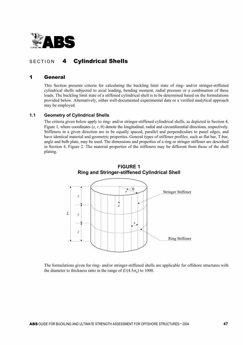
ABS GUIDE FOR BUCKLING AND ULTIMATE STRENGTH ASSESSMENT FOR OFFSHORE STRUCTURES . 2004 47
S e c t i o n 4 : C y l i n d r i c a l S h e l l s
S E C T I O N 4 Cylindrical Shells
1 General This Section presents criteria for calculating the buckling limit state of ring- and/or stringer-stiffened cylindrical shells subjected to axial loading, bending moment, radial pressure or a combination of these loads. The buckling limit state of a stiffened cylindrical shell is to be determined based on the formulations provided below. Alternatively, either well-documented experimental data or a verified analytical approach may be employed.
1.1 Geometry of Cylindrical Shells The criteria given below apply to ring- and/or stringer-stiffened cylindrical shells, as depicted in Section 4, Figure 1, where coordinates (x, r, θ) denote the longitudinal, radial and circumferential directions, respectively. Stiffeners in a given direction are to be equally spaced, parallel and perpendiculars to panel edges, and have identical material and geometric properties. General types of stiffener profiles, such as flat bar, T-bar, angle and bulb plate, may be used. The dimensions and properties of a ring or stringer stiffener are described in Section 4, Figure 2. The material properties of the stiffeners may be different from those of the shell plating.
FIGURE 1 Ring and Stringer-stiffened Cylindrical Shell
L
x
r θ
s
Stringer Stiffener
Ring Stiffener
The formulations given for ring- and/or stringer-stiffened shells are applicable for offshore structures with the diameter to thickness ratio in the range of E/(4.5σ0) to 1000.

Section 4 Cylindrical Shells
48 ABS GUIDE FOR BUCKLING AND ULTIMATE STRENGTH ASSESSMENT FOR OFFSHORE STRUCTURES . 2004
FIGURE 2 Dimensions of Stiffeners
rbf
b1b2tf
y0
z0 tw
dw
Sem
t
bf
b1b2tf
rFrR
r
y0
z0
CentroidCentroid
tw
dw
t
eo
Section of RingsSection of Stringers
1.3 Load Application This Section includes the buckling state limit criteria for the following loads and load effects.
• Uniform compression in the longitudinal direction, σa *
• Bending of the overall cylinder, σb
• External pressure, p
• Combinations of the above * Note: If uniform stress, σa, is tensile rather than compressive, it may be set equal to zero.
1.5 Buckling Control Concepts The probable buckling modes of ring- and/or stringer-stiffened cylindrical shells can be sorted as follows:
• Local shell or curved panel buckling (i.e., buckling of the shell between adjacent stiffeners). The stringers remain straight and the ring stiffeners remain round.
• Bay buckling (i.e., buckling of the shell plating together with the stringers, if present, between adjacent ring stiffeners). The ring stiffeners and the ends of the cylindrical shells remain round.
• General buckling, (i.e., buckling of one or more ring stiffeners together with the attached shell plus stringers, if present).
• Local stiffener buckling (i.e., torsional/flexural buckling of stiffeners, ring or stringer, or local buckling of the web and flange). The shell remains undeformed.
• Column buckling (i.e., buckling of cylindrical shell as a column).
The first three failure modes for ring and stringer-stiffened cylindrical shells are illustrated in Section 4, Figure 3.
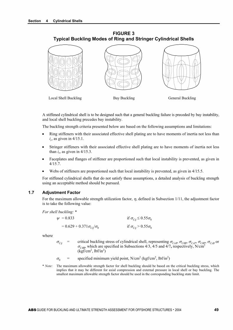
Section 4 Cylindrical Shells
ABS GUIDE FOR BUCKLING AND ULTIMATE STRENGTH ASSESSMENT FOR OFFSHORE STRUCTURES . 2004 49
FIGURE 3 Typical Buckling Modes of Ring and Stringer Cylindrical Shells
Local Shell Buckling Bay Buckling General Buckling
A stiffened cylindrical shell is to be designed such that a general buckling failure is preceded by bay instability, and local shell buckling precedes bay instability.
The buckling strength criteria presented below are based on the following assumptions and limitations:
• Ring stiffeners with their associated effective shell plating are to have moments of inertia not less than ir, as given in 4/15.1.
• Stringer stiffeners with their associated effective shell plating are to have moments of inertia not less than is, as given in 4/15.3.
• Faceplates and flanges of stiffener are proportioned such that local instability is prevented, as given in 4/15.7.
• Webs of stiffeners are proportioned such that local instability is prevented, as given in 4/15.5.
For stiffened cylindrical shells that do not satisfy these assumptions, a detailed analysis of buckling strength using an acceptable method should be pursued.
1.7 Adjustment Factor For the maximum allowable strength utilization factor, η, defined in Subsection 1/11, the adjustment factor is to take the following value:
For shell buckling: * ψ = 0.833 if σCij ≤ 0.55σ0
= 0.629 + 0.371σCij/σ0 if σCij > 0.55σ0
where σCij = critical buckling stress of cylindrical shell, representing σCxR, σCθR, σCxP, σCθP, σCxB or
σCθB, which are specified in Subsections 4/3, 4/5 and 4/7, respectively, N/cm2 (kgf/cm2, lbf/in2)
σ0 = specified minimum yield point, N/cm2 (kgf/cm2, lbf/in2)
* Note: The maximum allowable strength factor for shell buckling should be based on the critical buckling stress, which implies that it may be different for axial compression and external pressure in local shell or bay buckling. The smallest maximum allowable strength factor should be used in the corresponding buckling state limit.

Section 4 Cylindrical Shells
50 ABS GUIDE FOR BUCKLING AND ULTIMATE STRENGTH ASSESSMENT FOR OFFSHORE STRUCTURES . 2004
For column buckling:
ψ = 0.87 if σE(C) ≤ Prσ0
= )(0 /13.01 CErP σσ− if σE(C) > Prσ0
where
σE(C) = Euler’s buckling stress, as specified in Subsection 4/11, N/cm2 (kgf/cm2, lbf/in2)
Pr = proportional linear elastic limit of the structure, which may be taken as 0.6 for steel
σ0 = specified minimum yield point, N/cm2 (kgf/cm2, lbf/in2)
For tripping of stringer stiffeners: ψ = 1.0
3 Unstiffened or Ring-stiffened Cylinders
3.1 Bay Buckling Limit State For the buckling limit state of unstiffened or ring-stiffened cylindrical shells between adjacent ring stiffeners subjected to axial compression, bending moment and external pressure, the following strength criterion is to be satisfied:
22
+
−
RCRCCxR
xR
CxR
x
θ
θ
θ
θ
ησσ
ησσ
ησσ
ϕησ
σ ≤ 1
where
σx = compressive stress in longitudinal direction from 4/13.1, N/cm2 (kgf/cm2, lbf/in2)
σθ = compressive hoop stress from 4/13.3, N/cm2 (kgf/cm2, lbf/in2)
σCxR = critical buckling stress for axial compression or bending moment from 4/3.3, N/cm2 (kgf/cm2, lbf/in2)
σCθR = critical buckling stress for external pressure from 4/3.5, N/cm2 (kgf/cm2, lbf/in2)
ϕR = coefficient to reflect interaction between longitudinal and hoop stresses (negative values are acceptable)
= 0σσσ θRCCxR +
– 1.0
σ0 = specified minimum yield point, N/cm2 (kgf/cm2, lbf/in2)
η = maximum allowable strength utilization factor of shell buckling, as specified in Subsection 1/11 and 4/1.7, for ring-stiffened cylindrical shells subjected to axial compression or external pressure, whichever is less.
3.3 Critical Buckling Stress for Axial Compression or Bending Moment The critical buckling stress of unstiffened or ring-stiffened cylindrical shell subjected to axial compression or bending moment may be taken as:
σCxR = ( )
>
−−
≤
00
0
0
for11
for
σσσσ
σ
σσσ
rExRExR
rr
rExRExR
PPP
P

Section 4 Cylindrical Shells
ABS GUIDE FOR BUCKLING AND ULTIMATE STRENGTH ASSESSMENT FOR OFFSHORE STRUCTURES . 2004 51
where
Pr = proportional linear elastic limit of the structure, which may be taken as 0.6 for steel
σExR = elastic compressive buckling stress for an imperfect cylindrical shell, N/cm2 (kgf/cm2, lbf/in2)
= ρxRCσCExR
σCExR = classical compressive buckling stress for a perfect cylindrical shell, N/cm2 (kgf/cm2, lbf/in2)
= rEt605.0
C = length dependant coefficient
=
<+≥
85.2for175.0/425.185.2for0.1
zzzz
ρxR = nominal or lower bound knock-down factor to allow for shape imperfections
= ( )
≤−
<≤
−+−−
<
−+
ztr
zt
rzz
zt
rz
20for0002.035.0
201for300
1003.01142.075.0
1for300
1003.075.0
4.0
z = Batdorf parameter
= 22
1 ν−rt
= length between adjacent ring stiffeners (unsupported)
r = mean radius of cylindrical shell, cm (in.)
t = thickness of cylindrical shell, cm (in.)
E = modulus of elasticity, 2.06 × 10⁷ N/cm2 (2.1 × 10⁶ kgf/cm2, 30 × 106 lbf/in2) for steel
ν = Poisson’s ratio, 0.3 for steel
σ0 = specified minimum yield point, N/cm2 (kgf/cm2, lbf/in2)
3.5 Critical Buckling Stress for External Pressure The critical buckling stress for an unstiffened or ring-stiffened cylindrical shell subjected to external pressure may be taken as:
σCθR = ΦσEθR
where
Φ = plasticity reduction factor
= 1 for ∆ ≤ 0.55
= 18.045.0+
∆ for 0.55 < ∆ ≤ 1.6
= ∆15.11
31.1+
for 1.6 < ∆ < 6.25
= 1/∆ for ∆ ≥ 6.25

Section 4 Cylindrical Shells
52 ABS GUIDE FOR BUCKLING AND ULTIMATE STRENGTH ASSESSMENT FOR OFFSHORE STRUCTURES . 2004
∆ = σEθR/σ0
σEθR = elastic hoop buckling stress for an imperfect cylindrical shell, N/cm2 (kgf/cm2, lbf/in2)
= θθ
θρ Kt
trq RCER
)5.0( +
ρθR = nominal or lower bound knock-down factor to allow for shape imperfections
= 0.8
Kθ = coefficient to account for the effect of ring stiffener, as determined from 4/13.3
qCEθR = elastic buckling pressure, N/cm2 (kgf/cm2, lbf/in2)
=
<
≤<
≤<
≤
+
−
L
Lp
LL
LL
Atr
rtE
trA
tr
rtEC
trA
rt
AE
Art
AE
85.2for275.0
85.2208.0for836.0
208.05.2for92.0
5.2for5.0
27.1
3
3061.1
2
2
18.1
AL = kz 068.117.1)1( 412 +−
−ν
Cp = AL/(r/t)
k = 0 for lateral pressure
= 0.5 for hydrostatic pressure
z = Batdorf parameter
= 22
1 ν−rt
= length between adjacent ring stiffeners (unsupported)
r = mean radius of cylindrical shell, cm (in.)
t = thickness of cylindrical shell, cm (in.)
E = modulus of elasticity, 2.06 × 10⁷ N/cm2 (2.1 × 10⁶ kgf/cm2, 30 × 106 lbf/in2) for steel
ν = Poisson’s ratio, 0.3 for steel
σ0 = specified minimum yield point, N/cm2 (kgf/cm2, lbf/in2)
3.7 General Buckling The general buckling of a ring-stiffened cylindrical shell involves the collapse of one or more ring stiffeners together with the shell plating and is to be avoided due to its catastrophic consequences. The ring stiffeners are to be proportioned in accordance with Subsection 4/15 to exclude the general buckling failure mode.

Section 4 Cylindrical Shells
ABS GUIDE FOR BUCKLING AND ULTIMATE STRENGTH ASSESSMENT FOR OFFSHORE STRUCTURES . 2004 53
5 Curved Panels Local curved panel buckling of ring and stringer-stiffened cylindrical shells will not necessarily lead to complete failure of the shell, as stresses can be redistributed to the remaining effective section associated with the stringer. However, knowledge of local buckling behavior is necessary in order to control local deflections, in accordance with serviceability requirements, and to determine the effective width to be associated with the stringer when determining buckling strength of the stringer-stiffened shells.
5.1 Buckling State Limit The buckling state limit of curved panels between adjacent stiffeners can be defined by the following equation:
22
+
−
PCPCCxP
xP
CxP
x
θ
θ
θ
θ
ησσ
ησσ
ησσ
ϕησ
σ ≤ 1
where
σx = compressive stress in the longitudinal direction from 4/13.1, N/cm2 (kgf/cm2, lbf/in2)
σθ = compressive hoop stress from 4/13.3, N/cm2 (kgf/cm2, lbf/in2)
σCxP = critical buckling stress for axial compression or bending moment from 4/5.3, N/cm2 (kgf/cm2, lbf/in2)
σCθP = critical buckling stress for external pressure from 4/5.5, N/cm2 (kgf/cm2, lbf/in2)
ϕP = coefficient to reflect interaction between longitudinal and hoop stresses (negative values are acceptable),
= 8.0)(4.0
0−
+σ
σσ θPCCxP
σ0 = specified minimum yield point, N/cm2 (kgf/cm2, lbf/in2)
η = maximum allowable strength utilization factor of shell buckling, as specified in Subsection 1/11 and 4/1.7 for curved panels in axial compression or external pressure, whichever is the lesser
5.3 Critical Buckling Stress for Axial Compression or Bending Moment The critical buckling stress for curved panels bounded by adjacent pairs of ring and stringer stiffeners subjected to axial compression or bending moment may be taken as:
σCxP = ( )
>
−−
≤
00
0
0
for11
for
σσσσ
σ
σσσ
rExPExP
rr
rExPExP
PPP
P
where
Pr = proportional linear elastic limit of the structure, which may be taken as 0.6 for steel
σExP = elastic buckling stress for an imperfect curved panel, N/cm2 (kgf/cm2, lbf/in2)
= BxPρxPσCExP
σCExP = classical buckling stress for a perfect curved panel between adjacent stringer stiffeners, N/cm2 (kgf/cm2, lbf/in2)
= 2
2
2
)1(12
− stEK xP ν
π
Section 4 Cylindrical Shells
54 ABS GUIDE FOR BUCKLING AND ULTIMATE STRENGTH ASSESSMENT FOR OFFSHORE STRUCTURES . 2004
KxP = 4
234
πsz
+ for zs ≤ 11.4
= 0.702zs for zs > 11.4
ρxP = nominal or lower bound knock-down factor to allow for shape imperfections
=
−+−
trzz ss 300
10024.0019.01 25.1 for zs ≤ 11.4
=
−+++
trz
zz sss 300
1008.0275.127.0 2 for zs > 11.4
BxP = factor compensating for the lower bound nature of ρxP
=
≤+>
1for15.011for15.1
nn
n
λλλ
λn = CExPxPσρ
σ 0
zs = rts 2
21 ν−
s = spacing of stringer stiffeners, cm (in.)
r = mean radius of cylindrical shell, cm (in.)
t = thickness of cylindrical shell, cm (in.)
E = modulus of elasticity, 2.06 × 10⁷ N/cm2 (2.1 × 10⁶ kgf/cm2, 30 × 106 lbf/in2) for steel
ν = Poisson’s ratio, 0.3 for steel
σ0 = specified minimum yield point, N/cm2 (kgf/cm2, lbf/in2)
5.5 Critical Buckling Stress under External Pressure The critical buckling stress for curved panels bounded by adjacent pairs of ring and stringer stiffeners subjected to external pressure may be taken as:
σCθP = ΦσEθP
where
Φ = plasticity reduction factor
= 1 for ∆ ≤ 0.55
= 18.045.0+
∆ for 0.55 < ∆ ≤ 1.6
= ∆15.11
31.1+
for 1.6 < ∆ < 6.25
= 1/∆ for ∆ ≥ 6.25
∆ = σEθP/σ0
σEθP = elastic hoop buckling stress of imperfect curved panel, N/cm2 (kgf/cm2, lbf/in2)
= θθ K
ttrq PCE )5.0( +
Section 4 Cylindrical Shells
ABS GUIDE FOR BUCKLING AND ULTIMATE STRENGTH ASSESSMENT FOR OFFSHORE STRUCTURES . 2004 55
Kθ = coefficient to account for the strengthening effect of ring stiffener from 4/13.3
qCEθP = elastic buckling pressure, N/cm2 (kgf/cm2, lbf/in2)
= ( )( ) ( )
++
−−+
−+ 222
42
2
222
22 1121
1 α
αν
αα nr
tnknrEt
n = circumferential wave number starting at 0.5Ns and increasing until a minimum value of qCEθP is attained
α =
rπ
k = 0 for lateral pressure
= 0.5 for hydrostatic pressure
= length between adjacent ring stiffeners (unsupported)
r = mean radius of cylindrical shell, cm (in.)
t = thickness of cylindrical shell, cm (in.)
E = modulus of elasticity, 2.06 × 10⁷ N/cm2 (2.1 × 10⁶ kgf/cm2, 30 × 106 lbf/in2) for steel
Ns = number of stringers
7 Ring and Stringer-stiffened Shells
7.1 Bay Buckling Limit State For the buckling limit state of ring and stringer-stiffened cylindrical shells between adjacent ring stiffeners subjected to axial compression, bending moment and external pressure, the following strength criteria is to be satisfied:
22
+
−
BCBCeCxB
xB
eCxB
x
AAAA θ
θ
θ
θ
ησσ
ησσ
ησσ
ϕησ
σ ≤ 1
where
σx = compressive stress in longitudinal direction from 4/13.1, N/cm2 (kgf/cm2, lbf/in2)
σθ = compressive hoop stress from 4/13.3, N/cm2 (kgf/cm2, lbf/in2)
σCxB = critical buckling stress for axial compression or bending moment from 4/7.3, N/cm2 (kgf/cm2, lbf/in2)
σCθB = critical buckling stress for external pressure from 4/7.5, N/cm2 (kgf/cm2, lbf/in2)
ϕB = coefficient to reflect interaction between longitudinal and hoop stresses (negative values are acceptable)
= 0.2)(5.1
0−
+σ
σσ θBCCxB
Ae = effective cross sectional area, cm2 (in2)
= As + semt
A = total cross sectional area, cm2 (in2)
= As + st
Section 4 Cylindrical Shells
56 ABS GUIDE FOR BUCKLING AND ULTIMATE STRENGTH ASSESSMENT FOR OFFSHORE STRUCTURES . 2004
As = cross sectional area of stringer stiffener, cm2 (in2)
t = thickness of cylindrical shell, cm (in.)
s = spacing of stringers
sem = modified effective shell plate width
=
− 2
28.005.1
mm λλs for λm > 0.53
= s for λm ≤ 0.53
λm = modified reduced slenderness ratio
= ExP
CxB
σσ
σExP = elastic buckling stress for imperfect curved panel between adjacent stringer stiffeners subjected to axial compression from 4/5.3, N/cm2 (kgf/cm2, lbf/in2)
σ0 = specified minimum yield point, N/cm2 (kgf/cm2, lbf/in2)
η = maximum allowable strength utilization factor of shell buckling, as specified in Subsection 1/11 and 4/1.7, for ring and stringer-stiffened cylindrical shells in axial compression or external pressure, whichever is the lesser
7.3 Critical Buckling Stress for Axial Compression or Bending Moment The critical buckling stress of ring and stringer-stiffened cylindrical shells subjected to axial compression or bending may be taken as:
σCxB = ( )
>
−−
≤
00
0
0
for11
for
σσσσ
σ
σσσ
rExBExB
rr
rExBExB
PPP
P
where
Pr = proportional linear elastic limit of the structure, which may be taken as 0.6 for steel
σExB = elastic compressive buckling stress of imperfect stringer-stiffened shell, N/cm2 (kgf/cm2, lbf/in2)
= σc + σs
σs = elastic compressive buckling stress of stringer-stiffened shell, N/cm2 (kgf/cm2, lbf/in2)
=
stA
rt
sxB
+
1
605.0 Ερ
ρxB = 0.75
σc = elastic buckling stress of column, N/cm2 (kgf/cm2, lbf/in2)
= ( )tsA
EI
es
se
+2
2
π

Section 4 Cylindrical Shells
ABS GUIDE FOR BUCKLING AND ULTIMATE STRENGTH ASSESSMENT FOR OFFSHORE STRUCTURES . 2004 57
Ise = moment of inertia of stringer stiffener plus associated effective shell plate width, cm4 (in4)
= Is + Aszst2
12
3tstsA
ts e
es
e ++
Is = moment of inertia of stringer stiffener about its own centroid axis, cm4 (in4)
zst = distance from centerline of shell to the centroid of stringer stiffener, cm (in.)
As = cross sectional area of stringer stiffener, cm2 (in2)
se = reduced effective width of shell, cm (in.)
= sxPλ53.0 for λxP > 0.53
= s for λxP ≤ 0.53
s = shell plate width between adjacent stringers, cm (in.)
λxP = reduced shell slenderness ratio
= ExPσ
σ 0
σExP = elastic compressive buckling stress for imperfect curved panel between adjacent stringer stiffeners from 4/5.3, N/cm2 (kgf/cm2, lbf/in2)
= length between adjacent ring stiffeners (unsupported), cm (in.)
r = mean radius of cylindrical shell, cm (in.)
t = thickness of cylindrical shell, cm (in.)
E = modulus of elasticity, 2.06 × 10⁷ N/cm2 (2.1 × 10⁶ kgf/cm2, 30 × 106 lbf/in2) for steel
σ0 = specified minimum yield point, N/cm2 (kgf/cm2, lbf/in2)
7.5 Critical Buckling Stress for External Pressure The critical buckling stress for ring and stringer-stiffened cylindrical shells subjected to external pressure may be taken as
σCθB = (σCθR + σsp)Kp ≤ σ0
where
σCθR = critical hoop buckling stress for the unstiffened shell from 4/3.5, N/cm2 (kgf/cm2, lbf/in2)
σsp = collapse hoop stress for a stringer stiffener plus its associated shell plating, N/cm2 (kgf/cm2, lbf/in2)
= θKt
trqs )5.0( +
Kθ = coefficient to account for the strengthening effect of ring stiffener from 4/13.3
qs = collapse pressure of a stringer stiffener plus its associated shell plating, N/cm2 (kgf/cm2, lbf/in2)
= 0216 σsts zAs
zst = distance from centerline of shell to the centroid of stringer stiffener, cm (in.)

Section 4 Cylindrical Shells
58 ABS GUIDE FOR BUCKLING AND ULTIMATE STRENGTH ASSESSMENT FOR OFFSHORE STRUCTURES . 2004
As = cross sectional area of stringer stiffener, cm2 (in2)
Kp = effective pressure correction factor
= g500
85.025.0 + for g ≤ 500
= 1.10 for g > 500
g = geometrical parameter
= ss
s
INA2
2
π
Is = sectional moment area of inertia of stringer stiffener, cm4 (in4)
Ns = number of stringer stiffeners
= length between adjacent ring stiffeners (unsupported), cm (in.)
r = mean radius of cylindrical shell, cm (in.)
t = thickness of cylindrical shell, cm (in.)
σ0 = specified minimum yield point, N/cm2 (kgf/cm2, lbf/in2)
7.7 General Buckling The general buckling of a ring and stringer-stiffened cylindrical shell involves the collapse of one or more ring stiffeners together with shell plating plus stringer stiffeners and should be avoided due to its catastrophic consequences. The ring and stringer stiffeners are to be proportioned, in accordance with 4/15.1 and 4/15.3, to exclude the general buckling failure mode.
9 Local Buckling Limit State for Ring and Stringer Stiffeners
9.1 Flexural-Torsional Buckling When the torsional stiffness of the stiffeners is low and the slenderness ratio of the curved panels is relatively high, the stiffeners can suffer torsional-flexural buckling (tripping) at a stress level lower than that resulting in local or bay buckling. When the stiffener buckles, it loses a large part of its effectiveness to maintain the initial shape of the shell. The buckled stiffener sheds load to the shell, and therefore, should be suppressed.
The flexural-torsional buckling limit state of stringer stiffeners is to satisfy the ultimate state limit given below:
CT
x
ησσ
≤ 1
where
σx = compressive stress in the longitudinal direction from 4/13.1, N/cm2 (kgf/cm2, lbf/in2)
σCT = flexural-torsional buckling stress with respect to axial compression of a stiffener, including its associated shell plating, may be obtained from the following equations:
= ( )
>
−−
≤
00
0
0
if11
if
σσσσ
σ
σσσ
rETET
rr
rETET
PPP
P
σ0 = specified minimum yield point of the stringer under consideration, N/cm2 (kgf/cm2, lbf/in2)

Section 4 Cylindrical Shells
ABS GUIDE FOR BUCKLING AND ULTIMATE STRENGTH ASSESSMENT FOR OFFSHORE STRUCTURES . 2004 59
Pr = proportional linear elastic limit of the structure, which may be taken as 0.6 for steel
σET = ideal elastic flexural-torsional buckling stress, N/cm2 (kgf/cm2, lbf/in2)
= E
nC
I
nECnK
CL
20
0
20
2
6.2
+
+
+
πσ
πΓπ
K = St. Venant torsion constant for the stiffener cross-section, excluding the associated shell plating, cm4 (in4)
= 3
33wwff tdtb +
I0 = polar moment of inertia of the stiffener, excluding the associated shell plating, cm4 (in4)
= Iy + mIz + As(y02 + z0
2)
Iy, Iz = moment of inertia of the stiffener about the y- and z-axis, respectively, through the centroid of the longitudinal, excluding the shell plating (y-axis perpendicular to the web, see Section 4, Figure 2), cm4 (in4)
m =
−−
f
w
bd
u 1.07.00.1
u = non-symmetry factor
= fb
b121−
y0 = horizontal distance between centroid of stiffener and web plate centerline (see Section 4, Figure 2), cm (in.)
z0 = vertical distance between centroid of stiffener and its toe (see Section 4, Figure 2), cm (in.)
dw = depth of the web, cm (in.)
tw = thickness of the web, cm (in.)
bf = total width of the flange/face plate, cm (in.)
b1 = smaller outstanding dimension of flange or face plate with respect to web's centerline, cm (in.)
tf = thickness of the flange or face plate, cm (in.)
C0 = s
Et3
3
Γ ≅ warping constant, cm6 (in6)
≅ 36
332 wwwzf
tddmI +
Ixf =
+
s
wwff
Atdubt 23
0.30.112
, cm4 (in4)

Section 4 Cylindrical Shells
60 ABS GUIDE FOR BUCKLING AND ULTIMATE STRENGTH ASSESSMENT FOR OFFSHORE STRUCTURES . 2004
σCL = critical buckling stress for associated shell plating corresponding to n-half waves, N/cm2 (kgf/cm2, lbf/in2)
= ( )2
222
112 υ
αα
π
−
+
st
nnE
α = /s
n = number of half-waves which yields the smallest σE
σ0 = specified minimum yield point of the material, N/cm2 (kgf/cm2, lbf/in2)
E = modulus of elasticity, 2.06 × 10⁷ N/cm2 (2.1 × 10⁶ kgf/cm2, 30 × 106 lbf/in2) for steel
s = spacing of stringer stiffeners, cm (in.)
As = sectional area of stringer stiffener, excluding the associated shell plating, cm2 (in2)
t = thickness of shell plating, cm (in.)
= length between adjacent ring stiffeners (unsupported), cm (in.)
η = maximum allowable strength utilization factor, as specified in Subsection 1/11 and 4/1.7, for tripping of stringer stiffeners
9.3 Web Plate Buckling The depth to thickness ratio of the web plate is to satisfy the limit given in 4/15.5.
9.5 Faceplate and Flange Buckling The breadth to thickness ratio of the faceplate or flange is to satisfy the limit given in 4/15.7.
11 Beam-Column Buckling A cylindrical shell subjected to axial compression, or bending moment or both; with or without external pressure, is to be designed to resist beam-column buckling. Beam-column buckling is to be assessed if:
λxE ≥ 0.50
where
λxE = slenderness ratio of cylindrical shell
= )(0 / CEσσ
σE(C) = Euler buckling stress, N/cm2 (kgf/cm2, lbf/in2)
= π2Eri2/(kL)2
ri = radius of gyration of the cross section of the cylindrical shell
= T
T
AI
IT = moment of inertia of the cross section of the cylindrical shell; if the cross section is variable along the length, the minimum value is to be used, cm4 (in4)
AT = cross sectional area of the cylindrical shell; if the cross section is variable along the length, the minimum value is to be used, cm2 (in2)
kL = effective length of the cylinder, as defined in 2/3.3
E = modulus of elasticity, 2.06 × 10⁷ N/cm2 (2.1 × 10⁶ kgf/cm2, 30 × 106 lbf/in2) for steel
Section 4 Cylindrical Shells
ABS GUIDE FOR BUCKLING AND ULTIMATE STRENGTH ASSESSMENT FOR OFFSHORE STRUCTURES . 2004 61
The beam-column buckling limit state of a cylindrical shell subjected to axial compresion, or bending or both; with or without external pressure, is to satisfy the following criteria at all cross-sections along its length:
)]/(1[ )(CEaCx
b
Ca
a
ησσησσ
ησσ
−+ ≤ 1
where
σa = calculated axial normal compressive stress from 4/13.1, N/cm2 (kgf/cm2, lbf/in2)
σb = calculated bending stress from 4/13.1, N/cm2 (kgf/cm2, lbf/in2)
σCa = critical compressive buckling stress, N/cm2 (kgf/cm2, lbf/in2)
= ( )
>
−−
≤
CxrCECE
CxrrCx
CxrCECE
PPP
P
σσσσ
σ
σσσ
)()(
)()(
if11
if
σCx = critical axial or bending buckling stress of bay
for ring-stiffened cylindrical shell
=
−−+
2
2 )25.01(15.0RC
RRC
RCxRθ
θ
θ
θ
σσ
ϕσσ
ϕσ
for ring and stringer-stiffened cylindrical shell
=
−−+
2
2 )25.01(15.0BC
RBC
BCxBe
AA
θ
θ
θ
θ
σσ
ϕσσ
ϕσ
σθ = calculated hoop stress from 4/13.3, N/cm2 (kgf/cm2, lbf/in2)
A = cross sectional area as defined in 4/7.1
Ae = effective cross sectional area as defined in 4/7.1
η = maximum allowable strength utilization factor, as specified in Subsection 1/11 and 4/1.7, for column buckling
σCxR, σCθR, ϕR, σCxB, σCθB and ϕB are as defined in Subsections 4/3 and 4/7.
13 Stress Calculations
13.1 Longitudinal Stress The longitudinal stress in accordance with beam theory may be taken as:
σx = σa + σb
where
σa = stress due to axial force, N/cm2 (kgf/cm2, lbf/in2)
= )1(2 δπ +rt
P
σb = stress due to bending moment, N/cm2 (kgf/cm2, lbf/in2)
= )1(2 δπ +tr
M
Section 4 Cylindrical Shells
62 ABS GUIDE FOR BUCKLING AND ULTIMATE STRENGTH ASSESSMENT FOR OFFSHORE STRUCTURES . 2004
P = axial force, N (kgf, lbf)
M = bending moment, N-cm (kgf-cm, lbf-in)
δ = stAst
Ast = cross sectional area of stringer stiffener, cm2 (in2)
s = shell plate width between adjacent stringer stiffeners, cm (in.)
r = mean radius of cylindrical shell, cm (in.)
t = thickness of cylindrical shell, cm (in.)
13.3 Hoop Stress The hoop stress may be taken as
At midway of shell between adjacent ring stiffeners:
σθ = θKt
trq )5.0( +
At inner face of ring flange, (i.e., radius rF in Section 4, Figure 2):
σθR = RF
Krr
ttrq
θ)5.0( +
where
Kθ = αϖν G
Attk
Rw )(111
++−
−
KθR = )]([1
1ϖ
ν++
−
wR ttAk
RA = 2
RR r
rA , cm2 (in2)
ϖ = 0)2sin2(sinh
2cos2cosh≥
+−
ααααα
α = rt56.1
Gα = 02sin2sinh
sincoshcossinh2 ≥+
+αα
αααα
k = Nx/Nθ for lateral pressure
= Nx/Nθ + 0.5 for hydrostatic pressure
AR = cross sectional area of ring stiffener, cm2 (in2)
q = external pressure, N/cm2 (kgf/cm2, lbf/in2)
Nx = axial load per unit length, excluding the capped-end actions due to hydrostatic pressure, N/cm (kg/cm, lbf/in)
Nθ = circumferential load per unit length, N/cm (kg/cm, lbf/in)
r = mean radius of cylindrical shell, cm (in.)
Section 4 Cylindrical Shells
ABS GUIDE FOR BUCKLING AND ULTIMATE STRENGTH ASSESSMENT FOR OFFSHORE STRUCTURES . 2004 63
rR = radius to centroid of ring stiffener, as defined in Section 4, Figure 2, cm (in.)
rF = radius to inner face of ring flange, as defined in Section 4, Figure 2, cm (in.)
t = thickness of cylindrical shell, cm (in.)
tw = stiffener web thickness, cm (in.)
= length between adjacent ring stiffeners (unsupported), cm (in.)
ν = Poisson’s ratio
r, rR and rF are described in Section 4, Figure 2.
15 Stiffness and Proportions To fully develop the intended buckling strength of the assemblies of a stiffened cylindrical shell, ring and stringer stiffeners are to satisfy the following requirements for stiffness and proportions.
15.1 Stiffness of Ring Stiffeners The moment of inertia of the ring stiffeners, ir, together with the effective length of shell plating, eo, should not be less than that given by the following equation:
ir =
−
+++
R
eeex Er
zEK
trE
tr
θθ
θ
σησσδσ
0
24
1001
2500)1(
where
σx = compressive stress in longitudinal direction from 4/13.1, N/cm2 (kgf/cm2, lbf/in2)
σθ = compressive hoop stress midway between adjacent ring stiffeners from 4/13.3, N/cm2 (kgf/cm2, lbf/in2)
σθR = compressive hoop stress at outer edge of ring flange from 4/13.3, N/cm2 (kgf/cm2, lbf/in2)
δ = As/st
ir = moment of inertia of the ring stiffeners with associated effective shell length, eo
eo = rt56.1 ≤
re = radius to the centroid of ring stiffener, accounting for the effective length of shell plating, cm (in.)
ze = distance from inner face of ring flange to centroid of ring stiffener, accounting for the effective length of shell plating, cm (in.)
Kθ = coefficient from 4/13.3
σ0 = specified minimum yield point, N/cm2 (kgf/cm2, lbf/in2)
E = modulus of elasticity, 2.06 × 10⁷ N/cm2 (2.1 × 10⁶ kgf/cm2, 30 × 106 lbf/in2) for steel
s = spacing of stringer stiffeners, cm (in.)
As = cross sectional area of stringer, cm2 (in2)
t = thickness of shell plating, cm (in.)
= length between adjacent ring stiffeners (unsupported), cm (in.)
η = maximum allowable strength utilization factor for stiffened cylindrical shells subjected to external pressure

Section 4 Cylindrical Shells
64 ABS GUIDE FOR BUCKLING AND ULTIMATE STRENGTH ASSESSMENT FOR OFFSHORE STRUCTURES . 2004
15.3 Stiffness of Stringer Stiffeners The moment of inertia of the stringer stiffeners, is, with effective breadth of shell plating, sem, is not to be less than:
io = ( ) 02
3
112γ
ν−st
where
γ0 = (2.6 + 4.0δ)α2 + 12.4α – 13.2α1/2
δ = As/(st)
α = /s
s = spacing of stringer stiffeners, cm (in.)
t = thickness of shell plate, cm (in.)
ν = Poisson’s ratio
As = cross sectional area of stringer stiffener, cm2 (in2)
= length between adjacent ring stiffeners (unsupported), cm (in.)
15.5 Proportions of Webs of Stiffeners The depth to thickness ratio of webs of stiffeners is to satisfy the applicable limit given below.
dw/tw ≤ 1.5(E/σ0)1/2 for angles and tee bars
dw/tw ≤ 0.85(E/σ0)1/2 for bulb plates
dw/tw ≤ 0.4(E/σ0)1/2 for flat bars
where
σ0 = specified minimum yield point, N/cm2 (kgf/cm2, lbf/in2)
E = modulus of elasticity, 2.06 × 10⁷ N/cm2 (2.1 × 10⁶ kgf/cm2, 30 × 106 lbf/in2) for steel
dw and tw are as defined in Section 4, Figure 2.
15.7 Proportions of Flanges and Faceplates The breadth to thickness ratio of flanges and faceplates of stiffeners is to satisfy the limit given below.
b2/tf ≤ 0.4(E/σ0)1/2
where
b2 = larger outstanding dimension of the flange/faceplate, cm (in.)
tf = thickness of flange/face plate, cm (in.)
σ0 = specified minimum yield point, N/cm2 (kgf/cm2, lbf/in2)
E = modulus of elasticity, 2.06 × 10⁷ N/cm2 (2.1 × 10⁶ kgf/cm2, 30 × 106 lbf/in2) for steel

ABS GUIDE FOR BUCKLING AND ULTIMATE STRENGTH ASSESSMENT FOR OFFSHORE STRUCTURES . 2004 65
S e c t i o n 5 : T u b u l a r J o i n t s
S E C T I O N 5 Tubular Joints
1 General This Section provides ultimate strength criteria for tubular joints. Each joint should be considered as being comprised of a number of independent chord/brace intersections, and the ultimate strength limit state of each intersection is to be checked against the design requirement. For a multi-planar joint, each plane should be subjected to separate consideration and categorization.
The formulations provided in this Section may be used to assess the ultimate strength limit of tubular joints. Alternatively, the ultimate strength of a tubular joint may be determined based on either well-documented experimental data or a verified analytical approach.
1.1 Geometry of Tubular Joints The geometry of a simple joint is depicted in Section 5, Figure 1.
FIGURE 1 Geometry of Tubular Joints
g
t
d
D
T
θ
MIPBMOPB
PB
MOPC
MIPC
PC
CAN CHORD
The formulations in this Section are applicable for the strength assessment of tubular joints in the following geometric ranges:
τ ≤ 1.20
0.20 ≤ β ≤ 1.00
10 ≤ γ ≤ 50
−0.5 ≤ g/D
where
τ = ratio of brace wall thickness to chord wall thickness
= t/T

Section 5 Tubular Joints
66 ABS GUIDE FOR BUCKLING AND ULTIMATE STRENGTH ASSESSMENT FOR OFFSHORE STRUCTURES . 2004
β = ratio of brace outer diameter to chord outer diameter
= d/D
γ = ratio of chord outer diameter to two times of chord wall thickness
= D/(2T)
g = gap, cm (in.)
1.3 Loading Application The ultimate strength criteria are provided for the following loads and load effects:
• Axial load in a brace member, PB
• In-plane bending moment in a brace member, MIPB
• Out-of-plane bending moment in a brace member, MOPB
• Axial load in a chord member, PC
• In-plane bending moment in a chord member, MIPC
• Out-of-plane bending moment in a chord member, MOPC
• Combinations of the above mentioned loads and load effects.
1.5 Failure Modes The mode of failure of a tubular joint depends on the joint configuration, joint geometry and loading condition. These modes include:
Local failure of the chord:
• Plastic failure of the chord wall in the vicinity of the brace.
• Cracking leading to rupture of the brace from the chord.
• Local buckling in compression areas of the chord.
Global failure of the chord:
• Ovalization of the chord cross-section.
• Beam bending failure.
• Beam shear failure between adjacent braces.
In addition, a member can fail away from the brace-chord joint due to chord or brace overloading. These failure modes can be established following the approach described in Section 2 for tubular members.
1.7 Classfication of Tubular Joints Each chord/brace intersection is to be classified as T/Y, K or X, according to their configuration and load pattern for each load case. The following guidelines are to be used to classify tubular joints:
• For two or three brace members on one side of a chord, the classification is dependent on the equilibrium of the axial load components in the brace members. If the resultant shear on the chord member is balanced or algebraically around zero, the joint is to be categorized as a K. If the shear balance check is not met, the joint is to be categorized (downgraded) as a T&Y, as shown in Section 5, Figure 2. However, for braces that carry part of their load as K joints and part as Y or X joints, interpolation is to be used based on the proportion of each joint. The procedure for interpolation in such cases is to be specially agreed upon with ABS.
• For multi-brace joints with braces on either side of the chord, as shown in Section 5, Figure 2, care is to be taken in assigning the appropriate category. For example, a K classification would be valid if the net shear across the chord is balanced or algebraically zero. In contrast, if the loads in all of the braces are tensile, even an X classification may be too optimistic due to the increased ovalization effect. Classification in these cases is to be specially agreed with ABS.
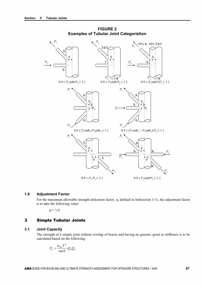
Section 5 Tubular Joints
ABS GUIDE FOR BUCKLING AND ULTIMATE STRENGTH ASSESSMENT FOR OFFSHORE STRUCTURES . 2004 67
FIGURE 2 Examples of Tubular Joint Categoriztion
0.9 ≤ P1sinθ/P2 ≤ 1.1
P1
P2
K
K
θ
0.9 ≤ P1sinθ/P2 ≤ 1.1
P1
θ
T&Y
T
P20.9 ≤ P1sinθ/2P2 ≤ 1.1
P1
θ
K
50% K, 50% T&Y
P2
P2
0.9 ≤ P1sinθ1/P3sinθ3 ≤ 1.1
θ1
P1
K
θ3
KP3
θ1
P1
K
θ3
KP3
KP2
0.9 ≤ (P1sinθ1 + P3sinθ3)/P2 ≤ 1.1
X
X
0.9 ≤ P1sinθ/P2 ≤ 1.10.9 ≤ P1/P2 ≤ 1.1
θ
P1
θ
P2
θ
P1
θ
P1
K K
K
K
P2
P2
1.9 Adjustment Factor For the maximum allowable strength utilization factor, η, defined in Subsection 1/11, the adjustment factor is to take the following value:
ψ = 1.0
3 Simple Tubular Joints
3.1 Joint Capacity The strength of a simple joint without overlap of braces and having no gussets, grout or stiffeners is to be calculated based on the following:
fuc
u QQT
Pθsin
20σ
=

Section 5 Tubular Joints
68 ABS GUIDE FOR BUCKLING AND ULTIMATE STRENGTH ASSESSMENT FOR OFFSHORE STRUCTURES . 2004
fuc
u QQdT
Mθsin
20σ
=
where
Pu = critical joint axial strength, N (kgf, lbf)
Mu = critical joint bending moment strength for in-plane and out-of plane bending, N-cm (kgf-cm, lbf-in)
θ = brace angle measured from chord, as defined in Section 5, Figure 1
Qu = strength factor depending on the joint loading and classification, as determined in Section 5, Table 1
Qf = chord load factor
= 1 – λγA2
λ = chord slenderness parameter
= 0.030 for brace axial load
= 0.045 for brace in-plane bending moment
= 0.021 for brace out-of-plane bending moment
γ = ratio of chord outer radius to chord wall thickness
= D/(2T)
A = chord utilization ratio
= oc
OPCIPCAC
ησσσσ 222 ++
σAC = nominal axial stress in the chord member, N/cm2 (kgf/cm2, lbf/in2)
σIPC = nominal in-plane bending stress in the chord member, N/cm2 (kgf/cm2, lbf/in2)
σOPC = nominal out-of-plane bending stress in the chord member, N/cm2 (kgf/cm2, lbf/in2)
σ0c = specified minimum yield point of the chord member, N/cm2 (kgf/cm2, lbf/in2)
D = chord outer diameter, cm (in.)
T = chord thickness, cm (in.)
d = brace outer diameter, cm (in.)
η = maximum allowable strength utilization factor, as defined in Subsection 1/11 and 5/1.9
Axially loaded braces based on a combination of K, X and Y joints should take a weighted average of Pu depending on the proportion of each load.
TABLE 1 Strength Factor, Qu
Joint Classification
Brace Load Effects
Axial Compression
Axial Tension
In-plane Bending
Out-of-plane Bending
K (0.5+12β)γ0.2 Qβ0.5 Qg (0.65+15.5β)γ0.2 Qβ
0.5 Qg 4.5βγ0.5 3.2γ(0.5β²) T/Y (0.5+12β)γ0.2 Qβ
0.5 (0.65+15.5β)γ0.2 Qβ0.5 4.5βγ0.5 3.2γ(0.5β²)
X (3.0+14.5β) Qβ (3.3+16β) Qβ 5.0βγ0.5 3.2γ(0.5β²)

Section 5 Tubular Joints
ABS GUIDE FOR BUCKLING AND ULTIMATE STRENGTH ASSESSMENT FOR OFFSHORE STRUCTURES . 2004 69
where
Qβ = 0.3/[β(1 – 0.833β)] for β > 0.6
= 1.0 for β ≤ 0.6
Qg = 1 + 0.85 exp (-4g/D) for g/D ≥ 0.0
g = gap, cm (in.)
β = ratio of brace outer diameter to chord outer diameter
= d/D
γ = ratio of chord outer diameter to two times of chord wall thickness
= D/(2T)
3.3 Joint Cans The advantage of a thicker chord may be taken for axially-loaded T/Y and X joints. This only applies if the effective can length of each brace is at least twice the distance from the brace toe to the nearest transition from the can to the main member, plus the brace diameter (see Section 5, Figure 3).
FIGURE 3 Examples of Effective Can Length
1 2c1 + d12 2c2 + d23 2c3 + d3
Brace Effective CanLength
Brace 3
Chord-canChord
Brace 1 Brace 2
d1
d2
c1 c2
c3
Tc T
d3
D
For K joints, the joint strength, Pu′, considering the additional effect of the can is to be calculated based on the following equation:
Pu′ = [C + (1 – C)(T/Tc)2]Pu
where
Pu = basic strength of the joint based on the can dimensions, N (kgf, lbf)
Tc = can thickness, cm (in.)
C = coefficient, which may not be taken greater than 1
= Lc/(2.5D) for β ≤ 0.9
= (4β – 3)Lc/(1.5D) for β > 0.9
β = ratio of brace outer diameter to chord outer diameter
= d/D
D = chord outer diameter, cm (in.)

Section 5 Tubular Joints
70 ABS GUIDE FOR BUCKLING AND ULTIMATE STRENGTH ASSESSMENT FOR OFFSHORE STRUCTURES . 2004
T = chord wall thickness, cm (in.)
Lc = effective length of can, cm (in.)
3.5 Strength State Limit The strength of a tubular joint subjected to combined axial and bending loads is to satisfy the following state limit:
uOPB
OPB
uIPB
IPB
u
D
MM
MM
PP
ηηη+
+
2
≤ 1
where
PD = axial load in the brace member, N (kgf, lbf)
MIPB = in-plane bending moment in the brace member, N-cm (kgf-cm, lbf-in)
MOPB = out-of-plane bending moment in the brace member, N-cm (kgf-cm, lbf-in)
Pu = tubular joint strength for brace axial load from 5/3.1 or 5/3.3, N (kgf, lbf)
MuIPB = tubular joint strength for brace in-plane bending moment from 5/3.1, N-cm (kgf-cm, lbf-in)
MuOPB = tubular joint strength for brace out-of-plane bending moment from 5/3.1, N-cm (kgf-cm, lbf-in)
η = maximum allowable strength utilization factor, as specified in Subsection 1/11 and 5/1.9
5 Other Joints
5.1 Multiplanar Joints The interaction between out-of-plane braces can be ignored, except for overlapping braces. It is recognized that for some load cases, particularly where braces lying in two perpendicular planes are loaded in the opposite sense (e.g., tension and compression), as shown in Section 5, Figure 4, joint strength can be significantly reduced. This strength reduction is primarily due to the additional ovalization occurring in the chord member. The design should account for this effect and is to consider applying a reduced allowable utilization factor, especially for critical, highly stressed, non-redundant joints. As required, the design of multiplanar joints loaded in opposite directions is to be based on suitable experimental data or nonlinear finite element analysis. Nonlinear finite element analysis is well-suited to investigate the effects of individual parameters such as load ratio, load sequence and interaction of out-of-plane braces.
FIGURE 4 Multiplanar Joints
Brace 2
Brace 1
Chord
P1
P2

Section 5 Tubular Joints
ABS GUIDE FOR BUCKLING AND ULTIMATE STRENGTH ASSESSMENT FOR OFFSHORE STRUCTURES . 2004 71
5.3 Overlapping Joints Joints with braces that overlap in plane are to be checked using the same formula as for non-overlapping braces given in Subsection 5/3. However, an additional check is to be performed for the region of the overlap by considering the through brace as the chord member and the overlapping brace as the brace member.
The Qg term for overlapped joints is to be based on the following equation:
Qg = 0.5
0
0 γ0.650.13 τσσ
+
c
b –0.50 ≤ g/D ≤ –0.05
where
σ0b = specified minimum yield point of the brace member, N/cm2 (kgf/cm2, lbf/in2)
σ0c = specified minimum yield point of the chord member, N/cm2 (kgf/cm2, lbf/in2)
τ = ratio of brace thickness to chord thickness
= t/T
γ = ratio of chord outer radius to chord wall thickness
= D/(2T)
g = gap, cm (in.)
D = chord outer diameter, cm (in.)
For -0.5 < g/D < 0.0, the value of Qg should be estimated by linear interpolation between the value of Qg calculated from the above expression and 1.85, the Qg factor at g/D = 0.0.
Joints that overlap out-of-plane should be treated as simple joints and checked in accordance with Subsection 5/3. However, an additional check should be performed for the region of overlap by considering the through brace as the chord member and the overlapping brace as the brace member. The joint will be considered as a T/Y joint in this instance. The combined out-of-plane bending moment between these offset members is equivalent to an in-plane bending moment as defined for a simple T/Y joint. Similarly, the combined in-plane bending moment is equivalent to an out-of-plane bending moment, as defined for a simple T/Y joint.
5.5 Grouted Joints Grouted joints can be classified into two types:
i) Those with a fully grouted chord member and
ii) Those with an inner steel sleeve with a grout filling the annulus between the two concentric tubular members.
Under axial compression, significant increases in joint strength have been recorded through test programs. Under axial tension, only modest strength enhancement is noted, which results primarily from the reduction in chord ovalization that occurs for the grouted specimen.
It is recommended that no benefit is taken from grouting or insertion of an inner sleeve under axial tension and bending in the strength assessment of a grouted joint. However, under axial compression, an enhancement in chord thickness may be available and an effective chord thickness may be obtained from the following equation.
Te = T + Tp + Tg/18
where
T = chord thickness, cm (in.)
Tp = thickness of the inner tube, cm (in.)
Tg = thickness of the grout-filled section, cm (in.)
= D/2 – (T + Tp), if fully grout-filled tube
D = outer diameter, cm (in.)
Tp and Tg are depicted in Section 5, Figure 5.
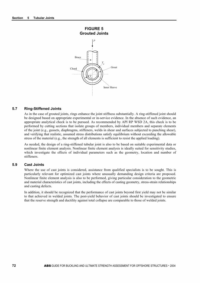
Section 5 Tubular Joints
72 ABS GUIDE FOR BUCKLING AND ULTIMATE STRENGTH ASSESSMENT FOR OFFSHORE STRUCTURES . 2004
FIGURE 5 Grouted Joints
P
Tg
Tp
Grout
Brace
Chord
Inner Sleeve
5.7 Ring-Stiffened Joints As in the case of grouted joints, rings enhance the joint stiffness substantially. A ring-stiffened joint should be designed based on appropriate experimental or in-service evidence. In the absence of such evidence, an appropriate analytical check is to be pursued. As recommended by API RP WSD 2A, this check is to be performed by cutting sections that isolate groups of members, individual members and separate elements of the joint (e.g., gussets, diaphragms, stiffeners, welds in shear and surfaces subjected to punching shear), and verifying that realistic, assumed stress distributions satisfy equilibrium without exceeding the allowable stress of the material (e.g., the strength of all elements is sufficient to resist the applied loading).
As needed, the design of a ring-stiffened tubular joint is also to be based on suitable experimental data or nonlinear finite element analysis. Nonlinear finite element analysis is ideally suited for sensitivity studies, which investigate the effects of individual parameters such as the geometry, location and number of stiffeners.
5.9 Cast Joints Where the use of cast joints is considered, assistance from qualified specialists is to be sought. This is particularly relevant for optimized cast joints where unusually demanding design criteria are proposed. Nonlinear finite element analysis is also to be performed, giving particular consideration to the geometric and material characteristics of cast joints, including the effects of casting geometry, stress-strain relationships and casting defects.
In addition, it should be recognized that the performance of cast joints beyond first yield may not be similar to that achieved in welded joints. The post-yield behavior of cast joints should be investigated to ensure that the reserve strength and ductility against total collapse are comparable to those of welded joints.
ABS GUIDE FOR BUCKLING AND ULTIMATE STRENGTH ASSESSMENT FOR OFFSHORE STRUCTURES . 2004 73
A p p e n d i x 1 : R e v i e w o f B u c k l i n g A n a l y s i s b y F i n i t e E l e m e n t M e t h o d ( F E M )
A P P E N D I X 1 Review of Buckling Analysis by Finite Element Method (FEM)
1 General This Appendix, in conjunction with API Bulletin 2V, provides guidance on the review of buckling analysis using FEM. If appropriate documentation is presented, proven numerical methods to establish the buckling strength of structural components subjected to various loads and their combinations are accepted as an alternative to the formulations presented in the previous Sections of this Guide. In some cases, especially those involving novel structural designs and loading situations, reliance on such analytical methods are to be pursued to provide added assurance of a proposed design’s adequacy. One widely-accepted method relies on the use of FEM analysis, which allows the designer to model the geometry; material properties; imperfections (such as out-of-roundness), fabrication-induced residual stresses, misalignment and corrosion defects; as well as boundary conditions.
Key issues in an FEM analysis include the selection of the computer program, the determination of the loads and boundary conditions, development of the mathematical model, choice of element types, design of the mesh, solution procedures and verification and validation. Numerous decisions are to be made during this analysis process.
This Appendix emphasizes some important aspects that should be satisfied in determining the buckling strength by FEM analysis.
3 Engineering Model The engineering model for buckling analysis is a simplification and idealization of an actual physical structural component. Hence, it is crucial that the modeling process is undertaken correctly, since the FEM analysis cannot improve on a poor engineering model.
The rationale for the following aspects is to be appropriately described and justified:
• Extent of the model. The model should include the main features of the physical structure related to buckling behavior and capture all relevant failure modes.
• Geometry. The use of a full model is preferred in the FEM buckling analysis. Symmetric conditions may be utilized to reduce the size of finite element model, if appropriate.
• Material properties. Material nonlinearity may need to be considered in some circumstances, particularly in order to account for the effects of residual stresses.
• Imperfections. Imperfections may remarkably reduce the buckling strength of structural components. For this reason, the imperfections should be included.
• Loads. All possible loads and their combinations are to be considered.
• Boundary conditions. Boundary conditions are the constraints applied to the model. The boundary conditions should suitably reflect the constraint relationship between the structural component and its surroundings.

Appendix 1 Review of Buckling Analysis by Finite Element Method (FEM)
74 ABS GUIDE FOR BUCKLING AND ULTIMATE STRENGTH ASSESSMENT FOR OFFSHORE STRUCTURES . 2004
5 FEM Analysis Model The FEM analysis model is translated from the engineering model. The rationale for the following items should be appropriately described and justified:
• Element types. Finite element types are specialized and can only simulate a limited number of response types. The choice of element types should be best suited to the problem.
• Mesh design. The discretization of a structure into a number of finite elements is one of the most critical tasks in finite element modeling and often a difficult one. The following parameters need to be considered in designing the layout of elements: mesh density, mesh transitions and the stiffness ratio of adjacent elements. As a general guidance, a finer mesh should be used in areas of high stress gradient. The performance of elements degrades as they become more skewed. If the mesh is graded, rather than uniform, the grading should be done in a way that minimizes the difference in size between adjacent elements.
• Loads. Typical structural loads and load effects in finite element models are forces, pressure load, gravity, body forces, prescribed displacements and temperatures. The loads and load effects may be applied or translated to nodes (e.g., nodal forces and body forces), element edges or faces (e.g., distributed line loads, pressure) and the entire model (e.g., gravity loads).
• Boundary conditions. Generally, the support condition assumed for the degree of freedom concerned is idealized as completely rigid or completely free. In reality, the support condition is usually somewhere in between.
7 Solution Procedures Two types of solution procedures are usually employed in buckling analysis (e.g., eigenvalue buckling analysis and nonlinear buckling analysis).
Eigenvalue buckling analysis predicts the theoretical buckling strength (the bifurcation point) of an ideal linear elastic structure. However, imperfections and nonlinearities prevent most real structures from achieving their theoretical elastic buckling strength. Thus, eigenvalue buckling analysis often yields unconservative results and should generally not be used in actual structural design.
The nonlinear buckling analysis employs a nonlinear static analysis with gradually increasing loads to seek the load level at which the structure becomes unstable. The basic approach in a nonlinear buckling analysis is to constantly apply incremental loads until the solution begins to diverge. The load increments should be sufficiently fine to ensure the accuracy of the prediction.
The sequence of applied loads may influence the results. If the sequence is unknown, several tests should be performed to make sure that the results represent the worst case scenario.
The analysis may be extended into the post-buckling range by activating, for example, the arc-length method. Use this feature to trace the load-deflection curve through regions of “snap-through” and “snap-back” response.
9 Verification and Validation It is necessary to perform verification and validation for the FEM analysis results to ensure that the loading, buckling strength and acceptance criteria are suitably considered.
• Results and acceptance criteria
The results should be presented so that they can be easily compared with the design/acceptance criteria and validated based on appropriate experimental or in-service evidence.
A statement confirming that all quality assessment checks, as required to confirm that a buckling analysis has been executed satisfactorily, should be included.
• Analysis model
In case of discrepancies in the results, the model and loading applied to the model should be reviewed as part of the investigation into the source of the problem. The appropriateness of the model, types of loads and load combination, load sequence, boundary conditions, etc., should be reviewed.
Appendix 1 Review of Buckling Analysis by Finite Element Method (FEM)
ABS GUIDE FOR BUCKLING AND ULTIMATE STRENGTH ASSESSMENT FOR OFFSHORE STRUCTURES . 2004 75
• Strength assessment
In the modeling process, several assumptions are made which may or may not be conservative. An assessment of the conservatism should be made particularly with regard to the underlying assumptions implicit in the design criteria that are being applied.
In making an assessment of the buckling strength of a structural component based on the results of an FEM analysis, appropriate allowances should also be made for factors that were not included or fully considered.
• Accuracy assessment
In assessing the accuracy of the results, factors to be considered include model complexity and behavior, mesh refinement, and solution options, etc. In reducing the model’s complexity, the analysts would necessarily have omitted some elements of the structure. The effect of these factors on the results should be assessed. The limitations of the element types used should also be assessed with respect to their capacity to model the required behavior.
Related Documents