Evaluates: MAXQ1103 MAXQ1103 Evaluation Kit ________________________________________________________________ Maxim Integrated Products 1 Rev 0; 8/08 ABRIDGED DATA SHEET For pricing, delivery, and ordering information, please contact Maxim Direct at 1-888-629-4642, or visit Maxim’s website at www.maxim-ic.com. General Description The MAXQ1103 evaluation kit (EV kit) is a proven plat- form to conveniently evaluate the capabilities of the MAXQ1103 secure microcontroller. The EV kit board contains the MAXQ1103, two smart card sockets, a PIN pad, and all the communication connectors needed to get started with a financial terminal design. With the included power supply, software, serial-to-JTAG board, and a serial cable connected to a personal computer, the EV kit provides a completely functional system ideal for evaluating the capabilities of the MAXQ1103. EV Kit Contents ♦ MAXQ1103 EV Kit Board ♦ MAXQ1103 EV Kit CD: Includes Evaluation Installation of Rowley Crossworks Compiler for the MAXQ1103 Includes MAXQ1103 Data Sheet, the MAXQ Family User’s Guide, MAXQ1103 Supplement, Application Notes, and Example Programs with Source Code ♦ Serial Cable ♦ Power Supply ♦ Serial-to-JTAG Board Features ♦ Easily Load Code and Debug Using Supplied JTAG Board ♦ JTAG Interface Provides In-Application Debugging Features Step-by-Step Execution Tracing Breakpointing by Code Address, Data Memory Address, or Register Access Data Memory View and Edit ♦ Includes Two-Line by 20-Character LCD Module for Rapid Product Development and Debugging ♦ On-Board 3.3V and 1.8V Linear Regulators ♦ 4x4 Keypad Matrix ♦ Self-Destruct Inputs Brought Out to Header for Connecting to External Trigger Circuits ♦ Battery for Memory Backup and Real-Time Clock Operation ♦ Level-Shifted RS-232 Interface for Serial Ports 0 and 1 ♦ Test/Expansion Headers ♦ Two Smart Card Sockets (One Full-Size Socket and One SIM Socket) for Prototyping IC Card Applications ♦ USB Connector ♦ 4MB Flash for External Program Code Storage and 4MB SRAM for External Data Storage (Additional to the MAXQ1103 Integrated 512KB Flash and 32KB SRAM) ♦ Included Board Schematics Provide a Convenient Reference Design Component List Ordering Information DESIGNATION QTY DESCRIPTION B1 1 Lithium battery, CR1632-based with leads 1632-J56 C1, C2, C56 3 10μF, 16V X5R ceramic capacitors (0805) GRM21BR61C106KE15L C3, C47 2 10000pF, 25V X7R ceramic capacitors (0603) ECJ-1VB1E103K C4, C5, C23–C26, C57 7 1μF, 16V Y5V ceramic capacitors (0805) ECJ-2VF1C105Z DESIGNATION QTY DESCRIPTION C6–C14 9 0.1μF, 10V X5R ceramic capacitors (0402) ECJ-0EB1A104K C15, C16 2 22pF, 50V SMD capacitors (0603) ECJ-1VC1H220J C17–C21, C27– C39, C42, C43, C45, C46, C50, C51, C54, C59, C61, C64, C65 29 0.1μF, 16V Y5V ceramic capacitors (0603) ECJ-1VF1C104Z C22, C49, C60 3 4.7μF, 16V Y5V ceramic capacitors (0805) ECJ-GVF1C475Z PART TEMP RANGE SIZE MAXQ1103-KIT Room 7.25in x 6.0in

Welcome message from author
This document is posted to help you gain knowledge. Please leave a comment to let me know what you think about it! Share it to your friends and learn new things together.
Transcript
Eva
lua
tes: M
AX
Q1
10
3
MAXQ1103 Evaluation Kit
________________________________________________________________ Maxim Integrated Products 1
Rev 0; 8/08
ABRIDGED DATA SHEET
For pricing, delivery, and ordering information, please contact Maxim Direct at 1-888-629-4642,or visit Maxim’s website at www.maxim-ic.com.
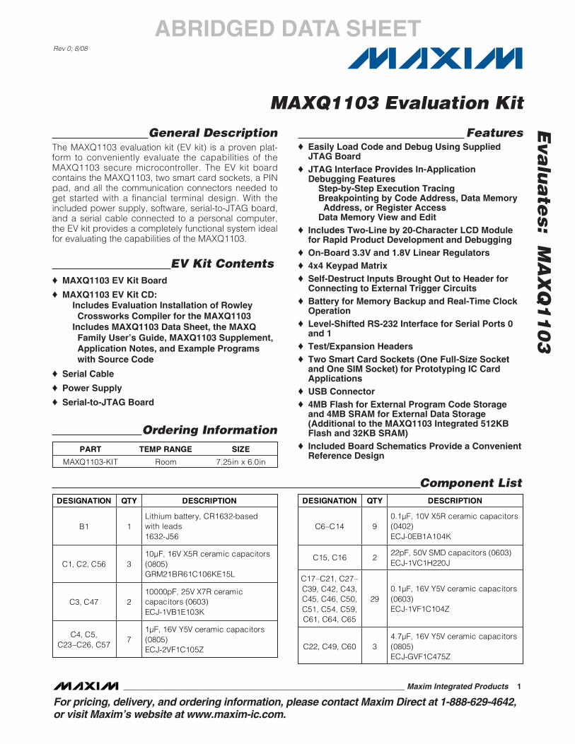
General DescriptionThe MAXQ1103 evaluation kit (EV kit) is a proven plat-form to conveniently evaluate the capabilities of theMAXQ1103 secure microcontroller. The EV kit boardcontains the MAXQ1103, two smart card sockets, a PINpad, and all the communication connectors needed toget started with a financial terminal design. With theincluded power supply, software, serial-to-JTAG board,and a serial cable connected to a personal computer,the EV kit provides a completely functional system idealfor evaluating the capabilities of the MAXQ1103.
EV Kit Contents♦ MAXQ1103 EV Kit Board
♦ MAXQ1103 EV Kit CD:Includes Evaluation Installation of RowleyCrossworks Compiler for the MAXQ1103
Includes MAXQ1103 Data Sheet, the MAXQFamily User’s Guide, MAXQ1103 Supplement,Application Notes, and Example Programswith Source Code
♦ Serial Cable
♦ Power Supply
♦ Serial-to-JTAG Board
Features♦ Easily Load Code and Debug Using Supplied
JTAG Board♦ JTAG Interface Provides In-Application
Debugging FeaturesStep-by-Step Execution TracingBreakpointing by Code Address, Data MemoryAddress, or Register Access
Data Memory View and Edit♦ Includes Two-Line by 20-Character LCD Module
for Rapid Product Development and Debugging♦ On-Board 3.3V and 1.8V Linear Regulators♦ 4x4 Keypad Matrix♦ Self-Destruct Inputs Brought Out to Header for
Connecting to External Trigger Circuits♦ Battery for Memory Backup and Real-Time Clock
Operation♦ Level-Shifted RS-232 Interface for Serial Ports 0
and 1♦ Test/Expansion Headers♦ Two Smart Card Sockets (One Full-Size Socket
and One SIM Socket) for Prototyping IC CardApplications
♦ USB Connector♦ 4MB Flash for External Program Code Storage
and 4MB SRAM for External Data Storage(Additional to the MAXQ1103 Integrated 512KBFlash and 32KB SRAM)
♦ Included Board Schematics Provide a ConvenientReference Design
Component List
Ordering Information
DESIGNATION QTY DESCRIPTION
B1 1 Lithium battery, CR1632-based with leads 1632-J56
C1, C2, C56 3 10μF, 16V X5R ceramic capacitors (0805) GRM21BR61C106KE15L
C3, C47 2 10000pF, 25V X7R ceramic capacitors (0603) ECJ-1VB1E103K
C4, C5, C23–C26, C57
71μF, 16V Y5V ceramic capacitors (0805) ECJ-2VF1C105Z
DESIGNATION QTY DESCRIPTION
C6–C14 9 0.1μF, 10V X5R ceramic capacitors (0402) ECJ-0EB1A104K
C15, C16 2 22pF, 50V SMD capacitors (0603) ECJ-1VC1H220J
C17–C21, C27–C39, C42, C43, C45, C46, C50, C51, C54, C59, C61, C64, C65
290.1μF, 16V Y5V ceramic capacitors (0603) ECJ-1VF1C104Z
C22, C49, C60 3 4.7μF, 16V Y5V ceramic capacitors (0805) ECJ-GVF1C475Z
PART TEMP RANGE SIZE
MAXQ1103-KIT Room 7.25in x 6.0in

Eva
lua
tes:
M
AX
Q1
10
3
MAXQ1103 Evaluation Kit
2 _______________________________________________________________________________________
ABRIDGED DATA SHEET
Component List (continued)DESIGNATION QTY DESCRIPTION
C40, C52 2 10μF, 10V Y5V ceramic capacitors (1206) ECJ-3YF1A106Z
C41, C53, C62 C63
40.1μF ±10%, 50V X7R ceramic capacitors (1206) GRM319R71H104KA01D
C44, C48, C55 C58
415pF, 50V SMD ceramic capacitors (0603) ECJ-1VC1H150J
D1 1 1500W, 5.0V SMC TVS Zener Unidir 1SMC5.0AT3G
DS1, DS2, DS3 3
2mm x 3mm surface mount with reflector, 660nm super red LEDs (clear lens) SML-LX23SRC-TR
F1 1 1A, 125V fast PICO-SMD fuse 0459001.UR
J1 1 DC power jack (2.5mm center) CUI Inc. PJ-002B
J2 1 Right-angle, 9-position connector, female socket receptacle (gold) 5745781-3
J3 1 Smart card socket, full snap in SMT ITT CCM01-2065LFT
J4 1 Connector, receptacle (Type B USB) PCB 897-43-004-90-000000
J5 1 6-pin SMD hinged connector, smart card ITT CCM03-3001LFT
J6 1 2x5 header 929836-02-05
JH1 1 16-pin jumper NO 3M 929647-09-08-2
JH2 1 6-pin header 3M 929647-09-01-I
JH3 1 14-pin header 3M 929647-09-06-2
JH4 1 1x8 header 3M 929647-09-08-I
DESIGNATION QTY DESCRIPTION
JU1–JU4, JU6–JU11, JU13, JU14, JU15, JU17, JU18, JU19
162-pin jumpers NO 3M 929647-09-02-I
JU5, JU12, JU16
33-pin jumpers NO 3M 929647-09-03-I
P1 1 Right-angle, 9-position connector, male plug (gold) 747250-4
R1, R2, R3 3 390 ±1%, 1/8W SMD resistors (0805) MCR10EZPF3900
R4 1 0 ±5%, 1/8W SMD resistor (0805) MCR10EZPJ000
R5, R7, R9, R17
4330 ±1%, 1/8W SMD resistors (0805) MCR10EZHF3300
R6 1 10k trim potentiometer, 3mm carbon SMD Panasonic EVN-5CSX50B14
R8, R10–R16, R18, R21, R22, R23, R42, R43
1410k ±1%, 1/8W SMD resistors (0805) MCR10EZHF1002
R19, R20 2 100k ±1%, 1/8W SMD resistors (0805) MCR10EZHF1003
R24, R25, R37 R38
4100 ±5%, 1/8W SMD resistors (0805) ERJ-6GEYJ101V
R26 1 47k ±1%, 1/8W SMD resistor (0805) MCR10EZHF4702
R27, R28, R31, R32, R33, R39,
R40, R41 8
1k ±1%, 1/8W SMD resistors (0805) ERJ-6ENF1001V
R30 1 4.7k ±1%, 1/8W SMD resistors (0805) MCR10EZHF4701

Eva
lua
tes: M
AX
Q1
10
3
Microcap is a registered trademark of American Technical Ceramics Corp.
AutoShutdown Plus is a trademark of Maxim Integrated Products, Inc.
MAXQ1103 Evaluation Kit
_______________________________________________________________________________________ 3
ABRIDGED DATA SHEET
Component List (continued)DESIGNATION QTY DESCRIPTION
R35, R36 2 26.1 ±1%, 1/2W SMD resistors (2010) ERJ-12SF26R1U
SW1–SW18 18 100gf tactile switches, 6mm momentary SMD B3FS-1000P
TP1–TP12 12 0.100in strip headers, single row, 1-position 929647-09-01-I
U1 1 High-performance secure RISC microcontroller (144 TQFP) Maxim MAXQ1103-ENS+
U2 1
Octal buffer/line driver with 3-state outputs (20 TSSOP) Fairchild Semiconductor 74VHC244MTCX
U3 1 Octal bus transceiver (20 TSSOP) Toshiba TC74LCX245FT(EL,M)
U4 1 LCD character module (20x2) Lumex LCM-S02002DSF
U5, U10 2 Single inverter gate (5 SOT23) Texas Instruments SN74LVC1G04DBVR
U6 1 1A, Microcap®, low-dropout, linear regulator (3.3V) (16 TSSOP) Maxim MAX8869EUE33
DESIGNATION QTY DESCRIPTION
U7 1 1A, MicroCap, low-dropout, linear regulator (1.8V) (16 TSSOP) Maxim MAX8869EUE18
U8, U9 2 1M x 16 flash S29AL016D70TFI01
U11, U12 2 1M x 16 static RAM CY7C1061AV33-10ZXC
U13, U16 2 Smart card interface (28 SO) Maxim DS8024-RRX+
U14 1
3V, ±15kV ESD-protected, AutoShutdown Plus™ RS-232 transceiver for PDAs and cell phones (250kbps) (24 TSSOP) Maxim MAX3387ECUG
U15 1 ±15kV ESD-protected USB transceiver (14 TSSOP)Maxim MAX3346EEUD
XY1 1 12.000MHz, 20pF HC-49/US crystal ECS ECS-120-20-4X
XY2, XY3 2 10.000MHz, 18pF HC-49/US crystals ECS ECS-100-18-4X
Y1 1 32.768kHz, 12.5pF cylinder crystal ECS ECS-327-12.5-13X
None 1 PCB: MAXQ1103 EV Kit Circuit Board

Eva
lua
tes:
M
AX
Q1
10
3
MAXQ1103 Evaluation Kit
4 _______________________________________________________________________________________
ABRIDGED DATA SHEET
NOTE THAT MORE RECENT VERSIONS OF THE EV KIT BOARD DO NOT CONTAIN A SOCKET FOR THE MAXQ1103 MICROCONTROLLER, BUT INSTEAD THE MICROCONTROLLER IS SOLDERED DIRECTLY TO THE BOARD.
Figure 1. MAXQ1103 EV Kit Board
LCD MODULE
POWERSUPPLY
SERIAL 0
SERIAL 1
USBFULL SMART CARD SOCKETAND ANALOG FRONT-END
SIM CARD SOCKETAND ANALOG FRONT-END
PROTOTYPING
4 x 4 KEYPAD
2MBFLASH
(ON BACK)
2MBFLASH
(ON BACK)
2MBSRAM
(ON BACK)
2MBSRAM
(ON BACK)
SELF-DESTRUCTSBATTERY MICROCONTROLLER
MAXQ1103
Figure 2. MAXQ1103 EV Kit Board Functional Layout

Eva
lua
tes: M
AX
Q1
10
3
MAXQ1103 Evaluation Kit
_______________________________________________________________________________________ 5
ABRIDGED DATA SHEET
Detailed DescriptionThis EV kit must be used in conjunction with the follow-ing documents, which are included with the EV kit’ssoftware CD:
• MAXQ Family User’s Guide
• MAXQ Family User’s Guide: MAXQ1103 Supplement
• MAXQ1103 Data Sheet
Because the MAXQ1103 is an export-controlled device,these documents are not available on the web and areprotected by a nondisclosure agreement (NDA). Visitwww.maxim-ic.com/secure to learn more about theNDA process.
The MAXQ1103 EV kit board is fully defined in theincluded schematic (Figure 3). However, a shortdescription of the major components and connectors ofthe board follows.
For a step-by-step guide to using your MAXQ1103 EVkit, refer to Application Note 4273: Getting Started withthe MAXQ1103 Evaluation Kit and the CrossworksCompiler for the MAXQ30, included on the EV kit CD.This application note covers jumper settings, cable
connections, software configuration, and the stepsneeded to run simple programs on the EV kit.
Power SupplyThe MAXQ1103 EV kit board can be powered directlyusing a DC power supply. Use a regulated 5V (±5%),300mA, center-post positive power supply connected toJ1. The MAXQ1103 EV kit board has the regulators tosupply 3.3V and 1.8V to the MAXQ1103 microcontroller.
MemoryThe MAXQ1103 EV kit board contains two 1MB x 16-bitflash memory chips and two 1MB x 16-bit SRAM mem-ory chips as shown in Figure 2. The flash devices’ chip-enable pins (CE) are connected to the processor’s pro-gram memory chip-select 1, nonbattery-backed pin(PCS1N). The SRAM devices’ chip-enable pins (CE)are connected to the processor’s data memory chipselect 1, nonbattery-backed pin (DCS1N).
Jumper FunctionsThe MAXQ1103 EV kit board contains a number ofjumpers to configure the board’s operation. Table 1describes the jumpers and their function.
NAME FUNCTION
JU1 Connects pin 114 (GND) of the MAXQ1103 to GND.
JU2 Connects pin 64 (VRST) of the MAXQ1103 to GND.
JU3 Connects reset switch (SW17) RESET pin to the 3.3V supply through a pullup resistor.
JU4 Connects program switch (SW18) PROG pin to the 3.3V supply through a pullup resistor.
JU5 Connects the board’s VBAT signal to the lithium battery (1 to 2) or to GND (2 to 3).
JU6 Connects U13’s (DS8024) CLKDIV1 pin (1) to the 3.3V supply.
JU7 Connects U13’s (DS8024) CLKDIV2 pin (2) to the 3.3V supply.
JU8 Connects U13’s (DS8024) 5V/3V pin (3) to GND.
JU9 Connects U14’s (MAX3387E) R2OUT pin (13) to the board’s PROG signal.
JU10 Connects U13’s (DS8024) AUX1IN pin (27) to GND.
JU11 Connects U13’s (DS8024) AUX2IN pin (28) to GND.
JU12 Connects U15’s (MAX3346) MODE pin (3) through a resistor to 3.3V (1 to 2 = differential mode) or to GND (2 to 3 = single-ended mode).
JU13 Connects U16’s (DS8024) CLKDIV1 pin (1) to the 3.3V supply.
JU14 Connects U16’s (DS8024) CLKDIV2 pin (2) to the 3.3V supply.
JU15 Connects U16’s (DS8024) 5V/3V pin (3) to GND.
JU16 Connects U15’s (MAX3346) SPEED pin (8) through a resistor to the 3.3V supply (1 to 2 = 12Mbps) or to GND (2 to 3 = 1.5Mbps).
JU17 Connects U16’s (DS8024) AUX1IN pin (27) to GND.
JU18 Connects U16’s (DS8024) AUX2IN pin (28) to GND.
JU19 Connects U16’s (DS8024) PRES pin (9) to GND.
Table 1. Jumper Functions

Eva
lua
tes:
M
AX
Q1
10
3
MAXQ1103 Evaluation Kit
6 _______________________________________________________________________________________
ABRIDGED DATA SHEET
Note to readers: This document is an abridged version of the full EV kit data sheet. To request the full EV kitdata sheet, go to www.maxim-ic.com/MAXQ1103-KIT.
Using the LCD ModuleThe LCD display module included on the MAXQ1103EV kit board is a two-line, 20-character display. Themodule contains the LCD driver and is communicatedwith through the MAXQ1103’s parallel interface. Alibrary function is available on the EV kit CD to demon-strate the use of this LCD module.
Make sure the LCD screen contrast is adjusted correct-ly before using it. If the contrast is not properly adjust-ed, the characters can be difficult or impossible to seeon the display. To adjust the contrast, use a Philipshead screwdriver on R6, labeled LCD Contrast (on theupper left side of the EV kit board). Turn the adjustmentuntil all the pixels darken, then turn back until the darkpixels just disappear.
Using the Smart Card SocketsTwo smart card sockets are included with theMAXQ1103 EV kit board. A full-sized smart card socketat J3 brings all eight smart card contacts out from an8024-style analog smart card interface. The SIM-sizedsocket at J5 brings out the six smart card contacts gen-erally used for SIM or SAM card communication. Theselines are also driven by an 8024-style analog smartcard interface.
Several jumpers around the smart card sockets allowthe user to configure inputs that are less commonlyused in smart card applications.
• JU6-JU7 (and JU13-JU14) are used to select theclock-divider inputs, CLKDIV[1:2], for the smart cardinterface.
• JU8 (and JU15) are used to select between 3V and5V card operation.
• JU10-JU11 (and JU17-JU18) are used to connectthe auxiliary input pins (AUX1IN and AUX2IN) toground.
• JU19 is used to configure the presence input(PRES) for the SIM-sized socket, which does notsupport a presence signal.
Use these smart card interface inputs dynamically byopening the jumpers and connecting the pins to any ofthe MAXQ1103 port headers, such as JH2 or JH4.
Configuring USBThe MAXQ1103 EV kit board contains a USB interfaceat J4 for prototyping USB slave applications. An exter-nal transceiver (MAX3346) is connected to the serialinterface engine of the MAXQ1103 to provide the USBinterface. JU12 and JU16 are configurable inputs forthe MAX3346. Use jumper JU12 to select single-endedor differential mode, and use JU16 to select 1.5Mb or12Mb communication speed.
Serial-Port InterfaceBoth MAXQ1103 serial ports are brought out to RS-232levels and have 9-pin connectors (labeled J2 and P1)on the left side of the EV kit board. Jumper JU9 allowsthe user to connect serial port 0’s DTR signal to theMAXQ1103 programming input signal, allowing theuser to control the entire loading process through a ser-ial cable connected to a PC.
KeypadThe MAXQ1103 EV kit board provides 16 momentarycontact switches that are intended for user input. Theswitches are arranged in a 4x4 matrix. One side of theswitch is connected to four buffered output port pinsthrough a resistor (ROW0–ROW3), and the other side ofthe switch is connected to four buffered input port pins(COL0–COL3). Each column is connected to the 3.3Vsupply through a pullup resistor. Therefore, the row-col-umn matrix can be scanned to determine when aswitch has been pressed. Software to perform thisscanning is provided by one of the example programsavailable on the EV kit CD.
JTAG InterfaceA serial-to-JTAG board (provided with the EV kit) isused to program and debug applications running onthe MAXQ1103 EV kit board. Connect the 10-pin ribboncable from the JTAG board to J6 on the MAXQ1103 EVkit board. Tools such as the Microcontroller Tool Kit(MTK) and Rowley’s CrossStudio Integrated DevelopmentEnvironment have built-in support for loading applica-tions through the JTAG interface and using all theMAXQ1103 debug functionality (breakpoints, registerand memory reading, etc.).
Related Documents