ABOVE GROUND STORAGE TANKS Practical Guide to Construction, Inspection, and Testing © 2015 by Taylor & Francis Group, LLC

Welcome message from author
This document is posted to help you gain knowledge. Please leave a comment to let me know what you think about it! Share it to your friends and learn new things together.
Transcript
Above Ground StorAGe tAnkSPractical Guide to Construction,
Inspection, and Testing
K22265_Book.indb 1 4/20/15 5:46 PM
© 2015 by Taylor & Francis Group, LLC

CRC Press is an imprint of theTaylor & Francis Group, an informa business
Boca Raton London New York
Above Ground StorAGe tAnkSPractical Guide to Construction,
Inspection, and Testing
Sunil Pullarcot
K22265_Book.indb 3 4/20/15 5:46 PM
© 2015 by Taylor & Francis Group, LLC
CRC PressTaylor & Francis Group6000 Broken Sound Parkway NW, Suite 300Boca Raton, FL 33487-2742
© 2015 by Taylor & Francis Group, LLCCRC Press is an imprint of Taylor & Francis Group, an Informa business
No claim to original U.S. Government worksVersion Date: 20141028
International Standard Book Number-13: 978-1-4822-2203-6 (eBook - PDF)
This book contains information obtained from authentic and highly regarded sources. Reasonable efforts have been made to publish reliable data and information, but the author and publisher cannot assume responsibility for the validity of all materials or the consequences of their use. The authors and publishers have attempted to trace the copyright holders of all material reproduced in this publication and apologize to copyright holders if permission to publish in this form has not been obtained. If any copyright material has not been acknowledged please write and let us know so we may rectify in any future reprint.
Except as permitted under U.S. Copyright Law, no part of this book may be reprinted, reproduced, transmitted, or utilized in any form by any electronic, mechanical, or other means, now known or hereafter invented, including photocopying, microfilming, and recording, or in any information stor-age or retrieval system, without written permission from the publishers.
For permission to photocopy or use material electronically from this work, please access www.copy-right.com (http://www.copyright.com/) or contact the Copyright Clearance Center, Inc. (CCC), 222 Rosewood Drive, Danvers, MA 01923, 978-750-8400. CCC is a not-for-profit organization that pro-vides licenses and registration for a variety of users. For organizations that have been granted a photo-copy license by the CCC, a separate system of payment has been arranged.
Trademark Notice: Product or corporate names may be trademarks or registered trademarks, and are used only for identification and explanation without intent to infringe.
Visit the Taylor & Francis Web site athttp://www.taylorandfrancis.com
and the CRC Press Web site athttp://www.crcpress.com
© 2015 by Taylor & Francis Group, LLC
v
Contents
Preface ................................................................................................................... xiii
1. Storage Tanks ..................................................................................................11.1 Introduction ...........................................................................................11.2 Classification of Storage Tanks ............................................................31.3 Classification of Above Ground Storage Tanks ................................51.4 Selection of Type ...................................................................................71.5 Two Common Types of Storage Tanks ...............................................81.6 Design and Construction Standards for Above Ground
Storage Tanks .........................................................................................91.7 API Specification for Storage Tanks ...................................................91.8 Jurisdiction of Various Standards for Storages ............................... 11
1.8.1 API 650: Welded Steel Tanks for Oil Storage ........................... 111.8.2 API 620: Design and Construction of Large, Welded,
Low-Pressure Storage Tanks ..................................................... 121.8.3 ASME Section VIII Div (1): Rules for Construction of
Pressure Vessels ........................................................................ 121.9 Layout of API 650 Based on April 2013 Edition .............................. 13
2. Classification of Storage .............................................................................. 152.1 Some Basics about Flammable and Combustible Liquids ............ 152.2 Classification of Storage (NFPA 30) .................................................. 152.3 Classification of Storage (Institute of Petroleum) ........................... 16
3. Tank Farm Layout ......................................................................................... 193.1 Considerations ..................................................................................... 193.2 Typical Tank Farms ............................................................................. 213.3 Spacing of Tanks in Tank Farms .......................................................223.4 Spacing of Tanks per NFPA 30 ..........................................................223.5 Spacing of a Tank for Petroleum Stocks as per the Institute
of Petroleum Guidelines ....................................................................283.5.1 Storage Classes I, II(2), III(2) ..................................................283.5.2 Storage Classes II(1) and III(1) ..............................................28
3.6 API Tank Sizes for Layout Purpose (Based on API 650) ............... 313.7 Summary of Refinery Storage Tanks ............................................... 323.8 Use of Floating and Fixed Roof Tanks ............................................. 32
3.8.1 Floating Roof Tanks ............................................................... 323.8.2 Fixed Roof Tanks ....................................................................33
K22265_Book.indb 5 4/20/15 5:46 PM
© 2015 by Taylor & Francis Group, LLC
vi Contents
3.8.3 Considerations to Decide between Floating Roof Type and Fixed Roof Type ....................................................33
3.8.4 Tank Type Selection Guidelines ..........................................353.9 Storage Tank Capacity Chart .............................................................36
4. Tank Design ................................................................................................... 374.1 Tank Design Considerations ............................................................. 374.2 Design Aids Available ........................................................................384.3 Basis for Designing .............................................................................404.4 Design Calculations ............................................................................404.5 Drawings .............................................................................................. 414.6 Approved for Construction Drawings and Documents ...............424.7 Documents for Statutory and Client Approvals .............................434.8 Design Change Note ...........................................................................434.9 As-Built Documents ...........................................................................44
5. Tank Foundation ...........................................................................................455.1 Considerations for the Selection of Foundation .............................455.2 Types of Foundations .........................................................................46
5.2.1 Compact Soil Foundations ....................................................465.2.2 Crushed-Stone Ring Wall Foundations ..............................465.2.3 Concrete Ring Wall Foundations ........................................ 475.2.4 Slab Foundations .................................................................... 475.2.5 Pile-Supported Foundations ................................................ 47
5.3 Handing Over the Foundation .......................................................... 47
6. Sequence of Mechanical Works for Storage Tank Erection ................. 496.1 Preliminary Works on Award of Contract ...................................... 496.2 Responsibility Matrix (Head Office and Site) ................................. 496.3 Organization Setup at the Site .......................................................... 51
6.3.1 Introduction ............................................................................ 516.3.2 Organization Chart ............................................................... 52
6.4 Design, Drawings, and Documents Approval ................................ 526.5 List of Documents ...............................................................................546.6 Preparation of Bill of Materials with Specifications....................... 576.7 Inquiry and Purchase of Raw Materials .......................................... 576.8 Materials Procured from Stockists or Traders ................................586.9 Purchase or Transfer of Construction Equipment to the Site ....... 596.10 List of Equipment Required at the Site ............................................ 596.11 Work Contracts ....................................................................................60
6.11.1 Subcontract for Nondestructive Testing (NDT) ................606.11.2 Subcontract for Scaffolding ..................................................606.11.3 Subcontract for Surface Preparation, Internal Lining,
and External Painting ...........................................................60
K22265_Book.indb 6 4/20/15 5:46 PM
© 2015 by Taylor & Francis Group, LLC
viiContents
6.11.4 Calibration and Certification of Storage Tanks .................606.12 Local Contracts and Purchases at the Site ....................................... 61
7. Tank Erection ................................................................................................637.1 Storage Tank Erection .........................................................................637.2 Inspection of Raw Materials ..............................................................63
7.2.1 Plates and Pipes......................................................................687.2.2 Pipe Fittings and Flanges .....................................................687.2.3 Fasteners and Gaskets ........................................................... 697.2.4 Consumable Such as Electrodes .......................................... 69
7.3 Identification and Traceability of Raw Materials ........................... 697.4 Marking of Plates ................................................................................ 70
7.4.1 Marking of Annular, Sketch, Bottom, and Roof Plates ..................................................................... 71
7.4.2 Marking of Shell Plates ......................................................... 717.5 Cutting of Plates and Other Pressure and Load
Retaining Parts ................................................................................727.6 Inspection of Plates after Cutting and Edge Preparation ............. 737.7 Bending of Plates ................................................................................. 73
7.7.1 Direction of Bending ............................................................. 737.7.2 Prepinging .............................................................................. 747.7.3 Templates ................................................................................ 76
7.8 Laying of Bottom (Annular, Bottom, and Sketch) Plates ..............807.8.1 Annular Plates ........................................................................807.8.2 Bottom Plates .......................................................................... 817.8.3 Sketch Plates ........................................................................... 817.8.4 Annular and Bottom Plate Layout ...................................... 817.8.5 Surface Preparation and Coating of Bottom Plates ........... 827.8.6 Laying of Annular Plates ...................................................... 827.8.7 Recommended Weld Joint Configurations ........................857.8.8 Laying of Bottom and Sketch Plates....................................867.8.9 Welding Sequence of Annular, Sketch, and Bottom
Plates ........................................................................................887.8.10 Annular Plate Welds..............................................................887.8.11 Bottom Plate Welds ................................................................ 897.8.12 Weld between Annular and Bottom Plates ........................ 897.8.13 Testing of Welds .....................................................................90
8. Erection of Shell Courses, Roofs, and Other Appurtenances ............. 938.1 General.................................................................................................. 938.2 Conventional Method ......................................................................... 938.3 Bygging or Jacking Up Method ........................................................ 958.4 Comparison of Erection Methodology ............................................ 968.5 Erection of Shells by Conventional Method .................................... 98
8.5.1 Shell Cutting Plan (Shell Development) ............................. 98
K22265_Book.indb 7 4/20/15 5:46 PM
© 2015 by Taylor & Francis Group, LLC
viii Contents
8.5.2 Erection of Shell Courses ...................................................... 988.5.3 Erection of Roof Structure and Roof Plates...................... 1058.5.4 Fit Up and Welding of Closure Plate................................. 1078.5.5 Fit Up and Welding of First Shell Course to Annular
Plate ........................................................................................ 1088.6 Methodology for Tank Erection by the Jacking Up Method ...... 108
8.6.1 Brief Overview ..................................................................... 1088.6.2 Detailed Working Procedure ............................................. 1098.6.3 Salient Features and Limitations of the Jacking Up
Method .................................................................................. 1118.6.4 Arrangements for Jacking Up ............................................ 1128.6.5 Pictures of the Jacking Up Method ................................... 113
8.7 Erection of Roof Structure and Cone Roof Plates......................... 1148.8 Shell Appurtenances......................................................................... 1148.9 Manufacture of Subassemblies ....................................................... 1148.10 Installation of Appurtenances......................................................... 1158.11 Spiral Stairway, Handrails, Platforms, and Other Support
Attachments ....................................................................................... 120
9. Welding ......................................................................................................... 1239.1 Weld Edge Preparation ..................................................................... 1239.2 Typical Weld Joints ........................................................................... 1239.3 Restrictions on Types of Weld Joints .............................................. 124
9.3.1 Shell Vertical Joints .............................................................. 1269.4 Welding Processes ............................................................................ 1279.5 Welding Procedure Specifications .................................................. 1289.6 Procedure Qualification ................................................................... 1289.7 Welder Qualification ......................................................................... 1299.8 Welder’s Identification Cards .......................................................... 1309.9 Welding Sequence ............................................................................. 130
9.9.1 Cleanliness of Weld Groove and Adjacent Area ............. 1309.9.2 Metal Temperature and Preheat ........................................ 1319.9.3 Reasons for Preheating before Welding ........................... 1329.9.4 Interpass Temperature ........................................................ 1329.9.5 Back Gouging, Grinding, and NDT .................................. 133
9.10 Electrode Storage and Its Drying .................................................... 1339.10.1 Storing Low Hydrogen Stick Electrodes .......................... 1349.10.2 Redrying: Low Hydrogen Stick Electrodes ..................... 1349.10.3 Redrying Conditions: Low Hydrogen
Stick Electrodes ................................................................1359.10.4 Storing and Redrying: Non-Low
Hydrogen Electrodes ........................................................ 1359.10.5 Redrying Conditions: Non-Low Hydrogen Stick
Electrodes .............................................................................. 136
K22265_Book.indb 8 4/20/15 5:46 PM
© 2015 by Taylor & Francis Group, LLC
ixContents
9.11 Weld Repairs ...................................................................................... 1369.12 Weld Repair Procedure .................................................................... 137
10. Inspection and Testing of Welds ............................................................. 13910.1 Summary of Inspection and Tests .................................................. 13910.2 Butt Welds .......................................................................................... 14210.3 Fillet Welds (Pressure Retaining) ................................................... 14310.4 Other Structural Welds on Shell and Roof (Inside and
Outside) .............................................................................................14310.5 Inspection (Dimensional) ................................................................ 144
10.5.1 Annular and Bottom plates ................................................ 14410.5.2 Shell ........................................................................................ 146
11. Nondestructive Testing ............................................................................. 15111.1 Radiographic Testing ........................................................................ 15111.2 Minimum Number and Location of Radiographs Required
as per API 650 .................................................................................... 15111.3 Weld Maps with Pictorial Presentation of Radiography ............. 154
11.3.1 Table 11.1 for Pictorial Presentation of Radiography (Shell Thickness 22 mm to 8 mm)...................................... 154
11.3.2 Table 11.2 for Pictorial Presentation of Radiography (Shell Thickness 28 mm to 8 mm) ...................................... 158
11.4 Other Requirements for Radiography ........................................... 16211.4.1 Technique .............................................................................. 16211.4.2 Personnel ............................................................................... 16211.4.3 Procedure .............................................................................. 16211.4.4 Radiographs .......................................................................... 16211.4.5 Acceptability Norms ........................................................... 16211.4.6 Progressive or Penalty Radiography ................................. 16211.4.7 Repair of Defective Welds .................................................. 16311.4.8 Records .................................................................................. 16311.4.9 Specific Requirements for Radiography from Some
Clients in the Oil and Gas Industry .................................. 16311.5 Ultrasonic Testing ............................................................................. 16511.6 Magnetic Particle Testing ................................................................. 16511.7 Liquid Penetrant Testing .................................................................. 16611.8 Visual Examination or Testing ........................................................ 166
11.8.1 Visual Examination Strategy.............................................. 16611.8.2 Vision Requirement for Visual Inspectors ....................... 16711.8.3 Acceptance Criteria for Visual Examination ................... 167
11.9 Weld Maps.......................................................................................... 16811.10 Documentation of NDT .................................................................... 168
K22265_Book.indb 9 4/20/15 5:46 PM
© 2015 by Taylor & Francis Group, LLC
x Contents
12. Other Tests ................................................................................................... 16912.1 Vacuum Box Testing ......................................................................... 169
12.1.1 Vacuum Box Test Procedure ............................................... 17012.1.2 Vacuum Box Testing (Standard and Client
Requirements) ...................................................................... 17012.1.3 Equipment ............................................................................. 17112.1.4 Types of Vacuum Boxes ...................................................... 17212.1.5 Methodology of Testing ...................................................... 17612.1.6 Acceptance Criteria ............................................................. 17712.1.7 Records .................................................................................. 177
12.2 Pneumatic Testing of Reinforcement Pads .................................... 17812.2.1 Requirements........................................................................ 17812.2.2 Test Pressure and Methodology ........................................ 17812.2.3 Arrangements ....................................................................... 178
12.3 Hydrostatic Testing of Tank ............................................................ 18112.3.1 Testing of Tank Shell ........................................................... 18112.3.2 Standard and Client Requirements for Hydrostatic
Testing ................................................................................... 18112.3.3 Recommended Contents for the Hydrostatic Test
Procedure .............................................................................. 18212.3.4 Water Filling and Draining Rates ...................................... 18312.3.5 Filling of Test Medium ........................................................ 18312.3.6 Visual Inspection ................................................................. 18412.3.7 Safety Precautions ............................................................... 18412.3.8 Repair and Retest ................................................................. 18412.3.9 Draining ................................................................................ 18512.3.10 Cleaning ................................................................................ 18512.3.11 Documentation ..................................................................... 185
12.4 Measurement of Settlement of Tank during Hydrostatic Testing ................................................................................................. 186
12.5 Alternate Tests in Lieu of Hydrostatic Testing ............................. 18712.6 Testing of Roof ................................................................................... 18812.7 Testing of Roof for Appendix F Tanks ........................................... 188
13. Cleaning, Internal Lining, and External Painting .............................. 19113.1 Cleaning after Hydrostatic Test ...................................................... 19113.2 Planning for Surface Preparation and Lining or Painting .......... 19113.3 Surface Preparation (Write-up Courtesy M/s Transocean
Coating, Rotterdam) ......................................................................... 19513.3.1 High-Pressure Freshwater Cleaning ................................. 19613.3.2 Solvent Cleaning .................................................................. 19613.3.3 Hand Tool Cleaning ............................................................ 19713.3.4 Pickling .................................................................................. 197
K22265_Book.indb 10 4/20/15 5:46 PM
© 2015 by Taylor & Francis Group, LLC
xiContents
13.3.5 Power Tool Cleaning ........................................................... 19713.3.6 Blast Cleaning ....................................................................... 19813.3.7 Spot Blasting ......................................................................... 20513.3.8 Hydroblasting or Water Jetting .......................................... 20613.3.9 Wet Slurry Blasting .............................................................. 20713.3.10 Sweep Blasting ..................................................................... 20713.3.11 Surface Preparation for Other Metals ............................... 208
13.4 Edge and Weld Preparation for New Construction ..................... 20913.4.1 Weld Preparation ................................................................. 20913.4.2 Edge Preparation .................................................................. 211
13.5 Paints and Their Uses ....................................................................... 21213.6 Effective Life of Coating and Film Thickness ............................... 21313.7 Other Requirements by Clients for Surface Preparation and
Lining and Painting of Tanks .......................................................... 21413.7.1 General .................................................................................. 21413.7.2 Lettering and Logo .............................................................. 21413.7.3 Safety Precautions for Blasting and Painting
Equipment ............................................................................. 21413.8 Commonly Used Color Schemes to Reduce Vapor Loss ............. 21513.9 Commonly Used External Coating Systems (for
Atmospheric Temperatures) ............................................................ 21613.10 Commonly Used Internal Lining Systems (for Atmospheric
Temperatures) .................................................................................... 21613.11 Inspection and Tests with Recommended Frequency for
Surface Preparation and Lining and Painting .............................. 217
14. Documentation ............................................................................................ 21914.1 General................................................................................................ 21914.2 Manufacturer’s Record Book ........................................................... 22014.3 Suggested Contents for MRB ........................................................... 22114.4 Documents Not Specified by a Standard ......................................225
14.4.1 Material Summary ............................................................... 22614.4.2 Weld Map .............................................................................. 22614.4.3 Weld Summary .................................................................... 22614.4.4 NDT Summary with Weld Map ........................................22714.4.5 NDT Reports .........................................................................22714.4.6 Pad Air Test Reports ............................................................22714.4.7 Tests Summary .....................................................................22714.4.8 Dimensional Inspection Reports .......................................22714.4.9 Prehydrostatic Inspection Report ......................................229
14.5 General Requirement for Contents of MRB ..................................23014.6 Records and Reports of Inspections, Tests,
and Calibrations ....................................................................... 231
K22265_Book.indb 11 4/20/15 5:46 PM
© 2015 by Taylor & Francis Group, LLC

xii Contents
14.7 Certification for Materials ................................................................ 23214.7.1 Components Requiring “Material Certification” ............23314.7.2 Contents of “Certification Dossier” for Bought
Out Items (as Applicable) ....................................................23314.8 Heat Treatment Records and Charts ..............................................23414.9 NDT Reports ......................................................................................235
15. Formats ......................................................................................................... 23715.1 General................................................................................................ 23715.2 Formats for Fixed Cone Roof Tanks ............................................... 23715.3 Additional Formats for Floating Roof Tanks ................................238
Annexure A: Material Specification Summary ...........................................283
Annexure B: Recommended Joint Design Guide to Sketches and Tables of API 650 .......................................................................285
Annexure C: Welding Procedure and Welder Qualification Requirements ............................................................................. 287
Annexure D: Radiography of Storage Tanks ............................................... 289
Annexure E: Inspection and Test Plan .......................................................... 297
Annexure F: Requirements for Floating Roof Tanks .................................305
Annexure G: Additional Inspections and Tests for Floating Roof Tanks ........................................................................................... 319
Annexure H: Calibration of Tanks................................................................. 323
Annexure I: Floating Roof Drains.................................................................. 339
Annexure J: Floating Roof Seal Selection Guidelines ...............................343
Bibliography ........................................................................................................ 361
Index .....................................................................................................................363
K22265_Book.indb 12 4/20/15 5:46 PM
© 2015 by Taylor & Francis Group, LLC
xiii
Preface
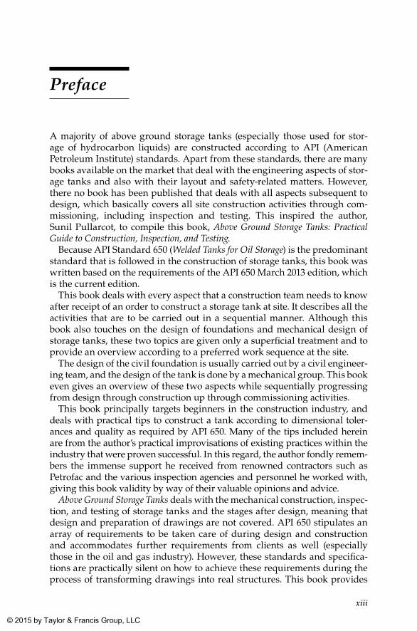
A majority of above ground storage tanks (especially those used for stor-age of hydrocarbon liquids) are constructed according to API (American Petroleum Institute) standards. Apart from these standards, there are many books available on the market that deal with the engineering aspects of stor-age tanks and also with their layout and safety-related matters. However, there no book has been published that deals with all aspects subsequent to design, which basically covers all site construction activities through com-missioning, including inspection and testing. This inspired the author, Sunil Pullarcot, to compile this book, Above Ground Storage Tanks: Practical Guide to Construction, Inspection, and Testing.
Because API Standard 650 (Welded Tanks for Oil Storage) is the predominant standard that is followed in the construction of storage tanks, this book was written based on the requirements of the API 650 March 2013 edition, which is the current edition.
This book deals with every aspect that a construction team needs to know after receipt of an order to construct a storage tank at site. It describes all the activities that are to be carried out in a sequential manner. Although this book also touches on the design of foundations and mechanical design of storage tanks, these two topics are given only a superficial treatment and to provide an overview according to a preferred work sequence at the site.
The design of the civil foundation is usually carried out by a civil engineer-ing team, and the design of the tank is done by a mechanical group. This book even gives an overview of these two aspects while sequentially progressing from design through construction up through commissioning activities.
This book principally targets beginners in the construction industry, and deals with practical tips to construct a tank according to dimensional toler-ances and quality as required by API 650. Many of the tips included herein are from the author’s practical improvisations of existing practices within the industry that were proven successful. In this regard, the author fondly remem-bers the immense support he received from renowned contractors such as Petrofac and the various inspection agencies and personnel he worked with, giving this book validity by way of their valuable opinions and advice.
Above Ground Storage Tanks deals with the mechanical construction, inspec-tion, and testing of storage tanks and the stages after design, meaning that design and preparation of drawings are not covered. API 650 stipulates an array of requirements to be taken care of during design and construction and accommodates further requirements from clients as well (especially those in the oil and gas industry). However, these standards and specifica-tions are practically silent on how to achieve these requirements during the process of transforming drawings into real structures. This book provides
K22265_Book.indb 13 4/20/15 5:46 PM
© 2015 by Taylor & Francis Group, LLC
xiv Preface
this vital information, but the author was careful not to overspecify require-ments, because this unnecessarily adds to the costs. However, the author was selectively cautious and stringent in specifying requirements with the intention of avoiding reworks and repairs, which eventually work out to be more expensive.
As indicated, the main highlight of this book is the satisfactory explana-tion the author tries to provide to all construction-related aspects of storage tank erection by explaining the logistics and rationale behind the require-ments spelled out in applicable codes and specifications. Apart from this, the book also contains various summaries of requirements as a quick reference to code and client requirements.
This book also provides logical explanations of various code requirements and is capable of throwing some light on the unexplained side of storage tank codes. This feature of the book makes it unique when compared with other books commonly in use.
On the basis of the author’s abundant practical experience, as in the case of his first book, Practical Guide to Pressure Vessel Manufacture (Marcel Dekker, Inc., 2002), this book can also be considered an effort to bridge the gap between standards and specifications and the actual construction of storage tanks taking place at the site.
K22265_Book.indb 14 4/20/15 5:46 PM
© 2015 by Taylor & Francis Group, LLC
1
1Storage Tanks
1.1 Introduction
A storage tank is a container, usually for holding liquids and sometimes compressed gases (gas tank). The term can be used for reservoirs (artificial lakes and ponds) and for manufactured containers. The usage of the word tank for reservoirs is common or universal in common parlance.
Storage tanks operate under no (or very little) internal pressure, distin-guishing them from pressure vessels. Storage tanks are often cylindrical in shape, are perpendicular to the ground with flat bottoms, and have a fixed or floating roof. There are usually many environmental regulations applied to the design and operation of storage tanks, often depending on the nature of the fluid contained within. Above ground storage tanks (ASTs) differ from underground storage tanks (USTs) with regard to design considerations and thereby applicable regulations as well.
As mentioned, tanks are meant to carry large quantities of liquid, vapor, or even solids for a variety of process applications. The process applications include the following, apart from pure storage function:
1. Settling 2. Mixing 3. Crystallization 4. Phase separation 5. Heat exchanging 6. Reactors
However, storage in large quantities is the principal purpose of tanks. Storage may be for a sales network wherein there shall be enough stock to cater to demand without any break, or storage may be for a process plant to facilitate uninterrupted working of a downstream plant or intermediate
K22265_Book.indb 1 4/20/15 5:46 PM
© 2015 by Taylor & Francis Group, LLC
2 Above Ground Storage Tanks
storage within the plant to store intermediate products for a short duration of time. The above-mentioned parameters are of interest to the designer in arriving at a rational size for a tank and in designing sizes of the nozzle, the piping in and out, and other safety attachments. The coverage of this book is mainly related to construction activities of storage tanks at site, upon completion of design of the same, including the mechanical design, implying that the process (sizing) and mechanical design of the tank are frozen and drawings have Approved for Construction (AFC) status. Therefore, this book covers all activities in construction of storage tanks right from the laying of bottom plates, through shell and roof erection, up to surface preparation and coating of the completed tank prior to handing over for commissioning.
Whatever use tanks are subjected to, the construction methodology that is followed is more or less the same, and differences if any in methodol-ogy shall be because of the configuration of the tank, which is marginal in nature.
As the present-day need for storages is continuously increasing because of increasing consumption, tanks of larger and larger capacities are built. These are the challenges of the time, and technocrats had risen to the expectation and were able to formulate codes, standards, and regulations for construction of such large storage tanks. The requirements spelled out in such codes and standards are based on many years of research, supple-mented by hands-on experience of experts in the field. Because of this rea-son, construction methodology has changed a lot over the years. Similarly in the design side also, tremendous changes have taken place over time, due to research about materials and their properties, which are implemented through periodic revision issues to codes and standards. Furthermore, as approximations give way to certainties, Safety factors are being reduced continually in the design of storages. In other words, as time passes, engi-neering is moving from a state of ignorance to an era of knowledge and enlightenment.
While talking about construction of storage tanks, it should not be for-getten that their design needs to be carried out as a prelude to this activ-ity. Since the requirements vary from place to place and process to process, based on economic considerations, every tank (except identical tanks in the same vicinity) requires a separate design, which makes it unique and tailor-made for the particular use.
As is known, tanks can be constructed only on a very strong foundation; failing this, the stability of the tank can be adversely affected, ending up in a disaster due to the large volume of liquid handled, which exerts tre-mendous forces on the foundation beneath the tank. While the design of the foundation and its construction fall under the realm of civil engineering,
K22265_Book.indb 2 4/20/15 5:46 PM
© 2015 by Taylor & Francis Group, LLC
3Storage Tanks
all subsequent design and construction activities (mechanical design and construction) of the storage tank are undertaken by the mechanical group. Because of this jurisdictional demarcation, after all civil works and associ-ated quality control checks on the foundation are completed, it has to be handed over to the mechanical team. Apart from the tests carried out on the foundation, the first comprehensive evidence of its adequacy is obtained from foundation settlement measurements carried out during hydrostatic testing of the storage tank. While uniform settlement is tolerated, uneven settlement needs further investigation and evaluation to assess the safety and integrity of the constructed storage tank.
1.2 Classification of Storage Tanks
One of the fundamental classifications employed in tankages is based on the location of the tank whether it is above ground or below, whose design and manufacturing features vary drastically. The number of above ground tanks is far in excess of those below ground, and they have their bottom directly resting on an earthen or concrete foundation. In some specific cases, tanks were placed on grillages, which facilitates periodic inspection of the bottom plates of the tank.
When the question of providing a storage facility arises, the obvious choice will be above ground storage because of the following reasons:
1. Above ground storage tanks are easy to construct. 2. The cost associated is low compared to that of other modes of storage. 3. Larger capacities are possible.
Another classification is elevated tanks placed on structural supports. Water supply tanks placed on steel structures belong to this category.
Underground storage tanks are usually designed for capacities in the range of 23 m3 to 91 m3 (5,000 gallons–20,000 gallons), with the majority fall-ing under 55 m3 (12,000 gallons). These are mainly used to store fuels and a variety of chemicals.
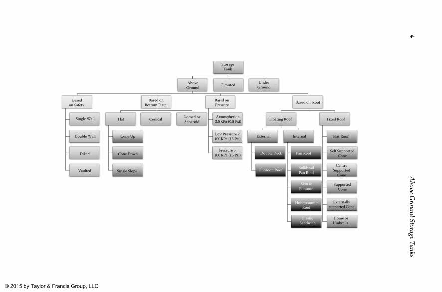
Since this book deals with construction aspects related to above ground storage tanks, the following chart shows a broad classification of storage tanks, with detailed classifications of above ground storage tanks.
K22265_Book.indb 3 4/20/15 5:46 PM
© 2015 by Taylor & Francis Group, LLC
4A
bove Ground Storage Tanks
StorageTank
AboveGround
Basedon Safety
Single Wall
Double Wall
Diked
Vaulted
Based onBottom Plate
Flat
Cone Up
Cone Down
Single Slope
Conical Domed orSpheroid
Based onPressure
Atmospheric ≤3.5 KPa (0.5 Psi)
Low Pressure <100 KPa (15 Psi)
Pressure >100 KPa (15 Psi)
Based on Roof
Floating Roof
External
Double Deck
Pontoon Roof
Internal
Pan Roof
BulkheadPan Roof
Skin &Pontoon
HoneycoumbRoof
PlasticSandwich
Fixed Roof
Flat Roof
Self SupportedCone
CentreSupported
Cone
SupportedCone
Externallysupported Cone
Dome orUmbrella
Elevated UnderGround
K22265_B
ook.indb 44/20/15 5:46 P
M © 2015 by Taylor & Francis Group, LLC
5Storage Tanks
1.3 Classification of Above Ground Storage Tanks
Prevailing codes, standards, and regulations basically classify storage tanks according to their internal pressure, as shown in the following table.
Classification Description
Atmospheric pressure tanks Tanks operating at an internal pressure slightly above atmospheric, up to a pressure of 3.5 kPa (0.5 psig).
Low-pressure tanks Tanks operating at a pressure higher than that of atmospheric storage tanks, up to a pressure of 100 kPa (15 psig).
Pressure tanks Tanks operating at a pressure above 100 kPa (15 psig), normally called pressure vessels. The term high-pressure tank is not used by those working with these tanks, as its falls under the specialized category of pressure vessels. The considerations for pressure vessels are totally different, as are the applicable codes, standards, and regulations.
Another way of classification is based on the type of construction of the stor-age tank.
Classification SubclassificationFurther
Classification Description
Fixed roof tanks
Flat roof The flat roof is for small-diameter storage tanks without any supports.
Self-supported cone roof
The roof is conical in shape but is self-supporting due to the rigidity offered by the shape of the roof.
Center-supported cone roof
The cone roof is supported at the center and is usually used for medium-sized tanks.
Supported cone roof
The roof is supported at many points as needed to take care of the load of the roof as well as other mobile and static loads expected.
Externally supported cone roof
The roof of this type is externally supported even by means of external columns outside the tank shell.
Dome or umbrella roof
The peculiar shape makes the roof a bit more rigid, but it is always expensive compared to other types of roofs.
(Continued)
K22265_Book.indb 5 4/20/15 5:46 PM
© 2015 by Taylor & Francis Group, LLC
6 Above Ground Storage Tanks
Classification SubclassificationFurther
Classification Description
Floating roof (FR) tanks
External FR Pontoon roof This is common for a floating roof for sizes in the range of 10 m to 30 m (30 ft–100 ft) in diameter. The roof is simply a steel deck with an annular compartment that provides buoyancy.
Double deck roof
Double deck roofs are built for a wide range of diameters including those above 30 m (100 ft) in diameter. They are very strong and durable because of the double deck and hence are suitable for large diameter tanks.
Internal FR Pan roof Pan roofs are made from a simple sheet of steel disks with the edge turned up for buoyancy. These roofs are prone to capsizing and sinking because a small leak can cause them to sink.
Bulkhead pan roof
A bulkhead pan roof has an open annular compartment at the periphery to prevent the roof from sinking in the event of a leak.
Skin and pontoon roof
Skin and pontoon roofs are usually constructed of an aluminum skin supported on a series of tubular aluminum pontoons. These tanks have a vapor space between the deck and the liquid surface.
Honeycomb roof
A honeycomb roof is made from a hexagonal cell pattern that is similar to a beehive in appearance. The honeycomb is glued to top and bottom aluminum skins that seal it. This roof directly rests on the liquid.
Plastic sandwich roof
A plastic sandwich roof is made from rigid polyurethane foam panels sandwiched inside a plastic coating.
K22265_Book.indb 6 4/20/15 5:46 PM
© 2015 by Taylor & Francis Group, LLC
7Storage Tanks
Yet another classification of tanks is based on the bottom plate provided for the tank.
Classification Subclassification Description
Flat bottom Flat For tanks up to 6 m to 10 m (20 ft to 30 ft) in diameter; inclusion of a small slope does not provide benefit and hence a flat bottom is permitted.
Cone up The cone up has a high point at the center and a slope of about 25 mm to 50 mm per 3 m (1” to 2” per 10 ft) diameter.
Cone down The cone down slopes toward the center. A collection sump is usually provided at the center with piping under the tank to a well for draining purposes.
Single slope The single slope bottom is tilted to only one side. Drainage is taken from the low point. As the diameter increases, the difference in elevation of the bottom plate increases and hence the use of the same is limited to a diameter up to 30 m (100 ft).
Conical bottom
— Conical bottom tanks provide complete drainage of even residues. Since these types are costly, they are limited to small sizes and are often found in the chemical industry or in processing plants.
Domed or spheroid
— The domed or spheroid bottom also provides complete and effective drainage. It is costly and difficult to construct, so its use is restricted to smaller sizes.
Another type of classification for small tanks is based on the safety feature of the tank, as shown in the following table.
Classification Description
Single wall tank Usually cylindrical and either vertical or horizontal.Double wall tank Common for both above ground and underground applications, since the
tank can contain leaks from the inner tank, and it serves as leak detection.Diked or unitized secondary containment tank
The primary containment above ground storage tank is housed within a rectangular steel dike that contains the product spill in the event of a leak or rupture of the primary tank. The dike can be an open or closed type.
Vaulted tank Refers to tanks installed inside concrete vaults.
1.4 Selection of Type
The decision to select a particular type of tank is principally based on pro-cess requirements. However, the cost of the tank also plays a very vital role in the selection process. For example, for storage of fire water, only fixed roof storage tanks are selected. Whereas in the case of storage for highly volatile fluids, floating roof tanks are preferred, in spite of the comparatively high cost of construction for floating roof tanks.
K22265_Book.indb 7 4/20/15 5:46 PM
© 2015 by Taylor & Francis Group, LLC
8 Above Ground Storage Tanks
As mentioned earlier, design and manufacture of such storage tanks need special consideration, as follows:
1. Earth load is to be considered in the design of the tank and its foundation.
2. Buoyancy forces also shall be considered, especially in the case of buried tanks.
3. The requirements for anchoring also need to be considered in most of the buried tanks.
4. As the tanks are prone to external corrosion, the following matters shall be considered seriously:
a. Backfill material and its properties b. Necessity of the cathodic protection system. c. Necessity for coating or lining of exterior surface 5. Necessity of leakage monitors as per regulatory requirements shall
be considered.
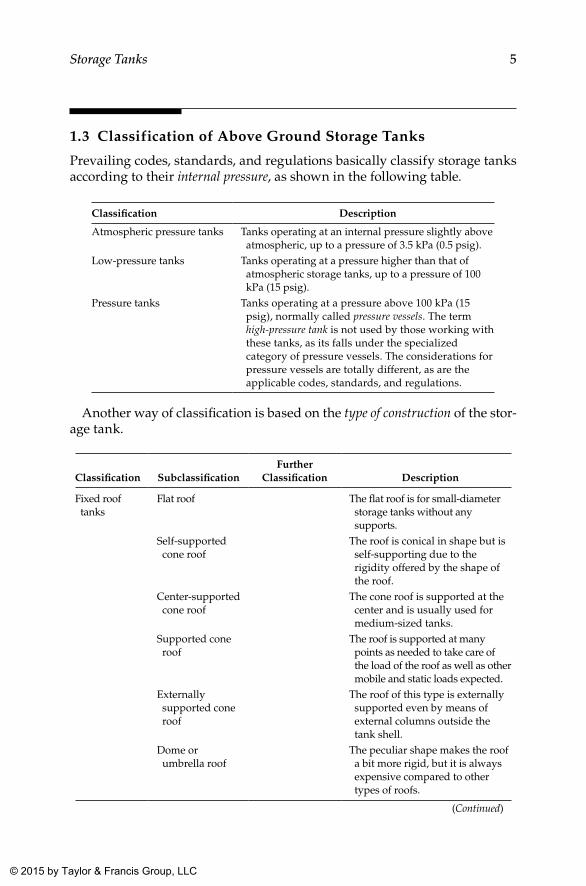
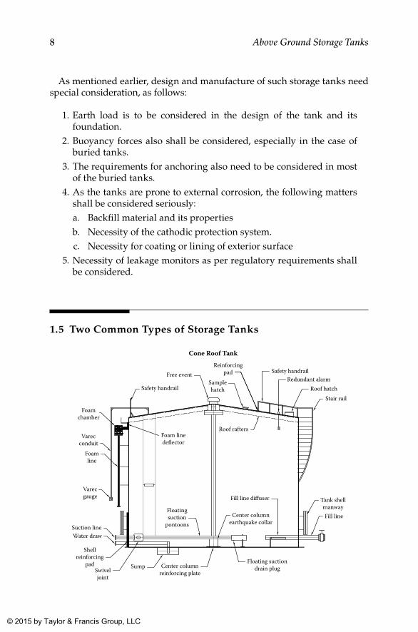
1.5 Two Common Types of Storage Tanks
Cone Roof TankReinforcing
pad Safety handrailRedundant alarm
Roof hatchStair rail
Samplehatch
Free event
Safety handrail
Foamchamber
Varecconduit
Varecgauge
Suction lineWater draw
Shellreinforcing
padSwiveljoint
Sump Center columnreinforcing plate
Floating suctiondrain plug
Floatingsuction
pontoons
Foam linede�ector
Roof rafters
Center columnearthquake collar
Fill line di�user Tank shellmanwayFill line
Foamline
K22265_Book.indb 8 4/20/15 5:46 PM
© 2015 by Taylor & Francis Group, LLC
9Storage Tanks
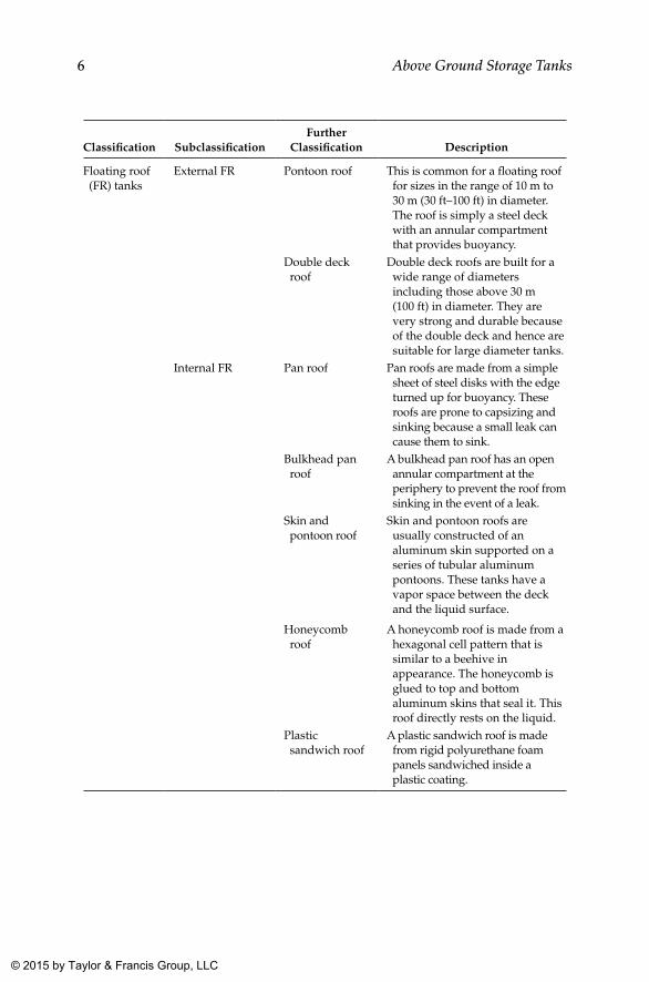
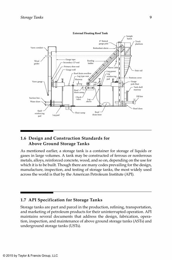
External Floating Roof Tank
8” Slottedgauge pole
Redundant alarm
Samplehatch
Truckplatform
Stair rail
Pontoon cover
Gaugepole �oat
Tank shellmanway
Fill line
Roof cleanRoof
drain hoseFloor sump
Leg pad
Shellreinforcing
pad
Water drawSuction line
Varec gauge
Windgirder
Varec conduit
Gauge tape
Gauge wellRoof drain over�ow
Leg gussetLegreinforcingpad
Leg type vent
Legpin
Legsleeve
Checkvalve
Roofdrain sump
Manway
Secondary CP sealRoo�ngladder
Alarm cablePrimary shoe seal
1.6 Design and Construction Standards for Above Ground Storage Tanks
As mentioned earlier, a storage tank is a container for storage of liquids or gases in large volumes. A tank may be constructed of ferrous or nonferrous metals, alloys, reinforced concrete, wood, and so on, depending on the use for which it is to be built. Though there are many codes prevailing for the design, manufacture, inspection, and testing of storage tanks, the most widely used across the world is that by the American Petroleum Institute (API).
1.7 API Specification for Storage Tanks
Storage tanks are part and parcel in the production, refining, transportation, and marketing of petroleum products for their uninterrupted operation. API maintains several documents that address the design, fabrication, opera-tion, inspection, and maintenance of above ground storage tanks (ASTs) and underground storage tanks (USTs).
K22265_Book.indb 9 4/20/15 5:46 PM
© 2015 by Taylor & Francis Group, LLC
10 Above Ground Storage Tanks
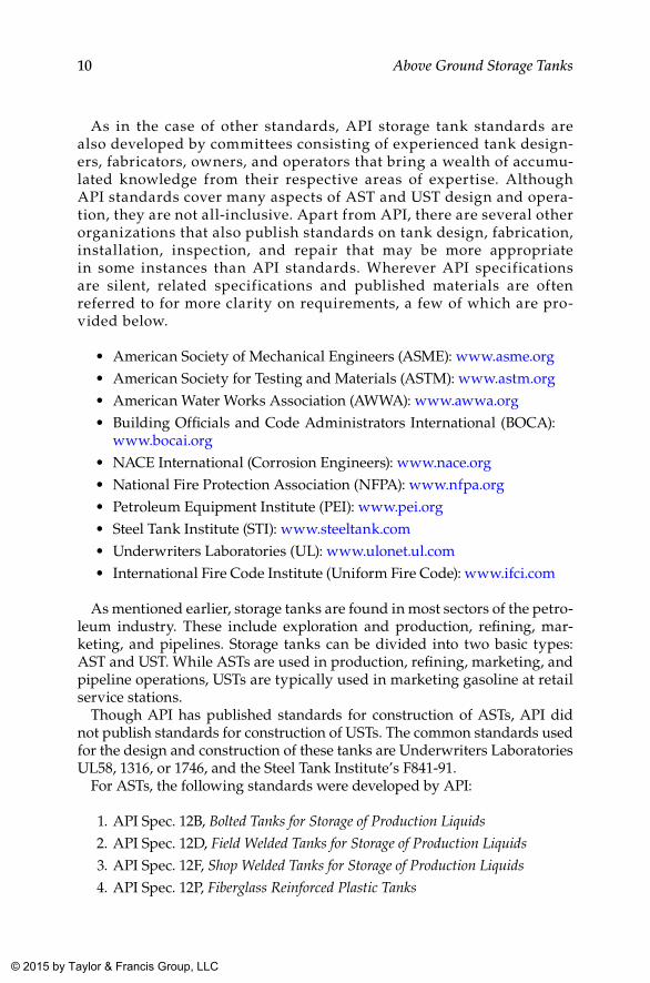
As in the case of other standards, API storage tank standards are also developed by committees consisting of experienced tank design-ers, fabricators, owners, and operators that bring a wealth of accumu-lated knowledge from their respective areas of expertise. Although API standards cover many aspects of AST and UST design and opera-tion, they are not all-inclusive. Apart from API, there are several other organizations that also publish standards on tank design, fabrication, installation, inspection, and repair that may be more appropriate in some instances than API standards. Wherever API specifications are silent, related specifications and published materials are often referred to for more clarity on requirements, a few of which are pro-vided below.
• American Society of Mechanical Engineers (ASME): www.asme.org• American Society for Testing and Materials (ASTM): www.astm.org• American Water Works Association (AWWA): www.awwa.org• Building Officials and Code Administrators International (BOCA):
www.bocai.org• NACE International (Corrosion Engineers): www.nace.org• National Fire Protection Association (NFPA): www.nfpa.org• Petroleum Equipment Institute (PEI): www.pei.org• Steel Tank Institute (STI): www.steeltank.com• Underwriters Laboratories (UL): www.ulonet.ul.com• International Fire Code Institute (Uniform Fire Code): www.ifci.com
As mentioned earlier, storage tanks are found in most sectors of the petro-leum industry. These include exploration and production, refining, mar-keting, and pipelines. Storage tanks can be divided into two basic types: AST and UST. While ASTs are used in production, refining, marketing, and pipeline operations, USTs are typically used in marketing gasoline at retail service stations.
Though API has published standards for construction of ASTs, API did not publish standards for construction of USTs. The common standards used for the design and construction of these tanks are Underwriters Laboratories UL58, 1316, or 1746, and the Steel Tank Institute’s F841-91.
For ASTs, the following standards were developed by API:
1. API Spec. 12B, Bolted Tanks for Storage of Production Liquids
2. API Spec. 12D, Field Welded Tanks for Storage of Production Liquids
3. API Spec. 12F, Shop Welded Tanks for Storage of Production Liquids
4. API Spec. 12P, Fiberglass Reinforced Plastic Tanks
K22265_Book.indb 10 4/20/15 5:46 PM
© 2015 by Taylor & Francis Group, LLC
11Storage Tanks
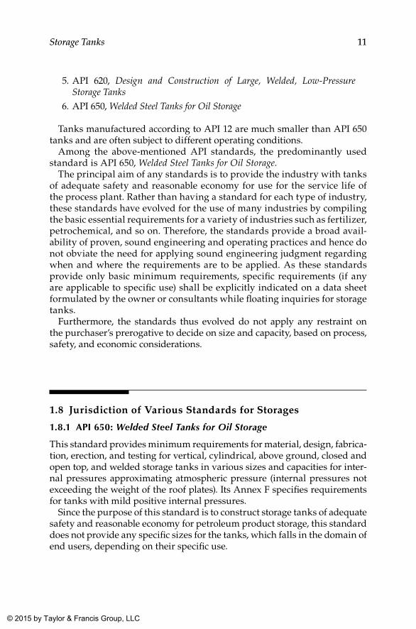
5. API 620, Design and Construction of Large, Welded, Low-Pressure Storage Tanks
6. API 650, Welded Steel Tanks for Oil Storage
Tanks manufactured according to API 12 are much smaller than API 650 tanks and are often subject to different operating conditions.
Among the above-mentioned API standards, the predominantly used standard is API 650, Welded Steel Tanks for Oil Storage.
The principal aim of any standards is to provide the industry with tanks of adequate safety and reasonable economy for use for the service life of the process plant. Rather than having a standard for each type of industry, these standards have evolved for the use of many industries by compiling the basic essential requirements for a variety of industries such as fertilizer, petrochemical, and so on. Therefore, the standards provide a broad avail-ability of proven, sound engineering and operating practices and hence do not obviate the need for applying sound engineering judgment regarding when and where the requirements are to be applied. As these standards provide only basic minimum requirements, specific requirements (if any are applicable to specific use) shall be explicitly indicated on a data sheet formulated by the owner or consultants while floating inquiries for storage tanks.
Furthermore, the standards thus evolved do not apply any restraint on the purchaser’s prerogative to decide on size and capacity, based on process, safety, and economic considerations.
1.8 Jurisdiction of Various Standards for Storages
1.8.1 API 650: Welded Steel Tanks for Oil Storage
This standard provides minimum requirements for material, design, fabrica-tion, erection, and testing for vertical, cylindrical, above ground, closed and open top, and welded storage tanks in various sizes and capacities for inter-nal pressures approximating atmospheric pressure (internal pressures not exceeding the weight of the roof plates). Its Annex F specifies requirements for tanks with mild positive internal pressures.
Since the purpose of this standard is to construct storage tanks of adequate safety and reasonable economy for petroleum product storage, this standard does not provide any specific sizes for the tanks, which falls in the domain of end users, depending on their specific use.
K22265_Book.indb 11 4/20/15 5:46 PM
© 2015 by Taylor & Francis Group, LLC
12 Above Ground Storage Tanks
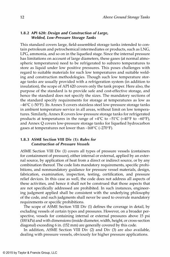
1.8.2 API 620: Design and Construction of Large, Welded, Low-Pressure Storage Tanks
This standard covers large, field-assembled storage tanks intended to con-tain petroleum and petrochemical intermediates or products, such as LNG, LPG, ammonia, and so on in the liquefied stage. Since the internal pressure has limitations on account of large diameters, these gases (at normal atmo-spheric temperatures) need to be refrigerated to subzero temperatures to store as liquid under low positive pressures. This poses challenges with regard to suitable materials for such low temperatures and suitable weld-ing and construction methodologies. Though such low temperature stor-age tanks are usually provided with a refrigeration system (in addition to insulation), the scope of API 620 covers only the tank proper. Here also, the purpose of the standard is to provide safe and cost-effective storage, and hence the standard does not specify the sizes. The mandatory sections of the standard specify requirements for storage at temperatures as low as –46°C (–50°F). Its Annex S covers stainless steel low-pressure storage tanks in ambient temperature service in all areas, without limit on low tempera-tures. Similarly, Annex R covers low-pressure storage tanks for refrigerated products at temperatures in the range of +4°C to –51°C (+40°F to –60°F), and Annex Q covers low-pressure storage tanks for liquefied hydrocarbon gases at temperatures not lower than –168°C (–270°F).
1.8.3 ASME Section VIII Div (1): Rules for Construction of Pressure Vessels
ASME Section VIII Div (1) covers all types of pressure vessels (containers for containment of pressure), either internal or external, applied by an exter-nal source, by application of heat from a direct or indirect source, or by any combination thereof. The code lists mandatory requirements, specific prohi-bitions, and nonmandatory guidance for pressure vessel materials, design, fabrication, examination, inspection, testing, certification, and pressure relief devices. In this case as well, the code does not address all aspects of these activities, and hence it shall not be construed that those aspects that are not specifically addressed are prohibited. In such instances, engineer-ing judgment applied shall be consistent with the underlying philosophy of the code, and such judgments shall never be used to overrule mandatory requirements or specific prohibitions.
The scope of ASME Section VIII Div (1) defines the coverage in detail, by excluding vessels of certain types and pressures. However, on a broader per-spective, vessels for containing internal or external pressures above 15 psi (100 kPa) and with dimensions (inside diameter, width, height, or cross-section diagonal) exceeding 6 in. (152 mm) are generally covered by this code.
In addition, ASME Section VIII Div (2) and Div (3) are also available, dealing with pressure vessels, obviously for higher pressure applications.
K22265_Book.indb 12 4/20/15 5:46 PM
© 2015 by Taylor & Francis Group, LLC
13Storage Tanks
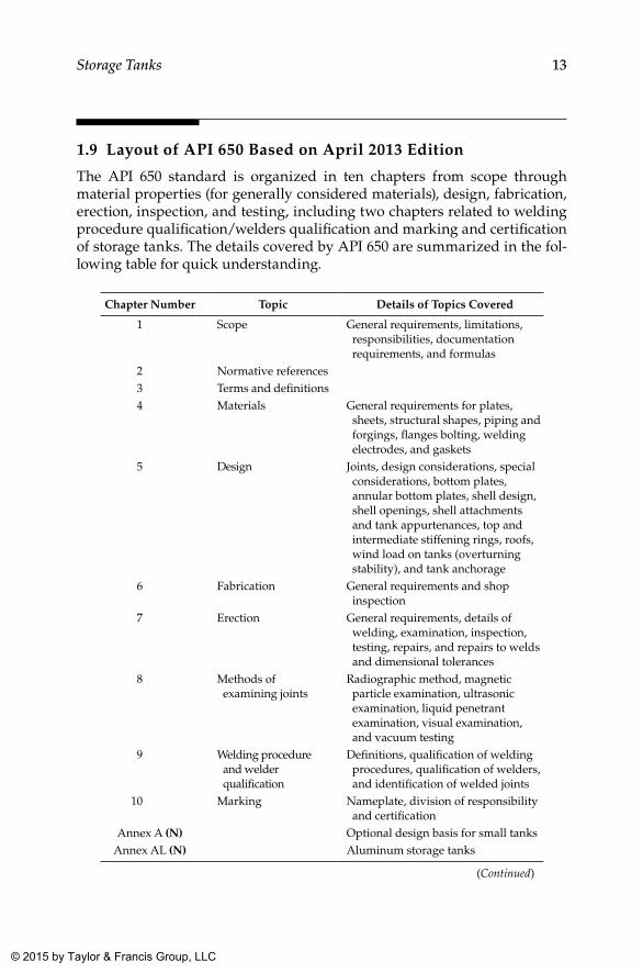
1.9 Layout of API 650 Based on April 2013 Edition
The API 650 standard is organized in ten chapters from scope through material properties (for generally considered materials), design, fabrication, erection, inspection, and testing, including two chapters related to welding procedure qualification/welders qualification and marking and certification of storage tanks. The details covered by API 650 are summarized in the fol-lowing table for quick understanding.
Chapter Number Topic Details of Topics Covered
1 Scope General requirements, limitations, responsibilities, documentation requirements, and formulas
2 Normative references3 Terms and definitions4 Materials General requirements for plates,
sheets, structural shapes, piping and forgings, flanges bolting, welding electrodes, and gaskets
5 Design Joints, design considerations, special considerations, bottom plates, annular bottom plates, shell design, shell openings, shell attachments and tank appurtenances, top and intermediate stiffening rings, roofs, wind load on tanks (overturning stability), and tank anchorage
6 Fabrication General requirements and shop inspection
7 Erection General requirements, details of welding, examination, inspection, testing, repairs, and repairs to welds and dimensional tolerances
8 Methods of examining joints
Radiographic method, magnetic particle examination, ultrasonic examination, liquid penetrant examination, visual examination, and vacuum testing
9 Welding procedure and welder qualification
Definitions, qualification of welding procedures, qualification of welders, and identification of welded joints
10 Marking Nameplate, division of responsibility and certification
Annex A (N) Optional design basis for small tanksAnnex AL (N) Aluminum storage tanks
(Continued)
K22265_Book.indb 13 4/20/15 5:46 PM
© 2015 by Taylor & Francis Group, LLC
14 Above Ground Storage Tanks
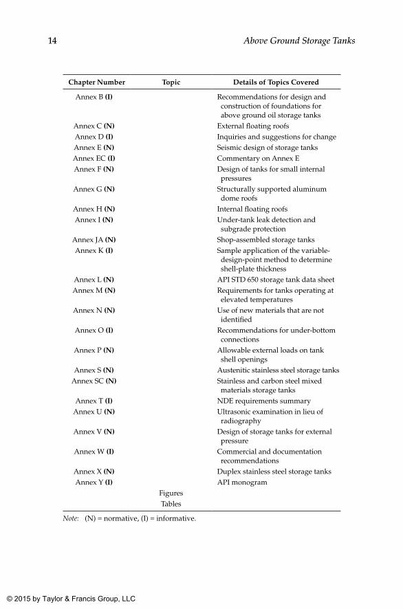
Chapter Number Topic Details of Topics Covered
Annex B (I) Recommendations for design and construction of foundations for above ground oil storage tanks
Annex C (N) External floating roofsAnnex D (I) Inquiries and suggestions for changeAnnex E (N) Seismic design of storage tanksAnnex EC (I) Commentary on Annex EAnnex F (N) Design of tanks for small internal
pressuresAnnex G (N) Structurally supported aluminum
dome roofsAnnex H (N) Internal floating roofsAnnex I (N) Under-tank leak detection and
subgrade protectionAnnex JA (N) Shop-assembled storage tanksAnnex K (I) Sample application of the variable-
design-point method to determine shell-plate thickness
Annex L (N) API STD 650 storage tank data sheetAnnex M (N) Requirements for tanks operating at
elevated temperaturesAnnex N (N) Use of new materials that are not
identifiedAnnex O (I) Recommendations for under-bottom
connectionsAnnex P (N) Allowable external loads on tank
shell openingsAnnex S (N) Austenitic stainless steel storage tanks
Annex SC (N) Stainless and carbon steel mixed materials storage tanks
Annex T (I) NDE requirements summaryAnnex U (N) Ultrasonic examination in lieu of
radiographyAnnex V (N) Design of storage tanks for external
pressureAnnex W (I) Commercial and documentation
recommendationsAnnex X (N) Duplex stainless steel storage tanksAnnex Y (I) API monogram
FiguresTables
Note: (N) = normative, (I) = informative.
K22265_Book.indb 14 4/20/15 5:46 PM
© 2015 by Taylor & Francis Group, LLC
15
2Classification of Storage
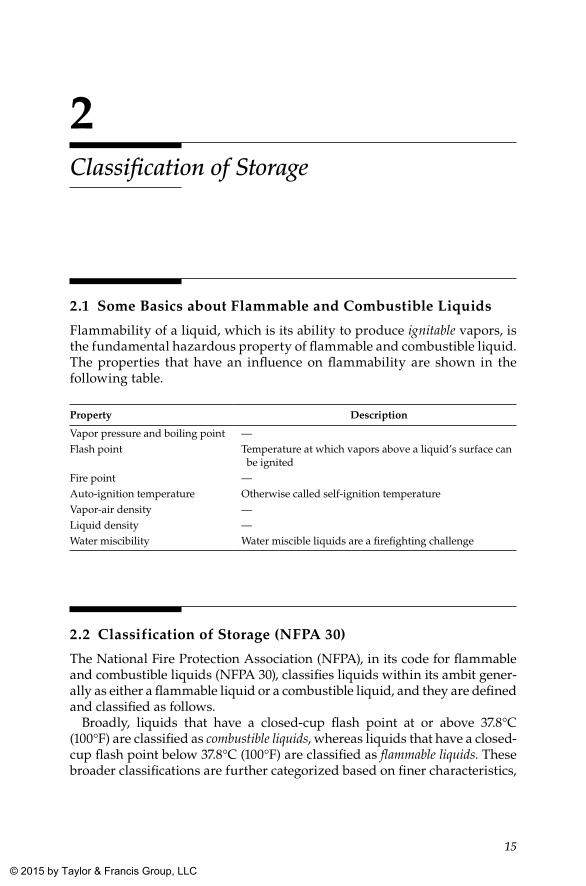
2.1 Some Basics about Flammable and Combustible Liquids
Flammability of a liquid, which is its ability to produce ignitable vapors, is the fundamental hazardous property of flammable and combustible liquid. The properties that have an influence on flammability are shown in the following table.
Property Description
Vapor pressure and boiling point —Flash point Temperature at which vapors above a liquid’s surface can
be ignitedFire point —Auto-ignition temperature Otherwise called self-ignition temperatureVapor-air density —Liquid density —Water miscibility Water miscible liquids are a firefighting challenge
2.2 Classification of Storage (NFPA 30)
The National Fire Protection Association (NFPA), in its code for flammable and combustible liquids (NFPA 30), classifies liquids within its ambit gener-ally as either a flammable liquid or a combustible liquid, and they are defined and classified as follows.
Broadly, liquids that have a closed-cup flash point at or above 37.8°C (100°F) are classified as combustible liquids, whereas liquids that have a closed-cup flash point below 37.8°C (100°F) are classified as flammable liquids. These broader classifications are further categorized based on finer characteristics,
K22265_Book.indb 15 4/20/15 5:46 PM
© 2015 by Taylor & Francis Group, LLC
16 Above Ground Storage Tanks
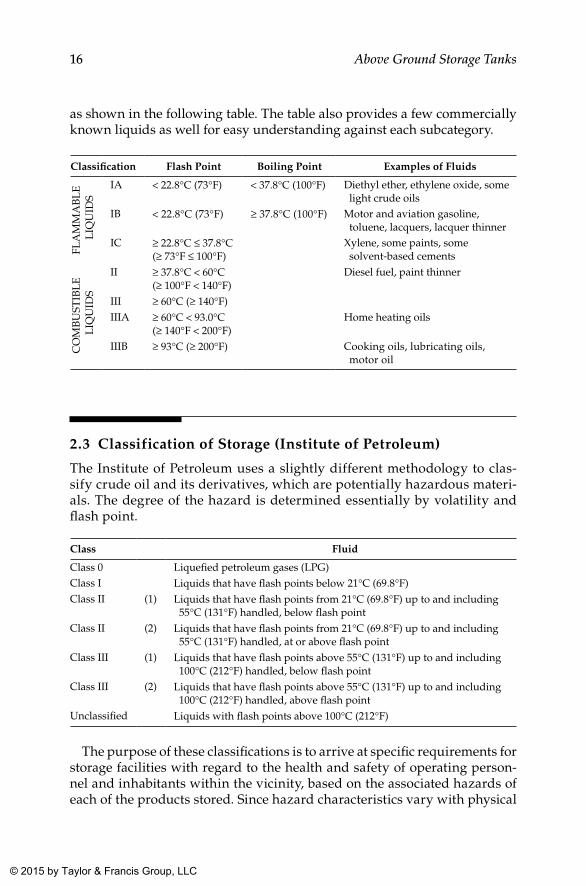
as shown in the following table. The table also provides a few commercially known liquids as well for easy understanding against each subcategory.
Classification Flash Point Boiling Point Examples of Fluids
FLA
MM
AB
LE
L
IQU
IDS
IA < 22.8°C (73°F) < 37.8°C (100°F) Diethyl ether, ethylene oxide, some light crude oils
IB < 22.8°C (73°F) ≥ 37.8°C (100°F) Motor and aviation gasoline, toluene, lacquers, lacquer thinner
IC ≥ 22.8°C ≤ 37.8°C(≥ 73°F ≤ 100°F)
Xylene, some paints, some solvent-based cements
CO
MB
UST
IBL
E
LIQ
UID
S
II ≥ 37.8°C < 60°C(≥ 100°F < 140°F)
Diesel fuel, paint thinner
III ≥ 60°C (≥ 140°F)IIIA ≥ 60°C < 93.0°C
(≥ 140°F < 200°F)Home heating oils
IIIB ≥ 93°C (≥ 200°F) Cooking oils, lubricating oils, motor oil
2.3 Classification of Storage (Institute of Petroleum)
The Institute of Petroleum uses a slightly different methodology to clas-sify crude oil and its derivatives, which are potentially hazardous materi-als. The degree of the hazard is determined essentially by volatility and flash point.
Class Fluid
Class 0 Liquefied petroleum gases (LPG)Class I Liquids that have flash points below 21°C (69.8°F)Class II (1) Liquids that have flash points from 21°C (69.8°F) up to and including
55°C (131°F) handled, below flash pointClass II (2) Liquids that have flash points from 21°C (69.8°F) up to and including
55°C (131°F) handled, at or above flash pointClass III (1) Liquids that have flash points above 55°C (131°F) up to and including
100°C (212°F) handled, below flash pointClass III (2) Liquids that have flash points above 55°C (131°F) up to and including
100°C (212°F) handled, above flash pointUnclassified Liquids with flash points above 100°C (212°F)
The purpose of these classifications is to arrive at specific requirements for storage facilities with regard to the health and safety of operating person-nel and inhabitants within the vicinity, based on the associated hazards of each of the products stored. Since hazard characteristics vary with physical
K22265_Book.indb 16 4/20/15 5:46 PM
© 2015 by Taylor & Francis Group, LLC
17Classification of Storage
properties of stored fluid, providing standard safeguards for all types of storages might not be economical. Therefore, NFPA and the Institute of Petroleum have developed criteria for storage tanks based on the nature of the fluid stored and the classifications as shown in the above table. Usually, a group of fluids is categorized under each class considering the fluids’ physical and chemical characteristics, to ward off complications in formulating requirements for each and every fluid.
K22265_Book.indb 17 4/20/15 5:46 PM
© 2015 by Taylor & Francis Group, LLC
19
3Tank Farm Layout
3.1 Considerations
A tank farm shall preferably be placed on one or not more than two sides of the process plant area. This arrangement allows adequate safety precautions to be taken and gives the possibility to expand either the tank farm area or the process plant area at any time in the future. Access shall be available on all four sides of each tank bund area, and all roads shall be linked in such a way that access is always possible even when any of the roads is blocked by fire.
For certain liquids, either burial or sun shielding is necessary or desirable. Cooling facilities also may be required in most of the cases. In all cases the layout shall have to satisfy the requirements of local statutory authorities for fire regulations and safety and access requirements. Tanks containing flammable liquids shall be surrounded by bund or dike walls, except those containing fluids with a high flash point at storage temperature (e.g., Class C, asphalt, heavy fuel oils, etc.). In this case, a low wall, 450 mm high, may be desirable in order to control spillage and prevention of pollution.
Areas around tanks can be varied in both size and shape to suit the land available. The type of bund or dike wall also can be varied. In cases where space is available, earth types with side slopes of 1.5 to 2.0 horizontal to 1.0 vertical are cheapest, but they require more space. Where space is a premium, concrete or masonry construction is advantageous. A desirable maximum height for safe access is 2.4 m, but this may be exceeded for very large tanks. Steps shall be provided over the bund with additional emergency exits as required. The minimum effective capacity within the retaining wall shall be equal to 110% that of the largest tank. This rate is based on the assumption that only one tank will fail at a time.
Tanks shall be grouped and bunded so that contents of tanks in one bund shall require only one type of firefighting system. This applies particularly when both water miscible liquids and water immiscible liquids are stored in the same installation. Space shall be allowed for foam or drenching systems. For tanks grouped together, consideration shall be given to a common walk-way with not less than two means of escape, depending on the number of tanks served.
K22265_Book.indb 19 4/20/15 5:46 PM
© 2015 by Taylor & Francis Group, LLC
20 Above Ground Storage Tanks
When exothermic chemical reactions are possible between stored liquids, tanks shall be segregated from other tanks, and consideration shall be given to increasing the spacing as much as possible.
The layout of storage tanks and related facilities has an impact on general pump arrangements. Pumps related to storages are generally placed in groups to serve one or more tanks and streams. Groups of pumps shall be placed in such a way for easy centralized operation but may require long suction runs of piping and thus prove costly for installation, as well as during operation. Lines carrying hot or flammable material shall be as short as possible.
Pumps shall not be located inside the bund wall around flammable liquid storage. The vertical distance between the tank outlet and the pump suction elevations shall be at least twice the anticipated tank settlement after load-ing. Steps shall be provided where access routes cross pipework.
Where tanks are provided with heating coils, enough space shall be pro-vided for withdrawal of heating coils for maintenance.
Storage and tank areas need not be provided with lighting if they are not intended to be visited at night by operating staff. If such facilities warrant visit at night because of emergencies, portable lamps with adequate light can be used.
For smaller plants, storage tanks can be located in such a way as to suit the flow of process and hence can be individually located. However, general principles as already narrated shall be adhered to regarding fire, safety, and spillage requirements; safe distances; and so on.
For multiple product storage where products vary according to seasonal or other changes, the layout is important to prevent the accidental mixing of two products and to permit flushing and cleaning of tanks and pipes. In such cases, individual tanks shall not be hard piped to the production plant or to the tanker or container-filling stations. A number of lines shall be provided from the production area to the storage area and from the storage area to the filling point and then connected with a flexible hose according to production requirements.
The layout of tanks, distinct from their spacing, shall always take into con-sideration the accessibility needed for firefighting and the potential value of a storage tank farm in providing a buffer area between the process plant and public roads, houses, and so on, for environmental reasons. Furthermore, the location of the tank farm relative to process units must be such as to ensure maximum safety from possible incidents. The primary considerations for the layout of storage tank farms can be summarized as follows.
Sl. No. Description
1 Intertank spacing and separation distances between the tank and the boundary line and the tank and other facilities are of fundamental importance.
2 Suitable roadways shall be available for approach to tank sites by mobile firefighting equipment and personnel.
K22265_Book.indb 20 4/20/15 5:46 PM
© 2015 by Taylor & Francis Group, LLC
21Tank Farm Layout
Sl. No. Description
3 The fire water system shall be laid out to provide adequate fire protection to all parts of the storage area and transfer facilities.
4 Bund wall and draining of the area surrounding the tanks shall be such that a spillage from any tank can be controlled to minimize subsequent damage to the tank and its contents. They shall also minimize the possibility of other tanks being involved.
5 Tank farms shall preferably not be located at higher levels than process units in the same catchment area.
6 Storage tanks holding flammable liquids shall be installed in such a way that any spill shall not flow toward a process area or any other source of ignition.
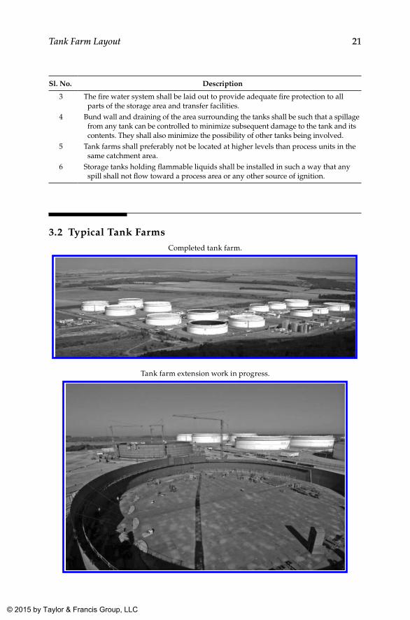
3.2 Typical Tank FarmsCompleted tank farm.
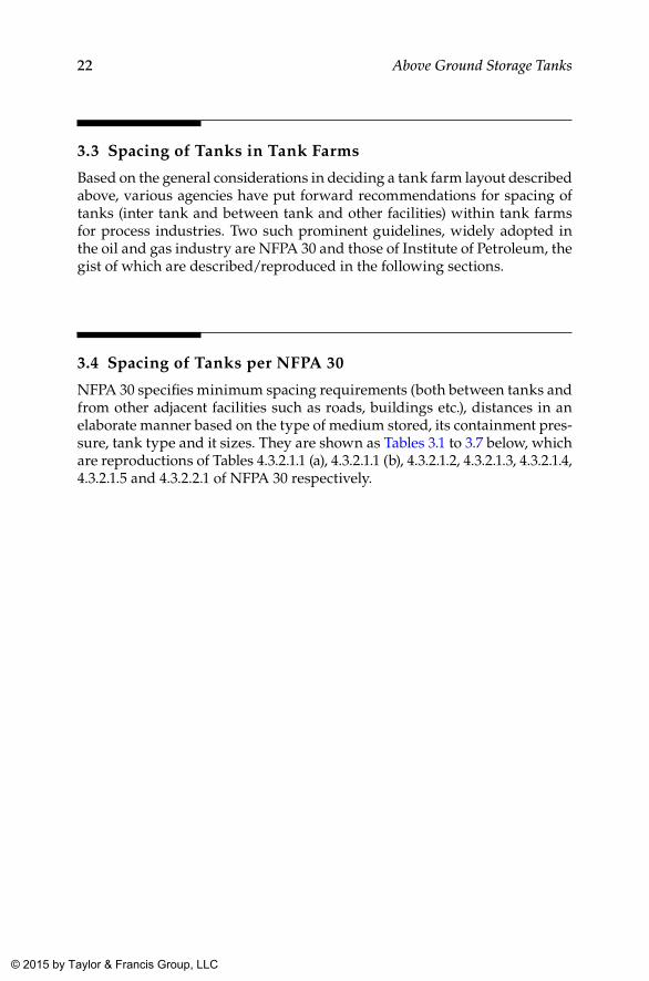
Tank farm extension work in progress.
K22265_Book.indb 21 4/20/15 5:46 PM
© 2015 by Taylor & Francis Group, LLC
22 Above Ground Storage Tanks
3.3 Spacing of Tanks in Tank Farms
Based on the general considerations in deciding a tank farm layout described above, various agencies have put forward recommendations for spacing of tanks (inter tank and between tank and other facilities) within tank farms for process industries. Two such prominent guidelines, widely adopted in the oil and gas industry are NFPA 30 and those of Institute of Petroleum, the gist of which are described/reproduced in the following sections.
3.4 Spacing of Tanks per NFPA 30
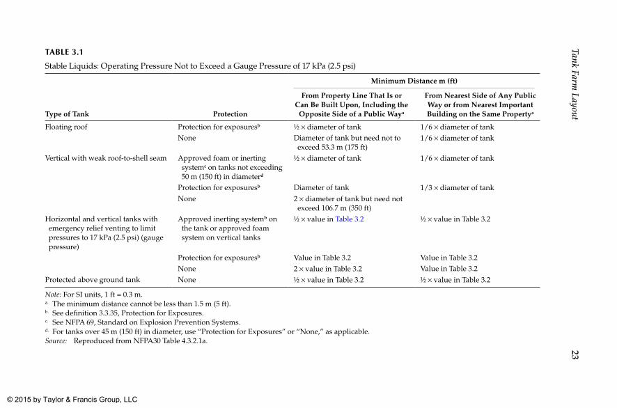
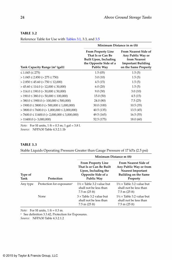
NFPA 30 specifies minimum spacing requirements (both between tanks and from other adjacent facilities such as roads, buildings etc.), distances in an elaborate manner based on the type of medium stored, its containment pres-sure, tank type and it sizes. They are shown as Tables 3.1 to 3.7 below, which are reproductions of Tables 4.3.2.1.1 (a), 4.3.2.1.1 (b), 4.3.2.1.2, 4.3.2.1.3, 4.3.2.1.4, 4.3.2.1.5 and 4.3.2.2.1 of NFPA 30 respectively.
K22265_Book.indb 22 4/20/15 5:46 PM
© 2015 by Taylor & Francis Group, LLC
23Tank Farm
LayoutTAblE 3.1
Stable Liquids: Operating Pressure Not to Exceed a Gauge Pressure of 17 kPa (2.5 psi)
Type of Tank Protection
Minimum Distance m (ft)
From Property Line That Is or Can Be Built Upon, Including the
Opposite Side of a Public Waya
From Nearest Side of Any Public Way or from Nearest Important Building on the Same Propertya
Floating roof Protection for exposuresb ½ × diameter of tank 1/6 × diameter of tankNone Diameter of tank but need not to
exceed 53.3 m (175 ft)1/6 × diameter of tank
Vertical with weak roof-to-shell seam Approved foam or inerting systemc on tanks not exceeding 50 m (150 ft) in diameterd
½ × diameter of tank 1/6 × diameter of tank
Protection for exposuresb Diameter of tank 1/3 × diameter of tankNone 2 × diameter of tank but need not
exceed 106.7 m (350 ft)Horizontal and vertical tanks with emergency relief venting to limit pressures to 17 kPa (2.5 psi) (gauge pressure)
Approved inerting systemb on the tank or approved foam system on vertical tanks
½ × value in Table 3.2 ½ × value in Table 3.2
Protection for exposuresb Value in Table 3.2 Value in Table 3.2None 2 × value in Table 3.2 Value in Table 3.2
Protected above ground tank None ½ × value in Table 3.2 ½ × value in Table 3.2
Note: For SI units, 1 ft = 0.3 m.a. The minimum distance cannot be less than 1.5 m (5 ft).b. See definition 3.3.35, Protection for Exposures.c. See NFPA 69, Standard on Explosion Prevention Systems.d. For tanks over 45 m (150 ft) in diameter, use “Protection for Exposures” or “None,” as applicable.Source: Reproduced from NFPA30 Table 4.3.2.1a.
K22265_B
ook.indb 234/20/15 5:46 P
M © 2015 by Taylor & Francis Group, LLC
24 Above Ground Storage Tanks
TAblE 3.2
Reference Table for Use with Tables 3.1, 3.3, and 3.5
Tank Capacity Range {m3 (gal)}
Minimum Distance in m (ft)
From Property Line That Is or Can Be
Built Upon, Including the Opposite Side of a
Public Way
From Nearest Side of Any Public Way or
from Nearest Important Building
on the Same Property
≤ 1.045 (≤ 275) 1.5 (05) 1.5 (5)
> 1.045 ≤ 2.850 (> 275 ≤ 750) 3.0 (10) 1.5 (5)
> 2.850 ≤ 45.60 (> 750 ≤ 12,000) 4.5 (15) 1.5 (5)
> 45.60 ≤ 114.0 (> 12,000 ≤ 30,000) 6.0 (20) 1.5 (5)
> 114.0 ≤ 190.0 (> 30,000 ≤ 50,000) 9.0 (30) 3.0 (10)
> 190.0 ≤ 380.0 (> 50,000 ≤ 100,000) 15.0 (50) 4.5 (15)
> 380.0 ≤ 1900.0 (> 100,000 ≤ 500,000) 24.0 (80) 7.5 (25)
> 1900.0 ≤ 3800.0 (> 500,000 ≤ 1,000,000) 30.0 (100) 10.5 (35)
> 3800.0 ≤ 7600.0 (> 1,000,000 ≤ 2,000,000) 40.5 (135) 13.5 (45)
> 7600.0 ≤ 11400.0 (> 2,000,000 ≤ 3,000,000) 49.5 (165) 16.5 (55)
> 11400.0 (> 3,000,000) 52.5 (175) 18.0 (60)
Note: For SI units, 1 ft = 0.3 m; 1 gal = 3.8 l.Source: NFPA30 Table 4.3.2.1.1b
TAblE 3.3
Stable Liquids Operating Pressure Greater than Gauge Pressure of 17 kPa (2.5 psi)
Type of Tank Protection
Minimum Distance m (ft)
From Property Line That Is or Can Be Built
Upon, Including the Opposite Side of a
Public Way
From Nearest Side of Any Public Way or from
Nearest Important Building on the Same
Property
Any type Protection for exposuresa 1½ × Table 3.2 value but shall not be less than 7.5 m (25 ft)
1½ × Table 3.2 value but shall not be less than 7.5 m (25 ft)
None 3 × Table 3.2 value but shall not be less than 7.5 m (25 ft)
1½ × Table 3.2 value but shall not be less than 7.5 m (25 ft)
Note: For SI units, 1 ft = 0.3 m.a See definition 3.3.42, Protection for Exposures.Source: NFPA30 Table 4.3.2.1.2
K22265_Book.indb 24 4/20/15 5:46 PM
© 2015 by Taylor & Francis Group, LLC
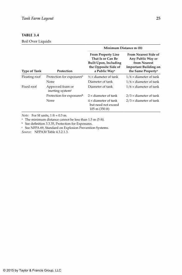
25Tank Farm Layout
TAblE 3.4
Boil Over Liquids
Type of Tank Protection
Minimum Distance m (ft)
From Property Line That Is or Can Be
Built Upon, Including the Opposite Side of
a Public Waya
From Nearest Side of Any Public Way or
from Nearest Important Building on
the Same Propertya
Floating roof Protection for exposuresb ½ × diameter of tank 1/6 × diameter of tankNone Diameter of tank 1/6 × diameter of tank
Fixed roof Approved foam or inerting systemc
Diameter of tank 1/6 × diameter of tank
Protection for exposuresb 2 × diameter of tank 2/3 × diameter of tankNone 4 × diameter of tank
but need not exceed 105 m (350 ft)
2/3 × diameter of tank
Note: For SI units, 1 ft = 0.3 m.a The minimum distance cannot be less than 1.5 m (5 ft).b See definition 3.3.35, Protection for Exposures.c See NFPA 69, Standard on Explosion Prevention Systems.Source: NFPA30 Table 4.3.2.1.3.
K22265_Book.indb 25 4/20/15 5:46 PM
© 2015 by Taylor & Francis Group, LLC
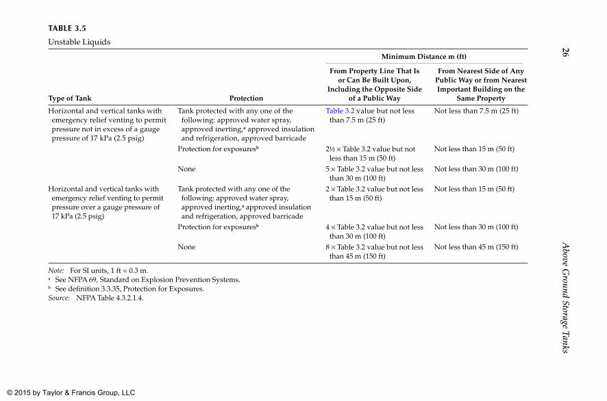
26A
bove Ground Storage Tanks
TAblE 3.5
Unstable Liquids
Type of Tank Protection
Minimum Distance m (ft)
From Property Line That Is or Can Be Built Upon,
Including the Opposite Side of a Public Way
From Nearest Side of Any Public Way or from Nearest Important Building on the
Same Property
Horizontal and vertical tanks with emergency relief venting to permit pressure not in excess of a gauge pressure of 17 kPa (2.5 psig)
Tank protected with any one of the following: approved water spray, approved inerting,a approved insulation and refrigeration, approved barricade
Table 3.2 value but not less than 7.5 m (25 ft)
Not less than 7.5 m (25 ft)
Protection for exposuresb 2½ × Table 3.2 value but not less than 15 m (50 ft)
Not less than 15 m (50 ft)
None 5 × Table 3.2 value but not less than 30 m (100 ft)
Not less than 30 m (100 ft)
Horizontal and vertical tanks with emergency relief venting to permit pressure over a gauge pressure of 17 kPa (2.5 psig)
Tank protected with any one of the following: approved water spray, approved inerting,a approved insulation and refrigeration, approved barricade
2 × Table 3.2 value but not less than 15 m (50 ft)
Not less than 15 m (50 ft)
Protection for exposuresb 4 × Table 3.2 value but not less than 30 m (100 ft)
Not less than 30 m (100 ft)
None 8 × Table 3.2 value but not less than 45 m (150 ft)
Not less than 45 m (150 ft)
Note: For SI units, 1 ft = 0.3 m.a See NFPA 69, Standard on Explosion Prevention Systems.b See definition 3.3.35, Protection for Exposures.Source: NFPA Table 4.3.2.1.4.
K22265_B
ook.indb 264/20/15 5:46 P
M © 2015 by Taylor & Francis Group, LLC
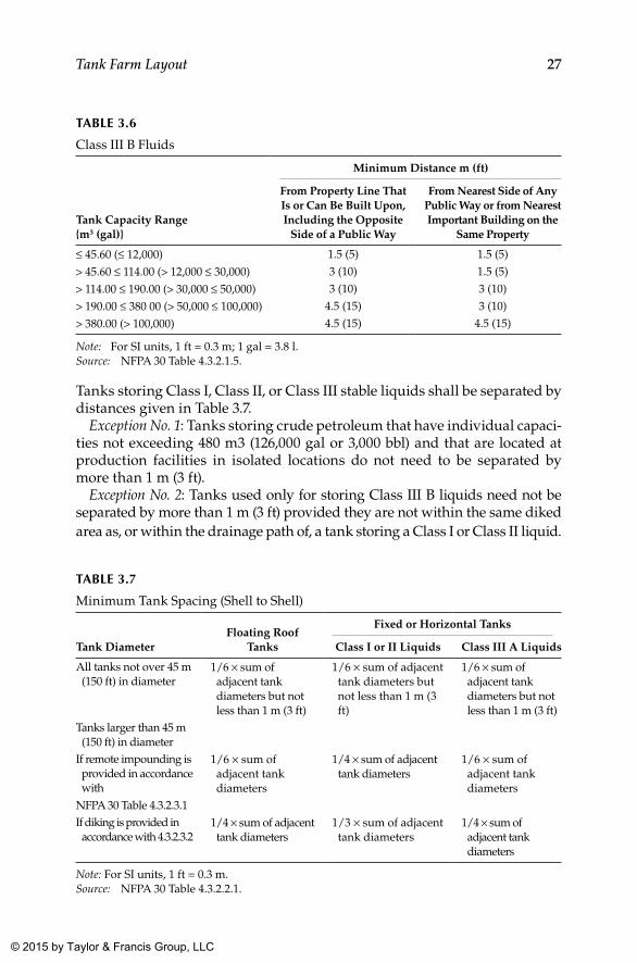
27Tank Farm Layout
Tanks storing Class I, Class II, or Class III stable liquids shall be separated by distances given in Table 3.7.
Exception No. 1: Tanks storing crude petroleum that have individual capaci-ties not exceeding 480 m3 (126,000 gal or 3,000 bbl) and that are located at production facilities in isolated locations do not need to be separated by more than 1 m (3 ft).
Exception No. 2: Tanks used only for storing Class III B liquids need not be separated by more than 1 m (3 ft) provided they are not within the same diked area as, or within the drainage path of, a tank storing a Class I or Class II liquid.
TAblE 3.6
Class III B Fluids
Tank Capacity Range{m3 (gal)}
Minimum Distance m (ft)
From Property Line That Is or Can Be Built Upon, Including the Opposite
Side of a Public Way
From Nearest Side of Any Public Way or from Nearest Important Building on the
Same Property
≤ 45.60 (≤ 12,000) 1.5 (5) 1.5 (5)
> 45.60 ≤ 114.00 (> 12,000 ≤ 30,000) 3 (10) 1.5 (5)
> 114.00 ≤ 190.00 (> 30,000 ≤ 50,000) 3 (10) 3 (10)
> 190.00 ≤ 380 00 (> 50,000 ≤ 100,000) 4.5 (15) 3 (10)
> 380.00 (> 100,000) 4.5 (15) 4.5 (15)
Note: For SI units, 1 ft = 0.3 m; 1 gal = 3.8 l.Source: NFPA 30 Table 4.3.2.1.5.
TAblE 3.7
Minimum Tank Spacing (Shell to Shell)
Tank DiameterFloating Roof
Tanks
Fixed or Horizontal Tanks
Class I or II Liquids Class III A Liquids
All tanks not over 45 m (150 ft) in diameter
1/6 × sum of adjacent tank diameters but not less than 1 m (3 ft)
1/6 × sum of adjacent tank diameters but not less than 1 m (3 ft)
1/6 × sum of adjacent tank diameters but not less than 1 m (3 ft)
Tanks larger than 45 m (150 ft) in diameter
If remote impounding is provided in accordance with
1/6 × sum of adjacent tank diameters
1/4 × sum of adjacent tank diameters
1/6 × sum of adjacent tank diameters
NFPA 30 Table 4.3.2.3.1If diking is provided in accordance with 4.3.2.3.2
1/4 × sum of adjacent tank diameters
1/3 × sum of adjacent tank diameters
1/4 × sum of adjacent tank diameters
Note: For SI units, 1 ft = 0.3 m.Source: NFPA 30 Table 4.3.2.2.1.
K22265_Book.indb 27 4/20/15 5:46 PM
© 2015 by Taylor & Francis Group, LLC
28 Above Ground Storage Tanks
3.5 Spacing of a Tank for Petroleum Stocks as per the Institute of Petroleum Guidelines
As mentioned earlier, the layout and general design of a petroleum storage installation is based on considerations of safety, operational ease, and envi-ronmental conservation. Installations for Class II(1) or Class III(1) petro-leum pose a lesser risk than those handling Class I, Class II(2), or Class III(2) fluids.
3.5.1 Storage Classes I, II(2), III(2)
The distances given in Table 3.8 (Reproduced from IP guideline Table 3.1) are normal minimum recommendations applicable to storage of Classes I, II(2), and III(2). Numerical values provided refer to horizontal distances in the plan between the nearest points of the specified features (e.g., storage tanks, filling points, openings in buildings, and boundaries). Special consideration should be given to sites on sloping ground or where high wind speeds pre-vail. The distances described in the table should be used in conjunction with the appropriate level of fire protection envisaged for the facility.
A group of small tanks referred to in the table is defined as tanks hav-ing a diameter of 10 m (30 ft) or less and a height of 14 m (46 ft) or less and may be regarded as one tank when considering tank spacing or bunding. Such small tanks may be placed together in groups, no groups having an aggregate capacity of more than 8,000 m3 (282,000 ft3). The distance between individual tanks in the group need to be governed only by constructional and operating convenience.
3.5.2 Storage Classes II(1) and III(1)
Petroleum products stored at installations and depots may be regarded as Class II(1) in temperate climates since they will be below their flash points at ambient temperatures. The spacing of tanks need be governed by construc-tional and operational convenience only.
However, it is recommended that tanks for Class II products should be spaced from tanks storing Class I products at the distances for fixed roof tanks shown in Table 3.8.
At refineries, products or product component stocks may at times be held at temperatures higher than their flash points. In this case, Class II materials will be classified as Class II(2), and spacing should be in accordance with that shown in Table 3.8.
K22265_Book.indb 28 4/20/15 5:46 PM
© 2015 by Taylor & Francis Group, LLC
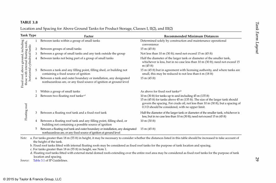
29Tank Farm
LayoutTAblE 3.8
Location and Spacing for Above Ground Tanks for Product Storage, Classes I, II(2), and III(2)
Tank Type Factor Recommended Minimum Distances
Fixe
d r
oof,
abov
e gr
ound
, inc
lud
ing
thos
e w
ith
inte
rnal
floa
ting
roo
fs,
hori
zont
al c
ylin
dri
cal t
anks
1 Between tanks within a group of small tanks Determined solely by construction and maintenance operational convenience
2 Between groups of small tanks 15 m (45 ft)
3 Between a group of small tanks and any tank outside the group Not less than 10 m (30 ft); need not exceed 15 m (45 ft)
4 Between tanks not being part of a group of small tanks Half the diameter of the larger tank or diameter of the smaller tank, whichever is less, but in no case less than 10 m (30 ft); need not exceed 15 m (45 ft)
5 Between a tank and any filling point, filling shed, or building not containing a fixed source of ignition
15 m (45 ft) but in agreement with licensing authority, and where tanks are small, this may be reduced to not less than 6 m (18 ft)
6 Between a tank and outer boundary or installation, any designated nonhazardous are, or any fixed source of ignition at ground level
15 m (45 ft)
Floa
ting
roo
f
1 Within a group of small tanks As above for fixed roof tanksa,b
2 Between two floating roof tanksc,d 10 m (30 ft) for tanks up to and including 45 m (135 ft)15 m (45 ft) for tanks above 45 m (135 ft). The size of the larger tank should
govern the spacing. For crude oil, not less than 10 m (30 ft), but a spacing of 0.3 D should be considered, with no upper limit.
3 Between a floating roof tank and a fixed roof tank Half the diameter of the larger tank or diameter of the smaller tank, which ever is less, but in no case less than 10 m (30 ft); need not exceed 15 m (45 ft)
4 Between a floating roof tank and any filling point, filling shed, or building not containing a possible source of ignition
10 m (30 ft)
5 Between a floating roof tank and outer boundary or installation, any designated nonhazardous are, or any fixed source of ignition at ground level
15 m (45 ft)
Note: a. For tanks greater than 18 m (55 ft) in height, it may be necessary to consider whether the distances listed in this table should be increased to take account of the height of the tank.
b. Fixed roof tanks fitted with internal floating roofs may be considered as fixed roof tanks for the purpose of tank location and spacing. c. For tanks greater than 18 m (55 ft) in height, see Note 1. d. Floating roof tanks fitted with external metal domed roofs extending over the entire roof area may be considered as fixed roof tanks for the purpose of tank
location and spacing.Source: Table 3.1 of IP Guidelines.
K22265_B
ook.indb 294/20/15 5:46 P
M © 2015 by Taylor & Francis Group, LLC
30 Above Ground Storage Tanks
While Table 3.8 provides guidance on the minimum tank spacing for Classes I, II, and III(2) storage facilities, the following points also shall be considered while applying the same:
1. Tanks of diameter up to 10 m (30 ft) are classed as small tanks. 2. Small tanks may be sited together in groups, no group having an
aggregate capacity of more than 8,000 m3 (282,500 ft3). Such a group may be regarded as one tank.
3. Where future changes of service of a storage tank are anticipated, the layout and spacing should be designed for the most stringent case.
4. For reasons of firefighting access, there should be no more than two rows of tanks between adjacent access roads.
5. Fixed roof tanks with internal floating covers should be treated for spacing purposes as fixed roof tanks.
6. Where fixed roof and floating roof tanks are adjacent, spac-ing should be on the basis of the tank(s) with the most stringent conditions.
7. Where tanks are erected on compressible soils, the distance between adjacent tanks should be sufficient to avoid excessive dis-tortion. This can be caused by additional settlements of the ground where the stressed soil zone of one tank overlaps that of the adja-cent tank.
8. For Class III(1) and unclassified petroleum stocks, spacing of tanks is governed only by constructional and operational convenience. However, the spacing of Class III(1) tankage from Classes I, II, and III(2) tankage is governed by the requirements for the latter.
K22265_Book.indb 30 4/20/15 5:46 PM
© 2015 by Taylor & Francis Group, LLC
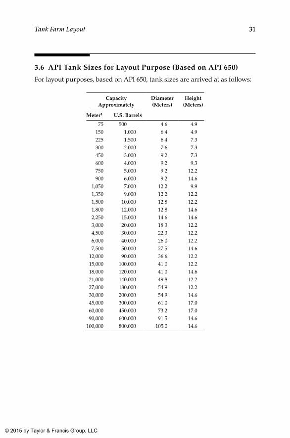
31Tank Farm Layout
3.6 API Tank Sizes for Layout Purpose (Based on API 650)
For layout purposes, based on API 650, tank sizes are arrived at as follows:
Capacity Approximately
Diameter(Meters)
Height(Meters)
Meter3 U.S. Barrels
75 500 4.6 4.9150 1.000 6.4 4.9225 1.500 6.4 7.3300 2.000 7.6 7.3450 3.000 9.2 7.3600 4.000 9.2 9.3750 5.000 9.2 12.2900 6.000 9.2 14.6
1,050 7.000 12.2 9.91,350 9.000 12.2 12.21,500 10.000 12.8 12.21,800 12.000 12.8 14.62,250 15.000 14.6 14.63,000 20.000 18.3 12.24,500 30.000 22.3 12.26,000 40.000 26.0 12.27,500 50.000 27.5 14.6
12,000 90.000 36.6 12.215,000 100.000 41.0 12.218,000 120.000 41.0 14.621,000 140.000 49.8 12.227,000 180.000 54.9 12.230,000 200.000 54.9 14.645,000 300.000 61.0 17.060,000 450.000 73.2 17.090,000 600.000 91.5 14.6
100,000 800.000 105.0 14.6
K22265_Book.indb 31 4/20/15 5:46 PM
© 2015 by Taylor & Francis Group, LLC
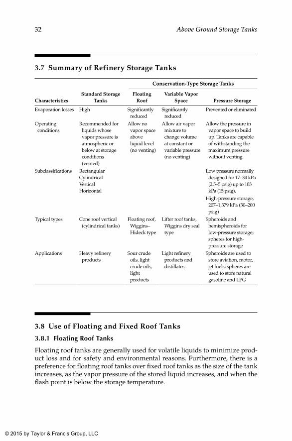
32 Above Ground Storage Tanks
3.7 Summary of Refinery Storage Tanks
CharacteristicsStandard Storage
Tanks
Conservation-Type Storage Tanks
Floating Roof
Variable Vapor Space Pressure Storage
Evaporation losses High Significantly reduced
Significantly reduced
Prevented or eliminated
Operating conditions
Recommended for liquids whose vapor pressure is atmospheric or below at storage conditions (vented)
Allow no vapor space above liquid level (no venting)
Allow air vapor mixture to change volume at constant or variable pressure (no venting)
Allow the pressure in vapor space to build up. Tanks are capable of withstanding the maximum pressure without venting.
Subclassifications RectangularCylindricalVerticalHorizontal
Low pressure normally designed for 17–34 kPa (2.5–5 psig) up to 103 kPa (15 psig),
High-pressure storage, 207–1,379 kPa (30–200 psig)
Typical types Cone roof vertical (cylindrical tanks)
Floating roof, Wiggins–Hideck type
Lifter roof tanks, Wiggins dry seal type
Spheroids and hemispheroids for low-pressure storage; spheres for high-pressure storage
Applications Heavy refinery products
Sour crude oils, light crude oils, light products
Light refinery products and distillates
Spheroids are used to store aviation, motor, jet fuels; spheres are used to store natural gasoline and LPG
3.8 Use of Floating and Fixed Roof Tanks
3.8.1 Floating Roof Tanks
Floating roof tanks are generally used for volatile liquids to minimize prod-uct loss and for safety and environmental reasons. Furthermore, there is a preference for floating roof tanks over fixed roof tanks as the size of the tank increases, as the vapor pressure of the stored liquid increases, and when the flash point is below the storage temperature.
K22265_Book.indb 32 4/20/15 5:46 PM
© 2015 by Taylor & Francis Group, LLC
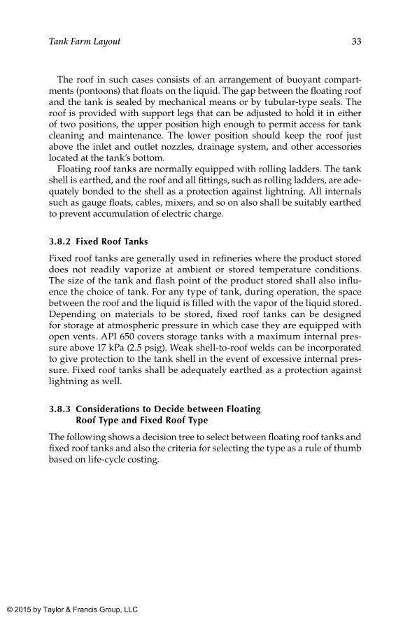
33Tank Farm Layout
The roof in such cases consists of an arrangement of buoyant compart-ments (pontoons) that floats on the liquid. The gap between the floating roof and the tank is sealed by mechanical means or by tubular-type seals. The roof is provided with support legs that can be adjusted to hold it in either of two positions, the upper position high enough to permit access for tank cleaning and maintenance. The lower position should keep the roof just above the inlet and outlet nozzles, drainage system, and other accessories located at the tank’s bottom.
Floating roof tanks are normally equipped with rolling ladders. The tank shell is earthed, and the roof and all fittings, such as rolling ladders, are ade-quately bonded to the shell as a protection against lightning. All internals such as gauge floats, cables, mixers, and so on also shall be suitably earthed to prevent accumulation of electric charge.
3.8.2 Fixed Roof Tanks
Fixed roof tanks are generally used in refineries where the product stored does not readily vaporize at ambient or stored temperature conditions. The size of the tank and flash point of the product stored shall also influ-ence the choice of tank. For any type of tank, during operation, the space between the roof and the liquid is filled with the vapor of the liquid stored. Depending on materials to be stored, fixed roof tanks can be designed for storage at atmospheric pressure in which case they are equipped with open vents. API 650 covers storage tanks with a maximum internal pres-sure above 17 kPa (2.5 psig). Weak shell-to-roof welds can be incorporated to give protection to the tank shell in the event of excessive internal pres-sure. Fixed roof tanks shall be adequately earthed as a protection against lightning as well.
3.8.3 Considerations to Decide between Floating Roof Type and Fixed Roof Type
The following shows a decision tree to select between floating roof tanks and fixed roof tanks and also the criteria for selecting the type as a rule of thumb based on life-cycle costing.
K22265_Book.indb 33 4/20/15 5:46 PM
© 2015 by Taylor & Francis Group, LLC
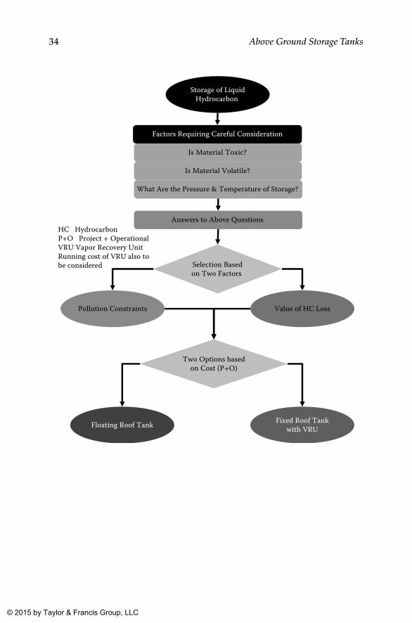
34 Above Ground Storage Tanks
Factors Requiring Careful Consideration
Is Material Toxic?
Is Material Volatile?
What Are the Pressure & Temperature of Storage?
Storage of LiquidHydrocarbon
Answers to Above Questions
Selection Basedon Two Factors
Pollution Constraints Value of HC Loss
Two Options basedon Cost (P+O)
Floating Roof Tank Fixed Roof Tankwith VRU
HC Hydrocarbon P+O Project + OperationalVRU Vapor Recovery UnitRunning cost of VRU also tobe considered
K22265_Book.indb 34 4/20/15 5:46 PM
© 2015 by Taylor & Francis Group, LLC
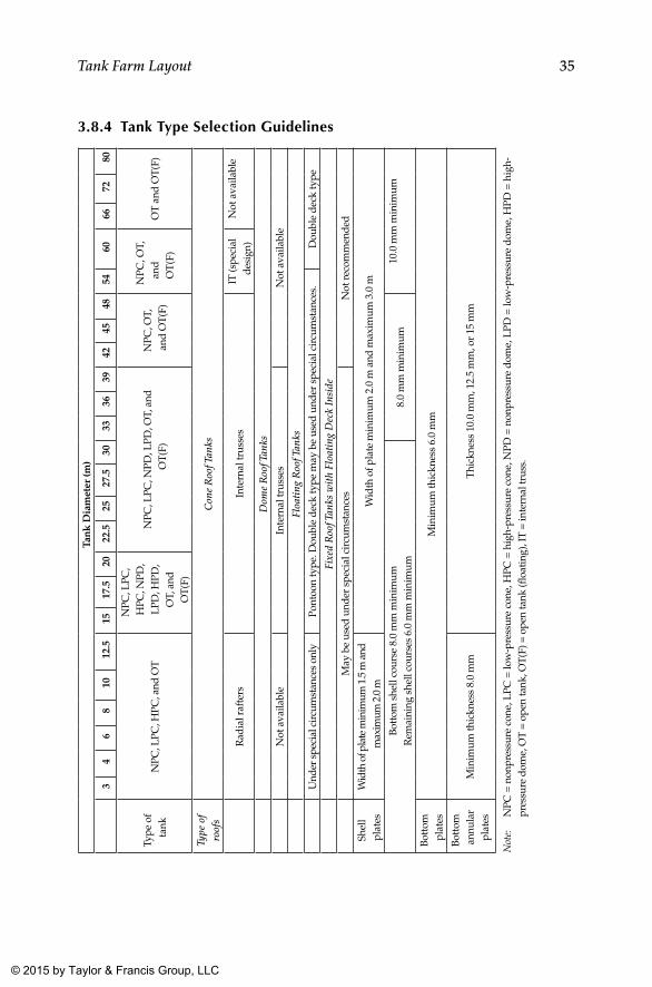
35Tank Farm Layout
3.8.4 Tank Type Selection Guidelines
Tan
k D
iam
eter
(m)
34
68
1012
.515
17.5
2022
.525
27.5
3033
3639
4245
4854
6066
7280
Type
of
tank
NPC
, LPC
, HPC
, and
OT
NPC
, LPC
, H
PC, N
PD,
LPD
, HPD
, O
T, a
nd
OT(
F)
NPC
, LPC
, NPD
, LPD
, OT,
and
O
T(F)
NPC
, OT,
an
d O
T(F)
NPC
, OT,
an
d
OT
(F)
OT
and
OT(
F)
Type
of
roof
sC
one
Roo
f Tan
ks
Rad
ial r
afte
rsIn
tern
al tr
usse
sIT
(spe
cial
de
sign
)N
ot a
vaila
ble
Dom
e R
oof T
anks
Not
ava
ilabl
eIn
tern
al tr
usse
sN
ot a
vaila
ble
Floa
ting
Roo
f Tan
ks
Und
er s
peci
al c
ircu
mst
ance
s on
lyPo
ntoo
n ty
pe. D
oubl
e de
ck ty
pe m
ay b
e us
ed u
nder
spe
cial
cir
cum
stan
ces.
Dou
ble
deck
type
Fixe
d R
oof T
anks
wit
h Fl
oati
ng D
eck
Insi
de
May
be
used
und
er s
peci
al c
ircu
mst
ance
sN
ot re
com
men
ded
Shel
l pl
ates
Wid
th o
f pla
te m
inim
um 1
.5 m
and
m
axim
um 2
.0 m
Wid
th o
f pla
te m
inim
um 2
.0 m
and
max
imum
3.0
m
Bott
om s
hell
cour
se 8
.0 m
m m
inim
umR
emai
ning
she
ll co
urse
s 6.
0 m
m m
inim
um8.
0 m
m m
inim
um10
.0 m
m m
inim
um
Bott
om
plat
esM
inim
um th
ickn
ess
6.0
mm
Bott
om
annu
lar
plat
esM
inim
um th
ickn
ess
8.0
mm
Thic
knes
s 10
.0 m
m, 1
2.5
mm
, or
15 m
m
Not
e:
NPC
= n
onpr
essu
re c
one,
LPC
= lo
w-p
ress
ure
cone
, HPC
= h
igh-
pres
sure
con
e, N
PD =
non
pres
sure
dom
e, L
PD =
low
-pre
ssur
e do
me,
HPD
= h
igh-
pres
sure
dom
e, O
T =
open
tank
, OT(
F) =
ope
n ta
nk (fl
oatin
g), I
T =
inte
rnal
trus
s.
K22265_Book.indb 35 4/20/15 5:46 PM
© 2015 by Taylor & Francis Group, LLC
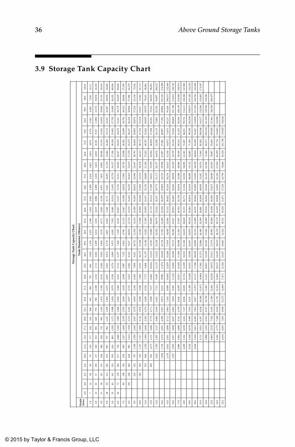
36 Above Ground Storage Tanks
3.9 Storage Tank Capacity ChartSt
orag
e Tan
k C
apac
ity C
hart
Hei
ght
Met
erTa
nk D
iam
eter
(Met
ers)
3.0
4.0
6.0
8.0
10.0
12.5
15.0
17.5
20.0
22.5
25.0
27.5
30.0
33.0
36.0
39.0
40.0
45.0
48.0
51.0
54.0
57.0
60.0
66.0
72.0
78.0
84.0
90.0
96.0
102.
0
1.0
713
2850
7912
317
724
131
439
849
159
470
785
51,
018
1,19
51,
257
1,59
01,
810
2,04
32,
290
2,55
22,
827
3,42
14,
072
4,77
85,
542
6,36
27,
238
8,17
1
2.0
1425
5710
115
724
535
348
162
879
598
21,
188
1,41
41,
711
2,03
62,
389
2,51
33,
181
3,61
94,
086
4,58
05,
104
5,65
56,
842
8,14
39,
557
11,0
8412
,723
14,4
7616
,343
3.0
2138
8515
123
636
853
072
294
21,
193
1,47
31,
782
2,12
12,
566
3,05
43,
584
3,77
04,
771
5,42
96,
128
6,87
17,
655
8,48
210
,264
12,2
1514
,335
16,6
2519
,085
21,7
1524
,514
4.0
2850
113
201
314
491
707
962
1,25
71,
590
1,96
32,
376
2,82
73,
421
4,07
24,
778
5,02
76,
362
7,23
88,
171
9,16
110
,207
11,3
1013
,685
16,2
8619
,113
22,1
6725
,447
28,9
5332
,685
5.0
3563
141
251
393
614
884
1,20
31,
571
1,98
82,
454
2,97
03,
534
4,27
65,
089
5,97
36,
283
7,95
29,
048
10,2
1411
,451
12,7
5914
,137
17,1
0620
,358
23,8
9227
,709
31,8
0936
,191
40,8
56
6.0
4275
170
302
471
736
1,06
01,
443
1,88
52,
386
2,94
53,
564
4,24
15,
132
6,10
77,
168
7,54
09,
543
10,8
5712
,257
13,7
4115
,311
16,9
6520
,527
24,4
2928
,670
33,2
5138
,170
43,4
2949
,028
7.0
8819
835
255
085
91,
237
1,68
42,
199
2,78
33,
436
4,15
84,
948
5,98
77,
125
8,36
28,
796
11,1
3312
,667
14,3
0016
,032
17,8
6219
,792
23,9
4828
,501
33,4
4938
,792
44,5
3250
,668
57,1
99
8.0
101
226
402
628
982
1,41
41,
924
2,51
33,
181
3,92
74,
752
5,65
56,
842
8,14
39,
557
10,0
5312
,723
14,4
7616
,343
18,3
2220
,414
22,6
1927
,370
32,5
7238
,227
44,3
3450
,894
57,9
0665
,370
9.0
254
452
707
1,10
41,
590
2,16
52,
827
3,57
84,
418
5,34
66,
362
7,69
89,
161
10,7
5111
,310
14,3
1416
,286
18,3
8520
,612
22,9
6625
,447
30,7
9136
,644
43,0
0549
,876
57,2
5665
,144
73,5
42
10.0
283
503
785
1,22
71,
767
2,40
53,
142
3,97
64,
909
5,94
07,
069
8,55
310
,179
11,9
4612
,566
15,9
0418
,096
20,4
2822
,902
25,5
1828
,274
34,2
1240
,715
47,7
8455
,418
63,6
1772
,382
81,7
13
11.0
553
864
1,35
01,
944
2,64
63,
456
4,37
45,
400
6,53
47,
775
9,40
811
,197
13,1
4013
,823
17,4
9519
,905
22,4
7125
,192
28,0
6931
,102
37,6
3344
,787
52,5
6260
,959
69,9
7979
,621
89,8
84
12.0
603
942
1,47
32,
121
2,88
63,
770
4,77
15,
890
7,12
78,
482
10,2
6412
,215
14,3
3515
,080
19,0
8521
,715
24,5
1427
,483
30,6
2133
,929
41,0
5448
,858
57,3
4066
,501
76,3
4186
,859
98,0
55
13.0
1,02
11,
595
2,29
73,
127
4,08
45,
169
6,38
17,
721
9,18
911
,119
13,2
3215
,530
16,3
3620
,676
23,5
2426
,557
29,7
7333
,173
36,7
5744
,476
52,9
3062
,119
72,0
4382
,702
94,0
9710
6,22
7
14.0
1,10
01,
718
2,47
43,
367
4,39
85,
567
6,87
28,
315
9,89
611
,974
14,2
5016
,724
17,5
9322
,266
25,3
3428
,599
32,0
6335
,725
39,5
8447
,897
57,0
0166
,897
77,5
8589
,064
101,
335
114,
398
15.0
1,17
81,
841
2,65
13,
608
4,71
25,
964
7,36
38,
909
10,6
0312
,829
15,2
6817
,919
18,8
5023
,856
27,1
4330
,642
34,3
5338
,276
42,4
1251
,318
61,0
7371
,675
83,1
2795
,426
108,
573
122,
569
16.0
1,25
71,
963
2,82
73,
848
5,02
76,
362
7,85
49,
503
11,3
1013
,685
16,2
8619
,113
20,1
0625
,447
28,9
5332
,685
36,6
4440
,828
45,2
3954
,739
65,1
4476
,454
88,6
6810
1,78
811
5,81
213
0,74
1
17.0
2,08
63,
004
4,08
95,
341
6,75
98,
345
10,0
9712
,017
14,5
4017
,304
20,3
0821
,363
27,0
3730
,762
34,7
2838
,934
43,3
8048
,066
58,1
6069
,216
81,2
3294
,210
108,
149
123,
050
138,
912
18.0
2,20
93,
181
4,33
05,
655
7,15
78,
836
10,6
9112
,723
15,3
9518
,322
21,5
0322
,619
28,6
2832
,572
36,7
7141
,224
45,9
3250
,894
61,5
8173
,287
86,0
1199
,752
114,
511
130,
288
147,
083
19.0
2,33
23,
358
4,57
05,
969
7,55
59,
327
11,2
8513
,430
16,2
5119
,340
22,6
9723
,876
30,2
1834
,382
38,8
1443
,514
48,4
8353
,721
65,0
0377
,359
90,7
8910
5,29
412
0,87
313
7,52
615
5,25
4
20.0
2,45
43,
534
4,81
16,
283
7,95
29,
817
11,8
7914
,137
17,1
0620
,358
23,8
9225
,133
31,8
0936
,191
40,8
5645
,804
51,0
3556
,549
68,4
2481
,430
95,5
6711
0,83
512
7,23
514
4,76
516
3,42
6
21.0
3,71
15,
051
6,59
78,
350
10,3
0812
,473
14,8
4417
,961
21,3
7525
,086
26,3
8933
,399
38,0
0142
,899
48,0
9553
,587
59,3
7671
,845
85,5
0210
0,34
611
6,37
713
3,59
615
2,00
317
1,59
7
22.0
3,88
85,
292
6,91
28,
747
10,7
9913
,067
15,5
5118
,817
22,3
9326
,281
27,6
4634
,989
39,8
1044
,942
50,3
8556
,139
62,2
0475
,266
89,5
7310
5,12
412
1,91
913
9,95
815
9,24
1
23.0
4,06
45,
532
7,22
69,
145
11,2
9013
,661
16,2
5819
,672
23,4
1127
,476
28,9
0336
,580
41,6
2046
,985
52,6
7558
,690
65,0
3178
,687
93,6
4510
9,90
212
7,46
114
6,32
016
6,47
9
24.0
4,24
15,
773
7,54
09,
543
11,7
8114
,255
16,9
6520
,527
24,4
2928
,670
30,1
5938
,170
43,4
2949
,028
54,9
6561
,242
67,8
5882
,109
97,7
1611
4,68
113
3,00
2
25.0
4,41
86,
013
7,85
49,
940
12,2
7214
,849
17,6
7121
,382
25,4
4729
,865
31,4
1639
,761
45,2
3951
,071
57,2
5663
,794
70,6
8685
,530
101,
788
119,
459
138,
544
K22265_Book.indb 36 4/20/15 5:46 PM
© 2015 by Taylor & Francis Group, LLC
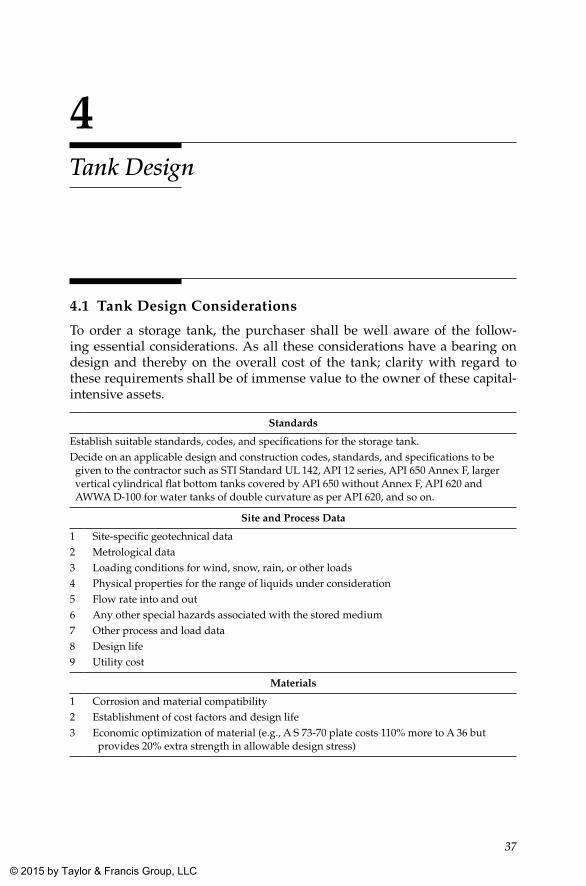
37
4Tank Design
4.1 Tank Design Considerations
To order a storage tank, the purchaser shall be well aware of the follow-ing essential considerations. As all these considerations have a bearing on design and thereby on the overall cost of the tank; clarity with regard to these requirements shall be of immense value to the owner of these capital-intensive assets.
Standards
Establish suitable standards, codes, and specifications for the storage tank.Decide on an applicable design and construction codes, standards, and specifications to be given to the contractor such as STI Standard UL 142, API 12 series, API 650 Annex F, larger vertical cylindrical flat bottom tanks covered by API 650 without Annex F, API 620 and AWWA D-100 for water tanks of double curvature as per API 620, and so on.
Site and Process Data
1 Site-specific geotechnical data2 Metrological data3 Loading conditions for wind, snow, rain, or other loads4 Physical properties for the range of liquids under consideration5 Flow rate into and out6 Any other special hazards associated with the stored medium7 Other process and load data8 Design life9 Utility cost
Materials
1 Corrosion and material compatibility2 Establishment of cost factors and design life3 Economic optimization of material (e.g., A S 73-70 plate costs 110% more to A 36 but
provides 20% extra strength in allowable design stress)
K22265_Book.indb 37 4/20/15 5:46 PM
© 2015 by Taylor & Francis Group, LLC
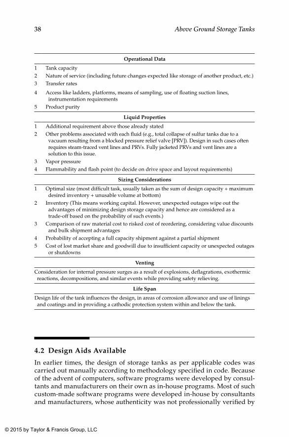
38 Above Ground Storage Tanks
Operational Data
1 Tank capacity2 Nature of service (including future changes expected like storage of another product, etc.)3 Transfer rates
4 Access like ladders, platforms, means of sampling, use of floating suction lines, instrumentation requirements
5 Product purity
Liquid Properties
1 Additional requirement above those already stated2 Other problems associated with each fluid (e.g., total collapse of sulfur tanks due to a
vacuum resulting from a blocked pressure relief valve [PRV]). Design in such cases often requires steam-traced vent lines and PRVs. Fully jacketed PRVs and vent lines are a solution to this issue.
3 Vapor pressure4 Flammability and flash point (to decide on drive space and layout requirements)
Sizing Considerations
1 Optimal size (most difficult task, usually taken as the sum of design capacity + maximum desired inventory + unusable volume at bottom)
2 Inventory (This means working capital. However, unexpected outages wipe out the advantages of minimizing design storage capacity and hence are considered as a trade-off based on the probability of such events.)
3 Comparison of raw material cost to risked cost of reordering, considering value discounts and bulk shipment advantages
4 Probability of accepting a full capacity shipment against a partial shipment5 Cost of lost market share and goodwill due to insufficient capacity or unexpected outages
or shutdowns
Venting
Consideration for internal pressure surges as a result of explosions, deflagrations, exothermic reactions, decompositions, and similar events while providing safety relieving.
Life Span
Design life of the tank influences the design, in areas of corrosion allowance and use of linings and coatings and in providing a cathodic protection system within and below the tank.
4.2 Design Aids Available
In earlier times, the design of storage tanks as per applicable codes was carried out manually according to methodology specified in code. Because of the advent of computers, software programs were developed by consul-tants and manufacturers on their own as in-house programs. Most of such custom-made software programs were developed in-house by consultants and manufacturers, whose authenticity was not professionally verified by
K22265_Book.indb 38 4/20/15 5:46 PM
© 2015 by Taylor & Francis Group, LLC
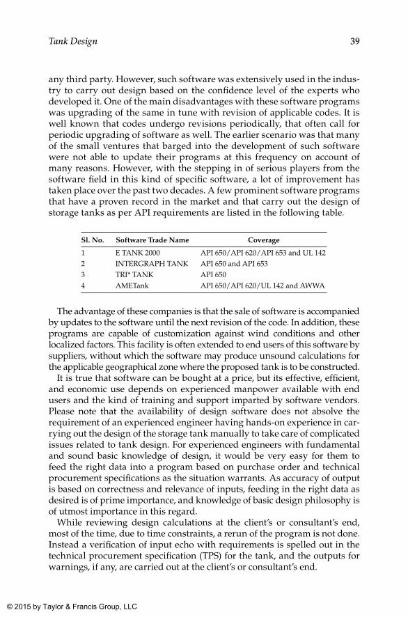
39Tank Design
any third party. However, such software was extensively used in the indus-try to carry out design based on the confidence level of the experts who developed it. One of the main disadvantages with these software programs was upgrading of the same in tune with revision of applicable codes. It is well known that codes undergo revisions periodically, that often call for periodic upgrading of software as well. The earlier scenario was that many of the small ventures that barged into the development of such software were not able to update their programs at this frequency on account of many reasons. However, with the stepping in of serious players from the software field in this kind of specific software, a lot of improvement has taken place over the past two decades. A few prominent software programs that have a proven record in the market and that carry out the design of storage tanks as per API requirements are listed in the following table.
Sl. No. Software Trade Name Coverage
1 E TANK 2000 API 650/API 620/API 653 and UL 1422 INTERGRAPH TANK API 650 and API 6533 TRI* TANK API 6504 AMETank API 650/API 620/UL 142 and AWWA
The advantage of these companies is that the sale of software is accompanied by updates to the software until the next revision of the code. In addition, these programs are capable of customization against wind conditions and other localized factors. This facility is often extended to end users of this software by suppliers, without which the software may produce unsound calculations for the applicable geographical zone where the proposed tank is to be constructed.
It is true that software can be bought at a price, but its effective, efficient, and economic use depends on experienced manpower available with end users and the kind of training and support imparted by software vendors. Please note that the availability of design software does not absolve the requirement of an experienced engineer having hands-on experience in car-rying out the design of the storage tank manually to take care of complicated issues related to tank design. For experienced engineers with fundamental and sound basic knowledge of design, it would be very easy for them to feed the right data into a program based on purchase order and technical procurement specifications as the situation warrants. As accuracy of output is based on correctness and relevance of inputs, feeding in the right data as desired is of prime importance, and knowledge of basic design philosophy is of utmost importance in this regard.
While reviewing design calculations at the client’s or consultant’s end, most of the time, due to time constraints, a rerun of the program is not done. Instead a verification of input echo with requirements is spelled out in the technical procurement specification (TPS) for the tank, and the outputs for warnings, if any, are carried out at the client’s or consultant’s end.
K22265_Book.indb 39 4/20/15 5:46 PM
© 2015 by Taylor & Francis Group, LLC
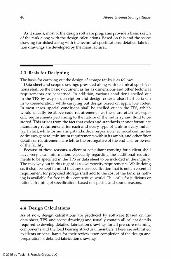
40 Above Ground Storage Tanks
As it stands, most of the design software programs provide a basic sketch of the tank along with the design calculations. Based on this and the scope drawing furnished along with the technical specifications, detailed fabrica-tion drawings are developed by the manufacturer.
4.3 Basis for Designing
The basis for carrying out the design of storage tanks is as follows.Data sheet and scope drawings provided along with technical specifica-
tions shall be the basic document as far as dimensions and other technical requirements are concerned. In addition, various conditions spelled out in the TPS by way of description and design criteria also shall be taken in to consideration, while carrying out design based on applicable codes. In most cases, special conditions shall be spelled out in the TPS, which would usually be above code requirements, as these are often user-spe-cific requirements pertaining to the nature of the industry and fluid to be stored. This arises from the fact that codes and standards cannot formulate mandatory requirements for each and every type of tank in every indus-try. In fact, while formulating standards, a responsible technical committee addresses general minimum requirements within its ambit, and other finer details or requirements are left to the prerogative of the end user or owner of the facility.
Because of these reasons, a client or consultant working for a client shall have very clear information, especially regarding the additional require-ments to be specified in the TPS or data sheet to be included in the inquiry. The easy way out in this regard is to overspecify requirements. While doing so, it shall be kept in mind that any overspecification that is not an essential requirement for proposed storage shall add to the cost of the tank, as noth-ing is available for free in this competitive world. This calls for judicious or rational framing of specifications based on specific and sound reasons.
4.4 Design Calculations
As of now, design calculations are produced by software (based on the data sheet, TPS, and scope drawing) and usually contain all salient details required to develop detailed fabrication drawings for all pressure retaining components and the load bearing structural members. These are submitted to clients or consultants for their review upon completion of the design and preparation of detailed fabrication drawings.
K22265_Book.indb 40 4/20/15 5:46 PM
© 2015 by Taylor & Francis Group, LLC
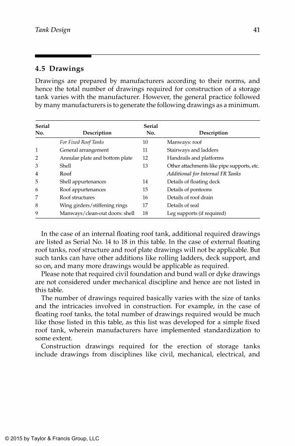
41Tank Design
4.5 Drawings
Drawings are prepared by manufacturers according to their norms, and hence the total number of drawings required for construction of a storage tank varies with the manufacturer. However, the general practice followed by many manufacturers is to generate the following drawings as a minimum.
Serial No. Description
Serial No. Description
For Fixed Roof Tanks 10 Manways: roof1 General arrangement 11 Stairways and ladders2 Annular plate and bottom plate 12 Handrails and platforms3 Shell 13 Other attachments like pipe supports, etc.4 Roof Additional for Internal FR Tanks5 Shell appurtenances 14 Details of floating deck6 Roof appurtenances 15 Details of pontoons7 Roof structures 16 Details of roof drain8 Wing girders/stiffening rings 17 Details of seal9 Manways/clean-out doors: shell 18 Leg supports (if required)
In the case of an internal floating roof tank, additional required drawings are listed as Serial No. 14 to 18 in this table. In the case of external floating roof tanks, roof structure and roof plate drawings will not be applicable. But such tanks can have other additions like rolling ladders, deck support, and so on, and many more drawings would be applicable as required.
Please note that required civil foundation and bund wall or dyke drawings are not considered under mechanical discipline and hence are not listed in this table.
The number of drawings required basically varies with the size of tanks and the intricacies involved in construction. For example, in the case of floating roof tanks, the total number of drawings required would be much like those listed in this table, as this list was developed for a simple fixed roof tank, wherein manufacturers have implemented standardization to some extent.
Construction drawings required for the erection of storage tanks include drawings from disciplines like civil, mechanical, electrical, and
K22265_Book.indb 41 4/20/15 5:46 PM
© 2015 by Taylor & Francis Group, LLC
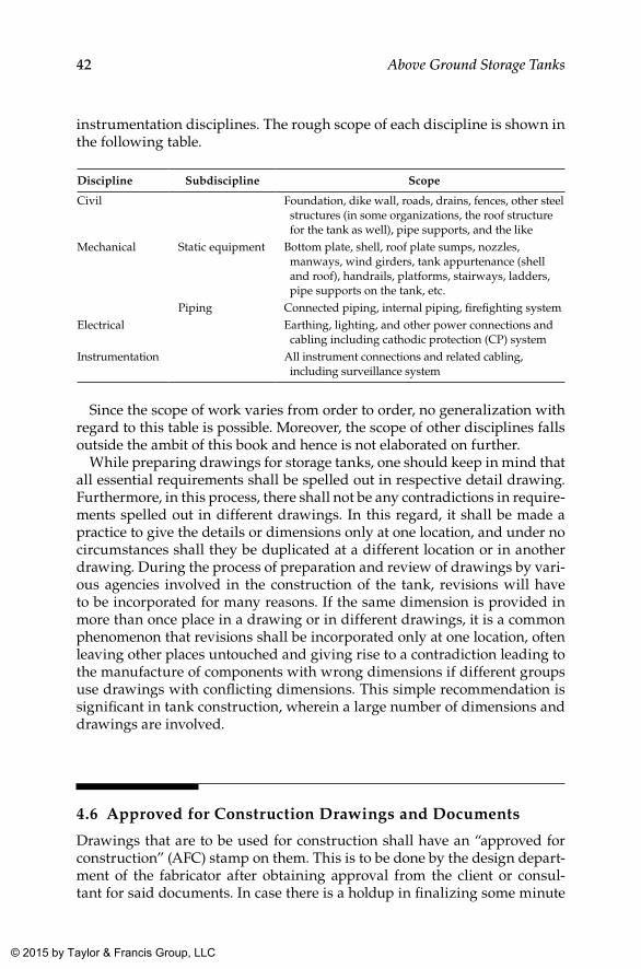
42 Above Ground Storage Tanks
instrumentation disciplines. The rough scope of each discipline is shown in the following table.
Discipline Subdiscipline Scope
Civil Foundation, dike wall, roads, drains, fences, other steel structures (in some organizations, the roof structure for the tank as well), pipe supports, and the like
Mechanical Static equipment Bottom plate, shell, roof plate sumps, nozzles, manways, wind girders, tank appurtenance (shell and roof), handrails, platforms, stairways, ladders, pipe supports on the tank, etc.
Piping Connected piping, internal piping, firefighting systemElectrical Earthing, lighting, and other power connections and
cabling including cathodic protection (CP) systemInstrumentation All instrument connections and related cabling,
including surveillance system
Since the scope of work varies from order to order, no generalization with regard to this table is possible. Moreover, the scope of other disciplines falls outside the ambit of this book and hence is not elaborated on further.
While preparing drawings for storage tanks, one should keep in mind that all essential requirements shall be spelled out in respective detail drawing. Furthermore, in this process, there shall not be any contradictions in require-ments spelled out in different drawings. In this regard, it shall be made a practice to give the details or dimensions only at one location, and under no circumstances shall they be duplicated at a different location or in another drawing. During the process of preparation and review of drawings by vari-ous agencies involved in the construction of the tank, revisions will have to be incorporated for many reasons. If the same dimension is provided in more than once place in a drawing or in different drawings, it is a common phenomenon that revisions shall be incorporated only at one location, often leaving other places untouched and giving rise to a contradiction leading to the manufacture of components with wrong dimensions if different groups use drawings with conflicting dimensions. This simple recommendation is significant in tank construction, wherein a large number of dimensions and drawings are involved.
4.6 Approved for Construction Drawings and Documents
Drawings that are to be used for construction shall have an “approved for construction” (AFC) stamp on them. This is to be done by the design depart-ment of the fabricator after obtaining approval from the client or consul-tant for said documents. In case there is a holdup in finalizing some minute
K22265_Book.indb 42 4/20/15 5:46 PM
© 2015 by Taylor & Francis Group, LLC
43Tank Design
aspects of the tank, a drawing could be in the “approved as noted” stage with the client or consultant. In such cases, drawings may be issued for construc-tion, with a hold indicated in the drawing for aspects pending decision. This will be necessary to meet stringent time schedules normally associated with such projects, though proceeding with “approved as noted” drawings is in violation of contract in most cases. Therefore, such advances, if any, made by contractor are credited under the contractor’s responsibility. Most of the time, clients and consultants coerce contractors to proceed with construction with “approved as noted” drawings, duly considering the impact of “hold” indicated in the drawings.
4.7 Documents for Statutory and Client Approvals
Usually tanks are constructed as a part of a storage facility. In such circum-stances, facilities warrant approval of statutory authorities of the province in which a tank farm is proposed. This may call for documents other than those for the tank, namely, the total facilities layout, along with drawings and doc-uments pertaining to the safety of the farm as a total package, including fire-fighting systems. Since the purview of this book is the mechanical erection of storage tanks, documents pertaining to other works within the tank farm are not touched upon. In the case of an individual tank, manufacturers are expected to submit a copy of the design calculations along with all applicable drawings (design and drawings) for each tank to the client/consultant for approval prior to start of tank construction.
4.8 Design Change Note
In the course of the procurement, fabrication, and erection of a tank, minor design changes may be needed to accommodate site conditions or other unavoidable situations. Upon receiving intimation from a construction group about this problem, the design group has to take up this matter imme-diately with the client or consultant and arrive at an acceptable solution. In case the change to be made is of a minor nature, the same could be effected by a design change note (DCN) issued to all concerned. While issuing a design change note, the design group shall ensure that it reaches all original recipients of the affected drawing. In case the changes happen to be major, it is better to reissue a drawing with a new revision number duly indicating the zone of revision marked by clouding. Here also, receipt of the revised drawing by all original recipients shall be ensured. In case of design change
K22265_Book.indb 43 4/20/15 5:46 PM
© 2015 by Taylor & Francis Group, LLC
44 Above Ground Storage Tanks
notes, they shall be issued under continuous serial numbers, and all of them shall be compiled and incorporated in the respective as-built drawings to be made after completion of tank construction.
Upon receipt of a new revision of the document, the recipients are expected to destroy or return the superceded document to the issuer. Since this erases the history of revisions and the source, the originating department shall main-tain records with regard to the revision history of each document it generates, with all salient details of its source. This information might be required at a later date to tackle some legal or money-related matters that may crop up dur-ing the execution phase of the contract.
4.9 As-Built Documents
As-built documents take care of all design changes (minor) incorporated after the issue of certified for fabrication drawings. The purpose of as-built docu-ments is to provide a true reflection of the constructed tank including any substitution of materials (with concurrence) implemented during construction due to availability or other similar constraints. The release of revised drawings for every minor change required at the site (due to either engineering changes or construction needs) after issue of AFC drawings is a time-consuming activ-ity. As mentioned earlier, in such cases, changes are incorporated through DCNs, which are controlled and documented and pass through necessary approval gates as required for the original design. The engineering or design team is responsible for incorporating all changes included in DCNs or oth-erwise (usually not recommended) and is expected to submit the same upon handing over the tank to the owner as as-built documents for future reference. Essentially, all engineering documents (drawings and design calculations) and any other construction-related documents considered relevant for future use shall be issued as an as-built document. Usually this is agreed upon prior to handing over the documents through a manufacturer’s record book (MRB) index submitted to the client, which talks about the intended contents of the MRB. Most clients are specific in their requirements for MRBs with regard to contents, indexing, quality, and document mode like hard and soft copies and numbers required. Whether this is spelled out in the contract or not, each con-tractor is expected to provide minimum records of construction to the client as indicated in the standard. While this requirement is quite minimum and basic in nature, most clients ask for more documents that they consider relevant for their storage tank. However, for clarity in requirements, it is better to have discussions with the client at an early date in formulating the MRB documents along with progression of construction at the site. As of now, clients prefer searchable PDF electronic documents, in addition to one or two hard copies, which are considered absolutely essential.
K22265_Book.indb 44 4/20/15 5:46 PM
© 2015 by Taylor & Francis Group, LLC
45
5Tank Foundation
5.1 Considerations for the Selection of Foundation
Annex B of API 650 provides important considerations for the design and construction of foundations for above ground storage tanks with a flat bot-toms. However, because of a variety of factors such as surface, subsurface and climatic conditions, it is not possible to address all aspects pertaining to the design of different types of foundations in a comprehensive way. The allowable soil loading and type of subsurface construction are decided based on specific merits of individual cases.
For any tank site, the subsurface condition shall be known to estimate the soil-bearing capacity and probable settlement of the tank during the service life of the tank. An expert geotechnical engineer who is familiar with the history of the tank erection site can gather this information from soil boring, load tests, sampling, lab testing, and analysis.
A few salient conditions that require special attention as listed in Annex B of API 650 are as follows:
1. Tanks to be erected at hillsides where one part of the tank rests in an undisturbed area and the other part rests on filled-up land.
2. Tanks constructed on swampy land or filled-up land where there are layers of muck just below the surface.
3. Sites underlain by soils such as plastic clay or organic clay that may temporarily support an excessive load but may yield during long service at a rate greater than allowable rates.
4. Sites adjacent to water courses or deep excavations where the lateral stability of the soil is questionable.
5. Sites immediately adjacent to heavy structures where some of the load is distributed laterally to the soil below the tank.
6. Sites where tanks may be exposed to floodwater resulting in uplift-ment or displacement of the tank during service.
K22265_Book.indb 45 4/20/15 5:46 PM
© 2015 by Taylor & Francis Group, LLC
46 Above Ground Storage Tanks
7. Sites in regions of high seismicity that may be susceptible to liquefaction.
8. Sites with thin layers of soft clay soil immediately below the bottom, which may cause lateral ground stability problems.
5.2 Types of Foundations
Since there is a wide variety of surfaces, subsurfaces, climatic conditions, and combinations thereof, it is not practical to establish design data to cover all situations. The allowable soil loading and exact type of subsurface con-struction required must therefore be decided for each individual case, after careful consideration, as elaborated above. As far as possible, the same rules, regulations, precautions, and considerations applied in the case of other foundations of comparable magnitude in the vicinity shall be adopted while designing the foundation for storage tanks.
Some of the usual types of foundations adopted for cylindrical tanks with uniformly supported flat bottoms are described next. However, a geotechni-cal study of the site is required to finally decide on the type of foundation and its design required at a particular site, taking into consideration the cost involved with the following options.
While it is difficult to classify all possible foundation types for storage tanks, listed next are a few general types that have proven over time to be cost-effective and efficient from a service point of view. These foundation types are listed in increasing order of costs.
5.2.1 Compact Soil Foundations
This type of foundation is generally preferred where soil quality and bear-ing capacity are good and is often called a sand pad foundation, laid directly on earth. Generally, existing topsoil (say from 100 mm to 150 mm) is removed first (depending on soil condition) and replaced with a sand or granular backfill. This is the cheapest foundation possible for any vertical storage tank with a flat bottom.
5.2.2 Crushed-Stone Ring Wall Foundations
This design incorporates a leak detection system. While it costs less than a concrete ring wall foundation, it has many of the advantages of the same. It provides uniform support of the tank bottom by distributing concentrated loads in a granular pattern. However, catastrophic failure of the foundation (and thereby the tank) is possible in the event of a leak from the bottom plate, which could wash away supporting matter.
K22265_Book.indb 46 4/20/15 5:46 PM
© 2015 by Taylor & Francis Group, LLC
47Tank Foundation
5.2.3 Concrete Ring Wall Foundations
This type of foundation has a concrete ring wall around the tank periphery below the shell of the tank with a designed width, on which the shell rests over an annular or bottom plate. The rest of the foundation area shall be filled with sand and compacted. This type of foundation is used for tanks with a diameter of 10 m or more. For large-diameter tanks, this is the most cost-effective foundation, with many advantages such as a reduced probabil-ity of an edge settlement type of failure.
5.2.4 Slab Foundations
The concrete slab foundation is obviously the best foundation possible, but it is usually limited to tanks with diameters less than 10 m on account of its cost. Often the edge of the slab shall be thick enough to provide for anchor-age as well (if required). A slab foundation is very versatile, but its high cost limits its use to small tanks. The slab provides a level and plane working sur-face that facilitates rapid field erection. Usually a leveling course of asphalt is provided on top of the slab to take care of any undulations on the surface caused during casting of the slab.
5.2.5 Pile-Supported Foundations
Pile-supported foundations are usually adopted in localities where the bearing capacity of the soil is very low. Tank locations in river deltas, backfilled land, land adjacent to bays, and so on could be considered as potential areas wherein this type of foundation may have to be adopted. Furthermore, this type of foundation is also considered necessary when high foundation uplift forces are encountered resulting from internal pres-sures or seismic loading.
5.3 Handing Over the Foundation
The civil engineering wing usually carries out the construction of the foun-dation. Upon satisfactory completion of work, followed by satisfactory inspection and testing, the foundation shall be released to the mechanical wing to proceed with erection of the tank. As there is a clear demarcation of work between the two disciplines, there shall be a proper handing-over document after successful completion of the foundation.
K22265_Book.indb 47 4/20/15 5:46 PM
© 2015 by Taylor & Francis Group, LLC
49
6Sequence of Mechanical Works for Storage Tank Erection
6.1 Preliminary Works on Award of Contract
Design, fabrication, erection, inspection, and testing of storage tanks are highly specialized works that require a lot of experience and expertise. Because of this fact, storage tank erection work is usually awarded to reputed vendors with a proven track record. Since most of the above ground storage tanks are of large capacities, almost all manufacturing work takes place at the site. In this regard, the site manufacturing facility needs to be set up. Since this process takes some time, initial works related to design, prepara-tion of drawings, inquiries for procurement, and so on are usually taken care of by the headquarters (HQ) of the contractor. Therefore, every construc-tion contractor shall have a well-established work execution plan, wherein bifurcation of responsibility between HQ and the site team shall be clearly defined. A typical model that is usually followed by most tank construction contractors is provided next.
6.2 Responsibility Matrix (Head Office and Site)
Serial No. Activity
Responsibility Serial No. Activity
Responsibility
HQ Site HQ Site1 Receipt of order X 14 Design change
requests (if any)X
2 Data sheets (DS) X 15 Design change notes (DCN)
X
3 Design calculations
X 16 Data for as-built drawings and documents
X
(Continued)
K22265_Book.indb 49 4/20/15 5:46 PM
© 2015 by Taylor & Francis Group, LLC
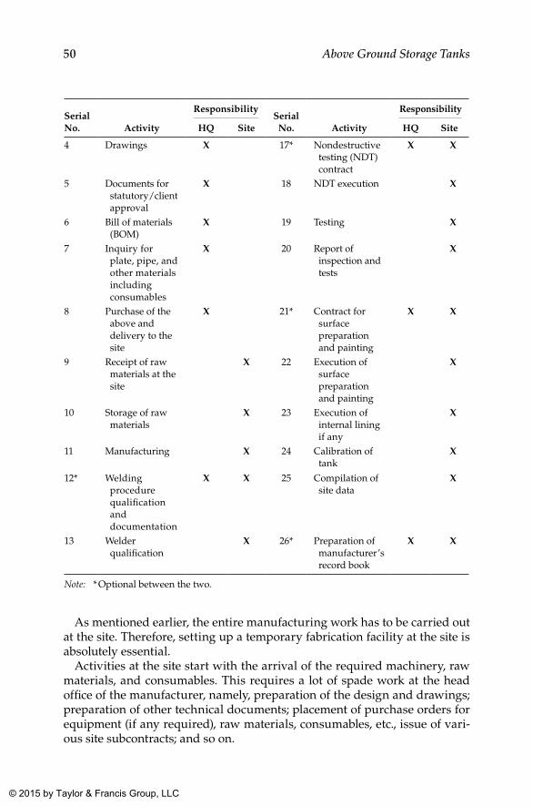
50 Above Ground Storage Tanks
Serial No. Activity
ResponsibilitySerial
No. Activity
Responsibility
HQ Site HQ Site
4 Drawings X 17* Nondestructive testing (NDT) contract
X X
5 Documents for statutory/client approval
X 18 NDT execution X
6 Bill of materials (BOM)
X 19 Testing X
7 Inquiry for plate, pipe, and other materials including consumables
X 20 Report of inspection and tests
X
8 Purchase of the above and delivery to the site
X 21* Contract for surface preparation and painting
X X
9 Receipt of raw materials at the site
X 22 Execution of surface preparation and painting
X
10 Storage of raw materials
X 23 Execution of internal lining if any
X
11 Manufacturing X 24 Calibration of tank
X
12* Welding procedure qualification and documentation
X X 25 Compilation of site data
X
13 Welder qualification
X 26* Preparation of manufacturer’s record book
X X
Note: * Optional between the two.
As mentioned earlier, the entire manufacturing work has to be carried out at the site. Therefore, setting up a temporary fabrication facility at the site is absolutely essential.
Activities at the site start with the arrival of the required machinery, raw materials, and consumables. This requires a lot of spade work at the head office of the manufacturer, namely, preparation of the design and drawings; preparation of other technical documents; placement of purchase orders for equipment (if any required), raw materials, consumables, etc., issue of vari-ous site subcontracts; and so on.
K22265_Book.indb 50 4/20/15 5:46 PM
© 2015 by Taylor & Francis Group, LLC
51Sequence of Mechanical Works for Storage Tank Erection
6.3 Organization Setup at the Site
6.3.1 Introduction
Construction companies with a proven track record in the erection of stor-age tanks by default should have established methodology in force to cover all activities right from submitting a quotation for the tank up to handing over the tank, usually within stringent contractual time frames. Effective and efficient progression of work requires well-defined systems within the organization, which is to be realized through a strong organizational struc-ture within.
The erection of a storage tank is basically a site activity, and hence a tempo-rary factory setup is required at the site. For any large contracting company, the erection of storage tanks shall form only a part of their activities, and the organization structure of the company shall be oriented toward those corporate goals. As a part of this corporate organization, a well-defined site organization structure is necessary to carry out all site activities according to the plans and procedures laid out for the purpose. Though the activities of the parent contracting company differ widely depending on their spectrum of operation, site-related activities in storage tank construction remain more or less the same, and hence site organization structure remains almost the same universally.
To complete all work related to tank construction with reasonably good quality (with an intention to avoid reworks), the contracting company must have a strong organization structure at the site with experienced and knowledgeable people manning all key positions. Organization at the site almost resembles that of any fabrication shop. However, for storage tank construction, the initial part of the work is carried out at the contrac-tor’s HQ, and all construction activities are to be completed using the site workshop (including forming of plates if required) and erection facilities. Therefore, a clear demarcation in the scope of the work proposed to be carried out by both groups shall be clearly laid out to avoid confusion dur-ing execution of the job with regard to the responsibility for each stage as described in Section 6.2. The organization structure recommended below is based on the following assumptions and presumptions:
1. It is presumed that the tank erection work is included under the scope of the contract.
2. Associated tank farm piping and other works are to be carried out by others.
3. Billing is done from the HQ (of the contractor) based on a duly certi-fied progress report from the site.
K22265_Book.indb 51 4/20/15 5:46 PM
© 2015 by Taylor & Francis Group, LLC
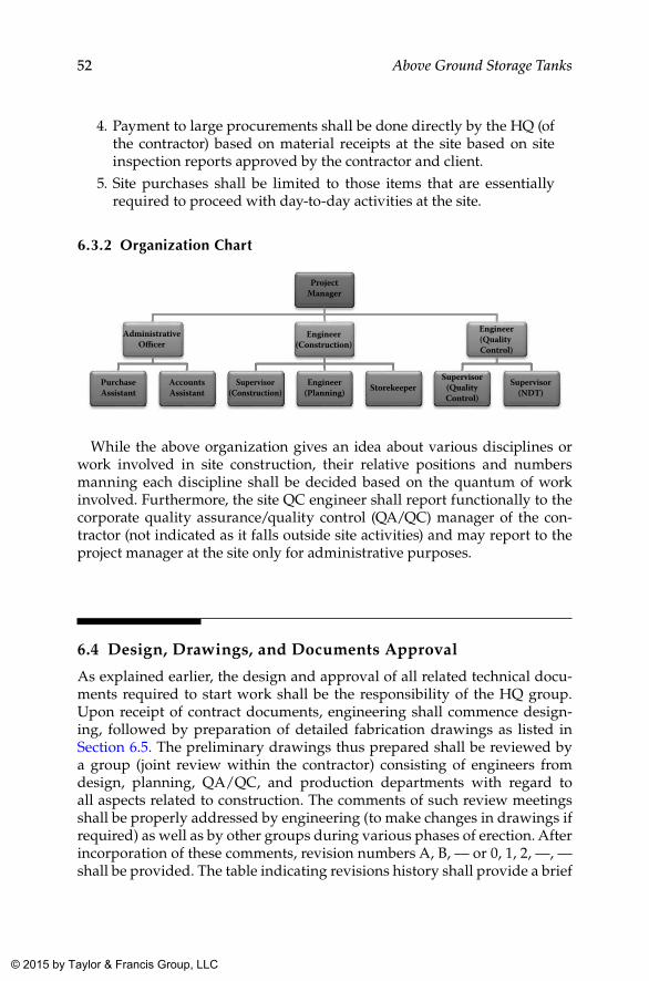
52 Above Ground Storage Tanks
4. Payment to large procurements shall be done directly by the HQ (of the contractor) based on material receipts at the site based on site inspection reports approved by the contractor and client.
5. Site purchases shall be limited to those items that are essentially required to proceed with day-to-day activities at the site.
6.3.2 Organization Chart
ProjectManager
AdministrativeO�cer
PurchaseAssistant
AccountsAssistant
Engineer(Construction)
Supervisor(Construction)
Engineer(Planning) Storekeeper
Engineer(Quality Control)
Supervisor(QualityControl)
Supervisor(NDT)
While the above organization gives an idea about various disciplines or work involved in site construction, their relative positions and numbers manning each discipline shall be decided based on the quantum of work involved. Furthermore, the site QC engineer shall report functionally to the corporate quality assurance/quality control (QA/QC) manager of the con-tractor (not indicated as it falls outside site activities) and may report to the project manager at the site only for administrative purposes.
6.4 Design, Drawings, and Documents Approval
As explained earlier, the design and approval of all related technical docu-ments required to start work shall be the responsibility of the HQ group. Upon receipt of contract documents, engineering shall commence design-ing, followed by preparation of detailed fabrication drawings as listed in Section 6.5. The preliminary drawings thus prepared shall be reviewed by a group (joint review within the contractor) consisting of engineers from design, planning, QA/QC, and production departments with regard to all aspects related to construction. The comments of such review meetings shall be properly addressed by engineering (to make changes in drawings if required) as well as by other groups during various phases of erection. After incorporation of these comments, revision numbers A, B, — or 0, 1, 2, —, — shall be provided. The table indicating revisions history shall provide a brief
K22265_Book.indb 52 4/20/15 5:46 PM
© 2015 by Taylor & Francis Group, LLC
53Sequence of Mechanical Works for Storage Tank Erection
description of the salient revision and reasons for the same at a designated location of the drawing to provide an overview of revisions implemented. Areas or regions where revisions were implemented shall be highlighted by clouding (for drawings) or by a straight line in the margin (for text doc-uments) to help reviewers locate revision zones and spot changes easily. Earlier versions of documents shall be marked as either “superceded” or “obsolete,” and these documents shall be withdrawn from respective end users of these documents. However, all end users shall have a system of maintaining superseded documents for verification of changes made at a later date for resolving commercial or other related legal matters, and hence these documents shall be available only to those authorized to do so, prefer-ably the concerned section head.
At this stage, the prepared documents are ready for submission for approval from various agencies involved such as the client, consultant statutory authorities, and so on as applicable. These documents are treated as deliverables under contract, and a proper tracking system shall be in position for proper monitoring and control of the approval process by various agencies concerned. For easy tracking and control of revisions of documents, it is also advisable to develop a proper document numbering system for all documents being generated for the work undertaken by the contractor. The document numbering system (including that for drawings) for storage tank construction shall resemble those adopted in other busi-ness units under the corporate umbrella of which the tank construction forms a part.
It is preferable to send documents simultaneously to all reviewing agencies for their approval. However, few back-and-forth transmissions would be required to reach “approved for construction” (AFC) status by all agencies concerned. When submitted for approval, comments on drawings are usually given as a markup in red color, whereas that for text documents is provided as a comment sheet or as markup at the option of the reviewer.
If the comments offered are within contractual requirements, they are incorporated in the next revision of the document and submitted for final approval of those concerned. Whereas if the comments fall outside the con-tract, the contractor is eligible to claim extra on account of the same and hence to be notified to the client through a “compliance sheet” enclosed with the revised document. As mentioned earlier, incorporation of com-ments (with or without reservations) shall be the responsibility of the origination section of that particular document. Therefore, the respective departments shall be responsible for maintaining a history of revisions implemented as well. Furthermore, they shall also ensure that revised documents have reached all end users, immediately after release of the new revision.
K22265_Book.indb 53 4/20/15 5:46 PM
© 2015 by Taylor & Francis Group, LLC
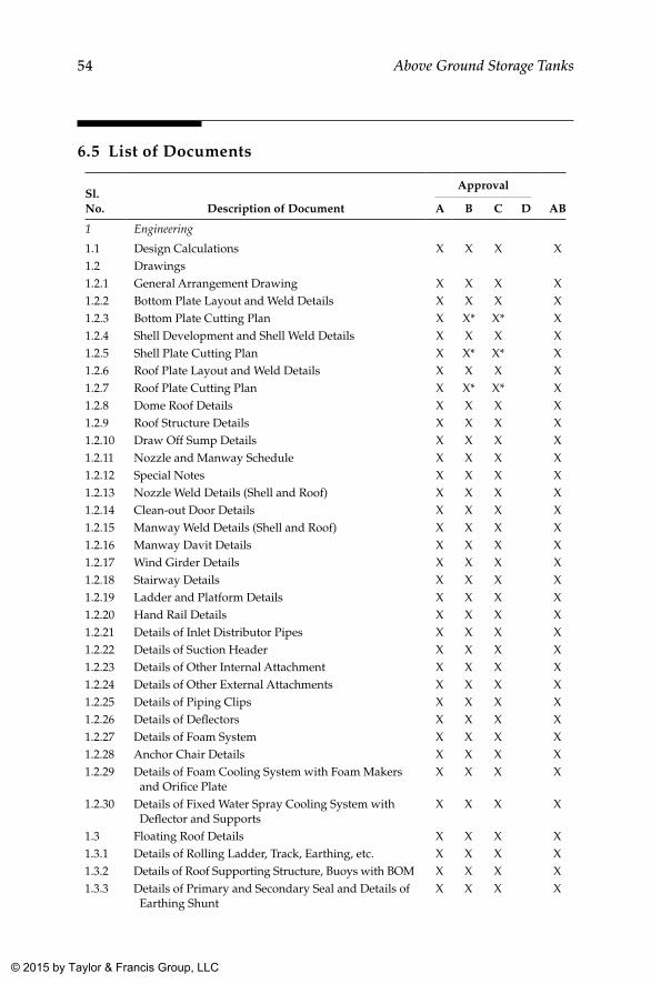
54 Above Ground Storage Tanks
6.5 List of Documents
Sl. No. Description of Document
Approval
ABA B C D
1 Engineering
1.1 Design Calculations X X X X1.2 Drawings1.2.1 General Arrangement Drawing X X X X1.2.2 Bottom Plate Layout and Weld Details X X X X1.2.3 Bottom Plate Cutting Plan X X* X* X1.2.4 Shell Development and Shell Weld Details X X X X1.2.5 Shell Plate Cutting Plan X X* X* X1.2.6 Roof Plate Layout and Weld Details X X X X1.2.7 Roof Plate Cutting Plan X X* X* X1.2.8 Dome Roof Details X X X X1.2.9 Roof Structure Details X X X X1.2.10 Draw Off Sump Details X X X X1.2.11 Nozzle and Manway Schedule X X X X1.2.12 Special Notes X X X X1.2.13 Nozzle Weld Details (Shell and Roof) X X X X1.2.14 Clean-out Door Details X X X X1.2.15 Manway Weld Details (Shell and Roof) X X X X1.2.16 Manway Davit Details X X X X1.2.17 Wind Girder Details X X X X1.2.18 Stairway Details X X X X1.2.19 Ladder and Platform Details X X X X1.2.20 Hand Rail Details X X X X1.2.21 Details of Inlet Distributor Pipes X X X X1.2.22 Details of Suction Header X X X X1.2.23 Details of Other Internal Attachment X X X X1.2.24 Details of Other External Attachments X X X X1.2.25 Details of Piping Clips X X X X1.2.26 Details of Deflectors X X X X1.2.27 Details of Foam System X X X X1.2.28 Anchor Chair Details X X X X1.2.29 Details of Foam Cooling System with Foam Makers
and Orifice PlateX X X X
1.2.30 Details of Fixed Water Spray Cooling System with Deflector and Supports
X X X X
1.3 Floating Roof Details X X X X1.3.1 Details of Rolling Ladder, Track, Earthing, etc. X X X X1.3.2 Details of Roof Supporting Structure, Buoys with BOM X X X X1.3.3 Details of Primary and Secondary Seal and Details of
Earthing ShuntX X X X
K22265_Book.indb 54 4/20/15 5:46 PM
© 2015 by Taylor & Francis Group, LLC
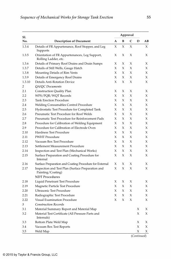
55Sequence of Mechanical Works for Storage Tank Erection
Sl. No. Description of Document
Approval
ABA B C D
1.3.4 Details of FR Appurtenance, Roof Stopper, and Leg Supports
X X X X
1.3.5 Orientation of FR Appurtenances, Leg Support, Rolling Ladder, etc.
X X X X
1.3.6 Details of Primary Roof Drains and Drain Sumps X X X X1.3.7 Details of Still Wells, Gauge Hatch X X X X1.3.8 Mounting Details of Rim Vents X X X X1.3.9 Details of Emergency Roof Drains X X X X1.3.10 Details Anti-Rotation Device X X X X2 QA/QC Documents2.1 Construction Quality Plan X X X X2.2 WPS/PQR/WQT Records X X X X2.3 Tank Erection Procedure X X X X2.4 Welding Consumables Control Procedure X X X X2.5 Hydrostatic Test Procedure for Completed Tank X X X X2.6 Pneumatic Test Procedure for Roof Welds X X X X2.7 Pneumatic Test Procedure for Reinforcement Pads X X X X2.8 Procedure for Calibration of Welding Equipment X X X X2.9 Procedure for Calibration of Electrode Oven X X X X2.10 Hardness Test Procedure X X X X2.11 PWHT Procedure X X X X2.12 Vacuum Box Test Procedure X X X X2.13 Settlement Measurement Procedure X X X X2.14 Inspection and Test Plan (Mechanical Works) X X X X2.15 Surface Preparation and Coating Procedure for
InternalX X X X
2.16 Surface Preparation and Coating Procedure for External X X X X2.17 Inspection and Test Plan (Surface Preparation and
Painting/Coating)X X X X
NDT Procedures2.18 Liquid Penetrant Test Procedure X X X X2.19 Magnetic Particle Test Procedure X X X X2.20 Ultrasonic Test Procedure X X X X2.21 Radiographic Test Procedure X X X X2.22 Visual Examination Procedure X X X X3 Construction Records3.1 Material Summary Report and Material Map X X3.2 Material Test Certificate (All Pressure Parts and
Internals)X X
3.3 Bottom Plate Weld Map X X3.4 Vacuum Box Test Reports X X3.5 Weld Map X X
(Continued)
K22265_Book.indb 55 4/20/15 5:46 PM
© 2015 by Taylor & Francis Group, LLC
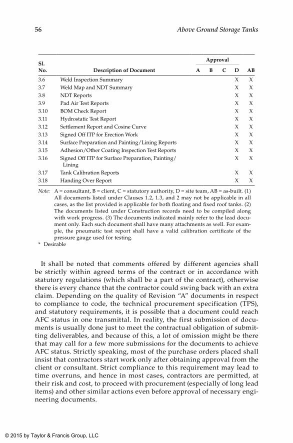
56 Above Ground Storage Tanks
Sl. No. Description of Document
Approval
ABA B C D
3.6 Weld Inspection Summary X X3.7 Weld Map and NDT Summary X X3.8 NDT Reports X X3.9 Pad Air Test Reports X X3.10 BOM Check Report X X3.11 Hydrostatic Test Report X X3.12 Settlement Report and Cosine Curve X X3.13 Signed Off ITP for Erection Work X X3.14 Surface Preparation and Painting/Lining Reports X X3.15 Adhesion/Other Coating Inspection Test Reports X X3.16 Signed Off ITP for Surface Preparation, Painting/
LiningX X
3.17 Tank Calibration Reports X X3.18 Handing Over Report X X
Note: A = consultant, B = client, C = statutory authority, D = site team, AB = as-built. (1) All documents listed under Clauses 1.2, 1.3, and 2 may not be applicable in all cases, as the list provided is applicable for both floating and fixed roof tanks. (2) The documents listed under Construction records need to be compiled along with work progress. (3) The documents indicated mainly refer to the lead docu-ment only. Each such document shall have many attachments as well. For exam-ple, the pneumatic test report shall have a valid calibration certificate of the pressure gauge used for testing.
* Desirable
It shall be noted that comments offered by different agencies shall be strictly within agreed terms of the contract or in accordance with statutory regulations (which shall be a part of the contract), otherwise there is every chance that the contractor could swing back with an extra claim. Depending on the quality of Revision “A” documents in respect to compliance to code, the technical procurement specification (TPS), and statutory requirements, it is possible that a document could reach AFC status in one transmittal. In reality, the first submission of docu-ments is usually done just to meet the contractual obligation of submit-ting deliverables, and because of this, a lot of omission might be there that may call for a few more submissions for the documents to achieve AFC status. Strictly speaking, most of the purchase orders placed shall insist that contractors start work only after obtaining approval from the client or consultant. Strict compliance to this requirement may lead to time overruns, and hence in most cases, contractors are permitted, at their risk and cost, to proceed with procurement (especially of long lead items) and other similar actions even before approval of necessary engi-neering documents.
K22265_Book.indb 56 4/20/15 5:46 PM
© 2015 by Taylor & Francis Group, LLC
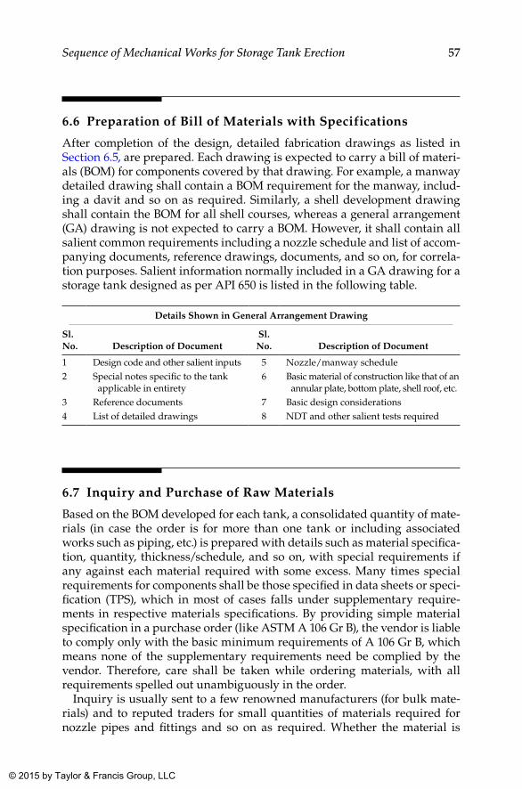
57Sequence of Mechanical Works for Storage Tank Erection
6.6 Preparation of Bill of Materials with Specifications
After completion of the design, detailed fabrication drawings as listed in Section 6.5, are prepared. Each drawing is expected to carry a bill of materi-als (BOM) for components covered by that drawing. For example, a manway detailed drawing shall contain a BOM requirement for the manway, includ-ing a davit and so on as required. Similarly, a shell development drawing shall contain the BOM for all shell courses, whereas a general arrangement (GA) drawing is not expected to carry a BOM. However, it shall contain all salient common requirements including a nozzle schedule and list of accom-panying documents, reference drawings, documents, and so on, for correla-tion purposes. Salient information normally included in a GA drawing for a storage tank designed as per API 650 is listed in the following table.
Details Shown in General Arrangement Drawing
Sl. No. Description of Document
Sl. No. Description of Document
1 Design code and other salient inputs 5 Nozzle/manway schedule2 Special notes specific to the tank
applicable in entirety6 Basic material of construction like that of an
annular plate, bottom plate, shell roof, etc.3 Reference documents 7 Basic design considerations4 List of detailed drawings 8 NDT and other salient tests required
6.7 Inquiry and Purchase of Raw Materials
Based on the BOM developed for each tank, a consolidated quantity of mate-rials (in case the order is for more than one tank or including associated works such as piping, etc.) is prepared with details such as material specifica-tion, quantity, thickness/schedule, and so on, with special requirements if any against each material required with some excess. Many times special requirements for components shall be those specified in data sheets or speci-fication (TPS), which in most of cases falls under supplementary require-ments in respective materials specifications. By providing simple material specification in a purchase order (like ASTM A 106 Gr B), the vendor is liable to comply only with the basic minimum requirements of A 106 Gr B, which means none of the supplementary requirements need be complied by the vendor. Therefore, care shall be taken while ordering materials, with all requirements spelled out unambiguously in the order.
Inquiry is usually sent to a few renowned manufacturers (for bulk mate-rials) and to reputed traders for small quantities of materials required for nozzle pipes and fittings and so on as required. Whether the material is
K22265_Book.indb 57 4/20/15 5:46 PM
© 2015 by Taylor & Francis Group, LLC
58 Above Ground Storage Tanks
procured from mills or traders, it shall meet all chemical or physical require-ments spelled out in applicable codes and as restricted by the purchase order. Furthermore, materials procured from traders shall have positive traceabil-ity with regard to hard stamping on materials and endorsement in related material test certificates (MTCs) for the materials.
6.8 Materials Procured from Stockists or Traders
The following aspects shall be considered absolutely essential in the case of small quantities of materials such as pipes, fittings, flanges, fasteners, and so on to be procured from stockists for construction of storage tanks. Compared to plate materials required for storage tanks, requirements for piping ele-ments shall usually be very small, and hence procuring them from manufac-turers would be often impractical. Therefore, the option available shall be to approach stockists who can supply these items with proper material certifica-tion. The following minimum requirements shall be complied to while doing so, in order to ensure that the material procured is genuine and traceable:
• Since stockists will have bulk materials in their stock, they may not provide the original MTC for small quantities of materials procured from them. In that case, it shall be ensured by the buyer that the original MTC is available with the stockist.
• The third-party inspector (TPI) or client representative assigned to stockists yards to inspect materials prior to dispatch shall be instructed to make such an endorsement either in copy of the MTC provided or in the inspection release note (IRN) issued by him or her after the inspection.
• Materials shall be traceable to the MTC through proper stamping or stenciling on raw materials such as pipes, fittings, and flanges as required in applicable specifications and manufacturing practices and endorsed accordingly.
• The TPI shall ensure that the origin of materials is from renowned sources with proven records.
• The TPI shall ensure that additional testing and certification require-ments (as specified in the TPS) are also certified in the MTC. If not, this shall be reported as a discrepancy, and the buyer’s confirmation shall be sought prior to release of materials.
• In case it is agreed by the buyer that the discrepancies can be cov-ered by additional testing at the construction site, discrepancies shall be reported in the IRN, with a reference to the buyer’s clearance to release with the reported discrepancy.
K22265_Book.indb 58 4/20/15 5:46 PM
© 2015 by Taylor & Francis Group, LLC
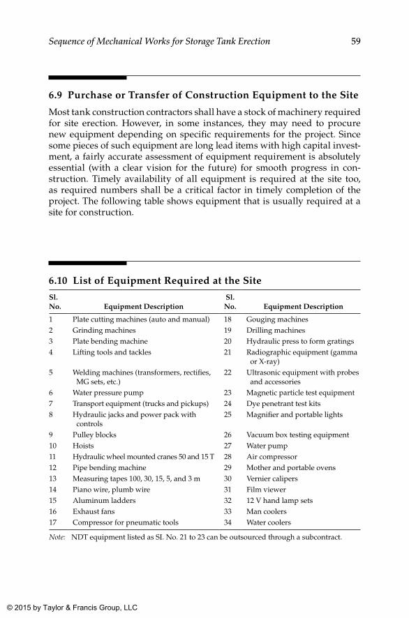
59Sequence of Mechanical Works for Storage Tank Erection
6.9 Purchase or Transfer of Construction Equipment to the Site
Most tank construction contractors shall have a stock of machinery required for site erection. However, in some instances, they may need to procure new equipment depending on specific requirements for the project. Since some pieces of such equipment are long lead items with high capital invest-ment, a fairly accurate assessment of equipment requirement is absolutely essential (with a clear vision for the future) for smooth progress in con-struction. Timely availability of all equipment is required at the site too, as required numbers shall be a critical factor in timely completion of the project. The following table shows equipment that is usually required at a site for construction.
6.10 List of Equipment Required at the Site
Sl. No. Equipment Description
Sl. No. Equipment Description
1 Plate cutting machines (auto and manual) 18 Gouging machines2 Grinding machines 19 Drilling machines3 Plate bending machine 20 Hydraulic press to form gratings4 Lifting tools and tackles 21 Radiographic equipment (gamma
or X-ray)5 Welding machines (transformers, rectifies,
MG sets, etc.)22 Ultrasonic equipment with probes
and accessories6 Water pressure pump 23 Magnetic particle test equipment7 Transport equipment (trucks and pickups) 24 Dye penetrant test kits8 Hydraulic jacks and power pack with
controls25 Magnifier and portable lights
9 Pulley blocks 26 Vacuum box testing equipment10 Hoists 27 Water pump11 Hydraulic wheel mounted cranes 50 and 15 T 28 Air compressor12 Pipe bending machine 29 Mother and portable ovens13 Measuring tapes 100, 30, 15, 5, and 3 m 30 Vernier calipers14 Piano wire, plumb wire 31 Film viewer15 Aluminum ladders 32 12 V hand lamp sets16 Exhaust fans 33 Man coolers17 Compressor for pneumatic tools 34 Water coolers
Note: NDT equipment listed as SI. No. 21 to 23 can be outsourced through a subcontract.
K22265_Book.indb 59 4/20/15 5:46 PM
© 2015 by Taylor & Francis Group, LLC
60 Above Ground Storage Tanks
6.11 Work Contracts
In case site erection work is directly taken up by the contractor, at a mini-mum the following subcontracts would be required to complete construction as per specification. It is presumed that such contractors shall be available in the vicinity of the site where the tank is to be constructed, and if so, it would be cheaper to use them rather than use a contractor’s own team, to be mobi-lized from elsewhere, most likely from HQ.
The usual practice is to have the following subcontracts organized at the site, from cost, convenience, and time frame considerations.
6.11.1 Subcontract for Nondestructive Testing (NDT)
All NDT work required to be carried out on tanks, such as radiographic test-ing (RT), ultrasonic testing (UT), magnetic particle testing (MPT), and dye penetrant testing (DPT), is usually covered in this contract. However, some contractors might wish to carry out a low-end NDT such as MPT and DPT with their own staff. This is because these tests may often be required at short notice during erection, wherein availability of technicians from an NDT sub-contractor might not be possible within short notice. In such instances, it shall be the duty of the main contractor to provide NDT technicians with the requisite qualifications to carry out, interpret, and document these NDT as required in applicable code and specifications.
6.11.2 Subcontract for Scaffolding
Yet another usual subcontract is for scaffolding. Many tank manufacturers have their own scaffolding services as well, whereas some prefer to go for subcontracts depending on logistics and cost.
6.11.3 Subcontract for Surface Preparation, Internal lining, and External Painting
All tanks require surface preparation and external painting as per the client’s specifications. Some tanks also may require some special internal lining as well. Usually a package consisting of surface preparation and application paint-ing or lining is subcontracted to an expert contractor who is specialized in this field. These applicators, especially those needed for lining application, need to be trained and qualified as per manufacturer’s recommendations, which would also be a part of the subcontract.
6.11.4 Calibration and Certification of Storage Tanks
Calibration and certification involving statutory authorities is usually yet another specialized job requiring expertise and hence off-loaded as a sub-contract package for convenience.
K22265_Book.indb 60 4/20/15 5:46 PM
© 2015 by Taylor & Francis Group, LLC
61Sequence of Mechanical Works for Storage Tank Erection
At the discretion of the management of the contractor, these subcontracts can be arranged directly from HQ or at the site. If this is done at the site, the project manager shall be responsible for all activities related to subcontract-ing, as well as the execution of the same.
6.12 Local Contracts and Purchases at the Site
Any other contract that is of not much significance to construction such as scrap removal and stacking of plates; housekeeping; trucking; maintenance support for equipment and consumables such as oxygen, acetylene, argon, and so on; and other consumables for the day-to-day activities at the site also shall be essentially initiated and controlled at the site so as not to hamper production. The project or construction manager at the site shall be respon-sible for such local contracts and purchases.
K22265_Book.indb 61 4/20/15 5:46 PM
© 2015 by Taylor & Francis Group, LLC
63
7Tank Erection
7.1 Storage Tank Erection
The references made here are mainly applicable to normal cone roof stor-age tanks, as they are simple in construction and the most common in the process industry where liquid storage is essential. As explained earlier, the location of the liquid storage system for a plant is decided based on many economic considerations and is not included within this book. Furthermore, it is presumed that the foundation is completed and ready for the laying of the bottom plate, as well as all subsequent activities related to the mechani-cal erection of the tank. While handing over the foundation for the mechani-cal erection of the tank, it shall be the responsibility of the civil engineer in charge of the foundation and other civil works to carry out all tests specified to ensure that the foundation has achieved requisite strength as specified and considered for the design of the foundation and the tank.
As mentioned earlier, the most commonly used type of foundation is the sand pad type with bitumen topping to obtain the required slope and surface. The sand pad foundation with a concrete ring wall foundation (with bitumen topping) is also extensively used in the industry. In some specific cases, a con-crete pad foundation is also used, again with a bitumen layer of 50 mm applied over the concreted surface to obtain a uniform surface for proper laying of the bottom plate. The decision to go for a particular type of foundation is based on economic considerations, as briefly described in Chapter 5. Irrespective of the type of foundation used, the mechanical erection methodology of the tank remains unaltered and is described in the following sections.
7.2 Inspection of Raw Materials
All materials used in the manufacture of a storage tank shall be trace-able to its documentation, especially that for all pressure retaining parts. These materials are to be identified against each of the items indicated in
K22265_Book.indb 63 4/20/15 5:46 PM
© 2015 by Taylor & Francis Group, LLC
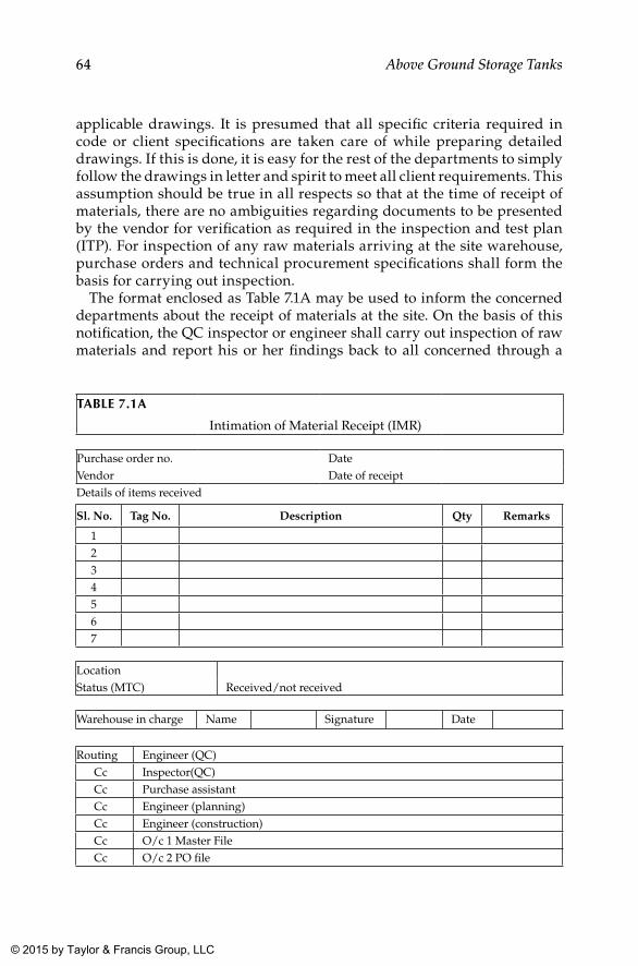
64 Above Ground Storage Tanks
applicable drawings. It is presumed that all specific criteria required in code or client specifications are taken care of while preparing detailed drawings. If this is done, it is easy for the rest of the departments to simply follow the drawings in letter and spirit to meet all client requirements. This assumption should be true in all respects so that at the time of receipt of materials, there are no ambiguities regarding documents to be presented by the vendor for verification as required in the inspection and test plan (ITP). For inspection of any raw materials arriving at the site warehouse, purchase orders and technical procurement specifications shall form the basis for carrying out inspection.
The format enclosed as Table 7.1A may be used to inform the concerned departments about the receipt of materials at the site. On the basis of this notification, the QC inspector or engineer shall carry out inspection of raw materials and report his or her findings back to all concerned through a
TAblE 7.1A
Intimation of Material Receipt (IMR)
Purchase order no. Date Vendor Date of receiptDetails of items received
Sl. No. Tag No. Description Qty Remarks
1234567
LocationStatus (MTC) Received/not received
Warehouse in charge Name Signature Date
Routing Engineer (QC)Cc Inspector(QC)Cc Purchase assistantCc Engineer (planning)Cc Engineer (construction)Cc O/c 1 Master FileCc O/c 2 PO file
K22265_Book.indb 64 4/20/15 5:46 PM
© 2015 by Taylor & Francis Group, LLC
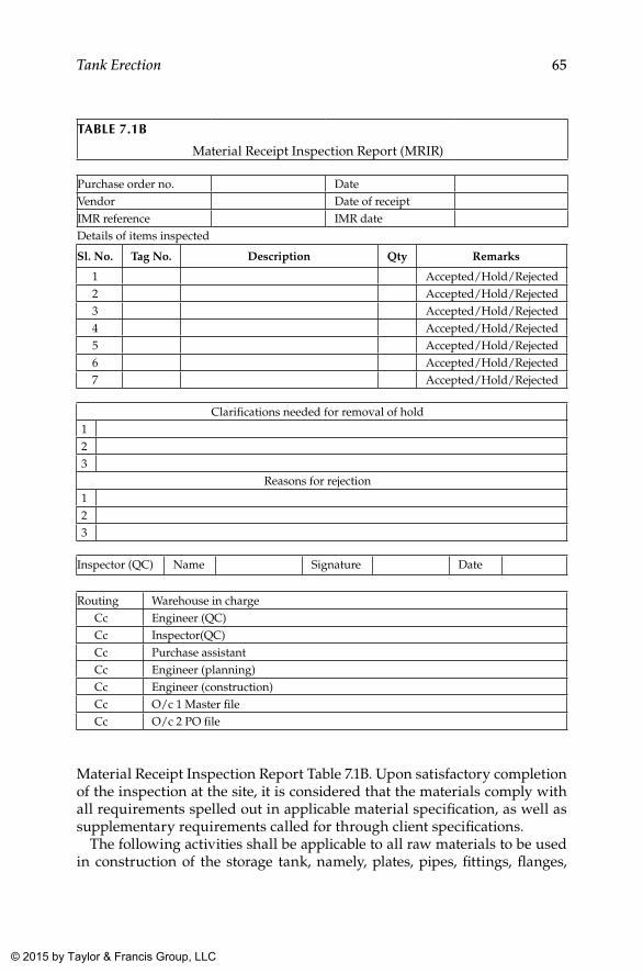
65Tank Erection
Material Receipt Inspection Report Table 7.1B. Upon satisfactory completion of the inspection at the site, it is considered that the materials comply with all requirements spelled out in applicable material specification, as well as supplementary requirements called for through client specifications.
The following activities shall be applicable to all raw materials to be used in construction of the storage tank, namely, plates, pipes, fittings, flanges,
TAblE 7.1b
Material Receipt Inspection Report (MRIR)
Purchase order no. Date Vendor Date of receiptIMR reference IMR dateDetails of items inspected
Sl. No. Tag No. Description Qty Remarks
1 Accepted/Hold/Rejected2 Accepted/Hold/Rejected3 Accepted/Hold/Rejected4 Accepted/Hold/Rejected5 Accepted/Hold/Rejected6 Accepted/Hold/Rejected7 Accepted/Hold/Rejected
Clarifications needed for removal of hold123
Reasons for rejection123
Inspector (QC) Name Signature Date
Routing Warehouse in chargeCc Engineer (QC)Cc Inspector(QC)Cc Purchase assistantCc Engineer (planning)Cc Engineer (construction)Cc O/c 1 Master fileCc O/c 2 PO file
K22265_Book.indb 65 4/20/15 5:46 PM
© 2015 by Taylor & Francis Group, LLC
66 Above Ground Storage Tanks
fasteners, and structural steel members that are directly intended to bear loads or be in contact with the medium stored:
• Physical verification of identification hard stamped/stenciled on plates, pipes, fittings, flanges, and so on, such as specification, heat number, stamping details of inspection agency, and so on
• Cross verification of the above data with respect to details given in respective mill test certificates (MTCs) and original stamping
• Verification of test reports with respect to code and purchase order requirements
• Physical verification of the condition of the material for any tran-sit damages and aging in the case of materials procured from traders
When all these aspects are in order, the material receipt intimation note can be closed by issuing a material receiving inspection report with the inspectors’ remarks on it and also by attaching a green tag on it Figure 7.1A. The warehouse department shall take only such materials in stock, and only those in stock shall be released for subsequent construction activities upon request by the production team.
As mentioned, upon receipt of the materials at the site, the stores section shall inform the QC department about the receipt through the intimation note as per format Table 7.1A. In the meantime, the procurement section is expected to forward all relevant documents (MTCs and other certificates if any) pertaining to materials to QC to facilitate inspection, with reference to the purchase order and intimation report (issued by the warehouse section), with a copy provided to planning for advance actions at their end. Until inspection activity is completed, raw materials are kept in the “incoming material inspection bay” of the warehouse (for all materials other than plates and pipes, which are usually stored separately in an open yard allocated for bulk material storage).
Items that have undergone inspection shall essentially have a green, yel-low, or red sticker or a tag with the initials of the inspection engineer (and with reference to the receiving inspection report) who attended the inspec-tion, with the date of inspection as shown in formats Figure 7.1(a), (b), and (c). The green sticker or tag is for “accepted” items, yellow is for “under hold” items, and red is for “rejected” items.
Items kept under hold are mostly on account of some missing informa-tion or document to fulfill PO requirements. All such deficiencies shall be intimated to the concerned department (planning, procurement, design) in detail through an inspection report as per format Table 7.1B. The con-cerned sections mentioned previously shall be responsible to remedy the shortfall appropriately as reported in the inspection report and shall com-municate with the vendor or subcontractor with clear actions to remedy
K22265_Book.indb 66 4/20/15 5:46 PM
© 2015 by Taylor & Francis Group, LLC
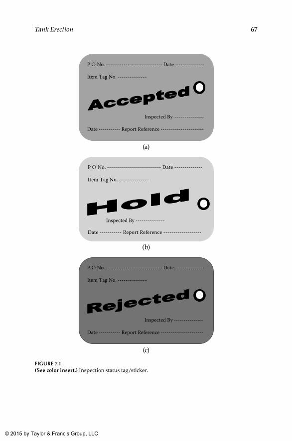
67Tank Erection
P O No. ----------------------------- Date ---------------
Item Tag No. ---------------
Inspected By ---------------
Date ----------- Report Reference ----------------------
(a)
P O No. --------------------------- Date --------------
Item Tag No. ---------------
Inspected By ---------------
Date ----------- Report Reference -------------------
(b)
P O No. ----------------------------- Date ---------------
Item Tag No. ---------------
Inspected By ---------------
Date ----------- Report Reference ----------------------
(c)
FIGuRE 7.1(See color insert.) Inspection status tag/sticker.
K22265_Book.indb 67 4/20/15 5:46 PM
© 2015 by Taylor & Francis Group, LLC
68 Above Ground Storage Tanks
the shortfall. Items shall remain under hold in an area earmarked for the purpose (quarantine area) till the matter is resolved. Items under hold shall not be taken in stock until the hold is removed and the item moves to the “accepted” category with a green tag. This system could ensure that all accepted materials have a green sticker or tag, which would imply the following:
• The materials are suitable for use as per the purchase order and technical specifications.
• The MTCs furnished are in line with the requirements.• The materials supplied are traceable to the certificates furnished.
Items that do not meet PO or code requirements shall be rejected and hence shall have a red sticker or tag. The reasons for rejection shall be elaborated in the inspection report and need to be taken up with the vendor by the procure-ment section for replacement. At the same time, the warehouse section shall take steps to return rejected materials back to the vendor at the vendor’s risk and cost.
As mentioned, the predominant raw materials for a storage tank are plates, pipes, flanges, and fittings. The recommended inspections for specific raw material types are elaborated to ensure quality and to avert untoward revela-tions at a later date.
7.2.1 Plates and Pipes
Measure possible physical dimensions, especially thickness. Correlate identification found on these items with that provided on the certificate furnished. In the event all of the above is in order, the certificate is verified against the code and PO requirements. If this also is in order, items can be accepted.
7.2.2 Pipe Fittings and Flanges
Record all possible dimensions and verify them against those given in appli-cable standards. Cross-check identification found on items to that given in the certificate. Verify the certificate against PO and code requirements. In case of large quantities, 100% inspection may not be possible or be rather a waste of time, provided materials are procured from proven reliable sources that have a well-established QA/QC organization and structure. Therefore, a random sample inspection can also be resorted to, for which a 10% ran-dom inspection at receipt is adopted almost universally. In case deviations are observed in this random inspection, a progressive inspection shall be imposed, resulting in 100% inspection eventually, at which stage the reli-ability and dependability of that vendor is questionable. When randomly
K22265_Book.indb 68 4/20/15 5:46 PM
© 2015 by Taylor & Francis Group, LLC
69Tank Erection
selected samples from a lot meet all requirements, the entire lot is accepted. Similarly when a progressive examination results in rejection, the entire lot shall be rejected. The mediocre policy of accepting the tolerable components from a lot subsequent to high rejection is not considered as a reliable meth-odology in random inspection.
7.2.3 Fasteners and Gaskets
Select random samples (say at 10%) and subject them to a dimensional check. Correlate certificates to identification given to the lot. Verify certificates for compliance to PO and code requirements. Once samples are found satisfac-tory, the lot represented by the sample shall be accepted.
7.2.4 Consumable Such as Electrodes
The containers for consumables such as electrodes are not to be opened for inspection. In such instances, inspection shall be limited to verifica-tion of batch numbers provided on containers, followed by cross matching them with certifications provided. If both match, items can be accepted. Furthermore, the condition of containers carrying electrodes upon receipt also shall be designated as a matter of concern, as it affects the quality of the weld on prolonged storage.
7.3 Identification and Traceability of Raw Materials
It is essential to maintain traceability records for all components of storage tanks, especially those for pressure retaining parts and those in contact with the stored medium. This needs to be carried out progressively and shall be available for each pressure retaining part identified in the relevant drawings. Therefore, the traceability methodology shall be evolved within the organi-zation to cover each and every part number identified in the drawings, with a bill of materials (BOM) in each drawing:
• Obtain mill test certificates (MTCs) from the planning or procure-ment department (concerned team) for all materials issued for production.
• In the case of plates, if used in full size, original stamping shall be retained on respective components as such. If not, stamping as seen in the original material shall be transferred to parts marked on each plate, preferably accompanied by the personal stamp of the inspector responsible for the transfer of identification.
K22265_Book.indb 69 4/20/15 5:46 PM
© 2015 by Taylor & Francis Group, LLC
70 Above Ground Storage Tanks
• Identify certificates for plates used for components and compile them in the MTC file pertaining to the respective tank with proper identification of the specific part for which the plate is used.
This methodology shall be maintained for all other raw materials, where a few parts are taken from one piece of raw material. Whereas for materials such as fittings, flanges, and so on, one certificate will cover many items, and in such cases, a list of part numbers for which this MTC is applicable shall be maintained as a table for easy understanding or by any other methodology deemed fit for positive and easy traceability. Furthermore, some clients may require hard stamping on individual components on the external surface. In such cases, please note the following:
• Hard stamping shall be limited to carbon steel materials like plates, pipes, fittings, and so on.
• Always ensure that these stampings are carried out on the external surface, wherein no contact with service fluid is expected.
• For stainless steel materials, chemical etching shall be resorted to for transfer of identification.
• For all types of flanges, hard stamping is possible on the flange edge, which in no way hampers its service life and is hence recommended.
• When a strong QC system is in force at the site, and if agreed by the client, consultant, and manufacturer, the transfer of identi-fication using paint markers can also be considered. All trans-ferred identification shall also contain the personal initials of the QC inspector who witnessed the transfer of identification.
• If permitted, identification transfer using paint markers shall be clear and legible, and a designated color shall be used for this pur-pose to distinguish it from other possible markings that may come later on the component.
• When paint markers are used on stainless steel components, it shall be ensured that paint used is free from chlorides and suitable for marking on stainless steel.
7.4 Marking of Plates
Cutting plans for all plates (bottom, shell, and roof) are prepared by the design team with a view to optimize utilization. Ordering the right size of plates (based on logistics and other constraints) needs to be given due consideration,
K22265_Book.indb 70 4/20/15 5:46 PM
© 2015 by Taylor & Francis Group, LLC
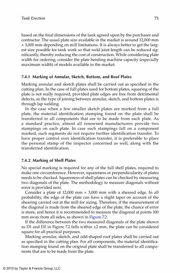
71Tank Erection
based on the final dimensions of the tank agreed upon by the purchaser and contractor. The usual plate size available in the market is around 12,000 mm × 3,000 mm depending on mill limitations. It is always better to get the larg-est size possible for tank work so that weld joint length can be reduced sig-nificantly, thereby reducing the cost of construction. While considering plate width for ordering, consider the plate bending machine capacity (especially maximum width) of models available in the market.
7.4.1 Marking of Annular, Sketch, bottom, and Roof Plates
Marking annular and sketch plates shall be carried out as specified in the cutting plan. In the case of full plates used for bottom plates, squaring of the plate is not really required, provided plate edges are free from detrimental defects, as the type of joining between annular, sketch, and bottom plates is through lap welding.
In the case when a few smaller sketch plates are marked from a full plate, the material identification stamping found on the plate shall be transferred to all components that are to be made from each plate. As a standard practice, almost all renowned manufacturers provide two stampings on each plate. In case such stampings fall on a component marked, such segments do not require further identification transfer. To have proper control over identification transfer, it is preferable to place the personal stamp of the inspector concerned as well, along with the transferred identification.
7.4.2 Marking of Shell Plates
No special marking is required for any of the full shell plates, required to make one circumference. However, squareness or perpendicularity of plates needs to be checked. Squareness of shell plates can be checked by measuring two diagonals of the plate. The methodology to measure diagonals without error is provided next.
Consider a plate of 12,000 mm × 3,000 mm with a sheared edge. In all probability, the edge of the plate can have a slight taper on account of the shearing carried out at the mill for sizing. Therefore, if the measurement of the diagonal is made from the sheared edge of the plate, the chance of error is more, and hence it is recommended to measure the diagonal at points 100 mm away from all sides, as shown in Figure 7.2.
If the difference between the two measured diagonals of the plate shown as D1 and D2 in Figure 7.2 falls within ±2 mm, the plate can be considered square for all practical purposes.
Marking annular, sketch, and odd-shaped roof plates shall be carried out as specified in the cutting plan. For all components, the material identifica-tion stamping found on the original plate shall be transferred to all compo-nents that are to be made from the plate.
K22265_Book.indb 71 4/20/15 5:46 PM
© 2015 by Taylor & Francis Group, LLC
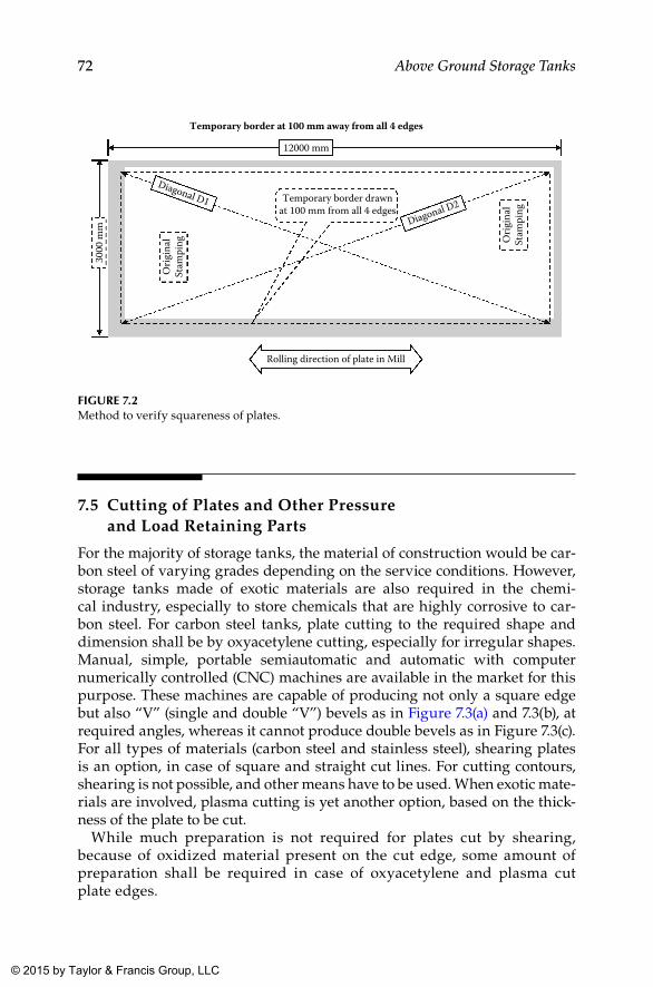
72 Above Ground Storage Tanks
7.5 Cutting of Plates and Other Pressure and Load Retaining Parts
For the majority of storage tanks, the material of construction would be car-bon steel of varying grades depending on the service conditions. However, storage tanks made of exotic materials are also required in the chemi-cal industry, especially to store chemicals that are highly corrosive to car-bon steel. For carbon steel tanks, plate cutting to the required shape and dimension shall be by oxyacetylene cutting, especially for irregular shapes. Manual, simple, portable semiautomatic and automatic with computer numerically controlled (CNC) machines are available in the market for this purpose. These machines are capable of producing not only a square edge but also “V” (single and double “V”) bevels as in Figure 7.3(a) and 7.3(b), at required angles, whereas it cannot produce double bevels as in Figure 7.3(c). For all types of materials (carbon steel and stainless steel), shearing plates is an option, in case of square and straight cut lines. For cutting contours, shearing is not possible, and other means have to be used. When exotic mate-rials are involved, plasma cutting is yet another option, based on the thick-ness of the plate to be cut.
While much preparation is not required for plates cut by shearing, because of oxidized material present on the cut edge, some amount of preparation shall be required in case of oxyacetylene and plasma cut plate edges.
Temporary border drawnat 100 mm from all 4 edges
Rolling direction of plate in Mill
Orig
inal
Stam
ping O
rigin
alSt
ampi
ng
Diagonal D1
Diagonal D2
12000 mm
Temporary border at 100 mm away from all 4 edges
3000
mm
FIGuRE 7.2Method to verify squareness of plates.
K22265_Book.indb 72 4/20/15 5:46 PM
© 2015 by Taylor & Francis Group, LLC
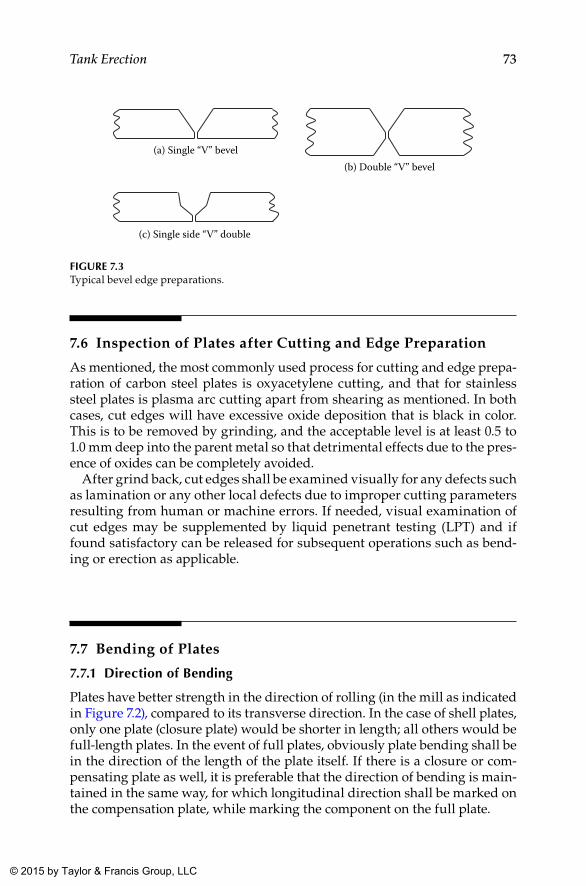
73Tank Erection
7.6 Inspection of Plates after Cutting and Edge Preparation
As mentioned, the most commonly used process for cutting and edge prepa-ration of carbon steel plates is oxyacetylene cutting, and that for stainless steel plates is plasma arc cutting apart from shearing as mentioned. In both cases, cut edges will have excessive oxide deposition that is black in color. This is to be removed by grinding, and the acceptable level is at least 0.5 to 1.0 mm deep into the parent metal so that detrimental effects due to the pres-ence of oxides can be completely avoided.
After grind back, cut edges shall be examined visually for any defects such as lamination or any other local defects due to improper cutting parameters resulting from human or machine errors. If needed, visual examination of cut edges may be supplemented by liquid penetrant testing (LPT) and if found satisfactory can be released for subsequent operations such as bend-ing or erection as applicable.
7.7 Bending of Plates
7.7.1 Direction of bending
Plates have better strength in the direction of rolling (in the mill as indicated in Figure 7.2), compared to its transverse direction. In the case of shell plates, only one plate (closure plate) would be shorter in length; all others would be full-length plates. In the event of full plates, obviously plate bending shall be in the direction of the length of the plate itself. If there is a closure or com-pensating plate as well, it is preferable that the direction of bending is main-tained in the same way, for which longitudinal direction shall be marked on the compensation plate, while marking the component on the full plate.
(a) Single “V” bevel(b) Double “V” bevel
(c) Single side “V” double
FIGuRE 7.3Typical bevel edge preparations.
K22265_Book.indb 73 4/20/15 5:46 PM
© 2015 by Taylor & Francis Group, LLC
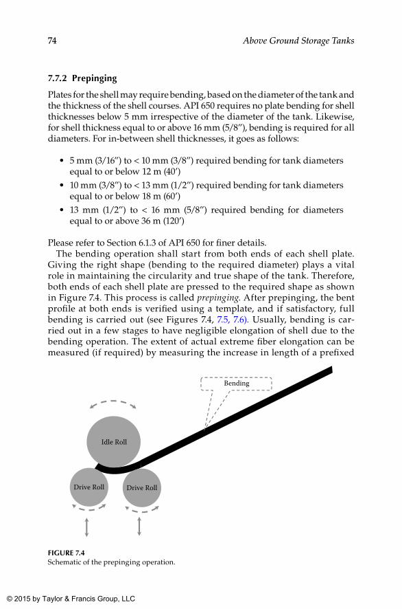
74 Above Ground Storage Tanks
7.7.2 Prepinging
Plates for the shell may require bending, based on the diameter of the tank and the thickness of the shell courses. API 650 requires no plate bending for shell thicknesses below 5 mm irrespective of the diameter of the tank. Likewise, for shell thickness equal to or above 16 mm (5/8”), bending is required for all diameters. For in-between shell thicknesses, it goes as follows:
• 5 mm (3/16”) to < 10 mm (3/8”) required bending for tank diameters equal to or below 12 m (40’)
• 10 mm (3/8”) to < 13 mm (1/2”) required bending for tank diameters equal to or below 18 m (60’)
• 13 mm (1/2”) to < 16 mm (5/8”) required bending for diameters equal to or above 36 m (120’)
Please refer to Section 6.1.3 of API 650 for finer details.The bending operation shall start from both ends of each shell plate.
Giving the right shape (bending to the required diameter) plays a vital role in maintaining the circularity and true shape of the tank. Therefore, both ends of each shell plate are pressed to the required shape as shown in Figure 7.4. This process is called prepinging. After prepinging, the bent profile at both ends is verified using a template, and if satisfactory, full bending is carried out (see Figures 7.4, 7.5, 7.6). Usually, bending is car-ried out in a few stages to have negligible elongation of shell due to the bending operation. The extent of actual extreme fiber elongation can be measured (if required) by measuring the increase in length of a prefixed
Drive Roll
Idle Roll
Bending
Drive Roll
FIGuRE 7.4Schematic of the prepinging operation.
K22265_Book.indb 74 4/20/15 5:46 PM
© 2015 by Taylor & Francis Group, LLC
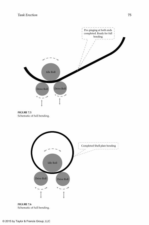
75Tank Erection
Idle Roll
Pre-pinging at both endscompleted. Ready for full
bending
Drive Roll Drive Roll
FIGuRE 7.5Schematic of full bending.
Drive Roll Drive Roll
Idle Roll
Completed Shell plate bending
FIGuRE 7.6Schematic of full bending.
K22265_Book.indb 75 4/20/15 5:46 PM
© 2015 by Taylor & Francis Group, LLC
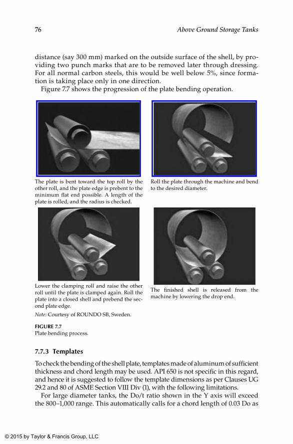
76 Above Ground Storage Tanks
distance (say 300 mm) marked on the outside surface of the shell, by pro-viding two punch marks that are to be removed later through dressing. For all normal carbon steels, this would be well below 5%, since forma-tion is taking place only in one direction.
Figure 7.7 shows the progression of the plate bending operation.
7.7.3 Templates
To check the bending of the shell plate, templates made of aluminum of sufficient thickness and chord length may be used. API 650 is not specific in this regard, and hence it is suggested to follow the template dimensions as per Clauses UG 29.2 and 80 of ASME Section VIII Div (1), with the following limitations.
For large diameter tanks, the Do/t ratio shown in the Y axis will exceed the 800–1,000 range. This automatically calls for a chord length of 0.03 Do as
The plate is bent toward the top roll by the other roll, and the plate edge is prebent to the minimum flat end possible. A length of the plate is rolled, and the radius is checked.
Roll the plate through the machine and bend to the desired diameter.
Lower the clamping roll and raise the other roll until the plate is clamped again. Roll the plate into a closed shell and prebend the sec-ond plate edge.
The finished shell is released from the machine by lowering the drop end.
Note: Courtesy of ROUNDO SB, Sweden.
FIGuRE 7.7Plate bending process.
K22265_Book.indb 76 4/20/15 5:46 PM
© 2015 by Taylor & Francis Group, LLC
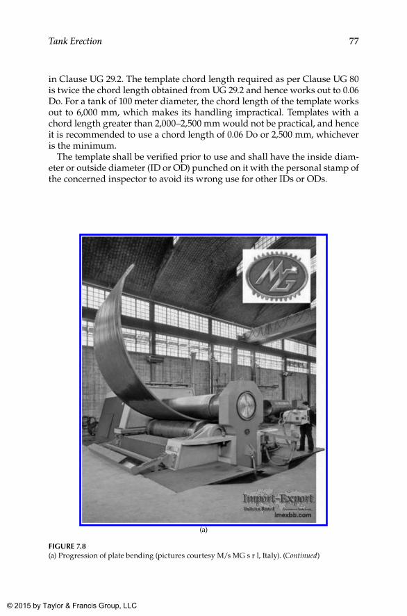
77Tank Erection
in Clause UG 29.2. The template chord length required as per Clause UG 80 is twice the chord length obtained from UG 29.2 and hence works out to 0.06 Do. For a tank of 100 meter diameter, the chord length of the template works out to 6,000 mm, which makes its handling impractical. Templates with a chord length greater than 2,000–2,500 mm would not be practical, and hence it is recommended to use a chord length of 0.06 Do or 2,500 mm, whichever is the minimum.
The template shall be verified prior to use and shall have the inside diam-eter or outside diameter (ID or OD) punched on it with the personal stamp of the concerned inspector to avoid its wrong use for other IDs or ODs.
(a)
FIGuRE 7.8(a) Progression of plate bending (pictures courtesy M/s MG s r l, Italy). (Continued)
K22265_Book.indb 77 4/20/15 5:47 PM
© 2015 by Taylor & Francis Group, LLC
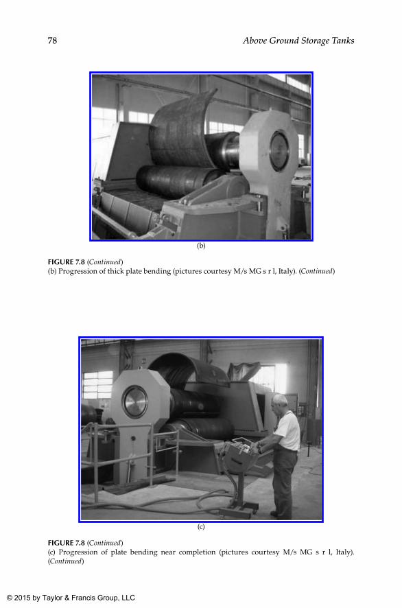
78 Above Ground Storage Tanks
(b)
FIGuRE 7.8 (Continued)(b) Progression of thick plate bending (pictures courtesy M/s MG s r l, Italy). (Continued)
(c)
FIGuRE 7.8 (Continued)(c) Progression of plate bending near completion (pictures courtesy M/s MG s r l, Italy). (Continued)
K22265_Book.indb 78 4/20/15 5:47 PM
© 2015 by Taylor & Francis Group, LLC
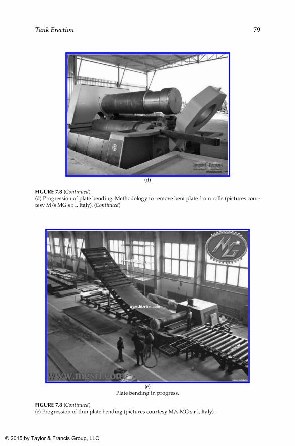
79Tank Erection
(d)
FIGuRE 7.8 (Continued)(d) Progression of plate bending. Methodology to remove bent plate from rolls (pictures cour-tesy M/s MG s r l, Italy). (Continued)
(e)Plate bending in progress.
FIGuRE 7.8 (Continued)(e) Progression of thin plate bending (pictures courtesy M/s MG s r l, Italy).
K22265_Book.indb 79 4/20/15 5:47 PM
© 2015 by Taylor & Francis Group, LLC
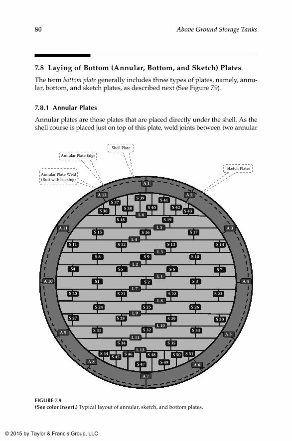
80 Above Ground Storage Tanks
7.8 Laying of Bottom (Annular, Bottom, and Sketch) Plates
The term bottom plate generally includes three types of plates, namely, annu-lar, bottom, and sketch plates, as described next (See Figure 7.9).
7.8.1 Annular Plates
Annular plates are those plates that are placed directly under the shell. As the shell course is placed just on top of this plate, weld joints between two annular
Annular Plate Edge
Shell Plate
Sketch Plates
S 36
S 39
S 19
S 37S 38 S 40
S 41S 42
S 43
S 18
S 16S 15 S 17
S 12S 11 S 13 S 14
S 27
S 9 S 10
S 31 S 33
S 7
S 28
S 32
S 35
S 29 S 30
S 34
S 47 S 49
S 51S 48 S 50S 44 S 46
S 8
S 6S 5 S4
S1 S 2 S 3
S 20 S 21 S 22 S 23
S 24 S 25 S 26
S 45
L 6
L 5
L 4
L 3
L 2
L 1
L 7
L 8
L 9
L 10
L 11
L 12
A 1
A 2
A 6
A 7
A 12
A 9
A 8
A 11
A 10
A 3
A 4
A 5
Annular Plate Weld(Butt with backing)
FIGuRE 7.9(See color insert.) Typical layout of annular, sketch, and bottom plates.
K22265_Book.indb 80 4/20/15 5:47 PM
© 2015 by Taylor & Francis Group, LLC
81Tank Erection
plates shall essentially be butt welded with (mostly) a backing strip underneath. Weld reinforcement of this butt weld is ground flush with the parent plate to facilitate proper seating of the shell plate at the location where the shell plate is expected to cross annular plate butt welds. The number and size of annular plates is decided based on the minimum width specified for such plates in client specifications, as well as the available size of plates. A typical arrangement of annular plates, sketch plates, and bottom plates are shown in Figure 7.9.
7.8.2 bottom Plates
Full-size plates that are used for the tank bottom are designated as bottom plates. Based on the assumed sizes of plates (12,000 mm × 3000 mm), there are 24 such plates, as shown in the bottom plate layout shown in Figure 7.9. They are lap welded to each other with an overlap of about 50 mm to 60 mm welded to the requisite fillet size. These welds are then tested to ascertain its integrity by vacuum box, LPT, or both, in addition to visual inspection, which is mandatory. While welding these lap joints on the bottom plate, utmost care shall be taken to see that distortion is controlled well. A typi-cal welding sequence is provided in Table 7.2 for this purpose with respect to Figure 7.9. In the case of larger diameter tanks wherein more plates come into picture, the staggered welding pattern described can be adapted to suit specific requirements as logical and feasible.
7.8.3 Sketch Plates
Sketch plates are those segmental subsize plates used to bridge the gap between the bottom plate and annular plates. There are 40 such plates pres-ent in the configuration of the bottom plate shown in Figure 7.9. These plates are basically polygons composed of a rectangular portion followed by a right-angled triangle, to fill the gap between a regular bottom plate and an annu-lar plate, as shown in Figure 7.9. Depending on the size of the tank and the size of the plates proposed, the configuration of the sketch plate will vary. Sketch plates are also lap welded to the annular plate. As annular plates are welded with a backing strip (between them), invariably the lap of the sketch plate shall be above the annular plate. Section 7.8.9 indicates the welding sequence proposed for the welding sketch plate to the bottom plate, whereas the weld between the sketch plate and the annular plate is taken up only after completion of all main welding of the tank, including the first shell course to the annular plate. The details pertaining to the welding of each type of plate are given separately in ensuing sections.
7.8.4 Annular and bottom Plate layout
Once the foundation is completed in all respects including the leveling course with bitumen mix, annular, sketch, and bottom plates are laid sequentially,
K22265_Book.indb 81 4/20/15 5:47 PM
© 2015 by Taylor & Francis Group, LLC
82 Above Ground Storage Tanks
with required overlap as specified in drawings. (Please note that the under-side of bottom plates shall be coated prior to layout to mitigate underside cor-rosion.) A typical layout scheme for a 54 m diameter storage tank is shown in Figure 7.9. The layout is so designed to optimize the use of plates of size 12,000 mm × 3,000 mm. Annular plates are laid first and butt welded (these are butt welded, usually with a backing strip). As per API 650, these welds require random spot radiography, whereas many client specifications insist for 100% radiography of these joints, especially from the oil and gas industry. While the welding of annular plates is progressing, laying of sketch plate and bottom plates is taken up progressively and tack welded in position.
7.8.5 Surface Preparation and Coating of bottom Plates
Underside corrosion of bottom (annular, sketch, and bottom) plates is a seri-ous matter, especially when natural phenomena such as a high water table, heavy rainfall, the salt content of soil in the near vicinity, and so on are pres-ent. Even otherwise it is better to provide a corrosion-resistant coating prior to laying the plates on the foundation even though cathodic protection is provided for the underside of bottom plates. When plates are coated up to the edge, care shall be taken to use paints or coating materials that shall not produce any detrimental effects in welds affecting the strength of the weld by way of entrapped defects or otherwise. As a precaution, to facilitate the sound welding of bottom plates, usually a 1” width around the plate edges is left uncoated by applying masking tape before coating.
As in any other coating application, the protective coating also shall be applied after proper surface preparation, as recommended by the paint man-ufacturer or as specified in the client specification. Being a specialized topic by itself, surface preparation and painting and coating are not dealt with in this book. However, for the sake of completeness, a brief overview of surface preparation and painting and lining is provided in Chapter 13.
7.8.6 laying of Annular Plates
Before annular plates are laid, the level of foundation prepared by the civil construction team needs to be verified, preferably in a joint examination by both civil and mechanical teams. As per API 650, for the ring wall type of foundation that is very common, the ring wall shall be level within ±3 mm (1/8”) in any 9 m (30’) of the circumference and within ±6 mm (1/4”) in total circumference measured from the average elevation. Similarly, tolerances on the level of foundations for other types of foundations are provided in Clause 7.5.5.2 of API 650.
After getting clearance for annular plate laying, mark the 0°, 90°, 180°, and 270° coordinates and the outside circumference of the annular plate on the foundation from a reference center point obtained through a theodolite survey. Annular plates are to be laid matching the diameter marked on the
K22265_Book.indb 82 4/20/15 5:47 PM
© 2015 by Taylor & Francis Group, LLC
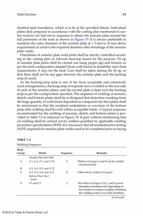
83Tank Erection
finished tank foundation, which is to be at the specified datum. Individual plates duly prepared in accordance with the cutting plan mentioned in ear-lier sections are laid out in sequence to obtain the annular plate around the full perimeter of the tank as shown in Figure 7.9. It is always preferable to maintain the outer diameter of the annular plate at + 5 mm to 10 mm above requirement, to achieve the required diameter after shrinkage of the annular plate welds.
Orientation of annular plate weld joints shall be strictly controlled accord-ing to the cutting plan or relevant drawing issued for the purpose. Fit up of annular plate joints shall be carried out using proper jigs and fixtures as per the joint configuration adopted (from code based on feasibility and client requirements, if any) for the tank. Care shall be taken during the fit up, so that there shall not be any gaps between the annular plate and the backing strip (if used).
As the backing-strip joint is one of the most acceptable and extensively used arrangements, a backing strip of requisite size is welded on the rear side of each of the annular plates, and the second plate is kept over the backing strip as per the configuration specified. The sequence of welding of annular, sketch, and bottom plates shall be so designed that distortion resulting from the huge quantity of weld metal deposited on comparatively thin plates shall be minimized so that the resultant undulations or waviness of the bottom plate after welding shall be well within acceptable limits. A typical sequence recommended for the welding of annular, sketch, and bottom plates is pro-vided in Table 7.2 in reference to Figure 7.9. It goes without mentioning that all welding shall be carried out by welders qualified by applicable welding procedure specifications (WPS). It is necessary that all nondestructive testing (NDT) required for annular plate welds need to be completed prior to laying
TAblE 7.2
Welding Sequence
Weld Group Welds Sequence Remarks
Annular Plate Butt WeldA A 1, A 4, A 7, and A 10 1 Welds in Groups A and B can be welded
simultaneouslyB A 3, A 6, A 9, and A 12C A 2, A 5, A 8, and A 11 2 Followed by welds in Group C
Bottom Plate Short Seams
A S 1 and S 3 3 All welds in Groups A, B, C, and D can be attempted simultaneously depending on the number of welders available. Distribute the welding evenly over welds identified.
(Continued)
K22265_Book.indb 83 4/20/15 5:47 PM
© 2015 by Taylor & Francis Group, LLC
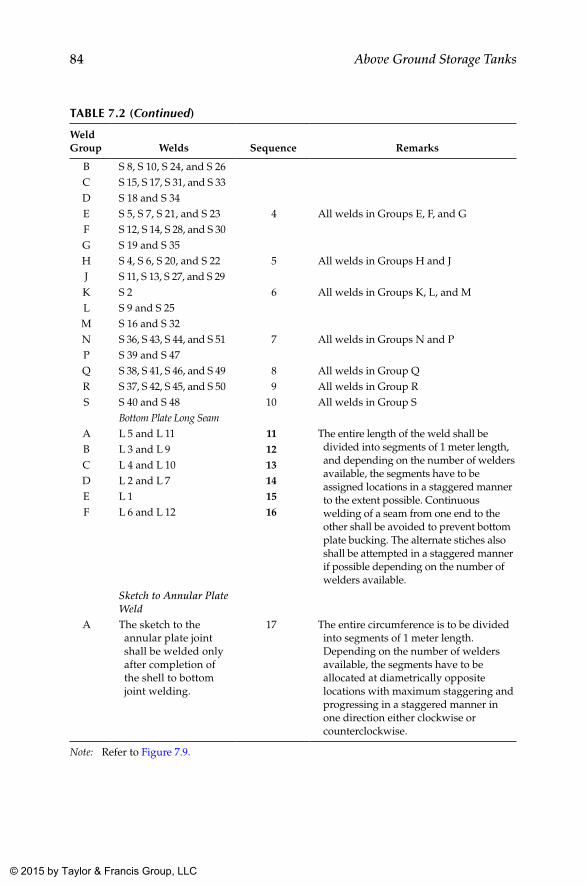
84 Above Ground Storage Tanks
TAblE 7.2 (Continued)
Weld Group Welds Sequence Remarks
B S 8, S 10, S 24, and S 26C S 15, S 17, S 31, and S 33D S 18 and S 34E S 5, S 7, S 21, and S 23 4 All welds in Groups E, F, and GF S 12, S 14, S 28, and S 30G S 19 and S 35H S 4, S 6, S 20, and S 22 5 All welds in Groups H and JJ S 11, S 13, S 27, and S 29K S 2 6 All welds in Groups K, L, and ML S 9 and S 25M S 16 and S 32N S 36, S 43, S 44, and S 51 7 All welds in Groups N and PP S 39 and S 47Q S 38, S 41, S 46, and S 49 8 All welds in Group QR S 37, S 42, S 45, and S 50 9 All welds in Group RS S 40 and S 48 10 All welds in Group S
Bottom Plate Long SeamA L 5 and L 11 11 The entire length of the weld shall be
divided into segments of 1 meter length, and depending on the number of welders available, the segments have to be assigned locations in a staggered manner to the extent possible. Continuous welding of a seam from one end to the other shall be avoided to prevent bottom plate bucking. The alternate stiches also shall be attempted in a staggered manner if possible depending on the number of welders available.
B L 3 and L 9 12C L 4 and L 10 13D L 2 and L 7 14E L 1 15F L 6 and L 12 16
Sketch to Annular Plate Weld
A The sketch to the annular plate joint shall be welded only after completion of the shell to bottom joint welding.
17 The entire circumference is to be divided into segments of 1 meter length. Depending on the number of welders available, the segments have to be allocated at diametrically opposite locations with maximum staggering and progressing in a staggered manner in one direction either clockwise or counterclockwise.
Note: Refer to Figure 7.9.
K22265_Book.indb 84 4/20/15 5:47 PM
© 2015 by Taylor & Francis Group, LLC
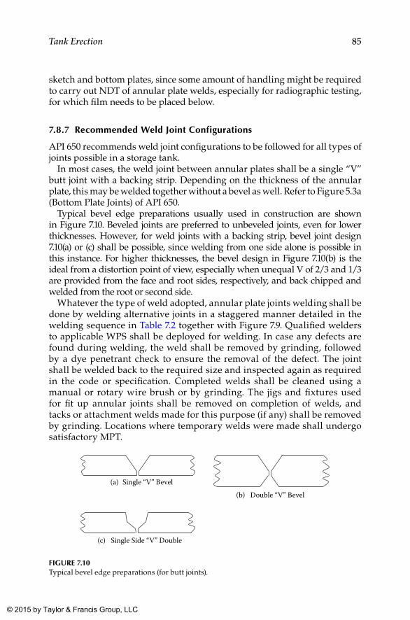
85Tank Erection
sketch and bottom plates, since some amount of handling might be required to carry out NDT of annular plate welds, especially for radiographic testing, for which film needs to be placed below.
7.8.7 Recommended Weld Joint Configurations
API 650 recommends weld joint configurations to be followed for all types of joints possible in a storage tank.
In most cases, the weld joint between annular plates shall be a single “V” butt joint with a backing strip. Depending on the thickness of the annular plate, this may be welded together without a bevel as well. Refer to Figure 5.3a (Bottom Plate Joints) of API 650.
Typical bevel edge preparations usually used in construction are shown in Figure 7.10. Beveled joints are preferred to unbeveled joints, even for lower thicknesses. However, for weld joints with a backing strip, bevel joint design 7.10(a) or (c) shall be possible, since welding from one side alone is possible in this instance. For higher thicknesses, the bevel design in Figure 7.10(b) is the ideal from a distortion point of view, especially when unequal V of 2/3 and 1/3 are provided from the face and root sides, respectively, and back chipped and welded from the root or second side.
Whatever the type of weld adopted, annular plate joints welding shall be done by welding alternative joints in a staggered manner detailed in the welding sequence in Table 7.2 together with Figure 7.9. Qualified welders to applicable WPS shall be deployed for welding. In case any defects are found during welding, the weld shall be removed by grinding, followed by a dye penetrant check to ensure the removal of the defect. The joint shall be welded back to the required size and inspected again as required in the code or specification. Completed welds shall be cleaned using a manual or rotary wire brush or by grinding. The jigs and fixtures used for fit up annular joints shall be removed on completion of welds, and tacks or attachment welds made for this purpose (if any) shall be removed by grinding. Locations where temporary welds were made shall undergo satisfactory MPT.
(a) Single “V” Bevel
(c) Single Side “V” Double
(b) Double “V” Bevel
FIGuRE 7.10Typical bevel edge preparations (for butt joints).
K22265_Book.indb 85 4/20/15 5:47 PM
© 2015 by Taylor & Francis Group, LLC
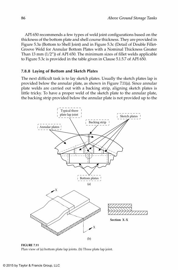
86 Above Ground Storage Tanks
API 650 recommends a few types of weld joint configurations based on the thickness of the bottom plate and shell course thickness. They are provided in Figure 5.3a (Bottom to Shell Joint) and in Figure 5.3c (Detail of Double Fillet-Groove Weld for Annular Bottom Plates with a Nominal Thickness Greater Than 13 mm (1/2”)) of API 650. The minimum sizes of fillet welds applicable to Figure 5.3c is provided in the table given in Clause 5.1.5.7 of API 650.
7.8.8 laying of bottom and Sketch Plates
The next difficult task is to lay sketch plates. Usually the sketch plates lap is provided below the annular plate, as shown in Figure 7.11(a). Since annular plate welds are carried out with a backing strip, aligning sketch plates is little tricky. To have a proper weld of the sketch plate to the annular plate, the backing strip provided below the annular plate is not provided up to the
Typical threeplate lap joint
Annular plates
Sketch plates
Bottom plates
Backing strip
(a)
Section X-X
X
X
(b)
FIGuRE 7.11Plan view of (a) bottom plate lap joints. (b) Three plate lap joint.
K22265_Book.indb 86 4/20/15 5:47 PM
© 2015 by Taylor & Francis Group, LLC
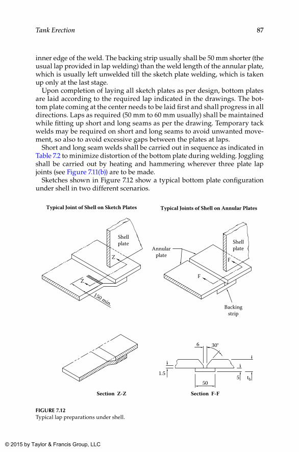
87Tank Erection
inner edge of the weld. The backing strip usually shall be 50 mm shorter (the usual lap provided in lap welding) than the weld length of the annular plate, which is usually left unwelded till the sketch plate welding, which is taken up only at the last stage.
Upon completion of laying all sketch plates as per design, bottom plates are laid according to the required lap indicated in the drawings. The bot-tom plate coming at the center needs to be laid first and shall pro gress in all directions. Laps as required (50 mm to 60 mm usually) shall be maintained while fitting up short and long seams as per the drawing. Temporary tack welds may be required on short and long seams to avoid unwanted move-ment, so also to avoid excessive gaps between the plates at laps.
Short and long seam welds shall be carried out in sequence as indicated in Table 7.2 to minimize distortion of the bottom plate during welding. Joggling shall be carried out by heating and hammering wherever three plate lap joints (see Figure 7.11(b)) are to be made.
Sketches shown in Figure 7.12 show a typical bottom plate configuration under shell in two different scenarios.
Section Z-Z Section F-F
Typical Joint of Shell on Sketch Plates
Shellplate Shell
plateAnnularplate
Backingstrip
6 30°
50
1.55 tb
F
Z
Z
150 min.
F
Typical Joints of Shell on Annular Plates
FIGuRE 7.12Typical lap preparations under shell.
K22265_Book.indb 87 4/20/15 5:47 PM
© 2015 by Taylor & Francis Group, LLC
88 Above Ground Storage Tanks
7.8.9 Welding Sequence of Annular, Sketch, and bottom Plates
With reference to the bottom plate layout shown in Figure 7.9, the welding sequence for a different category of welds is developed with a view to reduce distortion of the bottom plate. For easy understanding, the welding sequence is presented as Table 7.2 with sequence and subsequences.
Welds identified in Figure 7.9 are segregated into groups to be taken up in sequence and are indicated in the blue column. The short seam width is considered to be 3 meters, based on the maximum width of the plate usually available in the market and also the maximum plate bending width commercially available. The entire length of welds (3,000 mm) in short seams shall not be welded in a single stretch. Instead, the weld may be divided into three segments of 1,000 mm each and shall be welded at the middle (1 m length marked at the middle) first and then on either end.
The very same methodology shall be adopted for long seams as well, wherein the maximum length expected would be to the tune of around 47 meters for the tank size considered here. This methodology shall be appli-cable to annular to bottom plate welds as well and would be preferable for any weld of length of more than 1 meter to 1.5 meters in length.
In the case of annular to sketch plate welds (to be taken up as the last weld in the bottom plate), a lot of care is required. In the case of a tank of about 50 meters in diameter, the approximate weld length shall be around 150 meters. When the weld is divided into six segments over the circumference, each segment shall contain a length of 25 meters of weld. If a welder is allocated for each segment, he or she shall weld the same in a staggered manner. The segment allocated shall be subdivided into portions that are 1 meter long. Starting from the middle portion, the welder shall progress in both direc-tions (within the segment), welding alternate portions on either side of the designated midpoint. Later, the welder has to come back and complete the remaining segments of welds allotted to him or her in a progressive but stag-gered manner.
7.8.10 Annular Plate Welds
Annular plate butt welding shall be carried out in accordance with an approved welding procedure. The process for this welding is selected based on various constraints such as the time schedule, availability of welders, skill level of welders, quantity of welding required (welding economics), and so on. Since the usual width of annular plate butt welding is in the range of 2 meters to 2.5 meters, many times the shielded metal arc welding (SMAW) process is selected for these welds. Depending on the annular plate thick-ness required, the joint configuration may or may not be provided with a “V,” as mentioned in Section 7.8.7. A square butt weld joint configuration is
K22265_Book.indb 88 4/20/15 5:47 PM
© 2015 by Taylor & Francis Group, LLC
89Tank Erection
generally acceptable up to 6 mm thick annular plates. Beyond this thickness, either a single or a double bevel is recommended. A double bevel is usually used when the plate thickness is above 16 mm.
In the case of annular plate welds for storage tanks, a double bevel is usu-ally not possible on account of the lack of precision handling equipment at the site. Therefore, even if the thickness of the annular plate exceeds 16 mm, a single bevel is resorted to on account of practical limitations.
As mentioned earlier, codes and good engineering practices do not recom-mend any beveling for plates below 6 mm thickness. However, it is always better to have a bevel for plate joints, which will facilitate easy flotation of the slag to the top, thereby reducing the chances of slag inclusions and lack of side wall fusion in welds.
Normal tests that are carried out after welding the annular plates are visual examination, spot radiography, and penetrant testing at the areas where the reinforcement is ground flush with the parent plate to facilitate proper seat-ing of the shell plates. Even though these are not mandatory requirements, in the best interest of good quality work, and to avoid reworks at a later stage, it is better to carry out the penetrant test of all butt welds of the annular plate from the outside. Visual examination is the most powerful tool among inspections, and it can rule out a lot of discrepancies in welds and hence in no case shall be compromised. It should be carried out meticulously through every inch of weld on a storage tank.
7.8.11 bottom Plate Welds
For joints between bottom plates, lap welding is proposed as shown in Section 7.8.8. In this instance tack welding at the underside is not possible and hence needs to be done on the surface to be welded. Even for this lap welding, it is better to remove tacks entirely during welding of the joint, though code does not prohibit its adoption into the main weld, provided it is carried out by a qualified welder using a qualified WPS and compatible electrodes.
The welds between bottom plates are simple lap welds. The completed welds shall be inspected visually and then given a vacuum box test. In the vacuum box test, the amount of vacuum applied and amount of overlap given during testing plays a very vital role in ensuring the quality of the bottom plate weld and hence shall be carried out meticulously. The code specifies the methodology to carry out vacuum box testing, and the details are provided in Chapter 10.
7.8.12 Weld between Annular and bottom Plates
The major portion of this weld is a simple lap weld with an overlap of about 75 mm instead of the usual 50 mm for other bottom plate lap welds.
K22265_Book.indb 89 4/20/15 5:47 PM
© 2015 by Taylor & Francis Group, LLC
90 Above Ground Storage Tanks
However, at locations where long seams of bottom plates are coming, a three plate lap shall eventually occur, and hence care shall be taken to maintain proper alignment of plates while welding so that the gap between plates is minimal. Furthermore, the weld shall cover the entire three lap portion and bent portion of the bottom plate. These points are the most likely areas for a leak in vacuum box testing and hence need extra care during welding and to be inspected thoroughly afterward.
Tests applicable to bottom plate welds are applicable here also. However, in the event of three plate lap joints, where joggling is required to match double lap, welds around the double lap shall be compulsorily dye pen-etrant tested. This could reveal not only the flaw in the weld but also any flaws that might have occurred during the cold-hot joggling operation car-ried out.
7.8.13 Testing of Welds
Upon completion of welds pertaining to each category, they shall be sub-jected to tests as specified in the code and also according to client specifica-tions. The code always specifies the minimum amount of testing that usually would be increased by clients based on their past experience, which shall be reflected in the technical procurement specification (TPS) for the tank. As it is not practical to give all this information in bits and pieces to the construc-tion group, all these technical conditions (other than those specified by the code) are essentially to be listed out in the general arrangement drawing, so that the construction group need follow only the drawings and code, which it should be familiar with.
Apart from normal NDT methods, other effective inspection methods employed in storage tank erection are visual examination, vacuum box testing, pads air testing, and the final hydrostatic/pneumatic testing (of the roof).
Butt weld (usually with a backing strip) is proposed for annular plate welds to facilitate easy erection and for sound welding of the annular plate to the bottom shell course. As per code, the NDT required for this weld is only random spot radiography, apart from visual examination, whereas many client specifications call for 100% radiography. Since full penetration is required for this weld, it is logical to ask for radiography; however, the chances of unacceptable defects in butt weld of a few passes, that too with a backing strip is highly unlikely. Therefore, to ward off untoward incidents such as leaks in the annular plate to shell welds during a hydrostatic test, it is better to carry out the vacuum box test of the annular plate butt weld,
K22265_Book.indb 90 4/20/15 5:47 PM
© 2015 by Taylor & Francis Group, LLC
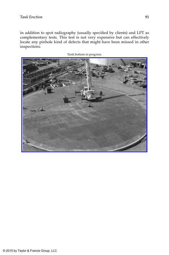
91Tank Erection
in addition to spot radiography (usually specified by clients) and LPT as complementary tests. This test is not very expensive but can effectively locate any pinhole kind of defects that might have been missed in other inspections.
Tank bottom in progress.
K22265_Book.indb 91 4/20/15 5:47 PM
© 2015 by Taylor & Francis Group, LLC
93
8Erection of Shell Courses, Roofs, and Other Appurtenances
8.1 General
For the erection of storage tanks, two well-established methodologies are available. The earliest methodology was the conventional erection of a stor-age tank from the bottom to top shell course (one after another) and roof structure and roof after that. The jacking methodology was developed later, wherein the erection of the shell courses start in reverse order from the top to bottom shell course. Each has its own advantages and disadvan-tages. The jacking up method has advantages in the case of fixed cone roof tanks, whereas for floating roof tanks, structural rigidity at the top could be a concern during lifting in some cases. Furthermore, there is no advantage of welding undercover for floating roof tanks, which depends on how and when the floating deck is constructed.
As mentioned earlier, in the conventional method, shell courses are erected one after another, starting from the first shell course to the top-most shell. Therefore, welding at height is required as the tank acquires height. Moreover, wind would be more at height, and hence the quality of the weld could be a concern for welds carried out at heights. In the jacking up method, the top shell course is erected first, followed by the roof structure and roof plates. Later, other shell courses from top to bottom are erected one after the other. The main advantage is that the majority of welding can be performed at a height slightly (500 mm to 1,000 mm) above the shell course width, which is of much significance from safety and convenience points of view.
8.2 Conventional Method
In the conventional method of the erection of storage tanks, shell courses are erected from the first shell course to the top shell course from the bottom of the tank in a progressive manner. Upon completion of laying the bottom plates
K22265_Book.indb 93 4/20/15 5:47 PM
© 2015 by Taylor & Francis Group, LLC
94 Above Ground Storage Tanks
(inclusive of annular plates, bottom plates, and sketch plates), the outer and inner circumferences of the tank are marked on the annular plate. Wherever this marking crosses butt welds (with a backing strip) of the annular plate, weld reinforcement is ground flush with the parent metal to facilitate proper seating of the shell to the annular plate. This flush grinding may be done for a width of about 25 mm (minimum) on either side of the shell thickness already marked on the annular plate. Furthermore, it is presumed that all welding between the bottom and sketch plates is completed prior to the erection of shell courses.
Shell plates shall be erected as per the cutting plan and be carried out based on the orientation marking on the annular or bottom plate. In fact, laying the bottom plate shall be done according to this orientation so that once the bot-tom plate is laid, the orientation cannot be changed. The shell plates of the first course shall be erected one by one progressively till the entire circum-ference (except the closure plate) is completed. Subject to satisfactory inspec-tion of fit up, vertical seams can be welded. After welding and completion of satisfactory visual inspection of these welds, they are released for subsequent nondestructive testing (NDT) as required by code and specifications.
Upon completion of the weld and NDT of vertical seams, the second shell course erection can be started as in the case of the first shell course, with the only difference being that erection is taking place at a height of one shell course above the bottom plate and foundation. Hence, a proper scaffolding arrangement shall be provided for easy and safe movement of personnel. The scaffolding arrangement can be of two types, one that is purely temporary, erected for the construction purpose without providing any welded cleats on the shell, and the other with scaffolding cleats permanently welded to the tank surface (both inside and outside) if permitted by the client. The purpose of permanent erection cleats is to reduce scaffolding cost and scaffolding erec-tion time during maintenance inspections, to follow during the service life of the tank. In such cases, these cleats are formed as specified in the design code and specifications and data sheets and shall be welded to the shell at proper predesigned intervals and elevations by a qualified welder using approved welding procedure specifications (WPS). This welding also shall be subjected to visual inspection and NDT as required in code and specifications and shall be free of open defects such as undercuts, blow holes, and so on that could act as an eventual stress riser, thereby causing corrosion during service.
During the welding of the vertical and horizontal seams of a storage tank, distortion associated with welding is one of the issues to be tackled based on practical judgment. Weld distortion is an inherent evil associated with every welding that cannot be eliminated under any circumstances. However, if proper techniques are adopted, distortion can be controlled to a great extent. For bottom plate welding, the sequence developed in Table 7.1 is with this intention based on practical experience at the site and hence recommended for all types of tank constructions (conventional and jacking up) in general. As mentioned therein, the weld between the annular plate and the bottom plate (consisting of sketch and bottom plates) is welded only after completion
K22265_Book.indb 94 4/20/15 5:47 PM
© 2015 by Taylor & Francis Group, LLC
95Erection of Shell Courses, Roofs, and Other Appurtenances
of the annular plate to shell plate welding. Similarly, for shell welds (both vertical and horizontal seams), the welding sequence proposed is explained in Section 8.5.2 and in Table 8.2.
8.3 Bygging or Jacking Up Method
In the jacking up method, the methodology adopted to lay the bottom plate is the same, whereas the erection of the shell plates takes place in reverse order, which means shells are erected progressively from the top to bottom course. The methodology followed by most contractors is explained briefly in the fol-lowing paragraphs.
On completion of laying the annular, bottom, and sketch plates, as done in the conventional method, the inside and outside circumferences of the first (bottom-most) shell course shall be marked on the annular plate. Thereafter, stools of 400 mm to 500 mm height with a rectangular surface plate at the top of the stool shall be placed along the marked circumference. The stools shall be preferably made of pipe with a size in the range of 350 to 450 (12” to 16”) NB. As a rule of thumb, stools shall be placed at a distance of about 1.5 m along the circumference. This arrangement shall be capable of taking up the full load of one shell course due for jacking. Afterward, the top surface of the square plate provided on the stools shall be leveled using the water level, and the circumfer-ence of the top-most shell course shall be marked on it. Subsequently, top shell plates, bent to a right curvature, shall be placed on the stools as per the shell cutting plan issued for this purpose, with proper orientation as per the draw-ing. Vertical seams are then aligned, inspected, welded, and visually inspected again. NDT as envisaged in the code and specifications and in the drawings shall follow. Once this is clear (or while this process is going on, as approved by the client), the top shell is now ready for fitting up of the roof structures.
Before the roof plates are placed, the structural support for the roof shall be ready. Therefore, the first step shall be to assemble and weld the curb angle or compression ring (as the case may be) and also to erect the structural mem-bers intended to support the roof plate and other appurtenances that are to be installed on the roof. Structural members are usually supported at chairs provided on the shell that in turn are strengthened by the compression ring or curb angle or by reinforcing pads and finally connecting through bolting. Once all necessary bolting of the structure as per the design is completed, structural members shall have the required strength to carry roof plates and appurtenances. Thereafter, the roof plates are laid in the same way as the bot-tom plates. For the welding of these plates, proper sequence shall be adopted so that adverse effects due to distortion can be kept at a minimum possible level so that water logging on the roof due to buckling of roof plates can be avoided. Because of this issue, roof plates shall never be welded in excess of
K22265_Book.indb 95 4/20/15 5:47 PM
© 2015 by Taylor & Francis Group, LLC
96 Above Ground Storage Tanks
what is being stipulated in the drawing, which may lead to excessive distor-tion. Welding of the roof shall be followed by visual inspection, as well as other NDT specified in the code, specifications, and drawings.
On completion of the roof, roof appurtenances shall be welded to the roof as per specifications and drawing. Manufacture, fit up, and welding of these items are dealt with separately under subassemblies in the following sections. Along with this work, the roof and top shell course, platforms, portions of stairways, ladders, and other supporting structures for piping and so on shall also be com-pleted prior to lifting the first shell course, which in reality is the top shell course.
The next step shall be lifting the top shell course up to the height of one shell course to facilitate placement of the second shell course from the top. To reduce the erection time, shell plates for the second shell course from the top shall be placed in position along the circumference to start fit up immediately upon lifting the top shell course. Initial lifting shall be to a height of +25 mm above the next shell course height so that the shell course plates are erected on a packing plate placed above the stool. Later, on completing the placement of all the plates and its tack welding, the same shall be lowered to the stool by removing the packing plates provided, which makes the lifting and erection quite easy and smooth. This process is repeated for all subsequent shells till the bottom shell course is reached, by which time the lifting arrangements can be removed. Though the above men-tioned methodology is the ideal, quite often first lifting of the shell was carried out after erection of two shell courses at the top. This is to provide ample head room for personnel working inside the tank even after the erection of roof struc-tural supports which could be quite big depending on the diameter of the tank. In such cases, the first erected shell course shall be the top most but one shell course, followed by the top most shell in conventional manner. Thereafter the roof sup-ports, roof plates and other attachments on roof and these two shell courses are completed. Therefore the first jacking will be the top two shell courses and roof together. All subsequent lifts shall be after addition of one shell course each.
By the time erection reaches the bottom-most shell, stools are removed, and any damages or dents that occurred on annular or bottom plates during the erection of shells shall be corrected satisfactorily. The shell plates shall then be placed on the annular plate, and its alignment shall be carried out. The vertical joints are welded first, and later the shell is welded to the bottom plate joint, both inside and outside.
8.4 Comparison of Erection Methodology
In the conventional method, as work is progressing from first to top shell courses, a large amount of work including welding shall be taking place at heights. This calls for scaffolding and stringent safety requirements for all working person-nel. Since a large quantity of welding is taking place at height, the probability of weld defects is higher on account of lower supervision, lesser accessibility,
K22265_Book.indb 96 4/20/15 5:47 PM
© 2015 by Taylor & Francis Group, LLC
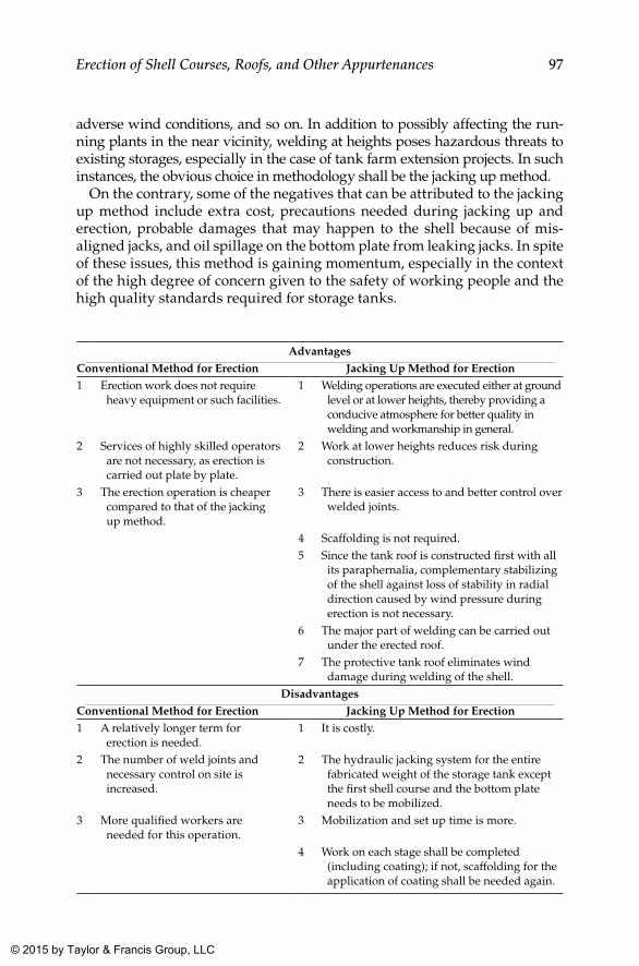
97Erection of Shell Courses, Roofs, and Other Appurtenances
adverse wind conditions, and so on. In addition to possibly affecting the run-ning plants in the near vicinity, welding at heights poses hazardous threats to existing storages, especially in the case of tank farm extension projects. In such instances, the obvious choice in methodology shall be the jacking up method.
On the contrary, some of the negatives that can be attributed to the jacking up method include extra cost, precautions needed during jacking up and erection, probable damages that may happen to the shell because of mis-aligned jacks, and oil spillage on the bottom plate from leaking jacks. In spite of these issues, this method is gaining momentum, especially in the context of the high degree of concern given to the safety of working people and the high quality standards required for storage tanks.
AdvantagesConventional Method for Erection Jacking Up Method for Erection1 Erection work does not require
heavy equipment or such facilities.1 Welding operations are executed either at ground
level or at lower heights, thereby providing a conducive atmosphere for better quality in welding and workmanship in general.
2 Services of highly skilled operators are not necessary, as erection is carried out plate by plate.
2 Work at lower heights reduces risk during construction.
3 The erection operation is cheaper compared to that of the jacking up method.
3 There is easier access to and better control over welded joints.
4 Scaffolding is not required.5 Since the tank roof is constructed first with all
its paraphernalia, complementary stabilizing of the shell against loss of stability in radial direction caused by wind pressure during erection is not necessary.
6 The major part of welding can be carried out under the erected roof.
7 The protective tank roof eliminates wind damage during welding of the shell.
DisadvantagesConventional Method for Erection Jacking Up Method for Erection1 A relatively longer term for
erection is needed.1 It is costly.
2 The number of weld joints and necessary control on site is increased.
2 The hydraulic jacking system for the entire fabricated weight of the storage tank except the first shell course and the bottom plate needs to be mobilized.
3 More qualified workers are needed for this operation.
3 Mobilization and set up time is more.
4 Work on each stage shall be completed (including coating); if not, scaffolding for the application of coating shall be needed again.
K22265_Book.indb 97 4/20/15 5:47 PM
© 2015 by Taylor & Francis Group, LLC
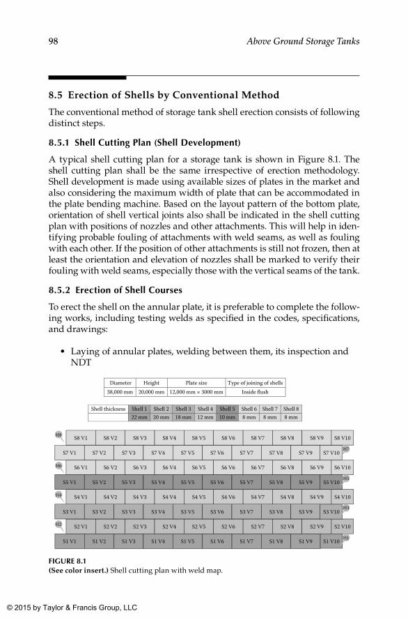
98 Above Ground Storage Tanks
8.5 Erection of Shells by Conventional Method
The conventional method of storage tank shell erection consists of following distinct steps.
8.5.1 Shell Cutting Plan (Shell Development)
A typical shell cutting plan for a storage tank is shown in Figure 8.1. The shell cutting plan shall be the same irrespective of erection methodology. Shell development is made using available sizes of plates in the market and also considering the maximum width of plate that can be accommodated in the plate bending machine. Based on the layout pattern of the bottom plate, orientation of shell vertical joints also shall be indicated in the shell cutting plan with positions of nozzles and other attachments. This will help in iden-tifying probable fouling of attachments with weld seams, as well as fouling with each other. If the position of other attachments is still not frozen, then at least the orientation and elevation of nozzles shall be marked to verify their fouling with weld seams, especially those with the vertical seams of the tank.
8.5.2 Erection of Shell Courses
To erect the shell on the annular plate, it is preferable to complete the follow-ing works, including testing welds as specified in the codes, specifications, and drawings:
• Laying of annular plates, welding between them, its inspection and NDT
Diameter Height Plate size Type of joining of shells38,000 mm 20,000 mm 12,000 mm × 3000 mm Inside �ush
Shell thickness Shell 1 Shell 2 Shell 3 Shell 4 Shell 5 Shell 6 Shell 7 Shell 822 mm 20 mm 18 mm 12 mm 10 mm 8 mm 8 mm 8 mm
S1 V1 S1 V2 S1 V3 S1 V4 S1 V5 S1 V6 S1 V7 S1 V8 S1 V9 S1 V10
S2 V1 S2 V2 S2 V3 S2 V4 S2 V5 S2 V6 S2 V7 S2 V8 S2 V9 S2 V10
S3 V1 S3 V2 S3 V3 S3 V4 S3 V5 S3 V6 S3 V7 S3 V8 S3 V9 S3 V10
S4 V1 S4 V2 S4 V3 S4 V4 S4 V5 S4 V6 S4 V7 S4 V8 S4 V9 S4 V10
S5 V1 S5 V2 S5 V3 S5 V4 S5 V5 S5 V6 S5 V7 S5 V8 S5 V9 S5 V10
S6 V1 S6 V2 S6 V3 S6 V4 S6 V5 S6 V6 S6 V7 S6 V8 S6 V9 S6 V10
S7 V1 S7 V2 S7 V3 S7 V4 S7 V5 S7 V6 S7 V7 S7 V8 S7 V9 S7 V10
S8 V1 S8 V2 S8 V3 S8 V4 S8 V5 S8 V6 S8 V7 S8 V8 S8 V9 S8 V10
H7
H5
H3
H1
H8
H6
H4
H2
FIGuRE 8.1(See color insert.) Shell cutting plan with weld map.
K22265_Book.indb 98 4/20/15 5:47 PM
© 2015 by Taylor & Francis Group, LLC
99Erection of Shell Courses, Roofs, and Other Appurtenances
• Laying of bottom plates, welding between them, its inspection and NDT
• Laying of sketch plates, its welding with bottom plate, its inspection and NDT
To minimize buckling of the bottom plate, the weld between sketch plates and annular plates is done only at the end, that is, at any time after welding (inside and outside) of the first shell course to the annular plate.
On the completed annular plate, the outer and inner circumferences of first shell course of tank are marked. Wherever this marking crosses butt welds (with a backing strip) of the annular plate, weld reinforcement is ground flush with the parent metal to facilitate proper seating of the shell to the annular plate. This may be done for a width of about 25 mm on either side of the shell thickness already marked on the annular plate. For stor-age tanks, shell thickness shall vary with height, meaning the first shell course would be thicker compared to others due to variation in static head envisaged.
Each shell course shall be erected as per the cutting plan in relation to the orientation marking already made on the bottom plate.
Plates of the first shell course shall be erected one by one progressively till the entire circumference is completed. After fit up of entire shell plates, the circumference at both ends (at top and bottom) is recorded. This reading shall be recorded under the head “During Fit Up” with weld gaps as pro-vided. In practice it is observed that whatever gap provided at fit up vanishes after welding because of shrinkage of welds. Therefore, it is recommended that the shell circumference shall be maintained at the actual circumference required + gap X number of vertical seams, worked out as follows:
Required outside circumference according to drawing = (ID + 2 T) X ∏ mm say XNumber of shell plate required for the shell course = 10Therefore, the number of vertical seams = 10Gap specified in weld joint configuration = 3 mmTherefore, outside circumference at fit up = X + 10×3 mm
= X + 30 mm
For the typical tank shell development shown in Figure 8.1, the circumfer-ence requirement during fit up with a gap of 3 mm (as in design) is worked out as shown in Table 8.1.
The circumference shall be measured at both ends (top and bottom) of each shell course at about 50 mm to 75 mm away from the edges (horizontal joint). If these measurements are within acceptable limits, vertical joint edge prepa-ration shall be checked for compliance to the drawing and codes. Further profile at the weld joint also shall be checked, and correction if needed may be done prior to the start of welding. When all these parameters are within allowable limits, vertical seams can be released for welding.
K22265_Book.indb 99 4/20/15 5:47 PM
© 2015 by Taylor & Francis Group, LLC
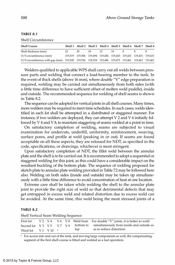
100 Above Ground Storage Tanks
Welders qualified to applicable WPS shall carry out all welds between pres-sure parts and welding that connect a load-bearing member to the tank. In the event of thick shells (above 16 mm), where double “V” edge preparation is required, welding may be carried out simultaneously from both sides (with a little time difference to have sufficient offset of molten weld puddle), inside and outside. The recommended sequence for welding of shell seams is shown in Table 8.2.
The sequence can be adopted for vertical joints in all shell courses. Many times, more welders may be required to meet time schedules. In such cases, welds iden-tified in each lot shall be attempted in a distributed or staggered manner. For instance, if two welders are deployed, they can attempt V 2 and V 6 initially fol-lowed by V 4 and V 8, to maintain staggering of seams welded at a point in time.
On satisfactory completion of welding, seams are subjected to visual examination for undercuts, underfill, uniformity, reinforcement, weaving, surface pores, and profile at weld (peaking in or out). If seams are found acceptable on all these aspects, they are released for NDT, as specified in the code, specifications, or drawings, whichever is most stringent.
Upon satisfactory completion of NDT, the fillet weld between the annular plate and the shell is to be carried out. It is recommended to adopt a sequential or staggered welding for this joint, as this could have a considerable impact on the resultant buckling of the bottom plate. The sequence of welding proposed for sketch plate to annular plate welding provided in Table 7.2 may be followed here also. Welding on both sides (inside and outside) may be taken up simultane-ously with a little time difference to avoid concentration of heat at one location.
Extreme care shall be taken while welding the shell to the annular plate joint to provide the right size of weld so that detrimental defects that may get entrapped in excess weld and related distortion due to excess weld can be avoided. At the same time, this weld being the most stressed joints of a
TAblE 8.2
Shell Vertical Seam Welding Sequence
First lot V 2 V 4 V 6 V 8 Weld from bottom to top
For double “V” joints, it is better to weld simultaneously from inside and outside so as to reduce distortion.
Second lot V 3 V 5 V 7 V 9Third lot V 1 V 10 a
a For access into and out of the tank, and moving large components as well, the compensating segment of the first shell course is fitted and welded as a last operation.
TAblE 8.1
Shell Circumference
Shell Course Shell 1 Shell 2 Shell 3 Shell 4 Shell 5 Shell 6 Shell 7 Shell 8
Shell thickness (mm) 22 20 18 12 10 8 8 8
O/S circumference (mm) 119,519 119,506 119,494 119,456 119,443 119,431 119,431 119,431
O/S circumference with gap (mm) 119,549 119,536 118,524 119,486 119,473 119,461 119,461 119,461
K22265_Book.indb 100 4/20/15 5:47 PM
© 2015 by Taylor & Francis Group, LLC
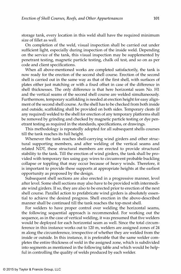
101Erection of Shell Courses, Roofs, and Other Appurtenances
storage tank, every location in this weld shall have the required minimum size of fillet as well.
On completion of the weld, visual inspection shall be carried out under sufficient light, especially during inspection of the inside weld. Depending on the service of the tank, this visual inspection may be supplemented by penetrant testing, magnetic particle testing, chalk oil test, and so on as per code and client specifications.
When all above-mentioned works are completed satisfactorily, the tank is now ready for the erection of the second shell course. Erection of the second shell is carried out in the same way as that of the first shell, with surfaces of plates either just matching or with a fixed offset in case of the difference in shell thicknesses. The only difference is that here horizontal seam No. H1 and the vertical seams of the second shell course are welded simultaneously. Furthermore, temporary scaffolding is needed at erection height for easy align-ment of the second shell course. As the shell has to be checked from both inside and outside, scaffolding shall be provided on both sides. Temporary cleats (if any required) welded to the shell for erection of any temporary platforms shall be removed by grinding and checked by magnetic particle testing or dye pen-etrant testing as required in the standards, specifications, or drawings.
This methodology is repeatedly adopted for all subsequent shells courses till the tank reaches its full height.
Whenever the tank reaches shell-carrying wind girders and other struc-tural supporting members, and after welding of the vertical seams and related NDT, these structural members are erected to provide structural stability to the tank. Till the erection of wind girders, the tank shall be pro-vided with temporary ties using guy wires to circumvent probable buckling collapse or toppling that may occur because of heavy winds. Therefore, it is important to provide these supports at appropriate heights at the earliest opportunity as proposed by the design.
Subsequent shell sections are also erected in a progressive manner, level after level. Some shell sections may also have to be provided with intermedi-ate wind girders. If so, they are also to be erected prior to erection of the next shell course. Parallel action to prefabricate wind girders is absolutely essen-tial to achieve the desired progress. Shell erection in the above-described manner shall be continued till the tank reaches the top-most shell.
For welders to have proper control over welding the horizontal seams, the following sequential approach is recommended. For working out the sequence, as in the case of vertical welding, it was presumed that five welders would be deployed for each horizontal seam as well. Since the total circum-ference in this instance works out to 120 m, welders are assigned zones of 24 m along the circumference, irrespective of whether they are welded from the inside or outside. In this instance, it is preferable that the same welder com-pletes the entire thickness of weld in the assigned zone, which is subdivided into segments as mentioned in the following table and which would be help-ful in controlling the quality of welds produced by each welder.
K22265_Book.indb 101 4/20/15 5:47 PM
© 2015 by Taylor & Francis Group, LLC
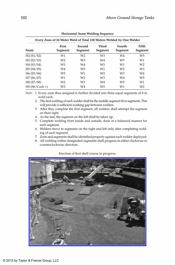
102 Above Ground Storage Tanks
Horizontal Seam Welding Sequence
Every Zone of 24 Meter Weld of Total 120 Meters Welded by One Welder
Seam First
SegmentSecond
SegmentThird
SegmentFourth
SegmentFifth
Segment
H2 (S1/S2) W1 W2 W3 W4 W5H3 (S2/S3) W2 W3 W4 W5 W1H4 (S3/S4) W3 W4 W5 W1 W2H5 (S4/S5) W4 W5 W1 W2 W3H6 (S5/S6) W5 W1 W2 W3 W4H7 (S6/S7) W1 W2 W3 W4 W5H8 (S7/S8) W2 W3 W4 W5 W1H9 (S8/Curb <) W3 W4 W5 W1 W2
Note: 1. Every zone thus assigned is further divided into three equal segments of 8 m weld each.
2. The first welding of each welder shall be the middle segment (8 m segment). This will provide a sufficient working gap between welders.
3. After they complete the first segment, all welders shall attempt the segment on their right.
4. As the last, the segment on the left shall be taken up. 5. Complete welding from inside and outside, done in a balanced manner for
each segment. 6. Welders move to segments on the right and left only after completing weld-
ing of each segment. 7. Zone and segments shall be identified properly against each welder deployed. 8. All welding within designated segments shall progress in either clockwise or
counterclockwise direction.
Erection of first shell course in progress.
K22265_Book.indb 102 4/20/15 5:47 PM
© 2015 by Taylor & Francis Group, LLC
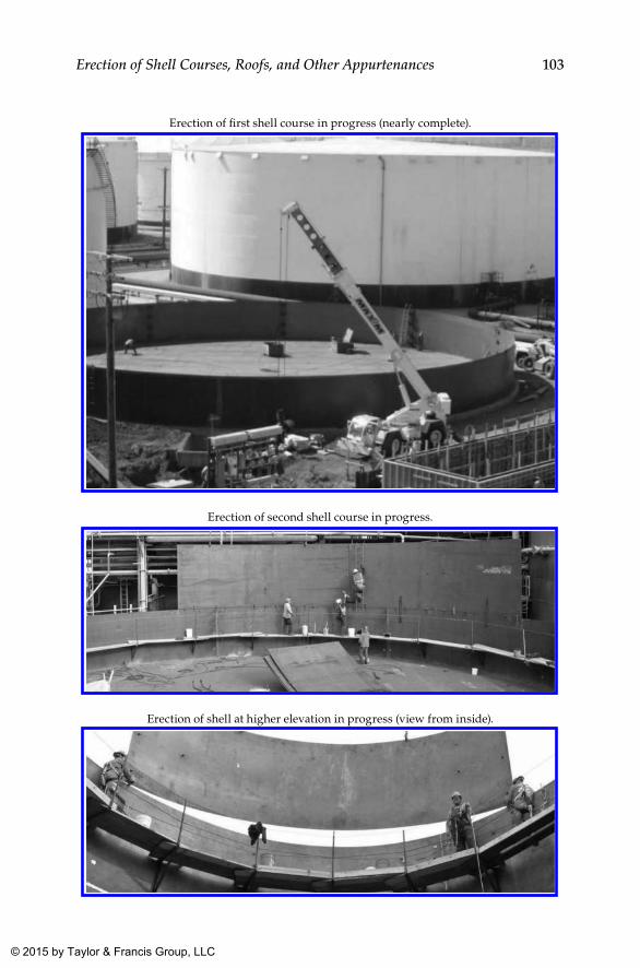
103Erection of Shell Courses, Roofs, and Other Appurtenances
Erection of first shell course in progress (nearly complete).
Erection of second shell course in progress.
Erection of shell at higher elevation in progress (view from inside).
K22265_Book.indb 103 4/20/15 5:47 PM
© 2015 by Taylor & Francis Group, LLC
http://www.crcnetbase.com/action/showImage?doi=10.1201/b18505-9&iName=master.img-001.jpg&w=322&h=242
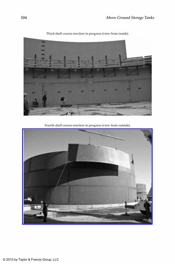
104 Above Ground Storage Tanks
Third shell course erection in progress (view from inside).
Fourth shell course erection in progress (view from outside).
K22265_Book.indb 104 4/20/15 5:47 PM
© 2015 by Taylor & Francis Group, LLC
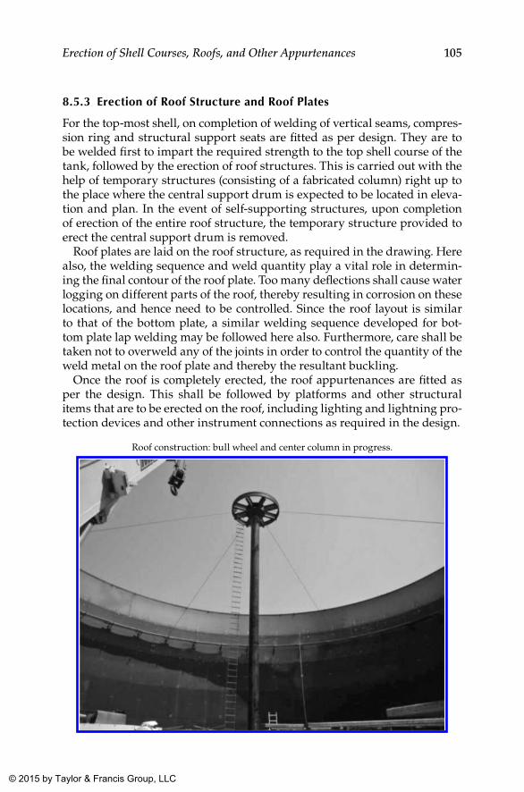
105Erection of Shell Courses, Roofs, and Other Appurtenances
8.5.3 Erection of Roof Structure and Roof Plates
For the top-most shell, on completion of welding of vertical seams, compres-sion ring and structural support seats are fitted as per design. They are to be welded first to impart the required strength to the top shell course of the tank, followed by the erection of roof structures. This is carried out with the help of temporary structures (consisting of a fabricated column) right up to the place where the central support drum is expected to be located in eleva-tion and plan. In the event of self-supporting structures, upon completion of erection of the entire roof structure, the temporary structure provided to erect the central support drum is removed.
Roof plates are laid on the roof structure, as required in the drawing. Here also, the welding sequence and weld quantity play a vital role in determin-ing the final contour of the roof plate. Too many deflections shall cause water logging on different parts of the roof, thereby resulting in corrosion on these locations, and hence need to be controlled. Since the roof layout is similar to that of the bottom plate, a similar welding sequence developed for bot-tom plate lap welding may be followed here also. Furthermore, care shall be taken not to overweld any of the joints in order to control the quantity of the weld metal on the roof plate and thereby the resultant buckling.
Once the roof is completely erected, the roof appurtenances are fitted as per the design. This shall be followed by platforms and other structural items that are to be erected on the roof, including lighting and lightning pro-tection devices and other instrument connections as required in the design.
Roof construction: bull wheel and center column in progress.
K22265_Book.indb 105 4/20/15 5:47 PM
© 2015 by Taylor & Francis Group, LLC
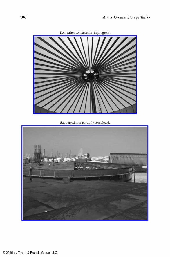
106 Above Ground Storage Tanks
Roof rafter construction in progress.
Supported roof partially completed.
K22265_Book.indb 106 4/20/15 5:47 PM
© 2015 by Taylor & Francis Group, LLC
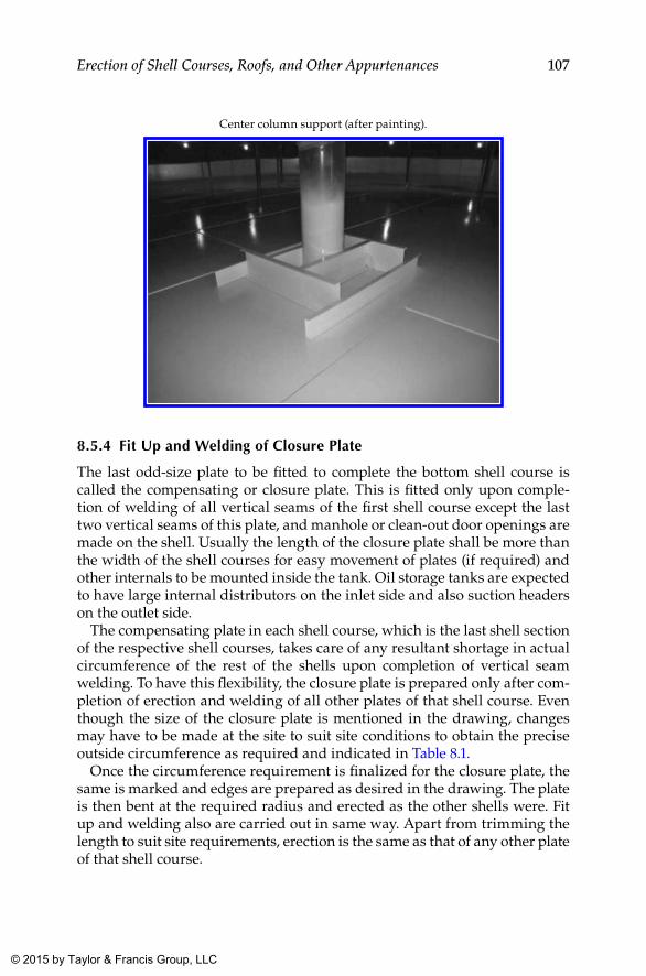
107Erection of Shell Courses, Roofs, and Other Appurtenances
Center column support (after painting).
8.5.4 Fit up and Welding of Closure Plate
The last odd-size plate to be fitted to complete the bottom shell course is called the compensating or closure plate. This is fitted only upon comple-tion of welding of all vertical seams of the first shell course except the last two vertical seams of this plate, and manhole or clean-out door openings are made on the shell. Usually the length of the closure plate shall be more than the width of the shell courses for easy movement of plates (if required) and other internals to be mounted inside the tank. Oil storage tanks are expected to have large internal distributors on the inlet side and also suction headers on the outlet side.
The compensating plate in each shell course, which is the last shell section of the respective shell courses, takes care of any resultant shortage in actual circumference of the rest of the shells upon completion of vertical seam welding. To have this flexibility, the closure plate is prepared only after com-pletion of erection and welding of all other plates of that shell course. Even though the size of the closure plate is mentioned in the drawing, changes may have to be made at the site to suit site conditions to obtain the precise outside circumference as required and indicated in Table 8.1.
Once the circumference requirement is finalized for the closure plate, the same is marked and edges are prepared as desired in the drawing. The plate is then bent at the required radius and erected as the other shells were. Fit up and welding also are carried out in same way. Apart from trimming the length to suit site requirements, erection is the same as that of any other plate of that shell course.
K22265_Book.indb 107 4/20/15 5:47 PM
© 2015 by Taylor & Francis Group, LLC
108 Above Ground Storage Tanks
8.5.5 Fit up and Welding of First Shell Course to Annular Plate
As mentioned already, the first shell course is erected on the annular plate. The first step in this regard shall be marking the inside and outside circum-ferences of the first shell course on the annular plate as per the drawing. Wherever this marking crosses butt welds between segments of annular plates, reinforcement of butt welds is ground flush with the parent metal to facilitate proper placement and seating of the shell course on the com-pleted annular plate. This flush grinding of the reinforcement is done for a length of about 25 mm on either side of the circumferences marked on the annular plate.
Shell plates are squared, and edges are prepared as required in the draw-ing. The sizes of all individual shell plates shall be provided in the shell cutting plan, in which all other plates except the closure plate shall be of full size. Since the orientation of the tank is already fixed before laying the annular or bottom plates, shell plates are erected according to the prefixed orientation of the bottom plate. Shell plates are then erected progressively from one end to the other excluding the closure plate, which is erected at the end.
Usually, the weld between the annular plate and the first shell course shall be a fillet weld, with or without a “V” on the shell plate. Some client specifica-tions insist for a 450 “V” bevel of the shell plate at the joint. Shells are aligned vertically as per the shell cutting plan along the circumference already marked on the annular plate. Stiffeners are provided at fixed intervals to retain plates in a vertical position along the circumference. Since shell plates are already bent to the required diameter, this process is comparatively easy. Upon completion of erection of all shell plates, the circumference at the bot-tom and top of each shell course is taken. This shall be within acceptable limits as specified in the code or client specification, whichever is more strin-gent. The weld joint configuration of the shell to the annular plate joint and all vertical seams are then inspected for profile at the joint, “V” geometry, and uniformity in edge preparation throughout the entire joint (especially root face and gap). In case these are within acceptable limits as per applicable documents, the same can be released for welding.
8.6 Methodology for Tank Erection by the Jacking Up Method
8.6.1 brief Overview
An outline of the methodology goes as follows. Though the erection of a spec-ified shell course is the same as that in the conventional method described in earlier sections, in this method, instead of erecting the first shell course first, the last or topmost shell course is erected first.
K22265_Book.indb 108 4/20/15 5:47 PM
© 2015 by Taylor & Francis Group, LLC
109Erection of Shell Courses, Roofs, and Other Appurtenances
The tank bottom plates are placed on the prepared foundation and welded together as described in Chapter 7. Spacers cum guide beams (or pipes) of not more than 400 mm height (stools) are tack welded to the tank bottom along the periphery of the shell plates, already marked on the annular plate. The shell circumference is again marked on the stool surface plate, for easy erec-tion of the shell plates. The shell plates of the first shell course (the top ring of the tank) are positioned on these temporary chairs, aligned, fitted up using temporary clamps, and welded together.
Lifting equipment (jacks, trestles, and hydraulic pumps) is assembled as shown in Figure 8.2. Further shell plates of the second shell course (next to the top course) are positioned outside the first one. The completed part of the tank (top shell) is lifted hydraulically to a height so that plates of the next shell course can be moved into place immediately.
Plates of the second shell course are located exactly as per the drawing with proper staggering of the vertical seam, and all vertical seams are welded. The horizontal seam between courses is also welded in a progressive man-ner. This shall be followed by welding the attachments and accessories to this shell course, erecting the roof structures, and laying the roof plates.
Upon completion of the horizontal seam welding (between the top two shell courses) or while it is progressing, the roof structure installation can be taken up, followed by laying the roof plates.
While welding of the roof plates is being completed, all appurtenances and accessories such as handrails, platforms, supports on the roof, portions of the staircase, and similar accessories on the top two shell courses also shall be completed in all respects, including the NDT and all other inspec-tions. However, one or two roof plates (based on the size of the tank) are not placed, usually to facilitate circulation of air during the entire construction operation. These plates are welded once all internal welding and assembly works are completed.
Upon completion of these steps, the plates of the third shell course are placed outside the second shell ring, and the portion of the tank is now ready for lifting. This cycle of operations is repeated until the last (bottom) shell ring is fitted and welded to the second shell course from the bottom of the tank. The entire tank is now lowered down to the annular plate. On completion of the annular plate to the shell welding, the lifting equipment is dismantled.
8.6.2 Detailed Working Procedure
• The tank periphery (shell ID and OD) is marked out on annular plates.
• Spacers cum guide beams for guiding shell courses are placed at approximately 1,500 mm–2,000 mm spacing, at a fixed level, and are tack welded to the annular or bottom plates.
K22265_Book.indb 109 4/20/15 5:47 PM
© 2015 by Taylor & Francis Group, LLC
110 Above Ground Storage Tanks
• The first (uppermost) shell course is positioned on leveled spacer cum guide beams, and the level of shell ring also shall be checked as reconfirmation. Shell plates shall be placed exactly as per the con-tour (radius) marked on the guide beam surface plate and shall be truly vertical (within the specified tolerance).
• Welding, inspection, and NDT follow.• The roof structure is assembled and fastened to the top shell course.
Most of the roof plates are placed and welded (except for one or two) for easy air circulation.
• The location of lifting trestles is marked out inside the erected shell course at equal spacing.
• The lifting equipment (described in Section 8.6.4, Figure 8.2) is installed.
• The first shell course is lifted to one plate height.• The second shell course (from top) is erected next.• While the horizontal seam welding between these two shells is pro-
gressing, the roof structure assembly and welding followed by the laying of roof plates and its welding are carried out.
• The completed part of the tank is lifted so that the next shell ring can be inserted below the first two shells. Care shall be taken not to lift too much above the requirement.
• Lifting can be stopped at any moment by the operator by cutting fluid flow to the jacks. In practice, lift may not be the same at all points. As soon as the required height is reached at any one point, lifting is stopped, and the stop valve of that lifting point (jack) is closed. Lifting is continued until the required height is reached at all lifting points.
• All valves are to be closed, and the elevated section of the tank is now loaded on lower grip-jaws of the climbing jacks.
• Adjustment of the tank level (if necessary) can be made by lifting or lowering with one or more jacks at a time. While doing so, the valves on the other jacks shall be closed.
• The shell course is fitted and welded (vertical joints followed by horizontal joints). For easy movement of personnel and materi-als, the erection and welding of the last (closure) plate of each course is carried out as the last operation in each shell course erection.
K22265_Book.indb 110 4/20/15 5:47 PM
© 2015 by Taylor & Francis Group, LLC
111Erection of Shell Courses, Roofs, and Other Appurtenances
• All welding works (including the welding of the closure plate) on respective shell courses shall be completed prior to lift up. This includes vertical and horizontal welds (from both sides) and that of all appurtenances, attachments, and accessories.
• Climbing jacks and sliding chairs are lowered, one at a time, using a rope with chain. During this operation, both of the grip-jaw sets of the jack shall be in a disengaged position.
• Lifting and fend-off lugs are now welded to the next uppermost shell course.
• This procedure is repeated for all following shell courses. As the shell courses are added, the load on the lifting trestles increases, which calls for higher oil pressures. However, the oil pressure shall not be increased exorbitantly, and in no case should this exceed 135 kg/cm2.
• Before assembly of the last (bottom) shell course, all the spacers cum guide beams are removed. If necessary, a hydraulic power pack also can be placed outside the tank.
• After the last shell ring is welded to the tank wall, fit up and welding of the bottom shell to the annular plate joint is carried out.
• Lifting attachments and equipment are dismantled and removed through the last plate of the bottom shell course. This plate is welded as the last operation.
Note that lifting of the tank shall not be carried out when wind veloc-ity exceeds “maximum safe wind speed for lifting,” which can be obtained from the tank erection specialist. Weather forecasts shall be referred to in this regard to select proper timing for lifting.
8.6.3 Salient Features and limitations of the Jacking up Method
Salient Parameters in Jacking Up
Sl. No. Parameter Limitation
1 Plate width Up to 3 m2 Unitary climb 100 mm/stroke3 Lifting capacity 12 T4 Plate thickness Up to 30 mm5 Time per stroke 5 min6 Working pressure
Hydraulic system200 kg/cm2
K22265_Book.indb 111 4/20/15 5:47 PM
© 2015 by Taylor & Francis Group, LLC
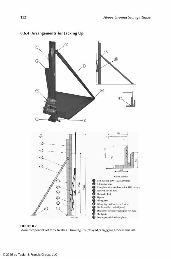
112 Above Ground Storage Tanks
8.6.4 Arrangements for Jacking up
3
4
9
10
6
11
81
7
5
2
4
1
11
8
2
7
400
600
Guide Trestle123456789
101112
RHS Section 100 × 100 × 3500 mmAdjustable stayBase plate with attachment for RHS sectionJack rod 35 × 35 mmHydraulic JackSlipperLifting armLifting lug (welded to shell plate)Guide (welded to shell plate)Shut off cock with coupling for HP hoseShell plateStay lug (welded to base plate)
9
Max
. 250
0
3500
900–
1100
700
500
6
10
5
3
93
12
FIGuRE 8.2Main components of tank trestles. Drawing Courtesy M/s Bygging Uddemann AB.
K22265_Book.indb 112 4/20/15 5:47 PM
© 2015 by Taylor & Francis Group, LLC
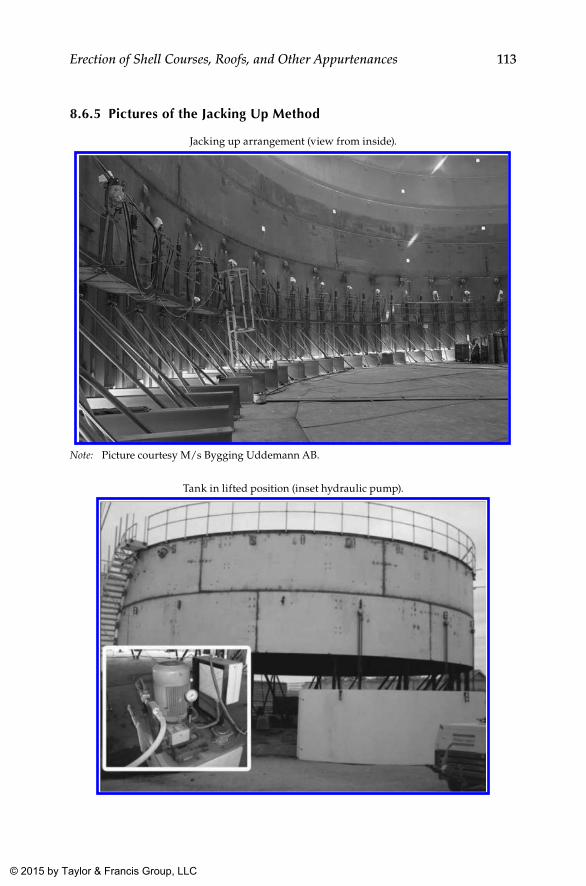
113Erection of Shell Courses, Roofs, and Other Appurtenances
8.6.5 Pictures of the Jacking up Method
Jacking up arrangement (view from inside).
Note: Picture courtesy M/s Bygging Uddemann AB.
Tank in lifted position (inset hydraulic pump).
K22265_Book.indb 113 4/20/15 5:47 PM
© 2015 by Taylor & Francis Group, LLC
114 Above Ground Storage Tanks
8.7 Erection of Roof Structure and Cone Roof Plates
In the jacking up method, the fit up and welding of the curb angle or com-pression ring is carried out after the completion of erection and welding of the two shell courses at the top. In the conventional method, this activity can be taken up only after erection of the top shell course, and all this activity shall take place at the full height of the tank. In both cases, this is followed by the erection of the fabricated center drum, roof truss, girders, and cross gird-ers as per the drawing. The roof structure installation involves both weld-ing of supports and bolting of the structure to the shell supports and center drum. The roof structure welding also shall be carried out by welders quali-fied to the approved welding procedure specification for the purpose.
Later roof plates are laid on the structure as per the drawing. During fit up of the short and long seam lap joints, proper lap as required in the drawing shall be maintained. To minimize distortion of the roof plate due to welding, it is recommended to follow sequential welding as in the case of the bottom plate. Since the layout plan of the roof plate also resembles that of the bot-tom plate, the welding sequence developed for the bottom plate as shown in Table 7.2 can be adopted here to minimize distortion.
Along with these works, roof nozzles, manways, and other attachments are fit up and welded. Ensure that nozzles, manways, and attachments are positioned exactly as required in the drawings.
8.8 Shell Appurtenances
In the conventional method of shell erection, nozzles, manways, and other attachments can be welded at any point during the time after the tank has acquired enough rigidity. In the jacking up method, shell appurtenances and attachments, including spiral stairways, have to be completed along with each shell course erection. Otherwise, scaffolding may have to be erected again for this purpose.
8.9 Manufacture of Subassemblies
Items that are categorized under this heading are those fittings and attach-ments that can be manufactured simultaneously with the construction of the tank as a parallel activity. These include, but are not limited to, the following:
• clean-out doors (COD)• manways (shell and roof) and davits, if any
K22265_Book.indb 114 4/20/15 5:47 PM
© 2015 by Taylor & Francis Group, LLC
115Erection of Shell Courses, Roofs, and Other Appurtenances
• nozzles• anchor chairs• curb angles, wind girders, compression ring, etc.• pipe support cleats and supports• roof support chairs• platform and ladder supports• distributor supports and chairs• platforms, ladders, etc.
These items are manufactured separately according to priority well in advance. Nozzles and manways may require NDT like RT, which may be a bit time-consuming and hence to be borne in mind while planning. Similarly, clean-out doors often call for post weld heat treatment (PWHT) after manufacture and NDT, prior to installation. Since a PWHT facility is not required at the site, this often has to be outsourced locally. This also has to be considered while planning subassembly works.
Since manway sizes (as per code) range from 500 mm to 900 mm, man-way necks have to be manufactured from the plate by bending. This also requires radiography for its long seam. Similarly, some client specifications require RT for nozzle necks to flange welds as well. Prior to the release of these subassemblies for installation, it shall be ensured that all required inspections and tests on these components are completed, so that the only remaining inspection shall be that related to installation and welding on the tank.
8.10 Installation of Appurtenances
The flange to pipe joint shall be prefabricated, and the required NDT shall be completed before fit up. Prior to this, orientation and eleva-tion shall be marked on the shell and roof as per the drawing. Since this happens at elevation, manual gas cutting alone shall be possible in most circumstances. Highly skilled gas cutters shall be deployed for such works so that rework can be eliminated to the extent possible. Upon making a straight cut opening on the shell, proper edge prepara-tion also shall be done by gas cutting or grinding as applicable. Fit up of prefabricated nozzles and manways is carried out as per the draw-ing at the required orientation and elevation with required standoff for nozzles. Large-size nozzles and manways shall require reinforcement pads as well and have to be installed along with nozzles or manways as the case may be.
K22265_Book.indb 115 4/20/15 5:47 PM
© 2015 by Taylor & Francis Group, LLC
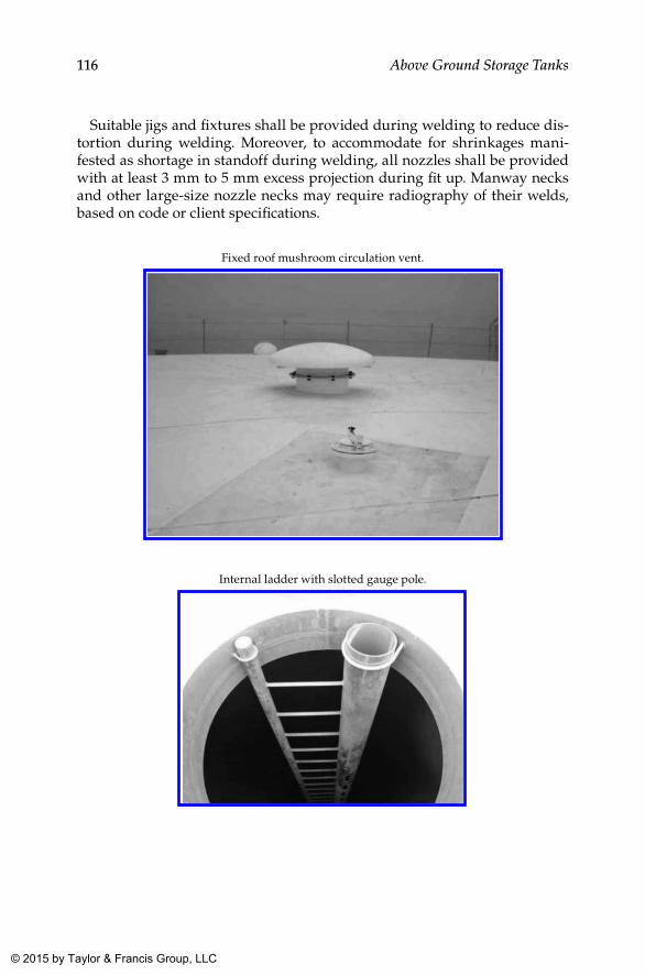
116 Above Ground Storage Tanks
Suitable jigs and fixtures shall be provided during welding to reduce dis-tortion during welding. Moreover, to accommodate for shrinkages mani-fested as shortage in standoff during welding, all nozzles shall be provided with at least 3 mm to 5 mm excess projection during fit up. Manway necks and other large-size nozzle necks may require radiography of their welds, based on code or client specifications.
Fixed roof mushroom circulation vent.
Internal ladder with slotted gauge pole.
K22265_Book.indb 116 4/20/15 5:47 PM
© 2015 by Taylor & Francis Group, LLC
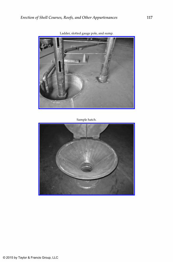
117Erection of Shell Courses, Roofs, and Other Appurtenances
Ladder, slotted gauge pole, and sump.
Sample hatch.
K22265_Book.indb 117 4/20/15 5:47 PM
© 2015 by Taylor & Francis Group, LLC
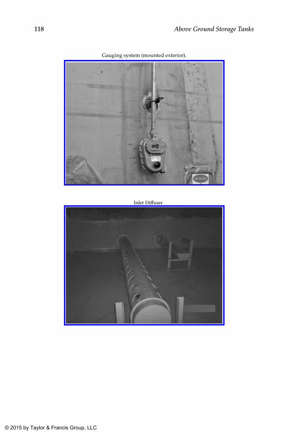
118 Above Ground Storage Tanks
Gauging system (mounted exterior).
Inlet Di�user
K22265_Book.indb 118 4/20/15 5:48 PM
© 2015 by Taylor & Francis Group, LLC
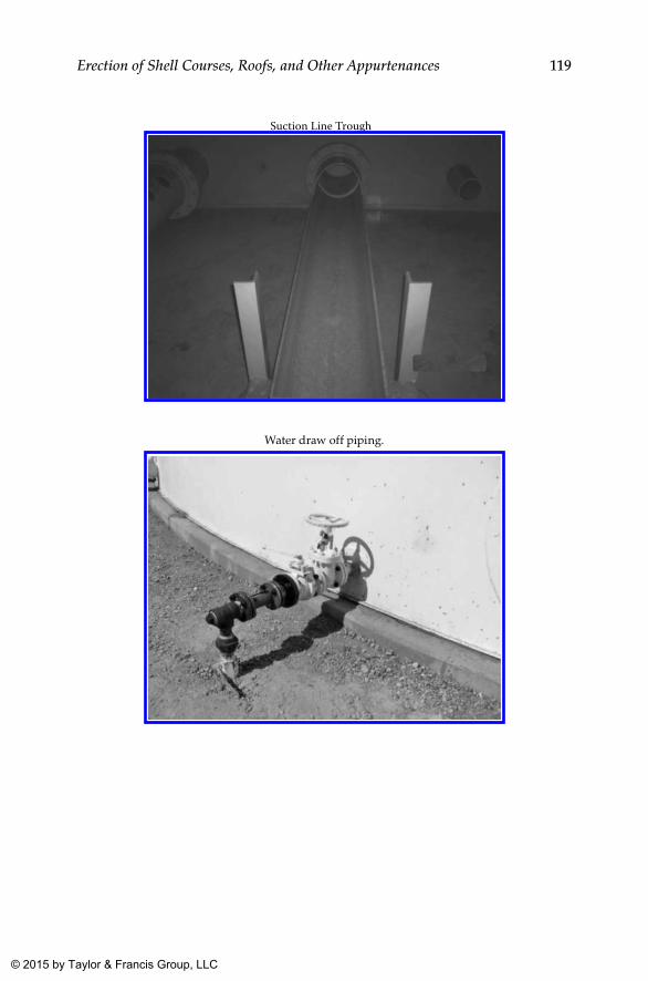
119Erection of Shell Courses, Roofs, and Other Appurtenances
Suction Line Trough
Water draw off piping.
K22265_Book.indb 119 4/20/15 5:48 PM
© 2015 by Taylor & Francis Group, LLC
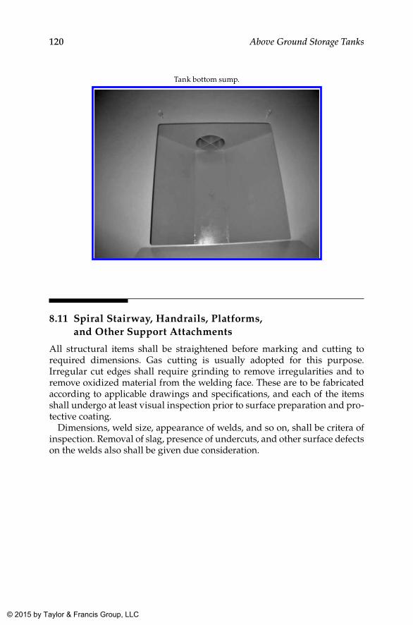
120 Above Ground Storage Tanks
Tank bottom sump.
8.11 Spiral Stairway, Handrails, Platforms, and Other Support Attachments
All structural items shall be straightened before marking and cutting to required dimensions. Gas cutting is usually adopted for this purpose. Irregular cut edges shall require grinding to remove irregularities and to remove oxidized material from the welding face. These are to be fabricated according to applicable drawings and specifications, and each of the items shall undergo at least visual inspection prior to surface preparation and pro-tective coating.
Dimensions, weld size, appearance of welds, and so on, shall be critera of inspection. Removal of slag, presence of undercuts, and other surface defects on the welds also shall be given due consideration.
K22265_Book.indb 120 4/20/15 5:48 PM
© 2015 by Taylor & Francis Group, LLC
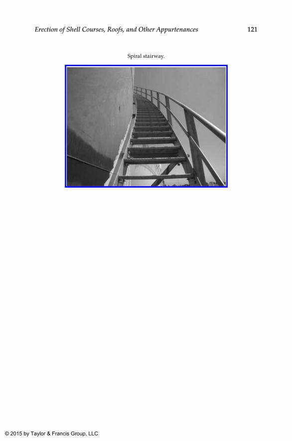
121Erection of Shell Courses, Roofs, and Other Appurtenances
Spiral stairway.
K22265_Book.indb 121 4/20/15 5:48 PM
© 2015 by Taylor & Francis Group, LLC
123
9Welding
9.1 Weld Edge Preparation
Edge preparation for any pressure and nonpressure joints shall be in accor-dance with the design given in the concerned drawing prepared according to code and specifications. Variations in the configuration (such as a change in “V” angle, etc.) shall be within normal allowable tolerances. Variation of root gap is one of the major problems seen during fit up of groove welds. Variation of root gap shall be limited within 1 mm to 1.5 mm throughout the entire weld joint (for vertical seams). Though this is not specified anywhere in API 650, provided proper care is taken during edge preparation and sub-sequent handling and fit up of the shell plates, this tolerance is quite possible. If this is achieved, its impact shall be seen in the final welding, and chances of having a repair shall be much less compared to a joint with more variation in root gap.
Another prominent defect usually observed is variation in root face or throat thickness. This may give rise to weld defects such as lack of fusion or insufficient fusion. With proper care taken during edge preparation, this can be reduced to a minimum. The preferred root face for shielded metal arc welding (SMAW) is in the range of 0.9 to 1.2 mm, which could be duly estab-lished while qualifying the welding procedure specification (WPS) (as this is principally dependent upon the current used and the manipulation of the welding rod in root welding).
9.2 Typical Weld Joints
The various types of weld joints that are considered acceptable as per API 650 are provided in the following table, with reference to the applicable sketches in the API 650 2013 edition.
Though the standard specifies various options in selecting weld joint details, its judicious selection depending on the situation is the prerogative
K22265_Book.indb 123 4/20/15 5:48 PM
© 2015 by Taylor & Francis Group, LLC
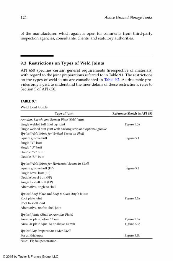
124 Above Ground Storage Tanks
of the manufacturer, which again is open for comments from third-party inspection agencies, consultants, clients, and statutory authorities.
9.3 Restrictions on Types of Weld Joints
API 650 specifies certain general requirements (irrespective of materials) with regard to the joint preparations referred to in Table 9.1. The restrictions on the types of weld joints are consolidated in Table 9.2. As this table pro-vides only a gist, to understand the finer details of these restrictions, refer to Section 5 of API 650.
TAblE 9.1
Weld Joint Guide
Type of Joint Reference Sketch in API 650
Annular, Sketch, and Bottom Plate Weld JointsSingle welded full fillet lap joint Figure 5.3aSingle welded butt joint with backing strip and optional grooveTypical Weld Joints for Vertical Seams in ShellSquare groove butt Figure 5.1Single “V” buttSingle “U” buttDouble “V” buttDouble “U” butt
Typical Weld Joints for Horizontal Seams in ShellSquare groove butt (FP) Figure 5.2Single bevel butt (FP)Double bevel butt (FP)Angle to shell butt (FP)Alternative, angle to shell
Typical Roof Plate and Roof to Curb Angle JointsRoof plate joint Figure 5.3aRoof to shell jointAlternative, roof to shell joint
Typical Joints (Shell to Annular Plate)Annular plate below 13 mm Figure 5.3aAnnular plate equal to or above 13 mm Figure 5.3c
Typical Lap Preparation under ShellFor all thickness Figure 5.3b
Note: FP, full penetration.
K22265_Book.indb 124 4/20/15 5:48 PM
© 2015 by Taylor & Francis Group, LLC
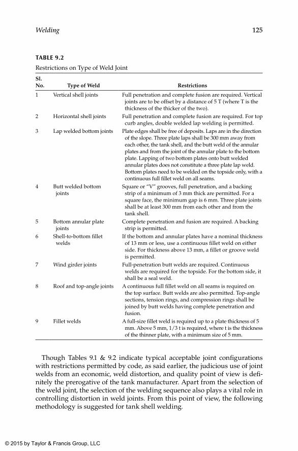
125Welding
Though Tables 9.1 & 9.2 indicate typical acceptable joint configurations with restrictions permitted by code, as said earlier, the judicious use of joint welds from an economic, weld distortion, and quality point of view is defi-nitely the prerogative of the tank manufacturer. Apart from the selection of the weld joint, the selection of the welding sequence also plays a vital role in controlling distortion in weld joints. From this point of view, the following methodology is suggested for tank shell welding.
TAblE 9.2
Restrictions on Type of Weld Joint
Sl. No. Type of Weld Restrictions
1 Vertical shell joints Full penetration and complete fusion are required. Vertical joints are to be offset by a distance of 5 T (where T is the thickness of the thicker of the two).
2 Horizontal shell joints Full penetration and complete fusion are required. For top curb angles, double welded lap welding is permitted.
3 Lap welded bottom joints Plate edges shall be free of deposits. Laps are in the direction of the slope. Three plate laps shall be 300 mm away from each other, the tank shell, and the butt weld of the annular plates and from the joint of the annular plate to the bottom plate. Lapping of two bottom plates onto butt welded annular plates does not constitute a three plate lap weld. Bottom plates need to be welded on the topside only, with a continuous full fillet weld on all seams.
4 Butt welded bottom joints
Square or “V” grooves, full penetration, and a backing strip of a minimum of 3 mm thick are permitted. For a square face, the minimum gap is 6 mm. Three plate joints shall be at least 300 mm from each other and from the tank shell.
5 Bottom annular plate joints
Complete penetration and fusion are required. A backing strip is permitted.
6 Shell-to-bottom fillet welds
If the bottom and annular plates have a nominal thickness of 13 mm or less, use a continuous fillet weld on either side. For thickness above 13 mm, a fillet or groove weld is permitted.
7 Wind girder joints Full-penetration butt welds are required. Continuous welds are required for the topside. For the bottom side, it shall be a seal weld.
8 Roof and top-angle joints A continuous full fillet weld on all seams is required on the top surface. Butt welds are also permitted. Top-angle sections, tension rings, and compression rings shall be joined by butt welds having complete penetration and fusion.
9 Fillet welds A full-size fillet weld is required up to a plate thickness of 5 mm. Above 5 mm, 1/3 t is required, where t is the thickness of the thinner plate, with a minimum size of 5 mm.
K22265_Book.indb 125 4/20/15 5:48 PM
© 2015 by Taylor & Francis Group, LLC
126 Above Ground Storage Tanks
9.3.1 Shell Vertical Joints
In the jacking up method, the shell is erected from top to bottom. In the con-ventional method, the shell is built the other way around. In both cases, the erection methodology followed is the same. Assembly of the first shell course (either top or bottom) is done in position, based on the circumference marked on the annular plate. In the jacking up method, shell plates are erected on spacer stools, whereas in the conventional method it is erected directly on an annular plate. Plates are set up one after another, and welding is normally carried out after the release of the entire shell course for vertical seam weld-ing, except the two seams on either side of the closure plate.
Upon erection of all plates of a shell course except the closure plate of that particular shell course, more welders are usually deployed simultaneously all around the circumference with a safe distance between each welder in order to meet stringent time schedules associated with the project.
For a tank 38 m in diameter, the approximate outside circumference is around 119.3 m. Assuming a plate length of 12 m, the entire circumference can be formed using nine full-size plates and a compensating plate of about 11.3 m length. This constitutes ten vertical weld joints. For easy movement of workers, materials, and machinery to and from the tank, the compensating (closure) plate shall be left open till completion of all works, and this plate is welded at the last stage (for conventional erection). Therefore, the number of vertical seams to be welded in the first phase is eight. If alternate vertical seams are attempted simultane-ously, this will provide a distance of around 24 m over circumference between welders. This requires four qualified welders at a minimum. If more welders are available, proper sequencing can be done at the site. The usual shell plate width is around 2.5 m to 3 m, and one welder can easily handle one seam. Such an assignment will exercise better control over quality and hence is recommended.
When welding is being done from the inside as well, the same number of welders can be deployed. From the distortion point of view, it is better if seams are welded simultaneously from the inside and outside. This requires deployment of additional welders. If this is done, proper time lag needs to be maintained between the start of the outside and inside welds. This is not possible for root and hot passes of groove welds in a manual process, which would require back gouging (in manual processes, the second side weld can be initiated only after back gouging and grinding of the second side to ensure sound base metal at the weld joint). In the event of double “V” preparation (for a shell thickness greater than 16 mm), the major “V” is usually provided on the outside, requiring more passes from the outside wherein more welders can be deployed comfortably, as they are in the open.
As far as possible, the same welder shall complete the weld, though it is permitted to have multiple welders for one seam as per code. If there is simultaneous welding from the inside and outside, this is not practical. Since the quantum of welding from the outside is more, more welders are required for the outside compared to the inside. As an option of manufacture, welding
K22265_Book.indb 126 4/20/15 5:48 PM
© 2015 by Taylor & Francis Group, LLC
127Welding
from the inside can be started either after completing welding from the out-side or after depositing two or three passes from the outside.
The last two joints are welded only after the closure plate is fitted. The closure plate is usually fitted only after all works are completed on the shell course from both the inside and the outside. As mentioned earlier, in the jack-ing up method, tank erection starts from top to bottom, after bottom plate erection and welding. In such cases, work on the top-most shell includes the erection of roof plates and other structural members including ladders, plat-forms, supports, and so on. Completion of these works is absolutely essen-tial, since carrying out these works at height poses safety hazards and also requires scaffolding again after erection.
Upon completion of all works on the shell course, the compensating plate or closure plate is fitted. The dimensions of this plate are decided based on the actual conditions at the site. The welding of two seams on the closure plate is also carried out as recommended for other vertical joints. In the jack-ing up method, each shell course shall be allowed to lift only after the erec-tion of all shell plates that are completed and fully welded. Jacking up the shell with partial welding of the shell courses shall not be permitted under any circumstances. This also requires completion of welding from the inside and outside of closure joints prior to lifting. As the shell plate is set up on stools of about 400 mm to 500 mm height, entry of workers into and out of the tank shall still be possible. The criteria for fixing stool height will be decided based on the width and height of the shell plate or sections to be used for construction of the shell and roof structures. If the width of the plate is more than 2,500 mm, it is always better to limit the stool height to about 400 mm to 450 mm so that entry of workers will still be possible. Excessive stool height may lead to the requirement of a platform to complete vertical seam welding of every shell course, especially when wider plates are used.
On completion of each shell course, it shall be lifted up, and the second course from the top shall be erected as per the staggering proposed in the drawing so as to avoid fouling of nozzles and other attachments with the main weld seams. In the conventional method, the difference is that shells are erected from bottom to top, and the closure plate on the first shell course is usually welded as a last operation, in addition to clean-out doors and man-ways for easy movement of workers, materials, and machinery.
9.4 Welding Processes
Usual welding processes that are permitted by API 650 (Clause 7.2.1.1) are SMAW, gas metal arc welding (GMAW), gas tunsten arc welding (GTAW), oxy fuel gas welding (OFW), flux cored arc welding (FCAW), submerged arc welding (SAW), electro slag welding (ESW), and electro
K22265_Book.indb 127 4/20/15 5:48 PM
© 2015 by Taylor & Francis Group, LLC
128 Above Ground Storage Tanks
gas welding (EGW) using appropriate equipment for the same. However, use of OFW, ESW, and EGW shall be employed only if the purchaser agrees for the same.
9.5 Welding Procedure Specifications
Upon receipt of the order for storage tanks, based on preliminary fabrica-tion drawings, the quality assurance team of the manufacturer prepares a comprehensive list of welding procedures required, including that for structural steel welds on the tank. For tanks constructed as per API 650/620, WPS and its qualification shall be carried out as per ASME Section IX. WPS shall be capable of addressing all expected combinations of weld sizes, base materials, and thickness ranges as required in respective draw-ings. This shall include all structural steel attachments to the tank shell as well. However, for ladder and platform assemblies, handrails, stairways, and other miscellaneous subassemblies, WPS need be qualified, either to AWS D1.1, AWS D1.6, or Section IX of ASME code, including the use of standard WPS.
In the case of established tank erectors, many (if not all) required WPS might be qualified already, and records may be available for review. In such circumstances, WPS need not be requalified. However, the decision of the inspection agency or client shall be final and binding in accordance with the contract. Though it is not mandatory that all WPS need to be qualified under third-party inspection, in the case of procedures already qualified by tank erectors, many clients require a third-party witness for the procedure qualification record (PQR) to improve its authenticity and as a minimum requirement for consideration.
9.6 Procedure Qualification
In the event of new WPS, a PQR test shall be carried out at the site or fac-tory, well in advance based on a proposed WPS, so that all mechanical tests required for qualification as per ASME Section IX can be completed prior to the start of work at the site. Obtaining approval of all necessary WPS with their PQRs shall be the responsibility of the QA team of the manufacturer (either at its works or at the site), and a controlled copy of this document shall be available with the site QC crew to proceed with the qualification of weld-ers and welding operators as required at the site.
K22265_Book.indb 128 4/20/15 5:48 PM
© 2015 by Taylor & Francis Group, LLC
129Welding
9.7 Welder Qualification
Once the PQR is qualified, the next important activity is the qualification of welders or welding operators. Since the construction of storage tanks is pre-dominantly a site activity, welders are normally recruited at the site. Because of this, welder and welding operator qualification tests are usually carried out at the site. The number of welders to be qualified against each process shall be judiciously decided based on the estimated quantum of welds in each category and time schedule for the entire construction activity accord-ing to the work plan.
Depending on production targets, available welders are qualified under different WPS. It would be advantageous to have a few more welders quali-fied than required so as to cater to voids created by unexpected migration of welders between contractors within the region. Welder or welding operator qualification also shall be carried out as per ASME Section IX, and certificates to this effect shall be issued at the site, the original of which shall be signed by all concerned agencies and shall be available at the site. Furthermore, it is desirable to issue the qualified welders with welder’s identification cards with photos so that unauthorized welding can be detected easily during sur-prise surveillance checks by inspecting agencies.
Welder qualification testing shall be carried out strictly in accordance with duly qualified WPS, and the welded test specimens shall be subjected to either a bend test or radiographic testing (RT) as required in ASME Section IX.
Though not mentioned in ASME Section IX, some client specifications allow welder qualification tests to be terminated at the welder’s option if he becomes aware that he has introduced a defect, and may be restarted after re-preparation or replacement of the test specimen. Only one such welder’s optional restart may be allowed except for intended restarts for new electrodes or repositioning.
On completion of the test weld, no repairs shall be allowed, including defects that are revealed by cosmetic grinding or filing as permitted.
The contractor, consultant, or client may terminate the test whenever it becomes apparent that the welder lacks the required skill to produce sat-isfactory results, or if he or she fails to observe the requirements of WPS or observe safety norms.
In the event of a test failure, the consultant or client reserves the right to disallow an immediate retest and to insist on a period of further training before any retest.
While ASME Section IX test requirements are sufficient for all commonly used welding processes like SMAW, SAW, and so on, additional test require-ments are specified by clients for welder or welding operator qualification for processes like SAW or EGW. The additional test usually recommended is ultrasonic examination of the weld in addition to either bend testing or radiography as required in ASME Section IX for qualification of welders and welding operators.
K22265_Book.indb 129 4/20/15 5:48 PM
© 2015 by Taylor & Francis Group, LLC
130 Above Ground Storage Tanks
9.8 Welder’s Identification Cards
Welders shall be assigned an identification code prior to undertaking any tests. A unique test number shall be allocated to each test and stamped on the specimen.
All test documentation shall reference this test number. Identification, grade, and thickness of the parent test material shall be positively estab-lished and recorded.
On satisfactory completion and recording of the welder’s test, a card shall be issued to each welder with the following information as a minimum:
• Photograph of the welder (not facsimile)• Welder’s name• Welder’s identity code• Brief details of qualified processes, positions, thicknesses, diam-
eters, and consumable codes• Consultant or client approval stamp, signature, and date• Validity of card
Cards with at least the welder’s photograph, name, and identification num-ber shall be presented at the time of testing as a means of positive identifica-tion. Welders shall be instructed to carry their identification card at all times when welding work is being performed.
9.9 Welding Sequence
Irrespective of the welding process or joint configuration, the following methodology is recommended for carrying out any weld.
9.9.1 Cleanliness of Weld Groove and Adjacent Area
Cleanliness of the weld groove plays a vital role in the final quality of weld, often revealed through nondestructive testing (NDT). With a little effort or precaution, this can be ensured, which adds significantly to the quality of the weld. After fit up (of any type of joint, butt, or fillet), just before the start of welding, groove or weld deposition surfaces shall be brush cleaned with a power brush so as to remove any rust or dirt that has accumulated because of humidity in the atmosphere or collection of dust
K22265_Book.indb 130 4/20/15 5:48 PM
© 2015 by Taylor & Francis Group, LLC
131Welding
from the atmosphere. Prior to the start of the weld from the groove side (for single bevel grooves), the joint shall be cleaned from the rear side as well. In addition to cleaning the groove, cleaning of about 10 mm width on either side of the groove would reduce chances of any debris going into the weld metal, which might affect the quality of the weld. Though this requirement is usually specified for groove welds, this may be extended to fillet welds to improve their quality.
Since tank construction is purely a site activity, atmospheric conditions also play a vital role in the final weld quality. Under no circumstances shall weld-ing be started on a wet surface or during rainfall or icefall or dust storms. Furthermore, strong winds at the site also could be a reason for weld defects. So, providing adequate protection from wind and other adverse atmospheric conditions (proven to be detrimental to the weld) is absolutely essential from a quality point of view.
9.9.2 Metal Temperature and Preheat
Because tank construction is a site activity, mostly in the open, yet another important factor is the metal temperature. While this is not a significant issue for tropical countries, in places where the temperature falls as low as 10°C or below, this is a critical situation. In such instances, after the weld groove and adjacent area are cleaned, the metal temperature needs to be checked with an infrared thermometer.
As per API 650, the lowest temperature permitted without preheat for any material is 0°C (32°F), whereas ASME Section VIII Div (1) Appendix R speci-fies 10°C (50°F) as the minimum temperature for welding in carbon steels without preheat. The author is of the opinion that 10°C (50°F) is a more ratio-nal limit for this lowest temperature. Table 7.1a of API 650 provides a mini-mum preheat requirement for welding of different materials covered by the standard. As per this table, for most commonly used carbon steel materials, the temperature ranges from 0°C (32°F) to 93°C (200°F) based on the thick-ness of the component to be welded.
At ambient temperatures below 10°C (50°F), additional measures shall be taken, such as shielding components, doing extensive preliminary heating, and preheating. This is significant especially when welding with a relatively low heat input (energy input per unit length of weld), for example, when laying down thin fillet welds, where rapid heat dissipation occurs, or when welding thick-walled components. Wherever possible, it is recommended not to carry out welding at ambient temperatures below –10°C (14°F).
Preheat is commonly applied with fuel gas torches or electrical resistance heaters and has to be applied over a band of at least 75 mm width on either side of the groove or of the weld area.
K22265_Book.indb 131 4/20/15 5:48 PM
© 2015 by Taylor & Francis Group, LLC
132 Above Ground Storage Tanks
9.9.3 Reasons for Preheating before Welding
The need for preheating ferritic steels and the preheating temperature depend on a number of factors. The predominant among them are as follows:
• Chemical composition of the base material (carbon equivalent) and the weld metal
• Thickness of the work piece and the type of weld joint (two- or three-dimensional heat flow)
• Welding process and the welding parameters (energy input per unit length of weld)
• Shrinkage and transformation stresses• Temperature dependence of the mechanical properties of the weld
metal and the heat-affected zone• Diffusible hydrogen content of the weld metal
9.9.4 Interpass Temperature
Interpass temperature refers to the temperature at the weld just prior to the deposit of a new weld layer or pass. It is identical to preheat, except that pre-heating is performed prior to any welding. When a minimum interpass tem-perature is specified in WPS, welding shall not be performed when the base plate containing already-deposited weld is below this temperature. The weld shall be heated back to the required minimum before welding continues. For certain other materials, the maximum interpass temperature may be specified to prevent deterioration of the weld metal and heat-affected zone properties. In this case, the weld shall be below this temperature before welding continues.
API 650 is rather silent on this matter. However, a general guideline is provided in API 582 as follows based on the P. No. classification in ASME Section IX.
Material Group
P. Number DescriptionMinimum Interpass
Temperature
P-1 Carbon Steels 315 °C (600 °F)P-3, P-4, P-5A, P-5B, and P-5C Low Alloy Steels 315 °C (600 °F)P-6 Type 410 315 °C (600 °F)P-6 CA6NM 345 °C (650 °F)P-7 Type 405/410S 260 °C (500 °F)P-8 Austenitic Stainless Steels 175 °C (350 °F)P-10H Duplex Stainless 150 °C (300 °F)P-41, P-42 150 °C (300 °F)P-43, P-44, and P-45 175 °C (350 °F)
K22265_Book.indb 132 4/20/15 5:48 PM
© 2015 by Taylor & Francis Group, LLC
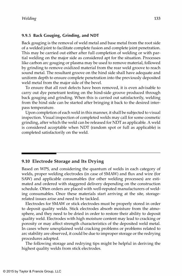
133Welding
9.9.5 back Gouging, Grinding, and NDT
Back gouging is the removal of weld metal and base metal from the root side of a welded joint to facilitate complete fusion and complete joint penetration. This may be carried out either after full completion of welding or with par-tial welding on the major side as considered apt for the situation. Processes like carbon arc gouging or plasma may be used to remove material, followed by grinding to remove oxidized material from the rear weld groove to reach sound metal. The resultant groove on the hind side shall have adequate and uniform depth to ensure complete penetration into the previously deposited weld metal from the major side of the bevel.
To ensure that all root defects have been removed, it is even advisable to carry out dye penetrant testing on the hind-side groove produced through back gouging and grinding. When this is carried out satisfactorily, welding from the hind side can be started after bringing it back to the desired inter-pass temperature.
Upon completion of each weld in this manner, it shall be subjected to visual inspection. Visual inspection of completed welds may call for some cosmetic grinding, after which the weld can be released for NDT as applicable. A weld is considered acceptable when NDT (random spot or full as applicable) is completed satisfactorily on the weld.
9.10 Electrode Storage and Its Drying
Based on WPS, and considering the quantum of welds in each category of welds, proper welding electrodes (in case of SMAW) and flux and wire (for SAW) and applicable consumables (for other welding processes) are esti-mated and ordered with staggered delivery depending on the construction schedule. Often orders are placed with well-reputed manufacturers of weld-ing consumables. Once these materials start arriving at the site, storage-related issues arise and need to be tackled.
Electrodes for SMAW or stick electrodes must be properly stored in order to deposit quality welds. Stick electrodes absorb moisture from the atmo-sphere, and they need to be dried in order to restore their ability to deposit quality weld. Electrodes with high moisture content may lead to cracking or porosity or may affect strength characteristics of the deposited weld metal. In cases where unexplained weld cracking problems or problems related to arc stability are observed, it could be due to improper storage or the redrying procedures adopted.
The following storage and redrying tips might be helpful in deriving the highest quality welds from stick electrodes.
K22265_Book.indb 133 4/20/15 5:48 PM
© 2015 by Taylor & Francis Group, LLC
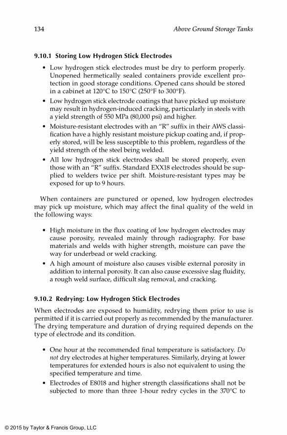
134 Above Ground Storage Tanks
9.10.1 Storing low Hydrogen Stick Electrodes
• Low hydrogen stick electrodes must be dry to perform properly. Unopened hermetically sealed containers provide excellent pro-tection in good storage conditions. Opened cans should be stored in a cabinet at 120°C to 150°C (250°F to 300°F).
• Low hydrogen stick electrode coatings that have picked up moisture may result in hydrogen-induced cracking, particularly in steels with a yield strength of 550 MPa (80,000 psi) and higher.
• Moisture-resistant electrodes with an “R” suffix in their AWS classi-fication have a highly resistant moisture pickup coating and, if prop-erly stored, will be less susceptible to this problem, regardless of the yield strength of the steel being welded.
• All low hydrogen stick electrodes shall be stored properly, even those with an “R” suffix. Standard EXX18 electrodes should be sup-plied to welders twice per shift. Moisture-resistant types may be exposed for up to 9 hours.
When containers are punctured or opened, low hydrogen electrodes may pick up moisture, which may affect the final quality of the weld in the following ways:
• High moisture in the flux coating of low hydrogen electrodes may cause porosity, revealed mainly through radiography. For base materials and welds with higher strength, moisture can pave the way for underbead or weld cracking.
• A high amount of moisture also causes visible external porosity in addition to internal porosity. It can also cause excessive slag fluidity, a rough weld surface, difficult slag removal, and cracking.
9.10.2 Redrying: low Hydrogen Stick Electrodes
When electrodes are exposed to humidity, redrying them prior to use is permitted if it is carried out properly as recommended by the manufacturer. The drying temperature and duration of drying required depends on the type of electrode and its condition.
• One hour at the recommended final temperature is satisfactory. Do not dry electrodes at higher temperatures. Similarly, drying at lower temperatures for extended hours is also not equivalent to using the specified temperature and time.
• Electrodes of E8018 and higher strength classifications shall not be subjected to more than three 1-hour redry cycles in the 370°C to
K22265_Book.indb 134 4/20/15 5:48 PM
© 2015 by Taylor & Francis Group, LLC
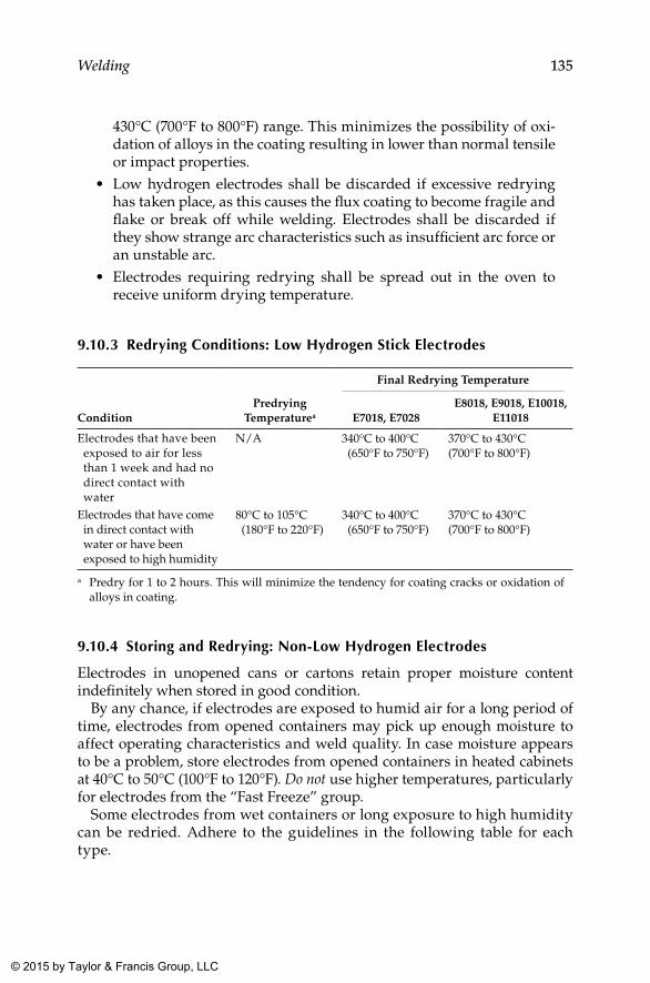
135Welding
430°C (700°F to 800°F) range. This minimizes the possibility of oxi-dation of alloys in the coating resulting in lower than normal tensile or impact properties.
• Low hydrogen electrodes shall be discarded if excessive redrying has taken place, as this causes the flux coating to become fragile and flake or break off while welding. Electrodes shall be discarded if they show strange arc characteristics such as insufficient arc force or an unstable arc.
• Electrodes requiring redrying shall be spread out in the oven to receive uniform drying temperature.
9.10.3 Redrying Conditions: low Hydrogen Stick Electrodes
ConditionPredrying
Temperaturea
Final Redrying Temperature
E7018, E7028E8018, E9018, E10018,
E11018
Electrodes that have been exposed to air for less than 1 week and had no direct contact with water
N/A 340°C to 400°C (650°F to 750°F)
370°C to 430°C (700°F to 800°F)
Electrodes that have come in direct contact with water or have been exposed to high humidity
80°C to 105°C (180°F to 220°F)
340°C to 400°C (650°F to 750°F)
370°C to 430°C (700°F to 800°F)
a Predry for 1 to 2 hours. This will minimize the tendency for coating cracks or oxidation of alloys in coating.
9.10.4 Storing and Redrying: Non-low Hydrogen Electrodes
Electrodes in unopened cans or cartons retain proper moisture content indefinitely when stored in good condition.
By any chance, if electrodes are exposed to humid air for a long period of time, electrodes from opened containers may pick up enough moisture to affect operating characteristics and weld quality. In case moisture appears to be a problem, store electrodes from opened containers in heated cabinets at 40°C to 50°C (100°F to 120°F). Do not use higher temperatures, particularly for electrodes from the “Fast Freeze” group.
Some electrodes from wet containers or long exposure to high humidity can be redried. Adhere to the guidelines in the following table for each type.
K22265_Book.indb 135 4/20/15 5:48 PM
© 2015 by Taylor & Francis Group, LLC
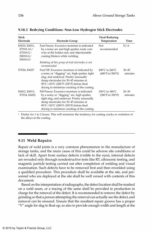
136 Above Ground Storage Tanks
9.10.5 Redrying Conditions: Non-low Hydrogen Stick Electrodes
Stick Electrode Electrode Group
Final Redrying Temperature Time
E6010, E6011, E7010-A1,a E7010-G,a E8010-G,a E9010-Ga
Fast Freeze: Excessive moisture is indicated by a noisy arc and high spatter, rusty core wire at the holder end, and objectionable coating blisters while welding.
Rebaking of this group of stick electrodes is not recommended.
Not recommended
N/A
E7024, E6027 Fast Fill: Excessive moisture is indicated by a noisy or “digging” arc, high spatter, tight slag, and undercut. Predry unusually damp electrodes for 30–45 minutes at 90°C–110°C (200°F–230°F) before final drying to minimize cracking of the coating.
200°C to 260°C (400°F to 500°F)
30–45 minutes
E6012, E6013, E7014, E6022
Fill Freeze: Excessive moisture is indicated by a noisy or “digging” arc, high spatter, tight slag, and undercut. Predry unusually damp electrodes for 30–45 minutes at 90°C–110°C (200°F–230°F) before final drying to minimize cracking of the coating.
150°C to 180°C (300°F to 350°F)
20–30 minutes
a Predry for 1 to 2 hours. This will minimize the tendency for coating cracks or oxidation of the alloys in the coating.
9.11 Weld Repairs
Repair of weld joints is a very common phenomenon in the manufacture of storage tanks, and the main cause of this could be adverse site conditions or lack of skill. Apart from surface defects (visible to the eyes), internal defects are revealed only through nondestructive tests like RT, ultrasonic testing, and magnetic particle testing carried out after completion of welding and visual examination. Such defects have to be removed first and then rewelded using a qualified procedure. This procedure shall be available at the site, and per-sonnel who are deployed at the site shall be well versed with contents of this document.
Based on the interpretation of radiographs, the defect location shall be marked on a weld seam, or a tracing of the same shall be provided to production in charge for the removal of the defect. It is recommended to remove the defect by grinding so that a person attempting the removal can actually see the defect, and removal can be ensured. Ensure that the resultant repair groove has a proper “V” angle for slag to float up, so also to provide enough width and length at the
K22265_Book.indb 136 4/20/15 5:48 PM
© 2015 by Taylor & Francis Group, LLC
137Welding
groove for the welder to manipulate the electrode and properly fill up the repair groove. As far as possible, try to carry out welding in a down-hand position, as this is the most favorable as far as weld quality is concerned.
9.12 Weld Repair Procedure
Every manufacturer shall have a repair procedure and normal procedure applicable to the welding process under consideration. In case repairs occur in automated welding, it may not be possible for local repairs (for very small lengths) to be undertaken by this process again. In such cases, the repair is carried out by manual welding. These requirements shall be reflected in the weld repair procedure, and the original applicable welding procedure shall be made as an annexure to this procedure.
Though it is not possible to anticipate all possible kinds of defects and their repair, the repair procedure need only address the removal of weld defects and the rewelding of groove welds under different processes envisaged in the construction process.
K22265_Book.indb 137 4/20/15 5:48 PM
© 2015 by Taylor & Francis Group, LLC
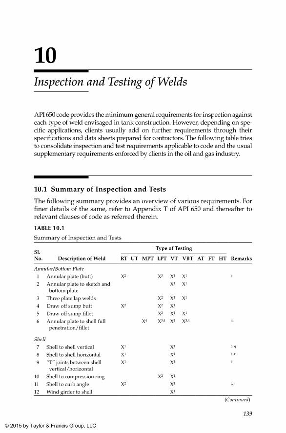
139
10Inspection and Testing of Welds
API 650 code provides the minimum general requirements for inspection against each type of weld envisaged in tank construction. However, depending on spe-cific applications, clients usually add on further requirements through their specifications and data sheets prepared for contractors. The following table tries to consolidate inspection and test requirements applicable to code and the usual supplementary requirements enforced by clients in the oil and gas industry.
10.1 Summary of Inspection and Tests
The following summary provides an overview of various requirements. For finer details of the same, refer to Appendix T of API 650 and thereafter to relevant clauses of code as referred therein.
TAblE 10.1
Summary of Inspection and Tests
Sl. No. Description of Weld
Type of Testing
RemarksRT UT MPT LPT VT VBT AT FT HT
Annular/Bottom Plate 1 Annular plate (butt) X2 X3 X1 X1 a
2 Annular plate to sketch and bottom plate
X1 X1
3 Three plate lap welds X2 X1 X1
4 Draw off sump butt X2 X2 X1
5 Draw off sump fillet X2 X1 X1
6 Annular plate to shell full penetration/fillet
X4 X3,4 X1 X3,4 m
Shell 7 Shell to shell vertical X1 X1 b, q
8 Shell to shell horizontal X1 X1 b, r
9 “T” joints between shell vertical/horizontal
X1 X1 b
10 Shell to compression ring X2 X1
11 Shell to curb angle X2 X1 c, j
12 Wind girder to shell X1
(Continued)
K22265_Book.indb 139 4/20/15 5:48 PM
© 2015 by Taylor & Francis Group, LLC
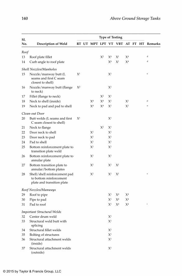
140 Above Ground Storage Tanks
Sl. No. Description of Weld
Type of Testing
RemarksRT UT MPT LPT VT VBT AT FT HT
Roof13 Roof plate fillet X2 X4 X1 X4 d
14 Curb angle to roof plate X4 X1 X4 d
Shell Nozzles/Manholes15 Nozzle/manway butt (L
seams and first C seam closest to shell)
X1 X1 e
16 Nozzle/manway butt (flange to neck)
X2 X1
17 Fillet (flange to neck) X2 X1
18 Neck to shell (inside) X4 X4 X1 X1 p
19 Neck to pad and pad to shell X4 X4 X1 X1 o
Clean-out Door20 Butt welds (L seams and first
C seam closest to shell)X1 X1
21 Neck to flange X2 X1
22 Door neck to shell X1 X1
23 Door neck to pad X1 X1
24 Pad to shell X1 X1
25 Bottom reinforcement plate to transition plate weld
X1 X1
26 Bottom reinforcement plate to annular plate
X1 X1
27 Bottom transition plate to annular/bottom plates
X1 X1 X1
28 Shell/shell reinforcement pad to bottom reinforcement plate and transition plate
X1 X1 X1 s
Roof Nozzles/Manways29 Roof to pipe X1 X4 X4
30 Pipe to pad X1 X4 X4
31 Pad to roof X1 X4 X4 i
Important Structural Welds32 Center drum weld X1
33 Structural weld butt with splicing
X1
34 Structural fillet welds X1
35 Bolting of structures X1
36 Structural attachment welds (inside)
X1
37 Structural attachment welds (outside)
X1
K22265_Book.indb 140 4/20/15 5:48 PM
© 2015 by Taylor & Francis Group, LLC
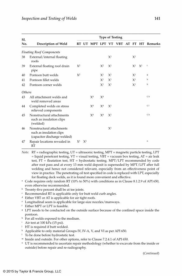
141Inspection and Testing of Welds
Sl. No. Description of Weld
Type of Testing
RemarksRT UT MPT LPT VT VBT AT FT HT
Floating Roof Components38 External/internal floating
roofsX1 X1
39 External floating roof drain pipe
X2 X2 X1 X1 X1 t
40 Pontoon butt welds X2 X1 X1 X1 g
41 Pontoon fillet welds X1 X1 X1 h
42 Pontoon corner welds X1 X1 X1 h
Others43 All attachment welds and
weld removed areasX4 X4 f, k
44 Completed welds on stress relieved components
X4 X4 X1 f, l
45 Nonstructural attachments such as insulation clips (welded)
X4 X4 X1 f, k
46 Nonstructural attachments such as insulation clips (capacitor discharge welded)
X1
47 Repair locations revealed in RT
X1 X2 n
Note: RT = radiographic testing, UT = ultrasonic testing, MPT = magnetic particle testing, LPT = liquid penetrant testing, VT = visual testing, VBT = vacuum box testing, AT = air leak test, FT = floatation test, HT = hydrostatic testing. MPT/LPT recommended by code after root pass and at every 13 mm weld deposit is superseded by MPT/LPT after full welding and hence not considered relevant, especially from an effectiveness point of view in practice. The penetrating oil test specified in code is replaced with LPT, especially for floating deck welds, as it is found more convenient and effective.
a Code requires only random RT (10% to 50%) with conditions as in Clause 8.1.2.9 of API 650, even otherwise recommended.
b Twenty-five percent shall be at tee joints.c Recommended RT is applicable only for butt weld curb angles.d Either VBT or AT is applicable for air tight roofs.e Longitudinal seam is applicable for large-size nozzles/manways.f Either MPT or LPT is feasible.g LPT needs to be conducted on the outside surface because of the confined space inside the
pontoon.h For all welds exposed to the medium.i Air test at 100 kPa (15 psi).j HT is required if butt welded.k Applicable to only material Groups IV, IV-A, V, and VI as per API 650.l To be done before hydrostatic test.m Inside and outside. For other options, refer to Clause 7.2.4.1 of API 650.n UT is recommended to ascertain repair methodology (whether to excavate from the inside or
outside) before repair and re-radiography.
(Continued)
K22265_Book.indb 141 4/20/15 5:48 PM
© 2015 by Taylor & Francis Group, LLC
142 Above Ground Storage Tanks
Sl. No. Description of Weld
Type of Testing
RemarksRT UT MPT LPT VT VBT AT FT HT
o Applicable if there are nozzles with reinforcement pads.p Air test at 100 kPa (15 psi) is applicable if pad is provided.q Refer to Clause 8.1.2.2 of API 650 regarding the finer details of the extent of RT.r Refer to Clause 8.1.2.3 of API 650 regarding the finer details of the extent of RT.s Applicable for both inside and outside.t Primary drain water test at 350 kPa (50 psi). Drain valve is to be kept open during floatation test.1 Required as per standard.2 Usually required by client.3 Desirable from construction point.4 Optional between the two or three NDT method proposed.
10.2 Butt Welds
All welds require visual inspection to ascertain contour, reinforcement, undercut, and other surface opening defects on the weld. Therefore, this needs to be carried out from both sides. Visual inspection of welds is a powerful tool to ensure the quality of the weld, and visual inspection supplemented by DPT (in specific cases) shall be used to eliminate the presence of surface opening defects. Whatever is the contour of the weld (even when weld reinforcement is within acceptable limits), it shall be free from any abrupt changes. Basically, the weld shall merge smoothly with the parent metal so that the concentration of stress at the weld edge can be minimized.
Weld ripples shall also be reasonably smooth so that if a radiograph from that joint is taken, it can be clearly interpreted. In case the weld surface is irregular or ugly looking, though there are no clear-cut requirements in applicable code sections, at the discretion of the inspection engineer, these welds shall be given a dressing-up grinding. This becomes especially impor-tant for inside welds when the tank is expected to carry corrosive fluids. When the weld requires dressings as mentioned, they shall be done prior to radiography of that joint, if this joint is identified for radiography as per requirement.
The random spot radiography specified in code covers mostly pressure contacting welds on the shell alone. However, many client specifications in the oil and gas industry require additional RT, as shown in the previous table. For any radiography taken on a storage tank, the acceptance criteria shall be as provided in API 650 Clause 8.1.5, which refers back to ASME Section VIII UW 51(b) and from there to Appendix 4 of ASME Section VIII Div (1) with regard to rounded indications. These requirements are summa-rized in Annexure D.
K22265_Book.indb 142 4/20/15 5:48 PM
© 2015 by Taylor & Francis Group, LLC
143Inspection and Testing of Welds
10.3 Fillet Welds (Pressure Retaining)
Three types of fillet welds on the bottom plate fall under this category: lap weld between the annular plate and the bottom plate including three plate lap welds, weld between the shell and the annular plate, and fillet weld of drain-off sump and the like.
Code requires all these welds to be inspected visually, for contour, leg sizes, undercut, and other surface opening defects. In addition to this, other tests (basically the vacuum box test) as specified in code also need to be done to ward off leakages during a hydrostatic test, leading to draining the tank and redoing the hydrostatic test. Fillet weld joints between bottom plates as well as those between the annular plate and the bottom plate and those between the shell and the annular plate are of prime concern, as this weld is expected to take the maximum pressure and overturning load due to acts of nature. Therefore, LPT is specified as a supplementary requirement by many of the client specifications from the oil and gas industry. As far as the fillet welds of gussets that support the roof structure and anchor chairs, the weld shall have the minimum size of fillet mentioned in the drawing. Furthermore, this weld also shall be free from surface defects as mentioned earlier.
Another aspect that is often overlooked by many inspection engineers is the unequal leg size of fillet welds and corner joints in storage tanks. API 650 does not specify any acceptance criteria for the difference in leg size of the fillet welds. As a rule of thumb, a maximum of 2 mm difference between legs is considered acceptable, with the lowest leg having the minimum speci-fied leg size, derived from the fillet size as shown in the drawing. As it is always practical and easy to measure the leg size of a fillet weld rather than the throat size, the measured minimum shall be translated as throat size as required in the applicable drawing.
For roof plate fillet welds, visual and vacuum box test or air leak tests need to be performed. This requirement is applicable to all attachment welds on the roof plate that are expected to make a penetration of the roof plate.
Though it is usual that inspectors allow higher fillet sizes for all fillet welds, in the case of roof plate fillet welds, it shall be controlled strictly to reduce the resultant distortion of the roof plate. Similarly, for frangible roof joints, the size of the fillet has to be controlled precisely as per the drawing.
10.4 Other Structural Welds on Shell and Roof (Inside and Outside)
All structural welds on the entire tank surface shall undergo satisfactory visual inspection. The most important in structural welding is the roof struc-ture welding to the top shell course. Roof structure attachment is decided
K22265_Book.indb 143 4/20/15 5:48 PM
© 2015 by Taylor & Francis Group, LLC
144 Above Ground Storage Tanks
by service, and it ranges from self-supporting to single or multiple-support column type. The principal consideration for this is the diameter and inter-nal pressures expected inside the tank. Since drawings for the structural steel attachment is decided based on the design loads considered, it shall be the duty of the inspector to ensure the minimum sizes of welds required for each of the components that constitute the roof structure. As live and cyclic loads are also often encountered during service, it is essential that these sizes are maintained strictly according to the drawing or design to the extent possible. The basic minimum requirement is that the attachment proposed shall be capable of supporting the roof and also should be sound enough to withstand the upward forces that start acting on the roof while the tank is in service.
Since the design of the weld joints of roof structure to shell and those welds between structural members is based on the above considerations, compliance to required fillet size with reasonable contour needs to be ensured during construction. For fillet welds of gussets that support the roof structure, weld shall have the minimum size of fillet mentioned in the drawing. Furthermore, this weld also shall be free from undercuts and other surface defects as mentioned earlier.
10.5 Inspection (Dimensional)
10.5.1 Annular and bottom plates
Dimensions
The annular plates shall be laid generally as per the dimensions in the draw-ing. The most critical dimension specified in the code against this is the minimum width of the annular plate. As per API 650, the minimum width requirement for this plate is 600 mm from the inside of the shell and the lap weld between the annular plate and the bottom plate (see Clause 5.1.5.4. of API 650). However, higher widths for annular plates are required by many client specifications or in the data sheets enclosed with inquiry. Therefore, the only parameter to be measured on the annular plate is the minimum width, apart from the thickness of the plate used.
Similarly, the dimensions of the bottom plates also shall be checked according to that specified in the drawing. Generally, the size of the annu-lar and bottom plates shall be based on the availability of the specific plate material proposed for tank construction, as well as logistic constraints. Because of this, no specific tolerance is specified in this regard. However, for reducing the quantum of weld length, it is important to go for the highest plate size possible.
K22265_Book.indb 144 4/20/15 5:48 PM
© 2015 by Taylor & Francis Group, LLC
145Inspection and Testing of Welds
Buckling of the Bottom Plate
Yet another aspect to be inspected and recorded is the buckling of bot-tom plates after welding. Buckling of the bottom plate is an unavoidable defect arising out of shrinkages taking place in the huge quantity of weld-ing involved in bottom plate fabrication. Furthermore, the low thickness of bottom plates usually provided also adds to this distortion. By adopting a proper welding sequence, this can be controlled to a great extent (see the welding sequence recommended in Chapter 7, Section 7.8.9). Clause 7.3.6.8 of API 650 specifies the methodology to record distortion or buckling of the bottom plate. This measurement is required to be carried out before and after the hydrostatic test of the tank. This would be of immense help in cross-verification with settlement (planar and out of plane) measurements taken during planned shutdowns during the service life of the tank to arrive at a rational decision with reliability about the extent of repairs required during shutdowns for the extended service life.
Bottom plate buckling shall be recorded after completion of all bottom plate welding, including full welding of the shell to the annular plate and that of the clean-out door and its components. Tank bottom buckling shall be recorded using an even number of diameter lines established at 10 m (32 ft) intervals over the circumference, with a minimum of four such diameters.
Similarly, along diameter lines, measurements shall be taken at 3 m (10 ft) intervals or eight measurements as a minimum, as shown in the following sketch.
Buckling measurement inside the tank shall be recorded with refer-ence to a reference point transferred to the inside surface of the shell (say at 200 mm from the surface of the bottom plate) and marked on the shell using permanent markers, which can be used for taking buckling/settle-ment measurements after hydrostatic testing and during periodic turn-around as well. This reference point shall be transferred to all locations identified over the circumference using water level. Buckling across a diameter is recorded by measuring the depth to the surface of the bottom plate at 3 m (10 ft) intervals as shown in Figure 10.1 along the diameters identified.
Though the methodology to record buckling of the bottom plate is speci-fied in API 650, it does not specify any tolerance for the same. In the event of a concrete ring wall foundation, used commonly in the oil and gas industry, the level variation permitted for the foundation is ±3 mm (1/8”) in any 3 m (10’) of the circumference and within ±6 mm (1/4”) in total cir-cumference measured from average elevation. So tanks constructed on a concrete ring wall foundation shall have a buckling tolerance above this level to accommodate distortion of the bottom plate due to welding. Based on experience from the field, a rational level of buckling tolerance achiev-able for tanks with a concrete ring wall foundation is ±12 mm (1/2”) in total circumference.
K22265_Book.indb 145 4/20/15 5:48 PM
© 2015 by Taylor & Francis Group, LLC
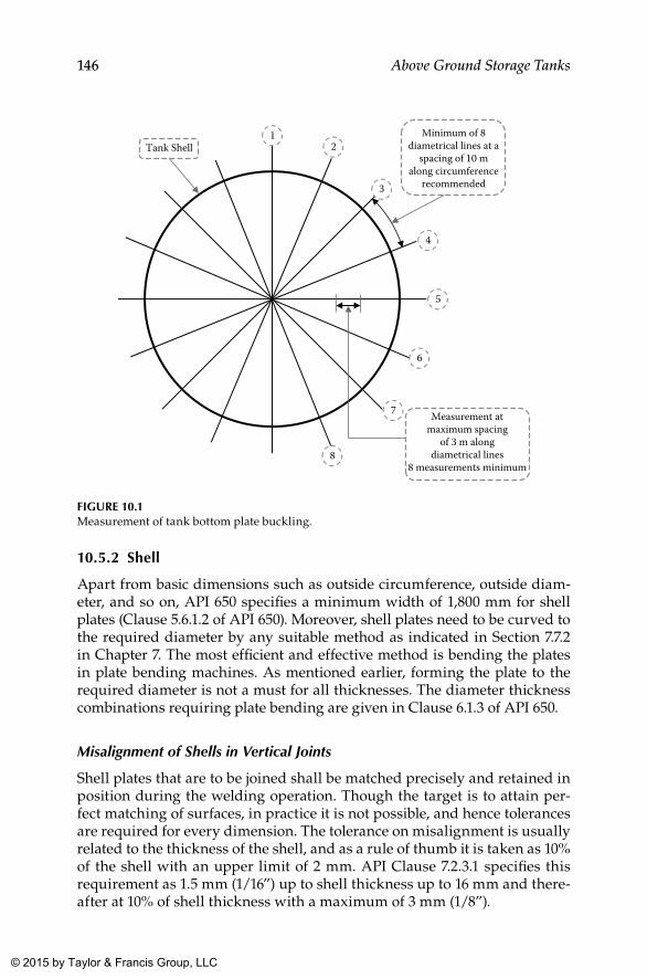
146 Above Ground Storage Tanks
10.5.2 Shell
Apart from basic dimensions such as outside circumference, outside diam-eter, and so on, API 650 specifies a minimum width of 1,800 mm for shell plates (Clause 5.6.1.2 of API 650). Moreover, shell plates need to be curved to the required diameter by any suitable method as indicated in Section 7.7.2 in Chapter 7. The most efficient and effective method is bending the plates in plate bending machines. As mentioned earlier, forming the plate to the required diameter is not a must for all thicknesses. The diameter thickness combinations requiring plate bending are given in Clause 6.1.3 of API 650.
Misalignment of Shells in Vertical Joints
Shell plates that are to be joined shall be matched precisely and retained in position during the welding operation. Though the target is to attain per-fect matching of surfaces, in practice it is not possible, and hence tolerances are required for every dimension. The tolerance on misalignment is usually related to the thickness of the shell, and as a rule of thumb it is taken as 10% of the shell with an upper limit of 2 mm. API Clause 7.2.3.1 specifies this requirement as 1.5 mm (1/16”) up to shell thickness up to 16 mm and there-after at 10% of shell thickness with a maximum of 3 mm (1/8”).
12
3
4
5
6
7
8
Tank Shell
Measurement atmaximum spacing
of 3 m alongdiametrical lines
8 measurements minimum
Minimum of 8diametrical lines at a
spacing of 10 malong circumference
recommended
FIGuRE 10.1Measurement of tank bottom plate buckling.
K22265_Book.indb 146 4/20/15 5:48 PM
© 2015 by Taylor & Francis Group, LLC
147Inspection and Testing of Welds
Misalignment of Shells in Horizontal Joints
For horizontal butt welds, the tolerance is specified in API 650 (Clause 7.2.3.2). However, it is stated in a slightly different manner as the projection of the top plate beyond the face of the lower plate rather than just a mismatch over a calculated difference, which occurs when shell thicknesses vary at hori-zontal joints. Furthermore, the standard calls for tapering the edges when mismatch is more than 3 mm.
Roundness
Yet another measurement to be verified at the site is the roundness of the shells. Clause 7.5.3 of API 650 requires the radii to be measured at 300 mm (1’) above the corner weld, and tolerances depending on tank diameters is provided in the table provided under this clause, which range from ±13 mm (1/2”) to ±32 mm (1¼”).
Circumference at Each Shell Course
API 650 is silent about this measurement. However, the following consider-ations make this measurement so important and critical.
When each shell course is set up, the outside circumference needs to be taken, from which the mean outside or inside diameter can be calcu-lated. The roundness measure needs to be verified with the diameter cal-culated in this manner as well and shall be within limits for the bottom shell course.
For the subsequent shells, the circumference needs to be recorded at both edges of the shell courses (say at 100 mm to 150 mm from the weld edge). For the misalignment tolerance to be within acceptance limits as specified in API 650 Clause 7.2.3.2, the circumference shall be within ±9.5 mm, for mating shells of the same thickness, with a permitted misalignment of 1.5 mm based on plate thickness. Table 10.2 with a sample calculation under a different scenario explains this requirement in detail.
It is almost impossible to distribute the mismatch present in every hori-zontal joint uniformly around the circumference on one side, either inside or outside. In all practical cases, it will vary from –1.5 to +1.5 over the entire
TAblE 10.2
Misalignment Calculation
Location IDTank Inside
Diameter (mm) Shell Thickness (mm)Required Outside
Circumference (mm)
Bottom shell top 24,000 12 75,435.3Second shell bottom 24,000 12 + 1.5 mismatch all around 75,444.8
Note: Maximum possible variation in circumference is only ±9.5 mm over circumference of the previous shell course.
K22265_Book.indb 147 4/20/15 5:48 PM
© 2015 by Taylor & Francis Group, LLC
148 Above Ground Storage Tanks
circumference, resulting in less variation in circumference. When the set up of the shell plates is carried out progressively with the mismatch as speci-fied, the circumference measurements shall be within the calculated values as shown previously.
When shell course thicknesses vary, from bottom to top, the calculation shall take care of the thickness difference as well, along with permitted mis-match based on the thickness of the shell.
Plumbness
API 650 provides tolerance on plumbness for erected and welded shell courses from top to bottom and for individual shells. It also provides toler-ance for plumbness for roof columns, guide poles, and other vertical com-ponents, especially those that traverse the entire height of the tank. The tolerance permitted is 1 in 200 of the total tank height, both for erected shell courses and for roof support columns, guide poles, and so on for fixed cone roof tanks (Clause 7.5.2 of API 650).
For plumbness in individual shell courses, the tolerance is the same as per-missible variations for flatness and waviness specified for bare plates used for construction. For the ASTM materials specified in API 650, this would necessitate reference to ASTM A 6, ASTM A 20, or ASTM A 480, depending on the respective ASTM specification to which plates are procured.
Though the above specified is the requirement as per API 650 for local deviations, some client specifications set explicit limits for the same as fol-lows based on the thickness of the shell sections.
In the event of floating roof tanks, as per API 650, the tolerance on plumb-ness for shells remains the same. Appurtenances such as columns, ladders, and antirotation devices that penetrate the deck need to be within 1 in 200 of total height, limited to ±75 mm (±3”).
Local Deviations
Clause 7.5.4 of API 650 specifies tolerance for local deviations from theoreti-cal shape, including flat spots, peaking and banding of welds, etc. Peaking at vertical joints and banding at horizontal joints are limited to ±13 mm (l/2”).
TAblE 10.3
Tolerance on Local Deviations (Restriction by Clients)
Tolerance
Plate Thickness Fixed Roof Tanks Floating Roof Tanks
Plates ≤ 12.5 mm thickness 16 mm 10 mmPlates > 12.5 mm to ≤ 25 mm thickness 13 mm 8 mmPlates > 25 mm thickness 10 mm 6 mm
K22265_Book.indb 148 4/20/15 5:48 PM
© 2015 by Taylor & Francis Group, LLC
149Inspection and Testing of Welds
For the measurement of peaking at vertical weld joints and banding at hori-zontal weld joints, horizontal (made to required curvature) and vertical sweep boards (straight edge type) of 900 mm (36”) length is proposed by API 650.
Moreover, for flat spots measured in vertical plane, the limits specified in API 650 refers to flatness or waviness specified in ASTM A 6, ASTM A 20, or ASTM A 480, as referred in respective ASTM specification for shell plates used in construction.
For columns, ladders, and other rigid vertical appurtenances that pen-etrate the deck and provided with a seal, in floating roof tanks, the tolerance permitted for local deviation is ±125 mm (±5”). (Clause H 4.5 of API 650).
For all local departures from the design form for shell, some client specifi-cations usually restrict the tolerance limits further based on the thickness of shell courses. Local departure in form, measured horizontally and vertically shall not exceed the following, when measured over a gauge length of 2500 mm (100”), reasonably away from weld seams:
Such departures from the designed form shall be gradual over the gauge length, sharp changes in form are not permitted.
Nozzles and Manholes
Clauses 7.5.6 and 7.5.7 of API 650 specify clear-cut tolerances for completed nozzles and manways as follows.
Many of the client specifications (even those from the oil and gas industry) are in agreement with the tolerances provided in API 650, and hence no more restrictions are specifically provided.
TAblE 10.4
Tolerance on Nozzle Dimensions
Description of Dimension Tolerance
Projection from the outside of the tank shell to the extreme face of the flange (raised face or flat face)
±5 mm (3/16”)
Elevation of the shell nozzle or radial location of a roof nozzle (though measurement is up to the center of the nozzle pipe but measured at the nearest outside diameter of the pipe for convenience)
±6 mm (1/4”)
Flange tilt in any plane, measured on the flange face
±1/2 degree for nozzles greater than NPS 300 (12”)
±3 mm (1/8”) at the outside flange diameter for nozzles NPS 300 (12”) and smaller
Flange bolt hole orientation (shall straddle centerline as a general practice unless otherwise specified)
±3 mm (1/8”)
K22265_Book.indb 149 4/20/15 5:48 PM
© 2015 by Taylor & Francis Group, LLC
150 Above Ground Storage Tanks
Similarly, for manways coming on the shell, the tolerance on projection, angular position, elevation, and flange tilt is required to be within ±13 mm (1/2”). However, it is observed that it is easy to maintain this measurement within ±10 mm (3/8”) in practice.
API 650 is silent on tolerance for projection, angular position, through and angular tilt of roof manways. However, the tolerance specified for shell man-ways is achievable for various dimensions of manways coming on the roof plate. In the event of roof nozzles and manways, because of the possibility of buckling the roof (due to welding and lower thickness), taking realistic measurements is a bit tricky.
K22265_Book.indb 150 4/20/15 5:48 PM
© 2015 by Taylor & Francis Group, LLC
151
11Nondestructive Testing
11.1 Radiographic Testing
The most extensively used nondestructive testing (NDT) method in tank construction is radiography. Conventionally, gamma radiography is per-formed on storage tanks. In gamma radiography, Iridium 192 source is the most commonly used source in the industry. In some specific instances such as the use of some special highly productive welding processes such as elec-tro gas welding, some clients ask for X-ray radiography. For both of these radiography tests, the applicable code for carrying out radiography is ASME Section V. The extent of radiography and its acceptance criteria are provided in Section 8 of API650, the excerpts of which are given below.
11.2 Minimum Number and Location of Radiographs Required as per API 650
Consideration
1 For arriving at number, location, and type of radiograph required, adjoining shell plates are considered to be of the same thickness, up to a thickness difference of 3 mm (1/8”).
Welds Requiring No Radiography2 Roof plate welds, bottom plate welds, welds joining the top angle to either the roof or the
shell, welds joining the shell plate to the bottom plate, welds in the nozzle and manway necks made from the plate, or appurtenance welds to the tank.
Welds Requiring Radiography3 Shell butt welds (as referred in Clauses 8.1.2.2, 8.1.2.3, and 8.1.2.4), annular plate butt
welds (Clause 8.1.2.9), and flush-type connections with butt welds (Clause 5.7.8.11).
K22265_Book.indb 151 4/20/15 5:48 PM
© 2015 by Taylor & Francis Group, LLC
152 Above Ground Storage Tanks
For Butt Welded Vertical Joints Wherein the Thinner Shell Plate Is ≤10 mm (3/8”) Thick4 One spot radiograph in the first 3 m (10’) of the completed vertical joint of each type and
thickness welded by each welder or welding operator, followed by one spot per each additional 30 m (100’) vertical weld or part thereof, regardless of the number of welders used. Of this, at least 25% of spots shall be at junctions of vertical and horizontal joints, with a minimum of two such intersections per tank. In addition, one random spot radiograph shall be taken in each vertical joint in the lowest course.
For Butt Welded Vertical Joints Wherein the Thinner Shell Plate Is >10 mm (3/8″) but ≤25 mm (1”) Thick5 Spots as specified in Item 4 and all junctions of vertical and horizontal joints in plates of
this thickness range.a
6 In the lowest course, two spot radiographs shall be taken in each vertical joint, with one as close to the bottom as is practicable, and the other shall be taken at random.
Vertical Joints in Shell Plates of Thickness >25 mm (1″)7 One hundred percent radiography; all junctions of vertical and horizontal joints in this
thickness range are included.
Butt Weld around the Periphery of Insert Plates8 Weld that extends less than the adjacent shell course height and that contains shell
openings (i.e., nozzle, manway, flush-type clean out, flush-type shell connection) and their reinforcing elements require 100% radiography.
9 Weld that extends to match the adjacent shell course height shall have the vertical and the horizontal butt joints and the intersections of vertical and horizontal weld joints radiographed using the same rules that apply to the weld joints in adjacent shell plates in the same shell course.
Horizontal Joints in Shell Plates10 One spot radiograph in the first 3 m (10’) of the completed horizontal butt joint of the
same type and thickness (based on the thickness of the thinner plate at the joint) regardless of the number of welders or welding operators, followed by one radiograph in each additional 60 m (200’) (approximately) and part thereof. These radiographs are in addition to the radiographs of junctions of vertical joints indicated in Items 4, 5, and 6.
Bottom Annular Plate Butt Welds (If Clauses 5.5.1 or M 4.1 Are Applicable)b, c
11 For double-welded butt joints, one spot radiograph is required on 10% of the radial joints.
12 For single-welded butt joints with a permanent or removable backup bar, one spot radiograph is required on 50% of the radial joints.
K22265_Book.indb 152 4/20/15 5:48 PM
© 2015 by Taylor & Francis Group, LLC
153Nondestructive Testing
Notes: a Radiographs at “T” joints shall clearly show not less than 75 mm (3”) of vertical weld and
50 mm (2”) of weld length on each side of the vertical intersection (to be read in conjunc-tion with Item 5).
b Each radiograph shall clearly show a minimum of 150 mm (6”) of weld length. The film shall be centered on the weld and shall be of sufficient width to permit adequate space for the location of identification marks and an image quality indicator (lQI).
c Locations of radiographs shall preferably be at the outer edge of the joint where the shell plate and annular plate join.
d The requirement of the number of spot radiographs is based on a per tank basis, irrespec-tive of the number of tanks being erected concurrently or continuously at any location.
e It is recognized that in many cases the same welder or welding operator does not weld both sides of a butt joint. If two welders or welding operators weld opposite sides of a butt joint, it is permissible to examine their work with one spot radiograph. If the radiograph is rejected, additional spot radiographs shall be taken to determine whether one or both of the welders or welding operators are at fault.
f An equal number of spot radiographs shall be taken from the work of each welder or welding operator in proportion to the length of joints welded.
Based on these requirements, the shell radiography requirement using vary-ing thicknesses for the shell for a typical storage tank is provided in the follow-ing table for easy understanding, covering almost all the conditions specified in API 650. Please note that the requirements are purely based on API 650 rounded off to the next positive integer with regard to numbers. While arriv-ing at this pictorial presentation, the following assumptions were made:
1 Plate size used is 12,000 mm × 2,500 mm for all thickness ranges indicated.2 Five welders are assigned to carry out the complete welding of all vertical and horizontal
seams.3 Extra welders are to be added for carrying out other structural welding of the tank.4 In case of tight schedules, more welders may have to be employed, which may have a
slight impact on the total radiography requirements mentioned in the sketches overleaf.5 The same welder is expected to complete welding from both sides of a particular seam to
the extent possible.6 The same welders engaged for vertical seams shall be employed for welding the
horizontal seams also.7 Welders shall be given a predesignated length of weld in any horizontal joint based on the
staggering required while welding. The same welders shall cover welding from both inside and outside in predesignated lengths of welds assigned to them.
K22265_Book.indb 153 4/20/15 5:48 PM
© 2015 by Taylor & Francis Group, LLC
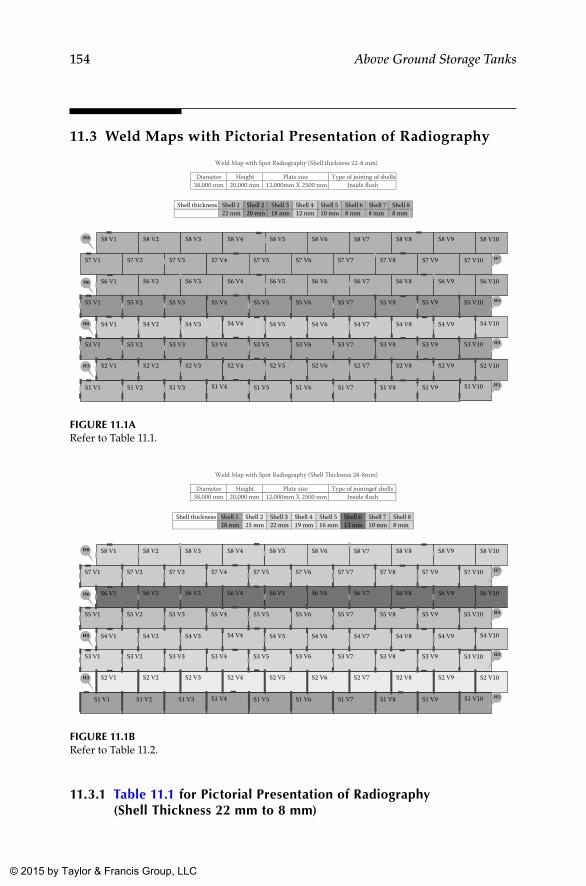
154 Above Ground Storage Tanks
11.3 Weld Maps with Pictorial Presentation of Radiography
11.3.1 Table 11.1 for Pictorial Presentation of Radiography (Shell Thickness 22 mm to 8 mm)
Diameter Height Plate size Type of joining of shells 38,000 mm 20,000 mm 12,000mm X 2500 mm Inside flush
Shell thickness Shell 1 Shell 2 Shell 3 Shell 4 Shell 5 Shell 6 Shell 7 Shell 8 22 mm 20 mm 18 mm 12 mm 10 mm 8 mm 8 mm 8 mm
S1 V1 S1 V2 S1 V3 S1 V4 S1 V5 S1 V6 S1 V7 S1 V8 S1 V9 S1 V10
S2 V1 S2 V2 S2 V3 S2 V4 S2 V5 S2 V6 S2 V7 S2 V8 S2 V9 S2 V10
S3 V1 S3 V2 S3 V3 S3 V4 S3 V5 S3 V6 S3 V7 S3 V8 S3 V9 S3 V10
S4 V1 S4 V2 S4 V3 S4 V4 S4 V5 S4 V6 S4 V7 S4 V8 S4 V9 S4 V10
S5 V1 S5 V2 S5 V3 S5 V4 S5 V5 S5 V6 S5 V7 S5 V8 S5 V9 S5 V10
S6 V1 S6 V2 S6 V3 S6 V4 S6 V5 S6 V6 S6 V7 S6 V8 S6 V9 S6 V10
S7 V1 S7 V2 S7 V3 S7 V4 S7 V5 S7 V6 S7 V7 S7 V8 S7 V9 S7 V10
S8 V1 S8 V2 S8 V3 S8 V4 S8 V5 S8 V6 S8 V7 S8 V8 S8 V9 S8 V10
H7
H5
H3
H1
H8
H6
H4
H2
Weld Map with Spot Radiography (Shell thickness 22-8 mm)
FIGuRE 11.1ARefer to Table 11.1.
Diameter Height Plate size Type of joining of shells 38,000 mm 20,000 mm 12,000mm X 2500 mm Inside flush
Shell thickness Shell 1 Shell 2 Shell 3 Shell 4 Shell 5 Shell 6 Shell 7 Shell 8 28 mm 25 mm 22 mm 19 mm 16 mm 13 mm 10 mm 8 mm
11.1.
S1 V1 S1 V2 S1 V3 S1 V4 S1 V5 S1 V6 S1 V7 S1 V8 S1 V9 S1 V10
S2 V1 S2 V2 S2 V3 S2 V4 S2 V5 S2 V6 S2 V7 S2 V8 S2 V9 S2 V10
S3 V1 S3 V2 S3 V3 S3 V4 S3 V5 S3 V6 S3 V7 S3 V8 S3 V9 S3 V10
S4 V1 S4 V2 S4 V3 S4 V4 S4 V5 S4 V6 S4 V7 S4 V8 S4 V9 S4 V10
S5 V1 S5 V2 S5 V3 S5 V4 S5 V5 S5 V6 S5 V7 S5 V8 S5 V9 S5 V10
S6 V1 S6 V2 S6 V3 S6 V4 S6 V5 S6 V6 S6 V7 S6 V8 S6 V9 S6 V10
S7 V1 S7 V2 S7 V3 S7 V4 S7 V5 S7 V6 S7 V7 S7 V8 S7 V9 S7 V10
S8 V1 S8 V2 S8 V3 S8 V4 S8 V5 S8 V6 S8 V7 S8 V8 S8 V9 S8 V10
H7
H5
H3
H1
H8
H6
H4
H2
Weld Map with Spot Radiography (Shell �ickness 28-8mm)
FIGuRE 11.1bRefer to Table 11.2.
K22265_Book.indb 154 4/20/15 5:48 PM
© 2015 by Taylor & Francis Group, LLC
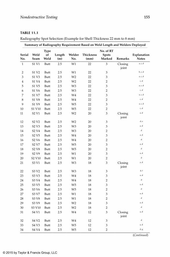
155Nondestructive Testing
TAblE 11.1
Radiography Spot Selection (Example for Shell Thickness 22 mm to 8 mm)
Summary of Radiography Requirement Based on Weld Length and Welders Deployed
Serial No.
Weld Seam
Type of
WeldLength
(m)Welder
No. Thickness
(mm)
No. of RT Spots
Marked RemarksExplanation
Notes
1 S1 V1 Butt 2.5 W1 22 3 Closing joint
a, c, d
2 S1 V2 Butt 2.5 W1 22 3 b, c, d
3 S1 V3 Butt 2.5 W2 22 3 a, c, d
4 S1 V4 Butt 2.5 W2 22 2 c, d
5 S1 V5 Butt 2.5 W3 22 3 a, c, d
6 S1 V6 Butt 2.5 W3 22 2 c, d
7 S1 V7 Butt 2.5 W4 22 3 a, c, d
8 S1 V8 Butt 2.5 W4 22 2 c, d
9 S1 V9 Butt 2.5 W5 22 3 a, c, d
10 S1 V10 Butt 2.5 W5 22 2 c, d
11 S2 V1 Butt 2.5 W2 20 3 Closing joint
a, d
12 S2 V2 Butt 2.5 W2 20 3 d, e
13 S2 V3 Butt 2.5 W3 20 3 a, d
14 S2 V4 Butt 2.5 W3 20 2 d
15 S2 V5 Butt 2.5 W4 20 3 a, d
16 S2 V6 Butt 2.5 W4 20 2 d
17 S2 V7 Butt 2.5 W5 20 3 a, d
18 S2 V8 Butt 2.5 W5 20 2 d
19 S2 V9 Butt 2.5 W1 20 3 a, d
20 S2 V10 Butt 2.5 W1 20 2 d
21 S3 V1 Butt 2.5 W3 18 3 Closing joint
a, d
22 S3 V2 Butt 2.5 W3 18 3 d, f
23 S3 V3 Butt 2.5 W4 18 3 a, d
24 S3 V4 Butt 2.5 W4 18 2 d
25 S3 V5 Butt 2.5 W5 18 3 a, d
26 S3 V6 Butt 2.5 W5 18 2 d
27 S3 V7 Butt 2.5 W1 18 3 a, d
28 S3 V8 Butt 2.5 W1 18 2 d
29 S3 V9 Butt 2.5 W2 18 3 a, d
30 S3 V10 Butt 2.5 W2 18 2 d
31 S4 V1 Butt 2.5 W4 12 3 Closing joint
a, d
32 S4 V2 Butt 2.5 W4 12 3 d
33 S4 V3 Butt 2.5 W5 12 3 a, d
34 S4 V4 Butt 2.5 W5 12 2 d, g
(Continued)
K22265_Book.indb 155 4/20/15 5:48 PM
© 2015 by Taylor & Francis Group, LLC
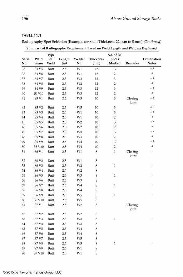
156 Above Ground Storage Tanks
TAblE 11.1
Radiography Spot Selection (Example for Shell Thickness 22 mm to 8 mm) (Continued)
Summary of Radiography Requirement Based on Weld Length and Welders Deployed
Serial No.
Weld Seam
Type of
WeldLength
(m)Welder
No. Thickness
(mm)
No. of RT Spots
Marked RemarksExplanation
Notes
35 S4 V5 Butt 2.5 W1 12 3 a, d
36 S4 V6 Butt 2.5 W1 12 2 d
37 S4 V7 Butt 2.5 W2 12 3 a, d
38 S4 V8 Butt 2.5 W2 12 2 d
39 S4 V9 Butt 2.5 W3 12 3 a, d
40 S4 V10 Butt 2.5 W3 12 2 d
41 S5 V1 Butt 2.5 W5 10 3 Closing joint
a, d
42 S5 V2 Butt 2.5 W5 10 3 d, h
43 S5 V3 Butt 2.5 W1 10 3 a, d
44 S5 V4 Butt 2.5 W1 10 2 d
45 S5 V5 Butt 2.5 W2 10 3 a, d
46 S5 V6 Butt 2.5 W2 10 2 d
47 S5 V7 Butt 2.5 W3 10 3 a, d
48 S5 V8 Butt 2.5 W3 10 2 d
49 S5 V9 Butt 2.5 W4 10 3 a, d
50 S5 V10 Butt 2.5 W4 10 2 d
51 S6 V1 Butt 2.5 W1 8 1 Closing joint
i
52 S6 V2 Butt 2.5 W1 8 53 S6 V3 Butt 2.5 W2 8 1 i
54 S6 V4 Butt 2.5 W2 8 55 S6 V5 Butt 2.5 W3 8 1 i
56 S6 V6 Butt 2.5 W3 8 57 S6 V7 Butt 2.5 W4 8 1 i
58 S6 V8 Butt 2.5 W4 8 59 S6 V9 Butt 2.5 W5 8 1 i
60 S6 V10 Butt 2.5 W5 8 61 S7 V1 Butt 2.5 W2 8 Closing
joint62 S7 V2 Butt 2.5 W2 8 63 S7 V3 Butt 2.5 W3 8 1 j
64 S7 V4 Butt 2.5 W3 8 65 S7 V5 Butt 2.5 W4 8 66 S7 V6 Butt 2.5 W4 8 67 S7 V7 Butt 2.5 W5 8 68 S7 V8 Butt 2.5 W5 8 1 j
69 S7 V9 Butt 2.5 W1 8 70 S7 V10 Butt 2.5 W1 8
K22265_Book.indb 156 4/20/15 5:48 PM
© 2015 by Taylor & Francis Group, LLC
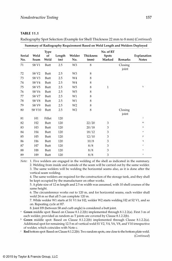
157Nondestructive Testing
TAblE 11.1
Radiography Spot Selection (Example for Shell Thickness 22 mm to 8 mm) (Continued)
Summary of Radiography Requirement Based on Weld Length and Welders Deployed
Serial No.
Weld Seam
Type of
WeldLength
(m)Welder
No. Thickness
(mm)
No. of RT Spots
Marked RemarksExplanation
Notes
71 S8 V1 Butt 2.5 W3 8 Closing joint
72 S8 V2 Butt 2.5 W3 8 73 S8 V3 Butt 2.5 W4 8 74 S8 V4 Butt 2.5 W4 8 75 S8 V5 Butt 2.5 W5 8 1 k
76 S8 V6 Butt 2.5 W5 8 77 S8 V7 Butt 2.5 W1 8 78 S8 V8 Butt 2.5 W1 8 79 S8 V9 Butt 2.5 W2 8 80 S8 V10 Butt 2.5 W2 8 Closing
joint81 H1 Fillet 120 l
82 H2 Butt 120 22/20 3 m
83 H3 Butt 120 20/18 3 n
84 H4 Butt 120 18/12 3 o
85 H5 Butt 120 12/10 3 p
86 H6 Butt 120 10/8 3 q
87 H7 Butt 120 8/8 3 r
88 H8 Butt 120 8/8 3 s
89 H9 Butt 120 8/8 3 t
Note: 1. Five welders are engaged in the welding of the shell as indicated in the summary. 2. Welding from inside and outside of the seam will be carried out by the same welder. 3. The same welders will be welding the horizontal seams also, as it is done after the vertical seam welding.
4. The same welders are required for the construction of the storage tank, and they shall be kept occupied by the manufacturer on other works.
5. A plate size of 12 m length and 2.5 m width was assumed, with 10 shell courses of the same height.
6. The circumference works out to 120 m, and for horizontal seams, each welder shall weld 24 m so that all 5 can complete 120 m.
7. While welder W1 starts at S1 V1 for H2, welder W2 starts welding H2 at S2 V1, and so on. Repeating cycle at H7.
8. Joint H9 (between S8 and curb angle) is considered a butt joint.a Green middle spot: Based on Clause 8.1.2.2(b) implemented through 8.1.2.2(a). First 3 m of
each welder, provided as random as T joints are covered by Clause 8.1.2.2(b).b Green middle spot: Based on Clause 8.1.2.2(b) implemented through Clause 8.1.2.2(a).
Additional spot for remaining 12.5 m of vertical weld S1 V2, V4, V6, V8, and V10 irrespective of welder, which coincides with Note c.
c Red bottom spot: Based on Clause 8.1.2.2(b). Two random spots, one close to the bottom plate weld.(Continued)
K22265_Book.indb 157 4/20/15 5:48 PM
© 2015 by Taylor & Francis Group, LLC
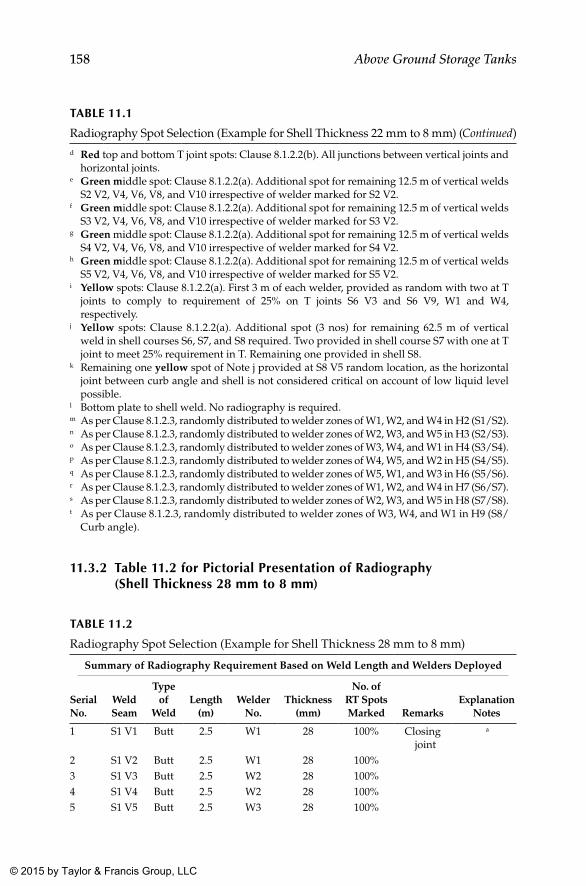
158 Above Ground Storage Tanks
11.3.2 Table 11.2 for Pictorial Presentation of Radiography (Shell Thickness 28 mm to 8 mm)
TAblE 11.2
Radiography Spot Selection (Example for Shell Thickness 28 mm to 8 mm)
Summary of Radiography Requirement Based on Weld Length and Welders Deployed
Serial No.
Weld Seam
Type of
WeldLength
(m)Welder
No.Thickness
(mm)
No. of RT Spots Marked Remarks
Explanation Notes
1 S1 V1 Butt 2.5 W1 28 100% Closing joint
a
2 S1 V2 Butt 2.5 W1 28 100%3 S1 V3 Butt 2.5 W2 28 100%4 S1 V4 Butt 2.5 W2 28 100%5 S1 V5 Butt 2.5 W3 28 100%
TAblE 11.1
Radiography Spot Selection (Example for Shell Thickness 22 mm to 8 mm) (Continued)d Red top and bottom T joint spots: Clause 8.1.2.2(b). All junctions between vertical joints and
horizontal joints.e Green middle spot: Clause 8.1.2.2(a). Additional spot for remaining 12.5 m of vertical welds
S2 V2, V4, V6, V8, and V10 irrespective of welder marked for S2 V2.f Green middle spot: Clause 8.1.2.2(a). Additional spot for remaining 12.5 m of vertical welds
S3 V2, V4, V6, V8, and V10 irrespective of welder marked for S3 V2.g Green middle spot: Clause 8.1.2.2(a). Additional spot for remaining 12.5 m of vertical welds
S4 V2, V4, V6, V8, and V10 irrespective of welder marked for S4 V2.h Green middle spot: Clause 8.1.2.2(a). Additional spot for remaining 12.5 m of vertical welds
S5 V2, V4, V6, V8, and V10 irrespective of welder marked for S5 V2.i Yellow spots: Clause 8.1.2.2(a). First 3 m of each welder, provided as random with two at T
joints to comply to requirement of 25% on T joints S6 V3 and S6 V9, W1 and W4, respectively.
j Yellow spots: Clause 8.1.2.2(a). Additional spot (3 nos) for remaining 62.5 m of vertical weld in shell courses S6, S7, and S8 required. Two provided in shell course S7 with one at T joint to meet 25% requirement in T. Remaining one provided in shell S8.
k Remaining one yellow spot of Note j provided at S8 V5 random location, as the horizontal joint between curb angle and shell is not considered critical on account of low liquid level possible.
l Bottom plate to shell weld. No radiography is required.m As per Clause 8.1.2.3, randomly distributed to welder zones of W1, W2, and W4 in H2 (S1/S2).n As per Clause 8.1.2.3, randomly distributed to welder zones of W2, W3, and W5 in H3 (S2/S3).o As per Clause 8.1.2.3, randomly distributed to welder zones of W3, W4, and W1 in H4 (S3/S4).p As per Clause 8.1.2.3, randomly distributed to welder zones of W4, W5, and W2 in H5 (S4/S5).q As per Clause 8.1.2.3, randomly distributed to welder zones of W5, W1, and W3 in H6 (S5/S6).r As per Clause 8.1.2.3, randomly distributed to welder zones of W1, W2, and W4 in H7 (S6/S7).s As per Clause 8.1.2.3, randomly distributed to welder zones of W2, W3, and W5 in H8 (S7/S8).t As per Clause 8.1.2.3, randomly distributed to welder zones of W3, W4, and W1 in H9 (S8/
Curb angle).
K22265_Book.indb 158 4/20/15 5:48 PM
© 2015 by Taylor & Francis Group, LLC
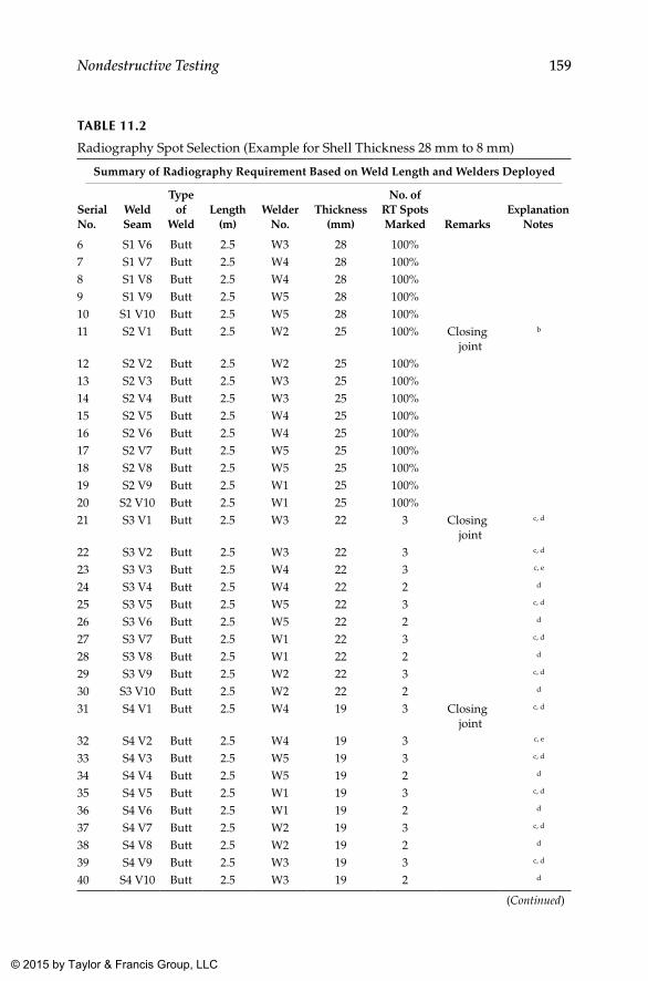
159Nondestructive Testing
TAblE 11.2
Radiography Spot Selection (Example for Shell Thickness 28 mm to 8 mm)
Summary of Radiography Requirement Based on Weld Length and Welders Deployed
Serial No.
Weld Seam
Type of
WeldLength
(m)Welder
No.Thickness
(mm)
No. of RT Spots Marked Remarks
Explanation Notes
6 S1 V6 Butt 2.5 W3 28 100%7 S1 V7 Butt 2.5 W4 28 100%8 S1 V8 Butt 2.5 W4 28 100%9 S1 V9 Butt 2.5 W5 28 100%10 S1 V10 Butt 2.5 W5 28 100%11 S2 V1 Butt 2.5 W2 25 100% Closing
joint
b
12 S2 V2 Butt 2.5 W2 25 100%13 S2 V3 Butt 2.5 W3 25 100%14 S2 V4 Butt 2.5 W3 25 100%15 S2 V5 Butt 2.5 W4 25 100%16 S2 V6 Butt 2.5 W4 25 100%17 S2 V7 Butt 2.5 W5 25 100%18 S2 V8 Butt 2.5 W5 25 100%19 S2 V9 Butt 2.5 W1 25 100%20 S2 V10 Butt 2.5 W1 25 100%21 S3 V1 Butt 2.5 W3 22 3 Closing
joint
c, d
22 S3 V2 Butt 2.5 W3 22 3 c, d
23 S3 V3 Butt 2.5 W4 22 3 c, e
24 S3 V4 Butt 2.5 W4 22 2 d
25 S3 V5 Butt 2.5 W5 22 3 c, d
26 S3 V6 Butt 2.5 W5 22 2 d
27 S3 V7 Butt 2.5 W1 22 3 c, d
28 S3 V8 Butt 2.5 W1 22 2 d
29 S3 V9 Butt 2.5 W2 22 3 c, d
30 S3 V10 Butt 2.5 W2 22 2 d
31 S4 V1 Butt 2.5 W4 19 3 Closing joint
c, d
32 S4 V2 Butt 2.5 W4 19 3 c, e
33 S4 V3 Butt 2.5 W5 19 3 c, d
34 S4 V4 Butt 2.5 W5 19 2 d
35 S4 V5 Butt 2.5 W1 19 3 c, d
36 S4 V6 Butt 2.5 W1 19 2 d
37 S4 V7 Butt 2.5 W2 19 3 c, d
38 S4 V8 Butt 2.5 W2 19 2 d
39 S4 V9 Butt 2.5 W3 19 3 c, d
40 S4 V10 Butt 2.5 W3 19 2 d
(Continued)
K22265_Book.indb 159 4/20/15 5:48 PM
© 2015 by Taylor & Francis Group, LLC
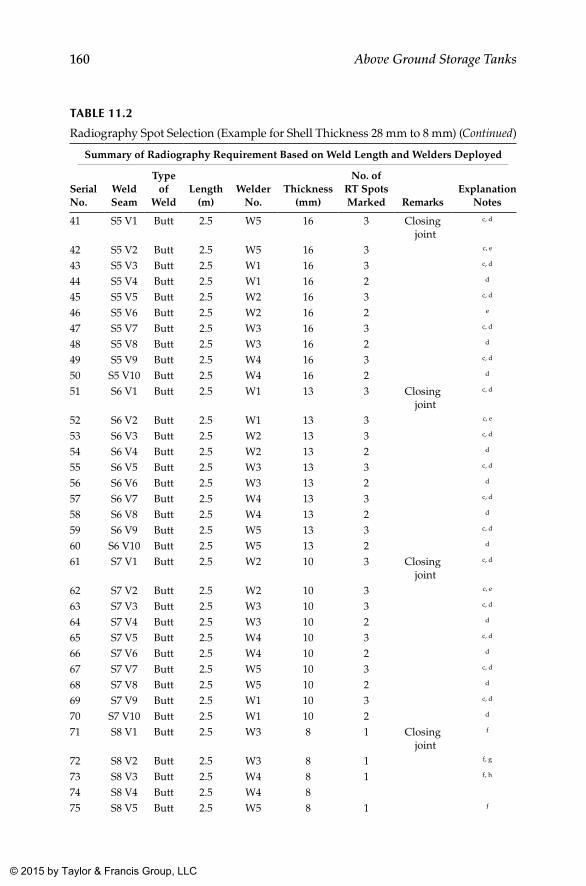
160 Above Ground Storage Tanks
TAblE 11.2
Radiography Spot Selection (Example for Shell Thickness 28 mm to 8 mm) (Continued)
Summary of Radiography Requirement Based on Weld Length and Welders Deployed
Serial No.
Weld Seam
Type of
WeldLength
(m)Welder
No.Thickness
(mm)
No. of RT Spots Marked Remarks
Explanation Notes
41 S5 V1 Butt 2.5 W5 16 3 Closing joint
c, d
42 S5 V2 Butt 2.5 W5 16 3 c, e
43 S5 V3 Butt 2.5 W1 16 3 c, d
44 S5 V4 Butt 2.5 W1 16 2 d
45 S5 V5 Butt 2.5 W2 16 3 c, d
46 S5 V6 Butt 2.5 W2 16 2 e
47 S5 V7 Butt 2.5 W3 16 3 c, d
48 S5 V8 Butt 2.5 W3 16 2 d
49 S5 V9 Butt 2.5 W4 16 3 c, d
50 S5 V10 Butt 2.5 W4 16 2 d
51 S6 V1 Butt 2.5 W1 13 3 Closing joint
c, d
52 S6 V2 Butt 2.5 W1 13 3 c, e
53 S6 V3 Butt 2.5 W2 13 3 c, d
54 S6 V4 Butt 2.5 W2 13 2 d
55 S6 V5 Butt 2.5 W3 13 3 c, d
56 S6 V6 Butt 2.5 W3 13 2 d
57 S6 V7 Butt 2.5 W4 13 3 c, d
58 S6 V8 Butt 2.5 W4 13 2 d
59 S6 V9 Butt 2.5 W5 13 3 c, d
60 S6 V10 Butt 2.5 W5 13 2 d
61 S7 V1 Butt 2.5 W2 10 3 Closing joint
c, d
62 S7 V2 Butt 2.5 W2 10 3 c, e
63 S7 V3 Butt 2.5 W3 10 3 c, d
64 S7 V4 Butt 2.5 W3 10 2 d
65 S7 V5 Butt 2.5 W4 10 3 c, d
66 S7 V6 Butt 2.5 W4 10 2 d
67 S7 V7 Butt 2.5 W5 10 3 c, d
68 S7 V8 Butt 2.5 W5 10 2 d
69 S7 V9 Butt 2.5 W1 10 3 c, d
70 S7 V10 Butt 2.5 W1 10 2 d
71 S8 V1 Butt 2.5 W3 8 1 Closing joint
f
72 S8 V2 Butt 2.5 W3 8 1 f, g
73 S8 V3 Butt 2.5 W4 8 1 f, h
74 S8 V4 Butt 2.5 W4 875 S8 V5 Butt 2.5 W5 8 1 f
K22265_Book.indb 160 4/20/15 5:48 PM
© 2015 by Taylor & Francis Group, LLC
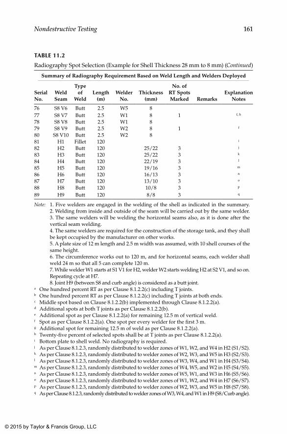
161Nondestructive Testing
TAblE 11.2
Radiography Spot Selection (Example for Shell Thickness 28 mm to 8 mm) (Continued)
Summary of Radiography Requirement Based on Weld Length and Welders Deployed
Serial No.
Weld Seam
Type of
WeldLength
(m)Welder
No.Thickness
(mm)
No. of RT Spots Marked Remarks
Explanation Notes
76 S8 V6 Butt 2.5 W5 877 S8 V7 Butt 2.5 W1 8 1 f, h
78 S8 V8 Butt 2.5 W1 879 S8 V9 Butt 2.5 W2 8 1 f
80 S8 V10 Butt 2.5 W2 881 H1 Fillet 120 i
82 H2 Butt 120 25/22 3 j
83 H3 Butt 120 25/22 3 k
84 H4 Butt 120 22/19 3 l
85 H5 Butt 120 19/16 3 m
86 H6 Butt 120 16/13 3 n
87 H7 Butt 120 13/10 3 o
88 H8 Butt 120 10/8 3 p
89 H9 Butt 120 8/8 3 q
Note: 1. Five welders are engaged in the welding of the shell as indicated in the summary. 2. Welding from inside and outside of the seam will be carried out by the same welder. 3. The same welders will be welding the horizontal seams also, as it is done after the vertical seam welding.
4. The same welders are required for the construction of the storage tank, and they shall be kept occupied by the manufacturer on other works.
5. A plate size of 12 m length and 2.5 m width was assumed, with 10 shell courses of the same height.
6. The circumference works out to 120 m, and for horizontal seams, each welder shall weld 24 m so that all 5 can complete 120 m.
7. While welder W1 starts at S1 V1 for H2, welder W2 starts welding H2 at S2 V1, and so on. Repeating cycle at H7.
8. Joint H9 (between S8 and curb angle) is considered as a butt joint.a One hundred percent RT as per Clause 8.1.2.2(c) including T joints.b One hundred percent RT as per Clause 8.1.2.2(c) including T joints at both ends.c Middle spot based on Clause 8.1.2.2(b) implemented through Clause 8.1.2.2(a).d Additional spots at both T joints as per Clause 8.1.2.2(b).e Additional spot as per Clause 8.1.2.2(a) for remaining 12.5 m of vertical weld.f Spot as per Clause 8.1.2.2(a). One spot per every welder for the first 3 m.g Additional spot for remaining 12.5 m of weld as per Clause 8.1.2.2(a).h Twenty-five percent of selected spots shall be at T joints as per Clause 8.1.2.2(a).i Bottom plate to shell weld. No radiography is required.j As per Clause 8.1.2.3, randomly distributed to welder zones of W1, W2, and W4 in H2 (S1/S2).k As per Clause 8.1.2.3, randomly distributed to welder zones of W2, W3, and W5 in H3 (S2/S3).l As per Clause 8.1.2.3, randomly distributed to welder zones of W3, W4, and W1 in H4 (S3/S4).m As per Clause 8.1.2.3, randomly distributed to welder zones of W4, W5, and W2 in H5 (S4/S5).n As per Clause 8.1.2.3, randomly distributed to welder zones of W5, W1, and W3 in H6 (S5/S6).o As per Clause 8.1.2.3, randomly distributed to welder zones of W1, W2, and W4 in H7 (S6/S7).p As per Clause 8.1.2.3, randomly distributed to welder zones of W2, W3, and W5 in H8 (S7/S8).q As per Clause 8.1.2.3, randomly distributed to welder zones of W3, W4, and W1 in H9 (S8/Curb angle).
K22265_Book.indb 161 4/20/15 5:48 PM
© 2015 by Taylor & Francis Group, LLC
162 Above Ground Storage Tanks
11.4 Other Requirements for Radiography
11.4.1 Technique
Many times, client specifications add restrictions to the technique and type of films to be used for radiography. In addition, based on the service require-ments, the extent of radiography required is also increased beyond those specified in API 650. Some of the salient additions made from the oil and gas industry related to the storage of hydrocarbons are indicated in the summary of inspection and tests provided in Chapter 10 (Section 10.1). In the absence of any such specification, basic minimum requirements in API 650 shall be complied with regarding the extent of testing and ASME Section V, Article 2 regarding the technique to be employed. (Refer to Clause 8.1.3.1 of API 650.)
11.4.2 Personnel
Personnel performing radiography and evaluating radiographs shall be qualified by the American Society for Nondestructive Testing (ASNT) SNT-TC-1A Level II or III.
11.4.3 Procedure
Radiography shall be carried out according to a written procedure based on applicable codes and standards and also shall consider the safety and health aspects of the personnel engaged in radiography, as well as the inhabitants within the vicinity.
11.4.4 Radiographs
Radiographs shall be presented for review along with proper reports for the same. It shall indicate all salient aspects of the technique and invariably shall contain details required for calculating the geometrical unsharpness of radio-graphs, which again is one of the acceptance criteria regarding technique.
11.4.5 Acceptability Norms
Radiographs shall be interpreted and evaluated for acceptance or rejection as per UW 51(b) of ASME Section VIII Div (1) (refer to API 650, Clause 8.1.5). Refer to Annexure D for excerpts from ASME Section VIII Div (1) for quick reference.
11.4.6 Progressive or Penalty Radiography
When a section of weld seen in a radiograph is found unacceptable because of defects present in the weld, two spots adjacent to this section shall be
K22265_Book.indb 162 4/20/15 5:48 PM
© 2015 by Taylor & Francis Group, LLC
163Nondestructive Testing
radiographed. In case the original radiograph shows a defect-free weld of at least 75 mm toward one end of the spot, an additional spot need not be taken on that side of the weld. If the weld on either of the adjacent sections radio-graphed fails to comply with requirements, additional spots shall be exam-ined until the limits of unacceptable welding are determined. The fabricator is provided with the option to replace the entire weld done by that particular welder without resorting to further radiography. If welding is replaced, the inspector can ask for spot radiography on any other weld by a new welder. If any of these additional spots fail to comply with requirements, the limit of unacceptability needs to be determined, as mentioned previously.
11.4.7 Repair of Defective Welds
Removal of any defective weld is carried out either by gouging or by grind-ing or by a combination of both. Depending on the relative positioning of the defect with respect to the thickness of the weld, the repair is carried out from either the inside or the outside. Use of ultrasonic flaw detection is extremely useful, especially with thick shell tanks, where repair is costly by way of lost time and effort, apart from the cost of consumables and labor. Repairs need to be carried out only on the weld area where the defect is present, and hence the defect location shall be marked on the weld as accu-rately as possible so as to avoid repair of any good weld. Keep in mind when marking repairs that the chance of having a defect in the repaired weld is higher compared to that of an original weld, as repairs are carried out under more hostile conditions. The repaired radiographic segment shall undergo radiography and shall meet acceptance criteria. This repaired radiograph shall be reviewed along with the original radiograph to ensure that the new radiography was carried out at the required location and also to ensure that the defect was removed satisfactorily.
11.4.8 Records
The radiographs and their reports and weld map showing the spots radio-graphed are the records pertaining to radiography. As a standard practice, all records shall be handed over to the owner of the facility as a part of the manufacturer’s record book on completion of work. However, a copy of the same shall be available with the fabricator at least for a period of 5 years or more as desired by the fabricator.
11.4.9 Specific Requirements for Radiography from Some Clients in the Oil and Gas Industry
• The procedure mentioned in Section 11.4.3 shall be accompanied by specific technique sheets covering all types of joints envisaged in radiography as per scope.
K22265_Book.indb 163 4/20/15 5:48 PM
© 2015 by Taylor & Francis Group, LLC
164 Above Ground Storage Tanks
• Interpretation of radiographs on behalf of the contractor shall be by ASNT SNT-TC-1A Level II or Ill qualified personnel or with equiva-lent qualification as agreed.
• All volumetric NDT shall be by radiography except for lamination checks or as agreed between contractor and client.
• X-radiography shall be used for all hydrocarbon storage tanks unless otherwise agreed for the use of the Iridium 192 isotope.
• Radiographic examination essentially shall follow work progres-sion. Where shell weld seams require 100% examination, this shall be delayed at least 24 hours after completion of welding.
• Locations for the spot radiography of horizontal and vertical seams and intersections shall be selected at random by the client inspector.
• Identification markers shall appear on the films as radiographic images.
• When additional radiography adjacent to a defective area of a spot or randomly radiographed vertical seam reveals further unacceptable defects, then that vertical seam shall be subject to 100% radiographic examination.
• Wire-type image quality indicators are preferred and shall be avail-able on each film, in independent single exposures. Radiographic sensitivity shall be 2% or better.
• The density through the weld metal shall not be less than 2.0 and not more than 3.2. The density in the parent metal adjacent to the weld shall not exceed 4.0. Film density shall be assessed using a suitably calibrated densitometer. Viewing facilities shall be capable of read-ing films with these densities.
• The type of film shall be ASTM A 1815 Class II (high contrast, low graininess; e.g., Kodak Industrex AA 400, Agfa D7, Fuji IX 100, or equivalent).
• Intensifying salt screens shall not be used.• Exposure conditions shall be attested in the report by the subcontrac-
tor responsible for carrying out radiography.• After interpretation and evaluation by ASNT Level II or III quali-
fied personnel, radiographs complete with reports are required to be reviewed and accepted by the client.
• After completion and acceptance of a tank, the radiographic films including those showing defects to be repaired shall be handed over to the client and properly sorted, boxed, and indexed.
K22265_Book.indb 164 4/20/15 5:48 PM
© 2015 by Taylor & Francis Group, LLC
165Nondestructive Testing
11.5 Ultrasonic Testing
As per API 650, ultrasonic testing (UT) is not mandatory. However, on agreement with the purchaser, inspection of weld using the ultrasonic test method is permitted in lieu of radiography. When ultrasonic testing is car-ried out in lieu of radiography as permitted, examinations need to be car-ried out as per Appendix U in API 650, which gives norms for acceptance of defects as well.
In addition to this, on many occasions, client specifications require ultrasonic testing as an additional requirement. Use of the ultrasonic test method is very helpful when shell thicknesses are comparatively higher. Furthermore, ultrasonic testing is very effective and foolproof in evaluating the corner welds such as the weld between nozzles and manholes and the shell. Because of this, it is always better to have ultrasonic testing procedures in position prior to the start of fabrication. The procedure shall address all types of weld configurations that may arise in its purview with other salient parameters involved in scanning and shall be approved by the client or con-sultant. Furthermore, examiners who perform ultrasonic testing shall be qualified to Level II or III of ASNT, as in the case of radiography.
When ultrasonic testing (not in lieu of radiography) is called for in the specification, it shall be carried out as per Article 5 of ASME Section V. Since this ultrasonic testing (additional) is not mandatory, acceptance criteria for the same may need to be agreed upon by the purchaser and manufacturer preferably before the start of work.
11.6 Magnetic Particle Testing
When magnetic particle testing (MPT) is specified in the order, it shall be car-ried out as per Article 7 of ASME Section V. A procedure covering testing of all anticipated types of welds shall be prepared with a proper reporting for-mat indicating all salient parameters of the test and is to be approved by the client or consultant. Personnel performing MPT shall be qualified to ASNT SNT-TC-1A Level II or III. The vision requirements specified in API 650 with regard to NDT technicians are similar to the requirements of SNT-TC-1A, and hence API 650, through Clause 8.2.3, puts no additional requirement forward.
Criteria for acceptance, removal, and repair of defects revealed in MPT shall be in accordance with ASME Section VIII Div (1) Appendix 6, para-graphs 6-3, 6-4, and 6-5.
K22265_Book.indb 165 4/20/15 5:48 PM
© 2015 by Taylor & Francis Group, LLC
166 Above Ground Storage Tanks
11.7 Liquid Penetrant Testing
When liquid penetrant testing (LPT) is specified in the order, it shall be car-ried out as per Article 6 of ASME Section V. As in the case of other NDT meth-ods, a written procedure covering testing of all anticipated types of welds shall be prepared with proper reporting format indicating all salient param-eters of the test and is to be approved by the client/consultant. Personnel performing and evaluating LPT shall be qualified to ASNT SNT-TC-1A Level II or III. Here also, the vision requirements specified in API 650 with regard to NDT technicians are similar to requirements of SNT-TC-1A and hence no additional requirement is put forward by API 650 through Clauses 8.4.3
Criteria for acceptance, removal and repair of defects revealed in LPT shall be in accordance with ASME Section VIII Div (1) Appendix 8, paragraphs 8-3, 8-4, and 8-5.
11.8 Visual Examination or Testing
As indicated in the inspection and test summary in Chapter 10, every weld of a storage tank is expected to be inspected visually and cleared off personally by one of the inspectors according to the norm specified in API 650, as well as in client specifications. In spite of all these written requirements, on many occasions, obvious and glaring defects can be noticed at the time of hydro-static testing and subsequent surface cleaning and coating and lining applica-tion of the storage tanks. Though it might be unintentional and due to human errors, most of the time it is felt that this results from a lack of clear strategy to clear each and every weld of a storage tank through visual examination or visual testing (VT). Therefore, it is considered important to evolve a clear strategy to carry out visual inspection of storage tanks as described next.
11.8.1 Visual Examination Strategy
In this regard, the right method is to list out all welds that are coning on the storage tank. Once this is done, it shall be ensured with the use of a checklist that each and every weld has undergone visual inspection. To not consume more time for visual inspection of welds at the final stage, the fol-lowing strategy to visually clear welds progressively at a convenient stage of manufacture would stagger the burden of visual inspection considerably over the entire manufacturing cycle. Though it is advisable to carry out the final visual inspection of the surface of the tank after completion of all weld-ing (including capacitor discharge welding of insulation clips and similar items), in practice this might not be possible because of the short time span
K22265_Book.indb 166 4/20/15 5:48 PM
© 2015 by Taylor & Francis Group, LLC
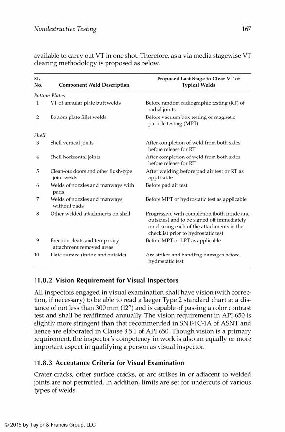
167Nondestructive Testing
available to carry out VT in one shot. Therefore, as a via media stagewise VT clearing methodology is proposed as below.
Sl. No. Component Weld Description
Proposed Last Stage to Clear VT of Typical Welds
Bottom Plates 1 VT of annular plate butt welds Before random radiographic testing (RT) of
radial joints 2 Bottom plate fillet welds Before vacuum box testing or magnetic
particle testing (MPT)
Shell 3 Shell vertical joints After completion of weld from both sides
before release for RT 4 Shell horizontal joints After completion of weld from both sides
before release for RT 5 Clean-out doors and other flush-type
joint weldsAfter welding before pad air test or RT as applicable
6 Welds of nozzles and manways with pads
Before pad air test
7 Welds of nozzles and manways without pads
Before MPT or hydrostatic test as applicable
8 Other welded attachments on shell Progressive with completion (both inside and outsides) and to be signed off immediately on clearing each of the attachments in the checklist prior to hydrostatic test
9 Erection cleats and temporary attachment removed areas
Before MPT or LPT as applicable
10 Plate surface (inside and outside) Arc strikes and handling damages before hydrostatic test
11.8.2 Vision Requirement for Visual Inspectors
All inspectors engaged in visual examination shall have vision (with correc-tion, if necessary) to be able to read a Jaeger Type 2 standard chart at a dis-tance of not less than 300 mm (12”) and is capable of passing a color contrast test and shall be reaffirmed annually. The vision requirement in API 650 is slightly more stringent than that recommended in SNT-TC-1A of ASNT and hence are elaborated in Clause 8.5.1 of API 650. Though vision is a primary requirement, the inspector’s competency in work is also an equally or more important aspect in qualifying a person as visual inspector.
11.8.3 Acceptance Criteria for Visual Examination
Crater cracks, other surface cracks, or arc strikes in or adjacent to welded joints are not permitted. In addition, limits are set for undercuts of various types of welds.
K22265_Book.indb 167 4/20/15 5:48 PM
© 2015 by Taylor & Francis Group, LLC
168 Above Ground Storage Tanks
The maximum permissible undercut is 0.4 mm (1/64”) in depth for vertical butt joints, vertically oriented permanent attachments, attachment welds for nozzles, manholes, flush-type openings, and inside shell-to-bottom welds. For full acceptance criteria with regard to undercuts and surface pores, see Clause 8.5.2 of API 650.
Weld Reinforcement
The reinforcement limits specified for vertical joints range from 2.5 mm to 5 mm, whereas those for horizontal joints range from 3 mm to 6 mm, based on plate thickness. As this limit produces wide variation in density between the weld and the parent plate, the reinforcement limit is restricted from 1.5 mm to 3 mm for the locations designated for spot radiography. The exact reinforcement limits in as welded condition is provided in Clause 8.1.3.4, and those for radiography locations are provided in Clause 8.5.2 of API 650, respectively.
11.9 Weld Maps
Contractors shall maintain a weld map of the shell weld to show locations of random spot radiography carried out, with unique identification provided for each spot radiographed. Apart from the required spots, the weld map also shall indicate penalty spots taken because of defective welding. It is recommended to use different color codes for depicting originally selected, repair, and penalty spots on the weld map. If required, separate weld maps shall be prepared for each NDT technique adopted in the tank construction.
11.10 Documentation of NDT
Documents in support of NDT shall be reports against each and every radiograph or other NDT performed on the tank during construction as per requirements. However, with this document alone, verifying the coverage as per requirement may not be possible. Therefore, it is suggested to have a consolidated summary of NDT reports depicting report numbers against each of the spots identified in the weld map.
K22265_Book.indb 168 4/20/15 5:48 PM
© 2015 by Taylor & Francis Group, LLC
169
12Other Tests
12.1 Vacuum Box Testing
Vacuum box testing is a practical technique of testing in comparison to quantitative measures used to examine objects. Vacuum box testing can be used to test objects on which a pressure differential can be created across the area to be examined. Common application areas of vacuum box testing include piping systems, pressure vessels, and storage tanks. There are vari-ous types of boxes or frames used in vacuum box testing depending on the application area and its configuration. Vacuum box inspection can be car-ried out on lap welds, butt welds, and fillet welds. These vacuum boxes are used to examine a small and specific portion of a welded area to produce accurate results. Vacuum boxes used in vacuum box testing are fabricated of thick, clear Perspex with a closed cell foam seal along the bottom edge. A vacuum gauge and hose coupling are fitted in the box before the testing begins. Then a soapy solution is put on the line of the welding of the object under test. After that, the vacuum box is placed over the testing object, and a vacuity is created inside the box. The object is then observed for either a drop in vacuum or a bubble formation on the surface, in which case the weld is considered defective.
Vacuum box testing is a very popular leak-testing technique that is widely used to test various objects against defects, flaws, leaks, or other imperfec-tions, being an efficient and effective method to test welded objects. There are basically two main types of vacuum box systems used for performing vacuum testing:
• High-pressure models are mainly used for inspection of above ground storage tanks that have been in service.
• Low-pressure models are used for weld integrity checks on new tank builds where gross defects are the main concern.
In storage tanks, vacuum box testing is extensively used to check for through defects in the welding of bottom and annular plates of the storage tank.
K22265_Book.indb 169 4/20/15 5:48 PM
© 2015 by Taylor & Francis Group, LLC
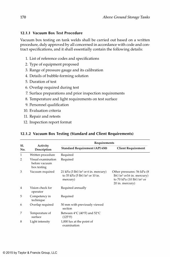
170 Above Ground Storage Tanks
12.1.1 Vacuum box Test Procedure
Vacuum box testing on tank welds shall be carried out based on a written procedure, duly approved by all concerned in accordance with code and con-tract specifications, and it shall essentially contain the following details:
1. List of reference codes and specifications 2. Type of equipment proposed 3. Range of pressure gauge and its calibration 4. Details of bubble-forming solution 5. Duration of test 6. Overlap required during test 7. Surface preparations and prior inspection requirements 8. Temperature and light requirements on test surface 9. Personnel qualification 10. Evaluation criteria 11. Repair and retests 12. Inspection report format
12.1.2 Vacuum box Testing (Standard and Client Requirements)
Sl. No.
Activity Description
Requirements
Standard Requirement (API 650) Client Requirement
1 Written procedure Required2 Visual examination
before vacuum box testing
Required
3 Vacuum required 21 kPa (3 lbf/in2 or 6 in. mercury) to 35 kPa (5 lbf/in2 or 10 in. mercury)
Other pressures: 56 kPa (8 lbf/in2 or16 in. mercury) to 70 kPa (10 lbf/in2 or 20 in. mercury)
4 Vision check for operator
Required annually
5 Competency in technique
Required
6 Overlap required 50 mm with previously viewed section
7 Temperature of surface
Between 4°C (40°F) and 52°C (125°F)
8 Light intensity 1,000 lux at the point of examination
K22265_Book.indb 170 4/20/15 5:48 PM
© 2015 by Taylor & Francis Group, LLC
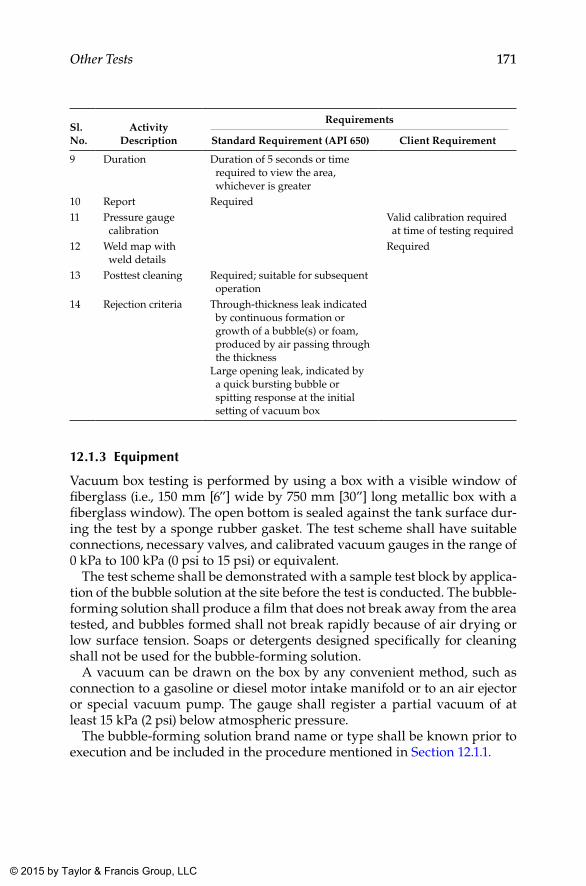
171Other Tests
Sl. No.
Activity Description
Requirements
Standard Requirement (API 650) Client Requirement
9 Duration Duration of 5 seconds or time required to view the area, whichever is greater
10 Report Required11 Pressure gauge
calibrationValid calibration required at time of testing required
12 Weld map with weld details
Required
13 Posttest cleaning Required; suitable for subsequent operation
14 Rejection criteria Through-thickness leak indicated by continuous formation or growth of a bubble(s) or foam, produced by air passing through the thickness
Large opening leak, indicated by a quick bursting bubble or spitting response at the initial setting of vacuum box
12.1.3 Equipment
Vacuum box testing is performed by using a box with a visible window of fiberglass (i.e., 150 mm [6”] wide by 750 mm [30”] long metallic box with a fiberglass window). The open bottom is sealed against the tank surface dur-ing the test by a sponge rubber gasket. The test scheme shall have suitable connections, necessary valves, and calibrated vacuum gauges in the range of 0 kPa to 100 kPa (0 psi to 15 psi) or equivalent.
The test scheme shall be demonstrated with a sample test block by applica-tion of the bubble solution at the site before the test is conducted. The bubble-forming solution shall produce a film that does not break away from the area tested, and bubbles formed shall not break rapidly because of air drying or low surface tension. Soaps or detergents designed specifically for cleaning shall not be used for the bubble-forming solution.
A vacuum can be drawn on the box by any convenient method, such as connection to a gasoline or diesel motor intake manifold or to an air ejector or special vacuum pump. The gauge shall register a partial vacuum of at least 15 kPa (2 psi) below atmospheric pressure.
The bubble-forming solution brand name or type shall be known prior to execution and be included in the procedure mentioned in Section 12.1.1.
K22265_Book.indb 171 4/20/15 5:48 PM
© 2015 by Taylor & Francis Group, LLC
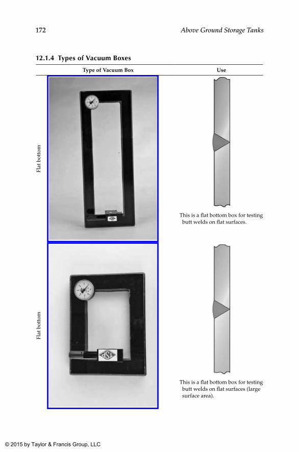
172 Above Ground Storage Tanks
12.1.4 Types of Vacuum boxes
Type of Vacuum Box Use
Flat
bot
tom
This is a flat bottom box for testing butt welds on flat surfaces.
Flat
bot
tom
This is a flat bottom box for testing butt welds on flat surfaces (large surface area).
K22265_Book.indb 172 4/20/15 5:48 PM
© 2015 by Taylor & Francis Group, LLC
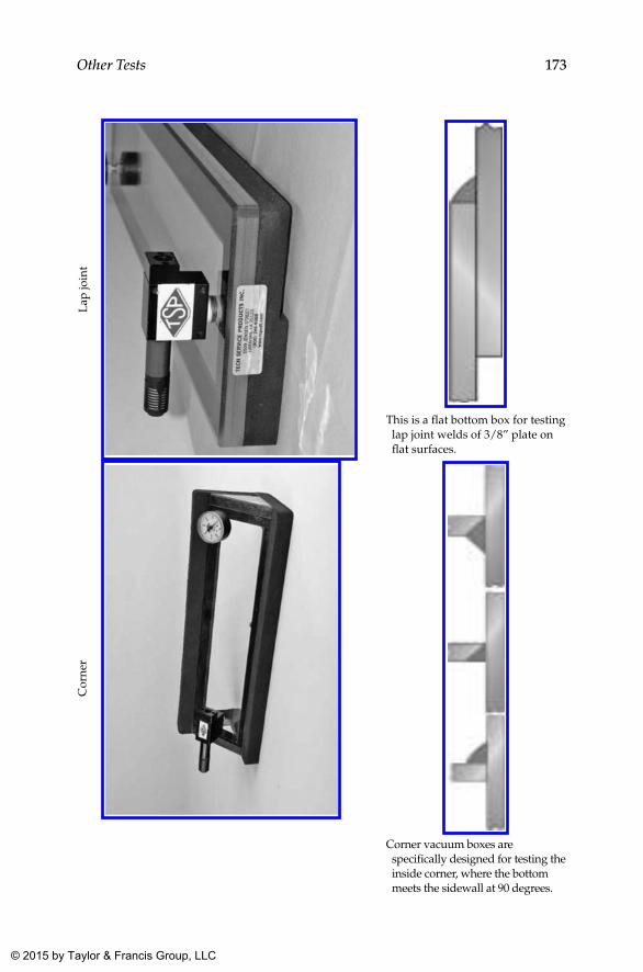
173Other TestsL
ap jo
int
This is a flat bottom box for testing lap joint welds of 3/8” plate on flat surfaces.
Cor
ner
Corner vacuum boxes are specifically designed for testing the inside corner, where the bottom meets the sidewall at 90 degrees.
K22265_Book.indb 173 4/20/15 5:48 PM
© 2015 by Taylor & Francis Group, LLC
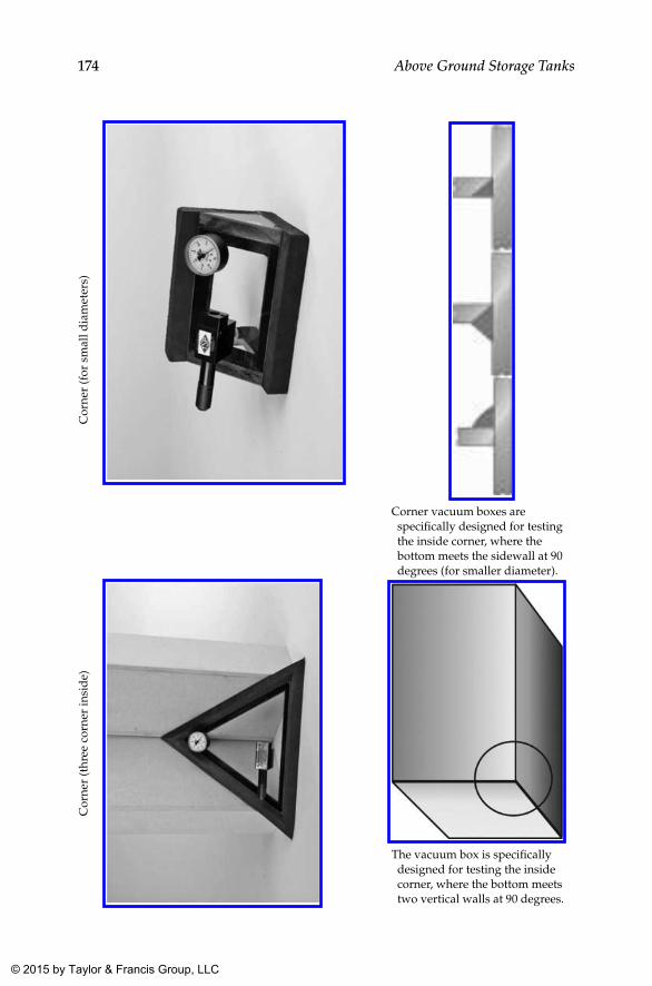
174 Above Ground Storage TanksC
orne
r (f
or s
mal
l dia
met
ers)
Corner vacuum boxes are specifically designed for testing the inside corner, where the bottom meets the sidewall at 90 degrees (for smaller diameter).
Cor
ner
(thr
ee c
orne
r in
sid
e)
The vacuum box is specifically designed for testing the inside corner, where the bottom meets two vertical walls at 90 degrees.
K22265_Book.indb 174 4/20/15 5:48 PM
© 2015 by Taylor & Francis Group, LLC
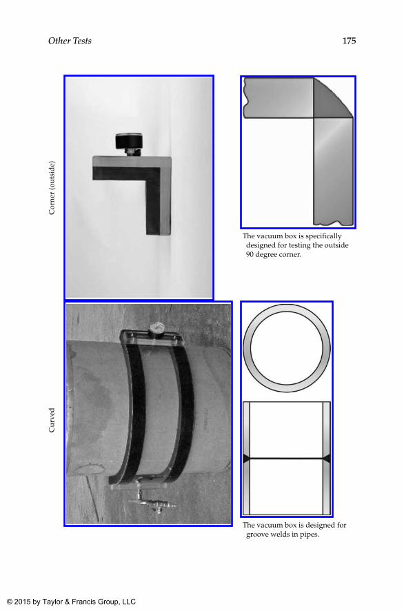
175Other TestsC
orne
r (o
utsi
de)
The vacuum box is specifically designed for testing the outside 90 degree corner.
Cur
ved
The vacuum box is designed for groove welds in pipes.
K22265_Book.indb 175 4/20/15 5:48 PM
© 2015 by Taylor & Francis Group, LLC
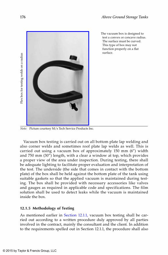
176 Above Ground Storage TanksFl
ex b
ox fo
r te
stin
g w
eld
s on
a r
adiu
s
The vacuum box is designed to test a convex or concave radius. The surface must be curved. This type of box may not function properly on a flat surface.
Note: Picture courtesy M/s Tech Service Products Inc.
Vacuum box testing is carried out on all bottom plate lap welding and also corner welds and sometimes roof plate lap welds as well. This is carried out using a vacuum box of approximately 150 mm (6”) width and 750 mm (30”) length, with a clear a window at top, which provides a proper view of the area under inspection. During testing, there shall be adequate lighting to facilitate proper evaluation and interpretation of the test. The underside (the side that comes in contact with the bottom plate) of the box shall be held against the bottom plate of the tank using suitable gaskets so that the applied vacuum is maintained during test-ing. The box shall be provided with necessary accessories like valves and gauges as required in applicable code and specifications. The film solution shall be used to detect leaks while the vacuum is maintained inside the box.
12.1.5 Methodology of Testing
As mentioned earlier in Section 12.1.1, vacuum box testing shall be car-ried out according to a written procedure duly approved by all parties involved in the contract, mainly the consultant and the client. In addition to the requirements spelled out in Section 12.1.1, the procedure shall also
K22265_Book.indb 176 4/20/15 5:48 PM
© 2015 by Taylor & Francis Group, LLC
177Other Tests
address the following aspects related to the actual performance of the test at the site:
1. Visual examination of the weld joints is made prior to conducting the vacuum box test.
2. Physical verification of the vacuum pump and its gaskets is made to assess whether they are capable of producing satisfactory results.
3. The adequacy of the wetness of the film solution (when applied to a dry area) to generate bubbles is ensured.
4. The vacuum shall be as indicated in the table provided in Section 12.1.2 and shall be monitored through calibrated pressure gauges.
5. The operator shall be qualified to carry out the test as specified in the written procedure and shall undergo a vision test annually.
6. The operator shall ensure a minimum overlap between consecutive tests as specified in code and specifications.
7. The test shall not be performed when the light intensity available is below that specified. Furthermore, the duration of the test also shall be maintained as required.
12.1.6 Acceptance Criteria
Through-thickness leaks of any sort are treated as unacceptable in API 650. The leaks are classified under the following two categories:
1. A through-thickness leak is indicated by continuous formation or growth of a bubble(s) or foam, produced by air passing through the thickness.
2. A large opening leak is indicated by a quick bursting bubble or spit-ting response at the initial setting of the vacuum box.
Both the leaks are unacceptable and shall be repaired and tested again.
12.1.7 Records
A report of the test indicating all salient aspects mentioned previously shall be a part of the final documentation pertaining to the tank, along with details of welds covered by the report and a weld map.
Though API 650 permits leak testing using a tracer gas and suitable detec-tor in lieu of vacuum box testing, the same is not addressed in this book, as this is intended to provide simple, effective, and low-cost options that are in strict compliance to API 650 requirements. However, if client specification requires the tracer gas leak detection system, details pertaining to the same can be had from Clause 8.6.1 of API 650.
K22265_Book.indb 177 4/20/15 5:48 PM
© 2015 by Taylor & Francis Group, LLC
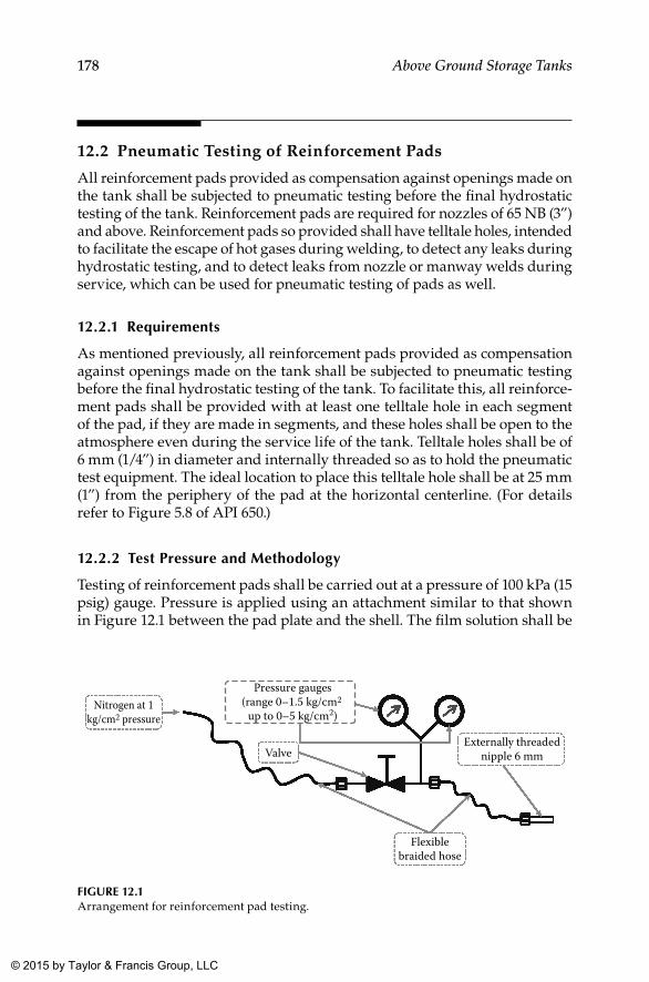
178 Above Ground Storage Tanks
12.2 Pneumatic Testing of Reinforcement Pads
All reinforcement pads provided as compensation against openings made on the tank shall be subjected to pneumatic testing before the final hydrostatic testing of the tank. Reinforcement pads are required for nozzles of 65 NB (3”) and above. Reinforcement pads so provided shall have telltale holes, intended to facilitate the escape of hot gases during welding, to detect any leaks during hydrostatic testing, and to detect leaks from nozzle or manway welds during service, which can be used for pneumatic testing of pads as well.
12.2.1 Requirements
As mentioned previously, all reinforcement pads provided as compensation against openings made on the tank shall be subjected to pneumatic testing before the final hydrostatic testing of the tank. To facilitate this, all reinforce-ment pads shall be provided with at least one telltale hole in each segment of the pad, if they are made in segments, and these holes shall be open to the atmosphere even during the service life of the tank. Telltale holes shall be of 6 mm (1/4”) in diameter and internally threaded so as to hold the pneumatic test equipment. The ideal location to place this telltale hole shall be at 25 mm (1”) from the periphery of the pad at the horizontal centerline. (For details refer to Figure 5.8 of API 650.)
12.2.2 Test Pressure and Methodology
Testing of reinforcement pads shall be carried out at a pressure of 100 kPa (15 psig) gauge. Pressure is applied using an attachment similar to that shown in Figure 12.1 between the pad plate and the shell. The film solution shall be
Nitrogen at 1kg/cm2 pressure
Flexiblebraided hose
Externally threadednipple 6 mmValve
Pressure gauges(range 0–1.5 kg/cm2
up to 0–5 kg/cm2)
FIGuRE 12.1Arrangement for reinforcement pad testing.
K22265_Book.indb 178 4/20/15 5:48 PM
© 2015 by Taylor & Francis Group, LLC
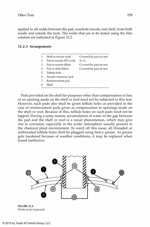
179Other Tests
applied to all welds between the pad, manhole/nozzle, and shell, from both inside and outside the tank. The welds that are to be tested using the film solution are indicated in Figure 12.2.
12.2.3 Arrangements
1 Shell to nozzle weld Covered by pad air test2 Pad to nozzle (FP) weld N/A3 Pad to nozzle (fillet) Covered by pad air test4 Pad to shell (fillet) Covered by pad air test5 Telltale hole6 Nozzle/manway neck7 Reinforcement pad8 Shell
Pads provided on the shell for purposes other than compensation in lieu of an opening made on the shell or roof need not be subjected to this test. However, such pads also shall be given telltale holes as provided in the case of reinforcement pads given as compensation to openings made on the shell or roof. Because of this, telltale holes on such pads need not be tapped. During a rainy season, accumulation of water in the gap between the pad and the shell or roof is a usual phenomenon, which may give rise to corrosion, especially in the acidic atmosphere usually present in the chemical plant environment. To ward off this issue, all threaded or unthreaded telltale holes shall be plugged using heavy grease. As grease gets hardened because of weather conditions, it may be replaced when found ineffective.
1
2 2
3
4 4 5
8
7
6
FIGuRE 12.2Welds to be inspected.
K22265_Book.indb 179 4/20/15 5:48 PM
© 2015 by Taylor & Francis Group, LLC
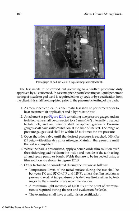
180 Above Ground Storage Tanks
Photograph of pad air test of a typical shop fabricated tank.
The test needs to be carried out according to a written procedure duly approved by all concerned. In case magnetic particle testing or liquid penetrant testing of nozzle or pad weld is required either by code or by specification from the client, this shall be completed prior to the pneumatic testing of the pads.
1. As mentioned earlier, this pneumatic test shall be performed prior to heat treatment (if applicable) and a hydrostatic test.
2. Attachment as per Figure 12.1A containing two pressure gauges and an isolation valve shall be connected to a 6 mm (1/4”) internally threaded telltale hole, and air pressure shall be applied gradually. Pressure gauges shall have valid calibration at the time of the test. The range of pressure gauges used shall be within 1.5 to 4 times the test pressure.
3. Open the inlet valve until the desired pressure is reached, 100 kPa (15 psig) with either dry air or nitrogen. Maintain that pressure until the test is completed.
4. While the pad is pressurized, apply a nonchloride film solution over the reinforcing pad welds on the inside and outside of the tank using a hand spray pump or brush. Welds that are to be inspected using a film solution are shown in Figure 12.1B.
5. Other factors to be considered during the test are as follows:• Temperature limits of the metal surface during the test shall be
between 4°C and 52°C (40°F and 125°F), unless the film solution is proven to work at temperatures outside these limits, either by test-ing or by the manufacturer’s recommendations.
• A minimum light intensity of 1,000 lux at the point of examina-tion is required during the test and evaluation for leaks.
• The examiner shall have a valid vision certification.
K22265_Book.indb 180 4/20/15 5:49 PM
© 2015 by Taylor & Francis Group, LLC
181Other Tests
6. Observe for any sign of leaks, the absence of which confirms accep-tance, and pressure can be brought back to atmospheric. Otherwise, depressurize, repair, and retest in the same manner.
7. When the pad has successfully passed the test, documentation to this effect shall be made and countersigned by all parties involved. This shall be included in the manufacturer’s record book.
12.3 Hydrostatic Testing of Tank
12.3.1 Testing of Tank Shell
API 650 proposes one of the following to assess the integrity of the shell of a storage tank. This test is to be carried out after the entire construction work of the tank is completed, including the roof and all other connected structures. However, tanks designed according to Appendix F of API 650 is excluded from the scope of this testing.
If water is available for carrying out the hydrostatic test, the tank shall be filled with water
1. up to a maximum design liquid level, 2. up to 50 mm (2”) above the weld connecting the roof plate or compres-
sion bar to the top angle or shell in the case of tanks with a tight roof, or 3. to a level lower than that just specified, when the maximum level is
limited by overflow nozzles.
12.3.2 Standard and Client Requirements for Hydrostatic Testing
Sl. No.
Activity Description
Requirements
Standard Requirement (API 650) Client Requirement
1 Written procedure
Required and shall address requirements in detail
2 Stage Before connecting external piping
After completion of all welding 3 Coverage Shell welds
All welds above water level shall be tested either pneumatically or using chalk and oil
Pneumatic or vacuum box testing
(Continued)
K22265_Book.indb 181 4/20/15 5:49 PM
© 2015 by Taylor & Francis Group, LLC
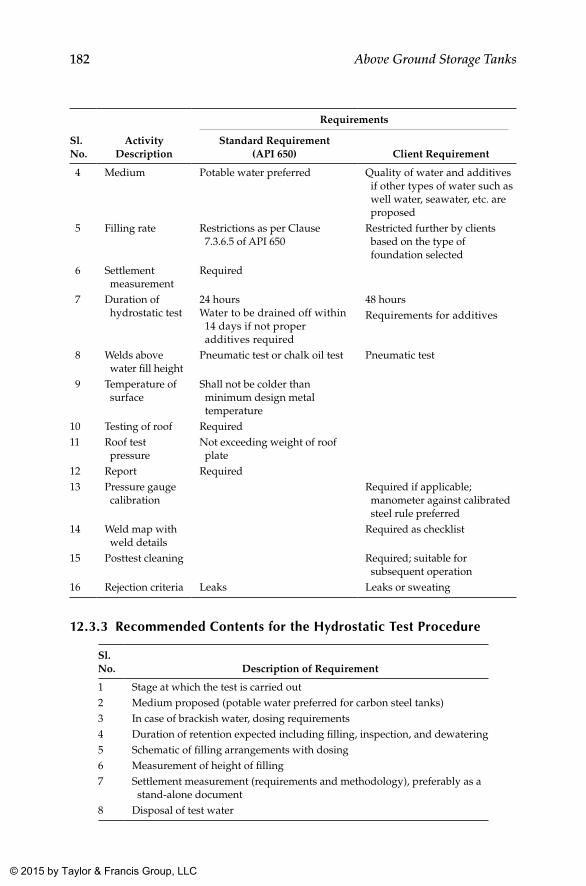
182 Above Ground Storage Tanks
Sl. No.
Activity Description
Requirements
Standard Requirement (API 650) Client Requirement
4 Medium Potable water preferred Quality of water and additives if other types of water such as well water, seawater, etc. are proposed
5 Filling rate Restrictions as per Clause 7.3.6.5 of API 650
Restricted further by clients based on the type of foundation selected
6 Settlement measurement
Required
7 Duration of hydrostatic test
24 hours Water to be drained off within
14 days if not proper additives required
48 hoursRequirements for additives
8 Welds above water fill height
Pneumatic test or chalk oil test Pneumatic test
9 Temperature of surface
Shall not be colder than minimum design metal temperature
10 Testing of roof Required11 Roof test
pressureNot exceeding weight of roof plate
12 Report Required13 Pressure gauge
calibrationRequired if applicable; manometer against calibrated steel rule preferred
14 Weld map with weld details
Required as checklist
15 Posttest cleaning Required; suitable for subsequent operation
16 Rejection criteria Leaks Leaks or sweating
12.3.3 Recommended Contents for the Hydrostatic Test Procedure
Sl. No. Description of Requirement
1 Stage at which the test is carried out2 Medium proposed (potable water preferred for carbon steel tanks)3 In case of brackish water, dosing requirements4 Duration of retention expected including filling, inspection, and dewatering5 Schematic of filling arrangements with dosing6 Measurement of height of filling7 Settlement measurement (requirements and methodology), preferably as a
stand-alone document8 Disposal of test water
K22265_Book.indb 182 4/20/15 5:49 PM
© 2015 by Taylor & Francis Group, LLC
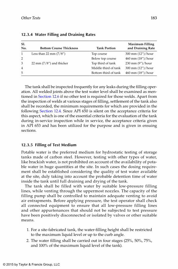
183Other Tests
12.3.4 Water Filling and Draining Rates
Sl. No. Bottom Course Thickness Tank Portion
Maximum Filling and Draining Rate
1 Less than 22 mm (7/8”) Top course 300 mm (12”)/hour2 Below top course 460 mm (18”)/hour3 22 mm (7/8”) and thicker Top third of tank 230 mm (9”)/hour4 Middle third of tank 300 mm (12”)/hour5 Bottom third of tank 460 mm (18”)/hour
The tank shall be inspected frequently for any leaks during the filling oper-ation. All welded joints above the test water level shall be examined as men-tioned in Section 12.6 if no other test is required for those welds. Apart from the inspection of welds at various stages of filling, settlement of the tank also shall be recorded, the minimum requirements for which are provided in the following Section 12.4. Since API 650 is silent on the acceptance criteria for this aspect, which is one of the essential criteria for the evaluation of the tank during in-service inspection while in service, the acceptance criteria given in API 653 and has been utilized for the purpose and is given in ensuing sections.
12.3.5 Filling of Test Medium
Potable water is the preferred medium for hydrostatic testing of storage tanks made of carbon steel. However, testing with other types of water, like brackish water, is not prohibited on account of the availability of pota-ble water in huge quantities at the site. In such cases the dosing require-ment shall be established considering the quality of test water available at the site, duly taking into account the probable detention time of water inside the tank until full draining and drying of the tank.
The tank shall be filled with water by suitable low-pressure filling lines, while venting through the uppermost nozzles. The capacity of the filling pump shall be controlled to maintain adequate venting to avoid air entrapments. Before applying pressure, the test operator shall check all connected equipment to ensure that all low-pressure filling lines and other appurtenances that should not be subjected to test pressure have been positively disconnected or isolated by valves or other suitable means.
1. For a site-fabricated tank, the water-filling height shall be restricted to the maximum liquid level or up to the curb angle.
2. The water filling shall be carried out in four stages (25%, 50%, 75%, and 100% of the maximum liquid level of the tank).
K22265_Book.indb 183 4/20/15 5:49 PM
© 2015 by Taylor & Francis Group, LLC
184 Above Ground Storage Tanks
3. Any leaks observed in the shell joints during the hydrostatic test shall be noted and repaired with the water level lowered down to a minimum of 300 mm below the leak spot.
4. Repairs shall be carried out as per an approved procedure and shall be subject to applicable nondestructive testing (NDT). Upon comple-tion of these two activities, the tank test shall be resumed.
5. After each stage of filling, a load stabilization period of 24 hours shall be observed between each stage of filling.
6. During the stabilization period, the settlement reading shall be recorded jointly with the contractor, consultant, and client represen-tatives as required using a dumpy level or a theodolite.
7. In addition to the filling rate indicated in Section 12.3.1, some clients specify a per-day cap on the filling rate as 5 m of height of water per day.
8. After completion of water filling, the full-height water load shall be maintained for 24 hours. After 24 hours the final settlement reading shall be recorded jointly.
In addition to tank settlement measurements taken at one-fourth, one-half, three-quarters, and full height, they shall be taken again after emptying the tank after the hydrostatic test.
12.3.6 Visual Inspection
During the test, inspection for leakage, bulging, or other visible defects shall be made on the whole body of the tank. Close examination shall be carried out on all weld joints and connections. The inspection shall be performed by experienced and qualified personnel from the contractor, consultant, or client side as required.
12.3.7 Safety Precautions
Warning signs shall be displayed at roped-off areas indicating that a test is in progress. Only authorized personnel shall be allowed within the test area during testing. All authorized personnel allowed within the test area shall stay clear of the tank during testing.
12.3.8 Repair and Retest
During inspection, if leaks, cracks, or any other defects are observed, the same shall be repaired as per the approved procedure and by qualified weld-ers. After successful repair and NDT, the tank shall be retested as per the original written procedure.
K22265_Book.indb 184 4/20/15 5:49 PM
© 2015 by Taylor & Francis Group, LLC
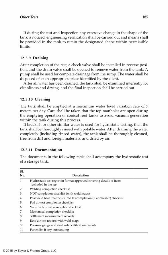
185Other Tests
If during the test and inspection any excessive change in the shape of the tank is noticed, engineering verification shall be carried out and means shall be provided in the tank to retain the designated shape within permissible limits.
12.3.9 Draining
After completion of the test, a check valve shall be installed in reverse posi-tion, and the drain valve shall be opened to remove water from the tank. A pump shall be used for complete drainage from the sump. The water shall be disposed of at an appropriate place identified by the client.
After all water has been drained, the tank shall be examined internally for cleanliness and drying, and the final inspection shall be carried out.
12.3.10 Cleaning
The tank shall be emptied at a maximum water level variation rate of 5 meters per day. Care shall be taken that the top manholes are open during the emptying operation of conical roof tanks to avoid vacuum generation within the tank during this process.
If brackish or other similar water is used for hydrostatic testing, then the tank shall be thoroughly rinsed with potable water. After draining the water completely (including rinsed water), the tank shall be thoroughly cleaned, free from dirt and foreign materials, and dried by air.
12.3.11 Documentation
The documents in the following table shall accompany the hydrostatic test of a storage tank.
Sl. No. Description
1 Hydrostatic test report in format approved covering details of items included in the test
2 Welding completion checklist3 NDT completion checklist (with weld maps)4 Post weld heat treatment (PWHT) completion (if applicable) checklist5 Pad air test completion checklist6 Vacuum box test completion checklist7 Mechanical completion checklist8 Settlement measurement records9 Roof air test reports with weld maps10 Pressure gauge and steel ruler calibration records11 Punch list if any outstanding
K22265_Book.indb 185 4/20/15 5:49 PM
© 2015 by Taylor & Francis Group, LLC
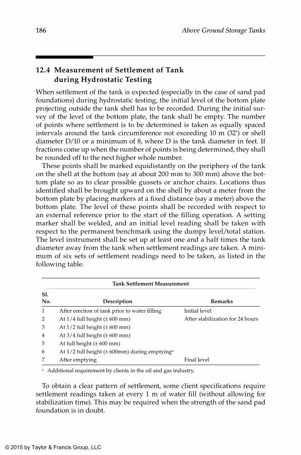
186 Above Ground Storage Tanks
12.4 Measurement of Settlement of Tank during Hydrostatic Testing
When settlement of the tank is expected (especially in the case of sand pad foundations) during hydrostatic testing, the initial level of the bottom plate projecting outside the tank shell has to be recorded. During the initial sur-vey of the level of the bottom plate, the tank shall be empty. The number of points where settlement is to be determined is taken as equally spaced intervals around the tank circumference not exceeding 10 m (32’) or shell diameter D/10 or a minimum of 8, where D is the tank diameter in feet. If fractions come up when the number of points is being determined, they shall be rounded off to the next higher whole number.
These points shall be marked equidistantly on the periphery of the tank on the shell at the bottom (say at about 200 mm to 300 mm) above the bot-tom plate so as to clear possible gussets or anchor chairs. Locations thus identified shall be brought upward on the shell by about a meter from the bottom plate by placing markers at a fixed distance (say a meter) above the bottom plate. The level of these points shall be recorded with respect to an external reference prior to the start of the filling operation. A setting marker shall be welded, and an initial level reading shall be taken with respect to the permanent benchmark using the dumpy level/total station. The level instrument shall be set up at least one and a half times the tank diameter away from the tank when settlement readings are taken. A mini-mum of six sets of settlement readings need to be taken, as listed in the following table.
Tank Settlement Measurement
Sl. No. Description Remarks
1 After erection of tank prior to water filling Initial level2 At 1/4 full height (± 600 mm) After stabilization for 24 hours3 At 1/2 full height (± 600 mm)4 At 3/4 full height (± 600 mm)5 At full height (± 600 mm)6 At 1/2 full height (± 600mm) during emptyinga
7 After emptying Final level
a Additional requirement by clients in the oil and gas industry.
To obtain a clear pattern of settlement, some client specifications require settlement readings taken at every 1 m of water fill (without allowing for stabilization time). This may be required when the strength of the sand pad foundation is in doubt.
K22265_Book.indb 186 4/20/15 5:49 PM
© 2015 by Taylor & Francis Group, LLC
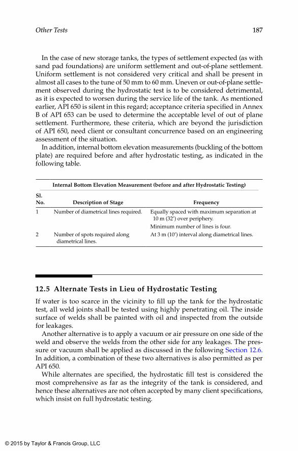
187Other Tests
In the case of new storage tanks, the types of settlement expected (as with sand pad foundations) are uniform settlement and out-of-plane settlement. Uniform settlement is not considered very critical and shall be present in almost all cases to the tune of 50 mm to 60 mm. Uneven or out-of-plane settle-ment observed during the hydrostatic test is to be considered detrimental, as it is expected to worsen during the service life of the tank. As mentioned earlier, API 650 is silent in this regard; acceptance criteria specified in Annex B of API 653 can be used to determine the acceptable level of out of plane settlement. Furthermore, these criteria, which are beyond the jurisdiction of API 650, need client or consultant concurrence based on an engineering assessment of the situation.
In addition, internal bottom elevation measurements (buckling of the bottom plate) are required before and after hydrostatic testing, as indicated in the following table.
Internal Bottom Elevation Measurement (before and after Hydrostatic Testing)
Sl. No. Description of Stage Frequency
1 Number of diametrical lines required. Equally spaced with maximum separation at 10 m (32’) over periphery.
Minimum number of lines is four.2 Number of spots required along
diametrical lines.At 3 m (10’) interval along diametrical lines.
12.5 Alternate Tests in Lieu of Hydrostatic Testing
If water is too scarce in the vicinity to fill up the tank for the hydrostatic test, all weld joints shall be tested using highly penetrating oil. The inside surface of welds shall be painted with oil and inspected from the outside for leakages.
Another alternative is to apply a vacuum or air pressure on one side of the weld and observe the welds from the other side for any leakages. The pres-sure or vacuum shall be applied as discussed in the following Section 12.6. In addition, a combination of these two alternatives is also permitted as per API 650.
While alternates are specified, the hydrostatic fill test is considered the most comprehensive as far as the integrity of the tank is considered, and hence these alternatives are not often accepted by many client specifications, which insist on full hydrostatic testing.
K22265_Book.indb 187 4/20/15 5:49 PM
© 2015 by Taylor & Francis Group, LLC
188 Above Ground Storage Tanks
12.6 Testing of Roof
The roof of a storage tank is tested after hydrostatic testing but before drain-ing the water. For hydrostatic testing, water is usually filled up to the top-most permitted height as mentioned in Clause 7.3.5(1) of API 650. Welds above this level are usually tested in any of the following manner, especially roof welds:
1. Apply internal air pressure that does not exceed the weight of the roof plates, and apply a film solution to the weld joints to detect leaks. This requires the design group to work out the test pressure by considering the weight of the roof plates alone. Since this varies with the thickness of the plates, the diameter of the tank, and so on, this needs to be calculated on a case-by-case basis.
2. Perform vacuum box testing of the weld joints as mentioned in Section 12.1 to detect possible leaks in the roof welds.
If roofs are not designed as gas tight or tanks have vents at the top, only visual inspection need be carried out unless otherwise spelled out elsewhere.
12.7 Testing of Roof for Appendix F Tanks
The foregoing sections are applicable only to tanks that are designed as per API 650, and special conditions shall apply to roofs designed as per Appendix F.4.4 and F.7.6 of API 650.
Appendix F gives the design basis for tanks subject to small internal pres-sures as defined in it. So when the tank is designed as per this appendix, a slight change in roof-testing methodology is required, as described next.
Roof testing is to be carried out after completion of the tank in all respects. Water shall be filled up to the top angle or designed liquid level, and designed internal pressure shall be applied to the enclosed space above the water level and shall be held for a period of 15 minutes minimum. Air pressure shall be reduced to half the designed pressure, and all welded joints above the liquid level shall be checked for leaks by means of a film solution. Tank vents also shall be tested along with this test or after.
In the case of anchored tanks, this testing shall be carried out with a few additional precautions:
1. After the tank is filled with water, the shell and anchorage shall be visually inspected for tightness.
2. Air pressure of 1.25 times the designed pressure shall be applied to the tank filled with water to the designed liquid height.
K22265_Book.indb 188 4/20/15 5:49 PM
© 2015 by Taylor & Francis Group, LLC
189Other Tests
3. The air pressure shall be reduced to the designed pressure, and the tank shall be checked for tightness.
4. In addition, all seams above the water level shall be tested using a film solution.
5. After satisfactory completion of the shell and roof testing, water shall be drained completely, and the tank shall be brought to atmo-spheric pressure. Anchorage shall be checked for tightness again in this condition.
6. The designed air pressure shall then be applied to the tank for a final check of the anchorage.
K22265_Book.indb 189 4/20/15 5:49 PM
© 2015 by Taylor & Francis Group, LLC
191
13Cleaning, Internal Lining, and External Painting
13.1 Cleaning after Hydrostatic Test
After hydrostatic testing, tanks are drained off and cleaned of debris and dirt. If potable water is used for hydrostatic testing, the subsequent cleaning process required is comparatively simple and straightforward. If brackish water or other similar types of water is used for the hydrostatic test, then washing the internal surface with potable water might be required sub-sequent to the hydrostatic test, prior to drying.
After drain off, the tank is dried using dry air, thereby making it ready to receive suitable surface preparation or internal lining and external coating as required by service.
13.2 Planning for Surface Preparation and Lining or Painting
Painting or lining works (in general and for storage tanks) are usually planned in the following way. Paints or linings are selected after studying various factors that affect the durability of the coated film under service. The surface preparation method and painting or lining procedure is decided by considering the characteristics of the paint or lining system, the design of structures, and so on. In addition, all painting and lining specifications are decided based on the cost factor as well. The four fundamental consid-erations involved in deciding a painting or lining system are shown in the following charts.
K22265_Book.indb 191 4/20/15 5:49 PM
© 2015 by Taylor & Francis Group, LLC
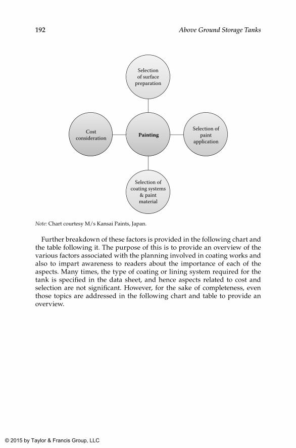
192 Above Ground Storage Tanks
Selectionof surface
preparation
Selection ofcoating systems
& paintmaterial
Costconsideration
Selection ofpaint
applicationPainting
Note: Chart courtesy M/s Kansai Paints, Japan.
Further breakdown of these factors is provided in the following chart and the table following it. The purpose of this is to provide an overview of the various factors associated with the planning involved in coating works and also to impart awareness to readers about the importance of each of the aspects. Many times, the type of coating or lining system required for the tank is specified in the data sheet, and hence aspects related to cost and selection are not significant. However, for the sake of completeness, even those topics are addressed in the following chart and table to provide an overview.
K22265_Book.indb 192 4/20/15 5:49 PM
© 2015 by Taylor & Francis Group, LLC
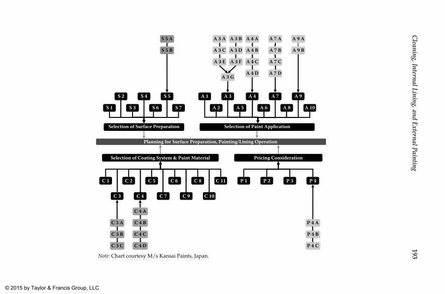
193C
leaning, Internal Lining, and External Painting
Planning for Surface Preparation, Painting/Lining Operation
S 1 S 3 S 6 S 7
S 2 S 4 S 5
A 2 A 5 A 6 A 8 A 10
A 1 A 3 A 4 A 7 A 9
Selection of Surface Preparation Selection of Paint Application
Selection of Coating System & Paint Material Pricing Consideration
C 1 C 2 C 5 C 6 C 8 C 11
C 3 C 4 C 7 C 9 C 10
P 1 P 2 P 3 P 4
S 5 A
S 5 B
A 3 BA 3 A
A 3 C
A 3 FA 3 E
A 3 D
A 3 G
A 4 A
A 4 B
A 4 C
A 4 D
A 7 A
A 7 B
A 7 C
A 7 D
A 9 A
A 9 B
C 3 A
C 3 B
C 3 C
C 4 A
C 4 B
C 4 C
C 4 D
P 4 A
P 4 B
P 4 C
Note: Chart courtesy M/s Kansai Paints, Japan.
K22265_B
ook.indb 1934/20/15 5:49 P
M © 2015 by Taylor & Francis Group, LLC
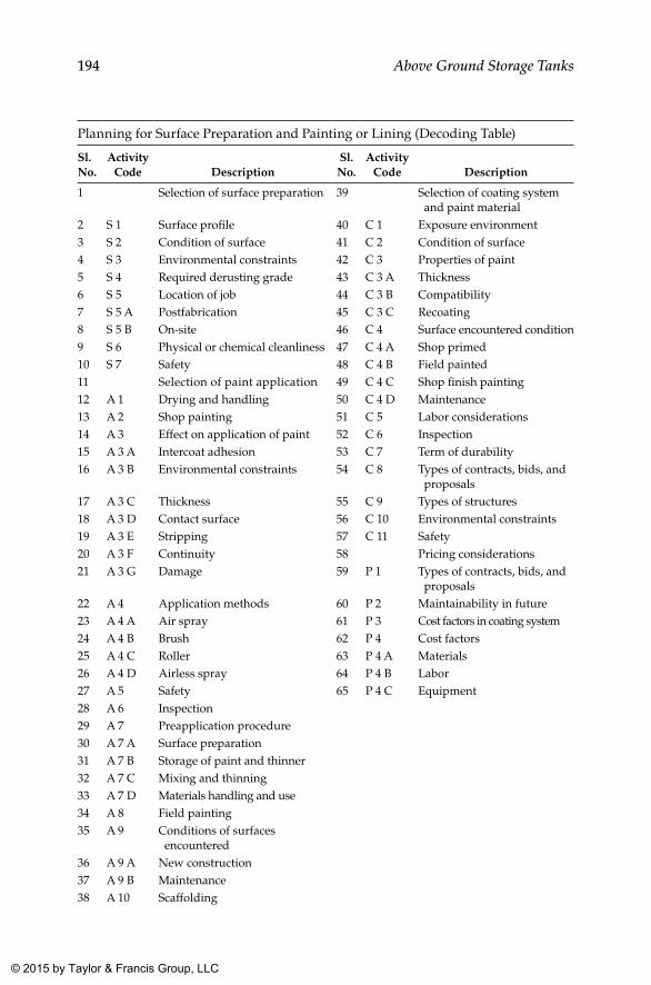
194 Above Ground Storage Tanks
Planning for Surface Preparation and Painting or Lining (Decoding Table)
Sl. No.
Activity Code Description
Sl. No.
Activity Code Description
1 Selection of surface preparation 39 Selection of coating system and paint material
2 S 1 Surface profile 40 C 1 Exposure environment3 S 2 Condition of surface 41 C 2 Condition of surface4 S 3 Environmental constraints 42 C 3 Properties of paint5 S 4 Required derusting grade 43 C 3 A Thickness6 S 5 Location of job 44 C 3 B Compatibility7 S 5 A Postfabrication 45 C 3 C Recoating8 S 5 B On-site 46 C 4 Surface encountered condition9 S 6 Physical or chemical cleanliness 47 C 4 A Shop primed10 S 7 Safety 48 C 4 B Field painted11 Selection of paint application 49 C 4 C Shop finish painting12 A 1 Drying and handling 50 C 4 D Maintenance13 A 2 Shop painting 51 C 5 Labor considerations14 A 3 Effect on application of paint 52 C 6 Inspection15 A 3 A Intercoat adhesion 53 C 7 Term of durability16 A 3 B Environmental constraints 54 C 8 Types of contracts, bids, and
proposals17 A 3 C Thickness 55 C 9 Types of structures18 A 3 D Contact surface 56 C 10 Environmental constraints19 A 3 E Stripping 57 C 11 Safety20 A 3 F Continuity 58 Pricing considerations21 A 3 G Damage 59 P 1 Types of contracts, bids, and
proposals22 A 4 Application methods 60 P 2 Maintainability in future23 A 4 A Air spray 61 P 3 Cost factors in coating system24 A 4 B Brush 62 P 4 Cost factors25 A 4 C Roller 63 P 4 A Materials26 A 4 D Airless spray 64 P 4 B Labor27 A 5 Safety 65 P 4 C Equipment28 A 6 Inspection29 A 7 Preapplication procedure 30 A 7 A Surface preparation31 A 7 B Storage of paint and thinner32 A 7 C Mixing and thinning33 A 7 D Materials handling and use34 A 8 Field painting35 A 9 Conditions of surfaces
encountered36 A 9 A New construction37 A 9 B Maintenance38 A 10 Scaffolding
K22265_Book.indb 194 4/20/15 5:49 PM
© 2015 by Taylor & Francis Group, LLC
195Cleaning, Internal Lining, and External Painting
13.3 Surface Preparation (Write-up Courtesy M/s Transocean Coating, Rotterdam)
The single most important function that can influence any paint performance is the quality of surface preparation. For optimum service life, the surface shall be completely free of all contaminants that might impair performance and shall be treated as such to ensure good and permanent adhesion of the paint system proposed for the environment. The quality of surface prepara-tion has a direct impact in the life cycle of paint and lining systems, even in the case of surface tolerant coatings, giving better performance in case surface preparation is better.
Surface preparation consists of two parts, namely, primary and secondary preparations. Primary preparation is intended to remove mill scales, rust, other corrosion products, and other foreign material from the metal surface prior to the application of shop primer.
Secondary surface preparation is intended to remove rust or any other for-eign matter if any from the metal surface that has already been coated with shop primer, prior to the application of an anticorrosive system. All rust, rust scale, heavy chalk, or deteriorated coating shall be removed by a combina-tion of solvent or detergent washing, hand or power tool cleaning, or abra-sive blasting. Glossy areas of sound previous coating need not be removed but shall be mechanically abraded or brush blasted to create a surface profile that increases coating adhesion.
The extent to which a surface is made clean before coating is applied as a balance between the following:
• Expected performance of coating• Paint manufacturers’ recommendations• Time available for the job• Relative cost of various surface preparation methods available• Access to area to be prepared• Condition of the steel prior to surface preparation
In most of the cases, coatings cannot be applied under ideal conditions, especially for repair and maintenance jobs.
The quality of surface cleanliness that is achieved (or that is possible to achieve) would widely vary between an uncorroded high-quality steel plate with a tightly adherent mill scale (used in new constructions) and that of a tank in service for ten years, with poorly adherent coating, loose rust scales, and heavy pitting.
K22265_Book.indb 195 4/20/15 5:49 PM
© 2015 by Taylor & Francis Group, LLC
196 Above Ground Storage Tanks
Any substance that prevents a coating from adhering directly to steel can be considered as a contaminant. Major contaminants for new constructions include the following:
• Moisture or water• Oil and grease• Ionic species from nearby sea and industrial areas• White rust (zinc salts from weathered zinc silicate shop primers)• Weld spatter• Weld fume• Cutting fume• Burn through from welding on reverse side of the plate• Dust and dirt from yard site and from neighboring industrial
processes
In addition, for maintenance and repair situations, the presence of pitting, corrosion products, cathodic protection products, aged coatings, trapped cargoes (liquid sediments), and so on must also be considered, particularly if only localized surface preparation of severely affected areas is being carried out prior to recoating.
13.3.1 High-Pressure Freshwater Cleaning
Freshwater cleaning is necessary to remove salts, fouling, or any loose paint or other contaminants. A water pressure to the tune of 500 kg/cm2 (approxi-mately 7,000 psi) is typically used for removal of surface contaminants and fouling organisms such as algae.
13.3.2 Solvent Cleaning
Prior to the use of any method of surface preparation, it is essential to remove all soluble salts, oil, grease, drilling or cutting compounds, or any other sur-face contaminants on the surface to be coated. Perhaps the most common method adopted is solvent washing followed by wiping the surface dry with clean rags. If wipe cleaning is not carried out properly, solvent washing may spread the contamination over a larger area than the original, and hence it is very important. Proprietary emulsions, degreasing compounds, and steam cleaning are also used extensively in the industry. ISO 8504 and SSPC SP1 describe acceptable procedures for solvent cleaning.
K22265_Book.indb 196 4/20/15 5:49 PM
© 2015 by Taylor & Francis Group, LLC
197Cleaning, Internal Lining, and External Painting
13.3.3 Hand Tool Cleaning
This method is the slowest and least satisfactory method of surface prep-aration. It is frequently used in confined areas where power tool access is not possible. Scrapers, chipping hammers, and chisels can be used to remove loose, nonadherent paint, rust, or scale, but it is a laborious method and very difficult to achieve a good standard of surface preparation. Wire brushing can make the surface worse by polishing rather than cleaning a rusted surface. Soluble salts, dirt, and other contaminants are frequently trapped and coated over, leading to early paint breakdown. These methods are incomplete, since such cleaning always leaves a layer of tightly adher-ing rust on a steel surface. Methods for hand tool cleaning are described in SSPC SP2 and ISO 8501-1 Grade St2-B, C, or D. After cleaning, the surface is brushed, swept, dusted, and blown off with compressed air to remove all loose matter.
13.3.4 Pickling
The acid pickling process can be used for preparation of small items before coating. Items such as pipes are alkali cleaned, then washed, and later passed through an acid pickling in a bath to remove rust. This is to be followed by a thorough washing to remove all remaining acid on the surface, particularly if the item is to be painted subsequently.
13.3.5 Power Tool Cleaning
The effectiveness of cleaning using power tools rather than abrasive or water blasting methods shall depend on the effort and endurance of the operator, as working above shoulder height is especially tiring.
Typical examples of mechanical power tool cleaning are rotary wire brushes, sanding discs, and needle guns. Power tool cleaning is in general more effective and less laborious than hand tool cleaning for removal of loosely adhering mill scale, paint, and rust. However, power tool cleaning will not remove tightly adhering rust and mill scales.
Care shall be taken, especially with power brushes, not to polish a metal surface, as this could reduce the key for subsequent paint coating.
Preparation grades with power tool cleaning are specified in ISO 8501-1 and relevant preparation grades St2-B, C, or D and St3-B, C, or D. SSPC SP 11 describes various degrees of surface profiles that can be achieved through power tool cleaning.
As mentioned, some of the more popular methods falling under this cat-egory are briefly described as follows.
K22265_Book.indb 197 4/20/15 5:49 PM
© 2015 by Taylor & Francis Group, LLC
198 Above Ground Storage Tanks
Rotary Power Disking
This one is the most commonly used surface preparation method in a major-ity of maintenance situations. It is also widely used in new constructions for preparation of welds and cut edges prior to painting. Normally silicon carbide discs are used, the grade of which is selected to suit the conditions of the surface to be abraded. It is important to change discs at regular intervals in order to maintain efficiency.
Care shall be exercised in the selection of grit size and type of disc to be utilized, so that the surface is not excessively smoothed, thereby reducing the ability of paint to adhere. Irregular and pitted surfaces may require a combination of various power tool cleaning methods to maximize effectiveness.
Power disc preparation is also widely used in new construction to clean edges of welds and intricate locations where other methods cannot reach effectively.
Mechanical Descaling
Needle guns, Roto-Peen, and other pounding-type tools are effective to some degree in removing thick rust and scale and are frequently used in maintenance works of storage tanks in service. The action of these types of devices is dependent on the cutting blade or point pounding of the surface concerned and breaking away of the scales present. This type of cleaning is effective only at the actual points of contact. The intermediate or adjacent areas are only partially cleaned, because brittle scale disintegrates, but the lowermost layer of rust and scale remains attached to the substrate, thereby resulting in reduced effectiveness of the applied coating.
Rotary Wire Brushing
This method has some merits, depending on the condition of the surface requiring treatment. Loose “powdery” rust can be removed, but hard scale will resist abrasion of wire bristles. When rust scale is intact and strongly adhered to the substrate, rotary wire brushing tends to merely burnish or polish the surface of rust scale but does not remove it. In fact, the burnished surface may give a false appearance of a well-cleaned surface, which is often misleading.
13.3.6 blast Cleaning
This is the most commonly used surface preparation method in the indus-try for the application of paint. When properly carried out, abrasive blasting
K22265_Book.indb 198 4/20/15 5:49 PM
© 2015 by Taylor & Francis Group, LLC
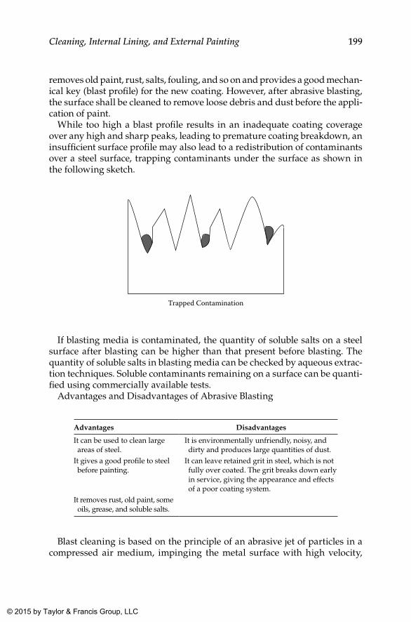
199Cleaning, Internal Lining, and External Painting
removes old paint, rust, salts, fouling, and so on and provides a good mechan-ical key (blast profile) for the new coating. However, after abrasive blasting, the surface shall be cleaned to remove loose debris and dust before the appli-cation of paint.
While too high a blast profile results in an inadequate coating coverage over any high and sharp peaks, leading to premature coating breakdown, an insufficient surface profile may also lead to a redistribution of contaminants over a steel surface, trapping contaminants under the surface as shown in the following sketch.
Trapped Contamination
If blasting media is contaminated, the quantity of soluble salts on a steel surface after blasting can be higher than that present before blasting. The quantity of soluble salts in blasting media can be checked by aqueous extrac-tion techniques. Soluble contaminants remaining on a surface can be quanti-fied using commercially available tests.
Advantages and Disadvantages of Abrasive Blasting
Advantages Disadvantages
It can be used to clean large areas of steel.
It is environmentally unfriendly, noisy, and dirty and produces large quantities of dust.
It gives a good profile to steel before painting.
It can leave retained grit in steel, which is not fully over coated. The grit breaks down early in service, giving the appearance and effects of a poor coating system.
It removes rust, old paint, some oils, grease, and soluble salts.
Blast cleaning is based on the principle of an abrasive jet of particles in a compressed air medium, impinging the metal surface with high velocity,
K22265_Book.indb 199 4/20/15 5:49 PM
© 2015 by Taylor & Francis Group, LLC
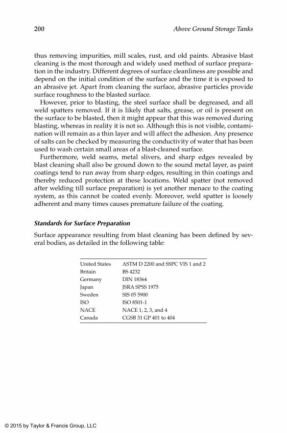
200 Above Ground Storage Tanks
thus removing impurities, mill scales, rust, and old paints. Abrasive blast cleaning is the most thorough and widely used method of surface prepara-tion in the industry. Different degrees of surface cleanliness are possible and depend on the initial condition of the surface and the time it is exposed to an abrasive jet. Apart from cleaning the surface, abrasive particles provide surface roughness to the blasted surface.
However, prior to blasting, the steel surface shall be degreased, and all weld spatters removed. If it is likely that salts, grease, or oil is present on the surface to be blasted, then it might appear that this was removed during blasting, whereas in reality it is not so. Although this is not visible, contami-nation will remain as a thin layer and will affect the adhesion. Any presence of salts can be checked by measuring the conductivity of water that has been used to wash certain small areas of a blast-cleaned surface.
Furthermore, weld seams, metal slivers, and sharp edges revealed by blast cleaning shall also be ground down to the sound metal layer, as paint coatings tend to run away from sharp edges, resulting in thin coatings and thereby reduced protection at these locations. Weld spatter (not removed after welding till surface preparation) is yet another menace to the coating system, as this cannot be coated evenly. Moreover, weld spatter is loosely adherent and many times causes premature failure of the coating.
Standards for Surface Preparation
Surface appearance resulting from blast cleaning has been defined by sev-eral bodies, as detailed in the following table:
United States ASTM D 2200 and SSPC VIS 1 and 2Britain BS 4232Germany DIN 18364Japan JSRA SPSS 1975Sweden SIS 05 5900ISO ISO 8501-1NACE NACE 1, 2, 3, and 4Canada CGSB 31 GP 401 to 404
K22265_Book.indb 200 4/20/15 5:49 PM
© 2015 by Taylor & Francis Group, LLC
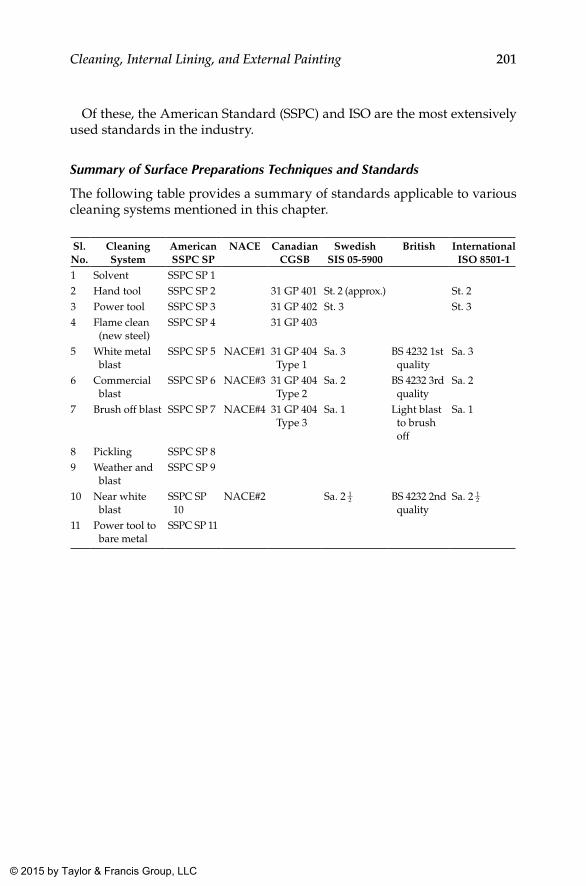
201Cleaning, Internal Lining, and External Painting
Of these, the American Standard (SSPC) and ISO are the most extensively used standards in the industry.
Summary of Surface Preparations Techniques and Standards
The following table provides a summary of standards applicable to various cleaning systems mentioned in this chapter.
Sl. No.
Cleaning System
American SSPC SP
NACE CanadianCGSB
SwedishSIS 05-5900
British International ISO 8501-1
1 Solvent SSPC SP 12 Hand tool SSPC SP 2 31 GP 401 St. 2 (approx.) St. 23 Power tool SSPC SP 3 31 GP 402 St. 3 St. 34 Flame clean
(new steel)SSPC SP 4 31 GP 403
5 White metal blast
SSPC SP 5 NACE#1 31 GP 404 Type 1
Sa. 3 BS 4232 1st quality
Sa. 3
6 Commercial blast
SSPC SP 6 NACE#3 31 GP 404 Type 2
Sa. 2 BS 4232 3rd quality
Sa. 2
7 Brush off blast SSPC SP 7 NACE#4 31 GP 404 Type 3
Sa. 1 Light blast to brush off
Sa. 1
8 Pickling SSPC SP 89 Weather and
blastSSPC SP 9
10 Near white blast
SSPC SP 10
NACE#2 Sa. 2 12 BS 4232 2nd
qualitySa. 2 1
2
11 Power tool to bare metal
SSPC SP 11
K22265_Book.indb 201 4/20/15 5:49 PM
© 2015 by Taylor & Francis Group, LLC
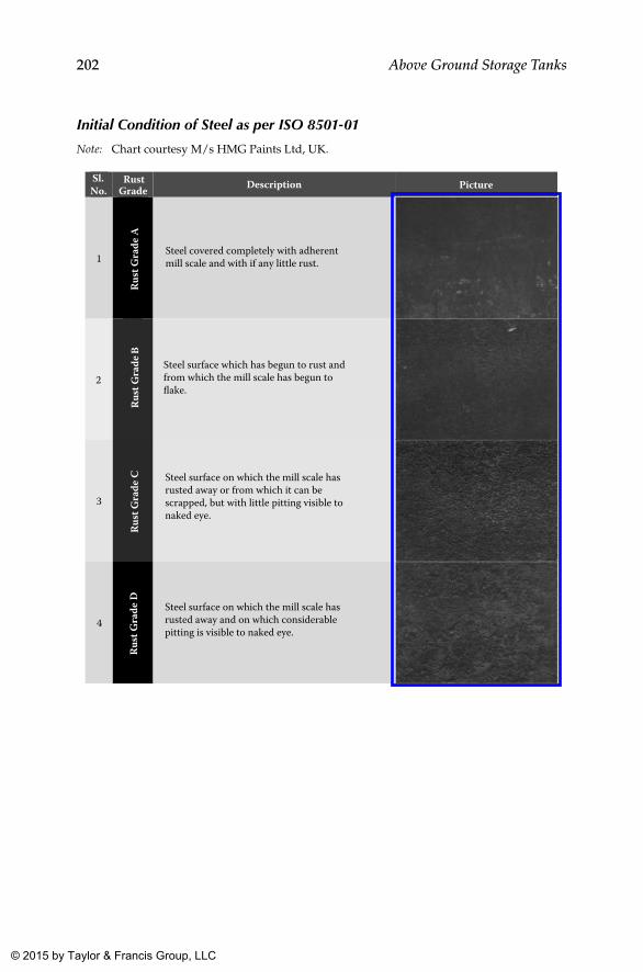
202 Above Ground Storage Tanks
Initial Condition of Steel as per ISO 8501-01
Note: Chart courtesy M/s HMG Paints Ltd, UK.
PictureDescription Picture
1
Rust
Gra
de A
2
Rust
Gra
de B
3
Rust
Gra
de C
4
Rust
Gra
de D
RustGrade
Sl. No.
Steel covered completely with adherentmill scale and with if any little rust.
Steel surface which has begun to rust andfrom which the mill scale has begun toflake.
Steel surface on which the mill scale hasrusted away and on which considerablepitting is visible to naked eye.
Steel surface on which the mill scale hasrusted away or from which it can bescrapped, but with little pitting visible tonaked eye.
K22265_Book.indb 202 4/20/15 5:49 PM
© 2015 by Taylor & Francis Group, LLC
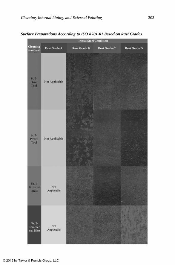
203Cleaning, Internal Lining, and External Painting
Surface Preparations According to ISO 8501-01 Based on Rust Grades
NotApplicable
NotApplicable
Sa. 1-Brush o�
Blast
Sa. 2-Commer-cial Blast
CleaningStandard
Initial Steel Condition
Rust Grade A Rust Grade B Rust Grade C Rust Grade D
St. 2-HandTool
Not Applicable
St. 3-PowerTool
Not Applicable
K22265_Book.indb 203 4/20/15 5:49 PM
© 2015 by Taylor & Francis Group, LLC
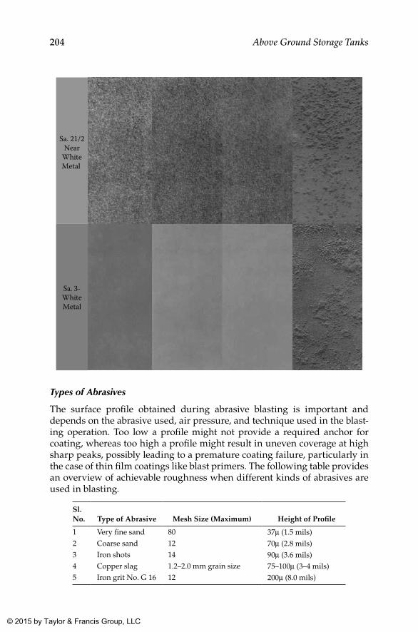
204 Above Ground Storage Tanks
Sa. 21/2Near
WhiteMetal
Sa. 3-WhiteMetal
Types of Abrasives
The surface profile obtained during abrasive blasting is important and depends on the abrasive used, air pressure, and technique used in the blast-ing operation. Too low a profile might not provide a required anchor for coating, whereas too high a profile might result in uneven coverage at high sharp peaks, possibly leading to a premature coating failure, particularly in the case of thin film coatings like blast primers. The following table provides an overview of achievable roughness when different kinds of abrasives are used in blasting.
Sl. No. Type of Abrasive Mesh Size (Maximum) Height of Profile
1 Very fine sand 80 37µ (1.5 mils)2 Coarse sand 12 70µ (2.8 mils)3 Iron shots 14 90µ (3.6 mils)4 Copper slag 1.2–2.0 mm grain size 75–100µ (3–4 mils)5 Iron grit No. G 16 12 200µ (8.0 mils)
K22265_Book.indb 204 4/20/15 5:49 PM
© 2015 by Taylor & Francis Group, LLC
205Cleaning, Internal Lining, and External Painting
The profile or roughness of a prepared surface can be considered as the most important factor in providing proper anchorage of paint systems. Mineral slag blasting grit generally gives faster rates of cleaning and lower health risk (from shattered grit) than that caused by sand. Grit also gives effective cleaning, especially for pitted substrates. Some grades of grits can be recycled, whereas some cannot be.
Surface Profile
The surface profile indicates the roughness of the blast-cleaned surface. The surface profile is an independent factor and has no connection with stan-dards of cleanliness. Profile roughness obtained during blasting is impor-tant and depends on the abrasive media, air pressure used, and technique of blasting. To specify roughness, a variety of values are used such as Rz, Rt, and Ra.
Rz = Average peak to valley height = blasting profileRt = Maximum peak to valley heightRa = Average distance to an imaginary center line that can be drawn between peaks and
valleys = CLA = center line average (ISO 3274)Rz = 4 to 6 times CLA (Ra) (also referred as blasting profile)
13.3.7 Spot blasting
This is an abrasive, localized preparation process commonly used for out-side surfaces during repair and maintenance work, when patches of local-ized corrosion have occurred. Care shall be taken to avoid the following situations:
• Undercutting and loosening of paint edges around the cleaned spot shall be avoided. Edges shall be feathered wherever and to the extent possible.
• Stray abrasive particles might damage the surrounding sound paint in confined spaces, and such damages if caused shall be remedied and repaired appropriately.
• Blasting shall be discontinued while moving from one spot to the next; blast media should not be trailed over the entire surface. Any damage caused in this way shall be repaired appropriately.
Spot blasting can be used to yield surfaces that are cleaned to Sa. 2 or bet-ter, but often surrounding intact areas are prepared with stray grit blast-ing. These areas also shall be treated as inclusion in grit blasting in the final coating system as well to avoid premature failure of coating in this region. Therefore, it is essential that areas for spot blasting are properly marked and
K22265_Book.indb 205 4/20/15 5:49 PM
© 2015 by Taylor & Francis Group, LLC
206 Above Ground Storage Tanks
blasted and followed by mechanical feathering of the adjacent area of the existing coating (which is intact), using a rotary disc or sander.
13.3.8 Hydroblasting or Water Jetting
While dry abrasive blasting is the most commonly used method of surface preparation, government and local regulations are continuously changing and require the development of more environmentally sensitive and user-friendly methods of surface preparation. In this context, hydroblasting (also known as hydrojetting, water blasting, and water jetting) is becoming an increasingly viable means to accomplish required surface preparation, the standards for which are in the pipeline.
It shall be noted that hydroblasted surfaces are visually much different from those produced by abrasive cleaning or power tools, and surfaces often appear dull or mottled after initial cleaning is completed.
One drawback of hydroblasting is the formation of flash rust (also called flash back or gingering) after blasting. Heavy rust formed in a short time period is indicative of residual salt on the steel, and reblasting is necessary before painting. However, light rusting is generally acceptable to most of the paint manufacturers for their products.
Hydroblasting does not produce a profile on the steel surface as compared with abrasive blasting. It does however remove rust and loose paint, as well as soluble salts, dirt, and oils, from steel to expose the original abrasive blast surface profile, including the profile produced by corrosion and mechanical damage, whereas ultra-high-pressure hydroblasting can remove adherent paint as well from a steel surface.
The terms water washing (usually used to remove salts, slimes, light foul-ing, etc., found on tanks under use) and hydroblasting (used to remove rust and paint) can easily be confused. The following pressure guidelines might be useful in distinguishing these two processes:
Low-pressure water washing and cleaning Pressures less than 68 kg/cm2 (1,000 psi).
High-pressure water washing and cleaning Pressures between 68–680 kg/cm2 (1,000–10,000 psi).
High-pressure hydroblasting Pressures between 680–1,700 kg/cm2 (10,000–25,000 psi).
Ultra-high-pressure hydroblasting Pressures above 1,700 kg/cm2 (25,000 psi). Most machines operate in the range 2,000–2,500 kg/cm2 (30,000–36,000 psi).
Inhibitors can be added (sometimes) to water to help prevent flash rusting prior to applying coating. However, they are often ionic in nature and shall be completely removed by further washing before paint is applied. It is also important to ensure that water being used is sufficiently pure and does not contaminate the surface being cleaned.
K22265_Book.indb 206 4/20/15 5:49 PM
© 2015 by Taylor & Francis Group, LLC
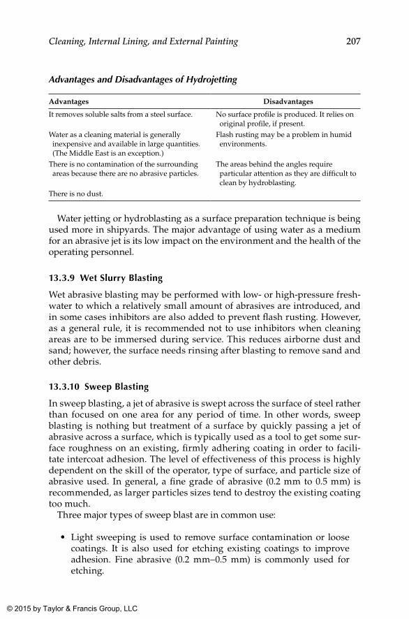
207Cleaning, Internal Lining, and External Painting
Advantages and Disadvantages of Hydrojetting
Advantages Disadvantages
It removes soluble salts from a steel surface. No surface profile is produced. It relies on original profile, if present.
Water as a cleaning material is generally inexpensive and available in large quantities. (The Middle East is an exception.)
Flash rusting may be a problem in humid environments.
There is no contamination of the surrounding areas because there are no abrasive particles.
The areas behind the angles require particular attention as they are difficult to clean by hydroblasting.
There is no dust.
Water jetting or hydroblasting as a surface preparation technique is being used more in shipyards. The major advantage of using water as a medium for an abrasive jet is its low impact on the environment and the health of the operating personnel.
13.3.9 Wet Slurry blasting
Wet abrasive blasting may be performed with low- or high-pressure fresh-water to which a relatively small amount of abrasives are introduced, and in some cases inhibitors are also added to prevent flash rusting. However, as a general rule, it is recommended not to use inhibitors when cleaning areas are to be immersed during service. This reduces airborne dust and sand; however, the surface needs rinsing after blasting to remove sand and other debris.
13.3.10 Sweep blasting
In sweep blasting, a jet of abrasive is swept across the surface of steel rather than focused on one area for any period of time. In other words, sweep blasting is nothing but treatment of a surface by quickly passing a jet of abrasive across a surface, which is typically used as a tool to get some sur-face roughness on an existing, firmly adhering coating in order to facili-tate intercoat adhesion. The level of effectiveness of this process is highly dependent on the skill of the operator, type of surface, and particle size of abrasive used. In general, a fine grade of abrasive (0.2 mm to 0.5 mm) is recommended, as larger particles sizes tend to destroy the existing coating too much.
Three major types of sweep blast are in common use:
• Light sweeping is used to remove surface contamination or loose coatings. It is also used for etching existing coatings to improve adhesion. Fine abrasive (0.2 mm–0.5 mm) is commonly used for etching.
K22265_Book.indb 207 4/20/15 5:49 PM
© 2015 by Taylor & Francis Group, LLC
208 Above Ground Storage Tanks
• Heavy or hard sweeping is used to remove an old coating or rust back to the original shop primer or bare steel.
• Sweeping shop primers in new construction are used to partially remove shop primer to an agreed standard, immediately prior to overcoating.
13.3.11 Surface Preparation for Other Metals
Aluminum
The surface shall be clean and dry. Any corrosion salts present on the metal surface shall be removed by light abrasion and water washing. The cleaned surface shall then be abraded or very lightly abrasive blasted using low pres-sure and nonmetallic abrasive (e.g., garnet). Alternately, aluminum can be etched by using an acidic solution or etch primer.
Galvanized Steel
The surface shall be dry, clean, and free from oil and grease before galva-nizing. Degreasing requires some effort to obtain a clean surface, as zinc corrosion products can trap grease and other contaminants. Any white zinc corrosion products also shall be removed by high-pressure freshwater wash-ing or freshwater washing with scrubbing.
Sweep blasting and abrading are suitable preparation methods, but fresh-water washing shall also be used to remove soluble salts. An etch primer can also be used after cleaning to provide a key for further coatings. Many coatings based on nonsaponifiable polymers can be applied directly to a gal-vanized surface prepared in this way. Paint companies shall be consulted on suitable preparation methods, primers, and coatings for galvanized steels.
When sweep blasting is not feasible, then an acid etch solution or etch primer shall be used to passivate the surface to provide a key for further paint coating. When steel has been treated with a passivating treatment immediately after galvanizing, this must either be allowed to weather off over a period of several months of exterior exposure or be abraded before application of a coating. In general, etch treatments have no effect on fresh materials of this type.
Stainless Steel
Stainless steels do not require any particularly specialized surface pretreat-ment prior to coating. These surfaces shall be free from oil, grease, dirt, and other foreign materials by chemical cleaning. The development of a surface profile on stainless steels is highly recommended to ensure good coating adhesion. A profile depth of 1.5 mils to 3.0 mils is suggested for most of the coating systems on stainless steels. Abrasive blasting is recommended to achieve this profile.
K22265_Book.indb 208 4/20/15 5:49 PM
© 2015 by Taylor & Francis Group, LLC
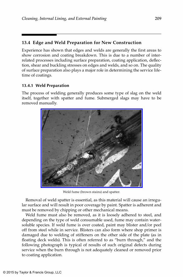
209Cleaning, Internal Lining, and External Painting
13.4 Edge and Weld Preparation for New Construction
Experience has shown that edges and welds are generally the first areas to show corrosion and coating breakdown. This is due to a number of inter-related processes including surface preparation, coating application, deflec-tion, shear and buckling stresses on edges and welds, and so on. The quality of surface preparation also plays a major role in determining the service life-time of coatings.
13.4.1 Weld Preparation
The process of welding generally produces some type of slag on the weld itself, together with spatter and fume. Submerged slags may have to be removed manually.
Weld fume (brown stains) and spatter.
Removal of weld spatter is essential, as this material will cause an irregu-lar surface and will result in poor coverage by paint. Spatter is adherent and must be removed by chipping or other mechanical means.
Weld fume must also be removed, as it is loosely adhered to steel, and depending on the type of weld consumable used, fume may contain water-soluble species. If weld fume is over coated, paint may blister and/or peel off from steel while in service. Blisters can also form where shop primer is damaged due to welding of stiffeners on the other side of the plate (as in floating deck welds). This is often referred to as “burn through,” and the following photograph is typical of results of such original defects during service when the burn through is not adequately cleaned or removed prior to coating application.
K22265_Book.indb 209 4/20/15 5:49 PM
© 2015 by Taylor & Francis Group, LLC
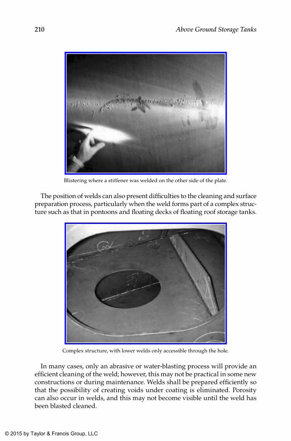
210 Above Ground Storage Tanks
Blistering where a stiffener was welded on the other side of the plate.
The position of welds can also present difficulties to the cleaning and surface preparation process, particularly when the weld forms part of a complex struc-ture such as that in pontoons and floating decks of floating roof storage tanks.
Complex structure, with lower welds only accessible through the hole.
In many cases, only an abrasive or water-blasting process will provide an efficient cleaning of the weld; however, this may not be practical in some new constructions or during maintenance. Welds shall be prepared efficiently so that the possibility of creating voids under coating is eliminated. Porosity can also occur in welds, and this may not become visible until the weld has been blasted cleaned.
K22265_Book.indb 210 4/20/15 5:49 PM
© 2015 by Taylor & Francis Group, LLC
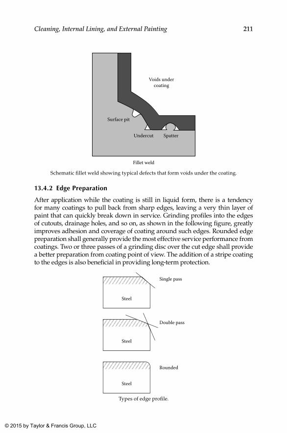
211Cleaning, Internal Lining, and External Painting
Surface pit
Undercut Spatter
Voids undercoating
Fillet weld
Schematic fillet weld showing typical defects that form voids under the coating.
13.4.2 Edge Preparation
After application while the coating is still in liquid form, there is a tendency for many coatings to pull back from sharp edges, leaving a very thin layer of paint that can quickly break down in service. Grinding profiles into the edges of cutouts, drainage holes, and so on, as shown in the following figure, greatly improves adhesion and coverage of coating around such edges. Rounded edge preparation shall generally provide the most effective service performance from coatings. Two or three passes of a grinding disc over the cut edge shall provide a better preparation from coating point of view. The addition of a stripe coating to the edges is also beneficial in providing long-term protection.
Steel
Single pass
Double pass
Rounded
Steel
Steel
Types of edge profile.
K22265_Book.indb 211 4/20/15 5:49 PM
© 2015 by Taylor & Francis Group, LLC
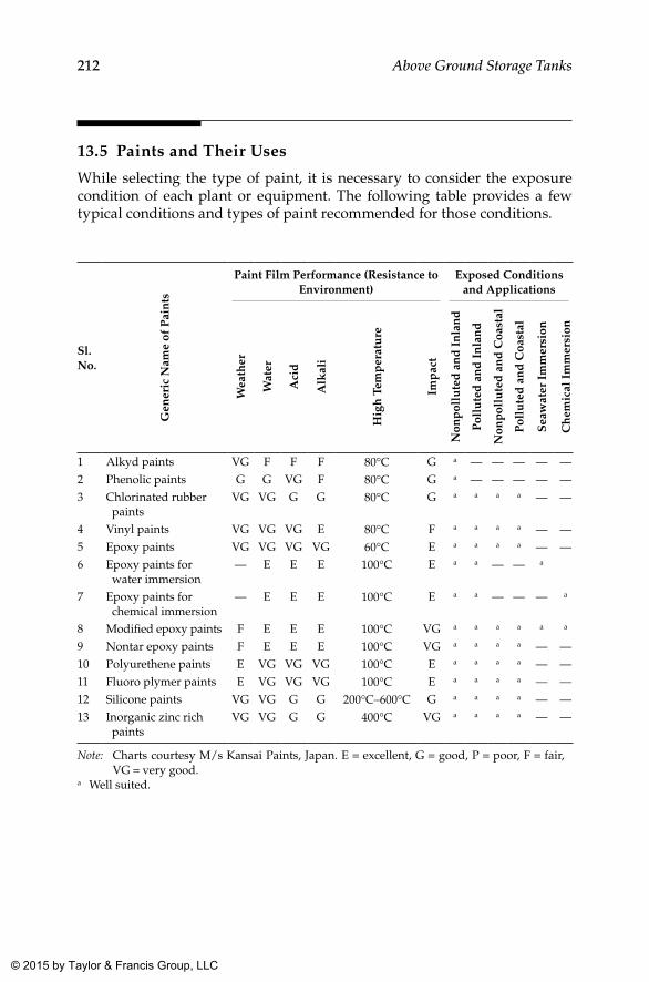
212 Above Ground Storage Tanks
13.5 Paints and Their Uses
While selecting the type of paint, it is necessary to consider the exposure condition of each plant or equipment. The following table provides a few typical conditions and types of paint recommended for those conditions.
Sl. No.
Gen
eric
Nam
e of
Pai
nts
Paint Film Performance (Resistance to Environment)
Exposed Conditions and Applications
Wea
ther
Wat
er
Aci
d
Alk
ali
Hig
h T
emp
erat
ure
Imp
act
Non
pol
lute
d a
nd
In
lan
d
Pol
lute
d a
nd
In
lan
d
Non
pol
lute
d a
nd
Coa
stal
Pol
lute
d a
nd
Coa
stal
Sea
wat
er I
mm
ersi
on
Ch
emic
al I
mm
ersi
on
1 Alkyd paints VG F F F 80°C G a — — — — —2 Phenolic paints G G VG F 80°C G a — — — — —3 Chlorinated rubber
paintsVG VG G G 80°C G a a a a — —
4 Vinyl paints VG VG VG E 80°C F a a a a — —5 Epoxy paints VG VG VG VG 60°C E a a a a — —6 Epoxy paints for
water immersion— E E E 100°C E a a — — a
7 Epoxy paints for chemical immersion
— E E E 100°C E a a — — — a
8 Modified epoxy paints F E E E 100°C VG a a a a a a
9 Nontar epoxy paints F E E E 100°C VG a a a a — —10 Polyurethene paints E VG VG VG 100°C E a a a a — —11 Fluoro plymer paints E VG VG VG 100°C E a a a a — —12 Silicone paints VG VG G G 200°C–600°C G a a a a — —13 Inorganic zinc rich
paintsVG VG G G 400°C VG a a a a — —
Note: Charts courtesy M/s Kansai Paints, Japan. E = excellent, G = good, P = poor, F = fair, VG = very good.
a Well suited.
K22265_Book.indb 212 4/20/15 5:49 PM
© 2015 by Taylor & Francis Group, LLC
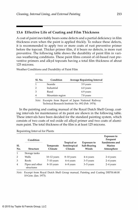
213Cleaning, Internal Lining, and External Painting
13.6 Effective Life of Coating and Film Thickness
A coat of paint inevitably bears some defects and a partial deficiency in film thickness even when the paint is applied thickly. To reduce these defects, it is recommended to apply two or more coats of rust preventive primer before the topcoat. Thicker primer film, if it bears no defects, is more rust preventive. The following table shows the durability of paint film in vari-ous weathering conditions. These paint films consist of oil-based rust pre-ventive primers and alkyd topcoats having a total film thickness of about 125 microns.Weather Conditions and Durability of Paint Film
Sl. No. Condition Average Repainting Interval
1 Seaside 3.9 years2 Industrial 6.0 years3 Rural 6.9 years4 Mountain region 7.8 years
Note: Excerpts from Report of Japan National Railway Technical Research Institute No. 892 (Feb. 1974).
In the painting and coating manual of the Royal Dutch Shell Group, coat-ing intervals for maintenance of its paint are shown in the following table. These intervals have been decided for the standard painting system, which consists of two coats of red oxide oil alkyd primer and two coats of alumi-num paint. The total thickness of the film is at least 125 microns.
Repainting Interval for Plants
Sl. No.
Condition
Temperate Climate
Tropical or Semitropical
Climate
Exposure to Salt-Bearing
Winds
Exposure to Frequent
Sandstorms and Marine
AtmosphereStructure
1 Storage tanks2 Walls 10–12 years 8–10 years 4–6 years 2–4 years3 Roofs 7–10 years 4–6 years 3–5 years 2–4 years4 Pipes and other
structures8–10 years 6–8 years 3–5 years 2–4 years
Note: Excerpt from Royal Dutch Shell Group manual, Painting and Coating DEP30.48.00 10-Gem. (Jan. 1973).
K22265_Book.indb 213 4/20/15 5:49 PM
© 2015 by Taylor & Francis Group, LLC
214 Above Ground Storage Tanks
13.7 Other Requirements by Clients for Surface Preparation and Lining and Painting of Tanks
13.7.1 General
All tank painting and paint testing shall be in accordance with AWWA D102, Steel Structures Painting Council Specification SSPC PA1, approved paint manufacturer specifications, and as specified herein.
Each system of painting shall be from a single manufacturer. Usually a list of acceptable manufacturers is also provided in the contract.
Preconstruction primers may be utilized in the fabrication process to pre-serve the blast profile and cleanliness. In the field, weld seams and abraded areas shall be cleaned on a spot basis. The remaining sound primer shall be cleaned to remove dirt and other contaminants. After cleaning, a speci-fied coating system shall be applied in its entirety in the field to obtain the required dry film thickness for coating.
No paint shall be applied when the temperature of the surface to be painted is below the minimum temperature specified by the paint manufacturer or less than 5 degrees above the dew point temperature. Paint shall not be applied to wet or damp surfaces or when the relative humidity exceeds 85% unless allowed by the manufacturer’s data sheets. Follow the manufacturer’s recommendations for the specific paint system used.
After erection and before painting, remove slag, weld metal spatter, and sharp edges by chipping or grinding. All surfaces that have been welded, abraded, or otherwise damaged shall be cleaned and primed in the field in accordance with the paint system requirements.
All areas blasted in the field shall be coated the same day before any rust-ing occurs.
13.7.2 lettering and logo
Lettering and logo design, size, and location shall be as indicated on the drawings issued by clients in this regard. The lettering and logo shall be applied using one coat of aliphatic acrylic polyurethane based on the aliphatic isocyanate curing agent in the required color.
13.7.3 Safety Precautions for blasting and Painting Equipment
• Blast cleaning pot, nozzles, and spray painting machines shall be earthed (grounded, spark proofed) to prevent buildup of an electro-static charge.
K22265_Book.indb 214 4/20/15 5:49 PM
© 2015 by Taylor & Francis Group, LLC
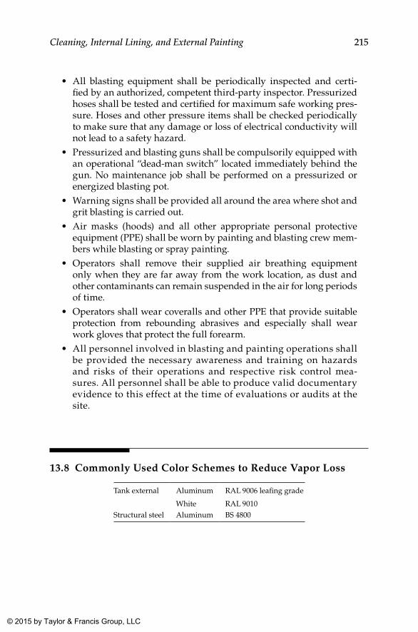
215Cleaning, Internal Lining, and External Painting
• All blasting equipment shall be periodically inspected and certi-fied by an authorized, competent third-party inspector. Pressurized hoses shall be tested and certified for maximum safe working pres-sure. Hoses and other pressure items shall be checked periodically to make sure that any damage or loss of electrical conductivity will not lead to a safety hazard.
• Pressurized and blasting guns shall be compulsorily equipped with an operational “dead-man switch” located immediately behind the gun. No maintenance job shall be performed on a pressurized or energized blasting pot.
• Warning signs shall be provided all around the area where shot and grit blasting is carried out.
• Air masks (hoods) and all other appropriate personal protective equipment (PPE) shall be worn by painting and blasting crew mem-bers while blasting or spray painting.
• Operators shall remove their supplied air breathing equipment only when they are far away from the work location, as dust and other contaminants can remain suspended in the air for long periods of time.
• Operators shall wear coveralls and other PPE that provide suitable protection from rebounding abrasives and especially shall wear work gloves that protect the full forearm.
• All personnel involved in blasting and painting operations shall be provided the necessary awareness and training on hazards and risks of their operations and respective risk control mea-sures. All personnel shall be able to produce valid documentary evidence to this effect at the time of evaluations or audits at the site.
13.8 Commonly Used Color Schemes to Reduce Vapor Loss
Tank external Aluminum RAL 9006 leafing grade
White RAL 9010Structural steel Aluminum BS 4800
K22265_Book.indb 215 4/20/15 5:49 PM
© 2015 by Taylor & Francis Group, LLC
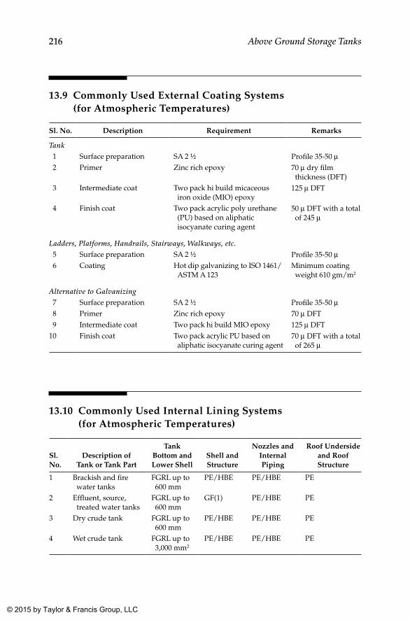
216 Above Ground Storage Tanks
13.9 Commonly Used External Coating Systems (for Atmospheric Temperatures)
Sl. No. Description Requirement Remarks
Tank 1 Surface preparation SA 2 ½ Profile 35-50 µ 2 Primer Zinc rich epoxy 70 µ dry film
thickness (DFT) 3 Intermediate coat Two pack hi build micaceous
iron oxide (MIO) epoxy125 µ DFT
4 Finish coat Two pack acrylic poly urethane (PU) based on aliphatic isocyanate curing agent
50 µ DFT with a total of 245 µ
Ladders, Platforms, Handrails, Stairways, Walkways, etc. 5 Surface preparation SA 2 ½ Profile 35-50 µ 6 Coating Hot dip galvanizing to ISO 1461/
ASTM A 123Minimum coating weight 610 gm/m2
Alternative to Galvanizing 7 Surface preparation SA 2 ½ Profile 35-50 µ 8 Primer Zinc rich epoxy 70 µ DFT 9 Intermediate coat Two pack hi build MIO epoxy 125 µ DFT10 Finish coat Two pack acrylic PU based on
aliphatic isocyanate curing agent70 µ DFT with a total of 265 µ
13.10 Commonly Used Internal Lining Systems (for Atmospheric Temperatures)
Sl. No.
Description of Tank or Tank Part
Tank Bottom and Lower Shell
Shell and Structure
Nozzles and Internal Piping
Roof Underside and Roof Structure
1 Brackish and fire water tanks
FGRL up to 600 mm
PE/HBE PE/HBE PE
2 Effluent, source, treated water tanks
FGRL up to 600 mm
GF(1) PE/HBE PE
3 Dry crude tank FGRL up to 600 mm
PE/HBE PE/HBE PE
4 Wet crude tank FGRL up to 3,000 mm2
PE/HBE PE/HBE PE
K22265_Book.indb 216 4/20/15 5:49 PM
© 2015 by Taylor & Francis Group, LLC
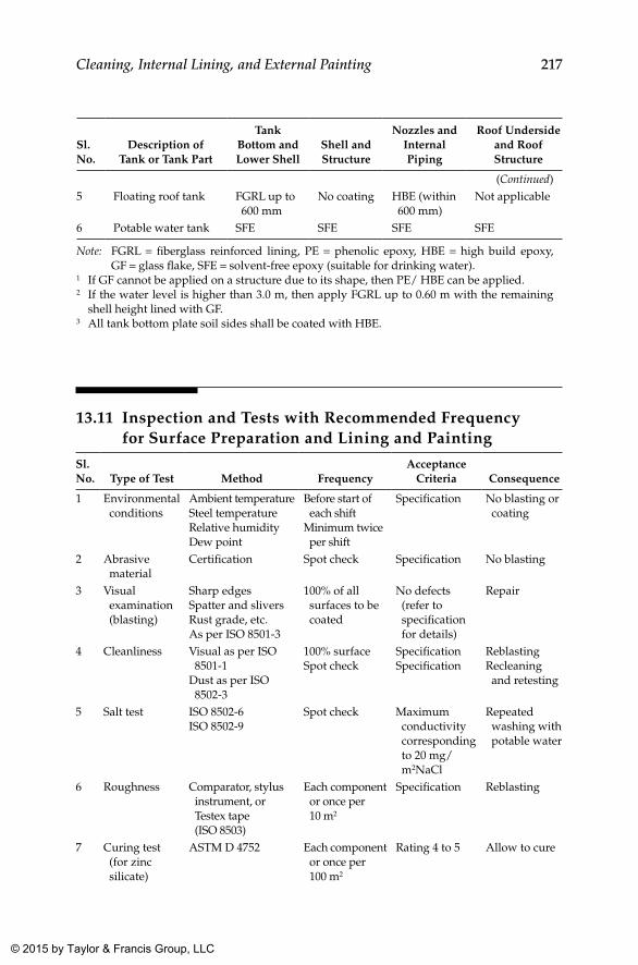
217Cleaning, Internal Lining, and External Painting
Sl. No.
Description of Tank or Tank Part
Tank Bottom and Lower Shell
Shell and Structure
Nozzles and Internal Piping
Roof Underside and Roof Structure
(Continued)5 Floating roof tank FGRL up to
600 mmNo coating HBE (within
600 mm)Not applicable
6 Potable water tank SFE SFE SFE SFE
Note: FGRL = fiberglass reinforced lining, PE = phenolic epoxy, HBE = high build epoxy, GF = glass flake, SFE = solvent-free epoxy (suitable for drinking water).
1 If GF cannot be applied on a structure due to its shape, then PE/ HBE can be applied.2 If the water level is higher than 3.0 m, then apply FGRL up to 0.60 m with the remaining
shell height lined with GF.3 All tank bottom plate soil sides shall be coated with HBE.
13.11 Inspection and Tests with Recommended Frequency for Surface Preparation and Lining and Painting
Sl. No. Type of Test Method Frequency
Acceptance Criteria Consequence
1 Environmental conditions
Ambient temperatureSteel temperatureRelative humidityDew point
Before start of each shift
Minimum twice per shift
Specification No blasting or coating
2 Abrasive material
Certification Spot check Specification No blasting
3 Visual examination (blasting)
Sharp edgesSpatter and sliversRust grade, etc.As per ISO 8501-3
100% of all surfaces to be coated
No defects (refer to specification for details)
Repair
4 Cleanliness Visual as per ISO 8501-1
Dust as per ISO 8502-3
100% surfaceSpot check
SpecificationSpecification
ReblastingRecleaning and retesting
5 Salt test ISO 8502-6ISO 8502-9
Spot check Maximum conductivity corresponding to 20 mg/m2NaCl
Repeated washing with potable water
6 Roughness Comparator, stylus instrument, or Testex tape (ISO 8503)
Each component or once per 10 m2
Specification Reblasting
7 Curing test (for zinc silicate)
ASTM D 4752 Each component or once per 100 m2
Rating 4 to 5 Allow to cure
K22265_Book.indb 217 4/20/15 5:49 PM
© 2015 by Taylor & Francis Group, LLC
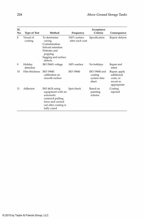
218 Above Ground Storage Tanks
Sl. No. Type of Test Method Frequency
Acceptance Criteria Consequence
8 Visual of coating
To determine curing
ContaminationSolvent retentionPinholes and popping
Sagging and surface defects
100% surface after each coat
Specification Repair defects
9 Holiday detection
ISO 29601 voltage 100% surface No holidays Repair and retest
10 Film thickness ISO 19840 calibration on smooth surface
ISO 19840 ISO 19840 and coating system data sheet
Repair, apply additional coats, or recoat as appropriate
11 Adhesion ISO 4624 using equipment with an automatic centered pulling force and carried out after coating is fully cured
Spot check Based on painting scheme
Coating rejected
K22265_Book.indb 218 4/20/15 5:49 PM
© 2015 by Taylor & Francis Group, LLC
219
14Documentation
14.1 General
This chapter describes the various documents to be included in the manu-facturer’s record book (MRB) for storage tank construction, which shall be the authentic document pertaining to the tank and contain all salient details about the tank, right from purchase or work order to design, materials, con-struction, inspections and tests, surface preparation and painting, and so on for future reference during the service life of the tank. As this document does not have any immediate use, often its due importance is not recognized well. But when some modification or rectification is needed during service, many technical details will be required to carry out the design for proposed modification, alteration, or repair. If due attention was not paid while finaliz-ing the contents of the MRB, salient information may not be available to help carry out the design for the proposed modification. Therefore, it is equally important to get a compilation of all relevant details and activities (especially inspections and tests) that were part of the construction process from the contractor. For the contractor to compile it properly and systematically, it is important that the requirements are provided to the contractor, preferably as part of the contract, so that the contractor can gear up the systems to gen-erate such a document to meet the expectations of the client. In the following sections, a comprehensive list of documents to be included in the MRB is provided. Depending on the specific requirements and applications, addi-tional documentation might be required. However, for all general purposes, the documents discussed shall suffice.
K22265_Book.indb 219 4/20/15 5:49 PM
© 2015 by Taylor & Francis Group, LLC
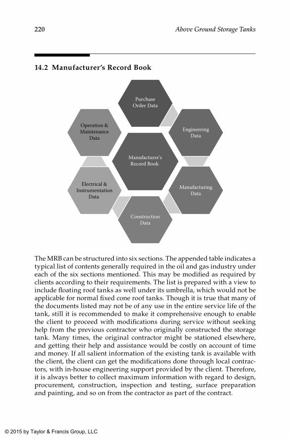
220 Above Ground Storage Tanks
14.2 Manufacturer’s Record Book
Manufacturer'sRecord Book
PurchaseOrder Data
EngineeringData
ManufacturingData
ConstructionData
Electrical &Instrumentation
Data
Operation &Maintenance
Data
The MRB can be structured into six sections. The appended table indicates a typical list of contents generally required in the oil and gas industry under each of the six sections mentioned. This may be modified as required by clients according to their requirements. The list is prepared with a view to include floating roof tanks as well under its umbrella, which would not be applicable for normal fixed cone roof tanks. Though it is true that many of the documents listed may not be of any use in the entire service life of the tank, still it is recommended to make it comprehensive enough to enable the client to proceed with modifications during service without seeking help from the previous contractor who originally constructed the storage tank. Many times, the original contractor might be stationed elsewhere, and getting their help and assistance would be costly on account of time and money. If all salient information of the existing tank is available with the client, the client can get the modifications done through local contrac-tors, with in-house engineering support provided by the client. Therefore, it is always better to collect maximum information with regard to design, procurement, construction, inspection and testing, surface preparation and painting, and so on from the contractor as part of the contract.
K22265_Book.indb 220 4/20/15 5:49 PM
© 2015 by Taylor & Francis Group, LLC
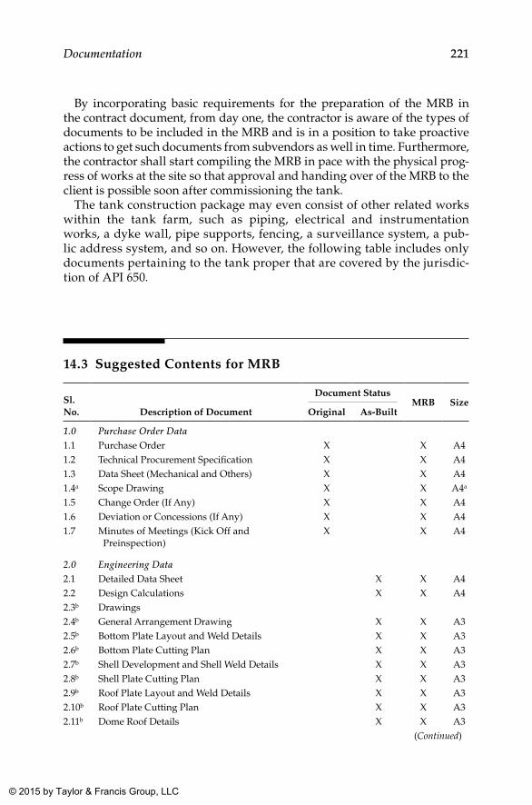
221Documentation
By incorporating basic requirements for the preparation of the MRB in the contract document, from day one, the contractor is aware of the types of documents to be included in the MRB and is in a position to take proactive actions to get such documents from subvendors as well in time. Furthermore, the contractor shall start compiling the MRB in pace with the physical prog-ress of works at the site so that approval and handing over of the MRB to the client is possible soon after commissioning the tank.
The tank construction package may even consist of other related works within the tank farm, such as piping, electrical and instrumentation works, a dyke wall, pipe supports, fencing, a surveillance system, a pub-lic address system, and so on. However, the following table includes only documents pertaining to the tank proper that are covered by the jurisdic-tion of API 650.
14.3 Suggested Contents for MRB
Sl. No. Description of Document
Document StatusMRB Size
Original As-Built
1.0 Purchase Order Data1.1 Purchase Order X X A41.2 Technical Procurement Specification X X A41.3 Data Sheet (Mechanical and Others) X X A41.4a Scope Drawing X X A4a
1.5 Change Order (If Any) X X A41.6 Deviation or Concessions (If Any) X X A41.7 Minutes of Meetings (Kick Off and
Preinspection)X X A4
2.0 Engineering Data2.1 Detailed Data Sheet X X A42.2 Design Calculations X X A42.3b Drawings2.4b General Arrangement Drawing X X A32.5b Bottom Plate Layout and Weld Details X X A32.6b Bottom Plate Cutting Plan X X A32.7b Shell Development and Shell Weld Details X X A32.8b Shell Plate Cutting Plan X X A32.9b Roof Plate Layout and Weld Details X X A32.10b Roof Plate Cutting Plan X X A32.11b Dome Roof Details X X A3
(Continued)
K22265_Book.indb 221 4/20/15 5:49 PM
© 2015 by Taylor & Francis Group, LLC
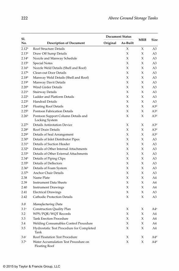
222 Above Ground Storage Tanks
Sl. No. Description of Document
Document StatusMRB Size
Original As-Built
2.12b Roof Structure Details X X A32.13b Draw Off Sump Details X X A32.14b Nozzle and Manway Schedule X X A32.15b Special Notes X X A32.16b Nozzle Weld Details (Shell and Roof) X X A32.17b Clean-out Door Details X X A32.18b Manway Weld Details (Shell and Roof) X X A32.19b Manway Davit Details X X A32.20b Wind Girder Details X X A32.21b Stairway Details X X A32.22b Ladder and Platform Details X X A32.23b Handrail Details X X A32.24b Floating Roof Details X X A3d
2.25b Pontoon Fabrication Details X X A3d
2.26b Pontoon Support Column Details and Locking System
X X A3d
2.27b Details Antirotation Device X X A3d
2.28b Roof Drain Details X X A3d
2.29b Details of Seal Arrangement X X A3d
2.30b Details of Inlet Distributor Pipes X X A32.31b Details of Suction Header X X A32.32b Details of Other Internal Attachments X X A32.33b Details of Other External Attachments X X A32.34b Details of Piping Clips X X A32.35b Details of Deflectors X X A32.36b Details of Foam System X X A32.37b Anchor Chair Details X X A32.38 Name Plate X X A42.39 Instrument Data Sheets X X A42.40 Instrument Drawings X X A42.41 Electrical Drawings X X A32.42 Cathodic Protection Details X X A3
3.0 Manufacturing Data3.1a Construction Quality Plan X X A4a
3.2 WPS/PQR/WQT Records X X A43.3 Tank Erection Procedure X X A43.4 Welding Consumables Control Procedure X X A43.5 Hydrostatic Test Procedure for Completed
TankX X A4
3.6c Roof Floatation Test Procedure X X A4d
3.7c Water Accumulation Test Procedure on Floating Roof
X X A4d
K22265_Book.indb 222 4/20/15 5:49 PM
© 2015 by Taylor & Francis Group, LLC
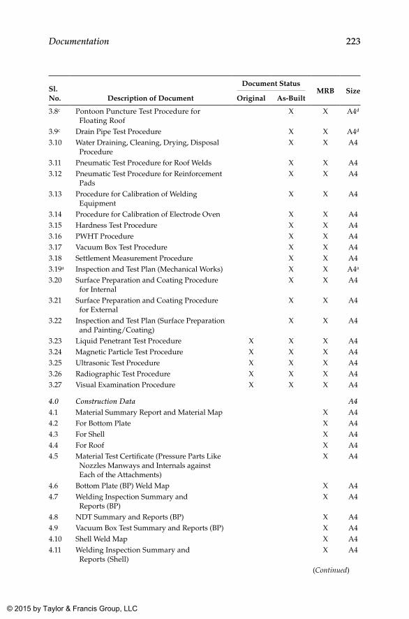
223Documentation
Sl. No. Description of Document
Document StatusMRB Size
Original As-Built
3.8c Pontoon Puncture Test Procedure for Floating Roof
X X A4d
3.9c Drain Pipe Test Procedure X X A4d
3.10 Water Draining, Cleaning, Drying, Disposal Procedure
X X A4
3.11 Pneumatic Test Procedure for Roof Welds X X A43.12 Pneumatic Test Procedure for Reinforcement
PadsX X A4
3.13 Procedure for Calibration of Welding Equipment
X X A4
3.14 Procedure for Calibration of Electrode Oven X X A43.15 Hardness Test Procedure X X A43.16 PWHT Procedure X X A43.17 Vacuum Box Test Procedure X X A43.18 Settlement Measurement Procedure X X A43.19a Inspection and Test Plan (Mechanical Works) X X A4a
3.20 Surface Preparation and Coating Procedure for Internal
X X A4
3.21 Surface Preparation and Coating Procedure for External
X X A4
3.22 Inspection and Test Plan (Surface Preparation and Painting/Coating)
X X A4
3.23 Liquid Penetrant Test Procedure X X X A43.24 Magnetic Particle Test Procedure X X X A43.25 Ultrasonic Test Procedure X X X A43.26 Radiographic Test Procedure X X X A43.27 Visual Examination Procedure X X X A4
4.0 Construction Data A44.1 Material Summary Report and Material Map X A44.2 For Bottom Plate X A44.3 For Shell X A44.4 For Roof X A44.5 Material Test Certificate (Pressure Parts Like
Nozzles Manways and Internals against Each of the Attachments)
X A4
4.6 Bottom Plate (BP) Weld Map X A44.7 Welding Inspection Summary and
Reports (BP)X A4
4.8 NDT Summary and Reports (BP) X A44.9 Vacuum Box Test Summary and Reports (BP) X A44.10 Shell Weld Map X A44.11 Welding Inspection Summary and
Reports (Shell)X A4
(Continued)
K22265_Book.indb 223 4/20/15 5:49 PM
© 2015 by Taylor & Francis Group, LLC
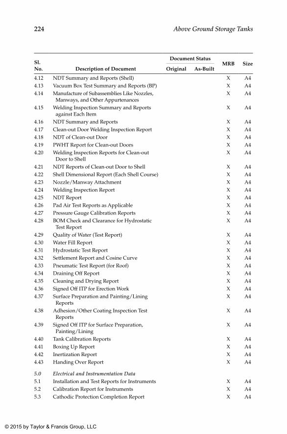
224 Above Ground Storage Tanks
Sl. No. Description of Document
Document StatusMRB Size
Original As-Built
4.12 NDT Summary and Reports (Shell) X A44.13 Vacuum Box Test Summary and Reports (BP) X A44.14 Manufacture of Subassemblies Like Nozzles,
Manways, and Other AppurtenancesX A4
4.15 Welding Inspection Summary and Reports against Each Item
X A4
4.16 NDT Summary and Reports X A44.17 Clean-out Door Welding Inspection Report X A44.18 NDT of Clean-out Door X A44.19 PWHT Report for Clean-out Doors X A44.20 Welding Inspection Reports for Clean-out
Door to ShellX A4
4.21 NDT Reports of Clean-out Door to Shell X A44.22 Shell Dimensional Report (Each Shell Course) X A44.23 Nozzle/Manway Attachment X A44.24 Welding Inspection Report X A44.25 NDT Report X A44.26 Pad Air Test Reports as Applicable X A44.27 Pressure Gauge Calibration Reports X A44.28 BOM Check and Clearance for Hydrostatic
Test ReportX A4
4.29 Quality of Water (Test Report) X A44.30 Water Fill Report X A44.31 Hydrostatic Test Report X A44.32 Settlement Report and Cosine Curve X A44.33 Pneumatic Test Report (for Roof) X A44.34 Draining Off Report X A44.35 Cleaning and Drying Report X A44.36 Signed Off ITP for Erection Work X A44.37 Surface Preparation and Painting/Lining
ReportsX A4
4.38 Adhesion/Other Coating Inspection Test Reports
X A4
4.39 Signed Off ITP for Surface Preparation, Painting/Lining
X A4
4.40 Tank Calibration Reports X A44.41 Boxing Up Report X A44.42 Inertization Report X A44.43 Handing Over Report X A4
5.0 Electrical and Instrumentation Data5.1 Installation and Test Reports for Instruments X A45.2 Calibration Report for Instruments X A45.3 Cathodic Protection Completion Report X A4
K22265_Book.indb 224 4/20/15 5:49 PM
© 2015 by Taylor & Francis Group, LLC
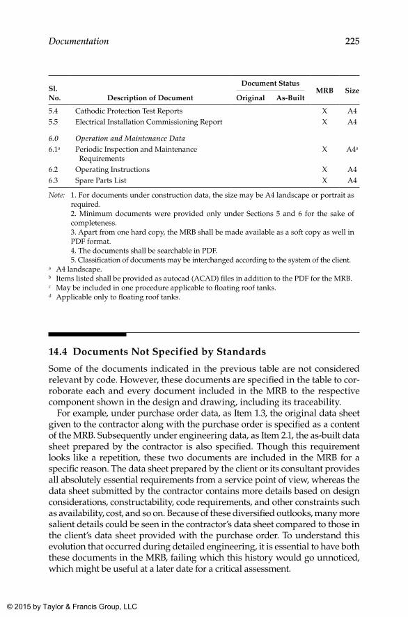
225Documentation
Sl. No. Description of Document
Document StatusMRB Size
Original As-Built
5.4 Cathodic Protection Test Reports X A45.5 Electrical Installation Commissioning Report X A4
6.0 Operation and Maintenance Data6.1a Periodic Inspection and Maintenance
RequirementsX A4a
6.2 Operating Instructions X A46.3 Spare Parts List X A4
Note: 1. For documents under construction data, the size may be A4 landscape or portrait as required.
2. Minimum documents were provided only under Sections 5 and 6 for the sake of completeness.
3. Apart from one hard copy, the MRB shall be made available as a soft copy as well in PDF format.
4. The documents shall be searchable in PDF. 5. Classification of documents may be interchanged according to the system of the client.a A4 landscape.b Items listed shall be provided as autocad (ACAD) files in addition to the PDF for the MRB.c May be included in one procedure applicable to floating roof tanks.d Applicable only to floating roof tanks.
14.4 Documents Not Specified by Standards
Some of the documents indicated in the previous table are not considered relevant by code. However, these documents are specified in the table to cor-roborate each and every document included in the MRB to the respective component shown in the design and drawing, including its traceability.
For example, under purchase order data, as Item 1.3, the original data sheet given to the contractor along with the purchase order is specified as a content of the MRB. Subsequently under engineering data, as Item 2.1, the as-built data sheet prepared by the contractor is also specified. Though this requirement looks like a repetition, these two documents are included in the MRB for a specific reason. The data sheet prepared by the client or its consultant provides all absolutely essential requirements from a service point of view, whereas the data sheet submitted by the contractor contains more details based on design considerations, constructability, code requirements, and other constraints such as availability, cost, and so on. Because of these diversified outlooks, many more salient details could be seen in the contractor’s data sheet compared to those in the client’s data sheet provided with the purchase order. To understand this evolution that occurred during detailed engineering, it is essential to have both these documents in the MRB, failing which this history would go unnoticed, which might be useful at a later date for a critical assessment.
K22265_Book.indb 225 4/20/15 5:49 PM
© 2015 by Taylor & Francis Group, LLC
226 Above Ground Storage Tanks
Similarly, some more documents such as weld maps, weld and nondestruc-tive testing (NDT) summaries, and so on are also of paramount importance in ensuring smooth corroboration of documents pertaining to each and every part that constitutes a component of the storage tank and ensures complete-ness of coverage (especially that of NDT and other tests) as envisaged in the contract. While describing the relevance of each document would be impracti-cal, some are explained next since they are considered as key in correlating documents to applicable drawings and to part numbers indicated therein.
14.4.1 Material Summary
The material summary is nothing but a tabulation of a list of part numbers (as per the drawing) against material test certificates (MTCs). In other words, it is a summary statement showing all part numbers connected with a mate-rial certificate. With the help of this document, at one glance, the actual mate-rial used during construction for a particular part number in the drawing can be traced back. Therefore, the material summary shall be read in con-junction with the MTCs for all pressure parts, so that the MTC of a particular part can be located easily. At a minimum, material certificates pertaining to all pressure containing parts shall be compiled systematically with the help of a summary as mentioned. In addition, material certificates for all internals also shall be compiled in a similar way. Though it is desirable to compile MTCs of structural steel materials as well, depending on the complexity of the structure, this may be included or excluded from the MRB as circum-stances warrant and in consultation with the client or consultant.
14.4.2 Weld Map
The weld map is another key document that usually forms a part of many of the reports such as for welding, NDT, vacuum box testing, and visual inspection. In tank construction three separate weld maps are required, one each for the bottom plate, shell, and roof. Other welds can be monitored through weld joint summary reports. The weld map is a pictorial development (representa-tion) of the bottom plate, shell, and roof plate identifying each weld joint with a unique number that has to be used in all subsequent activities and reports.
14.4.3 Weld Summary
A weld summary table is also accompanied by a weld map (for bottom, shell, and roof plates) that depicts welding processes, welding procedure specifications (WPS), and welders deployed for each of the pressure con-taining weld joints in the tank, including those for nozzles, manways, clean-out doors, and so on. In addition, nonpressure containing welds in internal piping, such as distribution or spreader pipes, are also considered impor-tant and included in the weld summary as per practice. While an overall
K22265_Book.indb 226 4/20/15 5:49 PM
© 2015 by Taylor & Francis Group, LLC
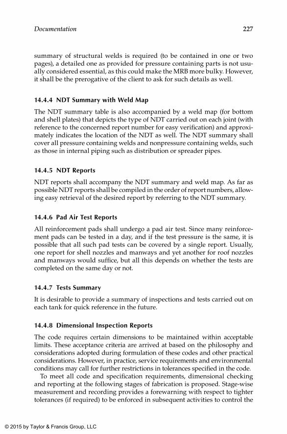
227Documentation
summary of structural welds is required (to be contained in one or two pages), a detailed one as provided for pressure containing parts is not usu-ally considered essential, as this could make the MRB more bulky. However, it shall be the prerogative of the client to ask for such details as well.
14.4.4 NDT Summary with Weld Map
The NDT summary table is also accompanied by a weld map (for bottom and shell plates) that depicts the type of NDT carried out on each joint (with reference to the concerned report number for easy verification) and approxi-mately indicates the location of the NDT as well. The NDT summary shall cover all pressure containing welds and nonpressure containing welds, such as those in internal piping such as distribution or spreader pipes.
14.4.5 NDT Reports
NDT reports shall accompany the NDT summary and weld map. As far as possible NDT reports shall be compiled in the order of report numbers, allow-ing easy retrieval of the desired report by referring to the NDT summary.
14.4.6 Pad Air Test Reports
All reinforcement pads shall undergo a pad air test. Since many reinforce-ment pads can be tested in a day, and if the test pressure is the same, it is possible that all such pad tests can be covered by a single report. Usually, one report for shell nozzles and manways and yet another for roof nozzles and manways would suffice, but all this depends on whether the tests are completed on the same day or not.
14.4.7 Tests Summary
It is desirable to provide a summary of inspections and tests carried out on each tank for quick reference in the future.
14.4.8 Dimensional Inspection Reports
The code requires certain dimensions to be maintained within acceptable limits. These acceptance criteria are arrived at based on the philosophy and considerations adopted during formulation of these codes and other practical considerations. However, in practice, service requirements and environmental conditions may call for further restrictions in tolerances specified in the code.
To meet all code and specification requirements, dimensional checking and reporting at the following stages of fabrication is proposed. Stage-wise measurement and recording provides a forewarning with respect to tighter tolerances (if required) to be enforced in subsequent activities to control the
K22265_Book.indb 227 4/20/15 5:49 PM
© 2015 by Taylor & Francis Group, LLC
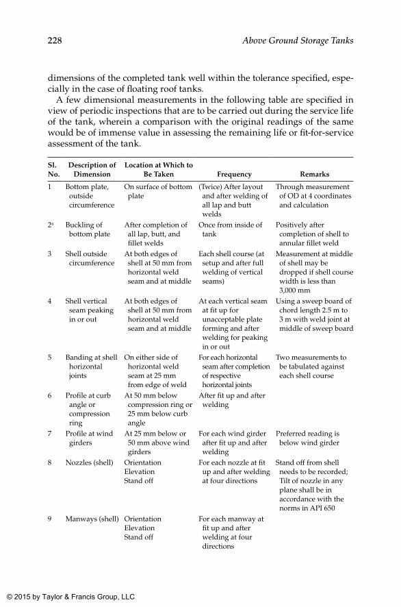
228 Above Ground Storage Tanks
dimensions of the completed tank well within the tolerance specified, espe-cially in the case of floating roof tanks.
A few dimensional measurements in the following table are specified in view of periodic inspections that are to be carried out during the service life of the tank, wherein a comparison with the original readings of the same would be of immense value in assessing the remaining life or fit-for-service assessment of the tank.
Sl. No.
Description of Dimension
Location at Which to Be Taken Frequency Remarks
1 Bottom plate, outside circumference
On surface of bottom plate
(Twice) After layout and after welding of all lap and butt welds
Through measurement of OD at 4 coordinates and calculation
2a Buckling of bottom plate
After completion of all lap, butt, and fillet welds
Once from inside of tank
Positively after completion of shell to annular fillet weld
3 Shell outside circumference
At both edges of shell at 50 mm from horizontal weld seam and at middle
Each shell course (at setup and after full welding of vertical seams)
Measurement at middle of shell may be dropped if shell course width is less than 3,000 mm
4 Shell vertical seam peaking in or out
At both edges of shell at 50 mm from horizontal weld seam and at middle
At each vertical seam at fit up for unacceptable plate forming and after welding for peaking in or out
Using a sweep board of chord length 2.5 m to 3 m with weld joint at middle of sweep board
5 Banding at shell horizontal joints
On either side of horizontal weld seam at 25 mm from edge of weld
For each horizontal seam after completion of respective horizontal joints
Two measurements to be tabulated against each shell course
6 Profile at curb angle or compression ring
At 50 mm below compression ring or 25 mm below curb angle
After fit up and after welding
7 Profile at wind girders
At 25 mm below or 50 mm above wind girders
For each wind girder after fit up and after welding
Preferred reading is below wind girder
8 Nozzles (shell) Orientation ElevationStand off
For each nozzle at fit up and after welding at four directions
Stand off from shell needs to be recorded; Tilt of nozzle in any plane shall be in accordance with the norms in API 650
9 Manways (shell) OrientationElevationStand off
For each manway at fit up and after welding at four directions
K22265_Book.indb 228 4/20/15 5:49 PM
© 2015 by Taylor & Francis Group, LLC
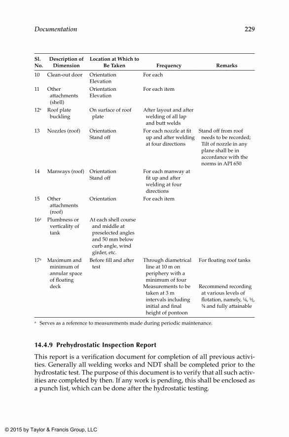
229Documentation
Sl. No.
Description of Dimension
Location at Which to Be Taken Frequency Remarks
10 Clean-out door OrientationElevation
For each
11 Other attachments (shell)
OrientationElevation
For each item
12a Roof plate buckling
On surface of roof plate
After layout and after welding of all lap and butt welds
13 Nozzles (roof) OrientationStand off
For each nozzle at fit up and after welding at four directions
Stand off from roof needs to be recorded; Tilt of nozzle in any plane shall be in accordance with the norms in API 650
14 Manways (roof) OrientationStand off
For each manway at fit up and after welding at four directions
15 Other attachments (roof)
Orientation For each item
16a Plumbness or verticality of tank
At each shell course and middle at preselected angles and 50 mm below curb angle, wind girder, etc.
17a Maximum and minimum of annular space of floating deck
Before fill and after test
Through diametrical line at 10 m on periphery with a minimum of four
Measurements to be taken at 3 m intervals including initial and final height of pontoon
For floating roof tanks
Recommend recording at various levels of flotation, namely, ¼, ½, ¾ and fully attainable
a Serves as a reference to measurements made during periodic maintenance.
14.4.9 Prehydrostatic Inspection Report
This report is a verification document for completion of all previous activi-ties. Generally all welding works and NDT shall be completed prior to the hydrostatic test. The purpose of this document is to verify that all such activ-ities are completed by then. If any work is pending, this shall be enclosed as a punch list, which can be done after the hydrostatic testing.
K22265_Book.indb 229 4/20/15 5:49 PM
© 2015 by Taylor & Francis Group, LLC
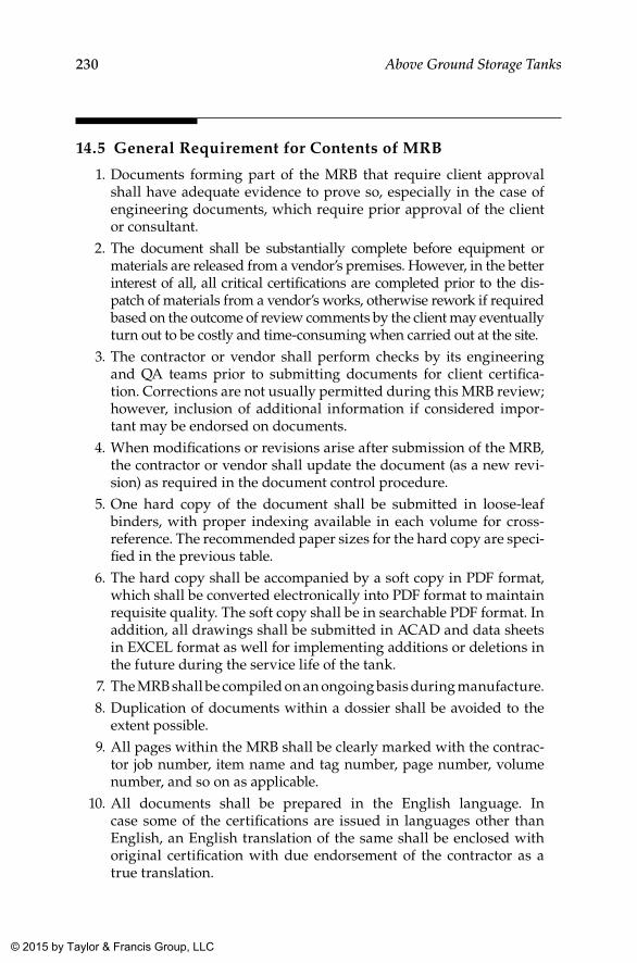
230 Above Ground Storage Tanks
14.5 General Requirement for Contents of MRB
1. Documents forming part of the MRB that require client approval shall have adequate evidence to prove so, especially in the case of engineering documents, which require prior approval of the client or consultant.
2. The document shall be substantially complete before equipment or materials are released from a vendor’s premises. However, in the better interest of all, all critical certifications are completed prior to the dis-patch of materials from a vendor’s works, otherwise rework if required based on the outcome of review comments by the client may eventually turn out to be costly and time-consuming when carried out at the site.
3. The contractor or vendor shall perform checks by its engineering and QA teams prior to submitting documents for client certifica-tion. Corrections are not usually permitted during this MRB review; however, inclusion of additional information if considered impor-tant may be endorsed on documents.
4. When modifications or revisions arise after submission of the MRB, the contractor or vendor shall update the document (as a new revi-sion) as required in the document control procedure.
5. One hard copy of the document shall be submitted in loose-leaf binders, with proper indexing available in each volume for cross-reference. The recommended paper sizes for the hard copy are speci-fied in the previous table.
6. The hard copy shall be accompanied by a soft copy in PDF format, which shall be converted electronically into PDF format to maintain requisite quality. The soft copy shall be in searchable PDF format. In addition, all drawings shall be submitted in ACAD and data sheets in EXCEL format as well for implementing additions or deletions in the future during the service life of the tank.
7. The MRB shall be compiled on an ongoing basis during manufacture. 8. Duplication of documents within a dossier shall be avoided to the
extent possible. 9. All pages within the MRB shall be clearly marked with the contrac-
tor job number, item name and tag number, page number, volume number, and so on as applicable.
10. All documents shall be prepared in the English language. In case some of the certifications are issued in languages other than English, an English translation of the same shall be enclosed with original certification with due endorsement of the contractor as a true translation.
K22265_Book.indb 230 4/20/15 5:49 PM
© 2015 by Taylor & Francis Group, LLC
231Documentation
11. The MRB shall be compiled according to a proposed MRB index duly approved by the client right at the beginning. After compila-tion, a single hard copy of the same shall be submitted for review of the client to ensure proper compilation and completeness of the document. The document thus approved by the client shall be sub-mitted as the MRB in the required number of hard and soft copies.
14.6 Records and Reports of Inspections, Tests, and Calibrations
1. When specifying documents to be included in the MRB, attention shall be paid to the distinction between certificates, reports, and records. Reports and records typically include useful data and definitive state-ments, whereas certificates can consist of unsupported statements cer-tifying that tests, inspections, and calibrations have been carried out with satisfactory results. Such statements from vendors or subcontrac-tors have no value to the client, especially after expiry of the guarantee.
2. Records and reports shall explicitly indicate the concerned item, material, or equipment through the proper identification system such as the item number, serial number, tag number, and so on as required.
3. When inspections or tests are performed on a sampling basis, this shall be made clear in the inspection certificate issued for the lot represented by the sample.
4. When inspections or tests are performed against a written pro-cedure, reference to this procedure shall be present in the test or inspection report.
5. When results of inspections or tests are compared and accepted based on standards or specifications, reference of this document also shall be made on the inspection or test report.
6. Inspection and test reports shall contain details such as performance date and report date, along with a description of the type of test or inspection carried out.
7. When reports consist of more than one page, all pages shall have the report number on them, along with “page x of y” at appropriate places to ensure completeness of the report.
8. Similarly, any attachments to the report also shall be clearly indi-cated in the report, including information as to the number of pages of each attachment.
9. Any corrections, alterations, or additions made to the report after endorsement by client inspectors shall be clearly traceable and dated.
K22265_Book.indb 231 4/20/15 5:49 PM
© 2015 by Taylor & Francis Group, LLC
232 Above Ground Storage Tanks
14.7 Certification for Materials
1. Material traceability is of paramount importance, and as far as pos-sible original certifications shall be maintained in the MRB.
2. When the original MTC is issued for a large quantity (of which only a small portion is required for the tank, such as pipes, fittings, flanges, etc.), the original certificates shall be available with the sup-plier or trader. Such availability of the original certification shall be ensured through endorsements made by the inspection engineers of the contractor, consultant, or client at the manufacturer’s or trader’s premises in the respective inspection reports for materials inspected and released from stockists.
3. Materials without any of these certifications shall not be entertained even for very small quantities.
4. It is mandatory that certificates for wrought butt weld fittings be supported by certification for the parent plate or pipe as applicable. However, it is not essential that such supporting cer-tification be original, as long as product specification require-ments are established through sample testing after forming the component.
5. Corrections to certificates shall not be acceptable under any circum-stances. When errors are found in a certificate, it shall be reissued at the source or else the material shall be rejected.
6. When supplementary tests (tests not carried out by the manufac-turer) are carried out on materials with original certification, this shall be reported on separate sheets with cross-reference to the origi-nal certification and endorsed by contractor or client inspectors as applicable.
7. Transcribed data on material certificates shall normally be accept-able under the following circumstances:
a. heat analyses for wrought materials, and b. certificates issued by stockists for bolting materials or screwed
and socket weld fittings, which contain data and test results taken from manufacturer’s certification and certified as having been accurately transcribed.
8. When material is required to satisfy a carbon equivalent limit as determined by the long formula (C + Mn16 + Cr+Mo+V/5 + Ni+Cu/l5), then all component elements of this formula shall be determined and reported. It shall not be acceptable to assume zero content for any unreported elements.
K22265_Book.indb 232 4/20/15 5:49 PM
© 2015 by Taylor & Francis Group, LLC
233Documentation
9. For nonferrous alloys, where the applicable standard gives a mini-mum value for the predominant element, it is not acceptable for this element to be certified as “remainder,” as this does not take into account the levels of impurities that may be present.
14.7.1 Components Requiring “Material Certification”
1. All components comprising the pressure envelope 2. All nozzle compensation pads 3. Lifting and tailing attachments 4. Components attached to the shell by welding 5. Weld consumables including consumables for overlay cladding 6. All materials requiring impact testing
14.7.2 Contents of “Certification Dossier” for bought Out Items (as Applicable)
1. Index of the dossier 2. Code data form or certificate of conformity 3. Third-party final report or certificate of inspection 4. Inspection and test plans (ITPs) signed by all inspection authorities 5. List of materials or layout sketch showing the position of the com-
ponent, cross-referenced to the page numbers of the material certifi-cates and any supplementary reports
6. MTCs including hardness testing as required 7. Material repair records 8. Weld key map and seam identification sketch (When the manufac-
turer opts to maintain a written record of the work performed by each coded welder in lieu of stamping welders identification against their welds, this record shall be included in the certification dossier. This record need not extend beyond “code” welds.)
9. Welding procedures and qualification records 10. Production test records 11. NDE reports and records (When repairs have been carried out,
reports of original examinations shall be included.) 12. Reports of any required special tests (SSC, HIC, etc.) 13. Heat treatment charts and records as applicable 14. Pressure and leak test reports 15. Coating or lining application records and examination reports
K22265_Book.indb 233 4/20/15 5:49 PM
© 2015 by Taylor & Francis Group, LLC
234 Above Ground Storage Tanks
16. Nameplate rubbing (facsimile) 17. As-built general arrangement drawing and isometric drawings
for piping 18. Records of critical dimensions 19. All design calculations (including relief valves supplied with pack-
aged vessels) 20. Function test records for actuated valves 21. Valve pressure and temperature ratings 22. Special certificates (fire safe, etc.) 23. Bend manufacturing procedures and qualification tests 24. Pump performance test records, vibration records, and function test
records for instruments and controls 25. Pipeline welds traceability, pressure testing charts, and gauging,
cleaning, and drying records 26. Dimensional records
14.8 Heat Treatment Records and Charts
1. When a heat treatment of materials or components is performed to satisfy code or specification requirements, it shall be sufficient for the manufacturer to declare that the requisite heat treatment was carried out, as in the case of normalizing, wherein temperatures need not be declared. However, for other heat treatments such as tempering and simulated post weld heat treatment (PWHT), heat-ing and cooling rates, soaking temperature, and time need to be specified in the accompanying certificate.
2. When a heat treatment is carried out on materials to meet NACE MR0175/ISO 15156 requirements, sufficient details shall be reported to verify conformance. Hardness testing on heat treated components also shall be required subsequent to the heat treatment, and results of the same shall be in accordance with NACE MR 0175/ISO 15156.
3. When heat treatments are carried out on fabricated components such as clean-out doors, a heat treatment certificate and a chart of a multipoint temperature recorder shall be provided as record, with due endorsement from the contractor and client or consultant.
4. Records and reports shall always have direct reference to heat treated components like part number, equipment tag number, and so on.
K22265_Book.indb 234 4/20/15 5:49 PM
© 2015 by Taylor & Francis Group, LLC
235Documentation
5. Actual chart speed, time of start, and heating, soaking, and cooling zones shall be clearly identified on a chart along with the direction of time progression.
6. Location and identification of thermocouples shall be indicated in a sketch provided with the report.
7. When a heat treatment is performed against a written procedure, reference to this procedure also needs to be reflected in the report.
8. As in the case of other inspection reports, both the performance date and the report date shall be clearly indicated in the heat treatment record as well.
9. When records consist of more than one page, all pages shall be num-bered as “page x of y” and have the report number on all pages to ensure inclusion of the complete report.
10. When records are allowed in lieu of recorder charts, the actual hold-ing temperature and time shall be reported. For post-weld or stress-relieving treatments, the maximum actual heating and cooling rates shall also be recorded.
14.9 NDT Reports
1. For all NDTs performed at the site, original reports shall be pro-vided with due endorsement from the contractor or consultant or client as applicable.
2. Reports shall contain details of components or welds radio-graphed with unique identifications provided to each of the weld seams or components.
3. The personnel deputed to carry out NDTs and prepare the report shall be qualified adequately for the envisaged works and provide evidence of proper qualifications.
4. Details of the examination techniques, equipment, consumables, and extent of testing shall be presented in detail in the report. When technique sheets have been separately approved, reports need only contain a reference to these sheets.
5. As in other reports, both performance date and report date shall be clearly indicated.
6. When records consist of more than one page, all pages shall be num-bered as “page x of y” and have the report number on all pages to ensure inclusion of the complete report.
K22265_Book.indb 235 4/20/15 5:49 PM
© 2015 by Taylor & Francis Group, LLC
236 Above Ground Storage Tanks
7. The report shall clearly indicate the stage at which the NDT was carried out. For example, when a heat treatment or forming is required in manufacturing, NDT reports shall indicate whether the required examination was carried out before or after the heat treat-ment operation.
8. Acceptance or rejection criteria adopted in the evaluation also shall be indicated in the report.
9. The minimum achieved sensitivity levels or calibration standards along with the acceptance criteria shall be recorded in the report.
K22265_Book.indb 236 4/20/15 5:49 PM
© 2015 by Taylor & Francis Group, LLC
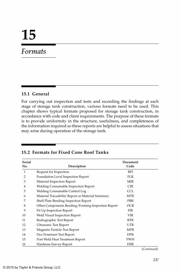
237
15Formats
15.1 General
For carrying out inspection and tests and recording the findings at each stage of storage tank construction, various formats need to be used. This chapter shows typical formats proposed for storage tank construction, in accordance with code and client requirements. The purpose of these formats is to provide uniformity in the structure, usefulness, and completeness of the information required so these reports are helpful to assess situations that may arise during operation of the storage tank.
15.2 Formats for Fixed Cone Roof Tanks
Serial No. Description
Document Code
1 Request for Inspection RFI 2 Foundation Level Inspection Report FLR 3 Material Inspection Report MIR 4 Welding Consumable Inspection Report CIR 5 Welding Consumable Control Log CCL 6 Material Traceability Report or Material Summary MTR 7 Shell Plate Bending Inspection Report PBR 8 Other Components Bending/Forming Inspection Report OCR 9 Fit Up Inspection Report FIR10 Weld Visual Inspection Report VIR11 Radiographic Test Report RTR12 Ultrasonic Test Report UTR13 Magnetic Particle Test Report MPR14 Dye Penetrant Test Report DPR15 Post Weld Heat Treatment Report PWH16 Hardness Survey Report HSR
(Continued)
K22265_Book.indb 237 4/20/15 5:49 PM
© 2015 by Taylor & Francis Group, LLC
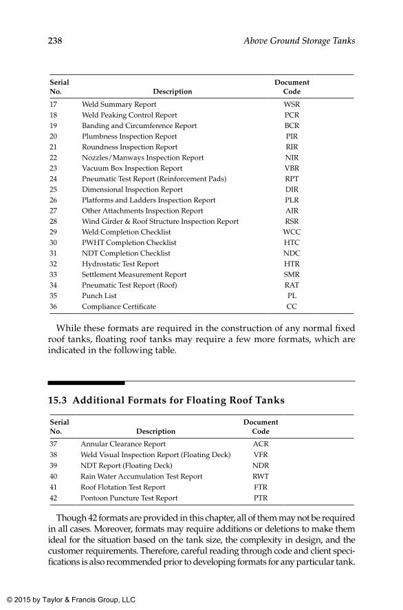
238 Above Ground Storage Tanks
Serial No. Description
Document Code
17 Weld Summary Report WSR18 Weld Peaking Control Report PCR19 Banding and Circumference Report BCR20 Plumbness Inspection Report PIR21 Roundness Inspection Report RIR22 Nozzles/Manways Inspection Report NIR23 Vacuum Box Inspection Report VBR24 Pneumatic Test Report (Reinforcement Pads) RPT25 Dimensional Inspection Report DIR26 Platforms and Ladders Inspection Report PLR27 Other Attachments Inspection Report AIR28 Wind Girder & Roof Structure Inspection Report RSR29 Weld Completion Checklist WCC30 PWHT Completion Checklist HTC31 NDT Completion Checklist NDC32 Hydrostatic Test Report HTR33 Settlement Measurement Report SMR34 Pneumatic Test Report (Roof) RAT35 Punch List PL36 Compliance Certificate CC
While these formats are required in the construction of any normal fixed roof tanks, floating roof tanks may require a few more formats, which are indicated in the following table.
15.3 Additional Formats for Floating Roof Tanks
Serial No. Description
Document Code
37 Annular Clearance Report ACR38 Weld Visual Inspection Report (Floating Deck) VFR39 NDT Report (Floating Deck) NDR40 Rain Water Accumulation Test Report RWT41 Roof Flotation Test Report FTR42 Pontoon Puncture Test Report PTR
Though 42 formats are provided in this chapter, all of them may not be required in all cases. Moreover, formats may require additions or deletions to make them ideal for the situation based on the tank size, the complexity in design, and the customer requirements. Therefore, careful reading through code and client speci-fications is also recommended prior to developing formats for any particular tank.
K22265_Book.indb 238 4/20/15 5:49 PM
© 2015 by Taylor & Francis Group, LLC
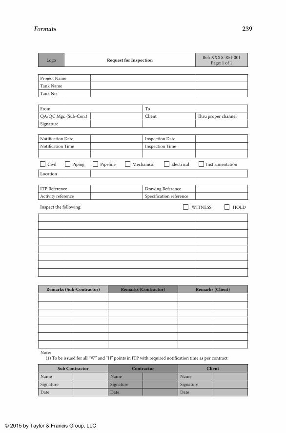
239Formats
Logo Request for Inspection Ref: XXXX-RFI-001Page: 1 of 1
Project NameTank NameTank No
From To QA/QC Mgr. (Sub-Con.) Client �ru proper channelSignature
Notification Date Inspection DateNotification Time Inspection Time
Civil Piping Pipeline Mechanical Electrical Instrumentation
Location
ITP Reference Drawing ReferenceActivity reference Specification reference
Inspect the following: WITNESS HOLD
Remarks (Sub-Contractor) Remarks (Contractor) Remarks (Client)
Note: (1) To be issued for all “W” and “H” points in ITP with required notification time as per contract
Sub Contractor Contractor ClientName Name NameSignature Signature SignatureDate Date Date
K22265_Book.indb 239 4/20/15 5:49 PM
© 2015 by Taylor & Francis Group, LLC
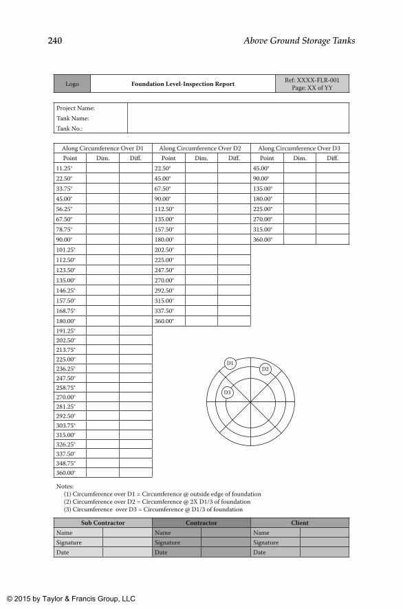
240 Above Ground Storage Tanks
Logo Foundation Level-Inspection Report Ref: XXXX-FLR-001Page: XX of YY
Project Name:Tank Name:Tank No.:
Along Circumference Over D1 Along Circumference Over D2 Along Circumference Over D3 Point Dim. Diff. Point Dim. Diff. Point Dim. Diff.
11.25° 22.50° 45.00°22.50° 45.00° 90.00°33.75° 67.50° 135.00°45.00° 90.00° 180.00°56.25° 112.50° 225.00°67.50° 135.00° 270.00°78.75° 157.50° 315.00°90.00° 180.00° 360.00°101.25° 202.50°112.50° 225.00°123.50° 247.50°135.00° 270.00°146.25° 292.50°157.50° 315.00°168.75° 337.50°180.00° 360.00°191.25°
D3
D2D1
202.50°213.75°225.00°236.25°247.50°258.75°270.00°281.25°292.50°303.75°315.00°326.25°337.50°348.75°360.00°
Notes: (1) Circumference over D1 = Circumference @ outside edge of foundation (2) Circumference over D2 = Circumference @ 2X D1/3 of foundation (3) Circumference over D3 = Circumference @ D1/3 of foundation
Sub Contractor Contractor ClientName Name NameSignature Signature SignatureDate Date Date
K22265_Book.indb 240 4/20/15 5:49 PM
© 2015 by Taylor & Francis Group, LLC
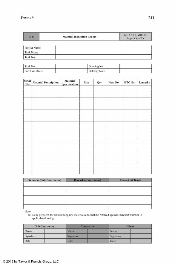
241Formats
Logo Material Inspection Report Ref: XXXX-MIR-001Page: XX of YY
Project NameTank NameTank No
Tank No. Drawing No.Purchase Order Delivery Note.
Serial No. Material Description Material
Specification Size Qty. Heat No. MTC No. Remarks
Remarks (Sub-Contractor) Remarks (Contractor) Remarks (Client)
Note: (1) To be prepared for all incoming raw materials and shall be referred against each part number in applicable drawing
Sub Contractor Contractor ClientName Name NameSignature Signature SignatureDate Date Date
K22265_Book.indb 241 4/20/15 5:49 PM
© 2015 by Taylor & Francis Group, LLC
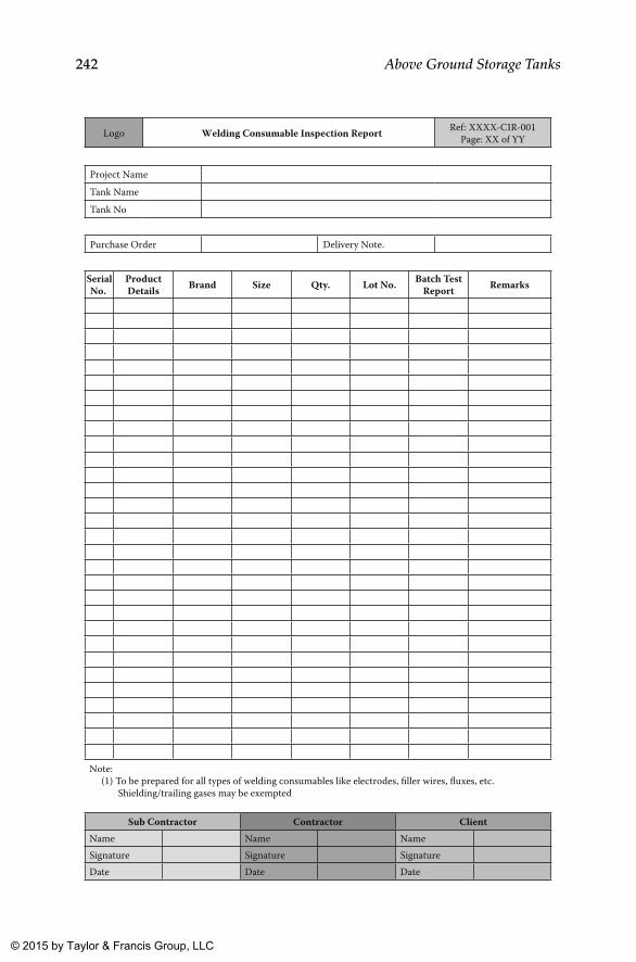
242 Above Ground Storage Tanks
Logo Welding Consumable Inspection Report Ref: XXXX-CIR-001Page: XX of YY
Project NameTank NameTank No
Purchase Order Delivery Note.
SerialNo.
ProductDetails Brand Size Qty. Lot No. Batch Test
Report Remarks
Note: (1) To be prepared for all types of welding consumables like electrodes, filler wires, fluxes, etc. Shielding/trailing gases may be exempted
Sub Contractor Contractor ClientName Name NameSignature Signature SignatureDate Date Date
K22265_Book.indb 242 4/20/15 5:49 PM
© 2015 by Taylor & Francis Group, LLC
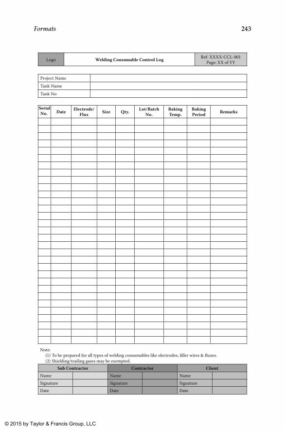
243Formats
Logo Welding Consumable Control Log Ref: XXXX-CCL-001Page: XX of YY
Project NameTank NameTank No
Date Electrode/Flux Size Qty. Lot/Batch
No.Baking Temp.
Baking Period Remarks
Note: (1) To be prepared for all types of welding consumables like electrodes, filler wires & fluxes. (2) Shielding/trailing gases may be exempted.
Sub Contractor Contractor ClientName Name NameSignature Signature SignatureDate Date Date
SerialNo.
K22265_Book.indb 243 4/20/15 5:49 PM
© 2015 by Taylor & Francis Group, LLC
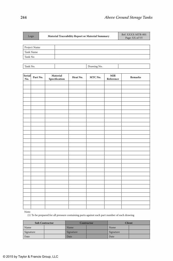
244 Above Ground Storage Tanks
Logo Material Traceability Report or Material Summary Ref: XXXX-MTR-001Page: XX of YY
Project NameTank NameTank No
Tank No. Drawing No.
Part No. MaterialSpecification Heat No. MTC No. MIR
Reference Remarks
Note: (1) To be prepared for all pressure containing parts against each part number of each drawing
Sub Contractor Contractor ClientName Name NameSignature Signature SignatureDate Date Date
SerialNo.
K22265_Book.indb 244 4/20/15 5:49 PM
© 2015 by Taylor & Francis Group, LLC

245Formats
Logo Shell Plate Bending Inspection Report Ref: XXXX-PBR-001Page: XX of YY
Project NameTank NameTank No
Tank No. Drawing No.Weld Map Ref:
Shell Plate Identification
MaterialSpecification
Plate�ickness
Condition or Surface & Edge Preparation Remarks
Note: (1) All shell plates including closure plates shall be included in this report
Sub Contractor Contractor ClientName Name NameSignature Signature SignatureDate Date Date
SerialNo.
K22265_Book.indb 245 4/20/15 5:49 PM
© 2015 by Taylor & Francis Group, LLC
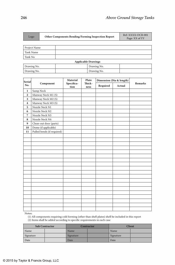
246 Above Ground Storage Tanks
Logo Other Components Bending/Forming Inspection Report Ref: XXXX-OCR-001Page: XX of YY
Project NameTank NameTank No
Applicable DrawingsDrawing No. Drawing No.Drawing No. Drawing No.
ComponentMaterial
Specifica-tion
Plate�ick-
ness
Dimension (Dia & length)Remarks
Required Actual
1 Sump Neck2 Manway Neck M1 (S)3 Manway Neck M2 (S)4 Manway Neck M3 (S)5 Nozzle Neck N16 Nozzle Neck N27 Nozzle Neck N38 Nozzle Neck N49 Clean-out door (parts)
10 Dome (if applicable)11 Pulled bends (if required)
Notes: (1) All components requiring cold forming (other than shell plates) shell be included in this report (2) Items shall be added according to specific requirements in each case
Sub Contractor Contractor ClientName Name NameSignature Signature SignatureDate Date Date
SerialNo.
K22265_Book.indb 246 4/20/15 5:49 PM
© 2015 by Taylor & Francis Group, LLC
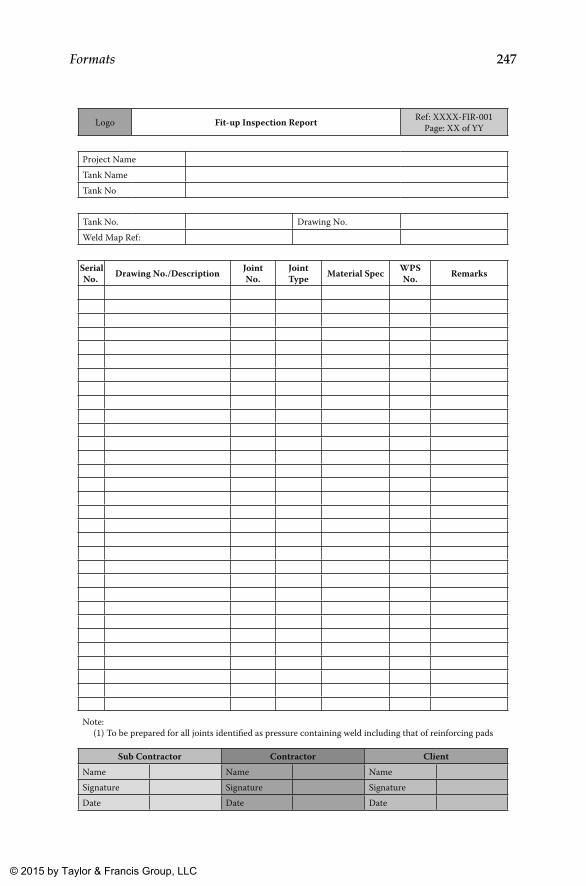
247Formats
Logo Fit-up Inspection Report Ref: XXXX-FIR-001Page: XX of YY
Project NameTank NameTank No
Tank No. Drawing No.Weld Map Ref:
Drawing No./Description JointNo.
Joint Type Material Spec WPS
No. Remarks
Note: (1) To be prepared for all joints identified as pressure containing weld including that of reinforcing pads
Sub Contractor Contractor ClientName Name NameSignature Signature SignatureDate Date Date
SerialNo.
K22265_Book.indb 247 4/20/15 5:49 PM
© 2015 by Taylor & Francis Group, LLC

248 Above Ground Storage Tanks
Logo Weld Visual Inspection Report Ref: XXXX-VIR-001Page: XX of YY
Project NameTank NameTank No
Tank No. Drawing No.Weld Map Ref:
Drawing No./Description JointNo.
Joint Type
Welding Process
WPSNo. Remarks
Notes: (1) To be prepared for all joints identified as pressure containing weld including that of reinforcing pads (2) For structural attachment welds; checklist as in format WCC-001 would suffice
Sub Contractor Contractor ClientName Name NameSignature Signature SignatureDate Date Date
SerialNo.
K22265_Book.indb 248 4/20/15 5:49 PM
© 2015 by Taylor & Francis Group, LLC
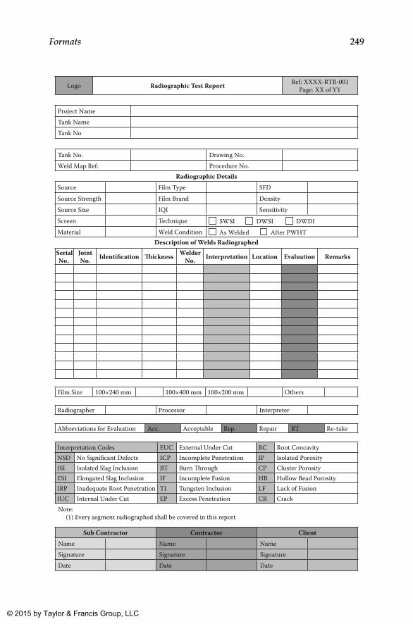
249Formats
Logo Radiographic Test Report Ref: XXXX-RTR-001Page: XX of YY
Project Name
Tank Name
Tank No
Tank No. Drawing No.
Weld Map Ref: Procedure No.
Film Size 100×240 mm 100×400 mm 100×200 mm Others
Radiographer Processor Interpreter
Abbreviations for Evaluation Acc. Acceptable Rep. Repair RT Re-take
Interpretation Codes EUC External Under Cut RC Root ConcavityNSD No Significant Defects ICP Incomplete Penetration IP Isolated PorosityISI Isolated Slag Inclusion BT Burn �rough CP Cluster PorosityESI Elongated Slag Inclusion IF Incomplete Fusion HB Hollow Bead PorosityIRP Inadequate Root Penetration TI Tungsten Inclusion LF Lack of FusionIUC Internal Under Cut EP Excess Penetration CR Crack
Radiographic DetailsSource Film Type SFD
Source Strength Film Brand Density
Source Size IQI Sensitivity
Screen Technique SWSI DWSI DWDIMaterial Weld Condition As Welded After PWHT
Description of Welds RadiographedJointNo. Identification �ickness Welder
No. Interpretation Location Evaluation Remarks
Note: (1) Every segment radiographed shall be covered in this report
Sub Contractor Contractor ClientName Name Name
Signature Signature Signature
Date Date Date
SerialNo.
K22265_Book.indb 249 4/20/15 5:49 PM
© 2015 by Taylor & Francis Group, LLC
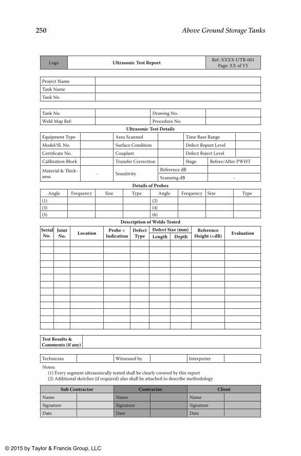
250 Above Ground Storage Tanks
Logo Ultrasonic Test Report Ref: XXXX-UTR-001Page: XX of YY
Project NameTank NameTank No
Tank No. Drawing No.Weld Map Ref: Procedure No.
Test Results & Comments (if any)
Technician Witnessed by Interpreter
Ultrasonic Test DetailsEquipment Type Area Scanned Time Base RangeModel/Sl. No. Surface Condition Defect Report LevelCertificate No. Couplant Defect Reject LevelCalibration Block Transfer Correction Stage Before/After PWHT
Material & �ick-ness - Sensitivity
Reference dBScanning dB -
Details of ProbesAngle Frequency Size Type Angle Frequency Size Type
(1) (2)(3) (4)(5) (6)
Description of Welds TestedJointNo. Location Probe <
IndicationDefect Type
Defect Size (mm) Reference Height (+dB) Evaluation
Length Depth
Notes: (1) Every segment ultrasonically tested shall be clearly covered by this report (2) Additional sketches (if required) also shall be attached to describe methodology
Sub Contractor Contractor ClientName Name NameSignature Signature SignatureDate Date Date
SerialNo.
K22265_Book.indb 250 4/20/15 5:49 PM
© 2015 by Taylor & Francis Group, LLC
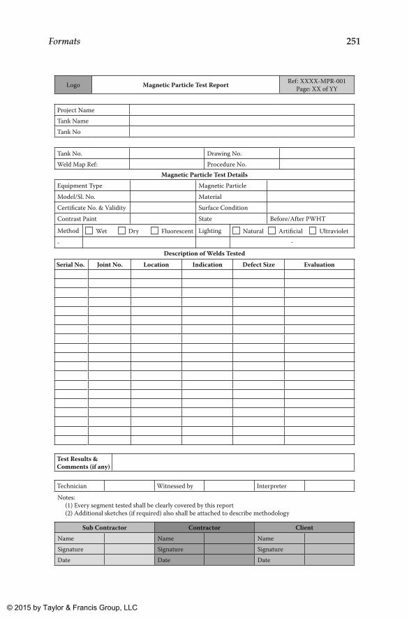
251Formats
Logo Magnetic Particle Test Report Ref: XXXX-MPR-001Page: XX of YY
Project NameTank NameTank No
Tank No. Drawing No.Weld Map Ref: Procedure No.
Test Results & Comments (if any)
Technician Witnessed by Interpreter
Magnetic Particle Test DetailsEquipment Type Magnetic ParticleModel/Sl. No. MaterialCertificate No. & Validity Surface ConditionContrast Paint State Before/After PWHT
Method Wet Dry Fluorescent Lighting Natural Artificial Ultraviolet
- -
Description of Welds TestedJoint No. Location Indication Defect Size Evaluation
Notes: (1) Every segment tested shall be clearly covered by this report (2) Additional sketches (if required) also shall be attached to describe methodology
Sub Contractor Contractor ClientName Name NameSignature Signature SignatureDate Date Date
Serial No.
K22265_Book.indb 251 4/20/15 5:49 PM
© 2015 by Taylor & Francis Group, LLC
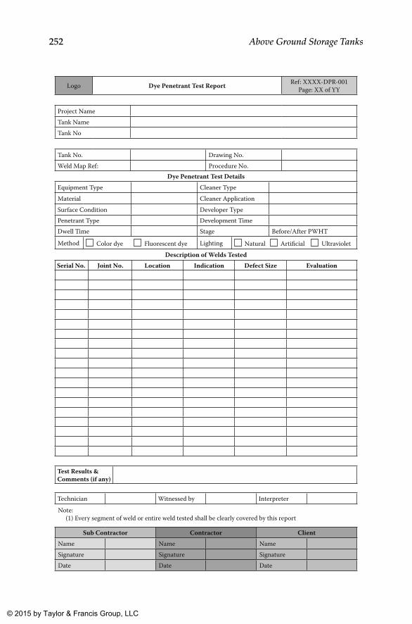
252 Above Ground Storage Tanks
Logo Dye Penetrant Test Report Ref: XXXX-DPR-001Page: XX of YY
Project NameTank NameTank No
Tank No. Drawing No.Weld Map Ref: Procedure No.
Test Results & Comments (if any)
Technician Witnessed by Interpreter
Dye Penetrant Test DetailsEquipment Type Cleaner TypeMaterial Cleaner ApplicationSurface Condition Developer TypePenetrant Type Development TimeDwell Time Stage Before/After PWHT
Method Color dye Fluorescent dye Lighting Natural Artificial UltravioletDescription of Welds Tested
Joint No. Location Indication Defect Size Evaluation
Note: (1) Every segment of weld or entire weld tested shall be clearly covered by this report
Sub Contractor Contractor ClientName Name NameSignature Signature SignatureDate Date Date
Serial No.
K22265_Book.indb 252 4/20/15 5:49 PM
© 2015 by Taylor & Francis Group, LLC
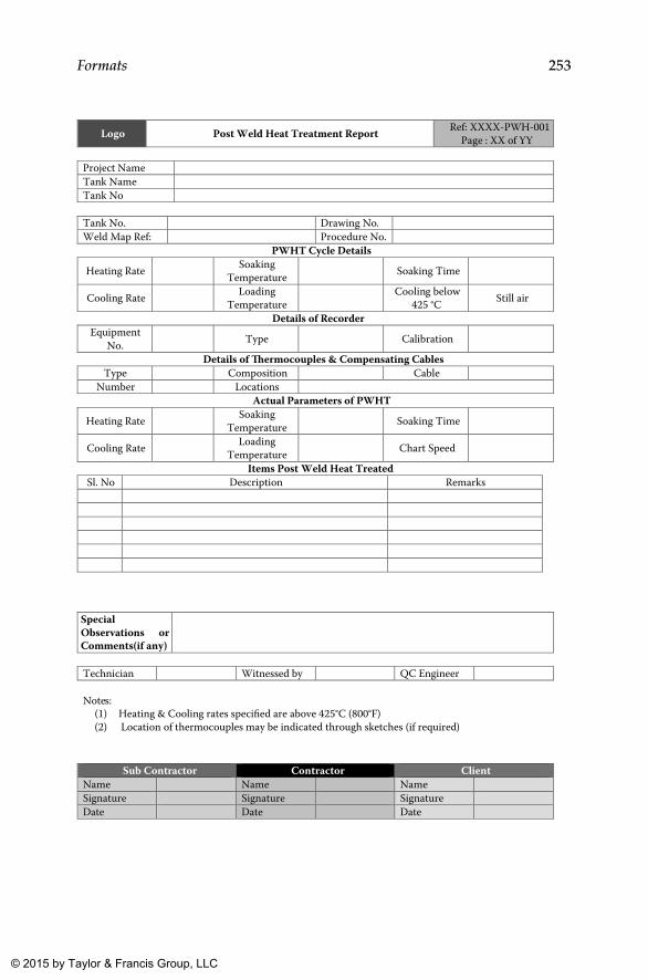
253Formats
Type
Ref: XXXX-PWH-001
Sub Contractor Contractor Client Name Name Name Signature Signature Signature Date Date Date
Project Name Tank Name Tank No
Tank No. Drawing No. Weld Map Ref: Procedure No.
Soaking
Loading Cooling below
Equipment
Composition Cable Number Locations
Soaking
Loading
Sl. No Description Remarks
Special
Technician Witnessed by QC Engineer
Logo Post Weld Heat Treatment Report Page : XX of YY
PWHT Cycle Details
Heating Rate Temperature Soaking Time
Cooling Rate Temperature 425 °C Still air
Details of Recorder
No. Type Calibration
Details of �ermocouples & Compensating Cables
Actual Parameters of PWHT
Heating Rate Temperature Soaking Time
Cooling Rate Temperature Chart Speed
Items Post Weld Heat Treated
Observations or Comments(if any)
Notes:
(1) Heating & Cooling rates specified are above 425°C (800°F) (2) Location of thermocouples may be indicated through sketches (if required)
K22265_Book.indb 253 4/20/15 5:49 PM
© 2015 by Taylor & Francis Group, LLC
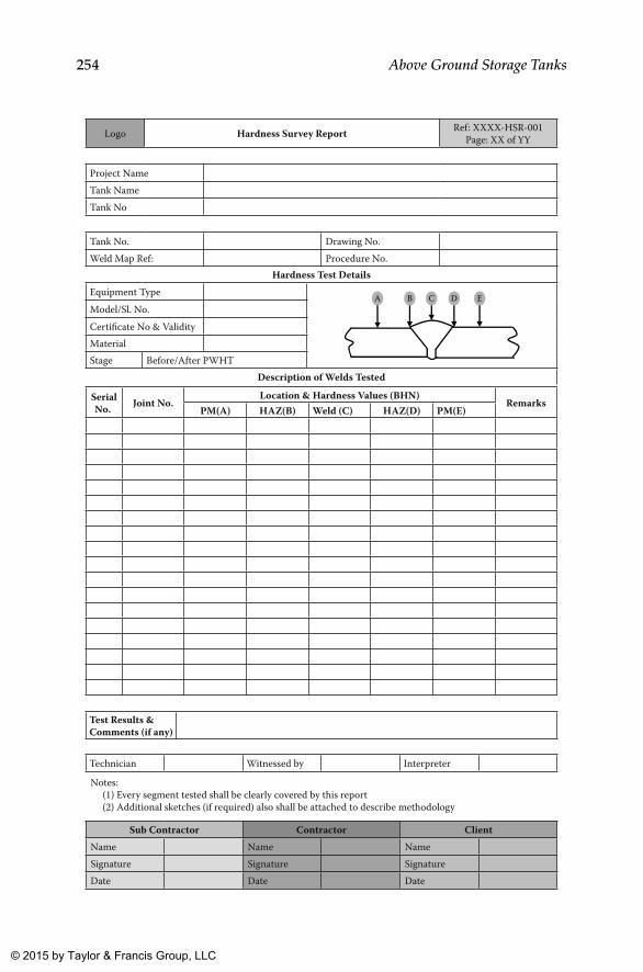
254 Above Ground Storage Tanks
Logo Hardness Survey Report Ref: XXXX-HSR-001Page: XX of YY
Project NameTank NameTank No
Tank No. Drawing No.Weld Map Ref: Procedure No.
Test Results & Comments (if any)
Technician Witnessed by Interpreter
Hardness Test DetailsEquipment Type A B C D EModel/Sl. No.Certificate No & ValidityMaterialStage Before/After PWHT
Description of Welds Tested
Joint No.Location & Hardness Values (BHN)
RemarksPM(A) HAZ(B) Weld (C) HAZ(D) PM(E)
Notes: (1) Every segment tested shall be clearly covered by this report (2) Additional sketches (if required) also shall be attached to describe methodology
Sub Contractor Contractor ClientName Name NameSignature Signature SignatureDate Date Date
SerialNo.
K22265_Book.indb 254 4/20/15 5:49 PM
© 2015 by Taylor & Francis Group, LLC
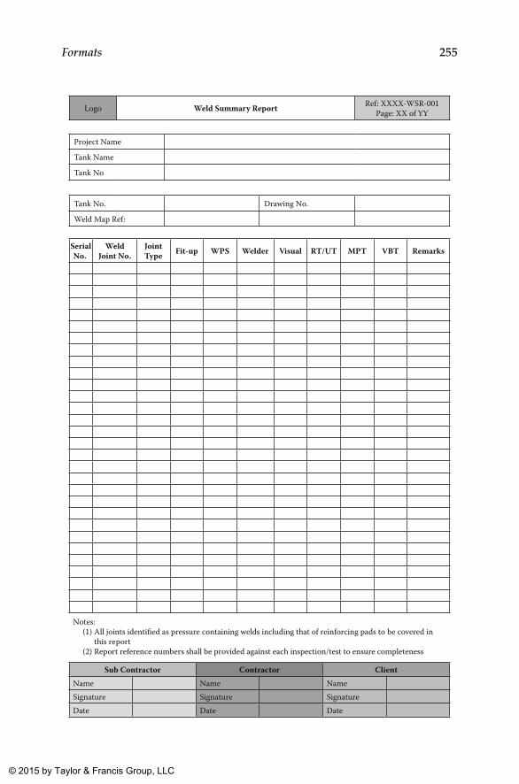
255Formats
Logo Weld Summary Report Ref: XXXX-WSR-001Page: XX of YY
Project Name
Tank Name
Tank No
Tank No. Drawing No.
Weld Map Ref:
Weld Joint No.
Joint Type Fit-up WPS Welder Visual RT/UT MPT VBT Remarks
Notes: (1) All joints identified as pressure containing welds including that of reinforcing pads to be covered in this report (2) Report reference numbers shall be provided against each inspection/test to ensure completeness
Sub Contractor Contractor ClientName Name NameSignature Signature SignatureDate Date Date
SerialNo.
K22265_Book.indb 255 4/20/15 5:49 PM
© 2015 by Taylor & Francis Group, LLC
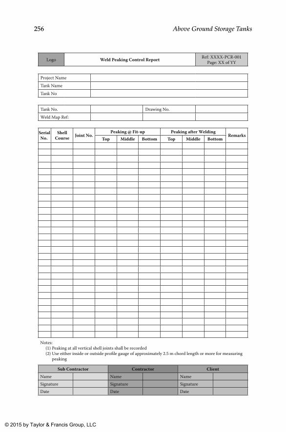
256 Above Ground Storage Tanks
Logo Weld Peaking Control Report Ref: XXXX-PCR-001Page: XX of YY
Project NameTank NameTank No
Tank No. Drawing No.Weld Map Ref:
Shell Course Joint No.
Peaking @ Fit-up Peaking after WeldingRemarks
Top Middle Bottom Top Middle Bottom
Notes: (1) Peaking at all vertical shell joints shall be recorded (2) Use either inside or outside profile gauge of approximately 2.5 m chord length or more for measuring peaking
Sub Contractor Contractor ClientName Name NameSignature Signature SignatureDate Date Date
SerialNo.
K22265_Book.indb 256 4/20/15 5:49 PM
© 2015 by Taylor & Francis Group, LLC
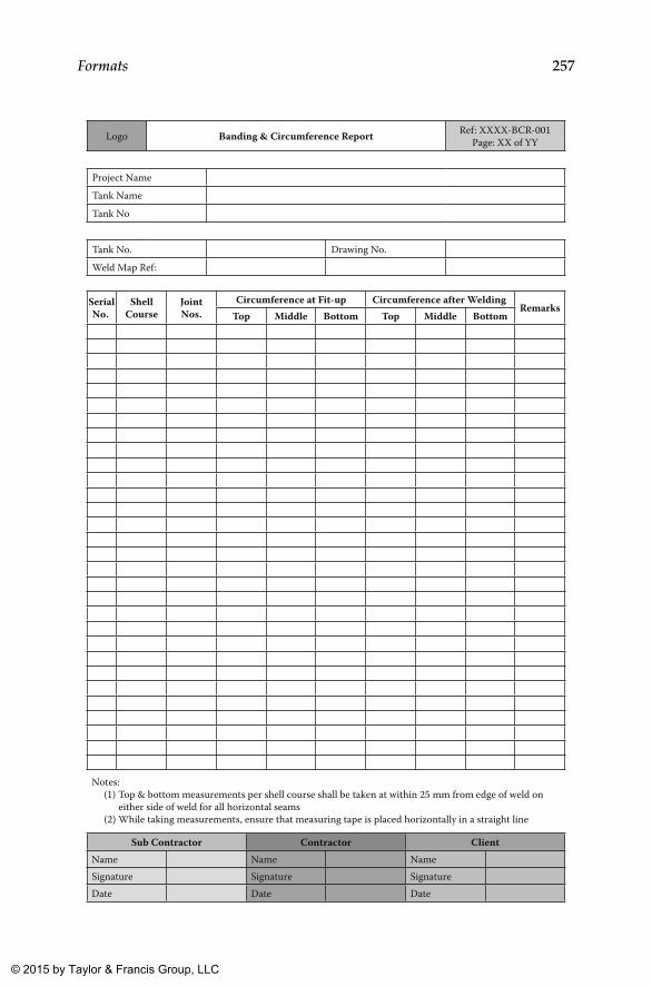
257Formats
Logo Banding & Circumference Report Ref: XXXX-BCR-001Page: XX of YY
Project NameTank NameTank No
Tank No. Drawing No.Weld Map Ref:
Shell Course
Joint Nos.
Circumference at Fit-up Circumference after WeldingRemarks
Top Middle Bottom Top Middle Bottom
Notes: (1) Top & bottom measurements per shell course shall be taken at within 25 mm from edge of weld on either side of weld for all horizontal seams (2) While taking measurements, ensure that measuring tape is placed horizontally in a straight line
Sub Contractor Contractor ClientName Name NameSignature Signature SignatureDate Date Date
SerialNo.
K22265_Book.indb 257 4/20/15 5:49 PM
© 2015 by Taylor & Francis Group, LLC
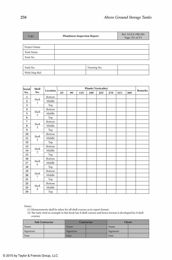
258 Above Ground Storage Tanks
Logo Plumbness Inspection Report Ref: XXXX-PIR-001Page: XX of YY
Project Name
Tank Name
Tank No
Tank No. Drawing No.
Weld Map Ref:
Shell No. Location
Plumb (Verticality)Remarks
45° 90° 135° 180° 225° 270° 315° 360°1
Shell1
Bottom2 Middle3 Top4
Shell2
Bottom5 Middle6 Top7
Shell3
Bottom8 Middle9 Top
10Shell
4
Bottom11 Middle12 Top13
Shell5
Bottom14 Middle15 Top16
Shell6
Bottom17 Middle18 Top19
Shell7
Bottom20 Middle21 Top22
Shell8
Bottom23 Middle24 Top
Notes: (1) Measurements shall be taken for all shell courses as in report format (2) �e tank cited as example in this book has 8 shell courses and hence format is developed for 8 shell courses
Sub Contractor Contractor ClientName Name NameSignature Signature SignatureDate Date Date
SerialNo.
K22265_Book.indb 258 4/20/15 5:49 PM
© 2015 by Taylor & Francis Group, LLC
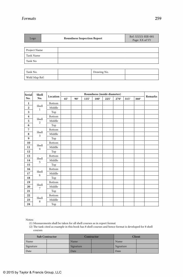
259Formats
Logo Roundness Inspection Report Ref: XXXX-RIR-001Page: XX of YY
Project Name
Tank Name
Tank No
Tank No. Drawing No.
Weld Map Ref:
Shell No. Location
Roundness (inside diameter)Remarks
45° 90° 135° 180° 225° 270° 315° 360°1
Shell1
Bottom2 Middle3 Top4
Shell2
Bottom5 Middle6 Top7
Shell3
Bottom8 Middle9 Top
10Shell
4
Bottom11 Middle12 Top13
Shell5
Bottom14 Middle15 Top16
Shell6
Bottom17 Middle18 Top19
Shell7
Bottom20 Middle21 Top22
Shell8
Bottom23 Middle24 Top
Notes: (1) Measurements shall be taken for all shell courses as in report format (2) �e tank cited as example in this book has 8 shell courses and hence format is developed for 8 shell courses
Sub Contractor Contractor ClientName Name NameSignature Signature SignatureDate Date Date
SerialNo.
K22265_Book.indb 259 4/20/15 5:49 PM
© 2015 by Taylor & Francis Group, LLC

260 Above Ground Storage Tanks
Logo Nozzles/Manways Inspection Report Ref: XXXX-NIR-001Page: XX of YY
Project Name
Tank Name
Tank No
Tank No. Drawing No.
Nozzle/Manway Identification Size
Elevation OrientationRemarks
Required Actual Required Actual
Notes: (1) To be prepared for all Nozzles and Manways (2) If required same format can be used for other attachments also
Sub Contractor Contractor ClientName Name NameSignature Signature SignatureDate Date Date
SerialNo.
K22265_Book.indb 260 4/20/15 5:49 PM
© 2015 by Taylor & Francis Group, LLC
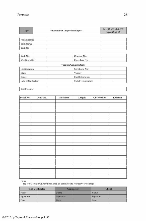
261Formats
Logo Vacuum Box Inspection Report Ref: XXXX-VBR-001Page: XX of YY
Project NameTank NameTank No
Tank No. Drawing No.Weld Map Ref: Procedure No.
Vacuum Gauge DetailsIdentification Certificate No.Make ValidityRange Bubble SolutionDate of Calibration Metal Temperature -
Test Pressure
Joint No. �ickness Length Observation Remarks
Note: (1) Welds joint numbers listed shall be correlated to respective weld maps
Sub Contractor Contractor ClientName Name NameSignature Signature SignatureDate Date Date
Serial No.
K22265_Book.indb 261 4/20/15 5:49 PM
© 2015 by Taylor & Francis Group, LLC
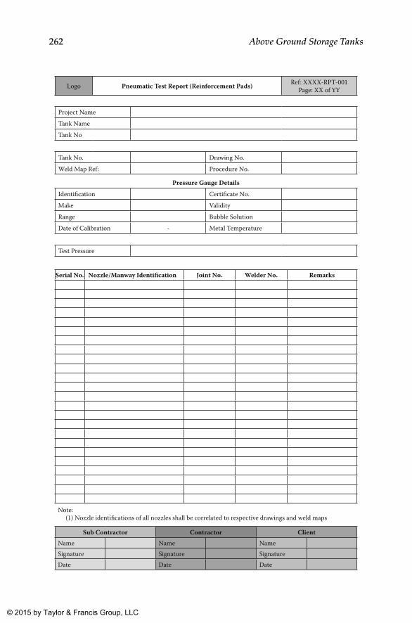
262 Above Ground Storage Tanks
Logo Pneumatic Test Report (Reinforcement Pads) Ref: XXXX-RPT-001Page: XX of YY
Project NameTank NameTank No
Tank No. Drawing No.Weld Map Ref: Procedure No.
Pressure Gauge DetailsIdentification Certificate No.Make ValidityRange Bubble SolutionDate of Calibration - Metal Temperature
Test Pressure
Nozzle/Manway Identification Joint No. Welder No. Remarks
Note: (1) Nozzle identifications of all nozzles shall be correlated to respective drawings and weld maps
Sub Contractor Contractor ClientName Name NameSignature Signature SignatureDate Date Date
Serial No.
K22265_Book.indb 262 4/20/15 5:49 PM
© 2015 by Taylor & Francis Group, LLC

263Formats
Logo Dimensional Inspection Report Ref: XXXX-DIR-001Page: XX of YY
Project Name
Tank Name
Tank No
Tank No. Drawing No.
Description of Dimension
Identification (if any)
DimensionRemarks
Required Actual
Note: (1) All salient dimensions shown in drawings shall be reported in this format
Sub Contractor Contractor ClientName Name NameSignature Signature SignatureDate Date Date
SerialNo.
K22265_Book.indb 263 4/20/15 5:49 PM
© 2015 by Taylor & Francis Group, LLC
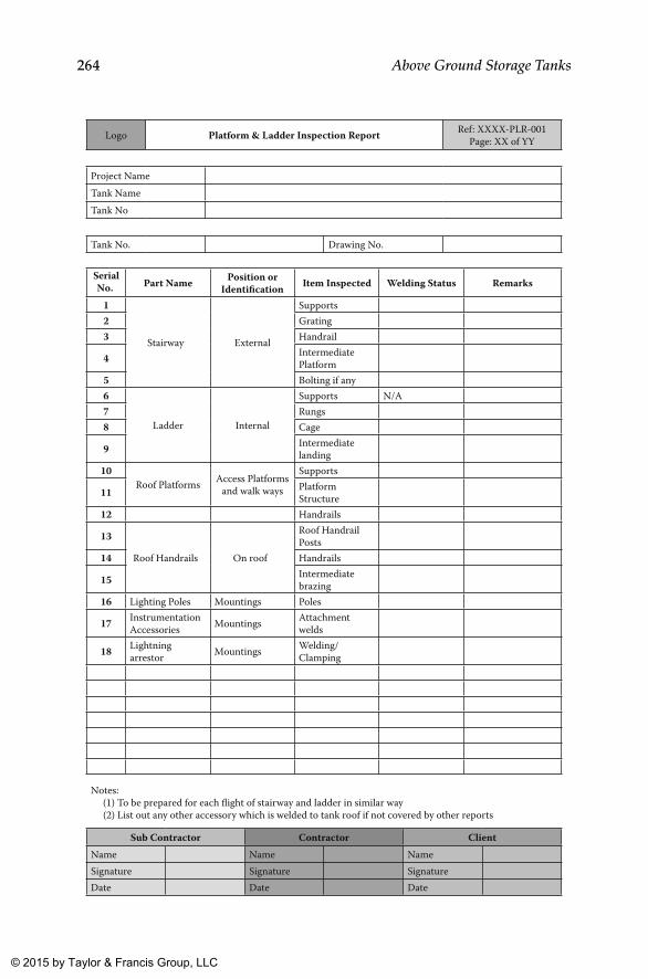
264 Above Ground Storage Tanks
Logo Platform & Ladder Inspection Report Ref: XXXX-PLR-001Page: XX of YY
Project NameTank NameTank No
Tank No. Drawing No.
Part Name Position or Identification Item Inspected Welding Status Remarks
1
Stairway External
Supports2 Grating3 Handrail
4 Intermediate Platform
5 Bolting if any6
Ladder Internal
Supports N/A7 Rungs8 Cage
9 Intermediate landing
10Roof Platforms Access Platforms
and walk ways
Supports
11 PlatformStructure
12 Handrails
13
Roof Handrails On roof
Roof Handrail Posts
14 Handrails
15 Intermediate brazing
16 Lighting Poles Mountings Poles
17 Instrumentation Accessories Mountings Attachment
welds
18 Lightningarrestor Mountings Welding/
Clamping
Notes: (1) To be prepared for each flight of stairway and ladder in similar way (2) List out any other accessory which is welded to tank roof if not covered by other reports
Sub Contractor Contractor ClientName Name NameSignature Signature SignatureDate Date Date
SerialNo.
K22265_Book.indb 264 4/20/15 5:49 PM
© 2015 by Taylor & Francis Group, LLC
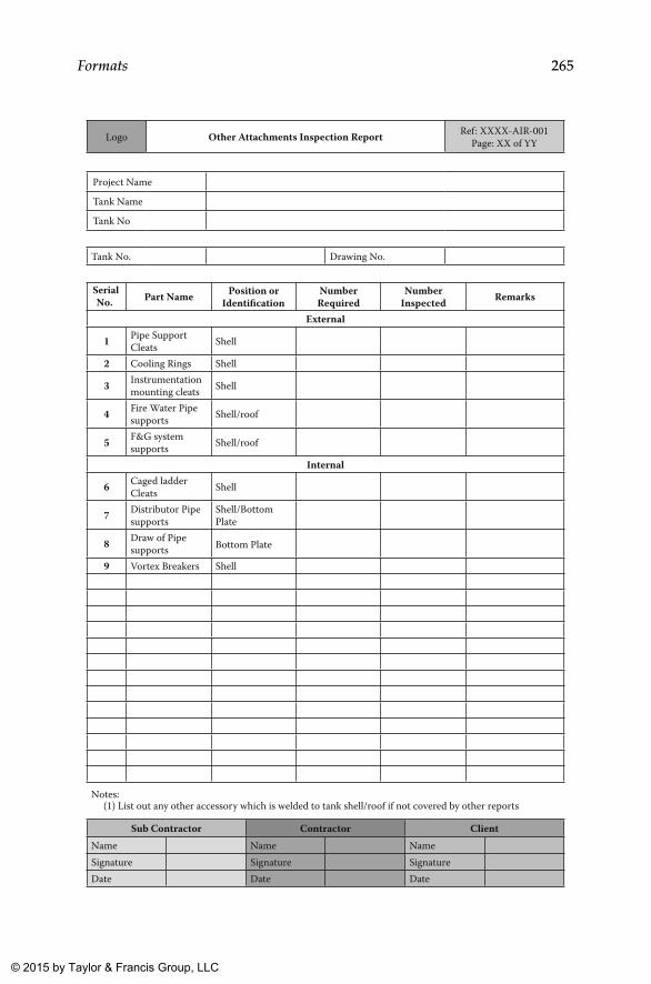
265Formats
Logo Other Attachments Inspection Report Ref: XXXX-AIR-001Page: XX of YY
Project Name
Tank Name
Tank No
Tank No. Drawing No.
Part Name Position or Identification
NumberRequired
NumberInspected Remarks
External
1 Pipe Support Cleats Shell
2 Cooling Rings Shell
3 Instrumentation mounting cleats Shell
4 Fire Water Pipe supports Shell/roof
5 F&G system supports Shell/roof
Bottom Plate
Internal
6 Caged ladder Cleats Shell
7 Distributor Pipe supports
Shell/Bottom Plate
8 Draw of Pipe supports
9 Vortex Breakers Shell
Notes: (1) List out any other accessory which is welded to tank shell/roof if not covered by other reports
Sub Contractor Contractor ClientName Name NameSignature Signature SignatureDate Date Date
SerialNo.
K22265_Book.indb 265 4/20/15 5:49 PM
© 2015 by Taylor & Francis Group, LLC
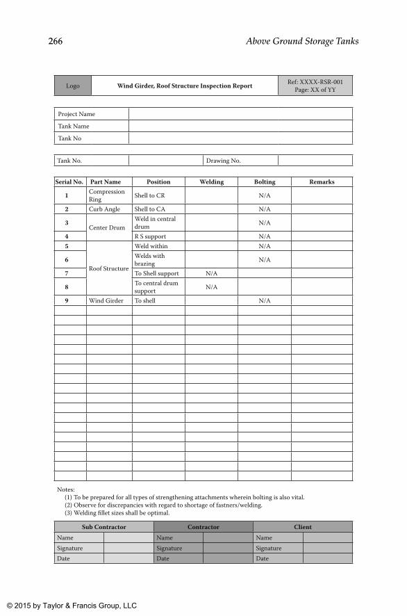
266 Above Ground Storage Tanks
Logo Wind Girder, Roof Structure Inspection Report Ref: XXXX-RSR-001Page: XX of YY
Project Name
Tank Name
Tank No
Tank No. Drawing No.
Part Name Position Welding Bolting Remarks
1 Compression Ring Shell to CR N/A
2 Curb Angle Shell to CA N/A
3Center Drum
Weld in central drum N/A
4 R S support N/A5
Roof Structure
Weld within N/A
6 Welds with brazing N/A
7 To Shell support N/A
8 To central drum support N/A
9 Wind Girder To shell N/A
Notes: (1) To be prepared for all types of strengthening attachments wherein bolting is also vital. (2) Observe for discrepancies with regard to shortage of fastners/welding. (3) Welding fillet sizes shall be optimal.
Sub Contractor Contractor ClientName Name NameSignature Signature SignatureDate Date Date
Serial No.
K22265_Book.indb 266 4/20/15 5:49 PM
© 2015 by Taylor & Francis Group, LLC
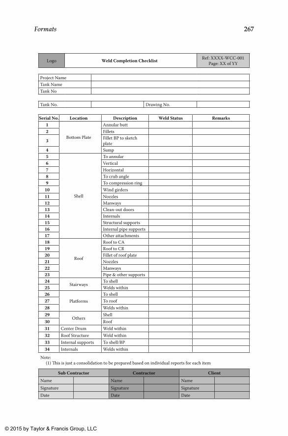
267Formats
Logo Weld Completion Checklist Ref: XXXX-WCC-001Page: XX of YY
Project NameTank NameTank No
Tank No. Drawing No.
Location Description Weld Status Remarks1
Bottom Plate
Annular butt2 Fillets
3 Fillet BP to sketch plate
4 Sump5
Shell
To annular6 Vertical7 Horizontal8 To crub angle9 To compression ring
10 Wind girders11 Nozzles12 Manways13 Clean-out doors14 Internals15 Structural supports16 Internal pipe supports17 Other attachments18
Roof
Roof to CA19 Roof to CR20 Fillet of roof plate21 Nozzles22 Manways23 Pipe & other supports24
StairwaysTo shell
25 Welds within26
PlatformsTo shell
27 To roof28 Welds within29
OthersShell
30 Roof31 Center Drum Weld within32 Roof Structure Weld within33 Internal supports To shell/BP34 Internals Welds within
Note: (1) �is is just a consolidation to be prepared based on individual reports for each item
Sub Contractor Contractor ClientName Name NameSignature Signature SignatureDate Date Date
Serial No.
K22265_Book.indb 267 4/20/15 5:49 PM
© 2015 by Taylor & Francis Group, LLC
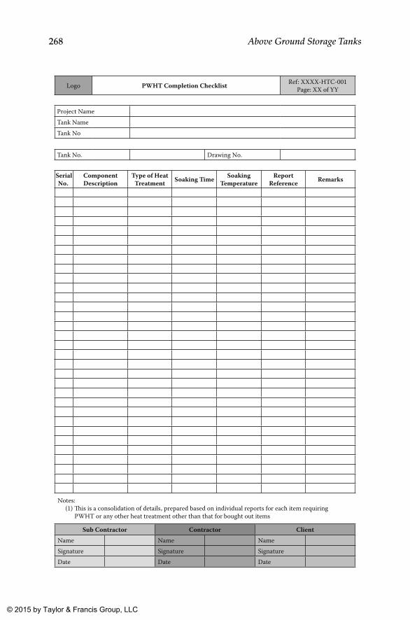
268 Above Ground Storage Tanks
Logo PWHT Completion Checklist Ref: XXXX-HTC-001Page: XX of YY
Project NameTank NameTank No
Tank No. Drawing No.
Component Description
Type of Heat Treatment Soaking Time Soaking
TemperatureReport
Reference Remarks
Notes: (1) �is is a consolidation of details, prepared based on individual reports for each item requiring PWHT or any other heat treatment other than that for bought out items
Sub Contractor Contractor ClientName Name NameSignature Signature SignatureDate Date Date
SerialNo.
K22265_Book.indb 268 4/20/15 5:49 PM
© 2015 by Taylor & Francis Group, LLC
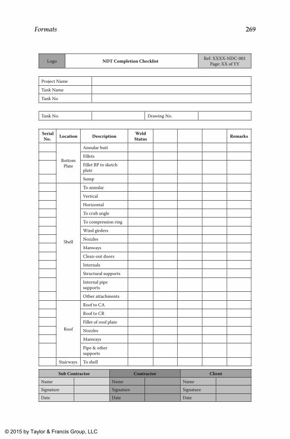
269Formats
Logo NDT Completion Checklist Ref: XXXX-NDC-001Page: XX of YY
Project Name
Tank Name
Tank No
Tank No. Drawing No.
Location Description Weld Status Remarks
Bottom Plate
Annular butt
Fillets
Fillet BP to sketch plate
Sump
Shell
To annular
Vertical
Horizontal
To crub angle
To compression ring
Wind girders
Nozzles
Manways
Clean-out doors
Internals
Structural supports
Internal pipesupports
Other attachments
Roof
Roof to CA
Roof to CR
Fillet of roof plate
Nozzles
Manways
Pipe & othersupports
Stairways To shell
Sub Contractor Contractor ClientName Name NameSignature Signature SignatureDate Date Date
SerialNo.
K22265_Book.indb 269 4/20/15 5:49 PM
© 2015 by Taylor & Francis Group, LLC
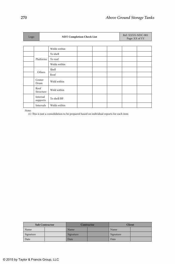
270 Above Ground Storage Tanks
Logo NDT Completion Check List Ref: XXXX-NDC-001Page: XX of YY
Welds within
Platforms
To shell
To roof
Welds within
OthersShell
Roof
Center Drum Weld within
Roof Structure Weld within
Internal supports To shell/BP
Internals Welds within
Note: (1) �is is just a consolidation to be prepared based on individual reports for each item
Sub Contractor Contractor ClientName Name NameSignature Signature SignatureDate Date Date
K22265_Book.indb 270 4/20/15 5:49 PM
© 2015 by Taylor & Francis Group, LLC
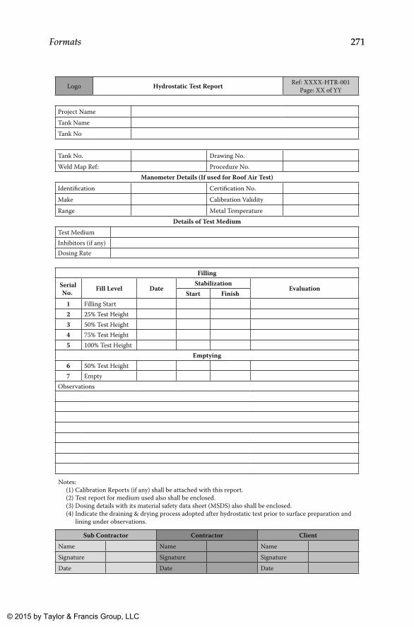
271Formats
Logo Hydrostatic Test Report Ref: XXXX-HTR-001Page: XX of YY
Project NameTank NameTank No
Tank No. Drawing No.Weld Map Ref: Procedure No.
Manometer Details (If used for Roof Air Test)Identification Certification No.Make Calibration ValidityRange Metal Temperature
Details of Test MediumTest MediumInhibitors (if any)Dosing Rate
Filling
Fill Level DateStabilization
EvaluationStart Finish
1 Filling Start2 25% Test Height3 50% Test Height4 75% Test Height5 100% Test Height
Emptying6 50% Test Height7 Empty
Observations
Notes: (1) Calibration Reports (if any) shall be attached with this report. (2) Test report for medium used also shall be enclosed. (3) Dosing details with its material safety data sheet (MSDS) also shall be enclosed. (4) Indicate the draining & drying process adopted after hydrostatic test prior to surface preparation and lining under observations.
Sub Contractor Contractor ClientName Name NameSignature Signature SignatureDate Date Date
SerialNo.
K22265_Book.indb 271 4/20/15 5:49 PM
© 2015 by Taylor & Francis Group, LLC
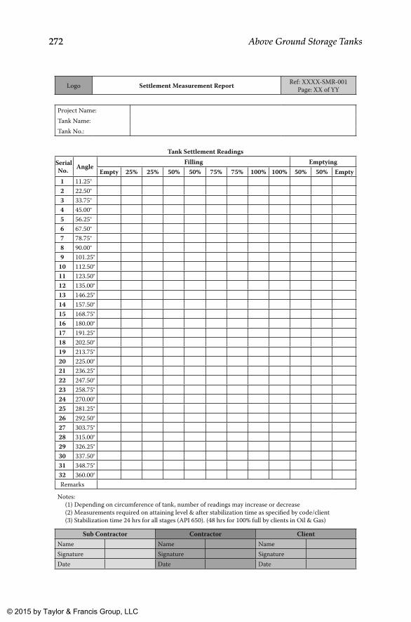
272 Above Ground Storage Tanks
Logo Settlement Measurement Report Ref: XXXX-SMR-001Page: XX of YY
Project Name:Tank Name:Tank No.:
Tank Settlement Readings
AngleFilling Emptying
Empty 25% 25% 50% 50% 75% 75% 100% 100% 50% 50% Empty1 11.25°2 22.50°3 33.75°4 45.00°5 56.25°6 67.50°7 78.75°8 90.00°9 101.25°
10 112.50°11 123.50°12 135.00°13 146.25°14 157.50°15 168.75°16 180.00°17 191.25°18 202.50°19 213.75°20 225.00°21 236.25°22 247.50°23 258.75°24 270.00°25 281.25°26 292.50°27 303.75°28 315.00°29 326.25°30 337.50°31 348.75°32 360.00°Remarks
Notes: (1) Depending on circumference of tank, number of readings may increase or decrease (2) Measurements required on attaining level & after stabilization time as specified by code/client (3) Stabilization time 24 hrs for all stages (API 650). (48 hrs for 100% full by clients in Oil & Gas)
Sub Contractor Contractor ClientName Name NameSignature Signature SignatureDate Date Date
SerialNo.
K22265_Book.indb 272 4/20/15 5:49 PM
© 2015 by Taylor & Francis Group, LLC
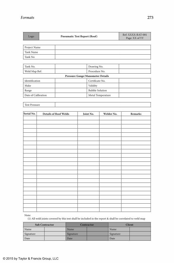
273Formats
Logo Pneumatic Test Report (Roof) Ref: XXXX-RAT-001Page: XX of YY
Project NameTank NameTank No
Tank No. Drawing No.Weld Map Ref: Procedure No.
Pressure Gauge/Manometer DetailsIdentification Certificate No.Make ValidityRange Bubble SolutionDate of Calibration Metal Temperature
Test Pressure
Details of Roof Welds Joint No. Welder No. Remarks
Note: (1) All weld joints covered by this test shall be included in the report & shall be correlated to weld map
Sub Contractor Contractor ClientName Name NameSignature Signature SignatureDate Date Date
Serial No.
K22265_Book.indb 273 4/20/15 5:49 PM
© 2015 by Taylor & Francis Group, LLC
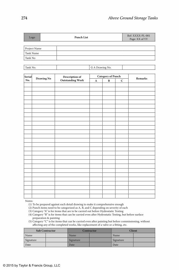
274 Above Ground Storage Tanks
Logo Punch List Ref: XXXX-PL-001Page: XX of YY
Project NameTank NameTank No
Tank No. G A Drawing No.
Drawing No Description ofOutstanding Work
Category of PunchRemarks
A B C
Notes: (1) To be prepared against each detail drawing to make it comprehensive enough (2) Punch items need to be categorized as A, B, and C depending on severity of each (3) Category “A” is for items that are to be carried out before Hydrostatic Testing (4) Category “B” is for items that can be carried even after Hydrostatic Testing, but before surface preparation & painting (5) Category “C” is for items that can be carried even after painting but before commissioning, without affecting any of the completed works, like replacement of a valve or a fitting, etc.
Sub Contractor Contractor ClientName Name NameSignature Signature SignatureDate Date Date
SerialNo.
K22265_Book.indb 274 4/20/15 5:49 PM
© 2015 by Taylor & Francis Group, LLC
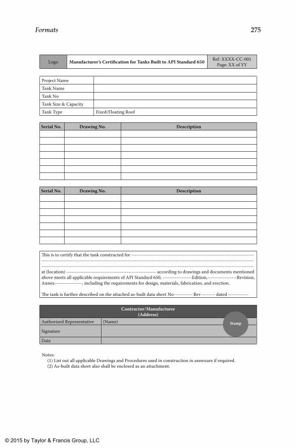
275Formats
Logo Manufacturer’s Certification for Tanks Built to API Standard 650 Ref: XXXX-CC-001Page: XX of YY
Project NameTank NameTank NoTank Size & CapacityTank Type Fixed/Floating Roof
Drawing No. Description
Drawing No. Description
Contractor/Manufacturer(Address)
Authorized Representative (Name)
Signature
Date
�is is to certify that the tank constructed for -----------------------------------------------------------------------------------------------------------------------------------------------------------------------------------------------------------------------------------------------------------------------------------------------------------------------------at (location) ---------------------------------------------------- according to drawings and documents mentioned above meets all applicable requirements of API Standard 650, -----------------Edition,-----------------Revision, Annex----------------, including the requirements for design, materials, fabrication, and erection.
�e tank is further described on the attached as-built data sheet No----------- Rev -------- dated ------------
Notes: (1) List out all applicable Drawings and Procedures used in construction in annexure if required. (2) As-built data sheet also shall be enclosed as an attachment.
Stamp
Serial No.
Serial No.
K22265_Book.indb 275 4/20/15 5:49 PM
© 2015 by Taylor & Francis Group, LLC
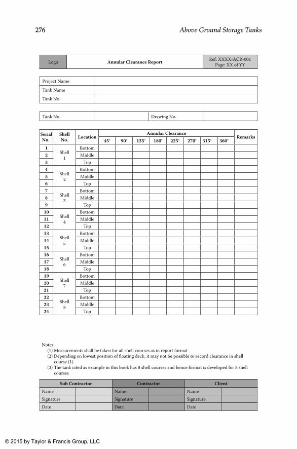
276 Above Ground Storage Tanks
Logo Annular Clearance Report Ref: XXXX-ACR-001Page: XX of YY
Project Name
Tank Name
Tank No
Tank No. Drawing No.
Shell No. Location
Annular ClearanceRemarks
45° 90° 135° 180° 225° 270° 315° 360°1
Shell1
Bottom2 Middle3 Top4
Shell2
Bottom5 Middle6 Top7
Shell3
Bottom8 Middle9 Top
10Shell
4
Bottom11 Middle12 Top13
Shell5
Bottom14 Middle15 Top16
Shell6
Bottom17 Middle18 Top19
Shell7
Bottom20 Middle21 Top22
Shell8
Bottom23 Middle24 Top
Notes: (1) Measurements shall be taken for all shell courses as in report format (2) Depending on lowest position of floating deck, it may not be possible to record clearance in shell course (1) (3) �e tank cited as example in this book has 8 shell courses and hence format is developed for 8 shell courses
Sub Contractor Contractor ClientName Name NameSignature Signature SignatureDate Date Date
SerialNo.
K22265_Book.indb 276 4/20/15 5:49 PM
© 2015 by Taylor & Francis Group, LLC

277Formats
Logo Weld Visual Inspection Report (Floating Deck) Ref: XXXX-VFR-001Page: XX of YY
Project NameTank NameTank No
Tank No. Drawing No.Weld Map Ref:
Drawing No./Description Joint No.
Joint Type
Welding Process
WPS No. Remarks
Notes: (1) To be prepared for all joints identified on floating deck including that of openings passing through pontoon or deck plate or compartments (in double deck type) (2) Welds of stiffeners and pads also shall be included in this report as a summary (if not listed in detail)
Sub Contractor Contractor ClientName Name NameSignature Signature SignatureDate Date Date
SerialNo.
K22265_Book.indb 277 4/20/15 5:49 PM
© 2015 by Taylor & Francis Group, LLC
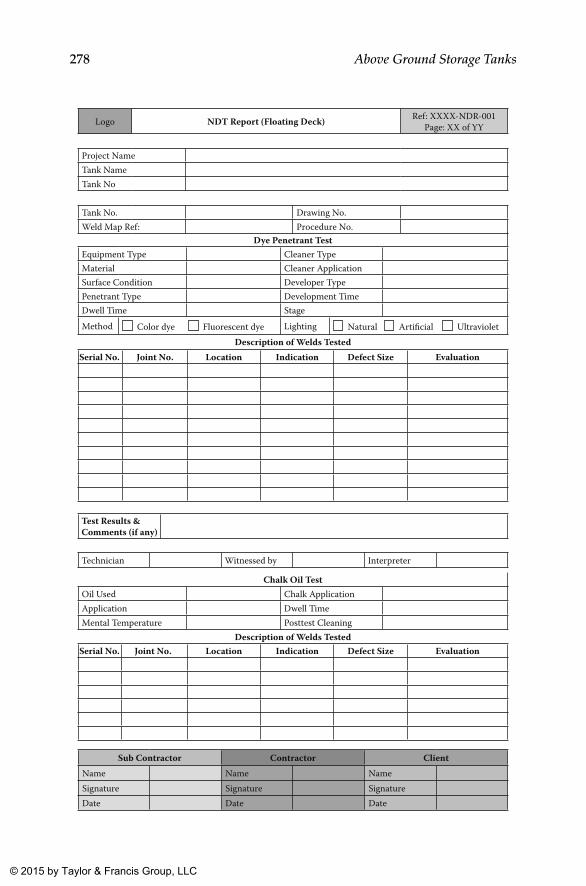
278 Above Ground Storage Tanks
Logo NDT Report (Floating Deck) Ref: XXXX-NDR-001Page: XX of YY
Project NameTank NameTank No
Tank No. Drawing No.Weld Map Ref: Procedure No.
Test Results & Comments (if any)
Technician Witnessed by Interpreter
Dye Penetrant TestEquipment Type Cleaner TypeMaterial Cleaner ApplicationSurface Condition Developer TypePenetrant Type Development TimeDwell Time StageMethod Color dye Fluorescent dye Lighting Natural Artificial Ultraviolet
Description of Welds Tested
Chalk Oil TestOil Used Chalk ApplicationApplication Dwell TimeMental Temperature Posttest Cleaning
Description of Welds Tested
Joint No. Location Indication Defect Size Evaluation
Joint No. Location Indication Defect Size Evaluation
Sub Contractor Contractor ClientName Name NameSignature Signature SignatureDate Date Date
Serial No.
Serial No.
K22265_Book.indb 278 4/20/15 5:49 PM
© 2015 by Taylor & Francis Group, LLC
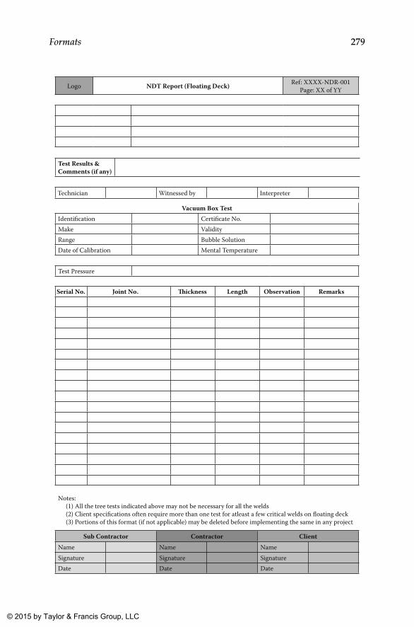
279Formats
Logo NDT Report (Floating Deck) Ref: XXXX-NDR-001Page: XX of YY
Test Results & Comments (if any)
Technician Witnessed by Interpreter
Vacuum Box TestIdentification Certificate No.Make ValidityRange Bubble SolutionDate of Calibration Mental Temperature
Test Pressure
Joint No. �ickness Length Observation Remarks
Notes: (1) All the tree tests indicated above may not be necessary for all the welds (2) Client specifications often require more than one test for atleast a few critical welds on floating deck (3) Portions of this format (if not applicable) may be deleted before implementing the same in any project
Sub Contractor Contractor ClientName Name NameSignature Signature SignatureDate Date Date
Serial No.
K22265_Book.indb 279 4/20/15 5:49 PM
© 2015 by Taylor & Francis Group, LLC
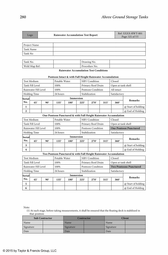
280 Above Ground Storage Tanks
Logo Rainwater Accumulation Test Report Ref: XXXX-RWT-001Page: XX of YY
Project NameTank NameTank No
Tank No. Drawing No.Weld Map Ref: Procedure No.
Rainwater Accumulation Test Conditions
Pontoon Intact & with Full Height Rainwater AccumulationTest Medium Potable Water NRV Condition ClosedTank Fill Level 100% Primary Roof Drain Open at tank shellRainwater Fill Level 100% Pontoon Condition All intactHolding Time 24 hours Stabilization Satisfactory
One Pontoon Punctured & with Full Height Rainwater AccumulationTest Medium Potable Water NRV Condition ClosedTank Fill Level 100% Primary Roof Drain Open at tank shellRainwater Fill Level 100% Pontoon Condition One Pontoon PuncturedHolding Time 24 hours Stabilization Satisfactory
Two Pontoon Punctured & with Full Height Rainwater AccumulationTest Medium Potable Water NRV Condition ClosedTank Fill Level 100% Primary Roof Drain Open at tank shellRainwater Fill Level 100% Pontoon Condition Two Pontoons PuncturedHolding Time 24 hours Stabilization Satisfactory
Note: (1) At each stage, before taking measurements, it shall be ensured that the floating deck is stabilized in that position
Sub Contractor Contractor ClientName Name NameSignature Signature SignatureDate Date Date
ImmersionRemarks
45° 90° 135° 180° 225° 270° 315° 360°1 @ Start of holding2 @ End of Holding
ImmersionRemarks
45° 90° 135° 180° 225° 270° 315° 360°3 @ Start of holding4 @ End of Holding
ImmersionRemarks
45° 90° 135° 180° 225° 270° 315° 360°5 @ Start of holding6 @ End of Holding
SerialNo.
SerialNo.
SerialNo.
K22265_Book.indb 280 4/20/15 5:49 PM
© 2015 by Taylor & Francis Group, LLC
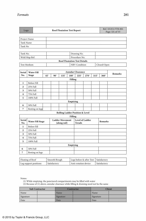
281Formats
Logo Roof Floatation Test Report Ref: XXXX-FTR-001Page: XX of YY
Project NameTank NameTank No
Tank No. Drawing No.Weld Map Ref: Procedure No.
Roof Floatation Test DetailsTest Medium NRV Condition Closed/Open
Floating of Roof Smooth/Rough Legs before & after Test SatisfactoryLeg support positions Satisfactory Anti-rotation device Satisfactory
Water Fill Stage
Annular ClearanceRemarks
45° 90° 135° 180° 225° 270° 315° 360°Filling
1 Before Fill2 25% Full3 50% Full4 75% Full5 100% Full
Emptying6 50% Full7 Resting on legs
Rolling Ladder Position & LevelFilling
Water Fill Stage Ladder Movement (along rail)
Level of Ladder Treads Remarks
1 Before Fill2 25% Full3 50% Full4 75% Full5 100% Full
Emptying6 50% Full7 Resting on legs
Notes: (1) While emptying, the punctured compartments may be filled with water (2) Because of (1) above, annular clearnace while filling & draining need not be the same
Sub Contractor Contractor ClientName Name NameSignature Signature SignatureDate Date Date
SerialNo.
SerialNo.
K22265_Book.indb 281 4/20/15 5:49 PM
© 2015 by Taylor & Francis Group, LLC
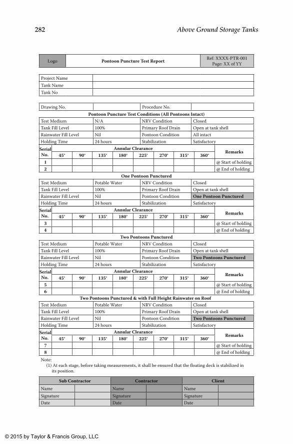
282 Above Ground Storage Tanks
Logo Pontoon Puncture Test Report Ref: XXXX-PTR-001Page: XX of YY
Project NameTank NameTank No
Drawing No. Procedure No.Pontoon Puncture Test Conditions (All Pontoons Intact)
Test Medium N/A NRV Condition ClosedTank Fill Level 100% Primary Roof Drain Open at tank shellRainwater Fill Level Nil Pontoon Condition All intactHolding Time 24 hours Stabilization Satisfactory
One Pontoon PuncturedTest Medium Potable Water NRV Condition ClosedTank Fill Level 100% Primary Roof Drain Open at tank shellRainwater Fill Level Nil Pontoon Condition One Pontoon PuncturedHolding Time 24 hours Stabilization Satisfactory
Two Pontoons PuncturedTest Medium Potable Water NRV Condition ClosedTank Fill Level 100% Primary Roof Drain Open at tank shellRainwater Fill Level Nil Pontoon Condition Two Pontoons PuncturedHolding Time 24 hours Stabilization Satisfactory
Two Pontoons Punctured & with Full Height Rainwater on RoofTest Medium Potable Water NRV Condition ClosedTank Fill Level 100% Primary Roof Drain Open at tank shellRainwater Fill Level Nil Pontoon Condition Two Pontoons PuncturedHolding Time 24 hours Stabilization Satisfactory
Note: (1) At each stage, before taking measurements, it shall be ensured that the floating deck is stabilized in its position.
Sub Contractor Contractor ClientName Name NameSignature Signature SignatureDate Date Date
Annular ClearanceRemarks
45° 90° 135° 180° 225° 270° 315° 360°1 @ Start of holding2 @ End of holding
Annular ClearanceRemarks
45° 90° 135° 180° 225° 270° 315° 360°3 @ Start of holding4 @ End of holding
Annular ClearanceRemarks
45° 90° 135° 180° 225° 270° 315° 360°5 @ Start of holding6 @ End of holding
Annular ClearanceRemarks
45° 90° 135° 180° 225° 270° 315° 360°7 @ Start of holding8 @ End of holding
SerialNo.
SerialNo.
SerialNo.
SerialNo.
K22265_Book.indb 282 4/20/15 5:49 PM
© 2015 by Taylor & Francis Group, LLC
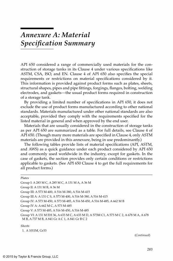
283
Annexure A: Material Specification Summary
API 650 considered a range of commercially used materials for the con-struction of storage tanks in its Clause 4 under various specifications like ASTM, CSA, ISO, and EN. Clause 4 of API 650 also specifies the special requirements or restrictions on material specifications considered by it. This information is provided against product forms such as plates, sheets, structural shapes, pipes and pipe fittings, forgings, flanges, bolting, welding electrodes, and gaskets—the usual product forms required in construction of a storage tank.
By providing a limited number of specifications in API 650, it does not exclude the use of product forms manufactured according to other national standards. Materials manufactured under other national standards are also acceptable, provided they comply with the requirements specified for the listed material in general and when approved by the end user.
Materials that are usually considered in the construction of storage tanks as per API 650 are summarized as a table. For full details, see Clause 4 of API 650. (Though many more materials are specified in Clause 4, only ASTM materials are provided in this annexure, being in use predominantly.)
The following tables provide lists of material specifications (API, ASTM, and AWS) as a quick guidance under each product considered by API 650 and commonly used worldwide in the industry, except for gaskets. In the case of gaskets, the section provides only certain conditions or restrictions applicable to gaskets. (See API 650 Clause 4 to get the full requirements for all product forms.)
PlatesGroup I: A 283 M C, A 285 M C, A 131 M A, A 36 MGroup II: A 131 M B, A 36 MGroup III: A 573 M-400, A 516 M-380, A 516 M-415Group III A: A 131 C S, A 573 M-400, A 516 M-380, A 516 M-415Group IV: A 573 M-450, A 573 M-485, A 516 M-450, A 516 M-485, A 662 M BGroup IV A: A 662 M C, A 573 M-485Group V: A 573 M-485, A 516 M-450, A 516 M-485Group VI: A 131 M EH 36, A 633 M C, A 633 M D, A 573M C1, A 573 M C 2, A 678 M A, A 678 M B, A 737 M B, A 841 Gr A C 1, A 841 Gr B C 2
Sheets 1. A 1011M, Gr33
(Continued)
K22265_Book.indb 283 4/20/15 5:49 PM
© 2015 by Taylor & Francis Group, LLC
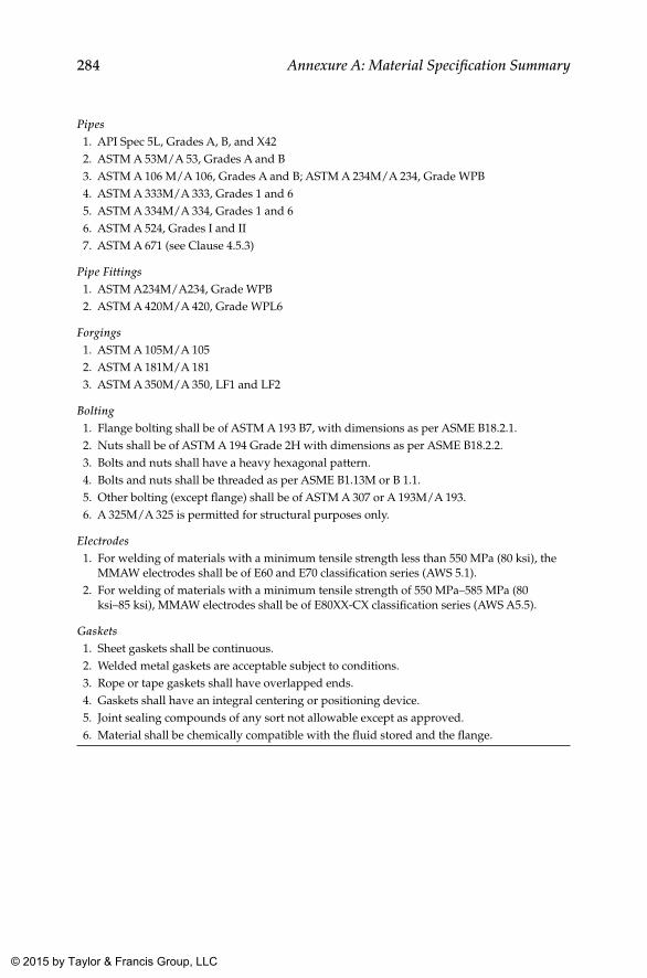
284 Annexure A: Material Specification Summary
Pipes 1. API Spec 5L, Grades A, B, and X42 2. ASTM A 53M/A 53, Grades A and B 3. ASTM A 106 M/A 106, Grades A and B; ASTM A 234M/A 234, Grade WPB 4. ASTM A 333M/A 333, Grades 1 and 6 5. ASTM A 334M/A 334, Grades 1 and 6 6. ASTM A 524, Grades I and II 7. ASTM A 671 (see Clause 4.5.3)
Pipe Fittings 1. ASTM A234M/A234, Grade WPB 2. ASTM A 420M/A 420, Grade WPL6
Forgings 1. ASTM A 105M/A 105 2. ASTM A 181M/A 181 3. ASTM A 350M/A 350, LF1 and LF2
Bolting 1. Flange bolting shall be of ASTM A 193 B7, with dimensions as per ASME B18.2.1. 2. Nuts shall be of ASTM A 194 Grade 2H with dimensions as per ASME B18.2.2. 3. Bolts and nuts shall have a heavy hexagonal pattern. 4. Bolts and nuts shall be threaded as per ASME B1.13M or B 1.1. 5. Other bolting (except flange) shall be of ASTM A 307 or A 193M/A 193. 6. A 325M/A 325 is permitted for structural purposes only.
Electrodes 1. For welding of materials with a minimum tensile strength less than 550 MPa (80 ksi), the
MMAW electrodes shall be of E60 and E70 classification series (AWS 5.1). 2. For welding of materials with a minimum tensile strength of 550 MPa–585 MPa (80
ksi–85 ksi), MMAW electrodes shall be of E80XX-CX classification series (AWS A5.5).
Gaskets 1. Sheet gaskets shall be continuous. 2. Welded metal gaskets are acceptable subject to conditions. 3. Rope or tape gaskets shall have overlapped ends. 4. Gaskets shall have an integral centering or positioning device. 5. Joint sealing compounds of any sort not allowable except as approved. 6. Material shall be chemically compatible with the fluid stored and the flange.
K22265_Book.indb 284 4/20/15 5:49 PM
© 2015 by Taylor & Francis Group, LLC
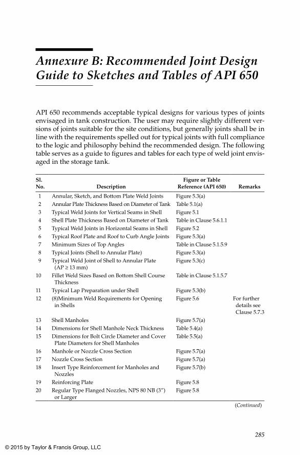
285
Annexure B: Recommended Joint Design Guide to Sketches and Tables of API 650
API 650 recommends acceptable typical designs for various types of joints envisaged in tank construction. The user may require slightly different ver-sions of joints suitable for the site conditions, but generally joints shall be in line with the requirements spelled out for typical joints with full compliance to the logic and philosophy behind the recommended design. The following table serves as a guide to figures and tables for each type of weld joint envis-aged in the storage tank.
Sl. No. Description
Figure or Table Reference (API 650) Remarks
1 Annular, Sketch, and Bottom Plate Weld Joints Figure 5.3(a) 2 Annular Plate Thickness Based on Diameter of Tank Table 5.1(a) 3 Typical Weld Joints for Vertical Seams in Shell Figure 5.1 4 Shell Plate Thickness Based on Diameter of Tank Table in Clause 5.6.1.1 5 Typical Weld Joints in Horizontal Seams in Shell Figure 5.2 6 Typical Roof Plate and Roof to Curb Angle Joints Figure 5.3(a) 7 Minimum Sizes of Top Angles Table in Clause 5.1.5.9 8 Typical Joints (Shell to Annular Plate) Figure 5.3(a) 9 Typical Weld Joint of Shell to Annular Plate
(AP ≥ 13 mm)Figure 5.3(c)
10 Fillet Weld Sizes Based on Bottom Shell Course Thickness
Table in Clause 5.1.5.7
11 Typical Lap Preparation under Shell Figure 5.3(b)12 (8)Minimum Weld Requirements for Opening
in ShellsFigure 5.6 For further
details see Clause 5.7.3
13 Shell Manholes Figure 5.7(a)14 Dimensions for Shell Manhole Neck Thickness Table 5.4(a)15 Dimensions for Bolt Circle Diameter and Cover
Plate Diameters for Shell ManholesTable 5.5(a)
16 Manhole or Nozzle Cross Section Figure 5.7(a)17 Nozzle Cross Section Figure 5.7(a)18 Insert Type Reinforcement for Manholes and
NozzlesFigure 5.7(b)
19 Reinforcing Plate Figure 5.820 Regular Type Flanged Nozzles, NPS 80 NB (3”)
or LargerFigure 5.8
(Continued)
K22265_Book.indb 285 4/20/15 5:49 PM
© 2015 by Taylor & Francis Group, LLC
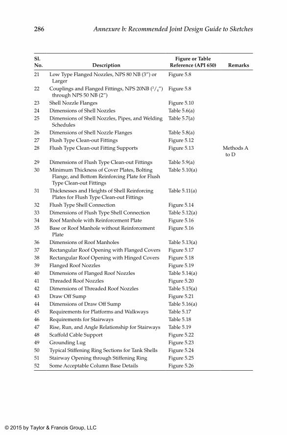
286 Annexure b: Recommended Joint Design Guide to Sketches
Sl. No. Description
Figure or Table Reference (API 650) Remarks
21 Low Type Flanged Nozzles, NPS 80 NB (3”) or Larger
Figure 5.8
22 Couplings and Flanged Fittings, NPS 20NB (3/4”) through NPS 50 NB (2”)
Figure 5.8
23 Shell Nozzle Flanges Figure 5.1024 Dimensions of Shell Nozzles Table 5.6(a)25 Dimensions of Shell Nozzles, Pipes, and Welding
SchedulesTable 5.7(a)
26 Dimensions of Shell Nozzle Flanges Table 5.8(a)27 Flush Type Clean-out Fittings Figure 5.1228 Flush Type Clean-out Fitting Supports Figure 5.13 Methods A
to D29 Dimensions of Flush Type Clean-out Fittings Table 5.9(a)30 Minimum Thickness of Cover Plates, Bolting
Flange, and Bottom Reinforcing Plate for Flush Type Clean-out Fittings
Table 5.10(a)
31 Thicknesses and Heights of Shell Reinforcing Plates for Flush Type Clean-out Fittings
Table 5.11(a)
32 Flush Type Shell Connection Figure 5.1433 Dimensions of Flush Type Shell Connection Table 5.12(a)34 Roof Manhole with Reinforcement Plate Figure 5.1635 Base or Roof Manhole without Reinforcement
Plate Figure 5.16
36 Dimensions of Roof Manholes Table 5.13(a)37 Rectangular Roof Opening with Flanged Covers Figure 5.1738 Rectangular Roof Opening with Hinged Covers Figure 5.1839 Flanged Roof Nozzles Figure 5.1940 Dimensions of Flanged Roof Nozzles Table 5.14(a)41 Threaded Roof Nozzles Figure 5.2042 Dimensions of Threaded Roof Nozzles Table 5.15(a)43 Draw Off Sump Figure 5.2144 Dimensions of Draw Off Sump Table 5.16(a)45 Requirements for Platforms and Walkways Table 5.1746 Requirements for Stairways Table 5.1847 Rise, Run, and Angle Relationship for Stairways Table 5.1948 Scaffold Cable Support Figure 5.2249 Grounding Lug Figure 5.2350 Typical Stiffening Ring Sections for Tank Shells Figure 5.2451 Stairway Opening through Stiffening Ring Figure 5.2552 Some Acceptable Column Base Details Figure 5.26
K22265_Book.indb 286 4/20/15 5:49 PM
© 2015 by Taylor & Francis Group, LLC
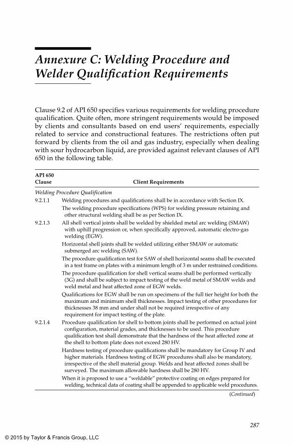
287
Annexure C: Welding Procedure and Welder Qualification Requirements
Clause 9.2 of API 650 specifies various requirements for welding procedure qualification. Quite often, more stringent requirements would be imposed by clients and consultants based on end users’ requirements, especially related to service and constructional features. The restrictions often put forward by clients from the oil and gas industry, especially when dealing with sour hydrocarbon liquid, are provided against relevant clauses of API 650 in the following table.
API 650 Clause Client Requirements
Welding Procedure Qualification9.2.1.1 Welding procedures and qualifications shall be in accordance with Section IX.
The welding procedure specifications (WPS) for welding pressure retaining and other structural welding shall be as per Section IX.
9.2.1.3 All shell vertical joints shall be welded by shielded metal arc welding (SMAW) with uphill progression or, when specifically approved, automatic electro-gas welding (EGW).
Horizontal shell joints shall be welded utilizing either SMAW or automatic submerged arc welding (SAW).
The procedure qualification test for SAW of shell horizontal seams shall be executed in a test frame on plates with a minimum length of 3 m under restrained conditions.
The procedure qualification for shell vertical seams shall be performed vertically (3G) and shall be subject to impact testing of the weld metal of SMAW welds and weld metal and heat affected zone of EGW welds.
Qualifications for EGW shall be run on specimens of the full tier height for both the maximum and minimum shell thicknesses. Impact testing of other procedures for thicknesses 38 mm and under shall not be required irrespective of any requirement for impact testing of the plate.
9.2.1.4 Procedure qualification for shell to bottom joints shall be performed on actual joint configuration, material grades, and thicknesses to be used. This procedure qualification test shall demonstrate that the hardness of the heat affected zone at the shell to bottom plate does not exceed 280 HV.
Hardness testing of procedure qualifications shall be mandatory for Group IV and higher materials. Hardness testing of EGW procedures shall also be mandatory, irrespective of the shell material group. Welds and heat affected zones shall be surveyed. The maximum allowable hardness shall be 280 HV.
When it is proposed to use a “weldable” protective coating on edges prepared for welding, technical data of coating shall be appended to applicable weld procedures.
(Continued)
K22265_Book.indb 287 4/20/15 5:49 PM
© 2015 by Taylor & Francis Group, LLC
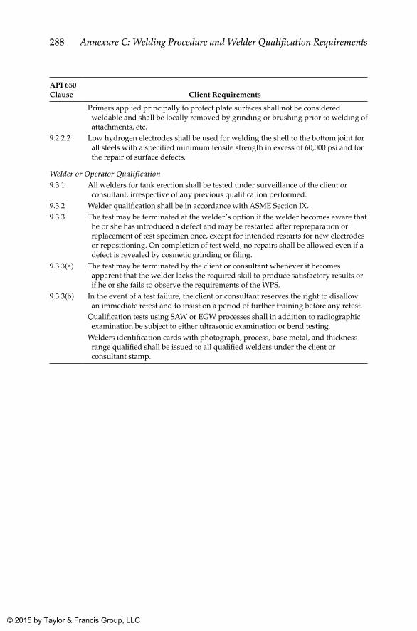
288 Annexure C: Welding Procedure and Welder Qualification Requirements
API 650 Clause Client Requirements
Primers applied principally to protect plate surfaces shall not be considered weldable and shall be locally removed by grinding or brushing prior to welding of attachments, etc.
9.2.2.2 Low hydrogen electrodes shall be used for welding the shell to the bottom joint for all steels with a specified minimum tensile strength in excess of 60,000 psi and for the repair of surface defects.
Welder or Operator Qualification9.3.1 All welders for tank erection shall be tested under surveillance of the client or
consultant, irrespective of any previous qualification performed.9.3.2 Welder qualification shall be in accordance with ASME Section IX.9.3.3 The test may be terminated at the welder’s option if the welder becomes aware that
he or she has introduced a defect and may be restarted after repreparation or replacement of test specimen once, except for intended restarts for new electrodes or repositioning. On completion of test weld, no repairs shall be allowed even if a defect is revealed by cosmetic grinding or filing.
9.3.3(a) The test may be terminated by the client or consultant whenever it becomes apparent that the welder lacks the required skill to produce satisfactory results or if he or she fails to observe the requirements of the WPS.
9.3.3(b) In the event of a test failure, the client or consultant reserves the right to disallow an immediate retest and to insist on a period of further training before any retest.
Qualification tests using SAW or EGW processes shall in addition to radiographic examination be subject to either ultrasonic examination or bend testing.
Welders identification cards with photograph, process, base metal, and thickness range qualified shall be issued to all qualified welders under the client or consultant stamp.
K22265_Book.indb 288 4/20/15 5:49 PM
© 2015 by Taylor & Francis Group, LLC
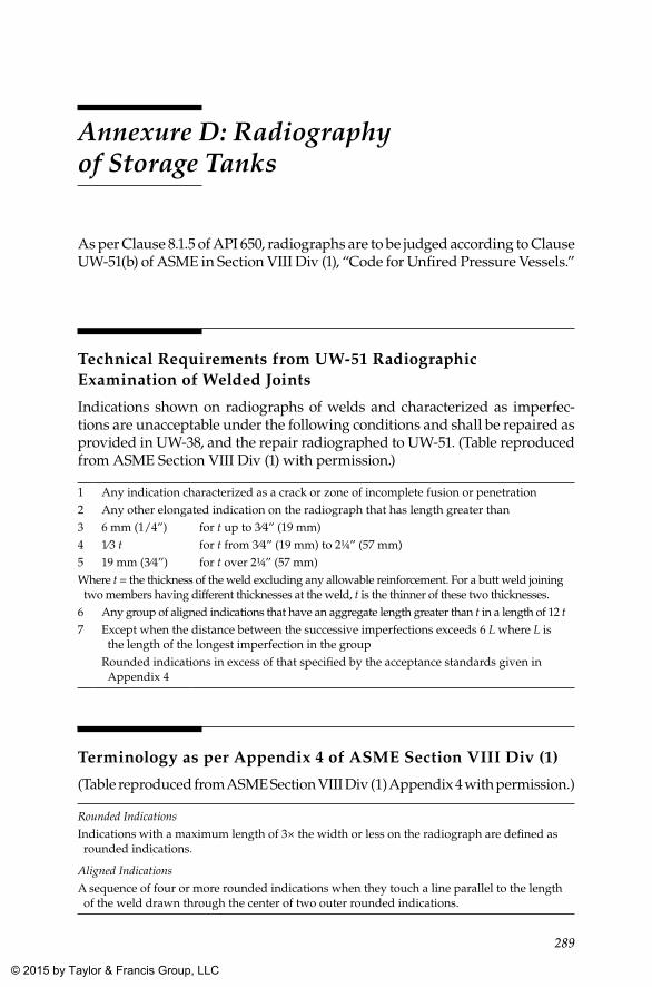
289
Annexure D: Radiography of Storage Tanks
As per Clause 8.1.5 of API 650, radiographs are to be judged according to Clause UW-51(b) of ASME in Section VIII Div (1), “Code for Unfired Pressure Vessels.”
Technical Requirements from UW-51 Radiographic Examination of Welded Joints
Indications shown on radiographs of welds and characterized as imperfec-tions are unacceptable under the following conditions and shall be repaired as provided in UW-38, and the repair radiographed to UW-51. (Table reproduced from ASME Section VIII Div (1) with permission.)
1 Any indication characterized as a crack or zone of incomplete fusion or penetration2 Any other elongated indication on the radiograph that has length greater than3 6 mm (1/4”) for t up to 3⁄4” (19 mm)4 1⁄3 t for t from 3⁄4” (19 mm) to 2¼” (57 mm)5 19 mm (3⁄4”) for t over 2¼” (57 mm)Where t = the thickness of the weld excluding any allowable reinforcement. For a butt weld joining two members having different thicknesses at the weld, t is the thinner of these two thicknesses.
6 Any group of aligned indications that have an aggregate length greater than t in a length of 12 t7 Except when the distance between the successive imperfections exceeds 6 L where L is
the length of the longest imperfection in the groupRounded indications in excess of that specified by the acceptance standards given in Appendix 4
Terminology as per Appendix 4 of ASME Section VIII Div (1)
(Table reproduced from ASME Section VIII Div (1) Appendix 4 with per mission.)
Rounded IndicationsIndications with a maximum length of 3× the width or less on the radiograph are defined as rounded indications.
Aligned IndicationsA sequence of four or more rounded indications when they touch a line parallel to the length of the weld drawn through the center of two outer rounded indications.
K22265_Book.indb 289 4/20/15 5:49 PM
© 2015 by Taylor & Francis Group, LLC
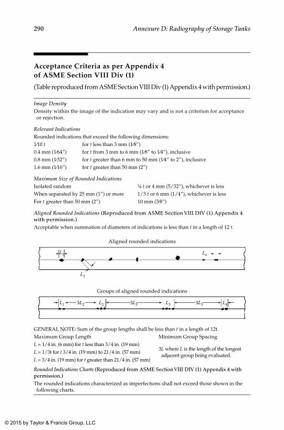
290 Annexure D: Radiography of Storage Tanks
Acceptance Criteria as per Appendix 4 of ASME Section VIII Div (1)
(Table reproduced from ASME Section VIII Div (1) Appendix 4 with permission.)
Image DensityDensity within the image of the indication may vary and is not a criterion for acceptance or rejection.
Relevant IndicationsRounded indications that exceed the following dimensions:1⁄10 t for t less than 3 mm (1⁄8”)0.4 mm (1⁄64”) for t from 3 mm to 6 mm (1⁄8” to 1⁄4”), inclusive0.8 mm (1⁄32”) for t greater than 6 mm to 50 mm (1⁄4” to 2”), inclusive1.6 mm (1⁄16”) for t greater than 50 mm (2”)
Maximum Size of Rounded IndicationsIsolated random ¼ t or 4 mm (5/32”), whichever is lessWhen separated by 25 mm (1”) or more 1/3 t or 6 mm (1/4”), whichever is lessFor t greater than 50 mm (2”) 10 mm (3⁄8”)
Aligned Rounded Indications (Reproduced from ASME Section VIII DIV (1) Appendix 4 with permission.)Acceptable when summation of diameters of indications is less than t in a length of 12 t.
Aligned rounded indications
L1
L2
Lx
Groups of aligned rounded indications
L1 L2 L33L2 3L3 3L3 L4
GENERAL NOTE: Sum of the group lengths shall be less than t in a length of 12t.Maximum Group Length Minimum Group SpacingL = 1/4 in. (6 mm) for t less than 3/4 in. (19 mm)L = 1/3t for t 3/4 in. (19 mm) to 21/4 in. (57 mm)L = 3/4 in. (19 mm) for t greater than 21/4 in. (57 mm)
3L where L is the length of the longest adjacent group being evaluated.
Rounded Indications Charts (Reproduced from ASME Section VIII DIV (1) Appendix 4 with permission.)The rounded indications characterized as imperfections shall not exceed those shown in the following charts.
K22265_Book.indb 290 4/20/15 5:49 PM
© 2015 by Taylor & Francis Group, LLC
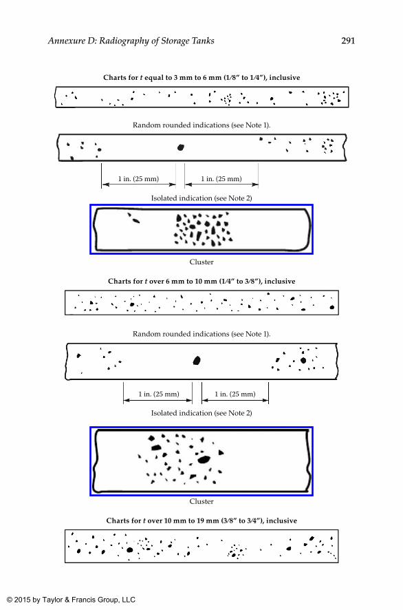
291Annexure D: Radiography of Storage Tanks
Charts for t equal to 3 mm to 6 mm (1 ⁄8” to 1 ⁄4”), inclusive
Random rounded indications (see Note 1).
1 in. (25 mm) 1 in. (25 mm)
Isolated indication (see Note 2)
Cluster
Charts for t over 6 mm to 10 mm (1 ⁄4” to 3⁄8”), inclusive
Random rounded indications (see Note 1).
1 in. (25 mm) 1 in. (25 mm)
Isolated indication (see Note 2)
Cluster
Charts for t over 10 mm to 19 mm (3⁄8” to 3⁄4”), inclusive
K22265_Book.indb 291 4/20/15 5:49 PM
© 2015 by Taylor & Francis Group, LLC
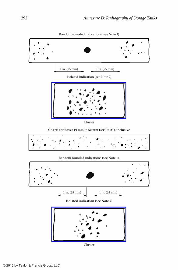
292 Annexure D: Radiography of Storage Tanks
Random rounded indications (see Note 1)
1 in. (25 mm) 1 in. (25 mm)
Isolated indication (see Note 2)
Cluster
Charts for t over 19 mm to 50 mm (3⁄4” to 2”), inclusive
Random rounded indications (see Note 1).
1 in. (25 mm) 1 in. (25 mm)
Isolated indication (see Note 2)
Cluster
K22265_Book.indb 292 4/20/15 5:50 PM
© 2015 by Taylor & Francis Group, LLC
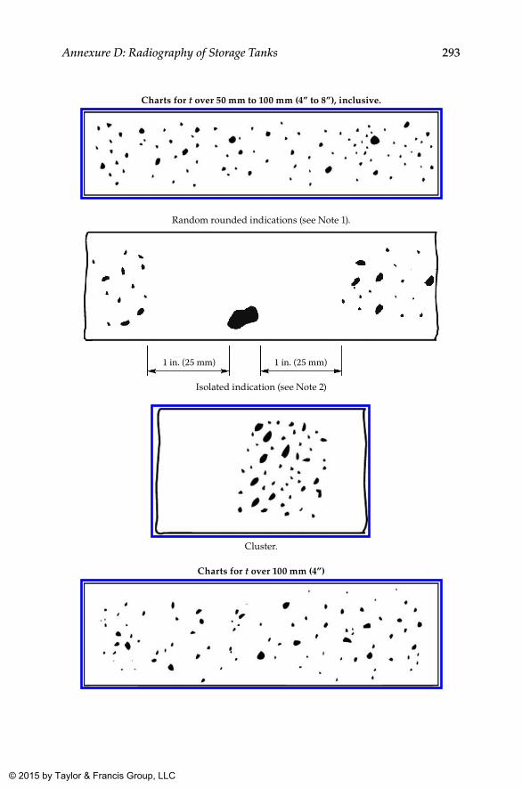
293Annexure D: Radiography of Storage Tanks
Charts for t over 50 mm to 100 mm (4” to 8”), inclusive.
Random rounded indications (see Note 1).
1 in. (25 mm) 1 in. (25 mm)
Isolated indication (see Note 2)
Cluster.
Charts for t over 100 mm (4”)
K22265_Book.indb 293 4/20/15 5:50 PM
© 2015 by Taylor & Francis Group, LLC
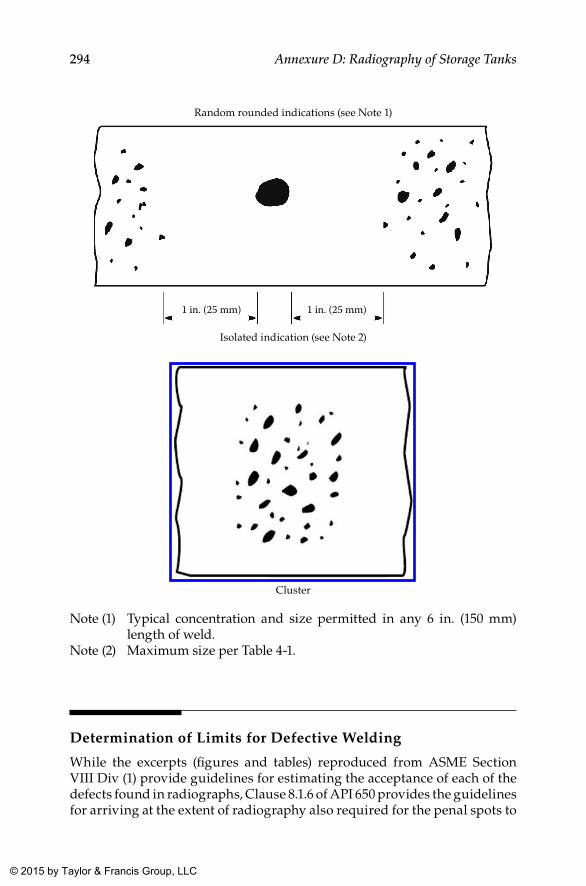
294 Annexure D: Radiography of Storage Tanks
Random rounded indications (see Note 1)
1 in. (25 mm) 1 in. (25 mm)
Isolated indication (see Note 2)
Cluster
Note (1) Typical concentration and size permitted in any 6 in. (150 mm) length of weld.
Note (2) Maximum size per Table 4-1.
Determination of Limits for Defective Welding
While the excerpts (figures and tables) reproduced from ASME Section VIII Div (1) provide guidelines for estimating the acceptance of each of the defects found in radiographs, Clause 8.1.6 of API 650 provides the guidelines for arriving at the extent of radiography also required for the penal spots to
K22265_Book.indb 294 4/20/15 5:50 PM
© 2015 by Taylor & Francis Group, LLC
295Annexure D: Radiography of Storage Tanks
be taken in the case of defective welds. When a radiographed spot shows unacceptable defects, two penalty spots adjacent to the spot radiographed need to be taken. This would be required even when defects extend beyond the boundaries of original spot, until the end of such defective welding. This may extend on one or both sides of the spot radiographed. If it extends to only one side, the penalty need be taken only on one side.
Repair of Defective Welds
Clause 8.1.7 of API 650 requires unacceptable defects to be repaired. As a corollary, these spots need to be radiographed again. The repair of the defec-tive weld shall be carried out by gouging, grinding, or both and rewelded prior to re-radiography.
K22265_Book.indb 295 4/20/15 5:50 PM
© 2015 by Taylor & Francis Group, LLC
297
Annexure E: Inspection and Test Plan
General
The inspection and test plan (ITP) for a storage tank is quite a lengthy docu-ment, since it involves the assembly of so many small components, attach-ments, and fixtures apart from principal components such as the bottom plate, shell, roof, manways, nozzles, and so on. To not miss any such salient activities during inspection, as required in codes and specifications, it is always better to have an ITP covering all these activities so that every activ-ity shall be inspected and recorded.
Though these terms are the general guide words, since tank construction involves multidisciplinary works, it is a usual practice to split the ITP into a few segments as follows, primarily based on the nature and discipline of the work concerned. Depending on the works involved, stage-wise inspections as listed in the following six ITPs would commonly suffice:
1. ITP for foundation till hand over for mechanical erection 2. ITP for mechanical erection of tank 3. ITP for surface preparation and painting 4. ITP for cathodic protection (including provision of sacrificial anodes) 5. ITP for electrical and instrumentation works 6. ITP for subsequent civil works such as preparation of dykes, roads,
illumination, and so on
Out of these six ITPs, Item 2 relates to works covered by this book, and hence a typical ITP for a fixed cone roof tank is provided in this annexure. Based on the specific need of each case, the ITP needs to be enlarged or tai-lored based on the type of the tank, the construction method, and the spe-cific requirements put forward by the client. Readers are encouraged to refer to the comments provided under the remarks column and give serious con-sideration while formulating the ITP for a specific tank.
Though it does not really fall under the jurisdiction of this book, a typi-cal ITP for surface preparation and painting (Item 3) is also included in this book (in Chapter 13) for the sake of completeness. Since works related to the other four ITPs are not within the ambit of this book, they are not included.
K22265_Book.indb 297 4/20/15 5:50 PM
© 2015 by Taylor & Francis Group, LLC
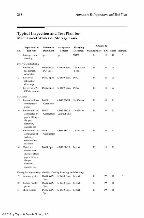
298 Annexure E: Inspection and Test Plan
Typical Inspection and Test Plan for Mechanical Works of Storage Tank
No.Inspection and
Test PlanReference Document
Acceptance Criteria
Verifying Document
Activity By
RemarkManufacturer TPI Client
1 Preinspection meeting
Spec. Spec. MOM H H H a
Before Manufacturing
2 Review of mechanical calculation
Data sheets, PO, Spec.
API 650, Spec. Calculation book
H H A
3 Review of fabrication drawings
DWG, Spec. API 650, Spec. DWG H H A
4 Review of QA/QC documents
DWG, Spec. API 650, Spec. DWG H H A
Materials
5 Review mill test certificates of plates
DWG, Certificates
ASME SEC II Certificates H W R
6 Review mill test certificates of pipes, fittings, flanges, fasteners, gaskets, etc.
DWG, Certificates
ASME SEC II, ASME B 16.5
Certificates H W R
7 Review mill test certificates of welding consumable material
WPS, Certificates
ASME SEC II Certificates H W R
8 Visual and dimensional check of plates, pipes, fittings, flanges, fasteners, gaskets, etc.
DWG, Spec. ASME SEC II Report H W R
During Manufacturing: Marking, Cutting, Beveling, and Grinding
9 Annular plates DWG, WPS, Spec.
API 650, Spec. Report H SW R b
10 Bottom/sketch plates
DWG, WPS, Spec.
API 650, Spec. Report H SW R
11 Shell courses DWG, WPS, Spec.
API 650, Spec. Report H SW R
K22265_Book.indb 298 4/20/15 5:50 PM
© 2015 by Taylor & Francis Group, LLC
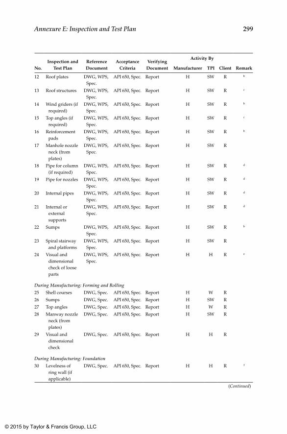
299Annexure E: Inspection and Test Plan
No.Inspection and
Test PlanReference Document
Acceptance Criteria
Verifying Document
Activity By
RemarkManufacturer TPI Client
12 Roof plates DWG, WPS, Spec.
API 650, Spec. Report H SW R b
13 Roof structures DWG, WPS, Spec.
API 650, Spec. Report H SW R c
14 Wind griders (if required)
DWG, WPS, Spec.
API 650, Spec. Report H SW R b
15 Top angles (if required)
DWG, WPS, Spec.
API 650, Spec. Report H SW R c
16 Reinforcement pads
DWG, WPS, Spec.
API 650, Spec. Report H SW R b
17 Manhole nozzle neck (from plates)
DWG, WPS, Spec.
API 650, Spec. Report H SW R
18 Pipe for column (if required)
DWG, WPS, Spec.
API 650, Spec. Report H SW R d
19 Pipe for nozzles DWG, WPS, Spec.
API 650, Spec. Report H SW R d
20 Internal pipes DWG, WPS, Spec.
API 650, Spec. Report H SW R d
21 Internal or external supports
DWG, WPS, Spec.
API 650, Spec. Report H SW R d
22 Sumps DWG, WPS, Spec.
API 650, Spec. Report H SW R b
23 Spiral stairway and platforms
DWG, WPS, Spec.
API 650, Spec. Report H SW R
24 Visual and dimensional check of loose parts
DWG, WPS, Spec.
API 650, Spec. Report H H R e
During Manufacturing: Forming and Rolling
25 Shell courses DWG, Spec. API 650, Spec. Report H W R
26 Sumps DWG, Spec. API 650, Spec. Report H SW R
27 Top angles DWG, Spec. API 650, Spec. Report H W R
28 Manway nozzle neck (from plates)
DWG, Spec. API 650, Spec. Report H SW R
29 Visual and dimensional check
DWG, Spec. API 650, Spec. Report H H R
During Manufacturing: Foundation
30 Levelness of ring wall (if applicable)
DWG, Spec. API 650, Spec. Report H H R f
(Continued)
K22265_Book.indb 299 4/20/15 5:50 PM
© 2015 by Taylor & Francis Group, LLC
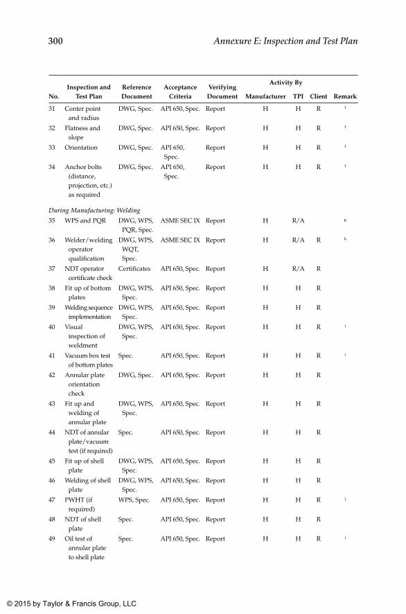
300 Annexure E: Inspection and Test Plan
No.Inspection and
Test PlanReference Document
Acceptance Criteria
Verifying Document
Activity By
RemarkManufacturer TPI Client
31 Center point and radius
DWG, Spec. API 650, Spec. Report H H R f
32 Flatness and slope
DWG, Spec. API 650, Spec. Report H H R f
33 Orientation DWG, Spec. API 650, Spec.
Report H H R f
34 Anchor bolts (distance, projection, etc.) as required
DWG, Spec. API 650, Spec.
Report H H R f
During Manufacturing: Welding
35 WPS and PQR DWG, WPS, PQR, Spec.
ASME SEC IX Report H R/A g
36 Welder/welding operator qualification
DWG, WPS, WQT, Spec.
ASME SEC IX Report H R/A R h
37 NDT operator certificate check
Certificates API 650, Spec. Report H R/A R
38 Fit up of bottom plates
DWG, WPS, Spec.
API 650, Spec. Report H H R
39 Welding sequence implementation
DWG, WPS, Spec.
API 650, Spec. Report H H R
40 Visual inspection of weldment
DWG, WPS, Spec.
API 650, Spec. Report H H R i
41 Vacuum box test of bottom plates
Spec. API 650, Spec. Report H H R i
42 Annular plate orientation check
DWG, Spec. API 650, Spec. Report H H R
43 Fit up and welding of annular plate
DWG, WPS, Spec.
API 650, Spec. Report H H R
44 NDT of annular plate/vacuum test (if required)
Spec. API 650, Spec. Report H H R
45 Fit up of shell plate
DWG, WPS, Spec.
API 650, Spec. Report H H R
46 Welding of shell plate
DWG, WPS, Spec.
API 650, Spec. Report H H R
47 PWHT (if required)
WPS, Spec. API 650, Spec. Report H H R j
48 NDT of shell plate
Spec. API 650, Spec. Report H H R
49 Oil test of annular plate to shell plate
Spec. API 650, Spec. Report H H R i
K22265_Book.indb 300 4/20/15 5:50 PM
© 2015 by Taylor & Francis Group, LLC
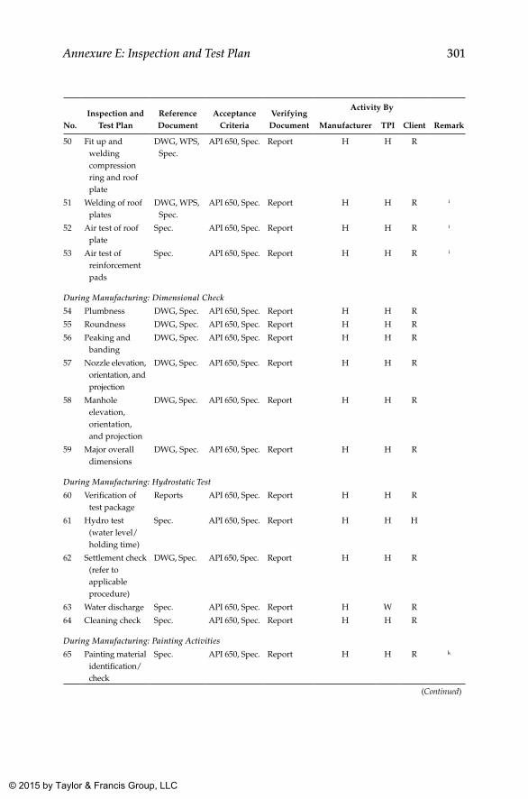
301Annexure E: Inspection and Test Plan
No.Inspection and
Test PlanReference Document
Acceptance Criteria
Verifying Document
Activity By
RemarkManufacturer TPI Client
50 Fit up and welding compression ring and roof plate
DWG, WPS, Spec.
API 650, Spec. Report H H R
51 Welding of roof plates
DWG, WPS, Spec.
API 650, Spec. Report H H R i
52 Air test of roof plate
Spec. API 650, Spec. Report H H R i
53 Air test of reinforcement pads
Spec. API 650, Spec. Report H H R i
During Manufacturing: Dimensional Check
54 Plumbness DWG, Spec. API 650, Spec. Report H H R
55 Roundness DWG, Spec. API 650, Spec. Report H H R
56 Peaking and banding
DWG, Spec. API 650, Spec. Report H H R
57 Nozzle elevation, orientation, and projection
DWG, Spec. API 650, Spec. Report H H R
58 Manhole elevation, orientation, and projection
DWG, Spec. API 650, Spec. Report H H R
59 Major overall dimensions
DWG, Spec. API 650, Spec. Report H H R
During Manufacturing: Hydrostatic Test
60 Verification of test package
Reports API 650, Spec. Report H H R
61 Hydro test (water level/holding time)
Spec. API 650, Spec. Report H H H
62 Settlement check (refer to applicable procedure)
DWG, Spec. API 650, Spec. Report H H R
63 Water discharge Spec. API 650, Spec. Report H W R
64 Cleaning check Spec. API 650, Spec. Report H H R
During Manufacturing: Painting Activities
65 Painting material identification/check
Spec. API 650, Spec. Report H H R k
(Continued)
K22265_Book.indb 301 4/20/15 5:50 PM
© 2015 by Taylor & Francis Group, LLC
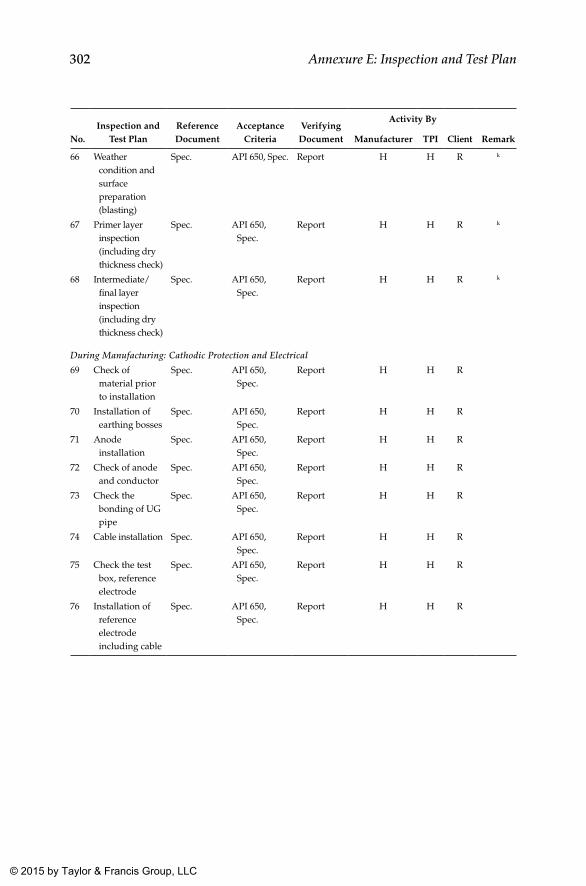
302 Annexure E: Inspection and Test Plan
No.Inspection and
Test PlanReference Document
Acceptance Criteria
Verifying Document
Activity By
RemarkManufacturer TPI Client
66 Weather condition and surface preparation (blasting)
Spec. API 650, Spec. Report H H R k
67 Primer layer inspection (including dry thickness check)
Spec. API 650, Spec.
Report H H R k
68 Intermediate/final layer inspection (including dry thickness check)
Spec. API 650, Spec.
Report H H R k
During Manufacturing: Cathodic Protection and Electrical
69 Check of material prior to installation
Spec. API 650, Spec.
Report H H R
70 Installation of earthing bosses
Spec. API 650, Spec.
Report H H R
71 Anode installation
Spec. API 650, Spec.
Report H H R
72 Check of anode and conductor
Spec. API 650, Spec.
Report H H R
73 Check the bonding of UG pipe
Spec. API 650, Spec.
Report H H R
74 Cable installation Spec. API 650, Spec.
Report H H R
75 Check the test box, reference electrode
Spec. API 650, Spec.
Report H H R
76 Installation of reference electrode including cable
Spec. API 650, Spec.
Report H H R
K22265_Book.indb 302 4/20/15 5:50 PM
© 2015 by Taylor & Francis Group, LLC
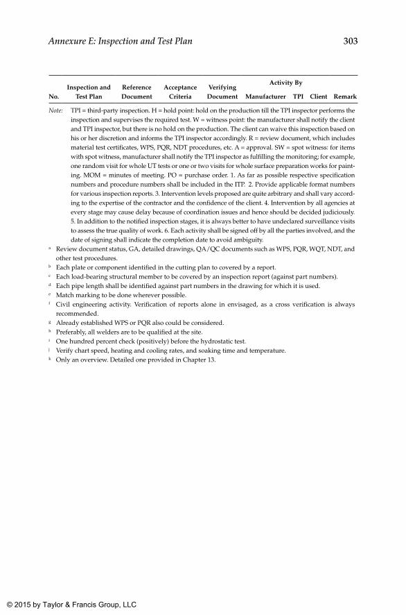
303Annexure E: Inspection and Test Plan
No.Inspection and
Test PlanReference Document
Acceptance Criteria
Verifying Document
Activity By
RemarkManufacturer TPI Client
Note: TPI = third-party inspection. H = hold point: hold on the production till the TPI inspector performs the inspection and supervises the required test. W = witness point: the manufacturer shall notify the client and TPI inspector, but there is no hold on the production. The client can waive this inspection based on his or her discretion and informs the TPI inspector accordingly. R = review document, which includes material test certificates, WPS, PQR, NDT procedures, etc. A = approval. SW = spot witness: for items with spot witness, manufacturer shall notify the TPI inspector as fulfilling the monitoring; for example, one random visit for whole UT tests or one or two visits for whole surface preparation works for paint-ing. MOM = minutes of meeting. PO = purchase order. 1. As far as possible respective specification numbers and procedure numbers shall be included in the ITP. 2. Provide applicable format numbers for various inspection reports. 3. Intervention levels proposed are quite arbitrary and shall vary accord-ing to the expertise of the contractor and the confidence of the client. 4. Intervention by all agencies at every stage may cause delay because of coordination issues and hence should be decided judiciously. 5. In addition to the notified inspection stages, it is always better to have undeclared surveillance visits to assess the true quality of work. 6. Each activity shall be signed off by all the parties involved, and the date of signing shall indicate the completion date to avoid ambiguity.
a Review document status, GA, detailed drawings, QA/QC documents such as WPS, PQR, WQT, NDT, and other test procedures.
b Each plate or component identified in the cutting plan to covered by a report.c Each load-bearing structural member to be covered by an inspection report (against part numbers).d Each pipe length shall be identified against part numbers in the drawing for which it is used.e Match marking to be done wherever possible.f Civil engineering activity. Verification of reports alone in envisaged, as a cross verification is always
recommended.g Already established WPS or PQR also could be considered.h Preferably, all welders are to be qualified at the site.i One hundred percent check (positively) before the hydrostatic test.j Verify chart speed, heating and cooling rates, and soaking time and temperature.k Only an overview. Detailed one provided in Chapter 13.
K22265_Book.indb 303 4/20/15 5:50 PM
© 2015 by Taylor & Francis Group, LLC
305
Annexure F: Requirements for Floating Roof Tanks
General
Tanks with floating roofs on a tank widely used in the oil industry for decreasing vapor loss when volatile oil products are to be stored in the tank. Floating roofs can be used when the tanks are open at the top or when pro-vided with a fixed roof. They can also be used when tanks are closed and no product leak is permitted to the environment.
Since the most extensively used type of floating roof tank (in oil and gas) is the external floating roof type, this annexure elaborates on special require-ments for this type of tank. However, for the sake completeness, the internal floating roof type is also touched upon briefly.
The functioning of floating roofs is strongly dependent on the good geom-etry of the shell, floating roof, and antirotation devices and hence requires careful considerations during construction and maintenance. The main advantages of tanks with floating roofs are as follows:
1. Minimizes loss of the stored product through evaporation. Factors influencing product evaporation are as follows:
a. Temperature of liquid b. Presence and size of vapor space above liquid c. Possibility for ventilation of vapor space d. Presence of free surface of stored product 2. Decreased evaporation of the product reduces corrosion of the upper
parts of the shell. 3. It lowers the risk of fire because of reduced evaporation. 4. The roof load is not transmitted to the shell.
K22265_Book.indb 305 4/20/15 5:50 PM
© 2015 by Taylor & Francis Group, LLC
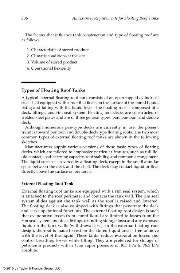
306 Annexure F: Requirements for Floating Roof Tanks
The factors that influence tank construction and type of floating roof are as follows:
1. Characteristic of stored product 2. Climatic conditions at the site 3. Volume of stored product 4. Operational flexibility
Types of Floating Roof Tanks
A typical external floating roof tank consists of an open-topped cylindrical steel shell equipped with a roof that floats on the surface of the stored liquid, rising and falling with the liquid level. The floating roof is composed of a deck, fittings, and rim seal system. Floating roof decks are constructed of welded steel plates and are of three general types: pan, pontoon, and double deck.
Although numerous pan-type decks are currently in use, the present trend is toward pontoon and double-deck-type floating roofs. The two most common types of external floating roof tanks are shown in the following sketches.
Manufacturers supply various versions of these basic types of floating decks, which are tailored to emphasize particular features, such as full liq-uid contact, load-carrying capacity, roof stability, and pontoon arrangement. The liquid surface is covered by a floating deck, except in the small annular space between the deck and the shell. The deck may contact liquid or float directly above the surface on pontoons.
External Floating Roof Tank
External floating roof tanks are equipped with a rim seal system, which is attached to the roof perimeter and contacts the tank wall. The rim seal system slides against the tank wall as the roof is raised and lowered. The floating deck is also equipped with fittings that penetrate the deck and serve operational functions. The external floating roof design is such that evaporative losses from stored liquid are limited to losses from the rim seal system and deck fittings (standing storage loss) and any exposed liquid on the tank walls (withdrawal loss). In the external floating roof design, the roof is made to rest on the stored liquid and is free to move with the level of the liquid. These tanks reduce evaporation losses and control breathing losses while filling. They are preferred for storage of petroleum products with a true vapor pressure of 10.3 kPa to 76.5 kPa absolute.
K22265_Book.indb 306 4/20/15 5:50 PM
© 2015 by Taylor & Francis Group, LLC
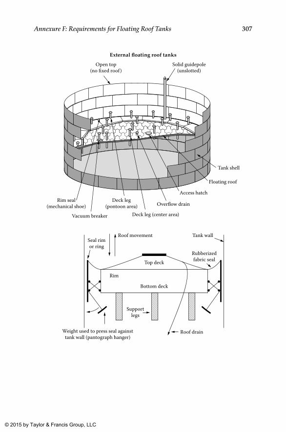
307Annexure F: Requirements for Floating Roof Tanks
External floating roof tanks
Rim seal(mechanical shoe)
Vacuum breaker
Deck leg(pontoon area)
Deck leg (center area)
Overflow drain
Access hatch
Floating roof
Tank shell
Solid guidepole(unslotted)
Open top(no fixed roof )
Weight used to press seal againsttank wall (pantograph hanger)
Supportlegs
Roof drain
Rim
Bottom deck
Top deck
Seal rimor ring
Roof movement Tank wall
Rubberizedfabric seal
K22265_Book.indb 307 4/20/15 5:50 PM
© 2015 by Taylor & Francis Group, LLC
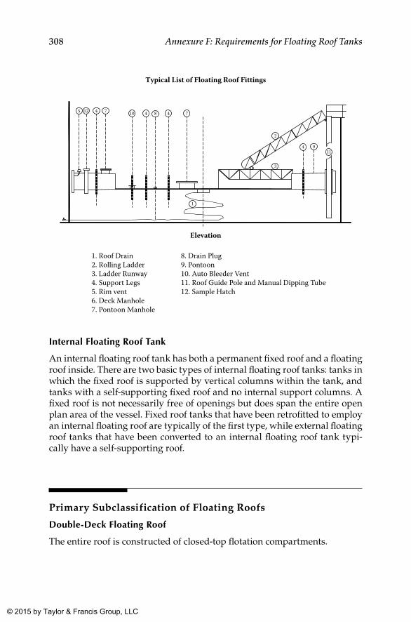
308 Annexure F: Requirements for Floating Roof Tanks
Typical List of Floating Roof Fittings
Elevation
1. Roof Drain2. Rolling Ladder3. Ladder Runway4. Support Legs5. Rim vent6. Deck Manhole7. Pontoon Manhole
8. Drain Plug9. Pontoon10. Auto Bleeder Vent11. Roof Guide Pole and Manual Dipping Tube12. Sample Hatch
5 12 4 7 10 4 8 4 7
1
2
3
4 911
Internal Floating Roof Tank
An internal floating roof tank has both a permanent fixed roof and a floating roof inside. There are two basic types of internal floating roof tanks: tanks in which the fixed roof is supported by vertical columns within the tank, and tanks with a self-supporting fixed roof and no internal support columns. A fixed roof is not necessarily free of openings but does span the entire open plan area of the vessel. Fixed roof tanks that have been retrofitted to employ an internal floating roof are typically of the first type, while external floating roof tanks that have been converted to an internal floating roof tank typi-cally have a self-supporting roof.
Primary Subclassification of Floating Roofs
Double-Deck Floating Roof
The entire roof is constructed of closed-top flotation compartments.
K22265_Book.indb 308 4/20/15 5:50 PM
© 2015 by Taylor & Francis Group, LLC
309Annexure F: Requirements for Floating Roof Tanks
Single-Deck Pontoon Floating Roof
The outer periphery of the roof consists of closed-top pontoon compart-ments, with the inner section of the roof constructed of a single deck without flotation means.
Standard and Client Requirements for Floating Roof Tanks
Annex C of API 650 regarding external floating roofs provides additional requirements applicable to a floating deck. As in the case of the main tank (bottom plate, shell, and roof), here also additional requirements are stipu-lated by clients based on their specific requirements, especially for the sour environment in the oil and gas industry. Salient requirements specified by clients in the oil and gas industry with a reference to the applicable clauses in API 650 are shown in the following table as a quick reference. As this is provided as a guideline, for finer details and other applicable conditions associated with these requirements, refer to the API Standard.
Sl. No.
API Code Clauses Client Requirements from Oil and Gas
Scope1 C.1.1 Pan-type roofs are not permitted.
Materials2 As per data sheet.
Design3 No additional requirements.
Decks4 C.3.3.2 Minimum thickness of bottom deck shall be 6 mm.5 C.3.3.3 All compartments shall be internally seal welded along the top, bottom,
and vertical edges. Top surfaces, including outer rim, shall be painted.6 C.3.3.4 For a double-deck roof, the bottom deck is to slope upward toward the
center of the tank. The top deck may either slope to drain toward the center (converging double-deck type) or slope down from both the rim and the center.
Pontoon Design7 No additional requirements.
Pontoon Opening8 C.3.5 Compartments shall be inspectable.
(Continued)
K22265_Book.indb 309 4/20/15 5:50 PM
© 2015 by Taylor & Francis Group, LLC
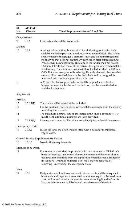
310 Annexure F: Requirements for Floating Roof Tanks
Sl. No.
API Code Clauses Client Requirements from Oil and Gas
Compartments9 C.3.6 Compartments shall be inspectable.
Ladders10 C.3.7 A rolling ladder with rails is required for all floating roof tanks. Rails
shall be welded to pads and not directly onto the roof deck. The ladder shall connect to the gauger’s platform. Pivot and wheel bearings shall be of a type that does not require any lubrication after commissioning. Wheels shall be nonsparking. The slope of the ladder shall not exceed 1270 mm (50”) to horizontal at the extreme low position. Treads shall be self-leveling. The minimum inside width of the ladder shall be 750 mm (30”). If it is necessary for rails to be significantly elevated, then suitable steps shall be provided down to the deck. It should be designed for wind and rain conditions prevailing at the site.
11 A 35 mm2 flexible copper conductor shall be applied across ladder hinges, between the ladder and the tank top, and between the ladder and the floating roof.
Roof Drains
Primary12 C.3.8.1(1) The drain shall be valved at the tank shell.13 For the pontoon type, the check valve shall be accessible from the deck by
mounting it in a recess.14 The maximum nominal size of articulated drain lines is 100 mm (4”). If
insufficient, additional numbers are to be provided.15 C.3.8.1(3) Primary roof drains shall be either articulated joint or flexible hose type.
Emergency Drain16 C.3.8.2 Inside the tank, the drain shall be fitted with a deflector to minimize
vapor losses.
Out-of-Service Supplementary Drains17 C.3.8.3 No additional requirements.
Maintenance Drain18 Pontoon-type roofs shall be provided with two numbers of NPS 80 (3”)
brass drain plugs, one located close to the center and the other close to the inner rim and fitted from the top for use when the roof is landed on its supports. Drainage of double-deck roofs may be achieved by removing (unscrewing) the emergency drain.
Vents19 C.3.9 Design, size, and location of automatic bleeder vents shall be adequate to
breathe air and vapors at a volumetric rate at least equal to the maximum tank outflow and to twice the specified commissioning liquid inflow. At least one bleeder vent shall be located near the center of the deck.
K22265_Book.indb 310 4/20/15 5:50 PM
© 2015 by Taylor & Francis Group, LLC
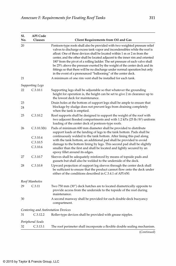
311Annexure F: Requirements for Floating Roof Tanks
Sl. No.
API Code Clauses Client Requirements from Oil and Gas
20 Pontoon-type roofs shall also be provided with two weighted pressure relief valves to discharge excess tank vapor and incondensibles while the roof is afloat. One of these devices shall be located within 1 m or 2 m from the center, and the other shall be located adjacent to the inner rim and oriented 180° from the pivot of a rolling ladder. The set pressure of each valve shall be 25% above the pressure exerted by the weight of the center deck and its fittings so that there will be no discharge under normal operation but only in the event of a pronounced “ballooning” of the center deck.
21 A minimum of one rim vent shall be installed for each tank.
Supporting Legs22 C.3.10.1 Supporting legs shall be adjustable so that whatever the grounding
height for operation is, the height can be set to give 2 m clearance up to the lowest deck for maintenance.
23 Drain holes at the bottom of support legs shall be ample to ensure that blockage by sludge does not prevent legs from draining completely when the tank is emptied.
24
25 C.3.10.2 Roof supports shall be designed to support the weight of the roof with two adjacent flooded compartments and with 1.2 kPa (25 lb/ft2) uniform loading of the center deck of pontoon-type roofs.
26 C.3.10.3(b) Pads of minimum 600 mm diameter shall be provided to distribute support loads at the landing of legs to the tank bottom. Pads shall be continuously welded to the tank bottom. After lining this pad along with the tank bottom, an additional pad shall be provided to avoid damage to the bottom lining by legs. This second pad shall be slightly smaller than the first and shall be located and lightly secured by an epoxy fillet around its edges.
C.3.10.4C.3.10.5C.3.10.6
27 C.3.10.7 Sleeves shall be adequately reinforced by means of topside pads and gussets but shall also be welded to the underside of the deck.
28 C.3.10.8 Upward projection of support leg sleeves through the center deck shall be sufficient to ensure that the product cannot flow onto the deck under either of the conditions described in C.3.4.1 of API 650.
Roof Manholes29 C.3.11 Two 750 mm (30”) deck hatches are to located diametrically opposite to
provide access from the underside to the topside of the roof during maintenance.
30 A second manway shall be provided for each double-deck buoyancy compartment.
Centering and Antirotation Devices31 C.3.12.2 Roller-type devices shall be provided with grease nipples.
Peripheral Seals32 C.3.13.1 The roof perimeter shall incorporate a flexible double sealing mechanism.
(Continued)
K22265_Book.indb 311 4/20/15 5:50 PM
© 2015 by Taylor & Francis Group, LLC
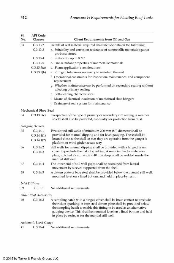
312 Annexure F: Requirements for Floating Roof Tanks
Sl. No.
API Code Clauses Client Requirements from Oil and Gas
33 C.3.13.2 Details of seal material required shall include data on the following:C.3.13.3 a. Suitability and corrosion resistance of nonmetallic materials against
products storedC.3.13.4 b. Suitability up to 80°CC.3.13.5 c. Fire-retardant properties of nonmetallic materials
C.3.13.5(a) d. Foam application considerationsC.3.13.5(b) e. Rim gap tolerances necessary to maintain the seal
f. Operational constraints for inspection, maintenance, and component replacement
g. Whether maintenance can be performed on secondary sealing without affecting primary sealing
h. Self-cleaning characteristicsi. Means of electrical insulation of mechanical shoe hangersj. Drainage of seal system for maintenance
Mechanical Shoe Seal34 C.3.13.5(c) Irrespective of the type of primary or secondary rim sealing, a weather
shield shall also be provided, especially for protection from dust.
Gauging Devices35 C.3.14.1 Two slotted still wells of minimum 200 mm (8”) diameter shall be
provided for manual dipping and for level gauging. These shall be located close to the shell so that they are operable from the gauger’s platform or wind girder access way.
C.3.14.1(1)C.3.14.1(2)
36 C.3.14.2 Still wells for manual dipping shall be provided with a hinged brass cover to preclude the risk of sparking. A semicircular top reference plate, notched 25 mm wide × 40 mm deep, shall be welded inside the manual still well.
C.3.14.3
37 C.3.14.4 The lower end of still well pipes shall be restrained from lateral movement by sleeves supported from the shell.
38 C.3.14.5 A datum plate of bare steel shall be provided below the manual still well, mounted level on a lined bottom, and held in place by resin.
Inlet Diffuser39 C.3.1.5 No additional requirements.
Other Roof Accessories40 C.3.16.3 A sampling hatch with a hinged cover shall be brass contact to preclude
the risk of sparking. A bare steel datum plate shall be provided below the sampling hatch to enable this fitting to be used as an alternative gauging device. This shall be mounted level on a lined bottom and held in place by resin, as for the manual still well.
Automatic Level Gauge41 C.3.16.4 No additional requirements.
K22265_Book.indb 312 4/20/15 5:50 PM
© 2015 by Taylor & Francis Group, LLC
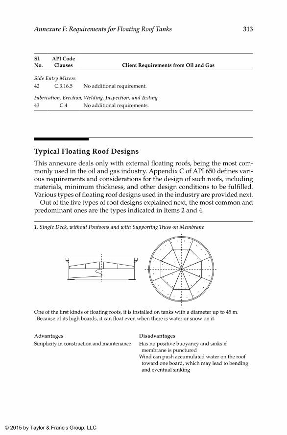
313Annexure F: Requirements for Floating Roof Tanks
Sl. No.
API Code Clauses Client Requirements from Oil and Gas
Side Entry Mixers42 C.3.16.5 No additional requirement.
Fabrication, Erection, Welding, Inspection, and Testing43 C.4 No additional requirements.
Typical Floating Roof Designs
This annexure deals only with external floating roofs, being the most com-monly used in the oil and gas industry. Appendix C of API 650 defines vari-ous requirements and considerations for the design of such roofs, including materials, minimum thickness, and other design conditions to be fulfilled. Various types of floating roof designs used in the industry are provided next.
Out of the five types of roof designs explained next, the most common and predominant ones are the types indicated in Items 2 and 4.
1. Single Deck, without Pontoons and with Supporting Truss on Membrane
One of the first kinds of floating roofs, it is installed on tanks with a diameter up to 45 m. Because of its high boards, it can float even when there is water or snow on it.
Advantages DisadvantagesSimplicity in construction and maintenance Has no positive buoyancy and sinks if
membrane is puncturedWind can push accumulated water on the roof toward one board, which may lead to bending and eventual sinking
K22265_Book.indb 313 4/20/15 5:50 PM
© 2015 by Taylor & Francis Group, LLC
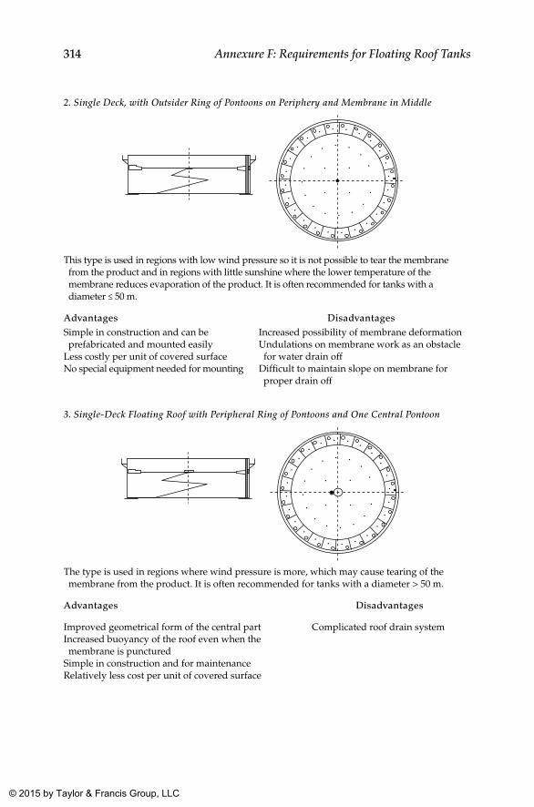
314 Annexure F: Requirements for Floating Roof Tanks
2. Single Deck, with Outsider Ring of Pontoons on Periphery and Membrane in Middle
This type is used in regions with low wind pressure so it is not possible to tear the membrane from the product and in regions with little sunshine where the lower temperature of the membrane reduces evaporation of the product. It is often recommended for tanks with a diameter ≤ 50 m.
Advantages DisadvantagesSimple in construction and can be prefabricated and mounted easily
Less costly per unit of covered surfaceNo special equipment needed for mounting
Increased possibility of membrane deformationUndulations on membrane work as an obstacle for water drain off
Difficult to maintain slope on membrane for proper drain off
3. Single-Deck Floating Roof with Peripheral Ring of Pontoons and One Central Pontoon
The type is used in regions where wind pressure is more, which may cause tearing of the membrane from the product. It is often recommended for tanks with a diameter > 50 m.
Advantages Disadvantages
Improved geometrical form of the central partIncreased buoyancy of the roof even when the membrane is punctured
Simple in construction and for maintenanceRelatively less cost per unit of covered surface
Complicated roof drain system
K22265_Book.indb 314 4/20/15 5:50 PM
© 2015 by Taylor & Francis Group, LLC
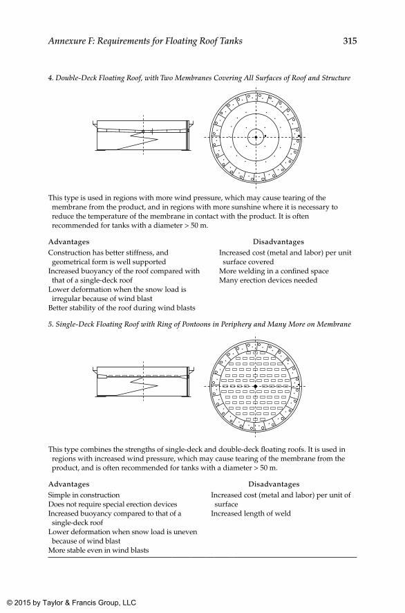
315Annexure F: Requirements for Floating Roof Tanks
4. Double-Deck Floating Roof, with Two Membranes Covering All Surfaces of Roof and Structure
This type is used in regions with more wind pressure, which may cause tearing of the membrane from the product, and in regions with more sunshine where it is necessary to reduce the temperature of the membrane in contact with the product. It is often recommended for tanks with a diameter > 50 m.
Advantages DisadvantagesConstruction has better stiffness, and geometrical form is well supported
Increased buoyancy of the roof compared with that of a single-deck roof
Lower deformation when the snow load is irregular because of wind blast
Better stability of the roof during wind blasts
Increased cost (metal and labor) per unit surface covered
More welding in a confined spaceMany erection devices needed
5. Single-Deck Floating Roof with Ring of Pontoons in Periphery and Many More on Membrane
This type combines the strengths of single-deck and double-deck floating roofs. It is used in regions with increased wind pressure, which may cause tearing of the membrane from the product, and is often recommended for tanks with a diameter > 50 m.
Advantages DisadvantagesSimple in constructionDoes not require special erection devicesIncreased buoyancy compared to that of a single-deck roof
Lower deformation when snow load is uneven because of wind blast
More stable even in wind blasts
Increased cost (metal and labor) per unit of surface
Increased length of weld
K22265_Book.indb 315 4/20/15 5:50 PM
© 2015 by Taylor & Francis Group, LLC
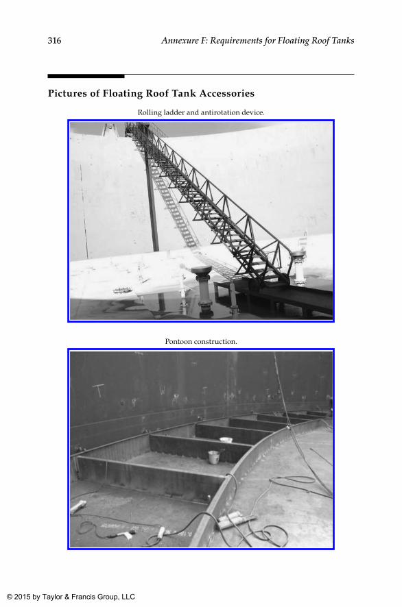
316 Annexure F: Requirements for Floating Roof Tanks
Pictures of Floating Roof Tank Accessories
Rolling ladder and antirotation device.
Pontoon construction.
K22265_Book.indb 316 4/20/15 5:50 PM
© 2015 by Taylor & Francis Group, LLC
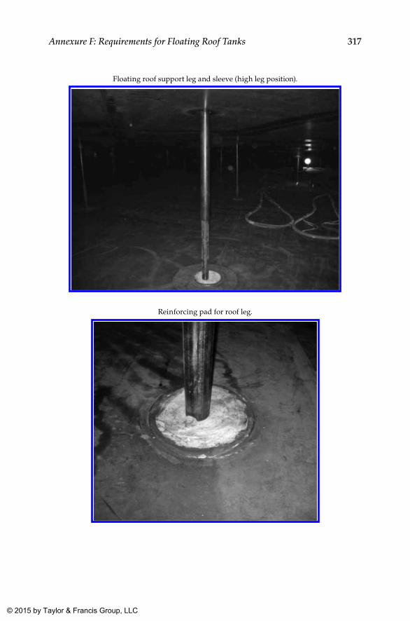
317Annexure F: Requirements for Floating Roof Tanks
Floating roof support leg and sleeve (high leg position).
Reinforcing pad for roof leg.
K22265_Book.indb 317 4/20/15 5:50 PM
© 2015 by Taylor & Francis Group, LLC
319
Annexure G: Additional Inspections and Tests for Floating Roof Tanks
Additional Tolerance Required in Construction
For tanks to have an acceptable appearance and to permit proper function-ing of a floating roof, they shall have strict tolerances as specified in API 650 or the client specification.
Tolerance allowed on the annular clearance between the shell and the floating roof shall be compatible with the requirement specified by the seal manufacturer but shall be limited to 50 mm radially.
Procedure for Rainwater Accumulation and Puncture/Floatation Tests
The rainwater accumulation test is to ascertain smooth operation of the floating deck even when roof drains are blocked. The puncture/floata-tion test is carried out to doubly make sure the floating roof operates even when a few pontoons or compartments in the floating deck are punctured during service. Such a test would facilitate the operating plant to get some breathing time to plan for a shutdown when it starts noticing a tilt of the floating deck, resulting from a puncture in a pontoon or floatation compartment.
Checklist Prior to Tests on Floating Roofs
1. Ensure completion of erection and visual inspection (100%) nonde-structive testing (as specified).
2. This is followed by tests such as pneumatic testing, diesel chalk test-ing of the outer rim, and so on. In case any rectifications or repairs
K22265_Book.indb 319 4/20/15 5:50 PM
© 2015 by Taylor & Francis Group, LLC
320 Annexure G: Additional Inspections and Tests for Floating Roof Tanks
are needed, they shall be completed and the roof reinspected to a satisfactory level.
3. Non-return valve (NRV) in central roof drain shall be checked for its functioning.
4. Ensure that tests such as the diesel chalk test, liquid penetrant test-ing (LPT), reinforcement pad (RF.Pad) pneumatic test, vacuum box test, and so on are also completed.
5. Punctures with couplings fitted in the deck and adjacent pontoons to be ensured before commencing of hydrostatic testing.
6. The puncture test shall be carried out when the roof is in the high-est position.
Test Medium
The test medium shall be iron-free water, which is clean and free of silt. Potable water is a good option.
Procedure for Puncture Test
1. Initial reading of rim space (at least at eight points) to be taken. 2. Location of rolling ladder (drum) with respect to the shell and spirit
level reading of threads of staircase need to be taken. 3. Deck immersion and rim position with respect to the tank shell shall
also be recorded. 4. Water fill height to be recorded. 5. Out of the two adjacent pontoons identified for the puncture test,
one has to be punctured and time has to be recorded along with the height of the water column coming out of the hole (this shall help in evaluating the final height of water after fill up of the punc-tured pontoon).
6. After water settles down in the first pontoon and no more significant change is seen, record the time taken and check for any leakage in the adjacent pontoon.
7. Repeat Steps 1 to 4 and puncture the next (adjacent) pontoon. 8. Repeat recording of the readings as in Steps 5 and 6.
K22265_Book.indb 320 4/20/15 5:50 PM
© 2015 by Taylor & Francis Group, LLC
321Annexure G: Additional Inspections and Tests for Floating Roof Tanks
9. After that, puncture the central deck and repeat the procedure and Steps 1 to 4.
10. Record the final readings of tilt and cross-check with theoretical values.
Procedure for Rainwater Fill Test
Blind the NRV and fill the central deck with water till 254 mm (10”) and keep the same for one day without and with the puncture test condition. The NRV shall be opened thereafter to see water flow from the roof drain and the time taken to remove the water.
Tests for Primary Drain
Drain pipes in a floating roof tank shall be pressure tested with water at 4 kg/cm2g. Furthermore, during the floatation test, the roof drain valve shall be kept open and observed for leakage of the tank contents through the pipe drain.
Acceptance Criteria
For the pontoon puncture test, at each stage of water filling, the time taken in water settling and tilting shall conform to the approved floating roof design within mentioned tolerances of all the variables such as rim space, tilting, time taken to fill the pontoon, and so on.
For the rainwater fill test, the quantity of water to be filled on the roof shall be equivalent to 254 mm (10”) of rainfall over the entire tank area for a period of 24 hours. This shall be done with the primary drains closed, and when done so, water shall in no case come out of the outer rim of the deck. Immersion of the deck in water in that condition shall be as per design in a stabilized state; however, submergence of the outer rim shall not exceed 65% of its height at any point.
The time taken by roof drain water to come out from the central roof drain sump should be in conformance to the design and code requirements (Appendix C, API 650).
Note that after completion of the test, punctures should be blinded and LPT tested for leakage when the roof is at the lowest position (after hydro-static testing) if welded, else coupling should be seal tightened.
K22265_Book.indb 321 4/20/15 5:50 PM
© 2015 by Taylor & Francis Group, LLC
322 Annexure G: Additional Inspections and Tests for Floating Roof Tanks
Cleaning
After the water is drained, the tank shall be thoroughly cleaned, free from dirt and foreign materials, and shall be dried by air.
Records
Records shall be prepared as per the formats provided in Chapter 15 of this book.
Safety
All safety precautions shall be taken during the test.
K22265_Book.indb 322 4/20/15 5:50 PM
© 2015 by Taylor & Francis Group, LLC
323
Annexure H: Calibration of Tanks
General
The calibration of a storage tank is the process by which the volume in the tank is established in relation to the liquid height (up to the maximum fill height). There are a few methods available to measure the diameters of different shell courses at the site.
The API Measurement Committee on Petroleum Measurement issued a Manual of Petroleum Measurement Standards (MPMS) containing all the present individual measurement standards. Tank calibration methods are detailed in the second chapter, as follows:
• API MPMS 2.2A: Measurement and Calibration of Upright Cylindrical Tanks by the Manual Strapping Method
• API MPMS 2.2B: Calibration of Upright Cylindrical Tanks Using the Optical Reference Line Method (ORLM)
• API MPMS 2.2C: Calibration of Upright Cylindrical Tanks Using the Optical-Triangulation Method (OTM)
• API MPMS 2.2D: Calibration of Upright Cylindrical Tanks Using the Internal Electro-Optical Distance Ranging Method (EODR)
• API Standard 2555: Method for Liquid Calibration of Tanks
Calibration Requirements
It is preferred that all new tanks undergo calibration. However, for fire water tanks and the like, the accuracy of calibration is not so critical, and hence a theoretical calibration based on drawings would be good enough for the purpose. Regarding hydrocarbon storage tanks, the accuracy of calibration plays a role as the product prices are soaring.
K22265_Book.indb 323 4/20/15 5:50 PM
© 2015 by Taylor & Francis Group, LLC
324 Annexure H: Calibration of Tanks
For carrying out effective and meaningful calibration, note the follow-ing requirements:
• The tank shall have access inside for accurate determination of deadwood.
• Inspector must be able to ascertain datum plate (reference plate at the bottom) flatness and level check.
• Calibration shall be taken up only after successful hydrostatic test-ing of the tank.
Similarly, all tanks in service shall undergo recalibration or recomputation periodically, as follows:
• Recalibration shall be carried out at a set frequency or after repair.• Frequency can be set by the owner or based on local regulations.• General informative guidelines shall be as per API MPMS Chapter 2.2A.• Recomputation is required only under certain specific conditions.
Recalibration Frequency
The Informative Appendix in API Chapter 2.2A provides guidelines regarding recalibration frequency. Recalibration is required on all tanks if internals are modified or the tank bottom repair work is undertaken. In addition, local regulations also play a vital role in deciding a recalibration frequency. On the basis of the 5/15 rule for tanks in custody service, the bottom shell course needs to be verified once every 5 years for diameter, thickness, and tilt if there are variations in diameter, thickness, and tilt from the previous calibration. If the computed volume based on new mea-surements is found in excess of 0.02% of the original calculated, recalibra-tion is recommended. If it is found to be within 0.02%, verification of the bottom shell course every 5 years shall be continued until 15 years, after which total recalibration is recommended.
Working Tape Recalibration
The working tape used for calibration shall undergo recalibration after use on 20 tanks. Furthermore, it shall undergo recalibration if it is used on tanks whose circumference varies by more than 20% of the circumference of the
K22265_Book.indb 324 4/20/15 5:50 PM
© 2015 by Taylor & Francis Group, LLC
325Annexure H: Calibration of Tanks
tank on which the tape was originally calibrated. The master used for cali-bration shall be recertified once every two years.
Capacity Table and Raw Field Data
All raw data collated in the field shall be handed over to the tank owner along with the main capacity table generated based on data furnished by the owner and the field measurements taken by the contractor. The capacity table shall generally contain the following minimum information:
• Product ID, reference height, nominal diameter• Product gravity, product temperature• Critical zone• Floating roof, total and incremental correction• Shell temperature correction table if capacity table is prepared at
15°C or 60°F• Appropriate footnote needs to be provided if corrections are already
built into the table• Reference height and reference gauge point location• Method of calibration and date of calibration• Certificate of calibration of working tape and master tape• Signature of the certifying authority• API Standard number (e.g., 2.2A) used for calibration
Recomputation
Recomputation or verification of the table is required when gravity changes by 10 deg API or higher. For this purpose, diameters from the last calibration report may be used to compute the new volumes resulting from gravity changes. Recomputation is required even when the average product temperature has changed by 20°F or more (if the temperature correction is built into the table).
Other General Information
It is not necessary for the tank to be empty for calibration. In fact it can be calibrated at any liquid level, but the tank shall not be calibrated dur-ing filling or draining. It is necessary for the tank level to be steady at
K22265_Book.indb 325 4/20/15 5:50 PM
© 2015 by Taylor & Francis Group, LLC
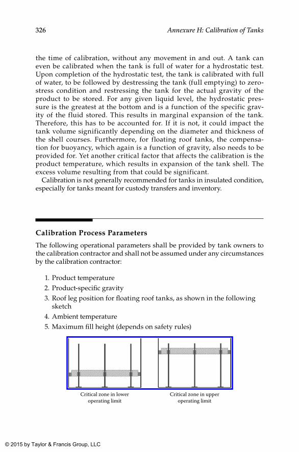
326 Annexure H: Calibration of Tanks
the time of calibration, without any movement in and out. A tank can even be calibrated when the tank is full of water for a hydrostatic test. Upon completion of the hydrostatic test, the tank is calibrated with full of water, to be followed by destressing the tank (full emptying) to zero-stress condition and restressing the tank for the actual gravity of the product to be stored. For any given liquid level, the hydrostatic pres-sure is the greatest at the bottom and is a function of the specific grav-ity of the fluid stored. This results in marginal expansion of the tank. Therefore, this has to be accounted for. If it is not, it could impact the tank volume significantly depending on the diameter and thickness of the shell courses. Furthermore, for floating roof tanks, the compensa-tion for buoyancy, which again is a function of gravity, also needs to be provided for. Yet another critical factor that affects the calibration is the product temperature, which results in expansion of the tank shell. The excess volume resulting from that could be significant.
Calibration is not generally recommended for tanks in insulated condition, especially for tanks meant for custody transfers and inventory.
Calibration Process Parameters
The following operational parameters shall be provided by tank owners to the calibration contractor and shall not be assumed under any circumstances by the calibration contractor:
1. Product temperature 2. Product-specific gravity 3. Roof leg position for floating roof tanks, as shown in the following
sketch 4. Ambient temperature 5. Maximum fill height (depends on safety rules)
Critical zone in loweroperating limit
Critical zone in upperoperating limit
K22265_Book.indb 326 4/20/15 5:50 PM
© 2015 by Taylor & Francis Group, LLC
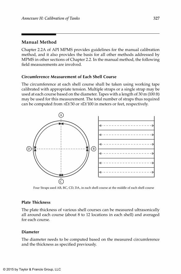
327Annexure H: Calibration of Tanks
Manual Method
Chapter 2.2A of API MPMS provides guidelines for the manual calibration method, and it also provides the basis for all other methods addressed by MPMS in other sections of Chapter 2.2. In the manual method, the following field measurements are involved.
Circumference Measurement of Each Shell Course
The circumference at each shell course shall be taken using working tape calibrated with appropriate tension. Multiple straps or a single strap may be used at each course based on the diameter. Tapes with a length of 30 m (100 ft) may be used for this measurement. The total number of straps thus required can be computed from πD/30 or πD/100 in meters or feet, respectively.
B
C
Four Straps used AB, BC, CD, DA, in each shell course at the middle of each shell course
A
D
Plate Thickness
The plate thickness of various shell courses can be measured ultrasonically all around each course (about 8 to 12 locations in each shell) and averaged for each course.
Diameter
The diameter needs to be computed based on the measured circumference and the thickness as specified previously.
K22265_Book.indb 327 4/20/15 5:50 PM
© 2015 by Taylor & Francis Group, LLC
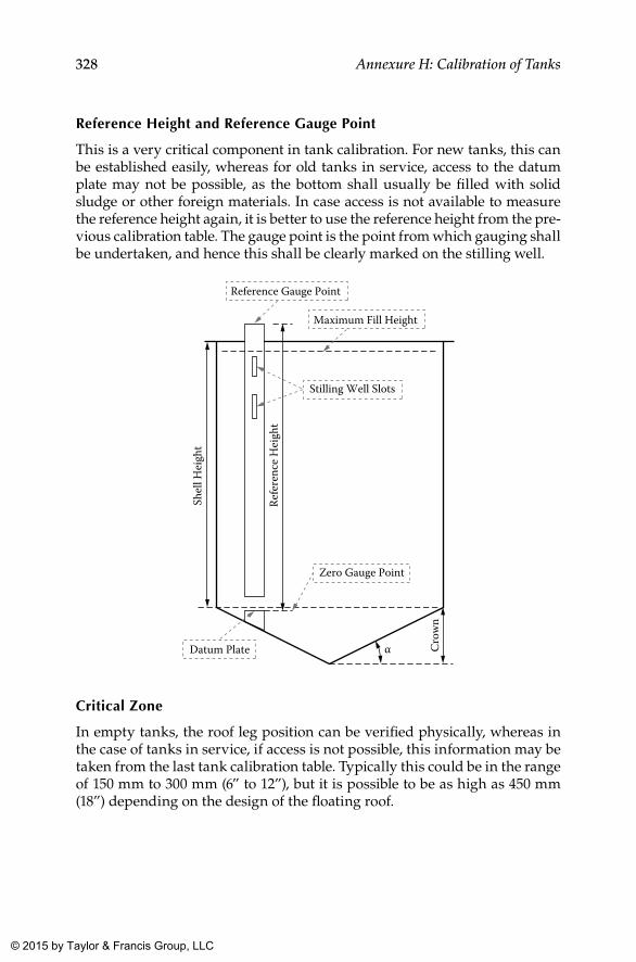
328 Annexure H: Calibration of Tanks
Reference Height and Reference Gauge Point
This is a very critical component in tank calibration. For new tanks, this can be established easily, whereas for old tanks in service, access to the datum plate may not be possible, as the bottom shall usually be filled with solid sludge or other foreign materials. In case access is not available to measure the reference height again, it is better to use the reference height from the pre-vious calibration table. The gauge point is the point from which gauging shall be undertaken, and hence this shall be clearly marked on the stilling well.
Shel
l Hei
ght
Datum Plate
Zero Gauge Point
Refe
renc
e H
eigh
t
Stilling Well Slots
Reference Gauge Point
Cro
wn
Maximum Fill Height
α
Critical Zone
In empty tanks, the roof leg position can be verified physically, whereas in the case of tanks in service, if access is not possible, this information may be taken from the last tank calibration table. Typically this could be in the range of 150 mm to 300 mm (6” to 12”), but it is possible to be as high as 450 mm (18”) depending on the design of the floating roof.
K22265_Book.indb 328 4/20/15 5:50 PM
© 2015 by Taylor & Francis Group, LLC
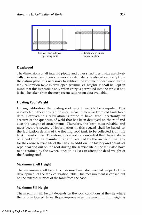
329Annexure H: Calibration of Tanks
Critical zone in loweroperating limit
Critical zone in upperoperating limit
Deadwood
The dimensions of all internal piping and other structures inside are physi-cally measured, and their volumes are calculated distributed vertically from the datum plate. It is necessary to subtract the volume of deadwood as the tank calibration table is developed (volume vs. height). It shall be kept in mind that this is possible only when entry is permitted into the tank; if not, it shall be taken from the most recent calibration data available.
Floating Roof Weight
During calibration, the floating roof weight needs to be computed. This is collected either through physical measurement or from old tank table data. However, this calculation is prone to have large uncertainty on account of the quantum of weld that has been deployed on the roof and also the weight of attachments. Therefore, the best, most reliable, and most accurate source of information in this regard shall be based on the fabrication details of the floating roof tank to be collected from the tank manufacturer. Therefore, it is absolutely essential that these data be obtained from the manufacturer and retained by the owner of the tank for the entire service life of the tank. In addition, the history and details of repair carried out on the roof during the service life of the tank also have to be retained by the owner, since this also can affect the dead weight of the floating roof.
Maximum Shell Height
The maximum shell height is measured and documented as part of the development of the tank calibration table. This measurement is carried out on the external surface of the tank from the base.
Maximum Fill Height
The maximum fill height depends on the local conditions at the site where the tank is located. In earthquake-prone sites, the maximum fill height is
K22265_Book.indb 329 4/20/15 5:50 PM
© 2015 by Taylor & Francis Group, LLC
330 Annexure H: Calibration of Tanks
restricted to 1,200 mm to 1,800 mm (4 ft to 6 ft) below the top rim or over-flow. For floating roof tanks, the limiting factor is the maximum height to which the floating roof can go.
bottom Calibration
Various types of tank bottoms are possible, meaning that they can be flat, cone up, or cone down. Tank bottoms need to be measured by a physical survey after entry is allowed for tanks in service. An alternate option is to calibrate the bottom with liquid (water). While the tank is in service, the zero gauge volume is copied from old tank calibration tables. The zero gauge volume is the volume of the tank below the datum plate.
Tilt
The tilt of a storage tank can be measured either using optical methods or manually by using plumb measurements.
Capacity Table
The capacity table for any storage tank is a table that gives the volume of the tank at any given height. The following corrections need to be applied to develop this table:
• Floating roof buoyancy correction• Tank tilt correction• Hydrostatic correction• Shell temperature correction• Master tape correction• Working tape correction• Other corrections such as tape rise
Floating Roof buoyancy Correction
This correction is based on the gravity of the product and floating roof weight. Floating roof buoyancy (FRB) correction (in units for volume) shall be subtracted from the total volume at any given level as long as the floating roof is fully floating. In the critical zone, the FRB correction is distributed over the range of the zone, whereas below the critical zone, FRB correction is zero. The tank table carries the base FRB correction for a given gravity and incremental correction for variations in base gravity.
K22265_Book.indb 330 4/20/15 5:50 PM
© 2015 by Taylor & Francis Group, LLC
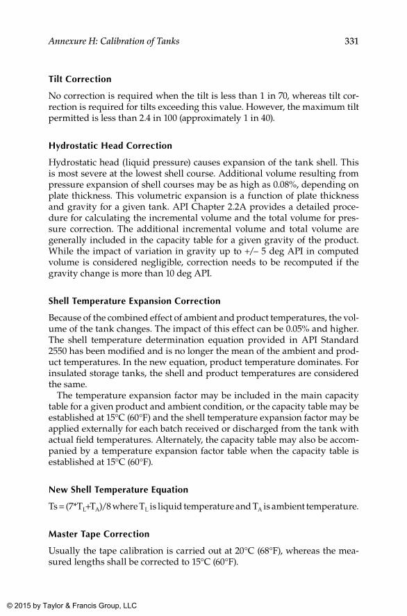
331Annexure H: Calibration of Tanks
Tilt Correction
No correction is required when the tilt is less than 1 in 70, whereas tilt cor-rection is required for tilts exceeding this value. However, the maximum tilt permitted is less than 2.4 in 100 (approximately 1 in 40).
Hydrostatic Head Correction
Hydrostatic head (liquid pressure) causes expansion of the tank shell. This is most severe at the lowest shell course. Additional volume resulting from pressure expansion of shell courses may be as high as 0.08%, depending on plate thickness. This volumetric expansion is a function of plate thickness and gravity for a given tank. API Chapter 2.2A provides a detailed proce-dure for calculating the incremental volume and the total volume for pres-sure correction. The additional incremental volume and total volume are generally included in the capacity table for a given gravity of the product. While the impact of variation in gravity up to +/– 5 deg API in computed volume is considered negligible, correction needs to be recomputed if the gravity change is more than 10 deg API.
Shell Temperature Expansion Correction
Because of the combined effect of ambient and product temperatures, the vol-ume of the tank changes. The impact of this effect can be 0.05% and higher. The shell temperature determination equation provided in API Standard 2550 has been modified and is no longer the mean of the ambient and prod-uct temperatures. In the new equation, product temperature dominates. For insulated storage tanks, the shell and product temperatures are considered the same.
The temperature expansion factor may be included in the main capacity table for a given product and ambient condition, or the capacity table may be established at 15°C (60°F) and the shell temperature expansion factor may be applied externally for each batch received or discharged from the tank with actual field temperatures. Alternately, the capacity table may also be accom-panied by a temperature expansion factor table when the capacity table is established at 15°C (60°F).
New Shell Temperature Equation
Ts = (7*TL+TA)/8 where TL is liquid temperature and TA is ambient temperature.
Master Tape Correction
Usually the tape calibration is carried out at 20°C (68°F), whereas the mea-sured lengths shall be corrected to 15°C (60°F).
K22265_Book.indb 331 4/20/15 5:50 PM
© 2015 by Taylor & Francis Group, LLC
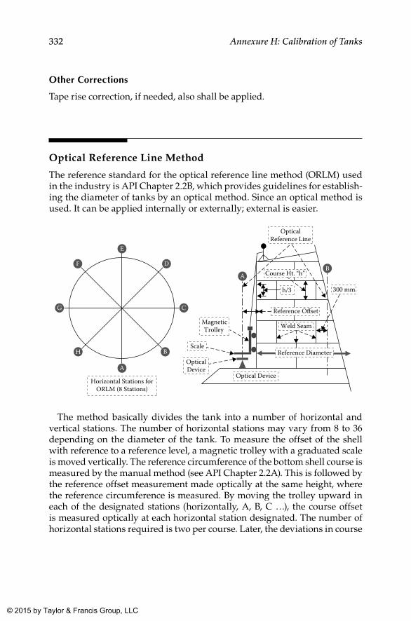
332 Annexure H: Calibration of Tanks
Other Corrections
Tape rise correction, if needed, also shall be applied.
Optical Reference Line Method
The reference standard for the optical reference line method (ORLM) used in the industry is API Chapter 2.2B, which provides guidelines for establish-ing the diameter of tanks by an optical method. Since an optical method is used. It can be applied internally or externally; external is easier.
AB
OpticalDeviceA
B
C
D
E
F
G
H
Horizontal Stations forORLM (8 Stations)
Reference Offset
OpticalReference Line
MagneticTrolley
Scale
300 mmh/3
Weld Seam
Optical Device
Course Ht. “h”
Reference Diameter
The method basically divides the tank into a number of horizontal and vertical stations. The number of horizontal stations may vary from 8 to 36 depending on the diameter of the tank. To measure the offset of the shell with reference to a reference level, a magnetic trolley with a graduated scale is moved vertically. The reference circumference of the bottom shell course is measured by the manual method (see API Chapter 2.2A). This is followed by the reference offset measurement made optically at the same height, where the reference circumference is measured. By moving the trolley upward in each of the designated stations (horizontally, A, B, C …), the course offset is measured optically at each horizontal station designated. The number of horizontal stations required is two per course. Later, the deviations in course
K22265_Book.indb 332 4/20/15 5:50 PM
© 2015 by Taylor & Francis Group, LLC
333Annexure H: Calibration of Tanks
offsets from the reference offset are averaged for each course. By using the reference circumference and averaged offset readings, the diameter of each shell course is established.
To ensure the reliability of measurements, the following aspects need to be given due consideration:
• The stability of the optical device shall be ensured.• The device shall be level in all directions.• The optical ray shall be vertical throughout the height of the tank
(within limits).• The reference offset shall be rechecked after the full vertical traverse
of the magnetic trolley.• The optical device shall be randomly checked for perpendicularity
at three locations by rotating the device 360°.• In extreme wind conditions, where it is difficult to maintain the trol-
ley in contact with the shell, calibration shall not be undertaken
The rest of the measurements are identical to those specified in the manual method described in API Chapter 2.2A, and the tank capacity table shall be prepared based on these measurements.
The significant advantage of this process is that it does not require any scaffolding to carry out shell offsets. Furthermore, as the reference circum-ference is at the base (first shell course), it is much easier to take a proper accurate measurement.
Optical Triangulation Method
The reference standard followed in the industry for this optical triangula-tion method (OTM) is API Chapter 2.2C, which establishes diameters of the courses by an optical method. While this method can be applied internally and externally, it is easier to apply internally.
K22265_Book.indb 333 4/20/15 5:50 PM
© 2015 by Taylor & Francis Group, LLC
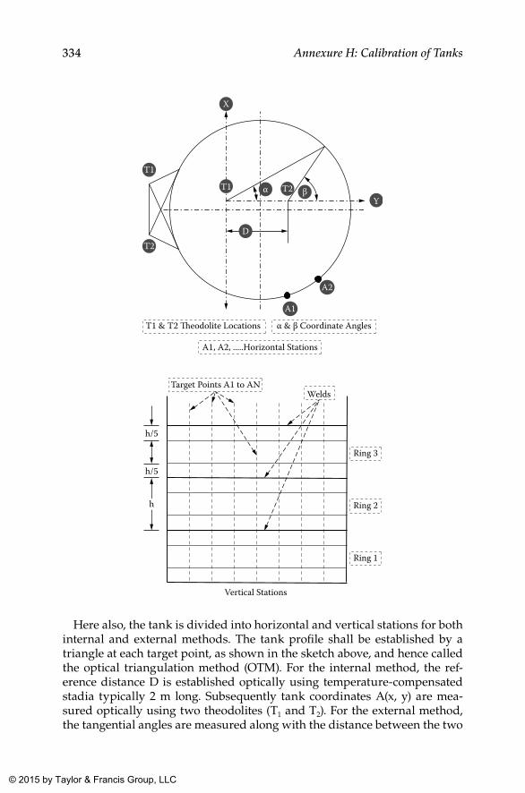
334 Annexure H: Calibration of Tanks
T1
T2
T2Y
X
D
β
T1 & T2 �eodolite Locations α & β Coordinate Angles
A1
A2
A1, A2, .....Horizontal Stations
αT1
h/5
h/5
Welds Target Points A1 to AN
Ring 1
Ring 2
Ring 3
Vertical Stations
h
Here also, the tank is divided into horizontal and vertical stations for both internal and external methods. The tank profile shall be established by a triangle at each target point, as shown in the sketch above, and hence called the optical triangulation method (OTM). For the internal method, the ref-erence distance D is established optically using temperature-compensated stadia typically 2 m long. Subsequently tank coordinates A(x, y) are mea-sured optically using two theodolites (T1 and T2). For the external method, the tangential angles are measured along with the distance between the two
K22265_Book.indb 334 4/20/15 5:50 PM
© 2015 by Taylor & Francis Group, LLC
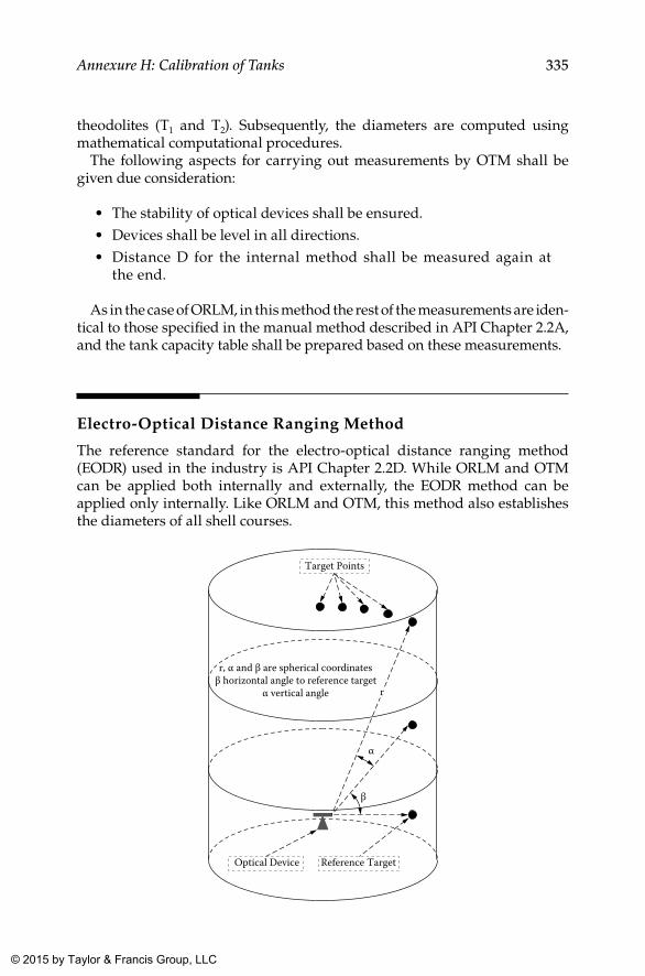
335Annexure H: Calibration of Tanks
theodolites (T1 and T2). Subsequently, the diameters are computed using mathematical computational procedures.
The following aspects for carrying out measurements by OTM shall be given due consideration:
• The stability of optical devices shall be ensured.• Devices shall be level in all directions.• Distance D for the internal method shall be measured again at
the end.
As in the case of ORLM, in this method the rest of the measurements are iden-tical to those specified in the manual method described in API Chapter 2.2A, and the tank capacity table shall be prepared based on these measurements.
Electro-Optical Distance Ranging Method
The reference standard for the electro-optical distance ranging method (EODR) used in the industry is API Chapter 2.2D. While ORLM and OTM can be applied both internally and externally, the EODR method can be applied only internally. Like ORLM and OTM, this method also establishes the diameters of all shell courses.
Target Points
Reference TargetOptical Device
β
α
r, α and β are spherical coordinatesβ horizontal angle to reference target
α vertical angle r
K22265_Book.indb 335 4/20/15 5:50 PM
© 2015 by Taylor & Francis Group, LLC
336 Annexure H: Calibration of Tanks
In this method, a reference target on the bottom course is established fol-lowed by observing the reference distance and reference angle. Spherical coordinates are measured using a distance ranging device (r, α, β) for each target point. In this method, the tank profile is thus established from bot-tom to top. The reference distance of the target and the reference angle of the target at the end are rechecked. Based on these measurements, using standard mathematical procedures, the diameter of individual shell courses is computed. With an online computer, diameters can be determined instantaneously.
The following aspects for carrying out measurements with the EODR method shall be given due consideration:
• The device shall be level in all directions.• Measurements at the reference targets after the complete traverse of
the tank shall be rechecked, and measurements thus obtained shall be a repetition of the initial measurements.
As in the case of the other three methods, in this method also the rest of the measurements are identical to those specified in the manual method described in API Chapter 2.2A, and the tank capacity table shall be prepared based on these measurements.
Liquid Calibration
The applicable reference standard for this method is API Standard 2555. Many client specifications for hydrocarbon storage tanks require liquid cali-bration. This is a very accurate method, but it is time-consuming. In this method, level versus volume is established directly. Volume Q1 is metered (volume is measured through a flow meter, calibrated prior to the start of tank calibration), and the corresponding level L1 is measured. Further increments in levels shall depend on the tank diameter and generally should be 10 mm to 300 mm (6” to 1’). The flow meter used for tank calibration shall undergo calibration before and after calibration of the tank to ensure accuracy.
In liquid calibration, hydrostatic correction is not necessary, because at each level, the tank gets expanded because of the internal pressure. Furthermore, this procedure does not require any deadwood correction. For liquid calibration, either the product or water can be used. If water is used for calibration, adjustments to the volume by courses are necessary because of variation in gravity between water and the product. As in the case of other procedures, the reference height shall be measured per API Chapter 2.2A.
K22265_Book.indb 336 4/20/15 5:50 PM
© 2015 by Taylor & Francis Group, LLC
337Annexure H: Calibration of Tanks
Summary
It is required that tanks used for custody transfers, mass balance in refiner-ies, volume balances in tank farms and pipeline terminals, and so on are cali-brated. In this regard the following aspects shall be given due consideration irrespective of the method adopted:
• Tank fabrication drawings shall not be used as a basis for determin-ing the tank diameter.
• Recalibration at a set frequency is also equally important.• Any of the previously mentioned methods may be used to establish
tank diameters.• Tank calibration shall never be undertaken over insulation in insu-
lated tanks.• For insulated tanks, internal calibration or liquid calibration may be
used if insulation cannot be removed.• If insulation can be removed, external calibration may be used.• Shell expansion due to hydrostatic pressure and expansion due to
temperature are not negligible and hence shall be included in the development of the tank capacity table.
K22265_Book.indb 337 4/20/15 5:50 PM
© 2015 by Taylor & Francis Group, LLC
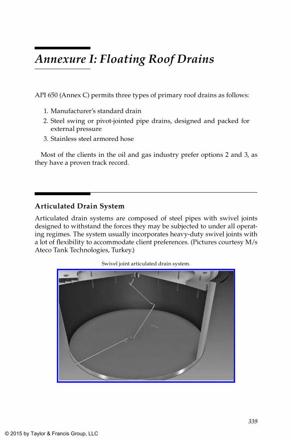
339
Annexure I: Floating Roof Drains
API 650 (Annex C) permits three types of primary roof drains as follows:
1. Manufacturer’s standard drain 2. Steel swing or pivot-jointed pipe drains, designed and packed for
external pressure 3. Stainless steel armored hose
Most of the clients in the oil and gas industry prefer options 2 and 3, as they have a proven track record.
Articulated Drain System
Articulated drain systems are composed of steel pipes with swivel joints designed to withstand the forces they may be subjected to under all operat-ing regimes. The system usually incorporates heavy-duty swivel joints with a lot of flexibility to accommodate client preferences. (Pictures courtesy M/s Ateco Tank Technologies, Turkey.)
Swivel joint articulated drain system.
K22265_Book.indb 339 4/20/15 5:50 PM
© 2015 by Taylor & Francis Group, LLC
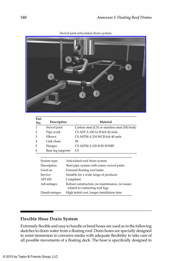
340 Annexure I: Floating Roof Drains
Swivel joint articulated drain system.
4
5
1 3
2
6
Part No. Description Material
1 Swivel joint Carbon steel (CS) or stainless steel (SS) body2 Pipe work CS AST A 106 Gr B Sch 40 smls3 Elbows CS ASTM A 234 WCB Sch 40 smls4 Link chain SS5 Flanges CS ASTM A 105 #150 WNRF6 Base leg supports CS
System type Articulated roof drain systemDescription Steel pipe system with rotary swivel jointsUsed on External floating roof tanksService Suitable for a wide range of productsAPI 650 CompliantAdvantages Robust construction, no maintenance, no issues
related to contacting roof legsDisadvantages High initial cost, longer installation time
Flexible Hose Drain System
Extremely flexible and easy to handle or bend hoses are used as in the following sketches to drain water from a floating roof. Drain hoses are specially designed to resist immersion in corrosive media with adequate flexibility to take care of all possible movements of a floating deck. The hose is specifically designed to
K22265_Book.indb 340 4/20/15 5:50 PM
© 2015 by Taylor & Francis Group, LLC
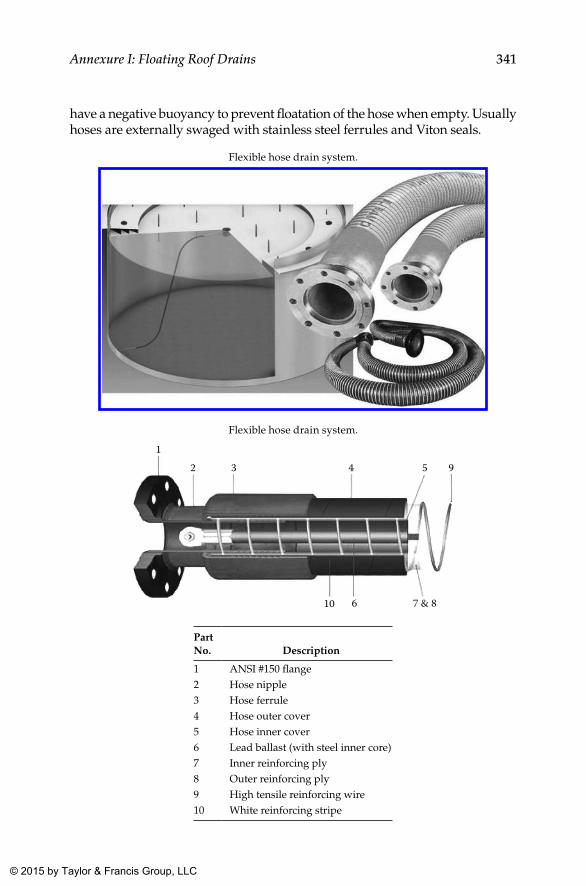
341Annexure I: Floating Roof Drains
have a negative buoyancy to prevent floatation of the hose when empty. Usually hoses are externally swaged with stainless steel ferrules and Viton seals.
Flexible hose drain system.
Flexible hose drain system.
12 3 4 5 9
7 & 8610
Part No. Description
1 ANSI #150 flange2 Hose nipple3 Hose ferrule4 Hose outer cover5 Hose inner cover6 Lead ballast (with steel inner core)7 Inner reinforcing ply8 Outer reinforcing ply9 High tensile reinforcing wire10 White reinforcing stripe
K22265_Book.indb 341 4/20/15 5:50 PM
© 2015 by Taylor & Francis Group, LLC
343
Annexure J: Floating Roof Seal Selection Guidelines
While numerous solutions are available in the market with regard to the type and number of seals to be provided on floating decks, only very limited guidance is available from standards specifications. If the wrong types of seals are selected, issues with regard to emissions and outages due to pre-mature failures can be expected. Therefore, it was considered essential to provide some more insights about seal selection criteria and also about com-mercially available seals and their working principles, from which the read-ers might be able to decide on the types of seals they may have to select for their specific situation.
Considerations
The seal selection process shall definitely consider the following:
• Emission mitigation• Centering of floating deck and smooth up-and-down movement of
floating deck• Safeguards against probable rim fires• Ease of maintenance and inspection
Chemical Compatibility
All metallic and nonmetallic materials (including elastomers and fabric) used in the seal shall be compatible with the fluid stored. Apart from the currently proposed fluid for storage, consideration of probable changes in the quality of products that may arise in the future also might be rewarding in the long run.
uV and Weather Resistance
Ultraviolet (UV) and weather resistance is another key consideration to seal selection and design. Materials exposed to weather should be resistant to the effects of sun, wind, and, depending on where the tank is located, extreme
K22265_Book.indb 343 4/20/15 5:50 PM
© 2015 by Taylor & Francis Group, LLC
344 Annexure J: Floating Roof Seal Selection Guidelines
cold and/or heat, especially the dust storm conditions prevailing in the Middle East.
Resistance to Abrasion
The seal’s resistance to abrasion is yet another consideration, which depends on factors such as cycle frequency, service life, and condition of abrading surface (shell surface). In addition, seal construction features such as the width of the plate, pressure application method, and so on can also signifi-cantly affect the performance and service life of the seal.
Suitability against Operational Range
Since the tank shell is a fabricated structure using comparatively low thick-ness plates and because of the huge quantities of welding involved, it is not possible to obtain precise accuracy with regard to dimensions. Therefore, the suitability of the roof seal to accommodate a wide range of dimensional disparity would be an added feature of any seal. In addition, for external floating roofs where dynamic forces such as wind and turbulence can move the floating roof, a higher range compared to that for internal floating roofs may be called for.
Similarly, designing seals to operate effectively across varying rim spaces is extremely important. When rim space varies greatly, support arms in hinged shoe seals should be long enough relative to the rim space to minimize shoe drop. In addition, secondary seal plate length, gauge, and tip type should be determined only after careful evaluation of the operating conditions including cycle frequency, temperature, and shell condition.
Flexibility along Circumference
Circumferential flexibility is the flexibility of the seal circumferentially and is closely related to flexibility for rim space variations. Seal designs and construction should allow expansion and contraction without com-promising seal integrity. Using modular vapor barriers such as gaskets can create gaps. Seals should use a continuous vapor barrier to ensure a proper seal.
Accommodation of Shell Irregularities
A good seal shall be flexible and apply continuous pressure even when the shell surface has irregularities, such as ovality and local departure from pro-file. To counter such issues, seal vendors recommend a flexible shoe with a
K22265_Book.indb 344 4/20/15 5:50 PM
© 2015 by Taylor & Francis Group, LLC
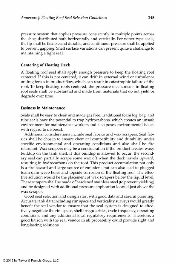
345Annexure J: Floating Roof Seal Selection Guidelines
pressure system that applies pressure consistently in multiple points across the shoe, distributed both horizontally and vertically. For wiper-type seals, the tip shall be flexible and durable, and continuous pressure shall be applied to prevent gapping. Shell surface variations can present quite a challenge to maintaining a tight seal.
Centering of Floating Deck
A floating roof seal shall apply enough pressure to keep the floating roof centered. If this is not centered, it can drift in external wind or turbulence or drag forces in product flow, which can result in catastrophic failure of the roof. To keep floating roofs centered, the pressure mechanisms in floating roof seals shall be substantial and made from materials that do not yield or degrade over time.
Easiness in Maintenance
Seals shall be easy to clean and made gas free. Traditional foam log, bag, and tube seals have the potential to trap hydrocarbons, which creates an unsafe environment for maintenance workers and also poses environmental issues with regard to disposal.
Additional considerations include seal fabrics and wax scrapers. Seal fab-rics shall be chosen to ensure chemical compatibility and durability under specific environmental and operating conditions and also shall be fire retardant. Wax scrapers may be a consideration if the product creates waxy buildup on the tank shell. If this buildup is allowed to occur, the second-ary seal can partially scrape some wax off when the deck travels upward, resulting in hydrocarbons on the roof. This product accumulation not only is a fire hazard and large source of emissions but can also lead to plugged foam dam weep holes and topside corrosion of the floating roof. The effec-tive solution would be the placement of wax scrapers below the liquid level. These scrapers shall be made of hardened stainless steel (to prevent yielding) and be designed with additional pressure application located just above the wax scraper.
Good seal selection and design start with good data and careful planning. Accurate tank data including rim space and verticality surveys would greatly benefit the seal vendor to ensure that the seal system is designed to effec-tively negotiate the rim space, shell irregularities, cycle frequency, operating conditions, and any additional local regulatory requirements. Therefore, a good liaison with the seal vendor in all probability could provide right and long-lasting solutions.
K22265_Book.indb 345 4/20/15 5:50 PM
© 2015 by Taylor & Francis Group, LLC
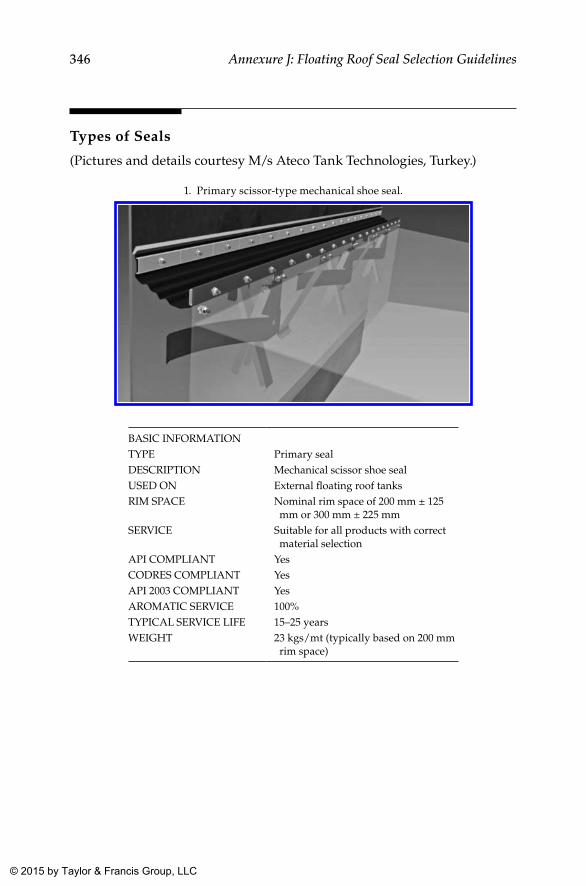
346 Annexure J: Floating Roof Seal Selection Guidelines
Types of Seals
(Pictures and details courtesy M/s Ateco Tank Technologies, Turkey.)
1. Primary scissor-type mechanical shoe seal.
BASIC INFORMATIONTYPE Primary sealDESCRIPTION Mechanical scissor shoe sealUSED ON External floating roof tanksRIM SPACE Nominal rim space of 200 mm ± 125
mm or 300 mm ± 225 mmSERVICE Suitable for all products with correct
material selectionAPI COMPLIANT YesCODRES COMPLIANT YesAPI 2003 COMPLIANT YesAROMATIC SERVICE 100%TYPICAL SERVICE LIFE 15–25 yearsWEIGHT 23 kgs/mt (typically based on 200 mm
rim space)
K22265_Book.indb 346 4/20/15 5:50 PM
© 2015 by Taylor & Francis Group, LLC
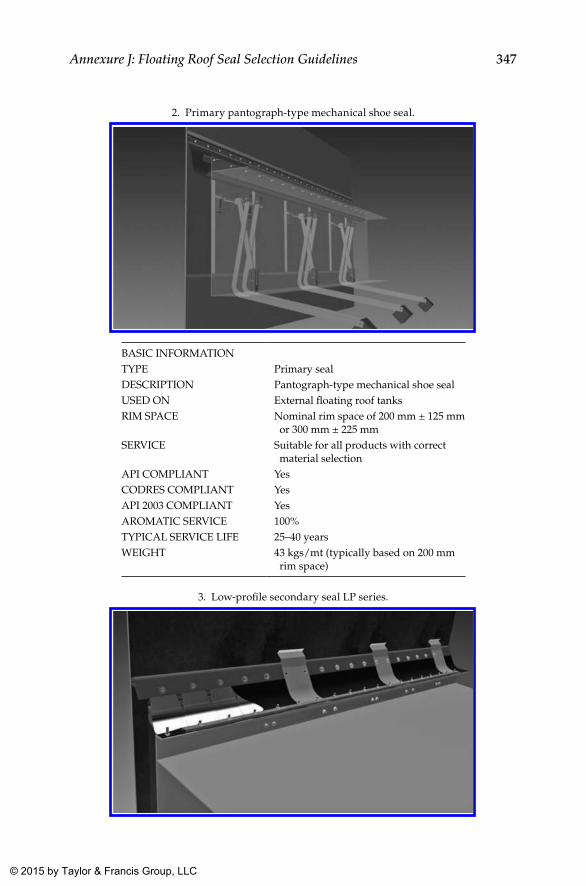
347Annexure J: Floating Roof Seal Selection Guidelines
2. Primary pantograph-type mechanical shoe seal.
BASIC INFORMATIONTYPE Primary sealDESCRIPTION Pantograph-type mechanical shoe sealUSED ON External floating roof tanksRIM SPACE Nominal rim space of 200 mm ± 125 mm
or 300 mm ± 225 mmSERVICE Suitable for all products with correct
material selectionAPI COMPLIANT YesCODRES COMPLIANT YesAPI 2003 COMPLIANT YesAROMATIC SERVICE 100%TYPICAL SERVICE LIFE 25–40 yearsWEIGHT 43 kgs/mt (typically based on 200 mm
rim space)
3. Low-profile secondary seal LP series.
K22265_Book.indb 347 4/20/15 5:50 PM
© 2015 by Taylor & Francis Group, LLC
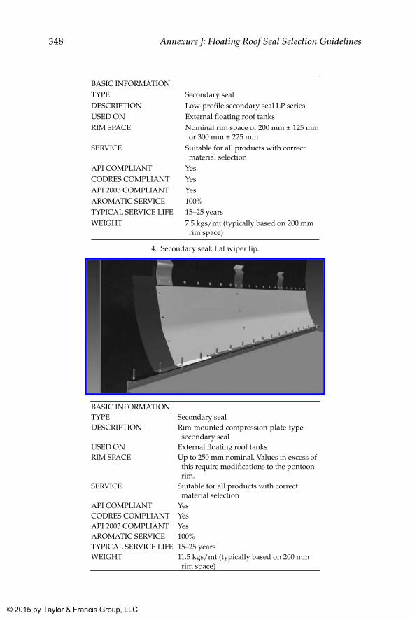
348 Annexure J: Floating Roof Seal Selection Guidelines
BASIC INFORMATIONTYPE Secondary sealDESCRIPTION Low-profile secondary seal LP seriesUSED ON External floating roof tanksRIM SPACE Nominal rim space of 200 mm ± 125 mm
or 300 mm ± 225 mmSERVICE Suitable for all products with correct
material selectionAPI COMPLIANT YesCODRES COMPLIANT YesAPI 2003 COMPLIANT YesAROMATIC SERVICE 100%TYPICAL SERVICE LIFE 15–25 yearsWEIGHT 7.5 kgs/mt (typically based on 200 mm
rim space)
4. Secondary seal: flat wiper lip.
BASIC INFORMATIONTYPE Secondary sealDESCRIPTION Rim-mounted compression-plate-type
secondary sealUSED ON External floating roof tanksRIM SPACE Up to 250 mm nominal. Values in excess of
this require modifications to the pontoon rim.
SERVICE Suitable for all products with correct material selection
API COMPLIANT YesCODRES COMPLIANT YesAPI 2003 COMPLIANT YesAROMATIC SERVICE 100%TYPICAL SERVICE LIFE 15–25 yearsWEIGHT 11.5 kgs/mt (typically based on 200 mm
rim space)
K22265_Book.indb 348 4/20/15 5:50 PM
© 2015 by Taylor & Francis Group, LLC
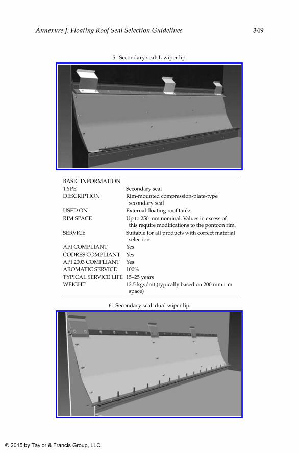
349Annexure J: Floating Roof Seal Selection Guidelines
5. Secondary seal: L wiper lip.
BASIC INFORMATIONTYPE Secondary sealDESCRIPTION Rim-mounted compression-plate-type
secondary sealUSED ON External floating roof tanksRIM SPACE Up to 250 mm nominal. Values in excess of
this require modifications to the pontoon rim.SERVICE Suitable for all products with correct material
selectionAPI COMPLIANT YesCODRES COMPLIANT YesAPI 2003 COMPLIANT YesAROMATIC SERVICE 100%TYPICAL SERVICE LIFE 15–25 yearsWEIGHT 12.5 kgs/mt (typically based on 200 mm rim
space)
6. Secondary seal: dual wiper lip.
K22265_Book.indb 349 4/20/15 5:50 PM
© 2015 by Taylor & Francis Group, LLC
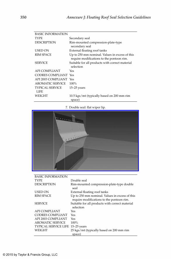
350 Annexure J: Floating Roof Seal Selection Guidelines
BASIC INFORMATIONTYPE Secondary sealDESCRIPTION Rim-mounted compression-plate-type
secondary sealUSED ON External floating roof tanksRIM SPACE Up to 250 mm nominal. Values in excess of this
require modifications to the pontoon rim.SERVICE Suitable for all products with correct material
selectionAPI COMPLIANT YesCODRES COMPLIANT YesAPI 2003 COMPLIANT YesAROMATIC SERVICE 100%TYPICAL SERVICE LIFE
15–25 years
WEIGHT 10.5 kgs/mt (typically based on 200 mm rim space)
7. Double seal: flat wiper lip.
BASIC INFORMATIONTYPE Double sealDESCRIPTION Rim-mounted compression-plate-type double
sealUSED ON External floating roof tanksRIM SPACE Up to 250 mm nominal. Values in excess of this
require modifications to the pontoon rim.SERVICE Suitable for all products with correct material
selectionAPI COMPLIANT YesCODRES COMPLIANT YesAPI 2003 COMPLIANT YesAROMATIC SERVICE 100%TYPICAL SERVICE LIFE 15–25 yearsWEIGHT 25 kgs/mt (typically based on 200 mm rim
space)
K22265_Book.indb 350 4/20/15 5:50 PM
© 2015 by Taylor & Francis Group, LLC
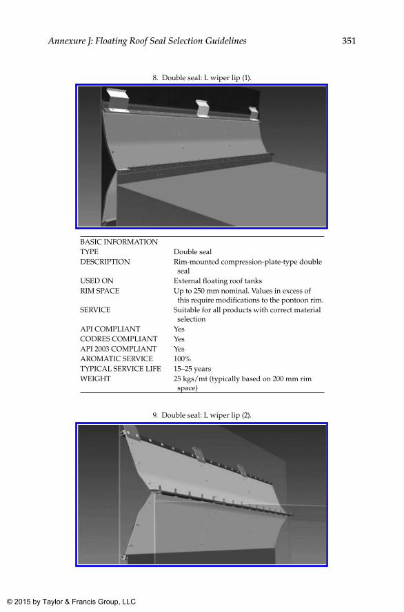
351Annexure J: Floating Roof Seal Selection Guidelines
8. Double seal: L wiper lip (1).
BASIC INFORMATIONTYPE Double sealDESCRIPTION Rim-mounted compression-plate-type double
sealUSED ON External floating roof tanksRIM SPACE Up to 250 mm nominal. Values in excess of
this require modifications to the pontoon rim.SERVICE Suitable for all products with correct material
selectionAPI COMPLIANT YesCODRES COMPLIANT YesAPI 2003 COMPLIANT YesAROMATIC SERVICE 100%TYPICAL SERVICE LIFE 15–25 yearsWEIGHT 25 kgs/mt (typically based on 200 mm rim
space)
9. Double seal: L wiper lip (2).
K22265_Book.indb 351 4/20/15 5:51 PM
© 2015 by Taylor & Francis Group, LLC
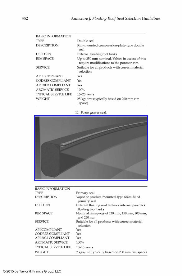
352 Annexure J: Floating Roof Seal Selection Guidelines
BASIC INFORMATIONTYPE Double sealDESCRIPTION Rim-mounted compression-plate-type double
sealUSED ON External floating roof tanksRIM SPACE Up to 250 mm nominal. Values in excess of this
require modifications to the pontoon rim.SERVICE Suitable for all products with correct material
selectionAPI COMPLIANT YesCODRES COMPLIANT YesAPI 2003 COMPLIANT YesAROMATIC SERVICE 100%TYPICAL SERVICE LIFE 15–25 yearsWEIGHT 25 kgs/mt (typically based on 200 mm rim
space)
10. Foam graver seal.
BASIC INFORMATIONTYPE Primary sealDESCRIPTION Vapor or product-mounted-type foam-filled
primary sealUSED ON External floating roof tanks or internal pan deck
floating roof tanksRIM SPACE Nominal rim spaces of 120 mm, 150 mm, 200 mm,
and 250 mmSERVICE Suitable for all products with correct material
selectionAPI COMPLIANT YesCODRES COMPLIANT YesAPI 2003 COMPLIANT YesAROMATIC SERVICE 100%TYPICAL SERVICE LIFE 10–15 yearsWEIGHT 7 kgs/mt (typically based on 200 mm rim space)
K22265_Book.indb 352 4/20/15 5:51 PM
© 2015 by Taylor & Francis Group, LLC
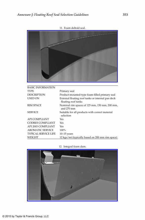
353Annexure J: Floating Roof Seal Selection Guidelines
11. Foam deltoid seal.
BASIC INFORMATIONTYPE Primary sealDESCRIPTION Product-mounted-type foam-filled primary sealUSED ON External floating roof tanks or internal pan deck
floating roof tanksRIM SPACE Nominal rim spaces of 125 mm, 150 mm, 200 mm,
and 270 mmSERVICE Suitable for all products with correct material
selectionAPI COMPLIANT YesCODRES COMPLIANT YesAPI 2003 COMPLIANT YesAROMATIC SERVICE 100%TYPICAL SERVICE LIFE 10–15 yearsWEIGHT 12 kgs/mt (typically based on 200 mm rim space)
12. Integral foam dam.
K22265_Book.indb 353 4/20/15 5:51 PM
© 2015 by Taylor & Francis Group, LLC
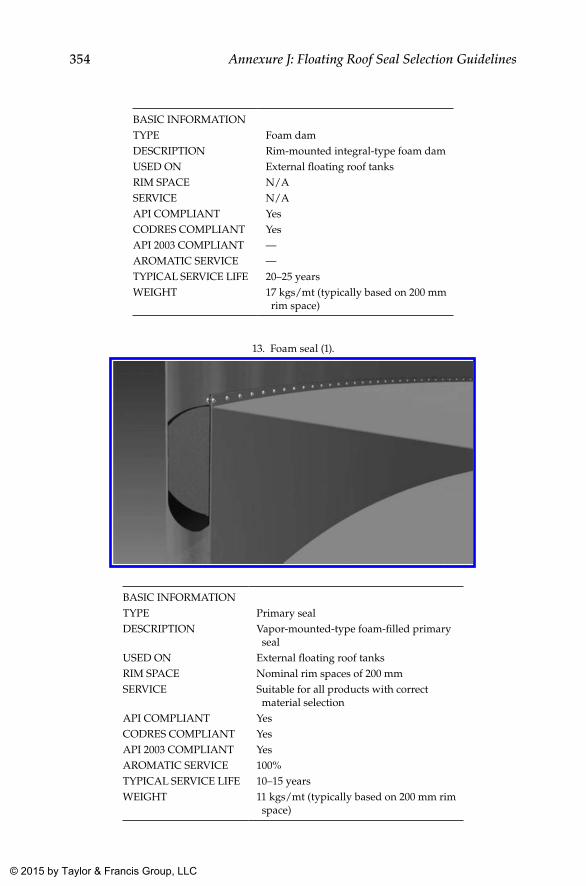
354 Annexure J: Floating Roof Seal Selection Guidelines
BASIC INFORMATIONTYPE Foam damDESCRIPTION Rim-mounted integral-type foam damUSED ON External floating roof tanksRIM SPACE N/ASERVICE N/AAPI COMPLIANT YesCODRES COMPLIANT YesAPI 2003 COMPLIANT —AROMATIC SERVICE —TYPICAL SERVICE LIFE 20–25 yearsWEIGHT 17 kgs/mt (typically based on 200 mm
rim space)
13. Foam seal (1).
BASIC INFORMATIONTYPE Primary sealDESCRIPTION Vapor-mounted-type foam-filled primary
sealUSED ON External floating roof tanksRIM SPACE Nominal rim spaces of 200 mmSERVICE Suitable for all products with correct
material selectionAPI COMPLIANT YesCODRES COMPLIANT YesAPI 2003 COMPLIANT YesAROMATIC SERVICE 100%TYPICAL SERVICE LIFE 10–15 yearsWEIGHT 11 kgs/mt (typically based on 200 mm rim
space)
K22265_Book.indb 354 4/20/15 5:51 PM
© 2015 by Taylor & Francis Group, LLC
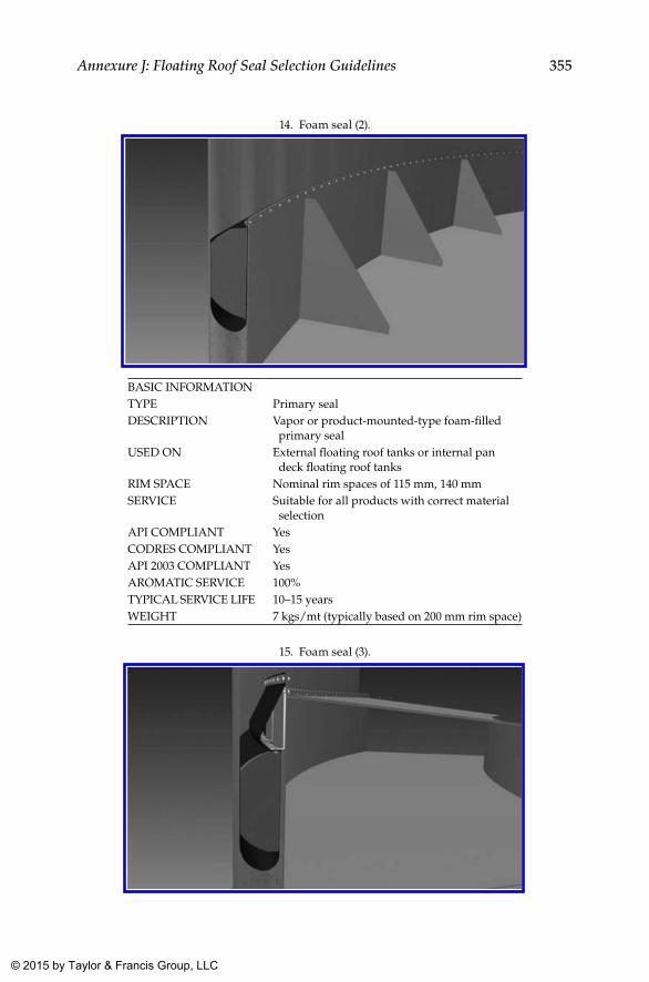
355Annexure J: Floating Roof Seal Selection Guidelines
14. Foam seal (2).
BASIC INFORMATIONTYPE Primary sealDESCRIPTION Vapor or product-mounted-type foam-filled
primary sealUSED ON External floating roof tanks or internal pan
deck floating roof tanksRIM SPACE Nominal rim spaces of 115 mm, 140 mmSERVICE Suitable for all products with correct material
selectionAPI COMPLIANT YesCODRES COMPLIANT YesAPI 2003 COMPLIANT YesAROMATIC SERVICE 100%TYPICAL SERVICE LIFE 10–15 yearsWEIGHT 7 kgs/mt (typically based on 200 mm rim space)
15. Foam seal (3).
K22265_Book.indb 355 4/20/15 5:51 PM
© 2015 by Taylor & Francis Group, LLC
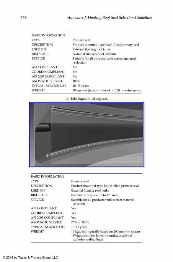
356 Annexure J: Floating Roof Seal Selection Guidelines
BASIC INFORMATIONTYPE Primary sealDESCRIPTION Product-mounted-type foam-filled primary sealUSED ON External floating roof tanksRIM SPACE Nominal rim spaces of 200 mmSERVICE Suitable for all products with correct material
selectionAPI COMPLIANT YesCODRES COMPLIANT YesAPI 2003 COMPLIANT YesAROMATIC SERVICE 100%TYPICAL SERVICE LIFE 10–15 yearsWEIGHT 20 kgs/mt (typically based on 200 mm rim space)
16. Tube liquid-filled bag seal.
BASIC INFORMATIONTYPE Primary sealDESCRIPTION Product-mounted-type liquid-filled primary sealUSED ON External floating roof tanksRIM SPACE Nominal rim space up to 275 mmSERVICE Suitable for all products with correct material
selectionAPI COMPLIANT YesCODRES COMPLIANT YesAPI 2003 COMPLIANT YesAROMATIC SERVICE 75% or 100%TYPICAL SERVICE LIFE 10–15 yearsWEIGHT 16 kgs/mt (typically based on 200 mm rim space)
Weight includes lower mounting angle but excludes sealing liquid
K22265_Book.indb 356 4/20/15 5:51 PM
© 2015 by Taylor & Francis Group, LLC
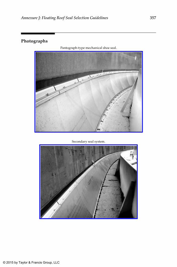
357Annexure J: Floating Roof Seal Selection Guidelines
PhotographsPantograph-type mechanical shoe seal.
Secondary seal system.
K22265_Book.indb 357 4/20/15 5:51 PM
© 2015 by Taylor & Francis Group, LLC
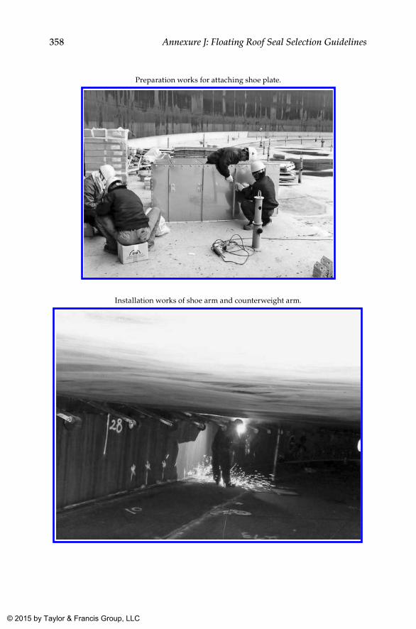
358 Annexure J: Floating Roof Seal Selection Guidelines
Preparation works for attaching shoe plate.
Installation works of shoe arm and counterweight arm.
K22265_Book.indb 358 4/20/15 5:51 PM
© 2015 by Taylor & Francis Group, LLC
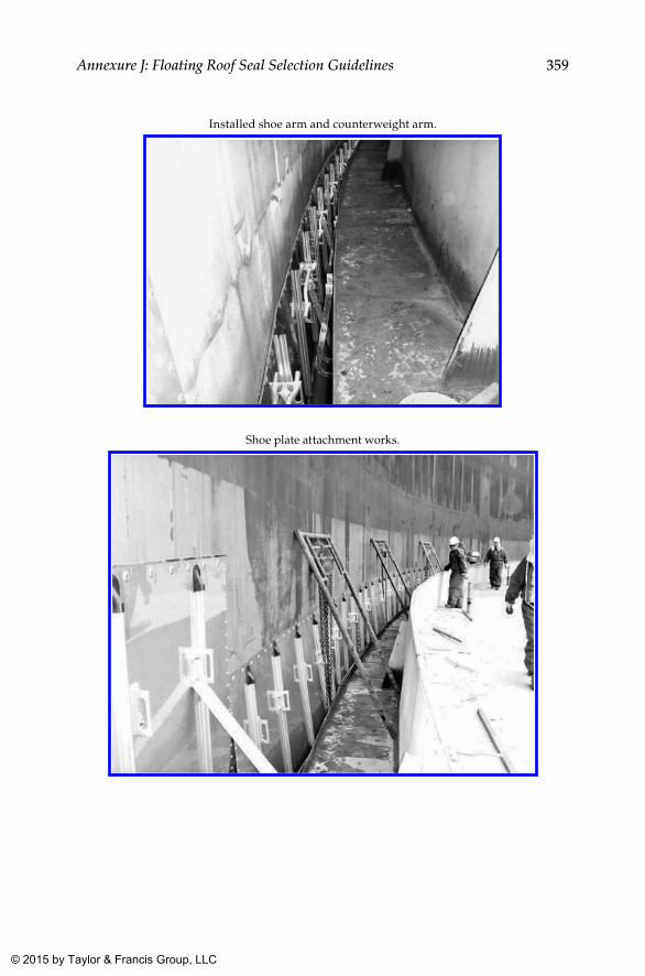
359Annexure J: Floating Roof Seal Selection Guidelines
Installed shoe arm and counterweight arm.
Shoe plate attachment works.
K22265_Book.indb 359 4/20/15 5:51 PM
© 2015 by Taylor & Francis Group, LLC
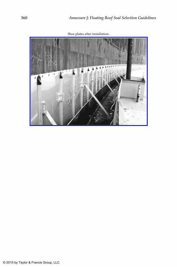
360 Annexure J: Floating Roof Seal Selection Guidelines
Shoe plates after installation.
K22265_Book.indb 360 4/20/15 5:51 PM
© 2015 by Taylor & Francis Group, LLC
361
Bibliography
1. Aboveground Storage Tanks, Philip E. Myers. 2. Above Ground Storage Tank Design, Inspection, and Compliance Management, a pre-
sentation by Gregory Coppola, P.E., Kinder Morgan Energy Partners. 3. Pictorial Surface Preparation Standards for Painting Steel Surfaces, HMG Paints. 4. NFPA 30 Flammable and Combustible Liquids Code, 2003 Edition, National Fire Protection
Association. 5. Specifications for Storage Tanks, KLM Technology Group. 6. Brochure of M/s Bygging Udheman. 7. Brochure of M/s Byggwik (UK) Ltd. 8. Brochure of Kansai Protection Coating Systems, Kansai Paints Japan. 9. Brochure of Ateco Floating Roof Seals. 10. Tank Erection Procedure, M/s Bygging (India) Ltd. 11. Brochure of Ateco Roof Drains. 12. Article on Surface Preparation, M/s Trancocean. 13. ASME Section VIII Div (1). Rules for construction of Pressure Vessels. 14. Welded Steel Tanks for Oil Storage, API 650. 15. Design and Construction of Large, Welded, Low-Pressure Storage Tanks, API 620. 16. Tank Inspection, Repair, Alteration, and Reconstruction, API 653. 17. Measurement and Calibration of Upright Cylindrical Tanks by the Manual Strapping
Method, API MPMS 2.2A. 18. Calibration of Upright Cylindrical Tanks Using the Optical Reference Line Method
(ORLM), API MPMS 2.2 B. 19. Calibration of Upright Cylindrical Tanks Using the Optical-Triangulation Method
(OTM), API MPMS 2.2 C. 20. Calibration of Upright Cylindrical Tanks Using the Internal Electro-Optical Distance
Ranging Method (EODR), API MPMS 2.2 D. 21. Method for Liquid Calibration of Tanks, API Standard 2555. 22. Fire Precautions at Petroleum Refineries and Bulk Storage Installation, Institute of
Petroleum.
K22265_Book.indb 361 4/20/15 5:51 PM
© 2015 by Taylor & Francis Group, LLC
363
Index
A
Above ground tanks, 1–14, 93–121. See also Storage tanks
calibration, 323–337classification, 5–7, 15–17cleaning, 191–217construction standards, 9design, 9, 37–44documentation, 219–236erection, 63–91erection mechanical works, 49–61external painting, 191–217floating roof drains, 339–341floating roof seals, 343–360floating roof tanks, 305–317, 319–322formats, 237–281inspection, 297–303internal lining, 191–217material specification summary,
283–284nondestructive testing, 151–168radiography, 289–295roofs, 93–121shell courses, 93–121sketches, tables, joint design guide,
285–286tank farm layout, 19–36test plan, 297–303tests, 169–189weld inspection, 139–149welder qualification, 287–288welding, 123–137welding procedure, 287–288
American Society for Testing and Materials, 10
American Society of Mechanical Engineers, 10
American Water Works Association, 10Annular, bottom plates, weld
inspection, 144–146shell, 146
Annular clearance report, 238, 276Annular plate welds, 88–89
Annular plates, 71, 80–82Appurtenance installation, 115–120Articulated drain system, floating roof
drain, 339–340As-built documents, 44ASME. See American Society of
Mechanical EngineersASTM. See American Society for
Testing and MaterialsAWWA. See American Water Works
Association
B
Back gouging, 133Banding and circumference report,
238, 257Bending of plates, 73–79
direction of bending, 73prepinging, 74–76templates, 76–79
Bill of materials with specifications, 57Blast cleaning, 198Blasting, safety precautions, painting
equipment, 214BOCA. See Building Officials and Code
Administrators InternationalBottom plates, 71, 81
layout, 81–82welds, 89
Building Officials and Code Administrators International, 10
Butt welds, 142Bygging, shell erection, 95–96
C
Calibration, tanks, 60–61, 325–326calibration process parameters, 326capacity table, 330–332
floating roof buoyancy correction, 330
hydrostatic head correction, 331
K22265_Book.indb 363 4/20/15 5:51 PM
© 2015 by Taylor & Francis Group, LLC
364 Index
master tape correction, 331new shell temperature equation,
331shell temperature expansion
correction, 331tilt correction, 331
electro-optical distance ranging method, 335–336
liquid calibration, 336manual method, 327–330
bottom calibration, 330circumference measurement, 327critical zone, 328–329deadwood, 329diameter, 327floating roof weight, 329maximum fill height, 329–330maximum shell height, 329plate thickness, 327reference height, 328tilt, 330
optical reference line method, 332–333
optical triangulation method, 333–335
Calibration process parameters, 326Calibration reports, 231Capacity chart, storage tanks, 36Capacity table, tank calibration, 325,
330–332floating roof buoyancy correction,
330hydrostatic head correction, 331master tape correction, 331new shell temperature equation, 331shell temperature expansion
correction, 331tilt correction, 331
Certification for materials, 232–234bought out items, 233–234components requiring, 233
Classification of storage tanks, 3–7Classification of storages, 15–17
combustible liquids, 15flammable liquids, 15
Cleaning after hydrostatic test, 191Cleanliness, weld groove, adjacent
area, 130–131Client approvals, tank design, 43
Client requirements, 214Coating of bottom plates, 82Color schemes, 214–217
external coating systems, 216inspection, 217internal lining systems, 216
Color schemes, vapor loss reduction, 214
Combustible liquids, 15Compact soil foundations, 46Concrete ring wall foundations, 47Cone roof plates, 114Construction drawings, 42–43Construction equipment
purchase, 59transfer, 59
Construction standards, 9Contract award, 49Corrosion Engineers, 10Crushed-stone ring wall foundations,
46Cutting of plates, 72–73
D
Defective weld repair, 163Design, storage tanks, 9, 37–44, 52–53
as-built documents, 44basis for designing, 40client approvals, 43construction drawings, 42–43design aids, 38–40design calculations, 40design change note, 43–44documents, 42–43drawings, 41–42
Design aids, storage tanks, 38–40Design calculations, storage tanks,
40Design change notes, storage tanks,
43–44Dimensional inspection report,
227–229, 238, 263Document approval, 52–53Documentation, 219–236
calibrations, reports of, 231certification for materials, 232–234
bought out items, 233–234components requiring, 233
K22265_Book.indb 364 4/20/15 5:51 PM
© 2015 by Taylor & Francis Group, LLC
365Index
dimensional inspection reports, 227–229
foundation selection, 45–46handing over foundation, 47heat treatment records, charts,
234–235inspections
records, 231reports of, 231
manufacturer’s record book, 220–224contents, 221–224, 230–231
material summary, 226nondestructive testing reports, 227,
235–236pad air test reports, 227prehydrostatic inspection report,
229tank design, 42–43tests, reports of, 231tests summary, 227types of foundations, 46–47
compact soil foundations, 46concrete ring wall foundations,
47crushed-stone ring wall
foundations, 46pile-supported foundations, 47slab foundations, 47
weld map, 226nondestructive testing summary
with, 227weld summary, 226–227
Documents list, 54–56Drawings
storage tanks, 52–53tank design, 41–42
Dye penetrant test report, 252
E
Edge preparationnew constructions, 209–211weld, 123
Electro-optical distance ranging method, tank calibration, 335–336
Electrode storage, drying, 133–136Electrodes, 69Equipment required at site, 59
Erection of shellbygging, 95–96conventional method, 93–95, 98–108
shell cutting plan, 98–99erection methodology, compared,
96–98first shell course weld to annular
plate, 108fit up, welding
closure plate, 107first shell course to annular plate,
108fit up closure plate, 107jacking up method, 95–96roof plates, 105–107roof structure, 105–107shell courses, 98–104weld map, 98
Erection of tanks, 63–91bending of plates, 73–79
direction of bending, 73prepinging, 74–76templates, 76–79
bill of materials with specifications, 57
construction equipment, purchase, or transfer of, 59
contract award, 49cutting of plates, 72–73design, 52–53documents approval, 52–53documents list, 54–56drawings, 52–53equipment required at site, 59head office, 49–50identification, raw materials, 69–70inspection of plates, 73intimation of material receipt, 64laying of bottom plates, 80–91
annular plate welds, 88–89annular plates, 80–82bottom plate layout, 81–82bottom plate welds, 89bottom plates, 81coating of bottom plates, 82laying of annular plates, 82–85laying of sketch plates, 86–87recommended weld joint
configurations, 85–86
K22265_Book.indb 365 4/20/15 5:51 PM
© 2015 by Taylor & Francis Group, LLC
366 Index
sketch plates, 81surface preparation, 82testing of welds, 90–91weld between annular, bottom
plates, 89–90welding sequence of plates, 88
load retaining parts, 72–73local contracts, 61marking of plates, 70–72
annular plates, 71bottom plates, 71roof plates, 71shell plates, 71–72sketch plates, 71
material receipt inspection report, 65mechanical works, 49–61organization chart, 52organization setup at site, 51–52purchase of raw materials, 57–58purchases at site, 61raw material inspection, 63–69
consumables, 69electrodes, 69fasteners, 69flanges, 68–69gaskets, 69pipe fittings, 68–69pipes, 68plates, 68
stocklists, materials procured from, 58
storage tank erection, 63traceability, raw materials, 69–70traders, materials procured from, 58work contracts, 60–61
calibration of storage tanks, 60–61
nondestructive testing, subcontract, 60
scaffolding, subcontract, 60surface preparation, internal
lining, subcontract, 60External coating systems, 216
F
Farm, tank, layout of, 19–36fixed roof tanks, 32–36floating roof tanks, 32–33
floating roof type, vs. fixed roof type, 33
location, 29for petroleum stocks
storage classes I, II(2), III(2), 28storage classes II(1) and III(1), 28–30
refinery storage tanks, 32spacing, 29spacing of tanks, 22–30
per Institute of Petroleum guidelines, 28–30
per National Fire Protection Association 30, 22–27
for petroleum stocks, 28–30tank capacity chart, 36tank sizes, 31tank type selection guidelines, 35typical tank farms, 21
Fasteners, 69Fillet welds, 143Film thickness, 213Fit-up inspection report, 247Fixed cone roof tanks, 237–238Fixed roof tanks, 32–36
vs. floating roof tanks, 33Flammable liquids, 15Flanges, 68–69Flexible hose drain system, floating
roof drain, 340–341Floating deck, 35, 41, 93, 141, 238,
276–278, 306, 308–309, 319, 340, 343, 345
Floating roof drains, 339–341articulated drain system, 339–340flexible hose drain system, 340–341
Floating roof seal selection guidelines, 343–360
abrasion resistance, 344chemical compatibility, 343circumference, flexibility along, 344floating deck, centering of, 345maintenance, 345operational range, suitability
against, 344shell irregularities, accommodation
of, 344–345types of seals, 346–356UV, 343–344weather resistance, 343–344
K22265_Book.indb 366 4/20/15 5:51 PM
© 2015 by Taylor & Francis Group, LLC
367Index
Floating roof tanks, 32–33, 238–281, 305–317, 319–322
acceptance criteria, 321additional inspections, 319–322checklist prior to tests, 319–320cleaning, 322client requirements, 309–313designs, 313–315double-deck floating roof, 308external floating roof tank, 306–308internal floating roof tank, 308primary drain, tests, 321primary subclassification, 308–309puncture/floatation test, 319puncture test, procedure, 320–321rainwater accumulation test, 319rainwater fill test, procedure, 321records, 322safety, 322single-deck pontoon floating roof,
309standard requirements, 309–313test medium, 320tests, 319–322tolerance, 319types, 306vs. fixed roof tanks, 33
Formats, 237–281banding and circumference report,
257fit-up inspection report, 247fixed cone roof tanks, 237–238floating roof tanks, 238–281foundation level-inspection report,
240manufacturer’s certification, 275material traceability report, 244platform and ladder inspection
report, 264plumb inspection report, 258pneumatic test report, reinforcement
pads, 262rainwater accumulation test report,
280welding consumable control log, 243welding consumable inspection
report, 242wind girder, roof structure
inspection report, 266
Foundation, tank, 45–47Foundation level-inspection report, 240Foundation selection, 45–46Foundations types, 46–47
compact soil foundations, 46concrete ring wall foundations, 47crushed-stone ring wall
foundations, 46pile-supported foundations, 47slab foundations, 47
G
Gaskets, 69Grinding, welding, 133
H
Hand tool cleaning, 197Handing over foundation, 47Handrails, 120–121Hardness survey report, 237, 254Head office, 49–50Heat treatment records, charts, 234–235High-pressure freshwater cleaning, 196Hydroblasting, 206Hydrostatic test report, 56, 185, 224, 238,
271Hydrostatic testing
settlement of tank, 186–187tank, 181–185
cleaning, 185contents, 182documentation, 185draining, 185filling of test medium, 183–184repair, 184–185retest, 184–185safety precautions, 184standard, client requirements,
181–182tank shell, 181visual inspection, 184water filling, draining rates, 183
I
Identification, raw materials, 69–70Identification cards, welder’s, 130
K22265_Book.indb 367 4/20/15 5:51 PM
© 2015 by Taylor & Francis Group, LLC
368 Index
IMR, 64Inspection of plates, 73Inspection of welds, 144–149
annular, bottom plates, 144–146shell, 146
Inspections, 298–303records, 231reports of, 231
Installation of appurtenances, 115–120Internal lining, surface preparation,
subcontract, 60Internal lining systems, 216International Fire Code Institute, 10Interpass temperature, welding, 132Intimation of material receipt, 64
J
Jacking up method, tank erection, 108–113
jacking up method, 111working procedure, 109–111
Joint design guide, 285–286Joint guide, welds, 124Joints, weld, 123–124
K
Kansai Paints, 192–193, 211Kodak Industrex AA radiographic film,
164
L
Ladder inspection report, 264Laying of annular plates, 82–85Laying of bottom plates, 80–91
annular plate welds, 88–89annular plates, 80–82bottom plate layout, 81–82bottom plate welds, 89bottom plates, 81coating of bottom plates, 82laying of annular plates, 82–85laying of sketch plates, 86–87recommended weld joint
configurations, 85–86sketch plates, 81surface preparation, 82
testing of welds, 90–91weld between annular, bottom
plates, 89–90welding sequence of plates, 88
Laying of sketch plates, 86–87Layout, tank farm, 19–36
fixed roof tanks, 32–36floating roof tanks, 32–33floating roof type, vs. fixed roof
type, 33location, 29for petroleum stocks
storage classes I, II(2), III(2), 28storage classes II(1) and III(1),
28–30refinery storage tanks, 32spacing, 29spacing of tanks, 22–30
per Institute of Petroleum guidelines, 28–30
per National Fire Protection Association 30, 22–27
for petroleum stocks, 28–30storage tank capacity chart, 36tank sizes, 31tank type selection guidelines, 35typical tank farms, 21
Lettering, 214Life of coating, 213Liquid calibration, tanks, 336Liquid penetrant testing, 166Load retaining parts, 72–73Local contracts, 61Logo, 214Low hydrogen stick electrodes
redrying, 134–135redrying conditions, 135storing, 134
Low-pressure storage tanks, 11
M
Magnetic particle test report, 251Magnetic particle testing, 165Manual tank calibration, 327–330
bottom calibration, 330circumference measurement, 327critical zone, 328–329deadwood, 329
K22265_Book.indb 368 4/20/15 5:51 PM
© 2015 by Taylor & Francis Group, LLC
369Index
diameter, 327floating roof weight, 329maximum fill height, 329–330maximum shell height, 329plate thickness, 327reference height, 328tilt, 330
Manufacturer’s certification, 232, 275Manufacturer’s record book, 220–224
contents, 221–224, 230–231Manways, inspection report, 238, 260Marking of plates, 70–72
annular plates, 71bottom plates, 71roof plates, 71shell plates, 71–72sketch plates, 71
Material inspection report, 237, 241Material receipt, 64Material receipt inspection report, 64–65Material specification summary,
283–284Material summary, 55, 223, 226, 237, 244Material traceability report, 244Mechanical works, 49–61
erection of storage tanks, 49–61Metal temperature, preheat, welding, 131MRB. See Manufacturer’s record bookMRIR. See Material receipt inspection
report
N
NACE International, 10National Fire Protection Association,
10, 15, 361NDT. See Nondestructive testingNew constructions, 209–211NFPA. See National Fire Protection
AssociationNon-low hydrogen electrodes
redrying, 135storing, 135
Non-low hydrogen stick electrodes, redrying conditions, 136
Nondestructive testing, 151–168acceptability norms, 162completion checklist, 185, 238,
268–270
defective weld repair, 163documentation, 168liquid penetrant testing, 166magnetic particle testing, 165number, location of radiographs,
151–153personnel, 162procedure, 162progressive, penalty radiography,
162–163radiographic testing, 151radiographs, 162records, 163, 177report, 224, 227, 235–236, 238,
277–279requirements for radiography,
163–164subcontract, 60technique, 162ultrasonic testing, 165visual examination, 166–168
acceptance criteria, 167–168strategy, 166–167vision requirement, 167
weld maps, 154–161, 168welding, 133
Nozzlesinspection report, 238, 260
O
Optical reference line method, tank calibration, 332–333
Optical triangulation method, tank calibration, 333–335
Organization chart, 52Organization setup at site, 51–52
P
Pad air test reports, 227Painting equipment, safety
precautions, 214Paints, 212Petroleum Equipment Institute, 10Pickling, 197Pile-supported foundations, 47Pipe fittings, 68–69Pipes, 68
K22265_Book.indb 369 4/20/15 5:51 PM
© 2015 by Taylor & Francis Group, LLC
370 Index
Plates, 68Platform inspection report, 264Platforms, 120–121Plumb inspection report, 258Pneumatic test report, 56, 224, 238, 262,
273roof, 238, 273
Pneumatic testing, reinforcement pads, 178–181, 262
arrangements, 178–181methodology, 178requirements, 178test pressure, 178
Pontoon floating roof, single-deck, 309Pontoon puncture test report, 238, 282Post weld heat treatment report, 253Power tool cleaning, 198Preheating before welding, 132Prehydrostatic inspection report, 229Primary drain, floating roof tanks,
tests, 321Progressive, penalty radiography,
162–163Punch list, 185, 229, 238, 274Puncture test, floating roof tanks,
procedure, 320–321Purchase of raw materials, 57–58Purchases at site, 61PWHT completion checklist, 238, 268
Q
Qualifications, welder, 129, 287–288
R
Radiographic testing, 151, 289–295acceptance criteria, 290–294defective welding, determination of
limits, 294–295repair, defective welds, 295report, 237, 249technical requirements, 289terminology, 289
Rainwater accumulation testfloating roof tanks, 319report, 280
Rainwater fill test, floating roof tanks, procedure, 321
Raw material inspection, 63–69consumables, 69electrodes, 69fasteners, 69flanges, 68–69gaskets, 69pipe fittings, 68–69pipes, 68plates, 68
Raw material purchase, 57–58Recalibration frequency, tank
calibration, 324Recomputation, tank calibration, 325Reference gauge point, tank calibration,
328Refinery storage tanks, 32Reinforcement pads, 55, 115, 142,
178–179, 227, 238, 262, 301Repairs, weld, 136–137
procedure, 137Request for inspection, 237, 239Roof
structural welds on, 143–144testing of, 188–189
Roof floatation test report, 281Roof plates, 71Roof structure, 114Roundness inspection report, 238,
259Rules for Construction of Pressure Vessels,
12
S
Safety precautions, blasting, painting equipment, 214
Scaffolding, subcontract, 60Seal selection guidelines, floating roof,
343–360abrasion resistance, 344chemical compatibility, 343circumference, flexibility along, 344floating deck, centering of, 345maintenance, 345operational range, suitability
against, 344shell irregularities, accommodation
of, 344–345types of seals, 346–356
K22265_Book.indb 370 4/20/15 5:51 PM
© 2015 by Taylor & Francis Group, LLC
371Index
UV, 343–344weather resistance, 343–344
Selection guidelines, tank type, 35Settlement measurement report, 238,
272Settlement of tank, hydrostatic testing,
186–187Shell appurtenances, 114Shell cutting plan, 98–99Shell erection
bygging, 95–96conventional method, 93–95,
98–108shell cutting plan, 98–99
erection methodology, compared, 96–98
first shell course weld to annular plate, 108
fit up, weldingclosure plate, 107first shell course to annular plate,
108fit up closure plate, 107jacking up method, 95–96roof plates, 105–107roof structure, 105–107shell courses, 98–104structural welds on, 143–144weld map, 98
Shell plate bending inspection report, 237, 245
Shell plates, 71–72Shell vertical joints, welding, 126–127Sizes of tanks, 31Sketch plates, 71, 81Slab foundations, 47Solvent cleaning, 196Spacing of tanks, 22–30
per Institute of Petroleum guidelines, 28–30
per National Fire Protection Association 30, 22–27
for petroleum stocks, 28–30storage classes I, II(2), III(2), 28storage classes II(1) and III(1),
28–30Specifications, 9–11Spiral stairway, 120–121Spot blasting, 204–206
StandardsAPI 650, layout, 13jurisdiction, 11–12
Steel Tank Institute, 10STI. See Steel Tank InstituteStocklists, materials procured from, 58Storage tank calibration, 323–337
calibration process parameters, 326capacity table, 325, 330–332
floating roof buoyancy correction, 330
hydrostatic head correction, 331master tape correction, 331new shell temperature equation,
331shell temperature expansion
correction, 331tilt correction, 331
electro-optical distance ranging method, 335–336
liquid calibration, 336manual method, 327–330
bottom calibration, 330circumference measurement, 327critical zone, 328–329deadwood, 329diameter, 327floating roof weight, 329maximum fill height, 329–330maximum shell height, 329plate thickness, 327reference height, 328tilt, 330
optical reference line method, 332–333
optical triangulation method, 333–335raw field data, 325recalibration frequency, 324recomputation, 325requirements, 323–324working tape recalibration, 324–325
Storage tank design, 37–44as-built documents, 44basis for designing, 40client approvals, 43construction drawings, 42–43design aids, 38–40design calculations, 40design change note, 43–44
K22265_Book.indb 371 4/20/15 5:51 PM
© 2015 by Taylor & Francis Group, LLC
372 Index
documents, 42–43drawings, 41–42
Storage tank documentsfoundation selection, 45–46handing over foundation, 47types of foundations, 46–47
compact soil foundations, 46concrete ring wall foundations,
47crushed-stone ring wall
foundations, 46pile-supported foundations, 47slab foundations, 47
Storage tank erection, 63–91bending of plates, 73–79
direction of bending, 73prepinging, 74–76templates, 76–79
bill of materials with specifications, 57
construction equipment, 59purchase, or transfer of, 59
contract award, 49cutting of plates, 72–73design, 52–53documents approval, 52–53documents list, 54–56drawings, 52–53equipment required at site, 59head office, 49–50identification, raw materials, 69–70inspection of plates, 73intimation of material receipt, 64jacking up method, 108–113
jacking up method, 111working procedure, 109–111
laying of bottom plates, 80–91annular plate welds, 88–89annular plates, 80–82bottom plate layout, 81–82bottom plate welds, 89bottom plates, 81coating of bottom plates, 82laying of annular plates, 82–85laying of sketch plates, 86–87recommended weld joint
configurations, 85–86sketch plates, 81surface preparation, 82
testing of welds, 90–91weld between annular, bottom
plates, 89–90welding sequence of plates, 88
load retaining parts, 72–73local contracts, 61marking of plates, 70–72
annular plates, 71bottom plates, 71roof plates, 71shell plates, 71–72sketch plates, 71
material receipt inspection report, 65mechanical works, 49–61organization chart, 52organization setup at site, 51–52purchase of raw materials, 57–58purchases at site, 61raw material inspection, 63–69
consumables, 69electrodes, 69fasteners, 69flanges, 68–69gaskets, 69pipe fittings, 68–69pipes, 68plates, 68
stocklists, materials procured from, 58
storage tank erection, 63traceability, raw materials, 69–70traders, materials procured from, 58work contracts, 60–61
calibration of storage tanks, 60–61nondestructive testing,
subcontract, 60scaffolding, subcontract, 60surface preparation, internal
lining, subcontract, 60Storage tank farm layout, 19–36
fixed roof tanks, 32–36floating roof tanks, 32–33floating roof type, vs. fixed roof
type, 33location, 29for petroleum stocks
storage classes I, II(2), III(2), 28storage classes II(1) and III(1),
28–30
K22265_Book.indb 372 4/20/15 5:51 PM
© 2015 by Taylor & Francis Group, LLC
373Index
refinery storage tanks, 32spacing, 22–30
per Institute of Petroleum guidelines, 28–30
per National Fire Protection Association 30, 22–27
for petroleum stocks, 28–30storage tank capacity chart, 36tank sizes, 31tank type selection guidelines, 35typical tank farms, 21
Storage tank radiography, 289–295acceptance criteria, 290–294defective welding, determination of
limits, 294–295repair, defective welds, 295technical requirements, 289terminology, 289
Storage tanks, 1–14, 37–44, 49–61, 63–91, 93–121, 219–236, 289–295, 323–337
classification, 3–7, 15–17cleaning, 191–217construction standards, 9external painting, 191–217floating roof drains, 339–341floating roof seals, 343–360floating roof tanks, 305–317, 319–322formats, 237–281inspection, 297–303internal lining, 191–217low-pressure storage tanks, 11material specification summary,
283–284nondestructive testing, 151–168roofs, 93–121Rules for Construction of Pressure
Vessels, 12selection, 7shell courses, 93–121sketches, tables, joint design guide,
285–286specification, 9–11standards
API 650, layout, 13jurisdiction, 11–12
tank farm layout, 19–36test plan, 297–303tests, 169–189
types, 8weld inspection, 139–149welded oil storage tanks, 11welder qualification, 287–288welding, 123–137, 287–288
Structural welds on shell, roof, 143–144Subassembly manufacture, 114–115Support attachments, 120–121Surface preparation, 2, 55–56, 60, 82,
120, 191–208, 216, 219–220, 223–224, 270, 273, 297, 302–303, 361
blast cleaning, 198hand tool cleaning, 197high-pressure freshwater cleaning,
196internal lining, subcontract, 60pickling, 197planning, and lining or painting,
191–194power tool cleaning, 198solvent cleaning, 196
Sweep blasting, 207
T
Tank foundation, 45–47Tanks. See Storage tanksTest plan, 297–303Testing
hydrostatic, 181–185cleaning, 185contents, 182documentation, 185draining, 185filling of test medium, 183–184repair, 184–185retest, 184–185safety precautions, 184standard, client requirements,
181–182tank shell, 181visual inspection, 184water filling, draining rates, 183
nondestructive, 151–168acceptability norms, 162acceptance criteria, 167–168defective weld repair, 163documentation, 168
K22265_Book.indb 373 4/20/15 5:51 PM
© 2015 by Taylor & Francis Group, LLC
374 Index
liquid penetrant testing, 166magnetic particle testing, 165number, location of radiographs,
151–153personnel, 162procedure, 162progressive, penalty radiography,
162–163radiographic testing, 151radiographs, 162records, 163, 177requirements for radiography,
163–164strategy, 166–167technique, 162ultrasonic testing, 165vision requirement, 167visual examination, 166–168weld maps, 154–161, 168
pneumatic, reinforcement pads, 178–181
arrangements, 178–181methodology, 178requirements, 178test pressure, 178
roof, 188–189vacuum box, 169–178
acceptance criteria, 177equipment, 171high-pressure models, 169low-pressure models, 169methodology of testing, 176–177procedures, 170types of vacuum boxes, 172–176
Testing of roof, 188–189Testing reports, 231Testing summaries, 227Traceability, raw materials, 69–70Traders, materials procured from, 58Types of tanks, 8Types of weld joints, 124–127
U
Ultrasonic testing, 165reports, 237, 250
Underwriters Laboratories, 10Uniform Fire Code, 10
V
Vacuum box inspection report, 238, 261Vacuum box testing, 169–178
acceptance criteria, 177client requirements, 170–171equipment, 171high-pressure models, 169low-pressure models, 169methodology of testing, 176–177procedures, 170standard requirements, 170–171types of vacuum boxes, 172–176
Vacuum box types, 172–176Vapor loss reduction, color schemes, 214Vision requirement, visual
examination, 167Visual examination, 166–168
acceptance criteria, 167–168strategy, 166–167vision requirement, 167
W
Water letting, 206Weather resistance, floating roof seal,
343–344Weld between annular, bottom plates,
89–90Weld completion checklist, 238, 267Weld inspection, 144–149
annular, bottom plates, 144–146shell, 146
Weld joint configurations, 85–86Weld joint guide, 124Weld map, 226
nondestructive testing summary with, 227
Weld maps, 153–161, 168Weld peaking control report, 238, 256Weld preparation, new constructions,
209Weld summary, 226–227Weld summary report, 238, 255Weld testing, 139–149
butt welds, 142fillet welds, 143structural welds on shell, roof,
143–144
K22265_Book.indb 374 4/20/15 5:51 PM
© 2015 by Taylor & Francis Group, LLC
375Index
Weld visual inspection report, 238, 248, 277
Welded oil storage tanks, 11Welder qualification requirements,
287–288Welding, 123–137
electrode storage, drying, 133–136low hydrogen stick electrodes
redrying, 134–135redrying conditions, 135storing, 134
non-low hydrogen electrodesredrying, 135storing, 135
non-low hydrogen stick electrodes, redrying, 136
procedure qualification, 128restrictions, types of weld joints,
124–127shell vertical joints, 126–127weld edge preparation, 123weld joint guide, 124weld joints, 123–124weld repairs, 136–137
procedure, 137welder qualification, 129welder’s identification cards, 130welding procedure specifications,
128welding processes, 127–128welding sequence, 130–133
back gouging, 133cleanliness, weld groove,
adjacent area, 130–131grinding, 133interpass temperature, 132metal temperature, preheat, 131
nondestructive testing, 133preheating before welding, 132
Welding consumable control log, 243Welding consumable inspection report,
242Welding procedure, 287–288Welding sequence of plates, 88Welds, testing of, 90–91Wet slurry blasting, 207Wind girder, roof structure inspection
report, 266Work contracts, 60–61
calibration of storage tanks, 60–61certification, 60–61external painting, subcontract, 60internal lining, external painting,
subcontract, 60nondestructive testing, subcontract,
60scaffolding, subcontract, 60surface preparation
external painting, subcontract, 60internal lining, subcontract, 60
Working tape recalibration, tank calibration, 324–325
X
Xylene, 16
Y
Yellow spots, radiography, 158
Z
Zone, critical, 328–329
K22265_Book.indb 375 4/20/15 5:51 PM
© 2015 by Taylor & Francis Group, LLC
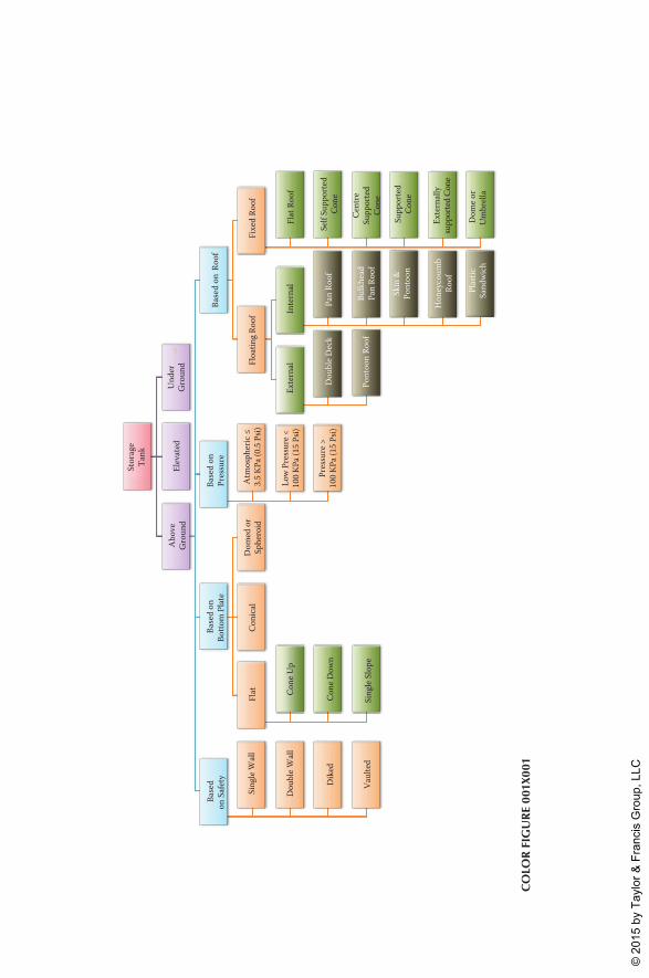
Stor
age
Tank
Abo
veG
roun
d
Base
don
Saf
ety
Sing
le W
all
Dou
ble W
all
Dik
ed
Vaul
ted
Base
d on
Botto
m P
late
Flat Co
ne U
p
Cone
Dow
n
Sing
le S
lope
Coni
cal
Dom
ed o
rSp
hero
id
Base
d on
Pres
sure
Atm
osph
eric
≤3.
5 KP
a (0.
5 Ps
i)
Low
Pre
ssur
e <10
0 KP
a (15
Psi)
Pres
sure
>10
0 KP
a (15
Psi)
Base
d on
Roo
f
Floa
ting R
oof
Exte
rnal
Dou
ble D
eck
Pont
oon
Roof
Inte
rnal
Pan
Roof
Bulk
head
Pan
Roof
Skin
&Po
ntoo
n
Hon
eyco
umb
Roof
Plas
ticSa
ndwi
ch
Fixe
d Ro
of
Flat
Roo
f
Self
Supp
orte
dCo
ne
Cent
reSu
ppor
ted
Cone
Supp
orte
dCo
ne
Exte
rnal
lysu
ppor
ted
Cone
Dom
e or
Um
brel
la
Elev
ated
Und
erG
roun
d
Co
lor
Fig
ur
e 00
1x00
1
K22265_CI.indd 1 4/21/15 4:14 PM
© 2
015
by T
aylo
r & F
ranc
is G
roup
, LLC
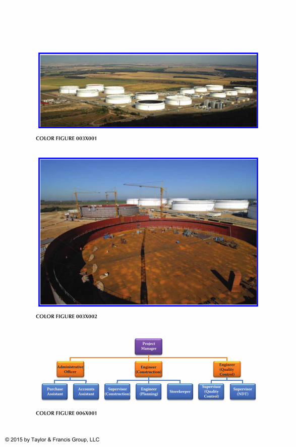
ProjectManager
AdministrativeOfficer
PurchaseAssistant
AccountsAssistant
Engineer(Construction)
Supervisor(Construction)
Engineer(Planning) Storekeeper
Engineer(Quality Control)
Supervisor(QualityControl)
Supervisor(NDT)
Color Figure 006x001
Color Figure 003x001
Color Figure 003x002
K22265_CI.indd 2 4/21/15 4:15 PM
© 2015 by Taylor & Francis Group, LLC
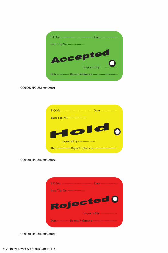
P O No. ----------------------------- Date ---------------
Item Tag No. ---------------
Inspected By ---------------
Date ----------- Report Reference ----------------------
Color Figure 007x001
P O No. --------------------------- Date --------------
Item Tag No. ---------------
Inspected By ---------------
Date ----------- Report Reference -------------------
Color Figure 007x002
P O No. ----------------------------- Date ---------------
Item Tag No. ---------------
Inspected By ---------------
Date ----------- Report Reference ----------------------
Color Figure 007x003
K22265_CI.indd 3 4/21/15 4:15 PM
© 2015 by Taylor & Francis Group, LLC
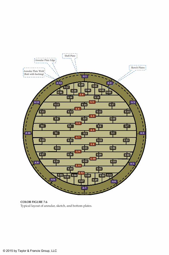
Annular Plate Edge
Shell Plate
Sketch Plates
S 36
S 39
S 19
S 37S 38 S 40
S 41S 42
S 43
S 18
S 16S 15 S 17
S 12S 11 S 13 S 14
S 27
S 9 S 10
S 31 S 33
S 7
S 28
S 32
S 35
S 29 S 30
S 34
S 47 S 49
S 51S 48 S 50S 44 S 46
S 8
S 6S 5 S4
S1 S 2 S 3
S 20 S 21 S 22 S 23
S 24 S 25 S 26
S 45
L 6
L 5
L 4
L 3
L 2
L 1
L 7
L 8
L 9
L 10
L 11
L 12
A 1
A 2
A 6
A 7
A 12
A 9
A 8
A 11
A 10
A 3
A 4
A 5
Annular Plate Weld(Butt with backing)
Color Figure 7.6Typical layout of annular, sketch, and bottom plates.
K22265_CI.indd 4 4/21/15 4:15 PM
© 2015 by Taylor & Francis Group, LLC
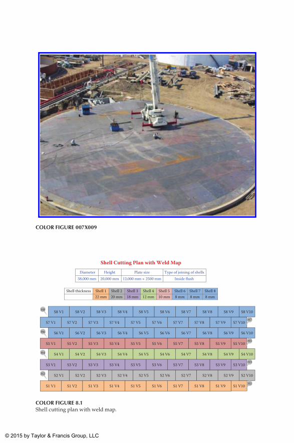
Color Figure 007x009
Shell Cutting Plan with Weld MapDiameter Height Plate size Type of joining of shells
38,000 mm 20,000 mm 12,000 mm × 2500 mm Inside flush
Shell thickness Shell 1 Shell 2 Shell 3 Shell 4 Shell 5 Shell 6 Shell 7 Shell 822 mm 20 mm 18 mm 12 mm 10 mm 8 mm 8 mm 8 mm
S1 V1 S1 V2 S1 V3 S1 V4 S1 V5 S1 V6 S1 V7 S1 V8 S1 V9 S1 V10
S2 V1 S2 V2 S2 V3 S2 V4 S2 V5 S2 V6 S2 V7 S2 V8 S2 V9 S2 V10
S3 V1 S3 V2 S3 V3 S3 V4 S3 V5 S3 V6 S3 V7 S3 V8 S3 V9 S3 V10
S4 V1 S4 V2 S4 V3 S4 V4 S4 V5 S4 V6 S4 V7 S4 V8 S4 V9 S4 V10
S5 V1 S5 V2 S5 V3 S5 V4 S5 V5 S5 V6 S5 V7 S5 V8 S5 V9 S5 V10
S6 V1 S6 V2 S6 V3 S6 V4 S6 V5 S6 V6 S6 V7 S6 V8 S6 V9 S6 V10
S7 V1 S7 V2 S7 V3 S7 V4 S7 V5 S7 V6 S7 V7 S7 V8 S7 V9 S7 V10
S8 V1 S8 V2 S8 V3 S8 V4 S8 V5 S8 V6 S8 V7 S8 V8 S8 V9 S8 V10
H7
H5
H3
H1
H8
H6
H4
H2
Color Figure 8.1Shell cutting plan with weld map.
K22265_CI.indd 5 4/21/15 4:15 PM
© 2015 by Taylor & Francis Group, LLC
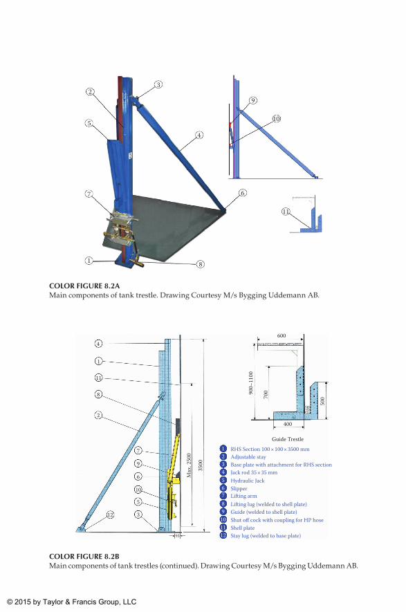
3
4
9
10
6
11
81
7
5
2
Color Figure 8.2aMain components of tank trestle. Drawing Courtesy M/s Bygging Uddemann AB.
4
1
11
8
2
7
400
600
Guide Trestle123456789
101112
RHS Section 100 × 100 × 3500 mmAdjustable stayBase plate with attachment for RHS sectionJack rod 35 × 35 mmHydraulic JackSlipperLifting armLifting lug (welded to shell plate)Guide (welded to shell plate)Shut off cock with coupling for HP hoseShell plateStay lug (welded to base plate)
9
Max
. 250
0
3500
900–
1100
700
500
6
10
5
3
93
12
Color Figure 8.2bMain components of tank trestles (continued). Drawing Courtesy M/s Bygging Uddemann AB.
K22265_CI.indd 6 4/21/15 4:15 PM
© 2015 by Taylor & Francis Group, LLC
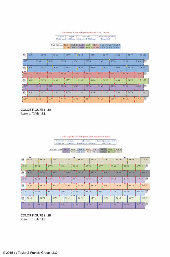
Weld Map with Spot Radiography (Shell thickness 22-8 mm)
Diameter Height Plate size Type of joining of shells 38,000 mm 20,000 mm 12,000mm X 2500 mm Inside �ush
Shell thickness Shell 1 Shell 2 Shell 3 Shell 4 Shell 5 Shell 6 Shell 7 Shell 8 22 mm 20 mm 18 mm 12 mm 10 mm 8 mm 8 mm 8 mm
S1 V1 S1 V2 S1 V3 S1 V4 S1 V5 S1 V6 S1 V7 S1 V8 S1 V9 S1 V10
S2 V1 S2 V2 S2 V3 S2 V4 S2 V5 S2 V6 S2 V7 S2 V8 S2 V9 S2 V10
S3 V1 S3 V2 S3 V3 S3 V4 S3 V5 S3 V6 S3 V7 S3 V8 S3 V9 S3 V10
S4 V1 S4 V2 S4 V3 S4 V4 S4 V5 S4 V6 S4 V7 S4 V8 S4 V9 S4 V10
S5 V1 S5 V2 S5 V3 S5 V4 S5 V5 S5 V6 S5 V7 S5 V8 S5 V9 S5 V10
S6 V1 S6 V2 S6 V3 S6 V4 S6 V5 S6 V6 S6 V7 S6 V8 S6 V9 S6 V10
S7 V1 S7 V2 S7 V3 S7 V4 S7 V5 S7 V6 S7 V7 S7 V8 S7 V9 S7 V10
S8 V1 S8 V2 S8 V3 S8 V4 S8 V5 S8 V6 S8 V7 S8 V8 S8 V9 S8 V10
H7
H5
H3
H1
H8
H6
H4
H2
Color Figure 11.1aRefer to Table 11.1.
Weld Map with Spot Radiography (Shell �ickness 28-8mm)
Diameter Height Plate size Type of joining of shells 38,000 mm 20,000 mm 12,000mm X 2500 mm Inside �ush
Shell thickness Shell 1 Shell 2 Shell 3 Shell 4 Shell 5 Shell 6 Shell 7 Shell 8 28 mm 25 mm 22 mm 19 mm 16 mm 13 mm 10 mm 8 mm
11.1.
S1 V1 S1 V2 S1 V3 S1 V4 S1 V5 S1 V6 S1 V7 S1 V8 S1 V9 S1 V10
S2 V1 S2 V2 S2 V3 S2 V4 S2 V5 S2 V6 S2 V7 S2 V8 S2 V9 S2 V10
S3 V1 S3 V2 S3 V3 S3 V4 S3 V5 S3 V6 S3 V7 S3 V8 S3 V9 S3 V10
S4 V1 S4 V2 S4 V3 S4 V4 S4 V5 S4 V6 S4 V7 S4 V8 S4 V9 S4 V10
S5 V1 S5 V2 S5 V3 S5 V4 S5 V5 S5 V6 S5 V7 S5 V8 S5 V9 S5 V10
S6 V1 S6 V2 S6 V3 S6 V4 S6 V5 S6 V6 S6 V7 S6 V8 S6 V9 S6 V10
S7 V1 S7 V2 S7 V3 S7 V4 S7 V5 S7 V6 S7 V7 S7 V8 S7 V9 S7 V10
S8 V1 S8 V2 S8 V3 S8 V4 S8 V5 S8 V6 S8 V7 S8 V8 S8 V9 S8 V10
H7
H5
H3
H1
H8
H6
H4
H2
Color Figure 11.1bRefer to Table 11.2.
K22265_CI.indd 7 4/21/15 4:15 PM
© 2015 by Taylor & Francis Group, LLC
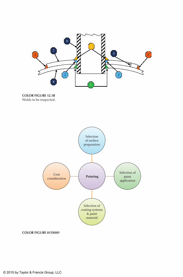
Selectionof surface
preparation
Selection ofcoating systems
& paintmaterial
Costconsideration
Selection ofpaint
applicationPainting
Color Figure 013x001
1
2 2
3
4 4 5
8
7
6
Color Figure 12.1bWelds to be inspected.
K22265_CI.indd 8 4/21/15 4:15 PM
© 2015 by Taylor & Francis Group, LLC
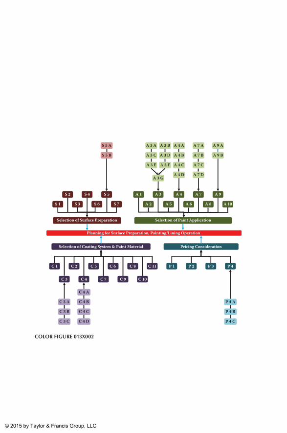
Planning for Surface Preparation, Painting/Lining Operation
S 1 S 3 S 6 S 7
S 2 S 4 S 5
A 2 A 5 A 6 A 8 A 10
A 1 A 3 A 4 A 7 A 9
Selection of Surface Preparation Selection of Paint Application
Selection of Coating System & Paint Material Pricing Consideration
C 1 C 2 C 5 C 6 C 8 C 11
C 3 C 4 C 7 C 9 C 10
P 1 P 2 P 3 P 4
S 5 A
S 5 B
A 3 BA 3 A
A 3 C
A 3 FA 3 E
A 3 D
A 3 G
A 4 A
A 4 B
A 4 C
A 4 D
A 7 A
A 7 B
A 7 C
A 7 D
A 9 A
A 9 B
C 3 A
C 3 B
C 3 C
C 4 A
C 4 B
C 4 C
C 4 D
P 4 A
P 4 B
P 4 C
Color Figure 013x002
K22265_CI.indd 9 4/21/15 4:15 PM
© 2015 by Taylor & Francis Group, LLC
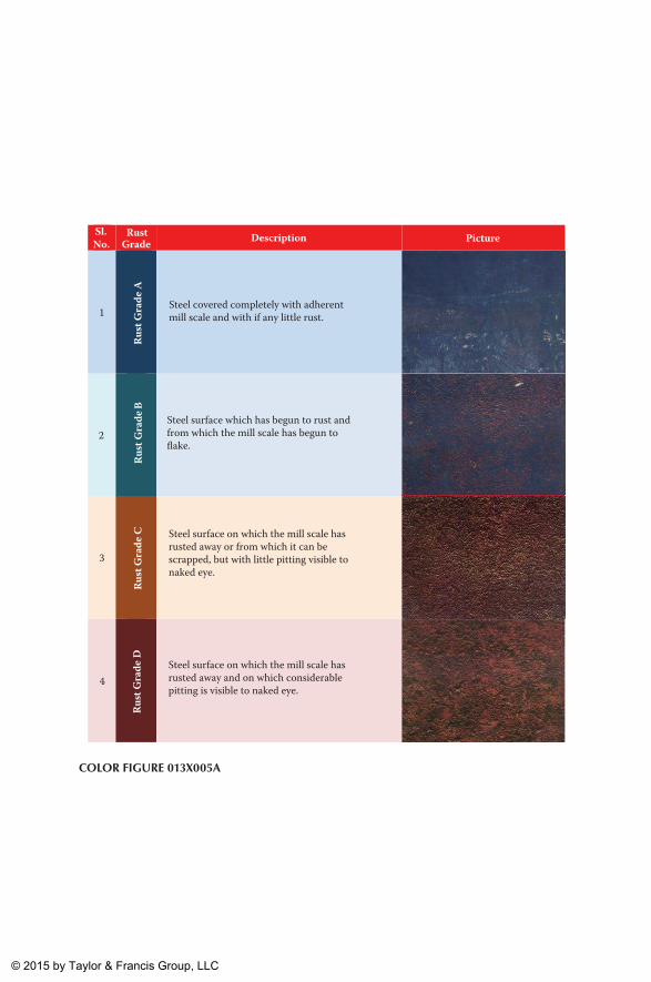
PictureDescription Picture
1
Rust
Gra
de A
2
Rust
Gra
de B
3
Rust
Gra
de C
4
Rust
Gra
de D
RustGrade
Sl. No.
Steel covered completely with adherentmill scale and with if any little rust.
Steel surface which has begun to rust andfrom which the mill scale has begun toflake.
Steel surface on which the mill scale hasrusted away and on which considerablepitting is visible to naked eye.
Steel surface on which the mill scale hasrusted away or from which it can bescrapped, but with little pitting visible tonaked eye.
Color Figure 013x005a
K22265_CI.indd 10 4/21/15 4:15 PM
© 2015 by Taylor & Francis Group, LLC
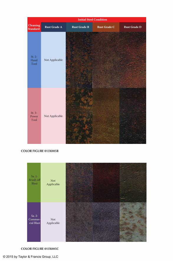
CleaningStandard
Initial Steel Condition
Rust Grade A Rust Grade B Rust Grade C Rust Grade D
St. 2-HandTool
Not Applicable
St. 3-PowerTool
Not Applicable
Color Figure 013x005b
NotApplicable
NotApplicable
Sa. 1-Brush o�
Blast
Sa. 2-Commer-cial Blast
Color Figure 013x005C
K22265_CI.indd 11 4/21/15 4:15 PM
© 2015 by Taylor & Francis Group, LLC
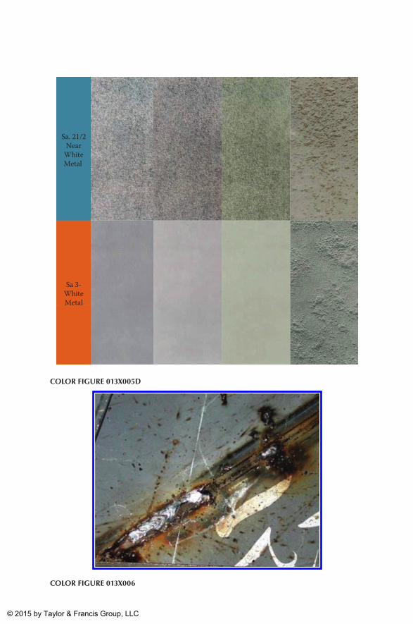
Color Figure 013x006
Sa. 21/2Near
WhiteMetal
Sa 3-WhiteMetal
Color Figure 013x005D
K22265_CI.indd 12 4/21/15 4:15 PM
© 2015 by Taylor & Francis Group, LLC
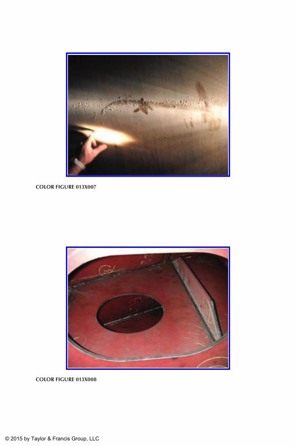
Color Figure 013x008
Color Figure 013x007
K22265_CI.indd 13 4/21/15 4:15 PM
© 2015 by Taylor & Francis Group, LLC
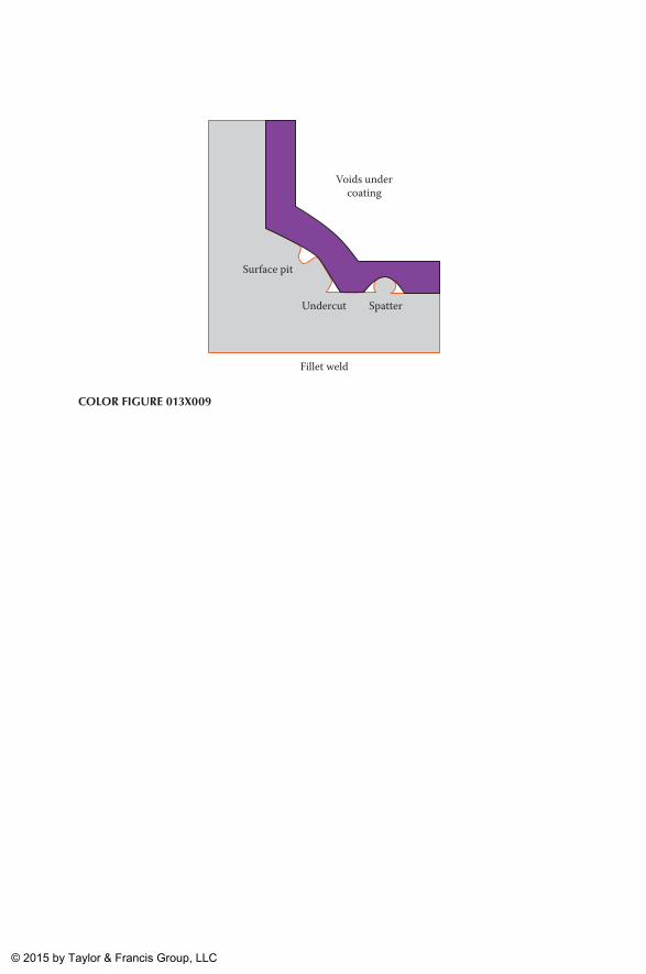
Surface pit
Undercut Spatter
Voids undercoating
Fillet weld
Color Figure 013x009
K22265_CI.indd 14 4/21/15 4:15 PM
© 2015 by Taylor & Francis Group, LLC
Related Documents