ACS800 Firmware Manual Application Program Template 7.x

Welcome message from author
This document is posted to help you gain knowledge. Please leave a comment to let me know what you think about it! Share it to your friends and learn new things together.
Transcript

ACS800
Firmware Manual Application Program Template 7.x

Application Program Template 7.x
Firmware Manual
ACS800
Code: 3AFE64616340 REV DEN
EFFECTIVE: 08.05.2006
© 2006 ABB Oy. All rights reserved.


5
Table of contents
Table of contents
Table of contents...............................................................................................................................5
Introduction to this manual ..............................................................................................................9 Overview .............................................................................................................................................9 Compatibility........................................................................................................................................9 Safety instructions ...............................................................................................................................9 Before you start ...................................................................................................................................9 What this manual contains ..................................................................................................................9
Overview of ACS800 programming ...............................................................................................11 Overview ...........................................................................................................................................11 ACS800 programming.......................................................................................................................11
Parameter Groups ........................................................................................................................11 Start-up Data Parameters ........................................................................................................11
Commissioning tools .........................................................................................................................12 DriveWindow............................................................................................................................12 Control panel............................................................................................................................12
Control diagrams...............................................................................................................................12
Commissioning; ACS800 SingleDrive...........................................................................................15
Software description.......................................................................................................................21 Drive functions...................................................................................................................................21
General .........................................................................................................................................21 Application program identification.................................................................................................22 Program boot ................................................................................................................................22 Control modes ..............................................................................................................................22 REMOTE mode ............................................................................................................................22 Local mode ...................................................................................................................................22
Reduced run function ........................................................................................................................23 Emergency stop ................................................................................................................................23
Emergency stop modes................................................................................................................23 Action if the motor is stopped .......................................................................................................23 Action if the motor is running ........................................................................................................24
Communication .................................................................................................................................24 Fieldbus communication....................................................................................................................25
Fieldbus signal..............................................................................................................................25 Integer scaling ..............................................................................................................................25
I/O devices on parallel slots or channel CH1 ....................................................................................25 Master/Follower link on channel CH2................................................................................................26
6
Table of contents
Commissioning and supporting tools on channel CH3......................................................................26 Modbus link .......................................................................................................................................26 Communication profiles .....................................................................................................................27 ABB Drives communication profile ....................................................................................................27
Drive states...................................................................................................................................27 Main Control Word (MCW) ................................................................................................................29 Generic Drive communication profile.................................................................................................35
Speed reference and actual speed scaling...................................................................................36 I/O Configurations..............................................................................................................................37
Digital inputs .................................................................................................................................37 Digital outputs....................................................................................................................................37 Analogue inputs.................................................................................................................................38
RMIO Motor and I/O control board ...............................................................................................38 RAIO-01 Analogue I/O Extension module ....................................................................................39
Analogue outputs ..............................................................................................................................39 Pulse encoder interface RTAC-01.....................................................................................................41 The Master/Follower link ...................................................................................................................41
General .........................................................................................................................................41 Link configuration..........................................................................................................................41 Follower diagnostics .....................................................................................................................42 Master/Follower link specification .................................................................................................42
Diagnostics........................................................................................................................................43 General .........................................................................................................................................43
Fault and event loggers.....................................................................................................................43 AMC time format and counting .....................................................................................................43
Data logger........................................................................................................................................43 Positioning counter ............................................................................................................................44
Positioning counting function ........................................................................................................45 Back-up of parameters or software ...................................................................................................45
Signals..............................................................................................................................................47 Overview ...........................................................................................................................................47 How to read the signal table ..............................................................................................................47 AMC Table Signals............................................................................................................................49
Group 1 Actual Signals .................................................................................................................49 Group 2 Actual Signals .................................................................................................................51 Group 3 Actual Signals .................................................................................................................53 Group 4 Information......................................................................................................................55 Group 7 Control Words.................................................................................................................56 Group 8 Status Words ..................................................................................................................58 Group 9 Fault Words ....................................................................................................................62
Parameters.......................................................................................................................................67 Overview ...........................................................................................................................................67 Parameter groups..............................................................................................................................67 How to read the Parameter Table .....................................................................................................68 Group 10 Start/Stop/Dir .....................................................................................................................69 Group 13 Analogue inputs.................................................................................................................69 Group 14 Digital outputs....................................................................................................................70

7
Table of contents
Group 15 Analogue outputs ..............................................................................................................71 Group 16 System control inputs ........................................................................................................73 Group 17 DC HOLD ..........................................................................................................................74 Group 18 LED panel control..............................................................................................................75 Group 19 Data storage......................................................................................................................76 Group 20 Limits .................................................................................................................................77 Group 21 Start/Stop functions ...........................................................................................................78 Group 22 Accel/Decel .......................................................................................................................79 Group 23 Speed reference................................................................................................................81 Group 24 Speed control ....................................................................................................................83
Proportional gain parameter of the speed controller ................................................................84 The Adaptive speed control as a function of the torque reference...........................................84 Set point weighting...................................................................................................................84 Integration time parameters of the speed controller.................................................................85 Derivation parameters of the speed controller .........................................................................85 Acceleration compensation parameters...................................................................................85 Adaptive Speed Control as Function of the Speed ..................................................................86
Group 25 Torque reference...............................................................................................................86 Group 26 Torque reference handling ................................................................................................87 Group 27 Flux control........................................................................................................................89 Group 29 Scalar control ....................................................................................................................90 Group 30 Fault functions ...................................................................................................................92
Motor thermal model user mode ..............................................................................................93 Stall protection .........................................................................................................................94 Underload protection................................................................................................................95
Group 37 Brake chopper ...................................................................................................................98 Group 50 Speed measurement .........................................................................................................99 Group 51 Communication module (FBA) ........................................................................................102 Group 52 Standard Modbus ............................................................................................................102 Group 70 DDCS control ..................................................................................................................103 Group 90 D set rec ADDR...............................................................................................................106 Group 92 D set TR ADDR...............................................................................................................106 Group 95 Hardware specific............................................................................................................107 Group 98 Option modules ...............................................................................................................108 Group 99 Start-up data....................................................................................................................112
Overview of the CDP 312R control panel....................................................................................115 Overview.....................................................................................................................................115 Panel link ....................................................................................................................................115 Display........................................................................................................................................116 Keys............................................................................................................................................116
Panel operation ...............................................................................................................................117 Keypad modes............................................................................................................................117
Identification display...............................................................................................................117 Actual signal display mode ....................................................................................................117 Parameter mode ....................................................................................................................121 Function mode .......................................................................................................................123 Copying parameters from one unit to other units ...................................................................125 Setting the contrast ................................................................................................................125 Drive selection mode..............................................................................................................125
8
Table of contents
Operational commands...............................................................................................................127 Start, Stop, Direction and reference.......................................................................................127
Fault tracing...................................................................................................................................129 Overview .........................................................................................................................................129 I/O error monitoring .........................................................................................................................129
Internal Fault on the I/O Board ...................................................................................................129 Communication monitoring..............................................................................................................129 Power plate overtemperature fault ..................................................................................................129 Ambient temperature .......................................................................................................................129 Overcurrent .....................................................................................................................................130 DC overvoltage................................................................................................................................130 DC undervoltage .............................................................................................................................131 Local control lost function................................................................................................................131 Run enable interlocking function .....................................................................................................131 Short circuit .....................................................................................................................................131 DC Link intermediate current ripple fault .........................................................................................131 Overspeed fault ...............................................................................................................................132 Overswitching frequency fault .........................................................................................................132 System fault.....................................................................................................................................132 Motor protections.............................................................................................................................132
Motor thermal protection functions .............................................................................................132 Motor thermal model ..............................................................................................................133
Usage of PTC or PT100 temperature sensors ................................................................................133 Stall function....................................................................................................................................135 Motor phase loss function................................................................................................................136 Fault and alarm messages ..............................................................................................................137
Fault message table ...................................................................................................................137 Alarm messages table ................................................................................................................144 Other messages .........................................................................................................................147

9
Introduction to this manual
Introduction to this manual
Overview This chapter describes the purpose, contents and the intended audience of this manual. It also explains the terms used in this manual and lists related publications.
Compatibility The manual is compatible with ACS800 Application Program Template 7.x.
Safety instructions Follow all safety instructions delivered with the drive.
Read the complete safety instructions before you install, commission, or use the drive. The complete safety instructions are given at the beginning of the Hardware Manual.
Read the software function specific warnings and notes before changing the default settings of the function. For each function, the warnings and notes are given in this manual in the subsection describing the related user-adjustable parameters.
Before you start The purpose of this manual is to provide you with the information necessary to control and program your ACS800.
The audience for this manual is expected to have:
• Knowledge of standard electrical wiring practices, electronic components and electrical schematic symbols.
What this manual contains Introduction to this manual the chapter you are reading now, introduces you to this manual.
Overview of ACS800 programming describes the programming principles of the drive.
Commissioning; ACS800 SingleDrive describes the commissioning procedure of the SingleDrive.
Software description describes the typical functions of the drive.
Signals describes the measured, calculated and control word signals of the drive.
Parameters describes the parameters of the drive.

10
Introduction to this manual
Overview of CDP 312R control panel gives instructions for using the panel.
Fault tracing lists the alarm and fault messages with the possible causes and remedies.

11
Overview of ACS800 programming
Overview of ACS800 programming
Overview This chapter describes the programming principles of the ACS800 drive.
ACS800 programming An application software template has been programmed using the FCB (Function Chart Builder) tool, whose target is the Motor and I/O Control board (RMIO). The trained user can further customize this template by FCB to extend the I/O, add mathematic calculations, application parameters and signals, logic control, communication between the RMIO boards, etc. Parameters are programmed during commissioning by DriveWindow or the CDP 312R control panel.
Parameter Groups In order to simplify programming, the parameters of the ACS800 drive are organised into logical Groups. All of the parameters are described in the chapter Parameters and signals in the chapter Signals.
Start-up Data Parameters
The Start-up Data parameters (group 99) contain the basic settings needed to match the ACS800 with the motor and to set the Control Panel display language. The Start-up Data Group includes parameters that are set at start-up and should not need to be changed later on. See the chapter Parameters � group 99.
12
Overview of ACS800 programming
Commissioning tools DriveWindow
The DriveWindow software is the commissioning and maintenance tool available for ABB products. With this component structure, enhanced flexibility is achieved to enable you to work with several different types of product through different target and communication drivers.
Control panel
The CDP 312R control panel is the device used for locally controlling and programming the ACS800. The CDP 312R control panel has 16 keys, and can monitor and control up to 31 drives. The display has 4 lines of 20 characters. For more information see the chapter Overview of CDP 312R control panel.
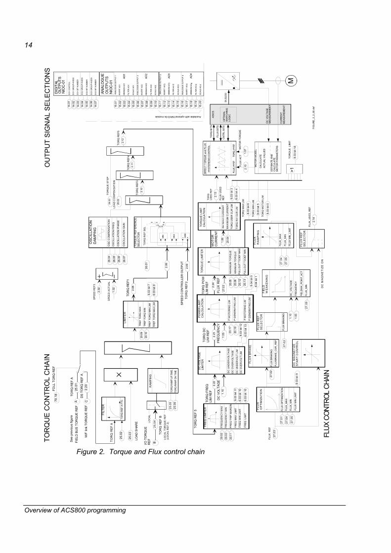
Control diagrams The speed control is executed every 1 ms in the fixed part of the software. The following figures shows the speed and torque control chains.

13
Overview of ACS800 programming
MO
TOR
MO
DE
L
SPE
ED
RE
F
ANAL
OG
UE
INPU
TS
AI1
AI1
HIG
H V
ALU
E13
.01
13.0
2
13.0
3
13.0
4
13.0
5
FIL
TER
AI1
13.0
6
13.0
7
13.0
8
13.0
9
13.1
0
13.1
1
AI1
LO
W
VA
LUE
AI2
HIG
H V
ALU
E
AI2
1 LO
W
VA
LUE
FIL
TE
R A
I2
MIN
IMU
M A
I2
AI3
HIG
H V
ALU
E
AI3
1 LO
W V
ALU
E
FILT
ER
AI3
MIN
IMU
M A
I3
AI2
AI3
DIG
ITAL
INPU
TS
FIEL
D B
US
CO
MM
UN
.
Dat
aset
s 10
...32
CO
MM
. M
OD
ULE
=
FBA
DS
ET1
098
.02
Dat
aset
s 11
...33
MSW
SPE
ED A
CT
TOR
Q R
EF
2
NO
EM
E S
TOP
RU
N E
NAB
LE
DI3
Sta
rt/St
op
DI DI2
STA
RT/
STO
PC
ON
TRO
L
MC
W
>1LO
CAL
CTR
LPA
NEL
RE
F
LOC
/REM
STAR
T
STO
P
FORW
ARD
RE
VER
SE
RE
SET
-1 1
LOC
AL
RE
F1
LOC
AL
DIR
EC
TIO
N
LOC
AL
DIR
ECTI
ON
LOC
AL
DIR
EC
TIO
NC
ON
TRO
L
LOC
AL
RE
F
LOC
AL
LOC
AL
STA
RTI
NG
HA
ND
LIN
G
SPE
ED
ME
AS
UR
EM
EN
T
SPEE
D RE
FERE
NCE
CHAI
N
SPEE
DAC
TUAL
A
CC
/DE
C/S
HAP
E
ACC
ELER
TIM
E
DEC
ELER
TIM
E
SPEE
D S
HAR
E
23.0
5
22.
01
22.
02
22.
03
22.
04
22.
05
22.
06
22.
07
AC
C/D
EC T
IME
SCAL
E
EME
STO
P R
AMP
RAM
P S
HPE
TIM
E
VAR
IABL
E SL
OPE
VAR
IABL
E SL
OPE
RAT
E
FILT
ER
SPE
ED E
RR
OR
FIL
T
SPE
ED S
TEP
+ +
WIN
DOW
2.03
23.1
0
WIN
DO
W W
IDTH
PO
S
WIN
DO
W W
IDTH
NEG
WIN
DO
W IN
TG O
N
23.0
6
SPEE
D E
RR
OR
N
EG
23.0
723
.08
23.0
9
ACC
ELE
RATI
ON
ACC
COMP
DER
TIM
E
ACC
COMP
FILT
TIM
E
TOR
Q A
CC
CO
MP
REF
24.1
424
.15
2.07
2.01
SET_
P_W
EIGH
TING
SET_
POIN
T_W
EIG
HT24
.0724
.08
dV/d
t2.
16
SPEE
D C
ORR
ECTI
ON
(-1)
PID
- CO
NTR
OLL
ER
TOR
Q R
EF2
PI
DER
IVA
TIO
N T
IME
DER
IV. F
ILT
TIM
E
D
LIM
ITER
2.04.2.06
2.0
5
AC
W b
8
TOR
QU
E P
RO
P R
EF
TOR
QU
E IN
TEG
RE
F
TOR
QU
E D
ER
REF
2.09
BAL_
NCO
NT
20.0
720
. 08
BAL
REF
24.1
1
24.1
3
24.1
2
SP
C T
OR
QM
AX
SP
C T
OR
QM
INKP
S
KPS
MIN
KPS
WE
AKP
OIN
T
KP
S W
P F
ILT
TIM
E
24.0
4
24.0
3
24.0
6
24.0
5
24.1
0
24.0
9
24.1
8
24.1
7
24.2
0
24.1
9
TIS
TIS
INIT
VA
LUE
KPS
TIS
MIN
FR
EQ
KP
S T
IS M
AX
FREQ
KPS
VAL
MIN
FR
EQ
TIS
VAL
MIN
FR
EQ
KPS
TO
RQ
RE
F2
SPEE
D CO
NTRO
L
KP
ST
IS
mot
or
freq
TIS
VA
L M
IN F
RE
Q
TIS
KPS
TIS
MAX
FR
EQ
KPS
TIS
MIN
FR
EQ
NTA
C-0
2N
IOB
-01
SP
EE
D S
CA
LIN
G50
.01
50.0
2
50.0
3
50.0
4
50.0
5
SP
EE
D F
B S
EL
SP
EE
D M
EA
S M
OD
E
EN
CO
DE
R P
ULS
E N
R
EN
CO
DE
R A
LM/F
LT
EN
CO
DE
R M
OD
ULE
98.0
1
PULS
E E
NC
OD
ER
SP
EED
MEA
SU
REM
ENT
LOC
AL
NO
EM
E S
TOP
RU
N E
NA
BLE
STA
RT/
STO
P
RES
ET
LIM
ITE
R
20.0
1M
INIM
UM
SP
EE
D
MA
XIM
UM
SP
EE
D
20.0
2
1.01
MO
TOR
SPE
ED
FILT
FILT
ER
TIM
E:
500
ms
1.04.
MO
TOR
SPE
ED
FILT
ER
SP
AC
T FI
LT T
IME
0
0
RA
MP
MCW
B4
MCW
B6
MCW
B5
HO
LD
MA
IN C
ON
TRO
LW
OR
DM
CW
24.0
2
AC
W B
3BA
L R
AMP
OU
T
22.
08BA
L R
AMP
REF
RAM
P B
YPAS
SA
CW
B2
KP
S
KP
S V
AL
MA
X F
RE
Q
MO
TOR
TEM
P
30.0
3
FIEL
D B
US
ADAP
TER
Dat
aset
1
CO
MM
. MO
DU
LE
= F
BA
DS
ET
198
.02
Dat
aset
2C
H0
MC
WR
EF1
REF
2
MSW
ACT1
ACT2
CH
0
CH
0
MC
WSP
EED
REF
TOR
Q R
EF A
MC
W
-1 1
98.0
2
LOC
AL
CO
MM
MO
DU
LE
MC
W
13.1
2M
INIM
UM
AI1
11.0
1
TOR
Q R
EF B
SPEE
DR
EF2
+
23.0
4+
2.02
SP
EE
D R
EF
323
.02
23.0
3
CON
ST S
PEED
1(IN
CHI
NG
1)
CONS
T SP
EED
2(IN
CHIN
G 2
)
MCW
B8,
B9
LIM
ITE
R
20.0
1
20.0
2
2.18
SPEE
DR
EF4
MIN
IMU
M
SP
EE
D
MA
XIM
UM
S
PE
ED
1.03
SP
EE
DM
EA
SUR
ED
SP
EE
DE
STI
MA
TED
1.02
50.0
6
MAS
TER
DR
IVE
Dat
aset
41
CH
2 M
/F M
OD
E=
MA
STE
R
CH
2M
AST
ER
RE
F1
70.0
8
MA
STE
R R
EF2
MA
STE
R R
EF3
FOLL
OW
ERD
RIV
EC
H2
M/F
MO
DE
= FO
LLO
WE
R
CH
2
MC
W
70.0
8
SPE
ED
REF
TOR
Q R
EF A
Fast
Mas
ter /
Fol
low
erD
DC
S Li
nk
70.0
9
70.1
0
70.1
1
23.0
1
70.1
7
See
nex
t fig
ure
PR
OG
RA
MM
ABL
EFU
NC
TIO
NS:
DI3
...D
I6, E
XT2:
DI1
and
EXT
2:D
I2
DI4
Rev
erse
DI5
Res
et
STA
RT,
STO
PR
EVE
RSE
RES
ET
SYN
C C
MD
KLI
XON
MO
TOR
FAN
AC
KH
AND
/AU
TO
(Def
ault) (D
efau
lt)
(Def
ault)
(not
sho
wn
in th
e si
gnal
23.0
1 S
PEED
RE
F)
C
B
98.0
6
AB
FOLL
SPE
ED
REF
EXT1
:AI1
EXT
1:A
I2
MO
TOR
1
MO
TOR
2
PTC
, PT1
00
98.0
6
30.0
6
7.01
10.0
1
10.0
2
10.0
9
2.20
2.19
CO
MP
ENS
ATI
ON
_
FIG
UR
2_1_
60.d
sf
8.03
bit
1
8.03
bit
2
SPC
TO
RQ
M
IN L
IMSP
C T
OR
Q
MAX
LIM
SP
C T
OR
Q M
AX
SPC
TO
RQ
MIN
DR
OO
P R
ATE
7
Figure 1. Speed reference chain
14
Overview of ACS800 programming
TOR
QU
E C
ON
TRO
L C
HA
INO
UTP
UT
SIG
NA
L SE
LEC
TIO
NS
ANAL
OG
UE
OU
TPU
TSN
IOC
-01
AO1
AN
ALO
GU
E O
UTP
UT
115
.01
15.0
215
.03
15.0
415
.05
MIN
IMU
M A
O1
15.0
615
.07
15.0
8
15.0
915
.10
INVE
RT
AO1
FILT
ER A
O1
SC
ALE
AO
1
INVE
RT
AO2
AN
ALO
GU
E O
UT
PUT
2
MIN
IMU
M A
O2
FILT
ER A
O2
SC
ALE
AO
2
AO2
DIG
ITAL
OU
TPUT
SNI
OC-
01D
O1
CO
NTR
OL
14.0
1
14.0
2
14.0
314
.04
14.0
5
DO
1 BI
T N
UM
BER
14.0
614
.07
DO
1 G
RO
UP
+IN
DEX
DO
2 G
RO
UP
+IN
DEX
DO
2 BI
T N
UM
BER
DO
3 BI
T N
UM
BER
DO
3 G
RO
UP
+IN
DEX
RA
MP
ING
TOR
Q R
AMP
UP
TIM
E
TOR
Q R
AMP
DN
TIM
E
TOR
Q R
EF
B
TO
RQ
RE
F A
FILT
ER
TOR
Q R
EF A
FTC
LOAD
SHA
RE
TREF
TO
RQ
MAX
TREF
TO
RQ
MIN
LIM
ITE
R
TOR
Q R
EF1
25.0
4
25.0
3 2.
08
25.0
2
25.0
5
25.0
6
20.0
9
20.1
0
TOR
QU
E R
EFE
RE
NC
ES
ELE
CTO
R
+ +MIN
MAX
0
3 45
2.10
2.08
TO
RQ
REF
3
OSC
ILLA
TIO
ND
AMPI
NG
2.02
SP
EED
RE
F3
SPE
ED
AC
TUA
L
26.0
1TO
RQ
RE
F S
EL
26.0
7
26.0
6
26.0
5
26.0
4
TOR
Q R
EF2
2.09
1.02
SPEE
D C
ON
TRO
LLE
R O
UTP
UT
2.11
TOR
Q R
EF4
2.12
TOR
Q R
EF5
LOA
D C
OM
PEN
SAT
ION
TOR
QU
E S
TE
P
26.0
2
26.0
3 TOR
Q
USE
D R
EF
OSC
CO
MPE
NSA
TIO
N
OS
CIL
LATI
ON
FR
EQ
OSC
ILLA
TIO
N P
HA
SE
OSC
ILLA
TIO
N G
AIN
LOC
AL
TOR
QU
E R
EF
(LO
CA
L R
EF
2)LOC
AL
FRE
QU
EN
CY
MAX
FRE
Q T
RIP
MA
RG
IN
FRE
Q L
IMIT
ER
TO
RQ
FR
EQLI
M R
EF
29.0
2
29.0
3FR
EQ
UE
NC
Y M
IN
20.1
1
TOR
Q R
EF
5
DC
UN
DE
RV
OLT
AG
E
DC
-VO
LTA
GE
LIM
ITE
R
TOR
Q D
CLI
M R
EF
DC
OV
ER
VO
LTA
GE
1.10
DC
VO
LTA
GE
PO
WE
R L
IMIT
CA
LCU
LATI
ON
P M
OTO
RIN
G L
IM
1.05
FRE
QU
ENC
Y
P G
ENER
ATI
NG
LIM
20.1
7
20.1
8
INV
MA
X C
UR
REN
T
TOR
QU
E L
IMIT
CA
LCU
LATI
ON
1.06
MO
TOR
CU
RR
EN
T
MA
XIM
UM
CU
RR
EN
T20
.04
2.13
HYS
TER
ESIS
CO
NTR
OL
CU
RR
ENT
MEA
SUR
EMEN
T
M
DC
VO
LTAG
EM
EASU
REM
ENT
MO
TOR
MO
DEL
ACTU
AL
VAL
UES
CAL
CU
LATE
ESTI
MAT
E AN
DC
ALC
ULA
TEM
OTO
R P
ARAM
ETER
S
MO
TOR
TO
RQ
UE
ASIC
S
FLU
X U
SED
RE
F
TOR
Q B
ITS
FLU
X BI
TS
OPT
IMAL
SWIT
CH
ING
LOG
ICS1
,S2,
S3
TORQ
_HYS
TFL
UX_H
YST
CN
TRL
BITS
2.15
1.
07
FLU
X A
CT
DIR
ECT
TOR
QU
E an
d FL
UX
FLU
X_US
ED_R
EF
FLU
XO
PTI
MIZ
AT
ION
FLU
X O
PTIM
IZAT
ION
FLU
X_M
AX
FLU
X_M
IN
27.0
1
FLU
X B
RA
KE
FLU
X BR
AKIN
G
FLU
XBR
AKE_
CU
R_R
EF
27.0
2
27.0
4
27.0
5
FLU
X R
EF
SE
LEC
TOR
FLU
X BR
AKI
NG
27.0
2
FIE
LDW
EA
KE
NIN
G
FIEL
DW
K_PO
INT_
ACT
FLU
X_M
IN27
.05
DC_V
OLT
AGE
FREQ
UEN
CY
1.10
1.05
FLU
XR
AM
PIN
G
FLU
X M
IN_L
IMIT
FLU
X_M
AX
FLU
X_M
IN
27.0
4
27.0
5
2.14
DC
MA
GN
ETI
ZE
STA
RT
CO
NTR
OL
FLU
X R
EF
27.0
3
FLU
X R
EF
SE
LEC
TO
R
DC
MA
GN
ET
IZE
ON
FLUX
CO
NTRO
L CH
AIN
AO3
AN
ALO
GU
E O
UTP
UT
315
.11
15.1
215
.13
15.1
415
.15
MIN
IMU
M A
O3
15.1
615
.17
15.1
8
15.1
915
.20
INV
ERT
AO3
FILT
ER
AO
3
SCAL
E A
O3
INV
ERT
AO4
ANAL
OG
UE
OU
TP
UT
4
MIN
IMU
M A
O4
FILT
ER
AO
4
SCAL
E A
O4
AO4
Available with optional NAIO-0x module
FIEL
D B
US
TO
RQ
UE
REF
I/O T
OR
QU
ER
EF
M/F
link
TO
RQ
UE
REF
70.1
8FO
LL T
OR
Q R
EF
A
B
C
See
pre
viou
s fig
ure
25.0
1
2.20
TOR
Q R
EF A
DS
TO
RQ
REF
A
2
61
AD
D
2.22
2.23
TOR
QU
E LI
MIT
ER
MA
XIM
UM
TO
RQ
UE
27.0
3
MIN
IMU
M T
OR
QU
E
20.0
5
20.0
6
2.24
TOR
Q P
OW
LIM
RE
F
FLU
X R
EF
PULL
OU
T TC
OE
F M
AX
20.1
2
20.1
3PU
LLO
UT
TCO
EF
MIN
8.03
bit
11FR
EQ M
AX L
IMIT
FREQ
MIN
LIM
IT8.
03 b
it 10
8.03
bit
12
8.03
bit
13
DC
UN
DER
VOLT
LIM
DC
OVE
RV
OLT
LIM
P M
OTO
RIN
G L
IM
P G
ENER
ATI
NG
LIM
8.04
bit
0
8.04
bit
1
8.03
bit
6
8.03
bit
5
8.03
bit
0
8.03
bit
3
8.03
bit
4
TOR
Q U
SER
CU
R L
IM
TOR
Q IN
V C
UR
LIM
TOR
Q M
AX L
IM
TOR
Q M
IN L
IM
TOR
Q M
OTO
R L
IM
FLU
X M
IN L
IMIT
8.03
bit
9
FREQ
LIM
IT8.
03 b
it 15
>18.
03 b
it 14
TOR
QU
E L
IMIT
8.03
bit
7
8.03
bit
8
TREF
TO
RQ
MIN
LIM
TREF
TO
RQ
MA
X LI
M
FIG
UR
E_2
_2_6
0.ds
f
Figure 2. Torque and Flux control chain

15
Commissioning; ACS800 SingleDrive
Commissioning; ACS800 SingleDrive
Commissioning procedure using the control panel 1 - SAFETY
The start-up may only be carried out by a qualified electrician. The safety instructions must be followed during the start-up procedure. See the appropriate hardware manual for safety instructions.
Check the installation. See the installation checklist in the appropriate hardware/installation manual. Check that the starting of the motor does not cause any danger.
De-couple the driven machine if: - there is a risk of damage in case of incorrect direction of rotation, or - a Standard ID Run needs to be performed during the drive start-up. (ID run is essential only in applications which require the ultimate in motor control accuracy.)
2 - POWER-UP Apply mains power. The Control Panel first enters the panel identification
data� CDP 312R PANEL Vx.xx ��
�then the Identification Display of the drive� ACS800 xx kW ID NUMBER 1
�and after a few seconds the Control Panel automatically enters the Actual Signal Display. Drive set-up can be started.
1 -> 0.0 rpm 0 LED PANE 0.0 Hz CURENT 0.0 A POWER 0.00 %

16
Commissioning; ACS800 SingleDrive
3 - COMMISSIONING DATA ENTERING (parameter group 99) Select the language. The general parameter setting procedure is given
below. The general parameter setting procedure: • Press PAR to select parameter mode.
• Press or to scroll parameter groups (10 to 99).
• Press or to scroll parameters within the parameter group.
• Select a new value by ENTER (brackets appear around the parameter
value) and or (Fast change by or ).
• Press ENTER to accept the new value (brackets disappear).
Enter the motor data from the motor nameplate.
3 ~ motor M2AA 200 MLA 4
No
ABB Motors
Ins.cl. F IP 55
V
690 Y
400 D
660 Y
380 D
415 D
440 D
Hz
50
50
50
50
50
60
kW
30
30
30
30
30
35
r/min
1475
1475
1470
1470
1475
1770
A
32.5
56
34
59
54
59
cos ϕ
0.83
0.83
0.83
0.83
0.83
0.83
IA/IN t E/s
IEC 200 M/L 55
Cat. no. 3GAA 202 001 - ADA
6312/C3 6210/C3 180 kg
IEC 34-1
CE
Note: Set the motor data to exactly the same value as on the motor nameplate. For example, if the motor nominal speed is 1440 rpm on the nameplate, setting the value of parameter 99.05 MOTOR NOM SPEED to 1500 rpm results in wrong operation of the drive.
1 -> 0.0 rpm O 99 START-UP DATA
01 LANGUAGE ENGLISH
Nominal voltage. The general parameter setting procedure is given on above. Allowed range: 1/2 UN�2 UN of ACS800. (UN refers to the highest voltage in each of the nominal voltage ranges: 415 VAC for 400 VAC units, 500 VAC for 500 VAC units and 690 VAC for 600 VAC units.)
1 -> 0.0 rpm O 99 START-UP DATA
02 MOTOR NOM VOLTAGE
[ ]
Nominal current. The general parameter setting procedure is given on above. Allowed range: 1/6 I2hd�2 I2hd of ACS800
1 -> 0.0 rpm O 99 START-UP DATA
03 MOTOR NOM CURRENT [ ]
Nominal frequency. The general parameter setting procedure is given on above. Range: 8�300 Hz
1 -> 0.0 rpm O
99 START-UP DATA 04 MOTOR NOM FREQ
[ ]
Nominal speed. The general parameter setting procedure is given on above. Range: 1�18000 rpm
1 -> 0.0 rpm O
99 START-UP DATA 05 MOTOR NOM SPEED
[ ]

17
Commissioning; ACS800 SingleDrive
Nominal power. The general parameter setting procedure is given on Page 16. Range: 0�9000 kW
1 -> 0.0 rpm O 99 START-UP DATA
06 MOTOR NOM POWER [ ]
When the motor data has been entered a warning appears. It indicates that the motor parameters have been set, and the ACS800 is ready to start the motor identification (ID magnetisation or ID Run).
1 -> 0.0 rpm O **WARNING**
ID MAGN REQ
Select the motor identification. The general parameter setting procedure is given on Page 16. The default value NO is suitable for most applications. It is applied in this basic commissioning procedure. The ID Run (STANDARD or REDUCED) should be selected instead if: • Operation point is near zero speed.
• Operation at torque range above the motor nominal torque within wide speed range and without any pulse encoder (i.e. without any measured speed feedback) is required.
See the Firmware Manual for the ID Run procedure.
1 -> 0.0 rpm O
99 START-UP DATA 07 MOTOR ID RUN
[NO]
Select the motor control mode. The general parameter setting procedure is given on Page 16. DTC is suitable in most cases. The SCALAR control mode is recommended • for multimotor drives when the number of motors connected to the
ACS800 is variable.
• when the nominal current of the motor is less than 1/6 of the nominal current of the inverter.
• when the inverter is used for test purposes with no motor connected.
1 -> 0.0 rpm O 99 START-UP DATA
08 MOTOR CTRL MODE
[DTC]
4 - IDENTIFICATION MAGNETISATION with motor ID run selection NO
1 L -> 0.0 rpm O **WARNING**
ID MAGN
Press the LOC/REM key to change to local control (L shown on the first row).
Press the to start the magnetisation. The motor is magnetised at zero speed for 20 to 60 s. Two warnings are displayed: • The upper warning is displayed while the magnetisation is on.
• The lower warning is displayed after the magnetisation is completed.
1 L -> 0.0 rpm O **WARNING**
ID MAGN
18
Commissioning; ACS800 SingleDrive
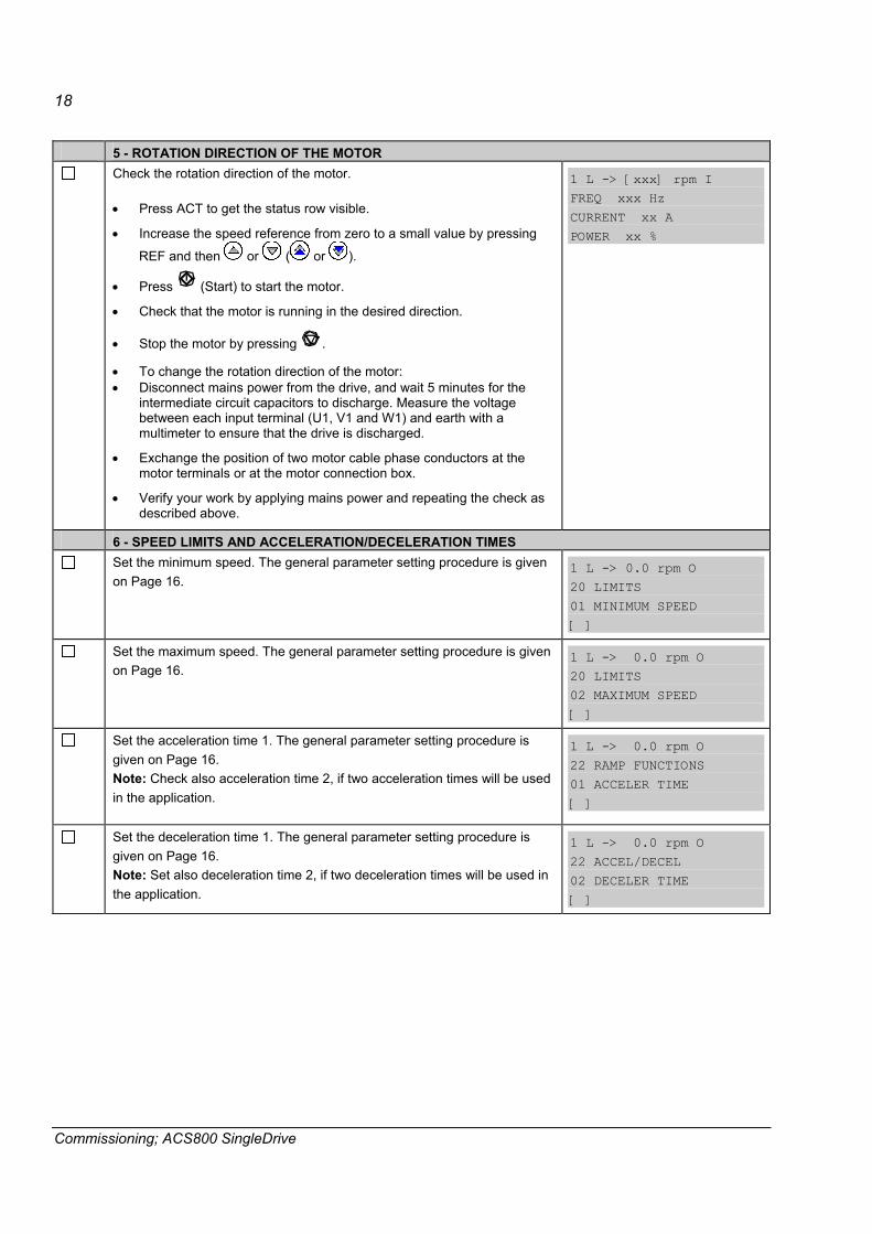
5 - ROTATION DIRECTION OF THE MOTOR Check the rotation direction of the motor.
• Press ACT to get the status row visible.
• Increase the speed reference from zero to a small value by pressing
REF and then or ( or ).
• Press (Start) to start the motor.
• Check that the motor is running in the desired direction.
• Stop the motor by pressing .
• To change the rotation direction of the motor: • Disconnect mains power from the drive, and wait 5 minutes for the
intermediate circuit capacitors to discharge. Measure the voltage between each input terminal (U1, V1 and W1) and earth with a multimeter to ensure that the drive is discharged.
• Exchange the position of two motor cable phase conductors at the motor terminals or at the motor connection box.
• Verify your work by applying mains power and repeating the check as described above.
1 L -> [xxx] rpm I FREQ xxx Hz
CURRENT xx A POWER xx %
6 - SPEED LIMITS AND ACCELERATION/DECELERATION TIMES Set the minimum speed. The general parameter setting procedure is given
on Page 16.
1 L -> 0.0 rpm O 20 LIMITS
01 MINIMUM SPEED
[ ]
Set the maximum speed. The general parameter setting procedure is given on Page 16.
1 L -> 0.0 rpm O 20 LIMITS
02 MAXIMUM SPEED [ ]
Set the acceleration time 1. The general parameter setting procedure is given on Page 16. Note: Check also acceleration time 2, if two acceleration times will be used in the application.
1 L -> 0.0 rpm O 22 RAMP FUNCTIONS
01 ACCELER TIME
[ ]
Set the deceleration time 1. The general parameter setting procedure is given on Page 16. Note: Set also deceleration time 2, if two deceleration times will be used in the application.
1 L -> 0.0 rpm O 22 ACCEL/DECEL
02 DECELER TIME
[ ]

19
Commissioning; ACS800 SingleDrive
7 - STARTING THE DRIVE THROUGH THE I/O INTERFACE As default the external start/stop signal is read from the digital input DI3,
and the external speed reference from the analogue input AI1. Starting through a digital input: • Press the LOC/REM key to change to external control (no L visible on
the first row of the panel display).
• Switch on digital input DI3.
Drive starts. The motor is accelerated to a speed determined by the voltage level of analogue input AI1.
8 - STOPPING THE MOTOR Stopping when in local control: Press .
Stopping when in external control: Switch off digital input DI3. Press the LOC/REM key to change between local and external control.

20
Commissioning; ACS800 SingleDrive
21
Software description
Software description
Drive functions This chapter describes the typical functions of the ACS800 drive.
General
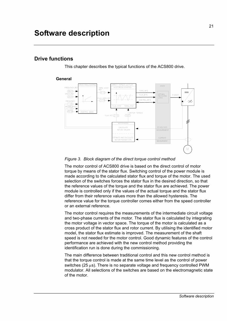
Figure 3. Block diagram of the direct torque control method
The motor control of ACS800 drive is based on the direct control of motor torque by means of the stator flux. Switching control of the power module is made according to the calculated stator flux and torque of the motor. The used selection of the switches forces the stator flux in the desired direction, so that the reference values of the torque and the stator flux are achieved. The power module is controlled only if the values of the actual torque and the stator flux differ from their reference values more than the allowed hysteresis. The reference value for the torque controller comes either from the speed controller or an external reference.
The motor control requires the measurements of the intermediate circuit voltage and two-phase currents of the motor. The stator flux is calculated by integrating the motor voltage in vector space. The torque of the motor is calculated as a cross product of the stator flux and rotor current. By utilising the identified motor model, the stator flux estimate is improved. The measurement of the shaft speed is not needed for the motor control. Good dynamic features of the control performance are achieved with the new control method providing the identification run is done during the commissioning.
The main difference between traditional control and this new control method is that the torque control is made at the same time level as the control of power switches (25 μs). There is no separate voltage and frequency controlled PWM modulator. All selections of the switches are based on the electromagnetic state of the motor.

22
Software description
This control method can only be realised by using high speed signal processing technology. Digital signal processors (MOTOROLA 563xx) are used in ACS800 products to achieve this performance.
Application program identification Each ACS800 product has a product specific loading package, which contains all the necessary software files to be downloaded to the RMIO board. The loading packages define for example, the inverter ratings which are different for AC and DC supplied inverters. Loading Package type information can be identified from the signal 4.01 SW PACKAGE VER.
The downloaded application program version is identifiable from signal 4.03 APPLIC SW VERSION.
Program boot The application program on the RMIO board is saved into FPROM memory. After switching the auxiliary power on, the program starts routines for initialisation and loading of the all tasks, parameters and application program from FPROM to RAM memory. The initialisation time can be minimised by equipping the RMIO board with an external power supply. A reset is given at the end of the boot procedure.
Control modes The ACS800 Application Program Template has two main control modes: REMOTE and LOCAL. The control mode is selected with the LOC/REM key on the CDP 312R control panel or with the DriveWindow PC tool.
REMOTE mode A drive is controlled either from the overriding system or from the drive I/O. The desired alternative is selected by parameter 98.02 COMM MODULE LINK.
NO I/O control: DI3 -start/stop; DI4 -reverse; DI5 -reset. FIELDBUS ADVANT STD MODBUS CUSTOMISED
Overriding system control using data sets 1 and 2, which are typically used with fieldbus adapters. It consists of 3 words (of 16 bits) in both directions. The purpose of each word is fixed.
Local mode The purpose of the local control mode is mainly commissioning and servicing. Local control is selected by the LOC/REM key on either the CDP 312R control panel or DriveWindow. The controls from the overriding system have no effect in this mode, but actual values from the drive are sent back as they are in REMOTE mode. Parameter values can always be monitored and changed regardless of the selected control mode.

23
Software description
Reduced run function Reduced run function is available for parallel connected inverters. Reduced run function makes it possible to continue the operation with limited current if an inverter module(s) is out of order. If one of the modules is broken, it must be removed. Parameter change is needed to continue the run with reduced current (95.03 INT CONFIG USER). For instructions on how to remove and reconnect an inverter module, see the appropriate drive hardware manual.
Emergency stop The emergency stop signal can be connected to digital input 7 (D17) of the Motor and I/O Control board (RMIO-01).
The emergency stop feedback signal can be sent through relay output RO1 of the Motor and I/O Control board (RMIO-01) or (RDIO-01) Extension module 1 to the control relays for the common emergency stop circuit. The purpose of the feedback signal is to confirm that the emergency stop function has been received and the drive program is running.
Note: When an emergency stop signal is detected, the emergency stop cannot be cancelled, even if the signal is cancelled (emergency stop push button is released).
Emergency stop modes The emergency stop mode can be pre-selected by parameter 21.04 EME STOP MODE. On an emergency stop, the torque selector is always set to position SPEED CONTROL.
21.04 EME STOP MODE 1 = STOP RAMPNG Stop by ramping (default).
Deceleration time is set by parameter 22.04 EME STOP RAMP
2 = STOP TORQ Stop by torque limit. 3 = COAST STOP Stop by coasting (torque decreased to
zero). 4 = Not Selected Emergency stop function is not
required in the configuration.
Action if the motor is stopped The motor is already at zero speed when the drive receives an emergency stop signal. The following actions are taken:
• Run is prevented and magnetised modes in LOCAL and REMOTE control.
• Bit 5 is set to a 0 of the 8.01 MAIN STATUS WORD
• Bit 1 of 9.04 ALARM WORD 1 is set to 1.
• Relay output RO1 is energised until MCW bit 0 is set to 0.
24
Software description
Action if the motor is running The motor is running when the drive receives an emergency stop signal. The following actions are taken:
• The drive is stopped according to the emergency stop mode parameter 21.04 EME STOP MODE.
• Locks the emergency stop procedure and energises the relay output1 until the motor has reached zero speed and the 7.01 MAIN CTRL WORD (MCW) bit 0 is set to �0� state.
• Supervises if the deceleration of the drive is higher than the parameter 21.05 EMSTOP SPEED DIF. This supervision starts 5 seconds after the drive has received the emergency stop signal. If the drive is not able to decelerate in the specified rate, it is stopped by coasting and the 8.02 AUX STATUS WORD (ASW) bit 3 (EMERG_STOP_COAST) is set to a �1� state. If this function is not required, the value can be set to 0.
Communication
RDCO DDCS link boardCH0 CH1 CH2 CH3
Old NxxxFB MOD
Slot2Parallel Port Slot1
ANYBUSorRxxxOption
RMIO - Motor and I/O Control Board
Rxxx Option Mother Board
Rxxx Rxxx
Master / Follower Link
PC-tool Link
DI1-6+1RO1-3 AI1-3 AO1,2
PPCC-Interface
RINT - Main Circuit Board
DSP+ MEM+ ICMC
ANYBUSorRxxxOption
Power SW ctrlMeasurements
Brk Chopper Inv Fan Ctrl
RS485
CDP312R
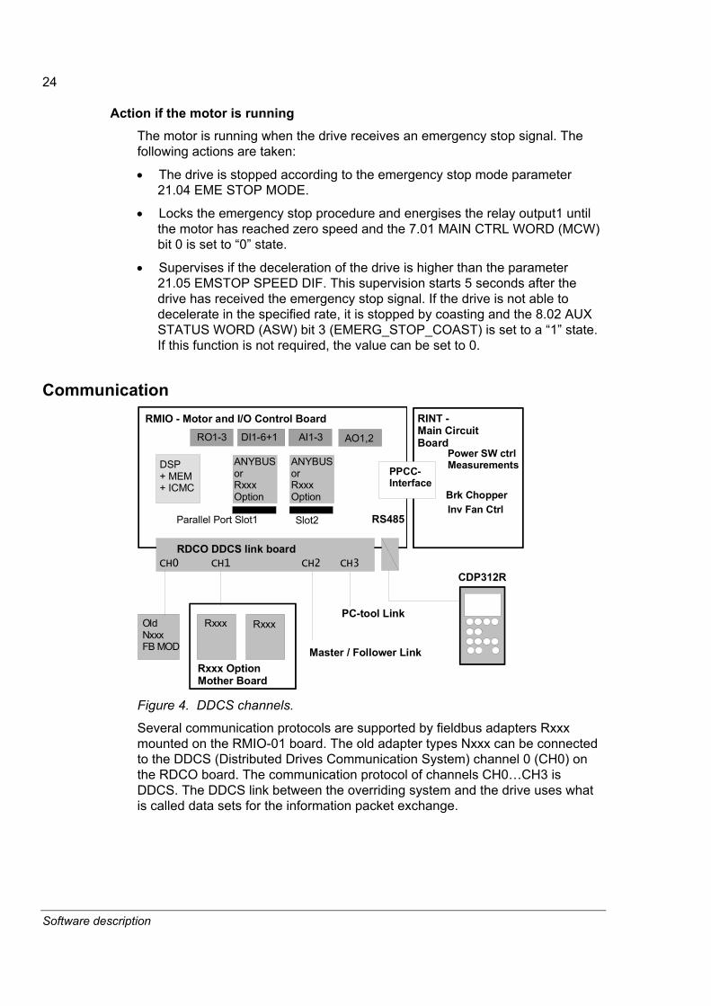
Figure 4. DDCS channels.
Several communication protocols are supported by fieldbus adapters Rxxx mounted on the RMIO-01 board. The old adapter types Nxxx can be connected to the DDCS (Distributed Drives Communication System) channel 0 (CH0) on the RDCO board. The communication protocol of channels CH0�CH3 is DDCS. The DDCS link between the overriding system and the drive uses what is called data sets for the information packet exchange.

25
Software description
The link sends the information of a transmitted data set to the data set table in the drive program and returns the content of the next data set to the overriding system as a "return message". The transmission rate is 4 Mbit/s and the link can send 1 data set every 1 ms. The data received from the overriding system affects only the RAM (not FPROM) memory on the RMIO board.
Fieldbus communication Fieldbus communication mainly uses data sets 1 and 2 between the fieldbus adapter and the RMIO board. Additionally some of the adapters can transfer more data and there is an offset parameter for the first transmitted data set in parameter group 51. For example, by setting the offset to 9, the first data set is used 10, that is supported in the System Application software.
Fieldbus signal Data sets 1 and 2 are used in the communication between the RMIO board and a fieldbus adapter. The updating time is 100 ms.
Table 1. Fieldbus signals.
Data set Index Signal Source or Target 7.01 MAIN CTRL WORD 23.01 SPEED REF in DTC or 29.01 FREQ REF in Scalar control
1
index 1 index 2 index 3
MCW REF1 REF2 25.04 TORQUE REF B
8.01 MAIN STATUS WORD 1.01 MOTOR SPEED FILT
2 index 1 index 2 index 3
MSW ACT1 ACT2 1.08 MOTOR TORQUE
Integer scaling Due to the effectiveness of the communication method, the data is transferred as integer values through the link. Therefore the actual and reference values have to be scaled to 16-bit integers. The integer scaling factor is mentioned in the AMC table parameter list in the column Integer scaling.
05 (161.3) CURRENTIndex Description: Measured motor current absolute value.
unit: A type: R Min: 0 Max: Integer scaling: 10 == 1A
Each parameter has two different gateways to write the value: integer format or decimal. Finally, the result is exactly same in the RMIO program. This relationship is always shown in the signal and parameter table as shown above.
I/O devices on parallel slots or channel CH1 The drive I/O devices are connected to parallel port slots or in a ring to channel 1 (CH1) on the RMIO board. The RMIO is the master in the communication link. Before use, each I/O device must be activated from parameter group 98.

26
Software description
Master/Follower link on channel CH2 A Master/Follower link can be formed by connecting the CH2 channels of two or more drives in a ring. Parameters 70.07 to 70.14 define the mode and the references. The message type is broadcast.
Commissioning and supporting tools on channel CH3 The DriveWindow commissioning and other tools can be connected to channel CH3 on the RMIO board. Node numbers must be set for each drive unit before starting the communication through the connection: see Parameter 70.15 CH3 NODE ADDR. This setting can be made by a point to point connection with either the control panel or DriveWindow. The new node address becomes valid after auxiliary power shutdown of the RMIO board. The RMIO board channel 3 (CH3) has been configured to Slave in the communication point of view.
Modbus link The control panel is connected to the ACS800 drive through a Modbus link. The communication speed is 9600 bit/s (8 data bits, 1 stop bit, odd parity). The connected device is the master of the communication link. A NBCI-01 bus connection units must be used if the distance between the panel and drive is over three metres.
Transmit/ReceiveGNDB-A+GND+24V
Terminal block X39 ofRMIO-01
GDNTXD/RXD+TXD/RXD-
Note:Terminating resistor
RS485
765
Figure 5. RS 485 connection principle.
Modbus is designed for integration with Modicon PLCs or other automation devices, and the services closely correspond to the PLC architecture. The ACS800 drive looks like a Modicon PLC on the network.

27
Software description
Communication profiles The ACS800 supports two communication profiles:
• ABB Drives communication profile
• Generic Drive communication profile.
The ABB Drives communication profile should be selected with type Nxxx fieldbus adapter modules, and when the manufacturer-specific mode is selected (via the PLC) with type Rxxx fieldbus adapter modules.
The Generic Drive profile is supported by type Rxxx fieldbus adapter modules only.
ABB Drives communication profile
Drive states The ABB Drives communication profile is active when parameter 98.07 COMM PROFILE is set to ABB DRIVES.
The ABB Drives communication profile is a PROFIBUS-based interface between the overriding system and the drive so that all ABB drives are controlled in the same way. In order to achieve this, the ABB Drives communication profile defines general states. A control word generally commands transitions between these states. The table below gives an interpretation for the most important states and also the ABB names for these states.

28
Software description
Table 2. ABB Drives communication profile states
Action Name of signal Explanation Switch on inhibit ON_INHIBIT The drive is moved to this state after the EMERGENCY
OFF/STOP or TRIPPED state. The main idea is to guarantee that the ON command is removed. Drive is moved to an OFF-state after the ON command has been removed.
Not ready for switch on
OFF The drive stays in this state as long as the EMERGENCY OFF/STOP commands are active. After these commands have been deactivated and the command �Control from the automation unit� is activated, the drive is moved to the RDYON state.
Ready to switch on RDY_ON After an �ON� command the drive is allowed to perform equipment specific actions. For drives these are: - Flux ON - Stator pulses inhibited
Ready RDY_RUN After a �RUN� command the drive performs - enabling internal controllers, When all internal controllers are ready, the drive is moved to RDYREF state.
Enable operation RDY_REF The drive is following the given references. RFG: enable output
This is actually the speed ramp control, all drive controllers are activated but the output of the speed ramp is clamped to zero. This causes the drive to decelerate to zero speed and regulate zero speed.
RFG: Acceleration enabled
This is also the speed ramp control, the ramping can be started or stopped (HOLD).
Operating status This is also the speed ramp control, the input of ramp is released.
OFF 1 active
The ON command is removed. The drive deactivates all of its functions which were commanded by the ON command e.g..Drive is first decelerated to the zero speed by emergency stop ramp. - Stator and flux current to zero. After this the drive is moved to the OFF-state.
OFF 2 active OFF_2_STA EMERGENCY OFF
The voltage of the drive is immediately removed (coast stop), all functions created by the ON command are removed and after that the drive is moved to ON INHIBIT state.
OFF 3 active OFF_3_STA EMERGENCY STOP
The drive is decelerated to zero speed according to the parameter 21.04 EME STOP MODE, all of the functions created by the ON command are removed and after that the drive is moved to the ON INHIBIT state.
Fault TRIPPED After tripping the drive remains in this state as long as the rising edge of the RESET-signal is sent to the drive. The drive is moved to the ON INHIBIT state, so the ON command must first be turned OFF before the sequence is allowed to continue.

29
Software description
Main Control Word (MCW) The table below defines the use of the ABB Drives communication profile command word for drives application.
Table 3. Main control word bits 0 and 7
Bit Name Value Description 0 ON 1 Command to �RDYRUN� -state. OFF1 0 Command to �OFF� state. (Can go immediately to �RDYON�
-state if there are no other interlockings (OFF 2 / OFF 3). Drive stops down to the zero speed by ramp. All pulses are removed, when in zero speed. Restart is not possible before zero speed.
1 OFF 2 1 No OFF 2 (Emergency OFF) 0 Command to �ON INHIBIT� state.
Inhibit pulses and drive coasts down. Sequence control handles: - Stator and flux current to zero - All pulses are removed
2 OFF 3 1 No OFF 3 (Emergency STOP) 0 Command to �ON INHIBIT� state. Digital input 7 in the
hardware operates parallel with this bit. Fast stop: The fastest possible deceleration, by current limit, fast ramp or coast stop. Defined in the parameter 21.04 EME STOP MODE. After zero speed the sequence control handles: - Stator and flux current to zero - All pulses are removed
3 RUN 1 Enable Operation Command to RDYREF -states. Enable stator/armature pulses. Raise flux to the nominal reference if not already in that value. Then accelerate via speed ramp to the given speed reference set-point.
0 Inhibit Operation. Inhibit inverter pulses and the drive coasts, and goes into the �READY� status (refer to control word bit 0)
4 RAMP-OUT-ZERO 1 Operating condition. 0 Ramp-function generator output is set to zero.
Drive ramps down along the current limit or at the DC link voltage limit.
5 RAMP-HOLD 1 Enable ramp-function generator. 0 Speed ramping stopped. Freeze the actual setpoint from the
ramp-function generator. 6 RAMP-IN-ZERO 1 Enable setpoint 0 Inhibit setpoint. Speed ramp input is forced to zero. 7 RESET 1 Fault resetting with a positive edge. 0 No significance
30
Software description
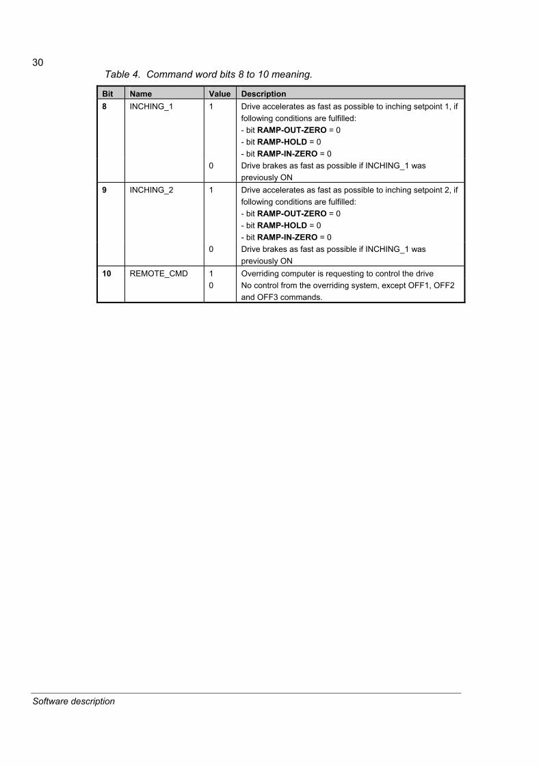
Table 4. Command word bits 8 to 10 meaning.
Bit Name Value Description 8 INCHING_1 1 Drive accelerates as fast as possible to inching setpoint 1, if
following conditions are fulfilled: - bit RAMP-OUT-ZERO = 0 - bit RAMP-HOLD = 0 - bit RAMP-IN-ZERO = 0
0 Drive brakes as fast as possible if INCHING_1 was previously ON
9 INCHING_2 1 Drive accelerates as fast as possible to inching setpoint 2, if following conditions are fulfilled: - bit RAMP-OUT-ZERO = 0 - bit RAMP-HOLD = 0 - bit RAMP-IN-ZERO = 0
0 Drive brakes as fast as possible if INCHING_1 was previously ON
10 REMOTE_CMD 1 Overriding computer is requesting to control the drive 0 No control from the overriding system, except OFF1, OFF2
and OFF3 commands.

31
Software description
Voltageswitched off
Switch oninhibit
Not readyto swich on
Power ON OFF 1 (MCW Bit0=0)
Status Disable(MSW Bit6=1)
Status Not ready for startup(MSW Bit0=0)
Ready to switch on Status Ready for startup
(MSW Bit0=1)
Main Control word basic condition(MCW=XXXX X1XX XXXX X110)
ON (MCW Bit0=1)
InhibitOperation active
Status: Operation Disabled(MSW Bit2=0 RDY_REF)operation
disabled
disable operation(MCW Bit3=0 RUN)
Ready Status Ready for operation
Releaseoperation
(MCW Bit3=1)
A B C D
OFF1 Stop by EMESTOP_RAMP
n(f)=0 / I=0
OFF1 (MCW Bit0=0)
from every device status
(MSW Bit1=0 RDY_RUN)OFF3active
Stop drive according toEME_STOP_MODE
(MSW Bit5=0)
n(f)=0 / I=0
Emergency StopOFF3 (MCW Bit2=0)
from any device status
OFF2
(MSW Bit4=0)
Emergency OffOFF2 (MCW Bit1=0)
from any device status
FaultStop drive
(MSW Bit3=1)
Fault
from every device status
EnableOperation
Release electronics and pulses (MSW Bit2=1)
RFG-output free
(MCW Bit4=1)
RFG: Enableoutput
RFG-output released
(MCW Bit5=1)
B
RFG: Acceleratorenable
Setpoint released
(MCW Bit6=1)
C
D
A
Operatingstate
D
n = n_set
(MSW Bit8=1)
MCW = Main Control WordMSW = Main Status Wordn = SpeedI = Power input currentRFG = Ramp Function Generatorf = Frequency
Error correctedconfirm by RESET (MCW Bit7= 1)
B C D
C D
RFG-outputdisable(MCW Bit4=0RAMP_OUT_ZERO)
RFG stop(MCW Bit5=0RAMP_HOLD)
Setpointdisabled(MCW Bit6=0RAMP_IN_ZERO)
ABB Drive communicationprofile for AC Drives Controland States
Inching 1 ActiveDrive Running Inching 1 setpoint
to speed control
MCW: Bit 4 = 0 and Bit 5 = 0 and Bit 6 = 0
INCHING 1 ON (MCW Bit 8 = 1)
Purpose: Main speed ref. is deactivated
Inching 2 setpointto speed control
INCHING 2 ON (MCW Bit 9 = 1)
Inching 2 ActiveDrive Running
INCHING 1 OFF (MCW Bit 8 = 0)
INCHING 2 OFF (MCW Bit 9 = 0)
ON INHIBIT
OFF
RDY_ON
RDY_RUN (MSW Bit1=1)
RDY_REF Status Operation released
OFF_3_STA
Coast Stop(no torque)
OFF_2_STA
TRIPPEDStatus:
Status:
RUN
RAMP_OUT_ZERO
RAMP_HOLD
RAMP_IN_ZERO
AT_SETPOINT
activeactive
E F
Inhibit inverter pulses
E
F
CONTROL4.dsf 28.09.1998 Figure 6. Control and state diagram.

32
Software description
DC Voltage ON
0 ON, OFF11 OFF22 OFF33 RUN4 RAMP_OUT_ZERO5 RAMP_HOLD6 RAMP_IN_ZERO7 RESET8 INCHING19 INCHING210 REMOTE_CMD
MCW
7.0
1 bi
ts
0 RDY_ON1 RDY_RUN2 RDY_REF3 TRIPPED4 OFF_2_STA5 OFF_3_STA6 ON_INHIBITED7 ALARM8 AT_SETPOINT9 REMOTE10 ABOVE_LIMIT
MSW
8.0
1 bi
ts
0 1 2 RAMP_BYPASS3 BAL_RAMP_OUT4 FLUX_ON_DC5 FLUX_ON6 7 AC
W 7
.02
bits
0
... 3 MAGNETIZED
11 ZERO_SPEED ASW
8.0
2 bi
ts23.01 SPEED REF
FLUX
111
111
1
30% FLUX ACTUAL
0000
111
State
00000
Par. 50.10 ABOVE_SPEED_LIMIT
11
0000
...
0
Par. 20.03 ZERO_SPEED_LIMIT
0
1
01
START by AUTO- or DC MAGN-mode, STOP by Ramp Generator Control
Cont
rol b
y O
verr
idin
g Sy
stem
Time
0
100%
0%
0 rpm
2
3
4
6
5
7
MOTOR SPEED
1
Figure 7. Control example: Start by AUTO or DC MAGN mode, stop by ramp generator.

33
Software description
DC Voltage ON
0 ON, OFF11 OFF22 OFF33 RUN4 RAMP_OUT_ZERO5 RAMP_HOLD6 RAMP_IN_ZERO7 RESET8 INCHING19 INCHING210 REMOTE_CMD
MCW
7.0
1 bi
ts
4 OFF_2_STA5 OFF_3_STA6 ON_INHIBITED7 ALARM8 AT_SETPOINT9 REMOTE10 ABOVE_LIMIT
MSW
8.0
1 bi
ts
0 1 2 RAMP_BYPASS3 BAL_RAMP_OUT4 FLUX_ON_DC5 FLUX_ON6 7 AC
W 7
.02
bits
0
... 3 MAGNETIZED
11 ZERO_SPEED ASW
8.0
2 bi
ts
23.01 SPEED REF
FLUX
111
111
1
0000
00
State
0
00
11
0000
...
0
Par. 20.03 ZERO_SPEED_LIMIT
0
1
01
FLUX ON, START, STOP by Torque Limit, FLUX ON
0
Time
MOTOR SPEED0 rpm
100%
0%
3
1
0 RDY_ON1 RDY_RUN2 RDY_REF3 TRIPPED
Par. 50.10 ABOVE_SPEED_LIMIT
Cont
rol b
y O
verr
idin
g Sy
stem
1
2
5
1
6
7
10
4
8
9
Figure 8. Control example: Start by FLUX ON DC command, stop by torque limit.
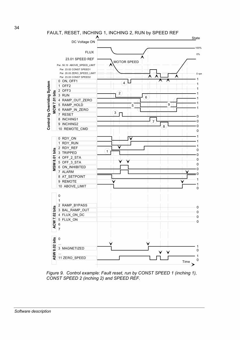
34
Software description
DC Voltage ON
0 ON, OFF11 OFF22 OFF33 RUN4 RAMP_OUT_ZERO5 RAMP_HOLD6 RAMP_IN_ZERO7 RESET8 INCHING19 INCHING210 REMOTE_CMD
MCW
7.0
1 bi
ts
0 RDY_ON1 RDY_RUN2 RDY_REF3 TRIPPED4 OFF_2_STA5 OFF_3_STA6 ON_INHIBITED7 ALARM8 AT_SETPOINT9 REMOTE10 ABOVE_LIMIT
MSW
8.0
1 bi
ts
0 1 2 RAMP_BYPASS3 BAL_RAMP_OUT4 FLUX_ON_DC5 FLUX_ON6 7 AC
W 7
.02
bits
0
... 3 MAGNETIZED
11 ZERO_SPEED ASW
8.0
2 bi
ts23.01 SPEED REF
FLUX
111
111
1
0000
111
State
00000
Par. 50.10 ABOVE_SPEED_LIMIT
11
0000
...
0
Par. 20.03 ZERO_SPEED_LIMIT
0
1
01
FAULT, RESET, INCHING 1, INCHING 2, RUN by SPEED REF
Cont
rol b
y O
verr
idin
g Sy
stem
Time
0
100%
0%
0 rpm
2
4
7
MOTOR SPEED
1
Par. 23.02 CONST SPEED1
Par. 23.03 CONST SPEED2
8
5 9
3
6
Figure 9. Control example: Fault reset, run by CONST SPEED 1 (inching 1), CONST SPEED 2 (inching 2) and SPEED REF.

35
Software description
Generic Drive communication profile The Generic Drive communication profile is active when parameter 98.07 is set to GENERIC. The Generic Drive profile realises the device profile for drives � speed control only � as defined by specific fieldbus standards such as PROFIDRIVE for PROFIBUS, DriveCom for InterBus-S, AC/DC Drive for DeviceNet, Drives and Motion Control for CANopen, etc. Each device profile specifies its Control and Status Words, Reference and Actual value scaling. The profiles also define Mandatory services which are transferred to the application interface of the drive in a standardised way.
The proper functioning of the Generic drive profile requires that Control word commands are enabled by setting parameter 98.02 to FIELDBUS and 98.07 to GENERIC.
Note 1: The Generic Drive communication profile requires the use Speed Control (26.01). Note 2: The Generic Drive profile is only available with type Rxxx fieldbus adapter modules.
Name Description STOP The drive decelerates the motor to zero speed according to the deceleration ramp
(22.02 DECELER TIME). START The drive accelerates to the set reference value according to the acceleration ramp
(22.01 ACCELER TIME). The direction of rotation is determined by the sign of the reference value.
COAST STOP The drive coasts to stop, i.e. the drive stops modulating. However, this command can be overridden by the Brake Control function, which forces the drive to decelerate to zero speed by the active deceleration ramp.
QUICK STOP The drive decelerates the motor to zero speed within the emergency stop deceleration time defined by parameter 22.04 EME STOP RAMP.
CURRENT LIMIT STOP (CLS)
The drive decelerates the motor to zero speed according to the set current limit (20.04 MAXIMUM CURRENT) or torque limit (20.05 MAXIMUM TORQUE), whichever is first reached. The same procedure is valid in case of a Voltage Limit Stop (VLS).
INCHING1 With this command active, the drive accelerates the motor to Constant Speed 1 (defined by parameter 23.02 CONST SPEED 1). After the command is removed, the drive decelerates the motor to zero speed. Note: The speed reference ramps are not effective. The speed change rate is only limited by the current (or torque) limit of the drive. Note: Inching 1 takes priority over Inching 2. Note: Not effective in Scalar control mode.
INCHING2 With this command active, the drive accelerates the motor to Constant Speed 2 (defined by parameter 23.03 CONST SPEED 2). After the command is removed, the drive decelerates the motor to zero speed. Note: The speed reference ramps are not effective. The speed change rate is only limited by the current (or torque) limit of the drive. Note: Inching 1 takes priority over Inching 2. Note: Not effective in Scalar control mode.
RAMP OUT ZERO When active, forces the output of the reference function generator to zero. RAMP HOLD When active, freezes the reference function generator output. FORCED TRIP Trips the drive. The drive will indicate a fault �FORCED TRIP�. RESET Resets an active fault.

36
Software description
Speed reference and actual speed scaling Both the nominal speed reference value given via the fieldbus interface and the actual speed value received from the drive are related to the motor nominal speed (DTC motor control mode) or motor nominal frequency (Scalar motor control mode) as follows.
Motor control mode Speed reference/Actual speed scaling DTC 0% = 0 rpm
100% = [par. 99.05] rpm Scalar 0% = 0 Hz
100% = [par.99.04] Hz
Note: Parameter 50.01 SPEED SCALING should be set to nominal speed when Generic profile is used.

37
Software description
I/O Configurations
Digital inputs All the inputs can be read by the overriding controller. See signals 1.15 DI7-1 STATUS and 8.05 DI STATUS WORD. Input functions are preprogrammed.
RMIO I/O Type Command Description STANDARD DI 2 +24 VDC RUN ENABLE Drive enable input. This digital input can be
used for external interlocking to disable the run enable signal of the drive.
STANDARD DI 3 +24 VDC START/STOP Start = 1, Stop = 0 (stop by ramping) Warning! After a power switch on, the drive will start if the start signal is ON.
STANDARD DI 4 +24 VDC DIRECTION Forward = 0, Reverse = 1 STANDARD DI 5 +24 VDC RESET Fault reset = rising edge (0->1) STANDARD DI 6 +24 VDC KLIXON Overtemperature switch located in the motor
windings can be connected to this input to indicate overtemperature of the motor. Opening contact causes a trip.
STANDARD DI 7 +24 VDC NO EME STOP
NO EMERGENCY STOP status is �1�. If the system does not require an emergency stop function, it can be deactivated by setting parameter 21.04 EME STOP MODE to value NOT SELECTD.
Digital outputs The following digital outputs are available in the RMIO program. Outputs are programmable (see Parameter Group 14) and can also be controlled from the overriding system.
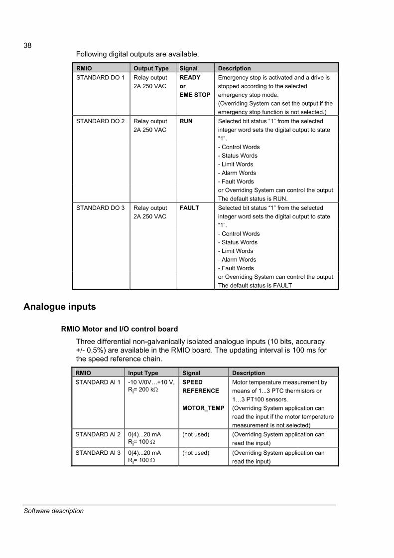
38
Software description
Following digital outputs are available.
RMIO Output Type Signal Description STANDARD DO 1 Relay output
2A 250 VAC READY or EME STOP
Emergency stop is activated and a drive is stopped according to the selected emergency stop mode. (Overriding System can set the output if the emergency stop function is not selected.) Selected bit status �1� from the selected integer word sets the digital output to state �1�. - Control Words - Status Words - Limit Words - Alarm Words - Fault Words
STANDARD DO 2 Relay output 2A 250 VAC
RUN
or Overriding System can control the output. The default status is RUN. Selected bit status �1� from the selected integer word sets the digital output to state �1�. - Control Words - Status Words - Limit Words - Alarm Words - Fault Words
STANDARD DO 3 Relay output 2A 250 VAC
FAULT
or Overriding System can control the output. The default status is FAULT
Analogue inputs
RMIO Motor and I/O control board Three differential non-galvanically isolated analogue inputs (10 bits, accuracy +/- 0.5%) are available in the RMIO board. The updating interval is 100 ms for the speed reference chain.
RMIO Input Type Signal Description STANDARD AI 1 -10 V/0V�+10 V,
Ri= 200 kΩ SPEED REFERENCE MOTOR_TEMP
Motor temperature measurement by means of 1...3 PTC thermistors or 1�3 PT100 sensors. (Overriding System application can read the input if the motor temperature measurement is not selected)
STANDARD AI 2 0(4)...20 mA Ri= 100 Ω
(not used) (Overriding System application can read the input)
STANDARD AI 3 0(4)...20 mA Ri= 100 Ω
(not used) (Overriding System application can read the input)

39
Software description
RAIO-01 Analogue I/O Extension module It is possible to use RAIO-01 or NAIO-02 Analogue I/O Extension Module to replace AI1, AI2, AO1 and AO2 inputs and outputs on the RMIO board. The resolution of the RAIO-01 or NAIO-02 is 12 bits. The input range is selectable by DIP switches and the maximum voltage or milliampere value corresponds 20000 unit as integer value in the SW. The module selection is done by parameter 98.06 AI/O EXT MODULE 1.
RAIO-01, NAIO-02 Input Type Signal Description Extension module 1 AI1 -20..0..+20 mA
0(4)�20 mA Ri= 100 Ω
-2..0..+2 VDC -10..0..+10 VDCRi= 200 kΩ
SPEED REFERENCE or MOTOR 1 TEMP
Speed reference of the drive or motor temperature measurement by means of 1�3 PTC thermistors or PT100 sensor(s).
Extension module 1 AI2 -20..0..+20 mA 0(4)...20 mA Ri= 100 Ω
-2..0..+2 VDC -10..0..+10 VDCRi= 200 kΩ
MOTOR 2 TEMP
Motor temperature measurement by means of 1�3 PTC thermistors or PT100 sensor(s).
Analogue outputs Two non-galvanically isolated analogue outputs (10 bits, accuracy +/- 1%) are available on the RMIO board. The output updating time is 20 ms.
RMIO Output Type Signal Description AO 1 0(4)�20 mA
Ri = 700 Ω AO1_OUT A programmable analogue output from
the program. The output can be used also as a constant current source to supply the temperature measurement sensor PT100 or PTC. The current is set automatically according to the type of the sensor.
STANDARD I/O Board AO 2
0(4)�20 mA Ri = 700 Ω
AO2_OUT (The overriding system application can control the output)
If extension module is used, the resolution is then 12 bits. These analogue outputs operates in parallel with the RMIO outputs.
RAIO-01, NAIO-02 I/O Type Command Description Extension module 1 AO1 0(4)�20 mA
Ri= 700 Ω
Isolated from power supply
AO1_OUT See Standard AO1.
Extension module 1 AO2 0(4)�20 mA Ri= 700 Ω
Isolated from power supply
AO2_OUT See Standard AO2.
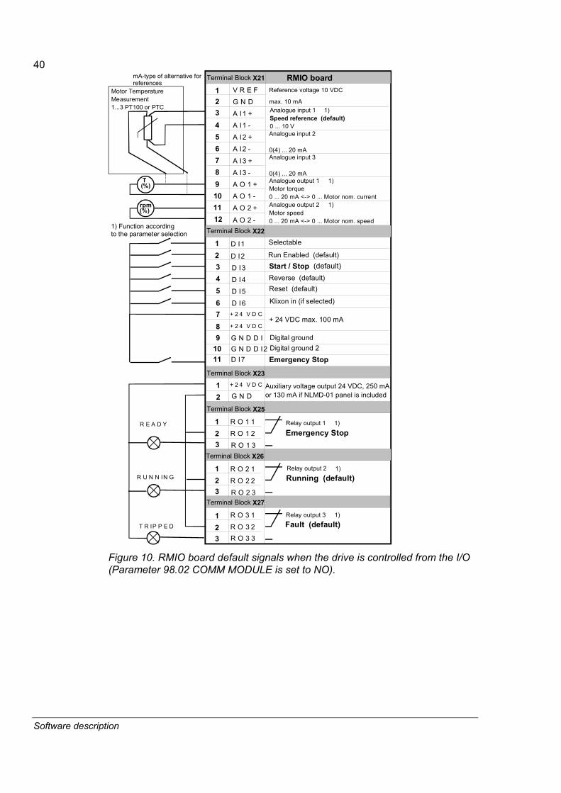
40
Software description
Terminal Block X21
123456789101112
V R E F
G N D
A I1 +
A I1 -
A I2 +
A I2 -
A I3 +
A O 1 +
A O 1 -
A O 2 +
A O 2 -
A I3 -
RMIO board
Terminal Block X23
12
3456789
G N D
D I3
D I4
D I5
D I6+ 2 4 V D C
G N D D I
Terminal Block X22
12 D I2
3 R O 1 3
Terminal Block X25
12
R O 1 1
R O 1 2
3 R O 2 3
Terminal Block X26
12
R O 2 1
R O 2 2
3 R O 3 3
Terminal Block X27
12
R O 3 1
R O 3 2
Reference voltage 10 VDC
max. 10 mAAnalogue input 1 1)Speed reference (default)0 ... 10 VAnalogue input 2 0(4) ... 20 mAAnalogue input 3 0(4) ... 20 mAAnalogue output 1 1)Motor torque0 ... 20 mA <-> 0 ... Motor nom. currentAnalogue output 2 1)Motor speed0 ... 20 mA <-> 0 ... Motor nom. speed
Selectable
+ 2 4 V D C
D I1Run Enabled (default)Start / Stop (default)Reverse (default)Reset (default)
+ 24 VDC max. 100 mA
Digital ground
Auxiliary voltage output 24 VDC, 250 mA or 130 mA if NLMD-01 panel is included
R E A D YEmergency Stop
Running (default)
Fault (default)
Relay output 1 1)
Relay output 2 1)
Relay output 3 1)
T(%)
rpm (%)
R U N N IN G
T R IP P E D
+ 2 4 V D C
Klixon in (if selected)
Motor Temperature Measurement1...3 PT100 or PTC
G N D D I2D I7
1011
Digital ground 2
Emergency Stop
1) Function accordingto the parameter selection
mA-type of alternative for references
Figure 10. RMIO board default signals when the drive is controlled from the I/O (Parameter 98.02 COMM MODULE is set to NO).

41
Software description
Pulse encoder interface RTAC-01 The pulse encoder module (RTAC-01) is connected to the parallel port slot on the RMIO board and activated by Parameter 98.01 ENCODER MODULE.
The feedback used is indicated in the 8.02 AUXILIARY STATUS WORD bit 12.
B12: 0 = External pulse encoder 1 = Internal speed
The Master/Follower link
General The Master/Follower Application macro is designed for applications in which the system is operated by several ACS800 drives and the shafts are coupled to each other gearing, chain, belt etc. The Master drive controls the Follower drive(s) via a fibre optic link.
The Master station is typically speed controlled and the other drives follow its torque or speed reference. In general, torque control of the Follower should be used when the motor shafts of the Master and Follower drives are coupled fixedly to each other by gearing, a chain etc. and no speed difference between the drives is possible.
In some applications both speed and torque controls of the Followers are required. In those cases a flying change between speed and torque control can be performed from the overriding system by controlling the torque selector position and additional speed reference.
For more information, Master/Follower Application Guide (3AFE64590430 English).
Link configuration Channel 2 (CH2) on the RDCO board is used for the Master/Follower link. Channel 2 (CH2) is configurable by software to be either the master or the follower in the communication. Typically the speed controlled process master drive is configured also to the communication master. Also, the torque reference source address in the Master Drive and the destination address in the Follower Drive can be defined by parameters 70.09 MASTER SIGNAL 1, 70.10 MASTER SIGNAL 2 and 70.11 MASTER SIGNAL 3.
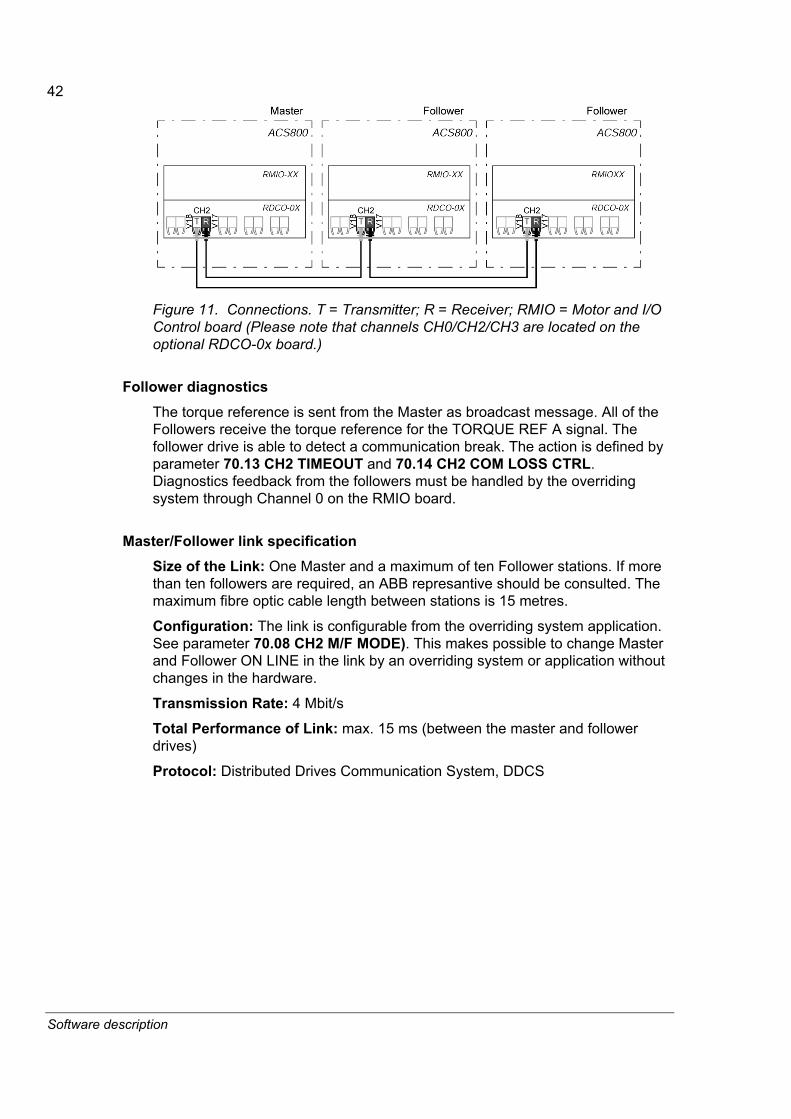
42
Software description
Figure 11. Connections. T = Transmitter; R = Receiver; RMIO = Motor and I/O Control board (Please note that channels CH0/CH2/CH3 are located on the optional RDCO-0x board.)
Follower diagnostics The torque reference is sent from the Master as broadcast message. All of the Followers receive the torque reference for the TORQUE REF A signal. The follower drive is able to detect a communication break. The action is defined by parameter 70.13 CH2 TIMEOUT and 70.14 CH2 COM LOSS CTRL. Diagnostics feedback from the followers must be handled by the overriding system through Channel 0 on the RMIO board.
Master/Follower link specification Size of the Link: One Master and a maximum of ten Follower stations. If more than ten followers are required, an ABB represantive should be consulted. The maximum fibre optic cable length between stations is 15 metres.
Configuration: The link is configurable from the overriding system application. See parameter 70.08 CH2 M/F MODE). This makes possible to change Master and Follower ON LINE in the link by an overriding system or application without changes in the hardware.
Transmission Rate: 4 Mbit/s
Total Performance of Link: max. 15 ms (between the master and follower drives)
Protocol: Distributed Drives Communication System, DDCS
43
Software description
Diagnostics
General A common method of drive diagnostics is to provide the user with information on previous conditions. Signals, data loggers and fault loggers are commonly implemented in most modern drives.
All of the loggers should provide the user with real time stamps to identify when the event was logged. The time should be co-ordinated and common for all system components. The following is a description of the data, event, and fault loggers available in the System Application Program.
Fault and event loggers The fault logger collects 64 of the most recent faults into the fault buffer in the RAM memory. The latest 16 faults are stored into the FLASH memory at the beginning of an auxiliary power loss. The fault logger records all available information from the drive including faults, alarms, reset and system messages.
AMC time format and counting The Time for the logger fault is taken from the power-on counter, whose format is 9999 hr, xx min, yy.yyyy s. However, the counter can be updated cyclically from the overriding system if the system includes an overriding controller (for example APC2). DriveWindow and the CDP 312R control panel show the real date and time.
Data logger The purpose of the Data logger is to collect the history of signals related to an incident and store it in the drive for later retrieval and analysis. The content of the Data logger is stored to the RAM memory.
The Data Logger consist of 1...4 channels. The total memory size for the Data logger is 1024 bytes. The maximum number of samples depends on the data type:
• Integer type signal or parameters reserve 1 byte
• Real-type values reserve 2 bytes
Example: Four real-type signals are measured. The maximum number of sample is 1024/(2 bytes x 4 channels) = 128.
The data logger stores the selected signals to the RAM memory every 5 milliseconds. By default the following signals are monitored:
1.01 MOTOR SPEED FILT 1.07 MOTOR TORQUE FILT 23.1 SPEED REF 25.1 TORQUE REF A
The signals to be monitored can be selected from DriveWindow; an auxiliary power cut restores the default signals. The default triggering mode is Fault.

44
Software description
Positioning counter The number of Pulse Encoder pulses can be counted and set using 7.02 AUX CONTROL WORD (ACW) bits B9�11. The SYNC_COMMAND can also be given by I/O to minimise the delays. The calculation has two output modes: counted number of pulses or number of revolutions and motor shaft position in degrees.
All the signals for this function can be seen with the description in group 3 (3.07�3.10), commands in the 7.02 AUX CONTROL WORD (ACW) and the parameters in group 50 (50.07�50.11).
Figure 12. Positioning counting logic and calculation diagram.
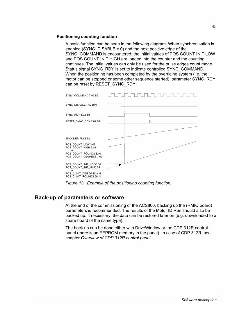
45
Software description
Positioning counting function A basic function can be seen in the following diagram. When synchronisation is enabled (SYNC_DISABLE = 0) and the next positive edge of the SYNC_COMMAND is encountered, the initial values of POS COUNT INIT LOW and POS COUNT INIT HIGH are loaded into the counter and the counting continues. The Initial values can only be used for the pulse edges count mode. Status signal SYNC_RDY is set to indicate controlled SYNC_COMMAND. When the positioning has been completed by the overriding system (i.e. the motor can be stopped or some other sequence started), parameter SYNC_RDY can be reset by RESET_SYNC_RDY.
SYNC_COMMAND 7.02 B9
SYNC_DISABLE 7.02 B10
SYNC_RDY 8.02 B5
RESET_SYNC_RDY 7.02 B11
ENCODER PULSES
POS_COUNT_LOW 3.07 POS_COUNT_HIGH 3.08 orPOS_COUNT_ROUNDS 3.10POS_COUNT_DEGREES 3.09
POS_COUNT_INIT_LO 50.08 POS_COUNT_INIT_HI 50.09 orPOS_C_INIT_DEG 50.10 andPOS_C_INIT_ROUNDS 50.11 Figure 13. Example of the positioning counting function.
Back-up of parameters or software At the end of the commissioning of the ACS800, backing up the (RMIO board) parameters is recommended. The results of the Motor ID Run should also be backed up. If necessary, the data can be restored later on (e.g. downloaded to a spare board of the same type).
The back up can be done either with DriveWindow or the CDP 312R control panel (there is an EEPROM memory in the panel). In case of CDP 312R, see chapter Overview of CDP 312R control panel.

46
Software description

47
Signals
Signals
Overview This chapter describes the measured, calculated and control word signals of the ACS800.
How to read the signal table Before you start to read the signal table, we first recommend you read this description.
ACS800 Signals
Group + Index Description Quantity 1.1...1.26, 1.44�1.45 Actual Signals 28 2.1...2.17 Actual Signals 17 3.1...3.15, 3.20�3.29 Actual Signals 25 4.1...4.5 Information 5 5.1...5.32 (reserved for the application) 6.1...6.32 (reserved for the application) 7.1...7.3 Control Words 3 8.1...8.6 Status Words, Limit Words 6 9.1...9.5, 9.8�9.12 Fault Words, Alarm Words 10 Total 94
• All signals are read-only. However the overriding system can write to the control words, but it only affects the RAM memory.
05 (161.3) CURRENTIndex Description: Measured motor current absolute value.
unit: A type: R Min: 0 Max: Integer scaling: 10 == 1A
Figure 14. Sample of an actual signal table.
• If the application program utilizes individual bits of a word (for example 7.01 MAIN CTRL WORD), it must be understood that bit 15 is set by the SIGN. Also bit 15 is read from the SIGN.
• If signal type is R (real value), it also has an integer scaling relation mentioned in the column Integer scaling. For example, if the CURRENT signal is read to the overriding system, an integer value of 10 corresponds to 1 Ampere. All the read and sent values are limited to 16 bits (-32768�32767).
• Unit of the signal value can be seen on the lower left-hand corner of the signal description.

48
Signals
• Minimum and maximum values are shown in decimal format.
• Data type is given with a short code:
B = Boolean value I = 16-bit signed integer value PB = Packet Boolean value R = Real value S = String

49
Signals
AMC Table Signals
Group 1 Actual Signals
1 Group name: ACTUAL SIGNALS Description: Measured or calculated values 01 MOTOR SPEED FILT Index Description: Filtered speed actual according to the speed feedback selection. See parameter 50.03. unit: rpm type: R Min: Max: Integer scaling: see par. 50.01 SPEED SCALING 02 SPEED ESTIMATED Index Description: Internally calculated actual speed. unit: rpm type: R Min: Max: Integer scaling: see par. 50.01 SPEED SCALING 03 SPEED MEASURED Index Description: Measured actual speed from the pulse encoder. This measurement is active also in case of
the SPEED FB SEL = internal speed. unit: rpm type: R Min: Max: Integer scaling: see par. 50.01 SPEED SCALING 04 EXTERNAL SPEED (Not available) Index Description: Measured external speed. unit: rpm type: R Min: Max: Integer scaling: see par. 50.01 SPEED SCALING 05 FREQUENCY Index Description: Calculated frequency of the motor. unit: Hz type: R Min: Max: Integer scaling: 100 == 1 Hz 06 MOTOR CURRENT Index Description: Measured motor current absolute value. unit: A type: R Min: Max: Integer scaling: 10 == 1 A 07 MOTOR TORQUE FILT Index Description: Filtered motor torque in percent of the rated motor torque. unit: % type: R Min: Max: Integer scaling: 100 == 1% 08 MOTOR TORQUE Index Description: Motor torque in percent of the rated motor torque. unit: % type: R Min: Max: Integer scaling: 100 == 1% 09 POWER Index Description: Motor power in percent of the rated motor power. unit: % type: R Min: Max: Integer scaling: 10 == 1% 10 DC VOLTAGE Index Description: Measured DC bus voltage unit: V type: R Min: Max: Integer scaling: 1 == 1 V 11 MOTOR VOLTAGE Index Description: Calculated motor output voltage. unit: V type: R Min: Max: Integer scaling: 1 == 1 V 12 PP TEMP Index Description: Temperature of the heat sink plate in percentage. 0°C equals 0% and tripping limit is 100%. unit: °C type: R Min: Max: Integer scaling: 1 == 1°

50
Signals
1 Group name: ACTUAL SIGNALS Description: Measured or calculated values 13 TIME OF USAGE Index Description: This actual signal is an elapsed time indicator of the mains switched on. unit: h type: R Min: Max: Integer scaling: 1 == 1 h 14 KILOWATT HOURS Index Description: This actual signal counts the kilowatt-hours in operation. unit: kWh type: R Min: Max: Integer scaling: 1 == 1 kWh Description: Measured or calculated values 15 Interval: 10 ms DI7-1 STATUS Index Description: Status of the digital inputs DI7...DI1 in the software.
Example: DI1 and DI4 are activated. Table format: 0001001 (CDP 312R display view) DI name 7654321.
unit: type: I Min: Max: Integer scaling: 1 == 1 16 Interval: 500 ms MOTOR 1 TEMP Index Description: Value of analogue input 1 displayed in °C, when PT100 temperature measurement is
selected. unit: °C type: R Min: Max: Integer scaling: 1 == 1° 17 Interval: 500 ms MOTOR 2 TEMP Index Description: Value of analogue input 2 displayed in °C, when PT100 temperature measurement is
selected. unit: °C type: R Min: Max: Integer scaling: 1 == 1° 18 MOTOR TEMP EST Index Description: Calculated motor temperature when thermal model is used for the motor overtemperature
protection. unit: °C type: R Min: Max: Integer scaling: 1 == 1° 19 Interval: 500 ms AI1 [V] Index Description: Scaled value of analogue input 1. See parameters 13.01...13.02. unit: type: R Min: -10 Max: 10 Integer scaling: 10000 == 10 V 20 Interval: 500 ms AI2 [mA] Index Description: Scaled value of analogue input 2. See parameters 13.04...13.05. unit: type: R Min: -20 Max: 20 Integer scaling: 20000 == 20 mA 21 Interval: 500 ms AI3 [mA] Index Description: Scaled value of analogue input 3. See parameters 13.08...13.09. unit: type: R Min: -20 Max: 20 Integer scaling: 20000 == 20 mA 22 Interval: 500 ms RO3-1 STATUS Index Description: Status of the RMIO board relay outputs.
Example: DO2 and DO3 are activated. Table format: 0000110 (CDP 312R display view). DO name 321.
unit: type: Min: 0 Max: Integer scaling: 23 Interval: 500 ms AO1 [mA] Index Description: Value of analogue output 1 signal in milliamperes. Signal selecting and scaling, see
parameter group 15. unit: mA type: R Min: 0 mA Max: 22 mA Integer scaling: 20000 == 20 mA

51
Signals
1 Group name: ACTUAL SIGNALS Description: Measured or calculated values 24 Interval: 500 ms AO2 [mA] Index Description: Value of analogue output 2 signal in milliamperes. Signal selecting and scaling, see
parameter group 15. unit: mA type: R Min: 0 mA Max: 22 mA Integer scaling: 20000 == 20 mA 25 Interval: 500 ms CONTROL MODE Index Description: Control mode in use
1 = Speed control 2 = Torque control (TORQ_REF_1 affects the output of TORQ REF 3)
unit: type: I Min: 1 Max: 2 Integer scaling: 26 Interval: 500 ms LED PANEL OUT Index Description: Output monitoring of the NLMD-01 LED panel. See parameter group 18. unit: % type: R Min: Max: Integer scaling: 1 == 1 44 Interval: 500 ms FAN ON-TIME Index Description: Running time of the drive cooling fan.
Note: The counter can be reset by the DriveWindow PC tool. Resetting is recommended when the fan is replaced.
unit: type: Min: Max: Integer scaling: 1 == 1 45 Interval: 500 ms CTRL BOARD TEMP Index Description: Control board temperature. unit: % type: Min: Max: Integer scaling: 1 == 1
Group 2 Actual Signals
2 Group name: ACTUAL SIGNALS Description: Measured or calculated values in the speed and torque reference chain. 01 SPEED REF2 Index Description: Limited speed reference. unit: rpm type: R Min: -18000 rpm Max: 18000rpm Integer scaling: see Par. 50.01 SPEED SCALING 02 SPEED REF3 Index Description: Speed reference after the speed ramp. unit: rpm type: R Min: -18000 rpm Max: 18000rpm Integer scaling: see Par. 50.01 SPEED SCALING 03 SPEED ERROR NEG Index Description: Difference between reference and the actual value. If parameter WINDOW_SEL_ON is
enabled, SPEED_ERROR_NEG is filtered through the window function. unit: % type: R Min: Max: Integer scaling: see Par. 50.01 SPEED SCALING 04 TORQUE PROP REF Index Description: P-part effect at the output of the of PID controller. Output of PID controller is formed from the
output parameters TORQUE PROP REF, TORQUE INTEG REF and TORQ ACC COMP REF.
unit: % type: R Min: Max: Integer scaling: 100 == 1% 05 TORQUE INTEG REF Index Description: I- part effect at the output of the PID controller. Output of PID controller is formed from the
output parameters TORQUE PROP REF, TORQUE INTEG REF, TORQ DER REF and TORQ ACC COMP REF.
unit: % type: R Min: Max: Integer scaling: 100 == 1%

52
Signals
2 Group name: ACTUAL SIGNALS Description: Measured or calculated values in the speed and torque reference chain. 06 TORQUE DER REF Index Description: D-part effect at the output of the PID controller. Output of PID controller is formed from the
output parameters TORQUE PROP REF, TORQUE INTEG REF, TORQ DER REF and TORQ ACC COMP REF.
unit: % type: f Min: Max: Integer scaling: 100 == 1% 07 TORQ ACC COMP REF Index Description: Output of the acceleration compensation. unit: % type: R Min: Max: Integer scaling: 100 == 1% 08 TORQUE REF 1 Index Description: Limited torque reference value in the torque reference chain. unit: % type: R Min: Max: Integer scaling: 100 == 1% 09 TORQUE REF 2 Index Description: Final torque reference from the speed control chain. unit: % type: R Min: Max: Integer scaling: 100 == 1% 10 TORQUE REF 3 Index Description: Torque reference after the torque selector block. unit: % type: R Min: Max: Integer scaling: 100 == 1% 11 TORQUE REF 4 Index Description: Sum of TORQUE REF 3 and LOAD COMPENSATION. unit: % type: R Min: Max: Integer scaling: 100 == 1% 12 TORQUE REF 5 Index Description: Sum of TORQUE REF 4 and TORQUE STEP. unit: % type: R Min: Max: Integer scaling: 100 == 1% 13 TORQ USED REF Index Description: Limited torque reference. This is the final torque input for the internal torque controller. unit: % type: R Min: Max: Integer scaling: 100 == 1% 14 FLUX USED REF Index Description: Used flux reference. unit: % type: R Min: Max: Integer scaling: 10 == 1% 15 FLUX ACT Index Description: Flux actual value. unit: % type: R Min: Max: Integer scaling: 10 == 1% 16 dV/dt Index Description: Speed reference change in rpm/s at the output of the speed ramp generator. unit: rpm/s type: R Min: Max: Integer scaling: See parameter 50.01 17 MOTOR ACCELERATIO Index Description: Motor acceleration in rpm/s. unit: rpm/s type: f Min: Max: Integer scaling:

53
Signals
Group 3 Actual Signals
3 Group name: ACTUAL SIGNALS Description: Data values 01 APPL DUTY Index Description: Microprocessor load measurement. Value 100% means the overloading of the
microprocessor and causes delay for the tasks executions. Application duty counter is recommended to be calibrated when application has been modified.
unit: % type: R Min: Max: Integer scaling: 1 == 1% 02 APPLICATION OVERL Index Description: Possible overload of each application task can be detected by means of this signal in the
Packed Boolean format. B0 =
B1 = B2 = B3 = B4 = B5 =
Application Task 1 overload Application Task 2 overload Application Task 3 overload Application Task 4 overload Application Task 5 overload Application Task 6 overload
unit: type: PB Min: 0 Max: Integer scaling: 1 == 1 03 RS Index Description: Estimated stator resistance RS unit: Ω type: R Min: 0 Max: Integer scaling: 100 == 1 Ω 04 LS Index Description: Estimated stator inductance LS unit: mH type: R Min: 0 Max: Integer scaling: 100 == 1 mH 05 SIGMALS Index Description: Estimated σLS value unit: Ω type: R Min: 0 Max: Integer scaling: 100 == 1 Ω 06 TR Index Description: Estimated time constant of the rotor. unit: ms type: R Min: 0 Max: Integer scaling: 1 == 1 ms 07 POS COUNT LOW Index Description: Position counter value in pulses (low word). unit: type: I Min: 0 Max: 65536 Integer scaling: 1 == 1 08 POS COUNT HIGH Index Description: Position counter value in pulses (high word). unit: type: I Min: 0 Max: 65536 Integer scaling: 1 == 1 09 POS COUNT DEGREES Index Description: Position counter value in degrees, when parameter 50.07 POS COUNT MODE has selection
ROUND&DEG. This signal is used together with signal 3.10 POS COUNT ROUNDS. unit: deg type: R Min: -360 deg Max: 360 deg Integer scaling: 1 == 1 deg 10 POS COUNT ROUNDS Index Description: Position counter value in total shafts rounds, when parameter 50.07 POS COUNT MODE has
selection ROUND&DEG. unit: type: R Min: -8388608 Max: 8388608 Integer scaling: 1 == 1
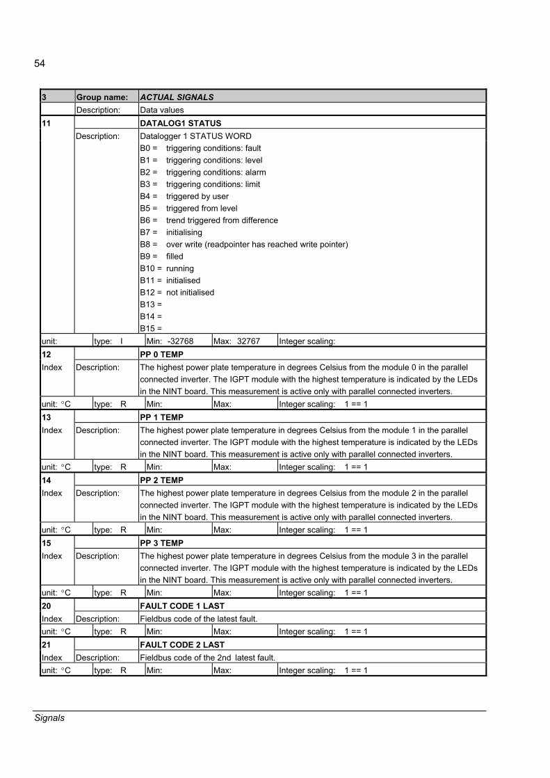
54
Signals
3 Group name: ACTUAL SIGNALS Description: Data values 11 DATALOG1 STATUS
Datalogger 1 STATUS WORD Description: B0 = B1 = B2 = B3 = B4 = B5 = B6 = B7 = B8 = B9 = B10 =B11 =B12 =B13 =B14 =B15 =
triggering conditions: fault triggering conditions: level triggering conditions: alarm triggering conditions: limit triggered by user triggered from level trend triggered from difference initialising over write (readpointer has reached write pointer) filled running initialised not initialised
unit: type: I Min: -32768 Max: 32767 Integer scaling: 12 PP 0 TEMP Index Description: The highest power plate temperature in degrees Celsius from the module 0 in the parallel
connected inverter. The IGPT module with the highest temperature is indicated by the LEDs in the NINT board. This measurement is active only with parallel connected inverters.
unit: °C type: R Min: Max: Integer scaling: 1 == 1 13 PP 1 TEMP Index Description: The highest power plate temperature in degrees Celsius from the module 1 in the parallel
connected inverter. The IGPT module with the highest temperature is indicated by the LEDs in the NINT board. This measurement is active only with parallel connected inverters.
unit: °C type: R Min: Max: Integer scaling: 1 == 1 14 PP 2 TEMP Index Description: The highest power plate temperature in degrees Celsius from the module 2 in the parallel
connected inverter. The IGPT module with the highest temperature is indicated by the LEDs in the NINT board. This measurement is active only with parallel connected inverters.
unit: °C type: R Min: Max: Integer scaling: 1 == 1 15 PP 3 TEMP Index Description: The highest power plate temperature in degrees Celsius from the module 3 in the parallel
connected inverter. The IGPT module with the highest temperature is indicated by the LEDs in the NINT board. This measurement is active only with parallel connected inverters.
unit: °C type: R Min: Max: Integer scaling: 1 == 1 20 FAULT CODE 1 LAST Index Description: Fieldbus code of the latest fault. unit: °C type: R Min: Max: Integer scaling: 1 == 1 21 FAULT CODE 2 LAST Index Description: Fieldbus code of the 2nd latest fault. unit: °C type: R Min: Max: Integer scaling: 1 == 1
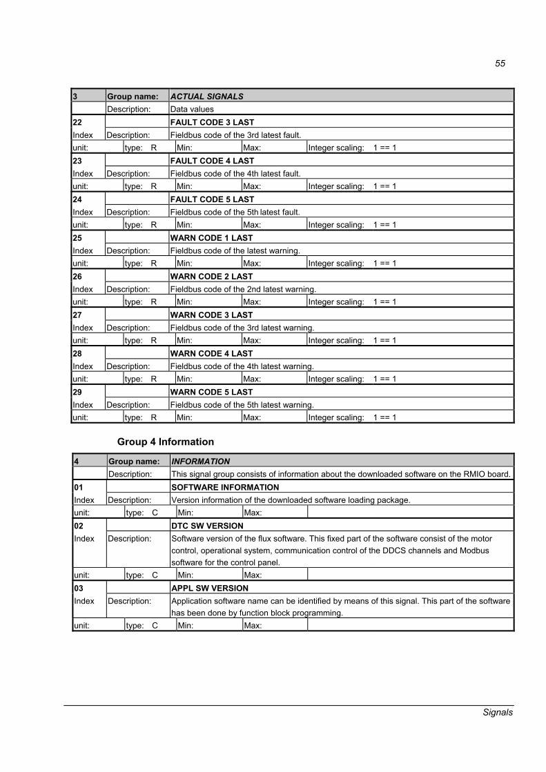
55
Signals
3 Group name: ACTUAL SIGNALS Description: Data values 22 FAULT CODE 3 LAST Index Description: Fieldbus code of the 3rd latest fault. unit: type: R Min: Max: Integer scaling: 1 == 1 23 FAULT CODE 4 LAST Index Description: Fieldbus code of the 4th latest fault. unit: type: R Min: Max: Integer scaling: 1 == 1 24 FAULT CODE 5 LAST Index Description: Fieldbus code of the 5th latest fault. unit: type: R Min: Max: Integer scaling: 1 == 1 25 WARN CODE 1 LAST Index Description: Fieldbus code of the latest warning. unit: type: R Min: Max: Integer scaling: 1 == 1 26 WARN CODE 2 LAST Index Description: Fieldbus code of the 2nd latest warning. unit: type: R Min: Max: Integer scaling: 1 == 1 27 WARN CODE 3 LAST Index Description: Fieldbus code of the 3rd latest warning. unit: type: R Min: Max: Integer scaling: 1 == 1 28 WARN CODE 4 LAST Index Description: Fieldbus code of the 4th latest warning. unit: type: R Min: Max: Integer scaling: 1 == 1 29 WARN CODE 5 LAST Index Description: Fieldbus code of the 5th latest warning. unit: type: R Min: Max: Integer scaling: 1 == 1
Group 4 Information
4 Group name: INFORMATION Description: This signal group consists of information about the downloaded software on the RMIO board. 01 SOFTWARE INFORMATION Index Description: Version information of the downloaded software loading package. unit: type: C Min: Max: 02 DTC SW VERSION Index Description: Software version of the flux software. This fixed part of the software consist of the motor
control, operational system, communication control of the DDCS channels and Modbus software for the control panel.
unit: type: C Min: Max: 03 APPL SW VERSION Index Description: Application software name can be identified by means of this signal. This part of the software
has been done by function block programming. unit: type: C Min: Max:
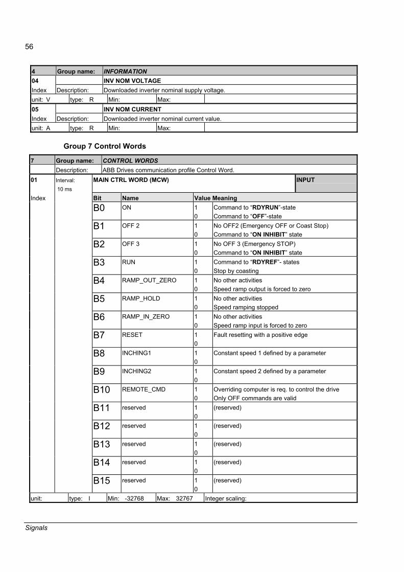
56
Signals
4 Group name: INFORMATION 04 INV NOM VOLTAGE Index Description: Downloaded inverter nominal supply voltage. unit: V type: R Min: Max: 05 INV NOM CURRENT Index Description: Downloaded inverter nominal current value. unit: A type: R Min: Max:
Group 7 Control Words
7 Group name: CONTROL WORDS Description: ABB Drives communication profile Control Word. 01 Interval:
10 ms MAIN CTRL WORD (MCW) INPUT
Index Bit Name Value Meaning B0 ON 1
0 Command to �RDYRUN�-state Command to �OFF�-state
B1 OFF 2
1 0
No OFF2 (Emergency OFF or Coast Stop) Command to �ON INHIBIT� state
B2 OFF 3
1 0
No OFF 3 (Emergency STOP) Command to �ON INHIBIT� state
B3 RUN
1 0
Command to �RDYREF�- states Stop by coasting
B4 RAMP_OUT_ZERO
1 0
No other activities Speed ramp output is forced to zero
B5 RAMP_HOLD
1 0
No other activities Speed ramping stopped
B6 RAMP_IN_ZERO
1 0
No other activities Speed ramp input is forced to zero
B7 RESET
1 0
Fault resetting with a positive edge
B8 INCHING1 1 0
Constant speed 1 defined by a parameter
B9 INCHING2 1 0
Constant speed 2 defined by a parameter
B10 REMOTE_CMD 1 0
Overriding computer is req. to control the drive Only OFF commands are valid
B11 reserved 1 0
(reserved)
B12 reserved 1 0
(reserved)
B13 reserved 1 0
(reserved)
B14 reserved 1 0
(reserved)
B15 reserved 1 0
(reserved)
unit: type: I Min: -32768 Max: 32767 Integer scaling:
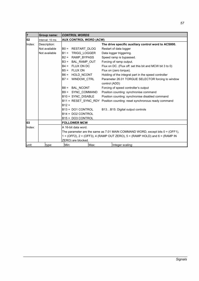
57
Signals
7 Group name: CONTROL WORDS 02 Interval: 10 ms AUX CONTROL WORD (ACW) Index: Description:
Not available Not available
B0 = B1 = B2 = B3 = B4 = B5 = B6 = B7 = B8 = B9 = B10 = B11 = B12 = B13 = B14 = B15 =
RESTART_DLOG TRIGG_LOGGER RAMP_BYPASS BAL_RAMP_OUT FLUX ON DC FLUX ON HOLD_NCONT WINDOW_CTRL BAL_NCONT SYNC_COMMAND SYNC_DISABLE RESET_SYNC_RDY DO1 CONTROL DO2 CONTROL DO3 CONTROL
The drive specific auxiliary control word to ACS800. Restart of data logger Data logger triggering. Speed ramp is bypassed. Forcing of ramp output. Flux on DC. (Flux off: set this bit and MCW bit 3 to 0) Flux on (zero torque). Holding of the integral part in the speed controller Parameter 26.01 TORGUE SELECTOR forcing to window control (ADD) Forcing of speed controller�s output Position counting: synchronise command Position counting: synchronise disabled command Position counting: reset synchronous ready command B13�B15: Digital output controls
03 FOLLOWER MCW Index:
A 16-bit data word. The parameter are the same as 7.01 MAIN COMMAND WORD, except bits 0 = (OFF1), 1 = (OFF2), 2 = (OFF3), 4 (RAMP OUT ZERO), 5 = (RAMP HOLD) and 6 = (RAMP IN ZERO) are blocked.
unit: type: Min: Max: Integer scaling:
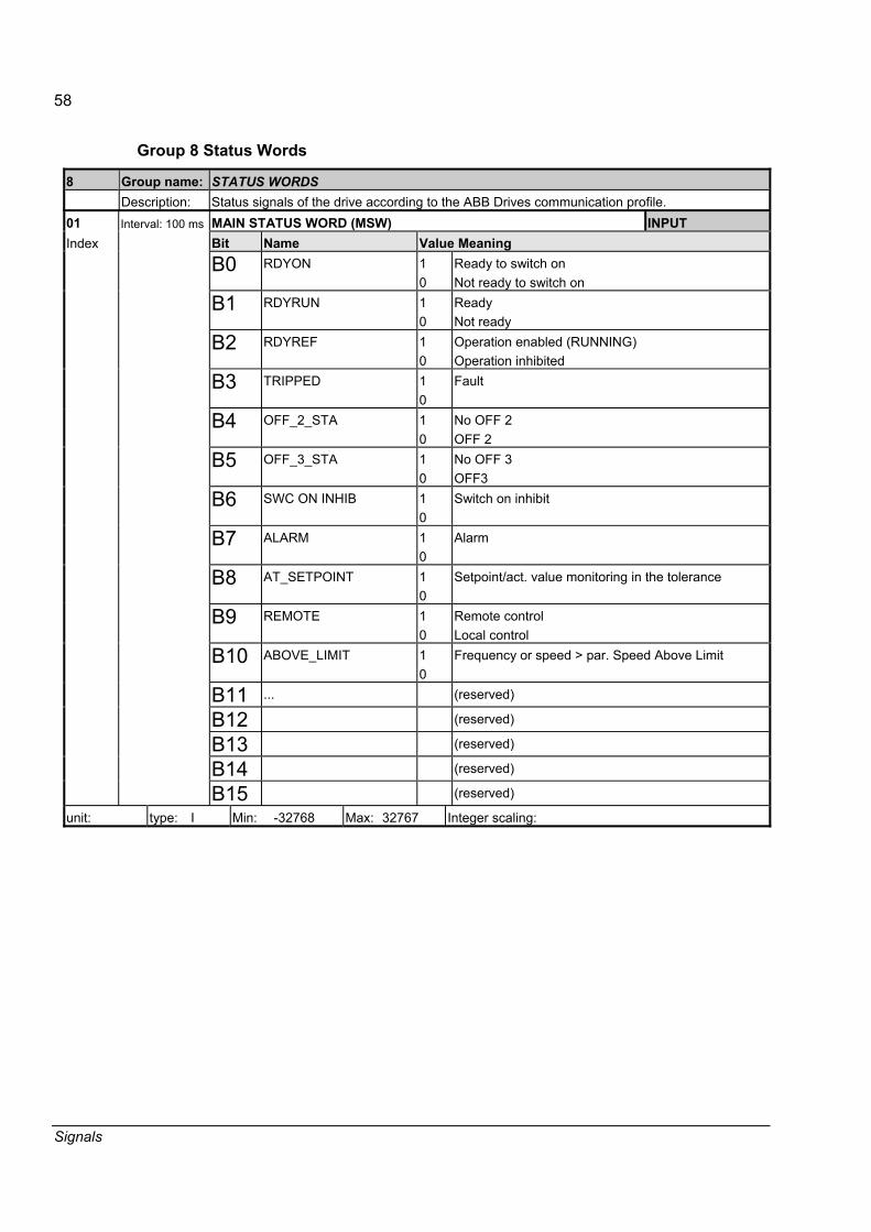
58
Signals
Group 8 Status Words
8 Group name: STATUS WORDS Description: Status signals of the drive according to the ABB Drives communication profile. 01 Interval: 100 ms MAIN STATUS WORD (MSW) INPUT Index Bit Name Value Meaning B0 RDYON
1 0
Ready to switch on Not ready to switch on
B1 RDYRUN
1 0
Ready Not ready
B2 RDYREF
1 0
Operation enabled (RUNNING) Operation inhibited
B3 TRIPPED
1 0
Fault
B4 OFF_2_STA
1 0
No OFF 2 OFF 2
B5 OFF_3_STA
1 0
No OFF 3 OFF3
B6 SWC ON INHIB 1 0
Switch on inhibit
B7 ALARM
1 0
Alarm
B8 AT_SETPOINT
1 0
Setpoint/act. value monitoring in the tolerance
B9 REMOTE
1 0
Remote control Local control
B10 ABOVE_LIMIT
1 0
Frequency or speed > par. Speed Above Limit
B11 ... (reserved)
B12 (reserved)
B13 (reserved)
B14 (reserved)
B15 (reserved)
unit: type: I Min: -32768 Max: 32767 Integer scaling:

59
Signals
8 Group name: STATUS WORDS 02 Interval: 100 ms AUX STATUS WORD (ASW) Index Description:
B0 = B1 = B2 = B3 = B4 = B5 = B6 = B7 = B8 = B9 =
B10 = B11 = B12 = B13 = B14 = B15 =
LOGG_DATA_READY OUT_OF_WINDOW EMERG_STOP_COAST MAGNETIZED RUN_DISABLED SYNC_RDY 1_START_NOT_DONE IDENTIF_RUN_DONE START_INHIBITION LIMITING TORQ_CONTROL ZERO_SPEED INTERNAL_SPEED_FB
Drive specific auxiliary status word Content of data logger is readable. Speed actual is outside of the defined window. Emergency stop function has failed. A flux has been activated to the motor External interlocking (DI2) prevents the run. Position counter synchronous ready status. Not started after the parameter set of group 99. Identification run has been completed. Inhibition of false start Control at the limit. See signals 8.03-8.04 Drive is torque controlled Motor speed actual is below the zero speed limits. Internal speed feedback selected
unit: type: I Min: -32768 Max: 32767 Integer scaling: 03 LIMIT WORD 1 Index Description: B0 =
B1 = B2 = B3 = B4 = B5 = B6 = B7 = B8 = B9 = B10 = B11 = B12 = B13 = B14 = B15 =
TORQ_MOTOR_LIM SPC_TORQ_MIN_LIM SPC_TORQ_MAX_LIM TORQ_USER_CUR_LIM TORQ_INV_CUR_LIM TORQ_MIN_LIM TORQ_MAX_LIM TREF_TORQ_MIN_LIM TREF_TORQ_MAX_LIM FLUX_MIN_LIMIT FREQ_MIN_LIMIT FREQ_MAX_LIMIT DC_UNDERVOLT_LIM DC_OVERVOLT_LIM TORQUE_LIMIT FREQ_LIMIT
unit: type: I Min: -32768 Max: 32767 Integer scaling:

60
Signals
8 Group name: STATUS WORDS 04 LIMIT WORD 2 Index Description: B0 =
B1 = B2 = B3 = B4 = B5 = B6 = B7 = B8 = B9 = B10 =B11 =B12 =B13 =B14 =B15 =
unit: type: I Min: -32768 Max: 32767 Integer scaling: 05 Interval: 500 ms DI STATUS WORD Index Description:
B0 = B1 = B2 = B3 = B4 = B5 = B6 = B7 = B8 = B9 = B10 =B11 =B12 =B13 =B14 =B15 =
DI1 DI2 DI3 DI4 DI5 DI6
Drive specific auxiliary status word Status of the digital input 1 Status of the digital input 2 Status of the digital input 3 Status of the digital input 4 Status of the digital input 5 Status of the digital input 6
unit: type: I Min: -32768 Max: 32767 Integer scaling:
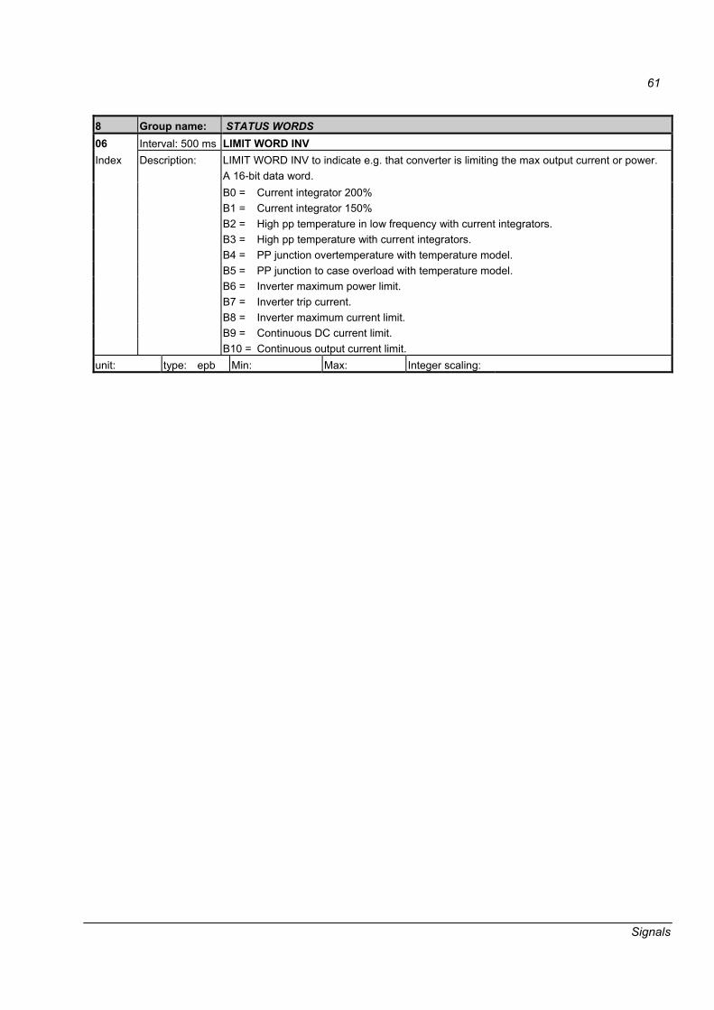
61
Signals
8 Group name: STATUS WORDS 06 Interval: 500 ms LIMIT WORD INV
LIMIT WORD INV to indicate e.g. that converter is limiting the max output current or power. A 16-bit data word. B0 = Current integrator 200% B1 = Current integrator 150% B2 = High pp temperature in low frequency with current integrators. B3 = High pp temperature with current integrators. B4 = PP junction overtemperature with temperature model. B5 = PP junction to case overload with temperature model. B6 = Inverter maximum power limit. B7 = Inverter trip current. B8 = Inverter maximum current limit. B9 = Continuous DC current limit.
Index Description:
B10 = Continuous output current limit. unit: type: epb Min: Max: Integer scaling:
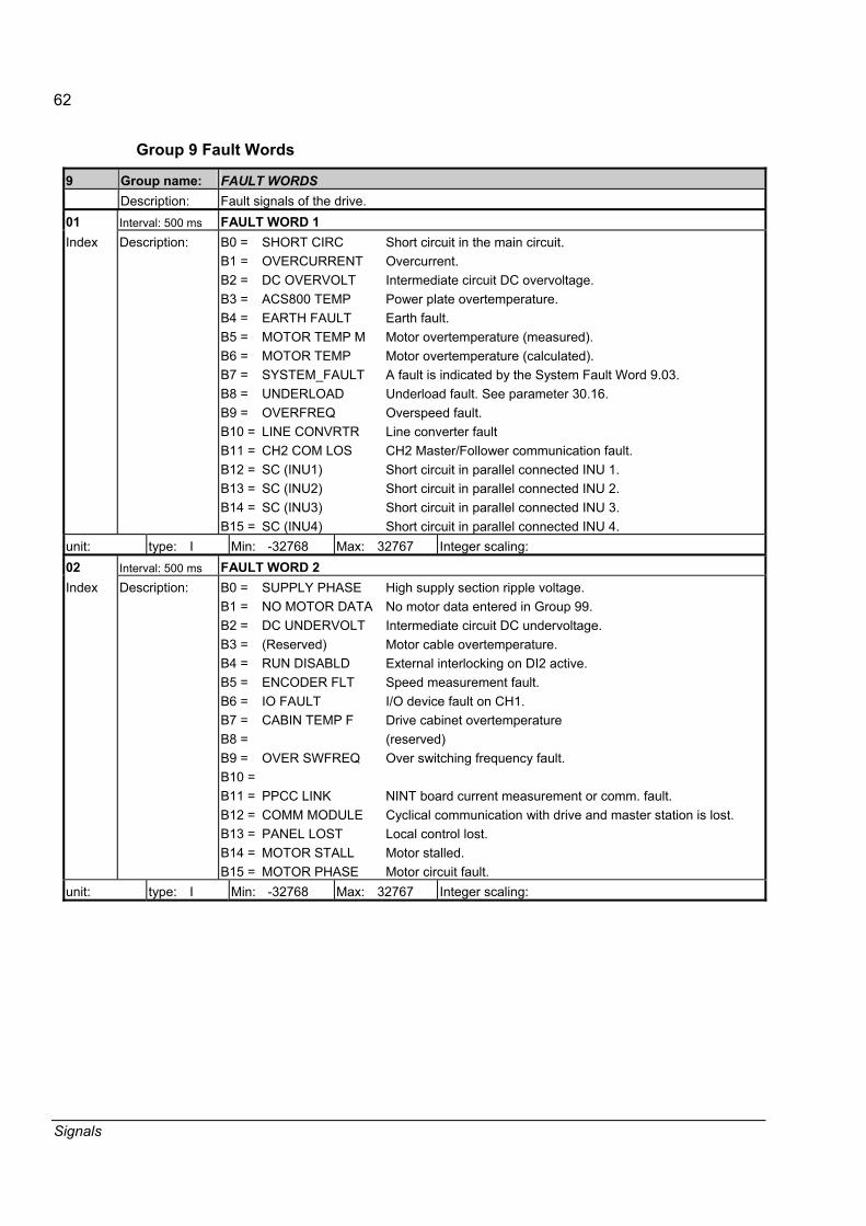
62
Signals
Group 9 Fault Words
9 Group name: FAULT WORDS Description: Fault signals of the drive. 01 Interval: 500 ms FAULT WORD 1 Index Description: B0 =
B1 = B2 = B3 = B4 = B5 = B6 = B7 = B8 = B9 = B10 =B11 =B12 =B13 =B14 =B15 =
SHORT CIRC OVERCURRENT DC OVERVOLT ACS800 TEMP EARTH FAULT MOTOR TEMP M MOTOR TEMP SYSTEM_FAULT UNDERLOAD OVERFREQ LINE CONVRTR CH2 COM LOS SC (INU1) SC (INU2) SC (INU3) SC (INU4)
Short circuit in the main circuit. Overcurrent. Intermediate circuit DC overvoltage. Power plate overtemperature. Earth fault. Motor overtemperature (measured). Motor overtemperature (calculated). A fault is indicated by the System Fault Word 9.03. Underload fault. See parameter 30.16. Overspeed fault. Line converter fault CH2 Master/Follower communication fault. Short circuit in parallel connected INU 1. Short circuit in parallel connected INU 2. Short circuit in parallel connected INU 3. Short circuit in parallel connected INU 4.
unit: type: I Min: -32768 Max: 32767 Integer scaling: 02 Interval: 500 ms FAULT WORD 2 Index Description: B0 =
B1 = B2 = B3 = B4 = B5 = B6 = B7 = B8 = B9 = B10 =B11 =B12 =B13 =B14 =B15 =
SUPPLY PHASE NO MOTOR DATA DC UNDERVOLT (Reserved) RUN DISABLD ENCODER FLT IO FAULT CABIN TEMP F OVER SWFREQ PPCC LINK COMM MODULE PANEL LOST MOTOR STALL MOTOR PHASE
High supply section ripple voltage. No motor data entered in Group 99. Intermediate circuit DC undervoltage. Motor cable overtemperature. External interlocking on DI2 active. Speed measurement fault. I/O device fault on CH1. Drive cabinet overtemperature (reserved) Over switching frequency fault. NINT board current measurement or comm. fault. Cyclical communication with drive and master station is lost. Local control lost. Motor stalled. Motor circuit fault.
unit: type: I Min: -32768 Max: 32767 Integer scaling:
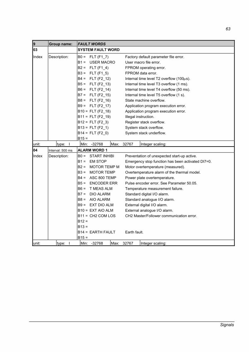
63
Signals
9 Group name: FAULT WORDS 03 SYSTEM FAULT WORD
Index Description: B0 = B1 = B2 = B3 = B4 = B5 = B6 = B7 = B8 = B9 = B10 = B11 = B12 = B13 = B14 = B15 =
FLT (F1_7) USER MACRO FLT (F1_4) FLT (F1_5) FLT (F2_12) FLT (F2_13) FLT (F2_14) FLT (F2_15) FLT (F2_16) FLT (F2_17) FLT (F2_18) FLT (F2_19) FLT (F2_3) FLT (F2_1) FLT (F2_0)
Factory default parameter file error. User macro file error. FPROM operating error. FPROM data error. Internal time level T2 overflow (100μs). Internal time level T3 overflow (1 ms). Internal time level T4 overflow (50 ms). Internal time level T5 overflow (1 s). State machine overflow. Application program execution error. Application program execution error. Illegal instruction. Register stack overflow. System stack overflow. System stack underflow.
unit: type: I Min: -32768 Max: 32767 Integer scaling: 04 Interval: 500 ms ALARM WORD 1 Index Description:
B0 = B1 = B2 = B3 = B4 = B5 = B6 = B7 = B8 = B9 = B10 = B11 = B12 = B13 = B14 = B15 =
START INHIBI EM STOP MOTOR TEMP M MOTOR TEMP ASC 800 TEMP ENCODER ERR T MEAS ALM DIO ALARM AIO ALARM EXT DIO ALM EXT AIO ALM CH2 COM LOS EARTH FAULT
Preventation of unexpected start-up active. Emergency stop function has been activated DI7=0. Motor overtemperature (measured). Overtemperature alarm of the thermal model. Power plate overtemperature. Pulse encoder error. See Parameter 50.05. Temperature measurement failure. Standard digital I/O alarm. Standard analogue I/O alarm. External digital I/O alarm. External analogue I/O alarm. CH2 Master/Follower communication error. Earth fault.
unit: type: I Min: -32768 Max: 32767 Integer scaling:
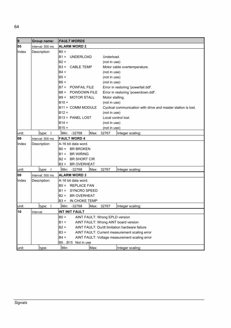
64
Signals
9 Group name: FAULT WORDS 05 Interval: 500 ms ALARM WORD 2 Index Description: B0 =
B1 = B2 = B3 = B4 = B5 = B6 = B7 = B8 = B9 = B10 =B11 =B12 =B13 =B14 =B15 =
UNDERLOAD CABLE TEMP POWFAIL FILE POWDOWN FILE MOTOR STALL COMM MODULE PANEL LOST
Underload. (not in use) Motor cable overtemperature. (not in use) (not in use) (not in use) Error in restoring 'powerfail.ddf�. Error in restoring 'powerdown.ddf�. Motor stalling. (not in use) Cyclical communication with drive and master station is lost. (not in use) Local control lost. (not in use) (not in use)
unit: type: I Min: -32768 Max: 32767 Integer scaling: 08 Interval: 500 ms FAULT WORD 4
A-16 bit data word. Index Description: B0 = B1 = B2 = B3 =
BR BROKEN BR WIRING BR SHORT CIR BR OVERHEAT
unit: type: I Min: -32768 Max: 32767 Integer scaling: 09 Interval: 500 ms ALARM WORD 3
A-16 bit data word. Index Description: B0 = B1 = B2 = B3 =
REPLACE FAN SYNCRO SPEED BR OVERHEAT IN CHOKE TEMP
unit: type: I Min: -32768 Max: 32767 Integer scaling: 10 Interval: INT INIT FAULT B0 =
B1 = B2 = B3 = B4 = B5�B15
AINT FAULT: Wrong EPLD version AINT FAULT: Wrong AINT board version AINT FAULT: Du/dt limitation hardware failure AINT FAULT: Current measurement scaling error AINT FAULT: Voltage measurement scaling error Not in use
unit: type: Min: Max: Integer scaling:

65
Signals
9 Group name: FAULT WORDS 11 Interval: INT FAULT INFO
A 16-bit data word. The INT FAULT INFO Word includes information on the location of faults PPCC LINK, OVERCURRENT, EARTH FAULT, SHORT CIRCUIT and ACS800 TEMP, (see 9.01 FAULT WORD 1 and 9.02 FAULT WORD 2 and the chapter Fault tracing).
Description:
0 1 2 3 4 5 6 7 8 9 10 11 12�14 15
INT 1 FLTINT 2 FLTINT 3 FLTINT 4 FLTINT 5 FLTINT 6 FLTINT 7 FLTINT 8 FLTINT 9 FLTINT 10 FLTINT 11 FLTINT 12 FLT PBU FLT
INT 1 board fault INT 2 board fault INT 3 board fault INT 4 board fault INT 5 board fault INT 6 board fault INT 7 board fault INT 8 board fault INT 9 board fault INT 10 board fault INT 11 board fault INT 12 board fault Not in use PBU board fault
unit: type: Min: 0 Max: 65535 Integer scaling: 12 Interval: INT SC INFO
A 16-bit data word. The INT SC INFO Word includes information on the location of the SHORT CIRCUIT fault (see 9.01 FAULT WORD 1 and the chapter Fault tracing).
Description
0 1 2 3 4 5 6�15
U-PH SC UU-PH SC L V-PH SC UV-PH SC L W-PH SC UW-PH SC LNot in use
Phase U upper-leg IGBT(s) short circuit Phase U upper-leg IGBT(s) short circuit Phase V upper-leg IGBT(s) short circuit Phase V upper-leg IGBT(s) short circuit Phase W upper-leg IGBT(s) short circuit Phase W upper-leg IGBT(s) short circuit
unit: type: Min: 0 Max: 65535 Integer scaling:

66
Signals
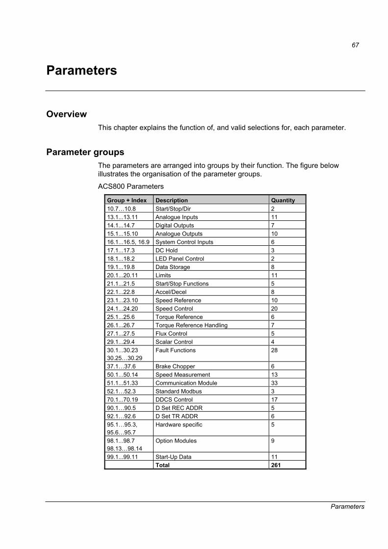
67
Parameters
Parameters
Overview This chapter explains the function of, and valid selections for, each parameter.
Parameter groups The parameters are arranged into groups by their function. The figure below illustrates the organisation of the parameter groups.
ACS800 Parameters
Group + Index Description Quantity 10.7�10.8 Start/Stop/Dir 2 13.1...13.11 Analogue Inputs 11 14.1...14.7 Digital Outputs 7 15.1...15.10 Analogue Outputs 10 16.1...16.5, 16.9 System Control Inputs 6 17.1...17.3 DC Hold 3 18.1...18.2 LED Panel Control 2 19.1...19.8 Data Storage 8 20.1...20.11 Limits 11 21.1...21.5 Start/Stop Functions 5 22.1...22.8 Accel/Decel 8 23.1...23.10 Speed Reference 10 24.1...24.20 Speed Control 20 25.1...25.6 Torque Reference 6 26.1...26.7 Torque Reference Handling 7 27.1...27.5 Flux Control 5 29.1...29.4 Scalar Control 4 30.1...30.23 30.25�30.29
Fault Functions 28
37.1�37.6 Brake Chopper 6 50.1...50.14 Speed Measurement 13 51.1...51.33 Communication Module 33 52.1�52.3 Standard Modbus 3 70.1...70.19 DDCS Control 17 90.1�90.5 D Set REC ADDR 5 92.1�92.6 D Set TR ADDR 6 95.1�95.3, 95.6�95.7
Hardware specific 5
98.1...98.7 98.13�98.14
Option Modules 9
99.1...99.11 Start-Up Data 11 Total 261

68
Parameters
How to read the Parameter Table Before you start to read the parameter table, we first recommend you read this description.
• Parameter change by DriveWindow or the CDP 312R is stored to FPROM memory; changes made by the overriding system are only stored to RAM.
• If the application software utilises individual bits of the word (for example 7.01 MAIN CTRL WORD), it must be understood that bit 15 is set by the SIGN. Also bit 15 is read from the SIGN.
• From DriveWindow and the control panel, parameter values are set in decimal.
• Communication between the overriding system and the drive uses 16 bit integer values (-32768...32767). To change a parameter value from the overriding system, an integer value for the parameter must be calculated using the information given in the Integer scaling column.
Example 1: If the signal type is R (real value), It has an integer scaling relation mentioned in the column Integer scaling. For example if TREF TORQMAX is set from the overriding system, an integer value of 100 corresponds to 1% (see below).
09 TREF TORQMAXIndex Description: Maximum torque reference as a percentage of the motor nominal torque.
unit: % type: R Min: 0 % Max: 300 % Def: 300 % Integer scaling: 100 == 1% Figure 15. Sample of the parameter table.
Example 2: Speed reference from the overriding system.
• Speed reference input is given by parameter 23.01 SPEED REF. The Integer scaling box reads �see parameter 50.01�. Parameter 50.01 defines the motor speed (in rpm) at maximum reference (20000 for the overriding system). Thus, sending a value of 20000 from the overriding system into Parameter 23.01 sets the speed reference to the rpm value given with Parameter 50.01.
• Unit of the parameter value can be seen on the lower left-hand corner of the parameter description.
• Minimum, maximum and default values are shown in decimal format.
• Data type is given with a short code:
B = Boolean value I = 16-bit signed integer value PB = Packet Boolean value R = Real value S = String

69
Parameters
Group 10 Start/Stop/Dir 10 Group name: START/STOP/DIR Description: 07 NET CONTROL Index: Description: When active, fieldbus control word is enabled when speed controlled.
Note: Only visible with the Generic Drive communication profile selected (98.07). Note: The setting is not saved in the permanent memory (will reset to zero when power is switched off). 0 = OFF Inactive 1 = ON Active
unit: type: I Min: Max: Def: 0 Integer scaling: 08 NET REFERENCE Index: Description: When active, fieldbus reference REF1 is enabled when speed controlled.
Note: Only visible with the Generic Drive communication profile selected (98.07). Note: The setting is not saved in the permanent memory (will reset to zero when power is switched off). 0 = OFF Inactive 1 = ON Active
unit: type: I Min: Max: Def: 0 Integer scaling:
Group 13 Analogue inputs 13 Group name: ANALOGUE INPUTS Description: 01 AI1 HIGH VALUE Index: Description: This value corresponds to the maximum input voltage on AI1 produced by the device used.
This parameter is not active when AI1 is used for motor 1 temperature measurement. See Parameter 30.03 MOT1 TEMP AI1 SEL.
unit: type: I Min: -32768 Max: 32767 Def: 20000 Integer scaling: 02 AI1 LOW VALUE Index: Description: This value corresponds to the minimum input voltage on AI1. This parameter is not active
when AI1 is used for motor 1 temperature measurement. See parameter 30.03 MOT1 TEMP AI1 SEL.
unit: type: I Min: -32768 Max: 32767 Def: 0 Integer scaling: 03 FILTER AI1 Index: Description: Filter time constant for analogue input AI1. The hardware filter time constant is 20 ms. unit: ms type: I Min: 0 ms Max: 30000 ms Def: 1000 ms Integer scaling: 04 AI2 HIGH VALUE Index: Description: This value corresponds to the maximum input in milliamperes (20 mA). This parameter is not
active when used for motor 2 temperature measurement. See parameter 30.06 MOT2 TEMP AI2 SEL.
unit: type: I Min: -32768 Max: 32767 Def: 20000 Integer scaling:
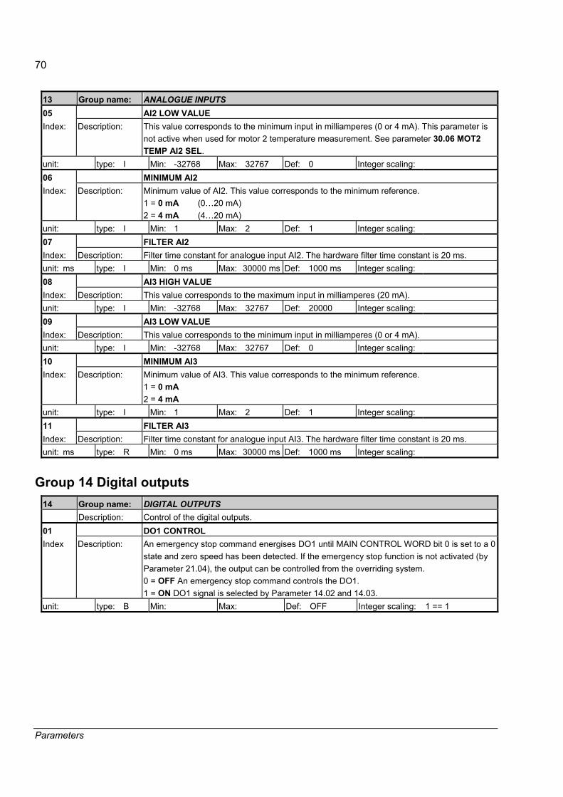
70
Parameters
13 Group name: ANALOGUE INPUTS 05 AI2 LOW VALUE Index: Description: This value corresponds to the minimum input in milliamperes (0 or 4 mA). This parameter is
not active when used for motor 2 temperature measurement. See parameter 30.06 MOT2 TEMP AI2 SEL.
unit: type: I Min: -32768 Max: 32767 Def: 0 Integer scaling: 06 MINIMUM AI2 Index: Description: Minimum value of AI2. This value corresponds to the minimum reference.
1 = 0 mA (0�20 mA) 2 = 4 mA (4�20 mA)
unit: type: I Min: 1 Max: 2 Def: 1 Integer scaling: 07 FILTER AI2 Index: Description: Filter time constant for analogue input AI2. The hardware filter time constant is 20 ms. unit: ms type: I Min: 0 ms Max: 30000 ms Def: 1000 ms Integer scaling: 08 AI3 HIGH VALUE Index: Description: This value corresponds to the maximum input in milliamperes (20 mA). unit: type: I Min: -32768 Max: 32767 Def: 20000 Integer scaling: 09 AI3 LOW VALUE Index: Description: This value corresponds to the minimum input in milliamperes (0 or 4 mA). unit: type: I Min: -32768 Max: 32767 Def: 0 Integer scaling: 10 MINIMUM AI3 Index: Description: Minimum value of AI3. This value corresponds to the minimum reference.
1 = 0 mA 2 = 4 mA
unit: type: I Min: 1 Max: 2 Def: 1 Integer scaling: 11 FILTER AI3 Index: Description: Filter time constant for analogue input AI3. The hardware filter time constant is 20 ms. unit: ms type: R Min: 0 ms Max: 30000 ms Def: 1000 ms Integer scaling:
Group 14 Digital outputs 14 Group name: DIGITAL OUTPUTS Description: Control of the digital outputs. 01 DO1 CONTROL Index Description: An emergency stop command energises DO1 until MAIN CONTROL WORD bit 0 is set to a 0
state and zero speed has been detected. If the emergency stop function is not activated (by Parameter 21.04), the output can be controlled from the overriding system. 0 = OFF An emergency stop command controls the DO1. 1 = ON DO1 signal is selected by Parameter 14.02 and 14.03.
unit: type: B Min: Max: Def: OFF Integer scaling: 1 == 1

71
Parameters
14 Group name: DIGITAL OUTPUTS 02 DO1 GROUP+INDEX Index Description: Digital output 1 is controlled by a selectable (see Par. 14.03) bit of the signal selected with
this parameter. The format is xyy, where, x = Group, yy = Index. Examples: If Parameters 14.02 and 14.03 are set to 801 and 1 respectively (default), digital output DO1 is active when 8.01 MAIN STATUS WORD bit 1 (READY) is 1. If this parameter is set to 0, digital output DI1 is controlled by the overriding system (7.02 AUX CTRL WORD bit 13). By default, DO1 indicates the READY state.
unit: type: I Min: 0 Max: 30000 Def: 801 Integer scaling: 03 DO1 BIT NUMBER Index Description: This parameter specifies the bit number for the signal selected at Parameter 14.02. unit: type: I Min: 0 Max: 23 Def: 1 Integer scaling: 04 DO2 GROUP+INDEX Index Description: Digital output 2 is controlled by a selectable (see Par. 14.05) bit of the signal selected with
this parameter. The format is xyy, where, x = Group, yy = Index. See parameter 14.02 If this parameter is set to 0, digital output DI1 is controlled by the overriding system (7.02 AUX CTRL WORD bit 14). By default, DO1 indicates the RUNNING state.
unit: type: I Min: 0 Max: 30000 Def: 801 Integer scaling: 05 DO2 BIT NUMBER Index Description: This parameter specifies the bit number for the signal selected at Parameter 14.04 unit: type: I Min: 0 Max: 23 Def: 2 Integer scaling: 06 DO3 GROUP+INDEX Index Description: Digital output 3 is controlled by a selectable (see Par. 14.06) bit of the signal selected with
this parameter. The format is xyy, where, x = Group, yy = Index. See parameter 14.02. If this parameter is set to 0, digital output DI1 is controlled by the overriding system (7.02 AUX CTRL WORD bit 15). By default, DO3 indicates the FAULT state.
unit: type: I Min: 0 Max: 30000 Def: 801 Integer scaling: 07 DO3 BIT NUMBER Index Description: This parameter specifies the bit number for the signal selected at Parameter 14.06. unit: type: I Min: 0 Max: 23 Def: 3 Integer scaling:
Group 15 Analogue outputs 15 Group name: ANALOGUE OUTPUTS Description: It is possible to select a real signal or parameter to control the analogue outputs by defining
the group and index. The outputs can also be controlled from the overriding system. 01 ANALOGUE OUTPUT 1 Index Description: To direct a measured signal to analogue output AO1, set the parameter according to the
format (x)xyy. Where (x) is the group and yy the index of the desired signal; e.g. 2301 denotes Parameter 23.01. If temperature measurement (Parameter 30.03) is selected, analogue output AO1 is used for supplying a constant current for the sensor.
unit: type: I Min: 0 Max: 30000 Def: 106 (Mot curr) Integer scaling:

72
Parameters
15 Group name: ANALOGUE OUTPUTS 02 INVERT AO1 Index Description: Analogue output AO1 signal inversion.
0 = NO minimum signal value corresponds to the minimum output value. 1 = YES maximum signal value corresponds to the minimum output value.
unit: type: B Min: Max: Def: NO Integer scaling: 1 == 1 03 MINIMUM AO1 Index Description: Analogue output 1 signal offset in milliamperes. This parameter is not effective if motor 1
temperature measurement is activated by parameter 30.01. Otherwise, the following settings are available. 1 = 0 mA 2 = 4 mA 3 = 10 mA 50% offset in the range 0...20 mA for testing or indication of direction (torque, speed etc.)
unit: type: I Min: 1 Max: 3 Def: 1 Integer scaling: 04 FILTER AO1 Index Description: Filter time constant for analogue output AO1. unit: s type: R Min: 0 s Max: 10 s Def: 0.1 s Integer scaling: 100 == 1s 05 SCALE AO1 Index Description: Nominal value of the analogue output AO1signal, which is selected in Parameter 15.01. This
value corresponds to 20 mA at the output. unit: type: R Min: 0 Max: 65536 Def: 100 Integer scaling: 1 == 1 06 ANALOGUE OUTPUT 2 Index Description: To direct a measured signal to analogue output AO1, set the parameter according to the
format (x)xyy. Where (x) is the group and yy the index of the desired signal; e.g. 1506 denotes Par. 15.06. If temperature measurement (Parameter 30.06) is selected, analogue output AO2 is used for supplying a constant current for the sensor.
unit: type: I Min: 0 Max: 30000 Def: 101 (Mot spd) Integer scaling: 07 INVERT AO2 Index Description: Analogue output AO2 signal inversion.
0 = NO minimum signal value corresponds to the minimum output value. 1 = YES maximum signal value corresponds to the minimum output value.
unit: type: B Min: Max: Def: NO Integer scaling: 1 == 1 08 MINIMUM AO2 Index Description: Analogue output AO2 signal offset in milliamperes.
1 = 0 mA 2 = 4 mA 3 = 10 mA 50% offset in the range of 0�20 mA for testing or indication of direction (torque, speed etc.)
unit: type: I Min: 1 Max: 3 Def: 1 Integer scaling: 09 FILTER AO2 Index Description: Filter time constant for analogue output AO2. unit: s type: R Min: 0 s Max: 10 s Def: 0.1 s Integer scaling: 100 == 1s

73
Parameters
15 Group name: ANALOGUE OUTPUTS 10 SCALE AO2 Index Description: Nominal value of analogue output AO2 signal, which is selected in Parameter 15.06.
This value corresponds to 20 mA at the output. unit: type: R Min: 0 Max: 65536 Def: 3000 Integer scaling: 1 == 1
Group 16 System control inputs 16 Group name: SYSTEM CTR INPUTS Description: 01 RUN ENABLE Index Description: This parameter activates the RUN ENABLE input. Digital Input DI2 is dedicated for this input
permanently. 1 = NOT USED 2 = DI2 To activate the RUN ENABLE signal, voltage must be connected to digital input DI2. If the voltage drops to 0V, the drive coasts to stop and a run enable fault is generated.
unit: type: I Min: 2 Max: 2 Def: 2 Integer scaling: 02 PARAMETER LOCK Index Description: This parameter selects the state of the parameter lock. With the parameter lock you can
prevent unauthorised changes by CDP 312R or the DriveWindow Tool for Parameter groups 0�99. 1 = LOCKED Parameter changes are disabled. 0 = OPEN Parameter changes are enabled.
unit: type: B Min: Max: Def: OPEN Integer scaling: 1 == 1 03 PASS CODE Index Description: This parameter enters the pass code for the Parameter Lock. The default value of this
parameter is 0. In order to open the Parameter Lock, change the value to 358. After the Parameter Lock is opened, the value is automatically changed back to 0.
unit: type: I Min: 0 Max: 30000 Def: 0 Integer scaling: 04 LOCAL LOCK Index Description: Control place change of the drive from remote to local can be disabled by setting this
parameter to TRUE. If LOCAL LOCK is activated during local control, it takes effect only after the control place is changed back to remote. 0 = FALSE No locking for control place change. 1 = TRUE Local control is disabled.
unit: type: B Min: Max: Def: FALSE Integer scaling: 1 == 1 05 PARAMETER BACKUP Index Description: Parameter saves from the RAM memory to FPROM. This is needed only when parameter
changes by overriding system have to be stored to FPROM memory instead of RAM. Note: Do not use the Parameter Backup function unnecessarily. Note: Parameter changes by CDP 312R Control Panel or DriveWindow are immediately saved to FPROM. 0 = DONE Parameter value after the saving has been completed. 1 = SAVE Parameter save to FPROM.
unit: type: B Min: 0 Max: 1 Def: DONE Integer scaling: 1 == 1
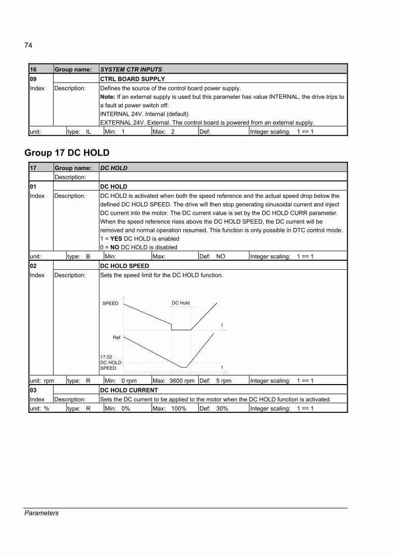
74
Parameters
16 Group name: SYSTEM CTR INPUTS 09 CTRL BOARD SUPPLY Index Description: Defines the source of the control board power supply.
Note: If an external supply is used but this parameter has value INTERNAL, the drive trips to a fault at power switch off. INTERNAL 24V. Internal (default) EXTERNAL 24V. External. The control board is powered from an external supply.
unit: type: IL Min: 1 Max: 2 Def: Integer scaling: 1 == 1
Group 17 DC HOLD 17 Group name: DC HOLD Description: 01 DC HOLD Index Description: DC HOLD is activated when both the speed reference and the actual speed drop below the
defined DC HOLD SPEED. The drive will then stop generating sinusoidal current and inject DC current into the motor. The DC current value is set by the DC HOLD CURR parameter. When the speed reference rises above the DC HOLD SPEED, the DC current will be removed and normal operation resumed. This function is only possible in DTC control mode. 1 = YES DC HOLD is enabled 0 = NO DC HOLD is disabled
unit: type: B Min: Max: Def: NO Integer scaling: 1 == 1 02 DC HOLD SPEED Index Description: Sets the speed limit for the DC HOLD function.
DC Hold
t
t
Ref.
SPEED
17.02 DC HOLDSPEED
unit: rpm type: R Min: 0 rpm Max: 3600 rpm Def: 5 rpm Integer scaling: 1 == 1 03 DC HOLD CURRENT Index Description: Sets the DC current to be applied to the motor when the DC HOLD function is activated. unit: % type: R Min: 0% Max: 100% Def: 30% Integer scaling: 1 == 1

75
Parameters
Group 18 LED panel control 18 Group name: LED PANEL CTRL
The NLMD-01 Monitoring Display has a 0�150% LED bar to show an absolute real type value. The source and the scale of this display signal are defined by this parameter group. Note: If NLMD -01 and CDP 312R control panel are used together, the first signal selected in the Actual Signal Display Mode of CDP 312R must be the default value 1.26 LED PANEL OUTP. Otherwise the NLMD-01 LED bar display will not show the correct value.
Description:
1 L -> 0.0 rpm 0 LED PANEL OUTP MOTOR SPEED FILT MOTOR TORQUE FILT
01 LED PANEL OUTPUT Index Description: Signal group and index for the LED monitor display. The default value for this signal is 1.07
MOTOR TORQUE FILT. unit: type: I Min: 0 Max: 30000 Def: 107 Integer scaling: 02 SCALE PANEL Index Description: The signal value (defined in Parameter 18.01), which corresponds to 100% on the LED bar
display. unit: type: R Min: 0 Max: 65536 Def: 100 Integer scaling: 1 == 1

76
Parameters
Group 19 Data storage 19 Group name: DATA STORAGE
This parameter group consists of unconnected parameters for linking, testing and commissioning purposes. Address of the Dataset 14 index 2 is 90.08. By setting parameter 90.08 to value 19.01, the value A can be trended with the DriveWindow monitor tool.
APC2, AC80
NEDRXDS14
Index:
Index:
Index:
123
RMIO
Dataset TableDS
.
.
.
.
.
VAL
.
.
1
.
.
.
14 23
GRP Index
90 .08 19.01
APC2 Applicationsoftware
AddressAssignmentof Dataset
A : Value assignedfor drive control i.e.,tension control output
A *
*
APC2, AC80
NEDRXDS15
Index:
Index:
Index:
123
RMIO
Dataset TableDS
.
.
.
.
.
VAL
.
.
1
.
.
.
15 23
GRP Index
92 .08 19.02
APC2 Applicationsoftware
AddressAssignmentof Dataset
FromDriveWindowTool
B : Value assignedfor APC2 application,for example tensionregulator gain.
B *
*
ForDriveWindowTool
Setting 92.08 to the value 19.02 by a CDP 312R control panel or DriveWindow it allows value being sent, for example gain value for tension regulator.
01 DATA 1 Index Description: A storage parameter for receiving from or sending to the overriding system. For example, if
the signal from data set 18 words 3 (DW 18.3) is required for monitoring by DriveWindow, first set Parameter 90.15 DATA SET VAL 3 to 1901 (denoting Par. 19.01), then select Parameter 19.01 DATA1 for the desired DriveWIndow monitoring channel.
unit: type: R Min: -32768 Max: 32767 Integer scaling: 1 == 1 02 DATA 2 Index Description: See 19.01 DATA 1 unit: type: R Min: -32768 Max: 32767 Integer scaling: 1 == 1 03 DATA 3 Index Description: See 19.01 DATA 1 unit: type: R Min: -32768 Max: 32767 Integer scaling: 1 == 1 04 DATA 4 Index Description: See 19.01 DATA 1 unit: type: R Min: -32768 Max: 32767 Integer scaling: 1 == 1

77
Parameters
19 Group name: DATA STORAGE 05 DATA 5 Index Description: See 19.01 DATA 1 unit: type: R Min: -32768 Max: 32767 Integer scaling: 1 == 1 06 DATA 6 Index Description: See 19.01 DATA 1 unit: type: R Min: -32768 Max: 32767 Integer scaling: 1 == 1 07 DATA 7 Index Description: See 19.01 DATA 1 unit: type: R Min: -32768 Max: 32767 Integer scaling: 1 == 1 08 DATA 8 Index Description: See 19.01 DATA 1 unit: type: R Min: -32768 Max: 32767 Integer scaling: 1 == 1
Group 20 Limits 20 Group name: LIMITS Description: This parameter group defines the maximum and minimum limits for the speed, frequency,
current and torque algorithms. Note: The absolute nominal torque is calculated in the application program from the motor parameters (see parameter group 99).
01 MINIMUM SPEED Index Description: Negative speed reference limit in rpm. unit: rpm type: R Min: -18000 rpm Max: 18000 rpm Def: See 99.05 Integer scaling: See 50.01 02 MAXIMUM SPEED Index Description: Positive speed reference limit in rpm. unit: rpm type: R Min: -18000 rpm Max: 18000 rpm Def: See 99.05 Integer scaling: See 50.01 03 ZERO SPEED LIMIT Index Description: The absolute speed value at which the drive coasts after a stop command. unit: rpm type: R Min: 0 rpm Max: 15000 rpm Def: 60 rpm Integer scaling: See 50.01 04 MAXIMUM CURRENT Index Description: Defines the allowed maximum motor current 0.0�x.x A. Current limit 0�100 x.x. unit: A type: R Min: 0 A Max: Type specific Def: 200% Integer scaling: 100 == 1% 05 MAXIMUM TORQUE Index Description: Maximum positive output torque as a percentage of the motor nominal torque. unit: % type: R Min: 0% Max: 300% Def: 600% Integer scaling: 100 == 1% 06 MINIMUM TORQUE Index Description: Minimum negative output torque as a percentage of the motor nominal torque. unit: % type: R Min: -600% Max: 0% Def: -300% Integer scaling: 100 == 1% 07 SPC TORQMAX Index Description: Maximum speed controller output limit as a percentage of the motor nominal torque. unit: % type: R Min: 0% Max: 600% Def: 300% Integer scaling: 100 == 1%
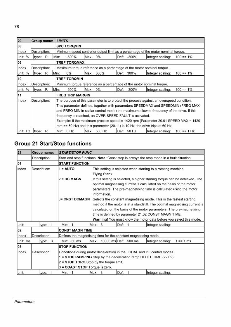
78
Parameters
20 Group name: LIMITS 08 SPC TORQMIN Index Description: Minimum speed controller output limit as a percentage of the motor nominal torque. unit: % type: R Min: -600% Max: 0% Def: -300% Integer scaling: 100 == 1% 09 TREF TORQMAX Index Description: Maximum torque reference as a percentage of the motor nominal torque. unit: % type: R Min: 0% Max: 600% Def: 300% Integer scaling: 100 == 1% 10 TREF TORQMIN Index Description: Minimum torque reference as a percentage of the motor nominal torque. unit: % type: R Min: -600% Max: 0% Def: -300% Integer scaling: 100 == 1% 11 FREQ TRIP MARGIN Index Description: The purpose of this parameter is to protect the process against an overspeed condition.
This parameter defines, together with parameters SPEEDMAX and SPEEDMIN (FREQ MAX and FREQ MIN in scalar control mode) the maximum allowed frequency of the drive. If this frequency is reached, an OVER SPEED FAULT is activated. Example: If the maximum process speed is 1420 rpm (Parameter 20.01 SPEED MAX = 1420 rpm == 50 Hz) and this parameter (20.11) is 10 Hz, the drive trips at 60 Hz.
unit: Hz type: R Min: 0 Hz Max: 500 Hz Def: 50 Hz Integer scaling: 100 == 1 Hz
Group 21 Start/Stop functions 21 Group name: START/STOP FUNC Description: Start and stop functions. Note: Coast stop is always the stop mode in a fault situation. 01 START FUNCTION Index Description: 1 = AUTO
2 = DC MAGN 3= CNST DCMAGN
This setting is selected when starting to a rotating machine Flying Start). If this setting is selected, a higher starting torque can be achieved. The optimal magnetising current is calculated on the basis of the motor parameters. The pre-magnetising time is calculated using the motor information. Selects the constant magnetising mode. This is the fastest starting method if the motor is at a standstill. The optimal magnetising current is calculated on the basis of the motor parameters. The pre-magnetising time is defined by parameter 21.02 CONST MAGN TIME. Warning! You must know the motor data before you select this mode.
unit: type: I Min: 1 Max: 3 Def: 1 Integer scaling: 02 CONST MAGN TIME Index Description: Defines the magnetising time for the constant magnetising mode. unit: ms type: R Min: 30 ms Max: 10000 ms Def: 500 ms Integer scaling: 1 == 1 ms 03 STOP FUNCTION Index Description: Conditions during motor deceleration in the LOCAL and I/O control modes.
1 = STOP RAMPING Stop by the deceleration ramp DECEL TIME (22.02) 2 = STOP TORQ Stop by the torque limit. 3 = COAST STOP Torque is zero.
unit: type: I Min: 1 Max: 3 Def: 1 Integer scaling:
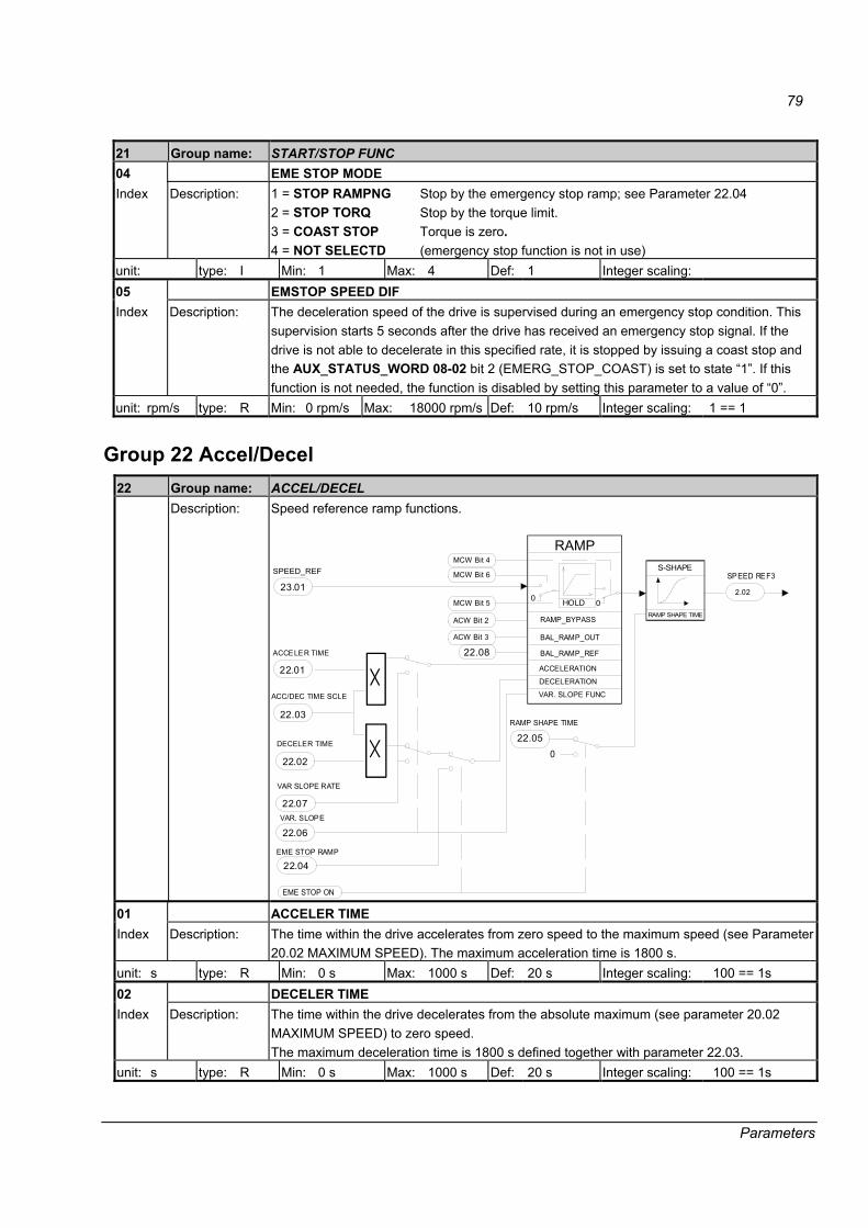
79
Parameters
21 Group name: START/STOP FUNC 04 EME STOP MODE Index Description: 1 = STOP RAMPNG
2 = STOP TORQ 3 = COAST STOP 4 = NOT SELECTD
Stop by the emergency stop ramp; see Parameter 22.04 Stop by the torque limit. Torque is zero. (emergency stop function is not in use)
unit: type: I Min: 1 Max: 4 Def: 1 Integer scaling: 05 EMSTOP SPEED DIF Index Description: The deceleration speed of the drive is supervised during an emergency stop condition. This
supervision starts 5 seconds after the drive has received an emergency stop signal. If the drive is not able to decelerate in this specified rate, it is stopped by issuing a coast stop and the AUX_STATUS_WORD 08-02 bit 2 (EMERG_STOP_COAST) is set to state �1�. If this function is not needed, the function is disabled by setting this parameter to a value of �0�.
unit: rpm/s type: R Min: 0 rpm/s Max: 18000 rpm/s Def: 10 rpm/s Integer scaling: 1 == 1
Group 22 Accel/Decel 22 Group name: ACCEL/DECEL Description: Speed reference ramp functions.
VAR SLOPE RATE
RAMP
23.01
SPEED_REF
RAMP SHAPE TIME
22.05
S-SHAPESPEED REF3
22.07
2.02
ACCELERATION
22.04EME STOP RAMP
VAR. SLOPE
EME STOP ON
DECELERATION
ACCELER TIME
22.01
DECELER TIME
22.02
22.03
ACC/DEC TIME SCLE
22.06
0
RAMP SHAPE TIME
VAR. SLOPE FUNC
BAL_RAMP_REF
BAL_RAMP_OUTACW Bit 3
22.08
RAMP_BYPASSACW Bit 2
0 0
MCW Bit 6
MCW Bit 4
MCW Bit 5 HOLD
01 ACCELER TIME Index Description: The time within the drive accelerates from zero speed to the maximum speed (see Parameter
20.02 MAXIMUM SPEED). The maximum acceleration time is 1800 s. unit: s type: R Min: 0 s Max: 1000 s Def: 20 s Integer scaling: 100 == 1s 02 DECELER TIME Index Description: The time within the drive decelerates from the absolute maximum (see parameter 20.02
MAXIMUM SPEED) to zero speed. The maximum deceleration time is 1800 s defined together with parameter 22.03.
unit: s type: R Min: 0 s Max: 1000 s Def: 20 s Integer scaling: 100 == 1s

80
Parameters
22 Group name: ACCEL/DECEL 03 ACC/DEC TIME SCLE Index Description: Multiplier for ACCELER TIME and DECELER TIME parameters to expand the time. unit: type: R Min: 0.1 Max: 100 Def: 1 Integer scaling: 100 == 1 04 EME STOP RAMP Index Description: If an emergency stop is activated and Parameter EME STOP MODE 21.04 = 1 (STOP BY
RAMP), the drive will decelerate according to this parameter from maximum speed to zero speed.
unit: s type: R Min: 0 s Max: 3000 s Def: 20 s Integer scaling: 10 == 1s 05 SHAPE TIME Index Description: Speed reference softening time. This function is deactivated during an emergency stop
condition.
0
MAX
ACCELERTIME
SPEED REFERENCE
SPEED REFERENCEchange limited by the RAMP FUNCTION
FILTERED SPEEDREFERENCE CHANGE
RAMP SHAPE TIME
unit: s type: R Min: 0 s Max: 1000 s Def: 0 s Integer scaling: 100 == 1s 06 VARIABLE SLOPE Index Description: This function is used to control the slope of the speed ramp during a speed reference change.
The time t for step A is defined by Parameter 22.07 VAR SLOPE RATE, where t = updating interval time of the overriding system. A = speed reference change during the time t. 1 = ON Variable slope is enabled; the slope rate is defined by Parameter 22.07 VARIABLE SLOPE RATE. 0 = OFF Function is disabled Example: The overriding system transmits interval time for the speed reference and the VAR SLOPE RATE value are equal. As a result, the shape of SPEED REF 3 is a straight line. This function is active only in REMOTE mode.
SPEED REF
SPEED REF 3
t
A
Speed Ref
time
unit: type: B Min: Max: Def: OFF Integer scaling: 1 == 1
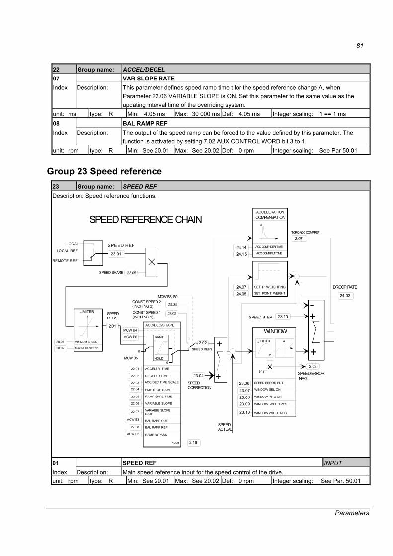
81
Parameters
22 Group name: ACCEL/DECEL 07 VAR SLOPE RATE Index Description: This parameter defines speed ramp time t for the speed reference change A, when
Parameter 22.06 VARIABLE SLOPE is ON. Set this parameter to the same value as the updating interval time of the overriding system.
unit: ms type: R Min: 4.05 ms Max: 30 000 ms Def: 4.05 ms Integer scaling: 1 == 1 ms 08 BAL RAMP REF Index Description: The output of the speed ramp can be forced to the value defined by this parameter. The
function is activated by setting 7.02 AUX CONTROL WORD bit 3 to 1. unit: rpm type: R Min: See 20.01 Max: See 20.02 Def: 0 rpm Integer scaling: See Par 50.01
Group 23 Speed reference 23 Group name: SPEED REF Description: Speed reference functions.
SPEED REF
23.01
SPEED REFERENCE CHAIN
SPEEDACTUAL
ACC/DEC/SHAPE
ACCELER TIME
DECELER TIME
SPEEDREF2
LIMITER
+
20.01 2.02MINIMUM SPEED
MAXIMUM SPEED SPEED REF3
SPEED SHARE 23.05
22.01
22.02
22.03
22.04
22.05
22.06
22.07
ACC/DEC TIME SCALE
EME STOP RAMP
RAMP SHPE TIME
VARIABLE SLOPE
VARIABLE SLOPERATE
20.02
FILTER
SPEED ERROR FILT
SPEED STEP +
+
-
WINDOW
2.03
23.10
WINDOW INTG ON
23.06
SPEED ERROR NEG
23.07
23.08
23.09
ACCELERATION COMPENSATION
ACC COMP DER TIME
ACC COMPFILT TIME
TORQ ACC COMP REF
2.07
CONST SPEED 1(INCHING 1)
23.02
23.03CONST SPEED 2(INCHING 2)
2.01
SET_P_WEIGHTINGSET_POINT_WEIGHT
24.0724.08
dV/dt 2.16
SPEEDCORRECTION
23.04(-1)
LOCAL
0
0
RAMP
MCW B8, B9
MCW B4
MCW B6
+MCW B5 HOLD
24.02
DROOP RATE
LOCAL REF
REMOTE REF
24.144 152 .
BAL RAMP REF
ACW B3
22.08
BAL RAMP OUT
ACW B2 RAMP BYPASS
23.10 WINDOW WIDTH NEG
WINDOW WIDTH POS
WINDOW SEL ON
01 SPEED REF INPUT Index Description: Main speed reference input for the speed control of the drive. unit: rpm type: R Min: See 20.01 Max: See 20.02 Def: 0 rpm Integer scaling: See Par. 50.01
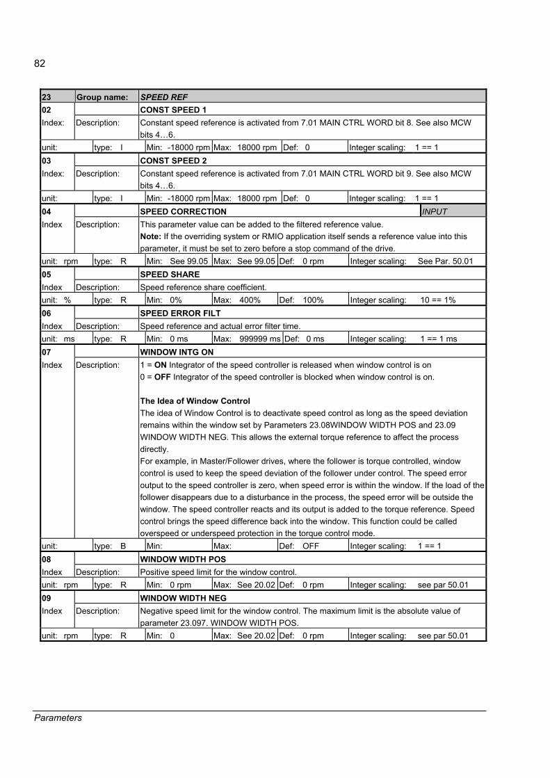
82
Parameters
23 Group name: SPEED REF 02 CONST SPEED 1 Index: Description: Constant speed reference is activated from 7.01 MAIN CTRL WORD bit 8. See also MCW
bits 4�6. unit: type: I Min: -18000 rpm Max: 18000 rpm Def: 0 Integer scaling: 1 == 1 03 CONST SPEED 2 Index: Description: Constant speed reference is activated from 7.01 MAIN CTRL WORD bit 9. See also MCW
bits 4�6. unit: type: I Min: -18000 rpm Max: 18000 rpm Def: 0 Integer scaling: 1 == 1 04 SPEED CORRECTION INPUT Index Description: This parameter value can be added to the filtered reference value.
Note: If the overriding system or RMIO application itself sends a reference value into this parameter, it must be set to zero before a stop command of the drive.
unit: rpm type: R Min: See 99.05 Max: See 99.05 Def: 0 rpm Integer scaling: See Par. 50.01 05 SPEED SHARE Index Description: Speed reference share coefficient. unit: % type: R Min: 0% Max: 400% Def: 100% Integer scaling: 10 == 1% 06 SPEED ERROR FILT Index Description: Speed reference and actual error filter time. unit: ms type: R Min: 0 ms Max: 999999 ms Def: 0 ms Integer scaling: 1 == 1 ms 07 WINDOW INTG ON Index Description: 1 = ON Integrator of the speed controller is released when window control is on
0 = OFF Integrator of the speed controller is blocked when window control is on. The Idea of Window Control The idea of Window Control is to deactivate speed control as long as the speed deviation remains within the window set by Parameters 23.08WINDOW WIDTH POS and 23.09 WINDOW WIDTH NEG. This allows the external torque reference to affect the process directly. For example, in Master/Follower drives, where the follower is torque controlled, window control is used to keep the speed deviation of the follower under control. The speed error output to the speed controller is zero, when speed error is within the window. If the load of the follower disappears due to a disturbance in the process, the speed error will be outside the window. The speed controller reacts and its output is added to the torque reference. Speed control brings the speed difference back into the window. This function could be called overspeed or underspeed protection in the torque control mode.
unit: type: B Min: Max: Def: OFF Integer scaling: 1 == 1 08 WINDOW WIDTH POS Index Description: Positive speed limit for the window control. unit: rpm type: R Min: 0 rpm Max: See 20.02 Def: 0 rpm Integer scaling: see par 50.01 09 WINDOW WIDTH NEG Index Description: Negative speed limit for the window control. The maximum limit is the absolute value of
parameter 23.097. WINDOW WIDTH POS. unit: rpm type: R Min: 0 Max: See 20.02 Def: 0 rpm Integer scaling: see par 50.01

83
Parameters
23 Group name: SPEED REF 10 SPEED STEP INPUT Index Description: An additional speed step can be given to the speed controller directly as an additive error
input. The total speed reference is limited by the parameter 20.02 MAXIMUM SPEED and 20.01 MINIMUM SPEED. (SPEED STEP max = MAXIMUM SPEED - SPEED REF - SPEED CORRECTION). Note: If the overriding system or RMIO application itself sends a reference value to here, it must be switched to zero before the stop command of the drive.
unit: rpm type: R Min: See above Max: See above Def: 0 rpm Integer scaling: see par 50.01
Group 24 Speed control 24 Group name: SPEED CONTROL Description: The speed controller is based on the PID algorithm, which continuous time is presented as
follows:
u s KPS bYr s Y ssTIS
Td sTf s
e s( ) ( ( ) ( )) ( ) ( )= − + ++
⎡
⎣⎢⎢
⎤
⎦⎥⎥
11
Variable u is the output of the controller, e is the speed error (difference between the actual and reference values).
1
Tis
T sd+
-
b+
-
Kpyr
y
uτfs+1
+ +
+
The PID controller also has set point weighting. y is the output; yr is the set point; u is the controller�s output.
01 PI TUNE Index Description: This parameter activates automatic tuning for the speed controller, which is based on the
estimation of the mechanical time constant. Parameters 24.03 KPS, 24.09 TIS and 24.15 ACC COMP DER TIME are updated after the PI TUNE test. 0 = OFF 1 = ON PI TUNE is activated.
unit: type: B Min: Max: Def: OFF Integer scaling: 1 == 1 02 DROOP RATE Index Description: The amount of speed decrease caused by the load is determined by means of this
parameter. A setting of 1% causes (with nominal torque reference) a 1% decrease in speed from the rated speed.
unit: % type: R Min: 0% Max: 100% Def: 0% Integer scaling: 10 == 1%

84
Parameters
24 Group name: SPEED CONTROL Proportional gain parameter of the speed controller
03 KPS Index Description: Relative gain for the speed controller. If you select a value of 1, a 10% change in the error
value (e.g. reference actual value) causes also the speed controller output to change by 10%.unit: type: R Min: 0 Max: 250 Def: 10 Integer scaling: 100 == 1
The Adaptive speed control as a function of the torque reference
KPS
Torque ref
KPS
KPS WEAKPOINT
KPS MIN
The adaptive gain of the speed controller is used to smooth out disturbances, which are caused by low load and backlash. Moderate filtering of the speed error (Parameter 23.04) is typically not enough to tune the drive.
04 KPS MIN Index Description: KPS MIN determines the proportional gain when the speed controller output is zero. unit: type: R Min: 0 Max: 150 Def: 10 Integer scaling: 100 == 1 05 KPS WEAKPOINT Index Description: The value of the speed controller output where the gain is KPS unit: % type: R Min: 0% Max: see 20.05 Def: 0% Integer scaling: 100 == 1% 06 KPS WP FILT TIME Index Description: The rate of change for the proportional gain can be softened by this parameter. unit: ms type: R Min: 0 ms Max: 999999 ms Def: 100 ms Integer scaling: 1 == 1 ms
Set point weighting
Set point weighting is a well known method in control engineering. In this method, the set point is weighted by a factor b<1. This weighting is applied only to the P term. Integral and derivative terms have a normally weighted (b=1) setpoint and speed error. This kind of manipulation leads to a situation where, in a steady state, the P term is not zero. The controller output is still �right� because the integral part compensates the P term error. Thus, in a steady state, the controller works normally; the integral term �sees� error caused by load and noise. In set point changes, however, the controller�s overshoot can be reduced by weighting factor b. Thus, good load rejection is not anymore related to huge overshoot. There are no free lunches so we have to sacrifice strict ramp following. In applications where ramp following without time lag is necessary, acceleration compensation is the right tool.
1
Tis
T sd+
-
b+
-
Kpyr
y
uτf s +1
+ +
+
There is no overshoot in a set point change when factor b is set correctly (b<1). This results in the integral term�s energy compensating the error caused by the P term. For example, if yr=1 and b=0.9, the P term set point is actually 0.9 which naturally causes a 10% error for the integral term handle.

85
Parameters
24 Group name: SPEED CONTROL 07 SET P WEIGHTING Index Description: Set Point Weighting is enabled by this parameter. The change over is smooth which enables
the on-line changing of weighting. 0 = OFF 1 = ON SET POINT WEIGHTING is activated.
unit: type: B Min: Max: Def: OFF Integer scaling: No 08 SET POINT WEIGHT Index Description: The value of the speed controller output, where the gain is KPS. unit: % type: R Min: 30% Max: 100% Def: 100% Integer scaling: 1 == 1%
Integration time parameters of the speed controller
09 TIS Index Description: Integration time for the speed controller. This defines the time within the maximum output is
achieved if a constant error value exists and the relative gain of the speed controller is 1. unit: s type: R Min: 0.01 s Max: 1000 s Def: 2.5 s Integer scaling: 1000 == 1 s 10 TIS INIT VALUE Index Description: Initial value of the integrator. unit: % type: R Min: see 20.06 Max: see 20.05 Def: 0% Integer scaling: 100 == 1% 11 BAL REF Index Description: External value for the integral part of the speed controller when 7.02 AUX CONTROL WORD
bit 8 BAL_NCONT is 1. unit: % type: R Min: see 20.06 Max: see 20.05 Def: 0% Integer scaling: 100 == 1%
Derivation parameters of the speed controller
12 DERIVATION TIME Index Description: Derivation time for speed controller. Defines the time within the speed controller derives the
error value before the output of the speed controller is changed. If this is set to zero, the controller works as a PI controller, otherwise as a PID controller.
unit: ms type: R Min: 0 ms Max: 10000 ms Def: 0 ms Integer scaling: 1 == 1 ms 13 DERIV FILT TIME Index Description: The derivation filter time constant. unit: ms type: R Min: 0 ms Max: 100000 ms Def: 8 ms Integer scaling: 1 == 1 ms
Acceleration compensation parameters
14 ACC COMP DER TIME Index Description: Derivation time used during compensation of acceleration. In order to compensate inertia
during acceleration, the derivative of the reference is added to the output of the speed controller. The function is deactivated by setting the parameter to 0.
unit: s type: R Min: 0 s Max: 1000 s Def: 0 s Integer scaling: 10 == 1 s 15 ACC COMPFILT TIME Index Description: Acceleration compensation term filter coefficient. unit: ms type: R Min: 0 ms Max: 999999 ms Def: 8 ms Integer scaling: 1 == 1 ms 16 SLIP GAIN Index Description: This parameter Is effective only when the calculated internal speed is used as actual speed
feedback. 100% means full slip compensation. 0% corresponds no slip compensation (the calculated speed equals to motor frequency).
unit: % type: R Min: 0% Max: 400% Def: 100% Integer scaling: 1 == 1%
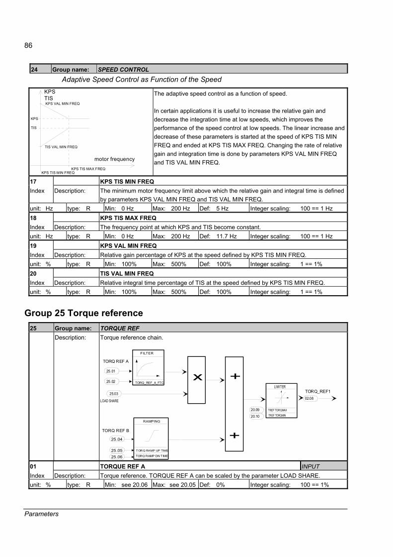
86
Parameters
24 Group name: SPEED CONTROL Adaptive Speed Control as Function of the Speed
KPSTIS
motor frequency
KPS VAL MIN FREQ
TIS VAL MIN FREQ
KPS
TIS
KPS TIS MAX FREQKPS TIS MIN FREQ
The adaptive speed control as a function of speed. In certain applications it is useful to increase the relative gain and decrease the integration time at low speeds, which improves the performance of the speed control at low speeds. The linear increase and decrease of these parameters is started at the speed of KPS TIS MIN FREQ and ended at KPS TIS MAX FREQ. Changing the rate of relative gain and integration time is done by parameters KPS VAL MIN FREQ and TIS VAL MIN FREQ.
17 KPS TIS MIN FREQ Index Description: The minimum motor frequency limit above which the relative gain and integral time is defined
by parameters KPS VAL MIN FREQ and TIS VAL MIN FREQ. unit: Hz type: R Min: 0 Hz Max: 200 Hz Def: 5 Hz Integer scaling: 100 == 1 Hz 18 KPS TIS MAX FREQ Index Description: The frequency point at which KPS and TIS become constant. unit: Hz type: R Min: 0 Hz Max: 200 Hz Def: 11.7 Hz Integer scaling: 100 == 1 Hz 19 KPS VAL MIN FREQ Index Description: Relative gain percentage of KPS at the speed defined by KPS TIS MIN FREQ. unit: % type: R Min: 100% Max: 500% Def: 100% Integer scaling: 1 == 1% 20 TIS VAL MIN FREQ Index Description: Relative integral time percentage of TIS at the speed defined by KPS TIS MIN FREQ. unit: % type: R Min: 100% Max: 500% Def: 100% Integer scaling: 1 == 1%
Group 25 Torque reference 25 Group name: TORQUE REF Description: Torque reference chain.
RAMPING
TORQ RAMP UP TIME
TORQ RAMP DN TIME
TORQ REF B
TORQ REF A
FILTER
TORQ_REF_A_FTC
LOAD SHARE
x +
+
TREF TORQMAX
TREF TORQMIN
LIMITER TORQ_REF1
25.01
25.04
25.03 02.08
25.02
25.0525.06
20.09
20.10
01 TORQUE REF A INPUT Index Description: Torque reference. TORQUE REF A can be scaled by the parameter LOAD SHARE. unit: % type: R Min: see 20.06 Max: see 20.05 Def: 0% Integer scaling: 100 == 1%

87
Parameters
25 Group name: TORQUE REF 02 TORQ REF A FTC Index Description: TORQUE REF A low pass filter time constant. unit: ms type: R Min: 0 ms Max: 60000 ms Def: 0 ms Integer scaling: 1 == 1 ms 03 LOAD SHARE Index Description: TORQ REF A scaling factor, which scales the external torque, reference to a required level. unit: % type: R Min: -400% Max: 400% Def: 100% Integer scaling: 10 == 1% 04 TORQUE REF B INPUT Index Description: Torque reference. Torque reference B is ramped by the parameters TORQ RAMP UP TIME
and TORQ RAMP DN TIME. unit: % type: R Min: see 20.06 Max: see 20.05 Def: 0% Integer scaling: 100 == 1% 05 TORQ RAMP UP Index Description: Torque reference B ramp time from 0% to 100%. unit: s type: R Min: 0 s Max: 120 s Def: 0 s Integer scaling: 100 == 1s 06 TORQ RAMP DOWN Index Description: Torque reference B ramp time from 100% to 0%. unit: s type: R Min: 0 s Max: 120 s Def: 0 s Integer scaling: 100 == 1s
Group 26 Torque reference handling 26 Group name: TORQ REF HANDLING Description: The torque reference can be given from the speed reference chain (TORQ REF2) or from the
torque reference chain (TORQ REF1) depending on the control mode. This group defines how to handle the reference after the torque selector block.
TORQUE REFERENCESELECTOR
+
+
MIN
MAX
0
1234
5
TORQ REF1
2.10
2.08
TORQ_REF3
OSCILLATIONDAMPING
2.02
SPEED REF3
SPEED ACTUAL
26.01TORQ REF SEL
26.07
26.06
26.05
26.04
TORQ REF2 2.09
1.02
EXTERNAL TORQUE REFERENCE
SPEED CONTROLLER OUTPUT
2.11
TORQ_REF4
2.12
TORQ_REF5
LOAD COMPENSATION
TORQUE STEP
26.02
26.03
TORQUEREFERENCELIMITING
2.13
TORQ USED
LIMITATIONS
6
OPTIONAL FUNCTION
01 TORQUE SELECTOR Index Description: The torque reference selector includes.
1 = ZERO Zero control 2 = SPEED Speed control 3 = TORQUE Torque control 4 = MINIMUM Minimum control 5 = MAXIMUM Maximum control 6 = ADD Add control (normally used with the window control )
unit: type: I Min: 1 Max: 6 Def: 2 SPEED Integer scaling:

88
Parameters
26 Group name: TORQ REF HANDLING 02 LOAD COMPENSATION INPUT Index Description: Load compensation added to TORQ REF3.
Note: If the overriding system or the RMIO application itself sends a reference value into this parameter, it must be set to zero before the stop command of the drive.
unit: % type: R Min: See 20.06 Max: See 20.05 Def: 0% Integer scaling: 100 == 1% 03 TORQUE STEP INPUT Index Description: Additional torque step added to TORQ REF4.
Note: If the overriding system or the RMIO application itself sends a reference value into this parameter, it must be set to zero before the stop command of the drive.
unit: % type: R Min: See 20.06 Max: See 20.05 Def: 0% Integer scaling: 100 == 1% 04 OSC COMPENSATION Index Description: TORSIONAL VIBRATION DAMPING
The filter uses the speed error as an input. The bandpass filter searches for certain frequencies and calculates a sine wave, which is summed to the torque reference after the phase shift. The phase shift can be set to phase angles between 0-360 degrees. Typically this function is needed to dampen the mechanical oscillations. The following three parameters also belong to this function. 0 = ON function is enabled 1 = OFF function is disabled
unit: type: B Min: Max: Def: OFF Integer scaling: 1 == 1 05 OSCILLATION FREQ Index Description: OSCILLATION FREQ is the oscillation frequency (Hz). Oscillation frequency is determined
by viewing the speed difference signal and the following equation:
fN
Tpeaks= , where
Npeaks is the number of peaks in the time window T (seconds). For example, if we see 11
peaks in 1.5 seconds the frequency is f =11/1.5=7.3 Hz.
unit: Hz type: R Min: 0 Hz Max: 60 Hz Def: 31 Hz Integer scaling: 100 == 1 Hz 06 OSCILLATION PHASE Index Description: Oscillation phase is the phase angle of the sine wave. The control algorithm produces a sine
wave whose phase can be shifted by this parameter.
0° 90° 180° unit: ° deg type: R Min: 0° Max: 360° Def: 0° Integer scaling: 1 == 1.41° 07 OSCILLATION GAIN Index Description: Oscillation gain determines how much the sine wave is amplified before it is summed to the
speed error signal. Oscillation gain is scaled according to the speed controller gain so that changing the speed controller gain will not disturb the oscillation damping.
unit: % type: R Min: 0% Max: 100% Def: 0% Integer scaling: 100 == 1%

89
Parameters
Group 27 Flux control 27 Group name: FLUX CONTROL Description: 01 FLUX OPTIMIZATION Index Description: The motor flux can be optimised in order to minimise the motor losses and reduce motor
noise. Flux optimisation is used in drives that usually operate below nominal load. 1 = YES flux optimisation enabled. 0 = NO flux optimisation disabled.
unit: type: B Min: Max: Def: NO Integer scaling: 1 == 1 02 FLUX BRAKING Index Description: The braking ability of the drive can be highly improved by utilising flux braking. During
braking, the mechanical energy of the driven equipment has to be dissipated in the motor and inverter. By modifying the magnetising level of the motor, thermal losses can be increased and the motor can be stopped more effectively. This function can be used with the non-regenerative incoming sections.
SPEEDNo flux braking
Flux braking
Desired deceleration
t
Selection of the flux braking function. 1 = YES Flux braking enabled. 0 = NO Flux braking disabled.
unit: type: B Min: Max: Def: ON Integer scaling: 1 == 1 03 FLUX REF INPUT Index Description: Flux reference value in percentage. unit: % type: R Min: 25% Max: 140% Def: 100% Integer scaling: 10 == 1% 04 FLUX MAX Index Description: Maximum limit of the flux percentage. unit: % type: R Min: 100% Max: 140% Def: 140% Integer scaling: 10 == 1% 05 FLUX MIN Index Description: Minimum limit of the flux percentage. unit: % type: R Min: 0% Max: 100% Def: 25% Integer scaling: 10 == 1%

90
Parameters
Group 29 Scalar control 29 Group name: SCALAR CONTROL Description: Scalar control is activated by selecting SCALAR at parameter 99.08 CONTROL MODE. This
parameter group is invisible when DTC control mode is selected. Note: The following Start-Up parameters have no effect in scalar control: 99.03 MOTOR NOM CURRENT 99.05 MOTOR NOM SPEED 99.06 MOTOR NOM POWER Note: Parameter 50.01 SPEED SCALING has only affect for scaling of the actual speed in the Scalar motor control mode. Scalar control parameters can be seen in the Control Diagram. The scalar control mode is recommended for multimotor drives when the number of motors connected to the ACS800 is variable. Scalar control is also recommended when the nominal current of the motor is less than 1/6 of the nominal current of the inverter, or the inverter is used for test purposes with no motor connected. The motor identification Run, flying start, torque control, DC HOLD, motor phase loss check, and stall functions are disabled in the scalar control mode.
01 FREQUENCY REF INPUT Index Description: This is an input for the frequency reference. unit: Hz type: R Min: See 29.03 Max: See 29.02 Def: 0 Integer scaling: 100 == 1 Hz 02 FREQUENCY MAX Index Description: Operating range maximum frequency. This parameter has an internal link to the parameter
SPEED MAX; if SPEED MAX is changed, this parameter is changed accordingly by the application program.
unit: Hz type: R Min: See 29.03 Max: 300 Hz Def: See 20.01 Integer scaling: 100 == 1 Hz 03 FREQUENCY MIN Index Description: Operating range maximum frequency. This parameter has an internal link to the parameter
SPEED MIN; if SPEED MIN is changed, this parameter is changed accordingly by the application program.
unit: Hz type: R Min: -300 Hz Max: See 29.02 Def: See 20.02 Integer scaling: 100 == 1 Hz 04 IR COMPENSATION Index Description: This parameter sets the extra relative voltage that is fed to the motor at zero frequency. The
range is 0�30% of motor nominal voltage. U(%)
Umax
f(Hz)
a
Field weakening pointUmax
unit: % type: R Min: 0% Max: 30% Def: 0 Integer scaling: 100 == 1
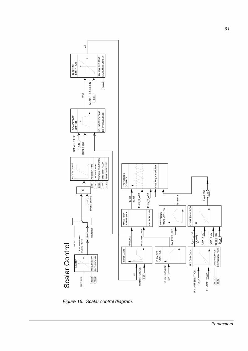
91
Parameters
AC
C/D
EC
/SH
AP
E
AC
CE
LER
TIM
E
DE
CE
LER
TIM
E
FREQ
REF
29.0
1
LOC
AL
FRE
Q R
EF
(LO
CA
L R
EF
3)
LOC
AL
22.0
1
22.0
2
22.0
3
22.0
4
22.0
5
AC
C/D
EC
TIM
E S
CA
LE
EM
E S
TO
P R
AM
P
RA
MP
SH
PE
TIM
E
LIM
ITE
R
29.0
2FR
EQU
ENC
Y M
AX
FREQ
UEN
CY
MIN
29.0
3
DC
UN
DER
VOLT
AGE
DC-V
OLT
AGE
LIM
ITER
DC
OV
ER
VO
LTA
GE
1.10
DC
VO
LTA
GE
INV
MAX
CU
RR
ENT
CURR
ENT
LIM
ITAT
ION
1.06
MO
TOR
CU
RR
ENT
MAX
IMU
M C
UR
RE
NT
20.0
4
mrl
mru
crra
mpn
_shp
STA
BIL
IZE
R
MO
TOR
TO
RQ
UE
ram
p_sc
_i
MA
KE
FLU
XR
EFE
RE
NC
E
FLU
X U
SE
D R
EF
sine
RO
M ta
ble
HYS
TER
ES
ISC
ON
TRO
L
mrl
FLU
X R
EF
CO
NTR
OL
FLU
X U
SE
D R
EF
SW
ITC
HIN
GFR
EQ
CO
NTR
OL
SW
_FR
EQ
_RE
F
hyst
eres
is
1.08
2.14
Sca
lar C
ontro
l
IR C
OM
P C
ALC
MO
TOR
NO
M V
OLT
MO
TOR
NO
M F
RE
Q
IR C
OM
PEN
SATI
ON
IR_C
OM
P_W
EAK
CO
MP
EN
SA
TIO
N
FLUX
_X_A
CT
FLUX
_Y_A
CT
FREQ
UENC
Y1.
05.
ir_co
rr_co
efir_
k_co
ef_
f
2.15
FLUX
_ACT
99.0
2
99.0
4
29.0
4
FLU
X_X_
ACT
FLU
X_Y_
AC
T
uses
torq
ue m
odul
ator
flx_r
effly
_ref
SPE
ED
SH
AR
E
x23
.03
FRE
Q R
EF
Figure 16. Scalar control diagram.
92
Parameters
Group 30 Fault functions 30 Group name: FAULT FUNCTIONS Description: 01 MOTOR THERM PMODE Index Description: Motor thermal protection mode selections. Selection 1 and 2 are based on the thermal model
defined by the drive (DTC) or the user (USER MODE). Motor heating is calculated assuming a load curve. Selections 3 and 4 are the measured indications from the motor temperature. Note: Motor thermal mode (selections 1 and 2) can be used when only one motor is connected to the output of inverter.
1 = DTC The drive defines the thermal model values during the identification run. (see parameter 99.06)
2 = USER MODE User can define the thermal model values by parameters 30.09�30.12. 3 = THERMISTOR PTC thermistor or PT100 sensors, see parameter 30.03 and 30.06 4 = KLIXON Temperature switch in the motor windings using the DI6 input. unit: type: I Min: 1 Max: 4 Def: 1 Integer scaling: 1 == 1 02 MOTOR THERM PROT Index Description: Operation in case of an overload or over temperature condition.
1 = FAULT 2 = WARNING 3 = NO (no action)
unit: type: I Min: 1 Max: 3 Def: 1 Integer scaling: 03 MOT1 TEMP AI1 SEL
This parameter is used to activate an external motor temperature measurement circuit connected to analogue input AI1. Analogue output AO1 supplies a constant current. The measurement circuit employs 1 to 3 PT100 sensors or PTC thermistors.
Index: Description:
1 = NOT IN USE 2 = 1xPT100 3 = 2xPT100 4 = 3xPT100 5 = 1�3 PTC
Analogue input AI1 is not in use for motor temperature measurement. One PT100 sensor; 9.1 mA current generator, (0�10 V or 0�2 V with NAIO-01 or NAIO-02 extension module. Two PT100 sensors; 9.1 mA current generator, 0�10 V. Three PT100 sensors; 9.1 mA current generator, 0�10 V. 1 to 3 PTC thermistors; 1.6 mA current generator, 0�10 V.
unit: type: I Min: 1 Max: 5 Def: 1 Integer scaling: 04 MOT 1 TEMP ALM L Index Description: Motor 1 temperature alarm is activated when the measured temperature rises above this limit.unit: °C or Ω type: R Min: -10°C or 0 Ω Max: 180°C or 5000 Ω Def: 110°C or 0 Ω Integer scaling: 1 = 1°C 05 MOT 1 TEMP FLT L Index Description: Motor 1 temperature trip is activated when the measured temperature rises above this limit. unit: °C or Ω type: R Min: -10°C or 0 Ω Max: 180°C or 5000 Ω Def: 130°C or 0 Ω Integer scaling: 1 = 1°C
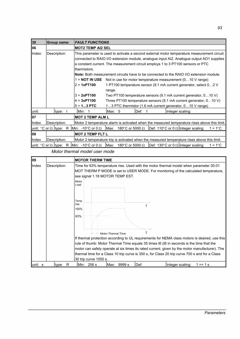
93
Parameters
30 Group name: FAULT FUNCTIONS 06 MOT2 TEMP AI2 SEL
This parameter is used to activate a second external motor temperature measurement circuit connected to RAIO I/O extension module, analogue input AI2. Analogue output AO1 supplies a constant current. The measurement circuit employs 1 to 3 PT100 sensors or PTC thermistors. Note: Both measurement circuits have to be connected to the RAIO I/O extension module. 1 = NOT IN USE Not in use for motor temperature measurement (0�10 V range) 2 = 1xPT100 1 PT100 temperature sensor (9.1 mA current generator, select 0�2 V
range. 3 = 2xPT100 Two PT100 temperature sensors (9.1 mA current generator, 0�10 V) 4 = 3xPT100 Three PT100 temperature sensors (9.1 mA current generator, 0�10 V)
Index: Description:
5 = 1...3 PTC 1�3 PTC thermistor (1.6 mA current generator, 0�10 V range) unit: type: I Min: 1 Max: 5 Def: 1 Integer scaling: 07 MOT 2 TEMP ALM L Index Description: Motor 2 temperature alarm is activated when the measured temperature rises above this limit.unit: °C or Ω type: R Min: -10°C or 0 Ω Max: 180°C or 5000 Ω Def: 110°C or 0 Ω Integer scaling: 1 = 1°C 08 MOT 2 TEMP FLT L Index Description: Motor 2 temperature trip is activated when the measured temperature rises above this limit. unit: °C or Ω type: R Min: -10°C or 0 Ω Max: 180°C or 5000 Ω Def: 130°C or 0 Ω Integer scaling: 1 = 1°C
Motor thermal model user mode
09 MOTOR THERM TIME Index Description: Time for 63% temperature rise. Used with the motor thermal model when parameter 30.01
MOT THERM P MODE is set to USER MODE. For monitoring of the calculated temperature, see signal 1.18 MOTOR TEMP EST.
Temprise
63%
100%
MotorLoad
t
Motor Thermal Time t If thermal protection according to UL requirements for NEMA class motors is desired, use this rule of thumb: Motor Thermal Time equals 35 times t6 (t6 in seconds is the time that the motor can safely operate at six times its rated current, given by the motor manufacturer). The thermal time for a Class 10 trip curve is 350 s, for Class 20 trip curve 700 s and for a Class 30 trip curve 1050 s.
unit: s type: R Min: 256 s Max: 9999 s Def: Integer scaling: 1 == 1 s

94
Parameters
30 Group name: FAULT FUNCTIONS 10 MOTOR LOAD CURVE Index Description: The motor load curve sets the maximum allowable operating load of the motor. It is active
when USER MODE is selected in Parameter 30.01 MOT THERM P MODE. When set to 100%, the maximum allowable load is equal to the value of Start-up Data Parameter 99.03 MOTOR NOM CURRENT. The load curve level should be adjusted if the ambient temperature differs from the nominal value.
Speed
I(%)
50
100
150
30.10 MOTOR LOAD CURVE
30.12 BREAK POINT
30.11 ZERO SPEED LOAD
99.02 MOTOR NOM CURRENT
unit: % type: R Min: 50% Max: 150% Def: 100% Integer scaling: 1 == 1% 11 ZERO SPEED LOAD Index Description: The maximum motor load at zero speed for the load curve. A higher value can be used if the
motor has an external fan motor to boost the cooling when running the drive at a low frequency. See the motor manufacturer�s recommendations. This parameter is used when USER MODE is selected in parameter 30.01 MOT THERM P MODE.
unit: % type: R Min: 25% Max: 150% Def: 74% Integer scaling: 1 == 1% 12 BREAK POINT Index Description: The break point frequency for the load curve. This parameter defines the point at which the
motor load curve begins to decrease from the maximum value set by Parameter 30.10 MOTOR LOAD CURVE to the value of Parameter 30.11 ZERO SPEED LOAD. Used when the USER MODE is selected in Parameter 30.01 MOT THERM P MODE.
unit: Hz type: R Min: 1 Hz Max: 300 Hz Def: 45 Hz Integer scaling: 100 == 1 Hz
Stall protection
13 STALL FUNCTION This parameter defines the operation of the stall protection. The protection is activated if the following conditions are valid for a time longer than the period set by Parameter 30.15 STALL TIME LIM. 1. The motor torque is close to the internal momentary changing limit of the motor control
program that prevents the motor and the inverter from overheating or the motor from pulling out.
2. The output frequency is below the level set by Parameter 30.14. STALL FREQ HI. 3. SPC TORQ MAX limit value must be higher than MAXIMUM TORQUE limit and SPC
TORQ MIN must be negative than MINIMUM TORQUE. Operation in case of a motor stall condition. 1 = NO No action 2 = WARNING A warning is produced.
Index Description:
3 = FAULT A fault is produced. unit: type: I Min: 1 Max: 3 Def: 1 Integer scaling:
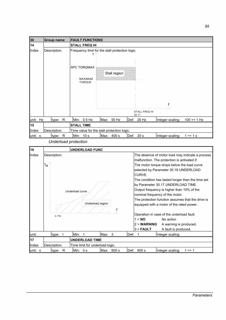
95
Parameters
30 Group name: FAULT FUNCTIONS 14 STALL FREQ HI Index Description: Frequency limit for the stall protection logic.
T
f
Stall region
STALL FREQ HI30.11
MAXIMUMTORQUE
SPC TORQMAX
unit: Hz type: R Min: 0.5 Hz Max: 50 Hz Def: 20 Hz Integer scaling: 100 == 1 Hz 15 STALL TIME Index Description: Time value for the stall protection logic. unit: s type: R Min: 10 s Max: 400 s Def: 20 s Integer scaling: 1 == 1 s
Underload protection
16 UNDERLOAD FUNC Index Description:
T
f
Underload region
0.1*fn
Underload curve
M
The absence of motor load may indicate a process malfunction. The protection is activated if: The motor torque drops below the load curve selected by Parameter 30.18 UNDERLOAD CURVE. The condition has lasted longer than the time set by Parameter 30.17 UNDERLOAD TIME. Output frequency is higher than 10% of the nominal frequency of the motor. The protection function assumes that the drive is equipped with a motor of the rated power. Operation in case of the underload fault. 1 = NO No action 2 = WARNING A warning is produced. 3 = FAULT A fault is produced.
unit: type: I Min: 1 Max: 3 Def: 1 Integer scaling: 17 UNDERLOAD TIME Index Description: Time limit for underload logic. unit: s type: R Min: 0 s Max: 600 s Def: 600 s Integer scaling: 1 == 1

96
Parameters
30 Group name: FAULT FUNCTIONS 18 UNDERLOAD CURVE Index Description: One of the 5 fixed underload curves can be selected for the underload protection
100
80
60
40
20
02.4 * �N
3
2
1 5
4
T M
70 %
50 %
30 %
�N
( % )
unit: type: I Min: 1 Max: 5 Def: 1 Integer scaling: 19 MOTOR PHASE LOSS Index Description: Operation in case a motor phase is lost.
1 = FAULT Enabled. 0 = NO Disabled.
unit: type: B Min: Max: Def: NO Integer scaling: 1 == 1 20 EARTH FAULT Index Description: Operation in case of an earth fault condition.
1 = FAULT A fault is produced. 0 = WARNING A warning is produced.
unit: type: B Min: Max: Def: FAULT Integer scaling: 1 == 1 21 PANEL LOSS Index Description: Operation in case local control (control panel or DriveWindow) is lost.
Drive continues running at the last speed reference and generates a warning. 1 = FAULT A fault is produced. 0 = LAST SPEED A warning is produced.
unit: type: B Min: Max: Def: FAULT Integer scaling: 1 == 1 22 UNDERVOLTAGE CTL Index Description: This parameter activates the undervoltage controller. If the DC voltage level starts to
decrease, the torque reference is reduced and the motor acts as a generator. 1 = ON Enabled. 0 = OFF Disabled.
unit: type: B Min: Max: Def: ON Integer scaling: 1 == 1 23 OVERVOLTAGE CTL Index Description: This parameter activates the overvoltage controller. The overvoltage controller increases the
torque if the DC bus voltage exceeds the limit - typically when the motor is running as a generator and there is no regenerative incoming supply or braking chopper with resistors. 1 = ON Enabled. 0 = OFF Disabled. (The normal mode with braking choppers and regenerative supply units.)
unit: type: B Min: Max: Def: ON Integer scaling: 1 == 1

97
Parameters
30 Group name: FAULT FUNCTIONS 25 COM LOSS CTRL
This parameter defines the action after a communication fault. See also parameter 30.26 MAIN REF DS T-OUT and parameter 70.04 CH0 TIMEOUT 1 = STOP RAMPNG The drive is stopped by ramping. The deceleration time is defined by
parameter 22.02 DECELER TIME. 2 = STOP TORQ The drive is stopped by torque limit. 3 = COAST STOP The drive is stopped by coasting. 4 = LAST SPEED The drive continues running on the last reference, the warning COMM
MODULE is activated, and 9.05 ALARM WORD 2 bit 11 is set to 1. The drive continues running at the last speed reference.
Index Description:
5 = CNST SPEED1 Parameters 23.02 CONST SPEED 1, the warning COMM MODULE is activated, and 9.05 ALARM WORD 2 bit 11 is set to 1.
unit: type: I Min: 1 Max: 5 Def: 1 Integer scaling: 1 == 1 26 MAIN REF DS T-OUT Index Description: Defines the time delay for the Main Reference Data Set supervision. See parameter 30.25. unit: s type: R Min: 0.1 s Max: 60 s Def: 3 s Integer scaling: 100 == 1 27 COMM FLT RO
Digital output control upon a communication fault on CH0, if controlled via ACW. Note: that this parameter does not affect digital output DO1, if emergency stop function is activated (see parameter 21.04). 0 = ZERO Digital outputs are de-energised.
Index Description:
1 = LAST VALUE The states of the digital outputs before the communication fault are retained.
unit: type: B Min: Max: Def: ZERO Integer scaling: 1 == 1 28 AUX DS T-OUT Index Description: Defines the delay time for the Auxiliary Reference Data Set supervision. See parameter
30.25. The supervision is active if the value is other than zero. unit: s type: R Min: 0 s Max: 60 s Def: 3 s Integer scaling: 100 == 1 29 LIMIT WARNING
Activates/deactivates limit alarms INV CUR LIM, DC BUS LIM, MOT CUR LIM, MOT TORQ LIM and/or MOT POW LIM. For more information, see the chapter Fault tracing. Value in decimal. As default only INV CUR LIM and DC BUS LIM alarms are active, i.e. parameter value is 3 (bit 0 and bit 1 values are 1).
0 = INV_CUR_LIM_IND 1 = DC_VOLT_LIM_IND 2 = MOT_CUR_LIM_IND 3 = MOT_TORQ_LIM_IND
Index Description:
4 = MOT_POW_LIM_IND unit: type: I Min: 0 Max: 255 Def: 0 Integer scaling:
98
Parameters
Group 37 Brake chopper 37 Group name: BRAKE CHOPPER 01 BRAKE CHOPPER CTL Index Description: Activates the brake chopper control.
0 = OFF Inactive 1 = ON Active Note: Ensure the brake chopper and resistor are installed and the overvoltage control is switched off (parameter 37.02).
unit: type: B Min: Max: 65535 Def: OFF Integer scaling: 1 == 1 02 BR OVERLOAD FUNC
Activates the overload protection of the brake resistor. The user-adjustable variables are parameters 37.03 BR RESISTANCE, 37.04 BR THERM TCONST and 37.05 MAX CONT BR POWER. 0 = NO Inactive 1 = WARNING Active. If the drive detects an overload, it generates a warning.
Index Description:
2 = FAULT Active. If the drive detects on overload, it trips on a fault. unit: type: I Min: 0 Max: 2 Def: NO Integer scaling: 1 == 1 03 BR RESISTANCE Index Description: Defines the resistance value of the brake resistor. The value is used in the overload
protection. See parameter 37.02 BR OVERLAOD FUNC. unit: ohm type: Min: 0 Max: 100 Def: 100 Integer scaling: 1 == 1 04 BR THERM TCONST Index Description: Defines the thermal time constant of the brake resistor. The value is used in the overload
protection. See parameter 37.02 BR OVERLOAD FUNC. unit: s type: Min: 0 Max: 10000 Def: 0.00 s Integer scaling: 1 == 1 05 MAX CONT BR POWER Index Description: Defines the maximum continuous braking power, which will raise the resistor temperature to
the maximum allowed value. The value is used in the overload protection. See parameter 37.02 BR OVERLOAD FUNC.
unit: kW type: R Min: 0 Max: 10000 Def: 0.00 s Integer scaling: 1 == 1

99
Parameters
37 Group name: BRAKE CHOPPER 06 BC CTRL MODE
Selects the control mode of the braking chopper. 1 = AS GENERATOR Chopper operation is allowed when the DC voltage exceeds the
braking limit, the inverter bridge modulates and the motor generates power to the drive. The selection prevents the operation in case the intermediate circuit DC voltage rises due to abnormally high supply voltage level. Long time supply voltage rise would damage the chopper.
Index Description:
2 = COMMON DC Chopper operation is allowed always when the DC voltage exceeds the braking limit. The selection is to be used in applications where several inverters are connected to the same intermediate circuit (DC bus). WARNING! Excessive supply voltage will raise the intermediate circuit voltage above the operation limit of the chopper. If the voltage remains abnormally high for a long period, the braking chopper will be overloaded and damaged.
unit: type: Min: Max: Def: Integer scaling: 1 == 1
Group 50 Speed measurement 50 Group name: SPEED MEASUREMENT Description:
FILTER
SP ACT FILT TIME50.06
SPEED FB SEL 50.03
SPEED SCALING50.01
SPEED FEEDBACKSELECTION
ENCODER PULSE NR50.04
SPEED MEAS MODE 50.02
ENCODER ALM/FLT50.05
ENCODER MODULE98.01
SPEED_MEASURED
1.031.04
1.01
MOTOR SPEED FILT
MOTOR MODEL1.02
FILTER
SP ACT FILT TIME
SPEED ESTIMATED
MOTOR SPEED
01 SPEED SCALING Index Description: This parameter defines the speed reference (in rpm) that corresponds to the value of 20000
from the overriding system or I/O. This parameter has only scaling effect to speed actual signals in the scalar control mode.
unit: rpm type: R Min: 0 rpm Max: 100000 rpm Def: 1500 rpm Integer scaling: 15000 = 1500 rpm

100
Parameters
50 Group name: SPEED MEASUREMENT 02 SPEED MEAS MODE
Selects the measurement type for the pulse encoder mode. 0 = A_-B DIR Positive edges for speed; channel B: direction 1 = A_-_ Positive and negative edges for speed; channel B: not used 2 = A_-_B DIR Positive and negative edges for speed; channel B: direction
Index Description:
3 = A_-_B_-_Channels A & B: positive and negative edges for speed and direction unit: type: I Min: 0 Max: 3 Def: 3 Integer scaling: 1 == 1 03 SPEED FB SEL Index Description: Source of the speed feedback to the speed controller.
1 = INTERNAL Internal actual speed. 2 = ENCODER Pulse encoder module (see also Parameter 98.01 ENCODER MODULE)
unit: type: I Min: 1 Max: 2 Def: 1 Integer scaling: 1 == 1 04 ENCODER PULSE NR Index Description: Number of pulse encoder pulses per revolution. unit: type: R Min: 1 Max: 30000 Def: 2048 Integer scaling: 1 == 1 05 ENCODER ALM/FLT
Defines if an encoder error causes a warning or a fault. 1 = FAULT
Index Description:
0 = ALARM A warning is generated. The drive continues running at the internal actual speed.unit: type: B Min: Max: Def: ALARM Integer scaling: 1 == 1 06 SP ACT FILT TIME Index Description: The time constant of the first order actual speed filter. unit: ms type: R Min: 0 ms Max: 999999 ms Def: 8 ms Integer scaling: 1 == 1 ms 07 POS COUNT MODE
The position counter is based on the pulse count from the pulse encoder. It has two different measurement modes: 0 = PULSE EDGES Both edges of the pulses are counted. Actual values can be read from
signals 3.07 POS COUNT LOW and 3.08 POS COUNT HIGH 1 = ROUND&DEG The application software counts the number of the motor shaft rounds
and the shaft angle in degrees. Actual values can be read from signals 3.09 POS COUNT DEGREES and 3.10 POS COUNT ROUNDS
Index Description:
The position counter is controlled by means of 7.02 AUX CONTROL WORD bits 9�11. The status can be seen from 8.02 AUX STATUS WORD bit 5 (SYNC_RDY). By means of the application program in the overriding system, it is possible to create the positioning control function.
unit: type: I Min: 0 Max: 1 Def: ROUND Integer scaling: 1 == 1 08 POS COUNT INIT LO Index Description: Position counter initial low word value when the mode is PULSE EDGES. unit: type: PB Min: 0 Max: 65536 Def: 0 Integer scaling: 1 == 1 09 POS COUNT INIT HI Index Description: Position counter initial high word value when the mode is PULSE EDGES. unit: type: PB Min: 0 Max: 65536 Def: 0 Integer scaling: 1 == 1 10 ABOVE SPEED LIMIT Index Description: When the actual speed has reached the value of this parameter, 8.01 MAIN STATUS WORD
bit 10 is set to 1. unit: rpm type: R Min: See 20.01 Max: See 20.02 Def: 0 Integer scaling: See 50.01
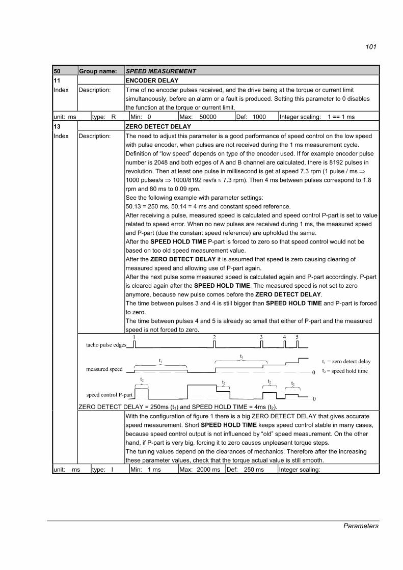
101
Parameters
50 Group name: SPEED MEASUREMENT 11 ENCODER DELAY Index Description: Time of no encoder pulses received, and the drive being at the torque or current limit
simultaneously, before an alarm or a fault is produced. Setting this parameter to 0 disables the function at the torque or current limit.
unit: ms type: R Min: 0 Max: 50000 Def: 1000 Integer scaling: 1 == 1 ms 13 ZERO DETECT DELAY
Description: The need to adjust this parameter is a good performance of speed control on the low speed with pulse encoder, when pulses are not received during the 1 ms measurement cycle. Definition of �low speed� depends on type of the encoder used. If for example encoder pulse number is 2048 and both edges of A and B channel are calculated, there is 8192 pulses in revolution. Then at least one pulse in millisecond is get at speed 7.3 rpm (1 pulse / ms ⇒ 1000 pulses/s ⇒ 1000/8192 rev/s ≈ 7.3 rpm). Then 4 ms between pulses correspond to 1.8 rpm and 80 ms to 0.09 rpm. See the following example with parameter settings: 50.13 = 250 ms, 50.14 = 4 ms and constant speed reference. After receiving a pulse, measured speed is calculated and speed control P-part is set to value related to speed error. When no new pulses are received during 1 ms, the measured speed and P-part (due the constant speed reference) are upholded the same. After the SPEED HOLD TIME P-part is forced to zero so that speed control would not be based on too old speed measurement value. After the ZERO DETECT DELAY it is assumed that speed is zero causing clearing of measured speed and allowing use of P-part again. After the next pulse some measured speed is calculated again and P-part accordingly. P-part is cleared again after the SPEED HOLD TIME. The measured speed is not set to zero anymore, because new pulse comes before the ZERO DETECT DELAY. The time between pulses 3 and 4 is still bigger than SPEED HOLD TIME and P-part is forced to zero. The time between pulses 4 and 5 is already so small that either of P-part and the measured speed is not forced to zero.
tacho pulse edges
measured speed 0
= zero detect delay
= speed hold time
speed control P-part
t1t1
t1
t2
t2
t2 t2 t2
0
1 2 3 4 5
ZERO DETECT DELAY = 250ms (t1) and SPEED HOLD TIME = 4ms (t2).
Index
With the configuration of figure 1 there is a big ZERO DETECT DELAY that gives accurate speed measurement. Short SPEED HOLD TIME keeps speed control stable in many cases, because speed control output is not influenced by �old� speed measurement. On the other hand, if P-part is very big, forcing it to zero causes unpleasant torque steps. The tuning values depend on the clearances of mechanics. Therefore after the increasing these parameter values, check that the torque actual value is still smooth.
unit: ms type: I Min: 1 ms Max: 2000 ms Def: 250 ms Integer scaling:

102
Parameters
50 Group name: SPEED MEASUREMENT 14 SPEED HOLD TIME Index Description: The time after the P-part of speed control is forced to zero, if the time has been elapsed and
no new pulses received after the last sample. By increasing the value, it amplifies the effect of P-part on low speed due to the longer effect time of P-part. An oscillation can be occurred, if the time is too long. See description of parameter 50.13 ZERO DETECT DELAY above. Note: The value of SPEED HOLD TIME <= ZERO DETECT DELAY.
unit: ms type: I Min: 1 Max: 250 Def: 4 ms Integer scaling:
Group 51 Communication module (FBA) 51 Group name: COMMUNICATION MODULE Description: This group defines the communication parameters for a fieldbus adapter module. The
parameter names are copied from the module when its connection to the drive is activated using parameter 98.02 COMM MODULE LINK. See the module manual. Note: Any changes in these parameters take effect only upon the next power-up of the adapter module.
01 FIELDBUS PAR1 (Module type and software version) Index Description: unit type: S Min: Max: Def: Integer scaling: 02...33 FIELDBUS PAR2�33 (According to module type) Index Description: unit type: R Min: Max: Def: Integer scaling:
Group 52 Standard Modbus 52 Group name: STANDARD MODBUS Description: The settings for the Standard Modbus Link. 01 STATION NUMBER Index Description: Defines the address of the device. Two units with the same address are not allowed on-line.
Address 1�247. unit type: I Min: 1 Max: 247 Def: 1 Integer scaling: 1 == 1 02 BAUDRATE
Defines the transfer rate of the link. Baudrate 600 1 = 600 bit/s 1200 2 = 1200 bit/s 2400 3 = 2400 bit/s 4800 4 = 4800 bit/s 9600 5 = 9600 bit/s
Index Description:
19200 6 = 19200 bit/s unit type: I Min: 1 Max: 6 Def: 5 Integer scaling: 1 = 1
103
Parameters
52 Group name: STANDARD MODBUS 03 PARITY Index Description: Defines the use of parity and stop bit(s). The same settings must be used in all on-line
station. 1 = NONE1STOPBIT. No parity bit, one stop bit 2 = NONE2STOPBIT. No parity bit, two stop bits. 3 = ODD. Odd parity indication bit, one stop bit. 4 = EVEN. Even parity indication bit, one stop bit.
unit type: I Min: 1 Max: 4 Def: 3 Integer scaling: 1 == 1
Group 70 DDCS control 70 Group name: DDCS CONTROL Description: Parameter settings of the DDCS communication channels. 01 CH0 NODE ADDR
Node address for channel CH0. When using the APC2 system, the address must be 1. If AC 70 or AC 80 is used through the Module Bus (adapters TB810 or TB811), CH0 NODE ADDR and input POSITION in the data base element DRIENG are set according to the following table. AC70, AC80 Module Bus
Index Description:
POSITION 101 102 103
(70.01) 17 18 19 etc
unit: type: R Min: 1 Max: 125 Def: 1 Integer scaling: 1 == 1 02 CH0 LINK CONTROL Index Description: DDCS channel 0 intensity control for transmission LEDs. This parameter can be used in
special cases to optimise the communication performance of the link. unit: type: R Min: 1 Max: 15 Def: 15 Integer scaling: 1 == 1 03 CH0 BAUD RATE- Index Description: Channel CH0 communication speed. This must be set to 4 Mbit/s, when FCI or FBA
communication modules are used. Otherwise, the overriding system automatically sets the communication speed. 0 = 8 Mbit/s (not in use) 1 = 4 Mbit/s 2 = 2 Mbit/s (not in use) 3 = 1 Mbit/s
unit: Mbit/s type: I Min: 1 Mbit/s Max: 8 Mbit/s Def: 1 Mbit/s Integer scaling: 1 == 1 04 CH0 TIMEOUT Index Description: The delay time before a communication break fault is declared. The time count starts when
the link fails update the message. During the time elapsing, the warning COMM MODULE is activated and 9.05 ALARM WORD 2 bit 11 is set to 1.Setting this parameter to 0 disables the function.
unit: ms type: R Min: 0 ms Max: 254 ms Def: 0 ms Integer scaling: 1 == 1 ms
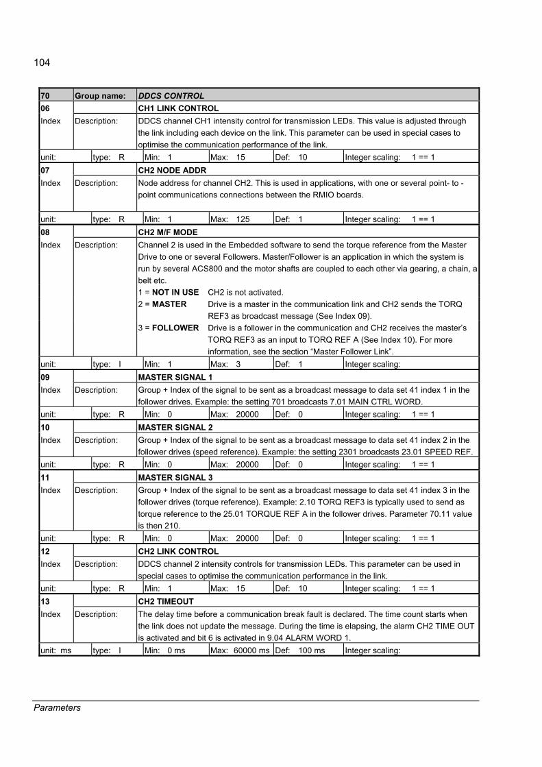
104
Parameters
70 Group name: DDCS CONTROL 06 CH1 LINK CONTROL Index Description: DDCS channel CH1 intensity control for transmission LEDs. This value is adjusted through
the link including each device on the link. This parameter can be used in special cases to optimise the communication performance of the link.
unit: type: R Min: 1 Max: 15 Def: 10 Integer scaling: 1 == 1 07 CH2 NODE ADDR Index Description: Node address for channel CH2. This is used in applications, with one or several point- to -
point communications connections between the RMIO boards.
unit: type: R Min: 1 Max: 125 Def: 1 Integer scaling: 1 == 1 08 CH2 M/F MODE
Channel 2 is used in the Embedded software to send the torque reference from the Master Drive to one or several Followers. Master/Follower is an application in which the system is run by several ACS800 and the motor shafts are coupled to each other via gearing, a chain, a belt etc. 1 = NOT IN USE CH2 is not activated. 2 = MASTER
Drive is a master in the communication link and CH2 sends the TORQ REF3 as broadcast message (See Index 09).
Index Description:
3 = FOLLOWER Drive is a follower in the communication and CH2 receives the master�s TORQ REF3 as an input to TORQ REF A (See Index 10). For more information, see the section �Master Follower Link�.
unit: type: I Min: 1 Max: 3 Def: 1 Integer scaling: 09 MASTER SIGNAL 1 Index Description: Group + Index of the signal to be sent as a broadcast message to data set 41 index 1 in the
follower drives. Example: the setting 701 broadcasts 7.01 MAIN CTRL WORD. unit: type: R Min: 0 Max: 20000 Def: 0 Integer scaling: 1 == 1 10 MASTER SIGNAL 2 Index Description: Group + Index of the signal to be sent as a broadcast message to data set 41 index 2 in the
follower drives (speed reference). Example: the setting 2301 broadcasts 23.01 SPEED REF. unit: type: R Min: 0 Max: 20000 Def: 0 Integer scaling: 1 == 1 11 MASTER SIGNAL 3 Index Description: Group + Index of the signal to be sent as a broadcast message to data set 41 index 3 in the
follower drives (torque reference). Example: 2.10 TORQ REF3 is typically used to send as torque reference to the 25.01 TORQUE REF A in the follower drives. Parameter 70.11 value is then 210.
unit: type: R Min: 0 Max: 20000 Def: 0 Integer scaling: 1 == 1 12 CH2 LINK CONTROL Index Description: DDCS channel 2 intensity controls for transmission LEDs. This parameter can be used in
special cases to optimise the communication performance in the link. unit: type: R Min: 1 Max: 15 Def: 10 Integer scaling: 1 == 1 13 CH2 TIMEOUT Index Description: The delay time before a communication break fault is declared. The time count starts when
the link does not update the message. During the time is elapsing, the alarm CH2 TIME OUT is activated and bit 6 is activated in 9.04 ALARM WORD 1.
unit: ms type: I Min: 0 ms Max: 60000 ms Def: 100 ms Integer scaling:
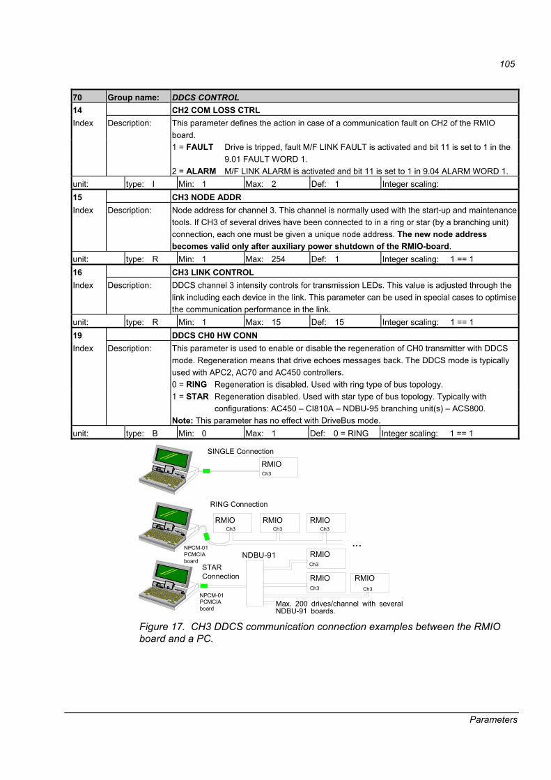
105
Parameters
70 Group name: DDCS CONTROL 14 CH2 COM LOSS CTRL
This parameter defines the action in case of a communication fault on CH2 of the RMIO board. 1 = FAULT
Drive is tripped, fault M/F LINK FAULT is activated and bit 11 is set to 1 in the 9.01 FAULT WORD 1.
Index Description:
2 = ALARM M/F LINK ALARM is activated and bit 11 is set to 1 in 9.04 ALARM WORD 1. unit: type: I Min: 1 Max: 2 Def: 1 Integer scaling: 15 CH3 NODE ADDR Index Description: Node address for channel 3. This channel is normally used with the start-up and maintenance
tools. If CH3 of several drives have been connected to in a ring or star (by a branching unit) connection, each one must be given a unique node address. The new node address becomes valid only after auxiliary power shutdown of the RMIO-board.
unit: type: R Min: 1 Max: 254 Def: 1 Integer scaling: 1 == 1 16 CH3 LINK CONTROL Index Description: DDCS channel 3 intensity controls for transmission LEDs. This value is adjusted through the
link including each device in the link. This parameter can be used in special cases to optimise the communication performance in the link.
unit: type: R Min: 1 Max: 15 Def: 15 Integer scaling: 1 == 1 19 DDCS CH0 HW CONN
This parameter is used to enable or disable the regeneration of CH0 transmitter with DDCS mode. Regeneration means that drive echoes messages back. The DDCS mode is typically used with APC2, AC70 and AC450 controllers. 0 = RING Regeneration is disabled. Used with ring type of bus topology. 1 = STAR Regeneration disabled. Used with star type of bus topology. Typically with
configurations: AC450 � CI810A � NDBU-95 branching unit(s) � ACS800.
Index Description:
Note: This parameter has no effect with DriveBus mode. unit: type: B Min: 0 Max: 1 Def: 0 = RING Integer scaling: 1 == 1
RMIO
NDBU-91
RMIO
...
RMIO RMIO
RMIO
RMIORMIO
SINGLE Connection
Max. 200 drives/channel with severalNDBU-91 boards.
RING Connection
STAR Connection
NPCM-01PCMCIAboard
NPCM-01PCMCIAboard
Ch3
Ch3
Ch3
Ch3Ch3Ch3
Ch3
Figure 17. CH3 DDCS communication connection examples between the RMIO board and a PC.

106
Parameters
Group 90 D set rec ADDR 90 Group name: D SET REC ADDR Description: Addresses into which the received fieldbus data sets are written.
Numbers of the main and auxiliary data sets. 01 AUX DS REF3 Index Description: Selects the address into which the value of fieldbus reference REF3 is written.
0�8999 parameter index. unit: type: Min: 0 Max: 8999 Def: 0 Integer scaling: 1 == 1 02 AUX DS REF4 Index Description: Selects the address into which the value of fieldbus reference REF4 is written.
0�8999 parameter index. unit: type: Min: 0 Max: 8999 Def: 0 Integer scaling: 1 == 1 03 AUX DS REF5 Index Description: Selects the address into which the value of fieldbus reference REF5 is written.
0�8999 parameter index. unit: type: Min: 0 Max: 8999 Def: 0 Integer scaling: 1 == 1 04 MAIN DS SOURCE Index Description: Defines the data set from which the drive reads the Control Word, Reference REF1 and
Reference REF2. 0�255 Data set number.
unit: type: Min: 0 Max: 255 Def: 1 Integer scaling: 1 == 1 05 AUX DS SOURCE Index Description: Defines the data set from which the drive reads References REF3, REF4 and REF5.
0�255 Data set number. unit: type: Min: 0 Max: 255 Def: 3 Integer scaling: 1 == 1
Group 92 D set TR ADDR 92 Group name: D SET TR ADDR Description: Main and Auxiliary Data Sets, which the drive sends to the fieldbus master station. 01 MAIN DS STATUS WORD Index Description: Stores the address from which the Main Status Word is read. Fixed value, not visible.
801 (fixed) Parameter index. unit: type: Min: Max: Def: Integer scaling: 1 == 1 02 MAIN DS ACT1 Index Description: Selects the address from which the Actual Signal 1 is read to the Main Data Set.
0�9999 parameter index. unit: type: Min: 0 Max: 9999 Def: 101 Integer scaling: 1 == 1 03 MAIN DS ACT2 Index Description: Selects the address from which the Actual Signal 2 is read to the Main Data Set.
0�9999 parameter index. unit: type: Min: 0 Max: 9999 Def: 107 Integer scaling: 1 == 1 04 AUX DS ACT3 Index Description: Selects the address from which the Actual Signal 3 is read to the Auxiliary Data Set.
0�9999 parameter index. unit: type: Min: 0 Max: 9999 Def: 901 Integer scaling: 1 == 1
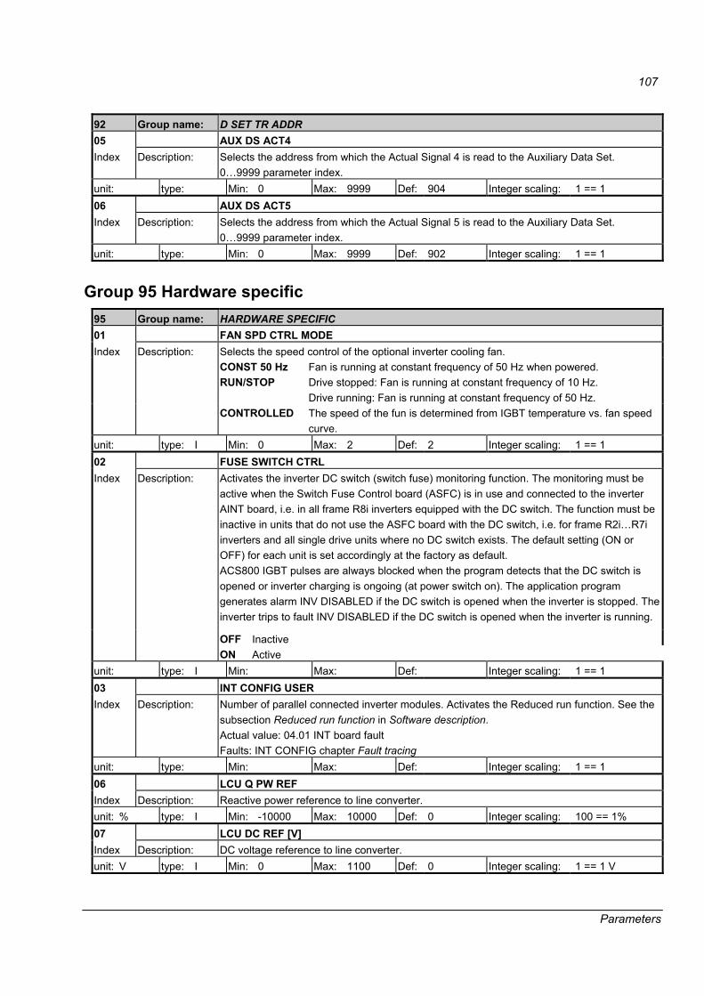
107
Parameters
92 Group name: D SET TR ADDR 05 AUX DS ACT4 Index Description: Selects the address from which the Actual Signal 4 is read to the Auxiliary Data Set.
0�9999 parameter index. unit: type: Min: 0 Max: 9999 Def: 904 Integer scaling: 1 == 1 06 AUX DS ACT5 Index Description: Selects the address from which the Actual Signal 5 is read to the Auxiliary Data Set.
0�9999 parameter index. unit: type: Min: 0 Max: 9999 Def: 902 Integer scaling: 1 == 1
Group 95 Hardware specific 95 Group name: HARDWARE SPECIFIC 01 FAN SPD CTRL MODE
Selects the speed control of the optional inverter cooling fan. CONST 50 Hz Fan is running at constant frequency of 50 Hz when powered. RUN/STOP Drive stopped: Fan is running at constant frequency of 10 Hz.
Drive running: Fan is running at constant frequency of 50 Hz.
Index Description:
CONTROLLED The speed of the fun is determined from IGBT temperature vs. fan speed curve.
unit: type: I Min: 0 Max: 2 Def: 2 Integer scaling: 1 == 1 02 FUSE SWITCH CTRL
Activates the inverter DC switch (switch fuse) monitoring function. The monitoring must be active when the Switch Fuse Control board (ASFC) is in use and connected to the inverter AINT board, i.e. in all frame R8i inverters equipped with the DC switch. The function must be inactive in units that do not use the ASFC board with the DC switch, i.e. for frame R2i�R7i inverters and all single drive units where no DC switch exists. The default setting (ON or OFF) for each unit is set accordingly at the factory as default. ACS800 IGBT pulses are always blocked when the program detects that the DC switch is opened or inverter charging is ongoing (at power switch on). The application program generates alarm INV DISABLED if the DC switch is opened when the inverter is stopped. The inverter trips to fault INV DISABLED if the DC switch is opened when the inverter is running.
OFF Inactive
Index Description:
ON Active unit: type: I Min: Max: Def: Integer scaling: 1 == 1 03 INT CONFIG USER Index Description: Number of parallel connected inverter modules. Activates the Reduced run function. See the
subsection Reduced run function in Software description. Actual value: 04.01 INT board fault Faults: INT CONFIG chapter Fault tracing
unit: type: Min: Max: Def: Integer scaling: 1 == 1 06 LCU Q PW REF Index Description: Reactive power reference to line converter. unit: % type: I Min: -10000 Max: 10000 Def: 0 Integer scaling: 100 == 1% 07 LCU DC REF [V] Index Description: DC voltage reference to line converter. unit: V type: I Min: 0 Max: 1100 Def: 0 Integer scaling: 1 == 1 V

108
Parameters
Group 98 Option modules 98 Group name: OPTION MODULES Description: Activation of the option modules. 01 ENCODER MODULE
Activates the communication to the optional pulse encoder module. See also parameter settings in group 50. 0 = NTAC Communication active. Module type: NTAC module.
Connection interface: Fibre optic DDCS link. Note: Module node number must be set to 16. For directions, see Installation and Start Guide for NTAC-0x/NDIO-0x/NAIO-0x Modules (Code: 3AFY58919730 English).
1 = NO Inactive 2 = RTAC-SLOT1 Communication active. Module type: RTAC.
Connection interface: Option SLOT 1 of the drive. 3 = RTAC-SLOT2 Communication active. Module type: RTAC
Connection interface: Option SLOT 2 of the drive.
Index Description:
4 = RTAC-DDCS Communication active. Module type: RTAC. Connection interface: Option module rack of the drive (communication with the drive through a fibre optic DDCS link). Note: Module node number must be set to 16. For directions, see User's Manual for RDIO Module (Code: 3AFE64485733 English).
unit: type: Min: 0 Max: 4 Def: 1 Integer scaling: 1 == 1 02 COMM MODULE LINK
Activates the external serial communication and selects the interface. 1 = NO No communication. 2 = FIELDBUS The drive communicates via a fieldbus adapter module in option SLOT 1
of the drive, or via CH0 on the RDCO board. See also parameter group 51.
3 = ADVANT The drive communicates with an ABB Advant OCS system via CH0 on the RDCO board (optional). See also parameter group 70.
4 = STD MODBUS The drive communicates with a Modbus controller via the Modbus Adapter Module (RMBA) in option SLOT 1 of the drive. See also parameter group 52.
Index Description:
5 = CUSTOMISED The drive communicates via a customer specified link. The control sources are defined by parameters 90.04 and 90.05.
unit: type: Min: Max: Def: 1 Integer scaling:

109
Parameters
98 Group name: OPTION MODULES 03 DI/O EXT MODULE 1
Activates the communication to the digital I/O extension module 1 (optional) and defines the type and connection interface of the module. Extension I/O replaces RMIO DI1 and DI2. 1 = NDIO Communication active. Module type: NDIO module.
Connection interface: Fibre optic DDCS link. Note: Module node number must be set to 2. For directions, see Installation and Start-up Guide for NTAC-0x/NDIO-0x/NAIO-0x Modules (Code: 3AFY58919730 English).
2 = NO Inactive 3 = RDIO-SLOT1 Communication active. Module type: RDIO.
Connection interface: Option SLOT 1 of the drive. 4 = RDIO-SLOT2 Communication active. Module type: RDIO.
Connection interface: Option SLOT 2 of the drive.
Index Description:
5 = RDIO-DDCS Communication active. Module type: RDIO Connection interface: Option module rack of the drive (communicates with the drive through a fibre optic DDCS link). Note: Module node number must be set to 2. For directions, see User's Manual for RDIO Module (Code: 3AFE64485733 English).
unit: type: Min: 1 Max: 5 Def: 2 Integer scaling: 1 == 1 04 DI/O EXT MODULE 2
Activates the communication to the digital I/O extension module 2 (optional) and defines the type and connection interface of the module. Extension I/O replaces RMIO DI3 and DI4. 1 = NDIO Communication active: Module type: NDIO module.
Connection interface: Fibre optic DDCS link. Note: Module node number must be set to 3. For directions, see Installation and Start-up Guide for NTAC-0x/NDIO-0x/NAIO-0x Modules (Code: 3AFY58919730 English).
2 = NO Inactive 3 = RDIO-SLOT1 Communication active. Module type: RDIO.
Connection interface: Option SLOT 1 of the drive. 4 = RDIO-SLOT2 Communication active. Module type: RDIO.
Connection interface: Option SLOT 2 of the drive.
Index Description:
5 = RDIO-DDCS Communication active. Module type: RDIO. Connection interface: Option module rack of the drive (communication with the drive through a fibre optic DDCS link). Note: Module node number must be set to 3. For directions, see User's Manual for RDIO Module (Code: 3AFE64485733 English).
unit: type: Min: 1 Max: 5 Def: 2 Integer scaling: 1 == 1

110
Parameters
98 Group name: OPTION MODULES 05 DI/O EXT MODULE 3
Activates the communication to the digital I/O extension module 3 (optional) and defines the type and connection interface of the module. Extension I/O replaces RMIO DI5 and DI6. 1 = NDIO Communication active. Module type: NDIO module.
Connection interface: Fibre optic DDCS link. 2 = NO Inactive 3 = RDIO-SLOT1 Communication active. Module type: RDIO.
Connection interface: Option SLOT 1 of the drive. 4 = SLOT2 Communication active. Module type: RDIO
Connection interface: Option SLOT 2 of the drive.
Index Description:
5 = RDIO-DDCS Communication active. Module type: RDIO. Connection interface: Option module rack of the drive (communicates with the drive through a fibre optic DDCS link). Note: Module node number must be set to 4. For directions, see User's Manual for RDIO Module (Code: 3AFE64485733 English).
unit: type: Min: 1 Max: 5 Def: 2 Integer scaling: 1 == 1 06 AI/O EXT MODULE 1
Activates the communication to the analogue I/O extension module (optional), and defines the type and connection interface of the module. Extension I/O replaces RMIO AI1 and AI2. Module inputs: - See parameters 98.13 and 98.14 for the signal type definitions. 1 = NAIO Communication active: Module type: NAIO
Connection interface: Fibre optic DDCS link. Note: Module node number must be set to 5. For direction, see Installationand Start-up Guide for NTAC-0x/NDIO-0x/NAIO-0x Modules (Code: 3AFY58919730 English).
2 = NO Communication inactive.
3 = RAIO-SLOT1 Communication active. Module type: RAIO. Connection interface: Option SLOT 1 of the drive.
4 = RAIO-SLOT2 Communication active: Module type: RAIO. Connection interface: Option SLOT 2 of the drive.
Index Description:
5 = RAIO-DDCS Communication active. Module type: RAIO. Connection interface: Optional module rack, which communicates with the drive through a fibre optic DDCS link. Note: Module node number must be set to 5. For direction, see User's Manual for RAIO Module (Code: 3AFE64484567 English).
unit: type: Min: 1 Max: 5 Def: 2 Integer scaling: no 07 COMM PROFILE
Defines the profile on which the communication with the fieldbus or another drive is based. ABB DRIVES ABB Drives profile.
Index Description:
GENERIC Generic drive profile. Typically used with the fieldbus modules that have the type designation of form Rxxx (installed in the option slot of the drive).
unit: type: Min: 1 Max: 2 Def: 1 Integer scaling:

111
Parameters
98 Group name: OPTION MODULES 13 AI/O EXT AI1 FUNC
Defines the signal type for input 1 of the analogue I/O extension module. The setting must match the signal connected to the module. Note: The communication must be activated by parameter 98.06. 1 = UNIP AI5 Unipolar
Index Description:
2 = BIPO AI5 Bipolar unit: type: Min: 1 Max: 2 Def: 1 Integer scaling: no 14 AI/O EXT AI2 FUNC
Defines the signal type for input 2 of the analogue I/O extension module. The setting must match the signal connected to the module. Note: The communication must be activated by parameter 98.06. 1 = UNIP AI6 Unipolar
Index Description:
2 = BIPO AI6 Bipolar unit: type: Min: 1 Max: 2 Def: 1 Integer scaling: no
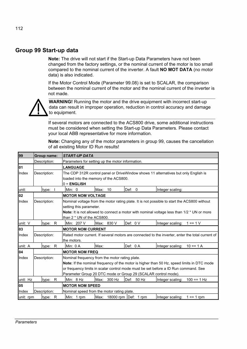
112
Parameters
Group 99 Start-up data Note: The drive will not start if the Start-up Data Parameters have not been changed from the factory settings, or the nominal current of the motor is too small compared to the nominal current of the inverter. A fault NO MOT DATA (no motor data) is also indicated.
If the Motor Control Mode (Parameter 99.08) is set to SCALAR, the comparison between the nominal current of the motor and the nominal current of the inverter is not made.
WARNING! Running the motor and the drive equipment with incorrect start-up data can result in improper operation, reduction in control accuracy and damage to equipment.
If several motors are connected to the ACS800 drive, some additional instructions must be considered when setting the Start-up Data Parameters. Please contact your local ABB representative for more information.
Note: Changing any of the motor parameters in group 99, causes the cancellation of all existing Motor ID Run results!
99 Group name: START-UP DATA Description: Parameters for setting up the motor information. 01 LANGUAGE Index Description: The CDP 312R control panel or DriveWindow shows 11 alternatives but only English is
loaded into the memory of the ACS800. 0 = ENGLISH
unit: type: I Min: 0 Max: 10 Def: 0 Integer scaling: 02 MOTOR NOM VOLTAGE Index Description: Nominal voltage from the motor rating plate. It is not possible to start the ACS800 without
setting this parameter. Note: It is not allowed to connect a motor with nominal voltage less than 1/2 * UN or more than 2 * UN of the ACS800.
unit: V type: R Min: 207 V Max: 830 V Def: 0 V Integer scaling: 1 == 1 V 03 MOTOR NOM CURRENT Index Description: Rated motor current. If several motors are connected to the inverter, enter the total current of
the motors. unit: A type: R Min: 0 A Max: Def: 0 A Integer scaling: 10 == 1 A 04 MOTOR NOM FREQ Index Description: Nominal frequency from the motor rating plate.
Note: If the nominal frequency of the motor is higher than 50 Hz, speed limits in DTC mode or frequency limits in scalar control mode must be set before a ID Run command. See Parameter Group 20 DTC mode or Group 29 (SCALAR control mode).
unit: Hz type: R Min: 8 Hz Max: 300 Hz Def: 50 Hz Integer scaling: 100 == 1 Hz 05 MOTOR NOM SPEED Index Description: Nominal speed from the motor rating plate. unit: rpm type: R Min: 1 rpm Max: 18000 rpm Def: 1 rpm Integer scaling: 1 == 1 rpm

113
Parameters
99 Group name: START-UP DATA 06 MOTOR NOM POWER Index Description: Nominal power from the motor rating plate. If several motors are connected to the inverter,
enter the total power of the motors. unit: kW type: R Min: 0 kW Max: 9000 kW Def: 0 kW Integer scaling: 10 == 1 kW 07 MOTOR ID RUN Index Description: This parameter is used to initiate the Motor Identification Run. During the run, the drive will
identify the characteristics of the motor for optimum motor control. The ID Run takes about one minute. The ID Run cannot be performed if scalar control is selected (Parameter 99.08 is set to SCALAR). Note: The ID Run (Standard or Reduced) should be selected if: • operation point is near zero speed
• operation at torques above the motor nominal torque within a wide speed range and without a pulse encoder is required.
Note: Check the rotation direction of the motor by first start before starting the Motor ID Run. During the run the motor will rotate in the forward direction. Warning! The motor will run at up to approximately 50%�80% of nominal speed during the Motor ID Run. BE SURE THAT IT IS SAFE TO RUN THE MOTOR BEFORE PERFORMING THE MOTOR ID RUN.
1 = NO 2 = STANDARD 3 = REDUCED
The Motor ID Run is not performed. If an ID Run has not been done yet, or any of the motor parameters have been changed, the motor will start the mode FIRST START after the start command has been given. The DC-magnetising phase lasts much longer than the normal start because the stator resistance and other electrical losses are first identified and stored into FPROM memory. . Performing the Standard Motor ID Run guarantees the best possible control accuracy. The motor must be decoupled from the driven equipment before performing the Standard ID Run. Only to be selected if the motor cannot be decoupled from the driven equipment. The Reduced Motor ID Run should be selected in applications where mechanical losses are higher than 20% (i.e. the load cannot be disconnected) or where flux reduction is not allowed (i.e. there are auxiliary devices connected in parallel with the motor) while the motor is running.
unit: type: I Min: 1 Max: 3 Def: 1 Integer scaling: 08 MOTOR CTRL MODE
Motor control mode selection. 1 = SCALAR Scalar control mode 0 = -DTC Direct Torque Control mode.
Index Description:
If several motors are connected to the inverter, there are certain restrictions on the usage of DTC. Please contact your local ABB representative for more information.
unit: type: B Min: Max: Def: DTC Integer scaling: 1 == 1

114
Parameters
99 Group name: START-UP DATA 09 APPLIC RESTORE Index Description: 1 = YES Values are restored.
0 = NO unit: type: B Min: 0 Max: 1 Def: 0 Integer scaling: 1 == 1 10 DRIVE ID NUMBER Index Description: This parameter can be used by the overriding system to check the correct connections of the
optical cables to the drive type. This parameter requires support from the overriding system. unit: type: I Min: 0 Max: 32767 Def: 0 Integer scaling: 11 DEVICE NAME Index Description: Defines the name for the drive or application. The name is visible on the control panel display
in the Drive Selection Mode. Note: The name can be typed only by using a drive PC tool. unit: type: S Min: Max: Def: 0 Integer scaling:
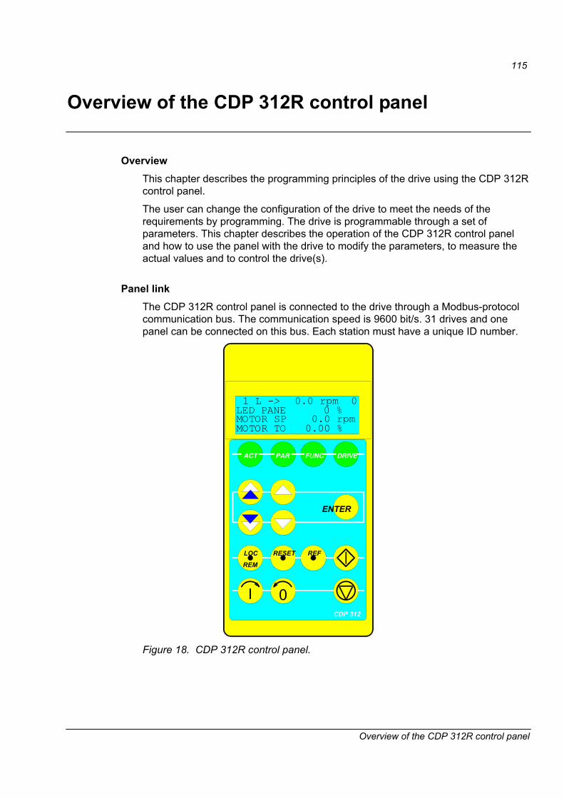
115
Overview of the CDP 312R control panel
Overview of the CDP 312R control panel
Overview This chapter describes the programming principles of the drive using the CDP 312R control panel.
The user can change the configuration of the drive to meet the needs of the requirements by programming. The drive is programmable through a set of parameters. This chapter describes the operation of the CDP 312R control panel and how to use the panel with the drive to modify the parameters, to measure the actual values and to control the drive(s).
Panel link The CDP 312R control panel is connected to the drive through a Modbus-protocol communication bus. The communication speed is 9600 bit/s. 31 drives and one panel can be connected on this bus. Each station must have a unique ID number.
1 L -> 0.0 rpm 0
MOTOR TO 0.00 %
LED PANE 0 %MOTOR SP 0.0 rpm
0
FUNC DRIVE
ENTER
LOC RESET REF
REM
PARACT
CDP 312
Figure 18. CDP 312R control panel.

116
Overview of the CDP 312R control panel
Display The LCD type display has 4 lines of 20 characters.
The language selection is made at Start-up by parameter 99.01 LANGUAGE. Depending on the customer�s selection, a set of four languages is loaded into the memory of the drive at the factory.
Keys The Control Panel keys are flat, labelled, push button keys that allow you to monitor drive functions, select drive parameters, and change settings.
1 L -> 0.0 rpm 0
MOTOR TO 0.00 %
LED PANE 0 %MOTOR SP 0.0 rpm
ENGLISH
99 START-UP DATA01 LANGUAGE
CONTRAST 4
UPLOAD <= <=DOWNLOAD => =>
ACS 800 0005_3
ID-NUMBER 1
Actual Signal Display Mode
Parameter Mode
Function Mode
Drive Selection Mode
ACT
PAR
FUNC
DRIVE
ENTER
ENTER
ENTER
ENTER
Display/group selection
Row/parameter selection
Enter selection modeAccept new parameter
Group selectionFast value change
Parameter selectionSlow value change
Enter selection modeAccept new value
Row selection
Function start
Drive/ID selection
Enter change modeAccept new value
Status Row
Actual SignalsNames andValues
Group numberand nameIndex numberand nameParameter value
Status Row
Selectablefunctions
Status Row
Drive name
ID-number of drivein the Modbus link
Device type
1 L -> 0.0 rpm 0
1 L -> 0.0 rpm 0
AMAM15D3 980605Application swname + version. *)
*) Name of the downloaded FCB (Function Chart Builder) application.
DRYER SECTION 1
Figure 19. Control Panel display indications and functions of the Control Panel keys.
LOC
REM
RESET
REF
Keypad /External Control
Fault Reset
Reference Setting Function
Forward
Reverse Stop
Start
0
Figure 20. Operational commands of the Control Panel keys.

117
Overview of the CDP 312R control panel
Panel operation The following is a description of the operation of the CDP 312R control panel. The Control Panel Keys and Displays are explained in Figures 8-2 and 8-3.
Keypad modes The CDP 312R control panel has four different keypad modes: Actual Signal Display Mode, Parameter Mode, Function Mode, and Drive Selection Mode. In addition, there is a special Identification Display, which is displayed after connecting the panel to the link. The Identification Display and the keypad modes are described briefly below.
Identification display
When the panel is connected for the first time, or the power is applied to the drive, the Identification Display appears, showing the panel type and the number of drives connected to the Panel Link.
Note: The panel can be connected to the drive while power is applied to the drive.
ACS 800 0005_3 ID NUMBER 1
After two seconds, the display will clear, and the Actual Signals of the drive will appear.
Actual signal display mode
This mode includes two displays, the Actual Signal Display and the Fault History Display. The Actual Signal Display is displayed first when the Actual Signal Display mode is entered. If the drive is in a fault condition, the Fault Display will be shown first.
The panel will automatically return to Actual Signal Display Mode from other modes if no keys are pressed within one minute (exceptions: Status Display in Drive Selection Mode and Fault Display Mode).
In the Actual Signal Display Mode you can monitor three Actual Signals at a time. How to select the three Actual Signals to the display is explained in Table 6.
The Fault History includes information on the 16 most recent faults that have occurred in your drive. The name of the fault and the total power-on time are displayed. If the APC2 overriding system has been connected to the drive (DDCS channel 0), this time can be seen in the date format instead of power-on time. The procedure for clearing the Fault History is described in Table 7.
The following table shows the events that are stored in the Fault History. For each event it is described what information is included.
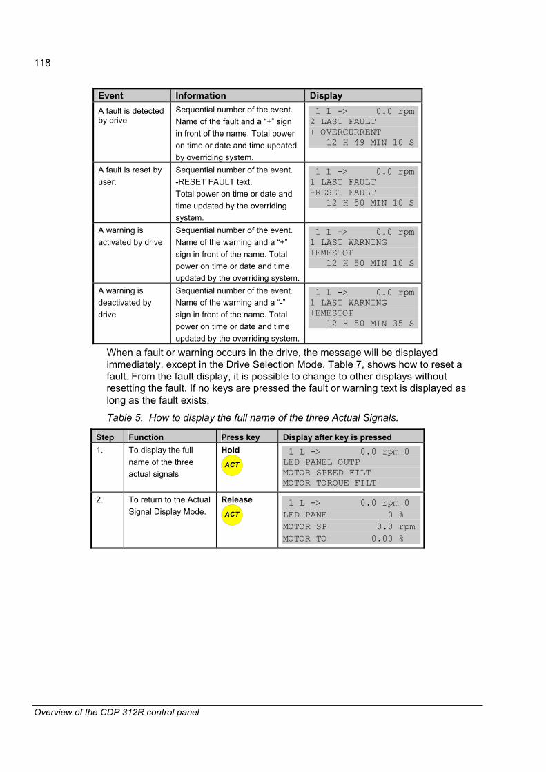
118
Overview of the CDP 312R control panel
Event Information Display A fault is detected by drive
Sequential number of the event. Name of the fault and a �+� sign in front of the name. Total power on time or date and time updated by overriding system.
1 L -> 0.0 rpm 2 LAST FAULT + OVERCURRENT 12 H 49 MIN 10 S
A fault is reset by user.
Sequential number of the event. -RESET FAULT text. Total power on time or date and time updated by the overriding system.
1 L -> 0.0 rpm 1 LAST FAULT -RESET FAULT 12 H 50 MIN 10 S
A warning is activated by drive
Sequential number of the event. Name of the warning and a �+� sign in front of the name. Total power on time or date and time updated by the overriding system.
1 L -> 0.0 rpm 1 LAST WARNING +EMESTOP 12 H 50 MIN 10 S
A warning is deactivated by drive
Sequential number of the event. Name of the warning and a �-� sign in front of the name. Total power on time or date and time updated by the overriding system.
1 L -> 0.0 rpm 1 LAST WARNING +EMESTOP 12 H 50 MIN 35 S
When a fault or warning occurs in the drive, the message will be displayed immediately, except in the Drive Selection Mode. Table 7, shows how to reset a fault. From the fault display, it is possible to change to other displays without resetting the fault. If no keys are pressed the fault or warning text is displayed as long as the fault exists.
Table 5. How to display the full name of the three Actual Signals.
Step Function Press key Display after key is pressed 1. To display the full
name of the three actual signals
Hold
ACT
1 L -> 0.0 rpm 0 LED PANEL OUTP MOTOR SPEED FILT MOTOR TORQUE FILT
2. To return to the Actual Signal Display Mode.
Release
ACT
1 L -> 0.0 rpm 0 LED PANE 0 % MOTOR SP 0.0 rpm MOTOR TO 0.00 %

119
Overview of the CDP 312R control panel
Table 6. How to select Actual Signals to the display
Step Function Press key Display after key is pressed 1. To enter the Actual
Signal Display Mode
ACT
1 L -> 0.0 rpm 0 LED PANE 0 % MOTOR SP 0.0 rpm MOTOR TO 0.00 %
2. To select the desired row.
1 L -> 0.0 rpm 0 LED PANE 0 % MOTOR SP 0.0 rpm MOTOR TO 0.00 %
3. To enter the Actual Signal Selection Mode.
ENTER
1 L -> 0.0 rpm 0 1 ACTUAL SIGNALS 01 MOTOR SPEED FILT 0.0 rpm
4. To select a different group.
1 L -> 0.0 rpm 0 2 ACTUAL SIGNALS 01 SPEED REF 2 0 rpm
5. To select an index.
1 L -> 0.0 rpm 0 2 ACTUAL SIGNALS 02 SPEED REF 3 0 rpm
6. To accept the selection and to return to the Actual Signal Display Mode.
ENTER
1 L -> 0.0 rpm 0 LED PANE 0 % SPEED RE 0.0 rpm MOTOR TO 0.00 %

120
Overview of the CDP 312R control panel
Table 7. How to display a fault and reset the Fault History
Step Function Press key Display after key is pressed 1. To enter the Actual
Signal Display Mode
ACT
1 L -> 0.0 rpm 0 LED PANE 0 % MOTOR SP 0.0 rpm MOTOR TO 0.00 %
1 L -> 0.0 rpm 2 LAST FAULT + PANEL LOST 20 H 49 MIN 56 S
1 L -> 0.0 rpm 1 LAST FAULT + PANEL LOST 980621 10:26:19.3043
2. To enter the Fault History Display. The time of occurrence can be seen either as total power-on time or in the date format if an overriding system (e.g. APC2) has been connected to control the drive.
s = fault or alarm logged into the fault logger r = fault or alarm reset
1 L -> 0.0 rpm 2 LAST FAULT + OVERCURRENT 12 H 49 MIN 10 S
3. To clear all the faults from the Fault History Buffer. A view of cleared fault logger.
RESET
1 L -> 0.0 rpm 0 2 LAST FAULT H MIN S
4. To return to the Actual Signal Display Mode.
1 L -> 0.0 rpm 0 LED PANE 0 % MOTOR SP 0.0 rpm MOTOR TO 0.00 %
Table 8. How to display and reset an active fault
Step Function Press key Display after key is pressed 1. To enter the Actual
Signal Display Mode.
ACT
1 L -> 0.0 rpm 0 ACS 800 75 kW *** FAULT *** PANEL LOST
2. To reset the fault. The Reset button functions also in the REMOTE mode.
RESET
1 L -> 0.0 rpm 0 LED PANE 0 % MOTOR SP 0.0 rpm MOTOR TO 0.00 %

121
Overview of the CDP 312R control panel
Parameter mode
The Parameter Mode is used for making changes to the drive parameters. When this mode is entered for the first time after power up, the display will show the first parameter of the first group. The next time, the Parameter Mode is entered, the previously selected parameter is shown.
Note: If you try to write to a write-protected parameter, the following warning will be displayed.
**WARNING** WRITE ACCESS DENIED PARAMETER SETTING NOT POSSIBLE

122
Overview of the CDP 312R control panel
Table 9. How to select a parameter and change the value
Step Function Press key Display after key is pressed 1. To enter the Parameter
Mode.
ACT
1 L -> 0.0 rpm 0 13 ANALOGUE INPUTS 01 AI1 HIGH VALUE 10000
1 L -> 0.0 rpm 0 14 DIGITAL INPUTS
2. To select another parameter group. While holding the arrow down, only the group name and number are displayed. When the key is released, name, number and value of the first parameter in the group are displayed.
1 L -> 0.0 rpm 0 14 DIGITAL OUTPUTS 01 DO1 CONTROL OFF
1 L -> 0.0 rpm 0 14 DIGITAL OUTPUTS 01 DO1 GROUP+INDEX
3. To select an index number. While holding the arrow down, only the parameter name and number are displayed. When the key is released the value of the parameter is also displayed.
1 L -> 0.0 rpm 0 14 DIGITAL OUTPUTS 02 DO1 GROUP+INDEX 801
4. To enter the parameter value.
ENTER
1 L -> 0.0 rpm 0 14 DIGITAL OUTPUTS 02 DO1 GROUP+INDEX [801]
5. To change the parameter value. (slow change) (fast change)
1 L -> 0.0 rpm 0 14 DIGITAL OUTPUTS 02 DO1 GROUP+INDEX [901]
1 L -> 0.0 rpm 0 14 DIGITAL OUTPUTS 02 DO1 GROUP+INDEX 901
6a. 6b.
To send a new value to the drive. To cancel the new setting and keep the original value. The selected Keypad Mode is entered.
ENTER
ACT PAR
FUNC DRIVE
1 L -> 0.0 rpm 0 14 DIGITAL OUTPUTS 02 DO1 GROUP+INDEX 801
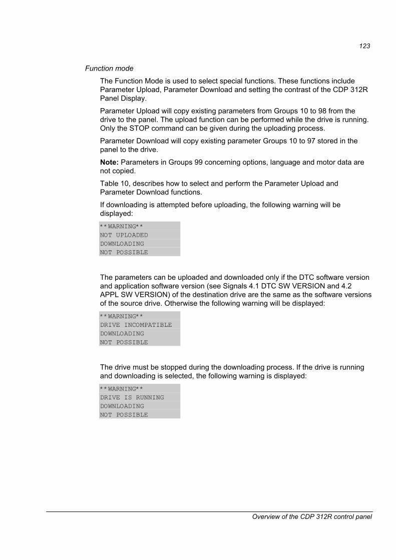
123
Overview of the CDP 312R control panel
Function mode
The Function Mode is used to select special functions. These functions include Parameter Upload, Parameter Download and setting the contrast of the CDP 312R Panel Display.
Parameter Upload will copy existing parameters from Groups 10 to 98 from the drive to the panel. The upload function can be performed while the drive is running. Only the STOP command can be given during the uploading process.
Parameter Download will copy existing parameter Groups 10 to 97 stored in the panel to the drive.
Note: Parameters in Groups 99 concerning options, language and motor data are not copied.
Table 10, describes how to select and perform the Parameter Upload and Parameter Download functions.
If downloading is attempted before uploading, the following warning will be displayed:
**WARNING** NOT UPLOADED DOWNLOADING NOT POSSIBLE
The parameters can be uploaded and downloaded only if the DTC software version and application software version (see Signals 4.1 DTC SW VERSION and 4.2 APPL SW VERSION) of the destination drive are the same as the software versions of the source drive. Otherwise the following warning will be displayed:
**WARNING** DRIVE INCOMPATIBLE DOWNLOADING NOT POSSIBLE
The drive must be stopped during the downloading process. If the drive is running and downloading is selected, the following warning is displayed:
**WARNING** DRIVE IS RUNNING DOWNLOADING NOT POSSIBLE

124
Overview of the CDP 312R control panel
Table 10. How to select and perform a function
Step Function Press key Display after key is pressed 1. To enter the Function
Mode
FUNC
1 L -> 0.0 rpm 0 UPLOAD <= <= DOWNLOAD => => CONTRAST 0
2. To select a function.
1 L -> 0.0 rpm 0 UPLOAD <= <= DOWNLOAD => => CONTRAST 0
3. To activate the selected function.
ENTER
1 L -> 0.0 rpm 0 => => => => => => => DOWNLOAD
4. Loading completed. 1 L -> 0.0 rpm 0 LED PANE 0 % MOTOR SP 0.0 rpm MOTOR TO 0.00 %
Table 11. How to set the contrast of the panel display.
Step Function Press key Display after key is pressed 1. To enter the Function
Mode.
FUNC
1 L -> 0.0 rpm 0 UPLOAD <= <= DOWNLOAD => => CONTRAST 0
2. To select a function.
1 L -> 0.0 rpm 0 UPLOAD <= <= DOWNLOAD => => CONTRAST 0
3. To enter the contrast setting function.
ENTER
1 L -> 0.0 rpm 0 CONTRAST [0]
4. To set the contrast. (0...7)
1 L -> 0.0 rpm 0 CONTRAST [7]
1 L -> 0.0 rpm 0 UPLOAD <= <= DOWNLOAD => => CONTRAST 7
5a. To accept the selected value. To cancel the new setting and keep the original value, press any of the Mode keys. The selected Keypad Mode is entered.
ENTER
ACT PAR
FUNC DRIVE
1 L -> 0.0 rpm 0 UPLOAD <= <= DOWNLOAD => => CONTRAST 0
125
Overview of the CDP 312R control panel
Copying parameters from one unit to other units
You can copy parameters in Groups 10...97 from one drive to another by using the Parameter Upload and Parameter Download functions in the Function Mode. Typically this kind of function can be used if the processes and the motor types are same. Follow the procedure below:
• Select the correct options (Group 98) and language (Group 99) for each drive.
• Set the rating plate values for the motors (Group 99) and perform the identification run for each motor if required.
• Set the parameters in Groups 10 to 97 as preferred in one drive.
• Upload the parameters from the drive to the panel (see Table 10).
• Disconnect the panel and reconnect it to the next drive unit.
• Download the parameters from the panel to the drive unit. (see Table 11).
• Repeat steps 5 and 6 for the rest of the units.
Note: Parameters in Groups 98 and 99 concerning options, language and motor data are not copied.
Setting the contrast
If the Control Panel Display is not clear enough, set the contrast according to the procedure explained in Table 11.
Drive selection mode
In normal use, the features available in the Drive Selection Mode are not needed; these features are reserved for applications where several drives are connected to one Modbus Link.
Modbus Link is the communication link connecting the Control Panel and the drive. Each on-line station must have an individual identification number (ID).
CAUTION! The default ID number setting of the drive must not be changed unless it is to be connected to the Modbus Link with other drives on-line.
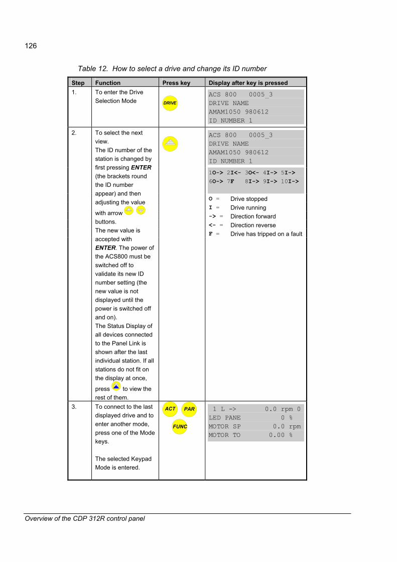
126
Overview of the CDP 312R control panel
Table 12. How to select a drive and change its ID number
Step Function Press key Display after key is pressed 1. To enter the Drive
Selection Mode
DRIVE
ACS 800 0005_3 DRIVE NAME AMAM1050 980612 ID NUMBER 1
ACS 800 0005_3 DRIVE NAME AMAM1050 980612 ID NUMBER 1
1O-> 2I<- 3O<- 4I-> 5I-> 6O-> 7F 8I-> 9I-> 10I-> O = Drive stopped I = Drive running -> = Direction forward <- = Direction reverse F = Drive has tripped on a fault
2. To select the next view. The ID number of the station is changed by first pressing ENTER (the brackets round the ID number appear) and then adjusting the value
with arrow buttons. The new value is accepted with ENTER. The power of the ACS800 must be switched off to validate its new ID number setting (the new value is not displayed until the power is switched off and on). The Status Display of all devices connected to the Panel Link is shown after the last individual station. If all stations do not fit on the display at once,
press to view the rest of them.
3. To connect to the last displayed drive and to enter another mode, press one of the Mode keys. The selected Keypad Mode is entered.
ACT PAR
FUNC
1 L -> 0.0 rpm 0 LED PANE 0 % MOTOR SP 0.0 rpm MOTOR TO 0.00 %
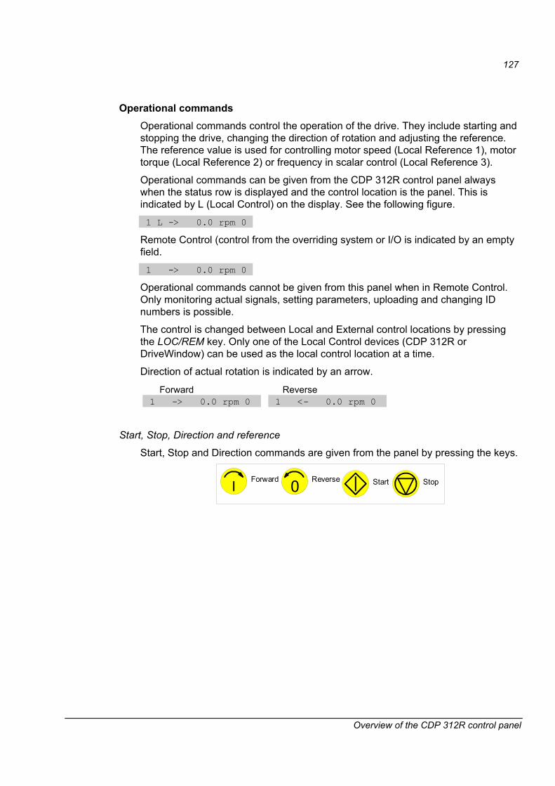
127
Overview of the CDP 312R control panel
Operational commands Operational commands control the operation of the drive. They include starting and stopping the drive, changing the direction of rotation and adjusting the reference. The reference value is used for controlling motor speed (Local Reference 1), motor torque (Local Reference 2) or frequency in scalar control (Local Reference 3).
Operational commands can be given from the CDP 312R control panel always when the status row is displayed and the control location is the panel. This is indicated by L (Local Control) on the display. See the following figure.
1 L -> 0.0 rpm 0
Remote Control (control from the overriding system or I/O is indicated by an empty field.
1 -> 0.0 rpm 0
Operational commands cannot be given from this panel when in Remote Control. Only monitoring actual signals, setting parameters, uploading and changing ID numbers is possible.
The control is changed between Local and External control locations by pressing the LOC/REM key. Only one of the Local Control devices (CDP 312R or DriveWindow) can be used as the local control location at a time.
Direction of actual rotation is indicated by an arrow.
Forward Reverse 1 -> 0.0 rpm 0
1 <- 0.0 rpm 0
Start, Stop, Direction and reference
Start, Stop and Direction commands are given from the panel by pressing the keys.
Forward Reverse StopStart0

128
Overview of the CDP 312R control panel
Table 13. How to set the reference from the CDP 312R panel.
Step Function Press key Display after key is pressed 1. To display enter a
Keypad Mode displaying the status row.
ACT PAR
FUNC
1 L -> 0.0 rpm 0 LED PANE 0 % MOTOR SP 0.0 rpm MOTOR TO 0.00 %
2. To enter the Reference Setting Mode
REF
1 L ->[ 0.0 rpm]0 LED PANE 0 % MOTOR SP 0.0 rpm MOTOR TO 0.00 %
3. To change the reference. (slow change) (fast change)
1 L ->[ 1030.0 rpm]0 LED PANE 0 % MOTOR SP 0.0 rpm MOTOR TO 0.00 %
4. To escape the Reference Setting Mode. The selected Keypad Mode is entered.
ACT PAR
FUNC DRIVE
1 L -> 0.0 rpm 0 LED PANE 0 % MOTOR SP 0.0 rpm MOTOR TO 0.00 %

129
Fault tracing
Fault tracing
Overview This chapter describes the protections and fault tracing of drive.
I/O error monitoring
Internal Fault on the I/O Board If there is communication problems with the basic RMIO board I/O or with an extension module I/O, the following alarm is given:
DIO ALARM Bit 7 in AW_1 (9.04) AIO ALARM Bit 8 in AW_1 (9.04) EXT DIO ALM Bit 9 in AW_1 (9.04) EXT AIO ALM Bit 10 in AW_1 (9.04)
Communication monitoring Messages received from the overriding system are monitored in the RMIO diagnostics program. The monitoring is activated by parameters 30.26, 30.28 and 70.04. The action in case of communication fault is defined in the parameter 30.25 COM LOSS CTRL. On a communication fault, bit 11 (alarm COMM MODULE) is activated in 9.05 ALARM WORD 2 and bit 12 (fault COMM MODULE) in 9.02 FAULT WORD 2.
Power plate overtemperature fault The drive supervises the inverter power plate module temperature. If it exceeds 115°C, a warning �ACS 800 TEMP� is given and 9.04 ALARM WORD 1 bit 4 is set to 1.
If the power plate module temperature exceeds 125°C, a fault �ACS 800 TEMP� is given and 09.01 FAULT WORD 1 bit 3 is set to 1.
Ambient temperature The drive measures the ambient temperature on the surface of the RMIO board. The drive will not start if the temperature is above 88°C (depending on converter type). Also a fault �CABIN TEMP F� is given and 9.02 FAULT WORD 2 bit 7 is set to 1.

130
Fault tracing
Overcurrent The overcurrent trip limit is 3.5 * Ihd (nominal motor current for heavy duty use). There are several sources of the overcurrent trip:
• SW trip (time level 100 μs, level = 97% of measurement scale)
• HW level trip (97% of measurement scale for 35 μs)
• HW derivative trip (12.5% of measurement scale for 75 μs)
• HW level trip in parallel connected units by PBU logic (94% of measurement scale for 75 μs)
A fault �OVERCURRENT� is given and 09.01 FAULT WORD 1 bit 1 is set to 1.
The current measurement is calibrated automatically during the start procedure.
DC overvoltage The DC overvoltage trip limit is 1.3 * U1max, where U1max is the maximum value of the mains voltage range.
Nominal Voltage of Inverter Unit U1max 400 V 415 V 500 V 500 V 690 V 690 V
A fault �DC OVERVOLT� is given and 09.01 FAULT WORD 1 bit 2 is set to 1. HIGH VOLTAGE TRIP LIMIT: 130%
HIGH VOLTAGE CONTROL LIMIT: 124%
BRAKE CHOPPER LIMIT: 120%
LOW VOLTAGE CONTROL LIMIT: 82%
CHARGING LIMIT: 79%
LOW VOLTAGE TRIPPING LIMIT: 60%
Figure 21. DC voltage control and tripping limits.
131
Fault tracing
DC undervoltage The DC Undervoltage trip limit is 0.60 *U1min, where U1min is the minimum value of the mains voltage range.
Nominal Voltage of Inverter Unit U1min
400 V 380 V 500 V 380 V 690 V 690 V
A fault �DC UNDERVOLT� is given and 9.02 FAULT WORD 2 bit 2 is set to 1.
Local control lost function The Local Control Lost function defines the operation of the drive when, while in local control mode, the communication between the local control device (control panel or DriveWindow) and the drive stops.
FAULT Stop2 the drive according to Parameter 21.03 LOCAL STOP FUNC. FW_2 (09.02) bit 13 is set to 1.
LAST SPEED Run at last speed and an alarm �PANEL LOST� is activated. AW_2 (09.05) bit 13 is set to 1.
Run enable interlocking function Digital input DI2 state �0� activates the RUN ENABLE function, used for external RUN interlocking and for internal charging logic, when the optional load switch is used at the input DC circuit of the inverter unit. When the state of DI2 switches to 0, the drive stops by coasting, a fault �RUN DISABLD� is given and 9.02 FAULT WORD 2 bit 4 and 08.02 AUX STATUS WORD (ASW) bit 4 are set to 1.
Short circuit There are separate protection circuits for supervising the motor cable and the inverter short circuits. If a short circuit occurs, the drive will not start and a fault �SHORT CIRC� is given and 9.01 FAULT WORD 1 bit 0 are set to a �1�.
DC Link intermediate current ripple fault Input phase loss protection circuits supervise the status of the mains in the supply section by detecting intermediate current ripple. If an input phase is lost, the intermediate current ripple increases. If the ripple exceeds 13% the drive is stopped and a fault �SUPPLY PHASE� is given. 9.02 FAULT WORD 2 bit 0 is set to 1.

132
Fault tracing
Overspeed fault If the drive output frequency exceeds the preset level (e.g. in the case of overshooting in speed control), the drive is stopped and a fault �OVER FREQ� is given. 9.01 FAULT WORD 1 bit 9 is set to 1. The trip level frequency margin is adjustable by Parameter 20.11 FREQ TRIP MARGIN The RTAC pulse encoder module contains diagnostics for the communication link, speed error between the internal and measured speeds, (difference limit 20% of nominal speed), and pulse encoder timeout limits. In case of a fault, 9.02 FAULT WORD 2 bit 5 is set to 1 and a fault �ENCODER FLT� is given. In case of an alarm, 9.04 ALARM WORD 1 bit 5 is set to 1 and an alarm �ENCODER ERR� is given. The Fault/Alarm function is activated by Parameter 50.05 ENCODER ALM/FLT.
Overswitching frequency fault If the inner control loop exceeds the maximum switching frequency, a fault �OVER SWFREQ� is given and 9.02 FAULT WORD 2 bit 9 is set to 1.
System fault If the program on the RMIO board has failed and causes an interruption, 09.01 FAULT WORD 1 bit 7 (SYSTEM_FAULT) is set to 1.
Motor protections
Motor thermal protection functions The motor can be protected against overheating by:
• activating the DTC motor thermal model or User Mode.
• temperature measurement from the motor by using PT 100 or PTC sensors (1 or 2 separate measurement channels)
• a thermal switch (KLIXON) inside the motor (contact opens above the rated temperature) connected to digital input DI6. See Parameter Group 10, selection KLIXON.
The motor thermal model can be used parallel with other protections.
Note: DTC motor thermal model is not active with parallel connected inverters and therefore User Mode must be used. See parameter 30.01 MOTOR THERM PMODE.

133
Fault tracing
40
120
180
130
80
155
C
Permissible temperature rise
Maximum ambienttemperature
Hot spot temperature margin 10
10
15
80 105 125
B130 C
F155 C
H180 C
Insulation classMaximum winding temperature
40 40 40
Figure 22. Insulation classes according to IEC 85
Motor thermal model
The drive calculates the temperature of the motor based on the following assumptions:
• The motor ambient temperature is 30°C.
• Motor temperature is calculated using either the user-adjustable or automatically calculated Motor Thermal Time and Motor Load Curve. The load curve should be adjusted in case the ambient temperature is higher than 30°C.
The thermal model provides protection equivalent to standard class 10, 20, or 30 overload relays by setting the Motor Thermal Time to 350, 700, or 1050 seconds respectively.
There are two levels of temperature monitoring:
• alarm �MOTOR TEMP� is activated when the alarm temperature limit is reached and 09.04 ALARM WORD 1 bit 3 is set to �1�.
• trip �MOTOR TEMP� is activated when the trip temperature limit is reached and 09.01 FAULT WORD 1 bit 6 is set to �1�.
Usage of PTC or PT100 temperature sensors Motor temperature can be measured by using the analogue inputs and outputs of the drive. The Application Program Template supports two measurement channels: AI1 and AI2 for motor 1 and motor 2 temperature measurements.
WARNING! According to IEC 664, the connection of the thermistor to the analogue I/O or to digital input DI6 requires double or reinforced insulation between motor live parts and the thermistor. Reinforced insulation entails a clearance and creepage of 8 mm (400/500 VAC equipment). If the thermistor assembly does not fulfil the requirement, the other I/O terminals of drive must be protected against contact, or a thermistor relay must be used to isolate the thermistor from the digital input.

134
Fault tracing
MotorT
AO+
AO-
AI+AI-
Figure 23. Thermistor connection example using analogue I/O.
Motor overtemperature can be detected by connecting 1...3 PTC thermistors or 1...3 PT100 elements. The purpose of the analogue output is to supply a constant current to the temperature element and analogue input measures the voltage across the element. The application program sets the correct constant current according to the sensor type selection.
• alarm �MOT TEMP� is activated when the alarm temperature limit is reached. 9.04 ALARM WORD 1 bit 2 is set to 1.
• fault �MOT TEMP� is activated when the trip temperature limit is reached and the 9.01 FAULT WORD 1 bit 5 is set to 1.
• Note: The thermistor can also be connected to digital input DI6 according to the following figure. If direct thermistor connection is used, digital input DI6 goes to 0 false when resistance rises higher than 4 kΩ. As a result, the drive is tripped, fault �KLIXON� is activated and appended to the fault logger, and 9.01 FAULT WORD 1 bit 5 is set to 1.
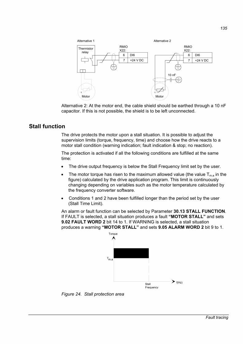
135
Fault tracing
Thermistor relay
MotorT
6 DI6
7 +24 V DC
RMIOX22:
Alternative 1
MotorT
6 DI6
7 +24 V DC
RMIOX22:
10 nF
Alternative 2
Alternative 2: At the motor end, the cable shield should be earthed through a 10 nF capacitor. If this is not possible, the shield is to be left unconnected.
Stall function The drive protects the motor upon a stall situation. It is possible to adjust the supervision limits (torque, frequency, time) and choose how the drive reacts to a motor stall condition (warning indication; fault indication & stop; no reaction).
The protection is activated if all the following conditions are fulfilled at the same time:
• The drive output frequency is below the Stall Frequency limit set by the user.
• The motor torque has risen to the maximum allowed value (the value Tm.a in the figure) calculated by the drive application program. This limit is continuously changing depending on variables such as the motor temperature calculated by the frequency converter software.
• Conditions 1 and 2 have been fulfilled longer than the period set by the user (Stall Time Limit).
An alarm or fault function can be selected by Parameter 30.13 STALL FUNCTION. If FAULT is selected, a stall situation produces a fault �MOTOR STALL� and sets 9.02 FAULT WORD 2 bit 14 to 1. If WARNING is selected, a stall situation produces a warning �MOTOR STALL� and sets 9.05 ALARM WORD 2 bit 9 to 1.
StallFrequency
Tm.a
Torque
f(Hz)
Stall region
Figure 24. Stall protection area

136
Fault tracing
The loss of motor load may indicate a process malfunction. The drive provides an Underload Function to protect the machinery and process in such a fault condition. The supervision limits (Underload Curve and Underload Time) can be chosen as well as the drive operation in an underload condition (warning indication; fault indication & stop; no reaction).
The protection is activated if all the following conditions are fulfilled at the same time:
• The motor load is below the Underload Curve selected by the user.
• The motor load has been below the selected Underload Curve longer than the time set by the user (Underload Time).
• The drive output frequency is more than 10% of the motor nominal frequency.
An alarm or fault function can be selected by Parameter 30.16 UNDERLOAD FUNC. If FAULT is selected, an underload situation produces a fault �UNDERLOAD� and sets 9.01 FAULT WORD 1 bit 8 to 1. If WARNING is selected, an underload situation produces a warning �UNDERLOAD� and sets 9.05 ALARM WORD 2 bit 1 to 1.
Motor phase loss function The Motor Phase Loss function monitors the status of the motor cable connections. The function is most useful during motor start. The drive detects if any of the motor phases have not been connected and refuses to start. The Phase Loss function also supervises the motor connection status during normal operation.
The user can define the operation upon motor phase loss. The alternatives are either a fault indication and Stop, or no reaction.
The fault indication is �MOTOR PHASE�. 9.02 FAULT WORD 2 bit 15 is simultaneously set to a 1.
The Earth Fault protection detects earth faults in the motor, the motor cable or the inverter. The Earth Fault protection is based on earth leakage current measurement with a summation current transformer at the input of the converter. Depending on the user�s selection, the Earth Fault function stops the drive and gives a fault indication, or the drive continues operation and gives an alarm.
A fault function can be selected by selecting FAULT at parameter 30.20 EARTH FAULT. In case of fault, �EARTH FAULT� is indicated and 9.01 FAULT WORD 1 bit 4 is set to 1. If NO is selected, an alarm �EARTH FAULT� is given and 9.04 ALARM WORD 1 bit 14 is set to 1.
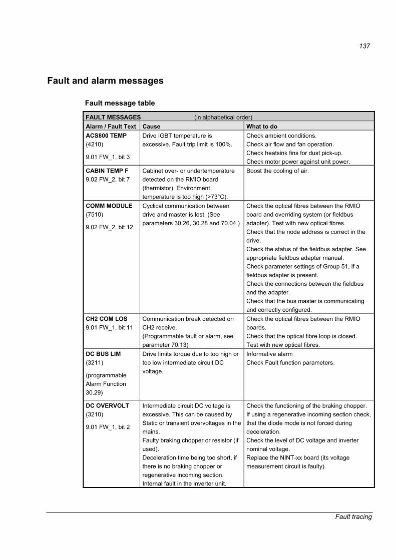
137
Fault tracing
Fault and alarm messages
Fault message table
FAULT MESSAGES (in alphabetical order) Alarm / Fault Text Cause What to do ACS800 TEMP (4210)
9.01 FW_1, bit 3
Drive IGBT temperature is excessive. Fault trip limit is 100%.
Check ambient conditions. Check air flow and fan operation. Check heatsink fins for dust pick-up. Check motor power against unit power.
CABIN TEMP F 9.02 FW_2, bit 7
Cabinet over- or undertemperature detected on the RMIO board (thermistor). Environment temperature is too high (>73°C).
Boost the cooling of air.
COMM MODULE (7510)
9.02 FW_2, bit 12
Cyclical communication between drive and master is lost. (See parameters 30.26, 30.28 and 70.04.)
Check the optical fibres between the RMIO board and overriding system (or fieldbus adapter). Test with new optical fibres. Check that the node address is correct in the drive. Check the status of the fieldbus adapter. See appropriate fieldbus adapter manual. Check parameter settings of Group 51, if a fieldbus adapter is present. Check the connections between the fieldbus and the adapter. Check that the bus master is communicating and correctly configured.
CH2 COM LOS 9.01 FW_1, bit 11
Communication break detected on CH2 receive. (Programmable fault or alarm, see parameter 70.13)
Check the optical fibres between the RMIO boards. Check that the optical fibre loop is closed. Test with new optical fibres.
DC BUS LIM (3211)
(programmable Alarm Function 30.29)
Drive limits torque due to too high or too low intermediate circuit DC voltage.
Informative alarm Check Fault function parameters.
DC OVERVOLT (3210)
9.01 FW_1, bit 2
Intermediate circuit DC voltage is excessive. This can be caused by Static or transient overvoltages in the mains. Faulty braking chopper or resistor (if used). Deceleration time being too short, if there is no braking chopper or regenerative incoming section. Internal fault in the inverter unit.
Check the functioning of the braking chopper. If using a regenerative incoming section check, that the diode mode is not forced during deceleration. Check the level of DC voltage and inverter nominal voltage. Replace the NINT-xx board (its voltage measurement circuit is faulty).
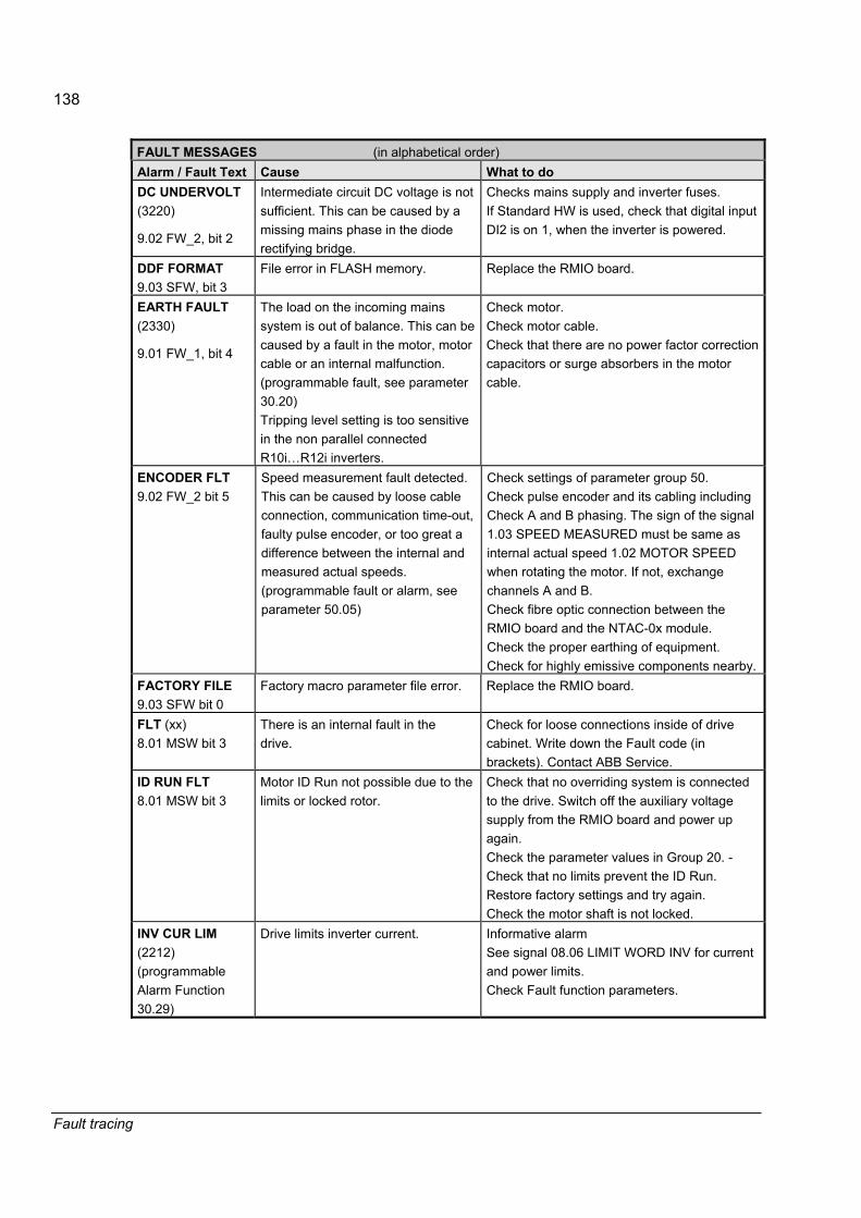
138
Fault tracing
FAULT MESSAGES (in alphabetical order) Alarm / Fault Text Cause What to do DC UNDERVOLT (3220)
9.02 FW_2, bit 2
Intermediate circuit DC voltage is not sufficient. This can be caused by a missing mains phase in the diode rectifying bridge.
Checks mains supply and inverter fuses. If Standard HW is used, check that digital input DI2 is on 1, when the inverter is powered.
DDF FORMAT 9.03 SFW, bit 3
File error in FLASH memory. Replace the RMIO board.
EARTH FAULT (2330)
9.01 FW_1, bit 4
The load on the incoming mains system is out of balance. This can be caused by a fault in the motor, motor cable or an internal malfunction. (programmable fault, see parameter 30.20) Tripping level setting is too sensitive in the non parallel connected R10i�R12i inverters.
Check motor. Check motor cable. Check that there are no power factor correction capacitors or surge absorbers in the motor cable.
ENCODER FLT 9.02 FW_2 bit 5
Speed measurement fault detected. This can be caused by loose cable connection, communication time-out, faulty pulse encoder, or too great a difference between the internal and measured actual speeds. (programmable fault or alarm, see parameter 50.05)
Check settings of parameter group 50. Check pulse encoder and its cabling including Check A and B phasing. The sign of the signal 1.03 SPEED MEASURED must be same as internal actual speed 1.02 MOTOR SPEED when rotating the motor. If not, exchange channels A and B. Check fibre optic connection between the RMIO board and the NTAC-0x module. Check the proper earthing of equipment. Check for highly emissive components nearby.
FACTORY FILE 9.03 SFW bit 0
Factory macro parameter file error. Replace the RMIO board.
FLT (xx) 8.01 MSW bit 3
There is an internal fault in the drive.
Check for loose connections inside of drive cabinet. Write down the Fault code (in brackets). Contact ABB Service.
ID RUN FLT 8.01 MSW bit 3
Motor ID Run not possible due to the limits or locked rotor.
Check that no overriding system is connected to the drive. Switch off the auxiliary voltage supply from the RMIO board and power up again. Check the parameter values in Group 20. -Check that no limits prevent the ID Run. Restore factory settings and try again. Check the motor shaft is not locked.
INV CUR LIM (2212) (programmable Alarm Function 30.29)
Drive limits inverter current. Informative alarm See signal 08.06 LIMIT WORD INV for current and power limits. Check Fault function parameters.
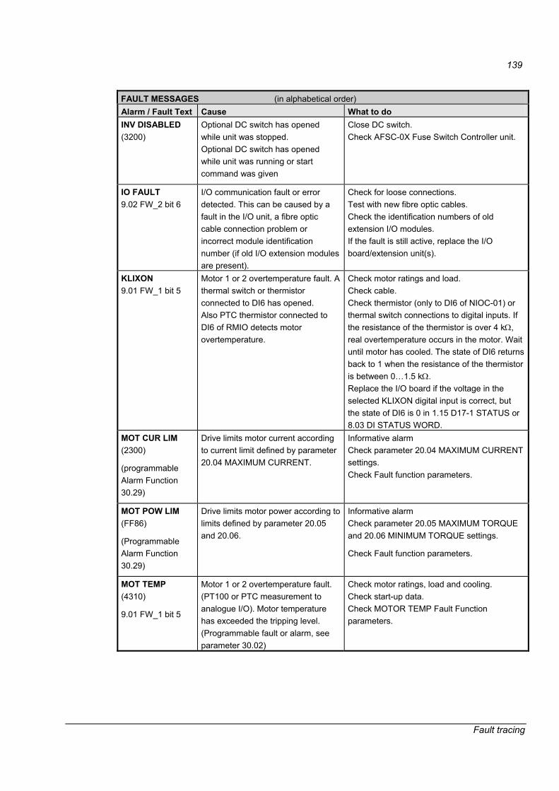
139
Fault tracing
FAULT MESSAGES (in alphabetical order) Alarm / Fault Text Cause What to do INV DISABLED (3200)
Optional DC switch has opened while unit was stopped. Optional DC switch has opened while unit was running or start command was given
Close DC switch. Check AFSC-0X Fuse Switch Controller unit.
IO FAULT 9.02 FW_2 bit 6
I/O communication fault or error detected. This can be caused by a fault in the I/O unit, a fibre optic cable connection problem or incorrect module identification number (if old I/O extension modules are present).
Check for loose connections. Test with new fibre optic cables. Check the identification numbers of old extension I/O modules. If the fault is still active, replace the I/O board/extension unit(s).
KLIXON 9.01 FW_1 bit 5
Motor 1 or 2 overtemperature fault. A thermal switch or thermistor connected to DI6 has opened. Also PTC thermistor connected to DI6 of RMIO detects motor overtemperature.
Check motor ratings and load. Check cable. Check thermistor (only to DI6 of NIOC-01) or thermal switch connections to digital inputs. If the resistance of the thermistor is over 4 kΩ, real overtemperature occurs in the motor. Wait until motor has cooled. The state of DI6 returns back to 1 when the resistance of the thermistor is between 0�1.5 kΩ. Replace the I/O board if the voltage in the selected KLIXON digital input is correct, but the state of DI6 is 0 in 1.15 D17-1 STATUS or 8.03 DI STATUS WORD.
MOT CUR LIM (2300)
(programmable Alarm Function 30.29)
Drive limits motor current according to current limit defined by parameter 20.04 MAXIMUM CURRENT.
Informative alarm Check parameter 20.04 MAXIMUM CURRENT settings. Check Fault function parameters.
MOT POW LIM (FF86)
(Programmable Alarm Function 30.29)
Drive limits motor power according to limits defined by parameter 20.05 and 20.06.
Informative alarm Check parameter 20.05 MAXIMUM TORQUE and 20.06 MINIMUM TORQUE settings.
Check Fault function parameters.
MOT TEMP (4310)
9.01 FW_1 bit 5
Motor 1 or 2 overtemperature fault. (PT100 or PTC measurement to analogue I/O). Motor temperature has exceeded the tripping level. (Programmable fault or alarm, see parameter 30.02)
Check motor ratings, load and cooling. Check start-up data. Check MOTOR TEMP Fault Function parameters.

140
Fault tracing
FAULT MESSAGES (in alphabetical order) Alarm / Fault Text Cause What to do MOT TORQ LIM (FF85)
(programmable Alarm Function 30.29)
Drive limits motor torque according to calculated motor pull-out torque limit and minimum and maximum torque limits defined by parameters 20.05 and 20.06.
Informative alarm Check parameter 20.05 MAXIMUM TORQUE and 20.06 MINIMUM TORQUE settings. Check Fault function parameters.
If LIMIT WORD 1 bit 0 TORQ MOTOR LIM is 1, - check motor parameter settings (parameter group 99 START-UP DATA) - ensure that ID run has been completed successfully.
Check setting of Fault function parameter 30.29.
MOTOR PHASE (FF56)
9.02 FW_2 bit 15
Fault in the motor circuit. One of the motor phases is lost. This can be caused by a fault in the motor, the motor cable, a thermal relay (if used), or an internal fault. (Programmable fault or alarm, see parameter 30.19).
Check motor and motor cable. If the motor is disconnected, this fault is activated. Check thermal relay (if used). Check MOTOR PHASE Fault Function parameters. Disable this protection. If the cable and motor is ok, this fault can appear with small motors (<30 kW) in low speed. Deactivate protection in this case.
MOTOR STALL (7121)
9.02 FW_2 bit 14
Motor or process stall. Motor is operating in the stall region. This can be caused by excessive load or insufficient motor power. (Programmable fault or alarm, see parameter 30.13)
Check motor load and the ACx800 ratings. Check MOTOR STALL Fault Function parameters (30.13�30.15).
MOTOR TEMP (4310)
9.01 FW_1 bit 6
Overtemperature fault (thermal model). Temperature has exceeded the tripping level of the thermal model. (Programmable fault or alarm, see parameter 30.02)
Check motor ratings, load and cooling. Check start-up data. Check MOTOR TEMP Fault Function parameters.
NVOS ERROR 9.03 SFW bit 2
Non-volatile operating system error. Replace the RMIO board.
OVER SWFREQ (FF55)
9.02 FW_2 bit 9
Over switching frequency fault. This may be due to a hardware fault in the electronics boards.
Replace the RMIO board. Replace the NINT board. On units with parallel connected inverters, replace the NPBU board.

141
Fault tracing
FAULT MESSAGES (in alphabetical order) Alarm / Fault Text Cause What to do OVERCURRENT (2310)
9.01 FW_1 bit 1
Overcurrent has been detected. If the drive tripped during flying start, check that parameter 21.01 START FUNCTION is set to AUTO. (Other modes do not support flying start). Check motor load. Check acceleration time. Check motor and motor cable (including phasing). Check the pulse encoder and pulse encoder cable. Check there are no power factor correction capacitors or surge absorbers in the motor cable. Check the nominal motor values from Group 99 to confirm that the motor model is correct.
OVERFREQ (7123)
9.01 FW_1 bit 9
Motor is turning faster than the highest allowed speed. This can be caused by an incorrect setting of parameters, insufficient braking torque or changes in the load when using torque reference.
Check the minimum and maximum speed settings. Check the adequacy of motor braking torque. Check the applicability of torque control. Check the need for a Braking Chopper and Braking Resistor if the drive has a Diode Supply Unit DSU. Check parameter 20.11 FREQ TRIP MARGIN.
PANEL LOST 9.02 FW_2 bit 13
A Local Control device (CDP 312R or DriveWindow) has ceased communicating. This can be caused by the disconnection of the selected local control device during local control or an internal fault in the local controlling device. (programmable fault or alarm, see parameter 30.21)
Check Control Panel connector. Replace Control Panel in the mounting platform. Check PANEL LOST Fault Function parameters.
PPCC LINK (5210)
9.02 FW_2 bit 11
Main circuit interface board current measurement or communication fault between the RMIO and Main circuit interface boards.
Check the fibre optic cables connected between the RMIO and Main circuit interface boards. In parallel connected inverters, also check the cabling on the NPBU-xx board. If the fault is still active, replace the NPBU board (only with parallel connected inverters), RMIO and NINT board (in this order) until the fault disappears. Test with new fibre optic cables in the PPCC link.
RUN DISABLD (FF54)
9.02 FW_2 bit 4
External interlocking (DI2=0) circuit is open. There is a fault in the external devices.
Check the circuit connected to digital input DI2.

142
Fault tracing
FAULT MESSAGES (in alphabetical order) Alarm / Fault Text Cause What to do SC (INU 1) 9.01 FW_1 bit 12
Short Circuit in (parallel connected) inverter unit 1
Short circuit detected in parallel connected inverter unit 1. Check the optic fibre connection from the NPBU-xx board channel CH1 (INT1) to the inverter. Check the motor and motor cable. Check all power plates in inverter unit 1. If a faulty power plate is detected, replace the whole phase module by another.
SC (INU 2) 9.01 FW_1 bit 13
Short Circuit in (parallel connected) inverter unit 2
Short circuit detected in the parallel connected inverter unit 2. Check the optic fibre connection from the NPBU-xx board channel CH2 (INT2) to the inverter. Check the motor and motor cable. Check all power plates in inverter unit 2. If a faulty power plate is detected, replace the whole phase module by another.
SC (INU 3) 9.01 FW_1 bit 14
Short Circuit in (parallel connected) inverter unit 3
Short circuit detected in the parallel connected inverter unit 3. Check the optic fibre connection from the NPBU-xx board channel CH3 (INT3) to the inverter. Check the motor and motor cable. Check all power plates in inverter unit 3. If a faulty power plate is detected, replace the whole phase module by another.
SC (INU 4) 9.01 FW_1 bit 15
Short Circuit in (parallel connected) inverter unit 4
Short circuit detected in the parallel connected inverter unit 4. Check the optic fibre connection from the NPBU-xx board channel CH4 (INT4) to the inverter. Check the motor and motor cable. Check all power plates in inverter unit 4. If a faulty power plate is detected, replace the whole phase module by another.
SHORT CIRC (2340)
9.01 FW_1 bit 0
Short circuit has been detected. The output current is excessive.
Check the motor and motor cable. Measure the resistances of the power plate(s). If a faulty power plate is detected, replace the power plate and the main circuit interface band NGDR boards or the whole inverter phase module. Check that the prevention of unexpected start-up circuit has not opened during the run.
SUPPLY PHASE (3130)
9.02 FW_2 bit 0
Ripple voltage in the DC link is too high. This can be caused by a missing mains phase in the diode rectifier bridge, or DC voltage oscillation by a thyristor rectifying bridge (if used in the incoming section).
Check for mains supply imbalance. Check the mains fuses.
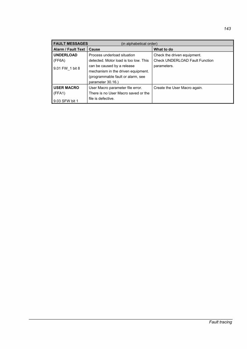
143
Fault tracing
FAULT MESSAGES (in alphabetical order) Alarm / Fault Text Cause What to do UNDERLOAD (FF6A)
9.01 FW_1 bit 8
Process underload situation detected. Motor load is too low. This can be caused by a release mechanism in the driven equipment. (programmable fault or alarm, see parameter 30.16.)
Check the driven equipment. Check UNDERLOAD Fault Function parameters.
USER MACRO (FFA1)
9.03 SFW bit 1
User Macro parameter file error. There is no User Macro saved or the file is defective.
Create the User Macro again.
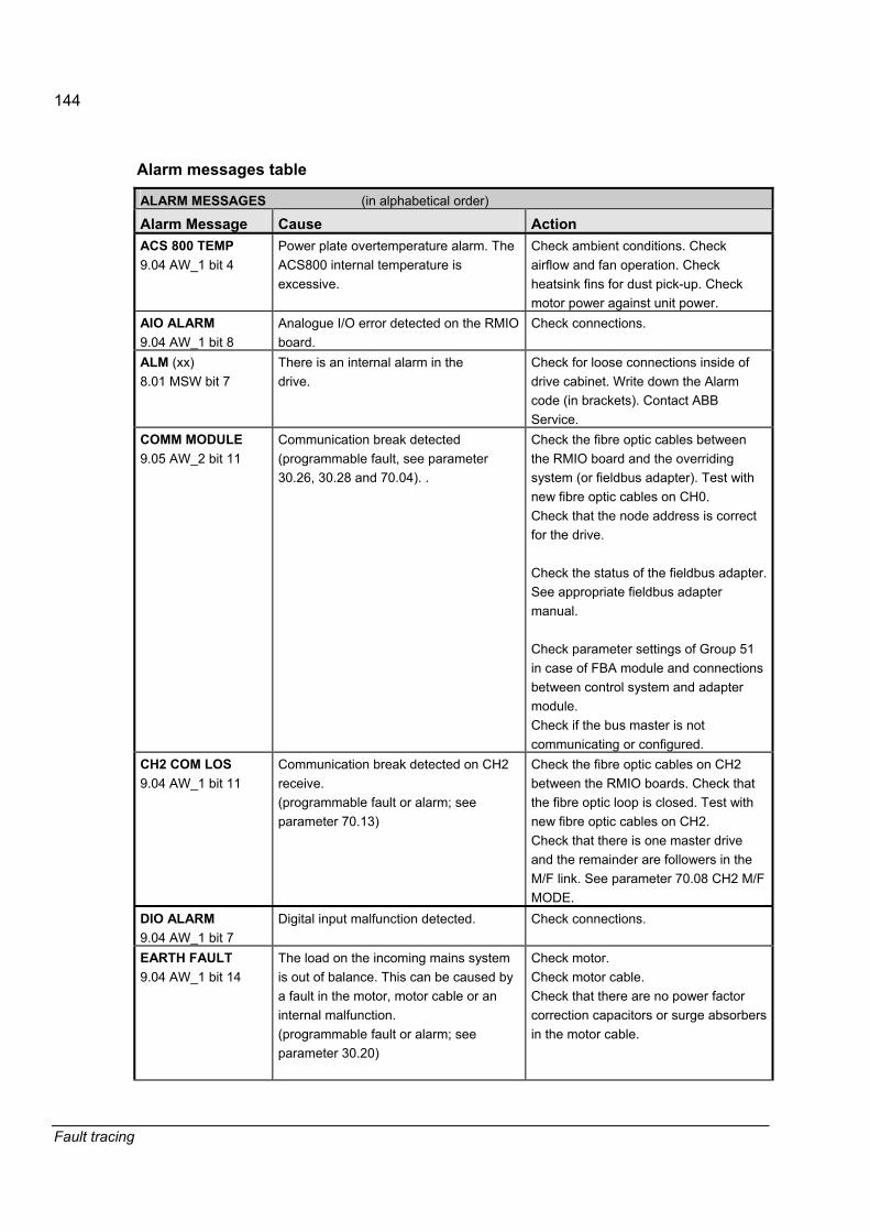
144
Fault tracing
Alarm messages table
ALARM MESSAGES (in alphabetical order)
Alarm Message Cause Action ACS 800 TEMP 9.04 AW_1 bit 4
Power plate overtemperature alarm. The ACS800 internal temperature is excessive.
Check ambient conditions. Check airflow and fan operation. Check heatsink fins for dust pick-up. Check motor power against unit power.
AIO ALARM 9.04 AW_1 bit 8
Analogue I/O error detected on the RMIO board.
Check connections.
ALM (xx) 8.01 MSW bit 7
There is an internal alarm in the drive.
Check for loose connections inside of drive cabinet. Write down the Alarm code (in brackets). Contact ABB Service.
COMM MODULE 9.05 AW_2 bit 11
Communication break detected (programmable fault, see parameter 30.26, 30.28 and 70.04). .
Check the fibre optic cables between the RMIO board and the overriding system (or fieldbus adapter). Test with new fibre optic cables on CH0. Check that the node address is correct for the drive. Check the status of the fieldbus adapter. See appropriate fieldbus adapter manual. Check parameter settings of Group 51 in case of FBA module and connections between control system and adapter module. Check if the bus master is not communicating or configured.
CH2 COM LOS 9.04 AW_1 bit 11
Communication break detected on CH2 receive. (programmable fault or alarm; see parameter 70.13)
Check the fibre optic cables on CH2 between the RMIO boards. Check that the fibre optic loop is closed. Test with new fibre optic cables on CH2. Check that there is one master drive and the remainder are followers in the M/F link. See parameter 70.08 CH2 M/F MODE.
DIO ALARM 9.04 AW_1 bit 7
Digital input malfunction detected. Check connections.
EARTH FAULT 9.04 AW_1 bit 14
The load on the incoming mains system is out of balance. This can be caused by a fault in the motor, motor cable or an internal malfunction. (programmable fault or alarm; see parameter 30.20)
Check motor. Check motor cable. Check that there are no power factor correction capacitors or surge absorbers in the motor cable.

145
Fault tracing
ALARM MESSAGES (in alphabetical order)
Alarm Message Cause Action EM STOP 9.04 AW_1 bit 1
Emergency Stop has been activated either by digital input DI7 (= 0) or MAIN CONTROL WORD 7.01 bit 2 (= 0).
Emergency stop push buttons must be returned to their normal position after the emergency stop situation is over. Check that the overriding system keeps sending the MAIN CONTROL WORD to drive. See bit 2 of MCW. To get drive to ready status, the MCW bit 0 must be set to state FALSE and back to TRUE.
ENCODER ERR 9.04 AW_1 bit 5
Speed measurement alarm detected. This can be caused by a loose cable connection or faulty pulse encoder. (programmable fault or alarm, see parameter 50.05)
Check settings of parameter group 50. Check the pulse encoder and its cabling (including CH A and CH B phasing). The sign of signal 1.03 SPEED MEASURED must be the same as internal actual speed 1.02 SPEED ESTIMATED. If it is not, reverse the channels A and B. Check fibre optic connection between the RMIO board and the NTAC-0x module. Check the proper earthing of equipment.Check for highly emissive components nearby.
EXT AIO ALM 9.04 AW_1 bit 10
Analogue I/O error detected in the Extension module.
If the alarm is continuously active, replace the module.
EXT DIO ALM 9.04 AW_1 bit 9
Digital I/O error detected in the Extension module.
If the alarm is continuously active, replace the module.
MOT TEMP 9.04 AW_1 bit 2
Motor 1 or 2 overtemperature alarm (PT100 or PTC measurement to Analogue I/O) (programmable fault or alarm; see parameter (30.01, 30.03...30.05)
Check motor ratings and load. Check start-up data. Check PT100 or thermistor connections for AI and AO of the RMIO board or extension module according to the hardware configuration.Check the DIP switches and selection of parameter 98.06 AIO EXT MODULE 1, if a NAIO-0x extension module is used for temperature measurement.
MOTOR STALL 9.05 AW_2 bit 9
Motor or process stall. Motor operating in the stall region. This can be caused by excessive load or insufficient motor power. (programmable fault or alarm; see parameter 30.13)
Check motor load and the ACx800 ratings. Check MOTOR STALL Fault Function parameters.
MOTOR STARTS Motor ID Run has been selected and the drive started in the Local control mode.
Wait until the Motor ID Run is complete.

146
Fault tracing
ALARM MESSAGES (in alphabetical order)
Alarm Message Cause Action MOTOR TEMP 9.04 AW_1 bit 3
Overtemperature alarm (thermal model). Temperature has exceeded the alarm level of the thermal model. (programmable fault or alarm; see parameter 30.02)
Check motor ratings, load and cooling. If USER MODE is selected, check that parameters 30.09�30.12 are set correctly.
NO MOTOR DATA 9.02 FW_2 bit 1
Motor data is not given or motor data does not match with inverter data.
Check the motor data given by parameters 99.02�99.06.
PANEL LOST 9.05 AW_2 bit 13
A Local Control device (CDP 312R or DriveWindow) has ceased communicating. This can be caused by the disconnection of the selected local control device during local control or an internal fault in the local controlling device. (programmable fault or alarm, see parameter 30.21)
Check Control Panel connector. Replace Control Panel in the mounting platform. Check PANEL LOST Fault Function parameters.
POWDOWN FILE 9.05 AW_2 bit 8
Error in restoring powerdown.ddf file If the alarm keeps reappearing, replace the RMIO board.
POWFAIL FILE 9.05 AW_2 bit 7
Error in restoring powerfail.ddf file. If the alarm keeps reappearing, replace the RMIO board.
START INHIBI 9.04 AW_1 bit 0
Prevention of unexpected Start-Up has been activated from the hardware typically by operator for equipment maintenance.
The Operator must close the prevention of unexpected start-up switch. If the switch is closed and the alarm is still active, check that the �Power On� LED is lit on the NGPS board. If the LED is off but there is a voltage at the input terminals of the NGPS, replace the board.
T MEAS ALM 9.04 AW_1 bit 6
Motor temperature measurement circuit is faulty. This can be caused by a broken temperature sensor or cable.
Check the motor temperature sensor connections.
UNDERLOAD 9.05 AW_2 bit 1
Process underload situation detected. Motor load is too low. This can be caused by a release mechanism in the driven equipment. (programmable fault or alarm; see parameter 30.16)
Check for a problem in the driven equipment. Check UNDERLOAD Fault Function parameters.

147
Fault tracing
Other messages
OTHER MESSAGES (in alphabetical order) Alarm Message Cause Action ID DONE Drive has performed the identification
magnetisation and is ready to start. -
ID MAGN Drive is performing identification magnetisation.
Please wait 20 to 60 seconds.
ID MAGN REQ Drive is ready to start identification magnetisation.
This warning belongs to the normal start-up procedure. Press PAR and check parameter 99.07.
ID N CHANGED Modbus ID number of the drive has been changed from 1 in Drive Selection Mode of CDP 312R panel (the change is not shown on the display).
To change the Modbus ID number back to 1, go to Drive Selection Mode by pressing DRIVE. Press ENTER. Set the ID number to 1. Press ENTER.
MACRO CHANGE A Macro is being restored or a user Macro is being saved.
Please wait.
NO COMMUNICATION Control Panel CDP 312R message. The selected drive is not present on the link. The link does not work because of a hardware malfunction or problem in the cabling.
Check the fibre optic cable connections in the I/O-link.
SWC ON INHIB 8.01 MSW bit 6
Drive is in the ON INHIBIT state. See ABB Drives communication profile description.
Set MAIN CONTROL WORD bit 0 first to 0, then back to 1 to proceed into the next state.

ABB Oy ABB Inc. ABB Beijing Drive Systems Co. Ltd. AC Drives Automation Technologies No. 1, Block D, A-10 Jiuxianqiao Beilu P.O. Box 184 Drives & Motors Chaoyang District FI-00381 HELSINKI 16250 West Glendale Drive Beijing, P.R. China, 100015 FINLAND New Berlin, WI 53151 Telephone +86 10 5821 7788 Telephone +358 10 22 11 USA Fax +86 10 5821 7618 Fax +358 10 22 22681 Telephone 262 785-3200 Internet http://www.abb.com Internet http://www.abb.com 800-HELP-365 Fax 262 780-5135
3AFE
6461
6340
RE
V D
/ E
N
EFF
EC
TIV
E: 0
8.05
.200
6
Related Documents