ACS 1000 User’s Manual, Rev. C 3BHS102769 1 (of 10) Table of Contents Chapter 1 - Safety Instructions General 1-1 Responsibilities 1-1 Safety Labels 1-2 Safety Concept 1-2 General Safety Regulations 1-3 Chapter 2 - Introduction Overview 2-1 Range of Application of the ACS 1000 2-1 Intended Audience for this Manual 2-2 What this Manual Contains 2-2 Chapter 3 - Design and Functional Description Overview 3-1 Fuseless Design 3-1 Control Equipment 3-1 Technical Specifications 3-1 Technical Data 3-1 Standards Fulfilled 3-1 Description of the ACS 1000 3-2 Functional Description 3-2 Power Circuit Interface 3-3 Input Circuit 3-3 Output Circuit 3-3 Control System 3-4 Direct Torque Control DTC 3-4 How does DTC Differ from PWM Flux Vector Drives? 3-5 Layout and Description of Assembly 3-5 Cabinet Design 3-5 Cabinet Sections 3-7 Door Locks 3-9 Lifting Arrangements 3-9 Cooling Circuit 3-9 Control and Monitoring Equipment 3-10 CDP 312 Control Panel 3-11

ABB ACS1000 User Manual
Nov 28, 2015
ABB systems
Welcome message from author
This document is posted to help you gain knowledge. Please leave a comment to let me know what you think about it! Share it to your friends and learn new things together.
Transcript

Table of Contents
Chapter 1 - Safety Instructions
General 1-1Responsibilities 1-1Safety Labels 1-2Safety Concept 1-2General Safety Regulations 1-3
Chapter 2 - Introduction
Overview 2-1Range of Application of the ACS 1000 2-1Intended Audience for this Manual 2-2What this Manual Contains 2-2
Chapter 3 - Design and Functional Description
Overview 3-1Fuseless Design 3-1Control Equipment 3-1
Technical Specifications 3-1Technical Data 3-1Standards Fulfilled 3-1
Description of the ACS 1000 3-2Functional Description 3-2Power Circuit Interface 3-3
Input Circuit 3-3Output Circuit 3-3
Control System 3-4Direct Torque Control DTC 3-4How does DTC Differ from PWM Flux Vector Drives? 3-5
Layout and Description of Assembly 3-5Cabinet Design 3-5Cabinet Sections 3-7
Door Locks 3-9Lifting Arrangements 3-9
Cooling Circuit 3-9Control and Monitoring Equipment 3-10
CDP 312 Control Panel 3-11
ACS 1000 User’s Manual, Rev. C 3BHS102769 1 (of 10)

Standard Control and Monitoring Functions 3-12General 3-12Motor Control Features 3-12
Motor ID Run 3-12Filter ID Run 3-13Full Torque at Zero Speed 3-13Enhanced Flying Start 3-13Flux Optimization 3-13Power Loss Ride-Through 3-13Acceleration and Deceleration Ramps 3-14Critical Speed 3-15Resonance Frequency Damping (RFD) 3-15Constant Speeds 3-15Speed Controller Tuning 3-16Accurate Speed Control 3-17Accurate Torque Control without Speed Feedback 3-17
Drive System Features 3-18Main Circuit Breaker (MCB) Control 3-18
Local and Remote Control 3-19Local Control 3-19Remote Control 3-19
Diagnostics 3-20Actual Signal Monitoring 3-20Fault History 3-20
Programmable Digital Outputs 3-20Programmable Analog Outputs 3-20Input Signal Source Selections and Signal Processing 3-21
Two Programmable Control Locations 3-21Reference Signal Processing 3-21Analog Input Processing 3-22Offset Calibration 3-22
Standard Protection Functions 3-23Programmable Fault Functions 3-23
Motor Winding Temperature 3-23Motor Stall 3-23Underload 3-24Overspeed 3-24Undervoltage 3-24
Preprogrammed Protection Functions 3-25Motor Phase Loss 3-25Short Circuit in the Rectifier Bridge 3-25Charging Fault 3-25Supply Phase Loss 3-25Overcurrent 3-25Loadability of the Inverter 3-25Short Circuit of the Inverter 3-26Ground Fault 3-26
2 (of 10) 3BHS102769 ACS 1000 User’s Manual, Rev. C

Operating System 3-26Measurement Loss 3-26Battery Test 3-26Communication Fault 3-26ID-Run Fault 3-26
Other Protection Functions 3-27External Motor Protection Trip 3-27External Transformer Protection Trip 3-27Process Stop 3-27External Emergency Off 3-27MCB Control Fault 3-27
Other Features 3-27Limits 3-27Automatic Reset 3-28Supervision 3-28ACS 1000 Information 3-28Parameter Lock 3-28Built-in PID Controller 3-29Resonance Frequency Damping (RFD) 3-29
Customer Specific Options 3-29PC Tools 3-29
DriveWindow 3-29DriveLink 3-29DriveSupport 3-30
Chapter 4 - I/O Interfaces and Application Macros
Overview 4-1Terms and Abbreviations 4-1Input/Output Boards 4-1
Standard I/O Boards 4-1I/O Ratings 4-2Control Voltage Output 4-2Potentiometer Supply 4-3Digital Output Home Position 4-3External Connections 4-3Location of IOEC Boards 4-3Pre-defined I/O Signals 4-5
Application Macros 4-11Overview 4-11Macro Applications 4-11
Factory 4-11Speed Control 4-11Hand/Auto 4-12PID Control 4-12Torque Control 4-12
ACS 1000 User’s Manual, Rev. C 3BHS102769 3 (of 10)
Sequential Control 4-12Master/Follower 4-12User 1/User 2 4-12
Factory Macro 4-13Description 4-13Control Overview 4-13Input and Output Signals 4-14Control Signal Diagram 4-15
Hand/Auto Macro 4-17Description 4-17Control Overview 4-17Input and Output Signals 4-18Control Signal Logic 4-19
PID Macro 4-21Description 4-21Control Overview 4-21Input and Output Signals 4-22Control Signal Diagram 4-23
Torque Macro 4-25Description 4-25Control Overview 4-25Input and Output Signals 4-26Control Signal Diagram 4-27
Sequential Control Macro 4-29Description 4-29Control Overview 4-29Input and Output Signals 4-30Control Signal Diagram 4-31
Master/Follower Macro 4-33Description 4-33Control Overview 4-34Input and Output Signals 4-35
Chapter 5 - Operation
Safety Instructions 5-1Introduction 5-1
Conventions 5-1Start Operation of the ACS 1000 5-2Preparatory Procedures 5-2
Prerequisites 5-2Preparatory Steps 5-3Closing Main Circuit Breaker 5-4Charging the Capacitor Bank 5-5
Entering Setpoint and Starting Up the ACS 1000 5-6In Local Control Mode 5-6
4 (of 10) 3BHS102769 ACS 1000 User’s Manual, Rev. C

In Remote Control Mode 5-7Changing Setpoints 5-7
In Local Control Mode 5-7In Remote Control Mode 5-8
Reverse Sense of Rotation 5-8In Local Control Mode 5-8In Remote Control Mode 5-9
Local / Remote Selection 5-9Local Control 5-9Remote Control 5-9
Changing Control Mode during Operation 5-9Remote -> Local Control 5-10Local -> Remote Control 5-10
Disabling Local Operation from CDP 312 Control Panel 5-10Stopping the ACS 1000 5-11
In Local Control Mode 5-11In Remote Control Mode 5-11
De-energizing the ACS 1000 5-12In Local Control Mode 5-12In Remote Control Mode 5-14
Emergency Stop 5-14Manual Initiation 5-14
Process Monitoring 5-14Actual Signal Display 5-15
Full Signal Name Display 5-17Active Fault Display 5-17Fault History Display 5-18
Other Operational Actions 5-19Panel and Display Functions 5-19
Chapter 6 - Parameter Viewing and Editing
Overview 6-1Safety Instructions 6-1ACS 1000 Application Parameters 6-1
Parameter Groups 6-1Start-up Parameters 6-2
Application Macros 6-2Application Parameter Editing: Overview 6-2Parameter Editing with the CDP 312 Control Panel 6-6
General 6-6Conventions 6-6Prerequisites 6-7Selection of Actual Signals 6-7Start-Up Parameters 6-7Selection or Verification of Application Macro 6-11
ACS 1000 User’s Manual, Rev. C 3BHS102769 5 (of 10)
Selection of Motor Control Features 6-13Verification and Modification of Parameters 6-14Motor Identification Run 6-15
Miscellaneous Functions 6-16ACS 1000 Information 6-16Parameter Lock 6-16Uploading Parameters 6-16Downloading Parameters 6-17Copying Parameters to Other Units 6-19Restoring Default Settings 6-19User Macros 6-20
Creating a User Macro 6-21Recalling User Macro Parameters 6-22
Chapter 7 - Preventive Maintenance
Introduction 7-1Safety Instructions 7-1Maintenance Schedule 7-3Required Tools 7-4Maintenance Instructions 7-4
Standard Procedure for Maintenance 7-4 Outside Cleaning 7-7Inside Floor Cleaning 7-7Check of Connections 7-7Replacement of Air Filters 7-8
Inverter Door Air Inlet 7-8Control Door Air Inlet 7-8
Replacement of Fan 7-8Replacement of Fan Bearings 7-10Replacement of Batteries 7-11Parameter Backup 7-11Inspection of Motor, Transformer and MCB 7-12
Maintenance Logbook 7-12ABB Service Address 7-12
Chapter 8 - Trouble Shooting & Repair
Overview 8-1Safety Instructions 8-1Alarm and Fault Handling 8-2
Fault Display on the CDP 312 Control Panel 8-3Active Fault Display 8-3Fault History Display 8-4
Standard
6 (of 10) 3BHS102769 ACS 1000 User’s Manual, Rev. C
Procedure for Trouble-Shooting 8-5Repair Work 8-7Error Messages and Fault Elimination 8-7
Chapter 9 - Transportation, Storage, Disposal and Recycling
Introduction 9-1Environmental Requirements 9-1
Storage 9-1Transportation 9-1Stationary Use 9-1
Packing 9-1Loading and Unloading 9-3
Lifting Angle 9-4Center of Gravity 9-4
Unpacking 9-4Transportation Damages 9-6
Storage 9-6Storage Conditions 9-6Periodical Inspections 9-7Battery 9-7
Storage Instructions for Spare Parts 9-7Transportation 9-7Ambient Conditions 9-7
Humidity 9-7Temperature 9-7
Handling Instructions for Spare Parts 9-8Temporary Shut Down 9-9Disposal of Packing Material 9-9
Packing Material 9-9Disassembly and Disposal of Equipment 9-9
Chapter 10 - Installation
Overview 10-1Safety Instructions 10-1Requirements to Foundation, Space and Ambient Conditions 10-2
Ambient Conditions 10-2Base Dimensions and Clearances 10-2Floor Levelling and Cable Ducts 10-3
Selection and Dimensioning of Power Equipment 10-3Main Circuit Breaker / Controller 10-3Instrumentation and Protection Equipment 10-5Transformer Primary Cable 10-6Transformer 10-6
ACS 1000 User’s Manual, Rev. C 3BHS102769 7 (of 10)

Transformer Secondary Cable 10-6Motor Cable 10-7Power Cable Dimensions 10-8
Comments: 10-8 Installation Conditions 10-9
Equipment Grounding 10-9Auxiliary Power Cable 10-9Control Cables 10-9Cable Routing 10-10
Power Cables 10-10Cable Termination 10-10Cable Length 10-10Grounding Wire 10-10Control Cables 10-10
Mains and Motor Cable Connection Diagrams 10-10Mechanical Installation 10-12
Required Tools and Parts 10-12Preparation of Mounting Site 10-12Displacement to Installation Site 10-13Mounting the Cabinet 10-13
Electrical Installation 10-16Mains and Motor Cable Lead-In 10-16Inserting Mains and Motor Cables 10-18
Grounding Connections 10-21Insulation Checks 10-21Mains and Motor Cable Connections 10-22Auxiliary Power Cable Connection 10-23Control Cable Connection 10-25
Wiring Tests 10-28Final Work 10-28
Preparation for commissioning 10-28
Chapter 11 - Commissioning
Overview 11-1Preparation of Commissioning 11-1
General Preconditions 11-1High Voltage Equipment 11-1Auxiliary Voltage Supply and Control 11-1Cooling Circuit 11-1Miscellaneous 11-2
Commissioning Procedure 11-2Required Customer Manpower 11-2Acceptance 11-2Warranty 11-2
8 (of 10) 3BHS102769 ACS 1000 User’s Manual, Rev. C
Appendix A - Technical Data
Appendix B - The CDP 312 Control Panel
Overview B-1ACS 1000 Parameter Programming B-1
Application Macros B-1Parameter Groups B-1Start-up Data Parameters B-1
Control Panel B-1Display B-2Keys B-2
Panel operation B-4Keypad Modes B-4Identification Display B-4Actual Signal Display Mode B-4
Actual Signal Display B-5Parameter Mode B-8Function Mode B-9Copying parameters from one unit to other units B-12Setting the contrast B-13Drive Selection Mode B-13
Operational Commands B-13Local Control B-13Remote Control B-14Changing Control Location B-14Start, Stop, Direction and Reference B-14
Appendix C - Customer Specific Options
Appendix D - Quality Assurance
Introduction to ABB’s QA System D-1ISO 9001 D-1ISO 14000 D-1
Appendix E - Applicable Codes and Standards
Appendix F - Layout and Mechanical Drawings
Appendix G - Wiring Diagrams
ACS 1000 User’s Manual, Rev. C 3BHS102769 9 (of 10)

Appendix H - Part List
Appendix I - Recommended Spare Parts ListAppendix J - Dummy
Appendix K - Signal and Parameter Table
Appendix L - Inspection and Commissioning Record
Appendix M - Parameter Setting List
Index
10 (of 10) 3BHS102769 ACS 1000 User’s Manual, Rev. C

Chapter 1 - Safety Instructions
General The ACS 1000 is a high voltage device and when misused it can cause damage to personnel and property. When located, installed and connected in accordance with the instructions given in this Manual, the device is safe.
Personnel involved in installation, commissioning and maintenance work on the ACS 1000 must be electrical professionals who are fully acquainted with medium voltage (MV) equipment.
Operating the drive does not require special knowledge of frequency converters. However, the user must understand the meaning of the messages on the control panel of the converter. If an alarm or a trip is registered by the converter control, the operator must be able to decide whether to shut down the converter for troubleshooting or repair or to reset the fault message and restart the drive.
This chapter includes the safety instructions that must be complied with when installing, operating and servicing the ACS 1000. If neglected, phys-ical injury and death may follow, or damage may occur to the frequency converter, the motor and the driven equipment. The contents of this chapter must therefore be studied before attempting any work on, or with the unit.
Responsibilities It is the owners responsibility to insure that each person involved in the installation, commissioning, operation or maintenance of the ACS 1000 has received the appropriate training or instructions and has thoroughly read and clearly understood the safety instructions in this chapter.
When installing the frequency converter as well as during commissioning and maintenance, all personnel involved must observe the relevant general safety regulations and standards for electrical works in medium and low voltage equipment which are in force at the place of installation. Furthermore personnel must make strict compliance with the instructions given in this manual.
ABB Industrie AG declines all liability for any possible damage resulting from failure or negligence to observe this warning.
ACS 1000 User’s Manual, Rev. C 3BHS102769 1-1 (of 6)

Chapter 1 - Safety Instructions
Safety Labels Several levels of safety instructions and notes are used in this manual to highlight a potentially dangerous situation. They are marked with one of the following labels:
Danger: This symbol indicates an imminent danger resulting from me-chanical forces. A non-observance may lead to life-threatening physical injury or death.
Danger: This symbol indicates an imminent danger resulting from high voltage. A non-observance may lead to life-threatening physical injury or death.
Warning/Caution: This symbol indicates a dangerous situation. A non-observance may lead to physical injury or cause serious damage to the converter.
Note: This symbol emphasizes important information. A non-observance may cause damage to the converter.
Safety Concept The design and the specific safety devices of the ACS 1000 allow safe installation, commissioning, operation and maintenance of the equipment when used as intended. The ACS 1000 is equipped with the following safety features (see Figure 1-1):
• Safety grounding isolator for intermediate DC-circuit
• Electromechanic interlocking system; the safety grounding isolator cannot be closed until the main circuit breaker is open and the DC-cir-cuit is completely discharged.
• Door interlocking system preventing access to live equipment. When the drive is energized, access is possible only to the control equipment.
• Control functions to prevent from dangerous operating conditions
• Full converter protection
• Inputs for external protection devices from transformer, motor and pro-cess control
Although the ACS 1000 is safe if all interlocks and safety precautions are operating, some residual danger areas remain if safety instructions are not observed.
1-2 (of 6) 3BHS102769 ACS 1000 User’s Manual, Rev. C

Chapter 1 - Safety Instructions
The ACS 1000 is operating in a medium voltage environment usually consisting (besides the converter) of a power transformer, a motor, cabling, the driven process and a superimposed control system. The safety concept for the ACS 1000 takes into account the embedding of these components in the sense that no additional threat arises from their interaction with the ACS 1000. However, the safety considerations for the individual external components and for the overall process are not part of the ACS 1000 safety concept.
Figure 1-1 Residual danger areas of the ACS 1000
General Safety Regulations
The safety instructions in this chapter generally apply when working on the ACS 1000. You will find additional instructions and warnings related to particular topics or actions throughout the manual where relevant.
The following regulations must be strictly observed:
• Intended purpose of useThe technical specifications (see Appendix A - Technical Data) and the intended purpose of use (see Chapter 2 - Introduction) must be strictly adhered to.
Never remove rear cover when converter is energized
Fan is coasting down after shut-down
Keep air intake free from dirt and obstacles
Do not attempt to open doors by force when drive is ener-gized or before grounding isolator is
Even after pressing EMERGENCY STOP the converter will not be voltage-free immediately. Discharging will take
converter doors earlier
Danger from auxiliary voltage when frontdoor is open
Control section:
or before groundingisolator is closed
closed
about 5 minutes. Do not attemptto close the grounding isolator by force or to open the
ACS 1000 User’s Manual, Rev. C 3BHS102769 1-3 (of 6)

Chapter 1 - Safety Instructions
• Training of personnelOnly well trained personnel are allowed to install, operate, maintain or service the ACS 1000. This personnel must be specially instructed about the dangers that can be caused by this equipment.
• Improper behaviorWorking in a way that could cause dangers to persons or the ACS 1000 is strictly prohibited.
• Access for untrained and Unauthorized PersonnelThe owner is responsible for making sure that untrained personnel do not have access to the ACS 1000 frequency converter and cannot op-erate the ACS 1000 and adjoining equipment.
• Modifications without authorityModifications and constructional changes in the ACS 1000 are not al-lowed. Always contact ABB Industrie AG.
• Duty of maintenanceThe owner must ensure that the ACS 1000 is used only under proper conditions and in a fully serviceable state.
• Operating environmentThe owner must guarantee that all ambient conditions specified in Ap-pendix A - Technical Data are fulfilled.
Warning: All electrical installation and maintenance work on the ACS 1000 must be carried out by qualified electricians.
Danger: Never work on a powered ACS 1000. The main circuit breaker and the input isolators must always be opened and locked in “OPEN” po-sition. Do not access the main power circuit nor the motor as long as the system is not grounded.
When switching off the mains, always allow the intermediate circuit capac-itors to discharge before grounding and starting work on the frequency converter, the motor or the motor cable.
The ACS 1000 and adjoining equipment must be properly grounded and the auxiliary supply voltage must be switched off prior to starting with any work.
Danger: Some loads may apply a mechanical torque on the motor shaft! If the motor can rotate due to such a load, always disconnect, short-circuit or mechanically block the motor before you start work.
1-4 (of 6) 3BHS102769 ACS 1000 User’s Manual, Rev. C

Chapter 1 - Safety Instructions
Danger: There can be dangerous voltages inside the ACS 1000 from ex-ternal control circuits (measurement inputs from PT’s etc.) even if the ACS 1000 mains power and auxiliary power are shut off. Take appropriate measures when working with the unit, i.e deenergize and disconnect all such external devices (auxiliary supply, heaters, coolers, I/O-interfaces) before you start work.
Danger: This converter can influence the working of heart pacemakers. Install a corresponding warning sign at the entrance to the converter room. In case the ACS 1000 is located in an open hall, the safety sign must be at a minimum distance of 6 meters / 20 feet to the converter!
ACS 1000 User’s Manual, Rev. C 3BHS102769 1-5 (of 6)

Chapter 1 - Safety Instructions
1-6 (of 6) 3BHS102769 ACS 1000 User’s Manual, Rev. C
Chapter 2 - Introduction
Overview This manual provides you with detailed information on the installation and start-up of the ACS 1000 frequency converter, including detailed descrip-tions of the functions, installation and start-up of the unit. Fault tracing information, technical data and dimensional drawings are included as well.
Range of Application of the ACS 1000
The ACS 1000 is a standard, medium-voltage AC drive, rated according to the technical specifications in Appendix A - Technical Data.
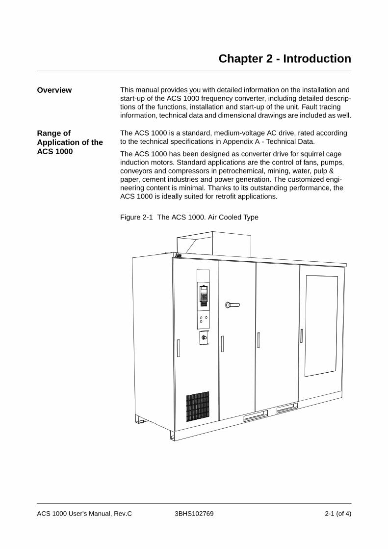
The ACS 1000 has been designed as converter drive for squirrel cage induction motors. Standard applications are the control of fans, pumps, conveyors and compressors in petrochemical, mining, water, pulp & paper, cement industries and power generation. The customized engi-neering content is minimal. Thanks to its outstanding performance, the ACS 1000 is ideally suited for retrofit applications.
Figure 2-1 The ACS 1000. Air Cooled Type
ACS 1000 User’s Manual, Rev.C 3BHS102769 2-1 (of 4)
Chapter 2 - Introduction
Intended Audience for this Manual
This manual is intended for electrical field professionals who are respon-sible for installing, commissioning and servicing the ACS 1000 frequency converter.
The audience is expected to have:
• professional education in electrical installation
• knowledge of physical and electrical fundamentals, electrical wiring practices for medium voltage (MV) and low voltage (LV) equipment, electrical components and electrical schematic symbols
• full knowledge of safety aspects (national standards and regulations, hazard prevention) related to work in medium voltage (MV) installa-tions.
On the other hand the audience is not expected to have:
• prior experience of ABB products
• prior experience of frequency converters
• prior experience of the ACS 1000 product family
• prior experience or training of installing, commissioning, operating and servicing the ACS 1000.
What this Manual Contains
Chapter 1 - Safety Instructions: In this chapter, which is placed at the beginning of the manual, the various safety instruction levels used in this manual are explained. This chapter also provides general instructions on safety which must be respected during all work on the ACS 1000.
Chapter 3 - Design and Functional Description contains a short technical overview of the ACS 1000 and a short description of its features and control functions.
Chapter 4 - I/O Interfaces and Application Macros describes standard I/O, control configuration using application macros (Factory, Hand/Auto, PID Control, Torque Control, Sequential Control, Master/Follower) together with the macro-specific I/O and indicates typical applications for each macro.
Chapter 5 - Operation describes safety considerations, preconditions for energizing and operation of the ACS 1000. Furthermore, remote and local control, starting and stopping, changing setpoints, monitoring of actual process values, de-energizing the ACS 1000 and the emergency stop function are described.
Chapter 6 - Parameter Viewing and Editing describes how to view and modify start-up data, how to select application macros and edit other parameters using the CDP 312 control panel. Some ancillary parameter and macro editing features are described as well.
Chapter 7 - Preventive Maintenance includes the maintenance schedule and specific descriptions of all preventive maintenance procedures.
Chapter 8 - Trouble Shooting & Repair explains what to do upon an alarm message and how to proceed in case of an alarm or a converter trip. A list
2-2 (of 4) 3BHS102769 ACS 1000 User’s Manual, Rev. C
Chapter 2 - Introduction
of fault codes and messages on the CDP 312 control panel as well as explanations of all alarm messages and trip functions is included. The procedure for restarting the converter is described.
Chapter 9 - Transportation, Storage, Disposal and Recycling provides information about environmental conditions to be maintained during trans-portation and storage, together with instructions for packing, unpacking, lifting and moving . It includes special requirements for storage and conservation together with instructions for periodical inspections. In addi-tion, information on disposal and recycling of material as well as on tempo-rary shut-down and decommissioning of the ACS 1000 is given.
Chapter 10 - Installation specifies the mechanical and electrical require-ments to the foundation, cabling and other equipment, gives instructions for mounting (drawings and descriptions), cable routing and termination for power, auxiliary and signal connections (incl. EMC requirements).
Chapter 11 - Commissioning includes an installation checklist and and preconditions for commissioning. In addition, the various commisioning steps are described.
Appendix A - Technical Data lists the ACS 1000 technical specifications.
Appendix B - The CDP 312 Control Panel explains all panel push-buttons and all panel functions.
Appendix C - Customer Specific Options is a documentation of all customer specific options including descriptions and drawings.
Appendix D - Quality Assurance gives you an introduction to ABB’s QA system, introduces you to ISO 9001 and ISO 14000 and contains the declaration of CE conformity and the UL/CSA approval.
Appendix E - Applicable Codes and Standards is a list of all applicable codes and standards for the ACS 1000.
Appendix F - Layout and Mechanical Drawings is a collection of mechan-ical outline drawings showing all relevant information for floor mounting, cable entries, water flanges etc.
Appendix G - Wiring Diagrams is a collection of electrical schematics and terminal diagrams.
Appendix H - Part List is a list of all major components including the parts in the repair tool kit.
Appendix I - Recommended Spare Parts List is a converter specific list of recommended spare parts. Those parts, which have to be exchanged as part of the regular maintenance program, are listed as well.
Appendix K - Signal and Parameter Table includes a complete description of all control parameters.
Appendix L - Inspection and Commissioning Record contains all records from factory testing. Commissioning test records and a provisional accep-tance certificate shall also be included in this Appendix.
Appendix M - Parameter Setting List is a customer specific parameter list
ACS 1000 User’s Manual, Rev. C 3BHS102769 2-3 (of 4)

Chapter 2 - Introduction
with all parameter settings after commissioning.
The Index contains an alphabetical list of topics treated in this manual with reference to the corresponding page numbers.
2-4 (of 4) 3BHS102769 ACS 1000 User’s Manual, Rev. C
Chapter 3 - Design and Functional Description
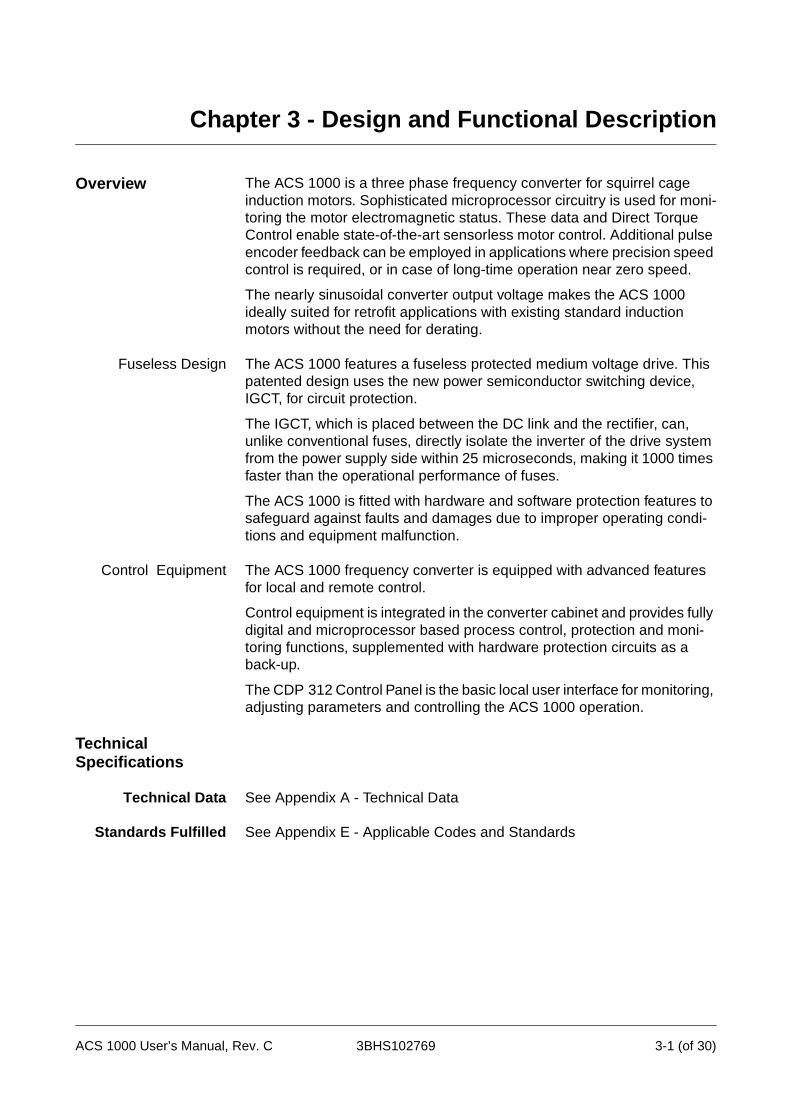
Overview The ACS 1000 is a three phase frequency converter for squirrel cage induction motors. Sophisticated microprocessor circuitry is used for moni-toring the motor electromagnetic status. These data and Direct Torque Control enable state-of-the-art sensorless motor control. Additional pulse encoder feedback can be employed in applications where precision speed control is required, or in case of long-time operation near zero speed.
The nearly sinusoidal converter output voltage makes the ACS 1000 ideally suited for retrofit applications with existing standard induction motors without the need for derating.
Fuseless Design The ACS 1000 features a fuseless protected medium voltage drive. This patented design uses the new power semiconductor switching device, IGCT, for circuit protection.
The IGCT, which is placed between the DC link and the rectifier, can, unlike conventional fuses, directly isolate the inverter of the drive system from the power supply side within 25 microseconds, making it 1000 times faster than the operational performance of fuses.
The ACS 1000 is fitted with hardware and software protection features to safeguard against faults and damages due to improper operating condi-tions and equipment malfunction.
Control Equipment The ACS 1000 frequency converter is equipped with advanced features for local and remote control.
Control equipment is integrated in the converter cabinet and provides fully digital and microprocessor based process control, protection and moni-toring functions, supplemented with hardware protection circuits as a back-up.
The CDP 312 Control Panel is the basic local user interface for monitoring, adjusting parameters and controlling the ACS 1000 operation.
Technical Specifications
Technical Data See Appendix A - Technical Data
Standards Fulfilled See Appendix E - Applicable Codes and Standards
ACS 1000 User’s Manual, Rev. C 3BHS102769 3-1 (of 30)

Chapter 3 - Design and Functional Description
Description of the ACS 1000
FunctionalDescription
The 3-phase AC line voltage is supplied to the rectifier bridges through the 3-winding converter transformer (see Figure 3-1). In order to obtain 12 pulse rectification, a 30° phase shift is necessary between the two secondary windings of the transformer. Therefore one secondary is wye-connected while the other is delta-connected.
The two fuseless rectifier bridges are connected in series, such that the DC-voltages are added up. Therefore, the full DC-bus current flows through both bridges.
Figure 3-1 Elementary diagram - ACS 1000
Each leg of the 3-phase inverter bridge consists of a combination of 2 IGCT’s for 3-level switching operation: with the IGCT’s the output is switched between positive DC voltage, neutral point (NP) and negative DC voltage. Hence both the output voltage and the frequency can be controlled continuously from zero to maximum, using Direct Torque Control.
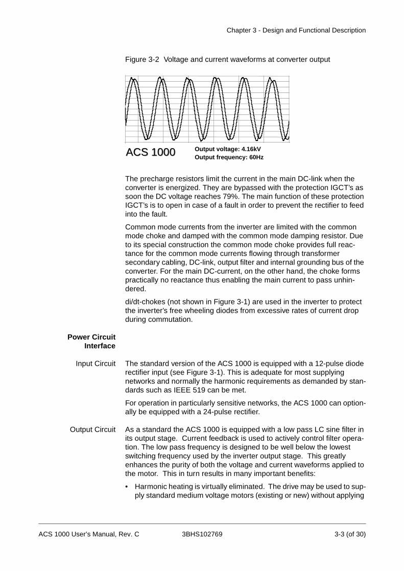
At the converter output a LC filter is used for reducing the harmonic content of the output voltage. With this filter, the voltage waveform applied to the motor is nearly sinusoidal (see Figure 3-2). Therefore, standard motors can be used at their nominal ratings. The filter also eliminates all high dv/dt effects and thus voltage reflections in the motor cables and stresses to the motor insulation are totally eliminated.
Converter InputTransformer
DiodeRectifier
IntermediateDC-Link
Three LevelInverter
Output Sine Filter
Squirrel CageInduction Motor
NP M
ProtectionIGCTs
3
Medium VoltageSwitchgear
ACS1000 Frequency Converter
Main CircuitBreaker
3-2 (of 30) 3BHS102769 ACS 1000 User’s Manual, Rev. C
Chapter 3 - Design and Functional Description
Figure 3-2 Voltage and current waveforms at converter output
The precharge resistors limit the current in the main DC-link when the converter is energized. They are bypassed with the protection IGCT’s as soon the DC voltage reaches 79%. The main function of these protection IGCT’s is to open in case of a fault in order to prevent the rectifier to feed into the fault.
Common mode currents from the inverter are limited with the common mode choke and damped with the common mode damping resistor. Due to its special construction the common mode choke provides full reac-tance for the common mode currents flowing through transformer secondary cabling, DC-link, output filter and internal grounding bus of the converter. For the main DC-current, on the other hand, the choke forms practically no reactance thus enabling the main current to pass unhin-dered.
di/dt-chokes (not shown in Figure 3-1) are used in the inverter to protect the inverter’s free wheeling diodes from excessive rates of current drop during commutation.
Power CircuitInterface
Input Circuit The standard version of the ACS 1000 is equipped with a 12-pulse diode rectifier input (see Figure 3-1). This is adequate for most supplying networks and normally the harmonic requirements as demanded by stan-dards such as IEEE 519 can be met.
For operation in particularly sensitive networks, the ACS 1000 can option-ally be equipped with a 24-pulse rectifier.
Output Circuit As a standard the ACS 1000 is equipped with a low pass LC sine filter in its output stage. Current feedback is used to actively control filter opera-tion. The low pass frequency is designed to be well below the lowest switching frequency used by the inverter output stage. This greatly enhances the purity of both the voltage and current waveforms applied to the motor. This in turn results in many important benefits:
• Harmonic heating is virtually eliminated. The drive may be used to sup-ply standard medium voltage motors (existing or new) without applying
ACS 1000ACS 1000 Output voltage: 4.16kVOutput frequency: 60Hz
ACS 1000 User’s Manual, Rev. C 3BHS102769 3-3 (of 30)
Chapter 3 - Design and Functional Description
thermal derating factors.
• Voltage reflection and the associated occurrence of voltage doubling at the motor input terminals is no longer an issue (the causal high frequen-cy content does not exist). Therefore, any standard medium voltage winding insulation system (existing or new) is compatible.
• Motor cables of any length may be utilized without concern (normal voltage drop issues as found in any electrical installation still applys).
• Motor bearing failures attributable to capacitively coupled high frequen-cy current are no longer an issue (the causal high frequency common mode voltage is eliminated).
• Motor insulation is not subjected to the common mode voltage typical for other drive topologies.
Control System
Direct Torque ControlDTC
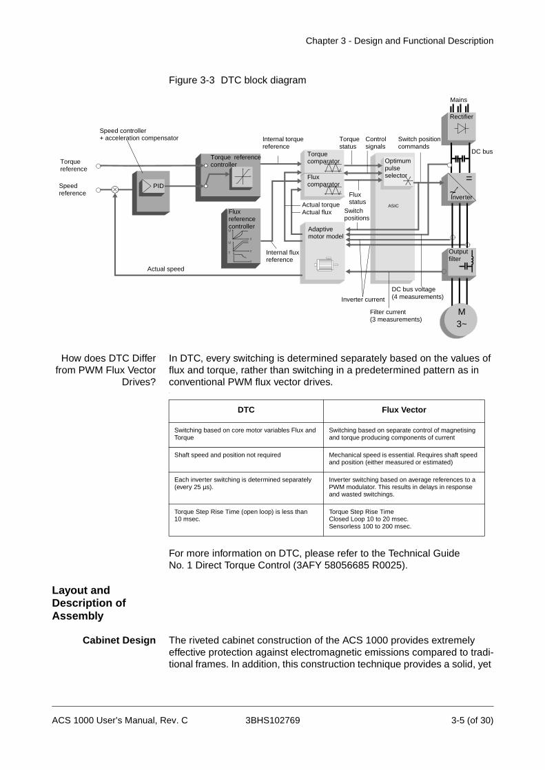
Direct torque control (DTC) is a unique motor control method for AC Drives. The inverter switching is directly controlled according to the motor core variables flux and torque.
The measured motor current and DC link voltage are inputs to an adaptive motor model which produces exact actual values of torque and flux every 25 microseconds. Motor torque and flux comparators compare actual values with the reference values produced by the torque and flux refer-ence controllers. Depending on the outputs from the hysteresis control-lers, the pulse selector directly determines the optimum inverter switch positions.
Typical performance figures for the speed and torque control are given in Standard Control and Monitoring Functions, page 3- 12.
3-4 (of 30) 3BHS102769 ACS 1000 User’s Manual, Rev. C
Chapter 3 - Design and Functional Description
Figure 3-3 DTC block diagram
How does DTC Differfrom PWM Flux Vector
Drives?
In DTC, every switching is determined separately based on the values of flux and torque, rather than switching in a predetermined pattern as in conventional PWM flux vector drives..
For more information on DTC, please refer to the Technical GuideNo. 1 Direct Torque Control (3AFY 58056685 R0025).
Layout and Description of Assembly
Cabinet Design The riveted cabinet construction of the ACS 1000 provides extremely effective protection against electromagnetic emissions compared to tradi-tional frames. In addition, this construction technique provides a solid, yet
Switch positions
Torque reference
Speed reference
Rectifier
=~Inverter
Torque comparator
Flux comparator
Adaptivemotor model
Torque referencecontroller
PID
Fluxreference controllerU
fU
fT
f
Speed controller+ acceleration compensator
Actual speed
Internal fluxreference
Actual torqueActual flux
Inverter current
DC bus voltage
DC bus
Fluxstatus
Torque status
Controlsignals
ASIC
Switch positioncommands
Mains
Internal torquereference
Optimumpulse selector
Filter current
Output filter
(3 measurements)
(4 measurements)
M3~
DTC Flux Vector
Switching based on core motor variables Flux and Torque
Switching based on separate control of magnetising and torque producing components of current
Shaft speed and position not required Mechanical speed is essential. Requires shaft speed and position (either measured or estimated)
Each inverter switching is determined separately (every 25 µs).
Inverter switching based on average references to a PWM modulator. This results in delays in response and wasted switchings.
Torque Step Rise Time (open loop) is less than 10 msec.
Torque Step Rise TimeClosed Loop 10 to 20 msec.Sensorless 100 to 200 msec.
ACS 1000 User’s Manual, Rev. C 3BHS102769 3-5 (of 30)

Chapter 3 - Design and Functional Description
flexible and self-supporting framework which avoids the need for addi-tional skeletal support.
The design fulfils the requirements of international standards like UL 347A.
EMC (Electromagnetic Compatibility) has been achieved by minimizing the spacing between the rivets and avoiding the use of paint on the cabinet’s inside walls. Paint tends to reduce the effectiveness of metallic bonding which is paramount to successful EMC.
As standard, only the front of the ACS 1000 cabinet is painted while all other walls are galvanized. The cabinet can be entirely painted outside as an option.
EMC performance is further enhanced by the use of metal cable channels, which are an integral part of the folded cabinet construction.
3-6 (of 30) 3BHS102769 ACS 1000 User’s Manual, Rev. C
Chapter 3 - Design and Functional Description
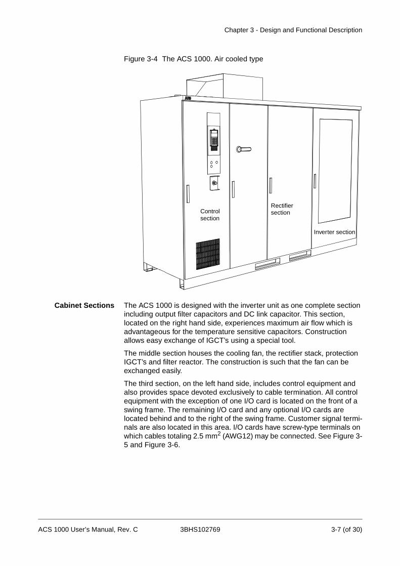
Figure 3-4 The ACS 1000. Air cooled type
Cabinet Sections The ACS 1000 is designed with the inverter unit as one complete section including output filter capacitors and DC link capacitor. This section, located on the right hand side, experiences maximum air flow which is advantageous for the temperature sensitive capacitors. Construction allows easy exchange of IGCT’s using a special tool.
The middle section houses the cooling fan, the rectifier stack, protection IGCT’s and filter reactor. The construction is such that the fan can be exchanged easily.
The third section, on the left hand side, includes control equipment and also provides space devoted exclusively to cable termination. All control equipment with the exception of one I/O card is located on the front of a swing frame. The remaining I/O card and any optional I/O cards are located behind and to the right of the swing frame. Customer signal termi-nals are also located in this area. I/O cards have screw-type terminals on which cables totaling 2.5 mm2 (AWG12) may be connected. See Figure 3-5 and Figure 3-6.
Inverter section
RectifiersectionControl
section
ACS 1000 User’s Manual, Rev. C 3BHS102769 3-7 (of 30)
Chapter 3 - Design and Functional Description
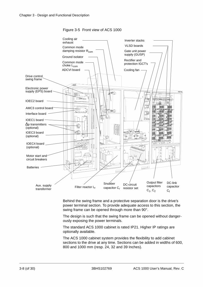
Figure 3-5 Front view of ACS 1000
Behind the swing frame and a protective separation door is the drive’s power terminal section. To provide adequate access to this section, the swing frame can be opened through more than 90°.
The design is such that the swing frame can be opened without danger-ously exposing the power terminals.
The standard ACS 1000 cabinet is rated IP21. Higher IP ratings are optionally available.
The ACS 1000 cabinet system provides the flexibility to add cabinet sections to the drive at any time. Sections can be added in widths of 600, 800 and 1000 mm (resp. 24, 32 and 39 Inches).
Inverter stacks
Cooling fan
Rectifier and
Filter reactor Lf
Cooling airexhaust
Gate unit power supply (GUSP)
protection IGCT’s
Ground isolator
Common modedamping resistor Rcom
Common mode choke Lcom
DC-circuitresistor set
SnubberAux. supplytransformer
Batteries
Motor start andcircuit breakers
IOEC1 board
IOEC2 board
IOEC4 board(optional)
IOEC3 board(optional)
∆p transmitters
AMC3 control board
Electronic powersupply (EPS) board
Drive control swing frame
capacitor Cr
Interface board
Output filter capacitors C1, C2
(optional)
ADCVI board
VLSD boards
DC-linkcapacitor Cf
3-8 (of 30) 3BHS102769 ACS 1000 User’s Manual, Rev. C
Chapter 3 - Design and Functional Description
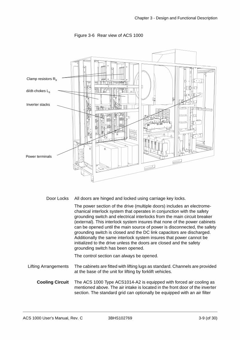
Figure 3-6 Rear view of ACS 1000
Door Locks All doors are hinged and locked using carriage key locks.
The power section of the drive (multiple doors) includes an electrome-chanical interlock system that operates in conjunction with the safety grounding switch and electrical interlocks from the main circuit breaker (external). This interlock system insures that none of the power cabinets can be opened until the main source of power is disconnected, the safety grounding switch is closed and the DC link capacitors are discharged. Additionally the same interlock system insures that power cannot be initialized to the drive unless the doors are closed and the safety grounding switch has been opened.
The control section can always be opened.
Lifting Arrangements The cabinets are fitted with lifting lugs as standard. Channels are provided at the base of the unit for lifting by forklift vehicles.
Cooling Circuit The ACS 1000 Type ACS1014-A2 is equipped with forced air cooling as mentioned above. The air intake is located in the front door of the inverter section. The standard grid can optionally be equipped with an air filter
di/dt-chokes Ls
Clamp resistors Rs
Inverter stacks
Power terminals
ACS 1000 User’s Manual, Rev. C 3BHS102769 3-9 (of 30)

Chapter 3 - Design and Functional Description
system to minimize air pollution in the converter. The air filter can be replaced from outside while the system is running.
Figure 3-7 Cooling fan inside the converter cabinet (standard)
From the front door intake, the air flows through the heat sinks of the vertical inverter stacks and is then routed to the central section where the fan is located. After passing the fan, the air is blown through the rectifier diode stacks, followed by the motor filter reactor. The exhaust is located on top of the cabinet and provides a natural stack effect in order to direct the air flow after the fan. The exhaust is covered in order to protect the equipment inside mechanically.
Control andMonitoringEquipment
The ACS 1000 can be controlled from several control locations:
• from the detachable CDP 312 Control Panel mounted on the ACS 1000 front door of the control section
• from external control devices, e.g. a supervisory control system, that connect to the analog and digital I/O terminals on the Standard I/O Boards
• through Fieldbus adapter modules
• with PC Tools (DriveWindow and DriveLink), connected via a PC adapt-er to the ACS 1000 control board.
Optional analog and digital I/O extension modules can be used to provide extended transformer and motor protection, protection for external cooling equipment (e.g. fans, chillers), on-line synchronization logic, and other customer requirements as needed.
Control Box InverterRectifier
3-10 (of 30) 3BHS102769 ACS 1000 User’s Manual, Rev. C

Chapter 3 - Design and Functional Description
CDP 312 Control PanelFigure 3-8 CDP 312 control panel
Using the panel it is possible to
• enter start-up data into the drive
• control the drive with a reference signal and with Start, Stop and Direc-tion commands
• display actual values (three values can be read simultaneously)
• display and adjust parameters
• display information on the most recent forty fault events
• upload and download complete parameter sets from one drive to an-other (this greatly simplifies the start-up procedure of several identical drives).
For further details please refer to Appendix B - The CDP 312 Control Panel.
ControlPanelDisplay
ControlPanelKeypad
Control Panel Mode Selection keys
Double Up Arrow, Up Arrow,Enter,Double Down Arrow, Down Arrow keys
Local/Remote, Reset, Reference and
Forward, Reverse and Stop keys
Start keys
ACT PAR FUNC DRIVE
ENTER
LOC
REM
RESET REF
1 L -> 1242 rpm I
SPEEDCURRENT
TORQUE
76.00 A1242.0rpm86.00 %
• Enclosure class IP54 when attached to the Control Panel Mounting Plat-form
• Multilingual Alphanumeric Display (4 lines x 20 characters)
• Plain text messages in 10 available languages
ACS 1000 User’s Manual, Rev. C 3BHS102769 3-11 (of 30)

Chapter 3 - Design and Functional Description
Standard Control and Monitoring Functions
General The ACS 1000 control and protection system is configured and custom-ized through a set of application parameters. These parameters can be programmed by the user, either with the CDP 312 control panel supplied with the converter or with a PC and the DriveWindow software package.
Parameters can be defined by setting them one by one or by invoking a predefined set of parameters which is optimized for a particular applica-tion. Such predefined parameter sets are called application macros. Therefore part of the functions described in this chapter will automatically be configured by selecting an application macro.
In the remainder of this chapter you will find the description of the standard control, monitoring and protection functions with references to the related parameters. A description of the basic I/O devices and the application macros of the ACS 1000 you will find in Chapter 4 - I/O Interfaces and Ap-plication Macros. This and the following chapter are intended to be used as a reference for obtaining quick information on a specific function. A sys-tematic guide for determining the parameter settings and I/O allocation for commissioning you will find in the ACS 1000 Engineering Manual.
Configuring the ACS 1000 is a task that requires a professional back-ground going far beyond the knowledge needed for system operation. Therefore parameters and application macros are set during commission-ing of the converter by ABB commissioning engineers – based on the in-formation received by the owner – and should normally not be changed afterwards by the user.
Warning: Never change any parameters if you are not thoroughly familiar with the meaning of each parameter and with the consequences resulting from the modification. Running the ACS 1000, the motor and the driven equipment with incorrect data can result in improper operation, reduction in control accuracy and damage to equipment.
Motor ControlFeatures
Motor ID Run With the standard motor identification run (ID run) (input of nameplate data is always required), a quick motor identification is automatically done the first time the Start command is given. During this first start-up the motor is run at zero speed for several seconds to allow a basic motor model to be created. This model is sufficient to allow normal operation.
The unbeatable performance of direct torque control (DTC) is based on an accurate motor model. The parameters of this model are automatically
3-12 (of 30) 3BHS102769 ACS 1000 User’s Manual, Rev. C
Chapter 3 - Design and Functional Description
determined during the enhanced ID run. Basic motor nameplate data (power rating, speed, etc.) must first be entered manually. Then the drive is instructed to perform a motor ID run. For optimum parameter determi-nation the load should be disconnected from the motor during the ID run. The ACS 1000 operates the motor under a predetermined set of running conditions for a few minutes. For each running condition motor and inverter feedback responses are measured. Based on these measure-ments the motor model parameters are calculated and optimized. The final result is an enhanced mathematical model of the motor which func-tions to provide the DTC controller with accurate flux, torque, and motor speed information.
If no ID run is selected, the converter will be stopped due to ID run fault.
Motor ID run can be selected upon entering the so-called start-up para-meters of parameter group 99 (parameter 99.12). For further details please refer to Chapter 6 - Parameter Viewing and Editing, Start-Up Parameters, page 6- 7.
Filter ID Run Filter ID run is used to verify output filter data. It is carried out with decoupled motor. Filter ID run is not required for normal operation, its purpose is to facilitate trouble shooting in the output filter circuit.
Full Torque at ZeroSpeed
A motor fed by the ACS 1000 can develop short-term motor nominal torque at start-up without any pulse encoder or tachogenerator feedback. This feature is essential for constant torque applications. However, if long-term operation at zero speed is required, a pulse encoder has to be applied.
Enhanced Flying Start The enhanced flying start function of the ACS 1000 is an improved version of the flying start and ramp start features normally found in frequency converters. The ACS 1000 can detect the state of the motor within a very short time. Hence, rapid starting is possible under all conditions. This feature allows easy starting of turbine pumps or windmill fans, for example.
Flux Optimization Flux optimization of the ACS 1000 reduces the total energy consumption and motor noise level when the drive operates below the nominal load. The total efficiency (motor and the drive) can be improved by 1..10%, depending on the load torque and speed.
Flux optimization is activated with parameter 27.01, Flux Control. For further details see Appendix K - Signal and Parameter Table.
Power Loss Ride-Through
If the incoming supply voltage is cut off the ACS 1000 will continue to operate in an active but non-torque producing mode by utilizing the kinetic energy of the rotating motor and load. The ACS 1000 will be fully active as long as the motor rotates and generates energy to the ACS 1000.
ACS 1000 User’s Manual, Rev. C 3BHS102769 3-13 (of 30)
Chapter 3 - Design and Functional Description
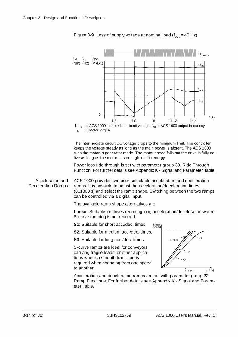
Figure 3-9 Loss of supply voltage at nominal load (fout = 40 Hz)
The intermediate circuit DC voltage drops to the minimum limit. The controller keeps the voltage steady as long as the main power is absent. The ACS 1000 runs the motor in generator mode. The motor speed falls but the drive is fully ac-tive as long as the motor has enough kinetic energy.
Power loss ride through is set with parameter group 39, Ride Through Function. For further details see Appendix K - Signal and Parameter Table.
Acceleration andDeceleration Ramps
ACS 1000 provides two user-selectable acceleration and deceleration ramps. It is possible to adjust the acceleration/deceleration times(0..1800 s) and select the ramp shape. Switching between the two ramps can be controlled via a digital input.
The available ramp shape alternatives are:
Linear: Suitable for drives requiring long acceleration/deceleration where S-curve ramping is not required.
S1: Suitable for short acc./dec. times.
S2: Suitable for medium acc./dec. times.
S3: Suitable for long acc./dec. times.
S-curve ramps are ideal for conveyors carrying fragile loads, or other applica-tions where a smooth transition is required when changing from one speed to another.
Acceleration and deceleration ramps are set with parameter group 22, Ramp Functions. For further details see Appendix K - Signal and Param-eter Table.
1.6 4.8 8 11.2 14.4t(s)
UDC
fout
TM
UDC = ACS 1000 intermediate circuit voltage, fout = ACS 1000 output frequencyTM = Motor torque
UmainsTM(Nm)
fout(Hz)
UDC(V d.c.)
0
Linear
1 t (s)
Motor
1.25 2
S1
S2
S3
speed
3-14 (of 30) 3BHS102769 ACS 1000 User’s Manual, Rev. C
Chapter 3 - Design and Functional Description
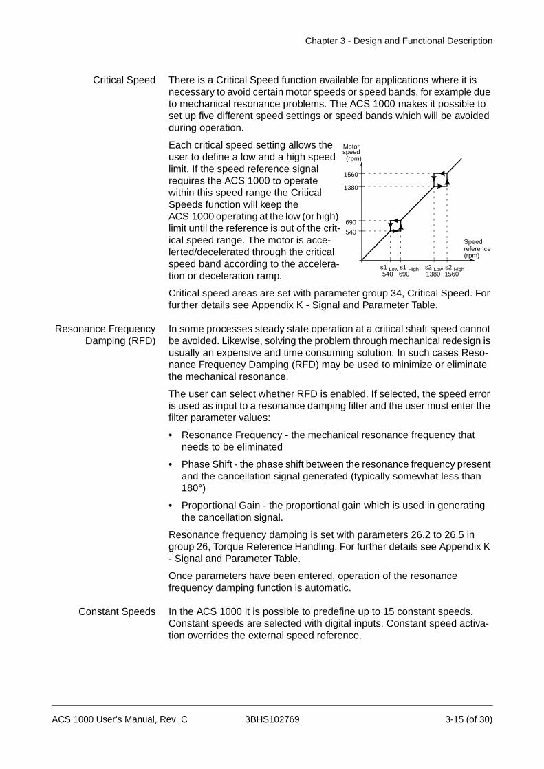
Critical Speed There is a Critical Speed function available for applications where it is necessary to avoid certain motor speeds or speed bands, for example due to mechanical resonance problems. The ACS 1000 makes it possible to set up five different speed settings or speed bands which will be avoided during operation.
Each critical speed setting allows the user to define a low and a high speed limit. If the speed reference signal requires the ACS 1000 to operate within this speed range the Critical Speeds function will keep the ACS 1000 operating at the low (or high) limit until the reference is out of the crit-ical speed range. The motor is acce-lerted/decelerated through the critical speed band according to the accelera-tion or deceleration ramp.
Critical speed areas are set with parameter group 34, Critical Speed. For further details see Appendix K - Signal and Parameter Table.
Resonance FrequencyDamping (RFD)
In some processes steady state operation at a critical shaft speed cannot be avoided. Likewise, solving the problem through mechanical redesign is usually an expensive and time consuming solution. In such cases Reso-nance Frequency Damping (RFD) may be used to minimize or eliminate the mechanical resonance.
The user can select whether RFD is enabled. If selected, the speed error is used as input to a resonance damping filter and the user must enter the filter parameter values:
• Resonance Frequency - the mechanical resonance frequency that needs to be eliminated
• Phase Shift - the phase shift between the resonance frequency present and the cancellation signal generated (typically somewhat less than 180°)
• Proportional Gain - the proportional gain which is used in generating the cancellation signal.
Resonance frequency damping is set with parameters 26.2 to 26.5 in group 26, Torque Reference Handling. For further details see Appendix K - Signal and Parameter Table.
Once parameters have been entered, operation of the resonance frequency damping function is automatic.
Constant Speeds In the ACS 1000 it is possible to predefine up to 15 constant speeds. Constant speeds are selected with digital inputs. Constant speed activa-tion overrides the external speed reference.
s1 Low s1 High s2 Low s2 High
Speed
540 690 1380 1560
(rpm)
540
690
1380
1560
(rpm)
Motorspeed
reference
ACS 1000 User’s Manual, Rev. C 3BHS102769 3-15 (of 30)

Chapter 3 - Design and Functional Description
Constant speed values are set with parameter group 33, Constant Speed. If the sequential control application macro is used, a standard set of parameter values is selected automatically. For further details see Appendix K - Signal and Parameter Table.
Speed ControllerTuning
During the motor identification run the ACS 1000 speed controller is auto-matically tuned. However, after the ID run, it is possible to manually adjust the controller gain, integration time and derivation action time, if desired. In the enhanced ID run, the motor is driven through a series of movements and the speed controller is tuned based on the load and inertia of the motor and the machine.
Speed controller parameters are set with parameter group 24, speed control (if the factory application macro is used, a standard set of para-meter values is selected automatically). For further details see Chapter 4 - I/O Interfaces and Application Macros, Application Macros, page 4- 11 and Appendix K - Signal and Parameter Table.
Figure 3-10 Examples of speed response at a speed reference step (typically, 1..20%). Speed step response can be seen by monitoring the actual SPEED signal.
A : Normally tuned speed controller, autotuning (undercompensated)B : Critically compensated speed controllerC : Optimally tuned speed controller, manual tuning. Better dynamic performance than with A or BD : Overcompensated speed controller
%
t
n
CB D
nN
A
3-16 (of 30) 3BHS102769 ACS 1000 User’s Manual, Rev. C

Chapter 3 - Design and Functional Description
Accurate SpeedControl
The static speed control error is typi-cally + 0.1% of motor nominal speed, which satisfies most industrial appli-cations. If even more precise speed regulation is required, a pulse encoder can be connected. With a pulse encoder, the static speed control error is typically + 0.01% of motor nominal speed.
The dynamic speed control error is typically + 0.4%sec. at 100% load torque step without a pulse encoder or tachogenerator. With a pulse encoder, the dynamic speed control error is typically + 0.1%sec.
The pulse encoder is an optional device. If used, parameter 75.03 of group Option Modules must be activated. Parameters are set with group 50, Speed Measurement. For further details see Appendix K - Signal and Parameter Table.
Table 3-1 Typical performance figures for speed control, when Direct Torque Control is used.
*Dynamic speed error depends on speed controller tuning.
Accurate TorqueControl without Speed
Feedback
The ACS 1000 can perform precise torque control without any speed feed-back from the motor shaft. With torque rise time less than 10 ms at 100% torque reference step compared to over 100 milliseconds in frequency converters using sensorless flux vector control, the ACS 1000 is unbeatable.
By applying a torque reference instead of a speed reference, the ACS 1000 will maintain a specific motor torque value; the speed will adjust automati-cally to maintain the required torque.
Torque control parameters are set with parameter groups 25 and 26, Torque Reference and Torque Ref Handling (If the torque control macro is used, a standard set of parameter values is
100
t (s)
TTN
(%)
Tload
nact-nrefnN
0.1 - 0.4 %secTN = rated motor torquenN = rated motor speednact = actual speednref = speed reference
0n
Speed ControlACS 1000
no Pulse EncoderACS 1000
with Pulse Encoder
Static speed error, [% of nN] + 0.1 %(10 % of nominal slip)
+ 0.01 %
Dynamic speed error(in % of nominal speed)
0.4 %sec.* 0.1 %sec.*
100
t(s)
TTN
< 10 ms
90
10
(%)
Tref
Tact
TN = rated motor torqueTref = torque referenceTact = actual torque
ACS 1000 User’s Manual, Rev. C 3BHS102769 3-17 (of 30)
Chapter 3 - Design and Functional Description
selected automatically). For further details see Chapter 4 - I/O Interfaces and Application Macros, Application Macros, page 4- 11 and Appendix K - Signal and Parameter Table.
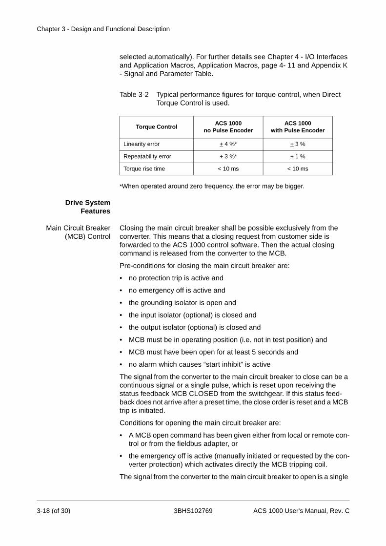
Table 3-2 Typical performance figures for torque control, when Direct Torque Control is used.
*When operated around zero frequency, the error may be bigger.
Drive SystemFeatures
Main Circuit Breaker(MCB) Control
Closing the main circuit breaker shall be possible exclusively from the converter. This means that a closing request from customer side is forwarded to the ACS 1000 control software. Then the actual closing command is released from the converter to the MCB.
Pre-conditions for closing the main circuit breaker are:
• no protection trip is active and
• no emergency off is active and
• the grounding isolator is open and
• the input isolator (optional) is closed and
• the output isolator (optional) is closed and
• MCB must be in operating position (i.e. not in test position) and
• MCB must have been open for at least 5 seconds and
• no alarm which causes “start inhibit” is active
The signal from the converter to the main circuit breaker to close can be a continuous signal or a single pulse, which is reset upon receiving the status feedback MCB CLOSED from the switchgear. If this status feed-back does not arrive after a preset time, the close order is reset and a MCB trip is initiated.
Conditions for opening the main circuit breaker are:
• A MCB open command has been given either from local or remote con-trol or from the fieldbus adapter, or
• the emergency off is active (manually initiated or requested by the con-verter protection) which activates directly the MCB tripping coil.
The signal from the converter to the main circuit breaker to open is a single
Torque ControlACS 1000
no Pulse Encoder ACS 1000
with Pulse Encoder
Linearity error + 4 %* + 3 %
Repeatability error + 3 %* + 1 %
Torque rise time < 10 ms < 10 ms
3-18 (of 30) 3BHS102769 ACS 1000 User’s Manual, Rev. C
Chapter 3 - Design and Functional Description
pulse signal which is reset upon receiving the status feedback MCB OPEN from the switchgear. If this status feedback does not arrive after a preset time the signal MCB ORDER TRIP is initiated to open the MCB.
The MCB ORDER TRIP is a activated when low signal, which directly acti-vates the tripping coil of the MCB. Several external MCB trip commands can be integrated into this hardwired tripping loop (e.g. transformer and motor supervision relays, process trips, etc.).
MCB control functions are set with parameter 11.4 and parameter group 21, Start/Stop/MCB Functions (for control outputs), Actual Signals (for status inputs). For further details see the Engineering Manual and Appendix K - Signal and Parameter Table.
Local and RemoteControl
The operation of the ACS 1000 is possible either by local or remote control.
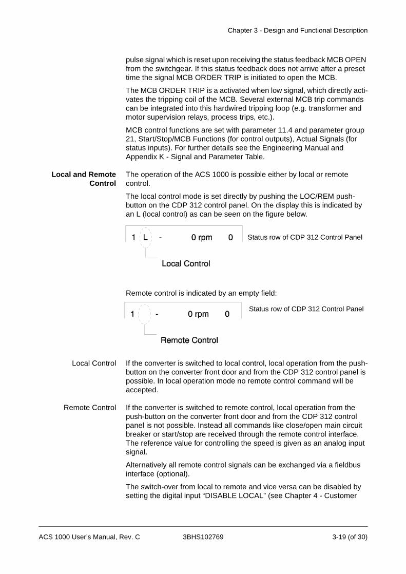
The local control mode is set directly by pushing the LOC/REM push-button on the CDP 312 control panel. On the display this is indicated by an L (local control) as can be seen on the figure below.
Remote control is indicated by an empty field:
Local Control If the converter is switched to local control, local operation from the push-button on the converter front door and from the CDP 312 control panel is possible. In local operation mode no remote control command will be accepted.
Remote Control If the converter is switched to remote control, local operation from the push-button on the converter front door and from the CDP 312 control panel is not possible. Instead all commands like close/open main circuit breaker or start/stop are received through the remote control interface. The reference value for controlling the speed is given as an analog input signal.
Alternatively all remote control signals can be exchanged via a fieldbus interface (optional).
The switch-over from local to remote and vice versa can be disabled by setting the digital input “DISABLE LOCAL” (see Chapter 4 - Customer
Status row of CDP 312 Control Panel
Status row of CDP 312 Control Panel
ACS 1000 User’s Manual, Rev. C 3BHS102769 3-19 (of 30)

Chapter 3 - Design and Functional Description
Interfaces and Application Macros, Table 4-1).
Diagnostics
Actual SignalMonitoring
90 Actual Signals are available. The most significant ones are:
• ACS 1000 output frequency, current, voltage and power
• Motor speed and torque
• DC Link voltage
• Active control location (Local / External 1 / External 2)
• Reference values
• ACS 1000 inverter air temperature
• Operating time counter (h), kWh counter
• Digital I/O and analog I/O status
• PID controller actual values (if the PID Control Macro is selected)
Three signals can be displayed simultaneously on the control panel.
Actual signals to be displayed can be selected from parameter group1 to 5, Actual Signals. For further details see Chapter 5 - Operation, Actual Signal Display, page 5- 15.
Fault History The Fault History contains information on the forty most recent faults detected by the ACS 1000. Faults are displayed in words. For further details seeChapter 5 - Operation, Fault History Display, page 5- 18.
Programmable DigitalOutputs
Four programmable digital outputs are at the user’s disposition. They can be used as floating change-over contacts. Each output can be selected via parameter setting: ready, running, fault, warning, motor stall, motor temperature alarm / trip, ACS 1000 temperature alarm / trip, reversed selected, external control selected, preset speed limits (2 pcs), interme-diate circuit voltage limits, preset motor current limit, reference limits (2 pcs), loss of reference signal, ACS 1000 started, motor operating at reference speed, process PID controller actual value limits (low, high) etc.
By choosing the two optional boards IOEC 3 and IOEC 4, 12 additional digital outputs (6 on each board) are available.
For further details on output allocation refer to the Engineering Manual.
ProgrammableAnalog Outputs
ACS 1000 offers two programmable current outputs. Analog output signals can be inverted and filtered. The minimum level can be adjusted to 0 mA, 4 mA or 10 mA.
Depending on parameter selection, the analog output signals can repre-sent motor speed, process speed (scaled motor speed), output frequency, output current, motor torque, motor power, DC bus voltage, output
0 L 1242 rpm IFREQ 55.00 Hz CURRENT 80 APOWER 55 %
3-20 (of 30) 3BHS102769 ACS 1000 User’s Manual, Rev. C

Chapter 3 - Design and Functional Description
voltage, application block output (the process PID controller output), the active reference, or reference deviation (difference between the reference and the actual value of the process PID controller).
Also, the output can be proportional to the process PID controller actual value of the ACS 1000. The process PID controller actual values can be scaled, inverted and filtered.
For further details on output allocation refer to the Engineering Manual.
Input Signal SourceSelections and Signal
Processing Note: The ACS 1000 is a speed controlled device. If you need to convert frequency to speed use the following formula:
Two ProgrammableControl Locations
The ACS 1000 (with no optional devices) can receive Start/Stop/Direction commands and reference from the integrated control panel or through digital and analog inputs.
It is possible to predefine two separate External Control Locations (EXT1 and EXT2) for both the Start/Stop/Direction commands and the reference signal. The active External Control Location can be changed via the control panel or via a digital input.
The control panel always overrides the other control signal sources when switched to local mode.
Control location functions are set with parameter groups 11, Start/Stop/Direction/MCB Control and 12, Reference Select. For further details see the Engineering Manual and Appendix K - Signal and Parameter Table.
Reference SignalProcessing
The ACS 1000 can handle a variety of speed reference schemes in addi-tion to the conventional analog input signal and control panel signals.
• The ACS 1000 reference can be given with two digital inputs: One digital input increases the speed, the other decreases it. The active ref-erence is memorized by the control.
• The ACS 1000 can form a reference out of two analog input signals by using mathematical functions: Addition, Subtraction, Multiplication, Minimum selection, and Maximum selection.
It is possible to scale the external reference so that the signal minimum and maximum values correspond to a speed other than the nominal minimum and maximum speed limits.
SPEED(rpm) =NUMBER OF POLES
FREQUENCY(Hz)· 120
Pole pairs = 1, 2, 3,..Number of poles = 2, 4, 6,...
ACS 1000 User’s Manual, Rev. C 3BHS102769 3-21 (of 30)

Chapter 3 - Design and Functional Description
Speed reference functions are set with parameter group 23, Speed Ref. For further details refer to the Engineering Manual and to Appendix K - Signal and Parameter Table.
Analog InputProcessing
The ACS 1000 has two programmable analog inputs: voltage or current inputs (hardware selected). Each of these analog inputs can be processed by adjusting the signal min/max levels, the filtering time constant, and the signal inversion selection with software parameters.
The minimum setting of 0 mA (0 V), 4 mA (2 V) or the input tuning can be selected. The tuning function allows the ACS 1000 to read the actual value and define it as minimum signal level.
The maximum setting of 20 mA (10 V) or the input tuning can be selected. The tuning function allows the ACS 1000 to read the actual value and define it as maximum signal level.
The analog input signal filtering time constant is user-adjustable from 0.01..10 s with software parameters.
Figure 3-11Analog input filtering time constant
With inversion activated, the minimum level of the analog input signal corresponds to the maximum reference and the maximum analog input signal corresponds to the minimum reference.
For further details on analog input allocation refer to the Engineering Manual.
Offset Calibration Automatic offset calibration of analog inputs is possible. For offset calibra-tion, signal cables must be disconnected first from the analog inputs. Analog inputs are calibrated by setting the appropriate parameters Auto Offset Calib (in parameter groups 15, 81 and 86).
Offset of the internal current and voltage measurement inputs will be calculated automatically if the grounding isolator is opened after de-ener-gization of the converter.
63
AI
100
Filter time constantt
Filtered Signal
Unfiltered Signal(%)
3-22 (of 30) 3BHS102769 ACS 1000 User’s Manual, Rev. C
Chapter 3 - Design and Functional Description
Standard Protection Functions
The ACS 1000 offers six programmable fault functions and several other non-user adjustable preprogrammed protection functions.
Programmable FaultFunctions
Motor WindingTemperature
The motor can be protected from overheating by activating the motor winding temperature supervision.
The calculation of the motor temperature is user adjustable. The tempe-rature supervision is based either on a load curve or on a thermal constant set by the customer or given by the automatically integrated function. The load curve should be adjusted in case the ambient temperature exceeds 30 °C.
Alternatively the ACS 1000 offers as standard three analog inputs for motor winding temperature measurement. If this measurement is connected, the calculation model is disabled.
The values for alarm and trip levels must be set in either case.
Motor temperature protection is set with parameters 30.01 to 30.11 in group Fault Functions. For further details see Engineering Manual and Appendix K - Signal and Parameter Table.
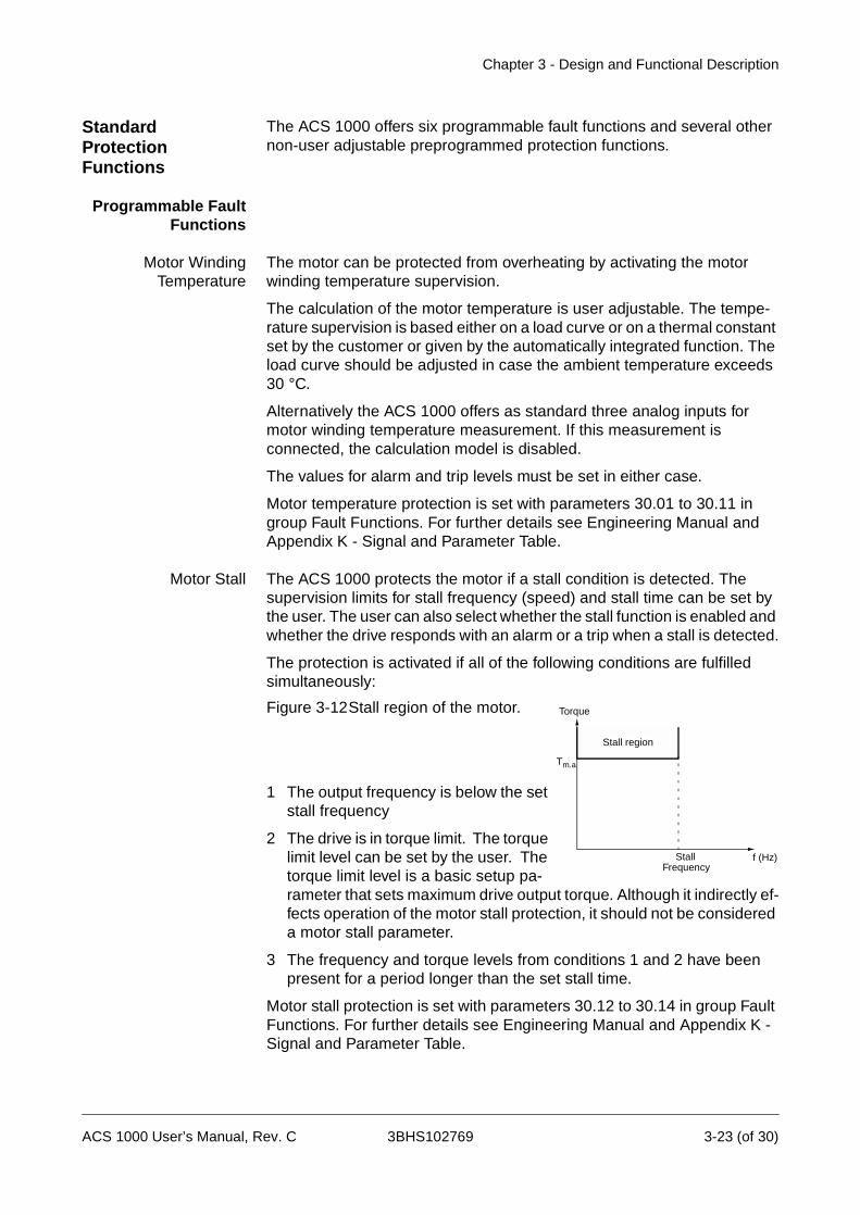
Motor Stall The ACS 1000 protects the motor if a stall condition is detected. The supervision limits for stall frequency (speed) and stall time can be set by the user. The user can also select whether the stall function is enabled and whether the drive responds with an alarm or a trip when a stall is detected.
The protection is activated if all of the following conditions are fulfilled simultaneously:
Figure 3-12Stall region of the motor.
1 The output frequency is below the set stall frequency
2 The drive is in torque limit. The torque limit level can be set by the user. The torque limit level is a basic setup pa-rameter that sets maximum drive output torque. Although it indirectly ef-fects operation of the motor stall protection, it should not be considered a motor stall parameter.
3 The frequency and torque levels from conditions 1 and 2 have been present for a period longer than the set stall time.
Motor stall protection is set with parameters 30.12 to 30.14 in group Fault Functions. For further details see Engineering Manual and Appendix K - Signal and Parameter Table.
Stall region
Tm.a
f (Hz)Stall
Torque
Frequency
ACS 1000 User’s Manual, Rev. C 3BHS102769 3-23 (of 30)

Chapter 3 - Design and Functional Description
Underload Loss of motor load may indicate a process malfunction. ACS 1000 provides an underload function to protect the machinery and process in such a serious fault condition. This supervision function checks whether the motor load is above the specified load curve. 5 different load curves can be selected by the customer.
Supervision limits: underload curve and underload time can be chosen as well as the drive response to the underload condition (alarm / trip indica-tion & stop the drive / no reaction).
The protection is activated if all the following conditions are fulfilled simul-taneously:
1 The motor load is below the Underload curve selected by the user (five options, see Figure 3-13).
2 The motor load has been below the selected underload curve longer than the time set by the user (Underload time).
Underload protection is set with parameters 30.15 to 30.17 in group fault functions. For further details see Engineering Manual and Appendix K - Signal and Parameter Table.
Figure 3-13Load curves for underload function
Overspeed Motor speed as determined by DTC is monitored. If motor speed exceeds the maximum permitted motor speed (user adjustable) a trip is initiated. In addition, an input for connection of an external motor overspeed trip is available. A converter trip is also initiated if the external motor overspeed trip is activated (signal active when low).
For further details refer to the Engineering Manual.
Undervoltage In order to detect a loss of the net supply, the levels of the positive and negative DC link voltage levels are supervised. If these voltage levels drop below 70% of their nominal levels an undervoltage alarm is initiated and
Load curves of underload function
0
0.1
0.2
0.3
0.4
0.5
0.6
0.7
0.8
10%
20%
30%
40%
50%
60%
70%
80%
90%
100%
110%
120%
130%
140%
curve 1
curve 2
curve 3
curve 4
curve 5
Torque
Speed
3-24 (of 30) 3BHS102769 ACS 1000 User’s Manual, Rev. C
Chapter 3 - Design and Functional Description
power loss ride through is activated (provided it is selected). If the DC link voltage levels drop below 65% of their nominal levels an undervoltage trip is initiated.
For further details refer to the Engineering Manual.
PreprogrammedProtection Functions
Motor Phase Loss The phase loss function monitors the status of the motor cable connec-tions. The function is useful especially during motor starting: the ACS 1000 detects if any of the motor phases are not connected and refuses to start.
The phase loss function also supervises the motor connection status during normal operation. The motor operating frequency must be above a minimum level in order for this feature to function. Should a motor phase loss be detected a trip is initiated.
Overvoltage The levels of the positive and negative DC link voltage are supervised to detect whether an improper overvoltage condition develops. If these voltage levels rise above 130% of their nominal levels an overvoltage trip is initiated. On rare occasions, a combination of conditions can result in the motor entering a self excitation mode that can cause the DC link voltage to continue to rise despite the fact that a trip has been imple-mented. If this condition occurs and if the DC link voltage levels rise above 135% of their nominal levels, a second overvoltage trip is initiated that causes the inner 6 IGCT’s to be gated simultaneously such that the motor windings are effectively shunted together. This eliminates the self excita-tion voltage that is causing the DC link voltage levels to rise. To provide ultimate reliability the second overvoltage trip is implemented both in soft-ware and redundantly in hardware (140%).
Short Circuit in theRectifier Bridge
A short circuit in the rectifier bridge is detected by supervising the DC link voltage. If a short circuit is detected a trip is initiated and the drive is disconnected from the supply voltage (MCB opening time ≤100 ms).
Charging Fault The intermediate DC link voltage is supervised while charging. If the voltage does not reach a certain level after a pre-set time a trip will be initi-ated.
Supply Phase Loss If the voltage ripple in the intermediate dc link rises above a pre-set level, a supply phase may be lost. A trip is initiated.
Overcurrent The overcurrent trip limit for the ACS 1000 is 2.2 times the nominal inverter rms current. If this level is exceeded a trip is initiated.
Loadability of theInverter
In order to insure that the inverter section does not exceed normal temper-ature limits, the current load of the inverter is supervised. If a current/time overload is detected a trip is initiated.
ACS 1000 User’s Manual, Rev. C 3BHS102769 3-25 (of 30)
Chapter 3 - Design and Functional Description
Short Circuit of theInverter
The inverter is monitored to insure that a short circuit condition does not exist. If a short circuit is detected a trip is initiated.
Ground Fault The ground current in the output filter circuit is monitored. If it exceeds a certain level, a trip is initiated.
Operating System The operating system of the microprocessor board supervises different functions within the control software and will initiate a trip if a malfunction is detected. Such faults are displayed as “Control SW fault”. Should one of these faults be initiated during operation, the system should be restarted.
Measurement Loss In order to guarantee proper operation of the protection functions included in the converter, all communications between the control boards are checked cyclically.
On the ADCVI board (analog digital conversion for voltage and current) analog signals are converted into digital signals. The digital signals are then transmitted via PPCC (fiber-optic bus system) to the interface board which is the main interface to the converter control.
On the interface board the status of the communication is supervised. If a fault is sensed a trip is initiated.
Battery Test In order to guarantee correct fault indications and proper trip sequencing in the event that the auxiliary power source feeding the drive is lost, the ACS 1000 is equipped with a battery to supply redundant DC control power. While the converter is in operation the charge on the battery is checked periodically by applying a known load and measuring the resulting voltage drop. If the battery is determined to be deficient in its ability to supply power, a fault message is displayed and either a normal stop or an alarm is initiated. Normal stop is initiated if the self excitation speed of the motor is lower than nominal speed. An alarm is set if the self excitation speed is higher than nominal speed. This is determined auto-matically during the ID run. Default value (if no ID run has been done) is normal stop.
Communication Fault Except for the measurement boards all communication links are realized by DDCS (Distributed Drive Control System). If one of these links is missing a trip is initiated.
ID-Run Fault An identification run is done during commissioning. The commissioning engineer enters nominal data for the identification of the system parame-ters. If the data has not been entered correctly and therefore the system parameters cannot be determined, a trip is initiated.
In this case the entered data needs to be corrected and the identification run has to be repeated.
3-26 (of 30) 3BHS102769 ACS 1000 User’s Manual, Rev. C
Chapter 3 - Design and Functional Description
Other ProtectionFunctions
External MotorProtection Trip
If the customer uses an external motor protection relay it can be connected to a pre-defined protection input of the ACS 1000. The motor protection input is integrated into the tripping loop by a normally closed (NC) contact.
External motor protection is set with parameter group 35, External Motor protection. For further details see Chapter 4 - I/O Interfaces and Applica-tion Macros, Standard I/O Boards, page 4- 1 and Appendix K - Signal and Parameter Table.
External TransformerProtection Trip
If the customer uses an external transformer protection relay it can be connected to a pre-defined protection input of the ACS 1000. The trans-former protection input is integrated into the tripping loop by a normally closed (NC) contact.
External transformer protection is set with parameter group 35, External Trafo Protection. For further details see Chapter 4 - I/O Interfaces and Application Macros, Standard I/O Boards, page 4- 1 and Appendix K - Signal and Parameter Table.
Process Stop A process stop button or relay can be connected to a pre-defined input of the ACS 1000. The actual process stop input must be normally closed during normal running. If the process stop input opens the drive control initiates a stop order. The type of stop (torque limit, ramp, or coast) is parameter selectable.
Process stop is set with parameter 16.01 in group System Ctr Inputs and parameters 21.03 and 21.04 in group Start/stop Functions. For further details see Chapter 4 - I/O Interfaces and Application Macros, Standard I/O Boards, page 4- 1 and Appendix K - Signal and Parameter Table.
External EmergencyOff
If the customer wants to use an External Emergency Off button it can be connected to a pre-defined protection input of the ACS 1000. The External Emergency Off input is integrated into the tripping loop by a normally closed (NC) contact.
For further details see Chapter 4 - I/O Interfaces and Application Macros, Standard I/O Boards, page 4- 1.
MCB Control Fault All opening and closing commands to the main circuit breaker (MCB) are supervised for time-out. If the MCB does not change its status within a pre-set time the MCB trip loop (signal active when low) is activated.
MCB time-out supervision is set with parameters 21.08 and 21.09 in group Start/stop Functions. For further details see Appendix K - Signal and Parameter Table.
Other Features
Limits The ACS 1000 offers adjustable limits for speed, current (max.) and
ACS 1000 User’s Manual, Rev. C 3BHS102769 3-27 (of 30)
Chapter 3 - Design and Functional Description
torque (max.) and protects itself against overvoltage.
For further details see Engineering Manual and Appendix K - Signal and Parameter Table.
Automatic Reset The ACS 1000 can automatically reset itself after an undervoltage. A user selectable parameter determines whether this feature is implemented. When the feature is activated, fault reset occurs within a few milliseconds after the fault is cleared. The fault has no effect on the drive or process operation; however, it is annunciated as a fault on the drive’s panel.
Automatic reset can be used in case of DC undervoltage detection.
A reset counter tracks the number of automatic resets that occur within a set time window. If an excessive number of automatic resets occur within this time window, a system fault trip is initiated and drive operation ceases.
Automatic reset is selected with parameter group 31, Automatic Reset. For further details see Appendix K - Signal and Parameter Table.
Supervision Programmable supervision is a unique feature of the ACS 1000 which allows the drive to monitor certain user selectable signals. A trigger level can be defined for each signal.
For example, the user may set two speed limits, one current limit, two torque limits, two reference limits and two actual value limits. The digital status of the active limit appears on the control panel display and can also be supervised through relay outputs.
Supervision parameters are set with parameter group 32, Supervision. For further details see Appendix K - Signal and Parameter Table.
ACS 1000 Information The ACS 1000 software version, test date, and serial number can be displayed.
Information data are stored in parameter group 6, Information. For further details see Appendix K - Signal and Parameter Table.
Parameter Lock The user can prevent unwanted parameter adjustment by activating the Parameter Lock.
Parameter Lock is set with parameters 16.02 and 16.03 in group System Ctr Inputs. For further details see Appendix K - Signal and Parameter Table.
3-28 (of 30) 3BHS102769 ACS 1000 User’s Manual, Rev. C
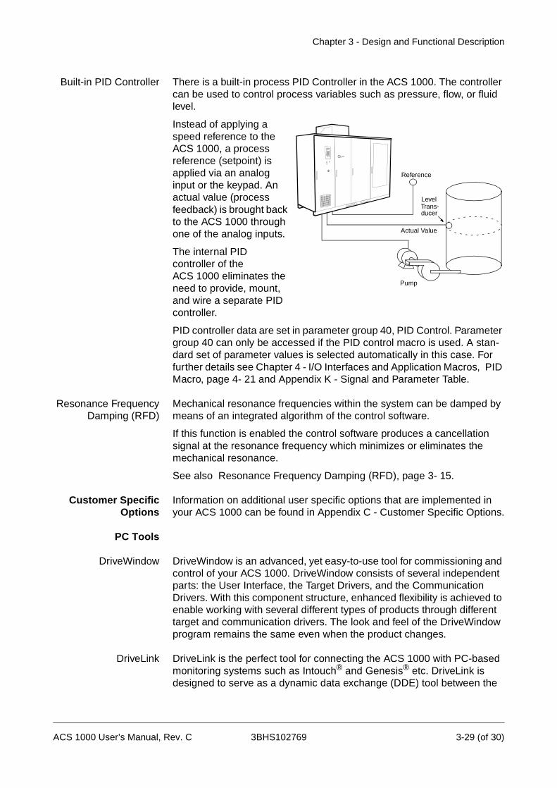
Chapter 3 - Design and Functional Description
Built-in PID Controller There is a built-in process PID Controller in the ACS 1000. The controller can be used to control process variables such as pressure, flow, or fluid level.
Instead of applying a speed reference to the ACS 1000, a process reference (setpoint) is applied via an analog input or the keypad. An actual value (process feedback) is brought back to the ACS 1000 through one of the analog inputs.
The internal PID controller of the ACS 1000 eliminates the need to provide, mount, and wire a separate PID controller.
PID controller data are set in parameter group 40, PID Control. Parameter group 40 can only be accessed if the PID control macro is used. A stan-dard set of parameter values is selected automatically in this case. For further details see Chapter 4 - I/O Interfaces and Application Macros, PID Macro, page 4- 21 and Appendix K - Signal and Parameter Table.
Resonance FrequencyDamping (RFD)
Mechanical resonance frequencies within the system can be damped by means of an integrated algorithm of the control software.
If this function is enabled the control software produces a cancellation signal at the resonance frequency which minimizes or eliminates the mechanical resonance.
See also Resonance Frequency Damping (RFD), page 3- 15.
Customer SpecificOptions
Information on additional user specific options that are implemented in your ACS 1000 can be found in Appendix C - Customer Specific Options.
PC Tools
DriveWindow DriveWindow is an advanced, yet easy-to-use tool for commissioning and control of your ACS 1000. DriveWindow consists of several independent parts: the User Interface, the Target Drivers, and the Communication Drivers. With this component structure, enhanced flexibility is achieved to enable working with several different types of products through different target and communication drivers. The look and feel of the DriveWindow program remains the same even when the product changes.
DriveLink DriveLink is the perfect tool for connecting the ACS 1000 with PC-based monitoring systems such as Intouch® and Genesis® etc. DriveLink is designed to serve as a dynamic data exchange (DDE) tool between the
Actual Value
Reference
LevelTrans-ducer
Pump
ACS 1000 User’s Manual, Rev. C 3BHS102769 3-29 (of 30)

Chapter 3 - Design and Functional Description
Target Driver and most of the DDE supporting Windows applications such as MS Excel. The DriveLink does not need any other ABB tool to perform its actions.
The DriveLink consists of several independent parts: the User Interface, the Target Driver, and the Communication Driver. With this component structure, enhanced flexibility is achieved to enable working with several different types of products through different target and communication drivers. The look and feel of the DriveLink program remains the same even when the product changes.
DriveSupport The DriveSupport is a multimedia-based diagnostics tool which identifies faults and warnings based on the signal values from the converter. It provides expert knowledge for troubleshooting and servicing of the converter. Actual pictures and step-by-step replacement procedures are available within the tool.
The DriveSupport is fully configurable for ABB drive products and/or projects. The user language can be customized, and special faults and warnings can be added based on experience.
In addition, the DriveSupport keeps a record of all service activities that have been performed on any part of the converter since start-up. Spare part numbers and contract information can be added to the tool.
The DriveSupport works on-line together with the DriveWindow tool.
3-30 (of 30) 3BHS102769 ACS 1000 User’s Manual, Rev. C

Chapter 4 - I/O Interfaces and Application Macros
Overview In this chapter information on I/O boards, macro-specific I/O configura-tions and application macros is given. Typical applications for each macro are listed as well.
Information regarding other customer interfaces can be found in:
• Chapter 10 - Installation on connection of mains, motor and auxiliary power and in case of a water-cooled ACS 1000 on cooling water supply
• the Fieldbus Control Adapter Start-up Manual on fieldbuses (i.e. Mod-bus, Profibus...)
• the Synchronized Bypass Installation and Start-Up Manual
• the Braking Chopper Installation and Start-up Manual
It is recommended to have the wiring diagrams at hand when reading this chapter (see Appendix G - Wiring Diagrams).
Terms and Abbreviations
The following terms and abbreviations are used in this chapter:
I/O: Input/Output
DI: Digital Input
DO: Digital Output
AI: Analog Input
AO: Analog Ouput
MCB: Main Circuit Breaker
If a reference is made to an I/O, for instance DI 2.1, ‘2’ refers to the board (in this case IOEC 2) and ‘1’ refers to the 1st. digital input of the same board.
Input/Output Boards
Standard I/O Boards The air-cooled ACS 1000 is equipped with IOEC 1 and IOEC 2 as a stan-dard and the water-cooled ACS 1000 is fitted with IOEC 1, IOEC 2 and IOEC 3 as a standard.
Optionally IOEC 3 and/or IOEC 4 can be added to the air-cooled ACS 1000 and IOEC 4 to the water-cooled ACS 1000. When an optional IOEC board is installed in the drive the corresponding manual is attached in Appendix C - Customer Specific Options.
Each board provides the following number of I/Os:
Digital Inputs: 14
ACS 1000 User’s Manual, Rev. C 3BHS102769 4-1 (of 38)
Chapter 4 - I/O Interfaces and Application Macros
Digital Outputs: 6
Analog Inputs: 4
Analog Outputs: 2
IOEC 1 is mainly used for internal control signals and the I/Os cannot be accessed by the customer, except for the following:
• DI 1.8 Disable Local, accessible via terminal block X301
• AI 1.1 Ref Value 2, accessible via terminal block X301
• AO 1.1 programmable analog output
• AO 1.2 programmable analog output
If an output of an I/O board is not predefined for a standard function, a macro or an option, the output can be assigned to a binary status signal of the ACS 1000 by setting the corresponding parameter(s) accordingly. In general all I/Os marked ‘PROGRAMMABLE’ can be used.
Digital inputs marked ‘FREE’ in the wiring diagrams cannot be programmed by parameters.
I/O Ratings All analog and digital I/Os are floating, galvanically isolated with the following ratings:
Analog Input: 0..20 mA / 4..20 mA or 0..10 V / 2..10 V, scalable by DIP switches
Analog Output: 0..20 mA / 4..20 mA, scalable by parameter
Digital Input: Opto-coupled, rated for 22..250 VAC or22..150 VDC
Digital Output: two-way contact , rated for 250 VAC, 4 A.
Control VoltageOutput
All IOEC boards have a built in DC control voltage output which can be used for digital input signals.
Voltage: 24 VDC +15%/-10% Max. load current: 180 mA
If a higher load current is required, the terminals of two I/O boards have to be connected in parallel
Terminals: X13/9: + 24 VDCX13/10: 0 V
4-2 (of 38) 3BHS102769 ACS 1000 User’s Manual, Rev. C
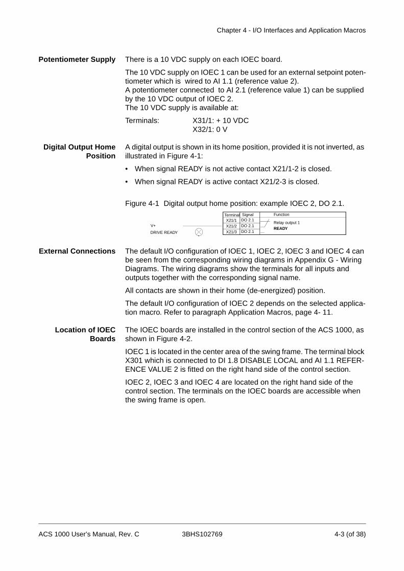
Chapter 4 - I/O Interfaces and Application Macros
Potentiometer Supply There is a 10 VDC supply on each IOEC board.
The 10 VDC supply on IOEC 1 can be used for an external setpoint poten-tiometer which is wired to AI 1.1 (reference value 2).A potentiometer connected to AI 2.1 (reference value 1) can be supplied by the 10 VDC output of IOEC 2. The 10 VDC supply is available at:
Terminals: X31/1: + 10 VDCX32/1: 0 V
Digital Output HomePosition
A digital output is shown in its home position, provided it is not inverted, as illustrated in Figure 4-1:
• When signal READY is not active contact X21/1-2 is closed.
• When signal READY is active contact X21/2-3 is closed.
Figure 4-1 Digital output home position: example IOEC 2, DO 2.1.
External Connections The default I/O configuration of IOEC 1, IOEC 2, IOEC 3 and IOEC 4 can be seen from the corresponding wiring diagrams in Appendix G - Wiring Diagrams. The wiring diagrams show the terminals for all inputs and outputs together with the corresponding signal name.
All contacts are shown in their home (de-energized) position.
The default I/O configuration of IOEC 2 depends on the selected applica-tion macro. Refer to paragraph Application Macros, page 4- 11.
Location of IOECBoards
The IOEC boards are installed in the control section of the ACS 1000, as shown in Figure 4-2.
IOEC 1 is located in the center area of the swing frame. The terminal block X301 which is connected to DI 1.8 DISABLE LOCAL and AI 1.1 REFER-ENCE VALUE 2 is fitted on the right hand side of the control section.
IOEC 2, IOEC 3 and IOEC 4 are located on the right hand side of the control section. The terminals on the IOEC boards are accessible when the swing frame is open.
X21/1X21/2X21/3
DO 2.1DO 2.1DO 2.1
Relay output 1READY
Terminal
DRIVE READY
FunctionSignal
V+
ACS 1000 User’s Manual, Rev. C 3BHS102769 4-3 (of 38)
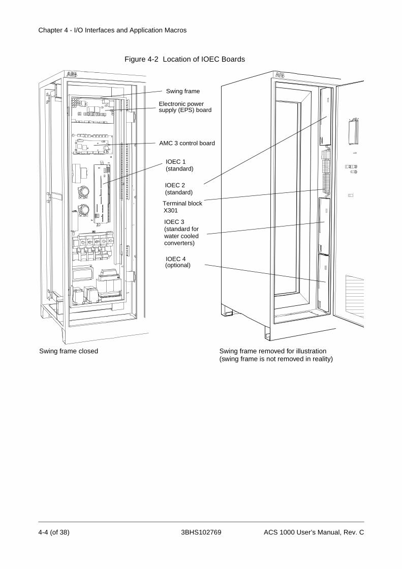
Chapter 4 - I/O Interfaces and Application Macros
Figure 4-2 Location of IOEC Boards
AMC 3 control board
Electronic powersupply (EPS) board
IOEC 3
IOEC 1
IOEC 2
Swing frame closed Swing frame removed for illustration
(standard)
(standard)
(standard for
(optional)
Swing frame
(swing frame is not removed in reality)
water cooled converters)
IOEC 4
Terminal blockX301
4-4 (of 38) 3BHS102769 ACS 1000 User’s Manual, Rev. C
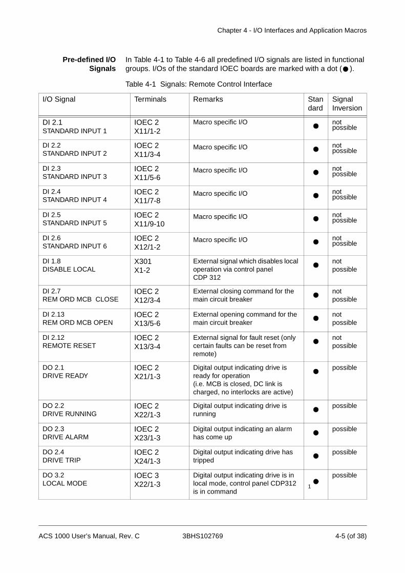
Chapter 4 - I/O Interfaces and Application Macros
Pre-defined I/OSignals
In Table 4-1 to Table 4-6 all predefined I/O signals are listed in functional groups. I/Os of the standard IOEC boards are marked with a dot ( ).
Table 4-1 Signals: Remote Control Interface
I/O Signal Terminals Remarks Standard
SignalInversion
DI 2.1 STANDARD INPUT 1
IOEC 2X11/1-2
Macro specific I/O not possible
DI 2.2 STANDARD INPUT 2
IOEC 2X11/3-4
Macro specific I/O not possible
DI 2.3 STANDARD INPUT 3
IOEC 2X11/5-6
Macro specific I/O not possible
DI 2.4 STANDARD INPUT 4
IOEC 2X11/7-8
Macro specific I/O not possible
DI 2.5 STANDARD INPUT 5
IOEC 2X11/9-10
Macro specific I/O not possible
DI 2.6 STANDARD INPUT 6
IOEC 2X12/1-2
Macro specific I/O not possible
DI 1.8 DISABLE LOCAL
X301X1-2
External signal which disables local operation via control panel CDP 312
not possible
DI 2.7 REM ORD MCB CLOSE
IOEC 2X12/3-4
External closing command for the main circuit breaker
not possible
DI 2.13 REM ORD MCB OPEN
IOEC 2X13/5-6
External opening command for the main circuit breaker
not possible
DI 2.12 REMOTE RESET
IOEC 2X13/3-4
External signal for fault reset (only certain faults can be reset from remote)
not possible
DO 2.1 DRIVE READY
IOEC 2X21/1-3
Digital output indicating drive is ready for operation(i.e. MCB is closed, DC link is charged, no interlocks are active)
possible
DO 2.2 DRIVE RUNNING
IOEC 2X22/1-3
Digital output indicating drive is running
possible
DO 2.3 DRIVE ALARM
IOEC 2X23/1-3
Digital output indicating an alarm has come up
possible
DO 2.4 DRIVE TRIP
IOEC 2X24/1-3
Digital output indicating drive has tripped
possible
DO 3.2 LOCAL MODE
IOEC 3X22/1-3
Digital output indicating drive is in local mode, control panel CDP312 is in command
1
possible
ACS 1000 User’s Manual, Rev. C 3BHS102769 4-5 (of 38)
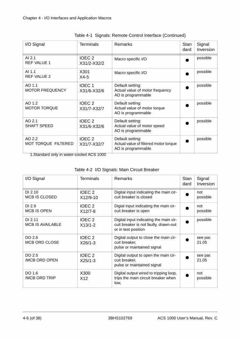
Chapter 4 - I/O Interfaces and Application Macros
AI 2.1 REF VALUE 1
IOEC 2X31/2-X32/2
Macro specific I/O possible
AI 1.1 REF VALUE 2
X301X4-5
Macro specific I/O possible
AO 1.1MOTOR FREQUENCY
IOEC 1X31/6-X32/6
Default setting:Actual value of motor frequencyAO is programmable
possible
AO 1.2MOTOR TORQUE
IOEC 2X31/7-X32/7
Default setting:Actual value of motor torqueAO is programmable
possible
AO 2.1 SHAFT SPEED
IOEC 2X31/6-X32/6
Default setting:Actual value of motor speedAO is programmable
possible
AO 2.2MOT TORQUE FILTERED
IOEC 2X31/7-X32/7
Default setting:Actual value of filtered motor torque AO is programmable
possible
1.Standard only in water-cooled ACS 1000
Table 4-1 Signals: Remote Control Interface (Continued)
I/O Signal Terminals Remarks Standard
SignalInversion
Table 4-2 I/O Signals: Main Circuit Breaker
I/O Signal Terminals Remarks Standard
SignalInversion
DI 2.10MCB IS CLOSED
IOEC 2X12/9-10
Digital input indicating the main cir-cuit breaker is closed
notpossible
DI 2.9MCB IS OPEN
IOEC 2X12/7-8
Digial input indicating the main cir-cuit breaker is open
notpossible
DI 2.11MCB IS AVAILABLE
IOEC 2X13/1-2
Digital input indicating the main cir-cuit breaker is not faulty, drawn-out or in test position
possible
DO 2.6MCB ORD CLOSE
IOEC 2X26/1-3
Digital output to close the main cir-cuit breaker,pulse or maintained signal
see par. 21.05
DO 2.5/MCB ORD OPEN
IOEC 2X25/1-3
Digital output to open the main cir-cuit breaker, pulse or maintained signal
see par. 21.05
DO 1.6 /MCB ORD TRIP
X300X12
Digital output wired to tripping loop, trips the main circuit breaker when low,
notpossible
4-6 (of 38) 3BHS102769 ACS 1000 User’s Manual, Rev. C

Chapter 4 - I/O Interfaces and Application Macros
Table 4-3 I/O Signals: Transformer (TRAFO)
I/O Signal Terminals Remarks Standard
Signal Inversion
DI 1.13/EXT TRAFO PROT TRIP
X300X4-5
External signal from a transformer protection device,signal active when low,wired to tripping loop,in case of trip:- alarm is displayed- main circut breaker is tripped
notpossible
DI 3.1OIL LEVEL ALARM
IOEC 3X11/1-2
External signal for alarm indication of transformer oil level 1
possible
DI 3.2TRAFO TEMP ALARM
IOEC 3X11/3-4
External signal for alarm indication of transformer oil or winding tem-perature
1
possible
DI 3.3/TRAFO TEMP TRIP
IOEC 3X11/5-6
External signal from a transformer oil or winding temperature monitor,trips the drive
1
notpossible
DI 3.4BUCHHOLZ ALARM
IOEC 3X11/7-8
Signal from Buchholz relay for alarm indication 1
possible
DI 3.5/BUCHHOLZ TRIP
IOEC 3X11/9-10
Signal from Buchholz relay, trips the drive 1
notpossible
AI 3.1TRAFO TEMP
IOEC 3X31/2-X32/2
Signal from transformer oil or wind-ing temperature monitor for alarm indication,drive reaction is set in parameter group 36
1
possible
1.Standard only in water-cooled ACS 1000
ACS 1000 User’s Manual, Rev. C 3BHS102769 4-7 (of 38)
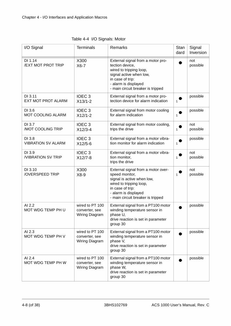
Chapter 4 - I/O Interfaces and Application Macros
Table 4-4 I/O Signals: Motor
I/O Signal Terminals Remarks Standard
SignalInversion
DI 1.14/EXT MOT PROT TRIP
X300X6-7
External signal from a motor pro-tection device, wired to tripping loop,signal active when low,in case of trip:- alarm is displayed- main circuit breaker is tripped
notpossible
DI 3.11EXT MOT PROT ALARM
IOEC 3X13/1-2
External signal from a motor pro-tection device for alarm indication 1
possible
DI 3.6MOT COOLING ALARM
IOEC 3X12/1-2
External signal from motor cooling for alarm indication 1
possible
DI 3.7/MOT COOLING TRIP
IOEC 3X12/3-4
External signal from motor cooling, trips the drive 1
notpossible
DI 3.8VIBRATION SV ALARM
IOEC 3X12/5-6
External signal from a motor vibra-tion monitor for alarm indication 1
possible
DI 3.9/VIBRATION SV TRIP
IOEC 3X12/7-8
External signal from a motor vibra-tion monitor,trips the drive
1
notpossible
DI 3.10/OVERSPEED TRIP
X300X8-9
External signal from a motor over-speed monitor, signal is active when low,wired to tripping loop, in case of trip:- alarm is displayed- main circuit breaker is tripped
1
notpossible
AI 2.2MOT WDG TEMP PH U
wired to PT 100 converter, see Wiring Diagram
External signal from a PT100 motor winding temperature sensor in phase U,drive reaction is set in parameter group 30
possible
AI 2.3MOT WDG TEMP PH V
wired to PT 100 converter, see Wiring Diagram
External signal from a PT100 motor winding temperature sensor in phase V,drive reaction is set in parameter group 30
possible
AI 2.4MOT WDG TEMP PH W
wired to PT 100 converter, see Wiring Diagram
External signal from a PT100 motor winding temperature sensor in phase W,drive reaction is set in parameter group 30
possible
4-8 (of 38) 3BHS102769 ACS 1000 User’s Manual, Rev. C
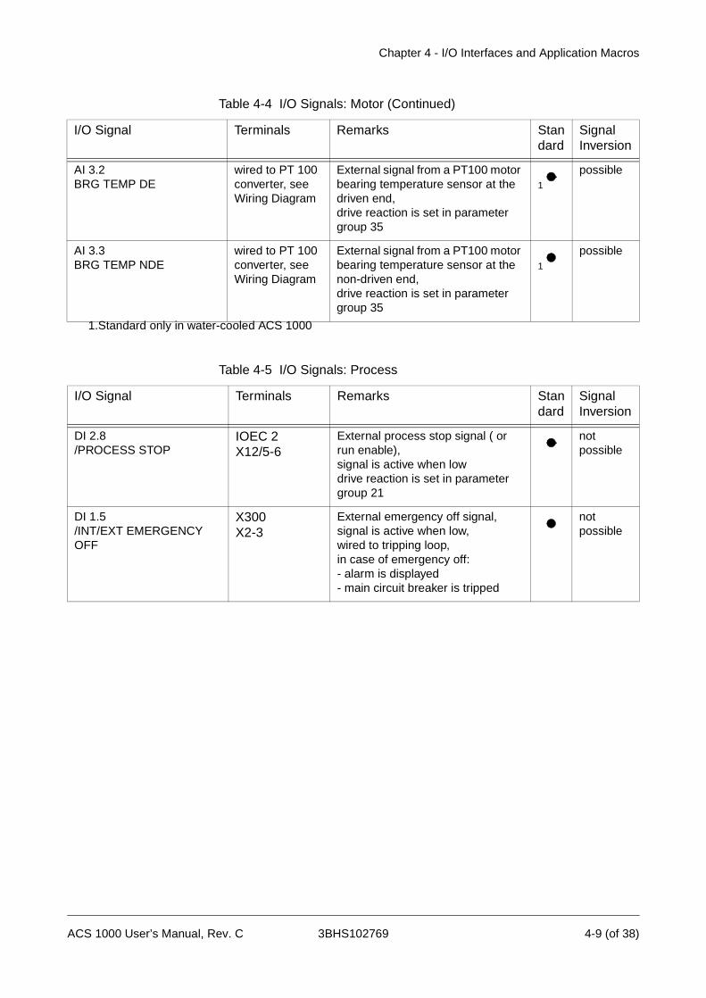
Chapter 4 - I/O Interfaces and Application Macros
AI 3.2BRG TEMP DE
wired to PT 100 converter, see Wiring Diagram
External signal from a PT100 motor bearing temperature sensor at the driven end,drive reaction is set in parameter group 35
1
possible
AI 3.3BRG TEMP NDE
wired to PT 100 converter, see Wiring Diagram
External signal from a PT100 motor bearing temperature sensor at the non-driven end,drive reaction is set in parameter group 35
1
possible
1.Standard only in water-cooled ACS 1000
Table 4-4 I/O Signals: Motor (Continued)
I/O Signal Terminals Remarks Standard
SignalInversion
Table 4-5 I/O Signals: Process
I/O Signal Terminals Remarks Standard
SignalInversion
DI 2.8/PROCESS STOP
IOEC 2X12/5-6
External process stop signal ( or run enable),signal is active when lowdrive reaction is set in parameter group 21
notpossible
DI 1.5/INT/EXT EMERGENCY OFF
X300X2-3
External emergency off signal, signal is active when low,wired to tripping loop,in case of emergency off:- alarm is displayed- main circuit breaker is tripped
notpossible
ACS 1000 User’s Manual, Rev. C 3BHS102769 4-9 (of 38)

Chapter 4 - I/O Interfaces and Application Macros
Table 4-6 I/O Signals: Others
I/O Signal Terminal Remarks Standard
Signal Inversion
DI 3.13/SUPPL VOLT UNBAL-ANCE
X300X10-11
External signal from a supply volt-age relay, signal is active when low,wired to tripping loop, in case of trip:- alarm is indicated- main circuit breaker is tripped
1
notpossible
DI 4.1EXT WTR COOLING ALARM
IOEC 4X11/1-2
External signal from a cooling water monitor for alarm indication
possible
DI 4.2/EXT WTR COOLING TRIP
IOEC 4X11/3-4
External signal from a cooling water monitor indicating a trip,signal is active when lowin case of trip:- alarm is displayed- drive is tripped
notpossible
DI 4.3BRAKE CHOP FAN PUMP ALARM
IOEC 4X11/5-6
External signal from a cooling fan or pump for braking resistors indicating a alarm,signal is active when low
notpossible
DI 4.4BRAKE CHOP TEMP ALARM
IOEC 4X11/7-8
External signal from a temperature monitor for braking resistors indica-ting an alarm,signal is active when low
notpossible
DI 4.5OUTPUT ISOL IS OPEN
IOEC 4X11/9-10
External signal indicating the output isolator is open
notpossible
DI 4.6OUTPUT ISOL IS CLOSED
IOEC 4X12/1-2
External signal indicating the output isolator is closed
notpossible
DI 4.7INPUT ISOL IS OPEN
IOEC 4X12/3-4
External signal indicating the input isolator is open
notpossible
DI 4.8INPUT ISOL IS CLOSED
IOEC 4X12/5-6
External signal indicating the input isolator is closed
notpossible
AI 3.4OUTSIDE AIR TEMP
IOEC 3X31/5-X32/5
External actual value of an outside air temperature,drive reaction is set in parameter group 37
1
possible
1.Standard only in water-cooled ACS 1000
4-10 (of 38) 3BHS102769 ACS 1000 User’s Manual, Rev. C
Chapter 4 - I/O Interfaces and Application Macros
Application Macros
Overview An application macro is a pre-programmed control software with specifi-cally adapted parameter sets. Depending on the process, the appropriate macro can be selected thus enabling a quick and easy start-up of the ACS 1000.
All application macros have factory-set parameter values. These default values can be left unchanged or they can be set individually according to the needs by the ABB commissioning engineer. Ask the local ABB service organization if more information is required.
The ACS 1000 can be operated using one of the following macros:
• Factory
• Speed Control
• Hand/Auto
• PID Control
• Sequential Control
• Torque Control
• Master/Follower
• User 1
• User 2
There are six digital inputs on IOEC board 2 marked STANDARD INPUT which are assigned to the application macros. See Table 4-1, I/O Signals: Remote control interface. The function of each digital input can change depending on the macro.
If I/Os are used which are not located on IOEC board 2 a reference to the corresponding board is made.
Besides the standard and the macro specific I/Os, various optional I/Os may be defined depending on the converter configuration. Refer to Appendix C - Customer Specific Options for more details.
All other customer interface signals are the same for each application macro. See also section Standard I/O Boards, page 4- 1.
Macro Applications
Factory The Factory Macro is the default-set macro. It covers most of the common applications such as pumps, fans, conveyors and other industrial applications where constant speed is required.
Speed Control The Speed Control Macro can be used for the same applications as the Factory Macro. The only difference to the Factory Macro is that the motor control parameters of the ACS 1000 will not be overwritten and set to 0 when the macro is activated.
ACS 1000 User’s Manual, Rev. C 3BHS102769 4-11 (of 38)
Chapter 4 - I/O Interfaces and Application Macros
Hand/Auto The Hand/Auto Macro is suitable for applications where the speed has to be controlled automatically by a process automation system and manually by an external control panel. The active control station is selected via a digital input.
The macro is also recommendable when two external control stations exist from where the reference value can be set and the drive can be started and stopped. The active control station for the reference value is selected via a digital input.
PID Control The PID Macro is intended for the use with closed loop control systems such as pressure control, level control and flow control. For example:
• Booster pumps of municipal water supply systems
• Automatic level control of water reservoirs
• Booster pumps of district heating systems
• Speed control of different types of material handling systems where the material flow has to be regulated.
Torque Control The Torque Control Macro is set up for processes requiring torque control, e.g. mixers and slave drives. The torque reference comes from a process automation system or a control panel.
Sequential Control The Sequential Control Macro is typically used in processes requiring different constant speed settings and/or different acceleration/decelera-tion settings in addition to an adjustable speed reference value. Up to seven constant speed settings and two acceleration/deceleration settings are possible. The selection of the different settings can be automized by a process control system or can be made manually by selector switches which are connected to the corresponding digital inputs.
Master/Follower The Master/Follower Macro is designed for applications with several ACS1000 drives where the motor shafts are coupled to each other by gearing, chain, belt etc. Thanks to the Master/Follower macro the load can be evenly distributed between the drives or at some adjustable other ratio which depends on the process.
User 1/User 2 Each of these two macros allows to save a complete customized para-meter set and to recall it at a later instant.
4-12 (of 38) 3BHS102769 ACS 1000 User’s Manual, Rev. C

Chapter 4 - I/O Interfaces and Application Macros
Factory Macro
Description All drive commands and reference settings can be given from the CDP 312 control panel or from an external control station.
The control station is selected with the LOC REM key on the control panel. The control panel can be disabled by closing DI 1.8. The digital input can be accessed via terminals X301:1 and X301:2.
In remote control the following default signal interface applies:
• The reference value is connected to AI 2.1.
• The start/stop command is wired to DI 2.1.
• The sense of rotation can be changed with DI 2.2. The default setting is FORWARD. It can be changed to REVERSE either by setting parameter 11.03 to REVERSE or via DI 2.2 if parameter 11.03 has been set to REQUEST before.
• Three constant speeds can be selected via DI 2.5 and DI 2.6 when the drive is in remote control.
• Two preset acceleration/deceleration ramps can be selected via DI 2.4.
When the Factory Macro is active the drive is speed controlled.
Control Overview Figure 4-3 Factory Macro, Control Overview
M3~
Motor
Ext. Controls
InputPower
Reference value, start/stop and direction commands are given from the control panel. To change to EXTERNAL, press LOC REM key.
Reference value is read from analog input AI 2.1. Start/stop and direction commands are given through digital inputs DI 2.1 and DI 2.2.
1 L -> 600.0 rpm 1Status RunningMotSpeed 600.00 rpmMotCurr 75.0 %
1 -> 600.0 rpm 1Status RunningMotSpeed 600.00 rpmMotCurr 75.0 %
ACS 1000 User’s Manual, Rev. C 3BHS102769 4-13 (of 38)
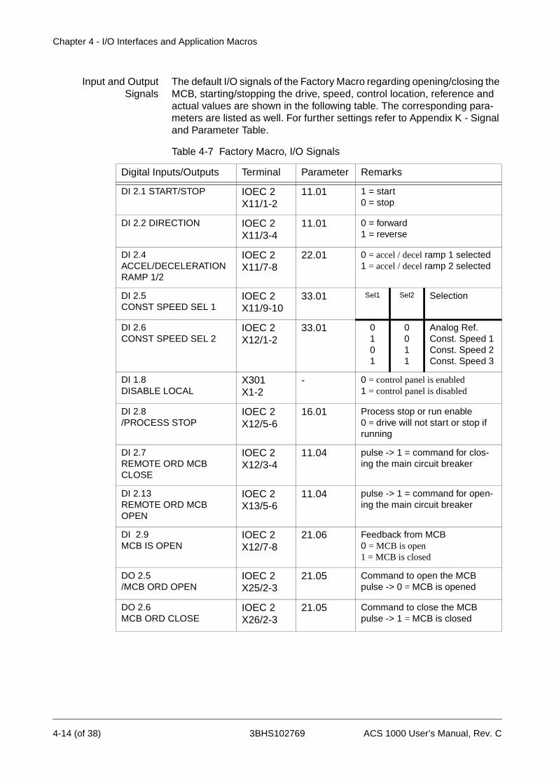
Chapter 4 - I/O Interfaces and Application Macros
Input and OutputSignals
The default I/O signals of the Factory Macro regarding opening/closing the MCB, starting/stopping the drive, speed, control location, reference and actual values are shown in the following table. The corresponding para-meters are listed as well. For further settings refer to Appendix K - Signal and Parameter Table.
Table 4-7 Factory Macro, I/O Signals
Digital Inputs/Outputs Terminal Parameter Remarks
DI 2.1 START/STOP IOEC 2X11/1-2
11.01 1 = start0 = stop
DI 2.2 DIRECTION IOEC 2X11/3-4
11.01 0 = forward1 = reverse
DI 2.4 ACCEL/DECELERATION RAMP 1/2
IOEC 2X11/7-8
22.01 0 = accel / decel ramp 1 selected1 = accel / decel ramp 2 selected
DI 2.5 CONST SPEED SEL 1
IOEC 2X11/9-10
33.01 Sel1 Sel2 Selection
DI 2.6CONST SPEED SEL 2
IOEC 2X12/1-2
33.01 0101
0011
Analog Ref.Const. Speed 1Const. Speed 2Const. Speed 3
DI 1.8DISABLE LOCAL
X301X1-2
- 0 = control panel is enabled1 = control panel is disabled
DI 2.8/PROCESS STOP
IOEC 2X12/5-6
16.01 Process stop or run enable 0 = drive will not start or stop if running
DI 2.7REMOTE ORD MCB CLOSE
IOEC 2X12/3-4
11.04 pulse -> 1 = command for clos-ing the main circuit breaker
DI 2.13REMOTE ORD MCBOPEN
IOEC 2X13/5-6
11.04 pulse -> 1 = command for open-ing the main circuit breaker
DI 2.9MCB IS OPEN
IOEC 2X12/7-8
21.06 Feedback from MCB 0 = MCB is open 1 = MCB is closed
DO 2.5/MCB ORD OPEN
IOEC 2X25/2-3
21.05 Command to open the MCBpulse -> 0 = MCB is opened
DO 2.6MCB ORD CLOSE
IOEC 2X26/2-3
21.05 Command to close the MCBpulse -> 1 = MCB is closed
4-14 (of 38) 3BHS102769 ACS 1000 User’s Manual, Rev. C
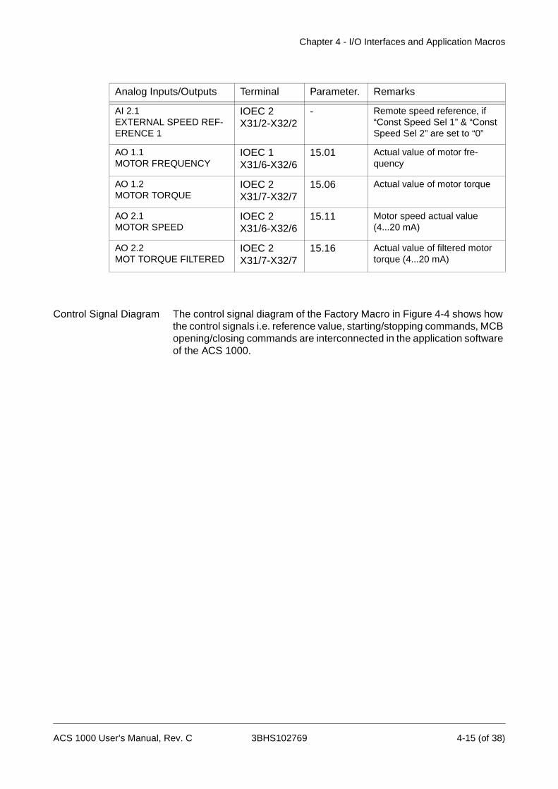
Chapter 4 - I/O Interfaces and Application Macros
Control Signal Diagram The control signal diagram of the Factory Macro in Figure 4-4 shows how the control signals i.e. reference value, starting/stopping commands, MCB opening/closing commands are interconnected in the application software of the ACS 1000.
Analog Inputs/Outputs Terminal Parameter. Remarks
AI 2.1EXTERNAL SPEED REF-ERENCE 1
IOEC 2X31/2-X32/2
- Remote speed reference, if “Const Speed Sel 1” & “Const Speed Sel 2” are set to “0”
AO 1.1MOTOR FREQUENCY
IOEC 1X31/6-X32/6
15.01 Actual value of motor fre-quency
AO 1.2MOTOR TORQUE
IOEC 2X31/7-X32/7
15.06 Actual value of motor torque
AO 2.1MOTOR SPEED
IOEC 2X31/6-X32/6
15.11 Motor speed actual value (4...20 mA)
AO 2.2MOT TORQUE FILTERED
IOEC 2X31/7-X32/7
15.16 Actual value of filtered motor torque (4...20 mA)
ACS 1000 User’s Manual, Rev. C 3BHS102769 4-15 (of 38)

Chapter 4 - I/O Interfaces and Application Macros
Figure 4-4 Control Signal Diagram of Factory Macro
12.06 EXT. REF2 SELECTION
12.03 EXT. REF1 SELECTION
33CONSTANT
SPEEDS
REF1
NOT SEL
REMOTE
REF2(%)
REF1(rpm)
EXT2
EXT2
IOEC 2-DI 1,2
IOEC2-DI 1,2
IOEC 2-DI 9MCB IS OPENIOEC 2-DI 10MCB IS CLOSED
REMOTE
LOCALREQUEST
FORWARDREVERSE
IOEC2-DI 8
START / STOP / DIRECTION
START/STOP
DIRECTIONEXT1
33.01 CONST. SPEED
SELECTION
12.01 KEYPADREF SEL
11.01 EXT1
STRT/STOP/DIR
11.02 EXT2
STRT/STOP/DIR
11.03DIRECTION
21.09 MCB
OPEN TIME LIM
21.08 MCB
CLOS. TIME LIM
21.07 MCB
AVAILABLE
21.06 MCB
OPEN SIGNAL
21.05 MCB ON
CTRL. MODE
11.05 EXT2
MCB CONTROL
11.04 EXT1
MCB CONTROL
16.01PROCESS STOP
MCB CLOSE COMMAND
MCB CONTROL
LOGIC
EXT2REMOTE
EXT1LOCAL
IOEC 2-DI 11MCB IS AVAILABLE
IOEC 2-DI 7,13COMM.MODULE
NOT SEL
KEYPAD LOCAL
KEYPAD
NOT USEDCOMM.MODULE
NOT SEL
NOT SELIOEC 2-DI 7,13
COMM.MODULE
*
12.02 EXT1/EXT2 SELECTION
* for further settings see Signal and Parameter Table
EXT1
COMM.MODULE
NOT SEL
KEYPADCOMM.MODULE EXT1
IOEC 2-DI 5, 6
DIG. INPUTS
CH0 AMC-BOARDCOMM.MODULE
ANAL. INPUTSIOEC 2: AI1 (REF1)IOEC 1: AI1 (REF2)
IOEC 2: DI 1...6 DI 7,13
CH2 DDCS LINK
REF. VALUE
CTRL. SIGNALS
REF. VALUE
CTRL. SIGNALS
REF
LOC
REM
STOP
START
DIRECTION
CONTROLPANEL
PUSH BUTTONS ON ACS 1000
IOEC 1: DI 6 MCB Offline
DI 7 MCB Online
REMOTEKEYPAD
REF 2 *
LOCAL
23.01SPEED REF
SPEED CONTROLLER
3.09TORQ REF 2
SPEED CONTROLLOOP
26.01TORQ SELECTOR
3.13TORQ REF USED
TORQUE CONTROLLOOP
MCB OPEN COMMAND
4-16 (of 38) 3BHS102769 ACS 1000 User’s Manual, Rev. C

Chapter 4 - I/O Interfaces and Application Macros
Hand/Auto Macro
Description Start/stop commands and reference settings can be given from the control panel of the ACS 1000 or from one of two external control stations, EXT1 (Hand) or EXT2 (Auto) (see Figure 4-5).
The LOC REM key on the control panel is used to enable the control panel or the external control stations. The control panel can be disabled by closing DI 1.8. The digital input can be accessed via terminals X301:1 and X301:2.
The remote control station EXT1 or EXT2 is selected with DI 2.5.
The control signals of EXT1 (Hand) for starting and stopping are connected to DI 2.1. Open/close commands for the MCB are wired to DI 2.13 and DI 2.7. The reference value is connected to AI 2.1. The speed reference value is given in rpm.
The commands from EXT 2 (Auto) for starting and stopping are connected to DI 2.2 and for opening/closing the MCB to DI 2.3 and DI 2.4. The refer-ence value is connected to AI 1.1. The analog input on IOEC 1 is acces-sible through terminals X301:3 and 4. The speed reference value is given as a percentage of the maximum speed of the drive (see parameters 12.7 and 12.8).
One constant speed can be selected through DI 2.6.
The drive is speed controlled when the Hand/Auto Macro is selected.
By default, the direction is fixed to FORWARD (see parameter 11.03).
Control Overview Figure 4-5 Hand/Auto Macro, Control Overview
M3∼
Motor
EXT1 (rpm) =InputPower
Hand/Auto
Const.Speed1
PLCorext. controls
EXT2 (%) =
Hand Control
Auto Control
Reference, start/stop and direction commands are given from the control panel. To change to EXTERNAL, press LOC REM key
Panel display in REMOTE:Hand control: Reference is read from analog input AI 1.1. Start/stop command is given through digital input DI 2.1.
1 L -> 600.0 rpm 1Status RunningMotSpeed 600.00 rpmMotCurr 75.0 %
1 -> 600.0 rpm 1Status RunningMotSpeed 600.00 rpmMotCurr 75.0 %
ACS 1000 User’s Manual, Rev. C 3BHS102769 4-17 (of 38)

Chapter 4 - I/O Interfaces and Application Macros
Input and OutputSignals
The default I/O signals of the Hand/Auto Macro regarding opening/closing the MCB, starting/stopping the drive, speed, control location, reference and actual values are shown in the following table. The corresponding parameters are listed as well. For further settings refer to Appendix K - Signal and Parameter Table.
Table 4-8 Hand/Auto Macro, I/O Signals
Digital Inputs/Outputs Terminal Parameter Remarks
DI 2.1 START/STOP HAND
IOEC 2X11/1-2
11.01 1 = start 0 = stop
DI 2.6START/STOP AUTO
IOEC 2X12/1-2
11.02 1 = start 0 = stop
DI 2.7REMOTE ORD MCB CLOSE HAND
IOEC 2X12/3-4
11.04 1 = request for closing the main circuit breaker
DI 2.13REMOTE ORD MCB OPEN HAND
IOEC 2X13/5-6
11.04 1 = request for opening the main circuit breaker
DI 2.3REMOTE ORD MCB CLOSE AUTO
IOEC 2X11/5-6
11.05 pulse -> 1 = command for clos-ing the main circuit breaker
DI 2.4REMOTE ORD MCB OPEN AUTO
IOEC 2X11/7-8
11.05 pulse -> 1 = command for open-ing the main circuit breaker
DI 2.5 EXT1/EXT2 SELECTION
IOEC 2X11/9-10
12.02 0 = hand selected1 = auto selected
DI 2.2CONSTANT SPEED 1
IOEC 2X11/3-4
33.01 If set to “1” a predefined constant speed reference is selected
DI 1.8DISABLE LOCAL
X301X1-2
- 0 = control panel is enabled1 = control panel is disabled
DI 2.8/PROCESS STOP
IOEC 2X12/5-6
16.01 Process stop or run enable 0 = drive will not start or stop if running
DI 2.9MCB IS OPEN
IOEC 2X12/7-8
21.06 Feedback from MCB 0 = MCB is open 1 = MCB is closed
DO 2.5/MCB ORD OPEN
IOEC 2X25/2-3
21.05 Command to open the MCBpulse -> 0 = MCB open 1
DO 2.6MCB ORD CLOSE
IOEC 2X26/2-3
21.05 Command to close the MCBpulse -> 1 = MCB close
4-18 (of 38) 3BHS102769 ACS 1000 User’s Manual, Rev. C

Chapter 4 - I/O Interfaces and Application Macros
Control Signal Logic The control signal diagram of the Hand/Auto Macro in Figure 4-6 shows how the control signals i.e. reference value, starting/stopping commands, MCB opening/closing commands are interconnected in the application software of the ACS 1000.
Analog Inputs/Outputs Terminal Parameter Remarks
AI 2.1 REFERENCE 1HAND
IOEC 2X31/2-X32/2
- External reference 1 in rpm
AI 1.1REFERENCE 2AUTO
X301:X3-X4
- External reference 2 in %
AO 1.1MOTOR FREQUENCY
IOEC 1X31/6-X32/6
15.01 Motor frequency actual value (4...20 mA)
AO 1.2MOTOR TORQUE
IOEC 1X31/7-X32/7
15.06 Motor torque actual value (4...20 mA)
AO 2.1MOTOR SPEED
IOEC 2X31/6-X32/6
15.11 Motor speed actual value (4...20 mA)
AO 2.2MOT TORQUE FILTERED
IOEC 2X31/7-X32/7
15.16 Actual value of filtered motor torque (4...20 mA)
ACS 1000 User’s Manual, Rev. C 3BHS102769 4-19 (of 38)

Chapter 4 - I/O Interfaces and Application Macros
Figure 4-6 Control Signal Diagram of Hand/Auto Macro
12.06 EXT. REF2 SELECTION
12.03 EXT. REF1 SELECTION
33CONSTANT
SPEEDS
REF1
NOT SEL
REMOTE
REF2(%)
REF1(rpm)
EXT2
EXT2
IOEC 2-DI 1
IOEC2-DI 6
IOEC 2-DI 9MCB IS OPENIOEC 2-DI 10MCB IS CLOSED
REMOTE
LOCALREQUEST
FORWARDREVERSE
IOEC2-DI 8
START / STOP / DIRECTION
START/STOP
DIRECTIONEXT1
33.01 CONST. SPEED
SELECTION
12.01 KEYPADREF SEL
11.01 EXT1
STRT/STOP/DIR
11.02 EXT2
STRT/STOP/DIR
11.03DIRECTION
21.09 MCB
OPEN TIME LIM
21.08 MCB
CLOS. TIME LIM
21.07 MCB
AVAILABLE
21.06 MCB
OPEN SIGNAL
21.05 MCB ON
CTRL. MODE
11.05 EXT2
MCB CONTROL
11.04 EXT1
MCB CONTROL
16.01PROCESS STOP
MCB CLOSE COMMAND
MCB CONTROL
LOGIC
EXT2REMOTE
EXT1LOCAL
IOEC 2-DI 11MCB IS AVAILABLE
IOEC 2-DI 7,13COMM.MODULE
NOT SEL
KEYPAD LOCAL
KEYPAD
NOT USEDCOMM.MODULE
NOT SEL
NOT SELIOEC 2-DI 3,4
COMM.MODULE
*
12.02 EXT1/EXT2 SELECTION
* for further settings see Signal and Parameter Table
EXT1
COMM.MODULE
NOT SEL
KEYPADCOMM.MODULE IOEC 2-DI 5
IOEC 2-DI 2(SPEED 2)
DIG. INPUTS
CH0 AMC-BOARDCOMM.MODULE
ANAL. INPUTSIOEC 2: AI1 (REF1)IOEC 1: AI1 (REF2)
IOEC 2: DI 1...6 DI 7,13
CH2 DDCS LINK
REF. VALUE
CTRL. SIGNALS
REF. VALUE
CTRL. SIGNALS
REF
LOC
REM
STOP
START
DIRECTION
CONTROLPANEL
PUSH BUTTONS ON ACS 1000
IOEC 1: DI 6 MCB Offline
DI 7 MCB Online
REMOTEKEYPAD
REF 2 *
LOCAL
23.01SPEED REF
SPEED CONTROLLER
3.09TORQ REF 2
SPEED CONTROLLOOP
26.01TORQ SELECTOR
3.13TORQ REF USED
TORQUE CONTROLLOOP
MCB OPEN COMMAND
4-20 (of 38) 3BHS102769 ACS 1000 User’s Manual, Rev. C
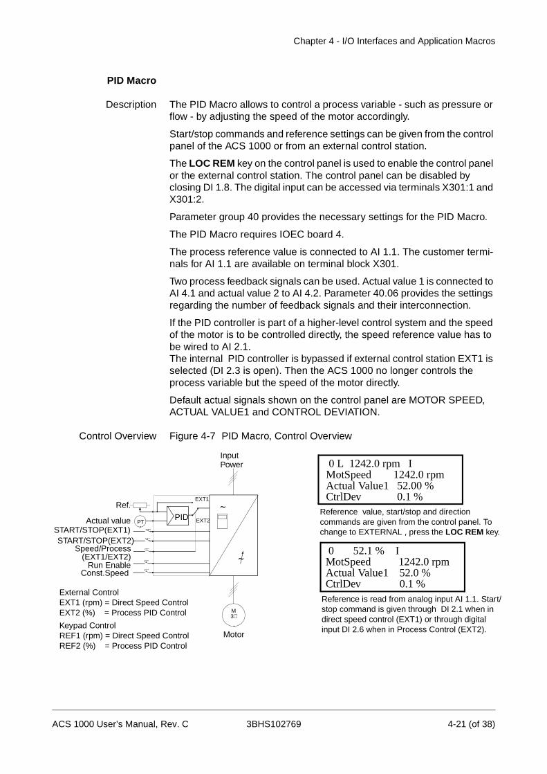
Chapter 4 - I/O Interfaces and Application Macros
PID Macro
Description The PID Macro allows to control a process variable - such as pressure or flow - by adjusting the speed of the motor accordingly.
Start/stop commands and reference settings can be given from the control panel of the ACS 1000 or from an external control station.
The LOC REM key on the control panel is used to enable the control panel or the external control station. The control panel can be disabled by closing DI 1.8. The digital input can be accessed via terminals X301:1 and X301:2.
Parameter group 40 provides the necessary settings for the PID Macro.
The PID Macro requires IOEC board 4.
The process reference value is connected to AI 1.1. The customer termi-nals for AI 1.1 are available on terminal block X301.
Two process feedback signals can be used. Actual value 1 is connected to AI 4.1 and actual value 2 to AI 4.2. Parameter 40.06 provides the settings regarding the number of feedback signals and their interconnection.
If the PID controller is part of a higher-level control system and the speed of the motor is to be controlled directly, the speed reference value has to be wired to AI 2.1. The internal PID controller is bypassed if external control station EXT1 is selected (DI 2.3 is open). Then the ACS 1000 no longer controls the process variable but the speed of the motor directly.
Default actual signals shown on the control panel are MOTOR SPEED, ACTUAL VALUE1 and CONTROL DEVIATION.
Control Overview Figure 4-7 PID Macro, Control Overview
M3∼
Motor
InputPower
Const.Speed Run Enable
Speed/Process
PIDPT
EXT1
EXT2
START/STOP(EXT2)START/STOP(EXT1)
Ref.
Actual value
(EXT1/EXT2)
Reference is read from analog input AI 1.1. Start/stop command is given through DI 2.1 when in direct speed control (EXT1) or through digital input DI 2.6 when in Process Control (EXT2).
Reference value, start/stop and direction commands are given from the control panel. To change to EXTERNAL , press the LOC REM key.
External ControlEXT1 (rpm) = Direct Speed ControlEXT2 (%) = Process PID Control
Keypad ControlREF1 (rpm) = Direct Speed ControlREF2 (%) = Process PID Control
0 L 1242.0 rpm IMotSpeed 1242.0 rpm Actual Value1 52.00 %CtrlDev 0.1 %
0 52.1 % IMotSpeed 1242.0 rpm Actual Value1 52.0 %CtrlDev 0.1 %
ACS 1000 User’s Manual, Rev. C 3BHS102769 4-21 (of 38)

Chapter 4 - I/O Interfaces and Application Macros
Input and OutputSignals
The default I/O signals of the PID Macro regarding opening/closing the MCB, starting/stopping the drive, speed, control location, reference and actual values are shown in the following table. The corresponding para-meters are listed as well. For further settings refer to Appendix K - Signal and Parameter Table.
Table 4-9 PID Macro, I/O Signals
Digital Inputs/Outputs Terminal Parameter Remarks
DI 2.1 START/STOP
IOEC 2X11/1-2
11.01 1 = start 0 = stop
DI 2.2 DIRECTION
IOEC 2X11/3-4
11.01 0 = forward 1 = reverse
DI 2.3 EXT 1/2 SELECTION
IOEC 2X11/5-6
12.02 Selection of external reference0 = EXT 11 = EXT 2
DI 2.4 ACCEL/DECELERATION RAMP 1/2
IOEC 2X11/7-8
22.01 0 = accel / decel ramp 1 selected1 = accel / decel ramp 2 selected
DI 2.5CONST SPEED SEL 1
IOEC 2X11/9-10
33.01 Sel1 Sel2 Selection
DI 2.6CONST SPEED SEL 2
IOEC 2X12/1-2
33.01 0101
0011
Analog Ref.Const. Speed 1Const. Speed 2Const. Speed 3
DI 1.8DISABLE LOCAL
X301X1-2
- 0 = control panel is enabled1 = control panel is disabled
DI 2.8/PROCESS STOP
IOEC 2X12/5-6
16.01 Process stop or run enable 0 = drive will not start or stop if running
DI 2.7REMOTE ORD MCB CLOSE
IOEC 2X12/3-4
11.04 pulse -> 1 = command for clos-ing the main circuit breaker
DI 2.13REMOTE ORD MCBOPEN
IOEC 2X13/5-6
11.04 pulse -> 1 = command for open-ing the main circuit breaker
DI 2.9MCB IS OPEN
IOEC 2X12/7-8
21.06 Feedback from MCB0 = MCB is open 1 = MCB is closed
DO 2.5/MCB ORD OPEN
IOEC 2X25/2-3
21.05 Command to open the MCBpulse -> 0 = MCB open
DO 2.6MCB ORD CLOSE
IOEC 2X26/2-3
21.05 Command to close the MCB pulse -> 1 = MCB close
4-22 (of 38) 3BHS102769 ACS 1000 User’s Manual, Rev. C

Chapter 4 - I/O Interfaces and Application Macros
Control Signal Diagram The control signal diagram of the PID Macro in Figure 4-8 shows how the control signals i.e. reference value, starting/stopping commands, MCB opening/closing commands are interconnected in the application software of the ACS 1000.
Analog Inputs/Outputs Terminal Parameter Remarks
AI 2.1 ANALOG REFERENCE
IOEC 2X31/2-X32/2
- External reference
AI 4.1ACTUAL VALUE
IOEC 4X31/2-X32/2
- Process feedback
AI 4.2ACTUAL VALUE
IOEC 4X31/3-X32/3
- Process feedback
AO 1.1MOTOR FREQUENCY
IOEC 1X31/6-X32/6
15.01 Motor frequency actual value (4...20 mA)
AO 1.2MOTOR TORQUE
IOEC 1X31/7-X32/7
15.06 Motor torque actual value (4...20 mA)
AO 2.1MOTOR SPEED
IOEC 2X31/6-X32/6
15.11 Motor speed actual value (4...20 mA)
AO 2.2MOT TORQUE FILTERED
IOEC 2X31/7-X32/7
15.16 Actual value of filtered motor torque (4...20 mA)
ACS 1000 User’s Manual, Rev. C 3BHS102769 4-23 (of 38)
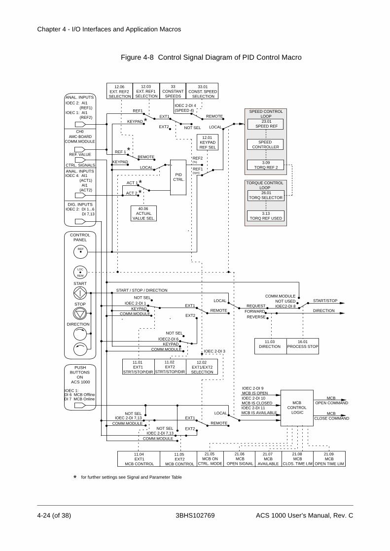
Chapter 4 - I/O Interfaces and Application Macros
Figure 4-8 Control Signal Diagram of PID Control Macro
12.06 EXT. REF2 SELECTION
12.03 EXT. REF1 SELECTION
33CONSTANT
SPEEDS
REF1
NOT SEL
REMOTE
REF2(%)
REF1(rpm)
EXT2
EXT2
IOEC 2-DI 1
IOEC2-DI 6
IOEC 2-DI 9MCB IS OPENIOEC 2-DI 10MCB IS CLOSED
REMOTE
LOCALREQUEST
FORWARDREVERSE
IOEC2-DI 8
START / STOP / DIRECTION
START/STOP
DIRECTIONEXT1
33.01 CONST. SPEED
SELECTION
12.01 KEYPADREF SEL
11.01 EXT1
STRT/STOP/DIR
11.02 EXT2
STRT/STOP/DIR
11.03DIRECTION
21.09 MCB
OPEN TIME LIM
21.08 MCB
CLOS. TIME LIM
21.07 MCB
AVAILABLE
21.06 MCB
OPEN SIGNAL
21.05 MCB ON
CTRL. MODE
11.05 EXT2
MCB CONTROL
11.04 EXT1
MCB CONTROL
16.01PROCESS STOP
MCB CLOSE COMMAND
MCB CONTROL
LOGIC
EXT2REMOTE
EXT1LOCAL
IOEC 2-DI 11MCB IS AVAILABLE
IOEC 2-DI 7,13COMM.MODULE
NOT SEL
KEYPAD LOCAL
KEYPAD
NOT USEDCOMM.MODULE
NOT SEL
NOT SELIOEC 2-DI 7,13
COMM.MODULE
*
12.02 EXT1/EXT2 SELECTION
* for further settings see Signal and Parameter Table
EXT1
COMM.MODULE
NOT SEL
KEYPADCOMM.MODULE IOEC 2-DI 3
IOEC 2-DI 4(SPEED 4)
DIG. INPUTS
CH0 AMC-BOARDCOMM.MODULE
ANAL. INPUTSIOEC 2: AI1 (REF1)IOEC 1: AI1 (REF2)
IOEC 2: DI 1...6 DI 7,13
REF. VALUE
CTRL. SIGNALS
REF
LOC
REM
STOP
START
DIRECTION
CONTROLPANEL
PUSH BUTTONS ON ACS 1000
IOEC 1: DI 6 MCB Offline
DI 7 MCB Online
REMOTEKEYPAD
REF 1 *
LOCAL
23.01SPEED REF
SPEED CONTROLLER
3.09TORQ REF 2
SPEED CONTROLLOOP
26.01TORQ SELECTOR
3.13TORQ REF USED
TORQUE CONTROLLOOP
PID CTRL.
40.06 ACTUAL
VALUE SEL.
ACT 1
ACT 2
**
IOEC 4: AI1 (ACT1) AI1 (ACT2)
ANAL. INPUTS
MCB OPEN COMMAND
4-24 (of 38) 3BHS102769 ACS 1000 User’s Manual, Rev. C

Chapter 4 - I/O Interfaces and Application Macros
Torque Macro
Description The Torque Control Macro is used in applications requiring torque control of the motor. The settings for torque reference and torque reference handling can be adjusted in parameter group 25 and 26 respectively.
The torque reference is given through AI 2.1 as a current signal. By default, 0 mA correspond to 0% and 20 mA to 100% of the rated motor torque.
The start and stop command is given through DI 2.1 and the sense of rota-tion is changed by means of DI 2.2.
Changing from torque control to speed control is achieved by setting DI 2.3 to low.
It is also possible to change the control location from external to local (i.e. to control panel) by pressing the LOC REM key. When LOCAL is selected on the control panel the drive is speed controlled by default. If torque control is required parameter 12.1 KEYPAD REF SELECT has to be changed to REF2 (%). The control panel can be disabled by closing DI 1.8. The digital input can be accessed via terminals X301:1 and X301:2.
Default settings for the display of the control panel are SPEED, TORQUE and CONTROL LOCATION.
Control Overview Figure 4-9 Torque Macro, Control Overview
M3∼
Motor
Ext. Controls
InputPower
External ControlEXT1 (rpm) = Speed ControlEXT2 (%) = Torque Control
Keypad ControlREF1 (rpm) = Speed ControlREF2 (%) = Torque Control
Reference value, start, stop and direction commands are given from the control panel. To change to EXTERNAL press LOC REM key.
The reference value is read from AI 2.1 (if torque control is selected) or AI 1.1 (if speed control is selected). Start, stop and direction commands are given through DI 2.1 and DI 2.2. Selec-tion between speed and torque control is done through DI 2.3.
EXT1
EXT2
Speed ref.Torque ref.
0 L 1242.0 rpm IMotSpeed 1242.0 rpm MotTorq 66.00 %CtrlLoc LOCAL
MotSpeed 1242.0 rpm MotTorq 66.00 %CtrlLoc EXT2
0 50.0 % I
ACS 1000 User’s Manual, Rev. C 3BHS102769 4-25 (of 38)

Chapter 4 - I/O Interfaces and Application Macros
Input and OutputSignals
The default I/Os of the Torque Macro regarding opening/closing the MCB, starting/stopping the drive, speed, control location, reference and actual values are shown in the following table. The corresponding parameters are listed as well. For further settings refer to Appendix K - Signal and Param-eter Table.
Table 4-10 Torque Macro, I/O Signals
Digital Inputs/Outputs Terminal Parameter Remarks
DI 2.1START/STOP
IOEC 2X11/1-2
11.01 1 = start0 = stop
DI 2.2DIRECTION
IOEC 2X11/3-4
11.01 0 = forward1 = reverse
DI 2.3 EXT 1/2 SELECTION
IOEC 2X11/5-6
12.02 0 = speed control1 = torque control
DI 2.4ACCEL/DECEL 1/2 SELECTION
IOEC 2X11/7-8
22.01 0 = accel / decel ramp 1 selected1 = accel / decel ramp 2 selected
DI 2.5CONSTANT SPEED SELECTION
IOEC 2X11/9-10
33.01 If set to “1” the predefined con-stant speed reference is selected
DI 1.8DISABLE LOCAL
X301X1-2
- 0 = control panel is enabled1 = control panel is disabled
DI 2.8/PROCESS STOP
IOEC 2X12/5-6
16.01 Process stop or run enable 0 = drive will not start or stop if running
DI 2.7REMOTE ORD MCB CLOSE
IOEC 2X12/3-4
11.04 pulse -> 1 = command for clos-ing the main circuit breaker
DI 2.13REMOTE ORD MCBOPEN
IOEC 2X13/5-6
11.04 pulse -> 1 = command for open-ing the main circuit breaker
DI 2.9MCB IS OPEN
IOEC 2X12/7-8
21.06 Feedback from MCB 0 = MCB is open 1 = MCB is closed
DO 2.5/MCB ORD OPEN
IOEC 2X25/2-3
21.05 Command to open the MCBpulse -> 0 = MCB open 1
DO 2.6MCB ORD CLOSE
IOEC 2X26/2-3
21.05 Command to close the MCBpulse -> 1 = MCB close
4-26 (of 38) 3BHS102769 ACS 1000 User’s Manual, Rev. C

Chapter 4 - I/O Interfaces and Application Macros
Control Signal Diagram The control signal diagram of the Torque Macro in Figure 4-10 shows how the control signals i.e. reference value, starting/stopping commands, MCB opening/closing commands are interconnected in the application software of the ACS 1000.
Analog Inputs/Outputs Terminal Parameter Remarks
AI 1.1SPEED REFERENCE
IOEC 1X31/2-X32/2
- Speed reference (EXT1)
AI 2.1TORQUE REFERENCE
IOEC 2X31/2-X32/2
- Torque reference (EXT2)
AO 1.1MOTOR FREQUENCY
IOEC 1X31/6-X32/6
15.01 Motor frequency actual value (4...20 mA)
AO 1.2MOTOR TORQUE
IOEC 1X31/7-X32/7
15.06 Motor torque actual value (4...20 mA)
AO 2.1MOTOR SPEED
IOEC 2X31/6-X32/6
15.11 Motor speed actual value (4...20 mA)
AO 2.2MOT TORQUE FILTERED
IOEC 2X31/7-X32/7
15.16 Actual value of filtered motor torque (4...20 mA)
ACS 1000 User’s Manual, Rev. C 3BHS102769 4-27 (of 38)
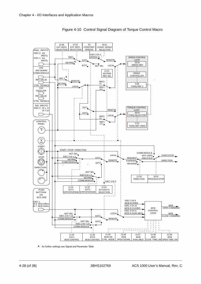
Chapter 4 - I/O Interfaces and Application Macros
Figure 4-10 Control Signal Diagram of Torque Control Macro
12.06 EXT. REF2 SELECTION
12.03 EXT. REF1 SELECTION
33CONSTANT
SPEEDS
REF1
NOT SEL
REMOTE
REF2(%)
REF1(rpm)
EXT2
EXT2
IOEC 2-DI 1,2
IOEC2-DI 1,2
IOEC 2-DI 9MCB IS OPENIOEC 2-DI 10MCB IS CLOSED
REMOTE
LOCALREQUEST
FORWARDREVERSE
IOEC2-DI 8
START / STOP / DIRECTION
START/STOP
DIRECTIONEXT1
33.01 CONST. SPEED
SELECTION
12.01 KEYPADREF SEL
11.01 EXT1
STRT/STOP/DIR
11.02 EXT2
STRT/STOP/DIR
11.03DIRECTION
21.09 MCB
OPEN TIME LIM
21.08 MCB
CLOS. TIME LIM
21.07 MCB
AVAILABLE
21.06 MCB
OPEN SIGNAL
21.05 MCB ON
CTRL. MODE
11.05 EXT2
MCB CONTROL
11.04 EXT1
MCB CONTROL
16.01PROCESS STOP
MCB CLOSE COMMAND
MCB CONTROL
LOGIC
EXT2REMOTE
EXT1LOCAL
IOEC 2-DI 11MCB IS AVAILABLE
IOEC 2-DI 7,13COMM.MODULE
NOT SEL
KEYPAD LOCAL
KEYPAD
NOT USEDCOMM.MODULE
NOT SEL
NOT SELIOEC 2-DI 7,13
COMM.MODULE
*
12.02 EXT1/EXT2 SELECTION
* for further settings see Signal and Parameter Table
EXT1
EXT2
EXT1
COMM.MODULE
NOT SEL
KEYPADCOMM.MODULE IOEC 2-DI 3
IOEC 2-DI 4(SPEED 4)
LOCAL
REMOTE
REF2(%)
REF1(rpm)
DIG. INPUTS
CH0 AMC-BOARDCOMM.MODULE
ANAL. INPUTSIOEC 2: AI1 (REF1)IOEC 1: AI1 (REF2)
IOEC 2: DI 1...6 DI 7,13
CH2 DDCS LINK
REF. VALUE
CTRL. SIGNALS
REF. VALUE
CTRL. SIGNALS
REF
LOC
REM
STOP
START
DIRECTION
CONTROLPANEL
PUSH BUTTONS ON ACS 1000
IOEC 1: DI 6 MCB Offline
DI 7 MCB Online
REMOTEKEYPAD
REF 2 *
LOCAL
23.01SPEED REF
SPEED CONTROLLER
3.09TORQ REF 2
SPEED CONTROLLOOP
26.01TORQ SELECTOR
3.13TORQ REF USED
TORQUE CONTROLLOOP
MCB OPEN COMMAND
4-28 (of 38) 3BHS102769 ACS 1000 User’s Manual, Rev. C
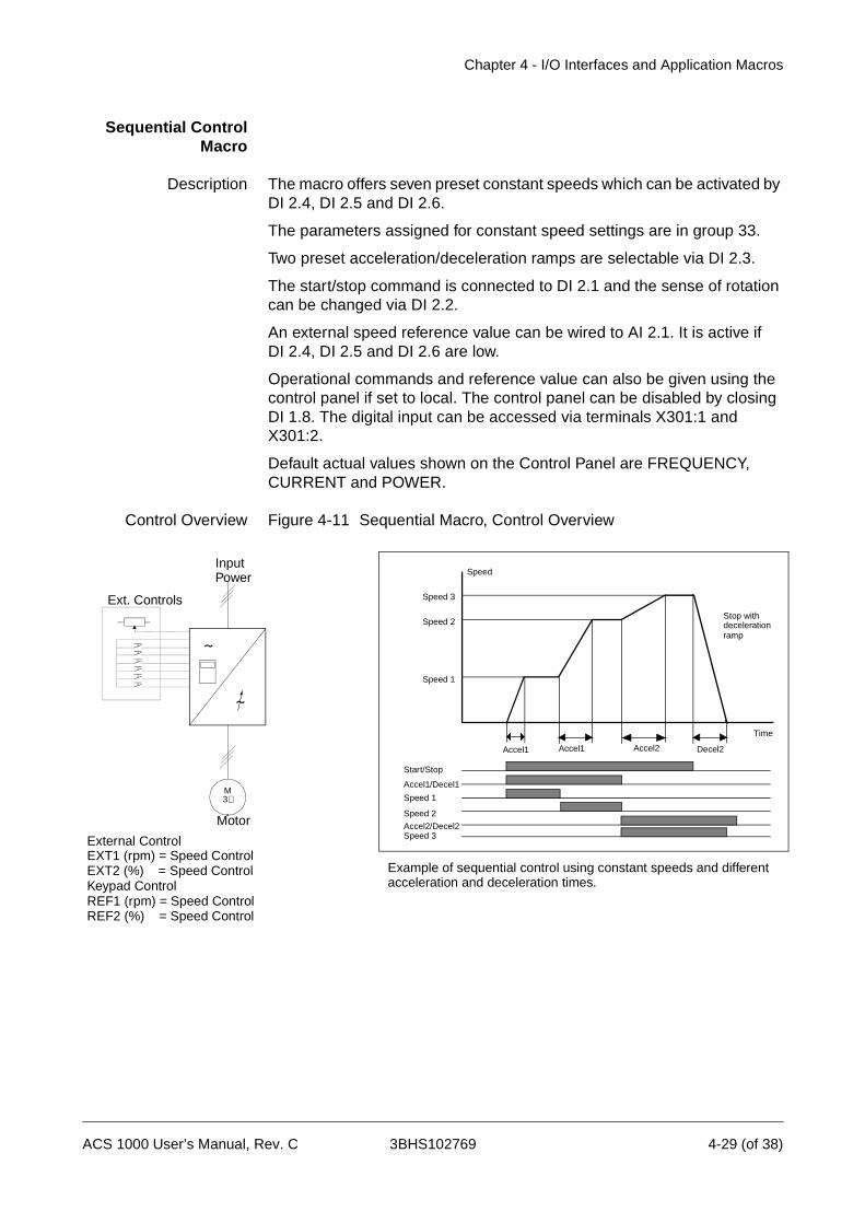
Chapter 4 - I/O Interfaces and Application Macros
Sequential ControlMacro
Description The macro offers seven preset constant speeds which can be activated by DI 2.4, DI 2.5 and DI 2.6.
The parameters assigned for constant speed settings are in group 33.
Two preset acceleration/deceleration ramps are selectable via DI 2.3.
The start/stop command is connected to DI 2.1 and the sense of rotation can be changed via DI 2.2.
An external speed reference value can be wired to AI 2.1. It is active if DI 2.4, DI 2.5 and DI 2.6 are low.
Operational commands and reference value can also be given using the control panel if set to local. The control panel can be disabled by closing DI 1.8. The digital input can be accessed via terminals X301:1 and X301:2.
Default actual values shown on the Control Panel are FREQUENCY, CURRENT and POWER.
Control Overview Figure 4-11 Sequential Macro, Control Overview
M3∼
Motor
Ext. Controls
InputPower
Accel1 Accel1 Accel2 Decel2
Speed 3
Speed 2
Speed 1
Speed
Time
Start/Stop
Accel1/Decel1
Speed 1
Speed 2
Accel2/Decel2Speed 3
Stop with deceleration ramp
Example of sequential control using constant speeds and different acceleration and deceleration times.
External ControlEXT1 (rpm) = Speed Control EXT2 (%) = Speed ControlKeypad ControlREF1 (rpm) = Speed ControlREF2 (%) = Speed Control
ACS 1000 User’s Manual, Rev. C 3BHS102769 4-29 (of 38)

Chapter 4 - I/O Interfaces and Application Macros
Input and OutputSignals
The default I/O signals of the Sequential Macro regarding opening/closing the MCB, starting/stopping the drive, speed, control location, reference and actual values are shown in the following table. The corresponding parameters are listed as well. For further settings refer to Appendix K - Signal and Parameter Table.
Table 4-11 Sequential Macro Macro, I/O Signals
Digital Inputs/Outputs Terminal Parameter Remarks
DI 2.1START/STOP
IOEC 2X11/1-2
11.01 1 = start0 = stop
DI 2.2DIRECTION
IOEC 2X11/3-4
11.01 0 = forward1 = reverse
DI 2.3ACCEL/DECEL 1/2 SELECTION
IOEC 2X11/5-6
22.01 0 = accel / decel ramp 1 selected1 = accel / decel ramp 2 selected
DI 2.4CONST SPEED SEL 1
IOEC 2X11/7-8
33.01 Sel1 Sel2 Sel3 Selection
DI 2.5CONST SPEED SEL 2
IOEC 2X11/9-10
33.01 01010101
00110011
00001111
Analog Ref.Const. Speed 1Const. Speed 2Const. Speed 3Const. Speed 4Const. Speed 5Const. Speed 6Const. Speed 7
DI 2.6CONST SPEED SEL 3
IOEC 2X12/1-2
33.01
DI 1.8DISABLE LOCAL
X301X1-2
- 0 = control panel is enabled1 = control panel is disabled
DI 2.8/PROCESS STOP
IOEC 2X12/5-6
16.01 Process stop or run enable 0 = drive will not start or stop if run-ning
DI 2.7REMOTE ORD MCB CLOSE
IOEC 2X12/3-4
11.04 pulse -> 1 = command to close the main circuit breaker
DI 2.13REMOTE ORD MCBOPEN
IOEC 2X13/5-6
11.04 pulse -> 1 = command to open the main circuit breaker
DI 2.9MCB IS OPEN
IOEC 2X12/7-8
21.06 Feedback from MCB0 = MCB is open1 = MCB is closed
DO 2.5MCB ORD OPEN
IOEC 2X26/2-3
21.05 Command to open the MCBpulse -> 0 = MCB open
4-30 (of 38) 3BHS102769 ACS 1000 User’s Manual, Rev. C
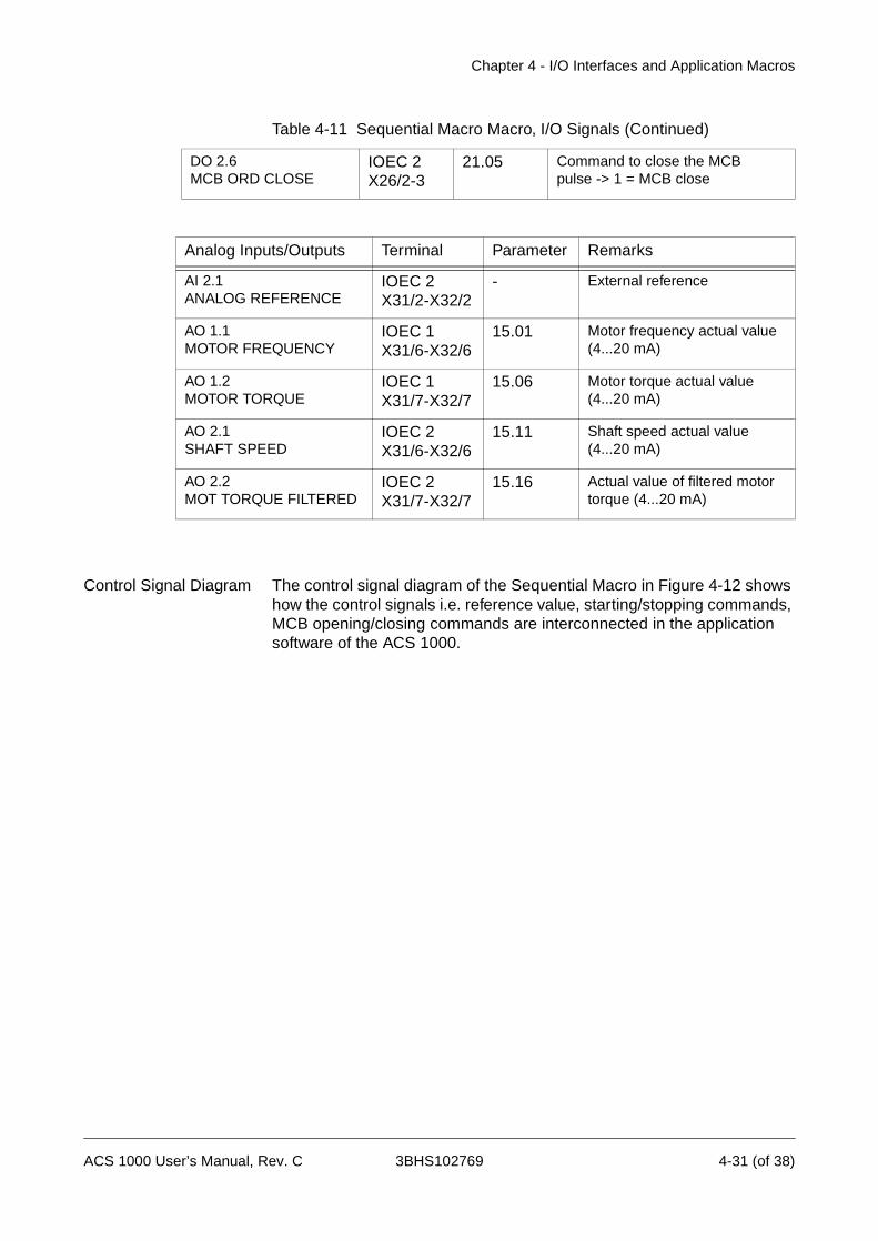
Chapter 4 - I/O Interfaces and Application Macros
Control Signal Diagram The control signal diagram of the Sequential Macro in Figure 4-12 shows how the control signals i.e. reference value, starting/stopping commands, MCB opening/closing commands are interconnected in the application software of the ACS 1000.
DO 2.6MCB ORD CLOSE
IOEC 2X26/2-3
21.05 Command to close the MCBpulse -> 1 = MCB close
Table 4-11 Sequential Macro Macro, I/O Signals (Continued)
Analog Inputs/Outputs Terminal Parameter Remarks
AI 2.1ANALOG REFERENCE
IOEC 2X31/2-X32/2
- External reference
AO 1.1MOTOR FREQUENCY
IOEC 1X31/6-X32/6
15.01 Motor frequency actual value (4...20 mA)
AO 1.2MOTOR TORQUE
IOEC 1X31/7-X32/7
15.06 Motor torque actual value (4...20 mA)
AO 2.1SHAFT SPEED
IOEC 2X31/6-X32/6
15.11 Shaft speed actual value (4...20 mA)
AO 2.2MOT TORQUE FILTERED
IOEC 2X31/7-X32/7
15.16 Actual value of filtered motor torque (4...20 mA)
ACS 1000 User’s Manual, Rev. C 3BHS102769 4-31 (of 38)
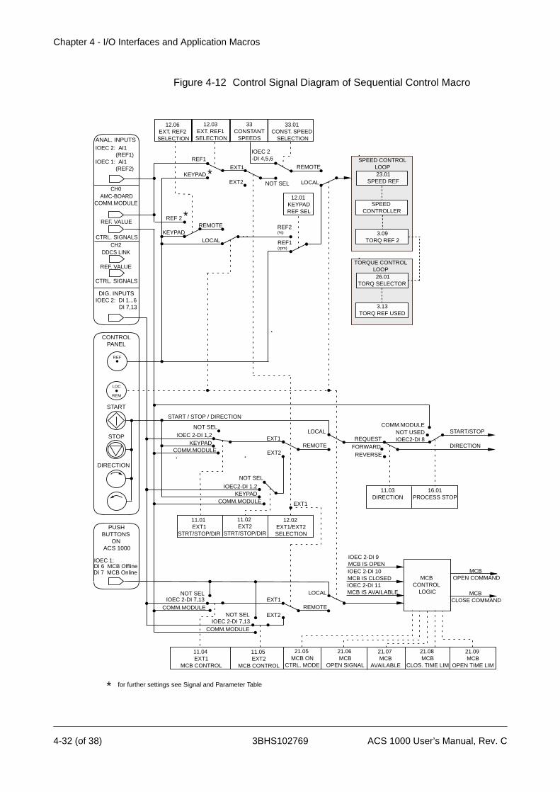
Chapter 4 - I/O Interfaces and Application Macros
Figure 4-12 Control Signal Diagram of Sequential Control Macro
12.06 EXT. REF2 SELECTION
12.03 EXT. REF1 SELECTION
33CONSTANT
SPEEDS
REF1
NOT SEL
REMOTE
REF2(%)
REF1(rpm)
EXT2
EXT2
IOEC 2-DI 1,2
IOEC2-DI 1,2
IOEC 2-DI 9MCB IS OPENIOEC 2-DI 10MCB IS CLOSED
REMOTE
LOCALREQUEST
FORWARDREVERSE
IOEC2-DI 8
START / STOP / DIRECTION
START/STOP
DIRECTIONEXT1
33.01 CONST. SPEED
SELECTION
12.01 KEYPADREF SEL
11.01 EXT1
STRT/STOP/DIR
11.02 EXT2
STRT/STOP/DIR
11.03DIRECTION
21.09 MCB
OPEN TIME LIM
21.08 MCB
CLOS. TIME LIM
21.07 MCB
AVAILABLE
21.06 MCB
OPEN SIGNAL
21.05 MCB ON
CTRL. MODE
11.05 EXT2
MCB CONTROL
11.04 EXT1
MCB CONTROL
16.01PROCESS STOP
MCB CLOSE COMMAND
MCB CONTROL
LOGIC
EXT2REMOTE
EXT1LOCAL
IOEC 2-DI 11MCB IS AVAILABLE
IOEC 2-DI 7,13COMM.MODULE
NOT SEL
KEYPAD LOCAL
KEYPAD
NOT USEDCOMM.MODULE
NOT SEL
NOT SELIOEC 2-DI 7,13
COMM.MODULE
*
12.02 EXT1/EXT2 SELECTION
* for further settings see Signal and Parameter Table
EXT1
COMM.MODULE
NOT SEL
KEYPADCOMM.MODULE EXT1
IOEC 2-DI 4,5,6
DIG. INPUTS
CH0 AMC-BOARDCOMM.MODULE
ANAL. INPUTSIOEC 2: AI1 (REF1)IOEC 1: AI1 (REF2)
IOEC 2: DI 1...6 DI 7,13
CH2 DDCS LINK
REF. VALUE
CTRL. SIGNALS
REF. VALUE
CTRL. SIGNALS
REF
LOC
REM
STOP
START
DIRECTION
CONTROLPANEL
PUSH BUTTONS ON ACS 1000
IOEC 1: DI 6 MCB Offline
DI 7 MCB Online
REMOTEKEYPAD
REF 2 *
LOCAL
23.01SPEED REF
SPEED CONTROLLER
3.09TORQ REF 2
SPEED CONTROLLOOP
26.01TORQ SELECTOR
3.13TORQ REF USED
TORQUE CONTROLLOOP
MCB OPEN COMMAND
4-32 (of 38) 3BHS102769 ACS 1000 User’s Manual, Rev. C
Chapter 4 - I/O Interfaces and Application Macros
Master/FollowerMacro
Description All drive commands and reference settings for a master follower drive configuration can be given from the control panel of the master drive or from an external control station connected to the master drive. The follower drive(s) receive(s) the control signals via a fibre-optic link from the master drive.
Connect all control signals to the master drive only.
Do not control the follower(s) with its(their) own control panel(s). Disable the control panels of all follower drive(s) by setting parameter 16.02 PA-RAMETER LOCK to LOCKED to prevent accidental use.
Do not control the follower through a fieldbus system.
Parameter settings and further information regarding the Master/Follower Macro can be found in Appendix K - Signal and Parameter Table, para-meter group 70.
The active control station - control panel or external control station - is selected by the LOC REM key on the control panel of the master. The control panel can be disabled by closing DI 1.8. The digital input can be accessed via terminals X301:1 and X301:2.
In remote control the reference value is connected to AI 2.1, the start/stop command is wired to DI 2.1 and the sense of rotation can be changed with DI 2.2. The default setting for the sense of rotation (parameter 11.03) is FORWARD. It can be changed to REVERSE either by setting parameter 11.03 to REVERSE or via DI 2.2 if parameter 11.03 has been set to REQUEST before (master and follower).
Three constant speeds can be selected via DI 2.5 and DI 2.6 when the drive is in remote control.
Furthermore, the Master/Follower Macro offers two preset acceleration/deceleration ramps which can be selected via DI 2.4.
ACS 1000 User’s Manual, Rev. C 3BHS102769 4-33 (of 38)
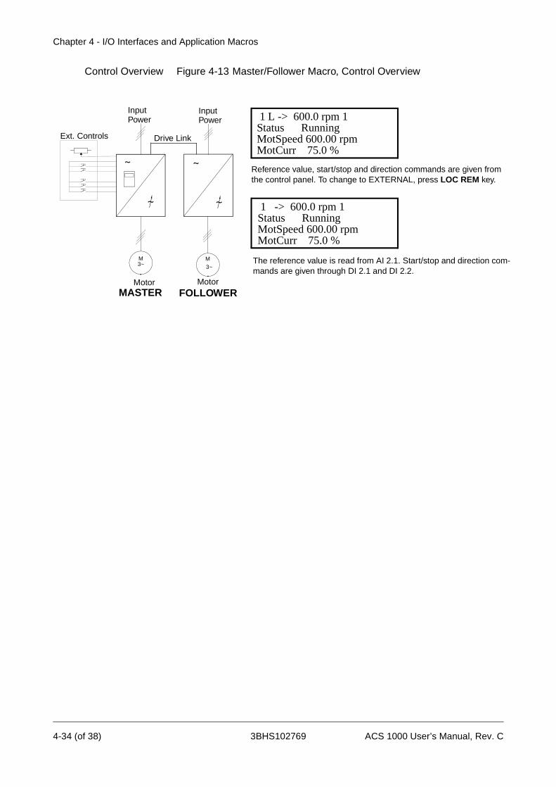
Chapter 4 - I/O Interfaces and Application Macros
Control Overview Figure 4-13 Master/Follower Macro, Control Overview
M3~
Motor
Ext. Controls
InputPower
Reference value, start/stop and direction commands are given from the control panel. To change to EXTERNAL, press LOC REM key.
The reference value is read from AI 2.1. Start/stop and direction com-mands are given through DI 2.1 and DI 2.2.
MASTER
1 L -> 600.0 rpm 1Status RunningMotSpeed 600.00 rpmMotCurr 75.0 %
1 -> 600.0 rpm 1Status RunningMotSpeed 600.00 rpmMotCurr 75.0 %
InputPower
FOLLOWER
M
3~
Motor
Drive Link
4-34 (of 38) 3BHS102769 ACS 1000 User’s Manual, Rev. C
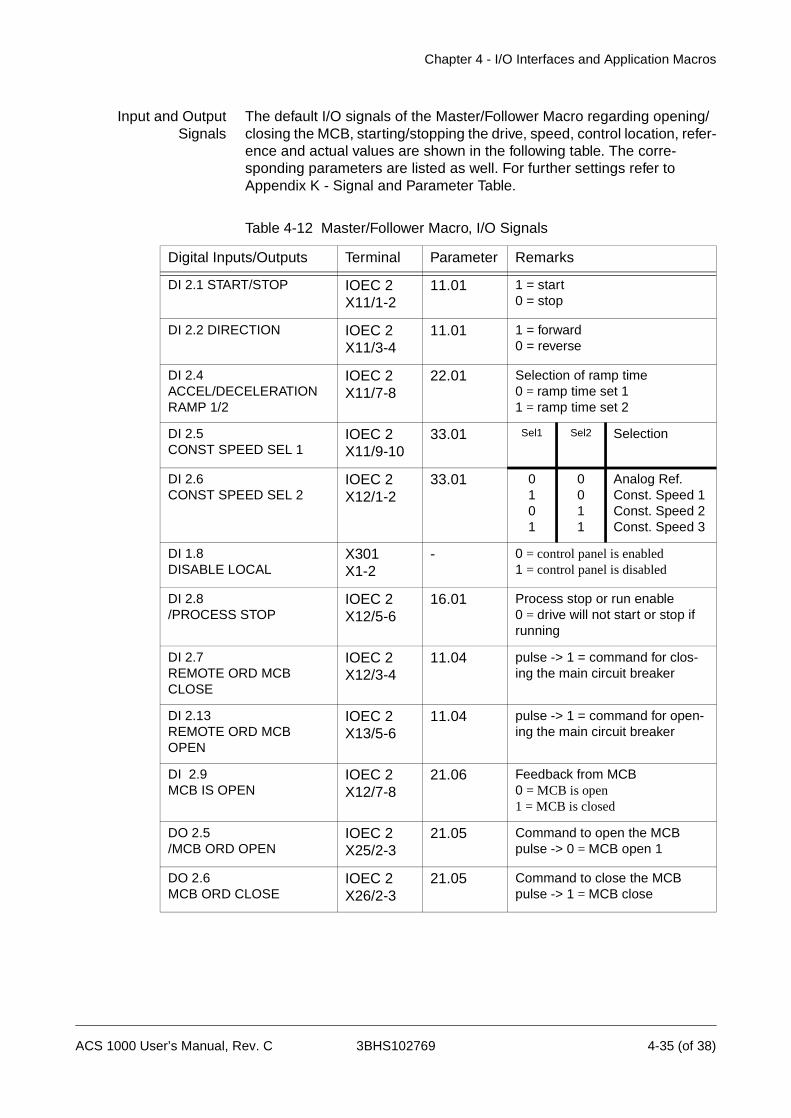
Chapter 4 - I/O Interfaces and Application Macros
Input and OutputSignals
The default I/O signals of the Master/Follower Macro regarding opening/closing the MCB, starting/stopping the drive, speed, control location, refer-ence and actual values are shown in the following table. The corre-sponding parameters are listed as well. For further settings refer to Appendix K - Signal and Parameter Table.
Table 4-12 Master/Follower Macro, I/O Signals
Digital Inputs/Outputs Terminal Parameter Remarks
DI 2.1 START/STOP IOEC 2X11/1-2
11.01 1 = start0 = stop
DI 2.2 DIRECTION IOEC 2X11/3-4
11.01 1 = forward0 = reverse
DI 2.4 ACCEL/DECELERATION RAMP 1/2
IOEC 2X11/7-8
22.01 Selection of ramp time 0 = ramp time set 11 = ramp time set 2
DI 2.5 CONST SPEED SEL 1
IOEC 2X11/9-10
33.01 Sel1 Sel2 Selection
DI 2.6CONST SPEED SEL 2
IOEC 2X12/1-2
33.01 0101
0011
Analog Ref.Const. Speed 1Const. Speed 2Const. Speed 3
DI 1.8DISABLE LOCAL
X301X1-2
- 0 = control panel is enabled1 = control panel is disabled
DI 2.8/PROCESS STOP
IOEC 2X12/5-6
16.01 Process stop or run enable 0 = drive will not start or stop if running
DI 2.7REMOTE ORD MCB CLOSE
IOEC 2X12/3-4
11.04 pulse -> 1 = command for clos-ing the main circuit breaker
DI 2.13REMOTE ORD MCBOPEN
IOEC 2X13/5-6
11.04 pulse -> 1 = command for open-ing the main circuit breaker
DI 2.9MCB IS OPEN
IOEC 2X12/7-8
21.06 Feedback from MCB 0 = MCB is open 1 = MCB is closed
DO 2.5/MCB ORD OPEN
IOEC 2X25/2-3
21.05 Command to open the MCBpulse -> 0 = MCB open 1
DO 2.6MCB ORD CLOSE
IOEC 2X26/2-3
21.05 Command to close the MCBpulse -> 1 = MCB close
ACS 1000 User’s Manual, Rev. C 3BHS102769 4-35 (of 38)
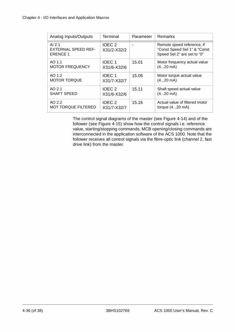
Chapter 4 - I/O Interfaces and Application Macros
The control signal diagrams of the master (see Figure 4-14) and of the follower (see Figure 4-15) show how the control signals i.e. reference value, starting/stopping commands, MCB opening/closing commands are interconnected in the application software of the ACS 1000. Note that the follower receives all control signals via the fibre-optic link (channel 2, fast drive link) from the master.
Analog Inputs/Outputs Terminal Parameter Remarks
AI 2.1EXTERNAL SPEED REF-ERENCE 1
IOEC 2X31/2-X32/2
- Remote speed reference, if “Const Speed Sel 1” & “Const Speed Sel 2” are set to “0”
AO 1.1MOTOR FREQUENCY
IOEC 1X31/6-X32/6
15.01 Motor frequency actual value (4...20 mA)
AO 1.2MOTOR TORQUE
IOEC 1X31/7-X32/7
15.06 Motor torque actual value (4...20 mA)
AO 2.1SHAFT SPEED
IOEC 2X31/6-X32/6
15.11 Shaft speed actual value (4...20 mA)
AO 2.2MOT TORQUE FILTERED
IOEC 2X31/7-X32/7
15.16 Actual value of filtered motor torque (4...20 mA)
4-36 (of 38) 3BHS102769 ACS 1000 User’s Manual, Rev. C
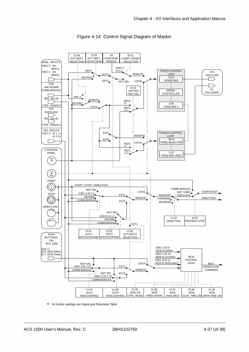
Chapter 4 - I/O Interfaces and Application Macros
Figure 4-14 Control Signal Diagram of Master
12.06 EXT. REF2 SELECTION
12.03 EXT. REF1 SELECTION
33CONSTANT
SPEEDS
REF1
NOT SEL
REMOTE
REF2(%)
REF1(rpm)
EXT2
EXT2
IOEC 2-DI 1,2
IOEC2-DI 1,2
IOEC 2-DI 9MCB IS OPENIOEC 2-DI 10MCB IS CLOSED
REMOTE
LOCALREQUEST
FORWARDREVERSE
IOEC2-DI 8
START / STOP / DIRECTION
START/STOP
DIRECTIONEXT1
33.01 CONST. SPEED
SELECTION
12.01 KEYPADREF SEL
11.01 EXT1
STRT/STOP/DIR
11.02 EXT2
STRT/STOP/DIR
11.03DIRECTION
21.09 MCB
OPEN TIME LIM
21.08 MCB
CLOS. TIME LIM
21.07 MCB
AVAILABLE
21.06 MCB
OPEN SIGNAL
21.05 MCB ON
CTRL. MODE
11.05 EXT2
MCB CONTROL
11.04 EXT1
MCB CONTROL
16.01PROCESS STOP
MCB OPEN/CLOSE COMMAND
MCB CONTROL
LOGIC
EXT2REMOTE
EXT1LOCAL
IOEC 2-DI 11MCB IS AVAILABLE
IOEC 2-DI 7,13COMM.MODULE
NOT SEL
KEYPAD LOCAL
KEYPAD
NOT USEDCOMM.MODULE
NOT SEL
NOT SELIOEC 2-DI 7,13
COMM.MODULE
*
12.02 EXT1/EXT2 SELECTION
* for further settings see Signal and Parameter Table
EXT1
EXT2
EXT1
COMM.MODULE
NOT SEL
KEYPADCOMM.MODULE EXT1
IOEC 2DI 5,6
LOCAL
REMOTE
REF2(%)
REF1(rpm)
TOFOLLOWER
CH2 DDCS LINK
DIG. INPUTS
CH0 AMC-BOARDCOMM.MODULE
ANAL. INPUTSIOEC 2: AI1 (REF1)IOEC 1: AI1 (REF2)
IOEC 2: DI 1...6 DI 7,13
CH2 DDCS LINK
REF. VALUE
CTRL. SIGNALS
REF. VALUE
CTRL. SIGNALS
REF
LOC
REM
STOP
START
DIRECTION
CONTROLPANEL
PUSH BUTTONS ON ACS 1000
IOEC 1: DI 6 MCB Offline
DI 7 MCB Online
REMOTEKEYPAD
REF 2 *
LOCAL
23.01SPEED REF
SPEED CONTROLLER
3.09TORQ REF 2
SPEED CONTROLLOOP
26.01TORQ SELECTOR
3.13TORQ REF USED
TORQUE CONTROLLOOP
ACS 1000 User’s Manual, Rev. C 3BHS102769 4-37 (of 38)
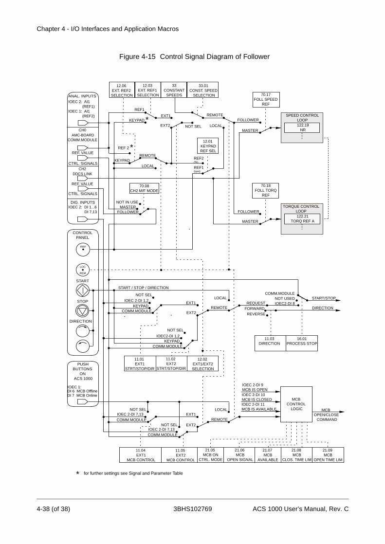
Chapter 4 - I/O Interfaces and Application Macros
Figure 4-15 Control Signal Diagram of Follower
PUSH BUTTONS ON ACS 1000
REF
LOC
REM
IOEC 1:
DIG. INPUTS
12.06 EXT. REF2 SELECTION
12.03 EXT. REF1 SELECTION
33CONSTANT
SPEEDS
CH0 AMC-BOARDCOMM.MODULE
REMOTE
REF1
NOT SEL
REMOTE
REF2(%)
REF1(rpm)
EXT2
EXT2
IOEC 2-DI 1,2
IOEC2-DI 1,2
IOEC 2-DI 9MCB IS OPENIOEC 2-DI 10MCB IS CLOSED
REMOTE
LOCALREQUEST
FORWARDREVERSE
IOEC2-DI 8
START / STOP / DIRECTION
START/STOP
DIRECTIONEXT1
33.01 CONST. SPEED
SELECTION
12.01 KEYPADREF SEL
11.01 EXT1
STRT/STOP/DIR
11.02 EXT2
STRT/STOP/DIR
11.03DIRECTION
21.09 MCB
OPEN TIME LIM
21.08 MCB
CLOS. TIME LIM
21.07 MCB
AVAILABLE
21.06 MCB
OPEN SIGNAL
21.05 MCB ON
CTRL. MODE
11.05 EXT2
MCB CONTROL
11.04 EXT1
MCB CONTROL
16.01PROCESS STOP
MCB OPEN/CLOSE COMMAND
MCB CONTROL
LOGIC
EXT2REMOTE
EXT1
ANAL. INPUTSIOEC 2: AI1 (REF1)IOEC 1: AI1 (REF2)
LOCALIOEC 2-DI 11MCB IS AVAILABLE
IOEC 2-DI 7,13COMM.MODULE
DI 6 MCB Offline DI 7 MCB Online
NOT SEL
KEYPAD LOCAL
KEYPAD
KEYPAD
NOT USEDCOMM.MODULE
NOT SEL
NOT SELIOEC 2-DI 7,13COMM.MODULE
REF 2
IOEC 2: DI 1...6 DI 7,13
*
*
STOP
START
DIRECTION
CONTROLPANEL
12.02 EXT1/EXT2 SELECTION
EXT1
LOCAL
FOLLOWER
MASTER
70.17FOLL SPEED
REF
CH2 DDCS LINK
70.18FOLL TORQ
REF
FOLLOWER
MASTER
REF. VALUE
CTRL. SIGNALS
COMM.MODULE
NOT SEL
KEYPADCOMM.MODULE
* for further settings see Signal and Parameter Table
REF. VALUE
CTRL. SIGNALS
NOT IN USE
FOLLOWERMASTER
70.08CH2 M/F MODE
122.19NR
SPEED CONTROLLOOP
122.21TORQ REF A
TORQUE CONTROLLOOP
4-38 (of 38) 3BHS102769 ACS 1000 User’s Manual, Rev. C
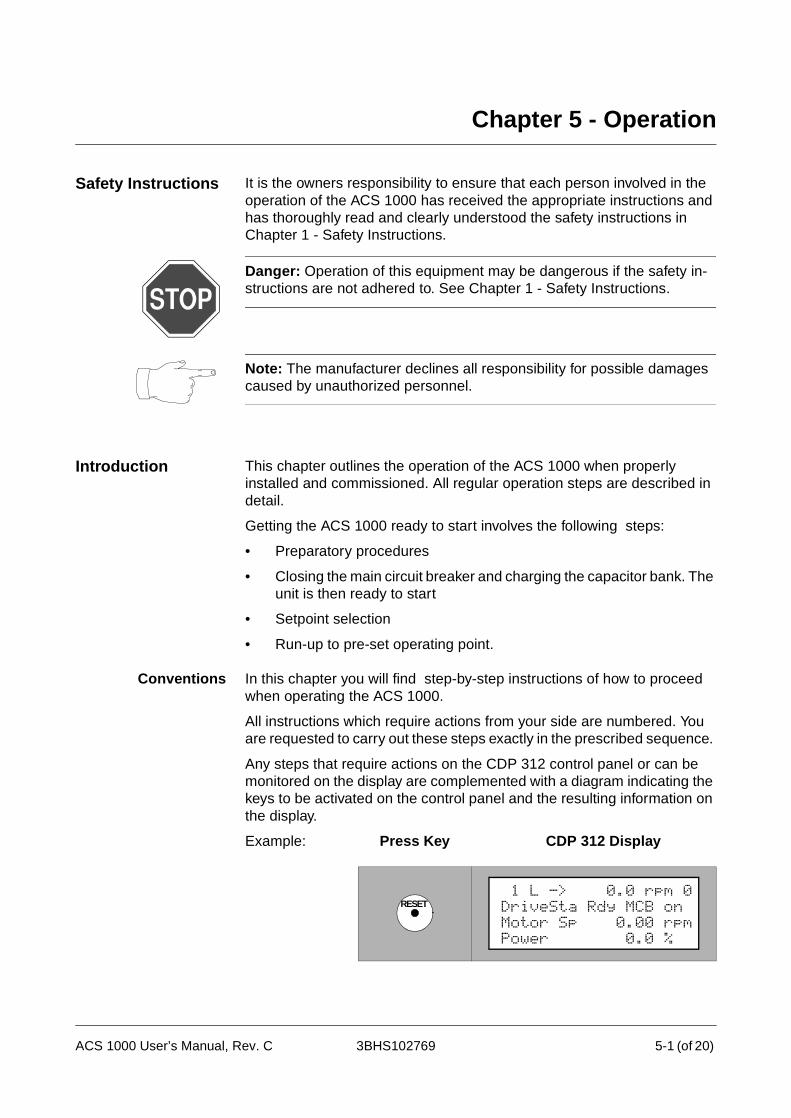
Chapter 5 - Operation
Safety Instructions It is the owners responsibility to ensure that each person involved in the operation of the ACS 1000 has received the appropriate instructions and has thoroughly read and clearly understood the safety instructions in Chapter 1 - Safety Instructions.
Danger: Operation of this equipment may be dangerous if the safety in-structions are not adhered to. See Chapter 1 - Safety Instructions.
Note: The manufacturer declines all responsibility for possible damages caused by unauthorized personnel.
Introduction This chapter outlines the operation of the ACS 1000 when properly installed and commissioned. All regular operation steps are described in detail.
Getting the ACS 1000 ready to start involves the following steps:
• Preparatory procedures
• Closing the main circuit breaker and charging the capacitor bank. The unit is then ready to start
• Setpoint selection
• Run-up to pre-set operating point.
Conventions In this chapter you will find step-by-step instructions of how to proceed when operating the ACS 1000.
All instructions which require actions from your side are numbered. You are requested to carry out these steps exactly in the prescribed sequence.
Any steps that require actions on the CDP 312 control panel or can be monitored on the display are complemented with a diagram indicating the keys to be activated on the control panel and the resulting information on the display.
Example: Press Key CDP 312 Display
RESET 1 L -> 0.0 rpm 0DriveSta Rdy MCB onMotor Sp 0.00 rpmPower 0.0 %
ACS 1000 User’s Manual, Rev. C 3BHS102769 5-1 (of 20)

Chapter 5 - Operation
• If there are several keys in the “Press Key” field you are requested to select one of them. Depending on your choice there might be different reactions.
• If the UP /DOWN keys are shown you can scroll using these keys alternately.
• Always keep keys pressed for some time (0.5-1 sec) in order to avoid misinterpretation.
Actual signals appear with their short name (8 characters) and their current value.
1 Press and hold the ACT key to view the full signal names.
2 Release the ACT key to return to normal display.
Start Operation of the ACS 1000
Preparatory Procedures
To prepare the ACS 1000 for operation take the following steps:
Danger: The cooling water system may start automatically as soon a the auxiliary voltage is swithed on, even if the converter is de-energized.
Prerequisites Check that all of the following prerequisites are met:
1 Installation and commissioning according to Chapter 11 - Commis-sioning is completed.
2 Auxiliary voltage is switched on.
3 All drive-specific start-up parameters according toChapter 6 - Parameter Viewing and Editing are set and checked.
Warning: Running the motor and the driven equipment with incorrect start-up data can result in improper operation, reduction in control accura-
HOLD
ACT
1 L -> 0.0 rpm 0DriveStatusWordMotor SpeedPower
1 L -> 0.0 rpm 0DriveSta Rdy MCB onMotor SP 0.00 rpmPower 0.0 %
5-2 (of 20) 3BHS102769 ACS 1000 User’s Manual, Rev. C

Chapter 5 - Operation
cy and damage to equipment.
4 Cooling water system is running (if applicable).
Preparatory Steps 5 Close all doors including the rear panel of the inverter section, the protective separation door and the control section front door.
Warning: All doors including the control section front door and the separation door behind the swing frame must be closed before energizing the unit. All fastening screws must be mounted and tightened in order to maintain EMC performance. The power section doors must be closed for safety reasons. The front doors are interlocked with the grounding isolator.The control section door must be closed to maintain EMC performance.
6 Open the grounding isolator located on the central section door of the converter.
Figure 5-1 Operating elements on front door
7 Check configuration of the mains circuit:
grounding isolator
CDP 312 control panel
main circuit control buttons
gnd.- switch unlocked
EMERGENCY OFF button
indicator
CLOSED
OPEN
ACS 1000 User’s Manual, Rev. C 3BHS102769 5-3 (of 20)

Chapter 5 - Operation
• input isolator is closed (if applicable)
• output isolator is closed (if applicable).
8 Select local or remote control mode by pressing the LOC REM key on the CDP 312 control panel. Local control mode is indicated with a “L” in the first line of the display.
Local control mode can only be selected if it is not dis-abled with appropriate parameter setting and if the digi-tal input DISABLE LOCAL is not active. For a detailed description of remote and local control please refer to the corresponding section in this chapter.
9 If control mode is set to REMOTE check that remote control is ready.
Closing Main CircuitBreaker
10 Check that MCB is in operating position (not drawn out or in test po-sition).
11 Check that ACS 1000 is ready:
• No alarm or error message on CDP 312 control panel display
• No emergency off is active.
If there is still an alarm pending, proceed as described in Chapter 8 - Trouble Shooting & Repair to eliminate the fault.
If the system is OK, the CDP 312 control panel displays READY MCB ON.
LOC
REM Motor SP 0.00 rpmPower 0.0 %
1 L -> 0.0 rpm 0DriveSta Rdy MCB on
1 L -> 0.0 rpm 0DriveSta Rdy MCB onMotor SP 0.00 rpmPower 0.0 %
5-4 (of 20) 3BHS102769 ACS 1000 User’s Manual, Rev. C
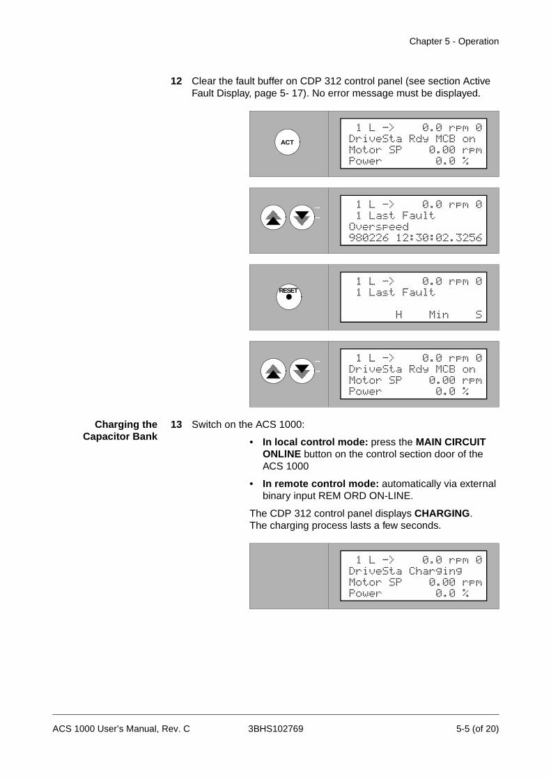
Chapter 5 - Operation
12 Clear the fault buffer on CDP 312 control panel (see section Active Fault Display, page 5- 17). No error message must be displayed.
Charging theCapacitor Bank
13 Switch on the ACS 1000:
• In local control mode: press the MAIN CIRCUIT ONLlNE button on the control section door of the ACS 1000
• In remote control mode: automatically via external binary input REM ORD ON-LINE.
The CDP 312 control panel displays CHARGING. The charging process lasts a few seconds.
ACT
1 L -> 0.0 rpm 0DriveSta Rdy MCB onMotor SP 0.00 rpmPower 0.0 %
1 L -> 0.0 rpm 0 1 Last FaultOverspeed980226 12:30:02.3256
RESET 1 L -> 0.0 rpm 0 1 Last Fault
H Min S
1 L -> 0.0 rpm 0DriveSta Rdy MCB onMotor SP 0.00 rpmPower 0.0 %
1 L -> 0.0 rpm 0DriveSta ChargingMotor SP 0.00 rpmPower 0.0 %
ACS 1000 User’s Manual, Rev. C 3BHS102769 5-5 (of 20)

Chapter 5 - Operation
14 The unit is now ready. The CDP 312 control panel displays READY TO START.
Entering Setpoint and Starting Up the ACS 1000
In Local Control Mode 15 To enter the setpoint press REF on the CDP 312 control panel.
16 Input setpoint (speed, torque, according to application macro require-ments; see Chapter 4 - I/O Interfaces and Application Macros) by us-ing the UP/DOWN keys.
The setpoint change will become active immediately.
17 Press a MODE key to exit setpoint mode.
18 Select the sense of rotation with the or key.
Warning: Many processes do not permit to reverse the sense of rotation. The sense of rotation can only be selected if not disabled by setting of pa-rameter 11.3. Make sure that the parameter 11.3 DIRECTION is correctly set according to the process requirements (see Chapter 6 - Parameter Viewing and Editing).
1 L -> 0.0 rpm 0DriveSta Rdy to StrtMotor SP 0.00 rpmPower 0.0 %
REF 1 L ->[ 0.0 rpm]0DriveSta Rdy to StrtMotor SP 0.00 rpmPower 0.0 %
1 L ->[ 600.0 rpm]0DriveSta Rdy to StrtMotor SP 0.00 rpmPower 0.0 %
ACT
FUNC DRIVE
PAR 1 L -> 600.0 rpm 0DriveSta Rdy to StrtMotor SP 0.00 rpmPower 0.0 %
5-6 (of 20) 3BHS102769 ACS 1000 User’s Manual, Rev. C
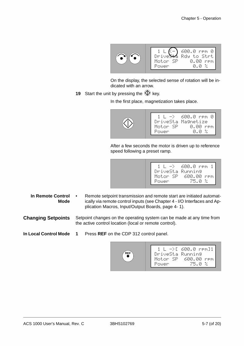
Chapter 5 - Operation
On the display, the selected sense of rotation will be in-dicated with an arrow.
19 Start the unit by pressing the key.
In the first place, magnetization takes place.
After a few seconds the motor is driven up to reference speed following a preset ramp.
In Remote ControlMode
• Remote setpoint transmission and remote start are initiated automat-ically via remote control inputs (see Chapter 4 - I/O Interfaces and Ap-plication Macros, Input/Output Boards, page 4- 1).
Changing Setpoints Setpoint changes on the operating system can be made at any time from the active control location (local or remote control).
In Local Control Mode 1 Press REF on the CDP 312 control panel.
Motor SP 0.00 rpmPower 0.0 %
1 L <- 600.0 rpm 0DriveSta Rdy to Strt
1 L -> 600.0 rpm 0DriveSta MagnetizeMotor SP 0.00 rpmPower 0.0 %
1 L -> 600.0 rpm 1DriveSta RunningMotor SP 600.00 rpmPower 75.0 %
REF 1 L ->[ 600.0 rpm]1DriveSta RunningMotor SP 600.00 rpmPower 75.0 %
ACS 1000 User’s Manual, Rev. C 3BHS102769 5-7 (of 20)
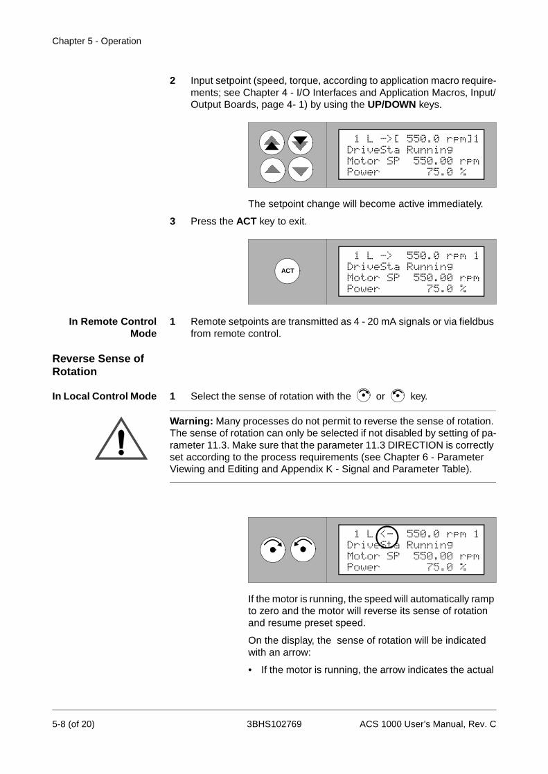
Chapter 5 - Operation
2 Input setpoint (speed, torque, according to application macro require-ments; see Chapter 4 - I/O Interfaces and Application Macros, Input/Output Boards, page 4- 1) by using the UP/DOWN keys.
The setpoint change will become active immediately.
3 Press the ACT key to exit.
In Remote ControlMode
1 Remote setpoints are transmitted as 4 - 20 mA signals or via fieldbus from remote control.
Reverse Sense of Rotation
In Local Control Mode 1 Select the sense of rotation with the or key.
Warning: Many processes do not permit to reverse the sense of rotation. The sense of rotation can only be selected if not disabled by setting of pa-rameter 11.3. Make sure that the parameter 11.3 DIRECTION is correctly set according to the process requirements (see Chapter 6 - Parameter Viewing and Editing and Appendix K - Signal and Parameter Table).
If the motor is running, the speed will automatically ramp to zero and the motor will reverse its sense of rotation and resume preset speed.
On the display, the sense of rotation will be indicated with an arrow:
• If the motor is running, the arrow indicates the actual
1 L ->[ 550.0 rpm]1DriveSta RunningMotor SP 550.00 rpmPower 75.0 %
ACT
1 L -> 550.0 rpm 1DriveSta RunningMotor SP 550.00 rpmPower 75.0 %
Motor SP 550.00 rpmPower 75.0 %
1 L <- 550.0 rpm 1DriveSta Running
5-8 (of 20) 3BHS102769 ACS 1000 User’s Manual, Rev. C
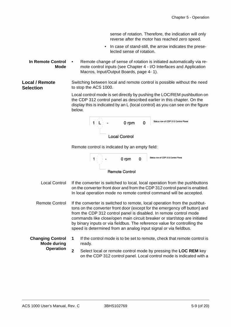
Chapter 5 - Operation
sense of rotation. Therefore, the indication will only reverse after the motor has reached zero speed.
• In case of stand-still, the arrow indicates the prese-lected sense of rotation.
In Remote ControlMode
• Remote change of sense of rotation is initiated automatically via re-mote control inputs (see Chapter 4 - I/O Interfaces and Application Macros, Input/Output Boards, page 4- 1).
Local / Remote Selection
Switching between local and remote control is possible without the need to stop the ACS 1000.
Local control mode is set directly by pushing the LOC/REM pushbutton on the CDP 312 control panel as described earlier in this chapter. On the display this is indicated by an L (local control) as you can see on the figure below.
Remote control is indicated by an empty field:
Local Control If the converter is switched to local, local operation from the pushbuttons on the converter front door and from the CDP 312 control panel is enabled. In local operation mode no remote control command will be accepted.
Remote Control If the converter is switched to remote, local operation from the pushbut-tons on the converter front door (except for the emergency off button) and from the CDP 312 control panel is disabled. In remote control mode commands like close/open main circuit breaker or start/stop are initiated by binary inputs or via fieldbus. The reference value for controlling the speed is determined from an analog input signal or via fieldbus.
Changing ControlMode during
Operation
1 If the control mode is to be set to remote, check that remote control is ready.
2 Select local or remote control mode by pressing the LOC REM key on the CDP 312 control panel. Local control mode is indicated with a
ACS 1000 User’s Manual, Rev. C 3BHS102769 5-9 (of 20)

Chapter 5 - Operation
“L” in the first line of the display.
Local control mode can only be selected if it is not dis-abled with appropriate parameter setting and if the digi-tal input “Disable local operation” is not active.
Remote -> LocalControl
• The motor is not stopping.
• The speed is not changing (initial value for nref is the last actual speed) but can now be changed by the CDP 312 control panel.
Local -> RemoteControl
• The motor is not stopping if the operational commands (MCB on/off and start/stop) of the remote system are correctly set.
• The speed is changing to the actual reference value of the analog in-put following the preset ramp.
Disabling LocalOperation from CDP
312 Control Panel
If the parameter DISABLE LOCAL is set to "1" then a change from remote control to local control (via the LOC/REM pushbutton on the CDP 312 control panel on the converter front door) is not possible anymore. The converter has to remain in the remote control mode.
If the parameter DISABLE LOCAL OPERATION is set to “1” during local control, the drive remains in local operation until remote control is selected (via the LOC/REM pushbutton on the CDP 312 control panel on the converter front door).
Table 5-1 Binary input
Table 5-2 Binary outputs
LOC
REM Motor SP 550.00 rpmPower 75.0 %
1 -> 550.0 rpm 1DriveSta Running
Type Signal Name Terminal Type Remarks Standard
DI DISABLE LOCAL IOEC 1 X12/5-6
high active
Remote input to disable the possibility for a local/remote switch-over from the CDP 312 Control Panel
Type Signal Name Terminal Type Remarks Standard
RO LOCAL MODE IOEC 3X22/1-3
high active
Local Mode Operation Status Indication, set to “1” in local mode
RO DRIVE READY IOEC 2X21/1-3
high active
Status Output “Drive Ready”(i.e. MCB closed, DC link charged, no lockout active)
5-10 (of 20) 3BHS102769 ACS 1000 User’s Manual, Rev. C
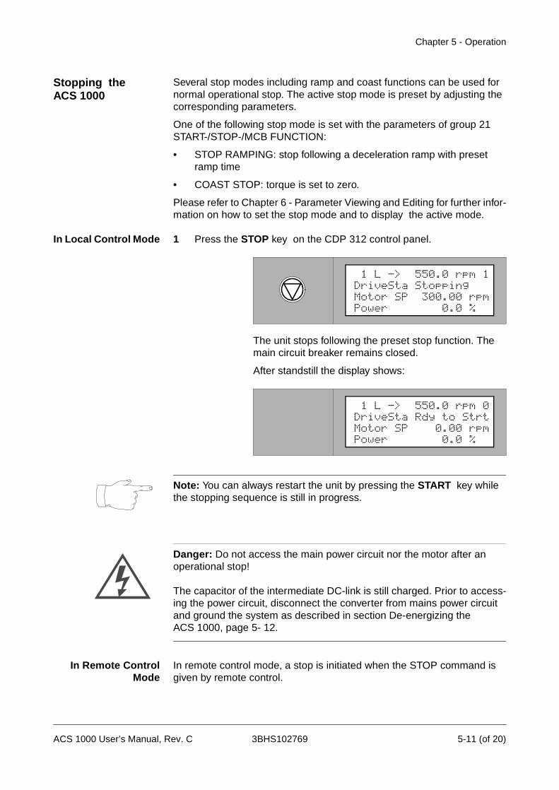
Chapter 5 - Operation
Stopping the ACS 1000
Several stop modes including ramp and coast functions can be used for normal operational stop. The active stop mode is preset by adjusting the corresponding parameters.
One of the following stop mode is set with the parameters of group 21 START-/STOP-/MCB FUNCTION:
• STOP RAMPING: stop following a deceleration ramp with preset ramp time
• COAST STOP: torque is set to zero.
Please refer to Chapter 6 - Parameter Viewing and Editing for further infor-mation on how to set the stop mode and to display the active mode.
In Local Control Mode 1 Press the STOP key on the CDP 312 control panel.
The unit stops following the preset stop function. The main circuit breaker remains closed.
After standstill the display shows:
Note: You can always restart the unit by pressing the START key while the stopping sequence is still in progress.
Danger: Do not access the main power circuit nor the motor after an operational stop!
The capacitor of the intermediate DC-link is still charged. Prior to access-ing the power circuit, disconnect the converter from mains power circuit and ground the system as described in section De-energizing the ACS 1000, page 5- 12.
In Remote ControlMode
In remote control mode, a stop is initiated when the STOP command is given by remote control.
1 L -> 550.0 rpm 1DriveSta StoppingMotor SP 300.00 rpmPower 0.0 %
1 L -> 550.0 rpm 0DriveSta Rdy to StrtMotor SP 0.00 rpmPower 0.0 %
ACS 1000 User’s Manual, Rev. C 3BHS102769 5-11 (of 20)

Chapter 5 - Operation
The unit stops following the preset stop function. The main circuit breaker remains closed.
Danger: Do not access the main power circuit nor the motor after an operational stop!
The capacitor of the intermediate DC-link is still charged. Prior to access-ing the power circuit, disconnect the converter from mains power circuit and ground the system as described in section De-energizing the ACS 1000, page 5- 12.
De-energizing the ACS 1000
In Local Control Mode To disconnect the drive from main power supply, proceed as follows:
1 Stop the ACS 1000 by performing the steps described in the previous section.
2 Press the main circuit OFFLINE button on the control section door of the ACS 1000 (see Figure 5-1). The MCB will open.
Danger: Do not access the main power circuit nor the motor as long as the system is not grounded.
After switching off the mains and after the motor has come to a stop, al-ways allow the intermediate circuit capacitors 5 minutes to discharge ( yel-low indicator GND.- SWITCH UNLOCKED must be on) before grounding and starting work on the frequency converter, the motor or the motor ca-ble.
The ACS 1000 and adjoining equipment must be properly grounded prior to starting with any work.
The display shows:.
1 L -> 550.0 rpm 0DriveSta Rdy MCB OnMotor SP 0.00 rpmPower 0.0 %
5-12 (of 20) 3BHS102769 ACS 1000 User’s Manual, Rev. C
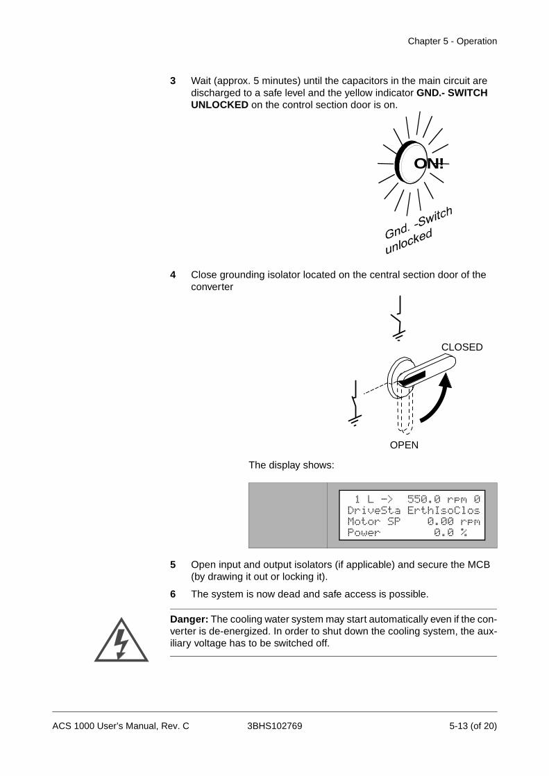
Chapter 5 - Operation
3 Wait (approx. 5 minutes) until the capacitors in the main circuit are discharged to a safe level and the yellow indicator GND.- SWITCH UNLOCKED on the control section door is on.
4 Close grounding isolator located on the central section door of the converter
The display shows:
5 Open input and output isolators (if applicable) and secure the MCB (by drawing it out or locking it).
6 The system is now dead and safe access is possible.
Danger: The cooling water system may start automatically even if the con-verter is de-energized. In order to shut down the cooling system, the aux-iliary voltage has to be switched off.
ON!
CLOSED
OPEN
1 L -> 550.0 rpm 0DriveSta ErthIsoClosMotor SP 0.00 rpmPower 0.0 %
ACS 1000 User’s Manual, Rev. C 3BHS102769 5-13 (of 20)
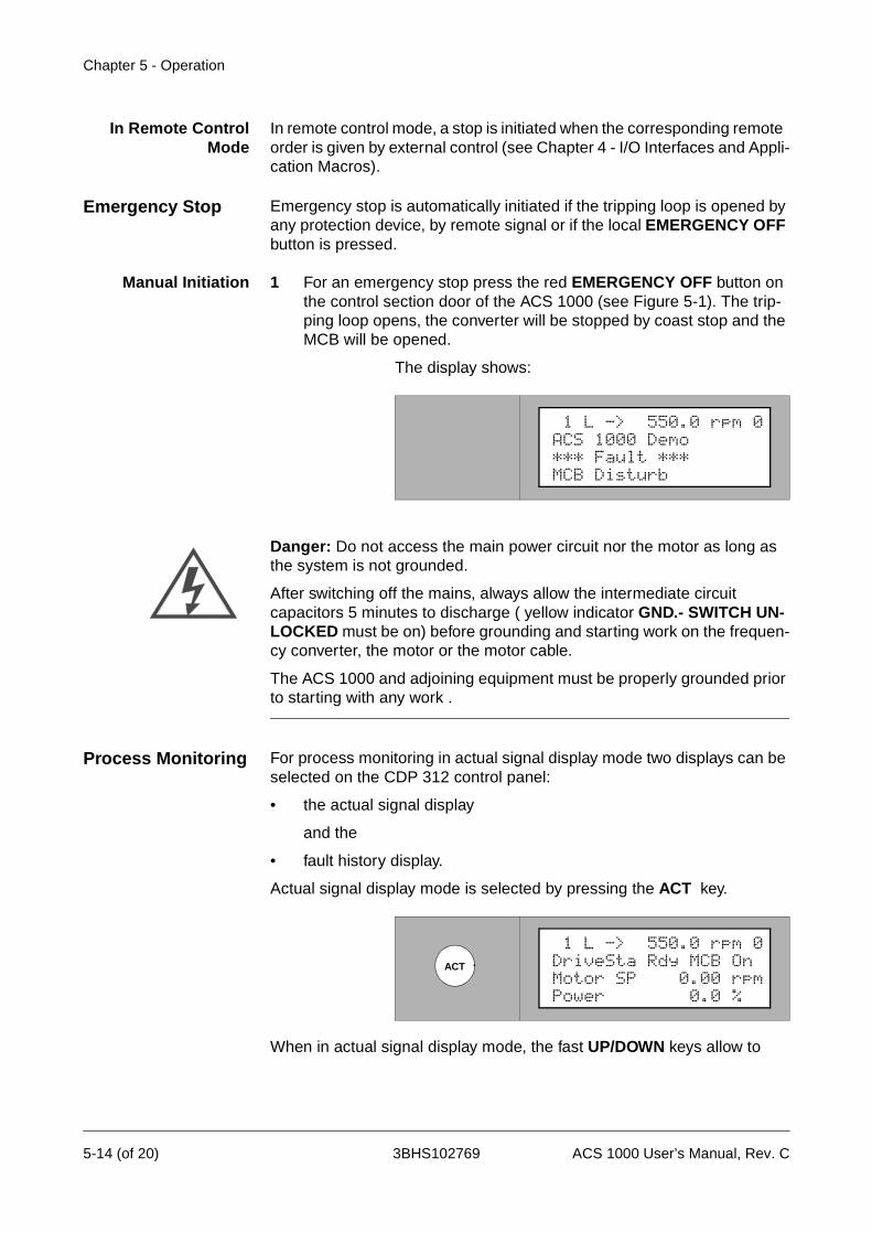
Chapter 5 - Operation
In Remote ControlMode
In remote control mode, a stop is initiated when the corresponding remote order is given by external control (see Chapter 4 - I/O Interfaces and Appli-cation Macros).
Emergency Stop Emergency stop is automatically initiated if the tripping loop is opened by any protection device, by remote signal or if the local EMERGENCY OFF button is pressed.
Manual Initiation 1 For an emergency stop press the red EMERGENCY OFF button on the control section door of the ACS 1000 (see Figure 5-1). The trip-ping loop opens, the converter will be stopped by coast stop and the MCB will be opened.
The display shows:
Danger: Do not access the main power circuit nor the motor as long as the system is not grounded.
After switching off the mains, always allow the intermediate circuit capacitors 5 minutes to discharge ( yellow indicator GND.- SWITCH UN-LOCKED must be on) before grounding and starting work on the frequen-cy converter, the motor or the motor cable.
The ACS 1000 and adjoining equipment must be properly grounded prior to starting with any work .
Process Monitoring For process monitoring in actual signal display mode two displays can be selected on the CDP 312 control panel:
• the actual signal display
and the
• fault history display.
Actual signal display mode is selected by pressing the ACT key.
When in actual signal display mode, the fast UP/DOWN keys allow to
1 L -> 550.0 rpm 0ACS 1000 Demo*** Fault ***MCB Disturb
ACT
1 L -> 550.0 rpm 0DriveSta Rdy MCB OnMotor SP 0.00 rpmPower 0.0 %
5-14 (of 20) 3BHS102769 ACS 1000 User’s Manual, Rev. C
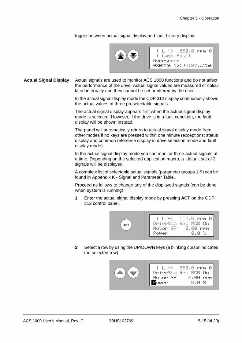
Chapter 5 - Operation
toggle between actual signal display and fault history display.
Actual Signal Display Actual signals are used to monitor ACS 1000 functions and do not affect the performance of the drive. Actual signal values are measured or calcu-lated internally and they cannot be set or altered by the user.
In the actual signal display mode the CDP 312 display continuously shows the actual values of three preselectable signals.
The actual signal display appears first when the actual signal display mode is selected. However, if the drive is in a fault condition, the fault display will be shown instead.
The panel will automatically return to actual signal display mode from other modes if no keys are pressed within one minute (exceptions: status display and common reference display in drive selection mode and fault display mode).
In the actual signal display mode you can monitor three actual signals at a time. Depending on the selected application macro, a default set of 3 signals will be displayed.
A complete list of selectable actual signals (parameter groups 1-9) can be found in Appendix K - Signal and Parameter Table.
Proceed as follows to change any of the displayed signals (can be done when system is running):
1 Enter the actual signal display mode by pressing ACT on the CDP 312 control panel.
2 Select a row by using the UP/DOWN keys (a blinking cursor indicates the selected row).
1 L -> 550.0 rpm 0 1 Last FaultOverspeed980226 12:30:02.3256
ACT
Power 0.0 %
1 L -> 550.0 rpm 0DriveSta Rdy MCB OnMotor SP 0.00 rpm
1 L -> 550.0 rpm 0DriveSta Rdy MCB OnMotor SP 0.00 rpmPower 0.0 %
ACS 1000 User’s Manual, Rev. C 3BHS102769 5-15 (of 20)

Chapter 5 - Operation
3 To activate the actual signal selection option press ENTER.
4 Select a parameter group using the fast UP/DOWN keys.
Please refer to Appendix K - Signal and Parameter Table for a list of all available signals (parameter groups 1 to 9).
5 Select a signal using the UP/DOWN keys.
6 To accept the selection and to return to the actual signal display Mode press ENTER.
To cancel the selection and keep the original selection, press any of the mode keys without pressing ENTER. The display will change to the selected Keypad Mode.
ENTER
0.0 %
1 L -> 550.0 rpm 01 Actual Signals9 Power
Speed Control
1 L -> 550.0 rpm 02 Actual Signals1 Control Mode
-0.0 A
1 L -> 550.0 rpm 02 Actual Signals12 InverterEarthCurr
ENTER
Inverter -0.0 A
1 L -> 550.0 rpm 0DriveSta Rdy MCB OnMotor SP 0.00 rpm
ACT
FUNC DRIVE
PAR
Power 0.0 %
1 L -> 550.0 rpm 0DriveSta Rdy MCB OnMotor SP 0.00 rpm
5-16 (of 20) 3BHS102769 ACS 1000 User’s Manual, Rev. C
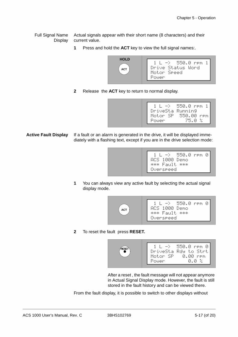
Chapter 5 - Operation
Full Signal NameDisplay
Actual signals appear with their short name (8 characters) and their current value.
1 Press and hold the ACT key to view the full signal names:.
2 Release the ACT key to return to normal display.
Active Fault Display If a fault or an alarm is generated in the drive, it will be displayed imme-diately with a flashing text, except if you are in the drive selection mode:
1 You can always view any active fault by selecting the actual signal display mode.
2 To reset the fault press RESET.
After a reset , the fault message will not appear anymore in Actual Signal Display mode. However, the fault is still stored in the fault history and can be viewed there.
From the fault display, it is possible to switch to other displays without
HOLD
ACT
Power
1 L -> 550.0 rpm 1Drive Status WordMotor Speed
Power 75.0 %
1 L -> 550.0 rpm 1DriveSta RunningMotor SP 550.00 rpm
1 L -> 550.0 rpm 0ACS 1000 Demo*** Fault ***Overspeed
ACT
1 L -> 550.0 rpm 0ACS 1000 Demo*** Fault ***Overspeed
RESET
Power 0.0 %
1 L -> 550.0 rpm 0DriveSta Rdy to StrtMotor SP 0.00 rpm
ACS 1000 User’s Manual, Rev. C 3BHS102769 5-17 (of 20)
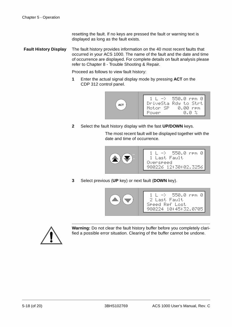
Chapter 5 - Operation
resetting the fault. If no keys are pressed the fault or warning text is displayed as long as the fault exists.
Fault History Display The fault history provides information on the 40 most recent faults that occurred in your ACS 1000. The name of the fault and the date and time of occurrence are displayed. For complete details on fault analysis please refer to Chapter 8 - Trouble Shooting & Repair.
Proceed as follows to view fault history:
1 Enter the actual signal display mode by pressing ACT on the CDP 312 control panel.
2 Select the fault history display with the fast UP/DOWN keys.
The most recent fault will be displayed together with the date and time of occurrence.
3 Select previous (UP key) or next fault (DOWN key).
Warning: Do not clear the fault history buffer before you completely clari-fied a possible error situation. Clearing of the buffer cannot be undone.
ACT
Power 0.0 %
1 L -> 550.0 rpm 0DriveSta Rdy to StrtMotor SP 0.00 rpm
1 L -> 550.0 rpm 0 1 Last FaultOverspeed980226 12:30:02.3256
1 L -> 550.0 rpm 0 2 Last FaultSpeed Ref Lost980224 10:45:32.0705
5-18 (of 20) 3BHS102769 ACS 1000 User’s Manual, Rev. C
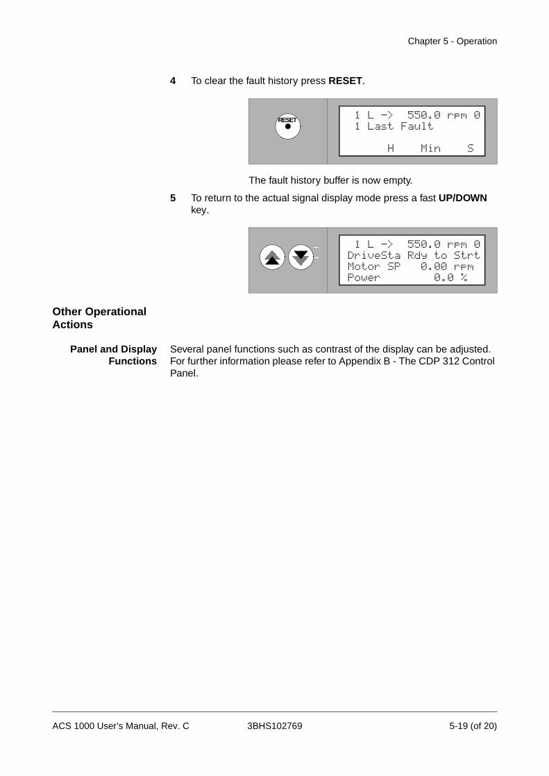
Chapter 5 - Operation
4 To clear the fault history press RESET.
The fault history buffer is now empty.
5 To return to the actual signal display mode press a fast UP/DOWN key.
Other Operational Actions
Panel and DisplayFunctions
Several panel functions such as contrast of the display can be adjusted. For further information please refer to Appendix B - The CDP 312 Control Panel.
RESET 1 L -> 550.0 rpm 0 1 Last Fault
H Min S
Power 0.0 %
1 L -> 550.0 rpm 0DriveSta Rdy to StrtMotor SP 0.00 rpm
ACS 1000 User’s Manual, Rev. C 3BHS102769 5-19 (of 20)

Chapter 5 - Operation
5-20 (of 20) 3BHS102769 ACS 1000 User’s Manual, Rev. C
Chapter 6 - Parameter Viewing and Editing
Overview This chapter contains the necessary instructions for checking application parameters as they are programmed in the ACS 1000. When starting the ACS 1000 for the first time after a modification in the driven system or in the control circuit, these application parameters should be checked and, if necessary, adapted.
Note: Parameters and application macros are normally set during com-missioning of the process and should not need to be changed by the user afterwards, except if a modification in the system configuration requires to do so.
The start-up parameters form a special group of parameters that allow you to set up the basic ACS 1000 and motor information. Start-up parameters are normally set during commissioning of the driven motor and should not need to be changed afterwards.
Safety Instructions It is the owners responsibility to ensure that only professionals with the appropriate education (i.e. electrical engineers or equivalent) are involved in the programming of the ACS 1000 parameter set and that each person has received the appropriate instructions and has thoroughly read and clearly understood the safety instructions in Chapter 1 - Safety Instruc-tions.
Warning: Never change any parameters if you are not thoroughly familiar with the meaning of each parameter and with the consequences resulting from the modification. Running the ACS 1000, the motor and the equipment being driven with in-correct data can result in improper operation, reduction in control accuracy and damage to equipment.
ACS 1000 Application Parameters
The control configuration and the application parameters of the ACS 1000 are programmable. Configuring the ACS 1000 includes basically the input of a set of parameters by the commissioning engineer. Some of these parameters are determined automatically by the control system (i.e. the motor characteristic by performing the motor ID run) and cannot be altered by the user.
Parameter Groups In order to simplify programming, parameters in the ACS 1000 are orga-nized in groups. Typical parameter groups are
• Start-up parameters
• Reference selection
• Analog / binary inputs or output definition parameters (all inputs and
ACS 1000 User’s Manual, Rev. C 3BHS102769 6-1 (of 22)
Chapter 6 - Parameter Viewing and Editing
outputs are programmable)
• Actual signals
A complete list of all parameters can be found in Appendix K - Signal and Parameter Table.
Start-up Parameters The start-up parameters form a special set of parameters defining the basic system characteristics, such as nominal mains voltage, rated current and other main data of the motor. They must be determined and entered individually for each drive.
Application Macros Application macros are preprogrammed parameter sets that are specially adapted to a specific application. Depending on the process, one can select one of these macros, thus enabling a quick and easy start-up of the ACS 1000.
With application macros, the number of different parameters to be set during start-up is minimized. All parameters have factory-set default values . Leaving them unchanged, a good system performance is obtained in typical situations. One can either use these default values or they can be optimized individually according to your needs (will be done by the ABB commissioning engineer). For more infomation please refer to Chapter 4 - I/O Interfaces and Application Macros, Input/Output Boards, page 4- 1 and to the ACS 1000 Engineering Manual or ask your local ABB service organization.
Application Parameter Editing: Overview
As already mentioned, good performance is achieved in an typical appli-cation even if you leave the default settings unchanged. However, in order to optimize the ACS 1000 for your system configuration it is necessary to check whether the default settings match your requirements and to customize the settings where appropriate. Initially this is done by the ABB commissioning engineer in cooperation with the owner.
Especially if options are added, the corresponding parameters must be checked before start-up. A systematic guide for determining optimum parameter settings can be found in the Engineering Manual. The flowchart shown in Figure 6-1 gives an overview on the complete parameter input procedure as it is carried out during commissioning.
In the remaining part of this chapter you will find detailed instructions of how to proceed when viewing and editing individual parameters in the control system of the ACS 1000.
6-2 (of 22) 3BHS102769 ACS 1000 User’s Manual, Rev. C

Chapter 6 - Parameter Viewing and Editing
Figure 6-1 Application parameter programming procedure
Input
START
start-upparameters
Selectapplication macro
Check start/stop/ref/ramp parameters (groups 11, 12, 13, 21, 22)
Input speed referenceparameters (group 23)
Check and adjust fault function parameters (group 30)depending on systemneeds
Inputreal time clock data(parameter group 98)
Any options ?
No
Yes2
1
& other macro related parameters (dependson selected macro)
Step I
Step II
Step III
Step IV
Step V
Step VI
ACS 1000 User’s Manual, Rev. C 3BHS102769 6-3 (of 22)

Chapter 6 - Parameter Viewing and Editing
Figure 6-1 Application parameter programming procedure (continued)
2
3
If applicable:Input motor winding temperature data(parameter group 30)
If applicable:Input external motor protection data(parameter group 35)
If applicable:Input external transfor- mer protection data(parameter group 36)
If applicable:Input external inverter protection data(parameter group 37)
If applicable:Activate external motor heater/cooler(parameter group 38)
If applicable:Activate external speedmeasurement (75.03)
If applicable:Activate fieldbus/APC2 communication (75.04)
groups 90 to 95)
Step VII
(parameter group 50)and input data
and input data (param.
Prerequisite: IOEC 3
Prerequisite: IOEC 3
Prerequisite: IOEC 3&4
Prerequisite: IOEC 3*
* For motor cooler only
6-4 (of 22) 3BHS102769 ACS 1000 User’s Manual, Rev. C
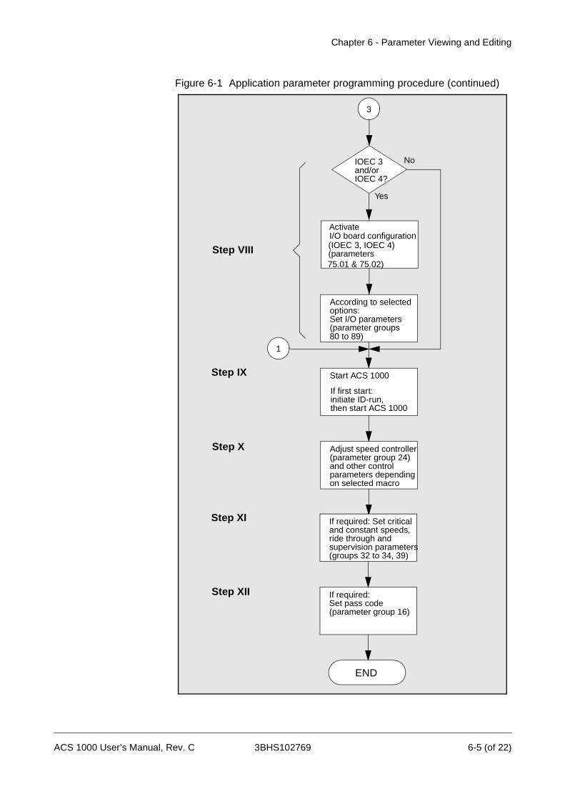
Chapter 6 - Parameter Viewing and Editing
Figure 6-1 Application parameter programming procedure (continued)
3
1
I/O board configuration (IOEC 3, IOEC 4)(parameters
According to selectedoptions: Set I/O parameters (parameter groups
IOEC 3
Yes
Noand/orIOEC 4?
80 to 89)
Start ACS 1000
Adjust speed controller
If required: Set criticaland constant speeds, ride through andsupervision parameters(groups 32 to 34, 39)
(parameter group 24)and other control parameters dependingon selected macro
If required:Set pass code(parameter group 16)
END
Activate
Step VIII
Step IX
Step X
Step XI
Step XII
75.01 & 75.02)
If first start: initiate ID-run, then start ACS 1000
ACS 1000 User’s Manual, Rev. C 3BHS102769 6-5 (of 22)
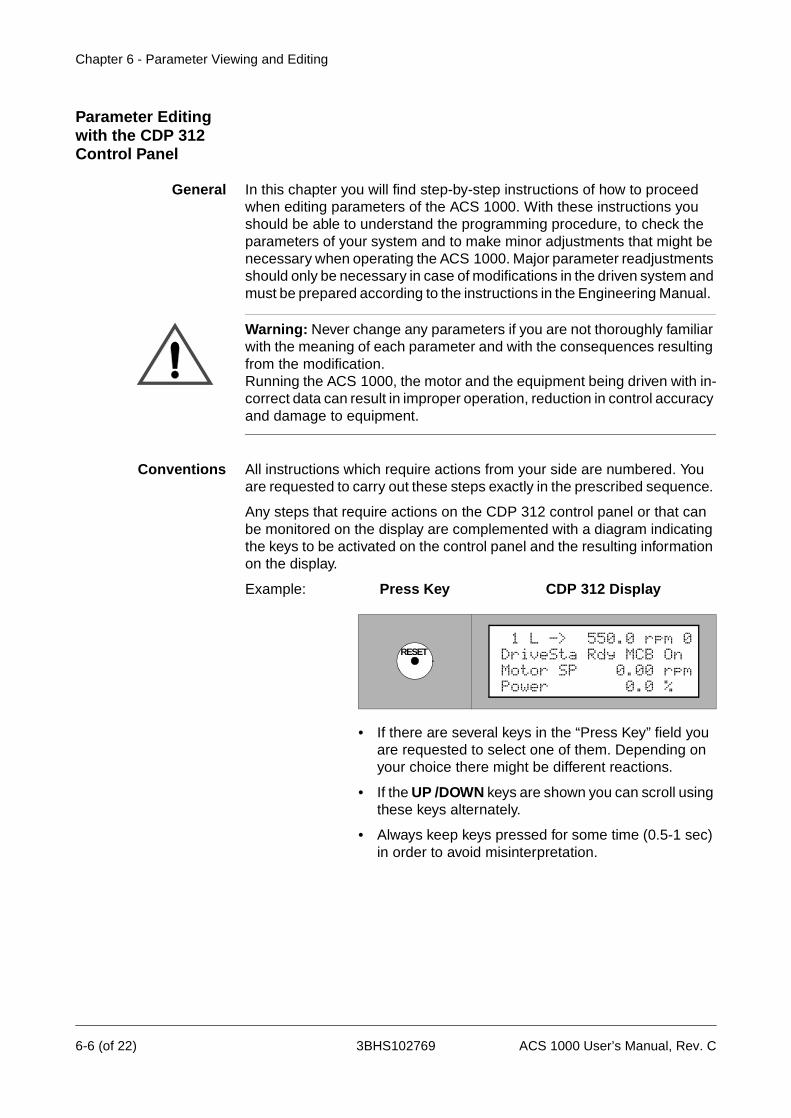
Chapter 6 - Parameter Viewing and Editing
Parameter Editing with the CDP 312 Control Panel
General In this chapter you will find step-by-step instructions of how to proceed when editing parameters of the ACS 1000. With these instructions you should be able to understand the programming procedure, to check the parameters of your system and to make minor adjustments that might be necessary when operating the ACS 1000. Major parameter readjustments should only be necessary in case of modifications in the driven system and must be prepared according to the instructions in the Engineering Manual.
Warning: Never change any parameters if you are not thoroughly familiar with the meaning of each parameter and with the consequences resulting from the modification. Running the ACS 1000, the motor and the equipment being driven with in-correct data can result in improper operation, reduction in control accuracy and damage to equipment.
Conventions All instructions which require actions from your side are numbered. You are requested to carry out these steps exactly in the prescribed sequence.
Any steps that require actions on the CDP 312 control panel or that can be monitored on the display are complemented with a diagram indicating the keys to be activated on the control panel and the resulting information on the display.
Example: Press Key CDP 312 Display
• If there are several keys in the “Press Key” field you are requested to select one of them. Depending on your choice there might be different reactions.
• If the UP /DOWN keys are shown you can scroll using these keys alternately.
• Always keep keys pressed for some time (0.5-1 sec) in order to avoid misinterpretation.
RESET
Power 0.0 %
1 L -> 550.0 rpm 0DriveSta Rdy MCB OnMotor SP 0.00 rpm
6-6 (of 22) 3BHS102769 ACS 1000 User’s Manual, Rev. C
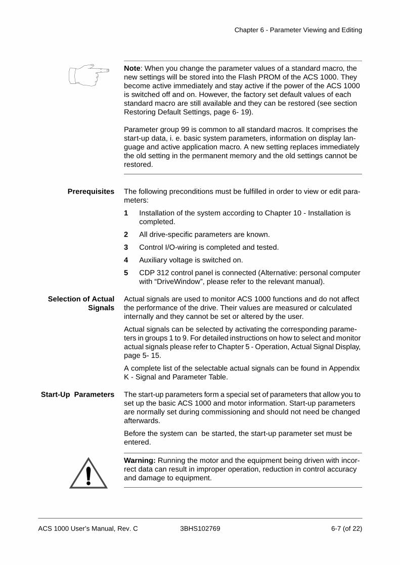
Chapter 6 - Parameter Viewing and Editing
Note: When you change the parameter values of a standard macro, the new settings will be stored into the Flash PROM of the ACS 1000. They become active immediately and stay active if the power of the ACS 1000 is switched off and on. However, the factory set default values of each standard macro are still available and they can be restored (see section Restoring Default Settings, page 6- 19).
Parameter group 99 is common to all standard macros. It comprises the start-up data, i. e. basic system parameters, information on display lan-guage and active application macro. A new setting replaces immediately the old setting in the permanent memory and the old settings cannot be restored.
Prerequisites The following preconditions must be fulfilled in order to view or edit para-meters:
1 Installation of the system according to Chapter 10 - Installation is completed.
2 All drive-specific parameters are known.
3 Control I/O-wiring is completed and tested.
4 Auxiliary voltage is switched on.
5 CDP 312 control panel is connected (Alternative: personal computer with “DriveWindow”, please refer to the relevant manual).
Selection of ActualSignals
Actual signals are used to monitor ACS 1000 functions and do not affect the performance of the drive. Their values are measured or calculated internally and they cannot be set or altered by the user.
Actual signals can be selected by activating the corresponding parame-ters in groups 1 to 9. For detailed instructions on how to select and monitor actual signals please refer to Chapter 5 - Operation, Actual Signal Display, page 5- 15.
A complete list of the selectable actual signals can be found in Appendix K - Signal and Parameter Table.
Start-Up Parameters The start-up parameters form a special set of parameters that allow you to set up the basic ACS 1000 and motor information. Start-up parameters are normally set during commissioning and should not need be changed afterwards.
Before the system can be started, the start-up parameter set must be entered.
Warning: Running the motor and the equipment being driven with incor-rect data can result in improper operation, reduction in control accuracy and damage to equipment.
ACS 1000 User’s Manual, Rev. C 3BHS102769 6-7 (of 22)
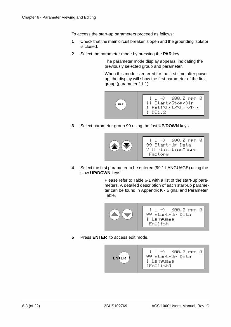
Chapter 6 - Parameter Viewing and Editing
To access the start-up parameters proceed as follows:
1 Check that the main circuit breaker is open and the grounding isolator is closed.
2 Select the parameter mode by pressing the PAR key.
The parameter mode display appears, indicating the previously selected group and parameter.
When this mode is entered for the first time after power-up, the display will show the first parameter of the first group (parameter 11.1).
3 Select parameter group 99 using the fast UP/DOWN keys.
4 Select the first parameter to be entered (99.1 LANGUAGE) using the slow UP/DOWN keys
Please refer to Table 6-1 with a list of the start-up para-meters. A detailed description of each start-up parame-ter can be found in Appendix K - Signal and Parameter Table.
5 Press ENTER to access edit mode.
PAR
1 DI1.2
1 L -> 600.0 rpm 011 Start/Stop/Dir1 Ext1Strt/Stop/Dir
Factory
1 L -> 600.0 rpm 099 Start-Up Data2 ApplicationMacro
English
1 L -> 600.0 rpm 099 Start-Up Data1 Language
ENTER
[English]
1 L -> 600.0 rpm 099 Start-Up Data1 Language
6-8 (of 22) 3BHS102769 ACS 1000 User’s Manual, Rev. C
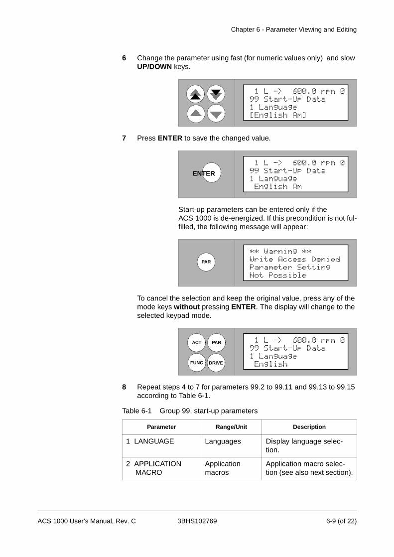
Chapter 6 - Parameter Viewing and Editing
6 Change the parameter using fast (for numeric values only) and slow UP/DOWN keys.
7 Press ENTER to save the changed value.
Start-up parameters can be entered only if the ACS 1000 is de-energized. If this precondition is not ful-filled, the following message will appear:
To cancel the selection and keep the original value, press any of the mode keys without pressing ENTER. The display will change to the selected keypad mode.
8 Repeat steps 4 to 7 for parameters 99.2 to 99.11 and 99.13 to 99.15 according to Table 6-1.
Table 6-1 Group 99, start-up parameters
Parameter Range/Unit Description
1 LANGUAGE Languages Display language selec-tion.
2 APPLICATION MACRO
Application macros
Application macro selec-tion (see also next section).
[English Am]
1 L -> 600.0 rpm 099 Start-Up Data1 Language
ENTER
English Am
1 L -> 600.0 rpm 099 Start-Up Data1 Language
PAR
Not Possible
** Warning **Write Access DeniedParameter Setting
ACT
FUNC DRIVE
PAR
English
1 L -> 600.0 rpm 099 Start-Up Data1 Language
ACS 1000 User’s Manual, Rev. C 3BHS102769 6-9 (of 22)
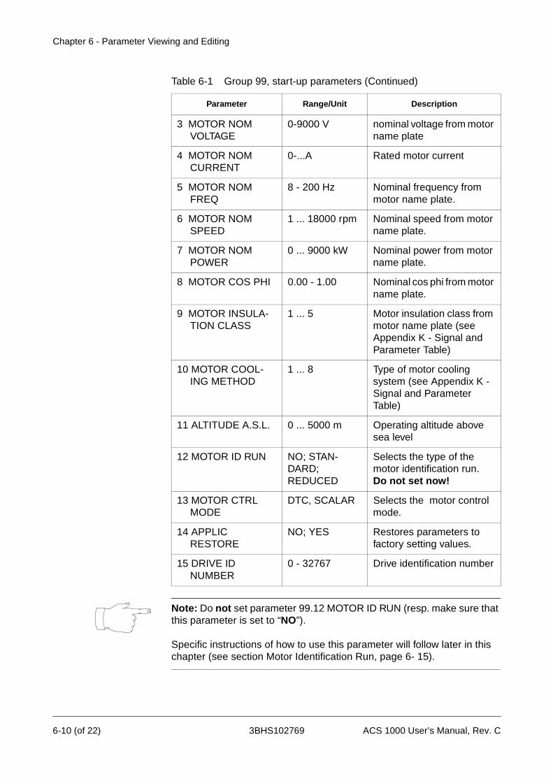
Chapter 6 - Parameter Viewing and Editing
Note: Do not set parameter 99.12 MOTOR ID RUN (resp. make sure that this parameter is set to “NO”).
Specific instructions of how to use this parameter will follow later in this chapter (see section Motor Identification Run, page 6- 15).
3 MOTOR NOM VOLTAGE
0-9000 V nominal voltage from motor name plate
4 MOTOR NOM CURRENT
0-...A Rated motor current
5 MOTOR NOM FREQ
8 - 200 Hz Nominal frequency from motor name plate.
6 MOTOR NOM SPEED
1 ... 18000 rpm Nominal speed from motor name plate.
7 MOTOR NOM POWER
0 ... 9000 kW Nominal power from motor name plate.
8 MOTOR COS PHI 0.00 - 1.00 Nominal cos phi from motor name plate.
9 MOTOR INSULA-TION CLASS
1 ... 5 Motor insulation class from motor name plate (see Appendix K - Signal and Parameter Table)
10 MOTOR COOL-ING METHOD
1 ... 8 Type of motor cooling system (see Appendix K - Signal and Parameter Table)
11 ALTITUDE A.S.L. 0 ... 5000 m Operating altitude above sea level
12 MOTOR ID RUN NO; STAN-DARD; REDUCED
Selects the type of the motor identification run.Do not set now!
13 MOTOR CTRL MODE
DTC, SCALAR Selects the motor control mode.
14 APPLIC RESTORE
NO; YES Restores parameters to factory setting values.
15 DRIVE ID NUMBER
0 - 32767 Drive identification number
Table 6-1 Group 99, start-up parameters (Continued)
Parameter Range/Unit Description
6-10 (of 22) 3BHS102769 ACS 1000 User’s Manual, Rev. C

Chapter 6 - Parameter Viewing and Editing
Parameter 99.15 DRIVE ID NUMBER is optional.
9 To exit the parameter mode press any of the mode keys
or
to select another parameter group to continue with parameter input use the fast UP/DOWN keys.
Selection orVerification of
Application Macro
Warning: Never change the application macro setting of a system which is already in operation if you do not have a very specific reason to do so.
Changing the application macro setting will affect the basic control struc-ture of the ACS 1000 and the input/output-allocation on the IOEC 2 board. This can result in improper operation, loss of control and damage to equip-ment.
To view or select an application macro setting proceed as follows:
1 Select the parameter mode by pressing the PAR key.
The parameter mode display appears, indicating the previously selected group and parameter (when this mode is entered for the first time after power-up, the dis-play will show the first parameter of the first group).
2 Select parameter group 99 using the fast UP/DOWN keys.
3 Select parameter 99.2 APPLICATION MACRO using the slow UP/
PAR
No
1 L -> 600.0 rpm 075 Option Modules1 IOEC3 Option Board
English
1 L -> 600.0 rpm 099 Start-Up Data1 Language
ACS 1000 User’s Manual, Rev. C 3BHS102769 6-11 (of 22)
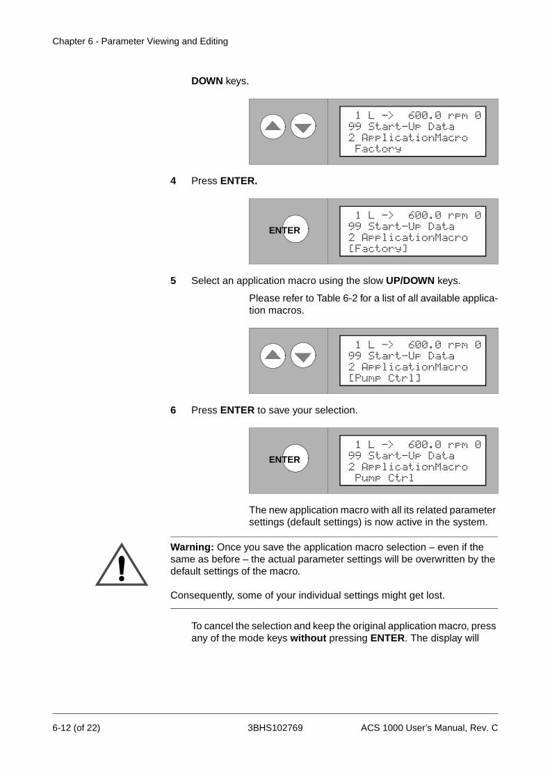
Chapter 6 - Parameter Viewing and Editing
DOWN keys.
4 Press ENTER.
5 Select an application macro using the slow UP/DOWN keys.
Please refer to Table 6-2 for a list of all available applica-tion macros.
6 Press ENTER to save your selection.
The new application macro with all its related parameter settings (default settings) is now active in the system.
Warning: Once you save the application macro selection – even if the same as before – the actual parameter settings will be overwritten by the default settings of the macro.
Consequently, some of your individual settings might get lost.
To cancel the selection and keep the original application macro, press any of the mode keys without pressing ENTER. The display will
Factory
1 L -> 600.0 rpm 099 Start-Up Data2 ApplicationMacro
ENTER
[Factory]
1 L -> 600.0 rpm 099 Start-Up Data2 ApplicationMacro
[Pump Ctrl]
1 L -> 600.0 rpm 099 Start-Up Data2 ApplicationMacro
ENTER
Pump Ctrl
1 L -> 600.0 rpm 099 Start-Up Data2 ApplicationMacro
6-12 (of 22) 3BHS102769 ACS 1000 User’s Manual, Rev. C
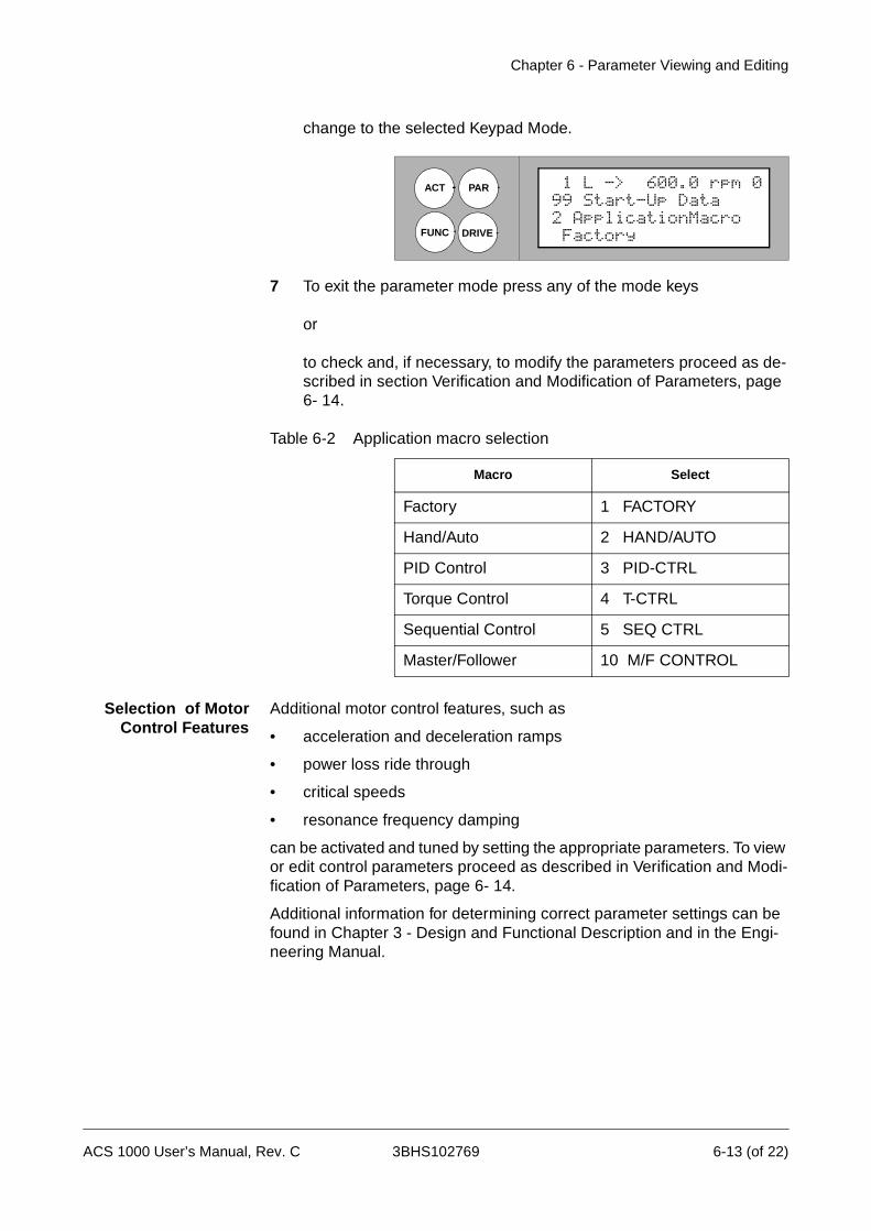
Chapter 6 - Parameter Viewing and Editing
change to the selected Keypad Mode.
7 To exit the parameter mode press any of the mode keys
or
to check and, if necessary, to modify the parameters proceed as de-scribed in section Verification and Modification of Parameters, page 6- 14.
Table 6-2 Application macro selection
Selection of MotorControl Features
Additional motor control features, such as
• acceleration and deceleration ramps
• power loss ride through
• critical speeds
• resonance frequency damping
can be activated and tuned by setting the appropriate parameters. To view or edit control parameters proceed as described in Verification and Modi-fication of Parameters, page 6- 14.
Additional information for determining correct parameter settings can be found in Chapter 3 - Design and Functional Description and in the Engi-neering Manual.
Macro Select
Factory 1 FACTORY
Hand/Auto 2 HAND/AUTO
PID Control 3 PID-CTRL
Torque Control 4 T-CTRL
Sequential Control 5 SEQ CTRL
Master/Follower 10 M/F CONTROL
ACT
FUNC DRIVE
PAR
Factory
1 L -> 600.0 rpm 099 Start-Up Data2 ApplicationMacro
ACS 1000 User’s Manual, Rev. C 3BHS102769 6-13 (of 22)
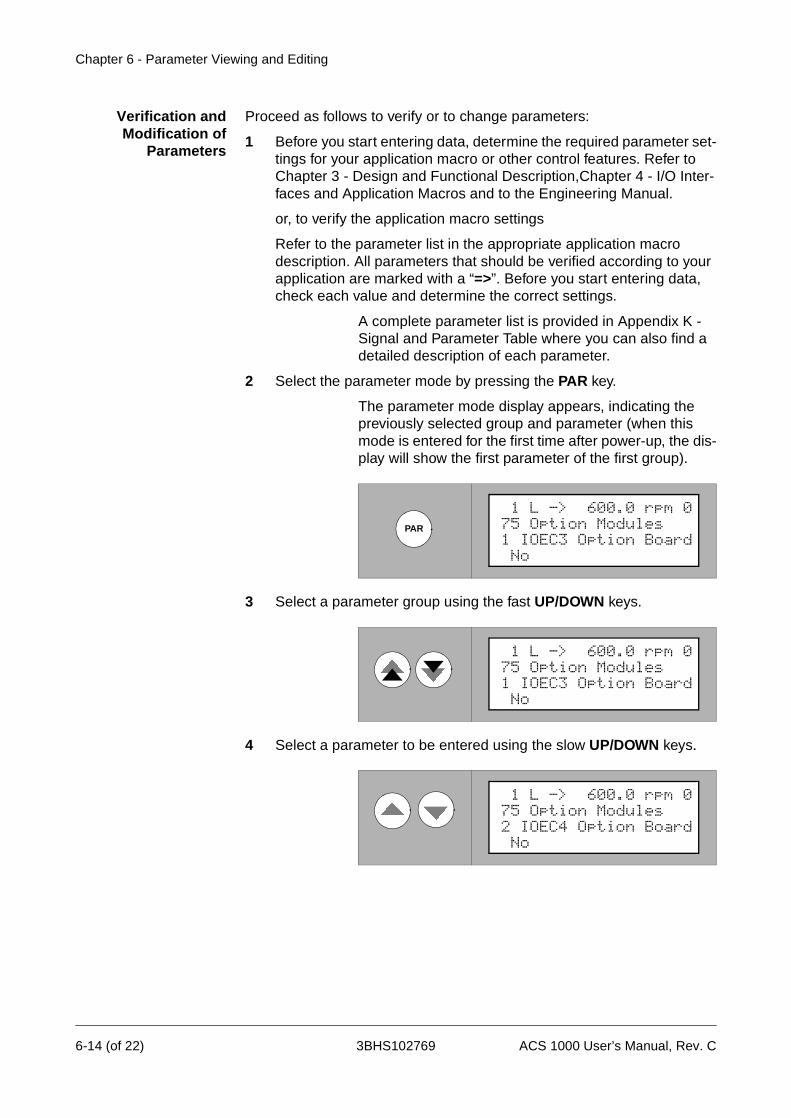
Chapter 6 - Parameter Viewing and Editing
Verification andModification of
Parameters
Proceed as follows to verify or to change parameters:
1 Before you start entering data, determine the required parameter set-tings for your application macro or other control features. Refer to Chapter 3 - Design and Functional Description,Chapter 4 - I/O Inter-faces and Application Macros and to the Engineering Manual.
or, to verify the application macro settings
Refer to the parameter list in the appropriate application macro description. All parameters that should be verified according to your application are marked with a “=>”. Before you start entering data, check each value and determine the correct settings.
A complete parameter list is provided in Appendix K - Signal and Parameter Table where you can also find a detailed description of each parameter.
2 Select the parameter mode by pressing the PAR key.
The parameter mode display appears, indicating the previously selected group and parameter (when this mode is entered for the first time after power-up, the dis-play will show the first parameter of the first group).
3 Select a parameter group using the fast UP/DOWN keys.
4 Select a parameter to be entered using the slow UP/DOWN keys.
PAR
No
1 L -> 600.0 rpm 075 Option Modules1 IOEC3 Option Board
No
1 L -> 600.0 rpm 075 Option Modules1 IOEC3 Option Board
No
1 L -> 600.0 rpm 075 Option Modules2 IOEC4 Option Board
6-14 (of 22) 3BHS102769 ACS 1000 User’s Manual, Rev. C
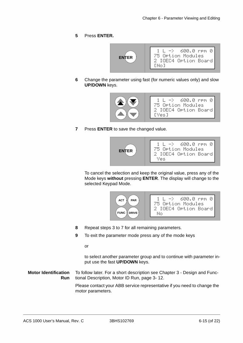
Chapter 6 - Parameter Viewing and Editing
5 Press ENTER.
6 Change the parameter using fast (for numeric values only) and slow UP/DOWN keys.
7 Press ENTER to save the changed value.
To cancel the selection and keep the original value, press any of the Mode keys without pressing ENTER. The display will change to the selected Keypad Mode.
8 Repeat steps 3 to 7 for all remaining parameters.
9 To exit the parameter mode press any of the mode keys
or
to select another parameter group and to continue with parameter in-put use the fast UP/DOWN keys.
Motor IdentificationRun
To follow later. For a short description see Chapter 3 - Design and Func-tional Description, Motor ID Run, page 3- 12.
Please contact your ABB service representative if you need to change the motor parameters.
ENTER
[No]
1 L -> 600.0 rpm 075 Option Modules2 IOEC4 Option Board
[Yes]
1 L -> 600.0 rpm 075 Option Modules2 IOEC4 Option Board
ENTER
Yes
1 L -> 600.0 rpm 075 Option Modules2 IOEC4 Option Board
ACT
FUNC DRIVE
PAR
No
1 L -> 600.0 rpm 075 Option Modules2 IOEC4 Option Board
ACS 1000 User’s Manual, Rev. C 3BHS102769 6-15 (of 22)
Chapter 6 - Parameter Viewing and Editing
Miscellaneous Functions
ACS 1000 Information The ACS 1000 software version, test date, and serial number can be displayed.
Information data are stored in parameter group 6, information. A detailed list can be found in Appendix K - Signal and Parameter Table.
Proceed as described in Selection of Actual Signals, page 6- 7 to view.
Parameter Lock The user can prevent unwanted parameter adjustment by activating the Parameter Lock.
Parameter lock is set with parameters 16.02 and 16.03 in group system ctr inputs. For further details see Appendix K - Signal and Parameter Table.
To set the parameter lock proceed as follows:
1 Select parameter 16.02 Parameter lock as described in Verification and Modification of Parameters, page 6- 14, steps 1 to 5.
2 Set parameter 16.02 to LOCKED
3 Save and exit as described in Verification and Modification of Parameters, page 6- 14, steps 7 ff.
To open the parameter lock proceed as follows:
1 Select parameter 16.03 Pass code as described in Verification and Modification of Parameters, page 6- 14, steps 1 to 5.
2 Set the correct pass code. If not known, see Appendix K - Signal and Parameter Table.
3 Save and exit as described in Verification and Modification of Parameters, page 6- 14, steps 7 ff.
UploadingParameters
If one CDP 312 control panel is used for more than one ACS 1000 unit, it is necessary to copy all parameters from the Flash PROM to the control panel when connecting it to a converter.
Uploading can be performed while the drive is running.
Note: Parameter groups 75 OPTION MODULES and 99 START-UP DATA will not be uploaded.
Proceed as follows for parameter uploading:
6-16 (of 22) 3BHS102769 ACS 1000 User’s Manual, Rev. C

Chapter 6 - Parameter Viewing and Editing
1 Select the Function mode by pressing the FUNC key.
2 Select UPLOAD using the slow UP/DOWN keys.
3 Press ENTER to start uploading.
4 During the uploading process only the STOP command can be given. To exit the function mode after completion press any of the mode keys.
DownloadingParameters
Parameter downloading might be necessary following the replacement of control equipment, such as the AMC3 board or the Flash PROM.
The drive must be stopped during downloading.
FUNC
Contrast 4
1 L -> 600.0 rpm 0Upload <= <=Download => =>
Contrast 4
1 L -> 600.0 rpm 0
Download => =>Upload <= <=
ENTER
Upload
1 L -> 600.0 rpm 0
<=<=<=<=<=<=<=
ACT
FUNC DRIVE
PAR
Power 0.0 %
1 L -> 550.0 rpm 0DriveSta Rdy MCB OnMotor SP 0.00 rpm
ACS 1000 User’s Manual, Rev. C 3BHS102769 6-17 (of 22)

Chapter 6 - Parameter Viewing and Editing
Downloading can only be started following a successful upload. Otherwise the following warning will appear:
Note: Parameter groups 75 OPTION MODULES and 99 START-UP DATA will not be downloaded.
Proceed as follows for parameter downloading:
1 Select the function mode by pressing the FUNC key.
2 Select DOWNLOAD using the slow UP/DOWN keys.
3 Press ENTER to start downloading.
4 During the downloading process only the STOP command can be given. To exit the function mode after completion press any of the mode keys.
FUNC
not Possible
** Warning **Not UploadedDownloading
FUNC
Contrast 4
1 L -> 600.0 rpm 0Upload <= <=Download => =>
Upload <= <=
Contrast 4
1 L -> 600.0 rpm 0
Download => =>
ENTER
Download
1 L -> 600.0 rpm 0
=>=>=>=>=>=>=>
ACT
FUNC DRIVE
PAR
Power 0.0 %
1 L -> 550.0 rpm 0DriveSta Rdy MCB OnMotor SP 0.00 rpm
6-18 (of 22) 3BHS102769 ACS 1000 User’s Manual, Rev. C
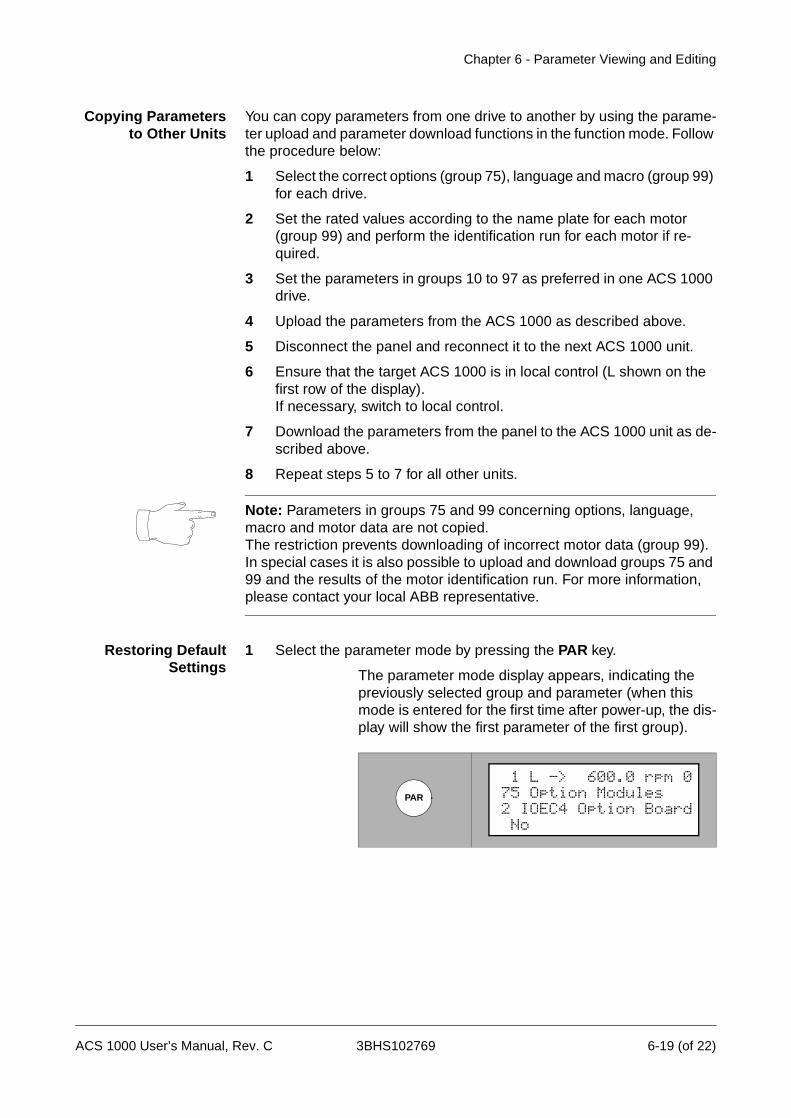
Chapter 6 - Parameter Viewing and Editing
Copying Parametersto Other Units
You can copy parameters from one drive to another by using the parame-ter upload and parameter download functions in the function mode. Follow the procedure below:
1 Select the correct options (group 75), language and macro (group 99) for each drive.
2 Set the rated values according to the name plate for each motor (group 99) and perform the identification run for each motor if re-quired.
3 Set the parameters in groups 10 to 97 as preferred in one ACS 1000 drive.
4 Upload the parameters from the ACS 1000 as described above.
5 Disconnect the panel and reconnect it to the next ACS 1000 unit.
6 Ensure that the target ACS 1000 is in local control (L shown on the first row of the display). If necessary, switch to local control.
7 Download the parameters from the panel to the ACS 1000 unit as de-scribed above.
8 Repeat steps 5 to 7 for all other units.
Note: Parameters in groups 75 and 99 concerning options, language, macro and motor data are not copied.The restriction prevents downloading of incorrect motor data (group 99). In special cases it is also possible to upload and download groups 75 and 99 and the results of the motor identification run. For more information, please contact your local ABB representative.
Restoring DefaultSettings
1 Select the parameter mode by pressing the PAR key.
The parameter mode display appears, indicating the previously selected group and parameter (when this mode is entered for the first time after power-up, the dis-play will show the first parameter of the first group).
PAR
No
1 L -> 600.0 rpm 075 Option Modules2 IOEC4 Option Board
ACS 1000 User’s Manual, Rev. C 3BHS102769 6-19 (of 22)

Chapter 6 - Parameter Viewing and Editing
2 Select parameter group 99 using the fast UP/DOWN keys.
3 Select parameter 99.11 APPLIC RESTORE using the slow UP/DOWN keys.
4 Press ENTER.
5 Select YES using the slow UP/DOWN keys.
6 Press ENTER to save the selection. The default settings for the active application macro are restored.
User Macros In addition to the standard application macros, it is possible to create two user macros. The user macro allows the user to save the parameter settings including group 99, the results of the motor identification run and the control location selection (local or external) into the Flash PROM of the ACS 1000, and recall the data at a later time.
Example: User macros make it possible to switch the ACS 1000 between
Factory
1 L -> 600.0 rpm 099 Start-Up Data2 ApplicationMacro
No
1 L -> 600.0 rpm 099 Start-Up Data11 ApplicationRestor
ENTER
[No]
1 L -> 600.0 rpm 099 Start-Up Data11 ApplicationRestor
[Yes]
1 L -> 600.0 rpm 099 Start-Up Data11 ApplicationRestor
ENTER
Yes
1 L -> 600.0 rpm 099 Start-Up Data11 ApplicationRestor
6-20 (of 22) 3BHS102769 ACS 1000 User’s Manual, Rev. C
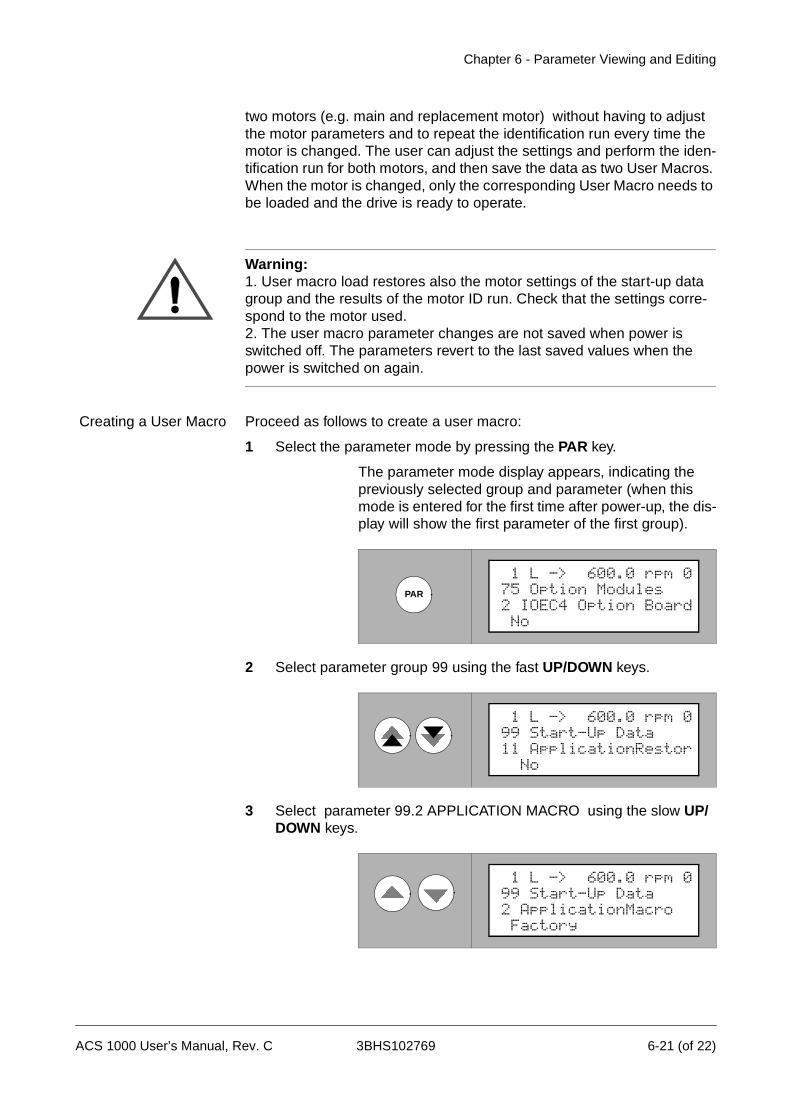
Chapter 6 - Parameter Viewing and Editing
two motors (e.g. main and replacement motor) without having to adjust the motor parameters and to repeat the identification run every time the motor is changed. The user can adjust the settings and perform the iden-tification run for both motors, and then save the data as two User Macros. When the motor is changed, only the corresponding User Macro needs to be loaded and the drive is ready to operate.
Warning: 1. User macro load restores also the motor settings of the start-up data group and the results of the motor ID run. Check that the settings corre-spond to the motor used.2. The user macro parameter changes are not saved when power is switched off. The parameters revert to the last saved values when the power is switched on again.
Creating a User Macro Proceed as follows to create a user macro:
1 Select the parameter mode by pressing the PAR key.
The parameter mode display appears, indicating the previously selected group and parameter (when this mode is entered for the first time after power-up, the dis-play will show the first parameter of the first group).
2 Select parameter group 99 using the fast UP/DOWN keys.
3 Select parameter 99.2 APPLICATION MACRO using the slow UP/DOWN keys.
PAR
No
1 L -> 600.0 rpm 075 Option Modules2 IOEC4 Option Board
No
1 L -> 600.0 rpm 099 Start-Up Data11 ApplicationRestor
Factory
1 L -> 600.0 rpm 099 Start-Up Data2 ApplicationMacro
ACS 1000 User’s Manual, Rev. C 3BHS102769 6-21 (of 22)

Chapter 6 - Parameter Viewing and Editing
4 Press ENTER.
5 Select USER 1 SAVE or USER 2 SAVE using the slow UP/DOWN keys.
6 Press ENTER to save your selection.
Saving will take a few minutes.
7 To exit the parameter mode press any of the mode keys
or
to check and, if necessary, to modify the parameters proceed as de-scribed in section Verification and Modification of Parameters, page 6- 14.
Recalling User MacroParameters
In order to recall the parameters saved in the user macro proceed as described above. In step 5 select USER 1 LOAD or USER 2 LOAD instead of USER 1 SAVE or USER 2 SAVE.
ENTER
[Factory]
1 L -> 600.0 rpm 099 Start-Up Data2 ApplicationMacro
[User 1 Save]
1 L -> 600.0 rpm 099 Start-Up Data2 ApplicationMacro
ENTER
User 1 Save
1 L -> 600.0 rpm 099 Start-Up Data2 ApplicationMacro
6-22 (of 22) 3BHS102769 ACS 1000 User’s Manual, Rev. C
Chapter 7 - Preventive Maintenance
Introduction This chapter contains a general maintenance schedule that lists all sched-uled maintenance and replacement actions to be carried out by the owner or by specialized ABB service staff. In addition, descriptions for those preventive maintenance tasks that can be carried out by the owner are included.
Maintenance work to be carried out by the owner is generally limited to various cleaning tasks and to parts replacement in the cooling circuit.
Warning: Do not attempt any maintenance work, parts replacement or other actions on the ACS 1000 you are not entitled to according to this manual.
Such maintenance work or installation of replacement parts on the ACS 1000 may only be carried out by service staff of ABB Industrie AG and by their authorized service representatives.
Failure to comply with these regulations will void guarantee and endanger correct operation of the installation.
All maintenance work must be carried out according to the maintenance schedule, on-time, in the described sequence and by authorized personnel.
Unless agreed otherwise in a service contract, it is the owner’s responsi-bility
• to verify that all necessary maintenance work is carried out according to the maintenance plan and
• to call up the local ABB service organization when maintenance work is due.
In order to maintain safe and reliable operation of the ACS 1000, it is strongly recommended to sign a service contract with the local ABB service organization. For more information please contact your local service representative.
Special maintenance and service training courses for professionals are offered by ABB. Customer staff having successfully attended such courses will be certified to do maintenance and repair work on the ACS 1000, provided that the equipment is not under warranty anymore. For further information please contact your local service representative.
Safety Instructions The ACS 1000 is a high voltage device and when misused it can cause damage to personnel and property. When located, installed and connected in accordance with the instructions given in this manual, the device is safe.
Warning: All electrical work on the ACS 1000 must be carried out by
ACS 1000 User’s Manual, Rev. C 3BHS102769 7-1 (of 12)

Chapter 7 - Preventive Maintenance
qualified electricians in compliance with local regulations.
Any work must be done with mains and auxiliary power off. Input and out-put isolators must be open and secured, any adjoining grounding device must be closed and power cables must be grounded.
Never apply power to the installation unless you have checked that:
• mains and motor connections are ok
• auxiliary power and control connections are ok
• no tools or other foreign objects are left in the cabinet
• All cabinet doors including protective shield and door of the control sec-tion are closed.
Danger: Never work on a powered ACS 1000. The main circuit breaker and the input isolators must always be opened and locked in “OPEN” po-sition. Do not access the main power circuit nor the motor as long as the system is not grounded.
When switching off the mains, always allow the intermediate circuit capac-itors to discharge before grounding and starting work on the frequency converter, the motor or the motor cable.
The ACS 1000 and adjoining equipment must be properly grounded and the auxiliary supply voltage must be switched off prior to starting with any work.
Danger: Some loads may apply a mechanical torque on the motor shaft! If the motor can rotate due to such a load, always disconnect, short-circuit or mechanically block the motor before you start work.
Danger: There can be dangerous voltages inside the ACS 1000 from ex-ternal control circuits (measurement inputs from PT’s etc.) even if the ACS 1000 mains power and auxiliary power are shut off. Take appropriate measures when working with the unit, i.e deenergize and disconnect all such external devices (auxiliary supply, heaters, coolers, I/O-interfaces) before you start work.
Prior to start working on the ACS 1000 the general safety regulations in Chapter 1 - Safety Instructions must be read and understood.
ABB Industrie AG declines all liability for any possible damage resulting from failure or negligence to observe these warnings.
7-2 (of 12) 3BHS102769 ACS 1000 User’s Manual, Rev. C
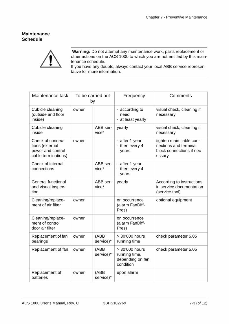
Chapter 7 - Preventive Maintenance
Maintenance Schedule
Warning: Do not attempt any maintenance work, parts replacement or other actions on the ACS 1000 to which you are not entitled by this main-tenance schedule.If you have any doubts, always contact your local ABB service represen-tative for more information.
Maintenance task To be carried out by
Frequency Comments
Cubicle cleaning (outside and floor inside)
owner - according to need
- at least yearly
visual check, cleaning if necessary
Cubicle cleaning inside
ABB ser-vice*
yearly visual check, cleaning if necessary
Check of connec-tions (external power and control cable terminations)
owner - after 1 year- then every 4
years
tighten main cable con-nections and terminal block connections if nec-essary
Check of internal connections
ABB ser-vice*
- after 1 year- then every 4
years
General functional and visual inspec-tion
ABB ser-vice*
yearly According to instructions in service documentation (service tool)
Cleaning/replace-ment of air filter
owner on occurrence (alarm FanDiff-Pres)
optional equipment
Cleaning/replace-ment of control door air filter
owner on occurrence (alarm FanDiff-Pres)
Replacement of fan bearings
owner (ABB service)*
> 30’000 hours running time
check parameter 5.05
Replacement of fan owner (ABB service)*
> 30’000 hours running time, depending on fan condition
check parameter 5.05
Replacement of batteries
owner (ABB service)*
upon alarm
ACS 1000 User’s Manual, Rev. C 3BHS102769 7-3 (of 12)

Chapter 7 - Preventive Maintenance
*service staff of ABB Industrie AG or authorized service representatives, is usually part of the service contract
** parameter backup can be done by instructed users. DriveWindow soft-ware is required.
Required Tools For maintenance tasks carried out by the owner, the following tools and materials are necessary:
• industrial vacuum cleaner with plastic tube and plastic tip
• compressed air (oil free)
• tool kit
• replacement parts
Maintenance Instructions
Standard Procedurefor Maintenance
In order to ensure maximum safety during maintenance activities proceed as follows:
1 Safety measures: Make sure to be familiar with and to observe all
Parameter backup and software ver-sion check
ABB ser-vice*
- upon any param-eter modifica-tion**
- at least every 5 years
Measurement of capacitors
ABB ser-vice*
- after 3 year- then every 2
years
Insulation test ABB ser-vice*
every 2 years According to instructions in service documentation (service tool)
Inspection of motor, transformer and MCB
owner ABB ser-vice*
according to the relevant mainte-nance instructions
see relevant mainte-nance instructions
Spare parts check ABB ser-vice*
yearly check stock according to Appendix I - Recom-mended Spare Parts List
Check of optional equipment
ABB ser-vice*
According to instructions in service documentation (service tool)
Maintenance task To be carried out by
Frequency Comments
7-4 (of 12) 3BHS102769 ACS 1000 User’s Manual, Rev. C

Chapter 7 - Preventive Maintenance
safety regulations as stated at the beginning of this chapter and in Chapter 1 - Safety Instructions.
2 De-energize the system
Danger: Do not access the main power circuit nor the motor as long as the system is still energized or as long as it is not grounded.
After switching off the mains and after the motor has come to a stop, al-ways allow the intermediate circuit capacitors 5 minutes to discharge (yel-low indicator GND.- SWITCH UNLOCKED must be on) before grounding and starting work on the frequency converter, the transformer, the motor or the cables.
The ACS 1000 and adjoining equipment must be properly grounded and the auxiliary supply voltage must be switched off prior to start-ing with any work.
ACS 1000 User’s Manual, Rev. C 3BHS102769 7-5 (of 12)
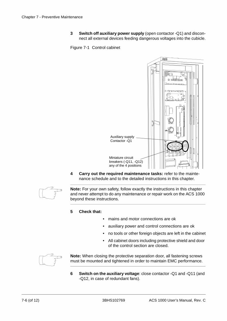
Chapter 7 - Preventive Maintenance
3 Switch off auxiliary power supply (open contactor -Q1) and discon-nect all external devices feeding dangerous voltages into the cubicle.
Figure 7-1 Control cabinet
4 Carry out the required maintenance tasks: refer to the mainte-nance schedule and to the detailed instructions in this chapter.
Note: For your own safety, follow exactly the instructions in this chapter and never attempt to do any maintenance or repair work on the ACS 1000 beyond these instructions.
5 Check that:
• mains and motor connections are ok
• auxiliary power and control connections are ok
• no tools or other foreign objects are left in the cabinet
• All cabinet doors including protective shield and door of the control section are closed.
Note: When closing the protective separation door, all fastening screws must be mounted and tightened in order to maintain EMC performance.
6 Switch on the auxiliary voltage: close contactor -Q1 and -Q11 (and -Q12, in case of redundant fans).
Miniature circuit breakers (-Q11, -Q12)any of the 4 positions
Auxiliary supplyContactor -Q1
7-6 (of 12) 3BHS102769 ACS 1000 User’s Manual, Rev. C

Chapter 7 - Preventive Maintenance
7 Restart the converter as described in Chapter 5 - Operation.
8 Make logbook entry: Any maintenance activity must be recorded in the maintenance logbook including:
• date and time
• maintenance task carried out according to mainte-nance schedule
• any special situation or action (scheduled or non-scheduled replacement of parts etc.)
Outside Cleaning Check air inlet and optional air filter for dirt, clean with compressed air and, if necessary, replace air filter (optional equipment, refer to filter manual)
Inside Floor Cleaning 1 De-energize the system according to Standard Procedure for Mainte-nance, page 7- 4
2 After the grounding switch has been closed, open the front doors
3 Carefully clean compartment floors with the vacuum cleaner (use plastic tip only to avoid damage to equipment).
Warning: Apply special care while cleaning inside the cubicle, especially do not damage the capacitor bushings. In order to avoid damages do not clean any other equipment besides the floor!
4 Accomplish your maintenance job as described in Standard Proce-dure for Maintenance, page 7- 4.
Check ofConnections
1 De-energize the system according to Standard Procedure for Mainte-nance, page 7- 4
2 After the grounding switch has been closed, open the front doors
3 Check if all connections of external power and control cables are fas-tened tightly.
Warning: Do not check the internal cabling! In particular do not tighten the capacitor connections. The capacitor bushings will be damaged when a excessive momentum is applied to the terminals.
4 Accomplish your maintenance job as described in Standard Proce-dure for Maintenance, page 7- 4.
ACS 1000 User’s Manual, Rev. C 3BHS102769 7-7 (of 12)
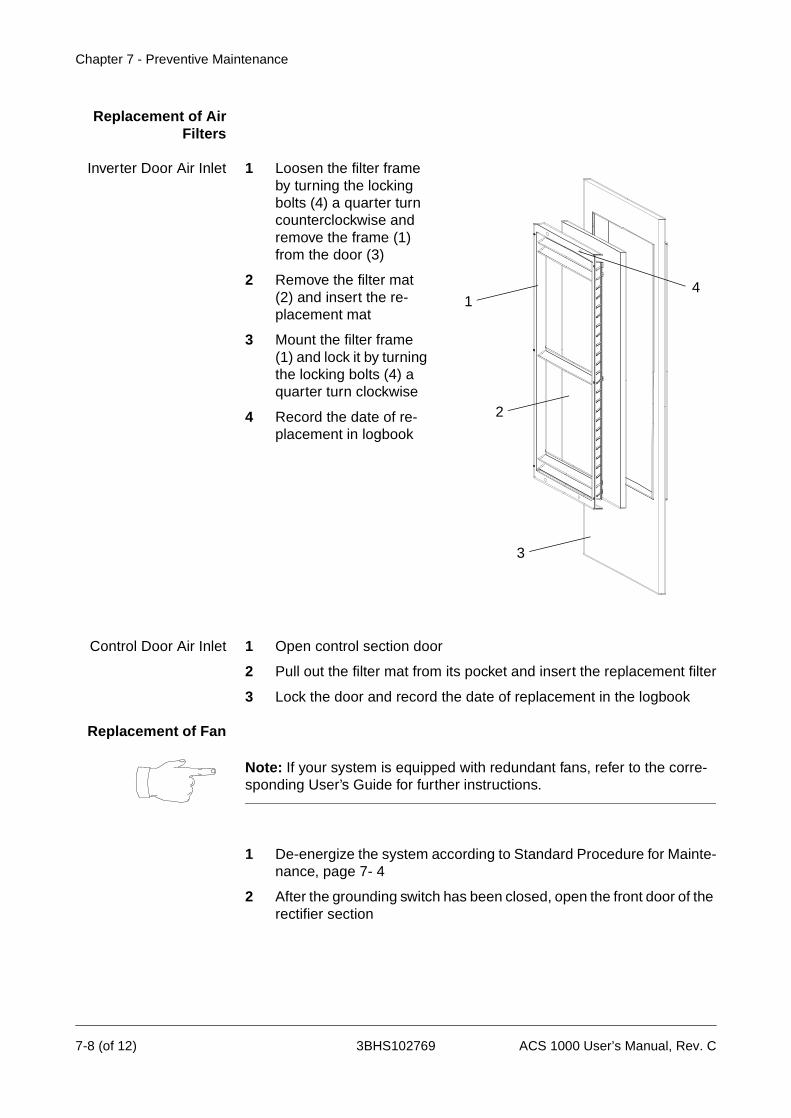
Chapter 7 - Preventive Maintenance
Replacement of AirFilters
Inverter Door Air Inlet 1 Loosen the filter frame by turning the locking bolts (4) a quarter turn counterclockwise and remove the frame (1) from the door (3)
2 Remove the filter mat (2) and insert the re-placement mat
3 Mount the filter frame (1) and lock it by turning the locking bolts (4) a quarter turn clockwise
4 Record the date of re-placement in logbook
Control Door Air Inlet 1 Open control section door
2 Pull out the filter mat from its pocket and insert the replacement filter
3 Lock the door and record the date of replacement in the logbook
Replacement of Fan
Note: If your system is equipped with redundant fans, refer to the corre-sponding User’s Guide for further instructions.
1 De-energize the system according to Standard Procedure for Mainte-nance, page 7- 4
2 After the grounding switch has been closed, open the front door of the rectifier section
1
3
2
4
7-8 (of 12) 3BHS102769 ACS 1000 User’s Manual, Rev. C
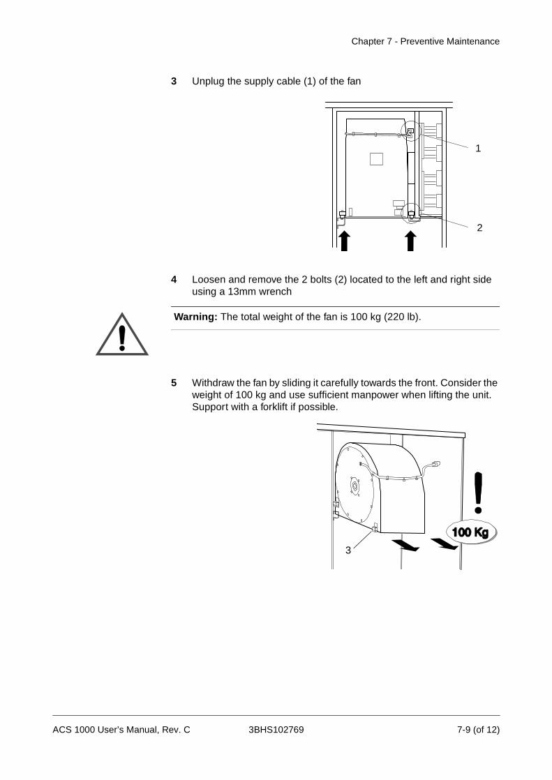
Chapter 7 - Preventive Maintenance
3 Unplug the supply cable (1) of the fan
4 Loosen and remove the 2 bolts (2) located to the left and right side using a 13mm wrench
Warning: The total weight of the fan is 100 kg (220 lb).
5 Withdraw the fan by sliding it carefully towards the front. Consider the weight of 100 kg and use sufficient manpower when lifting the unit. Support with a forklift if possible.
1
2
3
ACS 1000 User’s Manual, Rev. C 3BHS102769 7-9 (of 12)

Chapter 7 - Preventive Maintenance
6 Remove the 4 sliding blocks (3) and mount them on the replacement fan. The guiding grooves must be oriented towards the back side (4) of the housing (cable and nameplate are on the front side).
7 Lift the fan and slide it back onto the guiding rails
8 Press the housing towards the gasket on the right hand side (5), in-sert and tighten the 2 bolts.
9 Accomplish your maintenance job as described in Standard Proce-dure for Maintenance, page 7- 4. Check if the fan works properly when re-energizing the system.
Replacement of FanBearings
to follow later
3
4
backside offan housing
5
7-10 (of 12) 3BHS102769 ACS 1000 User’s Manual, Rev. C
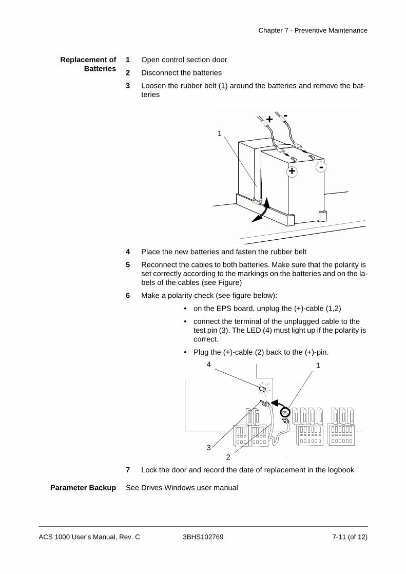
Chapter 7 - Preventive Maintenance
Replacement ofBatteries
1 Open control section door
2 Disconnect the batteries
3 Loosen the rubber belt (1) around the batteries and remove the bat-teries
4 Place the new batteries and fasten the rubber belt
5 Reconnect the cables to both batteries. Make sure that the polarity is set correctly according to the markings on the batteries and on the la-bels of the cables (see Figure)
6 Make a polarity check (see figure below):
• on the EPS board, unplug the (+)-cable (1,2)
• connect the terminal of the unplugged cable to the test pin (3). The LED (4) must light up if the polarity is correct.
• Plug the (+)-cable (2) back to the (+)-pin.
7 Lock the door and record the date of replacement in the logbook
Parameter Backup See Drives Windows user manual
+ -
+ -1
4
32
1
ACS 1000 User’s Manual, Rev. C 3BHS102769 7-11 (of 12)
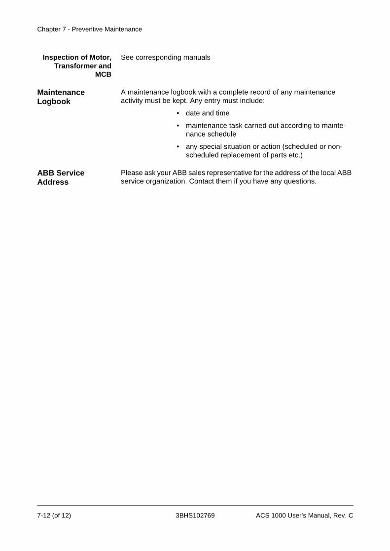
Chapter 7 - Preventive Maintenance
Inspection of Motor,Transformer and
MCB
See corresponding manuals
Maintenance Logbook
A maintenance logbook with a complete record of any maintenance activity must be kept. Any entry must include:
• date and time
• maintenance task carried out according to mainte-nance schedule
• any special situation or action (scheduled or non-scheduled replacement of parts etc.)
ABB Service Address
Please ask your ABB sales representative for the address of the local ABB service organization. Contact them if you have any questions.
7-12 (of 12) 3BHS102769 ACS 1000 User’s Manual, Rev. C
Chapter 8 - Trouble Shooting & Repair
Overview The purpose of this chapter is to provide information and instructions on how to proceed when encountering a problem with the ACS 1000. This chapter is addressed to electrical field professionals who are responsible for servicing the ACS 1000. In order to perform the suggested actions in case of a disturbance, no special training is required besides the profes-sional education as indicated in Chapter 2 - Introduction, Intended Audi-ence for this Manual, page 2- 2.
Warning: Do not attempt any measurement, parts replacement or other corrective actions on the ACS 1000 which are not described in this chap-ter.
Repair work or installation of spare parts on the ACS 1000 may only be carried out by service staff of ABB Industrie AG and by their authorized service representatives.
Failure to comply with this regulation will void guarantee and endanger correct operation of the installation.
It is strongly recommended to sign a service contract with ABB. For more information please contact your local service representative.
Special maintenance and service training courses for professionals are offered by ABB. Customer staff having successfully attended such courses will be certified to do maintenance and repair work on the ACS 1000, provided that the equipment is not under warranty anymore. For further information please contact your local service representative.
Safety Instructions The ACS 1000 is a high voltage device and when misused it can cause damage to personnel and property. When located, installed and connected in accordance with the instructions given in this manual, the device is safe.
Warning: All electrical work on the ACS 1000 must be carried out by qualified electricians in compliance with local regulations.
Any work must be done with mains and auxiliary power off. Input and out-put isolators must be open and secured, any adjoining grounding device must be closed and power cables must be grounded.
Never apply power to the installation unless you have checked that:
• mains and motor connections are ok
• auxiliary power and control connections are ok
• no tools or other foreign objects are left in the cabinet
• All cabinet doors including separation door behind the swing frame and
ACS 1000 User’s Manual, Rev. C 3BHS102769 8-1 (of 38)
Chapter 8 - Trouble Shooting & Repair
door of the control section are closed.
Danger: Never work on a powered ACS 1000. The main circuit breaker and the input isolators must always be opened and locked in “OPEN” po-sition. Do not access the main power circuit nor the motor as long as the system is not grounded.
When switching off the mains, always allow the intermediate circuit capac-itors to discharge before grounding and starting work on the frequency converter, the motor or the motor cable.
The ACS 1000 and adjoining equipment must be properly grounded and the auxiliary supply voltage must be switched off prior to starting with any work.
Danger: Some loads may apply a mechanical torque on the motor shaft! If the motor can rotate due to such a load, always disconnect, short-circuit or mechanically block the motor before you start work.
Danger: There can be dangerous voltages inside the ACS 1000 from ex-ternal control circuits (measurement inputs from PT’s etc.) even if the ACS 1000 mains power and auxiliary power are shut off. Take appropriate measures when working with the unit, i.e deenergize and disconnect all such external devices (auxiliary supply, heaters, coolers, I/O-interfaces) before you start work.
Danger: The grounding isolator may become ineffective if the power cir-cuit is opened. The main circuit breaker and the input isolators must al-ways be opened and locked in “OPEN” position. Any external ground switch must be closed and locked.
Prior to start working on the ACS 1000 the general safety regulations in Chapter 1 - Safety Instructions must be read and understood.
ABB Industrie AG declines all liability for any possible damage resulting from failure or negligence to observe these warnings.
Alarm and Fault Handling
If a disturbance occurs anywhere in the converter or in related equipment, it will be indicated with an error message on the CDP 312 control panel or, as alternative, on the DriveWindow error display.
Two error message levels are used with the ACS 1000:
• Fault: a fault is initiated by a serious disturbance in the converter or in related equipment (transformer, motor etc.) and always implies a con-verter trip. The converter will remain in tripped state (with the exception of a few faults where the converter will resume operation automatically after the disturbance has disappeared).
8-2 (of 38) 3BHS102769 ACS 1000 User’s Manual, Rev. C
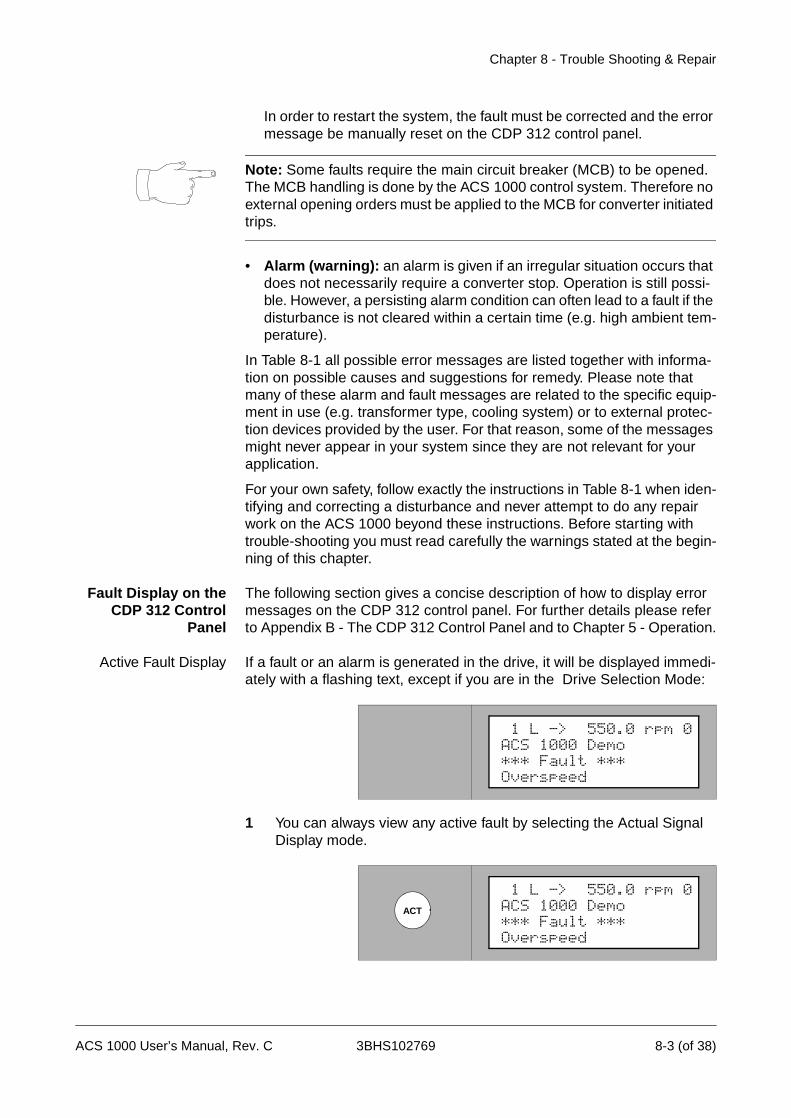
Chapter 8 - Trouble Shooting & Repair
In order to restart the system, the fault must be corrected and the error message be manually reset on the CDP 312 control panel.
Note: Some faults require the main circuit breaker (MCB) to be opened. The MCB handling is done by the ACS 1000 control system. Therefore no external opening orders must be applied to the MCB for converter initiated trips.
• Alarm (warning): an alarm is given if an irregular situation occurs that does not necessarily require a converter stop. Operation is still possi-ble. However, a persisting alarm condition can often lead to a fault if the disturbance is not cleared within a certain time (e.g. high ambient tem-perature).
In Table 8-1 all possible error messages are listed together with informa-tion on possible causes and suggestions for remedy. Please note that many of these alarm and fault messages are related to the specific equip-ment in use (e.g. transformer type, cooling system) or to external protec-tion devices provided by the user. For that reason, some of the messages might never appear in your system since they are not relevant for your application.
For your own safety, follow exactly the instructions in Table 8-1 when iden-tifying and correcting a disturbance and never attempt to do any repair work on the ACS 1000 beyond these instructions. Before starting with trouble-shooting you must read carefully the warnings stated at the begin-ning of this chapter.
Fault Display on theCDP 312 Control
Panel
The following section gives a concise description of how to display error messages on the CDP 312 control panel. For further details please refer to Appendix B - The CDP 312 Control Panel and to Chapter 5 - Operation.
Active Fault Display If a fault or an alarm is generated in the drive, it will be displayed immedi-ately with a flashing text, except if you are in the Drive Selection Mode:
1 You can always view any active fault by selecting the Actual Signal Display mode.
1 L -> 550.0 rpm 0ACS 1000 Demo*** Fault ***Overspeed
ACT
1 L -> 550.0 rpm 0ACS 1000 Demo*** Fault ***Overspeed
ACS 1000 User’s Manual, Rev. C 3BHS102769 8-3 (of 38)

Chapter 8 - Trouble Shooting & Repair
2 To reset the fault press RESET.
After a reset , the fault message will not appear anymore in Actual Signal Display mode. However, the fault is still stored in the fault history and can be viewed there.
From the fault display, it is possible to switch to other displays without resetting the fault. If no keys are pressed the fault or warning text is displayed as long as the fault exists.
Fault History Display The Fault History provides information on the 40 most recent faults that occurred in your ACS 1000. The name of the fault and the date and time of occurrence are displayed.
Proceed as follows to view fault history:
1 Enter the Actual Signal Display mode by pressing ACT on the CDP 312 control panel.
2 Select the Fault History Display with the fast UP/DOWN keys.
The most recent fault will be displayed together with the date and time of occurrence.
3 Select previous (UP key) or next fault (DOWN key).
RESET
Power 0.0 %
1 L -> 550.0 rpm 0DriveSta Rdy to StrtMotor SP 0.00 rpm
ACT
Power 0.0 %
1 L -> 550.0 rpm 0DriveSta Rdy to StrtMotor SP 0.00 rpm
1 L -> 550.0 rpm 0 1 Last FaultOverspeed980226 12:30:02.3256
1 L -> 550.0 rpm 0 2 Last FaultSpeed Ref Lost980224 10:45:32.0705
8-4 (of 38) 3BHS102769 ACS 1000 User’s Manual, Rev. C
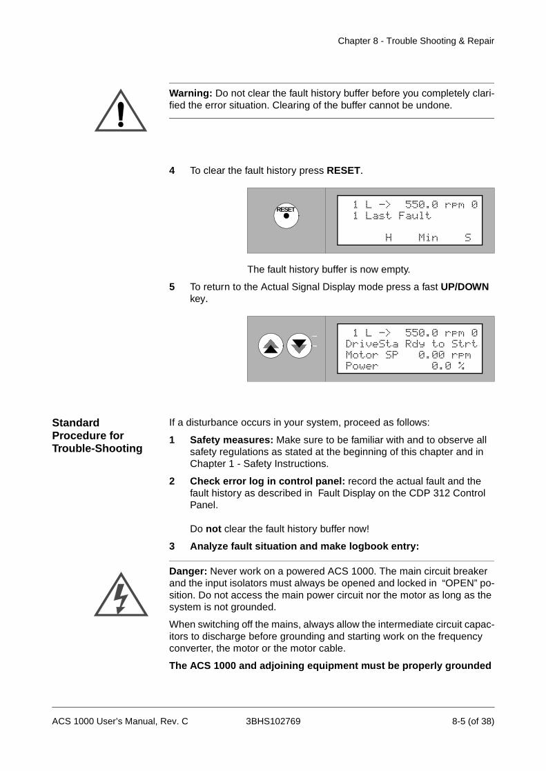
Chapter 8 - Trouble Shooting & Repair
Warning: Do not clear the fault history buffer before you completely clari-fied the error situation. Clearing of the buffer cannot be undone.
4 To clear the fault history press RESET.
The fault history buffer is now empty.
5 To return to the Actual Signal Display mode press a fast UP/DOWN key.
Standard Procedure for Trouble-Shooting
If a disturbance occurs in your system, proceed as follows:
1 Safety measures: Make sure to be familiar with and to observe all safety regulations as stated at the beginning of this chapter and in Chapter 1 - Safety Instructions.
2 Check error log in control panel: record the actual fault and the fault history as described in Fault Display on the CDP 312 Control Panel.
Do not clear the fault history buffer now!
3 Analyze fault situation and make logbook entry:
Danger: Never work on a powered ACS 1000. The main circuit breaker and the input isolators must always be opened and locked in “OPEN” po-sition. Do not access the main power circuit nor the motor as long as the system is not grounded.
When switching off the mains, always allow the intermediate circuit capac-itors to discharge before grounding and starting work on the frequency converter, the motor or the motor cable.
The ACS 1000 and adjoining equipment must be properly grounded
RESET 1 L -> 550.0 rpm 0 1 Last Fault
H Min S
Power 0.0 %
1 L -> 550.0 rpm 0DriveSta Rdy to StrtMotor SP 0.00 rpm
ACS 1000 User’s Manual, Rev. C 3BHS102769 8-5 (of 38)
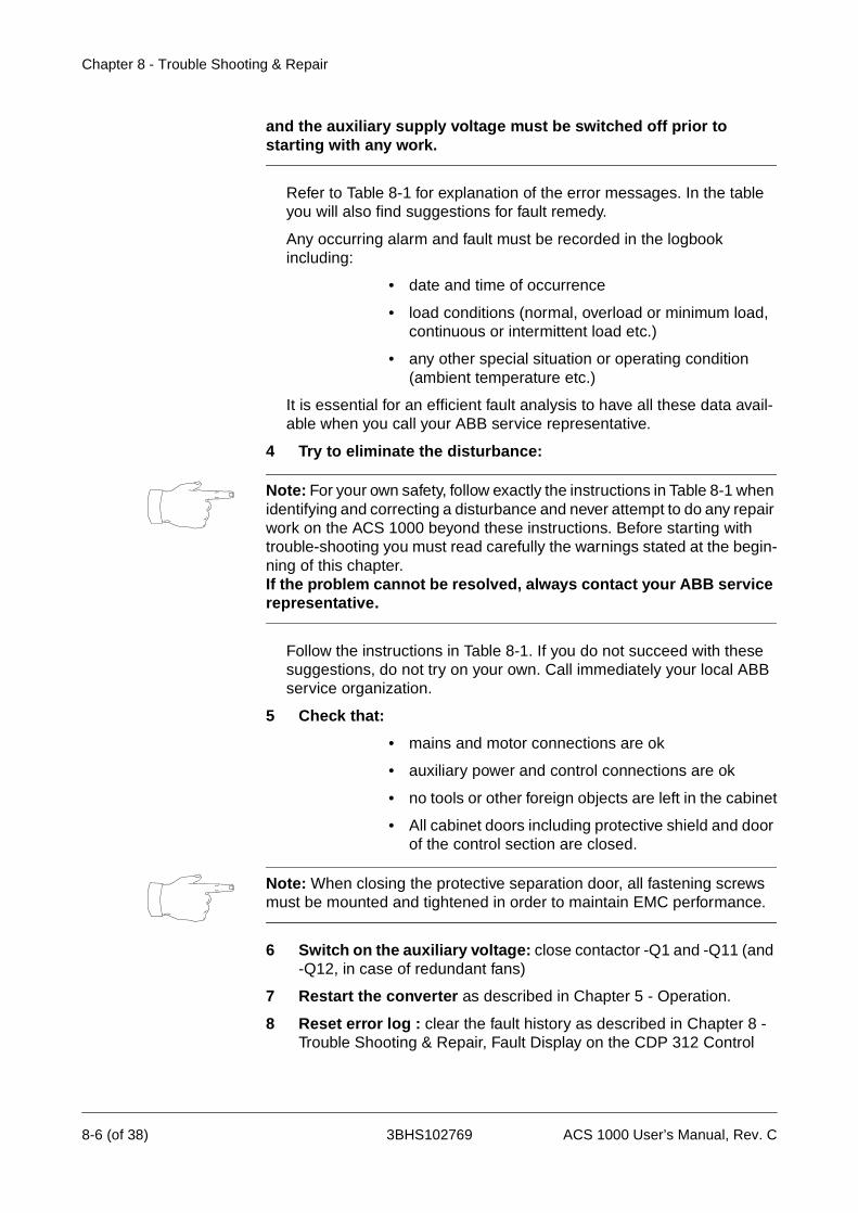
Chapter 8 - Trouble Shooting & Repair
and the auxiliary supply voltage must be switched off prior to starting with any work.
Refer to Table 8-1 for explanation of the error messages. In the table you will also find suggestions for fault remedy.
Any occurring alarm and fault must be recorded in the logbook including:
• date and time of occurrence
• load conditions (normal, overload or minimum load, continuous or intermittent load etc.)
• any other special situation or operating condition (ambient temperature etc.)
It is essential for an efficient fault analysis to have all these data avail-able when you call your ABB service representative.
4 Try to eliminate the disturbance:
Note: For your own safety, follow exactly the instructions in Table 8-1 when identifying and correcting a disturbance and never attempt to do any repair work on the ACS 1000 beyond these instructions. Before starting with trouble-shooting you must read carefully the warnings stated at the begin-ning of this chapter.If the problem cannot be resolved, always contact your ABB service representative.
Follow the instructions in Table 8-1. If you do not succeed with these suggestions, do not try on your own. Call immediately your local ABB service organization.
5 Check that:
• mains and motor connections are ok
• auxiliary power and control connections are ok
• no tools or other foreign objects are left in the cabinet
• All cabinet doors including protective shield and door of the control section are closed.
Note: When closing the protective separation door, all fastening screws must be mounted and tightened in order to maintain EMC performance.
6 Switch on the auxiliary voltage: close contactor -Q1 and -Q11 (and -Q12, in case of redundant fans)
7 Restart the converter as described in Chapter 5 - Operation.
8 Reset error log : clear the fault history as described in Chapter 8 - Trouble Shooting & Repair, Fault Display on the CDP 312 Control
8-6 (of 38) 3BHS102769 ACS 1000 User’s Manual, Rev. C

Chapter 8 - Trouble Shooting & Repair
Panel, page 8- 3 .
Repair Work During warranty, any repair work is to be done exclusively by ABB service personnel. After expiration of the warranty period repair work with the exception of replacement of parts specifically mentioned in Chapter 7 - Preventive Maintenance is to be done only by ABB service personnel or by authorized persons having attended the maintenance and service training as mentioned at the beginning of this chapter. Adequate docu-mentation will be handed out during these courses.
Error Messages and Fault Elimination
See Table 8-1 and Table 8-2.
ACS 1000 User’s Manual, Rev. C 3BHS102769 8-7 (of 38)

Chapter 8 - Trouble Shooting & Repair
Table 8-1 Error messages and fault elimination
Message Possible cause/meaning of message
Suggested remedy
IndicationA
larm
FaultM
CB
open
Comments
AirFiltSupv ∆p (differential pressure) supervi-sion Possible causes:- Air filter is dirty
- Replace air filter- If the fault cannot be located,
call local ABB service organiza-tion
x OptionalAir cooled convert-ers only
AnInpCalib Automatic input calibration of IOEC boards not successful
- Disconnect analog inputs and retry
- If the fault cannot be eliminated, call local ABB service organiza-tion
x
AnInpCalib Automatic input calibration of IOEC boards not successful
- Disconnect analog inputs and retry
- If the fault cannot be eliminated, call local ABB service organiza-tion
x
Aux Pwr Fail
Failure in 27 V power supplyPossible cause:- Loss of auxiliary input voltage
- Check auxiliary input voltage (Terminal X10, see Appendix G - Wiring Diagrams) and auxiliary power supply
- If the fault cannot be eliminated, call local ABB service organiza-tion
x x
AuxFan Contactor supervision of aux fanPossible causes:- Fan defective- Fan protection relay defective
- Call local ABB service organiza-tion
x x Water cooled con-verters only
Battery Down
Battery capacity too low - Replace battery (see Chapter 7 - Preventive Maintenance)
- Call local ABB service organiza-tion
x x Default setting: de-pending on applica-tion
Battery Miss
Battery is not connected - Check battery wiring and con-nections
- If the fault cannot be eliminated, call local ABB service organiza-tion
x x Default setting: de-pending on applica-tion
Brake Chop Temperature limit of the braking chopper exceededPossible causes:- Underdimensioning of braking
chopper
- Call local ABB service organiza-tion
x Optional
Brake Chop Temperature limit of the braking chopper exceededPossible causes:- Underdimensioning of braking
chopper
- Call local ABB service organiza-tion
x x Optional
8-8 (of 38) 3BHS102769 ACS 1000 User’s Manual, Rev. C
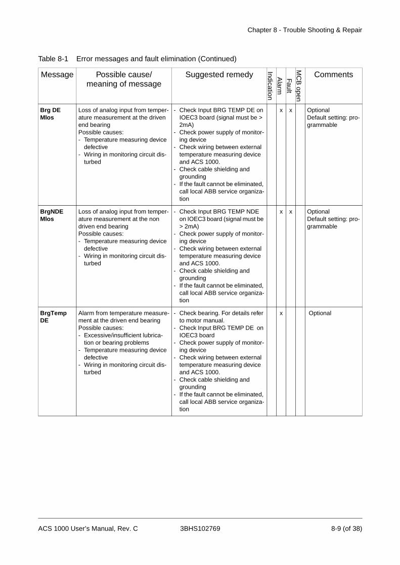
Chapter 8 - Trouble Shooting & Repair
Brg DE Mlos
Loss of analog input from temper-ature measurement at the driven end bearingPossible causes:- Temperature measuring device
defective- Wiring in monitoring circuit dis-
turbed
- Check Input BRG TEMP DE on IOEC3 board (signal must be > 2mA)
- Check power supply of monitor-ing device
- Check wiring between external temperature measuring device and ACS 1000.
- Check cable shielding and grounding
- If the fault cannot be eliminated, call local ABB service organiza-tion
x x OptionalDefault setting: pro-grammable
BrgNDE Mlos
Loss of analog input from temper-ature measurement at the non driven end bearingPossible causes:- Temperature measuring device
defective- Wiring in monitoring circuit dis-
turbed
- Check Input BRG TEMP NDE on IOEC3 board (signal must be > 2mA)
- Check power supply of monitor-ing device
- Check wiring between external temperature measuring device and ACS 1000.
- Check cable shielding and grounding
- If the fault cannot be eliminated, call local ABB service organiza-tion
x x OptionalDefault setting: pro-grammable
BrgTemp DE
Alarm from temperature measure-ment at the driven end bearingPossible causes:- Excessive/insufficient lubrica-
tion or bearing problems- Temperature measuring device
defective- Wiring in monitoring circuit dis-
turbed
- Check bearing. For details refer to motor manual.
- Check Input BRG TEMP DE on IOEC3 board
- Check power supply of monitor-ing device
- Check wiring between external temperature measuring device and ACS 1000.
- Check cable shielding and grounding
- If the fault cannot be eliminated, call local ABB service organiza-tion
x Optional
Table 8-1 Error messages and fault elimination (Continued)
Message Possible cause/meaning of message
Suggested remedy
IndicationA
larm
FaultM
CB
open
Comments
ACS 1000 User’s Manual, Rev. C 3BHS102769 8-9 (of 38)
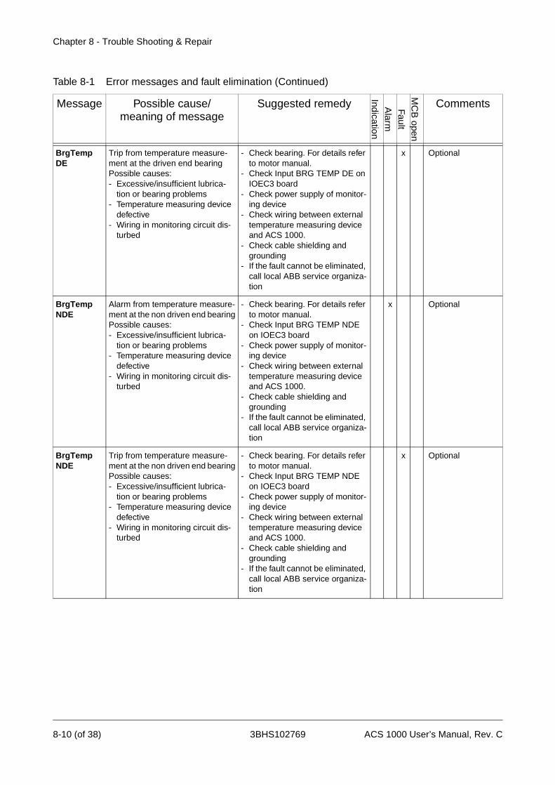
Chapter 8 - Trouble Shooting & Repair
BrgTemp DE
Trip from temperature measure-ment at the driven end bearingPossible causes:- Excessive/insufficient lubrica-
tion or bearing problems- Temperature measuring device
defective- Wiring in monitoring circuit dis-
turbed
- Check bearing. For details refer to motor manual.
- Check Input BRG TEMP DE on IOEC3 board
- Check power supply of monitor-ing device
- Check wiring between external temperature measuring device and ACS 1000.
- Check cable shielding and grounding
- If the fault cannot be eliminated, call local ABB service organiza-tion
x Optional
BrgTemp NDE
Alarm from temperature measure-ment at the non driven end bearingPossible causes:- Excessive/insufficient lubrica-
tion or bearing problems- Temperature measuring device
defective- Wiring in monitoring circuit dis-
turbed
- Check bearing. For details refer to motor manual.
- Check Input BRG TEMP NDE on IOEC3 board
- Check power supply of monitor-ing device
- Check wiring between external temperature measuring device and ACS 1000.
- Check cable shielding and grounding
- If the fault cannot be eliminated, call local ABB service organiza-tion
x Optional
BrgTemp NDE
Trip from temperature measure-ment at the non driven end bearingPossible causes:- Excessive/insufficient lubrica-
tion or bearing problems- Temperature measuring device
defective- Wiring in monitoring circuit dis-
turbed
- Check bearing. For details refer to motor manual.
- Check Input BRG TEMP NDE on IOEC3 board
- Check power supply of monitor-ing device
- Check wiring between external temperature measuring device and ACS 1000.
- Check cable shielding and grounding
- If the fault cannot be eliminated, call local ABB service organiza-tion
x Optional
Table 8-1 Error messages and fault elimination (Continued)
Message Possible cause/meaning of message
Suggested remedy
IndicationA
larm
FaultM
CB
open
Comments
8-10 (of 38) 3BHS102769 ACS 1000 User’s Manual, Rev. C

Chapter 8 - Trouble Shooting & Repair
Buchholz Alarm signal from external Buch-holz protectionPossible causes:- Gas or air bubble generation in
transformer oil circuit- Wiring in protection circuit dis-
turbed- Shielding of control cables not
properly grounded
- Inspect transformer according to the instructions in the transform-er manual
- Check wiring of Buchholz pro-tection circuit (input BUCH-HOLZ ALARM on IOEC3 board).
- Check if shielding of control ca-bles is properly grounded
- If the fault cannot be eliminated, call local ABB service organiza-tion
x Optional
Buchholz Trip signal from external Buchholz protectionPossible causes:- Gas or air bubble generation in
transformer oil circuit- Wiring in protection circuit dis-
turbed- Shielding of control cables not
properly grounded
- Inspect transformer according to the instructions in the transform-er manual
- Check wiring of Buchholz pro-tection circuit (input BUCH-HOLZ TRIP on IOEC3 board).
- Check if shielding of control ca-bles is properly grounded
- If the fault cannot be eliminated, call local ABB service organiza-tion
x x Optional
CalibNot Done
Offset calibration of IOEC boards was not successful
- x
CH0 LinkEr Communication time-out (internal comm.)
- Check fibre optic connections on AMC 3 board
- Call local ABB service organiza-tion
x x Default setting: Not active
CH2 LinkEr Communication time-out (internal comm.)
- Check fibre optic connections on AMC 3 board
- Call local ABB service organiza-tion
x x Default setting: Not active
Charge Circ Charging circuit disturbed - Call local ABB service organiza-tion
x x
Charging Charging of intermediate dc-circuit failedPossible causes:- Mains voltage low
- Verify measured dc-voltage (Pa-rameters 2.02 to 2.09)
- Check whether mains supply voltage is within the tolerated limits. See Appendix A - Techni-cal Data.
- Verify stiffness of mains supply- If the fault cannot be eliminated,
call local ABB service organiza-tion
x x
CoSens-Dirty
Cooling water conductivity sensor is dirty
- Call local ABB service organiza-tion
x Water cooled con-verters only
Table 8-1 Error messages and fault elimination (Continued)
Message Possible cause/meaning of message
Suggested remedy
IndicationA
larm
FaultM
CB
open
Comments
ACS 1000 User’s Manual, Rev. C 3BHS102769 8-11 (of 38)
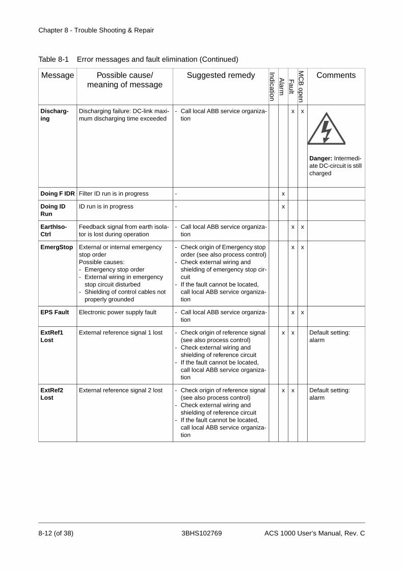
Chapter 8 - Trouble Shooting & Repair
Discharg-ing
Discharging failure: DC-link maxi-mum discharging time exceeded
- Call local ABB service organiza-tion
x x
Danger: Intermedi-ate DC-circuit is still charged
Doing F IDR Filter ID run is in progress - x
Doing ID Run
ID run is in progress - x
EarthIso-Ctrl
Feedback signal from earth isola-tor is lost during operation
- Call local ABB service organiza-tion
x x
EmergStop External or internal emergency stop orderPossible causes:- Emergency stop order- External wiring in emergency
stop circuit disturbed- Shielding of control cables not
properly grounded
- Check origin of Emergency stop order (see also process control)
- Check external wiring and shielding of emergency stop cir-cuit
- If the fault cannot be located, call local ABB service organiza-tion
x x
EPS Fault Electronic power supply fault - Call local ABB service organiza-tion
x x
ExtRef1 Lost
External reference signal 1 lost - Check origin of reference signal (see also process control)
- Check external wiring and shielding of reference circuit
- If the fault cannot be located, call local ABB service organiza-tion
x x Default setting: alarm
ExtRef2 Lost
External reference signal 2 lost - Check origin of reference signal (see also process control)
- Check external wiring and shielding of reference circuit
- If the fault cannot be located, call local ABB service organiza-tion
x x Default setting: alarm
Table 8-1 Error messages and fault elimination (Continued)
Message Possible cause/meaning of message
Suggested remedy
IndicationA
larm
FaultM
CB
open
Comments
8-12 (of 38) 3BHS102769 ACS 1000 User’s Manual, Rev. C
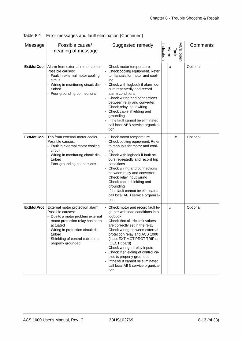
Chapter 8 - Trouble Shooting & Repair
ExtMotCool Alarm from external motor coolerPossible causes:- Fault in external motor cooling
circuit- Wiring in monitoring circuit dis-
turbed- Poor grounding connections
- Check motor temperature- Check cooling equipment. Refer
to manuals for motor and cool-ing
- Check with logbook if alarm oc-curs repeatedly and record alarm conditions
- Check wiring and connections between relay and converter. Check relay input wiring
- Check cable shielding and grounding
- If the fault cannot be eliminated, call local ABB service organiza-tion
x Optional
ExtMotCool Trip from external motor coolerPossible causes:- Fault in external motor cooling
circuit- Wiring in monitoring circuit dis-
turbed- Poor grounding connections
- Check motor temperature- Check cooling equipment. Refer
to manuals for motor and cool-ing
- Check with logbook if fault oc-curs repeatedly and record trip conditions
- Check wiring and connections between relay and converter. Check relay input wiring
- Check cable shielding and grounding
- If the fault cannot be eliminated, call local ABB service organiza-tion
x Optional
ExtMotProt External motor protection alarm Possible causes:- Due to a motor problem external
motor protection relay has been actuated
- Wiring in protection circuit dis-turbed
- Shielding of control cables not properly grounded
- Check motor and record fault to-gether with load conditions into logbook
- Check that all trip limit values are correctly set in the relay
- Check wiring between external protection relay and ACS 1000 (input EXT MOT PROT TRIP on IOEC1 board)
- Check wiring to relay inputs- Check if shielding of control ca-
bles is properly grounded- If the fault cannot be eliminated,
call local ABB service organiza-tion
x Optional
Table 8-1 Error messages and fault elimination (Continued)
Message Possible cause/meaning of message
Suggested remedy
IndicationA
larm
FaultM
CB
open
Comments
ACS 1000 User’s Manual, Rev. C 3BHS102769 8-13 (of 38)

Chapter 8 - Trouble Shooting & Repair
ExtMotProt External motor protection trip Possible causes:- Due to a motor problem external
motor protection relay has been actuated
- Wiring in protection circuit dis-turbed
- Shielding of control cables not properly grounded
- Check motor and record fault to-gether with load conditions into logbook
- Check that all trip limit values are correctly set in the relay
- Check wiring between external protection relay and ACS 1000 (input EXT MOT PROT TRIP on IOEC1 board)
- Check wiring to relay inputs- Check if shielding of control ca-
bles is properly grounded- If the fault cannot be eliminated,
call local ABB service organiza-tion
x
ExtOver-speed
External motor overspeed protec-tionPossible causes :- Wrong parameter settings- Loss of parameter settings or
power supply in external relay- Motor is forced to overspeed by
driven equipment- Wiring in protection circuit dis-
turbed- Poor grounding connections
- Check parameter settings of ex-ternal relay. Check that settings are not in conflict with converter parameter settings
- check power supply of external relay
- Check motor loading, especially if driven equipment is dimen-sioned correctly and functioning properly. Check with logbook if fault occurs repeatedly and record trip conditions
- Check wiring and connections between relay and converter. Check relay input wiring
- Check cable shielding and grounding
- If the fault cannot be eliminated, call local ABB service organiza-tion
x x Optional
ExtTrafProt Trip signal from external trans-former protectionPossible causes:- Transformer fault- Wiring in protection circuit dis-
turbed- Shielding of control cables not
properly grounded
- Inspect transformer according to the instructions in the external protection device and transform-er manuals
- Check wiring of external protec-tion circuit (input EXT TRAFO PROT TRIP on IOEC1 board).
- Check if shielding of control ca-bles is properly grounded
- If the fault cannot be eliminated, call local ABB service organiza-tion
x x
Table 8-1 Error messages and fault elimination (Continued)
Message Possible cause/meaning of message
Suggested remedy
IndicationA
larm
FaultM
CB
open
Comments
8-14 (of 38) 3BHS102769 ACS 1000 User’s Manual, Rev. C

Chapter 8 - Trouble Shooting & Repair
ExtWtrCool Alarm from external motor water cooling equipmentPossible causes:- Fault in external motor cooling
circuit- Wiring in monitoring circuit dis-
turbed- Poor grounding connections
- Check motor temperature- Check cooling equipment. Refer
to manuals for motor and cool-ing
- Check with logbook if alarm oc-curs repeatedly and record alarm conditions
- Check wiring and connections between relay and converter. Check relay input wiring
- Check cable shielding and grounding
- If the fault cannot be eliminated, call local ABB service organiza-tion
x Optional
ExtWtrCool Trip from external motor water cooling equipmentPossible causes:- Fault in external motor cooling
circuit- Wiring in monitoring circuit dis-
turbed- Poor grounding connections
- Check motor temperature- Check cooling equipment. Refer
to manuals for motor and cool-ing
- Check with logbook if fault oc-curs repeatedly and record trip conditions
- Check wiring and connections between relay and converter. Check relay input wiring
- Check cable shielding and grounding
- If the fault cannot be eliminated, call local ABB service organiza-tion
x Optional
Fan 1/2 Trip - fan contactor supervisionPossible causes:- Overload- Fan defective- Contactor defective
- Check contactor- Replace fan- If the fault cannot be eliminated,
call local ABB service organiza-tion
x x Air cooled convert-ers only
Fan 1/2 Alarm - fan contactor supervision in case of redundant fansPossible causes:- Overload- Fan defective- Contactor defective
- Check contactor- Replace fan- If the fault cannot be eliminated,
call local ABB service organiza-tion
x Air cooled convert-ers only
FanDiffPres Trip - differential pressure supervi-sionPossible causes:- Fan defective- Power supply for fan disturbed
- Check if doors are properly closed
- Check air filter and clean if nec-essary
- If the fault cannot be eliminated, call local ABB service organiza-tion
x x Air cooled convert-ers only
Table 8-1 Error messages and fault elimination (Continued)
Message Possible cause/meaning of message
Suggested remedy
IndicationA
larm
FaultM
CB
open
Comments
ACS 1000 User’s Manual, Rev. C 3BHS102769 8-15 (of 38)
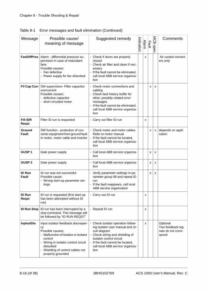
Chapter 8 - Trouble Shooting & Repair
FanDiffPres Alarm - differential pressure su-pervision in case of redundant fansPossible causes:- Fan defective- Power supply for fan disturbed
- Check if doors are properly closed
- Check air filter and clean if nec-essary
- If the fault cannot be eliminated, call local ABB service organiza-tion
x Air cooled convert-ers only
Fil Cap Curr SW supervision- Filter capacitor overcurrentPossible causes:- defective capacitor- short circuited motor
- Check motor connections and cabling
- Check fault history buffer for other, possibly related error messages
- If the fault cannot be eliminated, call local ABB service organiza-tion
x x
Filt IDR Reqst
Filter ID run is requested - Carry out filter ID run x
Ground Fault
SW function - protection of con-verter equipment from ground fault in motor, motor cable and inverter
- Check motor and motor cables. Refer to motor manual
- If the fault cannot be located, call local ABB service organiza-tion
x x depends on appli-cation
GUSP 1 Gate power supply - Call local ABB service organiza-tion
x x
GUSP 2 Gate power supply - Call local ABB service organiza-tion
x x
ID Run Fault
ID run was not successfulPossible cause:- Wrong start-up parameter set-
tings
- Verify parameter settings in pa-rameter group 99 and repeat ID run
- If the fault reappears, call local ABB service organization
x x
ID Run Reqst
ID run is requested (first start-up has been attempted without ID run)
- Carry out ID run x
ID Run Stop ID run has been interrupted by a stop command. This message will be followed by “ID RUN REQST”
- Repeat ID run x
InpIsolDis Input isolator feedback discrepan-cyPossible causes:- Malfunction of isolator or isolator
control- Wiring in isolator control circuit
disturbed- Shielding of control cables not
properly grounded
- Check isolator operation follow-ing isolator user manual and cir-cuit diagram.
- Check wiring and shielding of isolator control circuit
- If the fault cannot be located, call local ABB service organiza-tion
x OptionalTwo feedback sig-nals do not corre-spond
Table 8-1 Error messages and fault elimination (Continued)
Message Possible cause/meaning of message
Suggested remedy
IndicationA
larm
FaultM
CB
open
Comments
8-16 (of 38) 3BHS102769 ACS 1000 User’s Manual, Rev. C

Chapter 8 - Trouble Shooting & Repair
InpVolt-Unba
Converter input voltage is not bal-ancedPossible causes:- Loss of a phase or voltage un-
balance- Loss of aux. power supply for
unbalance protection relay- Wiring in monitoring circuit dis-
turbed- Shielding of cables not properly
grounded
- Check input mains voltage- Check auxiliary power supply for
protection relay- Check protection relay settings- Check wiring and shielding of
monitoring circuit - If the fault cannot be located,
call local ABB service organiza-tion
x x Optional
Inv Curr HW HW supervision - excessive invert-er output currentPossible causes:- Motor load not matched with in-
verter ratings- Incorrect motor data- If fault occurs during accelera-
tion , the acceleration time might be too short
- Stray currents in motor cabling
- Check fault history buffer for other, possibly related error messages
- Check dimensioning of motor and drive. For inverter ratings see Appendix A - ACS 1000 Technical Data
- Verify start-up parameters 99.3 to 99.8. Compare with motor nameplate. See Appendix K - Parameter Description
- Check if fault occurs only during acceleration If this is the case, increase the acceleration time (parameters 22.02 and 22.04)
- Check motor cable connections - If the fault cannot be eliminated,
call local ABB service organiza-tion
x
Inv Curr SOA
SW supervision of Inverter cur-rents according to safe operating area -excessive inverter output currentPossible causes:- Motor load not matched with in-
verter ratings- High supply voltage- Incorrect motor data- If fault occurs during accelera-
tion , the acceleration time might be too short
- Stray currents in motor cabling
- Check fault history buffer for other, possibly related error messages
- Check dimensioning of motor and drive. For inverter ratings see Appendix A - Technical Data
- Verify start-up parameters 99.3 to 99.8. Compare with motor nameplate. See Appendix K - Parameter Description
- Check if fault occurs only during acceleration If this is the case, increase the acceleration time (parameters 22.02 and 22.04)
- Check motor cable connections - If the fault cannot be eliminated,
call local ABB service organiza-tion
x
Table 8-1 Error messages and fault elimination (Continued)
Message Possible cause/meaning of message
Suggested remedy
IndicationA
larm
FaultM
CB
open
Comments
ACS 1000 User’s Manual, Rev. C 3BHS102769 8-17 (of 38)

Chapter 8 - Trouble Shooting & Repair
InvAirTemp Incoming cooling air above limit - Check ambient temperature- If ambient temperature is within
limits, call local ABB service or-ganization
x Air cooled convert-ers only
InvAirTemp Supervision of ambient tempera-turePossible cause:- Ambient temperature too high
- Check ambient temperature- If ambient temperature is within
limits, call local ABB service or-ganization
x Air cooled convert-ers only
IOEC1LinkEr
Supervision of communication link - Check connectors on IOEC1 and AMC3 boards
- If the fault cannot be eliminated call local ABB service organiza-tion
x x
IOEC2LinkEr
Supervision of communication link - Check connectors on IOEC2 and AMC3 boards
- If the fault cannot be eliminated call local ABB service organiza-tion
x x
IOEC3LinkEr
Supervision of communication link - Check connectors on IOEC3 and AMC3 boards
- If the fault cannot be eliminated call local ABB service organiza-tion
x x Optional
IOEC4LinkEr
Supervision of communication link - Check connectors on IOEC4 and AMC3 boards
- If the fault cannot be eliminated call local ABB service organiza-tion
x x Optional
Limit Superv
Supervision if actual or reference signal is at limit.
- Check limit settings in parame-ter group 32 Supervision
x
Link AB Lost
Loss of internal communication links
- Check connectors in control cabinet
- If the fault cannot be eliminated call local ABB service organiza-tion
x x
Link C Lost Loss of internal communication links
- Check connectors on interface board and ADCVI board
- If the fault cannot be eliminated call local ABB service organiza-tion
x x
Link D Lost Loss of internal communication links
- Check connectors on interface board and ADCVI board
- If the fault cannot be eliminated call local ABB service organiza-tion
x x
Table 8-1 Error messages and fault elimination (Continued)
Message Possible cause/meaning of message
Suggested remedy
IndicationA
larm
FaultM
CB
open
Comments
8-18 (of 38) 3BHS102769 ACS 1000 User’s Manual, Rev. C
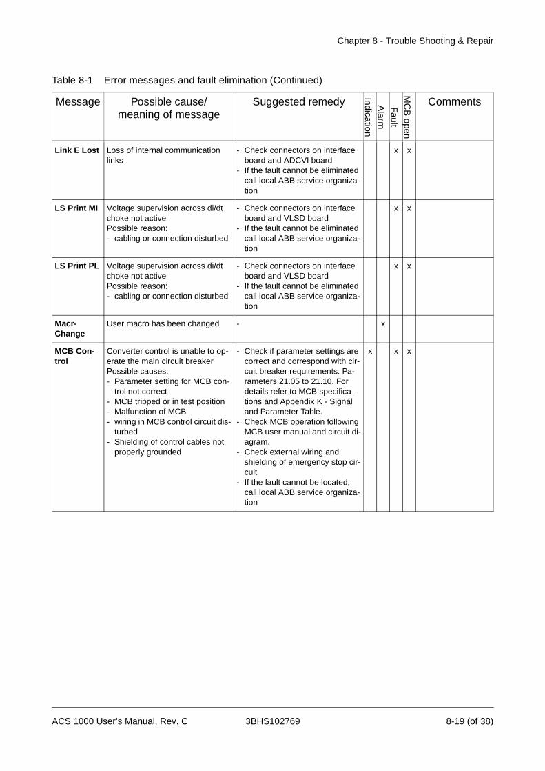
Chapter 8 - Trouble Shooting & Repair
Link E Lost Loss of internal communication links
- Check connectors on interface board and ADCVI board
- If the fault cannot be eliminated call local ABB service organiza-tion
x x
LS Print MI Voltage supervision across di/dt choke not activePossible reason:- cabling or connection disturbed
- Check connectors on interface board and VLSD board
- If the fault cannot be eliminated call local ABB service organiza-tion
x x
LS Print PL Voltage supervision across di/dt choke not activePossible reason:- cabling or connection disturbed
- Check connectors on interface board and VLSD board
- If the fault cannot be eliminated call local ABB service organiza-tion
x x
Macr-Change
User macro has been changed - x
MCB Con-trol
Converter control is unable to op-erate the main circuit breakerPossible causes:- Parameter setting for MCB con-
trol not correct- MCB tripped or in test position- Malfunction of MCB- wiring in MCB control circuit dis-
turbed- Shielding of control cables not
properly grounded
- Check if parameter settings are correct and correspond with cir-cuit breaker requirements: Pa-rameters 21.05 to 21.10. For details refer to MCB specifica-tions and Appendix K - Signal and Parameter Table.
- Check MCB operation following MCB user manual and circuit di-agram.
- Check external wiring and shielding of emergency stop cir-cuit
- If the fault cannot be located, call local ABB service organiza-tion
x x x
Table 8-1 Error messages and fault elimination (Continued)
Message Possible cause/meaning of message
Suggested remedy
IndicationA
larm
FaultM
CB
open
Comments
ACS 1000 User’s Manual, Rev. C 3BHS102769 8-19 (of 38)
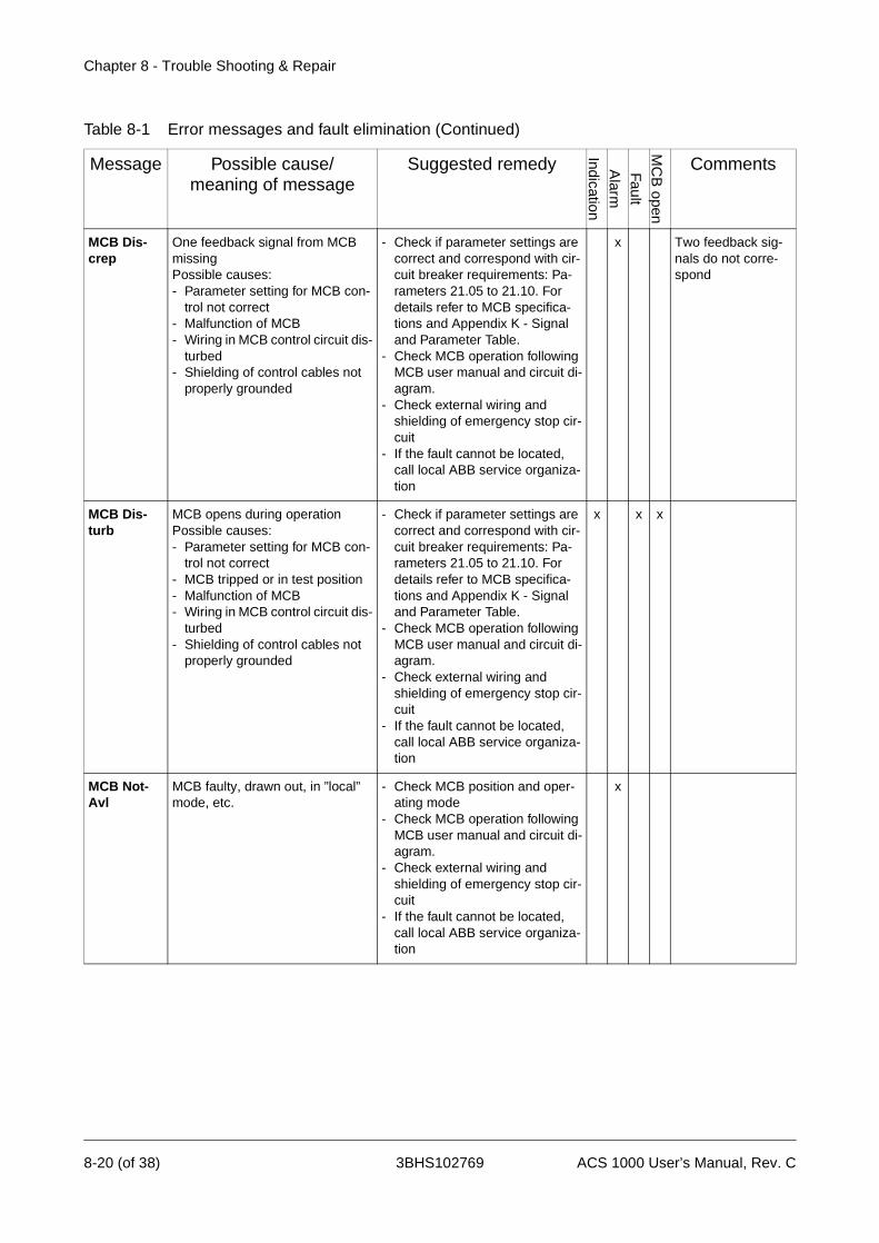
Chapter 8 - Trouble Shooting & Repair
MCB Dis-crep
One feedback signal from MCB missingPossible causes:- Parameter setting for MCB con-
trol not correct- Malfunction of MCB- Wiring in MCB control circuit dis-
turbed- Shielding of control cables not
properly grounded
- Check if parameter settings are correct and correspond with cir-cuit breaker requirements: Pa-rameters 21.05 to 21.10. For details refer to MCB specifica-tions and Appendix K - Signal and Parameter Table.
- Check MCB operation following MCB user manual and circuit di-agram.
- Check external wiring and shielding of emergency stop cir-cuit
- If the fault cannot be located, call local ABB service organiza-tion
x Two feedback sig-nals do not corre-spond
MCB Dis-turb
MCB opens during operationPossible causes:- Parameter setting for MCB con-
trol not correct- MCB tripped or in test position- Malfunction of MCB- Wiring in MCB control circuit dis-
turbed- Shielding of control cables not
properly grounded
- Check if parameter settings are correct and correspond with cir-cuit breaker requirements: Pa-rameters 21.05 to 21.10. For details refer to MCB specifica-tions and Appendix K - Signal and Parameter Table.
- Check MCB operation following MCB user manual and circuit di-agram.
- Check external wiring and shielding of emergency stop cir-cuit
- If the fault cannot be located, call local ABB service organiza-tion
x x x
MCB Not-Avl
MCB faulty, drawn out, in ”local” mode, etc.
- Check MCB position and oper-ating mode
- Check MCB operation following MCB user manual and circuit di-agram.
- Check external wiring and shielding of emergency stop cir-cuit
- If the fault cannot be located, call local ABB service organiza-tion
x
Table 8-1 Error messages and fault elimination (Continued)
Message Possible cause/meaning of message
Suggested remedy
IndicationA
larm
FaultM
CB
open
Comments
8-20 (of 38) 3BHS102769 ACS 1000 User’s Manual, Rev. C

Chapter 8 - Trouble Shooting & Repair
Mot Phase L
SW function - motor phase lossPossible causes:- Motor cabling- Current transformer malfunction
- Verify cable connections- Check that motor contactors
and safety switches are in prop-er positions
- Check if fault happens only spo-radically. If this is the case, the trip might be caused by low speed reference
- Check current measurement signals
- If the fault cannot be eliminated, call local ABB service organiza-tion
x x
Mot Prot SW
Internal motor supervision - Check motor for excessive heat- If the fault persists, call local
ABB service organization
x
MotCooler Alarm from converter internal con-tactor - supervision for the motor coolerPossible causes:- Fault in external motor cooling
circuit- Wiring in monitoring circuit dis-
turbed- Poor grounding connections
- Check motor temperature- Check cooling equipment. Refer
to manuals for motor and cool-ing
- Check with logbook if alarm oc-curs repeatedly and record alarm conditions
- Check wiring and connections between relay and converter. Check relay input wiring
- Check cable shielding and grounding
- If the fault cannot be eliminated, call local ABB service organiza-tion
x Optional
MotCooler Trip from converter internal con-tactor - supervision for the motor coolerPossible causes:- Fault in external motor cooling
circuit- Wiring in monitoring circuit dis-
turbed- Poor grounding connections
- Check motor temperature- Check cooling equipment. Refer
to manuals for motor and cool-ing
- Check with logbook if fault oc-curs repeatedly and record trip conditions
- Check wiring and connections between relay and converter. Check relay input wiring
- Check cable shielding and grounding
- If the fault cannot be eliminated, call local ABB service organiza-tion
x Optional
Table 8-1 Error messages and fault elimination (Continued)
Message Possible cause/meaning of message
Suggested remedy
IndicationA
larm
FaultM
CB
open
Comments
ACS 1000 User’s Manual, Rev. C 3BHS102769 8-21 (of 38)

Chapter 8 - Trouble Shooting & Repair
MotHeater Alarm from converter internal con-tactor - supervision for the motor heaterPossible causes:- Fault in motor heater- Wiring in monitoring circuit dis-
turbed- Poor grounding connections
- Check heater circuit resistance. See manual for motor heater and Appendix G - Wiring Dia-grams
- Check wiring and connections between relay and converter. Check relay input wiring
- Check cable shielding and grounding
- If the fault cannot be eliminated, call local ABB service organiza-tion
x Optional
Motor Stall SW function - Motor stall: sus-tained low speed and high currentPossible causes:- load conditions do not match
with motor and converter ratings- Incorrect parameter settings
(e.g. stall frequency limit too high)
- Motor load too high - Disturbance in driven equipment
- Check whether actual load con-ditions match motor and drive ratings
- Check whether motor and con-verter ratings do match through-out the speed range.
- Check motor stall parameters 30.02 to 30.04. Refer to Appen-dix K - Signal and Parameter Ta-ble
- Check load condition and verify that driven equipment is working properly
- If the fault cannot be eliminated, call local ABB service organiza-tion
x x Default setting: Not active
MotVibrat Alarm from external protection re-lay - motor vibration level too highPossible causes:- Excessive motor vibrations due
to unbalance or overheated bearing
- Vibration measuring device de-fective
- Wiring in monitoring circuit dis-turbed
- Check motor and bearings. For details refer to motor manual.
- Check vibration monitoring de-vice
- Check power supply of monitor-ing device
- Check wiring between external temperature measuring device and ACS 1000. Check input wiring of measuring device
- Check cable shielding and grounding
- If the fault cannot be eliminated, call local ABB service organiza-tion
x Optional
Table 8-1 Error messages and fault elimination (Continued)
Message Possible cause/meaning of message
Suggested remedy
IndicationA
larm
FaultM
CB
open
Comments
8-22 (of 38) 3BHS102769 ACS 1000 User’s Manual, Rev. C

Chapter 8 - Trouble Shooting & Repair
MotVibrat Trip from external protection relay - motor vibration level too highPossible causes:- Excessive motor vibrations due
to unbalance or overheated bearing
- Vibration measuring device de-fective
- Wiring in monitoring circuit dis-turbed
- Check motor and bearings. For details refer to motor manual.
- Check vibration monitoring de-vice
- Check power supply of monitor-ing device
- Check wiring between external temperature measuring device and ACS 1000. Check input wiring of measuring device
- Check cable shielding and grounding
- If the fault cannot be eliminated, call local ABB service organiza-tion
x Optional
MotWdgM-Los
Motor winding temperature mea-suring lostPossible causes:- measuring circuit output < 2 mA- Wiring in protection circuit dis-
turbed- Shielding of control cables not
properly grounded
- Check Input X31.3/X32.3, X31.4/X32.4 and X31.5/X32.5 on IOEC2 board (signals must be > 2mA)
- Check power supply of monitor-ing device
- Check wiring between external temperature measuring device and ACS 1000.
- Check wiring to measuring de-vice inputs
- Check if shielding of control ca-bles is properly grounded
- If the fault cannot be eliminated, call local ABB service organiza-tion
x
MotWdg Temp HW
Motor winding temperature too high Possible causes:- excessive load- ACS 1000 parameters not prop-
erly adjusted to motor data
- Check motor ratings, load and cooling
- Check torque and power limits (parameters 20.04 and 20.05)
- Check motor temperature su-pervision parameters (parame-ters 13.21 to 13.35)
- If the fault cannot be eliminated, call local ABB service organiza-tion
x sum of 3 signals
Table 8-1 Error messages and fault elimination (Continued)
Message Possible cause/meaning of message
Suggested remedy
IndicationA
larm
FaultM
CB
open
Comments
ACS 1000 User’s Manual, Rev. C 3BHS102769 8-23 (of 38)
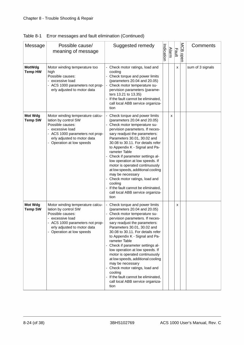
Chapter 8 - Trouble Shooting & Repair
MotWdg Temp HW
Motor winding temperature too high Possible causes:- excessive load- ACS 1000 parameters not prop-
erly adjusted to motor data
- Check motor ratings, load and cooling
- Check torque and power limits (parameters 20.04 and 20.05)
- Check motor temperature su-pervision parameters (parame-ters 13.21 to 13.35)
- If the fault cannot be eliminated, call local ABB service organiza-tion
x sum of 3 signals
Mot Wdg Temp SW
Motor winding temperature calcu-lation by control SWPossible causes:- excessive load- ACS 1000 parameters not prop-
erly adjusted to motor data- Operation at low speeds
- Check torque and power limits (parameters 20.04 and 20.05)
- Check motor temperature su-pervision parameters. If neces-sary readjust the parameters:Parameters 30.01, 30.02 and 30.08 to 30.11. For details refer to Appendix K - Signal and Pa-rameter Table
- Check if parameter settings al-low operation at low speeds. If motor is operated continuously at low speeds, additional cooling may be necessary
- Check motor ratings, load and cooling
- If the fault cannot be eliminated, call local ABB service organiza-tion
x
Table 8-1 Error messages and fault elimination (Continued)
Message Possible cause/meaning of message
Suggested remedy
IndicationA
larm
FaultM
CB
open
Comments
8-24 (of 38) 3BHS102769 ACS 1000 User’s Manual, Rev. C

Chapter 8 - Trouble Shooting & Repair
No Cur Offs Attempt to start the converter be-fore the current offsets have been checked
- De-energize converter and close grounding isolator accord-ing to Chapter 5 - Operation, De-energizing the ACS 1000, page 5- 12 (offset will be calculated automatically when grounding isolator is closed)
x x
Danger: When MCB is open, wait 5 minutes before closing grounding switch!
No Filt Data Filter data missing - Call local ABB service organiza-tion
x x
Offset Offset calibration was not suc-cessful
- x
OS Fault Operating system failure - Call local ABB service organiza-tion
x x
OutpIsolDis Output isolator feedback discrep-ancyPossible causes:- Malfunction of isolator or isolator
control- Wiring in isolator control circuit
disturbed- Shielding of control cables not
properly grounded
- Check isolator operation follow-ing isolator user manual and cir-cuit diagram.
- Check wiring and shielding of isolator control circuit
- If the fault cannot be located, call local ABB service organiza-tion
x OptionalTwo feedback sig-nals do not corre-spond
OutsAirM-Los
supervision of ambient tempera-ture measurementPossible causes:- Measuring circuit output < 2 mA- Wiring in protection circuit dis-
turbed- Shielding of control cables not
properly grounded
- Check if analog input OUTSIDE AIR TEMP on IOEC3 is >2mA
- Check wiring and shielding of measuring circuit
- If the fault cannot be located, call local ABB service organiza-tion
x x Water cooled con-verters only
Table 8-1 Error messages and fault elimination (Continued)
Message Possible cause/meaning of message
Suggested remedy
IndicationA
larm
FaultM
CB
open
Comments
ACS 1000 User’s Manual, Rev. C 3BHS102769 8-25 (of 38)

Chapter 8 - Trouble Shooting & Repair
OutsAir-Temp
Supervision of ambient tempera-turePossible causes:- High ambient temperature- External measurement device
defective- Parameter setting not correct- wiring in monitoring circuit dis-
turbed- Shielding of cables not properly
grounded
- Check ambient temperature- If ambient temperature is within
limits, check if analog input OUTSIDE AIR TEMP on IOEC3 is within range
- Check limit parameter settings 81.16 to 81.20. For details refer to MCB specifications and Ap-pendix K - Signal and Parameter Table
- Check wiring and shielding of measuring circuit
- If the fault cannot be located, call local ABB service organiza-tion
x Water cooled con-verters only
Overspeed SW function -Motor overspeed (supervision of rotation frequency)Possible causes:- Wrong parameter settings- Motor is forced to overspeed by
driven equipment
- Check all parameters (start-up data) of group 99, particularly the nominal speed setting and compare with the motor name-plate
- Check parameters in group 12 (reference select) and 20 (lim-its). Refer to Appendix K - Signal and Parameter Table
- Check motor loading, especially if driven equipment is dimen-sioned correctly and functioning properly. Check with logbook if fault occurs repeatedly and record trip conditions
- If the fault cannot be eliminated, call local ABB service organiza-tion
x
Overvolt-age
Voltage in the dc-circuit is too high in status “Ready to start”
-
Table 8-1 Error messages and fault elimination (Continued)
Message Possible cause/meaning of message
Suggested remedy
IndicationA
larm
FaultM
CB
open
Comments
8-26 (of 38) 3BHS102769 ACS 1000 User’s Manual, Rev. C

Chapter 8 - Trouble Shooting & Repair
Overvolt HW
HW supervision - detection of ov-ervoltage in the dc-circuitPossible cause:- Mains supply voltage too high
- Verify measured dc-voltage (Pa-rameters 2.02 to 2.09)
- Check whether mains supply voltage is within the tolerated limits. See Appendix A - Techni-cal Data
- Adjust input transformer taps- If the fault cannot be eliminated,
call local ABB service organiza-tion
x x
Overvolt SW
Redundant SW supervision - de-tection of overvoltage in the dc-circuitPossible cause:- Mains supply voltage too high
- Verify measured dc-voltage (Pa-rameters 2.02 to 2.09)
- Check whether mains supply voltage is within the tolerated limits. See Appendix A - Techni-cal Data
- Adjust input transformer taps- If the fault cannot be eliminated,
call local ABB service organiza-tion
x x
Panel Lost Control panel connection is dis-turbed
- Check if control panel is con-nected
- Check control panel connection terminals
- Replace control panel- If the fault cannot be eliminated,
call local ABB service organiza-tion
x
Panel Lost Control panel connection is dis-turbed
- Check if control panel is con-nected
- Check control panel connection terminals
- Replace control panel- If the fault cannot be eliminated,
call local ABB service organiza-tion
x Active only if con-verter is in in torque control and local mode.
Press Stop Alarm after Filter ID run has been completed
- Press the STOP key on the CDP 312 control panel
x
Process-Stop
Customer system protection inputPossible causes:- Stop order from process- wiring in control circuit disturbed- Shielding of control cables not
properly grounded
- Check if stop order is initiated by process (see process control)
- Check external wiring and shielding of control cables
- If the fault cannot be located, call local ABB service organiza-tion
x x
Table 8-1 Error messages and fault elimination (Continued)
Message Possible cause/meaning of message
Suggested remedy
IndicationA
larm
FaultM
CB
open
Comments
ACS 1000 User’s Manual, Rev. C 3BHS102769 8-27 (of 38)
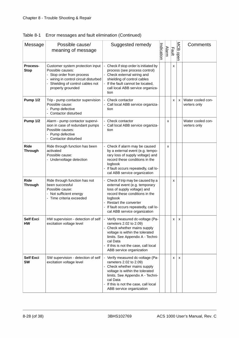
Chapter 8 - Trouble Shooting & Repair
Process-Stop
Customer system protection inputPossible causes:- Stop order from process- wiring in control circuit disturbed- Shielding of control cables not
properly grounded
- Check if stop order is initiated by process (see process control)
- Check external wiring and shielding of control cables
- If the fault cannot be located, call local ABB service organiza-tion
x
Pump 1/2 Trip - pump contactor supervisionPossible cause:- Pump defective- Contactor disturbed
- Check contactor- Call local ABB service organiza-
tion
x x Water cooled con-verters only
Pump 1/2 Alarm - pump contactor supervi-sion in case of redundant pumpsPossible causes:- Pump defective- Contactor disturbed
- Check contactor- Call local ABB service organiza-
tion
x Water cooled con-verters only
Ride Through
Ride through function has been activatedPossible cause:- Undervoltage detection
- Check if alarm may be caused by a external event (e.g. tempo-rary loss of supply voltage) and record these conditions in the logbook
- If fault occurs repeatedly, call lo-cal ABB service organization
x
Ride Through
Ride through function has not been successfulPossible cause:- Not sufficient energy- Time criteria exceeded
- Check if trip may be caused by a external event (e.g. temporary loss of supply voltage) and record these conditions in the logbook
- Restart the converter- If fault occurs repeatedly, call lo-
cal ABB service organization
x
Self Exci HW
HW supervision - detection of self excitation voltage level
- Verify measured dc-voltage (Pa-rameters 2.02 to 2.09)
- Check whether mains supply voltage is within the tolerated limits. See Appendix A - Techni-cal Data
- If this is not the case, call local ABB service organization
x x
Self Exci SW
SW supervision - detection of self excitation voltage level
- Verify measured dc-voltage (Pa-rameters 2.02 to 2.09)
- Check whether mains supply voltage is within the tolerated limits. See Appendix A - Techni-cal Data
- If this is not the case, call local ABB service organization
x x
Table 8-1 Error messages and fault elimination (Continued)
Message Possible cause/meaning of message
Suggested remedy
IndicationA
larm
FaultM
CB
open
Comments
8-28 (of 38) 3BHS102769 ACS 1000 User’s Manual, Rev. C

Chapter 8 - Trouble Shooting & Repair
Short Cir MI Supervision of di/dt choke voltage Possible causes:- short circuit in inverter minus pole
- Call local ABB service organiza-tion
x x
Short Cir PL
Supervision of di/dt choke voltage Possible causes:- short circuit in inverter plus pole
- Call local ABB service organiza-tion
x x
Short Cir-cuit
if undervoltage alarm and fault ap-pear in a time window of 200us, a short circuit in the rectifier has ap-peared
- Check fault history buffer for other, possibly related error messages
- Call local ABB service organiza-tion
x x
SpeedRef-Los
Speed reference signal lostPossible causes:- Wrong parameter setting- Signal source or wiring dis-
turbed- Shielding of control cables not
properly grounded
- Verify parameter settings of limit parameters 13.23 (minimum limit for AI2 on IOEC2 board) and 30.18 (activating AI2)
- Measure input signal at AI1 and verify correct signal level
- Check external signal source - Check wiring and shielding of
control cables - If the fault cannot be eliminated,
call local ABB service organiza-tion
x x Default setting: alarm and maintain last set speed
Supp Phase L
SW function - supervision of sup-ply phase is done by supervising the voltage ripple in the DC link Possible cause:- Loss of a phase or voltage un-
balance
- Loss of a phase or voltage un-balance
- If the fault cannot be located, call local ABB service organiza-tion
x x
Swfreq HW HW function - switching frequency exceeds allowed limitPossible cause: - Control SW error
- Call local ABB service organiza-tion
x
Swfreq SW Switching frequency too highPossible cause: - System parameters not correct- Wrong current offset
- Check parameter group 99- Readjust current offset (see er-
ror message NO CUR OFFSET)- If the fault cannot be eliminated,
call local ABB service organiza-tion
x
Tacho Supervision of tachometerPossible causes:- Faulty tachometer- Tachometer not compatible with
pulse encoder type
- Replace tachometer- If the fault cannot be eliminated,
call local ABB service organiza-tion
x Optional
Table 8-1 Error messages and fault elimination (Continued)
Message Possible cause/meaning of message
Suggested remedy
IndicationA
larm
FaultM
CB
open
Comments
ACS 1000 User’s Manual, Rev. C 3BHS102769 8-29 (of 38)

Chapter 8 - Trouble Shooting & Repair
Tacho Supervision of tachometerPossible causes:- Faulty tachometer- Tachometer not compatible with
pulse encoder type
- Replace tachometer- If the fault cannot be eliminated,
call local ABB service organiza-tion
x Optional
TrafoTemp Transformer winding temperature or oil temperature too highPossible causes:- Transformer load too high- Ambient temperature too high- Transformer cooling disturbed- Wiring in protection circuit dis-
turbed- Shielding of control cables not
properly grounded
- Check transformer load and am-bient temperature and compare with rated figures (make record in logbook). Refer to transformer manual
- Check if installation conditions are satisfactory (exposure to sun, obstacles in air flow etc.)
- Check cooling equipment. Refer to description of cooling circuit in transformer manual
- Check wiring of monitoring cir-cuit (input /OIL TEMP TRIP on IOEC3 board)
- Check if shielding of control ca-bles is properly grounded
- If the fault cannot be eliminated, call local ABB service organiza-tion
x x Optional
Table 8-1 Error messages and fault elimination (Continued)
Message Possible cause/meaning of message
Suggested remedy
IndicationA
larm
FaultM
CB
open
Comments
8-30 (of 38) 3BHS102769 ACS 1000 User’s Manual, Rev. C
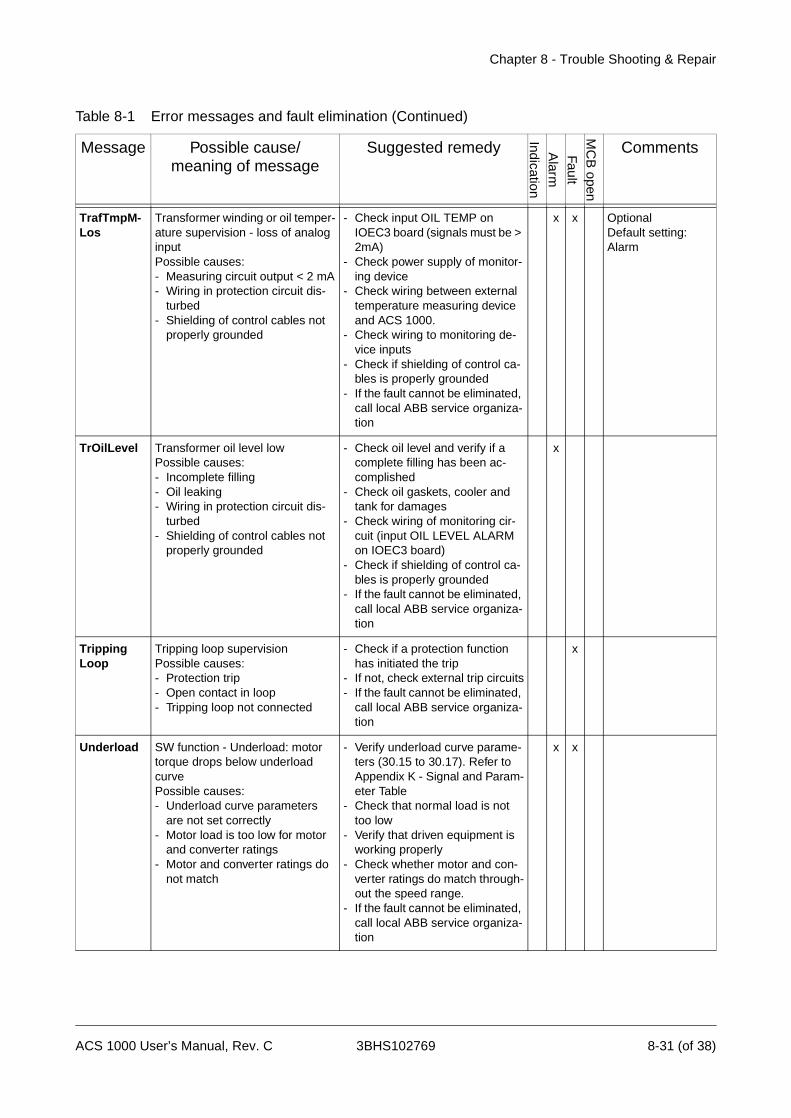
Chapter 8 - Trouble Shooting & Repair
TrafTmpM-Los
Transformer winding or oil temper-ature supervision - loss of analog inputPossible causes:- Measuring circuit output < 2 mA- Wiring in protection circuit dis-
turbed- Shielding of control cables not
properly grounded
- Check input OIL TEMP on IOEC3 board (signals must be > 2mA)
- Check power supply of monitor-ing device
- Check wiring between external temperature measuring device and ACS 1000.
- Check wiring to monitoring de-vice inputs
- Check if shielding of control ca-bles is properly grounded
- If the fault cannot be eliminated, call local ABB service organiza-tion
x x OptionalDefault setting: Alarm
TrOilLevel Transformer oil level lowPossible causes:- Incomplete filling- Oil leaking- Wiring in protection circuit dis-
turbed- Shielding of control cables not
properly grounded
- Check oil level and verify if a complete filling has been ac-complished
- Check oil gaskets, cooler and tank for damages
- Check wiring of monitoring cir-cuit (input OIL LEVEL ALARM on IOEC3 board)
- Check if shielding of control ca-bles is properly grounded
- If the fault cannot be eliminated, call local ABB service organiza-tion
x
Tripping Loop
Tripping loop supervisionPossible causes:- Protection trip- Open contact in loop- Tripping loop not connected
- Check if a protection function has initiated the trip
- If not, check external trip circuits- If the fault cannot be eliminated,
call local ABB service organiza-tion
x
Underload SW function - Underload: motor torque drops below underload curvePossible causes:- Underload curve parameters
are not set correctly- Motor load is too low for motor
and converter ratings- Motor and converter ratings do
not match
- Verify underload curve parame-ters (30.15 to 30.17). Refer to Appendix K - Signal and Param-eter Table
- Check that normal load is not too low
- Verify that driven equipment is working properly
- Check whether motor and con-verter ratings do match through-out the speed range.
- If the fault cannot be eliminated, call local ABB service organiza-tion
x x
Table 8-1 Error messages and fault elimination (Continued)
Message Possible cause/meaning of message
Suggested remedy
IndicationA
larm
FaultM
CB
open
Comments
ACS 1000 User’s Manual, Rev. C 3BHS102769 8-31 (of 38)
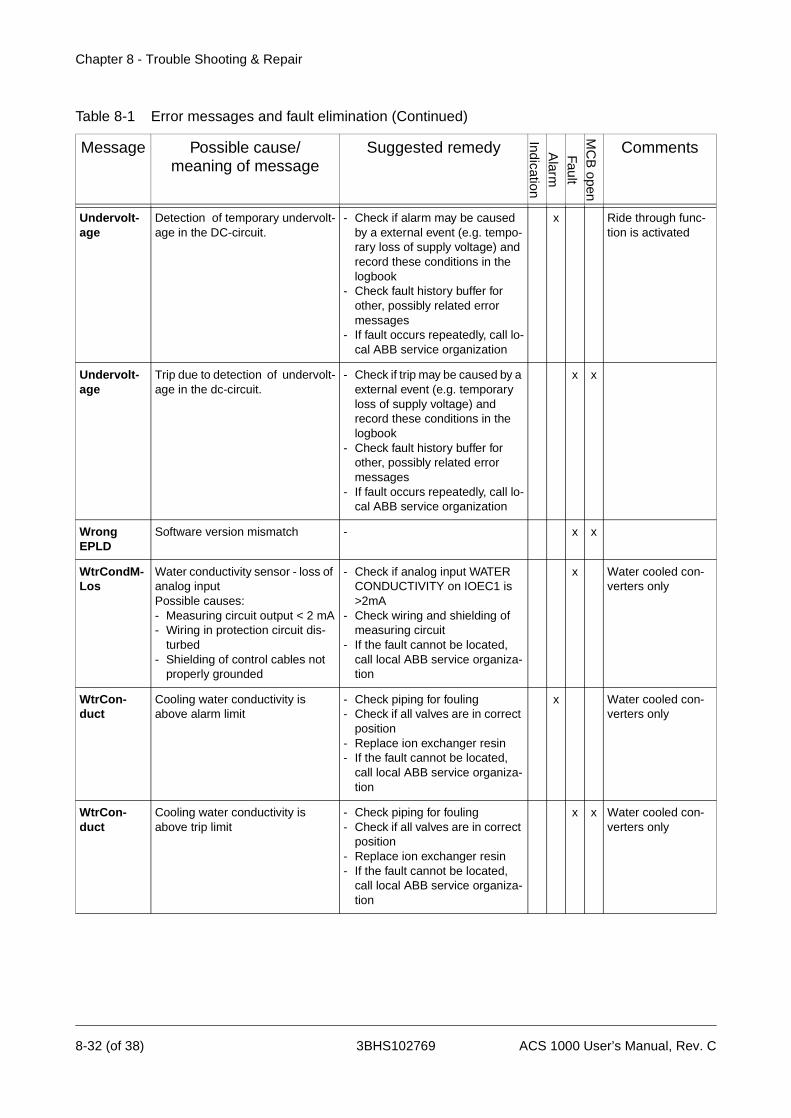
Chapter 8 - Trouble Shooting & Repair
Undervolt-age
Detection of temporary undervolt-age in the DC-circuit.
- Check if alarm may be caused by a external event (e.g. tempo-rary loss of supply voltage) and record these conditions in the logbook
- Check fault history buffer for other, possibly related error messages
- If fault occurs repeatedly, call lo-cal ABB service organization
x Ride through func-tion is activated
Undervolt-age
Trip due to detection of undervolt-age in the dc-circuit.
- Check if trip may be caused by a external event (e.g. temporary loss of supply voltage) and record these conditions in the logbook
- Check fault history buffer for other, possibly related error messages
- If fault occurs repeatedly, call lo-cal ABB service organization
x x
Wrong EPLD
Software version mismatch - x x
WtrCondM-Los
Water conductivity sensor - loss of analog inputPossible causes:- Measuring circuit output < 2 mA- Wiring in protection circuit dis-
turbed- Shielding of control cables not
properly grounded
- Check if analog input WATER CONDUCTIVITY on IOEC1 is >2mA
- Check wiring and shielding of measuring circuit
- If the fault cannot be located, call local ABB service organiza-tion
x Water cooled con-verters only
WtrCon-duct
Cooling water conductivity is above alarm limit
- Check piping for fouling- Check if all valves are in correct
position - Replace ion exchanger resin- If the fault cannot be located,
call local ABB service organiza-tion
x Water cooled con-verters only
WtrCon-duct
Cooling water conductivity is above trip limit
- Check piping for fouling- Check if all valves are in correct
position- Replace ion exchanger resin- If the fault cannot be located,
call local ABB service organiza-tion
x x Water cooled con-verters only
Table 8-1 Error messages and fault elimination (Continued)
Message Possible cause/meaning of message
Suggested remedy
IndicationA
larm
FaultM
CB
open
Comments
8-32 (of 38) 3BHS102769 ACS 1000 User’s Manual, Rev. C
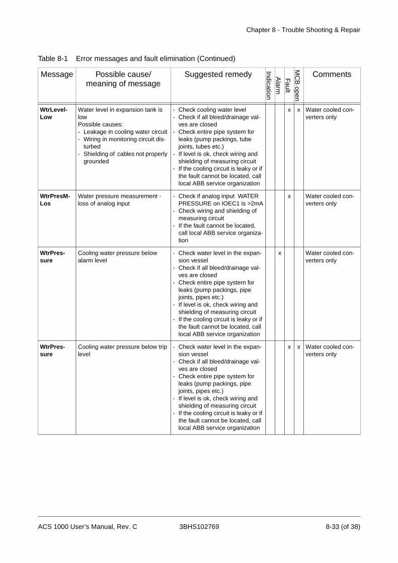
Chapter 8 - Trouble Shooting & Repair
WtrLevel-Low
Water level in expansion tank is lowPossible causes: - Leakage in cooling water circuit- Wiring in monitoring circuit dis-
turbed- Shielding of cables not properly
grounded
- Check cooling water level- Check if all bleed/drainage val-
ves are closed- Check entire pipe system for
leaks (pump packings, tube joints, tubes etc.)
- If level is ok, check wiring and shielding of measuring circuit
- If the cooling circuit is leaky or if the fault cannot be located, call local ABB service organization
x x Water cooled con-verters only
WtrPresM-Los
Water pressure measurement - loss of analog input
- Check if analog input WATER PRESSURE on IOEC1 is >2mA
- Check wiring and shielding of measuring circuit
- If the fault cannot be located, call local ABB service organiza-tion
x Water cooled con-verters only
WtrPres-sure
Cooling water pressure below alarm level
- Check water level in the expan-sion vessel
- Check if all bleed/drainage val-ves are closed
- Check entire pipe system for leaks (pump packings, pipe joints, pipes etc.)
- If level is ok, check wiring and shielding of measuring circuit
- If the cooling circuit is leaky or if the fault cannot be located, call local ABB service organization
x Water cooled con-verters only
WtrPres-sure
Cooling water pressure below trip level
- Check water level in the expan-sion vessel
- Check if all bleed/drainage val-ves are closed
- Check entire pipe system for leaks (pump packings, pipe joints, pipes etc.)
- If level is ok, check wiring and shielding of measuring circuit
- If the cooling circuit is leaky or if the fault cannot be located, call local ABB service organization
x x Water cooled con-verters only
Table 8-1 Error messages and fault elimination (Continued)
Message Possible cause/meaning of message
Suggested remedy
IndicationA
larm
FaultM
CB
open
Comments
ACS 1000 User’s Manual, Rev. C 3BHS102769 8-33 (of 38)

Chapter 8 - Trouble Shooting & Repair
WtrTemp Water temperature above alarm level
- Check flow in the main water cir-cuit
- Check temperature and pres-sure in the raw water circuit
- check the heat exchanger for fouling
- If the cooling circuit is leaky or if the fault cannot be located, call local ABB service organization
x Water cooled con-verters only
WtrTemp Water temperature above trip level - Call local ABB service organiza-tion
x Water cooled con-verters only
WtrTempM-Los
Water temperature measurement - loss of analog inputPossible causes:- Measuring circuit output < 2 mA- Wiring in protection circuit dis-
turbed- Shielding of control cables not
properly grounded
- Check if analog input COOL-ING WATER TEMP on IOEC1 is >2mA
- Check wiring and shielding of measuring circuit
- If the fault cannot be located, call local ABB service organiza-tion
x Water cooled con-verters only
Table 8-1 Error messages and fault elimination (Continued)
Message Possible cause/meaning of message
Suggested remedy
IndicationA
larm
FaultM
CB
open
Comments
8-34 (of 38) 3BHS102769 ACS 1000 User’s Manual, Rev. C

Chapter 8 - Trouble Shooting & Repair
ACS 1000 User’s Manual, Rev. C 3BHS102769 8-35 (of 38)

Chapter 8 - Trouble Shooting & Repair
Table 8-2 Indication messages
Message Possible cause/meaning of message
Suggested remedy
IndicationA
larm
FaultM
CB
open
Comments
Alarm Summarized signal - Check fault history display on control panel and proceed ac-cording to the specific alarm de-scription
x
Charging DC voltage charging state - none (normal operating status indication)
x
Defect A fault cannot be reset, because of a defect
- Call local ABB service organiza-tion
x
Discharg-ing
DC discharging state after switch-ing off MCB
- none (normal operating status indication)
x
EarthIso-clos
Grounding isolator is closed - none (normal operating status indication)
x
ID_RunReq
ID run is requested - Call local ABB service organiza-tion
x
ID_RunSelec
If ID run is selected - none x
Magnetiz-ing
Magnetization in progress, also in-dicating flying start
- none (normal operating status indication)
x
MCB not on Will be displayed if a start is tried when the MCB is not closed
- Proceed as described in Chap-ter 5 - Operation
x
MotWillRun Before/during ID run - none x
No ID Run Will be displayed if a start without preceding ID run is tried
- Carry out ID run- If you need assistance, call local
ABB service organization
x
Param Lock Parameter is locked and can’t be modified
- x
ProcessStop
Customer system protection inputPossible causes:- Stop order from process- wiring in control circuit disturbed- Shielding of control cables not
properly grounded
- Check if stop order is initiated by process (see process control)
- Check external wiring and shielding of control cables
- If the fault cannot be located, call local ABB service organiza-tion
x x
Ready MCB on
Converter ready to energize - none (normal operating status indication)
x
Ready to Run
System ready - DC link charged, no faults pending
- none (normal operating status indication)
x
Running System running - none (normal operating status indication)
x
8-36 (of 38) 3BHS102769 ACS 1000 User’s Manual, Rev. C
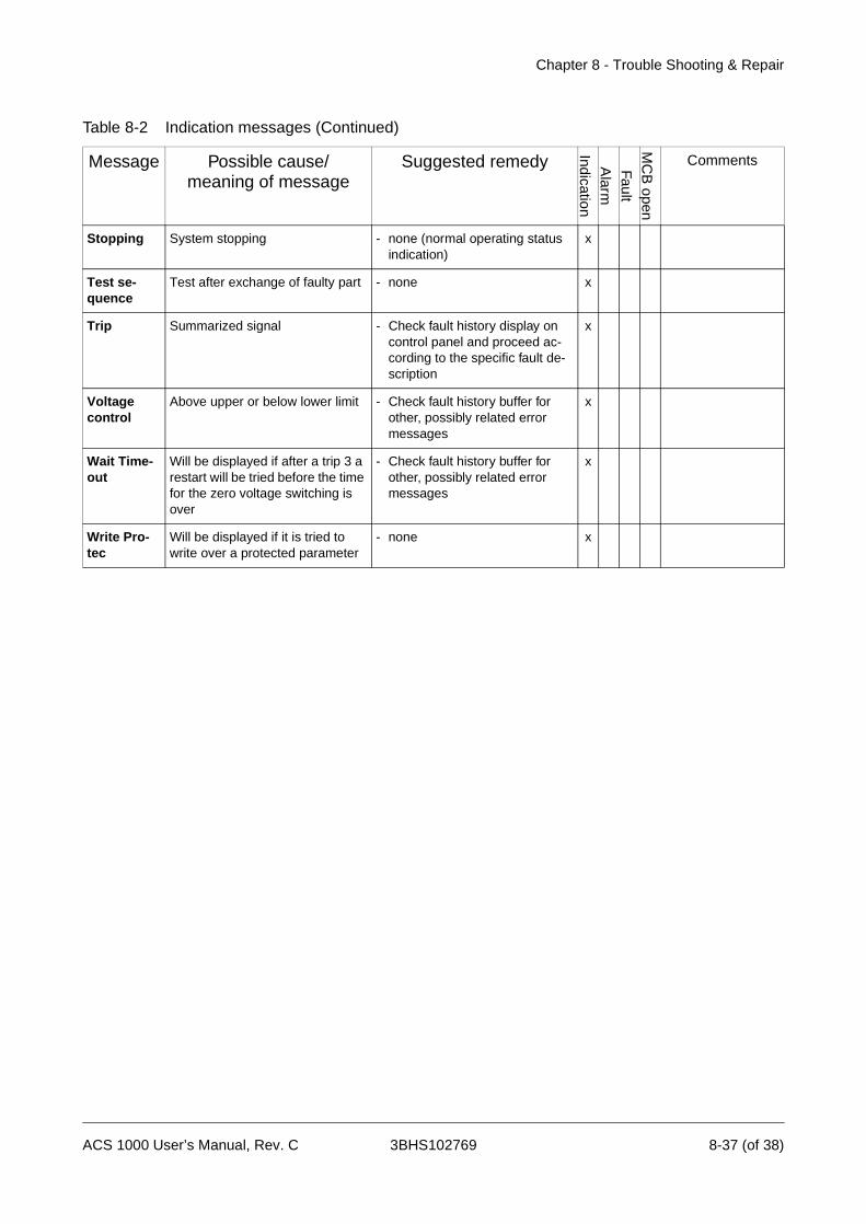
Chapter 8 - Trouble Shooting & Repair
Stopping System stopping - none (normal operating status indication)
x
Test se-quence
Test after exchange of faulty part - none x
Trip Summarized signal - Check fault history display on control panel and proceed ac-cording to the specific fault de-scription
x
Voltage control
Above upper or below lower limit - Check fault history buffer for other, possibly related error messages
x
Wait Time-out
Will be displayed if after a trip 3 a restart will be tried before the time for the zero voltage switching is over
- Check fault history buffer for other, possibly related error messages
x
Write Pro-tec
Will be displayed if it is tried to write over a protected parameter
- none x
Table 8-2 Indication messages (Continued)
Message Possible cause/meaning of message
Suggested remedy
IndicationA
larm
FaultM
CB
open
Comments
ACS 1000 User’s Manual, Rev. C 3BHS102769 8-37 (of 38)

Chapter 8 - Trouble Shooting & Repair
8-38 (of 38) 3BHS102769 ACS 1000 User’s Manual, Rev. C

Chapter 9 - Transportation, Storage, Disposal andRecycling
Introduction In this chapter you will find all necessary information about proper trans-portation and storage of the ACS 1000 converter unit and the spare parts as well as about disposal and recycling of materials.
ABB Industrie AG has determined basic requirements for transportation and storage in order not to reduce the reliability of the converter. Environ-mental requirements for transportation and storage are included in this chapter and must be observed.
For information about ambient conditions during transportation and storage refer also to Appendix A - Technical Data, Transportation and Storage, page A- 3.
Environmental Requirements
The packing, transportation and storage conditions are defined on the basis of ABB / HDST4.15/l - Classifications and the following norms:
Storage • IEC 721-3-1 Code: 1K5/1Z1/1Z5/1B1/1C2/1S1/1M1
Transportation • IEC 721-3-2 Code: 2B1/2C2/2S1
Stationary Use • IEC 721-3-3 Code: 3K4/3Z1/3Z7/3B1/3C2/3S1/3M1
For more information please contact your ABB representative.
Packing The converter is protected against external influences caused by either sea, air or road transportation. The packing is designed to give an optimal protection against
• contamination by water or dust
additionally for sea and air worthy packing against
• mechanical forces
• extreme climatic conditions
The packing is labeled with all relevant warnings and instructions for packaging, handling and storage.
ACS 1000 User’s Manual, Rev. C 3BHS102769 9-1 (of 10)

Chapter 9 - Transportation, Storage, Disposal and Recycling
Table 9-1 Warning and instruction labels on the converter packing
Label Meaning Application
A This way up Marked on all cases and open shipped components.
B Fragile - handle with care
Marked on cases containing fragile or sensitive to shock material.
C Keep dry Marked on cases, plywood cases and cartons that are to be kept dry. Do not put on crates or cases meant for long term storage outdoors.
D Center of gravity Marked on cases and components that are shipped unprotected (open) and require the indication of the center of gravity.
E Sling here Marked on all cases and open compo-nents where ropes and chains are slung.
9-2 (of 10) 3BHS102769 ACS 1000 User’s Manual, Rev. C
Chapter 9 - Transportation, Storage, Disposal and Recycling
The following symbol has become widely used and generally understood. Various customer packing specifications require a marking on the outside of the case if the inner packing of the goods requires the application of a desiccant.
ABB’s Quality Management assures that the packing of the converter unit corresponds to specific requirements regarding safety and cost efficiency.
The choice of the right conservation concept depends on the final desti-nation of the goods, namely the climatic zone. (Zone A: temperate zone; zone B: tropical zone).
The conservation measures taken for the transport packing are only useful as long as the packing is kept unopened and in its original condition.
Loading and Unloading
For loading and unloading the converter with the help of a hoisting device, following points have to be observed:
Caution: The converter has to be transported in upright position.
Caution: Use always the lifting eyes on the top of the converter.
• The lifting eyes may only be removed after the converter has been in-stalled at its final position. They have to be remounted if the converter has to be transported again.
• The material and diameter of the transport rope or chain have to corre-spond to the weight of the converter unit.
Label Meaning Application
F
Color of the label is black.
packing with desiccant On all cases requiring the application of a desiccant. Symbol preferably above the swivel cover of the inspection hole.DESICCANT
ACS 1000 User’s Manual, Rev. C 3BHS102769 9-3 (of 10)

Chapter 9 - Transportation, Storage, Disposal and Recycling
Lifting Angle The minimum lifting angle between the rope or chain and the converter unit is 45°. (see Figure 9-1)
Caution: The fan cover must not be mounted while lifting the converter unit.
Figure 9-1 Lifting Angle
Center of Gravity
Unpacking For unpacking the converter following steps have to be followed:
1 Check the packing condition. Pay attention to damages by mechanical forces, water, humidity, heat or fire.
45°45°
Front View
Top View
x = 1505 mmy = 926 mmz = 469 mm
x
y
z
9-4 (of 10) 3BHS102769 ACS 1000 User’s Manual, Rev. C
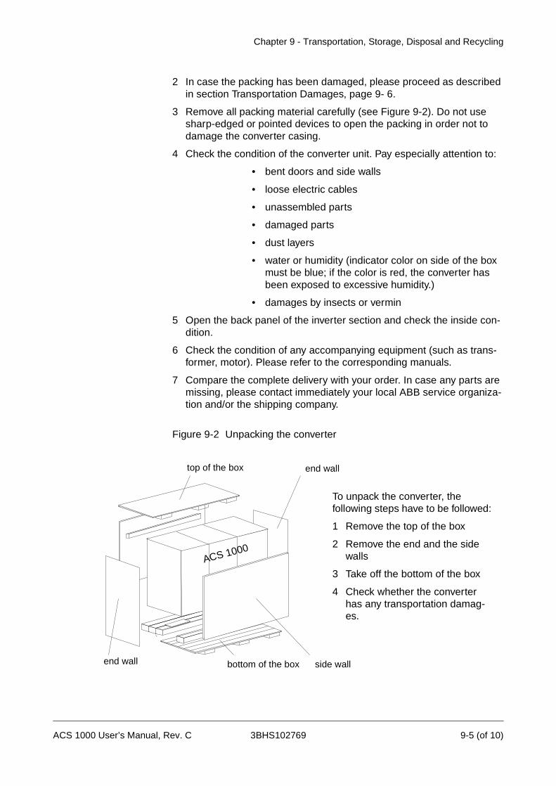
Chapter 9 - Transportation, Storage, Disposal and Recycling
2 In case the packing has been damaged, please proceed as described in section Transportation Damages, page 9- 6.
3 Remove all packing material carefully (see Figure 9-2). Do not use sharp-edged or pointed devices to open the packing in order not to damage the converter casing.
4 Check the condition of the converter unit. Pay especially attention to:
• bent doors and side walls
• loose electric cables
• unassembled parts
• damaged parts
• dust layers
• water or humidity (indicator color on side of the box must be blue; if the color is red, the converter has been exposed to excessive humidity.)
• damages by insects or vermin
5 Open the back panel of the inverter section and check the inside con-dition.
6 Check the condition of any accompanying equipment (such as trans-former, motor). Please refer to the corresponding manuals.
7 Compare the complete delivery with your order. In case any parts are missing, please contact immediately your local ABB service organiza-tion and/or the shipping company.
Figure 9-2 Unpacking the converter
top of the box end wall
bottom of the box side wallend wall
To unpack the converter, the following steps have to be followed:
1 Remove the top of the box
2 Remove the end and the side walls
3 Take off the bottom of the box
4 Check whether the converter has any transportation damag-es.
ACS 1000
ACS 1000 User’s Manual, Rev. C 3BHS102769 9-5 (of 10)
Chapter 9 - Transportation, Storage, Disposal and Recycling
TransportationDamages
In case of transportation damages please proceed as follows:
1 Take several photos of the damage(s).
2 Return the Transportation Damage Description Form for the ACS 1000 (included at the end of this chapter) together with the photos to the ship-ping company and a copy to
ABB Industrie AGDept.: IA / SalesCH-5300 TurgiSwitzerland
Fax: +41 56 2993400
Storage
Storage Conditions The minimum requirements for storage are based on the following norms:
• ABB / HDST 601 070 Classification of environmental conditions.
• IEC 721-3-1 Code: 1K5/1Z1/1Z5/1B1/1C2/1S1/1M1
• IEC 721-3-3 Code: 3K4/3Z1/3Z7/3B1/3C2/3S1/3M1
Storage time: up to 1 year
Microclimatic class: ABB class / HDST 601 012
Pay attention to always fulfill the following conditions during the storage period:
Air temperature: -5° C to + 55° C (23° F to 131° F)
Relative air humidity: 5 to 85 %
Pay attention to always fulfill the ambient conditions during the storage period according to Appendix A - Technical Data, Transportation and Storage, page A- 3.
Notice: Take the following measures, if you want to store the converter unit for up to one year. In case of a longer storage period please contact the ABB service organization.
1 Place the converter on a wooden frame or pallet.
2 Cover all cable inlets and ventilation slots with a wooden panel. Put an impermeable plastic or aluminum foil between the wooden cover and the slots.
3 Add the desiccant of the appropriate quality: 1 unit desiccant (30g) ab-sorbs 6g water vapor. According to the used packing material you need the following quantity:
• PE sheet: 10 units/sqm foil
• Aluminum foil: 8 units/sqm foil
4 Close and lock the doors of the converter unit.
9-6 (of 10) 3BHS102769 ACS 1000 User’s Manual, Rev. C

Chapter 9 - Transportation, Storage, Disposal and Recycling
5 Use the below listed polyethylene sheet or combined aluminum foil as protective packing and as a protection against moisture:
• PE sheet: 0,3g/sqm/24h water vapor diffusion
• Aluminum foil: 0,01g/sqm/24h water vapor diffusion
6 Attach humidity indicators (e.g. mechanical hygrometers) behind the protective foil. Place them for example on the front door of the convert-er.
PeriodicalInspections
The storage conditions, the condition of the converter unit as well as of the packing should be checked monthly during the whole storage period. Pay special attention to damages caused by mechanical forces, water, humidity, heat or fire.
If the packing is damaged or if you discover damages caused by water, humidity, heat or fire you have to unpack the converter and check its inner and outer condition. Before storing the converter again, all storage damages have to be repaired. Store the converter as described above.
Battery The battery has to be taken out of the converter unit for recharging every 6 months.
Storage Instructions for Spare Parts
In order to maintain the converter spare parts in good condition after the delivery and to keep the warranty valid during the warranty period the following must be taken care of:
• The storage place must be vibration and shock free and protected against dampness, frost, heat, dust and sand.
Transportation The spare parts must be inspected immediately after receipt in order to detect possible transportation damages. Any damage must be reported immediately to the forwarder and insurance company. ABB does not take any responsibility for damages due to external circumstances.
Ambient Conditions
Humidity The spare parts must be stored in their original packing in a dry, vermin and insect proof room. The place has to be free of corrosive gases.
Relative air humidity: 5 to 85 %
The electronic boards have to be stored in antistatic bags or boxes. The air must be free of corrosive gases, salt or other impurities that could damage electronic equipment and boards. No water condensation is allowed. If you are in doubt whether the maximum allowed humidity is exceeded, you should protect the spares by an external heater for example.
Temperature The storage temperature range for spare parts is -5 °C to + 55 °C (23 °F to 131 °F), the same as for the converter unit.
Should you store any batteries, the air temperature should not exceed
ACS 1000 User’s Manual, Rev. C 3BHS102769 9-7 (of 10)
Chapter 9 - Transportation, Storage, Disposal and Recycling
30 °C (86 °F).
For more information about the warranty period and the condition of the spare parts please consult the commercial terms in the purchasing agree-ment.
Should you have further questions, please consult your local ABB office or the manufacturer:
ABB Industrie AG, Dept. IACH-5300 TurgiSWITZERLAND
Tel +41 56 299 22 05Fax +41 56 299 34 00
Handling Instructions for Spare Parts
Spare parts must be handled carefully and protected against electrostatic discharges always when taken out of the original factory packing. Improper handling may cause damage to sensitive components. The following handling instructions must be followed carefully:
Notice: Even over short distances the spare parts must be transported in packages that are protected against static electricity (cards in a bag or box and components in an enclosure or tube).
Notice: Handle a printed circuit board as if it were a rare collector’s pho-nograph record. Hold the card by its edges. Avoid touching the card’s ter-minals, components and folios.
Notice: Put the card or component down only on a grounded working sur-face that is protected against electrostatic discharges.
Notice: Handle a faulty card just as carefully as a new one and transport it or send it in a package that is protected against electrostatic discharges.
9-8 (of 10) 3BHS102769 ACS 1000 User’s Manual, Rev. C
Chapter 9 - Transportation, Storage, Disposal and Recycling
Temporary Shut Down
When shutting down the ACS 1000 temporarily, the unit must first be de-energized and grounded according to Chapter 5 - Operation, De-ener-gizing the ACS 1000, page 5- 12. The same safety precautions as described in Chapter 8 - Trouble Shooting & Repair, Safety Instructions, page 8- 1 apply.
The directions in Storage, page 9- 6 are to be observed when placing the unit in storage.
Disposal of Packing Material
The packing is designed for minimum environmental impact. Parts of it are reusable. Dispose of packing material as prescribed by local legislation. If in doubt, ask your local environmental specialist or contact the local authorities.
Packing Material Listed below is the packing waste arising from unpacking and installing the ACS 1000.
• Wooden frame
• Wooden pallet
• Polyethylene sheet
• Plywood
• Ethylene
• Silicagel
Disassembly and Disposal of Equipment
Before starting the disassembly of the ACS 1000, the unit must be de-energized and grounded according to Chapter 5 - Operation, De-ener-gizing the ACS 1000, page 5- 12. The same safety precautions as described in Chapter 8 - Trouble Shooting & Repair, Safety Instructions, page 8- 1 apply.
None of the materials used in the ACS 1000 give rise to a special threat to the environment when disposed of correctly. However, special attention must be paid to the following equipment when disposed of or recycled:
• Battery
• Capacitors
• Printed circuit boards
• Electronic components
Proceed according to local legislation and prescriptions.
ACS 1000 User’s Manual, Rev. C 3BHS102769 9-9 (of 10)

Chapter 9 - Transportation, Storage, Disposal and Recycling
9-10 (of 10) 3BHS102769 ACS 1000 User’s Manual, Rev. C

3BHS102769
Company / Address: .....................................................................................................
Customer‘s Address: .....................................................................................................
Reporting person (Name / Phone / Fax): .......................................................................
.......................................................................................................................................
Type of ACS 1000: .........................................................................................................
ABB FAUF-No. / Serial No. (see nameplate):.................................................................
.......................................................................................................................................
Scene of damage: ..........................................................................................................
Date of damage: ............. and/or realized ............. Status of shock indicator:.............
Damage of packing visible: ............................................................................................
Brief description of damage at the equipment:
.......................................................................................................................................
.......................................................................................................................................
.......................................................................................................................................
.......................................................................................................................................
.......................................................................................................................................
.......................................................................................................................................
.......................................................................................................................................
.......................................................................................................................................
Date: ................................ Customer‘s Signature: ................................................
Date: ................................ Transport Company‘s Signature:.................................
Please return this form to: ABB Industrie AGDept. IA / SalesCH-5300 Turgi
Fax: +41 56 2993400
Transportation Damage Description FormACS 1000
Chapter 10 - Installation
Overview In this chapter the mechanical and electrical installation of the ACS 1000 is explained. The instructions include cabinet mounting, grounding, mains, motor and control connections. For information on optional modules and other extras installed in your drive refer to Appendix C - Customer Specific Options.
Safety Instructions The ACS 1000 is a high voltage device and when misused it can cause damage to personnel and property. When located, installed and connected in accordance with the instructions given in this manual, the device is safe.
Warning: All electrical installation and maintenance work on the ACS 1000 must be carried out by qualified electricians in compliance with local regulations.
Any installation work must be done with mains and auxiliary power off. In-put and output isolators must be open and secured, any adjoining ground-ing device must be closed and power cables must be grounded.
Never apply power to the installation unless authorization is given by ABB commissioning staff.
Danger: Never work on a powered ACS 1000. The main circuit breaker and the input isolators must always be opened and secured. Do not ac-cess the main power circuit nor the motor as long as the system is not grounded.
When switching off the mains after initial energizing of the system, always allow the intermediate circuit capacitors to discharge before grounding and starting work on the frequency converter, the motor or the motor ca-ble.
The ACS 1000 and adjoining equipment must be properly grounded and the auxiliary supply voltage must be switched off prior to start-ing with any work.
Danger: There can be dangerous voltages inside the ACS 1000 from ex-ternal control circuits (measurement inputs from PT’s etc.) even if the ACS 1000 mains power and auxiliary power are shut off. Take appropriate measures when working with the unit, i.e deenergize and disconnect all such external devices (auxiliary supply, heaters, coolers, I/O-interfaces) before you start work.
Prior to start working on the ACS 1000 the general safety regulations in Chapter 1 - Safety Instructions must be read and understood.
ACS 1000 User’s Manual, Rev. C 3BHS102769 10-1 (of 28)
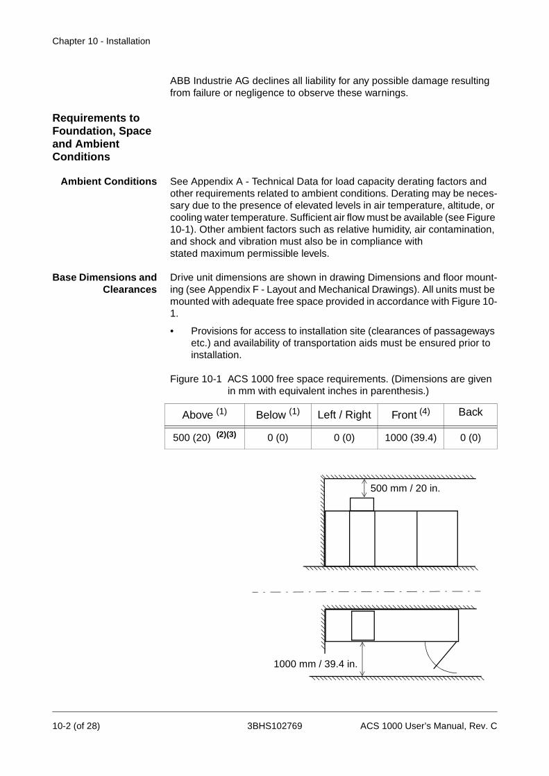
Chapter 10 - Installation
ABB Industrie AG declines all liability for any possible damage resulting from failure or negligence to observe these warnings.
Requirements to Foundation, Space and Ambient Conditions
Ambient Conditions See Appendix A - Technical Data for load capacity derating factors and other requirements related to ambient conditions. Derating may be neces-sary due to the presence of elevated levels in air temperature, altitude, or cooling water temperature. Sufficient air flow must be available (see Figure 10-1). Other ambient factors such as relative humidity, air contamination, and shock and vibration must also be in compliance with stated maximum permissible levels.
Base Dimensions andClearances
Drive unit dimensions are shown in drawing Dimensions and floor mount-ing (see Appendix F - Layout and Mechanical Drawings). All units must be mounted with adequate free space provided in accordance with Figure 10-1.
• Provisions for access to installation site (clearances of passageways etc.) and availability of transportation aids must be ensured prior to installation.
Figure 10-1 ACS 1000 free space requirements. (Dimensions are given in mm with equivalent inches in parenthesis.)
Above (1) Below (1) Left / Right Front (4) Back
500 (20) (2)(3) 0 (0) 0 (0) 1000 (39.4) 0 (0)
500 mm / 20 in.
1000 mm / 39.4 in.
10-2 (of 28) 3BHS102769 ACS 1000 User’s Manual, Rev. C
Chapter 10 - Installation
Notes:
1 Dimensions listed do not include space for cable en-try which can be from top or from below.
2 Dimensions listed are above the blower hood.
3 This is a general recommendation to insure proper air flow; actual site conditions may allow this dimension to decrease or force it to increase.
4 Dimensions listed indicate maximum necessary door swing area. Additional space may be needed to meet local code requirements.
Floor Levelling andCable Ducts
The ACS 1000 cabinet must be installed in upright position.
• The floor must be of non-flammable material, with smooth and non abrasive surface, protected against humidity diffusion, levelled and able to support the weight of the converter (min. 1’000 kg/m2).
• Cable ducts must be of non-flammable material, with non abrasive sur-face and protected against humidity, dust and penetration of animals.
Selection and Dimensioning of Power Equipment
The connection from the mains supply to the ACS 1000 drive consists of six basic elements:
• Main circuit breaker / controller
• Instrumentation and protection equipment
• Transformer primary cable
• Transformer
• Transformer secondary cable
• Cable termination - ACS 1000
Recommendations for the dimensioning and installation of each of these elements are given below. All applicable manufacturer’s instructions and local regulations must be followed when installing this equipment. If any specific instruction as stated in this manual appears to be in conflict with the requirements, please contact your local ABB representative for further assistance.
Main Circuit Breaker /Controller
The main circuit breaker / controller can be either a vacuum or gas insu-lated circuit breaker or vacuum controller (medium voltage starter). In ei-ther case it should carry basic voltage and current ratings in accordance with the rated primary voltage and current levels of the transformer which is supplied. In addition to the basic electrical characteristics it must also meet specific drive requirements (some items require proper coordination with the instrumentation and protection equipment):
• Tolerate transformer inrush currents without tripping
• Clear transformer secondary short circuits within 100 ms
• Close in response to a close command
ACS 1000 User’s Manual, Rev. C 3BHS102769 10-3 (of 28)
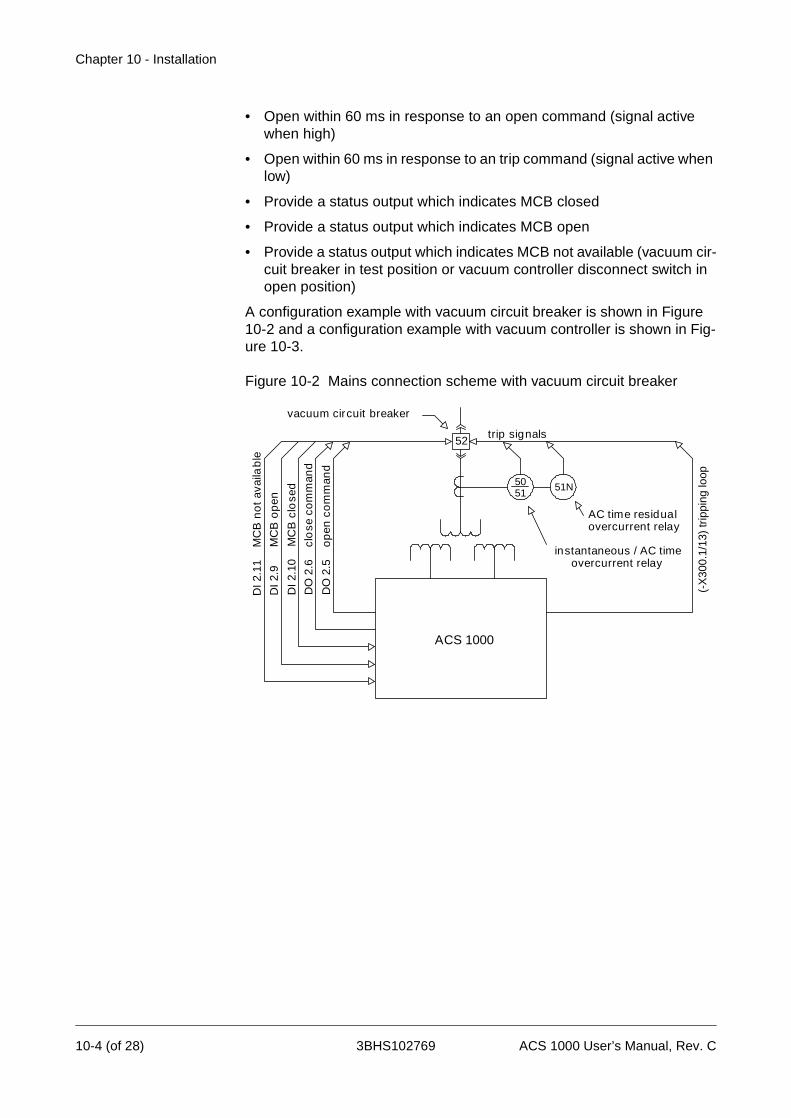
Chapter 10 - Installation
• Open within 60 ms in response to an open command (signal active when high)
• Open within 60 ms in response to an trip command (signal active when low)
• Provide a status output which indicates MCB closed
• Provide a status output which indicates MCB open
• Provide a status output which indicates MCB not available (vacuum cir-cuit breaker in test position or vacuum controller disconnect switch in open position)
A configuration example with vacuum circuit breaker is shown in Figure 10-2 and a configuration example with vacuum controller is shown in Fig-ure 10-3.
Figure 10-2 Mains connection scheme with vacuum circuit breaker
52
ACS 1000
5051
51N
DI 2
.11
M
CB
no
t av
aila
ble
DI 2
.9
M
CB
op
en
DI 2
.10
M
CB
clo
sed
DO
2.6
c
lose
co
mm
and
DO
2.5
o
pen
co
mm
and
AC time residuaovercurrent rela
instantaneous / AC timovercurrent relay
trip signals
vacuum circuit breaker
(-X
300.
1/13
) tr
ippi
ng lo
op
ly
e
10-4 (of 28) 3BHS102769 ACS 1000 User’s Manual, Rev. C
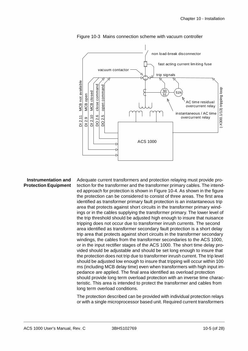
Chapter 10 - Installation
Figure 10-3 Mains connection scheme with vacuum controller
Instrumentation andProtection Equipment
Adequate current transformers and protection relaying must provide pro-tection for the transformer and the transformer primary cables. The intend-ed approach for protection is shown in Figure 10-4. As shown in the figure the protection can be considered to consist of three areas. The first area identified as transformer primary fault protection is an instantaneous trip area that protects against short circuits in the transformer primary wind-ings or in the cables supplying the transformer primary. The lower level of the trip threshold should be adjusted high enough to insure that nuisance tripping does not occur due to transformer inrush currents. The second area identified as transformer secondary fault protection is a short delay trip area that protects against short circuits in the transformer secondary windings, the cables from the transformer secondaries to the ACS 1000, or in the input rectifier stages of the ACS 1000. The short time delay pro-vided should be adjustable and should be set long enough to insure that the protection does not trip due to transformer inrush current. The trip level should be adjusted low enough to insure that tripping will occur within 100 ms (including MCB delay time) even when transformers with high input im-pedance are applied. The final area identified as overload protection should provide long term overload protection with an inverse time charac-teristic. This area is intended to protect the transformer and cables from long term overload conditions.
The protection described can be provided with individual protection relays or with a single microprocessor based unit. Required current transformers
ACS 1000
5051
51N
DI 2
.11
M
CB
no
t av
aila
ble
DI 2
.9
M
CB
op
en
DI 2
.10
M
CB
clo
sed
DO
2.6
c
lose
co
mm
and
DO
2.5
o
pen
co
mm
and
vacuum contactortrip signals
AC time residuaovercurrent rela
instantaneous / AC timovercurrent relay
non load-break disconnector
fast acting current lim it ing fuse
l
e
y
(-X
300.
1/13
) tr
ippi
ng lo
op
ACS 1000 User’s Manual, Rev. C 3BHS102769 10-5 (of 28)

Chapter 10 - Installation
should be sized in accordance with the rated current levels of the trans-former. Basic protection configuration and connection should be as previ-ously shown in Figure 10-2 and Figure 10-3.
Figure 10-4 Sample protection scheme
Transformer PrimaryCable
The cable from the circuit breaker to the transformer primary has no spe-cial requirements. It should carry a voltage rating consistent with the volt-age present in the primary circuit. The ampacity rating should be consistent with the size of the transformer being supplied and the protec-tion settings of the protection equipment. Derating of cable ampacity in ac-cordance with maximum expected ambient temperature, raceway fill factors, and any other factors required by local electrical codes should be applied. Installation should be in compliance with standard industry prac-tice for medium voltage equipment.
If required by local electrical code an equipment safety ground wire should be supplied either separately or by including it in the 3 conductor cable. The ampacity of this conductor should be in accordance with the code.
Transformer All ACS 1000 drives must be supplied from an isolation transformer with multiple phase shifted secondary windings designed in accordance with the pulse number of the input bridge (12 or 24). This transformer may be supplied from ABB with the ACS 1000 or may be supplied through another source in accordance with the specification provided by ABB. The design of the transformer must take into account user line conditions (voltage, short circuit capacity, existing harmonics, etc.) to insure compliance with harmonic standards invoked by the specification. Transformer quality is critical with respect to effecting proper limitation of harmonic currents and voltages. For more information concerning the transformer consult the documentation supplied with the order or reference the transformer specification which was provided when the order was placed.
TransformerSecondary Cable
The cables from the transformer secondaries to the ACS 1000 main pow-er input buses are exposed to common mode voltages resulting from nor-mal inverter operation of the ACS 1000. For this reason it is required that
Current
Timex 1
x 10
x 20
10 ms 100 ms 100 s
Transformer PrimaryFault Protection
Transformer SecondaryFault Protection
1 s 10 s
Overload Protection
Adjustable Time Delay
10-6 (of 28) 3BHS102769 ACS 1000 User’s Manual, Rev. C
Chapter 10 - Installation
cable rated 5 kV or higher be utilized for all transformer secondary cabling regardless of the transformer secondary voltage rating (1327, 1903, or 2305 VAC). Maximum installed cable length should not exceed 300 meters (1000 feet).
A cable with 3 individually shielded conductors is recommended in order to insure compliance with EMC requirements, and to provide a low imped-ance high frequency path through which the common mode currents can flow. Shields should be terminated and grounded in as short a distance as possible at both ends. The ACS 1000 includes a vertical ground bus within the cable termination compartment in order to facilitate this.
Non-shielded 3 conductor cable with a continuous corrugated aluminum armor may be used as an alternate to the individually shielded 3 conductor cable described above. Steel armored or interlocked aluminum armored cable should not be used. Connectors with 360° electrical contact to the armor should be used to terminate the cable ends to ground.
The ampacity rating of the cable should be consistent with 125% of the rat-ed current of the ACS 1000 being supplied (allows for harmonic content) and the protection settings of the protection equipment. Derating of cable ampacity in accordance with maximum expected ambient temperature, raceway fill factors, and any other factors required by local electrical codes should be applied.
Installation should be in compliance with standard industry practice for medium voltage equipment. Cables must be terminated with connectors according to the cable manufacturer’s requirements.
If required by local electrical code an equipment safety ground wire should be supplied either separately or by including it in the 3 conductor cable. The ampacity of this conductor should be in accordance with the code.
Motor Cable There are no special requirements to be considered for the cable from the ACS 1000 to the motor. It can be of any length provided that voltage drop is taken into consideration. A voltage rating consistent with the voltage present in the motor circuit must be selected. The ampacity rating should be consistent with the size of the motor being supplied and the overload settings of the motor protection software as input to the ACS 1000. Derat-ing of cable ampacity in accordance with maximum expected ambient temperature, raceway fill factors, and any other factors required by local electrical codes should be applied. Installation should be in compliance with standard industry practice for medium voltage equipment.
Cable screening is not required for the motor cables since converter out-put voltage and current are sinusoidal. Therefore no measures against common mode currents are needed.
If required by local electrical code an equipment safety ground wire should be supplied either separately or by including it in the 3 conductor cable. The ampacity of this conductor should be in accordance with the code.
Motor cables are terminated within the ACS 1000 in the same way as transformer secondary cables. See Electrical Installation, page 10- 16 for further details.
ACS 1000 User’s Manual, Rev. C 3BHS102769 10-7 (of 28)
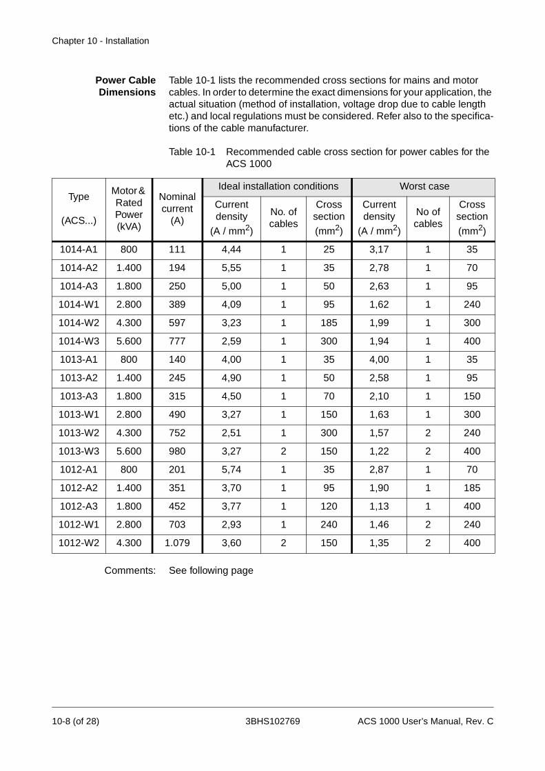
Chapter 10 - Installation
Power CableDimensions
Table 10-1 lists the recommended cross sections for mains and motor cables. In order to determine the exact dimensions for your application, the actual situation (method of installation, voltage drop due to cable length etc.) and local regulations must be considered. Refer also to the specifica-tions of the cable manufacturer.
Table 10-1 Recommended cable cross section for power cables for the ACS 1000
Comments: See following page
Type
(ACS...)
Motor & Rated Power (kVA)
Nominal current
(A)
Ideal installation conditions Worst case
Current density
(A / mm2)
No. of cables
Cross section
(mm2)
Current density
(A / mm2)
No of cables
Cross section
(mm2)
1014-A1 800 111 4,44 1 25 3,17 1 35
1014-A2 1.400 194 5,55 1 35 2,78 1 70
1014-A3 1.800 250 5,00 1 50 2,63 1 95
1014-W1 2.800 389 4,09 1 95 1,62 1 240
1014-W2 4.300 597 3,23 1 185 1,99 1 300
1014-W3 5.600 777 2,59 1 300 1,94 1 400
1013-A1 800 140 4,00 1 35 4,00 1 35
1013-A2 1.400 245 4,90 1 50 2,58 1 95
1013-A3 1.800 315 4,50 1 70 2,10 1 150
1013-W1 2.800 490 3,27 1 150 1,63 1 300
1013-W2 4.300 752 2,51 1 300 1,57 2 240
1013-W3 5.600 980 3,27 2 150 1,22 2 400
1012-A1 800 201 5,74 1 35 2,87 1 70
1012-A2 1.400 351 3,70 1 95 1,90 1 185
1012-A3 1.800 452 3,77 1 120 1,13 1 400
1012-W1 2.800 703 2,93 1 240 1,46 2 240
1012-W2 4.300 1.079 3,60 2 150 1,35 2 400
10-8 (of 28) 3BHS102769 ACS 1000 User’s Manual, Rev. C
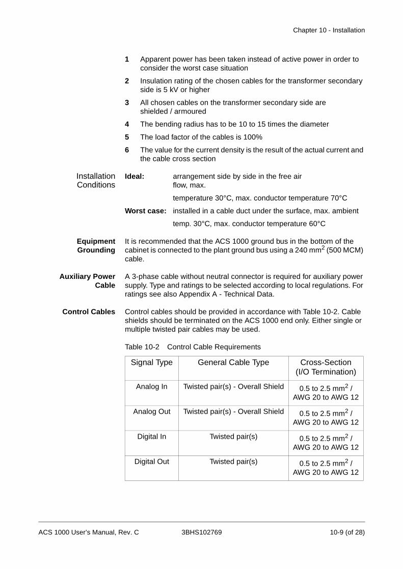
Chapter 10 - Installation
1 Apparent power has been taken instead of active power in order to consider the worst case situation
2 Insulation rating of the chosen cables for the transformer secondary side is 5 kV or higher
3 All chosen cables on the transformer secondary side are shielded / armoured
4 The bending radius has to be 10 to 15 times the diameter
5 The load factor of the cables is 100%
6 The value for the current density is the result of the actual current and the cable cross section
InstallationConditions
Ideal: arrangement side by side in the free air flow, max.
temperature 30°C, max. conductor temperature 70°C
Worst case: installed in a cable duct under the surface, max. ambient
temp. 30°C, max. conductor temperature 60°C
EquipmentGrounding
It is recommended that the ACS 1000 ground bus in the bottom of the cabinet is connected to the plant ground bus using a 240 mm2 (500 MCM) cable.
Auxiliary PowerCable
A 3-phase cable without neutral connector is required for auxiliary power supply. Type and ratings to be selected according to local regulations. For ratings see also Appendix A - Technical Data.
Control Cables Control cables should be provided in accordance with Table 10-2. Cable shields should be terminated on the ACS 1000 end only. Either single or multiple twisted pair cables may be used.
Table 10-2 Control Cable Requirements
Signal Type General Cable Type Cross-Section (I/O Termination)
Analog In Twisted pair(s) - Overall Shield 0.5 to 2.5 mm2 / AWG 20 to AWG 12
Analog Out Twisted pair(s) - Overall Shield 0.5 to 2.5 mm2 / AWG 20 to AWG 12
Digital In Twisted pair(s) 0.5 to 2.5 mm2 / AWG 20 to AWG 12
Digital Out Twisted pair(s) 0.5 to 2.5 mm2 / AWG 20 to AWG 12
ACS 1000 User’s Manual, Rev. C 3BHS102769 10-9 (of 28)

Chapter 10 - Installation
Cable Routing
Power Cables Routing of mains and motor cables must be carried out in compliance with the local regulations and according to the specifications and recommen-dations of the cable manufacturer.
• For best EMC performance it is recommended to use three phase ca-bles that are individually shielded and with steel armouring.
• If single phase cables are used, the cables with the three different phases must be grouped close together to ensure EMC performance.
• Phase interchange must be accomplished according to local regula-tions.
• For high power ratings a maximum of two cables per motor phase can be accommodated by the gland plates of the ACS 1000.
• If the cross section of the cable shielding is less than 50% of the cross section of one phase, an additional grounding wire must be laid along the power cables to avoid excessive heating losses in the cable shieldings. Please refer to the local regulations for further details.
Cable Termination • Cables must be terminated with connectors according to the cable manufacturer’s requirements.
Cable Length • The maximum length of the transformer secondary cables is limited to 300 m (1000 ft.). For longer distances special design measures must be considered.
• For the maximum length of the motor cables only the voltage drop in the cable must be taken into consideration. Since the converter out-put voltages and currents are nearly sinusoidal, reflections, which are typical for converters without output filter, do not occur.
Grounding Wire • Routing of the grounding connection must comply with local regula-tions. In some countries redundant cable routing is required. For grounding wire dimensions see also Equipment Grounding, page 10- 9.
Control Cables • Control cables should not be laid in parallel to the power cables. If this cannot be avoided, a minimum distance of 30 cm (12 in) must be maintained between control and power cables.
• Control and power cables should be crossed at an angle of 90°.
Mains and MotorCable Connection
Diagrams
Figure 10-5 shows a typical mains cable connection. The actually applied connecting scheme must comply with local regulations.
10-10 (of 28) 3BHS102769 ACS 1000 User’s Manual, Rev. C
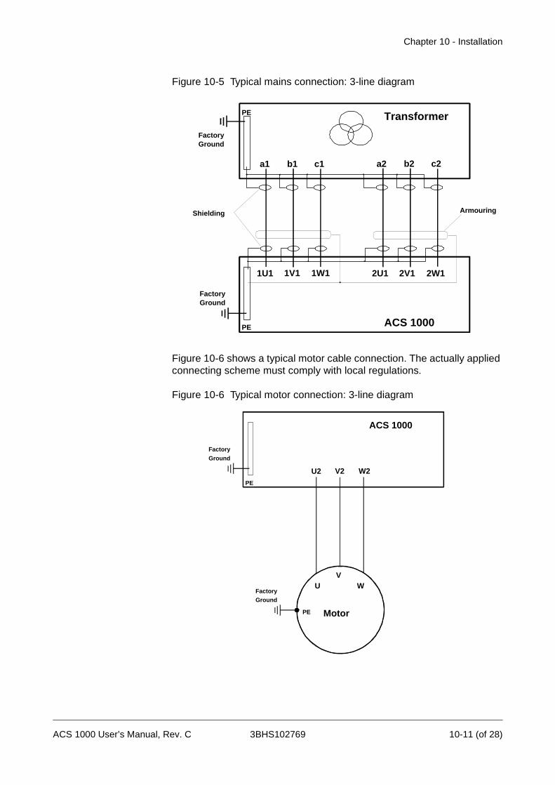
Chapter 10 - Installation
Figure 10-5 Typical mains connection: 3-line diagram
Figure 10-6 shows a typical motor cable connection. The actually applied connecting scheme must comply with local regulations.
Figure 10-6 Typical motor connection: 3-line diagram
Transformer
ACS 1000
PE
PE
a1 c1b1 a2 c2b2
1U1 1W11V1 2U1 2W12V1
FactoryGround
FactoryGround
Shielding Armouring
ACS 1000
PE
Factory
Ground
U2 W2V2
UV
W
PE
FactoryGround
Motor
ACS 1000 User’s Manual, Rev. C 3BHS102769 10-11 (of 28)

Chapter 10 - Installation
Mechanical Installation
This chapter provides instructions for moving the ACS 1000 cabinet to the mounting position, fastening it on the floor and preparing it for electrical connection.
Required Tools andParts
For the installation the following tools are required:
• Basic set of tools
• Set of wrenches
• Drilling machine with concrete drill (for M12 bolts with dowels)
• Knife
• Megger
• Volt- and Ohmmeter
• Special tools as prescribed by cable manufacturer
• Fork lift, crane or other means for moving the ACS 1000
Preparation ofMounting Site
1 Before you proceed with the mechanical installation, make sure that all preconditions as described in Section Requirements to Founda-tion, Space and Ambient Conditions are fulfilled.
Note: The following mounting instructions apply for normal mounting con-ditions in industrial surroundings.
In case of special site conditions (such as ships, cranes etc.) contact your ABB representative for further information on the installation procedure.
2 Check the floor levelling with a spirit level. The maximum allowable overall unevenness is ≤ 5mm.
If the floor is uneven, it must be levelled.
3 If power cables are to be installed from the bottom, provide floor cut-outs according to the arrangement of the cable glands as shown in drawing Dimensions and floor mounting (see Appendix F - Layout and Mechanical Drawings).
4 Drill mounting holes for M12 screws according to the drilling plan in drawing Dimensions and floor mounting (see Appendix F - Layout and Mechanical Drawings).
5 Insert dowels.
10-12 (of 28) 3BHS102769 ACS 1000 User’s Manual, Rev. C
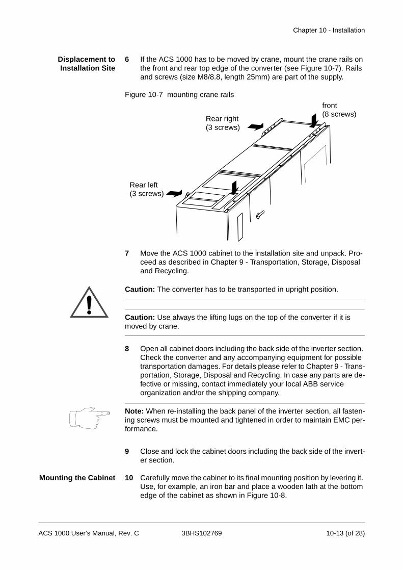
Chapter 10 - Installation
Displacement toInstallation Site
6 If the ACS 1000 has to be moved by crane, mount the crane rails on the front and rear top edge of the converter (see Figure 10-7). Rails and screws (size M8/8.8, length 25mm) are part of the supply.
Figure 10-7 mounting crane rails
7 Move the ACS 1000 cabinet to the installation site and unpack. Pro-ceed as described in Chapter 9 - Transportation, Storage, Disposal and Recycling.
Caution: The converter has to be transported in upright position.
Caution: Use always the lifting lugs on the top of the converter if it is moved by crane.
8 Open all cabinet doors including the back side of the inverter section. Check the converter and any accompanying equipment for possible transportation damages. For details please refer to Chapter 9 - Trans-portation, Storage, Disposal and Recycling. In case any parts are de-fective or missing, contact immediately your local ABB service organization and/or the shipping company.
Note: When re-installing the back panel of the inverter section, all fasten-ing screws must be mounted and tightened in order to maintain EMC per-formance.
9 Close and lock the cabinet doors including the back side of the invert-er section.
Mounting the Cabinet 10 Carefully move the cabinet to its final mounting position by levering it. Use, for example, an iron bar and place a wooden lath at the bottom edge of the cabinet as shown in Figure 10-8.
Rear left(3 screws)
Rear right(3 screws)
front(8 screws)
ACS 1000 User’s Manual, Rev. C 3BHS102769 10-13 (of 28)

Chapter 10 - Installation
Figure 10-8 Levering cabinet to place
11 Fasten the cabinet with M12 screws and lock washer using the mounting foot fastening plates provided as shown in Figure 10-9. These clamps can be installed either by accessing them from the ends of the cabinet structure or via the access plates that are provid-ed inside the cabinet.
Figure 10-9 Cabinet mounting
Fixing points
Removable access plates
10-14 (of 28) 3BHS102769 ACS 1000 User’s Manual, Rev. C
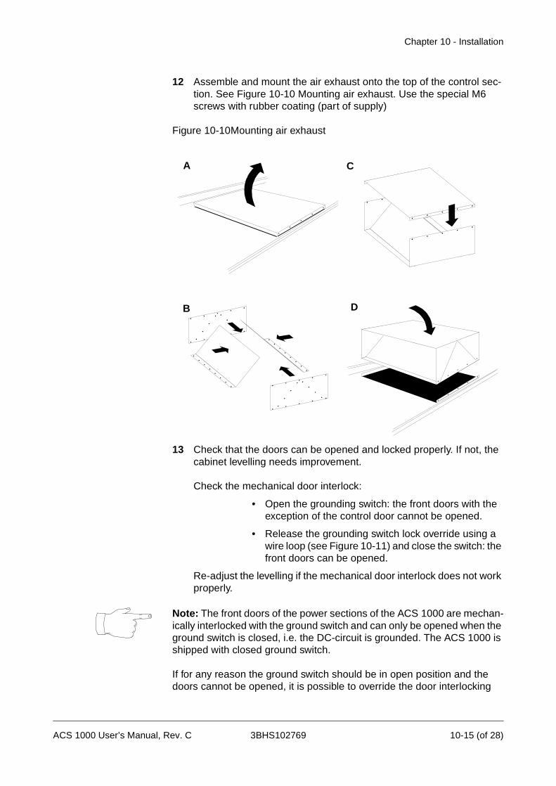
Chapter 10 - Installation
12 Assemble and mount the air exhaust onto the top of the control sec-tion. See Figure 10-10 Mounting air exhaust. Use the special M6 screws with rubber coating (part of supply)
Figure 10-10Mounting air exhaust
13 Check that the doors can be opened and locked properly. If not, the cabinet levelling needs improvement.
Check the mechanical door interlock:
• Open the grounding switch: the front doors with the exception of the control door cannot be opened.
• Release the grounding switch lock override using a wire loop (see Figure 10-11) and close the switch: the front doors can be opened.
Re-adjust the levelling if the mechanical door interlock does not work properly.
Note: The front doors of the power sections of the ACS 1000 are mechan-ically interlocked with the ground switch and can only be opened when the ground switch is closed, i.e. the DC-circuit is grounded. The ACS 1000 is shipped with closed ground switch.
If for any reason the ground switch should be in open position and the doors cannot be opened, it is possible to override the door interlocking
A
B
C
D
ACS 1000 User’s Manual, Rev. C 3BHS102769 10-15 (of 28)
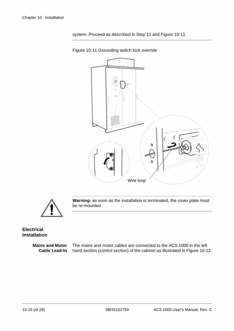
Chapter 10 - Installation
system. Proceed as described in Step 13 and Figure 10-11.
Figure 10-11.Grounding switch lock override
Warning: as soon as the installation is terminated, the cover plate must be re-mounted
Electrical Installation
Mains and MotorCable Lead-In
The mains and motor cables are connected to the ACS 1000 in the left hand section (control section) of the cabinet as illustrated in Figure 10-12.
Wire loop
10-16 (of 28) 3BHS102769 ACS 1000 User’s Manual, Rev. C
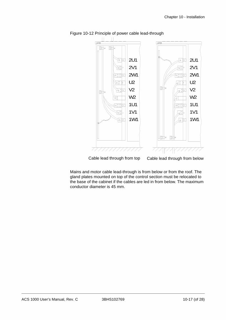
Chapter 10 - Installation
Figure 10-12 Principle of power cable lead-through
Mains and motor cable lead-through is from below or from the roof. The gland plates mounted on top of the control section must be relocated to the base of the cabinet if the cables are led in from below. The maximum conductor diameter is 45 mm.
2U1
2V1
2W1
U2
V2
W2
1U1
1V1
1W1
2U1
2V1
2W1
U2
V2
W2
1U1
1V1
1W1
Cable lead through from top Cable lead through from below
ACS 1000 User’s Manual, Rev. C 3BHS102769 10-17 (of 28)

Chapter 10 - Installation
Figure 10-13.Cable entries from top
To locate the terminals see Figure 10-12 and drawing Power and Auxiliary Terminals (see Appendix F - Layout and Mechanical Drawings).
Connect the mains and motor cables for the ACS 1000 as described in the following section. Ground the motor cable screen on the motor side as well.
Inserting Mains andMotor Cables
Warning: All electrical installation and maintenance work on the ACS 1000 must be carried out by qualified electricians in compliance with local regulations.
Any installation work must be done with mains and auxiliary power off. In-put and output isolators must be open and secured, any adjoining ground-ing device must be closed and power cables must be grounded.
Never apply power to the installation unless authorization is given by ABB commissioning staff.
For connecting the mains and motor cables to the ACS 1000 proceed as described below (for installation instructions of motor, transformer and other equipment please refer to the relevant manuals):
1 Make sure that the ACS 1000 is disconnected from the mains and auxiliary supply network during installation:
• main circuit breaker (MCB) must be open and in ser-vice position (i.e. disconnected from mains and grounded)
• Motor is disconnected from mains and grounded
Power cable entries
Aux. power and controlcable entries
10-18 (of 28) 3BHS102769 ACS 1000 User’s Manual, Rev. C

Chapter 10 - Installation
• Auxiliary power supply fuse is open
• Any control equipment to be connected with the ACS 1000 is disconnected.
2 Open the cabinet door of the control section.
3 Open the control swing frame and the protective separation door be-hind it. All power terminals are now accessible.
4 To take measurement for conductor length, strip the mains and motor cables and lead the conductors into the cabinet through the gland plate.
Warning: Do not cut cables inside the cabinet. Make sure that dust and chips from cable cutting and stripping cannot enter the cabinet.
Electrically conducting dust may cause damage or lead to malfunction.
5 Mark the required conductor length and withdraw the cables. Cut them to length, strip conductor ends and mount connectors (diameter of cable lug max. M12).
6 Lead the conductors into the cabinet through the EMC sleeves of the gland plate as shown in Figure 10-14 and Figure 10-15:
• Strip cable insulation in the gland area. Tighten the EMC sleeve on the stripped part of the cable with ca-ble ties.
• Remove the gland plate if cable entry is not possible otherwise and slide it onto the cable. After the grounding connections are made, fasten the gland plate.
• IP 54: Remove the rubber grommets from the gland plates and cut them to adequate diameter for the mains and the motor cable (Figure 10-15). To ensure proper sealing, cut along the diameter marking that corresponds to the cable diameter. Slide the grom-met onto the cable (Figure 10-14). The grommet must sit close in order to prevent water from entering the cabinet. If necessary, seal the junctions with silicone rubber.
ACS 1000 User’s Manual, Rev. C 3BHS102769 10-19 (of 28)
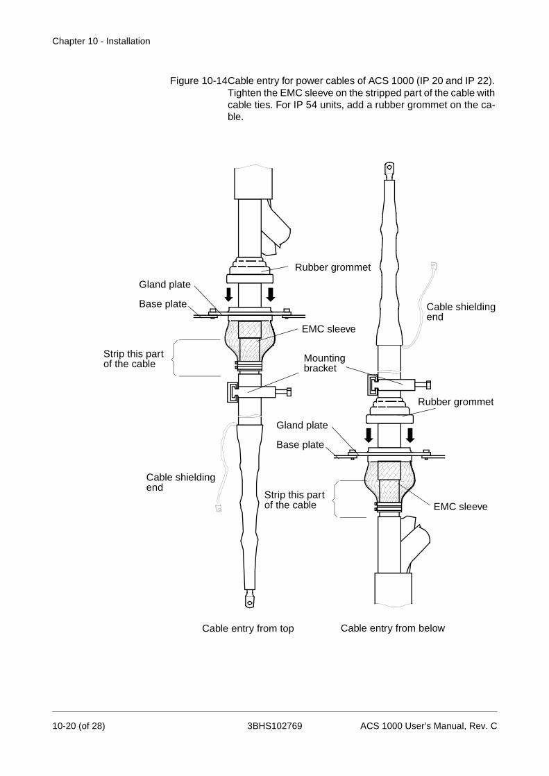
Chapter 10 - Installation
Figure 10-14Cable entry for power cables of ACS 1000 (IP 20 and IP 22). Tighten the EMC sleeve on the stripped part of the cable with cable ties. For IP 54 units, add a rubber grommet on the ca-ble.
Cable shielding end
Cable shielding end
Mounting bracket
EMC sleeve
EMC sleeve
Gland plate
Base plate
Gland plate
Base plate
Strip this partof the cable
Strip this partof the cable
Cable entry from top Cable entry from below
Rubber grommet
Rubber grommet
10-20 (of 28) 3BHS102769 ACS 1000 User’s Manual, Rev. C

Chapter 10 - Installation
Figure 10-15 Cutting rubber grommets to size
GroundingConnections
7 Lead the grounding wire into the cabinet through an EMC sleeve of the gland plate and fasten it to the grounding bar. If there is no free gland available, lead the grounding wire together with a phase con-ductor into EMC sleeve.
Figure 10-16 Grounding wire and phase conductor combined in one EMC-sleeve.
Insulation Checks Carry out cable insulation test before connecting the cables:
8 Check insulation of each cable with open ends when in final position and check that the results are within the specifications of the cable manufacturer.
A B
C
ACS 1000 User’s Manual, Rev. C 3BHS102769 10-21 (of 28)

Chapter 10 - Installation
Mains and MotorCable Connections
9 Remove bus stubs from power terminals (see Figure 10-17). Drill holes (max. M12) for accommodation of cable terminals according to your needs. Terminal screw sizes are to be selected according to ca-ble requirements.
Warning: Do not drill inside the cabinet. Make sure that dust and chips from drilling cannot enter the cabinet. If necessary, remove the bus stubs and drill the mounting holes outside the cabinet.
Electrically conducting dust may cause damage or lead to malfunction.
Figure 10-17 Power terminals with removable bus stubs
10 Using the bus stubs, connect the phase conductors of the mains ca-bles to the U1, V1 and W1 terminals and the phase conductors of the motor cable to the U2, V2 and W2 terminals. See Figure 10-18. Refer to connector specifications for tightening torques.
Removable Bus Stub
80 mm
5 mm
approx. 60 mm
10-22 (of 28) 3BHS102769 ACS 1000 User’s Manual, Rev. C

Chapter 10 - Installation
Figure 10-18 Principle of power cable lead-through
11 Connect the shielding ends of all conductors to the grounding bar us-ing pigtails; (1) in Figure 10-18.
12 Close the protective separation door and fasten it with the supplied screws (M6). All 36 joints must be fixed.
13 Fasten gland and blind plates with the supplied screws (M6). All joints must be fixed.
Note: When closing the protective separation door and rearranging the plates, all provided screws must be mounted and tightened in order to maintain EMC performance.
Auxiliary PowerCable Connection
Auxiliary power cable lead-through is from below or from the roof of the control section.
Proceed as follows:
14 Lead the auxiliary power cables into the cabinet through the EMC slot of the gland plate that leads to the front area of the control section.
• If shielded cables are used: Strip cable insulation in the gland area. The conductive cushions of the EMC slot should contact the stripped part of the cable. See Figure 10-19.
2U1
2V1
2W1
U2
V2
W2
1U1
1V1
1W1
2U1
2V1
2W1
U2
V2
W2
1U1
1V1
1W1
Cable lead through from top Cable lead through from below
1
ACS 1000 User’s Manual, Rev. C 3BHS102769 10-23 (of 28)

Chapter 10 - Installation
Figure 10-19 Auxiliary power cable lead-in
• IP 54 and cable entry from above: Remove the rubber grommets from the gland plate and cut them to ade-quate diameter for the auxiliary power cable. To en-sure proper sealing, cut along the diameter marking that corresponds to the cable diameter. Slide the grommet onto the cable. The grommet must sit close in order to prevent water from entering the cabinet. If necessary, seal the junctions with silicone rubber.
• Loosen position screws of the lead-trough plate and lead the cables inside the cabinet.
• Push the two halves of the lead-through plate togeth-er and tighten the screws. The EMC conductive cush-ions should press tightly around the bare screens.
15 Connect the cable to terminals X10 (U, V, W, PE). To locate the ter-minals see dimensional drawings (Appendix G in this manual).
16 If shielded cables are used: connect cable shielding to PE, e.g. by us-ing a pigtail (see Figure 10-20).
Figure 10-20 Auxiliary power cable connection
EMI conductive cushions
Base plate
Holes for position screws
Side view Bottom view
Lead-through plate
UVWPE
10-24 (of 28) 3BHS102769 ACS 1000 User’s Manual, Rev. C
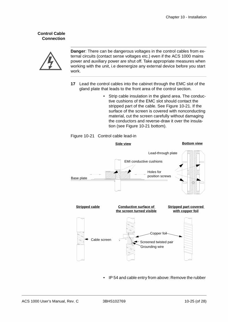
Chapter 10 - Installation
Control CableConnection
Danger: There can be dangerous voltages in the control cables from ex-ternal circuits (contact sense voltages etc.) even if the ACS 1000 mains power and auxiliary power are shut off. Take appropriate measures when working with the unit, i.e deenergize any external device before you start work.
17 Lead the control cables into the cabinet through the EMC slot of the gland plate that leads to the front area of the control section.
• Strip cable insulation in the gland area. The conduc-tive cushions of the EMC slot should contact the stripped part of the cable. See Figure 10-21. If the surface of the screen is covered with nonconducting material, cut the screen carefully without damaging the conductors and reverse-draw it over the insula-tion (see Figure 10-21 bottom).
Figure 10-21 Control cable lead-in
• IP 54 and cable entry from above: Remove the rubber
EMI conductive cushions
Base plate
Holes for position screws
Side view Bottom view
Lead-through plate
Cable screenScreened twisted pairGrounding wire
Copper foil
Stripped cable Conductive surface of the screen turned visible
Stripped part covered with copper foil
ACS 1000 User’s Manual, Rev. C 3BHS102769 10-25 (of 28)
Chapter 10 - Installation
grommets from the gland plate and cut them to ade-quate diameter for the auxiliary power cable. To en-sure proper sealing, cut along the diameter marking that corresponds to the cable diameter. Slide the grommet onto the cable. The grommet must sit close in order to prevent water from entering the cabinet. If necessary, seal the junctions with silicone rubber.
• Loosen position screws of the lead-trough plate and lead the cables inside the cabinet.
• Push the two halves of the lead-through plate togeth-er and tighten the screws. The EMC conductive cush-ions should press tightly around the bare screens.
18 Mark each conductor with stick-on tags for easy identification.
19 Connect the cables to signal terminals X300, X301 and to the IOEC boards (see Figure 10-22). They are located to the right hand side of the swing frame. To locate the terminals see dimensional drawings (Appendix G in this manual).
Note: Control cable shields must be terminated on the ACS 1000 end only.
10-26 (of 28) 3BHS102769 ACS 1000 User’s Manual, Rev. C
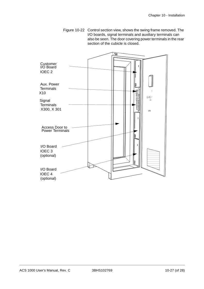
Chapter 10 - Installation
Figure 10-22 Control section view, shows the swing frame removed. The I/O boards, signal terminals and auxiliary terminals can also be seen. The door covering power terminals in the rear section of the cubicle is closed.
CustomerI/O Board
Access Door toPower Terminals
I/O BoardIOEC 3
IOEC 2
Aux. PowerTerminalsX10
SignalTerminalsX300, X 301
I/O BoardIOEC 4(optional)
(optional)
ACS 1000 User’s Manual, Rev. C 3BHS102769 10-27 (of 28)
Chapter 10 - Installation
20 Connect the cables to the external control terminals.
21 Check that the protective separation door as well as the gland and blind plates are fastened with the supplied screws (M6). All joints must be fixed.
Note: all provided screws must be mounted and tightened in order to maintain EMC performance.
Wiring Tests 22 Carry out wiring check.
A functional test of the control circuits will be made during commis-sioning.
23 Close the control swing frame.
Final Work
Warning: Never apply power to the installation unless authorization is givn by ABB commissioning staff.
Preparation forcommissioning
See Chapter 11 - Commissioning.
10-28 (of 28) 3BHS102769 ACS 1000 User’s Manual, Rev. C

Chapter 11 - Commissioning
Overview The ACS 1000 may only be commissioned by ABB staff or by their autho-rized representative.
Functional testing, commissioning and first parameter adjusting is carried out by the technicians of ABB. Testing, final parameter adjustment and performance tests are carried out by ABB staff with the customer present.
Preparation of Commissioning
Check the following preconditions which must be fulfilled before commis-sioning can be started:
GeneralPreconditions
1 Installation of the ACS 1000 must be completed according to Chapter 10 - Installation.
High VoltageEquipment
2 High voltage (HV) switchgear is connected and in operable condition.
3 Converter transformer is installed, connected and ready for operation.
4 The motor is installed, aligned, connected and ready for operation.
5 Grounding cables of transformers, converter and motor are connected.
6 All cable screens are connected.
7 Insulation of cables, transformers and motor has been tested and com-plies with the specification (insulation test of the converter will be per-formed by the commissioning engineer). An official test report is available.
8 Mains voltage supply is available.
9 The driven load (pump, fan, compressor etc.) is ready for coupling and for operation under nominal conditions.
Auxiliary VoltageSupply and Control
10 All auxiliary cables are connected
11 Auxiliary voltage switchgear is connected and operable
12 Control cables are connected:
• MCB control cables are connected directly to the con-verter
• Tripping loop
• Remote control cabling
• Cabling of options (Transformer and motor protec-tion, tachometer etc.)
13 Auxiliary voltage supply is available.
14 the plate of the grounding switch lock override is attached and secured
Cooling Circuit 15 Raw water circuit connected to the converter (if applicable)
ACS 1000 User’s Manual, Rev. C 3BHS102769 11-1 (of 2)
Chapter 11 - Commissioning
16 Raw water according to Chapter 10 - Installation is available (if applica-ble)
Miscellaneous 17 All spare parts are available.
18 All necessary process information has been handed over to your ABB sales representative. For details please contact ABB.
19 For water cooled converters only: Sufficient deionized water for filling the cooling system of the ACS 1000 is available.
Commissioning Procedure
The commissioning procedure will last 1 to 2 days excluding any waiting time.
Required CustomerManpower
During the whole commissioning period, the customer must provide 1 qualified electrical professional who is
• familiar with medium and low voltage equipment and with the local safety regulations
• familiar with the driven process
• authorized to operate the associated medium and low voltage equip-ment (MCB, other MV and LV switchgear etc.)
• authorized to operate the driven process for testing purposes.
Acceptance When commissioning is completed, the commissioning report will be signed by the customer as sign of acceptance and by the ABB commis-sioning engineer. One copy of this report will be handed out to the customer, the second copy will be sent to ABB Headquarters. The customer will then receive a confirmation from ABB Headquarters including a record of all parameter settings as they were set during commissioning.
Warranty Warranty will start on the date of acceptance, i. e. upon signing of the commissioning report by both parties, and will last 1 year.
11-2 (of 2) 3BHS102769 ACS 1000 User’s Manual, Rev. C
Index
A
ABB service address 7-12Active fault 5-17, 8-3Actual signal 3-19Actual Signals B-5Actual signals 5-15, 6-2
Full signal name display 5-17Air filters replacement 7-8Alarm handling 8-2Analog input 3-21, 4-1Analog output 3-19, 4-1Application macros 4-11, 6-2
Factory 4-1, 4-11, 4-13Hand/auto 4-1, 4-11, 4-17Master/follower 4-1, 4-11, 4-34PID control 4-1, 4-11, 4-22Selection 6-11, 6-13Sequential control 4-1, 4-11, 4-30Torque control 4-1, 4-11, 4-26
Assembly description 3-5Automatic reset 3-27
B
Battery replacement 7-11Battery test 3-25
C
Cabinet design 3-5Cable
Connections 10-22Wiring tests 10-28
Cable connection diagrams 10-10Cable dimensions 10-8Cable ducts 10-3Cable routing 10-10Cables 10-16CDP 312 3-1Charging fault 3-24Cleaning 7-7Clearances 10-2Commissioning 10-28, 11-1
Acceptance 11-2General procedure 11-2
Required customer manpower 11-2Common mode choke 3-3Common mode damping resistor 3-3Communication fault 3-25Constant speeds 3-14Control equipment 3-1, 3-9Control functions 3-11Control location 3-20Control panel 3-1, 3-10, 8-3, B-1
Contrast 5-19Display 5-1keys B-4
Control system 3-4Cooling circuit 3-8Critical speed 3-14
D
De-energizing the ACS 1000 5-12Device type B-3Digital input 4-1Digital output 3-19, 4-1Dimensioning of auxiliary power cable 10-9Dimensioning of control cables 10-9Dimensioning of power equipment 10-3
Cables 10-6Protection Equipment 10-5
Direct torque control (DTC) 3-4, 3-11Direction B-3Disabling local operation 5-10Disassembly 9-9Disposal 9-9Door locks 3-8DriveLink 3-28DriveSupport 3-29DriveWindow 3-28DTC block diagram 3-4
E
Electromagnetic compatibility (EMC) 3-5Elementary diagram 3-2Emergency off 3-26, 5-14Equipment grounding 10-9Error messages 8-8
ACS 1000 User’s Manual, Rev. C 3BHS102769 Index-1 (of 4)
F
Factory Macroexternal connections 4-10, 4-15, 4-20, 4-
24, 4-28, 4-32, 4-36Factory macro
Operation diagram 4-13Fan bearings replacement 7-10Fan replacement 7-8Fault display 8-3Fault elimination 8-8Fault functions 3-22Fault handling 8-2Fault history 3-19, 5-18, 8-4
clearing B-7displaying B-7
Faultsdisplaying B-8resetting B-8
Filter ID run 3-12Floor levelling 10-3Flux optimization 3-12Flying start 3-12Functional Description 3-1Functional description 3-2
G
Ground fault 3-25Grounding 10-9Grounding connections 10-21Grounding isolator 5-3, 5-12, 10-16Grounding switch lock override 10-16
H
Hand/auto macrooperation diagram 4-17, 4-22
Humidity 9-7
I
I/O boards 4-1ID-number B-3ID-run
fault 3-25Information 3-27Input signal source selections 3-20Installation 10-1
Ambient Conditions 10-2
Base dimensions and clearances 10-2Electrical 10-16Foundation 10-2Mechanical 10-12Required tools and parts 10-12Safety 10-1
Insulation check 10-21Intended purpose of use 1-3Intermediate DC link voltage 3-24Inverter
Loadability 3-24Short circuit 3-25
L
Layout 3-5Lifting arrangements 3-8Limits 3-26Local B-3Local control 3-18, 5-9
M
Main circuit breakerclosing 5-4
Main circuit breaker (MCB) 3-17, 3-26, 10-3Maintenance 7-1
Check of connections 7-7Logbook 7-12Required tools 7-4Safety 7-1Standard procedure 7-4
Maintenance schedule 7-3Measurement loss 3-25Motor ID run 3-11, 6-15Motor phase loss 3-24Motor protection 3-26Motor stall 3-22Motor winding temperature 3-22
O
Offset calibration 3-21Operation 5-1Options
Customer specific C-1Overcurrent 3-24Overspeed 3-23Overvoltage 3-24
Index-2 (of 4) 3BHS102769 ACS 1000 User’s Manual, Rev. C

P
Packing 9-1Parameter
Backup 7-11Downloading 6-17Editing 6-6Modification 6-14Parameter groups 6-1programming procedure 6-3Recalling user macro parameters 6-22Restoring default settings 6-19Safety 6-1Uploading 6-16Verification 6-14
Parameter Groups 6-1Parameter lock 3-27, 6-16Parameters
selecting B-8phase Loss 3-24PID controller 3-28Power circuit interface
Input circuit 3-3Output circuit 3-3
Power loss ride-through 3-12Preparation of mounting site 10-12Process monitoring 5-14Process stop 3-26Protection equipment 10-5
R
Ramp functions 3-13Reference
setting B-14value B-3
Reference signal processing 3-20Remote B-3Remote control 3-18, 5-9Repair work 8-7Resonance frequency damping (RFD) 3-14, 3-
28Run status B-3
S
Safety 1-1Commissioning 1-1Concept 1-2Improper behavior 1-4
Installation 1-1, 10-1Labels 1-2Maintenance 1-1, 7-1Operation 5-1Parameter 6-1Residual danger areas 1-3Responsibilities 1-1Trouble shooting 8-1
Selection of actual signals 6-7Sense of rotation 5-8Service address 7-12Setpoint
changing 5-7entering 5-6
Short circuitRectifier 3-24
SignalsMain circuit breaker 4-3Motor 4-4Others 4-5Process 4-5Remote control interface 4-2Transformer 4-3
Spare partsHandling 9-8
SpeedAccurate speed control 3-16Constant speeds 3-14controller 3-15response 3-15
Squirrel cage induction motors 3-1Standards fulfilled 3-1Start operation 5-2Start-up parameters 6-1, 6-7Status row B-3Stopping the ACS 1000 5-11Storage 9-6
Ambient conditions 9-7Battery 9-7Periodical Inspections 9-7Spare parts 9-7
Supervision 3-27
T
Technical data 3-1Temporary shut down 9-9Torque
Accurate torque control 3-16Full torque at zero speed 3-12
ACS 1000 User’s Manual, Rev. C 3BHS102769 Index-3 (of 4)

Training of personnel 1-4Transformer protection 3-26Transportation 9-1
Damages 9-6Displacement to installation site 10-13Environmental requirements 9-1Lifting Angle 9-4Loading 9-3Unloading 9-3Warning and instruction labels 9-2
Trouble shootingSafety 8-1Standard procedure 8-5
U
Underload 3-22Undervoltage 3-12, 3-23Unpacking 9-4User Macro 6-20User macros 6-20
W
Warranty 11-2Wiring tests 10-28
Index-4 (of 4) 3BHS102769 ACS 1000 User’s Manual, Rev. C
Related Documents