SF 6 -insulated Ring Main Unit, SafeRing 36 and SF 6 -insulated Compact Switchgear SafePlus 36 36 kV ABB

Welcome message from author
This document is posted to help you gain knowledge. Please leave a comment to let me know what you think about it! Share it to your friends and learn new things together.
Transcript
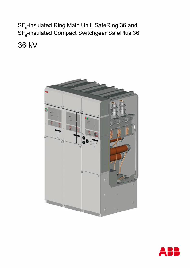
SF6-insulated Ring Main Unit, SafeRing 36 andSF6-insulated Compact Switchgear SafePlus 36
36 kV
ABB
SafeRing/SafePlus 36SF6 insulated CSG / RMU
�
Contents 1.
Contents
1. Application ................................................................................ 31.1 Applications SafeRing ............................................................... 31.2 Applications SafePlus ............................................................... 5
2. Design Philosophy .................................................................... 7
3. SafeRing 36 configurations ....................................................... 93.1 General ..................................................................................... 93.2 Configurations ............................................................................. 103.3 Technical data ............................................................................. 12
4. SafePlus 36 modules ................................................................. 144.1 General ...................................................................................... 144.2 C – cable switch ......................................................................... 154.3 F – switch-fuse disconnector ...................................................... 164.4 V – vacuum circuit-breaker ......................................................... 174.5 D – direct cable connection ........................................................ 184.6 De – direct cable connection with earthing ................................. 194.7 M – metering module .................................................................. 19
5. Switchgear design ...................................................................... 215.1 Outer assembly .......................................................................... 215.2 Cable switch module .................................................................. 225.3 Switch-fuse module ................................................................... 235.4 Vacuum circuit-breaker module ................................................. 245.5 Cable bushings .......................................................................... 255.6 Completely sealed enclosure ..................................................... 265.7 Mechanisms and interlocks ....................................................... 275.8 Side extension ............................................................................ 29
6. Accessories ................................................................................. 316.1 Low voltage compartment .......................................................... 316.2 Motor operation .......................................................................... 326.3 Transformer protection ............................................................... 356.4 Fuse selection table .................................................................... 366.5 Fuses .......................................................................................... 386.6 Relays ......................................................................................... 396.7 Cable termination ....................................................................... 446.8 Capacitive voltage detection / indication .................................... 476.9 Short-circuit indicator .................................................................. 496.10 Ronis key interlocks ................................................................... 50
7. Remote control ........................................................................... 51
8. Dimensions ................................................................................ 55
9. Technical data ........................................................................... 609.1 Standards .................................................................................. 609.2 Technical data SafeRing 36 ........................................................ 619.3 Technical data SafePlus 36 ........................................................ 629.4 General data .............................................................................. 639.5 Curves, number of operations .................................................... 65
10. Environment .............................................................................. 66
SafeRing/SafePlus 36SF6 insulated CSG / RMU
�
Applications SafeRing 36 1.1
ABB ABB
ABB
ABB
SafeRing/SafePlus 36SF6 insulated CSG / RMU
�
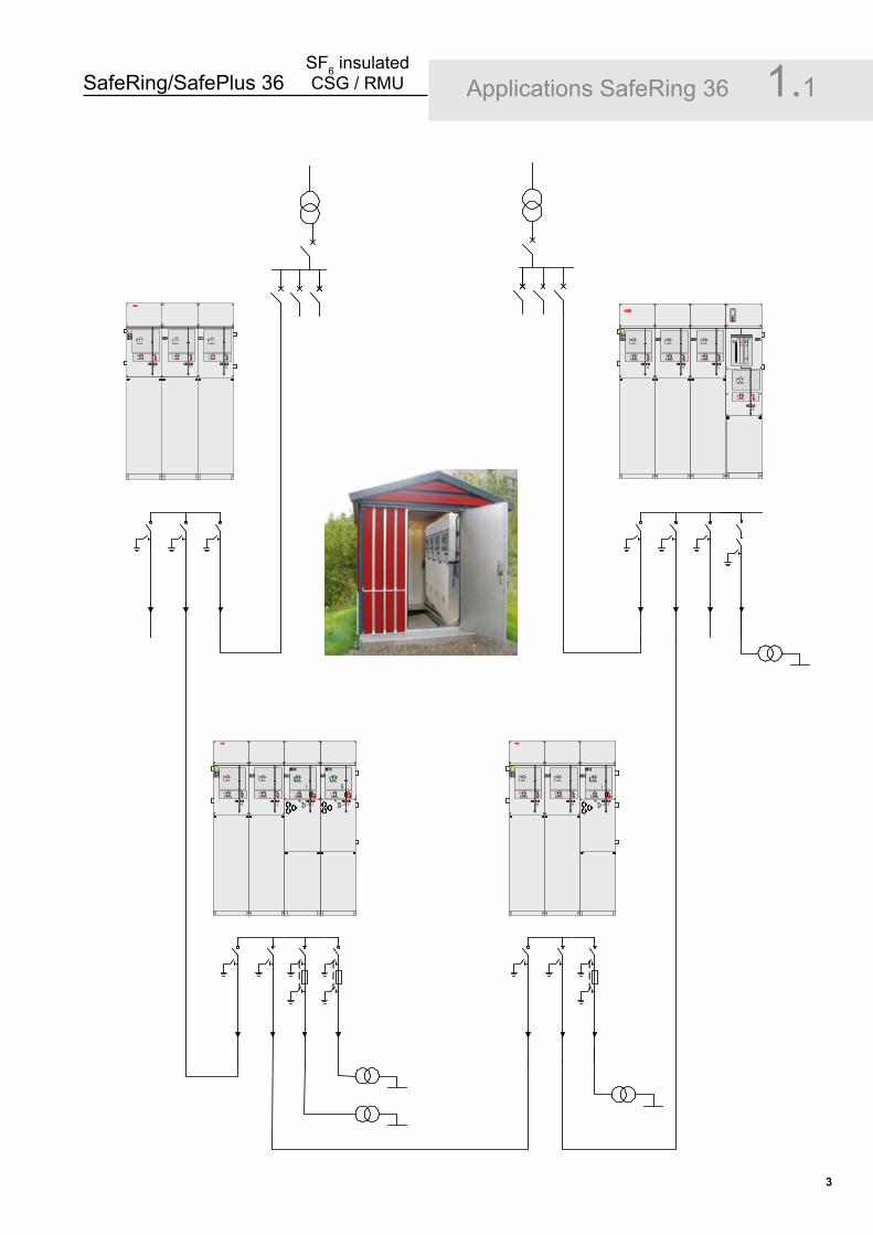
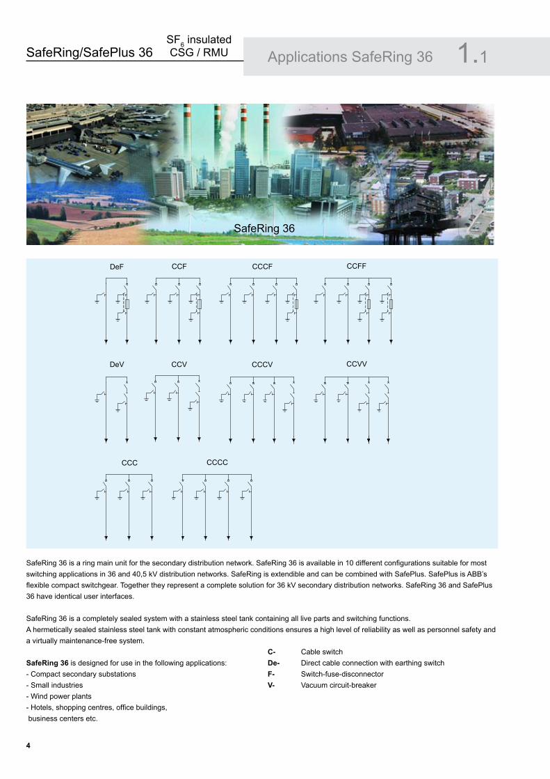
SafeRing 36 is a ring main unit for the secondary distribution network. SafeRing 36 is available in 10 different configurations suitable for most switching applications in 36 and 40,5 kV distribution networks. SafeRing is extendible and can be combined with SafePlus. SafePlus is ABB’s flexible compact switchgear. Together they represent a complete solution for 36 kV secondary distribution networks. SafeRing 36 and SafePlus 36 have identical user interfaces.
SafeRing 36 is a completely sealed system with a stainless steel tank containing all live parts and switching functions. A hermetically sealed stainless steel tank with constant atmospheric conditions ensures a high level of reliability as well as personnel safety and a virtually maintenance-free system.
SafeRing �6 is designed for use in the following applications:- Compact secondary substations- Small industries- Wind power plants- Hotels, shopping centres, office buildings, business centers etc.
C- Cable switchDe- Direct cable connection with earthing switchF- Switch-fuse-disconnector V- Vacuum circuit-breaker
Applications SafeRing 36 1.1
SafeRing 36
DeF CCF CCCF CCFF
DeV CCV CCCV CCVV
CCC CCCC
SafeRing/SafePlus 36SF6 insulated CSG / RMU
�
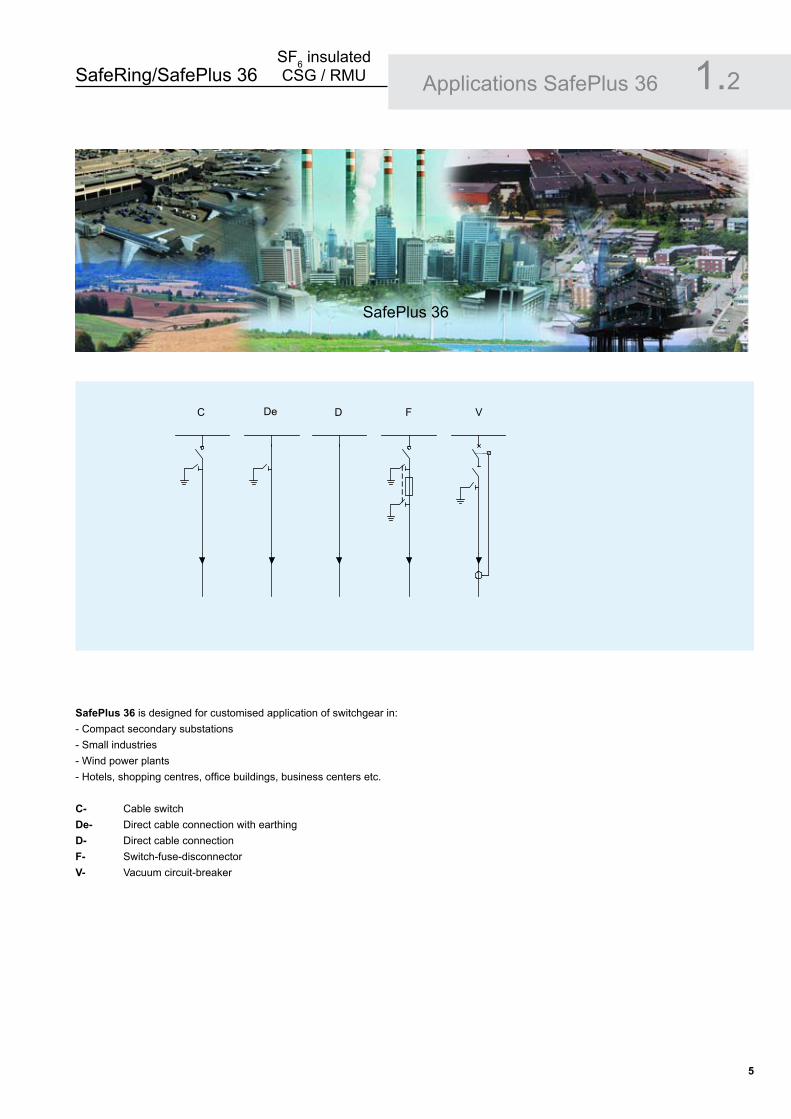
SafePlus �6 is designed for customised application of switchgear in: - Compact secondary substations- Small industries- Wind power plants- Hotels, shopping centres, office buildings, business centers etc.
C- Cable switchDe- Direct cable connection with earthingD- Direct cable connectionF- Switch-fuse-disconnectorV- Vacuum circuit-breakerM- Metering module (air-insulated)
Applications SafePlus 36 1.2
SafePlus 36
3
V
A
3
C De D F V M

SafeRing/SafePlus 36SF6 insulated CSG / RMU
6
SafePlus �6 compact switchgear in fully modular design, typical configuration:
- 3 pcs.1-way units of cable switches- 2 pcs 1-way units of switch-fuse-disconnectors
SafePlus 36 compact switchgear, typical configuration:
- 3-way section consisting of 3 modules of switch-fuse-disconnectors- Extendible with 1 or more 1-way units
SafePlus 36 compact switchgear, typical windmill configuration:
- 1 pc. 1-way unit of cable switch with cable bushings on left hand side- 1 pc- 1-way unit of vacuum circuit-breaker
Applications SafePlus 36 1.2
ABB ABB ABB ABB ABB
ABBABB ABB
ABB�� REJ 603
ABB

SafeRing/SafePlus 36SF6 insulated CSG / RMU
�
SafeRing and SafePlus – ABB switchgears for secondary distribution
Evolution: - more functionality, compact dimensions.Secondary distribution switchgears have been subject to a significant development the recent 20 years.
The traditional switching cells are substituted with complete switchgear systems. Specific functions such as grounding, disconnecting, cable connections, busbar extension, protection and switching have become integrated features in compact functional units.
Compact switchgear systems fulfils customers MV application requirements. ABB has always taken an active part in this development. The most unique specialisation is the development of the compact secondary switchgear. The numerous distribution substations requested a unified switching functionality that evolved into the Ring Main Unit concept.ABB SafeRing range is one major contributor to this specialisation.
Two Products – One rangeABB SafeRing is adapted to the needs in the utility distribution networks.ABB SafePlus offers more flexibility and electrical capacity.Both switchgears offer the same user interface.
Customers involvement:The applied functionality in ABB SafeRing and SafePlus is a result of input from customers all over the world.
Key customers are continuously involved with ABB design staff to ensure optimised switchgear operation.
Personnel – safety operationAll products are designed and manufactured in compliancewith ISO 9001, ISO 14001 and ISO 18001.The latest edition of rel-evant IEC standards will always apply to our continuous test programme.
Safety is not only a specification and rating issue, but also a real life experience.All units are factory routine tested according to international standards. ABB takes this further to be an objective related to durability and repetitive manufacturing quality.
Features for further enhancing personnel safety are available.
“Integrated functionality” is a key objective to reduce the number of moving components, further reducing the risk of any mechanical defect.
Design Philosophy 2.
SafeRing/SafePlus 36SF6 insulated CSG / RMU
�
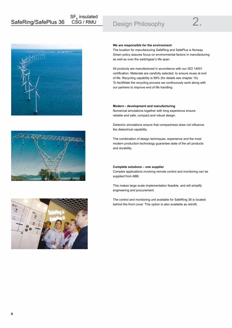
We are responsible for the environmentThe location for manufacturing SafeRing and SafePlus is Norway. Green policy assures focus on environmental factors in manufacturing as well as over the switchgear’s life span.
All products are manufactured in accordance with our ISO 14001 certification. Materials are carefully selected, to ensure reuse at end of life. Recycling capability is 89% (for details see chapter 10).To facitilitate the recycling process we continuously work along with our partners to improve end of life handling.
Modern - development and manufacturingNumerical simulations together with long experience ensure reliable and safe, compact and robust design.
Dielectric simulations ensure that compactness does not influence the dielectrical capability.
The combination of design techniques, experience and the most modern production technology guarantee state of the art products and durability.
Complete solutions – one supplierComplex applications involving remote control and monitoring can be supplied from ABB.
This makes large scale implementation feasible, and will simplify engineering and procurement.
The control and monitoring unit available for SafeRing 36 is located behind the front cover. This option is also available as retrofit.
Design Philosophy 2.

SafeRing/SafePlus 36SF6 insulated CSG / RMU
�
�.1 GeneralSafeRing 36 is an extendible ring main unit for the secondary distribution network. SafeRing 36 is available in 10 different configurations suitable for most switching applications up to 40,5 kV distribution networks.
SafeRing 36 is a completely sealed system with a stainless steel tank containing all live parts and switching functions. The sealed steel tank with constant atmospheric conditions ensures a high level of reliability, personnel safety and a virtually maintenance-free system.The SafeRing 36 concept offers a choice between switch-fuse combination or circuit-breaker in combination with relay for protection of the transformer. SafeRing 36 can be supplied with integrated remote control and monitoring unit.
SafeRing �6 is supplied with the following standard equipment
Vacuum circuit-breakerTwo-position load break switch, puffer typeEarthing switch with single spring operating mechanismSwitch position indication for load break switch and earthing switchSingle spring operating mechanism on cable switchesTwo-position mechanism with auto-reclosing duty for vacuum circuit-breakerDouble spring operating mechanism on switch-fuse disconnectorsCable bushings horizontal in front, 400 series bolted with integrated voltage divider for voltage indicationBusbars, 630AEarthing bar Operating handle Lifting lugs for easy handlingAdjustable cable support bars Manometer for SF6 pressure
••••
••
•
•
••••••
Factory assembled options
Bushings for extension busbar Interlocking - Cable compartment front cover interlocked with earthing switchSignal (1NO) from internal pressure indicator wired to terminals (one each SF6-enclosure)
Additional equipment also available as retrofit
Integrated control and monitoring unit (ICMU)Motor operationTrip coil openTrip coil open and closeAux. switch for load break switch 2NO + 2NCAux. switch for earth switch 2NO + 2NCAux. switch for fuse blown 1NOAux. switch for vacuum circuit-breaker 2NO+2NCCapacitive voltage indicationShort circuit indicatorCable cover for parallel cablesRonis key interlocking system, EL 11 APCurrent measuringSidewalls - painted
••
•
•••••••••••••••
SafeRing 36 Configurations 3.
SafeRing CCF

SafeRing/SafePlus 36SF6 insulated CSG / RMU
10
CCF
Depth: 900 mmWidth: 1330 mmHeight: 1930 mm
CCCF
Depth: 900 mmWidth: 1750 mmHeight: 1930 mm
CCFF
Depth: 900 mmWidth: 1750 mmHeight: 1930 mm
DeF
Depth: 900 mmWidth: 910 mmHeight: 1930 mm
SafeRing 36 Configurations 3.2ABB
ABB
ABB
ABB
SafeRing/SafePlus 36SF6 insulated CSG / RMU
11
SafeRing 36 Configurations 3.2
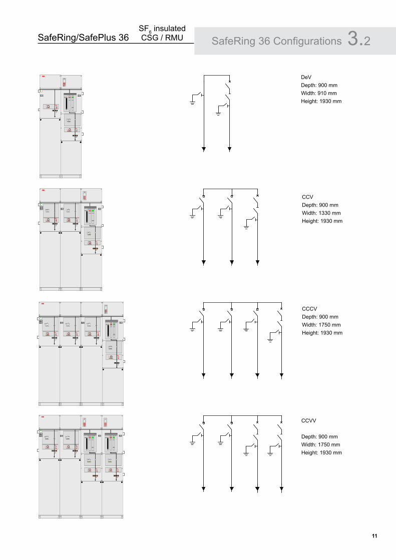
DeVDepth: 900 mmWidth: 910 mmHeight: 1930 mm
CCVDepth: 900 mmWidth: 1330 mmHeight: 1930 mm
ABB
��� REJ 603
ABB
��� REJ 603
CCCVDepth: 900 mmWidth: 1750 mmHeight: 1930 mm
CCVV
Depth: 900 mmWidth: 1750 mmHeight: 1930 mm
ABB
��� REJ 603
ABB
��� REJ 603 � �� REJ 603

SafeRing/SafePlus 36SF6 insulated CSG / RMU
1�
SafeRing 36 Configurations 3.2
CCC
Depth: 900 mmWidth: 1330 mmHeight: 1930 mm
CCCC
Depth: 900 mmWidth: 1750 mmHeight: 1930 mm
ABB
ABB
SafeRing/SafePlus 36SF6 insulated CSG / RMU
1�
C-module F-module V-module
SafeRing �6 Switch disconnector
Earthing switch
Switch-fuse disconnector
Downstream earthing switch
Vacuum circuit-breaker
Earthing switch/
disconnector
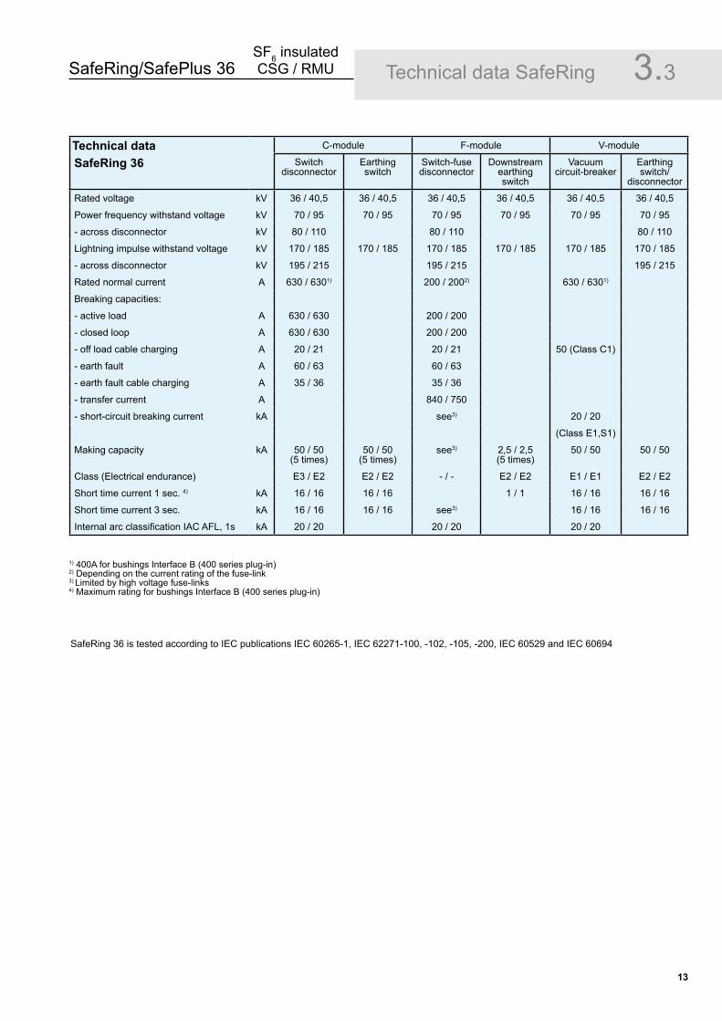
Rated voltage kV 36 / 40,5 36 / 40,5 36 / 40,5 36 / 40,5 36 / 40,5 36 / 40,5
Power frequency withstand voltage kV 70 / 95 70 / 95 70 / 95 70 / 95 70 / 95 70 / 95
- across disconnector kV 80 / 110 80 / 110 80 / 110
Lightning impulse withstand voltage kV 170 / 185 170 / 185 170 / 185 170 / 185 170 / 185 170 / 185
- across disconnector kV 195 / 215 195 / 215 195 / 215
Rated normal current A 630 / 6301) 200 / 2002) 630 / 6301)
Breaking capacities:
- active load A 630 / 630 200 / 200
- closed loop A 630 / 630 200 / 200
- off load cable charging A 20 / 21 20 / 21 50 (Class C1)
- earth fault A 60 / 63 60 / 63
- earth fault cable charging A 35 / 36 35 / 36
- transfer current A 840 / 750
- short-circuit breaking current kA see3) 20 / 20
(Class E1,S1)
Making capacity kA 50 / 50 (5 times)
50 / 50 (5 times)
see3) 2,5 / 2,5 (5 times)
50 / 50 50 / 50
Class (Electrical endurance) E3 / E2 E2 / E2 - / - E2 / E2 E1 / E1 E2 / E2
Short time current 1 sec. 4) kA 16 / 16 16 / 16 1 / 1 16 / 16 16 / 16
Short time current 3 sec. kA 16 / 16 16 / 16 see3) 16 / 16 16 / 16
Internal arc classification IAC AFL, 1s kA 20 / 20 20 / 20 20 / 20
Technical data
1) 400A for bushings Interface B (400 series plug-in) 2) Depending on the current rating of the fuse-link 3) Limited by high voltage fuse-links 4) Maximum rating for bushings Interface B (400 series plug-in)
SafeRing 36 is tested according to IEC publications IEC 60265-1, IEC 62271-100, -102, -105, -200, IEC 60529 and IEC 60694
3.3Technical data SafeRing
SafeRing/SafePlus 36SF6 insulated CSG / RMU
1�
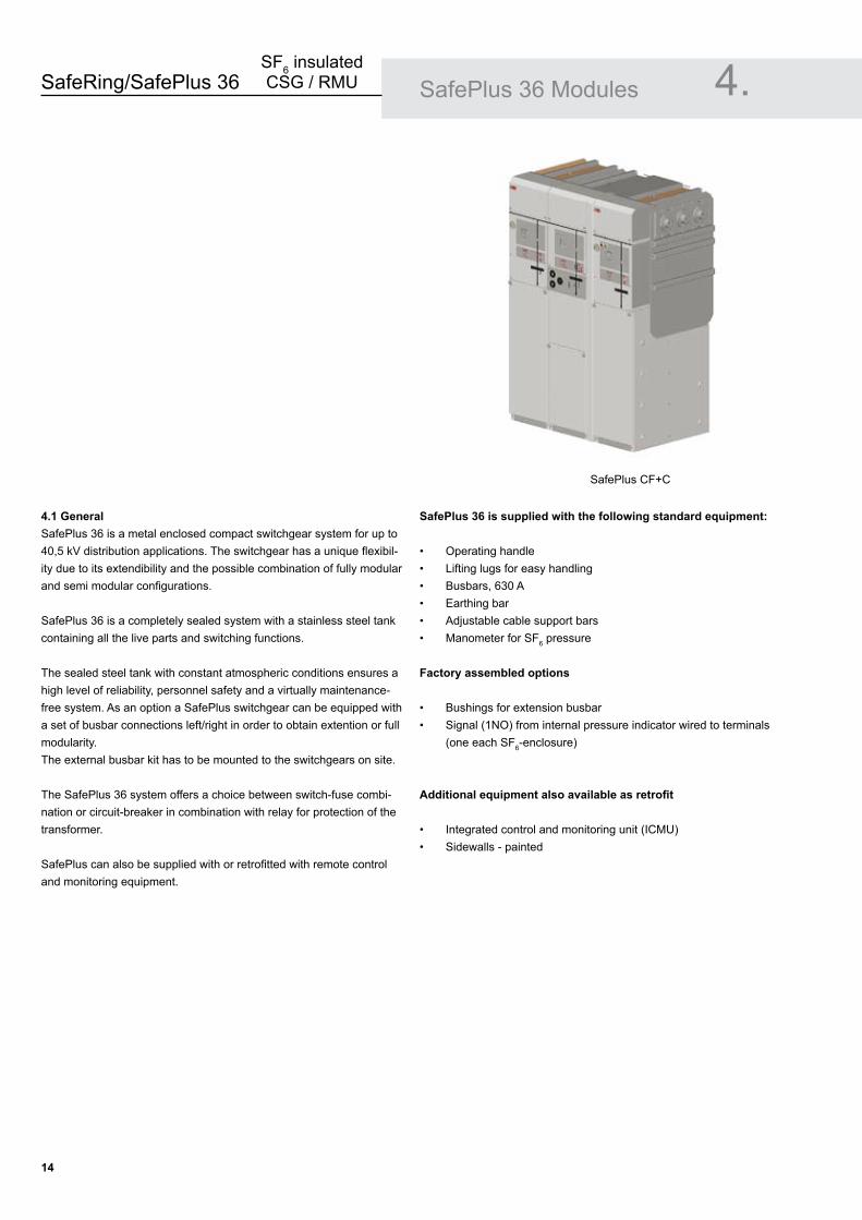
�.1 General SafePlus 36 is a metal enclosed compact switchgear system for up to 40,5 kV distribution applications. The switchgear has a unique flexibil-ity due to its extendibility and the possible combination of fully modular and semi modular configurations.
SafePlus 36 is a completely sealed system with a stainless steel tank containing all the live parts and switching functions.
The sealed steel tank with constant atmospheric conditions ensures a high level of reliability, personnel safety and a virtually maintenance-free system. As an option a SafePlus switchgear can be equipped with a set of busbar connections left/right in order to obtain extention or full modularity. The external busbar kit has to be mounted to the switchgears on site. The SafePlus 36 system offers a choice between switch-fuse combi-nation or circuit-breaker in combination with relay for protection of the transformer.
SafePlus can also be supplied with or retrofitted with remote control and monitoring equipment.
SafePlus 36 Modules 4.
SafePlus 36 is supplied with the following standard equipment:
Operating handleLifting lugs for easy handlingBusbars, 630 AEarthing barAdjustable cable support barsManometer for SF6 pressure
Factory assembled options
Bushings for extension busbar Signal (1NO) from internal pressure indicator wired to terminals (one each SF6-enclosure)
Additional equipment also available as retrofit
Integrated control and monitoring unit (ICMU)Sidewalls - painted
••••••
••
••
SafePlus CF+C
SafeRing/SafePlus 36SF6 insulated CSG / RMU
1�
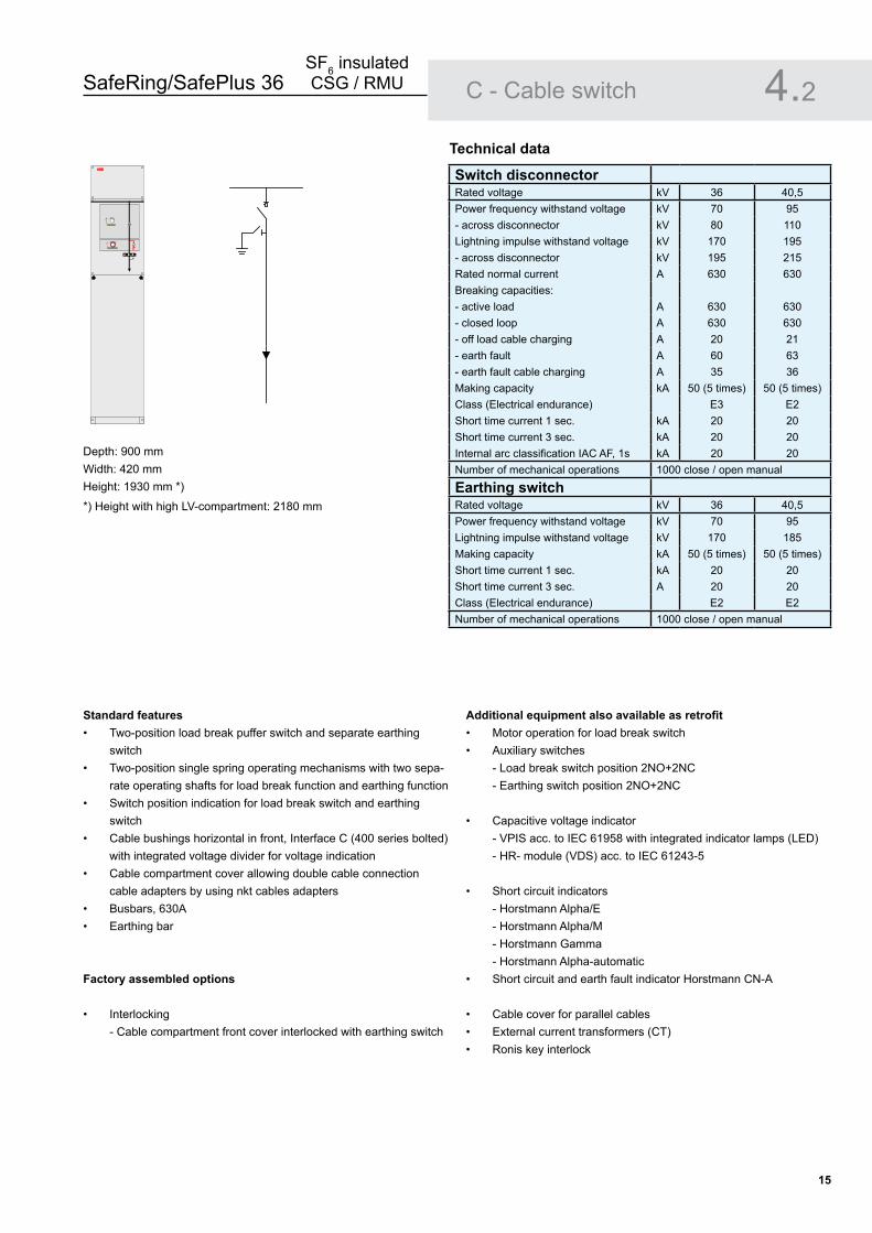
Depth: 900 mmWidth: 420 mmHeight: 1930 mm *)
Standard featuresTwo-position load break puffer switch and separate earthing switchTwo-position single spring operating mechanisms with two sepa-rate operating shafts for load break function and earthing functionSwitch position indication for load break switch and earthing switchCable bushings horizontal in front, Interface C (400 series bolted) with integrated voltage divider for voltage indicationCable compartment cover allowing double cable connection cable adapters by using nkt cables adapters Busbars, 630AEarthing bar
Factory assembled options
Interlocking - Cable compartment front cover interlocked with earthing switch
•
•
•
•
•
••
•
Additional equipment also available as retrofitMotor operation for load break switch Auxiliary switches
- Load break switch position 2NO+2NC - Earthing switch position 2NO+2NC
Capacitive voltage indicator - VPIS acc. to IEC 61958 with integrated indicator lamps (LED) - HR- module (VDS) acc. to IEC 61243-5
Short circuit indicators - Horstmann Alpha/E - Horstmann Alpha/M - Horstmann Gamma - Horstmann Alpha-automatic
Short circuit and earth fault indicator Horstmann CN-A
Cable cover for parallel cablesExternal current transformers (CT) Ronis key interlock
••
•
•
•
•••
Switch disconnectorRated voltage kV 36 40,5Power frequency withstand voltage kV 70 95- across disconnector kV 80 110Lightning impulse withstand voltage kV 170 195- across disconnector kV 195 215Rated normal current A 630 630Breaking capacities:- active load A 630 630- closed loop A 630 630- off load cable charging A 20 21- earth fault A 60 63- earth fault cable charging A 35 36Making capacity kA 50 (5 times) 50 (5 times)Class (Electrical endurance) E3 E2Short time current 1 sec. kA 20 20Short time current 3 sec. kA 20 20Internal arc classification IAC AF, 1s kA 20 20Number of mechanical operations 1000 close / open manual
Earthing switchRated voltage kV 36 40,5Power frequency withstand voltage kV 70 95Lightning impulse withstand voltage kV 170 185Making capacity kA 50 (5 times) 50 (5 times)Short time current 1 sec. kA 20 20Short time current 3 sec. A 20 20Class (Electrical endurance) E2 E2Number of mechanical operations 1000 close / open manual
Technical data
C - Cable switch 4.2
*) Height with high LV-compartment: 2180 mm
ABB

SafeRing/SafePlus 36SF6 insulated CSG / RMU
16
Standard featuresFuse/transformer rating: 36 kV, max 63 A fuse-linksTwo-position load break switch with separate uptsream earthing switch mechanically linked with downstream earthing switch Switch position indication for switch-fuse-disconnector and earthing switches Double spring mechanism for switch-fuse-disconnector with two separate operating shafts for loadbreak function and earthing functionFuse canisters for DIN type fuse-links. Only accessible when earthing switch is closedFuse tripping arrangementOptical fuse trip indicationCable bushings horizontal in front, Interface C (400 series bolted) with integrated voltage divider for voltage indicationCable compartment allowing double cable connection Main busbars, 630 AEarthing bar
••
•
•
•
•••
•••
Depth: 900 mmWidth: 420 mmHeight: 1930 mm *)
Factory assembled optionsInterlocking
- Cable compartment front cover interlocked with earthing switch
Additional equipment also available as retrofitMotor operation for switch-fuse-disconnectorTrip coil openTrip coil open and close
Auxiliary switches : - Switch-fuse-disconnector position 2NO+2NC - Earthing switch position 2NO+2NC - Fuse blown 1 NO
Capacitive voltage indicator - VPIS acc. to IEC 61958 with integrated indicator lamps (LED) - HR- module (VDS) acc. to IEC 61243-5
Ronis key interlock on earthing switch
•
•••
•
•
•
Switch-fuse disconnectorRated voltage kV 36 40,5Power frequency withstand voltage kV 70 95- across disconnector kV 80 110Lightning impulse withstand voltage kV 170 195- across disconnector kV 195 215Rated normal current A 200 1) 200 1)
Breaking capacities:- active load A 200 200- closed loop A 200 200- off load cable charging A 20 21- earth fault A 60 63- earth fault cable charging A 35 36- transfer current A 840 750Making capacity kA see 2) see 2)
Internal arc classification IAC AFL, 1s kA 20 20Number of mechanical operations 1000 close / open manual
Upstream earthing switchRated voltage kV 36 40,5Power frequency withstand voltage kV 70 95Lightning impulse withstand voltage kV 170 185Making capacity kA 50 50Class (Electrical endurance) E2 E2Short time current 1 sec. kA 20 20Number of mechanical operations 1000 close / open manual
Downstream earthing switchRated voltage kV 36 40,5Power frequency withstand voltage kV 70 95Lightning impulse withstand voltage kV 170 185Making capacity kA 2,5(5 times) 2,5(5 times)Class (Electrical endurance) kA E2 E2Short time current 1 sec. kA 1 1Number of mechanical operations 1000 close / open manual
F - Switch-fuse disconnector4.3
*) Height with high LV-compartment: 2180 mm
1) Depending on the current rting of the fuse-link2) Limited by high voltage fuse-links
ABB

SafeRing/SafePlus 36SF6 insulated CSG / RMU
1�
Standard features630A vacuum circuit-breakerTwo-position mechanism with auto-reclosing duty for vacuum circuit breakerTwo-position operating mechanisms for the downstream disconnector and earthing switchInterlocking between vacuum circuit-breaker and disconnectorSwitch position indication for vacuum circuit-breaker, disconnector and earthing switchSelf powered electronic protection relay ABB type REJ603 with ring core CTs on cablesTrip coil (for relay tripping)Cable bushings horizontal in front, Interface C (400 series bolted) with integrated voltage divider for voltage indicationCable compartment cover allowing double cable connectionMain busbar, 630AEarthing barIntegrated LV-compartment without hinged doorCounter
Factory assembled optionsCable bushings Interface B (400 series plug-in)Bushings for connection of external busbars or cable on side of the unit
- Interface 2 (inner cone) - Interface B (400 series plug-in) - Interface C (400 series bolted)
Interlocking - cable compartment front cover interlocked with earthing switch
Signal (1NO) from internal pressure indicator wired to terminals (only one for each SF6 tank)
••
•
••
•
••
•••••
••
•
•
Additional equipment also available as retrofitMotor operation for vacuum circuit-breakerIntegrated LV-compartment with hinged doorHigh LV-compartment with hinged doorShort circuit indicatorAuxiliary switches
- vacuum circuit-breaker position 2NO+2NC - disconnector position 2NO+2NC - earthing switch position 2NO+2NC - vacuum circuit-breaker tripped signal 1NO
Capacitive voltage indicating systems - HR-module (Voltage Detecting System, VDS, acc. to IEC 61243-5) - VPIS (Voltage Presence Indicating System, acc. to IEC 61958) with integrated indicator lamps
Indicator lamp for HR-module, 1-phase VIM-1Indicator lamp for HR-module, 3-phase VIM-3Trip coil openTrip coil open and closeUndervoltage release (optional electronic time delay device)Cable compartment cover
- with extra depth (surge arrestor) - arc proof (if existing modules have interlocked covers)
cable support bars, non-magneticRonis key interlock on disconnector/earthing switch
Relays with auxiliary voltageREF 610 (integrated LV-compartment with hinged door)REF 615 (integrated LV-compartment with hinged door)REF 541 (high LV-compartment with hinged door)REF 542+ (high LV-compartment with hinged door)
•••••
•
••••••
••
Depth: 900 mmWidth: 420 mmHeight: 1930 mm *)
*) Height with high LV-compartment: 2180 mm
Vacuum circuit-breakerRated voltage kV 36 40,5Power frequency withstand voltage kV 70 95Lightning impulse withstand voltage kV 170 195Rated normal current A 630 630Breaking capacities:- short-circuit breaking current (Class E1, S1) kA 20 20- D.C. component % 41 <20- cable charging breaking current (Class C1) A 50 50Making capacity kA 50 50 Short time current 1 sec. 1) kA 16 16Short time current 3 sec. kA 20 20Internal arc classification IAC AFL, 1s kA 20 20Rated operating sequence O - 0,3s - CO - 15s - CONumber of mechanical operations 2000 (class M1)
Downstream disconnector and earthing switchRated voltage kV 36 40,5Power frequency withstand voltage kV 70 95- across disconnector kV 80 110Lightning impulse withstand voltage kV 170 185- across disconnector kV 195 215Making capacity kA 50 50Class (Electrical endurance) E2 E2Short time current 1 sec. kA 20 20Internal arc classification IAC AFL, 1s kA 20 20Number of mechanical operations 1000 close / open manual
V - Vacuum circuit-breaker 4.4
1) Maximum rating for bushings Interface B (400 series plug-in)
ABB
��� REJ 603
SafeRing/SafePlus 36SF6 insulated CSG / RMU
1�
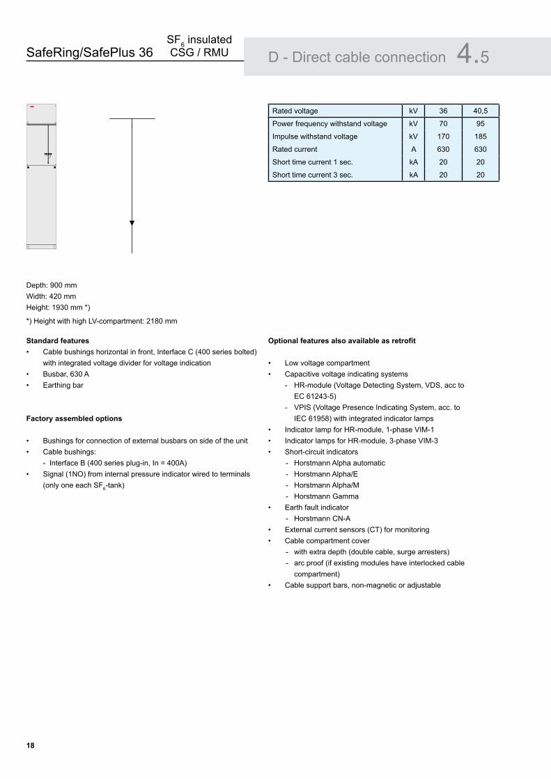
Depth: 900 mmWidth: 420 mmHeight: 1930 mm *)
*) Height with high LV-compartment: 2180 mm
Standard featuresCable bushings horizontal in front, Interface C (400 series bolted) with integrated voltage divider for voltage indicationBusbar, 630 AEarthing bar
Factory assembled options
Bushings for connection of external busbars on side of the unitCable bushings:
- Interface B (400 series plug-in, In = 400A)Signal (1NO) from internal pressure indicator wired to terminals (only one each SF6-tank)
•
••
••
•
Optional features also available as retrofit
Low voltage compartmentCapacitive voltage indicating systems
- HR-module (Voltage Detecting System, VDS, acc to EC 61243-5) - VPIS (Voltage Presence Indicating System, acc. to IEC 61958) with integrated indicator lamps
Indicator lamp for HR-module, 1-phase VIM-1Indicator lamps for HR-module, 3-phase VIM-3Short-circuit indicators
- Horstmann Alpha automatic - Horstmann Alpha/E - Horstmann Alpha/M - Horstmann Gamma
Earth fault indicator - Horstmann CN-A
External current sensors (CT) for monitoringCable compartment cover
- with extra depth (double cable, surge arresters) - arc proof (if existing modules have interlocked cable compartment)
Cable support bars, non-magnetic or adjustable
••
•••
•
••
•
Rated voltage kV 36 40,5
Power frequency withstand voltage kV 70 95
Impulse withstand voltage kV 170 185
Rated current A 630 630
Short time current 1 sec. kA 20 20
Short time current 3 sec. kA 20 20
D - Direct cable connection 4.5ABB

SafeRing/SafePlus 36SF6 insulated CSG / RMU
1�
Depth: 900 mmWidth: 420 mmHeight: 1930 mm *)
*) Height with high LV-compartment: 2180 mm
Standard featuresEarthing switchTwo-position single spring mechanismSwitch position indicationCable bushings horizontal in front, Interface C (400 series bolted) with integrated voltage divider for voltage indicationBusbar, 630 AEarthing bar
Factory assembled options
Bushings for connection of external busbars on side of the unitCable bushings:
- Interface B (400 series plug-in, In = 400A)Interlocking
- Cable compartment front cover interlocked with earthing switch
Signal (1NO) from internal pressure indicator wired to terminals (only one each SF6-tank)
••••
••
••
•
•
Optional features also available as retrofit
Low voltage compartmentCapacitive voltage indicating systems
- HR-module (Voltage Detecting System, VDS, acc to IEC 61243-5) - VPIS (Voltage Presence Indicating System, acc. to IEC 61958) with integrated indicator lamps
Indicator lamp for HR-module, 1-phase VIM-1Indicator lamps for HR-module, 3-phase VIM-3Short-circuit indicators
- Horstmann Alpha automatic - Horstmann Alpha/E - Horstmann Alpha/M - Horstmann Gamma
Earth fault indicator - Horstmann CN-A
External current sensors (CT) for monitoringCable compartment cover
- with extra depth (double cable, surge arresters) - arc proof (if existing modules have interlocked cable compartment)
Cable support bars, non-magnetic or adjustableAuxiliary switches
- Earthing switch position 2NO+2NC
••
•••
•
••
••
Rated voltage kV 36 40,5
Power frequency withstand voltage kV 70 95
Impulse withstand voltage kV 170 185
Rated current A 630 630
Making capacity kA 50 50
Short time current 1 sec. kA 20 20
Short time current 3 sec. kA 20 20
Number of mechanical operations 1000 close / open manual
De - Direct cable connection with earthing switch 4.6
ABB

SafeRing/SafePlus 36SF6 insulated CSG / RMU
�0
The M-module is a factory assembled type tested air insulated metering cubicle with conventional CTs and VTs. The M-module is designed for CTs and VTs with dimensions according to DIN 42600 Narrow type and for installation of transformers locally.
The M-module is manufactured and tested according to IEC 62271-200. It is available in 4 versions:
Bottom cable in/outLeft side connection to SafePlus modules, bottom cable in Right side connection to SafePlus modules, bottom cable inLeft and right side connection to SafePlus modules
Standard features
3 pcs DIN 42600 Narrow type current transformers with ribs3 pcs DIN Narrow type single pole voltage transformersPadlock interlocking to prevent access to live partsMV cable connection to SafePlus cubicle using Elastimold, 3M, Pirelli, Raychem, Kabeldon, etc. connectorsMV cable connection inside M-module by conventional cable lugs
Voltage transformers
Single pole insulated with measuring and earth fault windingsPrimary voltage and frequency (50 or 60 Hz) has to be specifiedSecondary windings -- / 110:V3 / 110:3 V or -- / 100:V3 / 100:3 V has to be specifiedNote: VTs can also be delivered without open Delta Earth fault windingsBurden / class has to be specified
••••
••••••
•••••••
Depth: 1100 mmWidth: 880 mmHeight: 1930 mm *)
*) Height with high LV-compartment: 2180 mm
Current transformers
Single-core or double-core designSecondary side reconnectable possiblePrimary current max 600 Amp, has to be specifiedSecondary current 5 Amp or 1 Amp has to be specified
Low voltage compartment
Terminals for voltage transformers secondary connection.3-pole MCB for measuring voltage.1-pole MCB for earth fault voltage. Damping resistor for voltage transformers open delta earth fault windings, to avoid ferro resonance.Separating terminals for current transformers secondary wind-ingsSpace for electronic kWh-meter
Optional features
Voltmeter with selector switch, 6 positions +0.A-meter with selector switch, 3 positions +0.
••••
••••••
•
••
Rated voltage kV 36 40,5
Power frequency withstand voltage kV 70 95
Impulse withstand voltage kV 170 185
Rated current A 630 630
Short time current 1 sec. kA 20 20
M - Metering module 4.7
ABB
3
V
A
3

SafeRing/SafePlus 36SF6 insulated CSG / RMU
�1
1. Low voltage compartment2. Manometer 3. Nameplate 4. Short circuit indicator 5. Capacitive voltage indication 6. Load break switch position 7. Earthing switch position 8. Push buttons close/open operation 9. Charged spring indicator 10. Fuse blown indicator 11. Cable compartment cover standard C-module 12. Cable compartment cover standard F-module 13. Side cover (option) 14. Lifting lug15. Protection relay16. Position indicator vacuum circuit-breaker17. Operating mrcanism for vacuum circuit-breaker18. Counter
Covers
Upper and lower front covers are manufactured of 2 millimeter Alu-zinc and covered with a polycarbonate foil. These foils contain the mimic diagram of the main circuit with the position indicators for the switching devices. Background colour for these foils is grey RAL 7035, which makes the black single line diagram to stand out for easy optical reading of posi-tion indicators. Both the upper and lower front covers are removable.
Low voltage compartments are available in three different versions; integrated without hinged door, integrated with hinged door and high with hinged door. For the high version, total height of panel will be 2180 mm. There are three different cable compartment covers; standard, arc proof and one with extra depth for parallel cables. All cable compartment covers are removable. Each module has a separate cable compartment which is divided from the others by means of partition walls.
A vertical partition wall is fitted to divide the cable compartment(s) from the rear side of the switchgear / ring main unit. In case of an internal arc fault, followed by an opening of the pressure relief in the bottom of the tank, this partition wall will prevent the hot gases blowing out from the pressure relief to enter the cable compartments. The optional side covers are made of 1,5 millimeter hot rolled steel and powder painted in colour RAL 7035.
Outer assembly 5.16 714
2
3
10
11
12
134
ABB
1
5
8
9
ABB
��� REJ 603
1
5
8
9
15
1617
18

SafeRing/SafePlus 36SF6 insulated CSG / RMU
��
The cable switch (C-Module) is a two positioning switch-disconnector using SF6 gas as an arc quenching medium with a separate earthing switch.
The switch positions are close and open. In the open position the switch satisfies the disconnector requirements.
Cable-switch module 5.2
SafeRing/SafePlus 36SF6 insulated CSG / RMU
��
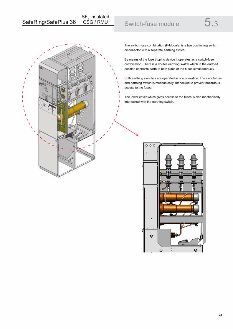
The switch-fuse combination (F-Module) is a two positioning switch diconnector with a separate earthing switch.
By means of the fuse tripping device it operates as a switch-fuse combination. There is a double earthing switch which in the earthed position connects earth to both sides of the fuses simultaneously.
Both earthing switches are operated in one operation. The switch-fuse and earthing switch is mechanically interlocked to prevent hazardous access to the fuses.
The lower cover which gives access to the fuses is also mechanically interlocked with the earthing switch.
Switch-fuse module 5.3
SafeRing/SafePlus 36SF6 insulated CSG / RMU
��
Vacuum circuit-breaker module 5.4
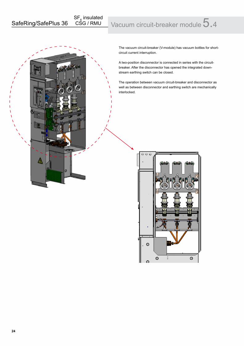
The vacuum circuit-breaker (V-module) has vacuum bottles for short-circuit current interruption.
A two-position disconnector is connected in series with the circuit-breaker. After the disconnector has opened the integrated down-stream earthing switch can be closed.
The operation between vacuum circuit-breaker and disconnector as well as between disconnector and earthing switch are mechanically interlocked.

SafeRing/SafePlus 36SF6 insulated CSG / RMU
��
The connection of the HV-cable is made by cable bushings. The bushings are made of cast resin with moulded in conductors. In addition, a screen is moulded in to control the electrical field and is also used as the main capacitor supplying the voltage indicators.
ABB has produced bushings for SF6 switchgears since 1985 with high performance and quality. A very large number has been installed worldwide in distribution networks, power stations and industrial complexes.
Used together with fully screened connectors it is an ideal solution for areas with humidity or condensation problems.The bushings are designed according to EN 50180 / EN 50181.
Two different cable bushings are available:400 series (Interface C) with M16 bolted contact (In = 630A)400 serie (Interface B) with plug-in contact (In = 400A)
For more details, please see chapter 6.7.
••
Cable bushings 5.5
400 series bushing (Interface C) with terminal for capacitive voltage indication
Inner cone (Interface 2) bushing for connection of external busbars (or cable) on the side of the unit

SafeRing/SafePlus 36SF6 insulated CSG / RMU
�6
SafeRing/SafePlus 36 are switchgear types using SF6 gas (Sulfur hexafluoride) as insulation and quenching medium. The SF6 is contained in a welded stainless steel enclosure.
The pressure system is defined as a sealed for life system with an operating life time better than 30 years. The leakage rate is less than 0,1% per year.
In order to guarantee a reliable and tight welding, all welding is carried out by computer controlled robots.Electrical and mechanical bushings are clamped to the enclosure and sealed by high quality O-rings.
The mechanical bushings have in addition a rotating shaft which connect the shaft of the switch to the corresponding shaft of the mechanism.The rotating shaft is sealed by a double set of gas seals.
All SF6 enclosures have to pass the leakage test with Helium, before being gas filled with SF6.Due to the characteristics of Helium, this test will detect any leakage. Leakage test and gas filling are made inside a vacuum chamber.
The SF6 enclosure has a degree of protection of IP67. This means the SF6 enclosure can be immersed into water and still maintain all functions in a satisfactory way.
Completely sealed enclosure 5.6
Robot welding
Vacuum chamber for leakage test and SF6 gas filling
Inside CCF switchgear
SafeRing/SafePlus 36SF6 insulated CSG / RMU
��
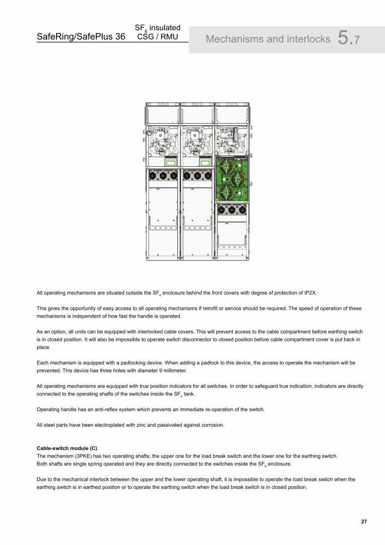
All operating mechanisms are situated outside the SF6 enclosure behind the front covers with degree of protection of IP2X.
This gives the opportunity of easy access to all operating mechanisms if retrofit or service should be required. The speed of operation of these mechanisms is independent of how fast the handle is operated.
As an option, all units can be equipped with interlocked cable covers. This will prevent access to the cable compartment before earthing switch is in closed position. It will also be impossible to operate switch disconnector to closed position before cable compartment cover is put back in place.
Each mechanism is equipped with a padlocking device. When adding a padlock to this device, the access to operate the mechanism will be prevented. This device has three holes with diameter 9 millimeter.
All operating mechanisms are equipped with true position indicators for all switches. In order to safeguard true indication, indicators are directly connected to the operating shafts of the switches inside the SF6 tank.
Operating handle has an anti-reflex system which prevents an immediate re-operation of the switch.
All steel parts have been electroplated with zinc and passivated against corrosion.
Cable-switch module (C)The mechanism (3PKE) has two operating shafts; the upper one for the load break switch and the lower one for the earthing switch.Both shafts are single spring operated and they are directly connected to the switches inside the SF6 enclosure.
Due to the mechanical interlock between the upper and the lower operating shaft, it is impossible to operate the load break switch when the earthing switch is in earthed position or to operate the earthing switch when the load break switch is in closed position.
Mechanisms and interlocks 5.7
SafeRing/SafePlus 36SF6 insulated CSG / RMU
��
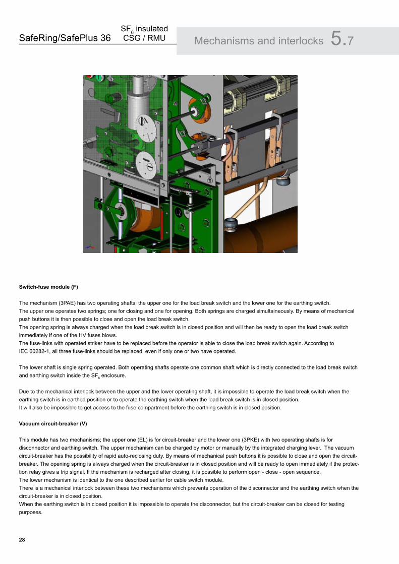
Switch-fuse module (F)
The mechanism (3PAE) has two operating shafts; the upper one for the load break switch and the lower one for the earthing switch. The upper one operates two springs; one for closing and one for opening. Both springs are charged simultaineously. By means of mechanical push buttons it is then possible to close and open the load break switch. The opening spring is always charged when the load break switch is in closed position and will then be ready to open the load break switch immediately if one of the HV fuses blows. The fuse-links with operated striker have to be replaced before the operator is able to close the load break switch again. According to IEC 60282-1, all three fuse-links should be replaced, even if only one or two have operated.
The lower shaft is single spring operated. Both operating shafts operate one common shaft which is directly connected to the load break switch and earthing switch inside the SF6 enclosure.
Due to the mechanical interlock between the upper and the lower operating shaft, it is impossible to operate the load break switch when the earthing switch is in earthed position or to operate the earthing switch when the load break switch is in closed position. It will also be impossible to get access to the fuse compartment before the earthing switch is in closed position.
Vacuum circuit-breaker (V)
This module has two mechanisms; the upper one (EL) is for circuit-breaker and the lower one (3PKE) with two operating shafts is for disconnector and earthing switch. The upper mechanism can be charged by motor or manually by the integrated charging lever. The vacuum circuit-breaker has the possibility of rapid auto-reclosing duty. By means of mechanical push buttons it is possible to close and open the circuit-breaker. The opening spring is always charged when the circuit-breaker is in closed position and will be ready to open immediately if the protec-tion relay gives a trip signal. If the mechanism is recharged after closing, it is possible to perform open - close - open sequence.The lower mechanism is identical to the one described earlier for cable switch module.There is a mechanical interlock between these two mechanisms which prevents operation of the disconnector and the earthing switch when the circuit-breaker is in closed position.When the earthing switch is in closed position it is impossible to operate the disconnector, but the circuit-breaker can be closed for testing purposes.
Mechanisms and interlocks 5.7
SafeRing/SafePlus 36SF6 insulated CSG / RMU
��
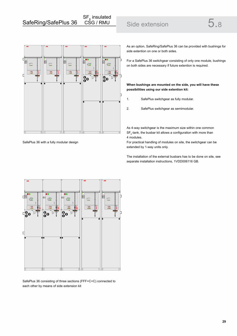
As an option, SafeRing/SafePlus 36 can be provided with bushings for side extention on one or both sides.
For a SafePlus 36 switchgear consisting of only one module, bushings on both sides are necessary if future extention is required.
When bushings are mounted on the side, you will have these possibilities using our side extention kit:
1. SafePlus switchgear as fully modular.
2. SafePlus switchgear as semimodular.
As 4-way switchgear is the maximum size within one common SF6-tank, the busbar kit allows a configuration with more than 4 modules. For practical handling of modules on site, the switchgear can be extended by 1-way units only. The installation of the external busbars has to be done on site, see separate installation instructions, 1VDD006116 GB.
Side extension 5.8
SafePlus 36 with a fully modular design
SafePlus 36 consisting of three sections (FFF+C+C) connected to each other by means of side extension kit
ABB ABB ABB ABB ABB
ABBABB ABB

SafeRing/SafePlus 36SF6 insulated CSG / RMU
�0
Side extension 5.8
The connection between two units by means of side extension has to be done at site, see separate installation instruction
SafeRing/SafePlus 36SF6 insulated CSG / RMU
�1
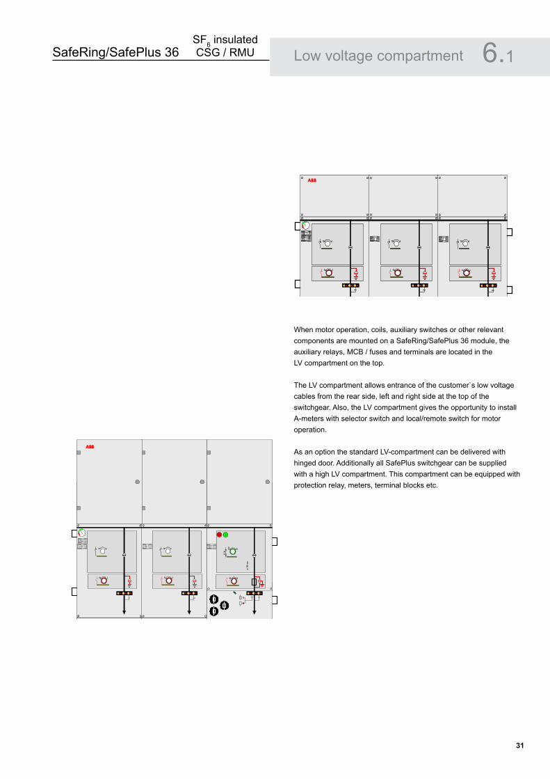
When motor operation, coils, auxiliary switches or other relevant components are mounted on a SafeRing/SafePlus 36 module, the auxiliary relays, MCB / fuses and terminals are located in the LV compartment on the top.
The LV compartment allows entrance of the customer`s low voltage cables from the rear side, left and right side at the top of the switchgear. Also, the LV compartment gives the opportunity to install A-meters with selector switch and local/remote switch for motor operation.
As an option the standard LV-compartment can be delivered with hinged door. Additionally all SafePlus switchgear can be supplied with a high LV compartment. This compartment can be equipped with protection relay, meters, terminal blocks etc.
Low voltage compartment 6.1
ABB
ABB
ABB
SafeRing/SafePlus 36SF6 insulated CSG / RMU
��
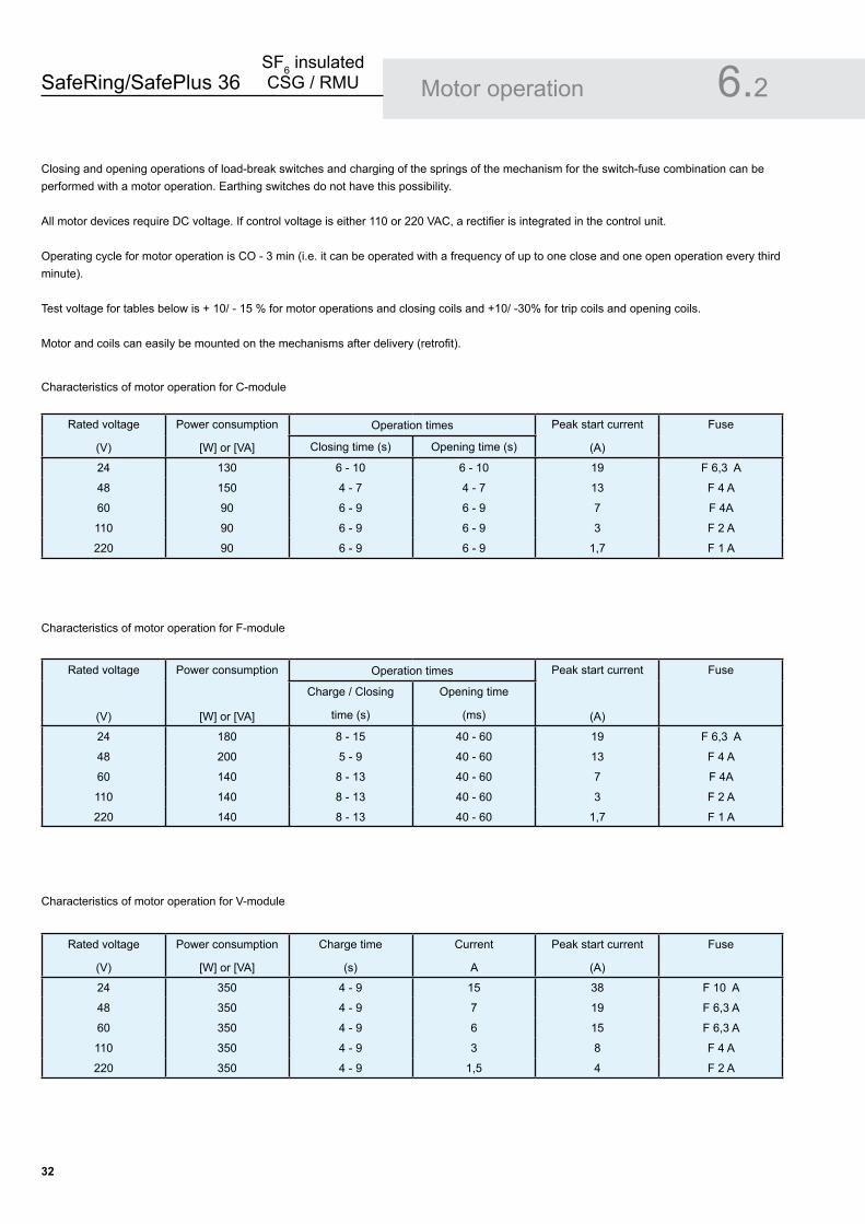
Closing and opening operations of load-break switches and charging of the springs of the mechanism for the switch-fuse combination can be performed with a motor operation. Earthing switches do not have this possibility.
All motor devices require DC voltage. If control voltage is either 110 or 220 VAC, a rectifier is integrated in the control unit.
Operating cycle for motor operation is CO - 3 min (i.e. it can be operated with a frequency of up to one close and one open operation every third minute).
Test voltage for tables below is + 10/ - 15 % for motor operations and closing coils and +10/ -30% for trip coils and opening coils.
Motor and coils can easily be mounted on the mechanisms after delivery (retrofit).
Motor operation
Rated voltage
(V)
Power consumption
[W] or [VA]
Operation times Peak start current
(A)
Fuse
Closing time (s) Opening time (s)
24 130 6 - 10 6 - 10 19 F 6,3 A
48 150 4 - 7 4 - 7 13 F 4 A
60 90 6 - 9 6 - 9 7 F 4A
110 90 6 - 9 6 - 9 3 F 2 A
220 90 6 - 9 6 - 9 1,7 F 1 A
Rated voltage
(V)
Power consumption
[W] or [VA]
Operation times Peak start current
(A)
Fuse
Charge / Closing
time (s)
Opening time
(ms)
24 180 8 - 15 40 - 60 19 F 6,3 A
48 200 5 - 9 40 - 60 13 F 4 A
60 140 8 - 13 40 - 60 7 F 4A
110 140 8 - 13 40 - 60 3 F 2 A
220 140 8 - 13 40 - 60 1,7 F 1 A
Characteristics of motor operation for C-module
Characteristics of motor operation for F-module
Rated voltage
(V)
Power consumption
[W] or [VA]
Charge time
(s)
Current
A
Peak start current
(A)
Fuse
24 350 4 - 9 15 38 F 10 A
48 350 4 - 9 7 19 F 6,3 A
60 350 4 - 9 6 15 F 6,3 A
110 350 4 - 9 3 8 F 4 A
220 350 4 - 9 1,5 4 F 2 A
Characteristics of motor operation for V-module
6.2
SafeRing/SafePlus 36SF6 insulated CSG / RMU
��
Rated voltage
(V)
Power consumption
[W] or [VA]
Operation times Current
(A)
Fuse
Closing time (ms) Opening time (ms)
24 V DC 170 40 - 60 40 - 60 7 F 6,3 A
48 V DC 200 40 - 60 40 - 60 4 F 4 A
60 V DC 200 40 - 60 40 - 60 3 F 4A
110 V DC 200 40 - 60 40 - 60 2 F 2 A
220 V DC 200 40 - 60 40 - 60 1 F 1 A
110 V AC 200 40 - 60 40 - 60 2 F 2 A
220 V AC 200 40 - 60 40 - 60 1 F 1 A
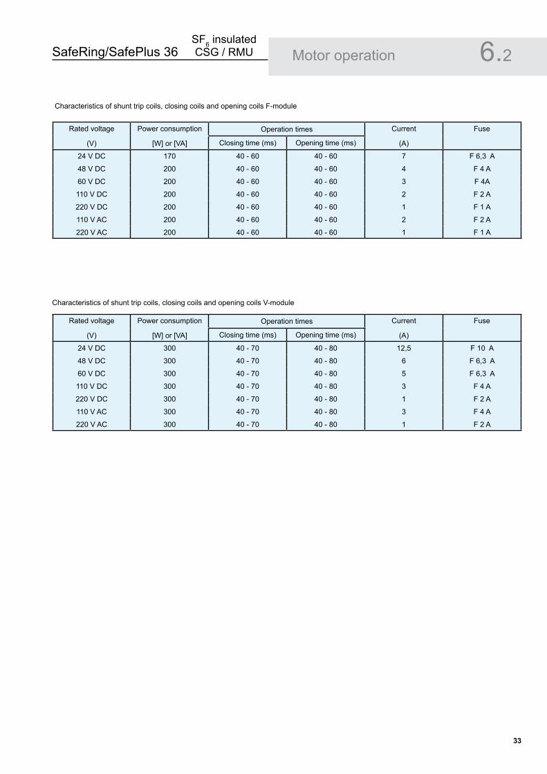
Characteristics of shunt trip coils, closing coils and opening coils V-module
Motor operation 6.2
Characteristics of shunt trip coils, closing coils and opening coils F-module
Rated voltage
(V)
Power consumption
[W] or [VA]
Operation times Current
(A)
Fuse
Closing time (ms) Opening time (ms)
24 V DC 300 40 - 70 40 - 80 12,5 F 10 A
48 V DC 300 40 - 70 40 - 80 6 F 6,3 A
60 V DC 300 40 - 70 40 - 80 5 F 6,3 A
110 V DC 300 40 - 70 40 - 80 3 F 4 A
220 V DC 300 40 - 70 40 - 80 1 F 2 A
110 V AC 300 40 - 70 40 - 80 3 F 4 A
220 V AC 300 40 - 70 40 - 80 1 F 2 A
SafeRing/SafePlus 36SF6 insulated CSG / RMU
��
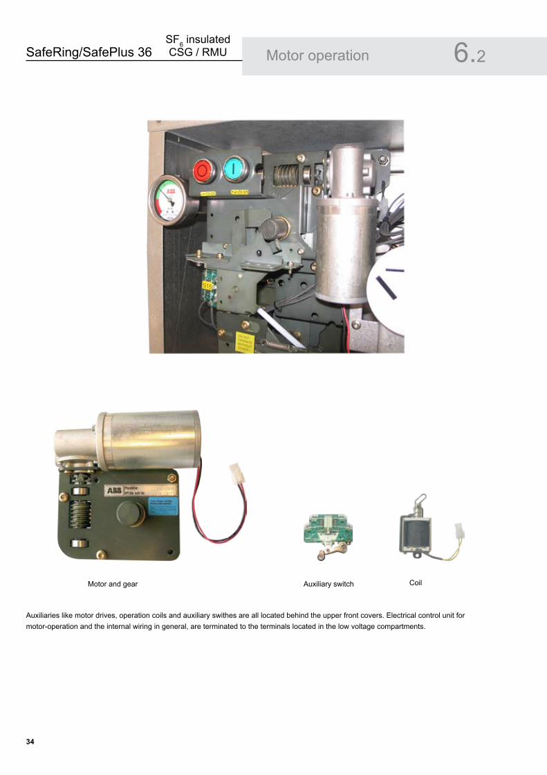
Auxiliaries like motor drives, operation coils and auxiliary swithes are all located behind the upper front covers. Electrical control unit for motor-operation and the internal wiring in general, are terminated to the terminals located in the low voltage compartments.
Motor operation 6.2
Auxiliary switchMotor and gear Coil

SafeRing/SafePlus 36SF6 insulated CSG / RMU
��
SafeRing/SafePlus 36 offer a choice between switch-fuse combination or circuit-breaker in combination with relay for transformer protection.
The switch-fuse combination offers optimal protection against short-circuit currents, while the circuit-breaker with relay offers better protection against low over-currents. Circuit-breaker with relay is always recommended for higher rated transformers.
SafeRing and SafePlus V-module are delivered with 630A rating.Both for SafeRing and SafePlus the relay is self powered utilizing the energy from the CT’s under a fault situation, for energizing the trip coil.
The self powered relay can also be used for cable protection and more details on the different relays can be found in chapter 6.6.
Transformer protection with self powered relay:ABB relay type REJ 603
Important features V-module:Relay behind cover. No need for additional low voltage box for the self powered relays used for transformer protection
Typical for vacuum circuit-breaker protection:Good protection against short-circuitsVery good for protection of over-currentsSmall fault currents are detected in an early stage
•
•
•••
SafeRing/SafePlus �6 - Fuse-link selection
By selection of fuse-links for the protection of a transformer, it is important that requirements in IEC 62271-105 and in IEC 60787 are fulfilled. In particular Annex A in IEC 62271-105 gives a good example of the coordination of fuses, switch and transformer.
Correct selection of fuse-links for the protection of the transformer will give:
Optimal protection of the transformer.No damage on the fuse-link’s fuse-elements due to the magnetizing inrush current of the transformer.No overheating of the fuse-links, the switch-fuse combination or the switchgear due to the full load current or the permissible periodic overload current of the transformerA transfer current of the combination which is as low as possible, and less that the rated transfer current of the switch-fuse combination.A situation where the fuse-links alone will deal with the condition of a short-circuit on the transformer secondary terminals.Fuse-links that discriminates with the low-voltage fuse-links in the event of phase-to-phase faults occurring downstream the low-voltage fuse-links.
By carefully checking that these rules are followed, fuse-links from any manufacturer can be used in combination with SafeRing/ SafePlus 36 as long as the fuse-links are in accordance with the requirements described in chapter 6.5.2.
••
•
•
•
•
Transformer protection 6.3
ABB

SafeRing/SafePlus 36SF6 insulated CSG / RMU
�6
FUSE SELECTION TABLES - CEF
SafeRing 36SafePlus 36F-panel100% load
Rated voltage: 36 kVOperating voltage: 30 kVItransfer at 36 kV: 840 ATo: 40 ms
Transformer rating (kVA) uk (%) Transformer rated current (A) ABB Catalogue no. Fuse link rated current (A)
100 4 1,9 1YMB531006M0001 6
125 4 2,4 1YMB531006M0002 10
160 4 3,1 1YMB531006M0002 10
200 4 3,8 1YMB531006M0003 16
250 4 4,8 1YMB531006M0003 16
315 4 6,1 1YMB531006M0003 16
400 4 7,7 1YMB531006M0003 16
500 4 9,6 1YMB531006M0004 25
630 4 12,1 1YMB531006M0004 25
800 5 15,4 1YMB531006M0004 25
1000 6 19,2 1YMB531006M0005 40
1250 6 24,1 1YMB531006M0005 40
- The table is based on using ABB CEF hihg-voltage current-limiting back-up fuse-links- Normal operating conditions with no overload of transformer- Ambient air temperature -25oC to +40oC
SafeRing 36SafePlus 36F-panel120% load
Rated voltage: 36 kVOperating voltage: 30 kVItransfer at 36 kV: 840 ATo: 40 ms
Transformer rating (kVA) uk (%) Transformer rated current (A) ABB Catalogue no. Fuse link rated current (A)
100 4 1,9 1YMB531006M0001 6
125 4 2,4 1YMB531006M0002 10
160 4 3,1 1YMB531006M0002 10
200 4 3,8 1YMB531006M0003 16
250 4 4,8 1YMB531006M0003 16
315 4 6,1 1YMB531006M0003 16
400 4 7,7 1YMB531006M0003 16
500 4 9,6 1YMB531006M0004 25
630 4 12,1 1YMB531006M0004 25
800 5 15,4 1YMB531006M0005 40
1000 6 19,2 1YMB531006M0005 40
1250 6 24,1 1YMB531006M0005 40
- The table is based on using ABB CEF hihg-voltage current-limiting back-up fuse-links- Normal operating conditions with 20% overload of transformer- Ambient air temperature -25oC to +40oC
Fuse selection table 6.4
SafeRing/SafePlus 36SF6 insulated CSG / RMU
��
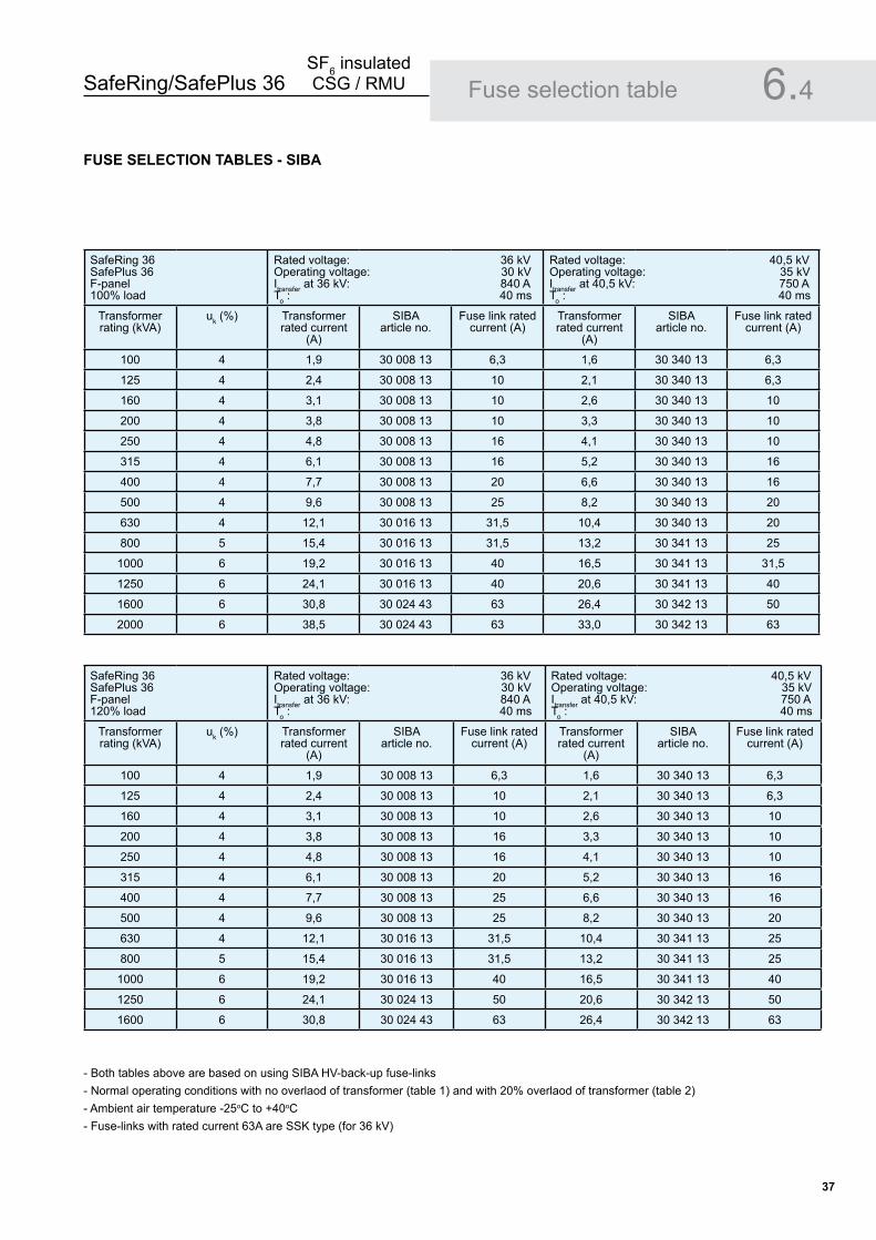
SafeRing 36SafePlus 36F-panel100% load
Rated voltage: 36 kVOperating voltage: 30 kVItransfer at 36 kV: 840 ATo : 40 ms
Rated voltage: 40,5 kVOperating voltage: 35 kVItransfer at 40,5 kV: 750 ATo : 40 ms
Transformer rating (kVA)
uk (%) Transformer rated current
(A)
SIBA article no.
Fuse link rated current (A)
Transformer rated current
(A)
SIBA article no.
Fuse link rated current (A)
100 4 1,9 30 008 13 6,3 1,6 30 340 13 6,3
125 4 2,4 30 008 13 10 2,1 30 340 13 6,3
160 4 3,1 30 008 13 10 2,6 30 340 13 10
200 4 3,8 30 008 13 10 3,3 30 340 13 10
250 4 4,8 30 008 13 16 4,1 30 340 13 10
315 4 6,1 30 008 13 16 5,2 30 340 13 16
400 4 7,7 30 008 13 20 6,6 30 340 13 16
500 4 9,6 30 008 13 25 8,2 30 340 13 20
630 4 12,1 30 016 13 31,5 10,4 30 340 13 20
800 5 15,4 30 016 13 31,5 13,2 30 341 13 25
1000 6 19,2 30 016 13 40 16,5 30 341 13 31,5
1250 6 24,1 30 016 13 40 20,6 30 341 13 40
1600 6 30,8 30 024 43 63 26,4 30 342 13 50
2000 6 38,5 30 024 43 63 33,0 30 342 13 63
FUSE SELECTION TABLES - SIBA
SafeRing 36SafePlus 36F-panel120% load
Rated voltage: 36 kVOperating voltage: 30 kVItransfer at 36 kV: 840 ATo : 40 ms
Rated voltage: 40,5 kVOperating voltage: 35 kVItransfer at 40,5 kV: 750 ATo : 40 ms
Transformer rating (kVA)
uk (%) Transformer rated current
(A)
SIBA article no.
Fuse link rated current (A)
Transformer rated current
(A)
SIBA article no.
Fuse link rated current (A)
100 4 1,9 30 008 13 6,3 1,6 30 340 13 6,3
125 4 2,4 30 008 13 10 2,1 30 340 13 6,3
160 4 3,1 30 008 13 10 2,6 30 340 13 10
200 4 3,8 30 008 13 16 3,3 30 340 13 10
250 4 4,8 30 008 13 16 4,1 30 340 13 10
315 4 6,1 30 008 13 20 5,2 30 340 13 16
400 4 7,7 30 008 13 25 6,6 30 340 13 16
500 4 9,6 30 008 13 25 8,2 30 340 13 20
630 4 12,1 30 016 13 31,5 10,4 30 341 13 25
800 5 15,4 30 016 13 31,5 13,2 30 341 13 25
1000 6 19,2 30 016 13 40 16,5 30 341 13 40
1250 6 24,1 30 024 13 50 20,6 30 342 13 50
1600 6 30,8 30 024 43 63 26,4 30 342 13 63
- Both tables above are based on using SIBA HV-back-up fuse-links- Normal operating conditions with no overlaod of transformer (table 1) and with 20% overlaod of transformer (table 2)- Ambient air temperature -25oC to +40oC- Fuse-links with rated current 63A are SSK type (for 36 kV)
Fuse selection table 6.4
SafeRing/SafePlus 36SF6 insulated CSG / RMU
��
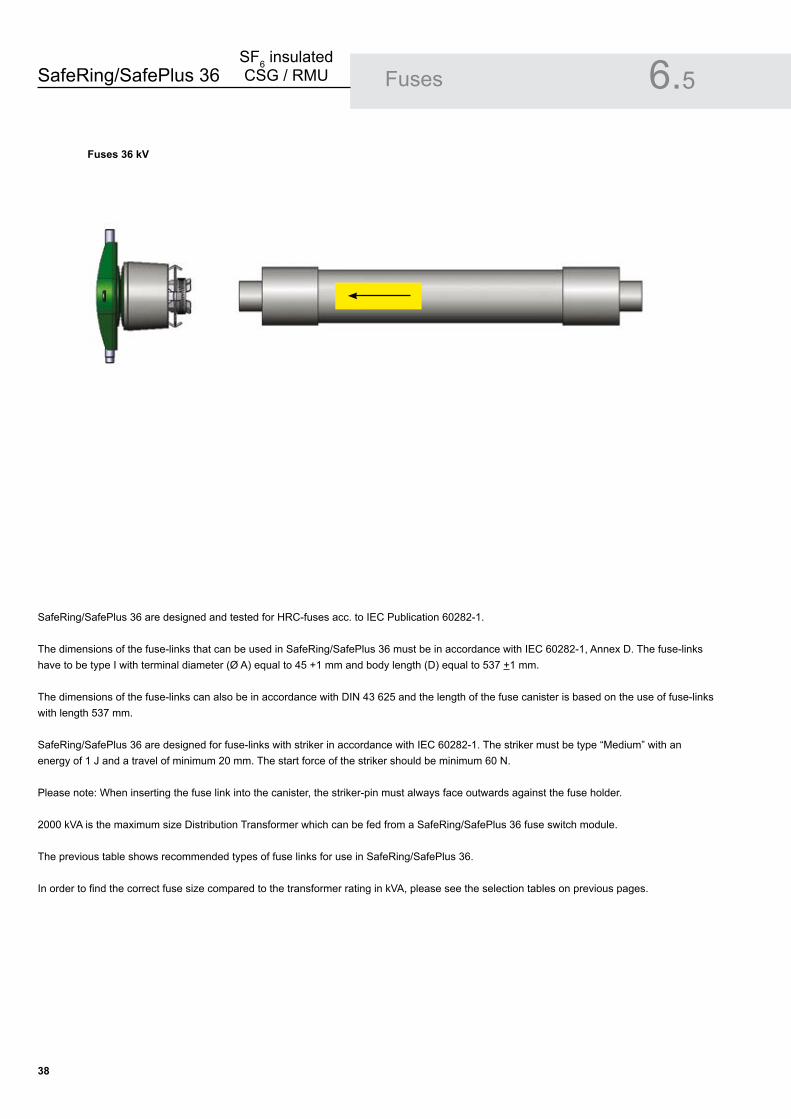
SafeRing/SafePlus 36 are designed and tested for HRC-fuses acc. to IEC Publication 60282-1.
The dimensions of the fuse-links that can be used in SafeRing/SafePlus 36 must be in accordance with IEC 60282-1, Annex D. The fuse-links have to be type I with terminal diameter (Ø A) equal to 45 +1 mm and body length (D) equal to 537 +1 mm.
The dimensions of the fuse-links can also be in accordance with DIN 43 625 and the length of the fuse canister is based on the use of fuse-links with length 537 mm.
SafeRing/SafePlus 36 are designed for fuse-links with striker in accordance with IEC 60282-1. The striker must be type “Medium” with an energy of 1 J and a travel of minimum 20 mm. The start force of the striker should be minimum 60 N.
Please note: When inserting the fuse link into the canister, the striker-pin must always face outwards against the fuse holder.
2000 kVA is the maximum size Distribution Transformer which can be fed from a SafeRing/SafePlus 36 fuse switch module.
The previous table shows recommended types of fuse links for use in SafeRing/SafePlus 36.
In order to find the correct fuse size compared to the transformer rating in kVA, please see the selection tables on previous pages.
Fuses �6 kV
Fuses 6.5
SafeRing/SafePlus 36SF6 insulated CSG / RMU
��
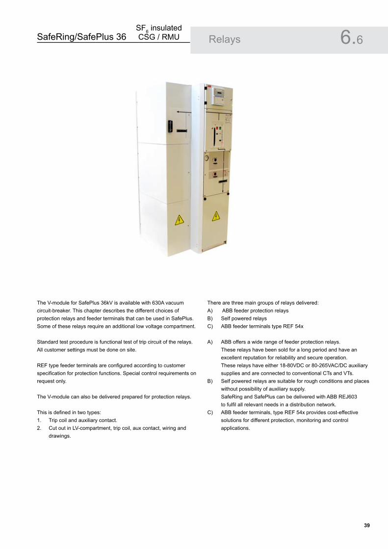
The V-module for SafePlus 36kV is available with 630A vacuum circuit-breaker. This chapter describes the different choices of protection relays and feeder terminals that can be used in SafePlus. Some of these relays require an additional low voltage compartment.
Standard test procedure is functional test of trip circuit of the relays. All customer settings must be done on site.
REF type feeder terminals are configured according to customer specification for protection functions. Special control requirements on request only.
The V-module can also be delivered prepared for protection relays.
This is defined in two types:Trip coil and auxiliary contact.Cut out in LV-compartment, trip coil, aux contact, wiring and drawings.
1.2.
There are three main groups of relays delivered: A) ABB feeder protection relaysB) Self powered relaysC) ABB feeder terminals type REF 54x
A) ABB offers a wide range of feeder protection relays. These relays have been sold for a long period and have an excellent reputation for reliability and secure operation. These relays have either 18-80VDC or 80-265VAC/DC auxiliary supplies and are connected to conventional CTs and VTs.B) Self powered relays are suitable for rough conditions and places without possibility of auxiliary supply. SafeRing and SafePlus can be delivered with ABB REJ603 to fulfil all relevant needs in a distribution network. C) ABB feeder terminals, type REF 54x provides cost-effective solutions for different protection, monitoring and control applications.
Relays 6.6
SafeRing/SafePlus 36SF6 insulated CSG / RMU
�0
Relays 6.6
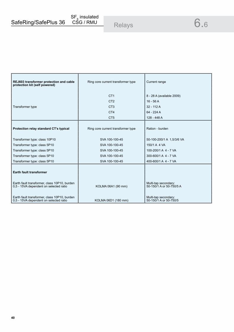
REJ60� transformer protection and cable protection kit (self powered)
Ring core current transformer type Current range
CT1 8 - 28 A (available 2009)
CT2 16 - 56 A
Transformer type CT3 32 - 112 A
CT4 64 - 224 A
CT5 128 - 448 A
Protection relay standard CT’s typical Ring core current transformer type Ration - burden
Transformer type: class 10P10 SVA 100-100-45 50-100-200/1 A 1,5/3/6 VA
Transformer type: class 5P10 SVA 100-100-45 150/1 A 4 VA
Transformer type: class 5P10 SVA 100-100-45 100-200/1 A 4 - 7 VA
Transformer type: class 5P10 SVA 100-100-45 300-600/1 A 4 - 7 VA
Transformer type: class 5P10 SVA 100-100-45 400-600/1 A 4 - 7 VA
Earth fault transformer
Earth fault transformer, class 10P10, burden 0,5 - 15VA dependent on selected ratio KOLMA 06A1 (90 mm)
Multi-tap secondary:50-150/1 A or 50-750/5 A
Earth fault transformer, class 10P10, burden 0,5 - 15VA dependent on selected ratio KOLMA 06D1 (180 mm)
Multi-tap secondary:50-150/1 A or 50-750/5
SafeRing/SafePlus 36SF6 insulated CSG / RMU
�1
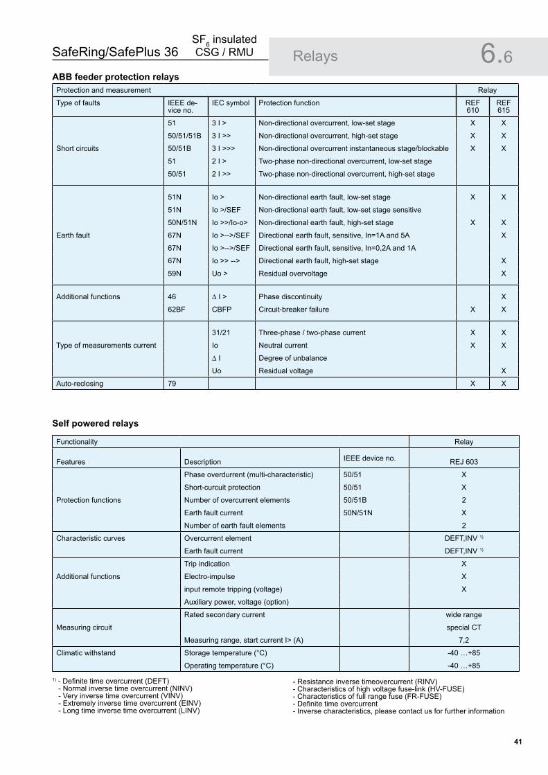
Relays 6.6Protection and measurement Relay
Type of faults IEEE de-vice no.
IEC symbol Protection function REF 610
REF 615
51 3 I > Non-directional overcurrent, low-set stage X X
50/51/51B 3 I >> Non-directional overcurrent, high-set stage X X
Short circuits 50/51B 3 I >>> Non-directional overcurrent instantaneous stage/blockable X X
51 2 I > Two-phase non-directional overcurrent, low-set stage
50/51 2 I >> Two-phase non-directional overcurrent, high-set stage
51N Io > Non-directional earth fault, low-set stage X X
51N Io >/SEF Non-directional earth fault, low-set stage sensitive
50N/51N Io >>/Io-o> Non-directional earth fault, high-set stage X X
Earth fault 67N Io >-->/SEF Directional earth fault, sensitive, In=1A and 5A X
67N Io >-->/SEF Directional earth fault, sensitive, In=0,2A and 1A
67N Io >> --> Directional earth fault, high-set stage X
59N Uo > Residual overvoltage X
Additional functions 46 ∆ I > Phase discontinuity X
62BF CBFP Circuit-breaker failure X X
31/21 Three-phase / two-phase current X X
Type of measurements current Io Neutral current X X
∆ I Degree of unbalance
Uo Residual voltage X
Auto-reclosing 79 X X
Functionality Relay
Features Description IEEE device no. REJ 603
Phase overdurrent (multi-characteristic) 50/51 X
Short-curcuit protection 50/51 X
Protection functions Number of overcurrent elements 50/51B 2
Earth fault current 50N/51N X
Number of earth fault elements 2
Characteristic curves Overcurrent element DEFT,INV 1)
Earth fault current DEFT,INV 1)
Trip indication X
Additional functions Electro-impulse X
input remote tripping (voltage) X
Auxiliary power, voltage (option)
Rated secondary current wide range
Measuring circuit special CT
Measuring range, start current I> (A) 7,2
Climatic withstand Storage temperature (°C) -40 …+85
Operating temperature (°C) -40 …+85
1) - Definite time overcurrent (DEFT) - Normal inverse time overcurrent (NINV) - Very inverse time overcurrent (VINV) - Extremely inverse time overcurrent (EINV) - Long time inverse time overcurrent (LINV)
- Resistance inverse timeovercurrent (RINV)- Characteristics of high voltage fuse-link (HV-FUSE)- Characteristics of full range fuse (FR-FUSE)- Definite time overcurrent - Inverse characteristics, please contact us for further information
ABB feeder protection relays
Self powered relays

SafeRing/SafePlus 36SF6 insulated CSG / RMU
��
ABB feeder terminals type REF ��x
SafePlus can be delivered with two different REF series feeder terminals:
REF 541 which is installed in the door of the low voltage compartment.REF542plus with integrated web-interface is a leader in the development of feeder terminals. REF 542plus has a separate display unit and does not need a build out frame.
Both REF units are configured according to customer specification for protection functions. Other configurations on request only.
••
Typical configuration of V-module:
Primary equipment, standard630A vacuum circuit-breakerDisconnectorEarthing switch
Additional equipmentTrip coil (Y4)VPIS or HR voltage indicationHigh low voltage compartmentREF 542plus or REF 541Motor operationEarth fault transformer (sensitive earth fault)Undervoltage release
•••
•••••••
Relays 6.6
SafeRing/SafePlus 36SF6 insulated CSG / RMU
��
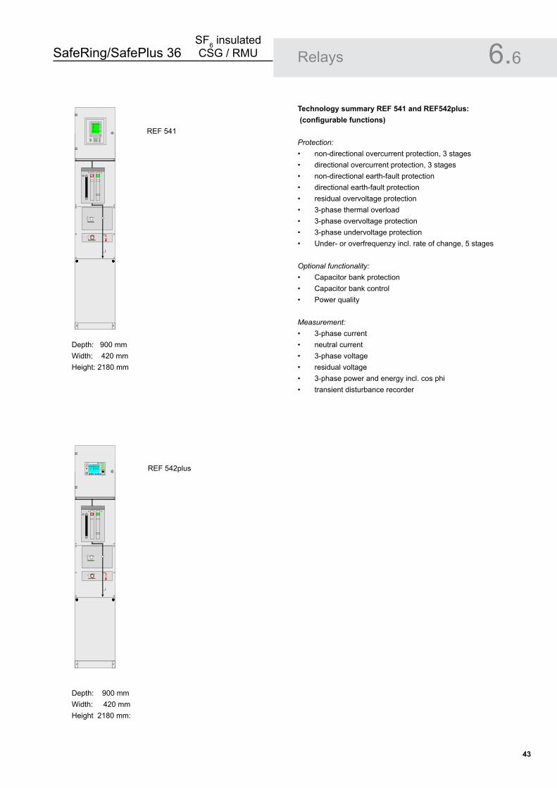
Technology summary REF 541 and REF542plus: (configurable functions)
Protection: non-directional overcurrent protection, 3 stagesdirectional overcurrent protection, 3 stagesnon-directional earth-fault protectiondirectional earth-fault protectionresidual overvoltage protection3-phase thermal overload3-phase overvoltage protection3-phase undervoltage protectionUnder- or overfrequenzy incl. rate of change, 5 stages
Optional functionality:Capacitor bank protectionCapacitor bank controlPower quality
Measurement:3-phase currentneutral current3-phase voltageresidual voltage3-phase power and energy incl. cos phitransient disturbance recorder
•••••••••
•••
••••••
Relays 6.6
Depth: 900 mmWidth: 420 mmHeight: 2180 mm
Depth: 900 mmWidth: 420 mmHeight 2180 mm:
REF 541
REF 542plus� �� REF542plus
M enu

SafeRing/SafePlus 36SF6 insulated CSG / RMU
��
SafeRing/SafePlus 36 are equipped with cable bushings which comply with CENELEC EN 50181 and IEC 60137 for termination of cables.
The bushings fulfil the requirements of DIN47636T1.
The following cable bushings are available:
Interface C with M16 x � metric threads
400 series, In = 630 AStandard on all modules and for side connection
Interface B with plug
400 series, In = 400 AOptional for all modules
The yellow area indicates the silver coated contact spring.
The installation instructions from the manufacturer of cable terminations must be followed. Be sure to lubricate the bushings thoroughly with the grease supplied.Important: Where cables are not connected, the earthing switch must be locked in closed position or the bushings must be fitted with dead end receptacles before the unit is energized.
Cable termination 6.7
Interface C (Bolted type 400 series)
Interface B (Plug-in type 400 series)
SafeRing/SafePlus 36SF6 insulated CSG / RMU
��
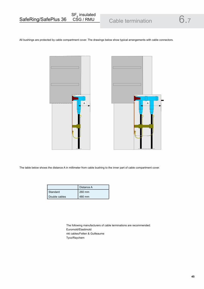
All bushings are protected by cable compartment cover. The drawings below show typical arrangements with cable connectors.
The table below shows the distance A in millimeter from cable bushing to the inner part of cable compartment cover.
The following manufacturers of cable terminations are recommended:Euromold/Elastimoldnkt cables/Felten & GuilleaumeTyco/Raychem
Cable termination 6.7
Distance A
Standard 260 mm
Double cables 480 mm
A A

SafeRing/SafePlus 36SF6 insulated CSG / RMU
�6
Cable termination 6.7Examples below shows a cable connector from Euromold which will fit with cable bushings used on SafePlus / SafeRing 36
SafeRing/SafePlus 36SF6 insulated CSG / RMU
��
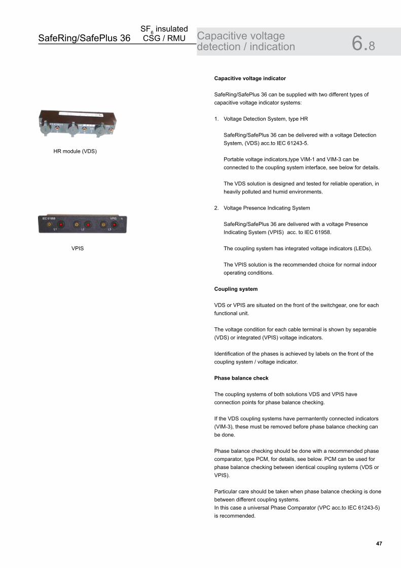
Capacitive voltage indicator
SafeRing/SafePlus 36 can be supplied with two different types of capacitive voltage indicator systems:
1. Voltage Detection System, type HR
SafeRing/SafePlus 36 can be delivered with a voltage Detection System, (VDS) acc.to IEC 61243-5.
Portable voltage indicators,type VIM-1 and VIM-3 can be connected to the coupling system interface, see below for details.
The VDS solution is designed and tested for reliable operation, in heavily polluted and humid environments.
2. Voltage Presence Indicating System
SafeRing/SafePlus 36 are delivered with a voltage Presence Indicating System (VPIS) acc. to IEC 61958.
The coupling system has integrated voltage indicators (LEDs).
The VPIS solution is the recommended choice for normal indoor operating conditions.
Coupling system
VDS or VPIS are situated on the front of the switchgear, one for each functional unit.
The voltage condition for each cable terminal is shown by separable (VDS) or integrated (VPIS) voltage indicators.
Identification of the phases is achieved by labels on the front of the coupling system / voltage indicator.
Phase balance check
The coupling systems of both solutions VDS and VPIS have connection points for phase balance checking.
If the VDS coupling systems have permantently connected indicators (VIM-3), these must be removed before phase balance checking can be done.
Phase balance checking should be done with a recommended phase comparator, type PCM, for details, see below. PCM can be used for phase balance checking between identical coupling systems (VDS or VPIS).
Particular care should be taken when phase balance checking is done between different coupling systems. In this case a universal Phase Comparator (VPC acc.to IEC 61243-5) is recommended.
Capacitive voltage detection / indication 6.8
HR module (VDS)
VPIS
SafeRing/SafePlus 36SF6 insulated CSG / RMU
��
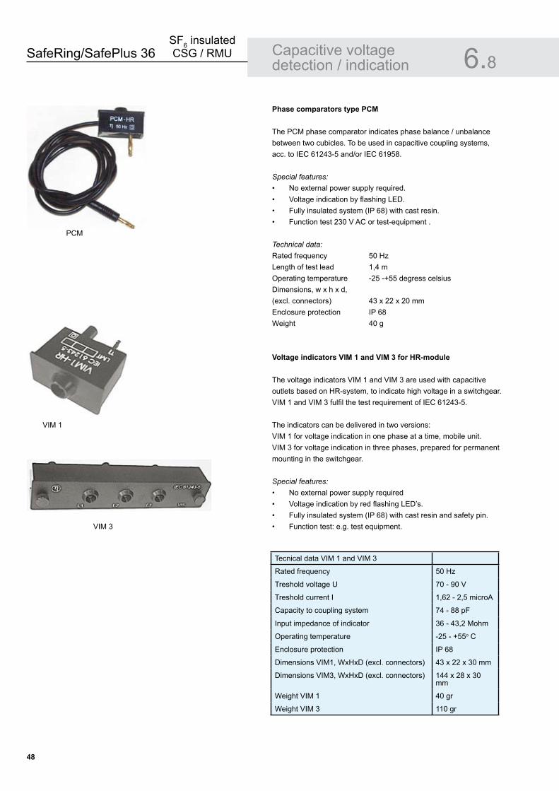
Capacitive voltage detection / indication 6.8Phase comparators type PCM
The PCM phase comparator indicates phase balance / unbalance between two cubicles. To be used in capacitive coupling systems, acc. to IEC 61243-5 and/or IEC 61958.
Special features:No external power supply required.Voltage indication by flashing LED.Fully insulated system (IP 68) with cast resin.Function test 230 V AC or test-equipment .
Technical data:Rated frequency 50 HzLength of test lead 1,4 mOperating temperature -25 -+55 degress celsiusDimensions, w x h x d,(excl. connectors) 43 x 22 x 20 mmEnclosure protection IP 68Weight 40 g
Voltage indicators VIM 1 and VIM � for HR-module
The voltage indicators VIM 1 and VIM 3 are used with capacitive outlets based on HR-system, to indicate high voltage in a switchgear. VIM 1 and VIM 3 fulfil the test requirement of IEC 61243-5.
The indicators can be delivered in two versions: VIM 1 for voltage indication in one phase at a time, mobile unit.VIM 3 for voltage indication in three phases, prepared for permanent mounting in the switchgear.
Special features:No external power supply requiredVoltage indication by red flashing LED’s.Fully insulated system (IP 68) with cast resin and safety pin.Function test: e.g. test equipment.
••••
••••
Tecnical data VIM 1 and VIM 3
Rated frequency 50 Hz
Treshold voltage U 70 - 90 V
Treshold current I 1,62 - 2,5 microA
Capacity to coupling system 74 - 88 pF
Input impedance of indicator 36 - 43,2 Mohm
Operating temperature -25 - +55o C
Enclosure protection IP 68
Dimensions VIM1, WxHxD (excl. connectors) 43 x 22 x 30 mm
Dimensions VIM3, WxHxD (excl. connectors) 144 x 28 x 30 mm
Weight VIM 1 40 gr
Weight VIM 3 110 gr
PCM
VIM 3
VIM 1
SafeRing/SafePlus 36SF6 insulated CSG / RMU
��
Short-circuit indicator 6.9
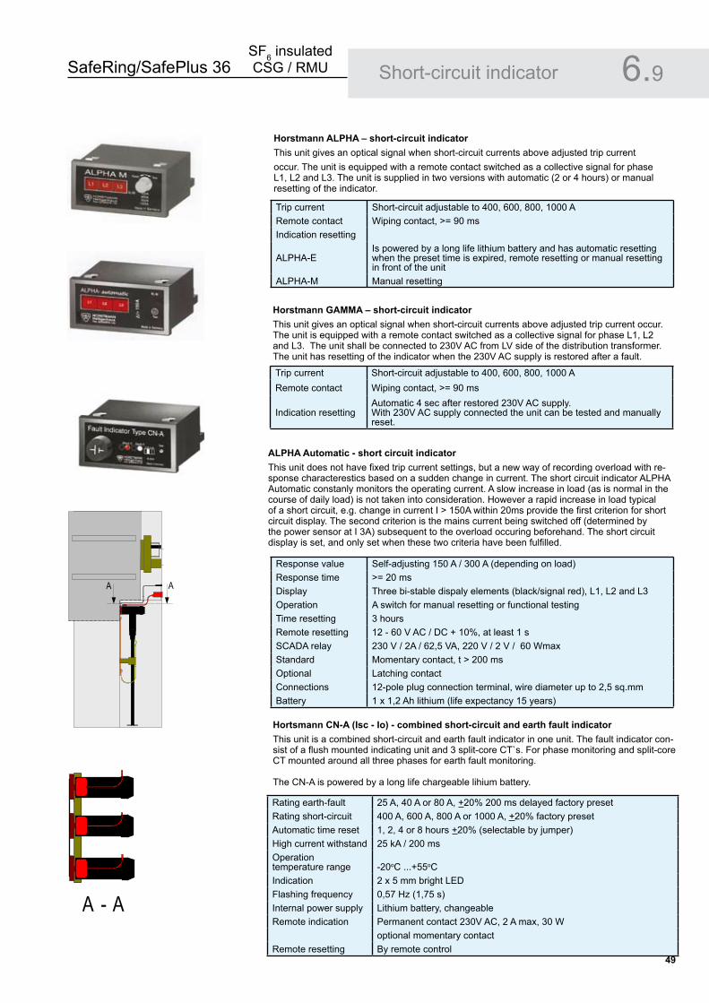
Horstmann ALPHA – short-circuit indicatorThis unit gives an optical signal when short-circuit currents above adjusted trip current occur. The unit is equipped with a remote contact switched as a collective signal for phase L1, L2 and L3. The unit is supplied in two versions with automatic (2 or 4 hours) or manual resetting of the indicator.
Horstmann GAMMA – short-circuit indicatorThis unit gives an optical signal when short-circuit currents above adjusted trip current occur. The unit is equipped with a remote contact switched as a collective signal for phase L1, L2 and L3. The unit shall be connected to 230V AC from LV side of the distribution transformer. The unit has resetting of the indicator when the 230V AC supply is restored after a fault.
ALPHA Automatic - short circuit indicatorThis unit does not have fixed trip current settings, but a new way of recording overload with re-sponse characterestics based on a sudden change in current. The short circuit indicator ALPHA Automatic constanly monitors the operating current. A slow increase in load (as is normal in the course of daily load) is not taken into consideration. However a rapid increase in load typical of a short circuit, e.g. change in current I > 150A within 20ms provide the first criterion for short circuit display. The second criterion is the mains current being switched off (determined by the power sensor at I 3A) subsequent to the overload occuring beforehand. The short circuit display is set, and only set when these two criteria have been fulfilled.
Hortsmann CN-A (Isc - Io) - combined short-circuit and earth fault indicator This unit is a combined short-circuit and earth fault indicator in one unit. The fault indicator con-sist of a flush mounted indicating unit and 3 split-core CT`s. For phase monitoring and split-core CT mounted around all three phases for earth fault monitoring.
The CN-A is powered by a long life chargeable lihium battery.
Trip current Short-circuit adjustable to 400, 600, 800, 1000 ARemote contact Wiping contact, >= 90 msIndication resetting
ALPHA-EIs powered by a long life lithium battery and has automatic resetting when the preset time is expired, remote resetting or manual resetting in front of the unit
ALPHA-M Manual resetting
Trip current Short-circuit adjustable to 400, 600, 800, 1000 ARemote contact Wiping contact, >= 90 ms
Indication resettingAutomatic 4 sec after restored 230V AC supply.With 230V AC supply connected the unit can be tested and manually reset.
Response value Self-adjusting 150 A / 300 A (depending on load)Response time >= 20 msDisplay Three bi-stable dispaly elements (black/signal red), L1, L2 and L3Operation A switch for manual resetting or functional testingTime resetting 3 hoursRemote resetting 12 - 60 V AC / DC + 10%, at least 1 sSCADA relay 230 V / 2A / 62,5 VA, 220 V / 2 V / 60 WmaxStandard Momentary contact, t > 200 msOptional Latching contactConnections 12-pole plug connection terminal, wire diameter up to 2,5 sq.mmBattery 1 x 1,2 Ah lithium (life expectancy 15 years)
Rating earth-fault 25 A, 40 A or 80 A, +20% 200 ms delayed factory presetRating short-circuit 400 A, 600 A, 800 A or 1000 A, +20% factory presetAutomatic time reset 1, 2, 4 or 8 hours +20% (selectable by jumper)High current withstand 25 kA / 200 msOperationtemperature range -20oC ...+55oCIndication 2 x 5 mm bright LEDFlashing frequency 0,57 Hz (1,75 s)Internal power supply Lithium battery, changeableRemote indication Permanent contact 230V AC, 2 A max, 30 W
optional momentary contactRemote resetting By remote control
AA
A - A
SafeRing/SafePlus 36SF6 insulated CSG / RMU
�0
Ronis key interlocks 6.10
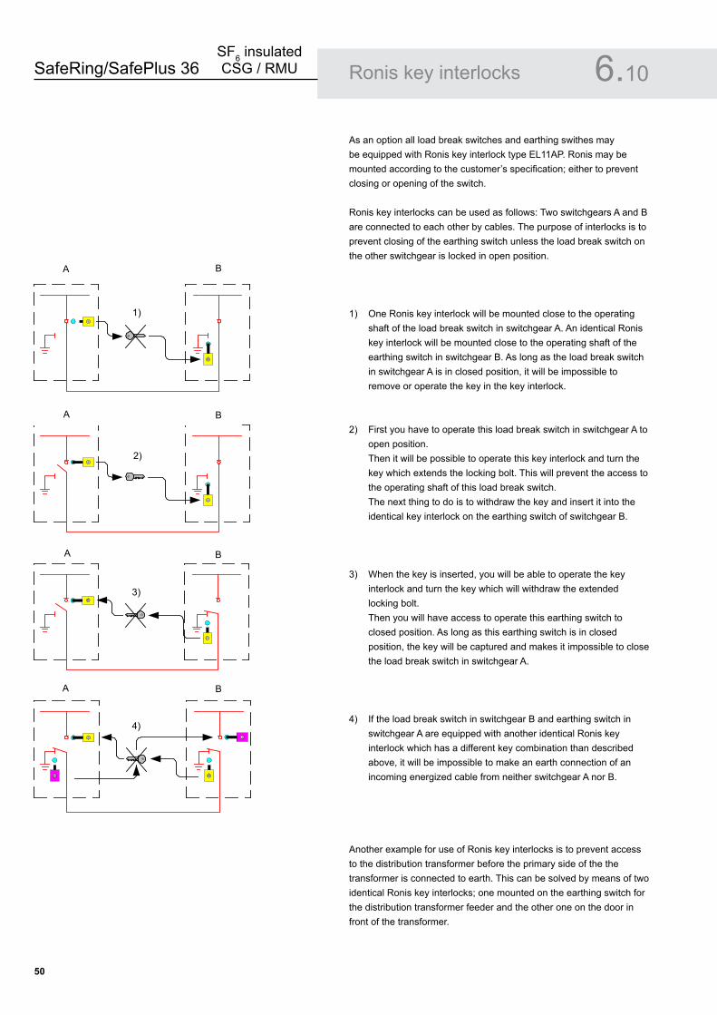
As an option all load break switches and earthing swithes may be equipped with Ronis key interlock type EL11AP. Ronis may be mounted according to the customer’s specification; either to prevent closing or opening of the switch.
Ronis key interlocks can be used as follows: Two switchgears A and B are connected to each other by cables. The purpose of interlocks is to prevent closing of the earthing switch unless the load break switch on the other switchgear is locked in open position.
1) One Ronis key interlock will be mounted close to the operating shaft of the load break switch in switchgear A. An identical Ronis key interlock will be mounted close to the operating shaft of the earthing switch in switchgear B. As long as the load break switch in switchgear A is in closed position, it will be impossible to remove or operate the key in the key interlock.
2) First you have to operate this load break switch in switchgear A to open position. Then it will be possible to operate this key interlock and turn the key which extends the locking bolt. This will prevent the access to the operating shaft of this load break switch. The next thing to do is to withdraw the key and insert it into the identical key interlock on the earthing switch of switchgear B.
3) When the key is inserted, you will be able to operate the key interlock and turn the key which will withdraw the extended locking bolt. Then you will have access to operate this earthing switch to closed position. As long as this earthing switch is in closed position, the key will be captured and makes it impossible to close the load break switch in switchgear A.
4) If the load break switch in switchgear B and earthing switch in switchgear A are equipped with another identical Ronis key interlock which has a different key combination than described above, it will be impossible to make an earth connection of an incoming energized cable from neither switchgear A nor B.
Another example for use of Ronis key interlocks is to prevent access to the distribution transformer before the primary side of the the transformer is connected to earth. This can be solved by means of two identical Ronis key interlocks; one mounted on the earthing switch for the distribution transformer feeder and the other one on the door in front of the transformer.
A B
1)
A B
2)
BA
3)
A B
4)

SafeRing/SafePlus 36SF6 insulated CSG / RMU
�1
Remote control 7.
The SafeRing and SafePlus can be supplied with remote control and monitoring equipment. The switchgears can be fitted with two different types of ABB remote terminal units; RTU211 or REC523.
The RTU211 and REC523 can communicate with control centres of all sizes. Different types of communication media can be delivered, and offers a choice, between the communication protocols ABB RP570, IEC 870-5-101, DNP 3.0 and Modbus RTU/ASCII. Other protocols can be developed on request.
The integrated remote control and monitoring unit is located in a special low voltage compartment.

SafeRing/SafePlus 36SF6 insulated CSG / RMU
��
Remote control 7.
Unit with RTU�11 Standard features:
16 DI (digital inputs), 8 DO (digital outputs) and 6 AI (analogue inputs).RS232 interface for connecting external communication media such as radio.
Standard functions:Remote control of up to 4 switchesPosition indicator for main switch (load break switch or circuit breaker).Monitoring of short-circuit indicator or earth-fault indicatorFuse trip indicationMonitoring of SF6 gas pressurePosition indicator for arc-suppressorRemote control ON/OFF selector
Additional equipment:Modems integrated in the unit: 23WT63 permanent line modem, dialled modem or modem (Distribution Line Carrier) with inductive coupler Batteries and battery charger: 24 VDC back up supply HeaterPosition indicator for earthing switch and disconnector. This requires an extra input board with 16DI.
Low-voltage DPI — Direct Process Interface: This is an I/O board in the RTU211 family, which can be directly connected to 5A and 230/400 V. This allows connection of a signal from the current transformers in a cable compartment, or for current/voltage measurements on the low-voltage side.The remote control and monitoring unit can be supplied with 2×3 current and 2×4 (including N) voltage inputs. On the basis of these measurements, the built-in processor can calculate a number of values to give power quality monitoring.
•
•
••••••••
•
•••
Remote control terminal RTU211 Auxiliary power 24 - 110 V DC or 110 / 220 V AC
Charger 2,5 A
Battery 2 x 12 V (24 V), 20 Ah
Communication protocols RP 570 / 571 Standard
IEC 870-5-101 With protocol converter card
DNP 3.0 With protocol converter card
Modbus RTU With protocol converter card
Modem ABB 23WT63, permanent-line V 23 modem for point-to-point
multidrop or radio up to 1200 Baud
Westermo dialled modem CCITT V.22bis. 2400 bit/s
CCITT V.22bis. Bell 212A. 1200 bit/s
CCITT V.21bis. Bell 103. 300 bit/s
CCITT V.23bis. 1200 75/ bit/s
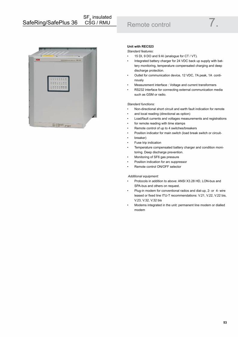
SafeRing/SafePlus 36SF6 insulated CSG / RMU
��
Remote control 7.
Unit with REC���Standard features:
15 DI, 9 DO and 9 AI (analogue for CT / VT).Integrated battery charger for 24 VDC back up supply with bat-tery monitoring, temperature compensated charging and deep discharge protection.Outlet for communication device, 12 VDC, 7A peak, 1A conti-nously Measurement interface : Voltage and current transformersRS232 interface for connecting external communication media such as GSM or radio.
Standard functions:
Non-directional short circuit and earth fault indication for remote and local reading (directional as option)Load/fault currents and voltages measurements and registrationsfor remote reading with time stamps Remote control of up to 4 switches/breakersPosition indicator for main switch (load break switch or circuit-breaker) Fuse trip indicationTemperature compensated battery charger and condition moni-toring. Deep discharge prevention.Monitoring of SF6 gas pressure Position indication for arc suppressor Remote control ON/OFF selector
Additional equipment:Protocols in addition to above: ANSI X3.28 HD, LON-bus and SPA-bus and others on request. Plug-in modem for conventional radios and dial-up, 2- or 4- wire leased or fixed line ITU-T recommendations: V.21, V.22, V.22 bis, V.23, V.32, V.32 bis Modems integrated in the unit: permanent line modem or dialled modem
••
•
••
•••••••••
•••
•
•
•
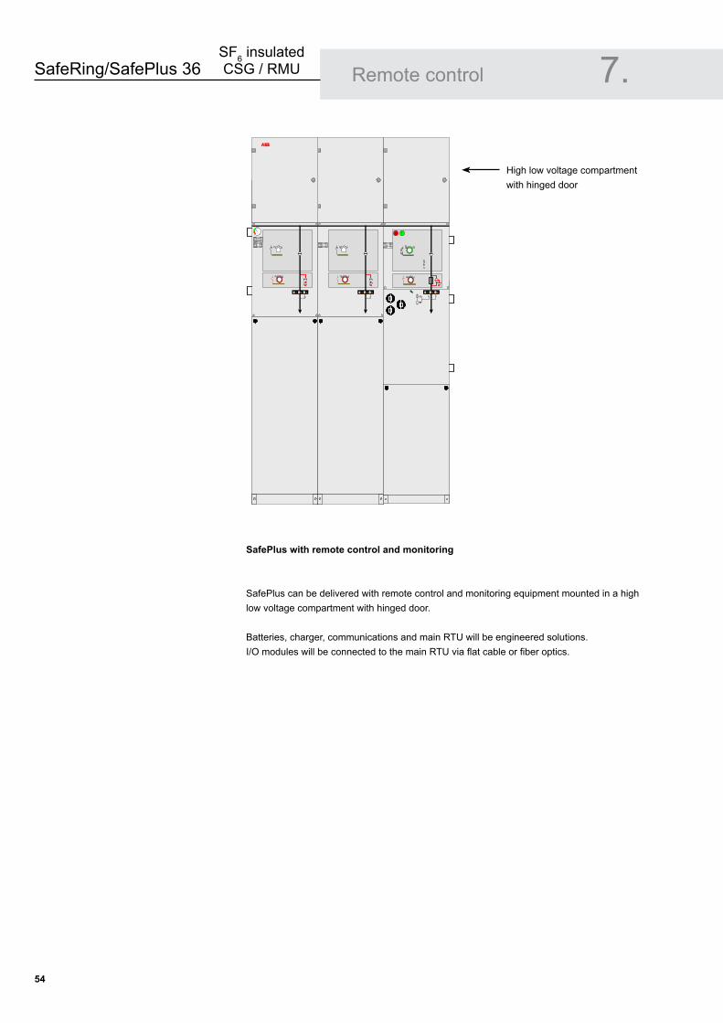
SafeRing/SafePlus 36SF6 insulated CSG / RMU
��
Remote control 7.
SafePlus with remote control and monitoring
SafePlus can be delivered with remote control and monitoring equipment mounted in a high low voltage compartment with hinged door.
Batteries, charger, communications and main RTU will be engineered solutions. I/O modules will be connected to the main RTU via flat cable or fiber optics.
High low voltage compartment with hinged doorABB
ABB
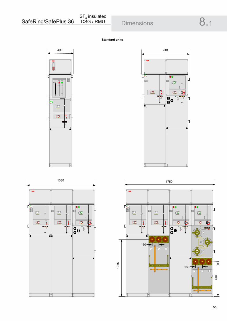
SafeRing/SafePlus 36SF6 insulated CSG / RMU
��
Dimensions 8.1Standard units
� �� REJ 603
ABB
490
ABB
910
ABB
1330
ABB
L1 L2 L3
L1 L2 L3
L1
L2
L3
1750
130
130
615
1035
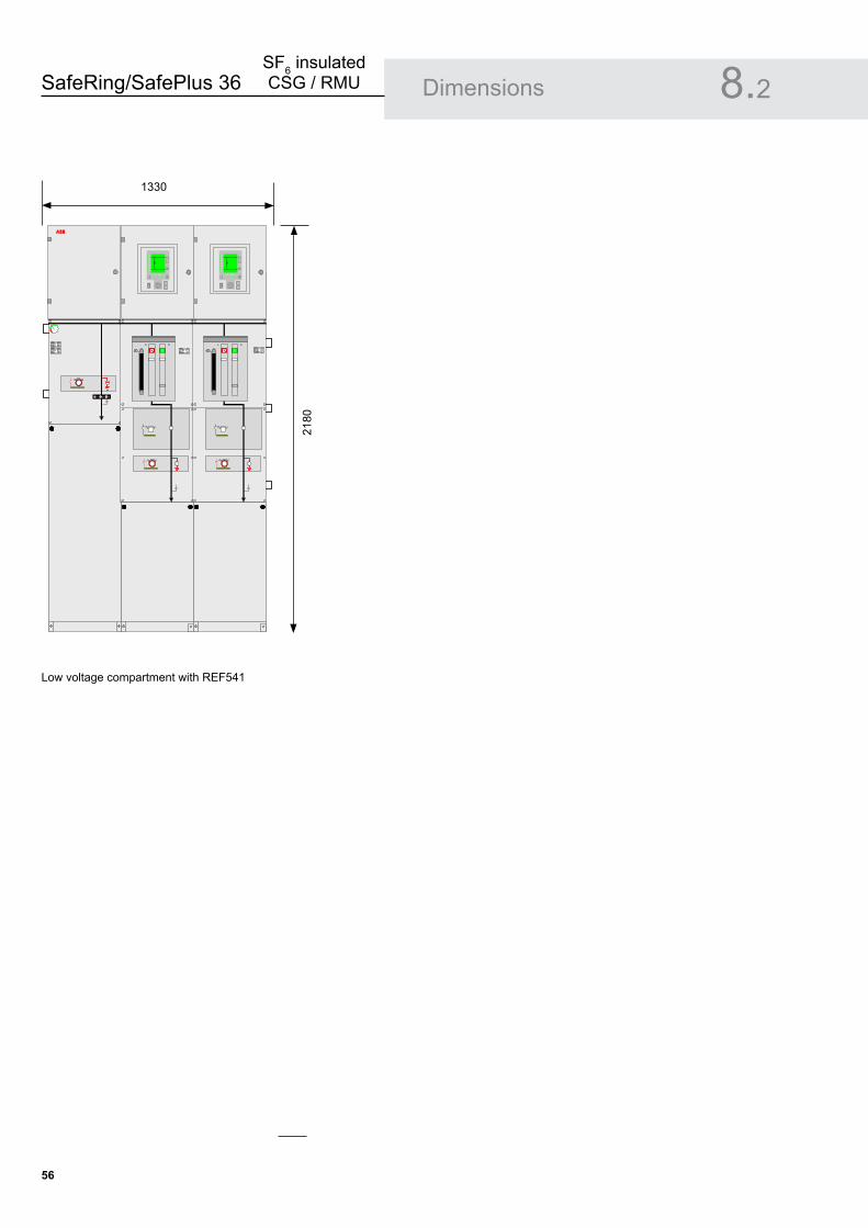
SafeRing/SafePlus 36SF6 insulated CSG / RMU
�6
Low voltage compartment with REF541
Dimensions 8.2
Metering cubicle
ABB
880
1930
1330
2180
ABB
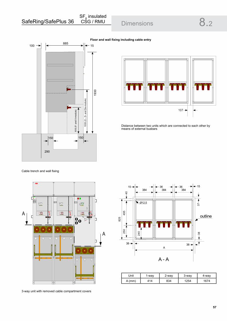
SafeRing/SafePlus 36SF6 insulated CSG / RMU
��
Dimensions 8.2
Unit 1-way 2-way 3-way 4-way
A (mm) 414 834 1254 1674
Cable trench and wall fixing
3-way unit with removed cable compartment covers
Distance between two units which are connected to each other by means of external busbars
Floor and wall fixing including cable entry
ABB
L1 L2 L3
L1 L2 L3L1 L2 L3
A
A
107
15384
36
4049
525
0
825
A38
Ø12,538
37
15
38
A - A
240
A
A
384 38436
outline
615
(F- a
nd V
-mod
ule)
1035
(C-,
D- a
nd D
e-m
odul
e)
290
150 150
1930
100 15885
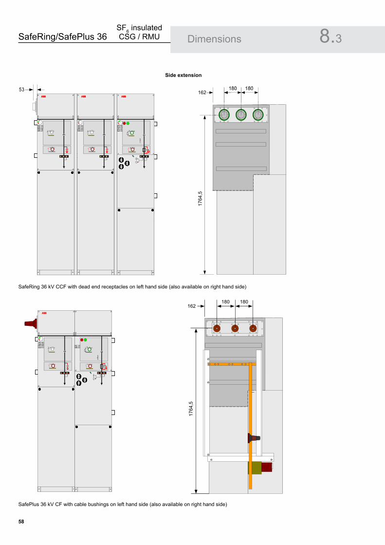
SafeRing/SafePlus 36SF6 insulated CSG / RMU
��
Dimensions 8.3
SafeRing 36 kV CCF with dead end receptacles on left hand side (also available on right hand side)
SafePlus 36 kV CF with cable bushings on left hand side (also available on right hand side)
Side extension
ABB ABB ABB
53
ABB
162180 180
1768
1764
,5
162180 180
1764
,5
180 180162
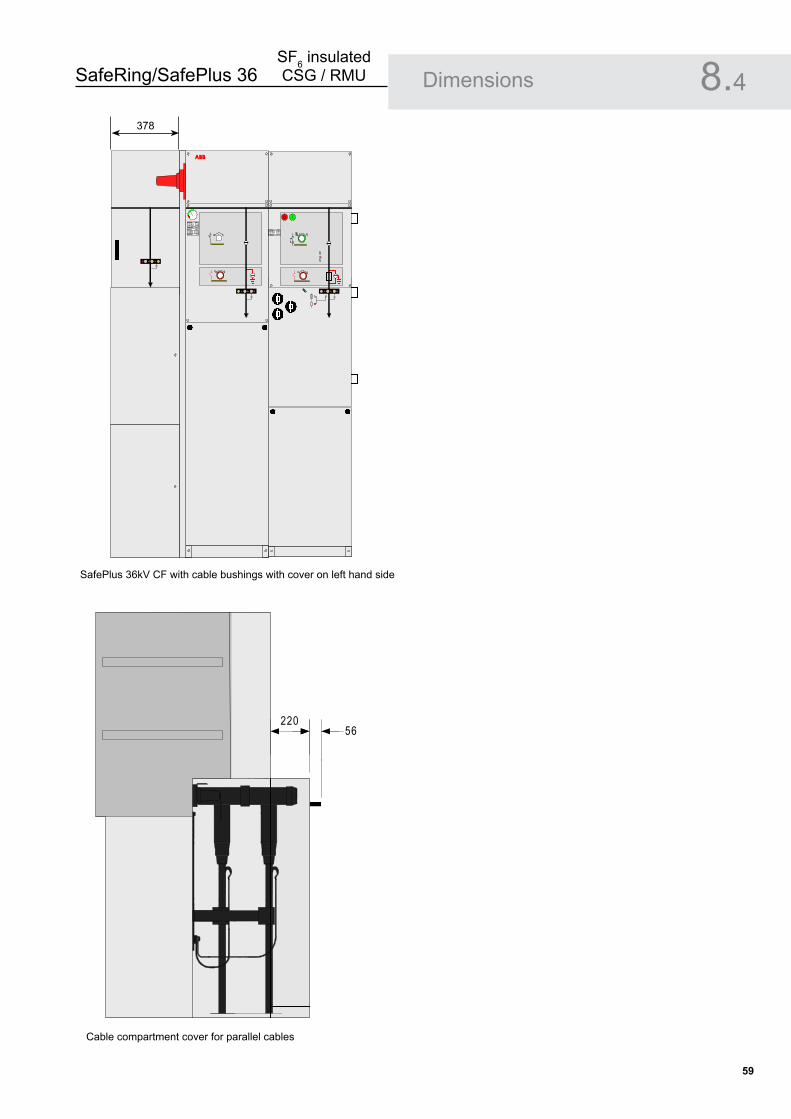
SafeRing/SafePlus 36SF6 insulated CSG / RMU
��
Dimensions 8.4
SafePlus 36kV CF with cable bushings with cover on left hand side
Cable compartment cover for parallel cables
22056
ABB
378

SafeRing/SafePlus 36SF6 insulated CSG / RMU
60
Technical data 9.1
IEC 62271-1 High-voltage switchgear and controlgear -Part 1: Common specifications
IEC 62271-100 High-voltage switchgear and controlgear - Part 100: High-voltage alternating-current circuit-breakers
IEC 62271-102 High-voltage switchgear and controlgear - Part 102: Alternating current disconnectors and earthing switches
IEC 62271-105 High-voltage switchgear and controlgear - Part 105: Alternating current switch-fuse combinations
IEC 62271-200 High-voltage switchgear and controlgear - Part 200: A.C. metal-enclosed switchgear and controlgear for rated voltages above 1 kV and up to and including 52 kV
IEC 60265-1 High-voltage switches- Part 1: Switches for rated voltages above 1 kV and less than 52 kV
IEC 60529 Degrees of protection provided by enclosures (IP code)
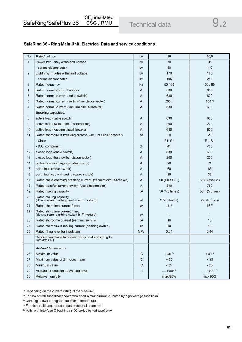
SafeRing/SafePlus 36SF6 insulated CSG / RMU
61
Technical data 9.2
No Rated voltage kV 36 40,5
1 Power frequency withstand voltage kV 70 95
- across disconnector kV 80 110
2 Lightning impulse withstand voltage kV 170 185
- across disconnector kV 195 215
3 Rated frequency Hz 50 / 60 50 / 60
4 Rated normal current busbars A 630 630
5 Rated normal current (cable switch) A 630 630
6 Rated normal current (switch-fuse disconnector) A 200 1) 200 1)
7 Rated normal current (vacuum circuit-breaker) A 630 630
Breaking capacities:
8 active load (cable switch) A 630 630
9 active laod (switch-fuse disconnector) A 200 200
10 active load (vacuum circuit-breaker) A 630 630
11 Rated short-circuit breaking current (vacuum circuit-breaker) kA 20 20
- Class E1, S1 E1, S1
- D.C. component % 41 <20
12 closed loop (cable switch) A 630 630
13 closed loop (fuse-switch disconnector) A 200 200
14 off load cable charging (cable switch) A 20 21
15 earth fault (cable switch) A 60 63
16 earth fault cable charging (cable switch) A 35 36
17 Rated cable-charging breaking current (vacuum circuit-breaker) A 50 (Class C1) 50 (Class C1)
18 Rated transfer current (switch-fuse disconnector) A 840 750
19 Rated making capacity kA 50 2) (5 times) 50 2) (5 times)
20 Rated making capacity (downstream earthing switch in F-module) kA 2,5 (5 times) 2,5 (5 times)
21 Rated short time current 3 sec. kA 16 5) 16 5)
22 Rated short time current 1 sec.(downstream earthing switch in F-module) kA 1 1
23 Rated short-time current (earthing switch) kA 16 16
24 Rated short-circuit making current (earthing switch) kA 40 40
25 Rated filling level for insulation MPa 0,04 0,04
Service conditions for indoor equipment according toIEC 62271-1
Ambient temperature
26 Maximum value oC + 40 3) + 40 3)
27 Maximum value of 24 hours mean oC + 35 + 35
28 Minimum value oC - 25 - 25
29 Altitude for erection above sea level m .....1000 4) .....1000 4)
30 Relative humidity max 95% max 95%
1) Depending on the current rating of the fuse-link2) For the switch-fuse disconnector the short-circuit current is limited by high voltage fuse-links3) Derating allows for higher maximum temperature4) For higher altitude, reduced gas pressure is required5) Valid with Interface C bushings (400 series bolted type) only
SafeRing �6 - Ring Main Unit, Electrical Data and service conditions

SafeRing/SafePlus 36SF6 insulated CSG / RMU
6�
Technical data 9.3SafePlus �6 - Compact Switchgear, Electrical Data
No Rated voltage kV 36 40,5
1 Power frequency withstand voltage kV 70 95
- across disconnector kV 80 110
2 Lightning impulse withstand voltage kV 170 185
- across disconnector kV 195 215
3 Rated frequency Hz 50 / 60 50 / 60
4 Rated normal current busbars A 630 630
5 Rated normal current (cable switch) A 630 630
6 Rated normal current (switch-fuse disconnector) A 200 1) 200 1)
7 Rated normal current (vacuum circuit-breaker) A 630 630
Breaking capacities:
8 active load (cable switch) A 630 630
9 active laod (switch-fuse disconnector) A 200 200
10 active load (vacuum circuit-breaker) A 630 630
11 Rated short-circuit breaking current (vacuum circuit-breaker) kA 20 20
- Class E1, S1 E1, S1
- D.C. component % 41 <20
12 closed loop (cable switch) A 630 630
13 closed loop (fuse-switch disconnector) A 200 200
14 off load cable charging (cable switch) A 20 21
15 earth fault (cable switch) A 60 63
16 earth fault cable charging (cable switch) A 35 36
17 Rated cable-charging breaking current (vacuum circuit-breaker) A 50 (Class C1) 50 (Class C1)
18 Rated transfer current (switch-fuse disconnector) A 840 750
19 Rated making capacity kA 50 2) (5 times) 50 2) (5 times)
20 Rated making capacity (downstream earthing switch in F-module) kA 2,5 (5 times) 2,5 (5 times)
21 Rated short time current 1 sec. kA 20 20
22 Rated short time current 3 sec. kA 20 5) 20 5)
23 Rated short time current 1 sec.(downstream earthing switch in F-module) kA 1 1
24 Rated short-time current (earthing switch) kA 20 20
25 Rated short-circuit making current (earthing switch) kA 50 50
26 Rated filling level for insulation MPa 0,04 0,04
Service conditions for indoor equipment according toIEC 62271-1
Ambient temperature
27 Maximum value oC + 40 3) + 40 3)
28 Maximum value of 24 hours mean oC + 35 + 35
29 Minimum value oC - 25 - 25
30 Altitude for erection above sea level m .....1000 4) .....1000 4)
31 Relative humidity max 95% max 95%
1) Depending on the current rating of the fuse-link2) For the switch-fuse disconnector the short-circuit current is limited by high voltage fuse-links3) Derating allows for higher maximum temperature4) For higher altitude, reduced gas pressure is required5) Valid with Interface C bushings (400 series bolted type) only

SafeRing/SafePlus 36SF6 insulated CSG / RMU
6�
Technical data 9.4General data, enclosure and dimensions
1 Strandard to which switchgear complies IEC / GB
2 Type of Ring Main Unit Metal enclosed
3 Number of phases 3
4 Whether RMU is type tested Yes
5 Pressure test on equipment tank or containers Until pressure relief device opens
6 Whether facility is provided with pressure relief device Yes
7 Insulating gas SF6
8 Nominal operating gas pressure 1,4 bar abs. at 20oC
9 Gas diffusion rate 0,1 % p.a.
10 Expected operating lifetime 30 years
11 Whether facilities are provided for gas monitoring Yes, temperature compensated manometer can be delivered
12 Material used in tank construction Stainless steel sheet, 2 mm
13 Busbars 300 mm2 Cu
14 Earth bar (external) 120 mm2 Cu
15 Earth bar bolt dimension M10
Overall dimensions of fully assembled Ring Main Unit Height Depth Width
16 2-way unit mm 1930 900 910
17 3-way unit mm 1930 900 1330
18 4-way unit mm 1930 900 1750
Compact switchgear (2-, 3- and 4-way units as for RMU)
19 1-way unit mm 1930 900 490
20 Distance between units when external extension mm 50
Weight table
Maximum weights for standard SafeRing 36 kV:
2-way DeV 550 kg 2-way DeF 550 kg3-way CCV 800 kg 3-way CCF 800 kg4-way CCCV 1050 kg 4-way CCCF 1050 kg4-way CCVV 1100 kg 4-way CCFF 1100 kg3-way CCC 750 kg4-way CCCC 1000 kg
SafePlus 36 kV:
Standard 1-way (C-, D-, De-module) 250 kgStandard 1-way (F-, V-module) 300 kg2-, 3- and 4-way as for SafeRingM – metering module ??? kg
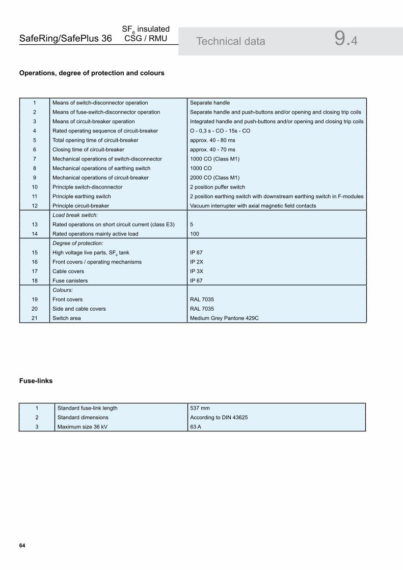
SafeRing/SafePlus 36SF6 insulated CSG / RMU
6�
Technical data 9.4Operations, degree of protection and colours
1 Means of switch-disconnector operation Separate handle
2 Means of fuse-switch-disconnector operation Separate handle and push-buttons and/or opening and closing trip coils
3 Means of circuit-breaker operation Integrated handle and push-buttons and/or opening and closing trip coils
4 Rated operating sequence of circuit-breaker O - 0,3 s - CO - 15s - CO
5 Total opening time of circuit-breaker approx. 40 - 80 ms
6 Closing time of circuit-breaker approx. 40 - 70 ms
7 Mechanical operations of switch-disconnector 1000 CO (Class M1)
8 Mechanical operations of earthing switch 1000 CO
9 Mechanical operations of circuit-breaker 2000 CO (Class M1)
10 Principle switch-disconnector 2 position puffer switch
11 Principle earthing switch 2 position earthing switch with downstream earthing switch in F-modules
12 Principle circuit-breaker Vacuum interrupter with axial magnetic field contacts
Load break switch:
13 Rated operations on short circuit current (class E3) 5
14 Rated operations mainly active load 100
Degree of protection:
15 High voltage live parts, SF6 tank IP 67
16 Front covers / operating mechanisms IP 2X
17 Cable covers IP 3X
18 Fuse canisters IP 67
Colours:
19 Front covers RAL 7035
20 Side and cable covers RAL 7035
21 Switch area Medium Grey Pantone 429C
1 Standard fuse-link length 537 mm
2 Standard dimensions According to DIN 43625
3 Maximum size 36 kV 63 A
Fuse-links
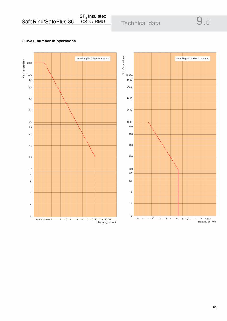
SafeRing/SafePlus 36SF6 insulated CSG / RMU
6�
Technical data 9.5Curves, number of operations
2000
1000
800
600
400
200
100
80
60
40
20
10
8
6
4
2
10,5 0 ,6 0 ,8 1 2 3 4 6 8 10 16 20 30 40 (kA )
B reaking curren t
No.
of o
pera
tions
S a feR ing/S afeP lus V m odu le
10000
8000
6000
4000
2000
1000
800
600
400
200
100
80
60
40
20
105 6 8 2 3 4 6 8 2 3 4 (A )
B reaking curren t
No.
of o
pera
tions S a feR ing/S afeP lus C m odu le
10 2 10 3

SafeRing/SafePlus 36SF6 insulated CSG / RMU
66
10.Environment
ENVIRONMENTAL CERTIFICATION FOR SF6 INSULATED SAFERING / SAFEPLUS �6
1. LIFE EXPECTANCY OF PRODUCT
The product is developed in compliance with the requirements denoted by IEC 62271-200. The design incorporates a life span under indoor service conditions exceeding 30 years.
The switchgear is gas-tight with an expected diffusion rate of less than 0.1 % per annum. Referring to the reference-pressure of 1.4 bar, the switchgear will maintain gas-tightness and a gas-pressure better than 1.3 bar at 20oC throughout its designed life span.
�. RECYCLING CAPABILITY
Raw Material Weight % of total Re- Environmental effects (kg) weight cycle & recycle/reuse processes Iron 139,9 31,1 Yes Separate, utilise in favour of new source (ore) Stainless steel 130,8 29,1 Yes Separate, utilise in favour of new source (ore) Copper 71,9 16,0 Yes Separate, utilise in favour of new source (ore) Brass 3,0 0,7 Yes Separate, utilise in favour of new source (ore) Aluminium 1,0 0,2 Yes Separate, utilise in favour of new source (ore) Zinc 5,1 1,2 Yes Separate, utilise in favour of new source (ore) Silver 0,075 0,014 Yes Electrolysis, utilise in favour of new source PBT 2,3 0,5 Yes Make granulate, re-use or apply as energy PA6-6 5,3 1,2 Yes PC 0,8 0,2 Yes Other thermoplastic 0,1 0 Yes Packing foil 0,3 0,1 Yes High-grade energy additive in refuse incineration SF6 gas 5,4 1,2 Yes ABB AS in Skien reclaims used SF6 gas Dielectric oil 0,3 0,1 Yes Collect / reclaim / regenerate Wooden pallet 27,8 6,2 Yes Re-use Total recycleables 394,075 89,0
Rubber 1,9 0,4 No Incinerate energy in rubber Epoxy compounds 46,5 10,3 No Contains 60 % quartz sand, incinerate energy in epoxy Unspecified 1,5 0,3 No Stickers, film foils, powder coating, lubricates Total non-recycleables 49,8 10,8
Total weight ** 443,875 100 %
**)All figures are collected from CCF 3-way unit with fuse canisters.
�. LIFECYCLE CONCEPT FOR TRANSPORT, INSTALLATION, REPAIR, SERVICE AND DISPOSAL AT END OF LIFEABB is committed to the protection of the environment and adhere to ISO 14001 standards. The unit contains no substances listed on the hazardous substances list. The unit contains SF6 with 0,4 bar overpressure in a maintenance free and sealed unit. The unit is a sealed pressure system and restrictions for air transport exist. Units damaged during transport are returned to the manufacturer for inspection and possible repair.
SF6 is a fluorinated greenhouse gas covered by the Kyoto Protocol and care must be taken not to cause emission of SF6 and at end-of-life the greenhouse gas must be recovered.
It is ABB's obligation to facilitate end-of-life recycling for our products. In the EU and EEA, the F-Gas Regulation must be followed. ABB’s recycling service is according to IEC 61634 edition 1995 section 6: «End of life of SF6 filled equipment» and in particular 6.5.2.a: «Low decomposition»: «No special action is required; non-recoverable parts can be disposed of normally according to local regulations.» We also advise customer always to consult ABB’s website : http://www.abb.com/sf6 .
ABB AS, Power Products Division's manufacturing site in Skien is equipped to recover SF6 gas from discarded switchgears.
SafeRing/SafePlus 36SF6 insulated CSG / RMU
6�
ISO 9001
ISO 14001
ISO 18001
ISO-Certificates 10.


1VD
D00
6114
GB
E
ditio
n 2
Sep
tem
ber 2
008
© C
opyr
ight
200
8 A
BB
. All
right
s re
serv
ed
ABB ASPower Products DivisionP. O. Box 108, SentrumN-3701 SKIENNORWAY
Tel.: +47 35 58 20 00Fax: +47 35 52 41 08www.abb.com
Text and illustrations are not binding. The right to make alterations is reserved.ABB
Related Documents