AASHTOWare Bridge Design and Rating Training – RC 6 – Two Span Reinforced Concrete Slab System Example Last Modified: 7/31/2013 RC 6 - 1 AASHTOWare Bridge Design and Rating Training 30'-0" 6" 6" Elevation 30'-0" 20'-0" 9'-0" 9'-0" 20'-0" 1'-0" 1'-6" 3'-0" #11's #11's A A B B

Welcome message from author
This document is posted to help you gain knowledge. Please leave a comment to let me know what you think about it! Share it to your friends and learn new things together.
Transcript
AASHTOWare Bridge Design and Rating Training – RC 6 – Two Span Reinforced Concrete Slab System Example
Last Modified: 7/31/2013 RC 6 - 1
AASHTOWare Bridge Design and Rating Training
30'-0
"6"
6"
Elev
atio
n
30'-0
"
20'-0
"9'
-0"
9'-0
"20
'-0"
1'-0
"
1'-6
"3'
-0"
#11'
s#1
1's
A A
B B
AASHTOWare Bridge Design and Rating Training – RC 6 – Two Span Reinforced Concrete Slab System Example
Last Modified: 7/31/2013 RC 6 - 2
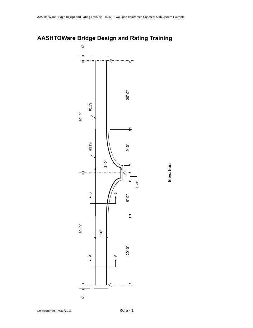
27'-0"
Top Row: 27-#11's @12"Bottom Row: 54-#11's @ 6"
24'-0" 1'-6"1'-6"
18"
#5
#5
1.5" clr.
2.0" clr.
Section A-A
27'-0"
Top Row: 54-#11's @ 6"Bottom Row: 54-#11's @ 6"
24'-0" 1'-6"1'-6"
Varies
#5
#5
1.5" clr.
2.0" clr.
Section B-B
Material PropertiesSlab Concrete: Class A (US) f'c = 4.0 ksi, modular ratio n = 8Slab Reinforcing Steel: AASHTO M31, Grade 60 with Fy = 60 ksi
ParapetsWeigh 300 lb/ft each

AASHTOWare Bridge Design and Rating Training – RC 6 – Two Span Reinforced Concrete Slab System Example
Last Modified: 7/31/2013 RC 6 - 3
RC6 – Two Span Reinforced Concrete Slab System Example
Topics Covered
Part 1: Reinforced concrete slab system input. Slab is not integral with pier. • Schedule based input of slab strip. • Slab depth varies parabolically over the pier.
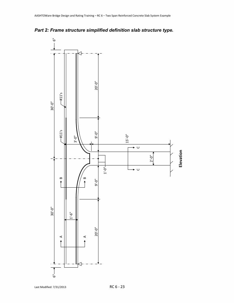
Part 2: Frame structure simplified definition slab structure type.
Part 1: Reinforced concrete slab system input. Slab is not integral with pier. From the Bridge Explorer, select File/New/New Bridge from the menu to create a new bridge and enter the following description data.
Close the window by clicking Ok. This saves the data to memory and closes the window.
AASHTOWare Bridge Design and Rating Training – RC 6 – Two Span Reinforced Concrete Slab System Example
Last Modified: 7/31/2013 RC 6 - 4
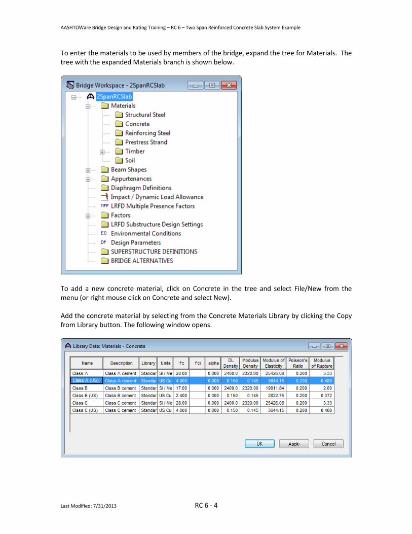
To enter the materials to be used by members of the bridge, expand the tree for Materials. The tree with the expanded Materials branch is shown below.
To add a new concrete material, click on Concrete in the tree and select File/New from the menu (or right mouse click on Concrete and select New). Add the concrete material by selecting from the Concrete Materials Library by clicking the Copy from Library button. The following window opens.
AASHTOWare Bridge Design and Rating Training – RC 6 – Two Span Reinforced Concrete Slab System Example
Last Modified: 7/31/2013 RC 6 - 5
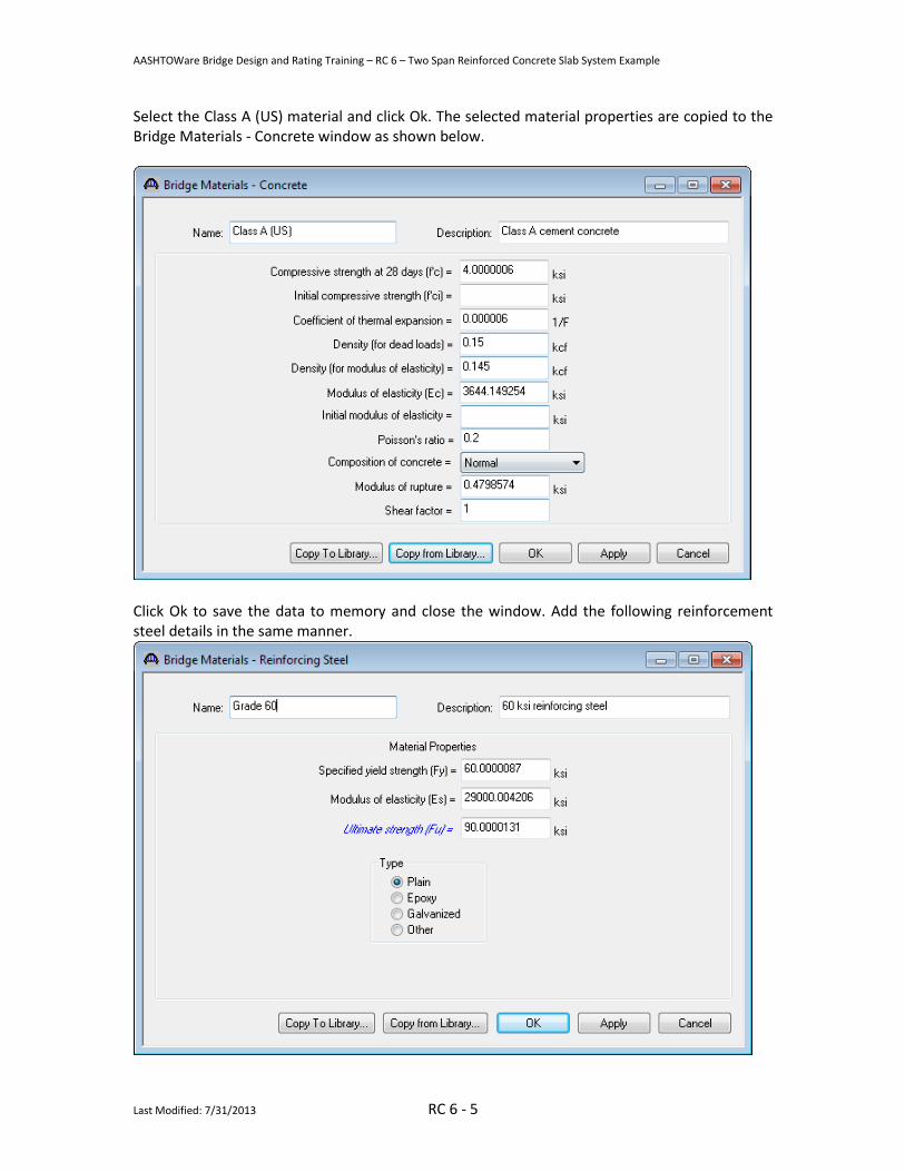
Select the Class A (US) material and click Ok. The selected material properties are copied to the Bridge Materials - Concrete window as shown below.
Click Ok to save the data to memory and close the window. Add the following reinforcement steel details in the same manner.

AASHTOWare Bridge Design and Rating Training – RC 6 – Two Span Reinforced Concrete Slab System Example
Last Modified: 7/31/2013 RC 6 - 6
Also add parapet information in similar maner under Appurtenances.
We do not need to define any beam shapes since we are using a reinforced concrete slab. The slab details will be entered later when we define the strip profile. The default impact factors, standard LRFD and LFD factors will be used so we will skip to superstructure definition. A bridge alternative will be added after we enter the superstructure definition.

AASHTOWare Bridge Design and Rating Training – RC 6 – Two Span Reinforced Concrete Slab System Example
Last Modified: 7/31/2013 RC 6 - 7
Double-click on SUPERSTRUCTURE DEFINITIONS (or click on SUPERSTRUCTURE DEFINITIONS and select File/New from the menu or right mouse click on SUPERSTRUCTURE DEFINITIONS and select New from the popup menu) to create a new Superstructure definition.
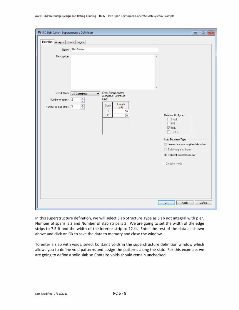
Select Reinforced Concrete Slab System Superstructure, click Ok and the RC Slab System Superstructure Definition window will open.
AASHTOWare Bridge Design and Rating Training – RC 6 – Two Span Reinforced Concrete Slab System Example
Last Modified: 7/31/2013 RC 6 - 8
In this superstructure definition, we will select Slab Structure Type as Slab not integral with pier. Number of spans is 2 and Number of slab strips is 3. We are going to set the width of the edge strips to 7.5 ft and the width of the interior strip to 12 ft. Enter the rest of the data as shown above and click on Ok to save the data to memory and close the window. To enter a slab with voids, select Contains voids in the superstructure definition window which allows you to define void patterns and assign the patterns along the slab. For this example, we are going to define a solid slab so Contains voids should remain unchecked.
AASHTOWare Bridge Design and Rating Training – RC 6 – Two Span Reinforced Concrete Slab System Example
Last Modified: 7/31/2013 RC 6 - 9
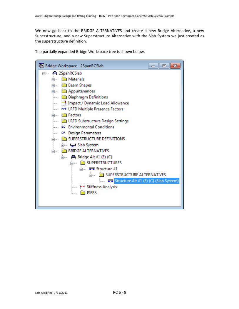
We now go back to the BRIDGE ALTERNATIVES and create a new Bridge Alternative, a new Superstructure, and a new Superstructure Alternative with the Slab System we just created as the superstructure definition. The partially expanded Bridge Workspace tree is shown below.
AASHTOWare Bridge Design and Rating Training – RC 6 – Two Span Reinforced Concrete Slab System Example
Last Modified: 7/31/2013 RC 6 - 10
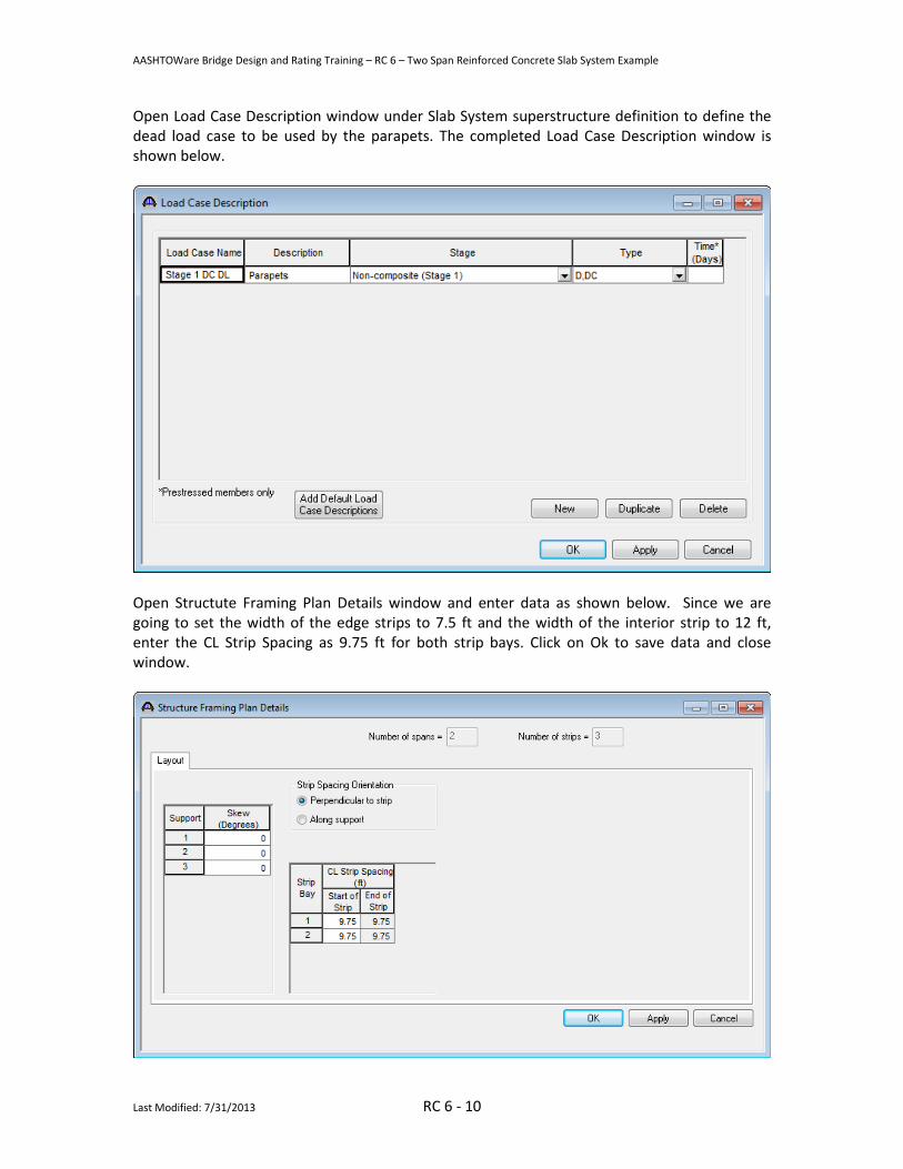
Open Load Case Description window under Slab System superstructure definition to define the dead load case to be used by the parapets. The completed Load Case Description window is shown below.
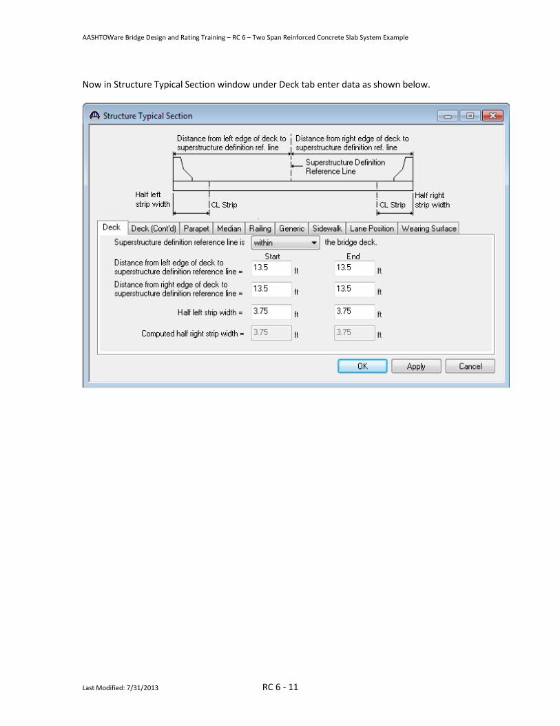
Open Structute Framing Plan Details window and enter data as shown below. Since we are going to set the width of the edge strips to 7.5 ft and the width of the interior strip to 12 ft, enter the CL Strip Spacing as 9.75 ft for both strip bays. Click on Ok to save data and close window.
AASHTOWare Bridge Design and Rating Training – RC 6 – Two Span Reinforced Concrete Slab System Example
Last Modified: 7/31/2013 RC 6 - 11
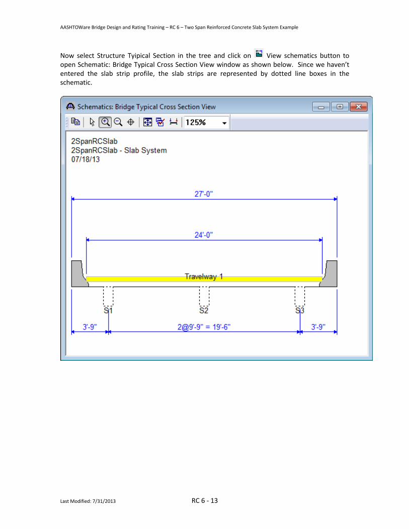
Now in Structure Typical Section window under Deck tab enter data as shown below.

AASHTOWare Bridge Design and Rating Training – RC 6 – Two Span Reinforced Concrete Slab System Example
Last Modified: 7/31/2013 RC 6 - 12
Also enter Parapet and Lane Position details as shown below in their respective tabs. Then click on Ok to save and close the window.
AASHTOWare Bridge Design and Rating Training – RC 6 – Two Span Reinforced Concrete Slab System Example
Last Modified: 7/31/2013 RC 6 - 13
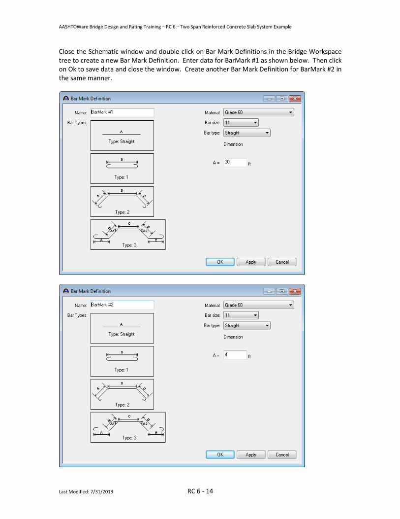
Now select Structure Tyipical Section in the tree and click on View schematics button to open Schematic: Bridge Typical Cross Section View window as shown below. Since we haven’t entered the slab strip profile, the slab strips are represented by dotted line boxes in the schematic.
AASHTOWare Bridge Design and Rating Training – RC 6 – Two Span Reinforced Concrete Slab System Example
Last Modified: 7/31/2013 RC 6 - 14
Close the Schematic window and double-click on Bar Mark Definitions in the Bridge Workspace tree to create a new Bar Mark Definition. Enter data for BarMark #1 as shown below. Then click on Ok to save data and close the window. Create another Bar Mark Definition for BarMark #2 in the same manner.

AASHTOWare Bridge Design and Rating Training – RC 6 – Two Span Reinforced Concrete Slab System Example
Last Modified: 7/31/2013 RC 6 - 15
Defining a Member Alternative: Double-click MEMBER ALTERNATIVES in the tree under the interior strip S2 to create a new alternative. The New Member Alternative dialog shown below will open. Select Reinforced Concrete for the Material Type and Reinforced Concrete Slab for the Girder Type.
Click Ok to close the dialog and create a new member alternative.
AASHTOWare Bridge Design and Rating Training – RC 6 – Two Span Reinforced Concrete Slab System Example
Last Modified: 7/31/2013 RC 6 - 16
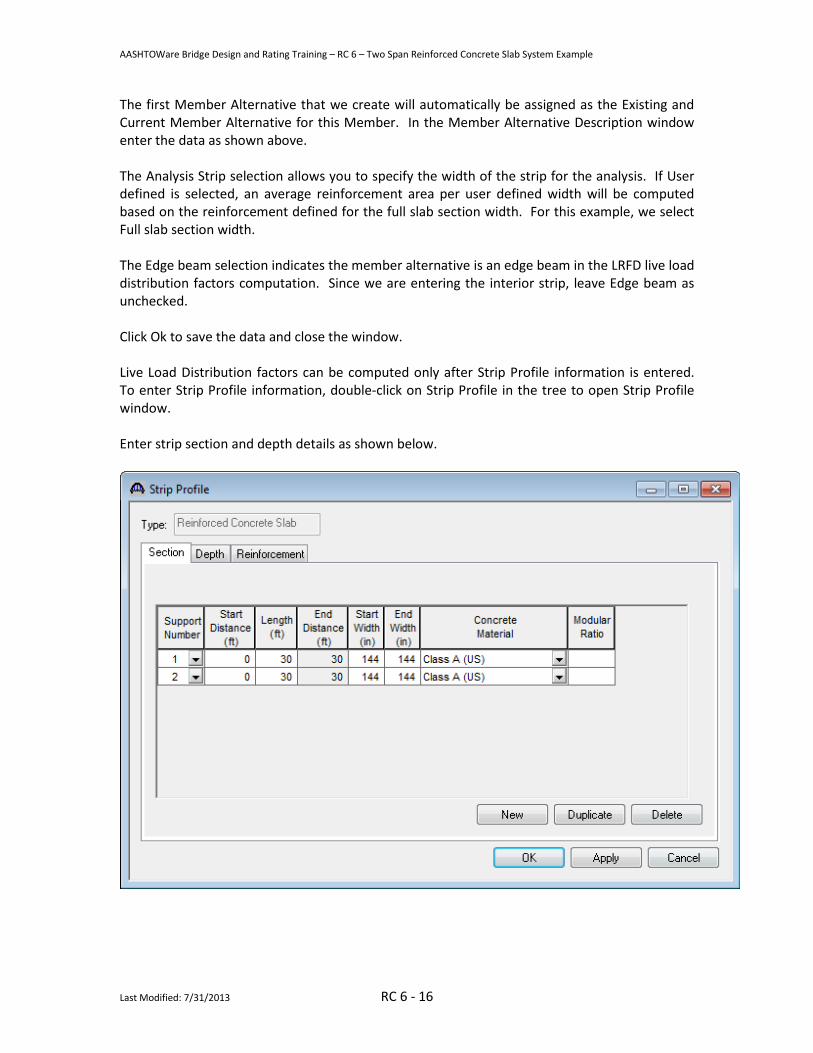
The first Member Alternative that we create will automatically be assigned as the Existing and Current Member Alternative for this Member. In the Member Alternative Description window enter the data as shown above. The Analysis Strip selection allows you to specify the width of the strip for the analysis. If User defined is selected, an average reinforcement area per user defined width will be computed based on the reinforcement defined for the full slab section width. For this example, we select Full slab section width. The Edge beam selection indicates the member alternative is an edge beam in the LRFD live load distribution factors computation. Since we are entering the interior strip, leave Edge beam as unchecked. Click Ok to save the data and close the window. Live Load Distribution factors can be computed only after Strip Profile information is entered. To enter Strip Profile information, double-click on Strip Profile in the tree to open Strip Profile window. Enter strip section and depth details as shown below.
AASHTOWare Bridge Design and Rating Training – RC 6 – Two Span Reinforced Concrete Slab System Example
Last Modified: 7/31/2013 RC 6 - 17
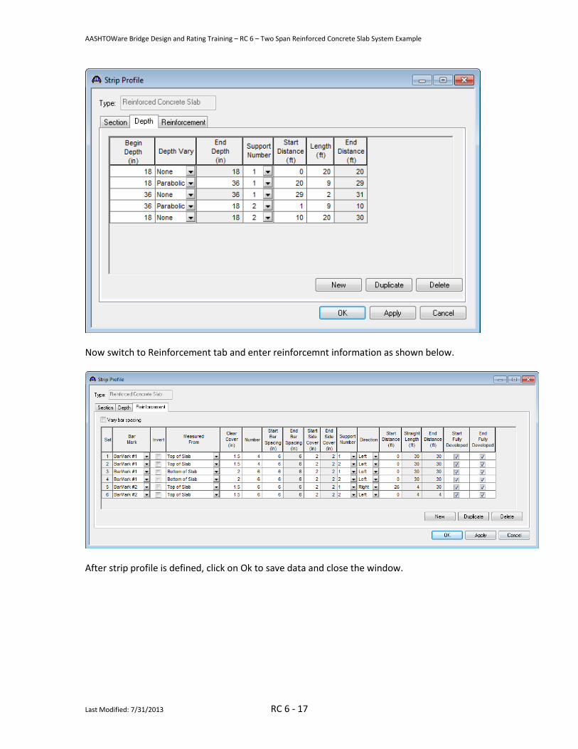
Now switch to Reinforcement tab and enter reinforcemnt information as shown below.
After strip profile is defined, click on Ok to save data and close the window.

AASHTOWare Bridge Design and Rating Training – RC 6 – Two Span Reinforced Concrete Slab System Example
Last Modified: 7/31/2013 RC 6 - 18
The profile of the slab strip can be viewed by selecting the member alternative and click on the
View schematic button on the toolbar. Schematic for Slab Strip S2 member alternaive is as shown below.
We can now enter the live load distribution factors for this member. Open Live Load Distribution window. Under Standard tab, click on Compute from Typical Section button. Live load distribution factors will be populated as shown below. If live load distribution factors are not entered, the AASHTO Engine will compute the distribution factors during the analysis.
Click on Ok to save data and close the window.
AASHTOWare Bridge Design and Rating Training – RC 6 – Two Span Reinforced Concrete Slab System Example
Last Modified: 7/31/2013 RC 6 - 19
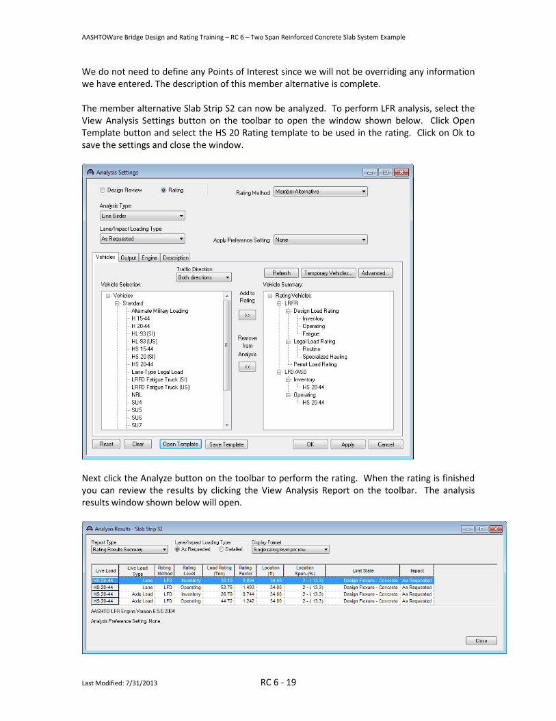
We do not need to define any Points of Interest since we will not be overriding any information we have entered. The description of this member alternative is complete. The member alternative Slab Strip S2 can now be analyzed. To perform LFR analysis, select the View Analysis Settings button on the toolbar to open the window shown below. Click Open Template button and select the HS 20 Rating template to be used in the rating. Click on Ok to save the settings and close the window.
Next click the Analyze button on the toolbar to perform the rating. When the rating is finished you can review the results by clicking the View Analysis Report on the toolbar. The analysis results window shown below will open.
AASHTOWare Bridge Design and Rating Training – RC 6 – Two Span Reinforced Concrete Slab System Example
Last Modified: 7/31/2013 RC 6 - 20
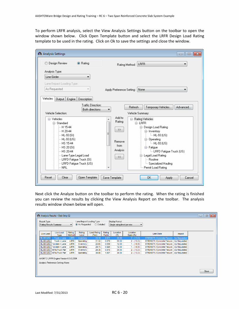
To perform LRFR analysis, select the View Analysis Settings button on the toolbar to open the window shown below. Click Open Template button and select the LRFR Design Load Rating template to be used in the rating. Click on Ok to save the settings and close the window.
Next click the Analyze button on the toolbar to perform the rating. When the rating is finished you can review the results by clicking the View Analysis Report on the toolbar. The analysis results window shown below will open.

AASHTOWare Bridge Design and Rating Training – RC 6 – Two Span Reinforced Concrete Slab System Example
Last Modified: 7/31/2013 RC 6 - 21
To perform LRFD design review, open the Analysis Settings window and select the HL 93 Design Review template as shown below.
Next click the Analyze button on the toolbar to perform the design review. Click on View Analysis Output button on toolbar and double-click Spec Check Results for a summary of the specification check results.

AASHTOWare Bridge Design and Rating Training – RC 6 – Two Span Reinforced Concrete Slab System Example
Last Modified: 7/31/2013 RC 6 - 22
AASHTOWare Bridge Design and Rating Training – RC 6 – Two Span Reinforced Concrete Slab System Example
Last Modified: 7/31/2013 RC 6 - 23
Part 2: Frame structure simplified definition slab structure type.
30'-0
"6"
6"
Elev
atio
n
30'-0
"
20'-0
"9'
-0"
9'-0
"20
'-0"
1'-0
"
1'-6
"3'
-0"
#11'
s#1
1's
A A
B B
CC
2'-0
"
15'-0
"

AASHTOWare Bridge Design and Rating Training – RC 6 – Two Span Reinforced Concrete Slab System Example
Last Modified: 7/31/2013 RC 6 - 24
Structure Typical Section at Pier
27'-0"24'-0" 1'-6"1'-6"
3'-0"
15'-0"
4'-0"(Typ.)
Section C-C
2'-0"Depth
4'-0"Width
AASHTOWare Bridge Design and Rating Training – RC 6 – Two Span Reinforced Concrete Slab System Example
Last Modified: 7/31/2013 RC 6 - 25
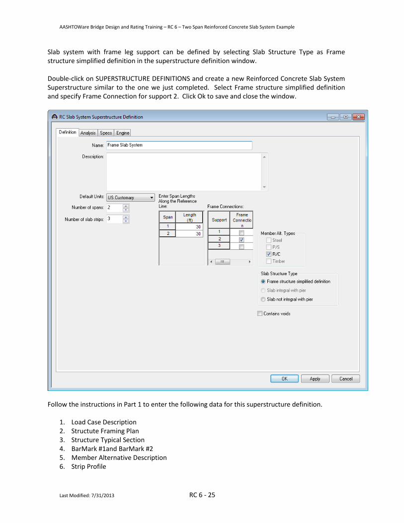
Slab system with frame leg support can be defined by selecting Slab Structure Type as Frame structure simplified definition in the superstructure definition window. Double-click on SUPERSTRUCTURE DEFINITIONS and create a new Reinforced Concrete Slab System Superstructure similar to the one we just completed. Select Frame structure simplified definition and specify Frame Connection for support 2. Click Ok to save and close the window.
Follow the instructions in Part 1 to enter the following data for this superstructure definition.
1. Load Case Description 2. Structute Framing Plan 3. Structure Typical Section 4. BarMark #1and BarMark #2 5. Member Alternative Description 6. Strip Profile

AASHTOWare Bridge Design and Rating Training – RC 6 – Two Span Reinforced Concrete Slab System Example
Last Modified: 7/31/2013 RC 6 - 26
Now we begin the windows with specific information for the Frame structure simplified definition. Open Structure Framing Plan Detail window, switch to Frame Connections tab and enter data as show below.
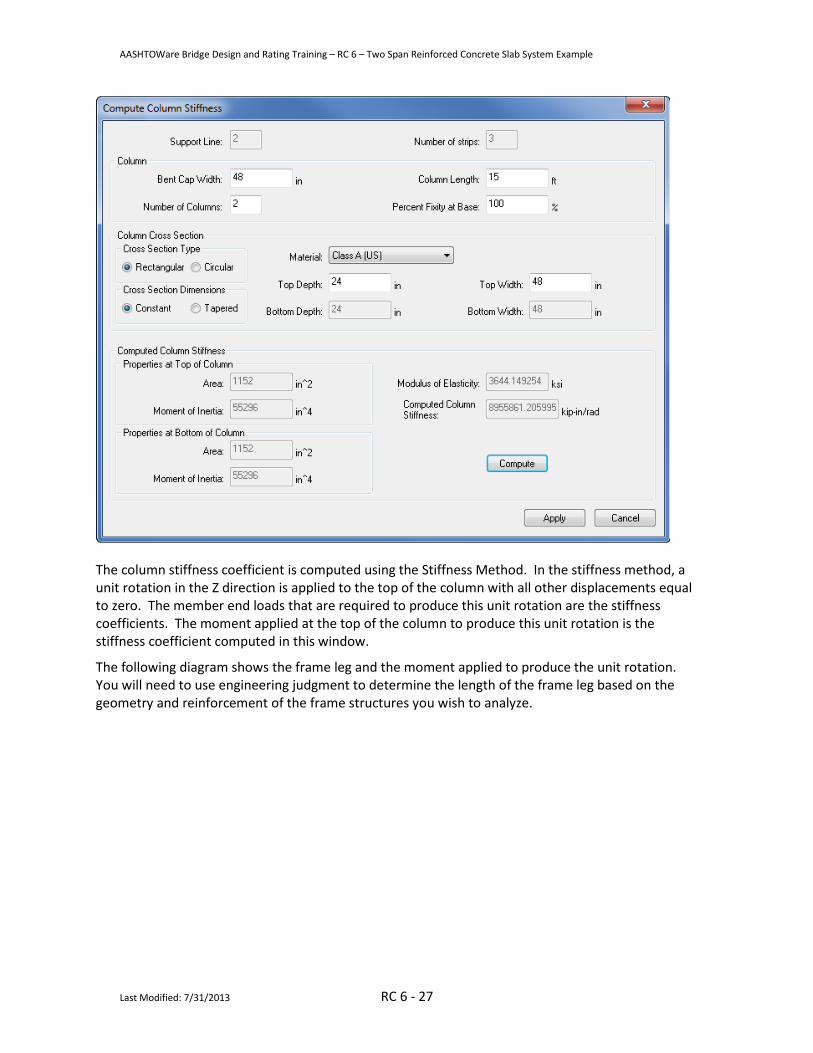
Select the Compute button to open the Compute Column Stiffness dialog. Click on the Compute button to compute the column stiffness coefficient.
AASHTOWare Bridge Design and Rating Training – RC 6 – Two Span Reinforced Concrete Slab System Example
Last Modified: 7/31/2013 RC 6 - 27
The column stiffness coefficient is computed using the Stiffness Method. In the stiffness method, a unit rotation in the Z direction is applied to the top of the column with all other displacements equal to zero. The member end loads that are required to produce this unit rotation are the stiffness coefficients. The moment applied at the top of the column to produce this unit rotation is the stiffness coefficient computed in this window.
The following diagram shows the frame leg and the moment applied to produce the unit rotation. You will need to use engineering judgment to determine the length of the frame leg based on the geometry and reinforcement of the frame structures you wish to analyze.

AASHTOWare Bridge Design and Rating Training – RC 6 – Two Span Reinforced Concrete Slab System Example
Last Modified: 7/31/2013 RC 6 - 28
30'-0" 30'-0"
15'-0"
Oa = 1Ma
The moment required to produce a unit rotation at the top of the cantilever column is Ma = 4EI/L.
The computed column stiffness coefficient is based on the entered number of columns. Click on Apply button to apply this stiffness coefficient to Support 2.
Click Ok to save and close the Structure Framing Plan Detail window.
AASHTOWare Bridge Design and Rating Training – RC 6 – Two Span Reinforced Concrete Slab System Example
Last Modified: 7/31/2013 RC 6 - 29
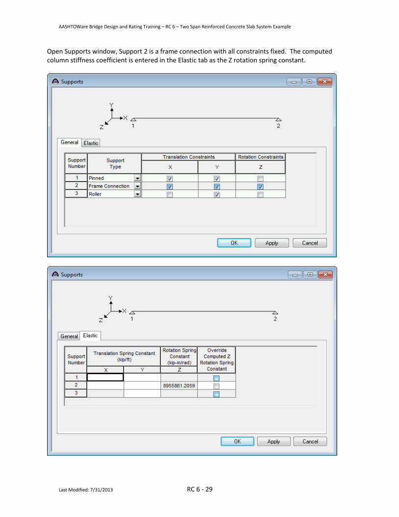
Open Supports window, Support 2 is a frame connection with all constraints fixed. The computed column stiffness coefficient is entered in the Elastic tab as the Z rotation spring constant.

AASHTOWare Bridge Design and Rating Training – RC 6 – Two Span Reinforced Concrete Slab System Example
Last Modified: 7/31/2013 RC 6 - 30
In similar manner as performed above, LFR, LRFR and LRFD analysis can be performed by selecting their respective templates. As this slab bridge is not designed with framed connection at pier, we are not going to perfrom rating and design analysis in this example.
Related Documents