AAS 01-352 DESIGN AND SYSTEM IDENTIFICATION OF A NANOSATELLITE STRUCTURE Craig L. Stevens ∗ , Jana L. Schwartz † , and Christopher D. Hall ‡ The Virginia Tech Ionospheric Scintillation Measurement Mis- sion, known as HokieSat, is a 40 lb nanosatellite being designed and built by graduate and undergraduate students. The satellite is part of the Ionospheric Observation Nanosatellite Formation (ION-F) which will perform ionospheric measurements and con- duct formation flying experiments. In this paper we describe the design of the primary satellite structure, the analysis used to arrive at the design, and the experimentation used to verify the analysis. We also describe the internal and external config- urations of the spacecraft and how we estimate the mass, mass center, and moments of inertia. INTRODUCTION The Virginia Tech Ionospheric Scintillation Measurement Mission, hereafter known as HokieSat, is part of a satellite formation known as the ION-F mission. ION-F is comprised of three nanosatellites designed and built by students at the University of Washington, Utah State University, and Virginia Tech. The ION-F mission is part of the Air Force Research Laboratory/DARPA/NASA University Nanosatellite Pro- gram. The University Nanosatellite Program involves 9 university-built nanosatellites planned to launch on two launches on the space shuttle in 2003. The program pro- vides technology demonstration for future high risk, low cost nanosatellite formation missions such as TechSat21[1]. The three satellites, University of Washington’s Dawgstar, Utah State’s USUSat, and Virginia Tech’s HokieSat, are all hexagonal prisms massing between 33 and 44 lbs. The configuration of HokieSat is 18 inches in major diameter, and approximately ∗ Graduate Research Assistant, Aerospace and Ocean Engineering, Virginia Polytechnic Institute and State University, Blacksburg, Virginia, 24061. email: [email protected] † National Science Foundation Fellow, Aerospace and Ocean Engineering, Virginia Polytechnic Institute and State University, Blacksburg, Virginia, 24061. email: [email protected] ‡ Associate Professor, Aerospace and Ocean Engineering, Virginia Polytechnic Institute and State University, Blacksburg, Virginia 24061. Associate Fellow AIAA. Member AAS. email: [email protected] 1

Welcome message from author
This document is posted to help you gain knowledge. Please leave a comment to let me know what you think about it! Share it to your friends and learn new things together.
Transcript

AAS 01-352
DESIGN AND SYSTEM IDENTIFICATION OF ANANOSATELLITE STRUCTURE
Craig L. Stevens∗, Jana L. Schwartz†, and Christopher D. Hall‡
The Virginia Tech Ionospheric Scintillation Measurement Mis-sion, known as HokieSat, is a 40 lb nanosatellite being designedand built by graduate and undergraduate students. The satelliteis part of the Ionospheric Observation Nanosatellite Formation(ION-F) which will perform ionospheric measurements and con-duct formation flying experiments. In this paper we describethe design of the primary satellite structure, the analysis usedto arrive at the design, and the experimentation used to verifythe analysis. We also describe the internal and external config-urations of the spacecraft and how we estimate the mass, masscenter, and moments of inertia.
INTRODUCTION
The Virginia Tech Ionospheric Scintillation Measurement Mission, hereafter knownas HokieSat, is part of a satellite formation known as the ION-F mission. ION-F iscomprised of three nanosatellites designed and built by students at the University ofWashington, Utah State University, and Virginia Tech. The ION-F mission is partof the Air Force Research Laboratory/DARPA/NASA University Nanosatellite Pro-gram. The University Nanosatellite Program involves 9 university-built nanosatellitesplanned to launch on two launches on the space shuttle in 2003. The program pro-vides technology demonstration for future high risk, low cost nanosatellite formationmissions such as TechSat21[1].
The three satellites, University of Washington’s Dawgstar, Utah State’s USUSat,and Virginia Tech’s HokieSat, are all hexagonal prisms massing between 33 and 44lbs. The configuration of HokieSat is 18 inches in major diameter, and approximately
∗Graduate Research Assistant, Aerospace and Ocean Engineering, Virginia Polytechnic Instituteand State University, Blacksburg, Virginia, 24061. email: [email protected]
†National Science Foundation Fellow, Aerospace and Ocean Engineering, Virginia PolytechnicInstitute and State University, Blacksburg, Virginia, 24061. email: [email protected]
‡Associate Professor, Aerospace and Ocean Engineering, Virginia Polytechnic Institute and StateUniversity, Blacksburg, Virginia 24061. Associate Fellow AIAA. Member AAS. email: [email protected]
1

12 inches in height. In this paper, we discuss the design of the spacecraft configuration,and the analysis and experimentation that define the satellite structural and massproperties.
SYSTEM DESIGN
Satellites typically have unique designs that are based on their respective missions.The structural design of HokieSat is based on several design goals. These goalsinclude integration compatibility, simplicity of fabrication, and structural and massoptimization.
Integration compatibility of the multiple spacecraft system is an integral part ofthe spacecraft design. As stated above, HokieSat is part of the three-satellite for-mation flying experiment ION-F. The formation flying mission requirements dictatethat the three spacecraft have nearly identical initial conditions [1]. Therefore, theformation must be launched aboard the same launch vehicle. The launch vehicle cho-sen for this mission is the Shuttle Hitchhiker Experiment Launch System (SHELS),via the Space Shuttle. Due to safety issues and tracking limitations, NASA prohibitsthe nanosatellites from deploying separately from the Shuttle Orbiter Payload Bay.The solution to the safety issues is the Multiple Satellite Deployment System (MSDS)designed by AFRL (see Figure 1). The MSDS is a platform that supports two groupsof three nanosatellites in a stack configuration aboard the SHELS [2]. The two stacksare comprised of two University Nanosatellite formation flying constellations, ION-Fand 3 CornerSat. The mission profile calls for the MSDS to deploy from the SHELSwith the stacks mounted to the platform. Once a specified time has elapsed, the twostacks are ejected from the MSDS. Finally, the ION-F nanosatellites separate fromeach other and begin the formation flying mission. The large number of organiza-tions involved in the mission created a necessity for emphasis on integration controlearly in the design phase of the project. In order to minimize the inherent complica-tions of integration, all satellites are designed as hexagonal cylinders with dimensionsresembling the figures stated for HokieSat above.
Another factor in the design of the nanosatellite is the simplicity of fabricationand assembly. Several materials are used in satellite fabrication, such as aluminum,titanium, graphite composite, and composite sandwich panels. These materials varyin cost, manufacturing time, mass, strength, durability, and required craftsmanship.Aluminum 6061 T-651 was selected as the primary material in the spacecraft structurefor several reasons. The material is relatively abundant and economically feasiblefor a low budget program. It has a density of approximately 0.1 lb/in3 which isroughly one third the density of steel and other metals used in manufacturing. Finally,aluminum is simple to manufacture and has relatively good workability [3]. Goodworkability is an important advantage to consider for a small budget program, whichmust minimize cost by using university machine shops, and relatively inexperienced
2

3CSION -F
USUSat
Dawgstar
HokieSatMSDS
3CSION -F
USUSat
Dawgstar
HokieSat
3CSION -F
USUSat
Dawgstar
HokieSatMSDS
Figure 1 University Nanosat launch configuration
students to perform the majority of the machine work.
The final consideration in the design process is optimizing the structural and massproperties of the spacecraft. The optimal mass reducing design chosen for HokieSatis isogrid. Isogrid, illustrated in Figure 2, uses an array of equilateral triangles toincrease the structural performance of a flat sheet of material. Ideally, machiningan isogrid pattern reduces the mass of the original plate by approximately 75% andreduces the strength of the plate by approximately 25%. Nominally, this proceduremay produce a 200% increase in strength per weight compared to the original flatplate [4]. Another advantage to machining the triangle array is that the plate remainsisotropic [5]. Therefore, it exhibits similar strength in all directions, and locations ofstress concentrations are minimized.
Figure 2 Photograph of HokieSat structure
The HokieSat structural configuration is designed to accommodate all of the com-ponents used to perform the mission (see Figure 3 and Figure 4). The isogrid pattern
3

is designed to have two inch spacing between each node, or connection point. Thispattern allows for convenient mounting of components while increasing the structuralperformance.
Torque coils (3)
Rate gyro
Downlink transmitter
Cameras
Camera
Electronics enclosure
Battery enclosure
MagnetometerCamera
Powerprocessing unit
X/L components
Pulsed plasmathrusters (2)
Torque coils (3)
Rate gyro
Downlink transmitter
Cameras
Camera
Electronics enclosure
Battery enclosure
MagnetometerCamera
Powerprocessing unit
X/L components
Pulsed plasmathrusters (2)
Figure 3 Internal configuration of HokieSat
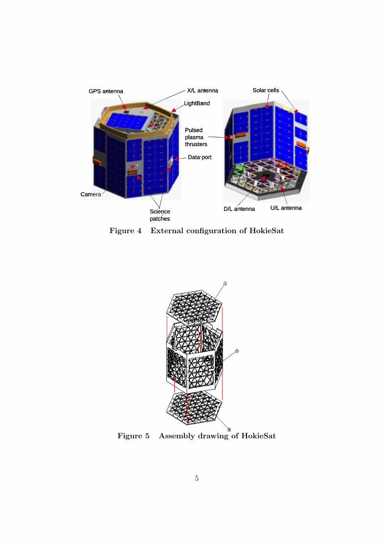
The structural assembly consists of eight isogrid plates (see Figure 5). The two endpanels are open isogrid plates that measure 18 inches in major diameter and are 0.25inches thick. The six side panels are constructed out of open 0.23 inch thick isogridplates adhered to a 0.02 inch outside skin (see Figure 6). The composite side panelsare less expensive to manufacture than a monocoque structure. The skins reinforcethe side panels and provide a surface to affix body-mounted solar cell arrays. Theside panels are modified to extend one inch above and below the end panel surfacesto provide more area to support the cell arrays. Modifications to the isogrid occur infour of the side panels to allow the nozzles of the pulsed plasma thrusters to protrudethrough the structure to the outside of the spacecraft. Based on previous analysisof isogrid structures, these modifications have a negligible effect on the structuralintegrity of the panels [4, 5].
ANALYSIS
The analysis of the structure is divided into three areas: static, dynamic, and massproperties. The static analysis ensures that the structure can support the masses ofthe other spacecraft, and the dynamic analysis investigates the stiffness propertiesof the structure. The mass properties analysis defines the mass moments of inertiaand center of mass location of the spacecraft which are important to the spacecraftattitude and orbital dynamics.
4
Data port
X/L antenna
U/L antennaD/L antennaSciencepatches
LightBand
GPS antenna
Pulsed plasmathrusters
Solar cells
Camera
Data port
X/L antenna
U/L antennaD/L antennaSciencepatches
LightBand
GPS antenna
Pulsed plasmathrusters
Solar cells
Camera
Figure 4 External configuration of HokieSat
Figure 5 Assembly drawing of HokieSat
5

Figure 6 Assembly drawing of composite side panels
A spacecraft typically experiences its greatest loads during launch. The launchconfiguration of ION-F is comprised of a stack of three interconnected satellites asshown in Figure 1. The NASA Space Shuttle payload requirements dictate that thestructure survive all of the system loads in all three directions simultaneously. NASAalso adds a factor of safety to this requirement that equates to multiplying all of thesystem loads by 11. Figure 7 illustrates the method used to perform a static finiteelement analysis (FEA) using I-DEAS version 8 [6]. The isogrid is modelled usingarrays of beam elements simulating the webs and arrays of shell elements emulatingthe side panel skins and all other solid aluminum entities (see Figure 7). The effectsof other two spacecraft of the stack are simulated using a resultant load appliedapproximately 13 inches above the zenith surface of HokieSat so as to provide theappropriate moment. The resultant load is distributed at nodes over the top ofa rigid fixture that models the correct load path. All significant internal spacecraftcomponents are simulated by applying the appropriate forces at each connection pointusing the method stated above. Examining the results from Figure 8 demonstratethat the spacecraft survives the launch loads with a margin of safety of 1.
The complex launch configuration explained above also affects the structural dy-namics analysis and design of the satellite. A modal finite element analysis of a sidepanel and the assembled structure was conducted using I-DEAS version 8 [6]. Thestructure is modelled using the same element assembly that is detailed above. Theresults from the side panel analysis, shown in Figure 9, show that the first modenatural frequency occurs at 131 Hz and the second mode natural frequency occurs at171 Hz. The first mode exhibits a twisting shape about the longitudinal axis whereasthe second mode exhibits a bending shape about the lateral axis. Subsequent modeshapes observed at frequencies above 400 Hz have little significance on the structuraldynamics of the panel. The assembled structure modal analysis results are shown in
6

Figure 7 Static finite element model of HokieSat (wireframe and shadedviews)
Figure 8 Static finite element model results
7

Figure 9 Side panel modal FEA results
Figure 10 and Figure 11. The first mode of the assembly has a natural frequencyof 249 Hz. At this frequency, the mode shape exhibits large deflections of the endpanels (typically called a “drum mode”) that resonate 180◦ out of phase. The sec-ond mode of the structure occurs at 263 Hz. The second mode shape is also a “drummode;” however, the bottom panel vibrates in phase with the top panel. The analysisdemonstrates that components mounted on the center of these panels will experiencethe greatest accelerations during launch.
Figure 10 Structural assembly modal FEA results
8

Figure 11 Structural assembly modal FEA results
FABRICATION
Spacecraft fabrication is a high risk operation for typical low budget programs. Sev-eral methods were implemented to alleviate fabrication and design errors and assurequality of the components. The fabrication of isogrid has simplified in recent yearsdue to the innovation of computer node controller (CNC) milling machines. The CNCmachines were used to mill the isogrid, while the rest of the fabrication required con-ventional methods of manufacturing. All of the aluminum in the flight structure wassubsequently iridited for corrosion protection while also allowing adequate thermaland electrical conductivity [7].
The side panels are designed to be stiffened using a composite structure as shownin Figure 6. Each side panel was adhered using a standard 2216 gray epoxy pur-chased through 3-M. The epoxy was chosen for its effectiveness at bonding aluminumand its durability in the arduous space environment [8]. A meticulous procedureensured a sufficient cure of the bond and satisfied all of the NASA safety criterion(see Figure 12). All of the hardware is stored in a Class 100,000 clean facility. Theenvironment is maintained at a temperatures between 70 and 76◦ Fahrenheit and a hu-midity range of 40 to 60%. These ideal conditions prevent oxidation of the aluminumand minimize the risk of damage to the electronic components (e.g. electrostaticdischarge).
SYSTEM IDENTIFICATION
HokieSat is a complicated system of aluminum, computer boards, cameras, solar cells,and other subsystem components. Computational analysis of the structural properties
9
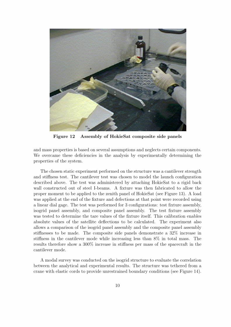
Figure 12 Assembly of HokieSat composite side panels
and mass properties is based on several assumptions and neglects certain components.We overcame these deficiencies in the analysis by experimentally determining theproperties of the system.
The chosen static experiment performed on the structure was a cantilever strengthand stiffness test. The cantilever test was chosen to model the launch configurationdescribed above. The test was administered by attaching HokieSat to a rigid backwall constructed out of steel I-beams. A fixture was then fabricated to allow theproper moment to be applied to the zenith panel of HokieSat (see Figure 13). A loadwas applied at the end of the fixture and defections at that point were recorded usinga linear dial gage. The test was performed for 3 configurations: test fixture assembly,isogrid panel assembly, and composite panel assembly. The test fixture assemblywas tested to determine the tare values of the fixture itself. This calibration enablesabsolute values of the satellite deflections to be calculated. The experiment alsoallows a comparison of the isogrid panel assembly and the composite panel assemblystiffnesses to be made. The composite side panels demonstrate a 32% increase instiffness in the cantilever mode while increasing less than 8% in total mass. Theresults therefore show a 300% increase in stiffness per mass of the spacecraft in thecantilever mode.
A modal survey was conducted on the isogrid structure to evaluate the correlationbetween the analytical and experimental results. The structure was tethered from acrane with elastic cords to provide unrestrained boundary conditions (see Figure 14).
10

A 75 pound shaker with a four-inch vertical stinger was used to apply a burst chirpimpulse to the structure ranging from 20 Hz to 1000 Hz. A three-axis accelerometerwas attached at different locations on the spacecraft for each test. A statisticalanalysis was performed on the results and the mean values for the first and secondmodal natural frequencies are shown in Table 1. The analysis correlates well with theexperimental results. The first and second mode shapes are similar and the first modeanalytical natural frequency deviates approximately 1% from the mean experimentalresult.
Table 1 Modal survey test dataMode Analysis (Hz) Experiment (Hz)
1 249 2462 263 272
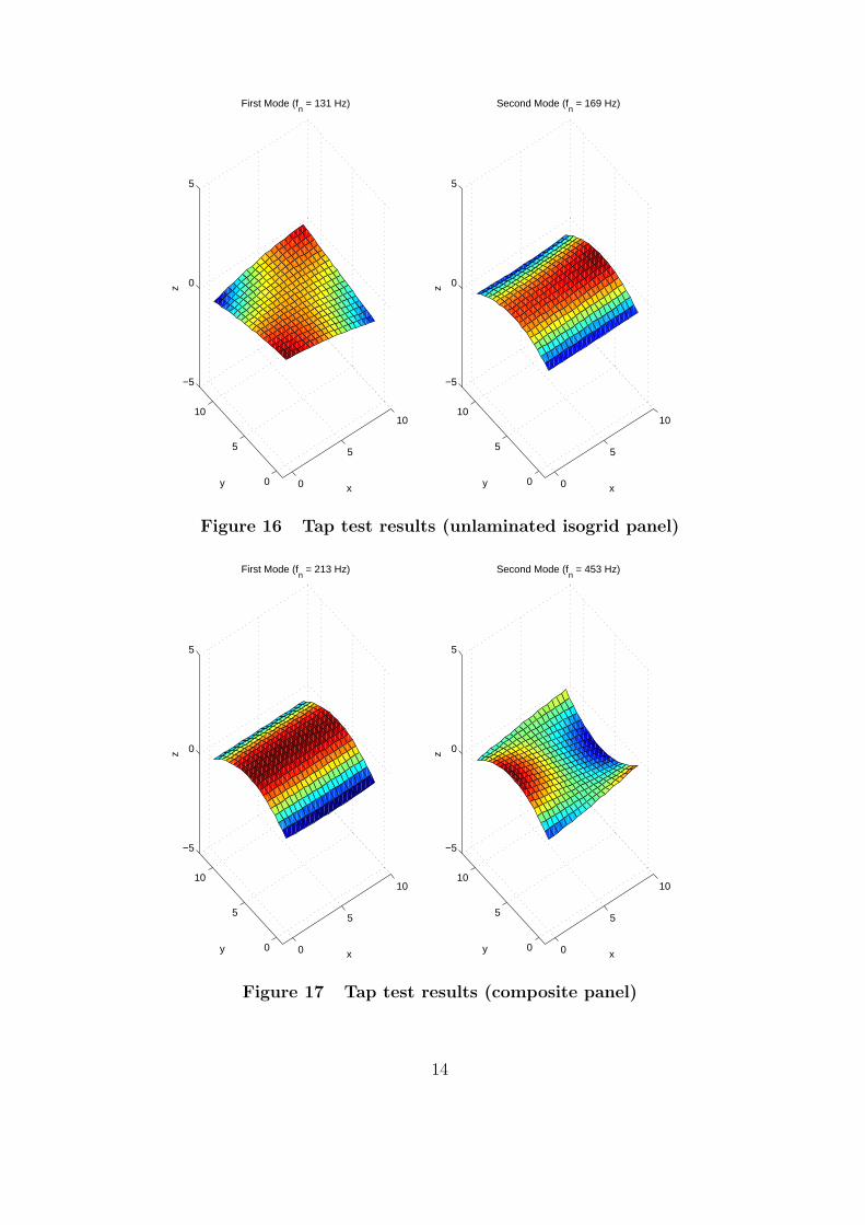
Tap testing was performed on the side panel to quantify the structural perfor-mance of the composite side panels with respect to the unskinned isogrid. The panelwas supported by hanging it from a fixture using packaging tape (see Figure 15). Anaccelerometer placed on the center of the panel measured accelerations normal to thecomponent. The tap hammer was used to provide an impulse at locations around thepanel to collect adequate resolution of the data. The data points were interpolatedand plotted using Matlab. The results are shown in Figure 16 and Figure 17, wherethe x-axis is defined as the lateral or bottom edge of the panel. The unlaminatedisogrid results exhibit the same mode shapes as computed in the analysis (see Fig-ure 9). The first two modal frequencies also correlate nicely between the analysis andexperiment as shown in Table 2. The experimental data also demonstrate that thefirst twisting mode of the isogrid panel increases to a frequency out of the spectrumof the experiment. The second mode of the isogrid panel increases by approximately26% in frequency, which becomes the first modal frequency of the composite panel.The error in the analytical solution is approximately 1%, which is standard acceptablemodeling error for most applications.
Table 2 Tap test data (unlaminated isogrid panel)Mode Analysis (Hz) Experiment (Hz)
1 131 1312 171 169
Dynamic structural testing was performed at NASA Wallops Flight Facility. Massmodels of the major components were constructed and attached to the satellite tosimulate the integrated system (see Figure 18). Fifteen accelerometers were usedto record the accelerations that the major components and panels experience. Thespacecraft was inspected for any yielding or failure after each test. The test sequenceand results are tabulated in Table 3. The dynamic testing demonstrated that the
11

satellite will survive the launch environment. Using the results of these tests, wewere able to relocate internal components to increase the natural frequencies of thespacecraft.
Table 3 Dynamic test sequence and resultsTest Description Result
Sine Sweep X 20 – 2000 Hz, 0.5 g RMS PassRandom Vibe X 9 g RMS, 1 min PassSine Burst X 24 g, 23 Hz, PassSine Sweep Y 20 – 2000 Hz, 0.5 g RMS PassRandom Vibe Y 9 g RMS, 1 min PassSine Burst Y 24 g, 23 Hz PassSine Sweep Z 20 – 2000 Hz, 0.5 g RMS PassRandom Vibe Z 9 g RMS, 1 min PassSine Burst Z 24 g, 23 Hz Pass
Figure 13 Strength and stiffness test assembly configuration
12
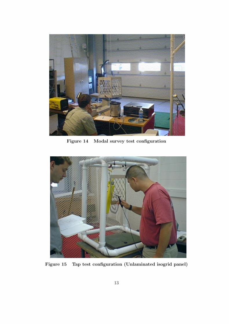
Figure 14 Modal survey test configuration
Figure 15 Tap test configuration (Unlaminated isogrid panel)
13
0
5
10
0
5
10
−5
0
5
x
First Mode (fn = 131 Hz)
y
z
0
5
10
0
5
10
−5
0
5
x
Second Mode (fn = 169 Hz)
y
z
Figure 16 Tap test results (unlaminated isogrid panel)
0
5
10
0
5
10
−5
0
5
x
First Mode (fn = 213 Hz)
y
z
0
5
10
0
5
10
−5
0
5
x
Second Mode (fn = 453 Hz)
y
z
Figure 17 Tap test results (composite panel)
14
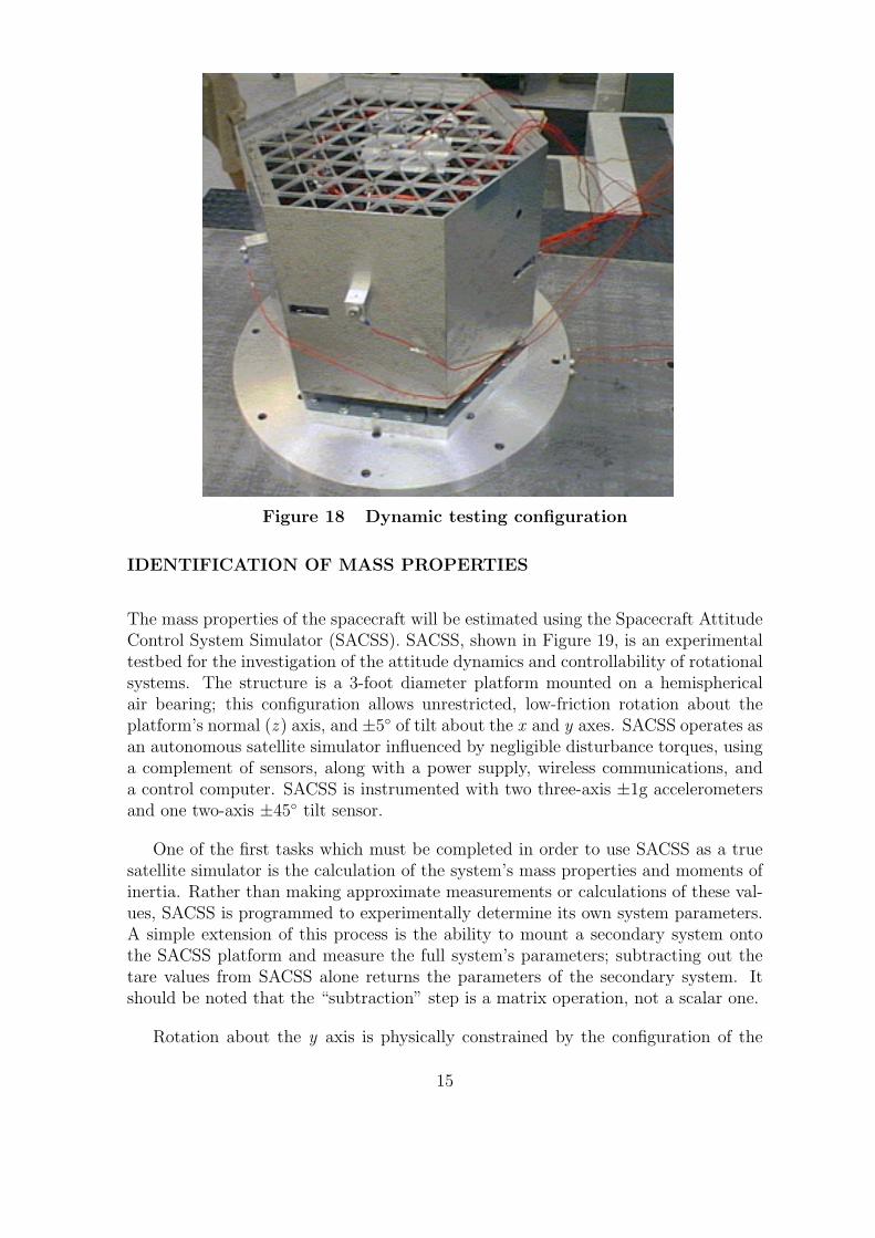
Figure 18 Dynamic testing configuration
IDENTIFICATION OF MASS PROPERTIES
The mass properties of the spacecraft will be estimated using the Spacecraft AttitudeControl System Simulator (SACSS). SACSS, shown in Figure 19, is an experimentaltestbed for the investigation of the attitude dynamics and controllability of rotationalsystems. The structure is a 3-foot diameter platform mounted on a hemisphericalair bearing; this configuration allows unrestricted, low-friction rotation about theplatform’s normal (z ) axis, and ±5◦ of tilt about the x and y axes. SACSS operates asan autonomous satellite simulator influenced by negligible disturbance torques, usinga complement of sensors, along with a power supply, wireless communications, anda control computer. SACSS is instrumented with two three-axis ±1g accelerometersand one two-axis ±45◦ tilt sensor.
One of the first tasks which must be completed in order to use SACSS as a truesatellite simulator is the calculation of the system’s mass properties and moments ofinertia. Rather than making approximate measurements or calculations of these val-ues, SACSS is programmed to experimentally determine its own system parameters.A simple extension of this process is the ability to mount a secondary system ontothe SACSS platform and measure the full system’s parameters; subtracting out thetare values from SACSS alone returns the parameters of the secondary system. Itshould be noted that the “subtraction” step is a matrix operation, not a scalar one.
Rotation about the y axis is physically constrained by the configuration of the
15

Figure 19 The Spacecraft Attitude Control System Simulator
air bearing, so an Euler angle sequence using θy as the second rotation can be usedwithout the risk of encountering a singularity. Thus, the equations of state become
θ = S−1(θ)ω (1)
ω = −I−1ω×Iω + I−1gext (2)
where the only external torque is that from gravity.
The Extended Kalman Filter (EKF) is a standard algorithm for nonlinear satel-lite sensor fusion and control. System identification is included within the EKFstructure by using a parameter-estimating EKF. In this algorithm, the parametersof the system are included as time-invariant members of the state vector, x, so that
x =[θT ωT mg rT IT
]where I is the “flattened” moment of inertia matrix.
CONCLUSIONS
The design and system identification of Virginia Tech’s nanosatellite has been com-pleted using several analytical and experimental techniques. The aluminum isogriddesign provides an improvement over the structural performance of flat plates and al-lows students and university technicians to fabricate most of the spacecraft, while theuse of thin aluminum skins improves the stiffness of the overall structure. Finite ele-ment analysis is used to characterize the performance of the primary structure. Modaltesting results verify the accuracy of the isogrid side panel finite element model withinan error of approximately 1%. The test also demonstrates a 300% increase in struc-tural performance by using a composite structure incorporating the thin aluminum
16

skins. The results from the finite element analyses and experiments verify that thestructure satisfies all of the NASA Space Shuttle payload requirements. Further test-ing will be performed to verify the structural integrity of the composite side panelsand to determine the mass properties of the spacecraft.
ACKNOWLEDGEMENTS
This project has been supported by the Air Force Research Laboratory, the AirForce Office of Scientific Research, the Defense Advanced Research Projects Agency,NASA Goddard Space Flight Center, NASA Wallops Flight Test Center, and the3 universities. We especially acknowledge the efforts of many of the students onthe HokieSat, USUSat, and Dawgstar teams who have contributed to the analysisand development of the structural subsystem. Professor A. Wicks of Virginia Tech’sMechanical Engineering Department provided invaluable assistance with the modaltesting.
REFERENCES
[1] Campbell, M., Fullmer, R. R., and Hall, C. D., “The ION-F Formation FlyingExperiments,” Space Flight Mechanics 2000 , AAS/AIAA, 2000, AAS 00-108.
[2] Brackett, C. E., “AFRL’s Multi-Satellite Deployment System (MSDS),” 15th An-nual AIAA/USU Conference on Small Satellites, Logan, Utah, August 13-16,2001 , AIAA, 2001.
[3] Mangonon, P. L., The Principles of Materials Selection for Engineering Design,Prentice Hall, Upper Saddle River, NJ, 1999.
[4] “Isogrid Microspacecraft Structures Final Report,” Tech. rep., Space DynamicsLaboratory, Utah State University, 1994, SDL/94-037.
[5] Isogrid Design Handbook , McDonnell Douglas Astronautics Co., HuntingtonBeach, CA, 1973, Major Reference.
[6] “I-DEAS General Capabilities User’s Guide,” Tech. rep., Structural DynamicsResearch Corporation, Milford, OH, 2001.
[7] “Military Plating Specifications,” Tech. rep., Alexandria Metal Finishers, Inc.,Lorton, VA, 2000.
[8] “UW Dawgstar/ION-F CDR Document: Structures Subsystem,” Tech. rep., Uni-versity of Washington, 2001, AA-22801-DOC100.
17
Related Documents