READ FIRST DO NOT use the machine until you read and understand all the dangers, warnings and cautions in this manual. SCISSOR HOIST AutoLift AL-162016 Full Rise Heavy Duty Scissor Hoist 5500Kg Maximum Lifting Capacity INSTALLATION MANUAL & OPERATION INSTRUCTIONS - READ THE ENTIRE CONTENTS OF THIS MANUAL BEFORE INSTALLATION AND OPERATION. BY PROCEEDING YOU AGREE THAT YOU FULLY UNDERSTAND AND COMPREHEND THE FULL CONTENTS OF THIS MANUAL. FORWARD THIS MANUAL TO ALL OPERATORS. FAILURE TO OPERATE THIS EQUIPMENT AS DIRECTED MAY CAUSE INJURY OR DEATH. Specifications subject to change without notice. Note: While all due care and attention has been taken in the preparation of this document, Advance AutoQuip shall not be liable for any inaccuracies or omissions which may occur therein Advance AutoQuip 2 McDonald Crescent | Bassendean WA 6054 Ph: 08 9279 1663 | Fax: 08 9279 1667 | E: [email protected] | W: www.aaq.net.au

Welcome message from author
This document is posted to help you gain knowledge. Please leave a comment to let me know what you think about it! Share it to your friends and learn new things together.
Transcript

READ FIRST
DO NOT use the
machine until you read
and understand all the
dangers, warnings and
cautions in this manual.
SCISSOR HOIST AutoLift AL-162016 Full Rise Heavy Duty Scissor Hoist 5500Kg Maximum Lifting Capacity
INSTALLATION MANUAL & OPERATION INSTRUCTIONS
- READ THE ENTIRE CONTENTS OF THIS MANUAL BEFOREINSTALLATION AND OPERATION. BY PROCEEDING YOU AGREE THAT YOU FULLY UNDERSTAND AND COMPREHEND THE FULL CONTENTS
OF THIS MANUAL. FORWARD THIS MANUAL TO ALL OPERATORS. FAILURE TO OPERATE THIS EQUIPMENT AS DIRECTED MAY CAUSE
INJURY OR DEATH.
Specifications subject to change without notice. Note: While all due care and attention has been taken in the preparation of this document, Advance AutoQuip shall not be liable for any inaccuracies or omissions
which may occur therein
Advance AutoQuip 2 McDonald Crescent | Bassendean WA 6054
Ph: 08 9279 1663 | Fax: 08 9279 1667 | E: [email protected] | W: www.aaq.net.au

162016
CONTENTS
Packing, transport and storage…………………………………………………
introduction………………………………………………………………………
Chapter 1 Description of the machine…………………………………………
Chapter 2 Technical specifications………………………………………………
Chapter 3 Safety…………………………………………………………………
Chapter 4 Installation……………………………………………………………
Chapter 5 Adjusting………………………………………………………………
Chapter 6 Operating principles and use…………………………………………
Chapter 7 Maintenance …………………………………………………………
Chapter 8 Troubleshooting………………………………………………………
Chapter 9 Appendix ………………………………………………………………

162016
PACKING, TRANSPORT AND STORAGE
All packing, lifting, handling, transport and unpacking operations are to be performed exclusively by expert personnel
PACKING AND TRANSPORT Packing :(Picture 1) Standard equipment: oil line and accessory(1#BOX), main and sub beam(3#、
4#BOX), control box(2#BOX), font and back stop board(5#BOX),
standard equipment, total is 5 pieces.
Choosing equipment: leading board(6#BOX) , cover(7#BOX)1 piece, (use to
installation)
PACKING LIST Number Name Accessory name and number 1 Oil line and
accessory 1. M16 anchor bolts 16 suits; M18 anchor bolts 4suits;2. 6*4mm air line 2 suits; 8*5mm air line 3 suits;3. 1.5mm line 5 m. 4.metal pipe 6 m5. limit switch and line 2 suits 6. 1 set of user’smanual7. uusseerr’’ss mmaannuuaall 8. seal 9. 10 line10. high pressure oil line 9 piece.11. 12.13.
2 Controlcabinet(EX)
3 Main beam (1p) 1. M16 anchor bolts 16 suits; adjust shim 2.3.
4 Sub beam (2p) 5 Front and back
stop board 1. Front stop board 2 piceces2. back stop board 2 pieces
6 Leading board 2 pieces 7 cover 1 piece of 1000mm, 1 piece of 950mm, 1 piece of
750mm data
<3.5t> 4.0t (5.5t)
picture 1

162016
PACKING, TRANSPORT AND STORAGE
Transport:(picture 2)
Packing can be lifted or moved by lift trucks, cranes or bridge cranes. In case of slinging, a second person must always take care of the load, in order to avoid dangerous oscillations.
At the arrival of the goods, check for possible damage due to transport
operations. Also verify that all items specified in the delivery notes are included. In
case of missing parts, possible defects or damage due to transport operations. Also
verify that all items specified in the delivery notes are included. In case of missing
parts, possible defects or damage due to transport, the person in charge or the
carrier must be immediately informed.
Furthermore, during loading and unloading operation goods must be handle as shown in the picture.
(picture 2)
STORAGE: Equipment should store in warehouse, waterproof process should do in outdoor.
Adopt Cabinet truck during transportation, cabinet storage in shipping.
Control box should store in vertical, and be careful of compressing.
Storage temperature: -25℃~55℃

162016
INTRODUCTION
This manual has been prepared for workshop personnel expert in the use of the lift (operator) and technicians responsible for routine maintenance ( maintenance fitter); read the manual before carrying out any operation with the lift and/or the packing. This manual contains important information regarding:
- the personal safety of operators and maintenance workers. - Lift safety, - The safety of lifted vehicles
Conserving the manual This manual is an integral part of the lift, which it should always accompany, even if the unit is sold. The manual must be kept in the vicinity of the lift, in an easily accessible place. The operator and maintenance staff must be able to locate and consult the manual quickly and at any time. Attentive and pepeated reading of chapter 3, which contains important information and safety warning, is particularly recommended. The lifting, transport, unpacking, assembly, installation, starting up, initial adjustment and testing, extraordinary maintenance, repair, overhauls, transport and dismantling of the lift must be performed by specialized personnel from the licensed dealer or an service center authorized by the manufacturer. The manufacturer declines all responsibility for injury to persons or damage to vehicles or objects when any of the above mentioned operations has been performed by unauthorized personnel or when the rack has been subject to improper use. This manual indicates only the operative and safety aspects that may prove useful to the operator and maintenance worker, I better understanding the structure and operation of the lift and for best use of
the same. In order to understand the terminology used in this manual, the maintenance and repair activities, the ability to interpret correctly the drawings and descriptions contained in the manual and be the country in which the machine has been installed. The same applies to the maintenance fitter, who must also possess specific and specialized knowledge (mechanical, engineering) needed to perform the operations described in the manual in complete safety. The words “operator” and “maintenance fitter” used in this manual are construed as follows: -OPERATOR: person authorized to use the lift -MAINTENANCE FITTER: person authorized for routine maintenance of the
lift.

162016
NOTE: Manufacturer own the right to make little change for the manual
Chapter 1 DESCRIPTION OF THE MACHINE
MACHINE
The scissor lifts suitable for use in four wheel alignment, vehicle tests,
maintenance and care for various types of small automobiles.
Features: -imported electric components.
-Graceful outlook, with concealing structure for the two levels and superior
synchronization.
-Easy for tyre mount and dismount and chasis maintenance.
-the position of the front wheel turntable (optional part) is movable so that the side
slide plate can be fit for more cars.
-the pneumatic double-teeth self-locking system and the anti explosive pipe
insurance are automatic opening when lowering. The sliding block is made by oil and
super-friction materials.
-stable and reliable equipment is relayed on imported hydraulic, pneumatic and
electrical components.
Equipment: -machine basement
-machine frame
- control box
Frame: Make up for steel connecting rod, main lifting platform, sliding board, pneumatic
double tooth, hydraulic oil tank.
Control box under the control box is hydraulic oil tank and hydraulic pump, valve and other control
system. On the control box is electrical system.
Scissor lift is designed and built to lift all kinds of vehicles, All other use are unauthorized. In particular, the lift is not suitable for: washing and respray work, creating raised platforms or lifting personnel, use as

162016
a makeshift press for crushing purposes, use as good lift. And not lift the vehicle which weight exceed the maximum weight.
Chapter 2 TECHNICAL SPECIFICATIONS
SPECIFICATIONS
Capacity 3.5t 4.0t 5.5t
Drive Electrical hydraulic
Max lift weight 3500kg 4000kg 5000kg
Sub machine lift weight 2000kg 2000kg 3000kg
Main machine Lift height 1870mm 1870mm 1870mm
Sub machine lift height 375mm 375mm 375mm
Platform initial height 180mm 180mm 180mm
Main machine platform length 4000mm 4500mm 5030mm
main machine platform width 635mm
Sub machine width 870-1400mm
main machine Lifting time ≤50S
main machine lowering time ≤60S
Sub machine Lifting time ≤10S
Sub machine lowering time ≤10S
Overall width Approximately 2120mm
Approximately 2120mm
Approximately 2120mm
Overall length 5285mm 5785mm 6320mm
Overall weight 1900Kg 2100Kg 2400Kg
power AC 400 or 230V±5% 50Hz
Hydraulic oil 20L 20# high abrasive hydraulic oil
temperature 5-40℃
30-95%
Noisy 76db
Installation height ≤1000M
Storage temperature -25-55C

162016
Chapter 2 TECHNICAL SPECIFICATIONS
3.5t (4.0t) (5.5t)
(picture 3)
MOTOR PUMP: PUMP: Type------------------------------Y90L Type--------------------------------- P4.3
Power---------------------------2.2Kw Model------------------------ teeth pump
Voltage-------------AC400V or 230V Dispacement---------------------- 4.3cc/r
Ie-------------------------------400V:5A Transmission: joint type-------230V:8.7A
Frequency-------------------------50Hz Relief valve
Poles-------------------------------4 Continuous working pressure-- 210bar
Speed---------------------1450rpm/min Intermittent working pressure-150-300 bar
Building shape---------------------B14
Isulation class----------- -------------F Oil
When connecting the motor refer to Inject 20 litters of hydraulic oil into the oil
the enclosed wiring diagrams on the tank
data plate on the casing.
Chapter 2 TECHNICAL SPECIFICATIONS

162016
Installation scheme for lift To install the lift it is necessary to execute suitable foundations with the following characteristics: -concrete type 425
-thickness of concrete≥150mm, the leveling of whole length≤10mm
-perfect parallelism between holes.
<3.5t> 4.0t(5.5t) (picture 4) The thickness and levelling of the base concrete are essential and the levelling adjustment ability of the machine itself cannot be relied upon to excessively.

162016
Chapter 2 TECHNICAL SPECIFICATIONS
Types of vechles suitable for being lifted and overall dimensions Lift are suitable for virtually all vehicles with total weight of no more than 3500 kg or
4000kg or 5500kg and with dimensions not exceeding the below data.
The following diagrams illustrate criteria used to define the operating limits of the lift.
(picture 5)
The lower parts of the vechile underbody could interfere with structural parts of
the lift, take particular parts of the sports-car.
The lift will also handle customized or non-standard vehicles provided they are
within the maximum specified carrying capacity.
Also the personnel safety zone must be defined in relation to vehicle with
unusual dimensions.
3.5t/4.0t 5.5t Min Max. Min Max.
A 1900 4000 2100 4500
B 100 100
C 1900 1900
D 900 900

162016
Chapter 3 SAFETY
Read this chapter carefully and completely since important information for the safety of the operator or others in case of improper use of the lift is included. In the following text there are clear explanations regarding certain situations
of risk or danger that may arise during the operation or maintenance of the
lift, the safety device installed and the correct use of such systems, residual
risks and operative procedures to use (general specific precautions to
eliminate potential hazards).
Lifts are designed and built to lift vehicles and hold them in the elevated position in an enclosed workshop. All other uses of the lifts are unauthorized. In particular, the lifts are not suitable for: -washing and spray work;
-creating raised platforms for personnel or lifting personnel;
-use as a press for crushing purposes;
-use as elevator;
-use as a lift jack for lifting vehicle bodies or changing wheels.
The manufacturer is not liable for any injury to persons or damage to
vehicles and other property caused by the incorrect and unauthorized use of
the lifts.
During lifting and lowering movements the operator must remain in the control
station.
The presence of persons inside the danger zone indicated is strictly
prohibited.
During operations persons are admitted to the area beneath the vehicle only
when the vehicle is already in the elevated position, when the platforms are
stationary, and when the mechanical safety devices are firmly engaged.
Do not use the lift without protecion devices or with the protection devices inhibited. Failure to comply with these regulation can cause serious injury to persons, and irrepearable damage to the lift and the vehicle bein lifed.

162016
( picture
6)
Chapter 3 SAFETY GENERAL PRECAUTIONS
The operator and the maintenance fitter are required to observe the prescriptions of safety regulation in force in the country of installation of the lift.
Furthermore, the operator and maintenance fitter must: -always work in the stations specified and illustrated in this manual; -never remove or deactivate the guards and mechanical, electrical, or other types of safety devices; -read the safety notices placed on the machine and the safety information in this manual. In the manual all safety notices are shown as follows: WARNING: indicates situations and/or types of manoeuvres that are unsafe and can cause minor injury to persons and /or death. CAUTION: indicates situations and/or types of manoeuvres that are unsafe and can cause minor injury to persons and/or damage the lift, the vehicle or other property. RISK OF ELECTRIC SHOCK: a specific safety notice placed on the lift in
areas where the risk of electric shock is particularly high. Risk and protection devices We shall now examine the risks that operators or maintenance fitters may be exposed to when the vehicle is standing on the platforms in the raised position, together with the various safety and protection devices adopted by the manufacturer to reduce all such hazards to the minimum: For optimal personal safety and safety of vehicles, observe the following regulations: -do not enter the safety and safety of vehicles are being lifted. -switch off the engine of the vehicle, engage a gear and engage the hand brake, -make sure the vehicle is positioned correctly. -be sure to lift only approved vehicles, never exceed the specified carrying capacity,

162016
maximum height, and projection (vehicle length and width); -make sure that there are no person on the platforms during up and down movements and during standing.
(picture 7)
Chapter 3 SAFETY
(picture 8)
RISKS FOR PERSONNEL This heading illustrates potential risks for the operator, maintenance fitter, or
any other person present in the area around the lift, result from incorrect use
of the lift.
RISK OF CRUSHING Possible if the operator controlling the lift is not I the specified position at the
control panel.
When the platforms (and vehicle) are lowering the operator must never be
partly or ompletely underneath the movable structure. Always remain in the
control zone.
RISK OF CRUSHING (PERSONNEL) When the platforms and the vehicle are lowering personnel are prohibited

162016
from entering the area beneath the movable parts of the lift. The lift operator must not
start the manoeuvre unit it has been clearly established that there are no person in
potentially dangerous positions.
RISK OF IMPACT Caused by the parts of the lift or the vehicle that are positioned at head
height.
When, due to operational reasons, the lift is stopped at relatively low elevations
personnel must be careful to avoid impact with parts of the machine not
marked with special colours.
(picture 9)
Chapter 3 SAFETY
(picture 10) RISK OF VEHICLE MOVING Caused by operations involving the application of force sufficient to displace the
vehicle.
In the case of large or particular heavy vehicles, sudden movement could create an
unacceptable overload or uneven loadsharing. Therefore, before lifting the
vehicle and during all operations on the vehicle-make sure that it is properly
stopped by the hand brake.

162016
(picture 11)
RISK OF VEHICLE FALLING FROM LIFT This hazard may arise in the case of incorrect positioning of the vehicle on
the platforms, incorrect stopping of the vehicle, or in the case of vehicles of
dimensions that are not compatible with the capacity of the lift.
(picture 12)
Never attempt to perform tests by driving the vehicle while it is on the platforms
Never leave objects in the lowering area of the movable parts of the lift.
Chapter 3 SAFETY
RISK OF SLIPPINE Caused by lubricant contamination of the floor around the lift.
The area beneath and immediately surrounding the lift and also the
platforms must be kept clean.
Remove any oil spills immediately.
When the lift is fully down, do not walk over the platforms or the cross-pieces
in places that are lubricated with a film of grease for functional requirements.
Reduce the risk of slipping by wearing safety shoes.

162016
(picture 13)
RISK OF ELECTRIC SHODK Risk of electric shock in areas of the lift housing electrical wiring.
Do not use jets of water, steam solvents or paint next to the lift, and take
special care to keep such substances clear of the electrical control panel.
RISKS RELATED TO IMAPPROPRIATE LIGHTING The operator and the maintenance fitter must be able to assure that all the
areas of the lift are properly and uniformly illuminate compliance with the
laws in force in the place of installation.
RISK OF COMPONENT FAILURE DURING OPERATION The manufacturer has used appropriate materials and construction techniques
in relation to the specified use of the machine in order to manufacture a reliable
and safe lift. Note however, that the lift must be used in conformity with
manufacturer’s prescriptions, and the frequency of inspections and
maintenance works recommended .
RISK RELATED TO IMPROPER USE Persons are not permitted to stand or sit on the platforms during the lift
manoeuvre or when the vehicle is already lifted.
The handling of safety devices is strictly forbidden. Never exceed the maximum carrying capacity of the lift, make sure the vehicles to be lifted have no load. It is therefore essential to adhere scrupulously to all regulations regarding
use, maintenance and safety contained in this manual.
Chapter 4 INSTALLAION
Skilled and authorized personnel only should be allowed to perform these operations, follow all instructions shown below carefully, in order to prevent possible damage to the car lift or risk of injury to people. Be sure that the operating area is cleared of people. Skilled technicians only, appointed by the same manufacturer or by
authorized dealers, are allowed to install the car lift. Serious damage to
people and equipment can be caused if this rule is not followed.
INSTALLATION REQUIREMENTS The car lift must be installed according to the specified safety distances from walls
must be 1000 mm at least, taking into consideration the necessary space to work
easily. Further space for the control site and for possible runways in case of

162016
emergency is also necessary, the room must be previously arranged for the power
supply and pneumatic feed of the car lift. The room must be 4000 mm in height, at
least, the car lift can be placed on any floor, as long as it is perfectly level and
sufficiently resistant.
-All parts of the machine must be uniformly lit with sufficient light to make sure that
the adjustment and maintenance operations specified in the manual can be
performed safely, and without areas of shadow, reflected light, glare and avoiding all
situations that could give rise to eye fatigue.
-The lighting must be installed in accordance with the laws in force in the place of
installation.
-the thickness and leveling of the base concrete are essential
-thickness of concrete≥150mm, the leveling of whole length≤10mm.
(picture
14)
Chapter 4 INSTALLAION
CROSSBEAM INSTALLATION -put two transom on the bracket.
-fix the direction of moving vehicle according to the position of the location. Put two
beam on the transom, the main beam should located on the left side of the moving
vehicle direction, the sub-beam located on the right side, the rolling wheel notch on
the beam should inside.
-check two platform and the diagonal of two transom are straight, then put four posts
on the side of the transom, and fix the nuts on the roof of the post with steel line, put
the safety teeth trough the limit axis, also fix the nuts on the roof of the post.

162016
(picture 15)
ROLLING JACK INSTALLATION -adjust the distance of the rolling jack, put the rolling jack between the slide track.
-adjust the sub beam to make sure the sliding of the rolling jack.
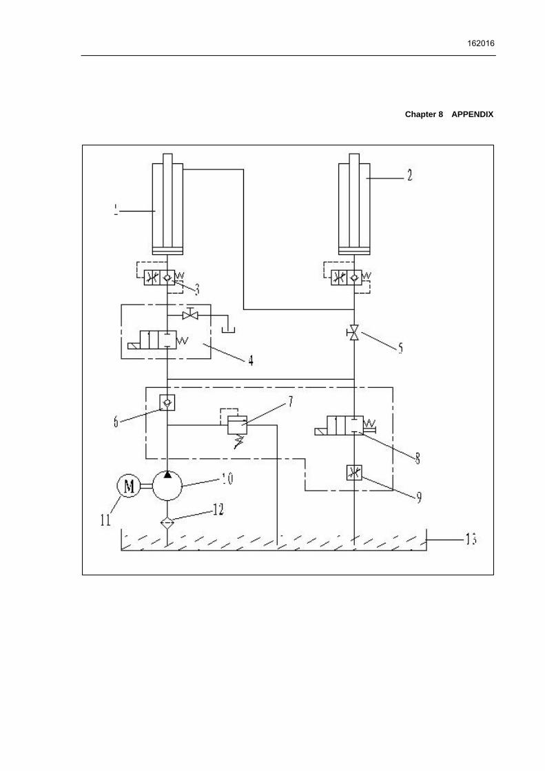
LINE CONNECTION Connect the electrical and oil line according to the electric wiring diagram and oil line
connection
To avoid the unexpected lift closure due to mechanical safety device release insert wooden pieces in the inner part of the base frame. Pay attention not to work under the lift until the hydraulic system has not been completely filled with hydraulic oil. To insert the lift into the recess, sling the lift as described and pay attention not to damage the hoses and electrical cables. Before placing the pneumatic and hydraulic hoses to the control unit, stick adhesive tape on the pipe fittings in order to protect the hoses from dust and impurities which could damage the hydraulic system. Perform electric, hydraulic and pneumatic connections, follow carefully the
relevant numbering. Regarding the proper connections necessary to make
the car lift perfectly working.
Chapter 4 INSTALLAION
Skilled personnel only is allowed to perform the operations shown below. -open the control box front cover
-connection of power supply: the connection wires (BVR-3*2.5mm2+1*1.5mm2) for
power supply are connected to terminalsL1#, L2#, L3#, the zero wire is connected
to terminal 0#. The ground wire is connected under the bolt marked ground.
-the electric panel are arranged by the manufacturer for operating at 400V
three-phase, therefore if you wish the lift to operated at 230V three-phase, change
the connection on the transformer and motor.

162016
L1 L2 L3 PE
(picture 16) (picture 17)
The limit switch connection (equipped with electrical carriage)
Connect the PE,10# from the control box with metal hoses to the limit switch of
electrical rolling jack.
Connect the hydraulic hoses as oil route connection drawing.
Electrical carriage oil line connection: The oil line of electrical carriage
from manual selector to oil tank .
(picture 18)
Add oil and check the order of phase.
-open the hydraulic oil tank , add 18L of hydraulic oil into the oil tank, the hydraulic oil
is provided by the user.
Make sure the clean of hydraulic oil, prevent any impurity into the oil line, lead the digest of the oil line and no working of the solenoid valve. -press the “power” button to turn on power, clicking the “up” button, check whether
the motor turns clockwise (looking downward), if not press “power” button, change
the phase of the motor.
Chapter 5 ADJUSTMENT
When turn on power, the is high voltage In the control box, only authorized person can operate.

162016
(picture 19 (picture 20)
Main machine oil make-up adjustment 1-close the oil make up stop valve “H” on the main machine and open the oil make up
stop valve “G” on the main machine.
2-press “lift” button SB1, and thus the left platform ( looking from machine head
direction ) is lifted to about 1000mm.
3-press the “lower” button SB2 to lower the left platform to the lowest position.
4-then lift it up to approximately 1400mm.
5-open the oil make up stop valve “H” on the main machine and close the oil make up
stop valve “G” on the main machine.
6-press “up” button SB1, and the right platform ( looking from machine head
direction ) is lifted to about 1000 mm.
7-press “ lower” button. SB2 to lower the platform to the lowest position.
8-repeat the lifting and lowering process for 6-7times to vent air automatically.
9-then lift the right platform to 1400mm. ( two platforms of the main machine are lifted
to the same height ).
End close the oil make up stop valve “H” and open the oil make up stop valve “G”.
Check oil leakage of the oil line and air tightness of the air loop.
Limit switch of main machine adjustment - press “SB1” and then lift the platform to 1700mm, adjust limit position of SQ1.
-lower the main machine platform, lift main machine platform to the limit position
several
times to check the efficiency of the limit position of the main machine.
If the ceiling is lower than 4000mm, it should do the limit adjustment after lift the vehicle. Anchor bolts installation
-affix the lift to the concrete base with 16 anchor bolts using a percussion drill into
120mm.
Chapter 5 ADJUSTMENT -At first, no expansion bolts are installed.
-adjust the parallel of the platform and the distance of two platform
-lock the machine in one safety teeth
-pad a shim
-adjust the clearance in front and back, and to the left and

162016
right,
-fix the anchor bolts (16 bolts) with a percussion electric drill ( percussion drill bit is of
16, drill to 120mm hole and clean the hole.
(picture21)
Level adjustment. -By using a level bar and the horizontal pipe and adjusting the adjustment screws at tow sides of the base plate. -adjust the level of two front turntables and the slide plates on two sides of the base
plate, adjust the level of two front turntables and the slide plates on two sides at
back, thus keep the levelness of error of the two platform≤5mm, and keep the
height difference between the two platform ≤10mm.
-the gap between the base plate and ground after adjustment must be filled with
iron plate or concrete and then tighten the anchor bolts.
(picture 22)
No load of main machine test -turn o the power QS.
-press “up” button SB1, main platform lifted.
-press “down” button SB2, and press insurance hand, the platform is lower.
-press “lower”, four insurance locking.
-check the lift of main machine is placidity, and the locking is secure, check whether
the oil line is leakage.
No person and thing leave under or on the lift.
Chapter 6 OPERATION
-clear obstacles around before operation. -during lifting or lowering, no person is allowed to stand neat the two sides and beneath the machine, and no person is allowed on the two platform. -avoid lifting super heavy vehicles. -when lifting vehicle, the hand brake lever of the vehicle should be pulled, and

162016
CAUTION The scissor lift should not be operated when
the platforms are not level.
Before the car is being modified on the scissor
lift, one must check and insure that the lock
units are locking reliably
When locking the lift, one must check and insure that the lock units are in the same level pitches
the slide resistant triangle woods should be used. -pay attention to the synchronization of the lifting and lowering. If any abnormal is found, stop the machine timely, check and remove the trouble. -when locking the main machine, the two platforms should be kept at the same height. -when the equipment is not used for a long time or over night, the machine should be lowered to the lowest position on ground, and remove vehicle, and cut off power supply.
Instructions on electric operation:(see the operation panel)
Scissor Lift For Wheel Aligmment
(picture 23)
Lifting Press “ lift” button SB1, the machine will be lifted immediately, while motor M starts
operation and the safety pawl is lifted, because the solenoid air valve DQ is
energized and open the air loop ( note: the secondary carriage has no delay of pawl
operation.)
Releasing “ lift” button SB1, the machine will stop immediately, while motor M stops
operation and the safety pawl falls to the safety teeth bar because the solenoid air
valve DQ is energized and air loop is open.
Emergency stop When the machine have abnormal or car maintenance, push “emergency stop”
button “SB0” and locking, cut off all the operation circuit, other operation can not be
work.
Oil make-up “adjust” operation ( normal service period)
after completion of machine installation and adjustment in the application process, the right platform is lower than the left one ( looking from machine head ) because of normal looses or leakage of
the hydraulic oil. When conducting oil make-up operation, the platforms must not be load.
Chapter 6 OPERATION

162016
-open the oil make up stop valve “H” on the main machine and close the oil make up
stop valve “G” on the main machine.
-press “up” button SB1, two platforms of the main machine are lifted to the same
height .
End close the oil make up stop valve “H” and open the oil make up stop valve “G”.
EMERGENCY MANUAL OPERATION FOR LOWERING (POWER FAILURE): When lowering through manual operation, should observe the condition of platform at any time because there are vehicles on the platform. If there is something abnormal, screw down oil loop valve immediately. The process of manual operation: -firstly lift two safety pawls of platform and use thin iron bar to fill up it. -switch off the power button (avoid abruptly incoming electricity ). Open the back cover of control box to find the electromagnetic valve A for lowering. -loosen manual oil loop stud at the end of lowering electromagnetic valve core, then the platform begins lowering. -after the machine has been lowered, screw down manual oil loop stud timely, the process of manual lowering comes to the end.
(picture 24) (picture25)
The machine should be lower to the lowest position when replace hydraulic oil, then
let the old oil out, and should be filter the hydraulic oil.
-the compressed air used in pneumatic safety devices must be filtered through water
to ensure long time reliable operation of the cylinder and air valve DQ for driving the
safety pawl .

162016
Chapter 7 TROUBLESHOOTING
Cause and Phenomena Resolutions ① Connection of power
supply wires or zero wire is not correct.
Check and correct wire connection.
② The AC contactor in the circuit of the motor does not pick up.
If the motor operates when forcing the contactor down with an isolation rod, check the control circuit. If the voltage at two ends of the contactor coil is normal, replace the contactor.
The motor does not run in lifting operation.
③ The limit switch is not closed.
Short-circuit terminal 10# and 0#, which are connected with the limit switch, and if the trouble disappears, check the limit switch, wires and adjust or replace the limit switch.
① The motor turns reverse. Change the phases of the power supply wires. ② Lifting with light load is
normal but no lifting with heavy load.
The set safe pressure of the over-flow valve may be increased by turning the set knob right ward slightly. The spool of the lowering solenoid valve is stuck by dirt. Clean the spool.
③ The amount of hydraulic oil is not enough.
Add hydraulic oil.
In lifting operation, the motor runs, but there is no lifting movement.
④ The “operation stop valve” is not open.
Turn right and open the “Operation stop valve and supply hydraulic oil to main oil cylinder.
① The safety pawl are not released form the safety teeth.
First lift a little and then lowering.
② The safety pawl is not lifted.
The air pressure is not enough or the safety pawl is stuck.
③ The solenoid air valve does not work.
If the solenoid air valve is energized, but does not open the air loop, check or replace the solenoid air valve.
④ The lowering solenoid valve is energized but does not work.
Check the plug and coil of the lowering solenoid valve and check the right turn tightness of its end copper nut and so on.
When press “Lower” button, the machine is not lowered.
⑤ The hydraulic oil has too high viscosity or frozen, deteriorated (in Winter).
Replace with 20# hydraulic oil in accordance with the instruction book.
The machine lowers extremely slowly under normal loads.
The “antiknock valve” for preventing oil pipe burst is blocked.
Remove or close air supply pipe and thus lock the safety pawl of the machine without lifting of the safety pawl. Remove the “antiknock valve” from the oil supply hole at the bottom of the oil cylinder, and clean the “antiknock valve”.
① The air in the oil cylinder is not vent completely.
Refer to “Ⅶ. Oil Make-up ‘Adjust’ Operation”.
② Oil leakage on oil pipe or at its connections.
Tighten oil pipe connections or replace oil seals and then make-up oil and adjust levelness.
The right and left platforms are not synchronous and not in the same height.
③ The “oil make-up stop valve” can not be closed tightly and almost make-up oil and adjust every day.
Replace oil make-up stop valve, and then make-up oil and adjust.
① Lubrication is not enough. Lubricate all hinges and motion parts (including piston rod) with machine oil.
Noisy lifting and lowering.
② The base or the machine is twisted.
Adjust again the levelness of the machine, and fill or pad the base.
162016
Chapter 8 APPENDIX

162016
Chapter 9 APPENDIX

5500kg Scissor Hoist
OPERATING INSTRUCTIONS The hoist should only be operated by personnel that have been thoroughly trained in operation and maintenance of the hoist.
1. Drive the vehicle evenly over the scissor platform andapply the park brake.
2. Install the four rubber lifting blocks to the underside ofthe jacking points of the hoist.
3. Make sure that all personnel are clear and there are noobstructions around the hoist.
TO RAISE THE HOIST 1. Press the “UP” button on the control panel to
approximately 500mm above the floor.
2. Check that the vehicle is evenly balanced on the hoist.
3. Continue raising the hoist to the desired working heightchecking for any obstructions.
4. Once the hoist has reached the desired working heightpress the lock button until the vehicle has rested on thelocksImportant: a visual check is to be made for correctengagement of the locks prior to going under the hoist.
TO LOWER THE HOIST 1. Check for any obstructions under the hoist prior to
lowering the hoist.
2. Press the “DOWN” button on the control panel until thelocks are clearPlease note: the hoist will raise approximately 100mmand then will descend automatically.
3. Once the hoist has reached its lowest position, removethe rubber supporting blocks.
4. Turn the power switch to the off position on the controlpanel.
MODEL: AL-162016
SERIAL NO.: APPROVALS

This Safety Operating Procedure does not necessarily cover all possible hazards associated with the machine and should be used in conjunction with other references. It is designed to be used as an adjunct to the operation in the safety procedures and to act as a reminder to the operatior prior to
machine use.
SAFETY OPERATING PROCEDURES Vehicle Hoist
DO NOT use this machine unless the operator has been thoroughly instructed in its safe use and operation.
Safety glasses must be worn at all times in work areas.
Long and loose hair must be contained.
Sturdy footwear must be worn at all times in work areas.
Close fitting/protective clothing must be worn.
Rings and jewellery must not be worn.
Do not stand on hoist whilst hoist is in operation.
A vehicle hoist must not be operated unless it has a current certificate of inspection.
PRE-OPERATIONAL SAFETY CHECKS 1. Ensure that vehicle hoist has operating and maintenance instructions permanently located
and clearly visible. 2. The equipment must be used in accordance with manufacturer’s instructions.3. Check the capacity of the hoist compared to the weight of the vehicle. If vehicle is too
heavy, do not proceed.4. Ensure the area is clean and clear of grease, oil, and objects that may be a slip/trip hazard.5. Familiarise yourself with and check all machine operations and controls.6. Check all safety devices are in good condition.7. Ensure support arms are capable of being locked in position.8. Ensure rubber pads are in good condition on all load points.9. Faulty equipment must not be used. Immediately report suspect equipment.
OPERATIONAL SAFETY CHECKS 1. Centre vehicle on hoist, ensuring that the weight is evenly distributed to the front and rear.2. Identify the correct jacking points.3. Only one person shall operate the hoist at a time.4. Ensure hoist area is clear of people and equipment before operating.5. Never leave the hoist running unattended.6. Check vehicle stability by looking at the jacking points.7. Engage and check for the correct engagement of the locks.8. At the completion of work lower the vehicle hoist and ensure all equipment is left in a safe
position.
HOUSEKEEPING 1. Switch off equipment.2. Leave the equipment and work area in a safe, clean and tidy state.
POTENTIAL HAZARDS Falling objects Trapping hazards Crushing hazards Entanglement hazards

Advance AutoQuip 2 McDonald Crescent | Bassendean WA 6054
Ph: 08 9279 1663 | Fax: 08 9279 1667 | E: [email protected] | W: www.aaq.net.au
ADVANCE AUTOQUIP WARRANTY
GENERAL WARRANTY INFORMATION: ADVANCE AUTOQUIP’S OBLIGATION UNDER THIS WARRANTY IS LIMITED TO REPAIRING OR REPLACING ANY PART OR PARTS RETURNED TO THIS FACTORY, TRANSPORTATION CHARGES PREPAID, WHICH PROVE UPON INSPECTION TO BE DEFECTIVE AND WHICH HAVE NOT BEEN MISUSED. DAMAGE OR FAILURE TO ANY PART DUE TO FREIGHT DAMAGE OR LACK OF MAINTENANCE IS NOT COVERED UNDER THIS WARRANTY. ADVANCE AUTOQUIP RESERVES THE RIGHT TO DECLINE RESPONSIBILITY WHEN REPAIRS HAVE BEEN MADE OR ATTEMPTED BY OTHERS, OR WHERE NON GENUINE PARTS HAVE BEEN USED. THIS WARRANTY DOES NOT COVER DOWNTIME EXPENSES INCURRED WHEN UNIT IS IN REPAIR. ADVANCE AUTOQUIP ARE NOT LIABLE FOR POSSIBLE ISSUES, DAMAGES, ACCIDENTS ETC RESULTING FROM FAILURE TO FOLLOW THE OPERATION OR INSTALLATION INSTUCTIONS CONTAINED IN THE MANUAL OR ON THE EQUIPMENT. THE MODEL NAME AND SERIAL NUMBER OF THE EQUIPMENT MUST BE PROVIDED WITH ALL WARRANTY CLAIMS. THIS WARRANTY STATEMENT CONTAINS THE ENTIRE AGREEMENT BETWEEN ADVANCE AUTOQUIP AND THE PURCHASER UNLESS OTHERWISE SPECIFICALLY EXPRESSED IN WRITING. THIS NON-TRANSFERABLE WARRANTY APPLIES TO THE ORIGINAL PURCHASER ONLY. THIS WARRANTY IS APPLICABLE TO UNITS LOCATED ONLY IN AUSTRALIA. CONTACT ADVANCE AUTOQUIP FOR SPECIFIC WARRANTY PROVISIONS FOR UNITS LOCATED OUTSIDE OF THESE COUNTRIES. NOTE: THE EQUIPMENT IS NOT TO BE USED FOR WASH DOWN PURPOSES OR TO BE INSTALLED IN AN OUTDOOR ENVIRONMENT WHERE IT IS SUBJECT TO WEATHER OR WATER DAMAGE. WARRANTY WILL BE IMMEDIATELY VOID.
STRUCTURAL COMPONENTS: ALL STRUCTURAL AND MECHANICAL COMPONENTS OF THIS UNIT ARE GUARANTEED FOR A PERIOD OF FIVE YEARS, FROM THE DATE OF INVOICE, AGAINST DEFECTS IN WORKMANSHIP AND/OR MATERIALS WHEN LIFT IS INSTALLED AND USED ACCORDING TO RECOMMENDATIONS.
POWER UNIT: POWER UNIT COMPONENTS (PUMP AND RESERVOIR) ARE GUARANTEED A PERIOD OF ONE YEAR, FROM THE DATE OF INVOICE, AGAINST DEFECTS IN WORKMANSHIP AND/OR MATERIALS WHEN THE LIFT IS INSTALLED AND USED ACCORDING TO RECOMMENDATIONS.
ELECTRICAL COMPONENTS: ALL ELECTRICAL COMPONENTS (INCLUDING MOTOR) ARE GUARANTEED A PERIOD OF ONE YEAR FOR PARTS ONLY (EXCLUDING LABOR), FROM THE DATE OF INVOICE, AGAINST DEFECTS IN WORKMANSHIP AND/OR MATERIALS WHEN THE LIFT IS INSTALLED AND USED ACCORDING TO RECOMMENDATIONS.
PNEUMATIC (AIR) COMPONENTS: ALL PNEUMATIC (AIR) COMPONENTS (I.E. AIR CYLINDERS AND POPPET AIR VALVES) ARE GUARANTEED FOR ONE YEAR FOR PARTS ONLY (EXCLUDING LABOR), FROM THE DATE OF INVOICE, AGAINST DEFECTS IN WORKMANSHIP AND/OR MATERIALS WHEN THE LIFT IS INSTALLED AND USED ACCORDING TO RECOMMENDATIONS.
EXCLUSIONS: WARRANTY DOES NOT INCLUDE CONSUMABLE ITEMS SUCH AS HYDRAULIC OIL, LIFTING PADS, OIL SEALS, VEE BELTS AND SLIDING BLOCKS.
THIS WARRANTY SUPERSEDES ALL OTHER WARRANTY POLICIES PREVIOUSLY STATED AND IN ALL OTHER ADVANCE AUTOQUIP’s PRODUCT SPECIFIC LITERATURE.
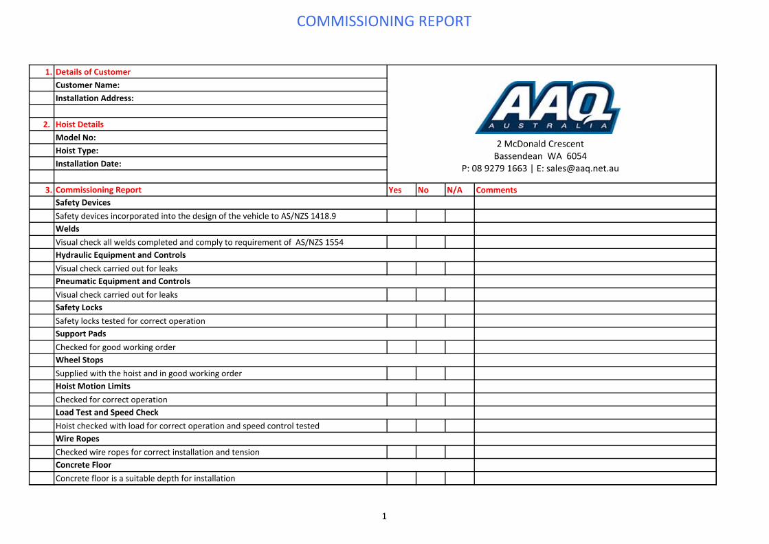
COMMISSIONING REPORT
1. Details of CustomerCustomer Name: Installation Address:
2. Hoist DetailsModel No: Hoist Type: Installation Date:
3. Commissioning Report Yes No N/A Comments
Safety devices incorporated into the design of the vehicle to AS/NZS 1418.9
Visual check all welds completed and comply to requirement of AS/NZS 1554
Visual check carried out for leaks
Visual check carried out for leaks
Safety locks tested for correct operation
Checked for good working order
Supplied with the hoist and in good working order
Checked for correct operation
Hoist checked with load for correct operation and speed control tested
Checked wire ropes for correct installation and tension
Concrete floor is a suitable depth for installation
Safety Devices
Welds
Hydraulic Equipment and Controls
Pneumatic Equipment and Controls
Safety Locks
Support Pads
Wheel Stops
Hoist Motion Limits
Load Test and Speed Check
Wire Ropes
Concrete Floor
2 McDonald CrescentBassendean WA 6054
P: 08 9279 1663 | E: [email protected]
1
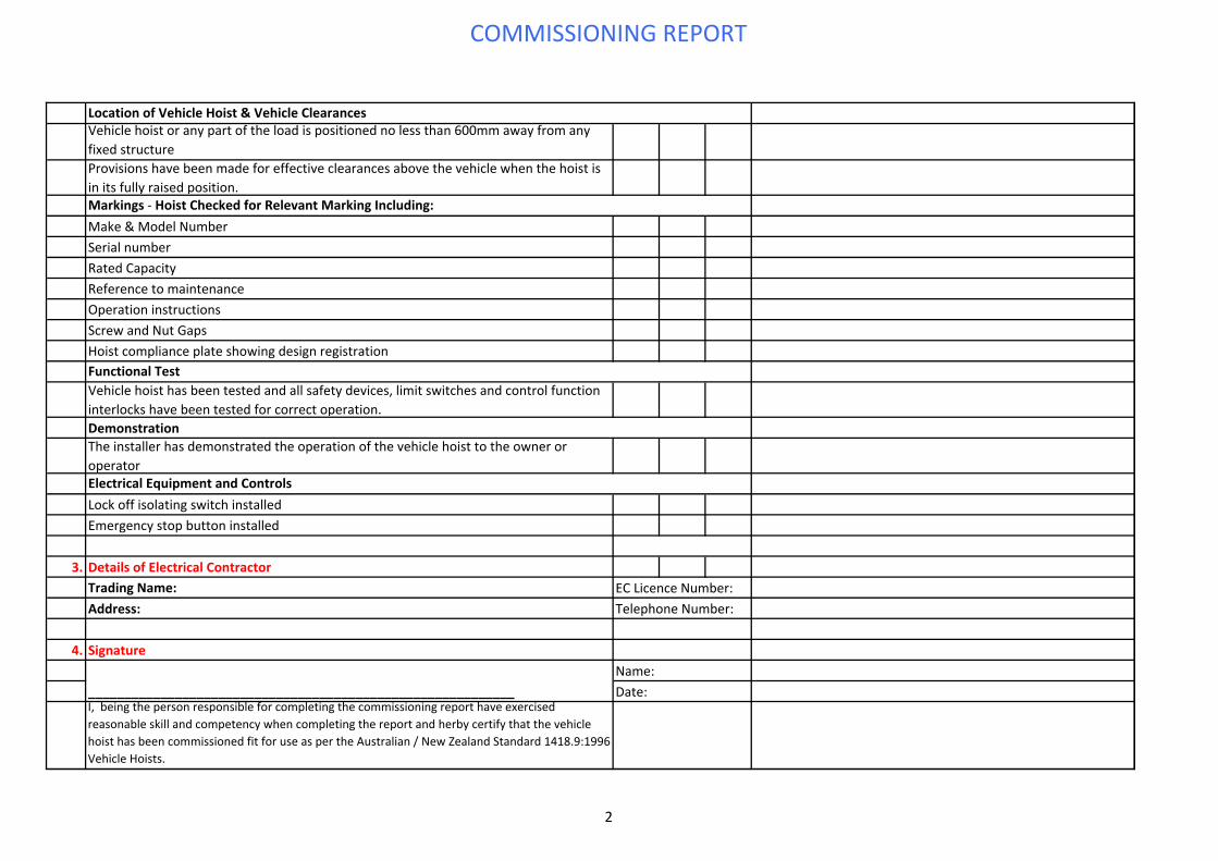
COMMISSIONING REPORT
Vehicle hoist or any part of the load is positioned no less than 600mm away from any fixed structureProvisions have been made for effective clearances above the vehicle when the hoist is in its fully raised position.
Make & Model NumberSerial numberRated CapacityReference to maintenanceOperation instructionsScrew and Nut GapsHoist compliance plate showing design registration
Vehicle hoist has been tested and all safety devices, limit switches and control function interlocks have been tested for correct operation.
The installer has demonstrated the operation of the vehicle hoist to the owner or operator
Lock off isolating switch installedEmergency stop button installed
3. Details of Electrical ContractorTrading Name:Address:
4. Signature
I, being the person responsible for completing the commissioning report have exercised reasonable skill and competency when completing the report and herby certify that the vehicle hoist has been commissioned fit for use as per the Australian / New Zealand Standard 1418.9:1996 Vehicle Hoists.
Name:Date:___________________________________________________________
Location of Vehicle Hoist & Vehicle Clearances
Markings ‐ Hoist Checked for Relevant Marking Including:
Functional Test
Demonstration
Electrical Equipment and Controls
EC Licence Number:Telephone Number:
2
Related Documents


