Alliance Air Products Page 1 TABLE OF CONTENTS General Layout Guidelines ………………………………………..………………………….. 2 General Construction Walls :: Roof :: Base :: Insulation ………………………………………..………...… 3 Plenum Fan :: Flow Measurement System ……………………………………...…. 4 Water, DX & Steam Coils :: Drain Pan …………………………………………...…. 5 Damper :: Door ……………………………………………………………………….... 6 Weatherhood :: Louver ………………………………………………………………... 7 Minimum Section Dimensions Plenum Fan - Belt Drive ………………………………………………………………. 8 Plenum Fan - Direct Drive ……………………………………………………………. 9 DWDI Housed Fan - Forward Curved …………………………………………10 - 11 DWDI Housed Fan - Backward Incline & Airfoil …………………………………... 12 Section Dimensions Overall Unit Cabinet …………………………………………………………………. 13 Base :: Roof Curb …………………………………………………………………….. 14 Water, DX & Steam Coils ……………………………………………………………. 15 Flat Filter ………………………………………………………………………………. 16 2” V-Filter ……………………………………………………………………………… 17 4” V-Filter ……………………………………………………………………………… 18 Indoor Mixing Box - End Wall Damper w/Roof or Floor Damper ………………... 19 Indoor Mixing Box - End Wall & Sidewall Dampers ……………………………… 20 Indoor Mixing Box - Sidewall Damper w/Roof or Floor Damper ………………... 21 Outdoor Economizer - Layout 1 ……………………………………………….. 22 - 23 Outdoor Economizer - Layout 2 ……………………………………………….. 24 - 25 Direct Evaporative Cooler …………………………………………………………... 26 Sample Air Handling Unit Specifications ……………………………………………... 27 - 32 Fundamentals of Acoustics ……………………………………………………………. 33 - 36 Rev. 0 10/05

Aap Catalog
Dec 14, 2015
Aap Catalog
Welcome message from author
This document is posted to help you gain knowledge. Please leave a comment to let me know what you think about it! Share it to your friends and learn new things together.
Transcript

Alliance Air Products Page 1
TABLE OF CONTENTS
General Layout Guidelines ………………………………………..………………………….. 2
General Construction
Walls :: Roof :: Base :: Insulation ………………………………………..………...… 3
Plenum Fan :: Flow Measurement System ……………………………………...…. 4
Water, DX & Steam Coils :: Drain Pan …………………………………………...…. 5
Damper :: Door ……………………………………………………………………….... 6
Weatherhood :: Louver ………………………………………………………………... 7
Minimum Section Dimensions
Plenum Fan - Belt Drive ………………………………………………………………. 8
Plenum Fan - Direct Drive ……………………………………………………………. 9
DWDI Housed Fan - Forward Curved …………………………………………10 - 11
DWDI Housed Fan - Backward Incline & Airfoil …………………………………... 12
Section Dimensions
Overall Unit Cabinet …………………………………………………………………. 13
Base :: Roof Curb …………………………………………………………………….. 14
Water, DX & Steam Coils ……………………………………………………………. 15
Flat Filter ………………………………………………………………………………. 16
2” V-Filter ……………………………………………………………………………… 17
4” V-Filter ……………………………………………………………………………… 18
Indoor Mixing Box - End Wall Damper w/Roof or Floor Damper ………………... 19
Indoor Mixing Box - End Wall & Sidewall Dampers ……………………………… 20
Indoor Mixing Box - Sidewall Damper w/Roof or Floor Damper ………………... 21
Outdoor Economizer - Layout 1 ……………………………………………….. 22 - 23
Outdoor Economizer - Layout 2 ……………………………………………….. 24 - 25
Direct Evaporative Cooler …………………………………………………………... 26
Sample Air Handling Unit Specifications ……………………………………………... 27 - 32
Fundamentals of Acoustics ……………………………………………………………. 33 - 36
Rev. 0 10/05

Page 2 Alliance Air Products
General Layout Guidelines
How to Layout an Alliance Air Custom Air Handler
A. Size the Fan
Step 1. Select a fan that meets your operating criteria (CFM, TSP, maximum HP, sound attenuation requirements, etc.) using the ACES fan program.
Step 2. Find the minimum section dimensions for the selected fan using the Minimum Section Dimension tables from pages 8 through 12.
B. Size the Cabinet
Step 1. Using the Overall Unit Cabinet table from page 13, select a cabinet size (internal cabinet height and internal cabinet width) that:
• Fits the selected fan.
• Meets the required CFM with a maximum 500 fpm coil or filter face velocity.
• Fits the site dimensions.
• Meets the shipping requirements.
Step 2. Using the Section Dimension tables from pages 13 through 26, select all applicable components for the selected cabinet:
• Coil (max 500 FPM) using table from page 15.
• Filter (max 500 FPM) using tables from pages 16 through 18.
• Mixing box or economizer (1,200 to 1,500 damper velocity) using tables from pages 19 through 25.
• Direct evaporative cooler (max 500 FPM) using table from page 26.
C. For special requirements, please contact factory.
Rev. 0 10/05
Alliance Air Products Page 3
General ConstructionWalls :: Roof :: Base :: Insulation
Unit BaseBase perimeter is structural "C" channel with
2" x 4" tubular structural steel cross members
on maximum 24" centers. Galvanized steel
stringers are placed in the direction of airflow
on maximum 24" centers for additional floor
support. All fans and coils are supported by
welded structural steel cross members. The
structural C channel is sand blasted before
assembly to remove all rust and mill scale. All
base members are fully welded. The floor is
constructed from 16 gauge bright galvanized
steel using standing seams capped with cleats.
All floor seams have structural members
centered underneath for support. Floor panels
are welded from below to supporting members.
There are no penetrations through the floor
material. Urethane foam insulation is applied
under the base and lined with 20 gauge bright
galvanized steel.
Roof PanelsRoof panels are constructed from the same
material as the wall panels. Roof panels utilize
standing seam construction with cleats over
the roof flanges that provide a weatherproof
design. Outdoor units have a minimum of 1/4
inch per foot slope to ensure rain and snow
runoff.
Wall Panels
Standard wall construction consists of 16
gauge paint grip galvanized steel panels.
Panels are attached to the floor, roof and each
other with 1/4" bolts and are caulked and
sealed during assembly to produce an airtight
seal. The panels are designed to operate at a
static pressure of positive or negative 8 inches
pressure differential while maintaining a
leakage rate below 1% of design air volume.
Standard panels are 2" thick. Other gauges
and materials are optional.
3
WALL PANELS
ROOF PANELS
BASE SKIN
BASE C CHANNEL
ROOF CLEAT
ROOF ANGLE
SUPPORT
INSULATION
InsulationWalls and roof are insulated with 2" thick
1.5 lb/ft insulation. Other thicknesses and
densities are optional. Surfaces exposed to
airflow are protected with an acrylic coating on
the insulation to prevent fiber erosion.
Insulation provided meets NFPA 90A
requirements. The unit base is insulated with
2" minimum of sprayed urethane foam. In
addition to providing a more rigid walking
surface, urethane foam provides an R-Value of
at least 11.5.
Rev. 0 10/05
Page 4 Alliance Air Products
General ConstructionPlenum Fan :: Flow Measurement System
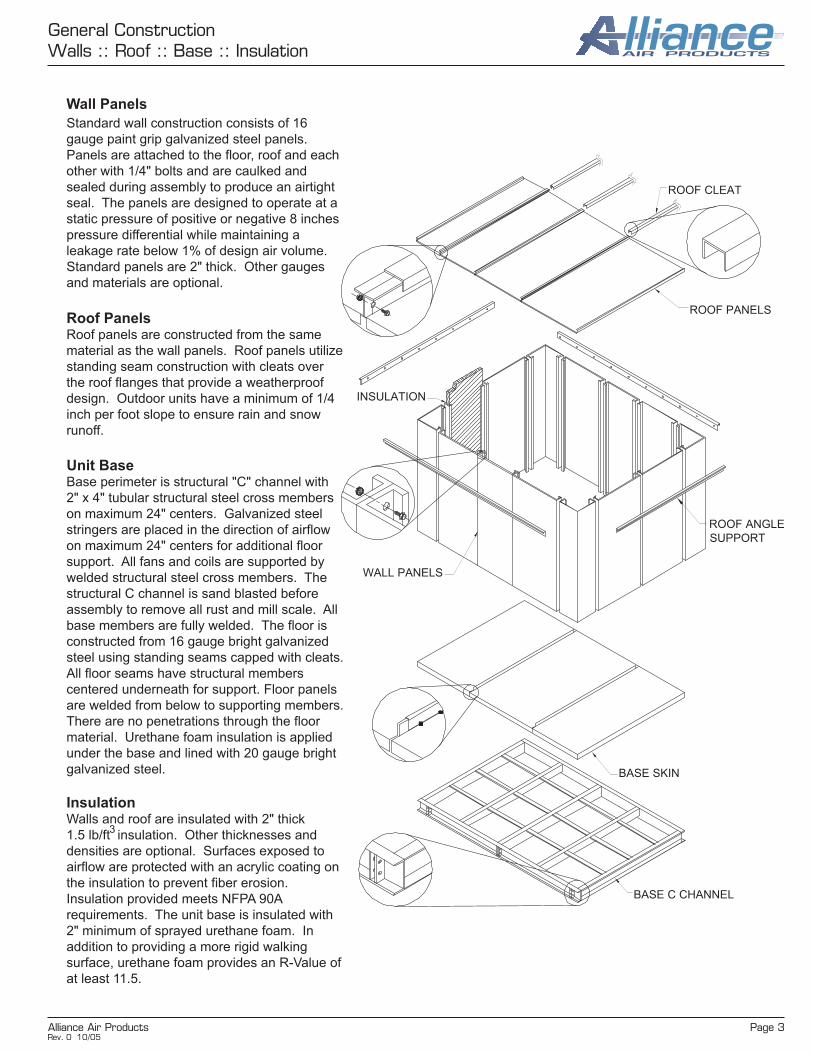
Inlet Tap
Mounted on
Face of Inlet
Cone
Piezometer Ring
Mounted at Throat
of Inlet Cone
Plenum Fan
Plenum fans are AMCA certified for sound and air performance. Standard fans are Arrangement 3 or Arrangement 1. Also available are direct-drive, Arrangement 4.
Standard fan wheels are high efficiency, airfoil design. Twelve blade wheels are available for improved sound performance. Fan blades are continuously welded to the fan backplate and spun inlet shroud. Wheels are statically and dynamically balanced in accordance with ANSI/AMCA 204-96 to Balance Quality Grade G6.3.
The frame and inlet panel are constructed of heavy gauge steel continuously welded at all connections for maximum strength and rigidity. Inlet cones are spun from heavy gauge steel. The cone is closely matched to insure quiet, efficient operation.
For Arrangements 1 and 3, bearings are ball or spherical roller, heavy duty, self-aligning, pillow block type. Bearings are mounted to structural steel supports and selected based on an average life of 200,000 hours. Shafts are AISI 1040 or 1045 hot rolled steel accurately turned, ground, polished and ring gauged for accuracy.
Sheaves are cast iron, variable pitch on applications with 5 HP and smaller, fixed pitch for 7.5 HP and larger. Drive and belts are rated for 150% of the required motor HP.
Fan and motor assemblies are mounted to a heavy welded structural base and supported at four points on rubber mounted 2" deflection isolator springs. All fan supports are designed for Zone 4 seismic restraint.
Prior to unit shipment, the complete fan assembly; including motor, drives and spring isolation assemblies, is factory balanced in accordance with ANSI/AMCA 204-96 to Balance Quality Grade G6.3.
Piezometer Ring (Airflow Measurement System)
A piezometer ring is available on plenum fans, as well as housed fans, as part of an airflow measurement system based on the principles of a flow nozzle. The inlet cone of the fan is used as the flow nozzle. The flow can be calculated by measuring the pressure drop through the inlet cone. No tubes or sensors are inserted in the high velocity airstream which could obstruct airflow.
The system consists of a piezometer ring mounted at the throat and a static pressure tap mounted on the face of the inlet cone. A differential pressure transducer and digital display can also be provided.
The pressure drop is measured from the tap located on the face of the inlet cone to the piezometer ring in the throat. The inlet tap is connected to the high-pressure side of the transducer and the piezometer ring is connected to the low-pressure side. See the diagram on the right.
Based on laboratory tests, the system was determined to be accurate within ±5%.
HIGH PRESSURE SIDE
LOW PRESSURE SIDE
STATIC PRESSURE TAP
PIEZOMETER RING
Rev. 0 10/05

Alliance Air Products Page 5
General ConstructionWater, DX & Steam Coils :: Drain Pan
Water, DX & Steam Coils
Chilled water, hot water and DX coils are certified in accordance with ARI Standard 410.
DX and water coils are constructed from seamless copper tubing mechanically expanded into fin collars. Fins are continuous within the casing to eliminate carryover. Fins are die formed plate type. Headers are seamless copper with die formed tube holes.
Water coil connections are male pipe thread (MPT) Schedule 40 red brass. Header vent and drain connections have 1/4" flare fittings with Shraeder valves and caps. Connections are extended to the exterior of the unit casing. Coils are suitable for 250 PSIG working pressure.
DX coil connections are O.D. sweat copper with a refrigerant distributor.
Cooling and DX coils are provided with stainless steel drain pans. Intermediate drain pans are provided on stacked coils and single coils greater than 48" fin height. Intermediate pans drain to the main pan through copper downspouts.
Standard construction is as follows:
• 5/8" O.D. x 0.020" Wall Copper Tube• 0.006" Aluminum Fins• 16 Gauge Galvanized G-90 Steel Casing For Hot Water Coil• 16 Gauge 304 Stainless Steel Casing For Chilled Water And DX Coils.
Steam coils are available in distributing and non-distributing with pitched casings and 5/8" O.D. copper tubes. Options and materials of construction are similar to water coils.
AIR
FLOW
BOTTOM
COIL
MIDDLE
COIL
TOP
COIL
INTERMEDIATE
DRAIN PAN
INTERMEDIATE
DRAIN PAN
MAIN DRAIN
PAN
Drain Pan
A) Main and intermediate drain pans are
constructed from 16 gauge 304 stainless steel.
The main pan incorporates a double-slope
IAQ design to ensure complete condensate
drainage to a single point. Intermediate pans
extend at least 6" downstream from the
coil face and are sloped for drainage to the
main pan.
B) 304 stainless steel channels are used to
support the main pan where the coil is seated.
C) Main pan has a double skin construction with
a 20 gauge galvanized steel liner unless
otherwise specified.
D) Main pan is insulated with minimum 2" sprayed
urethane foam. Urethane foam provides an
R Value of at least 11.5.
E) Main pan has a single 1-1/4" diameter MPT
drain connection located at the lowest point.
AIR
FLOW
SECTION A-A
CHANNEL
HEIGHT
1-1/4" MPT
STANDARD
COUPLINGCOVER
PLATE
MAIN DRAIN
PAN
Rev. 0 10/05

Page 6 Alliance Air Products
General ConstructionDamper :: Door
Airfoil Control Damper
Damper blades and frame are made of extruded aluminum. Standard blade action is opposed. Parallel blade action is optional.
Dampers are a low leak design with extruded EPDM blade gaskets and extruded TPE thermoplastic frame seals. Gaskets are secured in an integral slot within the aluminum extrusions.
Overlapping blade design compresses the blade gaskets on closure ensuring a tight seal.
Bearings are composed of a celcon inner bearing fixed to an aluminum hexagon blade pin rotating within a polycarbonate outer bearing inserted in the frame, resulting in no metal to metal or metal to plastic contact.
Linkage hardware is installed in the frame side and constructed of aluminum and corrosion resistant, zinc plated steel, complete with cup point trunnion screws for a slip proof grip.
Dampers are AMCA Certified for pressure drop and leakage rate.
Alternate materials are available as options.
Door
Doors are available in 2" or 4" thickness. The door panel is constructed of an extruded aluminum perimeter frame with exterior and interior liners. Painted galvanized steel exterior liner and bright galvanized steel interior liner are standard. Stainless steel and aluminum liners are optional.
Polyurethane foam insulation is pressure injected between the door liners to create a seamless rigid panel with an insulating value of R-13.
The door frame is extruded aluminum designed for in-swing or out-swing applications.
Hinges are adjustable, zinc die cast construction.
Door latching system consists of glass reinforced nylon plastic exterior handles, zinc plated steel with plastic grip interior handles, and zinc plated steel with tapered black plastic roller cams. As the door is closed, the smooth operating cams roll over the door frame compressing the frame gasket to ensure a tight seal. Exterior handles may be provided with either a lockable handle or tool operated latch housings.
Other options include a view window and thermal break construction.
Overlapping Blade Detail
Damper Linkage Detail
CelronInner Bearing
PolycarbonateOuter Bearing
Extruded Aluminum Lever
NON-CORROSIVE
OUTER LATCH
EXTRUDED ALUMINUM
DOOR FRAME
THERMAL DOOR
PROVIDED WITH
URETHANE THERMAL
BREAK
ROLLER CAMINTERIOR RED
SAFETY LATCH
SANTOPRENE PRESS-FITTED
CONTINUOUS GASKET
ZINC PLATED
ADJUSTABLE HINGE
PRESSURE INJECTED URETHANE
FOAM INSULATION (R-13)
Rev. 0 10/05
Alliance Air Products Page 7
General ConstructionWeatherhood :: Louver
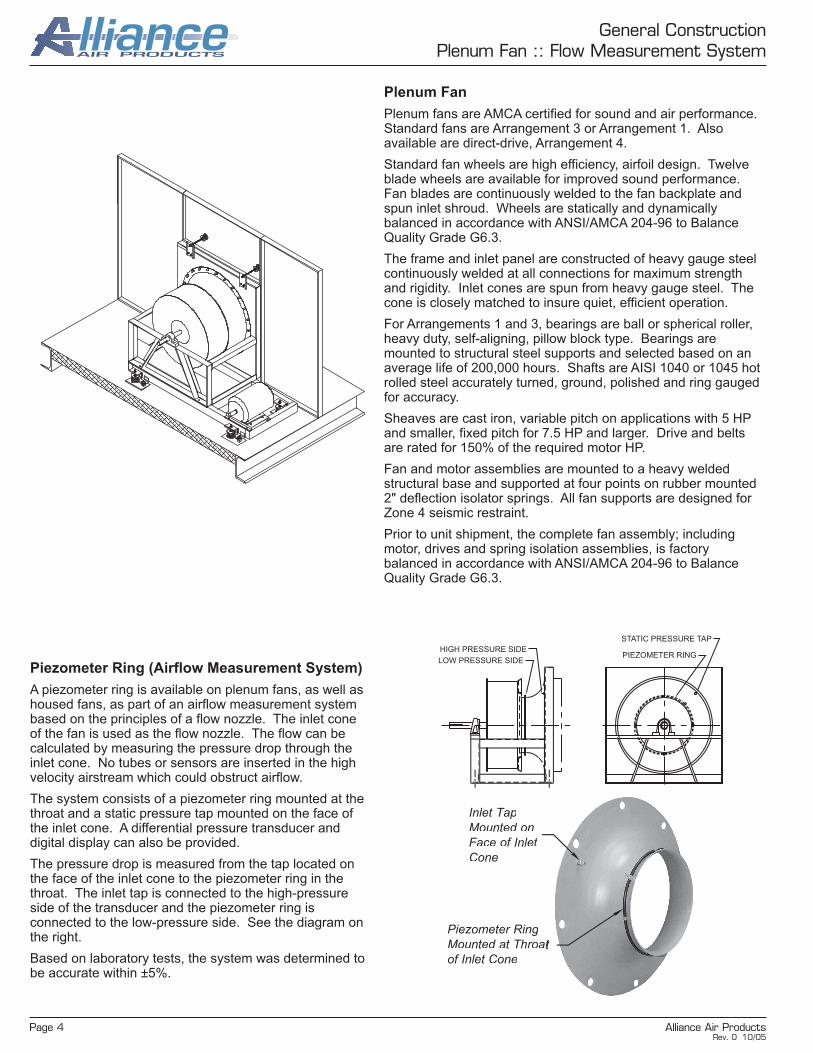
Louver
Louvers are fabricated from the same material as the unit casing.
Standard material thickness is 18 gauge for galvanized and
stainless steel and 0.050 inches for aluminum. The louver face
is lined with 1/2" galvanized mesh bird screen. Louvers are flush
mounted with 1" gutters to collect and drain water to outside of
the unit requiring no drain pan. Louvers are painted black.
Weatherhood
Weatherhoods are designed for 750 fpm maximum face
velocity.
Weatherhoods are fabricated from the same material as
the unit casing. Standard material thickness is 18 gauge
for galvanized and stainless steel and 0.050 inches for
aluminum. Openings are lined with 1/2" galvanized mesh
bird screen. Exterior paint matches the unit casing.
Outside air louvers are designed for 600 fpm maximum
face velocity. Exhaust air louvers are designed for 1200
fpm maximum face velocity. Outside air louver blades
also have breaks to prevent rainwater penetration.
UNIT SIDE VIEW
OUTSIDE AIR DESIGN
BIRD
SCREEN
CAULK
ALL AROUND
BACK SIDE OF
THE LOUVER
ROOF
EXTERIOR
WALL
UNIT SIDE VIEW
EXHAUST AIR DESIGN
CAULK
ALL AROUND
BACK SIDE OF
THE LOUVER
ROOF
BIRD
SCREEN
EXTERIOR
WALL
Rev. 0 10/05
Page 8 Alliance Air Products
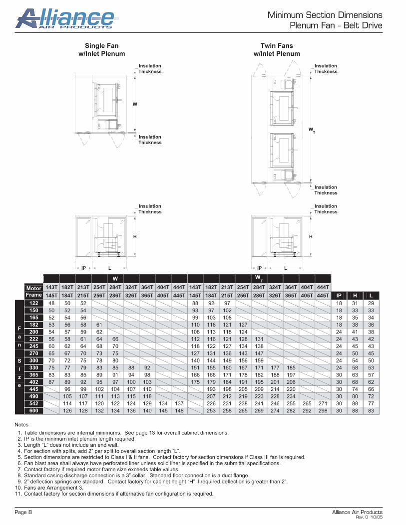
Minimum Section DimensionsPlenum Fan - Belt Drive
Single Fan
w/Inlet Plenum
Twin Fans
w/Inlet Plenum
Notes
1. Table dimensions are internal minimums. See page 13 for overall cabinet dimensions. 2. IP is the minimum inlet plenum length required. 3. Length “L” does not include an end wall. 4. For section with splits, add 2” per split to overall section length “L”. 5. Section dimensions are restricted to Class I & II fans. Contact factory for section dimensions if Class III fan is required. 6. Fan blast area shall always have perforated liner unless solid liner is specified in the submittal specifications. 7. Contact factory if required motor frame size exceeds table values. 8. Standard casing discharge connection is a 3” collar. Standard floor connection is a duct flange. 9. 2” deflection springs are standard. Contact factory for cabinet height “H” if required deflection is greater than 2”.
10. Fans are Arrangement 3. 11. Contact factory for section dimensions if alternative fan configuration is required.
W WT
Motor 143T 182T 213T 254T 284T 324T 364T 404T 444T 143T 182T 213T 254T 284T 324T 364T 404T 444T
Frame 145T 184T 215T 256T 286T 326T 365T 405T 445T 145T 184T 215T 256T 286T 326T 365T 405T 445T IP H L
122 48 50 52 88 92 97 18 31 29
150 50 52 54 93 97 102 18 33 33
165 52 54 56 99 103 108 18 35 34
182 53 56 58 61 110 116 121 127 18 38 36
200 54 57 59 62 108 113 118 124 24 41 38
222 56 58 61 64 66 112 116 121 128 131 24 43 42
245 60 62 64 68 70 118 122 127 134 138 24 45 43
270 65 67 70 73 75 127 131 136 143 147 24 50 45
300 70 72 75 78 80 140 144 149 156 159 24 54 50
330 75 77 79 83 85 88 92 151 155 160 167 171 177 185 24 58 53
365 83 83 85 89 91 94 98 166 166 171 178 182 188 197 30 63 57
402 87 89 92 95 97 100 103 175 179 184 191 195 201 206 30 68 62
445 96 99 102 104 107 110 193 198 205 209 214 220 30 74 66
490 105 107 111 113 115 118 207 212 219 223 228 234 30 80 72
542 114 117 120 122 124 129 134 137 226 231 238 241 246 255 265 271 30 88 77
F
a
n
S
i
z
e
600 126 128 132 134 136 140 145 148 253 258 265 269 274 282 292 298 30 88 83
W
H
LIP
Insulation
Thickness
Insulation
Thickness
Insulation
Thickness
W
H
LIP
T
Insulation
Thickness
Insulation
Thickness
Insulation
Thickness
Rev. 0 10/05

Alliance Air Products Page 9
Minimum Section DimensionsPlenum Fan - Direct Drive
Single Fan
w/Inlet Plenum
Twin Fans
w/Inlet Plenum
Notes
1. Table dimensions are internal minimums. See page 13 for overall cabinet dimensions. 2. IP is the minimum inlet plenum length required. 3. Length “L” does not include an end wall. 4. For section with splits, add 2” per split to overall section length “L”. 5. Section dimensions are restricted to Class I & II fans. Contact factory for section dimensions if Class III fan is required. 6. Fan blast area shall always have perforated liner unless solid liner is specified in the submittal specifications. 7. Contact factory if required motor frame size exceeds table values. 8. Standard casing discharge connection is a 3” collar. Standard floor connection is a duct flange. 9. 2” deflection springs are standard. Contact factory for cabinet height “H” if required deflection is greater than 2”.
10. Fans are Arrangement 4. 11. Contact factory for section dimensions if alternative fan configuration is required.
L W WT
Motor 143T 182T 213T 254T 284T 324T 364T 404T 444T 143T 182T 213T 254T 284T 324T 364T 404T 444T 143T 182T 213T 254T 284T 324T 364T 404T 444T
Frame 145T 184T 215T 256T 286T 326T 365T 405T 445T 145T 184T 215T 256T 286T 326T 365T 405T 445T 145T 184T 215T 256T 286T 326T 365T 405T 445T IP H
122 35 35 36 33 33 33 58 58 58 18 33
150 37 37 38 34 34 34 48 48 48 18 35
165 38 38 39 36 36 36 68 68 68 18 37
182 41 42 43 43 44 39 39 39 39 39 75 75 75 75 75 18 39
200 43 44 44 45 46 46 42 42 42 42 42 42 82 82 82 82 82 82 24 42
222 49 49 50 51 51 52 45 45 45 45 45 45 89 89 89 89 89 89 24 45
245 51 51 52 53 53 54 49 49 49 49 49 49 98 98 98 98 98 98 24 47
270 55 55 56 56 57 58 54 54 54 54 54 54 108 108 108 108 108 108 24 51
300 57 58 59 59 60 60 60 60 60 60 60 60 120 120 120 120 120 120 24 55
330 62 62 63 64 64 65 66 66 66 66 66 66 66 66 132 132 132 132 132 132 132 24 59
365 68 69 69 70 71 71 72 73 73 73 73 73 73 73 146 146 146 146 146 146 146 30 64
402 71 72 72 73 74 74 75 81 81 81 81 81 81 81 161 161 161 161 161 161 161 30 69
445 75 76 77 77 78 79 79 89 89 89 89 89 89 89 178 178 178 178 178 178 178 30 75
490 79 80 80 81 81 82 83 98 98 98 98 98 98 98 196 196 196 196 196 196 178 30 81
542 86 87 88 88 89 90 90 91 109 109 109 109 109 109 109 109 217 217 217 217 217 217 217 217 30 89
F
a
n
S
i
z
e
600 92 93 93 94 95 95 96 96 120 120 120 120 120 120 120 120 240 240 240 240 240 240 240 240 30 89
H
LIP
W
Insulation
Thickness
Insulation
Thickness
Insulation
Thickness
W
H
LIP
T
Insulation
Thickness
Insulation
Thickness
Insulation
Thickness
Rev. 0 10/05
Page 10 Alliance Air Products
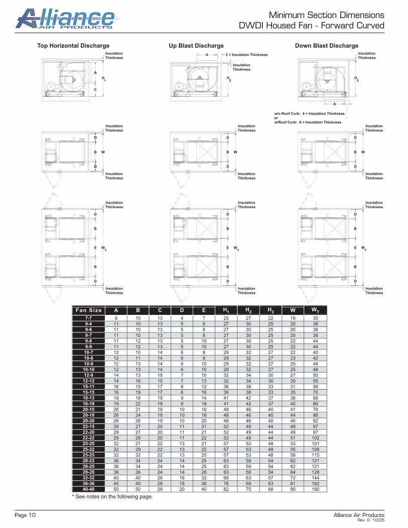
Minimum Section DimensionsDWDI Housed Fan - Forward Curved
Top Horizontal Discharge Up Blast Discharge Down Blast Discharge
* See notes on the following page.
B
D
D
W
D
D
Insulation
Thickness
Insulation
Thickness
WB
D
D
Insulation
Thickness
Insulation
Thickness
B
D
D
W
Insulation
Thickness
Insulation
Thickness
W
B
D
ET
B
D
Insulation
Thickness
Insulation
Thickness
W
B
D
ET
B
D
Insulation
Thickness
Insulation
Thickness
W
B
D
ET
B
D
Insulation
Thickness
Insulation
Thickness
H
A
C
1
Insulation
Thickness3 + Insulation ThicknessA
H2
Insulation
Thickness
w/o Roof Curb: 4 + Insulation Thickness
or
w/Roof Curb: 6 + Insulation Thickness
A
H3
Insulation
Thickness
Fan Size A B C D E H1 H
2 H
3 W W
T
7-7 9 10 13 4 7 25 27 22 18 35
9-4 11 10 13 5 8 27 30 25 20 38
9-6 11 10 13 5 8 27 30 25 20 38
9-7 11 10 13 5 8 27 30 25 20 38
9-8 11 12 13 5 10 27 30 25 22 44
9-9 11 12 13 5 10 27 30 25 22 44
10-7 12 10 14 6 8 29 32 27 22 40
10-8 12 11 14 6 8 29 32 27 23 42
10-9 12 13 14 6 10 29 32 27 25 48
10-10 12 13 14 6 10 29 32 27 25 48
12-9 14 13 15 7 10 32 34 30 27 50
12-12 14 16 15 7 13 32 34 30 30 59
15-11 16 15 17 8 12 36 38 33 31 58
15-15 16 19 17 8 16 36 38 33 35 70
18-13 19 18 19 9 14 41 42 37 36 68
18-18 19 22 19 9 18 41 42 37 40 80
20-15 26 21 19 10 16 48 46 40 41 78
20-18 26 24 19 10 18 48 46 40 44 86
20-20 26 26 19 10 20 48 46 40 46 92
22-15 29 27 20 11 21 52 49 44 49 97
22-20 29 27 20 11 21 52 49 44 49 97
22-22 29 29 20 11 22 52 49 44 51 102
25-20 32 27 22 13 21 57 53 48 53 101
25-22 32 29 22 13 22 57 53 48 55 106
25-25 32 32 22 13 25 57 53 48 58 115
28-22 36 34 24 14 25 63 59 54 62 121
28-25 36 34 24 14 25 63 59 54 62 121
28-28 36 36 24 14 28 63 59 54 64 128
32-32 40 40 26 16 32 69 63 57 72 144
36-36 45 45 28 18 36 76 69 63 81 162
40-40 50 50 29 20 40 82 75 68 90 180
Rev. 0 10/05

Alliance Air Products Page 11
Minimum Section DimensionsDWDI Housed Fan - Forward Curved
Top Horizontal Discharge Up Blast Discharge Down Blast Discharge
Notes
1. Table dimensions are internal minimums. See page 13 for overall cabinet dimensions. 2. BP is the minimum discharge plenum length required for blow through applications. 3. For sections with splits, add 2” per split to overall section lengths, “L1”, “L2” and “L3”. 4. Section dimensions are restricted to Class I & II fans. Contact factory for section dimensions if Class III fan is required. 5. Contact factory if required motor frame size exceeds table values. 6. Standard casing discharge connection is a 3” collar. Standard floor discharge connection is a duct flange. 7. 2” deflection springs are standard. Contact factory for cabinet heights “H1”, “H2” and “H3” if required spring deflection is greater than 2”. 8. Contact factory for section dimensions if alternative fan configuration is required.
L1
Insulation
ThicknessBP
Blow Thru
Plenum
L2
Insulation
ThicknessL
Insulation
Thickness3
L1 L
2 L
3
143T 182T 213T 254T 284T 324T 364T 143T 182T 213T 254T 284T 324T 364T 143T 182T 213T 254T 284T 324T 364T
Motor Frame 145T 184T 215T 256T 286T 326T 365T 145T 184T 215T 256T 286T 326T 365T 145T 184T 215T 256T 286T 326T 365T BP
7-7 38 35 37 18
9-4 41 43 39 41 40 43 18
9-6 41 43 39 41 40 43 18
9-7 41 43 39 41 40 43 18
9-8 41 43 39 41 40 43 18
9-9 41 43 39 41 40 43 18
10-7 43 45 41 43 42 44 18
10-8 43 45 41 43 42 44 18
10-9 43 45 41 43 42 44 18
10-10 43 45 41 43 42 44 18
12-9 45 48 50 41 43 45 42 44 47 22
12-12 45 48 50 44 46 48 45 47 50 22
15-11 49 51 53 57 47 50 52 56 49 51 54 58 22
15-15 49 51 54 57 47 50 52 56 49 51 54 58 22
18-13 53 55 58 62 53 55 57 61 55 56 59 63 26
18-18 53 56 58 62 53 55 57 61 55 56 59 63 26
20-15 57 59 62 66 68 58 60 63 67 69 60 63 65 69 71 26
20-18 59 61 66 68 60 63 67 69 63 65 69 71 30
20-20 59 61 66 68 73 60 63 67 69 74 63 65 69 71 77 30
22-15 62 64 69 71 76 65 67 71 73 79 67 69 73 75 81 30
22-20 62 64 69 71 76 65 67 71 73 79 67 69 73 75 81 30
22-22 63 65 69 71 76 65 67 71 73 79 67 69 73 75 81 30
25-20 67 69 73 75 80 70 72 76 78 84 72 74 79 81 86 30
25-22 67 69 73 75 80 70 72 76 78 84 72 74 79 81 86 34
25-25 67 69 73 75 80 70 72 76 78 84 72 74 79 81 86 34
28-22 72 74 79 81 86 76 78 82 84 90 78 80 84 86 92 34
28-25 72 74 79 81 86 76 78 82 84 90 78 80 84 86 92 34
28-28 72 74 79 81 86 76 78 82 84 90 78 80 84 86 92 34
32-32 79 83 85 90 96 84 88 90 96 102 86 91 93 98 104 36
36-36 85 89 91 96 102 91 95 97 103 109 93 98 100 105 111 36
F
a
n
S
i
z
e
40-40 91 95 97 103 108 98 102 104 109 115 100 104 106 112 117 36
Rev. 0 10/05

Page 12 Alliance Air Products
Minimum Section DimensionsDWDI Housed Fan - Backward Inclined & Airfoil
Top Horizontal Discharge Up Blast Discharge Down Blast Discharge
Notes
1. Table dimensions are internal minimums. See page 13 for overall cabinet dimensions. 2. BP is the minimum discharge plenum length required for blow through applications. 3. For sections with splits, add 2” per split to overall section lengths “L 1”, “L2” and “L3”. 4. Section dimensions are restricted to Class I & II fans. Contact factory for section dimensions if Class III fan is required. 5. Contact factory if required motor frame size exceeds table values. 6. Standard casing discharge connection is a 3” collar. Standard floor discharge connection is a duct flange. 7. 2” deflection springs are standard. Contact factory for cabinet heights “H1”, “H2” and “H3” if required spring deflection is greater than 2”. 8. Contact factory for section dimensions if alternative fan configuration is required.
L1 L
2 L
3
143T 182T 213T 254T 284T 324T 364T 143T 182T 213T 254T 284T 324T 364T 143T 182T 213T 254T 284T 324T 364T
Motor Frame 145T 184T 215T 256T 286T 326T 365T 145T 184T 215T 256T 286T 326T 365T 145T 184T 215T 256T 286T 326T 365T
122 45 47 50 45 47 49 46 48 50 135 47 49 51 47 48 50 48 50 52 57 150 49 51 53 57 49 51 54 58 51 53 55 59 165 50 52 54 58 51 54 56 60 54 56 58 63 182 52 54 56 59 62 54 57 59 63 65 57 59 62 66 68 200 54 56 58 63 64 68 57 59 62 66 68 73 60 63 65 69 71 77 222 57 59 62 65 68 72 61 63 66 70 72 77 64 67 69 73 75 81 245 61 63 65 69 71 75 65 67 69 73 75 81 68 71 73 77 79 85 270 64 66 69 73 76 80 69 71 73 77 79 85 73 75 77 82 84 89 300 69 71 74 78 80 85 74 76 79 83 85 90 79 81 83 88 90 95 330 73 75 77 82 84 89 95 79 81 83 88 90 95 101 84 87 89 93 95 101 365 78 80 82 86 88 94 100 84 87 89 93 95 101 106 91 93 95 100 102 107 113 402 83 85 87 92 94 99 105 91 93 95 99 101 107 113 98 100 103 107 109 114 120 445 88 91 93 97 99 104 110 97 99 102 106 108 113 123 106 108 110 114 116 122 128 490 94 97 99 103 105 111 116 104 107 109 113 115 121 126 114 116 118 123 125 130 136 542 104 106 108 111 113 118 123 116 118 120 124 126 130 134 124 127 129 133 135 141 146
F
a
n
S
i
z
e
600 111 114 117 119 121 126 131 125 127 129 133 135 139 143 135 137 139 144 146 151 157
Fan Size A B C D E BP H1 H
2 H
3 W
122 13 18 18 12 7 18 34 35 32 37 135 15 20 19 12 7 18 37 38 34 39 150 16 22 20 13 8 18 39 40 37 43 165 18 24 21 13 9 24 42 42 39 46 182 20 26 23 13 10 24 46 45 42 49 200 22 29 24 14 10 24 49 47 45 53 222 24 32 26 15 12 24 53 51 49 59 245 26 35 28 17 13 30 57 55 52 65 270 29 39 30 17 14 30 62 59 57 70 300 32 43 32 18 15 30 67 66 64 76 330 35 47 35 18 17 36 73 71 68 82 365 39 52 37 19 19 36 79 76 73 90 402 43 58 41 21 21 36 87 83 80 100 445 47 64 43 23 23 40 93 89 86 110 490 52 70 47 25 25 40 102 97 94 120 542 58 77 51 28 28 44 112 106 103 133 600 64 85 56 30 30 44 123 115 112 145
3 + Insulation ThicknessA
L2
H2
Insulation
Thickness
Insulation
Thickness
L3
w/o Roof Curb: 4 + Insulation Thickness
or
w/Roof Curb: 6 + Insulation Thickness
A
H3
Insulation
Thickness
Insulation Thickness
WB
E
D
Insulation
Thickness
Insulation
Thickness
WB
E
D
Insulation
Thickness
Insulation
Thickness
B
E
D
W
Insulation
Thickness
Insulation
Thickness
H
L BP
A
C
1
1
Insulation
Thickness
Insulation
Thickness
Plenum
Blow Thru
Rev. 0 10/05

Alliance Air Products Page 13
Section DimensionsOverall Unit Cabinet
I n t e r n a l C a b i n e t W i d t h
26 38 50 62 74 87 99 111 123 135 147 159 171 183 195 207 219 231 243
29
34 x 34 33 x 34
2,000 1,417
34 x 46 33 x 46
3,000 2,417
34 x 58 33 x 58
4,000 3,417
34 x 70 33 x 70
5,000 4,417
35 x 82 33 x 82
6,000 5,417
35 x 95 33 x 95
7,000 6,500
41
46 x 34 45 x 34
3,000 2,125
46 x 46 45 x 46
4,000 3,625
46 x 58 45 x 58
6,000 5,125
46 x 70 45 x 70
7,000 6,625
47 x 82 45 x 82
9,000 8,125
47 x 95 45 x 95
10,000 9,750
47 x 107 45 x 107
12,000 11,250
47 x 119 45 x 119
13,000 12,750
48 x 131 45 x 131
15,000 14,250
53
58 x 46 57 x 46
6,000 4,833
58 x 58 57 x 58
8,000 6,833
58 x 70 57 x 70
10,000 8,833
59 x 82 57 x 82
12,000 10,833
59 x 95 57 x 95
14,000 13,000
59 x 107 57 x 107
16,000 15,000
59 x 119 57 x 119
18,000 17,000
60 x 131 57 x 131
20,000 19,000
60 x 143 57 x 143
22,000 21,000
59 x 155 58 x 155
24,000 23,000
59 x 167 58 x 167
26,000 25,000
65
70 x 58 69 x 58
10,000 8,542
78 x 70 69 x 70
12,000 11,042
71 x 82 69 x 82
15,000 13,542
71 x 95 69 x 95
17,000 16,250
71 x 107 69 x 107
20,000 18,750
71 x 119 69 x 119
22,000 21,250
72 x 131 69 x 131
25,000 23,750
72 x 143 69 x 143
27,000 26,250
71 x 155 70 x 155
30,000 28,750
71 x 167 70 x 167
32,000 31,250
71 x 179 70 x 179
35,000 33,750
71 x 191 70 x 191
37,000 36,250
77
82 x 70 81 x 70
15,000 12,698
83 x 82 81 x 82
18,000 15,573
83 x 95 81 x 95
21,000 18,688
83 x 107 81 x 107
24,000 21,562
83 x 119 81 x 119
27,000 24,438
84 x 131 81 x 131
30,000 27,312
84 x 143 81 x 143
33,000 30,188
83 x 155 82 x 155
36,000 33,062
83 x 167 82 x 167
39,000 35,938
83 x 179 82 x 179
42,000 38,812
83 x 191 82 x 191
45,000 41,688
83 x 203 82 x 203
48,000 44,562
83 x 215 82 x 215
51,000 45,042
83 x 227 82 x 227
54,000 47,917
89
95 x 82 93 x 82
21,000 18,281
95 x 95 93 x 95
24,000 21,938
95 x 107 93 x 107
28,000 25,312
95 x 119 93 x 119
31,000 28,688
96 x 131 93 x 131
35,000 32,062
96 x 143 93 x 143
38,000 35,438
95 x 155 94 x 155
42,000 38,812
95 x 167 94 x 167
45,000 42,188
95 x 179 94 x 179
49,000 45,562
95 x 191 94 x 191
52,000 48,938
95 x 203 94 x 203
56,000 52,312
95 x 215 94 x 215
59,000 52,875
95 x 227 94 x 227
63,000 56,250
95 x 239 94 x 239
66,000 59,625
96 x 251 94 x 251
70,000 63,000
101
107 x 82 105 x 82
24,000 20,990
107 x 95 105 x 95
28,000 25,188
107 x 107 105 x 107
32,000 29,062
107 x 119 105 x 119
36,000 32,938
108 x 131 105 x 131
40,000 36,812
108 x 143 105 x 143
44,000 40,688
107 x 155 106 x 155
48,000 44,562
107 x 167 106 x 167
52,000 48,438
107 x 179 106 x 179
56,000 52,312
107 x 191 106 x 191
60,000 56,188
107 x 203 106 x 203
64,000 60,062
107 x 215 106 x 215
68,000 60,708
107 x 227 106 x 227
72,000 64,583
107 x 239 106 x 239
76,000 68,458
108 x 251 106 x 251
80,000 72,333
113
119 x 95 117 x 95
31,000 28,438
119 x 107 117 x 107
36,000 32,812
119 x 119 117 x 119
40,000 37,188
120 x 131 117 x 131
45,000 41,562
120 x 143 117 x 143
49,000 45,938
119 x 155 118 x 155
54,000 50,312
119 x 167 118 x 167
58,000 54,688
119 x 179 118 x 179
63,000 59,062
119 x 191 118 x 191
67,000 63,438
119 x 203 118 x 203
72,000 67,812
119 x 215 118 x 215
76,000 68,542
119 x 227 118 x 227
81,000 72,917
119 x 239 118 x 239
85,000 77,292
120 x 251 118 x 251
90,000 81,667
I
n
t
e
r
n
a
l
C
a
b
i
n
e
t
H
e
i g
h
t 125
131 x 95 129 x 95
35,000 31,688
131 x 107 129 x 107
40,000 36,562
131 x 119 129 x 119
45,000 41,438
132 x 131 129 x 131
50,000 46,612
132 x 143 129 x 143
55,000 51,188
131 x 155 130 x 155
60,000 56,062
131 x 167 130 x 167
65,000 60,938
131 x 179 130 x 179
70,000 65,812
131 x 191 130 x 191
75,000 70,688
131 x 203 130 x 203
80,000 75,562
131 x 215 130 x 215
85,000 76,375
131 x 227 130 x 227
90,000 81,250
131 x 239 130 x 239
95,000 86,125
132 x 251 130 x 251
100,000 91,000
Base Channel
Unit Base Maximum Span (inch) 192 240 300 360 480
Base Channel Height (inch) 5 6 8 10 12
Legend
Example 65” Internal Cabinet Height 87” Internal Cabinet Width
71 x 95 69 x 95
17,000 16,250
= 71” External Cabinet Height x 95” External Cabinet Width (Outdoor)
= 69” External Cabinet Height x 95” External Cabinet Width (Indoor)
= 17,000 CFM At 500 fpm Filter Face Velocity
= 16,250 CFM At 500 fpm Coil Face Velocity
Notes
1. Overall Height = External Cabinet Height + Base Channel Height. Use Base Channel table to select base height. 2. Overall Width = External Cabinet Width + Accessory Clearance “X”. Use Accessory Clearance table to select max. “X” for each side of the unit. 3. Indoor Units:
a. 142” wide and under do not have a sloped roof. b. Over 142” wide have a double pitch roof. Roof slope is 1/8 inch per foot.
4. Outdoor Units: a. 142” wide and under have a single pitch roof. Roof is sloped 1/4 inch per foot away from the access door side. b. Over 142” wide have a double pitch roof. Roof slope is 1/4 inch per foot.
*Base Channel Height
Internal Height
2" Insulation
1-1/2" Roof Flange
External Cabinet WidthRoof Slope (See Notes 3 & 4)
Internal Width
External
Cabinet Height2" Roof Overhang
2" Insulation
Internal Height
X
External
Accessory
Overall Width
Overall
Height
Accessory Clearance
X
Door 3
Coil Connection 3
Louver 2
Weatherhood 30
VFD 16
Filter Gauge 3
Duct Connection 3
Electric Enclosure
Contact factory for length “X”.
*
Rev. 0 10/05
Page 14 Alliance Air Products
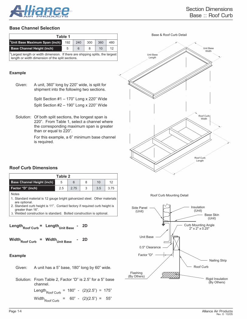
Section DimensionsBase :: Roof Curb
Unit BaseLength
Unit BaseWidth
Roof CurbLength
Roof CurbWidth
Base & Roof Curb Detail
Side Panel (Unit)
Insulation(Unit)
Base Skin(Unit)
Curb Mounting Angle2" x 2" x 0.25"
Unit Base
0.5" Clearance
Factor "D"
Roof Curb
Nailing Strip
Rigid Insulation(By Others)
Flashing(By Others)
Roof Curb Mounting Detail
Base Channel Selection
Table 1
Unit Base Maximum Span (inch) 192 240 300 360 480
Base Channel Height (inch) 5 6 8 10 12
Largest length or width dimension. If there are shipping splits, the largest length or width dimension of the split sections.
Example
Given: A unit, 360” long by 220” wide, is split for shipment into the following two sections.
Split Section #1 – 170” Long x 220” Wide
Split Section #2 – 190” Long x 220” Wide
Solution: Of both split sections, the longest span is 220”. From Table 1, select a channel where the corresponding maximum span is greater than or equal to 220”.
For this example, a 6” minimum base channel is required.
*
*
Roof Curb Dimensions
Table 2
Base Channel Height (inch) 5 6 8 10 12
Factor “D” (inch) 2.5 2.75 3 3.5 3.75
Notes
1. Standard material is 12 gauge bright galvanized steel. Other materials are optional.
2. Standard curb height is 11”. Contact factory if required curb height is greater than 16”.
3. Welded construction is standard. Bolted construction is optional.
LengthRoof Curb
= LengthUnit Base
- 2D
WidthRoof Curb
= WidthUnit Base
- 2D
Example
Given: A unit has a 5” base, 180” long by 60” wide.
Solution: From Table 2, Factor “D” is 2.5” for a 5” base channel.
LengthRoof Curb
= 180” - (2)(2.5”) = 175”
WidthRoof Curb
= 60” - (2)(2.5”) = 55”
Rev. 0 10/05

Alliance Air Products Page 15
Section DimensionsWater, DX & Steam Coils
I
nt
er
na
l
Ca
bi
ne
t
Wi
dt
h
26
38
50
62
74
87
99
111
123
135
147
159
171
183
195
207
219
231
243
FL
FH
17
29
41
53
65
78
90
102
114
126
138
150
162
174
186
(2)
94
(2)
100
(2)
106
(2)
112
29
24
2.8
1
,41
7
4.8
2
,41
7
6.8
3
,41
7
8.8
4
,41
7
10
.8
5,4
17
1
3
6,5
00
41
36
4.2
2
,12
5
7.2
3
,62
5
10
.2
5,1
25
1
3.2
6
,62
5
16
.2
8,1
25
1
9.5
9
,75
0
22
.5
11
,25
0
25
.5
12
,75
0
28
.5
14
,25
0
53
48
9
.7
4,8
33
1
3.7
6
,83
3
17
.7
8,8
33
2
1.7
1
0,8
33
2
6
13
,00
0
30
1
5,0
00
3
4
17
,00
0
38
1
9,0
00
4
2
21
,00
0
46
2
3,0
00
5
0
25
,00
0
65
60
17
.1
8,5
42
2
2.1
1
1,0
42
2
7.1
1
3,5
42
3
2.5
1
6,2
50
3
7.5
1
8,7
50
4
2.5
2
1,2
50
4
7.5
2
3,7
50
5
2.5
2
6,2
50
5
7.5
2
8,7
50
6
2.5
3
1,2
50
6
7.5
3
3,7
50
7
2.5
3
6,2
50
77
(2)
34.5
25
.4
12
,69
8
31
.1
15
,57
3
37
.4
18
,68
8
43
.1
21
,56
2
48
.9
24
,43
8
54
.6
27
,31
2
60
.4
30
,18
8
66
.1
33
,06
2
71
.9
35
,93
8
77
.6
38
,81
2
83
.4
41
,68
8
89
.1
44
,56
2
90
.1
45
,04
2
95
.8
47
,91
7
89
(2)
40.5
3
6.6
1
8,2
81
4
3.9
2
1,9
38
5
0.6
2
5,3
12
5
7.4
2
8,6
88
6
4.1
3
2,0
62
7
0.9
3
5,4
38
7
7.6
3
8,8
12
8
4.4
4
2,1
88
9
1.1
4
5,5
62
9
7.9
4
8,9
38
1
04
.6
52
,31
2
10
5.8
5
2,8
75
1
12
.5
56
,25
0
11
9.2
5
9,6
25
1
26
6
3,0
00
101
(2)
46.5
4
2.0
2
0,9
90
5
0.4
2
5,1
88
5
8.1
2
9,0
62
6
5.9
3
2,9
38
7
3.6
3
6,8
12
8
1.4
4
0,6
88
8
9.1
4
4,5
62
9
6.9
4
8,4
38
1
04
.6
52
,31
2
11
2.4
5
6,1
88
1
20
.1
60
,06
2
12
1.4
6
0,7
08
1
29
.2
64
,58
3
13
6.9
6
8,4
58
1
44
.7
72
,33
3
113
(2)
52.5
56
.9
28
,43
8
65
.6
32
,81
2
74
.4
37
,18
8
83
.1
41
,56
2
91
.9
45
,93
8
10
0.6
5
0,3
12
1
09
.4
54
,68
8
11
8.1
5
9,0
62
1
26
.9
63
,43
8
13
5.6
6
7,8
12
1
37
.1
68
,54
2
14
5.8
7
2,9
17
1
54
.6
77
,29
2
16
3.3
8
1,6
67
I n
t e r n
a l
C
a
b i n
e t H
e i g
h
t 125
(2)
58.5
63
.4
31
,68
8
73
.1
36
,56
2
82
.9
41
,43
8
92
.6
46
,61
2
10
2.4
5
1,1
88
1
12
.1
56
,06
2
12
1.9
6
0,9
38
1
31
.6
65
,81
2
14
1.4
7
0,6
88
1
51
.1
75
,56
2
15
2.8
7
6,3
75
1
62
.5
81
,25
0
17
2.2
8
6,1
25
1
82
9
1,0
00
Wate
r &
Ste
am
Heati
ng
Co
il
Ro
ws
HC
1
7
2
9
HC
DP
CC
CL
R
DP
CL
R
CC
DP
CC
CL
R
DP
CL
R
CC
W
ate
r &
DX
C
oo
lin
g C
oil
Ro
ws
DP
C
LR
C
C
1
19
17
23
2
19
15
23
3
19
15
23
4
19
14
23
5
19
14
23
6
24
17
28
7
24
15
28
8
24
15
28
9
30
18
34
10
30
18
34
11
35
20
39
12
35
20
39
Wa
ter
& D
X
Co
olin
g C
oil W
ith
Do
or
18 D
oo
r 24 D
oo
r
Ro
ws
DP
C
LR
C
C
CL
R
CC
1
19
27
33
33
39
2
19
27
35
33
41
3
19
27
35
33
41
4
19
27
36
33
42
5
19
27
36
33
42
6
24
27
38
33
44
7
24
27
40
33
46
8
24
27
40
33
46
9
30
27
43
33
49
10
30
27
43
33
49
11
35
27
46
33
52
12
35
27
46
33
52
Leg
en
d
Exam
ple
113” In
tern
al C
ab
inet
Heig
ht;
2 C
oils H
igh
, E
ach
Co
il 5
2.5
” F
in H
eig
ht
(FH
) 219” In
tern
al C
ab
inet
Wid
th;
2 C
oils W
ide, E
ach
Co
il 1
00” F
in L
en
gth
(F
L)
(Qty
. o
f C
oils)(
FH
x F
L)
= (
2)(
2)(
52.5
x 1
00)
= Q
ty. (4
) C
oils, 52.5
” F
H x
100” F
L
14
5.8
7
2,9
17
= 1
45
.8 f
t2 C
oil
Fa
ce
Are
a
= 7
2,9
17
CF
M A
t 5
00
fp
m C
oil
Fa
ce
Ve
loc
ity
Note
s
1.
Cabin
et heig
hts
and w
idth
s a
re inte
rnal. S
ee p
age 1
3 for
overa
ll cabin
et dim
ensio
ns.
2.
For
sections w
ith s
plit
s, add 2
” per
split
to o
vera
ll section length
s, “H
C”
and “
CC
”.
3.
CF
M c
alc
ula
ted a
t 500 fpm
coil
face v
elo
city.
4.
Table
valu
es r
epre
sent sta
ndard
coils
with 5
/8”
dia
mete
r tu
bes a
nd 1
-1/2
” tu
be s
pacin
g. S
ee p
age 5
for
coil
description.
5.
Maxim
um
fin
heig
ht is
60”
per
coil.
M
axim
um
fin
length
is 1
86”
per
coil.
C
onta
ct fa
cto
ry if re
quired c
oil
siz
e e
xceeds table
valu
es.
6.
Coolin
g c
oil
section s
hall
alw
ays h
ave s
tain
less s
teel solid
lin
er
to the e
nd o
f th
e d
rain
pan u
nle
ss n
ote
d d
iffe
rently in the s
ubm
itta
l specific
ations.
7.
DX
suction, w
ate
r and s
team
connections p
rotr
ude 4
” fr
om
the c
oil
section e
xte
rnal panel. D
X d
istr
ibuto
r connections a
re locate
d insid
e the s
ection.
8.
Optional coil
rem
oval ra
ck is a
vaila
ble
for
sta
cked c
oils
. If coil
rem
oval ra
ck is r
equired, fin h
eig
ht “F
H”
must be r
educed b
y 1
.5”
on e
ach c
oil.
9.
For
inte
rnal w
idth
s g
reate
r th
an 1
95”,
coil
connections, dra
in p
an c
onnections a
nd c
oil
access p
anels
are
locate
d o
n b
oth
sid
es o
f th
e c
oil
section.
10.
For
inte
rnal w
idth
s 1
95”
or
less, th
e c
oil
access p
anel is
locate
d o
n the s
ide o
pposite the c
oil
connections a
nd the d
rain
pan c
onnection is o
n the
sam
e s
ide a
s the c
oil
connections u
nle
ss n
ote
d d
iffe
rently o
n the s
ubm
itta
l dra
win
gs.
Rev. 0 10/05

Page 16 Alliance Air Products
Section DimensionsFlat Filter
In
te
rn
al
C
ab
in
et
W
id
th
26
38
50
62
74
87
99
111
123
135
147
159
171
183
195
207
219
231
243
F
W
F
H
1
1-1
/2
2
2-1
/2
3
3-1
/2
4
4-1
/2
5
5-1
/2
6
6-1
/2
7
7-1
/2
8
8-1
/2
9
9-1
/2
10
29
1
(1)
24
x2
4
4
2,0
00
(1)
24
x2
4
(1)
12
x2
4
6
3,0
00
(2)
24
x2
4
8
4,0
00
(2)
24
x2
4
(1)
12
x2
4
10
5
,00
0
(3)
24
x2
4
1
2
6,0
00
(3)
24
x2
4
(1)
12
x2
4
14
7
,00
0
41
1-1
/2
(1)
24
x2
4
(1)
12
x2
4
6
3,0
00
(1)
24
x2
4
(2)
12
x2
4
8
4,0
00
(2)
24
x2
4
(2)
12
x2
4
12
6
,00
0
(2)
24
x2
4
(3)
12
x2
4
14
7
,00
0
(3)
24
x2
4
(3)
12
x2
4
18
9
,00
0
(3)
24
x2
4
(4)
12
x2
4
20
1
0,0
00
(4)
24
x2
4
(4)
12
x2
4
24
1
2,0
00
(4)
24
x2
4
(5)
12
x2
4
26
1
3,0
00
(5)
24
x2
4
(5)
12
x2
4
30
1
5,0
00
53
2
(2)
24
x2
4
(2)
12
x2
4
12
6
,00
0
(4)
24
x2
4
1
6
8,0
00
(4)
24
x2
4
(2)
12
x2
4
20
1
0,0
00
(6)
24
x2
4
2
4
12
,00
0
(6)
24
x2
4
(2)
12
x2
4
28
1
4,0
00
(8)
24
x2
4
3
2
16
,00
0
(8)
24
x2
4
(2)
12
x2
4
36
1
8,0
00
(10
) 2
4x2
4
4
0
20
,00
0
(10
) 2
4x2
4
( 2
) 1
2x2
4
44
2
2,0
00
(12
) 2
4x2
4
4
8
24
,00
0
(12
) 2
4x2
4
( 2
) 1
2x2
4
52
2
6,0
00
65
2-1
/2
(4)
24x24
(2)
12
x2
4
20
1
0,0
00
(4)
24
x2
4
(4)
12
x2
4
24
1
2,0
00
(6)
24
x2
4
(3)
12
x2
4
30
1
5,0
00
(6)
24
x2
4
(5)
12
x2
4
34
1
7,0
00
(8)
24
x2
4
(4)
12
x2
4
40
2
0,0
00
(8)
24
x2
4
(6)
12
x2
4
44
2
2,0
00
(10
) 2
4x2
4
( 5
) 1
2x2
4
50
2
5,0
00
(10
) 2
4x2
4
( 7
) 1
2x2
4
54
2
7,0
00
(12
) 2
4x2
4
( 6
) 1
2x2
4
60
3
0,0
00
(12
) 2
4x2
4
( 8
) 1
2x2
4
64
3
2,0
00
(14
) 2
4x2
4
( 7
) 1
2x2
4
70
3
5,0
00
(14
) 2
4x2
4
( 9
) 1
2x2
4
74
3
7,0
00
77
3
(6)
24
x2
4
(3)
12
x2
4
30
1
5,0
00
(9)
24
x2
4
3
6
18
,00
0
(9)
24
x2
4
(3)
12
x2
4
42
2
1,0
00
(12
) 2
4x2
4
4
8
24
,00
0
(12
) 2
4x2
4
( 3 )
12x2
4
54
2
7,0
00
(15
) 2
4x2
4
6
0
30
,00
0
(15
) 2
4x2
4
( 3
) 1
2x2
4
66
3
3,0
00
(18
) 2
4x2
4
7
2
36
,00
0
(18
) 2
4x2
4
( 3
) 1
2x2
4
78
3
9,0
00
(21
) 2
4x2
4
8
4
42
,00
0
(21
) 2
4x2
4
( 3
) 1
2x2
4
90
4
5,0
00
(24
) 2
4x2
4
9
6
48
,00
0
(24
) 2
4x2
4
( 3
) 1
2x2
4
10
2
51
,00
0
(27
) 2
4x2
4
1
08
5
4,0
00
89
3-1
/2
(9)
24
x2
4
(3)
12
x2
4
42
2
1,0
00
(9)
24
x2
4
(6)
12
x2
4
48
2
4,0
00
(12
) 2
4x2
4
( 4
) 1
2x2
4
56
2
8,0
00
(12
) 2
4x2
4
( 7
) 1
2x2
4
62
3
1,0
00
(15
) 2
4x2
4
( 5
) 1
2x2
4
70
3
5,0
00
(15
) 2
4x2
4
( 8
) 1
2x2
4
76
3
8,0
00
(18
) 2
4x2
4
( 6
) 1
2x2
4
84
4
2,0
00
(18
) 2
4x2
4
( 9
) 1
2x2
4
90
4
5,0
00
(21
) 2
4x2
4
( 7
) 1
2x2
4
98
4
9,0
00
(21
) 2
4x2
4
(10
) 1
2x2
4
10
4
52
,00
0
(24
) 2
4x2
4
( 8
) 1
2x2
4
11
2
56
,00
0
(24
) 2
4x2
4
(11
) 1
2x2
4
11
8
59
,00
0
(27
) 2
4x2
4
( 9
) 1
2x2
4
12
6
63
,00
0
(27
) 2
4x2
4
(12
) 1
2x2
4
13
2
66
,00
0
(30
) 2
4x2
4
(10
) 1
2x2
4
14
0
70
,00
0
101
4
(12
) 2
4x2
4
4
8
24
,00
0
(12
) 2
4x2
4
( 4
) 1
2x2
4
56
2
8,0
00
(16
) 2
4x2
4
6
4
32
,00
0
(16
) 2
4x2
4
( 4
) 1
2x2
4
72
3
6,0
00
(20
) 2
4x2
4
8
0
40
,00
0
(20
) 2
4x2
4
( 4
) 1
2x2
4
88
4
4,0
00
(24
) 2
4x2
4
9
6
48
,00
0
(24
) 2
4x2
4
( 4
) 1
2x2
4
10
4
52
,00
0
(28
) 2
4x2
4
1
12
5
6,0
00
(28
) 24x24
( 4
) 1
2x2
4
12
0
60
,00
0
(32
) 2
4x2
4
1
28
6
4,0
00
(32
) 2
4x2
4
( 4
) 1
2x2
4
13
6
68
,00
0
(36
) 2
4x2
4
1
44
7
2,0
00
(36
) 2
4x2
4
( 4
) 1
2x2
4
15
2
76
,00
0
(40
) 2
4x2
4
1
60
8
0,0
00
113
4-1
/2
(12
) 2
4x2
4
( 7
) 1
2x2
4
62
3
1,0
00
(16
) 2
4x2
4
( 4
) 1
2x2
4
72
3
6,0
00
(16
) 2
4x24
( 8
) 1
2x2
4
80
4
0,0
00
(20
) 2
4x2
4
( 5
) 1
2x2
4
90
4
5,0
00
(20
) 2
4x2
4
( 9
) 1
2x2
4
98
4
9,0
00
(24
) 2
4x2
4
( 6
) 1
2x2
4
10
8
54
,00
0
(24
) 2
4x2
4
(10
) 1
2x2
4
11
6
58
,00
0
(28
) 2
4x2
4
( 7
) 1
2x2
4
12
6
63
,00
0
(28
) 2
4x2
4
(11
) 1
2x2
4
13
4
67
,00
0
(32
) 2
4x2
4
( 8
) 1
2x2
4
14
4
72
,00
0
(32
) 2
4x2
4
(12
) 1
2x2
4
15
2
76
,00
0
(36
) 2
4x2
4
( 9
) 1
2x2
4
16
2
81
,00
0
(36
) 2
4x2
4
(13
) 1
2x2
4
17
0
85
,00
0
(40
) 2
4x2
4
(10
) 1
2x2
4
18
0
90
,00
0
I n t e
r n
a l C
a
b i n
e t H
e i g
h t
125
5
(15
) 2
4x2
4
( 5
) 1
2x2
4
70
3
5,0
00
(20
) 2
4x2
4
8
0
40
,00
0
(20
) 2
4x2
4
( 5
) 1
2x2
4
90
4
5,0
00
(25
) 2
4x2
4
1
00
5
0,0
00
(25
) 2
4x2
4
( 5
) 1
2x2
4
11
0
55
,00
0
(30
) 2
4x2
4
1
20
6
0,0
00
(30
) 2
4x2
4
( 5
) 1
2x2
4
13
0
65
,00
0
(35
) 2
4x2
4
1
40
7
0,0
00
(35
) 2
4x2
4
( 5
) 1
2x2
4
15
0
75
,00
0
(40
) 2
4x2
4
1
60
8
0,0
00
(40
) 2
4x2
4
( 5
) 1
2x2
4
17
0
85
,00
0
(45
) 2
4x2
4
1
80
9
0,0
00
(45
) 2
4x2
4
( 5
) 1
2x2
4
19
0
95
,00
0
(50
) 2
4x2
4
2
00
1
00
,00
0
L
Air
Flo
w
Up
str
eam
2
Secti
on
Len
gth
– C
om
bin
ati
on
Pre
an
d F
inal F
ilte
r
L2
Pre
filt
er
De
pth
F
ina
l F
ilte
r D
ep
th
Up
str
ea
m L
oa
d
4
8
6
10
12
1
6
15
1
9
22
2
6
30
3
4
2
36
4
0
6
12
12
1
7
15
2
0
22
2
7
30
3
5
4
36
4
1
No
tes
1.
Ad
ditio
na
l p
len
um
with
do
or
req
uir
ed
fo
r filte
r a
cce
ss.
2.
Filt
er
fra
me
s a
re a
va
ilab
le in
sta
nd
ard
16
ga
ug
e b
rig
ht
ga
lva
niz
ed
or
sta
inle
ss s
tee
l. 3
. H
EP
A f
ilte
rs a
re n
ot
ava
ilab
le in
th
is p
re a
nd
fin
al filte
r co
nfig
ura
tio
n.
4.
Co
nta
ct
facto
ry f
or
oth
er
filte
r siz
es a
nd
co
nfig
ura
tion
s.
5.
Fo
r se
ctio
n w
ith
sp
lits,
ad
d 2
” p
er
sp
lit t
o o
ve
rall
se
ctio
n le
ng
th “
L2
”.
L
Air
Flo
w
Up
str
ea
m
1
Secti
on
Len
gth
– F
lat
Filte
r
L1
Fil
ter
De
pth
Sid
e
Lo
ad
U
ps
tre
am
L
oa
d
Do
wn
str
ea
m
Lo
ad
2
8
6
6
4
8
6
6
4 (
Hig
h E
ff.)
6
6
10
12
1
6
15
1
9
22
2
6
30
3
4
36
4
0
No
tes
1.
Up
str
ea
m a
nd
do
wn
str
ea
m lo
ad
s r
eq
uir
e a
n a
dd
itio
na
l p
len
um
with
do
or
for
filte
r a
cce
ss.
2.
Filt
er
fra
me
s a
re a
va
ilab
le in
sta
nd
ard
16
ga
ug
e b
rig
ht
ga
lva
niz
ed
or
sta
inle
ss s
tee
l. 3
. C
on
tact
facto
ry f
or
oth
er
filte
r siz
es a
nd
co
nfig
ura
tio
ns.
4.
Fo
r se
ctio
n w
ith
sp
lits,
ad
d 2
” p
er
sp
lit t
o o
ve
rall
se
ctio
n le
ng
th “
L1
”.
Leg
en
d
Exam
ple
53” In
tern
al C
ab
inet
Heig
ht;
2 F
ilte
rs H
igh
(F
H)
62” In
tern
al C
ab
inet
Wid
th;
2½
Filte
rs W
ide (
FW
)
(4)
24
x2
4
(2)
12
x2
4
20
1
0,0
00
= Q
ua
nti
ty (
4)
24
” x
24
” F
ilte
r F
ram
es
= Q
ua
nti
ty (
2)
12
” x
24
” F
ilte
r F
ram
es
= 2
0 f
t2 F
ilte
r F
ac
e A
rea
=
10
,00
0 C
FM
At
50
0 f
pm
Fil
ter
Fa
ce
Ve
loc
ity
No
te
1.
Ca
bin
et
he
igh
ts a
nd
wid
ths
are
in
tern
al.
S
ee
pa
ge
13
fo
r o
ve
rall
c
ab
ine
t d
ime
ns
ion
s.
Rev. 0 10/05
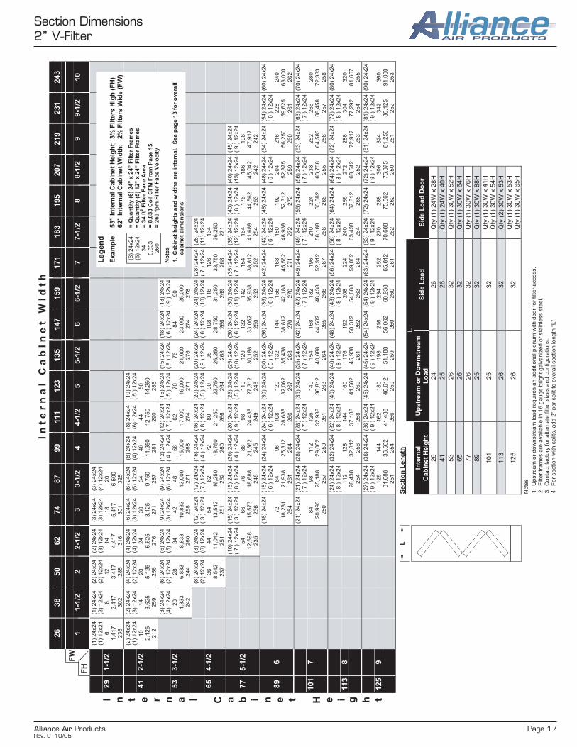
Alliance Air Products Page 17
Section Dimensions2” V-Filter
In
te
rn
al
C
ab
in
et
W
id
th
26
38
50
62
74
87
99
111
123
135
147
159
171
183
195
207
219
231
243
F
W
F
H
1
1-1
/2
2
2-1
/2
3
3-1
/2
4
4-1
/2
5
5-1
/2
6
6-1
/2
7
7-1
/2
8
8-1
/2
9
9-1
/2
10
29
1-1
/2
(1)
24
x2
4
(1)
12
x2
4
6
1,4
17
2
36
(1)
24
x2
4
(2)
12
x2
4
8
2,4
17
3
02
(2)
24
x2
4
(2)
12
x2
4
12
3
,41
7
28
5
(2)
24
x2
4
(3)
12
x2
4
14
4
,41
7
31
6
(3)
24
x2
4
(3)
12
x2
4
18
5
,41
7
30
1
(3)
24
x2
4
(4)
12
x2
4
20
6
,50
0
32
5
41
2-1
/2
(2)
24
x2
4
(1)
12
x2
4
10
2
,12
5
21
2
(2)
24
x2
4
(3)
12
x2
4
14
3
,62
5
25
9
(4)
24
x2
4
(2)
12
x2
4
20
5
,12
5
25
6
(4)
24
x2
4
(4)
12
x2
4
24
6
,62
5
27
6
(6)
24
x2
4
(3)
12
x2
4
30
8
,12
5
27
1
(6)
24
x2
4
(5)
12
x2
4
34
9
,75
0
28
7
(8)
24
x2
4
(4)
12
x2
4
40
1
1,2
50
2
81
(8)
24
x2
4
(6)
12
x2
4
44
1
2,7
50
2
90
(10
) 2
4x2
4
( 5
) 1
2x24
50
1
4,2
50
2
85
53
3-1
/2
(3)
24
x2
4
(4)
12
x2
4
20
4
,83
3
24
2
(6)
24
x2
4
(2)
12
x2
4
28
6
,83
3
24
4
(6)
24
x2
4
(5)
12
x2
4
34
8
,83
3
26
0
(9)
24
x2
4
(3)
12
x2
4
42
1
0,8
33
2
58
(9)
24
x2
4
(6)
12
x2
4
48
1
3,0
00
2
71
(12
) 2
4x2
4
( 4
) 1
2x2
4
56
1
5,0
00
2
68
(12
) 2
4x2
4
( 7
) 1
2x2
4
62
1
7,0
00
2
74
(15
) 2
4x2
4
( 5
) 1
2x2
4
70
1
9,0
00
2
71
(15
) 2
4x2
4
( 8
) 1
2x2
4
76
2
1,0
00
2
76
(18
) 2
4x2
4
( 6
) 1
2x2
4
84
2
3,0
00
2
74
(18
) 2
4x2
4
( 9
) 1
2x2
4
90
2
5,0
00
2
78
65
4-1
/2
(8)
24
x2
4
(2)
12
x2
4
36
8
,54
2
23
7
(8)
24
x2
4
(6)
12
x2
4
44
1
1,0
42
2
51
(12
) 2
4x2
4
( 3
) 1
2x2
4
54
1
3,5
42
2
51
(12
) 2
4x2
4
( 7
) 1
2x2
4
62
1
6,2
50
2
62
(16
) 2
4x2
4
( 4
) 1
2x2
4
72
1
8,7
50
2
60
(16
) 2
4x2
4
( 8
) 1
2x2
4
80
2
1,2
50
2
66
(20
) 2
4x2
4
( 5
) 1
2x2
4
90
2
3,7
50
2
64
(20
) 2
4x2
4
( 9
) 1
2x2
4
98
2
6,2
50
2
68
(24
) 2
4x2
4
( 6
) 1
2x2
4
10
8
28
,75
0
26
6
(24
) 2
4x2
4
(10
) 1
2x2
4
11
6
31
,25
0
26
9
(28
) 2
4x2
4
( 7
) 1
2x2
4
12
6
33
,75
0
26
8
(28
) 2
4x2
4
(11
) 1
2x2
4
13
4
36
,25
0
27
1
77
5-1
/2
(10
) 2
4x2
4
( 7
) 1
2x2
4
54
1
2,6
98
2
35
(15
) 2
4x2
4
( 3
) 1
2x2
4
66
1
5,5
73
2
36
(15
) 2
4x2
4
( 8
) 1
2x2
4
76
1
8,6
88
2
46
(20
) 2
4x24
( 4
) 1
2x2
4
88
2
1,5
62
2
45
(20
) 2
4x2
4
( 9
) 1
2x2
4
98
2
4,4
38
2
49
(25
) 2
4x2
4
( 5
) 1
2x2
4
11
0
27
,31
2
24
8
(25
) 2
4x2
4
(10
) 1
2x2
4
12
0
30
,18
8
25
2
(30
) 2
4x2
4
( 6
) 1
2x2
4
13
2
33
,06
2
25
0
(30
) 2
4x2
4
(11
) 1
2x2
4
14
2
35
,93
8
25
3
(35
) 2
4x2
4
( 7
) 1
2x2
4
15
4
38
,81
2
25
2
(35
) 2
4x2
4
(12
) 1
2x2
4
16
4
41
,68
8
25
4
(40
) 2
4x2
4
( 8
) 1
2x2
4
17
6
44
,56
2
25
3
(40
) 2
4x2
4
(13
) 1
2x2
4
18
6
45
,04
2
24
2
(45
) 2
4x2
4
( 9
) 1
2x2
4
19
8
47
,91
7
24
2
89
6
(18
) 2
4x2
4
7
2
18
,28
1
25
4
(18
) 2
4x2
4
( 6
) 1
2x2
4
84
2
1,9
38
2
61
(24
) 2
4x2
4
9
6
25
,31
2
26
4
(24
) 2
4x2
4
( 6
) 1
2x2
4
10
8
28
,68
8
26
6
(30
) 2
4x2
4
1
20
3
2,0
62
2
67
(30
) 2
4x2
4
( 6
) 1
2x2
4
13
2
35
,43
8
26
8
(36
) 2
4x2
4
1
44
3
8,8
12
2
70
(36
) 2
4x2
4
( 6
) 1
2x2
4
15
6
42
,18
8
27
0
(42
) 2
4x2
4
1
68
4
5,5
62
2
71
(42
) 2
4x2
4
( 6
) 1
2x2
4
18
0
48
,93
8
27
2
(48
) 2
4x2
4
1
92
5
2,3
12
2
72
(48
) 2
4x2
4
( 6
) 1
2x2
4
20
4
52
,87
5
25
9
(54
) 2
4x2
4
2
16
5
6,2
50
2
60
(54
) 2
4x2
4
( 6
) 1
2x2
4
22
8
59
,62
5
26
1
(60
) 2
4x2
4
2
40
6
3,0
00
2
62
101
7
(21
) 2
4x2
4
8
4
20
,99
0
25
0
(21
) 2
4x2
4
( 7
) 1
2x2
4
98
2
5,1
88
2
57
(28
) 2
4x2
4
1
12
2
9,0
62
2
59
(28
) 2
4x2
4
( 7
) 1
2x2
4
12
6
32
,93
8
26
1
(35
) 2
4x2
4
1
40
3
6,8
12
2
63
(35
) 2
4x2
4
( 7
) 1
2x2
4
15
4
40
,68
8
26
4
(42
) 2
4x2
4
1
68
4
4,5
62
2
65
(42
) 2
4x2
4
( 7
) 1
2x2
4
18
2
48
,43
8
26
6
(49
) 2
4x2
4
1
96
5
2,3
12
2
67
(49
) 2
4x2
4
( 7
) 1
2x2
4
21
0
56
,18
8
26
8
(56
) 2
4x2
4
2
24
6
0,0
62
2
68
(56
) 2
4x2
4
( 7
) 1
2x2
4
23
8
60
,70
8
25
5
(63
) 2
4x2
4
2
52
6
4,5
83
2
56
(63
) 2
4x2
4
( 7
) 1
2x2
4
26
6
68
,45
8
25
7
(70
) 2
4x2
4
2
80
7
2,3
33
2
58
113
8
(24
) 2
4x2
4
( 8
) 1
2x2
4
11
2
28
,43
8
25
4
(32
) 2
4x2
4
1
28
3
2,8
12
2
56
(32
) 2
4x2
4
( 8
) 1
2x2
4
14
4
37
,18
8
25
8
(40
) 2
4x2
4
1
60
4
1,5
62
2
60
(40
) 2
4x2
4
( 8
) 1
2x2
4
17
6
45
,93
8
26
1
(48
) 2
4x2
4
1
92
5
0,3
12
2
62
(48
) 2
4x2
4
( 8
) 1
2x2
4
20
8
54
,68
8
26
3
(56
) 2
4x2
4
2
24
5
9,0
62
2
64
(56
) 2
4x2
4
( 8
) 1
2x2
4
24
0
63
,43
8
26
4
(64
) 2
4x2
4
2
56
6
7,8
12
2
65
(64
) 2
4x2
4
( 8
) 1
2x2
4
27
2
68
,54
2
25
2
(72
) 2
4x2
4
2
88
7
2,9
17
2
53
(72
) 2
4x2
4
( 8
) 1
2x2
4
30
4
77
,29
2
25
4
(80
) 2
4x2
4
3
20
8
1,6
67
2
55
I n
t e r n
a l C
a
b i n
e t H
e i g
h
t 125
9
(27
) 2
4x2
4
( 9
) 1
2x2
4
12
6
31
,68
8
25
1
(36
) 2
4x2
4
1
44
3
6,5
62
2
54
(36
) 2
4x2
4
( 9
) 1
2x2
4
16
2
41
,43
8
25
6
(45
) 2
4x2
4
1
80
4
6,6
12
2
59
(45
) 2
4x2
4
( 9
) 1
2x2
4
19
8
51
,18
8
25
9
(54
) 2
4x2
4
2
16
5
6,0
62
2
60
(54
) 2
4x2
4
( 9
) 1
2x2
4
23
4
60
,93
8
26
0
(63
) 2
4x2
4
2
52
6
5,8
12
2
61
(63
) 2
4x2
4
( 9
) 1
2x2
4
27
0
70
,68
8
26
2
(72
) 2
4x2
4
2
88
7
5,5
62
2
62
(72
) 2
4x2
4
( 9
) 1
2x2
4
30
6
76
,37
5
25
0
(81
) 2
4x2
4
3
24
8
1,2
50
2
51
(81
) 2
4x2
4
( 9
) 1
2x2
4
34
2
86
,12
5
25
2
(90
) 24x24
3
60
9
1,0
00
2
53
L
Leg
en
d
Exam
ple
53” In
tern
al C
ab
inet
Heig
ht;
3½
Filte
rs H
igh
(F
H)
62” In
tern
al C
ab
inet
Wid
th;
2½
Filte
rs W
ide (
FW
)
(6)
24
x2
4
(5)
12
x2
4
34
8
,83
3
26
0
= Q
ua
nti
ty (
6)
24
” x
24
” F
ilte
r F
ram
es
=
Qu
an
tity
(5
) 1
2” x
24
” F
ilte
r F
ram
es
=
34
ft2
Fil
ter
Fa
ce
Are
a
= 8
,83
3 C
oil
CF
M F
rom
Pa
ge
15
. =
26
0 f
pm
Fil
ter
Fa
ce
Ve
loc
ity
No
tes
1.
Ca
bin
et
he
igh
ts a
nd
wid
ths
are
in
tern
al.
S
ee
pa
ge
13
fo
r o
ve
rall
c
ab
ine
t d
ime
ns
ion
s.
Secti
on
Len
gth
L
Inte
rnal
Cab
inet
Heig
ht
Up
str
eam
or
Do
wn
str
eam
L
oad
S
ide L
oad
S
ide L
oad
Do
or
29
24
26
Qty
(1)
24W
x 2
8H
41
25
26
Qty
(1)
24W
x 4
0H
53
26
32
Qty
(1)
30W
x 5
2H
65
26
32
Qty
(1)
30W
x 6
4H
77
26
32
Qty
(1)
30
W x
76
H
89
25
32
Qty
(1)
30W
x 8
8H
101
25
32
Qty
(1)
30W
x 4
1H
Q
ty (
1)
30W
x 5
4H
113
26
32
Qty
(2)
30W
x 5
3H
125
26
32
Qty
(1)
30W
x 5
3H
Q
ty (
1)
30W
x 6
5H
No
tes
1.
Up
str
ea
m o
r d
ow
nstr
ea
m lo
ad
re
qu
ire
s a
n a
dd
itio
na
l p
len
um
with
do
or
for
filte
r a
cce
ss.
2.
Filt
er
fra
me
s a
re a
va
ilab
le in
16
ga
ug
e b
rig
ht
ga
lva
niz
ed
or
sta
inle
ss s
tee
l. 3
. C
on
tact
facto
ry f
or
alte
rna
te f
ilte
r siz
es a
nd
co
nfig
ura
tio
ns.
4.
Fo
r se
ctio
n w
ith
sp
lits,
ad
d 2
” p
er
sp
lit t
o o
ve
rall
se
ctio
n le
ng
th “
L”.
Rev. 0 10/05

Page 18 Alliance Air Products
Section Dimensions4” V-Filter
In
te
rn
al
C
ab
in
et
W
id
th
26
38
50
62
74
87
99
111
123
135
147
159
171
183
195
207
219
231
243
F
W
F
H
1
1-1
/2
2
2-1
/2
3
3-1
/2
4
4-1
/2
5
5-1
/2
6
6-1
/2
7
7-1
/2
8
8-1
/2
9
9-1
/2
10
29
1-1
/2
(1)
24
x2
4
(1)
12
x2
4
6
1,4
17
2
36
(1)
24
x2
4
(2)
12
x2
4
8
2,4
17
3
02
(2)
24
x2
4
(2)
12
x2
4
12
3
,41
7
28
5
(2)
24
x2
4
(3)
12
x2
4
14
4
,41
7
31
6
(3)
24
x2
4
(3)
12
x2
4
18
5
,41
7
30
1
(3)
24
x2
4
(4)
12
x2
4
20
6
,50
0
32
5
41
2
(2)
24
x2
4
(0)
12
x2
4
8
2,1
25
2
66
(2)
24
x2
4
(2)
12
x2
4
12
3
,62
5
30
2
(4)
24
x2
4
(0)
12
x2
4
16
5
,12
5
32
0
(4)
24
x2
4
(2)
12
x2
4
20
6
,62
5
33
1
(6)
24
x2
4
(0)
12
x2
4
24
8
,12
5
33
9
(6)
24
x2
4
(2)
12
x2
4
28
9
,75
0
34
8
(8)
24
x2
4
(0)
12
x2
4
32
1
1,2
50
3
52
(8)
24
x2
4
(2)
12
x2
4
36
1
2,7
50
3
54
(10
) 2
4x2
4
(0)
12
x2
4
40
1
4,2
50
3
56
53
3
(3)
24
x2
4
(3)
12
x2
4
18
4
,83
3
26
8
(6)
24
x2
4
(0)
12
x2
4
24
6
,83
3
28
5
(6)
24
x2
4
(3)
12
x2
4
30
8
,83
3
29
4
(9)
24
x2
4
(0)
12
x2
4
36
1
0,8
33
3
01
(9)
24
x2
4
(3)
12
x2
4
42
1
3,0
00
3
10
(12
) 2
4x2
4
(0)
12
x2
4
48
1
5,0
00
3
12
(12
) 2
4x2
4
(3)
12
x2
4
54
1
7,0
00
3
15
(15
) 2
4x2
4
(0)
12
x2
4
60
1
9,0
00
3
17
(15
) 2
4x2
4
(3)
12
x2
4
66
2
1,0
00
3
18
(18
) 2
4x2
4
(0)
12
x2
4
72
2
3,0
00
3
19
(18
) 2
4x2
4
(3)
12
x2
4
78
2
5,0
00
3
21
65
4
(8)
24
x2
4
(0)
12
x2
4
32
8
,54
2
26
7
(8)
24
x2
4
(4)
12
x2
4
40
1
1,0
42
2
76
(12
) 2
4x2
4
(0)
12
x2
4
48
1
3,5
42
2
82
(12
) 2
4x2
4
(4)
12
x2
4
56
1
6,2
50
2
90
(16
) 2
4x2
4
(0)
12
x2
4
64
1
8,7
50
2
93
(16
) 2
4x2
4
(4)
12
x2
4
72
2
1,2
50
2
95
(20
) 2
4x2
4
(0)
12
x2
4
80
2
3,7
50
2
97
(20
) 2
4x2
4
(4)
12
x2
4
88
2
6,2
50
2
98
(24
) 2
4x2
4
(0)
12
x2
4
96
2
8,7
50
2
99
(24
) 2
4x2
4
(4)
12
x2
4
10
4
31
,25
0
30
0
(28
) 2
4x2
4
(0)
12
x2
4
11
2
33
,75
0
30
1
(28
) 2
4x2
4
(4)
12
x2
4
12
0
36
,25
0
30
2
77
5
(10
) 2
4x2
4
(5)
12
x2
4
50
1
2,6
98
2
54
(15
) 2
4x2
4
(0)
12
x2
4
60
1
5,5
73
2
60
(15
) 2
4x2
4
(5)
12
x2
4
70
1
8,6
88
2
67
(20
) 2
4x2
4
(0)
12
x2
4
80
2
1,5
62
2
70
(20
) 2
4x2
4
(5)
12
x2
4
90
2
4,4
38
2
72
(25
) 2
4x2
4
(0)
12
x2
4
10
0
27
,31
2
27
3
(25
) 2
4x2
4
(5)
12
x2
4
11
0
30
,18
8
27
4
(30
) 2
4x2
4
(0)
12
x2
4
12
0
33
,06
2
27
6
(30
) 2
4x2
4
(5)
12
x2
4
13
0
35
,93
8
27
6
(35
) 2
4x2
4
(0)
12
x2
4
14
0
38
,81
2
27
7
(35
) 2
4x2
4
(5)
12
x2
4
15
0
41
,68
8
27
8
(40
) 2
4x2
4
(0)
12
x2
4
16
0
44
,56
2
27
9
(40
) 2
4x2
4
(5)
12
x2
4
17
0
45
,04
2
26
5
(45
) 2
4x2
4
(0)
12
x2
4
18
0
47
,91
7
26
6
89
6
(18
) 2
4x2
4
(0)
12
x2
4
72
1
8,2
81
2
54
(18
) 2
4x2
4
(6)
12
x2
4
84
2
1,9
38
2
61
(24
) 2
4x2
4
(0)
12
x2
4
96
2
5,3
12
2
64
(24
) 2
4x2
4
(6)
12
x2
4
10
8
28
,68
8
26
6
(30
) 2
4x2
4
(0)
12
x2
4
12
0
32
,06
2
26
7
(30
) 2
4x2
4
(6)
12
x2
4
13
2
35
,43
8
26
8
(36
) 2
4x2
4
(0)
12
x2
4
14
4
38
,81
2
27
0
(36
) 2
4x2
4
(6)
12
x2
4
15
6
42
,18
8
27
0
(42
) 2
4x2
4
(0)
12
x2
4
16
8
45
,56
2
27
1
(42
) 2
4x2
4
(6)
12
x2
4
18
0
48
,93
8
27
2
(48
) 2
4x2
4
(0)
12
x2
4
19
2
52
,31
2
27
2
(48
) 2
4x2
4
(6)
12
x2
4
20
4
52
,87
5
25
9
(54
) 2
4x2
4
(0)
12
x2
4
21
6
56
,25
0
26
0
(54
) 2
4x2
4
(6)
12
x2
4
22
8
59
,62
5
26
2
(60
) 2
4x2
4
(0)
12
x2
4
24
0
63
,00
0
26
2
101
6-1
/2
(18
) 2
4x2
4
(3)
12
x2
4
78
2
0,9
90
2
69
(18
) 2
4x2
4
(9)
12
x2
4
90
2
5,1
88
2
80
(24
) 2
4x2
4
(4)
12
x2
4
10
4
29
,06
2
27
9
(24
) 2
4x2
4
(10
) 1
2x2
4
11
6
32
,93
8
28
4
(30
) 2
4x2
4
(5)
12
x2
4
13
0
36
,81
2
28
3
(30
) 2
4x2
4
(11
) 1
2x2
4
14
2
40
,68
8
28
7
(36
) 2
4x2
4
(6)
12
x2
4
15
6
44
,56
2
28
6
(36
) 2
4x2
4
(12
) 1
2x2
4
16
8
48
,43
8
28
8
(42
) 2
4x2
4
(7)
12
x2
4
18
2
52
,31
2
28
7
(42
) 2
4x2
4
(13
) 1
2x2
4
19
4
56
,18
8
29
0
(48
) 2
4x2
4
(8)
12
x2
4
20
8
60
,06
2
28
9
(48
) 2
4x2
4
(14
) 1
2x2
4
22
0
60
,70
8
27
6
(54
) 2
4x2
4
(9)
12
x2
4
23
4
64
,58
3
27
6
(54
) 2
4x2
4
(15
) 1
2x2
4
24
6
68
,45
8
27
8
(60
) 2
4x2
4
(10
) 1
2x2
4
26
0
72
,33
3
27
8
113
7-1
/2
(24
) 2
4x2
4
(8)
12
x2
4
11
2
28
,43
8
25
4
(32
) 2
4x2
4
(0)
12
x2
4
12
8
32
,81
2
25
6
(32
) 24x24
(8)
12
x2
4
14
4
37
,18
8
25
8
(40
) 2
4x2
4
(0)
12
x2
4
16
0
41
,56
2
26
0
(40
) 2
4x2
4
(8)
12
x2
4
17
6
45
,93
8
26
1
(48
) 2
4x2
4
(0)
12
x2
4
19
2
50
,31
2
26
2
(48
) 2
4x2
4
(8)
12
x2
4
20
8
54
,68
8
26
3
(56
) 2
4x2
4
(0)
12
x2
4
22
4
59
,06
2
26
4
(56
) 2
4x2
4
(8)
12
x2
4
24
0
63
,43
8
26
4
(64
) 2
4x2
4
(0)
12
x2
4
25
6
67
,81
2
26
5
(64
) 2
4x2
4
(8)
12
x2
4
27
2
68
,54
2
25
2
(72
) 2
4x2
4
(0)
12
x2
4
28
8
72
,91
7
25
3
(72
) 2
4x2
4
(8)
12
x2
4
30
4
77
,29
2
25
4
(80
) 2
4x2
4
(0)
12
x2
4
32
0
81
,66
7
25
5
I n
t e r n
a l C
a
b i n
e t H
e i g
h
t 125
8
(24
) 2
4x2
4
(8)
12
x2
4
11
2
31
,68
8
28
3
(32
) 2
4x2
4
(0)
12
x2
4
12
8
36
,56
2
28
6
(32
) 2
4x2
4
(8)
12
x2
4
14
4
41
,43
8
28
8
(40
) 2
4x2
4
(0)
12
x2
4
16
0
46
,61
2
29
1
(40
) 2
4x2
4
(8)
12
x2
4
17
6
51
,18
8
29
1
(48
) 2
4x2
4
(0)
12
x2
4
19
2
56
,06
2
29
2
(48
) 2
4x2
4
(8)
12
x2
4
20
8
60
,93
8
29
3
(56
) 2
4x2
4
(0)
12
x2
4
22
4
65
,81
2
29
4
(56
) 2
4x2
4
(8)
12
x2
4
24
0
70
,68
8
29
5
(64
) 2
4x2
4
(0)
12
x2
4
25
6
75
,56
2
29
5
(64
) 2
4x2
4
(8)
12
x2
4
27
2
76
,37
5
28
1
(72
) 2
4x2
4
(0)
12
x2
4
28
8
81
,25
0
28
2
(72
) 2
4x2
4
(8)
12
x2
4
30
4
86
,12
5
28
3
(80
) 2
4x2
4
(0)
12
x2
4
32
0
91
,00
0
28
4
Leg
en
d
Exam
ple
53” In
tern
al C
ab
inet
Heig
ht;
3 F
ilte
rs H
igh
(F
H)
62” In
tern
al C
ab
inet
Wid
th;
2½
Filte
rs W
ide (
FW
)
(6)
24
x2
4
(3)
12
x2
4
30
8
,83
3
29
4
= Q
ua
nti
ty (
6)
24
” x
24
” F
ilte
r F
ram
es
=
Qu
an
tity
(3
) 1
2” x
24
” F
ilte
r F
ram
es
=
30
ft2
Fil
ter
Fa
ce
Are
a
= 8
,83
3 C
oil
CF
M F
rom
Pa
ge
15
. =
29
4 f
pm
Fil
ter
Fa
ce
Ve
loc
ity
No
tes
1.
Ca
bin
et
he
igh
ts a
nd
wid
ths
are
in
tern
al.
S
ee
pa
ge
13
fo
r o
ve
rall
c
ab
ine
t d
ime
ns
ion
s.
Secti
on
Len
gth
L
Inte
rnal
Cab
inet
Heig
ht
Up
str
eam
or
Do
wn
str
eam
L
oad
S
ide L
oad
S
ide L
oad
Do
or
29
25
32
Qty
(1)
30W
x 2
8H
41
23
26
Qty
(1)
24W
x 4
0H
53
25
32
Qty
(1)
30W
x 5
2H
65
25
32
Qty
(1)
30W
x 6
4H
77
26
32
Qty
(1)
30W
x 7
6H
89
26
32
Qty
(1)
30W
x 8
8H
101
26
32
Qty
(1)
30W
x 3
8H
Q
ty (
1)
30W
x 5
7H
113
26
32
Qty
(1
) 3
0W
x 5
1H
Q
ty (
1)
30W
x 5
6H
125
26
32
Qty
(2)
30W
x 5
9H
No
tes
1.
Up
str
ea
m o
r d
ow
nstr
ea
m lo
ad
re
qu
ire
s a
n a
dd
itio
na
l p
len
um
with
do
or
for
filte
r a
cce
ss.
2.
Filt
er
fra
me
s a
re a
va
ilab
le in
16
ga
ug
e b
rig
ht
ga
lva
niz
ed
or
sta
inle
ss s
tee
l.
3.
Co
nta
ct
facto
ry f
or
altern
ate
filt
er
siz
es a
nd
co
nfig
ura
tio
ns.
4.
Fo
r se
ctio
n w
ith
sp
lits,
ad
d 2
” p
er
sp
lit t
o o
ve
rall
se
ctio
n le
ng
th “
L”.
L
Rev. 0 10/05
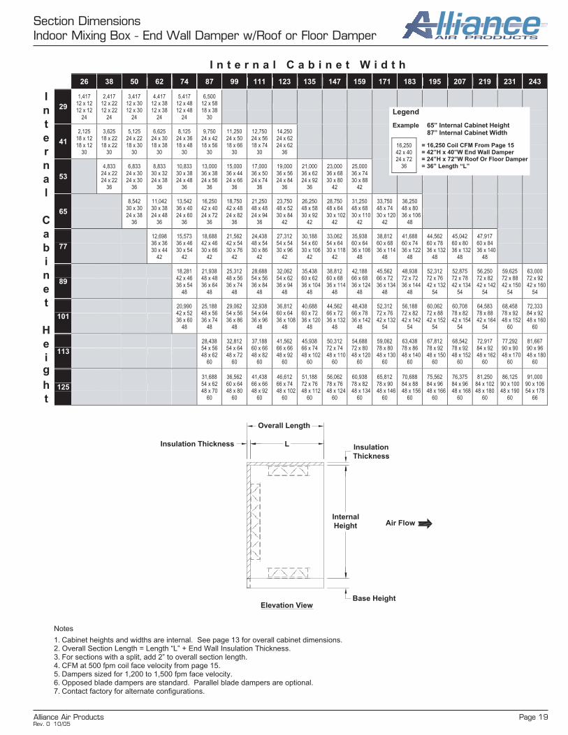
Alliance Air Products Page 19
Section DimensionsIndoor Mixing Box - End Wall Damper w/Roof or Floor Damper
I n t e r n a l C a b i n e t W i d t h
26 38 50 62 74 87 99 111 123 135 147 159 171 183 195 207 219 231 243
29
1,417 12 x 12 12 x 12
24
2,417 12 x 22 12 x 22
24
3,417 12 x 30 12 x 30
24
4,417 12 x 38 12 x 38
24
5,417 12 x 48 12 x 48
24
6,500 12 x 58 18 x 38
30
41
2,125 18 x 12 18 x 12
30
3,625 18 x 22 18 x 22
30
5,125 24 x 22 18 x 30
30
6,625 24 x 30 18 x 38
30
8,125 24 x 36 18 x 48
30
9,750 24 x 42 18 x 56
30
11,250 24 x 50 18 x 66
30
12,750 24 x 56 18 x 74
30
14,250 24 x 62 24 x 62
36
53
4,833 24 x 22 24 x 22
36
6,833 24 x 30 24 x 30
36
8,833 30 x 32 24 x 38
36
10,833 30 x 38 24 x 48
36
13,000 36 x 38 24 x 56
36
15,000 36 x 44 24 x 66
36
17,000 36 x 50 24 x 74
36
19,000 36 x 56 24 x 84
36
21,000 36 x 62 24 x 92
36
23,000 36 x 68 30 x 80
42
25,000 36 x 74 30 x 88
42
65
8,542 30 x 30 24 x 38
36
11,042 30 x 38 24 x 48
36
13,542 36 x 40 24 x 60
36
16,250 42 x 40 24 x 72
36
18,750 42 x 48 24 x 82
36
21,250 48 x 48 24 x 94
36
23,750 48 x 52 30 x 84
42
26,250 48 x 58 30 x 92
42
28,750 48 x 64
_30 x 102 42
31,250 48 x 68
_30 x 110 42
33,750 48 x 74
_30 x 120 42
36,250 48 x 80
_36 x 106 48
77
12,698 36 x 36 30 x 44
42
15,573 36 x 46 30 x 54
42
18,688 42 x 46 30 x 66
42
21,562 42 x 54 30 x 76
42
24,438 48 x 54 30 x 86
42
27,312 54 x 54 30 x 96
42
30,188 54 x 60
_30 x 106 42
33,062 54 x 64
_30 x 118 42
35,938 60 x 64
_36 x 106 48
38,812 60 x 68
_36 x 114 48
41,688 60 x 74
_36 x 122 48
44,562 60 x 78
_36 x 132 48
45,042 60 x 80
_36 x 132 48
47,917 60 x 84
_36 x 140 48
89
18,281 42 x 46 36 x 54
48
21,938 48 x 48 36 x 64
48
25,312 48 x 56 36 x 74
48
28,688 54 x 56 36 x 84
48
32,062 54 x 62 36 x 94
48
35,438 60 x 62
_36 x 104 48
38,812 60 x 68
_36 x 114 48
42,188 66 x 68
_36 x 124 48
45,562 66 x 72
_36 x 134 48
48,938 72 x 72
_36 x 144 48
52,312 72 x 76
_42 x 132 54
52,875 72 x 78
_42 x 134 54
56,250 72 x 82
_42 x 142 54
59,625 72 x 88
_42 x 150 54
63,000 72 x 92
_42 x 160 54
101
20,990 42 x 52 36 x 60
48
25,188 48 x 56 36 x 74
48
29,062 54 x 56 36 x 86
48
32,938 54 x 64 36 x 96
48
36,812 60 x 64
_36 x 108 48
40,688 60 x 72
_36 x 120 48
44,562 66 x 72
_36 x 132 48
48,438 66 x 78
_36 x 142 48
52,312 72 x 76
_42 x 132 54
56,188 72 x 82
_42 x 142 54
60,062 72 x 88
_42 x 152 54
60,708 78 x 82
_42 x 154 54
64,583 78 x 88
_42 x 164 54
68,458 78 x 92
_48 x 152 60
72,333 84 x 92
_48 x 160 60
113
28,438 54 x 56 48 x 62
60
32,812 54 x 64 48 x 72
60
37,188 60 x 66 48 x 82
60
41,562 66 x 66 48 x 92
60
45,938 66 x 74
_48 x 102 60
50,312 72 x 74
_48 x 110 60
54,688 72 x 80
_48 x 120 60
59,062 78 x 80
_48 x 130 60
63,438 78 x 86
_48 x 140 60
67,812 78 x 92
_48 x 150 60
68,542 78 x 92
_48 x 152 60
72,917 84 x 92
_48 x 162 60
77,292 90 x 90
_48 x 170 60
81,667 90 x 96
_48 x 180 60
I
n
t
e
r
n
a
l
C
a
b
i
n
e
t
H
e
i g
h
t
125
31,688 54 x 62 48 x 70
60
36,562 60 x 64 48 x 80
60
41,438 66 x 66 48 x 92
60
46,612 66 x 74
_48 x 102 60
51,188 72 x 76
_48 x 112 60
56,062 78 x 76
_48 x 124 60
60,938 78 x 82
_48 x 134 60
65,812 78 x 90
_48 x 146 60
70,688 84 x 88
_48 x 156 60
75,562 84 x 96
_48 x 166 60
76,375 84 x 96
_48 x 168 60
81,250 84 x 102 48 x 180
60
86,125 90 x 100 48 x 190
60
91,000 90 x 106 54 x 178
66
Legend
Example 65” Internal Cabinet Height 87” Internal Cabinet Width
16,250 42 x 40 24 x 72
36
= 16,250 Coil CFM From Page 15 = 42”H x 40”W End Wall Damper = 24”H x 72”W Roof Or Floor Damper = 36” Length “L”
Notes
1. Cabinet heights and widths are internal. See page 13 for overall cabinet dimensions. 2. Overall Section Length = Length “L” + End Wall Insulation Thickness. 3. For sections with a split, add 2” to overall section length. 4. CFM at 500 fpm coil face velocity from page 15. 5. Dampers sized for 1,200 to 1,500 fpm face velocity. 6. Opposed blade dampers are standard. Parallel blade dampers are optional. 7. Contact factory for alternate configurations.
L
Internal
Height
Base Height
Insulation
Thickness
Elevation View
Air Flow
Insulation Thickness
Overall Length
Rev. 0 10/05

Page 20 Alliance Air Products
Section DimensionsIndoor Mixing Box - End Wall & Sidewall Dampers
I n t e r n a l C a b i n e t W i d t h
26 38 50 62 74 87 99 111 123 135 147 159 171 183 195 207 219 231 243
29
1,417 18 x 8 24 x 6
17
2,417 18 x 14 24 x 10
21
3,417 18 x 20 24 x 14
25
4,417 24 x 20 24 x 20
31
5,417 24 x 24 24 x 24
35
6,500 24 x 28 24 x 28
39
41
2,125 18 x 12 30 x 8
19
3,625 18 x 22 36 x 10
21
5,125 18 x 30 36 x 14
25
6,625 24 x 28 36 x 20
31
8,125 24 x 36 36 x 24
35
9,750 30 x 34 36 x 28
39
11,250 30 x 40 36 x 32
43
12,750 36 x 38 36 x 38
49
14,250 36 x 42 36 x 42
53
53
4,833 24 x 22 42 x 12
23
6,833 24 x 30 48 x 14
25
8,833 30 x 32 48 x 20
31
10,833 30 x 38 48 x 24
35
13,000 36 x 38 48 x 28
39
15,000 36 x 44 48 x 32
43
17,000 42 x 42 48 x 38
49
19,000 42 x 48 48 x 42
53
21,000 42 x 52 48 x 46
57
23,000 48 x 50 48 x 50
61
25,000 48 x 54 48 x 54
65
65
8,542 30 x 30 54 x 16
27
11,042 30 x 38 60 x 20
31
13,542 36 x 40 60 x 24
35
16,250 42 x 40 60 x 28
39
18,750 42 x 48 60 x 32
43
21,250 48 x 48 60 x 38
49
23,750 48 x 52 60 x 42
53
26,250 48 x 58 60 x 46
57
28,750 54 x 56 60 x 50
61
31,250 54 x 62 60 x 54
65
33,750 60 x 60 60 x 60
71
36,250 60 x 64 60 x 64
75
77
12,698 36 x 38 72 x 18
29
15,573 36 x 46 72 x 22
33
18,688 42 x 48 72 x 28
39
21,562 48 x 48 72 x 32
43
24,438 48 x 54 72 x 36
47
27,312 54 x 54 72 x 40
51
30,188 54 x 60 72 x 44
55
33,062 54 x 64 72 x 48
59
35,938 60 x 64 72 x 52
63
38,812 60 x 68 72 x 56
67
41,688 66 x 66 72 x 62
73
44,562 66 x 72 72 x 66
77
45,042 66 x 72 72 x 66
77
47,917 66 x 76 72 x 70
81
89
18,281 42 x 46 84 x 24
35
21,938 42 x 56 84 x 28
39
25,312 48 x 56 84 x 32
43
28,688 54 x 56 84 x 36
47
32,062 54 x 62 84 x 40
51
35,438 60 x 62 84 x 44
55
38,812 60 x 68 84 x 48
59
42,188 60 x 74 84 x 52
63
45,562 66 x 72 84 x 56
67
48,938 66 x 78 84 x 62
73
52,312 72 x 76 84 x 66
77
52,875 72 x 78 84 x 66
77
56,250 78 x 76 84 x 70
81
59,625 78 x 82 84 x 74
85
63,000 78 x 86 84 x 80
91
101
20,990 48 x 46 96 x 24
35
25,188 48 x 56 96 x 28
39
29,062 54 x 56 96 x 32
43
32,938 54 x 64 96 x 36
47
36,812 60 x 64 96 x 40
51
40,688 60 x 72 96 x 44
55
44,562 66 x 72 96x 48
59
48,438 72 x 72 96 x 52
63
52,312 72 x 76 96 x 58
69
56,188 72 x 82 96 x 62
73
60,062 72 x 88 96 x 66
77
60,708 78 x 82 96 x 66
77
64,583 78 x 88 96 x 70
81
68,458 84 x 86 96 x 76
87
72,333 84 x 90 96 x 80
91
113
28,438 54 x 56
108 x 28_ 39
32,812 54 x 64
108 x 32_ 43
37,188 60 x 66
108 x 36_ 47
41,562 66 x 66
108 x 40_ 51
45,938 66 x 74
108 x 44_ 55
50,312 72 x 74
108 x 48_ 59
54,688 72 x 80
108 x 54_ 65
59,062 78 x 80
108 x 58_ 69
63,438 78 x 86
108 x 62_ 73
67,812 84 x 86
108 x 66_ 77
68,542 84 x 86
108 x 66_ 77
72,917 84 x 92
108 x 72_ 83
77,292 90 x 90
108 x 76_ 87
81,667 90 x 96
108 x 80_ 91
I
n
t
e
r
n
a
l
C
a
b
i
n
e
t
H
e
i g
h
t
125
31,688 54 x 62
114 x 30_ 41
36,562 54 x 72
120 x 32_ 43
41,438 66 x 66
120 x 36_ 47
46,612 66 x 74
120 x 40_ 51
51,188 72 x 76
120 x 44_ 55
56,062 72 x 82
120 x 48_ 59
60,938 78 x 82
120 x 54_ 65
65,812 78 x 90
120 x 58_ 69
70,688 84 x 90
120 x 62_ 73
75,562 84 x 96
120 x 66_ 77
76,375 84 x 96
120 x 66_ 77
81,250 90 x 96
120 x 72_ 83
86,125 _90 x 102 120 x 76_
87
91,000 _90 x 108 120 x 80_
91
Notes
1. Cabinet heights and widths are internal. See page 13 for overall cabinet dimensions. 2. Overall Section Length = Length “L” + End Wall Insulation Thickness. 3. For sections with a split, add 2” to overall section length. 4. CFM at 500 fpm coil face velocity from page 15. 5. Dampers sized for 1,200 to 1,500 fpm face velocity. 6. Opposed blade dampers are standard. Parallel blade dampers are optional. 7. Contact factory for alternate configurations.
Internal
Height
Base Height
Insulation
Thickness
L
Elevation View
Air Flow
Insulation Thickness
Overall Length
Legend
Example 65” Internal Cabinet Height 87” Internal Cabinet Width
16,250 42 x 40 60 x 28
39
= 16,250 Coil CFM From Page 15 = 42”H x 40”W End Wall Damper = 60”H x 28”W Left or Right Sidewall Damper = 39” Length “L”
Rev. 0 10/05

Alliance Air Products Page 21
Section DimensionsIndoor Mixing Box - Sidewall Damper w/Roof or Floor Damper
I n t e r n a l C a b i n e t W i d t h
26 38 50 62 74 87 99 111 123 135 147 159 171 183 195 207 219 231 243
29
1,417 12 x 12 12 x 12
24
2,417 18 x 14 18 x 14
30
3,417 12 x 30 18 x 20
31
4,417 12 x 38 18 x 26
37
5,417 12 x 48 18 x 32
43
6,500 18 x 38 18 x 38
49
41
2,125 18 x 12 24 x 10
30
3,625 18 x 18 30 x 12
30
5,125 18 x 30 30 x 18
30
6,625 18 x 38 30 x 22
33
8,125 18 x 48 30 x 28
39
9,750 18 x 56 30 x 34
45
11,250 18 x 66 30 x 40
51
12,750 18 x 72 30 x 44
55
14,250 24 x 62 30 x 50
61
53
4,833 18 x 28 36 x 14
30
6,833 18 x 40 36 x 20
31
8,833 24 x 38 42 x 22
36
10,833 24 x 48 42 x 26
37
13,000 24 x 56 42 x 32
43
15,000 24 x 66 42 x 38
49
17,000 24 x 74 42 x 42
53
19,000 24 x 84 42 x 48
59
21,000 24 x 92 42 x 52
63
23,000 30 x 80 42 x 58
69
25,000 30 x 88 42 x 62
73
65
8,542 24 x 38 48 x 20
36
11,042 24 x 48 48 x 24
36
13,542 24 x 60 48 x 30
41
16,250 24 x 72 54 x 32
43
18,750 24 x 82 54 x 36
47
21,250 24 x 94 54 x 40
51
23,750 30 x 84 54 x 46
57
26,250 30 x 92 54 x 50
61
28,750 _30 x 102
54 x 56 67
31,250 _30 x 110
54 x 60 71
33,750 _30 x 120
54 x 66 77
36,250 _36 x 106
54 x 70 81
77
12,698 30 x 44 66 x 20
42
15,573 30 x 54 66 x 24
42
18,688 30 x 66 66 x 30
42
21,562 30 x 76 66 x 34
45
24,438 30 x 86 66 x 38
49
27,312 30 x 96 66 x 44
55
30,188 _30 x 106
66 x 48 59
33,062 _30 x 116
66 x 52 63
35,938 _36 x 106
66 x 58 69
38,812 _36 x 114
66 x 62 73
41,688 _36 x 122
66 x 66 77
44,562 _36 x 132
66 x 72 83
45,042 _36 x 132
66 x 72 83
47,917 _36 x 140
66 x 76 87
89
18,281 30 x 64 72 x 26
42
21,938 30 x 76 72 x 32
43
25,312 36 x 74 78 x 34
48
28,688 36 x 84 78 x 38
49
32,062 36 x 94 78 x 42
53
35,438 _36 x 104
78 x 48 59
38,812 _36 x 114
78 x 52 63
42,188 _36 x 124
78 x 56 67
45,562 _36 x 134
78 x 62 73
48,938 _36 x 144
78 x 66 77
52,312 _42 x 132
78 x 70 81
52,875 _42 x 134
78 x 72 83
56,250 _42 x 142
78 x 76 87
59,625 _42 x 150
78 x 80 91
63,000 _42 x 160
78 x 86 97
101
20,990 36 x 58 90 x 24
48
25,188 36 x 72 90 x 28
48
29,062 36 x 84 90 x 34
48
32,938 36 x 96 90 x 38
48
36,812 _36 x 108
90 x 42 48
40,688 _36 x 120
90 x 48 59
44,562 _36 x 132
90 x 52 63
48,438 _36 x 142
90 x 56 67
52,312 _42 x 132
90 x 62 73
56,188 _42 x 142
90 x 66 77
60,062 _42 x 152
90 x 70 81
60,708 _42 x 154
90 x 70 81
64,583 _42 x 164
90 x 76 87
68,458 _42 x 168
90 x 80 91
72,333 _48 x 160
90 x 84 95
113
28,438 _42 x 72 102 x 28
54
32,812 _42 x 82 102 x 34
54
37,188 _42 x 94 102 x 38
54
41,562 _42 x 104 102 x 42_
54
45,938 _42 x 116 102 x 48_
59
50,312 _42 x 126 102 x 52_
63
54,688 _42 x 138 102 x 56_
67
59,062 _42 x 150 102 x 60_
71
63,438 _42 x 160 102 x 66_
77
67,812 _42 x 168 102 x 70_
81
68,542 _42 x 168 102 x 70_
81
72,917 _48 x 162 102 x 76_
87
77,292 _48 x 170 102 x 80_
91
81,667 _48 x 180 102 x 84_
95
I
n
t
e
r
n
a
l
C
a
b
i
n
e
t
H
e
i g
h
t
125
31,688 _48 x 70 114 x 28
60
36,562 _48 x 80 114 x 34
60
41,438 48 x 92
114 x 38_ 60
46,612 _48 x 102 114 x 42_
60
51,188 _48 x 112 114 x 46_
60
56,062 _48 x 124 114 x 52_
63
60,938 _48 x 134 114 x 56_
67
65,812 _48 x 146 114 x 60_
71
70,688 _48 x 156 114 x 66_
77
75,562 _48 x 166 114 x 70_
81
76,375 _48 x 168 114 x 70_
81
81,250 _48 x 180 114 x 76_
87
86,125 _48 x 190 114 x 80_
91
91,000 _54 x 180 114 x 84_
95
Notes
1. Cabinet heights and widths are internal. See page 13 for overall cabinet dimensions. 2. Overall Section Length = Length “L” + End Wall Insulation Thickness. 3. For sections with a split, add 2” to overall section length. 4. CFM at 500 fpm coil face velocity from page 15. 5. Dampers sized for 1,200 to 1,500 fpm face velocity. 6. Opposed blade dampers are standard. Parallel blade dampers are optional. 7. Contact factory for alternate configurations.
Internal
Height
Base Height
Insulation
Thickness
L
Elevation View
Air Flow
Insulation Thickness
Overall Length
Legend
Example 65” Internal Cabinet Height 87” Internal Cabinet Width
16,250 24 x 72 54 x 32
43
= 16,250 Coil CFM From Page 15 = 24”H x 72”W Roof or Floor Damper = 54”H x 32”W Left or Right Sidewall Damper = 43” Length “L”
Rev. 0 10/05

Page 22 Alliance Air Products
Section DimensionsOutdoor Economizer - Layout 1
I n t e r n a l C a b i n e t W i d t h
26 38 50 62 74 87 99 111 123
29 n/a n/a n/a n/a n/a n/a
41 n/a n/a n/a
6,625 200 - 5 (184T)
18 x 36 36 x 20 40 x 44
24 / 38 / 49
8,125 200 - 5 (184T)
18 x 44 36 x 24 40 x 54
24 / 38 / 59
9,750
Special design. Contact factory.
11,250
Special design. Contact factory.
12,750
Special design. Contact factory.
14,250 2x200 - 5 (184T)
18 x 76 36 x 42 40 x 94
24 / 57 / 99
53 n/a n/a
8,833 245 - 5 (184T)
18 x 48 48 x 20 50 x 48
24 / 43 / 53
10,833 270 - 5 (184T)
18 x 58 48 x 24 50 x 58
24 / 45 / 63
13,000 270 - 7.5 (213T)
18 x 70 48 x 28 50 x 70
24 / 45 / 75
15,000 270 - 10 (215T)
18 x 80 48 x 34 50 x 80
24 / 47 / 85
17,000 270 - 15 (254T)
18 x 92 48 x 38 50 x 90
24 / 53 / 95
19,000
Special design. Contact factory.
65 n/a
11,042
Special design. Contact factory.
13,542 270 - 7.5 (213T)
20 x 66 60 x 24 60 x 60
26 / 42 / 65
16,250 365 - 7.5 (213T)
24 x 66 60 x 28 60 x 72
30 / 57 / 77
18,750 365 - 7.5 (213T)
24 x 76 60 x 34 60 x 82
30 / 57 / 87
21,250 365 - 10 (215T)
24 x 86 60 x 38 60 x 94
30 / 57 / 99
23,750 365 - 15 (254T)
24 x 96 60 x 42 60 x 104
30 / 57 / 109
77
12,698
Special design. Contact factory.
15,573 270 - 10 (215T)
24 x 64 72 x 24 75 x 56
30 / 45 / 61
18,688 365 - 7.5 (213T)
24 x 76 72 x 28 75 x 66
30 / 57 / 71
21,562 445 - 10 (215T)
24 x 88 72 x 32 75 x 76
30 / 66 / 81
24,438 445 - 10 (215T)
24 x 98 72 x 36 75 x 86
30 / 66 / 91
27,312 445 - 15 (254T)
24 x 110 72 x 40 75 x 96
30 / 66 / 101
89
18,281
Special design. Contact factory.
21,938 365 - 10 (215T)
28 x 78 84 x 28 85 x 68
34 / 57 / 73
25,312 445 - 10 (215T)
28 x 90 84 x 32 85 x 78
34 / 66 / 83
28,688 490 - 15 (254T)
28 x 102 84 x 36 85 x 90
34 / 72 / 95
32,062 542 - 15 (254T)
28 x 114 84 x 40 85 x 100
34 / 77 / 105
101
20,990
Special design. Contact factory.
25,188
Special design. Contact factory.
29,062 402 - 15 (254T)
32 x 90 96 x 32 100 x 78
38 / 62 / 83
32,938 490 - 15 (254T)
32 x 102 96 x 36 100 x 88
38 / 72 / 93
36,812 542 - 15 (254T)
32 x 114 96 x 40 100 x 98
38 / 77 / 103
113
28,438
Special design. Contact factory.
32,812 402 - 20 (256T)
36 x 90 108 x 32 110 x 80
42 / 62 / 85
37,188 490 - 20 (256T)
36 x 102 108 x 36 110 x 90
42 / 72 / 95
41,562 542 - 20 (256T)
36 x 114 108 x 42
110 x 100 42 / 77 / 105
I
n
t
e
r
n
a
l
C
a
b
i
n
e
t
H
e
i
g
h
t
125
31,688
Special design. Contact factory.
36,562 402 - 25 (284T)
40 x 90 120 x 32 120 x 80
46 / 62 / 85
41,438 490 - 20 (256T)
40 x 102 120 x 36 120 x 92
46 / 72 / 97
46,612 542 - 20 (256T)
40 x 114 120 x 42
120 x 102 46 / 77 / 107
L LIPF E
W
HRA
RA
Insulation
Thickness
Internal
Width
Insulation
Thickness
Insulation
Thickness
Plan View
Legend
Example
41” Internal Cabinet Height 123” Internal Cabinet Width
14,250 2x200 - 5 (184T)
18 x 76 36 x 42 40 x 94
24 / 57 / 99
= CFM @ 500 fpm coil velocity from page 15. = Qty x Max Fan Size - Motor Hp Per Fan (Motor Frame Size) = HRA x WRA RA Opening Size = H x W OSA Damper Size = H x W OSA Louver Size = IP / LF / LE Section Lengths
Rev. 0 10/05

Alliance Air Products Page 23
Section DimensionsOutdoor Economizer - Layout 1
Notes
1. Cabinet heights and widths are internal. See page 13 for overall cabinet dimensions. 2. Overall Section Length = End Wall Insulation Thickness + IP + LF + LE. 3. For sections with splits, add 2” to overall section length. 4. Fans selected for maximum size at nominal CFM and 1.5” w.g. TSP. Nominal CFM at 500 fpm coil face velocity from page 15. 5. Motor frame size based on 1800 rpm ODP motors. 6. OSA dampers sized for 1,200 to 1,500 fpm face velocity. OSA louvers sized for 500 to 550 fpm face velocity. 7. OSA plenum supplied with 24” wide access door. 8. Opposed blade dampers are standard. Parallel blade dampers are optional. 9. Contact factory for alternate configurations.
I n t e r n a l C a b i n e t W i d t h
135 147 159 171 183 195 207 219 231 243
29
41
53
21,000 2x270 - 5 (184T)
18 x 114 48 x 46
50 x 110 24 / 63 / 115
23,000 2x270 - 7.5 (213T)
18 x 124 48 x 52 50 x 122
24 / 67 / 127
25,000 2x270 - 7.5 (213T)
18 x 134 48 x 56 50 x 132
24 / 73 / 137
65
26,250 365 - 15 (254T)
24 x 106 60 x 46
60 x 116 30 / 63 / 121
28,750 365 - 20 (256T)
24 x 116 60 x 52 60 x 126
30 / 67 / 131
31,250 365 - 20 (256T)
24 x 126 60 x 56 60 x 138
30 / 73 / 143
33,750 2x365 - 7.5 (213T)
24 x 136 60 x 60 60 x 148
30 / 77 / 153
36,250 2x365 - 7.5 (213T)
24 x 146 60 x 64 60 x 160
30 / 83 / 165
77
30,188 445 - 15 (254T)
24 x 122 72 x 44
75 x 106 30 / 66 / 111
33,062 445 - 15 (254T)
24 x 134 72 x 48 75 x 116
30 / 66/ 121
35,938 445 - 20 (256T)
24 x 144 72 x 54 75 x 126
30 / 69 / 131
38,812 445 - 20 (256T)
24 x 156 72 x 58 75 x 136
30 / 75 / 141
41,688 445 - 25 (284T)
24 x 168 72 x 62 75 x 146
30 / 79 / 151
44,562 445 - 30 (286T)
24 x 180 72 x 66 75 x 156
30 / 85 / 161
45,042 2x445 - 10 (215T)
24 x 182 72 x 66 75 x 158
30 / 85 / 163
47,917 2x445 - 10 (215T)
24 x 192 72 x 70 75 x 168
30 / 89 / 173
89
35,438 600 - 15 (254T)
28 x 126 84 x 46
85 x 110 34 / 83 / 115
38,812 600 - 15 (254T)
28 x 138 84 x 50 85 x 120
34 / 83 / 125
42,188 600 - 20 (256T)
28 x 150 84 x 54 85 x 130
34 / 83 / 135
45,562 600 - 20 (256T)
28 x 162 84 x 58 85 x 142
34 / 83 / 147
48,938 600 - 20 (256T)
28 x 174 84 x 62 85 x 152
34 / 83 / 157
52,312 600 - 25 (284T)
28 x 186 84 x 66 85 x 162
34 / 85 / 167
52,875 600 - 25 (284T)
26 x 198 84 x 68 85 x 164
32 / 85 / 169
56,250 600 - 25 (284T)
26 x 210 84 x 72 85 x 174
32 / 91 / 179
59,625 600 - 30 (286T)
26 x 222 84 x 76 85 x 184
32 / 95 / 189
63,000 600 - 30 (286T)
26 x 234 84 x 80 85 x 196
32 / 99 / 201
101
40,688 600 - 15 (254T)
32 x 126 96 x 46
100 x 108 38 / 83 / 113
44,562 600 - 20 (256T)
32 x 138 96 x 50
100 x 118 38 / 83 / 123
48,438 600 - 20 (256T)
32 x 150 96 x 54
100 x 128 38 / 83 / 133
52,312 600 - 25 (284T)
32 x 162 96 x 58
100 x 138 38 / 83 / 143
56,188 600 - 25 (284T)
32 x 174 96 x 62
100 x 148 38 / 83 / 153
60,062 600 - 30 (286T)
32 x 186 96 x 66
100 x 158 38 / 85 / 163
60,708 600 - 30 (286T)
30 x 198 96 x 68
100 x 160 36 / 85 / 165
64,583 600 - 30 (286T)
30 x 210 96 x 72
100 x 170 36 / 91 / 175
68,458 600 - 40 (324T)
30 x 222 96 x 76
100 x 180 36 / 95 / 185
72,333 600 - 40 (324T)
30 x 234 96 x 80
100 x 190 36 / 101 / 195
113
45,938 600 - 20 (256T)
36 x 126 108 x 46 110 x 110
42 / 83 / 115
50,312 600 - 20 (256T)
36 x 138 108 x 50
110 x 120 42 / 83 / 125
54,688 600 - 25 (284T)
36 x 150 108 x 54
110 x 132 42 / 83 / 137
59,062 600 - 30 (286T)
36 x 162 108 x 58
110 x 142 42 / 83 / 147
63,438 600 - 30 (286T)
36 x 174 108 x 62
110 x 152 42 / 83 / 157
67,812 600 - 40 (324T)
36 x 186 108 x 66
110 x 162 42 / 85 / 167
68,542 600 - 40 (324T)
34 x 198 108 x 68
110 x 164 40 / 87 / 169
72,917 600 - 40 (324T)
34 x 210 108 x 72
110 x 174 40 / 91 / 179
77,292 600 - 50 (326T)
34 x 222 108 x 76
110 x 184 40 / 95 / 189
81,667 600 - 50 (326T)
34 x 234 108 x 80
110 x 196 40 / 101 / 201
I
n
t
e
r
n
a
l
C
a
b
i
n
e
t
H
e
i
g
h
t
125
51,188 600 - 25 (284T)
40 x 126 120 x 46 120 x 112
46 / 83 / 117
56,062 600 - 25 (284T)
40 x 138 120 x 50
120 x 124 46 / 83 / 129
60,938 600 - 30 (286T)
40 x 150 120 x 54
120 x 134 46 / 83 / 139
65,812 600 - 40 (324T)
40 x 162 120 x 58
120 x 144 46 / 83 / 149
70,688 600 - 40 (324T)
40 x 174 120 x 62
120 x 156 46 / 83 / 161
75,562 600 - 50 (326T)
40 x 186 120 x 68
120 x 166 46 / 85 / 171
76,375 600 - 50 (326T)
38 x 198 120 x 68
120 x 168 44 / 87 / 173
81,250 2x490 - 20 (256T)
38 x 210 120 x 72
120 x 178 44 / 91 / 183
86,125 2x490 - 20 (256T)
38 x 222 120 x 76
120 x 188 44 / 97 / 193
91,000 2x542 - 20 (256T)
38 x 234 120 x 80
120 x 200 44 / 101 / 205
Rev. 0 10/05

Page 24 Alliance Air Products
Section DimensionsOutdoor Economizer - Layout 2
I n t e r n a l C a b i n e t W i d t h
26 38 50 62 74 87 99 111 123
29
1,417 10-10
1 (143T) 24 x 6 25 x 16 43 / 39
2,417 10-10
1-1/2 (145T) 24 x 10 25 x 26 43 / 52
3,417 10-10
3 (182T) 24 x 16 25 x 36 45 / 68
4,417 (2) 10-10
1-1/2 (145T) 24 x 20 25 x 48 43 / 84
5,417 (2) 10-10
1-1/2 (145T) 24 x 24 25 x 58 43 / 100
6,500 (2) 10-10 3 (182T) 24 x 28 25 x 70 45 / 120
41
2,125 10-10
1 (143T) 30 x 8 40 x 14 43 / 38
3,625 18-13
1-1/2 (145T) 36 x 10 40 x 24 53 / 55
5,125 18-18
3 (182T) 36 x 16 40 x 34 56 / 66
6,625 18-18
3 (182T) 36 x 20 40 x 44 56 / 80
8,125 18-18
5 (184T) 36 x 24 40 x 54 56 / 96
9,750 18-18
7-1/2 (213T) 36 x 28 40 x 64 58 / 114
11,250 18-18
10 (215T) 36 x 34 40 x 74 58 / 128
12,750 (2) 18-18 3 (182T) 36 x 38 40 x 84 56 / 144
14,250 (2) 18-18 5 (184T) 36 x 42 40 x 94 56 / 158
53
4,833 18-13
3 (182T) 48 x 10 50 x 26 55 / 57
6,833 22-20
3 (182T) 48 x 16 50 x 36 62 / 71
8,833 22-22
5 (184T) 48 x 20 50 x 48 63 / 84
10,833 22-22
5 (184T) 48 x 24 50 x 58 63 / 102
13,000 22-22
7-1/2 (213T) 48 x 28 50 x 70 65 / 120
15,000 22-22
10 (215T) 48 x 34 50 x 80 65 / 134
17,000 22-22
15 (254T) 48 x 38 50 x 90 69 / 150
19,000 22-22
15 (254T) 48 x 42 50 x 100 69 / 164
65
8,542 22-20
5 (184T) 60 x 16 60 x 38 62 / 73
11,042 25-25
5 (184T) 60 x 20 60 x 50 67 / 89
13,542 28-28
7-1/2 (213T) 60 x 24 60 x 60 74 / 104
16,250 28-28
7-1/2 (213T) 60 x 28 60 x 72 74 / 122
18,750 28-28
10 (215T) 60 x 34 60 x 82 74 / 136
21,250 28-28
15 (254T) 60 x 38 60 x 94 79 / 154
23,750 28-28
15 (254T) 60 x 42 60 x 104 79 / 168
77
12,698 25-25
7-1/2 (213T) 72 x 18 75 x 46 69 / 85
15,573 32-32
7-1/2 (213T) 72 x 24 75 x 56 79 / 97
18,688 36-36
7-1/2 (213T) 72 x 28 75 x 66 85 / 114
21,562 36-36
10 (215T) 72 x 32 75 x 76 85 / 128
24,438 36-36
10 (215T) 72 x 36 75 x 86 85 / 144
27,312 36-36
15 (254T) 72 x 40 75 x 96 89 / 158
89
18,281 32-32
10 (215T) 84 x 24 85 x 58 79 / 101
21,938 36-36
10 (215T) 84 x 28 85 x 68 85 / 116
25,312 36-36
15 (254T) 84 x 32 85 x 78 89 / 130
28,688 36-36
15 (254T) 84 x 36 85 x 90 89 / 148
32,062 36-36
20 (256T) 84 x 40 85 x 100 89 / 162
101
20,990 32-32
10 (215T) 96 x 24 100 x 56 79 / 98
25,188 36-36
15 (254T) 96 x 28 100 x 66 89 / 114
29,062 40-40
15 (254T) 96 x 32 100 x 76 95 / 130
32,938 40-40
15 (254T) 96 x 36 100 x 88 95 / 146
36,812 40-40
20 (256T) 96 x 40 100 x 98 95 / 159
113
28,438 36-36
15 (254T) 108 x 28 110 x 68 89 / 116
32,812 40-40
15 (254T) 108 x 32 110 x 80 95 / 134
37,188 40-40
20 (256T) 108 x 36 110 x 90 95 / 148
41,562 40-40
25 (284T) 108 x 42 110 x 100 97 / 164
I
n
t
e
r
n
a
l
C
a
b
i
n
e
t
H
e
i
g
h
t
125
31,688 36-36
20 (256T) 120 x 28 120 x 70 89 / 118
36,562 40-40
20 (256T) 120 x 32 120 x 80 95 / 134
41,438 40-40
25 (284T) 120 x 36 120 x 92 97 / 150
46,612 40-40
30 (286T) 120 x 42 120 x 102 97 / 166
L LF E
Plan View
Legend
Example
29” Cabinet Height 74” Cabinet Width
5,417 (2) 10-10
1-1/2 (145T) 24 x 24 25 x 58 43 / 100
= CFM at 500 fpm coil velocity from page 15. = (Qty) Fan Size = Motor Horsepower Per Fan (Motor Frame Size) = H x W OSA Damper Size = H x W OSA Louver Size = LF / LE Section Lengths
Rev. 0 10/05

Alliance Air Products Page 25
Section DimensionsOutdoor Economizer - Layout 2
Notes
1. Cabinet heights and widths are internal. See page 13 for overall cabinet dimensions. 2. Overall Section Length = End Wall Insulation Thickness + LF + LE. 3. For sections with splits, add 2” to overall section length. 4. Fans selected at nominal CFM and 1.5” w.g. TSP. Nominal CFM at 500 fpm coil face velocity from page 15. 5. Motor frame sizes based on 1800 rpm ODP motors. 6. OSA dampers sized for 1,200 to 1,500 fpm face velocity. OSA louvers sized for 500 to 550 fpm face velocity. 7. OSA plenum supplied with 24” wide access door. 8. Opposed blade dampers are standard. Parallel blade dampers are optional. 9. Contact factory for alternate configurations.
I n t e r n a l C a b i n e t W i d t h
135 147 159 171 183 195 207 219 231 243
29
41
53
21,000 (2) 22-22 5 (184T) 48 x 46 50 x 110 63 / 180
23,000 (2) 22-22
7-1/2 (213T) 48 x 52 50 x 122 65 / 198
25,000 (2) 22-22
7-1/2 (213T) 48 x 56 50 x 132 65 / 214
65
26,250 28-28
20 (256T) 60 x 46 60 x 116 79 / 186
28,750 28-28
20 (256T) 60 x 52 60 x 126 79 / 202
31,250 28-28
25 (284T) 60 x 56 60 x 138 81 / 220
33,750 (2) 28-28
7-1/2 (213T) 60 x 60 60 x 148 74 / 234
36,250 (2) 28-28 10 (215T) 60 x 64 60 x 160 74 / 252
77
30,188 36-36
15 (254T) 72 x 44 75 x 106 89 / 174
33,062 36-36
20 (256T) 72 x 48 75 x 116 89 / 188
35,938 36-36
20 (256T) 72 x 54 75 x 126 89 / 204
38,812 36-36
25 (284T) 72 x 58 75 x 136 91 / 220
41,688 36-36
30 (286T) 72 x 62 75 x 146 91 / 234
44,562 36-36
30 (286T) 72 x 66 75 x 156 91 / 250
45,042 36-36
40 (324T) 72 x 66 75 x 158 96 / 252
47,917 36-36
40 (324T) 72 x 70 75 x 168 96 / 266
89
35,438 40-40
20 (256T) 84 x 46 85 x 110 95 / 178
38,812 40-40
20 (256T) 84 x 50 85 x 120 95 / 194
42,188 40-40
25 (284T) 84 x 54 85 x 130 97 / 210
45,562 40-40
25 (284T) 84 x 58 85 x 142 97 / 226
48,938 40-40
30 (286T) 84 x 62 85 x 152 97 / 240
52,312 40-40
40 (324T) 84 x 66 85 x 162 103 / 256
52,875 40-40
40 (324T) 84 x 68 85 x 164 103 / 258
56,250 40-40
40 (324T) 84 x 72 85 x 174 103 / 274
59,625 40-40
50 (326T) 84 x 76 85 x 184 103 / 288
63,000 40-40
50 (326T) 84 x 80 85 x 194 103 / 302
101
40,688 40-40
20 (256T) 96 x 46
100 x 108 95 / 176
44,562 40-40
25 (284T) 96 x 50
100 x 118 97 / 190
48,438 40-40
30 (286T) 96 x 54
100 x 128 97 / 208
52,312 40-40
40 (324T) 96 x 58
100 x 138 103 / 222
56,188 40-40
40 (324T) 96 x 62
100 x 148 103 / 238
60,062 40-40
50 (326T) 96 x 66
100 x 158 103 / 252
60,708 40-40
50 (326T) 96 x 68
100 x 160 103 / 254
64,583 40-40
60 (364T) 96 x 72
100 x 170 108 / 270
68,458 (2) 40-40 15 (254T) 96 x 76
100 x 180 95 / 284
72,333 (2) 40-40 20 (256T) 96 x 80
100 x 190 95 / 300
113
45,938 40-40
25 (284T) 108 x 46 110 x 110 97 / 178
50,312 40-40
30 (286T) 108 x 50 110 x 120 97 / 194
54,688 40-40
40 (324T) 108 x 54 110 x 132 103 / 212
59,062 40-40
50 (326T) 108 x 58 110 x 142 103 / 226
63,438 40-40
50 (326T) 108 x 62 110 x 152 103 / 242
67,812 (2) 40-40 15 (254T) 108 x 66 110 x 162 95 / 256
68,542 (2) 40-40 15 (254T) 108 x 68 110 x 164 95 / 260
72,917 (2) 40-40 20 (256T) 108 x 72 110 x 174 95 / 274
77,292 (2) 40-40 20 (256T) 108 x 76 110 x 184 95 / 288
81,667 (2) 40-40 20 (256T) 108 x 80 110 x 196 95 / 306
I
n
t
e
r
n
a
l
C
a
b
i
n
e
t
H
e
i
g
h
t
125
51,188 40-40
40 (324T) 120 x 46 120 x 112 103 / 180
56,062 40-40
40 (324T) 120 x 50 120 x 124 103 / 198
60,938 40-40
50 (326T) 120 x 54 120 x 134 103 / 214
65,812 40-40
60 (364T) 120 x 58 120 x 144 108 / 228
70,688 (2) 40-40 20 (256T) 120 x 62 120 x 156 95 / 246
75,562 (2) 40-40 20 (256T) 120 x 68 120 x 166 95 / 260
76,375 (2) 40-40 20 (256T) 120 x 68 120 x 168 95 / 264
81,250 (2) 40-40 20 (256T) 120 x 72 120 x 178 95 / 278
86,125 (2) 40-40 25 (284T) 120 x 76 120 x 188 97 / 294
91,000 (2) 40-40 25 (284T) 120 x 80 120 x 200 97 / 310
Rev. 0 10/05

Page 26 Alliance Air Products
Section DimensionsDirect Evaporative Cooler
I n t e r n a l C a b i n e t W i d t h
26 38 50 62 74 87 99 111 123 135 147 159 171 183 195 207 219 231 243
29 833
12 x 20 1/3 Hp
1333 12 x 32 1/3 Hp
1,833 12 x 44 1/3 Hp
2,333 12 x 56 1/3 Hp
2,833 12 x 68 1/3 Hp
3,375 12 x 81 1/3 Hp
41 1,667
24 x 20 1/3 Hp
2,667 24 x 32 1/3 Hp
3,667 24 x 44 1/3 Hp
4,667 24 x 56 1/3 Hp
5,667 24 x 68 1/3 Hp
6,750 24 x 81 1/3 Hp
7,750 24 x 93 1/3 Hp
8,750 24 x 105 1/3 Hp
9,750 24 x 117 1/3 Hp
53 4,000
36 x 32 1/3 Hp
5,500 36 x 44 1/3 Hp
7,000 36 x 56 1/3 Hp
8,500 36 x 68 1/3 Hp
10,125 36 x 81 1/3 Hp
11,625 36 x 93 1/3 Hp
13,125 36 x 105 1/3 Hp
14,625 36 x 117 1/3 Hp
16,125 36 x 129 1/3 Hp
17,625 36 x 141 1/3 Hp
19,125 36 x 153 1/3 Hp
65 7,333
48 x 44 1/3 Hp
9,333 48 x 56 1/3 Hp
11,333 48 x 68 1/3 Hp
13,500 48 x 81 1/3 Hp
15,500 48 x 93 1/3 Hp
17,500 48 x 105 1/3 Hp
19,500 48 x 117 1/3 Hp
21,500 48 x 129 1/3 Hp
23,500 48 x 141 1/3 Hp
25,500 48 x 153 1/3 Hp
27,500 48 x 165 1/3 Hp
29,500 48 x 177 1/3 Hp
77 11,667 60 x 56 1/3 Hp
14,167 60 x 68 1/3 Hp
16,875 60 x 81 1/3 Hp
19,375 60 x 93 1/3 Hp
21,875 60 x 105 1/3 Hp
24,375 60 x 117 1/3 Hp
26,875 60 x 129 1/3 Hp
29,375 60 x 141 1/3 Hp
31,875 60 x 153 1/3 Hp
34,375 60 x 165 1/3 Hp
36,875 60 x 177 1/3 Hp
39,375 60 x 189 1/3 Hp
41,875 60 x 201 1/3 Hp
44,375 60 x 213 1/3 Hp
89 17,000 72 x 68 1/3 Hp
20,250 72 x 81 1/3 Hp
23,250 72 x 93 1/3 Hp
26,250 72 x 105 1/3 Hp
29,250 72 x 117 1/3 Hp
32,250 72 x 129 1/3 Hp
35,250 72 x 141 1/3 Hp
38,250 72 x 153 1/3 Hp
41,250 72 x 165 1/3 Hp
44,250 72 x 177 1/3 Hp
47,250 72 x 189 1/3 Hp
50,250 72 x 201 1/3 Hp
53,250 72 x 213 1/3 Hp
56,250 72 x 225 1/3 Hp
59,250 72 x 237 4/10 Hp
101 19,833 84 x 68 1/3 Hp
23,625 84 x 81 1/3 Hp
27,125 84 x 93 1/3 Hp
30,625 84 x 105 1/3 Hp
34,125 84 x 117 1/3 Hp
37,625 84 x 129 1/3 Hp
41,125 84 x 141 1/3 Hp
44,625 84 x 153 1/3 Hp
48,125 84 x 165 1/3 Hp
51,625 84 x 177 1/3 Hp
55,125 84 x 189 1/3 Hp
58,625 84 x 201 1/3 Hp
62,125 84 x 213 4/10 Hp
65,625 84 x 225 4/10 Hp
69,125 84 x 237 4/10 Hp
113 27,000 96 x 81 1/3 Hp
31,000 96 x 93 1/3 Hp
35,000 96 x 105 1/3 Hp
39,000 96 x 117 1/3 Hp
43,000 96 x 129 1/3 Hp
47,000 96 x 141 1/3 Hp
51,000 96 x 153 1/3 Hp
55,000 96 x 165 1/3 Hp
59,000 96 x 177 1/3 Hp
63,000 96 x 189 1/3 Hp
67,000 96 x 201 4/10 Hp
71,000 96 x 213 4/10 Hp
75,000 96 x 225 4/10 Hp
79,000 96 x 237 4/10 Hp
I
n
t
e
r
n
a
l
C
a
b
i
n
e
t
H
e
i g
h
t 125
30,375 108 x 81 1/3 Hp
34,875 108 x 93 1/3 Hp
39,375 108 x 105
1/3 Hp
43,875 108 x 117
1/3 Hp
48,375 108 x 129
1/3 Hp
52,875 108 x 141
1/3 Hp
57,375 108 x 153
1/3 Hp
61,875 108 x 165
1/3 Hp
66,375 108 x 177 4/10 Hp
70,875 108 x 189 4/10 Hp
75,375 108 x 201 4/10 Hp
79,875 108 x 213 4/10 Hp
84,375 108 x 225 4/10 Hp
88,875 108 x 237
1/2 Hp
Legend
Example 77” Internal Cabinet Height 111” Internal Cabinet Width
21,875 60 x 105 1/3 Hp
= 21,875 CFM At 500 fpm Media Face Velocity = 60”H x 105”W Media Face Area = Submersible Pump Horsepower
MD L % Efficiency Make Up
Water Conn.
4 16 52.8 1/2
6 18 67.9 1/2
8 20 79.1 1/2
12 24 89.2 3/4
18 30 97.5 3/4
24 36 98.9 3/4
Notes
1. Cabinet heights and widths are internal. See page 13 for overall cabinet dimensions. 2. For section with splits, add 2” per split to overall section length “L”. 3. 6” minimum base channel required. 4. CFM and percent efficiency calculated at 500 fpm media face velocity. 5. Munters CELdek and GLASdek media available. GLASdek media required on ETL Listed units. 6. Standard water distribution piping is Schedule 40 PVC. Optional copper piping available. 7. Submersible pumps are sized for 12” deep media. Contact factory for pump size when alternate media depth is required. 8. Standard sump and liner material is 304 stainless steel. Optional 316 stainless steel available. 9. Optional flush cycle control, level control and single source power panel available.
(1) 1" Drain Conn.
(1) 1-1/4" Overflow Conn.
Make-Up
Water Conn.
Plan View
Internal
Width
Insulation
Thickness
Insulation
ThicknessMin. 6" Base
L
MD
(Media Depth)
Elevation View
Internal
Height
Insulation
Thickness
Rev. 0 10/05

Alliance Air Products Page 27
Sample Air Handling Unit Specifi cations
SECTION 15850
AIR HANDLING UNITS
PART 1 GENERAL
1.01 WORK INCLUDED
A. Custom air handling units in accordance with the equipment schedules and specifications.
1.02 REFERENCES
A. AFBMA 9 – Load Ratings and Fatigue Life for Ball Bearings.
B. AFBMA 11 – Load Ratings and Fatigue Life for Roller Bearings.
C. AMCA 99 – Standards Handbook.
D. AMCA 210 – Laboratory Methods of Testing Fans for Rating Purposes.
E. AMCA 300 – Test Code for Sound Rating Air Moving Devices.
F. AMCA 301 – Method of Publishing Sound Ratings for Air Moving Devices.
G. AMCA 500 – Test Methods for Louver, Dampers, and Shutters.
H. ARI 410 – Forced-Circulation Air-Cooling and Air-Heating Coils.
I. ARI 435 – Application of Central-Station Air-Handling Units.
J. NEMA MG1 – Motors and Generators.
K. NFPA 70 – National Electrical Code.
L. SMACNA – HVAC Duct Construction Standards - Metal and Flexible.
M. UL 900 – Test Performance of Air Filter Units.
1.03 SUBMITTALS
A. Submit shop drawings and product data as applicable.
1. Shop Drawings: Indicate assembly, unit dimensions, weight loading, required clearances, construction details, field connection details, and electrical characteristics and connection requirements.
2. Product Data
a. Provide literature that indicates dimensions, capacities, ratings, performances, gauges and finishes of materials, and electrical characteristics and connection requirements.
b. Provide data of filter media, performance, framing and assembly.
c. Provide fan curves with specified operating point clearly plotted.
d. Provide coil selection with performance data.
e. Provide pressure drop calculation report indication the internal pressure loss and available external loss.
f. Submit sound power level data for fan outlet, fan inlet and casing radiation at rated capacity.
g. Submit electrical requirements for power supply wiring including wiring diagrams for interlock and control wiring, clearly indicating factory-installed and field-installed wiring.
h. Submit performance, noise and vibration test results of the air handling unit as required by specifications. Provide test results for review prior to any air handling unit shipment to the job site.
Rev. 0 10/05

Page 28 Alliance Air Products
Sample Air Handling Unit Specifi cations
1.04 OPERATION AND MAINTENANCE DATA
A. Submit installation, startup, operation and maintenance data.
1. Maintenance Data: Include instructions for lubrication, filter replacement, motor and drive replacement, spare parts lists, and wiring diagrams.
2. Include manufacturer's installation instructions.
1.05 QUALIFICATIONS
A. Manufacturer: Company specializing in manufacturing the Products specified in this section who issues complete catalog data on total product.
1.06 DELIVERY, STORAGE, AND HANDLING
A. Deliver, store, protect and handle products to site under provisions of General Conditions and Division 1 as applicable.
B. Accept products on site in factory-fabricated protective containers, with factory-installed shipping skids and lifting lugs. Inspect for damage.
C. Store in clean dry place and protect from weather and construction traffic. Handle carefully to avoid damage to components, enclosures, and finish.
1.07 ENVIRONMENTAL REQUIREMENTS
A. Do not operate units for any purpose, temporary or permanent, until ductwork is clean, filters are in place and fan has been test run under observation.
1.08 QUALITY ASSURANCE
A. Conform to space and access requirements; units which do not conform to space and access requirements will not be accepted.
B. Direct expansion coils shall be designed and tested in accordance with ANSI/ASHRAE 15 Safety Code for Mechanical Refrigeration.
C. Insulation and insulation adhesive shall comply with NFPA 90A requirements for flame spread and smoke generation.
PART 2 PRODUCTS
2.01 MANUFACTURERS
A. Alliance Air
B. Buffalo Model J
C. Miller Picking
2.02 FABRICATION
A. Unit Base: Perimeter of unit base shall be constructed from ASTM A36 structural steel ‘C’ channel. Internal supports shall consist of structural rectangular tubing on minimum 24” centers. All fans and coils shall be supported on minimum ¼” thick structural tubular steel. The unit base shall be fully welded. Height and section of structural members shall take into account internal loading, unit height, length and width, and split sections so as to limit base deflection to 1/200 of span. Curb mounted units shall be provided with curb angle welded on inside of the structural base.
1. Prior to welding, all structural ‘C’ channels shall be sandblasted to remove rust and mill scale. Wire brushing or chemical treatment is not acceptable.
Rev. 0 10/05

Alliance Air Products Page 29
Sample Air Handling Unit Specifi cations
2. Heavy removable lifting lugs shall be added to the perimeter channel along the longest length of the unit. Removable type lifting lugs shall be provided with welded attachments. Provide a minimum of 4 lugs per section to ensure proper rigging.
3. Unit floor shall be covered with 16 gauge bright galvanized sheets as standard. The floor shall be supported by stringers and structural members on maximum 24” centers. All seams shall be supported underneath by structural supports. Floor shall be attached to base structure by welding from underneath on maximum 6” centers. Floor seams shall consist of minimum 1” standing seams, caulked and covered with cleats to ensure water and air tightness. Penetrations through unit floor are not acceptable.
4. Isolator supports shall be attached to base structural members with minimum 3/8” Grade 5 bolts. Welding to the floor skin is not acceptable.
5. Coil drain pans shall be supported by structural steel members under the floor.
B. Unit Housing: The unit housing side and roof panels shall be constructed of 16 gauge galvanized steel, and shall utilize a standing seam modular panel type construction. The panels shall be attached to each other, to the roof, and to the floor using bolts so that all panels are removable. All seams shall be sealed with a high strength polyurethane sealant prior to assembling the panels. After assembly, exterior panel seams shall be filled with acrylic latex caulk for appearance. Bolting shall be zinc plated ¼-20 on maximum 8” centers. Sheet metal or ‘Tek’ fasteners are not acceptable for sealing pressure containing panels.
1. Fan sections shall include 20 gauge perforated galvanized interior sheet metal liners in fan blast area.
2. Cooling coil and direct evaporative sections shall include 20 gauge 304 stainless steel liner.
3. Insulation in sections lined with perforated sheets shall be faced with neoprene.
4. All accessible floor openings shall be protected by walkway grating.
5. Roof shall be sloped at ¼” per foot for all exterior units. Slope must be maintained after installation.
6. Access doors shall be provided full height (72”) where unit height permits, and shall be 24” wide where section length permits, otherwise minimum of 18” shall be used. Doors shall be 2” thick, double wall, and insulated type. Exterior door panels shall be constructed from painted A60 galvanized steel; interior panels are bright galvanized G60 steel. Door insulation shall be injected urethane foam with a minimum R value of 13-Ft
2-°F/BTU. Door frames shall be heavy aluminum extrusion with one-piece,
closed cell, replaceable santoprene gasket seal.
7. Door hinges shall be die-cast zinc with provision for adjustment without the use of shims or special tools. Door latches and handles are to be bolted to the unit and made with corrosion resistant materials. Bolts, nuts and shafts for door latches, handles and hinges shall be made of zinc plated steel. Door latch and pawl assembly shall be industrial quality and corrosion resistant with a handle on both the inside and outside of door. Latching mechanism shall be of conical roller design. Latch and pawl assembly shall be bolted together without the use of set screws allowed.
8. All doors to fan sections shall be provided with latches which require a tool to open.
9. Viewing windows shall have double thermal pane wire reinforced safety glass.
C. Insulation: Wall and ceiling panels shall be insulated with 2”-1.5#/cu.ft. fiberglass insulation. Insulation under solid lining shall be unfaced; otherwise, insulation shall be faced with an acrylic or neoprene coating. Insulation shall be tested and rated per ASTM C 423 and NFPA-90a rated. Insulation shall have thermal
conductivity K factor of .24 Btu/Hr/Sq Ft/Degree F @ 75°F mean and the following sound attenuation characteristics:
Octave Bands 125 250 500 1K 2K 4K NRC
Absorption Coefficient .15 .77 1.11 1.08 1.00 1.03 1.00
Rev. 0 10/05
Page 30 Alliance Air Products
Sample Air Handling Unit Specifi cations
D. Paint Finish: Exterior wall and roof panels shall be coated with air dry acrylic polyurethane to a minimum dry thickness of 3 mils. Finish shall have no blistering or rusting on unscribed areas after 2,000 hours in accordance with ASTM B-117 salt fog test. Entire structural steel base shall be primer painted with industrial grade epoxy primer for total thickness of 4 mils minimum.
E. Fans:
1. Housed Fan Assembly: Fan housing shall be heavy gauge galvanized steel construction. Fan scroll shall be bolted to fan frame. Bearings shall be cast iron pillow block mounted self-aligning ball type. Bearings shall be rated for a minimum average life of 200,000 hours at the maximum horsepower and speed ratings for the fan class. Fan wheel and sheaves shall be keyed to the fan shaft. Each fan assembly, including sheaves and belts, shall be trim balanced at the factory in accordance with ANSI 204-96 to Balance Quality Grade G6.3. Fans shall be rated in accordance with AMCA standard 210 for air performance and AMCA 300 for sound. All fans shall carry the AMCA certification label.
2. Plenum Fan Assembly: Fan shall be SWSI arrangement 3 (Direct drive arrangement 4 is acceptable) as indicated on the schedule. Shaft shall be sized not to exceed 75% of the first critical speed at the maximum speed for the fan class. Fan frame and base shall be constructed of welded structural steel angle, and painted with 3 mils of industrial grade water-based air dry enamel. Bearings shall be cast iron pillow block mounted self-aligning ball or roller type. Bearings shall be rated for a minimum average life of 200,000 hours at the maximum horsepower and speed ratings for the fan class. Fan wheel and sheaves shall be keyed to the fan shaft. Each fan assembly, including sheaves and belts, shall be trim balanced at the factory in accordance with ANSI 204-96 to Balance Quality Grade G6.3. Fans shall be rated in accordance with AMCA Standard 210 for air performance and AMCA 300 for sound. All fans shall carry the AMCA certification label.
3. Fan Assembly Isolation Base: Fan and motor shall be mounted on an integral fully welded structural steel base. Base shall be free floating at all four corners on spring type isolators with earthquake restraints rated for Seismic Zone 4 requirements. Isolator spring deflection shall be 2” minimum or as indicated on specifications.
4. Motors and Drive: Furnish premium-efficiency open drip proof, NEMA frame, ball bearing type motors. Motor horsepower shall be in accordance with the schedule and are minimum allowable. Minimum service factor shall be 1.15 and motors shall not be selected to operate in the service factor. The motor shall be mounted on an adjustable motor base with two adjusting bolts per side. The fan motors shall be factory wired to an external junction box with flexible conduit of adequate length so that it will not have any effect on the vibration isolation. Provide V-belt type, cast-iron sheaves, and reinforced rubber belts. The belts shall be selected for 150% of the motor nameplate horsepower. Drives shall be “Browning type QD” or equal.
F. Coil Sections:
1. Chilled water coils shall be of the plate fin extended surface type. Tubes shall be seamless copper with a 0.020” minimum wall thickness. Tubes shall be mechanically expanded into the fin collars to provide a permanent mechanical bond.
2. The secondary surface shall be die formed of aluminum (copper fins are optional) with thickness as specified on the equipment schedule. Fin spacing shall not exceed 12 fins per inch. Headers shall be non-ferrous material, outside the airstream and provided with brazed male pipe connections. Drain and vent fittings shall be provided for complete coil drainage. All coil connections shall be extended to the exterior of the air handling unit.
3. All coils shall have counterflow construction with connections left or right hand as shown on the drawings. The use of internal restrictive devices to obtain turbulent flow will not be accepted.
4. Cooling coil casings shall be of minimum 16 gauge 304 stainless steel. All other coil casing shall be of 16 gauge galvanized steel. Tube sheets shall have extruded tube holes. All coil assemblies shall be tested under water at 300 psi and rated for 150 psi working pressure.
5. Main drain pans are 16 gauge 304 stainless steel with a double sloped IAQ design to ensure complete condensate drainage. Drainpans are insulated with 2” of urethane foam with an R value of at least 11.5. The insulation is protected by a 20 gauge galvanized steel liner.
Rev. 0 10/05
Alliance Air Products Page 31
Sample Air Handling Unit Specifi cations
6. Intermediate condensate pans are to be furnished on multiple coil units and single coils greater than 48” high. The pans shall be 16 gauge 304 stainless steel. Intermediate pans shall extend at least 6” in the direction of airflow and drain to the main drain pan through copper downspouts.
7. All water coils shall be rated in accordance with ARI Standard 410.
G. Filter Sections: Filter sections shall be factory fabricated as part of the air handling unit. Filters shall be arranged for upstream, downstream or side loading into galvanized filter frames. Provide filter holding frames to accommodate scheduled filters. Filter rack shall be thoroughly caulked and sealed for minimal filter bypass.
H. Damper Sections: Dampers shall be low leakage type with airfoil blade design. All dampers shall carry the AMCA Standard 500 certification label. Air leakage through a 48” x 48” damper shall not exceed 10 CFM/ft².
1. Blade gasket shall be extruded EPDM elastomer secured in an integral slot within the aluminum extrusion. Frame seals shall be extruded TPE thermoplastic. Overlapping blade design shall compress seals to ensure tight seal on closure.
2. Damper frame shall be extruded aluminum with a thickness of not less than .080” and a depth of 4”. Pivot rods shall be 7/16” hexagon extruded aluminum interlocking into blade section.
3. Bearings shall be double seal with an inner bearing fixed to the rod within a polycarbonate outer bearing inserted into the frame so that the outer bearing cannot rotate. Bearings shall be designed so that there is no metal to metal contact.
4. Linkage hardware shall be installed outside of the frame and constructed of corrosion resistant aluminum and zinc plated steel.
I. Louvers: Louvers shall be constructed from 18 gauge A60 galvanized steel and painted with same finish as unit exterior. The louver face is lined with 1/2" galvanized mesh bird screen. Louvers shall be designed to collect and drain rainwater to outside of unit. Outside air louvers shall be sized for a maximum face velocity of 500 fpm based on gross louver area. Louvers shall have zero water penetration at 600 ft/min air velocity. Maximum louver pressure drop shall be 0.03” w.g. at 500 ft/min.
J. Weatherhood: Weatherhoods are fabricated from 16 gauge A60 galvanized steel and painted the same finish as unit exterior. Weatherhood openings are lined with 1/2" galvanized mesh bird screen. Weatherhoods are designed for 750 fpm maximum face velocity.
K. Air Flow Measuring Stations: The flow measuring station shall consist of total pressure taps located in the inlet cone of each fan, with static pressure tap located near fan inlet panel. Any flow measuring device which creates an obstruction in the fan inlet is not acceptable.
1. Provide a Dwyer magnehelic pressure gauge with CFM scale which indicates the fan volume. Flow gauges shall be calibrated to match the flow coefficient of the fan inlet cone provided.
2. Provide a Setra model 264 electronic differential pressure transmitter mounted to the exterior of the fan section. The transmitter shall be produce a 4 – 20 mA or 0 – 5 Vdc signal linear and scaled to air volume or velocity. The transmitter shall be capable or withstanding over pressurization up to 200 times greater than span and shall be factory calibrated.
L. Access Sections: Access sections shall be installed where indicated on the drawings and shall be as specified on the equipment schedule.
1. Access sections shall have double-walled hinged doors.
M. Electrical: Provide vapor tight marine lights as specified in the submittal documents, factory wired to a single weatherproof switch located on exterior of cabinet. Provide weatherproof, 15 amps, GFCI receptacle near the light switch wired to the lighting circuit. Separate 120/1/60 power to the light switch shall be provided and installed by others.
1. All wiring shall meet N.E.C requirements.
2. All wiring shall be run in EMT conduit, raceways are not acceptable. If the unit requires splits, junction boxes shall be furnished on each section to allow the electrical contractor to make final connections in the field. Wiring shall be clearly labeled to facilitate field connection.
Rev. 0 10/05

Page 32 Alliance Air Products
Sample Air Handling Unit Specifi cations
3. Variable frequency drive for indoor units shall be housed in Nema 1 enclosure. Variable frequency drives for outdoor units shall be housed in suitable NEMA 3R rated enclosures, or in recessed enclosures provided inside the air handling unit, equipped with air-tight access doors and interior cooling provided by circulating conditioned air.
4. Motor starter panels shall carry the U.L. 508 listing.
5. Unit mounted controls shall be installed and tested by AHU manufacturer. Controls shall be provided by the temperature controls contractor and shipped to the factory for installation.
N. Testing:
1. Factory Leak Test: Air Handling Unit manufacturer shall provide a witnessed factory leakage test at 1.5 times design static pressure up to a maximum of 10” w.g. Leakage rate at test pressure shall not exceed 1% of design air volume. Unit shall be tested with all openings sealed. A pressure blower with a variable frequency drive shall be used to set the test pressure. CFM shall be determined using a calibrated orifice. Unless specified otherwise, test pressures shall be positive on positively pressurized sections and negative on negatively pressurized sections of the air handler. A report of all test results shall be written and submitted to Owner’s representative for approval.
2. Factory Cabinet Deflection Test: Air handling unit manufacturer shall provide a witnessed factory Panel Deflection Test at the unit design static pressure (1.5 times design static pressure optional). Panel deflection shall not exceed L/200 of longest plane being measured the test pressure. The casing deflection shall be measured at mid point of panel and at panel seam. A report of all test results shall be written and submitted to Owner’s representative for approval.
O. Warranty: The manufacturer shall provide a one (1) year parts warranty.
PART 3 EXECUTION
3.01 INSTALLATION
A. Install in accordance with manufacturer's instructions.
B. Install in conformance with ARI 435.
C. Install the units as shown on the floor plans.
D. Chilled water pipe connection for cooling coils and heating hot water pipe connection to heating coils shall be offset from the coil and shall not interfere with coil pull space or access doors into the air handling unit. Contractor shall coordinate exact location with air handling unit manufacturer.
E. Air handling units shall not be operated unless the following requirements (if applicable) are met:
1. Ductwork is clean and filters are in place
2. Bearings are lubricated.
3. Bearing and drive setscrews to be torqued in accordance with the installation instructions.
4. Belts aligned and fan has been test run
5. Shipping braces removed
6. Condensates properly trapped.
7. Piping connections verified and leak tested.
END OF SECTION
Rev. 0 10/05

Alliance Air Products Page 33
Fundamentals of Acoustics
1. Sound Power and Sound Pressure
Sound power and sound pressure are two fundamental units for the measurement of sound transmission.
Although both sound power (SWL) and sound pressure (SPL) are measured in decibels (dB), they are derived
from different units. Sound pressure is the ratio between the measured pressure level in Pascals and a reference
level expressed as:
SPL = 20log(ref
meas
P
P )
where Pref = 20 µPa. Sound power is the ratio between the measured power level in watts and a reference level expressed as:
SWL = 20log(ref
meas
W
W )
where Wref = 10-12
watts (1 picowatt). It is important to understand the difference between these two units; sound
pressure decreases with increased distance from the sound source, and in this way is similar to light emitted from
a light bulb – the farther you are from the light source, the dimmer the light appears. This happens because the
light radiates in all directions from the source in a spherical pattern. The farther from the source, the greater the
area of the sphere, and the less light is available at any point on the sphere. The same is true of sound pressure
– the farther it travels, the more it decreases, and this is why sound pressure levels should always be referenced
to the distance from the sound source.
Sound power is an absolute measure of sound energy, and is independent of distance. In this way, sound power
is similar to the power output of a light bulb, and is in fact expressed in the same basic units – Watts. A 50 watt
light bulb is a 50 watt light bulb no matter how far away it is, and the same is true of sound power – it is a
measure of the intensity of the sound source and therefore is a reliable way to compare sound sources
independent of other variables.
2. Octave Bands and Multiple Noise Sources
The audible frequency spectrum is normally divided into eight octave bands. These bands cover audible
frequencies from 45 Hz to 11,200 Hz. Each octave band is identified by its center frequency, as shown in Table 1:
When there is more than one noise source, for instance two or more fans in parallel, the sources must be added
logarithmically to arrive at a single sound power spectrum. Two noise sources expressed in dB, S1 and S2, can
be added logarithmically using the following equation:
St = 10log( 10
2S
10
1S
1010 + )
Table 1 – Octave Bands
Center Frequency, Hz 63 125 250 500 1,000 2,000 4,000 8,000
Upper Frequency, Hz 90 180 355 710 1,400 2,800 5,600 11,200
Lower Frequency, Hz 45 90 180 355 710 1,400 2,800 5,600
Rev. 0 10/05
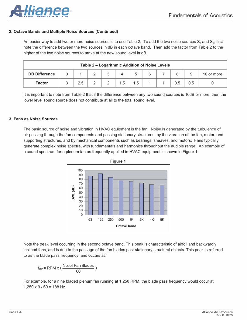
Page 34 Alliance Air Products
Fundamentals of Acoustics
2. Octave Bands and Multiple Noise Sources (Continued)
An easier way to add two or more noise sources is to use Table 2. To add the two noise sources S1 and S2, first
note the difference between the two sources in dB in each octave band. Then add the factor from Table 2 to the
higher of the two noise sources to arrive at the new sound level in dB.
It is important to note from Table 2 that if the difference between any two sound sources is 10dB or more, then the
lower level sound source does not contribute at all to the total sound level.
3. Fans as Noise Sources
The basic source of noise and vibration in HVAC equipment is the fan. Noise is generated by the turbulence of
air passing through the fan components and passing stationary structures, by the vibration of the fan, motor, and
supporting structures, and by mechanical components such as bearings, sheaves, and motors. Fans typically
generate complex noise spectra, with fundamentals and harmonics throughout the audible range. An example of
a sound spectrum for a plenum fan as frequently applied in HVAC equipment is shown in Figure 1:
Figure 1
Note the peak level occurring in the second octave band. This peak is characteristic of airfoil and backwardly
inclined fans, and is due to the passage of the fan blades past stationary structural objects. This peak is referred
to as the blade pass frequency, and occurs at:
fBP = RPM x (60
Blades Fan of No.)
For example, for a nine bladed plenum fan running at 1,250 RPM, the blade pass frequency would occur at
1,250 x 9 / 60 = 188 Hz.
Table 2 – Logarithmic Addition of Noise Levels
DB Difference 0 1 2 3 4 5 6 7 8 9 10 or more
Factor 3 2.5 2 2 1.5 1.5 1 1 0.5 0.5 0
0
10
20
30
40
50
60
70
80
90
100
63 125 250 500 1K 2K 4K 8K
Octave band
SW
L (
dB
)
Rev. 0 10/05

Alliance Air Products Page 35
Fundamentals of Acoustics
3. Fans as Noise Sources (Continued)
Because lower frequencies are much harder to attenuate than higher frequencies, it is desirable for the blade
pass frequency to occur in the highest possible octave band. This can be accomplished by using more blades
(12 blades instead of nine for example) and by running the fan at a higher speed. However, because the sound
power level increases exponentially with fan speed, care must be taken in balancing fan performance, fan speed,
and sound power levels. In some cases the best fan selection may be a large fan running at a low speed; in other
cases it may be preferable to use two or more smaller fans running at higher speeds.
Different types of fans have different acoustic characteristics. In situations where acoustic performance is a
factor, these different fan types should be carefully evaluated to determine which is best suited for the application.
Often many factors must be evaluated together, such as first cost, operating efficiency, acoustical performance,
and physical size and arrangement. Here is a summary of the general characteristics of fan types most frequently
encountered in HVAC applications:
Airfoil plenum – These are unhoused fans that discharge directly into a plenum. Wheels
typically have from eight to twelve blades with an airfoil section. Depending on point of
operation, blade pass frequencies can be a problem and difficult to attenuate. However, design
of the surrounding plenum can be very effective in reducing the noise levels of these fans, and
because of their naturally high efficiencies these fans are frequently the best overall choice for
air handling unit applications.
DWDI (Double Width, Double Inlet) Airfoil – These fans generally have the same efficiency
and flow characteristics as plenum fans, and also share the problems of low frequency noise
resulting from blade pass. Because of their double width design, they are frequently used
where high air volumes are required with restricted space. These fans are sensitive to inlet and
outlet conditions, and care must be taken to avoid restrictions that cause efficiency loss due to
system effects, with resulting increase in noise.
DWDI Forward Curved – these are housed fans with multiple forward curving shallow blades.
Blade pass frequencies are usually less noticeable and occur at higher frequencies than with
airfoil type fans. However, because of their inherently lower efficiencies and lower pressure
characteristics, these fans produce low frequency noise as a result of inefficient airflow around
and through the blade passages. Application of forward curved fans should be limited to low
speed and low pressure applications.
Axial – These are housed fans having airfoil type wheels with inlets and outlets oriented in the
direction of airflow. Because of their high efficiencies and inlet guide vanes, these fans are
considered to have the best low frequency noise characteristics. However, they typically have a
high first cost, and can be difficult to apply in the usual air handling unit layout. This generally
limits their application to the most noise sensitive installations.
Rev. 0 10/05

Page 36 Alliance Air Products
Fundamentals of Acoustics
4. Factors Affecting HVAC Acoustics
By far the best method of reducing HVAC generated noise is to make the best possible fan selection. If further
attenuation is required, the next place to look is the design of the equipment cabinetry. The type of insulation
used can contribute greatly to attenuation, both through absorption of noise inside the cabinet, which reduces
sound power levels at the equipment openings, and by preventing noise from being radiated through the cabinet
walls.
The absorption effectiveness of insulation is mainly a function of its thickness. In the most commonly used HVAC
insulating materials, density has less impact on absorption than thickness. Typical absorption characteristics of
commonly used insulation are shown in Figure 2:
Figure 2
Another factor greatly affecting the absorption characteristics of insulations is liner. The absorption coefficients
shown above are based on unfaced, or neoprene faced material without liner. As a rule of thumb, perforated liner
with a minimum of 50% open area will not significantly affect absorption coefficients; solid liner, FSK facing, mylar,
and other ‘hard’ surfaces can reduce absorption coefficients to as low as .05 across all octave bands.
Equipment layout can also greatly affect sound performance. Use of thicker insulation, avoiding hard surfaced
liners, and avoiding ‘line of sight’ transmission paths all help reduce sound power levels at equipment openings.
Combining efficient fan selections, good cabinet design, and use of bellmouths and low-velocity openings can in
many cases avoid the necessity of external noise attenuators, and prevent many costly noise problems from
showing up after the equipment has been commissioned.
0
0.2
0.4
0.6
0.8
1
1.2
125 250 500 1K 2K 4K
Octave band (Hz)
Ab
so
rpri
on
co
eff
.
1in 3# fiberglass
2in 3# fiberglass
1in, 1.5# fiberglass
2in, 1.5# fiberglass
1in, 6# fiberglass
2in, 6# fiberglass
4in, 6# rock wool
Rev. 0 10/05
Related Documents