Aalborg Universitet RBI Optimization of Offshore Wind Turbines Ramírez, José G. Rangel; Sørensen, John Dalsgaard Published in: Proceedings IFIP WG7.5 Conference on Reliability and Optimization of Structural Systems Publication date: 2009 Document Version Publisher's PDF, also known as Version of record Link to publication from Aalborg University Citation for published version (APA): Ramírez, J. G. R., & Sørensen, J. D. (2009). RBI Optimization of Offshore Wind Turbines. In Proceedings IFIP WG7.5 Conference on Reliability and Optimization of Structural Systems The IFIP International Conference on Research and Practical Issues of Enterprise Information Systems. General rights Copyright and moral rights for the publications made accessible in the public portal are retained by the authors and/or other copyright owners and it is a condition of accessing publications that users recognise and abide by the legal requirements associated with these rights. - Users may download and print one copy of any publication from the public portal for the purpose of private study or research. - You may not further distribute the material or use it for any profit-making activity or commercial gain - You may freely distribute the URL identifying the publication in the public portal - Take down policy If you believe that this document breaches copyright please contact us at [email protected] providing details, and we will remove access to the work immediately and investigate your claim. Downloaded from vbn.aau.dk on: April 07, 2022

Welcome message from author
This document is posted to help you gain knowledge. Please leave a comment to let me know what you think about it! Share it to your friends and learn new things together.
Transcript

Aalborg Universitet
RBI Optimization of Offshore Wind Turbines
Ramírez, José G. Rangel; Sørensen, John Dalsgaard
Published in:Proceedings IFIP WG7.5 Conference on Reliability and Optimization of Structural Systems
Publication date:2009
Document VersionPublisher's PDF, also known as Version of record
Link to publication from Aalborg University
Citation for published version (APA):Ramírez, J. G. R., & Sørensen, J. D. (2009). RBI Optimization of Offshore Wind Turbines. In Proceedings IFIPWG7.5 Conference on Reliability and Optimization of Structural Systems The IFIP International Conference onResearch and Practical Issues of Enterprise Information Systems.
General rightsCopyright and moral rights for the publications made accessible in the public portal are retained by the authors and/or other copyright ownersand it is a condition of accessing publications that users recognise and abide by the legal requirements associated with these rights.
- Users may download and print one copy of any publication from the public portal for the purpose of private study or research. - You may not further distribute the material or use it for any profit-making activity or commercial gain - You may freely distribute the URL identifying the publication in the public portal -
Take down policyIf you believe that this document breaches copyright please contact us at [email protected] providing details, and we will remove access tothe work immediately and investigate your claim.
Downloaded from vbn.aau.dk on: April 07, 2022

WG7.5 RELIABILITY AND OPTIMIZATION OF STRUCTURAL SYSTEMS Toluca, Mexico, August 6- 9 2008
RBI OPTIMIZATION OF OFFSHORE WIND TURBINES
José G. Rangel-Ramírez * & John D. Sørensen * * Department of Civil Engineering, Aalborg University Sohngaardsholmsvej 57, DK-9000 Aalborg, Denmark
[email protected], [email protected].
ABSTRACT
Wind turbines for electricity production have increased significantly the last years both in production capability and size. This development is expected to continue also in the coming years. Offshore wind turbines with an electricity production of 5-10 MW are planned. Typically, the wind turbine support structure is a steel structure consisting of a tower and a monopile, tripod or jacket type foundation. This paper considers aspects of inspection and maintenance planning of fatigue prone details in jacket and tripod type of wind turbine support structures. Based on risk-based inspection planning methods for oil & gas installations, a framework for optimal inspection and maintenance planning of offshore wind turbines is presented. Special aspects for offshore wind turbines considered are the fatigue loading characteristics where usually the wind loading are dominating the wave loading, wake effects in wind farms and also the reliability level which is typically significantly lower than for oil & gas installations. An illustrative example is presented. Keywords: inspection, reliability, decision analysis, fatigue, wake turbulence 1. INTRODUCTION Risk Based Inspection (RBI) planning is addressed to achieve a suitable life-cycle performance by an optimal inspection, maintenance and reparation strategy; this efficient strategy entails an optimal control of deterioration in the structure, not neglecting important economical, technical and social aspects related with its overall performance.
Offshore Wind Turbines' operation and maintenance costs are much larger than for onshore structures, making RBI an important tool to accomplish substantial improvements in costs that will be considerable, bearing in mind the significant increase of this industry in production capability and size. Attending to this expansion, 5-10 MW Wind turbines are developed and going to harsh environments begin to be profitable options. In-place conditions as deep water depths, waves and wind farm location affects significantly the life-cycle performance of offshore wind turbines (OWTs). Depending on the site characteristics, typically, OWTs support structure is made of steel consisting of a tower and a monopile, tripod or jacket type foundation depending on the water depth.
RBI for oil & gas installations have been developed during the last two decades, see e.g. Faber et al. (2000) , Sørensen and Faber (2001) and Moan (2005), giving a theoretical guideline based on Bayesian decision theory that can be applied also to offshore wind turbines. This paper considers aspects of inspection and maintenance planning of fatigue prone details in jacket and tripod types of OWT support structures. Based on RBI methods for oil & gas installations, a framework for optimal inspection and maintenance planning of OWTs is presented. It is taken into account that for fatigue loading usually the wind load is dominating the wave load. Within wind load, wake effects in wind farms affect the reliability level, decreasing it in comparison with the oil & gas installation case. Further the influence of the control system is discussed.
In contrast to other structures, OWTs usually represent low risk of human injury, allowing the allocation of a minimum reliability level obtained by optimization of the risk-based preventive actions’ costs. Conditioned and time-tabled actions (inspection, maintenance and repairing) can be optimized by applying pre-posterior Bayesian decision

IFIP WG7.5’ 08 RELIABILITY AND OPTIMIZATION OF STRUCTURAL SYSTEMS
2
theory approach permitting with feedback data, e.g. hot spots inspection data, inference of inspection results; actualized RBI strategy to accomplish suitable planned actions by adaptive strategies.
Wind farms, a viable source of electricity production, are involving additional technical and economical efforts related with the interaction of the OWT. Spatial correlation of OWTs entails turbulence conditions that affect the performance of neighboring wind turbines. Wake effects, coming from the decrease of wind velocity behind OWT and increase the turbulence results in increased wind load and decrease in OWT fatigue life. Other loads like waves and ice represent important aspect also to consider.
The fatigue failure limit state is primary addressed in this paper. Fatigue failure is located on: WIND TURBINE STRUCTURE: − Tower – welded steel connections − Hub o Hub – cast steel o Blade – glass fiber reinforce plastics (GPR), carbon fiber, composites…
− Nacelle – made of cast steel, welded steel connections o Gear Box – gears, shafts… o Yaw mechanism – gears, ring…
SUPPORT STRUCTURE: − Transition node – welded steel connections. − Jacket substructure – welded steel connections, cast steel nodes… − Tripod substructure – welded steel connections.
Active control affects considerably the response by wind action in structural and non-structural parts. Non-structural failure modes are related with start/stop operation and accidental/unusual loads that will affect these specific parts.
In water depths of about 20 m to 50 m, the use of jacket and tripod structures represents a feasible option that improves technical aspects concerning structural redundancy, damage distribution, scour conditions and dynamical behavior. Economically, jacket and tripod structures have certain advantages over monopole structures in larger water depths. Another important OWT part is the transition node between the jacket or tripod and the tubular tower. The transition node is a critical design element, needing special careful design concerning the fatigue performance.
RBI optimization of OWT is considered in this paper for fatigue prone details in jacket and tripod type support structures. Probabilistic models and representative limit state equations for ultimate structural fatigue failure are formulated. Illustrative examples are described, considering fatigue failure using both linear and bilinear SN-curves and for single and wind farm location.
2. OPTIMAL PLANNING OF INSPECTION AND MAINTENANCE The time varying fatigue degradation in offshore structures is a highly uncertain process, making a probabilistic approach the best way to deal with the problem. Further, to assess the uncertainties arising from external randomness (external conditions, environmental exposure, etc) and models uncertainties stochastic modelling is a rational tool. Reliability-based and risk-based approaches for inspection and planning have been developed during the last decades, see Skjong (1985), Madsen et al. (1987), Thoft-Christensen and Sørensen (1987) and Fujita et al. (1989); and are being applied to outline RBI plans that have as main aim to improve structural reliability and minimize the life cycle overall costs.
The suitable decision plan to improve costs will be carried out in the framework of pre-posterior analysis from classical Bayesian decision theory, see Raiffa and Schlaifer (1961), Benjamin and Cornell (1970) and Ang & Tang (1975), and adapted to the particular case of OWTs.
In figure 2.1 is shown a decision tree for RBI planning for OWTs, The basic steps in the decision process are illustrated. The decisions and random outcomes could be summarized as follows: • Initial design phase, in which the optimal design parameters z=(z1,z2,z3,..,zn) are determinate. They have certain
limits zmin-zmax. The interval zmin-zmax is established according codes and practice requirements. • First interaction with external conditions, such as wind and wave climate; triggers a state of nature Xo. This random
outcome, due to high-uncertain nature; is the part of the process in which reliability and simulation methods attempt to represent numerically time-deterioration process (wear, dent, corrosion, fatigue…) dealing with model uncertainties at the same time. If the statistical basis for evaluation of the uncertainties is limited then also epistemic uncertainties will become important.
• Monitoring activities “e” at the times t=(t1,t2,t3,..,ti), include inspection, sampling and analyzing actions which result in inspection results “S” (degree of wear and corrosion, denting level, size of fatigue cracks…) that are

IFIP WG7.5’ 08 RELIABILITY AND OPTIMIZATION OF STRUCTURAL SYSTEMS
3
obtained depending on inspection quality q=(q1,q2,q3,..,qn) (inspection techniques, technical expertise of inspectors…).
• Based on the obtained monitoring results, Mitigation alternatives will be considered according to fixed or adapting mitigation policy d(S). Such policies are related to repairing or not repairing activities.
• State of nature Xi will be the beginning of new random outcomes. Theoretically, posterior states of nature depend on assumptions established to simplify the RBI process, e.g. assuming that repaired components behave like new component (see figure 2.1, dash line ti+1-ti) and repaired parts will have no indication at the inspection (see figure 2.1, dash-dots line ti-to).
Figure 2.1 RBI’s Decision tree
In Figure 2.1, , , , are the total service life costs. Overall cost optimization will be achieved by minimizing :
, , , , , , , , , , , , 2.1 s.t. , 1,2,… . , ∆ , , , , ∆ , 1,2,… . , is the expected (RBI action) costs in the service life where is the initial costs, is the expected
inspection costs, is the expected reparation costs and is the expected failure costs. Equation 2.1 is constrained by limits on design parameters and that the annual probability of failure ∆ , has to be less than ∆ at all times, assuring a maximum annual risk-state. The n inspections are performed at times , i=1,…,n where , , … . , .
Total capitalized expected inspection costs are:
, , 11
1 2.2
Where ith index characterizes the capitalized inspection costs at the ith inspection when failure has not occurred earlier, , is the inspection cost of the ith inspection, is the probability of failure in the time interval 0, and r is the real rate of interest.
Total capitalized expected maintenance and repair costs are:
, ,1
1 2.3
Where ith index characterize the capitalized reparation costs at the ith inspection when failure has not occurred earlier, , is the cost of maintenance and repair (incl. loss of production) at the ith inspection and is the probability of performing a repair after the ith inspection when failure has not occurred earlier and assuming no earlier repair action has been performed.
The total capitalized expected costs due to failure are:

,
Where t ithe annuafatigue fa
CoRBI planstructuralcomponemonths oevents.
Unturbulencstate, caudominatinper year)methods cases. Ge
3. WIN The winddifferencestatistics unstable cwind farmand the d
Figure 3.vertical pwind farmfrom Fra
prediction
IFIP W
index represenal probabilityailure of the coonsidering poss making this l and mechanints, more pre
or day), structu
nlike oil & gce (wake effecusing typical lng case, respe). Density fun(Rain-flow c
enerally, they
ND LOAD
d load at an oe of surface roshow that seaconditions on ms face certaindecrease of the
.1 Ratios of profiles insidem and inside wandsen and C
and ouns, from Frand
WG7.5’ 0
∆ , |
nt the costs ofy of failure anonsidering comsterior optimiprocess a rec
ical parts (towcise RBI shouure conditione
as installationcts). Wind intoad cycles peectively) that nction of strecounting methcan be modele
offshore site isoughness, wha mean atmosp
the average, n unfavorable
eir fatigue life
wind speed e and outside wind farm, re
Christensen (1utside dsen (2005).
08 RELIAB
11
f failure at the nd |
mponent j. ization of inspcursive activitywer, blades, suuld be carrieded-states (acti
ns, OWTs restensity fluctua
er year (νwf=5xare larger co
ess ranges, thhod, peak coued by a Weibu
s fairly differere sea roughpheric stabilitsee Frandsen
e wind variatio.
/ and the wind farm
espectively. A1994). (c) Ra the win
BILITY AND OP
time t, is the condit
pection plan, y, see Sørenseupport structu
d out, taking iive or passive
sponse is ofteations are a sx107 and νrr=1mpared with
hat is obtainedunting methodull distribution
rent than at laness is typicaty is slightly oet al. (1996). ons (see figure
standard devm. The indicembient wind atios of windnd farm, as fu
PTIMIZATION O
is the cost of tional probab
inspection anen et al. (1991ures, gears, shinto account t controlled O
en dominatedsignificant fea1x107 cycles pwave domina
d from the std…); will difn.
and sites. Thisally much smaon the stable sIn addition toe 3.1) with th
viation of turbes “A” and “Fspeed betweed speed U a
function of wi
OF STRUCTUR
f failure (incl. bility of collap
nd monitoring1). This approhafts…). Withthe refinementWTs) and non
d by wind loaature to considper year, wakeating cases (tytructural respffer dependin
s variation is aller than the lside; whereas o the ambient te increase of w
bulent wind sF” refer to meen (a) 8<U<12at hub heightind speed. Th
RAL SYSTEMS
loss of producpse or the str
g data can be oach can be ush inclusion of t in time intern-usual or ext
ading, includider for fatigue effects and ypically, νwaveonse by diffe
ng the respons
principally reland one. The over land it iturbulence, Owakes behind
speed fluctuaeteorogical m2 m/s and (b) t and turbulehe full lines a
S
4
2.4
ction), ∆ , iructures given
use to updatesed for OWTsf different-typervals (years totreme externa
ng wind farmue failure limirotor response
e=1x10⁶ cycleerent countingse dominating
elated with thewind stability
s seen slightlyOWTs inside od others OWT
tions /mast outside o
12<U<24 m/nce σu insideare the mode
4
s n
e ’ e o al
m it e s g g
e y y f s
f s e
el

IFIP WG7.5’ 08 RELIABILITY AND OPTIMIZATION OF STRUCTURAL SYSTEMS
5
Wind load stress effects are strongly related with the type of power control (pitch or stall) in the OWT. Moreover, the response is dependent on the OWT mode: standstill or operational. Within the operational case there are passive, active or mixed power control, assuring a rational output of electricity and protecting structural and electromechanical parts.
The turbulence intensity, defined as the standard deviation of the wind speed fluctuations divided by the mean (n-minutes) wind speed; represent an important aspect to consider because its effects on OWT’s fatigue life. In this paper is used the following model for standard deviation of wake turbulence proposed by Frandsen, S. (2005):
1 ⁄ 3.1
where is the turbulence standard deviation under free flow condition, is the maximum wake turbulence under wake condition, (=0.06) is the probability of wake condition and is the number of wakes to which the considered wind turbines is exposed to. It is assumed that the standard deviation of the response is proportional to the standard deviation of turbulence; while in certain situations (load, passive or active power control; complex geography, atypical terrain condition…) this simple relation with the response may be inadequate.
The above mentioned turbulence model demonstrates to be consistent (with a slightly conservative inaccuracy of 3-4%) when it is used with superimposed deterministic load component, see Frandsen (2005) and Sørensen et al. (2007). 4. PROBABILISTIC MODEL FOR FATIGUE FAILURE In this section the probabilistic models for assessing the fatigue failure life based on SN-curves and fracture mechanics (FM) model are briefly mentioned. To evaluate the fatigue life is used the probabilistic model for fatigue failure described in Sørensen et al. (2007).
In the assessment of SN fatigue life, the deterministic design equation for free flow ambient turbulence is:
1· ·
; · 0 4.1
where for linear SN-curve:
; s · | 4.2
and bi-linear SN-curve:
, , Δ ; s · | s · s| 4.3
· · 0.75 · ; 5.6 4.4 , where is the total number of fatigue load cycles per year, FDF is the fatigue design factor ( ⁄ ), is the characteristic value of K (mean log minus two standard deviation of log ), and are the cut-in and cut-out wind speed, respectively; is the density function of mean wind speed U, is the expected value of Δ given standard deviation and mean wind speed U in which | represents the density function for stress ranges given standard deviation at mean wind speed U. This density function and can be obtained by counting methods, e.g. Rainflow counting.
In the 4.4a equation is the influence coefficient for stress ranges given mean wind speed U U⁄ , is the standard deviation of turbulence given mean wind speed U and is the design
parameter (e.g. proportional a cross sectional area). The 4.4b equation is the characteristic (90% fractil representative turbulence) ambient turbulence where Iref is the (IEC-) reference turbulence intensity (equal to 0.14 for medium turbulence characteristics).
The corresponding limit state equation is:
∆·
· · ; · | · 4.5
IFIP WG7.5’ 08 RELIABILITY AND OPTIMIZATION OF STRUCTURAL SYSTEMS
6
Where Δ is a stochastic variable modeling the uncertainty related to the Miner rule for damage accumulation, t is the life time in years, is the model uncertainty related to wind load effects (exposure, assessment of lift and drag coefficients, dynamic response calculation), is the model uncertainty related to local stress analysis and is modeled as LogNormal distributed with a representative mean turbulence (90% fractil value-IEC 61400-1) equal to 0.75 · 3.6 with a standard deviation equal to 1.4 ⁄ · .
For a wind farm location the design equation is based on IEC 61400-1 (IEC 2005):
1· ·
1 · · ;
· ; , , · 0 4.6
where is the number of neighboring wind turbines, is the probability of wake from a neighboring wind turbine (equal to 0.06), , is the standard deviation of turbulence from neighboring wind turbine no. j:
, ,0.9 ·
1.5 0.3 · ⁄ 4.7
where dj is the distance between OWT normalized by rotor diameter to the neighboring wind turbine j and c is a constant equal to 1 m/s.
The limit state equation corresponding to the above equation is:
∆·
· ·
1 · · ;
· ; , , · · | 4.8
where
, ,·
1.5 0.3 · ⁄ 4.9
XW is the model uncertainty related with wake turbulence model. The design parameter z is calculated with (4.1) or (4.6) and then used in limit state equation (4.5) or (4.8) to estimate the reliability index or probability for failure of the reference time t.
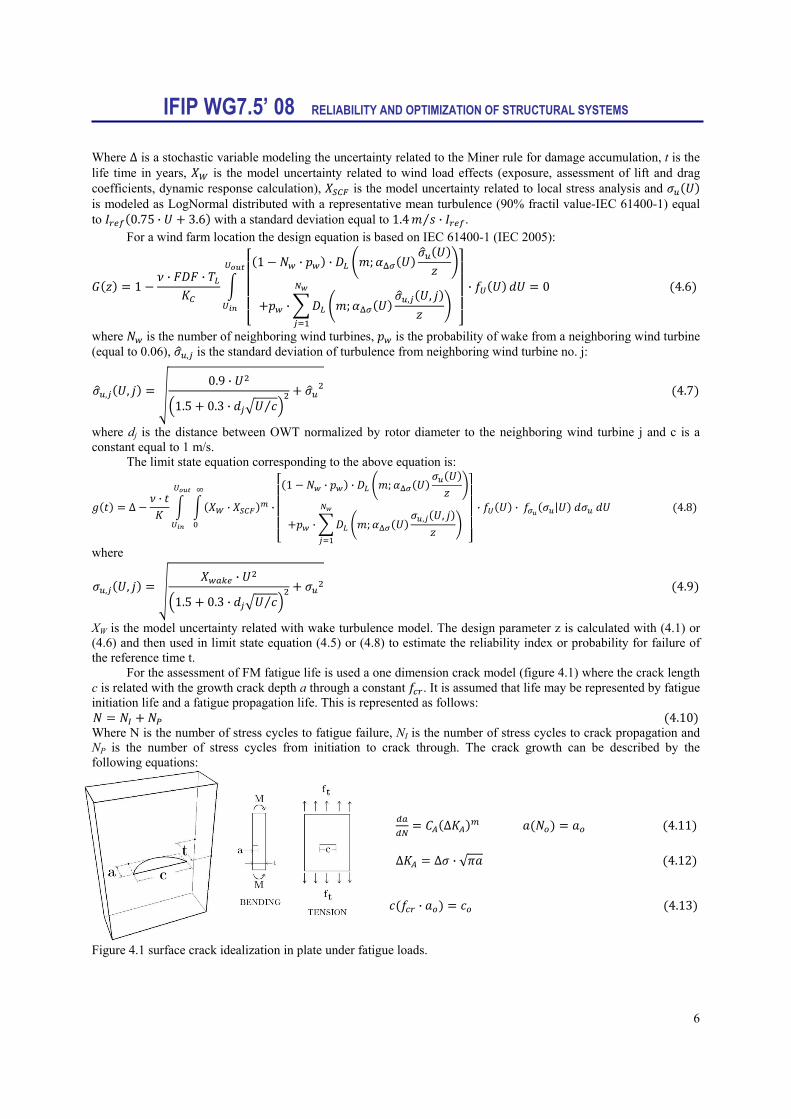
For the assessment of FM fatigue life is used a one dimension crack model (figure 4.1) where the crack length c is related with the growth crack depth a through a constant . It is assumed that life may be represented by fatigue initiation life and a fatigue propagation life. This is represented as follows:
4.10 Where N is the number of stress cycles to fatigue failure, NI is the number of stress cycles to crack propagation and NP is the number of stress cycles from initiation to crack through. The crack growth can be described by the following equations: ∆ 4.11 ∆ ∆ · √ 4.12 · 4.13 Figure 4.1 surface crack idealization in plate under fatigue loads.
IFIP WG7.5’ 08 RELIABILITY AND OPTIMIZATION OF STRUCTURAL SYSTEMS
7
where and m are the material parameters, and describe the initial crack depth a and crack length c, respectively, after cycles and where the stress intensity range is ∆ .
The stress range ∆ is obtained from: Δ · Δ 4.14 where is the model uncertainty variable related to geometry function and Δ is the equivalent stress range. Δ for a single OWT is calculated with:
Δ · · ; · · |
/
4.15
and for a wind farm location case: Δ ·
·
1 · · ;
· ; , ,· · |
/
4.16
The limit state criteria used in the FM analysis is related with the failure when crack exceeds a critical crack size:
4.17 where is the critical crack size and is crack depth.
For RBI planning the FM model is usually calibrated to result in the same reliability level as the code-based SN model. The RBI planning and maintenance is strongly related with inspection quality (inspection methods, technology, environmental conditions, inspectors’ expertise, etc). The incorporation of these influential factors is attained by using a distribution of the detectable crack size or probability of detection curve (POD). Examples of POD equations are:
1 1 1 4.18
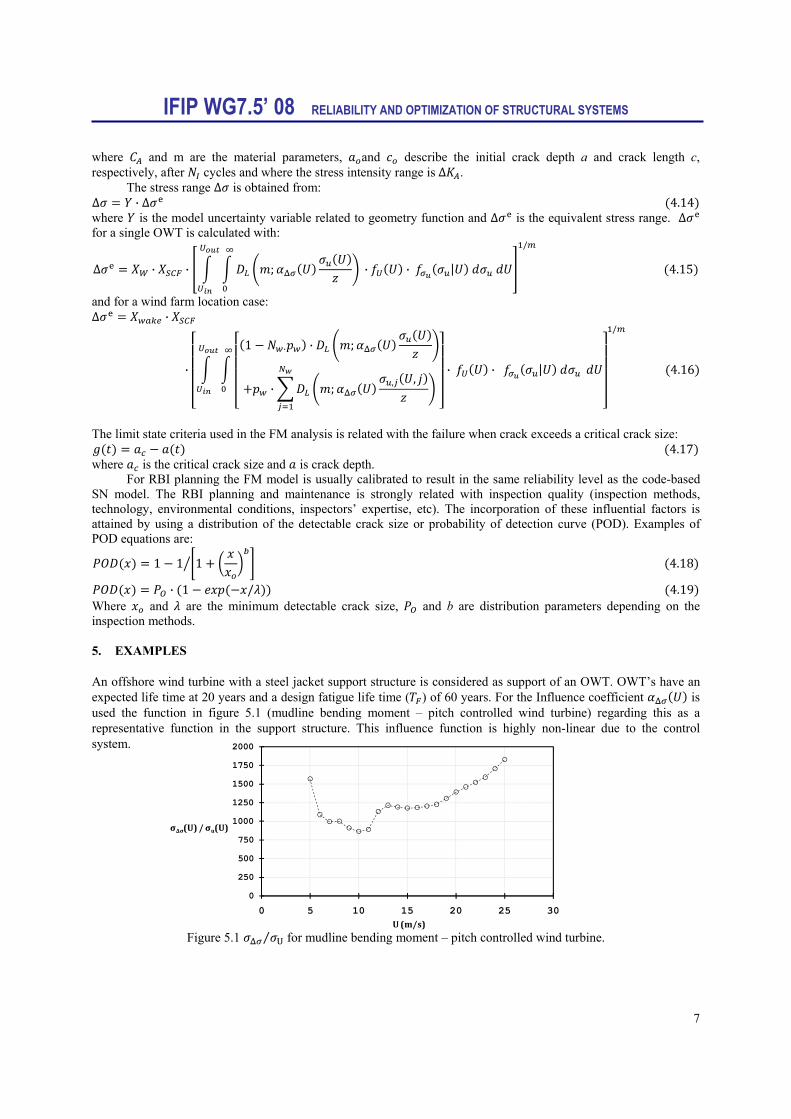
· 1 / 4.19 Where and are the minimum detectable crack size, and b are distribution parameters depending on the inspection methods. 5. EXAMPLES An offshore wind turbine with a steel jacket support structure is considered as support of an OWT. OWT’s have an expected life time at 20 years and a design fatigue life time ( ) of 60 years. For the Influence coefficient is used the function in figure 5.1 (mudline bending moment – pitch controlled wind turbine) regarding this as a representative function in the support structure. This influence function is highly non-linear due to the control system.
Figure 5.1 U⁄ for mudline bending moment – pitch controlled wind turbine.
0
250
500
750
1000
1250
1500
1750
2000
0 5 10 15 20 25 30
σΔσ(U) / σu(U)
U (m/s)

IFIP WG7.5’ 08 RELIABILITY AND OPTIMIZATION OF STRUCTURAL SYSTEMS
8
Wind turbine in wind farm (IWF) and alone/single (S) OWT location are considered. For each location is considered linear (L) and bi-linear (BL) SN-curve. In tables 5.1 – 5.3 are shown the stochastic models used.
Table 5.1 SN Stochastic model (welded steel detail). Variable Distribution Expected value Standard deviation Comment
Δ N 1.0 0.10 Damage accumulation LN 1.0 0.10 Wind LN 1.0 0.10 Stress concentration factor LN 1.0 0.15 Wake
D 3 -- SN-curve. Exponent (linear) D 5 -- SN-curve. Exponent (bi-linear)
Δ D 71 MPa -- Constant amplitude fatigue limit Log N Determined from Δ 0.20 Material parameter Log N Determined from Δ 0.25 Material parameter T D 60 years -- Fatigue life Nw D 5/-- -- In-wind farm/single OWT
D 5 · 10 -- Fatigue cycles per year D 5 – 25 m/s -- Cut in – out velocities
pw D 0.06/0.0 -- In-wind farm/single OWT d D 4.0 -- Normalized distance of OWT
Log and Log are assumed fully correlated D: Deterministic, N:Normal, LN:LogNormal, W:Weibull.
Table 5.2 FM Uncertainty modeling (welded steel detail).
Variable Distribution Expected value Standard deviation Comment Ln Cc N (fitted) 0.77 Crack growth ratio
W · 0.35 · (fitted), Initiation Time Y LN 1.0 0.10 Shape factor
LN 1.0 0.10 Wind N 1.0 0.10 Stress concentration factor LN 1.0 0.15 Wake
D 50 mm -- Critical crack size D 0.4 mm -- Initial crack size D 4.0 -- Crack length/depth ratio
Thickness D 50 mm -- thickness m D 3.0 -- Material parameter
Ln and are correlated with correlation coefficient , 0.5 D: Deterministic, N:Normal, LN:LogNormal, W:Weibull.
Table 5.3 Distribution parameters and Equations.
Variable Distribution Parameters Comment D 1.0 · 10 /1.0 · 10 Annual max. prob. of failure
, 2.3 , 10.0 / Mean wind speed · , 0.8 Stress ranges · , · 0.75 · 3.6 , 1.4 · Mean turbulence
Equation (4.19) 1.0, 2.67 Probability of Detection · ∆ SN curve linear · ∆ SN curve bi-linear
D: Deterministic, N:Normal, LN:LogNormal, W:Weibull.
The design values z for each case are shown in table 5.4 (equations 4.1 and 4.6) and in figures 5.1 and 5.2 are shown the results of the assessment of the reliability with SN approach (equations 4.5 and 4.8). and ∆ are defined as the cumulative probability of failure and the annual probability ∆ of failure ( Φ PF t and Δ Φ PF t Φ PF t 1 ), respectively. It is seen that for bilinear SN-curve values of and z are smaller than for linear cases. The design values for cases in wind farm location (wake turbulence) are larger than the ones exposed to free flow turbulence due to the accumulation of fatigue.

IFIP WG7.5’ 08 RELIABILITY AND OPTIMIZATION OF STRUCTURAL SYSTEMS
9
Table 5.4 z-design parameters
Fig. 5.1 Reliability indices for SN-approach corresponding to an cumulative probability of failure For all the cases the calibration of fracture mechanic reliability curve in the interval 10 to 20 years (see figure 5.2)
Fig 5.2 Reliability indices for SN- and calibrated fracture mechanics curve corresponding to the cumulative probability of failure.
In Figure 5.3 and table 5.5 is shown the resulting life-cycle assessment of reliability and inspection plan obtained with a maximum acceptable annual probability of failure equal to 1.0 10 and 1.0 10 . Comparing the first inspection time, slightly earlier inspections are coming out in-wind farm sites due to the increase of fatigue coming from wake turbulence. It is noted that in all four cases the design parameter z is determined by deterministic design such that the code-based design criteria is exactly satisfied.
IWF OWT, L S OWT, L IWF OWT, BL S OWT, BLZ 0.5654 0.4934 0.4253 0.3657
0
0.5
1
1.5
2
2.5
3
3.5
4
4.5
5
5 10 15 20 25 30 35 40 45
β
TIME (YEARS)
S OWT- LIWF OWT-LS OWT-BLIWF OWT-BL
1.5
2
2.5
3
3.5
4
4.5
9 11 13 15 17 19 21
β
TIME (YEARS)
β-S OWT, L-SN β-S OWT, L- FMβ-IWF OWT, L-SN β-IWF OWT, L-FMβ-S OWT, BL-SN β-S OWT, BL-FMβ-IWF OWT, BL-SN β-IWF OWT, BL-FM

IFIP WG7.5’ 08 RELIABILITY AND OPTIMIZATION OF STRUCTURAL SYSTEMS
10
Table 5.5 Inspections times as a function of the threshold on the maximum annual probability of failure.
(a) (b)
(c) (d) Fig 5.3 Annual and cumulative probability of failure as a function of time (∆ 1 10 and reliability
indices corresponding to the cumulative and annual probability of failure. (a) In wind farm OWT with linear SN-curve. (b) Single OWT with linear SN-curve. (c) In wind farm OWT with bilinear SN-curve. (d) Single OWT with
bilinear SN-curve.
CASE SN CURVE 1.00E-03 1.00E-04IWF OWT LINEAR -- 17SINGLE LINEAR -- 26IWF OWT BILINEAR 17 7,15,30SINGLE BILINEAR 23 8,17,38
Maximum Annual PF
INSPECTION TIME
0.0000
0.0001
0.0002
0.0003
0.0004
0 2 4 6 8 10 12 14 16 18
PF
TIME (YEARS)
ANNUAL
CUMULATIVE
0.0
0.5
1.0
1.5
2.0
2.5
3.0
3.5
4.0
4.5
5.0
8 9 10 11 12 13 14 15 16 17 18
β&Δβ
TIME (YEARS)
β-SNβ-FMΔβ-FM
0.0000
0.0002
0.0004
0.0006
0.0008
0.0010
0 3 6 9 12 15 18 21 24 27
PF
TIME (YEARS)
ANNUALCUMULATIVE
0.0
0.5
1.0
1.5
2.0
2.5
3.0
3.5
4.0
4.5
5.0
5 7 9 11 13 15 17 19 21 23 25 27
β&Δβ
TIME (YEARS)
β-SNβ-FMΔβ-FM
0.0000
0.0002
0.0004
0.0006
0.0008
0.0010
0 3 6 9 12 15 18 21 24 27 30
PF
TIME (YEARS)
ANNUAL
CUMULATIVE
0.0
0.5
1.0
1.5
2.0
2.5
3.0
3.5
4.0
4.5
5.0
0 3 6 9 12 15 18 21 24 27 30
β& Δβ
TIME (YEARS)
β-SNβ-FMΔβ-FM
0.0000
0.0002
0.0004
0.0006
0.0008
0.0010
0 3 6 9 12 15 18 21 24 27 30 33 36 39
PF
TIME (YEARS)
ANNUAL
CUMULATIVE
0.0
0.5
1.0
1.5
2.0
2.5
3.0
3.5
4.0
4.5
5.0
0 3 6 9 12 15 18 21 24 27 30 33 36 39
β& Δβ
TIME (YEARS)
β-SNβ-FMΔβ-FM
IFIP WG7.5’ 08 RELIABILITY AND OPTIMIZATION OF STRUCTURAL SYSTEMS
11
6. CONCLUSIONS Based on risk-based inspection planning methods for oil & gas installations, a framework for optimal inspection and maintenance planning was applied for offshore wind turbines, addressing the analysis of fatigue prone details (single hot spots in the context of RBI for this work) at the jacket or tripod steel support structures. In wind park location and single OWT were taken into account by using a probabilistic model for fatigue failure included in an established code. This inspection optimization approach represents a viable method to outline inspection plans aimed at OWT, regarding its application to large structural systems (steel jacket, tripod and monopile as support structures). Furthermore, it may also be applied to other important components like blades, nacelle, yaw system, etc. Knowingly of the fast growth of wind industry (EWEA 2007) and offshore wind turbine parks, larger and complex cluster of such structural systems may potentially be benefited for optimizing the inspection and maintenance efforts and generate suitable inspection plans ensuring an acceptance criteria with respect to risk. Besides, this RBI approach may also be applied as a decision tool for estimating the consequences of a possible service life extensions and reduction (or strengthening) on the necessary maintenance and inspection efforts. 7. ACKNOWLEDGEMENTS The financial support from the Mexican National Council of Science and Technology (CONACYT) is greatly appreciated. 8. REFERENCES Ang, A.H.S., Tang W.H., 1975. Probability Concepts in Engineering Planning and Design. Vol. I and II, John Wiley
& Sons. Benjamin J.R., Cornell C.A., 1970. Probability, statistics and decision for civil engineering. McGrawHill, New York. EWEA 2007, (1) Delivering Offshore Wind Power in Europe - Policy recommendations for Large-scale deployment
of offshore wind power in Europe by 2020. (2) Pure Power. European Wind Energy Association. Faber, M.H., Engelund, S., Sørensen, J.D., and Bloch, A., 2000. Simplified and Generic Risk-based Inspection
Planning, Proc. Int. Conf. Offshore Mech. & Arct. Eng, S&R paper 6143. Frandsen, S. and Christensen, J.C., 1994. Structural loads in large wind farm arrays, Proc. European Wind Energy’94
Conference, Thessaloniki, Greece, vol. III, 116-122. Frandsen S., Chacón L., Crespo A., Enevoldsen P., Gómez-Elvira R., Hernández J., Højstrup J., Manuel F., Thomsen
K. and Sørensen P., 1996. Final Report on Measurements on and Modelling of Offshore Wind Farms, Risø-R-903(EN), Risø National Laboratory, Bonus Energy AS, Universidad Politecnica de Madrid, Elkraft AS, Finish Meteorological Institute.
Frandsen, S., 2005. Turbulence and turbulence-generated structural loading in wind turbine clusters, Risø National Laboratory, Denmark, Report R1188.
Fujita M., Schall G., Rackwitz R., 1989. Adaptive Reliability-Based Inspection Strategies for Structures Subject to Fatigue. Proc. 5th International Conference on Structural Safety and Reliability, ICOSSAR 89, Vol. 2, San Francisco, 1619-1626.
IEC 61400-1 (IEC 2005), International Electrotechnical Comission. Wind Turbine generator systems – Part 1: Safety requirements.
Madsen, H.O., Skjong R., Kirkemo F., 1987. Probabilistic Fatigue Analysis of Offshore Structures – Reliability Updating Through Inspection Results. In Integrity of Offshore Structures 3, edited by Faulkner D, Cowling MJ, Incecik A, Elsevier Applied Science.
Moan, T., 2005. Reliability-based management of inspection, maintenance and repair of offshore structures. Structures and infrastructure Engineering, Vol.1, No.1, 33-62.
Raiffa H., Schlaifer R., 1961. Applied Statistical Decision Theory. Cambrige University Press, Cambridge, Mass. Skjong, R., 1985. Reliability Based Optimization of Inspection Strategies. Proc. International Conference on
Structural Safety and Reliability, ICOSSAR 85, Col. III, Kobe, Japan, 614-618. Sørensen, J. D. & M.H. Faber, M.H., 2001. Generic inspection planning for steel structures, Proc. International
Conference on Structural Safety and Reliability, ICOSSAR’01, USA. Sørensen J.D., Faber, M.H., Rackwitz, R. and Thoft-Christensen, P.T., 1991. Modeling in optimal inspection and

IFIP WG7.5’ 08 RELIABILITY AND OPTIMIZATION OF STRUCTURAL SYSTEMS
12
repair. In Proc. International Conference on Ocean, Offshore and Arctic Engineering, OMAE, Stavanger, Norway, 281-288.
Sørensen, J.D., Frandsen, S. & Tarp-Johansen, N.J., 2007. Fatigue reliability and effective turbulence models in wind farms. Applications of statistics and Probability in Civil Engineering – Kanda, Takada & Furuta (Eds).
Thoft-Christensen P., Sørensen J.D., 1987. Optimal strategy for inspection and repair of structural systems. Civil Engineering Systems, 4, 94-100.
Related Documents


