Chapter 5 5-1 S y = 350 MPa. MSS: 1 3 = S y /n 1 3 y S n DE: 1/ 2 1/ 2 2 2 2 2 3 A A B B x x y y xy 2 y S n (a) MSS: 1 = 100 MPa, 2 = 100 MPa, 3 = 0 350 3.5 . 100 0 n A ns DE: 2 2 1/2 350 (100 100(100) 100 ) 100 MPa, 3.5 . 100 n A ns (b) MSS: 1 = 100 MPa, 2 = 50 MPa, 3 = 0 350 3.5 . 100 0 n A ns DE: 2 2 1/2 350 (100 100(50) 50 ) 86.6 MPa, 4.04 . 86.6 n A ns (c) 2 2 100 100 , ( 75) 140, 40 MPa 2 2 A B 1 2 3 140, 0, 40 MPa MSS: 350 1.94 . 140 ( 40) n A ns DE: 1/ 2 2 2 350 100 3 75 164 MPa, 2.13 . 164 n A ns (d) 2 2 50 75 50 75 , ( 50) 11.0, 114.0 MPa 2 2 A B 1 2 3 0, 11.0, 114.0 MPa MSS: 350 3.07 . 0 ( 114.0) n A ns DE: 2 2 2 1/2 [( 50) ( 50)( 75) ( 75) 3( 50) ] 109.0 MPa 350 3.21 . 109.0 n A ns (e) 2 2 100 20 100 20 , 20 104.7, 15.3 MPa 2 2 A B Chapter 5-Rev B, Page 1/55

Welcome message from author
This document is posted to help you gain knowledge. Please leave a comment to let me know what you think about it! Share it to your friends and learn new things together.
Transcript

Chapter 5 5-1 Sy = 350 MPa.
MSS: 1 3 = Sy /n 1 3
ySn
DE: 1/2 1/22 2 2 2 3A A B B x x y y xy 2
ySn
(a) MSS: 1 = 100 MPa,2 = 100 MPa,3 = 0
350
3.5 .100 0
n A
ns
DE: 2 2 1/2 350(100 100(100) 100 ) 100 MPa, 3.5 .
100n A ns
(b) MSS: 1 = 100 MPa,2 = 50 MPa,3 = 0
350
3.5 .100 0
n A
ns
DE: 2 2 1/2 350(100 100(50) 50 ) 86.6 MPa, 4.04 .
86.6n A ns
(c) 2
2100 100, ( 75) 140, 40 MPa
2 2A B
1 2 3140, 0, 40 MPa
MSS: 350
1.94 .140 ( 40)
n A
ns
DE: 1/22 2 350
100 3 75 164 MPa, 2.13 .164
n A ns
(d) 2
250 75 50 75, ( 50) 11.0, 114.0 MPa
2 2A B
1 2 30, 11.0, 114.0 MPa
MSS: 350
3.07 .0 ( 114.0)
n A
ns
DE: 2 2 2 1/2[( 50) ( 50)( 75) ( 75) 3( 50) ] 109.0 MPa
350
3.21 .109.0
n A ns
(e) 2
2100 20 100 20, 20 104.7, 15.3 MPa
2 2A B
Chapter 5-Rev B, Page 1/55

1 2 3104.7, 15.3, 0 MPa
MSS: 350
3.34 .104.7 0
n A
ns
DE: 1/222 2100 100(20) 20 3 20 98.0 MPa
350
3.57 .98.0
n A ns
______________________________________________________________________________ 5-2 Sy = 350 MPa.
MSS: 1 3 = Sy /n 1 3
ySn
DE: 1/22 2 y yA A B B
S Sn
n
(a) MSS: 1 3
350100 MPa, 0 3.5 .
100 0n A ns
DE: 2 2 1/2
3503.5 .
[100 (100)(100) 100 ]n A
ns
(b) MSS: 1 3
350100 , 100 MPa 1.75 .
100 ( 100)n A
ns
DE:
1/222
3502.02 .
100 (100)( 100) 100n A
ns
(c) MSS: 1 3
350100 MPa, 0 3.5 .
100 0n A ns
DE: 1/22 2
3504.04 .
100 (100)(50) 50n A
ns
(d) MSS: 1 3
350100, 50 MPa 2.33 .
100 ( 50)n A
ns
DE:
1/222
3502.65 .
100 (100)( 50) 50n A
ns
(e) MSS: 1 3
3500, 100 MPa 3.5 .
0 ( 100)n A
ns
DE:
1/22 2
3504.04 .
50 ( 50)( 100) 100n A
ns
______________________________________________________________________________ 5-3 From Table A-20, Sy = 37.5 kpsi
Chapter 5-Rev B, Page 2/55
MSS: 1 3 = Sy /n 1 3
ySn
DE: 1/2 1/22 2 2 2 3A A B B x x y y xy 2
ySn
(a) MSS: 1 3
37.525 kpsi, 0 1.5 .
25 0n A ns
DE: 1/22 2
37.51.72 .
25 (25)(15) 15n A
ns
(b) MSS: 1 3
37.515 kpsi, 15 1.25 .
15 ( 15)n A
ns
DE:
1/222
37.51.44 .
15 (15)( 15) 15n A
ns
(c) 2
220 20, ( 10) 24.1, 4.1 kpsi
2 2A B
1 2 324.1, 0, 4.1 kpsi
MSS: 37.5
1.33 .24.1 ( 4.1)
n A
ns
DE: 1/22 2 37.5
20 3 10 26.5 kpsi 1.42 .26.5
n A ns
(d) 2
212 15 12 15, ( 9) 17.7, 14.7 kpsi
2 2A B
1 2 317.7, 0, 14.7 kpsi
MSS: 37.5
1.16 .17.7 ( 14.7)
n A
ns
DE: 1/22 2 2( 12) ( 12)(15) 15 3( 9) 28.1 kpsi
37.5
1.33 .28.1
n A ns
(e) 2
224 24 24 24, 15 9, 39 kpsi
2 2A B
1 2 30, 9, 39 kpsi
MSS:
37.50.96 .
0 39n A
ns
Chapter 5-Rev B, Page 3/55

DE: 1/22 2 2
24 24 24 24 3 15 35.4 kpsi
37.5
1.06 .35.4
n A ns
______________________________________________________________________________ 5-4 From Table A-20, Sy = 47 kpsi.
MSS: 1 3 = Sy /n 1 3
ySn
DE: 1/22 2 y yA A B B
S Sn
n
(a) MSS: 1 3
4730 kpsi, 0 1.57 .
30 0n A ns
DE: 2 2 1/2
471.57 .
[30 (30)(30) 30 ]n A
ns
(b) MSS: 1 3
4730 , 30 kpsi 0.78 .
30 ( 30)n A
ns
DE:
1/222
470.90 .
30 (30)( 30) 30n A
ns
(c) MSS: 1 3
4730 kpsi, 0 1.57 .
30 0n A ns
DE: 1/22 2
471.81 .
30 (30)(15) 15n A
ns
(d) MSS: 1 3
470, 30 kpsi 1.57 .
0 ( 30)n A
ns
DE:
1/22 2
471.81 .
30 ( 30)( 15) 15n A
ns
(e) MSS: 1 3
4710, 50 kpsi 0.78 .
10 ( 50)n A
ns
DE:
1/22 2
470.84 .
50 ( 50)(10) 10n A
ns
______________________________________________________________________________
Chapter 5-Rev B, Page 4/55

5-5 Note: The drawing in this manual may not be to the scale of original drawing. The
measurements were taken from the original drawing. (a) MSS and DE:
4.95"
3.51 .1.41"
OBn Ans
OA
(b) MSS:
3.91"
3.49 .1.12"
ODn Ans
OC
DE:
4.51"
4.03 .1.12"
OEn Ans
OC
(c) MSS:
2.50"
2.00 .1.25"
OGn A
OF ns
DE: 2.86"
2.29 .1.25"
OHn A ns
OF
(d) MSS: 3.51"
3.05 .1.15"
OJn A , DE: ns
OI
3.65"3.17 .
1.15"
OKn A
OI ns
(e) MSS: 3.54"
3.34 .1.06"
OMn Ans
OL , DE:
3.77"3.56 .
1.06"
ONn A ns
OL
______________________________________________________________________________
Chapter 5-Rev B, Page 5/55

5-6 Note: The drawing in this manual may not be to the scale of original drawing. The
measurements were taken from the original drawing. (a) A = 25 kpsi, B = 15 kpsi MSS:
4.37"
1.50 .2.92"
OBn Ans
OA
DE:
5.02"
1.72 .2.92"
OCn A ns
OA
(b) A = 15 kpsi, B = 15 kpsi MSS:
2.66"
1.25 .2.12"
OEn A ns
OD
DE:
3.05"
1.44 .2.12"
OFn A ns
OD
(c) 2
220 20, ( 10) 24.1, 4.1 kpsi
2 2A B
MSS: 3.25"
1.34 .2.43"
OHn A DE: ns
OG
3.46"1.42 .
2.43"
OIn A
OG ns
(d) 2
212 15 12 15, ( 9) 17.7, 14.7 MPa
2 2A B
MSS: 2.67"
1.16 .2.30"
OKn A DE: ns
OJ
3.06"1.33 .
2.30"
OLn A
OJ ns
(e) 2
224 24 24 24, 15 9, 39 kpsi
2 2A B
MSS: 3.85"
0.96 .4.00"
ONn A DE: ns
OM
4.23"1.06 .
4.00"
OPn A
OM ns
______________________________________________________________________________
Chapter 5-Rev B, Page 6/55
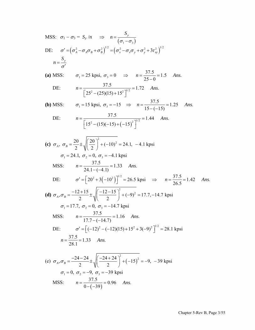
5-7 Sy = 295 MPa, A = 75 MPa, B = 35 MPa,
(a)
1/2 1/222 2 2
2953.03 .
75 75 35 35
y
A A B B
Sn A
ns
(b) Note: The drawing in this manual may not be to the scale of original drawing. The
measurements were taken from the original drawing.
2.50"
3.01 .0.83"
OBn Ans
OA
______________________________________________________________________________
Chapter 5-Rev B, Page 7/55

5-8 Sy = 295 MPa, A = 30 MPa, B = 100 MPa,
(a)
1/2 1/222 2 2
2952.50 .
30 30 100 100
y
A A B B
Sn A
ns
(b) Note: The drawing in this manual may not be to the scale of original drawing. The
measurements were taken from the original drawing.
2.50"
3.01 .0.83"
OBn Ans
OA
______________________________________________________________________________
Chapter 5-Rev B, Page 8/55

5-9 Sy = 295 MPa, 2
2100 100, ( 25) 105.9, 5.9 MPa
2 2A B
(a)
1/2 1/222 2 2
2952.71 .
105.9 105.9 5.9 5.9
y
A A B B
Sn A ns
(b) Note: The drawing in this manual may not be to the scale of original drawing. The
measurements were taken from the original drawing.
2.87"
2.71 .1.06"
OBn Ans
OA
______________________________________________________________________________
Chapter 5-Rev B, Page 9/55

5-10 Sy = 295 MPa, 2
230 65 30 65, 40 3.8, 91.2 MPa
2 2A B
(a)
1/2 1/22 22 2
2953.30 .
3.8 3.8 91.2 91.2
y
A A B B
Sn A ns
(b) Note: The drawing in this manual may not be to the scale of original drawing. The
measurements were taken from the original drawing.
3.00"
3.33 .0.90"
OBn Ans
OA
______________________________________________________________________________
Chapter 5-Rev B, Page 10/55

5-11 Sy = 295 MPa, 2
280 30 80 30, 10 30.9, 80.9 MPa
2 2A B
(a)
1/2 1/222 2 2
2952.95 .
30.9 30.9 80.9 80.9
y
A A B B
Sn Ans
(b) Note: The drawing in this manual may not be to the scale of original drawing. The
measurements were taken from the original drawing.
2.55"
2.93 .0.87"
OBn Ans
OA
______________________________________________________________________________ 5-12 Syt = 60 kpsi, Syc = 75 kpsi. Eq. (5-26) for yield is
1
31
yt yc
nS S
(a) 1 325 kpsi, 0 1
25 02.40 .
60 75n A ns
(b) 1 315, 15 kpsi 1
15 152.22 .
60 75n A
ns
Chapter 5-Rev B, Page 11/55

(c) 2
220 20, ,
( 10) 24.1, 4.1 kpsi2 2A B
1 2 324.1, 0, 4.1 kpsi 1
24.1 4.12.19 .
60 75n A
ns
(d) 2
212 15 12 15, ( 9) 17.7, 14.7 kpsi
2 2A B
1 2 317.7, 0, 14.7 kpsi 1
17.7 14.72.04 .
60 75n A ns
(e) 2
224 24 24 24, 15 9, 39 kpsi
2 2A B
1 2 30, 9, 39 kpsi 1
0 391.92 .
60 75n A
ns
______________________________________________________________________________ 5-13 Note: The drawing in this manual may not be to the scale of original drawing. The
measurements were taken from the original drawing. (a) 25, 15 kpsiA B
3.49"
2.39 .1.46"
OBn A ns
OA
(b) A B15, 15 kpsi
2.36"
2.23 .1.06"
ODn A
ns
OC
(c)
2220 20
, ( 10) 24.1, 4.1 kpsi2 2A B
2.67"2.19 .
1.22"
OFn A
OE ns
(d)
2212 15 12 15
, ( 9) 17.7, 14.7 kpsi2 2A B
Chapter 5-Rev B, Page 12/55

2.34"2.03 .
1.15"
OHn A
OG ns
(e)
2
224 24 24 24, 15 9, 39 kpsi
2 2A B
3.85"1.93 .
2.00"
OJn A
OI ns
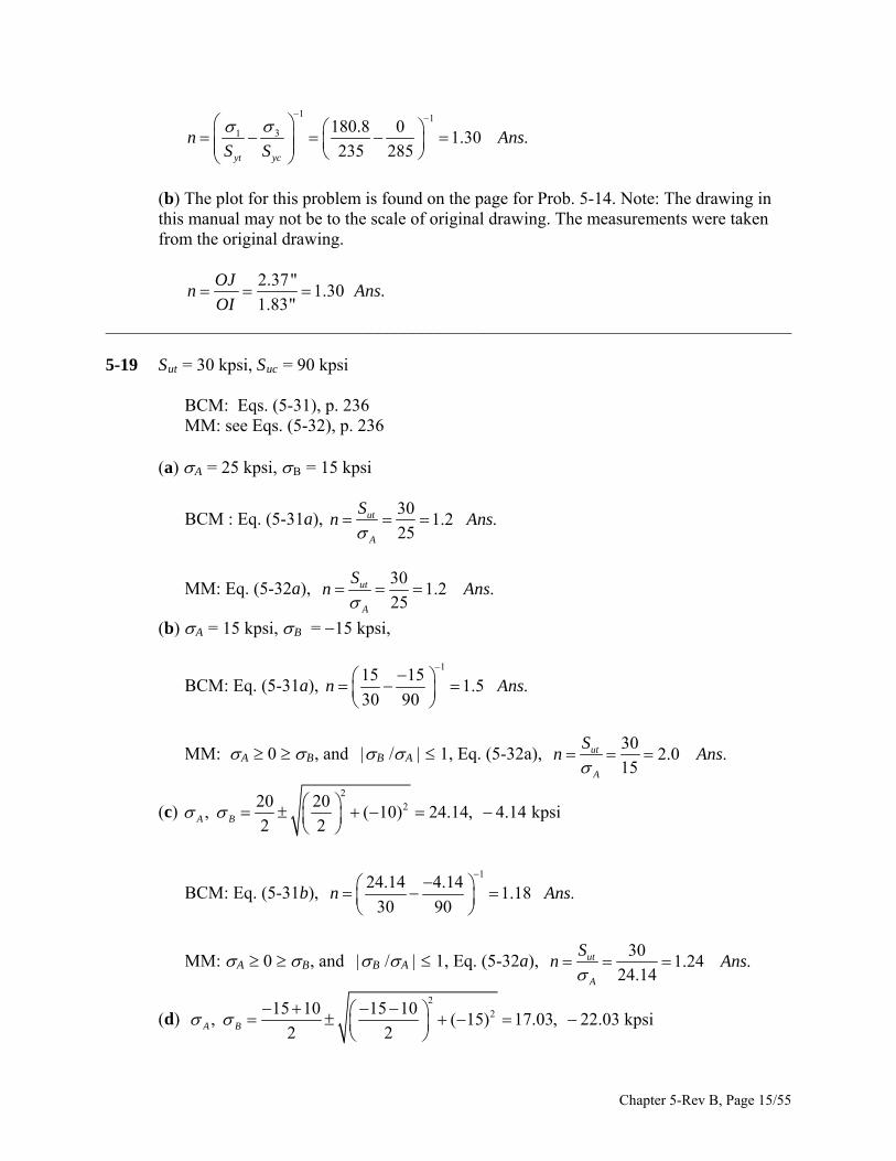
______________________________________________________________________________ 5-14 Since f > 0.05, and Syt Syc, the Coulomb-Mohr theory for ductile materials will be
used. (a) From Eq. (5-26),
1 1
31 150 501.23 .
235 285yt yc
n A nsS S
(b) Plots for Problems 5-14 to 5-18 are found here. Note: The drawing in this manual
may not be to the scale of original drawing. The measurements were taken from the original drawing.
1.94"
1.23 .1.58"
OBn Ans
OA
______________________________________________________________________________ 5-15 (a) From Eq. (5-26),
1 1
31 50 1501.35 .
235 285yt yc
n A nsS S
Chapter 5-Rev B, Page 13/55
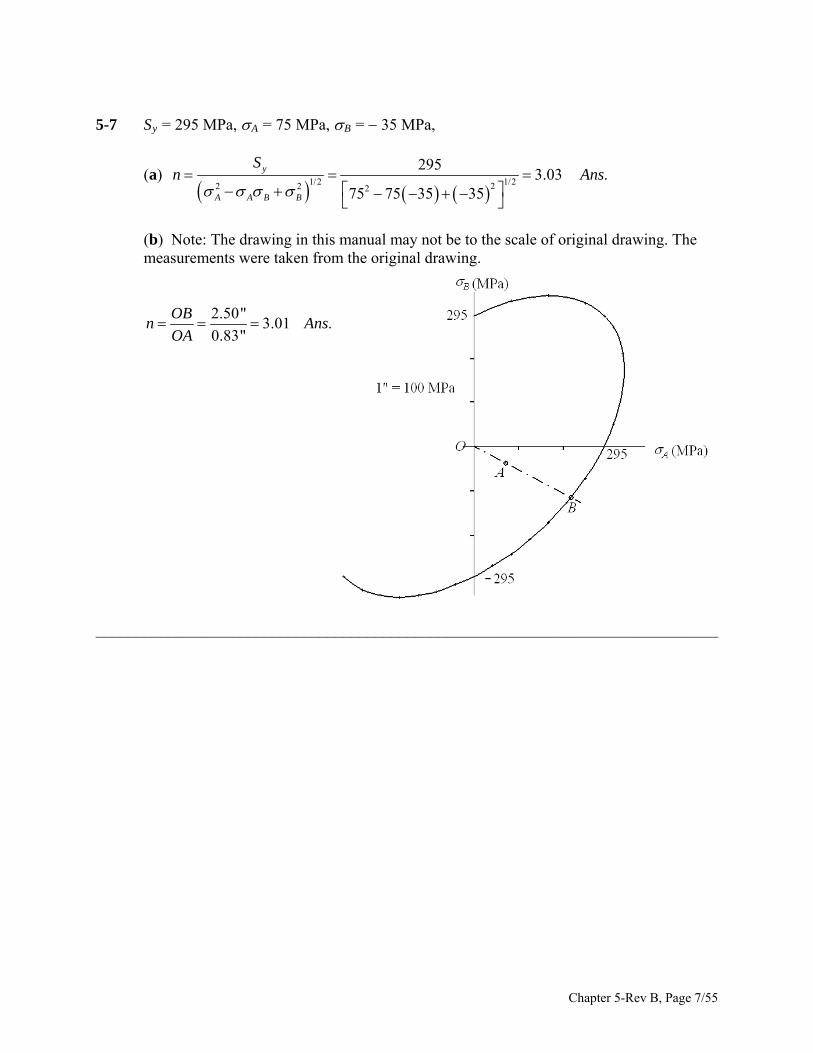
(b) The plot for this problem is found on the page for Prob. 5-14. Note: The drawing in this manual may not be to the scale of original drawing. The measurements were taken from the original drawing.
2.14"
1.35 .1.58"
ODn A
OC ns
______________________________________________________________________________
5-16 2
2125 125, ( 75) 160, 35 kpsi
2 2A B
(a) From Eq. (5-26),
1 1
31 160 351.24 .
235 285yt yc
n AS S
ns
(b) The plot for this problem is found on the page for Prob. 5-14. Note: The drawing in
this manual may not be to the scale of original drawing. The measurements were taken from the original drawing.
2.04"
1.24 .1.64"
OFn A
OE ns
______________________________________________________________________________
5-17 2
280 125 80 125, 50 47.7, kpsi
2 2A B
157.3
(a) From Eq. (5-26),
1 1
31 0 157.31.81 .
235 285yt yc
n AS S
ns
(b) The plot for this problem is found on the page for Prob. 5-14. Note: The drawing in
this manual may not be to the scale of original drawing. The measurements were taken from the original drawing.
2.99"
1.82 .1.64"
OHn A
OG ns
______________________________________________________________________________
5-18 2
2125 80 125 80, ( 75) 180.8, 24.2 kpsi
2 2A B
(a) From Eq. (5-26),
Chapter 5-Rev B, Page 14/55
1 1
31 180.8 01.30 .
235 285yt yc
n AS S
ns
(b) The plot for this problem is found on the page for Prob. 5-14. Note: The drawing in
this manual may not be to the scale of original drawing. The measurements were taken from the original drawing.
2.37"
1.30 .1.83"
OJn A
OI ns
______________________________________________________________________________ 5-19 Sut = 30 kpsi, Suc = 90 kpsi BCM: Eqs. (5-31), p. 236 MM: see Eqs. (5-32), p. 236 (a) A = 25 kpsi, B = 15 kpsi
BCM : Eq. (5-31a), 30
1.2 .25
ut
A
Sn A
ns
MM: Eq. (5-32a), 30
1.2 .25
ut
A
Sn A
ns
(b) A = 15 kpsi, B = 15 kpsi,
BCM: Eq. (5-31a), 1
15 151.5 .
30 90n A
ns
MM: A 0 B, and B /A 1, Eq. (5-32a), 30
2.0 .15
ut
A
Sn A
ns
(c) 2
220 20, ( 10) 24.14, 4.14 kpsi
2 2A B
BCM: Eq. (5-31b), 1
24.14 4.141.18 .
30 90n A
ns
MM: A 0 B, and B /A 1, Eq. (5-32a), 30
1.24 .24.14
ut
A
Sn A
ns
(d) 2
215 10 15 10, ( 15) 17.03, kpsi
2 2A B
22.03
Chapter 5-Rev B, Page 15/55
BCM: Eq. (5-31b), 1
17.03 22.031.23 .
30 90n A
ns
MM: A 0 B, and B /A 1, Eq. (5-32b),
1190 30 17.03 22.03
1.60 .90 30 90
uc ut A B
uc ut uc
S Sn A ns
S S S
(e) 2
220 20 20 20, ( 15) 5, 35 kpsi
2 2A B
BCM: Eq. (5-31c), 90
2.57 .35
uc
B
Sn A
ns
MM: Eq. (5-32c), 90
2.57 .35
uc
B
Sn A
ns
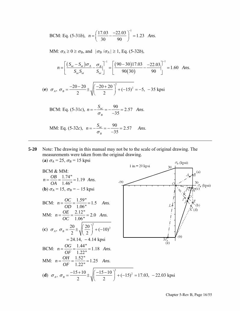
______________________________________________________________________________ 5-20 Note: The drawing in this manual may not be to the scale of original drawing. The
measurements were taken from the original drawing. (a) A = 25, B = 15 kpsi BCM & MM:
1.74"
1.19 .1.46"
OBn A
OA ns
(b) A = 15, B = 15 kpsi
BCM: 1.59"
1.5 .1.06"
OCn A ns
OD
MM: 2.12"
2.0 .1.06"
OEn A ns
OC
(c) 2
220 20, ( 10)
2 2A B
24.14, 4.14 kpsi
BCM: 1.44"
1.18 .1.22"
OGn A ns
OF
MM: 1.52"
1.25 .1.22"
OHn A ns
OF
(d) 2
215 10 15 10, ( 15) 17.03, kpsi
2 2A B
22.03
Chapter 5-Rev B, Page 16/55

BCM: 1.72"
1.24 .1.39"
OJn A
OI ns
MM: 2.24"
1.61 .1.39"
OKn A ns
OI
2220 20 20 20
(e) ,A ( 15) 5, 35 kpsi2 2B
d MM:4.55"
2.57 .1.77"
OMn A
OL BCM an ns
______________________________________________________________________________
From Table A-24, S = 31 kpsi, S = 109 kpsi
BCM: Eqs. (5-31), MM: Eqs. (5-32)
(a) = 15, = 10 kpsi.
5-21 ut uc
A B
31
2.07 .15
ut
A
S BCM: Eq. (5-31a), n Ans
312.07 .
15ut
A
S MM: Eq. (5-32a), n Ans
(b), (c) The plot is shown below is for Probs. 5-21 to 5-25. Note: The drawing in this an e scale of original drawing. The measurements were taken from
the original drawing.
m ual may not be to th
BCM and MM:
1.86"
2.07 .0.90"
nOA
OB
_________________________________ _ -22 Sut = 31 kpsi, Suc = 109 kpsi
(a) A = 15, B = 50 kpsi, B /A > 1
Ans
___________________________________________
_5 BCM: Eq. (5-31), MM: Eqs. (5-32)
Chapter 5-Rev B, Page 17/55

1
15 501.06 .
31 109n
Ans
BCM: Eq. (5-31b),
11109 31 15 50
1.24 .109 31 109
uc ut A B
uc ut uc
S S MM: Eq. (3-32b), n Ans
S S S
(b), (c) The plot is shown in the solution to Prob. 5-21.
BCM: 2.78"
1.07 .2.61"
n AnsOC
OD
MM: 3.25"
1.25 .2.61"
OEn A
OC ns
______________________________________________________________________________
e A-24, Sut = 31 kpsi, Suc = 109 kpsi
BCM: Eq. (5-31), MM: Eqs. (5-32)
5-23 From Tabl
2215 15
, ( 10) 202 2A B
, 5 kpsi
(a) BCM: Eq. (5-32b), 1
20 51.45 .
31 109n A
ns
MM: Eq. (5-32a), 31
1.55 .20
ut
A
Sn A
ns
(b), (c) The plot is shown in the solution to Prob. 5-21.
BCM: 1.48"
1.44 .1.03"
n AnsOF
OG
MM: 1.60"
1.55 .1.03"
OHn A
OF ns
e A-24, Sut = 31 kpsi, Suc = 109 kpsi
BCM: Eq. (5-31), MM: Eqs. (5-32)
______________________________________________________________________________ 5-24 From Tabl
2210 25 10 25
, ( 10) 5, 30 kpsiA B
a) BCM: Eq. (5-31c),
2 2
109
3.63 .30
uc
B
Sn A
( ns
MM: Eq. (5-32c), 109
3.63 .30
uc
B
Sn A
ns
Chapter 5-Rev B, Page 18/55
(b), (c) The plot is show
n in the solution to Prob. 5-21.
5.53"3.64 .
1.52"
OJ BCM and MM: n Ans
OI
-25 From Table A-24, Sut = 31 kpsi, Suc = 109 kpsi
BCM: Eq. (5-31), MM: Eqs. (5-32)
______________________________________________________________________________ 5
2
235 13 35 13, ( 10) 15
2 2A B , 37 kpsi
(a) BCM: Eq. (5-31b), 1
15 3 7
1.21 .31 109
n Ans
MM: Eq. (5-32b),
11109 31 15 37
1.46 .109 31 109
uc ut A B
uc ut uc
S Sn A
S S S
ns
n in the solution to Prob. 5-21. (b), (c) The plot is show
BCM: 2.42"
1.21 .2.0
nOK
0"
OLAns
MM: 2.91"
1.46 .2.00"
OMn Ans
OK
______________________________________________________________________________
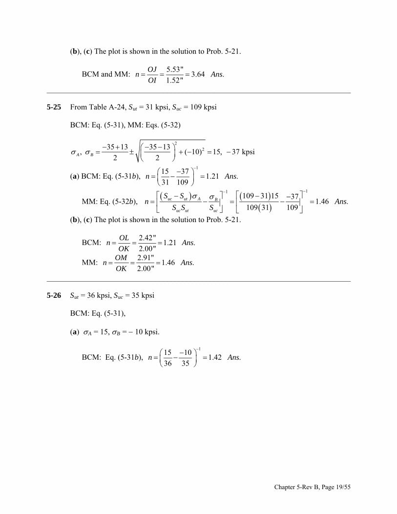
5-26 Sut = 36 kpsi, Suc = 35 kpsi
BCM: Eq. (5-31),
(a) = 15, = 10 kpsi.
1b),
A B
1
15 101.42 .
36 35n A
BCM: Eq. (5-3 ns
Chapter 5-Rev B, Page 19/55
(b) The plot is shown below is for Probs. 5-26 to 5-30. Note: The drawing in this manual
may not be to the scale of original drawing. The measurements were taken from the original drawing.
1.28"
1.42 .0.90"
OBn Ans
OA
______________________________________________________________________________ 5-27 Sut = 36 kpsi, Suc = 35 kpsi BCM: Eq. (5-31), (a) A = 15, B = 15 kpsi.
BCM: Eq. (5-31b), 1
10 151.42 .
36 35n A
ns
(b) The plot is shown in the solution to Prob. 5-26.
1.28"
1.42 .0.90"
ODn A ns
OC
______________________________________________________________________________ 5-28 Sut = 36 kpsi, Suc = 35 kpsi BCM: Eq. (5-31),
(a) 2
212 12, ( 8) 16, 4 kpsi
2 2A B
BCM: Eq. (5-31b), 1
16 41.79 .
36 35n A
ns
(b) The plot is shown in the solution to Prob. 5-26.
Chapter 5-Rev B, Page 20/55

1.47"
1.79 .0.82"
OFn A
OE ns
______________________________________________________________________________ 5-29 Sut = 36 kpsi, Suc = 35 kpsi BCM: Eq. (5-31),
(a) 2
210 15 10 15, 10 2.2, 22.8 kpsi
2 2A B
BCM: Eq. (5-31c), 35
1.54 .22.8
n A ns
(b) The plot is shown in the solution to Prob. 5-26.
1.76"
1.53 .1.15"
OHn A
OG ns
______________________________________________________________________________ 5-30 Sut = 36 kpsi, Suc = 35 kpsi BCM: Eq. (5-31),
(a) 2
215 8 15 8, 8 20.2, 2.8 kpsi
2 2A B
BCM: Eq. (5-31a), 36
1.78 .20.2
n A ns
(b) The plot is shown in the solution to Prob. 5-26.
1.82"
1.78 .1.02"
OJn A
OI ns
______________________________________________________________________________ 5-31 Sut = 36 kpsi, Suc = 35 kpsi. MM: Use Eq. (5-32). For this problem, MM reduces to the
MNS theory.
(a) A = 15, B = 10 kpsi. Eq. (5-32a), 36
2.4 .15
ut
A
Sn Ans
Chapter 5-Rev B, Page 21/55
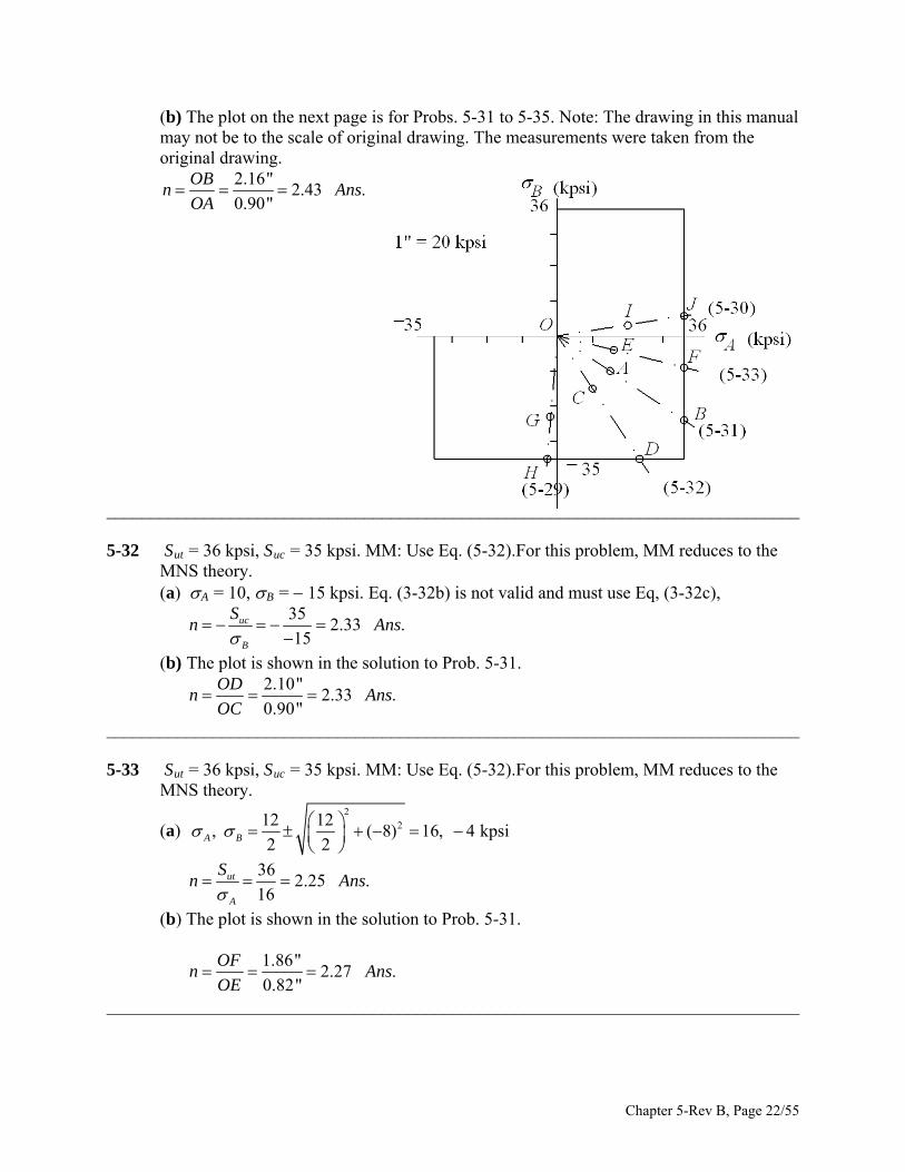
(b) The plot on the next page is for Probs. 5-31 to 5-35. Note: The drawing in this manual may not be to the scale of original drawing. The measurements were taken from the original drawing.
2.16"
2.43 .0.90"
OBn Ans
OA
______________________________________________________________________________ 5-32 Sut = 36 kpsi, Suc = 35 kpsi. MM: Use Eq. (5-32).For this problem, MM reduces to the
MNS theory. (a) A = 10, B = 15 kpsi. Eq. (3-32b) is not valid and must use Eq, (3-32c),
35
2.33 .15
uc
B
Sn Ans
(b) The plot is shown in the solution to Prob. 5-31.
2.10"
2.33 .0.90"
ODn Ans
OC
______________________________________________________________________________ 5-33 Sut = 36 kpsi, Suc = 35 kpsi. MM: Use Eq. (5-32).For this problem, MM reduces to the
MNS theory.
(a) 2
212 12, ( 8) 16, 4 kpsi
2 2A B
36
2.25 .16
ut
A
Sn Ans
(b) The plot is shown in the solution to Prob. 5-31.
1.86"
2.27 .0.82"
OFn Ans
OE
______________________________________________________________________________
Chapter 5-Rev B, Page 22/55

5-34 Sut = 36 kpsi, Suc = 35 kpsi. MM: Use Eq. (5-32).For this problem, MM reduces to the MNS theory.
(a) 2
210 15 10 15, 10 2.2, 22.8 kpsi
2 2A B
35
1.54 .22.8
uc
B
Sn A
ns
(b) The plot is shown in the solution to Prob. 5-31.
1.76"
1.53 .1.15"
OHn A
OG ns
______________________________________________________________________________ 5-35 Sut = 36 kpsi, Suc = 35 kpsi. MM: Use Eq. (5-32).For this problem, MM reduces to the
MNS theory.
(a) 2
215 8 15 8, 8 20.2, 2.8 kpsi
2 2A B
36
1.78 .20.2
ut
A
Sn A
ns
(b) The plot is shown in the solution to Prob. 5-31.
1.82"
1.78 .1.02"
OJn A
OI ns
______________________________________________________________________________ 5-36 Given: AISI 1006 CD steel, F = 0.55 kN, P = 4.0 kN, and T = 25 Nm. From Table A-20,
Sy =280 MPa. Apply the DE theory to stress elements A and B
A:
36
2 2
4 4 10422.6 10 Pa 22.6 MPa
0.015x
P
d
3
63 23
0.55 1016 2516 4 441.9 10 Pa 41.9 MPa
3 3 / 4 0.0150.015xy
T V
d A
1/22 222.6 3 41.9 76.0 MPa
280
3.68 .76.0
n A ns
B:
3 36
3 2 3 2
32 0.55 10 0.1 4 4 1032 4189 10 Pa 189 MPa
0.015 0.015x
Fl P
d d
Chapter 5-Rev B, Page 23/55
63 3
16 251637.7 10 Pa 37.7 MPa
0.015xy
T
d
1/21/22 2 2 23 189 3 37.7 200 MPax xy
280
1.4 .200
ySn A
ns
______________________________________________________________________________ 5-37 From Prob. 3-44, the critical location is at the top of the beam at x = 27 in from the left
end, where there is only a bending stress of = 7 456 psi. Thus, = 7 456 psi and (Sy)min = n = 2(7 456) = 14 912 psi Choose (Sy)min = 15 kpsi Ans. ______________________________________________________________________________ 5-38 From Table A-20 for 1020 CD steel, Sy = 57 kpsi. From Eq. (3-42), p.102,
63 025H
Tn
(1)
where n is the shaft speed in rev/min. From Eq. (5-3), for the MSS theory,
max 3
16
2y
d
S T
n d
(2)
where nd is the design factor. Substituting Eq. (1) into Eq. (2) and solving for d gives
1/332 63 025 d
y
Hnd
n S
(3)
Substituting H = 20 hp, nd = 3, n = 1750 rev/min, and Sy = 57(103) psi results in
1/3
min 3
32 63 025 20 30.728 in .
1750 57 10d A
ns
______________________________________________________________________________ 5-39 From Table A-20, Sy = 54 kpsi. From the solution of Prob. 3-68, in the plane of analysis 1 = 16.5 kpsi, 2 = 1.19 kpsi, and max = 8.84 kpsi The state of stress is plane stress. Thus, the three-dimensional principal stresses are
Chapter 5-Rev B, Page 24/55
1 = 16.5 kpsi, 2 = 0, and 3 = 1.19 kpsi
MSS: From Eq. (5-3), 1 3
543.05 .
16.5 1.19yS
n A
ns
Note: Whenever the two principal stresses of a plane stress state are of opposite sign, the
maximum shear stress found in the analysis is the true maximum shear stress. Thus, the factor of safety could have been found from
max
543.05 .
2 2 8.84yS
n A
ns
DE: The von Mises stress can be found from the principal stresses or from the stresses found in part (d) of Prob. 3-68. That is,
Eqs. (5-13) and (5-19)
1/2 1/222 2 2
54
16.5 16.5 1.19 1.19
3.15 .
y y
A A B B
S Sn
Ans
or, Eqs. (5-15) and (5-19) using the results of part (d) of Prob. 3-68
1/2 1/22 2 2 2
54
3 15.3 3 4.43
3.15 .
y yS Sn
Ans
______________________________________________________________________________ 5-40 From Table A-20, Sy = 370 MPa. From the solution of Prob. 3-69, in the plane of analysis 1 = 275 MPa, 2 = 12.1 MPa, and max = 144 MPa The state of stress is plane stress. Thus, the three-dimensional principal stresses are 1 = 275 MPa, 2 = 0, and 3 = 12.1 MPa
MSS: From Eq. (5-3), 1 3
3701.29 .
275 12.1yS
n A
ns
Chapter 5-Rev B, Page 25/55

DE: From Eqs. (5-13) and (5-19)
1/2 1/222 2 2
370
275 275 12.1 12.1
1.32 .
y y
A A B B
S Sn
Ans
______________________________________________________________________________
Chapter 5-Rev B, Page 26/55

5-41 From Table A-20, Sy = 54 kpsi. From the solution of Prob. 3-70, in the plane of analysis 1 = 22.6 kpsi, 2 = 1.14 kpsi, and max = 11.9 kpsi The state of stress is plane stress. Thus, the three-dimensional principal stresses are 1 = 22.6 kpsi, 2 = 0, and 3 = 1.14 kpsi
MSS: From Eq. (5-3), 1 3
542.27 .
22.6 1.14yS
n Ans
DE: From Eqs. (5-13) and (5-19)
1/2 1/222 2 2
54
22.6 22.6 1.14 1.14
2.33 .
y y
A A B B
S Sn
Ans
______________________________________________________________________________ 5-42 From Table A-20, Sy = 370 MPa. From the solution of Prob. 3-71, in the plane of analysis 1 = 78.2 MPa, 2 = 5.27 MPa, and max = 41.7 MPa The state of stress is plane stress. Thus, the three-dimensional principal stresses are 1 = 78.2 MPa, 2 = 0, and 3 = 5.27 MPa
MSS: From Eq. (5-3), 1 3
3704.43 .
78.2 5.27yS
n Ans
DE: From Eqs. (5-13) and (5-19)
1/2 1/222 2 2
370
78.2 78.2 5.27 5.27
4.57 .
y y
A A B B
S Sn
Ans
______________________________________________________________________________ 5-43 From Table A-20, Sy = 54 kpsi. From the solution of Prob. 3-72, in the plane of analysis 1 = 36.7 kpsi, 2 = 1.47 kpsi, and max = 19.1 kpsi The state of stress is plane stress. Thus, the three-dimensional principal stresses are 1 = 36.7 kpsi, 2 = 0, and 3 = 1.47 kpsi
Chapter 5-Rev B, Page 27/55

MSS: From Eq. (5-3), 1 3
541.41 .
36.7 1.47yS
n A
ns
DE: From Eqs. (5-13) and (5-19)
1/2 1/222 2 2
54
36.7 36.7 1.47 1.47
1.44 .
y y
A A B B
S Sn
Ans
______________________________________________________________________________ 5-44 From Table A-20, Sy = 370 MPa. From the solution of Prob. 3-73, in the plane of analysis 1 = 376 MPa, 2 = 42.4 MPa, and max = 209 MPa The state of stress is plane stress. Thus, the three-dimensional principal stresses are 1 = 376 MPa, 2 = 0, and 3 = 42.4 MPa
MSS: From Eq. (5-3), 1 3
3700.88 .
376 42.4yS
n Ans
DE: From Eqs. (5-13) and (5-19)
1/2 1/222 2 2
370
376 376 42.4 42.4
0.93 .
y y
A A B B
S Sn
Ans
______________________________________________________________________________ 5-45 From Table A-20, Sy = 54 kpsi. From the solution of Prob. 3-74, in the plane of analysis 1 = 7.19 kpsi, 2 = 17.0 kpsi, and max = 12.1 kpsi The state of stress is plane stress. Thus, the three-dimensional principal stresses are 1 = 7.19 kpsi, 2 = 0, and 3 = 17.0 kpsi
MSS: From Eq. (5-3), 1 3
542.23 .
7.19 17.0yS
n A
ns
DE: From Eqs. (5-13) and (5-19)
1/2 1/222 2 2
54
7.19 7.19 17.0 17.0
2.51 .
y y
A A B B
S Sn
Ans
______________________________________________________________________________
Chapter 5-Rev B, Page 28/55
5-46 From Table A-20, Sy = 54 kpsi. From the solution of Prob. 3-76, in the plane of analysis 1 = 1.72 kpsi, 2 = 35.9 kpsi, and max = 18.8 kpsi The state of stress is plane stress. Thus, the three-dimensional principal stresses are 1 = 1.72 kpsi, 2 = 0, and 3 = 35.9 kpsi
MSS: From Eq. (5-3), 1 3
541.44 .
1.72 35.9yS
n A
ns
DE: From Eqs. (5-13) and (5-19)
1/2 1/222 2 2
54
1.72 1.72 35.9 35.9
1.47 .
y y
A A B B
S Sn
Ans
______________________________________________________________________________ 5-47 From Table A-20, Sy = 370 MPa. From the solution of Prob. 3-77, Bending: B = 68.6 MPa, Torsion: B = 37.7 MPa For a plane stress analysis it was found that max = 51.0 MPa. With combined bending
and torsion, the plane stress analysis yields the true max.
MSS: From Eq. (5-3), max
3703.63 .
2 2 51.0yS
n A
ns
DE: From Eqs. (5-15) and (5-19)
1/2 1/22 2 2 2
370
3 68.6 3 37.7
3.91 .
y y
B B
S Sn
Ans
______________________________________________________________________________ 5-48 From Table A-20, Sy = 54 kpsi. From the solution of Prob. 3-79, Bending: C = 3460 psi, Torsion: C = 882 kpsi For a plane stress analysis it was found that max = 1940 psi. With combined bending and
torsion, the plane stress analysis yields the true max.
MSS: From Eq. (5-3),
3
max
54 1013.9 .
2 2 1940yS
n Ans
Chapter 5-Rev B, Page 29/55

DE: From Eqs. (5-15) and (5-19)
3
1/2 1/22 2 2 2
54 10
3 3460 3 882
14.3 .
y y
C C
S Sn
Ans
______________________________________________________________________________ 5-49 From Table A-20, Sy = 54 kpsi. From the solution of Prob. 3-80, in the plane of analysis 1 = 17.8 kpsi, 2 = 1.46 kpsi, and max = 9.61 kpsi The state of stress is plane stress. Thus, the three-dimensional principal stresses are 1 = 17.8 kpsi, 2 = 0, and 3 = 1.46 kpsi
MSS: From Eq. (5-3), 1 3
542.80 .
17.8 1.46yS
n A
ns
DE: From Eqs. (5-13) and (5-19)
1/2 1/222 2 2
54
17.8 17.8 1.46 1.46
2.91 .
y y
A A B B
S Sn
Ans
______________________________________________________________________________ 5-50 From Table A-20, Sy = 54 kpsi. From the solution of Prob. 3-81, in the plane of analysis 1 = 17.5 kpsi, 2 = 1.13 kpsi, and max = 9.33 kpsi The state of stress is plane stress. Thus, the three-dimensional principal stresses are 1 = 17.5 kpsi, 2 = 0, and 3 = 1.13 kpsi
MSS: From Eq. (5-3), 1 3
542.90 .
17.5 1.13yS
n A
ns
DE: From Eqs. (5-13) and (5-19)
1/2 1/222 2 2
54
17.5 17.5 1.13 1.13
2.98 .
y y
A A B B
S Sn
Ans
______________________________________________________________________________
Chapter 5-Rev B, Page 30/55
5-51 From Table A-20, Sy = 54 kpsi. From the solution of Prob. 3-82, in the plane of analysis 1 = 21.5 kpsi, 2 = 1.20 kpsi, and max = 11.4 kpsi The state of stress is plane stress. Thus, the three-dimensional principal stresses are 1 = 21.5 kpsi, 2 = 0, and 3 = 1.20 kpsi
MSS: From Eq. (5-3), 1 3
542.38 .
21.5 1.20yS
n Ans
DE: From Eqs. (5-13) and (5-19)
1/2 1/222 2 2
54
21.5 21.5 1.20 1.20
2.44 .
y y
A A B B
S Sn
Ans
______________________________________________________________________________ 5-52 From Table A-20, Sy = 54 kpsi. From the solution of Prob. 3-83, the concern was failure
due to twisting of the flat bar where it was found that max = 14.3 kpsi in the middle of the longest side of the rectangular cross section. The bar is also in bending, but the bending stress is zero where max exists.
MSS: From Eq. (5-3), max
541.89 .
2 2 14.3yS
n Ans
DE: From Eqs. (5-15) and (5-19)
1/2 1/22 2
max
542.18 .
3 3 14.3
y yS Sn A
ns
______________________________________________________________________________ 5-53 From Table A-20, Sy = 54 kpsi. From the solution of Prob. 3-84, in the plane of analysis 1 = 34.7 kpsi, 2 = 6.7 kpsi, and max = 20.7 kpsi The state of stress is plane stress. Thus, the three-dimensional principal stresses are 1 = 34.7 kpsi, 2 = 0, and 3 = 6.7 kpsi
MSS: From Eq. (5-3), 1 3
541.30 .
34.7 6.7yS
n Ans
Chapter 5-Rev B, Page 31/55

DE: From Eqs. (5-13) and (5-19)
1/2 1/222 2 2
54
34.7 34.7 6.7 6.7
1.40 .
y y
A A B B
S Sn
Ans
______________________________________________________________________________ 5-54 From Table A-20, Sy = 54 kpsi. From the solution of Prob. 3-85, in the plane of analysis 1 = 51.1 kpsi, 2 = 4.58 kpsi, and max = 27.8 kpsi The state of stress is plane stress. Thus, the three-dimensional principal stresses are 1 = 51.1 kpsi, 2 = 0, and 3 = 4.58 kpsi
MSS: From Eq. (5-3), 1 3
540.97 .
51.1 4.58yS
n A
ns
DE: From Eqs. (5-13) and (5-19)
1/2 1/222 2 2
54
51.1 51.1 4.58 4.58
1.01 .
y y
A A B B
S Sn
Ans
______________________________________________________________________________ 5-55 From Table A-20, Sy = 54 kpsi. From the solution of Prob. 3-86, in the plane of analysis 1 = 59.7 kpsi, 2 = 3.92 kpsi, and max = 31.8 kpsi The state of stress is plane stress. Thus, the three-dimensional principal stresses are 1 = 59.7 kpsi, 2 = 0, and 3 = 3.92 kpsi
MSS: From Eq. (5-3), 1 3
540.85 .
59.7 3.92yS
n A
ns
DE: From Eqs. (5-13) and (5-19)
1/2 1/222 2 2
54
59.7 59.7 3.92 3.92
0.87 .
y y
A A B B
S Sn
Ans
______________________________________________________________________________
Chapter 5-Rev B, Page 32/55
5-56 For Prob. 3-84, from Prob. 5-53 solution, with 1018 CD, DE theory yields, n = 1.40. From Table A-21, for 4140 Q&T @400F, Sy = 238 kpsi. From Prob. (3-87) solution
which considered stress concentrations for Prob. 3-84 1 = 53.0 kpsi, 2 = 8.48 kpsi, and max = 30.7 kpsi DE: From Eqs. (5-13) and (5-19)
1/2 1/222 2 2
238
53.0 53.0 8.48 8.48
4.12 .
y y
A A B B
S Sn
Ans
Using the 4140 versus the 1018 CD, the factor of safety increases by a factor of 4.12/1.40 = 2.94. Ans. ______________________________________________________________________________ 5-57 Design Decisions Required:
Material and condition Design factor Failure model Diameter of pin
Using F = 416 lbf from Ex. 5-3,
max 3
32M
d
1
3
max
32Md
Decision 1: Select the same material and condition of Ex. 5-3 (AISI 1035 steel, Sy = 81
kpsi) Decision 2: Since we prefer the pin to yield, set nd a little larger than 1. Further
explanation will follow. Decision 3: Use the Distortion Energy static failure theory. Decision 4: Initially set nd = 1
max 81 000 psi
1y y
d
S S
n
1
332(416)(15)0.922 in
(81 000)d
Chapter 5-Rev B, Page 33/55

Choose preferred size of 1.000 ind
3(1) (81 000)530 lbf
32(15)
5301.274
416
F
n
Set design factor to 1.274dn Adequacy Assessment:
max
1
3
8100063 580 psi
1.274
32(416)(15)1.000 in (OK)
(63 580)
y
d
S
n
d
3(1) (81000)530 lbf
32(15)F
530
1.274 (OK)416
n
______________________________________________________________________________ 5-58 From Table A-20, for a thin walled cylinder made of AISI 1020 CD steel, Syt = 57 kpsi,
Sut = 68 kpsi. Since r/t = 7.5/0.0625 = 120 > 10, the shell can be considered thin-wall. From the
solution of Prob. 3-93 the principal stresses are
1 2 3
(15)60 ,
4 4(0.0625)
pd pp p
t
From Eq. (5-12)
1/22 2 21 2 2 3 3 1
1/22 2 2
1( ) ( ) ( )
21
(60 60 ) (60 ) ( 60 ) 612
p p p p p p
p
Ans
For yield, = Sy 61p = 57 (103) p = 934 psi Ans. For rupture, 61 68 1.11 kpsi .p p ________________________________________________________________________
Chapter 5-Rev B, Page 34/55

5-59 For AISI 1020 HR steel, from Tables A-5 and A-20, w = 0.282 lbf/in3, Sy = 30 kpsi, and = 0.292. Then, = w/g = 0.282/386 lbfs2/in. For the problem, ri = 3 in, and ro = 5 in.
Substituting into Eqs. (3-55), p. 115, gives
2 22
4 2 2 22
4 2 2 22
9 25 1 3 0.2920.282 3 0.2929 25
386 8 3 0.292
2253.006 10 34 0.5699 (1)
2253.006 10 34 (2)
t
r
rr
r F rr
r G rr
For the distortion-energy theory, the von Mises stress will be
1/2 1/22 2 2 2 22 ( ) ( ) ( ) ( )t t r F r F r G r G r (3)
Although it was noted that the maximum radial stress occurs at r = (rori )
1/2 we are more interested as to where the von Mises stress is a maximum. One could take the derivative of Eq. (3) and set it to zero to find where the maximum occurs. However, it is much easier to plot / 2 for 3 r 5 in. Plotting Eqs. (1) through (3) results
in It can be seen that there is no maxima, and the greatest value of the von Mises stress is
the tangential stress at r = ri. Substituting r = 3 in into Eq. (1) and setting = Sy gives
1/2
3
4 22
30 101361 rad/s
2253.006 10 34 0.5699 3
3
Chapter 5-Rev B, Page 35/55

60 60(1361)
13 000 rev/min .2 2
n Ans
________________________________________________________________________ 5-60 Since r/t = 1.75/0.065 = 26.9 > 10, we can use thin-walled equations. From Eqs. (3-53)
and (3-54), p. 114,
3.5 2(0.065) 3.37 in
( )
2
i
it
d
p d t
t
500(3.37 0.065)13 212 psi 13.2 kpsi
2(0.065)
500(3.37)6481 psi 6.48 kpsi
4 4(0.065)
500 psi 0.5 kpsi
t
il
r i
pd
t
p
These are all principal stresses, thus, from Eq. (5-12),
1/22 2113.2 6.48 6.48 ( 0.5) 0.5 13.2
211.87 kpsi
2
46
11.873.88 .
ySn
n A
ns
________________________________________________________________________ 5-61 From Table A-20, 320 MPayS With pi = 0, Eqs. (3-49), p. 113, are
2 2 2
2 2 2 2
2 2 2
2 2 2 2
1 1
1 1
o o it
o i
o o ir
o i
r p r bc
r r r r
r p r bc
r r r r
(1)
For the distortion-energy theory, the von Mises stress is
1/22 22 2 2 2
1/22 22 2 2 2
1/24
4
1 1 1 1
1 3
t t r r
b b b bc
r r r r
bc
r
Chapter 5-Rev B, Page 36/55
We see that the maximum von Mises stress occurs where r is a minimum at r = ri. Here, r = 0 and thus = t . Setting t = Sy = 320 MPa at r = 0.1 m in Eq. (1) results in
22
2 2 2 2
2 0.1523.6 320 88.9 MPa .
0.15 0.1i
oo ot o or r
o i
pr pp p Ans
r r
________________________________________________________________________ 5-62 From Table A-24, Sut = 31 kpsi for grade 30 cast iron. From Table A-5, = 0.211 and w = 0.260 lbf/in3. In Prob. 5-59, it was determined that the maximum stress was the
tangential stress at the inner radius, where the radial stress is zero. Thus at the inner radius, Eq. (3-55), p. 115, gives
2 2 2 2 2 2 2
2 3
3 1 3 0.260 3.211 1 3(0.211)2 2 5 3
8 3 386 8 3.211
0.01471 31 10 1452 rad/ sec
t o i i
v vr r r
v
23
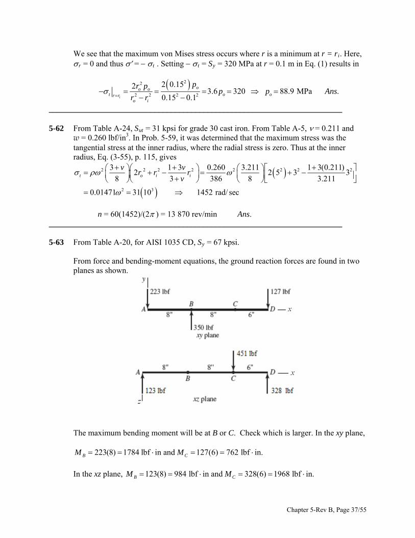
n = 60(1452)/(2 ) = 13 870 rev/min Ans. ________________________________________________________________________ 5-63 From Table A-20, for AISI 1035 CD, Sy = 67 kpsi. From force and bending-moment equations, the ground reaction forces are found in two
planes as shown.
The maximum bending moment will be at B or C. Check which is larger. In the xy plane, 223(8) 1784 lbf in and 127(6) 762 lbf in.B CM M In the xz plane, 123(8) 984 lbf in and 328(6) 1968 lbf in.B CM M
Chapter 5-Rev B, Page 37/55
12 2 2
12 2 2
[(1784) (984) ] 2037 lbf in
[(762) (1968) ] 2110 lbf in
B
C
M
M
So point C governs. The torque transmitted between B and C is T = (300 50)(4) = 1000
lbf·in. The stresses are
3 3 3
16 16(1000) 5093psixz
T
d d d
3 3 3
32 32(2110) 21 492psiC
x
M
d d d
For combined bending and torsion, the maximum shear stress is found from
1/2 1/22 2 22
max 3 3 3
21.49 5.09 11.89kpsi
2 2x
xz d d d
Max Shear Stress theory is chosen as a conservative failure theory. From Eq. (5-3)
max 3
11.89 670.892 in .
2 2 2yS
d An d
ns
________________________________________________________________________ 5-64 As in Prob. 5-63, we will assume this to be a statics problem. Since the proportions are
unchanged, the bearing reactions will be the same as in Prob. 5-63 and the bending moment will still be maximum at point C. Thus
xy plane: 127(3) 381 lbf inCM xz plane: 328(3) 984 lbf inCM
So
1/22 2
max (381) (984) 1055 lbf inM
3 3 3 3
32 2(1055) 10 746 10.75psi kpsiC
x
M
d d d d
Since the torsional stress is unchanged,
3
5.09 kpsixz d
For combined bending and torsion, the maximum shear stress is found from
Chapter 5-Rev B, Page 38/55

1/2 1/22 2 22
max 3 3 3
10.75 5.09 7.40kpsi
2 2x
xz d d d
Using the MSS theory, as was used in Prob. 5-63, gives
max 3
7.40 670.762 in .
2 2 2yS
d An d
ns
________________________________________________________________________ 5-65 For AISI 1018 HR, Table A-20 gives Sy = 32 kpsi. Transverse shear stress is maximum at
the neutral axis, and zero at the outer radius. Bending stress is maximum at the outer radius, and zero at the neutral axis.
Model (c): From Prob. 3-40, at outer radius,
17.8 kpsi
321.80
17.8yS
n
At neutral axis,
223 3 3.4 5.89 kpsi
325.43
5.89yS
n
The bending stress at the outer radius dominates. n = 1.80 Ans. Model (d): Assume the bending stress at the outer radius will dominate, as in model
(c). From Prob. 3-40,
25.5 kpsi
321.25 .
25.5yS
n Ans
Model (e): From Prob. 3-40,
17.8 kpsi
321.80 .
17.8yS
n Ans
Model (d) is the most conservative, thus safest, and requires the least modeling time. Model (c) is probably the most accurate, but model (e) yields the same results with less
modeling effort. ________________________________________________________________________ 5-66 For AISI 1018 HR, from Table A-20, Sy = 32 kpsi. Model (d) yields the largest bending
moment, so designing to it is the most conservative approach. The bending moment is M = 312.5 lbfin. For this case, the principal stresses are
Chapter 5-Rev B, Page 39/55
1 2 33
32, 0
M
d
Using a conservative yielding failure theory use the MSS theory and Eq. (5-3)
1/3
1 3 3
32 32y y
y
S SM Md
n d n S
n
Thus,
1/3
3
32 312.5 2.5 110.629 in Use in .
32 10 16d d Ans
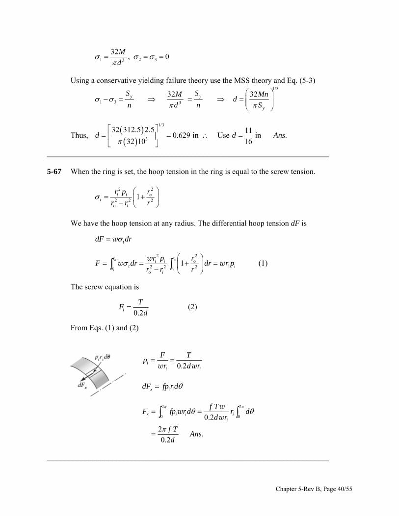
________________________________________________________________________ 5-67 When the ring is set, the hoop tension in the ring is equal to the screw tension.
2 2
2 2 21i i o
to i
r p r
r r r
We have the hoop tension at any radius. The differential hoop tension dF is
dF tdr w
2 2
2 2 21
o o
i i
r ri i o
t ir ro i
r p rF dr dr
r r r
ww w ir p (1)
The screw equation is
0.2i
TF
d (2)
From Eqs. (1) and (2)
0.2i
i i
F Tp
r d w wr
x i idF fp rd
2 2
0 00.2
2.
0.2
x i i ii
f TF fp rd r d
d r
f TAns
d
w
ww
________________________________________________________________________
Chapter 5-Rev B, Page 40/55
5-68 T = 20 Nm, Sy = 450 MPa (a) From Prob. 5-67, T = 0.2 Fi d
3
3
2016.7 10 N 16.7 kN .
0.2 0.2 6 10i
TF Ans
d
(b) From Prob. 5-67, F =wri pi
3
6
3 3
16.7 10111.3 10 Pa 111.3 MPa .
12 10 25 / 2 10i
ii i
FFp A
r r
w wns
(c) 2 22 2
2 2 2 21
i
i i oi i ot
o i o ir r
p r rr p r
r r r r r
2 2
2 2
111.3 0.0125 0.025185.5 MPa .
0.025 0.0125Ans
111.3 MPar ip
(d)
1 3max 2 2
185.5 ( 111.3)148.4 MPa .
2
t r
Ans
2 2' ( )A A B B 1/2
1/22 2185.5 (185.5)( 111.3) ( 111.3)
259.7 MPa .Ans (e) Maximum Shear Stress Theory
max
4501.52 .
2 2 148.4yS
n A
ns
Distortion Energy theory
4501.73 .
259.7yS
n A
ns
the force F is F re where re is the effective
________________________________________________________________________ 5-69 The moment about the center caused by
Chapter 5-Rev B, Page 41/55
radius. This is balanced by the moment about the center caused by the tangential
(hoop) stress.
2 2
2 2
2 2 22
2 2ln
2
o
i
o
i
r
e tr
ri i o
ro i
i i o i oe o
io i
Fr r dr
p r rr dr
r r r
p r r r rr r
rF r r
w
w
w
From Prob. 5-67, F = wri pi. Therefore,
2 2
22 2
ln2
i o i oe o
o i i
r r r rr r
r r r
For the conditions of Prob. 5-67, ri = 12.5 mm and ro = 25 mm
2 22
2 2
12.5 25 12.5 2525 ln 17.8 mm .
25 12.5 2 12.5er A
ns
________________________________________________________________________
(a) The nominal radial interference is nom = (2.002 2.001) /2 = 0.0005 in.
From Eq. (3-57), p. 116,
5-70
2 2 2 2
3 2 2
6 2 2 2 2
2 23
2
30 10 0.0005 1.5 1 1 0.6253072 psi .
1.5 0.6252 1
o i
o i
r R R rEp
R r r
Ans
Inner member: pi = 0, po = p = 3072 psi. At fit surface r =R = 1 in,
Eq. (3-49), p. 113,
2 2 2 2
2 2 2 2
1 0.6253072 7010 psi
1 0.625i
ti
R rp
R r
r = p = 3072 psi
Chapter 5-Rev B, Page 42/55
Eq. (5-13)
1/22 2
1/227010 7010 3072 3072 6086 psi .
A A B A
Ans
Outer member: pi = p = 3072 psi, po = 0. At fit surface r =R = 1 in,
Eq. (3-49), p. 113, 2 2 2 2
2 2 2 2
1.5 13072 7987 psi
1.5 1o
to
r Rp
r R
r = p = 3072 psi Eq. (5-13)
1/22 2
1/227987 7987 3072 3072 9888 psi .
A A B A
Ans
(b) For a solid inner tube,
6 2 2 2
23
30 10 0.0005 1.5 1 14167 psi .
1.52 1p Ans
Inner member: t = r = p = 4167 psi
1/22 2
4167 4167 4167 4167 4167 psi .Ans
Outer member: pi = p = 4167 psi, po = 0. At fit surface r =R = 1 in,
Eq. (3-49), p. 113, 2 2 2 2
2 2 2 2
1.5 14167 10834 psi
1.5 1o
to
r Rp
r R
r = p = 4167 psi Eq. (5-13)
1/22 2
1/2210 834 10 834 4167 4167 13 410 psi .
A A B A
Ans
________________________________________________________________________
Chapter 5-Rev B, Page 43/55

5-71 From Table A-5, E = 207 (103) MPa. The nominal radial interference is nom = (40 39.98) /2 = 0.01 mm.
From Eq. (3-57), p. 116,
2 2 2 2
3 2 2
3 2 2 2 2
2 23
2
207 10 0.01 32.5 20 20 1026.64 MPa .
32.5 102 20
o i
o i
r R R rEp
R r r
Ans
Inner member: pi = 0, po = p = 26.64 MPa. At fit surface r =R = 20 mm,
Eq. (3-49), p. 113, 2 2 2 2
2 2 2 2
20 1026.64 44.40 MPa
20 10i
ti
R rp
R r
r = p = 26.64 MPa Eq. (5-13)
1/22 2
1/2244.40 44.40 26.64 26.64 38.71 MPa .
A A B A
Ans
Outer member: pi = p = 26.64 MPa, po = 0. At fit surface r =R = 20 mm,
Eq. (3-49), p. 113, 2 2 2 2
2 2 2 2
32.5 2026.64 59.12 MPa
32.5 20o
to
r Rp
r R
r = p = 26.64 MPa Eq. (5-13)
1/22 2
1/2259.12 59.12 26.64 26.64 76.03 MPa .
A A B A
Ans
________________________________________________________________________ 5-72 From Table A-5, E = 207 (103) MPa. The nominal radial interference is nom = (40.008
39.972) /2 = 0.018 mm. From Eq. (3-57), p. 116,
Chapter 5-Rev B, Page 44/55

2 2 2 2
3 2 2
3 2 2 2 2
2 23
2
207 10 0.018 32.5 20 20 1047.94 MPa .
32.5 102 20
o i
o i
r R R rEp
R r r
Ans
Inner member: pi = 0, po = p = 47.94 MPa. At fit surface r =R = 20 mm,
Eq. (3-49), p. 113, 2 2 2 2
2 2 2 2
20 1047.94 79.90 MPa
20 10i
ti
R rp
R r
r = p = 47.94 MPa Eq. (5-13)
1/22 2
1/2279.90 79.90 47.94 47.94 69.66 MPa .
A A B A
Ans
Outer member: pi = p = 47.94 MPa, po = 0. At fit surface r =R = 20 mm,
Eq. (3-49), p. 113, 2 2 2 2
2 2 2 2
32.5 2047.94 106.4 MPa
32.5 20o
to
r Rp
r R
r = p = 47.94 MPa Eq. (5-13)
1/22 2
1/22106.4 106.4 47.94 47.94 136.8 MPa .
A A B A
Ans
________________________________________________________________________ 5-73 From Table A-5, for carbon steel, Es = 30 kpsi, and s = 0.292. While for Eci = 14.5
Mpsi, and ci = 0.211. For ASTM grade 20 cast iron, from Table A-24, Sut = 22 kpsi. For midrange values, = (2.001 2.0002)/2 = 0.0004 in. Eq. (3-50), p. 116,
Chapter 5-Rev B, Page 45/55

2 2 2 2
2 2 2 2
2 2 2
2 2 26 6
1 1
0.00042613 psi
1 2 1 1 11 0.211 0.292
2 1 114.5 10 30 10
o io i
o o i i
pr R R r
RE r R E R r
At fit surface, with pi = p =2613 psi, and po = 0, from Eq. (3-50), p. 113
2 2 2 2
2 2 2 2
2 12613 4355 psi
2 1o
to
r Rp
r R
r = p = 2613 psi
From Modified-Mohr theory, Eq. (5-32a), since A > 0 > B and B /A <1,
22
5.05 .4.355
ut
A
Sn A
ns
________________________________________________________________________ 5-74 E = 207 GPa Eq. (3-57), p. 116, can be written in terms of diameters,
32 2 2 2 2 2 2 2
33 2 2 2 2
207 10 (0.062)( )( ) (50 45 )(45 40 )
2 ( ) (50 40 )2 45d o i
o i
E d D D dp
D d d
15.80 MPap Outer member: From Eq. (3-50),
Outer radius: 2
2 2
45 (15.80)(2) 134.7 MPa
50 45t o
0r o
Inner radius: 2 2
2 2 2
45 (15.80) 501 150.5 MPa
50 45 45t i
15.80 MPar i
Bending (no slipping): I = ( /64)(504 404) = 181.1 (103) mm4
Chapter 5-Rev B, Page 46/55

At :r o 6
9
75(0.05 / 2)93.2(10 ) Pa 93.2 MPa
181.1 10x o
Mc
I
At :r i 6
9
675(0.045 / 2)83.9 10 Pa 83.9 MPa
181.1 10x i
Torsion: J = 2I = 362.2 (103) mm4
At :r o 6
9
900(0.05 / 2)62.1 10 Pa 62.1 MPa
362.2 10xy o
Tc
J
At :r i 6
9
900(0.045 / 2)55.9 10 Pa 55.9 MPa
362.2 10xy i
Outer radius, is plane stress. Since the tangential stress is positive the von Mises stress
will be maximum with a negative bending stress. That is, 93.2 MPa, 134.7 MPa, 62.1 MPax y xy
Eq. (5-15)
1/22 2 2
1/22 22
3
93.2 93.2 134.7 134.7 3 62.1 226 MPa
x x y y xy
415
1.84 .226
yo
Sn A
ns
Inner radius, 3D state of stress
From Eq. (5-14) with yz = zx = 0 and x = + 83.9 MPa
1/22 2 2 21
(83.9 150.5) (150.5 15.8) ( 15.8 83.9) 6(55.9) 174 MPa2
With x = 83.9 MPa
1/22 2 2 21( 83.9 150.5) (150.5 15.8) ( 15.8 83.9) 6(55.9) 230 MPa
2
Chapter 5-Rev B, Page 47/55

4151.80 .
230y
i S
n Ans
________________________________________________________________________ 5-75 From the solution of Prob. 5-74, p = 15.80 MPa Inner member: From Eq. (3-50),
Outer radius: 2 2 2 2
2 2 2 2
45 40(15.80) 134.8 MPa
45 40o i
t ooo i
r rp
r r
15.80 MPar op
Inner radius: 22
2 2 2 2
2 452(15.80) 150.6 MPa
45 40o
t oio i
rp
r r
0r i
Bending (no slipping): I = ( /64)(504 404) = 181.1 (103) mm4
At :r o 6
9
75(0.045 / 2)83.9(10 ) Pa 83.9 MPa
181.1 10x o
Mc
I
At :r i 6
9
675(0.040 / 2)74.5 10 Pa 74.5 MPa
181.1 10x i
Torsion: J = 2I = 362.2 (103) mm4
At :r o 6
9
900(0.045 / 2)55.9 10 Pa 55.9 MPa
362.2 10xy o
Tc
J
At :r i 6
9
900(0.040 / 2)49.7 10 Pa 49.7 MPa
362.2 10xy i
Outer radius, 3D state of stress
Chapter 5-Rev B, Page 48/55

From Eq. (5-14) with yz = zx = 0 and x = + 83.9 MPa
1/22 2 2 21
(83.9 134.8) ( 134.8 15.8) ( 15.8 83.9) 6(55.9) 213 MPa2
With x = 83.9 MPa
1/22 2 2 21
( 83.9 134.8) ( 134.8 15.8) ( 15.8 83.9) 6(55.9) 142 MPa2
4151.95 .
213y
o
Sn A
ns
Inner radius, plane stress. Worst case is when x is positive
74.5 MPa, 150.6 MPa, 49.7 MPax y xy
Eq. (5-15)
1/22 2 2
1/22 22
3
74.5 74.5 150.6 150.6 3 49.7 216 MPa
x x y y xy
415
1.92 .216
yi
Sn A
ns
______________________________________________________________________________ 5-76 For AISI 1040 HR, from Table A-20, Sy = 290 MPa. From Prob. 3-110, pmax = 65.2 MPa. From Eq. (3-50) at the inner radius R of the outer
member,
2 2 2 2
2 2 2 2
50 2565.2 108.7 MPa
50 25o
to
r Rp
r R
65.2 MPar p
These are principal stresses. From Eq. (5-13)
1/21/2 22 2 2108.7 108.7 65.2 65.2 152.2 MPao t t r r
290
1.91 .152.2
y
o
Sn A
ns
________________________________________________________________________ 5-77 For AISI 1040 HR, from Table A-20, Sy = 42 kpsi. From Prob. 3-111, pmax = 9 kpsi. From Eq. (3-50) at the inner radius R of the outer
member,
Chapter 5-Rev B, Page 49/55

2 2 2 2
2 2 2 2
2 19 15 kpsi
2 1o
to
r Rp
r R
9 kpsir p
These are principal stresses. From Eq. (5-13)
1/21/2 22 2 215 15( 9) 9 21 kpsio t t r r
42
2 .21
y
o
Sn A
ns
________________________________________________________________________ 5-78 For AISI 1040 HR, from Table A-20, Sy = 290 MPa. From Prob. 3-111, pmax = 91.6 MPa. From Eq. (3-50) at the inner radius R of the outer
member,
2 2 2 2
2 2 2 2
50 2591.6 152.7 MPa
50 25o
to
r Rp
r R
91.6 MPar p
These are principal stresses. From Eq. (5-13)
1/21/2 22 2 2152.7 152.7( 91.6) 91.6 213.8 MPao t t r r
290
1.36 .213.8
y
o
Sn A
ns
________________________________________________________________________ 5-79 For AISI 1040 HR, from Table A-20, Sy = 42 kpsi. From Prob. 3-111, pmax = 12.94 kpsi. From Eq. (3-50) at the inner radius R of the outer
member,
2 2 2 2
2 2 2 2
2 112.94 21.57 kpsi
2 1o
to
r Rp
r R
12.94 kpsir p
These are principal stresses. From Eq. (5-13)
1/21/2 22 2 221.57 21.57( 12.94) 12.94 30.20 kpsio t t r r
42
1.39 .30.2
y
o
Sn A
ns
________________________________________________________________________
Chapter 5-Rev B, Page 50/55
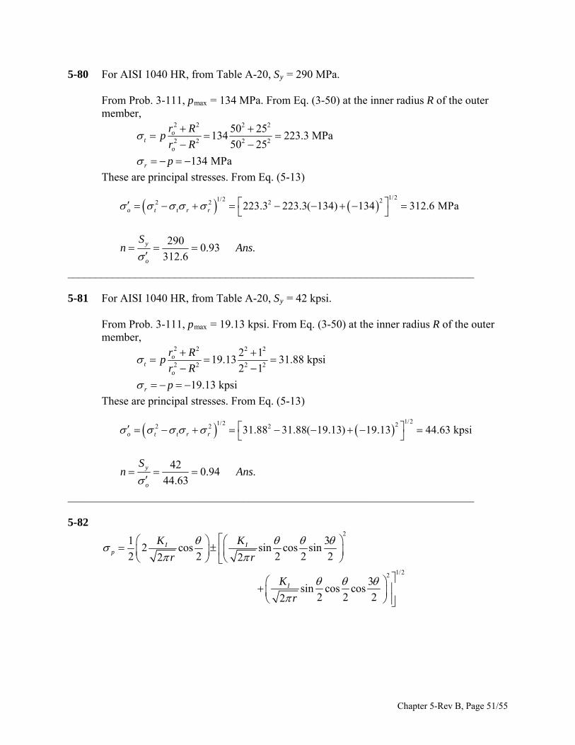
5-80 For AISI 1040 HR, from Table A-20, Sy = 290 MPa. From Prob. 3-111, pmax = 134 MPa. From Eq. (3-50) at the inner radius R of the outer
member,
2 2 2 2
2 2 2 2
50 25134 223.3 MPa
50 25o
to
r Rp
r R
134 MPar p
These are principal stresses. From Eq. (5-13)
1/21/2 22 2 2223.3 223.3( 134) 134 312.6 MPao t t r r
290
0.93 .312.6
y
o
Sn A
ns
________________________________________________________________________ 5-81 For AISI 1040 HR, from Table A-20, Sy = 42 kpsi. From Prob. 3-111, pmax = 19.13 kpsi. From Eq. (3-50) at the inner radius R of the outer
member,
2 2 2 2
2 2 2 2
2 119.13 31.88 kpsi
2 1o
to
r Rp
r R
19.13 kpsir p
These are principal stresses. From Eq. (5-13)
1/21/2 22 2 231.88 31.88( 19.13) 19.13 44.63 kpsio t t r r
42
0.94 .44.63
y
o
Sn A
ns
________________________________________________________________________ 5-82
2
1/22
1 32 cos sin cos sin
2 2 2 2 22 2
3sin cos cos
2 2 22
I Ip
I
K K
r r
K
r
Chapter 5-Rev B, Page 51/55
1/22 2 2 2 2 23 3
cos sin cos sin sin cos cos2 2 2 2 2 2 22
cos sin cos cos 1 sin2 2 2 2 22 2
I
I I
K
r
K K
r r
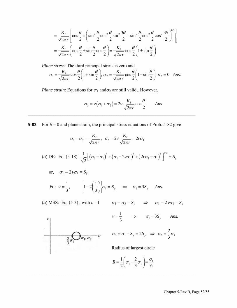
Plane stress: The third principal stress is zero and
1 2 3cos 1 sin , cos 1 sin , 0 .2 2 2 22 2
I IK KAns
r r
Plane strain: Equations for 1 and2 are still valid,. However,
3 1 2 2 cos22
IKAns
r.
________________________________________________________________________ 5-83 For = 0 and plane strain, the principal stress equations of Prob. 5-82 give
1 2 3, 2 22 2
I IK K
r r1
(a) DE: Eq. (5-18) 1/22 2 2
1 1 1 1 1 1
12 2
2yS
or, 1 21 = Sy
1 1
1 1Fo r , 1 2 3 .
3 3 y yS S Ans (a) MSS: Eq. (5-3) , with n =1 1 3 = Sy 1 21 = Sy
1
13 .
3 yS Ans
3 1 3
22
3y yS S 1
Radius of largest circle
11 1
1 2
2 3R
6
________________________________________________________________________
Chapter 5-Rev B, Page 52/55
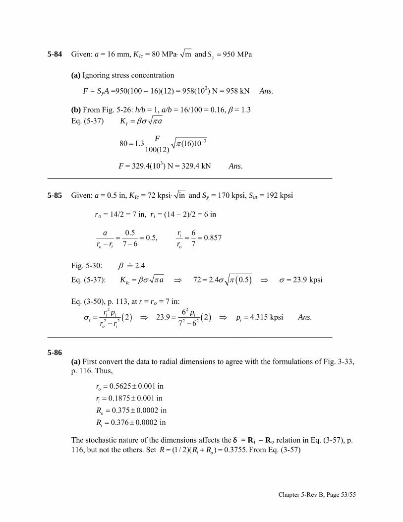
5-84 Given: a = 16 mm, KIc = 80 MPa m and 950 MPayS
(a) Ignoring stress concentration
F = SyA =950(100 16)(12) = 958(103) N = 958 kN Ans. (b) From Fig. 5-26: h/b = 1, a/b = 16/100 = 0.16, = 1.3
Eq. (5-37) IK a
380 1.3 (16)10100(12)
F
F = 329.4(103) N = 329.4 kN Ans. ________________________________________________________________________
5-85 Given: a = 0.5 in, KIc = 72 kpsi in and Sy = 170 kpsi, Sut = 192 kpsi ro = 14/2 = 7 in, ri = (14 2)/2 = 6 in
0.5 6
0.5, 0.8577 6 7
i
o i o
ra
r r r
Fig. 5-30: 2.4
Eq. (5-37): 72 2.4 0.5 23.9 kpsiIcK a
Eq. (3-50), p. 113, at r = ro = 7 in:
2 2
2 2 2 2
62 23.9 2 4.315 kpsi .
7 6i i i
t io i
r p pp Ans
r r
________________________________________________________________________ 5-86 (a) First convert the data to radial dimensions to agree with the formulations of Fig. 3-33,
p. 116. Thus,
0.5625 0.001 in
0.1875 0.001 in
0.375 0.0002 in
0.376 0.0002 in
o
i
o
i
r
r
R
R
The stochastic nature of the dimensions affects the = Ri Ro relation in Eq. (3-57), p. 116, but not the others. Set (1/ 2)( ) 0.3755.i oR R R From Eq. (3-57)
Chapter 5-Rev B, Page 53/55
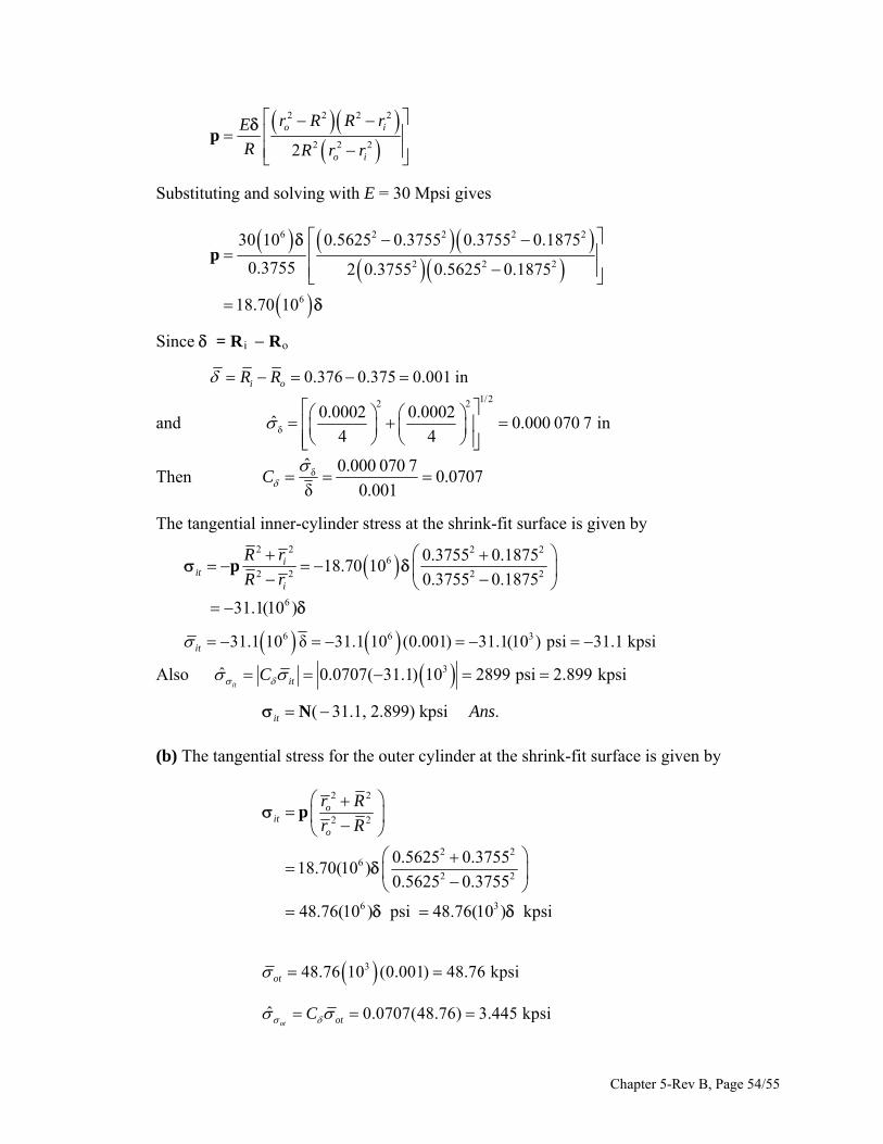
2 2 2 2
2 2 22
o i
o i
r R R rE
R R r r
p
Substituting and solving with E = 30 Mpsi gives
6 2 2 2
2 2 2
6
30 10 0.5625 0.3755 0.3755 0.1875
0.3755 2 0.3755 0.5625 0.1875
18.70 10
p
2
Since = Ri Ro
0.376 0.375 0.001 ini oR R
and
1/22 2
δ
0.0002 0.0002ˆ 0.000 070 7 in
4 4
Then δˆ 0.000 070 70.0707
δ 0.001C
The tangential inner-cylinder stress at the shrink-fit surface is given by
2 2 2 2
62 2 2 2
0.3755 0.187518.70 10
0.3755 0.1875i
iti
R r
R r
p
631.1(10 )
6 6 331.1 10 δ 31.1 10 (0.001) 31.1(10 ) psi 31.1 kpsiit
Also 3ˆ 0.0707( 31.1) 10 2899 psi 2.899 kpsiit itC
( 31.1, 2.899) kpsi .it Ans N (b) The tangential stress for the outer cylinder at the shrink-fit surface is given by
2 2
2 2
2 26
2 2
6 3
0.5625 0.375518.70(10 )
0.5625 0.3755
48.76(10 ) psi 48.76(10 ) kpsi
oit
o
r R
r R
p
348.76 10 (0.001) 48.76 kpsiot
ˆ 0.0707(48.76) 3.445 kpsi
ot otC
Chapter 5-Rev B, Page 54/55
ot = N(48.76, 3.445) kpsi Ans.
________________________________________________________________________ 5-87 From Prob. 5-86, at the fit surface ot = N(48.76, 3.445) kpsi. The radial stress is the fit
pressure which was found to be p = 18.70(106)
6 3
3
18.70 10 0.001 18.70 10 psi
ˆ 0.707 18.70 10 1322 psip
p
C p
and so p = N(18.7, 1.32) kpsi and or = N(18.7, 1.32) kpsi These represent the principal stresses. The von Mises stress is next assessed.
1/21/2 22 2 2
48.8 kpsi, 18.7 kpsi
= 48.8 48.8 18.7 18.7
60.4 kpsi
ˆ 0.707 60.4 4.27 kpsi
A B
A A B B
pC
Using the interference equation, Eq. (5-40),
1/2 1/22 2 2 2
95.5 60.44.5
ˆ ˆ 6.59 4.27S
Sz
From Table A-10, pf = = 0.000 003 40 or 3.4 chances in a million. Ans. ______________________________________________________________________________ 5-88 Note to the Instructor. In the first printing, the pressure was incorrectly given to be p =
N(40, 2) MPa. This will be changed to p = N(20, 1) MPa in subsequent printings. We are sorry for any inconvenience.
20 1, 0.05 69230 1, 0.05 MPa
2 2 3
115 1, 0.05) MPa2
20 1, 0.05 MPa
it
tl
r
d
t
NpN
N
p N
Chapter 5-Rev B, Page 55/55
These three stresses are principal stresses whose variability is due to the loading. From Eq. (5-12), we find that the von Mises stress to be
1/222 2230 115 115 20 20 230
217 MPa2
ˆ 0.05 217 10.9 MPapC
Using the interference equation, Eq. (5-40),
1/2 1/22 2 2 2
350 2174.29
ˆ ˆ 29 10.9S
Sz
From Table A-10, the reliability is very high at R = 1 (4.29) 1 0.00000854 1 Ans.
______________________________________________________________________________
Chapter 5-Rev B, Page 56/55
Related Documents