ภาคผนวก ก การคํานวณปริมาณการระบายอากาศ ตามมาตรฐาน ASHRAE 62.1-2013 (OLD)

Welcome message from author
This document is posted to help you gain knowledge. Please leave a comment to let me know what you think about it! Share it to your friends and learn new things together.
Transcript
ภาคผนวก ก
การคานวณปรมาณการระบายอากาศ
ตามมาตรฐาน ASHRAE 62.1-2013 (OLD)

ÊÁÒ¤ÁÇÔÈÇ¡ÃÃÁ»ÃѺÍÒ¡ÒÈáË‹§»ÃÐà·Èä·Â 43
1. º·¹íÒ ระบบระบายอากาศ คอ ระบบทตองมการน�าเอา
อากาศบรสทธจากภายนอก เขามาเตม ในบรเวณท
มผอยอาศย ในปรมาณทพอเพยง และมการระบาย
อากาศเสย (Exhaust) ออกไปทง เพอรกษา
คณภาพของอากาศภายในอาคาร (IAQ) ไวในระดบ
ทยอมรบได
บทความนจะกลาวถงการค�านวณหาปรมาณ
อากาศระบาย ตามมาตรฐาน ASHRAE 62.11,2
แตเนอหาจะครอบคลมเฉพาะสวนทเปน Ventilation
Rate Procedure (VRP) เทานน เนองจากวธการน
เป นวธการทตรงไปตรงมา และโดยทวไปแลว
ในชวงตนของการออกแบบ วศวกรมกจะไมมขอมล
เพยงพอทจะสามารถท�ารายการค�านวณตามวธ IAQ
Procedure ได
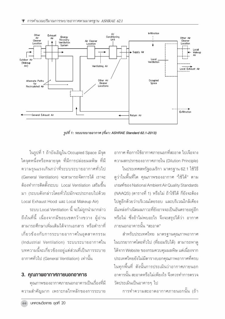
2. ÃٻẺ¢Í§Ãкº ระบบระบายอากาศทท�างานรวมกนกบระบบ
ปรบอากาศ (General Ventilation) มกจะมรปแบบ
ดงแสดงอยในรปท 1 อากาศบรสทธจากภายนอกจะ
ถกน�าเขาสบรเวณทมผอยอาศย (Occupied Space)
ผานทางระบบปรบอากาศ (รวมกบ Supply Air) และ
อากาศเสยทวไป (General Exhaust) จะถกน�าออก
ผานทาง Return Air โดยทวไปปรมาณอากาศบรสทธ
จากภายนอกจะมคาอยประมาณราว 10 ถง 15% ของ
ปรมาณ Supply Air และอากาศเสยกจะถกก�าจดออก
ไปในปรมาณทใกลเคยงกน คาต�าทสดของปรมาณ
อากาศภายนอกทตองน�าเขามาเพอการระบายอากาศ
ตามมาตรฐาน 62.1 และปรมาณอากาศเสยทตอง
ดดออกจาก Occupied Space นจะถกกลาวถงโดย
ละเอยดในหวขอถดๆ ไป
การคานวณปรมาณการระบายอากาศ
ตามมาตรฐาน ASHRAE 62.1
ตลยมณวฒนาภาควชาวศวกรรมเครองกล คณะวศวกรรมศาสตร จฬาลงกรณมหาวทยาลย เขตปทมวน กรงเทพฯ 10330
โทรศพท: 0-2218-6640 E-mail: [email protected]
º·¤ÇÒÁÇÔªÒ¡Òà ªØ´·Õè 2044
ในรปท 1 ถาบงเอญใน Occupied Space มจด
ใดจดหนงหรอหลายจด ทมการปลอยมลพษ ทม
ความรนแรงเกนกวาทระบบระบายอากาศทวไป
(General Ventilation) จะสามารถจดการได เราจะ
ตองท�าการตดตงระบบ Local Ventilation เสรมขน
มา (ระบบดงกลาวโดยทวไปมกจะประกอบไปดวย
Local Exhaust Hood และ Local Makeup Air)
ระบบ Local Ventilation น จะไมถกน�ามากลาว
ถงในทน เนองจากมขอบเขตกวางขวาง ผ อาน
สามารถศกษาเพมเตมไดจากเอกสาร หรอต�าราท
เกยวของกบการระบายอากาศในอตสาหกรรม
(Industrial Ventilation) ระบบระบายอากาศใน
บทความนจะเกยวของอยแตสวนทเปนการระบาย
อากาศทวไป (General Ventilation) เทานน
3.คØณภาพอากาศภายนอกอาคาร คณภาพของอากาศภายนอกอาคารเปนเรองทม
ความส�าคญมาก เพราะกลไกหลกของการระบาย
อากาศ คอการใชอากาศภายนอกทสะอาด ไปเจอจาง
ความสกปรกของอากาศภายใน (Dilution Principle)
ในประเทศสหรฐอเมรกา มาตรฐาน 62.1 ใชวธ
ดวาในพนทใด คณภาพของอากาศ “ใชได” ตาม
เกณฑของ National Ambient Air Quality Standards
(NAAQS) (ตารางท 1) หรอไม ถาใชได กยงจะตอง
ไปดอกดวยวาบรเวณโดยรอบ และบรเวณใกลเคยง
มแหลงก�าเนดมลภาวะทยงอาจจะเปนอนตรายอยอก
หรอไม ซงถาไมพบอะไร จงจะสรปไดวา อากาศ
ภายนอกอาคารนน “สะอาด”
ส�าหรบประเทศไทย มาตรฐานคณภาพอากาศ
ในบรรยากาศโดยทวไป (ทยอมรบได) สามารถหาด
ไดจาก Website ของกรมควบคมมลพษ แตเนองจาก
ประเทศไทยยงไมมตารางบอกคณภาพอากาศทครบ
ในทกพนท ดงนนการประเมนวาอากาศภายนอก
อาคารนน สะอาดหรอไมเพยงไร จงควรท�าการตรวจ
วดประเมนเปนอาคารๆ ไป
การท�าความสะอาดอากาศภายนอกนน (ถา
Air โดยทวไปปรมาณอากาศบรสทธจากภายนอกจะมคาอยประมาณราว 10 ถง 15% ของปรมาณ Supply Air
และอากาศเสยกจะถกกาจดออกไปในปรมาณทใกลเคยงกน คาตาทสดของปรมาณอากาศภายนอกทตองนาเขา
มาเพอการระบายอากาศตามมาตรฐาน 62.1 และปรมาณอากาศเสยทตองดดออกจาก Occupied Space นจะถก
กลาวถงโดยละเอยดในหวขอถดๆ ไป
ในรปท 1 ถาบงเอญใน Occupied Space มจดใดจดหนงหรอหลายจด ทมการปลอยมลพษ ทมความ
รนแรงเกนกวาทระบบระบายอากาศทวไป (General Ventilation) จะสามารถจดการได เราจะตองทาการตดตง
ระบบ Local Ventilation เสรมขนมา (ระบบดงกลาวโดยทวไปมกจะประกอบไปดวย Local Exhaust Hood และ
Local Makeup Air)
ระบบ Local Ventilation น จะไมถกนามากลาวถงในทน เนองจากมขอบเขตกวางขวาง ผอานสามารถ
ศกษาเพมเตมไดจากเอกสาร หรอตาราทเกยวของกบการระบายอากาศในอตสาหกรรม (Industrial Ventilation)
ระบบระบายอากาศในบทความนจะเกยวของอยแตสวนทเปนการระบายอากาศทวไป (General Ventilation)
เทานน
รปท 1: ระบบระบายอากาศ (ทมา: ASHRAE Standard 62.1-2013)
3. คณภาพอากาศภายนอกอาคาร
คณภาพของอากาศภายนอกอาคารเปนเรองทมความสาคญมาก เพราะกลไกหลกของการระบายอากาศ
คอการใชอากาศภายนอกทสะอาด ไปเจอจางความสกปรกของอากาศภายใน (Dilution Principle)
ในประเทศสหรฐอเมรกา มาตรฐาน 62.1 ใชวธดวาในพนทใด คณภาพของอากาศ “ใชได” ตามเกณฑ
ของ National Ambient Air Quality Standards (NAAQS) (ตารางท 1) หรอไม ถาใชได กยงจะตองไปดอกดวยวา
บรเวณโดยรอบ และบรเวณใกลเคยง มแหลงกาเนดมลภาวะทยงอาจจะเปนอนตรายอยอกหรอไม ซงถาไมพบ
อะไร จงจะสรปไดวา อากาศภายนอกอาคารนน “สะอาด”
รปท 1: ระบบระบายอากาศ (ทมา: ASHRAE Standard 62.1-2013)
การคำานวณปรมาณการระบายอากาศตามมาตรฐาน ASHRAE 62.1

สมาคมวศวกรรมปรบอากาศแหงประเทศไทย 45
คณภาพของอากาศ “ใชไมได”) มาตรฐาน 62.1
ก�าหนดไวดงนคอ
• PM10 ใหใช Filter MERV 6 ขนไป (แตถาม
Cooling Coil ดวย ตองใช MERV 8 ขนไปเพอปองกน
Cooling Coil)
• PM2.5 ใหใช Filter MERV 11 ขนไป
• Ozone ใหใช Air Cleaning Device ทม
ประสทธภาพการขจดโอโซน ขนต�า 40% ขนไป
• มลภาวะอนๆ – เนองจากยงไมมแนวปฏบต
ทเหมาะสมในขณะน มาตรฐานจงใหจดท�าแตเพยง
รายงานผลกระทบทคาดวาจะมตอคณภาพของ
อากาศภายในอาคารเทานน
4.ภาพรวมของการค�านวณหาอตราการ ระบายอากาศ ในการค�านวณหาอตราการระบายอากาศใน
อาคารหลงใดหลงหนง วศวกรจะตองท�าความเขาใจ
ในภาพรวมเสยกอนวา เรองทจะตองคดพจารณา
ทส�าคญมอยดวยกน 5 เรองคอ
1) การน�าเอาอากาศบรสทธจากภายนอกเขา
มายงบรเวณทมผ อย อาศย เพอใชในการระบาย
อากาศ(OutdoorAirIntaketoOccupiedZonefor
Ventilation) เรองนเปนหวใจของมาตรฐาน มาตรฐาน
จะมการก�าหนดไวอยางชดเจนวา จะตองมการน�า
อากาศบรสทธจากภายนอกเขามาอยางนอยเทาใด
สาหรบประเทศไทย มาตรฐานคณภาพอากาศในบรรยากาศโดยทวไป (ทยอมรบได) สามารถหาดได
จาก Website ของกรมควบคมมลพษ แตเนองจากประเทศไทยยงไมมตารางบอกคณภาพอากาศทครบในทก
พนท ดงนนการประเมนวาอากาศภายนอกอาคารนน สะอาดหรอไมเพยงไร จงควรทาการตรวจวดประเมนเปน
อาคารๆ ไป
การทาความสะอาดอากาศภายนอกนน (ถาคณภาพของอากาศ “ใชไมได”) มาตรฐาน 62.1 กาหนดไว
ดงนคอ
• PM10 ใหใช Filter MERV 6 ขนไป (แตถาม Cooling Coil ดวย ตองใช MERV 8 ขนไปเพอปองกน
Cooling Coil)
• PM2.5 ใหใช Filter MERV 11 ขนไป
• Ozone ใหใช Air Cleaning Device ทมประสทธภาพการขจดโอโซน ขนตา 40% ขนไป
• มลภาวะอนๆ – เนองจากยงไมมแนวปฏบตทเหมาะสมในขณะน มาตรฐานจงใหจดทาแตเพยง
รายงานผลกระทบทคาดวาจะมตอคณภาพของอากาศภายในอาคารเทานน
ตารางท 1: National Ambient Air Quality Standard (NAAQS)
ของประเทศสหรฐอเมรกา (ทมา: ASHRAE Standard 62.1-2013)
สารมลพษ คามาตรฐานหลก เวลาทใชในการเฉลยคา
กาซคารบอนมอนอกไซด (CO) 9 ppm (10 mg/m3) 8 ชวโมงก
35 ppm (40 mg/m3) 1 ชวโมงก
ตะกว (Pb) 0.15 µg/m3 3 เดอน (Rolling)
กาซไนโตรเจนไดออกไซด (NO2) 100 ppb 1 ชวโมงข
0.053 ppm (100 µg/m3) 1 ป (arithmetic mean)
ฝนละอองขนาดไมเกน 10 ไมครอน (PM10) 150 µg/m3 24 ชวโมงค
ฝนละอองขนาดไมเกน 2.5 ไมครอน (PM2.5) 12 µg/m3 1 ป (arithmetic mean)
35 µg/m3 24 ชวโมงข
กาซโอโซน (O3) 0.075 ppm 8 ชวโมงจ
กาซซลเฟอรไดออกไซด (SO2) 75 ppb 1-ชวโมงฉ
— 3 ชวโมง
หมายเหต:
ก. เกนไดไมเกนปละ 1 ครง
ข. 98th percentile เฉลยตลอดชวง 3 ป
ค. เกนไดไมเกนปละ 1 ครง จากคาเฉลย 3 ป
ง. เฉลยตลอด 3 ป
จ. คาเฉลย 3 ปของคาสงสดในสวนของคาเฉลย 8 ชวโมงรายวน
ฉ. 99th percentile ของความเขมขนสงสดในหนงชวโมงเปนรายวน เฉลยตลอดชวง 3 ป
ตารางท1: National Ambient Air Quality Standard (NAAQS) ของประเทศสหรฐอเมรกา
(ทมา: ASHRAE Standard 62.1-2013)
หมายเหต:ก. เกนไดไมเกนปละ 1 ครงข. 98th percentile เฉลยตลอดชวง 3 ปค. เกนไดไมเกนปละ 1 ครง จากคาเฉลย 3 ปง. เฉลยตลอด 3 ปจ. คาเฉลย 3 ปของคาสงสดในสวนของคาเฉลย 8 ชวโมงรายวนฉ. 99th percentile ของความเขมขนสงสดในหนงชวโมงเปนรายวน เฉลยตลอดชวง 3 ป
โดย ตลย มณวฒนา
บทความวชาการ ชดท 2046
รายละเอยดการค�านวณหาคานดวยวธ Ventilation
Rate Procedure (VRP) จะแสดงอยในหวขอท 6
2) การดดออก(Exhaust) พนทบางพนทดง
แสดงในตารางท 7 เปนพนททตองจดใหมการระบาย
อากาศดวยวธดดออก (Exhaust) และทงอากาศทดด
ออกน ไปนอกอาคารเลย พนทเหลาน บางพนทกม
ขอก�าหนดดงแสดงในตารางท 2 วาจะตองน�าอากาศ
ภายนอกมาเตมอยางนอยเทาใด แตบางพนทกไมม
ผออกแบบจะตองพจารณาความเหมาะสมเองวาจะ
ท�าการ Makeup อยางไร ดวยอากาศ Class ไหน
หรอจะตองน�าอากาศภายนอกเขามาเพมเตมอก
3) การควบคมความดนในอาคาร (Building
Pressurization) มาตรฐานมการก�าหนดภาพรวมของ
การระบายอากาศในอาคารไววา เมอพจารณารวมทง
อาคารแลว อากาศทน�าเขาตองมากกวาอากาศเสย
ททงไป (ยกเวนบางกรณพเศษจรง ๆ) เพอให
การ Pressurization ของอาคารเปนบวก และม
Exfiltration อยางเหมาะสม
4) การMakeupและการBleedทง มาตรฐาน
บอกวา Zone ใดทตองการน�าอากาศบรสทธ เขาไป
เตมบาง (หรอดดออกทง) เพอการระบายอากาศ แต
ไมไดบอกถงรายละเอยดของการ Makeup หรอ
รายละเอยดของการ Bleed ออกทง หรอ Recirculate
อยางไร ผออกแบบจะตองใชวจารณญาณในการดวา
จะจดการอยางไรกบลมทตองจดใหมการเขาออก
เพมเตม เพอการรกษาทง Zone และ Building
Pressurization ไวใหเหมาะสม
5) ชนคณภาพของอากาศและการน�ากลบมา
ใชงาน(AirClassificationandRecirculation)
มาตรฐานมการแบงชนคณภาพอากาศภายในอาคาร
ออกเปน 4 ระดบ คอ 1 2 3 และ 4 และมการก�าหนด
ขอจ�ากดในการ Transfer หรอ Recirculate ไวอยาง
ชดเจน ดงทจะกลาวถงตอไปในหวขอท 5 ขอจ�ากด
ตางๆ เหลาน เมอน�าเอาไปพจารณารวมกบเรองอนๆ
ดงกลาวขางตนกจะน�าไปสการออกแบบระบบระบาย
อากาศทถกตองตอไป
วศวกร/ผออกแบบ จะตองประมวลเรองตางๆ
ทงหมดใหมความสอดคลองกน และน�าไปสระบบ
ระบายอากาศทท�างานไดอยางมประสทธภาพตาม
ความตองการตอไป
5.AirClassifications มาตรฐาน 62.1 ไดมการก�าหนดระดบคณภาพ
ของอากาศภายในอาคารไวเปน 4 ระดบ เรยกวาระดบ
ชนคณภาพ Air Class 1 ถง Air Class 4 โดย Air
Class 1 คอ ระดบดทสด (ใกลเคยงกบอากาศ
ภายนอก) และ Air Class 4 คอระดบแยทสด (อากาศ
เสยทตองทงออกไปนอกอาคาร) คณภาพของอากาศ
ทงส Class โดยสงเขปมดงตอไปนคอ
• AirClass1 คอคณภาพด ใช Recirculate
และใช Transfer ไปยงหองทม Air Class ต�ากวาได
• Air Class 2 คอคณภาพพอใชได ใช
Recirculate ใน Zone เดมได และใช Transfer ไป
ยงหอง Toilet ได
• AirClass3 คอคณภาพแย อาทเชน อากาศ
ระบายออกจากครว ใช Recirculate ใน Zone เดม
ได แตใช Transfer ไปยง Zone อนๆไมได
• AirClass4 คอคณภาพแยมาก อาทเชน
อากาศระบายออกจากเครองพมพบางประเภท
อากาศระบายออกจาก Laboratory Hood ซงทง
สกปรก เหมน และมพษ ตองทงอยางเดยว หามน�า
กลบมาใช
มาตรฐานมการก�าหนด Air Class ไวกเพอท�าให
เกดความชดเจนวา อากาศจะไหลจากไหนไปไหนได
การคำานวณปรมาณการระบายอากาศตามมาตรฐาน ASHRAE 62.1

ÊÁÒ¤ÁÇÔÈÇ¡ÃÃÁ»ÃѺÍÒ¡ÒÈáË‹§»ÃÐà·Èä·Â 47
บาง และทราบวาอากาศจาก Zone ไหน อย Class
อะไร ชอง Air Class ในตารางท 2 และ 7 เปนการ
ก�าหนดวาคณภาพอากาศทจะถกระบายออก หรอ
Return ออกจาก Zone นนๆ จะมคณภาพดแคไหน
(อย Class อะไร) โดยทวไปแลว การ Recirculation
และการ Transfer ระหวาง Zone ตางๆ ตามมาตรฐาน
ตองเปนไปตามขอจ�ากดดงแสดงอยในรปท 2 น
เทานน
6.การค�านวณหา»รมาณอากาศภายนอก â´ยว¸ÕVRP การค�านวณหาปรมาณอากาศภายนอกทตอง
ปอนเขาสตวอาคารโดยวธ VRP นน ประกอบดวย
ขนตอนทส�าคญ 3 ขนตอนดงตอไปนคอ (ดรปท 3
ประกอบ)
• ขนตอนท1 ตองดวาอากาศภายนอกสะอาด
พอหรอไม ถาไม ตอง Clean กอนน�าเขามาใชในการ
ระบายอากาศ
• ขนตอนท2 ค�านวณวาในแตละ Ventilation
Zone เราตองการอากาศภายนอกในอตราอยางนอย
ทสดเทาใด เพอเอามาจายทหวจายใน Zone นนๆ
(Voz)
• ขนตอนท3 ค�านวณวาในแตละ Ventilation
System (AHU) เราตองเอาอากาศภายนอกมาปอน
ใหท AHU ในอตราอยางนอยทสดเทาใด (Vot)
รายละเอยดของขนตอนท 1 ไดมการกลาวถงไป
แลวในหวขอท 3 สวนการค�านวณตามขนตอนท 2
และ 3 มรายละเอยดแบงออกเปนเรองของ Zone และ
System Calculations ดงตอไปนคอ
รปท 2: Recirculation Restrictions for Classified Air (ทมา: ASHRAE Standard 62.1 User Manual)
5. Air Classifications
มาตรฐาน 62.1 ไดมการกาหนดระดบคณภาพของอากาศภายในอาคารไวเปน 4 ระดบ เรยกวาระดบชน
คณภาพ Air Class 1 ถง Air Class 4 โดย Air Class 1 คอระดบดทสด (ใกลเคยงกบอากาศภายนอก) และ Air
Class 4 คอระดบแยทสด (อากาศเสยทตองทงออกไปนอกอาคาร) คณภาพของอากาศทงส Class โดยสงเขปม
ดงตอไปนคอ
• Air Class 1 คอคณภาพด ใช Recirculate และใช Transfer ไปยงหองทม Air Class ตากวาได
• Air Class 2 คอคณภาพพอใชได ใช Recirculate ใน Zone เดมได และใช Transfer ไปยงหอง Toilet
ได
• Air Class 3 คอคณภาพแย อาทเชน อากาศระบายออกจากครว ใช Recirculate ใน Zone เดมได แต
ใช Transfer ไปยง Zone อนๆไมได
• Air Class 4 คอคณภาพแยมาก อาทเชน อากาศระบายออกจากเครองพมพบางประเภท อากาศ
ระบายออกจาก Laboratory Hood ซงทงสกปรก เหมน และมพษ ตองทงอยางเดยว หามนากลบมา
ใช
รปท 2: Recirculation Restrictions for Classified Air (ทมา: ASHRAE Standard 62.1 User Manual)
มาตรฐานมการกาหนด Air Class ไวกเพอทาใหเกดความชดเจนวา อากาศจะไหลจากไหนไปไหนได
บาง และทราบวาอากาศจาก Zone ไหน อย Class อะไร ชอง Air Class ในตารางท 2 และ 7 เปนการกาหนดวา
คณภาพอากาศทจะถกระบายออก หรอ Return ออกจาก Zone นนๆ จะมคณภาพดแคไหน (อย Class อะไร)
โดย ตลย มณวฒนา

บทความวชาการ ชดท 2048
รปท 3: Ventilation Rate Procedure Flow Chart (ทมา: ASHRAE Standard 62.1 User Manual)
การคำานวณปรมาณการระบายอากาศตามมาตรฐาน ASHRAE 62.1
สมาคมวศวกรรมปรบอากาศแหงประเทศไทย 49
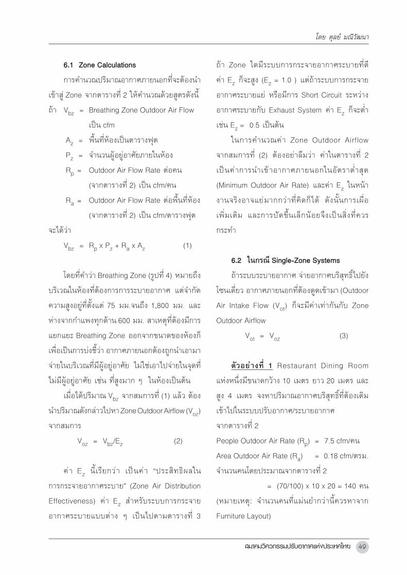
6.1ZoneCalculations
การค�านวณปรมาณอากาศภายนอกทจะตองน�า
เขาส Zone จากตารางท 2 ใหค�านวณดวยสตรดงน
ถา Vbz = Breathing Zone Outdoor Air Flow
เปน cfm
Az = พนทหองเปนตารางฟต
Pz = จ�านวนผอยอาศยภายในหอง
Rp = Outdoor Air Flow Rate ตอคน
(จากตารางท 2) เปน cfm/คน
Ra = Outdoor Air Flow Rate ตอพนทหอง
(จากตารางท 2) เปน cfm/ตารางฟต
จะไดวา
Vbz = Rp x Pz + Ra x Az (1)
โดยทค�าวา Breathing Zone (รปท 4) หมายถง
บรเวณในหองทตองการการระบายอากาศ แตจ�ากด
ความสงอยทตงแต 75 มม.จนถง 1,800 มม. และ
หางจากก�าแพงทกดาน 600 มม. สาเหตทตองมการ
แยกแยะ Breathing Zone ออกจากขนาดของหองก
เพอเปนการบงชวา อากาศภายนอกตองถกน�าเอามา
จายในบรเวณทมผอยอาศย ไมใชเอาไปจายในจดท
ไมมผอยอาศย เชน ทสงมาก ๆ ในหองเปนตน
เมอไดปรมาณ Vbz จากสมการท (1) แลว ตอง
น�าปรมาณดงกลาวไปหา Zone Outdoor Airflow (Voz)
จากสมการ
Voz = Vbz/Ez (2)
คา Ez นเรยกวา เปนคา “ประสทธผลใน
การกระจายอากาศระบาย” (Zone Air Distribution
Effectiveness) คา Ez ส�าหรบระบบการกระจาย
อากาศระบายแบบตาง ๆ เปนไปตามตารางท 3
ถา Zone ใดมระบบการกระจายอากาศระบายทด
คา Ez กจะสง (Ez = 1.0 ) แตถาระบบการกระจาย
อากาศระบายแย หรอมการ Short Circuit ระหวาง
อากาศระบายกบ Exhaust System คา Ez กจะต�า
เชน Ez = 0.5 เปนตน
ในการค�านวณคา Zone Outdoor Airflow
จากสมการท (2) ตองอยาลมวา คาในตารางท 2
เปนคาการน�าเขาอากาศภายนอกในอตราต�าสด
(Minimum Outdoor Air Rate) และคา Ez ในหนา
งานจรงอาจแยมากกวาทคดกได ดงนนการเผอ
เพมเตม และการปดขนเลกนอยจงเปนสงทควร
กระท�า
6.2ในกรณSingle-ZoneSystems
ถาระบบระบายอากาศ จายอากาศบรสทธไปยง
โซนเดยว อากาศภายนอกทตองดดเขามา (Outdoor
Air Intake Flow (Vot) กจะมคาเทากนกบ Zone
Outdoor Airflow
Vot = Voz (3)
ตวอยางท 1 Restaurant Dining Room
แหงหนงมขนาดกวาง 10 เมตร ยาว 20 เมตร และ
สง 4 เมตร จงหาปรมาณอากาศบรสทธทตองเตม
เขาไปในระบบปรบอากาศ/ระบายอากาศ
จากตารางท 2
People Outdoor Air Rate (Rp) = 7.5 cfm/คน
Area Outdoor Air Rate (Ra) = 0.18 cfm/ตรม.
จ�านวนคนโดยประมาณจากตารางท 2
= (70/100) x 10 x 20 = 140 คน
(หมายเหต: จ�านวนคนทแมนย�ากวานควรหาจาก
Furniture Layout)
โดย ตลย มณวฒนา

º·¤ÇÒÁÇÔªÒ¡Òà ªØ´·Õè 2050
จากสมการท (1) จะไดวา Breathing Zone
Outdoor Air Flow (Vbz) จะมคาเทากบ
Vbz = 7.5 x140 + 0.18 x 10 x 20 x 10.76
= 1,050 + 388
= 1,438 cfm.
ขนตอนถดไป คอ การหา Zone Outdoor
Airflow (Voz) จาก
Voz = Vbz/ Ez
เนองจากโจทยไมไดบอกรายละเอยดมาวาระบบ
การกระจายอากาศระบายเปนอยางไร เราจะสมมตวา
ระบบดงกลาวมประสทธผลดปานกลางคอ Ez มคา
ประมาณ 0.8 (ในกรณททราบวาระบบการกระจาย
อากาศระบายมรายละเอยดอยางไร ใหดตารางท 3
เพอพจารณาก�าหนดคา Ez ทเหมาะสม)
Voz = 1,438/0.8
= 1,798 cfm
ในโจทยข อน ใหสงเกตอยางหนงด วยคอ
ในตารางท 2 Air Class ของพนทนคอ 2 ซงแปลวา
อากาศท Return ออกจากหองนสามารถน�ามา
Recirculate ได ไมจ�าเปนตอง Exhaust ออกทงไป
แตถาในตารางท 2 Air Class มคาเปน 4 อากาศ
ท Return ออกจากหองนจะไมสามารถน�ามา
Recirculate ได ตอง Exhaust ออกทงไปเลย
6.3ในกรณ100%OutdoorAirSystems
ในกรณนเนองจากเปนอากาศบรสทธทงหมด
ดงนน
Vot = ∑all zones Voz (4)
6.4 ในกรณMultiple-ZoneRecirculating
Systems
ถาระบบระบายอากาศ จายอากาศบรสทธไป
ยงโซนหลายๆ โซนพรอมๆ กนคา Outdoor Air
Intake (Vot) จะตองมการค�านวณเพมเตมดงน
Vot = Vou/Ev (5)
การคำานวณปรมาณการระบายอากาศตามมาตรฐาน ASHRAE 62.1
รปท 4: Breathing Zone (ทมา: ASHRAE Standard 62.1 User Manual)
คา Ez นเรยกวา เปนคา “ประสทธผลในการกระจายอากาศระบาย” (Zone Air Distribution
Effectiveness) คา Ez สาหรบระบบการกระจายอากาศระบายแบบตาง ๆ เปนไปตามตารางท 3 ถา Zone ใดม
ระบบการกระจายอากาศระบายทด คา Ez กจะสง (Ez = 1.0 ) แตถาระบบการกระจายอากาศระบายแย หรอมการ
Short Circuit ระหวางอากาศระบายกบ Exhaust System คา Ez กจะตาเชน Ez = 0.5 เปนตน
ในการคานวณคา Zone Outdoor Airflow จากสมการท (2) ตองอยาลมวา คาในตารางท 2 เปนคาการ
นาเขาอากาศภายนอกในอตราตาสด (Minimum Outdoor Air Rate) และคา Ez ในหนางานจรงอาจแยมากกวาท
คดกได ดงนนการเผอเพมเตม และการปดขนเลกนอยจงเปนสงทควรกระทา
รปท 4: Breathing Zone (ทมา: ASHRAE Standard 62.1 User Manual)
6.2 ในกรณ Single-Zone Systems
ถาระบบระบายอากาศ จายอากาศบรสทธไปยงโซนเดยว อากาศภายนอกทตองดดเขามา (Outdoor Air
Intake Flow (Vot) กจะมคาเทากนกบ Zone Outdoor Airflow
Vot = Voz (3)
ตวอยางท 1 Restaurant Dining Room แหงหนงมขนาดกวาง 30 เมตร ยาว 60 เมตร และสง 4 เมตร
จงหาปรมาณอากาศบรสทธทตองเตมเขาไปในระบบปรบอากาศ/ระบายอากาศ
จากตารางท 2 People Outdoor Air Rate (Rp) = 7.5 cfm/คน
Area Outdoor Air Rate (Ra) = 0.18 cfm/ตรม.
จานวนคนโดยประมาณจากตารางท 2 = (70/100) x 30 x 60 = 1,260 คน
(หมายเหต: จานวนคนทแมนยากวานควรหาจาก Furniture Layout)

ÊÁÒ¤ÁÇÔÈÇ¡ÃÃÁ»ÃѺÍÒ¡ÒÈáË‹§»ÃÐà·Èä·Â 51
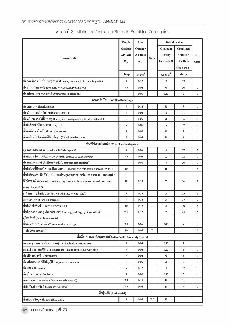
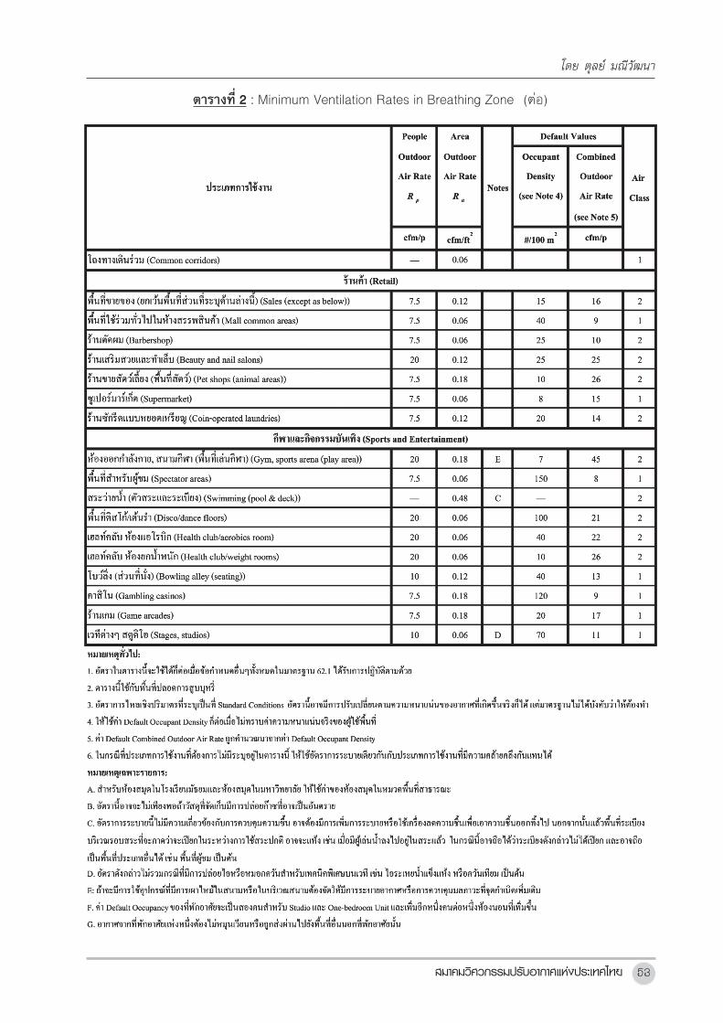
ตารางท2 : Minimum Ventilation Rates in Breathing Zone (ทมา: ASHRAE Standard 62.1-2013)
โดย ตลย มณวฒนา
บทความวชาการ ชดท 2052
ตารางท2 : Minimum Ventilation Rates in Breathing Zone (ตอ)
การคำานวณปรมาณการระบายอากาศตามมาตรฐาน ASHRAE 62.1
สมาคมวศวกรรมปรบอากาศแหงประเทศไทย 53
ตารางท2 : Minimum Ventilation Rates in Breathing Zone (ตอ)
โดย ตลย มณวฒนา
บทความวชาการ ชดท 2054
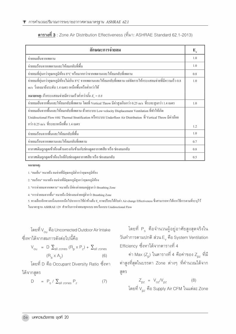
ตารางท3 : Zone Air Distribution Effectiveness (ทมา: ASHRAE Standard 62.1-2013)
ตารางท 3: Zone Air Distribution Effectiveness (ทมา: ASHRAE Standard 62.1-2013)
ลกษณะการจายลม Ez
จายลมเยนจากเพดาน 1.0
จายลมรอนจากเพดานและใหลมกลบทพน 1.0
จายลมทอนกวาอณหภมหอง 8°C หรอมากกวาจากเพดานและใหลมกลบทเพดาน 0.8
จายลมทอนกวาอณหภมหองไมเกน 8°C จากเพดานและใหลมกลบทเพดาน แตจดการใหกระแสลมจายทมความเรว 0.8
m/s วงลงมาถงระดบ 1.4 เมตร เหนอพนหรอตากวาได
1.0
หมายเหต: ถากระแสลมจายมความเรวตากวานน Ez = 0.8
จายลมเยนจากพนและใหลมกลบทเพดาน โดยท Vertical Throw มคาสงเกนกวา 0.25 m/s ทระยะสงกวา 1.4 เมตร 1.0
จายลมเยนจากพนและใหลมกลบทเพดาน ดวยระบบ Low-velocity Displacement Ventilation ททาใหเกด
Unidirectional Flow และ Thermal Stratification หรอระบบ Underfloor Air Distribution ท Vertical Throw มคานอย
กวา 0.25 m/s ทระยะเหนอพน 1.4 เมตร 1.2
จายลมรอนจากพนและใหลมกลบทพน 1.0
จายลมรอนจากเพดานและใหลมกลบทเพดาน 0.7
อากาศเตมถกดดเขาหองดานตรงกนขามกบชองดดอากาศเสย หรอ ชองลมกลบ 0.8
อากาศเตมถกดดเขาหองใกลกบชองดดอากาศเสย หรอ ชองลมกลบ 0.5
หมายเหต:
1. "ลมเยน" หมายถง ลมจายทมอณหภมตากวาอณหภมหอง
2. "ลมรอน" หมายถง ลมจายทมอณหภมสงกวาอณหภมหอง
3. "การจายลมจากเพดาน" หมายถง มชองจายลมอยสงกวา Breathing Zone
4. "การจายลมจากพน" หมายถง มชองลมจายอยต ากวา Breathing Zone
5. ทางเลอกอกทางหนงนอกเหนอไปจากการใชคาขางตน Ez อาจเปรยบไดกบคา Air-change Effectiveness ซงสามารถหาไดจากวธการตามทระบไว
ในมาตรฐาน ASHRAE 129 สาหรบการจายลมทกแบบ ยกเวนแบบ Unidirectional Flow
โดยท Vou คอ Uncorrected Outdoor Air Intake ซงหาไดจากสมการดงตอไปนคอ
Vou = D Σall zones (Rp x Pz) + Σall zones (Ra x Az) (6)
โดยท D คอ Occupant Diversity Ratio ซงหาไดจากสตร
D = Ps/ Σall zones Pz (7)
โดยท Ps คอจานวนผอยอาศยสงสดจรงในวนทาการตามปกต สวน Ev คอ System Ventilation Efficiency
ซงหาไดจากตารางท 4
คา Max (Zp) ในตารางท 4 คอคาของ Zpz ทมคาสงทสดในบรรดา Zone ตาง ๆ ทคานวณไดจากสตร
Zpz = Voz/Vpz (8)
โดยท Vpz คอ Supply Air CFM ในแตละ Zone
โดยท Vou คอ Uncorrected Outdoor Air Intake
ซงหาไดจากสมการดงตอไปนคอ
Vou = D ∑all zones (Rp x Pz) + ∑all zones
(Ra x Az) (6)
โดยท D คอ Occupant Diversity Ratio ซงหา
ไดจากสตร
D = Ps / ∑all zones Pz (7)
โดยท Ps คอจ�านวนผอย อาศยสงสดจรงใน
วนท�าการตามปกต สวน Ev คอ System Ventilation
Efficiency ซงหาไดจากตารางท 4
คา Max (Zp) ในตารางท 4 คอคาของ Zpz ทม
คาสงทสดในบรรดา Zone ตางๆ ทค�านวณไดจาก
สตร
Zpz = Voz/Vpz (8)
โดยท Vpz คอ Supply Air CFM ในแตละ Zone
การคำานวณปรมาณการระบายอากาศตามมาตรฐาน ASHRAE 62.1
สมาคมวศวกรรมปรบอากาศแหงประเทศไทย 55
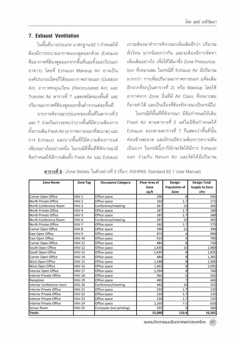
ตวอยางท 2 อาคารส�านกงานแหงหนงม
Typical Floor Plan ดงแสดงในรปท 5 ระบบ
ปรบอากาศในแตละชนเปน VAV ม AHU อยหนงตว
ซงไดรบ Pre-conditioned Outdoor Air จาก
OAU ซงตงอยบนชนดาดฟา (OAU ดงกลาวจาย
Pre-conditioned Outdoor Air ใหแก AHU ในทกชน)
รปท 5 ทางดานขวามอแสดง VAV Zoning ของชน
โดยในแตละโซนมการตดตงกลอง VAV แบบ
Fan-powered ในทกโซน คาประสทธผลในการ
กระจายอากาศระบาย (Ez) ส�าหรบทก Zone จะ
ก�าหนดใหเทากบ 1.0 Zone Details แสดงอยใน
ตารางท 5 โดยจ�านวนคน (Design Occupancy) หา
ไดจาก Furniture Layout และมการใชคา Design
Occupancy เทากบ 1.7 ส�าหรบ Private Office ดวย
(ทมาของคา Design Occupancy ส�าหรบ Private
Office นจะแสดงอยในตวอยางท 5) คา Design
Total Supply Air to Zone ไดมาจากรายการ Cooling
Load Calculations ของวศวกร จ�านวนคนจรงท
แนนอน (ทไมไดหาจาก Furniture Plan) จะมอยรวม
ทงสน 73 คน จงหาวา Designed Outdoor
Requirement ของ AHU ในชนนวาจะมคาเทาไหร
ถาใชคา System Ventilation Efficiency ในตาราง
ท 4 ในการค�านวณ
เนองจากโจทย ในตวอยางท 2 นเปนกรณ
Multiple-Zone System เราจงตองใชสมการท (5)
ถง (8) ในการค�านวณหาคา Vot ดงน
เนองจาก Ps มคาเทากบ 73 และ ∑all zones Pz
มคาเทากบ 150.4 ดงนนจากสมการท (7)
D = 73/150.4
= 0.485
ท�าการค�านวณหา Vou จากสมการ (6) จะได
Vou = 0.485 x 752 + 905
= 1,270 cfm
โดยทคา ∑all zones (Rp x Pz) และ ∑all zones
(Rq x Az) แสดงอยในตารางท 6
คา Max Zp ตามสมการท (8) แสดงอยในตาราง
ท 6 เชนกน และ Max (Zp) = 0.34 เกดขนท Zone
VAV-20
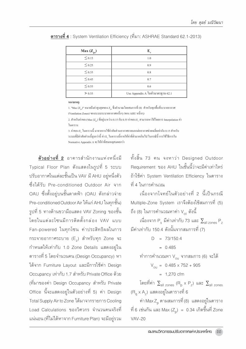
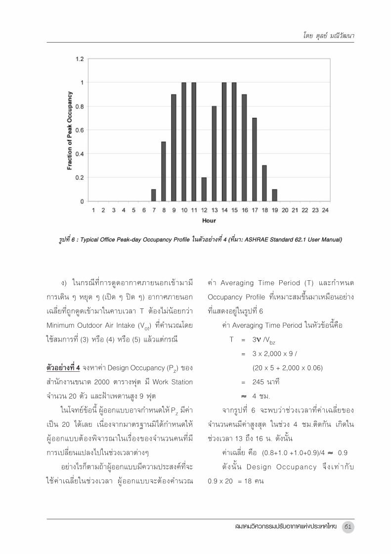
ตารางท4 : System Ventilation Efficiency (ทมา: ASHRAE Standard 62.1-2013)
ตารางท 4: System Ventilation Efficiency (ทมา: ASHRAE Standard 62.1-2013)
Max (Zpz) Ev
≤ 0.15 1.0
≤ 0.25 0.9
≤ 0.35 0.8
≤ 0.45 0.7
≤ 0.55 0.6
> 0.55 Use Appendix A ในตวมาตรฐาน 62.1
หมายเหต:
1. "Max (Zpz)" หมายถงคาสงสดของ Zpz ซงคานวณโดยสมการท (8) สาหรบทกพนทระบายอากาศ
(Ventilation Zones) ของระบบระบายอากาศหนงๆ (ของ AHU หนงๆ)
2. สาหรบคาของ Max (Zpz) ทอยระหวาง 0.15 กบ 0.55 คาของ Ev สามารถหาไดโดยการ Interpolation คา
ในตาราง
3. คาของ Ev ในตารางน มาจากการใชคาสดสวนอากาศภายนอกตออากาศจายเฉลยเทากบ 0.15 สาหรบ
ระบบทมคาสดสวนนสงกวาน คา Ev ในตารางนอาจใหคาทต ามากเกนไป ในกรณน การใชวธการใน
Normative Appendix A จะใหคาทสมเหตสมผลกวา
ตวอยางท 2 อาคารสานกงานแหงหนงม Typical Floor Plan ดงแสดงในรปท 5 ระบบปรบอากาศ
ในแตละชนเปน VAV ม AHU อยหนงตวซงไดรบ Pre-conditioned Outdoor Air จาก OAU ซงตงอยบนชน
ดาดฟา (OAU ดงกลาวจาย Pre-conditioned Outdoor Air ใหแก AHU ในทกชน) รปท 5 ทางดานขวามอแสดง
VAV Zoning ของชน โดยในแตละโซนมการตดตงกลอง VAV แบบ Fan-powered ในทกโซน คาประสทธผล
ในการกระจายอากาศระบาย (Ez) สาหรบทก Zone จะกาหนดใหเทากบ 1.0 Zone Details แสดงอยในตารางท 5
โดยจานวนคน (Design Occupancy) หาไดจาก Furniture Layout และมการใชคา Design Occupancy เทากบ 1.7
สาหรบ Private Office ดวย (ทมาของคา Design Occupancy สาหรบ Private Office นจะแสดงอยในตวอยางท
5) คา Design Total Supply Air to Zone ไดมาจากรายการ Cooling Load Calculations ของวศวกร จานวนคน
จรงทแนนอน (ทไมไดหาจาก Furniture Plan) จะมอยรวมทงสน 73 คน จงหาวา Designed Outdoor
Requirement ของ AHU ในชนนวาจะมคาเทาไหร ถาใชคา System Ventilation Efficiency ในตารางท 4 ในการ
คานวณ
เนองจากโจทยในตวอยางท 2 นเปนกรณ Multiple-Zone System เราจงตองใชสมการท (5) ถง (8) ใน
การคานวณหาคา Vot ดงน
เนองจาก Ps มคาเทากบ 73 และ Σall zones Pz มคาเทากบ 150.4 ดงนนจากสมการท (7)
D = 73/150.4
= 0.485
โดย ตลย มณวฒนา

บทความวชาการ ชดท 2056
จากตารางท 4 จะไดวา System Ventilation
Efficiency (Ev) จะมคาเทากบ 0.81 (โดยการ
Interpolation คาในตารางท 4)
ดงนนจากสมการท (5)
Vot = Vou/Ev
= 1,270/0.81
= 1,568 cfm
การค�านวณในกรณ Multiple-Zone นปกตเรา
จะไมไดท�าดวยมอ ผ อ านสามารถดาวน โหลด
Spread Sheet ของ USGBC LEED 62MZCalc.xls
มาชวยในการค�านวณได นอกจากนนแลวคา System
Ventilation Efficiency (Ev) ในตารางท 4 อาจให
คาไมถกตองอกดวย เนองจากคาดงกลาวมาจาก
สมมตฐานทวาอตราสวนระหวางอากาศภายนอกกบ
ลมจาย (Supply Air) มคาอยท 15% ถาอตราสวน
ดงกลาวไมเปนไปตามสมมตฐานขางตน คา Ev กอาจ
จะผดไปได ในตวอยางท 2 นถาใช Spread Sheet
ของ USGBC มาชวยในการค�านวณจะพบวาคาของ
Ev จะมคาอยเพยง 0.75 และจะท�าใหเราไดคาปรมาณ
อากาศระบายเพมขนเปน 1,693 cfm
กอนจะจบในหวขอน ขอย�าอกครงวาปรมาณ
อากาศบรสทธจากภายนอกตามตารางท 2 นนเปน
คาต�าทสดทมาตรฐานอนญาต USGBC (US Green
Building Council) ซงเปนหนวยงานทใหการรบรอง
เรอง LEED สนบสนนการเพมอตราการระบายขนอก
30% จากคาขนต�าตามมาตรฐานน โดยการให
Credit เพมในหวขอ Indoor Environmental
Quality ขอควรระวงในขอนคอ ส�าหรบระบบ VAV
แลว การเพม 30% ท AHU อาจจะไมใช 30% ใน
Breathing Zone และถาจะใหได 30% ใน Breathing
Zone อาจตองเพมปรมาณท AHU ขนถง 50% ก
เปนไปได
รปท 5: Typical Floor Plan ของอาคารส�านกงานในตวอยางท 2 (ทมา: ASHRAE Standard 62.1 User Manual)
การคำานวณปรมาณการระบายอากาศตามมาตรฐาน ASHRAE 62.1
สมาคมวศวกรรมปรบอากาศแหงประเทศไทย 57
7.ExhaustVentilation ในพนทบางประเภท มาตรฐาน 62.1 ก�าหนดให
ตองมการระบายอากาศแบบดดออกดวย (Exhaust
คออากาศทตองดดออกจากพนทและทงออกไปนอก
อาคาร) โดยท Exhaust Makeup Air อาจเปน
องคประกอบใดๆกไดของอากาศภายนอก (Outdoor
Air) อากาศหมนเวยน (Recirculated Air) และ
Transfer Air ตารางท 7 แสดงชนดของพนท และ
ปรมาณอากาศทตองดดออกขนต�าจากแตละพนท
จากการพจารณาประเภทของพนทในตารางท 2
และ 7 รวมกนเราจะพบวาบางพนทมความตองการ
ทงการเตม Fresh Air (อากาศภายนอกทสะอาด) และ
การ Exhaust และบางพนทกมความตองการแต
เพยงอยางใดอยางหนง ในกรณทพนททพจารณาม
ขอก�าหนดใหมการเตมทง Fresh Air และ Exhaust
เราจะตองมาท�าการพจารณาเพมเตมอกวา ปรมาณ
ฝงไหน มากนอยกวากน และจะตองมการจดหา
เพมเตมอยางไร เพอใหไดมาซง Zone Pressuriza-
tion ทเหมาะสม ในกรณท Exhaust Air มปรมาณ
มากกวา การเพมปรมาณอากาศภายนอก (เพมเตม
อกจากทระบในตารางท 2) หรอ Makeup โดยใช
อากาศจาก Zone อนทม Air Class ทเหมาะสม
กอาจท�าได และเปนเรองทตองพจารณาเปนกรณไป
ในกรณทพนททพจารณา มขอก�าหนดใหเตม
Fresh Air ตามตารางท 2 แตไมมขอก�าหนดให
Exhaust ออกตามตารางท 7 กแสดงวาพนทนน
คอนขางสะอาด และมกจะมความตองการความดน
เปนบวก ในกรณนเรากมกจะจดใหมการ Exhaust
ออก รวมกบ Return Air และจดใหมปรมาณ
ตารางท5 : Zone Details ในตวอยางท 2 (ทมา: ASHRAE Standard 62.1 User Manual)
โดย ตลย มณวฒนา

บทความวชาการ ชดท 2058
General Exhaust ประมาณ 90% ของปรมาณ
Fresh Air ทเตมเขาสพนท
ในกรณทพนททพจารณา มข อก�าหนดให
Exhaust อยางเดยวตามตารางท 7 แตไมมขอก�าหนด
ใหเตม Fresh Air ตามตารางท 2 กแสดงวา พนทนน
คอนขางสกปรก และมกจะมความตองการความดน
เปนลบ ในกรณนเรากมกจะจดใหมการเตมอากาศ
เขาไปชดเชยในปรมาณประมาณ 90% ของปรมาณ
Exhaust Air ทถกดดออกจากพนท อากาศทเตม
เขาไปชดเชยน อาจเปนอากาศภายนอกทสะอาดหรอ
อากาศจาก Zone อนกได แตตองม Air Class ท
เหมาะสม
ตวอยางท3 ในหอง Art Class Room ขนาด
กวาง 10 เมตร ยาว 12 เมตร และมผใชหองจ�านวน
30 คน จงหาวาจะตองจดใหมการระบายอากาศ
อยางไรในปรมาณเทาใดบาง
จากตารางท 2 และ 7 จะพบวา Art Class Room
ตองมทงการดดอากาศเสยออกทงไป และเตมอากาศ
บรสทธเขามาในบรเวณทปรบอากาศดวย
จากตารางท 7 ปรมาณอากาศเสยทตองดดออก
ทงไป (VEX) จะค�านวณไดดงนคอ
VEX = 0.7 x 10 x 12 x 10.76
= 904 cfm
จากตารางท 2 ปรมาณอากาศบรสทธทตองน�า
เขาคอ (สมมตให Ez = 1.0)
VOZ = 30 x 10 + 0.18 x 10 x 12 x 10.76
= 300 + 232.4
= 533 cfm
ตารางท6 : รายการค�านวณในตวอยางท 2
การคำานวณปรมาณการระบายอากาศตามมาตรฐาน ASHRAE 62.1

สมาคมวศวกรรมปรบอากาศแหงประเทศไทย 59
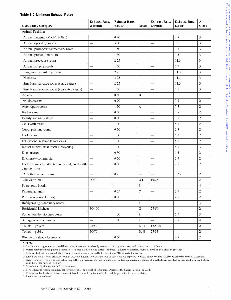
ตารางท 7: Minimum Exhaust Rates (ทมา: ASHRAE Standard 62.1-2013)
ประเภทการใชงาน Exhaust Rate Exhaust Rate หมายเหต Air
cfm/unit cfm/ft2 Class
สนามกฬา (Arenas) — 0.50 B 1
หองเรยนศลปะ (Art classrooms) — 0.70 2
อซอมรถยนต (Auto repair rooms) — 1.50 A 2
รานตดผม (Barber shops) — 0.50 2
รานเสรมสวยและทาเลบ (Beauty and nail salons) — 0.60 2
หองคมขงนกโทษพรอมสวม (Cells with toilet) — 1.00 2
หองพมพเอกสารและถายสาเนา (Copy, printing rooms) — 0.50 2
หองลางฟลม (Darkrooms) — 1.00 2
หองปฏบตการทางวทยาศาสตรในสถานศกษา (Educational science
laboratories)
— 1.00 2
หองเกบอปกรณทาความสะอาด หองขยะ หองรไซเคล (Janitor closets,
trash rooms, recycling)
— 1.00 3
หองครวเลกๆ (Kitchenettes) — 0.30 2
หองครวเชงพาณชย (Kitchens-commercial) — 0.70 2
หองแตงตว/เกบของ (Locker/dressing rooms) — 0.25 2
หองตลอกเกอร (Locker rooms) — 0.50 2
บธสเปรยส (Paint spray booths) — — F 4
โรงจอดรถ (Parking garages) — 0.75 C 2
รานขายสตวเลยง (พนทสตว) (Pet shops (animal areas)) — 0.90 2
หองเครองทาความเยน (Refrigerating machinery rooms) — — F 3
หองครวในทพกอาศย (Residential kitchens) 50/100 — G 2
หองเกบผาสกปรก (Soiled laundry storage rooms) — 1.00 F 3
หองเกบสารเคม (Storage rooms, chemical) — 1.50 F 4
หองนาสวนตว (Toilets—private) 25/50 — E, H 2
หองนาสาธารณะ (Toilets—public) 50/70 — D, H 2
หองชาง/หองเรยน-งานไม (Woodwork shop/classrooms) — 0.50 2
หมายเหต:
A: ตรงตาแหนงทเครองยนตมการเดนเครองตองมระบบดดไอเสยทเชอมตอโดยตรงเขากบทอไอเสยและมการปองกนการเลดลอดของควนไอเสย
B: ถามการใชอปกรณทมการเผาไหมในสนามตองจดใหมการระบายอากาศหรอการควบคมมลภาวะทจดกาเนดเพมเตม
C: ไมจาเปนตองดดอากาศออกทงถามผนงอยางนอยสองดานหรอมากกวาทมชองเปดโลงเกนกวา 50 % ของพนทผนงแตละดาน
D: อตรานเปนอตราตอสวมหรอตอโถปสสาวะ ใชอตราอนสงในสภาวะทคาดวาจะมการใชงานหนก เชน หองสขาในโรงภาพยนตร โรงเรยน และสถานท
เลนกฬา นอกนนแลวใชอตราอนตาได
E: อตรานเปนอตราสาหรบหองน าสวนตวทเขาใชทละคน สาหรบระบบททางานอยางตอเนองในชวงเวลาการใชงานปกต ใหใชอตราทตากวาทระบได
มฉะนนใหใชอตราทสงขน
F: ดมาตรฐานบงคบอนๆ ทเกยวของ
G: สาหรบระบบทมการทางานตอเนองใหใชอตราอนตา มฉะนนแลวใหใชอตราอนสง
H: อากาศเสยทผานกระบวนการความสะอาดจนไดตามเกณฑของ Air Class I แลว สามารถนาไปใชหมนเวยนได (Return กลบไป AHU ได)
ตารางท7 : Minimum Exhaust Rates (ทมา: ASHRAE Standard 62.1-2013)
โดย ตลย มณวฒนา
บทความวชาการ ชดท 2060
จากผลการค�านวณดงกลาวขางตนจะพบวา
ปรมาณ Exhaust ทตองดดออกมมากกวาความ
ตองการน�าเขาอากาศบรสทธอย 904 - 533 = 371
cfm ปรมาณอากาศชดเชย (Makeup Air) ทขาดอย
อก 371 cfm น ท�าให เราตองน�าเข าอากาศ
บรสทธ (หรอใชอากาศอนกไดทเปนไปตามกตกา
ของ Recirculation Restrictions for Classified Air)
อกประมาณ 371 cfm เขามาชดเชยเพมเตม
ถาเราตองการใหความดนในหองนเปนลบ
เลกนอย วธการงาย ๆ (เบองตน) คอ น�าอากาศเขา
มาชดเชยใหนอยกวา 371 cfm
สมมตวา เราตองการให Exhaust ทงหมด
มากกวา Fresh Air ประมาณ 10% ดงนน Fresh Air
รวมควรเทากบ 0.9 x 904 = 814 ดงนน VOZ ควร
ตองปรบเพมจากคา Minimum 533 cfm ใหเปน
ประมาณ 814 cfm
8.การออกแบบเพอรองรบVariableLoad Conditions Variable Load Conditions ในทนหมายถง
การทภาระความรอน หรอความเยน เปลยนไป หรอ
จ�านวนคนมการเปลยนแปลงไป ระบบระบายอากาศ
จะตองไดรบการออกแบบใหสามารถสง Fresh Air
เขาไปยง Breathing Zone ไดเสมอ ในปรมาณ
อยางนอยตามทค�านวณไดจากตารางท 2 ไมวา Load
Condit ions จะเปลยนแปลงไปอยางไรกตาม
(มากกวาไมเปนไร)
เรองนมประเดนมาจากเรองของระบบ VAV ซง
มการหรลมทจายเขาส Breathing Zone ตาม Load
ทมการเปลยนแปลงไป มาตรฐานจงก�าหนดไววา ใน
การค�านวณจะตองศกษาวา Outdoor Air ทสงเขาส
Breathing Zone มการเปลยนแปลงอยางไร ภายใต
สภาวะ Load ตาง ๆ และผออกแบบจะตองท�าใหระบบ
มความสามารถทจะสง Outdoor Air เขาส Breathing
Zone ไดเสมอ ตามมาตรฐานน ในทกสภาวะ Load
9.Short-TermConditions Short-Term Conditions ตาง ๆ มผลตอการ
ค�านวณปรมาณอากาศระบาย เพราะจะมผลกบ
จ�านวนคนทใชในการค�านวณ อาทเชน ในหองของ
ผบรหาร โดยปกตจะมผอยอาศยประจ�าเพยงคนเดยว
แตกมกจะมผอน (แขก) แวะเขามา เพอปรกษาหารอ
อยเรอย ๆ เปนระยะ บางทกมาเพยงคนเดยว บางท
กมาสองคนเปนตน และอาจใชเวลาอยไมนานกกลบ
ออกไป ดงนนจงเกดปญหากบตวเลขทใชในการ
ออกแบบจ�านวนคน (Design Occupancy) ขนวาจะ
ใหตวเลขเปน หนง หรอ สอง หรอสามคนดในหอง
ดงกลาว
มาตรฐานไดก�าหนดวธการ จดการกบกรณ
Short-Term Conditions ตางๆ ไวดงนคอ
ก) ใหหาคา Averaging Time Period จาก
สตร
T = 3ν /Vbz (9)
โดย ν = Space Volume เปนลกบาศกฟต
Vbz = Breathing Zone Outdoor Air
Rate เปน cfm
T = Average Time Period เปนนาท
ข) ในกรณจ�านวนคนไมแนนอน มาตรฐาน
ก�าหนดใหหาคาเฉลยของจ�านวนคนในชวงคาบเวลา
T และก�าหนดใหคาเฉลยดงกลาวมคาเปนคา Design
Occupancy เพอน�าไปใชค�านวณปรมาณอากาศ
ระบายตามตารางท 2 ไดเลย
ค) ในกรณทอากาศจาย (Supply Air) มการ
เปดๆ ปด ๆ คาเฉลยของ Outdoor Air Flow ทจาย
เขามายง Breathing Zone ในชวงคาบเวลา T ตอง
ไมนอยกวาคา Vbz ทค�านวณไดจากสมการท (1)
การคำานวณปรมาณการระบายอากาศตามมาตรฐาน ASHRAE 62.1
ÊÁÒ¤ÁÇÔÈÇ¡ÃÃÁ»ÃѺÍÒ¡ÒÈáË‹§»ÃÐà·Èä·Â 61
ง) ในกรณทการดดอากาศภายนอกเขามาม
การเดน ๆ หยด ๆ (เปด ๆ ปด ๆ) อากาศภายนอก
เฉลยทถกดดเขามาในคาบเวลา T ตองไมนอยกวา
Minimum Outdoor Air Intake (Vot) ทค�านวณโดย
ใชสมการท (3) หรอ (4) หรอ (5) แลวแตกรณ
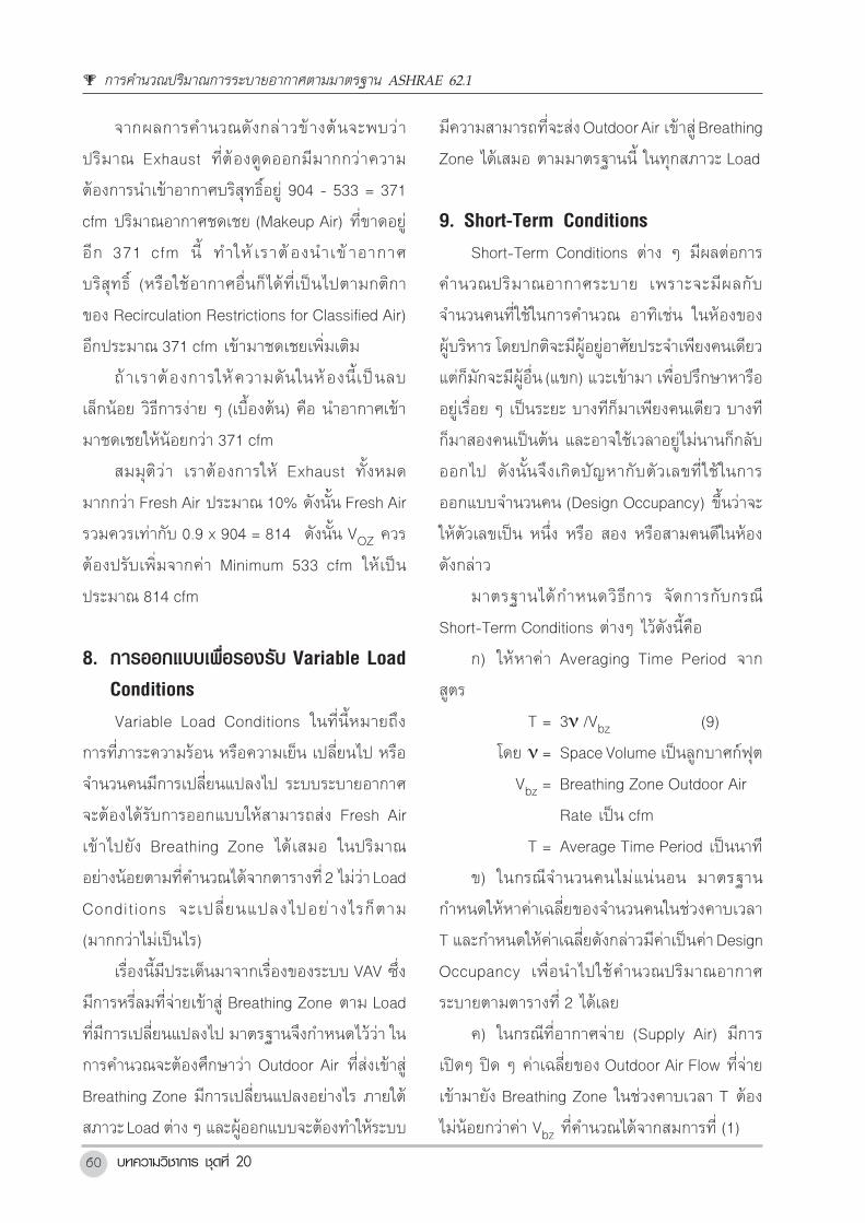
ตวอยางท4 จงหาคา Design Occupancy (Pz) ของ
ส�านกงานขนาด 2000 ตารางฟต ม Work Station
จ�านวน 20 ตว และฝาเพดานสง 9 ฟต
ในโจทยขอน ผออกแบบอาจก�าหนดให Pz มคา
เปน 20 ไดเลย เนองจากมาตรฐานมไดก�าหนดให
ผออกแบบตองพจารณาในเรองของจ�านวนคนทม
การเปลยนแปลงไปในชวงเวลาตางๆ
อยางไรกตามถาผออกแบบมความประสงคทจะ
ใชคาเฉลยในชวงเวลา ผออกแบบจะตองค�านวณ
รปท 6: Typical Office Peak-day Occupancy Profile ในตวอยางท 4 (ทมา: ASHRAE Standard 62.1 User Manual)
10. Demand Control Ventilation (DCV)
ในกรณทจานวนคนมการเปลยนแปลงไป มาตรฐานอนญาตใหปรมาณการระบายอากาศตามสมการท
(1) มการเปลยนแปลงไปตามจานวนคนได แตทงน Breathing Zone Outdoor Airflow (Abz) ตองมคาไมนอยไป
กวา Building Component (Ra x Az) ของ DCV Zone และตองไมลดลงจน Outdoor Air Intake มคานอยไปกวา
Exhaust Airflow เพอการรกษา Building Pressurization เอาไวใหเปนบวก
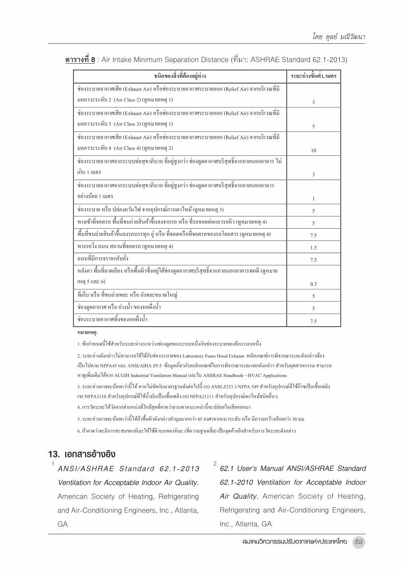
11. ระยะหางขนตา
ตาแหนงของหวลมดด (Fresh Air Grill) และหวลม Exhaust (Exhaust Air Grill) ตองไมใกลกน
จนเกนไปเพอปองกนอากาศเสยหลดรอดเขาไปยงชองลมดดอากาศบรสทธจากภายนอก มาตรฐาน 62.1 ได
กาหนดระยะหางขนตาไวดงแสดงในตารางท 8
12. เรองอน ๆ
มาตรฐานการระบายอากาศทออกมาใหมตงแตป ค.ศ. 2004 มการเพมเตมรายละเอยดวธการคานวณ
และอน ๆ อกมาก วศวกรผออกแบบระบบปรบอากาศจะคดถงระบบระบายอากาศแบบเมอ 10 ปกอนไมไดอก
ตอไป รายการคานวณของระบบระบายอากาศจะกลายเปนสงทมความสาคญมากขนกวาแตกอนมาก และสาคญ
ไมนอยไปกวารายการคานวณ Cooling Load Calculations
มาตรฐาน 62.1 ยงมรายละเอยดอนๆ ทสาคญอกมากมาย ทยงไมไดกลาวถงในบทความน อาทเชน เรอง
ของ
คา Averaging Time Period (T) และก�าหนด
Occupancy Profile ทเหมาะสมขนมาเหมอนอยาง
ทแสดงอยในรปท 6
คา Averaging Time Period ในหวขอนคอ
T = 3ν /Vbz
= 3 x 2,000 x 9 /
(20 x 5 + 2,000 x 0.06)
= 245 นาท
≈ 4 ชม.
จากรปท 6 จะพบวาชวงเวลาทคาเฉลยของ
จ�านวนคนมคาสงสด ในชวง 4 ชม.ตดกน เกดใน
ชวงเวลา 13 ถง 16 น. ดงนน
คาเฉลย คอ (0.8+1.0 +1.0+0.9)/4 ≈ 0.9
ดงนน Design Occupancy จงเท ากบ
0.9 x 20 = 18 คน
รปท 6 : Typical Office Peak-day Occupancy Profile ในตวอยางท 4 (ทมา: ASHRAE Standard 62.1 User Manual)
โดย ตลย มณวฒนา

บทความวชาการ ชดท 2062
ตวอยางท5 Private Office ขนาด 230 ตารางฟต
ฝาสง 9 ฟต โดยใน Furniture Plan ม Work Station
หนงท และมเกาอแขกสองตว จงค�านวณหา Design
Occupancy
คา Averaging Time Window คอ
T = 3ν /Vbz
= 3 x 230 x 9 /
(3 x 5 + 230 x 0.06)
= 215 นาท
≈ 3.6 ชม.
สมมตวาเกาอแขกทงสองตวมผมานงเปนเวลา
สนๆ ตวละ 1/3 ของชวงเวลา T ดงนน Design
Occupancy จะมคาเทากบ
1 + 2 x (1/3) = 1.7 คน
10.DemandControlVentilation(DCV) ในกรณ ทจ�านวนคนมการเปลยนแปลงไป
มาตรฐานอนญาตใหปรมาณการระบายอากาศตาม
สมการท (1) มการเปลยนแปลงไปตามจ�านวนคนได
แตทงน Breathing Zone Outdoor Airflow (Vbz)
ตองมคาไมนอยไปกวา Building Component
(Ra x Az) ของ DCV Zone และตองไมลดลงจน
Outdoor Air Intake มคานอยไปกวา Exhaust
Airflow เพอการรกษา Building Pressurization
เอาไวใหเปนบวก
11.ระยะหางขนต�า ต�าแหนงของหวลมดด (Fresh Air Grill) และ
หวลม Exhaust (Exhaust Air Grill) ตองไมใกลกน
จนเกนไปเพอปองกนอากาศเสยหลดรอดเขาไปยง
ชองลมดดอากาศบรสทธจากภายนอก มาตรฐาน
62.1 ไดก�าหนดระยะหางขนต�าไวดงแสดงในตาราง
ท 8
12.เรองอนๆ มาตรฐานการระบายอากาศทออกมาใหมตงแต
ป ค.ศ. 2004 มการเพมเตมรายละเอยดวธการ
ค�านวณ และอน ๆ อกมาก วศวกรผออกแบบระบบ
ปรบอากาศจะคดถงระบบระบายอากาศแบบเมอ
10 ปกอนไมไดอก ตอไป รายการค�านวณของระบบ
ระบายอากาศจะกลายเปนสงทมความส�าคญมากขน
กวาแตกอนมาก และส�าคญไมนอยไปกวารายการ
ค�านวณ Cooling Load Calculations
มาตรฐาน 62.1 ยงมรายละเอยดอนๆ ทส�าคญ
อกมากมาย ทยงไมไดกลาวถงในบทความน อาทเชน
เรองของ
• รายละเอยดของ System และ Equipment ท
เหมาะสมส�าหรบระบบระบายอากาศทด
• การค�านวณปรมาณอากาศระบายดวยวธอนๆ
อาทเชนวธ Indoor Air Quality และ Natural
Ventilation Procedure
• การกอสรางระบบทด และการ Start-up
• การใช งานและการบ�ารงรกษาระบบทด
เปนตน
ระบบระบายอากาศมผลกระทบทส�าคญทงใน
เรองของการใชพลงงานในอาคารและในเรองของ
Indoor Environmental Quality วศวกรผมหนาท
ออกแบบระบบระบายอากาศ จะต องมความ
รบผดชอบมาก และจะตองท�าการศกษาเรองตางๆ
ทงหมดอยางละเอยดลกซง จงจะสามารถ ออกแบบ
ระบบ ไดอยางสมบรณถกตอง เอกสารทควรจะตอง
ศกษา และตดตาม นอกจากตวเนอมาตรฐานเองแลว
คอ User Manual ของมาตรฐาน เทาทผเขยนทราบ
ทงตวมาตรฐาน และ User Manual กก�าลงจะม
ฉบบปรบปรงออกมาใหมในป 2016 น
การคำานวณปรมาณการระบายอากาศตามมาตรฐาน ASHRAE 62.1
สมาคมวศวกรรมปรบอากาศแหงประเทศไทย 63
ตารางท 8: Air Intake Minimum Separation Distance (ทมา: ASHRAE Standard 62.1-2013)
ชนดของสงทตองอยหาง ระยะหางขนตา, เมตร
ชองระบายอากาศเสย (Exhaust Air) หรอชองระบายอากาศระบายออก (Relief Air) จากบรเวณทม
มลภาวะระดบ 2 (Air Class 2) (ดหมายเหต 1) 3
ชองระบายอากาศเสย (Exhaust Air) หรอชองระบายอากาศระบายออก (Relief Air) จากบรเวณทม
มลภาวะระดบ 3 (Air Class 3) (ดหมายเหต 1) 5
ชองระบายอากาศเสย (Exhaust Air) หรอชองระบายอากาศระบายออก (Relief Air) จากบรเวณทม
มลภาวะระดบ 4 (Air Class 4) (ดหมายเหต 2) 10
ชองระบายอากาศจากระบบทอสขาภบาล ทอยสงกวา ชองดดอากาศบรสทธจากภายนอกอาคาร ไม
เกน 1 เมตร 3
ชองระบายอากาศจากระบบทอสขาภบาล ทอยสงกวา ชองดดอากาศบรสทธจากภายนอกอาคาร
อยางนอย 1 เมตร 1
ชองระบาย หรอ ปลองควนไฟ จากอปกรณการเผาไหม (ดหมายเหต 3) 5
ทางเขาทจอดรถ พนทขนถายสนคาขนลงจากรถ หรอ ทรถจอดตอแถวรอคว (ดหมายเหต 4) 5
พนทขนถายสนคาขนลงรถบรรทก อ หรอ ทจอดหรอทจอดรอของรถโดยสาร (ดหมายเหต 4) 7.5
ทางรถวง ถนน สถานทจอดรถ (ดหมายเหต 4) 1.5
ถนนทมการจราจรคบคง 7.5
หลงคา พนทลาดเอยง หรอพนผวซงอยใตชองดดอากาศบรสทธจากภายนอกอาคารพอด (ดหมาย
เหต 5 และ 6) 0.3
ทเกบ หรอ ทขนถายขยะ หรอ ถงขยะขนาดใหญ 5
ชองดดอากาศ หรอ อางนา ของหอผงนา 5
ชองระบายอากาศทงของหอผงนา 7.5
หมายเหต:
1. ขอกาหนดนใชสาหรบระยะหางระหวางชองดดของระบบหนงกบชองระบายของอกระบบหนง
2. ระยะหางดงกลาวไมสามารถใชใดกบชองระบายของ Laboratory Fume Hood Exhaust หลกเกณฑการพจารณาระยะดงกลาวตอง
เปนไปตาม NFPA45 และ ANSI/AIHA Z9.5 ขอมลเกยวกบหลกเกณฑในการพจารณาระยะแยกดงกลาว สาหรบอตสาหกรรม สามารถ
หาดเพมเตมไดจาก ACGIH Industrial Ventilation Manual และใน ASHRAE Handbook—HVAC Applications
3. ระยะหางอาจจะนอยกวานได หากไมขดกบมาตรฐานดงตอไปน (ก) ANSI Z233.1/NFPA 549 สาหรบอปกรณทใชกาซเปนเชอเพลง
(ข) NFPA3110 สาหรบอปกรณทใชน ามนเปนเชอเพลง (ค) NFPA21111 สาหรบอปกรณเผาไหมชนดอนๆ
4. การวดระยะใหวดจากตาแหนงทใกลสดทคาดวายานพาหนะเหลานจะปลอยไอเสยออกมา
5. ระยะหางอาจจะนอยกวานไดถาพนผวดงกลาวทามมมากกวา 45 องศาจากแนวระดบ หรอ มความกวางนอยกวา 30 มม.
6. ถาคาดวาจะมการสะสมของหมะใหใชผวบนของหมะ (ทความสงเฉลย) เปนจดอางองสาหรบการวดระยะดงกลาว
• รายละเอยดของ System และ Equipment ทเหมาะสมสาหรบระบบระบายอากาศทด
• การคานวณปรมาณอากาศระบายดวยวธอนๆ อาทเชนวธ Indoor Air Quality และ Natural
Ventilation Procedure
• การกอสรางระบบทด และการ Start-up
• การใชงานและการบารงรกษาระบบทด เปนตน
ตารางท8 : Air Intake Minimum Separation Distance (ทมา: ASHRAE Standard 62.1-2013)
13.เอกสารอางอง1 ANSI /ASHRAE Standard 62.1-2013
Ventilation for Acceptable Indoor Air Quality.
American Society of Heating, Refrigerating
and Air-Conditioning Engineers, Inc., Atlanta,
GA.
โดย ตลย มณวฒนา
2 62.1 User’s Manual ANSI/ASHRAE Standard
62.1-2010 Ventilation for Acceptable Indoor
Air Quality. American Society of Heating,
Refrigerating and Air-Conditioning Engineers,
Inc., Atlanta, GA.
ภาคผนวก ข
ASHRAE Standard 62.1-2019
Section 6: Procedures
ANSI/ASHRAE Standard 62.1-2019 15
5.19.7 Signage. A sign shall be posted outside each entrance to each ETS area. The sign shallstate, as a minimum, “This Area May Contain Environmental Tobacco Smoke” in letters at least1 in. (25 mm) high or otherwise in compliance with accessibility guidelines.
Exception to 5.19.7: Instead of the specified sign, equivalent notification means acceptableto the AHJ may be used.
Informative Note: Based on the definition of “ETS area,” such a sign might be posted out-side a larger ETS area that includes the area where smoking is permitted.
5.19.8 Reclassification. An area that was previously an ETS area but now meets the require-ments of an ETS-free area shall be permitted to be classified as such where smoke exposurehas stopped and odor and irritation from residual ETS contaminants are not apparent.
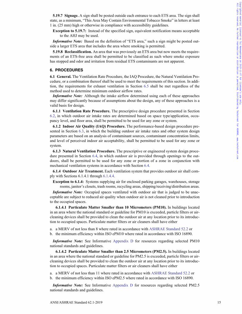
6. PROCEDURES
6.1 General. The Ventilation Rate Procedure, the IAQ Procedure, the Natural Ventilation Pro-cedure, or a combination thereof shall be used to meet the requirements of this section. In addi-tion, the requirements for exhaust ventilation in Section 6.5 shall be met regardless of themethod used to determine minimum outdoor airflow rates.
Informative Note: Although the intake airflow determined using each of these approachesmay differ significantly because of assumptions about the design, any of these approaches is avalid basis for design.
6.1.1 Ventilation Rate Procedure. The prescriptive design procedure presented in Section6.2, in which outdoor air intake rates are determined based on space type/application, occu-pancy level, and floor area, shall be permitted to be used for any zone or system.
6.1.2 Indoor Air Quality (IAQ) Procedure. The performance-based design procedure pre-sented in Section 6.3, in which the building outdoor air intake rates and other system designparameters are based on an analysis of contaminant sources, contaminant concentration limits,and level of perceived indoor air acceptability, shall be permitted to be used for any zone orsystem.
6.1.3 Natural Ventilation Procedure. The prescriptive or engineered system design proce-dure presented in Section 6.4, in which outdoor air is provided through openings to the out-doors, shall be permitted to be used for any zone or portion of a zone in conjunction withmechanical ventilation systems in accordance with Section 6.4.
6.1.4 Outdoor Air Treatment. Each ventilation system that provides outdoor air shall com-ply with Sections 6.1.4.1 through 6.1.4.4.
Exception to 6.1.4: Systems supplying air for enclosed parking garages, warehouses, storagerooms, janitor’s closets, trash rooms, recycling areas, shipping/receiving/distribution areas.
Informative Note: Occupied spaces ventilated with outdoor air that is judged to be unac-ceptable are subject to reduced air quality when outdoor air is not cleaned prior to introductionto the occupied spaces.
6.1.4.1 Particulate Matter Smaller than 10 Micrometers (PM10). In buildings locatedin an area where the national standard or guideline for PM10 is exceeded, particle filters or air-cleaning devices shall be provided to clean the outdoor air at any location prior to its introduc-tion to occupied spaces. Particulate matter filters or air cleaners shall have either
a. a MERV of not less than 8 where rated in accordance with ASHRAE Standard 52.2 orb. the minimum efficiency within ISO ePM10 where rated in accordance with ISO 16890.
Informative Note: See Informative Appendix D for resources regarding selected PM10national standards and guidelines.
6.1.4.2 Particulate Matter Smaller than 2.5 Micrometers (PM2.5). In buildings locatedin an area where the national standard or guideline for PM2.5 is exceeded, particle filters or air-cleaning devices shall be provided to clean the outdoor air at any location prior to its introduc-tion to occupied spaces. Particulate matter filters or air cleaners shall have either
a. a MERV of not less than 11 where rated in accordance with ASHRAE Standard 52.2 orb. the minimum efficiency within ISO ePM2.5 where rated in accordance with ISO 16890.
Informative Note: See Informative Appendix D for resources regarding selected PM2.5national standards and guidelines.
Copyrighted material licensed to Tul Manewattana on 2019-11-07 for licensee's use only. All rights reserved. No further reproduction or distribution is permitted. Distributed by Techstreet for ASHRAE, www.techstreet.com
Tul
Rectangle

16 ANSI/ASHRAE Standard 62.1-2019
6.1.4.3 Ozone. Air-cleaning devices for ozone shall be provided when the most recentthree-year average annual fourth-highest daily maximum eight-hour average ozone concentra-tion exceeds 0.100 ppm (195 μg/m3).
Such air-cleaning devices shall have a volumetric ozone removal efficiency of not less than40% where installed, operated, and maintained in accordance with manufacturer recommenda-tions and shall be approved by the authority having jurisdiction (AHJ). Such devices shall beoperated where the outdoor ozone levels are expected to exceed 0.100 ppm (195 μg/m3).
Exceptions to 6.1.4.3: Air cleaning for ozone shall not be required where1. the system design outdoor air intake flow is 1.5 ach or less,2. controls are provided that sense outdoor ozone level and reduce intake airflow to
1.5 ach or less while complying with the outdoor airflow requirements of Section 6, or3. outdoor air is brought into the building and heated by direct-fired makeup air units.
Informative Note: In the U.S., a most recent three-year average annual fourth-highest dailymaximum eight-hour average ozone concentration exceeding 0.100 ppm (195 μg/m3) equatesto a USEPA eight-hour ozone classification of “Serious” or higher (Severe 15, Severe 17, orExtreme).
6.1.4.4 Other Outdoor Contaminants. In buildings located in an area where the nationalstandard for one or more contaminants not addressed in Section 6.1.4 is exceeded, any designassumptions and calculations related to the impact on IAQ shall be included in the design doc-uments.
6.2 Ventilation Rate Procedure. The outdoor air intake flow (Vot) for a ventilation systemshall be determined in accordance with Section 6.1.4 and Sections 6.2.1 through 6.2.6.
Informative Note: Additional explanation of terms used below is contained in NormativeAppendix A, along with a ventilation system schematic (Figure A-1).
6.2.1 Zone Calculations. Ventilation zone parameters shall be determined in accordancewith Sections 6.2.1.1 through 6.2.1.3 for ventilation zones served by the ventilation system,except that the ventilation rates from ASHRAE/ASHE Standard 170 shall be used for the occu-pancy categories within the scope of ASHRAE/ASHE Standard 170.
Informative Note: The ventilation rates in ASHRAE/ASHE Standard 170 are intended toachieve asepsis and control odor migration and might not be adequate to achieve acceptableIAQ as defined in Standard 62.1.
6.2.1.1 Breathing Zone Outdoor Airflow. The outdoor airflow required in the breathingzone (Vbz) of the occupiable space or spaces in a ventilation zone shall be not less than thevalue determined in accordance with Equation 6-1.
Vbz = Rp × Pz + Ra × Az (6-1)
where
Az = zone floor area, the net occupiable floor area of the ventilation zone, ft2 (m2)
Pz = zone population, the number of people in the ventilation zone during use
Rp = outdoor airflow rate required per person as determined from Table 6-1
Informative Note: These values are based on adapted occupants.
Ra = outdoor airflow rate required per unit area as determined from Table 6-1
Informative Notes: 1. Equation 6-1 accounts for people-related sources and area-related sources inde-
pendently in the determination of the outdoor air rate required at the breathing zone.The use of Equation 6-1 in the context of this standard does not necessarily implythat simple addition of outdoor airflow rates for different sources can be applied toany other aspect of IAQ.
2. The rates in Table 6-1 are based on all other applicable requirements of this standardbeing met. If other requirements of the standard are not met, then the rates do notapply.
6.2.1.1.1 Unlisted Occupancy. Where the occupancy category for a proposed space orzone is not listed, the requirements for the listed occupancy category that is most similar interms of occupant density, activities, and building construction shall be used.
Copyrighted material licensed to Tul Manewattana on 2019-11-07 for licensee's use only. All rights reserved. No further reproduction or distribution is permitted. Distributed by Techstreet for ASHRAE, www.techstreet.com
ANSI/ASHRAE Standard 62.1-2019 17
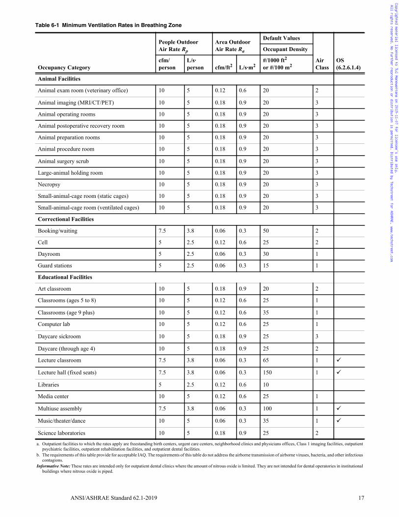
Table 6-1 Minimum Ventilation Rates in Breathing Zone
Occupancy Category
People Outdoor Air Rate Rp
Area Outdoor Air Rate Ra
Default Values
Air Class
OS(6.2.6.1.4)
Occupant Density
cfm/person
L/s·person cfm/ft2 L/s·m2
#/1000 ft2
or #/100 m2
Animal Facilities
Animal exam room (veterinary office) 10 5 0.12 0.6 20 2
Animal imaging (MRI/CT/PET) 10 5 0.18 0.9 20 3
Animal operating rooms 10 5 0.18 0.9 20 3
Animal postoperative recovery room 10 5 0.18 0.9 20 3
Animal preparation rooms 10 5 0.18 0.9 20 3
Animal procedure room 10 5 0.18 0.9 20 3
Animal surgery scrub 10 5 0.18 0.9 20 3
Large-animal holding room 10 5 0.18 0.9 20 3
Necropsy 10 5 0.18 0.9 20 3
Small-animal-cage room (static cages) 10 5 0.18 0.9 20 3
Small-animal-cage room (ventilated cages) 10 5 0.18 0.9 20 3
Correctional Facilities
Booking/waiting 7.5 3.8 0.06 0.3 50 2
Cell 5 2.5 0.12 0.6 25 2
Dayroom 5 2.5 0.06 0.3 30 1
Guard stations 5 2.5 0.06 0.3 15 1
Educational Facilities
Art classroom 10 5 0.18 0.9 20 2
Classrooms (ages 5 to 8) 10 5 0.12 0.6 25 1
Classrooms (age 9 plus) 10 5 0.12 0.6 35 1
Computer lab 10 5 0.12 0.6 25 1
Daycare sickroom 10 5 0.18 0.9 25 3
Daycare (through age 4) 10 5 0.18 0.9 25 2
Lecture classroom 7.5 3.8 0.06 0.3 65 1
Lecture hall (fixed seats) 7.5 3.8 0.06 0.3 150 1
Libraries 5 2.5 0.12 0.6 10
Media center 10 5 0.12 0.6 25 1
Multiuse assembly 7.5 3.8 0.06 0.3 100 1
Music/theater/dance 10 5 0.06 0.3 35 1
Science laboratories 10 5 0.18 0.9 25 2
a. Outpatient facilities to which the rates apply are freestanding birth centers, urgent care centers, neighborhood clinics and physicians offices, Class 1 imaging facilities, outpatientpsychiatric facilities, outpatient rehabilitation facilities, and outpatient dental facilities.
b. The requirements of this table provide for acceptable IAQ. The requirements of this table do not address the airborne transmission of airborne viruses, bacteria, and other infectiouscontagions.
Informative Note: These rates are intended only for outpatient dental clinics where the amount of nitrous oxide is limited. They are not intended for dental operatories in institutionalbuildings where nitrous oxide is piped.
Copyrighted material licensed to Tul Manewattana on 2019-11-07 for licensee's use only. All rights reserved. No further reproduction or distribution is permitted. Distributed by Techstreet for ASHRAE, www.techstreet.com

18 ANSI/ASHRAE Standard 62.1-2019
Educational Facilities (continued)
University/college laboratories 10 5 0.18 0.9 25 2
Wood/metal shop 10 5 0.18 0.9 20 2
Food and Beverage Service
Bars, cocktail lounges 7.5 3.8 0.18 0.9 100 2
Cafeteria/fast-food dining 7.5 3.8 0.18 0.9 100 2
Kitchen (cooking) 7.5 3.8 0.12 0.6 20 2
Restaurant dining rooms 7.5 3.8 0.18 0.9 70 2
Food and Beverage Service, General
Break rooms 5 2.5 0.06 0.3 25 1
Coffee stations 5 2.5 0.06 0.3 20 1
Conference/meeting 5 2.5 0.06 0.3 50 1
Corridors — — 0.06 0.3 — 1
Occupiable storage rooms for liquids or gels 5 2.5 0.12 0.6 2 2
Hotels, Motels, Resorts, Dormitories
Barracks sleeping areas 5 2.5 0.06 0.3 20 1
Bedroom/living room 5 2.5 0.06 0.3 10 1
Laundry rooms, central 5 2.5 0.12 0.6 10 2
Laundry rooms within dwelling units 5 2.5 0.12 0.6 10 1
Lobbies/prefunction 7.5 3.8 0.06 0.3 30 1
Multipurpose assembly 5 2.5 0.06 0.3 120 1
Miscellaneous Spaces
Banks or bank lobbies 7.5 3.8 0.06 0.3 15 1
Bank vaults/safe deposit 5 2.5 0.06 0.3 5 2
Computer (not printing) 5 2.5 0.06 0.3 4 1
Freezer and refrigerated spaces (<50°F [10°C]) 10 5 0 0 0 2
Manufacturing where hazardous materials are not used
10 5.0 0.18 0.9 7 2
Manufacturing where hazardous materials are used (excludes heavy industrial and chemical processes)
10 5.0 0.18 0.9 7 3
Pharmacy (prep. area) 5 2.5 0.18 0.9 10 2
Photo studios 5 2.5 0.12 0.6 10 1
Shipping/receiving 10 5 0.12 0.6 2 2
Table 6-1 Minimum Ventilation Rates in Breathing Zone (Continued)
Occupancy Category
People Outdoor Air Rate Rp
Area Outdoor Air Rate Ra
Default Values
Air Class
OS(6.2.6.1.4)
Occupant Density
cfm/person
L/s·person cfm/ft2 L/s·m2
#/1000 ft2
or #/100 m2
a. Outpatient facilities to which the rates apply are freestanding birth centers, urgent care centers, neighborhood clinics and physicians offices, Class 1 imaging facilities, outpatientpsychiatric facilities, outpatient rehabilitation facilities, and outpatient dental facilities.
b. The requirements of this table provide for acceptable IAQ. The requirements of this table do not address the airborne transmission of airborne viruses, bacteria, and other infectiouscontagions.
Informative Note: These rates are intended only for outpatient dental clinics where the amount of nitrous oxide is limited. They are not intended for dental operatories in institutionalbuildings where nitrous oxide is piped.
Copyrighted material licensed to Tul Manewattana on 2019-11-07 for licensee's use only. All rights reserved. No further reproduction or distribution is permitted. Distributed by Techstreet for ASHRAE, www.techstreet.com

ANSI/ASHRAE Standard 62.1-2019 19
Miscellaneous Spaces (continued)
Sorting, packing, light assembly 7.5 3.8 0.12 0.6 7 2
Telephone closets — — 0.00 0.0 — 1
Transportation waiting 7.5 3.8 0.06 0.3 100 1
Warehouses 10 5 0.06 0.3 — 2
Office Buildings
Breakrooms 5 2.5 0.12 0.6 50 1
Main entry lobbies 5 2.5 0.06 0.3 10 1
Occupiable storage rooms for dry materials 5 2.5 0.06 0.3 2 1
Office space 5 2.5 0.06 0.3 5 1
Reception areas 5 2.5 0.06 0.3 30 1
Telephone/data entry 5 2.5 0.06 0.3 60 1
Outpatient Health Care Facilities a,b
Birthing room 10 5 0.18 0.9 15 2
Class 1 imaging rooms 5 2.5 0.12 0.6 5 1
Dental operatory 10 5 0.18 0.9 20 1
General examination room 7.5 3.8 0.12 0.6 20 1
Other dental treatment areas 5 2.5 0.06 0.3 5 1
Physical therapy exercise area 20 10 0.18 0.9 7 2
Physical therapy individual room 10 5 0.06 0.3 20 1
Physical therapeutic pool area — — 0.48 2.4 — 2
Prosthetics and orthotics room 10 5 0.18 0.9 20 1
Psychiatric consultation room 5 2.5 0.06 0.3 20 1
Psychiatric examination room 5 2.5 0.06 0.3 20 1
Psychiatric group room 5 2.5 0.06 0.3 50 1
Psychiatric seclusion room 10 5 0.06 0.3 5 1
Speech therapy room 5 2.5 0.06 0.3 20 1
Urgent care examination room 7.5 3.8 0.12 0.6 20 1
Urgent care observation room 5 2.5 0.06 0.3 20 1
Urgent care treatment room 7.5 3.8 0.18 0.9 20 1
Urgent care triage room 10 5 0.18 0.9 20 1
Table 6-1 Minimum Ventilation Rates in Breathing Zone (Continued)
Occupancy Category
People Outdoor Air Rate Rp
Area Outdoor Air Rate Ra
Default Values
Air Class
OS(6.2.6.1.4)
Occupant Density
cfm/person
L/s·person cfm/ft2 L/s·m2
#/1000 ft2
or #/100 m2
a. Outpatient facilities to which the rates apply are freestanding birth centers, urgent care centers, neighborhood clinics and physicians offices, Class 1 imaging facilities, outpatientpsychiatric facilities, outpatient rehabilitation facilities, and outpatient dental facilities.
b. The requirements of this table provide for acceptable IAQ. The requirements of this table do not address the airborne transmission of airborne viruses, bacteria, and other infectiouscontagions.
Informative Note: These rates are intended only for outpatient dental clinics where the amount of nitrous oxide is limited. They are not intended for dental operatories in institutionalbuildings where nitrous oxide is piped.
Copyrighted material licensed to Tul Manewattana on 2019-11-07 for licensee's use only. All rights reserved. No further reproduction or distribution is permitted. Distributed by Techstreet for ASHRAE, www.techstreet.com

20 ANSI/ASHRAE Standard 62.1-2019
Public Assembly Spaces
Auditorium seating area 5 2.5 0.06 0.3 150 1
Courtrooms 5 2.5 0.06 0.3 70 1
Legislative chambers 5 2.5 0.06 0.3 50 1
Libraries 5 2.5 0.12 0.6 10 1
Lobbies 5 2.5 0.06 0.3 150 1
Museums (children’s) 7.5 3.8 0.12 0.6 40 1
Museums/galleries 7.5 3.8 0.06 0.3 40 1
Places of religious worship 5 2.5 0.06 0.3 120 1
Retail
Sales (except as below) 7.5 3.8 0.12 0.6 15 2
Barbershop 7.5 3.8 0.06 0.3 25 2
Beauty and nail salons 20 10 0.12 0.6 25 2
Coin-operated laundries 7.5 3.8 0.12 0.6 20 2
Mall common areas 7.5 3.8 0.06 0.3 40 1
Pet shops (animal areas) 7.5 3.8 0.18 0.9 10 2
Supermarket 7.5 3.8 0.06 0.3 8 1
Sports and Entertainment
Bowling alley (seating) 10 5 0.12 0.6 40 1
Disco/dance floors 20 10 0.06 0.3 100 2
Gambling casinos 7.5 3.8 0.18 0.9 120 1
Game arcades 7.5 3.8 0.18 0.9 20 1
Gym, sports arena (play area) 20 10 0.18 0.9 7 2
Health club/aerobics room 20 10 0.06 0.3 40 2
Health club/weight rooms 20 10 0.06 0.3 10 2
Spectator areas 7.5 3.8 0.06 0.3 150 1
Stages, studios 10 5 0.06 0.3 70 1
Swimming (pool and deck) — — 0.48 2.4 — 2
Transient Residential
Common corridors — — 0.06 0.3 1
Dwelling unit 5 2.5 0.06 0.3 F 1
Table 6-1 Minimum Ventilation Rates in Breathing Zone (Continued)
Occupancy Category
People Outdoor Air Rate Rp
Area Outdoor Air Rate Ra
Default Values
Air Class
OS(6.2.6.1.4)
Occupant Density
cfm/person
L/s·person cfm/ft2 L/s·m2
#/1000 ft2
or #/100 m2
a. Outpatient facilities to which the rates apply are freestanding birth centers, urgent care centers, neighborhood clinics and physicians offices, Class 1 imaging facilities, outpatientpsychiatric facilities, outpatient rehabilitation facilities, and outpatient dental facilities.
b. The requirements of this table provide for acceptable IAQ. The requirements of this table do not address the airborne transmission of airborne viruses, bacteria, and other infectiouscontagions.
Informative Note: These rates are intended only for outpatient dental clinics where the amount of nitrous oxide is limited. They are not intended for dental operatories in institutionalbuildings where nitrous oxide is piped.
Copyrighted material licensed to Tul Manewattana on 2019-11-07 for licensee's use only. All rights reserved. No further reproduction or distribution is permitted. Distributed by Techstreet for ASHRAE, www.techstreet.com
ANSI/ASHRAE Standard 62.1-2019 21
Table 6-2 Minimum Exhaust Rates
Occupancy CategoryExhaust Rate, cfm/unit
Exhaust Rate, cfm/ft2 Notes
Exhaust Rate,L/s·unit
Exhaust Rate, L/s·m2
Air Class
Animal Facilities
Animal imaging (MRI/CT/PET) — 0.90 — 4.5 3
Animal operating rooms — 3.00 — 15 3
Animal postoperative recovery room — 1.50 — 7.5 3
Animal preparation rooms — 1.50 — 7.5 3
Animal procedure room — 2.25 — 11.3 3
Animal surgery scrub — 1.50 — 7.5 3
Large-animal holding room — 2.25 — 11.3 3
Necropsy — 2.25 — 11.3 3
Small-animal-cage room (static cages) — 2.25 — 11.3 3
Small-animal-cage room (ventilated cages) — 1.50 — 7.5 3
Arenas — 0.50 B — — 1
Art classrooms — 0.70 — 3.5 2
Auto repair rooms — 1.50 A — 7.5 2
Barber shops — 0.50 — 2.5 2
Beauty and nail salons — 0.60 — 3.0 2
Cells with toilet — 1.00 — 5.0 2
Copy, printing rooms — 0.50 — 2.5 2
Darkrooms — 1.00 — 5.0 2
Educational science laboratories — 1.00 — 5.0 2
Janitor closets, trash rooms, recycling — 1.00 — 5.0 3
Kitchenettes — 0.30 — 1.5 2
Kitchens—commercial — 0.70 — 3.5 2
Locker rooms for athletic, industrial, and health care facilities
— 0.50 — 2.5 2
All other locker rooms — 0.25 — — 1.25 2
Shower rooms 20/50 G,I 10/25 2
Paint spray booths — — F — — 4
Parking garages — 0.75 C — 3.7 2
Pet shops (animal areas) — 0.90 — — 4.5 2
Refrigerating machinery rooms — — F — — 3
Residential kitchens 50/100 — G 25/50 — 2
Soiled laundry storage rooms — 1.00 F — 5.0 3
Storage rooms, chemical — 1.50 F — 7.5 4
Toilets—private 25/50 — E, H 12.5/25 — 2
Toilets—public 50/70 — D, H 25/35 — 2
Woodwork shop/classrooms — 0.50 — — 2.5 2NOTES:A Stands where engines are run shall have exhaust systems that directly connect to the engine exhaust and prevent escape of fumes.B Where combustion equipment is intended to be used on the playing surface, additional dilution ventilation, source control, or both shall be provided.C Exhaust shall not be required where two or more sides compose walls that are at least 50% open to the outside.D Rate is per water closet, urinal, or both. Provide the higher rate where periods of heavy use are expected to occur. The lower rate shall be permitted to be used otherwise.E Rate is for a toilet room intended to be occupied by one person at a time. For continuous system operation during hours of use, the lower rate shall be permitted to be used. Other-
wise the higher rate shall be used.F See other applicable standards for exhaust rate.G For continuous system operation, the lower rate shall be permitted to be used. Otherwise the higher rate shall be used.H Exhaust air that has been cleaned to meet Class 1 criteria from Section 5.18.1 shall be permitted to be recirculated.I Rate is per showerhead.
Copyrighted material licensed to Tul Manewattana on 2019-11-07 for licensee's use only. All rights reserved. No further reproduction or distribution is permitted. Distributed by Techstreet for ASHRAE, www.techstreet.com
22 ANSI/ASHRAE Standard 62.1-2019
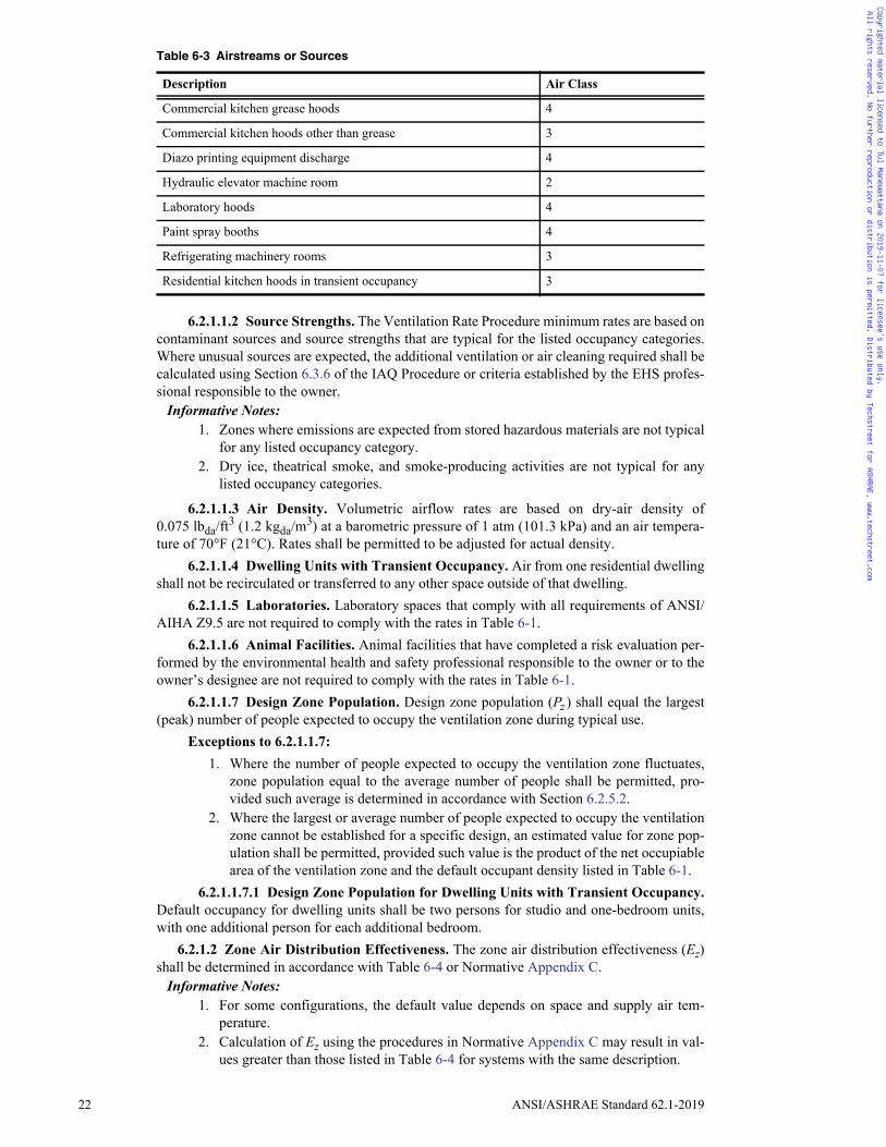
6.2.1.1.2 Source Strengths. The Ventilation Rate Procedure minimum rates are based oncontaminant sources and source strengths that are typical for the listed occupancy categories.Where unusual sources are expected, the additional ventilation or air cleaning required shall becalculated using Section 6.3.6 of the IAQ Procedure or criteria established by the EHS profes-sional responsible to the owner.
Informative Notes: 1. Zones where emissions are expected from stored hazardous materials are not typical
for any listed occupancy category. 2. Dry ice, theatrical smoke, and smoke-producing activities are not typical for any
listed occupancy categories.
6.2.1.1.3 Air Density. Volumetric airflow rates are based on dry-air density of0.075 lbda/ft
3 (1.2 kgda/m3) at a barometric pressure of 1 atm (101.3 kPa) and an air tempera-
ture of 70°F (21°C). Rates shall be permitted to be adjusted for actual density. 6.2.1.1.4 Dwelling Units with Transient Occupancy. Air from one residential dwelling
shall not be recirculated or transferred to any other space outside of that dwelling.6.2.1.1.5 Laboratories. Laboratory spaces that comply with all requirements of ANSI/
AIHA Z9.5 are not required to comply with the rates in Table 6-1.6.2.1.1.6 Animal Facilities. Animal facilities that have completed a risk evaluation per-
formed by the environmental health and safety professional responsible to the owner or to theowner’s designee are not required to comply with the rates in Table 6-1.
6.2.1.1.7 Design Zone Population. Design zone population (Pz ) shall equal the largest(peak) number of people expected to occupy the ventilation zone during typical use.
Exceptions to 6.2.1.1.7: 1. Where the number of people expected to occupy the ventilation zone fluctuates,
zone population equal to the average number of people shall be permitted, pro-vided such average is determined in accordance with Section 6.2.5.2.
2. Where the largest or average number of people expected to occupy the ventilationzone cannot be established for a specific design, an estimated value for zone pop-ulation shall be permitted, provided such value is the product of the net occupiablearea of the ventilation zone and the default occupant density listed in Table 6-1.
6.2.1.1.7.1 Design Zone Population for Dwelling Units with Transient Occupancy.Default occupancy for dwelling units shall be two persons for studio and one-bedroom units,with one additional person for each additional bedroom.
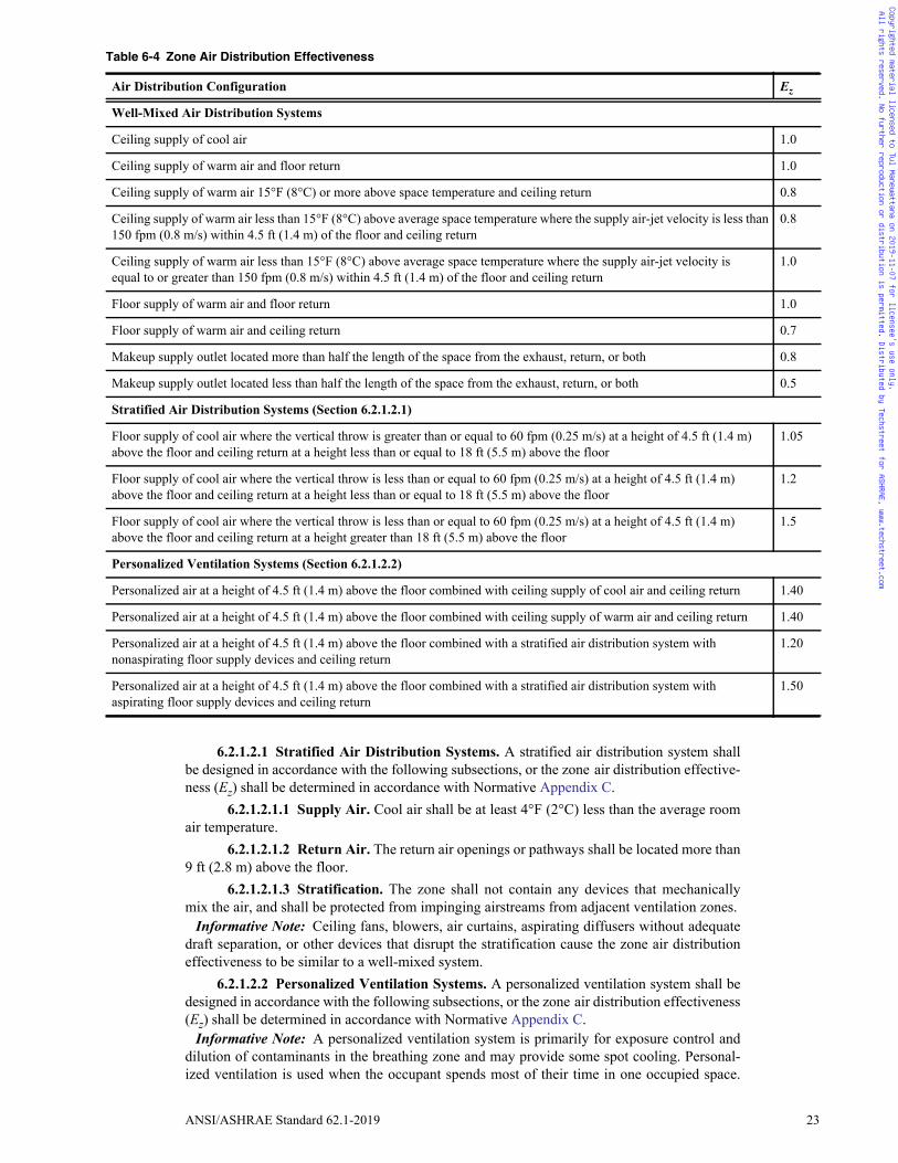
6.2.1.2 Zone Air Distribution Effectiveness. The zone air distribution effectiveness (Ez)shall be determined in accordance with Table 6-4 or Normative Appendix C.
Informative Notes: 1. For some configurations, the default value depends on space and supply air tem-
perature.2. Calculation of Ez using the procedures in Normative Appendix C may result in val-
ues greater than those listed in Table 6-4 for systems with the same description.
Table 6-3 Airstreams or Sources
Description Air Class
Commercial kitchen grease hoods 4
Commercial kitchen hoods other than grease 3
Diazo printing equipment discharge 4
Hydraulic elevator machine room 2
Laboratory hoods 4
Paint spray booths 4
Refrigerating machinery rooms 3
Residential kitchen hoods in transient occupancy 3
Copyrighted material licensed to Tul Manewattana on 2019-11-07 for licensee's use only. All rights reserved. No further reproduction or distribution is permitted. Distributed by Techstreet for ASHRAE, www.techstreet.com
ANSI/ASHRAE Standard 62.1-2019 23
6.2.1.2.1 Stratified Air Distribution Systems. A stratified air distribution system shallbe designed in accordance with the following subsections, or the zone air distribution effective-ness (Ez) shall be determined in accordance with Normative Appendix C.
6.2.1.2.1.1 Supply Air. Cool air shall be at least 4°F (2°C) less than the average roomair temperature.
6.2.1.2.1.2 Return Air. The return air openings or pathways shall be located more than9 ft (2.8 m) above the floor.
6.2.1.2.1.3 Stratification. The zone shall not contain any devices that mechanicallymix the air, and shall be protected from impinging airstreams from adjacent ventilation zones.
Informative Note: Ceiling fans, blowers, air curtains, aspirating diffusers without adequatedraft separation, or other devices that disrupt the stratification cause the zone air distributioneffectiveness to be similar to a well-mixed system.
6.2.1.2.2 Personalized Ventilation Systems. A personalized ventilation system shall bedesigned in accordance with the following subsections, or the zone air distribution effectiveness(Ez) shall be determined in accordance with Normative Appendix C.
Informative Note: A personalized ventilation system is primarily for exposure control anddilution of contaminants in the breathing zone and may provide some spot cooling. Personal-ized ventilation is used when the occupant spends most of their time in one occupied space.
Table 6-4 Zone Air Distribution Effectiveness
Air Distribution Configuration Ez
Well-Mixed Air Distribution Systems
Ceiling supply of cool air 1.0
Ceiling supply of warm air and floor return 1.0
Ceiling supply of warm air 15°F (8°C) or more above space temperature and ceiling return 0.8
Ceiling supply of warm air less than 15°F (8°C) above average space temperature where the supply air-jet velocity is less than 150 fpm (0.8 m/s) within 4.5 ft (1.4 m) of the floor and ceiling return
0.8
Ceiling supply of warm air less than 15°F (8°C) above average space temperature where the supply air-jet velocity is equal to or greater than 150 fpm (0.8 m/s) within 4.5 ft (1.4 m) of the floor and ceiling return
1.0
Floor supply of warm air and floor return 1.0
Floor supply of warm air and ceiling return 0.7
Makeup supply outlet located more than half the length of the space from the exhaust, return, or both 0.8
Makeup supply outlet located less than half the length of the space from the exhaust, return, or both 0.5
Stratified Air Distribution Systems (Section 6.2.1.2.1)
Floor supply of cool air where the vertical throw is greater than or equal to 60 fpm (0.25 m/s) at a height of 4.5 ft (1.4 m)above the floor and ceiling return at a height less than or equal to 18 ft (5.5 m) above the floor
1.05
Floor supply of cool air where the vertical throw is less than or equal to 60 fpm (0.25 m/s) at a height of 4.5 ft (1.4 m)above the floor and ceiling return at a height less than or equal to 18 ft (5.5 m) above the floor
1.2
Floor supply of cool air where the vertical throw is less than or equal to 60 fpm (0.25 m/s) at a height of 4.5 ft (1.4 m)above the floor and ceiling return at a height greater than 18 ft (5.5 m) above the floor
1.5
Personalized Ventilation Systems (Section 6.2.1.2.2)
Personalized air at a height of 4.5 ft (1.4 m) above the floor combined with ceiling supply of cool air and ceiling return 1.40
Personalized air at a height of 4.5 ft (1.4 m) above the floor combined with ceiling supply of warm air and ceiling return 1.40
Personalized air at a height of 4.5 ft (1.4 m) above the floor combined with a stratified air distribution system with nonaspirating floor supply devices and ceiling return
1.20
Personalized air at a height of 4.5 ft (1.4 m) above the floor combined with a stratified air distribution system with aspirating floor supply devices and ceiling return
1.50
Copyrighted material licensed to Tul Manewattana on 2019-11-07 for licensee's use only. All rights reserved. No further reproduction or distribution is permitted. Distributed by Techstreet for ASHRAE, www.techstreet.com

24 ANSI/ASHRAE Standard 62.1-2019
The ventilation outlet is usually incorporated into or mounted on the furniture. It is used inconjunction with another air distribution system that handles the area ventilation requirementsand thermal loads in the space.
6.2.1.2.2.1 Personalized Air. The personalized air shall be distributed in the breathingzone and designed such that the velocity is equal to or less than 50 fpm (0.25 m/s) at the head/facial region of the occupant.
6.2.1.2.2.2 Return Air. The return air openings or pathways shall be located more than9 ft (2.8 m) above the floor.
6.2.1.3 Zone Outdoor Airflow. The zone outdoor airflow (Voz) provided to the ventilationzone by the supply air distribution system shall be determined in accordance with Equation 6-2.
Voz = Vbz/Ez (6-2)
6.2.2 Single-Zone Systems. For ventilation systems wherein one or more air handler sup-plies a mixture of outdoor air and recirculated air to only one ventilation zone, the outdoor airintake flow (Vot) shall be determined in accordance with Equation 6-3.
Vot = Voz (6-3)
6.2.3 100% Outdoor Air Systems. For ventilation systems wherein one or more air handlersupplies only outdoor air to one or more ventilation zones, the outdoor air intake flow (Vot) shallbe determined in accordance with Equation 6-4.
Vot = all zonesVoz (6-4)
6.2.4 Multiple-Zone Recirculating Systems. For ventilation systems wherein one ormore air handler supplies a mixture of outdoor air and recirculated air to more than one ven-tilation zone, the outdoor air intake flow (Vot) shall be determined in accordance with Sec-tions 6.2.4.1 through 6.2.4.4.
6.2.4.1 Uncorrected Outdoor Air Intake. The uncorrected outdoor air intake (Vou) flowshall be determined in accordance with Equation 6-5.
Vou = Dall zones(Rp × Pz) + all zones(Ra × Az) (6-5)
6.2.4.1.1 Occupant Diversity. The occupant diversity ratio (D) shall be determined inaccordance with Equation 6-6 to account for variations in population within the ventilationzones served by the system.
D = Ps /all zones Pz (6-6)
where the system population (Ps) is the total population in the area served by the system. Exception to 6.2.4.1.1: Alternative methods to account for occupant diversity shall be
permitted, provided the resulting Vou value is not less than that determined usingEquation 6-5.
6.2.4.1.2 Design System Population. Design system population (Ps) shall equal the larg-est (peak) number of people expected to occupy all ventilation zones served by the ventilationsystem during use.
Informative Note: Design system population is always equal to or less than the sum of designzone population for all zones in the area served by the system because all zones may not besimultaneously occupied at design population.
6.2.4.1.3 Other Ventilation Requirements. When a zone ventilation rate is obtained fromcriteria other than this standard, the ventilation rate shall be converted to cfm or L/s and the valueadded to Vou for use in system design calculations.
6.2.4.2 System Ventilation Efficiency. The system ventilation efficiency (Ev) shall bedetermined in accordance with Section 6.2.4.3 for the Simplified Procedure or NormativeAppendix A for the Alternative Procedure.
Informative Note: These procedures also establish zone minimum primary airflow rates forVAV systems.
6.2.4.3 Simplified Procedure6.2.4.3.1 System Ventilation Efficiency. System ventilation efficiency (Ev) shall be
determined in accordance with Equation 6-7 or 6-8.
Copyrighted material licensed to Tul Manewattana on 2019-11-07 for licensee's use only. All rights reserved. No further reproduction or distribution is permitted. Distributed by Techstreet for ASHRAE, www.techstreet.com
ANSI/ASHRAE Standard 62.1-2019 25
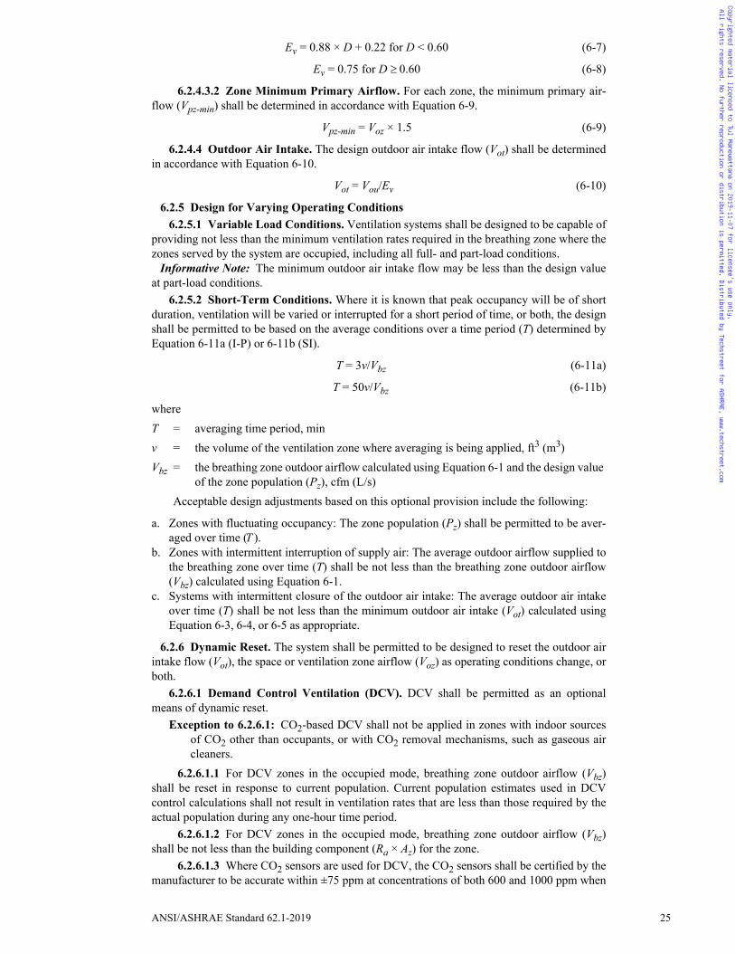
Ev = 0.88 × D + 0.22 for D < 0.60 (6-7)
Ev = 0.75 for D 0.60 (6-8)
6.2.4.3.2 Zone Minimum Primary Airflow. For each zone, the minimum primary air-flow (Vpz-min) shall be determined in accordance with Equation 6-9.
Vpz-min = Voz × 1.5 (6-9)
6.2.4.4 Outdoor Air Intake. The design outdoor air intake flow (Vot) shall be determinedin accordance with Equation 6-10.
Vot = Vou/Ev (6-10)
6.2.5 Design for Varying Operating Conditions6.2.5.1 Variable Load Conditions. Ventilation systems shall be designed to be capable of
providing not less than the minimum ventilation rates required in the breathing zone where thezones served by the system are occupied, including all full- and part-load conditions.
Informative Note: The minimum outdoor air intake flow may be less than the design valueat part-load conditions.
6.2.5.2 Short-Term Conditions. Where it is known that peak occupancy will be of shortduration, ventilation will be varied or interrupted for a short period of time, or both, the designshall be permitted to be based on the average conditions over a time period (T) determined byEquation 6-11a (I-P) or 6-11b (SI).
T = 3v/Vbz (6-11a)
T = 50v/Vbz (6-11b)
whereT = averaging time period, minv = the volume of the ventilation zone where averaging is being applied, ft3 (m3)Vbz = the breathing zone outdoor airflow calculated using Equation 6-1 and the design value
of the zone population (Pz), cfm (L/s)Acceptable design adjustments based on this optional provision include the following:
a. Zones with fluctuating occupancy: The zone population (Pz) shall be permitted to be aver-aged over time (T ).
b. Zones with intermittent interruption of supply air: The average outdoor airflow supplied tothe breathing zone over time (T) shall be not less than the breathing zone outdoor airflow(Vbz) calculated using Equation 6-1.
c. Systems with intermittent closure of the outdoor air intake: The average outdoor air intakeover time (T) shall be not less than the minimum outdoor air intake (Vot) calculated usingEquation 6-3, 6-4, or 6-5 as appropriate.
6.2.6 Dynamic Reset. The system shall be permitted to be designed to reset the outdoor airintake flow (Vot), the space or ventilation zone airflow (Voz) as operating conditions change, orboth.
6.2.6.1 Demand Control Ventilation (DCV). DCV shall be permitted as an optionalmeans of dynamic reset.
Exception to 6.2.6.1: CO2-based DCV shall not be applied in zones with indoor sourcesof CO2 other than occupants, or with CO2 removal mechanisms, such as gaseous aircleaners.
6.2.6.1.1 For DCV zones in the occupied mode, breathing zone outdoor airflow (Vbz)shall be reset in response to current population. Current population estimates used in DCVcontrol calculations shall not result in ventilation rates that are less than those required by theactual population during any one-hour time period.
6.2.6.1.2 For DCV zones in the occupied mode, breathing zone outdoor airflow (Vbz)shall be not less than the building component (Ra × Az) for the zone.
6.2.6.1.3 Where CO2 sensors are used for DCV, the CO2 sensors shall be certified by themanufacturer to be accurate within ±75 ppm at concentrations of both 600 and 1000 ppm when
Copyrighted material licensed to Tul Manewattana on 2019-11-07 for licensee's use only. All rights reserved. No further reproduction or distribution is permitted. Distributed by Techstreet for ASHRAE, www.techstreet.com
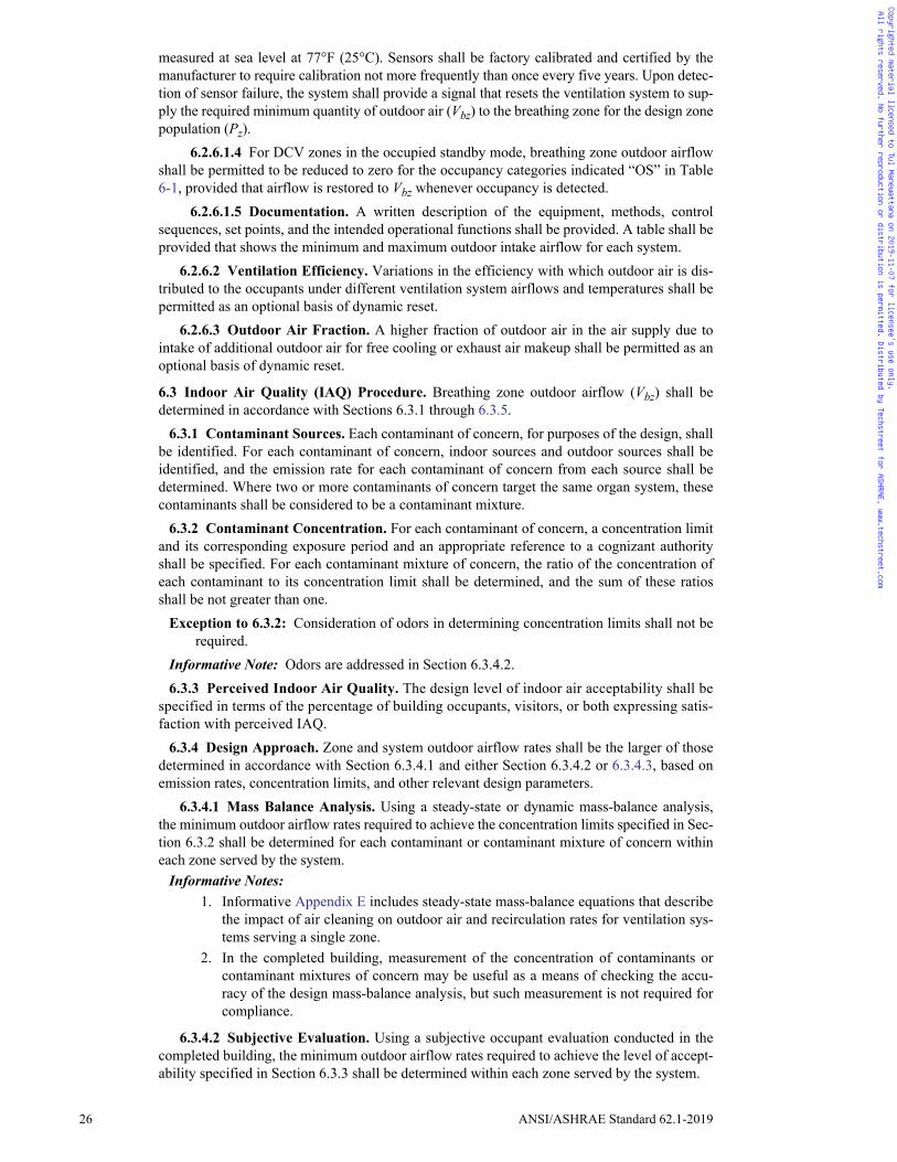
26 ANSI/ASHRAE Standard 62.1-2019
measured at sea level at 77°F (25°C). Sensors shall be factory calibrated and certified by themanufacturer to require calibration not more frequently than once every five years. Upon detec-tion of sensor failure, the system shall provide a signal that resets the ventilation system to sup-ply the required minimum quantity of outdoor air (Vbz) to the breathing zone for the design zonepopulation (Pz).
6.2.6.1.4 For DCV zones in the occupied standby mode, breathing zone outdoor airflowshall be permitted to be reduced to zero for the occupancy categories indicated “OS” in Table6-1, provided that airflow is restored to Vbz whenever occupancy is detected.
6.2.6.1.5 Documentation. A written description of the equipment, methods, controlsequences, set points, and the intended operational functions shall be provided. A table shall beprovided that shows the minimum and maximum outdoor intake airflow for each system.
6.2.6.2 Ventilation Efficiency. Variations in the efficiency with which outdoor air is dis-tributed to the occupants under different ventilation system airflows and temperatures shall bepermitted as an optional basis of dynamic reset.
6.2.6.3 Outdoor Air Fraction. A higher fraction of outdoor air in the air supply due tointake of additional outdoor air for free cooling or exhaust air makeup shall be permitted as anoptional basis of dynamic reset.
6.3 Indoor Air Quality (IAQ) Procedure. Breathing zone outdoor airflow (Vbz) shall bedetermined in accordance with Sections 6.3.1 through 6.3.5.
6.3.1 Contaminant Sources. Each contaminant of concern, for purposes of the design, shallbe identified. For each contaminant of concern, indoor sources and outdoor sources shall beidentified, and the emission rate for each contaminant of concern from each source shall bedetermined. Where two or more contaminants of concern target the same organ system, thesecontaminants shall be considered to be a contaminant mixture.
6.3.2 Contaminant Concentration. For each contaminant of concern, a concentration limitand its corresponding exposure period and an appropriate reference to a cognizant authorityshall be specified. For each contaminant mixture of concern, the ratio of the concentration ofeach contaminant to its concentration limit shall be determined, and the sum of these ratiosshall be not greater than one.
Exception to 6.3.2: Consideration of odors in determining concentration limits shall not berequired.
Informative Note: Odors are addressed in Section 6.3.4.2.6.3.3 Perceived Indoor Air Quality. The design level of indoor air acceptability shall be
specified in terms of the percentage of building occupants, visitors, or both expressing satis-faction with perceived IAQ.
6.3.4 Design Approach. Zone and system outdoor airflow rates shall be the larger of thosedetermined in accordance with Section 6.3.4.1 and either Section 6.3.4.2 or 6.3.4.3, based onemission rates, concentration limits, and other relevant design parameters.
6.3.4.1 Mass Balance Analysis. Using a steady-state or dynamic mass-balance analysis,the minimum outdoor airflow rates required to achieve the concentration limits specified in Sec-tion 6.3.2 shall be determined for each contaminant or contaminant mixture of concern withineach zone served by the system.
Informative Notes: 1. Informative Appendix E includes steady-state mass-balance equations that describe
the impact of air cleaning on outdoor air and recirculation rates for ventilation sys-tems serving a single zone.
2. In the completed building, measurement of the concentration of contaminants orcontaminant mixtures of concern may be useful as a means of checking the accu-racy of the design mass-balance analysis, but such measurement is not required forcompliance.
6.3.4.2 Subjective Evaluation. Using a subjective occupant evaluation conducted in thecompleted building, the minimum outdoor airflow rates required to achieve the level of accept-ability specified in Section 6.3.3 shall be determined within each zone served by the system.
Copyrighted material licensed to Tul Manewattana on 2019-11-07 for licensee's use only. All rights reserved. No further reproduction or distribution is permitted. Distributed by Techstreet for ASHRAE, www.techstreet.com
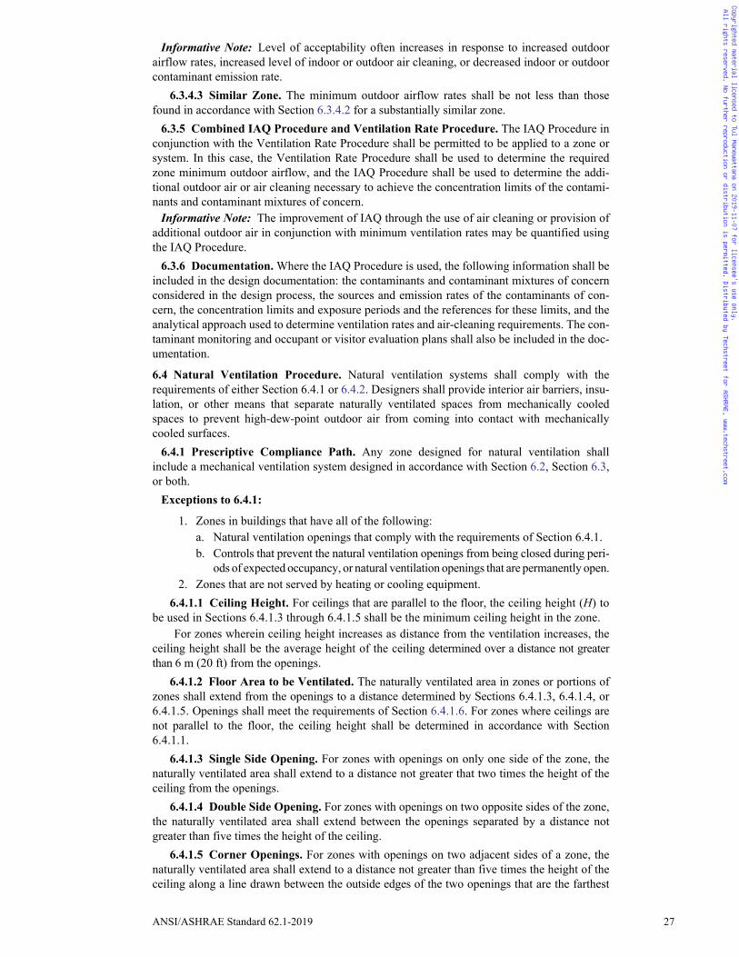
ANSI/ASHRAE Standard 62.1-2019 27
Informative Note: Level of acceptability often increases in response to increased outdoorairflow rates, increased level of indoor or outdoor air cleaning, or decreased indoor or outdoorcontaminant emission rate.
6.3.4.3 Similar Zone. The minimum outdoor airflow rates shall be not less than thosefound in accordance with Section 6.3.4.2 for a substantially similar zone.
6.3.5 Combined IAQ Procedure and Ventilation Rate Procedure. The IAQ Procedure inconjunction with the Ventilation Rate Procedure shall be permitted to be applied to a zone orsystem. In this case, the Ventilation Rate Procedure shall be used to determine the requiredzone minimum outdoor airflow, and the IAQ Procedure shall be used to determine the addi-tional outdoor air or air cleaning necessary to achieve the concentration limits of the contami-nants and contaminant mixtures of concern.
Informative Note: The improvement of IAQ through the use of air cleaning or provision ofadditional outdoor air in conjunction with minimum ventilation rates may be quantified usingthe IAQ Procedure.
6.3.6 Documentation. Where the IAQ Procedure is used, the following information shall beincluded in the design documentation: the contaminants and contaminant mixtures of concernconsidered in the design process, the sources and emission rates of the contaminants of con-cern, the concentration limits and exposure periods and the references for these limits, and theanalytical approach used to determine ventilation rates and air-cleaning requirements. The con-taminant monitoring and occupant or visitor evaluation plans shall also be included in the doc-umentation.
6.4 Natural Ventilation Procedure. Natural ventilation systems shall comply with therequirements of either Section 6.4.1 or 6.4.2. Designers shall provide interior air barriers, insu-lation, or other means that separate naturally ventilated spaces from mechanically cooledspaces to prevent high-dew-point outdoor air from coming into contact with mechanicallycooled surfaces.
6.4.1 Prescriptive Compliance Path. Any zone designed for natural ventilation shallinclude a mechanical ventilation system designed in accordance with Section 6.2, Section 6.3,or both.
Exceptions to 6.4.1:
1. Zones in buildings that have all of the following: a. Natural ventilation openings that comply with the requirements of Section 6.4.1.b. Controls that prevent the natural ventilation openings from being closed during peri-
ods of expected occupancy, or natural ventilation openings that are permanently open.2. Zones that are not served by heating or cooling equipment.
6.4.1.1 Ceiling Height. For ceilings that are parallel to the floor, the ceiling height (H) tobe used in Sections 6.4.1.3 through 6.4.1.5 shall be the minimum ceiling height in the zone.
For zones wherein ceiling height increases as distance from the ventilation increases, theceiling height shall be the average height of the ceiling determined over a distance not greaterthan 6 m (20 ft) from the openings.
6.4.1.2 Floor Area to be Ventilated. The naturally ventilated area in zones or portions ofzones shall extend from the openings to a distance determined by Sections 6.4.1.3, 6.4.1.4, or6.4.1.5. Openings shall meet the requirements of Section 6.4.1.6. For zones where ceilings arenot parallel to the floor, the ceiling height shall be determined in accordance with Section6.4.1.1.
6.4.1.3 Single Side Opening. For zones with openings on only one side of the zone, thenaturally ventilated area shall extend to a distance not greater that two times the height of theceiling from the openings.
6.4.1.4 Double Side Opening. For zones with openings on two opposite sides of the zone,the naturally ventilated area shall extend between the openings separated by a distance notgreater than five times the height of the ceiling.
6.4.1.5 Corner Openings. For zones with openings on two adjacent sides of a zone, thenaturally ventilated area shall extend to a distance not greater than five times the height of theceiling along a line drawn between the outside edges of the two openings that are the farthest
Copyrighted material licensed to Tul Manewattana on 2019-11-07 for licensee's use only. All rights reserved. No further reproduction or distribution is permitted. Distributed by Techstreet for ASHRAE, www.techstreet.com
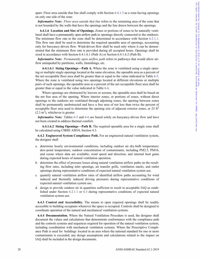
28 ANSI/ASHRAE Standard 62.1-2019
apart. Floor area outside that line shall comply with Section 6.4.1.3 as a zone having openingson only one side of the zone.
Informative Note: Floor area outside that line refers to the remaining area of the zone thatis not bounded by the walls that have the openings and the line drawn between the openings.
6.4.1.6 Location and Size of Openings. Zones or portions of zones to be naturally venti-lated shall have a permanently open airflow path to openings directly connected to the outdoors.The minimum flow rate to the zone shall be determined in accordance with Section 6.2.1.1.This flow rate shall be used to determine the required openable area of openings, accountingonly for buoyancy-driven flow. Wind-driven flow shall be used only where it can be demon-strated that the minimum flow rate is provided during all occupied hours. Openings shall besized in accordance with Section 6.4.1.6.1 (Path A) or Section 6.4.1.6.2 (Path B).
Informative Note: Permanently open airflow path refers to pathways that would allow air-flow unimpeded by partitions, walls, furnishings, etc.
6.4.1.6.1 Sizing Openings—Path A. Where the zone is ventilated using a single open-ing or multiple single openings located at the same elevation, the openable area as a percent ofthe net occupiable floor area shall be greater than or equal to the value indicated in Table 6-5.Where the zone is ventilated using two openings located at different elevations or multiplepairs of such openings, the openable area as a percent of the net occupiable floor area shall begreater than or equal to the value indicated in Table 6-6.
Where openings are obstructed by louvers or screens, the openable area shall be based onthe net free area of the opening. Where interior zones, or portions of zones, without directopenings to the outdoors are ventilated through adjoining zones, the opening between zonesshall be permanently unobstructed and have a free area of not less than twice the percent ofoccupiable floor area used to determine the opening size of adjacent exterior zones, or 25 ft2(2.3 m2), whichever is greater.
Informative Note: Tables 6-5 and 6-6 are based solely on buoyancy-driven flow and havenot been created to address thermal comfort.
6.4.1.6.2 Sizing Openings—Path B. The required openable area for a single zone shallbe calculated using CIBSE AM10, Section 4.3.
6.4.2 Engineered System Compliance Path. For an engineered natural ventilation system,the designer shall
a. determine hourly environmental conditions, including outdoor air dry-bulb temperature;dew-point temperature; outdoor concentration of contaminants, including PM2.5, PM10,and ozone where data are available; wind speed and direction; and internal heat gainsduring expected hours of natural ventilation operation.
b. determine the effect of pressure losses along natural ventilation airflow paths on the result-ing flow rates, including inlet openings, air transfer grills, ventilation stacks, and outletopenings during representative conditions of expected natural ventilation system use.
c. quantify natural ventilation airflow rates of identified airflow paths accounting for windinduced and thermally induced driving pressures during representative conditions ofexpected natural ventilation system use.
d. design to provide outdoor air in quantities sufficient to result in acceptable IAQ as estab-lished under Section 6.2.1.1 or 6.3 during representative conditions of expected naturalventilation system use.
6.4.3 Control and Accessibility. The means to open required openings shall be readilyaccessible to building occupants whenever the space is occupied. Controls shall be designed tocoordinate operation of the natural and mechanical ventilation systems.
6.4.4 Documentation. Where the Natural Ventilation Procedure is used, the designer shalldocument the values and calculations that demonstrate conformance with the compliance pathand the controls systems and sequences required for operation of the natural ventilation system,including coordination with mechanical ventilation systems. Where the Prescriptive Compli-ance Path is used for buildings located in an area where the national standard for one or morecontaminants is exceeded, any design assumptions and calculations related to the impact onIAQ shall be included in the design documents.
Copyrighted material licensed to Tul Manewattana on 2019-11-07 for licensee's use only. All rights reserved. No further reproduction or distribution is permitted. Distributed by Techstreet for ASHRAE, www.techstreet.com
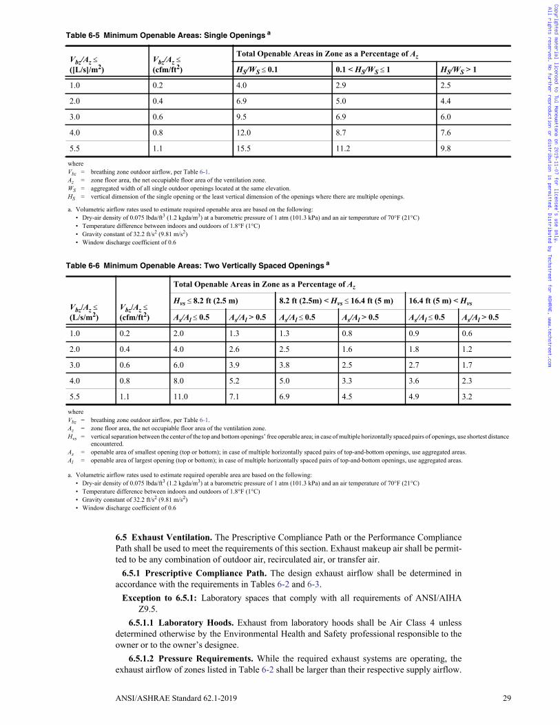
ANSI/ASHRAE Standard 62.1-2019 29
6.5 Exhaust Ventilation. The Prescriptive Compliance Path or the Performance CompliancePath shall be used to meet the requirements of this section. Exhaust makeup air shall be permit-ted to be any combination of outdoor air, recirculated air, or transfer air.
6.5.1 Prescriptive Compliance Path. The design exhaust airflow shall be determined inaccordance with the requirements in Tables 6-2 and 6-3.
Exception to 6.5.1: Laboratory spaces that comply with all requirements of ANSI/AIHAZ9.5.
6.5.1.1 Laboratory Hoods. Exhaust from laboratory hoods shall be Air Class 4 unlessdetermined otherwise by the Environmental Health and Safety professional responsible to theowner or to the owner’s designee.
6.5.1.2 Pressure Requirements. While the required exhaust systems are operating, theexhaust airflow of zones listed in Table 6-2 shall be larger than their respective supply airflow.
Table 6-5 Minimum Openable Areas: Single Openings a
Vbz/Az ([L/s]/m2)
Vbz/Az (cfm/ft2)
Total Openable Areas in Zone as a Percentage of Az
HS/WS 0.1 0.1 < HS/WS 1 HS/WS > 1
1.0 0.2 4.0 2.9 2.5
2.0 0.4 6.9 5.0 4.4
3.0 0.6 9.5 6.9 6.0
4.0 0.8 12.0 8.7 7.6
5.5 1.1 15.5 11.2 9.8
whereVbz = breathing zone outdoor airflow, per Table 6-1.Az = zone floor area, the net occupiable floor area of the ventilation zone.WS = aggregated width of all single outdoor openings located at the same elevation.HS = vertical dimension of the single opening or the least vertical dimension of the openings where there are multiple openings.
a. Volumetric airflow rates used to estimate required openable area are based on the following:• Dry-air density of 0.075 lbda/ft3 (1.2 kgda/m3) at a barometric pressure of 1 atm (101.3 kPa) and an air temperature of 70°F (21°C) • Temperature difference between indoors and outdoors of 1.8°F (1°C)• Gravity constant of 32.2 ft/s2 (9.81 m/s2)• Window discharge coefficient of 0.6
Table 6-6 Minimum Openable Areas: Two Vertically Spaced Openings a
Vbz/Az (L/s/m2)
Vbz/Az (cfm/ft2)
Total Openable Areas in Zone as a Percentage of Az
Hvs 8.2 ft (2.5 m) 8.2 ft (2.5m) < Hvs 16.4 ft (5 m) 16.4 ft (5 m) < Hvs
As/Al 0.5 As/Al > 0.5 As/Al 0.5 As/Al > 0.5 As/Al 0.5 As/Al > 0.5
1.0 0.2 2.0 1.3 1.3 0.8 0.9 0.6
2.0 0.4 4.0 2.6 2.5 1.6 1.8 1.2
3.0 0.6 6.0 3.9 3.8 2.5 2.7 1.7
4.0 0.8 8.0 5.2 5.0 3.3 3.6 2.3
5.5 1.1 11.0 7.1 6.9 4.5 4.9 3.2
whereVbz = breathing zone outdoor airflow, per Table 6-1.Az = zone floor area, the net occupiable floor area of the ventilation zone.Hvs = vertical separation between the center of the top and bottom openings’ free operable area; in case of multiple horizontally spaced pairs of openings, use shortest distance
encountered.As = openable area of smallest opening (top or bottom); in case of multiple horizontally spaced pairs of top-and-bottom openings, use aggregated areas.Al = openable area of largest opening (top or bottom); in case of multiple horizontally spaced pairs of top-and-bottom openings, use aggregated areas.
a. Volumetric airflow rates used to estimate required operable area are based on the following:• Dry-air density of 0.075 lbda/ft3 (1.2 kgda/m3) at a barometric pressure of 1 atm (101.3 kPa) and an air temperature of 70°F (21°C) • Temperature difference between indoors and outdoors of 1.8°F (1°C)• Gravity constant of 32.2 ft/s2 (9.81 m/s2)• Window discharge coefficient of 0.6
Copyrighted material licensed to Tul Manewattana on 2019-11-07 for licensee's use only. All rights reserved. No further reproduction or distribution is permitted. Distributed by Techstreet for ASHRAE, www.techstreet.com
30 ANSI/ASHRAE Standard 62.1-2019
If zones listed in Table 6-2 are adjacent, the difference between the exhaust and the supply air-flow shall be larger for the zone with the higher number class of air.
Exception to 6.5.1.2: Where airflow offset requirements are established by the Environ-mental Health and Safety professional responsible to the owner or owner’s designee.
Informative Notes: 1. Exhaust systems are required for any occupancy category listed in Table 6-2.2. Where intermittent operation is allowed in Table 6-2, exhaust equipment is intended
to be operated when the space is in use.6.5.2 Performance Compliance Path. The exhaust airflow shall be determined in accor-
dance with the following subsections.6.5.2.1 Contaminant Sources. Contaminants or mixtures of concern for purposes of the
design shall be identified. For each contaminant or mixture of concern, indoor sources (occu-pants, materials, activities, and processes) and outdoor sources shall be identified, and theemission rate for each contaminant of concern from each source shall be determined.
6.5.2.2 Contaminant Concentration. For each contaminant of concern, a concentrationlimit and its corresponding exposure period and an appropriate reference to a cognizant author-ity shall be specified.
6.5.2.3 Monitoring and control systems shall be provided to automatically detect contami-nant levels of concern and modulate exhaust airflow such that contaminant levels are main-tained at not greater than the specified contaminant concentration limits.6.6 Design Documentation Procedures. Design criteria and assumptions shall be docu-mented and made available for operation of the system after installation. See Sections 4.3,5.1.3, 5.18.4, 6.2.6.1.5, 6.3.6, and 6.4.4 regarding assumptions to be detailed in the documen-tation.
7. CONSTRUCTION AND SYSTEM START-UP
7.1 Construction Phase7.1.1 Application. The requirements of this section apply to ventilation systems and the
spaces they serve in new buildings and additions to or alterations in existing buildings.7.1.2 Filters. Systems designed with particle filters shall not be operated without filters in
place.7.1.3 Protection of Materials. When recommended by the manufacturer, building materials
shall be protected from rain and other sources of moisture by appropriate in-transit and on-siteprocedures. Porous materials with visible microbial growth shall not be installed. Nonporousmaterials with visible microbial growth shall be decontaminated.
7.1.4 Protection of Occupied Areas7.1.4.1 Application. The requirements of Section 7.1.4 apply when construction requires
a building permit and entails sanding, cutting, grinding, or other activities that generate sig-nificant amounts of airborne particles or procedures that generate significant amounts of gas-eous contaminants.
7.1.4.2 Protective Measures. Measures shall be employed to reduce the migration of con-struction-generated contaminants to occupied areas.
Informative Note: Examples of acceptable measures include, but are not limited to, sealingthe construction area using temporary walls or plastic sheathing, exhausting the constructionarea, or pressurizing contiguous occupied areas.
7.1.5 Air Duct System Construction. Air duct systems shall be constructed in accordancewith the following standards, as applicable:
a. The following sections of ANSI/SMACNA 006, HVAC Duct Construction Standards—Metal and Flexible:
• Section S1.9 of Section 1.3.1, “Duct Construction and Installation Standards”• Section 7.4, “Installation Standards for Rectangular Ducts Using Flexible Liner”• Section 3.5, “Duct Installation Standards”• Section 3.6, “Specification for Joining and Attaching Flexible Duct”• Section 3.7, “Specification for Supporting Flexible Duct”
Copyrighted material licensed to Tul Manewattana on 2019-11-07 for licensee's use only. All rights reserved. No further reproduction or distribution is permitted. Distributed by Techstreet for ASHRAE, www.techstreet.com
Tul
Rectangle
ภาคผนวก ค
ASHRAE Standard 62.1-2019
INFORMATIVE APPENDIX L
VENTILATION RATE CHECK TABLE

ANSI/ASHRAE Standard 62.1-2019 71
(This appendix is not part of this standard. It is merely informative and does not contain require-ments necessary for conformance to the standard. It has not been processed according to the ANSIrequirements for a standard and may contain material that has not been subject to public reviewor a consensus process. Unresolved objectors on informative material are not offered the right toappeal at ASHRAE or ANSI.)
INFORMATIVE APPENDIX LVENTILATION RATE CHECK TABLE
Table L-1 is not for design purposes. It is intended to provide check values. Default rate per unit area isbased on a multiple-zone system with default occupancy and default Ev that equals 0.75. This is the defaultEv in the simplified rate when D > 0.60.
Table L-1 Check Table for the Ventilation Rate Procedure
Occupancy Category
Combined Outdoor Air Rate (Rc)
cfm/ft2 L/s· m2
Animal Facilities
Animal exam room (veterinary office) 0.43 2.13
Animal imaging (MRI/CT/PET) 0.51 2.53
Animal operating rooms 0.51 2.53
Animal postoperative recovery room 0.51 2.53
Animal preparation rooms 0.51 2.53
Animal procedure room 0.51 2.53
Animal surgery scrub 0.51 2.53
Large-animal holding room 0.51 2.53
Necropsy 0.51 2.53
Small-animal-cage room (static cages) 0.51 2.53
Small-animal-cage room (ventilated cages) 0.51 2.53
Correctional Facilities
Booking/waiting 0.58 2.93
Cell 0.33 1.63
Dayroom 0.28 1.40
Guard stations 0.18 0.90
Educational Facilities
Art classroom 0.51 2.53
Classrooms (ages 5 through 8) 0.49 2.47
Classrooms (ages 9 plus) 0.63 3.13
Computer lab 0.49 2.47
Daycare sickroom 0.57 2.87
Daycare (through age 4) 0.57 2.87
Lecture classroom 0.73 3.69
Lecture hall (fixed seats) 1.58 8.00
Libraries 0.23 1.13
Media center 0.49 2.47
Copyrighted material licensed to Tul Manewattana on 2019-11-07 for licensee's use only. All rights reserved. No further reproduction or distribution is permitted. Distributed by Techstreet for ASHRAE, www.techstreet.com

72 ANSI/ASHRAE Standard 62.1-2019
Multiuse assembly 1.08 5.47
Music/theater/dance 0.55 2.73
Science laboratories 0.57 2.87
University/college laboratories 0.57 2.87
Wood/metal shop 0.51 2.53
Food and Beverage Service
Bars, cocktail lounges 1.24 6.27
Cafeteria/fast-food dining 1.24 6.27
Kitchen (cooking) 0.36 1.81
Restaurant dining rooms 0.94 4.75
Food and Beverage Service, General
Break rooms 0.25 1.23
Coffee stations 0.21 1.07
Conference/meeting 0.41 2.07
Corridors 0.08 0.40
Occupiable storage rooms for liquids or gels 0.17 0.87
Hotels, Motels, Resorts, Dormitories
Barracks sleeping areas 0.21 1.07
Bedroom/living room 0.15 0.73
Laundry rooms (central) 0.23 1.13
Laundry rooms within dwelling units 0.23 1.13
Lobbies/prefunction 0.38 1.92
Multipurpose assembly 0.88 4.40
Miscellaneous Spaces
Banks or bank lobbies 0.23 1.16
Bank vaults/safe deposit 0.11 0.57
Computer (not printing) 0.11 0.53
Freezer and refrigerated spaces (<50°F [10°C]) 0.03 0.13
General manufacturing (excludes heavy industrialand processes using chemicals)
0.33 1.67
Pharmacy (prep area) 0.31 1.53
Photo studios 0.23 1.13
Shipping/receiving 0.19 0.93
Sorting, packing, light assembly 0.23 1.15
Telephone closets 0.00 0.00
Transportation waiting 1.08 5.47
Warehouses 0.09 0.47
Table L-1 Check Table for the Ventilation Rate Procedure (Continued)
Occupancy Category
Combined Outdoor Air Rate (Rc)
cfm/ft2 L/s· m2
Copyrighted material licensed to Tul Manewattana on 2019-11-07 for licensee's use only. All rights reserved. No further reproduction or distribution is permitted. Distributed by Techstreet for ASHRAE, www.techstreet.com
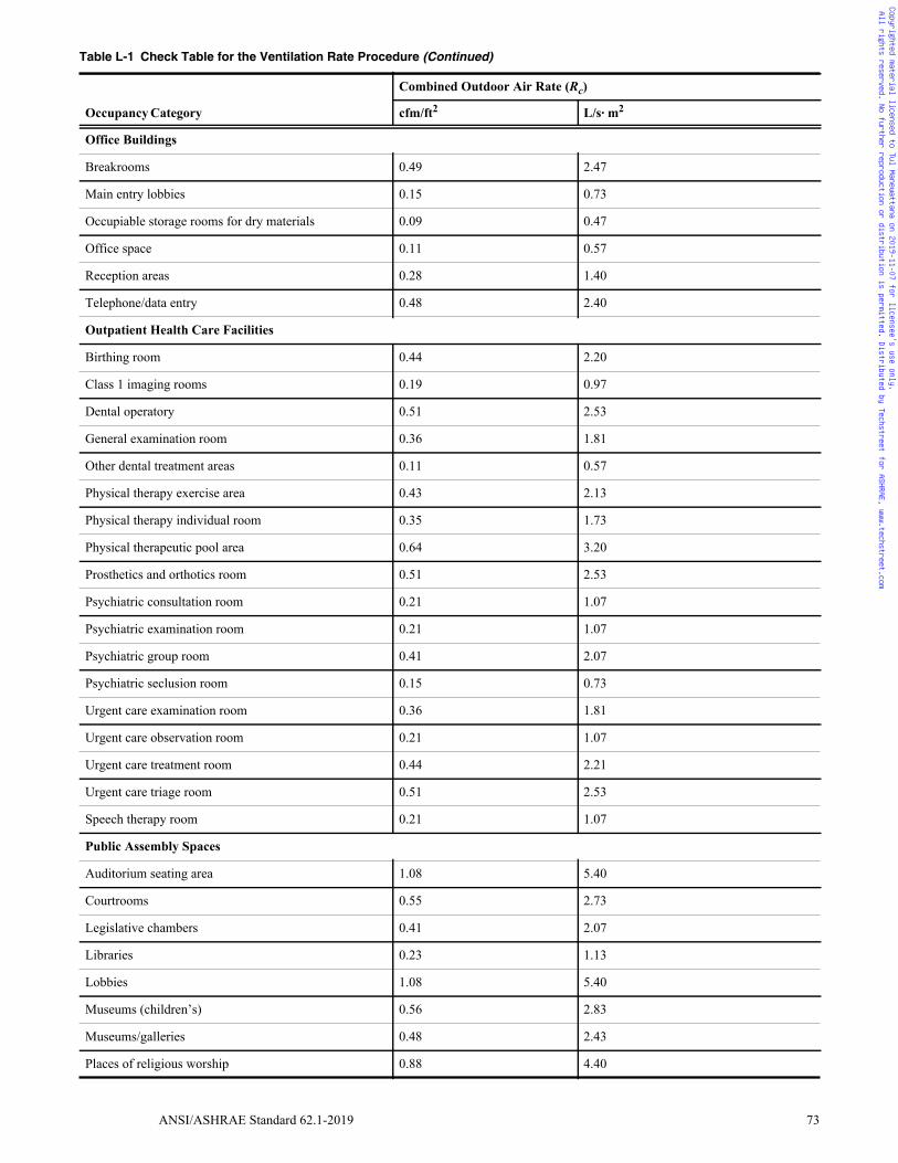
ANSI/ASHRAE Standard 62.1-2019 73
Office Buildings
Breakrooms 0.49 2.47
Main entry lobbies 0.15 0.73
Occupiable storage rooms for dry materials 0.09 0.47
Office space 0.11 0.57
Reception areas 0.28 1.40
Telephone/data entry 0.48 2.40
Outpatient Health Care Facilities
Birthing room 0.44 2.20
Class 1 imaging rooms 0.19 0.97
Dental operatory 0.51 2.53
General examination room 0.36 1.81
Other dental treatment areas 0.11 0.57
Physical therapy exercise area 0.43 2.13
Physical therapy individual room 0.35 1.73
Physical therapeutic pool area 0.64 3.20
Prosthetics and orthotics room 0.51 2.53
Psychiatric consultation room 0.21 1.07
Psychiatric examination room 0.21 1.07
Psychiatric group room 0.41 2.07
Psychiatric seclusion room 0.15 0.73
Urgent care examination room 0.36 1.81
Urgent care observation room 0.21 1.07
Urgent care treatment room 0.44 2.21
Urgent care triage room 0.51 2.53
Speech therapy room 0.21 1.07
Public Assembly Spaces
Auditorium seating area 1.08 5.40
Courtrooms 0.55 2.73
Legislative chambers 0.41 2.07
Libraries 0.23 1.13
Lobbies 1.08 5.40
Museums (children’s) 0.56 2.83
Museums/galleries 0.48 2.43
Places of religious worship 0.88 4.40
Table L-1 Check Table for the Ventilation Rate Procedure (Continued)
Occupancy Category
Combined Outdoor Air Rate (Rc)
cfm/ft2 L/s· m2
Copyrighted material licensed to Tul Manewattana on 2019-11-07 for licensee's use only. All rights reserved. No further reproduction or distribution is permitted. Distributed by Techstreet for ASHRAE, www.techstreet.com

74 ANSI/ASHRAE Standard 62.1-2019
Retail
Sales (except as below) 0.31 1.56
Barbershop 0.33 1.67
Beauty and nail salons 0.83 4.13
Coin-operated laundries 0.36 1.81
Mall common areas 0.48 2.43
Pet shops (animal areas) 0.34 1.71
Supermarket 0.16 0.81
Sports and Entertainment
Bowling alley (seating) 0.69 3.47
Disco/dance floors 2.75 13.73
Gambling casinos 1.44 7.28
Game arcades 0.44 2.21
Gym, sports arena (play area) 0.43 2.13
Health club/aerobics room 1.15 5.73
Health club/weight rooms 0.35 1.73
Spectator areas 1.58 8.00
Stages, studios 1.01 5.07
Swimming (pool and deck) 0.64 3.20
Transient Residential
Dwelling unit 0.10 0.50
Table L-1 Check Table for the Ventilation Rate Procedure (Continued)
Occupancy Category
Combined Outdoor Air Rate (Rc)
cfm/ft2 L/s· m2
Copyrighted material licensed to Tul Manewattana on 2019-11-07 for licensee's use only. All rights reserved. No further reproduction or distribution is permitted. Distributed by Techstreet for ASHRAE, www.techstreet.com

ภาคผนวก ง
CO2 Based DCV
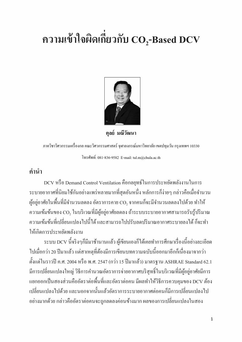
ความเขาใจผดเกยวกบ CO2-Based DCV
ตลย มณวฒนา
ภาควชาวศวกรรมเครองกล คณะวศวกรรมศาสตร จฬาลงกรณมหาวทยาลย เขตปทมวน กรงเทพฯ 10330
โทรศพท: 081-836-9582 E-mail: [email protected]
คานา
DCV หรอ Demand Control Ventilation คอกลยทธในการประหยดพลงงานในการ
ระบายอากาศทนยมใชกนอยางแพรหลายมากทสดอนหนง หลกการกงายๆ กลาวคอเมอจานวน
ผอยอาศยในพนทมจานวนลดลง อตราการคาย CO2 จากคนกจะมจานวนลดลงไปดวย ทาให
ความเขมขนของ CO2 ในบรเวณทมผอยอาศยลดลง ถาระบบระบายอากาศสามารถรบรปรมาณ
ความเขมขนทเปลยนแปลงไปนได และสามารถไปปรบลดปรมาณอากาศระบายลงได กจะทา
ใหเกดการประหยดพลงงาน
ระบบ DCV นจรงๆกมมาชานานแลว ผเขยนเองกไดเคยทาการศกษาเรองนอยางละเอยด
ไปเมอกวา 20 ปมาแลว แตสาเหตทตองมการเขยนบทความฉบบนออกมาอกกเนองมาจากวา
ตงแตในราวป ค.ศ. 2004 หรอ พ.ศ. 2547 (กวา 15 ปมาแลว) มาตรฐาน ASHRAE Standard 62.1
มการเปลยนแปลงใหญ วธการคานวณอตราการจายอากาศบรสทธในบรเวณทมผอยอาศยมการ
แยกออกเปนสองสวนคออตราตอพนทและอตราตอคน มผลทาใหวธการควบคมของ DCV ตอง
เปลยนแปลงไปดวย และนอกจากนนแลวอตราการระบายอากาศตอคนกมการเปลยนแปลงไป
อยางมากดวย กลาวคออตราตอคนจะถกลดลงคอนขางมาก ผลของการเปลยนแปลงในสอง
1

ประเดนดงกลาวยงไมคอยเปนททราบแนชดในหมวศวกรออกแบบระบบระบายอากาศและ
ผใชงานในประเทศ ทาใหเกดการถกเถยงกนอยบอยครง ผเขยนจงคดวาสมควรทจะเอาหวขอน
มาชแจงใหเกดความกระจางอกครง
พนฐานของระบบ CO2-Based DCV
CO2 เปน Bioeffluents ทเกดขนจากคนในอตราตามขนาดของรางกาย อาย เพศ และ
ระดบกจกรรม (Metabolic Rate) นอกจากนนแลวในเวลาเดยวกนคนยงผลตกลนตว (Odorous
Bioeffluents) ออกมาอกดวย ผลลพธของงานวจยยงพบอกดวยวาอตราการผลตกลนตวนมคา
แปรผนโดยตรงกบอตราการผลต CO2 ดวยสาเหตดงกลาวขางตน CO2 จงมกถกใชเปน
“ตวแทน” ของมลพษทปลอยออกมาจากตวคนอยเสมอจนผคนสวนมากนกไปวา CO2 เปน
มลพษ (จรงๆกเปนในระดบหนง แตความเขมขนตองสงมากๆ เชน มคาเกนกวา 5,000 ppm เปน
ตน)
รปท 1: Single Zone CO2
เนองจากวาอตราการผลต CO2 นเราสามารถทจะคานวณไดใกลเคยงทาใหเราสามารถใช
คาความเขมขนของ CO2 ในหองไปคานวณหาอตราการระบายอากาศทเหมาะสมไดถาเราทราบ
จานวนผอยอาศย และในทางกลบกน ถาเรารวาเรากาลงระบายอากาศอยเทาใด เรากสามารถใช
ความเขมขนของ CO2 ไปคานวณหาจานวนผอยอาศยภายในหองได
CO2-based DCV ไมควรนาไปใชในสถานททมแหลงกาเนด CO2 นอกเหนอจากผอย
อาศย อาทเชน หองทมอปกรณการเผาไหม เชน เตาหรอมการใชนาแขงแหงเปนตน เพราะจะทา
2
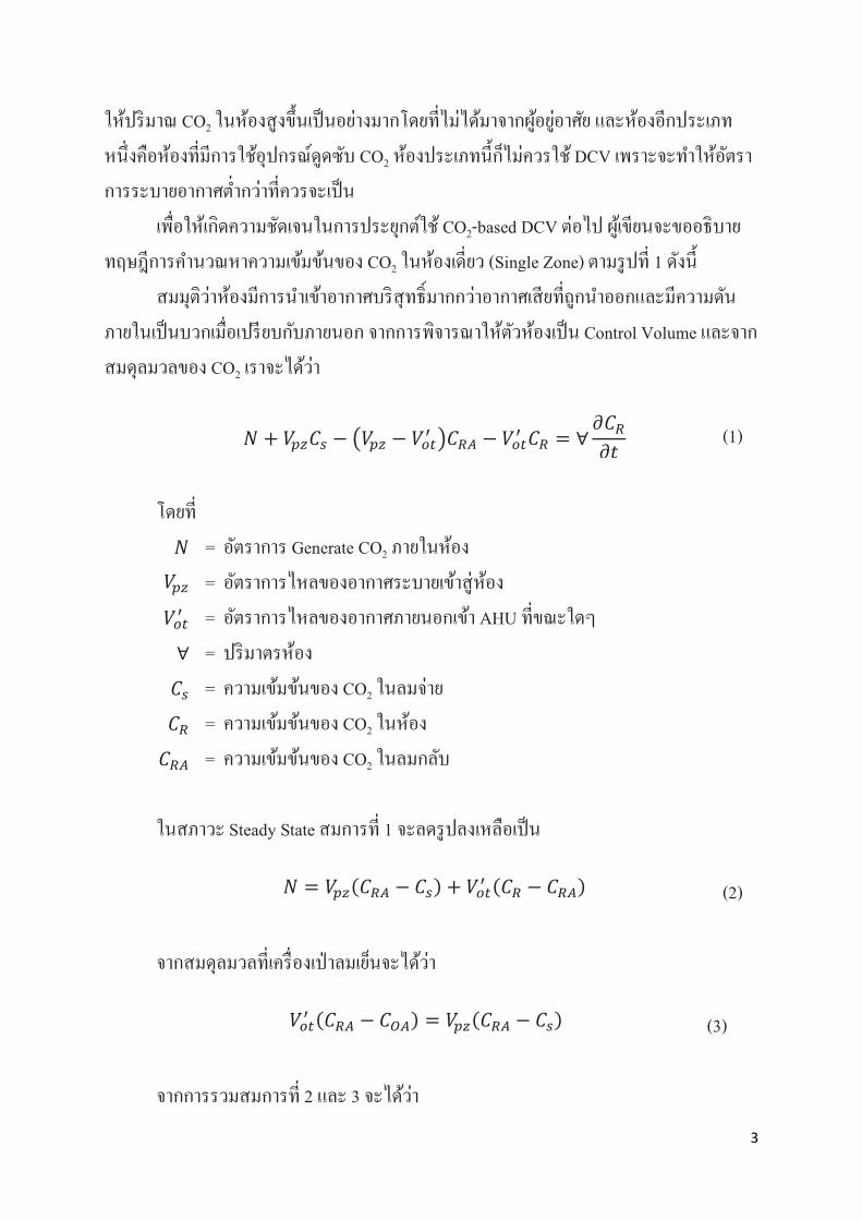
ใหปรมาณ CO2 ในหองสงขนเปนอยางมากโดยทไมไดมาจากผอยอาศย และหองอกประเภท
หนงคอหองทมการใชอปกรณดดซบ CO2 หองประเภทนกไมควรใช DCV เพราะจะทาใหอตรา
การระบายอากาศตากวาทควรจะเปน
เพอใหเกดความชดเจนในการประยกตใช CO2-based DCV ตอไป ผเขยนจะขออธบาย
ทฤษฎการคานวณหาความเขมขนของ CO2 ในหองเดยว (Single Zone) ตามรปท 1 ดงน
สมมตวาหองมการนาเขาอากาศบรสทธมากกวาอากาศเสยทถกนาออกและมความดน
ภายในเปนบวกเมอเปรยบกบภายนอก จากการพจารณาใหตวหองเปน Control Volume และจาก
สมดลมวลของ CO2 เราจะไดวา
โดยท
𝑁𝑁 = อตราการ Generate CO2 ภายในหอง
𝑉𝑉𝑝𝑝𝑝𝑝 = อตราการไหลของอากาศระบายเขาสหอง
𝑉𝑉𝑜𝑜𝑜𝑜′ = อตราการไหลของอากาศภายนอกเขา AHU ทขณะใดๆ
∀ = ปรมาตรหอง
𝐶𝐶𝑠𝑠 = ความเขมขนของ CO2 ในลมจาย
𝐶𝐶𝑅𝑅 = ความเขมขนของ CO2 ในหอง
𝐶𝐶𝑅𝑅𝑅𝑅 = ความเขมขนของ CO2 ในลมกลบ
ในสภาวะ Steady State สมการท 1 จะลดรปลงเหลอเปน
จากสมดลมวลทเครองเปาลมเยนจะไดวา
จากการรวมสมการท 2 และ 3 จะไดวา
𝑁𝑁 + 𝑉𝑉𝑝𝑝𝑝𝑝𝐶𝐶𝑠𝑠 − �𝑉𝑉𝑝𝑝𝑝𝑝 − 𝑉𝑉𝑜𝑜𝑜𝑜′ �𝐶𝐶𝑅𝑅𝑅𝑅 − 𝑉𝑉𝑜𝑜𝑜𝑜′ 𝐶𝐶𝑅𝑅 = ∀𝜕𝜕𝐶𝐶𝑅𝑅𝜕𝜕𝜕𝜕 (1)
𝑁𝑁 = 𝑉𝑉𝑝𝑝𝑝𝑝(𝐶𝐶𝑅𝑅𝑅𝑅 − 𝐶𝐶𝑠𝑠) + 𝑉𝑉𝑜𝑜𝑜𝑜′ (𝐶𝐶𝑅𝑅 − 𝐶𝐶𝑅𝑅𝑅𝑅) (2)
𝑉𝑉𝑜𝑜𝑜𝑜′ (𝐶𝐶𝑅𝑅𝑅𝑅 − 𝐶𝐶𝑂𝑂𝑅𝑅) = 𝑉𝑉𝑝𝑝𝑝𝑝(𝐶𝐶𝑅𝑅𝑅𝑅 − 𝐶𝐶𝑠𝑠) (3)
3
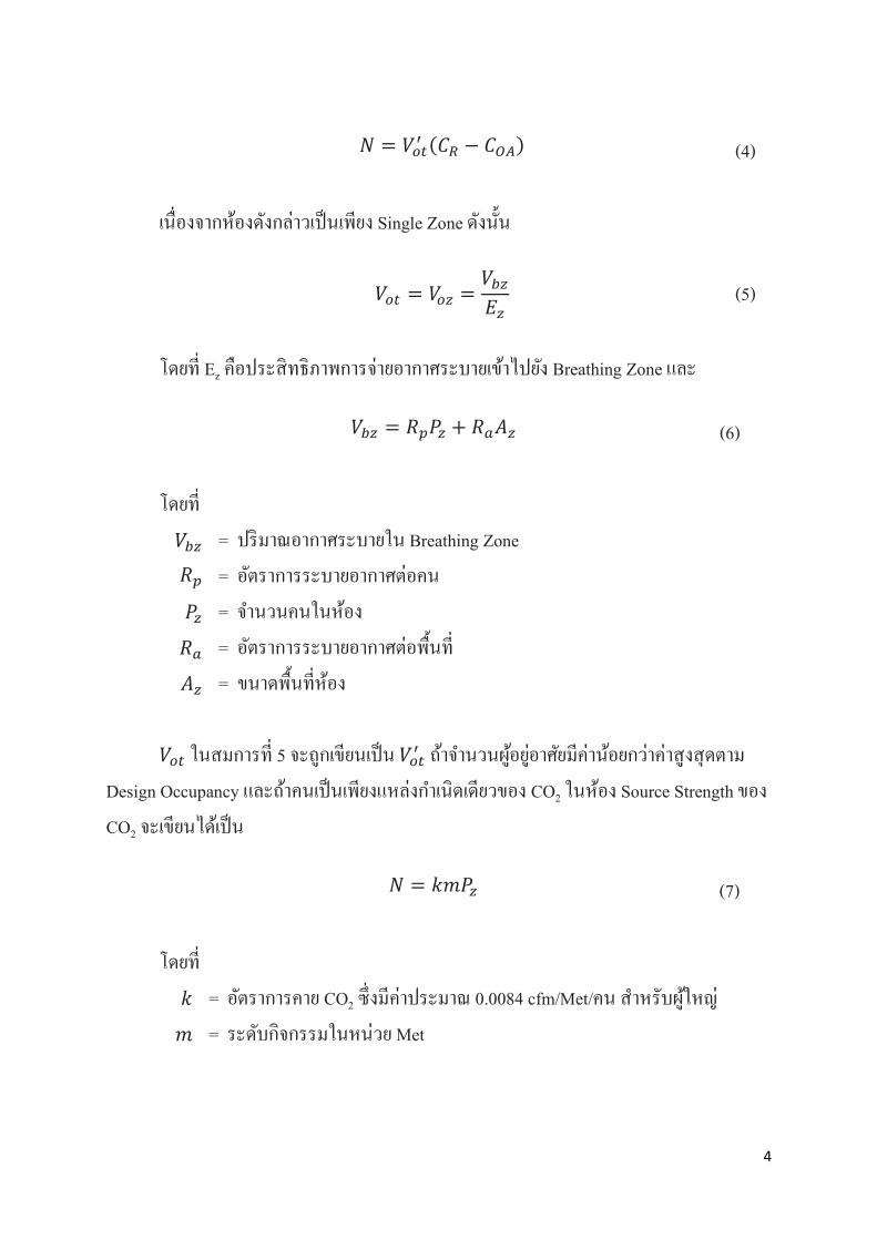
เนองจากหองดงกลาวเปนเพยง Single Zone ดงนน
โดยท Ez คอประสทธภาพการจายอากาศระบายเขาไปยง Breathing Zone และ
โดยท
𝑉𝑉𝑏𝑏𝑝𝑝 = ปรมาณอากาศระบายใน Breathing Zone
𝑅𝑅𝑝𝑝 = อตราการระบายอากาศตอคน
𝑃𝑃𝑝𝑝 = จานวนคนในหอง
𝑅𝑅𝑎𝑎 = อตราการระบายอากาศตอพนท
𝐴𝐴𝑝𝑝 = ขนาดพนทหอง
𝑉𝑉𝑜𝑜𝑜𝑜 ในสมการท 5 จะถกเขยนเปน 𝑉𝑉𝑜𝑜𝑜𝑜′ ถาจานวนผอยอาศยมคานอยกวาคาสงสดตาม
Design Occupancy และถาคนเปนเพยงแหลงกาเนดเดยวของ CO2 ในหอง Source Strength ของ
CO2 จะเขยนไดเปน
โดยท
𝑘𝑘 = อตราการคาย CO2 ซงมคาประมาณ 0.0084 cfm/Met/คน สาหรบผใหญ
𝑚𝑚 = ระดบกจกรรมในหนวย Met
𝑁𝑁 = 𝑉𝑉𝑜𝑜𝑜𝑜′ (𝐶𝐶𝑅𝑅 − 𝐶𝐶𝑂𝑂𝑅𝑅) (4)
𝑉𝑉𝑜𝑜𝑜𝑜 = 𝑉𝑉𝑜𝑜𝑝𝑝 =𝑉𝑉𝑏𝑏𝑝𝑝𝐸𝐸𝑝𝑝
(5)
𝑉𝑉𝑏𝑏𝑝𝑝 = 𝑅𝑅𝑝𝑝𝑃𝑃𝑝𝑝 + 𝑅𝑅𝑎𝑎𝐴𝐴𝑝𝑝 (6)
𝑁𝑁 = 𝑘𝑘𝑚𝑚𝑃𝑃𝑝𝑝 (7)
4
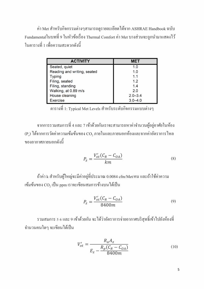
คา Met สาหรบกจกรรมตางๆสามารถดรายละเอยดไดจาก ASHRAE Handbook ฉบบ
Fundamentalในบทท 9 ในหวขอเรอง Thermal Comfort คา Met บางสวนจะถกนามาแสดงไว
ในตารางท 1 เพอความสะดวกดงน
ตารางท 1: Typical Met Levels สาหรบระดบกจกรรมแบบตางๆ
จากการรวมสมการท 4 และ 7 เขาดวยกนเราจะสามารถหาคาจานวนผอยอาศยในหอง
(Pz) ไดจากการวดคาความเขมขนของ CO2 ภายในและภายนอกหองและจากคาอตราการไหล
ของอากาศภายนอกดงน
ถาคา k สาหรบผใหญจะมคาอยทประมาณ 0.0084 cfm/Met/คน และถาใชคาความ
เขมขนของ CO2 เปน ppm เราจะเขยนสมการขางบนไดเปน
รวมสมการ 5 6 และ 9 เขาดวยกน จะไดวาอตราการจายอากาศบรสทธเขาไปยงหองท
จานวนคนใดๆ จะเขยนไดเปน
𝑃𝑃𝑝𝑝 =𝑉𝑉𝑜𝑜𝑜𝑜′ (𝐶𝐶𝑅𝑅 − 𝐶𝐶𝑂𝑂𝑅𝑅)
𝑘𝑘𝑚𝑚 (8)
𝑃𝑃𝑝𝑝 =𝑉𝑉𝑜𝑜𝑜𝑜′ (𝐶𝐶𝑅𝑅 − 𝐶𝐶𝑂𝑂𝑅𝑅)
8400𝑚𝑚 (9)
𝑉𝑉𝑜𝑜𝑜𝑜′ =𝑅𝑅𝑎𝑎𝐴𝐴𝑝𝑝
𝐸𝐸𝑝𝑝 −𝑅𝑅𝑝𝑝(𝐶𝐶𝑅𝑅 − 𝐶𝐶𝑂𝑂𝑅𝑅)
8400𝑚𝑚
(10)
5
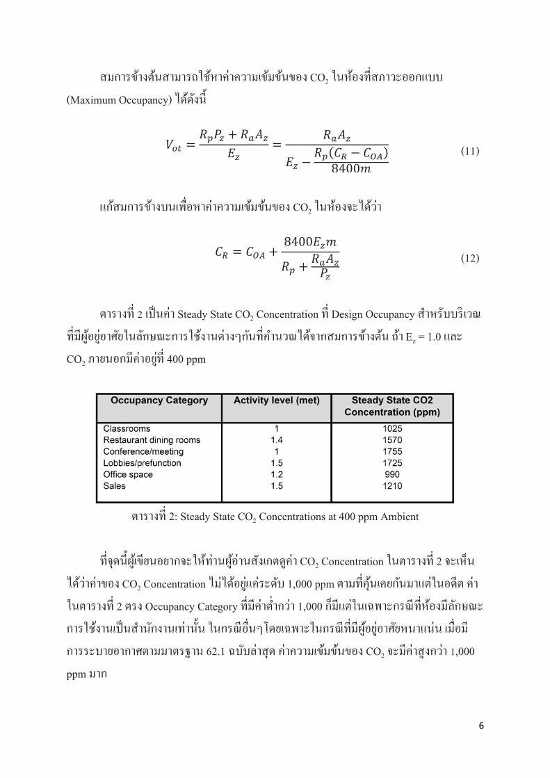
สมการขางตนสามารถใชหาคาความเขมขนของ CO2 ในหองทสภาวะออกแบบ
(Maximum Occupancy) ไดดงน
แกสมการขางบนเพอหาคาความเขมขนของ CO2 ในหองจะไดวา
ตารางท 2 เปนคา Steady State CO2 Concentration ท Design Occupancy สาหรบบรเวณ
ทมผอยอาศยในลกษณะการใชงานตางๆกนทคานวณไดจากสมการขางตน ถา Ez = 1.0 และ
CO2 ภายนอกมคาอยท 400 ppm
ตารางท 2: Steady State CO2 Concentrations at 400 ppm Ambient
ทจดนผเขยนอยากจะใหทานผอานสงเกตดคา CO2 Concentration ในตารางท 2 จะเหน
ไดวาคาของ CO2 Concentration ไมไดอยแคระดบ 1,000 ppm ตามทคนเคยกนมาแตในอดต คา
ในตารางท 2 ตรง Occupancy Category ทมคาตากวา 1,000 กมแตในเฉพาะกรณทหองมลกษณะ
การใชงานเปนสานกงานเทานน ในกรณอนๆโดยเฉพาะในกรณทมผอยอาศยหนาแนน เมอม
การระบายอากาศตามมาตรฐาน 62.1 ฉบบลาสด คาความเขมขนของ CO2 จะมคาสงกวา 1,000
ppm มาก
𝑉𝑉𝑜𝑜𝑜𝑜 =𝑅𝑅𝑝𝑝𝑃𝑃𝑝𝑝 + 𝑅𝑅𝑎𝑎𝐴𝐴𝑝𝑝
𝐸𝐸𝑝𝑝=
𝑅𝑅𝑎𝑎𝐴𝐴𝑝𝑝
𝐸𝐸𝑝𝑝 −𝑅𝑅𝑝𝑝(𝐶𝐶𝑅𝑅 − 𝐶𝐶𝑂𝑂𝑅𝑅)
8400𝑚𝑚
(11)
𝐶𝐶𝑅𝑅 = 𝐶𝐶𝑂𝑂𝑅𝑅 +8400𝐸𝐸𝑝𝑝𝑚𝑚
𝑅𝑅𝑝𝑝 + 𝑅𝑅𝑎𝑎𝐴𝐴𝑝𝑝𝑃𝑃𝑝𝑝
(12)
6

อะไรทเปลยนไปจากเดม
ตงแตกอนป ค.ศ. 2004 คอเรมมาตงแตป ค.ศ. 1989 มาตรฐาน 62.1 จะระบอตราการ
ระบายอากาศเปนตอคนอยางเดยวจนกระทงในป ค.ศ. 2004 ถงไดมการเปลยนแปลงใหญ เปน
อตราทงตอคนและพนท
ในสมยทอตราการระบายอากาศเปนเพยงแตอตราเฉพาะตอคน การควบคม DCV เปน
เรองงายมากเพราะการควบคมกเพยงแตปรบอตราการระบายอากาศใหความเขมขนของ CO2 ใน
หองมคาคงทเทานน เหมอนกบการตงคา Thermostat ใหรกษาอณหภมหองไวใหคงท แตพอ
มาตรฐาน 62.1 ในป ค.ศ. 2004 ถกประกาศใชออกมา ความงายทเคยมกไมเหมอนเดมเสยแลว
เนองจากวาอตราการระบายอากาศมไดขนอยแตเพยงจานวนคนอยางเดยวแตขนอยกบขนาด
พนทหองดวย เพอใหเกดความกระจางในเรองนผเขยนจะขอยกตวอยางจากเอกสารอางอง [1]
ซงเขยนไวไดดมากมาใหพวกเราดกนเปนตวอยาง
สมมตวาเราอยในหองเรยนแบบบรรยายขนาด 1,000 ตารางฟต มนกเรยนอย 65 คน
มาตรฐาน 62.1 สมยกอนป ค.ศ. 2004 บอกใหเราระบายอากาศ 15 cfm/คน คอ Vbz = 15 x 65 =
975 cfm ใชคา Ez = 1.0 และ Vot = Voz เนองจากเปน Single Zone สมมตใหคาเฉลยของระดบ
กจกรรมคอ Met = 1.25 และ CO2 Generation Rate, k = 0.0084 cfm/คน/Met กจะทาใหเรา
สามารถคานวณไดวาปรมาณ CO2 ทเกดขนคอ 65 x 0.0084 x 1.25 cfm ซงถาเอา 975 cfm ของ
Vbz ไปหาร กจะไดวาระดบ CO2 ในหองจะเพมขน 700 ppm จากคา CO2 ภายนอกอาคาร (ในทน
ตอไปเราจะสมมตใหระดบ CO2 ภายนอกอาคารมคาคงทเทากบ 400 ppm) และทาใหระดบ CO2
ภายในหองเพมขนเปน 700 + 400 = 1,100 ppm
ในกรณทไมใช DCV อตราการระบายอากาศกจะคงทอยท 975 cfm เสมอไมวาจานวนผ
อยอาศยจะมคาลดลงหรอไม แตถามการใช DCV ปรมาณการระบายอากาศกจะลดลงตาม
จานวนคน ดงแสดงในรปท 2
สมมตวาจานวนคนลดลงจาก 65 เปน 50 ความเขมขนของ CO2 ในหองกจะลดลงเปน
400 + (50 x 0.0084 x 1.25)×106/975 ppm = 940 ppm โดยประมาณ ซงตากวา Set Point 1,100
ppm เดม ระบบ DCV กจะปรบลดการระบายอากาศลงจาก 975 cfm ใหเปนเหลอเพยง 50 × 15 =
750 cfm เพอทาใหความเขมขนของ CO2 กลบขนไปเปน 1,100 ppm ดงเดม จะเหนไดวาเมอ
อตราการระบายอากาศขนอยกบตวบคคลแตเพยงอยางเดยว การควบคม DCV กจะ
ตรงไปตรงมาคอแคคอยรกษา Set Point ตามรายการคานวณไวท 1,100 ppm
7

รปท 2: Characteristic ของ CO2-based DCV ในยคกอนป ค.ศ. 2004
คราวนมาลองดสงทเกดขนเมอการระบายอากาศเปนไปตามมาตรฐาน 62.1 ป ค.ศ. 2004
จากตารางคาในมาตรฐานจะพบวาปรมาณการระบายอากาศจะกลายเปน 7.5 cfm/คน บวกกบอก
0.06 cfm/ตารางฟต สาหรบหองเรยนหองเดม จากสมการท 6 จะไดวาปรมาณอากาศบรสทธท
ตองการคอ 7.5 x 65 + 0.06 x 1,000 = 550 cfm (นอยกวาคาตามมาตรฐานในป ค.ศ. 2001 เปน
อยางมาก!!!) ปรมาณการระบายอากาศจะเพมจากคาเพยง 60 cfm เมอไมมผอยอาศยไปเปน 550
cfm เมอมผอยอาศยครบ 65 คนตามทออกแบบไว (ตาม Design Occupancy) สวนคา CO2 ใน
หองจะเพมจาก 400 เปน 1,650 ppm ดงแสดงในรปท 3 คราวนถาจานวนผอยอาศยลดลงจาก 65
ไปเปน 50 เหมอนอยางในคราวทแลว คาความเขมขนของ CO2 ในหองกจะลดลง จากการ
คานวณดวยวธการเชนเดมกจะพบวาคาความเขมขนของ CO2 กนาจะลดลงเหลอเพยงประมาณ
950 + 400 = 1,350 ppm ถาปรมาณการระบายยงไมเปลยน (คออยทคาสงสด 550 cfm ตามเดม)
แตเมอจานวนคนลดลง ระบบ DCV กนาจะสามารถปรบลดปรมาณ Voz ลงไดอยางทควรโดย
ตองปรบลดปรมาณการระบายอากาศลงจนคาความเขมขนของ CO2 กลบขนไปจนถงจดทควร
จะเปน แตคราวนไมงายเหมอนเดมเพราะไมม “Target CO2” งายๆ เปนคาคงทเหมอนอยางใน
คราวทแลว คราวนคาเปาหมายของ CO2 มกราฟเปนเสนโคง มคาเปลยนแปลงอยตลอดเวลา
เนองจากการระบายอากาศเสมอนตอคน (Effective Rate Per Person) มคาไมคงท การคานวณ
Target CO2 ตองการเครองวด/ปรบ Air Flow และตองมคอมพวเตอรมาชวยในการคานวณ!
8

รปท 3: Characteristic ของ CO2-based DCV ในยคหลงป ค.ศ. 2004
มาถงจดนเมอหลายปกอนวศวกรผออกแบบบางคนถงกบบนวาการออกแบบระบบ
DCV ในยคหลงจากค.ศ. 2004 เปนตนมาเปนเรองทเปนไปไมได ซงในความเปนจรงกไมไดแย
ขนาดนน การออกแบบ DCV เพอใหได Characteristic Curve ใกลเคยงกบทแสดงอยในรปท 3
กเปนเรองททาไดไมยากนก รปท 4 เปน Characteristic Curve ของระบบ CO2-Based DCV ท
ASHRAE ไดแนะนาไวใหใชทดแทนระบบ CO2-Based DCV ทใชอยแตเดมกอนป ค.ศ. 2004
จากรปท 4 จะเหนไดวา Characteristic Curve ทไดกไมไดหางไปจากคาตามทฤษฎ (ตามรปท 3)
มากนก ผลประหยดตามทแสดงอยในเอกสารอางอง [1] กยงถอไดวาไมตางกบของเดมมากนก
คอ เชน ถาของเดมทาไดตามทฤษฎอาจประหยด 47% แตถาของใหมทาไดตามรปท 4 อาจ
ประหยดไดเพยง 40% เปนตน ซงกยงถอไดวามผลประหยดคอนขางมากอย
วธการ Setup ระบบเพอใหได Characteristic Curve ดงรปท 4 นทาไดไมยากและไมได
ตองใชอปกรณพเศษใดๆมากไปกวาในอดตเลย รายละเอยดวธการ Setup ดงกลาวในทางปฏบต
ASHRAE ไดใหคาแนะนาไวในเอกสารอางอง [2] สาหรบในกรณ Single Zone โดยให
ดาเนนการตามขนตอนดงตอไปน
9

รปท 4: Characteristic ของ CO2-based DCV แบบงายตามวธท ASHRAE แนะนา
ขนตอนท 1 คานวณคา Voz ตอนทจานวนคนมากทสดตามคา Design Occupancy จากสมการ
ท 6 และตอไปเราจะเรยกคานวาคา Voz-max
ขนตอนท 2 คานวณคา Voz ตอนทจานวนคน Pz = 0 คอไมมคนเลยจากสมการท 6 และตอไป
เราจะเรยกคานวาคา Voz-min
ขนตอนท 3 คานวณคา Steady State CO2 Concentration ทเกดขนในหองนเมอ Voz = Voz-max
และเมอ Voz = Voz-min และเรยกคาทงสองนวา CR-max และ CR-min ตามลาดบ โดย
ปกตคา CR-min นจะมคาเทากบคา CO2 ของอากาศภายนอกอาคารคอมคาประมาณ
400 ppm
ขนตอนท 4 จดหา CO2 Sensor + Controller ทสามารถ Calibrate ใหคา Output Signal เปน
คาสงสดเมอคา CO2 ในหองเปนคา CR-max และใหคา Output Signal เปนคาตาสด
เมอคา CO2 ในหองเปนคา CR-min แลวสงสญญาณการควบคมนไปยง Outdoor Air
Damper (รปท 5)
ขนตอนท 5 ปรบ Outdoor Air Damper ให สงลมเทากบ Voz-max เมอไดรบ Output Signal
สงสดจาก CO2 Controller
10
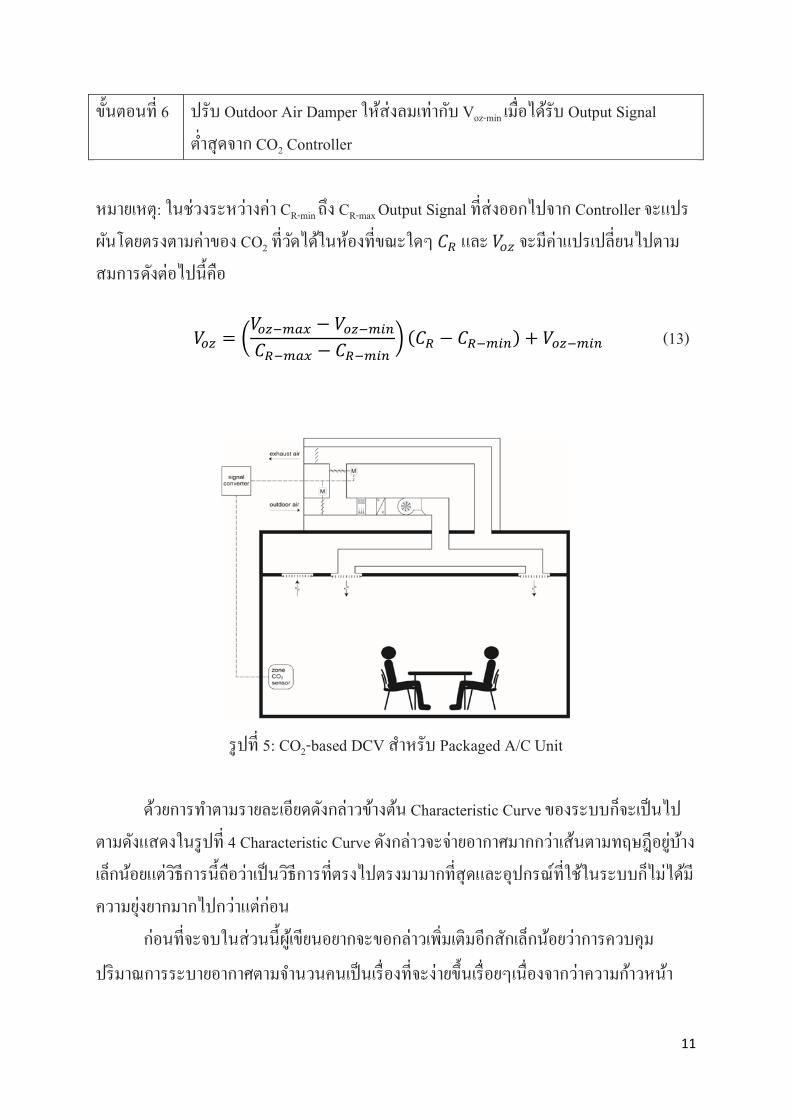
ขนตอนท 6 ปรบ Outdoor Air Damper ใหสงลมเทากบ Voz-min เมอไดรบ Output Signal
ตาสดจาก CO2 Controller
หมายเหต: ในชวงระหวางคา CR-min ถง CR-max Output Signal ทสงออกไปจาก Controller จะแปร
ผนโดยตรงตามคาของ CO2 ทวดไดในหองทขณะใดๆ 𝐶𝐶𝑅𝑅 และ 𝑉𝑉𝑜𝑜𝑝𝑝 จะมคาแปรเปลยนไปตาม
สมการดงตอไปนคอ
รปท 5: CO2-based DCV สาหรบ Packaged A/C Unit
ดวยการทาตามรายละเอยดดงกลาวขางตน Characteristic Curve ของระบบกจะเปนไป
ตามดงแสดงในรปท 4 Characteristic Curve ดงกลาวจะจายอากาศมากกวาเสนตามทฤษฎอยบาง
เลกนอยแตวธการนถอวาเปนวธการทตรงไปตรงมามากทสดและอปกรณทใชในระบบกไมไดม
ความยงยากมากไปกวาแตกอน
กอนทจะจบในสวนนผเขยนอยากจะขอกลาวเพมเตมอกสกเลกนอยวาการควบคม
ปรมาณการระบายอากาศตามจานวนคนเปนเรองทจะงายขนเรอยๆเนองจากวาความกาวหนา
𝑉𝑉𝑜𝑜𝑝𝑝 = �𝑉𝑉𝑜𝑜𝑝𝑝−𝑚𝑚𝑎𝑎𝑚𝑚 − 𝑉𝑉𝑜𝑜𝑝𝑝−𝑚𝑚𝑚𝑚𝑚𝑚
𝐶𝐶𝑅𝑅−𝑚𝑚𝑎𝑎𝑚𝑚 − 𝐶𝐶𝑅𝑅−𝑚𝑚𝑚𝑚𝑚𝑚� (𝐶𝐶𝑅𝑅 − 𝐶𝐶𝑅𝑅−𝑚𝑚𝑚𝑚𝑚𝑚) + 𝑉𝑉𝑜𝑜𝑝𝑝−𝑚𝑚𝑚𝑚𝑚𝑚 (13)
11
ทางเทคโนโลยจะทาใหเราสามารถนบจานวนคนในหองไดไมยาก เทคโนโลยการวดและการ
ควบคมปรมาณลมจายกจะงายขนเรอยๆและมราคาถกลง เมอถงเวลานน เรากสามารถทจะใช
สมการตางๆทกลาวถงไปแลวในตอนตนทาการคานวณใน Controller ไดเลยและสงให
Intelligent Motor/Advanced Air Flow Measurement ปรบลดอตราการจายลมไดอยางไมยาก
เมอเวลานนมาถง (จรงๆกถงแลวนะ) การประหยดพลงงานดวย Dynamic Reset/DCV กจะ
สมบรณและทางานใหเราไดอยางมประสทธภาพสงสด
สรป
CO2-based DCV ตามมาตรฐาน 62.1 ฉบบตงแตป ค.ศ. 2004 มความยงยากกวาในอดต
อยบางเลกนอยแตกอยในวสยทสามารถจดการไดตามรายละเอยดวธการดงทกลาวไปแลว
ขางตน สงทควรทาความเขาใจใหมใหชดเจนคอ
1) คาของ CO2 สงสดในหองเมอมผอยอาศยเตมตาม Design Occupancy มคาสงกวา 1,000
ppm มาก (ในหลายๆกรณ) ทานผอานไมควรยดอยกบ “Rule of Thumb” วา CO2 ในหอง
จะตองเปน 700 + 400 = 1,100 ppm เสมอไปดงทมกจะเขาใจกนผดๆ เปนสวนมาก
2) คาของปรมาณการระบายอากาศตามมาตรฐาน 62.1 ในปจจบน เปนคาขนตาแลวจรงๆ
ตงแตป ค.ศ. 2004 เปนตนมา ปรมาณการระบายอากาศถกปรบใหลดลงเปนอยางมาก
เพอสะทอนวาเปนคาขนตาแลวจรงๆ ดงนนจงอยากใหทานผอานมความชดเจนในเรอง
น และเขาใจวาเรากาลงอยในสภาวะหมนเหมของคาวา “การระบายอากาศเพอคณภาพ
อากาศภายในอาคารทยอมรบได” แลวจรงๆ
เอกสารอางอง
1. Stanke, D. 2006. “Standard 62.1-2004 System Operation: Dynamic Reset Options”
ASHRAE Journal 48(12):18–32.
2. ASHRAE. 2016. 62.1 User’s Manual: ANSI/ASHRAE Standard 62.1-2016.
12
ภาคผนวก จ
ASHRAE Standard 62.1-2019
INFORMATIVE APPENDIX E
ACCEPTABLE MASS BALANCE EQUATIONS
FOR USE WITH THE IAQP
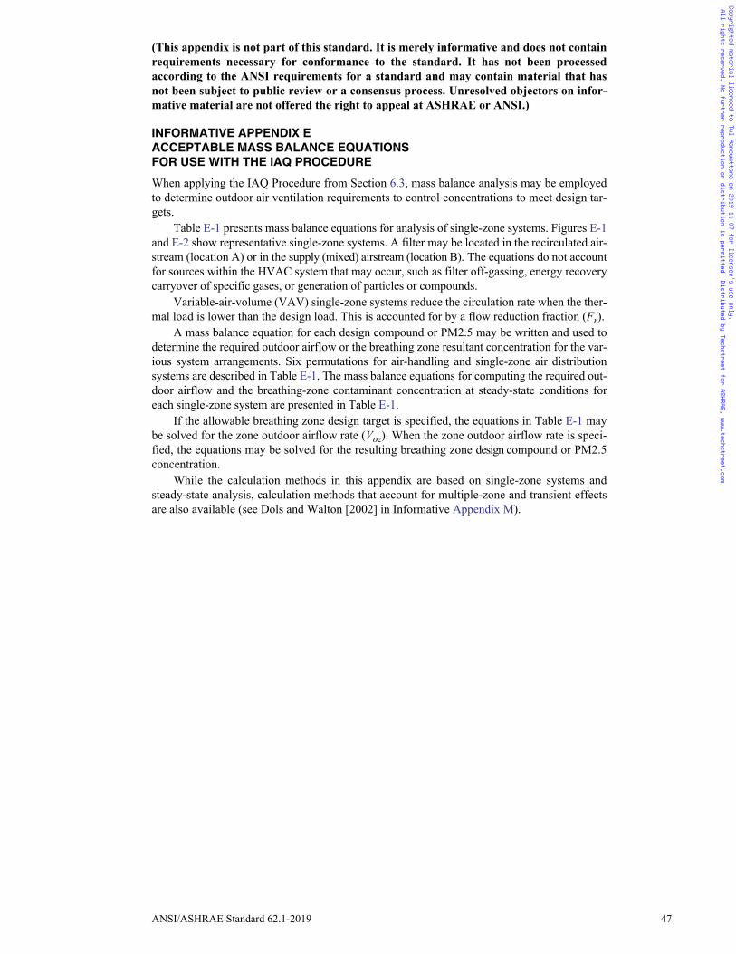
ANSI/ASHRAE Standard 62.1-2019 47
(This appendix is not part of this standard. It is merely informative and does not containrequirements necessary for conformance to the standard. It has not been processedaccording to the ANSI requirements for a standard and may contain material that hasnot been subject to public review or a consensus process. Unresolved objectors on infor-mative material are not offered the right to appeal at ASHRAE or ANSI.)
INFORMATIVE APPENDIX EACCEPTABLE MASS BALANCE EQUATIONSFOR USE WITH THE IAQ PROCEDURE
When applying the IAQ Procedure from Section 6.3, mass balance analysis may be employedto determine outdoor air ventilation requirements to control concentrations to meet design tar-gets.
Table E-1 presents mass balance equations for analysis of single-zone systems. Figures E-1and E-2 show representative single-zone systems. A filter may be located in the recirculated air-stream (location A) or in the supply (mixed) airstream (location B). The equations do not accountfor sources within the HVAC system that may occur, such as filter off-gassing, energy recoverycarryover of specific gases, or generation of particles or compounds.
Variable-air-volume (VAV) single-zone systems reduce the circulation rate when the ther-mal load is lower than the design load. This is accounted for by a flow reduction fraction (Fr).
A mass balance equation for each design compound or PM2.5 may be written and used todetermine the required outdoor airflow or the breathing zone resultant concentration for the var-ious system arrangements. Six permutations for air-handling and single-zone air distributionsystems are described in Table E-1. The mass balance equations for computing the required out-door airflow and the breathing-zone contaminant concentration at steady-state conditions foreach single-zone system are presented in Table E-1.
If the allowable breathing zone design target is specified, the equations in Table E-1 maybe solved for the zone outdoor airflow rate (Voz). When the zone outdoor airflow rate is speci-fied, the equations may be solved for the resulting breathing zone design compound or PM2.5concentration.
While the calculation methods in this appendix are based on single-zone systems andsteady-state analysis, calculation methods that account for multiple-zone and transient effectsare also available (see Dols and Walton [2002] in Informative Appendix M).
Copyrighted material licensed to Tul Manewattana on 2019-11-07 for licensee's use only. All rights reserved. No further reproduction or distribution is permitted. Distributed by Techstreet for ASHRAE, www.techstreet.com
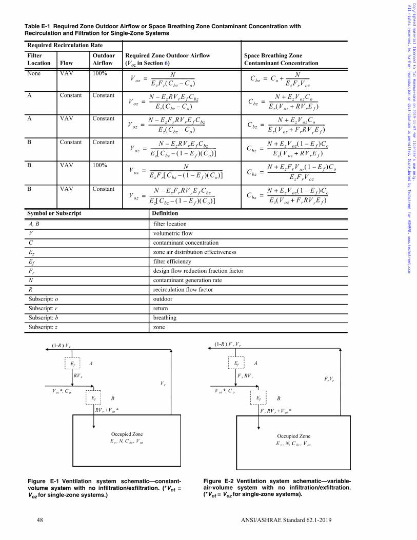
48 ANSI/ASHRAE Standard 62.1-2019
Table E-1 Required Zone Outdoor Airflow or Space Breathing Zone Contaminant Concentration withRecirculation and Filtration for Single-Zone Systems
Required Recirculation Rate
Required Zone Outdoor Airflow(Voz in Section 6)
Space Breathing ZoneContaminant Concentration
FilterLocation Flow
OutdoorAirflow
None VAV 100%
A Constant Constant
A VAV Constant
B Constant Constant
B VAV 100%
B VAV Constant
Symbol or Subscript Definition
A, B filter locationV volumetric flowC contaminant concentrationEz zone air distribution effectivenessEf filter efficiencyFr design flow reduction fraction factorN contaminant generation rateR recirculation flow factorSubscript: o outdoorSubscript: r returnSubscript: b breathingSubscript: z zone
V ozN
EzFr Cbz Co– --------------------------------------= Cbz Co
NEzFrV oz---------------------+=
V ozN EzRV rE f Cbz–
Ez Cbz Co– -------------------------------------------= Cbz
N EzV ozCo+
Ez V oz RV rE f+ -------------------------------------------=
V ozN EzFrRV rE f Cbz–
Ez Cbz Co– --------------------------------------------------= Cbz
N EzV ozCo+
Ez V oz FrRV rE f+ --------------------------------------------------=
V ozN EzRV rE f Cbz–
Ez Cbz 1 E f– Co – ----------------------------------------------------------= Cbz
N EzV oz 1 E f– Co+
Ez V oz RV rE f+ ------------------------------------------------------=
V ozN
EzFr Cbz 1 E f– Co – ----------------------------------------------------------------= Cbz
N EzFrV oz 1 E f– Co+
EzFrV oz------------------------------------------------------------=
V ozN EzFrRV rE f Cbz–
Ez Cbz 1 E f– Co – ----------------------------------------------------------= Cbz
N EzV oz 1 E f– Co+
Ez V oz FrRV rE f+ ------------------------------------------------------=
Figure E-1 Ventilation system schematic—constant-volume system with no infiltration/exfiltration. (*Vot =Voz for single-zone systems.)
Figure E-2 Ventilation system schematic—variable-air-volume system with no infiltration/exfiltration.(*Vot = Voz for single-zone systems).
Copyrighted material licensed to Tul Manewattana on 2019-11-07 for licensee's use only. All rights reserved. No further reproduction or distribution is permitted. Distributed by Techstreet for ASHRAE, www.techstreet.com

ภาคผนวก ฉ
ASHRAE Standard 62.1-2019
SECTION 8
OPERATIONS AND MAINTENANCE
ANSI/ASHRAE Standard 62.1-2019 31
• Sections S6.1, S6.3, S6.4, and S6.5 of Section 9.1, “Casing and Plenum ConstructionStandards”
b. All sections of SMACNA’s Fibrous Glass Duct Construction Standardsc. NFPA 90A, Standard for the Installation of Air-Conditioning and Ventilating Systemsd. NFPA 90B, Standard for the Installation of Warm Air Heating and Air-Conditioning Sys-
tems
7.2 System Start-Up7.2.1 Application. The requirements of this section apply to the following ventilation sys-
tems:
a. Newly installed air-handling systemsb. Existing air-handling systems undergoing supply air or outdoor airflow reduction (Only the
requirements of Section 7.2.2 shall apply to these altered systems.)c. Existing air-handling distribution systems undergoing alterations affecting more than 25%
of the floor area served by the systems (Only the requirements of Section 7.2.2 shall applyto these altered systems.)
7.2.2 Air Balancing and Verification of Outdoor Air Performance. Ventilation systemsshall be balanced in accordance with ASHRAE Standard 111 or another applicable nationalstandards so as to verify conformance with the total outdoor airflow requirements of this stan-dard (Vot).
7.2.3 Testing of Drain Pans. To minimize conditions of water stagnation that may result inmicrobial growth, drain pans shall be field tested under operating conditions that are the mostrestrictive to condensate flow to demonstrate proper drainage.
Exception to 7.2.3: Field testing of drain pans is not required if units with factory-installeddrain pans have been certified (attested in writing) by the manufacturer for proper drain-age when installed as recommended.
Informative Note: Above conditions usually occur at full fan airflow for draw-through fansand minimum fan airflow for blow-through fans.
7.2.4 Ventilation System Start-Up. Ventilation air distribution systems shall be clean ofdirt and debris.
7.2.5 Outdoor Air Dampers. Prior to occupancy, each ventilation system shall be tested todemonstrate that outdoor air dampers operate in accordance with the system design.
7.2.6 Documentation. The following ventilation system documentation shall be provided tothe building owner or his/her designee, retained within the building, and made available to thebuilding operating personnel:
a. An operations and maintenance manual describing basic data relating to the operation andmaintenance of ventilation systems and equipment as installed
b. HVAC controls information consisting of diagrams, schematics, control sequence narra-tives, and maintenance and/or calibration information
c. An air balance report documenting the work performed for Section 7.2.2d. Construction drawings of record, control drawings, and final design drawingse. Design criteria and assumptions
8. OPERATIONS AND MAINTENANCE
8.1 General8.1.1 Application. The requirements of this section apply to buildings and their ventilation
systems and their components constructed or renovated after the adoption date of this section.8.1.2 Building Alterations or Change of Use. When buildings are altered or when changes
in building use, occupant category, significant change in occupant density, or other changesinconsistent with system design assumptions are made, the ventilation system design, opera-tion, and maintenance shall be reevaluated and the operations and maintenance (O&M) manualupdated as necessary.8.2 O&M Manual. An O&M manual, either written or electronic, shall be developed andmaintained on site or in a centrally accessible location for the working life of the applicableventilation system equipment or components. This manual shall be updated as necessary. The
Copyrighted material licensed to Tul Manewattana on 2019-11-07 for licensee's use only. All rights reserved. No further reproduction or distribution is permitted. Distributed by Techstreet for ASHRAE, www.techstreet.com
Tul
Rectangle
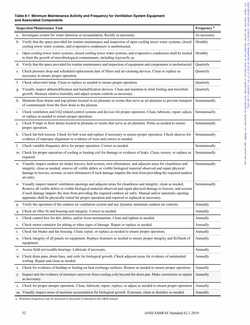
32 ANSI/ASHRAE Standard 62.1-2019
Table 8-1 Minimum Maintenance Activity and Frequency for Ventilation System Equipmentand Associated Components
Inspection/Maintenance Task Frequency a
a. Investigate system for water intrusion or accumulation. Rectify as necessary. As necessary
b. Verify that the space provided for routine maintenance and inspection of open cooling tower water systems, closed cooling tower water systems, and evaporative condensers is unobstructed.
Monthly
c. Open cooling tower water systems, closed cooling tower water systems, and evaporative condensers shall be treated to limit the growth of microbiological contaminants, including legionella sp.
Monthly
d. Verify that the space provided for routine maintenance and inspection of equipment and components is unobstructed. Quarterly
e. Check pressure drop and scheduled replacement date of filters and air-cleaning devices. Clean or replace as necessary to ensure proper operation.
Quarterly
f. Check ultraviolet lamp. Clean or replace as needed to ensure proper operation. Quarterly
g. Visually inspect dehumidification and humidification devices. Clean and maintain to limit fouling and microbial growth. Measure relative humidity and adjust system controls as necessary.
Quarterly
h. Maintain floor drains and trap primer located in air plenums or rooms that serve as air plenums to prevent transport of contaminants from the floor drain to the plenum.
Semiannually
i. Check ventilation and IAQ related control systems and devices for proper operation. Clean, lubricate, repair, adjust, or replace as needed to ensure proper operation.
Semiannually
j. Check P-traps in floor drains located in plenums or rooms that serve as air plenums. Prime as needed to ensure proper operation.
Semiannually
k. Check fan belt tension. Check for belt wear and replace if necessary to ensure proper operation. Check sheaves for evidence of improper alignment or evidence of wear and correct as needed.
Semiannually
l. Check variable-frequency drive for proper operation. Correct as needed. Semiannually
m. Check for proper operation of cooling or heating coil for damage or evidence of leaks. Clean, restore, or replace as required.
Semiannually
n. Visually inspect outdoor air intake louvers, bird screens, mist eliminators, and adjacent areas for cleanliness and integrity; clean as needed; remove all visible debris or visible biological material observed and repair physical damage to louvers, screens, or mist eliminators if such damage impairs the item from providing the required outdoor air entry.
Semiannually
o. Visually inspect natural ventilation openings and adjacent areas for cleanliness and integrity; clean as needed. Remove all visible debris or visible biological material observed and repair physical damage to louvers, and screens if such damage impairs the item from providing the required outdoor air entry. Manual and/or automatic opening apparatus shall be physically tested for proper operation and repaired or replaced as necessary.
Semiannually
p. Verify the operation of the outdoor air ventilation system and any dynamic minimum outdoor air controls. Annually
q. Check air filter fit and housing seal integrity. Correct as needed. Annually
r. Check control box for dirt, debris, and/or loose terminations. Clean and tighten as needed. Annually
s. Check motor contactor for pitting or other signs of damage. Repair or replace as needed. Annually
t. Check fan blades and fan housing. Clean, repair, or replace as needed to ensure proper operation. Annually
u. Check integrity of all panels on equipment. Replace fasteners as needed to ensure proper integrity and fit/finish of equipment.
Annually
v. Assess field serviceable bearings. Lubricate if necessary. Annually
w. Check drain pans, drain lines, and coils for biological growth. Check adjacent areas for evidence of unintended wetting. Repair and clean as needed.
Annually
x. Check for evidence of buildup or fouling on heat exchange surfaces. Restore as needed to ensure proper operation. Annually
y. Inspect unit for evidence of moisture carryover from cooling coils beyond the drain pan. Make corrections or repairs as necessary.
Annually
z. Check for proper damper operation. Clean, lubricate, repair, replace, or adjust as needed to ensure proper operation. Annually
aa. Visually inspect areas of moisture accumulation for biological growth. If present, clean or disinfect as needed. Annually
a. Minimum frequencies may be increased or decreased if indicated in the O&M manual.
Copyrighted material licensed to Tul Manewattana on 2019-11-07 for licensee's use only. All rights reserved. No further reproduction or distribution is permitted. Distributed by Techstreet for ASHRAE, www.techstreet.com

ANSI/ASHRAE Standard 62.1-2019 33
manual shall include the O&M procedures, ventilation system operating schedules and anychanges made thereto, final design drawings, maintenance schedules based on manufacturerinstructions, and the maintenance requirements and frequencies provided in Table 8-1.8.3 Ventilation System Operation. Mechanical and natural ventilation systems shall be oper-ated in a manner consistent with the O&M manual. Systems shall be operated such that spacesare ventilated in accordance with Section 6 during periods of expected occupancy.8.4 Ventilation System Maintenance. The building ventilation system components shall bemaintained in accordance with the O&M manual.
ab. Check condensate pump. Clean or replace as needed. Annually
ac. Visually inspect exposed ductwork and external piping for insulation and vapor barrier for integrity. Correct as needed.
Annually
ad. Verify the accuracy of permanently mounted sensors whose primary function is outdoor air delivery monitoring, outdoor air delivery verification, or dynamic minimum outdoor air control, such as flow stations at an air handler and those used for demand control ventilation, including CO2 sensors. A sensor failing to meet the accuracy specified in the O&M manual shall be recalibrated or replaced. Performance verification shall include output comparison to a measurement reference standard consistent with those specified for similar devices in ASHRAE Standard 41.2 or ASHRAE Standard 111.
5 years
ae. Verify the total quantity of outdoor air delivered by air handlers set to minimum outdoor air mode. If measured minimum airflow rates are less than the design minimum rate documented in the O&M manual, ± a 10% balancing tolerance, (1) confirm the measured rate does not conform with the provisions of this standard and (2) adjust or modify the air-handler components to correct the airflow deficiency. Ventilation systems shall be balanced in accordance with ASHRAE Standard 111 or its equivalent, at least to the extent necessary to verify conformance with the total outdoor airflow and space supply airflow requirements of this standard.
Exception: Units under 2000 cfm (1000 L/s) of supply air are exempt from this requirement.
5 years
Table 8-1 Minimum Maintenance Activity and Frequency for Ventilation System Equipmentand Associated Components (Continued)
Inspection/Maintenance Task Frequency a
a. Minimum frequencies may be increased or decreased if indicated in the O&M manual.
Copyrighted material licensed to Tul Manewattana on 2019-11-07 for licensee's use only. All rights reserved. No further reproduction or distribution is permitted. Distributed by Techstreet for ASHRAE, www.techstreet.com
ภาคผนวก ช
ASHRAE Standard 62.1-2019
NORMATIVE APPENDIX A
MULTIPLE-ZONE SYSTEM VENTILATION
EFFICIENCY: ALTERNATIVE PROCEDURE
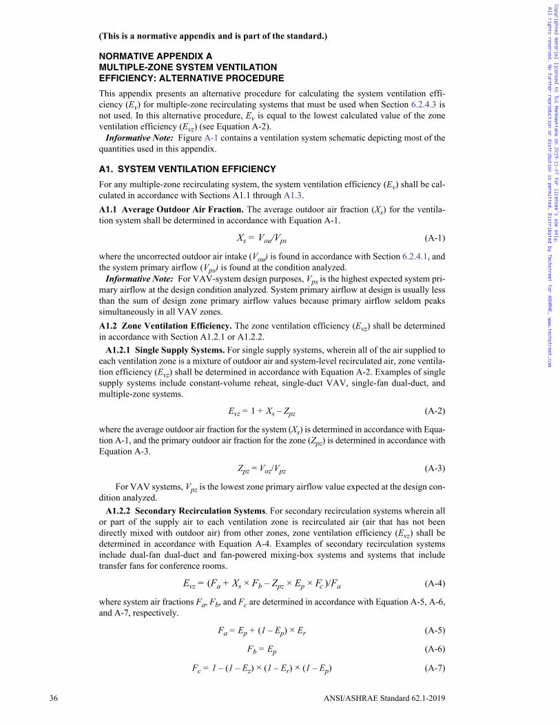
36 ANSI/ASHRAE Standard 62.1-2019
(This is a normative appendix and is part of the standard.)
NORMATIVE APPENDIX AMULTIPLE-ZONE SYSTEM VENTILATIONEFFICIENCY: ALTERNATIVE PROCEDURE
This appendix presents an alternative procedure for calculating the system ventilation effi-ciency (Ev) for multiple-zone recirculating systems that must be used when Section 6.2.4.3 isnot used. In this alternative procedure, Ev is equal to the lowest calculated value of the zoneventilation efficiency (Evz) (see Equation A-2).
Informative Note: Figure A-1 contains a ventilation system schematic depicting most of thequantities used in this appendix.
A1. SYSTEM VENTILATION EFFICIENCY
For any multiple-zone recirculating system, the system ventilation efficiency (Ev) shall be cal-culated in accordance with Sections A1.1 through A1.3.A1.1 Average Outdoor Air Fraction. The average outdoor air fraction (Xs) for the ventila-tion system shall be determined in accordance with Equation A-1.
Xs = Vou/Vps (A-1)
where the uncorrected outdoor air intake (Vou) is found in accordance with Section 6.2.4.1, andthe system primary airflow (Vps) is found at the condition analyzed.
Informative Note: For VAV-system design purposes, Vps is the highest expected system pri-mary airflow at the design condition analyzed. System primary airflow at design is usually lessthan the sum of design zone primary airflow values because primary airflow seldom peakssimultaneously in all VAV zones.A1.2 Zone Ventilation Efficiency. The zone ventilation efficiency (Evz) shall be determinedin accordance with Section A1.2.1 or A1.2.2.
A1.2.1 Single Supply Systems. For single supply systems, wherein all of the air supplied toeach ventilation zone is a mixture of outdoor air and system-level recirculated air, zone ventila-tion efficiency (Evz) shall be determined in accordance with Equation A-2. Examples of singlesupply systems include constant-volume reheat, single-duct VAV, single-fan dual-duct, andmultiple-zone systems.
Evz = 1 + Xs – Zpz (A-2)
where the average outdoor air fraction for the system (Xs) is determined in accordance with Equa-tion A-1, and the primary outdoor air fraction for the zone (Zpz) is determined in accordance withEquation A-3.
Zpz = Voz/Vpz (A-3)
For VAV systems, Vpz is the lowest zone primary airflow value expected at the design con-dition analyzed.
A1.2.2 Secondary Recirculation Systems. For secondary recirculation systems wherein allor part of the supply air to each ventilation zone is recirculated air (air that has not beendirectly mixed with outdoor air) from other zones, zone ventilation efficiency (Evz) shall bedetermined in accordance with Equation A-4. Examples of secondary recirculation systemsinclude dual-fan dual-duct and fan-powered mixing-box systems and systems that includetransfer fans for conference rooms.
Evz = (Fa + Xs × Fb – Zpz × Ep × Fc )/Fa (A-4)
where system air fractions Fa, Fb, and Fc are determined in accordance with Equation A-5, A-6,and A-7, respectively.
Fa = Ep + (1 – Ep) × Er (A-5)
Fb = Ep (A-6)
Fc = 1 – (1 – Ez) × (1 – Er) × (1 – Ep) (A-7)
Copyrighted material licensed to Tul Manewattana on 2019-11-07 for licensee's use only. All rights reserved. No further reproduction or distribution is permitted. Distributed by Techstreet for ASHRAE, www.techstreet.com

ANSI/ASHRAE Standard 62.1-2019 37
Where the zone primary air fraction (Ep) is determined in accordance with Equation A-8,zone secondary recirculation fraction (Er) is determined by the designer based on system con-figuration, and zone air distribution effectiveness (Ez) is determined in accordance with Section6.2.1.2.
Ep = Vpz /Vdz (A-8)
where Vdz is zone discharge airflow.Informative Notes:
1. For plenum return systems with secondary recirculation (e.g., fan-powered VAVwith plenum return), Er is usually less than 1.0, although values may range from 0.1to 1.2 depending upon the location of the ventilation zone relative to other zonesand the air handler. For ducted return systems with secondary recirculation (e.g.,fan-powered VAV with ducted return), Er is typically 0.0, while for those with sys-tem-level recirculation (e.g, dual-fan dual-duct systems with ducted return), Er istypically 1.0. For other system types, Er is typically 0.75.
2. For single-zone and single-supply systems, Ep is 1.0.
A1.3 System Ventilation Efficiency. The system ventilation efficiency shall equal the lowestzone ventilation efficiency among all ventilation zones served by the air handler in accordancewith Equation A-9.
Ev = minimum (Evz) (A-9)
A2. DESIGN PROCESS
The system ventilation efficiency and, therefore, the outdoor air intake flow for the system(Vot) determined as part of the design process are based on the design and minimum expected
Figure A-1 Ventilation system schematic.
Copyrighted material licensed to Tul Manewattana on 2019-11-07 for licensee's use only. All rights reserved. No further reproduction or distribution is permitted. Distributed by Techstreet for ASHRAE, www.techstreet.com
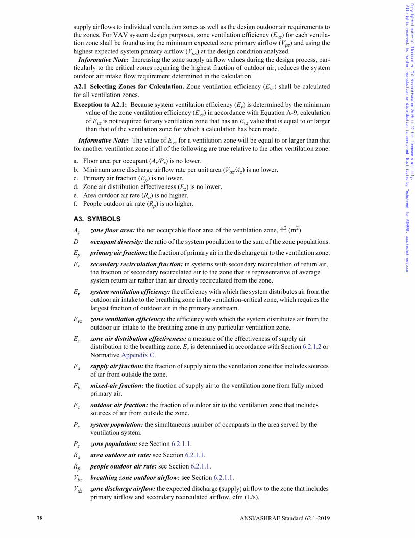
38 ANSI/ASHRAE Standard 62.1-2019
supply airflows to individual ventilation zones as well as the design outdoor air requirements tothe zones. For VAV system design purposes, zone ventilation efficiency (Evz) for each ventila-tion zone shall be found using the minimum expected zone primary airflow (Vpz) and using thehighest expected system primary airflow (Vps) at the design condition analyzed.
Informative Note: Increasing the zone supply airflow values during the design process, par-ticularly to the critical zones requiring the highest fraction of outdoor air, reduces the systemoutdoor air intake flow requirement determined in the calculation.A2.1 Selecting Zones for Calculation. Zone ventilation efficiency (Evz) shall be calculatedfor all ventilation zones. Exception to A2.1: Because system ventilation efficiency (Ev) is determined by the minimum
value of the zone ventilation efficiency (Evz) in accordance with Equation A-9, calculationof Evz is not required for any ventilation zone that has an Evz value that is equal to or largerthan that of the ventilation zone for which a calculation has been made.
Informative Note: The value of Evz for a ventilation zone will be equal to or larger than thatfor another ventilation zone if all of the following are true relative to the other ventilation zone:
a. Floor area per occupant (Az/Pz) is no lower.b. Minimum zone discharge airflow rate per unit area (Vdz/Az) is no lower.c. Primary air fraction (Ep) is no lower.d. Zone air distribution effectiveness (Ez) is no lower.e. Area outdoor air rate (Ra) is no higher.f. People outdoor air rate (Rp) is no higher.
A3. SYMBOLS
Az zone floor area: the net occupiable floor area of the ventilation zone, ft2 (m2).
D occupant diversity: the ratio of the system population to the sum of the zone populations.
Ep primary air fraction: the fraction of primary air in the discharge air to the ventilation zone.
Er secondary recirculation fraction: in systems with secondary recirculation of return air, the fraction of secondary recirculated air to the zone that is representative of average system return air rather than air directly recirculated from the zone.
Ev system ventilation efficiency: the efficiency with which the system distributes air from the outdoor air intake to the breathing zone in the ventilation-critical zone, which requires the largest fraction of outdoor air in the primary airstream.
Evz zone ventilation efficiency: the efficiency with which the system distributes air from the outdoor air intake to the breathing zone in any particular ventilation zone.
Ez zone air distribution effectiveness: a measure of the effectiveness of supply air distribution to the breathing zone. Ez is determined in accordance with Section 6.2.1.2 or Normative Appendix C.
Fa supply air fraction: the fraction of supply air to the ventilation zone that includes sources of air from outside the zone.
Fb mixed-air fraction: the fraction of supply air to the ventilation zone from fully mixed primary air.
Fc outdoor air fraction: the fraction of outdoor air to the ventilation zone that includes sources of air from outside the zone.
Ps system population: the simultaneous number of occupants in the area served by the ventilation system.
Pz zone population: see Section 6.2.1.1.
Ra area outdoor air rate: see Section 6.2.1.1.
Rp people outdoor air rate: see Section 6.2.1.1.
Vbz breathing zone outdoor airflow: see Section 6.2.1.1.
Vdz zone discharge airflow: the expected discharge (supply) airflow to the zone that includes primary airflow and secondary recirculated airflow, cfm (L/s).
Copyrighted material licensed to Tul Manewattana on 2019-11-07 for licensee's use only. All rights reserved. No further reproduction or distribution is permitted. Distributed by Techstreet for ASHRAE, www.techstreet.com
ANSI/ASHRAE Standard 62.1-2019 39
Vot outdoor air intake flow: see Sections 6.2.2, 6.2.3, and 6.2.4.4.Vou uncorrected outdoor air intake: see Section 6.2.4.1.Voz zone outdoor airflow: see Section 6.2.1.3.Vps system primary airflow: the total primary airflow supplied to all zones served by the
system from the air-handling unit at which the outdoor air intake is located.Vpz zone primary airflow: the zone primary airflow to the ventilation zone, including outdoor
air and recirculated air.Xs average outdoor air fraction: at the primary air handler, the fraction of outdoor air intake
flow in the system primary airflow. Zpz primary outdoor air fraction: the outdoor air fraction required in the primary air supplied
to the ventilation zone prior to the introduction of any secondary recirculation air.
Copyrighted material licensed to Tul Manewattana on 2019-11-07 for licensee's use only. All rights reserved. No further reproduction or distribution is permitted. Distributed by Techstreet for ASHRAE, www.techstreet.com
Related Documents