TM 55-2840-241-23 TECHNICAL MANUAL AVIATION UNIT AND AVIATION INTERMEDIATE MAINTENANCE MANUAL ENGINE, AIRCRAFT, GAS TURBINE MODEL T63-A-720 P/N6887191 NSN 2840-01-013-1339 This copy is a reprint which includes current pages from Changes 1 through 15. HEADQUARTERS, DEPARTMENT OF THE ARMY 2 NOVEMBER 1977

a720 Tech Manual
Oct 23, 2014
Welcome message from author
This document is posted to help you gain knowledge. Please leave a comment to let me know what you think about it! Share it to your friends and learn new things together.
Transcript
TM 55-2840-241-23
TECHNICAL MANUAL
AVIATION UNITAND AVIATION INTERMEDIATE
MAINTENANCE MANUAL
ENGINE, AIRCRAFT, GAS TURBINEMODEL T63-A-720 P/N6887191
NSN 2840-01-013-1339
This copy is a reprint which includes current
pages from Changes 1 through 15.
HEADQUARTERS, DEPARTMENT OF THE ARMY2 NOVEMBER 1977

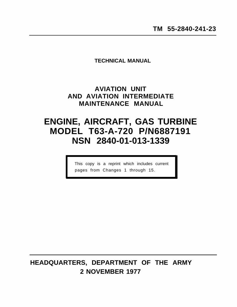
TM 55-2840-241-23C 18
CHANGE
NO. 18 } HEADQUARTERSDEPARTMENT OF THE ARMY
WASHINGTON, D.C., 31 July 1995
Aviation Unit and Aviation Intermediate Maintenance Manual
Engine, Aircraft, Gas TurbineModel T63-A-720 P/N 6887191
NSN 2840-01-013-1339
DISTRIBUTION STATEMENT A: Approved fur public release; distribution is unlimited.
TM 55-2840-241 -23,2 November 1977, is changed as follows:
1. Remove and insert pages as indicated below. New or changed text material is indicated by a vertical barin the margin. An illustration change is indicated by a miniature pointing hand.
Remove pagesi and ii2-5 and 2-64-9 through 4-10.1/(4-10.2 blank)4-16.1 and 4-16.2
- - - -
5-3 and 5-4- - - -
5-15 and 5-165-16.1/(5-16.2 blank)5-19 through 5-20.1/(5-20.2 blank)7-1 and 7-2B-9 and B-10Index 1 and Index 2
Insert pagesi and ii2-5 and 2-64-9 through 4-10.1/(4-10.2 blank)4-16.1 and 4-16.24-16.3/(4-16.4 blank)5-3 and 5-45-14.1/(5-14.2 blank)5-15 and 5-16516.1/(5-16.2 blank)5-19 through 5-20.1/(5-20.2 blank)7-1 and 7-2B-9 and B-10Index 1 and Index 2
2. Retain this sheet in front of manual for reference purposes.
TM 55-2840-241-23C 18
By Order of the Secretary of the Army:
Acting Administrative Assistant to theSecretary of the Army
00863
DENNIS J. REIMERGeneral, United States Army
Chief of Staff
DISTRIBUTION:To be distributed in accordance with DA Form 12-31-E, block no. 1802, requirements for
TM 55-2840-241-23.
TM 56-2840-241-23C17
CHANGE
NO. 17
HEADQUARTERSDEPARTMENT OF THE ARMY
WASHINGTON, D.C., 4 November 1994
Aviation Unit and Aviation Intermediate Maintenance Manual
Engine, Aircraft, Gas TurbineModel T63-A-720 P/N 6867191
NSN 2640-01-013-1339
DISTRIBUTION STATEMENT A: Approved for public release; distribution is unlimited
TM 55-2840-241-23, 2 November 1977, is changed as follows:
1. Remove and insert pages as indicated below. New or changed text material is indicated by a vertical barin the margin. An illustration change is indicated by a miniature pointing hand.
Remove pages Insert pages2-5 and 2-6 2-5 and 2-67-1 through 7-4 7-1 through 7-4
- - - 7-4.1/(7-4.2 blank)
2. Retain this sheet in front of manual for reference purposes.
By Order of the Secretary of the Army:
MILTION H. HAMILTON
Official:
Administrative Assistant to theSecretary of the Army
GORDON R. SULLIVANGeneral, United States Army
Chief of Staff
DISTRIBUTION:To be distributed
TM 55-2840241-23.in accordance with DA Form 12-31-E, block no. 1802, requirements for

TM 55-2840-241-23C 16
CHANGE
NO. 16
HEADQUARTERSDEPARTMENT OF THE ARMY
WASHINGTON, D.C., 15 OCTOBER 1993
AVIATION UNIT AND AVIATION INTERMEDIATEMAINTENANCE MANUAL
ENGINE, AIRCRAFT, GAS TURBINEMODEL T63-A-720 P/N 6887191
NSN 2840-01-013-1339
DISTRIBUTION STATEMENT A: Approved for public release; distribution is unlimited.
TM 55-2840-241-23, 2 November 1977, is changed as follows:
1. Remove and insert pages as indicated below. New or changed text material isindicated by a vertical bar in the margin. An illustration change is indicatedby a miniature pointing hand.
Remove pages Insert pages
1-1/(1-2 blank)2-1 through 2-43-1 and 3-23-5 and 3-64-7 and 4-84-13 and 4-144-16.1/(4-16.2 blank)5-3 and 5-45-4.1/(5-4.2 blank)5-16.1/(5-16.2 blank)7-5 and 7-67-11 and 7-1210-1 and 10-210-7 and 10-812-3 and 12-413-1 and 13-2A-1/(A-2 blank)
1-1/(1-2 blank)2-1 through 2-43-1 and 3-23-5 and 3-64-7 and 4-84-13 and 4-144-16.1 and 4-16.25-3 and 5-45-4.1/(5-4.2 blank)5-16.1/(5-16.2 blank)7-5 and 7-67-11 and 7-1210-1 and 10-210-7 and 10-812-3 and 12-413-1 and 13-2A-1/(A-2 blank)
2. Retain this sheet in front of manual for reference purposes.
TM 55-2840-241-23C 16
By Order of the Secretary of the Army:
Official:
MILTON H. HAMILTONAdministrative Assistant to the
Secretary of the Army05528
GORDON R. SULLIVANGeneral, United States Army
Chief of Staff
DISTRIBUTION:To be distributed in accordance with DA Form 12-31-E, block no. 1802, require-ments for TM 55-2840-241-23.
TM 55-2840-241-23C 15
CHANGE
NO. 15
HEADQUARTERSDEPARTMENT OF THE ARMY
WASHINGTON, D.C., 14 August 1991
AVIATION UNIT AND AVIATION INTERMEDIATEMAINTENANCE MANUAL
ENGINE, AIRCRAFT, GAS TURBINEMODEL T63-A-720 P/N 68887191
NSN 2840-01-013-1339
TM 55-2840-241-23, 2 November 1977, is changed as follows:
1. Remove and insert pages as indicated below. New or changed text materialis indicated by a vertical bar in the margin. An illustration change is indicatedby a miniature pointing hand.
Remove pages Insert pages
1-1/1-24-12.1 and 4-12.24-13 and 4-144-16.1/4-16.25-7 and 5-85-18.1/5-18.2
5-21 and 5-227-5 and 7-67-9 and 7-107-19 and 7-2011-1 and 11-2A-1/A-2
1-1/1-24-12.1 and 4-12.24-13 and 4-144-16.1/4-16.25-7 and 5-85-18.1/5-18.2
5-21 and 5-227-5 and 7-67-9 and 7-107-19 and 7-2011-1 and 11-2A-1/A-2
2. Retain this sheet in front of manual for reference purposes.
By Order of the Secretary of the Army:
Official:
PATRICIA P. HICKERSONColonel, United States Army
The Adjutant General
GORDON R. SULLIVANGeneral, United States Army
Chief of Staff
DISTRIBUTION:To be distributed in accordance with DA Form 12-31-E, block no. 1802, AVUM and AVIM
maintenance requirements for Engine, Gas Turbine, T63-A-720 (TM 55-2840-241-series).

TM 55-2840-241-23C 14
CHANGE
NO. 14
HEADQUARTERSDEPARTMENT OF THE ARMY
WASHINGTON, D.C., 22 September 1988
AVIATION UNIT AND AVIATION INTERMEDIATEMAINTENANCE MANUAL
ENGINE, AIRCRAFT, GAS TURBINEMODEL T63-A-720 P/N 68887191
NSN 2840-01-013-1339
TM 55-2840-241-23, 2 November 1977, is changed as follows:
1. Remove and insert pages as indicated below. New or changed text materialis indicated by a vertical bar in the margin. An illustration change is indicatedby a miniature pointing hand.
Remove pages Insert pages
A and Bi and ii1-1 and 1-2
1-3 and 1-41-9 through 1-122-1 through 2-63-5 through 3-83-11 and 3-124-1 through 4-6
4-7 and 4-8
4-9 and 4-10
4-11 and 4-12
4-13 and 4-144-14.1 and 4-14.24-15 and 4-165-1 and 5-2
5-3 and 5-45-4A/5-4B5-7 through 5-105-10.1 through 5-10.45-11 through 5-165-16A/5-16B5-17 and 5-185-18A5-19 and 5-20
5-21 and 5-22
A and Bi and ii1-1/1-21-2.1/1-2.21-3 and 1-41-9 through 1-122-1 through 2-63-5 through 3-83-11 and 3-124-1 through 4-64-6.1/4-6.24-7 and 4-84-8.1/4-8.24-9 and 4-104-10.1/4-10.24-11 and 4-124-12.1 and 4-12.24-13 and 4-144-14.1 and 4-14.24-15 and 4-165-1 and 5-25-2.1/5-2.25-3 and 5-45-4.1/5-4.25-7 through 5-105-10.1 through 5-10.45-11 through 5-165-16.1/5-16.25-17 and 5-185-18.1/5-18.25-19 and 5-205-20.1/5-20.25-21 and 5-22
TM 55-2840-241-23
C 14
Remove pages
5-27 and 5-28
6-1 and 6-27-1 through 7-127-15 through 7-188-1/8-29-1 and 9-210-1 through 10-4
10-5 and 10-6
10-7 and 10-811-1 through 11-4
12-3 and 12-4A-l/A-2B-1 and B-2B-7 and B-8B-11 and B-12Index 1 through Index 6
Insert pages
5-27 and 5-285-28.1/5-28.26-1 and 6-27-1 through 7-127-15 through 7-188-1/8-29-1 and 9-210-1 through 10-410-4.1/10-4.210-5 and 10-610-6.1/10-6.210-7 and 10-811-1 through 11-411-5/11-612-3 and 12-4A-1/A-2B-1 and B-2B-7 and B-8B-n and B-12Index 1 through Index 6
2. Retain these sheets in front of manual for reference purposes.
By Order of the Secretary of the Army:
Official:
R. L. DILWORTHBrigadier General, United States Army
The Adjutant General
CARL E. VUONOGeneraI, United States Army
Chief of Staff
DISTRIBUTION:To be distributed in accordance with DA Form 12-31, AVUM and AVIM requirements
for Engine, Gas Turbine, T63-A-720 (TM 55-284O-24l-series)
CHANGE
NO. 13
TM 55-2840-241-23C 13
HEADQUARTERSDEPARTMENT OF THE ARMY
WASHINGTON, D.C., 6 November 1987
Aviation Unit and Aviation IntermediateMaintenance Manual
ENGINE, AIRCRAFT, GAS TURBINEMODEL T63-A-720 P/N 6887191
NSN 2840-01-013-1339
TM 55-2840-241-23, 2 November 1977, is changed as follows:
1. Remove and insert pages as indicated below. New or changed text materialis indicated by a vertical bar in the margin. An illustration change is indicatedby a miniature pointing hand.
Remove pages Insert pages
5-7 and 5-8 5-7 and 5-8
2. Retain this sheet in front of manual for reference purposes.
By Order of the Secretary of the Army:
Official:
CARL E. VUONO,General, United States Army
Chief of Staff
R. L. DILWORTHBrigadier General, United States Army
The Adjutant General
DISTRIBUTION:To be distributed in accordance with DA Form 12-31, AVUM and AVIM requirements
for Engine, Gas Turbine, T63-A-720 (TM 55-2840-241 series).

CHANGE
NO. 12
TM 55-2840-241-23C 12
HEADQUARTERSDEPARTMENT OF THE ARMY
WASHINGTON, D.C., 14 April 1987
Aviation Unit and Aviation IntermediateMaintenance Manual
ENGINE, AIRCRAFT, GAS TURBINEMODEL T63-A-720 P/N 6887191
NSN 2840-01-013-1339
TM 55-2840-241-23, 2 November 1977, is changed as follows:
1. Remove and insert pages as indicated below. New or changed text materialis indicated by a vertical bar in the margin. An illustration change is indicated
by a miniature pointing hand.
Remove pages Insert pages
13-1 and 13-2 13-1 and 13-2
2. Retain this sheet in front of manual for reference purposes.
By Order of the Secretary of the Army:
Official:
JOHN A. WICKHAM, JR.General, United States Army
Chief of Staff
R. L. DILWORTHBrigadier General, United States Army
The Adjutant General
DISTRIBUTION:To be distributed in accordance with DA Form 12-31, AVUM and AVIM maintenance
requirements for Engine, Gas Turbine, T-63-A-720 (TM 55-2840-241 series).

URGENTNOTICE: THIS CHANGE HAS BEEN PRINTED AND DISTRIBUTED OUT OF SEQUENCE. IT SHOULD
BE INSERTED IN THE MANUAL AND USED. UPON RECEIPT OF THE EARLIER SEQUENCEDCHANGE INSURE A MORE CURRENT CHANGE PAGE IS NOT REPLACED WITH A LESSCURRENT PAGE.
TM 55-2840-241-23C 11
CHANGE
NO. 11
HEADQUARTERSDEPARTMENT OF THE ARMY
WASHINGTON, D.C., 12 December 1986
Aviation Unit and Aviation IntermediateMaintenance Manual
ENGINE, AIRCRAFT, GAS TURBINEMODEL T63-A-720 P/N 6887191
NSN 2840-01-013-1339
TM 55-2840-241-23, 2 November 1977, is changed as follows:
1. Remove and insert pages as indicated below. New or changed text materialis indicated by a vertical bar in the margin. An illustration change is indicatedby a miniature pointing hand.
Remove pages Insert pages
i and ii i and ii5-3 and 5-4 5-3 and 5-45-9 and 5-10 5-9 and 5-105-10.1 through 5-10.3/5-10.4 5-10.1 through 5-10.45-11 through 5-14 5-11 through 5-1410-3 and 10-4 10-3 and 10-4
2. Retain this sheet in front of manual for reference purposes.
By Order of the Secretary of the Army:
Official:
JOHN A. WICKHAM, JR.GeneraI, United States Army
Chief of Staff
R. L.DILWORTHBrigadier General, United States Army
The Adjutant General
DISTRIBUTION:To be distributed in accordance with DA Form 12-31, Organizational, Direct Support
and General Support Maintenance requirements for Engine, Gas Turbine, T-63-A-720(TM 55-2840-241 series).
URGENT

CHANGE
NO. 10
TM 55-2840-241-23C 10
HEADQUARTERSDEPARTMENT OF THE ARMY
WASHINGTON, D.C., 17 November 1986
Aviation Unit and Aviation IntermediateMaintenance Manual
ENGINE, AIRCRAFT, GAS TURBINEMODEL T63-A-720 P/N 6887191
NSN 2840-01-013-1339
TM 55-2840-241-23, 2 November 1977, is changed as follows:
1. Remove and insert pages as indicated below. New or changed text material isindicated by a vertical bar in the margin. An illustration change is indicated bya miniature pointing hand.
Remove pages Insert pages
i and ii2-3 and 2-43-5 and 3-63-11 and 3-124-3 through 4-64-11 through 4-144-14A/4-14B4-15 and 4-164-16A/4-16B5-3 and 5-45-9 and 5-10
---
5-11 and 5-125-13 through 5-165-19 and 5-205-25 through 5-287-1 and 7-27-7 and 7-87-17 and 7-189-1 and 9-210-1 and 10-210-7 and 10-812-1 through 12-413-1 and 13-2B-13 and B-14Index 5 and Index 6
i and ii2-3 and 2-43-5 and 3-63-11 and 3-124-3 through 4-64-11 through 4-144-14.1 and 4-14.24-15 and 4-164-16.1/4-16.25-3 and 5-45-9 and 5-105-10.1 through 5-10.3/5-10.45-11 and 5-125-13 through 5-165-19 and 5-205-25 through 5-287-1 and 7-27-7 and 7-87-17 and 7-189-1 and 9-210-1 and 1O-210-7 and 10-812-1 through 12-413-1 and 13-2B-13 and B-14Index 5 and Index 6
2. Retain this sheet in front of manual for reference purposes.
TM 55-2840-241-23C 10
By Order of the Secretary of the Army:
Official:
R. L. DILWORTHBrigadier General, United States Army
The Adjutant General
JOHN A. WICKHAM, JR.General, United States Army
Chief of Staff
DISTRIBUTION:To be distributed in accordance with DA Form 12-31, Organizational, Direct
Support and General Support Maintenance requirements for Engine, Gas Turbine,T-63-A-720 (TM 55-2840-241-series).
TM 55-2840-241-23C 9
CHANGE
No. 9
HEADQUARTERSDEPARTMENT OF THE ARMY
WASHINGTON, D.C., 30 March 1984
Aviation Unit and Aviation IntermediateMaintenance Manual
ENGINE, AIRCRAFT, GAS TURBINEMODEL T63-A-720 P/N 6887191
NSN 2840-01-013-1339
TM 55-2840-241-23, 2 November 1977, is changed as follows:
1. Remove and insert pages as indicated below.
Remove pages Insert pages
Chapter 3 3-5 and 3-63-11 and 3-12
Chapter 4 4-5 and 4-64-9 and 4-104-13 thru 4-14A/4-14B4-16A/4-16B
Chapter 5 5-3 and 5-45-9 and 5-105-25 and 5-26
Chapter 7 7-1 and 7-27-7 and 7-8
Appendix B B-3 and B-4B-13 thru B-16
3-5 and 3-63-11 and 3-124-5 thru 4-6A/4-6B4-9 and 4-104-13 thru 4-14A/4-14B4-16A/4-16B5-3 and 5-35-9 and 5-105-25 and 5-267-1 and 7-27-7 and 7-8B-3 and B-4B-13 thru B-16
2. New or changed text material is indicated by a vertical bar in the margin.An illustration change is indicated by a miniature pointing hand.
3. Retain this sheet in front of manual for reference purposes.
By Order of the Secretary of the Army:
JOHN A. WICKHAM, JR.General, United States Army
Official: Chief of Staff
ROBERT M. JOYCEMajor General, United States Army
The Adjutant General
DISTRIBUTION:To be distributed in accordance with DA Form 12-31, Organizational Maintenance
requirements for OH-58 and OH-58C aircraft.

URGENTTM 55-2840-241-23
C 8
CHANGE
NO. 8
HEADQUARTERSDEPARTMENT OF THE ARMY
WASHINGTON, D.C., 8 November 1982
Aviation Unit and Aviation IntermediateMaintenance Manual
ENGINE, AIRCRAFT, GAS TURBINEMODEL T63-A-720 P/N 6887191
NSN 2840-01-013-1339
TM 55-2840-241-23,2 November 1977, is changed as follows:
1. Remove and insert pages as indicated below.
Remove Pages Insert Pages
Chapter 4 4-13 thru 4-16 4-13 thru 4-16Chapter 12 12-1 and 12-2 12-1 and 12-2Chapter 13 13-1/13-2 13-1/ 13-2
2. New or changed text material is indicated by a vertical bar in themargin. An illustration change is indicated by a miniature pointing hand.
3. Retain this sheet in front of manual for reference purposes.
By Order of the Secretary of the Army:
E.C.MEYERGeneral, United States Army
Official: Chief of Staff
ROBERT M. JOYCEMajor General, United States Army
The Adjutant General
DISTRIBUTION:To be distributed in accordance with DA Form 12-31, Organizational Maintenance
Requirements for OH-58 and OH-58C aircraft.
URGENT

URGENT
CHANGE
NO. 7
TM 55-2840-241-23C 7
HEADQUARTERSDEPARTMENT OF THE ARMY
WASHINGTON, D.C., 2 August 1982
Aviation Unit and Aviation IntermediateMaintenance Manual
ENGINE, AIRCRAFT, GAS TURBINEMODEL T63-A-720 P/N 6887191
NSN 2840-01-013-1339
TM 55-2840-241-23, 2 November 1977, is changed as follows:
1. Remove and insert pages as indicated below.
Remove Pages Insert Pages
Chapter 4 4-13 and 4-14 4-13 and 4-144-16A/(4-16B blank)
2. New or changed text material is indicated by a vertical bar in themargin. An illustration change is indicated by a miniature pointing hand.
3. Retain this sheet in front of manual for reference purposes.
By Order of the Secretary of the Army:
Official:
ROBERT M. JOYCEMajor General, United States Army
The Adjutant General
E. C. MEYERGeneral, United States Army
Chief of Staff
DISTRIBUTION:To be distributed in accordance with DA Form 12-31, Organizational Maintenance
Requirements for OH-58 and OH-58C aircraft.

TM 55-2840-241-23C 6
CHANGE
}
HEADQUARTERSDEPARTMENT OF THE ARMY
No. 6 WASHINGTON, D. C., 13 May 1982
Aviation Unit and Aviation Intermediate Maintenance ManualENGINE, AIRCRAFT, GAS TURBINEMODEL T63-A-720 P/N 6887191
NSN 2840-01-013-1339
TM 55-2840-241-23, 2 November 1977, is changed as follows:
1. Remove and insert pages as indicated below.
Remove pages Insert pages
Chapter 1
Chapter 2Chapter 3
Chapter 4Chapter 5
Chapter 7Chapter 10Chapter 13
1-1 and 1-21-13 and 1-142-5 and 2-63-5 and 3-63-11 and 3-124-13 thru 4-165-11 and 5-125-16A/B5-21 and 5-225-25 thru 5-287-1 and 7-210-1 thru 10-413-1/13-2
1-1 and 1-21-13 and 1-142-5 and 2-63-5 and 3-63-11 and 3-124-13 thru 4-165-11 and 5-125-16A/B5-21 and 5-225-25 thru 5-287-1 and 7-210-1 thru 10-413-1/13-2
2. New or changed text material is indicated by a vertical bar in the margin.An illustration change is indicated by a miniature pointing hand.
3. Retain this sheet in front of manual for reference purposes.
By Order of the Secretary of the Army:
Official:
ROBERT M. JOYCEBrigadier General, United States Army
Tbe Adjutant General
E. C. MEYERGeneral, United States Army
Chief of Staff
DISTRIBUTION:To be distributed in accordance with DA Form 12-31, Organizational Maintenance
Requirements for OH-58 and OH-58C Aircraft.

TM 55-2840-241-23C 5
CHANGENo. 5
HEADQUARTERSDEPARTMENT OF THE ARMY
WASHINGTON, D.C., 26 June 1981
Aviation Unit and Aviation Intermediate Maintenance ManualENGINE, AIRCRAFT, GAS TURBINEMODEL T63-A-720 P/N 6887191
TM 55-2840-241-23, 2 November 1977, is changed as follows:
1. Remove and insert pages as indicated below.
Chapter 2Chapter 4
Chapter 5
Chapter 7Appendix B
Remove pages
2-5 and 2-64-5 thru 4-84-11 thru 4-15/4-165-3 and 5-45-9 and 5-105-15 and 5-16
7-1 thru 7-4B-1 and B-2
Insert pages
2-5 and 2-64-5 thru 4–84-11 thru 4-165-3 thru 5-4A/B5-9 and 5-105-15 thru 5-16A/B5-18A/B7-1 thru 7-4B-1 and B-2
2. New or changed text material is indicated by a vertical bar in the margin.An illustration change is indicated by a miniature pointing hand.
3. Retain this sheet in front of manual for reference purposes.By Order of the Secretary of the Army:
Official:
E. C. MEYERGeneral, United States Army
Chief of Staff
J. C. PENNINGT’ONMajor General, United States Army
The Adjutant GeneralDISTRIBUTION:
To be distributed in accordance with DA Form 12-31, Organizational MaintenanceRequirements for OH-58 and OH-58C Aircraft.

TM 55-2840-241-23C4
CHANGE
No. 4
HEADQUARTERSDEPARTMENT OF THE ARMY
WASHINGTON, D. C., 14 January 1981
Aviation Unit and Aviation Intermediate Maintenance ManualENGINE, AIRCRAFT, GAS TURBINE
MODEL T63-A-720 P/N 6887191NSN 2840-01-013-1339
TM 55-2840-241 -23, 2 November 1977, is changed as follows:
1. Remove and insert pages as indicated below.
Chapter 3
Chapter 4
Chapter 5
Chapter 7Chapter 10
Remove pages
3-1 and 3-23-5 and 3-64-1 and 4-24-13 thru 4-15/4-165-3 and 5-45-9 thru 5-12 A/5-12B7-1 and 7-210-1 thru 10-410-7 and 10-8
Insert pages
3-1 and 3-23-5 and 3-64-1 and 4-24-13 thru 4-15/4-165-3 and 5-45-9 thru 5-12A/5-12B7-1 and 7-210-1 thru 10-410-7 and 10-8
2. New or changed text material is indicated by a vertical bar in the margin. An illustration change isindicated by a miniature pointing hand.
3. Retain this sheet in front of manual for reference purposes.
By Order of the Secretary of the Army:
Official:
J. C. PENNINGTONMajor General, United States Army
The Adjutant General
E. C. MEYERGeneral, United States Army
Chief of Staff
DISTRIBUTION:To be distributed in accordance with DA Form 12-31, Organizational Maintenance Requirements for
OH-58 and 0H-58C aircraft.

TM 55-2840-241-23
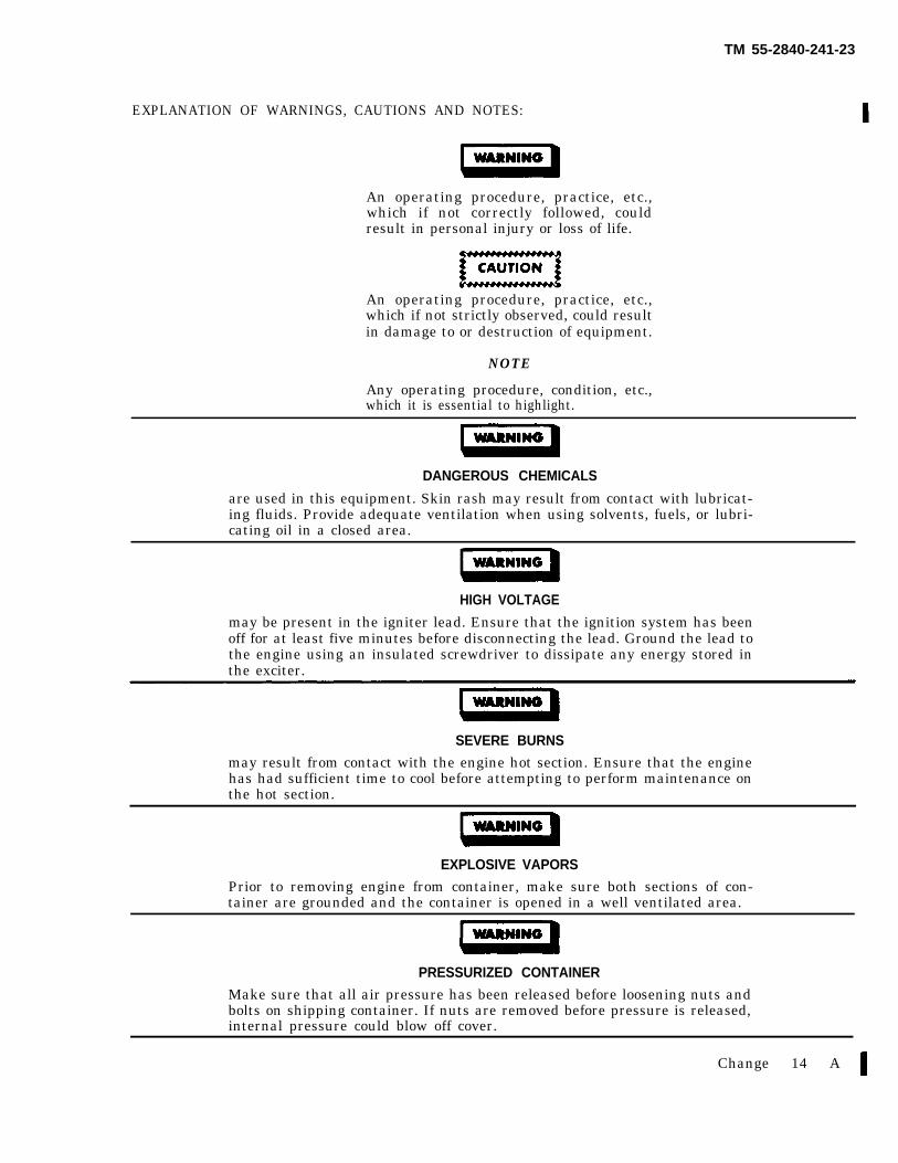
EXPLANATION OF WARNINGS, CAUTIONS AND NOTES:
An operating procedure, practice, etc.,which if not correctly followed, couldresult in personal injury or loss of life.
An operating procedure, practice, etc.,which if not strictly observed, could resultin damage to or destruction of equipment.
NOTE
Any operating procedure, condition, etc.,which it is essential to highlight.
DANGEROUS CHEMICALS
are used in this equipment. Skin rash may result from contact with lubricat-ing fluids. Provide adequate ventilation when using solvents, fuels, or lubri-cating oil in a closed area.
HIGH VOLTAGE
may be present in the igniter lead. Ensure that the ignition system has beenoff for at least five minutes before disconnecting the lead. Ground the lead tothe engine using an insulated screwdriver to dissipate any energy stored inthe exciter.
SEVERE BURNS
may result from contact with the engine hot section. Ensure that the enginehas had sufficient time to cool before attempting to perform maintenance onthe hot section.
EXPLOSIVE VAPORS
Prior to removing engine from container, make sure both sections of con-tainer are grounded and the container is opened in a well ventilated area.
PRESSURIZED CONTAINER
Make sure that all air pressure has been released before loosening nuts andbolts on shipping container. If nuts are removed before pressure is released,internal pressure could blow off cover.
Change 14 A
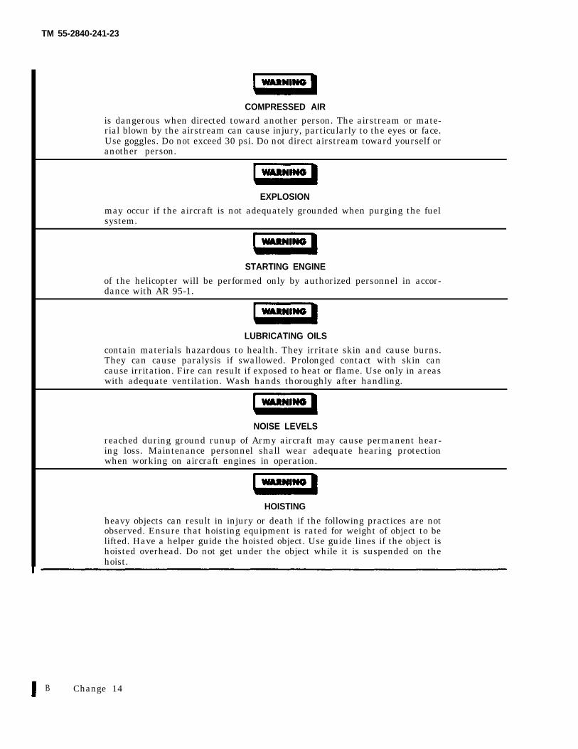
TM 55-2840-241-23
COMPRESSED AIRis dangerous when directed toward another person. The airstream or mate-rial blown by the airstream can cause injury, particularly to the eyes or face.Use goggles. Do not exceed 30 psi. Do not direct airstream toward yourself oranother person.
EXPLOSION
may occur if the aircraft is not adequately grounded when purging the fuelsystem.
STARTING ENGINE
of the helicopter will be performed only by authorized personnel in accor-dance with AR 95-1.
LUBRICATING OILS
contain materials hazardous to health. They irritate skin and cause burns.They can cause paralysis if swallowed. Prolonged contact with skin cancause irritation. Fire can result if exposed to heat or flame. Use only in areaswith adequate ventilation. Wash hands thoroughly after handling.
NOISE LEVELS
reached during ground runup of Army aircraft may cause permanent hear-ing loss. Maintenance personnel shall wear adequate hearing protectionwhen working on aircraft engines in operation.
HOISTING
heavy objects can result in injury or death if the following practices are notobserved. Ensure that hoisting equipment is rated for weight of object to belifted. Have a helper guide the hoisted object. Use guide lines if the object ishoisted overhead. Do not get under the object while it is suspended on thehoist.
B Change 14
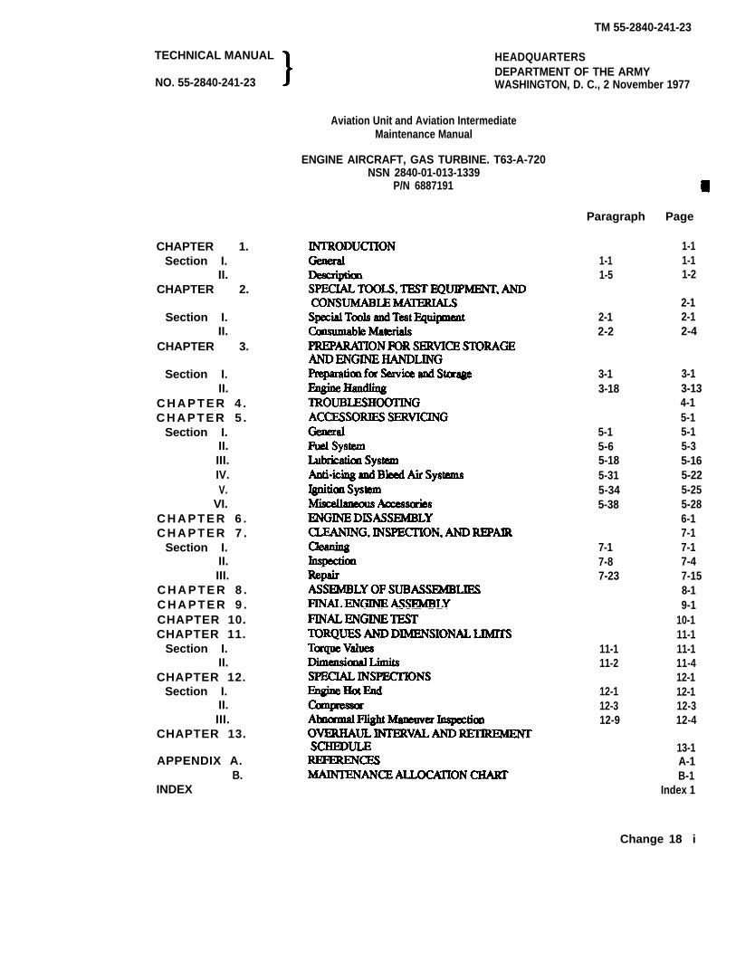
TM 55-2840-241-23
TECHNICAL MANUAL
NO. 55-2840-241-23
HEADQUARTERSDEPARTMENT OF THE ARMYWASHINGTON, D. C., 2 November 1977
Aviation Unit and Aviation IntermediateMaintenance Manual
CHAPTER 1.Section I.
II.CHAPTER 2.
Section I.II.
CHAPTER 3.
Section I.II.
C H A P T E R 4 .C H A P T E R 5 .
Section I.II.III.IV.V.
VI.C H A P T E R 6 .C H A P T E R 7 .
Section I.II.III.
C H A P T E R 8 .C H A P T E R 9 .CHAPTER 10.CHAPTER 11.
Section I.II.
CHAPTER 12.Section I.
II.III.
CHAPTER 13.
APPENDIX A.B.
INDEX
ENGINE AIRCRAFT, GAS TURBINE. T63-A-720NSN 2840-01-013-1339
P/N 6887191
Paragraph Page
1-11-1 1-11-5 1-2
2-12-1 2-12-2 2-4
3-13-18
5-15-65-185-315-345-38
7-17-87-23
11-111-2
12-112-312-9
3-13-134-15-15-15-35-165-225-255-286-17-17-17-47-158-19-1
10-111-111-111-412-112-112-312-4
13-1A-1B-1
Index 1
Change 18 i
TM 55-280-241-23
LIST OF ILLUSTRATIONS
Number Title Page
1-1.1-2.1-3.1-4.1-5.1-6.1-7.1-8.1-9.2-1.2-2.
2-3.2-4.2-5.2-6.2-7.2-8.2-9.3-1.3-2.3-3.
3-4.3-5.3-6.3-7.3-8.4-1.4-2.4-3.4-4.4-5.4-6.5-1.5-2.5-3.5-4.5-5.5-6.5-6.1
Number
1-1.1-2.
2-1.2-2.3-1.4-1.5-1.
5-1.15-1.2
5-2.
Right Side View of Engine (Typical) . . . . . . . . . . .Engine Airflow . . . . . . . . . . . . . . . . . . . . . . . . . . . .Fuel System Schematic . . . . . . . . . . . . . . . . . . . . .Fuel Control System Schematic. . . . . . . . . . . . . . .Fuel Pump and Filter Assembly . . . . . . . . . . . . . . .Engine Lubrication System Schematic . . . . . . . . .Oil Pump Schematic . . . . . . . . . . . . . . . . . . . . . . . .Compressor Bleed Control Valve . . . . . . . . . . . . . .Compressor Bleed Control Valve Operation . . . . .Engine Turning Adapter 6799790 . . . . . . . . . . . . .Compressor Vibration PickupMounting Bracket 6872539 . . . . . . . . . . . . . . . . . .Loop Clamps 6799952 and 6799953 . . . . . . . . . . .Compressor Protector Kit 6886204 . . . . . . . . . . . .Engine Assembly Lift 6796963 . . . . . . . . . . . . . . .Mechanical Puller Kit 6796941 . . . . . . . . . . . . . . .Modular Engine Test Stand LTCT10465-22 . . . . Engine Assembly Turnover Stand 6795579 . . . . . .Ground Idle Wrench 6798292 . . . . . . . . . . . . . . . .Engine Shipping Container . . . . . . . . . . . . . . . . . .Engine Shipping Parts . . . . . . . . . . . . . . . . . . . . . .Engine Shipping Container Stencilingand Labeling . . . . . . . . . . . . . . . . . . . . . . . . . . . . . .Accessories Shipping Container . . . . . . . . . . . . . .Accessories Shipping Container Stenciling . . . . . .Gas Producer Fuel Control Ports Identification . . .Engine Assembly Turnover Stand 6795579 . . . . . .Combustion Section Removal . . . . . . . . . . . . . . . .OH58C HIT T0T Worksheet . . . . . . . . . . . . . . . .OH58C HIT TOT Log . . . . . . . . . . . . . . . . . . . . . .Bendix Governor . . . . . . . . . . . . . . . . . . . . . . . . . .Bendix Fuel Control . . . . . . . . . . . . . . . . . . . . . . . .P. C. Gage Test Kit . . . . . . . . . . . . . . . . . . . . . . . . .Set-Up of P.C. Gage . . . . . . . . . . . . . . . . . . . . . . . .Universal Fittings . . . . . . . . . . . . . . . . . . . . . . . . . .Fuel, Oil, and Air Tubing . . . . . . . . . . . . . .Fuel System Components . . . . . . . . . . . . . . . . . . . .Fuel Filter Replacement . . . . . . . . . . . . . . . . . . . . .Fuel Control Quadrant and Pointer . . . . . . . . . . . .Gas Producer Fuel Control Adjustmemts . . . . . . . .Start Acceleration and StartDerichment Adjustments. . . . . . . . . . . . . . . . . . . .
1-211-31-51-71-91-111-121-131-132-2
2-22-22-22-22-22-32-32-33-33-4
3-93-103-113-123-133-154-14.24-154-164-164-16.34-1635-25-55-65-85-105-10.1
5-10.2
Number Title Page5-6.2
5-7.5-8.5-9.5-9.1.5-9.25-10.
5-10.1
5-11.
5-12.5-13.5-14.5-15.5-16.5-17.6-1.7-1.7-27-3.7-4.7-5.7-6.7-7.7-8.7-9.
7-10.
7-11.7-12.7-13.7-14.7-15.7-16.10-1.10-2.11-1.12-1.
LIST OF TABLES
Start-Derich and Start-Accel(Tweaker) Adjustments . . . . . . . . . . . . . . . . . . . . .Fuel Control Max Flow Stop Adjustment . . . . . . .Fuel Control Fuel Filter . . . . . . . . . . . . . . . . . . . . .Carbon Buildup on Fuel Nozzle . . . . . . . . . . . . . . .Removal of Accumulator and Union . . . . . . . . . . .Installation of P/N MS 9015-04 Plug. . . . . . . . . . .Particlle Accumulation on MagneticChip Detector . . . . . . . . . . . . . . . . . . . . . . . . . . . . .Pressure Oil Tube andPressure Oil Filtering Screen . . . . . . . . . . . . . . . .Oil Falter, Housing, Check Valve, andRegulator Valve . . . . . . . . . . . . . . . . . . . . . . . . . . .External Oil Check Valve . . . . . . . . . . . . . . . . . . . .Engine Air Systems (Anti-icing and Bleed Air) . .Anti-icing Valve Poppet Seat Replacement . . . . . .Anti-icing Valve Lever Repair . . . . . . . . . . . . . . . .Ignition System . . . . . . . . . . . . . . . . . . . . . . . . . . .Spark Igniter . . . . . . . . . . . . . . . . . . . . . . . . . . . . . .Compressor Case Assembly . . . . . . . . . . . . . . . . . .Bleed Valve Jet and Nozzle Removal . . . . . . . . . .Compressor Blade Damage Caused By Rub . . . . .Compressor Vane Erosion . . . . . . . . . . . . . . . . . . .Gearbox Accessory Pad Locations . . . . . . . . . . . .Outer Combustion Case Inspection . . . . . . . . . . . .Dent Limits-Top of Outer Combustion Case . . . . .Outer Combustion Case Air Tube Boss. . . . . . . . .Combustion Liner Inspection. . . . . . . . . . . . . . . . .Inspection of Combustion LinerDome Louvers . . . . . . . . . . . . . . . . . . . . . . . . . . . .Compressor Rotor Blade Leadingand Trailing Edge Blend Limits. . . . . . . . . . . . . . .Compressor Rotor Blade Tip Blend Limits . . . . . .Compressor Blade Surface Blending Limits . . . . .Compressor Stator Vane Blend Limits. . . . . . . . . .Seal Puller Kit . . . . . . . . . . . . . . . . . . . . . . . . . . . .Gearbox External Seals . . . . . . . . . . . . . . . . . . . . .Gearbox External Stud Data . . . . . . . . . . . . . . . . .Idle Flight Automtation GPTOT Limits . . . . . . . .Diffuser Vent Orifice Installation . . . . . . . . . . . . . .Typical Locknut Installation . . . . . . . . . . . . . . . . .Typical First-Stage Turbine Nozzle . . . . . . . . . . . .
5-10.45-115-125-145-155-15
5-17
5-18.1
5-195-20.15-235-245-255-265-276-27-37-57-67-77-87-97-97-13
7-14
7-157-157-167-177-187-197-2010-310-711-412-2
Title Page Number Title Page
Leading Particulars . . . . . . . . . . . . . . . . . . . . . . . .Performance Ratings (Standard SeaLevel Static Conditions) . . . . . . . . . . . . . . . . . . . . .Special Tools and Test Equipment . . . . . . . . . . . . .Consumable Materials . . . . . . . . . . . . . . . . . . . . . .Container Air Pressure vs. Ambient Temperature .Troubleshooting. . . . . . . . . . . . . . . . . .Recommended Torque for AirframeEngine Interface Connections . . . . . . . . . . . . . . . .Adjustments to Improve Starting . . . . . . . . . . . . . .Torque Limits for Steel Couplings on SteelFittings . . . . . . . . . . . . . . . . . . . . . . . . . . . . . . . .Anti-icing Air Valve Inspection and Repair . . . . . .
1-14
1-142-12-43-84-1
5-2.15-10.3
5-155-24
7-1.10-1.10-2.10-3.11-1.11-1.111-2.12-1.12-2.12-3.13-1.
Combustion Liner Inspection . . . . . . . . . . . . . . . . . 7-10Operating Limits. . . . . . . . . . . . . . . . . . . . . . . . . . 10-4Test Requirements . . . . . . . . . . . . . . . . . . . . . . . . 10-6Functional Test Schedule . . . . . . . . . . . . . . . . . . . . 10-8Torwue Values . . . . . . . . . . . . . . . . . . . 11-1Minimum Prevailing Torque for Used Locknuts 11-4Dimensional Limits . . . . . . . . . . . . . . . . . . . . . . . . 11-5Overtemperature During Start . . . . . . . . . . . . . . . . 12-1Overtemperature During Power Transients . . . . . . 12-1First-stage Turbine Nozzle and Shield Inspection . 12-2Overhaul and Retirement Intend . . . . . . . . . . . . . 13-1Maintenance Allocation Chart . . . . . . . . . . . . . . . . B-1
ii Change 18
TM 55-2840-241-23
CHAPTER 1
INTRODUCTION
Section 1. GENERAL
1-1. Scope.
a. This manual is issued expressly for Avia-tion Unit Maintenance (AVUM) and AviationIntermediate Maintenance (AVIM) activities.Its purpose is to familiarize maintenance per-sonnel having limited technical training and ex-perience with the maintenance functions to beperformed on the Army Model T63-A-720 (Al-lison Gas Turbine Model 250-C20C) tur-boshaft engine. The study and use of thismanual will enable maintenance personnel toperform the assigned functions with maximumefficiency. This manual provides all essentialinformation to accomplish the three levels ofmaintenance on the complete engine, its com-ponents, and systems as prescribed in theMaintenance Allocation Chart (MAC). (Referto Appendix B.)
Use only chrome plated steel orunplated steel tools for the disas-sembly or reassembly proceduresdescribed in this manual. The useof cadmium or zinc plated tools isnot permitted since these platingsare prone to chipping and flaking.Should these chips enter the enginethey may contaminate the lubrica-tion system, ultimately clogging
the filters or produce intergranularattack on nickel or titanium basealloys at elevated temperatures.
1-2. Maintenance Forms and Records.
Maintenance forms, records, and reportswhich are to be used by maintenance person-nel at all maintenance levels are listed in andprescribed by DA Pamphlet 738-751, Func-tional Users Manual for the Army Main-tenance Management System - Aviation(TAMMS-A).
1-3. Reporting of Errors.
Report of errors, omissions, and recom-mendations for improving this publication bythe individual user is encouraged. Reportsshall be submitted on DA Form 2028 (Recom-mended Changes to Publication and BlankForms) and forwarded directly to Commander,U.S. Army Aviation and Troop Command,ATTN: AMSAT-I-MP, 4300 GoodfellowBlvd., St. Louis, MO 63120-1798.
1-4. Destruction of Army Material toPrevent Enemy Use.
Procedures for destruction of Armymaterials to prevent enemy use are prescribedby TM 750-244-1-5.
Change 16 1-1/(1-2 blank)

TM 55-2840-241-23
Section Il. DESCRIPTION
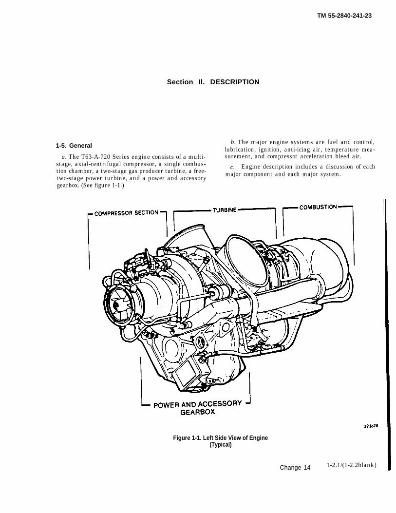
1-5. General b. The major engine systems are fuel and control,lubrication, ignition, anti-icing air, temperature mea-
a. The T63-A-720 Series engine consists of a multi-stage, axial-centrifugal compressor, a single combus-
surement, and compressor acceleration bleed air.
tion chamber, a two-stage gas producer turbine, a free-c. Engine description includes a discussion of each
two-stage power turbine, and a power and accessorymajor component and each major system.
gearbox. (See figure 1-1.)
Figure 1-1. Left Side View of Engine(Typical)
Change 14 1-2.1/(1-2.2blank)

TM 55-2840-241-23
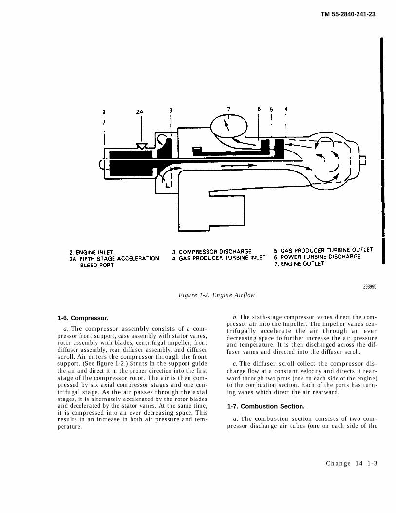
298995Figure 1-2. Engine Airflow
1-6. Compressor.
a. The compressor assembly consists of a com-pressor front support, case assembly with stator vanes,rotor assembly with blades, centrifugal impeller, frontdiffuser assembly, rear diffuser assembly, and diffuserscroll. Air enters the compressor through the frontsupport. (See figure 1-2.) Struts in the support guidethe air and direct it in the proper direction into the firststage of the compressor rotor. The air is then com-pressed by six axial compressor stages and one cen-trifugal stage. As the air passes through the axialstages, it is alternately accelerated by the rotor bladesand decelerated by the stator vanes. At the same time,it is compressed into an ever decreasing space. Thisresults in an increase in both air pressure and tem-perature.
b. The sixth-stage compressor vanes direct the com-pressor air into the impeller. The impeller vanes cen-trifugally accelerate the air through an everdecreasing space to further increase the air pressureand temperature. It is then discharged across the dif-fuser vanes and directed into the diffuser scroll.
c. The diffuser scroll collect the compressor dis-charge flow at a constant velocity and directs it rear-ward through two ports (one on each side of the engine)to the combustion section. Each of the ports has turn-ing vanes which direct the air rearward.
1-7. Combustion Section.
a. The combustion section consists of two com-pressor discharge air tubes (one on each side of the
Change 14 1-3
TM 55-2840-241-23
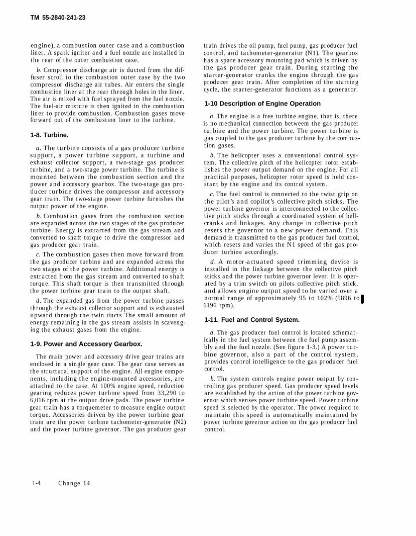
engine), a combustion outer case and a combustionliner. A spark igniter and a fuel nozzle are installed inthe rear of the outer combustion case.
b. Compressor discharge air is ducted from the dif-fuser scroll to the combustion outer case by the twocompressor discharge air tubes. Air enters the singlecombustion liner at the rear through holes in the liner.The air is mixed with fuel sprayed from the fuel nozzle.The fuel-air mixture is then ignited in the combustionliner to provide combustion. Combustion gases moveforward out of the combustion liner to the turbine.
1-8. Turbine.
a. The turbine consists of a gas producer turbinesupport, a power turbine support, a turbine andexhaust collector support, a two-stage gas producerturbine, and a two-stage power turbine. The turbine ismounted between the combustion section and thepower and accessory gearbox. The two-stage gas pro-ducer turbine drives the compressor and accessorygear train. The two-stage power turbine furnishes theoutput power of the engine.
b. Combustion gases from the combustion sectionare expanded across the two stages of the gas producerturbine. Energy is extracted from the gas stream andconverted to shaft torque to drive the compressor andgas producer gear train.
c. The combustion gases then move forward fromthe gas producer turbine and are expanded across thetwo stages of the power turbine. Additional energy isextracted from the gas stream and converted to shafttorque. This shaft torque is then transmitted throughthe power turbine gear train to the output shaft.
d. The expanded gas from the power turbine passesthrough the exhaust collector support and is exhaustedupward through the twin ducts The small amount ofenergy remaining in the gas stream assists in scaveng-ing the exhaust gases from the engine.
1-9. Power and Accessory Gearbox.
The main power and accessory drive gear trains areenclosed in a single gear case. The gear case serves asthe structural support of the engine. All engine compo-nents, including the engine-mounted accessories, areattached to the case. At 100% engine speed, reductiongearing reduces power turbine speed from 33,290 to6,016 rpm at the output drive pads. The power turbinegear train has a torquemeter to measure engine outputtorque. Accessories driven by the power turbine geartrain are the power turbine tachometer-generator (N2)and the power turbine governor. The gas producer gear
train drives the oil pump, fuel pump, gas producer fuelcontrol, and tachometer-generator (N1). The gearboxhas a spare accessory mounting pad which is driven bythe gas producer gear train. During starting thestarter-generator cranks the engine through the gasproducer gear train. After completion of the startingcycle, the starter-generator functions as a generator.
1-10 Description of Engine Operation
a. The engine is a free turbine engine, that is, thereis no mechanical connection betweem the gas producerturbine and the power turbine. The power turbine isgas coupled to the gas producer turbine by the combus-tion gases.
b. The helicopter uses a conventional control sys-tem. The collective pitch of the helicopter rotor estab-lishes the power output demand on the engine. For allpractical purposes, helicopter rotor speed is held con-stant by the engine and its control system.
c. The fuel control is connected to the twist grip onthe pilot’s and copilot’s collective pitch sticks. Thepower turbine governor is interconnected to the collec-tive pitch sticks through a coordinated system of bell-cranks and linkages. Any change in collective pitchresets the governor to a new power demand. Thisdemand is transmitted to the gas producer fuel control,which resets and varies the N1 speed of the gas pro-ducer turbine accordingly.
d. A motor-actuated speed trimming device isinstalled in the linkage between the collective pitchsticks and the power turbine governor lever. It is oper-ated by a trim switch on pilots collective pitch stick,and allows engine output speed to be varied over anormal range of approximately 95 to 102% (5896 to6196 rpm).
1-11. Fuel and Control System.
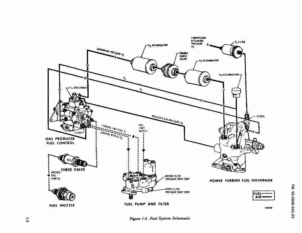
a. The gas producer fuel control is located schemat-ically in the fuel system between the fuel pump assem-bly and the fuel nozzle. (See figure 1-3.) A power tur-bine governor, also a part of the control system,provides control intelligence to the gas producer fuelcontrol.
b. The system controls engine power output by con-trolling gas producer speed. Gas producer speed levelsare established by the action of the power turbine gov-ernor which senses power turbine speed. Power turbinespeed is selected by the operator. The power required tomaintain this speed is automatically maintained bypower turbine governor action on the gas producer fuelcontrol.
1-4 Change 14
TM
55-2840-241-23
Fig
ur
e
1-3
. F
ue
l S
ys
tem
S
ch
em
atic
1-5
TM 55-2840-241-23
c. The power turbine governor lever schedules thegovernor requirements. The power turbine governor,in turn, schedules the gas producer speed to a changedpower output to maintain output shaft speed.
d. Fuel flow for engine control depends on com-pressor discharge pressure (Pc), engine speed (gasproducer—N1 and/or power turbine—N2), and leverangle. Fuel flow is a function of Pc as sensed in thefuel control. Variations of fuel flow schedules are ob-tained by modulating the Pc to Px and Py pressures inthe control through the action of a bleed-down circuitactuated by the governors. (See figure 1-4.)
1-12. Gas Producer Fuel Control.
a. The gas producer fuel control has a bypassvalve, metering valve, acceleration bellows, governingand enrichment bellows, manually operated cutoffvalve, maximum pressure relief valve, torque tubeseal and lever assembly, and a start derichment valve.The maximum pressure relief valve protects thesystem from excessive fuel pressure.
b. Fuel enters the control from the engine fuelpump and filter assembly and is delivered to themetering valve. The bypass valve maintains a cons-tant pressure differential across the metering valve.Also, excess fuel is bypassed to the fuel pump andfilter assembly through an external line connectingthe pump bypass inlet to the bypass outlet port of thegas producer fuel control.
c. The metering valve is operated by lever actionthrough movement of the governor and accelerationbellows, Metering valve area depends on valve travel,Before light -off and acceleration, the metering valve isset at a pre-determined open position by the accelera-tionbellows under the influence of ambient pressure(Pc at zero rpm).
d. The start derichment valve is open duringlight-off and acceleration to a set Pc. The open derich-ment valve vents Py pressure to atmosphere. VentingPy allows the governor bellows to move the meteringvalve against the minimum flow stop. At minimumflow the metering valve provides the required lean fuelschedule after light-off. As compressor rpm increases,the derichment valve is closed by Pc acting on thederichment bellows. When the derichment valve isclosed, control of the metering valve is returned to thenormal operating schedule.
e. During acceleration, the Px and Py pressuresare equal to the modified compressor dischargepressure (Pc) up to the point where the speed enrich-ment orifice is opened by flyweight action. Opening
the speed enrichment orifice bleeds Px pressure whilPy remains at a value equal to Pc. Under the influenceof the Py minus Px pressure drop across the governorbellows, the metering valve moves toward the maximum flow stop where it increases fuel flow.
f. Gas producer speed is controlled by the gasproducer fuel control governor. A set of flyweightsoperate the governor lever which controls the governorbellows (Py) bleed at the governing orifice. Flyweightoperation of the governor lever is opposed by avariable spring load. The spring force is establishedby the throttle lever acting on a spring schedulingcam. Opening the governing orifice bleeds Py pressureand allows Px pressure to control the governorbellows. The Px influence on the bellows moves themetering valve toward minimum flow and at a posi-tion where metered flow is at steady state re-quirements.
g. The governor reset assembly in the gasproducer fuel control limits or governs power turbinespeed. Control of the reset assembly is derived fromthe power turbine governor. The power turbine gover-nor also provides quick responding overspeed protec-t ion by bleeding governor servo (Py) pressure from thegas producer fuel control.
1-13. Power Turbine Governor.
a. Power turbine speed is scheduled by the powerturbine governor lever and the power turbine speedscheduling cam. The cam sets a governor spring loadwhich opposes a flyweight output. As the desiredspeed is approached, the flyweights operating againstthe governor spring move a link to open the power tur-bine governor orifice. The flyweights also open theoverspeed bleed (Py) orifice but at a higher speedthan the regular governor (Pg) orifice.
b. The governor orifice is downstream of a bleedsupplied by a regulated air pressure (Pr). Opening theorifice results in a reduced pressure downstream of thebleed (Pg) as an inverse function of increasing speed.Regulated pressure (Pr) and governing pressure (Pg)are applied to opposite sides of a diaphragm in thegovernor reset section of the gas producer fuel control,The force generated by Pr minus Pg across thediaphragm acts on the gas producer power output linkthrough the governor reset rod. This forcesupplements the weight force in the gas producer fuelgovernor to reset (reduce) the gas producer speed. Gasproducer speed cannot exceed the gas producer fuelgovernor setting. The Pr minus Pg diaphragm ispreloaded for establishing the active Pr minus Pgrange. Pr pressure is supplied from engine Pc pressureby an air regulator valve.
1-6
TM 55-2840-241-23
c. The overspeed orifice bleeds Py pressure fromthe governing system of the gas producer fuel control.Bleeding Py pressure at the power turbine governorgives the fuel control system a rapid response tooverspeed conditions.
1-14. Fuel Pump and Filter Assembly.
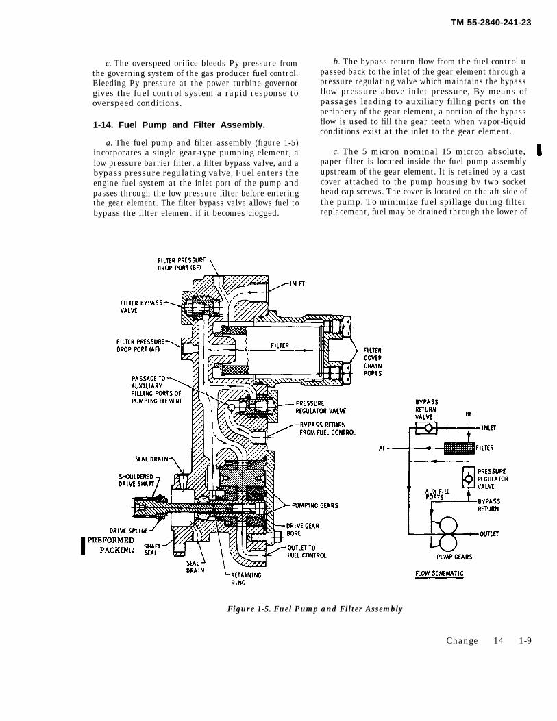
a. The fuel pump and filter assembly (figure 1-5)incorporates a single gear-type pumping element, alow pressure barrier filter, a filter bypass valve, and abypass pressure regulating valve, Fuel enters theengine fuel system at the inlet port of the pump andpasses through the low pressure filter before enteringthe gear element. The filter bypass valve allows fuel tobypass the filter element if it becomes clogged.
b. The bypass return flow from the fuel control upassed back to the inlet of the gear element through apressure regulating valve which maintains the bypassflow pressure above inlet pressure, By means ofpassages leading to auxiliary filling ports on theperiphery of the gear element, a portion of the bypassflow is used to fill the gear teeth when vapor-liquidconditions exist at the inlet to the gear element.
c. The 5 micron nominal 15 micron absolute,paper filter is located inside the fuel pump assemblyupstream of the gear element. It is retained by a castcover attached to the pump housing by two sockethead cap screws. The cover is located on the aft side ofthe pump. To minimize fuel spillage during filterreplacement, fuel may be drained through the lower of
Figure 1-5. Fuel Pump and Filter Assembly
Change 14 1-9
TM 55-2840-241-23
the two drain ports located on the aft face of the filtercover. Pressure taps are provided before and after(labeled BF and AF) the filter element to permit mea-surement of filter pressure drop if desired.
1-15. Double Check Valve.
The double check valve assembly is a mechanicaldevice placed in the governing pressure (Pg) circuitbetween the power turbine governor and the main fuelcontrol to dampen surges in the Pg pressure signal.(See figure 1-4.) It incorporates two individual,diaphragm operated valves within one unit. The valvesare located in parallel with each other and open inopposite directions. Movement of air through the checkvalve assembly in either direction is permitted by oneof the valves. However, when a stable signal is pro-vided, a very small flow of air is experienced with thevalve toward its closed position. Any pressure surges inthe Pg signal will be dampened by spring loading onthe valve.
1-16. Pc Air Filter.
The Pc air filter is a 10 micron filter located in the Pcair supply line leading from the diffuser scroll to thepower turbine governor. It incorporates a permanenttype, wire mesh, cleanable element. It prevents thegovernor and fuel control pneumatic components frombeing contaminated with foreign particles by filteringPc air flow to the governor and control.
1-17. Fuel Check Valve.
The fuel check valve is located in the fuel linebetween the fuel control and the fuel nozzle. It has acracking pressure of 22-28 psi and serves to preventleakage of fuel through the fuel nozzle into the combus-tion chamber if the fuel cutoff valve is inadvertentlyopened or leaks while the engine is not operating.
1-18. Fuel Nozzle.
The fuel nozzle is a single-entry, dual-orifice typeunit. It contains an integral valve for dividing primaryand secondary flow. This fuel nozzle relies on the fuelcheck valve to provide fuel cutoff when the fuel mani-fold pressure falls below a pre-determined pressure, tokeep fuel out of the combustion chamber at shutdown.
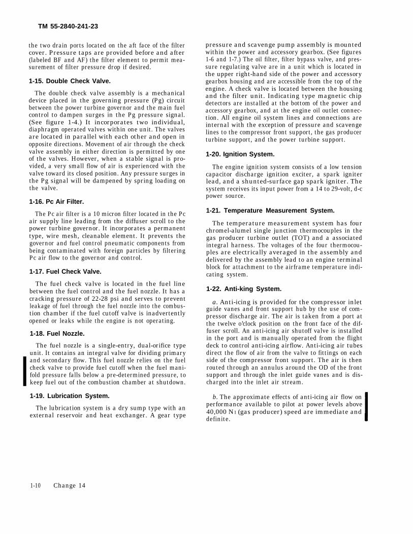
1-19. Lubrication System.
The lubrication system is a dry sump type with anexternal reservoir and heat exchanger. A gear type
pressure and scavenge pump assembly is mountedwithin the power and accessory gearbox. (See figures1-6 and 1-7.) The oil filter, filter bypass valve, and pres-sure regulating valve are in a unit which is located inthe upper right-hand side of the power and accessorygearbox housing and are accessible from the top of theengine. A check valve is located between the housingand the filter unit. Indicating type magnetic chipdetectors are installed at the bottom of the power andaccessory gearbox, and at the engine oil outlet connec-tion. All engine oil system lines and connections areinternal with the exception of pressure and scavengelines to the compressor front support, the gas producerturbine support, and the power turbine support.
1-20. Ignition System.
The engine ignition system consists of a low tensioncapacitor discharge ignition exciter, a spark igniterlead, and a shunted-surface gap spark igniter. Thesystem receives its input power from a 14 to 29-volt, d-cpower source.
1-21. Temperature Measurement System.
The temperature measurement system has fourchromel-alumel single junction thermocouples in thegas producer turbine outlet (TOT) and a associatedintegral harness. The voltages of the four thermocou-ples are electrically averaged in the assembly anddelivered by the assembly lead to an engine terminalblock for attachment to the airframe temperature indi-cating system.
1-22. Anti-king System.
a. Anti-icing is provided for the compressor inletguide vanes and front support hub by the use of com-pressor discharge air. The air is taken from a port atthe twelve o’clock position on the front face of the dif-fuser scroll. An anti-icing air shutoff valve is installedin the port and is manually operated from the flightdeck to control anti-icing airflow. Anti-icing air tubesdirect the flow of air from the valve to fittings on eachside of the compressor front support. The air is thenrouted through an annulus around the OD of the frontsupport and through the inlet guide vanes and is dis-charged into the inlet air stream.
b. The approximate effects of anti-icing air flow onperformance available to pilot at power levels above40,000 N1 (gas producer) speed are immediate anddefinite.
1-10 Change 14
TM
55-2840-241-23
Fig
ure
1-6. E
ng
ine
Lu
brica
tion
System
S
chem
atic
1-11
TM 55-2840-241-23
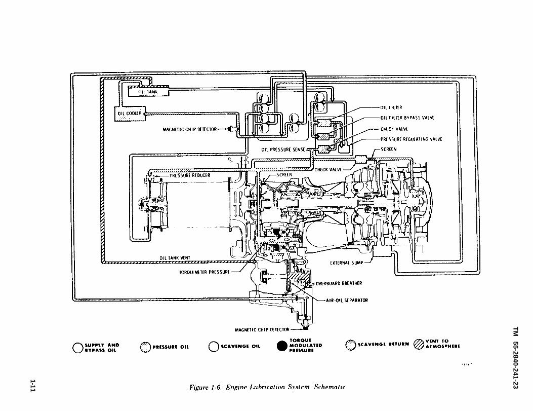
Figure 1-7. Oil Pump Schematic
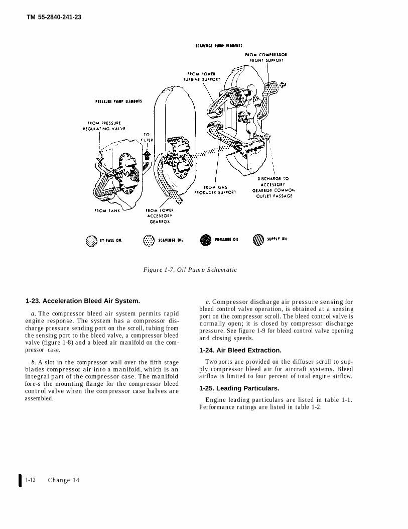
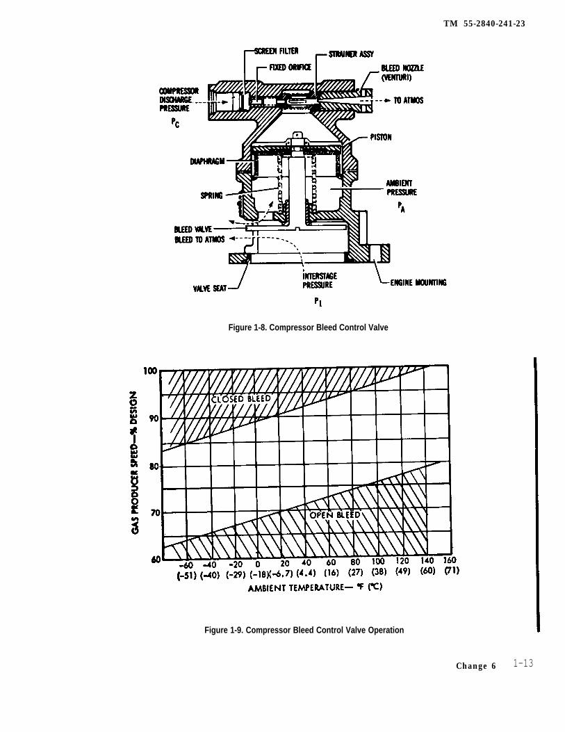
1-23. Acceleration Bleed Air System. c. Compressor discharge air pressure sensing forbleed control valve operation, is obtained at a sensing
a. The compressor bleed air system permits rapid port on the compressor scroll. The bleed control valve isengine response. The system has a compressor dis- normally open; it is closed by compressor dischargecharge pressure sending port on the scroll, tubing fromthe sensing port to the bleed valve, a compressor bleed
pressure. See figure 1-9 for bleed control valve openingand closing speeds.
valve (figure 1-8) and a bleed air manifold on the com-pressor case. 1-24. Air Bleed Extraction.
b. A slot in the compressor wall over the fifth stage TWO ports are provided on the diffuser scroll to sup-blades compressor air into a manifold, which is an ply compressor bleed air for aircraft systems. Bleedintegral part of the compressor case. The manifold airflow is limited to four percent of total engine airflow.fore-s the mounting flange for the compressor bleedcontrol valve when the compressor case halves are 1-25. Leading Particulars.
assembled. Engine leading particulars are listed in table 1-1.Performance ratings are listed in table 1-2.
1-12 Change 14
TM 55-2840-241-23
Figure 1-8. Compressor Bleed Control Valve
Figure 1-9. Compressor Bleed Control Valve Operation
Change 6 1-13
TM 55-2840-241-23
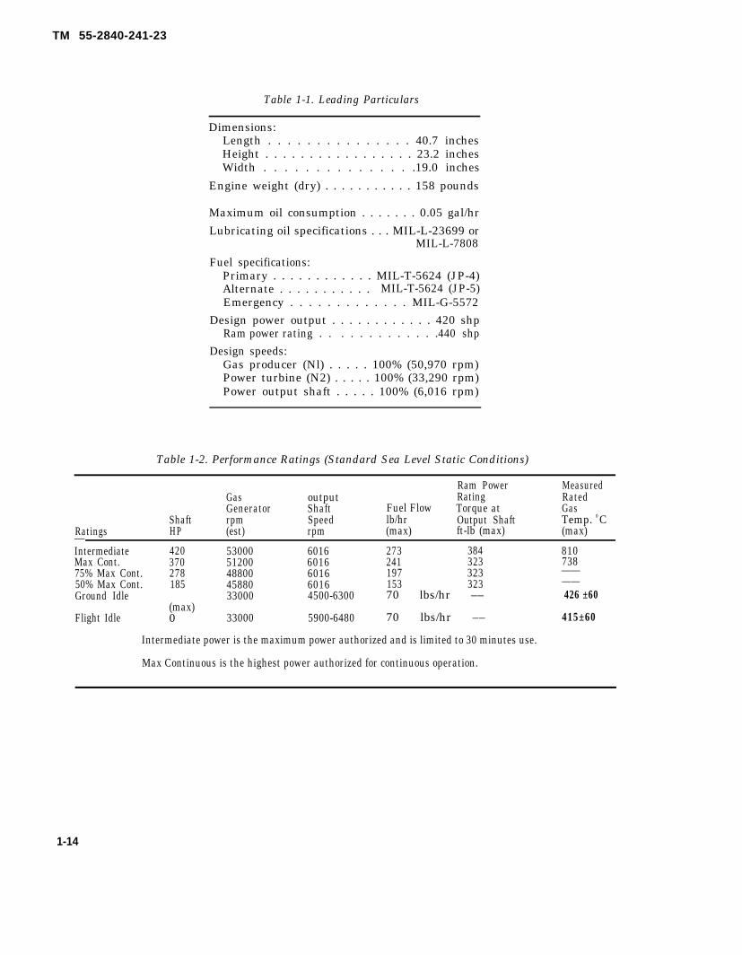
Table 1-1. Leading Particulars
Dimensions:Length . . . . . . . . . . . . . . . 40.7 inchesHeight . . . . . . . . . . . . . . . . . 23.2 inchesWidth . . . . . . . . . . . . . . .19.0 inches
Engine weight (dry) . . . . . . . . . . . 158 pounds
Maximum oil consumption . . . . . . . 0.05 gal/hr
Lubricating oil specifications . . . MIL-L-23699 orMIL-L-7808
Fuel specifications:Primary . . . . . . . . . . . . MIL-T-5624 (JP-4)Alternate . . . . . . . . . . . MIL-T-5624 (JP-5)Emergency . . . . . . . . . . . . . MIL-G-5572
Design power output . . . . . . . . . . . . 420 shpRam power rating . . . . . . . . . . . . .440 shp
Design speeds:Gas producer (Nl) . . . . . 100% (50,970 rpm)Power turbine (N2) . . . . . 100% (33,290 rpm)Power output shaft . . . . . 100% (6,016 rpm)
Table 1-2. Performance Ratings (Standard Sea Level Static Conditions)
Ram Power MeasuredGas output Rating RatedGenerator Shaft Fuel Flow Torque at Gas
Shaft rpm Speed lb/hr Output Shaft Temp. 0 CRatings HP (est) rpm (max) ft-lb (max) (max)—Intermediate 420 53000 6016 273 384 810Max Cont. 370 51200 6016 241 323 73875% Max Cont. 278 48800 6016 197 323 ——50% Max Cont. 185 45880 6016 153 323 ——Ground Idle 33000 4500-6300 70 lbs/hr –– 426 ±60
(max)Flight Idle 0 33000 5900-6480 70 lbs/hr –– 415±60
Intermediate power is the maximum power authorized and is limited to 30 minutes use.
Max Continuous is the highest power authorized for continuous operation.
1-14
TM 55-2840-241-23
CHAPTER 2
SPECIAL TOOLS, TEST EQUIPMENT, AND CONSUMABLE MATERIALS
Section I. SPECIAL TOOLS AND TEST EQUIPMENT
2-1. General. for special tools and test equipment availableto perform maintenance functions on the en-gine. It is primarily intended as a ready refer-
A listing and illustration of special tools ence for maintenance personnel in determiningand test equipment is presented in this section. what equipment is available. All tools andThis listing provides a convenient reference equipment are arranged alphabetically.
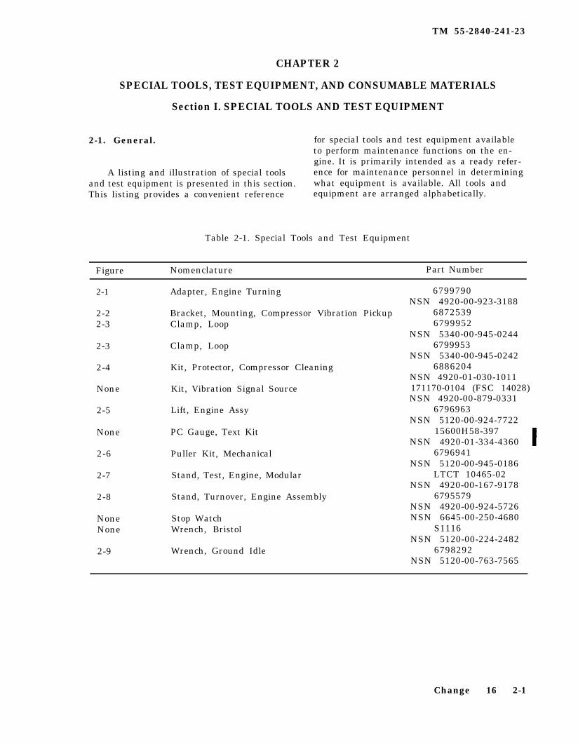
Table 2-1. Special Tools and Test Equipment
Figure Nomenclature Part Number
2-1
2-22-3
2-3
2-4
None
2-5
None
2-6
2-7
2-8
NoneNone
2-9
Adapter, Engine Turning
Bracket, Mounting, Compressor Vibration PickupClamp, Loop
Clamp, Loop
Kit, Protector, Compressor Cleaning
Kit, Vibration Signal Source
Lift, Engine Assy
PC Gauge, Text Kit
Puller Kit, Mechanical
Stand, Test, Engine, Modular
Stand, Turnover, Engine Assembly
Stop WatchWrench, Bristol
Wrench, Ground Idle
6799790NSN 4920-00-923-3188
68725396799952
NSN 5340-00-945-02446799953
NSN 5340-00-945-02426886204
NSN 4920-01-030-1011171170-0104 (FSC 14028)NSN 4920-00-879-0331
6796963NSN 5120-00-924-7722
15600H58-397NSN 4920-01-334-4360
6796941NSN 5120-00-945-0186
LTCT 10465-02NSN 4920-00-167-9178
6795579NSN 4920-00-924-5726NSN 6645-00-250-4680
S1116NSN 5120-00-224-2482
6798292NSN 5120-00-763-7565
Change 16 2-1
TM 55-2840-241-23
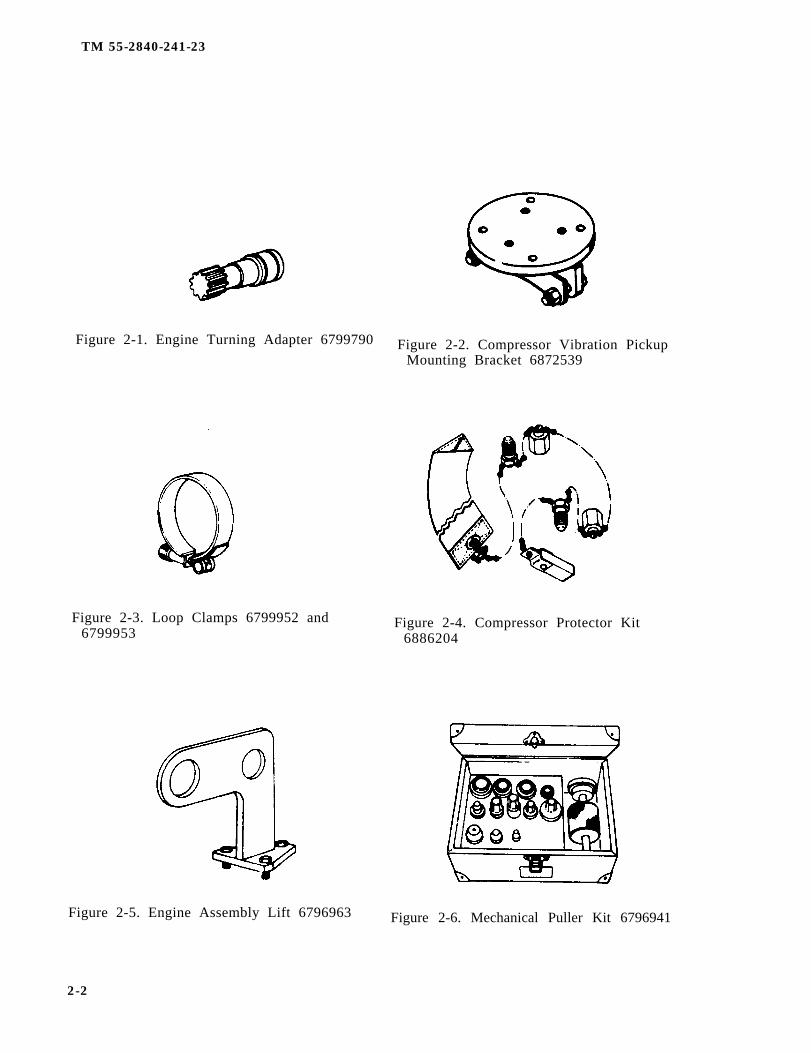
Figure 2-1. Engine Turning Adapter 6799790 Figure 2-2. Compressor Vibration PickupMounting Bracket 6872539
Figure 2-3. Loop Clamps 6799952 and6799953
Figure 2-4. Compressor Protector Kit6886204
Figure 2-5. Engine Assembly Lift 6796963
2-2
Figure 2-6. Mechanical Puller Kit 6796941
TM 55-2840-241-23
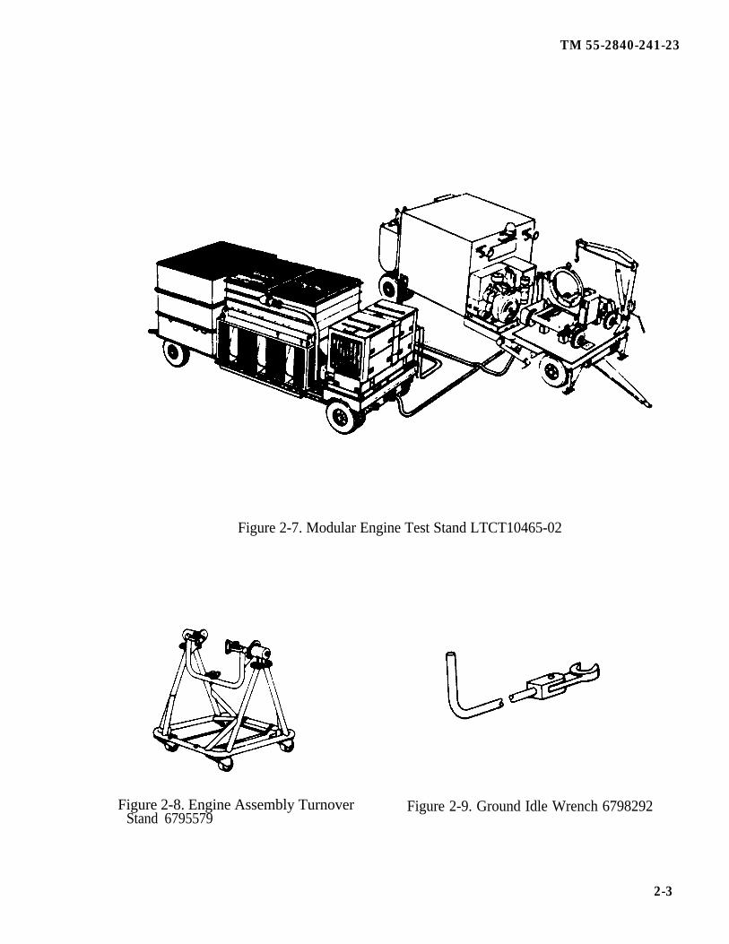
Figure 2-7. Modular Engine Test Stand LTCT10465-02
Figure 2-8. Engine Assembly TurnoverStand 6795579
Figure 2-9. Ground Idle Wrench 6798292
2-3
TM 55-2840-241-23
Section II. CONSUMABLE MATERIALS
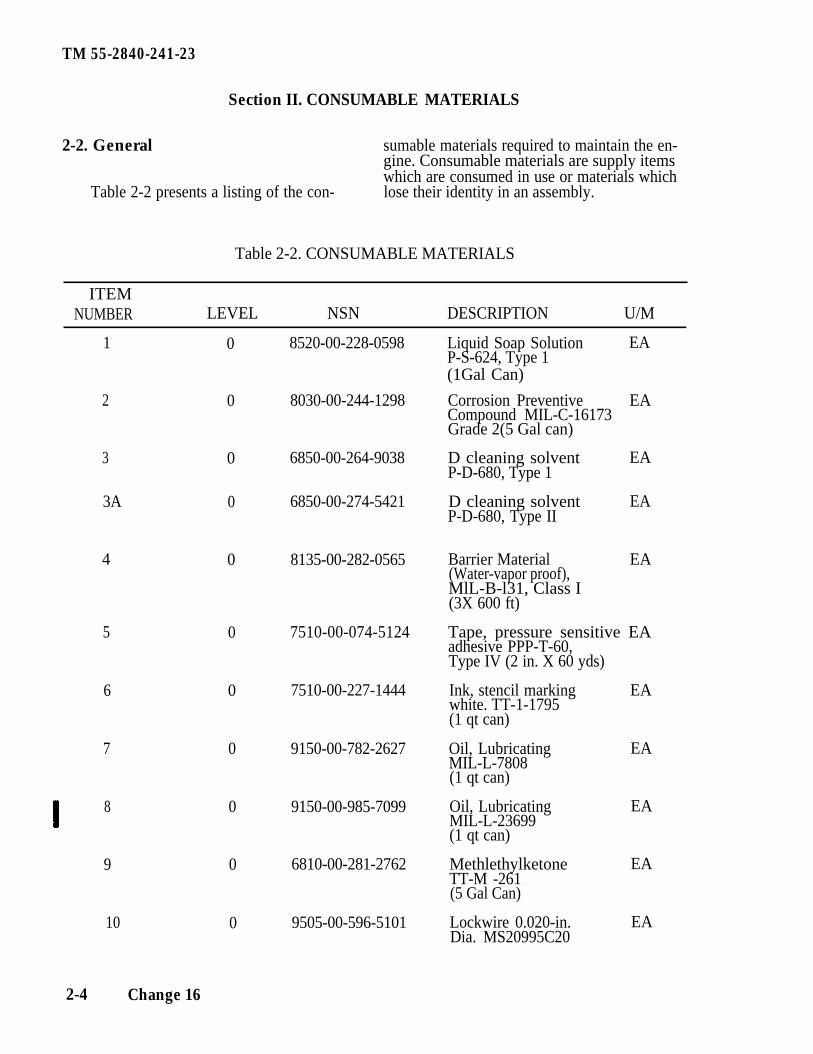
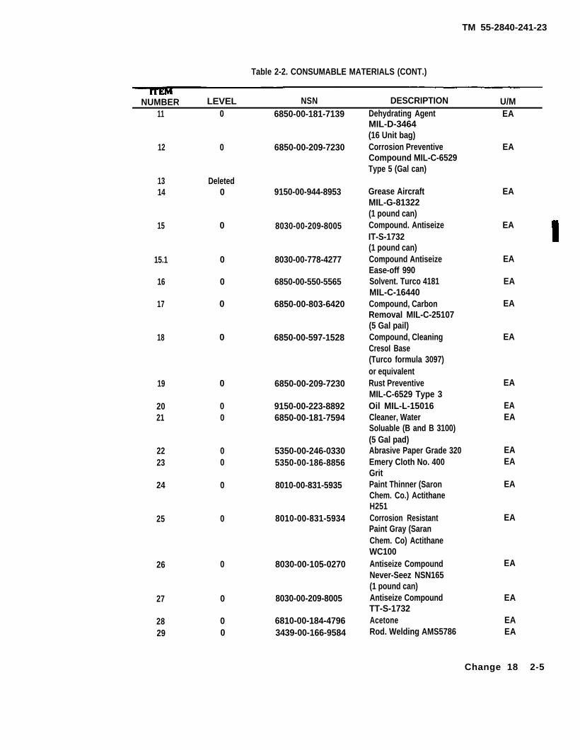
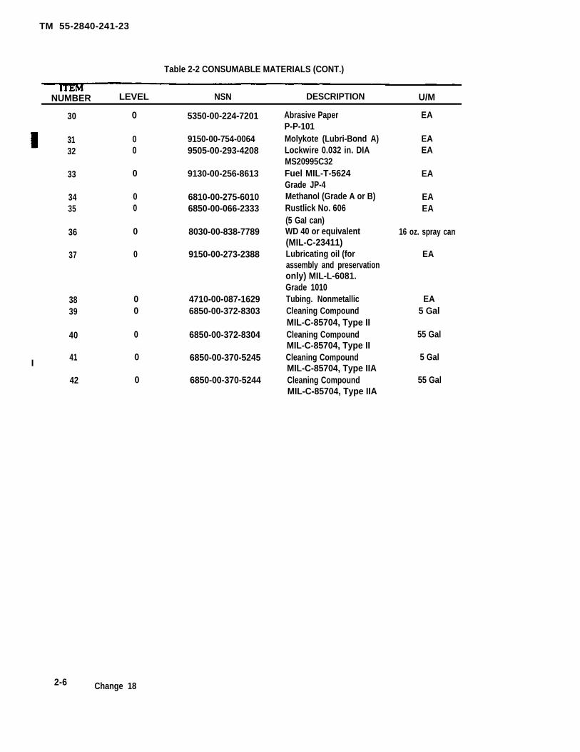
2-2. General sumable materials required to maintain the en-gine. Consumable materials are supply itemswhich are consumed in use or materials which
Table 2-2 presents a listing of the con- lose their identity in an assembly.
Table 2-2. CONSUMABLE MATERIALS
ITEMNUMBER LEVEL NSN DESCRIPTION U/M
1
2
3
3A
4
5
6
7
8
9
10
0
0
0
0
0
0
0
0
0
0
0
8520-00-228-0598
8030-00-244-1298
6850-00-264-9038
6850-00-274-5421
8135-00-282-0565
7510-00-074-5124
7510-00-227-1444
9150-00-782-2627
9150-00-985-7099
6810-00-281-2762
9505-00-596-5101
Liquid Soap Solution EAP-S-624, Type 1(1Gal Can)
Corrosion Preventive EACompound MIL-C-16173Grade 2(5 Gal can)
D cleaning solvent EAP-D-680, Type 1
D cleaning solvent EAP-D-680, Type II
Barrier Material EA(Water-vapor proof),MlL-B-l31, Class I(3X 600 ft)
Tape, pressure sensitive EAadhesive PPP-T-60,Type IV (2 in. X 60 yds)
Ink, stencil markingwhite. TT-1-1795
EA
(1 qt can)
Oil, Lubricating EAMIL-L-7808(1 qt can)
Oil, Lubricating EAMIL-L-23699(1 qt can)
Methlethylketone EATT-M -261(5 Gal Can)
Lockwire 0.020-in. EADia. MS20995C20
2-4 Change 16
TM 55-2840-241-23
Table 2-2. CONSUMABLE MATERIALS (CONT.)
NUMBER LEVEL NSN DESCRIPTION U/M11 0 6850-00-181-7139 Dehydrating Agent EA
MIL-D-3464(16 Unit bag)Corrosion Preventive EACompound MIL-C-6529Type 5 (Gal can)
12 0 6850-00-209-7230
13 Deleted14 0 9150-00-944-8953 Grease Aircraft EA
MIL-G-81322(1 pound can)Compound. Antiseize EAIT-S-1732(1 pound can)Compound Antiseize EAEase-off 990Solvent. Turco 4181 EAMIL-C-16440Compound, Carbon EARemoval MIL-C-25107(5 Gal pail)Compound, Cleaning EACresoI Base(Turco formula 3097)or equivalentRust PreventiveMIL-C-6529 Type 3Oil MIL-L-15016Cleaner, WaterSoluable (B and B 3100)(5 Gal pad)Abrasive Paper Grade 320Emery Cloth No. 400GritPaint Thinner (SaronChem. Co.) ActithaneH251Corrosion ResistantPaint Gray (SaranChem. Co) ActithaneWC100Antiseize CompoundNever-Seez NSN165(1 pound can)Antiseize CompoundTT-S-1732AcetoneRod. Welding AMS5786
15 0 8030-00-209-8005
15.1 0 8030-00-778-4277
16 0 6850-00-550-5565
17 0 6850-00-803-6420
18 0 6850-00-597-1528
19 0
00
6850-00-209-7230
9150-00-223-88926850-00-181-7594
EA
2021
EAEA
5350-00-246-03305350-00-186-8856
EAEA
2223
00
0 8010-00-831-5935 EA24
25 0 8010-00-831-5934 EA
EA26 0 8030-00-105-0270
0
00
8030-00-209-8005
6810-00-184-47963439-00-166-9584
EA
EAEA
27
2829
Change 18 2-5
TM 55-2840-241-23
Table 2-2 CONSUMABLE MATERIALS (CONT.)
NUMBER LEVEL NSN DESCRIPTION U/M
30 0 5350-00-224-7201
31 0 9150-00-754-006432 0 9505-00-293-4208
33 0 9130-00-256-8613
34 0 6810-00-275-601035 0 6850-00-066-2333
36 0 8030-00-838-7789
37 0 9150-00-273-2388
3839
40
I41
42
00
0
0
0
4710-00-087-16296850-00-372-8303
6850-00-372-8304
6850-00-370-5245
6850-00-370-5244
Abrasive PaperP-P-101Molykote (Lubri-Bond A)Lockwire 0.032 in. DIAMS20995C32Fuel MIL-T-5624Grade JP-4Methanol (Grade A or B)Rustlick No. 606(5 GaI can)WD 40 or equivalent(MIL-C-23411)Lubricating oil (forassembly and preservationonly) MIL-L-6081.Grade 1010Tubing. NonmetallicCleaning CompoundMIL-C-85704, Type IICleaning CompoundMIL-C-85704, Type IICleaning CompoundMIL-C-85704, Type IIACleaning CompoundMIL-C-85704, Type IIA
EA
EAEA
EA
EAEA
16 oz. spray can
EA
EA5 Gal
55 Gal
5 Gal
55 Gal
2-6 Change 18
TM 55-2840-241-23
CHAPTER 3
PREPARATION FOR SERVICE, STORAGE, AND ENGINE HANDLING
Section I. PREPARATION FOR SERVICE AND STORAGE
3-1. General.
NOTE
The periodic preservation, storage,and activation of engines areprescribed in TM 55-1520-228-23.
soap solution (item 1, table 2-2) aat all closures.
This section provides procedures for thepreservation, depreservation and storage of acomplete en me assembly. It also contains
tion of the compressor, fuel pump, gasprocedures or the preservation and depreserva-
producer fuel control, and power turbine gover-nor. Weight and dimension data for the ship-ping containers are shown in paragraph 3-14.
NOTE
All engine operation procedureswill be accomplishshed in accord-ance with TM 5-1520-228-10.
3-2. Preservation Maintenance.
Preservation maintenance is not represer-vation, but is the regular inspection an re-placement of the dehydrating agent. Allowengine awaiting installation to remain in thedehumidified shipping container as long aspossible.
3-3. Inspection of Pressurized Containers.
Immediately upon receipt of an engine atan activity and every 90 days (or more fre-quently) thereafter check the relative humidityindicator and the internal pressure of the con-tamer in accordance with table 3-1.
NOTE
An all blue color in the humidityindicator indicates a safe condi-tion. As moisture content insidethe container increases, the in-dicator color willl change from blueto pink. An all ink condition isconsidered unsafe and indicatesthat the desiccant must be changedand the container repressurized.
a. If the humidity indicator indicates thatthe relative humidity is less than 40 percentand the internal pressure is more than 1 psig,no maintenance is necessary until the nextregular inspection.
b. If the humidity indicator indicates thatthe relative humidity is less than 40 percentbut the internal pressure is less than psig, thecontainer shall be checked for leadage, using a
( R e f e r t o T B 5 - 8 1 0 0 - 2 0 0 - 2 4 . ) W h e nleakage has been corrected, the container shallbe repressurized to the value stated in table 3-1. Use clean dry compressed air. Recorddate of represurization and name of activitym appropriate section of engine historicalrecord.
c. If the humidity indicator indicates therelative humidity to be 40 percent or more, anunsafe or corrosive condition exists. Cometas follows:
(1) Depressurize shipping container byopening air filling valve a front of container.
Do not disturb rel ief valve.Present pressure valve could be af-fected.
(2) Allow air pressure to return to zero.
(3) Remove capscrews and nuts thatsecure con ta ine r ha lves toge the r .
(4) Remove cover from container and in-spect engine to determine its serviceability.
Any presence of corrosion on the inlet or com-pressor housings, or on other visible exteriorsurfaces, or on the compressor or turbineblades or-vanes is cause to render the engineas unserviceable.
(5) If engine is found to be serviceable,remove it from container and place it in ser-vice or represerve it per paragraph 3-11.
(6) If unserviceable inspect and repair to alike-new corrosion free condition per ap-aplicable paragraphs within this manual asauthorized by Maintenance Allocation Chart.If not repairable, ship engine to overhaul.
3-4. Removal of Engine From Shipping
Change 16 3-1
TM 55-2840-241-23
NOTE
Before removing the engine fromthe shipping container, inspect forevidence of rough handling ortampering.
To remove the engine from the shippingand storage container, proceed as follows:
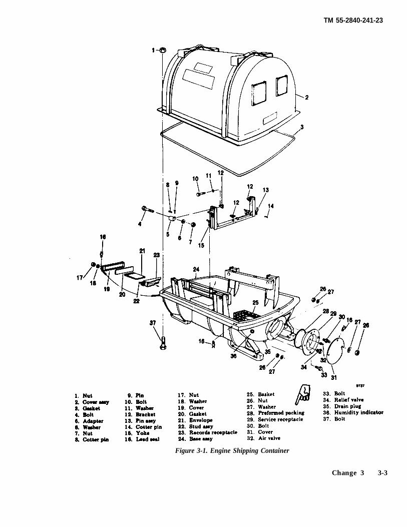
a. Loosen nut (17, figure 3-1) and open cover (19). Remove the engine records fromthe records receptacle.
b. Loosen two nuts (26) and open cover(31). Loosen air valve (32) and allow the con-tainer to depressurize.
Make certain that all air pressurehas been released before looseningnuts and bolts 1 and 37). If nutsare removed before pressure isreleased internal pressure couldblow off cover.
c. Remove nuts (1) and bolts (37) from thecontainer splitline and remove cover (2).
Ensure upper half of shipping con-tainer does not strike engine whenremoving cover. Damage to en-gine could occur.
d. Install engine assembly lift, tool No,6796963 on the gearbox top mounting adand attach a hoist. Raise the engine onlyenough to take the strain off the mounts.
e. Remove four nuts (7), washers (6), andbolts (4) from the engine side mounts.Remove two cotter pins (8 , pins (9), and adap-ters (5) from the engine side mounts.
f. Remove cotter pin (14) and pull out onpin assembly (13) until it disengages from theengine bottom mount.
g. Lift the engine assembly out of the ship-ping container. Remove the three enginemounting brackets (12) from the engine; thesebrackets are to remain with the shipping con-tainer. Install the three engine mountingbrackets supplied with the en me turnoverstand tool No. 6795579, on the engine. In-stall the engine m the turnover stand.
Do not use the shipping containermounting brackets in lieu of theturnover stand mounting brackets.Brackets are not interchangeable,damage to turnover stand couldoccur.
h. Place all loose shipping containerhardware in the cloth bag supplied with thecontainer. and place the bag m the bottom ofthe container.
i. Remove desiccant from desiccant basket.
j. Install gasket (3) on container base as-sembly (24).
k. Lower cover assembly (2) into place.Engage the forward end of the cover with theguide in in the closure flange of base assemb-ly (24); then lower the aft end. Ensure that
gasket (3) is properly seated.
1. Install thirty-two bolts 37) and nuts (1) inthe closure flange. Bolts (3 shall be in-serted from thhe bottom side of the closureflange. Tighten nuts (1) finger tight. Applypreservative to bolt threads (item 2, table 2-2).
3-5. Engine Depreservation.
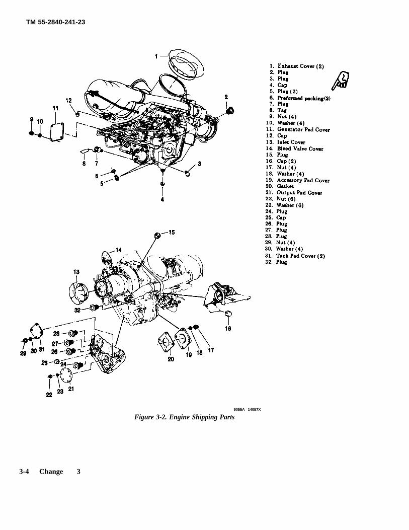
a. Remove engine shipping caps, plugs, andcovers from the engine as required (see figure3-2.)
b. Remove the lockwire from the fuel con-trol and governor stops and anti-lcmg air valve
c. Remove all barrier material and tape.Remove tape residue with solvent (item 3,table 2-2).
d. Remove any corrosion from the exteriorsurfaces of the engine and touch up paint as re-quired. (Refer to paragraphs 7-25b and 7-29).
NOTE
Flushing of the engine fuel systemis not required.
3-6. Inspection of Engine Dropped DuringHandling.
If the engine is dropped during handling,perform the following inspection and tests:
a. Inspect accessory drive gearbox for crack-ed flanges.
b. Inspect governor and tachometer drivefor cracks, distortion, and bent shafts.
c. Inspect oil falter for damage.
d. Inspect fuel control assembly for crackedflanges.
e. Inspect engine mounting pads for cracks.
f. Check air, oil, and fuel hose connectionsfor security.
g. Check all accessories for loose bolts,nuts, and connections.
3-2 Change 3
TM 55-2840-241-23
Figure 3-1. Engine Shipping Container
Change 3 3-3
TM 55-2840-241-23
9055A 14057X
Figure 3-2. Engine Shipping Parts
3-4 Change 3
TM 55-2840-241-23
able.
h. If no visual damage is apparent, enginema be operationally checked either inairframe or in mobile engine test unit. (Referto Chapter 10.) Minimum test time is 30minutes and shall include vibration check,coastdown noise check, and post-test mspec-tion of oil falter and chip detectors for metal,lint, or other foreign material. Vibrationlevels must be within established limits. If nodefects are noted, engine is considered service-
i. If engine is unserviceable, it will bepreserved in accordance with paragragh 3-8,
returned to an overhaul facility. Completeand attach necessary tags to engine; preparenecessary forms and records and place mrecords receptacle m accordance with para-graph 3-9.
3-7. Accident Engine Preservation.
paced in a metal reusable shipping andstorage container (paragraph 3-11), and
NOTE
Do not treat an engine for. cor-rosion that has been involved m anaccident where engine failure ormalfunction is known or suspectedto have been a factor. This enginemust be held for shipment to anoverhaul depot or designated in-investigation area and should not betreated for corrosion prevention.
a. Without disconnecting lines or fittings,make eve effort to prevent the remainingfuel and oil in the engine from leaking out.
b. Seal all openings with covers. (See fig-ure 3-2.) If covers are not available, seal withbarrier material (item 4, table 2-2) and securewith tape (item, table 2-2).
c. Plug all ports and cap all fittings. (Seef igure 3 -2 . )
d. Install engine in bottom half of metalreusable shipping and storage container in ac-cordance with paragraph 3-11b. Ground en-gine to container to prevent a possibleexplosion of dangerous vapors which may beignited by static electricity or a spark. Secure
all loose metal components to the containerwith tape (item 5, table 2-2 to prevent pos-sible spark during shipment.
3-8. Damaged, Cannilizd, or Failed En-gine Preservation.
preserve the compressor as follows:
Inoperable engines that are idle becausethey require parts or maintenance shall bepreserved in accordance with paragraph 3-7b,c and d and stored m a shipping container or ina clean, dry, area where the engine will be ade-
quately protected from dirt, corrosion, andphys ic damage .
3-9. Forms, Records, Tags and Stenciling.
a. The forms, records, and reports that areto be used by maintenance personnel whenpreparing an engine or engine component forstorage or shipment are listed in andprescribed by DA Pamphlet 738-751.
b. Authorized tags and the published, proce-dure for their completion is prescribed in TB750-126. Additional pressurization tags maybe applied to assist the maintenance officer indepreservation.
c. Stenciling, labeling and marking of con-tamers for storage and shipment ares shown infigures 3-3 and 3-5. Obliterate old markingsthat do not apply. Letters and numerals ofstencils shall be in block letters 1/2 inch high.,Use white stencil ink (item 6, table 2-2). Foradditional information on marking and stencil-ing refer to MIL-STD-l29.
3-10. Engine Preservation.
A serviceable engine that is beingremoved from an aircraft for the purpose of storage or return to the overhaul facility willbe preserved prior to removal from the aircraft.
a. Ensure that the engine,. accessories, inletduct, plenum chamber, and relet screens areclean and free from corrosion and foreignmaterial. When external cleaning is neces-sary, clean with solvent (item 3, table 2-2).(Refer to TB 55-9150-200-24.)
b. Fill the engine oil tanks as necessary tonormal operating level with standard operatingoil (item 7, table 2-2). Start engine. If avail-able, use external auxiliary power unit (APU).
c. Run at idle to ensure that the engine isoperating satisfactorily. Accelerate to 100%
N2, collective full down. Operate engine forfive minutes or until oil temperature reaches88°C (191° F), whichever occurs first.
d. Idle engine for two minutes prior to shut-ting down engine.
e. Allow the engine to cool until the com-pressor is cool to the touch (bare hand); then
(1) Disconnect the fuels stem pressuresensing (Pc) tube from the elbow at the dif-fuser scroll. Cap the tube and the elbow usingcompressor protector cleaning kit 6886204.
(2) Disconnect the bleed control valvepressure sensing (Pc) tube from the elbow atthe diffuser scroll. Cap the tube and the
elbow using compressor protector cleaning kit6886204.
Change 14 3-5
TM 55-2840-241-23
(3) Block the bleed control valve in theclosed position using compressor protectorcleaning kit 6886204.
(4) Retain the anti-ice valve in the closedposition.
(5) Spray one-quarter pint of preservativeitem 35, table 2-.2) into the engine whde it isbeing motored with the starter and without ig-
nition. Use a sprayer with a quick openingvalve and a nozzle sized to spray one-quarterpint of preservative m 1 to 3 seconds. Holdsprayer 8 to 12 inches in front of thecompressor. Allow the preservative to be drawn into the compressor while spraycircular motion which covers the entire intakearea. As an alternate method of applicationuse an aerosol pressure-type spray can. Spraypreservation from the can or 15 to 20 secondswhale the engine is being motored. Spray in acircular motion which covers the entire retakearea.
ping plugs (26, 27, 28, figure 3-2) with oilDo not exceed 10% N1 rpm motor-ing speed. Do not reject a solidstream of fluid into the compres-sor, proper compressor preserva-bon may not occur and damage tothe compressor vanes could result.
(6) Reconnect the control system andbleed control valve pressure sensing. Tightencoupling nuts to 80-120 lb. in.
(7) Remove the wedge which was used toblock the bleed control valve in the closedposition.
f. Preserve the engine fuel system as fol-lows:
1 0 1 0 .(l) Disconnect the power input lead at the
ignition exciter or pull the IGN ENG circuitbreaker Reference TM 55-1520-228-10).Pull the boost pump circuit breaker.
(2) Disconnect the fuel line at the fuelpump inlet port and connect a source oflubricating oil (item 37, table 2-2). Cap thedisconnected fuel line.
(3) Move the twist grip to the IDLE detentand motor the engine with the starter (use APUif available).
To prevent damage to the starterobserve starter time restriction-35seconds maximum when tempera-ture is 90°F or (32°C) or above.
(4) Discontinue motoring when fuel-freeoil flows from the combustion burner drainvalve hose.
(5) Disconnect the source of lubricatingoil and cap relet port of fuel pump.
(6) Reconnect the power lead to the igni-tion exciter or reset the IGN ENG circuitbreaker. Reset the boost pump circuit breaker.
g. Install engine inlet and exhaust protectivecovers. If covers are not available, seal theopenings with barrier material (item 4 table 2-2) and secure with tape (item 5, table 2-2).
h. Make all necessary entries to include thedate and extent of engine reservation on theforms (DA Form 2408-13).
i. Remove engine accessories in accordancewith Chapter 4 of TM 55-1520-228-23.
j. Clean the starter-generator drives lineswith methylethylketone (item 9, table 2-2) asnecessary to remove previously applied lubrcant. Coat all accessory drive splinesand accessory drive pads which do not have ac-cessories installed on them and engine oil ship-
(item 7, table 2-2). Coat fuel inlet shippingplug (7) with oil (item 8, table 2-2). Installshipping plugs, covers, gaskets, washers andnuts.
k. Secure the gas producer fuel control stopin the cut-off Position. Secure the power tur-bine governor stop and anti-icing valve leversufficiently tight to prevent movement. Lock-wire (item 10, table 2-2) shall be used tosecure the stops and lever.
1. Attach a tag (8) tome fuel inlet shippingplug (7) with the following reformation shownclearly on the tag: THIS FUEL SYSTEMHAS BEEN PREPARED FOR STORAGEBY FLUSHING WITH OIL CONFORMINGTO SPECIFICATION MIL-L-6081, GRADE
m. Touch up paint where damaged in ac-cordance with paragraphs 7-25b and 7-29.Do not expose touchup areas to engine fluidsor cleaning solvents for a minimum period of72 hours after application.
n. Tighten aluminum and plastic shippingcaps an plugs finger tight; except, tightencaps (12 and 16, figure 3-2) on the combustordrain valve and exhaust collector drain to bot-tom of cap; then twist an additional 90-120degrees.
o. Tighten threaded parts to standard tor-ques.
p. Tighten nuts which secure plastic acces-so covers as required to obtain a snug fitwithout out excessive cover indentation.
q. Cover the compressor bleed valve withcover (14).
3-6 Change 16
TM 55-2840-241-23
a. Preparation of Container(1) Loosen two nuts (26, figure 3-1) and pivot
cover (31) around to expose air valve (32).(2) Slowly loosen the air valve (31) to relieve
pressure in the container.
Personnel should stand clear of air valvewhen loosening to prevent personalinjury.
(3) Remove thirty-two nuts (1) and bolts (37)from the closure flange and remove cover assembly (2).
(4) Remove two cotter pins (8) and pins (9) andremove engine side mounting brackets (12).
(5) Remove cotter pin (14) and slide pin assem-bly (13) out until it disengages from the engine lowermounting bracket (12). Remove the mounting bracket.
(6) Remove four nuts (7) washers (6), and bolts(4) and remove engine side mounting adapters (5).
(7) Inspect the container to determine that it iscomplete and serviceable. Particular attention shouldbe given to the mounting brackets, bolts, nuts, pins andcotter pins in the engine suspension system. Replaceparts which show signs of wear and/or damage.
b. Installation of Engine In Container
The fuel system of all engines that are tobe placed in containers (less accident-involved engines) will be thoroughlydrained, purged, and preserved. All dis-connected lines will be capped or plug-ged. Tape will not be used in lieu of caps orplugs.
(1) Suspend the engine from a hoist in theupright position (exhaust ducts up) using engineassembly lift, tool No. 6796963.
(2) Remove the three turnover stand mountingbrackets and assemble three engine mountingbrackets (12, figure 3-1) on the engine using nine bolts(10) and washers (11). Tighten bolts to 85-110 in. lbs.and lockwire (item 10, table 2-2).
Do not use the engine turnover standmounting brackets in lieu of enginemounting brackets. Brackets are notinterchangeable, damage to engine couldoccur.
Avoid sharp bends when coiling the ther-mocouple lead.
(2.1) Coil the thermocouple lead and secure itto the top of the turbine.
(3) Lower the engine into the container untilthe bottom mounting bracket (12) engages with thebottom mounting adapter.
(4) Align the pin holes and engage pin assem-bly (13). Secure with one cotter pin (14).
(5) Insert the two side mounting adapters (5)through the locating holes in yoke assembly (15) andengage with the two side mounting brackets (12).Secure with two pins (9) and cotter pins (8).
(6) Secure the two side mounting adapters (5)to the yoke assembly (15) with four bolts (4) washers (6)and nuts (7). Tighten nuts (7) firmly then loosen onecomplete turn.
(7) Release the engine weight from the hoistand remove the engine assembly lift, tool No. 679696,from the engine.
(8) Tighten four nuts (7) at the engine sidemounts to 40.50 in. lb.
(9) Tie the cloth bag, used to store the enginemounting bolts (10) and washers (11), to desiccant bas-ket (25) for future use.
(10) Place two bags of desiccant (item 11, table2.2) into desiccant basket (25).
(11) Install gasket (3) on container base assem-bly (24).
(12) Lower cover assembly (2) into place over theengine. Engage the forward end of the cover with theguide pin in the closure flange of base assembly (24);then lower the aft end. Ensure that gasket (3) is prop-erly seated.
(13) Install thirty-two bolts (37) and nuts (1) inthe closure flange. Bolts (37) shall be inserted from thebottom side of the closure flange. Tighten nuts (1) fin-ger tight.
(14) Tighten one nut (1) on each side of the con-tainer at the center and at each of the four comers toapproximately 75 in. lb.
(15) Starting at the guide pin in the forward endof the closure flange and moving in a clockwise direc-tion, final tighten nuts (1) to 150-165 in. lb.
c. Container Pressurization.(1) Tighten the air valve (32, figure 3-l).(2) Using a source of filtered, dry, compressed
air, pressurize the container to the value shown intable 3-1.
Change 14 3-7

TM 55-2840-241-23
(3) Check gasket (3), humidity indicator,packing (28), drain plug (35), air valve (32), and reliefvalve (34) for leaks by brushing a liquid soap solution(item 1, table 2-2) on all seams and closure points.
(4) If leaks are found, check torque on nuts (1)and bolts (30, 33). Replace gasket (3) and packing (28) ifnecessary.
Do not attempt to stop leaks by over-torquing nuts. Overtorquing may causedamage to container.
(5) Repeat steps (2) and (3) as required.(6) Wipe off or flush away soap solution.(7) Install cover (31) on bolts (30) and tighten
nuts (26) to 15-25 in. lbs.
Table 3-1. Container Air Pressure vsAmbient Temperature
Temperature Pressure Temperature Pressure(%F) (psig) (%F) (psig)
1401301201101009080706050
7.67.36.96.56.15.85.45.04.64.3
40302010
0– 10–20–30–40
3.93.53.22.82.42.01.71.30.9
d. Engine Records Receptacle.(1) Loosen two nuts (17, figure 3-1 ) and swing
stud assembly (22) out of the slot in cover (19). Pivot thecover out of the way.
(2) Insert applicable engine records in envelope(21) and place in the engine records receptacle.
(3) Pivot cover (19) with gasket (20) into placeover the receptacle opening and swing stud assembly(22) into the cover (19) slot.
(4) Secure the cover in place by tightening twonuts (17) to 30-45 in. lb.
e. Tamper-proof Security.Container tamper-proof security is provided by five
lead seals; two in the container closure flange, two inthe records receptacle cover, and one in the servicereceptacle cover,
(1) Thread seal (16, figure 3-1) wire through thesealing holes in cover (31) and service receptacle (29).Seal the ends of the wire together with the attachedlead seal.
(2) Seal both ends of the records receptaclecover (19) by threading seal wire (16) through the seal-ing holes in cover (19) and receptacle (23). Seal the endsof the wires together with the attached lead seals.
(3) Thread seal wire (16) through each set ofsealing holes in the closure flange of base assembly (24)and cover assembly (2). Thread the wire down throughone hole and up through the other hole. Secure theends of the wires together with the attached lead seals.The sealing holes are located at the left front and rightrear of container closure flange,
(4) Coat the exposed threads of bo]ts (30 and 37) andstud assembly (22) with corrosion preventive com-pound (item 2, table 2-2).
f. Container Stenciling.Stenciling of the engine shipping container will be in
accordance with paragraph 3-9 and figure 3-3.
3-12. Engine Container Internal Pressure andHumidity Check.
Check the internal pressure and humidity within 24hours after the container is pressurized. Check thepressure and humidity immediately prior to shipmentif the engine is to be shipped.
a. Internal Pressure Check. If the internal pressureis not within 0.5 psig of the value shown in table 3-1,repeat paragraph 3-11c(2) and (3).
b. Humidity Indicator Check. The humidity indica-tor (36, figure 3-1) is normally light blue in color. At40± 3 percent relative humidity, the color will changeto light lavender or lavender pink.
(1) the humidity indicator may be light lav-ender or lavender pink when the container is pres-surized and should change to light blue within one totwo hours. If it does not change to light blue, replacethe indicator.
NOTE
The humidity indicator should change to lightblue in an atmosphere of less than 37 percentrelative humidity unless it has absorbed suffi-cient moisture to wash away or destroy itschemical properties.
(2) If the humidity indicator changes to lightlavender or lavender pink after the container has beenpressurized, open the container and inspect the enginefor corrosion. Replace the desiccant (item 11, table 2-2.)
3-13. Removing Accessory from Shipping Con-tainer
NOTEBefore removing the accessory from the ship-ping container, inspect for evidence of roughhandling or tampering.
3-8 Change 14
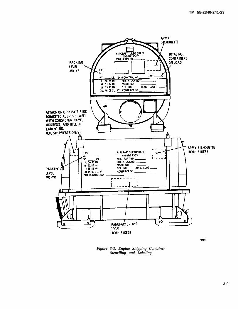
TM 55-2340-241-23
Figure 3-3. Engine Shipping ContainerStenciling and Labeling
3-9
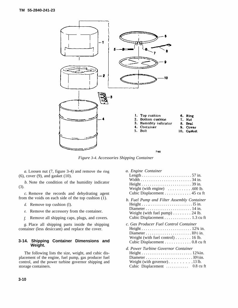
TM 55-2840-241-23
Figure 3-4. Accessories Shipping Container
a. Loosen nut (7, figure 3-4) and remove the ring a. Engine Container(6), cover (9), and gasket (10). Length . . . . . . . . . . . . . . . . . . . . . . . . 57 in.
b. Note the condition of the humidity indicatorWidth . . . . . . . . . . . . . . . . . . . . . . . . 34 in.
(3).Height . . . . . . . . . . . . . . . . . . . . . . . . 39 in.Weight (with engine) . . . . . . . . . . .600 lb.
c. Remove the records and dehydrating agent Cubic Displacement . . . . . . . . . . . . 45 cu ftfrom the voids on each side of the top cushion (1). b. Fuel Pump and Filter Assembly Container
d. Remove top cushion (l). Height . . . .. . . . . . . . . . . . . . . . . . . . . l5 in.
e.
f.
Remove the accessory from the container.Diameter . . . . . . . . . . . . . . . . . . . . . . 14 in.Weight (with fuel pump) . . . . . . . . 24 lb.
Remove all shipping caps, plugs, and covers. Cubic Displacement . . . . . . . . . . . . . 1.3 cu ft
g. Place all shipping parts inside the shippingcontainer (less desiccant) and replace the cover.
3-14. Shipping Container Dimensions andWeight.
The following lists the size, weight, and cubic dis-placement of the engine, fuel pump, gas producer fuelcontrol, and the power turbine governor shipping andstorage containers.
c. Gas Producer Fuel Control ContainerHeight . . . . . . . . . . . . . . . . . . . . . . . . 12¾ in.Diameter . . . . . . . . . . . . . . . . . . . . . . l0½ in..
Weight (with fuel control) . . . . . . . 16 lb.Cubic Displacement . . . . . . . . . . . . 0.8 cu ft
d. Power Turbine Governor ContainerHeight . . . . . . . . . . . . . . . . . . . . . . . . 12¾in.Diameter . . . . . . . . . . . . . . . . . . . . . . l0½in.Weight (with governor) . . . . . . . . . 13 lb.Cubic Displacement . . . . . . . . . . . . 0.8 cu ft
3-10
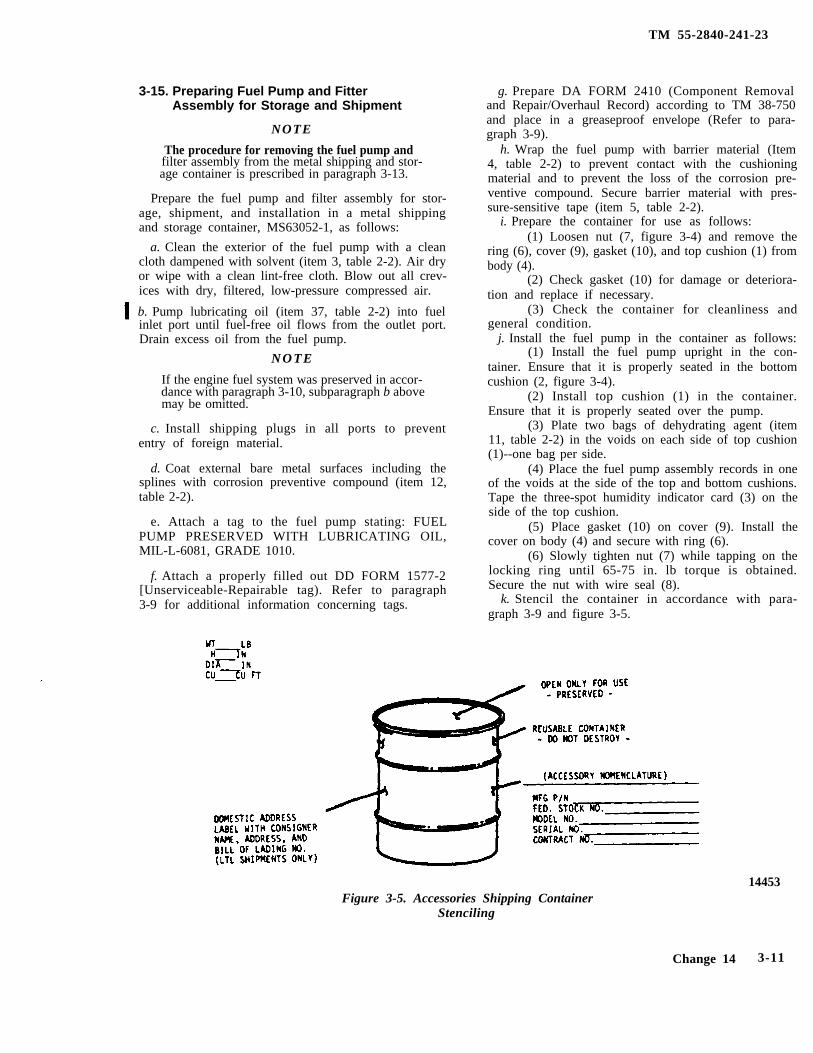
TM 55-2840-241-23
3-15. Preparing Fuel Pump and FitterAssembly for Storage and Shipment
NOTE
The procedure for removing the fuel pump andfilter assembly from the metal shipping and stor-age container is prescribed in paragraph 3-13.
Prepare the fuel pump and filter assembly for stor-age, shipment, and installation in a metal shippingand storage container, MS63052-1, as follows:
a. Clean the exterior of the fuel pump with a cleancloth dampened with solvent (item 3, table 2-2). Air dryor wipe with a clean lint-free cloth. Blow out all crev-ices with dry, filtered, low-pressure compressed air.
b. Pump lubricating oil (item 37, table 2-2) into fuelinlet port until fuel-free oil flows from the outlet port.Drain excess oil from the fuel pump.
N O T E
If the engine fuel system was preserved in accor-dance with paragraph 3-10, subparagraph b abovemay be omitted.
c. Install shipping plugs in all ports to prevententry of foreign material.
d. Coat external bare metal surfaces including thesplines with corrosion preventive compound (item 12,table 2-2).
e. Attach a tag to the fuel pump stating: FUELPUMP PRESERVED WITH LUBRICATING OIL,MIL-L-6081, GRADE 1010.
f. Attach a properly filled out DD FORM 1577-2[Unserviceable-Repairable tag). Refer to paragraph3-9 for additional information concerning tags.
g. Prepare DA FORM 2410 (Component Removaland Repair/Overhaul Record) according to TM 38-750and place in a greaseproof envelope (Refer to para-graph 3-9).
h. Wrap the fuel pump with barrier material (Item4, table 2-2) to prevent contact with the cushioningmaterial and to prevent the loss of the corrosion pre-ventive compound. Secure barrier material with pres-sure-sensitive tape (item 5, table 2-2).
i. Prepare the container for use as follows:(1) Loosen nut (7, figure 3-4) and remove the
ring (6), cover (9), gasket (10), and top cushion (1) frombody (4).
(2) Check gasket (10) for damage or deteriora-tion and replace if necessary.
(3) Check the container for cleanliness andgeneral condition.
j. Install the fuel pump in the container as follows:(1) Install the fuel pump upright in the con-
tainer. Ensure that it is properly seated in the bottomcushion (2, figure 3-4).
(2) Install top cushion (1) in the container.Ensure that it is properly seated over the pump.
(3) Plate two bags of dehydrating agent (item11, table 2-2) in the voids on each side of top cushion(1)--one bag per side.
(4) Place the fuel pump assembly records in oneof the voids at the side of the top and bottom cushions.Tape the three-spot humidity indicator card (3) on theside of the top cushion.
(5) Place gasket (10) on cover (9). Install thecover on body (4) and secure with ring (6).
(6) Slowly tighten nut (7) while tapping on thelocking ring until 65-75 in. lb torque is obtained.Secure the nut with wire seal (8).
k. Stencil the container in accordance with para-graph 3-9 and figure 3-5.
Figure 3-5. Accessories Shipping ContainerStenciling
14453
Change 14 3-11
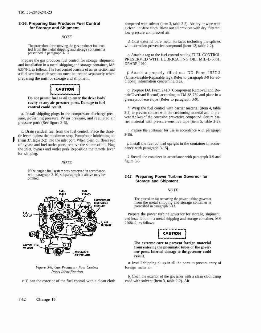
TM 55-2840-241-23
3-16. Preparing Gas Producer Fuel Controlfor Storage and Shipment.
NOTE
The procedure for removing the gas producer fuel con-trol from the metal shipping and storage container isprescribed in paragraph 3-13.
Prepare the gas producer fuel control for storage, shipment,and installation in a metal shipping and storage container, MS63048-1, as follows. The fuel control consists of an air section anda fuel section; each section must be treated separately whenpreparing the unit for storage and shipment.
Do not permit fuel or oil to enter the drive bodycavity or any air pressure ports. Damage to fuelcontrol could result.
a. Install shipping plugs in the compressor discharge pres-sure, governing pressure, Py air pressure, and regulated airpressure pork (See figure 3-6),
b. Drain residual fuel from the fuel control. Place the throt-tle lever against the maximum stop. Pump/pour lubricating oil(item 37, table 2-2) into the inlet port. When clean oil flows outof bypass and fuel outlet ports, remove the source of oil. Plugthe inlet, bypass and outlet pork Reposition the throttle leverfor shipping.
NOTE
If the engine fuel system was preserved in accordancewith paragraph 3-10, subparagraph b above may beomitted.
Figure 3-6. Gas Producerr Fuel ControlPorts Identification
c. Clean the exterior of the fuel control with a clean cloth
dampened with solvent (item 3, table 2-2). Air dry or wipe witha clean lint-free cloth. Blow out all crevices with dry, filtered,low-pressure compressed air.
d. Coat external bare metal surfaces including the splineswith corrosion preventive compound (item 12, table 2-2).
e. Attach a tag to the fuel control stating FUEL CONTROLPRESERVED WITH LUBRICATING OIL, MIL-L-6081,GRADE 1010.
f. Attach a properly filled out DD Form 1577-2(Unserviceable-Reparable tag). Refer to paragraph 3-9 for ad-ditional information concerning tags.
g. Prepare DA Form 2410 (Component Removal and Re-pair/Overhaul Record) according to TM 38-750 and place in agreaseproof envelope (Refer to paragraph 3-9).
h. Wrap the fuel control with barrier material (item 4, table2-2) to prevent contact with the cushioning material and to pre-vent the l0SS of the corrosion preventive compound. Secure bar-rier material with pressure-sensitive tape (item 5, table 2-2).
i. Prepare the container for use in accordance with paragraph3-15i.
j. Install the fuel control upright in the container in accor-dance with paragraph 3-15j.
k. Stencil the container in accordance with paragraph 3-9 andfigure 3-5.
3-17. Preparing Power Turbine Governor forStorage and Shipment
NOTE
The procedure for removing the power turbine governorfrom the metal shipping and storage container isprescribed in paragraph 3-13.
Prepare the power turbine governor for storage, shipment,and installation in a metal shipping and storage container, MS27684-2, as follows:
Use extreme care to prevent foreign materialfrom entering the pneumatic tubes or the gover-nor ports. Internal damage to the governor couldresult.
a. Install shipping plugs in all the ports to prevent entry offoreign material.
b. Clean the exterior of the governor with a clean cloth dampened with solvent (item 3, table 2-2). Air
3-12 Change 10
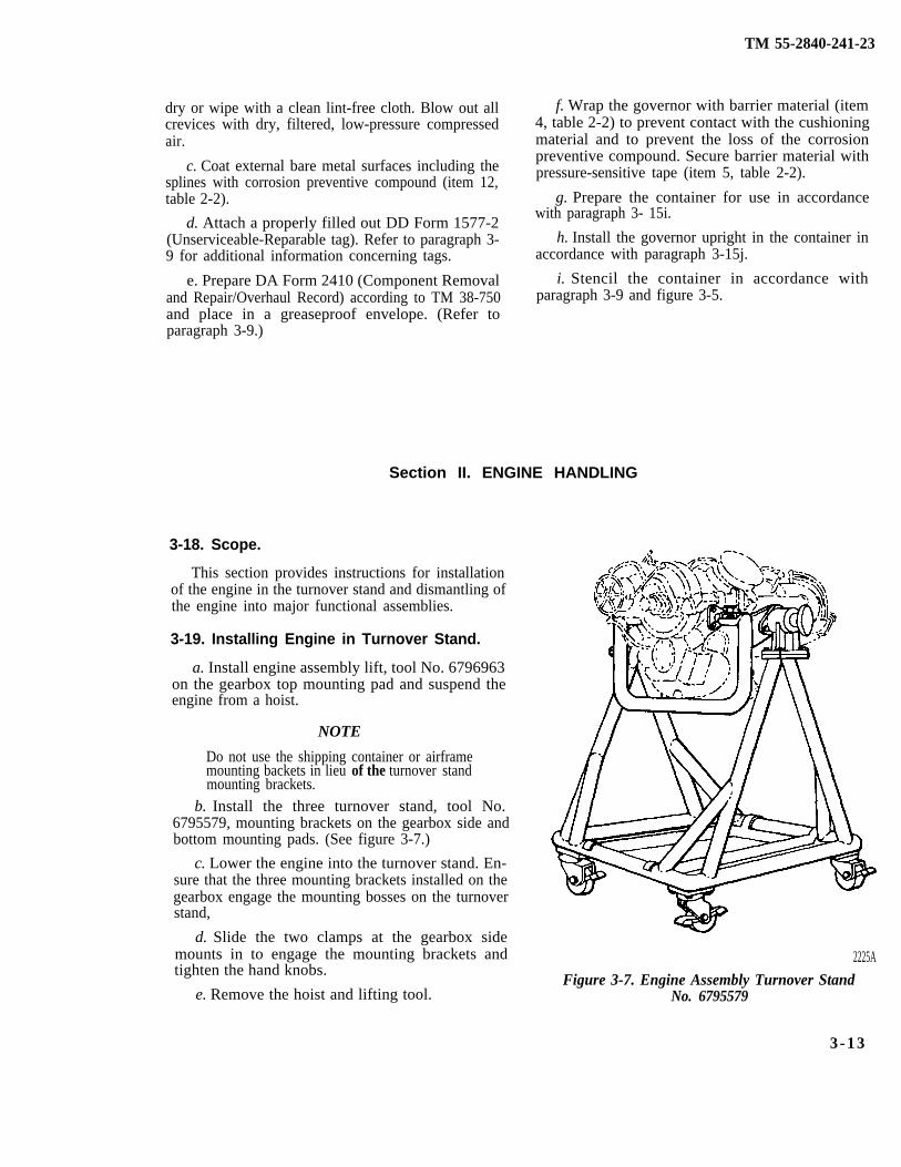
TM 55-2840-241-23
dry or wipe with a clean lint-free cloth. Blow out allcrevices with dry, filtered, low-pressure compressedair.
c. Coat external bare metal surfaces including thesplines with corrosion preventive compound (item 12,table 2-2).
d. Attach a properly filled out DD Form 1577-2(Unserviceable-Reparable tag). Refer to paragraph 3-9 for additional information concerning tags.
e. Prepare DA Form 2410 (Component Removaland Repair/Overhaul Record) according to TM 38-750and place in a greaseproof envelope. (Refer toparagraph 3-9.)
Section II. ENGINE HANDLING
3-18. Scope.
f. Wrap the governor with barrier material (item4, table 2-2) to prevent contact with the cushioningmaterial and to prevent the loss of the corrosionpreventive compound. Secure barrier material withpressure-sensitive tape (item 5, table 2-2).
g. Prepare the container for use in accordancewith paragraph 3- 15i.
h. Install the governor upright in the container inaccordance with paragraph 3-15j.
i. Stencil the container in accordance withparagraph 3-9 and figure 3-5.
This section provides instructions for installationof the engine in the turnover stand and dismantling ofthe engine into major functional assemblies.
3-19. Installing Engine in Turnover Stand.
a. Install engine assembly lift, tool No. 6796963on the gearbox top mounting pad and suspend theengine from a hoist.
NOTE
Do not use the shipping container or airframemounting backets in lieu of the turnover standmounting brackets.
b. Install the three turnover stand, tool No.6795579, mounting brackets on the gearbox side andbottom mounting pads. (See figure 3-7.)
c. Lower the engine into the turnover stand. En-sure that the three mounting brackets installed on thegearbox engage the mounting bosses on the turnoverstand,
d. Slide the two clamps at the gearbox sidemounts in to engage the mounting brackets andtighten the hand knobs.
e. Remove the hoist and lifting tool.
2225A
Figure 3-7. Engine Assembly Turnover StandNo. 6795579
3-13
TM 55-2840-241-23
3-20. Dismantling Engine intoFunctional Assemblies
Major
a. During dismantling, examine all major func-tional assemblies for serviceability. The condition ofan assembly can often be better determined by ex-amination during dismantling. Signs of scoring, bur-ning, and excessive wear or the presence of metal par-ticles are danger signals. Thorough inspection shouldbe made immediately. Look for any indication ofwork incorrectly performed during previousmaintenance or overhaul. Report any such indicationsto the local maintenance officer.
b. Care must be exercised to prevent the entranceof dirt and other foreign material into the engine.Whenever practicable, temporary covers should beused to seal all openings in the dismantled engine. Allthreads, splines, and pilot diameters should beprotected against damage. Protective covers shouldbe of a configuration that prohibits assembly withmating parts without removing the covers.
c. Unless parts of a particular engine are to be heldfor a special inspection discard all gaskets, lockwashers,preformed packings, diaphragms, and cotter pins as theyare removed. These parts must not be mixed with newparts of similar type and must not be used again. Disposi-tion of self-locking nuts shall be determined in accod-ance with minimum prevailing toque at reassembly.
d.
Prolonged contact with lubricating oil(item 7, table 2-2) may cause a skin rash.Those areas of skin and clothing thatcome in contact with lubricating oilshould be thoroughly washed im-mediately. Enclosed areas wherelubricating oil is used ehould he ade-quately ventilated to keep mist andfumes to a minimum.
Lubricating oil may soften paint uponcontact. If lubricating oil is spilled onpainted surfaces, these surfaces shouldbe thoroughly washed.
Remove the magnetic drain plug from the bot-tom of the gearbox and allow oil to drain before theengine is rotated in the turnover stand.
3-21. Combustion Section Removal.
a. Disconnect the drain hose from thedrain valve (14, figure 3-8).
burner
b. Remove the lockwire, remove jam nut (16) anddisengage bracket (15) from the engine.
To prevent personnel injury due toelectrical chock, ensure ignition sys-tem has been off for at least fiveminutes before disconnecting the-igniter lead. Ground the lead to theengine using an insulated screw-driver to dissipate any energy storedin the exciter.
c. Disconnect the igniter lead (9) from the sparkigniter (10).
d. Remove fuel hose (8) between the firewallshield and fuel nozzle (7).
e. If a new outer combustion case (6) is to be in-stalled:
(1) Remove fuel nozzle (7) and spark igniter(10) from outer combustion case (6).
(2) Remove drain valve (14) and plug (12)the bottom of outer combution case (6), Diacard pre-formed packing (11, 13).
f. Remove the two retaining rings (17) from outercombustion case (6) and slide them forward on thedischarge air tubes (18).
g. Remove 24 nuts (5), one clamp (4) and 24 bolts(1, 2) at the combustion case splitline.
h. Remove outer combustion case (6) and airtubes (18). Separate the air tubes from the outer com-bustion case.
i. Remove combustion liner (3) from the engine.
j. Remove seal rings (19) from the small ends ofthe air tubes.
k. Remove retaining rings (17) and seal rings (20)from the large ends of the air tubes.
NOTEIf a turbine overtemperature inspection is to bemade, complete step l.
l. Remove lockwire and two positioning plugs(21). Lift off first stage turbine nozzle shield (22).
3-14 Change 3
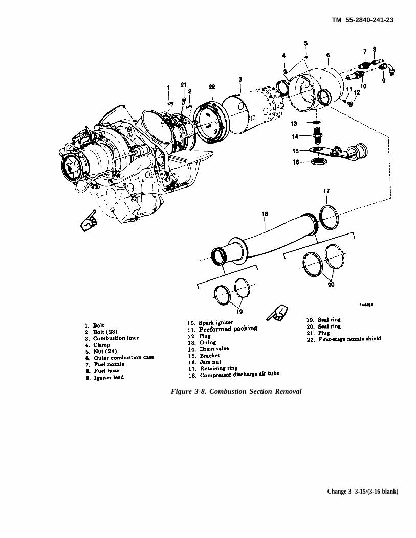
TM 55-2840-241-23
Figure 3-8. Combustion Section Removal
Change 3 3-15/(3-16 blank)

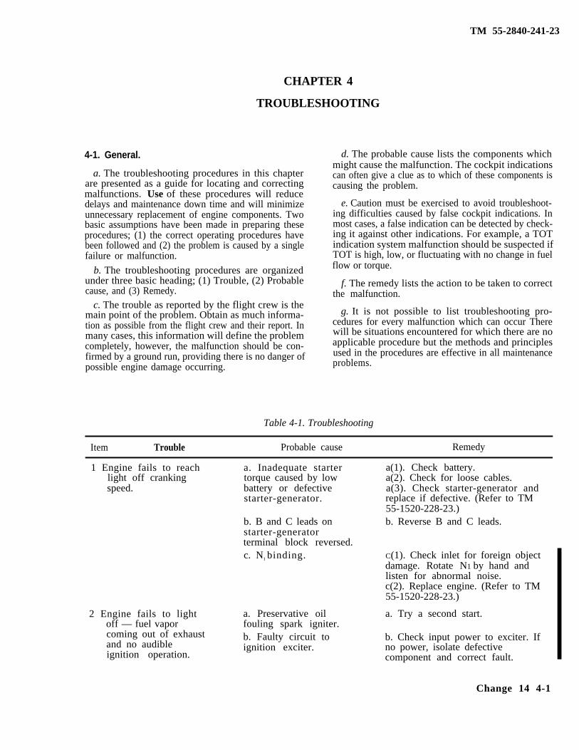
TM 55-2840-241-23
CHAPTER 4
TROUBLESHOOTING
4-1. General.
a. The troubleshooting procedures in this chapterare presented as a guide for locating and correctingmalfunctions. Use of these procedures will reducedelays and maintenance down time and will minimizeunnecessary replacement of engine components. Twobasic assumptions have been made in preparing theseprocedures; (1) the correct operating procedures havebeen followed and (2) the problem is caused by a singlefailure or malfunction.
b. The troubleshooting procedures are organizedunder three basic heading; (1) Trouble, (2) Probablecause, and (3) Remedy.
c. The trouble as reported by the flight crew is themain point of the problem. Obtain as much informa-tion as possible from the flight crew and their report. Inmany cases, this information will define the problemcompletely, however, the malfunction should be con-firmed by a ground run, providing there is no danger ofpossible engine damage occurring.
d. The probable cause lists the components whichmight cause the malfunction. The cockpit indicationscan often give a clue as to which of these components iscausing the problem.
e. Caution must be exercised to avoid troubleshoot-ing difficulties caused by false cockpit indications. Inmost cases, a false indication can be detected by check-ing it against other indications. For example, a TOTindication system malfunction should be suspected ifTOT is high, low, or fluctuating with no change in fuelflow or torque.
f. The remedy lists the action to be taken to correctthe malfunction.
g. It is not possible to list troubleshooting pro-cedures for every malfunction which can occur Therewill be situations encountered for which there are noapplicable procedure but the methods and principlesused in the procedures are effective in all maintenanceproblems.
Table 4-1. Troubleshooting
Item Trouble Probable cause Remedy
1 Engine fails to reachlight off crankingspeed.
2 Engine fails to lightoff — fuel vaporcoming out of exhaustand no audibleignition operation.
a. Inadequate startertorque caused by lowbattery or defectivestarter-generator.
b. B and C leads onstarter-generatorterminal block reversed.c. N1 binding.
a. Preservative oilfouling spark igniter.b. Faulty circuit toignition exciter.
a(1). Check battery.a(2). Check for loose cables.a(3). Check starter-generator andreplace if defective. (Refer to TM55-1520-228-23.)b. Reverse B and C leads.
C(1). Check inlet for foreign objectdamage. Rotate N1 by hand andlisten for abnormal noise.c(2). Replace engine. (Refer to TM55-1520-228-23.)
a. Try a second start.
b. Check input power to exciter. Ifno power, isolate defectivecomponent and correct fault.
Change 14 4-1
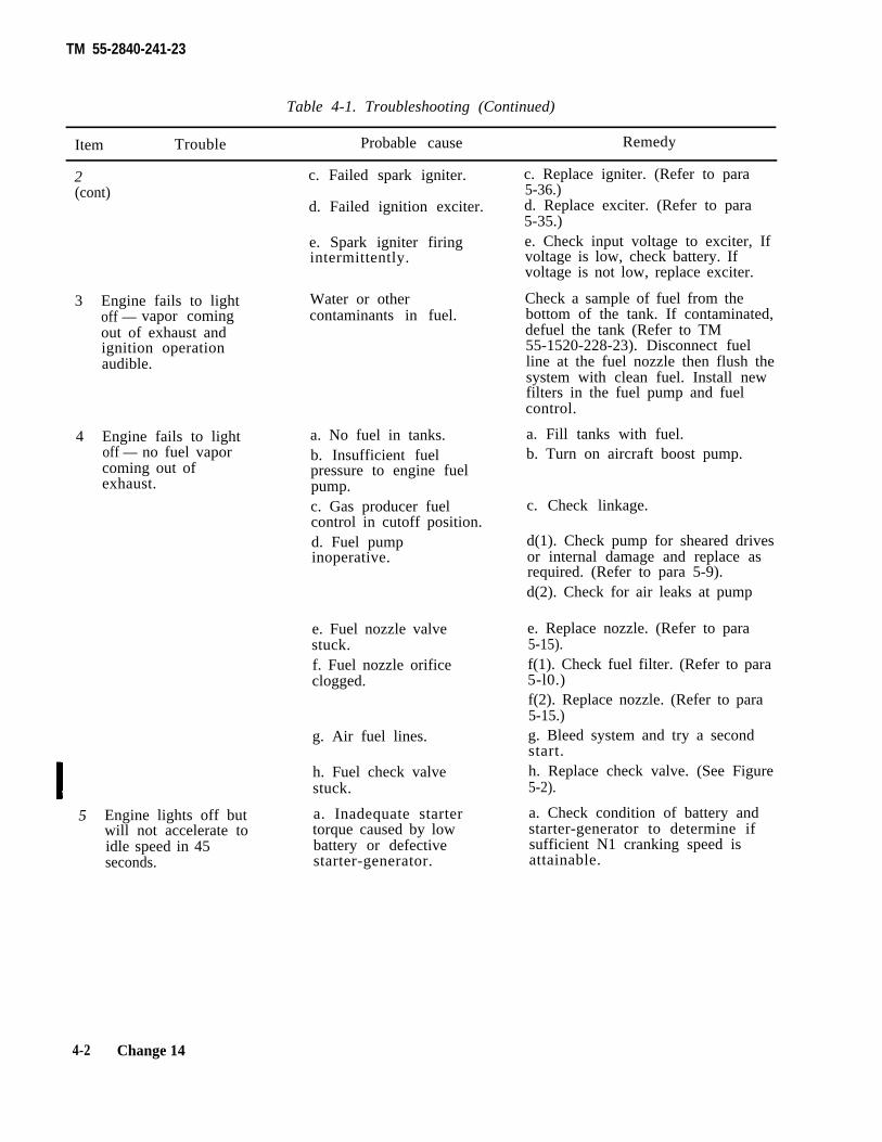
TM 55-2840-241-23
Table 4-1. Troubleshooting (Continued)
Item Trouble Probable cause Remedy
2 c. Failed spark igniter.(cont)
d. Failed ignition exciter.
e. Spark igniter firingintermittently.
3
4
5
Engine fails to lightoff — vapor comingout of exhaust andignition operationaudible.
Engine fails to lightoff — no fuel vaporcoming out ofexhaust.
Engine lights off butwill not accelerate toidle speed in 45seconds.
Water or othercontaminants in fuel.
a. No fuel in tanks.b. Insufficient fuelpressure to engine fuelpump.c. Gas producer fuelcontrol in cutoff position.d. Fuel pumpinoperative.
e. Fuel nozzle valvestuck.f. Fuel nozzle orificeclogged.
g. Air fuel lines.
h. Fuel check valvestuck.
a. Inadequate startertorque caused by lowbattery or defectivestarter-generator.
c. Replace igniter. (Refer to para5-36.)d. Replace exciter. (Refer to para5-35.)e. Check input voltage to exciter, Ifvoltage is low, check battery. Ifvoltage is not low, replace exciter.
Check a sample of fuel from thebottom of the tank. If contaminated,defuel the tank (Refer to TM55-1520-228-23). Disconnect fuelline at the fuel nozzle then flush thesystem with clean fuel. Install newfilters in the fuel pump and fuelcontrol.
a. Fill tanks with fuel.b. Turn on aircraft boost pump.
c. Check linkage.
d(1). Check pump for sheared drivesor internal damage and replace asrequired. (Refer to para 5-9).d(2). Check for air leaks at pump
e. Replace nozzle. (Refer to para5-15).f(1). Check fuel filter. (Refer to para5-l0.)f(2). Replace nozzle. (Refer to para5-15.)g. Bleed system and try a secondstart.h. Replace check valve. (See Figure5-2).
a. Check condition of battery andstarter-generator to determine ifsufficient N1 cranking speed isattainable.
4-2 Change 14
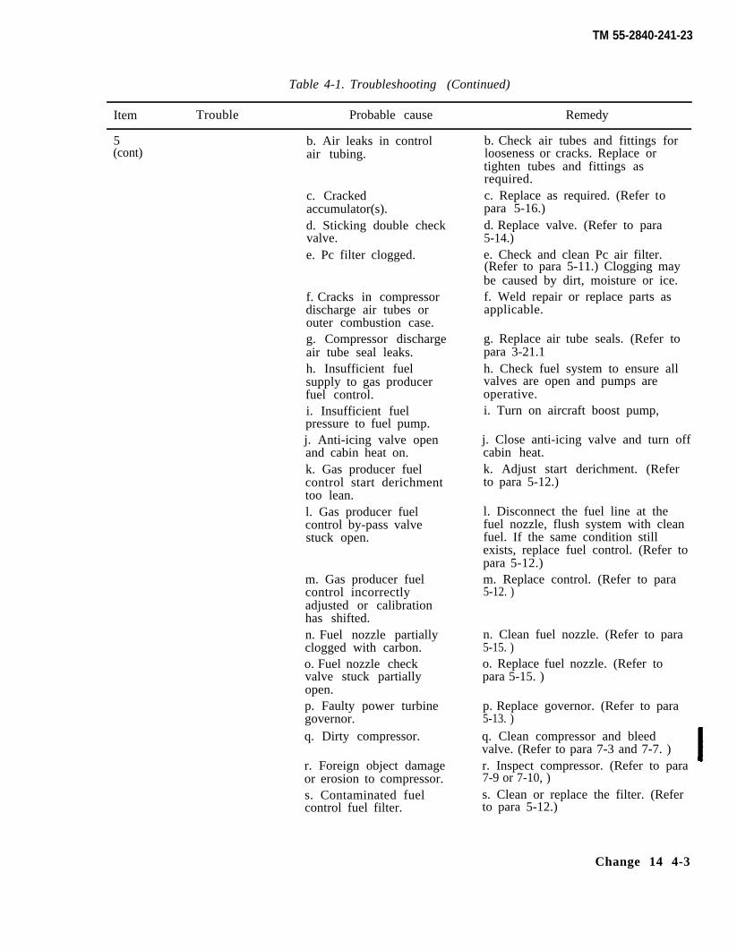
TM 55-2840-241-23
Table 4-1. Troubleshooting (Continued)
Item Trouble Probable cause Remedy
5 b. Air leaks in control(cont) air tubing.
c. Crackedaccumulator(s).d. Sticking double checkvalve.e. Pc filter clogged.
f. Cracks in compressordischarge air tubes orouter combustion case.g. Compressor dischargeair tube seal leaks.h. Insufficient fuelsupply to gas producerfuel control.i. Insufficient fuelpressure to fuel pump.j. Anti-icing valve openand cabin heat on.k. Gas producer fuelcontrol start derichmenttoo lean.l. Gas producer fuelcontrol by-pass valvestuck open.
m. Gas producer fuelcontrol incorrectlyadjusted or calibrationhas shifted.n. Fuel nozzle partiallyclogged with carbon.o. Fuel nozzle checkvalve stuck partiallyopen.p. Faulty power turbinegovernor.q. Dirty compressor.
r. Foreign object damageor erosion to compressor.s. Contaminated fuelcontrol fuel filter.
b. Check air tubes and fittings forlooseness or cracks. Replace ortighten tubes and fittings asrequired.c. Replace as required. (Refer topara 5-16.)d. Replace valve. (Refer to para5-14.)e. Check and clean Pc air filter.(Refer to para 5-11.) Clogging maybe caused by dirt, moisture or ice.f. Weld repair or replace parts asapplicable.
g. Replace air tube seals. (Refer topara 3-21.1h. Check fuel system to ensure allvalves are open and pumps areoperative.i. Turn on aircraft boost pump,
j. Close anti-icing valve and turn offcabin heat.k. Adjust start derichment. (Referto para 5-12.)
l. Disconnect the fuel line at thefuel nozzle, flush system with cleanfuel. If the same condition stillexists, replace fuel control. (Refer topara 5-12.)m. Replace control. (Refer to para5-12. )
n. Clean fuel nozzle. (Refer to para5-15. )o. Replace fuel nozzle. (Refer topara 5-15. )
p. Replace governor. (Refer to para5-13. )q. Clean compressor and bleedvalve. (Refer to para 7-3 and 7-7. )r. Inspect compressor. (Refer to para7-9 or 7-10, )s. Clean or replace the filter. (Referto para 5-12.)
Change 14 4-3
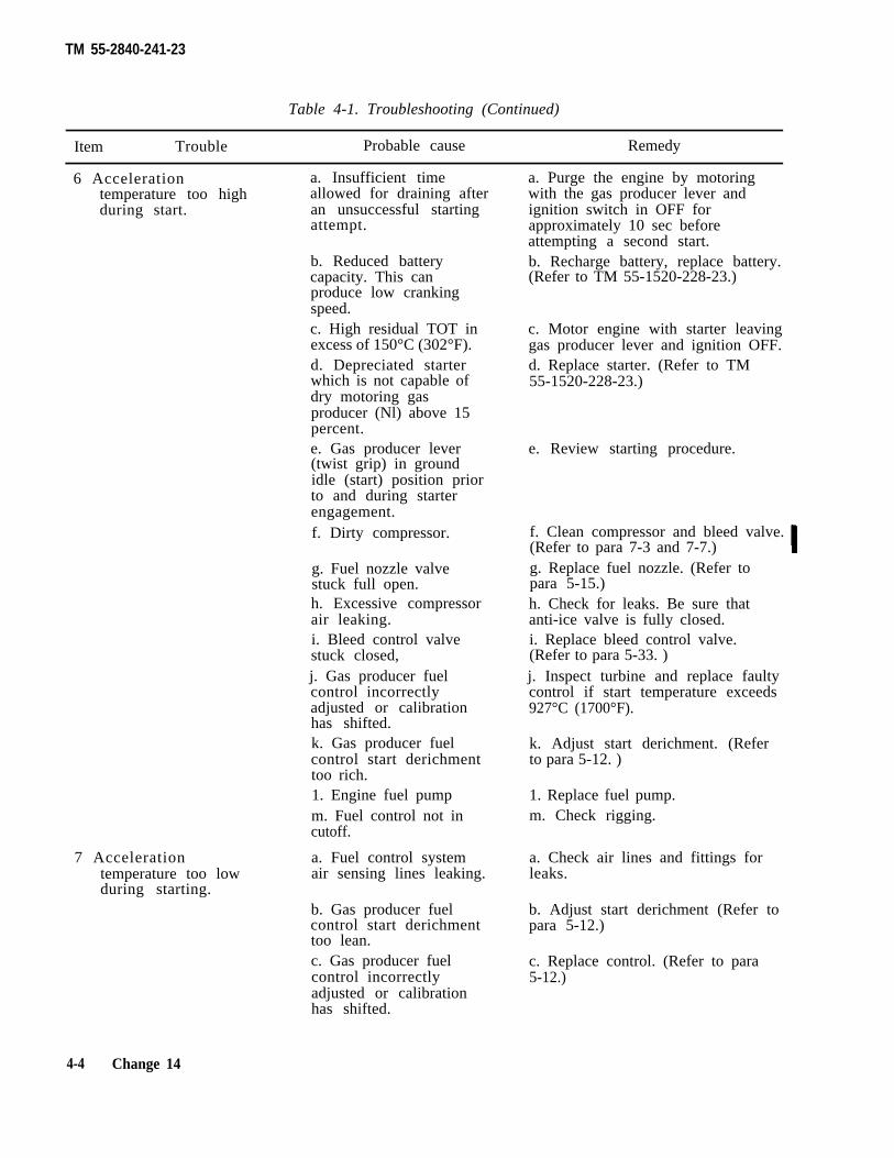
TM 55-2840-241-23
Table 4-1. Troubleshooting (Continued)
Item Trouble Probable cause Remedy
6 Acceleration a. Insufficient timetemperature too high allowed for draining afterduring start. an unsuccessful starting
attempt.
b. Reduced batterycapacity. This canproduce low crankingspeed.c. High residual TOT inexcess of 150°C (302°F).d. Depreciated starterwhich is not capable ofdry motoring gasproducer (Nl) above 15percent.e. Gas producer lever(twist grip) in groundidle (start) position priorto and during starterengagement.f. Dirty compressor.
g. Fuel nozzle valvestuck full open.h. Excessive compressorair leaking.i. Bleed control valvestuck closed,j. Gas producer fuelcontrol incorrectlyadjusted or calibrationhas shifted.k. Gas producer fuelcontrol start derichmenttoo rich.1. Engine fuel pumpm. Fuel control not incutoff.
7 Acceleration a. Fuel control systemtemperature too low air sensing lines leaking.during starting.
b. Gas producer fuelcontrol start derichmenttoo lean.c. Gas producer fuelcontrol incorrectlyadjusted or calibrationhas shifted.
a. Purge the engine by motoringwith the gas producer lever andignition switch in OFF forapproximately 10 sec beforeattempting a second start.b. Recharge battery, replace battery.(Refer to TM 55-1520-228-23.)
c. Motor engine with starter leavinggas producer lever and ignition OFF.d. Replace starter. (Refer to TM55-1520-228-23.)
e. Review starting procedure.
f. Clean compressor and bleed valve.(Refer to para 7-3 and 7-7.)g. Replace fuel nozzle. (Refer topara 5-15.)h. Check for leaks. Be sure thatanti-ice valve is fully closed.i. Replace bleed control valve.(Refer to para 5-33. )j. Inspect turbine and replace faultycontrol if start temperature exceeds927°C (1700°F).
k. Adjust start derichment. (Referto para 5-12. )
1. Replace fuel pump.m. Check rigging.
a. Check air lines and fittings forleaks.
b. Adjust start derichment (Refer topara 5-12.)
c. Replace control. (Refer to para5-12.)
4-4 Change 14
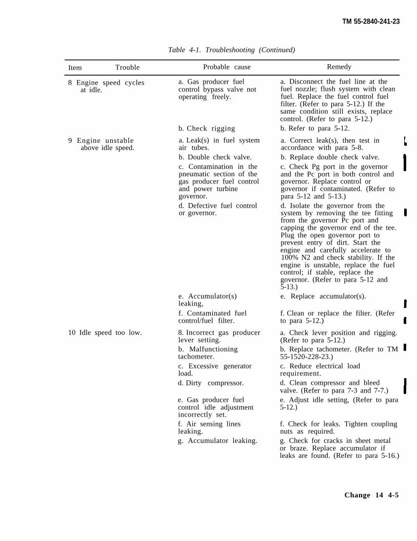
TM 55-2840-241-23
Table 4-1. Troubleshooting (Continued)
Item Trouble Probable cause Remedy
8 Engine speed cycles a. Gas producer fuelat idle. control bypass valve not
operating freely.
b. Check rigging
9 Engine unstableabove idle speed.
10 Idle speed too low.
a. Leak(s) in fuel systemair tubes.b. Double check valve.c. Contamination in thepneumatic section of thegas producer fuel controland power turbinegovernor.d. Defective fuel controlor governor.
e. Accumulator(s)leaking,f. Contaminated fuelcontrol/fuel filter.
8. Incorrect gas producerlever setting.b. Malfunctioningtachometer.c. Excessive generatorload.d. Dirty compressor.
e. Gas producer fuelcontrol idle adjustmentincorrectly set.f. Air sensing linesleaking.g. Accumulator leaking.
a. Disconnect the fuel line at thefuel nozzle; flush system with cleanfuel. Replace the fuel control fuelfilter. (Refer to para 5-12.) If thesame condition still exists, replacecontrol. (Refer to para 5-12.)b. Refer to para 5-12.
a. Correct leak(s), then test inaccordance with para 5-8.b. Replace double check valve.c. Check Pg port in the governorand the Pc port in both control andgovernor. Replace control orgovernor if contaminated. (Refer topara 5-12 and 5-13.)d. Isolate the governor from thesystem by removing the tee fittingfrom the governor Pc port andcapping the governor end of the tee.Plug the open governor port toprevent entry of dirt. Start theengine and carefully accelerate to100% N2 and check stability. If theengine is unstable, replace the fuelcontrol; if stable, replace thegovernor. (Refer to para 5-12 and5-13.)e. Replace accumulator(s).
f. Clean or replace the filter. (Referto para 5-12.)
a. Check lever position and rigging.(Refer to para 5-12.)b. Replace tachometer. (Refer to TM55-1520-228-23.)c. Reduce electrical loadrequirement.d. Clean compressor and bleedvalve. (Refer to para 7-3 and 7-7.)e. Adjust idle setting, (Refer to para5-12.)
f. Check for leaks. Tighten couplingnuts as required.g. Check for cracks in sheet metalor braze. Replace accumulator ifleaks are found. (Refer to para 5-16.)
Change 14 4-5
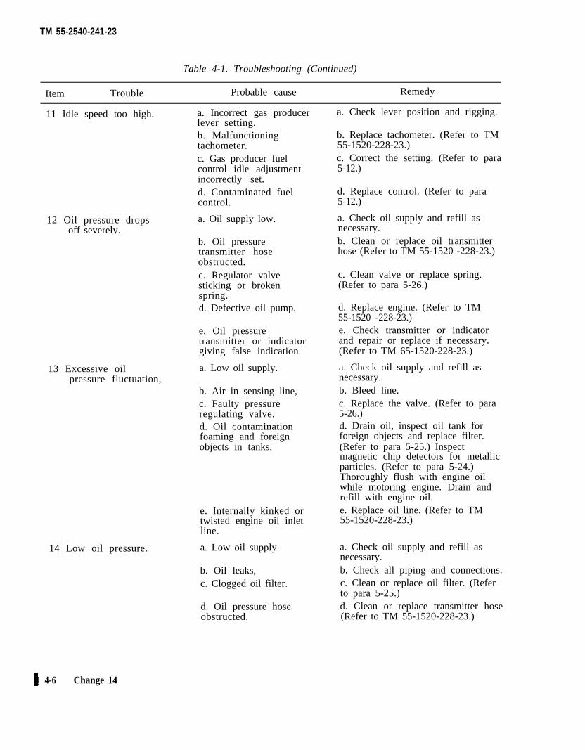
TM 55-2540-241-23
Table 4-1. Troubleshooting (Continued)
Item Trouble Probable cause Remedy
11 Idle speed too high. a. Incorrect gas producerlever setting.b. Malfunctioningtachometer.c. Gas producer fuelcontrol idle adjustmentincorrectly set.d. Contaminated fuelcontrol.
12 Oil pressure drops a. Oil supply low.off severely.
b. Oil pressuretransmitter hoseobstructed.c. Regulator valvesticking or brokenspring.d. Defective oil pump.
e. Oil pressuretransmitter or indicatorgiving false indication.
13 Excessive oil a. Low oil supply.pressure fluctuation,
b. Air in sensing line,c. Faulty pressureregulating valve.d. Oil contaminationfoaming and foreignobjects in tanks.
e. Internally kinked ortwisted engine oil inletline.
14 Low oil pressure. a. Low oil supply.
b. Oil leaks,c. Clogged oil filter.
d. Oil pressure hoseobstructed.
a. Check lever position and rigging.
b. Replace tachometer. (Refer to TM55-1520-228-23.)c. Correct the setting. (Refer to para5-12.)
d. Replace control. (Refer to para5-12.)
a. Check oil supply and refill asnecessary.b. Clean or replace oil transmitterhose (Refer to TM 55-1520 -228-23.)
c. Clean valve or replace spring.(Refer to para 5-26.)
d. Replace engine. (Refer to TM55-1520 -228-23.)e. Check transmitter or indicatorand repair or replace if necessary.(Refer to TM 65-1520-228-23.)
a. Check oil supply and refill asnecessary.b. Bleed line.c. Replace the valve. (Refer to para5-26.)d. Drain oil, inspect oil tank forforeign objects and replace filter.(Refer to para 5-25.) Inspectmagnetic chip detectors for metallicparticles. (Refer to para 5-24.)Thoroughly flush with engine oilwhile motoring engine. Drain andrefill with engine oil.e. Replace oil line. (Refer to TM55-1520-228-23.)
a. Check oil supply and refill asnecessary.b. Check all piping and connections.c. Clean or replace oil filter. (Referto para 5-25.)d. Clean or replace transmitter hose(Refer to TM 55-1520-228-23.)
4-6 Change 14
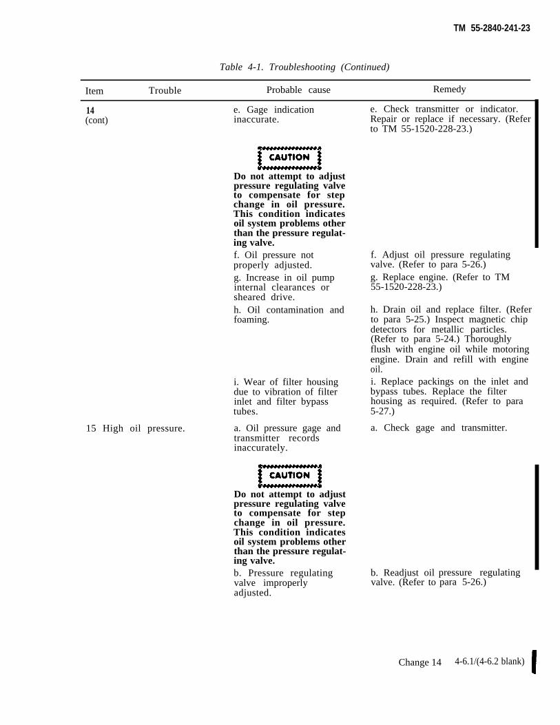
TM 55-2840-241-23
Table 4-1. Troubleshooting (Continued)
Item Trouble Probable cause Remedy
14 e. Gage indication(cont) inaccurate.
Do not attempt to adjustpressure regulating valveto compensate for stepchange in oil pressure.This condition indicatesoil system problems otherthan the pressure regulat-ing valve.
15 High oil pressure.
f. Oil pressure notproperly adjusted.g. Increase in oil pumpinternal clearances orsheared drive.h. Oil contamination andfoaming.
i. Wear of filter housingdue to vibration of filterinlet and filter bypasstubes.
a. Oil pressure gage andtransmitter recordsinaccurately.
Do not attempt to adjustpressure regulating valveto compensate for stepchange in oil pressure.This condition indicatesoil system problems otherthan the pressure regulat-ing valve.b. Pressure regulatingvalve improperlyadjusted.
e. Check transmitter or indicator.Repair or replace if necessary. (Referto TM 55-1520-228-23.)
f. Adjust oil pressure regulatingvalve. (Refer to para 5-26.)g. Replace engine. (Refer to TM55-1520-228-23.)
h. Drain oil and replace filter. (Referto para 5-25.) Inspect magnetic chipdetectors for metallic particles.(Refer to para 5-24.) Thoroughlyflush with engine oil while motoringengine. Drain and refill with engineoil.i. Replace packings on the inlet andbypass tubes. Replace the filterhousing as required. (Refer to para5-27.)
a. Check gage and transmitter.
b. Readjust oilvalve. (Refer to
pressure regulatingpara 5-26.)
Change 14 4-6.1/(4-6.2 blank)

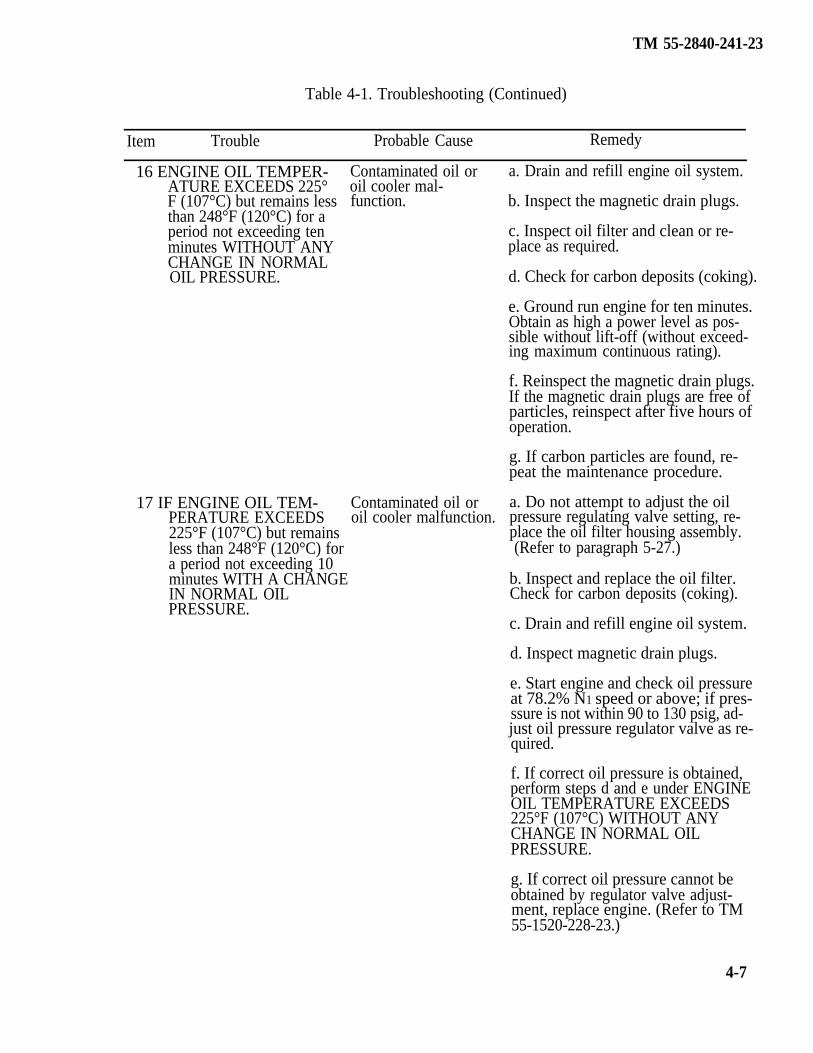
TM 55-2840-241-23
Table 4-1. Troubleshooting (Continued)
Item Trouble Probable Cause Remedy
Contaminated oil oroil cooler mal-function.
16 ENGINE OIL TEMPER- a. Drain and refill engine oil system.ATURE EXCEEDS 225°F (107°C) but remains lessthan 248°F (120°C) for aperiod not exceeding tenminutes WITHOUT ANYCHANGE IN NORMALOIL PRESSURE.
17 IF ENGINE OIL TEM-PERATURE EXCEEDS225°F (107°C) but remainsless than 248°F (120°C) fora period not exceeding 10minutes WITH A CHANGEIN NORMAL OILPRESSURE.
Contaminated oil oroil cooler malfunction.
b. Inspect the magnetic drain plugs.
c. Inspect oil filter and clean or re-place as required.
d. Check for carbon deposits (coking).
e. Ground run engine for ten minutes.Obtain as high a power level as pos-sible without lift-off (without exceed-ing maximum continuous rating).
f. Reinspect the magnetic drain plugs.If the magnetic drain plugs are free ofparticles, reinspect after five hours ofoperation.
g. If carbon particles are found, re-peat the maintenance procedure.
a. Do not attempt to adjust the oilpressure regulating valve setting, re-place the oil filter housing assembly.(Refer to paragraph 5-27.)
b. Inspect and replace the oil filter.Check for carbon deposits (coking).
c. Drain and refill engine oil system.
d. Inspect magnetic drain plugs.
e. Start engine and check oil pressureat 78.2% N1 speed or above; if pres-ssure is not within 90 to 130 psig, ad-just oil pressure regulator valve as re-quired.
f. If correct oil pressure is obtained,perform steps d and e under ENGINEOIL TEMPERATURE EXCEEDS225°F (107°C) WITHOUT ANYCHANGE IN NORMAL OILPRESSURE.
g. If correct oil pressure cannot beobtained by regulator valve adjust-ment, replace engine. (Refer to TM55-1520-228-23.)
4-7
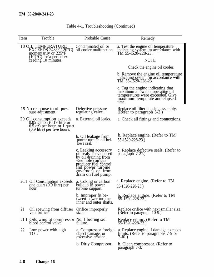
TM 55-2840-241-23
Table 4-1. Troubleshooting (Continued)
Item Trouble Probable Cause Remedy
18 OIL TEMPERATUREEXCEEDS 248°F 120°C)momentarily or 225°F(107°C) for a period ex-ceeding 10 minutes.
Contaminated oil oroil cooler malfunction.
a. Test the engine oil temperatureindicating system, m accordance withTM 55-l520-228-23.
NOTE
Check the engine oil cooler.
b. Remove the engine oil temperatureindicating system, in accordance withTM 55-1520-228-23.
c. Tag the engine indicating thatmaximum allowable operating oiltemperatures were exceeded. Givemaximum temperate and elapsedtime.
19 No response to oilsure adjustment.
pres-
20 Oil consumption exceeds0.05 gallon (0.19 litre or6.5 oz) per hour, or 1 quart(0.9 litre) per five hours.
b. Replace engine. (Refer to TM
and power turbinegovernor) or fromdrain on fuel pump.
20.1
21
21.1
22
Oil Consumption exceedsone quart (0.9 litre) perhour.
a. Replace engine. (Refer to TM55-1520-228-23.)
Oil spewing from diffuservent orifice.
Oils wing at compressorbleed control valve.
Low power with highTOT.
Defective pressureregulating valve.
a. External oil leaks.
b. Oil leakage frompower turbine oil bel-lows seal.
c. Leaking accessoryoil seals as evidencedby oil draining fromwee hole (on gasproducer fuel control
a. Coking or carbonbuildup in powerturbine support.
b. Improper fit be-tween power turbineinner and outer shafts.
Orifice improperlysized.
No. 1 bearing sealfailure.
a. Compressor foreignobject damage. orexcessive erosion.
b. Dirty Compressor.
Replace oil filter housing assembly.(Refer to paragraph 5-2.)
a. Check all fittings and connections.
55-1520-228-23.)
c. Replace defective seals. (Refer toparagraph 7-27.)
b. Replace engine. (Refer to TM55-1520-228-23.)
Replace orifice with next smaller size.(Refer to paragraph 10-9.)
Replace en inc. (Refer to TM55-1520-228-23.)
a. Replace engine if damage exceedslimits. (Refer to paragraphs 7-9 or7-l0.)
b. Clean compressor. (Refer toparagraph 7-3.
4-8 Change 16
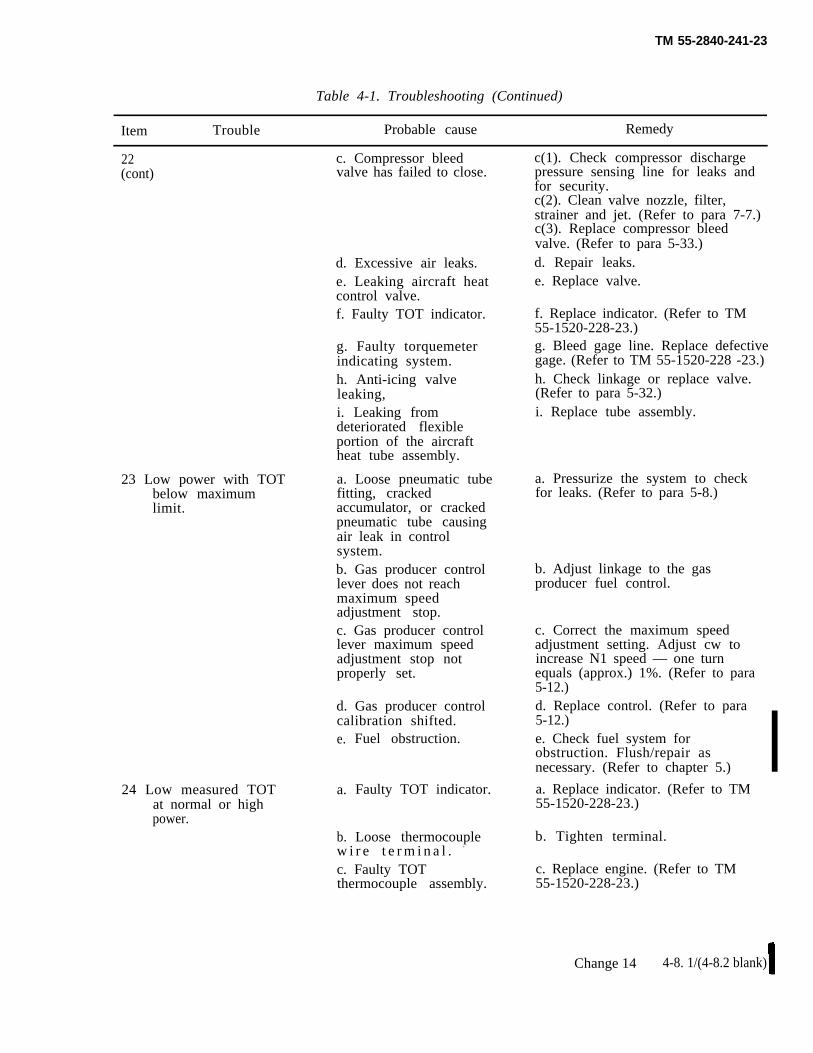
TM 55-2840-241-23
Table 4-1. Troubleshooting (Continued)
Item Trouble Probable cause Remedy
22 c. Compressor bleed(cont) valve has failed to close.
d. Excessive air leaks.e. Leaking aircraft heatcontrol valve.f. Faulty TOT indicator.
23 Low power with TOTbelow maximumlimit.
24 Low measured TOTat normal or highpower.
g. Faulty torquemeterindicating system.h. Anti-icing valveleaking,i. Leaking fromdeteriorated flexibleportion of the aircraftheat tube assembly.
a. Loose pneumatic tubefitting, crackedaccumulator, or crackedpneumatic tube causingair leak in controlsystem.b. Gas producer controllever does not reachmaximum speedadjustment stop.c. Gas producer controllever maximum speedadjustment stop notproperly set.
d. Gas producer controlcalibration shifted.e.
a.
b.
Fuel obstruction.
Faulty TOT indicator.
Loose thermocouplew i r e t e r m i n a l . -
c. Faulty TOTthermocouple assembly.
c(1). Check compressor dischargepressure sensing line for leaks andfor security.c(2). Clean valve nozzle, filter,strainer and jet. (Refer to para 7-7.)c(3). Replace compressor bleedvalve. (Refer to para 5-33.)d. Repair leaks.e. Replace valve.
f. Replace indicator. (Refer to TM55-1520-228-23.)g. Bleed gage line. Replace defectivegage. (Refer to TM 55-1520-228 -23.)h. Check linkage or replace valve.(Refer to para 5-32.)i. Replace tube assembly.
a. Pressurize the system to checkfor leaks. (Refer to para 5-8.)
b. Adjust linkage to the gasproducer fuel control.
c. Correct the maximum speedadjustment setting. Adjust cw toincrease N1 speed — one turnequals (approx.) 1%. (Refer to para5-12.)d. Replace control. (Refer to para5-12.)e. Check fuel system forobstruction. Flush/repair asnecessary. (Refer to chapter 5.)
a. Replace indicator. (Refer to TM55-1520-228-23.)
b. Tighten terminal.
c. Replace engine. (Refer to TM55-1520-228-23.)
Change 14 4-8. 1/(4-8.2 blank)

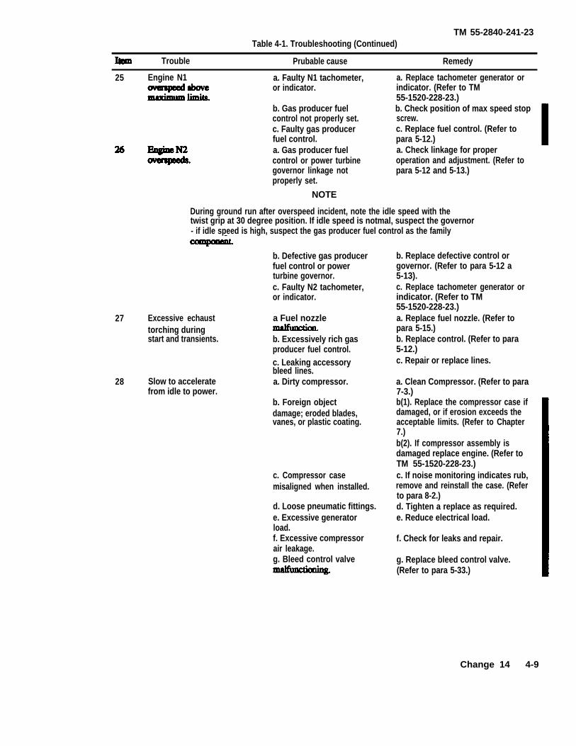
TM 55-2840-241-23Table 4-1. Troubleshooting (Continued)
Trouble Prubable cause Remedy
25 Engine N1 a. Faulty N1 tachometer, a. Replace tachometer generator oror indicator. indicator. (Refer to TM
55-1520-228-23.)b. Gas producer fuel b. Check position of max speed stopcontrol not properly set. screw.c. Faulty gas producer c. Replace fuel control. (Refer tofuel control. para 5-12.)a. Gas producer fuel a. Check linkage for propercontrol or power turbine operation and adjustment. (Refer togovernor linkage not para 5-12 and 5-13.)properly set.
NOTE
During ground run after overspeed incident, note the idle speed with thetwist grip at 30 degree position. If idle speed is notmal, suspect the governor- if idle speed is high, suspect the gas producer fuel control as the family
27 Excessive echausttorching duringstart and transients.
28 Slow to acceleratefrom idle to power.
b. Defective gas producerfuel control or powerturbine governor.c. Faulty N2 tachometer,or indicator.
a Fuel nozzle
b. Excessively rich gasproducer fuel control.c. Leaking accessorybleed lines.a. Dirty compressor.
b. Foreign objectdamage; eroded blades,vanes, or plastic coating.
c. Compressor casemisaligned when installed.
d. Loose pneumatic fittings.e. Excessive generatorload.f. Excessive compressorair leakage.g. Bleed control valve
b. Replace defective control orgovernor. (Refer to para 5-12 a5-13).c. Replace tachometer generator orindicator. (Refer to TM55-1520-228-23.)a. Replace fuel nozzle. (Refer topara 5-15.)b. Replace control. (Refer to para5-12.)c. Repair or replace lines.
a. Clean Compressor. (Refer to para7-3.)b(1). Replace the compressor case ifdamaged, or if erosion exceeds theacceptable limits. (Refer to Chapter7.)b(2). If compressor assembly isdamaged replace engine. (Refer toTM 55-1520-228-23.)c. If noise monitoring indicates rub,remove and reinstall the case. (Referto para 8-2.)d. Tighten a replace as required.e. Reduce electrical load.
f. Check for leaks and repair.
g. Replace bleed control valve.(Refer to para 5-33.)
Change 14 4-9
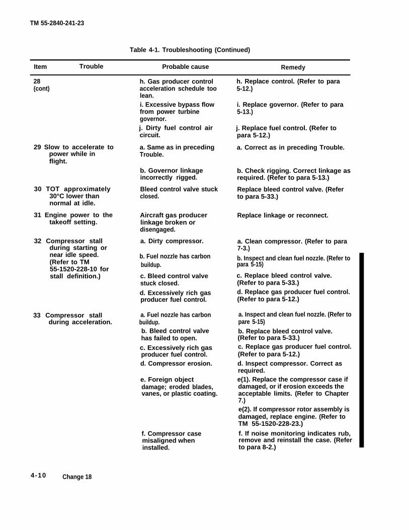
TM 55-2840-241-23
Table 4-1. Troubleshooting (Continued)
Item Trouble Probable cause Remedy
28(cont)
h. Gas producer controlacceleration schedule toolean.
h. Replace control. (Refer to para5-12.)
i. Excessive bypass flowfrom power turbinegovernor.j. Dirty fuel control aircircuit.
i. Replace governor. (Refer to para5-13.)
j. Replace fuel control. (Refer topara 5-12.)
29 Slow to accelerate topower while inflight.
a. Same as in precedingTrouble.
a. Correct as in preceding Trouble.
b. Governor linkageincorrectly rigged.
b. Check rigging. Correct linkage asrequired. (Refer to para 5-13.)
Replace bleed control valve. (Referto para 5-33.)
30 TOT approximately30°C lower thannormal at idle.
Bleed control valve stuckclosed.
31 Engine power to thetakeoff setting.
Aircraft gas producerlinkage broken ordisengaged.
Replace linkage or reconnect.
32 Compressor stallduring starting ornear idle speed.(Refer to TM55-1520-228-10 forstall definition.)
a. Dirty compressor. a. Clean compressor. (Refer to para7-3.)
b. Inspect and clean fuel nozzle. (Refer topara 5-15)
b. Fuel nozzle has carbonbuildup.
c. Bleed control valvestuck closed.d. Excessively rich gasproducer fuel control.
c. Replace bleed control valve.(Refer to para 5-33.)d. Replace gas producer fuel control.(Refer to para 5-12.)
a. Inspect and clean fuel nozzle. (Refer topare 5-15)b. Replace bleed control valve.(Refer to para 5-33.)
33 Compressor stallduring acceleration.
a. Fuel nozzle has carbonbuildup.b. Bleed control valvehas failed to open.c. Excessively rich gasproducer fuel control.
c. Replace gas producer fuel control.(Refer to para 5-12.)
d. Compressor erosion. d. Inspect compressor. Correct asrequired.e(1). Replace the compressor case ifdamaged, or if erosion exceeds theacceptable limits. (Refer to Chapter7.)
e. Foreign objectdamage; eroded blades,vanes, or plastic coating.
e(2). If compressor rotor assembly isdamaged, replace engine. (Refer toTM 55-1520-228-23.)
f. If noise monitoring indicates rub,remove and reinstall the case. (Referto para 8-2.)
f. Compressor casemisaligned wheninstalled.
4-10 Change 18
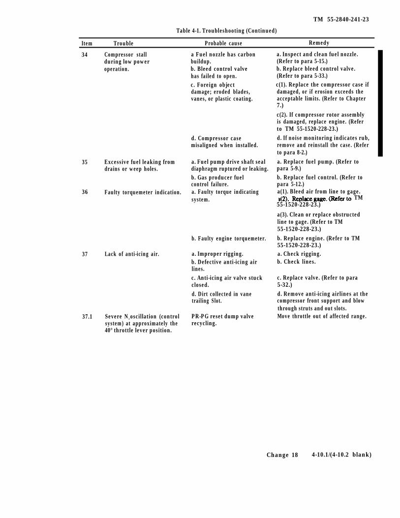
TM 55-2840-241-23
Table 4-1. Troubleshooting (Continued)
Item Trouble Probable cause Remedy
34 Compressor stall a Fuel nozzle has carbonduring low power buildup.operation. b. Bleed control valve
has failed to open.c. Foreign objectdamage; eroded blades,vanes, or plastic coating.
d. Compressor casemisaligned when installed.
35 Excessive fuel leaking from a. Fuel pump drive shaft sealdrains or weep holes. diaphragm ruptured or leaking.
b. Gas producer fuelcontrol failure.
36 Faulty torquemeter indication. a. Faulty torque indicatingsystem. TM
55-1520-228-23.)
37 Lack of anti-icing air.
b. Faulty engine torquemeter.
a. Improper rigging.b. Defective anti-icing airlines.c. Anti-icing air valve stuckclosed.d. Dirt collected in vanetrailing Slot.
37.1 Severe N1 oscillation (control PR-PG reset dump valvesystem) at approximately the recycling.40° throttle lever position.
a. Inspect and clean fuel nozzle.(Refer to para 5-15.)b. Replace bleed control valve.(Refer to para 5-33.)c(1). Replace the compressor case ifdamaged, or if erosion exceeds theacceptable limits. (Refer to Chapter7.)c(2). If compressor rotor assemblyis damaged, replace engine. (Referto TM 55-1520-228-23.)d. If noise monitoring indicates rub,remove and reinstall the case. (Referto para 8-2.)a. Replace fuel pump. (Refer topara 5-9.)b. Replace fuel control. (Refer topara 5-12.)a(1). Bleed air from line to gage.
a(3). Clean or replace obstructedline to gage. (Refer to TM55-1520-228-23.)b. Replace engine. (Refer to TM55-1520-228-23.)a. Check rigging.b. Check lines.
c. Replace valve. (Refer to para5-32.)d. Remove anti-icing airlines at thecompressor front support and blowthrough struts and out slots.Move throttle out of affected range.
Change 18 4-10.1/(4-10.2 blank)

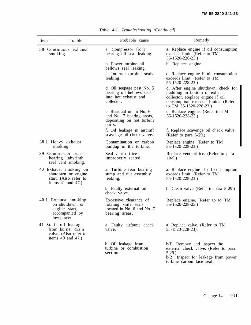
TM 55-2840-241-23
Table 4-1. Troubleshooting (Continued)
Item Trouble Probable cause Remedy
38 Continuous exhaustsmoking.
38.1 Heavy exhaustsmoking.
39 Compressor rearbearing labyrinthseal vent smoking.
40 Exhaust smoking onshutdown or enginestart. (Also refer toitems 41 and 47.)
40.1 Exhaust smokingon shutdown, orengine start,accompanied bylow power.
41 Static oil leakagefrom burner drainvalve. (Also refer toitems 40 and 47.)
a. Compressor frontbearing oil seal leaking.
b. Power turbine oilbellows seal leaking.c. Internal turbine sealsleaking.
d. Oil seepage past No. 5bearing oil bellows sealinto hot exhaust andcollector.
e. Residual oil in No. 6and No. 7 bearing areas,depositing on hot turbineparts.f. Oil leakage in aircraftscavenge oil check valve.
Contamination or carbonbuildup in the turbine.
Seal vent orificeimproperly seated.
a. Turbine rear bearingsump and nut assemblyleaking.
b. Faulty external oilcheck valve.
Excessive clearance ofrotating knife sealslocated in No. 6 and No. 7bearing areas.
a. Faulty airframe checkvalve.
b. Oil leakage fromturbine or combustionsection.
a. Replace engine if oil consumptionexceeds limit. (Refer to TM55-1520-228-23.)b. Replace engine.
c. Replace engine if oil consumptionexceeds limit. (Refer to TM55-1520-228-23.)d. After engine shutdown, check forpuddling in bottom of exhaustcollector. Replace engine if oilconsumption exceeds limits. (Referto TM 55-1520-228-23.)e. Replace engine. (Refer to TM55-1520-228-23.)
f. Replace scavenge oil check valve.(Refer to para 5-29.)
Replace engine. (Refer to TM55-1520-228-23.)
Replace vent orifice. (Refer to para10-9.)
a. Replace engine if oil consumptionexceeds limit. (Refer to TM55-1520-228-23.)
b. Clean valve (Refer to para 5-29.)
Replace engine. (Refer to to TM55-1520-228-23.)
a. Replace valve. (Refer to TM55-1520-228-23).
b(l). Remove and inspect theexternal check valve. (Refer to para5-29.)b(2). Inspect for leakage from powerturbine carbon face seal.
Change 14 4-11
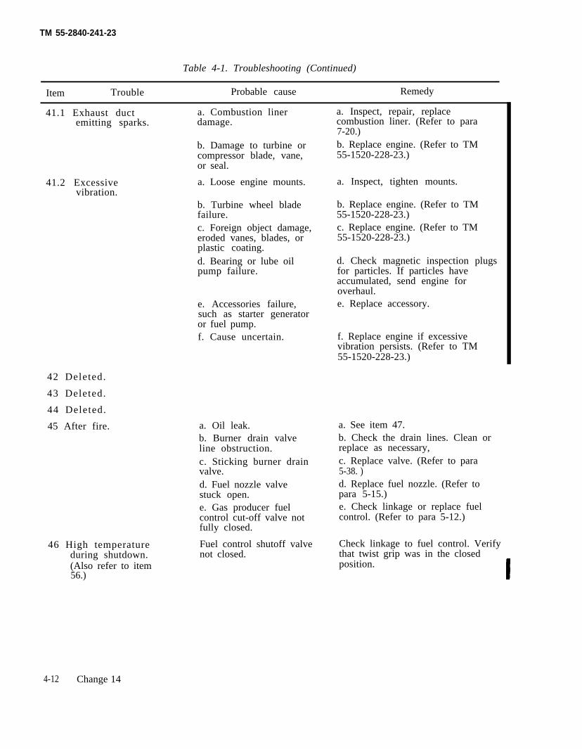
TM 55-2840-241-23
Table 4-1. Troubleshooting (Continued)
Item Trouble Probable cause Remedy
41.1 Exhaust duct a. Combustion lineremitting sparks. damage.
b. Damage to turbine orcompressor blade, vane,or seal.
41.2 Excessivevibration.
42 Deleted.
43 Deleted.
44 Deleted.
45 After fire.
a. Loose engine mounts.
b. Turbine wheel bladefailure.c. Foreign object damage,eroded vanes, blades, orplastic coating.d. Bearing or lube oilpump failure.
e. Accessories failure,such as starter generatoror fuel pump.f. Cause uncertain.
a. Oil leak.b. Burner drain valveline obstruction.c. Sticking burner drainvalve.d. Fuel nozzle valvestuck open.e. Gas producer fuelcontrol cut-off valve notfully closed.
46 High temperature Fuel control shutoff valveduring shutdown. not closed.(Also refer to item56.)
a. Inspect, repair, replacecombustion liner. (Refer to para7-20.)b. Replace engine. (Refer to TM55-1520-228-23.)
a. Inspect, tighten mounts.
b. Replace engine. (Refer to TM55-1520-228-23.)c. Replace engine. (Refer to TM55-1520-228-23.)
d. Check magnetic inspection plugsfor particles. If particles haveaccumulated, send engine foroverhaul.e. Replace accessory.
f. Replace engine if excessivevibration persists. (Refer to TM55-1520-228-23.)
a. See item 47.b. Check the drain lines. Clean orreplace as necessary,c. Replace valve. (Refer to para5-38. )d. Replace fuel nozzle. (Refer topara 5-15.)e. Check linkage or replace fuelcontrol. (Refer to para 5-12.)
Check linkage to fuel control. Verifythat twist grip was in the closedposition.
4-12 Change 14
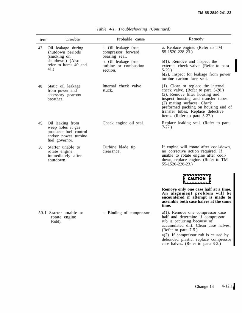
TM 55-2840-241-23
Table 4-1. Troubleshooting (Continued)
Item Trouble Probable cause Remedy
47
48
49
50
Oil leakage duringshutdown periods(smoking onshutdown.) (Alsorefer to items 40 and41.)
Static oil leakagefrom power andaccessory gearboxbreather.
Oil leaking fromweep holes at gasproducer fuel controland/or power turbinefuel governor.
Starter unable torotate engineimmediately aftershutdown.
50.1 Starter unable torotate engine(cold).
a. Oil leakage fromcompressor forwardbearing seal.b. Oil leakage fromturbine or combustionsection.
Internal check valvestuck.
Check engine oil seal.
Turbine blade tipclearance.
a. Replace engine. (Refer to TM55-1520-228-23.)
b(1). Remove and inspect theexternal check valve. (Refer to para5-29.)b(2). Inspect for leakage from powerturbine carbon face seal.
(1). Clean or replace the internalcheck valve. (Refer to para 5-28.)(2). Remove filter housing andinspect housing and transfer tubes(2) mating surfaces. Checkpreformed packing on housing end oftransfer tubes. Replace defectiveitems. (Refer to para 5-27.)
Replace leaking seal. (Refer to para7-27.)
If engine will rotate after cool-down,no corrective action required. Ifunable to rotate engine after cool-down, replace engine. (Refer to TM55-1520-228-23.)
Remove only one case half at a time.An alignment problem will beencountered if attempt is made toassemble both case halves at the sametime.
a. Binding of compressor. a(1). Remove one compressor casehalf and determine if compressorrub is occurring because ofaccumulated dirt. Clean case halves.(Refer to para 7-5.)a(2). If compressor rub is caused bydebonded plastic, replace compressorcase halves. (Refer to para 8-2.)
Change 14 4-12.1
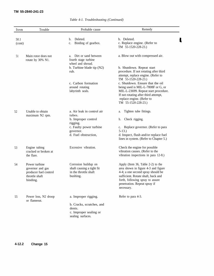
TM 55-2840-241-23
Table 4-1. Troubleshooting (Continued)
Item Trouble Probable cause Remedy
50.1 b.(cont) c.
51 Main rotor does not a.
Deleted. b. Deleted.Binding of gearbox. c. Replace engine. (Refer to
TM 55-1520-228-23.)
Dirt or sand between a. Blow out with compressed air.rotate by 30% N1. fourth stage turbine
wheel and shroud.b. Turbine blade tip (N2) b. Shutdown. Repeat startrub. procedure. If not rotating after third
attempt, replace engine. (Refer toTM 55-1520-228-23.)
c. Carbon formation c. Shutdown. Ensure that the oilaround rotating being used is MIL-L-7808F or G, orlabyrinth seals. MIL-L-23699. Repeat start procedure.
If not rotating after third attempt,replace engine. (Refer to
TM 55-1520-228-23.)
52 Unable to obtainmaximum N2 rpm.
53 Engine tubingcracked or broken atthe flare.
54 Power turbinegovernor and gasproducer fuel controlthrottle shaftbinding.
55 Power loss, N2 droopor flameout.
a. Air leak in control airtubes.b. Improper controlrigging.c. Faulty power turbinegovernor.d. Fuel obstruction,
Excessive vibration.
Corrosion buildup onshaft causing a tight fitin the throttle shaftbushing.
a. Improper rigging.
a.
b.
c.
Tighten tube fittings.
Check rigging.
Replace governor. (Refer to para5-13.)d. Inspect, flush and/or replace fuellines in system. (Refer to Chapter 5.)
Check the engine for possiblevibration causes. (Refer to thevibration inspections in para 12-8.)
Apply (Item 36, Table 2-2) to thearea shown in figure 4-3 and figure4-4; a one second spray should besufficient. Rotate shaft, back andforth, following spray to assurepenetration. Repeat spray ifnecessary.
Refer to para 4-3.
b. Cracks, scratches, anddents.c. Improper sealing orsealing surfaces.
4-12.2 Change 15
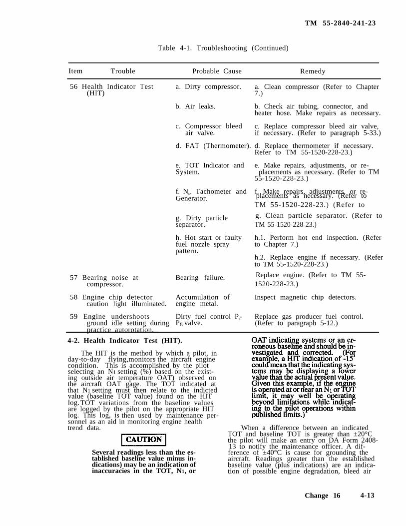
TM 55-2840-241-23
Table 4-1. Troubleshooting (Continued)
Item Trouble Probable Cause Remedy
56 Health Indicator Test(HIT)
placements as necessary. (Refer to
g. Clean particle separator. (Refer to
57 Bearing noise atcompressor.
58 Engine chip detectorcaution light illuminated.
59 Engine undershootsground idle setting duringpractice autorotation.
a. Dirty compressor.
b. Air leaks.
c. Compressor bleedair valve.
d. FAT (Thermometer).
e. TOT Indicator andSystem.
f. Nl, Tachometer andGenerator.
g. Dirty particleseparator.
h. Hot start or faultyfuel nozzle spraypattern.
Bearing failure. Replace engine. (Refer to TM 55-
Accumulation ofengine metal.
Dirty fuel control Pl-Pg valve.
a. Clean compressor (Refer to Chapter7.)
b. Check air tubing, connector, andheater hose. Make repairs as necessary.
c. Replace compressor bleed air valve,if necessary. (Refer to paragraph 5-33.)
d. Replace thermometer if necessary.Refer to TM 55-1520-228-23.)
e. Make repairs, adjustments, or re-placements as necessary. (Refer to TM
55-1520-228-23.)
f. Make repairs, adjustments, or re-
TM 55-1520-228-23.) (Refer to
TM 55-1520-228-23.)
h.1. Perform hot end inspection. (Referto Chapter 7.)
h.2. Replace engine if necessary. (Referto TM 55-1520-228-23.)
1520-228-23.)
Inspect magnetic chip detectors.
Replace gas producer fuel control.(Refer to paragraph 5-12.)
4-2. Health Indicator Test (HIT).
The HIT is the method by which a pilot, inday-to-day flying,monitors the aircraft enginecondition. This is accomplished by the pilotselecting an N1 setting (%) based on the exist-ing outside air temperature OAT) observed onthe aircraft OAT gage. The TOT indicated atthat N1 setting must then relate to the indictedvalue (baseline TOT value) found on the HITlog. TOT variations from the baseline valuesare logged by the pilot on the appropriate HITlog. This log, is then used by maintenance per-sonnel as an aid in monitoring engine healthtrend data.
Several readings less than the es-tablished baseline value minus in-dications) may be an indication ofinaccuracies in the TOT, N1, or
When a difference between an indicatedTOT and baseline TOT is greater than ±20°Cthe pilot will make an entry on DA Form 2408-13 to notify the maintenance officer. A dif-ference of ±40°C is cause for grounding theaircraft. Readings greater than the establishedbaseline value (plus indications) are an indica-tion of possible engine degradation, bleed air
Change 16 4-13
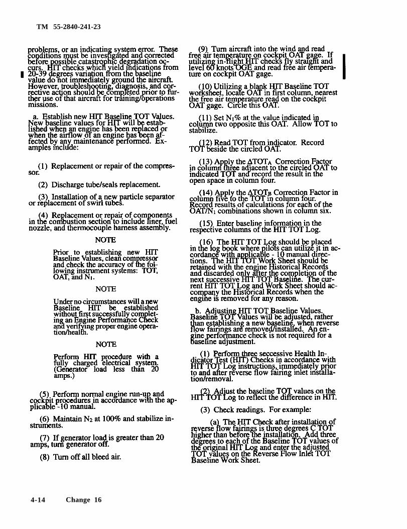
TM 55-2840-241-23
4-14 Change 16
TM 55-2840-241-23
c. Verification of Baseline HIT Values. When cor-rective action is taken to bring the HIT TOT Log valuesback in tolerance with Baseline TOT Values. I Refer toTable 4-1, Troubleshooting Procedure No. 56, HealthIndicator Test (HIT)], verification of the Baseline TOTis required.
(1) Perform a normal HIT Check in accordancewith instructions on the HIT Log.
(2) Compare actual HIT TOT value when Base-line HIT TOT value.
NOTEIf variations between actual TOT and BaselineTOT values are within acceptable tolerance. thenthe Baseline TOT Values are verified.
(3) If variations are not acceptable, perform anEngine Performance Check to ensure proper engineoperation/health and establish a New Engine TOTBaseline.
Change 14 4-14.1
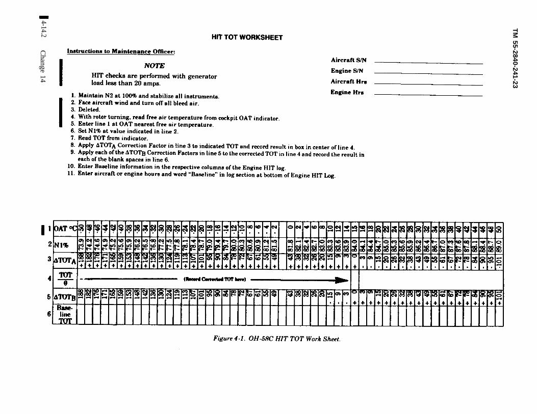
TM
55-2840-241-23
4-14.2C
hange 14
Fig
ure
4-1
. O
H-5
8C
H
IT
TO
T
Wo
rk S
heet.

TM 55-2040-241-23
Fig
ur
e
4-
2.
OH
-5
8C
H
IT
T
OT
L
og
Change
14
4-15
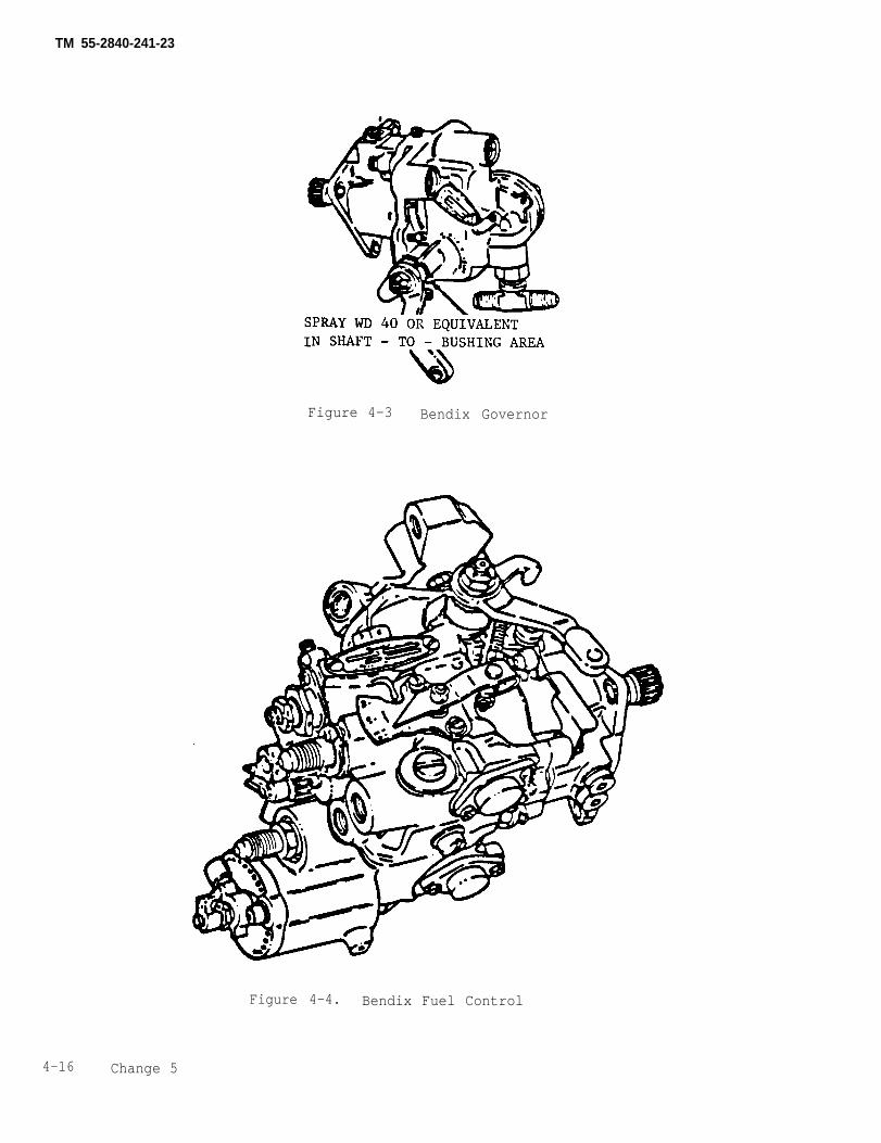
TM 55-2840-241-23
Figure 4-3 Bendix Governor
Figure 4-4. Bendix Fuel Control
4-16 Change 5
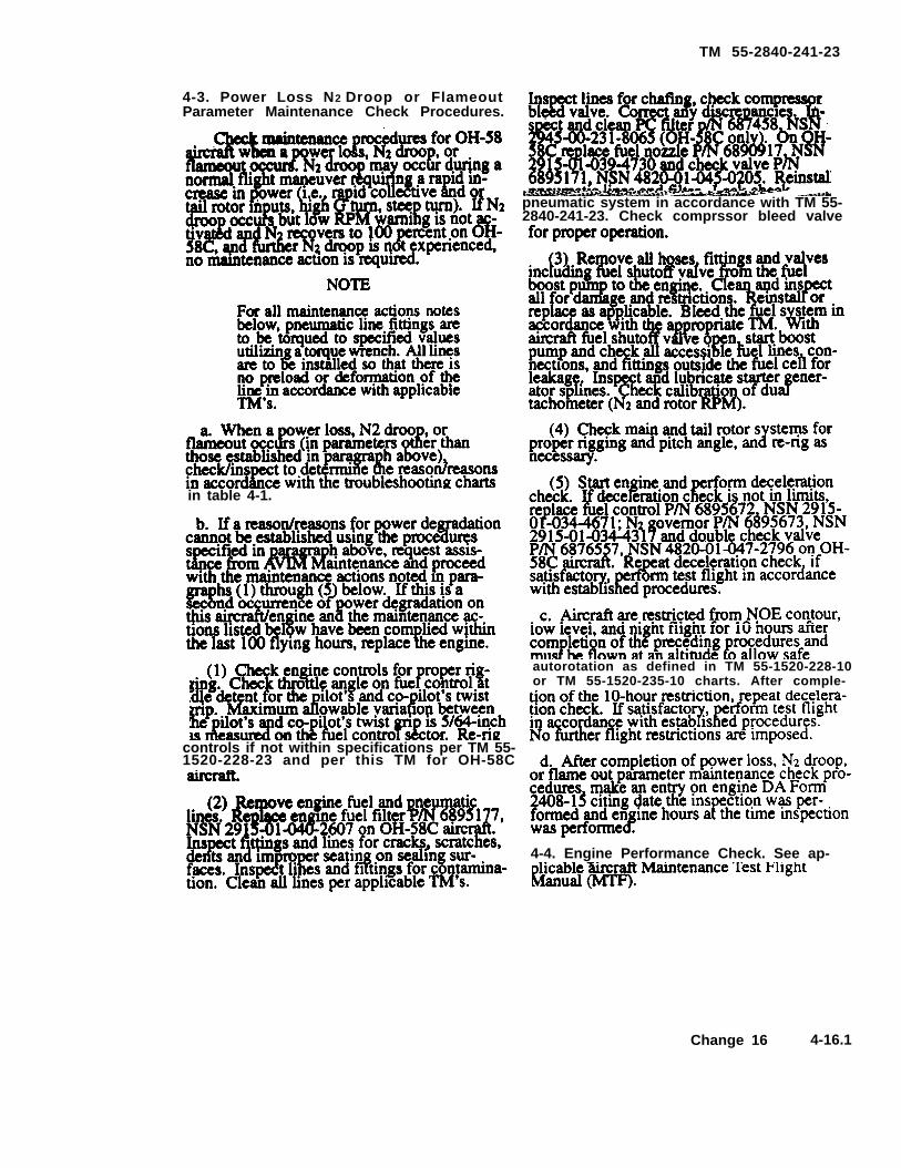
TM 55-2840-241-23
4-3. Power Loss N2 Droop or FlameoutParameter Maintenance Check Procedures.
pneumatic system in accordance with TM 55-2840-241-23. Check comprssor bleed valve
in table 4-1.
autorotation as defined in TM 55-1520-228-10or TM 55-1520-235-10 charts. After comple-
controls if not within specifications per TM 55-1520-228-23 and per this TM for OH-58C
4-4. Engine Performance Check. See ap-
Change 16 4-16.1
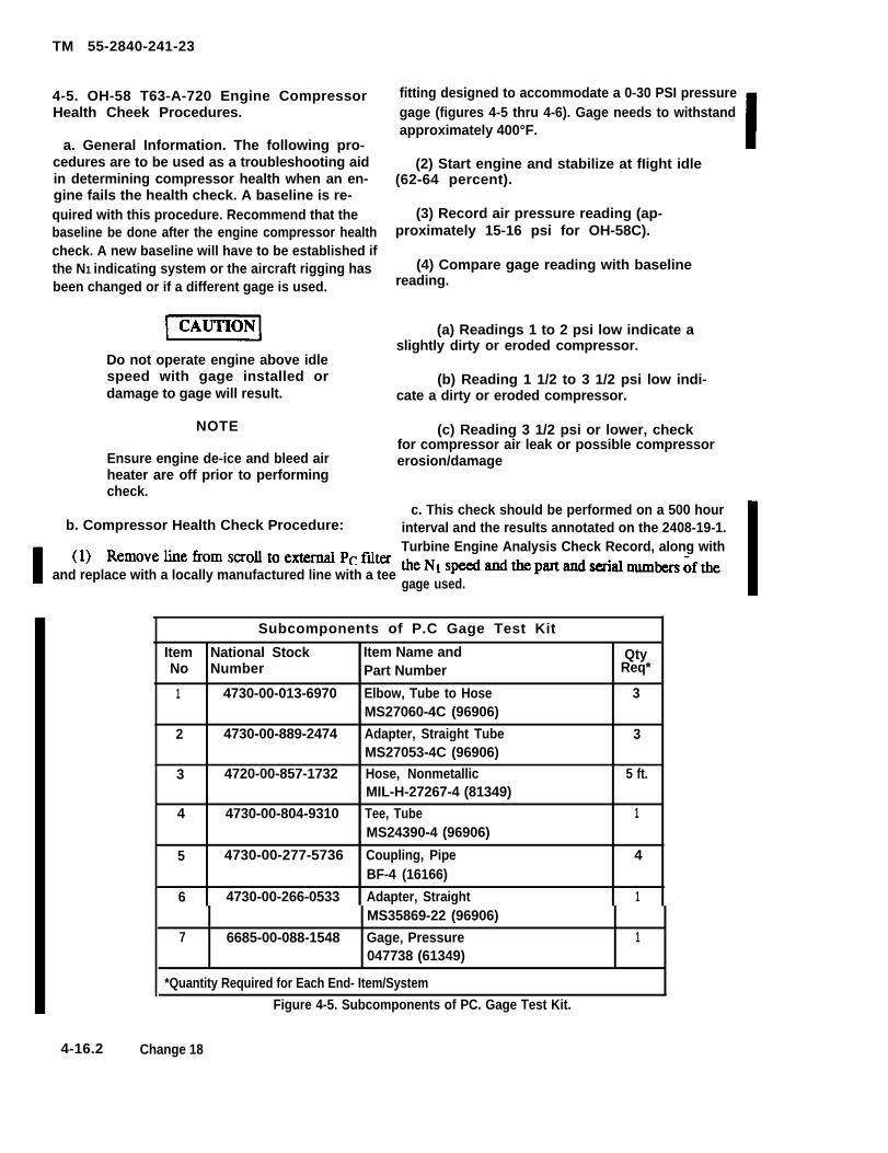
TM 55-2840-241-23
4-5. OH-58 T63-A-720 Engine CompressorHealth Cheek Procedures.
a. General Information. The following pro-cedures are to be used as a troubleshooting aidin determining compressor health when an en-gine fails the health check. A baseline is re-quired with this procedure. Recommend that thebaseline be done after the engine compressor healthcheck. A new baseline will have to be established ifthe N1 indicating system or the aircraft rigging hasbeen changed or if a different gage is used.
Do not operate engine above idlespeed with gage installed ordamage to gage will result.
NOTE
Ensure engine de-ice and bleed airheater are off prior to performingcheck.
b. Compressor Health Check Procedure:
fitting designed to accommodate a 0-30 PSI pressuregage (figures 4-5 thru 4-6). Gage needs to withstandapproximately 400°F.
(2) Start engine and stabilize at fIight idle(62-64 percent).
(3) Record air pressure reading (ap-proximately 15-16 psi for OH-58C).
(4) Compare gage reading with baselinereading.
(a) Readings 1 to 2 psi low indicate aslightly dirty or eroded compressor.
(b) Reading 1 1/2 to 3 1/2 psi low indi-cate a dirty or eroded compressor.
(c) Reading 3 1/2 psi or lower, checkfor compressor air leak or possible compressorerosion/damage
c. This check should be performed on a 500 hourinterval and the results annotated on the 2408-19-1.Turbine Engine Analysis Check Record, along with
and replace with a locally manufactured line with a teegage used.
Subcomponents of P.C Gage Test Kit
Item National Stock Item Name and QtyNo Number Part Number Req*
1 4730-00-013-6970 Elbow, Tube to Hose 3MS27060-4C (96906)
2 4730-00-889-2474 Adapter, Straight Tube 3MS27053-4C (96906)
3 4720-00-857-1732 Hose, Nonmetallic 5 ft.MIL-H-27267-4 (81349)
4 4730-00-804-9310 Tee, Tube 1MS24390-4 (96906)
5 4730-00-277-5736 Coupling, Pipe 4BF-4 (16166)
6 4730-00-266-0533 Adapter, Straight 1MS35869-22 (96906)
7 6685-00-088-1548 Gage, Pressure 1047738 (61349)
*Quantity Required for Each End- Item/System
Figure 4-5. Subcomponents of PC. Gage Test Kit.
4-16.2 Change 18
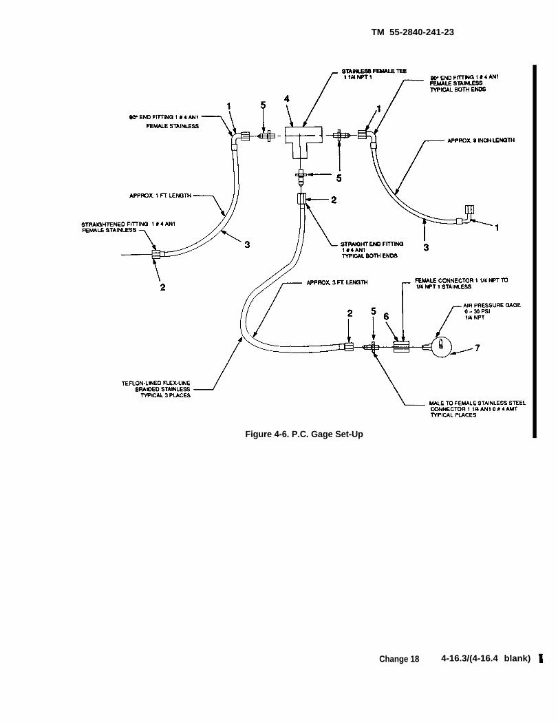
TM 55-2840-241-23
Figure 4-6. P.C. Gage Set-Up
Change 18 4-16.3/(4-16.4 blank)

TM 55-2840-241-23
CHAPTER 5
ACCESSORIES SERVICING
Section 1. GENERAL
5-1. Scope.
This section is intended to be used by Aviation Unitand Aviation Intermediate Maintenance personnel toperform accessories maintenance with maximum effi-ciency. Maintenance functions are grouped into sec-tions by systems. Each section includes detailedinstructions for removal, installation, adjustment,lubrication, and minor servicing of the individual com-ponents of the system.
5-2. General Practices and Precautions.
When performing maintenance on the engine. thefollowing practices and precautions must be observed.
Prolonged contact with lubricating oil,(item 7, table 2-2) may cause a skin rash.Those areas of skin and clothing that comeinto contact with lubricating oil should bethoroughly washed immediately. Areas inwhich lubricating oil is used should beadequately ventilated to keep mist andfumes to a minimum.
NOTELubricating oil may soften paint upon contact. Iflubricating oil is spilled on painted surfaces. thesesurfaces should be thoroughly washed.
a. Protect engine from dust and inclement weather.When possible, perform maintenance in a shelteredarea.
b. On removal of engine components, exercise careto prevent dirt and other foreign matter from enteringthe engine. Caps, plugs, or temporary covers shall beused to close all openings. Do not use tape to cover fueland oil openings. Tape adhesive is soluble in fuel or oiland can cause contamination.
c. When the gas producer fuel control power tur-bine governor, check valve, or accumulator areremoved from the engine, use extreme care to preventforeign materials from entering the pneumatic lines orthe ports of the components.
d. Always use a backup wrench on fittings whenremoving or installing tubing.
e. Before removing ignition components. discon-nect the input power lead at the ignition exciter.
f. C a r e f u l l y i n s p e c t t h e c o n d i t i o n o f a l lreplacement parts before installation.
g. Never attempt to rotate the gear trains androtors using a speed wrench at the tachometer drivepads. Side loads on the speed wrench could crack thetachometer drive shaft. Rotate the gas producer geartrain and rotor using the 6799790 turning adapter atthe fuel control, fuel pump. starter generator, or spareaccessory drive pad. Rotate the power turbine geartrain and rotor using the 6799790 turning adapter atthe power turbine governor drive pad.
5-3. Hardware.
Use 0.020 in. diameter stainless steel lockwire (item10, table 2-21 where lockwire size is not specified. Dou-ble strand lockwire all drilled bolts, plugs, and screws.except those locked with self-locking nuts or lock-washers. Lockwire bolts in pairs where possible. Whenreassembling, be sure to safety wherever lockwire wasremoved.
To prevent possible failure, do not use zinclockwire. Do not reuse lockwire, cotterpins, ring seals, lip seals, composition gas-kets, and split or tab washers.
Change 14 5-1
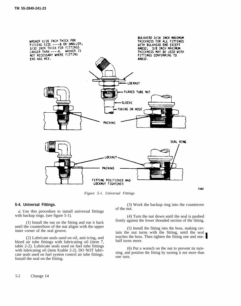
TM 55-2840-241-23
Figure 5-1. Universal Fittings
5-4. Universal Fittings.
a. Use this procedure to install universal fittingswith backup rings. (see figure 5-1).
(1) Install the nut on the fitting and run it backuntil the counterbore of the nut aligns with the upperinner corner of the seal groove.
(2) Lubricate seals used on oil, anti-icing, andbleed air tube fittings with lubricating oil (item 7,table 2-2). Lubricate seals used on fuel tube fittingswith lubricating oil (item 8,table 2-2). DO NOT lubri-cate seals used on fuel system control air tube fittings.Install the seal on the fitting.
(3) Work the backup ring into the counteroreof the nut.
(4) Turn the nut down until the seal is pushedfirmly against the lower threaded section of the fitting.
(5) Install the fitting into the boss, making cer-tain the nut turns with the fitting, until the sealtouches the boss. Then tighten the fitting one and one-half turns more.
(6) Put a wrench on the nut to prevent its turn-ning, and position the fitting by turning it not more thanone turn.
5-2 Change 14
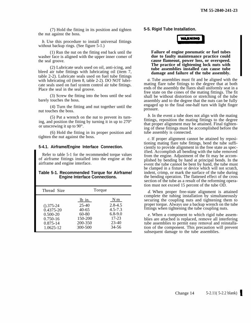
TM 55-2840-241-23
(7) Hold the fitting in its position and tightenthe nut against the boss.
b. Use this procedure to install universal fittingswithout backup rings. (See figure 5-1.)
(1) Run the nut on the fitting end back until thewasher face is aligned with the upper inner comer ofthe seal groove.
(2) Lubricate seals used on oil, anti-icing, andbleed air tube fittings with lubricating oil (item 7,table 2-2). Lubricate seals used on fuel tube fittingswith lubricating oil (item 8, table 2-2). DO NOT lubri-cate seals used on fuel system control air tube fittings.Place the seal in the seal groove.
(3) Screw the fitting into the boss until the sealbarely touches the boss.
(4) Turn the fitting and nut together until thenut touches the boss.
(5) Put a wrench on the nut to prevent its turn-ing, and position the fitting by turning it in up to 270°or unscrewing it up to 90°.
(6) Hold the fitting in its proper position andtighten the nut against the boss.
5-4.1. Airframe/Engine Interface Connection.
Refer to table 5-1 for the recommended torque valuesof airframe fittings installed into the engine at theairframe and engine interface.
Table 5-1. Recommended Torque for Airframe/Engine Interface Connections.
Thread Size Torque
lb in. N m
().375-24 25-40 2.8-4.50.4375-20 40-65 4.5-7.30.500-20 60-80 6.8-9.00.750-16 150-200 17-230.875-14 200-350 23-401.0625-12 300-500 34-56
5-5. Rigid Tube Installation.
Failure of engine pneumatic or fuel tubesdue to faulty maintenance practice couldcause flameout, power loss, or overspeed.The practice of tightening lock nuts withtube assemblies installed can cause tubedamage and failure of the tube assembly.
a. Tube assemblies must fit and be aligned with themating flare tube fittings to the degree that at bothends of the assembly the flares shall uniformly seat in afree state on the cones of the mating fittings. The fitshall be without distortion or stretching of the tubeassembly and to the degree that the nuts can be fullyengaged up to the final one-half turn with light fingerpressure.
b. In the event a tube does not align with the matingfittings, reposition the mating fittings to the degreethat proper alignment may be attained. Final tighten-ing of these fittings must be accomplished before thetube assembly is connected.
c. If proper alignment cannot be attained by reposi-tioning mating flare tube fittings, bend the tube suffi-ciently to provide alignment in the free state as spec-ified. Accomplish all bending with the tube removedfrom the engine. Adjustment of the fit may be accom-plished by bending by hand at principal bends. In theevent the tube cannot be bent by hand, the tube mustbe clamped in a fixture or device which will not scratch,indent, crimp, or mark the surface of the tube duringthe bending operation. The flattened effect of the crosssection of the tube as a result of the reforming opera-tion must not exceed 15 percent of the tube OD.
d. When proper free-state alignment is attainedcomplete the tubing installation by simultaneouslysecuring the coupling nuts and tightening them toproper torque. Always use a backup wrench on the tubefittings when tightening the tube coupling nuts.
e. When a component to which rigid tube assem-blies are attached is replaced, remove all interferingtube assemblies to permit easy removal and reinstalla-tion of the component. This precaution will preventsubsequent damage to the tube assemblies.
Change 14 5-2.11( 5-2.2 blank)

TM 55-2840-241-23
The fuel/air discharge is irritatingand highly flammable. Mechanicsmust take suitable measures toprotect their eyes and prevent fire.Aircraft must be properlygrounded before working on theFuel/air system.
Failure to properly install, align,and tighten fuel fittings and tubescould result in an engine failure.
5-6. General.
Fuel system servicing includes removaland installation of the fuel pump, gas reducerfuel control, power turbine governor, fuel noz-zle, and double check valve. In addition it in-cludes fuel filter replacement, cleaning the fuelnozzle and adjusting the gas producer fuelcontrol.
5-7. Bleeding the Fuel System.
Maintenance of the fuel system can resultin air entrapment m the fuel, lines and sub-
purge the air from the fuel system as follows:sequent false tarts. Following maintenance,
a. Disconnect the input lead to the ignitionexciter.
b. Disconnect the fuel hose at the fuel nozzleand place the open end in a suitable container.
c. Loosen the line to the inlet side of the fuelcheck valve. Move the twist grip to the idle detentand motor engine until fuel appears at the inlet sideof the check valve. Move the twist grip to theclosed position. Reconnect the fuel line to the inletside of the fuel check valve.
d. Move the twist grip to the idle detent andmotor engine until a solid stream of the fuel flowsfrom the disconnected fuel line. Move the twistgrip to the closed position.
e. Reconnect the fuel hose to the fuel nozzle.Reconnect the input lead to the ignition exciter.
5-8. Fuel System Pneumatic Leak Check.
If any fuel system control air tubing (i.e.,Pr, Pg, Py or Pc from tee fitting on governor tofuel control) is removed or disturbed duringmaintenance, check the control air tubing orleaks as follows:
a. Disconnect the pressure sensing (Pc) linefrom the pressure probe elbow m the diffuserscroll.
b. Apply 50-80 psi filtered air or nitrogen tothe Pc line. Ai will immediately escape fromthe pressure regulating air valve port on thepower turbine governor.
c. Use a liquid soap solution item 1 table 2-2) to check the air tubes for leakage. Coverand parting surfaces on the fuel control andgovernor which produce a slight bubbling ofpower soap solution do not represent a leak of suf-ficient magnitude to warrant concem., These
and were compensated for at that time.
d. Reduce the pressure to 20-22 psi (0.14-1.54 kg sqcm) and check the governordiaphragm for leakage. No leakage is accept-able. If leakage is noted from the governordiaphragm, remove the safe wire from thescrews, back off screws and then torque to 8-11 inch lbs. Let screws rest for 20 minutesand retorque to same value. If after this iScompleted, the governor diaphragm still leaks,replace governor.
e. Reconnect the Pc tube. Tighten couplingnuts to .80-120 m. lb. Hold the Pc filter whaletightening the couplingnut. During aircraftrun UP, use the soap solution to verify noleakage around the-reconnected Pc line prior tofight. Rinse the soap and water solutionfrom the engine after the check is completed.
5-9. Fuel Pump.
a. Removal.
(1) Disconnect the before-filter and after-filter pressure lines (25 and 27, figure 5-2) andthe seal drain line (26) from the fuel pump
(2). Disconnect the fuel supply hose atpump relet (23).
(3) Remove fuel tubes (3- and 4) betweenthe fuel urn and control. It will not be neces-sary tools disturb the clamping arrangement be-tween the tubes.
(4) Remove the three self-locking nuts 29,figure 5-3) and washers (30) which secure thefuel pump (31 ) to the gearbox. Remove thepump from the mounting studs.
5 Remove and discard mounting flangegasket (32) and preformed packing (33).
(6) If a new pump is to be installed,remove the tube fittings and keep them for in-stallation in the new pump. Discardpreformed packing.
b. Installation.
Change 18 5-3
TM 55-2840-241-23
fer the tube fitting from the removed pump tothe new pump.Iubricated with oil (item 8, table 2-2). Tighten
to 75-100 in. lb. Tighten fittings in the before-filter, after-filter, an seal drain ports to 55-80in. lb.
(2) Lubricate new preformed packing (33,figure 5-3 with oil (item 7 or 8, table 2-2) andinstall on the pump drive.
(3) Coat fuel pump drives lines withlubricating oil (item 7, table 2-2).
(4) Install the pump with new gasket (32)on the mounting pads studs.
cover on the rear of the pump. Replace the ele-ment as follows:
When there is evidence that fuelfilter bypassing has occured, thefuel filter in the gas produced fuelcontrol must also be cleaned orreplaced. Contamination will beevident due to the fuel pump filterbeing by-passed (Refer to para-graph 5-12j.)
a. Place a container under the pump assemb-ly as some fueltwo screws (1, figure 5-4) and washers (2)retaining the cover (4) to the housing.
5) Secure the pump with three washers(30\ and self-locking nuts (29). lighten the b. Remove the cover and element (6). Discardnuts to 70-85 in. lb. preformed packings (5,7) and the contaminated
filter element. If the element is a tight fit, remove(6) Install fuel tubes (3 and 4, figure 5-2)
between the fuel pump and control.Tightenby pulling straight out. Twisting may cause the
the tube coupling nuts to 150-200 m. lb.element end cap to tear off.
. -
(7) Connect the fuel supply hose at the c. Clean the filter cover with a ray of sol-
200 in. lb.urn inlet (23). Tighten coupling nut to 150-
vent (item 3, table 2-2) or with a cl-soakedcloth.
(8) Connect the before-filter, after-filter, (7) is in place then install the element (6) inand seal dram (25, 26 and 27) hoses. Tightencoupling nuts to 80-120 m. lb. preformed packing (5). Tighten cover screws
(9) Bleed fuel system. (Refer to paragraph(1) to 95-105 in. lb.
5-7.) NOTE
NOTE
On the first start after the fuelpump has been changed, return thegas producer level to fuel cut-offand motor the engine for about 10seconds if a false start occurs or ifa start is not completed within 45
c. Testing. Following installation of the fuelpump, test the engine as outlined in Chapter
5-10. Fuel Filter.
The fueI/air discharge is irritatingand highly flammable. Mechanicsmust take suitable measures toprotect their eyes and prevent fire.
Lockwire is not required if filtercover screws are retained by selflocking inserts.
e. Puree as follows:
The fueI/air discharge is irritatingand highly flammable. Mechanicsmust take suitable measures toprotect their eyes and prevent fire.protect their eyes and prevent fire.plug (figure 5-4, item 3.)
(1) Remove the safety wire from the upperbleed port plug (figure 5-4, item 3.)
(2) Provide a shop rag to deflect the fuelspray.
(3) Turn on the aircraft boost pump.
The fuel filter is a 5-micron nominal, 15micron absolute, paper element located inside
fuel is emitted and then retighten to 34-45 in.the fuel pump. It is retained by a flanged Ibs.
(5) nun off the fuel pump.
5 - 4 Change 18
TM 55-2840-241-23
(6) Remove any fuel that may have been (1) Disconnect air tubes (22, 78, figure 5-spilled in the engine compartment and re- 3) from both ends of filter (69). Hold the faltersafety the upper bleed port. while loosening the coupling nuts.
(2) Remove nut (64) and bolt (63) securing5-11. Pc Filter. falter clamp (65) to filter mounting bracket.
Remove the filter and separate the clamp froma. Removal. the filter.
Change 16 5-4.l/(5-4.2 blank)

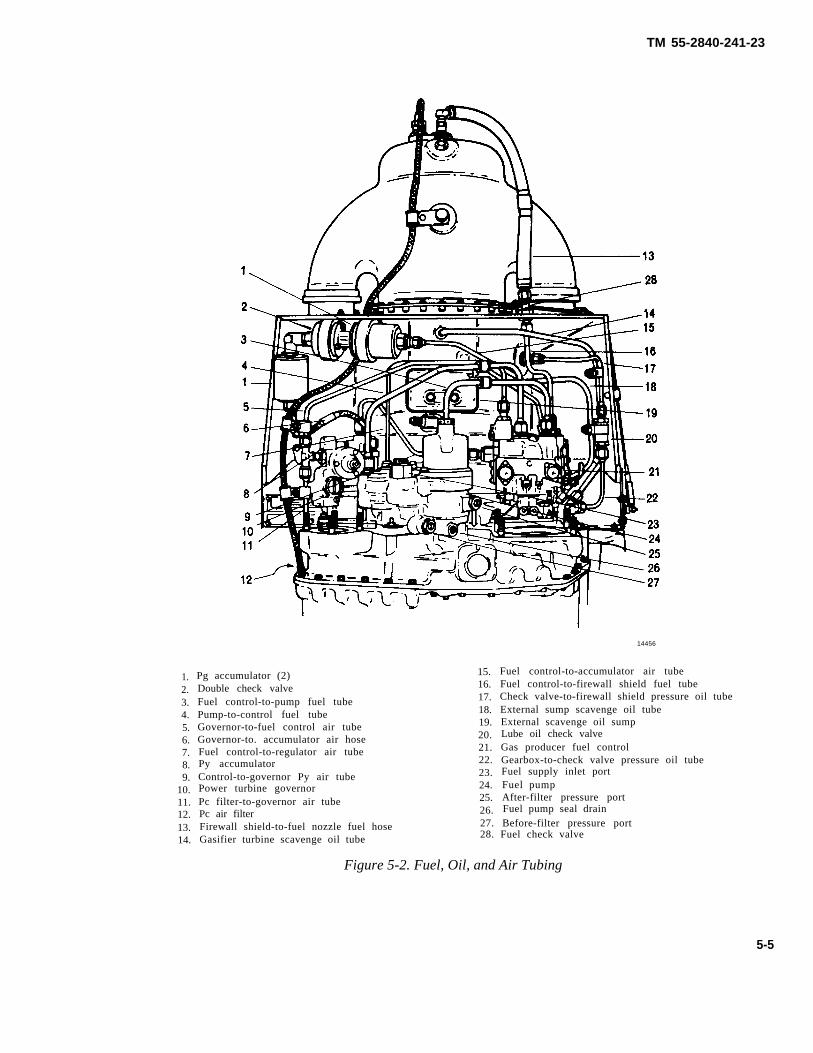
TM 55-2840-241-23
1.2.3.4.5.6.7.8.9.
10.11.12.13.14.
Pg accumulator (2)Double check valveFuel control-to-pump fuel tubePump-to-control fuel tubeGovernor-to-fuel control air tubeGovernor-to. accumulator air hoseFuel control-to-regulator air tubePy accumulatorControl-to-governor Py air tubePower turbine governorPc filter-to-governor air tube
15.16.17.18.19.20.21.22.23.24.25.
14456
Fuel control-to-accumulator air tubeFuel control-to-firewall shield fuel tubeCheck valve-to-firewall shield pressure oil tubeExternal sump scavenge oil tubeExternal scavenge oil sumpLube oil check valveGas producer fuel controlGearbox-to-check valve pressure oil tubeFuel supply inlet portFuel pumpAfter-filter pressure portFuel pump seal drainPc air filter 26.
Firewall shield-to-fuel nozzle fuel hose 27. Before-filter pressure port
Gasifier turbine scavenge oil tube 28. Fuel check valve
Figure 5-2. Fuel, Oil, and Air Tubing
5-5
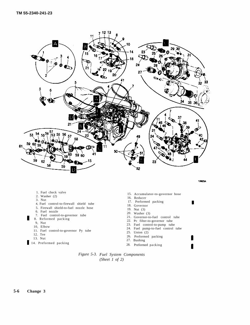
TM 55-2340-241-23
1. Fuel check valve2. Washer (2)3. Nut4, Fuel control-to-firewall shield tube5. Firewall shield-to-fuel nozzle hose6. Fuel nozzle7. Fuel control-to-governor tube
8. Reformed packing9, Nut
10, Elbow11. Fuel control-to-governor Py tube12. Tee13. Nut
14. Preformed packing
Figure 5-3.
15.16.17.18.19.20.21.22.23.24.25.26.27.
28.
Accumulator-to-governor hoseReducerPreformed packing
GovernorNut (3)Washer (3)Governor-to-fuel control tubePc filter-to-governor tubeFuel control-to-pump tubeFuel pump-to-fuel control tubeUnion (2)Preformed packing
Bushing
Preformed packing
Fuel System Components(Sheet 1 of 2)
5-6 Change 3
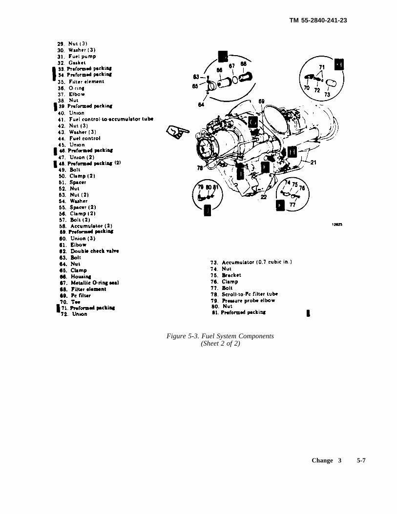
TM 55-2840-241-23
Figure 5-3. Fuel System Components(Sheet 2 of 2)
Change 3 5-7
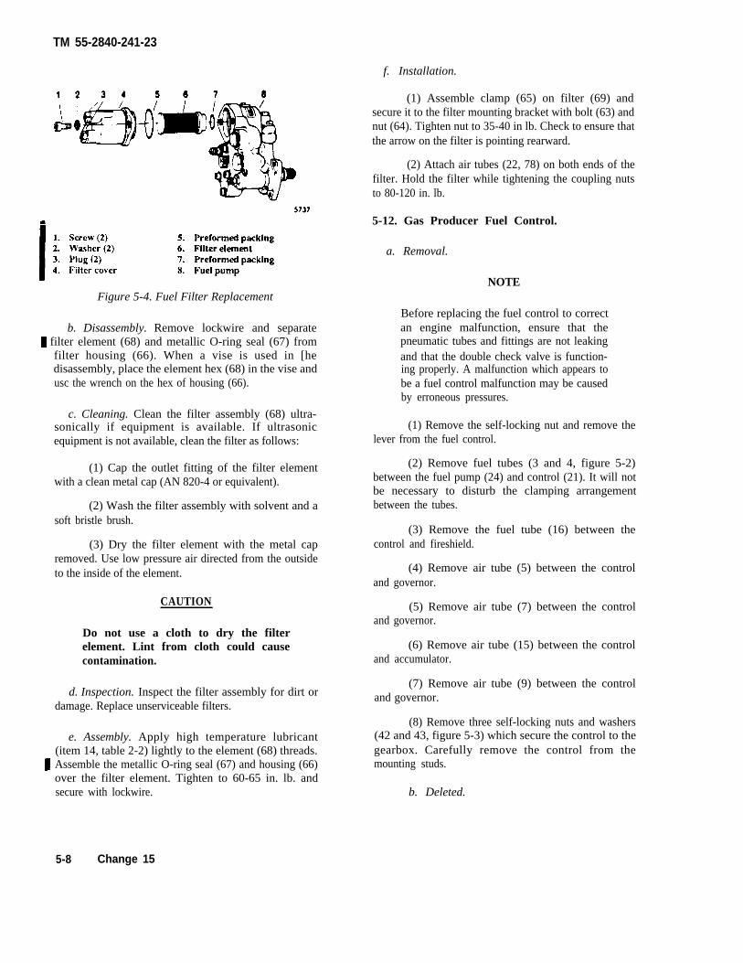
TM 55-2840-241-23
f. Installation.
Figure 5-4. Fuel Filter Replacement
b. Disassembly. Remove lockwire and separate filter element (68) and metallic O-ring seal (67) from
filter housing (66). When a vise is used in [hedisassembly, place the element hex (68) in the vise andusc the wrench on the hex of housing (66).
c. Cleaning. Clean the filter assembly (68) ultra-sonically if equipment is available. If ultrasonicequipment is not available, clean the filter as follows:
(1) Cap the outlet fitting of the filter elementwith a clean metal cap (AN 820-4 or equivalent).
(2) Wash the filter assembly with solvent and asoft bristle brush.
(3) Dry the filter element with the metal capremoved. Use low pressure air directed from the outsideto the inside of the element.
CAUTION
Do not use a cloth to dry the filterelement. Lint from cloth could causecontamination.
d. Inspection. Inspect the filter assembly for dirt ordamage. Replace unserviceable filters.
e. Assembly. Apply high temperature lubricant(item 14, table 2-2) lightly to the element (68) threads.
Assemble the metallic O-ring seal (67) and housing (66)over the filter element. Tighten to 60-65 in. lb. andsecure with lockwire.
(1) Assemble clamp (65) on filter (69) andsecure it to the filter mounting bracket with bolt (63) andnut (64). Tighten nut to 35-40 in lb. Check to ensure thatthe arrow on the filter is pointing rearward.
(2) Attach air tubes (22, 78) on both ends of thefilter. Hold the filter while tightening the coupling nutsto 80-120 in. lb.
5-12. Gas Producer Fuel Control.
a. Removal.
NOTE
Before replacing the fuel control to correctan engine malfunction, ensure that thepneumatic tubes and fittings are not leakingand that the double check valve is function-ing properly. A malfunction which appears tobe a fuel control malfunction may be causedby erroneous pressures.
(1) Remove the self-locking nut and remove thelever from the fuel control.
(2) Remove fuel tubes (3 and 4, figure 5-2)between the fuel pump (24) and control (21). It will notbe necessary to disturb the clamping arrangementbetween the tubes.
(3) Remove the fuel tube (16) between thecontrol and fireshield.
(4) Remove air tube (5) between the controland governor.
(5) Remove air tube (7) between the controland governor.
(6) Remove air tube (15) between the controland accumulator.
(7) Remove air tube (9) between the controland governor.
(8) Remove three self-locking nuts and washers(42 and 43, figure 5-3) which secure the control to thegearbox. Carefully remove the control from themounting studs.
b. Deleted.
5-8 Change 15
TM 55-2840-241-23
c. Installation. (a) Idle speed. (Refer to paragraph 5-12e.)
When removing or installing fittings in thefuel control, be careful not to cause a loadon the drive shaft. Damage to the fuel con-trol could occure.
(1) If a new fuel control is to be installed, trans-fer the tube fittings from the removed control to thenew control. Use new preformed packing. Lubricatepreformed packing on fuel tube fittings with oil (item8, table 2-2). Do not lubricate preformed packing on airtube fittings. Tighten the unions to 75-110 in. lb. Do nottighten jam nuts.
(2) Check the max flow stop setting and adjustif required. (Refer to paragraph 5-12h.)
(3) Coat the fuel control drive shaft splineswith lubricant (item 14, table 2-2), the studs with anti-seize compound (item 15, table 2-2 ), and fuel tube fit-tings with oil (item 8, table 2-2).
(4) Install the fuel control on the mounting padstuds. Make certain the fuel control drive splines areproperly engaged in the gearbox drive splines; the fuelcontrol must be flush against the gearbox mountingpad. Secure the control with three washers (43, figure5-3) and self-locking nuts (42). Tighten the nuts to70-85 in. lb.
(5) Install air tube (9, figure 5-2) between thefuel control and governor. Tighten coupling nuts to80-120 in. lb.
(6) Install air tube (15) between the control andaccumulator. Tighten coupling nuts to 80-120 in. lb.Tighten the jam nut on the tube fitting to 55-80 in. lb.
(7) Install air tube (7) between the control andgovernor. Tighten coupling nuts to 80-120 in. lb.Tighten the jam nut on the tube fitting to 55-80 in. lb.
(8) Install fuel tube (16) between the controland fireshield. Tighten coupling nuts to 80-120 in. lb,
(9) Install air tube (5) between the control andgovernor. Tighten coupling nuts to 80-120 in. lb.
(10) Install fuel tubes (3 and 4) between the fuelpump and control. Tighten coupling nuts to 150-200 in.lb .
(11) Assemble the lever on the control and securewith a self-locking nut. Position the lever in accordancewith the Rigging Check. (Refer to paragraphs 5-12d.)Tighten the nut to 40-50 in. lb. (Overtorquing causesbinding of the lever shaft.)
(12) Check the pneumatic tubes for leaks. (Referto paragraph 5-8.)
(13) Bleed the fuel system. (Refer to paragraph5-7.)
(14) Test the engine as outlined in Chapter 10and make the following adjustments if required.
(b) Start derichment. (Refer to paragraph5-12g.)
(c) Start acceleration - AVIM. (Refer to para-graph 5-12g.)
(15) Make appropriate entry relative to fuel con-trol replacement in the engine log.
d. Rigging Check.
Do not adjust the minimum stop to com-pensate for aircraft rigging difficulties.The minimum stop is set on a flow benchand is not a field adjustment.
NOTEFor N1 rigging procedures, refer to TM55-1520-228-23.
Check the rigging of the gas producer fuel controlafter a deceleration check has revealed the decelera-tion time to be less than the allowable minimum. Thischeck is also required after installation of a fuel controlor any component of the rigging system. Make therigging check with the engine shut down using thefollowing procedure.
(1) Check to ensure that sufficient travel is pro-vided to allow physical contact with the gas producerminimum stop at or before the full closed position of thetwist grip.
(2) Check the travel to the opposite end. Phys-ical contact must be made with the gas producer max-imum stop at or before the full open position of thetwist grip.
(3) Looseness encountered in the rigging mustbe minimized by replacement of worn items and/oraccuracy of the rigging. Looseness that cannot beremoved must be within the limits indicated in figure5-5. Check the looseness as follows:
(a) Start with the twist grip at the full openposition then rotate the grip to the IDLE position. Thepointer must beat the 30 degree mark.
NOTEThe pointer must be exactly at the 30 degree markfor initial rigging setup or when rigging is beingadjusted.
(b) Start with the twist grip at the full closedposition then rotate the grip to the IDLE position. Thepointer must be no more than 5/64 in. below the 30degree mark.
Change 14 5-9
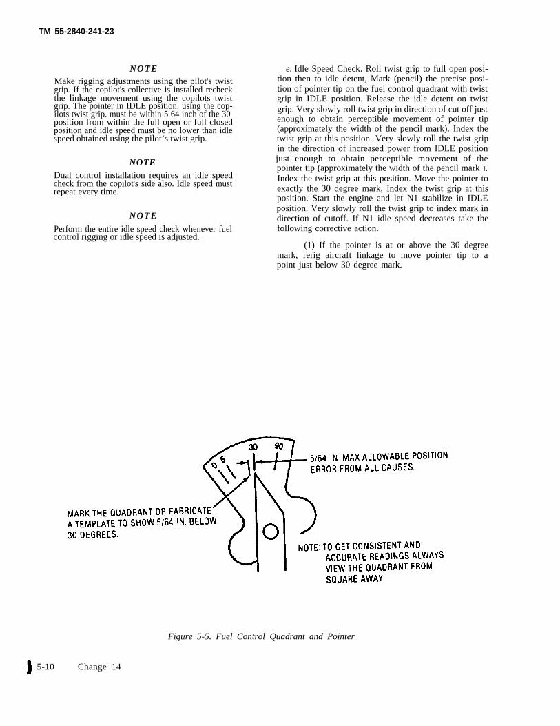
TM 55-2840-241-23
NOTEMake rigging adjustments using the pilot's twistgrip. If the copilot's collective is installed recheckthe linkage movement using the copilots twistgrip. The pointer in IDLE position. using the cop-ilots twist grip. must be within 5 64 inch of the 30position from within the full open or full closedposition and idle speed must be no lower than idlespeed obtained using the pilot’s twist grip.
NOTEDual control installation requires an idle speedcheck from the copilot's side also. Idle speed mustrepeat every time.
NOTE
Perform the entire idle speed check whenever fuelcontrol rigging or idle speed is adjusted.
e. Idle Speed Check. Roll twist grip to full open posi-tion then to idle detent, Mark (pencil) the precise posi-tion of pointer tip on the fuel control quadrant with twistgrip in IDLE position. Release the idle detent on twistgrip. Very slowly roll twist grip in direction of cut off justenough to obtain perceptible movement of pointer tip(approximately the width of the pencil mark). Index thetwist grip at this position. Very slowly roll the twist gripin the direction of increased power from IDLE positionjust enough to obtain perceptible movement of thepointer tip (approximately the width of the pencil mark I.Index the twist grip at this position. Move the pointer toexactly the 30 degree mark, Index the twist grip at thisposition. Start the engine and let N1 stabilize in IDLEposition. Very slowly roll the twist grip to index mark indirection of cutoff. If N1 idle speed decreases take thefollowing corrective action.
(1) If the pointer is at or above the 30 degreemark, rerig aircraft linkage to move pointer tip to apoint just below 30 degree mark.
Figure 5-5. Fuel Control Quadrant and Pointer
5-10 Change 14
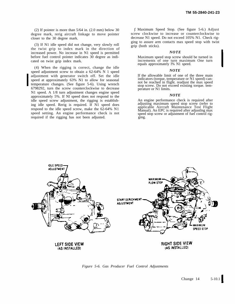
TM 55-2840-241-23
(2) If pointer is more than 5/64 in. (2.0 mm) below 30degree mark, rerig aircraft linkage to move pointercloser to the 30 degree mark.
(3) If N1 idle speed did not change, very slowly rollthe twist grip to index mark in the direction ofincreased power. No increase in N1 speed is permittedbefore fuel control pointer indicates 30 degree as indi-cated on twist grip index mark.
(4) When the rigging is correct, change the idlespeed adjustment screw to obtain a 62-64% N 1 speedadjustment with generator switch off. Set the idlespeed at approximately 63% N1 to allow for seasonaltemperature changes. (See figure 5-6). Using wrench6798292, turn the screw counterclockwise to decreaseN1 speed. A 1/8 turn adjustment changes engine speedapproximately 5%. If Nl speed does not respond to theidle speed screw adjustment, the rigging is establish-ing idle speed. Rerig is required. If N1 speed doesrespond to the idle speed screw, make the 62-64% N1speed setting. An engine performance check is notrequired if the rigging has not been adjusted.
f. Maximum Speed Stop. (See figure 5-6.) Adjustscrew clockwise to increase or counterclockwise todecrease N1 speed. Do not exceed 105% N1. Check rig-ging to assure arm contacts max speed stop with twistgrip (both sticks).
NOTEMaximum speed stop screw should be turned inincrements of one turn maximum One turnequals approximately l% N1 speed.
NOTEIf the allowable limit of one of the three mainindicators (torque, temperature or N1 speed) can-not be reached in flight. readjust the max speedstop screw. Do not exceed existing torque. tem-perature or N1 limits.
NOTEAn engine performance check is required afteradjusting maximum speed stop screw (refer toapplicable Aircraft Maintenance Test FlightManual). An EPC is required after adjustlng maxspeed stop screw or adjustment of fuel control rig-ging.
Figure 5-6. Gas Producer Fuel Control Adjustments
Change 14 5-10.1
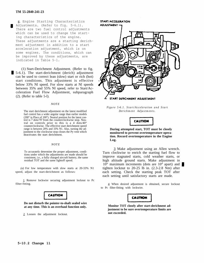
TM 55-2840-241-23
g. Engine Starting CharacteristicsAdjustments. (Refer to fig. 5-6.1).There are two fuel control adjustmentswhich can be used to change the start-ing characteristics of the engine.These adjustments are a starting derich-ment adjustment in addition to a startacceleration adjustment, which is onsome engines. The conditions, which canbe improved by these adjustments, areindicated in Table 5-1.
(1) Start-Derichment Adjustment. (Refer to fig.5-6.1). The start-derichment (derich) adjustmentcan be used to correct lean (slow) start or rich (hot)start conditions. This adjustment is effectivebelow 33% Nl speed. For slow starts at Nl speedsbetween 35% and 55% Nl speed, refer to Start/Ac-celeration Fuel Flow Adjustment, subparagraph(2). (Refer to table 5-l).
NOTE
The start derichment adjustment on the latest modifiedfuel control has a wider angular range than earlier models(200° in Place of 100°). Neutral position for the latest con-trol is 7 dots/70O from the counterclockwise stop. Neu-tral on controls prior to this is a 4 dots/40°counterclockwise. The effective start derichment speedrange is between 20% and 33% N1. Also, turning the ad-justment to the clockwise stop closes the Py vent whichdeactivates the start derichment.
NOTE
To accurately determine the proper adjustment, condi-tions under which the adjustments are made should beconsistent, i.e., a fully charged aircraft battery, the sameresidual TOT and the same lightoff speed.
(a) For low temperature with slow starts at 20-33% N1speed, adjust the start-derichment as follows:
1 Remove lockwire securing adjustment locknut to Pcfilter-fitting.
Do not disturb the pointer-to-shaft sealed wireat any time. This is an overhaul function only.
2 Loosen the adjustment locknut.
Figure 5-6.1. Start/Acceleration and StartDerichment Adjustments.
During attempted start, TOT must be closelymonitored to prevent overtemperature opera-tion. Record overtemperature in the EngineLog.
3 Make adjustment using an Allen wrench.Turn clockwise to enrich the starting fuel flow toimprove stagnated starts, cold weather starts, orhigh altitude ground starts. Make adjustment in10° maximum increments (dots are 10° apart) andtighten locknut to 20-25 lb in. (2.3-2.8 Nm) aftereach setting. Check the starting peak TOT aftereach setting until satisfactory starts are made.
4 When desired adjustment is obtained, secure lockoutto Pc filter-fitting with lockwire.
Monitor TOT closely after start-derichment ad-justment to be sure overtemperature limits arenot exceeded.
5-10.2 Change 11
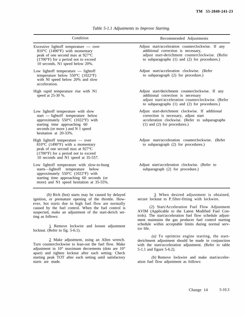
TM 55-2840-241-23
Table 5-1.1 Adjustments to Improve Starting.
Condition Recommended Adjustments
Excessive lightoff temperature — over Adjust start/acceleration counterclockwise. If any810°C (1490°F) with momentary additional correction is necessary,peak of one second max at 927°C adjust start-derichment counterclockwise. (Refer(1700°F) for a period not to exceed to subparagraphs (1) and (2) for procedures.)10 seconds. N1 speed below 20%.
Low lightoff temperature — lightoff Adjust start/acceleration clockwise. (Refertemperature below 550°C (1022°F) to subparagraph (2) for procedure.)with Nl speed below 20% and slowacceleration.
High rapid temperature rise with N1 Adjust start/derichment counterclockwise. If anyspeed at 25-30 %. additional correction is necessary
adjust start/acceleration counterclockwise. (Referto subparagraphs (1) and (2) for procedures.)
Low lightoff temperature with slow Adjust start-derichment clockwise. If additionalstart — lightoff temperature below correction is necessary, adjust startapproximately 550°C (1022°F) with acceleration clockwise. (Refer to subparagraphsstarting time approaching 60 (1) and (2) for procedures.)seconds (or more ) and N 1 speedhesitation at 20-33%.
High lightoff temperature — over Adjust start/acceleration counterclockwise. (Refer810°C (1490°F) with a momentary to subparagraph (2) for procedures.)peak of one second max at 927°C(1700°F) for a period not to exceed10 seconds and N1 speed at 35-557.
Low lightoff temperature with slow-to-hungstarts—lightoff temperature belowapproximately 550°C (1022°F) withstarting time approaching 60 seconds (ormore) and N1 speed hesitation at 35-55%.
Adjust start/acceleration clockwise. (Refer tosubparagraph (2) for procedure.)
(b) Rich (hot) starts may be caused by delayedignition, or premature opening of the throttle. How-ever, hot starts due to high fuel flow are normallycaused by the fuel control. When the fuel control issuspected, make an adjustment of the start-derich set-ting as follows:
1 Remove lockwire and loosen adjustmentlocknut. (Refer to fig. 5-6.1).
2 Make adjustment, using an Allen wrench.Turn counterclockwise to lean-out the fuel flow. Makeadjustment in 10° maximum decrements (dots are 10°apart) and tighten locknut after each setting. Checkstarting peak TOT after each setting until satisfactorystarts are made.
3 When desired adjustment is obtained,secure locknut to Pc filter-fitting with lockwire.
(2) Start/Acceleration Fuel Flow AdjustmentAVIM (Applicable to the Latest Modified Fuel Con-trols). The start/acceleration fuel flow schedule adjust-ment maintains the gas producer fuel control startingschedule within acceptable limits during normal serv-ice life.
(a) To optimize engine starting, the start-derichment adjustment should be made in conjunctionwith the start/acceleration adjustment. (Refer to table5-1.1 and figure 5-6.2).
(b) Remove lockwire and make start/acceler-ation fuel flow adjustment as follows:
Change 14 5-10.3
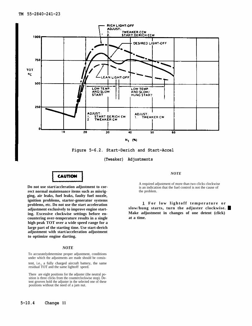
TM 55-2840-241-23
Figure 5-6.2. Start-Derich and Start-Accel
(Tweaker) Adjustments
Do not use start/accleration adjustment to cor-rect normal maintenance items such as misrig-ging, air leaks, fuel leaks, faulty fuel nozzle,ignition problems, starter-generator systemsproblems, etc. Do not use the start accelerationadjustment exclusively to improve engine start-ing. Excessive clockwise settings before en-countering over-temperature results in a singlehigh peak TOT over a wide speed range for alarge part of the starting time. Use start-derichadjustment with start/acceleration adjustmentto optimize engine darting.
NOTE
To accuratelydetermine proper adjustment, conditionsunder which the adjustments are made should be consis-
tent, i.e., a fully charged aircraft battery, the sameresidual TOT and the same lightoff speed.
NOTE
A required adjustment of more than two clicks clockwiseis an indication that the fuel control is not the cause ofthe problem.
1 F o r l o w l i g h t o f f t e m p e r a t u r e o rslow/hung starts, turn the adjuster clockwise.Make adjustment in changes of one detent (click)at a time.
There are eight positions for the adjuster (the neutral po-sition is three clicks from the counterclockwise stop). De-tent grooves hold the adjuster in the selected one of thesepositions without the need of a jam nut.
5-10.4 Change 11
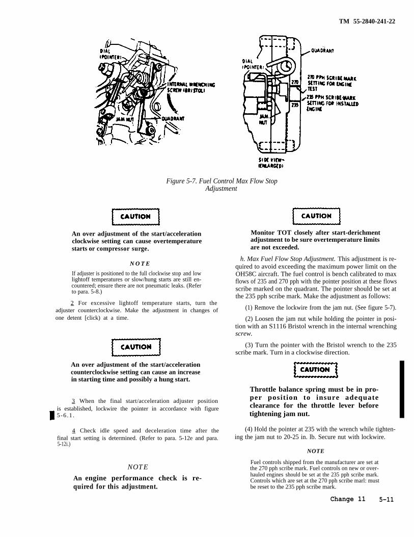
TM 55-2840-241-22
Figure 5-7. Fuel Control Max Flow StopAdjustment
An over adjustment of the start/accelerationclockwise setting can cause overtemperaturestarts or compressor surge.
N O T E
If adjuster is positioned to the full clockwise stop and lowlightoff temperatures or slow/hung starts are still en-countered; ensure there are not pneumatic leaks. (Referto para. 5-8.)
2 For excessive lightoff temperature starts, turn theadjuster counterclockwise. Make the adjustment in changes ofone detent [click) at a time.
An over adjustment of the start/accelerationcounterclockwise setting can cause an increasein starting time and possibly a hung start.
3 When the final start/acceleration adjuster positionis established, lockwire the pointer in accordance with figure5-6 .1 .
4 Check idle speed and deceleration time after thefinal start setting is determined. (Refer to para. 5-12e and para.5-12i.)
NOTE
An engine performance check is re-quired for this adjustment.
Monitor TOT closely after start-derichmentadjustment to be sure overtemperature limitsare not exceeded.
h. Max Fuel Flow Stop Adjustment. This adjustment is re-quired to avoid exceeding the maximum power limit on theOH58C aircraft. The fuel control is bench calibrated to maxflows of 235 and 270 pph with the pointer position at these flowsscribe marked on the quadrant. The pointer should be set atthe 235 pph scribe mark. Make the adjustment as follows:
(1) Remove the lockwire from the jam nut. (See figure 5-7).
(2) Loosen the jam nut while holding the pointer in posi-tion with an S1116 Bristol wrench in the internal wrenchingscrew.
(3) Turn the pointer with the Bristol wrench to the 235scribe mark. Turn in a clockwise direction.
Throttle balance spring must be in pro-per position to insure adequateclearance for the throttle lever beforetightening jam nut.
(4) Hold the pointer at 235 with the wrench while tighten-ing the jam nut to 20-25 in. lb. Secure nut with lockwire.
NOTE
Fuel controls shipped from the manufacturer are set atthe 270 pph scribe mark. Fuel controls on new or over-hauled engines should be set at the 235 pph scribe mark.Controls which are set at the 270 pph scribe marl: mustbe reset to the 235 pph scribe mark.
Change 11 5-11
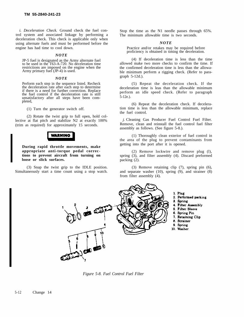
TM 55-2840-241-23
i. Deceleration Check. Ground check the fuel con-trol system and associated linkage by performing adeceleration check. This check is applicable only whenusing alternate fuels and must be performed before theengine has had time to cool down.
NOTEJP-5 fuel is designated as the Army alternate fuelto be used in the T63-A-720. No deceleration timerestrictions are imposed on the engine when theArmy primary fuel (JP-4) is used.
NOTEPerform each step in the sequence listed. Recheckthe deceleration rate after each step to determineif there is a need for further correction. Replacethe fuel control if the deceleration rate is stillunsatisfactory after all steps have been com-pleted,
(1) Turn the generator switch off.
(2) Rotate the twist grip to full open, hold col-lective at flat pitch and stabilize N2 at exactly 100%(trim as required) for approximately 15 seconds.
Stop the time as the N1 needle passes through 65%.The minimum allowable time is two seconds.
NOTEPractice and/or retakes may be required beforeproficiency is obtained in timing the deceleration.
(4) If deceleration time is less than the timeallowed make two more checks to confirm the time. Ifthe confirmed deceleration time is less than the allowa-ble minimum perform a rigging check. (Refer to para-graph 5-12d.).
(5) Repeat the deceleration check. If thedeceleration time is leas than the allowable minimumperform an idle speed check. (Refer to paragraph5-12e.).
(6) Repeat the deceleration check. If decelera-tion time is less than the allowable minimum, replacethe fuel control.
j. Cleaning Gas Producer Fuel Control Fuel Filter.Remove, clean and reinstall the fuel control fuel filterassembly as follows. (See figure 5-8.).
(1) Thoroughly clean exterior of fuel control inthe area of the plug to prevent contaminants fromgetting into the port after it is opened.
(2) Remove lockwire and remove plug (l),spring (3), and filter assembly (4). Discard preformedpacking (2).
(3) Remove retaining clip (7), spring pin (6),and separate washer (10), spring (9), and strainer (8)
During rapid throttle movements, makeappropriate anti-torque pedal correc-tions to prevent aircraft from turning onloose or slick surfaces.
(3) Snap the twist grip to the IDLE position.Simultaneously start a time count using a stop watch.
from filter assembly (4).
Figure 5-8. Fuel Control Fuel Filter
5-12 Change 14
TM 55-2840-241-23
of the strainer. Repeat the procedure if visual in-spection with a bright light shows that the interiorof the drainer is not entirely free of contaminates.
Be cure strainer (8) is installed asshown in figure 5-8. Open end ofstrainer toward the outside of thecontrol, away from the spring. Do notinstall backwards.
(5) Install drainer (8), spring (9), and washer(10) in filter sleeve (5). Secure components in the
filter sleeve with spring pin (6) and retaining clip(7).
Use extreme care to insure that thepneumatic lines and fittings are notleaking. Erroneous pressures willcause fuel control malfunction.
(6) Lightly lubricate a new preformed pack-ing (2) with engine fuel and place it on plug (1). In-stall filter assembly (4), spring (3) and plug (1) infuel control.
Change 4 5-12A/(5-12B blank)

TM 55-2840-241-23
Do not attempt to open a clogged screenwith a sharp instrument.
(4) Clean filter assembly parts ultrasonically ifequipment is available. If equipment is not available,agitate parts in solvent (item 3. table 2-2). Dry partsusing clean shop air regulated to approximately 15psig. Air pressure should be applied to the exterior ofthe strainer. Repeat the procedure if visual inspectionwith a bright light shows that the interior of thestrainer is not entirely free of contaminates.
Be sure strainer (8) is installed as shown infigure 5-8. Open end of strainer toward theoutside of the control, away from thespring. Do not install backwards.
(5) Install strainer (8), spring (9), and washer(10) in filter sleeve (5). Secure components in the filtersleeve with spring pin (6) and retaining clip (7).
Use extreme care to insure that the pneu-matic lines and fittings are not leaking.Erroneous pressures will cause fuel con-trol malfunction.
(6) Lightly lubricate a new preformed packing(2) with engine fuel and place it on plug (1). Install filterassembly (4), spring (3) and plug (1) in fuel control.Tighten the plug 65-70 in. lb and lockwire (item 10,table 2-2).
5-13. Power Turbine Governor.
a. Removal.
NOTE
Before replacing the power turbine governor tocorrect an engine malfunction, ensure that thepneumatic tubes and fittings are not leaking andthe double check valve is functioning properly. Amalfunction which appears to be a governor mal-function may be caused by erroneous pressures.
(1) Remove the self-locking nut and remove thelever from the governor (10, figure 5-2).
(2) Remove air tube (11) between the Pc filter(12) and governor tee.
(3) Remove air tube (5) between the governortee and fuel control.
(4) Remove air tube (7) between the governorand fuel control.
(5) Remove air hose (6) between the governorand accumulator (1).
(6) Remove air tube (9) between the governorand control.
(7) Remove three self-locking nuts (19. figure5-3) and washers (20) securing the governor to thegearbox. Remove the governor from the mountingstuds.
b. Deleted
c. Installation.
(1) If a new governor is to be installed. transferthe union and Py accumulator. Use new preformedpacking. Do not lubricate. Tighten union 75-110 in. lb.Tighten Py accumulator to 75-110 in. lb.
(2) Coat the governor drive shaft splines withlubricant (item 14, table 2-2) and the studs with anti-seize compound (item 15, table 2-21. Do not lubricatetube fittings.
(3) Install the governor on the mounting padstuds. Make certain the governor drive splines areproperly engaged in the gearbox drive splines: the gov-ernor must be flush against the gearbox mounting pad.Secure the governor with three washers (20. figure 5-3)and self-locking nuts (19). Tighten the nuts to 70-85 in.lb.
(4) Install air tube (9, figure 5-2) between thecontrol and the governor. Tighten the coupling nuts to80-120 in. lb.
(5) Install air hose (6) between the governorand accumulator (1). Tighten the coupling nuts to80-120 in. lb.
(6) Install air tube (7) between the governorand control. Tighten the coupling nuts to 80-120 in. lb.Tighten elbow jam nut to 55-80 in. lb.
(7) Install air tube (5) between the governor teeand the control. Tighten coupling nuts to 80-120 in. lb.Tighten the tee jam nut to 55-80 in. lb.
(8) Install air tube (11) between Pc filter (12) andgovernor tee. Tighten the coupling nuts to 80-120 in. lb.
(9) Perform a fuel system pneumatic leakcheck. (Refer to paragraph 5-8.)
(10) Install the governor lever on the governorshaft and position approximately 90 degrees to thecenterline of the indicator on the stop assembly. Securethe lever with the self-locking nut. Tighten the nut to40-50 in. lb. (Overtorquing will cause binding of thelever shaft.)
Change 14 5-13
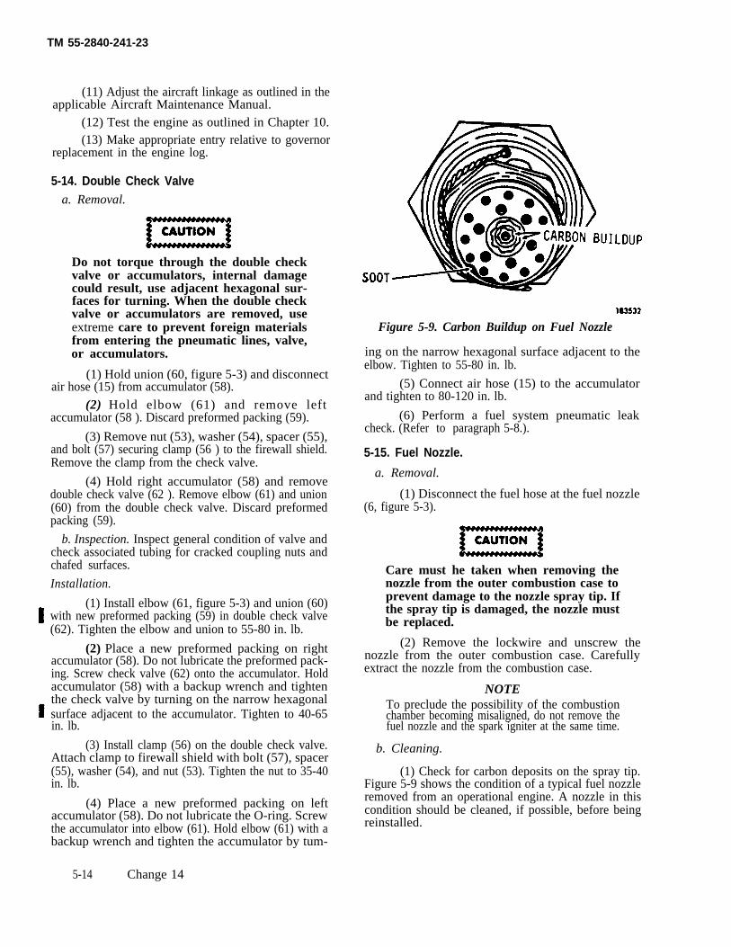
TM 55-2840-241-23
(11) Adjust the aircraft linkage as outlined in theapplicable Aircraft Maintenance Manual.
(12) Test the engine as outlined in Chapter 10.(13) Make appropriate entry relative to governor
replacement in the engine log.
5-14. Double Check Valvea. Removal.
Do not torque through the double checkvalve or accumulators, internal damagecould result, use adjacent hexagonal sur-faces for turning. When the double checkvalve or accumulators are removed, useextreme care to prevent foreign materialsfrom entering the pneumatic lines, valve,or accumulators.
(1) Hold union (60, figure 5-3) and disconnectair hose (15) from accumulator (58).
(2) Hold elbow (61) and remove leftaccumulator (58 ). Discard preformed packing (59).
(3) Remove nut (53), washer (54), spacer (55),and bolt (57) securing clamp (56 ) to the firewall shield.Remove the clamp from the check valve.
(4) Hold right accumulator (58) and removedouble check valve (62 ). Remove elbow (61) and union(60) from the double check valve. Discard preformedpacking (59).
b. Inspection. Inspect general condition of valve andcheck associated tubing for cracked coupling nuts andchafed surfaces.
Installation.
(1) Install elbow (61, figure 5-3) and union (60)with new preformed packing (59) in double check valve(62). Tighten the elbow and union to 55-80 in. lb.
(2) Place a new preformed packing on rightaccumulator (58). Do not lubricate the preformed pack-ing. Screw check valve (62) onto the accumulator. Holdaccumulator (58) with a backup wrench and tightenthe check valve by turning on the narrow hexagonalsurface adjacent to the accumulator. Tighten to 40-65in. lb.
(3) Install clamp (56) on the double check valve.Attach clamp to firewall shield with bolt (57), spacer(55), washer (54), and nut (53). Tighten the nut to 35-40in. lb.
(4) Place a new preformed packing on leftaccumulator (58). Do not lubricate the O-ring. Screwthe accumulator into elbow (61). Hold elbow (61) with abackup wrench and tighten the accumulator by tum-
Figure 5-9. Carbon Buildup on Fuel Nozzle
ing on the narrow hexagonal surface adjacent to theelbow. Tighten to 55-80 in. lb.
(5) Connect air hose (15) to the accumulatorand tighten to 80-120 in. lb.
(6) Perform a fuel system pneumatic leakcheck. (Refer to paragraph 5-8.).
5-15. Fuel Nozzle.
a. Removal.
(1) Disconnect the fuel hose at the fuel nozzle(6, figure 5-3).
Care must he taken when removing thenozzle from the outer combustion case toprevent damage to the nozzle spray tip. Ifthe spray tip is damaged, the nozzle mustbe replaced.
(2) Remove the lockwire and unscrew thenozzle from the outer combustion case. Carefullyextract the nozzle from the combustion case.
NOTETo preclude the possibility of the combustionchamber becoming misaligned, do not remove thefuel nozzle and the spark igniter at the same time.
b. Cleaning.
(1) Check for carbon deposits on the spray tip.Figure 5-9 shows the condition of a typical fuel nozzleremoved from an operational engine. A nozzle in thiscondition should be cleaned, if possible, before beingreinstalled.
5-14 Change 14
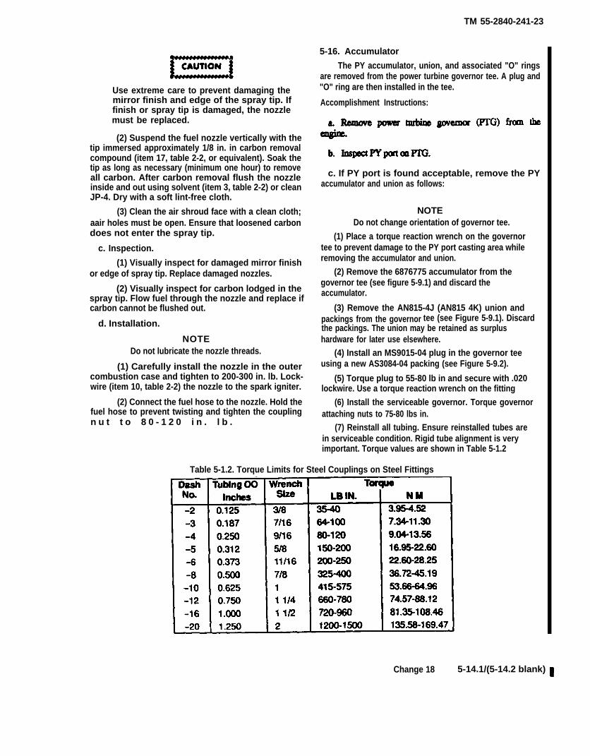
TM 55-2840-241-23
Use extreme care to prevent damaging themirror finish and edge of the spray tip. Iffinish or spray tip is damaged, the nozzlemust be replaced.
(2) Suspend the fuel nozzle vertically with thetip immersed approximately 1/8 in. in carbon removalcompound (item 17, table 2-2, or equivalent). Soak thetip as long as necessary (minimum one hour) to removeall carbon. After carbon removal flush the nozzleinside and out using solvent (item 3, table 2-2) or cleanJP-4. Dry with a soft lint-free cloth.
(3) Clean the air shroud face with a clean cloth;aair holes must be open. Ensure that loosened carbondoes not enter the spray tip.
c. Inspection.
(1) Visually inspect for damaged mirror finishor edge of spray tip. Replace damaged nozzles.
(2) Visually inspect for carbon lodged in thespray tip. Flow fuel through the nozzle and replace ifcarbon cannot be flushed out.
d. Installation.
NOTEDo not lubricate the nozzle threads.
(1) Carefully install the nozzle in the outercombustion case and tighten to 200-300 in. lb. Lock-wire (item 10, table 2-2) the nozzle to the spark igniter.
(2) Connect the fuel hose to the nozzle. Hold thefuel hose to prevent twisting and tighten the couplingn u t t o 8 0 - 1 2 0 i n . l b .
5-16. Accumulator
The PY accumulator, union, and associated "O" ringsare removed from the power turbine governor tee. A plug and"O" ring are then installed in the tee.
Accomplishment Instructions:
c. If PY port is found acceptable, remove the PYaccumulator and union as follows:
NOTEDo not change orientation of governor tee.
(1) Place a torque reaction wrench on the governortee to prevent damage to the PY port casting area whileremoving the accumulator and union.
(2) Remove the 6876775 accumulator from thegovernor tee (see figure 5-9.1) and discard theaccumulator.
(3) Remove the AN815-4J (AN815 4K) union andpackings from the governor tee (see Figure 5-9.1). Discardthe packings. The union may be retained as surplushardware for later use elsewhere.
(4) Install an MS9015-04 plug in the governor teeusing a new AS3084-04 packing (see Figure 5-9.2).
(5) Torque plug to 55-80 lb in and secure with .020lockwire. Use a torque reaction wrench on the fitting
(6) Install the serviceable governor. Torque governorattaching nuts to 75-80 lbs in.
(7) Reinstall all tubing. Ensure reinstalled tubes arein serviceable condition. Rigid tube alignment is veryimportant. Torque values are shown in Table 5-1.2
Table 5-1.2. Torque Limits for Steel Couplings on Steel Fittings
Change 18 5-14.1/(5-14.2 blank)

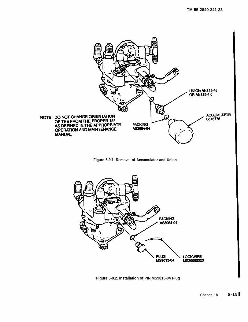
TM 55-2840-241-23
Figure 5-9.1. Removal of Accumulator and Union
Figure 5-9.2. Installation of PIN MS9015-04 Plug
Change 18 5 -15
TM 55-2840-241-23
5-17. Fuel System Tubes.
a. Removal. Observe the following precautions whenremoving tubes.
(1) When loosening a coupling nut, always use a backup wrench on the mating fitting to prevent thefitting from turning.
(2) Always use the proper size wrench to preventrounding off the hex corners.
(3) Attach the wrench to the fitting or couplingnut in a manner that will prevent crushing of the fittingor coupling nut.
(4) Never use a pipe wrench, pliers, or vise gripson a coupling nut or fitting.
b. Cleaning. Flush tubes with solvent (item 3, table2-2) and blow dry.
c. Inspection. Inspect and reject tubes for the follow-ing damage.
(1) Kinks or dents which could obstruct fuelflow. Dents are allowable up to 0.015 in.
(2) Cracked or broken tubes or coupling nuts.(3) Cross-threaded, crushed, or otherwise dam-
aged coupling nuts.(4) Chafing within clamp areas in excess of
0.010 in. deep. Chafing is not allowed at or near theflared tubing end.
(5) Nicks which exceed 0.010 in. deep.d. Installation.
(1) Observe the precautions listed in removalwhen installing the fuel tubes.
(2) Tighten No. 4 size coupling nuts 80 to 120in. lb. and No. 5 size coupling nuts 150 to 200 in. lb.
(3) Rigid steel tubing must align with its matingfittings in the free state such that both coupling nuts willengage two full threads of their mating fittings with lightfinger pressure. The tube must not be stretched duringfinal tightening of the coupling nuts. Adjustments maybe made by bending the tube at the principal bend orbends. All bending must be accomplished with the tuberemoved from the engine. Flattening effects as a resultof reforming shall not exceed 15 percent of the tube OD.
5-17.1 Fuel Check Valve.
a. Removal.
(1) Disconnect Fire Shield to Fuel Nozzle Hose(5, Figure 5-3) from fuel nozzle (6) and fuel check valve(1).
(2) Disconnect fuel control-to-firewall shieldtube (4) from Fuel Check Valve (1).
(3) Remove nut (3) washer (2) and check valve(1) from the firewall shield.
b. Inspection.
Visually inspect general condition of valve andcheck associated tubing for cracked or broken tubes orcoupling nuts.
c. Installation.
(1) Install the check valve (1) and washer (2) inthe fireshield. Install from the aft side with arrow point-ing rearward. Secure the valve with washer (2) and nut(3). Tighten 55-80 in. lb.
(2) Install fuel control to check valve tube (4)an fuel nozzle to check valve hose (5). Tighten cou-pling muts to 80-120 in. lb.
Section III. LUBRICATION SYSTEM
Failure to properly install, align andtighten oil fittings and tubes could re-sult in an engine failure.
5-18. Scope.
Lubrication system servicing includes cleaning andinspecting the magnetic chip detectors and oil pressureregulator, changing the system oil, cleaning the oil filter,removing and installing the oil filter housing, oil pres-sure reducer, and lube oil check valves. In adition, itincludes adjusting the oil pressure regulating valve andthe scavenge oil flow check.
5-19. Use of Oils.
NOTE
It is not advisable to mix MIL-L-7808 andML-L-23699 oils except in cases of emer-gency. If it becomes necessary, the systemmust be flushed within 6 hours of operation.(Refer to paragraph 5-21.)
NOTENearly all present day lube oils contain anti-foam additives which can settle to the bottomof the container. Thoroughly shake (agitate)the container prior to adding oil to the systemeither at an oil change or during routineservicing.
a. Use of MIL-L-23699 oil is authorized and directedfor ambient temperatures abouve minus 25°F.
5-16 Change 14
TM 55-2840-241-23
b. Use of MIL-L-7808 oil is specified for op-eration in ambient temperatures below minus 25°F.This oil may also be used when MIL-L-23699 oil isnot available.
5-20. Oil Change Procedure.
Drain and refill the lubrication system after each 200 hours of engine operations as follows:
g. Motor the engine with the starter until posi-tive oil pressure indication is obtained. Do not exceedstarter limitations.
h. After all work is completed make a groundrun, check for leaks and monitor oil pressure for thefirst five minutes of engine operation. Check and re-service the oil tank to the proper level.
5-21. Oil Changeover Procedure.a . Drain the oil tank.
b. Remove the magnetic chip detector from thebottom of the gearbox and drain residual oil. (Refer toparagraph 5-24.)
Remove and cIean or replace the oil filter,(Refer to paragraph 5-25.)
d. Refill the oil tank with engine oil (item 7 or8, table 2-2).
e. Remove and clean the magnetic chip detec-tor on the forwardside of the gearbox (refer to para-graph 5-24). While both magnetic plugs are removed,motor the engine with the starter and permit a smallamount of oil (1 or 2 ounces) to flow from the open-ings in the gearbox. This will assist in rinsing thegearbox of carbon particles. Reinstall the cleanedmagnetic plugs.
f. Refer to figure 5-10.1, Loosen clamp nut,then fittings and remove the line going to the “T” fit-tings that feeds oil to the number six and seven bear-ing. Pressure Oil Tube 6871470. Remove the small oilscreen, 6840476 (Pressure Oil Fittings Screen Assem-bly). Motor the engine with the starter and permit asmall amount of oil (1 or 2 ounces) to come out theend of the oil tube. Clean and reinstall the screen andtube assembly. Tighten pressure oil tube coupling nutsto 80 to 120 in. lb. Tighten clamp nuts to 35 to 40 in.lb.
When changing over from MIL-L-7808 oilto MIL-L-23699 oil or vice versa, proceed as fol-lows:
a. Drain the oil tank, system components andpiping, and engine gearbox as completely as possible.
Remove and clean or replace the oil filter.(Refer to paragraph 5-25.)
c. Remove, inspect, and clean the magneticchip detectors.
d. Fill the oil tank with the desired lubricatingoil (item 7 or 8, table 2-2).
e. Motor the engine to pump oil through thesystem. Check the tank oil level and add oil as re-quired. Repeat the motoring cycle until the tank oillevel does not change.
f. Run the engine for 30 minutes to one hourand shut down.
g. Inspect and clean or replace the oil filter.
(1) If the filter was heavily contaminated,accomplish steps h through 1.
Change 18 5-16.1/(5-16.2 blank)

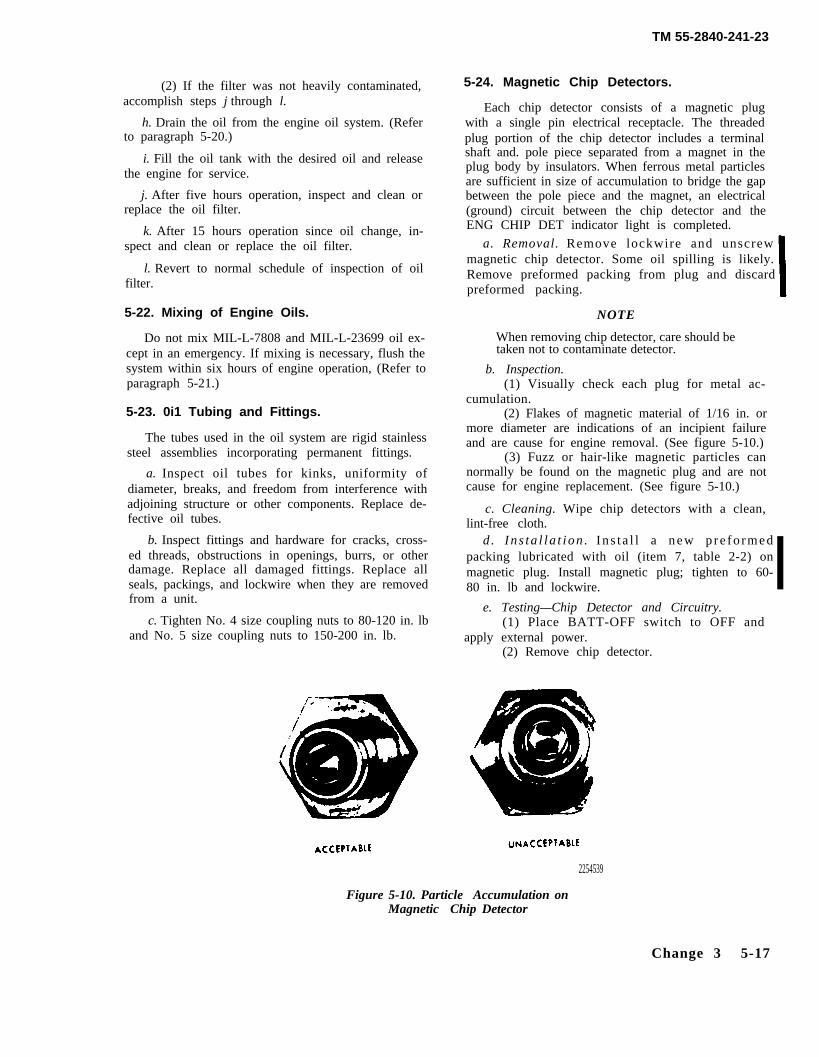
TM 55-2840-241-23
(2) If the filter was not heavily contaminated,accomplish steps j through l.
h. Drain the oil from the engine oil system. (Referto paragraph 5-20.)
i. Fill the oil tank with the desired oil and releasethe engine for service.
j. After five hours operation, inspect and clean orreplace the oil filter.
k. After 15 hours operation since oil change, in-spect and clean or replace the oil filter.
l. Revert to normal schedule of inspection of oilfilter.
5-22. Mixing of Engine Oils.
Do not mix MIL-L-7808 and MIL-L-23699 oil ex-cept in an emergency. If mixing is necessary, flush thesystem within six hours of engine operation, (Refer toparagraph 5-21.)
5-23. 0i1 Tubing and Fittings.
The tubes used in the oil system are rigid stainlesssteel assemblies incorporating permanent fittings.
a. Inspect oil tubes for kinks, uniformity ofdiameter, breaks, and freedom from interference withadjoining structure or other components. Replace de-fective oil tubes.
b. Inspect fittings and hardware for cracks, cross-ed threads, obstructions in openings, burrs, or otherdamage. Replace all damaged fittings. Replace allseals, packings, and lockwire when they are removedfrom a unit.
c. Tighten No. 4 size coupling nuts to 80-120 in. lband No. 5 size coupling nuts to 150-200 in. lb.
5-24. Magnetic Chip Detectors.
Each chip detector consists of a magnetic plugwith a single pin electrical receptacle. The threadedplug portion of the chip detector includes a terminalshaft and. pole piece separated from a magnet in theplug body by insulators. When ferrous metal particlesare sufficient in size of accumulation to bridge the gapbetween the pole piece and the magnet, an electrical(ground) circuit between the chip detector and theENG CHIP DET indicator light is completed.
a. Removal. Remove lockwire and unscrewmagnetic chip detector. Some oil spilling is likely.Remove preformed packing from plug and discardpreformed packing.
NOTE
When removing chip detector, care should betaken not to contaminate detector.
b. Inspection.(1) Visually check each plug for metal ac-
cumulation.(2) Flakes of magnetic material of 1/16 in. or
more diameter are indications of an incipient failureand are cause for engine removal. (See figure 5-10.)
(3) Fuzz or hair-like magnetic particles cannormally be found on the magnetic plug and are notcause for engine replacement. (See figure 5-10.)
c. Cleaning. Wipe chip detectors with a clean,lint-free cloth.
d . I n s ta l l a t i on . In s t a l l a new p re fo rmedpacking lubricated with oil (item 7, table 2-2) onmagnetic plug. Install magnetic plug; tighten to 60-80 in. lb and lockwire.
e. Testing—Chip Detector and Circuitry.(1) Place BATT-OFF switch to OFF and
apply external power.(2) Remove chip detector.
2254539
Figure 5-10. Particle Accumulation onMagnetic Chip Detector
Change 3 5-17
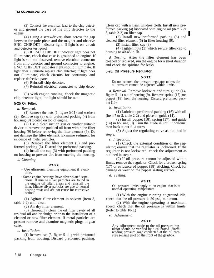
TM 55-2840-241-23
(3) Connect the electrical lead to the chip detect-or and ground the case of the chip detector to theengine.
(4) Using a screwdriver, short across the gapbetween the pole piece and the magnet and observeENC. CHIP DET indicator light. If light is on, circuitand detector test good.
(5) If ENC. CHIP DET indicator light does notilluminate, check that case is grounded to engine. Iflight is still not observed, remove electrical connectorfrom chip detector and ground connector to engine.ENC. CHIP DET indicator light should illuminate. Iflight does illuminate replace chip detector; if light doesnot illuminate, check circuits for continuity andreplace defective parts.
(6) Reinstall chip detector.(7) Reinstall electrical connector to chip detec-
tor.(8) With engine running, check the magnetic
chip detector light; the light should be out.
5-25 Oil Filter.a. Removal.
(1) Remove the nuts (1, figure 5-11) and washers(2). Remove cap (3) with preformed packing (4) fromhousing (9) located on top of engine.
(2) Use a clean suction gun or another suitabledevice to remove the puddled oil from within the filterhousing (9) before removing the filter element (5). Donot damage the filter element. Examine sediment forevidence of metal particles.
(3) Remove the filter element (5) and pre-formed packing (6). Discard the preformed packing.
(4) Install the cap (3) with preformed packingon housing to prevent dirt from entering the housing.
b. Cleaning.
NOTE• Use ultrasonic cleaning equipment if avail-
able.• Some engine bearings have silver-plated sepa-
rators, If minute silver particles are found inthe engine oil filter, clean and reinstall thefilter. Minute silver particles are due to normalbearing wear and are not cause for correctiveaction.
(1) Agitate filter element in solvent (item 3,table 2-2) until clean.
(2) Air dry filter element.(3) Thoroughly clean the oil filter cavity of all
residual oil and/or sludge prior to the installation of acleaned or new filter element. If metal particles arepresent remove and examine magnetic plugs in gearcase.
c. Installation.(1) Remove cap (3, figure 5-11 ) with preformed
packing from housing. Discard preformed packing.
Clean cap with a clean lint-free cloth. Install new pre-formed packing (4) lubricated with engine oil (item 7 or8, table 2-2) on filter cap.
(2) Install new preformed packing (6) andcleaned filter element (5) in filter housing (9).
(3) Install filter cap (3).(4) Tighten nuts (1) which secure filter cap to
housing to 40-45 in. lb.
d. Testing. After the filter element has beencleaned or replaced, run the engine for a short durationand check the splitline for leaks.
5-26. Oil Pressure Regulator.
NOTEDo not remove the pressure regulator unless theoil pressure cannot be adjusted within limits.
a. Removal. Remove lockwire and turn guide (14,figure 5-11) out of housing (9). Remove spring (17) andpoppet (18) from the housing. Discard preformed pack-ing (16).
b. Installation.(1) Lubricate preformed packing (16) with oil
(item 7 or 8, table 2-2) and place on guide (14).(2) Install poppet (18), spring (17), and guide
(14) in housing (9). Turn the guide in until it bottoms;then back it out 5 ½ turns.
(3) Adjust the regulating valve as outlined instep e.
c. Inspection.(1) Check the external condition of the reg-
ulator; ensure that the regulator is lockwired. If theregulator is not lockwired, check the adjustment asoutlined in step e.
(2) If oil pressure cannot be adjusted withinlimits, remove the regulator. Check for a broken spring(17) or evidence of poppet (18) sticking. Check fordamage or wear on the poppet seating surface.
d. Testing.
NOTEOil pressure limits apply to an engine that is atnormal operating temperature.
(1) With the engine running at ground idle,check that the oil pressure is 50 psig minimum.
(2) With the engine operating at maximumspeed, check that the oil pressure is within limits.(Refer to table 10-1.)
e. Adjustment.
NOTEAny adjustment made to the oil pressure reg-ulator should be verified by a calibrated direct-reading pressure gage connected at the oil pres-sure sensing port on the front of the gearbox.
5-18 Change 14
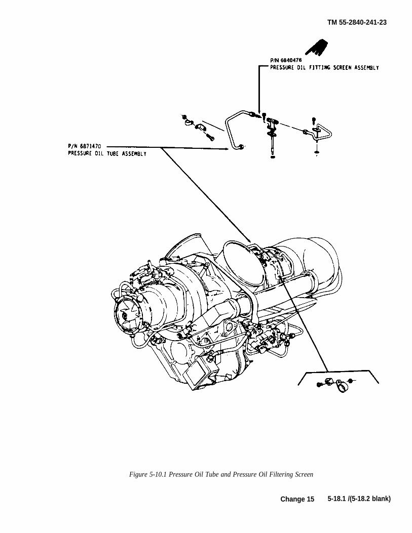
TM 55-2840-241-23
Figure 5-10.1 Pressure Oil Tube and Pressure Oil Filtering Screen
Change 15 5-18.1 /(5-18.2 blank)

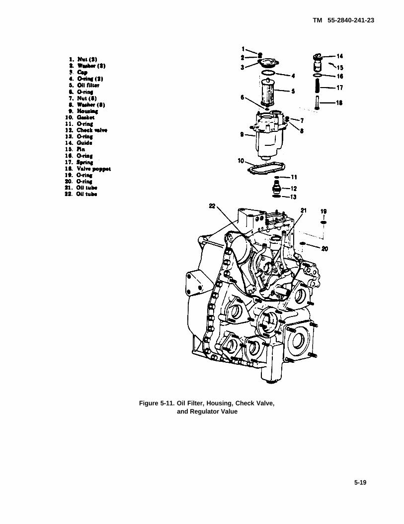
TM 55-2840-241-23
Figure 5-11. Oil Filter, Housing, Check Valve,and Regulator Value
5-19
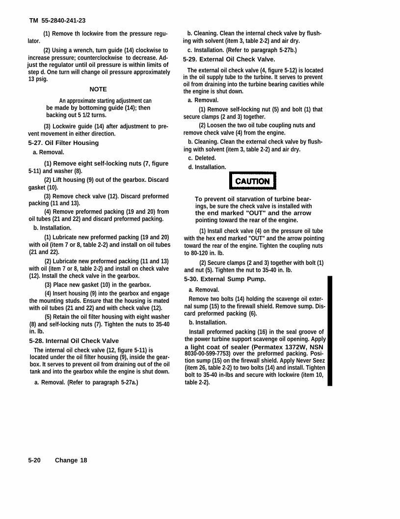
TM 55-2840-241-23
(1) Remove th lockwire from the pressure regu-lator.
(2) Using a wrench, turn guide (14) clockwise toincrease pressure; counterclockwise to decrease. Ad-just the regulator until oil pressure is within limits ofstep d. One turn will change oil pressure approximately13 psig.
NOTE
An approximate starting adjustment canbe made by bottoming guide (14); thenbacking out 5 1/2 turns.
(3) Lockwire guide (14) after adjustment to pre-vent movement in either direction.5-27. Oil Filter Housing
a. Removal.
(1) Remove eight self-locking nuts (7, figure5-11) and washer (8).
(2) Lift housing (9) out of the gearbox. Discardgasket (10).
(3) Remove check valve (12). Discard preformedpacking (11 and 13).
(4) Remove preformed packing (19 and 20) fromoil tubes (21 and 22) and discard preformed packing.
b. Installation.(1) Lubricate new preformed packing (19 and 20)
with oil (item 7 or 8, table 2-2) and install on oil tubes(21 and 22).
(2) Lubricate new preformed packing (11 and 13)with oil (item 7 or 8, table 2-2) and install on check valve(12). Install the check valve in the gearbox.
(3) Place new gasket (10) in the gearbox.(4) Insert housing (9) into the gearbox and engage
the mounting studs. Ensure that the housing is matedwith oil tubes (21 and 22) and with check valve (12).
(5) Retain the oil filter housing with eight washer(8) and self-locking nuts (7). Tighten the nuts to 35-40in. lb.
5-28. Internal Oil Check ValveThe internal oil check valve (12, figure 5-11) is
located under the oil filter housing (9), inside the gear-box. It serves to prevent oil from draining out of the oiltank and into the gearbox while the engine is shut down.
a. Removal. (Refer to paragraph 5-27a.)
b. Cleaning. Clean the internal check valve by flush-ing with solvent (item 3, table 2-2) and air dry.
c. Installation. (Refer to paragraph 5-27b.)5-29. External Oil Check Valve.
The external oil check valve (4, figure 5-12) is locatedin the oil supply tube to the turbine. It serves to preventoil from draining into the turbine bearing cavities whilethe engine is shut down.
a. Removal.(1) Remove self-locking nut (5) and bolt (1) that
secure clamps (2 and 3) together.(2) Loosen the two oil tube coupling nuts and
remove check valve (4) from the engine.b. Cleaning. Clean the external check valve by flush-
ing with solvent (item 3, table 2-2) and air dry.c. Deleted.d. Installation.
To prevent oil starvation of turbine bear-ings, be sure the check valve is installed withthe end marked "OUT" and the arrowpointing toward the rear of the engine.
(1) Install check valve (4) on the pressure oil tubewith the hex end marked "OUT" and the arrow pointingtoward the rear of the engine. Tighten the coupling nutsto 80-120 in. lb.
(2) Secure clamps (2 and 3) together with bolt (1)and nut (5). Tighten the nut to 35-40 in. lb.5-30. External Sump Pump.
a. Removal.Remove two bolts (14) holding the scavenge oil exter-
nal sump (15) to the firewall shield. Remove sump. Dis-card preformed packing (6).
b. Installation.Install preformed packing (16) in the seal groove of
the power turbine support scavenge oil opening. Applya light coat of sealer (Permatex 1372W, NSN8030-00-599-7753) over the preformed packing. Posi-tion sump (15) on the firewall shield. Apply Never Seez(item 26, table 2-2) to two bolts (14) and install. Tightenbolt to 35-40 in-lbs and secure with lockwire (item 10,table 2-2).
5-20 Change 18
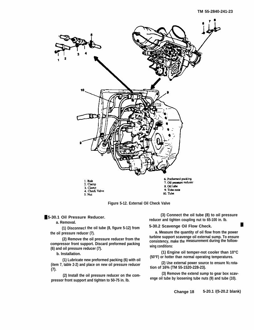
TM 55-2840-241-23
Figure 5-12. External Oil Check Valve
5-30.1 Oil Pressure Reducer.a. Removal.
(1) Disconnect the oil tube (8, figure 5-12) fromthe oil pressure reducer (7).
(2) Remove the oil pressure reducer from thecompressor front support. Discard preformed packing(6) and oil pressure reducer (7).
b. lnstallation.
(1) Lubricate new preformed packing (6) with oil(item 7, table 2-2) and place on new oil pressure reducer(7).
(2) Install the oil pressure reducer on the com-pressor front support and tighten to 50-75 in. lb.
(3) Connect the oil tube (8) to oil pressurereducer and tighten coupling nut to 65-100 in. lb.
5-30.2 Scavenge Oil Flow Check.a. Measure the quantity of oil flow from the power
turbine support scavenge oil external sump. To ensureconsistency, make the measurement during the follow-wing conditions:
(1) Engine oil temper-not cooler than 10°C(50°F) or hotter than normal operating temperatures.
(2) Use external power source to ensure N1 rota-tion of 16% (TM 55-1520-228-23).
(3) Remove the extend sump to gear box scav-enge oil tube by loosening tube nuts (9) and tube (10).
Change 18 5-20.1 /(5-20.2 blank)

TM 55-2840-241-23
At the external sump and fitting, connect clear tube(item 38, table 2-2) to oil sump scavenge fitting todirect oil flow.
(4) Open ignition circuit breakers and make apreliminary rotation of the engine to 15 seconds toensure that the oil lines and external sump are full ofoil and there is oil flow.
b. With ignition circuit breakers open, rotateengine for exactly 15 seconds. At least 16% N1 speedmust be achieved. Collect and measure oil flow duringthe 15 seconds of rotation period and during coast downuntil engine stops. It is not necessary to collect andmeasure minor drips.
c. A flow of less than 90 cc (3 oz.) indicates a signifi-cant restriction of the oil nozzle and/or passages and iscause for engine removal.
NOTECleaning of lubrication system internal compo-nents should only be done at Depot Level Mainte-nance.
d. Remove oil drain tube.
e. Install the oil scavenge tube to the externalsump. Tighten coupling nuts (9) to 150-200 inch lbs.
f. Pilot: Check run engine to determine presence ofoil leakage at power turbine support pressure and scav-enge oil system components.
Change 14 5-21
TM 55-2840-241-23
5-31. Scope.
Section IV. ANTI-ICING AND BLEED AIR SYSTEMS
Failure to properly install, align, andtighten air fittings and tubes could resultin an engine failure.
Anti-icing and bleed air systems servicing includesreplacing and testing the compressor bleed valve andanti-icing air valve. In addition, it includes anti-icingvalve repair.
5-32. Anti-icing Air Valve.
a. Removal.
(1) Disconnect air tubes (23 and 26, figure 5-13)at the anti-icing air valve (29). Disconnect the air tubesat the compressor front support only if necessary.
(2) Disconnect the aircraft linkage from thevalve lever.
(3) Remove lockwire, loosen jam nut (24), andunscrew the valve from the diffuser scroll. Discardpreformed packing (25).
b. Testing.
(1) Apply 100 psig air pressure to the Valve Inletwith a 0.025 inch orifice installed between the air sourceand the valve inlet after installing gauges to monitor thepressure on both sides of the orifice.
(2) Apply 3.75 pounds maximum force to hold thelever in the closed position.
(3) Allow air pressure on both sides of the orificeto stabilize, maintaining pressure at the orifice inlet at 100psig.
(4) If the valve leakage is excessive such that thepressure downstream of the orifice decreases, replace thevalve and retest.
c. Anti-icing Valve Poppet Seat Replacement.Replace the Teflon poppet seat of the anti-icing valve asfollows:
(1) Remove the cotter pin (17, figure 5-13),washer (16), and pin (14 ). Detach the actuating lever(13) from the valve. Discard the cotter pin.
(2) Remove the lockwire and unscrew the pop-pet guide (15) from the valve body (22). Separate thepoppet (18) from the body.
(3) Remove the screw (21) and separate the pop-pet seat (20) from the poppet.
(4) Clean valve component in cleaning solvent(3, table 2-2).
(5) Inspect valve components per table 5-2.(6) Install the replacement poppet seat (20).
Retain the seat with screw (21). Stake the screwsecurely. (See figure 5-14. )
5-22 Change 15
(7) Insert the poppet and seat into the valvebody (22, figure 5-13) and screw the poppet guide (15)onto the body. Tighten the coupling nut to 65-75 in. lb.Do not lockwire at this time.
(8) Align the actuating lever (13) with the holein the poppet guide (notch in the lever toward theguide) and insert the pin (14). Secure the pin withwasher (16) and new cotter pin (17).
(9) Recheck the valve for leakage. Replacevalve assembly if leakage is still excessive.
d. Installation.(1) Place new preformed packing (25) with
backed-off jam nut (24) on anti-icing valve (29). Applyantiseize compound (item 15, table 2-2) lightly to thethreads and install the valve in the diffuser scroll. Donot tighten jam nut (24).
(2) Connect air tubes (23 and 26) to the valve.Tighten the coupling nuts to 150-200 in. lb. Tightenjam nut (24) to 100-150 in. lb. and lockwire (item 10,table 2-2).
(3) Loosen poppet guide (15) and position lever(13) parallel with the vertical centerline of the engine.Tighten the poppet guide to 65-75 in. lb. and lockwire(item 10, table 2-2).
5-33. Compressor Bleed Valve.a. Testing. Test the compressor bleed valve while
installed on the engine. Turn off all bleed air.(1) Pilot and observer use helmets and exten-
sion cord to passenger communication box.(2) Observer use flashlight to view operation of
the bleed valve.(3) Run up engine to 100% N2 and observe com-
pressor bleed valve operation. Valve should not be fullyclosed.
(4) Apply collective until valve is fully closed.
NOTEIt may be necessary to increase aircraft grossweight to accomplish run-up. If passengers areused to increase gross weight, ensure that seatbelts are fastened for all occupants.
Do not have personnel stand on aircraft skid tubes to increase gross weight.
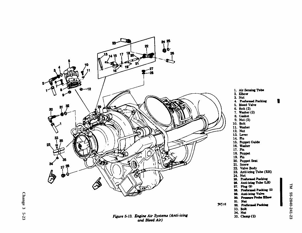
TM
55-2840-241-23
Figure
5-13. E
ngine A
ir System
s (A
nti-icing and
Bleed
Air)
Change 3 5-23
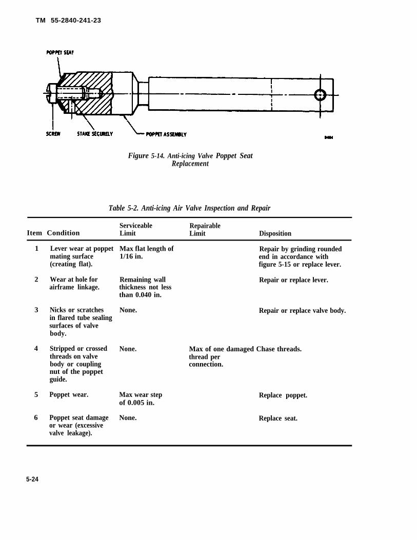
TM 55-2840-241-23
Figure 5-14. Anti-icing Valve Poppet SeatReplacement
Table 5-2. Anti-icing Air Valve Inspection and Repair
Serviceable RepairableItem Condition Limit Limit Disposition
1
2
3
4
5
6
Lever wear at poppetmating surface(creating flat).
Wear at hole forairframe linkage.
Nicks or scratchesin flared tube sealingsurfaces of valvebody.
Stripped or crossedthreads on valvebody or couplingnut of the poppetguide.
Poppet wear.
Poppet seat damage
Max flat length of Repair by grinding rounded1/16 in. end in accordance with
figure 5-15 or replace lever.
Remaining wall Repair or replace lever.thickness not lessthan 0.040 in.
None. Repair or replace valve body.
None. Max of one damaged Chase threads.thread perconnection.
Max wear step Replace poppet.of 0.005 in.
None. Replace seat.or wear (excessivevalve leakage).
5-24
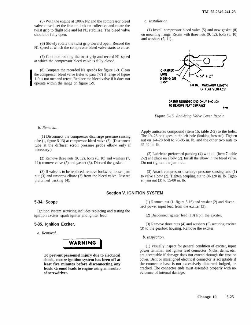
TM 55-2840-241-23
(5) With the engine at 100% N2 and the compressor bleedvalve closed, set the friction lock on collective and rotate thetwist grip to flight idle and let N1 stabilize. The bleed valveshould be fully open.
(6) Slowly rotate the twist grip toward open. Record theN1 speed at which the compressor bleed valve starts to close.
(7) Continue rotating the twist grip and record N1 speedat which the compressor bleed valve is fully closed.
(8) Compare the recorded N1 speeds for figure 1-9. Cleanthe compressor bleed valve (refer to para 7-7) if range of figure1-9 is not met and retest. Replace the bleed valve if it does notoperate within the range on figure 1-9.
c. Installation.
(1) Install compressor bleed valve (5) and new gasket (8)on mounting flange. Retain with three nuts (9, 12), bolts (6, 10)and washers (7, 11).
Figure 5-15. Anti-icing Valve Lever Repair
b. Removal.
(1) Disconnect the compressor discharge pressure sensingtube (1, figure 5-13) at compressor bleed valve (5). (Disconnecttube at the diffuser scroll pressure probe elbow only ifnecessary.)
(2) Remove three nuts (9, 12), bolts (6, 10) and washers (7,11); remove valve (5) and gasket (8). Discard the gasket.
(3) If valve is to be replaced, remove lockwire, loosen jamnut (3) and unscrew elbow (2) from the bleed valve. Discardpreformed packing (4).
Apply antiseize compound (item 15, table 2-2) to the bolts.The 1/4-28 bolt goes in the left hole (looking forward). Tightennut on 1/4-28 bolt to 70-85 in. lb. and the other two nuts to35-40 in. lb.
(2) Lubricate preformed packing (4) with oil (item 7, table2-2) and place on elbow (2). Install the elbow in the bleed valve.Do not tighten the jam nut.
(3) Attach compressor discharge pressure sensing tube (1)to valve elbow (2). Tighten coupling nut to 80-120 in. lb. Tight-en jam nut (3) to 55-80 in. lb.
Section V. IGNITION SYSTEM
5-34. Scope
Ignition system servicing includes replacing and testing theignition exciter, spark igniter and igniter lead.
5-35. Ignition Exciter.
a. Removal.
To prevent personnel injury due to electricalshock, ensure ignition system has been off atleast five minutes before disconnecting anyleads. Ground leads to engine using an insulat-ed screwdriver.
(1) Remove nut (1, figure 5-16) and washer (2) and discon-nect power input lead from the exciter (3).
(2) Disconnect igniter lead (18) from the exciter.
(3) Remove three nuts (4) and washers (5) securing exciter(3) to the gearbox housing. Remove the exciter.
b. Inspection.
(1) Visually inspect for general condition of exciter, inputpower terminal, and igniter lead connector. Nicks, dents, etc.are acceptable if damage does not extend through the case orcover, Bent or misaligned electrical connector is acceptable ifthe connector base is not excessively distorted, bulged, orcracked. The connector ends must assemble properly with noevidence of internal damage.
Change 10 5-25
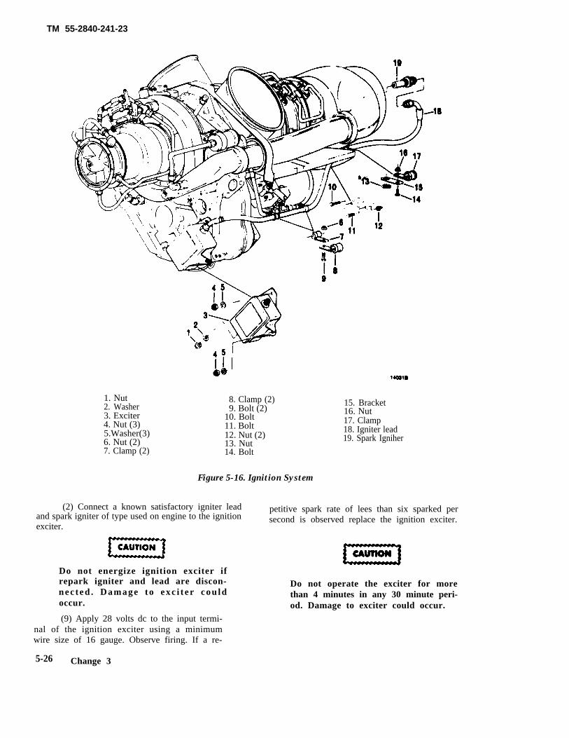
TM 55-2840-241-23
1. Nut2. Washer3. Exciter4. Nut (3)5.Washer(3)6. Nut (2)7. Clamp (2)
8. Clamp (2)9. Bolt (2)
10. Bolt11. Bolt12. Nut (2)13. Nut14. Bolt
Figure 5-16. Ignition System
(2) Connect a known satisfactory igniter leadand spark igniter of type used on engine to the ignitionexciter.
Do not energize ignition exciter ifrepark igniter and lead are discon-nec ted . Damage to exc i t er cou ldoccur.
(9) Apply 28 volts dc to the input termi-nal of the ignition exciter using a minimumwire size of 16 gauge. Observe firing. If a re-
15. Bracket16. Nut17. Clamp18. Igniter lead19. Spark Igniher
petitive spark rate of lees than six sparked persecond is observed replace the ignition exciter.
Do not operate the exciter for morethan 4 minutes in any 30 minute peri-od. Damage to exciter could occur.
5-26 Change 3
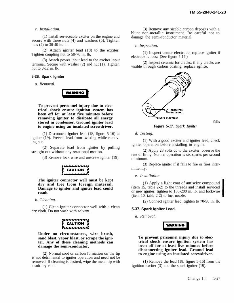
TM 55-2840-241-23
c. Installation.
(1) Install serviceable exciter on the engine andsecure with three nuts (4) and washers (5). Tightennuts (4) to 30-40 in. lb.
(2) Attach igniter lead (18) to the exciter.Tighten coupling nut to 50-70 in. lb.
(3) Attach power input lead to the exciter inputterminal. Secure with washer (2) and nut (1). Tightennut to 8-12 in. lb.
5-36. Spark Igniter
a. Removal.
To prevent personnel injury due to elec-trical shock ensure ignition system hasbeen off for at least five minutes beforeremoving igniter to dissipate all energystored in condenser. Ground igniter leadto engine using an insulated screwdriver.
(1) Disconnect igniter lead (18, figure 5-16) atigniter (19). Prevent lead from twisting while remov-ing nut.
(2) Separate lead from igniter by pullingstraight out without any rotational motion.
(3) Remove lock wire and unscrew igniter (19).
The igniter connector well must be keptdry and free from foreign material.Damage to igniter and igniter load couldresult.
b. Cleaning.
(1) Clean igniter connector well with a cleandry cloth. Do not wash with solvent.
Under no circumstances, wire brush,sand blast, vapor blast, or scrape the igni-ter. Any of these cleaning methods candamage the semi-conductor.
(2) Normal soot or carbon formation on the tipis not detrimental to igniter operation and need not beremoved. If cleaning is desired, wipe the metal tip witha soft dry cloth.
(3) Remove any sizable carbon deposits with ablunt non-metallic instrument. Be careful not todamage the semi-conductor material.
c. Inspection.
(1) Inspect center electrode; replace igniter ifelectrode is loose (See figure 5-17.)
(2) Inspect ceramic for cracks; if any cracks arevisible through carbon coating, replace ignite.
4364AFigure 5-17. Spark Igniter
d. Testing.
(1) With a good exciter and igniter lead, checkigniter operation before installing in engine.
(2) Apply 28 volts dc to the exciter; observe therate of firing. Normal operation is six sparks per secondminimum.
(3) Replace igniter if it fails to fire or fires inter-mittently.
e. Installation.
(1) Apply a light coat of antiseize compound(item 15, table 2-2) to the threads and install servicedor new igniter; tighten to 150-200 in. lb. and lockwire(item 10, table 2-2) to fuel nozzle.
(2) Connect igniter lead; tighten to 70-90 in. lb.
5-37. Spark Igniter Lead.
a. Removal.
To prevent personnel injury due to elec-trical shock ensure ignition system hasbeen off for at least five minutes beforedisconnecting igniter lead. Ground leadto engine using an insulated screwdriver.
(1) Remove the lead (18, figure 5-16) from theignition exciter (3) and the spark igniter (19).
Change 14 5-27
TM 55-2840-241-23
(2) Remove bolts (9) and nuts (6) securingclamps (7 and 8) together.
(3) Remove bolt (14) and nut (16) securingclamp (17) to bracket (15).
(4) Remove two bolts (10 and 11) and nuts (12)securing the lead to the fireshield. Remove the lead.
NOTEBolt (10) also secures the accumulator bracket andspacer to the fireshield.
b. Inspection.
(1) Inspect the outer part of the lead for braiddamage; replace lead if there are more than five brokenstrands in any localized area, the braided conduit ispunctured, or discolored and brittle from extreme heat.
(2} Inspect terminals of lead to ensure all partsare intact and no pitting is evident; replace lead if anypart is missing or pitting is present.
c. Installation
(1) Insert the igniter lead (18) through the holdin the fireshield. Secure the lead to the fireshield withbolt (11) and nut (12). Secure accumulator clamp,spacer, and igniter lead with bolt (10) and nut (12).Tighten the nuts to 35-40 in. lb.
(2) Connect the igniter lead to the ignitionexciter (3) and tighten the coupling nut to 50-70 in. lb.
(3) Connect the igniter lead to the spark igniter(19) and tighten the coupling nut to 70-90 in. lb.
(4) Secure the lead to the air tubing at thepower turbine governor with four clamps ( 7 and 8), two
bolts (9) and nuts (6). Tighten the nuts to 35-40 in. lb.(5) Secure the igniter lead to bracket (15) with
clamp (17), bolt (14) and nut (16). Tighten the nut to35-40 in. lb.
d. Ignition System Check. The following procedurecan be used to check the operation of the ignition sys-tem.
NOTETo preclude the possibility of the combustionchamber becoming misalined, do not remove thefuel nozzle and the spark igniter at the same time.
(1) Remove the spark igniter lead (18) fromspark igniter.
(2) Remove the spark igniter (19).
To prevent damage to the igniter, whenassembling or disassembling a lead andan igniter which is not installed on theengine, turn the lead nut and not the sparkigniter.
the
(3) Attach the spark igniter lead to the sparkigniter.
(4) Apply 28 volts dc across the ignition exciter.Observe or listen for spark.
(5) Install spark igniter and spark igniter leadon the engine. Tighten the spark igniter to 150-200 in.lb. and lockwire to the fuel nozzle. Tighten the lead to70-90 in. lb.
Section VI. MISCELLANEOUS ACCESSORIES
5-38. Burner Drain Valve.
a. Removal.
NOTEUse a wrench on the drain valve boss to offsettorque when removing or installing the valve.
(1) Remove lockwire and remove nut ( 16, figure3-8) from the drain valve (14). Disengage bracket (15)and remove the drain valve from the outer combustioncase. Discard preformed packing (13).
(2) Flush the valve with petroleum solvent(item 3, table 2-2). Pass solvent through the valve toensure that it is open.
(3) Blow dry with clean compressed air.
c. Testing.
Test the valve to ensure that it closes by applying airpressure (8 psig maximum) to the valve inlet or test asdescribed in paragraph 5-38 d (2).
b. Cleaning. d. Installation.
(1) Soak the valve in solvent (item 16, table 2-2). (1) Lubricate new preformed packing (13) withoil (item 7 or 8, table 2-2) and place on drain valve (14).Install the drain valve in the outer combustion case
5-28 Change 14
TM 55-2840-241-23
and tighten to 120-140 in. lb. Apply antiseize com-pound (item 15, table 2-2) to the threads on the outerend of the drain valve and install bracket (15) and nut(16). Tighten the nut to 55-80 in. lb. and lockwire (item32, table 2-2).
(2) Start the engine and check to ensure thatthe valve is closed. Replace the valve if it fails to close.
(3) Attach the drain hose to the valve.
5-39. Thermocouple Terminal Assembly.
a. Removal.(1) Remove the two nuts securing the thermo-
couple leads to the terminal assembly.
(2) Remove the two nuts and bolts securing theterminal assembly to the exhaust collector.
b. Installation.(1) Position the terminal assembly on the
exhaust collector with the large terminal to the top andsecure with two bolts and self-locking nuts. Tightenthe nuts to 35-40 in. lb.
(2) Attach the alumel leads to the top post onthe terminal assembly and secure with the No. 10-32alumel nut. Tighten the nut to 17-25 in. lb.
(3) Attach the chrome] leads to the bottom poston the terminal assembly and secure with the No. 8-32chromel nut. Tighten the nut to 17-25 in. lb.
Change 14 5-28. 1/(5-28.2 blank)

TM 55-2840-241-23
CHAPTER 6
ENGINE DISASSEMBLY
6-1. Scope.This chapter provide sequential disassembly pro-
cedures for major functional assemblies. Proceduresare provided for disassembly only to the extent neces-sary for Aviation Unit and Aviation IntermediateMaintenance activities to perform cleaning, inspec-tion, repair, and/or replacement of provisioned parts inaccordance with the Maintenance Allocation Chartand TM 55-2840-241-23P.
6-2. Compressor Case Half Removal.
One compressor case half may be removed to inspectthe rotor blades, stator vanes, plastic coating, and frontsupport welds. (Refer to paragraphs 7-9 thru 7-12.)Removal of the compressor case half is authorized onlyas a last resort to determine the cause of low engineperformance when foreign object damaged (FOD) issuspected or when sand erosion is suspected. Beforeremoving the case half ensure that low engine perfor-mance is not caused by a defective compressor bleedvalve or anti-icing valve, leaking scroll-to-rear diffuseror compressor discharge air tube seals, or a dirty com-pressor. REMOVAL OF THE COMPRESSOR CASEHALF TO PERFORM ROUTINEINSPECTIONS IS NOT PERMITTED.
PERIODIC
Remove only one case half at a time. DONOT remove both case halves at the sametime. Ensure that the removed case half isproperly reinstalled and that the bolts aretightened to the required torque valuesbefore any of the bolts on the other casehalf are loosened. Misalignment of thecompressor could result if both casehalves were removed simultaneously.(Refer to paragraph 8-2.)
a. Remove the compressor bleed valve. (Refer toparagraph 5-33.)
b. Remove the anti-icing air tubes (23, 26, figure5-13) between the anti-icing air valve and the com-pressor front support.
c. Mark the location of nameplate (8, figure 6-1)when the applicable compressor case half-to-front sup-port bolts (5) are to be removed. This is to ensure thatthe nameplate will be returned to the same location atassembly.
d. Remove one compressor case half (2) by remov-ing 16 horizontal splitline nuts (7) and bolts (1), fivecase half-to-front support nuts (3) and bolts (5), andeight case half-to-front diffuser nuts (6) and bolts (4).Lift the case half straight out.
Change 14 6-1
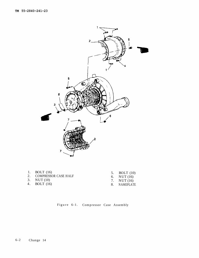
TM 55-2840-241-23
1. BOLT (16)2. COMPRESSOR CASE HALF3. NUT (10)4. BOLT (16)
5. BOLT (10)6. NUT (16)7. NUT (16)8. NAMEPLATE
F i g u r e 6 - 1 . Compressor Case Assembly
6 - 2 Change 14
TM 55-2840-241-23
CHAPTER 7
CLEANING, INSPECTION AND REPAIR
Section I. CLEANING
7-1. General.
Use care in separating metals for cleaning. Observethe following general cleaning precautions.
Petroleum solvent vapors are toxic. Provideadequate ventilation for personnel using it.
a. Petroleum solvent (item 3, table 2-2) is the clean-ing solvent recommended for nonferrous parts (clean”ers for steel will damage nonferrous parts.) Do not userust preventives on magnesium and aluminum parts.
b. Clean aluminum-coated steel parts with carbon re-moval compound (item 17, table 2-2). Rinse the partwith water and dry with an air blast.
c. Clean steel parts with cresol base cleaning com-pound (item 18, table 2-2). Rinse the part thoroughlywith hot water. Coat parts with a compound of one partrust preventive (item 19. table 2-2) and the parts oil(item 20, table 2-2).
7-2. Cleaning Engine Exterior Surfaces
Flush or spray wash external surfaces with petroleumsolvent (item 3A, table 2-2) to remove grease. oil. anddirt. Ensure that all openings are plugged or covered be-fore cleaning.
Engine thermocouples should never be satu-rated or sprayed with cleaning solvents Liq-uid cleaning solvents will penetrate the po-rous magnesium oxide insulation. Engineheat will vaporize the solvents leaving a resi-due containing carbon which causes a lowresistance to ground.
7-3. Compressor Cleaning to Restore LostPerformance.
Allow the engine to cool for a minimum of 45minutes prior to spraying the compressor.
Mandatory cooling period is required toprevent warpage to internal engine compo-nents.
Buildup of dirt in the compressor can result in a seri-ous loss of engine power and performance. Lost perfor-mance may be restored by flushing the installed enginewith a water/solvent solution as follows:
Methanol is flammable; it should not beused if the ambient temperature is above4°C (40°F), its vapor is harmful; it could befatal or cause blindness if swallowed. Keepit away from open flame and avoid pro-longed breathing of the vapor.
NOTEOnce the cleaning procedure is started, it mustbe carried through to completion withoutdelay. At ambient temperatures below 4“ C(40°F) and above -29°C (-20°F), use a 40 per-cent Methanol (item 34. table 2-2),60 percentwater mixture, in place of fresh water. Thetemperature of the wash solution should not bebelow 4°C (40°F), ideally it should be be-tween 21-26°CC (70-80°F). TO avoid spray-ing concentrated Methanol. which is combus-tible. mix the solution thoroughly.
NOTEB&B 3100 (MIL-C-85704, Type I is the pri-mary cleaner for Army turbine engines and re-mains an approved cleaner for locales whereenvironmental restrictions permit. Enginecleaners that conform to MIL-C-85704. TypeII and Type IIA are also acceptable enginecleaners and meet EPA environmental require-ments. Continue use of B & B 3100 where notrestricted. Where restrictions apply useMIL-C-85704. Type II and Type IIA cleaners.Approved Type II and Type IIA cleaners shallbe used in accordamce with the existing wash-ing procedure. Type IIA cleaners do not requiredilution with water. Both types of cleaners areless effectzive than Type I cleaners. Thereforemore frequent engine washes may be requiredto achieve satisfactory results.
Change 17 7-1
TM 55-2840-241-23
a. Prepare two to four quarts of cleaning solution con-sisting of one part cleaning compound (items 39, 40, 41,42, table 2-2) to four parts of clean water (distilled ifavailable).
Do not substitute petroleum base solvent orjet fuels for recommended cleaning com-pound. Damage to compressor plastic liningcould result.
b. Retain the anti-icing air valve in the closed posi-tion.
c. Inspect Pc tube at scroll and filter ends for cracksand fretting wear. Closely check the areas covered bythe floating ferrules and the flared ends. Inspect thescroll for cracks at the junction with Pc elbow.
d . Disconnect the control air and compressor bleedvalve pressure sensing tubes at the diffuser scroll pres-sure probes. Cap both pressure probes and plug all opensensing lines. Block the compressor bleed valve in theclosed position using the compressor protector cleaningkit, tool No. 68886204. (See figure 2-4.) Refer to TM55-1520-228-23 for airframe bleed air operated sys-tems.
e. Remove the burner drain valve (14, figure 3-8) fromthe bottom drain port on the outer combustion case.
f. Deactivate the ignition system by diconnecting thepower lead to the ignition exciter or pull engine ignitioncircuit breaker.
Do not exceed 10% N1 motoring speed dur-ing the cleaning and rinsing cycles to preventpossible blade damage and assure adequaterinse/cleaning at the base of the blades. Donot inject a solid stream of fluid into the com-pressor. Damage to compressor could occur.
g. Spray cleaning solution into the compressor inletusing a low pressure type sprayer equipped with a quickopening valve while motoring the engine without igni-tion. Start injection 3 seconds prior to starter engage-ment and inject the solution at the rate of one quart in 9to 11 seconds until 2 to 4 quarts (1.9 - 3.8) have beenutilized. Maintain motoring speed below 10% for theduration of the injection. Disengage the starter if N1speed is attained. Repeat the injection cycle as ceces-sary until the compressor is clean.
h. Within 15 minutes after injection of the cleaningsolution, spray clean water (distilled preferred) intocompressor. Use methanol water mixture if ambienttemperature is below 4°C (40°F). Start injection 3 se-conds prior to starter engagement and inject steam orwater at the rate of one pint to one quart in 5 to 10 se-
i. Remove the compressor protector cleaning kit andreconnect the control and compressor bleed valve sens-ing tubes. Tighten the coupling nuts to 80 - 120 in. lb.
j. Reconnect the power lead to the ignition exciter orreset the IGN ENG circuit breaker.
k. Apply antiseize compound (item 15, table 2-2) tothe threads and install burner drain valve (14, figure 3-8)with new preformed packing (13) in the bottom drainport of the outer combustion case. Tighten the drainvalve to 120 - 140 in. lb. Apply antiseize compound(itm 15, table 2-2) to the threads on the outer end of thedrain valve. Secure clamp and bracket assembly (15) tothe drain valve with jam nut (16). Tighten the jam nutto 55-80 in. lb. and secure with lockwire (item 32, table2-2).
l. Start and operate the engine for a minimum of fiveminutes. Operate the engine anti-icing system to purgesolution from the compressor front support. Also, oper-ate any aircraft systems which use compressor bleed air.Complete the engine drying run within 15 minutes aftercleaning and rinsing. Using the soap solution, mainte-nance operation check (MOC) is required to verify thatthe reconnected Pc line and bleed valve line do not leak.
NOTEAn EPC and torsional oscillation check is notrequired for routine 50 hour engine flushesunless poor engine performance is noted.
7-4. Compressor Rinsing to Remove Salt WaterContamination.
Allow the engine to cool for a minimum of 45minutes prior to spraying the compressor.Mandatory cooling period is required toprevent warpage to internal engine compo-nents.
The compressor shall be rinsed if operated within 200miles of volcanic activity or operated within 10 miles ofsalt water and on all engines operated below 1000 feet(304.8m) over salt water shall overgo cleaning accord-ing to the following procedure after shutdown followingthe last flight of the day. Use the procedure in paragraph7-3 with the following additions.
7-2 Change 18
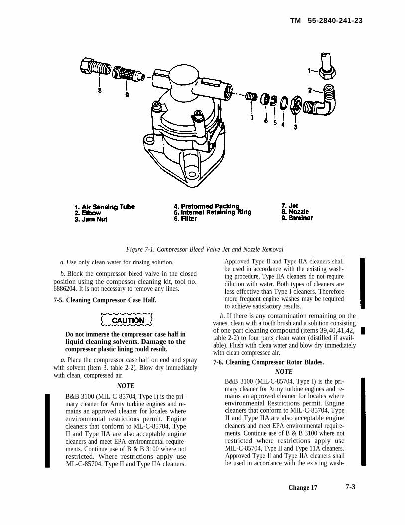
TM 55-2840-241-23
Figure 7-1. Compressor Bleed Valve Jet and Nozzle Removal
a. Use only clean water for rinsing solution.
b. Block the compressor bleed valve in the closedposition using the compessor cleaning kit, tool no.6886204. It is not necessary to remove any lines.
7-5. Cleaning Compressor Case Half.
Do not immerse the compressor case half inliquid cleaning solvents. Damage to thecompressor plastic lining could result.
a. Place the compressor case half on end and spraywith solvent (item 3. table 2-2). Blow dry immediatelywith clean, compressed air.
NOTE
B&B 3100 (MIL-C-85704, Type I) is the pri-mary cleaner for Army turbine engines and re-mains an approved cleaner for locales whereenvironmental restrictions permit. Enginecleaners that conform to ML-C-85704, TypeII and Type IIA are also acceptable enginecleaners and meet EPA environmental require-ments. Continue use of B & B 3100 where notrestricted. Where restrictions apply useML-C-85704, Type II and Type IIA cleaners.
Approved Type II and Type IIA cleaners shallbe used in accordance with the existing wash-ing procedure, Type IIA cleaners do not requiredilution with water. Both types of cleaners areless effective than Type I cleaners. Thereforemore frequent engine washes may be requiredto achieve satisfactory results.
b. If there is any contamination remaining on thevanes, clean with a tooth brush and a solution consistingof one part cleaning compound (items 39,40,41,42, table 2-2) to four parts clean water (distilled if avail- able). Flush with clean water and blow dry immediatelywith clean compressed air.7-6. Cleaning Compressor Rotor Blades.
NOTEB&B 3100 (MIL-C-85704, Type I) is the pri-mary cleaner for Army turbine engines and re-mains an approved cleaner for locales whereenvironmental Restrictions permit. Enginecleaners that conform to MIL-C-85704, TypeII and Type IIA are also acceptable enginecleaners and meet EPA environmental require-ments. Continue use of B & B 3100 where notrestricted where restrictions apply useMIL-C-85704, Type II and Type 11A cleaners.Approved Type II and Type IIA cleaners shallbe used in accordance with the existing wash-
Change 17 7-3
TM 55-2840-231-23
ing procedure. Type HA cleaners do not requiredilution with water. Both types of cleaners areless effective than Type I cleaners. Thereforemore frequent engine washes may be requiredto achieve satisfactory results.
a. With one compressor case half removed, cleancontamination from the blades using a tooth brush anda solution of one part cleaning compound (items 39,40,41,42, table 2-2).
b. Flush with clean water and blow dry with cleancompressed air.
7-7. Compressor Bleed Valve Cleaning.
a. Remove the air sensing line (l, figure 7-l) from thecompressor bleed valve elbow (2).
b. Remove the elbow from the bleed valve, Discardpreformed packing (4).
c. Remove internal retaining ring (5) and separate fil-lter (6) from the compressor bleed valve. Replace the re-taining ring before assembly if it is damaged during theremoval operation.
d. Using a screwdriver, remove jet (7) from the com-pressor bleed valve.
e. Clip the lockwire, then remove nozzle (8) andstrainer (9) from the compressor bleed valve.
f. Clean the nozzle, falter, strainer, and jet ultrasoni-cally if equipment is available. If ultrasonic equipmentis not available, agitate the parts in a clean container ofsolvent (item 3, table 2-2). Use a soft bristle brush toclean exposed surfaces. Insert a sewing thread throughthe jet hole. Slide the jet back and forth on the thread toremove film. Clean the nozzle in the same manner.
Do not blow the jet dry. The small jet can beeasily lost or damaged.
NOTEIf the jet must be replaced, return the compres-sor bleed valve to overhaul for part replace-ment and recalibration of the valve assembly.
g. Inspect the jet and the nozzle using a flashlight.Place the part on the center of the lens so the light canbe seen through the hole. Reclean the part if any par-ticles or coating can be seen.
Do not use a probe to remove particleslodged in the jet or nozzle. Damage to the jetor nozzle could result.
h. Install jet (7) in the compressor bleed valve. Tight-en to 8-12 in. lb.
i. Place filter (6) in the compressor bleed valve (skirtend first). Secure with internal retaining ring (5).
j. Install strainer (9) and nozzle (8) in the compressorbleed valve. Tighten to 35-45 in. lb. and secure withlockwire (item 10, table 2-2).
k. Lubricate preformed packing (4) with oil (item 7or 8. table 2-2) and install it with elbow (2) on the com-pressor bleed valve. Do not tighten the elbow jam nut (3)at this time.
l. Position the elbow as required and install air sens-ing line (l). Tighten the coupling nut to 80-120 in. lb.Tighten elbow jam nut (3) to 55-80 in. lb.
Section II. INSPECTION
7-8. Scope.
This section provides instructions for complete in-spection of engine parts within the scope of the Mainte-nance Allocation Chart. Service limits and standards arepresented to determine when parts should be repaired orreplaced.
7-9. Compressor Rotor and Blade Inspection.Visually inspect the compressor rotor and blades for
the following conditions. Replace the engine if any ofthe limits are exceeded.
Honing stone shall he used for any blending.Use of a file may relieve stresses purposelyplaced in new or overhauled compressorblades, weakening blades and risking pre-mature failure.
NOTEThis inspection requires removal of a compres-sor case half and shall be performed only forthe reasons stated in paragraph 6-2. It is not
7-4 Change 17
TM 55-2840-241-23
possible to fully describe all of the damageconditions that could be incurred; therefore, ifpossible to fully describe all of the damageconditions that could be incurred; therefore, ifdamage is within rework limits, but there isreasonable doubt about the strength of the re-worked blade as compared to a new blade, re-place the engine. Light polishing to removeminor nicks, where blade dimensions are basi-cally unchanged, is permissible on the other2/3 of the blade.
Blend and polish blades or vanes in a longitudi-nal direction only with the rework forming asmooth blend with the basic airfoil. The num-ber of blades or vanes which maybe reworkedis not limited. Other than restriction to the out-er 2/3 of the blade, the limiting factor of bladeor vane rework is engine performance. Any re-duction of blade or vane area will decrease the
efficiency of the compressor and the perfor-mance of the engine. Remove as little materialas possible. No sharp edges, burrs, cracks ortears are acceptable.
a. Inspect for cracked or missing compressor blades- none are permitted.
b. Inspect the compressor rotor blades and wheelhubs for evidence of corrosion. Corrosion must be re-moved by lending and polishing. (Refer to paragraph7-24.) Replace the engine if pitting in any area of theblade forjs a definite line, pitting exceeds the blend lim-its, or if pitting in the inner 1/3 of blade.
c. Inspect the compressor rotor blades and wheel hubsfor nicks, dents and scratches in areas other than theblade leading and trailing edges. All damage andimperfections must be blended out. (Refer to paragraph7-24 c and d.) Blended areas must not exceed the limitsshown on figure 7-12.
Change 17 7-4.1 /(7-4.2 blank)

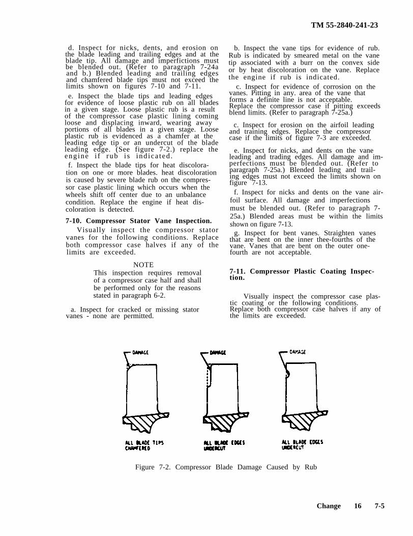
TM 55-2840-241-23
d. Inspect for nicks, dents, and erosion onthe blade leading and trailing edges and at theblade tip. All damage and imperfictions mustbe blended out. (Refer to paragraph 7-24aand b.) Blended leading and trailing edgesand chamfered blade tips must not exceed thelimits shown on figures 7-10 and 7-11.
b. Inspect the vane tips for evidence of rub.Rub is indicated by smeared metal on the vanetip associated with a burr on the convex sideor by heat discoloration on the vane. Replacethe engine if rub is indicated.
e. Inspect the blade tips and leading edgesfor evidence of loose plastic rub on all bladesin a given stage. Loose plastic rub is a resultof the compressor case plastic lining comingloose and displacing inward, wearing awayportions of all blades in a given stage. Looseplastic rub is evidenced as a chamfer at theleading edge tip or an undercut of the bladeleading edge. (See figure 7-2.) replace theeng ine i f rub i s i nd ica ted .f. Inspect the blade tips for heat discolora-
tion on one or more blades. heat discolorationis caused by severe blade rub on the compres-sor case plastic lining which occurs when the wheels shift off center due to an unbalancecondition. Replace the engine if heat dis-coloration is detected.
7-10. Compressor Stator Vane Inspection.
NOTE
a. Inspect for cracked or missing statorvanes - none are permitted.
f. Inspect for nicks and dents on the vane air-foil surface. All damage and imperfectionsmust be blended out. (Refer to paragraph 7-25a.) Blended areas must be within the limitsshown on figure 7-13.
Visually inspect the compressor statorvanes for the following conditions. Replaceboth compressor case halves if any of thelimits are exceeded.
This inspection requires removalof a compressor case half and shallbe performed only for the reasonsstated in paragraph 6-2.
c. Inspect for evidence of corrosion on thevanes. Pitting in any. area of the vane thatforms a definite line is not acceptable.Replace the compressor case if pitting exceedsblend limits. (Refer to paragraph 7-25a.)
c. Inspect for erosion on the airfoil leadingand training edges. Replace the compressorcase if the limits of figure 7-3 are exceeded.
e. Inspect for nicks, and dents on the vaneleading and trading edges. All damage and im-perfections must be blended out. (Refer toparagraph 7-25a.) Blended leading and trail-ing edges must not exceed the limits shown onfigure 7-13.
g. Inspect for bent vanes. Straighten vanesthat are bent on the inner thee-fourths of thevane. Vanes that are bent on the outer one-fourth are not acceptable.
7-11. Compressor Plastic Coating Inspec-tion.
Visually inspect the compressor case plas-tic coating or the following conditions.Replace both compressor case halves if any ofthe limits are exceeded.
Figure 7-2. Compressor Blade Damage Caused by Rub
Change 16 7-5
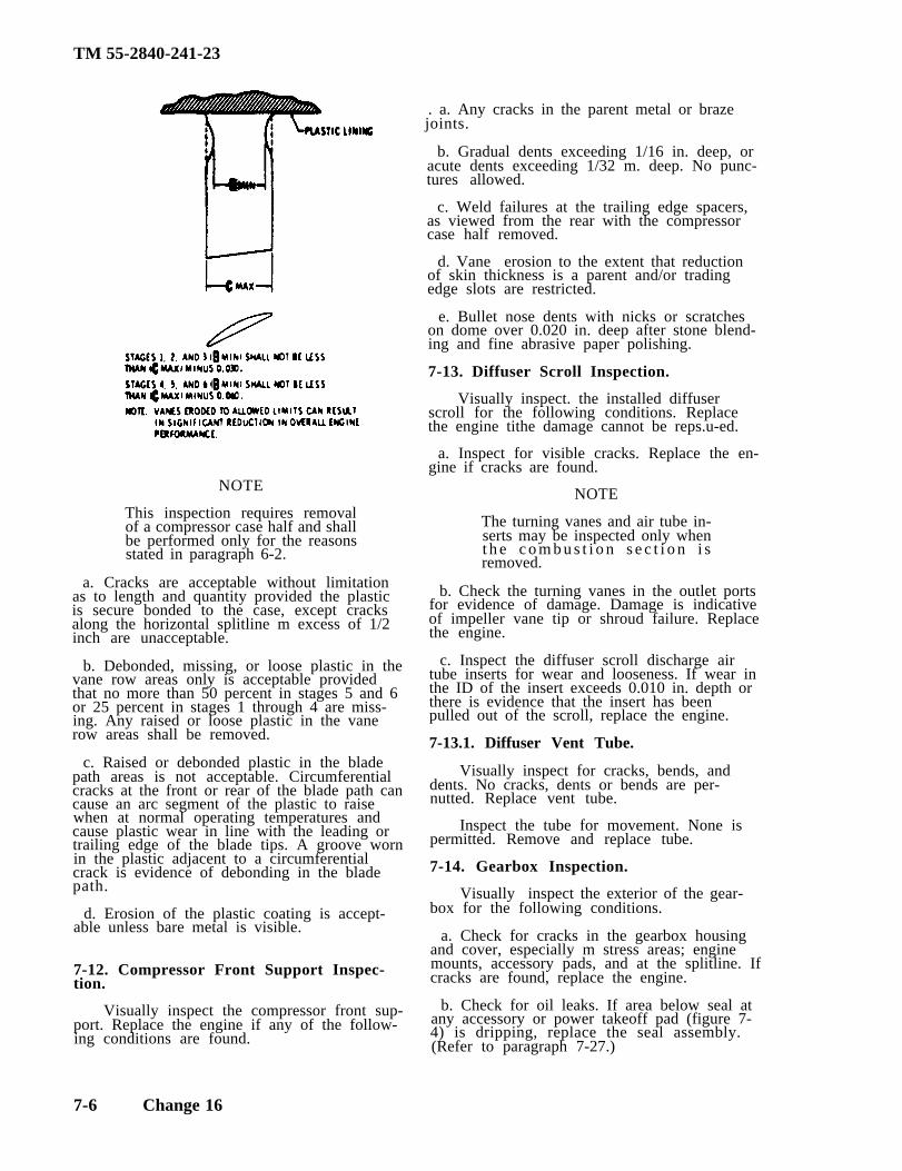
TM 55-2840-241-23
NOTE
This inspection requires removalof a compressor case half and shallbe performed only for the reasonsstated in paragraph 6-2.
a. Cracks are acceptable without limitationas to length and quantity provided the plasticis secure bonded to the case, except cracksalong the horizontal splitline m excess of 1/2inch are unacceptable.
b. Debonded, missing, or loose plastic in thevane row areas only is acceptable providedthat no more than 50 percent in stages 5 and 6or 25 percent in stages 1 through 4 are miss-ing. Any raised or loose plastic in the vanerow areas shall be removed.
c. Raised or debonded plastic in the bladepath areas is not acceptable. Circumferentialcracks at the front or rear of the blade path cancause an arc segment of the plastic to raisewhen at normal operating temperatures andcause plastic wear in line with the leading ortrailing edge of the blade tips. A groove wornin the plastic adjacent to a circumferential crack is evidence of debonding in the bladepath.
d. Erosion of the plastic coating is accept-able unless bare metal is visible.
7-12. Compressor Front Support Inspec-tion.
Visually inspect the compressor front sup-port. Replace the engine if any of the follow-ing conditions are found.
. a. Any cracks in the parent metal or brazejoints.
b. Gradual dents exceeding 1/16 in. deep, oracute dents exceeding 1/32 m. deep. No punc-tures allowed.
c. Weld failures at the trailing edge spacers,as viewed from the rear with the compressorcase half removed.
d. Vane erosion to the extent that reductionof skin thickness is a parent and/or tradingedge slots are restricted.
e. Bullet nose dents with nicks or scratcheson dome over 0.020 in. deep after stone blend-ing and fine abrasive paper polishing.
7-13. Diffuser Scroll Inspection.
Visually inspect. the installed diffuserscroll for the following conditions. Replacethe engine tithe damage cannot be reps.u-ed.
a. Inspect for visible cracks. Replace the en-gine if cracks are found.
NOTE
The turning vanes and air tube in-serts may be inspected only whent h e c o m b u s t i o n s e c t i o n i sremoved.
b. Check the turning vanes in the outlet portsfor evidence of damage. Damage is indicativeof impeller vane tip or shroud failure. Replacethe engine.
c. Inspect the diffuser scroll discharge airtube inserts for wear and looseness. If wear inthe ID of the insert exceeds 0.010 in. depth orthere is evidence that the insert has beenpulled out of the scroll, replace the engine.
7-13.1. Diffuser Vent Tube.
Visually inspect for cracks, bends, anddents. No cracks, dents or bends are per-nutted. Replace vent tube.
Inspect the tube for movement. None ispermitted. Remove and replace tube.
7-14. Gearbox Inspection.
Visually inspect the exterior of the gear-box for the following conditions.
a. Check for cracks in the gearbox housingand cover, especially m stress areas; enginemounts, accessory pads, and at the splitline. Ifcracks are found, replace the engine.
b. Check for oil leaks. If area below seal atany accessory or power takeoff pad (figure 7-4) is dripping, replace the seal assembly.(Refer to paragraph 7-27.)
7-6 Change 16
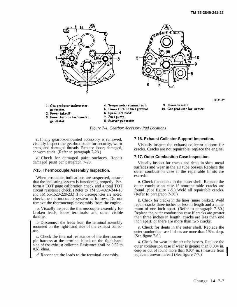
TM 55-2840-241-23
Figure 7-4. Gearbox Accessory Pad Locations
c. If any gearbox-mounted accessory is removed,visually inspect the gearbox studs for security, wornareas, and damaged threads. Replace loose, damaged,or worn studs. (Refer to paragraph 7-28.)
d. Check for damaged paint surfaces. Repairdamaged paint per paragraph 7-29.
7-15. Thermocouple Assembly Inspection.
When erroneous indications are suspected, ensurethat the indicating system is functioning properly. Per-form a TOT gage calibration check and a total TOTcircuit resistance check. (Refer to TM 55-4920-244-15and TM 55-1520-228-23.) If no discrepancies are noted,check the thermocouple system as follows. Do notremove the thermocouple assembly from the engine.
a. Visually inspect the thermocouple assembly forbroken leads, loose terminals, and other visibledamage.
b. Disconnect the leads from the terminal assemblymounted on the right-hand side of the exhaust collec-tor.
c. Check the internal resistance of the thermocou-ple harness at the terminal block on the right-handside of the exhaust collector. Resistance shall be 0.55 to0.65 ohms.
d. Reconnect the leads to the terminal assembly.
7-16. Exhaust Collector Support Inspection.Visually inspect the exhaust collector support for
cracks. Cracks are not repairable, replace the engine.
7-17. Outer Combustion Case Inspection.Visually inspect for cracks and dents in sheet metal
surfaces and wear in the air tube bosses. Replace theouter combustion case if the repairable limits areexceeded.
a. Check for cracks in the outer shell. Replace theouter combustion case if nonrepairable cracks arefound. (See figure 7-5.) Weld all repairable cracks.(Refer to paragraph 7-30.)
b. Check for cracks in the liner (inner basket). Weldrepair cracks three inches or less in length and a mini-mum of one inch apart. (Refer to paragraph 7-30.)Replace the outer combustion case if cracks are greaterthan three inches in length, cracks are less than oneinch apart, or there are more than two cracks.
c. Check for dents in the outer shell. Replace theouter combustion case if dents are more than 1/8in. deep.(See figure 7-6.)
d. Check for wear in the air tube bosses. Replace theouter combustion case if wear is greater than 0.004 in.deep or out of round more than 0.004 in. (measure fromadjacent unworn area.) (See figure 7-7.)
Change 14 7-7
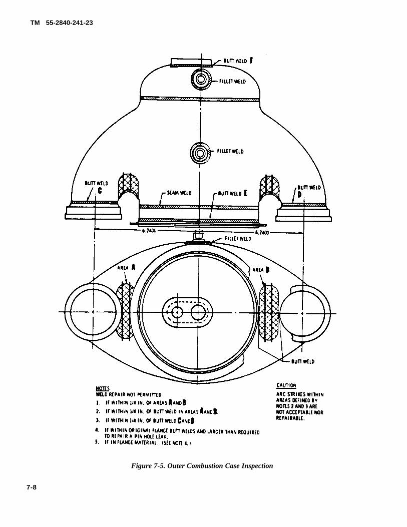
TM 55-2840-241-23
Figure 7-5. Outer Combustion Case Inspection
7-8
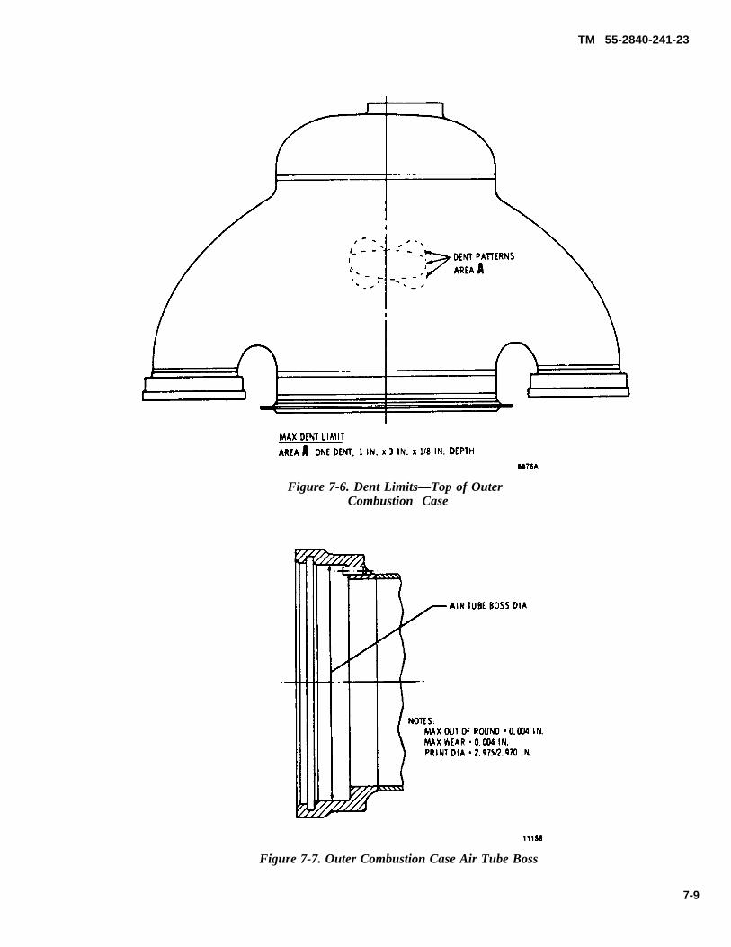
TM 55-2840-241-23
Figure 7-6. Dent Limits—Top of OuterCombustion Case
Figure 7-7. Outer Combustion Case Air Tube Boss
7-9
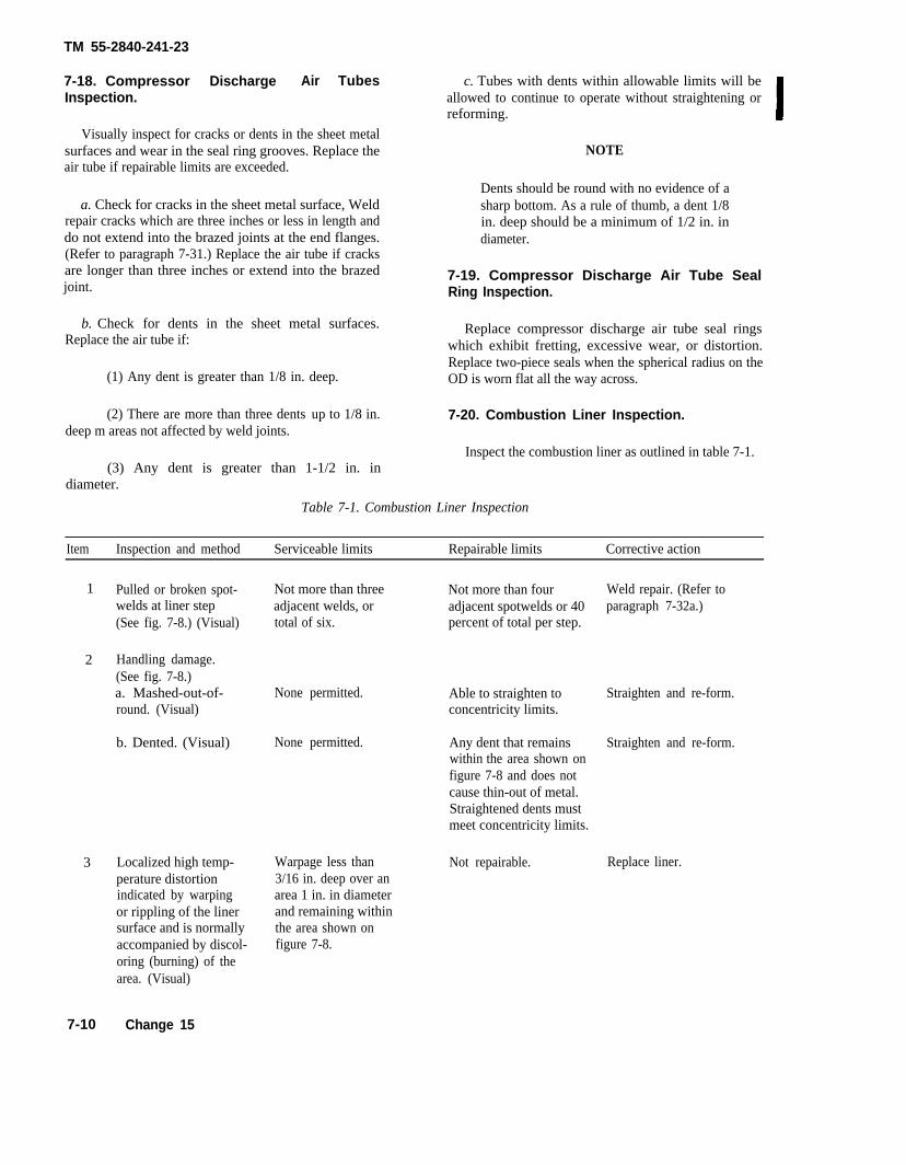
TM 55-2840-241-23
7-18. Compressor Discharge Air TubesInspection.
Visually inspect for cracks or dents in the sheet metalsurfaces and wear in the seal ring grooves. Replace theair tube if repairable limits are exceeded.
a. Check for cracks in the sheet metal surface, Weldrepair cracks which are three inches or less in length anddo not extend into the brazed joints at the end flanges.(Refer to paragraph 7-31.) Replace the air tube if cracksare longer than three inches or extend into the brazedjoint.
c. Tubes with dents within allowable limits will beallowed to continue to operate without straightening orreforming.
NOTE
Dents should be round with no evidence of asharp bottom. As a rule of thumb, a dent 1/8in. deep should be a minimum of 1/2 in. indiameter.
7-19. Compressor Discharge Air Tube SealRing Inspection.
b. Check for dents in the sheet metal surfaces.Replace the air tube if:
Replace compressor discharge air tube seal ringswhich exhibit fretting, excessive wear, or distortion.Replace two-piece seals when the spherical radius on the
(1) Any dent is greater than 1/8 in. deep. OD is worn flat all the way across.
(2) There are more than three dents up to 1/8 in. 7-20. Combustion Liner Inspection.deep m areas not affected by weld joints.
Inspect the combustion liner as outlined in table 7-1.(3) Any dent is greater than 1-1/2 in. in
diameter.
Table 7-1. Combustion Liner Inspection
Item Inspection and method Serviceable limits Repairable limits Corrective action
1 Pulled or broken spot- Not more than three Not more than four Weld repair. (Refer towelds at liner step adjacent welds, or adjacent spotwelds or 40 paragraph 7-32a.)(See fig. 7-8.) (Visual) total of six. percent of total per step.
2 Handling damage.(See fig. 7-8.)a. Mashed-out-of- None permitted. Able to straighten to Straighten and re-form.round. (Visual) concentricity limits.
b. Dented. (Visual) None permitted. Any dent that remains Straighten and re-form.within the area shown onfigure 7-8 and does notcause thin-out of metal.Straightened dents mustmeet concentricity limits.
3 Localized high temp- Warpage less thanperature distortion 3/16 in. deep over anindicated by warping area 1 in. in diameteror rippling of the liner and remaining withinsurface and is normally the area shown onaccompanied by discol- figure 7-8.oring (burning) of thearea. (Visual)
Not repairable. Replace liner.
7-10 Change 15
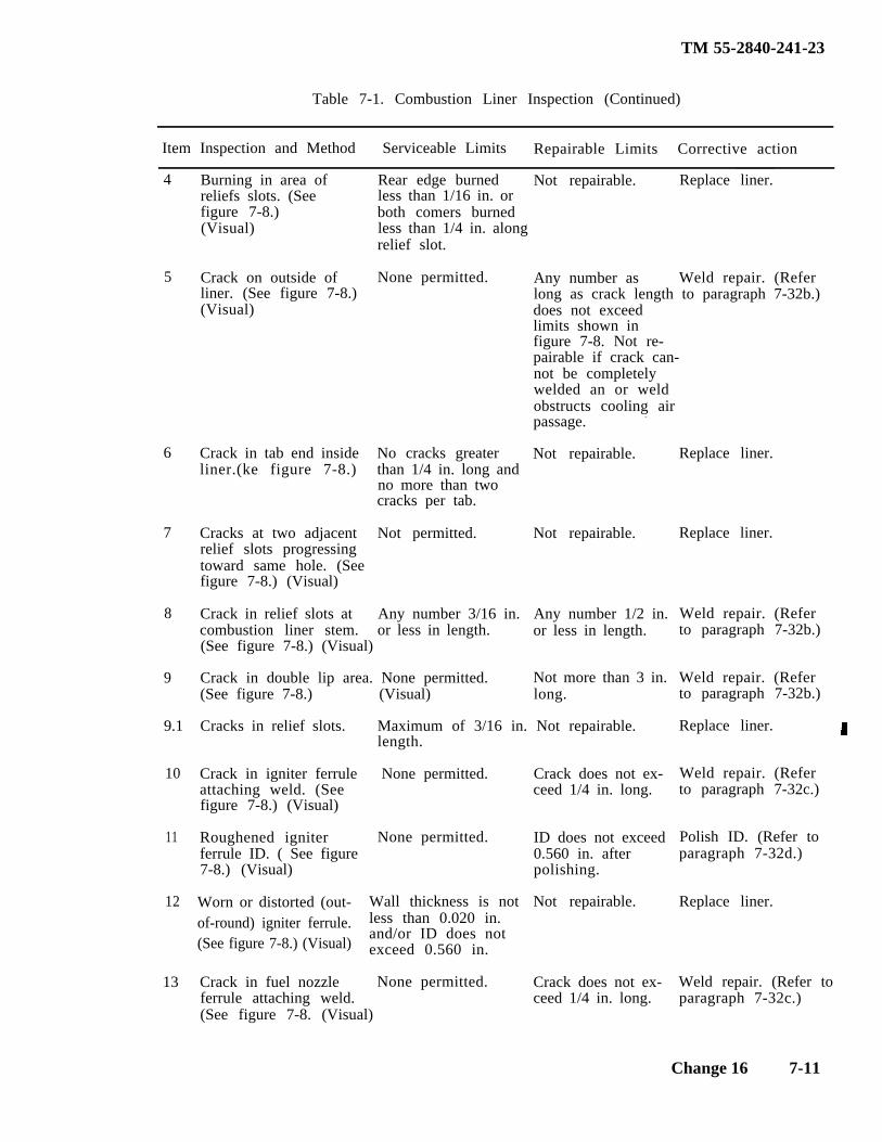
TM 55-2840-241-23
Table 7-1. Combustion Liner Inspection (Continued)
Item Inspection and Method Serviceable Limits Repairable Limits Corrective action
4 Burning in area ofreliefs slots. (Seefigure 7-8.)(Visual)
Rear edge burned Not repairable. Replace liner.less than 1/16 in. orboth comers burnedless than 1/4 in. alongrelief slot.
5 Crack on outside ofliner. (See figure 7-8.)(Visual)
Any number as Weld repair. (Referlong as crack length to paragraph 7-32b.)
None permitted.
does not exceedlimits shown infigure 7-8. Not re-pairable if crack can-not be completelywelded an or weldobstructs cooling airpassage. -
Not repairable.6
7
Crack in tab end insideliner.(ke figure 7-8.)
No cracks greaterthan 1/4 in. long andno more than twocracks per tab.
Not permitted.
Replace liner.
Replace liner.
Weld repair. (Referto paragraph 7-32b.)
Weld repair. (Referto paragraph 7-32b.)
Replace liner.
Weld repair. (Referto paragraph 7-32c.)
Polish ID. (Refer toparagraph 7-32d.)
Replace liner.
Cracks at two adjacentrelief slots progressingtoward same hole. (Seefigure 7-8.) (Visual)
Not repairable.
8 Crack in relief slots atcombustion liner stem.
Any number 3/16 in.or less in length.
Any number 1/2 in.or less in length.
(See figure 7-8.) (Visual)
Crack in double lip area. None permitted.(See figure 7-8.) (Visual)
9
9.1
10
Not more than 3 in.long.
Cracks in relief slots. Maximum of 3/16 in. Not repairable.length.
Worn or distorted (out-of-round) igniter ferrule.(See figure 7-8.) (Visual)
Crack in igniter ferrule None permitted.attaching weld. (Seefigure 7-8.) (Visual)
Roughened igniter None permitted.ferrule ID. ( See figure7-8.) (Visual)
Wall thickness is notless than 0.020 in.and/or ID does notexceed 0.560 in.
Crack in fuel nozzle None permitted.ferrule attaching weld.(See figure 7-8. (Visual)
Crack does not ex-ceed 1/4 in. long.
11 ID does not exceed0.560 in. afterpolishing.
12 Not repairable.
13 Crack does not ex-ceed 1/4 in. long.
Weld repair. (Refer toparagraph 7-32c.)
Change 16 7-11
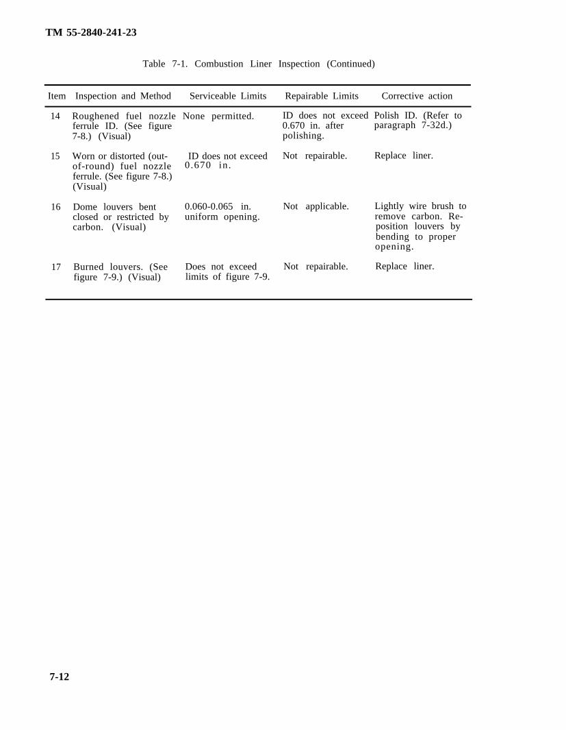
TM 55-2840-241-23
Table 7-1. Combustion Liner Inspection (Continued)
Item Inspection and Method Serviceable Limits Repairable Limits Corrective action
14
15
16
17
Roughened fuel nozzle None permitted.ferrule ID. (See figure7-8.) (Visual)
Worn or distorted (out- ID does not exceedof-round) fuel nozzleferrule. (See figure 7-8.)(Visual)
0.670 in.
Dome louvers bent 0.060-0.065 in.closed or restricted by uniform opening.carbon. (Visual)
Burned louvers. (See Does not exceedfigure 7-9.) (Visual) limits of figure 7-9.
ID does not exceed Polish ID. (Refer to0.670 in. after paragraph 7-32d.)polishing.
Not repairable. Replace liner.
Not applicable. Lightly wire brush toremove carbon. Re-position louvers bybending to properopening.
Not repairable. Replace liner.
7-12
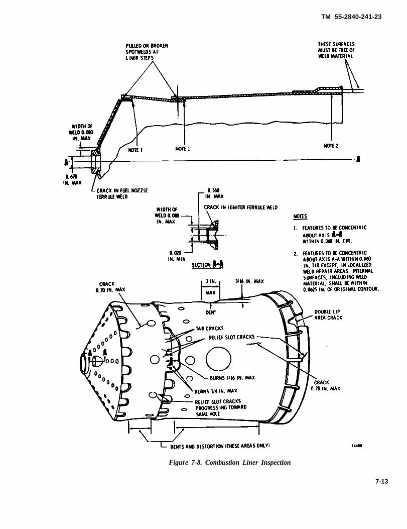
TM 55-2840-241-23
Figure 7-8. Combustion Liner Inspection
7-13
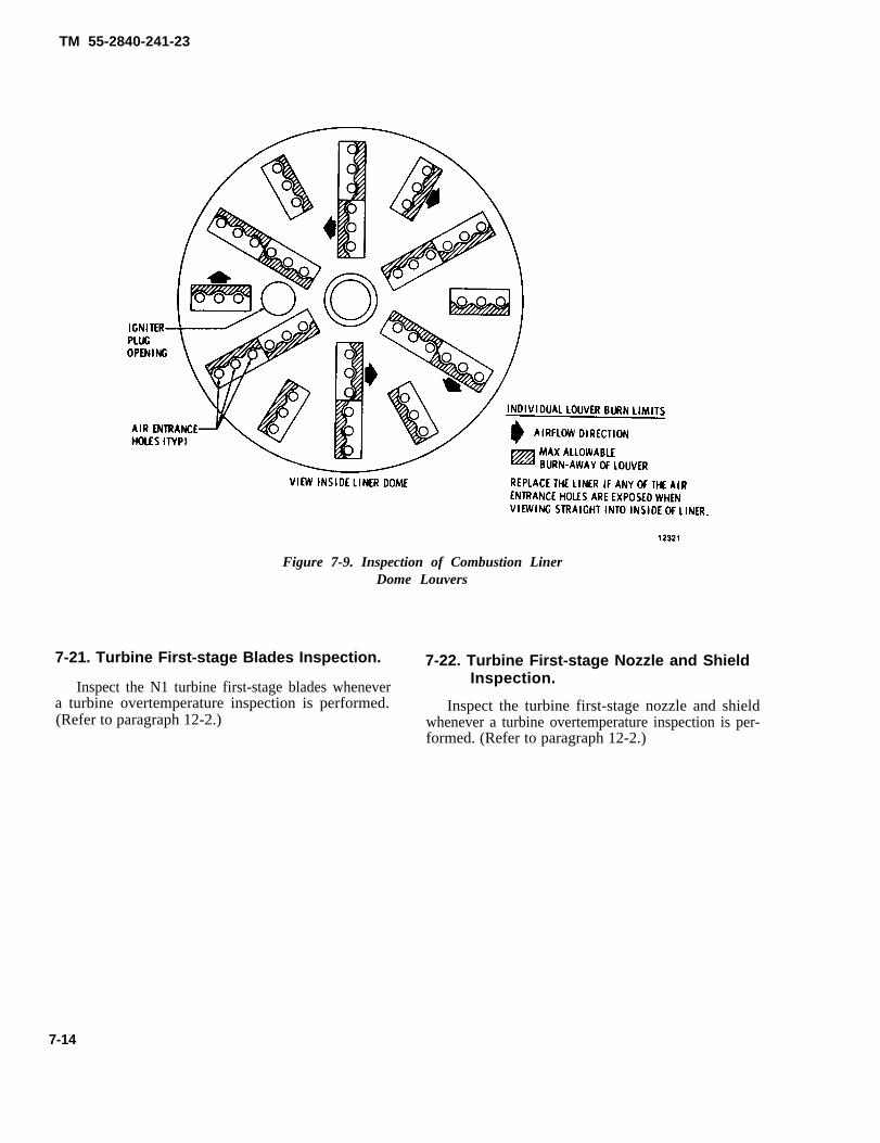
TM 55-2840-241-23
Figure 7-9. Inspection of Combustion LinerDome Louvers
7-21. Turbine First-stage Blades Inspection. 7-22. Turbine First-stage Nozzle and ShieldInspection.Inspect the N1 turbine first-stage blades whenever
a turbine overtemperature inspection is performed. Inspect the turbine first-stage nozzle and shield(Refer to paragraph 12-2.) whenever a turbine overtemperature inspection is per-
formed. (Refer to paragraph 12-2.)
7-14
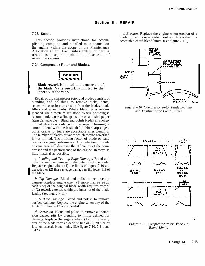
TM 55-2840-241-22
Section Ill. REPAIR
7-23. Scope.
This section provides instructions for accom-plishing complete and detailed maintenance onthe engine within the scope of the MaintenanceAllocation Chart. Each subassembly or part istreated as a separate unit in the discussion ofrepair procedures.
7-24. Compressor Rotor and Blades.
Blade rework is limited to the outer 2/3 ofthe blade. Vane rework is limited to theinner 3/4 of the vane.
Repair of the compressor rotor and blades consists ofblending and polishing to remove nicks, dents,scratches, corrosion, or erosion from the blades, bladefillets and wheel hubs. Where blending is recom-mended, use a medium grit stone. Where polishing isrecommended, use a fine grit stone or abrasive paper(item 22, table 2-2), Blend and polish blades in a longi-tudinal direction only with the repair forming asmooth blend with the basic airfoil. No sharp edges,burrs, cracks, or tears are acceptable after blending.The number of blades or vanes which maybe reworkedis not limited. The limiting factor of blade or vanerework is engine performance. Any reduction of bladeor vane area will decrease the efficiency of the com-pressor and the performance of the engine. Remove aslittle material as possible.
a. Leading and Trailing Edge Damage. Blend andpolish to remove damage on the outer 2/3 of the blade.Replace engine when: (1) the limits of figure 7-10 areexceeded or (2) there is edge damage in the lower 1/3 ofthe blade.
b. Tip Damage. Blend and polish to remove tipdamage. Replace engine when: (1) more than 1/3 (1/6 oneach side) of the original blade width requires reworkor (2) rework extends within the inner 4/5 of the bladelength. (See figure 7-11.)
c. Surface Damage. Blend and polish to removesurface damage. Replace the engine when any of thelimits of figure 7-12 are exceeded.
d. Corrosion. Blend and polish to remove all corro-sion caused pits by blending to limits defined fordamage. Replace the engine when: (1) pitting in anyarea of the blade forms a definite line or (2) pit size orlocation exceeds blend limits. (See figure 7-10, 7-11, and7-12.)
e. Erosion. Replace the engine when erosion of ablade tip results in a blade chord width less than theacceptable chord blend limits. (See figure 7-12.)
Figure 7-10. Compressor Rotor Blade Leadingand Trailing Edge Blend Limits
Figure 7-11. Compressor Rotor Blade TipBlend Limits
Change 14 7-15
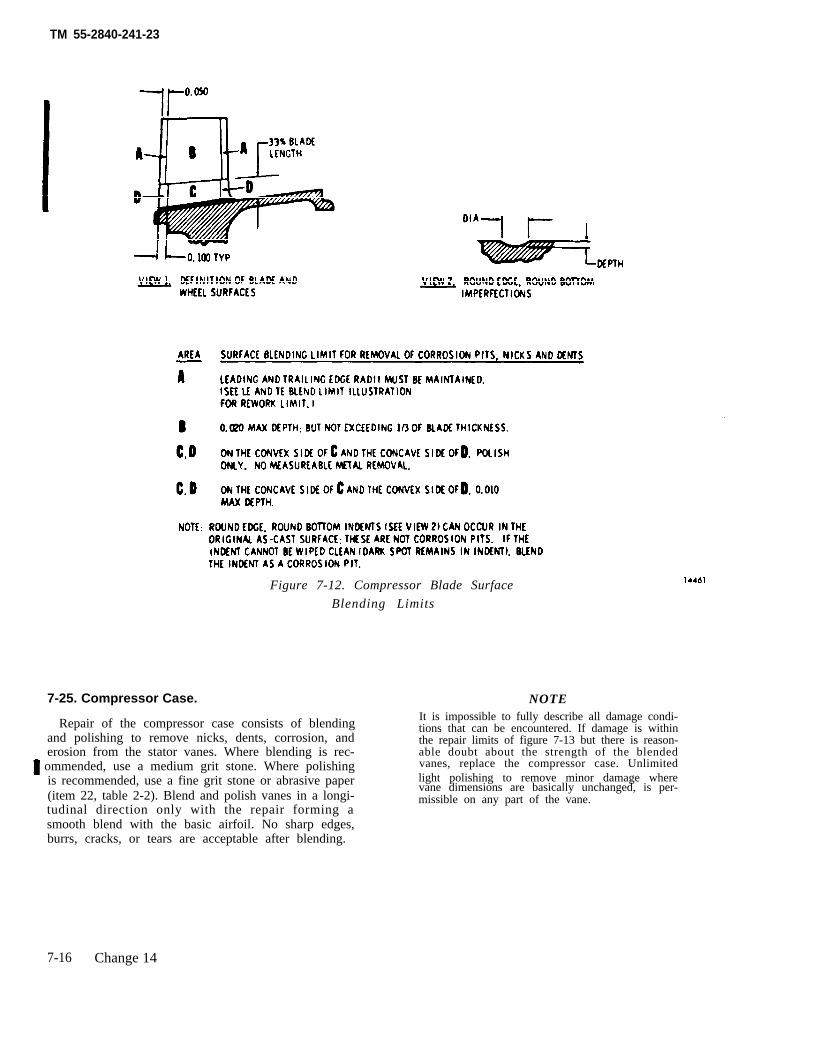
TM 55-2840-241-23
Figure 7-12. Compressor Blade Surface
Blending Limits
7-25. Compressor Case.
Repair of the compressor case consists of blendingand polishing to remove nicks, dents, corrosion, anderosion from the stator vanes. Where blending is rec-ommended, use a medium grit stone. Where polishingis recommended, use a fine grit stone or abrasive paper(item 22, table 2-2). Blend and polish vanes in a longi-tudinal direction only with the repair forming asmooth blend with the basic airfoil. No sharp edges,burrs, cracks, or tears are acceptable after blending.
NOTEIt is impossible to fully describe all damage condi-tions that can be encountered. If damage is withinthe repair limits of figure 7-13 but there is reason-able doubt about the strength of the blendedvanes, replace the compressor case. Unlimitedlight polishing to remove minor damage wherevane dimensions are basically unchanged, is per-missible on any part of the vane.
7-16 Change 14
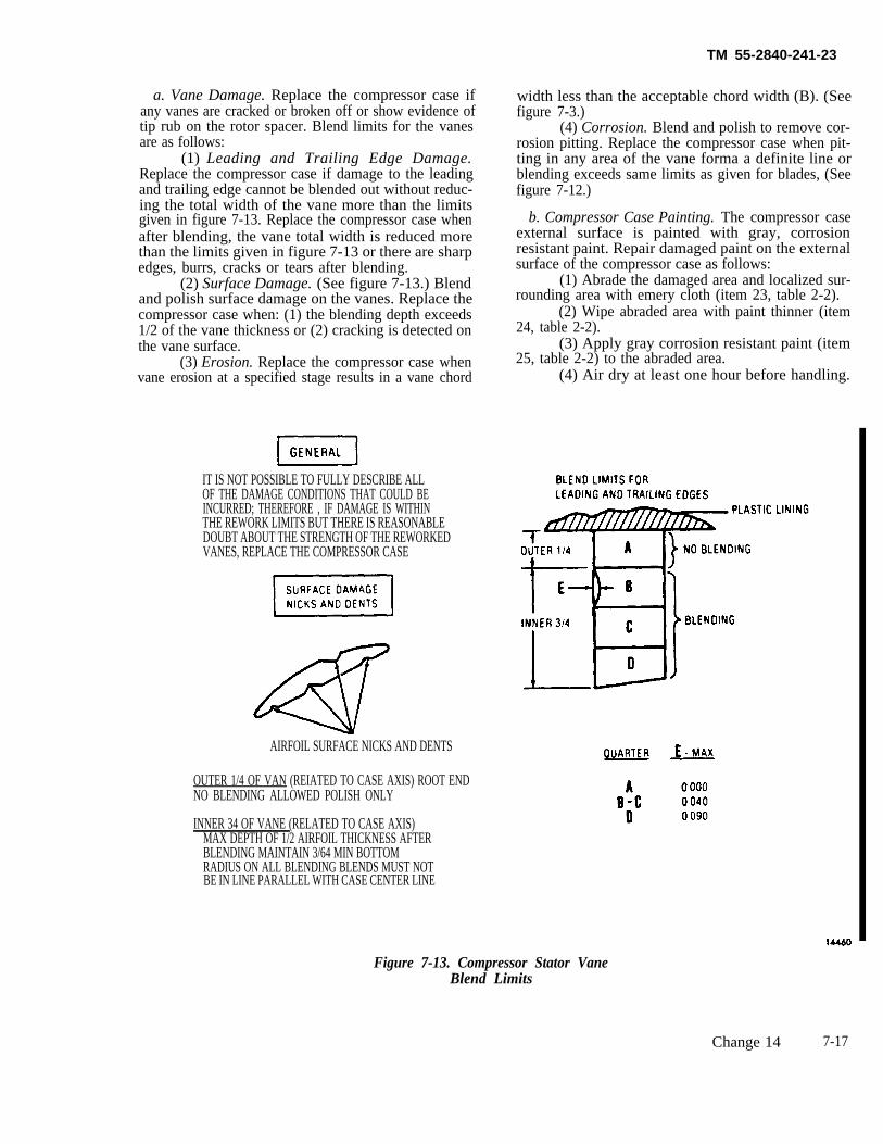
TM 55-2840-241-23
a. Vane Damage. Replace the compressor case ifany vanes are cracked or broken off or show evidence oftip rub on the rotor spacer. Blend limits for the vanesare as follows:
(1) Leading and Trailing Edge Damage.Replace the compressor case if damage to the leadingand trailing edge cannot be blended out without reduc-ing the total width of the vane more than the limitsgiven in figure 7-13. Replace the compressor case whenafter blending, the vane total width is reduced morethan the limits given in figure 7-13 or there are sharpedges, burrs, cracks or tears after blending.
(2) Surface Damage. (See figure 7-13.) Blendand polish surface damage on the vanes. Replace thecompressor case when: (1) the blending depth exceeds1/2 of the vane thickness or (2) cracking is detected onthe vane surface.
(3) Erosion. Replace the compressor case whenvane erosion at a specified stage results in a vane chord
IT IS NOT POSSIBLE TO FULLY DESCRIBE ALLOF THE DAMAGE CONDITIONS THAT COULD BEINCURRED; THEREFORE , IF DAMAGE IS WITHINTHE REWORK LIMITS BUT THERE IS REASONABLEDOUBT ABOUT THE STRENGTH OF THE REWORKEDVANES, REPLACE THE COMPRESSOR CASE
AIRFOIL SURFACE NICKS AND DENTS
OUTER 1/4 OF VAN (REIATED TO CASE AXIS) ROOT ENDNO BLENDING ALLOWED POLISH ONLY
INNER 34 OF VANE (RELATED TO CASE AXIS)MAX DEPTH OF 1/2 AIRFOIL THICKNESS AFTER
width less than the acceptable chord width (B). (Seefigure 7-3.)
(4) Corrosion. Blend and polish to remove cor-rosion pitting. Replace the compressor case when pit-ting in any area of the vane forma a definite line orblending exceeds same limits as given for blades, (Seefigure 7-12.)
b. Compressor Case Painting. The compressor caseexternal surface is painted with gray, corrosionresistant paint. Repair damaged paint on the externalsurface of the compressor case as follows:
(1) Abrade the damaged area and localized sur-rounding area with emery cloth (item 23, table 2-2).
(2) Wipe abraded area with paint thinner (item24, table 2-2).
(3) Apply gray corrosion resistant paint (item25, table 2-2) to the abraded area.
(4) Air dry at least one hour before handling.
BLENDING MAINTAIN 3/64 MIN BOTTOMRADIUS ON ALL BLENDING BLENDS MUST NOTBE IN LINE PARALLEL WITH CASE CENTER LINE
Figure 7-13. Compressor Stator VaneBlend Limits
Change 14 7-17
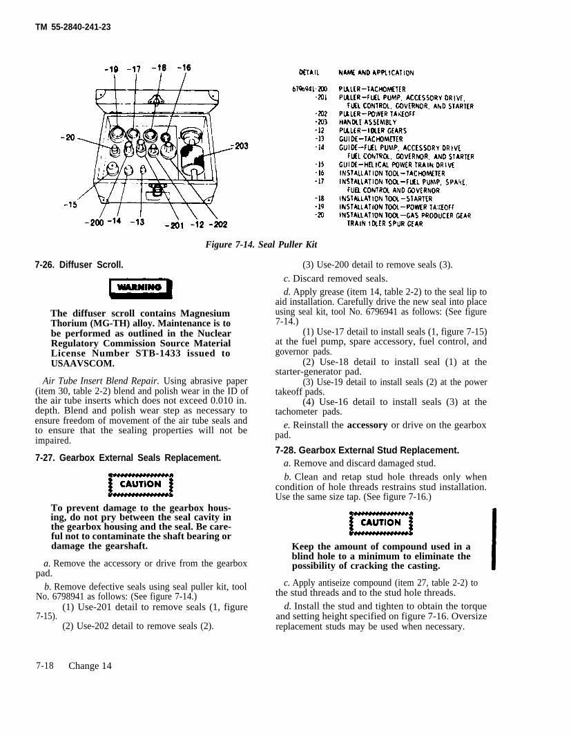
TM 55-2840-241-23
7-26. Diffuser Scroll.
The diffuser scroll contains
Figure 7-14. Seal Puller Kit
MagnesiumThorium (MG-TH) alloy. Maintenance is tobe performed as outlined in the NuclearRegulatory Commission Source MaterialLicense Number STB-1433 issued toUSAAVSCOM.
Air Tube Insert Blend Repair. Using abrasive paper(item 30, table 2-2) blend and polish wear in the ID ofthe air tube inserts which does not exceed 0.010 in.depth. Blend and polish wear step as necessary toensure freedom of movement of the air tube seals andto ensure that the sealing properties will not beimpaired.
7-27. Gearbox External Seals Replacement.
To prevent damage to the gearbox hous-ing, do not pry between the seal cavity inthe gearbox housing and the seal. Be care-ful not to contaminate the shaft bearing ordamage the gearshaft.
a. Remove the accessory or drive from the gearboxpad.
b. Remove defective seals using seal puller kit, toolNo. 6798941 as follows: (See figure 7-14.)
(1) Use-201 detail to remove seals (1, figure7-15).
(2) Use-202 detail to remove seals (2).
(3) Use-200 detail to remove seals (3).
c. Discard removed seals.d. Apply grease (item 14, table 2-2) to the seal lip to
aid installation. Carefully drive the new seal into placeusing seal kit, tool No. 6796941 as follows: (See figure7-14.)
(1) Use-17 detail to install seals (1, figure 7-15)at the fuel pump, spare accessory, fuel control, andgovernor pads.
(2) Use-18 detail to install seal (1) at thestarter-generator pad.
(3) Use-19 detail to install seals (2) at the powertakeoff pads.
(4) Use-16 detail to install seals (3) at thetachometer pads.
e. Reinstall the accessory or drive on the gearboxpad.
7-28. Gearbox External Stud Replacement.a. Remove and discard damaged stud.b. Clean and retap stud hole threads only when
condition of hole threads restrains stud installation.Use the same size tap. (See figure 7-16.)
Keep the amount of compound used in ablind hole to a minimum to eliminate thepossibility of cracking the casting.
c. Apply antiseize compound (item 27, table 2-2) tothe stud threads and to the stud hole threads.
d. Install the stud and tighten to obtain the torqueand setting height specified on figure 7-16. Oversizereplacement studs may be used when necessary.
7-18 Change 14
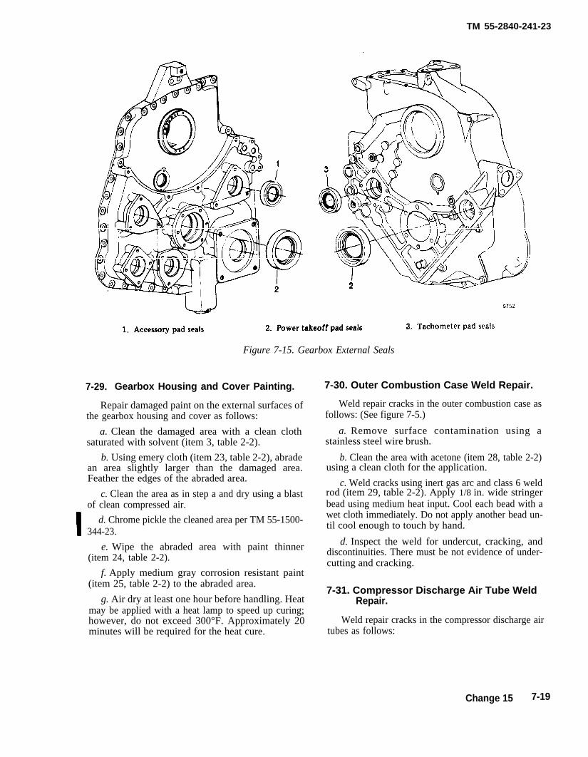
TM 55-2840-241-23
7-29.
Figure 7-15. Gearbox External Seals
Gearbox Housing and Cover Painting.
Repair damaged paint on the external surfaces ofthe gearbox housing and cover as follows:
a. Clean the damaged area with a clean clothsaturated with solvent (item 3, table 2-2).
b. Using emery cloth (item 23, table 2-2), abradean area slightly larger than the damaged area.Feather the edges of the abraded area.
c. Clean the area as in step a and dry using a blastof clean compressed air.
d. Chrome pickle the cleaned area per TM 55-1500-344-23.
e. Wipe the abraded area with paint thinner(item 24, table 2-2).
f. Apply medium gray corrosion resistant paint(item 25, table 2-2) to the abraded area.
g. Air dry at least one hour before handling. Heatmay be applied with a heat lamp to speed up curing;however, do not exceed 300°F. Approximately 20minutes will be required for the heat cure.
7-30. Outer Combustion Case Weld Repair.
Weld repair cracks in the outer combustion case asfollows: (See figure 7-5.)
a. Remove surface contamination using astainless steel wire brush.
b. Clean the area with acetone (item 28, table 2-2)using a clean cloth for the application.
c. Weld cracks using inert gas arc and class 6 weldrod (item 29, table 2-2). Apply 1/8 in. wide stringerbead using medium heat input. Cool each bead with awet cloth immediately. Do not apply another bead un-til cool enough to touch by hand.
d. Inspect the weld for undercut, cracking, anddiscontinuities. There must be not evidence of under-cutting and cracking.
7-31. Compressor Discharge Air Tube WeldRepair.
Weld repair cracks in the compressor discharge airtubes as follows:
Change 15 7-19
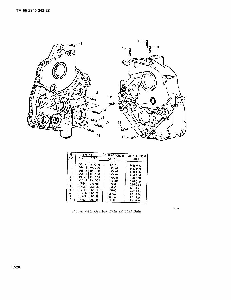
TM 55-2840-241-23
7-20
Figure 7-16. Gearbox External Stud Data
TM 55-2840-241-23
a. Remove surface contamination using astainless steel brush.
b. Clean the area with acetone (item 28, table 2-2)using a clean cloth for the application.
c. Weld cracks using inert gee arc and class 6 weldrod (item 29, table 2-2).
d. Do not grind weld unless weld material extendsinto air path. Thin-out of material from welding orgrinding is not permitted.
7-32. Combuston Liner Repair.
a. Pulled or Broken Spotwelds. Weld repair pull-ed or broken spotwelds in the liner steps as follows:(See figure 7-8.)
(1) Drill a 3/16-in. diameter hole through theouter liner section only.
(2) Remove surface contamination using astainless steel wire brush.
(3) Clean the area with acetone (item 28, table2-2) using a clean cloth for the application.
(4) Press the liner sections together andplugweld using inert gas arc with class 6 weld rod(item 29, table 2-2). Weld material must not extendinto air openings. Do not grind the weld unless weldmaterial blocks air entry.
b. Cracks in Liner Surface, Relief Slots, and Dou-ble Lip Area. Weld repair cracks as follows:
(1) Remove surface contamination using astainless steel wire brush.
(2) Clean the area with acetone (item 28, table2-2) using a clean cloth for the application.
(3) Weld cracks using inert gas arc with clean 6weld rod (item 29, table 2-2). Weld material must notobstruct cooling air passage. Do not grind weld unlessweld material obstructs cooling air passage.
c. Cracks in Igniter and Fuel Nozzle Ferrule At-taching Welds. Repair cracks in the attaching (fillet)weld as follows:
(1) Remove surface contamination using astainless steel wire brush.
(2) Clean the area with acetone (item 28, table2-2) using a clean cloth for the application.
(3) Weld cracks using insert gas arc. Use class 6weld rod (item 29, table 2-2) on the igniter ferrule. Useclass 12 weld rod (item 29, table 2-2) on the fuel nozzleferrule.
d. Fuel Nozzle and Igniter Ferrule ID Roughness.Remove roughened or galled surfaces in the ID of thefuel nozzle and igniter ferrules by polishing withemery cloth (item 23, table 2-2). Polish as required toremove all surface roughness. Check to ensure thatthe ID, after polishing, does not exceed the limitspecified in table 7-1.
7-21/(7-22 blank)

TM 55-2840-241-23
CHAPTER 8
ASSEMBLY OF SUBASSEMBLIES
8-1. Scope.
This chapter presents step-by-step procedures forreassembly of component parts into major functionalassemblies from the level of disassembly permitted bythe Maintenance Allocation Chart.
Use only chrome plated steel or unplatedsteel tools for the assembly proceduresdescribed in this manual. The use of cad-mium or zinc plated tools is not permittedsince these platings are prone to chippingand flaking. Should these chips enter theengine, they may contaminate the lubrica-tion system, ultimately clogging the faltersor produce intergranular attack on nickelor titanium base alloys at elevated tem-peratures.
8-2. Compressor Case Half Installation.
The compressor case halves are amatched set and shall not be intermixed. Ifthe removed case half cannot be repairedto a serviceable condition, replace bothcase halves. Remove only one case half at atime. Do not remove both case halves at thesame time. Misalignment of the com-pressor could result if both case halveswere removed simultaneously.
a. Position the compressor case half in place on thecompressor.
b. Install eight bolts (1, figure 6-1) and nuts (7) ineach horizontal splitline. Bolts at positions two andseven are pilot bolts. Tighten nuts on the pilot bolts to10-15 in. lb. plus locknut drag; then tighten theremaining nuts.
NOTETo determine locknut drag, run the nut up snug;then back off one-half turn. The torque required tofirst turn the loosened nut is locknut drag.
c. Install the eight case-to-front diffuser bolts (4)and nuts (6). Tighten the nuts to 10-15 in. lb. pluslocknut drag.
d. Install nameplate (8) (if applicable) and the fivecase-to-front support bolts (5) and nuts (3). Tighten thenuts to 10-15 in. lb. plus locknut drag.
Do not attempt to rotate the compressorusing a speed wrench at the tachometerdrive pad. Side loads on the speed wrenchcould crack the tachometer drive shaft.
e. Turn the compressor rotor using the 6799790engine turning adapter (figure 2-1) at the starter gen-erator pad (figure 7-4). The rotor and gear train shouldturn freely with no evidence of interference or blade tiprub (evidenced by feel or noise).
f. Install the compressor bleed valve. (Refer to par-agraph 5-33.)
g. Install anti-icing air tubes (23, 26, figure 5-13.)Tighten the coupling nuts to 150-200 in. lb.
Change 14 8-1(8-2 blank)

TM 55-2840-241-23
CHAPTER 9
FINAL ENGINE ASSEMBLY
9-1. Scope
This chapter provides instruction for installingmajor engine assemblies and components on theengine while it is installed in the airframe or in the6795579 engine assembly turnover stand. (See figure2-8.)
Use only chrome plated steel or unplatedsteel tools for the assembly proceduresdescribed in this manual. The use of cad-mium or zinc plated tools is not permittedsince these platings are prone to chippingand flaking. Should these chips enter theengine, they may contaminate the lubrica-tion system, ultimately clogging the filtersor produce intergranular attack on nickelor titanium base alloys at elevated tem-peratures.
9-2. Combustion Section Installation.
Install the combustion section on the engine whilethe engine is installed in the airframe or while it isinstalled in turnover stand, tool No. 6795579. (Seefigure 2-8.) If the turnover stand is used, rotate theengine in the stand to a vertical position with thecompressor on the bottom.
a. Install the first stage nozzle shield (22, figure3-8).
(1) Apply anti seize compound (item 15, table2-2), and install two positioning plugs (21). Tighten to100-150 in. lb. and secure with lockwire (item 10, table2-2).
b. Place the combustion liner (3) over the first-stageturbine nozzle shield with the igniter plug opening atthe nine o’clock position (as viewed from the rear of theengine).
c. Slip the retaining rings (17) over the large ends ofthe compressor discharge air tubes (18).
d. Apply lubricant (item 31, table 2-2) to the sealring assemblies (19 and 20) if they do not incorporate apreviously applied bonded lubricant. Install the indi-vidual components of the seal assemblies (19 and 20) onthe compressor discharge air tubes (18). On the smallend of air tubes (18), position the ring gaps 180 degreesapart with the gap of the seal rings to the outboard sideof tubes (18). On the large end of air tubes (18), positionthe ring gaps 180 degrees apart with the gap of the sealrings to the inboard side of tubes (18).
e. Insert the left-hand compressor discharge airtube (18) through the firewall. Compress the seal ringwith the compressor discharge air tube-to-compressorscroll installation clamp, tool No. 6799953. (See figure2-3.) Mate the air tube (18) with the compressor scroll;then, remove the installation clamp.
f. Install the right-hand compressor discharge airtube (18) in the same manner used for installing theleft-hand tube.
g. Compress the seal rings at the large end of airtubes (18) with the compressor discharge air tube-to-outer combustion case installation clamps, tool No.6799952. (See figure 2-3.) Then, place the outer com-bustion case (6) over combustion liner (3) while matingcase (6) to compressor discharge air tubes (18). Case (6)is properly indexed when the drain port is at the bot-tom of the engine. Also, check to ensure that the igniterplug hole in outer combustion case (6) aligns with theigniter plug hole in combustion liner (3) before insert-ing attaching bolts.
h. Coat the threads of the 24 outer combustion caseattaching bolts (1,2) lightly with antiseize compound(item 15, table 2-2). Secure the outer combustion case(6) to the gas producer turbine support with the 24bolts (1,2) and nuts (5). The half-inch length bolt is usedto secure the thermocouple harness clamp (4) on therear side of the splitline flange at bolt position 6(viewed from the rear of the engine with 1 at top cen-ter). Tighten nuts (5) to 20-30 in. lb. Remove the
Change 14 9-1
TM 55-2840-241-23
installation clamps. Secure compressor discharge airtubes (18) to outer combustion case (6) with retainingrings (17).
i. If removed, install the following in outer combus-tion case (6):
(1) Apply antiseize compound (item 15, table 2-2)to the threads; then install burner drain valve ( 14) andplug (12) with new preformed packing (11 and 13).Tighten the drain valve and the plug to 120-140 in. lband lockwire.
(2) Install the fuel nozzle (7). Apply antiseizecompound to the fuel nozzle threads. Tighten the fuelnozzle to 200-300 in. lb.
(3) Install the spark igniter (10). Apply antiseizecompound to the spark igniter threads. Tighten thespark igniter (10) to 150-200 in. lb. and secure to thefuel nozzle (7) with lockwire (item 10, table 2-2).
j. Install the fireshield-to-fuel nozzle hose (8).Tighten the coupling nuts to 80-120 in. lb.
k. Attach the spark igniter lead (9) to the sparkigniter (10). Tighten coupling nut to 70-90 in. lb. Applyantiseize compound (item 15, table 2-2) lightly to thethreads of the drain valve (14). Clamp the igniter lead(9) to the drain valve using clamp and bracket assem-bly (15). Secure the clamp and bracket using a jam nut(16). Tighten jam nut (16) to 55-80 in. lb.
l. Attach the drain hose to the burner drain valve ofthe airframe installed engine.
m. Make appropriate entry relative to combustionsection replacement in the Engine Log.
9-3. Test Run.
Test run the engine after combustion sectionreplacement. (Refer to Chapter 10.)
9 - 2 Change 14
TM 55-2840-241-23
CHAPTER 10
FINAL ENGINE TEST
10-1. Scope.
This chapter provides instructions for con-ducting fuctional tests following repair or re-placement of parts.
10-2. Preparation for Test.
Engine testing maybe accomplished withthe engine installed in the airframe or on amobile engine test stand.
a. Engine Installation in Airframe. Installthe engine in the airframe as outlined in the ap-plicable aircraft maintenance manual TM 55-1520-228-23.
b. Engine Installation on Test Stand. In-stall the engine on the mobile engine teststand, Part No. LTCT10465-02 (NSN 4920-00-167-9178), as outlined in TM 55-4920-328-13.
10-3. Instrumentation Requirements.
Engine testing may be accomplished usingno more than standard aircraft instrumentationto monitor the following parameters.
a. Turbine Outlet Temperature (0-1000°C)
b. Output Shaft Torque (0-110 psi)
c. Oil Pressure (0-150 psi)
d. Gas Producer (N1) Speed (0-110%)
e. Power Turbine (N2 Speed (0-120%)
10-4. Engine Motoring Procedure.
a. Engine Installed in Airframe.
(1) Disconnect the power input lead fromthe ignition exciter or pull IGN ENG circuitbreaker.
(2) Ensure that the throttle (twist grip) is inthe FUEL CUTOFF position.
(3) Ensure that the collective pitch controlis at the minimum position.
(4) Press and hold the starter-ignition but-ton to motor the engine. Release the button tostop motoring.
b. Engine Installed on Test Stand.
(1) Prepare the test stand for operation asoutlined in TM 55-4920-328-13.
(2) Place the N1 throttle lever to the zerodegree position as indicated on the throttleposition indicator.
(3) Place the governor lever to the mini-mum lever.
NOTE
Do not press the ignition switch.
Ensure that lubricating oil is avail-able at the engine oil inlet port.Damage to the engine could resultif lubricating oil was not availableat the oil inlet port at the start of themotoring procedure.
(4) Press the start switch to motor the en-gine. Press the start switch a second time tostop motoring.
10-5. Engine Operating Procedures.
NOTE
Refer to applicable TM 55-1520-228-10 for starting, operating, andshutdown procedures when the en-gine is to be tested in the airframe.
The following operating procedures applywhen the engine is installed on the test stand.
a. Starting.
Change 16 10-1
TM 55-2840-241-23
(1) Prepare the test stand for operation asoutlined in TM 55-4920-328-13.
To prevent fuel starvation at enginestart and to prevent engine damagedue to lack of lubricating oil atengine start, ensure that fuel andlubrication oil are available at theengine fuel and oil inlet ports.
(2) Place the N1 throttle lever to the zero degreeposition as indicated on the throttle position indicator.
(3) Place the governor lever to the minimum posi-tion.
Abort the start if any of the follow-ing conditions occur:
1. Time from starter ON to idlespeed exceeds one minute. Inves-tigate and correct cause before at-tempting another start.
2. Engine oil pressure does notstart to increase by the time asproducer rotor speed (N1) reaches20%speed. Investigate and cor-rect cause before attemptinganother start.
3. No indication of power turbinerotor speed (N2) by the time asproducer rotor speed (N1) reaches30%speed. Investigate and cor-rect cause if malfunction was oftest stand origin. Reject engine ifmalfunction was of engine origin.
4. Indicated TOT exceeds 1490°F(810°C) for more than 10 secondswith a momentarysecond at 1700°F(927°C). Referto table 12-1.
5. Indicated TOT exceeds 1700°F(927°C) or remains at 1700°F(927°C) for more than one second.Refer to table 12-1.
(4) Simultaneously press the start switch ig-nition switch, and timer start switch.
Do not advance the Nl throttlelever above the 0° position fuelcutoff) until the proper crankingspeed is attained. An over-
temperature start or an explosivelightoff may occur.
(5) When N1 speed reaches the value listedbelow, advance the N1 throttle lever to 30 de-
TOT indication retard the throttle lever to thegree position (idle). If there is no immediate
0°position (fuel cutoff). Investigate to deter-mine the cause for no lightoff.
Ambient temperature N1 speed7 to 54°C (45 to 130°F) 15%-18 to 7°C (0 to 44°F) 13%-54 to -18°C (-65 to -l°F) 12%
(6) At 58% N1 speed, press the startswitch , and ignition switch to cut off starterand Ignition.
(7) The engine. should continue to ac-celerate and stabilize at 62-64% N1 speed(idle).
(8) Oil pressure should beat least 50 psi.
NOTE
During cold weather, oil pressureup to 150 pSi is permissible.Operate at idle until normal pres-sure limits can be maintained.
b. Operating.
(1) Idle. Idle is the same setting as forstarting and is established with the governorlever at the minimum position and the N1 throt-tle lever at the idle (30°) opposition. Otherdetermining factors are:
N1 speed= 62 to 64%N2 speed = 75 to 105%GPTOT = Determine from figure 10-1Torque pressure = 0 to 11 psi
(2) Flight autorotation. Flight autorotationis established with governor lever m the mini-mum position and the N1throttle lever at any
(90). Other determining factors are:position between idle (30°) and maximum
N1 speed - 63% (estimated)N2 speed -98 to 108% normal (See
table 10-1 for exception)GPTOT - Determine from figure 10-1Torque pressure -0 to 5 psi
(3) Take off. Takeoff is established withthe N1 throttle lever at maximum (90°), thegovernor lever positioned to produce 100% N2
10-2 Change 14
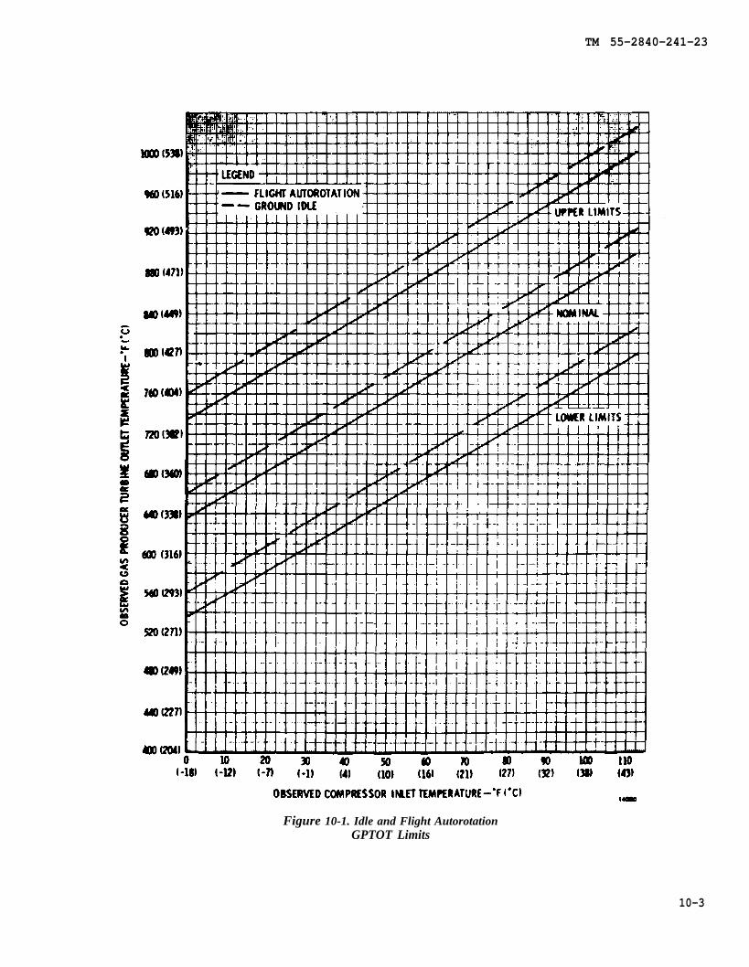
TM 55-2840-241-23
Figure 10-1. Idle and Flight AutorotationGPTOT Limits
10-3
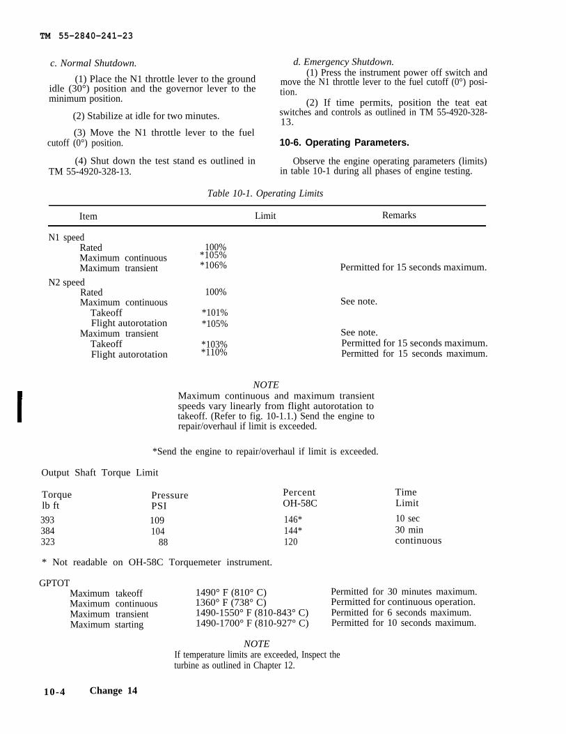
TM 55-2840-241-23
c. Normal Shutdown. d. Emergency Shutdown.
(1) Place the N1 throttle lever to the ground(1) Press the instrument power off switch and
move the N1 throttle lever to the fuel cutoff (0°) posi-idle (30°) position and the governor lever to the tion.minimum position. (2) If time permits, position the teat eat
(2) Stabilize at idle for two minutes. switches and controls as outlined in TM 55-4920-328-13.
(3) Move the N1 throttle lever to the fuelcutoff (0°) position. 10-6. Operating Parameters.
(4) Shut down the test stand es outlined in Observe the engine operating parameters (limits)TM 55-4920-328-13. in table 10-1 during all phases of engine testing.
Table 10-1. Operating Limits
Item Limit Remarks
N1 speedRatedMaximum continuousMaximum transient
N2 speedRatedMaximum continuous
TakeoffFlight autorotation
Maximum transientTakeoffFlight autorotation
100%*105%*106% Permitted for 15 seconds maximum.
100%See note.
*101%*105%
See note.*103% Permitted for 15 seconds maximum.*110% Permitted for 15 seconds maximum.
NOTEMaximum continuous and maximum transientspeeds vary linearly from flight autorotation totakeoff. (Refer to fig. 10-1.1.) Send the engine torepair/overhaul if limit is exceeded.
*Send the engine to repair/overhaul if limit is exceeded.
Output Shaft Torque Limit
Torque Pressure Percentlb ft PSI OH-58C
393 109 146*384 104 144*323 88 120
* Not readable on OH-58C Torquemeter instrument.
GPTOTMaximum takeoff 1490° F (810° C)Maximum continuous 1360° F (738° C)Maximum transient 1490-1550° F (810-843° C)Maximum starting 1490-1700° F (810-927° C)
NOTE
TimeLimit
10 sec30 mincontinuous
Permitted for 30 minutes maximum.Permitted for continuous operation.Permitted for 6 seconds maximum.Permitted for 10 seconds maximum.
If temperature limits are exceeded, Inspect theturbine as outlined in Chapter 12.
10-4 Change 14
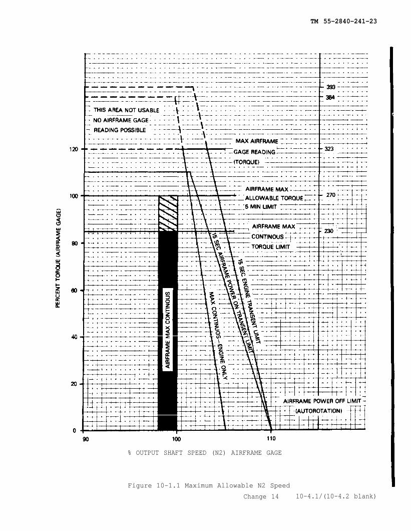
TM 55-2840-241-23
% OUTPUT SHAFT SPEED (N2) AIRFRAME GAGE
Figure 10-1.1 Maximum Allowable N2 Speed
Change 14 10-4.1/(10-4.2 blank)

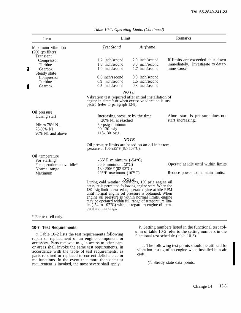
TM 55-2840-241-23
Table 10-1. Operating Limits (Continued)
Item Limit Remarks
Maximum vibration Test Stand Airframe(200 cps filter)
Transient1.2 inch/second 2.0 inch/second If limits are exceeded shut downCompressor
Turbine 1.8 inch/second 3.0 inch/second immediately. InvestigateGearbox 1.0 inch/second 1.7 inch/second mine cause.
Steady stateCompressor 0.6 inch/second 0.9 inch/secondTurbine 0.9 inch/second 1.5 inch/secondGearbox 0.5 inch/second 0.8 inch/second
NOTEVibration test required after initial installation ofengine in aircraft or when excessive vibration is sus-pected (refer to paragraph 12-8).
Oil pressureDuring start
Idle to 78% N178-89% N190% N1 and above
Oil temperatureFor startingFor operation above idle*Normal rangeMaximum
Increasing pressure by the time Abort start is pressure20% N1 is reached start increasing.
50 psig minimum90-130 psig115-130 psig
NOTEOil pressure limits are based on an oil inlet tem-perature of 180-225°F (82- 107°C).
to deter-
does not
-65°F minimum (-54°C)35°F minimum (2°C) Operate at idle until within limits180-200°F (82-93°C)225°F maximum (107°C) Reduce power to maintain limits.
During cold weather operations, 150 psig engine oilpressure is permitted following engine start. When the130 psig limit is exceeded, operate engine at idle RPMuntil normal engine oil pressure is obtained. Whenengine oil pressure is within normal limits, enginemay be operated within full range of temperature lim-its (-54 to 107°C) without regard to engine oil tem-perature markings.
NOTE
* For test cell only.
10-7. Test Requirements. b. Setting numbers listed in the functional test col-
a. Table 10-2 lists the test requirements followingumn of table 10-2 refer to the setting numbers in the
repair or replacement of an engine component orfunctional test schedule (table 10-3).
accessory. Parts removed to gain access to other partsor areas shall invoke the same test requirements, in c. The following test points should be utilized foraccordance with the table of test requirements, as vibration testing of an engine when installed in a air-parts repaired or replaced to correct deficiencies or craft.malfunctions. In the event that more than one testrequirement is invoked, the most severe shall apply. (1) Steady state data points:
Change 14 10-5
TM 55-2840-241-23
(a) Throttle full open, 100% N2, flat pitch,stabilize for 30 seconds, record reading.
(b) Throttle full open, 100% N2, increasecollective until skids are light, stabilize for 30 seconds,record reading.
(2) Transient datapoint:
(a) Throttle at idle, flat pitch, increase throt-tle to full open, 100% N2, record the peak reading.
(b) Throttle full open, 100% N2, flat pitch,increase collective until skids are light, record the peakreading.
10-6 Change 14
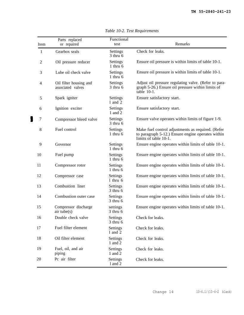
TM 55-2840-241-23
Table 10-2. Test Requirements
Parts replaced FunctionalItem or repaired test Remarks
1
2
3
4
5
6
7
8
9
10
11
12
13
14
15
16
17
18
19
20
Gearbox seals
Oil pressure reducer
Lube oil check valve
Oil filter housing andassociated valves
Spark igniter
Ignition exciter
Compressor bleed valve
Fuel control
Governor
Fuel pump
Compressor rotor
Compressor case
Combustion liner
Combustion outer case
Compressor dischargeair tube(s)
Double check valve
Fuel filter element
Oil filter element
Fuel, oil, and airpipingPc air filter
Settings3 thru 6
Settings1 thru 6
Settings1 thru 6
Settings3 thru 6
Settingsl and 2Settings1 and 2
Settings3 thru 6
Settings1 thru 6
Settings1 thru 6
Settings1 thru 6
Settings1 thru 6
Settingsl thru 6Settings3 thru 6Settings3 thru 6
settings3 thru 6
Settings3 thru 6Settingsl and 2
Settings1 and 2
Settings1 and 2Settings l and 2
Check for leaks.
Ensure oil pressure is within limits of table 10-1.
Ensure oil pressure is within limits of table 10-1.
Adjust oil pressure regulating valve. (Refer to para-graph 5-26.) Ensure oil pressure within limits oftable 10-1.
Ensure satisfactory start.
Ensure satisfactory start.
Ensure valve operates within limits of figure 1-9.
Make fuel control adjustments as required. (Referto paragraph 5-12.) Ensure engine operates withinlimits of table 10-1.Ensure engine operates within limits of table 10-1.
Ensure engine operates within limits of table 10-1.
Ensure engine operates within limits of table 10-1.
Ensure engine operates within limits of table 10-1.
Ensure engine operates within limits of table 10-1.
Ensure engine operates within limits of table 10-1.
Ensure engine operates within limits of table 10-1.
Check for leaks.
Check for leaks.
Check for leaks.
Check for leaks.
Check for leaks.
Change 14 10-6.1/(10-6-2 blank)

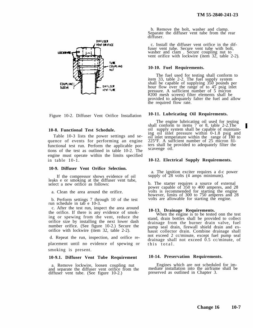
TM 55-2840-241-23
Table 10-3 lists the power settings and se-quence of events for performing an enginefunctional test run. Perform the applicable por-tions of the test as outlined in table 10-2. Theengine must operate within the limits specifiedin table 10-1.
Figure 10-2. Diffuser Vent Orifice Installation
10-8. Functional Test Schedule.
10-9. Diffuser Vent Orifice Selection.
If the compressor shows evidence of oilleaks e or smoking at the diffuser vent tube,select a new orifice as follows:
a. Clean the area around the orifice.
b. Perform settings 7 through 10 of the testrun schedule in tab e 10-3.
c. After the test run, inspect the area aroundthe orifice. If there is any evidence of smok-ing or spewing from the vent, reduce theorifice size by installing the next lower dashnumber orifice. (See figure 10-2.) Secure theorifice with lockwire (item 32, table 2-2).
When the engine is to be tested onn the teststand, drain bottles shall be provided to collectdrainage from the burner drain valve, fuelpump seal drain, firewall shield drain and ex-haust collector drain. Combine drainage shallnot exceed 2 cc/minute, except fuel pump sealdrainage shall not exceed 0.5 cc/minute, oft h i s t o t a l .
d. Repeat the run, inspection, and orifice re-placement until no evidence of spewing orsmoking is present.
10-9.1. Diffuser Vent Tube Requirement
a. Remove lockwire, loosen coupling nutand separate the diffuser vent orifice from thediffuser vent tube. (See figure 10-2.)
b. Remove the bolt, washer and clamp.Separate the diffuser vent tube from the reardiffuser.
c. Install the diffuser vent orifice in the dif-fuser vent tube. Secure vent tube with bolt,washer and clam . Secure coupling nut tovent orifice with lockwire (item 32, table 2-2).
10-10. Fuel Requirements.
The fuel used for testing shall conform toitem 33, table 2-2. The fuel suppIy systemshall be capable of supplying 350 pounds perhour flow over the range of to 45 psig inletpressure. A sufficient number of 5 micron#200 mesh screen) filter elements shall beprovided to adequately falter the fuel and allowthe required flow rate.
10-11. Lubricating Oil Requirements.
The engine lubricating oil used for testingshall conform to items 7 or 8, table 2-2.Theoil supply system shall be capable of maintain-ing oil inlet pressure within 0-1.8 psig andoil inlet temperature within the range of 180 to225°F. A suffcient number of 25 micron fil-ters shall be provided to adequately filter thescavenge oil.
10-12. Electrical Supply Requirements.
a. The ignition exciter requires a d-c powersupply of 28 volts (4 amps minimum).
b. The starter requires a source of externalpower capable of 350 to 400 amperes, and 28volts is recommended for starting the enginehowever, limits of 300 to 750 amperes and 28volts are allowable for starting the engine.
10-13. Drainage Requirements.
10-14. Preservation Requirements.
Engines which are not scheduled for im-mediate installation into the airframe shall bepreserved as outlined in Chapter 3.
Change 16 10-7
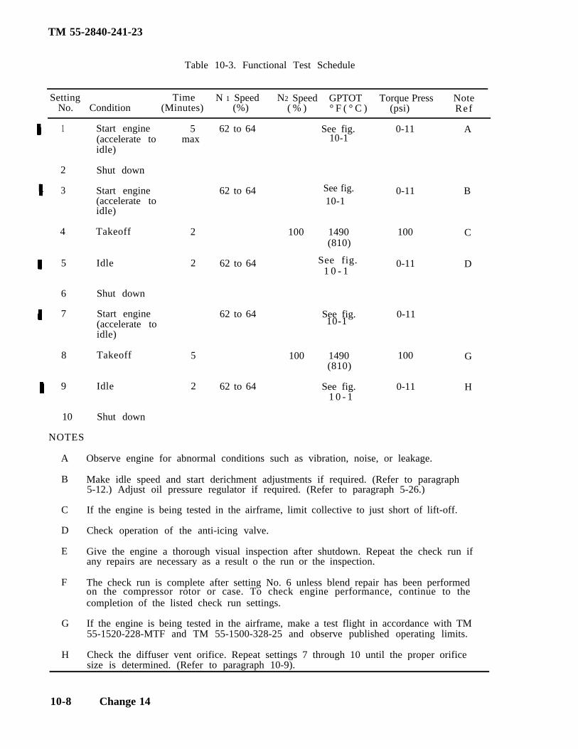
TM 55-2840-241-23
Table 10-3. Functional Test Schedule
Setting Time N 1 Speed N2 Speed GPTOT Torque Press NoteNo. Condition (Minutes) (%) ( % ) (psi)° F ( ° C ) Ref
1
2
3
4
5
6
7
8
9
10-1
See fig.
See fig.1 0 - 1
10-1
10
NOTES
A
B
C
D
E
F
G
H
Start engine(accelerate toidle)
Shut down
Start engine(accelerate toidle)
Takeoff
Idle
Shut down
Start engine(accelerate toidle)
Takeoff
Idle
Shut down
5max
2
2
5
2
62 to 64
62 to 64
62 to 64
62 to 64
62 to 64
See fig. 0-11 A
0-11 B10-1
100 1490 100 C(810)
0-11 D
See fig. 0-11
100 1490 100 G(810)
See fig. 0-11 H1 0 - 1
Observe engine for abnormal conditions such as vibration, noise, or leakage.
Make idle speed and start derichment adjustments if required. (Refer to paragraph5-12.) Adjust oil pressure regulator if required. (Refer to paragraph 5-26.)
If the engine is being tested in the airframe, limit collective to just short of lift-off.
Check operation of the anti-icing valve.
Give the engine a thorough visual inspection after shutdown. Repeat the check run ifany repairs are necessary as a result o the run or the inspection.
The check run is complete after setting No. 6 unless blend repair has been performed
completion of the listed check run settings.
If the engine is being tested in the airframe, make a test flight in accordance with TM55-1520-228-MTF and TM 55-1500-328-25 and observe published operating limits.
Check the diffuser vent orifice. Repeat settings 7 through 10 until the proper orificesize is determined. (Refer to paragraph 10-9).
on the compressor rotor or case. To check engine performance, continue to the
10-8 Change 14
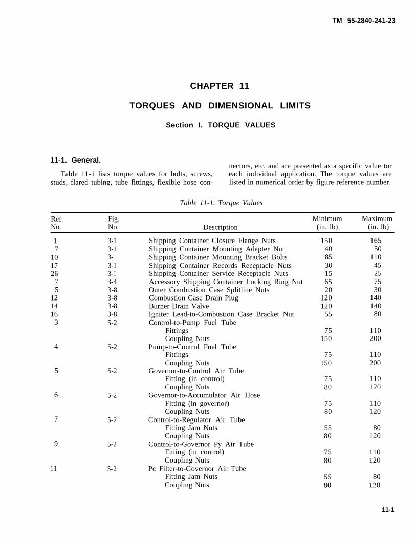
TM 55-2840-241-23
CHAPTER 11
TORQUES AND DIMENSIONAL LIMITS
Section I. TORQUE VALUES
11-1. General.nectors, etc. and are presented as a specific value tor
Table 11-1 lists torque values for bolts, screws, each individual application. The torque values arestuds, flared tubing, tube fittings, flexible hose con- listed in numerical order by figure reference number.
Table 11-1. Torque Values
Ref. Fig. Minimum MaximumNo. No. Description (in. lb) (in. lb)
17
101726
75
121416
3
3-13-13-13-13-13-43-83-83-83-85-2
Shipping Container Closure Flange NutsShipping Container Mounting Adapter NutShipping Container Mounting Bracket BoltsShipping Container Records Receptacle NutsShipping Container Service Receptacle NutsAccessory Shipping Container Locking Ring NutOuter Combustion Case Splitline NutsCombustion Case Drain PlugBurner Drain ValveIgniter Lead-to-Combustion Case Bracket NutControl-to-Pump Fuel Tube
FittingsCoupling Nuts
Pump-to-Control Fuel TubeFittingsCoupling Nuts
Governor-to-Control Air TubeFitting (in control)Coupling Nuts
Governor-to-Accumulator Air HoseFitting (in governor)Coupling Nuts
Control-to-Regulator Air TubeFitting Jam NutsCoupling Nuts
Control-to-Governor Py Air TubeFitting (in control)Coupling Nuts
Pc Filter-to-Governor Air TubeFitting Jam NutsCoupling Nuts
150408530156520
120120
55
16550
11045257530
140140
80
75150
110200
4 5-275
150110200
5 5-27580
110120
6 5-27580
110120
7 5-25580
80120
9 5-2110120
7580
11 5-280
1205580
11-1
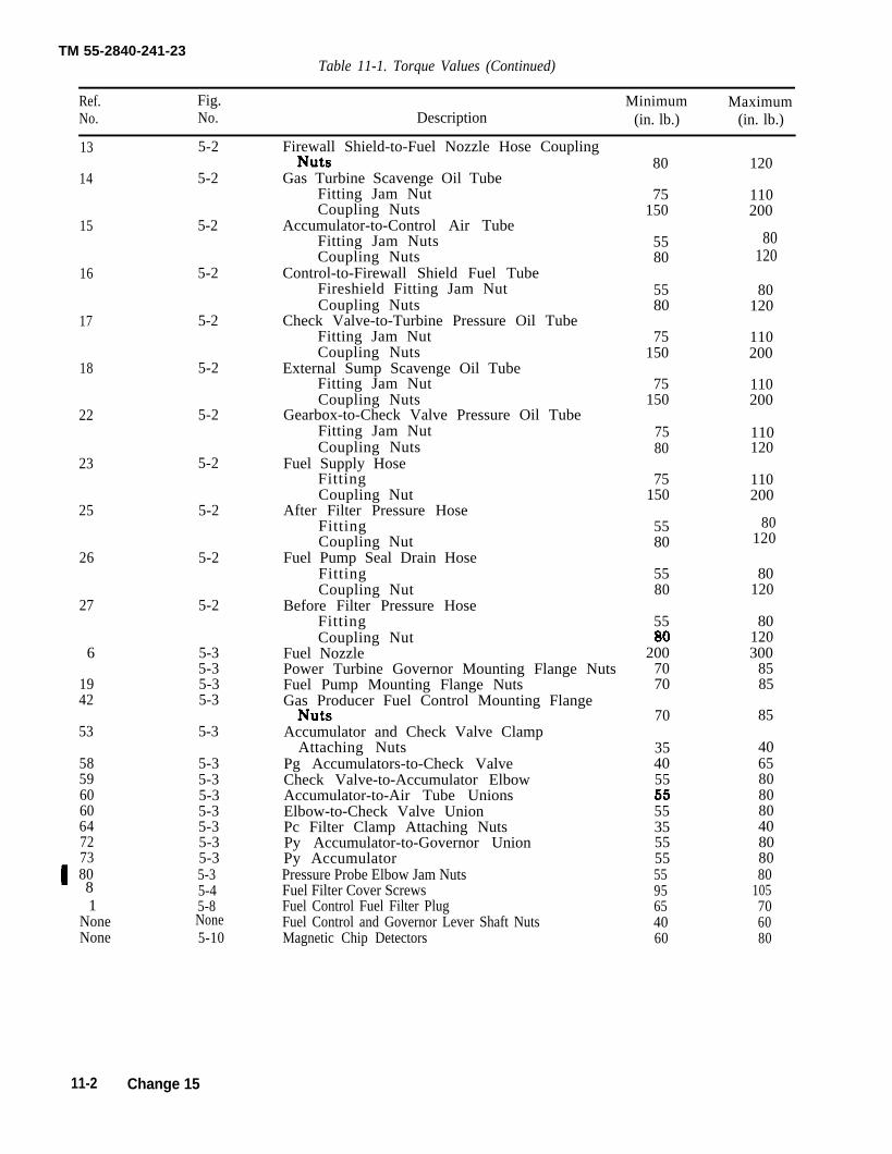
TM 55-2840-241-23Table 11-1. Torque Values (Continued)
Ref. Fig. Minimum MaximumNo. No. Description (in. lb.) (in. lb.)
13
14
15
16
17
18
22
23
25
26
27
6
1942
53
5859606064727380
1NoneNone
5-2
5-2
5-2
5-2
5-2
5-2
5-2
5-2
5-2
5-2
5-2
5-35-35-35-3
5-3
5-35-35-35-35-35-35-35-35-45-8
80120
80120
8
None5-10
Firewall Shield-to-Fuel Nozzle Hose Coupling
Gas Turbine Scavenge Oil TubeFitting Jam NutCoupling Nuts
Accumulator-to-Control Air TubeFitting Jam NutsCoupling Nuts
Control-to-Firewall Shield Fuel TubeFireshield Fitting Jam NutCoupling Nuts
Check Valve-to-Turbine Pressure Oil TubeFitting Jam NutCoupling Nuts
External Sump Scavenge Oil TubeFitting Jam NutCoupling Nuts
Gearbox-to-Check Valve Pressure Oil TubeFitting Jam NutCoupling Nuts
Fuel Supply HoseFittingCoupling Nut
After Filter Pressure HoseFittingCoupling Nut
Fuel Pump Seal Drain HoseFittingCoupling Nut
Before Filter Pressure HoseFittingCoupling Nut
Fuel NozzlePower Turbine Governor Mounting Flange NutsFuel Pump Mounting Flange NutsGas Producer Fuel Control Mounting Flange
Accumulator and Check Valve ClampAttaching Nuts
Pg Accumulators-to-Check ValveCheck Valve-to-Accumulator ElbowAccumulator-to-Air Tube UnionsElbow-to-Check Valve UnionPc Filter Clamp Attaching NutsPy Accumulator-to-Governor UnionPy AccumulatorPressure Probe Elbow Jam NutsFuel Filter Cover ScrewsFuel Control Fuel Filter PlugFuel Control and Governor Lever Shaft NutsMagnetic Chip Detectors
80
75150
5580
5580
75150
75150
7580
75150
5580
5580
55
2007070
70
354055
553555555595654060
120
110200
80120
110200
110200
110120
110200
80120
80120300
8585
85
406580808040808080
105706080
11-2 Change 15
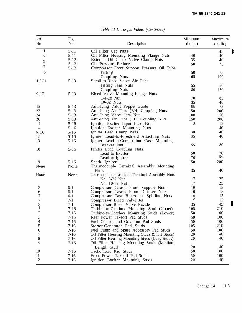
TM 55-2840-241-23
Table 11-1. Torque Values (Continued)
Ref. Fig. Minimum MaximumNo. No. Description (in. lb.) (in. lb.)
17578
1,3,31
9,12
15232426
14
6,161213
18
9019None
None
36778
23456789
8
1
101112
5-115-115-125-125-12
5-13
5-13
5-135-135-135-135-165-165-165-165-16
5-16
5-16None
None
6-16-16-17-17-17-167-167-167-167-167-167-167-167-16
7-167-167-16
Oil Filter Cap NutsOil Filter Housing Mounting Flange NutsExternal Oil Check Valve Clamp NutsOil Pressure ReducerCompressor Front Support Pressure Oil Tube
FittingCoupling Nuts
Scroll-to-Bleed Valve Air TubeFitting Jam NutsCoupling Nuts
Bleed Valve Mounting Flange Nuts1/4-28 Nut10-32 Nuts
Anti-Icing Valve Poppet GuideAnti-Icing Air Tube (RH) Coupling NutsAnti-Icing Valve Jam NutAnti-Icing Air Tube (LH) Coupling NutsIgnition Exciter Input Lead NutIgnition Exciter Mounting NutsIgniter Lead Clamp NutsIgniter Lead-to-Fireshield Attaching NutsIgniter Lead-to-Combustion Case Mounting
Bracket NutIgniter Lead Coupling Nuts
Lead-to-ExciterLead-to-Igniter
Spark IgniterThermocouple Terminal Assembly Mounting
NutsThermocouple Leads-to-Terminal Assembly Nuts
No. 8-32 NutNo. 10-32 Nut
Compressor Case-to-Front Support NutsCompressor Case-to-Front Diffuser NutsCompressor Case Horizontal Splitline NutsCompressor Bleed Valve JetCompressor Bleed Valve NozzleTurbine-to-Gearbox Mounting Stud (Upper)Turbine-to-Gearbox Mounting Studs (Lower)Rear Power Takeoff Pad StudsFuel Control and Governor Pad StudsStarter-Generator Pad StudsFuel Pump and Spare Accessory Pad StudsOil Filter Housing Mounting Studs (Short Studs)Oil Filter Housing Mounting Studs (Long Studs)Oil Filter Housing Mounting Studs (Medium
Length Stud)Tachometer Pad StudsFront Power Takeoff Pad StudsIgnition Exciter Mounting Studs
403550
5065
5580
703565
150100150
8
3035
55
5070
150
35
1717101010
35105505050
105502020
20505020
45404075
75100
80120
854075
200150200
12404040
80
70
200
40
25251515151245
2101001001002101004040
4010010040
Change 14 11-3
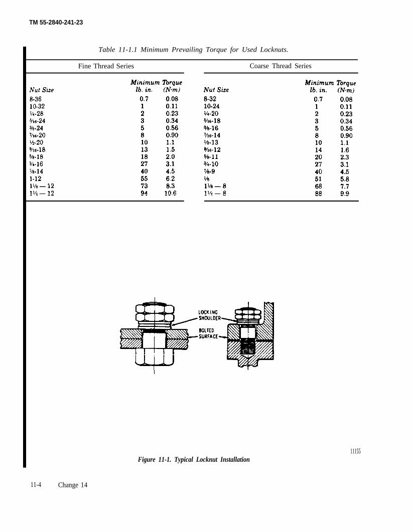
TM 55-2840-241-23
Table 11-1.1 Minimum Prevailing Torque for Used Locknuts.
Fine Thread Series Coarse Thread Series
Figure 11-1. Typical Locknut Installation11155
11-4 Change 14
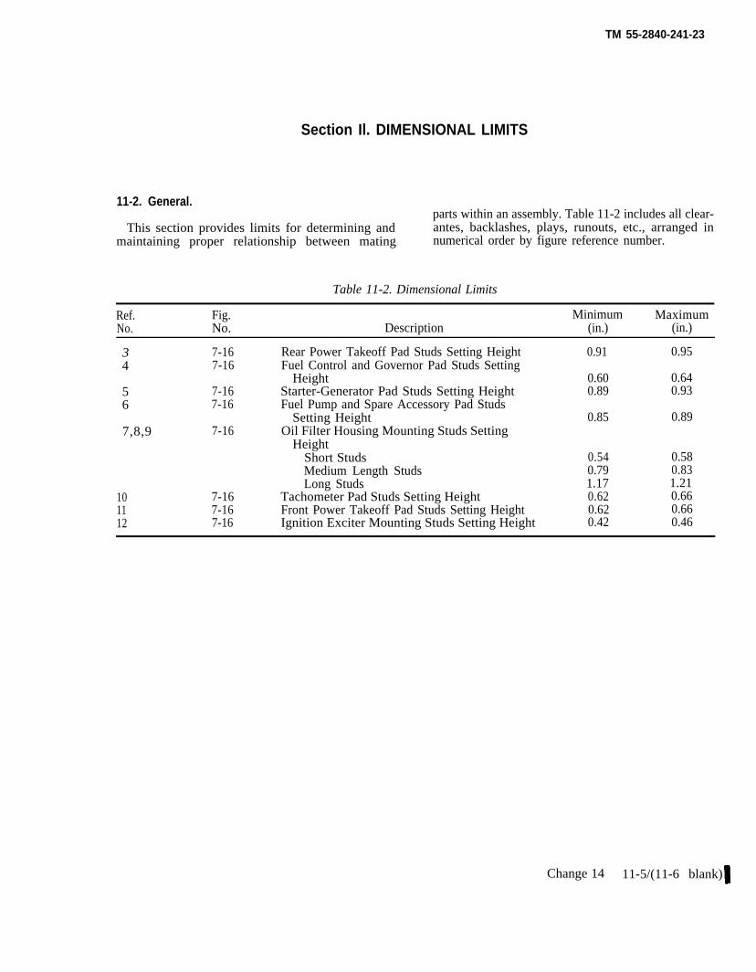
TM 55-2840-241-23
Section Il. DIMENSIONAL LIMITS
11-2. General.parts within an assembly. Table 11-2 includes all clear-
This section provides limits for determining and antes, backlashes, plays, runouts, etc., arranged inmaintaining proper relationship between mating numerical order by figure reference number.
Table 11-2. Dimensional Limits
Ref. Fig. Minimum MaximumNo. No. Description (in.) (in.)
3 7-16 Rear Power Takeoff Pad Studs Setting Height 0.91 0.954 7-16 Fuel Control and Governor Pad Studs Setting
Height 0.60 0.645 7-16 Starter-Generator Pad Studs Setting Height 0.89 0.936 7-16 Fuel Pump and Spare Accessory Pad Studs
Setting Height 0.85 0.897,8,9 7-16 Oil Filter Housing Mounting Studs Setting
HeightShort Studs 0.54 0.58Medium Length Studs 0.79 0.83Long Studs 1.17 1.21
10 7-16 Tachometer Pad Studs Setting Height 0.62 0.6611 7-16 Front Power Takeoff Pad Studs Setting Height 0.62 0.6612 7-16 Ignition Exciter Mounting Studs Setting Height 0.42 0.46
Change 14 11-5/(11-6 blank)

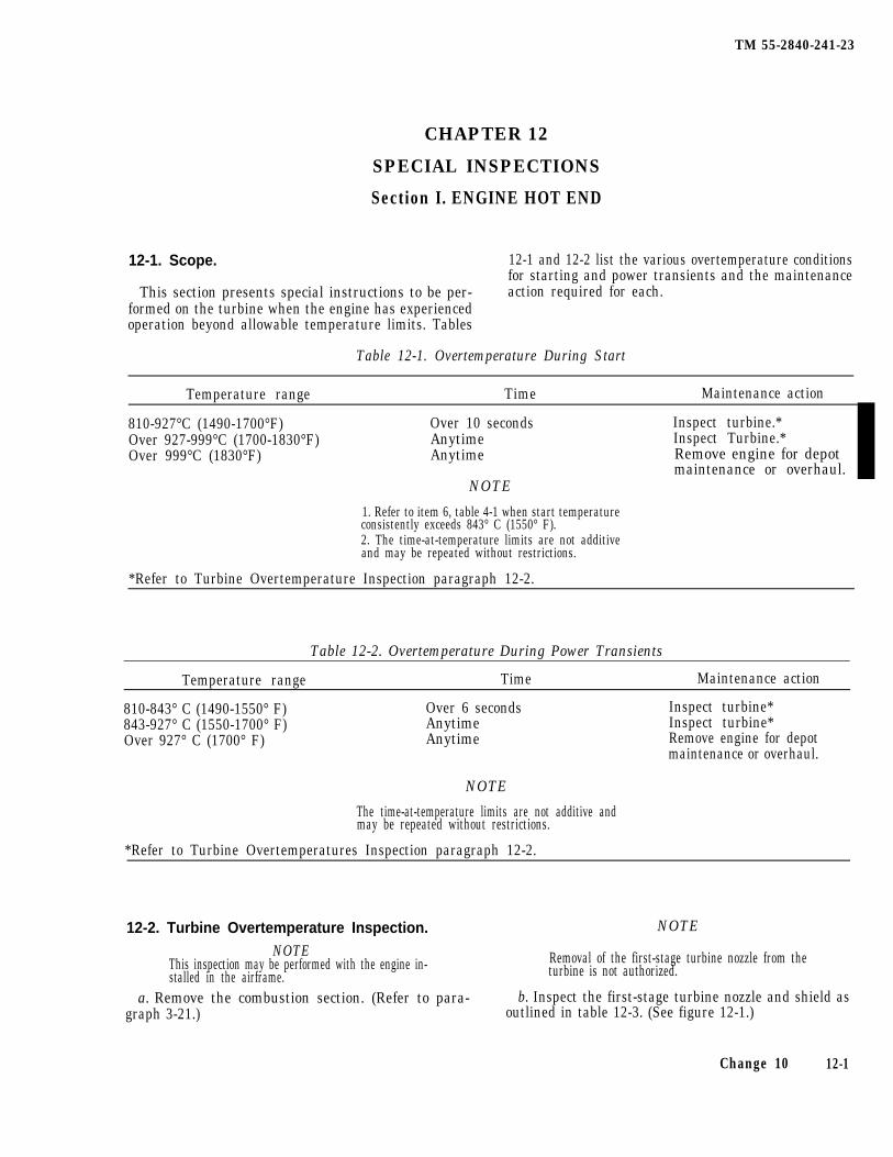
TM 55-2840-241-23
CHAPTER 12
SPECIAL INSPECTIONS
Section I. ENGINE HOT END
12-1. Scope. 12-1 and 12-2 list the various overtemperature conditionsfor starting and power transients and the maintenance
This section presents special instructions to be per- action required for each.formed on the turbine when the engine has experiencedoperation beyond allowable temperature limits. Tables
Table 12-1. Overtemperature During Start
Temperature range Time Maintenance action
810-927°C (1490-1700°F) Over 10 seconds Inspect turbine.*Over 927-999°C (1700-1830°F) Anytime Inspect Turbine.*Over 999°C (1830°F) Anytime Remove engine for depot
maintenance or overhaul.NOTE
1. Refer to item 6, table 4-1 when start temperatureconsistently exceeds 843° C (1550° F).2. The time-at-temperature limits are not additiveand may be repeated without restrictions.
*Refer to Turbine Overtemperature Inspection paragraph 12-2.
Table 12-2. Overtemperature During Power Transients
Temperature range Time Maintenance action
810-843° C (1490-1550° F) Over 6 seconds Inspect turbine*843-927° C (1550-1700° F) Anytime Inspect turbine*Over 927° C (1700° F) Anytime Remove engine for depot
maintenance or overhaul.
NOTE
The time-at-temperature limits are not additive andmay be repeated without restrictions.
*Refer to Turbine Overtemperatures Inspection paragraph 12-2.
12-2. Turbine Overtemperature Inspection. NOTE
NOTEThis inspection may be performed with the engine in- Removal of the first-stage turbine nozzle from thestalled in the airframe. turbine is not authorized.
a. Remove the combustion section. (Refer to para- b. Inspect the first-stage turbine nozzle and shield asgraph 3-21.) outlined in table 12-3. (See figure 12-1.)
Change 10 12-1
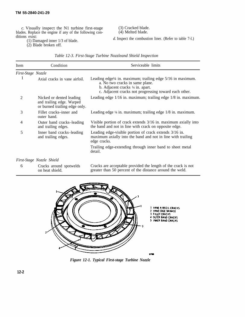
TM 55-2840-241-29
c. Visually inspect the N1 turbine first-stage (3) Cracked blade.blades. Replace the engine if any of the following con- (4) Melted blade.ditions exist:
(1) Damaged inner 1/3 of blade. d. Inspect the combustion liner. (Refer to table 7-l.)
(2) Blade broken off.
Table 12-3. First-Stage Turbine Nozzleand Shield Inspection
Item Condition Serviceable limits
First-Stage Nozzle
Axial cracks in vane airfoil.1
2 Nicked or dented leadingand trailing edge. Warpedor burned trailing edge only.
3 Fillet cracks–inner andouter hand.
4 Outer band cracks–leadingand trailing edges.
5 Inner band cracks–leadingand trailing edges.
Leading edge¼ in. maximum; trailing edge 5/16 in maximum.a. No two cracks in same plane.b. Adjacent cracks ¼ in. apart.c. Adjacent cracks not progressing toward each other.
Leading edge 1/16 in. maximum; trailing edge 1/8 in. maximum.
Leading edge ¼ in. maximum; trailing edge 1/8 in. maximum.
Visible portion of crack extends 3/16 in. maximum axially intothe band and not in line with crack on opposite edge.Leading edge-visible portion of crack extends 3/16 in.maximum axially into the band and not in line with trailingedge cracks.Trailing edge-extending through inner band to sheet metaldetail.
First-Stage Nozzle Shield6 Cracks around spotwelds Cracks are acceptable provided the length of the crack is not
on heat shield. greater than 50 percent of the distance around the weld.
Figure 12-1. Typical First-stage Turbine Nozzle
12-2
TM 55-2840-241-23
Section II. COMPRESSOR
b. Inspect the compressor front supportvanes and first-stage rotor blades. Replace theengine if any mechanical damage, bending, ordistortion is detected. If the engine is frequently subject to sand
and dirt ingestion, compressor erosion inspec-tion is recommended. (Refer to paragraphs 7-10 and 7-11.)
a. Foreign objects or materials found ininlet during inspection of the aircraft when notin operation. If it can be determined that theblackage was not there during the last opera-tion of the engine, remove the foreign objector material and leave the engine in service.
Perform engine vibration test afterinitial installation of engine inaircraft, after removal of combus-tion case, when excessive enginevibration is suspected; or when anymaintenance has been performedthat may effect engine to transmis-sion alignment. The engine vibra-tion test requirement shall apply toall engines installed, reinstalled,new, overhauled, same or dif-ferent.
b. Power loss encountered following arestriction at the compressor inlet area whilethe engine is in operation. Blockage in flightcan usually be verified by inspection after land-ing (blockage still exists). However, someblockage may be followed by ingestion beforeinspection can take place. Objects or materialswhich were large enough to have stopped atthe inlet guide vanes before ingestion shouldbe considered to have caused compressor inletb lockage .
12-3. Scope.
This section presents special inspectionsto be performed on the engine when damagehas been sustained due to operation under ab-normal conditions or operation in severeclimatic conditions.
12-4. Snow and Ice Ingestion Inspection.
This inspection must be performed follow-ing an inflight flameout in ice producingweather or anytime snow and ice ingestion issuspected. Inspect the compressor or snow,ice, or water damage as follows:
a. Obtain access to the compressor inlet butdo not disassemble any engine parts.
12-5. Compressor Inlet Blockage Inspec-tion.
Replace the engine if it has been operatedwith inlet air restricted due to foreign objectsor materials which have become lodged in thecompressor relet. Tag the replaced engine toshow that the cause of removal was inlet airblockage. Conditions which constitute block-age are as follows:
12-6. Foreign Object Damage (FOD) In-spection.
Power loss associated with an increase inengine vibration can often be attributed to
foreign object damage. Inspect for foreign ob-ject damage as follows:
a. Obtain access to the compressor inlet butdo not disassemble any engine parts.
b. Inspect the compressor front supportvanes and first-stage rotor blades and vanesfor FOD.
c. If the inspection in step b is inconclusive,remove one compressor case half and checkfor FOD. (Refer to paragraph 6-2.)
d. If the compressor FOD is not detected,remove the combustion section (paragraph 3-21) and check the turbine first-stage vanes andblades for FOD.
e. If compressor or turbine FOD is detected,replace the engine.
12-7. Erosion Inspection.
12-8. Vibration Inspection.
NOTE
In engine. vibration is encountered deter-mine the origin of the vibration as follows andrepair or replace the engine as applicable.
a. Install vibration monitoring kit, tool No.171170-0104, in accordance with TM 55-4920-243-15.
b. Run the engine and check for vibration inexcess of the limits specified in table 10-1.Note the origin of the vibration.
c. If the compressor, turbine, or gearboxvibration limits are exceeded, replace the en-gine.
Change 16 12-3
TM 55-2840-241-23
Section III. ABNORMAL FLIGHT MANEUVER INSPECTION
12-9. Hard Landing Inspection.
a. Replace the engine if landing forces ex-ceed 10 g. Use the airframe condition to deter-mine if the 10g force limit has been exceeded.If the airframe landing skids and cross tubesare deformed to a degree that the fuselagetouches (or shows evidence of having touched)the ground, the 10g limit has been exceeded.
b. If the conditions of step a do not apply,make an inspection of the engine for damageas follows
(1) Check gearbox housing and flanges forcracks.
(2) Inspect magnetic chip detectors formetal particle accumulation.
(3) Check engine mounting pads for cracks.
(4) Check air, oil, and fuel tube connec-tions for tightness and leaks.
(5) Check all engine accessories for crack-ed flanges, loose bolts and nuts, connections,and general condition.
(6) Install vibration monitoring kit, toolNo. 171170-0104, in accordance with TM 55-4920-243-15, and operate the engine on theground for 30 minutes. Check for vibration inexcess of the limits specified in table 10-1.
(7) Shut down and check the magneticchip detectors for metal particles.
12-10. Sudden Stoppage Inspection.
The following inspections must be ac-complished whenever the main rotor or tailrotor strikes a stationary object.
a. Inspect the engine mounts for cracks andsecurity. If stoppage was severe enough tofracture an engine mount, send the engine tooverhaul.
b. Check the magnetic chip detectors formetal particles.
c. Inspect the compressor blades and vanesfor foreign object damage.
d. Inspect the engine inlet for foreign objects.
e. Motor the engine and check for unusualnoise.
f. Install vibration monitoring kit, tool No.171170-0104, in accordance with TM 55-4920-243-15 and operate the engine on the groundfor 30 minutes. Check that vibration is withinlimits specified in table 10-1.
g. Shut down and check the magnetic chipdetectors for metal particles.
h. Reinspect the magnetic chip detectorsafter eight hours of engine operation.
12-4
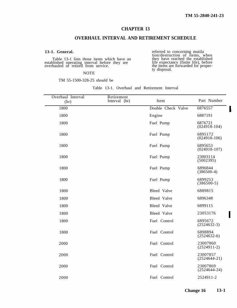
TM 55-2840-241-23
CHAPTER 13
OVERHAUL INTERVAL AND RETIREMENT SCHEDULE
13-1. General. referred to concerning mutila
Table 13-1 lists those items which have antion/destruction of items, whenthey have reached the established
overhauled or retired from service.established operating interval before they are life expectancy (finite life), before
the items are forwarded for proper-ty disposal.
NOTE
TM 55-1500-328-25 should be
Table 13-1. Overhaul and Retirement Interval
Overhaul Interval(hr)
RetirementInterval (hr) Item Part Number
1800 Double Check Valve
1800 Engine
1800 Fuel Pump
1800 Fuel Pump
1800 Fuel Pump
1800 Fuel Pump
1800 Fuel Pump
1800 Fuel Pump
1800 Bleed Valve
1800 Bleed Valve
1800 Bleed Valve
1800 Bleed Valve
1800 Fuel Control
1800 Fuel Control
2000 Fuel Control
2000 Fuel Control
2000 Fuel Control
2000 Fuel Control
6876557
6887191
6876721(024918-104)
6895172(024918-106)
6895653(024918-107)
23003114(5002395)
6896844(386500-4)
6899253(386500-5)
6889815
6896348
6899115
23053176
6895672(2524632-3)
6898894(2524632-6)
23007860(2524911-2)
23007857(2524644-21)
23007869(2524644-24)
2524911-2
Change 16 13-1
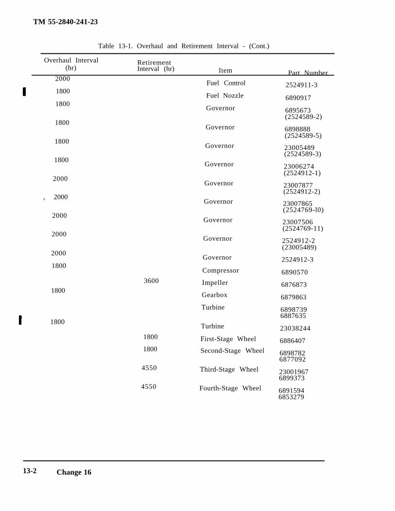
TM 55-2840-241-23
Table 13-1. Overhaul and Retirement Interval - (Cont.)
Overhaul Interval(hr)
RetirementInterval (hr) Item Part Number
2000Fuel Control
1800Fuel Nozzle
1800Governor
1800Governor
1800Governor
1800Governor
2000Governor
, 2000Governor
2000Governor
2000Governor
2000
1800
3600
1800
1800
1800
1800
4550
4550
Governor
Compressor
Impeller
Gearbox
Turbine
Turbine
First-Stage Wheel
Second-Stage Wheel
Third-Stage Wheel
Fourth-Stage Wheel
2524911-3
6890917
6895673(2524589-2)
6898888(2524589-5)
23005489(2524589-3)
23006274(2524912-1)
23007877(2524912-2)
23007865(2524769-l0)
23007506(2524769-11)
2524912-2(23005489)
2524912-3
6890570
6876873
6879863
68987396887635
23038244
6886407
68987826877092
230019676899373
68915946853279
13-2 Change 16
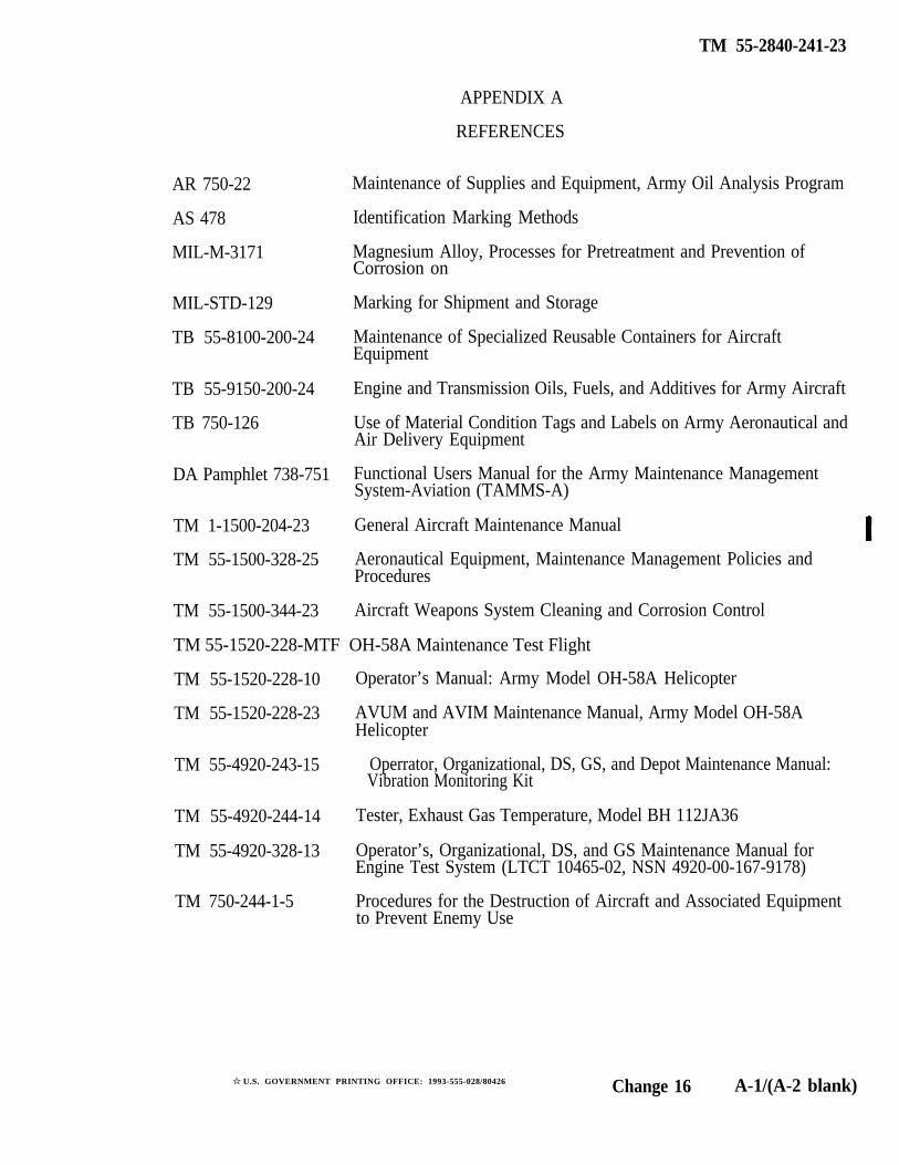
TM 55-2840-241-23
APPENDIX A
REFERENCES
AR 750-22 Maintenance of Supplies and Equipment, Army Oil Analysis Program
AS 478 Identification Marking Methods
MIL-M-3171 Magnesium Alloy, Processes for Pretreatment and Prevention ofCorrosion on
MIL-STD-129 Marking for Shipment and Storage
TB 55-8100-200-24 Maintenance of Specialized Reusable Containers for AircraftEquipment
TB 55-9150-200-24 Engine and Transmission Oils, Fuels, and Additives for Army Aircraft
TB 750-126 Use of Material Condition Tags and Labels on Army Aeronautical andAir Delivery Equipment
DA Pamphlet 738-751 Functional Users Manual for the Army Maintenance ManagementSystem-Aviation (TAMMS-A)
TM 1-1500-204-23 General Aircraft Maintenance Manual
TM 55-1500-328-25 Aeronautical Equipment, Maintenance Management Policies andProcedures
TM 55-1500-344-23 Aircraft Weapons System Cleaning and Corrosion Control
TM 55-1520-228-MTF OH-58A Maintenance Test Flight
TM 55-1520-228-10 Operator’s Manual: Army Model OH-58A Helicopter
TM 55-1520-228-23 AVUM and AVIM Maintenance Manual, Army Model OH-58AHelicopter
TM 55-4920-243-15 Operrator, Organizational, DS, GS, and Depot Maintenance Manual:Vibration Monitoring Kit
TM 55-4920-244-14 Tester, Exhaust Gas Temperature, Model BH 112JA36
TM 55-4920-328-13 Operator’s, Organizational, DS, and GS Maintenance Manual forEngine Test System (LTCT 10465-02, NSN 4920-00-167-9178)
TM 750-244-1-5 Procedures for the Destruction of Aircraft and Associated Equipmentto Prevent Enemy Use
✩ U.S. GOVERNMENT PRINTING OFFICE: 1993-555-028/80426 Change 16 A-1/(A-2 blank)

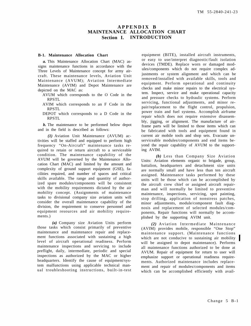
TM 55-2840-241-23
A P P E N D I X BMAINTENANCE ALLOCATION CHART
Section I. INTRODUCTION
B-1. Maintenance Allocation Chart
a. This Maintenance Allocation Chart (MAC) as-signs maintenance functions in accordance with theThree Levels of Maintenance concept for army air-craft. These maintenance levels, Aviation UnitMaintenance (AVUM); Aviat ion IntermediateMaintenance (AVIM) and Depot Maintenance aredepicted on the MAC as:
AVUM which corresponds to the O Code in theRPSTL
AVIM which corresponds to an F Code in theRPSTL
DEPOT which corresponds to a D Code in theRPSTL
b. The maintenance to be performed below depotand in the field is described as follows:
(1) Aviation Unit Maintenance (AVUM) ac-tivities will be staffed and equipped to perform highfrequency “On-Aircraft” maintenance tasks re-quired to retain or return aircraft to a serviceablecondition. The maintenance capability of theAVUM will be governed by the Maintenance Allo-cation Chart (MAC) and limited by the amount andcomplexity of ground support equipment (GSE), fa-cilities required, and number of spaces and criticalskills available. The range and quantity of author-ized spare modules/components will be consistentwith the mobility requirements dictated by the airmobility concept. (Assignments of maintenancetasks to divisional company size aviation units willconsider the overall maintenance capability of thedivision, the requirement to conserve personnel andequipment resources and air mobility require-ments.)
(a) Company size Aviation Units performthose tasks which consist primarily of preventivemaintenance and maintenance repair and replace-ment functions associated with sustaining a highlevel of aircraft operational readiness. Performmaintenance inspections and servicing to includepreflight, daily, intermediate, periodic and specialinspections as authorized by the MAC or higherheadquarters. Identify the cause of equipment/sys-tem malfunctions using applicable technical man-ual t roubleshoot ing instruct ions, bui l t - in- test
equipment (BITE), installed aircraft instruments,or easy to use/interpret diagnostic/fault isolationdevices (TMDE). Replace worn or damaged mod-ules/components which do not require complex ad-justments or system alignment and which can beremoved/installed with available skills, tools andequipment. Perform operational and continuitychecks and make minor repairs to the electrical sys-tem. Inspect, service and make operational capacityand pressure checks to hydraulic systems. Performservicing, functional adjustments, and minor re-pair/replacement to the flight control, propulsion,power train and fuel systems. Accomplish airframerepair which does not require extensive disassem-bly, jigging, or alignment. The manufacture of air-frame parts will be limited to those items which canbe fabricated with tools and equipment found incurrent air mobile tools and shop sets. Evacuate un-serviceable modules/components and end items be-yond the repair capability of AVUM to the support-ing AVIM.
(b) Less than Company Size Aviat ionUnits: Aviation elements organic to brigade, group,battalion, headquarters and detachment size unitsare normally small and have less than ten aircraftassigned. Maintenance tasks performed by theseunits will be those which can be accomplished bythe aircraft crew chief or assigned aircraft repair-man and will normally be limited to preventivemaintenance, inspections, servicing, spot painting,stop drilling, application of nonstress patches,minor adjustments, module/component fault diag-nosis and replacement of selected modules/com-ponents, Repair functions will normally be accom-plished by the supporting AVIM unit.
(2) Avia t ion In t e rmed ia t e Ma in t enance(AVIM) provides mobile, responsible “One Stop”maintenance support . (Maintenance funct ionswhich are not conducive to sustaining air mobilitywill be assigned to depot maintenance). Performsall maintenance functions authorized to be done atAVUM. Repair of equipment for return to user willemphasize support or operational readiness require-ments. Authorized maintenance includes replace-ment and repair of modules/components and itemswhich can be accomplished efficiently with avail-
C h a n g e 5 B - 1
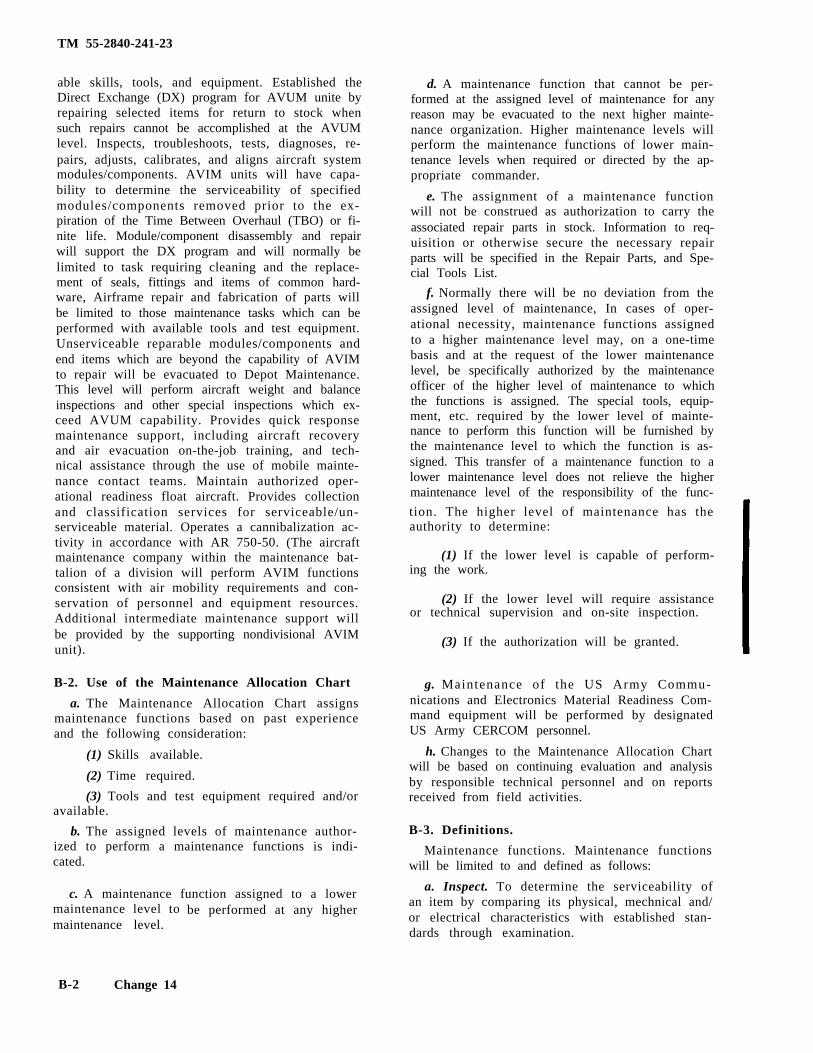
TM 55-2840-241-23
able skills, tools, and equipment. Established theDirect Exchange (DX) program for AVUM unite byrepairing selected items for return to stock whensuch repairs cannot be accomplished at the AVUMlevel. Inspects, troubleshoots, tests, diagnoses, re-pairs, adjusts, calibrates, and aligns aircraft systemmodules/components. AVIM units will have capa-bility to determine the serviceability of specifiedmodules/components removed prior to the ex-piration of the Time Between Overhaul (TBO) or fi-nite life. Module/component disassembly and repairwill support the DX program and will normally belimited to task requiring cleaning and the replace-ment of seals, fittings and items of common hard-ware, Airframe repair and fabrication of parts willbe limited to those maintenance tasks which can beperformed with available tools and test equipment.Unserviceable reparable modules/components andend items which are beyond the capability of AVIMto repair will be evacuated to Depot Maintenance.This level will perform aircraft weight and balanceinspections and other special inspections which ex-ceed AVUM capability. Provides quick responsemaintenance support, including aircraft recoveryand air evacuation on-the-job training, and tech-nical assistance through the use of mobile mainte-nance contact teams. Maintain authorized oper-ational readiness float aircraft. Provides collectionand classification services for serviceable/un-serviceable material. Operates a cannibalization ac-tivity in accordance with AR 750-50. (The aircraftmaintenance company within the maintenance bat-talion of a division will perform AVIM functionsconsistent with air mobility requirements and con-servation of personnel and equipment resources.Additional intermediate maintenance support willbe provided by the supporting nondivisional AVIMunit).
B-2. Use of the Maintenance Allocation Chart
a. The Maintenance Allocation Chart assignsmaintenance functions based on past experienceand the following consideration:
(1) Skills available.
(2) Time required.
(3) Tools and test equipment required and/oravailable.
b. The assigned levels of maintenance author-ized to perform a maintenance functions is indi-cated.
c. A maintenance function assigned to a lowermaintenance level tomaintenance level.
be performed at any higher
d. A maintenance function that cannot be per-formed at the assigned level of maintenance for anyreason may be evacuated to the next higher mainte-nance organization. Higher maintenance levels willperform the maintenance functions of lower main-tenance levels when required or directed by the ap-propriate commander.
e. The assignment of a maintenance functionwill not be construed as authorization to carry theassociated repair parts in stock. Information to req-uisition or otherwise secure the necessary repairparts will be specified in the Repair Parts, and Spe-cial Tools List.
f. Normally there will be no deviation from theassigned level of maintenance, In cases of oper-ational necessity, maintenance functions assignedto a higher maintenance level may, on a one-timebasis and at the request of the lower maintenancelevel, be specifically authorized by the maintenanceofficer of the higher level of maintenance to whichthe functions is assigned. The special tools, equip-ment, etc. required by the lower level of mainte-nance to perform this function will be furnished bythe maintenance level to which the function is as-signed. This transfer of a maintenance function to alower maintenance level does not relieve the highermaintenance level of the responsibility of the func-
tion. The higher level of maintenance has theauthority to determine:
(1) If the lower level is capable of perform-ing the work.
(2) If the lower level will require assistanceor technical supervision and on-site inspection.
(3) If the authorization will be granted.
g. Maintenance of the US Army Commu-nications and Electronics Material Readiness Com-mand equipment will be performed by designatedUS Army CERCOM personnel.
h. Changes to the Maintenance Allocation Chartwill be based on continuing evaluation and analysisby responsible technical personnel and on reportsreceived from field activities.
B-3. Definitions.
Maintenance functions. Maintenance functionswill be limited to and defined as follows:
a. Inspect. To determine the serviceability ofan item by comparing its physical, mechnical and/or electrical characteristics with established stan-dards through examination.
B-2 Change 14
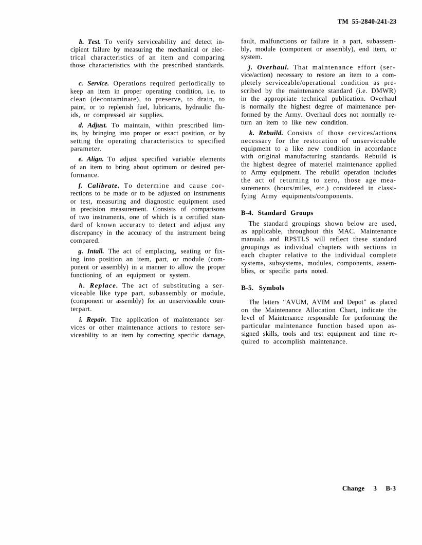
TM 55-2840-241-23
b. Test. To verify serviceability and detect in-cipient failure by measuring the mechanical or elec-trical characteristics of an item and comparingthose characteristics with the prescribed standards.
c. Service. Operations required periodically tokeep an item in proper operating condition, i.e. toclean (decontaminate), to preserve, to drain, topaint, or to replenish fuel, lubricants, hydraulic flu-ids, or compressed air supplies.
d. Adjust. To maintain, within prescribed lim-its, by bringing into proper or exact position, or bysetting the operating characteristics to specifiedparameter.
e. Align. To adjust specified variable elementsof an item to bring about optimum or desired per-formance.
f. Calibrate. To determine and cause cor-rections to be made or to be adjusted on instrumentsor test, measuring and diagnostic equipment usedin precision measurement. Consists of comparisonsof two instruments, one of which is a certified stan-dard of known accuracy to detect and adjust anydiscrepancy in the accuracy of the instrument beingcompared.
g. Intall. The act of emplacing, seating or fix-ing into position an item, part, or module (com-ponent or assembly) in a manner to allow the properfunctioning of an equipment or system.
h. Replace. The act of substituting a ser-viceable like type part, subassembly or module,(component or assembly) for an unserviceable coun-terpart.
i. Repair. The application of maintenance ser-vices or other maintenance actions to restore ser-viceability to an item by correcting specific damage,
fault, malfunctions or failure in a part, subassem-bly, module (component or assembly), end item, orsystem.
j. Overhaul. That maintenance effort (ser-vice/action) necessary to restore an item to a com-pletely serviceable/operational condition as pre-scribed by the maintenance standard (i.e. DMWR)in the appropriate technical publication. Overhaulis normally the highest degree of maintenance per-formed by the Army. Overhaul does not normally re-turn an item to like new condition.
k. Rebuild. Consists of those cervices/actionsnecessary for the restoration of unserviceableequipment to a like new condition in accordancewith original manufacturing standards. Rebuild isthe highest degree of materiel maintenance appliedto Army equipment. The rebuild operation includesthe act of returning to zero, those age mea-surements (hours/miles, etc.) considered in classi-fying Army equipments/components.
B-4. Standard Groups
The standard groupings shown below are used,as applicable, throughout this MAC. Maintenancemanuals and RPSTLS will reflect these standardgroupings as individual chapters with sections ineach chapter relative to the individual completesystems, subsystems, modules, components, assem-blies, or specific parts noted.
B-5. Symbols
The letters “AVUM, AVIM and Depot” as placedon the Maintenance Allocation Chart, indicate thelevel of Maintenance responsible for performing theparticular maintenance function based upon as-signed skills, tools and test equipment and time re-quired to accomplish maintenance.
Change 3 B-3
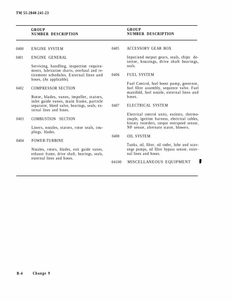
TM 55-2840-241-23
GROUP GROUPNUMBER DESCRIPTION NUMBER DESCRIPTION
0400
0401
0402
0403
0404
ENGINE SYSTEM
ENGINE GENERAL
Servicing, handling, inspection require-ments, lubrication charts, overhaul and re-tirement schedules. External lines andhoses, (As applicable).
COMPRESSOR SECTION
Rotor, blades, vanes, impeller, stators,inlet guide vanes, main frame, particleseparator, bleed valve, bearings, seals, ex-ternal lines and hoses.
COMBUSTION SECTION
Liners, nozzles, stators, rotor seals, cou-plings, blades.
POWER-TURBINE
Nozzles, rotors, blades, exit guide vanes,exhaust frame, drive shaft, bearings, seals,external lines and hoses.
0405
0406
0407
0408
04100
ACCESSORY GEAR BOX
Input/and output gears, seals, chips de-tector, housings, drive shaft bearings,seals.
FUEL SYSTEM
Fuel Control, fuel boost pump, governor,fuel filter assembly, sequence valve. Fuelmanifold, fuel nozzle, external lines andhoses.
ELECTRICAL SYSTEM
Electrical control units, exciters, thermo-couple, ignition harness, electrical cables,history recorders, torque overspeed sensor,NP sensor, alternate stator, blowers.
OIL SYSTEM
Tanks, oil, filter, oil coder, lube and scav-enge pumps, oil filter bypass sensor, exter-nal lines and hoses.
MISCELLANEOUS EQUIPMENT
B-4 Change 9
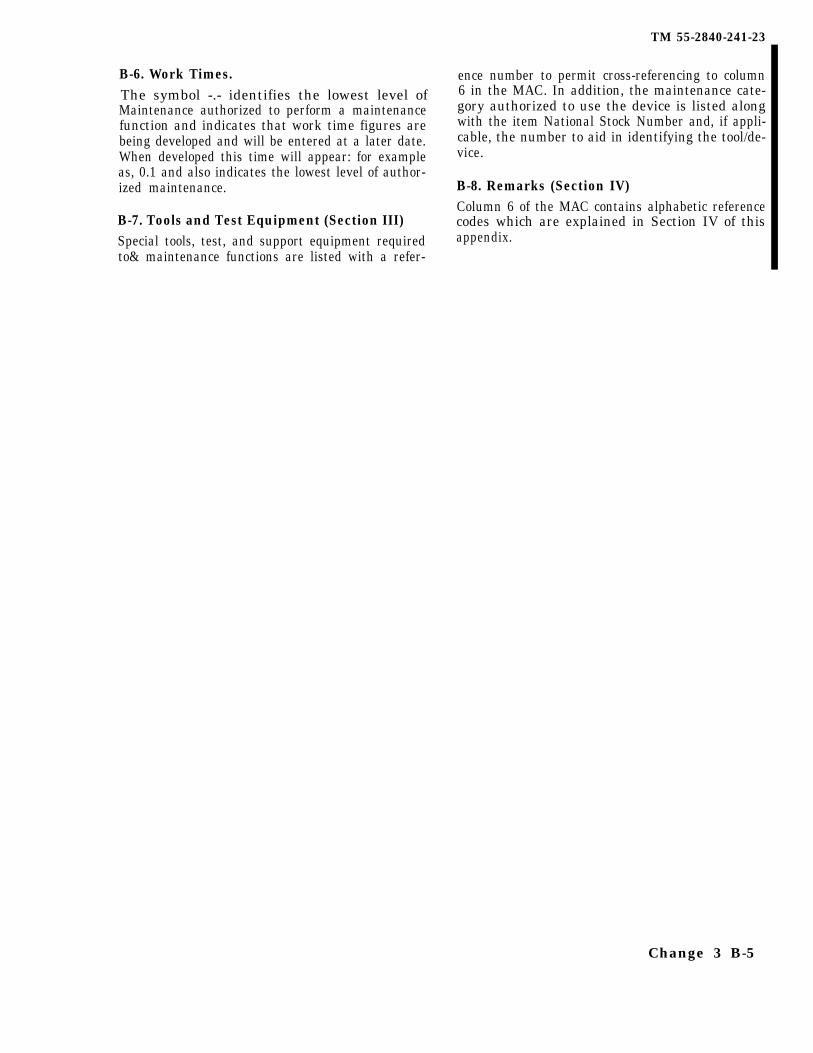
TM 55-2840-241-23
B-6. Work Times.The symbol -.- identifies the lowest level ofMaintenance authorized to perform a maintenancefunction and indicates that work time figures arebeing developed and will be entered at a later date.When developed this time will appear: for exampleas, 0.1 and also indicates the lowest level of author-ized maintenance.
B-7. Tools and Test Equipment (Section III)Special tools, test, and support equipment requiredto& maintenance functions are listed with a refer-
ence number to permit cross-referencing to column6 in the MAC. In addition, the maintenance cate-gory authorized to use the device is listed alongwith the item National Stock Number and, if appli-cable, the number to aid in identifying the tool/de-vice.
B-8. Remarks (Section IV)Column 6 of the MAC contains alphabetic referencecodes which are explained in Section IV of thisappendix.
Change 3 B-5
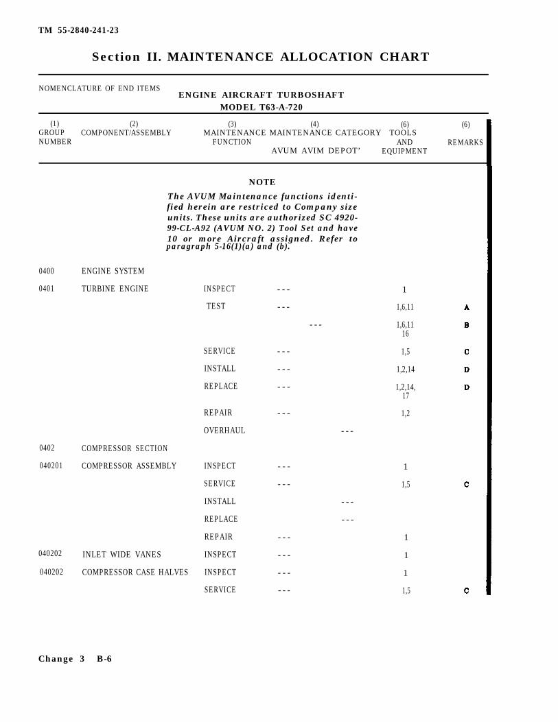
TM 55-2840-241-23
Section II. MAINTENANCE ALLOCATION CHART
NOMENCLATURE OF END ITEMSENGINE AIRCRAFT TURBOSHAFT
MODEL T63-A-720
(1) (2) (3) (4)GROUP
(6) (6)COMPONENT/ASSEMBLY MAINTENANCE MAINTENANCE CATEGORY TOOLS
NUMBER FUNCTION AND REMARKSAVUM AVIM DEPOT’ EQUIPMENT
NOTE
The AVUM Maintenance functions identi-fied herein are restriced to Company sizeunits. These units are authorized SC 4920-99-CL-A92 (AVUM NO. 2) Tool Set and have10 or more Aircraft assigned. Refer toparagraph 5-16(1)(a) and (b).
0400
0401
0402
040201
040202
ENGINE SYSTEM
TURBINE ENGINE 1
TEST
COMPRESSOR SECTION
COMPRESSOR ASSEMBLY
040202 INLET WIDE VANES
COMPRESSOR CASE HALVES
INSPECT
SERVICE
INSTALL
REPLACE
REPAIR
OVERHAUL
INSPECT
SERVICE
INSTALL
REPLACE
REPAIR
INSPECT
INSPECT
SERVICE
- - -
- - -
- - -
- - -
- - -
- - -
- - -
- - -
- - -
- - -
- - -
- - -
- - -
1,6,11
1,6,1116
1,5
1,2,14
1,2,14,17
1,2
- - -
1
1,5
- - -
- - -
1
1
1
1,5
Change 3 B-6
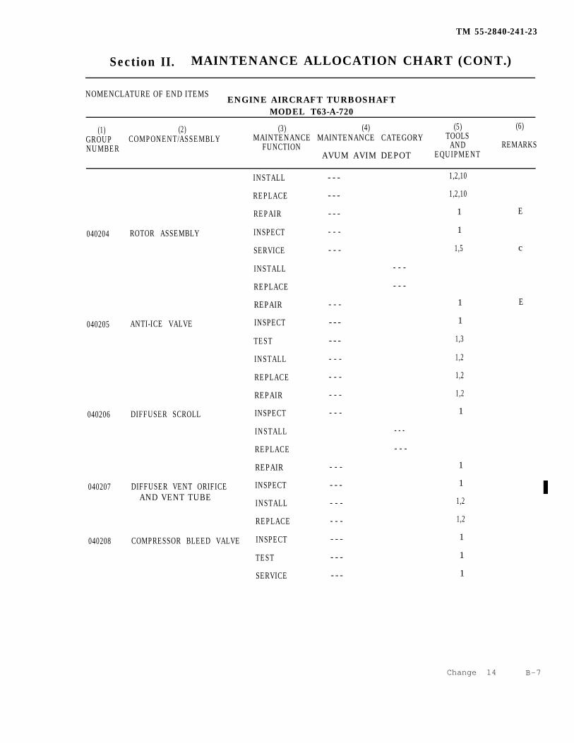
TM 55-2840-241-23
Section II. MAINTENANCE ALLOCATION CHART (CONT.)
NOMENCLATURE OF END ITEMSENGINE AIRCRAFT TURBOSHAFT
MODEL T63-A-720
(1) (2) (3) (4) (5) (6)GROUP COMPONENT/ASSEMBLY MAINTENANCE MAINTENANCE CATEGORY TOOLSNUMBER FUNCTION AND REMARKS
AVUM AVIM DEPOT EQUIPMENT
INSTALL - - - 1,2,10
REPLACE 1,2,10- - -
REPAIR 1 E- - -
040204 ROTOR ASSEMBLY
040205 ANTI-ICE VALVE
040206 DIFFUSER SCROLL
INSPECT 1- - -
SERVICE 1,5 c- - -
INSTALL
REPLACE
REPAIR - - -
INSPECT - - -
TEST - - -
INSTALL - - -
REPLACE - - -
REPAIR - - -
INSPECT - - -
INSTALL
REPLACE
REPAIR - - -
040207 DIFFUSER VENT ORIFICE INSPECT - - -AND VENT TUBE
INSTALL - - -
REPLACE - - -
040208 COMPRESSOR BLEED VALVE INSPECT - - -
TEST - - -
- - -
- - -
1
1
1,3
1,2
1,2
1,2
1
- - -
- - -
1
1
1,2
1,2
1
1
1
E
SERVICE - - -
Change 14 B-7

TM 55-2840-241-23
Section II. MAINTENANCE ALLOCATION CHART (CONT.)
NOMENCLATURE OF END ITEMSENGINE AIRCRAFT TURBOSHAFT
MODEL T63-A-720
(1) (2) (3) (4) (5) (6)GROUP COMPONENT/ASSEMBLY MAINTENANCE MAINTENANCE CATEGORY TOOLSNUMBER FUNCTION AND REMARKS
AVUM AVIM DEPOT EQUIPMENT
040209
0403
040301
040302
040303
0404
040401
F
F
B-8
OIL PRESSURE REDUCER
COMBUSTION SECTION
OUTER CASE
COMBUSTION LINER
DISCHARGE AIR TUBES
TURBINE SECTION
TURBINE ASSEMBLY
INSTALL
REPLACE
INSPECT
INSTALL
REPLACE
INSPECT
INSTALL
REPLACE
REPAIR
INSPECT
INSTALL
REPLACE
REPAIR
INSPECT
INSTALL
REPLACE
REPAIR
INSPECT
INSTALL
REPLACE
REPAIR
- - -
- - -
- - -
- - -
- - -
- - -
- - -
- - -
- - -
- - -
- - -
- - -
- - -
- - -
- - -
- - -
- - -
- - -
- - -
- - -
- - -
1,2
1,2
1
1,2
1,2
1
1
1,2
1,24
1
1,2
1,2
1,3,4,9
1
1,2,12,13
1,2,12,13
1,4
1
F
Change 3
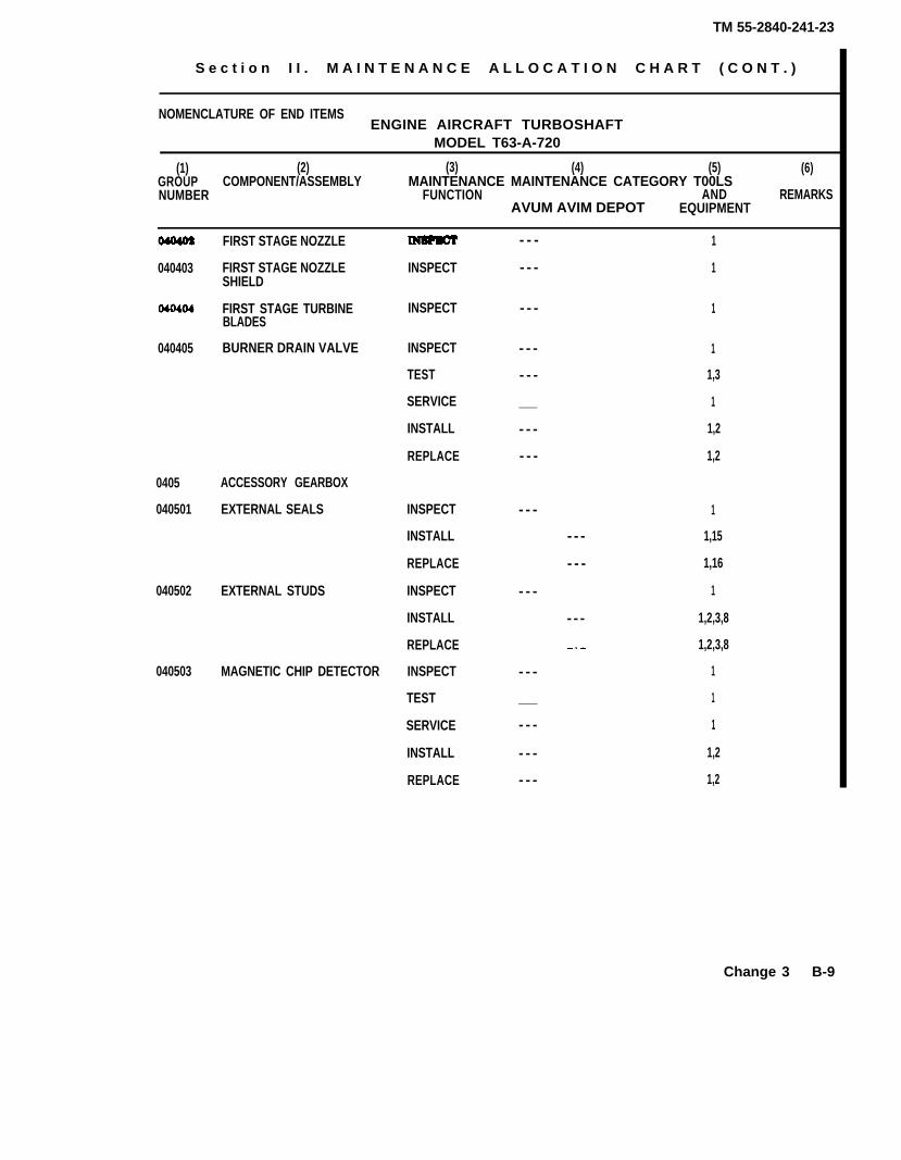
TM 55-2840-241-23
S e c t i o n I I . M A I N T E N A N C E A L L O C A T I O N C H A R T ( C O N T . )
NOMENCLATURE OF END ITEMSENGINE AIRCRAFT TURBOSHAFT
MODEL T63-A-720
(1) (2) (3) (4) (5) (6)GROUP COMPONENT/ASSEMBLY MAINTENANCE MAINTENANCE CATEGORY T00LSNUMBER FUNCTION AND REMARKS
AVUM AVIM DEPOT EQUIPMENT
FIRST STAGE NOZZLE
040403 FIRST STAGE NOZZLE INSPECTSHIELD
FIRST STAGE TURBINE INSPECTBLADES
040405 BURNER DRAIN VALVE INSPECT
TEST
SERVICE
INSTALL
REPLACE
0405 ACCESSORY GEARBOX
040501 EXTERNAL SEALS
040502 EXTERNAL STUDS
INSPECT
INSTALL
REPLACE
INSPECT
INSTALL
REPLACE
040503 MAGNETIC CHIP DETECTOR INSPECT
TEST
SERVICE
INSTALL
REPLACE
- - -
- - -
- - -
- - -
- - -
___
- - -
- - -
- - -
- - -
- - -
___
- - -
- - -
- - -
1
1
1
1
1,3
1
1,2
1,2
1
- - - 1,15
- - - 1,16
1
- - - 1,2,3,8
1,2,3,8
1
1
1
1,2
1,2
Change 3 B-9
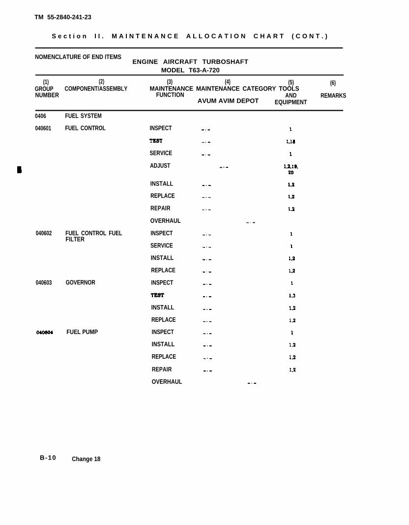
TM 55-2840-241-23
S e c t i o n I I . M A I N T E N A N C E A L L O C A T I O N C H A R T ( C O N T . )
NOMENCLATURE OF END ITEMSENGINE AIRCRAFT TURBOSHAFT
MODEL T63-A-720
(1) (2) (3) (4) (5) (6)GROUP COMPONENT/ASSEMBLY MAINTENANCE MAINTENANCE CATEGORY TOOLSNUMBER FUNCTION AND REMARKS
AVUM AVIM DEPOT EQUIPMENT
0406 FUEL SYSTEM
040601 FUEL CONTROL INSPECT
SERVICE
ADJUST
INSTALL
REPLACE
REPAIR
OVERHAUL
040602 FUEL CONTROL FUEL INSPECTFILTER
SERVICE
INSTALL
REPLACE
040603 GOVERNOR INSPECT
INSTALL
REPLACE
INSPECT
INSTALL
REPLACE
REPAIR
OVERHAUL
FUEL PUMP
B-10 Change 18
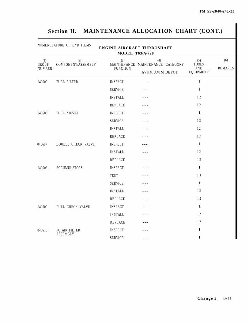
TM 55-2840-241-23
Section II. MAINTENANCE ALLOCATION CHART (CONT.)
NOMENCLATURE OF END ITEMSENGINE AIRCRAFT TURBOSHAFT
MODEL T63-A-720
(1) (2) (3) (4) (5) (6)GROUP COMPONENT/ASSEMBLY MAINTENANCE MAINTENANCE CATEGORY TOOLSNUMBER FUNCTION AND REMARKS
AVUM AVIM DEPOT EQUIPMENT
040606 FUEL NOZZLE
040608 ACCUMULATORS
040609 FUEL CHECK VALVE
040610 PC AIR FILTERASSEMBLY
040605 FUEL FILTER INSPECT
SERVICE
INSTALL
REPLACE
INSPECT
SERVICE
INSTALL
REPLACE
040607 DOUBLE CHECK VALVE INSPECT
INSTALL
REPLACE
INSPECT
TEST
SERVICE
INSTALL
REPLACE
INSPECT
INSTALL
REPLACE
INSPECT
SERVICE
- - -
- - -
- - -
- - -
- - -
- - -
- - -
- - -
- - -
- - -
- - -
- - -
- - -
- - -
- - -
- - -
- - -
- - -
- - -
- - -
- - -
1
1
1,2
1,2
1
1,2
1,2
1,2
1
1,2
1,2
1
1,3
1
1,2
1,2
1
1,2
1,2
1
1
Change 3 B-11
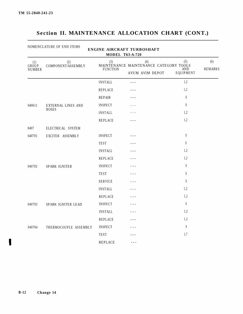
TM 55-2840-241-23
Section II. MAINTENANCE ALLOCATION CHART (CONT.)
NOMENCLATURE OF END ITEMSENGINE AIRCRAFT TURBOSHAFT
MODEL T63-A-720
(1) (2) (3) (4) (5) (6)GROUP COMPONENT/ASSEMBLY MAINTENANCE MAINTENANCE CATEGORY TOOLSNUMBER FUNCTION AND REMARKS
AVUM AVIM DEPOT EQUIPMENT
040611 EXTERNAL LINES ANDHOSES
INSTALL - - - 1,2
REPLACE - - - 1,2
REPAIR - - - 1
INSPECT - - - 1
INSTALL - - - 1,2
REPLACE - - - 1,2
0407 ELECTRICAL SYSTEM
040701 EXCITER ASSEMBLY
040702 SPARK IGNITER
040703 SPARK IGNITER LEAD
INSPECT
TEST
INSTALL
REPLACE
INSPECT
TEST
SERVICE
INSTALL
REPLACE
INSPECT
INSTALL
REPLACE
040704 THERMOCOUPLE ASSEMBLY INSPECT
TEST
REPLACE
- - -
- - -
- - -
- - -
- - -
- - -
- - -
- - -
- - -
- - -
- - -
- - -
- - -
- - -
- - -
1
1
1,2
1,2
1
1
1
1,2
1,2
1
1,2
1,2
1
1,7
B-12 Change 14
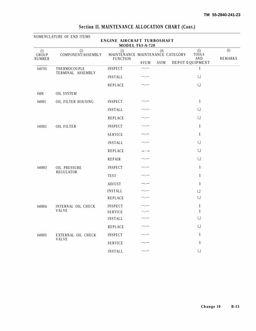
TM 55-2840-241-23
Section II. MAINTENANCE ALLOCATION CHART (Cont.)
NOMENCLATURE OF END ITEMSENGINE AIRCRAFT TURBOSHAFT
MODEL T63-A-720(1) (2) (3) (4) (5) (6)
GROUP COMPONENT/ASSEMBLY MAINTENANCE MAINTENANCE CATEGORY TOOLSNUMBER FUNCTION AND REMARKS
AVUM AVIM DEPOT EQUIPMENT040705 THERMOCOUPLE INSPECT
TERMINAL ASSEMBLYINSTALL
REPLACE
0408 OIL SYSTEM
040801 OIL FILTER HOUSING INSPECT
INSTALL
REPLACE
040802 OIL FILTER INSPECT
SERVICE
INSTALL
REPLACE
REPAIR
040803 OIL PRESSUREREGULATOR
INSPECT
TEST
ADJUST
INSTALL
REPLACE
040804 INTERNAL OIL CHECK INSPECTVALVE SERVICE
INSTALL
REPLACE
040805 EXTERNAL OIL CHECK INSPECTVALVE
SERVICE
INSTALL
—.—
—.—
—.—
—.—
—.—
—.—
—.—
—.—
—.—
—.—
—.—
—.—
—.—
—.—
—.—
—.—–.—
—.—
—.—
—.—
—.—
—.—
1
1,2
1,2
1
1,2
1,2
1
1
1,2
1,2
1,2
1
1
1
1,21,2
11
1,2
1,2
1
1
1,2
Change 10 B-13
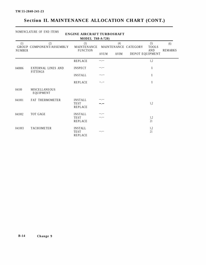
TM 55-2840-241-23
Section II. MAINTENANCE ALLOCATION CHART (CONT.)
NOMENCLATURE OF END ITEMSENGINE AIRCRAFT TURBOSHAFT
MODEL T68-A-720)(1) (2) (3) (4) (5) (6)
GROUP COMPONENT/ASSEMBLY MAINTENANCE MAINTENANCE CATEGORY TOOLSNUMBER FUNCTION AND REMARKS
AVUM AVIM DEPOT EQUIPMENT
REPLACE
040806 EXTERNAL LINES AND INSPECTFITTINGS
INSTALL
REPLACE
04100 MISCELLANEOUSEQUIPMENT
041001 FAT THERMOMETER INSTALLTESTREPLACE
041002 TOT GAGE
041003 TACHOMETER
INSTALLTESTREPLACE
INSTALLTESTREPLACE
—.— 1,2
—.— 1
—.— 1
–.– 1
—.—1,2
—.——.—
—.—
1,221
1,221
B-14 Change 9
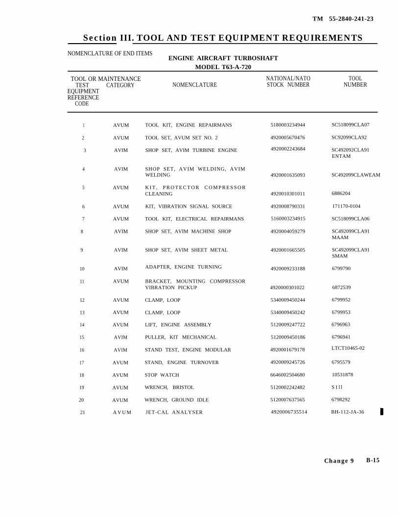
TM 55-2840-241-23
Section III. TOOL AND TEST EQUIPMENT REQUIREMENTS
NOMENCLATURE OF END ITEMSENGINE AIRCRAFT TURBOSHAFT
MODEL T63-A-720
TOOL OR MAINTENANCE NATIONAL/NATO TOOLTEST CATEGORY NOMENCLATURE STOCK NUMBER NUMBER
EQUIPMENTREFERENCE
CODE
1
2
3
4
5
6
7
8
9
10
11
12
13
14
15
16
17
18
19
20
21
AVUM
AVUM
AVIM
AVIM
AVUM
AVUM
AVUM
AVIM
AVIM
AVIM
AVUM
AVUM
AVUM
AVUM
AVIM
AVIM
AVUM
AVUM
AVUM
AVUM
A V U M
TOOL KIT, ENGINE REPAIRMANS
TOOL SET, AVUM SET NO. 2
SHOP SET, AVIM TURBINE ENGINE
SHOP SET, AVIM WELDING, AVIMWELDING
K I T , P R O T E C T O R C O M P R E S S O RCLEANING
KIT, VIBRATION SIGNAL SOURCE
TOOL KIT, ELECTRICAL REPAIRMANS
SHOP SET, AVIM MACHINE SHOP
SHOP SET, AVIM SHEET METAL
ADAPTER, ENGINE TURNING
BRACKET, MOUNTING COMPRESSORVIBRATION PICKUP
CLAMP, LOOP
CLAMP, LOOP
LIFT, ENGINE ASSEMBLY
PULLER, KIT MECHANICAL
STAND TEST, ENGINE MODULAR
STAND, ENGINE TURNOVER
STOP WATCH
WRENCH, BRISTOL
WRENCH, GROUND IDLE
JET-CAL ANALYSER
5180003234944
4920005670476
4920002243684
4920001635093
4920010301011
4920008790331
5160003234915
4920004059279
4920001665505
4920009233188
4920000301022
5340009450244
5340009450242
5120009247722
5120009450186
4920001679178
4920009245726
6646002504680
5120002242482
5120007637565
4920006735514
SC518099CLA07
SC92099CLA92
SC492092CLA91ENTAM
SC492099CLAWEAM
6886204
171170-0104
SC518099CLA06
SC492099CLA91MAAM
SC492099CLA91SMAM
6799790
6872539
6799952
6799953
6796963
6796941
LTCT10465-02
6795579
10531878
S 1 l l
6798292
BH-112-JA-36
Change 9 B-15
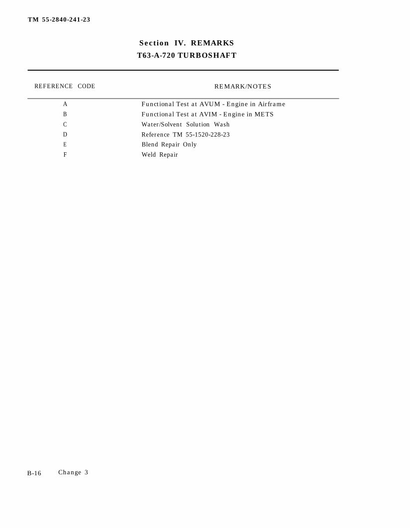
TM 55-2840-241-23
Section IV. REMARKS
T63-A-720 TURBOSHAFT
REFERENCE CODE REMARK/NOTES
A Functional Test at AVUM - Engine in Airframe
B Functional Test at AVIM - Engine in METS
C Water/Solvent Solution Wash
D Reference TM 55-1520-228-23E Blend Repair Only
F Weld Repair
B-16 Change 3
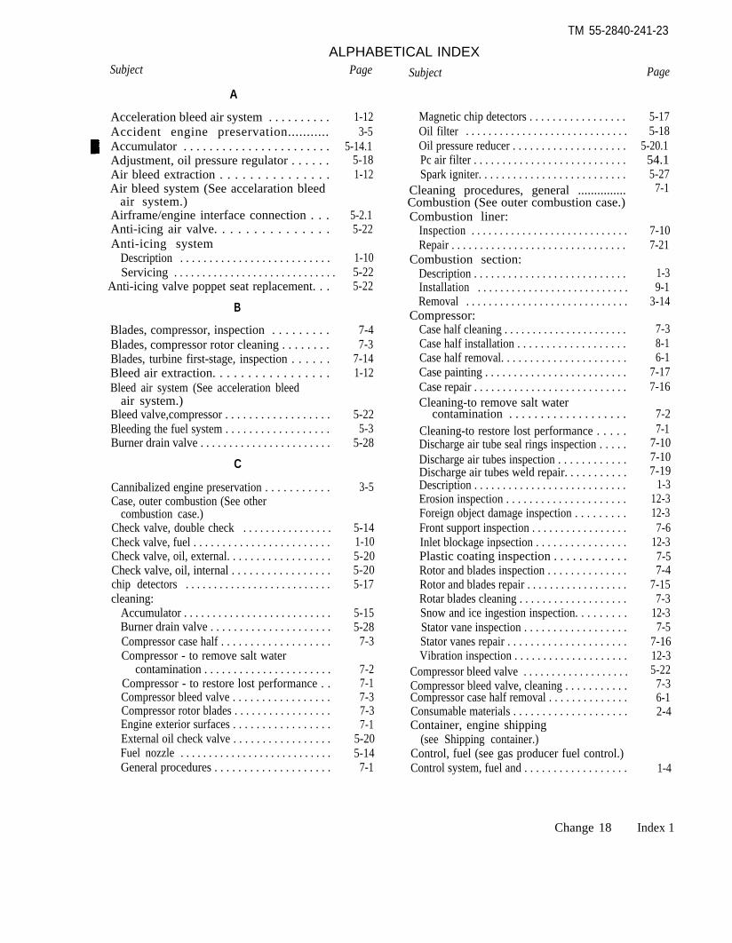
TM 55-2840-241-23
ALPHABETICAL INDEXSubject
A
Acceleration bleed air system . . . . . . . . . .Accident engine preservation...........Accumulator . . . . . . . . . . . . . . . . . . . . . . .Adjustment, oil pressure regulator . . . . . .Air bleed extraction . . . . . . . . . . . . . . .Air bleed system (See accelaration bleed
air system.)Airframe/engine interface connection . . .Anti-icing air valve. . . . . . . . . . . . . . .Anti-icing system
Description . . . . . . . . . . . . . . . . . . . . . . . . . .Servicing . . . . . . . . . . . . . . . . . . . . . . . . . . . . .
Anti-icing valve poppet seat replacement. . .
B
Blades, compressor, inspection . . . . . . . . .Blades, compressor rotor cleaning . . . . . . . .Blades, turbine first-stage, inspection . . . . . .Bleed air extraction. . . . . . . . . . . . . . . . .Bleed air system (See acceleration bleed
air system.)Bleed valve,compressor . . . . . . . . . . . . . . . . . .Bleeding the fuel system . . . . . . . . . . . . . . . . . .Burner drain valve . . . . . . . . . . . . . . . . . . . . . . .
C
Cannibalized engine preservation . . . . . . . . . . .Case, outer combustion (See other
combustion case.)Check valve, double check . . . . . . . . . . . . . . . .Check valve, fuel . . . . . . . . . . . . . . . . . . . . . . . .Check valve, oil, external. . . . . . . . . . . . . . . . . .Check valve, oil, internal . . . . . . . . . . . . . . . . .chip detectors . . . . . . . . . . . . . . . . . . . . . . . . . .cleaning:
Accumulator . . . . . . . . . . . . . . . . . . . . . . . . . .Burner drain valve . . . . . . . . . . . . . . . . . . . . .Compressor case half . . . . . . . . . . . . . . . . . . .Compressor - to remove salt water
contamination . . . . . . . . . . . . . . . . . . . . . .Compressor - to restore lost performance . .Compressor bleed valve . . . . . . . . . . . . . . . . .Compressor rotor blades . . . . . . . . . . . . . . . . .Engine exterior surfaces . . . . . . . . . . . . . . . . .External oil check valve . . . . . . . . . . . . . . . . .Fuel nozzle . . . . . . . . . . . . . . . . . . . . . . . . . . .General procedures . . . . . . . . . . . . . . . . . . . .
Page
1-123-5
5-14.15-181-12
5-2.15-22
1-105-225-22
7-47-3
7-141-12
5-225-3
5-28
3-5
5-141-105-205-205-17
5-155-28
7-3
7-27-17-37-37-1
5-205-14
7-1
Subject
Magnetic chip detectors . . . . . . . . . . . . . . . . .Oil filter . . . . . . . . . . . . . . . . . . . . . . . . . . . . .Oil pressure reducer . . . . . . . . . . . . . . . . . . . .Pc air filter . . . . . . . . . . . . . . . . . . . . . . . . . . .Spark igniter. . . . . . . . . . . . . . . . . . . . . . . . . .
Cleaning procedures, general ...............Combustion (See outer combustion case.)Combustion liner:
Inspection . . . . . . . . . . . . . . . . . . . . . . . . . . . .Repair . . . . . . . . . . . . . . . . . . . . . . . . . . . . . . .
Combustion section:Description . . . . . . . . . . . . . . . . . . . . . . . . . . .Installation . . . . . . . . . . . . . . . . . . . . . . . . . . .Removal . . . . . . . . . . . . . . . . . . . . . . . . . . . . .
Compressor:Case half cleaning . . . . . . . . . . . . . . . . . . . . . .Case half installation . . . . . . . . . . . . . . . . . . .Case half removal. . . . . . . . . . . . . . . . . . . . . .Case painting . . . . . . . . . . . . . . . . . . . . . . . . .Case repair . . . . . . . . . . . . . . . . . . . . . . . . . . .Cleaning-to remove salt water
contamination . . . . . . . . . . . . . . . . . . .Cleaning-to restore lost performance . . . . .Discharge air tube seal rings inspection . . . . .Discharge air tubes inspection . . . . . . . . . . . .Discharge air tubes weld repair. . . . . . . . . . .Description . . . . . . . . . . . . . . . . . . . . . . . . . . .Erosion inspection . . . . . . . . . . . . . . . . . . . . .Foreign object damage inspection . . . . . . . . .Front support inspection . . . . . . . . . . . . . . . . .Inlet blockage inpsection . . . . . . . . . . . . . . . .Plastic coating inspection . . . . . . . . . . . .Rotor and blades inspection . . . . . . . . . . . . . .Rotor and blades repair . . . . . . . . . . . . . . . . . .Rotar blades cleaning . . . . . . . . . . . . . . . . . . .Snow and ice ingestion inspection. . . . . . . . .Stator vane inspection . . . . . . . . . . . . . . . . . .Stator vanes repair . . . . . . . . . . . . . . . . . . . . .Vibration inspection . . . . . . . . . . . . . . . . . . . .
Compressor bleed valve . . . . . . . . . . . . . . . . . . .Compressor bleed valve, cleaning . . . . . . . . . . .Compressor case half removal . . . . . . . . . . . . . .Consumable materials . . . . . . . . . . . . . . . . . . . .Container, engine shipping
(see Shipping container.)Control, fuel (see gas producer fuel control.)Control system, fuel and . . . . . . . . . . . . . . . . . .
Page
5-175-18
5-20.154.15-27
7-1
7-107-21
1-39-1
3-14
7-38-16-1
7-177-16
7-27-1
7-107-107-19
1-312-312-37-6
12-37-57-4
7-157-3
12-37-5
7-1612-35-22
7-36-12-4
1-4
Change 18 Index 1
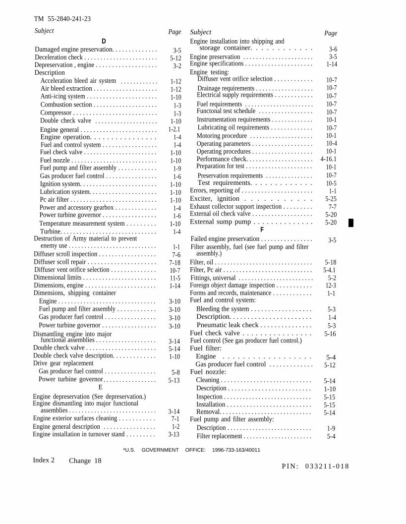
TM 55-2840-241-23
Subject
DDamaged engine preservation. . . . . . . . . . . . . .Deceleration check . . . . . . . . . . . . . . . . . . . . . . .Depreservation , engine . . . . . . . . . . . . . . . . . . .Description
Acceleration bleed air system . . . . . . . . . . . .Air bleed extraction . . . . . . . . . . . . . . . . . . . .Anti-icing system . . . . . . . . . . . . . . . . . . . . . .Combustion section . . . . . . . . . . . . . . . . . . . .Compressor . . . . . . . . . . . . . . . . . . . . . . . . . .Double check valve . . . . . . . . . . . . . . . . . . . .Engine general . . . . . . . . . . . . . . . . . . . . . . . .Engine operation. . . . . . . . . . . . . . . .Fuel and control system . . . . . . . . . . . . . . . . .Fuel check valve . . . . . . . . . . . . . . . . . . . . . . .Fuel nozzle . . . . . . . . . . . . . . . . . . . . . . . . . . .Fuel pump and filter assembly . . . . . . . . . . . .Gas producer fuel control . . . . . . . . . . . . . . . .Ignition system. . . . . . . . . . . . . . . . . . . . . . . .Lubrication system. . . . . . . . . . . . . . . . . . . . .Pc air filter . . . . . . . . . . . . . . . . . . . . . . . . . . .Power and accessory gearbox . . . . . . . . . . . . .Power turbine governor . . . . . . . . . . . . . . . . .Temperature measurement system . . . . . . . . .Turbine. . . . . . . . . . . . . . . . . . . . . . . . . . . . . .
Destruction of Army material to preventenemy use . . . . . . . . . . . . . . . . . . . . . . . . . . . .
Diffuser scroll inspection . . . . . . . . . . . . . . . . . .Diffuser scoll repair . . . . . . . . . . . . . . . . . . . . .Diffuser vent orifice selection . . . . . . . . . . . . . .Dimensional limits . . . . . . . . . . . . . . . . . . . . . . .Dimensions, engine . . . . . . . . . . . . . . . . . . . . . .Dimensions, shipping container
Engine . . . . . . . . . . . . . . . . . . . . . . . . . . . . . . .Fuel pump and filter assembly . . . . . . . . . . . .Gas producer fuel control . . . . . . . . . . . . . . . .Power turbine governor . . . . . . . . . . . . . . . . .
Dismantling engine into majorfunctional assemblies . . . . . . . . . . . . . . . . . . .
Double check valve . . . . . . . . . . . . . . . . . . . . . .Double check valve description. . . . . . . . . . . . .Drive gear replacement
Gas producer fuel control . . . . . . . . . . . . . . . .Power turbine governor . . . . . . . . . . . . . . . . .
EEngine depreservation (See depreservation.)Engine dismantling into major functional
assemblies . . . . . . . . . . . . . . . . . . . . . . . . . . . .Engine exterior surfaces cleaning . . . . . . . . . . .Engine general description . . . . . . . . . . . . . . . .Engine installation in turnover stand . . . . . . . . .
Page
3-55-12
3-2
1-121-121-10
1-31-3
1-101-2.1
1-41-4
1-101-10
1-91-6
1-101-101-10
1-41-6
1-101-4
1-17-6
7-1810-711-51-14
3-103-103-103-10
3-145-141-10
5-85-13
3-147-11-2
3-13
SubjectEngine installation into shipping and
storage container. . . . . . . . . . . .Engine preservation . . . . . . . . . . . . . . . . . . . . . .Engine specifications . . . . . . . . . . . . . . . . . . . . .Engine testing:
Diffuser vent orifice selection . . . . . . . . . . . .Drainage requirements . . . . . . . . . . . . . . . . . .Electrical supply requirements . . . . . . . . . . . .Fuel requirements . . . . . . . . . . . . . . . . . . . . . .Functonal test schedule . . . . . . . . . . . . . . . . .Instrumentation requirements . . . . . . . . . . . . .Lubricating oil requirements . . . . . . . . . . . . .Motoring procedure . . . . . . . . . . . . . . . . . . . .Operating parameters . . . . . . . . . . . . . . . . . . .Operating procedures . . . . . . . . . . . . . . . . . . .Performance check. . . . . . . . . . . . . . . . . . . . .Preparation for test . . . . . . . . . . . . . . . . . . . . .Preservation requirements . . . . . . . . . . . . . . .Test requirements. . . . . . . . . . . . .
Errors, reporting of . . . . . . . . . . . . . . . . . . . . . .Exciter, ignition . . . . . . . . . . .Exhaust collector support inspection . . . . . . . . .External oil check valve . . . . . . . . . . . . . . . . . . .External sump pump . . . . . . . . . . . . . .
FFailed engine preservation . . . . . . . . . . . . . . . .Filter assembly, fuel (see fuel pump and filter
assembly.)Filter, oil . . . . . . . . . . . . . . . . . . . . . . . . . . . . . . .Filter, Pc air . . . . . . . . . . . . . . . . . . . . . . . . . . . .Fittings, universal . . . . . . . . . . . . . . . . . . . . . . . .Foreign object damage inspection . . . . . . . . . . .Forms and records, maintenance . . . . . . . . . . . .Fuel and control system:
Bleeding the system . . . . . . . . . . . . . . . . . .Description. . . . . . . . . . . . . . . . . . . . . . .Pneumatic leak check . . . . . . . . . . . . . . .
Fuel check valve . . . . . . . . . . . . . . . .Fuel control (See gas producer fuel control.)Fuel filter:
Engine . . . . . . . . . . . . . . . . . .Gas producer fuel control . . . . . . . . . . . . .
Fuel nozzle:Cleaning . . . . . . . . . . . . . . . . . . . . . . . . . . . .Description . . . . . . . . . . . . . . . . . . . . . . . . .Inspection . . . . . . . . . . . . . . . . . . . . . . . . . . . .Installation . . . . . . . . . . . . . . . . . . . . . . . . . .Removal. . . . . . . . . . . . . . . . . . . . . . . . . . . . .
Fuel pump and filter assembly:Description . . . . . . . . . . . . . . . . . . . . . . . . . . .Filter replacement . . . . . . . . . . . . . . . . . . . . . .
Page
3-63-5
1-14
10-710-710-710-710-710-110-710-110-410-1
4-16.110-110-710-5
1-15-25
7-75-205-20
3-5
5-185-4.1
5-212-31-1
5-31-45-3
5-16
5-45-12
5-141-105-155-155-14
1-95-4
Index 2 Change 18
*U.S. GOVERNMENT OFFICE: 1996-733-163/40011
P I N : 0 3 3 2 1 1 - 0 1 8
TM 55-2840-241-23
Subject Page
Installation . . . . . . . . . . . . . . . . . . . . . . . . . . . . . 5-4Preparation for storage and shipment . . . . . . . . 3-11Removal . . . . . . . . . . . . . . . . . . . . . . . . . . . . . . . .5-4Testing. . . . . . . . . . . . . . . . . . . . .5-3
Fuel system bleeding . . . . . . . . . . . . . .5-3Fuel system tubes . . . . . . . . . . . . . . . . . . . . . . . . 5-16Functional test schedule . . . . . . . . . . . . . . . . . . 10-7
G
Gas producer fuel control:Deceleration check . . . . . . . . . . . . . . . . . . . . . . . 5-l2Description . . . . . . . . . . . . . . . . . . . . . . . . . . . . . . . 1-6Drive gear replacement . . . . . . . . . . . . . . . . . 5-9Idle speed check . . . . . . . . . . . . . . . . . . . . . . . . 5-10Installation . . . . . . . . . . . . . . . . . . . . . . . . . . . . . 5-9Max fuel flow stop adjustment . . . . . . . . . . . . . . 5-11Maximum speed stop . . . . . . . . . . . . . . . . . . . 5-l0.lPreparation for storage and shipment . . . . . . . 3-12Removal . . . . . . . . . . . . . . . . . . . . . . . . . . . . . . 5-8Replacing fuel filter . . . . . . . . . . . . . . . . . . . . . . 5-l3Rigging check . . . . . . . . . . . . . . . . . . . . . . . . . . . 5-9Start derichment adjustment . . . . . . . . . . 5-10.2
Gearbox (See Power and accessorygearbox.)
General cleaning procedures. . . . . . . . . . . . . . . . . . . 7-1General description, engine . . . . . . . . . . . . . . . 1-2.1General practices and precautions . . . . . . . . . . . . . . 5-1Governor (See power turbine governor.)
H
Hard landing inspection . . . . . . . . . . . . . . . . . . . 12-4Hardware . . . . . . . . . . . . . . . . . . . . . . . . . . . . . . . . . 5-1Health indicator test . . . . . . . . . . . . . . . . . . . . . . 4-13Housing, oil filter . . . . . . . . . . . . . . . . . . . . . . . . 5-20
I
Idle speed check . . . . . . . . . . . . . . . . . . . . . . . . . . 5-10Igniter, spark . . . . . . . . . . . . . . . . . . . . . . . . . . . . 5-27Ignition exciter . . . . . . . . . . . . . . . . . . . . . . . . . . . 5-25Ignition system:
Check . . . . . . . . . . . . . . . . . . . . . . . . . . . . . . . . . 5-25Description . . . . . . . . . . . . . . . . . . . . . . . . . . . . . 1-10Servicing . . . . . . . . . . . . . . . . . . . . . . . . . . . . . . 5-25
Inspection:Combustion liner . . . . . . . . . . . . . . . . . . . . . . . 7-10Compressor discharge air tube seal rings . . . . 7-10Compressor diacharge air tubes. . . . . . . . . . . . . 7-10Compressor erosion . . . . . . . . . . . . . . . . . . . . . . 7-6Compressor front support . . . . . . . . . . . . . . . . 7-6Compressor inlet blockage . . . . . . . . . . . . . . . . . . 12-3
Subject Page
Compressor plastic coating . . . . . . . . . . . . . . . . . . 7-5Compressor rotor and blades . . . . . . . . . . . . . . . . 7-4Compressor stator vane . . . . . . . . . . . . . . . . . . 7-5Compressor vibration . . . . . . . . . . . . . . . . . . . 12-3Diffuser scroll . . . . . . . . . . . . . . . . . . . . . . . . . . . 7-6Double check valve . . . . . . . . . . . . . . . . . . . . . 5-14Engine dropped during handling. . . . . . . . . . . . . 3-2Exhaust collector support . . . . . . . . . . . . . . . . . . . 7-7Foreign object damage . . . . . . . . . . . . . . . . . . 12-3Fuel nozzle . . . . . . . . . . . . . . . . . . . . . . . . . . . . . . . . 5-14Gearbox . . . . . . . . . . . . . . . . . . . . . . . . . . . . . . . . 7-6Hard landing . . . . . . . . . . . . . . . . . . . . . . . . . . . 12-4Ignition exciter . . . . . . . . . . . . . . . . . . . . . . . . . 5-25Magnetic chip detectors . . . . . . . . . . . . . . . . . 5-17Oil pressure regulator . . . . . . . . . . . . . . . . . . . 5-18Outer combustion case . . . . . . . . . . . . . . . . . . . 7-7Overtemperature during power transients . . . 12-1Overtemperature during start . . . . . . . . . . . . . . 12-1Pc air filter . . . . . . . . . . . . . . . . . . . . . . . . . . . . . . . 5-4.1Power and accessory gearbox inspection . . . . . . 7-6Shipping container . . . . . . . . . . . . . . . . . . . . . . 3-1Snow and ice ingestion. . . . . . . . . . . . . . . . . . 12-3Spark igniter . . . . . . . . . . . . . . . . . . . . . . . . . . 5-27Spark igniter lead . . . . . . . . . . . . . . . . . . . . . . 5-27Sudden stoppage . . . . . . . . . . . . . . . . . . . . . . . 12-4Thermocouple assembly . . . . . . . . . . . . . . . . 7-7Turbine first-stage blades . . . . . . . . . . . . . . . . . . 7-14Turbine first-stage nozzle and shield . . . . . . . . 7-14Turbine overtemperature. . . . . . . . . . . . . . . . . . . 12-1
Installation:Accumulator . . . . . . . . . . . . . . . . . . . . . . . . . . . 5-15Anti-icing air valve . . . . . . . . . . . . . . . . . . . . . 5-22Bumer drain valve . . . . . . . . . . . . . . . . . . . . . 5-28Combustion section . . . . . . . . . . . . . . . . . . . . . . 9-1Compressor bleed valve . . . . . . . . . . . . . . . . . . . . 5-22Compressor case half . . . . . . . . . . . . . . . . . . . . . 8-1Double check valve . . . . . . . . . . . . . . . . . . . . . 5-14Engine into shipping container . . . . . . . . . . . . . . 3-6External oil check valve . . . . . . . . . . . . . . . . . 5-20Fuel nozzle . . . . . . . . . . . . . . . . . . . . . . . . . . . . . . . . 5-14Fuel pump and filter assembly . . . . . . . . . . . . 5-4Gas producer fuel control . . . . . . . . . . . . . . . . . 5-89Ignition exciter . . . . . . . . . . . . . . . . . . . . . . . . . 5-27Internal oil check valve . . . . . . . . . . . . . . . . . 5-20Magnetic chip detectors . . . . . . . . . . . . . . . . . . . . 5-17Oil filter . . . . . . . . . . . . . . . . . . . . . . . . . . . . . . . 5-18Oil filter housing . . . . . . . . . . . . . . . . . . . . . . . 5-20Oil pressure reducer . . . . . . . . . . . . . . . . . . . . . 5-20.1Oil pressure regulator . . . . . . . . . . . . . . . . . . . 5-18Pc air filter . . . . . . . . . . . . . . . . . . . . . . . . . . . . . . . 5-4.1Power turbine governor . . . . . . . . . . . . . . . . . 5-13Rigid tube . . . . . . . . . . . . . . . . . . . . . . . . . . . . . . 5-3Spark igniter . . . . . . . . . . . . . . . . . . . . . . . . . . 5-27
Change 14 Index 3
TM 55-2840-241-23
Subject Page
Spark igniter lead . . . . . . . . . . . . . . . . . . . . . . 5-27Thermocouple terminal assembly . . . . . . . . . 5-28.1
Installing engine in turnover stand . . . . . . . . . . . 3-13Internal oil check valve. . . . . . . . . . . . . . . . . . . .5-20
L
Lead, spark igniter . . . . . . . . . . . . . . . . . . . . . . . 5-27Leading particulars . . . . . . . . . . . . . . . . . . . . . . . 1-12Leakcheck, fuel system pneumatic. . . . . . . . . . . . . 5-3Liner, combustion (See combustion liner.)Locknut installation, typical . . . . . . . . . . . . . . . 11-4Lubrication system:
Description . . . . . . . . . . . . . . . . . . . . . . . . . . . . . 1-10Servicing . . . . . . . . . . . . . . . . . . . . . . . . . . . . . . 5-16
M
Magnetic chip detectors . . . . . . . . . . . . . . . . . . . . 5-17Maintenance allocation chart:
Additional information . . . . . . . . . . . . . . . . . . . B-3Definitions . . . . . . . . . . . . . . . . . . . . . . . . . . . . . . B-2General . . . . . . . . . . . . . . . . . . . . . . . . . . . . . . . . . B-1
Maintenance check procedurespower loss, N2 droop or flameoutparameter . . . . . . . . . . . . . . . . . . . . . . . . . . . . 4-16.1
Maintenance forms and records . . . . . . . . . . . . . . . . 1-1Measurement system, temperature (see
temperature measurement system.)Mixing of engine oils . . . . . . . . . . . . . . . . . . . . . . 5-17Motming procedure, engine . . . . . . . . . . . . . . . . . . . 10-1
N
Nozzle, fuel (See fuel nozzle)Nozzle shield, turbine first-stage, inspection . . . 7-14Nozzle, turbine first-stage inspection . . . . . . . . . . 7-14
0
Oil change procedure . . . . . . . . . . . . . . . . . . . . 5-16.1Oil changeover procedure . . . . . . . . . . . . . . . . . . . 5-16.1Oil filter . . . . . . . . . . . . . . . . . . . . . . . . . . . . . . . . . 5-18Oil filter housing . . . . . . . . . . . . . . . . . . . . . . . . . 5-20Oil pressure reducer . . . . . . . . . . . . . . . . . . . . . . 5-21Oil pressure regulator . . . . . . . . . . . . . . . . . . . . . 5-18Oil system (see lubrication system.)Oil tubing and fittings . . . . . . . . . . . . . . . . . . . . 5-17Oils, mixing of . . . . . . . . . . . . . . . . . . . . . . . . . . 5-17operating parameters, engine . . . . . . . . . . . . . . . . 10-4Operation, description of . . . . . . . . . . . . . . . . . . . . . . 1-4Outer combustion case:
Inspection . . . . . . . . . . . . . . . . . . . . . . . . . . . . . . 7-7Weld repair . . . . . . . . . . . . . . . . . . . . . . . . . . . . 7-19
Overhaul interval . . . . . . . . . . . . . . . . . . . . . . . . .13-1Overtemperature during power transients . . . . . 12-1Overtemperature during start . . . . . . . . . . . . . . . . 12-1Overtemperature inspection, turbine . . . . . . . . . . 12-1
Subject
P
Page
Painting:Compressor case . . . . . . . . . . . . . . . . . . . . . . . . . . . 7-16Gearbox housing and cover . . . . . . . . . . . . . . 7-19
Plastic coating inspection . . . . . . . . . . . . . . . . . . 7-5Pneumatic leak check, fuel system . . . . . . . . . . . . . 5-3Power and accessory gearbox:
Description . . . . . . . . . . . . . . . . . . . . . . . . . . . . . 1-4External seals replacement . . . . . . . . . . . . . . . . . 7-18External studs replacement . . . . . . . . . . . . . . . . 7-18Painting . . . . . . . . . . . . . . . . . . . . . . . . . . . . . 7-19Inspection . . . . . . . . . . . . . . . . . . . . . . . . . . . . . . . . . . .7-6
Power turbine governor:Description . . . . . . . . . . . . . . . . . . . . . . . . . . . . . 1-6Drive gear replacement . . . . . . . . . . . . . . . . . 5-13Installation . . . . . . . . . . . . . . . . . . . . . . . . . . . . . 5-13Preparation for storage and shipment . . . . . . . 3-12Removal . . . . . . . . . . . . . . . . . . . . . . . . . . . . . . . 5-13
Poppet seat replacement, anti-icing valve . . . . . . 5-22Preparation for storage and shipment:
Engine . . . . . . . . . . . . . . . . . . . . . . . . . . . . . . . . . 3-5Fuel pump and filter assembly . . . . . . . . . . . . . . 3-11Gas producer fuel control . . . . . . . . . . . . . . . . . . . 3-12Power turbine governor .. . . . . . . . . . . . . . . .3-12
Preservation:Accident engine . . . . . . . . . . . . . . . . . . . . . . . . . 3-5Damaged, cannibalized, or failed engine . . . . . . 3-5Engine . . . . . . . . . . . . . . . . . . . . . . . . . . . . . . . . . 3-5Forms, records, tags, and stenciling . . . . . . . . 3-5Fuel control . . . . . . . . . . . . . . . . . . . . . . . . . . . . 3-12Puel pump . . . . . . . . . . . . . . . . . . . . . . . . . . . . 3-11Governor . . . . . . . . . . . . . . . . . . . . . . . . . . . . . 3-12Reservation maintenance . . . . . . . . . . . . . . . . 3-1
Pump Assembly, fuel (See fuel pump andfilter assembly.)
R
Reducer, oil pressure . . . . . . . . . . . . . . . . . . . . . . . 5-20.1References . . . . . . . . . . . . . . . . . . . . . . . . . . . . . . . . . A-lRegulator, oil pressure . . . . . . . . . . . . . . . . . . . . 5-18Removal:
Accessory from shipping container . . . . . . . . . . . 3-8Accumulator . . . . . . . . . . . . . . . . . . . . . . . . . . . 5-15Anti-icing air valve . . . . . . . . . . . . . . . . . . . .5-22Bumer drain valve . . . . . . . . . . . . . . . . . . . . . 5-28Combustion section . . . . . . . . . . . . . . . . . . . . . 3-14Compressor bleed valve . . . . . . . . . . . . . . . . . 5-22Compressor case half . . . . . . . . . . . . . . . . . . . . . 6-1Double check valve . . . . . . . . . . . . . . . . . . . . . 5-14Engine from shipping container . . . . . . . . . . . . . . 3-1External oil check valve . . . . . . . . . . . . . . . . . 5-20Fuel nozzle . . . . . . . . . . . . . . . . . . . . . . . . . . . . . 5-14Fuel pump and filter assembly. . . . . . . . . . . . 5-4
Index 4 Change 14
TM 55-2840-241-23
Subject Page
Gas producer fuel control . . . . . . . . . . . . . . . . . 5-8Ignition exciter . . . . . . . . . . . . . . . . . . . . . . . . . 5-25Internal oil check valve . . . . . . . . . . . . . . . . . 5-20Magnetic chip detectors . . . . . . . . . . . . . . . . . 5-17Oil filter . . . . . . . . . . . . . . . . . . . . . . . . . . . . . . . 5-18Oil filter housing . . . . . . . . . . . . . . . . . . . . . . . 5-20Oil pressure reducer . . . . . . . . . . . . . . . . . . . . . 5-20.1Oil pressure regulator . . . . . . . . . . . . . . . . . . . 5-18Pc air filter . . . . . . . . . . . . . . . . . . . . . . . . . . . . 5-4.1Power turbine governor . . . . . . . . . . . . . . . . . . 5-13Spark igniter . . . . . . . . . . . . . . . . . . . . . . . . . . 5-27Spark igniter lead . . . . . . . . . . . . . . . . . . . . . . 5-27Thermocouple terminal assembly . . . . . . . . .5-28.1
Removing combustion section. . . . . . . . . . . . . . . . . 3-14Repair:
Combustion liner . . . . . . . . . . . . . . . . . . . . . . . 7-21Compressor case vanes . . . . . . . . . . . . . . . . . . 7-16Compressor discharge air tubes . . . . . . . . . . . . . 7-19Compressor rotor and blades . . . . . . . . . . . . . . . . 7-15Diffuser scroll . . . . . . . . . . . . . . . . . . . . . . . . . . 7-18Outer combustion cafe . . . . . . . . . . . . . . . . . . 7-19
Replacement:Anti-icing valve poppet seat . . . . . . . . . . . . . . . . 5-22Fuel filter . . . . . . . . . . . . . . . . . . . . . . . . . .5-4Gear box external seals . . . . . . . . . . . . . . . . . . . . . 7-18Gear box external studs . . . . . . . . . . . . . . . . . . 7-18
Reporting of errors . . . . . . . . . . . . . . . . . . . . . . . . . 1-1Retirement life interval . . . . . . . . . . . . . . . . . 13-1Rigging check, gas producer fuel control . . . . . . 5-9
Rigid tube installation . . . . . . . . . . . . . . . . . . . . 5-2.1Rotor, compressor, inspection . . . . . . . . . . . . . . . . . . 7-4
S
Seal rings (See compressor dischargeair tube seal rings.)
Scavenge oil flow check . . . . . . . . . . . . . . . . . . . 5-20.lScroll (See diffusor scroll.)Shipping container, accessory:
Container stenciling . . . . . . . . . . . . . . . . . . . . . 3-5Dimensions and weight . . . . . . . . . . . . . . . . . 3-10Preparation of . . . . . . . . . . . . . . . . . . . . . . . . . . 3-11
Shipping Container, engine:Dimensions and weight . . . . . . . . . . . . . . . . . 3-10Inspection . . . . . . . . . . . . . . . . . . . . . . . . . . . . . . . 3-1Installation of engine . . . . . . . . . . . . . . . . . . . . . . .3-6Internal pressure and humidity check . . . . . . . .3-8Maintenance during storage . . . . . . . . . . . . . . . . . 3-8Preparation of . . . . . . . . . . . . . . . . . . . . . . . . . . 3-7Pressurization . . . . . . . . . . . . . . . . . . . . . . . . . . . 3-7Removal of engine . . . . . . . . . . . . . . . . . . . . . . . 3-1Stenciling . . . . . . . . . . . . . . . . . . . . . . . . . . . . . . . . .3-5Tamper-proof security . . . . . . . . . . . . . . . . . . . . 3-8
Snow and ice ingestion inspection . . . . . . . . . . . . . 12-3Spark igniter . . . . . . . . . . . . . . . . . . . . . . . . . . . . 5-27
Subject Page
Spark igniter lead . . . . . . . . . . . . . . . . . . . . . . . . 5-27Special tool sand test equipment . . . . . . . . . . . . . . . 2-1Specifications, engine . . . . . . . . . . . . . . . . . . . . . 1-14Start derichment adjustment . . . . . . . . . . . . . . 5-11Storage and shipment:
Engine . . . . . . . . . . . . . . . . . . . . . . . . . . . . . . . . . 3-1Fuel pump and filter assembly . . . . . . . . . . . . . . 3-11Gas producer fuel control . . . . . . . . . . . . . . . . 3-12Power turbine governor . . . . . . . . . . . . . . . . . 3-12
Sudden stoppage inspection . . . . . . . . . . . . . . . . . . 12-4Systems description:
Acceleration bleed air . . . . . . . . . . . . . . . . . . . . . . 1-12Anti-icing . . . . . . . . . . . . . . . . . . . . . . . . . . . . . . 1-10Fuel and control . . . . . . . . . . . . . . . . . . . . . . . . . 1-4Ignition . . . . . . . . . . . . . . . . . . . . . . . . . . . . . . . . 1-10Lubrication . . . . . . . . . . . . . . . . . . . . . . . . . . . . 1-10Temperature measurement . . . . . . . . . . . . . . . . . 1-10
T
Temperature measurement system . . . . . . . . . . . . 1-10Terminal assembly, thermocouple . . . . . . . . . . . 5-28.1Test equipment . . . . . . . . . . . . . . . . . . . . . . . . . . . . 2-1Test, health indicator . . . . . . . . . . . . . . . . . . . . . 4-13Testing:
Accumulator . . . . . . . . . . . . . . . . . . . . . . . . . . . 5-15Anti-icing air valve . . . . . . . . . . . . . . . . . . . . . 5-22Burner drain valve . . . . . . . . . . . . . . . . . . . . . 5-28Compressor bleed valve . . . . . . . . . . . . . . . . . 5-22Engine (See engine testing.)Fuel pump and filter assembly . . . . . . . . . . . . 5-4Magnetic chip detectors . . . . . . . . . . . . . . . . . 5-17Oil filter . . . . . . . . . . . . . . . . . . . . . . . . . . . . . . . 5-18Oil pressure regulator . . . . . . . . . . . . . . . . . . . 5-18Spark igniter . . . . . . . . . . . . . . . . . . . . . . . . . . 5-27
Themrmocoupleaaaembly inspection . . . . . . . . . . . . . 7-7Thermocouple terminal assembly . . . . . . . . . . . 5-28.1Tools, special . . . . . . . . . . . . . . . . . . . . . . . . . . . . 2-1Torque for air frame/engine interface
connections, recommended . . . . . . . . . . . . . . . . . 5-2.1Torque for used locknuts, minimum
prevailing . . . . . . . . . . . . . . . . . . . . . . . . . . . . . 11-4Torque values . . . . . . . . . . . . . . . . . . . . . . . . . . . . 11-1Troubleshooting . . . . . . . . . . . . . . . . . . . . . . . . . . 4-1Tubing and fittings, oil . . . . . . . . . . . . . . . . . . . . 5-17Tubing, fuel . . . . . . . . . . . . . . . . . . . . . . . . . . . . . . . . 5-16Turbine:
Description . . . . . . . . . . . . . . . . . . . . . . . . . . . . . 1-4First-stage blades inspection . . . . . . . . . . . . . . . 7-14First-stage nozzle and shield inspection . . . . . . 7-14Overtemperature inspection . . . . . . . . . . . . . . . . 12-1
U
Universal fittings . . . . . . . . . . . . . . . . . . . . . . . . . . 5-2Use of oils . . . . . . . . . . . . . . . . . . . . . . . . . . . . . . . . 5-16
Change 14 Index 5
TM 55-2840-241-23
Subject Page
V W
Valve, anti-icing air . . . . . . . . . . . . . . . . . . . . . . 5-22Valve, burner drain . . . . . . . . . . . . . . . . . . . . . . . 5-28Valve, check, extemal oil . . . . . . . . . . . . . . . . . . 5-20Valve, check, internal oil . . . . . . . . . . . . . . . . . . 5-20Valve, compressor bleed . . . . . . . . . . . . . . . . . . . 5-22Valve, double check, . . . . . . . . . . . . . . . . . . . . . . 5-14Valve, fuel check . . . . . . . . . . . . . . . . . . . . . . . . . . 1-10Vanes, compressor, inspection . . . . . . . . . . . . . . . . . . 7-5
Subject Page
Weight, engine . . . . . . . . . . . . . . . . . . . . . . . . . . . 1-14Weight, shipping container:
Engine . . . . . . . . . . . . . . . . . . . . . . . . . . . . . . . . . 3-10Fuel pump and filter assembly . . . . . . . . . . . . 3-l0Gas producer fuel control . . . . . . . . . . . . . . . . . 3-10Power turbine governor . . . . . . . . . . . . . . . . . .3-l0
Index 6 Change 14
✩ U.S. GOVERNMENT PRINTING OFFICE: 1993-342-421/80380
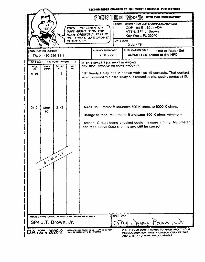
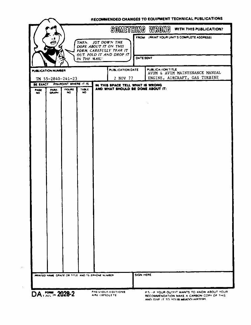


PIN: 033211-016


PIN: 033211-000
Related Documents