© KEMET Electronics Corporation • P.O. Box 5928 • Greenville, SC 29606 • 864-963-6300 • www.kemet.com T2020_A700 • 12/6/2017 1 One world. One KEMET Benefits • ESR: 4.5 mΩ to 70 mΩ • Voltage: 2 V to 16 V • Capacitance: 6.8 µF to 560 µF • Polymer cathode technology • High frequency capacitance retention • Non-ignition failure mode • 100% accelerated steady state aging • 100% surge current tested • Volumetric efficiency • Self-healing mechanism • EIA standard case sizes Overview The KEMET Aluminum Organic Capacitor (AO-CAP) is a solid state aluminum capacitor. The cathode is a conductive organic polymer which results in very low ESR and improved capacitance retention at high frequency. AO- CAPs may be operated at steady state voltages up to 100% of rated voltage without the need to de-rate. Since there is no liquid electrolyte, the A700 offers long operational lifetimes, low ESR and high operational temperatures. The inherent low ESR renders the A700 suitable for high ripple current handling. The small package size, high ripple current capability, high operating temperature, low parasistics and high capacitance makes the A700 ideal for high performance microprocessor, FPGA and ASIC decoupling designs. Aluminum Organic Capacitor (AO-CAP) A700 Polymer Aluminum, 2 – 16 VDC Applications Typical applications include DC/DC converters, notebook PCs, telecommunications, displays, and industrial applications. Environmental Compliance RoHS Compliant (6/6) according to Directive 2002/95/EC when ordered with 100% Sn solder.

Welcome message from author
This document is posted to help you gain knowledge. Please leave a comment to let me know what you think about it! Share it to your friends and learn new things together.
Transcript
© KEMET Electronics Corporation • P.O. Box 5928 • Greenville, SC 29606 • 864-963-6300 • www.kemet.com T2020_A700 • 12/6/2017 1One world. One KEMET
Benefits
• ESR:4.5mΩto70mΩ• Voltage: 2 V to 16 V• Capacitance: 6.8 µF to 560 µF• Polymer cathode technology• High frequency capacitance retention• Non-ignition failure mode• 100% accelerated steady state aging• 100% surge current tested• Volumetricefficiency• Self-healing mechanism• EIA standard case sizes
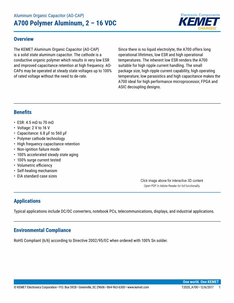
Overview
The KEMET Aluminum Organic Capacitor (AO-CAP) is a solid state aluminum capacitor. The cathode is a conductive organic polymer which results in very low ESR and improved capacitance retention at high frequency. AO-CAPs may be operated at steady state voltages up to 100% of rated voltage without the need to de-rate.
Since there is no liquid electrolyte, the A700 offers long operational lifetimes, low ESR and high operational temperatures. The inherent low ESR renders the A700 suitable for high ripple current handling. The small package size, high ripple current capability, high operating temperature, low parasistics and high capacitance makes the A700 ideal for high performance microprocessor, FPGA and ASIC decoupling designs.
Aluminum Organic Capacitor (AO-CAP)
A700 Polymer Aluminum, 2 – 16 VDC
Applications
Typical applications include DC/DC converters, notebook PCs, telecommunications, displays, and industrial applications.
Environmental Compliance
RoHS Compliant (6/6) according to Directive 2002/95/EC when ordered with 100% Sn solder.
© KEMET Electronics Corporation • P.O. Box 5928 • Greenville, SC 29606 • 864-963-6300 • www.kemet.com T2020_A700 • 12/6/2017 22
Aluminum Organic Capacitor (AO-CAP) A700 Polymer Aluminum, 2 – 16 VDC
K-SIM
Foradetailedanalysisofspecificpartnumbers,pleasevisitksim.kemet.comtoaccessKEMET’sK-SIMsoftware.KEMETK-SIM is designed to simulate behavior of components with respect to frequency, ambient temperature, and DC bias levels.
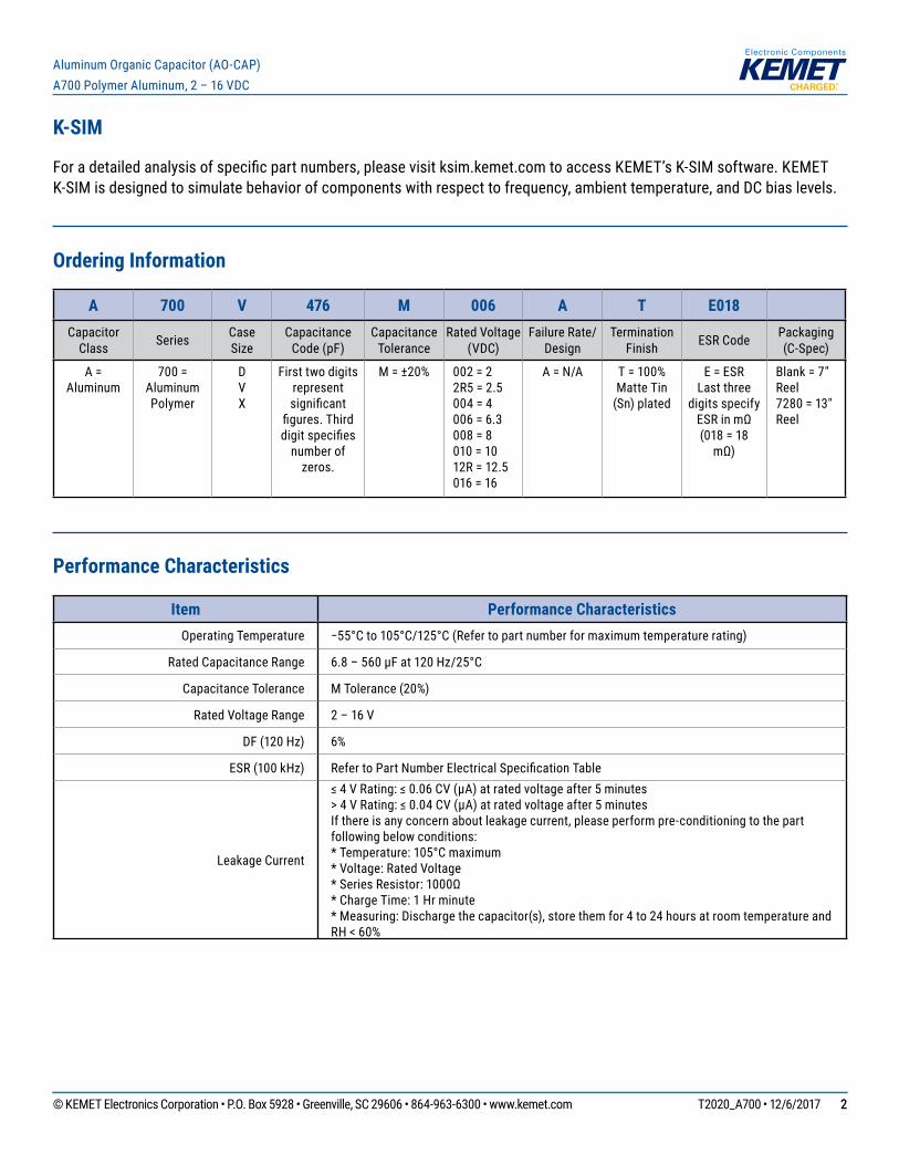
Ordering Information
A 700 V 476 M 006 A T E018Capacitor
Class Series Case Size
Capacitance Code (pF)
Capacitance Tolerance
Rated Voltage (VDC)
Failure Rate/Design
Termination Finish ESR Code Packaging
(C-Spec)
A = Aluminum
700 = Aluminum Polymer
D V X
First two digits represent significant
figures.Thirddigitspecifies
number of zeros.
M = ±20% 002 = 22R5 = 2.5004 = 4006 = 6.3008 = 8010 = 1012R = 12.5 016 = 16
A = N/A T = 100% Matte Tin
(Sn) plated
E = ESR Last three
digits specify ESRinmΩ(018 = 18
mΩ)
Blank = 7" Reel 7280 = 13" Reel
Performance Characteristics
Item Performance CharacteristicsOperating Temperature −55°Cto105°C/125°C(Refertopartnumberformaximumtemperaturerating)
Rated Capacitance Range 6.8–560µFat120Hz/25°C
Capacitance Tolerance M Tolerance (20%)
Rated Voltage Range 2 – 16 V
DF (120 Hz) 6%
ESR (100 kHz) RefertoPartNumberElectricalSpecificationTable
Leakage Current
≤4VRating:≤0.06CV(µA)atratedvoltageafter5minutes>4VRating:≤0.04CV(µA)atratedvoltageafter5minutesIf there is any concern about leakage current, please perform pre-conditioning to the part following below conditions:*Temperature:105°Cmaximum* Voltage: Rated Voltage *SeriesResistor:1000Ω* Charge Time: 1 Hr minute* Measuring: Discharge the capacitor(s), store them for 4 to 24 hours at room temperature and RH < 60%

© KEMET Electronics Corporation • P.O. Box 5928 • Greenville, SC 29606 • 864-963-6300 • www.kemet.com T2020_A700 • 12/6/2017 33
Aluminum Organic Capacitor (AO-CAP) A700 Polymer Aluminum, 2 – 16 VDC
Qualification
Test Condition Characteristics
Endurance 105°C/125°C**atratedvoltage,2,000hours
ΔC/C Within ±10% of initial value
DF ≤initiallimit
DCL Within 1.25 x initial limit
ESR Within 2.0 x initial limit
Storage Life 105°C/125°C**at0volts,2,000hours
ΔC/C Within ±10% of initial value
DF Within initial limits
DCL Within 1.25 x initial limit
ESR Within 2.0 x initial limit
Humidity 60°C,90%RH,1,000hours,ratedvoltage60°C,90%RH,500 hours, No Load
ΔC/CWithin -5/+30% of initial valueA700V477M002ATPN:−30%/+70%ofinitial value
DF ≤initiallimit
DCL Within 5.0 x initial limit
Temperature StabilityExtreme temperature exposure at a successionofcontinuousstepsat+25°C,−55°C,+85°C,+105°C/+125°C**
+25°C −55°C +85°C +105°C/125°C
ΔC/C IL* ±15% ±15% ±20%
DF IL IL 1.2 x IL 1.5 x IL
DCL IL N/A 10 x IL 10 x IL
Surge Voltage 105°C/125°C**,1.32xratedvoltage,33ΩResistance, 1,000 cycles
ΔC/C Within ±10% of initial value
DF Within initial limits
DCL Within initial limits
ESR Within initial limits
Mechanical Shock/Vibration
MIL–STD–202, Method 213, Condition I, 100 G peakMIL–STD–202, Method 204, Condition D, 10 Hz to 2,000 Hz, 20 G peak
ΔC/C Within ±10% of initial value
DF Within initial limits
DCL Within initial limits
*IL = Initial Limit** Refer to part number specifications for individual temperature classification
© KEMET Electronics Corporation • P.O. Box 5928 • Greenville, SC 29606 • 864-963-6300 • www.kemet.com T2020_A700 • 12/6/2017 44
Aluminum Organic Capacitor (AO-CAP) A700 Polymer Aluminum, 2 – 16 VDC
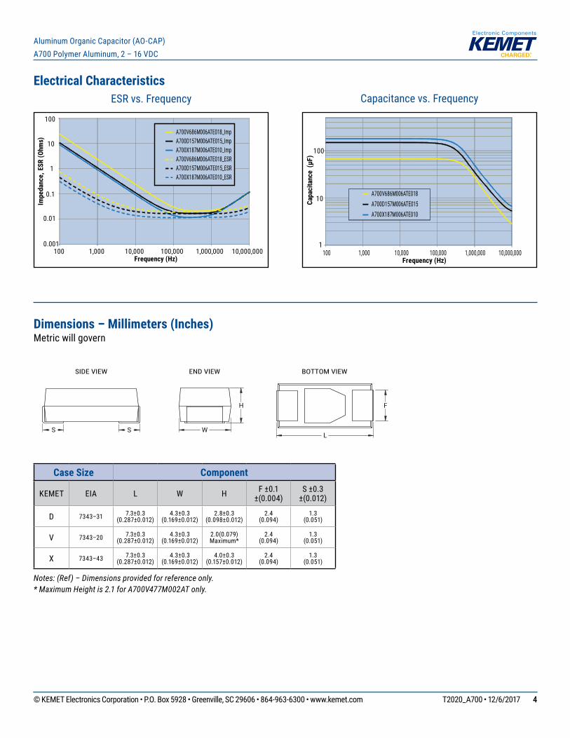
Electrical Characteristics
100 1,000 10,000 100,000 1,000,000 10,000,000
A700V686M006ATE018A700D157M006ATE015A700X187M006ATE010
Capa
cita
nce
(µF)
Frequency (Hz)
1
10
100
Capacitance vs. FrequencyESR vs. Frequency
0.01
0.1
1
10
100
100 1,000 10,000 100,000 1,000,000 10,000,000
Impe
danc
e, E
SR (O
hms)
Frequency (Hz)
0.001
A700V686M006ATE018_ImpA700D157M006ATE015_ImpA700X187M006ATE010_ImpA700V686M006ATE018_ESRA700D157M006ATE015_ESRA700X187M006ATE010_ESR
Dimensions – Millimeters (Inches) Metric will govern
H F
L
SIDE VIEW END VIEW BOTTOM VIEW
W S S
Case Size Component
KEMET EIA L W H F ±0.1 ±(0.004)
S ±0.3 ±(0.012)
D 7343–31 7.3±0.3 (0.287±0.012)
4.3±0.3 (0.169±0.012)
2.8±0.3 (0.098±0.012)
2.4 (0.094)
1.3 (0.051)
V 7343–20 7.3±0.3 (0.287±0.012)
4.3±0.3 (0.169±0.012)
2.0(0.079) Maximum*
2.4 (0.094)
1.3 (0.051)
X 7343–43 7.3±0.3 (0.287±0.012)
4.3±0.3 (0.169±0.012)
4.0±0.3 (0.157±0.012)
2.4 (0.094)
1.3 (0.051)
Notes: (Ref) – Dimensions provided for reference only.* Maximum Height is 2.1 for A700V477M002AT only.
© KEMET Electronics Corporation • P.O. Box 5928 • Greenville, SC 29606 • 864-963-6300 • www.kemet.com T2020_A700 • 12/6/2017 55
Aluminum Organic Capacitor (AO-CAP) A700 Polymer Aluminum, 2 – 16 VDC
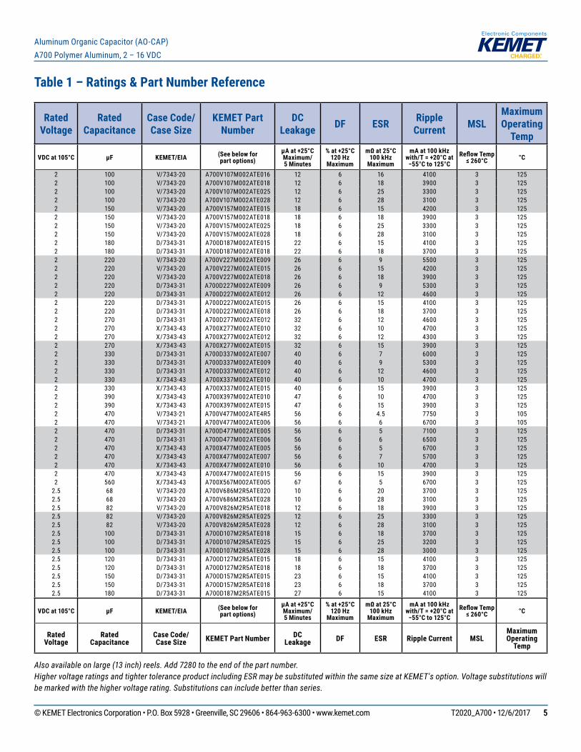
Table 1 – Ratings & Part Number Reference
Also available on large (13 inch) reels. Add 7280 to the end of the part number.Higher voltage ratings and tighter tolerance product including ESR may be substituted within the same size at KEMET's option. Voltage substitutions will be marked with the higher voltage rating. Substitutions can include better than series.
Rated Voltage
Rated Capacitance
Case Code/ Case Size
KEMET Part Number
DC Leakage DF ESR Ripple
Current MSLMaximum Operating
Temp
VDC at 105°C µF KEMET/EIA (See below forpart options)
µA at +25°C Maximum/ 5 Minutes
% at +25°C 120 Hz
Maximum
mΩ at 25°C100 kHz
Maximum
mA at 100 kHzwith/T = +20°C at −55°C to 125°C
Reflow Temp ≤ 260°C °C
2 100 V/7343-20 A700V107M002ATE016 12 6 16 4100 3 1252 100 V/7343-20 A700V107M002ATE018 12 6 18 3900 3 1252 100 V/7343-20 A700V107M002ATE025 12 6 25 3300 3 1252 100 V/7343-20 A700V107M002ATE028 12 6 28 3100 3 1252 150 V/7343-20 A700V157M002ATE015 18 6 15 4200 3 1252 150 V/7343-20 A700V157M002ATE018 18 6 18 3900 3 1252 150 V/7343-20 A700V157M002ATE025 18 6 25 3300 3 1252 150 V/7343-20 A700V157M002ATE028 18 6 28 3100 3 1252 180 D/7343-31 A700D187M002ATE015 22 6 15 4100 3 1252 180 D/7343-31 A700D187M002ATE018 22 6 18 3700 3 1252 220 V/7343-20 A700V227M002ATE009 26 6 9 5500 3 1252 220 V/7343-20 A700V227M002ATE015 26 6 15 4200 3 1252 220 V/7343-20 A700V227M002ATE018 26 6 18 3900 3 1252 220 D/7343-31 A700D227M002ATE009 26 6 9 5300 3 1252 220 D/7343-31 A700D227M002ATE012 26 6 12 4600 3 1252 220 D/7343-31 A700D227M002ATE015 26 6 15 4100 3 1252 220 D/7343-31 A700D227M002ATE018 26 6 18 3700 3 1252 270 D/7343-31 A700D277M002ATE012 32 6 12 4600 3 1252 270 X/7343-43 A700X277M002ATE010 32 6 10 4700 3 1252 270 X/7343-43 A700X277M002ATE012 32 6 12 4300 3 1252 270 X/7343-43 A700X277M002ATE015 32 6 15 3900 3 1252 330 D/7343-31 A700D337M002ATE007 40 6 7 6000 3 1252 330 D/7343-31 A700D337M002ATE009 40 6 9 5300 3 1252 330 D/7343-31 A700D337M002ATE012 40 6 12 4600 3 1252 330 X/7343-43 A700X337M002ATE010 40 6 10 4700 3 1252 330 X/7343-43 A700X337M002ATE015 40 6 15 3900 3 1252 390 X/7343-43 A700X397M002ATE010 47 6 10 4700 3 1252 390 X/7343-43 A700X397M002ATE015 47 6 15 3900 3 1252 470 V/7343-21 A700V477M002ATE4R5 56 6 4.5 7750 3 1052 470 V/7343-21 A700V477M002ATE006 56 6 6 6700 3 1052 470 D/7343-31 A700D477M002ATE005 56 6 5 7100 3 1252 470 D/7343-31 A700D477M002ATE006 56 6 6 6500 3 1252 470 X/7343-43 A700X477M002ATE005 56 6 5 6700 3 1252 470 X/7343-43 A700X477M002ATE007 56 6 7 5700 3 1252 470 X/7343-43 A700X477M002ATE010 56 6 10 4700 3 1252 470 X/7343-43 A700X477M002ATE015 56 6 15 3900 3 1252 560 X/7343-43 A700X567M002ATE005 67 6 5 6700 3 125
2.5 68 V/7343-20 A700V686M2R5ATE020 10 6 20 3700 3 1252.5 68 V/7343-20 A700V686M2R5ATE028 10 6 28 3100 3 1252.5 82 V/7343-20 A700V826M2R5ATE018 12 6 18 3900 3 1252.5 82 V/7343-20 A700V826M2R5ATE025 12 6 25 3300 3 1252.5 82 V/7343-20 A700V826M2R5ATE028 12 6 28 3100 3 1252.5 100 D/7343-31 A700D107M2R5ATE018 15 6 18 3700 3 1252.5 100 D/7343-31 A700D107M2R5ATE025 15 6 25 3200 3 1252.5 100 D/7343-31 A700D107M2R5ATE028 15 6 28 3000 3 1252.5 120 D/7343-31 A700D127M2R5ATE015 18 6 15 4100 3 1252.5 120 D/7343-31 A700D127M2R5ATE018 18 6 18 3700 3 1252.5 150 D/7343-31 A700D157M2R5ATE015 23 6 15 4100 3 1252.5 150 D/7343-31 A700D157M2R5ATE018 23 6 18 3700 3 1252.5 180 D/7343-31 A700D187M2R5ATE015 27 6 15 4100 3 125
VDC at 105°C µF KEMET/EIA (See below forpart options)
µA at +25°C Maximum/ 5 Minutes
% at +25°C 120 Hz
Maximum
mΩ at 25°C100 kHz
Maximum
mA at 100 kHzwith/T = +20°C at −55°C to 125°C
Reflow Temp ≤ 260°C °C
Rated Voltage
Rated Capacitance
Case Code/ Case Size KEMET Part Number DC
Leakage DF ESR Ripple Current MSLMaximum Operating
Temp

© KEMET Electronics Corporation • P.O. Box 5928 • Greenville, SC 29606 • 864-963-6300 • www.kemet.com T2020_A700 • 12/6/2017 66
Aluminum Organic Capacitor (AO-CAP) A700 Polymer Aluminum, 2 – 16 VDC
Rated Voltage
Rated Capacitance
Case Code/ Case Size
KEMET Part Number
DC Leakage DF ESR Ripple
Current MSLMaximum Operating
Temp
VDC at 105°C µF KEMET/EIA (See below forpart options)
µA at +25°C Maximum/ 5 Minutes
% at +25°C 120 Hz
Maximum
mΩ at 25°C100 kHz
Maximum
mA at 100 kHzwith/T = +20°C at −55°C to 125°C
Reflow Temp ≤ 260°C °C
2.5 180 D/7343-31 A700D187M2R5ATE018 27 6 18 3700 3 1252.5 180 X/7343-43 A700X187M2R5ATE010 27 6 10 4700 3 1252.5 180 X/7343-43 A700X187M2R5ATE015 27 6 15 3900 3 1252.5 180 X/7343-43 A700X187M2R5ATE018 27 6 18 3500 3 1252.5 220 X/7343-43 A700X227M2R5ATE009 33 6 9 5000 3 1252.5 220 X/7343-43 A700X227M2R5ATE010 33 6 10 4700 3 1252.5 220 X/7343-43 A700X227M2R5ATE015 33 6 15 3900 3 1252.5 330 X/7343-43 A700X337M2R5ATE010 50 6 10 4700 3 1252.5 330 X/7343-43 A700X337M2R5ATE015 50 6 15 3900 3 1254 68 V/7343-20 A700V686M004ATE020 16 6 20 3700 3 1254 68 V/7343-20 A700V686M004ATE028 16 6 28 3100 3 1254 82 V/7343-20 A700V826M004ATE016 20 6 16 4100 3 1254 82 V/7343-20 A700V826M004ATE018 20 6 18 3900 3 1254 82 V/7343-20 A700V826M004ATE025 20 6 25 3300 3 1254 82 V/7343-20 A700V826M004ATE028 20 6 28 3100 3 1254 100 D/7343-31 A700D107M004ATE018 24 6 18 3700 3 1254 100 D/7343-31 A700D107M004ATE025 24 6 25 3200 3 1254 100 D/7343-31 A700D107M004ATE028 24 6 28 3000 3 1254 100 V/7343-20 A700V107M004ATE025 24 6 25 3300 3 1254 100 V/7343-20 A700V107M004ATE028 24 6 28 3100 3 1254 120 D/7343-31 A700D127M004ATE015 29 6 15 4100 3 1254 120 D/7343-31 A700D127M004ATE018 29 6 18 3700 3 1254 150 D/7343-31 A700D157M004ATE015 36 6 15 4100 3 1254 150 D/7343-31 A700D157M004ATE018 36 6 18 3700 3 1254 150 V/7343-20 A700V157M004ATE015 36 6 15 4200 3 1254 150 V/7343-20 A700V157M004ATE016 36 6 16 4100 3 1254 150 V/7343-20 A700V157M004ATE018 36 6 18 3900 3 1254 180 D/7343-31 A700D187M004ATE012 43 6 12 4600 3 1254 180 D/7343-31 A700D187M004ATE015 43 6 15 4100 3 1254 180 D/7343-31 A700D187M004ATE018 43 6 18 3700 3 1254 180 X/7343-43 A700X187M004ATE010 43 6 10 4700 3 1254 180 X/7343-43 A700X187M004ATE015 43 6 15 3900 3 1254 180 X/7343-43 A700X187M004ATE018 43 6 18 3500 3 1254 220 D/7343-31 A700D227M004ATE009 53 6 9 5300 3 1254 220 D/7343-31 A700D227M004ATE010 53 6 10 5000 3 1254 220 D/7343-31 A700D227M004ATE015 53 6 15 4100 3 1254 220 X/7343-43 A700X227M004ATE009 53 6 9 5000 3 1254 220 X/7343-43 A700X227M004ATE010 53 6 10 4700 3 1254 220 X/7343-43 A700X227M004ATE015 53 6 15 3900 3 1254 270 X/7343-43 A700X277M004ATE010 65 6 10 4700 3 1254 270 X/7343-43 A700X277M004ATE015 65 6 15 3900 3 1254 330 X/7343-43 A700X337M004ATE008 79 6 8 5300 3 1254 330 X/7343-43 A700X337M004ATE010 79 6 10 4700 3 1254 330 X/7343-43 A700X337M004ATE015 79 6 15 3900 3 125
6.3 10 V/7343-20 A700V106M006ATE055 3 6 55 2200 3 1256.3 22 V/7343-20 A700V226M006ATE028 6 6 28 3100 3 1256.3 22 V/7343-20 A700V226M006ATE045 6 6 45 2400 3 1256.3 33 V/7343-20 A700V336M006ATE018 8 6 18 3900 3 1256.3 33 V/7343-20 A700V336M006ATE025 8 6 25 3300 3 1256.3 33 V/7343-20 A700V336M006ATE028 8 6 28 3100 3 125
VDC at 105°C µF KEMET/EIA (See below forpart options)
µA at +25°C Maximum/ 5 Minutes
% at +25°C 120 Hz
Maximum
mΩ at 25°C100 kHz
Maximum
mA at 100 kHzwith/T = +20°C at −55°C to 125°C
Reflow Temp ≤ 260°C °C
Rated Voltage
Rated Capacitance
Case Code/ Case Size KEMET Part Number DC
Leakage DF ESR Ripple Current MSLMaximum Operating
Temp
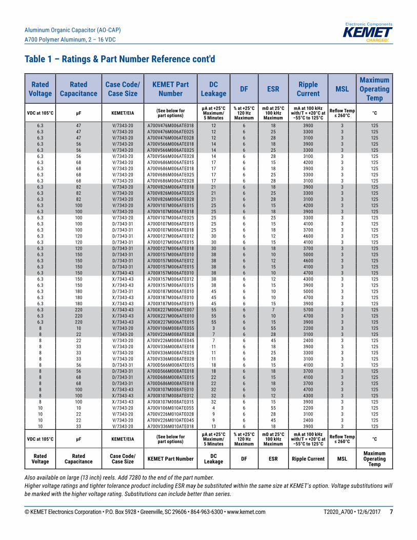
Table 1 – Ratings & Part Number Reference cont'd
Also available on large (13 inch) reels. Add 7280 to the end of the part number.Higher voltage ratings and tighter tolerance product including ESR may be substituted within the same size at KEMET's option. Voltage substitutions will be marked with the higher voltage rating. Substitutions can include better than series.
© KEMET Electronics Corporation • P.O. Box 5928 • Greenville, SC 29606 • 864-963-6300 • www.kemet.com T2020_A700 • 12/6/2017 77
Aluminum Organic Capacitor (AO-CAP) A700 Polymer Aluminum, 2 – 16 VDC
Rated Voltage
Rated Capacitance
Case Code/ Case Size
KEMET Part Number
DC Leakage DF ESR Ripple
Current MSLMaximum Operating
Temp
VDC at 105°C µF KEMET/EIA (See below forpart options)
µA at +25°C Maximum/ 5 Minutes
% at +25°C 120 Hz
Maximum
mΩ at 25°C100 kHz
Maximum
mA at 100 kHzwith/T = +20°C at −55°C to 125°C
Reflow Temp ≤ 260°C °C
6.3 47 V/7343-20 A700V476M006ATE018 12 6 18 3900 3 1256.3 47 V/7343-20 A700V476M006ATE025 12 6 25 3300 3 1256.3 47 V/7343-20 A700V476M006ATE028 12 6 28 3100 3 1256.3 56 V/7343-20 A700V566M006ATE018 14 6 18 3900 3 1256.3 56 V/7343-20 A700V566M006ATE025 14 6 25 3300 3 1256.3 56 V/7343-20 A700V566M006ATE028 14 6 28 3100 3 1256.3 68 V/7343-20 A700V686M006ATE015 17 6 15 4200 3 1256.3 68 V/7343-20 A700V686M006ATE018 17 6 18 3900 3 1256.3 68 V/7343-20 A700V686M006ATE025 17 6 25 3300 3 1256.3 68 V/7343-20 A700V686M006ATE028 17 6 28 3100 3 1256.3 82 V/7343-20 A700V826M006ATE018 21 6 18 3900 3 1256.3 82 V/7343-20 A700V826M006ATE025 21 6 25 3300 3 1256.3 82 V/7343-20 A700V826M006ATE028 21 6 28 3100 3 1256.3 100 V/7343-20 A700V107M006ATE015 25 6 15 4200 3 1256.3 100 V/7343-20 A700V107M006ATE018 25 6 18 3900 3 1256.3 100 V/7343-20 A700V107M006ATE025 25 6 25 3300 3 1256.3 100 D/7343-31 A700D107M006ATE015 25 6 15 4100 3 1256.3 100 D/7343-31 A700D107M006ATE018 25 6 18 3700 3 1256.3 120 D/7343-31 A700D127M006ATE012 30 6 12 4600 3 1256.3 120 D/7343-31 A700D127M006ATE015 30 6 15 4100 3 1256.3 120 D/7343-31 A700D127M006ATE018 30 6 18 3700 3 1256.3 150 D/7343-31 A700D157M006ATE010 38 6 10 5000 3 1256.3 150 D/7343-31 A700D157M006ATE012 38 6 12 4600 3 1256.3 150 D/7343-31 A700D157M006ATE015 38 6 15 4100 3 1256.3 150 X/7343-43 A700X157M006ATE010 38 6 10 4700 3 1256.3 150 X/7343-43 A700X157M006ATE012 38 6 12 4300 3 1256.3 150 X/7343-43 A700X157M006ATE015 38 6 15 3900 3 1256.3 180 D/7343-31 A700D187M006ATE010 45 6 10 5000 3 1256.3 180 X/7343-43 A700X187M006ATE010 45 6 10 4700 3 1256.3 180 X/7343-43 A700X187M006ATE015 45 6 15 3900 3 1256.3 220 X/7343-43 A700X227M006ATE007 55 6 7 5700 3 1256.3 220 X/7343-43 A700X227M006ATE010 55 6 10 4700 3 1256.3 220 X/7343-43 A700X227M006ATE015 55 6 15 3900 3 1258 10 V/7343-20 A700V106M008ATE055 3 6 55 2200 3 1258 22 V/7343-20 A700V226M008ATE028 7 6 28 3100 3 1258 22 V/7343-20 A700V226M008ATE045 7 6 45 2400 3 1258 33 V/7343-20 A700V336M008ATE018 11 6 18 3900 3 1258 33 V/7343-20 A700V336M008ATE025 11 6 25 3300 3 1258 33 V/7343-20 A700V336M008ATE028 11 6 28 3100 3 1258 56 D/7343-31 A700D566M008ATE015 18 6 15 4100 3 1258 56 D/7343-31 A700D566M008ATE018 18 6 18 3700 3 1258 68 D/7343-31 A700D686M008ATE015 22 6 15 4100 3 1258 68 D/7343-31 A700D686M008ATE018 22 6 18 3700 3 1258 100 X/7343-43 A700X107M008ATE010 32 6 10 4700 3 1258 100 X/7343-43 A700X107M008ATE012 32 6 12 4300 3 1258 100 X/7343-43 A700X107M008ATE015 32 6 15 3900 3 125
10 10 V/7343-20 A700V106M010ATE055 4 6 55 2200 3 12510 22 V/7343-20 A700V226M010ATE028 9 6 28 3100 3 12510 22 V/7343-20 A700V226M010ATE045 9 6 45 2400 3 12510 33 V/7343-20 A700V336M010ATE018 13 6 18 3900 3 125
VDC at 105°C µF KEMET/EIA (See below forpart options)
µA at +25°C Maximum/ 5 Minutes
% at +25°C 120 Hz
Maximum
mΩ at 25°C100 kHz
Maximum
mA at 100 kHzwith/T = +20°C at −55°C to 125°C
Reflow Temp ≤ 260°C °C
Rated Voltage
Rated Capacitance
Case Code/ Case Size KEMET Part Number DC
Leakage DF ESR Ripple Current MSLMaximum Operating
Temp
Table 1 – Ratings & Part Number Reference cont'd
Also available on large (13 inch) reels. Add 7280 to the end of the part number.Higher voltage ratings and tighter tolerance product including ESR may be substituted within the same size at KEMET's option. Voltage substitutions will be marked with the higher voltage rating. Substitutions can include better than series.
© KEMET Electronics Corporation • P.O. Box 5928 • Greenville, SC 29606 • 864-963-6300 • www.kemet.com T2020_A700 • 12/6/2017 88
Aluminum Organic Capacitor (AO-CAP) A700 Polymer Aluminum, 2 – 16 VDC
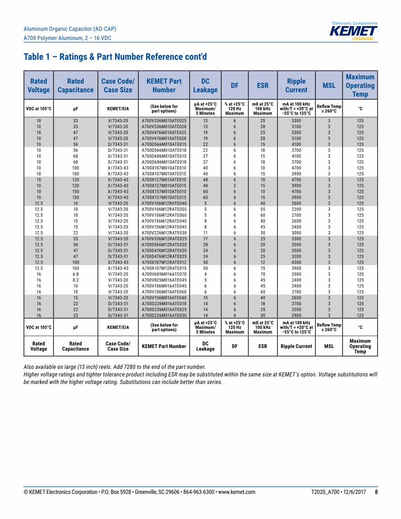
Table 1 – Ratings & Part Number Reference cont'd
Also available on large (13 inch) reels. Add 7280 to the end of the part number.Higher voltage ratings and tighter tolerance product including ESR may be substituted within the same size at KEMET's option. Voltage substitutions will be marked with the higher voltage rating. Substitutions can include better than series.
Rated Voltage
Rated Capacitance
Case Code/ Case Size
KEMET Part Number
DC Leakage DF ESR Ripple
Current MSLMaximum Operating
Temp
VDC at 105°C µF KEMET/EIA (See below forpart options)
µA at +25°C Maximum/ 5 Minutes
% at +25°C 120 Hz
Maximum
mΩ at 25°C100 kHz
Maximum
mA at 100 kHzwith/T = +20°C at −55°C to 125°C
Reflow Temp ≤ 260°C °C
10 33 V/7343-20 A700V336M010ATE025 13 6 25 3300 3 12510 33 V/7343-20 A700V336M010ATE028 13 6 28 3100 3 12510 47 V/7343-20 A700V476M010ATE025 19 6 25 3300 3 12510 47 V/7343-20 A700V476M010ATE028 19 6 28 3100 3 12510 56 D/7343-31 A700D566M010ATE015 22 6 15 4100 3 12510 56 D/7343-31 A700D566M010ATE018 22 6 18 3700 3 12510 68 D/7343-31 A700D686M010ATE015 27 6 15 4100 3 12510 68 D/7343-31 A700D686M010ATE018 27 6 18 3700 3 12510 100 X/7343-43 A700X107M010ATE010 40 6 10 4700 3 12510 100 X/7343-43 A700X107M010ATE015 40 6 15 3900 3 12510 120 X/7343-43 A700X127M010ATE010 48 6 10 4700 3 12510 120 X/7343-43 A700X127M010ATE015 48 2 15 3900 3 12510 150 X/7343-43 A700X157M010ATE010 60 6 10 4700 3 12510 150 X/7343-43 A700X157M010ATE015 60 6 15 3900 3 125
12.5 10 V/7343-20 A700V106M12RATE040 5 6 40 2600 3 12512.5 10 V/7343-20 A700V106M12RATE055 5 6 55 2200 3 12512.5 10 V/7343-20 A700V106M12RATE060 5 6 60 2100 3 12512.5 15 V/7343-20 A700V156M12RATE040 8 6 40 2600 3 12512.5 15 V/7343-20 A700V156M12RATE045 8 6 45 2400 3 12512.5 22 V/7343-20 A700V226M12RATE030 11 6 30 3000 3 12512.5 33 V/7343-20 A700V336M12RATE025 17 6 25 3300 3 12512.5 56 D/7343-31 A700D566M12RATE020 28 6 20 3500 3 12512.5 47 D/7343-31 A700D476M12RATE020 24 6 20 3500 3 12512.5 47 D/7343-31 A700D476M12RATE025 24 6 25 3200 3 12512.5 100 X/7343-43 A700X107M12RATE012 50 6 12 4300 3 12512.5 100 X/7343-43 A700X107M12RATE015 50 6 15 3900 3 12516 6.8 V/7343-20 A700V685M016ATE070 4 6 70 2000 3 12516 8.2 V/7343-20 A700V825M016ATE045 5 6 45 2400 3 12516 10 V/7343-20 A700V106M016ATE045 6 6 45 2400 3 12516 10 V/7343-20 A700V106M016ATE060 6 6 60 2100 3 12516 15 V/7343-20 A700V156M016ATE040 10 6 40 2600 3 12516 22 D/7343-31 A700D226M016ATE018 14 6 18 3700 3 12516 22 D/7343-31 A700D226M016ATE025 14 6 25 3200 3 12516 22 D/7343-31 A700D226M016ATE030 14 6 30 2900 3 125
VDC at 105°C µF KEMET/EIA (See below forpart options)
µA at +25°C Maximum/ 5 Minutes
% at +25°C 120 Hz
Maximum
mΩ at 25°C100 kHz
Maximum
mA at 100 kHzwith/T = +20°C at −55°C to 125°C
Reflow Temp ≤ 260°C °C
Rated Voltage
Rated Capacitance
Case Code/ Case Size KEMET Part Number DC
Leakage DF ESR Ripple Current MSLMaximum Operating
Temp
© KEMET Electronics Corporation • P.O. Box 5928 • Greenville, SC 29606 • 864-963-6300 • www.kemet.com T2020_A700 • 12/6/2017 99
Aluminum Organic Capacitor (AO-CAP) A700 Polymer Aluminum, 2 – 16 VDC
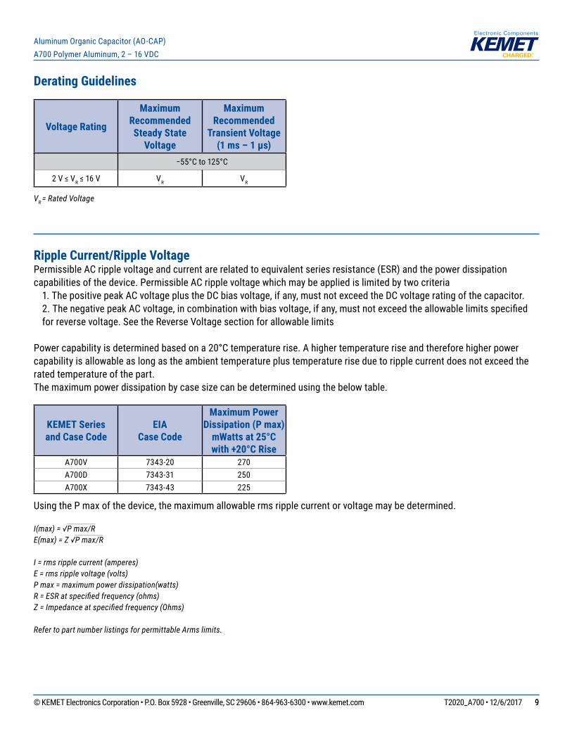
Derating Guidelines
Voltage Rating
Maximum Recommended Steady State
Voltage
Maximum Recommended
Transient Voltage (1 ms – 1 µs)
−55°Cto125°C
2V≤VR≤16V VR VR
VR = Rated Voltage
Ripple Current/Ripple VoltagePermissible AC ripple voltage and current are related to equivalent series resistance (ESR) and the power dissipation capabilities of the device. Permissible AC ripple voltage which may be applied is limited by two criteria 1. The positive peak AC voltage plus the DC bias voltage, if any, must not exceed the DC voltage rating of the capacitor. 2.ThenegativepeakACvoltage,incombinationwithbiasvoltage,ifany,mustnotexceedtheallowablelimitsspecified
for reverse voltage. See the Reverse Voltage section for allowable limits
Powercapabilityisdeterminedbasedona20°Ctemperaturerise.Ahighertemperatureriseandthereforehigherpowercapability is allowable as long as the ambient temperature plus temperature rise due to ripple current does not exceed the rated temperature of the part.The maximum power dissipation by case size can be determined using the below table.
KEMET Series and Case Code
EIA Case Code
Maximum Power Dissipation (P max)
mWatts at 25°C with +20°C Rise
A700V 7343-20 270A700D 7343-31 250A700X 7343-43 225
Using the P max of the device, the maximum allowable rms ripple current or voltage may be determined.
I(max) = √P max/RE(max) = Z √P max/R
I = rms ripple current (amperes)E = rms ripple voltage (volts)P max = maximum power dissipation(watts)R = ESR at specified frequency (ohms)Z = Impedance at specified frequency (Ohms)
Refer to part number listings for permittable Arms limits.
© KEMET Electronics Corporation • P.O. Box 5928 • Greenville, SC 29606 • 864-963-6300 • www.kemet.com T2020_A700 • 12/6/2017 1010
Aluminum Organic Capacitor (AO-CAP) A700 Polymer Aluminum, 2 – 16 VDC
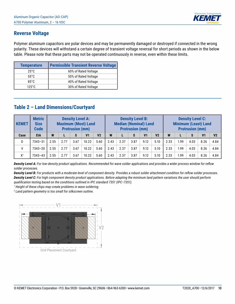
Reverse Voltage
Polymer aluminum capacitors are polar devices and may be permanently damaged or destroyed if connected in the wrong polarity. These devices will withstand a certain degree of transient voltage reversal for short periods as shown in the below table. Please note that these parts may not be operated continuously in reverse, even within these limits.
Temperature Permissible Transient Reverse Voltage25°C 60% of Rated Voltage55°C 50% of Rated Voltage85°C 40% of Rated Voltage125°C 30% of Rated Voltage
Table 2 – Land Dimensions/Courtyard
KEMET Metric Size Code
Density Level A: Maximum (Most) Land
Protrusion (mm)
Density Level B: Median (Nominal) Land
Protrusion (mm)
Density Level C: Minimum (Least) Land
Protrusion (mm)Case EIA W L S V1 V2 W L S V1 V2 W L S V1 V2
D 7343–31 2.55 2.77 3.67 10.22 5.60 2.43 2.37 3.87 9.12 5.10 2.33 1.99 4.03 8.26 4.84
V 7343–20 2.55 2.77 3.67 10.22 5.60 2.43 2.37 3.87 9.12 5.10 2.33 1.99 4.03 8.26 4.84
X1 7343–43 2.55 2.77 3.67 10.22 5.60 2.43 2.37 3.87 9.12 5.10 2.33 1.99 4.03 8.26 4.84
Density Level A: For low-density product applications. Recommended for wave solder applications and provides a wider process window for reflow solder processes. Density Level B: For products with a moderate level of component density. Provides a robust solder attachment condition for reflow solder processes.Density Level C: For high component density product applications. Before adapting the minimum land pattern variations the user should perform qualification testing based on the conditions outlined in IPC standard 7351 (IPC–7351).1 Height of these chips may create problems in wave soldering.2 Land pattern geometry is too small for silkscreen outline.
L
S
W W
L
V1
V2
Grid Placement Courtyard
© KEMET Electronics Corporation • P.O. Box 5928 • Greenville, SC 29606 • 864-963-6300 • www.kemet.com T2020_A700 • 12/6/2017 1111
Aluminum Organic Capacitor (AO-CAP) A700 Polymer Aluminum, 2 – 16 VDC
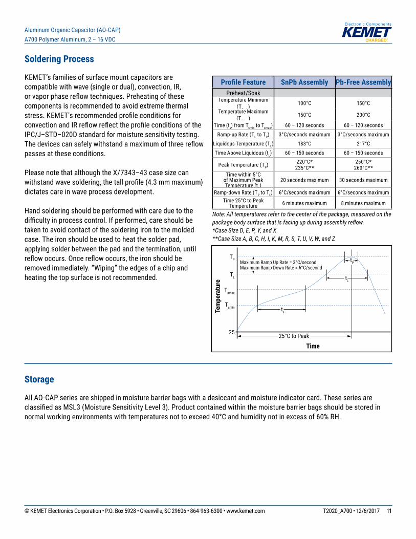
Soldering Process
KEMET’sfamiliesofsurfacemountcapacitorsarecompatible with wave (single or dual), convection, IR, orvaporphasereflowtechniques.Preheatingofthesecomponents is recommended to avoid extreme thermal stress.KEMET'srecommendedprofileconditionsforconvectionandIRreflowreflecttheprofileconditionsoftheIPC/J–STD–020D standard for moisture sensitivity testing. Thedevicescansafelywithstandamaximumofthreereflowpasses at these conditions.
Please note that although the X/7343–43 case size can withstandwavesoldering,thetallprofile(4.3mmmaximum)dictates care in wave process development.
Hand soldering should be performed with care due to the difficultyinprocesscontrol.Ifperformed,careshouldbetaken to avoid contact of the soldering iron to the molded case. The iron should be used to heat the solder pad, applying solder between the pad and the termination, until reflowoccurs.Oncereflowoccurs,theironshouldberemoved immediately. “Wiping” the edges of a chip and heating the top surface is not recommended.
Profile Feature SnPb Assembly Pb-Free AssemblyPreheat/Soak
Temperature Minimum (TSmin)
100°C 150°CTemperature Maximum
(TSmax)150°C 200°C
Time (ts) from Tsmin to Tsmax) 60 – 120 seconds 60 – 120 seconds
Ramp-up Rate (TL to TP) 3°C/secondsmaximum 3°C/secondsmaximum
Liquidous Temperature (TL) 183°C 217°C
Time Above Liquidous (tL) 60 – 150 seconds 60 – 150 seconds
Peak Temperature (TP) 220°C*235°C**
250°C*260°C**
Timewithin5°Cof Maximum Peak Temperature (tP)
20 seconds maximum 30 seconds maximum
Ramp-down Rate (TP to TL) 6°C/secondsmaximum 6°C/secondsmaximumTime25°CtoPeak
Temperature 6 minutes maximum 8 minutes maximum
Note: All temperatures refer to the center of the package, measured on the package body surface that is facing up during assembly reflow. *Case Size D, E, P, Y, and X **Case Size A, B, C, H, I, K, M, R, S, T, U, V, W, and Z
Time
Tem
pera
ture
Tsmin
25
Tsmax
TL
TP Maximum Ramp Up Rate = 3°C/secondMaximum Ramp Down Rate = 6°C/second
tP
tL
ts
25°C to Peak
Storage
All AO-CAP series are shipped in moisture barrier bags with a desiccant and moisture indicator card. These series are classifiedasMSL3(MoistureSensitivityLevel3).Productcontainedwithinthemoisturebarrierbagsshouldbestoredinnormalworkingenvironmentswithtemperaturesnottoexceed40°Candhumiditynotinexcessof60%RH.
© KEMET Electronics Corporation • P.O. Box 5928 • Greenville, SC 29606 • 864-963-6300 • www.kemet.com T2020_A700 • 12/6/2017 1212
Aluminum Organic Capacitor (AO-CAP) A700 Polymer Aluminum, 2 – 16 VDC
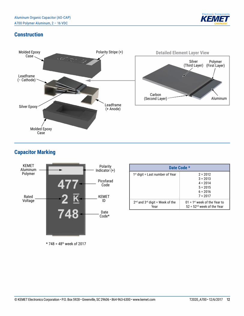
Construction
Leadframe(− Cathode)
Leadframe(+ Anode)
Molded Epoxy Case
Molded Epoxy Case
Silver Epoxy
Detailed Element Layer View
Aluminum
Polymer(First Layer)
Carbon(Second Layer)
Silver(Third Layer)
Polarity Stripe (+)
Capacitor Marking
KEMET Aluminum Polymer
Polarity Indicator (+)
Rated Voltage
Picofarad Code
KEMET ID
Date Code*
* 748 = 48th week of 2017
Date Code *1st digit = Last number of Year 2 = 2012
3 = 20134 = 20145 = 20156 = 20167 = 2017
2nd and 3rd digit = Week of the Year
01 = 1st week of the Year to 52 = 52nd week of the Year
© KEMET Electronics Corporation • P.O. Box 5928 • Greenville, SC 29606 • 864-963-6300 • www.kemet.com T2020_A700 • 12/6/2017 1313
Aluminum Organic Capacitor (AO-CAP) A700 Polymer Aluminum, 2 – 16 VDC
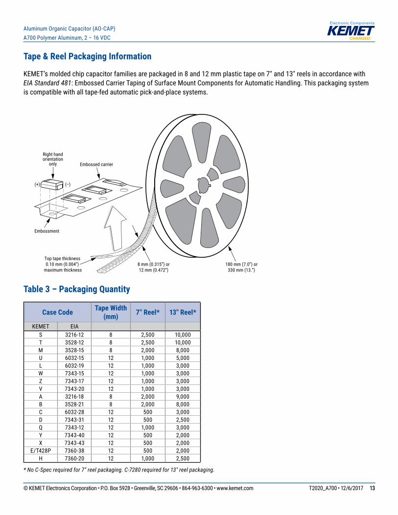
Tape & Reel Packaging Information
KEMET’smoldedchipcapacitorfamiliesarepackagedin8and12mmplastictapeon7"and13"reelsinaccordancewithEIA Standard 481: Embossed Carrier Taping of Surface Mount Components for Automatic Handling. This packaging system is compatible with all tape-fed automatic pick-and-place systems.
Embossment
8 mm (0.315”) or12 mm (0.472”)
Embossed carrier
Right handorientation
only
(+) (−)
Top tape thickness0.10 mm (0.004”)
maximum thickness180 mm (7.0”) or
330 mm (13.”)
Table 3 – Packaging Quantity
Case Code Tape Width (mm) 7" Reel* 13" Reel*
KEMET EIAS 3216-12 8 2,500 10,000T 3528-12 8 2,500 10,000M 3528-15 8 2,000 8,000U 6032-15 12 1,000 5,000L 6032-19 12 1,000 3,000W 7343-15 12 1,000 3,000Z 7343-17 12 1,000 3,000V 7343-20 12 1,000 3,000A 3216-18 8 2,000 9,000B 3528-21 8 2,000 8,000C 6032-28 12 500 3,000D 7343-31 12 500 2,500Q 7343-12 12 1,000 3,000Y 7343-40 12 500 2,000X 7343-43 12 500 2,000
E/T428P 7360-38 12 500 2,000H 7360-20 12 1,000 2,500
* No C-Spec required for 7" reel packaging. C-7280 required for 13" reel packaging.

© KEMET Electronics Corporation • P.O. Box 5928 • Greenville, SC 29606 • 864-963-6300 • www.kemet.com T2020_A700 • 12/6/2017 1414
Aluminum Organic Capacitor (AO-CAP) A700 Polymer Aluminum, 2 – 16 VDC
Figure 1 – Embossed (Plastic) Carrier Tape Dimensions
P0
T
F
W
Center Lines of Cavity
A0
B0
User Direction of Unreeling
Cover Tape
K0
B1 is for tape feeder reference only, including draft concentric about B0.
T2
ØD1
ØD0
B1
S1
T1
E1
E2
P1
P2
EmbossmentFor cavity size,see Note 1 Table 4
[10 pitches cumulativetolerance on tape ±0.2 mm]
Table 4 – Embossed (Plastic) Carrier Tape DimensionsMetric will govern
Constant Dimensions — Millimeters (Inches)
Tape Size D0 D1 Minimum
Note 1 E1 P0 P2 R Reference
Note 2S1 Minimum
Note 3 T Maximum T1 Maximum
8 mm1.5 +0.10/-0.0
(0.059+0.004/-0.0)
1.0 (0.039) 1.75±0.10
(0.069±0.004)4.0±0.10
(0.157±0.004)2.0±0.05
(0.079±0.002)
25.0 (0.984) 0.600
(0.024)0.600
(0.024)0.100
(0.004)12 mm 1.5
(0.059)30
(1.181)
Variable Dimensions — Millimeters (Inches)
Tape Size Pitch B1 Maximum Note 4 E2 Minimum F P1 T2 Maximum W Maximum A0, B0 & K0
8 mm Single (4 mm) 4.35 (0.171)
6.25 (0.246)
3.5±0.05 (0.138±0.002)
2.0±0.05 or 4.0±0.10(0.079±0.002 or 0.157±0.004)
2.5 (0.098)
8.3 (0.327)
Note 512 mm
Single (4 mm) & Double(8 mm)
8.2 (0.323)
10.25 (0.404)
5.5±0.05 (0.217±0.002)
2.0±0.05 (0.079±0.002) or 4.0±0.10 (0.157±0.004) or
8.0±0.10 (0.315±0.004)
4.6 (0.181)
12.3 (0.484)
1. The embossment hole location shall be measured from the sprocket hole controlling the location of the embossment. Dimensions of embossment location and hole location shall be applied independent of each other.
2. The tape, with or without components, shall pass around R without damage (see Figure 4).3. If S1 < 1.0 mm, there may not be enough area for cover tape to be properly applied (see EIA Standard 481–D, paragraph 4.3, section b).4. B1 dimension is a reference dimension for tape feeder clearance only.5. The cavity defi ned by A0, B0 and K0 shall surround the component with suffi cient clearance that: (a) the component does not protrude above the top surface of the carrier tape. (b) the component can be removed from the cavity in a vertical direction without mechanical restriction, after the top cover tape has been removed. (c) rotation of the component is limited to 20° maximum for 8 and 12 mm tapes (see Figure 2). (d) lateral movement of the component is restricted to 0.5 mm maximum for 8 mm and 12 mm wide tape (see Figure 3). (e) see Addendum in EIA Standard 481–D for standards relating to more precise taping requirements.
© KEMET Electronics Corporation • P.O. Box 5928 • Greenville, SC 29606 • 864-963-6300 • www.kemet.com T2020_A700 • 12/6/2017 1515
Aluminum Organic Capacitor (AO-CAP) A700 Polymer Aluminum, 2 – 16 VDC
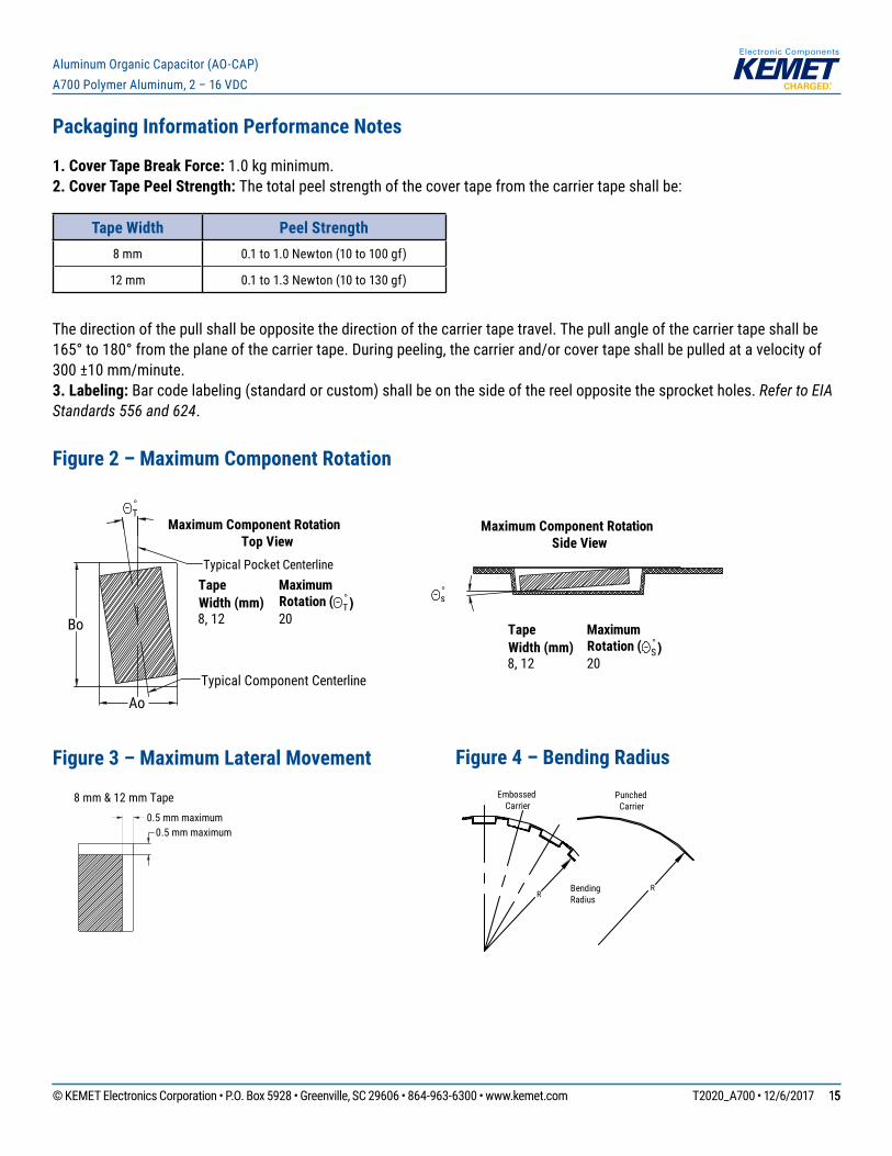
Packaging Information Performance Notes
1. Cover Tape Break Force: 1.0 kg minimum.2. Cover Tape Peel Strength: The total peel strength of the cover tape from the carrier tape shall be:
Tape Width Peel Strength8 mm 0.1 to 1.0 Newton (10 to 100 gf)
12 mm 0.1 to 1.3 Newton (10 to 130 gf)
The direction of the pull shall be opposite the direction of the carrier tape travel. The pull angle of the carrier tape shall be 165°to180°fromtheplaneofthecarriertape.Duringpeeling,thecarrierand/orcovertapeshallbepulledatavelocityof300 ±10 mm/minute.3. Labeling: Bar code labeling (standard or custom) shall be on the side of the reel opposite the sprocket holes. Refer to EIA Standards 556 and 624.
Figure 2 – Maximum Component Rotation
Ao
Bo
°T
°s
Maximum Component RotationTop View
Maximum Component RotationSide View
TapeWidth (mm)
MaximumRotation ( °
T)8, 12 20
TapeWidth (mm)
MaximumRotation (
8, 12 20 °S)
Typical Pocket Centerline
Typical Component Centerline
Figure 3 – Maximum Lateral Movement
0.5 mm maximum0.5 mm maximum
8 mm & 12 mm Tape
Figure 4 – Bending Radius
RRBending
Radius
EmbossedCarrier
PunchedCarrier
© KEMET Electronics Corporation • P.O. Box 5928 • Greenville, SC 29606 • 864-963-6300 • www.kemet.com T2020_A700 • 12/6/2017 1616
Aluminum Organic Capacitor (AO-CAP) A700 Polymer Aluminum, 2 – 16 VDC
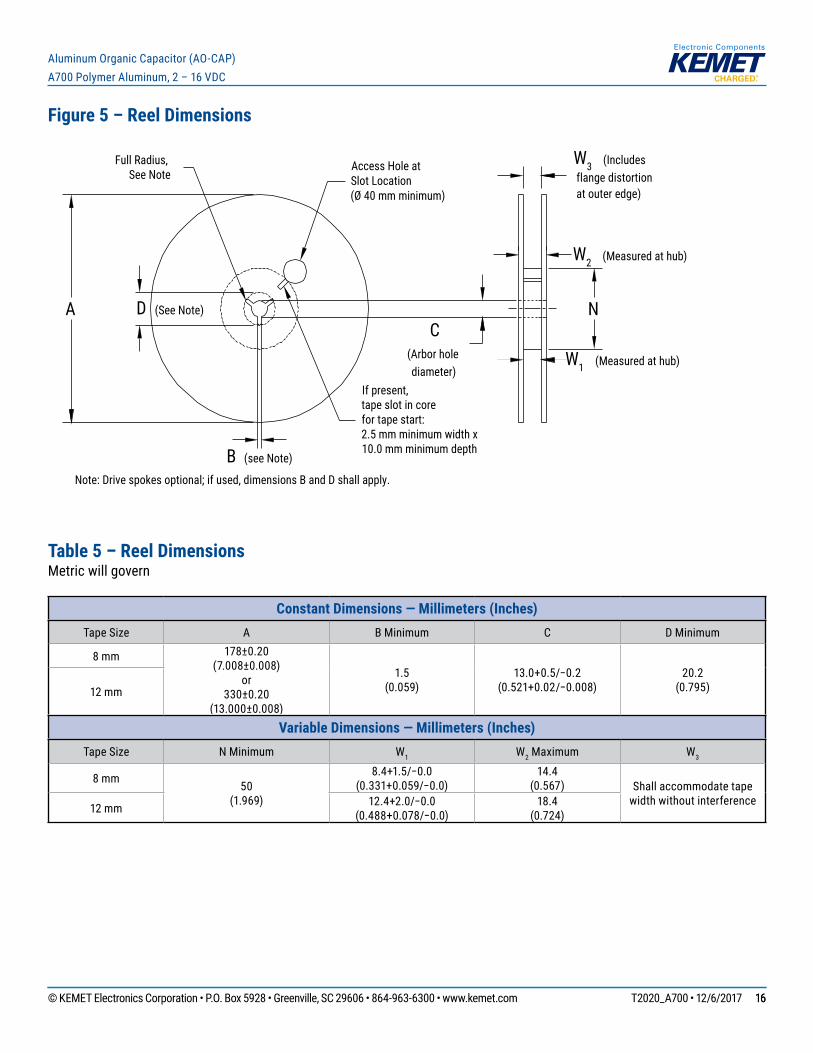
Figure 5 – Reel Dimensions
A D (See Note)
Full Radius,See Note
B (see Note)
Access Hole atSlot Location(Ø 40 mm minimum)
If present,tape slot in corefor tape start:2.5 mm minimum width x10.0 mm minimum depth
W3 (Includes flange distortion at outer edge)
W2 (Measured at hub)
W1 (Measured at hub)
C(Arbor holediameter)
Note: Drive spokes optional; if used, dimensions B and D shall apply.
N
Table 5 – Reel DimensionsMetric will govern
Constant Dimensions — Millimeters (Inches) Tape Size A B Minimum C D Minimum
8 mm 178±0.20 (7.008±0.008)
or330±0.20
(13.000±0.008)
1.5 (0.059)
13.0+0.5/−0.2(0.521+0.02/−0.008)
20.2 (0.795)12 mm
Variable Dimensions — Millimeters (Inches) Tape Size N Minimum W1 W2 Maximum W3
8 mm 50 (1.969)
8.4+1.5/−0.0(0.331+0.059/−0.0)
14.4 (0.567) Shall accommodate tape
width without interference12 mm 12.4+2.0/−0.0(0.488+0.078/−0.0)
18.4 (0.724)
© KEMET Electronics Corporation • P.O. Box 5928 • Greenville, SC 29606 • 864-963-6300 • www.kemet.com T2020_A700 • 12/6/2017 1717
Aluminum Organic Capacitor (AO-CAP) A700 Polymer Aluminum, 2 – 16 VDC
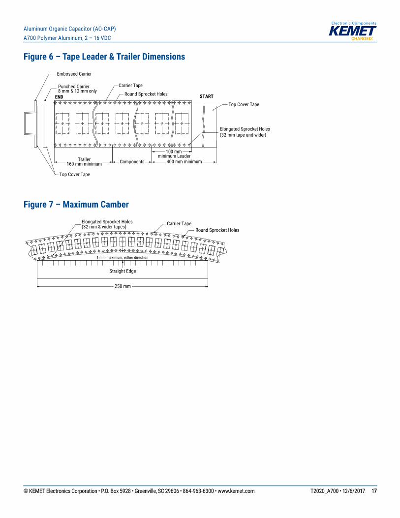
Figure 6 – Tape Leader & Trailer Dimensions
Trailer160 mm minimum
Carrier Tape
END STARTRound Sprocket Holes
Elongated Sprocket Holes(32 mm tape and wider)
Top Cover Tape
Top Cover Tape
Punched Carrier8 mm & 12 mm only
Embossed Carrier
Components
100 mm minimum Leader
400 mm minimum
Figure 7 – Maximum Camber
Carrier TapeRound Sprocket Holes
1 mm maximum, either direction
Straight Edge
250 mm
Elongated Sprocket Holes(32 mm & wider tapes)
© KEMET Electronics Corporation • P.O. Box 5928 • Greenville, SC 29606 • 864-963-6300 • www.kemet.com T2020_A700 • 12/6/2017 1818
Aluminum Organic Capacitor (AO-CAP) A700 Polymer Aluminum, 2 – 16 VDC
KEMET Electronics Corporation Sales Offi ces
Foracompletelistofourglobalsalesoffices,pleasevisitwww.kemet.com/sales.
DisclaimerAllproductspecifications,statements,informationanddata(collectively,the“Information”)inthisdatasheetaresubjecttochange.Thecustomerisresponsibleforchecking and verifying the extent to which the Information contained in this publication is applicable to an order at the time the order is placed.
All Information given herein is believed to be accurate and reliable, but it is presented without guarantee, warranty, or responsibility of any kind, expressed or implied.
StatementsofsuitabilityforcertainapplicationsarebasedonKEMETElectronicsCorporation’s(“KEMET”)knowledgeoftypicaloperatingconditionsforsuchapplications,butarenotintendedtoconstitute–andKEMETspecificallydisclaims–anywarrantyconcerningsuitabilityforaspecificcustomerapplicationoruse.The Information is intended for use only by customers who have the requisite experience and capability to determine the correct products for their application. Any technicaladviceinferredfromthisInformationorotherwiseprovidedbyKEMETwithreferencetotheuseofKEMET’sproductsisgivengratis,andKEMETassumesnoobligation or liability for the advice given or results obtained.
Although KEMET designs and manufactures its products to the most stringent quality and safety standards, given the current state of the art, isolated component failures may still occur. Accordingly, customer applications which require a high degree of reliability or safety should employ suitable designs or other safeguards (suchasinstallationofprotectivecircuitryorredundancies)inordertoensurethatthefailureofanelectricalcomponentdoesnotresultinariskofpersonalinjuryorproperty damage.
Although all product–related warnings, cautions and notes must be observed, the customer should not assume that all safety measures are indicted or that other measures may not be required.
KEMET is a registered trademark of KEMET Electronics Corporation.
Related Documents