Information System OGL-ECD A50016-E1110-A503-2-7619

Welcome message from author
This document is posted to help you gain knowledge. Please leave a comment to let me know what you think about it! Share it to your friends and learn new things together.
Transcript

InformationSystem
OGL-ECD
A50016-E1110-A503-2-7619

2 A50016-E1110-A503-2-7619
OGL-ECD
Id:0900d80580579656
The information in this document is subject to change without notice and describes only the product defined in the introduction of this documentation. This documentation is intended for the use of Nokia Siemens Networks customers only for the purposes of the agreement under which the document is submitted, and no part of it may be used, reproduced, modified or transmitted in any form or means without the prior written permission of Nokia Siemens Networks. The documentation has been prepared to be used by professional and properly trained personnel, and the customer assumes full responsibility when using it. Nokia Siemens Networks welcomes customer comments as part of the process of continuous development and improvement of the documentation.
The information or statements given in this documentation concerning the suitability, capacity, or performance of the mentioned hardware or software products are given "as is" and all liability arising in connection with such hardware or software products shall be defined conclusively and finally in a separate agreement between Nokia Siemens Networks and the customer. However, Nokia Siemens Networks has made all reasonable efforts to ensure that the instructions contained in the document are adequate and free of material errors and omissions. Nokia Siemens Networks will, if deemed necessary by Nokia Siemens Networks, explain issues which may not be covered by the document.
Nokia Siemens Networks will correct errors in this documentation as soon as possible. IN NO EVENT WILL Nokia Siemens Networks BE LIABLE FOR ERRORS IN THIS DOCUMENTA-TION OR FOR ANY DAMAGES, INCLUDING BUT NOT LIMITED TO SPECIAL, DIRECT, INDI-RECT, INCIDENTAL OR CONSEQUENTIAL OR ANY LOSSES, SUCH AS BUT NOT LIMITED TO LOSS OF PROFIT, REVENUE, BUSINESS INTERRUPTION, BUSINESS OPPORTUNITY OR DATA,THAT MAY ARISE FROM THE USE OF THIS DOCUMENT OR THE INFORMATION IN IT.
This documentation and the product it describes are considered protected by copyrights and other intellectual property rights according to the applicable laws.
The wave logo is a trademark of Nokia Siemens Networks Oy. Nokia is a registered trademark of Nokia Corporation. Siemens is a registered trademark of Siemens AG.
Other product names mentioned in this document may be trademarks of their respective owners, and they are mentioned for identification purposes only.
Copyright © Nokia Siemens Networks 2007. All rights reserved
f Important Notice on Product Safety Elevated voltages are inevitably present at specific points in this electrical equipment. Some of the parts may also have elevated operating temperatures.
Non-observance of these conditions and the safety instructions can result in personal injury or in property damage.
Therefore, only trained and qualified personnel may install and maintain the system.
The system complies with the standard EN 60950 / IEC 60950. All equipment connected has to comply with the applicable safety standards.
The same text in German:
Wichtiger Hinweis zur Produktsicherheit
In elektrischen Anlagen stehen zwangsläufig bestimmte Teile der Geräte unter Span-nung. Einige Teile können auch eine hohe Betriebstemperatur aufweisen.
Eine Nichtbeachtung dieser Situation und der Warnungshinweise kann zu Körperverlet-zungen und Sachschäden führen.
Deshalb wird vorausgesetzt, dass nur geschultes und qualifiziertes Personal die Anlagen installiert und wartet.
Das System entspricht den Anforderungen der EN 60950 / IEC 60950. Angeschlossene Geräte müssen die zutreffenden Sicherheitsbestimmungen erfüllen.

A50016-E1110-A503-2-7619
3
OGL-ECD
Id:0900d80580579656
Table of ContentsThis document has 60 pages.
Change History . . . . . . . . . . . . . . . . . . . . . . . . . . . . . . . . . . . . . . . . . . . . 6
1 General . . . . . . . . . . . . . . . . . . . . . . . . . . . . . . . . . . . . . . . . . . . . . . . . . . 7
2 Document List (DOL) . . . . . . . . . . . . . . . . . . . . . . . . . . . . . . . . . . . . . . . . 9
3 Layout Plan (LP) . . . . . . . . . . . . . . . . . . . . . . . . . . . . . . . . . . . . . . . . . . 11
4 Layout List (LL) . . . . . . . . . . . . . . . . . . . . . . . . . . . . . . . . . . . . . . . . . . . 124.1 Layout List for Rack (LL:RACK). . . . . . . . . . . . . . . . . . . . . . . . . . . . . . . 124.2 Layout List for Shelfs (LL:SHELF) . . . . . . . . . . . . . . . . . . . . . . . . . . . . . 134.3 Layout List for Power Distribution Frame (LL:PDF) . . . . . . . . . . . . . . . . 174.4 Layout List for Main Feeder (LL:MAIN FE) . . . . . . . . . . . . . . . . . . . . . . 17
5 Equipment List:Rack (EL:R). . . . . . . . . . . . . . . . . . . . . . . . . . . . . . . . . . 205.1 Equipment List for Rack with Line/Trunk Groups (EL:R (LTG)). . . . . . . 205.2 Equipment List for Rack, except LTG and DLU (EL:R (except LTG and
DLU)) . . . . . . . . . . . . . . . . . . . . . . . . . . . . . . . . . . . . . . . . . . . . . . . . . . . 235.3 Equipment List for Rack with DLU (EL:R (DLU)) . . . . . . . . . . . . . . . . . . 24
6 Survey List (SUL). . . . . . . . . . . . . . . . . . . . . . . . . . . . . . . . . . . . . . . . . . 276.1 Survey List for Application (SUL:APPLICATION) . . . . . . . . . . . . . . . . . 276.2 Survey List for Digital Line Unit (SUL:DLU) . . . . . . . . . . . . . . . . . . . . . . 286.3 Survey List for High-Speed Links (SUL:HSL) . . . . . . . . . . . . . . . . . . . . 306.4 Survey List for Line Interface Card / PORT (SUL:LIC/PORT) . . . . . . . . 326.5 Survey List for Line/Trunk Group / Digital Line Unit (SUL:LTG/DLU) . . 336.6 Survey List for Line/Trunk Group / Line/Trunk Unit (SUL:LTG/LTU) . . . 346.7 Survey List for Line Interface Card - TRAU Server Card / Line/Trunk Group
(SUL:LIC_TSC/LTG) . . . . . . . . . . . . . . . . . . . . . . . . . . . . . . . . . . . . . . . 406.8 Survey List for Line Interface Card - Redundant (SUL:LIC-REDUNDANT)
416.9 Survey list for RSU (SUL:RSU) . . . . . . . . . . . . . . . . . . . . . . . . . . . . . . . 41
7 Equipment Plan for Distribution Frame (EP:DF) . . . . . . . . . . . . . . . . . . 44
8 Cable Laying Lists (CLL) . . . . . . . . . . . . . . . . . . . . . . . . . . . . . . . . . . . . 478.1 Set D1A20 - Rack-to-Rack Connections . . . . . . . . . . . . . . . . . . . . . . . . 488.2 Set D1A30 - Rack-to-MDF ConnectionsSet D1A30 - Rack-to-MDF Con-
nections . . . . . . . . . . . . . . . . . . . . . . . . . . . . . . . . . . . . . . . . . . . . . . . . . 518.3 Set D1A40 - Rack-to-DS2 Distributor Connections . . . . . . . . . . . . . . . . 558.4 Set D1A50 - Rack-to-DS2NR / DS2 Connections . . . . . . . . . . . . . . . . . 58

4 A50016-E1110-A503-2-7619
OGL-ECD
Id:0900d80580579656
List of FiguresFigure 1 Example of a layout plan (with raised floor) . . . . . . . . . . . . . . . . . . . . . . 11Figure 2 Overview of cable routes in standard cabling . . . . . . . . . . . . . . . . . . . . . 47
A50016-E1110-A503-2-7619
5
OGL-ECD
Id:0900d80580579656
List of TablesTable 1 Example of a pseudo LTU types . . . . . . . . . . . . . . . . . . . . . . . . . . . . . . 34
6 A50016-E1110-A503-2-7619
OGL-ECD
Id:0900d80580105588
Change History
Change HistoryIssue 2 (01/2007)Correction: SILT removed
Issue 1 (10/2006)New software release.
A50016-E1110-A503-2-7619
7
OGL-ECD General
Id:0900d8058006935a
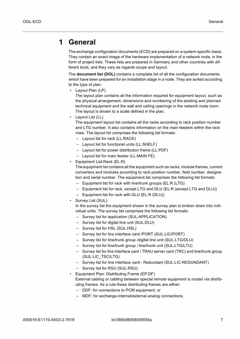
1 GeneralThe exchange configuration documents (ECD) are prepared on a system-specific basis. They contain an exact image of the hardware implementation of a network node, in the form of project lists. These lists are prepared in Germany and other countries with dif-ferent tools, and they vary as regards scope and layout.
The document list (DOL) contains a complete list of all the configuration documents which have been prepared for an installation stage in a node. They are sorted according to the type of plan: • Layout Plan (LP)
The layout plan contains all the information required for equipment layout, such as the physical arrangement, dimensions and numbering of the existing and planned technical equipment and the wall and ceiling openings in the network node room. The layout is shown to a scale defined in the plan.
• Layout List (LL)The equipment layout list contains all the racks according to rack position number and LTG number. It also contains information on the main feeders within the rack rows. The layout list comprises the following list formats:– Layout list for rack (LL:RACK)– Layout list for functional units (LL:SHELF)– Layout list for power distribution frame (LL:PDF)– Layout list for main feeder (LL:MAIN FE)
• Equipment List:Rack (EL:R)The equipment list contains all the equipment such as racks, module frames, current converters and modules according to rack position number, field number, designa-tion and serial number. The equipment list comprises the following list formats:– Equipment list for rack with line/trunk groups (EL:R (LTG)– Equipment list for rack, except LTG and DLU (EL:R (except LTG and DLU))– Equipment list for rack with DLU (EL:R (DLU))
• Survey List (SUL)In the survey list the equipment shown in the survey plan is broken down into indi-vidual units. The survey list comprises the following list formats:– Survey list for application (SUL:APPLICATION)– Survey list for digital line unit (SUL:DLU)– Survey list for HSL (SUL:HSL)– Survey list for line interface card /PORT (SUL:LIC/PORT)– Survey list for line/trunk group /digital line unit (SUL:LTG/DLU)– Survey list for line/trunk group / line/trunk unit (SUL:LTG/LTU)– Survey list for line interface card / TRAU server card (TRC) and line/trunk group
(SUL:LIC_TSC/LTG)– Survey list for line interface card - Redundant (SUL:LIC-REDUNDANT)– Survey list for RSU (SUL:RSU)
• Equipment Plan: Distributing Frame (EP:DF)External cabling or cabling between special remote equipment is routed via distrib-uting frames. As a rule these distributing frames are either:– DDF: for connections to PCM equipment, or– MDF: for exchange-internal/external analog connections.

8 A50016-E1110-A503-2-7619
OGL-ECD
Id:0900d8058006935a
General
• Cable Laying List (CLL)The cable laying list contains all the plug-in cables in the network node, including the internal cabling of the CP.The cable laying lists are organized in the following groups:– A: Coordination processor - internal cabling– C: Central clock generator - message buffers / digital line/trunk groups– D, D1: Digital line/trunk groups - distributing frames– J: Intercables of analog and digital line/trunk groups– N: Switching network / time stage / space stage - message buffer / common
channel signaling link - central data channel– P: Message buffer /central clock generator / common channel signaling link /
system display panel control to coordination processor– Q: Test and special equipment– R: Analog / digital line/trunk groups - switching network / time stage for
SN126/SN252– S: Time stage - space stage / SN126 / SN252– T: Test cabling (test ring)– V: Analog line/trunk groups - distributing frame– W: special equipment - distributing frameThe following sets are available for the different cabling groups:– Set D1A20 - Rack-to-rack connections– Set D1A30 - Rack-to-MDF connections– Set D1A40 - Rack-to-DS2 distributor connections– Set D1A50 - Rack-to-DS2NR / DS2 connections

A50016-E1110-A503-2-7619
9
OGL-ECD Document List (DOL)
Id:0900d8058006935c
2 Document List (DOL)The document list contains all the project documents required for procuring, installing and operating a network node. For each document the type of plan is specified with its contents as well as the document number, the number of sheets and the date of the current release
Keys1. ORDER NO
Order number of the relevant installation stage (initial stage or expansion), format: 16 characters
2. EXCHANGE DOCUMENT SERIAL NO The 3rd and 4th block for the document serial number is taken from column 7), format: 25 characters
3. TYPE PLAN Designation of the hardware document, format: 8 characters
4. CONTENTS Contents of the hardware document, format: 14 characters
5. REMARKS Remarks relating to column 4), format: 12 characters
6. RACK POS. NO Rack position number (only for EL:R),format: 6 characters
SUL LL
LIC_TSCLIC/PORLIC_REDLTG/LTURACKLTGMDF
FIRST FLOOR
U 509-01U 510-01U 512-01U 502-01A101-01A201-01A 2-01
0101010101-06011
10.03.0410.03.0410.03.0410.03.0411.09.04 11.09.04
TYPEPLAN
CONTENTS REMARKS RACKPOS. NO
SHEET DATE *)
ORDER NO.:.37 . . . - . . . - . . . EXCHANGE DOCUMENT SERIAL NO: A39 . . . - A . . . - . . . - . . - . .7633
1) 2)
3) 4) 5) 6) 7) 8) 9) 10)
characters 1, 2 room number
characters 3, 4 rack row number
characters 5, 6 position number within the row
10 A50016-E1110-A503-2-7619
OGL-ECD
Id:0900d8058006935c
Document List (DOL)
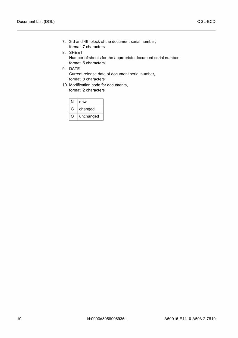
7. 3rd and 4th block of the document serial number, format: 7 characters
8. SHEET Number of sheets for the appropriate document serial number, format: 5 characters
9. DATE Current release date of document serial number, format: 8 characters
10. Modification code for documents, format: 2 characters
N new
G changed
O unchanged
A50016-E1110-A503-2-7619
11
OGL-ECD Layout Plan (LP)
Id:0900d8058006933c
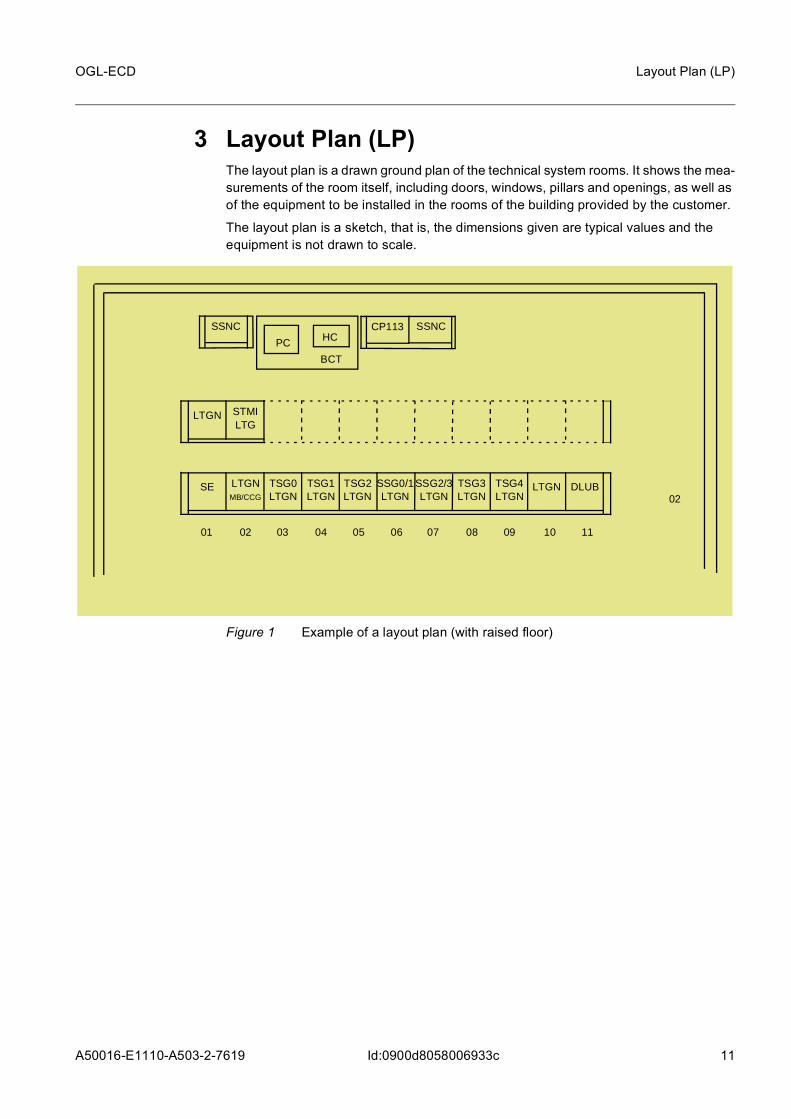
3 Layout Plan (LP)The layout plan is a drawn ground plan of the technical system rooms. It shows the mea-surements of the room itself, including doors, windows, pillars and openings, as well as of the equipment to be installed in the rooms of the building provided by the customer.
The layout plan is a sketch, that is, the dimensions given are typical values and the equipment is not drawn to scale.
Figure 1 Example of a layout plan (with raised floor)
0201 07 08
02
0903 04 05 06
DLUBLTGN
PC HC
BCT
TSG4LTGN
TSG3LTGN
SSG2/3LTGN
SSG0/1LTGN
TSG2LTGN
TSG1LTGN
TSG0LTGN
LTGNMB/CCG
SE
LTGN STMILTG
SSNC
10 11
CP113 SSNC
12 A50016-E1110-A503-2-7619
OGL-ECD
Id:0900d80580105623
Layout List (LL)
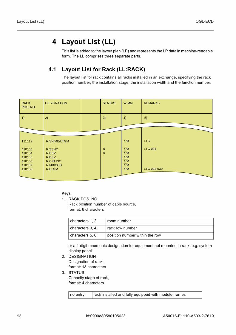
4 Layout List (LL)This list is added to the layout plan (LP) and represents the LP data in machine-readable form. The LL comprises three separate parts.
4.1 Layout List for Rack (LL:RACK)The layout list for rack contains all racks installed in an exchange, specifying the rack position number, the installation stage, the installation width and the function number.
Keys1. RACK POS. NO.
Rack position number of cable source, format: 6 characters
or a 4-digit mnemonic designation for equipment not mounted in rack, e.g. system display panel
2. DESIGNATION Designation of rack, format: 18 characters
3. STATUS Capacity stage of rack, format: 4 characters
RACKPOS. NO
DESIGNATION STATUS W.MM REMARKS
1) 2) 3) 5)4)
111112 410103410104410105410106410107410108
R:SN/MB/LTGM R:SSNCR:DEVR:DEVR:CP113CR:MB/CCGR:LTGM
00
770 770770770770770770
LTG LTG 001 LTG 002-030
characters 1, 2 room number
characters 3, 4 rack row number
characters 5, 6 position number within the row
no entry rack installed and fully equipped with module frames

A50016-E1110-A503-2-7619
13
OGL-ECD Layout List (LL)
Id:0900d80580105623
4. W.MM Rack width in millimeters (mm), format: 4 characters
5. REMARKS Supplementary information, format: 24 charactersModification identifier:
4.2 Layout List for Shelfs (LL:SHELF)The existing LTGs, DLUs, TSGs and SSGs of the switching network are listed together with the shelves they occupy. In addition to this, the automatic test equipment (ATE) with test ring is described. The layout list for functional units contains an overview of the existing LTG, DLU, SN, SSNC test units and code receivers. It also contains information on the rack designation, rack position number and the installation unit.
With the introduction of the F:SNMUX(B) the value LTGSET is supplemented by MUXA or MUXB, depending on whether the F:SNMUX(A) or F:SNMUX(B) is involved. The F:SNMUX(A) contains 2 LTGSETs, whose duplication is guaranteed by a second
T rack installed and partially equipped with module frames
0 rack planned (not existent)
* line was changed
+ line was added

14 A50016-E1110-A503-2-7619
OGL-ECD
Id:0900d80580105623
Layout List (LL)
F:SNMUX(A). The F:SNMUX(B) contains 4 LTGSETs, the redundant units are in the same frame.
Keys (project-specific modifications possible)1. LTG
Number of the line/trunk group, format: 4 characters
2. TSG Number of the time stage group (TSG) starting with “0” and counting in ascending order with values from 0-7 (not in the case of SND), format: 2 characters
3. SSG Number of the space stage group (SSG) starting with “0” and counting in ascending order with values from 0-3 (not in the case of SND), format: 2 characters
Number
LTG TS SS DESIGNATION RACKPOS.NO.
R2MACA LS PCMUMUAT SG LIC DLU VLTG
1) 2) 3) 12) 13) 16)6)4) 5) 17)15)14)7) 8) 9) 10) 11)
LTGSET MUXALTGSET MUXALTGSET MUXALTGSET MUXA
010610010610010711010711
00010203
07070707
06060606
at F:SNMUX(A)
LTGSET MUXALTGSET MUXALTGSET MUXALTGSET MUXA
010610010610010610010610
00010203
06060606
at F:SNMUX(B)
characters 1, 2 LTGSET (numbering from 00-31)
characters 3, 4 LTG number (numbering from 01-63 per LTGSET)

A50016-E1110-A503-2-7619
15
OGL-ECD Layout List (LL)
Id:0900d80580105623
4. CA SNCARE with values from 1-4, format: 2 characters
5. LS LINKSET with values from 00-31, format: 2 characters
6. MA SNMAT with values from 0-7, format: 2 characters
7. AT The automatic test equipment (ATE) is counted through, starting with “0”, format: 2 characters
8. SG Number of the signaling link terminal group (SILTG), two-digit entry with values from 00-31 - only in the case of R:CCNC/SILT, format: 5 characters
9. LIC Number of the line interface card (LIC) in the R:SSNC to which the corresponding LTG is connected, or indication of the rack and shelf where the LIC is located, format: 2 characters
10. DLU Number of the digital line unit, format: 5 characters
11. VLTG Indicates which LTG is the virtual master LTG,format: 4 characters
12. NAME Name of the unit, e.g. LTGA / LTGB.In the last position in this column, the following designations are entered:
Format: 12 characters13. RACK POS NO
Rack position number, format: 6 characters
character 1 ... 5 DLU
E Echo suppressor pool
F OPAL DLU
T Full Feature Set
K Conference LTG
M Monitoring LTG
P Reduced Feature Set
S UI LTG
16 A50016-E1110-A503-2-7619
OGL-ECD
Id:0900d80580105623
Layout List (LL)
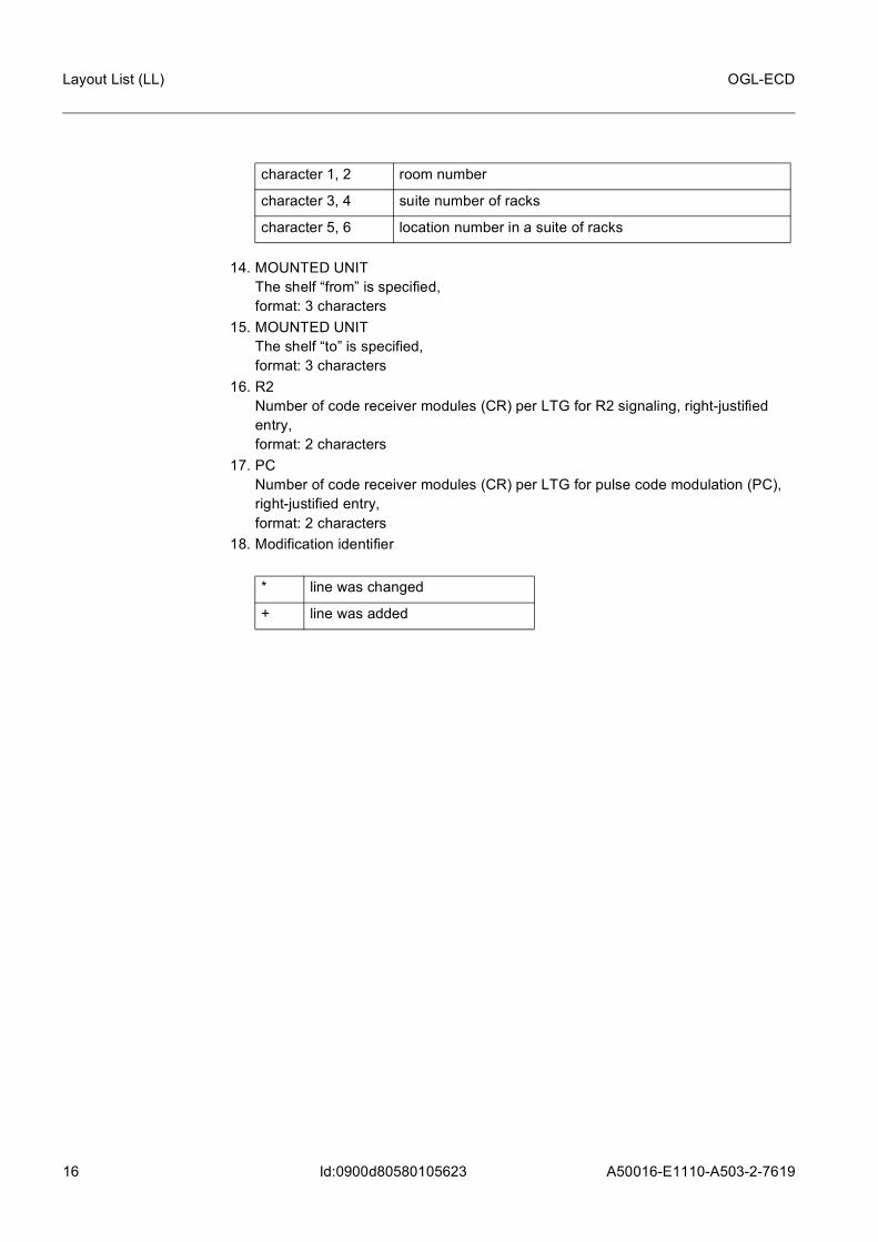
14. MOUNTED UNIT The shelf “from” is specified, format: 3 characters
15. MOUNTED UNIT The shelf “to” is specified, format: 3 characters
16. R2 Number of code receiver modules (CR) per LTG for R2 signaling, right-justified entry, format: 2 characters
17. PC Number of code receiver modules (CR) per LTG for pulse code modulation (PC), right-justified entry, format: 2 characters
18. Modification identifier
character 1, 2 room number
character 3, 4 suite number of racks
character 5, 6 location number in a suite of racks
* line was changed
+ line was added
A50016-E1110-A503-2-7619
17
OGL-ECD Layout List (LL)
Id:0900d80580105623
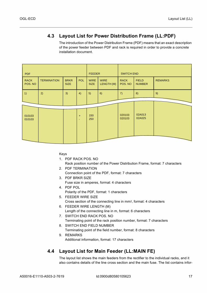
4.3 Layout List for Power Distribution Frame (LL:PDF)The introduction of the Power Distribution Frame (PDF) means that an exact description of the power feeder between PDF and rack is required in order to provide a concrete installation document.
Keys1. PDF RACK POS. NO
Rack position number of the Power Distribution Frame, format: 7 characters2. PDF TERMINATION
Connection point of the PDF, format: 7 characters3. PDF BRKR SIZE
Fuse size in amperes, format: 4 characters4. PDF POL
Polarity of the PDF, format: 1 characters5. FEEDER WIRE SIZE
Cross section of the connecting line in mm2, format: 4 characters6. FEEDER WIRE LENGTH (M)
Length of the connecting line in m, format: 6 characters7. SWITCH END RACK POS. NO
Terminating point of the rack position number, format: 7 characters8. SWITCH END FIELD NUMBER
Terminating point of the field number, format: 8 characters9. REMARKS
Additional information, format: 17 characters
4.4 Layout List for Main Feeder (LL:MAIN FE)The layout list shows the main feeders from the rectifier to the individual racks, and it also contains details of the line cross section and the main fuse. The list contains infor-
RACK POS. NO
TERMINATION WIRESIZE
WIRELENGTH (M)
RACKPOS. NO
FIELDNUMBER
REMARKSPOL
1) 2) 5) 6) 7) 8) 9)4)
BRKRSIZE
SWITCH ENDFEEDER
3)
010103010103
+-
150250
020103020103
02A01302A025

18 A50016-E1110-A503-2-7619
OGL-ECD
Id:0900d80580105623
Layout List (LL)
mation on the routing of the feeders within the racks. This list is produced and processed on the basis of a template, e.g. of an existing exchange.
Keys1. NO.
Number of the main feeder (supply from power supply unit to rack row),format: 2 characters
2. S Sequence per main feeder number, (single feed cables per main feeder), e.g.:
format: 1 character3. POLARITY
Conductor type (potential) per main feeder sequence,format: 8 characters
4. FUSE NO. Number of connected main fuse,format: 2 characters
5. FUSE AMP Nominal load of main fuse in ampere,format: 3 characters
6. MM2 Cross-section of the individual conductors to the main fuse in mm2,format: 3 characters
MAIN FEEDER
NO POLARITY NO TYPE ROW R-R MM2 TYPE REMARKSMM2
1) 2) 3) 5) 6) 7) 8) 9) 10)4)
0101 0202
11 11
41014101 41024102
02-0902-09 01-0901-09
200150 200150
1X 5X 40H07VK150 1X 5X 40H07VK150
M.FUSE
S AMP
11) 12)
ROOM BRANCH FEEDER
+- +-
1 positive conductor
2 negative conductor (–60 V)
3 voltage compensation cable
4 negative conductor (–48 V)

A50016-E1110-A503-2-7619
19
OGL-ECD Layout List (LL)
Id:0900d80580105623
7. TYPE Type of conductor inside the rack row,format: 8 characters
8. ROOM ROW Rack row to be supplied, format: 4 characters
9. BRANCH FEEDER R-R Power supply per circuit inside the rack row,format: 5 characters
10. MM2 Cross-section in mm2 of the branch feeder,format: 3 characters
11. TYPE Type of conductor inside the rack row,format: 8 characters
12. REMARKS Supplementary information, format: 24 charactersModification identifier:
1 X 5 X 40 flat copper for positive conductor
NYAF flexible cable for neg. round conductor
characters 1, 2 room number
characters 3, 4 rack row number
characters 1, 2 rack number of the first rack connected to the branch feeder
character 3 hyphen (–)
characters 4, 5 Rack number of the last rack connected to the branch feeder
1X 5X 40 flat copper for positive conductor
NYAF flexible cable for negative round conductor
* line was changed
+ line was added
20 A50016-E1110-A503-2-7619
OGL-ECD
Id:0900d80580069345
Equipment List:Rack (EL:R)
5 Equipment List:Rack (EL:R)The equipment list for racks contains all units such as racks, module frames, current converters with their designation and serial number.
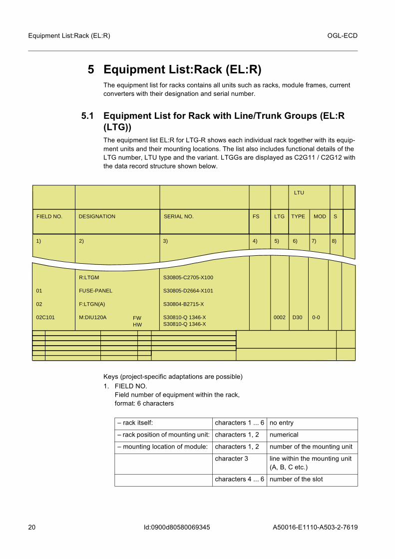
5.1 Equipment List for Rack with Line/Trunk Groups (EL:R (LTG))The equipment list EL:R for LTG-R shows each individual rack together with its equip-ment units and their mounting locations. The list also includes functional details of the LTG number, LTU type and the variant. LTGGs are displayed as C2G11 / C2G12 with the data record structure shown below.
Keys (project-specific adaptations are possible)1. FIELD NO.
Field number of equipment within the rack, format: 6 characters
FIELD NO. DESIGNATION
LTU
SERIAL NO. FS S
1) 2) 3) 5) 6) 7) 8)4)
01 02 02C101
R:LTGM FUSE-PANEL F:LTGN(A) M:DIU120A
S30805-C2705-X100 S30805-D2664-X101 S30804-B2715-X S30810-Q 1346-XS30810-Q 1346-X
0002
D30
0-0
MODLTG
FWHW
TYPE
– rack itself: characters 1 ... 6 no entry
– rack position of mounting unit: characters 1, 2 numerical
– mounting location of module: characters 1, 2 number of the mounting unit
character 3 line within the mounting unit (A, B, C etc.)
characters 4 ... 6 number of the slot

A50016-E1110-A503-2-7619
21
OGL-ECD Equipment List:Rack (EL:R)
Id:0900d80580069345
2. DESIGNATION Designation of the mounted equipment, format: 18 characters
3. SERIAL NO. Serial number for rack, frame and module,format: 25 characters
4. FS Function status,format: 2 characters
5. LTG Number of the line/trunk group,format: 4 characters
6. LTU TYPE Type of LTU or ATE (automatic test equipment) employed,format: 3 characters
7. LTU MOD Module position within an LTU,format: 3 characters
Module position outside an LTU (modules with CR for code receiver)
characters 1 ... 14 z.B. R rack
F frame
M module
characters 15, 16 no entry modules without FW
FW upper stage
HW base module
for modules on the frame wiring side
BP backplane module without FW
BF FW upper stage of a backplane module
BH base module of a backplane module
characters 1, 2 LTGSET (numbering from 00 - 31)
characters 3, 4 LTG number (numbering from 01 - 63 per LTGSET)
character 1 number of the LTU within an LTG
character 2 hyphen (–)
character 3 number of the module within an LTU
character 1 C

22 A50016-E1110-A503-2-7619
OGL-ECD
Id:0900d80580069345
Equipment List:Rack (EL:R)
8. S Module variant of the LTU (sequence), has the following meaning in conjunction with the designation:
Where “L” is specified, this LTU is connected to a LIC. In line “MOD 0-0” the following identifiers are entered in record type C2G11:
format: 1 characterModification identifier
character 2 hyphen (–)
character 3 consecutive number
Sequence = blank,
Designation = filled: module installed
Sequence = blank,
Designation = blank: mounting location not usable for module
Sequence = 0,
Designation = blank: module not installed
Sequence = 1 ... N,
Designation = filled: a specific module installed in conformity with standard document
E Echo suppressor pool
F OPAL DLU (only DTAG)
T Full Feature Set
K Conference LTG
M Monitoring LTG
P Reduced Feature Set
S UI LTG
* line was changed
+ line was added

A50016-E1110-A503-2-7619
23
OGL-ECD Equipment List:Rack (EL:R)
Id:0900d80580069345
5.2 Equipment List for Rack, except LTG and DLU (EL:R (except LTG and DLU))The equipment list for other racks lists all the units contained in the rack with their position numbers in the room (RPOSNO) and within the individual rack with their field numbers.
Keys1. FIELD NO.
Field number of equipment within the rack, format: 6 characters
2. DESIGNATION Designation of the mounted equipment, format: 18 characters
FIELD NO. DESIGNATION SERIAL NO. FS
1) 2) 3) 5) 6)4)
06 06C10906C13106C15306C175
R:SNB/LTGNF:TSG(B) M:TSMBM:TSMBM:TSMBM:TSMB
S30804-B2688-X S30810-Q1186-XS30810-Q1186-XS30810-Q1186-XS30810-Q1186-X
SND LTG 001-007LTG 008-015LTG 016-023LTG 024-031
REMARKSEN
– rack itself: characters 1 ... 6 no entry
– rack position of mounting unit: characters 1, 2 numerical
– mounting location of module characters 1, 2 number of the mounting unit
character 3 line within the mounting unit (A, B, C etc.)
characters 4 ... 6 number of the slot

24 A50016-E1110-A503-2-7619
OGL-ECD
Id:0900d80580069345
Equipment List:Rack (EL:R)
for modules on the frame wiring side
3. SERIAL NO. Serial number for rack, frame and module,format: 25 characters
4. FS Function status,format: 2 characters
5. EN Equipment number for cable device, LIC number of the SSNC and SNMAT No. Two-digit for C2Q12, three-digit for C2Q13,format: 2/3 characters
6. REMARKS Supplementary information,format: 14 characters
5.3 Equipment List for Rack with DLU (EL:R (DLU))The equipment list for DLU racks lists the units contained in each individual rack with their mounting locations in the room (RPOSNO) and within the individual rack with their
characters 1 ... 14 e.g. R rack: e.g. for LTGB
F frame
M module
characters 15, 16 no entry module without FW
FW FW upper stage
HW base module
BP backplane module without FW
BF FW upper stage of a backplane module
BH base module of a backplane module

A50016-E1110-A503-2-7619
25
OGL-ECD Equipment List:Rack (EL:R)
Id:0900d80580069345
field numbers. The list also contains the functional data relating to the DLU, SHELF and module number.
Keys1. FIELD NO.
Field number of equipment within the rack, format: 6 characters
2. DESIGNATION Designation of the mounted equipment, format: 18 characters
for modules on the frame wiring side
FIELD NO. DESIGNATION SERIAL NO. FS
1) 2) 3) 5) 6)4)
0101S0010202A00102A010
R:DLUFUSE-PANELFILTER:DLUF:DLU(D)M:DCCDCM:SLMA:FPE
S30805-C2666-X100S30805-C2666-X101S30805-C2666-X102S30805-C2666-XS30050-Q5619-CS30810-Q 814-X103
0-00
SHELFMODUL
DLU
FW
00010
– rack itself: characters 1 ... 6 no entry
– rack position of mounting unit: characters 1, 2 numerical
– mounting location of module: characters 1, 2 number of the mounting unit
character 3 line within the mounting unit (A, B, C etc.)
characters 4 ... 6 number of the slot
characters 1 ... 14 e.g. rack: e.g. for LTGB
characters 15, 16 no entry module without FW
FW FW upper stage
HW base module
BP backplane module without FW

26 A50016-E1110-A503-2-7619
OGL-ECD
Id:0900d80580069345
Equipment List:Rack (EL:R)
3. SERIAL NO. Serial number for rack, frame and module,format: 25 characters
4. FS Function status,format: 2 characters
5. DLU Number of the digital line unit, format: 5 characters
6. SHELF MODULE Number of the shelf and the module for variable modules, format: 4 characters
7. MODE operation mode of the DLUformat: 4 charactersModification identifier:format: 1 character
BF FW upper stage of a backplane module
BH base module of a backplane module
characters 1 ... 5 DLU
character 1 number of shelf
character 2 hyphen (–)
characters 3, 4 number of the module
* line was changed
+ line was added
A50016-E1110-A503-2-7619
27
OGL-ECD Survey List (SUL)
Id:0900d8058006934f
6 Survey List (SUL)
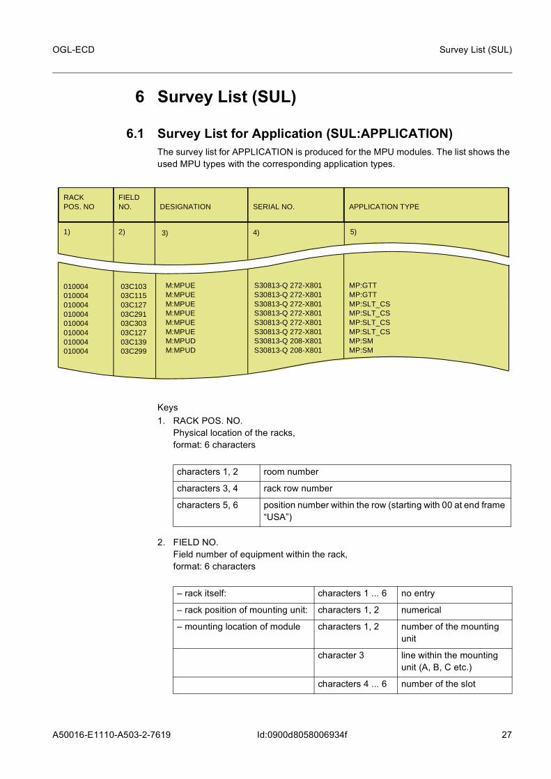
6.1 Survey List for Application (SUL:APPLICATION)The survey list for APPLICATION is produced for the MPU modules. The list shows the used MPU types with the corresponding application types.
Keys1. RACK POS. NO.
Physical location of the racks, format: 6 characters
2. FIELD NO. Field number of equipment within the rack, format: 6 characters
RACKPOS. NO
FIELDNO.
SERIAL NO.
APPLICATION TYPE
DESIGNATION
1) 2) 3) 5)4)
010004010004010004010004010004010004010004010004
03C10303C11503C12703C29103C30303C12703C13903C299
S30813-Q 272-X801S30813-Q 272-X801S30813-Q 272-X801S30813-Q 272-X801S30813-Q 272-X801S30813-Q 272-X801S30813-Q 208-X801S30813-Q 208-X801
MP:GTTMP:GTTMP:SLT_CSMP:SLT_CSMP:SLT_CSMP:SLT_CSMP:SMMP:SM
M:MPUEM:MPUEM:MPUEM:MPUEM:MPUEM:MPUEM:MPUDM:MPUD
characters 1, 2 room number
characters 3, 4 rack row number
characters 5, 6 position number within the row (starting with 00 at end frame “USA”)
– rack itself: characters 1 ... 6 no entry
– rack position of mounting unit: characters 1, 2 numerical
– mounting location of module characters 1, 2 number of the mounting unit
character 3 line within the mounting unit (A, B, C etc.)
characters 4 ... 6 number of the slot
28 A50016-E1110-A503-2-7619
OGL-ECD
Id:0900d8058006934f
Survey List (SUL)
3. DESIGNATION Designation of the mounted module e.g. M:MPUE, format: 20 characters
4. SERIAL NO. Serial number for rack, frame and module,format: 20 characters
5. APPLICATION TYPEe.g. the module M:MPUE works as a MP:SLT, format: 20 characters
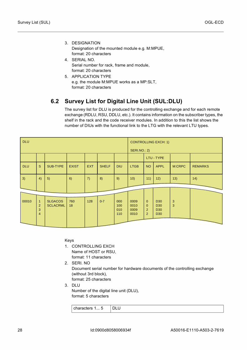
6.2 Survey List for Digital Line Unit (SUL:DLU)The survey list for DLU is produced for the controlling exchange and for each remote exchange (RDLU, RSU, DDLU, etc.). It contains information on the subscriber types, the shelf in the rack and the code receiver modules. In addition to this the list shows the number of DIUs with the functional link to the LTG with the relevant LTU types.
Keys1. CONTROLLING EXCH
Name of HOST or RSU, format: 11 characters
2. SERI. NO Document serial number for hardware documents of the controlling exchange (without 3rd block), format: 25 characters
3. DLU Number of the digital line unit (DLU), format: 5 characters
DLU
DLU S EXIST SHELF LTGB NO M:CRPC REMARKS
CONTROLLING EXCH: 1) SERI.NO.: 2)
SUB-TYPE EXT DIU APPL
LTU - TYPE
3) 4) 6) 8) 10) 11) 13) 14)5) 7) 9) 12)
00010 1234
76018
0-7 0009001000090010
0022
33
SLGACOSSCLACRML
128 000100010110
D30D30D30D30
characters 1... 5 DLU

A50016-E1110-A503-2-7619
29
OGL-ECD Survey List (SUL)
Id:0900d8058006934f
4. S Sequence number per DLU/DIU (1 - G (A=10, B=11, ... G=16)), format: 1 character
5. SUB TYPE Subscriber line circuit type e.g. SLCACOS, SLCACM16, format: 8 characters
6. EXIST Number of existing subscriber line circuits for DLU, format: 5 characters
7. EXT Increase/reduction in number of subscriber line circuits due to expansion (difference from previous installation stage), format: 5 characters
8. SHELF Number of shelves belonging to one DLU, format: 3 characters
9. DIU Number of the DIU in the F:DLU(A) with LTG connection in “B” mode, format: 3 characters
10. LTGB Number of the line/trunk group (LTG) in “B” mode to which the DLU is connected, format: 4 characters
11. LTU TYPE NO Number of the LTU with which the DLU-DIU is connected in the LTG in “B” mode, format: 2 characters
12. LTU TYPE APPL. format: 6 characters
or with LTU type D24 or D30 the last three characters of the application (e.g. CCS)
character 1 from shelf number
character 2 hyphen (–)
character 3 to shelf number
characters 1, 2 LTGSET (numbering from 00 - 31)
characters 3, 4 LTG number (numbering from 01 - 63 per LTGSET)
– with PCM30, e.g.:
D30 for DIU without CCS link
D30 for DIU with CCS link
– with PCM24, e.g.:
D24 for DIU without CCS link
D24 for DIU with CCS link
30 A50016-E1110-A503-2-7619
OGL-ECD
Id:0900d8058006934f
Survey List (SUL)
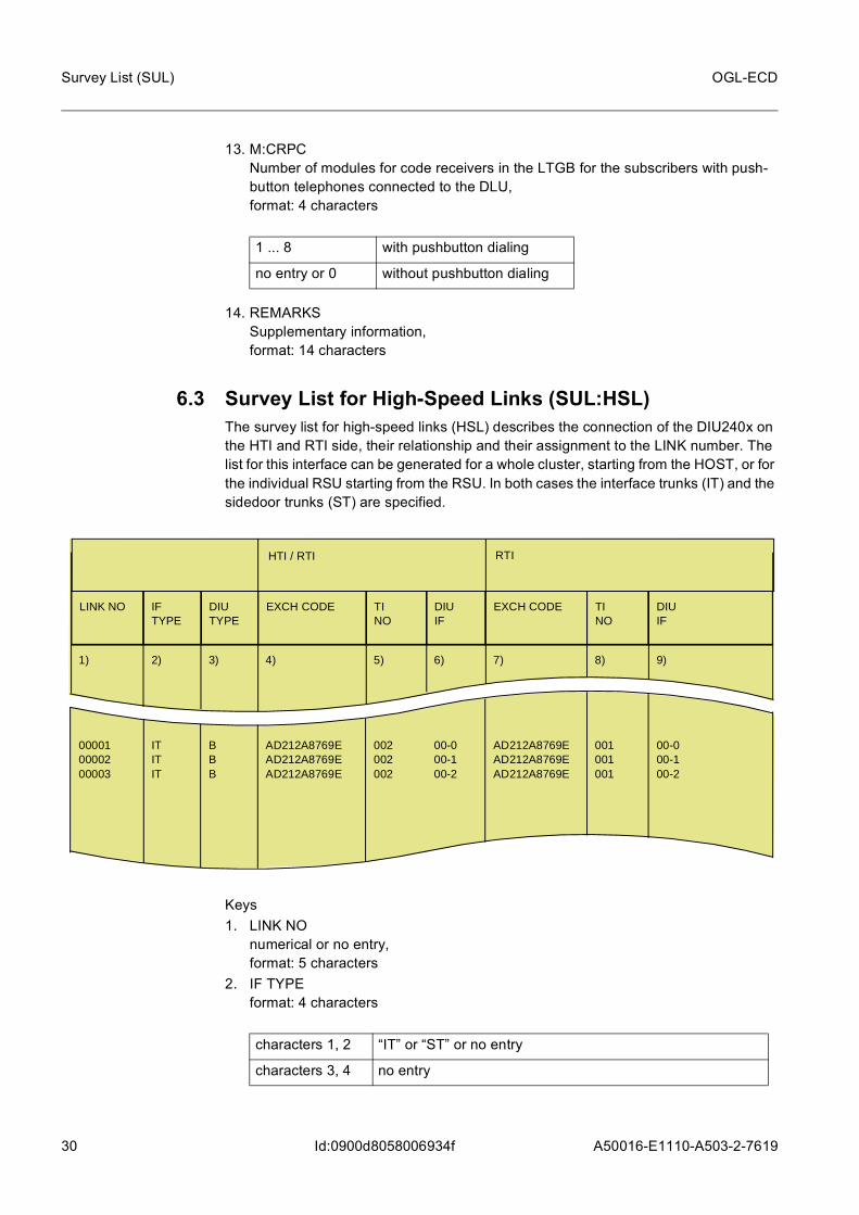
13. M:CRPC Number of modules for code receivers in the LTGB for the subscribers with push-button telephones connected to the DLU, format: 4 characters
14. REMARKS Supplementary information, format: 14 characters
6.3 Survey List for High-Speed Links (SUL:HSL)The survey list for high-speed links (HSL) describes the connection of the DIU240x on the HTI and RTI side, their relationship and their assignment to the LINK number. The list for this interface can be generated for a whole cluster, starting from the HOST, or for the individual RSU starting from the RSU. In both cases the interface trunks (IT) and the sidedoor trunks (ST) are specified.
Keys1. LINK NO
numerical or no entry, format: 5 characters
2. IF TYPE format: 4 characters
1 ... 8 with pushbutton dialing
no entry or 0 without pushbutton dialing
LINK NO IFTYPE
HTI / RTI
EXCH CODE TINO
DIUIF
TINO
DIUIF
RTI
DIUTYPE
EXCH CODE
1) 2) 4) 5) 6) 8) 9)3) 7)
000010000200003
ITITIT
AD212A8769EAD212A8769EAD212A8769E
002002002
00-000-100-2
001001001
00-000-100-2
BBB
AD212A8769EAD212A8769EAD212A8769E
characters 1, 2 “IT” or “ST” or no entry
characters 3, 4 no entry

A50016-E1110-A503-2-7619
31
OGL-ECD Survey List (SUL)
Id:0900d8058006934f
3. DIU TYPE format: 4 characters
4. HTI/RTI EXCH CODEExchange or installation stage separated by a hyphen (alphanumeric or no entry),format: 14 characters
5. HTI/RTI TI NO RSU numbering Timeslot Interchange Number (1 - 286 or no entry), format: 3 characters
6. HTI/RTI DIU IF format: 4 characters
7. RTI EXCH CODEExchange or installation stage separated by a hyphen (alphanumeric or no entry), format: 14 characters
8. RTI TI NO RSU numbering Timeslot Interchange Number (1 - 286 or no entry), format: 3 characters
9. RTI DIU IF format: 4 characters
character 1 “A” or “B” or no entry
characters 2 - 4 no entry
characters 1, 2 numeric or no entry
character 3 “-” or no entry
character 4 numeric or no entry
characters 1, 2 numeric or no entry
character 3 “-” or no entry
character 4 numeric or no entry

32 A50016-E1110-A503-2-7619
OGL-ECD
Id:0900d8058006934f
Survey List (SUL)
6.4 Survey List for Line Interface Card / PORT (SUL:LIC/PORT)The survey list for line inter face card / port shows for each port of the LICs the load type and the connection type.
Keys1. RACK POS. NO.
Physical location of the racks, format: 6 characters
2. LIC Number of the line interface card (LIC) within the rack, format: 2 characters
3. PORT NO. Load type of the port, format: 3 characters
4. CONNECTION TYPE Connection type of line interface card,format: 3 characters
RACKPOS. NO.
LICNO. 1
1) 2) 3)
701101701101701106701106701106
1112213132
C01XXXUOSXXXXXX
2 3 4 5 6 7 8
PORT NO.
CONNECTION TYPE
4)
C01XXX XXX
C01XXX XXX
C01XXX XXX
C01XXX XXX
C01XXX XXX
C01XXX XXX
C01XXX XXX
LICLICSTMSTMA2S
3) 3) 3) 3) 3)3) 3)
characters 1, 2 room number
characters 3, 4 rack row number
characters 5, 6 position number within the row (starting with 00 at end frame “USA”)
AE1 for 3G connection A* interface (only for LIC:TSC)
C01 for connection to CP
UOS for IU optical shorthall-interface (only for STM1 opt.)

A50016-E1110-A503-2-7619
33
OGL-ECD Survey List (SUL)
Id:0900d8058006934f
6.5 Survey List for Line/Trunk Group / Digital Line Unit (SUL:LTG/DLU)The survey list for LTG/DLU shows the interconnection of the LTGs with operating mode “B” to the relevant DLUs and their DIUs as well as the relevant LTU types. The list also shows whether the DLU concerned belongs to the Host or Remote DLU. This list is only generated for the Host RSU.
When the Remote Control Unit (RCU) is used in a Remote DLU, an entry must be made in the survey list of the controlling exchange and in the Remote DLU list.
Keys1. LTGB
Number of line/trunk group (LTG) in “B” mode format: 4 characters
2. LTU NO. Number of the LTU in the LTGB with which the DLU-DIU is connected, format: 2 characters
3. LTU TYPE Type of line/trunk unit,format: 3 characters
LTGB NO. TYPE EXCHANGE-NAME SERIAL NO.
LTU
DLU DIU
1) 2) 3) 6) 7)4) 5)
DLU-EXCHANGE
0009000900100010 0009
0202 1
D30D30D30D30 D30
LX5 CHOLON LX5 CHOLON
A39358-D A39358-D
00010 00020
000001010011 000
3 - . . . . - 01 - 0033 3 - . . . . - 01 - 0033
characters 1, 2 LTGSET (numbering from 00 - 31)
characters 3, 4 LTG number (numbering from 01 - 63 per LTGSET)

34 A50016-E1110-A503-2-7619
OGL-ECD
Id:0900d8058006934f
Survey List (SUL)
or with LTU type D24 or D30 the last three characters of the application (e.g. CCS)4. DLU
Number of the digital line unit, format: 5 characters
5. DIU Number of the DIU in the F:DLU(A) with LTG connection in “B” mode, format: 3 characters
6. EXCHANGE NAME Name of the controlled DLU exchange (no entry for remote DLU), format: 20 characters
7. SERIAL NO. Document serial number for hardware documents of the controlled DLU exchange, format: 25 characters
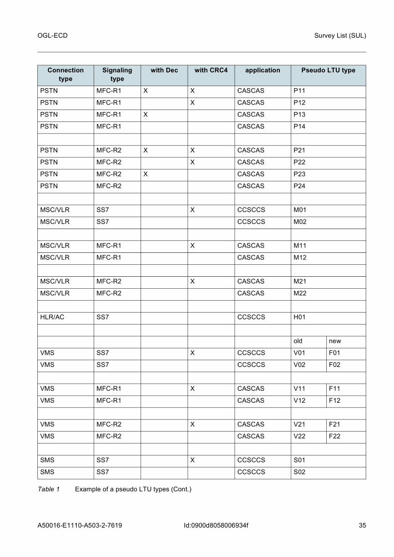
6.6 Survey List for Line/Trunk Group / Line/Trunk Unit (SUL:LTG/LTU)The survey list for LTG/LTU shows all the LTGs contained in an exchange with LTG type, LTG number and associated rack position number. The list also shows all the LTUs with their LTU types and applications.
As of SR 2.0 only the LTU type "D30" is used for all connections (according to load type overview).
So as to ensure that the individual connections can be distinguished, the following pseudo-LTG types have been set:
– with PCM30, e.g.:
D30 or DIU without CCS link
D30 or DIU with CCS link
– with PCM24, e.g.:
D24 or DIU without CCS link
D24 or DIU with CCS link
characters 1 ... 5 DLU
Connection type
Signaling type
with Dec with CRC4 application Pseudo LTU type
PSTN SS7 X X CCSCCS P01
PSTN SS7 X CCSCCS P02
PSTN SS7 X CCSCCS P03
PSTN SS7 CCSCCS P04
Table 1 Example of a pseudo LTU types
A50016-E1110-A503-2-7619
35
OGL-ECD Survey List (SUL)
Id:0900d8058006934f
PSTN MFC-R1 X X CASCAS P11
PSTN MFC-R1 X CASCAS P12
PSTN MFC-R1 X CASCAS P13
PSTN MFC-R1 CASCAS P14
PSTN MFC-R2 X X CASCAS P21
PSTN MFC-R2 X CASCAS P22
PSTN MFC-R2 X CASCAS P23
PSTN MFC-R2 CASCAS P24
MSC/VLR SS7 X CCSCCS M01
MSC/VLR SS7 CCSCCS M02
MSC/VLR MFC-R1 X CASCAS M11
MSC/VLR MFC-R1 CASCAS M12
MSC/VLR MFC-R2 X CASCAS M21
MSC/VLR MFC-R2 CASCAS M22
HLR/AC SS7 CCSCCS H01
old new
VMS SS7 X CCSCCS V01 F01
VMS SS7 CCSCCS V02 F02
VMS MFC-R1 X CASCAS V11 F11
VMS MFC-R1 CASCAS V12 F12
VMS MFC-R2 X CASCAS V21 F21
VMS MFC-R2 CASCAS V22 F22
SMS SS7 X CCSCCS S01
SMS SS7 CCSCCS S02
Connection type
Signaling type
with Dec with CRC4 application Pseudo LTU type
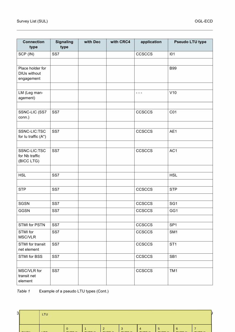
Table 1 Example of a pseudo LTU types (Cont.)

36 A50016-E1110-A503-2-7619
OGL-ECD
Id:0900d8058006934f
Survey List (SUL)
EIR SS7 X CCSCCS E01
EIR SS7 CCSCCS E02
PABX EDSS.1 X CCSPA A01
PABX EDSS.1 CCSPA A02
PABX MFC-R1 X CCSPA A11
PABX MFC-R1 CCSPA A12
PABX MFC-R2 X CCSPA A21
PABX MFC-R2 CCSPA A22
PABX P7 X CCSPA A31
PABX P7 CCSPA A32
PABX P8 X CCSPA A41
PABX P8 CCSPA A42
RAS EDSS.1 X CCSPA A51
Multy Party
Service
- - - T01
Loop LTG
Mobile Internal
Call
SS7 X CASCAS L01
Loop LTG
PABX
SS7 X X CASCAS L11
Loop LTG
PABX
SS7 X CASCAS L12
Connection type
Signaling type
with Dec with CRC4 application Pseudo LTU type
Table 1 Example of a pseudo LTU types (Cont.)

A50016-E1110-A503-2-7619
37
OGL-ECD Survey List (SUL)
Id:0900d8058006934f
Loop LTG
Dig. Service
Tele./Subscriber
SS7 X X CASCAS L21
Loop LTG
Dig. Service
Tele./Subscriber
SS7 X CASCAS L22
Loop LTG
Analog Subscr.
SS7 X X CASCAS L41
Loop LTG
Analog Subscr.
SS7 X CASCAS L42
DAS SS7 CASRCA U05
BSS SS7 X CCSCCS B01
BSS SS7 CCSCCS B02
Monitoring Center
CCSCCS MC1
EDSS.1
IWF / DSU SS7 CCSDLU
EXTDLU
CCSLDI
EXTLDI
W01
W02
W03
W04
DLU SS7 CCSDLU
EXTDLU
CCSLDI
EXTLDI
W11
W12
W13
W14
OMC-SBS SS7 CCSCCS S11
OCANEQ (IN) U07
Connection type
Signaling type
with Dec with CRC4 application Pseudo LTU type
Table 1 Example of a pseudo LTU types (Cont.)
38 A50016-E1110-A503-2-7619
OGL-ECD
Id:0900d8058006934f
Survey List (SUL)
SCP (IN) SS7 CCSCCS I01
Place holder for DIUs without engagement
B99
LM (Leg man-agement)
- - - V10
SSNC-LIC (SS7 conn.)
SS7 CCSCCS C01
SSNC-LIC:TSC for Iu traffic (A*)
SS7 CCSCCS AE1
SSNC-LIC:TSC for Nb traffic (BICC LTG)
SS7 CCSCCS AC1
HSL SS7 HSL
STP SS7 CCSCCS STP
SGSN SS7 CCSCCS SG1
GGSN SS7 CCSCCS GG1
STMI for PSTN SS7 CCSCCS SP1
STMI for MSC/VLR
SS7 CCSCCS SM1
STMI for transit net element
SS7 CCSCCS ST1
STMI for BSS SS7 CCSCCS SB1
MSC/VLR for transit net element
SS7 CCSCCS TM1
Connection type
Signaling type
with Dec with CRC4 application Pseudo LTU type
Table 1 Example of a pseudo LTU types (Cont.)
RACK
LTG
0TYPE |*
LTU
1TYPE |*
2TYPE |*
3TYPE |*
4TYPE |*
5TYPE |*
6TYPE |*
7TYPE |*
A50016-E1110-A503-2-7619
39
OGL-ECD Survey List (SUL)
Id:0900d8058006934f
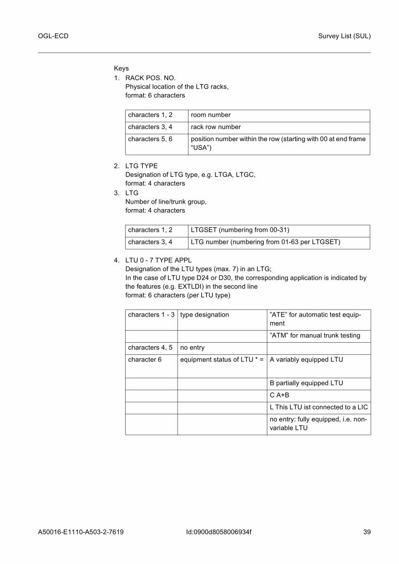
Keys1. RACK POS. NO.
Physical location of the LTG racks, format: 6 characters
2. LTG TYPE Designation of LTG type, e.g. LTGA, LTGC, format: 4 characters
3. LTG Number of line/trunk group, format: 4 characters
4. LTU 0 - 7 TYPE APPL Designation of the LTU types (max. 7) in an LTG; In the case of LTU type D24 or D30, the corresponding application is indicated by the features (e.g. EXTLDI) in the second lineformat: 6 characters (per LTU type)
characters 1, 2 room number
characters 3, 4 rack row number
characters 5, 6 position number within the row (starting with 00 at end frame “USA”)
characters 1, 2 LTGSET (numbering from 00-31)
characters 3, 4 LTG number (numbering from 01-63 per LTGSET)
characters 1 - 3 type designation ”ATE” for automatic test equip-ment
”ATM” for manual trunk testing
characters 4, 5 no entry
character 6 equipment status of LTU * = A variably equipped LTU
B partially equipped LTU
C A+B
L This LTU ist connected to a LIC
no entry: fully equipped, i.e. non-variable LTU
40 A50016-E1110-A503-2-7619
OGL-ECD
Id:0900d8058006934f
Survey List (SUL)
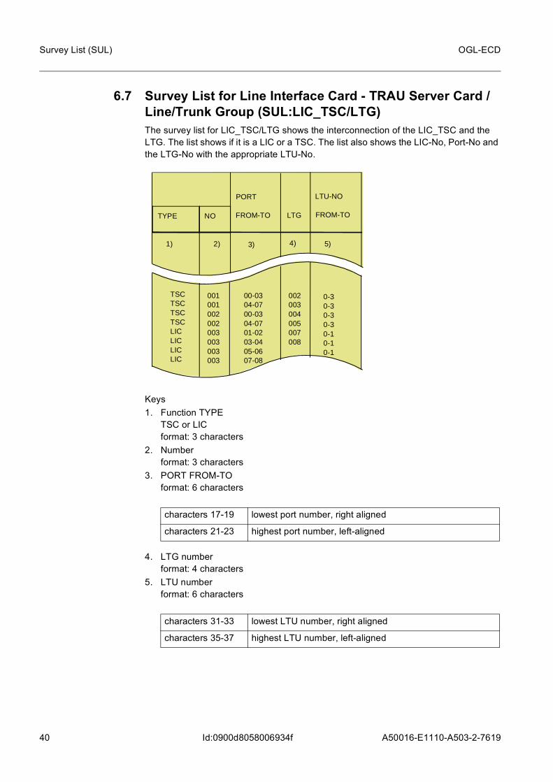
6.7 Survey List for Line Interface Card - TRAU Server Card / Line/Trunk Group (SUL:LIC_TSC/LTG)The survey list for LIC_TSC/LTG shows the interconnection of the LIC_TSC and the LTG. The list shows if it is a LIC or a TSC. The list also shows the LIC-No, Port-No and the LTG-No with the appropriate LTU-No.
Keys1. Function TYPE
TSC or LICformat: 3 characters
2. Numberformat: 3 characters
3. PORT FROM-TOformat: 6 characters
4. LTG numberformat: 4 characters
5. LTU numberformat: 6 characters
characters 17-19 lowest port number, right aligned
characters 21-23 highest port number, left-aligned
characters 31-33 lowest LTU number, right aligned
characters 35-37 highest LTU number, left-aligned
TYPE NO
PORT
TSCTSCTSCTSCLICLICLICLIC
001001002002003003003003
00-0304-0700-0304-0701-0203-0405-0607-08
002003004005007008
LTG FROM-TO
1) 2) 3) 4) 5)
0-30-30-30-30-10-10-1
FROM-TO
LTU-NO

A50016-E1110-A503-2-7619
41
OGL-ECD Survey List (SUL)
Id:0900d8058006934f
6.8 Survey List for Line Interface Card - Redundant (SUL:LIC-REDUNDANT)An LIC can be operated as a self-sufficient connection or to achieve a higher level of fault reliability it can be supported by a second LIC. If a redundant LIC connection is used, thre are three types of redundancy:– BOARD REDUNDANCY– LINE + BOARD REDUNDANCY– LINE REDUNDANCY.
A redundancy always occurs within a frame.
Keys1. RACK-TYPE
format: 10 characters2. RACK POS. NO.
format: 6 characters3. MUT
format: 2 characters4. LIC NO.
format: 2 characters5. LIC NO.
format: 2 characters6. REDANDANT TYPE
format: 5 characters
6.9 Survey list for RSU (SUL:RSU)The survey list for a Remote Switching Unit (RSU) shows how the AMUX is connected on the HTI and RTI side, as well as showing the relationship between the AMUX and the associated LTG number.
RACK-TYPE
RACKPOS.NO
SSNCSSNCSSNCSSNC
OEM-SGSNOEM-SGSNOEM-SGSNOEM-SGSN
010101010101010101010101010102010102010102010102
BOBOLI_BOLI_BOLILILILI
0202040402020404
MUT
RED. TYPE
1) 2) 3) 5) 6)
0103050709111315
LICNO
LICNO
4)
0204060810121416

42 A50016-E1110-A503-2-7619
OGL-ECD
Id:0900d8058006934f
Survey List (SUL)
This interface can be generated for a whole cluster, starting from the HOST, or for the individual RSU starting from the RSU.
Keys1. LTG NO
Number of the line/trunk group, format: 4 characters
2. RTI EXCH CODEExchange and installation stage separated by a hyphen (alphanumeric or no entry), format: 14 characters
3. RTI TI NO RSU numbering Timeslot Interchange Number (1 - 286 or no entry), format: 3 characters
4. RTI MH NO format: 2 characters
5. RTI AMUX PORT Description of the link between the LTG ports of the HTI and the LTG ports of the RTI, format: 4 characters
LTG NO
EXCH CODE
RTI
TINO
AMUXPORT
RSUID
TINO
MHNO
AMUXPORT
RSUID
MHNO
1) 2) 3) 5) 6) 7) 8) 9) 10)4)
002700280029
AD212 002002002
0 - 080 - 090 - 10
RTI002RTI002RTI002
001001001
000
0 - 100 - 110 - 12
HTI001HTI001HTI001
000
HTI / RTI
characters 1, 2 LTGSET (numbering from 00-31)
characters 3, 4 LTG number (numbering from 01-63 per LTGSET)
character 1 0 - 6 or no entry
character 2 no entry

A50016-E1110-A503-2-7619
43
OGL-ECD Survey List (SUL)
Id:0900d8058006934f
6. RTI RSUID The RSU ID is compulsory for each HTI and RTI and must be unique throughout the cluster, format: 8 characters
7. HTI/RTI TI NO RSU numbering Timeslot Interchange Number (1 - 286 or no entry), format: 3 characters
8. HTI/RTI MH NO format: 2 characters
9. HTI/RTI AMUX PORT Description of the link between the LTG ports of the HTI and the LTG ports of the RTI, format: 4 characters
10. HTI/RTI RSUID The RSU ID is compulsory for each HTI and RTI and must be unique throughout the cluster, format: 8 characters
character 1 “0” - “7” for AMUX number or no entry
character 2 “-” or no entry
characters 3, 4 “6” - “15” for AMUX port or no entry
character 1 0 - 6 or no entry
character 2 no entry
character 1 “0” - “7” for AMUX number or no entry
character 2 “-” or no entry
characters 3, 4 “6” - “15” for AMUX port or no entry
44 A50016-E1110-A503-2-7619
OGL-ECD
Id:0900d80580069353
Equipment Plan for Distribution Frame (EP:DF)
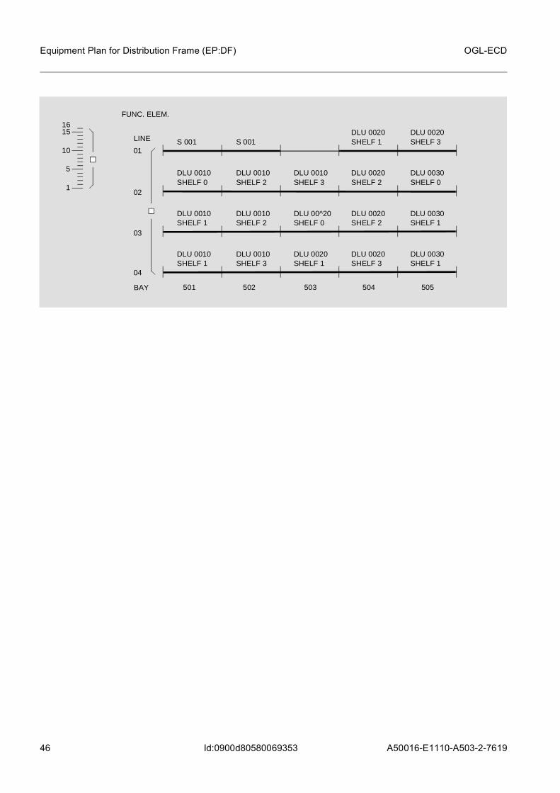
7 Equipment Plan for Distribution Frame (EP:DF) This plan shows in schematic form the distribution frame and the mounting locations of the system-side units.

A50016-E1110-A503-2-7619
45
OGL-ECD Equipment Plan for Distribution Frame (EP:DF)
Id:0900d80580069353
It is produced specifically for systems and/or customers.
032
033034
035036
037038
039040
041042
043044
045046
047048
049050
051056
057058
059060
061
016
020021
022023
024025
026
006
007008
009010
011012
013014
016EXISTING
EXISTINGEXISTING
EXISTING
027
028
120
121
DIU
240
01
02
03
04
05
06
07
08
09
10
11
12
13
A
B
C
D
E
F
G
H
J
K
L
M
N
LTG LTG LTG LTGFILA
V4304
V3303
V2302
V1301
SECTION
INCOMING
OUTGOING
ELEM. FUNC
LTU
0405
01
08
0
1
2
34
5
6
7
46 A50016-E1110-A503-2-7619
OGL-ECD
Id:0900d80580069353
Equipment Plan for Distribution Frame (EP:DF)
S 001
S 001
DLU 0020SHELF 1
DLU 0020SHELF 3
DLU 0010SHELF 0
DLU 0010SHELF 2
DLU 0010SHELF 3
DLU 0020SHELF 2
DLU 0030SHELF 0
DLU 0010SHELF 1
DLU 0010SHELF 2
DLU 00^20SHELF 0
DLU 0020SHELF 2
DLU 0030SHELF 1
DLU 0010SHELF 1
DLU 0010SHELF 3
DLU 0020SHELF 1
DLU 0020SHELF 3
DLU 0030SHELF 1
501 502 503 504 505
LINE
01
02
03
04
FUNC. ELEM.
BAY
15
10
5
1
16
A50016-E1110-A503-2-7619
47
OGL-ECD Cable Laying Lists (CLL)
Id:0900d80580105634
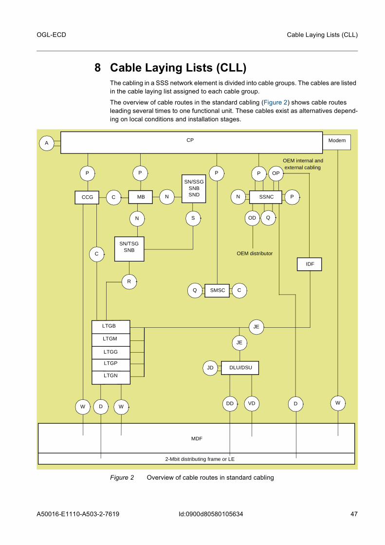
8 Cable Laying Lists (CLL) The cabling in a SSS network element is divided into cable groups. The cables are listed in the cable laying list assigned to each cable group.
The overview of cable routes in the standard cabling (Figure 2) shows cable routes leading several times to one functional unit. These cables exist as alternatives depend-ing on local conditions and installation stages.
Figure 2 Overview of cable routes in standard cabling
CP
DD
A
P P P
C N
SN
C
Q C
R
JE
JD
WDW
VDW
ModemCP
CCG MB
SN/SSG SNBSND
SN/TSG SNB
SMSC
LTGB
LTGM
LTGG
DLU/DSU
MDF
2-Mbit distributing frame or LE
PSSNCN
P
Q
D
LTGP
LTGN
OP
OEM internal andexternal cabling
OD
OEM distributor
JE
IDF

48 A50016-E1110-A503-2-7619
OGL-ECD
Id:0900d80580105634
Cable Laying Lists (CLL)
8.1 Set D1A20 - Rack-to-Rack ConnectionsThe list for set D1A20 is valid for cabling groups A, C, JD, JE, N, OP, P, Q, R, S, T, W(NtaVt).
Keys1. PLUGIN CABLE
Abbreviated number of plug-in cable,format: 6 characters
2. SValue entered if different cable connectors are connected on the same RPOSNO and FIELDNO, otherwise blankFormat: 1 character
3. FROM RACK POS NO.Mounting position of originating rack,format: 6 characters
PLUG INCABLE
RACKPOS. NO
C:BK RACKPOS. NO
REMARKS
1) 2) 3) 5) 6) 7) 8) 10) 11)4)
060005060005060005
06C107P106C107P206C107P3
888
FROM
FIELD NO.
12) 13)
TO
140104140104140104
9)
09C109P109C109P209C109P3
140104140104140104
% 5% 5% 5
DLU /LTG
VAR.FIELD NO.S RDD
000
characters 1 ... 3 code for plug-in cable type
characters 4 ... 6 length in decimeters (from 2 to 980 dm) or coded counting number for lengths of 2.5 to 21.5 dm and over 1000 dm
characters 1, 2 room number
characters 3, 4 rack row number
characters 5, 6 position number within the row

A50016-E1110-A503-2-7619
49
OGL-ECD Cable Laying Lists (CLL)
Id:0900d80580105634
4. FROM FIELD NO.Plug-in position of cable in the originating rack, format: 8 characters
5. D Routing of the plug-in cables in the originating rack,Format: 1 character
6. C:BK Type of ceiling / wall opening, Format: 4 characters
If the numbering is consecutive the building has more than 10 storeys.7. TO RACK POS NO.
Mounting location of destination rackFormat: 6/7 characters
characters 1, 2 number of mounting unit
character 5 row within mounting unit
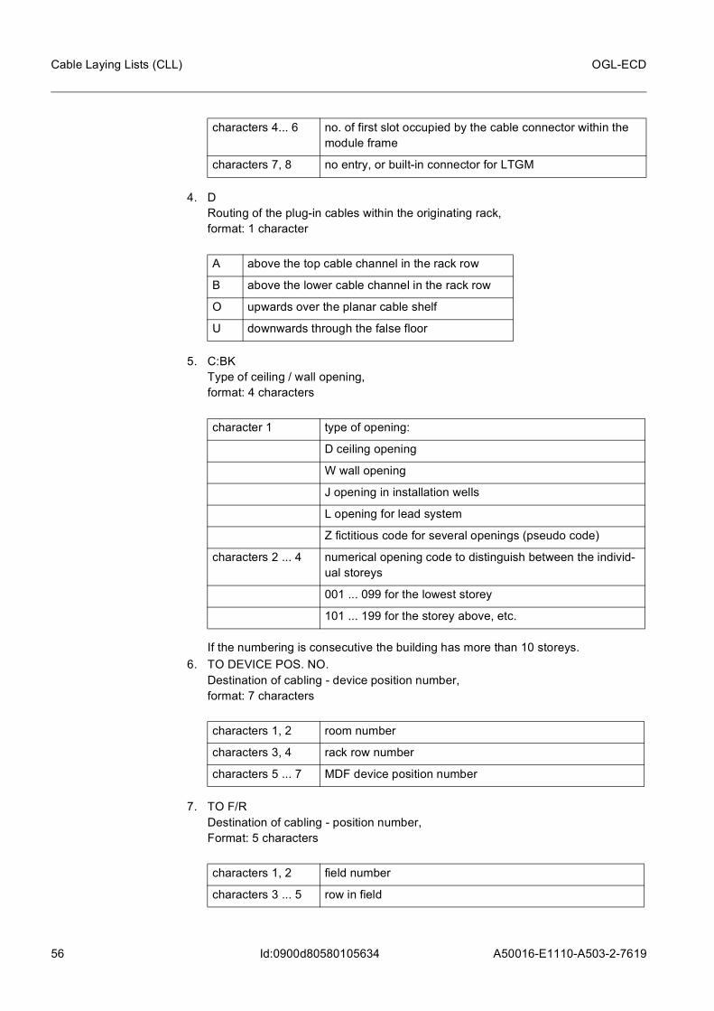
characters 4, 6 no. of first slot occupied by the cable connector within the module frame
character 11 P (PIN = plug in position number) for transfer level
character 12 system unit (plug in position)
A above the top cable channel in the rack row
B above the lower cable channel in the rack row
O upwards over the planar cable shelf
U downwards through the false floor
character 1 type of opening:
D ceiling opening
W wall opening
J opening in installation shafts
L opening for lead system
Z fictitious code for several openings (pseudo code)
characters 2 ... 4 numerical opening code to distinguish between the individ-ual storeys
001 ... 099 for the lowest storey
101 ... 199 for the storey above, etc.
characters 1, 2 room number
characters 3, 4 rack row number
characters 5, 6 position number within the row

50 A50016-E1110-A503-2-7619
OGL-ECD
Id:0900d80580105634
Cable Laying Lists (CLL)
8. TO FIELD NO.Plug-in position of cable within the destination rackformat: 8 characters
9. D Cable routing within the destination rackformat: 1 character
10. DLU/LTG LTG or DLU No. to the cableformat: 4/5 characters
11. R Identifier for re-used cable SNB > SNDformat: 1 character
12. REMARKS Additional information, The last position of the remarks is an additional identifier for EXPORT:
format: 16 characters13. VAR.
The variant number is a 6-digit number, leading zeros are writtenformat: 6 characters
character 7 empty
characters 1, 2 number of the mounting unit
character 5 line in the mounting unit
characters 4, 6 no. of first slot occupied by the cable connector within the module frame
character 11 P (PIN = plug in position number) for transfer level
character 12 system unit (plug in position)
A above the top cable channel in the rack row
B above the lower cable channel in the rack row
O upwards over the planar cable shelf
U downwards through the false floor
characters 1, 2 LTGSET (numbering from 00 - 31) one SNMUX includes 2 LTGSET
characters 3, 4 LTG-Nr. - (numbering from 01 - 63 per LTGSET)
characters 1 ... 5 DLU number
* line was changed
+ line was added

A50016-E1110-A503-2-7619
51
OGL-ECD Cable Laying Lists (CLL)
Id:0900d80580105634
8.2 Set D1A30 - Rack-to-MDF ConnectionsSet D1A30 - Rack-to-MDF ConnectionsThe list for set D1A30 is valid for cabling groups D, DD, D1, OD, VD, VE, V0-V7, W(HVT).
Keys1. PLUGIN CABLE
Abbreviated number of plug-in cable,format: 6 characters
2. SEQ Cable connector number for cabling of DLU racks with 64-pair cableformat: 1 character
3. FROM RACK POS NO.Position of originating rack, format: 6 characters
PLUG INCABLE
RACKPOS. NO
C:BK BAYLINE
RE-MARKS
1) 2) 3) 5) 6) 7) 8) 10) 11)4)
942109942109942109942109942109942109
301301301301301301
023023023023023023
FROM
FIELDNO.
12) 14)
TO
140111140111140111140111140111140111
9)
02A01302A02502A09102A10302A01302A025
LTGCLTGCLTGCLTGCLTGCLTGC
DLU /LTG
VAR.FUNC.ELEM.
S D
CE
DPIN C:CAB
13) 15)
000200020002000200030003
D3000D3001D3002D3003D3000D30001
001-006007-012001-006007-012001-006007-012
01-0101-0102-0202-0203-0303-03
301013010130101301013010130101
characters 1 ... 3 code for plug-in cable type
characters 4 ... 6 length in decimeters (from 2 to 980 dm) or coded counting number for lengths of 2.5 to 21.5 dm and over 1000 dm
characters 1, 2 room number
characters 3, 4 rack row number
characters 5, 6 position number with the row

52 A50016-E1110-A503-2-7619
OGL-ECD
Id:0900d80580105634
Cable Laying Lists (CLL)
4. FROM FIELD NO. Plug-in position of cable within the originating rack, format: 8 characters
5. D Routing of plug-in cables within the originating rack, format: 1 character
6. C:BK Type of ceiling / wall opening, format: 4 characters
If the numbering is consecutive the building has more than 10 storeys.7. TO CE
Details of individual bay for cable routing on MDF, format: 3 characters
8. TO BAY LINE Number of bay and line within the MDF, format: 5 characters
characters 1, 2 number of mounting unit
character 7 row within mounting unit
characters 4... 6 no. of first slot occupied by the cable connector within the module frame
characters 7, 8 position of connector in the slot
A above the top cable channel in the rack row
B above the lower cable channel in the rack row
O upwards over the planar cable shelf
U downwards through the false floor
character 1 type of opening:
D ceiling opening
W wall opening
J opening in installation wells
L opening for lead system
Z fictitious code for several openings (pseudo code)
characters 2 ... 4 numerical opening code to distinguish between the individ-ual storeys
001 ... 099 for the lowest storey
101 ... 199 for the storey above, etc.
characters 1... 3 number of the bay

A50016-E1110-A503-2-7619
53
OGL-ECD Cable Laying Lists (CLL)
Id:0900d80580105634
9. TO FUNC. ELEM Number of the functional element group to which the cable is allocated on the con-necting strip, format: 5 characters
10. TO PIN Number of the pins within the functional element, format: 7 characters
11. D Direction of cable routing within the destination rack, format: 1 character
12. C:CAB Code for cable laying, format: 6 characters
characters 4, 5 number of the row or
number of the last occupied functional element
characters 1, 2 no. of the first occupied functional element
character 3 hyphen (-)
characters 4, 5 number of the last occupied functional element
Representation for new, 3-contact pins:
characters 1 ... 3 no. of first pin occupied
character 4 hyphen (-)
characters 5 ... 7 no. of last pin occupied
Representation for old, 2-contact pins:
character 1 empty
characters 2, 3 no. of first pin occupied
character 4 hyphen (-)
character 5 empty
characters 6, 7 no. of last pin occupied
A above the top cable channel in the rack row
B above the lower cable channel in the rack row
O upwards over the planar cable shelf
U downwards through the false floor
LTG/units to MDF:
characters 1 ... 3 LTU type/unit number

54 A50016-E1110-A503-2-7619
OGL-ECD
Id:0900d80580105634
Cable Laying Lists (CLL)
13. LTG/DLU / LTG Number of line/trunk group, format: 4/5 characters
14. REMARKS Additional information, The last position of the remarks is an additional identifier for EXPORT:
format: 6 characters15. VAR.
The variant number is a 6-digit number, leading zeros are written,format: 6 characters
characters 4, 5 no. of LTU / DIU (numbering 00 ... nn)
character 6 functional element group on connecting strip
module mounting locations in DLU to MDF:
characters 1, 2 allocation of module group,
in DLUA: 1st digit = module 1, 2nd digit= module 2,
in DLUB/D/G only one module per cable
character 3 shelf
characters 4, 5 no. of module mounting location (numbering 00 ... nn)
character 6 functional element group on connecting strip
characters 1, 2 LTGSET (numbering from 00 - 31)
one SNMUX contains 2 LTGSET
characters 3, 4 LTG No. - (numbering from 01 - 63 per LTGSET)
characters 1 ... 5 DLU number
* line was changed
+ line was added

A50016-E1110-A503-2-7619
55
OGL-ECD Cable Laying Lists (CLL)
Id:0900d80580105634
8.3 Set D1A40 - Rack-to-DS2 Distributor ConnectionsThe list for set D1A40 is valid for cabling groups E (Remote), W(DS2).
Keys1. PLUGIN CABLE
Abbreviated number of plug-in cable,format: 6 characters
2. FROM RACK POS. NO Mounting location of the originating rack, format: 6 characters
3. FROM FIELD NO. Plug-in position of the cable in the originating rack, format: 8 characters
PLUG INCABLE
RACKPOS. NO
C:BK DEVICEPOS. NO
REMARKS
1) 2) 3) 5) 6) 7) 8) 10)4)
9411X49411X49411X49411X4
05005050060600106003
023023023
FROM
FIELD NO.
12)
TO
030401030401030401030401
9)
02A05102A07402B05102B074
0300007030000703000070300007
DIU/PORT
VAR.BAKTD2NR
D LTG/DIU
F/R
UUU
0949095309510955
00620006200062000620
00100111
11)
D2NR:
characters 1 ... 3 code for plug-in cable type
characters 4 ... 6 length in decimeters (from 2 to 980 dm) or coded counting number for lengths of 2.5 to 21.5 dm and over 1000 dm
characters 1, 2 room number
characters 3, 4 rack row number
characters 5, 6 position number within the row
characters 1, 2 number of mounting unit
character 10 row within mounting unit
56 A50016-E1110-A503-2-7619
OGL-ECD
Id:0900d80580105634
Cable Laying Lists (CLL)
4. D Routing of the plug-in cables within the originating rack, format: 1 character
5. C:BK Type of ceiling / wall opening, format: 4 characters
If the numbering is consecutive the building has more than 10 storeys.6. TO DEVICE POS. NO.
Destination of cabling - device position number, format: 7 characters
7. TO F/R Destination of cabling - position number, Format: 5 characters
characters 4... 6 no. of first slot occupied by the cable connector within the module frame
characters 7, 8 no entry, or built-in connector for LTGM
A above the top cable channel in the rack row
B above the lower cable channel in the rack row
O upwards over the planar cable shelf
U downwards through the false floor
character 1 type of opening:
D ceiling opening
W wall opening
J opening in installation wells
L opening for lead system
Z fictitious code for several openings (pseudo code)
characters 2 ... 4 numerical opening code to distinguish between the individ-ual storeys
001 ... 099 for the lowest storey
101 ... 199 for the storey above, etc.
characters 1, 2 room number
characters 3, 4 rack row number
characters 5 ... 7 MDF device position number
characters 1, 2 field number
characters 3 ... 5 row in field

A50016-E1110-A503-2-7619
57
OGL-ECD Cable Laying Lists (CLL)
Id:0900d80580105634
8. D2NR:BAKT/D2NR Destination of cabling, format: 5 characters
9. LTG/DLU LTG or DLU number to the cable, format: 4/5 characters
10. DIU/PORT Number of the DIU within the LTG or duplicate DIU within the DLU (BAKT), format: 4 characters
11. REMARKS Additional information, The last position of the remarks is an additional identifier for EXPORT:
format: 12 characters12. VAR.
The variant number is a 6-digit number, leading zeros are writtenformat: 6 characters
characters 1, 2 LTGSET (numbering from 00 - 31)
one SNMUX contains 2 LTGSET
characters 3, 4 LTG no. (numbering from 01 - 63 per LTGSET)
characters 1 ... 5 DLU number
* line was changed
+ line was added

58 A50016-E1110-A503-2-7619
OGL-ECD
Id:0900d80580105634
Cable Laying Lists (CLL)
8.4 Set D1A50 - Rack-to-DS2NR / DS2 ConnectionsThe list for set D1A50 is valid for cabling groups E (Host).
Keys1. PLUGIN CABLE
Abbreviated number of plug-in cable,format: 6 characters
2. FROM RACK POS. NO Mounting location of the originating rack, format: 6 characters
3. FROM FIELD NO. Plug-in position of the cable in the originating rack, format: 8 characters
PLUG INCABLE
RACKPOS. NO
C:BK DEVICEPOS. NO
REMARKS
1) 2) 3) 5) 6) 7) 8) 10)4)
9411X49411X49411X49411X4
05007060010500805001
461461461461
FROM
FIELD NO.
12)
TO
130101130101130101130101
9)
02A05102A07402B05102B074
1201035120103512010351201035
DIU VAR.PMXAPE
D LTG/DLU
F/R
000
0265026702660392
00470004700047000470
00100111
11)
AL:LTG/
. LTGM PCM30
. LTGM PCM30
. LTGM PCM30
. LTGM PCM30
characters 1 ... 3 code for plug-in cable type
characters 4 ... 6 length in decimeters (from 2 to 980 dm) or coded counting number for lengths of 2.5 to 21.5 dm and over 1000 dm
characters 1, 2 room number
characters 3, 4 rack row number
characters 5, 6 position number within the row
characters 1, 2 number of mounting unit
character 11 row within mounting unit
characters 4... 6 no. of first slot occupied by the cable connector within the module frame

A50016-E1110-A503-2-7619
59
OGL-ECD Cable Laying Lists (CLL)
Id:0900d80580105634
4. D Routing of the plug-in cables within the originating rack, format: 1 character
5. C:BK Type of ceiling / wall opening, format: 4 characters
If the numbering is consecutive the building has more than 10 storeys.6. TO DEVICE POS. NO.
Destination of the cabling - device position number, format: 7 characters
7. TO F/R Destination of the cabling - position number, format: 5 characters
characters 7, 8 no entry or built-in connector for LTGM (P3)
A above the top cable channel in the rack row
B above the lower cable channel in the rack row
O upwards over the planar cable shelf
U downwards through the false floor
character 1 type of opening:
D ceiling opening
W wall opening
J opening in installation wells
L opening for lead system
Z fictitious code for several openings (pseudo code)
characters 2 ... 4 numerical opening code to distinguish between the individ-ual storeys
001 ... 099 for the lowest storey
101 ... 199 for the storey above, etc.
characters 1, 2 room number
characters 3, 4 rack row number
characters 5 ... 7 MDF device position number
characters 1, 2 field number
characters 3 ... 5 row in field

60 A50016-E1110-A503-2-7619
OGL-ECD
Id:0900d80580105634
Cable Laying Lists (CLL)
8. AL:LTG/PMX APE Destination of cabling, format: 5 characters
9. LTG/DLU LTG or DLU number to the cable, format: 4/5 characters
10. DIU Number of the DIU in the LTG or duplicate DIU in the DLU (BAKT), format: 4 characters
11. REMARKS Additional information, The last position of the remarks is an additional identifier for EXPORT:
format: 12 characters12. VAR.
The variant number is a 6-digit number, leading zeros are writtenFormat: 6 characters
characters 1, 2 LTGSET (numbering from 00 - 31)
One SNMUX contains 2 LTGSET
characters 3, 4 LTG-No. - (numbering from 01 - 63 per LTGSET)
characters 1 ... 5 DLU number
* line was changed
+ line was added
Related Documents