EDKVS93-02 .:òh Ä.:`hä Information for the operator of the machine 9300 15 ... 30 kW EVS9327 ... EVS9329 Servo controller

Welcome message from author
This document is posted to help you gain knowledge. Please leave a comment to let me know what you think about it! Share it to your friends and learn new things together.
Transcript

EDKVS93-02.:òh
Ä.:`hä
Information for the operator of the machine
9300 15 ... 30 kW
EVS9327 ... EVS9329
Servo controller

This documentation applies to ...
... 9300 servo controllers as of nameplate data:
Nameplate
EVS 93xx – x x Vxx 1x xx
Product series
9300vec112
EVS = Servo controller
Type no. / rated power
400 V 480 V
9327 = 15 kW 18.5 kW
9328 = 22 kW 30 kW
9329 = 30 kW 37 kW
Type
E = Panel-mounted unit
C = Built-in unit in ”cold plate” technique
Design
I = Servo PLC
K = Servo cam
P = Servo position controller
R = Register controller
S = Servo inverter
T = Servo PLC technology
Variant
– Standard
V003 = In ”cold plate” technique
V004 = With ”safe standstill” function
V100 = For IT mains
V104 = With ”safe standstill” function and for IT mains
Hardware version
Software version
Note!This documentation contains all necessary information for the machine operator to beable to operate the servo controllers of the 9300 series installed in your machine/plant.You can make further use of all information in this documentation without consultingLenze if you do not make any changes to the contents.
0Fig. 0Tab. 0
Tip!Current documentation and software updates concerning Lenze products can be foundon the Internet in the ”Services & Downloads” area underhttp://www.Lenze.com
© 2008 Lenze Drive Systems GmbH, Hans-Lenze-Straße 1, D-31855 AerzenWe have compiled all information in this documentation with great care und have checked it with regard to compliance withthe hardware and software described. Nevertheless, we cannot entirely exclude deviations. We do not accept legalresponsibility or liability for damage possibly resulting therefrom. We will include necessary amendments in the subsequenteditions.

9300std079
Key for overview
Position Description
Controller
Fixing bracket for standard mounting
EMC shield sheet with fixing screws for shielded control cables
Cover with fixing screws
EMC shield sheet for the motor cable and the feed cable for the motor temperature monitoring with PTCthermistor or thermal contact (NC contact)
Connections and interfaces
Position Description
L1, L2, L3, PE Mains connection
+UG, -UG DC supply
U, V, W, PE Motor connection
T1, T2 Connection of PTC thermistor or thermal contact (NC contact) of the motor
X1 AIF interface (automation interface)Slot for communication module (e. g. XT EMZ9371BC keypad)
X3 Jumper for setting analog input signal at X6/1, X6/2
X4 Terminal strip for system bus (CAN) connection
X5 Terminal strips for connection of digital inputs and outputs
X6 Terminal strips for connection of analog inputs and outputs
X7 Sub-D connector (female) for connection of resolver and KTY temperature sensor of the motor
X8 Sub-D connector (male) for connection of incremental encoder with TTL level or SinCos encoder and KTYtemperature sensor of the motor
X9 Sub-D connector (male) for connection of digital frequency input signal
X10 Sub-D connector (female) for connection of digital frequency output signal
X11 Terminal strip for connection of KSR relay output for ”safe standstill” (for variants V004 and V024 only)

Status displays
Position LED red LED green Operating status
Off On Controller enabled
On On Mains is switched on and automatic start is inhibited
Off Blinking slowly Controller inhibited
Blinking quickly Off Undervoltage or overvoltage
Blinking slowly Off Active fault

Contentsi
6 EDKVS93-02 DE 1.0
1 Safety instructions 7. . . . . . . . . . . . . . . . . . . . . . . . . . . . . . . . . . . . . . . . . . . . . . . . . . . . . . . . .
1.1 General safety and application notes for Lenze controllers 7. . . . . . . . . . . . . . . . . .
1.2 Residual hazards 10. . . . . . . . . . . . . . . . . . . . . . . . . . . . . . . . . . . . . . . . . . . . . . . . . . . . .
1.3 Definition of notes used 12. . . . . . . . . . . . . . . . . . . . . . . . . . . . . . . . . . . . . . . . . . . . . . .
2 Parameter setting 13. . . . . . . . . . . . . . . . . . . . . . . . . . . . . . . . . . . . . . . . . . . . . . . . . . . . . . . . .
2.1 Parameter setting with the XT EMZ9371BC keypad 13. . . . . . . . . . . . . . . . . . . . . . . .2.1.1 General data and operating conditions 13. . . . . . . . . . . . . . . . . . . . . . . . . .2.1.2 Installation and commissioning 14. . . . . . . . . . . . . . . . . . . . . . . . . . . . . . . .2.1.3 Display elements and function keys 14. . . . . . . . . . . . . . . . . . . . . . . . . . . . .2.1.4 Changing and saving parameters 16. . . . . . . . . . . . . . . . . . . . . . . . . . . . . . .2.1.5 Loading a parameter set 18. . . . . . . . . . . . . . . . . . . . . . . . . . . . . . . . . . . . . . .2.1.6 Transferring parameters to other standard devices 19. . . . . . . . . . . . . . . . .2.1.7 Activating password protection 21. . . . . . . . . . . . . . . . . . . . . . . . . . . . . . . . .2.1.8 Diagnostics 22. . . . . . . . . . . . . . . . . . . . . . . . . . . . . . . . . . . . . . . . . . . . . . . . . .2.1.9 Menu structure 23. . . . . . . . . . . . . . . . . . . . . . . . . . . . . . . . . . . . . . . . . . . . . .
3 Troubleshooting and fault elimination 25. . . . . . . . . . . . . . . . . . . . . . . . . . . . . . . . . . . . . . .
3.1 Display of operating data, diagnostics 25. . . . . . . . . . . . . . . . . . . . . . . . . . . . . . . . . . .
3.2 Troubleshooting 26. . . . . . . . . . . . . . . . . . . . . . . . . . . . . . . . . . . . . . . . . . . . . . . . . . . . .3.2.1 Status display (LEDs on the controller) 26. . . . . . . . . . . . . . . . . . . . . . . . . . .3.2.2 Fault analysis with the history buffer 27. . . . . . . . . . . . . . . . . . . . . . . . . . . .3.2.3 Fault analysis via LECOM status words (C0150/C0155) 28. . . . . . . . . . . . .
3.3 System error messages 29. . . . . . . . . . . . . . . . . . . . . . . . . . . . . . . . . . . . . . . . . . . . . . . .3.3.1 General error messages 29. . . . . . . . . . . . . . . . . . . . . . . . . . . . . . . . . . . . . . . .3.3.2 Resetting system error messages 37. . . . . . . . . . . . . . . . . . . . . . . . . . . . . . . .

Safety instructionsGeneral safety and application notes for Lenze controllers
1
7EDKVS93-02 DE 1.0
1 Safety instructions
1.1 General safety and application notes for Lenze controllers
(in accordance with Low-Voltage Directive 2006/95/EC)
For you personal safety
During the operation, Lenze controllers (frequency inverters, servo inverters, DC speedcontrollers) and their associated components can hold live as well as moving or rotaryparts, according to their degree of protection. Surfaces may be hot.Non-authorised removal of the required cover, inappropriate use, faulty installation orincorrect operation creates the risk of severe injury to persons or damage to materialassets.More information can be obtained from the documentation.
High amounts of energy are released in the controller. Thus, it is required to always weara personal protective equipment (body protection, headgear, eye protection, earprotection, hand guard).
All operations concerning transport, installation, and commissioning as well asmaintenancemust be carried out by qualified, skilled personnel (IEC 364 and CENELECHD384 or DIN VDE 0100 and IEC report 664 or DIN VDE 0110 and national regulations for theprevention of accidents must be observed).According to this basic safety information, qualified, skilledpersonnel arepersonswhoarefamiliarwith the assembly, installation, commissioning, andoperationof theproduct andwho have the qualifications necessary for their occupation.
Application as directed
Drive controllers are components which are designed for the installation in electricalsystemsormachinery. They are not to beused as household appliances. They are intendedexclusively for professional and commercial purposes according to EN 61000-3-2.When installing the controllers into machines, the commissioning (i.e. starting ofoperation as directed) is prohibited until it is proven that the machine complies with theregulations of the EC Directive 98/37/EC (Machinery Directive); EN 60204 must beobserved.Commissioning (i.e. starting of operation as directed) is only allowed when there iscompliance with the EMC Directive (89/336/EWG).The controllers meet the requirements of the Low-Voltage Directive 2006/95/EC. Theharmonised standard EN 61800-5-1 applies to the controllers.The technical data and information on connection conditions must be obtained from thenameplate and the documentation. They must be observed in any case.Warning: The controllers can be used according to EN 61800-3 in drive systems of thecategory C2. These products can cause radio interferences in residential areas. In this case,special measures are required.
Transport, storage
Please observe the notes on transport, storage and appropriate handling.Observe the climatic conditions according to the technical data.

Safety instructionsGeneral safety and application notes for Lenze controllers
1
8 EDKVS93-02 DE 1.0
Installation
The controllers must be installed and cooled according to the instructions given in thecorresponding documentation.Ensure proper handling and avoidmechanical stress. Do not bend any components anddonot change any insulation distances during transport or handling. Do not touch anyelectronic component or contact.Controllers contain electrostatically sensitive components which can easily be damagedby inappropriate handling. Do not damage or destroy any electrical component since thismight endanger your health!
Electrical connection
When working on live controllers, the valid national regulations for the prevention ofaccidents (e.g. VBG 4) must be observed.The electrical installation must be carried out according to the appropriate regulations(e.g. cable cross-sections, fuses, PE connection). Additional information can be obtainedfrom the documentation.The documentation contains information on installation in compliance with EMC(shielding, earthing, filter arrangement, and cable installation). These notes must also beobserved for CE-marked controllers. The manufacturer of the system or machine isresponsible for ensuring compliance with the limit values demanded by the EMClegislation. The controllers must be installed in housings (e.g. control cabinets) to complywith the limit values for radio interferences valid at the site of installation. The housingsmust enable an EMC-compliant installation. Make sure in particular that e.g. the controlcabinet doors have a circumferential metal connection to the housing. Reduce housingopenings and cutouts to a minimum.Lenze controllers can cause a DC current in the protective conductor. If a residual currentdevice (RCD) is used as a protective means in case of direct or indirect contact, only aresidual current device (RCD) of type B may be used on the current supply side of thecontroller. Otherwise, another protective measure, such as separation from theenvironment through double or reinforced insulation or disconnection from themains bymeans of a transformer, must be used.
Operation
If necessary, systems including controllers must be equipped with additional monitoringand protection devices according to the valid safety regulations (e.g. law on technicalequipment, regulations for the prevention of accidents). The controllers canbe adapted toyour application. Please observe the corresponding information given in thedocumentation.After a controller has been disconnected from the voltage supply, all live components andpower connections must not be touched immediately because capacitors may still becharged. Please observe the corresponding stickers on the controller.All protection covers and doors must be shut during operation.Note forULapprovedsystemswith integratedcontrollers:ULwarningsarenotes thatonlyapply to UL systems. The documentation contains special information about UL.
Safety functions
Certain variants of the drive controller support safety functions (e.g. ”safe torque off”,formerly ”safe standstill”), according to the requirements of appendix I No. 1.2.7 of the ECMachinery Directive 98/37/EC, EN 954-1 Category 3 and EN 1037. You must observe thenotes pertaining to the safety functions in the documentation to the variants.
Safety instructionsGeneral safety and application notes for Lenze controllers
1
9EDKVS93-02 DE 1.0
Maintenance and servicing
The controllers do not require any maintenance if the prescribed conditions of operationare observed.If theambientair is polluted, the cooling surfacesof the controllermaybecomedirty or theair vents of the controllermay be obstructed. Therefore, clean the cooling surfaces and airvents periodically under these operating conditions. Do not use sharp or pointed tools forthis purpose!
Waste disposal
Recycle metal and plastic materials. Ensure professional disposal of assembled PCBs.The product-specific safety and application notes given in these instructions must beobserved!
Safety instructionsResidual hazards
1
10 EDKVS93-02 DE 1.0
1.2 Residual hazards
Protection of persons
ƒ Before working on the controller, check that all power terminals are deenergised:
– The power terminals U, V, W, +UG and -UG remain live for at least three minutesafter disconnection from the mains.
– The power terminals L1, L2, L3; U, V, W, +UG and -UG remain live when the motor isstopped.
ƒ The leakage current to earth (PE) is > 3.5 mA. According to EN 50178
– a fixed installation is required.
– a double PE connection is required or, if in single design, it must have a cablecross-section of at least 10 mm2.
ƒ The heatsink of the controller has an operating temperature of > 80 °C:
– Contact with the heatsink results in burns.
ƒ During parameter set transfer the control terminals of the controller can haveundefined states.
– Therefore the connentors X5 and X6 must be disconnected from the controllerbefore the transfer takes place. This ensures that the controller is inhibited and allcontrol terminals have the defined state ”LOW”.
Device protection
ƒ Frequent mains switching (e.g. inching mode via mains contactor) can overload anddestroy the input current limitation of the drive controller:
– For this reason at least 3 minutes have to pass between two starting operations.
– Use the ”safe torque off” safety function (STO) if safety-related mainsdisconnections occur frequently. The drive variants Vxx4 are equipped with thisfunction.
Protection of the machine/system
ƒ Drives can reach dangerous overspeeds (e. g. setting of high output frequencies inconnection with motors and machines not suitable for this purpose):
– The drive controllers do not provide protection against such operating conditions.For this purpose, use additional components.
Safety instructionsResidual hazards
1
11EDKVS93-02 DE 1.0
Warnings!ƒ The device has no overspeed protection.ƒ Must be provided with external or remote overload protection.ƒ Maximum surrounding air temperature: 50 °Cƒ Use 60/75 °C or 75 °C copper wire only.ƒ Please observe the specifications for fuses and screw-tightening torques inthese instructions.
ƒ EVS9321 ... EVS9329:Suitable for use on a circuit capable of delivering not more than 5000 rmssymmetrical amperes, 480 V maximum.
ƒ EVS9330 ... EVS9332:Suitable for use on a circuit capable of delivering not more than 10000 rmssymmetrical amperes, 480 V maximum.

Safety instructionsDefinition of notes used
1
12 EDKVS93-02 DE 1.0
1.3 Definition of notes used
The following pictographs and signal words are used in this documentation to indicatedangers and important information:
Safety instructions
Structure of safety instructions:
Danger!(characterises the type and severity of danger)Note(describes the danger and gives information about how to prevent dangeroussituations)
Pictograph and signal word Meaning
Danger!Danger of personal injury through dangerous electrical voltage.Reference to an imminent danger that may result in death orserious personal injury if the corresponding measures are nottaken.
Danger!Danger of personal injury through a general source of danger.Reference to an imminent danger that may result in death orserious personal injury if the corresponding measures are nottaken.
Stop!Danger of property damage.Reference to a possible danger that may result in property damageif the corresponding measures are not taken.
Application notes
Pictograph and signal word Meaning
Note! Important note to ensure troublefree operation
Tip! Useful tip for simple handling
Reference to another documentation

Parameter settingParameter setting with the XT EMZ9371BC keypad
General data and operating conditions
2
13EDKVS93-02 DE 1.0
2 Parameter setting
2.1 Parameter setting with the XT EMZ9371BC keypad
Description
The keypad is available as an accessory. A full description of the keypad can be obtainedfrom the Instructions included in the keypad delivery.
Plugging in the keypad
It is possible to plug the keypad into the AIF interface or remove it during operation.
As soonas thekeypad is suppliedwithvoltage, it carriesout aself-test. Thekeypad is readyfor operation if it is in display mode.
2.1.1 General data and operating conditions
� ��
� � �
�
�� ��SHPRG
Para
Code
Menu
0050 00
50.00_Hz
M C T R L - N O U T
0 b
ca
9371BC011
Feature Values
Dimensions
Width a 60mm
Height b 73.5 mm
Depth c 15mm
Environmental conditions
Climate
Storage IEC/EN 60721-3-1 1K3 (-25 ... +60 °C)
Transport IEC/EN 60721-3-2 2K3 (-25 ... +70 °C)
Operation IEC/EN 60721-3-3 3K3 (-10 ... +60 °C)
Enclosure IP 20

Parameter settingParameter setting with the XT EMZ9371BC keypadInstallation and commissioning
2
14 EDKVS93-02 DE 1.0
2.1.2 Installation and commissioning
�
��
�
�
�
�
�
��
��
SHPRG Pa
raCode
Menu 00
5000
50.00_Hz
MCTRL-NOUT
E82ZWLxxx
� ��
� � �
�
�� ��SHPRG
Para
Code
Menu
0050 00
50.00_Hz
M C T R L - N O U T
E82ZBBXC
EMZ9371BC
� ��
� � �
�
�� ��SHPRG
Para
Code
Menu
0050 00
G L O B A L D R I V E
I n i t
� ��
� � �
�
0050 00
50.00 Hz
2 0 %
� ��
� � �
�
0050 00
50.00 Hz
2 0 %
�
�
� �� � �
�
� �
9371BC018
Fig.2-1 Installation and commissioning of XT EMZ9371BC keypad or E82ZBBXC diagnosis terminal
Connect keypad to the AIF interface on the front of the standard device.
The keypad can be connected/disconnected during operation.
As soon as the keypad is supplied with voltage, it carries out a short self-test.
The operation level indicates when the keypad is ready for operation:
Current state of the standard device
Memory location 1 of the user menu (C0517):
Code number, subcode number, and current value
Active fault message or additional status message
Actual value in % of the status display defined in C0004
must be pressed to leave the operation level
2.1.3 Display elements and function keys
� ��
� � �
�
�� ��SHPRG
Para
Code
Menu
0050 00
50.00_Hz
M C T R L - N O U T
�
�
�
�
�
�
�
�
�
9371BC002
Fig.2-2 Display elements and function keys of the XT EMZ9371BC keypad

Parameter settingParameter setting with the XT EMZ9371BC keypad
Display elements and function keys
2
15EDKVS93-02 DE 1.0
Displays
Display Meaning Explanation
Status displays of standard device
Ready for operation
Pulse inhibit is active Power outputs are inhibited
Set current limit is exceeded in motor orgenerator mode
Speed controller 1 in its limitation Drive is torque-controlled(Only active for operation with standard devicesof 9300 series)
Active fault
Parameter acceptance
Parameter is accepted immediately Standard device operates immediately with thenew parameter value
SHPRG Parameter must be confirmed with
Standard device operates with the new parametervalue after being confirmed
SHPRG When the controller is inhibited theparameter must be confirmed with
Standard device operates with the new parametervalue after the controller is re-enabled
None Display parameter Change is not possible
Active level
Menu Menu level is active Select main menu and submenus
Code Code level is active Select codes and subcodes
Para Parameter level is active Change parameters in the codes or subcodes
None Operating level is active Display operating parameters
Short text
Alphanumeric Contents of the menus, meaning of thecodes and parameters
In the operating level C0004 (in %) andthe active fault are displayed
Number
Menu level With active level:Menu number
Only active for operation with standard devices of8200 vector or 8200 motec series
Code level With active level:Four-digit code number
Number
Menu level With active level:Submenu number
Only active for operation with standard devices of8200 vector or 8200 motec series
Code level With active level:Two-digit subcode number
Parameter value
Parameter value with unit
Cursor
In the parameter level, the figure above the cursorcan be changed directly
Function keys
For description see the following table

Parameter settingParameter setting with the XT EMZ9371BC keypadChanging and saving parameters
2
16 EDKVS93-02 DE 1.0
Function keys
Note!Key combinations with:Press and keep it pressed, then press the second key in addition.
Key Function
Menu level Code level Parameter level Operating level
Change to theparameter level
Change to the operatinglevel
Change to the codelevel
Load predefinedconfigurations in themenu ”Short setup” 1)
Accept parameterswhen SHPRG orSHPRG is displayed
Change between menuitems
Change of code numberChange of figure abovecursor
Quick change betweenthe menu items
Quick change of codenumber
Quick change of figureabove cursor
Change between main menu, submenus and codelevel
Cursor to the right
Cursor to the left
Cancel the function of key, the LED in the key is off
Inhibit controller, the LED in the key is lit
Reset the fault (TRIPreset):
1. Remedy the cause of malfunction2. Press3. Press
1) Only active for operation with standard devices of 8200 vector or 8200motec series
2.1.4 Changing and saving parameters
Note!Your settings have an effect on the current parameters in the mainmemory.Youmust save your settings in a parameter set so that they are not lost whenthe mains are connected.If you only need one parameter set, save your settings as parameter set 1,since parameter set 1 is loaded automatically after mains connection.
Step Keysequence
Action
1. Select the menu Use the arrow keys to select the desired menu
2. Change to the code level Display of the first code in the menu
3. Select code or subcode Display of the current parameter value
4. Change to the parameter level
5. When SHPRG is displayed, inhibit thecontroller
1) The drive coasts
6. Change parameter
A Move cursor below the figure to be changed
B Change of figure
Quick change of figure
7. Accept the changed parameter

Parameter settingParameter setting with the XT EMZ9371BC keypad
Changing and saving parameters
2
17EDKVS93-02 DE 1.0
ActionKeysequence
Step
Display of SHPRG or SHPRG Confirm change to accept the parameterDisplay ”OK”
Display - The parameter has been accepted immediately
8. Enable the controller, if required 1) The drive runs again
9. Change to the code level
A Display of the operating level
B Display of the code with changed parameter
10. Change further parameters Restart the ”loop” with step 1. or 3.
11. Save changed parameters
A Select the code C0003 ”PAR SAVE” in the menu”Load/Store”
B Change to the parameter levelDisplay ”0” and ”READY”
Select the parameter set in whichthe parameters are to be savedpermanently
C Save as parameter set 1:Set ”1” ”Save PS1”
Save as parameter set 2:Set ”2” ”Save PS2”
Save as parameter set 3:Set ”3” ”Save PS3”
Save as parameter set 4:Set ”4” ”Save PS4”
D When ”OK” is displayed, the settings are permanentlysaved in the selected parameter set.
12. Change to the code level
A Display of the operating level
B Display of C0003 ”PAR SAVE”
13. Set parameters for another parameterset
Restart the ”loop” with step 1. or 3.
1) The function of the key can be programmed:C0469 = 1: Controller inhibitC0469 = 2: Quick stop (Lenze setting)
Parameter settingParameter setting with the XT EMZ9371BC keypadLoading a parameter set
2
18 EDKVS93-02 DE 1.0
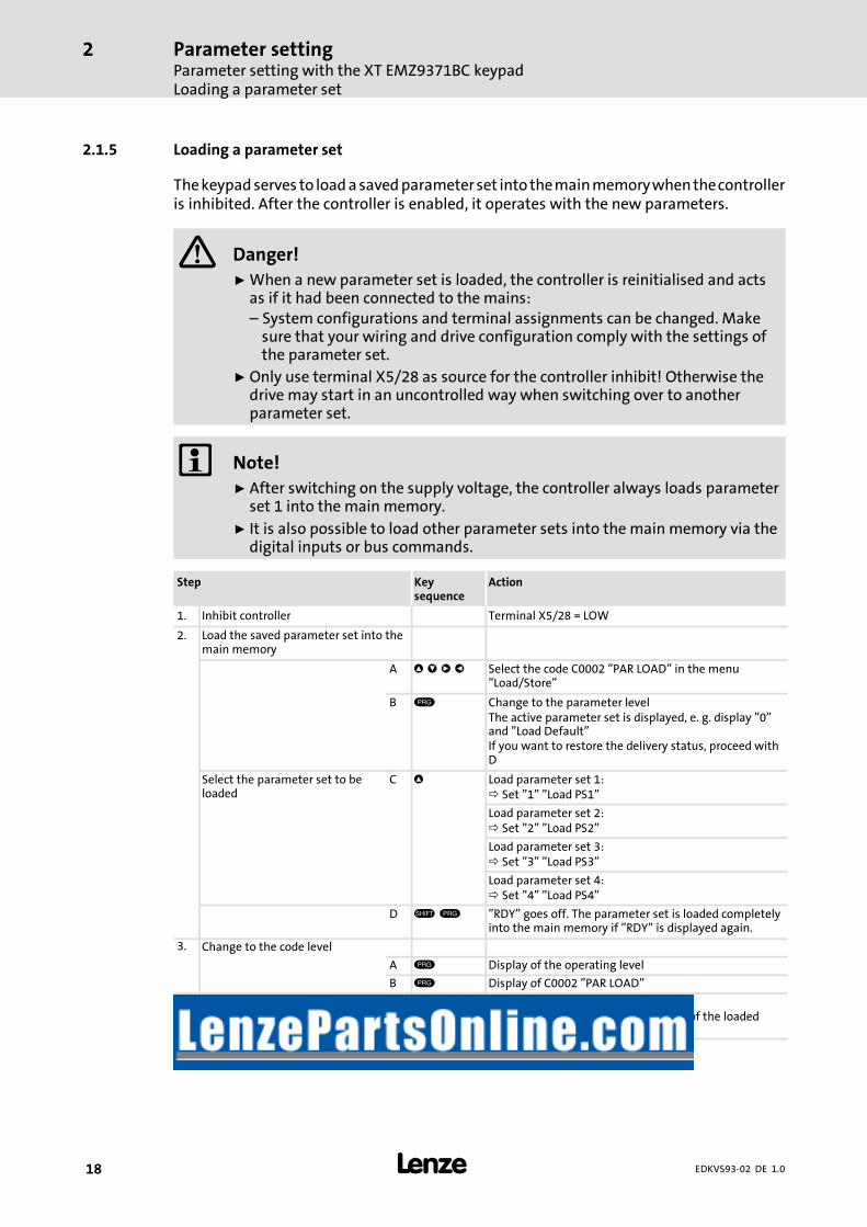
2.1.5 Loading a parameter set
Thekeypadserves to loadasavedparameterset into themainmemorywhenthecontrolleris inhibited. After the controller is enabled, it operates with the new parameters.
Danger!ƒ When a new parameter set is loaded, the controller is reinitialised and actsas if it had been connected to the mains:– System configurations and terminal assignments can be changed. Makesure that your wiring and drive configuration comply with the settings ofthe parameter set.
ƒ Only use terminal X5/28 as source for the controller inhibit! Otherwise thedrive may start in an uncontrolled way when switching over to anotherparameter set.
Note!ƒ After switching on the supply voltage, the controller always loads parameterset 1 into the mainmemory.
ƒ It is also possible to load other parameter sets into the mainmemory via thedigital inputs or bus commands.
Step Keysequence
Action
1. Inhibit controller Terminal X5/28 = LOW
2. Load the saved parameter set into themain memory
A Select the code C0002 ”PAR LOAD” in the menu”Load/Store”
B Change to the parameter levelThe active parameter set is displayed, e. g. display ”0”and ”Load Default”If you want to restore the delivery status, proceed withD
Select the parameter set to beloaded
C Load parameter set 1:Set ”1” ”Load PS1”
Load parameter set 2:Set ”2” ”Load PS2”
Load parameter set 3:Set ”3” ”Load PS3”
Load parameter set 4:Set ”4” ”Load PS4”
D ”RDY” goes off. The parameter set is loaded completelyinto the main memory if ”RDY” is displayed again.
3. Change to the code level
A Display of the operating level
B Display of C0002 ”PAR LOAD”
4. Enable controller Terminal X5/28 = HIGHThe drive is running with the settings of the loadedparameter set

Parameter settingParameter setting with the XT EMZ9371BC keypadTransferring parameters to other standard devices
2
19EDKVS93-02 DE 1.0
2.1.6 Transferring parameters to other standard devices
The keypad enables you to copy parameter settings from one standard device to another.
For this purpose use the ”Load/Store” menu:
Danger!During the transfer of the parameters from the keypad to the controller, thecontrol terminals may adopt undefined states!Therefore be absolutely sure to disconnect the connectors X5 and X6 from thecontroller prior to the transfer. Like this you will ensure that the drivecontroller is inhibited and all control terminals are in the defined ”LOW” state.
Copying parameter sets from the standard device to the keypad
Note!After the parameter sets are copied to the keypad XT (C0003 = 11), theparameter set last loaded using C0002 is always activated.So the actual parameters remain active also after copying:ƒ Prior to copying, save the actual parameters in the parameter set and loadthis parameter set into the drive controller using C0002.
Step Keysequence
Action
1. Connect keypad to controller 1
2. Inhibit controller Terminal X5/28 = LOWThe drive coasts.
3. On the ”Load/Store” menu selectC0003
On the ”Load/Store” menu select code C0003 ”PARSAVE” using the arrow keys.
4. Change to the parameter level Display ”0” and ”READY”
5. Copy all parameter sets to the keypad The settings stored in the keypad are overwritten.
Set ”11” ”Save extern”
6. Start copying The ”RDY” status display goes off. ”BUSY” is indicatedas parameter value.When ”BUSY” goes off after approx. one minute, allparameter sets have been copied to the keypad. The”RDY” status display illuminates.
7. Change to the code level
A Display of the operating level
B Display of C0003 and ”PAR SAVE”
8. Enable controller Terminal X5/28 = HIGH
9. Remove keypad from controller 1

Parameter settingParameter setting with the XT EMZ9371BC keypadTransferring parameters to other standard devices
2
20 EDKVS93-02 DE 1.0
Copying parameter sets from the keypad to the standard device
Step Keysequence
Action
1. Connect keypad to controller 2
2. Inhibit controller Terminal X5/28 = LOWThe ”IMP” status display illuminates.The drive coasts
3. Disconnect connectors X5 and X6 All control terminals have the defined ”LOW” state.
4. On the ”Load/Store” menu selectC0002
On the ”Load/Store” menu select code C0002 ”PARLOAD” using the arrow keys.
5. Change to the parameter level The active parameter set is displayed, e. g. display ”0”and ”Load Default”
6. Select the correct copy function The settings stored in the controller are overwritten.
Copy all available parameter sets to thecontroller and save in non-volatile memory.
The parameters are not yet active after copying. Selectparameter set and load into main memory. 18
Set ”20” ”ext -> EEPROM”
Copy individual parameter sets to main memory.
Copy parameter set 1:Set ”11” ”Load ext PS1”
Copy parameter set 2:Set ”12” ”Load ext PS2”
Copy parameter set 3:Set ”13” ”Load ext PS3”
Copy parameter set 4:Set ”14” ”Load ext PS4”
7. Start copying The ”RDY” status display goes off. ”BUSY” is indicatedas parameter value.When ”BUSY” goes off, all selected parameter setshave been copied to the controller. The ”RDY” statusdisplay illuminates.
8. Change to the code level
A Display of the operating level
B Display of C0002 and ”PAR LOAD”
9. Save individually copied parametersets in non-volatile memory
On the ”Load/Store” menu select code C0003 ”PARSAVE” using arrow keys and save contents of the mainmemory in non-volatile memory.
10. Connect connectors X5 and X6
11. Enable controller Terminal X5/28 = HIGHThe drive runs with the new settings.

Parameter settingParameter setting with the XT EMZ9371BC keypad
Activating password protection
2
21EDKVS93-02 DE 1.0
2.1.7 Activating password protection
Note!ƒ If the password protection is activated (C0094 = 1 ... 9999), you only havefree access to the user menu.
ƒ To access the other menus, youmust enter the password. By this, thepassword protection is annulled until you enter a new password.
ƒ Please observe that the password-protected parameters can be overwrittenas well when transferring the parameter sets to other standard devices. Thepassword is not transferred.
ƒ Do not forget your password! If you have forgotten your password, it canonly be reset via a PC or a bus system!
Activate password protection
Step Keysequence
Action
1. Select the ”USER menu” Change to the user menu using the arrow keys
2. Change to the code level Display of code C0051 ”MCTRL-NACT”
3. Select C0094 Display of code C0094 ”Password”
4. Change to the parameter level Display ”0” = no password protection
5. Set password
A Select password (1 ... 9999)
B Confirm password
6. Change to the code level
A Display of the operating level
B Display of C0094 and ”Password”
7. Change to the ”USER menu”
The password protection is active now.You can only quit the user menu if you re-enter the password and confirm it with.
Remove password protection
Step Keysequence
Action
1. Change to the code level in the usermenu
2. Select C0094 Display of code C0094 ”Password”
3. Change to the parameter level Display ”9999” = password protection is active
4. Enter password
A Set valid password
B ConfirmThe password protection is deactivated by entering thepassword once again.
5. Change to the code level
A Display of the operating level
B Display of C0094 and ”Password”
The password protection is deactivated now. All menus can be freely accessed again.

Parameter settingParameter setting with the XT EMZ9371BC keypadDiagnostics
2
22 EDKVS93-02 DE 1.0
2.1.8 Diagnostics
In the ”Diagnostic”menu the two submenus ”Actual info” and ”History” contain all codesfor
ƒ monitoring the drive
ƒ fault/error diagnosis
In the operating level, more status messages are displayed. If several status messages areactive, the message with the highest priority is displayed.
Priority Display Meaning
1 GLOBAL DRIVE INIT Initialisation or communication error betweenkeypad and controller
2 XXX - TRIP Active TRIP (contents of C0168/1)
3 XXX - MESSAGE Active message (contents of C0168/1)
4 Special device states:
Switch-on inhibit
5 Source for controller inhibit (the value of C0004 is displayed simultaneously):
STP1 9300 servo: Terminal X5/28
ECSxS/P/M/A: Terminal X6/SI1
STP3 Operating module or LECOM A/B/LI
STP4 INTERBUS or PROFIBUS-DP
STP5 9300 servo, ECSxA/E: System bus (CAN)
ECSxS/P/M: MotionBus (CAN)
STP6 C0040
6 Source for quick stop (QSP):
QSP-term-Ext The MCTRL-QSP input of the MCTRL function block is on HIGH signal.
QSP-C0135 Operating module or LECOM A/B/LI
QSP-AIF INTERBUS or PROFIBUS-DP
QSP-CAN 9300 servo, ECSxA: System bus (CAN)
ECSxS/P/M: MotionBus (CAN)
7 XXX - WARNING Active warning (contents of C0168/1)
8 xxxx Value below C0004

Parameter settingParameter setting with the XT EMZ9371BC keypad
Menu structure
2
23EDKVS93-02 DE 1.0
2.1.9 Menu structure
For simple, user-friendly operation, the codes are clearly arranged in function-relatedmenus:
Main menu Submenus Description
Display Display
User-Menu Codes defined in C0517
Code list All available codes
ALL All available codes listed in ascending order (C0001 ... C7999)
PS 1 Codes in parameter set 1 (C0001 ... C1999)
PS 2 Codes in parameter set 2 (C2001 ... C3999)
PS 3 Codes in parameter set 3 (C4001 ... C5999)
PS 4 Codes in parameter set 4 (C6001 ... C7999)
Load/Store Parameter set managementParameter set transfer, restore delivery status
Diagnostic Diagnostic
Actual info Display codes to monitor the drive
History Fault analysis with history buffer
Short setup Quick configuration of predefined applicationsConfiguration of the user menuThe predefined applications depend on the type of the standard device (frequencyinverter, servo inverter, position controller, ...)
Main FB Configuration of the main function blocks
NSET Setpoint processing
NSET-JOG Fixed setpoints
NSET-RAMP1 Ramp function generator
MCTRL Motor control
DFSET Digital frequency processing
DCTRL Internal control
Terminal I/O Connection of inputs and outputs with internal signals
AIN1 X6.1/2 Analog input 1
AIN2 X6.3/4 Analog input 2
AOUT1 X6.62 Analog output 1
AOUT2 X6.63 Analog output 2
DIGIN Digital inputs
DIGOUT Digital outputs
DFIN Digital frequency input
DFOUT Digital frequency output
State bus State bus (not with 9300 frequency inverter)
Controller Configuration of internal control parameters
Speed Speed controller
Current Current controller or torque controller
Phase Phase controller (not with 9300 frequency inverter)
Motor/Feedb. Input of motor data, configuration of speed feedback
Motor adj Motor data
Feedback Configuration of feedback systems
Monitoring Configuration of monitoring functions

Parameter settingParameter setting with the XT EMZ9371BC keypadMenu structure
2
24 EDKVS93-02 DE 1.0
DescriptionSubmenusMain menu Description
DisplayDisplay
LECOM/AIF Configuration of operation with communication modules
LECOM A/B Serial interface
AIF interface Process data
Status word Display of status words
System bus Configuration of system bus (CAN)
Management CAN communication parameters
CAN-IN1CAN object 1
CAN-OUT1
CAN-IN2CAN object 2
CAN-OUT2
CAN-IN3CAN object 3
CAN-OUT3
Status word Display of status words
FDO Free digital outputs
Diagnostic CAN diagnostic
FB config Configuration of function blocks
Func blocks Parameterisation of function blocksThe submenus contain all available function blocks
FCODE Configuration of free codes
Identify Identification
Drive Software version of standard device
Op Keypad Software version of keypad

Troubleshooting and fault eliminationDisplay of operating data, diagnostics
3
25EDKVS93-02 DE 1.0
3 Troubleshooting and fault elimination
3.1 Display of operating data, diagnostics
The dialog box displays important operating parameters and supports you in diagnosingthe drive controller.
ƒ Open the Diagnostics dialog box in the parameter menu.
9300std230
Fig.3-1 ”Diagnostics” dialog box
ƒ You can recognise immediately that a fault has occurred from the display elementsor status information.
ƒ An error can be analysed with
– the history buffer in Global Drive Control (GDC) ( 27) or
– the keypad XT
– and with the ”General error messages” table in the ”System error messages”chapter.
ƒ The ”General error messages” table provides tips on how to eliminate an error.
Troubleshooting and fault eliminationTroubleshootingStatus display (LEDs on the controller)
3
26 EDKVS93-02 DE 1.0
3.2 Troubleshooting
Failure identification
A failure can be identified quickly by means of the LEDs on the controller or thestatusinformation on the keypad.
Error analysis
Errors can be analysed bymeans of the history buffer. There are helpful hints in the list offault messages on how to correct them.
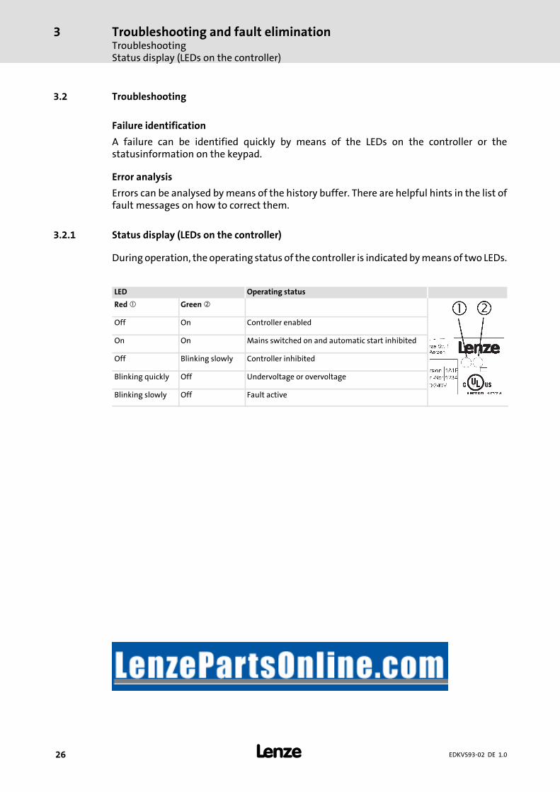
3.2.1 Status display (LEDs on the controller)
During operation, the operating status of the controller is indicatedbymeans of two LEDs.
LED Operating status
Red Green
Off On Controller enabled
On On Mains switched on and automatic start inhibited
Off Blinking slowly Controller inhibited
Blinking quickly Off Undervoltage or overvoltage
Blinking slowly Off Fault active

Troubleshooting and fault eliminationTroubleshooting
Fault analysis with the history buffer
3
27EDKVS93-02 DE 1.0
3.2.2 Fault analysis with the history buffer
The history buffer can be used to trace faults. The fault messages are stored in the 8memory locations in the order of their occurrence.
ƒ Open the Diagnostics dialog box in the parameter menu.
9300std230
Fig.3-2 ”Diagnostics” dialog box
FieldMemory locationfor the history
bufferEntry Note
1 Active fault If the fault is not pending any more or was quit:The contents of the memory locations 1 ... 7 aremoved up by one memory location.The contents of memory location 8 drops out ofthe history buffer and is not available any more.Memory location 1 is cleared (= no active fault).
2 Last fault
3 Last but two fault
4 Last but three fault
5 Last but four fault
6 Last but five fault
7 Last but six fault
8 Last but six fault

Troubleshooting and fault eliminationTroubleshootingFault analysis via LECOM status words (C0150/C0155)
3
28 EDKVS93-02 DE 1.0
Explanations
, Fault indication and fault reaction (C0168)The entry is performed as LECOM error number.If various faults with different reactions occur at the same time:– Only one fault is entered whose reaction has the highest priority (1. TRIP, 2. message,3. warning).
For faults occurring at the same time with the same reaction (e.g. 2 messages):– Only the fault that was caused first is entered.Exception: The OH3 warning has a higher priority than the OH7 warning.– A pending OH7 warning is overwritten by the OH3 warning.– After the OH3 warning has gone out, a pending OH7 warning is displayed again.
, Time of the fault (C0169)The reference point is the state of the power-on time meter .If a fault is immediately followed by another fault for several times, only the time of the lastoccurrence is stored.
, Fault frequency (C0170)The time of the last occurance is stored.
Click Fault history reset to clear the history buffer.The history buffer can only be cleared if no fault is active.
Click TRIP reset to reset the fault.
3.2.3 Fault analysis via LECOM status words (C0150/C0155)
The LECOM status words (C0150/C0155) are coded as follows:
Code Possible settings IMPORTANT
No. Designation Lenze/{Appl.}
Selection
C0150 Status word 0 Status word for networking viaautomation interface (AIF)Read only
0 {1} 65535 Controller evaluates informationas 16 bits (binary coded)
Bit 0 Not assigned
Bit 1 Pulse inhibit (IMP) is active
Bit 2 Not assigned
Bit 3 Not assigned
Bit 4 Not assigned
Bit 5 Not assigned
Bit 6 n=0
Bit 7 Controller inhibit (CINH) is active
Bit 8 Controller status
Bit 9 Controller status
Bit 10 Controller status
Bit 11 Controller status
Bit 12 Warning is active
Bit 13 Message is active
Bit 14 Not assigned
Bit 15 Not assigned

Troubleshooting and fault eliminationSystem error messagesGeneral error messages
3
29EDKVS93-02 DE 1.0
IMPORTANTPossible settingsCode
SelectionLenze/{Appl.}
DesignationNo.
C0155 Status word 2 0 Status word 2 (advanced statusword)Display only
0 {1} 65535 Controller interprets informationas 16 bit (binary coded)
Bit 0 Active fault
Bit 1 Mmax reached
Bit 2 Imax reached
Bit 3 Pulse inhibit(IMP)
Bit 4 Ready for operation (RDY)
Bit 5 Controller inhibit (CINH)
Bit 6 TRIP active
Bit 7 Initialisation
Bit 8 Motor direction of rotation (Cw/CCw)
Bit 9 Not assigned
Bit 10 Not assigned
Bit 11 Not assigned
Bit 12 Not assigned
Bit 13 Not assigned
Bit 14 Not assigned
Bit 15 Not assigned
3.3 System error messages
3.3.1 General error messages
Note!If the system error is retrieved via the system bus (CAN), the error messagesare displayed as numbers (see column ”Error message – No.” of the belowtable).
Fault message Description Cause Remedy
No. Display
--- --- No fault - -
0011 OC1 Short circuit of motor cable Short circuit Search for cause of shortcircuit.Check motor cable.
Excessive capacitive chargingcurrent in the motor cable.
Use motor cable which is shorteror of lower capacitance.
0012 OC2 Motor cable earth fault One of the motor phases hasearth contact.
Search for cause of shortcircuit.Check motor cable.
0015 OC5 I x t overload Frequent and too longacceleration with overcurrentContinuous overload withImotor > 1.05 x Irx.
Check drive dimensioning.

Troubleshooting and fault eliminationSystem error messagesGeneral error messages
3
30 EDKVS93-02 DE 1.0
RemedyCauseDescriptionFault message RemedyCauseDescription
DisplayNo.
1020 OU Overvoltage in DC bus Braking energy is too high.(DC-bus voltage is higher than setin C0173.)
Use braking unit orregenerative module.Check dimensioning of thebrake resistance.
1030 LU Undervoltage in the DC bus DC bus voltage is lower thanspecified in C0173.
Check mains voltageCheck supply cable
x032 LP1 Motor phase failure A current-carrying motor phasehas failed.
Check motor.Check motor cable.Switch off monitoring(C0597 = 3).
The current limit value is set toolow.
Set higher current limit valuevia C0599.
0050 OH Heatsink temperature > +90 °C Ambient temperatureTu > +40 °C or > +50 °C
Allowmodule to cool andensure better ventilation.Check ambient temperature inthe control cabinet.
Heatsink is very dirty. Clean heatsink.
Wrong mounting position Change mounting position.x053 OH3 Motor temperature
> +150 °C threshold(temperature detection viaresolver or incremental valueencoder)
Motor is thermally overloadeddue to:
Impermissible continuouscurrentFrequent or too longacceleration processes
Check drive dimensioning.Switch off monitoring(C0583 = 3).
No PTC/temperature contactconnected.
Correct wiring.
x054 OH4 Heatsink temperature > C0122 Ambient temperature Tu > +40 °Cor > +50 °C
Allowmodule to cool andensure better ventilation.Check ambient temperature inthe control cabinet.Switch off monitoring(C0582 = 3).
Heatsink is very dirty. Clean heatsink
Wrong mounting position Change mounting position.
The value specified under C0122is set too low.
Enter a higher value under C0122.
x057 OH7 Motor temperature > C0121(temperature detection viaresolver or incremental valueencoder)
Motor is thermally overloadeddue to:
Impermissible continuouscurrentFrequent or too longacceleration processes
Check drive dimensioning.Switch off monitoring(C0584 = 3).
No PTC/temperature contactconnected.
Correct wiring.
The value specified under C0121is set too low.
Enter a higher value in C0121.
x058 OH8 Motor temperature via inputs T1and T2 is too high.
Motor is thermally overloadeddue to:
Impermissible continuouscurrentFrequent or too longacceleration processes
Check drive dimensioning.Switch off monitoring(C0585 = 3).
Terminals T1 and T2 are notconnected
Connect PTC/temperaturecontact.
x061 CE0 Automation interface (AIF)communication error
Faulty transfer of controlcommands via AIF.
Plug in the communicationmodule/keypad XT firmly,screw down, if necessary.Switch off monitoring(C0126 = 3).

Troubleshooting and fault eliminationSystem error messagesGeneral error messages
3
31EDKVS93-02 DE 1.0
RemedyCauseDescriptionFault message RemedyCauseDescription
DisplayNo.
x062 CE1 Communication error on theprocess data input objectCAN1_IN
CAN1_IN object receives faultydata or communication isinterrupted.
Check wiring at X4.Check sender.Increase monitoring timeunder C0357/1, if necessary.Switch off monitoring(C0591 = 3).
x063 CE2 Communication error on theprocess data input objectCAN2_IN
CAN2_IN object receives faultydata or communication isinterrupted.
Check wiring at X4.Check sender.Increase monitoring timeunder C0357/2, if necessary.Switch off monitoring(C0592 = 3).
x064 CE3 Communication error on theprocess data input objectCAN3_IN
CAN3_IN object receives faultydata or communication isinterrupted.
Check wiring at X4.Check sender.Increase monitoring timeunder C0357/3, if necessary.Switch off monitoring(C0593 = 3).
x065 CE4 BUS-OFF state of system bus(CAN)
The controller has received toomany faulty telegrams via thesystem bus (CAN) and hasdisconnected from the bus.
Check wiring at X4: Is the buscorrectly terminated?Check shield connection of thecables.Check PE connection.Check bus load, reduce thebaud rate if necessary.(Observe the cable length!)Switch off the monitoring(C0595 = 3).
0071 CCr System failure Strong interference injection onthe control cables
Screen control cables
Ground or earth loops in thewiring
Check wiringCheck PE connection
After troubleshooting: Deenergisethe device completely (disconnect24 V supply, discharge DC bus)!
0072 PR1 Checksum error in parameterset 1CAUTION: The Lenze setting isloaded automatically!
Fault when loading aparameter set.Interruption whiletransmitting the parameter setvia keypad.
Set the required parametersand store them under C0003 =1.As to PLC devices, check theuse of pointers.
The stored parameters areincompatible with the loadedsoftware version.
Store the parameter set underC0003 = 1 first to allow for afaults reset.
0074 PEr Program error Error in the program flow Send the parameter set (on floppydisk/CD-ROM) with a detaileddescription of the problem toLenze.After troubleshooting: Deenergisethe device completely (disconnect24 V supply, discharge DC bus)!
0075 PR0 Error in parameter set. The operating system softwarehas been updated.
Storage of the Lenze settingC0003 = 1.
After troubleshooting: Deenergisethe device completely (disconnect24 V supply, discharge DC bus)!

Troubleshooting and fault eliminationSystem error messagesGeneral error messages
3
32 EDKVS93-02 DE 1.0
RemedyCauseDescriptionFault message RemedyCauseDescription
DisplayNo.
0079 PI Fault during parameterinitialisation
An error has been detectedduring the parameter settransfer between two devices.The parameter set does notmatch the controller, e.g. ifdata has been transferred froma higher-power controller to alower-power controller.
Correct parameter set.Send parameter set (on floppydisk/CD-ROM) and a detaileddescription of the problem toLenze.
x082 Sd2 Resolver error at X7 Resolver cable interrupted. Check cable for open circuit.Check resolver.Switch off the monitoring(C0586 = 3).
x083 Sd3 Encoder error at X9 Cable interrupted. Check cable for open circuit.
Pin X9/8 not connected. Apply 5 V to pin X9/8 or switch offmonitoring (C0587 = 3).
x085 Sd5 Encoder error at X6/1 and X6/2(C0034 = 1)
Current signal at X6/1 X6/2 <2mA.
Check cable for open circuit.Check current signal encoder.Switch off monitoring(C0598 = 3).
x086 Sd6 Motor temperature sensor error(X7 or X8)
Encoder for detecting the motortemperature at X7 or X8 indicatesundefined values.
Check cable for firmconnection.Switch off the monitoring(C0594 = 3).
x087 sd7 Initialisation error of absolutevalue encoder at X8
Defect of the encoderelectronicsAbsolute value encoder at X8does not send any data.
Tip: The encoder may not rotateduring mains switching.
Check cable at X8 with regardto tight fit and open circuit.Check absolute value encoderwith regard to correct function.Set voltage supply to 8.1 V viaC0421.No Stegmann encoderconnected.Replace defective encoder.
Communication error of absolutevalue encoder at X8 during rotorposition adjustment
A rotor position adjustment viaC0095 = 1 could not be completedsuccessfully.
Repeat rotor position adjustment.
Note: After an Sd7 fault it isabsolutely required to carry out afurther rotor position adjustment.Otherwise the drive may carry outuncontrolled movements aftercontroller enable. The drive maynot be commissioned withouthaving carried out a rotor positionadjustment successfully!
After fault correction: completelydeenergise the device (switch off24 V supply, discharge DC bus)!

Troubleshooting and fault eliminationSystem error messagesGeneral error messages
3
33EDKVS93-02 DE 1.0
RemedyCauseDescriptionFault message RemedyCauseDescription
DisplayNo.
x088 SD8 SinCos encoder at X8 sendsinconsistent data.
The tracks in the SinCos encoderare damaged.
Replace SinCos encoder.
Interference level on the encodercable is too high.
Check correct shieldconnection of encoder cable.Where required, decelerate theactuation of the fault messagevia the filter time constant.Setting:– for ECSxS/P/M/A in C0559.– for 9300 servo cam in C0575.
SinCos encoder at X8 does notsend any data.
Open circuit. Check cable with regard to opencircuit.
Incorrect encoder connected. Connect SinCos encoder of thecompany Stegmann.
SinCos encoder defective. Replace SinCos encoder.
Supply voltage set incorrectly. Set voltage supply in C0421.
After fault correction: completelydeenergise the device (switch off24 V supply, discharge DC bus)!
x089 PL Fault during rotor positionadjustment (the fault is storedsafe frommains failure)
The rotor position adjustmenthas been aborted.During rotor positionadjustment with absolutevalue encoder the fault Sd7 orSD8 has occurred.
Restart rotor position adjustmentwith C0095 = 1. Then reset TRIP.
x091 EEr External monitoring has beentriggered via DCTRL.
A digital signal assigned to theTRIP-SET function has beenactivated.
Check external encoder.Switch off the monitoring(C0581 = 3).
0105 H05 Internal fault (memory) Contact Lenze.
0107 H07 Internal fault (power stage) During initialisation of thecontroller, an incorrect powerstage was detected.
Contact Lenze.
x110 H10 Heatsink temperature sensorerror
Sensor for detecting the heatsinktemperature indicates undefinedvalues.
Contact Lenze.Switch off the monitoring(C0588 = 3).
x111 H11 Temperature sensor error:Temperature inside the controller
Sensor for detecting the internaltemperature indicates undefinedvalues.
Contact Lenze.Switch off the monitoring(C0588 = 3).
x151 P01 Error ”negative limit switch”. Negative limit switch wasreached.
Control drive in positivedirectionCheck wiring at X5/E2.
x152 P02 Error ”positive limit switch”. Positive limit switch was reached. Control drive in negativedirectionCheck wiring at X5/E1.
x153 P03 Following error The angle difference between setand actual position is larger thanthe following error limit set underC0255.
Increase following error limitunder C0255.Switch off the monitoring(C0589 = 3).
Drive cannot follow the digitalfrequency (Imax limit).
Check drive dimensioning.
x154 P04 Error ”negative position limit”. Negative position limit (C1224)was not reached.
Find out why the value was notreached (e.g. ”incorrect” positiontargets, set function positionvalue) and adjust the positionlimit in C1224 if necessary.
x155 P05 Error ”positive position limit”. Positive position limit (C1223)was exceeded.
Find out why the value wasexceeded (e.g. ”incorrect” positiontargets, set function positionvalue) and adjust the positionlimit in C1223 if necessary.
Troubleshooting and fault eliminationSystem error messagesGeneral error messages
3
34 EDKVS93-02 DE 1.0
RemedyCauseDescriptionFault message RemedyCauseDescription
DisplayNo.
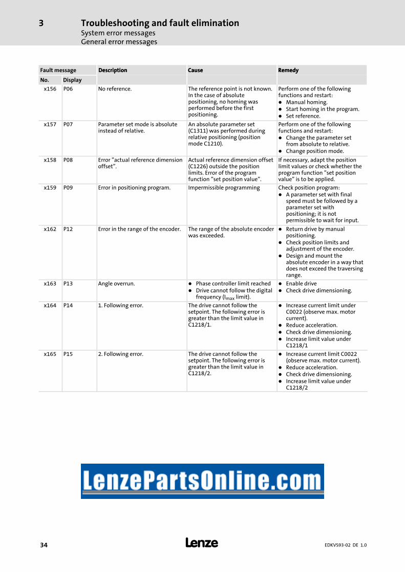
x156 P06 No reference. The reference point is not known.In the case of absolutepositioning, no homing wasperformed before the firstpositioning.
Perform one of the followingfunctions and restart:
Manual homing.Start homing in the program.Set reference.
x157 P07 Parameter set mode is absoluteinstead of relative.
An absolute parameter set(C1311) was performed duringrelative positioning (positionmode C1210).
Perform one of the followingfunctions and restart:
Change the parameter setfrom absolute to relative.Change position mode.
x158 P08 Error ”actual reference dimensionoffset”.
Actual reference dimension offset(C1226) outside the positionlimits. Error of the programfunction ”set position value”.
If necessary, adapt the positionlimit values or check whether theprogram function ”set positionvalue” is to be applied.
x159 P09 Error in positioning program. Impermissible programming Check position program:A parameter set with finalspeed must be followed by aparameter set withpositioning; it is notpermissible to wait for input.
x162 P12 Error in the range of the encoder. The range of the absolute encoderwas exceeded.
Return drive by manualpositioning.Check position limits andadjustment of the encoder.Design and mount theabsolute encoder in a way thatdoes not exceed the traversingrange.
x163 P13 Angle overrun. Phase controller limit reachedDrive cannot follow the digitalfrequency (Imax limit).
Enable driveCheck drive dimensioning.
x164 P14 1. Following error. The drive cannot follow thesetpoint. The following error isgreater than the limit value inC1218/1.
Increase current limit underC0022 (observe max. motorcurrent).Reduce acceleration.Check drive dimensioning.Increase limit value underC1218/1
x165 P15 2. Following error. The drive cannot follow thesetpoint. The following error isgreater than the limit value inC1218/2.
Increase current limit C0022(observe max. motor current).Reduce acceleration.Check drive dimensioning.Increase limit value underC1218/2

Troubleshooting and fault eliminationSystem error messagesGeneral error messages
3
35EDKVS93-02 DE 1.0
RemedyCauseDescriptionFault message RemedyCauseDescription
DisplayNo.
x166 P16 Faulty transfer of system bus(CAN) sync telegram.
The sync telegram from themaster (PLC) is out of sync cycle.
Set the ”sync cycle” to thetransmission cycle of themaster (PLC) under C1121.Note:– C0362 displays the timeinterval between 2 synctelegrams.
– C0362 = 0: communicationinterrupted.
The sync telegram of the master(PLC) is not received.
Check communication channel.Check baud rate, controlleraddress.Note:– C0362 displays the timeinterval between 2 synctelegrams.
– C0362 = 0: communicationinterrupted.
The controller is enabled too fast. Delay the controller enable.The time delay required dependson the time interval between thesync telegrams.
x167 P17 Error ”touch probe control”. Various function blocks use thetouch probe input at the sametime (e.g. FB DFSET and POS). Aconflict arises.
Configure another touch probeinput for FB POS (not possiblefor FB DFSET).Switch off monitoring(C1289/1).
x168 P18 Internal limitation. Arithmetic operation generateddata cannot be varied arbitrarily.Wrongly specified values wereautomatically limited internally.C1298 = 1:The negative position limit inC1223 is outside the possibledisplay range of1 ≤ (C1223 × C1205) ≤ 1.07E9 inc
Check the values in C1202/4,C1207/1, C1207/2. Read out thelimited value in C1220/10 andenter it in C1223 if necessary.
C1298 = 2:The positive position limit inC1224 is outside the possibledisplay range of1 ≤ (C1224 × C1205) ≤ 1.07E9 inc
Check the values in C1202/4,C1207/1, C1207/2. Read out thelimited value in C1220/11 andenter it in C1224 if necessary.
C1298 = 3:The maximum speed vmax inC1240 is outside the possibledisplay range of1 ≤ (C1240 × C1205 ×16.384) ≤ 2.14E9 inc or vmax notC1240 / C1204 × 60 ≤ 1.5 × nmax
Check the values in C0011,C1202/4, C1207/1, C1207/2. Readout the limited value in C1220/12and enter it in C1240 or adjust thevalue in C1240 to C0011 ifnecessary.
C1298 = 4:The maximum acceleration amaxin C1250 is outside the possibledisplay range of1 ≤ (C1250 × C1205 × 16.384 / 1000) ≤ 2.8634E7 inc
Check the values in C1202/4,C1207/1, C1207/2. Read out thelimited value in C1220/13 andenter it in C1250 if necessary.
C1298 = 5:An internal value range has beenexceeded for a speedstandardisation. Valid range:1 ≤ (C0011 × C1207/1 / C1207/265536 / 60000) ≤ 32767
Check the values in C0011,C1207/1, C1207/2 and correctthem.

Troubleshooting and fault eliminationSystem error messagesGeneral error messages
3
36 EDKVS93-02 DE 1.0
RemedyCauseDescriptionFault message RemedyCauseDescription
DisplayNo.
x169 P19 The input values at X9 are limited. The function block DFIN limits theinput values. This causes the lossof increments.
Reduce the frequency on thedigital frequency connection.Check the settings for the slave(C0425) and for the master(C0030). These settings mustbe identical.
x171 P21 Following error. The phase difference between setand actual position is larger thanthe following error limit set underC1328.
Extend the following errorlimit under C1328.Switch off monitoring(C1329=3).
Drive cannot follow the digitalfrequency (Imax limit).
Check drive dimensioning.
x190 nErr Speed control error(Speed out of tolerance margin(C0576))
Active load (e.g. for hoists) istoo high.Mechanical blockades on theload side
Check drive dimensioning.
x200 Nmax Maximum speed (C0596) hasbeen exceeded.
Active load (e.g. for hoists) istoo highDrive is not speed-controlled,torque is excessively limited.
Check drive dimensioning.Possibly increase torque limit.Switch off monitoring(C0607 = 3).
x220 CDA Data error Attempt to transmit faulty profiledata
Repeat profile data transfer.
x221 CDA-LOAD Faulty checksum The checksum of the transferredprofile data is not correct.
Repeat profile data transfer andcheck for correctness.
Explanation of the error numbers:x 0 = TRIP, 1 = message, 2 = warning, 3 = FAIL-QSP
e.g. ”2091”: An external monitoring has triggered the warning EEr

Troubleshooting and fault eliminationSystem error messages
Resetting system error messages
3
37EDKVS93-02 DE 1.0
3.3.2 Resetting system error messages
Reaction Measures to reset the fault message
TRIP/ FAIL-QSP Note!If a TRIP/FAIL QSP source is still active, the pending TRIP/FAIL QSP cannot be reset.
The TRIP/FAIL QSP can be reset by:pressing on keypad XT EMZ9371 BC. Then, press to re-enable the controller.Set code C0043 = 0.Control word C0135, bit 11Control word AIFControl word system bus (CAN) / MotionBus (CAN) at ECSxS/P/M
After the reset of the TRIP/FAIL QSP, the drive remains at standstill.
Message Danger!The fault message is reset automatically after the fault has been eliminated, and the driverestarts automatically.
Warning After the fault has been eliminated, the fault message is reset automatically.

Lenze Drive Systems GmbHHans-Lenze-Straße 1D-31855 AerzenGermany
EDKVS93-02DE 1.0
© 06/2008TD23
+49 (0) 51 54 82-0
Service 00 80 00 24 4 68 77 (24 h helpline)
Service +49 (0) 51 54 82-1112
E-Mail [email protected] www.Lenze.com
10 9 8 7 6 5 4 3 2 1
Related Documents