General Description ZENO™ (MAX79356) is a programmable narrowband orthogonal frequency division multiplexing (OFDM)-based powerline communication (PLC) modem system-on-chip (SoC) device that provides standards compliant high performance and secured powerline communication in a small package. ZENO integrates two pipelined 32-bit RISC (MAXQ®30E) processors to offer high performance and future-proof flexibility. These two 32-bit RISC proces- sors perform dedicated PHY signal processing functions and MAC layer functionality. Maxim provided, certified firmware images allow faster time to market. Factory or in- field firmware update feature allows adoption of changes and updates in PLC communication standards. The inte- grated high-speed AES-CCM* engine ensures standards compliant data communication security and integrity. Applications ● Smart Grid Communications ● Smart Meters ● Advanced Metering Infrastructure (AMI) ● AMI Concentrators ● Factory and Building Automation ● Electric Vehicle Charging ● Home Energy Monitoring ● Solar and Renewable Energy Management ● Street Lighting Automation and Lighting Control Benefits and Features ● Supports All Standards and Frequency Bands to Reduce R&D Investment and Time to Market • G3-PLC Certified • Compliant with, G3-PLC, IEEE 1901.2, ITU G9903, PRIME • Supports Regulated Frequency Bands for Communication: CENELEC, FCC, ARIB ● Accommodates Evolving Standards with Flexible System Architecture That Integrates Dual 32-Bit RISC Processors with 512KB Flash and 288KB RAM for MAC and PHY • Universal Firmware Supports Both PAN Coordinator and PAN Device Functionality • Programmable Frequency Notching ● Efficient BOM for Building Competitive Modems • Supports All G3-PLC Bands with One SKU • Integrates MAC, OFDM PHY, and Analog Front End for Simplified Board Design • Single 16MHz Crystal Generates All Operating Clocks • UART Provides Simple Interface for Host Processor Communications ● Low Power Consumption (typ) • 55mW in Listen Mode • 70mW in Active Mode ● High-Sensitivity Receiver with Adaptive Gain Control Allows Communication with Low Signal-to-Noise Ratio ● Integrated 128/256-bit AES and AES-CCM* Engine for Encryption/Decryption and Authentication Ordering Information appears at end of data sheet. MAXQ is a registered trademark and ZENO is a trademark of Maxim Integrated Products, Inc. 19-7548; Rev 2; 9/17 MAX79356 ZENO Flexible Narrowband OFDM Powerline Communication Modem with Integrated Analog Front End Typical Operating Circuit

Welcome message from author
This document is posted to help you gain knowledge. Please leave a comment to let me know what you think about it! Share it to your friends and learn new things together.
Transcript
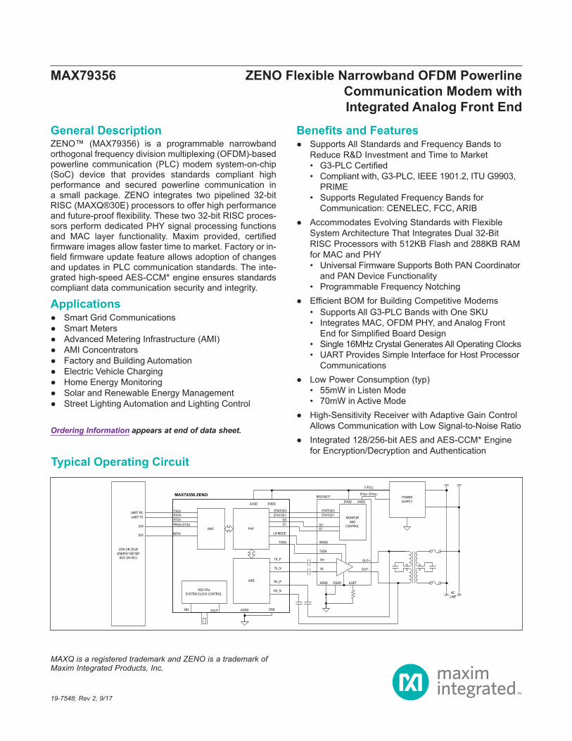
General DescriptionZENO™ (MAX79356) is a programmable narrowband orthogonal frequency division multiplexing (OFDM)-based powerline communication (PLC) modem system-on-chip (SoC) device that provides standards compliant high performance and secured powerline communication in a small package. ZENO integrates two pipelined 32-bit RISC (MAXQ®30E) processors to offer high performance and future-proof flexibility. These two 32-bit RISC proces-sors perform dedicated PHY signal processing functions and MAC layer functionality. Maxim provided, certified firmware images allow faster time to market. Factory or in-field firmware update feature allows adoption of changes and updates in PLC communication standards. The inte-grated high-speed AES-CCM* engine ensures standards compliant data communication security and integrity.
Applications Smart Grid Communications Smart Meters Advanced Metering Infrastructure (AMI) AMI Concentrators Factory and Building Automation Electric Vehicle Charging Home Energy Monitoring Solar and Renewable Energy Management Street Lighting Automation and Lighting Control
Benefits and Features Supports All Standards and Frequency Bands to
Reduce R&D Investment and Time to Market• G3-PLC Certified• Compliant with, G3-PLC, IEEE 1901.2, ITU G9903,
PRIME• Supports Regulated Frequency Bands for
Communication: CENELEC, FCC, ARIB Accommodates Evolving Standards with Flexible
System Architecture That Integrates Dual 32-Bit RISC Processors with 512KB Flash and 288KB RAM for MAC and PHY• Universal Firmware Supports Both PAN Coordinator
and PAN Device Functionality• Programmable Frequency Notching
Efficient BOM for Building Competitive Modems• Supports All G3-PLC Bands with One SKU• Integrates MAC, OFDM PHY, and Analog Front
End for Simplified Board Design• Single 16MHz Crystal Generates All Operating Clocks• UART Provides Simple Interface for Host Processor
Communications Low Power Consumption (typ)
• 55mW in Listen Mode• 70mW in Active Mode
High-Sensitivity Receiver with Adaptive Gain Control Allows Communication with Low Signal-to-Noise Ratio
Integrated 128/256-bit AES and AES-CCM* Engine for Encryption/Decryption and Authentication
Ordering Information appears at end of data sheet.
MAXQ is a registered trademark and ZENO is a trademark of Maxim Integrated Products, Inc.
19-7548; Rev 2; 9/17
MAX79356 ZENO Flexible Narrowband OFDM Powerline Communication Modem with Integrated Analog Front End
Typical Operating Circuit

(All voltages referenced to AGND_0, AGND_1.)Supplies and Ground PinsDVDD33_0, DVDD33_1, AVDD33 .......................-0.5V to +3.6VDVDD12, AVDD12 ................................................-0.5V to +1.7VDGND_0, DGND_1, DGND_2..............................-0.2V to +0.2VAnalog Output PinsDVDD12_REG......................................................-0.5V to +1.7VTX_N, TX_P ........................................ -0.5V to VAVDD33 + 0.5VAnalog Input PinsRX_N, RX_P........................................ -0.5V to VAVDD33 + 0.5VOscillator PinsXIN, XOUT...........................................-0.5V to VDVDD33 + 0.5V
Digital Output PinsTXD0, RTS0, READY, TXEN, LD MODE, G0, G1, MOSI, MOSI, SSEL, SCLK, COLLISION, ACTIVITY .........................................-0.5V to VDVDD33 + 0.5VDigital Input PinsRXD0, PROG/CTS0 , ZC1, ZC2, STATUS0, STATUS1, MISO, RSTN ..................-0.5V to VDVDD33 + 0.5VTemperatureOperating Junction Temperature (peak, 100ms) .............+140°COperating Junction Temperature (continuous) ................+125°CStorage Temperature Range ............................ -65°C to +150°CLead Temperature (soldering, 10s) .................................+300°CSoldering Temperature (reflow) .......................................+260°C
Junction-to-Ambient Thermal Resistance (θJA) ..............46°C/W Junction-to-Case Thermal Resistance (θJC) ...................10°C/W
(Note 1)
(Limits are production tested at TA = +25°C. Limits over the operating temperature range and relevant supply voltage range are guaranteed by design and characterization.)
PARAMETER SYMBOL CONDITIONS MIN TYP MAX UNITSOPERATING CONDITIONS
Digital Supply Voltage VDVDD33_0, VDVDD33_1
VAVDD33 = VDVDD33_0 = VDVDD33_1 (Note 2) 2.7 3.3 3.6 V
Analog Supply Voltage VAVDD33VAVDD33 = VDVDD33_0 = VDVDD33_1 (Note 2) 3.0 3.3 3.6 V
Operating Temperature -40 +85 °C
INTERNAL LOW DROPOUT (LDO) VOLTAGE REGULATOR
LDO Output Voltage VDVDD12_REG
VDVDD12_REG = VDVDD12 = VAVDD12, internal LDO enabled (Note 3) 1.18 1.20 1.22 V
SUPPLY MONITORS
VDD33 Fail Warning Voltage (Note 4) VDD33PFW 2.85 3.05 V
VDD33 Reset Voltage (Note 4) VDD33RST 2.8 3.0 V
VDD12 Fail Warning Voltage (Note 5) VDD12PFW 1.157 1.19 V
VDD12 Reset Voltage (Note 5) VDD12RST 1.127 1.16 V
MAX79356 ZENO Flexible Narrowband OFDM Powerline Communication Modem with Integrated Analog Front End
www.maximintegrated.com Maxim Integrated 2
Note 1: Package thermal resistances were obtained using the method described in JEDEC specification JESD51-7, using a four-layer board. For detailed information on package thermal considerations, refer to www.maximintegrated.com/thermal-tutorial.
Absolute Maximum Ratings
Stresses beyond those listed under “Absolute Maximum Ratings” may cause permanent damage to the device. These are stress ratings only, and functional operation of the device at these or any other conditions beyond those indicated in the operational sections of the specifications is not implied. Exposure to absolute maximum rating conditions for extended periods may affect device reliability.
Package Thermal Characteristics
Electrical Characteristics
(Limits are production tested at TA = +25°C. Limits over the operating temperature range and relevant supply voltage range are guaranteed by design and characterization.)
PARAMETER CONDITIONS MIN TYP MAX UNITSDIGITAL INPUT/OUTPUT
Input Low-Level Voltage VIL GND 0.29 x VDD33
V
Input High-Level Voltage VIH0.7 x
VDD33VDD33 V
Input Voltage Hysteresis VIHYS 300 mV
Input Leakage Current IL Internal pullup/down resistor disabled -1 +1 µA
Input Capacitance CIN 5 pF
Input Pullup Resistance RPU 50 100 180 kΩ
Input Pulldown Resistance RPD 50 100 180 kΩ
Output Low-Level Voltage VOLStandard drive, IOL = 2mA 0.4 V
High drive, IOL = 4mA 0.4 V
Output High-Level Voltage VOH
Standard drive, IOH = 2mA VDD33 - 0.5 V
High drive, IOH = 4mA VDD33 - 0.5 V
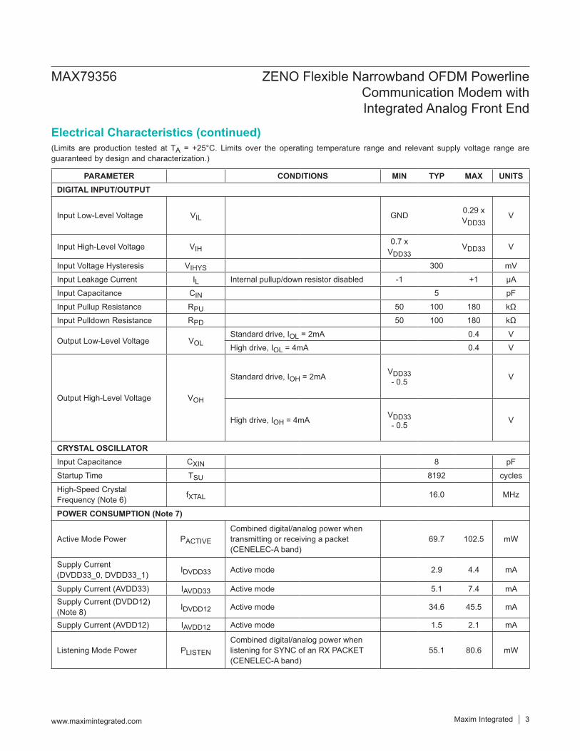
CRYSTAL OSCILLATORInput Capacitance CXIN 8 pF
Startup Time TSU 8192 cycles
High-Speed Crystal Frequency (Note 6) fXTAL 16.0 MHz
POWER CONSUMPTION (Note 7)
Active Mode Power PACTIVE
Combined digital/analog power when transmitting or receiving a packet (CENELEC-A band)
69.7 102.5 mW
Supply Current (DVDD33_0, DVDD33_1) IDVDD33 Active mode 2.9 4.4 mA
Supply Current (AVDD33) IAVDD33 Active mode 5.1 7.4 mASupply Current (DVDD12) (Note 8) IDVDD12 Active mode 34.6 45.5 mA
Supply Current (AVDD12) IAVDD12 Active mode 1.5 2.1 mA
Listening Mode Power PLISTEN
Combined digital/analog power when listening for SYNC of an RX PACKET (CENELEC-A band)
55.1 80.6 mW
MAX79356 ZENO Flexible Narrowband OFDM Powerline Communication Modem with Integrated Analog Front End
www.maximintegrated.com Maxim Integrated 3
Electrical Characteristics (continued)
(Limits are production tested at TA = +25°C. Limits over the operating temperature range and relevant supply voltage range are guaranteed by design and characterization.)
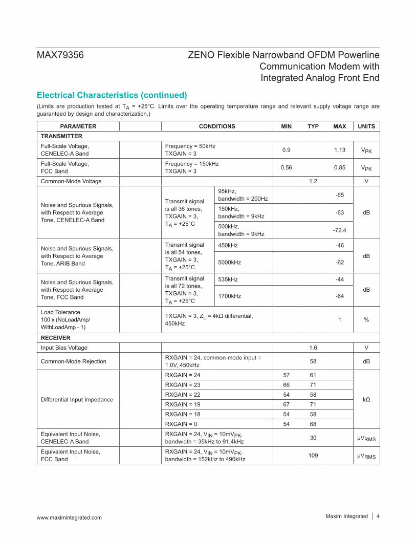
PARAMETER CONDITIONS MIN TYP MAX UNITSTRANSMITTERFull-Scale Voltage, CENELEC-A Band
Frequency = 50kHz TXGAIN = 3 0.9 1.13 VPK
Full-Scale Voltage, FCC Band
Frequency = 150kHz TXGAIN = 3 0.56 0.85 VPK
Common-Mode Voltage 1.2 V
Noise and Spurious Signals, with Respect to Average Tone, CENELEC-A Band
Transmit signal is all 36 tones, TXGAIN = 3, TA = +25°C
95kHz, bandwidth = 200Hz -65
dB150kHz, bandwidth = 9kHz -63
500kHz, bandwidth = 9kHz -72.4
Noise and Spurious Signals, with Respect to Average Tone, ARIB Band
Transmit signal is all 54 tones, TXGAIN = 3, TA = +25°C
450kHz -46
dB5000kHz -62
Noise and Spurious Signals, with Respect to Average Tone, FCC Band
Transmit signal is all 72 tones, TXGAIN = 3, TA = +25°C
535kHz -44
dB1700kHz -64
Load Tolerance 100 x (NoLoadAmp/ WithLoadAmp - 1)
TXGAIN = 3, ZL = 4kΩ differential, 450kHz 1 %
RECEIVERInput Bias Voltage 1.6 V
Common-Mode Rejection RXGAIN = 24, common-mode input = 1.0V, 450kHz 58 dB
Differential Input Impedance
RXGAIN = 24 57 61
kΩ
RXGAIN = 23 66 71
RXGAIN = 22 54 58
RXGAIN = 19 67 71
RXGAIN = 18 54 58
RXGAIN = 0 54 68
Equivalent Input Noise, CENELEC-A Band
RXGAIN = 24, VIN = 10mVPK, bandwidth = 35kHz to 91.4kHz 30 µVRMS
Equivalent Input Noise, FCC Band
RXGAIN = 24, VIN = 10mVPK, bandwidth = 152kHz to 490kHz 109 µVRMS
MAX79356 ZENO Flexible Narrowband OFDM Powerline Communication Modem with Integrated Analog Front End
www.maximintegrated.com Maxim Integrated 4
Electrical Characteristics (continued)
(Limits are production tested at TA = +25°C. Limits over the operating temperature range and relevant supply voltage range are guaranteed by design and characterization.)
Note 2: The AVDD33 DVDD33_0, DVDD33_1 supplies should be connected together at the board level. Appropriate decoupling should be used between the analog AVDD33 supply and the digital DVDD33_0 and DVDD33_1 supplies.
Note 3: The internal LDO voltage regulator should be enabled and the DVDD12_REG supply output should be connected to the AVDD12 and DVDD12 supply inputs at the board level. Appropriate decoupling should be used between the analog AVDD12 supply and the digital DVDD12 supply.
Note 4: VDD33 is referencing that AVDD33 DVDD33_0, and DVDD33_1 are connected together at the board level.Note 5: VDD12 is referencing that DVDD12_REG, DVDD12, and AVDD12 are connected together at the board level.Note 6: The high-speed crystal should have a calibration tolerance no greater than ±10ppm and a frequency stability better than
±15ppm. The maximum clock frequency deviation must be within ±25ppm.Note 7: All TYP power consumption specifications are based on nominally processed parts running at +25°C and powered with
TYP supply voltages.Note 8: The internal LDO voltage regulator should be enabled and the DVDD12_REG supply output should be connected to the
AVDD12 and DVDD12 supply inputs at the board level. Therefore, the current sunk by AVDD12 and DVDD12 is sourced by DVDD12_REG.
MAX79356 ZENO Flexible Narrowband OFDM Powerline Communication Modem with Integrated Analog Front End
www.maximintegrated.com Maxim Integrated 5
Electrical Characteristics (continued)
ZENO
MACMAXQ30E
PHYMAXQ30E
SHARED DATA RAM
224KB
FLASH MEMORY512KB
CACHE
CACHE
INTERPROCESSOR COMMUNICATION
SPI**
UART
I/O C
ONTR
OL
OFDM HARDWARE AFE
SHARED DATA RAM
64KB
AES-CCM*
SFR
SFR
TX_P
TX_N
UART TX0
PROG/CTS0
UART RX0RTS0
INSTRUCTION/DATA
INSTRUCTION/DATA
SYSTEM CLOCK CONTROL OSC + PLL
DATA
DATA
DATA
DATA
POWER MANAGEMENT
VOLTAGE MONITOR
RX_PRX_N
STATUS AND
CONTROL
UART TX1UART RX1
RSTN
STATUS[ 1:0]
GAIN[ 1:0]
TXEN
LD MODE
XOUTXIN
**THE USE OF SPI INTERFACE IS SUBJECT
TO MAX79356FIRMWARE SUPPORT
MAX79356 ZENO Flexible Narrowband OFDM Powerline Communication Modem with Integrated Analog Front End
www.maximintegrated.com Maxim Integrated 6
Block Diagram
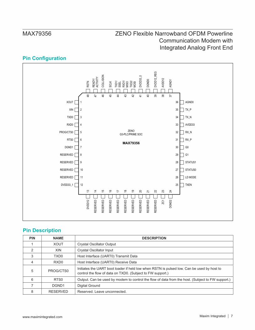
PIN NAME DESCRIPTION1 XOUT Crystal Oscillator Output
2 XIN Crystal Oscillator Input
3 TXD0 Host Interface (UART0) Transmit Data
4 RXD0 Host Interface (UART0) Receive Data
5 PROG/CTS0 Initiates the UART boot loader if held low when RSTN is pulsed low. Can be used by host to control the flow of data on TXD0. (Subject to FW support.)
6 RTS0 Output. Can be used by modem to control the flow of data from the host. (Subject to FW support.)
7 DGND1 Digital Ground
8 RESERVED Reserved. Leave unconnected.
XIN
TXD0
RXD0
PROG/CTS0
RTS0
DGND1
RESERVED
RESERVED
RESERVED
RESERVED
DVDD33_1
RSTN
READ
Y/AC
TIVI
TY
COLL
ISIO
N
SCLK
TXD1
/SS
ELRX
D1/
MISO
TXD 2
/MO
SI
DVDD
33_0
DGND
0
DVDD
12_R
EG
AVDD
12
AGND
1
G0
RX_P
TX_P
RX_N
TX_N
AVDD33
DVDD
12
RESE
RVED
RESE
RVED ZC
1
DGND
2
RESE
RVED
RESE
RVED
RESE
RVED
RESE
RVED
RESE
RVED
RESE
RVED
G1
STATUS1
STATUS0
LD MODE
TXEN
AGND01
2
3
4
5
6
7
8
9
10
11
12
13 14 15 16 17 18 19 20 21 22 23 24
36
35
34
33
32
31
30
29
28
27
26
25
48 47 46 45 44 43 42 41 40 39 38 37
ZENOG3-PLC/PRIME SOC
MAX79356
XOUT
RESE
RVED
MAX79356 ZENO Flexible Narrowband OFDM Powerline Communication Modem with Integrated Analog Front End
www.maximintegrated.com Maxim Integrated 7
Pin Configuration
Pin Description
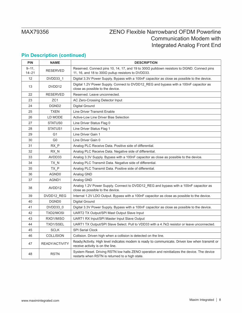
PIN NAME DESCRIPTION9–11, 14–21 RESERVED Reserved. Connect pins 10, 14, 17, and 19 to 300Ω pulldown resistors to DGND. Connect pins
11, 16, and 18 to 300Ω pullup resistors to DVDD33.
12 DVDD33_1 Digital 3.3V Power Supply. Bypass with a 100nF capacitor as close as possible to the device.
13 DVDD12 Digital 1.2V Power Supply. Connect to DVDD12_REG and bypass with a 100nF capacitor as close as possible to the device.
22 RESERVED Reserved. Leave unconnected.
23 ZC1 AC Zero-Crossing Detector Input
24 DGND2 Digital Ground
25 TXEN Line Driver Transmit Enable
26 LD MODE Active-Low Line Driver Bias Selection
27 STATUS0 Line Driver Status Flag 0
28 STATUS1 Line Driver Status Flag 1
29 G1 Line Driver Gain 1
30 G0 Line Driver Gain 0
31 RX_P Analog PLC Receive Data. Positive side of differential.
32 RX_N Analog PLC Receive Data. Negative side of differential.
33 AVDD33 Analog 3.3V Supply. Bypass with a 100nF capacitor as close as possible to the device.
34 TX_N Analog PLC Transmit Data. Negative side of differential.
35 TX_P Analog PLC Transmit Data. Positive side of differential.
36 AGND0 Analog GND
37 AGND1 Analog GND
38 AVDD12 Analog 1.2V Power Supply. Connect to DVDD12_REG and bypass with a 100nF capacitor as close as possible to the device.
39 DVDD12_REG Internal 1.2V LDO Output. Bypass with a 100nF capacitor as close as possible to the device.
40 DGND0 Digital Ground
41 DVDD33_0 Digital 3.3V Power Supply. Bypass with a 100nF capacitor as close as possible to the device.
42 TXD2/MOSI UART2 TX Output/SPI Mast Output Slave Input
43 RXD1/MISO UART1 RX Input/SPI Master Input Slave Output
44 TXD1/SSEL UART1 TX Output/SPI Slave Select. Pull to VDD33 with a 4.7kΩ resistor or leave unconnected.
45 SCLK SPI Serial Clock
46 COLLISION Collision. Driven high when a collision is detected on the line.
47 READY/ACTIVITY Ready/Activity. High level indicates modem is ready to communicate. Driven low when transmit or receive activity is on the line.
48 RSTN System Reset. Driving RSTN low halts ZENO operation and reinitializes the device. The device restarts when RSTN is returned to a high state.
MAX79356 ZENO Flexible Narrowband OFDM Powerline Communication Modem with Integrated Analog Front End
www.maximintegrated.com Maxim Integrated 8
Pin Description (continued)
Detailed DescriptionBaseband PHY OverviewZENO is designed to overcome the challenges associated with the harsh powerline environment for data communi-cations. Some of the challenges are noted below:
Channel variability with frequency, location, and time
Narrowband, wideband, and impulse noise and multipath signal propagation commonly present on the power line
Low and time varying network impedance Propagation through transformers that makes the
channel subject to severe group delay and attenuation
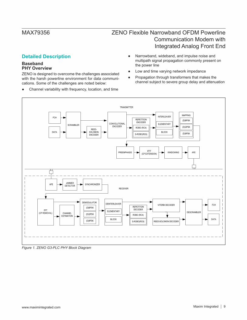
Figure 1. ZENO G3-PLC PHY Block Diagram
FCH
DATAREED-
SOLOMON ENCODER
REPETITION ENCODER
INTERLEAVER
ELEMENTARY
BLOCK
PREEMPHASIS IFFT(CP EXTENSION) WINDOWING AFE
ROBO (RC4)
S-ROBO(RC6)
AFE JAMMER DETECTOR SYNCHRONIZER
DEMODULATOR
(D)BPSK
(D)QPSK
(D)8PSK
REPETITION DECODER
ROBO (RC4)
S-ROBO(RC6) REED-SOLOMON DECODER
DEINTERLEAVER
ELEMENTARY
BLOCK
FCH
DATA
RECEIVER
MAPPING
(D)BPSK
(D)QPSK
(D)8PSK
TRANSMITTER
VITERBI DECODER
SCRAMBLER CONVOLUTIONALENCODER
DESCRAMBLERFFT
(CP REMOVAL) CHANNEL ESTIMATION
MAX79356 ZENO Flexible Narrowband OFDM Powerline Communication Modem with Integrated Analog Front End
www.maximintegrated.com Maxim Integrated 9
ZENO is based on orthogonal frequency division mul-tiplexing (OFDM) to overcome the powerline channel impairment, providing high reliability in data transmission and reception. This method combines spectral efficiency with the flexibility of bandwidth allocation. In combination with error correction coding, ZENO is robust in the pres-ence of frequency selective channels and resilient to jam-mer signals and impulsive noise.The OFDM technique places evenly spaced carriers into the available frequency band. ZENO can be configured to operate in a subset of frequencies in the range 10kHz to 490kHz, encompassing CENELEC, FCC, and ARIB frequency bands. The modulation methods supported in differential mode are DBPSK, DQPSK, and D8PSK, and in coherent mode are BPSK, QPSK, and 8PSK. This allows ZENO to trade off channel condition and data rate to achieve the highest efficiency as the channels vary. Additional performance is obtained by adaptive tone map-ping, a process by which ZENO automatically detects carriers with poor SNR and redistribute data to carriers with good SNR.There are several advantages of ZENO OFDM scheme as compared to traditional single carrier FSK or spread-spectrum systems.ZENO OFDM PHY allows flexible allocation and use of a given channel bandwidth. As an example, the lower and the upper limit of the used frequency band can easily be
configured. It is also possible to use any number of sub bands (either contiguous or noncontiguous) for the trans-mission of a single data stream.It is considerably more robust against intersymbol interfer-ence (ISI) or group delay distortion caused by the trans-mission channel than narrowband systems. This is mainly due to the fact that the parallel transmission on multiple carriers leads to longer symbol duration. Furthermore, ISI is simply removed by inserting cyclic prefixes between the symbols.ZENO is robust in presence of narrowband interference because such jammers typically destroy a single carrier only. Through the use of forward error correction (FEC) coding, the erroneous data is detected and corrected using the received coded information.On the transmitter side of ZENO, data passes through scrambler, FEC encoder (Reed-Solomon encoder, con-volutional encoder, and repetition encoder), interleaver, mapping, IFFT with CP extension, windowing, and AFE. On the receiver side of ZENO, digital signal processing blocks accept signals from the AFE, process them, and pass the results to the upper layer. The jammer detector is dedicated to detection and cancellation of narrow band interference. The channel estimator provides critical infor-mation such as the link quality and the channel response.Table 1 shows the frequency bands with which ZENO complies.
Table 1. Supported Frequency BandsBAND NUMBER OF CARRIERS FIRST CARRIER (kHz) LAST CARRIER (kHz)
CENELEC A 36 35.9375 90.625
CENELEC B 16 98.4375 121.875
FCC 72 154.6875 487.5
ARIB 54 154.6875 403.125
MAX79356 ZENO Flexible Narrowband OFDM Powerline Communication Modem with Integrated Analog Front End
www.maximintegrated.com Maxim Integrated 10
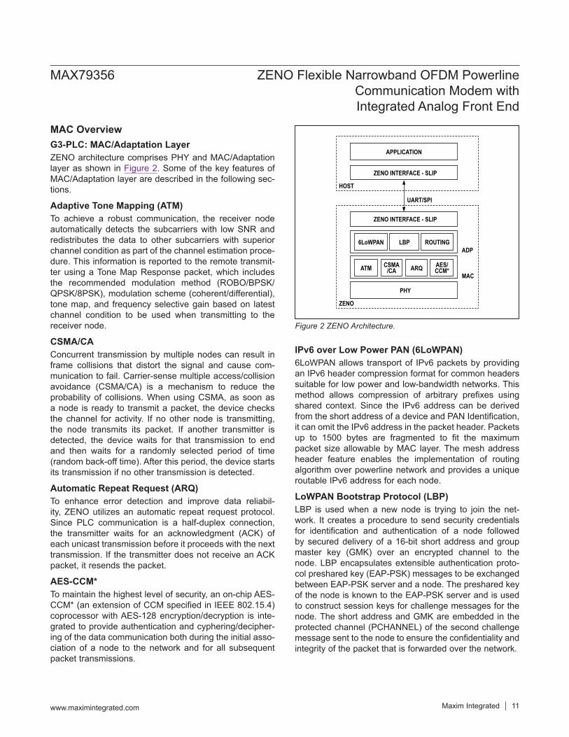
MAC OverviewG3-PLC: MAC/Adaptation LayerZENO architecture comprises PHY and MAC/Adaptation layer as shown in Figure 2. Some of the key features of MAC/Adaptation layer are described in the following sec-tions.
Adaptive Tone Mapping (ATM)To achieve a robust communication, the receiver node automatically detects the subcarriers with low SNR and redistributes the data to other subcarriers with superior channel condition as part of the channel estimation proce-dure. This information is reported to the remote transmit-ter using a Tone Map Response packet, which includes the recommended modulation method (ROBO/BPSK/QPSK/8PSK), modulation scheme (coherent/differential), tone map, and frequency selective gain based on latest channel condition to be used when transmitting to the receiver node.
CSMA/CAConcurrent transmission by multiple nodes can result in frame collisions that distort the signal and cause com-munication to fail. Carrier-sense multiple access/collision avoidance (CSMA/CA) is a mechanism to reduce the probability of collisions. When using CSMA, as soon as a node is ready to transmit a packet, the device checks the channel for activity. If no other node is transmitting, the node transmits its packet. If another transmitter is detected, the device waits for that transmission to end and then waits for a randomly selected period of time (random back-off time). After this period, the device starts its transmission if no other transmission is detected.
Automatic Repeat Request (ARQ)To enhance error detection and improve data reliabil-ity, ZENO utilizes an automatic repeat request protocol. Since PLC communication is a half-duplex connection, the transmitter waits for an acknowledgment (ACK) of each unicast transmission before it proceeds with the next transmission. If the transmitter does not receive an ACK packet, it resends the packet.
AES-CCM*To maintain the highest level of security, an on-chip AES-CCM* (an extension of CCM specified in IEEE 802.15.4) coprocessor with AES-128 encryption/decryption is inte-grated to provide authentication and cyphering/decipher-ing of the data communication both during the initial asso-ciation of a node to the network and for all subsequent packet transmissions.
IPv6 over Low Power PAN (6LoWPAN)6LoWPAN allows transport of IPv6 packets by providing an IPv6 header compression format for common headers suitable for low power and low-bandwidth networks. This method allows compression of arbitrary prefixes using shared context. Since the IPv6 address can be derived from the short address of a device and PAN Identification, it can omit the IPv6 address in the packet header. Packets up to 1500 bytes are fragmented to fit the maximum packet size allowable by MAC layer. The mesh address header feature enables the implementation of routing algorithm over powerline network and provides a unique routable IPv6 address for each node.
LoWPAN Bootstrap Protocol (LBP)LBP is used when a new node is trying to join the net-work. It creates a procedure to send security credentials for identification and authentication of a node followed by secured delivery of a 16-bit short address and group master key (GMK) over an encrypted channel to the node. LBP encapsulates extensible authentication proto-col preshared key (EAP-PSK) messages to be exchanged between EAP-PSK server and a node. The preshared key of the node is known to the EAP-PSK server and is used to construct session keys for challenge messages for the node. The short address and GMK are embedded in the protected channel (PCHANNEL) of the second challenge message sent to the node to ensure the confidentiality and integrity of the packet that is forwarded over the network.
Figure 2 ZENO Architecture.
APPLICATION
ZENO INTERFACE - SLIP
UART/SPI
ZENO INTERFACE - SLIP
6LoWPAN LBP ROUTING
ATM CSMA/CA ARQ AES/
CCM*
PHY
ADP
MAC
ZENO
HOST
MAX79356 ZENO Flexible Narrowband OFDM Powerline Communication Modem with Integrated Analog Front End
www.maximintegrated.com Maxim Integrated 11
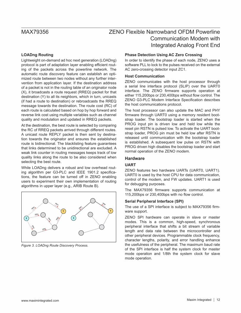
LOADng RoutingLightweight on-demand ad hoc next generation (LOADng) protocol is part of adaptation layer enabling efficient rout-ing of the packets across the powerline network. The automatic route discovery feature can establish an opti-mized route between two nodes without any further inter-vention from application layer. If the destination address of a packet is not in the routing table of an originator node (X), it broadcasts a route request (RREQ) packet for that destination (Y) to all its neighbors, which in turn, unicasts (if had a route to destination) or rebroadcasts the RREQ message towards the destination. The route cost (RC) of each route is calculated based on hop by hop forward and reverse link cost using multiple variables such as channel quality and modulation and updated in RREQ packets.At the destination, the best route is selected by comparing the RC of RREQ packets arrived through different routes. A unicast route REPLY packet is then sent by destina-tion towards the originator and ensures the established route is bidirectional. The blacklisting feature guarantees that links determined to be unidirectional are excluded. A weak link counter in routing messages keeps track of low quality links along the route to be also considered when selecting the best route.While LOADng delivers a robust and low overhead rout-ing algorithm per G3-PLC and IEEE 1901.2 specifica-tions, the feature can be turned off in ZENO enabling users to experiment their own implementation of routing algorithms in upper layer (e.g., ARIB Route B).
Phase Detection Using AC Zero CrossingIn order to identify the phase of each node, ZENO uses a software PLL to lock to the pulses received on the external AC zero-crossing detector input ZC1.
Host CommunicationZENO communicates with the host processor through a serial line interface protocol (SLIP) over the UART0 interface. The ZENO firmware supports operation at either 115,200bps or 230,400bps without flow control. The ZENO G3-PLC Modem Interface Specification describes the host communications protocol.The host processor can also update the MAC and PHY firmware through UART0 using a memory resident boot-strap loader. The bootstrap loader is started when the PROG input pin is driven low and held low while the reset pin RSTN is pulsed low. To activate the UART boot-strap loader, PROG pin must be held low after RSTN is released until communication with the bootstrap loader is established. A subsequent low pulse on RSTN with PROG driven high disables the bootstrap loader and start normal operation of the ZENO modem.
HardwareUARTZENO features two hardware UARTs (UART0, UART1). UART0 is used by the host CPU for data communication, control of the modem, and FW updates. UART1 is used for debugging purposes.The MAX79356 firmware supports communication at 115,200bps or 230,400bps with no flow control.
Serial Peripheral Interface (SPI)The use of a SPI interface is subject to MAX79356 firm-ware support.ZENO SPI hardware can operate in slave or master modes. This is a common, high-speed, synchronous peripheral interface that shifts a bit stream of variable length and data rate between the microcontroller and other peripheral devices. Programmable clock frequency, character lengths, polarity, and error handling enhance the usefulness of the peripheral. The maximum baud rate of the SPI interface is half the system clock for master mode operation and 1/8th the system clock for slave mode operation.
Figure 3. LOADng Route Discovery Process.
MAX79356 ZENO Flexible Narrowband OFDM Powerline Communication Modem with Integrated Analog Front End
www.maximintegrated.com Maxim Integrated 12
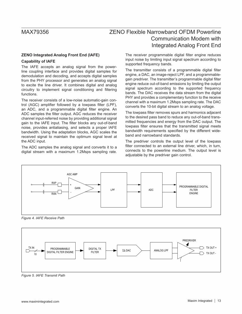
ZENO Integrated Analog Front End (IAFE)Capability of IAFEThe IAFE accepts an analog signal from the power-line coupling interface and provides digital samples for demodulation and decoding, and accepts digital samples from the PHY processor and generates an analog signal to excite the line driver. It combines digital and analog circuitry to implement signal conditioning and filtering functions.The receiver consists of a low-noise automatic-gain con-trol (AGC) amplifier followed by a lowpass filter (LPF), an ADC, and a programmable digital filter engine. An ADC samples the filter output. AGC reduces the receiver channel input-referred noise by providing additional signal gain to the IAFE input. The filter blocks any out-of-band noise, provides antialiasing, and selects a proper IAFE bandwidth. Using the adaptation blocks, AGC scales the received signal to maintain the optimum signal level at the ADC input.The ADC samples the analog signal and converts it to a digital stream with a maximum 1.2Msps sampling rate.
The receiver programmable digital filter engine reduces input noise by limiting input signal spectrum according to supported frequency bands.The transmitter consists of a programmable digital filter engine, a DAC, an image-reject LPF, and a programmable-gain predriver. The transmitter’s programmable digital filter engine reduce out-of-band emissions by limiting the output signal spectrum according to the supported frequency bands. The DAC receives the data stream from the digital PHY and provides a complementary function to the receive channel with a maximum 1.2Msps sampling rate. The DAC converts the 10-bit digital stream to an analog voltage. The lowpass filter removes spurs and harmonics adjacent to the desired pass band to reduce any out-of-band trans-mitted frequencies and energy from the DAC output. The lowpass filter ensures that the transmitted signal meets bandwidth requirements specified by the different wide-band and narrowband standards. The predriver controls the output level of the lowpass filter connected to an external line driver, which, in turn, connects to the powerline medium. The output level is adjustable by the predriver gain control.
Figure 4. IAFE Receive Path
Figure 5. IAFE Transmit Path
RXP
RXN
+
-LPF
AGC AMP
GAIN ADCPROGRAMMABLE DIGITAL
FILTER ENGINE
DIGITAL TX FILTER ΣΔ DAC ANALOG LPF
PREDRIVER
TX OUT +
TX OUT -10
TX IN PROGRAMMABLEDIGITAL FILTER ENGINE
MAX79356 ZENO Flexible Narrowband OFDM Powerline Communication Modem with Integrated Analog Front End
www.maximintegrated.com Maxim Integrated 13
Power ManagementZENO’s power management feature reduces power con-sumption by automatically clock gating and providing a means for the firmware to optimize the clock frequency. Clock gating is automatically applied to functional hard-ware blocks when not in use.ZENO operates in two power modes: designated active and listening.Active mode: It is defined as the mode when the ZENO modem is either in active transmit or active receive. In active mode the baseband and the analog front end (AFE) are working at a high level of activity. In active mode all the hardware modules might not be working at the same time, which allows automatic clock gating features to reduce power. Listening mode: When ZENO is not in active mode, it is in listening mode. Most of the baseband hardware is turned off in this mode. Only the AFE and a small section of the baseband hardware dedicated to packet detection is on at this point. ZENO transitions to active mode when it detects the start of a packet on the line.
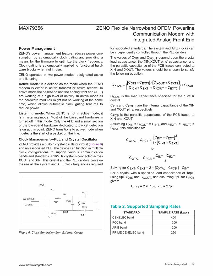
Clock Management—PLL and Crystal OscillatorZENO provides a built-in crystal oscillator circuit (Figure 6) and an associated PLL. The device can function in multiple clock configurations to support various communication bands and standards. A 16MHz crystal is connected across XOUT and XIN. This crystal and the PLL dividers can syn-thesize all the system and AFE clock frequencies required
for supported standards. The system and AFE clocks can be independently controlled through the PLL dividers. The values of CXIN and CXOUT depend upon the crystal load capacitance, the XIN/XOUT pins’ capacitance, and the parasitic capacitance of the PCB traces connected to XIN and XOUT. The values should be chosen to satisfy the following equation:
[ ]XIN EXT1 XOUT EXT2XTAL PCB
XIN EXT1 XOUT EXT2
C C C CC C
C C C C + × + = +
+ + +
CXTAL is the load capacitance specified for the 16MHz crystalCXIN and CXOUT are the internal capacitance of the XIN and XOUT pins, respectivelyCPCB is the parasitic capacitance of the PCB traces to XIN and XOUTAssuming CXIN = CXOUT = CINT, and CEXT1 = CEXT2 = CEXT, this simplifies to:
[ ][ ]
2INT EXT
XTAL PCBINT EXT
C CC C
2 C C+
− =× +
or
INT EXTXTAL PCB
C CC C2+
− =
Solving for CEXT, CEXT = 2 × [CXTAL - CPCB ] - CINTFor a crystal with a specified load capacitance of 18pF, using 9pF CXIN and CXOUT, and assuming 3pF for CPCB gives:
CEXT = 2 × [18-3] - 3 = 27pF
Figure 6. Clock Generation from External Crystal
Table 2. Supported Sampling RatesSTANDARD SAMPLE RATE (ksps)
CENELEC band 400
FCC band 1200
ARIB band 1200
PRIME CENELEC band 250
ZENO
1MΩ CEXT2
CEXT1
16MHz
XIN
XOUTGND
PLL
SYSTEM CLK
IAFE CLK
CXIN
CXOUT
MAX79356 ZENO Flexible Narrowband OFDM Powerline Communication Modem with Integrated Analog Front End
www.maximintegrated.com Maxim Integrated 14
System ResetZENO can be reset by asserting the RSTN pin low, by the power supply voltage monitor, or by a software command.
External ResetDuring normal operation, ZENO can be placed into external reset mode by holding the RSTN pin low for a minimum of eight clock cycles. After the RSTN pin returns high, the MAXQ30E processors exit the reset state within eight clock cycles and begin program execution.
Voltage Monitor ResetA system reset is generated if any of the supply voltages falls below the power fail reset voltages (VDD12RST VDD33RST).
Software ResetThe modem firmware can initiate a reset in response to a command from the host processor.
**The CXIN and CXOUT values depend on the crystal used and the PCB trace capacitance and must be determined at PCB design time.
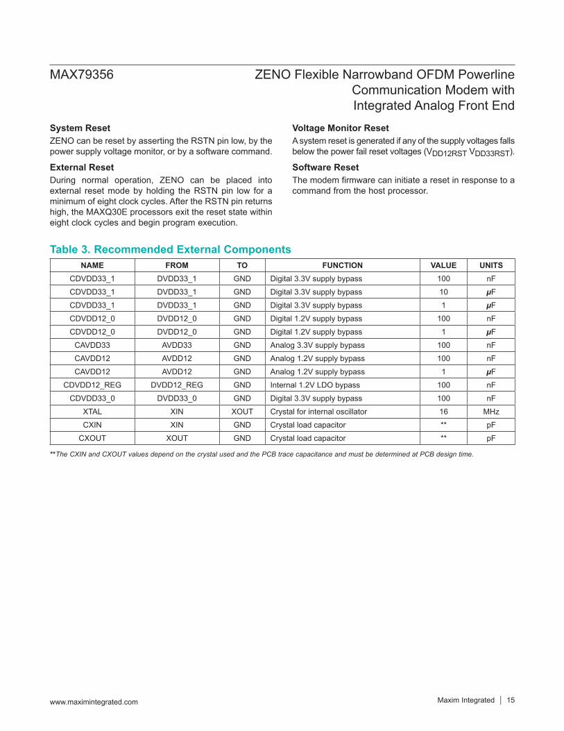
Table 3. Recommended External ComponentsNAME FROM TO FUNCTION VALUE UNITS
CDVDD33_1 DVDD33_1 GND Digital 3.3V supply bypass 100 nF
CDVDD33_1 DVDD33_1 GND Digital 3.3V supply bypass 10 µF
CDVDD33_1 DVDD33_1 GND Digital 3.3V supply bypass 1 µF
CDVDD12_0 DVDD12_0 GND Digital 1.2V supply bypass 100 nF
CDVDD12_0 DVDD12_0 GND Digital 1.2V supply bypass 1 µF
CAVDD33 AVDD33 GND Analog 3.3V supply bypass 100 nF
CAVDD12 AVDD12 GND Analog 1.2V supply bypass 100 nF
CAVDD12 AVDD12 GND Analog 1.2V supply bypass 1 µF
CDVDD12_REG DVDD12_REG GND Internal 1.2V LDO bypass 100 nF
CDVDD33_0 DVDD33_0 GND Digital 3.3V supply bypass 100 nF
XTAL XIN XOUT Crystal for internal oscillator 16 MHz
CXIN XIN GND Crystal load capacitor ** pF
CXOUT XOUT GND Crystal load capacitor ** pF
MAX79356 ZENO Flexible Narrowband OFDM Powerline Communication Modem with Integrated Analog Front End
www.maximintegrated.com Maxim Integrated 15
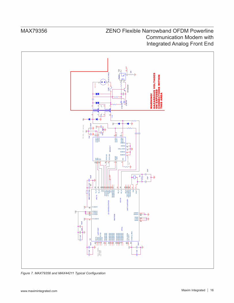
Figure 7. MAX79356 and MAX44211 Typical Configuration
Host
: RE
SET,
PRO
GRAM
an
d UA
RT
9V-1
8V,
15V
nomi
nal
Curr
ent
Limi
t S
et
LINE
WA
RN
ING
!H
AZ
AR
DO
US
VO
LT
AG
ES
ON
EX
PO
SE
DC
ON
NE
CT
ION
S W
ITH
INT
HIS
AR
EA
NEUT
RAL
3.3V
1.2V
1.2V
1.2V
3.3V
3.3V
15V
15V
15V
20K
D1N
4148.
.
1.0u
F
FUSE
..
100n
F10
0nF
..
1.0u
F
..
10uF
1.0u
F25
V10
0nF
100n
F
27pF
MAX
4421
1
MO
DE
1
TXEN
2
Iset
3
AGND04
AGND15O
UTN
06
OU
TN1
7
AGND28
OU
TP0
9
OU
TP1
10
AVD
D0
11AV
DD
112
DVD
D13
G0
14
G1
15
STAT
US1
16
STAT
US0
17
DGND18
INP
19
INN
20
HEAT PAD21
10uF
D1N
4148
..
UAR
T H
OST
UAR
T1/U
ART2
/SPIAF
E TX
AFE
RX
LD C
ON
TRO
L/ST
ATU
S
GPI
Os
U9
MAX
7935
6
XOU
T1
RST
N48
TXD
03
RXD
04
PRO
G/C
TS0
5
RTS
06
GND.17
RES
ERVE
D8
RES
ERVE
D9
RES
ERVE
D10
DVDD12.013
RES
ERVE
D14
RES
ERVE
D15
RES
ERVE
D16
RES
ERVE
D11
VDD33.112
RES
ERVE
D17
RES
ERVE
D18
RES
ERVE
D19
RES
ERVE
D20
RES
ERVE
D21
RES
ERVE
D22
ZC1
23
GND224
TXEN
25LD
MO
DE
26ST
ATU
S027
STAT
US1
28G
129
G0
30
RX_
P31
RX_
N32
AVDD3333
TX_N
34TX
_P35
AGND036
AGND137
AVDD1238
DVD
D12
_REG
39
GND040
VDD33.041
TXD
2/M
OSI
42R
XD1/
MIS
O43
TXD
1/SS
EL44
SCLK
45
CO
LLIS
ION
46
ACTI
VITY
47
XIN
2
1.3:
21
10
29
456 7
38
PLU
G A
C M
ALE
12
..
100n
F
100n
F1.
0uF
PS25
011 2
3
4
1M
MM
Z160
8Y15
2B
27pF
PZT3
904/
INF
10uF
ZC_D
ET
ZC_D
ET
MAX79356 ZENO Flexible Narrowband OFDM Powerline Communication Modem with Integrated Analog Front End
www.maximintegrated.com Maxim Integrated 16
+Denotes a lead(Pb)-free/RoHS-compliant package.
PART TEMP RANGE PIN-PACKAGEMAX79356ECM+ -40°C to +85°C 48 LQFP
PACKAGE TYPE
PACKAGE CODE
OUTLINE NO.
LAND PATTERN NO.
48 LQFP C48+2 21-0054 90-0093
MAX79356 ZENO Flexible Narrowband OFDM Powerline Communication Modem with Integrated Analog Front End
www.maximintegrated.com Maxim Integrated 17
Ordering Information Package InformationFor the latest package outline information and land patterns (footprints), go to www.maximintegrated.com/packages. Note that a “+”, “#”, or “-” in the package code indicates RoHS status only. Package drawings may show a different suffix character, but the drawing pertains to the package regardless of RoHS status.
REVISION NUMBER
REVISION DATE DESCRIPTION PAGES CHANGED
0 3/15 Initial release —
1 3/16
Updated Benefits and Features, Typical Operating Circuit, Electrical Characteristics, Block Diagram, Pin Configuration, Pin Description, Automatic Repeat Requestor (ARQ), IPv6 over Low Power PAN (6LoWPAN), Phase Detection Using AC Zero Crossing, UART, Serial Peripheral Interface (SPI), ZENO Integrated Analog Front End (IAFE), Figure 4 caption, Figure 5 caption, Voltage Monitor Reset, Table 3, and Figure 7
1, 3, 6–8, 11–13, 15, 16
2 9/17 Updated Typical Operating Circuit, Electrical Characteristics and Pin Description tables, and Figure 7 1, 4, 8, 16
Maxim Integrated cannot assume responsibility for use of any circuitry other than circuitry entirely embodied in a Maxim Integrated product. No circuit patent licenses are implied. Maxim Integrated reserves the right to change the circuitry and specifications without notice at any time. The parametric values (min and max limits) shown in the Electrical Characteristics table are guaranteed. Other parametric values quoted in this data sheet are provided for guidance.
Maxim Integrated and the Maxim Integrated logo are trademarks of Maxim Integrated Products, Inc.
MAX79356 ZENO Flexible Narrowband OFDM Powerline Communication Modem with Integrated Analog Front End
© 2017 Maxim Integrated Products, Inc. 18
Revision History
For pricing, delivery, and ordering information, please contact Maxim Direct at 1-888-629-4642, or visit Maxim Integrated’s website at www.maximintegrated.com.
Related Documents