AASHTO Type IV - LRFD Specifications Detailed Design Examples - 1 A.2 AASHTO Type IV, LRFD Specifications A.2.1 INTRODUCTION A.2.2 DESIGN PARAMETERS Detailed example showing sample calculations for design of typical Interior AASHTO Type–IV prestressed concrete Beam supporting single span bridge. The design is based on AASHTO LRFD Bridge Design Specifications 3 rd Edition 2004. The bridge considered for design has a span length of 110 ft. (c/c pier distance) with no skew and a total width of 46 ft. The bridge superstructure consists of 6 AASHTO Type IV beams spaced 8 ft. center to center designed to act compositely with 8 in. thick cast in place concrete deck as shown in figure A.2.2.1. The wearing surface thickness is 1.5 in. which includes the thickness of any future wearing surface. T501 type rails are considered in the design. HL-93 is the design live load. The relative humidity of 60% is considered in the design. The bridge cross section is shown in fig A.2.2.1. 1.5" 8.0" 3' 1'-5.0" 3' 5 SPACES @ 8'-0" c/c = 40'-0" 43'-2.0" 46' Figure A.2.2.1 Bridge Cross Section A.2.3 MATERIAL PROPERTIES Cast in place slab: Thickness t s = 8.0 in. Concrete Strength at 28-days, f c ’ = 4,000 psi Thickness of asphalt wearing surface (including any future wearing surfaces), t w = 1.5 in. Unit weight of concrete = 150 pcf Precast beams: AASHTO Type- IV Concrete Strength at release, f’ ci = 4000 psi (This value is taken as initial guess and will be finalized based on most optimum design) Concrete Strength at 28 days, f’ c = 5000 psi (This value is taken as initial guess and will be finalized based on most optimum design) Concrete unit weight = 150 pcf

Welcome message from author
This document is posted to help you gain knowledge. Please leave a comment to let me know what you think about it! Share it to your friends and learn new things together.
Transcript
AASHTO Type IV - LRFD Specifications
Detailed Design Examples - 1
A.2 AASHTO Type IV, LRFD Specifications
A.2.1
INTRODUCTION
A.2.2 DESIGN
PARAMETERS
Detailed example showing sample calculations for design of typical Interior AASHTO Type–IV prestressed concrete Beam supporting single span bridge. The design is based on AASHTO LRFD Bridge Design Specifications 3rd Edition 2004.
The bridge considered for design has a span length of 110 ft. (c/c pier distance) with no skew and a total width of 46 ft. The bridge superstructure consists of 6 AASHTO Type IV beams spaced 8 ft. center to center designed to act compositely with 8 in. thick cast in place concrete deck as shown in figure A.2.2.1. The wearing surface thickness is 1.5 in. which includes the thickness of any future wearing surface. T501 type rails are considered in the design. HL-93 is the design live load. The relative humidity of 60% is considered in the design. The bridge cross section is shown in fig A.2.2.1.
1.5"
8.0"
3'
1'-5.0"
3' 5 SPACES @ 8'-0" c/c = 40'-0"
43'-2.0"
46'
Figure A.2.2.1 Bridge Cross Section
A.2.3 MATERIAL
PROPERTIES
Cast in place slab: Thickness ts = 8.0 in.
Concrete Strength at 28-days, fc’ = 4,000 psi
Thickness of asphalt wearing surface (including any future wearing
surfaces), tw = 1.5 in.
Unit weight of concrete = 150 pcf
Precast beams: AASHTO Type- IV
Concrete Strength at release, f’ci = 4000 psi (This value is taken as initial
guess and will be finalized based on most optimum design)
Concrete Strength at 28 days, f’c = 5000 psi (This value is taken as initial
guess and will be finalized based on most optimum design)
Concrete unit weight = 150 pcf
AASHTO Type IV - LRFD Specifications
Detailed Design Examples - 2
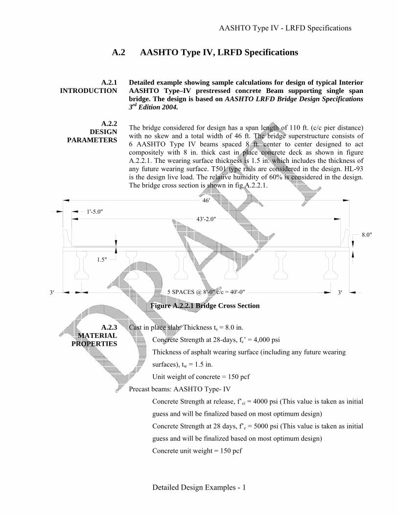
Fig A.2.3.1 Beam end Details
(Adapted from TxDOT Standard drawing ibebste1)
Span Length (c/c Piers) = 110’-0”
From fig. A.2.3.1
Overall beam length = 110’ – 2(2”) = 109’-8”
Design Span = 110’ – 2(8.5”) = 108’-7” = 108.583’(c/c of bearing)
Pretensioning Strands: ½ in. diameter, seven wire low relaxation
Area of one strand = 0.153 in.2
Ultimate Stress, fpu = 270,000 psi
Yield Strength, fpy = 0.9fpu = 243,000 psi [LRFD Table 5.4.4.1-1]
Stress limits for prestressing strands: [LRFD Table 5.9.3-1]
before transfer, fpi ≤ 0.75 fpu = 202,500 psi
at service limit state(after all losses) fpe ≤ 0.80 fpy = 194,400 psi
Modulus of Elasticity, Ep = 28,500 ksi [LRFD Art. 5.4.4.2]
Non Prestressed Reinforcement:
Yield Strength, fy = 60,000 psi
Modulus of Elasticity, Es = 29,000 ksi [LRFD Art. 5.4.3.2]
Unit weight of asphalt wearing surface = 140 pcf
T501 type barrier weight = 326 plf /side

AASHTO Type IV - LRFD Specifications
Detailed Design Examples - 3
A.2.4 CROSS-SECTION
PROPERTIES FOR A TYPICAL INTERIOR
BEAM A.2.4.1
Non-Composite Section
Figure A.2.4.1 Section Geometry of Figure A.2.4.2 Strand Pattern for AASHTO Type – IV Beams AASHTO Type – IV Beams (Adapted from TxDOT 2001) (Adapted from TxDOT 2001)
Table A.2.4.1 Section Properties of AASHTO Type IV beam (notations as used in Figure A.2.4.1, Adapted from TxDOT Bridge Design Manual)
A B C D E F G H W yt yb Area I Wt/lf
in. in. in. in. in. in. in. in. in. in. in. in.2 in.4 lbs
20.00 26.00 8.00 54.00 9.00 23.00 6.00 8.00 8.00 29.25 24.75 788.40 260,403.00 821.00
where I = moment of inertia about the centroid of the non-composite Precast beam
yb = distance from centroid to the extreme bottom fiber of the non-composite
precast beam
yt = distance from centroid to the extreme top fiber of the non-composite
precast beam
Sb = section modulus for the extreme bottom fiber of the non-composite
precast beam = I/yb = 260403.00/24.75 = 10521.33 in.3
St = section modulus for the extreme top fiber of the non-composite
precast beam = I/yt = 260403.00/29.25 = 8902.67 in.3

AASHTO Type IV - LRFD Specifications
Detailed Design Examples - 4
A.2.4.2 Composite Section
A.2.4.2.1 Effective Flange Width
A.2.4.2.2 Modular Ratio between Slab and Beam Material
A.2.4.2.3 Transformed Section
Properties [LRFD ]
The effective flange width is lesser of: [LRFD Art. 4.6.2.6.1]
1/4 span length: 108.583(12 in./ft)
4 = 325.75 in.
Distance center to center of beams: 8(12 in./ft) = 96.00 in. (controls)
12(Effective slab thickness) + greater of web thickness or ½ beam top flange
width: 12(8.0) + 1/2(20.0) = 106.00 in.
Effective flange width = 96.00 in.
Following the TxDOT Design manual recommendation (Pg. #7-85) the modular
ratio between slab and beam materials is taken as 1
n = c
c
E for slabE for beam
⎛ ⎞⎜ ⎟⎝ ⎠
= 1
Transformed flange width = n (effective flange width) = 1(96) = 96.0 in.
Transformed Flange Area = n (effective flange width) (ts) = 1(96) (8) = 768.0 in.2
Table A.2.4.2 Properties of Composite Section
Transformed Area
in.2 yb in.
A yb in.
A(ybc - yb)2
I
in4 I+A(ybc- yb)2
in4
Beam 788.40 24.75 19512.90 212231.53 260403.00 472634.53
Slab 768.00 58.00 44544.00 217868.93 4096.00 221964.93
∑ 1556.40 64056.90 694599.46
Ac = total area of composite section = 1556.4 in.2
hc = total height of composite section = 62.0 in.
Ic = moment of inertia of composite section = 694599.5 in4
ybc = distance from the centroid of the composite section to extreme bottom fiber
of the precast beam = 64056.9/1556.4 = 41.157 in.
ytg = distance from the centroid of the composite section to extreme top fiber of
the precast beam = 54 - 41.157 = 12.843 in.
ytc = distance from the centroid of the composite section to extreme top fiber of
the slab = 62 - 41.157 = 20.843 in.

AASHTO Type IV - LRFD Specifications
Detailed Design Examples - 5
A.2.5 SHEAR FORCES
AND BENDING MOMENTS
A.2.5.1 Shear Forces and
Bending Moments due to Dead Loads
A.2.5.1.1 Dead Loads
Sbc = composite section modulus for extreme bottom fiber of the precast
beam = Ic/ybc = 694599.50/41.157 = 16876.83 in.3
Stg = composite section modulus for top fiber of the precast beam
= Ic/ytg = 694599.50/12.843 = 54083.90 in.3
Stc = composite section modulus for top fiber of the slab
= 1n
⎛ ⎞⎜ ⎟⎝ ⎠
Ic/ytc = 1(694599.50/20.843) = 33325.31 in.3
5'-2"
1'-8" 8"
4'-6"3'-5"ybc=
c.g. of composite section
8'
Figure A.2.4.3 Composite Section
The self weight of the beam and the weight of slab act on the non-composite simple span structure, while the weight of barriers, future wearing surface, and live load plus impact act on the composite simple span structure
[LRFD Art. 3.3.2]
DC = Dead load of structural components and non-structural attachments
Dead loads acting on the non-composite structure:
Self Weight of the beam = 0.821 kip/ft. (TxDOT Bridge Design Manual)
Weight of cast in place deck on each interior beam = 8"
(0.150 pcf) (8')12 in/ft
⎛ ⎞⎜ ⎟⎝ ⎠
= 0.800 kip/ft.
Total Dead Load = 0.821 + 0.800 = 1.621 kips/ft.

AASHTO Type IV - LRFD Specifications
Detailed Design Examples - 6
A.2.5.1.2 Super Imposed Dead
Load
A.2.5.1.3 Unfactored Shear
Forces and Bending Moments
Dead loads placed on the composite structure:
The permanent loads on the bridge including loads from railing and wearing
surface can be distributed uniformly among all beams if the following conditions
are met: [LRFD Art. 4.6.2.2.1]
Width of deck is constant (O.K.)
Number of beams, Nb, is not less than four (Nb = 6) (O.K.)
Beams are parallel and have approximately the same stiffness (O.K.)
The roadway part of the overhang, de ≤ 3.0 ft.
de = 3.0 – (width of barrier at road surface) = 3 .0 – 1.417 = 1.583 ft. (O.K.)
Curvature in plan is less than 40 (curvature = 0.0) (O.K.)
Cross section of the bridge is consistent with one of the cross sections given in
LRFD Table 4.6.2.2.1-1 (O.K.)
Since all the above criteria are satisfied, the barrier and wearing surface loads are
equally distributed among the 6 beams
Weight of T501 Rails or Barriers on each beam = 326 plf /1000
26 beams
⎛ ⎞⎜ ⎟⎝ ⎠
= 0.110 kips/ft./beam
Weight of 1.5” Wearing surface = 1.5"
(0.140 kcf)12 in/ft
⎛ ⎞⎜ ⎟⎝ ⎠
= 0.0175 kips/ft.
Weight of wearing surface on each beam = (0.0175 ksf)(43.167 ft.)
6 beams
= 0.126 Kips/ft./beam
Total Super Imposed Dead Load = 0.110 + 0.126 = 0.236 kip/ft./beam Shear forces and bending moments for the beam due to dead loads, superimposed dead loads at every tenth of the design span and at critical sections (hold down point or harp point) are shown in this section. The bending moment (M) and shear force (V) due to dead loads and super imposed dead loads at any section at a distance x are calculated using the following formulae.
M = 0.5wx (L - x)
V = w(0.5L - x) As per the recommendations of TxDOT Bridge Design Manual Chap. 7, Sec 21
Distance of hold down point from centerline of bearing = 108.583 108.583
- 2 20
HD = 48.862 ft.

AASHTO Type IV - LRFD Specifications
Detailed Design Examples - 7
Table A.2.5.1. Shear forces and Bending moments due to Dead loads
Dead Load Super Imposed Dead Loads
Beam Weight Slab Weight Barrier Wearing Surface Total Total Dead Load
Shear Moment Shear Moment Shear Moment Shear Moment Shear Moment Shear Moment
Distance
x
ft.
Section
x/L
Kips k-ft kips k-ft kips k-ft kips k-ft. kips k-ft. Kips K-ft.
0.000 0.0 44.57 0.00 43.43 0.00 5.97 0.00 6.84 0.00 12.81 0.00 100.81 0.00 5.520 0.051 40.04 233.54 39.02 227.56 5.36 31.29 6.15 35.84 11.51 67.13 85.21 496.94 6.190 0.057 39.49 260.18 38.48 253.53 5.29 34.86 6.06 39.93 11.35 74.79 89.32 588.50
10.858 0.1 35.66 435.58 34.75 424.44 4.78 58.36 5.47 66.85 10.25 125.21 80.66 985.23 21.717 0.2 26.74 774.40 26.06 754.59 3.58 103.76 4.10 118.85 7.69 222.60 60.49 1751.5932.575 0.3 17.83 1016.38 17.37 990.38 2.39 136.18 2.74 155.99 5.13 292.16 40.33 2298.9243.433 0.4 8.91 1161.58 8.69 1131.86 1.19 155.63 1.37 178.27 2.56 333.90 20.16 2627.3448.862 0.45 4.46 1197.87 4.34 1167.24 0.60 160.49 0.68 183.84 1.28 344.33 10.08 2709.4454.292 0.5 0.00 1209.98 0.00 1179.03 0.00 162.11 0.00 185.70 0.00 347.81 0.00 2736.82
A.2.5.2
Shear Forces and Bending Moments due
to Live Load A.2.5.2.1
Live Load
A.2.5.2.2
Live Load Distribution Factor for a Typical
Interior Beam
[LRFD Art. 3.6.1.2.1] Design live load is HL-93 which consists of a combination of:
1. Design truck or design tandem with dynamic allowance [LRFD Art. 3.6.1.2.2]
The design truck is the same as HS20 design truck specified by the Standard
Specifications, [STD Art. 3.6.1.2.2]. The design tandem consists of a pair of
25.0-kip axles spaced at 4.0 ft. apart. [LRFD Art. 3.6.1.2.3]
2. Design lane load of 0.64 kip/ft. without dynamic allowance
[LRFD Art. 3.6.1.2.4]
The bending moments and shear forces due to live load are determined using simplified distribution factor formulas, [LRFD Art. 4.6.2.2]. To use the simplified live load distribution factors the following conditions must be met [LRFD Art. 4.6.2.2.1]
Width of deck is constant (O.K.)
Number of beams, Nb, is not less than four (Nb = 6) (O.K.)
Beams are parallel and of the same stiffness (O.K.)
The roadway part of the overhang, de ≤ 3.0 ft.
de = 3.0 – (width of barrier at road surface) = 3 .0 – 1.417 = 1.583 ft. (O.K.)
Curvature in plan is less than 40 (curvature = 0.0) (O.K.)
For precast concrete I-beams with cast-in-place concrete deck, the bridge
type is (k) [LRFD Table 4.6.2.2.1-1]

AASHTO Type IV - LRFD Specifications
Detailed Design Examples - 8
A.2.5.2.2.1
Distribution factor for Bending Moment
The number of design lanes is computed as:
Number of design lanes = the integer part of the ratio of (w/12), where (w) is the
clear roadway width, in ft., between the curbs [LRFD Art. 3.6.1.1.1]
w = 43.167
Number of design lanes = integer part of (43.167/12) = 3 lanes
For all limit states except fatigue limit state: For two or more lanes loaded:
3
0.6 0.2 0.1SDFM = 0.075 +
9.5 12.0g
s
S KL Lt
⎛ ⎞ ⎛ ⎞ ⎛ ⎞⎜ ⎟ ⎜ ⎟ ⎜ ⎟⎝ ⎠ ⎝ ⎠ ⎝ ⎠
[LRFD Table 4.6.2.2.2b-1]
Provided that: 3.5 ≤ S ≤ 16; S = 8.0 ft (O.K.)
4.5 ≤ ts ≤ 12; ts = 8.0 in (O.K.)
20 ≤ L ≤ 240; L = 108.583 ft. (O.K.)
Nb ≥ 4; Nb = 6 (O.K.)
10,000 ≤ Kg ≤ 7,000,000 (O.K., as shown below)
where
DFM = distribution factor for moment for interior beam
S = spacing of beams = 8.0 ft
L = beam span = 108.583 ft
ts = depth of concrete deck = 8.0 in.
Kg = longitudinal stiffness parameter, in.4
Kg = n (I + Aeg2) [LRFD Art. 3.6.1.1.1]
where
n = modular ratio between beam and slab materials
= c
c
E (beam)E (deck)
= 1
The modular ratio is assumed to be 1 and needs to be updated once the optimum fc’ value is established, and the distribution factor based on new modular ratio will be compared to the present distribution factor and updated if needed
A = cross-sectional area of the beam (non-composite section)
A = 788.4 in.2
I = moment of inertia of beam (non-composite section) = 260,403.0 in.4
eg = distance between centers of gravity of the beam and slab, in.
= (ts/2 + yt) = (8/2 + 29.25) = 33.25 in.

AASHTO Type IV - LRFD Specifications
Detailed Design Examples - 9
A.2.5.2.2.2
Distribution factor for Shear Force
Therefore
Kg = 1[260403 + 788.4(33.25)2] = 1,132,028.48 in.4
3
0.10.6 0.28 8 1132028.48DFM = 0.075 +
9.5 108.583 12.0(108.583)(8)⎛ ⎞⎛ ⎞ ⎛ ⎞
⎜ ⎟ ⎜ ⎟ ⎜ ⎟⎝ ⎠ ⎝ ⎠ ⎝ ⎠
= 0.075 + (0.902)(0.593)(1.054) = 0.639 lanes/beam
For one design lane loaded:
3
0.4 0.3 0.1SDFM = 0.06 +
14 12.0g
s
S KL Lt
⎛ ⎞ ⎛ ⎞ ⎛ ⎞⎜ ⎟ ⎜ ⎟ ⎜ ⎟⎝ ⎠ ⎝ ⎠ ⎝ ⎠
3
0.10.4 0.38 8 1132028.48= 0.06 +
14 108.583 12.0(108.583)(8)⎛ ⎞⎛ ⎞ ⎛ ⎞
⎜ ⎟ ⎜ ⎟ ⎜ ⎟⎝ ⎠ ⎝ ⎠ ⎝ ⎠
= 0.06 + (0.8)(0.457)(1.054) = 0.445 lanes/beam
Thus, the case of two or more lanes loaded controls
DFM = 0.639 lanes/beam
For fatigue limit state:
LRFD Specifications, Art. 3.4.1, states that for fatigue limit state, a single design truck should be used. However, live load distribution factors given in LRFD Article 4.6.2.2 take into consideration the multiple presence factor, m. LRFD Article 3.6.1.1.2 states that the multiple presence factor, m, for one design lane loaded is 1.2. Therefore, the distribution factor for one design lane loaded with the multiple presence factor removed should be used. The distribution factor for the fatigue limit state is: 0.445/1.2 = 0.371 lanes/beam.
For two or more lanes loaded:
2S SDFV = 0.2 + -
12 35⎛ ⎞ ⎛ ⎞⎜ ⎟ ⎜ ⎟⎝ ⎠ ⎝ ⎠
[LRFD Table 4.6.2.2.3a-1]
Provided that: 3.5 ≤ S ≤ 16; S = 8.0 ft (O.K.)
4.5 ≤ ts ≤ 12; ts = 8.0 in (O.K.)
20 ≤ L ≤ 240; L = 108.583 ft. (O.K.)
Nb ≥ 4; Nb = 6 (O.K.)
where
DFV = Distribution factor for shear for interior beam
S = Beam spacing = 8 ft.
Therefore the distribution factor for shear force is:
28 8DFV = 0.2 + -
12 35⎛ ⎞ ⎛ ⎞⎜ ⎟ ⎜ ⎟⎝ ⎠ ⎝ ⎠
= 0.814 lanes/beam

AASHTO Type IV - LRFD Specifications
Detailed Design Examples - 10
A.2.5.2.3
Dynamic Allowance
A.2.5.2.4 Unfactored Shear
Forces and Bending Moments
A.2.5.2.4.1 Due to Truck load
VLT and MLT
For one design lane loaded:
S 8DFV = 0.36 + = 0.36 +
25.0 25.0⎛ ⎞ ⎛ ⎞⎜ ⎟ ⎜ ⎟⎝ ⎠ ⎝ ⎠
= 0.68 lanes/beam [LRFD Table 4.6.2.2.3a-1]
Thus, the case of two or more lanes loaded controls
DFV = 0.814 lanes/beam
IM = 33% [LRFD Table 3.6.2.1-1]
where
IM = dynamic load allowance, applied to truck load only
For all limit states except for fatigue limit state:
Shear force and bending moment due to truck load on a per-lane-basis are
calculated at tenth-points of the span using the following equations
For x/L = 0 – 0.333
Maximum bending moment due to truck load, M = 72(x)[(L - x) - 9.33]
L
For x/L = 0.333 – 0.5
Maximum bending moment due to truck load, M = 72(x)[(L - x) - 4.67]
- 112L
Unfactored Bending Moment due to truck load plus impact
MLT = (bending moment per lane) (DFM) (1+IM)
= (bending moment per lane)(0.639)(1+0.33)
= (bending moment per lane)(0.85) For x/L = 0 – 0.5
Maximum Shear Force due to truck load, V = 72[(L - x) - 9.33]
L
Unfactored Shear Force due to truck load plus impact
VLT = (shear force per lane)(DFV) (1+IM)
= (shear force per lane)(0.814)(1 + 0.33)
= (shear force per lane)(1.083)
MLT and VLT values at every tenth of span are shown in Table A.2.5.2

AASHTO Type IV - LRFD Specifications
Detailed Design Examples - 11
A.2.5.2.4.1 Due to Design Lane
Load VLL and MLL
For fatigue limit state: Art. 3.6.1.4.1 in the LRFD specifications states that the fatigue load is a single design truck which has the same axle weight used in all other limit states but with a constant spacing of 30.0 ft. between the 32.0 kip axles. Bending moment envelope on a per-lane-basis is calculated using the following equation For x/L = 0 – 0.241
Maximum bending moment due to fatigue truck load, M = 72(x)[(L - x) - 18.22]
L
For x/L = 0.241 – 0.5
M = 72(x)[(L - x) - 11.78]
- 112L
Unfactored Bending Moment due to fatigue truck load plus impact
Mf = (bending moment per lane) (DFM) (1+IM)
= (bending moment per lane)(0.371)(1+0.15)
= (bending moment per lane)(0.427) Mf values at every tenth of span are shown in Table A.2.5.2 The maximum bending moments and shear forces due to uniformly distributed
lane load of 0.64 kip/ft. are calculated using the following formulae
Maximum Bending moment, Mx = 0.5(0.64)(x)(L-x)
Unfactored Bending Moment due to lane load
MLL = (bending moment per lane) (DFM)
= (bending moment per lane)(0.639)
Maximum Shear Force, Vx = 20.32(L - x)
L for x ≤ 0.5L
Unfactored Shear Force due to lane load
VLL = (shear force per lane)(DFV)
= (shear force per lane)(0.814)
where
x = distance from the support to the section at which bending moment or
shear force is calculated
L = span length = 108.583 ft.

AASHTO Type IV - LRFD Specifications
Detailed Design Examples - 12
Table A.2.5.2. Shear forces and Bending moments due to Live loads
Truck Loading Fatigue Truck loading
Truck Load Truck load + ImpactLane loading
Truck load Truck load + impact
Shear Moment Shear Moment Shear Moment Moment Moment
Distance
x
Section
x/L
VLT MLT VLL MLL
Mf
ft. Kips K-ft. Kips K-ft. Kips K-ft. K-ft. K-ft. 0 0 65.81 0.00 71.25 0.00 28.28 0.00 0.00 0.00
5.520 0.051 62.15 343.09 67.28 291.58 25.48 116.33 310.55 132.50 6.190 0.057 61.71 381.98 66.81 324.63 25.15 129.60 345.49 147.40
10.858 0.1 58.61 636.43 63.45 540.88 22.91 216.97 572.42 244.22 21.717 0.2 51.41 1116.54 55.66 948.91 18.10 385.75 988.52 421.75 32.575 0.3 44.21 1440.25 47.86 1224.03 13.86 506.28 1275.33 544.12 43.433 0.4 37.01 1629.82 40.07 1385.14 10.18 578.61 1425.05 608.00 48.862 0.45 33.41 1671.64 36.17 1420.68 8.56 596.69 1441.28 614.92 54.292 0.5 29.81 1674.37 32.27 1423.00 7.07 602.72 1418.41 605.16
A.2.5.3 Load Combinations
Total factored load shall be taken as:
Q = η∑γiqi [LRFD Eq. 3.4.1-1]
where
η = a factor relating to ductility, redundancy and operational importance
(η = 1 in present case) [LRFD Art. 1.3.2]
γi = load factors [LRFD Table 3.4.1-1]
qi = specified loads
Investigating different limit states given in LRFD Art. 3.4.1, the following limit
states are applicable in present case:
Service I: check compressive stresses in prestressed concrete components:
Q = 1.00(DC + DW) + 1.00(LL+IM) [LRFD Table 3.4.1-1]
This load combination is the general combination for service limit state stress
checks and applies to all conditions other than Service III.
Service III: check tensile stresses in prestressed concrete components:
Q = 1.00(DC + DW) + 0.80(LL+IM) [LRFD Table 3.4.1-1]
This load combination is a special combination for service limit state stress
checks that applies only to tension in prestressed concrete structures to control
cracks.

AASHTO Type IV - LRFD Specifications
Detailed Design Examples - 13
A.2.6 ESTIMATION OF
REQUIRED PRESTRESS
A.2.6.1 Service load Stresses at
Midspan
Strength I: check ultimate strength: [LRFD Table 3.4.1-1 and 2]
Maximum Q = 1.25(DC) + 1.50(DW) + 1.75(LL + IM)
Minimum Q = 0.90(DC) + 0.65(DW) + 1.75(LL + IM)
This load combination is the general load combination for strength limit state
design.
For simple span bridges, the maximum load factors produce maximum effects.
However, minimum load factors are used for dead load (DC), and wearing
surface load (DW) when dead load and wearing surface stresses are opposite to
those of live load.
Fatigue: check stress range in strands: [LRFD Table 3.4.1-1]
Q = 0.75(LL + IM)
This load combination is a special load combination to check the tensile stress
range in the strands due to live load and dynamic load allowance
where
DC = self weight of beam
DW = wearing surface load
LL = live load
IM = Dynamic allowance
The required number of strands is usually governed by concrete tensile stresses at the bottom fiber for load combination at Service III at the section of maximum moment or at the harp points. For estimating the number of strands, only the stresses at midspans are considered. Bottom tensile stresses at midspan due to applied dead and live loads using load
combination Service III is:
g S SDL LT LLb
b bc
M +M M +(0.8)(M + M )f = + S S
where
fb = concrete stress at the bottom fiber of the beam
Mg = Unfactored bending moment due to beam self-weight
MS = Unfactored bending moment due to slab weight
MSDL = Unfactored bending moment due to super imposed dead load
MLT = Bending moment due to truck load plus impact
MLL = Bending moment due to lane load
AASHTO Type IV - LRFD Specifications
Detailed Design Examples - 14
A.2.6.2
Allowable Stress Limit
A.2.6.3 Required Number of Strands
Substituting the bending moments and section modulus values, bottom fiber
stresses at mid span is:
bc(1209.98 + 1179.03)(12) (347.81)(12) + (0.8)(1423.00 + 602.72)(12)
f = + 10521.33 16876.83
= 2.725 + 1.400 = 4.125 ksi
At service load conditions, allowable tensile stress is
Fb = cf0.19 ' [LRFD Art. 5.9.4.2b]
where fc’ = beam concrete strength at service, ksi
Fb = 0.19 5 = –0.425 ksi
Required precompressive stress in the bottom fiber after losses:
Bottom tensile stress – allowable tensile stress at final = fb – F b
fpb = 4.125 – 0.425 = 3.700 ksi
Assuming the distance from the center of gravity of strands to the bottom fiber of
the beam is equal to ybs = 2 in.
Strand Eccentricity at midspan:
ec = yb – ybs = 24.75 – 2 = 22.75 in.
Bottom fiber stress due to prestress after losses:
fb = pe pe c
b
P P e+
A S
where Ppe = effective prestressing force after all losses pe peP 22.75 P
3.700 = +788.4 10521.33
Solving for Ppe we get,
Ppe = 1078.5 Kips
Assuming final losses = 20% of fpi
Assumed final losses = 0.2(202.5) = 40.5 ksi
The prestress force per strand after losses
= (cross sectional area of one strand) [fpi – losses]
= 0.153(202.5 – 40.5) = 24.78 Kips
Number of Strands Required = 1078.5/24.78 = 43.52
Try 44 – ½ in. diameter, 270 ksi strands as an initial trial
AASHTO Type IV - LRFD Specifications
Detailed Design Examples - 15
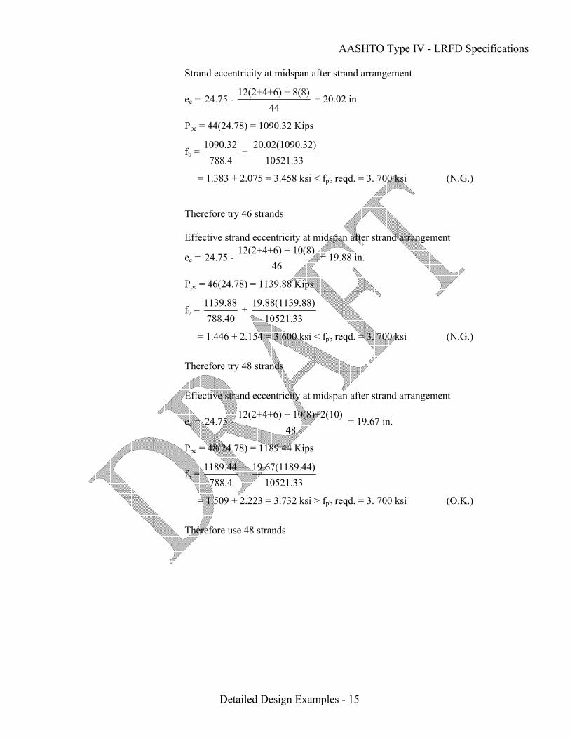
Strand eccentricity at midspan after strand arrangement
ec = 12(2+4+6) + 8(8)
24.75 - 44
= 20.02 in.
Ppe = 44(24.78) = 1090.32 Kips
fb = 1090.32 20.02(1090.32)
+ 788.4 10521.33
= 1.383 + 2.075 = 3.458 ksi < fpb reqd. = 3. 700 ksi (N.G.)
Therefore try 46 strands Effective strand eccentricity at midspan after strand arrangement
ec = 12(2+4+6) + 10(8)
24.75 - 46
= 19.88 in.
Ppe = 46(24.78) = 1139.88 Kips
fb = 1139.88 19.88(1139.88)
+ 788.40 10521.33
= 1.446 + 2.154 = 3.600 ksi < fpb reqd. = 3. 700 ksi (N.G.)
Therefore try 48 strands
Effective strand eccentricity at midspan after strand arrangement
ec = 12(2+4+6) + 10(8)+2(10)
24.75 - 48
= 19.67 in.
Ppe = 48(24.78) = 1189.44 Kips
fb = 1189.44 19.67(1189.44)
+ 788.4 10521.33
= 1.509 + 2.223 = 3.732 ksi > fpb reqd. = 3. 700 ksi (O.K.)
Therefore use 48 strands

AASHTO Type IV - LRFD Specifications
Detailed Design Examples - 16
A.2.7 PRESTRESS LOSSES
A.2.7.1 Iteration 1
A.2.7.1.1 Elastic Shortening
Number of Distance Strands from bottom
(in.) 2 10 10 8 12 6 12 4 12 2
Fig. A.2.6.1 Initial Strand Pattern
Total prestress loss:
∆fpT = ∆fpES + ∆fpSR + ∆fpCR + ∆fpR2 [LRFD Eq. 5.9.5.1-1]
where
∆fpES = loss of prestress due to elastic shortening
∆fpSR = loss of prestress due to concrete shrinkage
∆fpCR = loss of prestress due to creep of concrete
∆fpR2 = loss of prestress due to relaxation of steel after transfer
Number of strands = 48
A number of iterations will be performed to arrive at the optimum fc’ and f’ci
∆fpES = p
cicgp
E fE
[LRFD Art. 5.9.5.2.3a]
where
fcgp = sum of concrete stresses at the center of gravity of the prestressing steel due to prestressing force at transfer and self weight of the member at sections of maximum moment
LRFD Art. 5.9.5.2.3a states that fcgp can be calculated on the basis of prestressing steel stress assumed to be 0.7fpu for low-relaxation strands. However, common practice assumes the initial losses as a percentage of the initial prestressing stress before release, fpi. In both procedures initial losses assumed should be checked
11 spaces @ 2"2"

AASHTO Type IV - LRFD Specifications
Detailed Design Examples - 17
A.2.7.1.2 Shrinkage
A.2.7.1.3
Creep of Concrete
and if different from the assumed value a second iteration should be carried out. In this example, 8% fpi initial loss is used
fcgp = 2
i i c g cP P e (M )e + - A I I
where Pi = pretension force after allowing for the initial losses, assuming 8% initial losses = (number of strands)(area of each strand)[0.92(fpi)] = 48(0.153)(0.92)(202.5) = 1368.19 Kips Mg = Unfactored bending moment due to beam self weight = 1209.98 K-ft.
ec = eccentricity of the strand at the midspan = 19.67 in.
fcgp = 21368.19 1368.19(19.67) 1209.98(12)(19.67)
+ - 788.4 260403 260403
= 1.735 + 2.033 – 1.097 = 2.671 ksi
Eci = modulus of elasticity of beam at release = (wc)1.5(33) cif'
where [LRFD Eq. 5.4.2.4-1]
wc = weight of concrete = 150 pcf
Initial assumed value of f’ci = 4000 psi
Eci = (150)1.5(33) 4000 1
1000 = 3834 ksi
Ep = modulus of elasticity of prestressing reinforcement = 28500 ksi
Therefore loss due to elastic shortening:
∆fpES = 285003834
(2.671) = 19.855 ksi
∆fpSR = 17 – 0.15 H [LRFD Eq. 5.9.5.4.2-1]
where H is relative humidity = 60%
∆fpSR = [17 – 0.15(60)] = 8.0 ksi
∆fpCR = 12fcgp – 7∆fcdp [LRFD Eq. 5.9.5.4.3-1]
where
∆fcdp = change of stresses at the center of gravity of the prestressing steel due to permanent loads except the dead load present at the time the prestress force is applied calculated at the same section as fcgp

AASHTO Type IV - LRFD Specifications
Detailed Design Examples - 18
A.2.7.1.4
Relaxation of Prestressing Strands
A.2.7.1.4.1 Relaxation before Transfer
A.2.7.1.4.2 Relaxation after Transfer
∆fcdp = S c SDL bc bs
c
M e M (y - y ) + I I
where
MS = slab moment = 1179.03 K-ft.
MSDL = superimposed dead load moment = 347.81 K-ft.
ybc = 41.157 in.
ybs = the distance from center of gravity of the strand at midspan
to the bottom of the beam = 24.75 – 19.67 = 5.08 in.
I = moment of inertia of the non-composite section =260403 in.4
Ic = moment of inertia of composite section = 694599.5 in.4
∆fcdp = 1179.03(12)(19.67) (347.81)(12)(41.157 - 5.08)
+260403 694599.5
∆fcdp = 1.069 + 0.217 = 1.286 ksi
∆fpCR = 12(2.671) – 7(1.286) = 23.05 ksi.
Initial loss due to relaxation of prestressing steel is accounted for in the beam fabrication process. Therefore, loss due to relaxation of the prestressing steel prior to transfer is not computed, i.e. ∆fpR1 = 0. Recognizing this for pretensioned members, LRFD Article 5.9.5.1 allows the portion of the relaxation loss that occurs prior to transfer to be neglected in computing the final loss.
For pretensioned members with 270 ksi low-relaxation strands, loss due to
relaxation after transfer
∆fpR2 = 30% [20.0 – 0.4 ∆fpES – 0.2(∆fpSR + ∆fpCR)
= 0.3[20.0 – 0.4(19.855) – 0.2(8 + 23.05)] = 1.754 ksi
TxDOT Bridge Design Manual (Pg. # 7-85) recommends that 50% of the final
steel relaxation loss be considered for calculation of total initial loss given as
[Elastic shortening loss + 0.50(total steel relaxation loss)]
Initial Prestress loss % = pES pR2
pi
( f + 0.5 f )100f
∆ ∆
= [19.855 + 0.5(1.754)]100
202.5 = 10.24% > 8% (assumed initial prestress losses)
Therefore next trial is required assuming 10.24% initial losses

AASHTO Type IV - LRFD Specifications
Detailed Design Examples - 19
∆fpES =
p
cicgp
E fE
[LRFD Art. 5.9.5.2.3a]
where
fcgp = 2
i i c g cP P e (M )e + - A I I
Pi = pretension force after allowing for the initial losses, assuming 10.24% initial losses = (number of strands)(area of each strand)[0.8976(fpi)] = 48(0.153)(0.8976)(202.5) = 1334.87 Kips Mg = 1209.98 K-ft.
ec = 19.67 in.
fcgp = 21334.87 1334.87(19.67) 1209.98(12)(19.67)
+ - 788.4 260403 260403
= 1.693 + 1.983 – 1.097 = 2.579 ksi
Eci = 3834 ksi
Ep = 28500 ksi
Therefore loss due to elastic shortening:
∆fpES = 285003834
(2.579) = 19.17 ksi
∆fpCR = 12fcgp – 7∆fcdp [LRFD Eq. 5.9.5.4.3-1]
where
fcgp = 2.579 ksi
∆fcdp = 1.286 ksi
∆fpCR = 12(2.579) – 7(1.286) = 21.95 ksi.
∆fpSR = 8.0 ksi
For pretensioned members with 270 ksi low-relaxation strands, loss due to
relaxation after transfer
∆fpR2 = 30% [20.0 – 0.4 ∆fpES – 0.2(∆fpSR + ∆fpCR)
= 0.3[20.0 – 0.4(19.17) – 0.2(8 + 21.95)] = 1.903 ksi
Initial Prestress loss % = pES pR2
pi
( f + 0.5 f )100f
∆ ∆
= [19.17 + 0.5(1.903)]100
202.5 = 9.94% < 10.24% (assumed initial prestress losses)

AASHTO Type IV - LRFD Specifications
Detailed Design Examples - 20
Therefore next trial is required assuming 9.94% initial losses
∆fpES = p
cicgp
E fE
[LRFD Art. 5.9.5.2.3a]
where
fcgp = 2
i i c g cP P e (M )e + - A I I
Pi = pretension force after allowing for the initial losses, assuming 9.94% initial losses = (number of strands)(area of each strand)[0.9006(fpi)] = 48(0.153)(0.9006)(202.5) = 1339.34 Kips Mg = 1209.98 K-ft.
ec = 19.67 in.
fcgp = 21339.34 1339.34(19.67) 1209.98(12)(19.67)
+ - 788.4 260403 260403
= 1.699 + 1.99 – 1.097 = 2.592 ksi
Eci = 3834 ksi
Ep = 28500 ksi
Therefore loss due to elastic shortening:
∆fpES = 285003834
(2.592) = 19.27 ksi
∆fpCR = 12fcgp – 7∆fcdp [LRFD Eq. 5.9.5.4.3-1]
where
fcgp = 2.592 ksi
∆fcdp = 1.286 ksi
∆fpCR = 12(2.592) – 7(1.286) = 22.1 ksi.
∆fpSR = 8.0 ksi
For pretensioned members with 270 ksi low-relaxation strands, loss due to
relaxation after transfer
∆fpR2 = 30% [20.0 – 0.4 ∆fpES – 0.2(∆fpSR + ∆fpCR)
= 0.3[20.0 – 0.4(19.27) – 0.2(8 + 22.1)] = 1.882 ksi
Initial Prestress loss % = pES pR2
pi
( f + 0.5 f )100f
∆ ∆
= [19.27 + 0.5(1.882)]100
202.5 = 9.98% ≈ 9.94% (assumed initial prestress losses)

AASHTO Type IV - LRFD Specifications
Detailed Design Examples - 21
A.2.7.1.5 Total Losses at Transfer
A.2.7.1.6 Total Losses at Service
Loads
A.2.7.1.7 Final Stresses at midspan
Total Initial loss, ∆fpi = pES pR2( f + 0.5 f )∆ ∆ = [19.27 + 0.5(1.882)] = 20.21 ksi
fpi = effective initial prestress = 202.5 – 20.21 = 182.29 ksi
Pi = effective pretension force after allowing for the initial losses
= 48(0.153)(182.29) = 1338.74 Kips
∆fpES = 19.270 ksi
∆fpSR = 8.000 ksi
∆fpCR = 22.100 ksi
∆fpR2 = 1.882 ksi
Total final loss, ∆fpT = ∆fpES + ∆fpSR + ∆fpCR + ∆fpR2 [LRFD Eq. 5.9.5.1-1]
= 19.270 + 8.000 + 22.100 + 1.882 = 51.25 ksi
or 51.25(100)
202.5 = 25.31 %
fpe = effective final prestress = fpi – ∆fpT = 202.5 – 51.25 = 151.25 ksi
Check Prestressing stress limit at service limit state:
fpe ≤ 0.8fpy = 0.8(243) = 194.4 ksi > 151.25 ksi (O.K.)
Total prestressing force after all losses
Ppe = 48(0.153)(151.25) = 1110.78 Kips
Final stress in the bottom fiber at midspan:
fb = pe pe c
b
P P e+
A S
fb = 1110.78 19.67(1110.78)
+ 788.4 10521.33
= 1.409 + 2.077 = 3.486 ksi < fpb reqd. = 3.700 ksi (N.G)
Therefore try 50 strands
ec = 24.75 - 12(2+4+6) + 10(8) + 4(10)
50 = 19.47 in.
Ppe = 50(0.153)(151.25) = 1157.06 Kips
fb = 1157.06 19.47(1157.06)
+ 788.4 10521.33
= 1.468 + 2.141 = 3.609 ksi < fpb reqd. = 3.700 ksi (N.G.)

AASHTO Type IV - LRFD Specifications
Detailed Design Examples - 22
A.2.7.1.8 Initial Stresses at Hold down point
Therefore try 52 strands
ec = 24.75 - 12(2+4+6) + 10(8) + 6(10)
52 = 19.29 in.
Ppe = 52(0.153)(151.25) = 1203.35 Kips
fb = 1203.35 19.29(1203.35)
+ 788.4 10521.33
= 1.526 + 2.206 = 3.732 ksi > fpb reqd. = 3.700 ksi (O.K.)
Therefore use 52 strands
Concrete stress at the top fiber of the beam, ft
Under permanent loads, Service I:
ft = pe pe c g S SDL
t t tg
P P e M + M M + + A S S S
−
= 1203.35 19.29(1203.35) (1209.98 + 1179.03)(12) 347.81(12)
- + + 788.4 8902.67 8902.67 54083.9
= 1.526 - 2.607 + 3.22 + 0.077 = 2.216 ksi
Under permanent and transient loads, Service I:
ft = pe pe c g S SDL LT LL
t t tg tg
P P e M + M M (M + M ) + + + A S S S S
−
= 2.216 + (1423 + 602.72)12
54083.9 = 2.216 + 0.449 = 2.665 ksi
Initial Prestress
Pi = 52(0.153)(182.29) = 1450.30 Kips
Initial concrete stress at top fiber of the beam at hold down point
i i c gti
t t
P P eA S
Mf = - + S
where
Mg = Moment due to beam self weight at hold down point = 1197.87 K-ft.
fti = 1450.3 19.29(1450.3) 1197.87(12)
- + 788.4 8902.67 8902.67
= 1.839 – 3.142 + 1.615 = 0.312 ksi

AASHTO Type IV - LRFD Specifications
Detailed Design Examples - 23
A.2.7.2 Iteration 2
A.2.7.2.1 Elastic Shortening
Initial concrete stress at bottom fiber of the beam at hold down point
i i c gbi
b b
P P eA S
Mf = - S
+
fbi = 1450.3 19.29(1450.3) 1197.87(12)
+ - 788.4 10521.33 10521.33
= 1.839 + 2.659 – 1.366 = 3.132 ksi
Compression stress limit at transfer is 0.6f’ci
Therefore, f’ci reqd. = 31320.6
= 5220 psi
Number of strands = 52
∆fpES = p
cicgp
E fE
[LRFD Art. 5.9.5.2.3a]
where
fcgp = sum of concrete stresses at the center of gravity of the prestressing steel due to prestressing force at transfer and self weight of the member at sections of maximum moment
fcgp = 2
i i c g cP P e (M )e + - A I I
where Pi = pretension force after allowing for the initial losses, assuming 9.98% initial losses = (number of strands)(area of each strand)[0.9002(fpi)] = 52(0.153)(0.9002)(202.5) = 1450.3 Kips Mg = Unfactored bending moment due to beam self weight = 1209.98 K-ft.
ec = eccentricity of the strand at the midspan = 19.29 in.
fcgp = 21450.3 1450.3(19.29) 1209.98(12)(19.29)
+ - 788.4 260403 260403
= 1.839 + 2.072 – 1.076 = 2.835 ksi
Eci = modulus of elasticity of beam at release = (wc)1.5(33) cif'
where [LRFD Eq. 5.4.2.4-1]
wc = weight of concrete = 150 pcf
f’ci = 5220 psi
Eci = (150)1.5(33) 5220 1
1000 = 4380.12 ksi

AASHTO Type IV - LRFD Specifications
Detailed Design Examples - 24
A.2.7.2.2 Shrinkage
A.2.7.2.3 Creep of Concrete
A.2.7.2.4 Relaxation of
Prestressing Strands A.2.7.2.4.1
Relaxation before Transfer
Ep = modulus of elasticity of prestressing reinforcement = 28500 ksi
Therefore loss due to elastic shortening:
∆fpES = 28500
4380.12 (2.835) = 18.45 ksi
∆fpSR = 17 – 0.15 H [LRFD Eq. 5.9.5.4.2-1]
where H is relative humidity = 60%
∆fpSR = [17 – 0.15(60)] = 8.0 ksi
∆fpCR = 12fcgp – 7∆fcdp [LRFD Eq. 5.9.5.4.3-1]
where
∆fcdp = change of stresses at the center of gravity of the prestressing steel due to permanent loads except the dead load present at the time the prestress force is applied calculated at the same section as fcgp
∆fcdp = S c SDL bc bs
c
M e M (y - y ) + I I
where
MS = slab moment = 1179.03 K-ft.
MSDL = superimposed dead load moment = 347.81 K-ft.
ybc = 41.157 in.
ybs = the distance from center of gravity of the strand at midspan
to the bottom of the beam = 24.75 – 19.29 = 5.46 in.
I = moment of inertia of the non-composite section =260403 in.4
Ic = moment of inertia of composite section = 694599.5 in.4
∆fcdp = 1179.03(12)(19.29) (347.81)(12)(41.157 - 5.46)
+260403 694599.5
∆fcdp = 1.048 + 0.214 = 1.262 ksi
∆fpCR = 12(2.835) – 7(1.262) = 25.19 ksi.
Loss due to Relaxation of steel before transfer ∆fpR1 = 0

AASHTO Type IV - LRFD Specifications
Detailed Design Examples - 25
A.2.7.2.4.2 Relaxation after Transfer
For pretensioned members with 270 ksi low-relaxation strands, loss due to
relaxation after transfer
∆fpR2 = 30% [20.0 – 0.4 ∆fpES – 0.2(∆fpSR + ∆fpCR)
= 0.3[20.0 – 0.4(18.45) – 0.2(8 + 25.19)] = 1.795 ksi
TxDOT Bridge Design Manual (Pg. # 7-85) recommends that 50% of the final steel relaxation loss be considered for calculation of total initial loss given as [Elastic shortening loss + 0.50(total steel relaxation loss)]
Initial Prestress loss % = pES pR2
pi
( f + 0.5 f )100f
∆ ∆
= [18.45 + 0.5(1.795)]100
202.5 = 9.55% < 9.98% (assumed initial prestress losses)
Therefore next trial is required assuming 9.55% initial losses
∆fpES = p
cicgp
E fE
[LRFD Art. 5.9.5.2.3a]
where
fcgp = 2
i i c g cP P e (M )e + - A I I
Pi = pretension force after allowing for the initial losses, assuming 9.55% initial losses = (number of strands)(area of each strand)[0.9045(fpi)] = 52(0.153)(0.9045)(202.5) = 1457.23 Kips Mg = 1209.98 K-ft.
ec = 19.29 in.
fcgp = 21457.23 1457.23(19.29) 1209.98(12)(19.29)
+ - 788.4 260403 260403
= 1.848 + 2.082 – 1.076 = 2.854 ksi
Eci = 4380.12 ksi
Ep = 28500 ksi
Therefore loss due to elastic shortening:
∆fpES = 28500
4380.12 (2.854) = 18.57 ksi

AASHTO Type IV - LRFD Specifications
Detailed Design Examples - 26
A.2.7.2.5
Total Losses at Transfer
A.2.7.2.6 Total Losses at Service Loads
∆fpCR = 12fcgp – 7∆fcdp [LRFD Eq. 5.9.5.4.3-1]
where
fcgp = 2.854 ksi
∆fcdp = 1.262 ksi
∆fpCR = 12(2.854) – 7(1.262) = 25.41 ksi.
∆fpSR = 8.0 ksi
For pretensioned members with 270 ksi low-relaxation strands, loss due to
relaxation after transfer
∆fpR2 = 30% [20.0 – 0.4 ∆fpES – 0.2(∆fpSR + ∆fpCR)
= 0.3[20.0 – 0.4(18.57) – 0.2(8 + 25.41)] = 1.767 ksi
Initial Prestress loss % = pES pR2
pi
( f + 0.5 f )100f
∆ ∆
= [18.57 + 0.5(1.767)]100
202.5 = 9.61% ≈ 9.55% (assumed initial prestress losses)
Total Initial loss, ∆fpi = pES pR2( f + 0.5 f )∆ ∆ = [18.57 + 0.5(1.767)] = 19.45 ksi
fpi = effective initial prestress = 202.5 – 19.45 = 183.05 ksi
Pi = effective pretension force after allowing for the initial losses
= 52(0.153)(183.05) = 1456.35 Kips
∆fpES = 18.570 ksi
∆fpSR = 8.000 ksi
∆fpCR = 25.410 ksi
∆fpR2 = 1.767 ksi
Total final loss, ∆fpT = ∆fpES + ∆fpSR + ∆fpCR + ∆fpR2 [LRFD Eq. 5.9.5.1-1]
= 18.570 + 8.000 + 25.410 + 1.767 = 53.75 ksi
or 53.75(100)
202.5 = 26.54 %
fpe = effective final prestress = fpi – ∆fpT = 202.5 – 53.75 = 148.75 ksi
Check Prestressing stress limit at service limit state:
fpe ≤ 0.8fpy = 0.8(243) = 194.4 ksi > 148.75 ksi (O.K.)
Total prestressing force after all losses
Ppe = 52(0.153)(148.75) = 1183.46 Kips

AASHTO Type IV - LRFD Specifications
Detailed Design Examples - 27
A.2.7.2.7 Final Stresses at midspan
Concrete stress at the top fiber of the beam, ft
Effective prestress and permanent loads, Service I:
ft = pe pe c g S SDL
t t tg
P P e M + M M + + A S S S
−
= 1183.46 19.29(1183.46) (1209.98 + 1179.03)(12) 347.81(12)
- + + 788.4 8902.67 8902.67 54083.9
= 1.501 - 2.564 + 3.220 + 0.077 = 2.234 ksi
Allowable compression stress limit for this load combination = 0.45f’c
f’c reqd. = 2234/0.45 = 4964.44 psi
1/2(Effective prestress + permanent loads) + transient loads, Service I:
ft = pe pe c g S SDL LT LL
t t tg tg
P P e M + M M (M + M )0.5 + + + A S S S S
⎛ ⎞−⎜ ⎟⎝ ⎠
= 0.5(2.234) + (1423 + 602.72)12
54083.9 = 1.117 + 0.449 = 1.566 ksi
Allowable compression stress limit for this load combinations = 0.4f’c
f’c reqd. = 1566/0.4 = 3915 psi
Effective prestress + permanent and transient loads, Service I:
ft = pe pe c g S SDL LT LL
t t tg tg
P P e M + M M (M + M ) + + + A S S S S
−
= 2.234 + (1423 + 602.72)12
54083.9 = 2.234 + 0.449 = 2.683 ksi
Allowable compression stress limit for this load combinations = 0.6f’c
f’c reqd. = 2683/0.6 = 4471.67 psi Bottom fiber stress in concrete at midspan, Service III
fbf = pe pe c
b
P P e+
A S- fb
fbf = 1183.46 19.29(1183.46)
+ 788.4 10521.33
- 4.126 = 1.501 + 2.170 – 4.126 = -0.455 ksi
Allowable tension in concrete = 0.19 cf'
f’c reqd. = 20.455
10000.19
⎛ ⎞⎜ ⎟⎝ ⎠
= 5734.76 psi (controls)

AASHTO Type IV - LRFD Specifications
Detailed Design Examples - 28
A.2.7.2.8 Initial Stresses at Hold down point
A.2.7.2.9 Initial Stresses at
End
Pi = 52(0.153)(183.05) = 1456.35 Kips
Initial concrete stress at top fiber of the beam at hold down point
i i c gti
t t
P P eA S
Mf = - + S
where Mg = moment due to beam self weight at hold down point = 1197.87 K-ft.
fti = 1456.35 19.29(1456.35) 1197.87(12)
- + 788.4 8902.67 8902.67
= 1.847 – 3.155 + 1.615 = 0.307 ksi
i i c gbi
b b
P P eA S
Mf = - S
+
fbi = 1456.35 19.29(1456.35) 1197.87(12)
+ - 788.4 10521.33 10521.33
= 1.847 + 2.670 - 1.366 = 3.151 ksi
Compression stress limit at hold down point = 0.6f’ci
f’ci reqd. = 31510.6
= 5251.67 psi
Assuming 10 web strands are draped to top location (5 rows)
ee = 24.75 – 10(2+4+6) + 8(8) + 4(10) + 2(52 + 50 + 48 + 46 + 44)
52 = 11.21 in.
i i eti
t
P P eA S
f = -
fti = 1456.35 11.21(1456.35)
- 788.4 8902.67
= 1.847 – 1.834 = 0.013 ksi
i i ebi
b
P P eA S
f = +
fbi = 1456.35 11.21(1456.35)
+ 788.4 10521.33
= 1.847 + 1.552 = 3.399 ksi
Compression stress limit = 0.6f’ci
f’ci reqd. = 33990.6
= 5665 psi (controls)

AASHTO Type IV - LRFD Specifications
Detailed Design Examples - 29
A.2.7.3 Iteration 3
A.2.7.3.1 Elastic Shortening
A.2.7.3.2 Shrinkage
Number of strands = 52
∆fpES = p
cicgp
E fE
[LRFD Art. 5.9.5.2.3a]
where
fcgp = sum of concrete stresses at the center of gravity of the prestressing steel due
to prestressing force at transfer and self weight of the member at sections of maximum moment
fcgp = 2
i i c g cP P e (M )e + - A I I
where Pi = pretension force after allowing for the initial losses, assuming 9.61% initial losses = (number of strands)(area of each strand)[0.9039(fpi)] = 52(0.153)(0.9039)(202.5) = 1456.26 Kips
Mg = Unfactored bending moment due to beam self weight = 1209.98 K-ft.
ec = eccentricity of the strand at the midspan = 19.29 in.
fcgp = 21456.26 1456.26(19.29) 1209.98(12)(19.29)
+ - 788.4 260403 260403
= 1.847 + 2.081 – 1.076 = 2.852 ksi
Eci = modulus of elasticity of beam at release = (wc)1.5(33) cif'
where [LRFD Eq. 5.4.2.4-1]
wc = weight of concrete = 150 pcf
f’ci = 5665 psi
Eci = (150)1.5(33) 5665 1
1000 = 4563 ksi
Ep = modulus of elasticity of prestressing reinforcement = 28500 ksi
Therefore loss due to elastic shortening:
∆fpES = 285004563
(2.852) = 17.81 ksi
∆fpSR = 17 – 0.15 H [LRFD Eq. 5.9.5.4.2-1]
where H is relative humidity = 60%
∆fpSR = [17 – 0.15(60)] = 8.0 ksi

AASHTO Type IV - LRFD Specifications
Detailed Design Examples - 30
A.2.7.3.3 Creep of Concrete
A.2.7.3.4 Relaxation of
Prestressing Strands A.2.7.3.4.1
Relaxation before Transfer
A.2.7.3.4.2
Relaxation after Transfer
∆fpCR = 12fcgp – 7∆fcdp [LRFD Eq. 5.9.5.4.3-1]
where
∆fcdp = change of stresses at the center of gravity of the prestressing steel due to permanent loads except the dead load present at the time the prestress force is applied calculated at the same section as fcgp
∆fcdp = S c SDL bc bs
c
M e M (y - y ) + I I
where
MS = slab moment = 1179.03 K-ft.
MSDL = superimposed dead load moment = 347.81 K-ft.
ybc = 41.157 in.
ybs = the distance from center of gravity of the strand at midspan
to the bottom of the beam = 24.75 – 19.29 = 5.46 in.
I = moment of inertia of the non-composite section =260403 in.4
Ic = moment of inertia of composite section = 694599.5 in.4
∆fcdp = 1179.03(12)(19.29) (347.81)(12)(41.157 - 5.46)
+260403 694599.5
∆fcdp = 1.048 + 0.214 = 1.262 ksi
∆fpCR = 12(2.852) – 7(1.262) = 25.39 ksi.
Loss due to Relaxation of steel before transfer ∆fpR1 = 0
For pretensioned members with 270 ksi low-relaxation strands, loss due to
relaxation after transfer
∆fpR2 = 30% [20.0 – 0.4 ∆fpES – 0.2(∆fpSR + ∆fpCR)
= 0.3[20.0 – 0.4(17.81) – 0.2(8 + 25.39)] = 1.859 ksi
TxDOT Bridge Design Manual (Pg. # 7-85) recommends that 50% of the final steel relaxation loss be considered for calculation of total initial loss given as [Elastic shortening loss + 0.50(total steel relaxation loss)]
Initial Prestress loss % = pES pR2
pi
( f + 0.5 f )100f
∆ ∆

AASHTO Type IV - LRFD Specifications
Detailed Design Examples - 31
= [17.81 + 0.5(1.859)]100
202.5 = 9.25% < 9.61% (assumed initial prestress losses)
Therefore next trial is required assuming 9.25% initial losses
∆fpES = p
cicgp
E fE
[LRFD Art. 5.9.5.2.3a]
where
fcgp = 2
i i c g cP P e (M )e + - A I I
Pi = pretension force after allowing for the initial losses, assuming 9.25% initial losses = (number of strands)(area of each strand)[0.9075(fpi)] = 52(0.153)(0.9075)(202.5) = 1462.06 Kips Mg = 1209.98 K-ft.
ec = 19.29 in.
fcgp = 21462.06 1462.06(19.29) 1209.98(12)(19.29)
+ - 788.4 260403 260403
= 1.854 + 2.089 – 1.076 = 2.867 ksi
Eci = 4563 ksi
Ep = 28500 ksi
Therefore loss due to elastic shortening:
∆fpES = 285004563
(2.867) = 17.91 ksi
∆fpCR = 12fcgp – 7∆fcdp [LRFD Eq. 5.9.5.4.3-1]
where
fcgp = 2.867 ksi
∆fcdp = 1.262 ksi
∆fpCR = 12(2.867) – 7(1.262) = 25.57 ksi.
∆fpSR = 8.0 ksi
For pretensioned members with 270 ksi low-relaxation strands, loss due to
relaxation after transfer
∆fpR2 = 30% [20.0 – 0.4 ∆fpES – 0.2(∆fpSR + ∆fpCR)
= 0.3[20.0 – 0.4(17.91) – 0.2(8 + 25.57)] = 1.837 ksi
Initial Prestress loss % = pES pR2
pi
( f + 0.5 f )100f
∆ ∆
= [17.91 + 0.5(1.837)]100
202.5 = 9.30% ≈ 9.25 % (assumed initial prestress losses)

AASHTO Type IV - LRFD Specifications
Detailed Design Examples - 32
A.2.7.3.5 Total Losses at Transfer
A.2.7.3.6 Total Losses at Service
Loads
A.2.7.3.7 Final Stresses at midspan
Total Initial loss, ∆fpi = pES pR2( f + 0.5 f )∆ ∆ = [17.91 + 0.5(1.837)] = 18.83 ksi
fpi = effective initial prestress = 202.5 – 18.83 = 183.67 ksi
Pi = effective pretension force after allowing for the initial losses
= 52(0.153)(183.67) = 1461.28 Kips
∆fpES = 17.910 ksi
∆fpSR = 8.000 ksi
∆fpCR = 25.570 ksi
∆fpR2 = 1.837 ksi
Total final loss, ∆fpT = ∆fpES + ∆fpSR + ∆fpCR + ∆fpR2 [LRFD Eq. 5.9.5.1-1]
= 17.910 + 8.000 + 25.570 + 1.837 = 53.32 ksi
or 53.32(100)
202.5 = 26.33 %
fpe = effective final prestress = fpi – ∆fpT = 202.5 – 53.32 = 149.18 ksi
Check Prestressing stress limit at service limit state:
fpe ≤ 0.8fpy = 0.8(243) = 194.4 ksi > 149.18 ksi (O.K.)
Total prestressing force after all losses
Ppe = 52(0.153)(149.18) = 1186.88 Kips
Concrete stress at the top fiber of the beam, ft
Effective prestress + permanent loads, Service I:
ft = pe pe c g S SDL
t t tg
P P e M + M M + + A S S S
−
= 1186.88 19.29(1186.88) (1209.98 + 1179.03)(12) 347.81(12)
- + + 788.4 8902.67 8902.67 54083.9
= 1.505 - 2.572 + 3.22 + 0.077 = 2.23 ksi
Allowable compression stress limit for this load combination = 0.45f’c
f’c reqd. = 2230/0.45 = 4955.55 psi
½(Effective prestress + permanent loads) + transient loads, Service I:
ft = pe pe c g S SDL LT LL
t t tg tg
P P e M + M M (M + M )0.5 + + + A S S S S
⎛ ⎞−⎜ ⎟⎝ ⎠
= 0.5(2.230) + (1423 + 602.72)12
54083.9 = 1.115 + 0.449 = 1.564 ksi

AASHTO Type IV - LRFD Specifications
Detailed Design Examples - 33
A.2.7.3.8
Initial Stresses at Hold down point
Allowable compression stress limit for this load combinations = 0.4f’c
f’c reqd. = 1564/0.4 = 3910 psi
Effective prestress + permanent loads + transient loads, Service I:
ft = pe pe c g S SDL LT LL
t t tg tg
P P e M + M M (M + M ) + + + A S S S S
−
= 2.230 + (1423 + 602.72)12
54083.9 = 2.230 + 0.449 = 2.679 ksi
Allowable compression stress limit for this load combinations = 0.6f’c
f’c reqd. = 2679/06 = 4465 psi
Bottom fiber stress in concrete at midspan, Service III
fbf = pe pe c
b
P P e+
A S- fb
fbf = 1186.88 19.29(1186.88)
+ 788.4 10521.33
- 4.126 = 1.505 + 2.176 – 4.126 = –0.445 ksi
Allowable tension in concrete = 0.19 cf'
f’c reqd. = 20.445
10000.19
⎛ ⎞⎜ ⎟⎝ ⎠
= 5485.46 psi (controls)
Pi = 52(0.153)(183.67) = 1461.28 Kips
Initial concrete stress at top fiber of the beam at hold down point
i i c gti
t t
P P eA S
Mf = - + S
where Mg = moment due to beam self weight at hold down point = 1197.87 K-ft.
fti = 1461.28 19.29(1461.28) 1197.87(12)
- + 788.4 8902.67 8902.67
= 1.853 – 3.166 + 1.615 = 0.302 ksi
i i c gbi
b b
P P eA S
Mf = - S
+
fbi = 1461.28 19.29(1461.28) 1197.87(12)
+ - 788.4 10521.33 10521.33
= 1.853 + 2.679 - 1.366 = 3.166 ksi
Compression stress limit at hold down point = 0.6f’ci
f’ci reqd. = 31660.6
= 5276.67 psi

AASHTO Type IV - LRFD Specifications
Detailed Design Examples - 34
A.2.7.3.9 Initial Stresses at
End
Assuming 10 web strands are draped to top location (5 rows)
ee = 24.75 – 10(2+4+6) + 8(8) + 4(10) + 2(52 + 50 + 48 + 46 + 44)
52 = 11.21 in.
i i eti
t
P P eA S
f = -
fti = 1461.28 11.21(1461.28)
- 788.4 8902.67
= 1.853 – 1.840 = – 0.013 ksi
Concrete stresses at bottom fiber
i i ebi
b
P P eA S
f = +
fbi = 1461.28 11.21(1461.28)
+ 788.4 10521.33
= 1.853 + 1.557 = 3.410 ksi
Compression stress limit = 0.6f’ci
f’ci reqd. = 34100.6
= 5683.33 psi (controls)
Therefore provide f’ci = 5683.33 psi
f’c = 5683.33 psi (f’c should be atleast equal to f’ci)
52 – ½ in. diameter, 10 harped at the end, GR 270 low relaxation strands

AASHTO Type IV - LRFD Specifications
Detailed Design Examples - 35
No. of Distance Strands from bottom (in.) 2 52 2 50 No. of Distance 2 48 Strands from bottom 2 46
(in.) 2 44 6 10 No. of Distance 10 8 Strands from bottom 12 6 Harped (in.) 12 4 Strands 4 10 12 2 8 8 10 6 10 4 10 2
Fig. A.2.7.1 Fig. A.2.7.2 Final Strand Pattern at Midspan Final Strand Pattern at Ends 10 Strands 42 Strands
CL Fig. A.2.7.3 Longitudinal strand profile (Half of the beam length is shown)
Note: The hold down distance of 49.4 ft. is measured from the end of the beam.
11 spaces @ 2" 2"2"11 spaces
@ 2"2"

AASHTO Type IV - LRFD Specifications
Detailed Design Examples - 36
A.2.8 CHECK FOR
DISTRIBUTION FACTORS
A.2.8.1 Distribution factor for
Bending Moment
The distance between the center of gravity of the 10 harped strands and the top
of the beam at the end of the beam = 2(2) + 2(4) + 2(6) + 2(8) + 2(10)
10 = 6 in.
The distance between the center of gravity of the 10 harped strands and the
bottom of the beam at harp points = 2(2) + 2(4) + 2(6) + 2(8) + 2(10)
10 = 6 in.
The distance between the center of gravity of the 10 harped strands and the top of the beam at transfer length section
= 6 in. + (54 in - 6 in - 6 in)
49.4 ft.(2.5 ft.) = 8.12 in.
The distance between the center of gravity of the 42 straight strands and the bottom of the beam at all locations
ybsend =10(2) + 10(4) + 10(6) + 8(8) + 4(10)
42 = 5.33 in.
The distribution factor for moment based on actual modular ratio is calculated and compared to the one used in the design until this point. If the change is found to be large then the bending moments and Shear forces will be updated based on new Distribution factors and used for further design.
For all limit states except fatigue limit state: For two or more lanes loaded:
3
0.6 0.2 0.1SDFM = 0.075 +
9.5 12.0g
s
S KL Lt
⎛ ⎞ ⎛ ⎞ ⎛ ⎞⎜ ⎟ ⎜ ⎟ ⎜ ⎟⎝ ⎠ ⎝ ⎠ ⎝ ⎠
[LRFD Table 4.6.2.2.2b-1]
Provided that: 3.5 ≤ S ≤ 16; S = 8.0 ft (O.K.)
4.5 ≤ ts ≤ 12; ts = 8.0 in (O.K.)
20 ≤ L ≤ 240; L = 108.583 ft. (O.K.)
Nb ≥ 4; Nb = 6 (O.K.)
10,000 ≤ Kg ≤ 7,000,000 (O.K., as shown below)
where
DFM = distribution factor for moment for interior beam
S = spacing of beams = 8.0 ft
L = beam span = 108.583 ft
ts = depth of concrete deck = 8.0 in.
Kg = longitudinal stiffness parameter, in.4

AASHTO Type IV - LRFD Specifications
Detailed Design Examples - 37
Kg = n (I + Aeg2) [LRFD Art. 3.6.1.1.1]
where
A = cross-sectional area of the beam (non-composite section)
A = 788.4 in.2
I = moment of inertia of beam (non-composite section) = 260,403.0 in.4
eg = distance between centers of gravity of the beam and slab, in.
= (ts/2 + yt) = (8/2 + 29.25) = 33.25 in.
n = modular ratio between beam and slab materials = c
c
E (beam)E (deck)
Ec(beam) = modulus of elasticity of beam at service = (wc)1.5(33) cf'
where [LRFD Eq. 5.4.2.4-1]
wc = weight of beam concrete = 150 pcf
f’c = 5683.33 psi
Ec(beam) = (150)1.5(33) 5683.33 1
1000 = 4570.38 ksi
Ec(deck) = modulus of elasticity of slab = (wc)1.5(33) cf'
where [LRFD Eq. 5.4.2.4-1]
wc = weight of slab concrete = 150 pcf
f’c = 4000.0 psi
Ec(deck) = (150)1.5(33) 4000 1
1000 = 3834.25 ksi
n = 4570.383834.25
= 1.192
Therefore
Kg = 1.192[260403 + 788.4(33.25)2] = 1,349,377.94 in.4
3
0.10.6 0.28 8 1349377.94DFM = 0.075 +
9.5 108.583 12.0(108.583)(8)⎛ ⎞⎛ ⎞ ⎛ ⎞
⎜ ⎟ ⎜ ⎟ ⎜ ⎟⎝ ⎠ ⎝ ⎠ ⎝ ⎠
= 0.075 + (0.902)(0.593)(1.073) = 0.649 lanes/beam
For one design lane loaded:
3
0.4 0.3 0.1SDFM = 0.06 +
14 12.0g
s
S KL Lt
⎛ ⎞ ⎛ ⎞ ⎛ ⎞⎜ ⎟ ⎜ ⎟ ⎜ ⎟⎝ ⎠ ⎝ ⎠ ⎝ ⎠

AASHTO Type IV - LRFD Specifications
Detailed Design Examples - 38
STRESS SUMMARY A.2.8.1
Concrete Stresses at Transfer
A.2.8.1.1 Allowable Stress limits
3
0.10.4 0.38 8 1349377.94= 0.06 +
14 108.583 12.0(108.583)(8)⎛ ⎞⎛ ⎞ ⎛ ⎞
⎜ ⎟ ⎜ ⎟ ⎜ ⎟⎝ ⎠ ⎝ ⎠ ⎝ ⎠
= 0.06 + (0.8)(0.457)(1.073) = 0.452 lanes/beam
Thus, the case of two or more lanes loaded controls
DFM = 0.649 lanes/beam
For fatigue limit state:
LRFD Specifications, Art. 3.4.1, states that for fatigue limit state, a single design truck should be used. However, live load distribution factors given in LRFD Article 4.6.2.2 take into consideration the multiple presence factor, m. LRFD Article 3.6.1.1.2 states that the multiple presence factor, m, for one design lane loaded is 1.2. Therefore, the distribution factor for one design lane loaded with the multiple presence factor removed should be used. The distribution factor for the fatigue limit state is: 0.452/1.2 = 0.377 lanes/beam.
Percent change in DFM = 0.649 - 0.639
1000.649
⎛ ⎞⎜ ⎟⎝ ⎠
= 1.54%
Percent change in DFM for fatigue limit state = 0.377 - 0.371
1000.377
⎛ ⎞⎜ ⎟⎝ ⎠
= 1.6%
The change in the distribution factors is very less and can be neglected as they
won’t impact the moments by a great amount. The moments obtained using
previous distribution factors are used in the following design.
[LRFD Art. 5.9.4] Compression: 0.6 f’ci = 0.6(5683.33) = +3410.0 psi = 3.410 ksi (compression)
Tension:
Without bonded reinforcement
0.0948 cif' ≤ 0.200 ksi; –0.0948 5.683 = –0 .226 ksi
Therefore –0.200 ksi controls
With bonded auxiliary reinforcement which is sufficient to resist 120% of the
tension force in the cracked concrete
–0.24 cif' = –0.24 5.683 = –0.572 ksi

AASHTO Type IV - LRFD Specifications
Detailed Design Examples - 39
A.2.8.1.2 Stresses at Beam End
A.2.8.1.3
Stresses at Transfer Length Section
Total prestressing force after transfer = 52(0.153)(183.67) = 1461.28 kips. Stresses at end are checked only at release, because it almost always governs. Assuming all web strands are draped to top location (5 rows)
Eccentricity of strands at the end of the beam
ee = 24.75 – 10(2+4+6) + 8(8) + 4(10) + 2(52 + 50 + 48 + 46 + 44)
52 = 11.21 in.
End concrete stress at top fiber at release
i i eti
t
P P eA S
f = -
fti = 1461.28 11.21(1461.28)
- 788.4 8902.67
= 1.853 – 1.84 = 0.013 ksi
Allowable compression: +3.410 ksi >> 0.013 ksi (reqd.) (O.K.)
There is no need for additional bonded reinforcement as there is no tension in the top fiber of the beam.
End concrete stress at bottom fiber at release
i i ebi
b
P P eA S
f = +
fbi = 1461.28 11.21(1461.28)
+ 788.4 10521.33
= 1.853 + 1.557 = 3.410 ksi
Allowable compression: +3.410 ksi = 3.410 ksi (reqd.) (O.K.)
Stresses at transfer length are checked only at release, because it almost always governs. Transfer length = 60(strand diameter) [LRFD Art. 5.8.2.3]
= 60 (0.50) = 30 in. = 2.5 ft.
Transfer length section is located at a distance of 2.5 ft. from end of the beam or at a point 1.96 ft. from center of the bearing as the beam extends 6.5 in. beyond the bearing centerline. Overall beam length of 109.67 ft. is considered for the calculation of bending moment at transfer length.
Moment due to beam self weight, Mg = 0.5wx (L-x)
Mg = 0.5(0.821)(2.5)(109.67 – 2.5)
= 110.00 K –ft.

AASHTO Type IV - LRFD Specifications
Detailed Design Examples - 40
A.2.8.1.4 Stresses at Harp points
Concrete stress at top fiber of the beam
i i t gt
t t
P P eA S
Mf = - + S
Strand eccentricity at transfer section, ex = ec – (ec - ee) (48.862 - x)
48.862
et = 19.29 – (19.29 – 11.21)(48.862 - 2.5)
48.862 = 11.62 in.
ft = 1461.28 11.62(1461.28) 110.00(12)
- + 788.4 8902.67 8902.67
= 1.853 – 1.907 + 0.148 = 0.094 ksi
Allowable compression: 3.410 ksi >> 0.094 ksi (reqd.) (O.K.)
Concrete stress at the bottom fiber of the beam
i i c gb
b b
P P eA S
Mf = - S
+
fbi = 1461.28 11.62(1461.28) 110.00(12)
+ - 788.4 10521.33 10521.33
= 1.853 + 1.614 - 0.125 = 3.342 ksi
Allowable compression: +3.410 ksi > 3.342 ksi (reqd.) (O.K.)
Eccentricity of the strands at harp points is same as at midspan
eharp = ec = 19.29 in.
Distance of harp point from bearing center line = 48.862 ft.
Distance of harp point from beam end = (6.5/12) + 48.862 = 49.4 ft.
Bending moment at harp point due to beam self weight based on overall beam
length, Mg = 0.5wx (L-x) = 0.5(0.821)(49.4)(109.67 - 49.4) = 1222.2 K-ft.
Concrete stress at top fiber of the beam at hold down point
i i c gt
t t
P P eA S
Mf = - + S
ft = 1461.28 19.29(1461.28) 1222.2(12)
- + 788.4 8902.67 8902.67
= 1.853 – 3.166 + 1.647 = 0.334 ksi
Allowable compression: +3.410 ksi >> 0.334 ksi (Reqd.) (O.K.)
Concrete stresses in bottom fibers of the beam at hold down point
i i c gb
b b
P P eA S
Mf = - S
+

AASHTO Type IV - LRFD Specifications
Detailed Design Examples - 41
A.2.8.1.5 Stresses at Midspan
A.2.8.1.6 Stress Summary
at transfer
A.2.8.2 Concrete Stresses at Service Loads
A.2.8.2.1 Allowable Stress Limits
fb = 1461.28 19.29(1461.28) 1222.2(12)
+ - 788.4 10521.33 10521.33
= 1.853 + 2.679 - 1.394 = 3.138 ksi
Allowable compression: +3.410 ksi > 3.138 ksi (reqd.) (O.K.)
Bending moment at midspan due to beam self –weight based on overall length
Mg = 0.5wx (L-x)
= 0.5(0.821)(54.835)(109.67 – 54.835) = 1234.32 K-ft.
Concrete stress at top fiber of the beam at midspan
si si c gt
t t
P P eA S
Mf = - + S
ft = 1461.28 19.29(1461.28) 1234.32(12)
- + 788.4 8902.67 8902.67
= 1.853 – 3.166 + 1.664 = 0.351 ksi
Allowable compression: +3.410 ksi >> 0.351 ksi (Reqd.) (O.K.)
Concrete stresses in bottom fibers of the beam at hold down point
si si c gb
b b
P P eA S
Mf = - S
+
fb = 1461.28 19.29(1461.28) 1234.32(12)
+ - 788.4 10521.33 10521.33
= 1.853 + 2.679 - 1.408 = 3.124 ksi
Allowable compression: +3.410 ksi > 3.124 ksi (reqd.) (O.K.)
Top of beam Bottom of beam ft (ksi) fb (ksi)
At End +0.013 +3.410
At transfer length section +0.094 +3.342
At harp Points +0.334 +3.138
At Midspan +0.351 +3.124
[LRFD Art. 5.9.4.2]
Compression
Due to (Effective prestress + permanent loads) for load combination service I
0.45f’c = 0.45(5683.33)/1000 = +2.557 ksi (for precast beam)
0.45f’c = 0.45(4000)/1000 = +1.800 ksi (for slab)

AASHTO Type IV - LRFD Specifications
Detailed Design Examples - 42
A.2.8.2.2 Stresses at Midspan
Due to ½(effective prestress + permanent loads) + transient loads for load
combination Service I
0.40f’c = 0.40(5683.33)/1000 = +2.273 ksi (for precast beam)
Due to permanent and transient loads for load combination Service I
0.60f’c = 0.60(5683.33)/1000 = +3.410 ksi (for precast beam)
0.60f’c = 0.60(4000)/1000 = +2.400 ksi (for slab)
Tension:
For components with bonded prestressing tendons
for load combination Service III: -0.19 cf'
for precast beam: –0.19 5.683 = -0.453 ksi
Ppe = 52(0.153)(149.18) = 1186.88 Kips
Concrete stresses at top fiber of the beam:
The compressive stresses are checked for two cases
1. Effective prestress + permanent loads, Service I
ft = pe pe c g S SDL
t t tg
P P eA S
M +M M - + + S S
ft = 1186.88 19.29(1186.88) (1209.98+1179.03)(12) (347.81)(12)
- + +788.4 8902.67 8902.67 54083.9
ft = 1.505 – 2.572 + 3.220 + 0.077 = 2.230 ksi
Allowable compression: +2.557 ksi > +2.230 ksi (reqd.) (O.K.)
2. ½(Effective prestress + permanent loads) + transient loads, Service I:
ft = pe pe c g S SDL LL LT
t t tg tg
P P eA S
M +M M M +M0.5 - + + + S S S
⎛ ⎞⎜ ⎟⎝ ⎠
1186.88 19.29(1186.88) (1209.98+1179.03)(12) 347.81(12) (1423.00+602.72)120.5 - + +
788.4 8902.67 8902.67 54083.9 54083.9+⎛ ⎞
⎜ ⎟⎝ ⎠
ft = 0.5(1.505 – 2.572 + 3.220 + 0.077) + 0.449 = 1.564 ksi
Allowable compression: +2.273 ksi > +1.564 ksi (reqd.) (O.K.)

AASHTO Type IV - LRFD Specifications
Detailed Design Examples - 43
A.2.8.2.3 Fatigue Stress Limit
3. Under permanent and transient loads, Service I:
ft = pe pe c g S SDL LL LT
t t tg tg
P P eA S
M +M M M +M - + + + S S S
1186.88 19.29(1186.88) (1209.98+1179.03)(12) 347.81(12) (1423.00+602.72)12- + +
788.4 8902.67 8902.67 54083.9 54083.9+
ft = 1.505 – 2.572 + 3.220 + 0.077 + 0.449 = 2.679 ksi
Allowable compression: +3.410 ksi > +2.679 ksi (reqd.) (O.K.)
Stresses at the top of the deck
1. Under permanent loads, Service I
ft = SDL
tc
MS
= (347.81)(12)
33325.31 = 0.125 ksi
Allowable compression: +1.800 ksi > +0.125 ksi (reqd.) (O.K.)
2. Under permanent and transient loads, Service I
ftc = SDL LT LL
tc
M +M +MS
= (347.81 + 1423.00 + 602.72)(12)
33325.31 = +0.855 ksi
Allowable compression: +2.400 ksi > +0.855 ksi (reqd.) (O.K.)
Concrete stresses at bottom fiber of the beam, Service III:
fb = pe pe c g S SDL LT LL
b b bc
P P eA S
M +M M +0.8(M +M ) + - - S S
[ ]347.81+0.8(1423.00+602.72) (12)1186.88 19.29(1186.88) (1209.98+1179.03)(12)+
788.4 10521.33 10521.33 16876.83− −
fb = 1.505 + 2.176 - 2.725 - 1.400 = –0.444 ksi
Allowable Tension: –0.453 ksi (O.K.)
In regions of compressive stress due to permanent loads and prestress, fatigue is considered only if the compressive stress is less than twice the maximum tensile live load stress resulting from fatigue load combination [LRFD Art. 5.5.3.1] At midspan, bottom fiber stress due to permanent loads and prestress is:
pe pe c g S SDL
b b bc
P P eA S
M +M M + - - S S

AASHTO Type IV - LRFD Specifications
Detailed Design Examples - 44
A.2.8.2.4 Summary of Stresses
at Service loads
= 1186.88 19.29(1186.88) (1209.98+1179.03)(12) 347.81(12)
+788.4 10521.33 10521.33 16876.83
− −
= 1.505 + 2.176 – 2.725 – 0.247 = 0.709 ksi
Stress at the bottom fiber of the beam due to fatigue load combination is:
–( )f
bc
0.75 MS
= –0.75(605.16)(12)
16876.83 = –0.323 ksi
2(0.323 ksi) = 0.646 ksi < 0.709 ksi, therefore fatigue check need not be
performed.
Top of Deck (ksi) Service I
Top of Beam (ksi) Service I Permanent
loads Total Loads
Permanent loads
Total Loads
Bottom of Beam (ksi) Service III
At Midspan +0.125 +0.855 +2.230 +2.679 –0.444

AASHTO Type IV - LRFD Specifications
Detailed Design Examples - 45
A.2.9 STRENGTH LIMIT
STATE
Total ultimate bending moment for Strength I is: Mu = 1.25(DC) + 1.5(DW) + 1.75(LL + IM)
where
DC = bending moment due to dead loads except wearing surface
DW = bending moment due to wearing surface load
LL+IM = bending moment due to live load and impact
The ultimate bending moment at midspan is
Mu = 1.25(1209.98 + 1179.03 + 162.12) + 1.5(185.70) + 1.75(1423 + 602.72)
= 7012.47 Kip-ft.
fpe = 149.18 ksi > 0.5fpu = 0.5(270) = 135 ksi
Average stress in pretensioning steel when fpe ≥ 0.5fpu:
pup
psc = f 1-kd
f ⎛ ⎞⎜ ⎟⎝ ⎠
[LRFD Eq. 5.7.3.1.1-1]
where
fps = average stress in prestressing steel
fpu = specified tensile strength of prestressing steel = 270 ksi
k = 2py
pu
f1.04 - f
⎛ ⎞⎜ ⎟⎝ ⎠
[LRFD Eq. 5.7.3.1.1-2]
= 0.28 for low-relaxation strand [LRFD Table C5.7.3.1.1-1]
dp = distance from extreme compression fiber to the centroid of the
prestressing tendons = h – ybs = 62 – 5.46 = 56.54 in.
c = distance between neutral axis and the compressive face, in.
To compute c, assume rectangular section behavior and check if the
depth of the equivalent compression stress block, a, is less than or equal
to ts [LRFD C5.7.3.2.2]
where a = β1c
c = ps pu s y s y
puc 1 ps
p
A f + A f - A 'f 'f0.85f ' b + kAd
β [LRFD Eq. 5.7.3.1.1.-4]
where
Aps = area of prestressing steel = 52(0.153) = 7.956 in.2
As = area of mild steel tension reinforcement = 0 in.2
As’ = area of compression reinforcement = 0 in.2

AASHTO Type IV - LRFD Specifications
Detailed Design Examples - 46
fc’ = compressive strength of deck concrete = 4 ksi
fy = yield strength of tension reinforcement, ksi
fy’ = yield strength of compression reinforcement, ksi
β1 = stress factor of compression block [LRFD Art. 5.7.2.2]
= 0.85 for fc’ ≤ 4.0 ksi
b = effective width of compression flange = 96 in.
c = 7.956(270) + 0 - 0
2700.85(4.0)(0.85)(96) + 0.28(7.956)
56.54⎛ ⎞⎜ ⎟⎝ ⎠
= 7.457 in. < ts = 8.0 in. O.K.
a = β1c = 0.85(7.457) = 6.338 in.< ts = 8 in.
Therefore, the rectangular section behavior assumption is valid
The average stress in prestressing steel is:
fps = 2707.457
1 - 0.2856.54
⎛ ⎞⎜ ⎟⎝ ⎠
= 260.03 ksi
Nominal flexural resistance: [LRFD Art. 5.7.3.2.3]
Mn = Apsfps pa
d - 2
⎛ ⎞⎜ ⎟⎝ ⎠
[LRFD Eq. 5.7.3.2.2-1]
The above equation is a simplified form of LRFD Equation 5.7.3.2.2-1 because
no compression reinforcement or mild tension reinforcement is considered and
the section behaves as a rectangular section
Mn = 6.338
(7.956)(260.03) 56.54 - /122
⎛ ⎞⎜ ⎟⎝ ⎠
= 9201.15 kip-ft.
Factored flexural resistance:
Mr = φ Mn [LRFD Eq. 5.7.3.2.1-1]
where
φ = resistance factor [LRFD Art. 5.5.4.2.1]
= 1.0 for flexure and tension of prestressed concrete
Mr = 1(9201.15) = 9201.15 kip-ft. > Mu = 7012.47 kip-ft O.K.

AASHTO Type IV - LRFD Specifications
Detailed Design Examples - 47
A.2.10 LIMITS OF
REINFORCEMENT A.2.10.1
Maximum Reinforcement
A.2.10.2
Minimum Reinforcement
[LRFD Art. 5.7.3.3.1]
The amount of prestressed and non-prestressed reinforcement should be such that
e
cd
≤ 0.42 [LRFD Eq. 5.7.3.3.1-1]
where de = s
ps ps p s y s
ps ps y
A f d + A f dA f + A f
[LRFD Eq. 5.7.3.3.1-2]
As = 0, Therefore de = dp = 56.54 in.
e
cd
= 7.45756.54
= 0.132 < 0.42 O.K.
[LRFD Art. 5.7.3.3.2]
At any section, the amount of prestressed and non-prestressed tensile
reinforcement should be adequate to develop a factored flexural resistance, Mr,
equal to the lesser of:
1.2 times he cracking strength determined on the basis of elastic stress
distribution and the modulus of rupture, and
1.33 times the factored moment required by the applicable strength load
combination.
Check at midspan:
Cracking moment:
Mcr = (fr + fpe) Sbc – Md-ncbc
b
S - 1S
⎛ ⎞⎜ ⎟⎝ ⎠
≤ Scfr [LRFD Eq. 5.7.3.3.2-1]
where
fr = modulus of rupture [LRFD Art. 5.4.2.6]
= 0.24 cf' = 0.24 5.683 = 0.572 ksi
fpe = compressive stress in concrete due to effective prestress forces at
extreme fiber of section where tensile stress is caused by externally applied
loads
fpe = pe pe c
b
P P e + A S
where
Ppe = effective prestress force after losses = 1186.88 Kips
ec = 19.29 in.

AASHTO Type IV - LRFD Specifications
Detailed Design Examples - 48
A.2.11 SHEAR DESIGN
fpe = 1186.88 1186.88(19.29)
+788.4 10521.33
= 1.505 + 2.176 = 3.681 ksi
Md-nc = non-composite dead load moment at midspan due to self weight of
beam and weight of slab = 1209.98 + 1179.03 = 2389.01 kip-ft.
Sb = non-composite section modulus for the extreme fiber of the section
where the tensile stress is caused by externally applied loads = 10521.33 in.4
Sbc = composite section modulus for the extreme fiber of the section where
the tensile stress is caused by externally applied loads = 16876.83 in.4
= (0.572 + 3.681)(16876.83)1
12⎛ ⎞⎜ ⎟⎝ ⎠
- 2389.0116876.83
- 110521.33
⎛ ⎞⎜ ⎟⎝ ⎠
= 5981.43 – 1443.10 = 4538.33 kip-ft.
Scfr = 16876.83(0.572) = 9653.55 kips-ft. > 4538.33 kip-ft.
Mcr = 4538.33 kip-ft.
1.2 Mcr = 1.2(4538.33) = 5446.0 kip-ft.
At midspan, factored moment required by Strength I load combination is:
Mu = 7012.47 kip-ft.
1.33Mu = 1.33(7012.47 K-ft.) = 9326.59 kip-ft.
Since 1.2Mcr < 1.33Mu, the 1.2Mcr requirement controls.
Mr = 9201.15 kip-ft > 1.2Mcr = 5446.0 kip-ft. O.K.
The area and spacing of shear reinforcement must be determined at regular intervals along the entire length of the beam. In this design example, transverse shear design procedures are demonstrated below by determining these values at the critical section near the supports. Transverse shear reinforcement is provided when:
Vu < 0.5 ∅ (Vc + Vp) [LRFD Art. 5.8.2.4-1] where
Vu = total factored shear force at the section, kips
Vc = shear strength provided by concrete
Vs = component of the effective prestressing force in the direction of the
applied shear, Kips
∅ = resistance factor = 0.90 [LRFD Art. 5.5.4.2.1]

AASHTO Type IV - LRFD Specifications
Detailed Design Examples - 49
A.2.11.1 Critical Section
A.2.11.1.1 Angle of Diagonal
Compressive Stresses
A.2.11.1.2
Effective Shear Depth
A.2.11.1.3 Calculation of critical
section
Critical section near the supports is the greater of: [LRFD Art. 5.8.3.2]
0.5dvcotθ or dv
where
dv = effective shear depth
= distance between resultants of tensile and compressive forces, (de-a/2), but
not less than the greater of (0.9de) or (0.72h) [LRFD Art. 5.8.2.9]
where
de = the corresponding effective depth from the extreme compression fiber
to the centroid of the tensile force in the tensile reinforcement
[LRFD Art. 5.7.3.3.1]
a = depth of compression block = 6.338 in. at midspan
h = total height of section = 62 in.
θ = angle of inclination of diagonal compressive stresses, assume θ is 230 (slope
of compression field)
The shear design at any section depends on the angle of diagonal compressive stresses at the section. Shear design is an iterative process that begins with assuming a value for θ.
Since some of the strands are harped, the effective depth de, varies from point to point. However de must be calculated at the critical section in shear which is not yet known; therefore, for the first iteration, de is calculated based on the center of gravity of the straight strand group at the end of the beam, ybsend.
de = hc – ybsend = 62.0 – 5.33 = 56.67 in.
dv = de – 0.5(a) = 56.67 – 0.5(6.338) = 53.50 in (controls)
≥ 0.9 de = 0.9 (56.67) = 51.00 in
≥ 0.72h = 0.72(62) = 44.64 in O.K.
Therefore dv = 53.50 in.
The critical section near the support is greater of:
dv = 53.50 in
and
0.5dvcot θ = 0.5(53.50)(cot230) = 63.02 in. from face of the support (controls)
Adding half the bearing width (3.25 in.) to critical section distance from face of
the support to get the distance of the critical section from center line of bearing.

AASHTO Type IV - LRFD Specifications
Detailed Design Examples - 50
A.2.11.2 Contribution of Concrete to
Nominal Shear Resistance
A.2.11.2.1 Strain in Flexural Tension
Reinforcement
Critical section for shear is
63.02 + 3.25 = 66.27 in. = 5.52 ft. from centerline of bearing
x/L = 5.52/108.583 = 0.05L
It is conservative not to refine the value of de based on the critical section 0.05L.
The value if refined will have small difference.
The contribution of the concrete to the nominal shear resistance is:
c vc vV =0.0316β f' b d [LRFD Eq. 5.8.3.3-3]
Calculate the strain in the reinforcement, εx on the flexural tension side.
Assuming that the section contains at least the minimum transverse
reinforcement as specified in LRFD Specifications Art. 5.8.2.5:
uu u p ps po
vx
s s p ps0.001
2
M + 0.5N + 0.5(V -V )cotθ - A fd=
(E A + E A )ε ≤ [LRFD Eq. 5.8.3.4.2-1]
where
Vu = applied factored shear force at the specified section, 0.05L
= 1.25(40.04 + 39.02 + 5.36) +1.50(6.15) + 1.75(67.28 + 25.48)
= 277.08 kips
Mu = applied factored moment at the specified section, 0.05L > Vudv
= 1.25(233.54 + 227.56 + 31.29) + 1.50(35.84) + 1.75(291.58 + 116.33)
= 1383.09 Kip-ft. > 277.08(53.5/12) = 1253.32 Kip-ft. O.K.
Nu = applied factored normal force at the specified section, 0.05L = 0
fpo = a parameter taken as modulus of elasticity of prestressing tendons multiplied
by the locked in difference in strain between the prestressing tendons and
the surrounding concrete (ksi) For pretensioned members, LRFD Art.
C5.8.3.4.2 indicates that fpo can be taken as the stress in strands when the
concrete is cast around them, which is jacking stress fpj, or fpu.
= 0.75(270.0) = 202.5 ksi
Vp = component of the effective prestressing force in the direction of the applied
shear = (Force per strand)(Number of harped strands)(sinΨ)
Ψ = tan-1 42.6749.4(12)
⎛ ⎞⎜ ⎟⎝ ⎠
= 0.072 rad.
Vp = 22.82(10) sin (0.072) = 16.42 Kips

AASHTO Type IV - LRFD Specifications
Detailed Design Examples - 51
A.2.11.2.2 Values of β and θ
[ ]
o
x
1383.09(12) + 0.5(0.0) + 0.5(277.08 - 16.42)cot23 - 42(0.153)202.5
53.50 0.0012 28000(0.0) + 28500(42)(0.153)
ε = ≤
εx = –0.00187
Since this value is negative LRFD Eq. 5.8.3.4.2-3 should be used to calculate εx
uu u p ps po
vx
c c s s p ps2
M + 0.5N + 0.5(V -V )cotθ - A fd=
(E A + E A + E A )ε
where
Ac = area of the concrete (in.2) on the flexural tension side below h/2
Ac = 473 in.2
Ec = (150)1.5(33) 5683.33 1
1000 = 4570.38 ksi
[ ]
o
x
1383.09(12) + 0.5(0.0) + 0.5(277.08 - 16.42)cot23 - 42(0.153)202.5
53.502 4570.38(473) + 28000(0.0) + 28500(42)(0.153)
ε =
εx = –0.000146
υu = u p
v v
V - Vb d
ϕϕ
[LRFD Eq. 5.8.3.4.2-1]
where
υu = shear stress in concrete
φ = resistance factor = 0.9 [LRFD Art. 5.5.4.2.1]
bv = web width = 8 in. [LRFD Art. 5.8.2.9]
υu = 277.08 - 0.9(16.42)
0.9(8)(53.50)= 0.681 ksi
υu/f’c = 0.681/5.683 = 0.12
The values of β and θ are determined using LRFD Table 5.8.3.4.2-1. Linear
interpolation is allowed if the values lie between two rows

AASHTO Type IV - LRFD Specifications
Detailed Design Examples - 52
εx x 1000 υu/f’c ≤–0.200 –0.146 ≤ –0.100 18.100 20.400
≤ 0.100 3.790 3.380
19.540 20.65 21.600 0.12 3.302 3.176 3.068 19.900 21.900
≤ 0.125 3.180 2.990
θ = 20.650 < 230 (assumed)
Another iteration is made with θ = 20.650 to arrive at the correct value of β and θ.
de = 56.67 in.
dv = 53.50 in.
The critical section near the support is greater of:
dv = 53.50 in
and
0.5dvcot θ = 0.5(53.50)(cot20.650) = 71.0 in. from face of the support (controls)
Adding half the bearing width (3.25 in.) to critical section distance from face of
the support to get the distance of the critical section from center line of bearing.
Critical section for shear is
71.0 + 3.25 = 74.25 in. = 6.19 ft. from centerline of bearing
x/L = 6.19/108.583 = 0.057L
It is conservative not to refine the value of de based on the critical section 0.057L.
The value if refined will have small difference.
Calculate the strain in the reinforcement, εx on the flexural tension side.
Assuming that the section contains at least the minimum transverse
reinforcement as specified in LRFD Specifications Art. 5.8.2.5:

AASHTO Type IV - LRFD Specifications
Detailed Design Examples - 53
Assuming the strain will be negative again, LRFD Eq. 5.8.3.4.2-3 should be used to calculate εx
uu u p ps po
vx
c c s s p ps2
M + 0.5N + 0.5(V -V )cotθ - A fd=
(E A + E A + E A )ε
where
Vu = applied factored shear force at the specified section, 0.057L
= 1.25(39.49 + 38.48 + 5.29) +1.50(6.06) + 1.75(66.81 + 25.15)
= 274.10 kips
Mu = applied factored moment at the specified section, 0.058L > Vudv
= 1.25(260.18 + 253.53 + 34.86) + 1.50(39.93) + 1.75(324.63 + 129.60)
= 1540.50 Kip-ft. > 274.10(53.5/12) = 1222.03 Kip-ft. O.K.
Nu = applied factored normal force at the specified section, 0.057L = 0
fpo = 0.75(270.0) = 202.5 ksi
Vp = 22.82(10) sin (0.072) = 16.42 Kips
Ac = 473 in.2
Ec = (150)1.5(33) 5683.33 1
1000 = 4570.38 ksi
[ ]
o
x
1540.50(12) + 0.5(0.0) + 0.5(274.10 - 16.42)(cot20.65 - 42(0.153)202.5
53.502 4570.38(473) + 28000(0.0) + 28500(42)(0.153)
)ε =
εx = –0.000131
υu = u p
v v
V - Vb d
ϕϕ
= 274.10 - 0.9(16.42)
0.9(8)(53.50)= 0.673 ksi [LRFD Eq. 5.8.3.4.2-1]
υu/f’c = 0.673/5.683 = 0.118
εx x 1000 υu/f’c ≤–0.200 –0.131 ≤ –0.100 18.100 20.400
≤ 0.100 3.790 3.380
19.396 20.83 21.480 0.118 3.351 3.18 3.099 19.90 21.900
≤ 0.125 3.180 2.990

AASHTO Type IV - LRFD Specifications
Detailed Design Examples - 54
A.2.11.2.3 Computation of Concrete
Contribution
A.2.11.3 Contribution of
Reinforcement to Nominal Shear Resistance
A.2.11.3.1 Requirement for
Reinforcement
A.2.11.3.2 Required Area of
Reinforcement
θ = 20.830 ≈ 20.650 (assumed)
Therefore no further iteration is needed.
β = 3.18
where β = a factor indicating the ability of diagonally cracked concrete to
transmit tension.
The nominal shear resisted by the concrete is:
c c v v0.0316V = β f' b d [LRFD Eq. 5.8.3.3-3]
c 0.0316(3.18) 5.683(8)(53.50)V = = 102.53 kips
Check if Vu > 0.5∅(Vc + Vp) [LRFD Eq. 5.8.2.4-1]
Vu = 274.10 kips > 0.5(0.9)(102.53 + 16.42) = 53.53 kips
Therefore, transverse shear reinforcement should be provided.
un c s p
VV = (V + V + V )
φ≤ [LRFD Eq. 5.8.3.3-1]
where
Vs = shear force carried by transverse reinforcement
= u
c p 274.10
- 102.53 - 16.420.9
V - V - V =
φ⎛ ⎞⎜ ⎟⎝ ⎠
= 185.61 kips
v y vs
A f d (cot + cot )sinαV =
sθ α
[LRFD Eq. 5.8.3.3-4]
where
Av = area of shear reinforcement within a distance s, in.2
s = spacing of stirrups, in.
fy = yield strength of shear reinforcement, ksi
α = angle of inclination of transverse reinforcement to longitudinal axis
= 900 for vertical stirrups
Therefore, area of shear reinforcement within a distance s is:
Av = (sVs)/ y vf d (cot + cot )sinαθ α

AASHTO Type IV - LRFD Specifications
Detailed Design Examples - 55
A.2.11.3.4 Determine spacing of
reinforcement
A.2.11.3.4 Minimum Reinforcement
requirement
A.2.11.4 Maximum Nominal Shear
Resistance
= s(185.61)/(60)(53.50)(cot 20.650 + cot 900)sin 900 = 0.0218(s)
If s = 12 in., required Av = 0.262 in2 / ft
Check for maximum spacing of transverse reinforcement [LRFD Art.. 5.8.2.7]
check if vu < 0.125f’c [LRFD Eq. 5.8.2.7-1]
or if vu ≥ 0.125f’c [LRFD Eq. 5.8.2.7-2]
0.125f’c = 0.125(5.683) = 0.71 ksi
vu = 0.673 ksi
Since vu < 0.125f’c therefore s ≤ 24 in. [LRFD Eq. 5.8.2.7-2]
s ≤ 0.8dv = 0.8(53.50) = 42.80 in.
Therefore maximum s = 24.0 in. > s provided O.K.
Use #4 bar double legs at 12 in. c/c, Av = 2(0.20) = 0.40 in2/ft > 0.262 in2/ft 0
s0.4(60)(53.50)(cot 20.65 )
12V = = 283.9 kips
The area of transverse reinforcement should not be less than: [LRFD Art. 5.8.2.5]
vc
y0.0316
b sf'
f [LRFD Eq. 5.8.2.5-1]
= 0.0316(8)(12)
5.68360
= 0.12 < Av provided O.K.
In order to assure that the concrete in the web of the beam will not crush prior to
yield of the transverse reinforcement, the LRFD Specifications give an upper
limit for Vn as follows:
Vn = 0.25f’cbvdv + Vp [LRFD Eq. 5.8.3.3-2]
Comparing above equation with LRFD Eq. 5.8.3.3-1
Vc + Vs ≤ 0.25f’cbvdv
102.53 + 283.9 = 386.43 kips ≤ 0.25(5.683)(8)(53.50) = 608.08 kips O.K.
This is a sample calculation for determining transverse reinforcement requirement at critical section and this procedure can be followed to find the transverse reinforcement requirement at increments along the length of the beam.

AASHTO Type IV - LRFD Specifications
Detailed Design Examples - 56
A.2.12 INTERFACE SHEAR
TRANSFER A.2.12.1
Factored Horizontal Shear
A.2.12.2 Required Nominal
Resistance
A.2.12.3 Required Interface Shear
Reinforcement
[LRFD Art. 5.8.4]
At the strength limit state, the horizontal shear at a section can be calculated as
follows
uh
v
VV =d
[LRFD Eq. C5.8.4.1-1]
where
Vh = horizontal shear per unit length of the beam, kips
Vu = factored shear force at specified section due to superimposed loads, kips
dv = the distance between resultants of tensile and compressive forces
(de-a/2), in
The LRFD Specifications do not identify the location of the critical section. For convenience, it will be assumed here to be the same location as the critical section for vertical shear, at point 0.057L
Using load combination Strength I:
Vu = 1.25(5.29) +1.50(6.06) + 1.75(66.81 + 25.15) = 176.63 kips
dv = 53.50 in
Therefore applied factored horizontal shear is:
h176.63V =53.50
= 3.30 kips/in.
Required Vn = Vh / φ = 3.30/0.9 = 3.67 kip/in
The nominal shear resistance of the interface surface is:
Vn = cAcv + µ [Avffy + Pc] [LRFD Eq. 5.8.4.1-1]
where
c = cohesion factor [LRFD Art. 5.8.4.2]
µ = friction factor [LRFD Art. 5.8.4.2]
Acv = area of concrete engaged in shear transfer, in2.
Avf = area of shear reinforcement crossing the shear plane, in2.
Pc = permanent net compressive force normal to the shear plane, kips
fy = shear reinforcement yield strength, ksi

AASHTO Type IV - LRFD Specifications
Detailed Design Examples - 57
A.2.12.3.1 Minimum Interface shear
reinforcement
A.2.12.4 Minimum Interface shear
reinforcement
A.2.13 MINIMUM
LONGITUDINAL REINFORCEMENT
REQUIREMENT
For concrete placed against clean, hardened concrete and free of laitance, but not
an intentionally roughened surface: [LRFD Art. 5.8.4.2]
c = 0.075 ksi
µ = 0.6λ, where λ = 1.0 for normal weight concrete, and therefore,
µ = 0.6
The actual contact width, bv, between the slab and the beam is 20 in.
Acv = (20 in.)(1 in) = 20 in2
The LRFD Eq. 5.8.4.1-1 can be solved for Avf as follows:
3.67 = (0.075)(20) + 0.6(Avf(60) + 0)
Solving for Avf = 0.06 in2/in or 0.72 in2 / ft
2 - #4 double-leg bar per ft are provided.
Area of steel provided = 2 (0.40) = 0.80 in2 / ft
Provide 2 legged #4 bars at 6 in. c/c
The web reinforcement shall be provided at 6 in. c/c which can be extended into
the cast in place slab to account for the interface shear requirement.
Minimum Avf ≥ (0.05bv)/fy [LRFD Eq. 5.8.4.1-4]
where bv = width of the interface
Avf = 0.80 in.2/ft. > [0.05(20)/60](12 in./ft) = 0.2 in.2/ft. O.K.
Vn provided = 0.075(20) + 0.60.80
(60) + 012
⎛ ⎞⎜ ⎟⎝ ⎠
= 3.9 kips/in.
0.2f’cAcv = 0.2(4.0)(20) = 16 kips/n.
0.8Acv = 0.8(20) = 16 kips/in.
Since provided Vn ≤ 0.2 f’cAcv O.K. [LRFD Eq. 5.8.4.1-2]
≤ 0.8Acv O.K. [LRFD Eq. 5.8.4.1-3]
[LRFD Art. 5.8.3.5]
Longitudinal reinforcement should be proportioned so that at each section the
following equation is satisfied
Asfy + Apsfps ≥ pv
u u us
M N V + 0.5 + - 0.5V - V cotθ
d ϕ ϕ ϕ⎛ ⎞⎜ ⎟⎝ ⎠
[LRFD Eq. 5.8.3.5-1]
where
As = area of non prestressed tension reinforcement, in.2

AASHTO Type IV - LRFD Specifications
Detailed Design Examples - 58
A.2.13.1 Required
Reinforcement at Face of Bearing
fy = specified minimum yield strength of reinforcing bars, ksi
Aps = area of prestressing steel at the tension side of the section, in.2
fps = average stress in prestressing steel at the time for which the nominal
resistance is required, ksi
Mu = factored moment at the section corresponding to the factored shear
force, kip-ft.
Nu = applied factored axial force, kips
Vu = factored shear force at the section, kips
Vs = shear resistance provided by shear reinforcement, kips
Vp = component in the direction of the applied shear of the effective
prestressing force, kips
dv = effective shear depth, in.
∅ = resistance factor as appropriate for moment, shear and axial resistance. Therefore different ∅factors will be used for terms in Eq. 5.8.3.5-1, depending on the type of action being considered [LRFD Art. 5.5.4.2]
θ = angle of inclination of diagonal compressive stresses.
[LRFD Art. 5.8.3.5] Width of bearing = 6.5 in.
Distance of section = 6.5/2 = 3.25 in. = 0.271 ft.
Shear forces and bending moment are calculated at this section
Vu = 1.25(44.35 + 43.22 + 5.94) + 1.50(6.81) + 1.75(71.05 + 28.14)
= 300.69 kips.
Mu = 1.25(12.04 + 11.73 + 1.61) + 1.50(1.85) + 1.75(15.11 + 6.00)
= 71.44 Kip-ft.
pv
u u us
M N V + 0.5 + - 0.5V - V cotθ
d ϕ ϕ ϕ⎛ ⎞⎜ ⎟⎝ ⎠
= 071.44(12) 300.69+ 0 + - 0.5(283.9) - 16.42 cot 20.65
53.50(0.9) 0.9⎛ ⎞⎜ ⎟⎝ ⎠
= 484.09 kips
The crack plane crosses the centroid of the 42 straight strands at a distance of 6 + 5.33 cot 20.650 = 20.14 in. from the end of the beam. Since the transfer length is 30 in. the available prestress from 42 straight strands is a fraction of the effective prestress, fpe, in these strands. The 10 harped strands do not contribute the tensile capacity since they are not on the flexural tension side of the member.

AASHTO Type IV - LRFD Specifications
Detailed Design Examples - 59
A.2.14 PRETENSIONED
ANCHORAGE ZONE A.2.14.1
Minimum Vertical Reinforcement
A.2.14.2
Confinement Reinforcement
Therefore available prestress force is:
Asfy + Apsfps = 0 + 42(0.153)20.33
149.1830
⎛ ⎞⎜ ⎟⎝ ⎠
= 649.63 Kips
Asfy+Apsfps=649.63 kips > pv
u u us
M N V + 0.5 + - 0.5V - V cotθ
d ϕ ϕ ϕ⎛ ⎞⎜ ⎟⎝ ⎠
= 484.09 kips
Therefore additional longitudinal reinforcement is not required.
[LRFD Art. 5.10.10]
[LRFD Art. 5.10.10.1]
Design of the anchorage zone reinforcement is computed using the force in the
strands just prior to transfer:
Force in the strands at transfer = Fpi = 52 (0.153)(202.5) = 1611.09 kips
The bursting resistance, Pr, should not be less than 4% of Fpi
[LRFD Arts. 5.10.10.1 and C3.4.3]
Pr = fsAs ≥ 0.04Fpi = 0.04(1611.09) = 64.44 kips
where
As = total area of vertical reinforcement located within a distance of h/4 from
the end of the beam, in 2.
fs = stress in steel not exceeding 20 ksi.
Solving for required area of steel As= 64.44/20 = 3.22 in2
Atleast 3.22 in2 of vertical transverse reinforcement should be provided within a
distance of (h/4 = 62 / 4 = 15.5 in). from the end of the beam.
Use 6 - #5 double leg bars at 2.0 in. spacing starting at 2 in. from the end of the
beam.
The provided As = 6(2)0.31 = 3.72 in2 > 3.22 in2 O.K.
[LRFD Art. 5.10.10.2]
For a distance of 1.5d = 1.5(54) = 81 in. from the end of the beam, reinforcement is placed to confine the prestressing steel in the bottom flange. The reinforcement shall not be less than #3 deformed bars with spacing not exceeding 6 in. The reinforcement should be of shape which will confine the strands.

AASHTO Type IV - LRFD Specifications
Detailed Design Examples - 60
A.2.15 DEFLECTION AND
CAMBER A.2.15.1
Maximum Camber calculations using
Hyperbolic Functions Method
TxDOT’s prestressed bridge design software, PSTRS 14 uses the Hyperbolic
Functions Method proposed by Sinno Rauf, and Howard L Furr (1970) for the
calculation of maximum camber. This design example illustrates the PSTRS 14
methodology for calculation of maximum camber.
Step1: Total Prestress after release
P = Di c s
2 2c s c s
Ps M e A n + e A n e A n1 + pn + I 1 + pn +
I I⎛ ⎞ ⎛ ⎞⎜ ⎟ ⎜ ⎟⎝ ⎠ ⎝ ⎠
where
Psi = total prestressing force = 1461.28 Kips
I = moment of inertia of non-composite section = 260403 in.4
ec = eccentricity of pretensioning force at the midspan = 19.29 in.
MD = Moment due to self weight of the beam at midspan = 1209.98 K-ft.
As = Area of strands = number of strands (area of each strand)
= 52(0.153) = 7.96 in.2
p = As/A
where
A = Area of cross section of beam = 788.4 in.2
p = 7.96/788.4 = 0.0101
Ec = modulus of elasticity of the beam concrete at release, ksi
= 33(wc)3/2cf' [STD Eq. 9-8]
= 33(150)1.5 5683.33 1
1000 = 4570.38 ksi
Ep = Modulus of elasticity of prestressing strands = 28500 ksi
n = Ep/Ec = 28500/4570.38 = 6.236 2
c se A n1 + pn + I
⎛ ⎞⎜ ⎟⎝ ⎠
= 1+ (0.0101)(6.236) + 2(19.29 )(7.96)(6.236)260403
= 1.134
P = Di c s
2 2c s c s
Ps M e A n + e A n e A n1 + pn + I 1 + pn +
I I⎛ ⎞ ⎛ ⎞⎜ ⎟ ⎜ ⎟⎝ ⎠ ⎝ ⎠
= 1461.28 (1209.98)(12 in./ft.)(19.29)(7.96)(6.236)
+ 1.134 260403(1.134)

AASHTO Type IV - LRFD Specifications
Detailed Design Examples - 61
= 1288.61 + 47.08 = 1335.69 Kips
Concrete Stress at steel level immediately after transfer
fsci =
2c s
c1 eP + - fA I
⎛ ⎞⎜ ⎟⎝ ⎠
where
fsc = Concrete stress at steel level due to dead loads
= D cM eI
= (1209.98)(12 in./ft.)(19.29)
260403 = 1.0756 ksi
fsci = 1335.69
21 19.29+ - 1.0756
788.4 260403⎛ ⎞⎜ ⎟⎝ ⎠
= 2.527 ksi
Step2: Ultimate time-dependent strain at steel level
εsc1 = ε∞cr fs
ci + ε∞sh
where
ε∞cr = ultimate unit creep strain = 0.00034 in./in. (this value is prescribed by
Sinno et. al. (1970))
ε∞sh = ultimate unit creep strain = 0.000175 in./in. (this value is prescribed
by Sinno et. al. (1970))
εsc1 = 0.00034(2.527) + 0.000175 = 0.001034 in./in.
Step3: Adjustment of total strain in step 2
εsc2 = εs
c1 - εsc1 Ep
2s c
c
A 1 e + E A I
⎛ ⎞⎜ ⎟⎝ ⎠
= 0.001034 – 0.001034(28500)27.96 1 19.29
+ 4570.38 788.4 260403
⎛ ⎞⎜ ⎟⎝ ⎠
= 0.000896 in./in.
Step4: Change in concrete stress at steel level
∆fsc = εs
c2 Ep
2c
s1 eA + A I
⎛ ⎞⎜ ⎟⎝ ⎠
= 0.000896(28500)(7.96)21 19.29
+ 788.4 260403
⎛ ⎞⎜ ⎟⎝ ⎠
∆fsc = 0.548 ksi

AASHTO Type IV - LRFD Specifications
Detailed Design Examples - 62
Step5: Correction of the total strain from step2
εsc4 = ε∞cr
scs
ciff - 2
⎛ ⎞∆⎜ ⎟⎝ ⎠
+ ε∞sh
εsc4 = 0.00034
0.5482.527 -
2⎛ ⎞⎜ ⎟⎝ ⎠
+ 0.000175 = 0.000941 in./in.
Step6: Adjustment in total strain from step 5
εsc5 = εs
c4 - εsc4 Es
2s c
c
A 1 e + E A I
⎛ ⎞⎜ ⎟⎝ ⎠
= 0.000941 – 0.000941(28500)27.96 1 19.29
+ 4570.38 788.4 260403
⎛ ⎞⎜ ⎟⎝ ⎠
= 0.000815 in./in
Step 7: Change in concrete stress at steel level
∆fsc1 = εs
c5 Ep
2c
s1 eA + A I
⎛ ⎞⎜ ⎟⎝ ⎠
= 0.000815(28500)(7.96)21 19.29
+ 788.4 260403
⎛ ⎞⎜ ⎟⎝ ⎠
∆fsc1 = 0.499 ksi
Step 8: Correction of the total strain from step 5
εsc6 = ε∞cr
sc1s
ciff - 2
⎛ ⎞∆⎜ ⎟⎝ ⎠
+ ε∞sh
εsc6 = 0.00034
0.4992.527 -
2⎛ ⎞⎜ ⎟⎝ ⎠
+ 0.000175 = 0.000949 in./in.
Step9: Adjustment in total strain from step 8
εsc7 = εs
c6 - εsc6 Ep
2s c
c
A 1 e + E A I
⎛ ⎞⎜ ⎟⎝ ⎠
= 0.000949 – 0.000949(28500)27.96 1 19.29
+ 4570.38 788.4 260403
⎛ ⎞⎜ ⎟⎝ ⎠
= 0.000822 in./in
Step 10: Computation of initial prestress loss
PLi = 1461.28 - 1335.69
1461.28Psi - P =
Psi = 0.0859

AASHTO Type IV - LRFD Specifications
Detailed Design Examples - 63
Step 11: Computation of Final Prestress loss
PL∞ = sc7 p s
si
E AP
ε =
0.000822(28500)(7.96)1461.28
= 0.128
Total Prestress loss
PL = PLi + PL∞ = 100(0.0859 + 0.128) = 21.39%
Step 12: Initial deflection due to dead load
CDL = c
45wL384E I
where
w = weight of beam = 0.821 kips/ft.
L = span length = 108.583 ft.
CDL =
40.8215 [(108.583)(12 in./ft.)]
12 in./ft.384(4570.38)(260403)
⎛ ⎞⎜ ⎟⎝ ⎠ = 2.158 in.
Step 13: Initial Camber due to prestress
Cpi=[0.5(P)(ee)(0.5L)2 + 0.5(P)(ec – ee)(0.67)(HD)2
+0.5P (ec – ee)(HDdis)(0.5L + HD)]/(Ec)(I)
where
HD = Hold down distance from support = 48.87 ft. = 586.44 in.
HDdis = Hold down distance from center
= 0.5(108.583) – 48.87 = 5.422 ft. = 65.06 in.
ee = Eccentricity at support = 11.21 in.
L = span length = 108.583 ft. = 1303 in.
Cpi = {0.5(1335.69)(11.21)[(0.5)(1303)]2 + 0.5(1335.69)(19.29 – 11.21)(0.67)(586.44)2
+ 0.5(1335.69)(19.29 – 11.21)(65.06)(0.5(1303) + 586.44)}/[(4570.38)(260403)]
Cpi = [3.178*109 + 1.243*109 + 0.4346*109]/1.19*109 = 4.08 in.
Step 14: Initial Camber
Ci = Cpi – CDL = 4.080 – 2.158 = 1.922 in.
Step 15: Ultimate Time Dependent Camber
Ultimate strain εse= fs
ci/Ec = 2.527/4570.37 = 0.000553 in./in.

AASHTO Type IV - LRFD Specifications
Detailed Design Examples - 64
A.2.15.2 Deflection due to slab
weight
A.2.15.3 Deflection due to
Super Imposed loads
Ultimate camber Ct = Ci(1 - PL∞)
sc1s s
cr ci e
se
fε f - + ε2
ε
∞ ⎛ ⎞∆⎜ ⎟⎝ ⎠
= 1.922(1 – 0.128)
0.4990.00034 2.527 - + 0.000553
20.000553
⎛ ⎞⎜ ⎟⎝ ⎠
Ct = 4.023 in. = 0.335 ft.
Deflection at midspan due to slab weight
∆slab1 = 4
s
c
5w L384E I
where
ws = slab weight = 0.8 Kips/ft.
Ec = modulus of elasticity of beam concrete at service
= (150)1.5(33) 5683.33 1
1000 = 4570.38 ksi
I = moment of inertia of non-composite section = 260403 in.4
L = span length = 108.583 ft.
∆slab1 = 45(0.8 /12)[(108.583)(12)]
384(4570.38)(260403)= 2.10 in. = 0.175 ft.
Deflection at quarter span due to slab weight
∆slab2 = 4
s
c
57w L6144E I
∆slab2 = 457(0.8/12)[(108.583)(12)]
6144(4570.38)(260403) = 1.498 in. = 0.1248 ft.
Deflection due to barrier weight at midspan
∆barr1 = 4
c c
barr5w L384E I
where
wbarr = barrier weight = 0.11 Kips/ft.

AASHTO Type IV - LRFD Specifications
Detailed Design Examples - 65
Ic = moment of inertia of composite section = 694599.5 in.4
∆barr1 = 45(0.11/12)[(108.583)(12)]
384(4570.38)(694599.5) = 0.108 in. = 0.009 ft.
Deflection at quarter span due to barrier weight
∆barr2 = 4
barr
c c
57w L6144E I
∆barr2 = 457(0.11/12)[(108.583)(12)]
6144(4570.38)(694599.5) = 0.0772 in. = 0.0064 ft.
Deflection due to wearing surface weight at midspan
∆ws1 = 4
c c
ws5w L384E I
where
wws = wearing surface weight = 0.1259 Kips/ft.
Ic = moment of inertia of composite section = 694599.5 in.4
∆ws1 = 45(0.1259/12)[(108.583)(12)]
384(4570.38)(694599.5) = 0.124 in. = 0.01 ft.
Deflection at quarter span due to barrier weight
∆ws2 = 4
ws
c c
57w L6144E I
∆ws2 = 457(0.1259/12)[(108.583)(12)]
6144(4570.38)(694599.5) = 0.0884 in. = 0.0074 ft.

AASHTO Type IV - LRFD Specifications
Detailed Design Examples - 66
A.1.16 COMPARISON OF RESULTS OBTAINED FROM STANDARD DETAILED DESIGN AND PSTRS
14 WITH THAT OF THE LRFD DETAILED DESIGN
The prestressed beam design program, PSTRS14 is used by TxDOT to design the bridges. PSTRS14 program was
run with same parameters as used in this detailed design and the results are compared in table A.1.16.1. Also the
results from detailed design using AASHTO Standard Specifications are compared.
Table A.1.16.1 Comparison of results obtained from PSTRS with that of the detailed design
Parameter LRFD
Detailed Design Results
PSTRS 14 Results
Percent Difference
Standard Detailed Design
Results
Percent Difference
Live Load Distribution factor Moment 0.639 0.727 -13.77 % 0.727 -13.77 %
Shear 0.814 0.727 10.69 % 0.727 10.69 % Initial Prestress loss 9.30 % 8.93% 3.98 % 8.94% 3.87 % Final Prestress Loss 26.33 % 25.23% 4.18 % 25.25% 4.10 %
Beam Stresses at release At beam end: at top fiber 13 psi 35 psi -169.23 % 35 psi -169.23 %
at bottom fiber 3410 psi 3274 psi 3.99 % 3274 psi 3.99 % At transfer length section:
at top fiber 94 psi Not Calculated - 103 psi -9.57 %
At bottom fiber 3342 psi Not calculated - 3216 psi 3.77 % At Hold Down: at top fiber 334 psi 319 psi 4.49 % 354 psi -5.99 %
At bottom fiber 3138 psi 3034 psi 3.31 % 3005 psi 4.24 % At Midspan: at top fiber 351 psi 335 psi 4.56 % 368 psi -4.84 %
At bottom fiber 3124 psi 3020 psi 3.33 % 2991 psi 4.26 % Beam Stresses at service loads
At beam end: at top fiber Not Calculated 29 psi - Not Calculated - At bottom fiber Not Calculated 2688 psi - Not Calculated -
At Midspan under total loads: at top fiber 2679 psi 2562 psi 4.37 % 2562 psi 4.37 %
At bottom fiber -444 psi -413 psi 6.98 % -411 psi 7.43 % Slab Top Stresses under total
loads 855 psi Not Caclulated - 660 psi 22.81 %
Release Concrete Strength required 5683.33 psi 5457 psi 3.98 % 5457 psi 3.98 %
Final Concrete Strength required 5683.33 psi 5585 psi 1.73 % 5585 psi 1.73 %
Total No. of Strands 52 50 3.85 % 50 3.85 % No. of Draped Strands 10 10 0.00 % 10 0.00 %
Ultimate Moment Required 7012.47 K-ft. 6769 K-ft. 3.47 % 6767.27 K-ft. 3.50 % Ultimate Moment Provided 9201.15 K-ft. 8805 K-ft 4.31 % 8936.56 K-ft. 2.88 %
Shear Reinforcement #4 bars at 6 in. c/c
#3 bars at 12 in. c/c
#3 bars at 12 in. c/c
Area of shear Reinforcement 0.40 in.2/ft. 0.11 in.2/ft. 72.50 % 0.11 in.2/ft. 72.50 %

AASHTO Type IV - LRFD Specifications
Detailed Design Examples - 67
Maximum Camber 0.335 ft. 0.318 ft. 5.35 % 0.320 ft. 5.33 % Deflections
Slab Weight: At midspan -0.175 ft. -0.1767 ft. -0.97 % -0.177 ft. -1.14 % At Quarter span -0.1248 ft. -0.1259 ft. -0.88 % -0.1259 ft. -0.88 %
Barrier Weight: At midspan -0.0090 ft. -0.0091 ft. -1.11 % -0.0091 ft. -1.11 % At quarter span -0.0064 ft. -0.0065 ft. -1.56 % -0.0065 ft. -1.56 %
Wearing surface weight: At midspan -0.01 ft. -0.0104 ft. -4.00 % -0.01 ft. 0.00 %
At quarter span -0.0074 ft. -0.0074 ft. 0.00 % -0.0074 ft. 0.00 %
Related Documents