WATER ~NDSANITATION FOR HEALTH PUOJEC! ~ £ ~ w~ ~ ~ I~YVIIbJN~ III J,,.IU~WD ~DI ~,. V W W OORDINATION AND IN1~)RMATION CENTER Operat~. CDM FIVE for the L.S. Agency for International Development A WORKSHOP DESIGN FOR RAINWATER ROOF CATCHMENT SYSTEMS A TRAINING GUIDE WASH TECHNICAL REPORT NO. 27 1611 N. Kent Street, Room 1002 Arlington, Virginia 22209 USA Telephone: (703) 243-8200 Telex No. WUI 64552 Cable Address WASHAID k-P s-ES-’ / 1~ - 213. O—902 Prepared for: Dffice of Health Bureau for Science and Technology Agency for International Development OTD No. 153

Welcome message from author
This document is posted to help you gain knowledge. Please leave a comment to let me know what you think about it! Share it to your friends and learn new things together.
Transcript

WATER ~NDSANITATIONFOR HEALTH PUOJEC!
~£~w~~ ~I~YVIIbJN~IIIJ,,.IU~WD~DI
~,. V W W
OORDINATION ANDIN1~)RMATIONCENTER
Operat~. CDM FIVEfor the L.S. Agency
for International Development
A WORKSHOP DESIGNFOR RAINWATER ROOFCATCHMENT SYSTEMS
A TRAINING GUIDE
WASH TECHNICAL REPORT NO. 27
1611 N. Kent Street, Room 1002Arlington, Virginia 22209 USA
Telephone: (703) 243-8200Telex No. WUI 64552
Cable Address WASHAID
k-P s-ES-’
/1~-
213.O—902
Prepared for:
Dffice of HealthBureau for Science and Technology
Agency for International DevelopmentOTD No. 153

S
WASHTECHNICAL REPORT NO. 27
a A WORKSHOPDESIGN FOR RAINWATER ROOF CATCHMENTSYSTEMS
A TRAINING GUIDE
Prepared for the Office of Health. Bureau for Science and TechnologyAgency for International Development
Under Order of Technical Direction No. 153
Prepared by
Daniel Edwards
Kent Keller
,,- AR\I Ei~~’~flN’
~I~NH~ rc~~ ~ ~ -‘,
IL I
H ~ ~i / ~R~j.
Z13~O ~LR~D ~~:i::~-~? R4: 4~:: ~
)~ ~ ~at~r S,~v
Water and Sanitation for Health Project
Contract No. A1D/DSPE-C-0080, Project No. 931-1176
is sponsored by the Office of Health, Bureau for Science and Technology
u.S. Agency for International Development
Washington, DC 20523
r)avid Yohalem
June 1984
V~V~9Q~

4 I

TABLE OF CONTENTS
Chapter Page
ACKNOWLEDGEMENTS v
INTRODUCTION 1
1.1 Needs Addressed by the Training 1
1.2 Overall Workshop Goals for Participants I
1.3 Approach of the Training Guide 2
1.4 Intended Trainers and Participants: Minimin Skills 3
1.4.1 Trainers 31.4.2 Participants 3
1.5 Session Organization and Methodology 4
1.5.1 Organization 41.5.2 Methodology 4
1.6 Planning for the Training Program 5
1.6.1 Selecting the Trainers 51.6.2 Selecting the Participants 91.6.3 Selecting a Training Site 91.6.4 Preparation for Training Sessions 101.6.5 Ordering Materials . 121.6.6 Workshop Checklist and Timetable 131.6.7 Preparing the Staff to Conduct the Training Program... 15
1.7 Task Analysis 15
1.R Pre-workshop Skill Assessment 21
Handout: Pre-workshop Skill Assessment Fonn 23
THE TRAINING SESSIONS
Session 1: Introduction to the Workshop in Rainwater Roof
Catctiiient Systems 27
Handout 1—I: Workshop Goals for Participants 33
Handoutl-2:WorkshopSchedule 35
Session 2: Developing a Rainwater Roof Catchrnent Project 37
Handout2—1: Task Guide 43Handout 2-2: Decisions in the Process of Project
Developnent 45
Chapter Page
Session 3: Initial Technical Assessment 47
Session 4: Conducting a Co1mlunity Social Assessment for
aRainwaterRoofCatchmentProject 55
Session 5: Conducting a Coniiiunity Resource ~nventory 65
Handout 5—1: Ferrocernent Tank In~tallation in Java 71Handout 5—2: Conriunity Resource Inventory Checklist 73
Session 6: Choosing the Appropriate Storage~and GutteringTechnology 75
Handout 6-1: Decision Matrix forTank Type 85Handout 6—2: Guttering Systems 87Handout 6—3: Diverting the “Foul Flush” 91Trainer Reference Notes: Storage Technologies on “Tanks”... 95
Session 7: Sizing the Tank iii
Session 8: Building Small Cement Household ~torage Tanks 125
HandoutA—1: Building WaterTank~ 133Trainer Reference Notes: Costs of Construction 143
Session 9: Designing the System 149
Handout 9—1: Tank Session Guide 159Handout 9—2: Calculation Sheets 161Trainer Reference Notes: Tank D~sign and Calculations 169
Session 10: Thatch Roof Catchrnent with Bambdo Gutters andCharcoal Filter 175
Handout 10-1: Design Drawings for a Simple RWC Systemfor a Thatched Roof.. ............. 185
Handout 10-2: Typical Materials Estimate 191Handout 10-3: Filtering Systems.! 193Handout 10—4: Using Coconut Fiber Filters 195
Session 11: Planning and Management of the qonstruction Operations.... 197
Handout 11—1: Blank Calendar 203Handout 11-2: Filled Out Calenda~r 205
Session 12: Mid—point Evaluation/Feedback 207
Sessionl3:Coristructioriofthelank 211
Handout 13—1: ConstructionGuide’lines 225Handout 13—2: Construction Procedures 233Trainer Reference Notes: Construction of the Tank 245
—ii—
Chapter Page
Session 14: Preparation for Construction: Con~iiunity Participation
Handoutl4—1:CaseStudy
Developing a Plan for Rainwater Roof CatchmerutSystemMonitoring and Maintenance
Handout 15—1: Maintenance Checklist
Critiquing and Refining the System Design
Making and Connecting the Gutters
Handout 17—1: Construction Guidelines for GuttersHandout 17-2: Procedures for Construction and Placement
of GuttersTrainer Reference Notes: Constructing and
Placing the Gutters
Planning Application of the Workshop in “Hciiie” Villages...
Workshop Evaluation
Handoutl9—1: Evaluation Form
ANNOTATEDBIBLIOGRAPHY 299
REFERENCES 307
PARTICIPANT REFERENCEPACKET (Handouts)
Session 15:
Session 16:
Session 17:
Session 18:
Session 19:
S
253
259
261
267
269
273
279
281
283
285
291
295
—111—

ACKNOWLEDGEMENTS
Thanks should be given to the many people who contributed to the design andwriting of this training guide over the past year. Many made significantcontributions during the several phases of designing, drafting, pilot testing,and revising the training guide. The first pilot test was conducted by PierreLeger and Lee Jennings in logo. A Togolese adaptation and translation of theguide was supervised by Lee Jennings. Following the first pilot, a session onthatched roofs by Sy Tin Nguyen was added based on his experience in Viet Nam.Based on recorrii~endations from the first pilot, the training guide was revisedand a second pilot test was conducted in Zaire by David Yohalem and Sy TinNguyen to •the final revision of the guide. In addition, Carl Johnson and DickStanley made some important technical revisions. Their insightful commentsgreatly improved the final product. Throughout the whole process Craig Hafnerof WASH provided cheerful and wholehearted encouragement and support.
Sor editing the report we would like to thank Barbara Furst, Deirdre Zitek,nd Diane Bendahmane and for graphics Johnny Palmer. Finally, and most
importantly, Yvonne Ways of the WASH staff and Corinne de Jesus providedconsistent, patient and thorough secretarial support through multiple draftsand produced the final product.
.
-v-

.

I
INTRODUCTION

I.

1. INTRODUCTION
1.1 Needs Addressed by the Training
The following training guide provides systematic skill development fortraining local project promoters in the steps and techniques necessary for aproject in rainwater roof catchment systems.
It provides training in setting up systems intended for either dry or wetareas. The guide is a response to the need for water supply in developingcountries where roof catchment for drinking and domestic use is feasible andoften the only low—cost alternative.
The development of this manual is based upon extensive research in the fullrange of rainwater harvesting techniques which have been successfully used inall areas of the world.
.1.2 Overall Workshop Goals for Participants
During the two-week workshop a balance is struck between the technical skillsneeded to select and construct a rainwater roof catchment and storage systemand the community development skills needed to mobilize and involve villagepeople in asstining responsibility for their rainwater harvesting project. Inthe workshop, participants will plan and implement a rainwater catchmentproject in a selected demonstration coiTiiiunity. They will participate in allphases of the project. At the same time they will be learning effectivemethods of involving communities in decision-making related to projectdevelopment.
At the end of this workshop, participants will be able to:
• Plan and develop a rainwater roof catchment project
• Determine the feasibility of a rooftop catchment program in light of
local rainfall patterns
• Assess a community’s willingness and ability to support a rooftop catch-
ment system• Conduct an inventory of local skills, materials, and techniques which can
be used in rooftop catchment
• Choose the most appropriate technologies for tank and gutter construction
• Calculate an optimum size for a storage tank
• Mix and prepare cement and mortar
• Design and plan a rainwater catchment system using all of the steps andprocedures necessary for detailing and ordering construction materials
—l —

• Design and construct a roof catchmen~ and filtration system for thatchroofs
• Manage the ordering of material and ~abor necessary for constructing a
rainwater roof catchment system• Build a small household storage tank and a large cistern tank
• Develop strategies for involving comm~jnities in the construction of thesystem
• Develop a monitoring and maintenance plan for the system which thecommunity can use and implement
• Construct, connect and hang gutters for the system
• Develop action plans for promoting rainwater roof catchment in their
project areas .1.3 Approach of the Training Guide
This training guide uses a “project approac~i” to rainwater roof catchment. Itis not primarily organized for either strictly technical training or communitydevelopment training, but is a blend of the two. The sessions provide all ofthe basic steps necessary to develop and carry out a project, from the initialtechnical feasibility study through instructing the community in how to main-tain a completed system. The guide does not1 present only one option for rain-water catchment, but introduces the participants to the best options for localconditions. As such, the training sessions follow a decision-making model witha variety of possible options for most of tt~e steps in the project developmentprocess.
In order to aid this decision-making and support the variety of constructionoptions, a Participant Reference Packet of1 all of the workshop handouts hasbeen included as an appendix. This packel~ can later be used by workshopgraduates as a reference in completing fu4ire projects. The packet containsall of the necessary reference materials needed to design and construct thesystem. These materials accompany the training sessions and are handed out asthe workshop progresses.
In order to successfully use this training guide, the trainer will need toconduct some of the training in the field in a typical community. The sessionsinclude actually constructing systems. A community which is ready and willingto participate must be selected ahead of time as a training site. It is pos-sible to conduct the training in the absencd of all of these ideal conditionsbut the training would become merely a theot~etical exercise and would be muchless useful. The assumption is that actual r~ather than simulated field condi-tions are necessary for learning how to develop and implement a project inrainwater roof catchment.
-2-

1.4 Intended Trainers and Participants: Minimum Skills
1.4.1 Trainers
The materials are designed to be used by a two trainer team: an individualskilled in community-level project promotion with background in training andan individual skilled in construction (such as a mason or engineer). In rareinstances, one individual may possess both sets of skills and could conductthe training alone. Ideally, however, because someone has to supervise theconstruction while the training is going on, a minimum of two people isactually needed. The minimum combination of skills required by the trainers isas follows:
• Ability to follow written instructions and read diagrams and drawings
• Ability to use arithmetic
• Some background in the physical sciences (e.g., secondary school scienceclasses)
• Willingness and ability to work with their hands in basic simpleconstruction activities (i.e., mixing cement, making forms, plastering),and knowledge of how to organize and supervise hired construction workersor masons
• Ability to explain reasons for various construction activities andprocedures
• Opportunity to take time away from routine obligations to conducttraining
• Experience in project development/training
• Demonstrated ability to work with groups
This workshop could be delivered by one trainer if there were ten participantsor fewer. The trainer, however, would need technical, training, and corl~iiunity
• development skills.
1.4.2 Participants
The participants in the training program are assumed to be village levelworkers or project promoters working for a health ministry or a communitylevel project development organization. It is assumed that the promoteralready knows how a coaTnunity is organized and how to enter a community.Therefore, sessions in basic community dynamics (which may vary world-wide)are not included. Some of the training includes “new” skills, which are uniqueto the technical aspects of rainwater roof catchment projects, and some are“enhanced” skills, which build upon the assumption that the participants arealready community workers. The training program can also be given for ruraldevelopment project masons or construction foremen responsible for initiatingvillage water supply projects. The minimum skills and conditions for theparticipants in this training are as follows:
-3-

• Ability to communicate with people~ and gain access to a community(knowledge of community entry skills)
• Willingness and the aptitude to learn enough about constructiontechniques to be able to supervise others in a proper sequence ofconstruction steps I
• Ability to include community people in project decisions
• Ability to use arithmetic
• Ability to follow written instructions
Since this course requires participants as trainees to become involved in andlearn from actually working on a project with a good deal of access to thetrainers throughout the course, the number of participants should be keptsmall. The optimum number of participants is 16 to 18. It would be possible tohave 20 to 22 but with difficulty, and anything over 20 would seriously limitthe workshop’s effectiveness.
1.5 Session Organization and Methodology
1.5.1 Organization
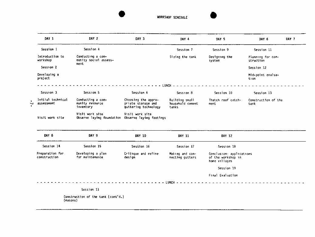
The training is organized into a 12-day w~rkshop with one day free half-waythrough the sessions (see the schedule). Each training session is organizedaccording to a standardized format which provides the trainer with theinformation necessary to conduct training. Each session begins with a synopsiswhich indicates the steps, content, time, and materials. This is followed witha major goal, which is a general intention or outcome for the session. Follow-ing this a series of specific session objectives are stated which are measur-able and indicate most of the session content. The session overview tells whatthe session is intended to accomplish within the perspective of the overallprogram and serves as a framework for th~ activities which follow. For theactivities of a session the trainer is giv~n specific instructions on what todo and say at each step in the session. Suggested times are provided for eachactivity. At the end of a session, trainer notes are provided when necessaryand a list of materials needed for a gUven session is provided. In a fewinstances where a technique is particula1rly complex or requires material,trainer reference notes have been provided. When they occur, they follow thehandouts. I
If handouts are required for a session, they are at the end of the section.All of the handouts for all of the session~s (for purposes of duplication) arecontained in the Participant Reference Packet, an appendix which is intendedas a take-home packet for the trainees.
1.5.2 Methodology
The methods depend upon the active participation of the participants who arewilling to try out activities, reflect upon and “process” those activities,
-4-

and derive generalized learning which can be applied later in the worksetting. The training activities are designed to be practical “hands-on” work.That is, an activity which is the same as or nearly the same as the actualwork which will be done later on the job. The trainer acts as a guide or coachwhich allows the participant to try out the skill first and then learn fromthe experience. Theory is provided by using written handouts and an occasional“lecturette” by the trainer.
Since this workshop is designed on principles of adult learning andexperiential methodologies, some of the common workshop activities are:
• Lecturettes/discussions (short trainer-led presentations anddiscussions)
• Demonstrations• Large group discussions• Small group work tasks• Role plays
• • Simulations• Case studies• Critical incidents (problems)• Questionnaires• Individual reading and reflecting
All methods are designed to put the learner in the active role--doing tasks,solving problems, working with others to plan activities, developingstrategies, and trying things out, etc. Trainees work in this active role bothas individuals and as members of a working group.
In a larger sense, the entire training program for which this material isdesigned is an extended case study. However, rather than provide a writtencase study which would be somewhat abstract, a real community is used as thetraining example. This allows the training program to take local conditionsinto account and provide a “tailored” approach to the many different condi-tions which may be encountered throughout the world where rainwater roofcatchment may be used. However, this also creates special planning responsi-bilities for the trainer and the organization which sponsors and arranges forthe training program (this is discussed in the next section).
1.6 Planning for the Training Program
There are a number of planning considerations for conducting this workshop.These are discussed in chronological order.
1.6.1 Selecting the Trainers
We have discussed the minimum skills necessary for using this training guide.The ideal training team would consist of an experienced trainer with a com-munity promotion background and a construction foreman with experience in theconstruction technology to be used. While there is little “hard” engineeringin this program, a knowledge of calculations and math and basic constructionpractice is essential to teach the technical parts of the program. Anexperienced mason who is literate could also work as the technical trainer.
—5—

. .
. WORKSHOPSCHEDULE S
DAY 1 DAY 2 DAY 3 DAY 4 DAY 5 DAY 6 DAY 7
Session 1 Session 4 Session 7 Session 9 SessIon 11
Introduction to Conducting a corn—workshop munity social assess—
mentSession 2
Sizing the tank Designing the Planning for con-system struction
SessIon 12
Developing aproject
Mid-point evalua—tion
LUNOl
Session 3 Session 5 Session 6 Session 8 Session 10 Session 13
Initial technical Conducting a corn—assessment munity resource
Inventory
Choosing the appro- Building smallpriate storage and household cementguttering technology tanks
Thatch roof catch- Construction of thement tank
Visit work siteVisit work site Observe laying foundation
Visit work siteObserve lay~~ng footings
DAY 8 DAY 9 DAY 10 DAY 11 DAY 12
Session 14 Session 15 Session 16 Session 17 Session 18
Preparation for Developing a planconstruction for maintenance
Critique and refine Making and con-design necting gutters
Conclusion: applicationsof the workshop inhome villages
Session 19
Final Evaluation
LUNCH
Session 13
Construction of the tank (contd.)(masons)

. .

Both trainers need to be able to let the participants try out skills withoutwanting to do the work for them. The training designs are based upon alearning—by—doing approach with the trainers serving as facilitators. It mayalso be advantageous to the project sponsoring the workshop to assign anassistant trainer to work with the trainers to learn how to run the workshopin the future.
1.6.2 Selecting the Participants
The assumption of all of these training materials is that a community levelpromoter (such as a health extension worker) will be able to guide the devel-opment of rainwater roof catchment projects if he/she is provided assistancewith the construction from local masons. We do not assume that a healthpromoter will be able to learn all of the skills necessary to become a mason,but he/she should understand all of the steps necessary to guide the process.Participants should be selected keeping this in mind. They should be involvedin community promotion activities, be able to learn a certain amount of tech—nical material, and be willing to work with their hands to demonstrate tech-niques and assist local masons.
1.6.3 Selecting a Training Site
There are a number of considerations for selecting the location for thetraining. The materials are designed to use an actual village as a trainingcase study or laboratory. Therefore, it is important that the community’sneeds and point of view be taken into account before they are “invaded” by agroup of participants to put up roof catchment devices and construct one ormore tanks. The community should:
• Have the physical characteristics to make such systems technicallyfeasible: i.e., have adequate rainfall and roofs that can be used tocatch water. Along with zinc pan roofs, a thatch roof should be availablefor Session 10. At least one large roof such as a school or dispensarywill be required. If a communal tank is to be demonstrated the siteshould be in an area which has enough rainfall so that such a projectwill work.
• Have demonstrated interest through prior investigation and promotion in aproject: i.e., be willing to care for a system once installed, be willingto cooperate in community survey activities, construction, and projectfinancing (if the project is not to be a demonstration “donation”).
• Have the requisite local resources: construction materials, tools,aptitudes and labor. All construction technologies require local sand andwater to be mixed with cement. Clean gravel will also be needed for someconstruction methods and steps. Bamboo, bush poles, wood boards, twine,wicker baskets, etc. are often needed. Local masons and iron workers, andmasons, helpers and/or laborers are also needed.
• Have or be near a classroom facility, or a room large enough to handlethe group, as well as suitable space for lodging and eating. Theparticipants will be working in the community part of the time, and in a
- 9-.

classroom setting part of the time. School dormitories are often the bestalternative but are not always available. Lodging and food can becomevery important if they are inadequate. You need not have such facilitiesin the village, but the village should not be too far away from theclassroom site and dormitories or unnecessary time will be spent travel-ing to and from the training room an~ the village. A good rule of thumbis to spend no more than 20 minutes travelling between sites (10 to 15minutes is better).
• Possess a building with a large enough roof to fill a communal cistern:Many tanks and gutters may be added to meet the needs of a large villageafter the training demonstration. On a small village may be selectedwhich can be substantially helped with one large catchment system builtwith a school or a dispensary roof. This should be taken into account inthe selection of a site. The training workshop is designed to demonstrateboth individual family size tanks and a large tank and catchment system.It is important that the conriunity be aware of what is going to takeplace in this regard.
Once a training site has been identified and chosen, a three-month process ofsite preparation can start. The amount of time needed to prepare a villagesite for this workshop will depend on the availability and proximity of cons-truction materials, the amount of time available to the community to collectthe materials, and the difficulty of securing rooms for lodging and a placefor cooking and eating. The distance of the site from the project headquartersand the ease with which the workshop trainers and logistics coordinator canvisit the site on a regular basis are also factors in how much lead time isrequired. Never underestimate the amount of time it may take to set up avillage as a training site. An unprepared kite or one with inadequate hastilyprepared logistical support can ruin an oth~erwise well prepared workshop.
1.6.4 Preparation for Training Sessions
The trainers will need to carefully read tt~rough all of the training sessionswell in advance of the workshop and double check all of the materials neededunder local conditions. Written materials ‘will need to be ordered or dupli-cated. The trainers will need to prepare their presentations and writeinstructions to the group and lecturette material outlines on newsprint. Eachtraining session is designed as a guide to the trainer. He/she may need toadapt the session in some way to the learning needs of the participants, toavailable time and resources, or to his/her’ personal style.
Preparation for Construction
A considerable amount of preparation is required for the construction sessionsof the training. The design of Session 13:: Construction of the Tank is non-specific and must be completed for the~ specific construction technologyselected. Construction guidelines with tra~ner suggestions for processing andgeneralizing questions for several common construction technologies are givenin the trainer notes to help in finalizing~ the session design. This work willhave to be undertaken by the lead trainer/training coordinator and theconstruction foreman in charge of supervising the construction of the demon-stration systems and answering technical questions before the start of thetraining.
-10-

The construction sessions are designed to give the participants hands-onknowledge of the construction process which they will be called upon tosupervise when implementing a rainwater roof catchment project. The goal ofthe practcal sessions is to permit the participants to learn all the steps inthe construction of a rainwater roof catchment system and to improve theirskills in common construction techniques (mixing and pouring concrete, mixingand applying plaster, etc.). These learning needs must be balanced with thehost community’s needs for an alternative or supplemental potable water supplysystem.
In balancing these needs, the training staff must design a system thatprovides potable water using locally available resources. If the system isbeyond the resources of the community it will not be replicable and its valueas a model will be lost. The system should also approximate the kind of systemmost of the participants will have the resources to construct after the work-shop. The choice of a construction technology (i .e., cement block or bakedbrick, poured concrete, ferrocement lined pit, etc.) therefore must balancethe participants needs to practice a technology which they may use in theirwork with the technology most replicable for the community in which the train-ing is taking place. This factor has to he considered in selecting the site.
The system must also be designed so that it can be finished by theparticipants with the help of local masons and workers by the end of theworkshop. It is essential that the participants be able to complete an entiresystem and understand the entire process. The need to complete a large,community-size rainwater roof catchment system (with a tank of approximately10 cubic meters supplied by a roof surface of from 40 to 80 square meters)during the course of the workshop in such a manner so that the participantscan observe and participate in all the steps in the construction process takescareful planning and organization.
The task guide for the development of a rainwater roof catchment project(Handout 2-1) introduced in Session 2 and included in the ParticipantReference Packet should be followed by the trainers in planning and designingthe demonstration system two months before the start of the workshop to allowsufficient time to prepare the community and gather all the necessaryconstruction materials. The actual construction of the system can take fromtwo to four weeks depending upon its size, the technology used, and the numberof participants and local masons and workers available. This means that someof the construction will have to be started before the participants have timeto take part in the work. Wherever possible, the construction should beplanned to permit key steps such as pouring the footings for the wall, to beobserved by the participants during the first week of the workshop.
In general , plan the construction schedule by moving backwards from Day 10when the tank should be completed to whenever it has to be started. Inrireparing the site for construction, remember that it should be a model of anefficient work site and must be able to accommodate up to 20 participants andfive local workers.
In addition to preparing for the construction of the community system, thetrainers will have to prepare materials and the community for the twopractical sessions which occur during the first week of the workshop (buildingsmall household cement jars and a thatch roof catchment system). The bases for
—11—

the household jars should be constructed~five days prior to the practicalsessions so they have adequate time to cure.
All times given for the practical construction sessions are approximate andwill have to be adapted to local conditions and participant skills.
1.6.5 Ordering Materials
The following materials are needed for classroom training and constructiondemonstrations and must be ordered and ready ahead of time.
Classroom Supplies
o Notebooks, graph paper, pen and pencilso A flipchart, or at least a blackboardo Tables and chairso Magic markers or large writing pens, newsprinto Data on rainfall patterns in the area: month by month totals are most
useful; yearly averages are least useful
Construction Materials
A variety of tools and materials will be needed to construct a large communityroof catchment system, small family size tanks, and a thatch roof catchmentsystem. The size of the tank and the method for its construction will dependupon the learning needs of the participants, water supply needs and prefer-ences of the community, available local r:esources, the workshop time frame,and budget. The actual quality of constróction materials and the number oftools will vary for each workshop and will have to be determined during theplanning of the workshop. The following list should not be consideredexhaustive but used only as a guide.
• Cement I• Clean gravel• Clean coarse sand I• Water I• Reinforcing rod for reinforced concr1ete• Wood boards for poured concrete mold1s, wood box filters, gutter braces• Chicken wire for ferrocement construction• Corrugated iron sheeting for gutters• Bamboo, boards, PVC pipe for gutters’• Sacking materials (125 cm x 110 cm) for molds for Thailand jars• Local wicker baskets (100-200 liter) for “ghala” basket jars• Oil drum for filter I
• Charcoal , rice husks, or coconut fib~rs for thatch fil ter• Cement block molds for block construction• Nails I• Wire or local tying material• Bush poles I• Trowels (one per participant)• Shovels• Pickets• Buckets
-12—

• Levels• Tape measure and meter stick• Woodworking tools (haniliers, saws, drill)• Iron working tools (shears, hacksaw, drill)• Welding tools (blow torch and solder if available)• Large needles and thread for sewing sacking materials• Tar or local resin to seal gutters
1.6.6 Workshop Checklist and Timetable
The following table indicates the key steps and time frame for planning andimplementing the Rainwater Roof Catchment Workshop:
Time to be CompletedActivity Before Workshop
Determine role, experience, and learningneeds of participant group 4 months
Determine how workshop will fit in withon—going water supply and sanitationprogram, and how workshop activities(including training site demonstration)will be followed up 4 months
Develop preliminary budget 4 months
Identify/hire workshop coordinator/leadtrainer 4 months
Identify potential villages and startsite selection process 4 months
Get up-to-date information on localrainfall patterns, the existing watersupply system, consumption patterns,etc., for prospective training sites 3 months
Select an appropriate village or communityas a training site and start involving themin planning/preparation 3 months
Identify/hire rest of training staff(construction foreman, logistics coor-dinator, co—trainers) 2 months
Decide on number of participants; identifyand recruit them 2 months
Locate and, if necessary, start preparinglodging, eating, and classroom facilitiesat site; identify all logistical needs andplan acquisition 2 months
-13-

Time to be CompletedActivity Before Workshop
Conduct a community resource inventory andccimnunity evaluation, and start motivatingcommunity to provide promised materials(sand, gravel, wood, etc.) and labor 2 months
Determine construction methodology to beused in the demonstration system, selectsite and design system, and start orderingmaterials and preparing construction plans 2 months
Finalize budget 2 months
Inform participants of workshop format andgeneral goals, site, and travel arrangements,etc. 1 month
Work with the village or villages to preparethem for their involvement in the worksho~5;start gathering local materials and discusswork with local masons, ironworkers, etc., 1 month
Arrange all transportaton necessary forparticipants, materials, food purchase, etc. I month
Finalize all site logistics; hire cooks anddevelop menu and budget if needed; purchaseSite logistic materials; start preparing the site 1 month
Purchase all training and constructionmaterials, tools, etc. I month
Design specifics of practical constructior~sessions based on choice of construction Itechnology to be used at site I 1 month
Prepare all handouts for participants I 1 month
Identify and prepare storeroom and I
construction site for receiving materials I 1 month
Entire staff arrives at training site and Istarts final workshop preparations, staff,training, and comunity mobilization 2 weeks
Construction foreman starts working withlocal skilled and unskilled labor to prep~reconstruction site and work plan and startssome of the construction depending upon th’etechnology 2 weeks
-14-

Time to be CompletedActivity Before Workshop
Lead and co—trainers hold final briefingsfor community to make sure they understandand are motiviated to fulfill theirresponsibilities 1 week
Trainers prepare all training materials,finalize design adaptations, and plan imple-mentation of each session 1 week
Begin training -
1.6.7 Preparing the Staff to Conduct the Training Program
In order for a training program of this complexity to be conducted• effectively, with events running smoothly, the training staff must certainly
work together as a team. A vital part of working together as a team is havingtime together before the workshop begins to plan and coordinate how the train-ing activities will be delivered. These planning activities would include:
• A concerted effort to build the teamwork needed
• Arriving at a mutual understanding and clarity on how the trainingprogram will go
• Making decisions on which trainer will do what
• Preparation for conducting workshop sessions
• Advance preparation for trainee field work (at site and in thecommuni ty)
• Planning how workshop time and site progress will be coordinated
• Getting training materials ready
• Personal preparation time to get ready to deliver a session
• Planning for brief, daily staff meetings throughout the course
1.7 Task Analysis
The following task analysis is a list of all the major tasks involved indeveloping a rainwater roof catchment project and system. The tasks areanalyzed in three dimensions: difficulty, importance, and new or improvedskills for the intended workshop participants. In this analysis the number onedenotes the highest degree of importance or difficulty, the number threedenotes the lowest. For example, a task which is rated one in importance,means that it is very important and a task which is rated three is notcritical but important enough to be taught in the workshop. The task analysis
-15-

is used as the basis of the workshop design. It is also used in slightlyaltered form in Session 2, Developing a Rai~nwater Roof Catchrnent Project, as aguide to project development.
Task Analysis
Determining Coniiiunity Needs Diifficulty Importance New orand Interest (initial) I ____________ Improved
1. Determine extent of community need 3 1 Imp
• find out how water is currentlysupplied , 3 1 Imp
• find out role of women and childrenin carrying water and amount oftime now spent on this activity 3 1 Imp
• does the need justify proceedingat this point? I 2 1 rmp
2. Talk with community people and leadersto promote the idea of rainwater catch-ment; determine initial interest 3 1 Imp
• make individual house calls 3 1 Imp
• talk with co~nliunity members inwork settings I 3 1 Imp
• begin promotion of ideas as a test
of support 2 1 Imp
• discover potential supports 2 1 Imp
3. Decide if the community is interested Ienough to justify a promotional I
effort I 1 1 Imp
• does leadership exist for conullunitymobilization? 2 1 Imp
Initial Technical Assessment
1. Identi fy best sources ofinformation on local rainfall
• find any weather statistics 3 New
• talk with local people (olderpeople) about wet and dryperiods 3 1 Imp
-16-

Initial Technical Assessment Difficulty Importance New or____________ ____________ Improved
• effectiveness of rainwater catch-ment systems in use 3 1 Imp
2. Identify acceptable roofs 3 1 Imp
• identify suitable surfaces
• measure roofs
3. Plot available rainfall data andrough calculation of yield froma local roof 1 1 New
4. Decide if there is enough rain and
catchment area to proceed 3 1 New
.Detailed Social and CommunityAssessment
1. Collect opinions: would additionalwater increment from a rooftopcatchment system be useful? 2 1 New
2. Explore commitment villagerswould make:
• sharing a roof and tank 2 or 1 1 Imp
• contributing labor and/or moneytoward construction
3. Find out how many systems andpeople are concerned 3 1 Imp
4. Decide whether the coniiiunity supportsrooftop catchment enough to proceed 1 1 Imp
Inventory of Local Skills
,
Materials, and Experience
1. Find out whether there are localmasons who can build with cementor mortar/stone 3 1 Imp
2. Find out whether there are crafts-people who construct vessels usinglocal fiber 3 1 Imp
—17—

Difficulty Importance New or_____ ______ ____________ Improved
3. Determine availability and costs of
tank construction materials 1 Imp
• cement, stone, sand, gravel , bricks 3 1 Imp
• reeds, bamboo, chicken wire, Istraight wire 3 1 Imp
• shovels, trowels, etc. 3 1 Imp
4. Determine local availability ofguttening materials 2 1 New/Imp
•wood 2 1
• PVC pipe 2 1
• sheet metal 2 1
5. Determine availability and cost Iof roofing materials 3 1 Imp
6. Determine how local people havecollected and stored rainwaterto date 1 Imp
• storage containers
• water hauling vessels: buckets,tins, etc.
• lined holes in ground
7. Begin community promotion I .• will skilled people be willing Ito contribute time? 1 Imp
Choosing an Appropriate Comnbina-ET1 w99 238 m292 238 lSBTtion of Technologies with theCommunity
1. Present the range of tank andguttering technologies 1 1 New
2. Decide on individual or convilunitytank with community 1 New
3. Discuss maintenance activities andtype of outlet for each type of tank 2 1 New
-18-

Difficulty Importance New or
___________ ______________ Improved
4. List material requirements;estimate costs of different tanktypes 1 1 New
5. List levels of skills requiredto construct each type of tank 2 1 New/Imp
6. Evaluate amount of labor (e.g.,person-days) required forconstruction of each tank type 2 1 New
7. Use these criteria to decide withcommunity which option is best andmobilize community commitment forlabor and cost contributions 1 1 New
Designing the RainwaterCatchment System
1. Using projected yield patternfrom local roofs, figureoptimum tank volume 1 1 or 2 New
2. Determine how big a tankavailable resources permit 2 1 New
3. Determine location(s) andtype of outlet 2 1 New
4. Design gutters 1 or 2 1 Newand foul-flush routines ormechanism 1 or 2 1 New
5. Choose specifications: founda-tion, floor, walls, cover (useguidelines provided to determinematerials and thickness) I I New
Ordering/Gathering Materialsand Organizing to Construct
1. Order materials: when willthey arrive? 3 1 Imp
2. Devise sequence of steps andconstruction schedule withcommunity participation 2 1 New
-19-

Di ffi cul ty Importance New or___________ ____________ Improved
3. Organize construction teams. Whowill work? When will they work? 3 1
4. Get materials to site atchosen time 3 1 Imp
5. Determine place to keep/storematerials 3 1 Imp
Construction of System
1. Prepare/excavate site 2/3 1 Imp
2. Prepare form work for floor 3 1 New
3. Place reinforcement (if necessary) 3 1 New
4. Mix/pour concrete floor 2 1 Imp
5. Prepare form work for walls 1-3 1 New
6. Place wall reinforcement(if necessary) 13 1 New
7. Mix mortar and construct wall 1 1 Imp
8. Mix and apply waterproofing plaster 1 1 Imp
9. Construct roof/cover and place 2 1 Imp
10. Cure-cement work I 1 New
11. Provide for tank drainage 3 1 Imp I12. Prepare and attach gutters 2 1 New
13. Hook up down pipe/foul flush 2 1 New
Note: Nos. 5 and 6 vary depending on type of tank, e.g., above groundferrocement tank is very difficult; ferrocement lined pit is easy.
-20-

Monitoring and Maintenance Difficulty Importance New or_____________ ______________ Improved
1. Instruct users in
• regular use of foul flush 3 1 New
O cleaning of catchment area!gutter/screens/tank 3 1 Imp
• checking for cracks/leaks/overflow 3 1 Imp
• checking tank drainage 3 1 New
• checking water quality (taste!color/odor) 3 1 Imp
. 2. Develop cleaning/inspection schedule 2 1 New
3. Organize community maintenance group 2 1 Imp
1.8 Pre—workshop Skill Assessment
The above task analysis also provides the basis for the pre-workshop skillassessment. The following skill assessment form should be filled out by theparticipants prior to the start of the workshop. It provides the trainer withan idea of the skill level and hence learning needs of the participants. If itcan be completed a month before the start of the workshop it can be used inadapting the workshop design to the participants’ learning needs; if not, itcan be useful in determining how much stress to give to specific learningobjectives in each session. It also provides trainers and participants with abasis on which to assess the participants’ progress in improving or developingthe skills needed to perform the tasks inherent in planning and implementing aroof catchment project.
I
-21-

. S

Pre-Workshop Handout, p.1
Skill Area
1. Identify the technical feasi-bility of a rainwater catchmentproject
• identify best sources of informa-
tion on local rainfall
• identify suitable roof surfaces
• calculate roof yield from above
2. Social and community assessment
• survey community needs
• assess community interest
• determine community preference
for individual or group project• present information to a community
• Local resource inventory
• identify available materials
• identify available skills
• determine resources needed
for a roof catchment project
• determine conviiunity’s prior
experience with such a project
4. Choose an appropriate combination
of technologies
• familiar with alternativetechnologies used in constructinga water tank
PRE-WORKSHOPSKILL ASSESSMENTFORM
Please fill out the following form by checking in the appropriate columnwhether you feel that you have no experience, some skill, or adequatecompetency in the following skill areas:
NoExperience
SomeSkill
AdequateCompetency
-23-
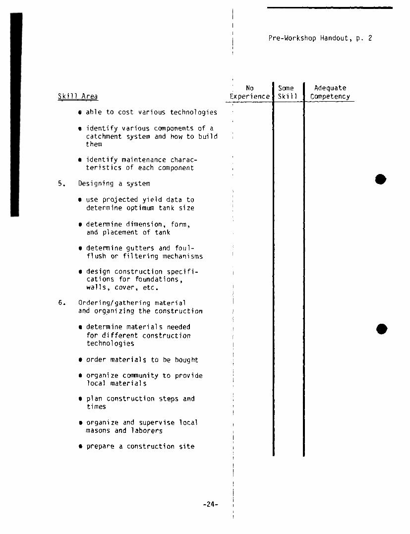
Pre-Workshop Handout, p. 2
No Some AdequateSkill Area Experience Skill Competency
• able to cost various technologies
• identify various components of acatchment system and how to buildthem
• identify maintenance charac-teristics of each component
5. Designing a system
• use projected yield data todetermine optimum tank size
• determine dimension, form,and placement of tank
• determine gutters and foul-flush or filtering mechanisms
• design construction specifi-cations for foundations,walls, cover, etc.
6. Ordering/gathering materialand organizing the construction
• determine materials neededfor different constructiontechnol ogies
• order materials to be bought
• organize cociwnunity to providelocal materials
• plan construction steps andtimes
• organize and supervise localmasons and laborers
• prepare a construction site
-24-

Pre-Workshop Handout, p. 3
Skill Area
7. Construction skills
• mix and apply mortar
• mix and pour concrete
• use reinforcing rod inreinforced concrete
• use chicken wire in ferrocement
• construct cement blocks
• lay blocks or bricks
• construct forms for pouringconcrete walls, foundations,top slabs
• waterproof a tank
• construct and install gutters
• construct and install downspout, foul flush and filters
• disinfect the system
• cure concrete and plaster
8. Monitoring and maintenance
• organize a community to maintaina roof catchment system
• assess a community’s skillsand willingness to maintainsuch a system
• teach community members tomaintain the system
• monitor water quality
NoExperience
SomeSkill
AdequateCompetency
S
.
-25-

S.

S I
SESSION 1

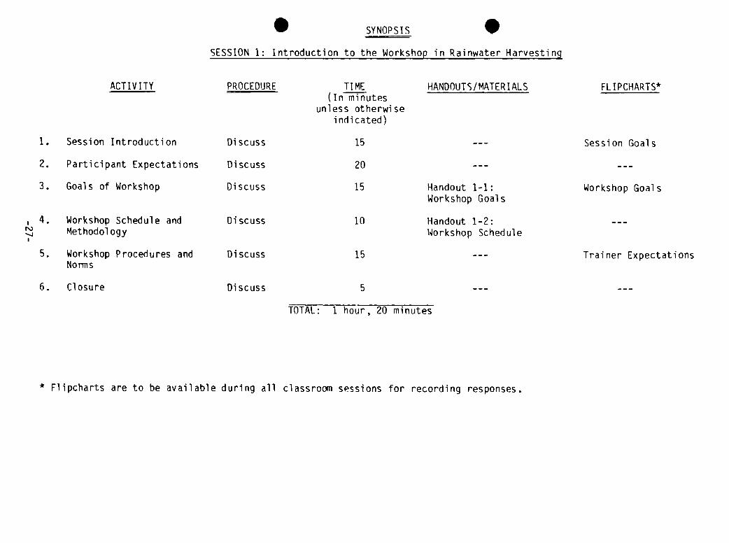
SYNOPSIS
SESSION 1: Introduction to the Workshop in Rainwater Harvesting
ACTIVITY PROCEDURE TI ME(In minutes
unless otherwiseindicated)
HANDOUTS/MATERIALS FLIPCHARTS*
1. Session Introduction
2. Participant Expectations
3. Goals of Workshop
4. Workshop Schedule andMethodology
5. Workshop Procedures andNorms
6. Closure
Di scuss
Discuss
Di scuss
Discuss
Discuss
Discuss
15
20
15
10
15
5
Handout 1-1:Workshop Goals
Handout 1-2:Workshop Schedule
Session Goals
Workshop Goals
Trainer Expectations
TOTAL: 1 hour, 20 minutes
S .
* Flipcharts are to be available during all classroom sessions for recording responses.

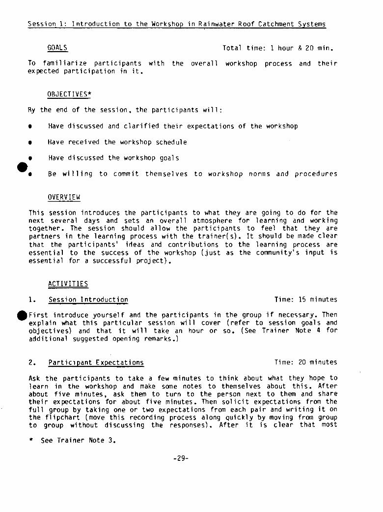
Session 1: Introduction to the Workshop in Rainwater Roof Catchment Systems
GOALS Total time: 1 hour & 20 mm.
To familiarize participants with the overall workshop process and their
expected participation in it.
OBJECTIVES*
By the end of the session, the participants will:
• Have discussed and clarified their expectations of the workshop
• Have received the workshop schedule
• Have discussed the workshop goals
Be willing to commit themselves to workshop norms and procedures
OVERVIEW
This session introduces the participants to what they are going to do for thenext several days and sets an overall atmosphere for learning and workingtogether. The session should allow the participants to feel that they arepartners in the learning process with the trainer(s). It should be made clearthat the participants’ ideas and contributions to the learning process areessential to the success of the workshop (just as the coniTiunity’s input isessential for a successful project).
ACTIVITIES
1. Session Introduction Time: 15 minutes
5 First introduce yourself and the participants in the group if necessary. Thenexplain what this particular session will cover (refer to session goals andobjectives) and that it will take an hour or so. (See Trainer Note 4 foradditional suggested opening remarks.)
2. Participant Expectations Time: 20 minutes
Ask the participants to take a few minutes to think about what they hope tolearn in the workshop and make some notes to themselves about this. Afterabout five minutes, ask them to turn to the person next to them and sharetheir expectations for about five minutes. Then solicit expectations from thefull group by taking one or two expectations from each pair and writing it onthe flipchart (move this recording process along quickly by moving from groupto group without discussing the responses). After it is clear that most
* See Trainer Note 3.
-29-
expectations have been recorded, discuss ~nd clarify each expectation. In thisdiscussion, clarify what will and will not be covered. This discussion willflow naturally into the workshop goals and schedule (Steps 3 and 4 below).
3. Goals of the Workshqp , Time: 15 minutes
Distribute Handout 1-1: Workshop Goals far Participants* and have the goalswritten up on a chalkboard or flipchart. Go over the goals with the group andmake sure they are clear and understood. If the group has comments on thegoals or wishes clarification discuss the issues that are raised.
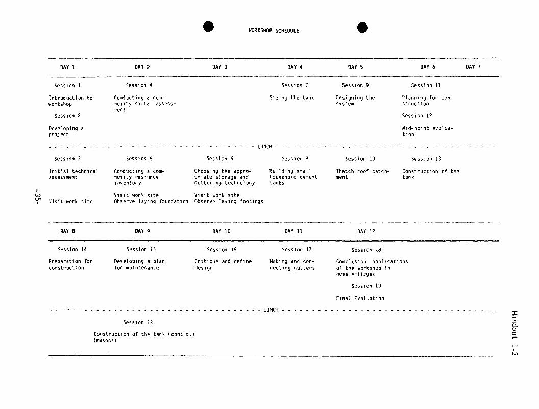
4. Workshop Schedule and Methodology Time: 10 minutes
Distribute Handout 1-2: Workshop Schedule. Go over this and explain ingeneral how the training activities are arranged to meet the goals. Explainthe kinds of activities which will be taking place each day. Make sure it isclear that the participants are at a “workshop” and not a traditional courseThey are going to learn principally by doing. The methodologies used will bcase studies, field experiences, group and individual problem solving,discussions, role play, demonstration, and practice skill building.
5. Workshop Procedures and Norms Time: 15 minutes
Since the group will be working together for two weeks, it is important tomake clear and discuss how everyone will work together to avoid future mis-understanding. Have a list prepared of expectations that the trainer(s) has(have) of the group. List such things as starting and ending times, expecta-tions for the use of time, and expectations of group participation andresponsibilities. If you expect the paCticipants to work with their handssometimes, say so. Ask them if they have any particular expectations of theinstructor or of each other. Add these to the list and discuss. By the end ofthis segment, all participants should 6e clear about how they will worktogether and what is expected of them. I
6. Closure Time: 5 minute•
Refer back to session goals. Ask if ever))one is clear about what the workshopwill cover and how it will be done. Link ‘this session to the next session bysaying, for example, “Now that we know what we are going to do, we will startwith a review of everything one does in a’rainwater roof catchment project.”
* Handouts are located at the end of each session. They are also collected
into a reference packet called the Participant Reference Packet which is anappendix to this training guide.
-30-

TRAINER NOTES
1. This session may seem very simple, and you may wonder why it is beingdone. It is important that the participants be treated as adults and knowwhat they are getting into and why. If these matters are dealt with atthe beginning, a lot of time and trouble is saved in the long run. It isalso important that group members approach their work together with thetrainer in the same way that a project is approached in the comunity.This session establishes this framework.
2. You will need to prepare the materials to hand out and/or have thingswritten up on a flipchart or chalkboard. You will also need to thinkabout the expectations you have for workshop norms ahead of time and havethem listed on a flipchart.
3. A “get acquainted” exercise has not been included in the goals and thesession design, except for a brief exchange in Step 1. It is suggested,if participants do not know each other, that this step be dealt withprior to this session (e.g. the night before). If this is not possible,then the time of this session should be expanded by about 30 minutes todo a short exercise. A useful exercise is to ask all participants tostate who they are, what they do, where they come from and one thing theyexpect to learn in the workshop. The last point is recorded by thetrainer and used to compare with the actual workshop goals in Step 2.Another exercise is to ask participants to interview each other in pairsand present the person interviewed to the group. This is a good ice-breaker and allows people to get to know each other.
4. In Step 1, the trainer may wish to briefly introduce the topic ofrainwater roof catchment systems, explaining why one decides to use themas opposed to other water supply approaches.
5. If a formal “opening ceremony” is planned on the first day, it will beabsolutely necessary to do this session the night before. Pilot testingof this workshop indicates that the first day of the workshop is veryfull. It is strongly suggested that participants arrive the day beforethe formal opening ceremony and settle in. Then this session can beI conducted as an evening activity on the arrival day.
MATERIALS
- Flipchart for workshop goals- Flipchart for workshop schedule- Flipchart for workshop norms— Handout 1—1: Workshop Goals for Participants- Handout 1-2: Workshop Schedule
-31-

.
.
Handout 1—1
WORKSHOP GOALS FOR PARTICIPANT
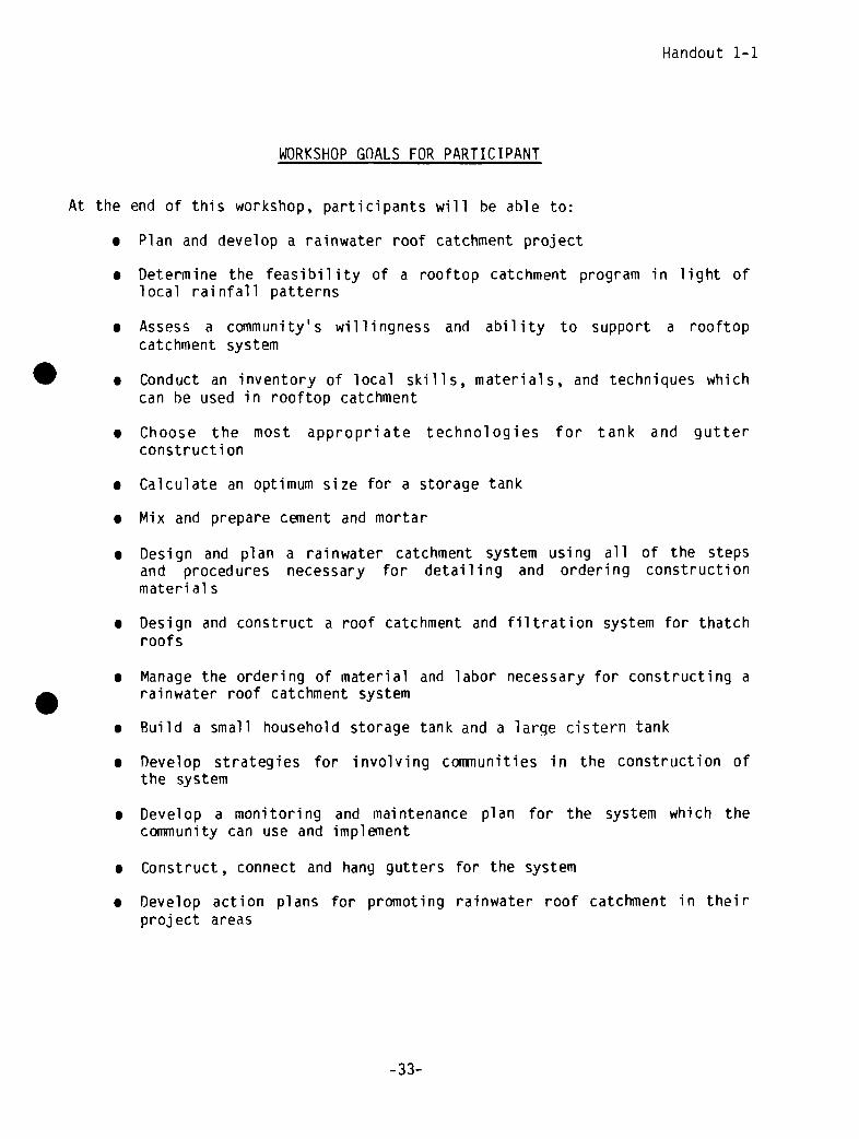
At the end of this workshop, participants will be able to:
• Plan and develop a rainwater roof catchrnent project
• Determine the feasibility of a rooftop catchment program in light of
local rainfall patterns
• Assess a community’s willingness and ability to support a rooftop
catchment system
• Conduct an inventory of local skills, materials, and techniques which
can he used in rooftop catchment
• Choose the most appropriate technologies for tank and gutter
constructi on• Calculate an optimum size for a storage tank
• Mix and prepare cement and mortar
• Design and plan a rainwater catchment system using all of the stepsand procedures necessary for detailing and ordering constructionmaterial s
• Design and construct a roof catchment and filtration system for thatchroofs
• Manage the ordering of material and labor necessary for constructing a
rainwater roof catchment system
• Build a small household storage tank and a large cistern tank
• Develop strategies for involving coniiiunities in the construction of
the system
• Develop a monitoring and maintenance plan for the system which the
community can use and implement
• Construct, connect and hang gutters for the system
• Develop action plans for promoting rainwater roof catchment in theirproject areas
-33-

S
I
S WORKSHOPSCHEDULE S
Session 14
Preparation forconstructi on
Session 15
Developing a planfor maintenance
Session 16
Critique and refinedesign
Session 17
Making and con-necting gutters
Session 18
Conclusion applicationsof the workshop inhome villages
Session 19
Final Evaluation
U,
DAY 1 DAY 2 DAY 3 DAY 4 DAY 5 DAY 6 DAY 7
Session 1 Session 4 Session 7 Session 9 Session 11
Introduction to Conducting a corn- Sizing the tank Designing the Planning for con-workshop munity social assess-
mentsystem struction
Session 2 Session 12
Developing a Mid-point evalua-project tion
UJNCH
Session 3 Session 5 Session f Session 8 Session 10 Session 13
Initial technical Conducting a corn— Choosing the appro- Building small Thatch roof catch- Construction of theassessment munity resource
inventorypriate storage and household cementguttering technology tanks
ment tank
Visit work siteVisit work siteObserve laying foundation
Visit work SiteObserve laying footings
DAY 8 I~Y 9 DAY 10 DAY 11 DAY 12
LUNCH
Session 13
Construction of the tank (contd.)(masons)
=0)
0~0
(-t-
N.)

S
S

S S
- SESSION 2 -


.SYNOPSIS
.
SESSION 2: Developing a Rainwater Harvesting Project
ACTIVITY PROCEDURE TIME(In minutes
unless otherwiseindicated)
HANDOUTS/MATERIALS FLIPCHARTS
1. Introduction Discussion 5 Goals of Session
2. Project Steps Question, Answer,Re ad
45 Handout 2—1:Task Guide
3. Considering LocalOptions
Small Group Task 40 Handout 2-2:Decisions in theProcess of ProjectDevel opment
4. Reports from SmallGroups
Discussion 30
5. Listing ProjectPrerequisites
Writing, AskExamples
10 Instructions for Task
6. Closure: FutureApplications
Discussion 5
TOTAL: 2 hours, 15 minutes

.

Session 2: Developing a Rainwater Roof Catchment Project
GOALS Total time: 2 hours & 15 mm.
To learn the major steps and basic considerations in planning and developing arainwater roof catchment project and how to adapt them to the unique condi-tions of the local setting.
OBJECTIVES
At the end of the session the participants will be able to:
• Analyze and review the task guide and decision diagram for rainwater roofcatchment projects and describe what is involved in a project
5. Consider how local conditions and needs produce variations in the projectcycle
• List the basic prerequisites for undertaking a rainwater catchmentproject
OVERVIEW
This is a major orientation session which explains what is involved in theprocess of developing a rainwater catchment project. This session sets thestage for all of the learning activities which follow in the workshop. As suchit is a key session. There are a lot of factors which must be taken intoaccount to determine if a rainwater project makes sense. There are also anumber of decisions which must be made alor~g the way with local users. Thissession systematically takes the participants through the steps of projectdevelopment and decision-making. The workshop sessions which follow alsoprovide training in each of the steps.
ACTIVITIES
1. Introduction Time: 5 minutes
Introduce the session by restating the content of the overview. Share thesession goals and objectives (which should be written on a flipchart).
2. Project Steps Time: 45 minutes
Distribute Handout 2-1: Task Guide and Handout 2~2: Decisions in the Processof Project Development. Ask the participants to briefly review these handouts.Go over each step in the task guide and explain it.
-39-
Refer to the necessary decisions along the way using the decision chart.Answer any questions that come up without going into all of the detail whichwill be covered in subsequent sessions. (See Trainer Note 2.)
3. Considering Local Options Time: 40 minutes
Ask the participants to divide into small groups of four or five and go overthe project steps, thinking about a particular community project and villagethey have worked in. Ask them to consider what might be feasible in thatparticular community situation and how its major steps or tasks may differfrom those in the project guide. Ask them to note down the major points intheir discussions so that they can explain them later to the rest of the groupwhen they get back together. Write these tasks on a flipchart.
4. Reports from the Small Groups Time: 30 minutes
Ask each group to report and ask for comments. Answer any questions anddiscuss all appropriate issues.
5. Listing Project Prerequisites Time: 10 minutes
Say: “Now that you have had an opportunity to consider what it takes to do aproject in general and in a community, take a few minutes to consider and listfor yourself what conditions must be present in order to develop a rainwaterroof catchment project.” Ask for examples from people after they havecompleted this so that everyone has an idea of the thinking of the group.
6. Closure: Future Applications Time: 5 minutes
Close the session by referring to the fact that the workshop will systematic-ally provide training in each step in project development. Provide a linkageto the next session by leading into the Tact that we are going to use thedemonstration training community to learn how to conduct an initial technicalassessment. Refer back to the session objectives to see if they have beenreached. I
TRAINER NOTES
1. At some point on Day 1 the first “Visit to the Work Site” should bescheduled. This 30 minute activity is described in Session 13, Visit #1.
2. The trainer should not hand out the entire Participant Reference Packetat this point because it may cause the participants to get involved withreading instead of listening. In this case, just hand out the two chartswhich are appropriate to the task (Handouts 2-1 and 2-2). Almost all ofthe Participant Reference Packet can be handed out in this manner (pieceby piece) as the material is covered. At the end of the workshop theparticipants will have assembled their own Participant Reference Packet.For this reason the Participant Reference Packet has its own pagenumbering system for these handouts as they appear in the Appendix.
-40-

MATERIALS
- F]ipchart for session goals and objectives- Handout 2—1: Task Guide- Handout 2-2: Decisions in the Process of Project Development
-41-


TASK •: MAJOR STEPS iN PROJECT DEVELOPMENTOF RAINWATER INQ
I. DETERMINING COMMJN:TY NEEDS AND lNTEREST~ INITIAL PROI4IfIONI. Detennine extent of comnunity need
— find out how water is currently supplied- find out role of wonen and children in
carrying water and amount of time nowspent in this activity
- does the need justify proceeding at this point’
2. Talk with comnunity people and leaders to promote theidea of rainwater catchrnent; see if interest exists— individual house calls- talk with community members in work settings- begin promotion of idea as a test of support— discover potential supporters
3. Decjde Is this comnunity interested?— enough to justify a pronotional effort’- does leadership exist for coimiunity mobilization’
II. INITIAL TECHNICAL ASSESSMENT1. Identify best sources ofinfonnation on local rainfall
— find any weather statistics— talk with local people (older people) about wet and dry
periods— effectiveness of rainwater catctment systems in use
2. Identify acceptable roofs— identify suitable surfaces
— measure roofs
3. Plot available rainfall data and rough calculationof yield from a local roof
4. DecideS Is there enough rain and catcMent area toproceed?
III. SOCIAL AND COMMJNITY ASSESSMENTI. Collect Opinions- would additional water from a
rooftop catci,nent system be useful
2. Explore conmitmient villagers would make- sharing a roof and tank
— contributing labor and/or money toward construction
3. Find out. How many systems and people are involved’
4. Decide: Does the comeunity support rooftop catchiient
enough to proceed?
IV. INVENTORY OF LOCAL SKILLS, MATERIALS AND EXPERIENCE1. Find out: Are there local masons ~io can build with
cement • mortar/stone?
2. Find out: Are there craftspeople who construct vesselsusing local fiber?
3. Determine availability and costs of tank constructionmaterials:— cement, stone, sand, gravel, bricks- reeds, bamboo, wire, chickenwire- shovels, trowels, etc.
4. Determine availability of guttering materials:- local wood/grasses- PVC pipe- metal sheet
S. Determine availability and cost of roofing materials
6. Determine. How have local people caught and storedrainwater to date’
— traditional water and food storing containers- water hauling vessels- buckets, tins, etc.- lined holes in ground
7. Begin community promotionS- will skilled people be willing to contribute time’
V. CHOOSINGAN APPROPRIATE CO~INATIONOF TECHNOLOGIESWITH THE COMNIJNITY1. Present the range of tank and guttering technologies2. Decide with ccxnmunity~ individual or community tank3. Discuss maintenance activities and type of outlet for each type of
tank4. List material requirements; estimate costs of different typesof
tanksS. List levels of skills required to construct each type of tank6. EvaluateS amount of labor (e.g., person—days) required for
construction of each type of tank7. Use these criteria to decide with community which construction
option is best and mobilize coennunity connitiment for labor and costcontributions
VI. OESIGNING THE RAINWATER HARVESTING SYSTEM1. Using projected yield pattern from local roofs, figure optimum tank
vol lane2. Determine How big a tank do available resources permit?3. Determine location(s) and type of outlet4. Design gutters and foul flush routines or mechanismS. Choose specifications: foundation, floor, walls, cover (use guide-
lines provided to determine materials andthickness)
VII. ORDERING/GATHERINGMATERIALS AND ORGANIZING FOR CONSTRUCTIONI. Order materials~ When will they arrive~2. Devise sequence of steps and construction schedule with community
participation3. Organize construction teams- Who will work, and when will they work?4. Get materials to site at chosen timeS. Determine place to keep/store materials
VIII. CONSTRUCTINGTHE CATCHMENTSYSTEM1. Prepare/excavate site2. Set-up forms, mixing boards, measuring containers3. Mix cement/ conc rete4. Prepare freiiework, if usedS. Ruild footing for cover6. Trowel/apply mortar7. Cure tank8. Fabricate coverg, Hook up gutter/foul flush
IX. ~3NlTORINGAND MAINTENANCEI. Instruct users in:
— watching for cracks/leaks- check water quality
a. visual checksb. smell, taste, etc.
2. Develop cleaning/inspection schedule3. Organize community maintenance group
aCe)
=0)
a0Crt-
N.)

.
.

01
Social
Community
Iarnenj~uPPort~
no
0)
a0
ri-
N.)
.


I
-~ - SESSION3


.
SY NOPSI S
SESSION 3: Initial Technical Assessment
Goals of Session
Talking Points of
Lecturette
(Optional Recap ofHandout on Rainfall)Bar Graphs
ACTIVITY
1. Introduction
2. Lecturette on RainfallMeasurement
3. Roof Yield Calculation
4. Examine Calculations
5. Generalize
6. Application
7. Reports on Survey
8. Compare Information
FLIPCHARTSHANDOUTS/MATERIALS
Monthly Rainfall Totals(obtained from localsources)
PROCEDURE TIME(In minutes
unless otherwiseindicated)
Discuss 5
Lecturette 25
Group Activity 20
Discussion 15
Discussion 10
Survey in Small 90Groups in Village
Group Presentation 20
Discussion 15
TOTAL: 3 hours, 20 minutes

.

Session 3: Initial Technical Assessment
GOAL Total time: 3 hours & 20 mm.
To learn how to examine the feasibility of a rooftop catchment program in
light of local rainfall patterns.
OBJECTIVES
By the end of the session, the participants will be able to:
• Identify useful rainfall data
• Identify sources of rainfall data
• Gather information from local people on rainfall patterns
Assess, identify, and measure suitable roofs for catchments
• Calculate and/or estimate the water yield from a local roof, using theabove data
OVERVIEW
A rainwater roof catchment system will be effective only if enough water canbe collected and stored. The yield or amount of water we can get from arooftop catchment system depends on how much rain falls at different timesduring the year. It is possible to use information on how much rain has fallenin the past as a rough indicator of how much rain is likely to fall in thefuture. Then it is possible to calculate how much water could be collectedfrom a particular roof in the community. These calculations are then checkedby talking with local people, especially people who have tried rooftopcatchment before.
There are two reasons why this information is important. First, the results• will indicate whether there is enough rain collected on local roofs to make a
rooftop catchment project worthwhile. Second, a decision about how big a tankis needed to store the water from the roof depends on how much time passesbetween periods of rain. For example, if an area has a long dry season, awater storage tank should be large so that people have water after the rainshave stopped and until the next rains start. If, on the other hand, there israin all year, water from the roof will refill a tank more frequently and thetank does not need to be as large.
This session raises these issues and gives the participants practice in as-sessing factors which will influence the decision to carry out a rainwaterharvesting project.
-49-
ACTIVITIES
1. Introduction Time: 5 minutes
Give the group the information in the overview, and state the goals andobjectives. Answer any questions.
7. Lecturette: Rainfall Measurement Time: 25 minutes
Explain what rainfall measurements are and explain the importance of correctlyinterpreting rainfall statistics derived from measurements.
Make the following points:
• A rainfall measurement is the depth of water which would accumulate in acontainer with straight vertical sides (like a glass) of a known sizeover a period of time (see Trainer Note 3).
• The amount of rainwater a roof will yield is calculated by first findingout the surface area of a roof. Multiplying the length times the width ofa horizontal area (length x width) gives that area. Rainfall measurementis then obtained for a given geographic area from rainfall statistics.This figure is multiplied by the roof area to obtain the volume of waterfor a given roof at a given time. This is summarized by the equation:rainfall measurement x roof length x roof width = volume of water for themeasurement period.
• In order to get a practical concept of this idea, step outdoors:
— Examine a roof- Pace off or measure its horizontal dimensions- Discuss its effectiveness as a catchment surface. How well will it shed
rain?- Identify other aspects of the roofwhich would reduce the yield. Note
that any roof and guttering system is not 100 percent efficient but canbe assumed to be about 80 percent efficient. This is because a certainamount of water will splash off or blow off in a storm or may overflowgutters at certain times. I
• Explain that weather reporting agencies record rainfall measurements andpublish them in a variety of forms. One common form is the monthly total.These totals can be used to figure what the yield of a roof would be foreach of a succession of months: I
length x width x rainfall June 81 x .80 = roof yield June 81length x width x rainfall July 81x .80 = roof yield July 81length x width x rainfall Aug. 81 x .80 = roof yield Aug. 81
The .80 multiplication factor is because of an assumed 80 percenteffi ci ency.
-50-

• A more common form of published rainfall data is the average monthlytotal. While average monthly totals take account of measurements recordedover several years, they conceal the variation in monthly totals from oneyear to the next. Thus they should only be considered a rough guide tothe local rainfall pattern.
• It is preferable to calculate roof yields for a series of monthly totalsover a period of several years. This gives an idea of how much the rain-fall and the length of dry periods vary from year to year. But even ifmonthly totals are not available, roof yields calculated from averagemonthly totals can give some idea of the amount of rainfall and thelength of dry periods.
3. Group Activity: Roof Yield Calculation Time: 20 minutes
Roof yield calculation: exhibit or hand out a table of monthly rainfalltotals, preferably for a nearby area. Calculate the roof yield for one month
• and start a bar graph on a chalkboard. Have participants calculate and entersubsequent monthly yields on the bar graph.
6m3
4m3
2m3
Monthly Total Roof Yield Bar Graph
J FMAMJ J ASONDJ F MAMJ J A SOND
8281
Suggestions:
• Have each participant calculate and enter yields for one particular monthfor each year. This way each participant sees variations graphically fromyear to year.
• If time allows and if there is a hand calculator available, generate,from the monthly total bar graph, a bar graph showing monthly averageover several years. Examine the difference between the two.
-51-
4. Examine Calculations Time: 15 minutes
Examine the roof yield data: add the heights of the bars, which are monthlyvolumes, for each wet season. Discuss the variability of this sum from year toyear. Take the sum for one of the years and discuss how long that much watermight last, depending on how many people use the water, how much they use, andwhat they use it for.
Suggestion: Introduce the idea of consumption as measured inliters/day/person; begin to explore what a reasonable local consumption figuremight be. This should make participants more alert for clues regardingconsumption during subsequent sessions in the village.
5. Generalize/Discussion Time: 10 minutes
Briefly review the use of rainfall data in figuring roof yields by going backover bar graphs, identifying wet and dry periods, noting variations from yearto year, and emphasizing the caution needed with average totals. Review theassumption of 80 percent roof efficiency, emphasizing the fact that this andthe unpredictable nature of rainfall mean that our results should not be takenas hard and fast, and trainees should refer to the experiences of localpeople.
6. Application: Survey in Small Groups Time: 90 minutes
Divide into groups of two or three. Each group should go to talk to villagers(individuals from three or four households). Ask each villager the followingquestions, which are written up on the flipchart (see Trainer Note 2):
• What are the periods of heavy rain, some rain, and no rain? How long arethey?
• Could local roofs be used to catch useful quantities of rainwater? Why orwhy not? I
• Do you know anyone who has done this? If so, how much water was col-lected, and how long did it last? I
• What do local people think of drinking rainwater?
• What are the advantages and disadvantages of collecting rainwater?
7. Group Presentation of Results of Survey Time: 20 minutes
In class, informally tabulate answers to each of the above questions. Examinethe tabulation for agreement or lack of agreement among respondents. (Note:This need not be a “report” from each group, just ask the question and get oneresponse.) Then ask the group if others found out the same information anddiscuss.
-52-

8. Compare Information Time: 15 minutes
Compare the information collected from villagers with the bar graphs showingthe roof yield calculations done earlier, emphasizing points of consistencyand inconsistency. Ask participants if they believe there is enoughinformation to decide that a rooftop catchrnent project is feasible.
TRAINER NOTES
1. An alternative way to do this session is to conduct it at a rainwatermeasuring station if one exists nearby. Thus the assistance of thepersonnel at the station could be used in the session.
2. The community will need to be alerted in advance that participants willvisit. If possible, individuals who will be home during the timescheduled for this session should be selected.
3. The trainer may need more time for Step 2, the lecturette, if the groupis anxious about math. The lecturette may need to be slow paced. It issuggested that concepts be described first, and perhaps even visualized,before explaining mathematical material. For example, one way tovisualize how much water a given roof will yield in one month is toassume that a roof is totally covered with tall drinking glasses whichcollect the rain. The monthly rain fall statistic which a weather stationcollects tells you how much rain would fall into only one of thoseglasses in a month. If you multiply the length times the width of a givenroof times the rainfall statistic, you (in effect) can find out how muchrain would fall into all of the glasses on a roof in a given month.
MATERIALS
- Flipchart for session goals and objectives- Measuring tape, graph paper, ruler- Handout to be prepared by trainer based on local rainfall data.
-53-

.

SESSION 4
U


.SYNOPSIS
SESSION 4: Conducting a Community Social Assessment for a Rainwater Harvesting Project
1. Introduction
2. Introduction toGroup Task
3. Task Assignment
4. Cocmiunicating Group One’s
Strategy
5. Role Play Discussion
6. GeneralIze
7. Communicating Group Two’sStrategy
8. Meeting Simulation
9. Generalize
10. Application
- Option 1- Option 2
11. Closure
PROCEDURE TIME(In minutes
unless otherwiseindicated)
Discuss 5
Discuss 5
Group Activity 45
Role Play 15
Discuss 20
5
Role Play 20
ACTIVITY HANDOUTS/MATERTALS FLIPCHARTS
Session Goals
Team Tasks
(For recording answers)
(For recording answers)
(For recording answers)
inDevel opiient
Discuss 20
Discuss 15
Field Work 1-2 hrs.Paper and Pencil 10
Discuss 5 (Option 1) Handout 2—2: Decisions20 (Option 2) the Process of Project
TOTAL: 3 to 4 hours, 35 minutes (Option 1)3 hours (Option 2)

Session 4: Conducting a Community Social Assessment for a Rainwater RoofCatchment Project
GOALS Total time: 3-4 hours & 30 mm. (Option #1)2 hours & 45 mm. (Option #2)
To improve the participants’ skills in assessing a community’s willingness andability to support a rooftop catchment project.
OBJECTIVES
By the end of the session, the participants will have:
• Explored and developed strategies for collecting information on:
— existing catchment technologies
- opinions of local people on the usefulness of water supplied by alocal roof
- the community’s desire for communal vs. individual catchment systems- the amount of time and money families would be willing to commit to
the project
• Explored and developed strategies for communicating the followingessential project information to the community:
- the amount of money and labor required- the uses of the water
OVERVIEW
Once it has been established that it is technically feasible to do a rainwaterroof catchment project, the next essential step is to find out if people arewilling to participate in a project. The community will need to be includedin the process. The project developer needs to find out what people have been
• doing in the past, how they see the collected rainwater being used, and whatkind of system they envision. This infonnation needs to be matched with tech-nical feasibility. Ultimately, the community m~nbers will need to decide ifthey are willing to participate in the project and pay for it. CoaTnitmentsneed to be made to the process by the community. This session allows theparticipants to use their existing skills and knowledge of coninunity work todevelop strategies to gather and communicate this information to a potentialproject community. At the same time, participants will learn what should becommunicated and investigated at this stage of project development.
-57-
ACTIVITIES
1. Introduction Time: 5 minutes
Restate the content of the overview in your own words. State the goals andobjectives of the session and see if there are any questions.
2. Introduction to Group Task Time: 5 minutes
State the following to the group: “In order to find out if a community is ableto undertake a rooftop catchment project, a certain amount of information mustfirst be collected regarding the community’s interest in such a project. Forexample, the project developer needs to know if the community is willing tocooperate in a communal or an individual catchment system. More informationlike this needs to be collected. Most of you have been involved in workingwith people in the community before, so this will not be totally new to you.You will need to develop a strategy to collect specific information and tocommunicate it to the village people so that they ultimately can decide ifthey are willing to make the commitments necessary to carry out a project. Wewould like to give you an opportunity to practice developing strategies tocollect and communicate information. In order to do this, we want to dividethe group into two teams. It will be one team’s task to design a strategy tocollect certain information, and the other team’s task to design a strategy tocommunicate certain infonnation and reach a decision with the cormnunity.”
3. Task Assignment time: 45 minutes
Divide the participants into two teams. Assign the following tasks (written up
on a chalkboard or flipchart):
Team One:
Design a strategy to collect the following information:
• Has the community collected rainwater before? If so, how?
• Do community members see how they m~ight use a rooftop catchment systemand what it might do for them?
• In what kind of a system might the~ community cooperate? An individualhouse system or a larger community system such as a school or healthclinic rooftop system?
• How much time are people willing to put in to help in the project con-struct ion?
• How much money are they willing and able to pay for the system?
• What has been the coninunity’s history of project involvement?
-58-

Team Two:
Design a strategy to communicate the following information to communitymembers and to reach a decision with them on whether they want to cooperatewith the project:
• The project is going to cost approximately US $500 for each 100 in-habitants (this is an assumption for purposes of this exercise). Is thecommunity willing to pay this much? How will they pay this? Assume thatthis is for a communal system on a school roof. (Note: If it is clearthat this particular community does not want communal systems, thenchange to individual.)
• The community needs to understand that the water which comes from thissystem is limited and is only intended as a source of drinking water. Itmay not be used for bathing or washing clothes. How will this be madeclear?
• Each family will need to commit six hours of labor (or supply a laborer)to help the masons with tank and gutter construction. How will you knowif they are willing to do this?
Give the teams 30 minutes to develop a strategy. Tell them, they must not onlydevelop a strategy but be prepared to try their strategy out on the othergroup in a role play (short dramatization) situation.
4. Communicating Group One’s Strategy Time: 15 minutesUsing a Role Play
Ask the trainees in group one (developing information gathering strategies) toassume that they are going to use their process in a real comunity. Selectsome members of the other group to assume the role of the community members.If the strategy is an interviewing strategy, then role play the interviewsituation. If it is a meeting strategy, then role play a meeting. Select themembers of both sides of the role play, and make sure they are prepared to. play their roles. Let the role play proceed for five minutes or so until mostof the strategy is revealed (don’t let it drag on too long). Then discuss therole play.
5. Discussing the Role Play Time: 20 minutes
Before starting the discussion, ask the trainees that were role playing howthey felt about the role play. After any initial feelings are expressed, statethat you will return to the role players shortly. Then, ask the trainees thatwere observing the role play the following questions (after each question,discuss the answers before moving on to the next question):
• What was the strategy used by the community workers? For example, howwere questions asked? How did they get answers to their questions?
• Did the strategy work? Was it effective?
-59-
• What might you have done differently 1to gather the information if you had
been in that situation?
Next, ask the person(s) who was (were) playing the roles:
• What, in fact, was the strategy you were using (or perceived you were
using)?• Do you think it was effective for you?
• What would you change next time?
Next, ask the persons who were playing the community people:
• How did it feel to be dealt with in the way you were in the role play?
• Was the community worker’s strategy effective to you?
• How would you change it?S
6. Generalizing from the Role Play Time: 5 minutes
State the following: “Now that we have discussed the different strategies forgathering the necessary information in a community social survey and have seena role play, let us suniiiarize what one should keep in mind when it isnecessary to gather such information?” As the group responds, record theanswers on a flipchart. “It is important to keep these things in mind, becauselater on in this session, you will get the opportunity to try them out in areal coimiiunity.”
7. Communicating Group Two’s Strate~y Time: 20 minutesUsing a Community Meeting Situation
State the following: “Let us assume that t’he trainees in group number two havedetermined how they are going to let the corTlilunity know about their informa-tion, and they have worked out a way to decide with the community if a rain-water catchment system is a good idea for them. We are going to have acommunity meeting to transmit this information. Some of you will need toassume the role of community members (frorb team number one). Some of you fromteam two will need to volunteer to be I the community worker and use thestrategy your group has designed. Be sureleach person is clear about the rolehe/she will play.” When they are prepared~ then start the meeting and let itplay out for up to 20 minutes.
8. Discussing the Meeting Simulation Time: 20 minutes
Before starting the discussion questions, ask the role players how they feel.Defuse any left over feelings. As in the previous role play, tell them youwill return to them shortly. Then discuss the meeting by asking the followingquestions in the general order in which they appear. After each question, givethe group time to answer and discuss it.
-60-

• What did you see happening in the simulation?
• What was the approach and strategy used by the community worker to com-municate the project information to the community people?
• Did it appear to be an effective strategy?
• What would you do to improve it?
Then ask the community worker(s):
• What were you trying to do in the simulation to communicate to the
conuiiunity?
• Do you think it was effective?
• What would you change next time?
hen ask the person(s) who was (were) acting as community members:
• How did the community worker appear to you?
• Was he/she effective?
• Would you have preferred that the community worker do something dif-
ferentl y?
9. Generalizing from the Simulation Time: 15 minutes
Discuss with the trainees the overall things they have learned from thesimulation by asking the following:
• How does a community promoter get people involved and committed to aproject such as this?
How does a project developer make clear the community’s responsibility ina project such as this?
What are some of the things that are important to take into account when
communicating this project information to communities in the future?
• What have you learned from this simulation?
Write the answers on a flipchart.
10. Application from the Two Role Plays Time: Option #1: 1-2 hoursOption #2: 10 minutes
State the following: “We have had an opportunity to consider the socialinformation that must be both gathered and disseminated for a communityrainwater roof catchment system. You have also considered strategies for how
-61-

to do this and made some generalizations about this process. Now let us try toapply what you have learned.”
Note to Trainer: At this point in the training design, there are two options:a field experience to apply the learning, or a paper and pencil exercise toreflect on future applications. You must judge whether the trainees haveenough experience or know-how to do this work now or if they need somepractice. Both options are presented. The field experience takes an additionalhour or so and may even be completed during an evening in the community.
Option #1: State the following: “It is the group’s task to go out into thecommunity that we are using here for demonstration purposes and talk to thepeople and conduct a social assessment for the project now under considerationin this training program. After you collect the information, we will discussit and consider what you have learned.” (Note: the trainees should apply theirstrategy now in a reasonable time period, depending upon local conditions.They may need to talk with community people during an evening, or go out intothe fields to talk with people, or find people where they are to conduct thissocial assessment.)
Option #2: Ask the trainees to take out ai pencil and paper, and to reflect onan~EI answer the following questions:
• The next time I work on a rainwater harvesting project in a community,what should I plan to do when conducting a social assessment?
• What is the most important thing I must keep in mind while doing a socialassessment?
Ask the group for any comments on the questions.
11. Closure Time: Option #1: 5 minutesOption #2: 20 minutes
Option #1: State the following: “Now that you have had a chance to conduct areal social assessment in a community, what have you learned that you did noknow before about how to conduct one?” (Discuss) “In what ways did the reaexperience differ from the role play in thrms of strategy?” (Di scuss)
Refer back to the goals and objectives àf the session and go over them. Askthe group if they have been accomplished.’ Tell the group what the next sessionis and how it relates to this step in the project development process. Referto the project development steps in the flow-chart in Handout 2-2: Decisionsin the Process of Project Development
.
Option #2: Refer back to the goals and objectives of the session. Ask thegroup if they have been accomplished. Tell the group what the next session isand how it relates to this step in the project development process. Refer tothe project development steps in the flow chart in Handout 2-2: Decisions inthe Process of Project Development.
-62-
TRAINER NOTE
During the field testing of the training session, the role plays developed agreat deal of rich and lively discussion material. Much of this material isvaluable in later sessions which involve organizing community participation inconstruction and maintenance. The processing discussions of these role plays(in particular the role play in Step 7) may tend to move quickly togeneralizations (which should follow the processing discussion). To avoidthis, the trainer will need to keep the discussion focused on what actuallytook place in the role play.
MATERI ALS
— Flipchart for session goals- Flipchart for team tasks- Handout 2-2: Decisions in the Process of Project Development (from
Session 2)
-63-

S
I

I I
SESSION 5

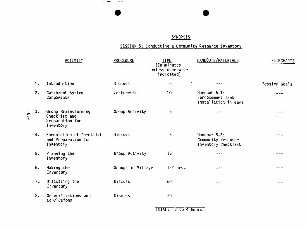
S
SYNOPSIS
S
SESSION 5: Conductinq a Community Resource Inventory
ACTIVITY PROCEDURE TI ME(In minutes
unless otherwiseindicated)
HANDOUTS/MATERTALS FL I PCHARTS
1. Introduction Discuss 5 Session Goals
2. Catchment SystemCorn po nents
Lect urette 10 Handout 5—1:Ferrocement TankInstallation in Java
3. Group BrainstormingU, Checklist and
Preparation forInventory
Group Activity 5
4. Formulation of Checklist Discussand Preparation forInventory
5 Handout 5-2:Community ResourceInventory Checklist
5. Planning theInventory
6. Making theInventory
7. Discussing theInventory
8. Generalizations andConcl us ions
Group Activity
Groups in Village
15
1—2 hrs.
TOTAL: 3 to 4 hours
Discuss
Discuss
60
20

S
S
Session 5: Conducting a Community Resource Inventory
GOALS Total ti
To learn how to conduct an inventory of local skills, materii
niques which can be used in rooftop catchment.
OBJECTIVES
By the end of this session, the participants will be able to:
• List the types of materials and the crafts/skills involved in building
rooftop catchment systems
• Use checklists to survey a community for availability of materials and
skills
OVERVIEW
A rooftop catchment system which is built with materials which are easy toobtain by local people who know how to work with the materials will be chea~.and easier to build and repair. This is why it is important to determineavailability and prices of the materials which can be used in construction aswell as the availability and level of construction skills. This session isaimed at collecting this information through a village survey. An example ofan inventory checklist is included as Handout 5-2: Community Reso””ceInventory Checklist
.
ACTIVITIES Time: 5 minutes
1. Introduction
State the goals and objectives of the session and introduce the session
• linking it to the prior session. Restate the material in the overview.
2. Lecturette: Catchment System Components Time: 10 minutes
Outline the functions of each of the components of a rooftop catchment system,giving an example of the material best suited to each of the functions. Referto the system diagram, Handout 5-1: Ferrocernent Tank Installation in Java (orhave a scale model of a system on display) and make the following points:
o Roof surfaces should be smooth and impermeable (should shed water).Recall there is an “efficiency” factor (80 percent) used to calculateroof yields. Roofing material should also be light in weight. Thisreduces the cost of transportation and reduces the materials needed tosupport it. An example of a suitable roofing material is corrugatedaluminium sheet.
-67-
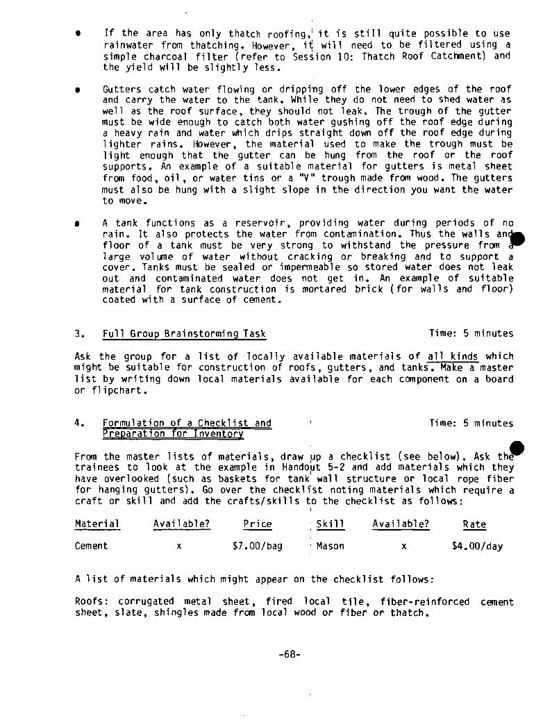
• If the area has only thatch roofing,i it is still quite possible to userainwater from thatching. However, il~will need to be filtered using asimple charcoal filter (refer to Session 10: Thatch Roof Catchment) andthe yield will be slightly less.
• Gutters catch water flowing or dripping off the lower edges of the roofand carry the water to the tank. While they do not need to shed water aswell as the roof surface, they should not leak. The trough of the guttermust be wide enough to catch both water gushing off the roof edge duringa heavy rain and water which drips straight down off the roof edge duringlighter rains. However, the material used to make the trough must belight enough that the gutter can be hung from the roof or the roofsupports. An example of a suitable material for gutters is metal sheetfrom food, oil , or water tins or a “V” trough made from wood. The guttersmust also be hung with a slight slope in the direction you want the waterto move.
• A tank functions as a reservoir, providing water during periods of norain. It also protects the water from contamination. Thus the walls anfloor of a tank must be very strong to withstand the pressure fromlarge volume of water without cracking or breaking and to support acover. Tanks must be sealed or impermeable so stored water does not leakout and contaminated water does not get in. An example of suitablematerial for tank construction is mortared brick (for walls and floor)coated with a surface of cement.
3. Full Group Brainstorming Task Time: 5 minutes
Ask the group for a list of locally available materials of all kinds whichmight be suitable for construction of roofs, gutters, and tanks. Make a masterlist by writing down local materials available for each component on a boardor flipchart.
4. Formulation of a Checklist and I Time: 5 minutesPreparation for Inventory
From the master lists of materials, draw ~ip a checklist (see below). Ask thitrainees to look at the example in Hando~it 5-2 and add materials which theyhave overlooked (such as baskets for tank wall structure or local rope fiberfor hanging gutters). Go over the checklist noting materials which require acraft or skill and add the crafts/skills to the checklist as follows:
Material Available? Price Skill Available? Rate
Cement x $7.00/bag Mason x $4.00/day
A list of materials which might appear on the checklist follows:
Roofs: corrugated metal sheet, fired local tile, fiber-reinforced cementsheet, slate, shingles made from local wood or fiber or thatch.
-68-

Gutters: metal sheet of almost any kind, cut and bent to shape; planks (nailededge-to-edge in a “V”); wood pieces hollowed out; split bamboo or the like;PVC pipe cut in half lengthwise; wire and local fiber for hanging guttersections; pitch, tar, or the like for sealing joints.
Tanks: cement, stones, sand, gravel, fired brick, concrete block, bamboo (forbamboo cement walls), wire netting (chicken wire), straight wire, steel re-inforcing rod, baskets, large clay jars, steel drums.
Skills: masonry, carpentry, basketry, pottery, brazing, or soldering (tin-smith), welding, plumbing, and unskilled labor for excavation andconstruction.
5. Planning the Inventory Time: 15 minutes
Divide the participants into four groups, one group for each of the abovecategories. Direct the groups to devise a strategy for filling out their por-tion of the checklist (where to go, whom to seek out, etc.) Emphasize theimportance of getting good information on material prices.
6. Making the Invent~y Time: 1-2 hours
After agreeing on a time to reconvene, the groups go to the village. (Perhapsthe trainees could have lunch in village.)
7. Receiving and Discussing the Inventory Time: 60 minutes
On reconvening, direct each group to write its portion of the checklist on theblackboard or flipchart sheets. This should be done so that everyone can seeall the information, including the material prices. Direct someone in eachgroup to briefly summarize the information ‘and identify the materials whichare lowest in cost and those which might be most useful for a local project.Ask the groups to report:
S • The strategy used to get the information• Problems encountered and solutions found• Results
8. Generalizations and Conclusions Time: 20 minutes
Seek ideas from the trainees as to what type of tank might be most appropriatefor the local situation, given the information on materials and skills justcollected and analyzed. Ask them what they have learned about how to conduct acommunity resource inventory. Ask how long one would need to do it as aproject developer. Ask how one might involve the community in this process.After the discussion, conclude the session by reviewing the sessionobjectives.
-69-

TRAINER NOTES
1. If you chose the shorter option in the prior session, it may be possibleto start this session on the same day as Session 4. In this case timewould be saved and the trainer could cover Steps 1 to 5 in this sessionin the morning and Steps 6 to 8 in the afternoon.
2. Advance planning for interviewing families will need to be made. It maybe a good idea to survey a village different from the one at the projectsite to determine if different materials might be used in differentvillages.
MATERIALS
— Flipchart for session goals— Handout 5—1: Ferrocement Tank Installation in Java- Handout 5-2: Community Resource Inventory Checklist- Paper pads, pencils
-70-
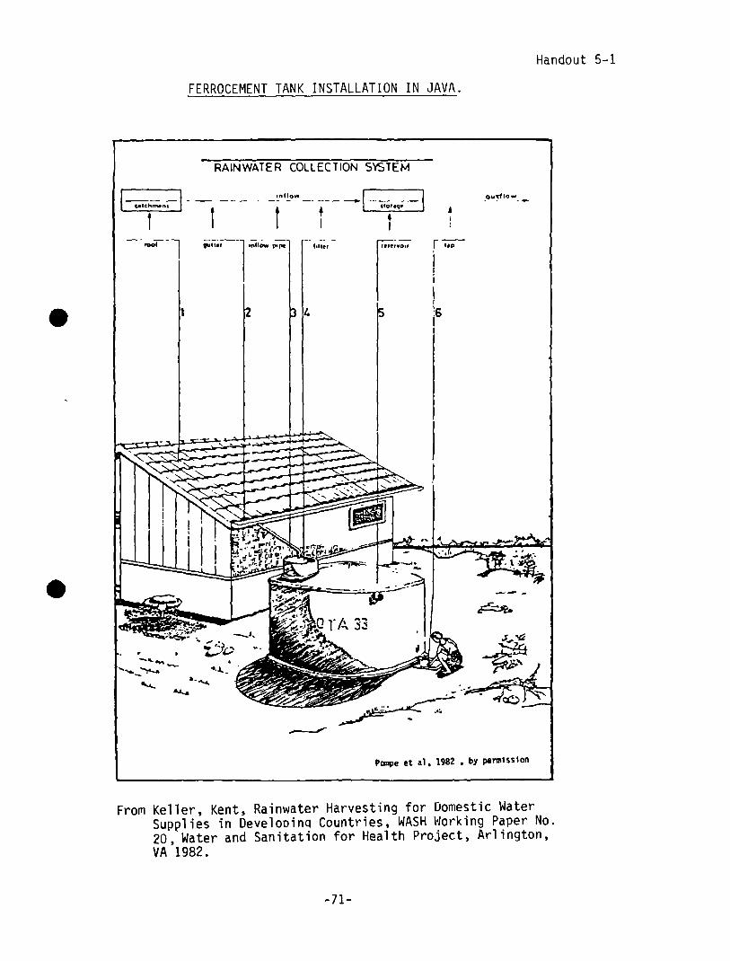
Handout 5-1
.
.
FERROCEMENT TANK INSTALLATION IN JAVA.
From Keller, Kent, Rainwater Harvesting for Domestic WaterSupplies in Develooin~ Countries, WASHWorking Paper No.20, Water and Sanitation for Health Project, Arlington,VA 1982.
-71—

S

Handout 5-2
COMMUNITYRESOURCEINVENTORY CHECKLIST
Here is one way to organize a checklist for finding out availabilities ar.~costs of local materials and skills. The checklist below is an example; in anyparticular area, other materials and skills would be included.
Material Available Price
Roofs Corrugated metal sheetFired local tileFiber-reinforced cement sheetShingles/local wood or fiberSlate
Gutters Metal sheet, any kindWood planks or boardsWood pieces (hollowed)BambooPVC pipeWire (hanging)Fiber (hanging)Pitch (sealing)Tar (sealing)
Tanks CementStonesSandGravelFired brickConcrete blockBambooLocal basketsChicken wireStraight wireSteel reinforcing rod
-
Skills MasonryCarpentryBasketryPotteryTinsmithWelding
Rate
Category
-73-

S
S

C
I I
SESSION 6

1

S
SYNOPSIS
.
SESSION 6: Choosing the Appropriate Storage and Guttering Technology
ACTIVITY PROCEDURE TI ME(In minutes
unless otherwiseindicated)
HANDOUTS/MATER I ALS FL I PCHARTS
1. Introduction Discuss 10 Session Goals
2. Lecturette on StorageTanks and Materials
Lecturette 40 Outline ofLecturette
—4U,
3.a. Deciding Tank Location
and Configuration
b. Guttering Considerations
Listing Materials
Group One toVillage
Group Two in
Classroom
Discuss
2 hrs.
Handout 6—1:Decision Matrix forTank Type
Handout 6—2:Guttering SystemsHandout 5—2: CommunityResource Inventory Checklist
Task Outline
PreliminaryRecommendations
Discuss
4. Reports from Two Sub-groups Presentation 30
5. Foul Flush Discussion Discuss 30 Handout 6—3:Diverting “Foul Flush”
(cont’ d)

SYNOPSIS
SESSION #6 (cont’d)
ACTIVITY
6. Making a Decision onTank Type
Option I
PROCEDURE
Presentation
TI ME(In minutes
unless otherwiseindicated)
60
HANDOUTS/MATER I ALS FLIPCHARTS
Task Outline
—Ia.,
Option 2
7. Conclusion
Small GroupActivity _____ —-—-----— 2- 1-/2~-hrs--.----
~ndPresentationand Critique
Discuss
S
15
TOTAL: S hours, S ~inutes6 hours, 35 minutes
(Option 1)
(Option 2)
S
Session 6: Choosing the Appropriate Storage and Guttering Technology
GOAL Total time: 5 hours & 35 mm. (Option #1)6 hours & 35 mm. (Option ~2)
To learn how to use a series of criteria to decide on which storage andguttering technology to design and use.
OBJECTIVES
By the end of this session, the participants will be able to:
• Describe and review all project steps covered to date
• Determine or estimate the materials, material costs, skills and labor re-quirements of a variety of tank and gutter combinations
Take into account the following local factors which influence choice oftechnology:
- soil type and water table- water carrying practices- possible tank locations
• Review/restate a decision between household vs. community systems
• Apply all the above information to choice of tank and guttering tech-
nology
OVERVIEW
This session is the point at which all the information collected and skillsgained in the previous sessions are brought together and an important conclu-sion is reached. The importance of the task and the difficulty of presenting
•and considering all factors at the same time, mean that the training groupmust be prepared to digest a great deal of information fairly quickly. Adecision matrix is used to organize and streamline the process. This sessionshould take most of a training day. Breaks are indicated as a guideline, butuse your own best judgement. You will need to explain to participants that thetrainers have chosen a particular storage and guttering technology for pur-poses of training demonstration. These choices may or may not be the correctones for this village or setting. The group will need to make its own choicesand be able to justify them putting the trainers’ choices to one side. Theobjective of the training session is to learn how to make these choices.
—77-

AC TIV ITI ES
1. Introduction Time: 10 minutes
Give the participants the information in’ the overview. Go over the goal and
the objectives.
Stress the following point: “Choosing a locally appropriate technology dependson thoughtful consideration of many interrelated features in a local situa-tion. Decisions made in this session will refer to a particular community. Infact, we will learn how to make those de~isions by actually doing it in thiscommunity.”
(Note: Prepare for the following lecturette by reading Trainer ReferenceNotes: Storage Technologies or “Tanks”, which follow the handouts for thissession, and Handout 6-2: Guttering Systems and Handout 6-3: Diverting the“Foul Flush”.
2. Lecturette on Storage Tanks and Materials Time: 40 minutes
Begin by emphasizing that there are many ways in which people around the worldhave collected and stored rainwater. Mention examples like:
• Food storage pots for tanks (e.g., China, Thailand)• Petrol drums for tanks (e.g., Keny~ and the Pacific Islands)• Barrels and buckets• Stone cisterns (e.g., throughout North P~erica and Europe)• Clay pots (e.g., Thailand, India, Nepal, Sri Lanka)
Mention any other examples that come to mind and probe for additional examplesfrom the participants. Propose a categorization of rooftop catchment systemsaccording to the kind of tanks used in~ the system by listing the followingcategories on a flipchart. (Note: Leave ~nough space after each category to beable to write in examples.)
• Existing containers• Masonry containers made of bricks, blocks, or stones• Lined or sealed holes in the ground~• Containers made by applying cement~ mortar to a framework which provides
strength I• Containers made by pouring concretei into a form or mold
Include each example given earlier ui~der the appropriate category, againprobing for additional examples or ideas from the group, and list them underthe category. Nudge the process along by giving a description of a type oftank and asking the group to assign it to the proper category. Additionaltypes of tanks include:
o Ghala baskets: baskets woven from ~ticks and reeds are fabricated with nobottom. The walls of the circular basket are pressed into the wet surfaceof a concrete foundation. The inside surface of the wall is plasteredwith cement mortar
- 78-

• Concrete rings, strengthened with strips of bamboo cast into them
• Tanks made by applying cement mortar to a mesh of wire netting wrappedaround a sheet metal form
• Grain storage pits up to 3 meters deep, lined with a layer of cementmortar, a layer of wire netting, and another layer of cement mortar
• Traditional adobe granaries built into homes in Mali, lined with steelnetting and cement mortar
When sufficient examples are given to open up ideas for the group, ask thegroup to consider which materials are used most frequently in this country andlist them. Note that some materials are used in almost every type of container(e.g., cement, sand-cement mortar, or cement and sand). Then discuss theadvantages and disadvantages of each type of container (cost, water tempera-ture, cleaning). Conclude the discussion by asking the group what tank config-uration is most common (square, cylindrical, or rectangular). Distribute
S Handout 6-I: Decision Matrix for Tank Type at this point and tell participantsthat they will be using it in the following task.
3. Group Task: Considerations for Tank Location and Guttering Time: 2 hours
Divide the group in half and assign the following tasks:
A. Group One: Collect the following information in the community whichrelates to tank configuration and location(s). (Note: Write the task onflipchart.)
• Vessels used by villagers to carry water
• Villagers’ ideas on how they would get water out of a tank
• Villagers’ suggestions on good places to locate a tank, including ideason whether and where tanks could be excavated into the soil
• Approximate total roof area which would fill a tank at each location
• Which proposed locations would drain well
Ask this group to assign these questions among its members and decide whereeach will go in the village. Tell them that during their survey they should bethinking about recommendations they will be asked to make to the whole groupon:
• Tank configuration: above or below ground, type of outlet
• Tank location(s) (Note: It might be good to caution the group against atank location which would present the possibility of contamination sucha heavily travelled area, a very low area, etc.)
Send this group out to do its task. Then turn to group two.
-79-
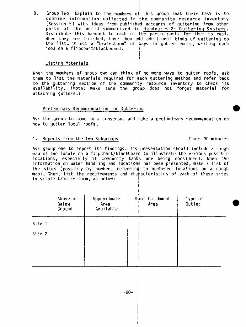
B. Group Two: Explain to the members o~this group that their task is tocombine information collected in the community resource inventory(Session 5) with ideas from published accounts of guttering from otherparts of the world summarized in Handout 6-2: Guttering Systems.Distribute this handout to each of the participants for them to read.When they are finished, have them add additional kinds of guttering tothe list. Direct a “brainstorm” of ways to gutter roofs, writing eachidea on a flipchart/blackboard.
Listing Materials
When the members of group two can think of no more ways to gutter roofs, askthem to list the materials required for each guttering method and refer backto the guttering section of the community resource inventory to check itsavailability. (Note: make sure the group does not forget material forattaching gutters.)
Prelimi nary Recommendation for Guttering SAsk the group to come to a consensus and make a preliminary recommendation onhow to gutter local roofs.
4. Reports from the Two Subgroups ‘ Time: 30 minutes
Ask group one to report its findings. Itsipresentation should include a roughmap of the locale on a flipchart/blackboard to illustrate the various possiblelocations, especially if community tank~s are being considered. When theinformation on water handling and locations has been presented, make a list ofthe sites (possibly by number, referring to numbered locations on a roughmap). Then, list the requirements and characteristics of each of these sitesin simple tabular form, as below:
Above or Approximate Roof Catchment Type ofBelow Area Area OutletGround Available I
Site 1
Site 2
-80-

With the above table before the trainees, ask them to comment on thelocations.
Then ask group two to present its findings on guttering. The trainees in thisgroup will need to get an idea of vertical and horizontal distances from roofsto tank inlets (from the other subgroup) in order to recommend gutteringstrategies for each of the sites in the table. Add additional columns for“guttering” and “cover” to the table and ask group two to put in itsrecotniiendat ions.
5. Foul Flush Discussion Time: 30 minutes
Distribute Handout 6-3: Diverting the “Foul Flush”. Give the trainees 10minutes to read it. Then begin to discuss ideas for foul flush systems and howto connect them to the gutters and a tank. Throughout the discussion, thefollowing points should be kept in mind:
• The best foul flush system is simple and easy to take care of
• If a system requires attention before and/or after each rain, thoughtshould be given to who will be given the task and how the task could bebuilt into a person’s daily routine.
(Note: If time allows the participants should go out and experiment with thefoul flush ideas after this session).
6. Making a Decision on Tank Type Time: Option #1: 60 minutesOption #2: 2 1/2 hours
~bwthat the group has made some preliminary decisions on the best location(s)and whether the storage should be placed above or below ground, it needs toconsider what type of storage tank should be constructed. There are manyfactors which could be considered in this process, but the key factors are:
How much water is needed for drinking, cooking, and washing?
• How much can be collected and stored?
• How big a storage tank would be needed?
• What technology is known locally and can be feasibly used or taught(bricks, blocks, ferrocement, reinforced concrete, plastered containers,etc.)
• What materials are available or obtainable locally?
• What is the least cost option the project can afford and construct?
A project developer may, in fact, have little or no choice about the type oftank to construct (beyond size and shape), because available technologies and
-81-
materials may be the determining factors, therefore, it may not be necessaryto conduct an exercise on how to make this decision,
If so, Option #1 (below) should be used. If there is a great variety ofdifferent local conditions, materials, technologies and possible choices, thenOption #2 (below) should be followed.
Option #1: Justifying the Option Taken
Conduct a presentation, question-answer discussion which completely explainsand justifies why the option under consideraticn was chosen and recommendsthis option as the most practical choice for future project development. Goover each of the six choice factors listed above. As each point is explainedto the full group, ask the group what other alternatives could have beenchosen and why. Entertain questions at each step. Consider such factors ascost, time required, the type of cover, how to get the water out of the tank,how to clean the tank and maintain it, and foul fl ush.
Option #2: Choosing the Best Alternative
Small Group Activity
Divide the participants into small groups of five or six members each. Givethem the following task (written on a flipchart):
First take about 20 minutes to discuss and answer the following questions:
• How much water do you need (refer to previous calculations in Session 3,? people x ? liters per day x ? days ‘per year when water is not avail-able)?
• How much water will the roof chosen ~roduce (refer to calculation madepreviously in this session).
• How big a storage container would hold this amount of water (cubicmeters of water stored is equal to cubic meter of space in tank)? (Note:This is a rough calculation at this point. Session B goes into tank sizein detail.)
• What technologies are known or easy tp teach to local masons and project
workers? I
• What materials are available locally?
After discussion of the above questions, t~ke about 30 to 40 minutes to make alist of at least two types of tanks the group considers to be locally feasi-ble. For each tank, list and discuss all of the advantages and disadvantageson a flipchart and be prepared to present’these to the larger group. Considersuch factors as cost, time required, the type of cover for the tank, how toget the water out of the tank, how to clean the tank, maintenance, tank life,and foul flush. Be prepared to decide which type of tank you would reconrnend.
-82-

Small Group Presentation and Critique
Ask each group to present its selected choice and justify its choice factors,advantages, and disadvantages. Give each group 15 minutes. Af\terwardsentertain questions from the full group and discuss (10 minutes). This shouldrequire no more than one hour and a half.
9. Conclusion Time: 15 minutes
State the following: “In this session we have discussed the major types ofrainwater storage facilities for projects of this nature. In the followingsessions, we will test our selections against the realities of tank size and,later, system design. When you work with the corTliiunity in your futureprojects, you will need to take all of the factors we have discussed intoaccount.” Ask if there are any remaining questions. Refer back to theobjectives of the session to see if they have been achieved.
TRAINER NOTES
Following Session 6 on Day 3, the third visit to the work site should bescheduled. This one hour activity is described in Session 13.
MATERIALS
- Flipcharts for session goal and objectives— Flipcharts with lecturette material outlined for Step 2- Flipcharts with group tasks for Steps 3 and 9- Handout 6-I: Decision Matrix for Tank Type- Handout 6—2: Guttering Systems- Handout 6—3: Diverting the “Foul Flush”
-83-

I S
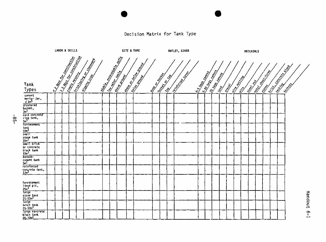
U,
LABOR & SKILLS
S
Decision Matrix for Tank Type
SITE & TYPE OUTLET. COVER
S
MATERIALS

I S

Handout 6-2, p. 1
Chapter 4
GUTTERING SYSTEMS*
Clearly, effective guttering is a key to rooftop catchment systems; water can beneither stored nor consumed if it is not channelled efficiently from the capturearea to the tank. Yet the materials and techniques for construction of effectivegutters is a topic that is omitted from almost all accounts. Technically, gutter—ing is far less challenging than construction of cost—effective water storage,and its cost is usually a relatively small part of total costs. Possibly gutter—ing has been largely ignored in published accounts for these reasons,
4.1 General Considerations
ow big do gutters need to be? Size needs will obviously vary with the intensityof local storms and the ground area covered by the roof. Ree (1976), investigatingrunoff yields from sloping metal roofs, used sheet metal gutters 20 cm wide by10 cm deep, each with a downpipe 15 cm in diameter. Each of these gutters had acapacity of twice the greatest runoff rate recorded from half a 12 x 18 m areaof roof over a period of one year in Oklahoma. Thus, gutters half as wide orhalf as deep would have handled the year’s heaviest rain from the roof. Ingeneral, gutters and downpipes with a cross—sectional area (width x depth) of 100cm2 will probably be big enough to handle all but the most torrential rains frommost roofs.
A greater problem than gutter size is probably hanging gutters securely so thatthey do not sag or fall during heavy rainfall, and keeping them positioned sothat they catch both gushing flow and dripping flow from the edges of the roof.Ensuring adequate slope for the entire system, so that water does not stand anddamage gutters or attract mosquitoes, is equally important.
4.2 Manufactured Metal Gutters
Aluminum or galvanized sheet metal guttering Is the technology of choice in mostareas in developed countries. The gutter sections are joined with special bracketsand hung with metal Straps or long spikes with sleeves which are driven throughthe upper part of the gutter’s width and into wood backing. As of this writing,in the U.S. aluminum guttering and downpipe sections cost about $US1.85/m(galvanized sheet is sligntly less expensive but tends to corrode more quicklyunless coated with nigh—quality rust—resistant paint). Hardware for joining andhanging the system costs another $0.60 per meter. mis would make the materialscosts of guttering and downpipe for a building 6 m long approximately $30.00.Higher cost or unavailability are likely to eliminate manufactured metal guttersas possibilities In most rural areas of developing countries.
4.3 Alternatives Usin1 Local Materials
McDowell (1976, page 33)** observes:
“It is noticed that, in many areas, houses will nave a short lengtn of roughlyfashioned guttering fixed under the eaves just above the door, and that water
From Keller, Kent, Rainwater Harvestinq for DOMESTIC Water Supplies in DevelopingCountries, WASH Working Paper No. 20, Water and Sanitation for HealthProject, Arlington, VA 1982.
-87-
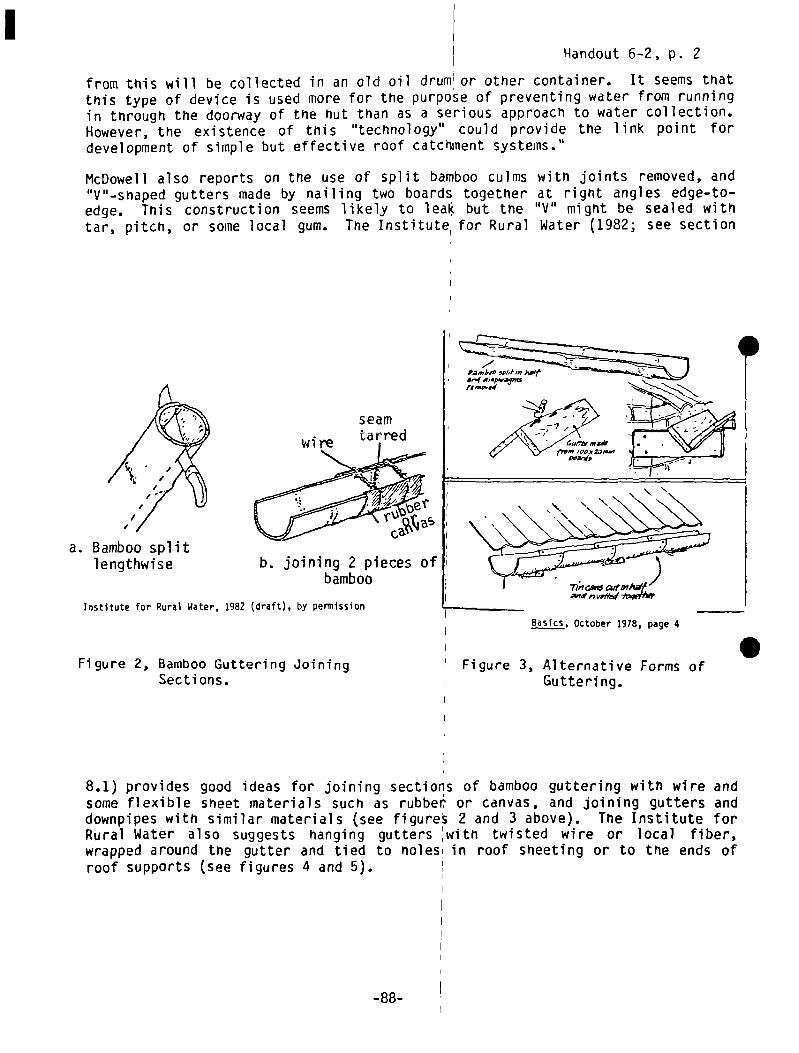
Handout 6-2, p. 2
b. joining 2 pieces ofbamboo
Figure 2, Bamboo Guttering JoiningSecti ons.
from tttis will be collected in an old oil drum~or other container. It seems thatthis type of device is used more for the purpose of preventing water from runningin through the doorway of the hut than as a serious approach to water collection.However, the existence of this “technology” could provide the link point fordevelopment of simple but effective roof catchment systems.”
McDowell also reports on the use of split bamboo culms with joints removed, and“V”—snaped gutters made by nailing two boards together at right angles edge—to—edge. Tnis construction seems likely to leak but the “V” might be sealed withtar, pitch, or some local gum. The Institute1 for Rural Water (1982; see section
seam
a. Bamboo splitlengthwise
Institute for Rural Water. 1982 (draft), by permission
I Figure 3, Alternative Forms of
I Guttering.
8.1) provides good ideas for joining sections of bamboo guttering with wire andsome flexible sheet materials such as rubber or canvas, and joining gutters anddownpipes with similar materials (see figures 2 and 3 above). The Institute forRural Water also suggests hanging gutters with twisted wire or local fiber,wrapped around the gutter and tied to noles in roof sheeting or to the ends ofroof supports (see figures 4 and 5).
-88-
I BasIcs, October 1978, page 4 .

Handout 6-2, p. 3
Institute for aural Water, 1982, by permission
Figure 5. Joining Gutters and Oownplpes
1Nst~tute for Rural Water, 1982b (draft), by permission
Figure 4. Hanging Guttering.
I
-89-

S S

Handout 6-3, p. 1
Chapter 5
DIVERTING THE “FOUL FLUSHI*
The crucial importance of some routine or technique for keeping dirty waterflowing off a roof at the beginning of a storm out of the storage tank is dis-cussed below in section 7.4. In general, there is more to be gained by devisingan effective “foul flush” method than by investing in filters, which clog andbecome contaminated quickly (e.g. Midwest Plan Service, 1979). Tnere are twokinds of foul—flusn devices, those which require the flow of water to be switchedmanually from waste to the tank after the appropriate interval and those whichare “automatic”.
5.1 Manual Systems
Isually lower in cost and easier to devise, these will be the obvious choice inmost poor areas. An attractive and simple approach is to attach the downpipe sothat it can be propped in the “waste” position, then propped in the tank inletafter the roof is clean. Open trough downpipes like split bamboo can be suspendedbeneath the outflow of the gutter with wire or local fiber; closed downpipes witha flexible joint can be moved in the same manner (see figure 6 below).
I
INstitute for Rural Water, 1982 (draft), by permission
Figure 6, Manual System for Diverting Foul Flush.
*From Keller, Kent, Rainwater Harvesting for Domestic Water Supplies in DevelopingCountries, WASHWorking Paper No. 23, Water and Sanitation for HealthProject, Arlington, VA 1982. 91
R~bb~rj~ I
C4~i
ra,~ee~ec(.ç~--fo~./~- ~—
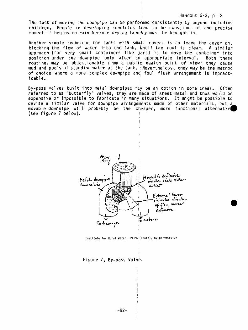
Handout 6-3, p. 2
Tne task of moving the downpipe can be perfoiLmed consistently by anyone includingchildren. People in developing countries tlend to be conscious of the precisemoment it begins to rain because drying laundry must be brought in.
Another simple technique for tanks with small covers is to leave the cover on,blocking the flow of water into the tank, Lintil the roof is clean. A similarapproach (for very small containers like jars) is to move the container intoposition under the downpipe only after an, appropriate interval, Both theseroutines may be objectionable from a public health point of view: they causemud and pools of standing water at the tank. Nevertheless, they may be the methodof choice where a more complex downpipe and foul flush arrangement is impract-icable.
By—pass valves built into metal downpipes nay be an option in some areas. Oftenreferred to as “butterfly” valves, they are made of sheet metal and thus would beexpensive or impossible to fabricate in many situations. It might be possible todevise a similar valve for downpipe arrangements made of other materials, but amovable downpipe will probably be the cheaper, more functional aiternativ5(see figure 7 below).
i~I~ ~
Eda,ii~!(eyey-J,~hcdsrcS”’of Id4ieJ~-
csshrv~
Institute for Rural Water. 1982b (draft), by permisssiOfl
Figure 7, By-pass Val~~e.
-92-
f3C,.4 4
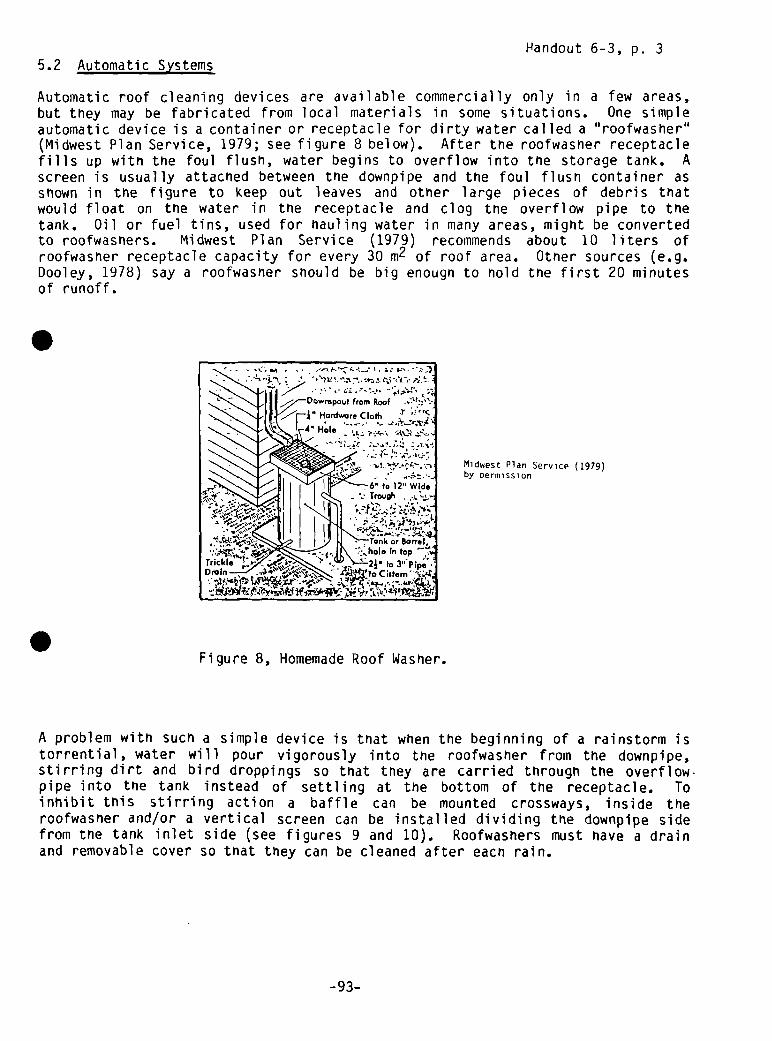
Handout 6-3, p. 3
5.2 Automatic Systems
Automatic roof cleaning devices are available commercially only in a few areas,but they may be fabricated from local materials in some situations. One simpleautomatic device is a container or receptacle for dirty water called a “roofwasher”(Midwest Plan Service, 1979; see figure 8 below). After the roofwasner receptaclefills up with the foul flush, water begins to overflow into the storage tank. Ascreen is usually attached between the downpipe and the foul flush container asshown in the figure to keep out leaves and other large pieces of debris thatwould float on the water in the receptacle and clog the overflow pipe to thetank. Oil or fuel tins, used for hauling water in many areas, might be convertedto roofwashers. Midwest Plan Service (1979) recommends about 10 liters ofroofwasher receptacle capacity for every 30 m2 of roof area. Otner sources (e.g.Dooley, 1978) say a roofwasner should be big enough to hold the first 20 minutesof runoff.
Midwest Plan Service (1979)by Dermission
Figure 8, Homemade Roof Washer.
A problem with such a simple device is that when the beginning of a rainstorm istorrential, water will pour vigorously into the roofwasher from the downpipe,stirring dirt and bird droppings so that they are carried through the overflow.pipe into the tank instead of settling at the bottom of the receptacle. Toinhibit this stirring action a baffle can be mounted crossways, inside theroofwasher and/or a vertical screen can be installed dividing the downpipe sidefrom the tank inlet side (see figures 9 and 10). Roofwashers must have a drainand removable cover so that they can be cleaned after eacn rain.
• .- .
wmpou~from RoofHordwore CIotf, !
.-Hole ~ ~
i’~—~:‘-~
:ó’ to 12 Wide~~Trovgh.~
-93-

Handout 6-3, p. 4
Institute for Rural Water, 1982 UNEP (1979)(draft) by permission by permission
Figure 9, Roof Washers.
More complicated “automatic” foul flusfl devic~s tend to require more attentionand stronger structures with more hardware for mounting in the downpipe. Reported~ use in Australia are, “swing funnels” made of sheet metal, with a large inflowside divided into two compartments, and hinged on a horizontal pin (see figure10 below). At the start of a storm, water pours from the gutter into the first
compartment. As the weight ofthe assembly increases, the
‘funnel swings so that water poursfrom the gutter into the secondcompartment which leads through
‘the downpipe into the tank. Such Ia funnel would have to be quite
I large to hold the recommendedIvolume of foul flush. Mountingand hinge—pins would also have tobe quite strong. This particular
,device is unlikely to be the most‘attractive of foul flush options
in most places, but it is aninteresting idea.
Figure 10, Swing Funnel.
-94-
coreY
~owvspjpC
CLrnc re,1L-
F1b, b.IfI.
Act, ,nuI.t.d
F,nn.I Iris ,, to,.,. I,w.rd.w.,i •II.ing c,rnp.rtm.n~ B,o ,sc..,s Wfl5t from root.pr..I.AiIy tl..nbd by ft.. .ftth.CC,m,,I.f5, in .00mb., A

Session 6: Trainer Reference Notes
Page 1
Chapter 6
STORAGETECHNOLOGIESOR “TANKS’I*
6.,1 General Considerations
A satisfactory storage tank is the key element in a rooftop catchment System.As has been noted in other sections, the water storage facility or “tank”is usually the most expensive part of simple RWH systems and at the same timethe most difficult to construct so that it will perform satisfactorily over along period. An adequate tank must not leak. It must be structurally strongenough to support the great load of the water it will hold and it must be coveredto keep out sunshine, dirt, insects, and (if the tank is buried) dirty surfaceand ground water.
far as users are concerned, the tank is also the focus of the system. It isusually both the storage and distribution point, requiring cleaning and main-tenance to ensure both these functions.
Tanks can be categorized into three groups:
1. those used with individual household rooftops (mostly above ground).2. those used with larger rooftops or several rooftops (above, partially
buried, and below ground).3. those used with surface catchrnents.
Witnin each of these three groups there are many different kinds of tanks, eachwith its own construction methods, materials costs, and labor requirements. Eachof these factors, along with the required capacity of the tank (see technicalnote on using rainfall data to design a RWH system, Appendix A), enters intodecisions about what kind of tank to build.
The tank’s function——as an individual household source or source for a group of, milies-—is probably the single most important determinant of tank size andsign. This choice can be made only in close consultation with the people who
will build and use the tank. Without their participation and genuine supporta tank—building effort nas little prospect of success. In their comments on theslow progress of open tank construction for irrigating school gardens in Botswana,Farrar and Pacey (1974) note:
“In any community where a tank programme is contemplated, it would seem importantto inquire into the ‘felt needs’ of the people. To which category of water usedo they give highest priority?
“a) drinking water: for home or school use?“b) washing water“c) water for gardens: again, at home or at school?
“In most parts of southern Africa, water for school gardens would be given the
lowest priority.”
*From Keller, Kent, Rainwater Harvesting for Domestic Water Supplies in DevelopingCountries, WASH Working Paper No. 20, Water and Sanitation for HealthProject, Arlington, VA 1982.
**For References in text see annotated bibliography which follows the SessionGuides in this Training Guide.
-95-

I Session 6: Trainer Reference NotesPage 2
Whether to build an above—ground tank or an ex1cavated (underground) tank deservesconsiderable thought. Watt (1978) notes:
“Storing water in tanks built on the surface’ has many advantages when comparedwith storage tanks excavated into the groundi. Besides avoiding the need forlaborious excavation which is almost impossible in some hard dry soils, thetanks can be observed for leaks and easily ‘repaired by trowelling a layer ofmortar onto the inside of the empty tank. In addition, although the stored wateris likely to become hotter in the sun, the risks of polluted material fallinginto the tanks are reduced. Water stored above ground can flow Out under itsown weight whereas it has to be pumped out of’a ground tank.”
The main advantage of underground tanks, on the other hand, is that the earthsupports the tank lining and contents, making it possible to build deeper tankswith thinner walls. This means that building ‘materials can be conserved and usedto make Ieakproof wall surfaces instead Of structural wall reinforcement. IUnderground tanks do not always require a pump. Figures in section 6.3 (below)Show flow a concrete block tank supported with earth embanklnents can be fittedwith a tap.
Larger tanks require fewer materials per unit of water storage capacity thansmaller tanks, which tend to give them a cost advantage. Constructing smallertanks, though, tends to require less expertise and preparation, fewer tools, andless cash “up—front”. Large tanks may bring ‘with them structural problems. Forexample, large areas of flat plastered wall are more vulnerable to cracking thansmaller walls (e.g. Maikano and Nyberg, 1980). Thus, in many cases, smallertanks or groups of smaller tanks will be chosen in preference to a single largerone. I
Different kinds of tanks demand different standards of workmanship in construc-tion. Ferrocement and other tanks made with’ mortar plaster will crack and leakif mortar is not made with clean componentsl in proper proportions, and appliedproperly to the reinforcing framework. A prototype made by people who have nevermade one before may not perform satisfactorijly. A failure should be planned on 5or experience sought.
The walls of underground tanks must be buil~t carefully, especially if they areof brick or masonry. Cairncross and Feachem (1978) say tnese tanks should onlybe built by an experienced builder (and indeed, local masons should always beinvolved). Individual Water Supply Systems ~Office of Water Programs/EPA, 1974)emphasizes the importance of high—quality workmanship and recommends against“unskilled labor”.
6.2 Household Tanks I
6.2.1 Recycled Used Containers
A wide variety of locally-available containers can be used to catch water flowingfrom guttering or simply dripping off the edge of roofing. White et al (1973)describe the use in West Africa of steel petrol drums with one end cut out (see
-96-

Session 6: Trainer Reference NotesPage 3
picture at the front of this report). These drums hold about 0.17 m3 and costabout US $2.50 (1969); they can be covered with a board and a rock. Watt (1975)notes that Triais collect rainwater from roofs in large pottery jars. He reportsa price of about US $5.00 (1975) for a 0.3 m3 jar.
6.2.2 Cement Mortar Jars
Apparently first devised in Thailand (Watt, 1975), these jars nave been enthusi-astically built in other parts of southeast Asia and Africa (McDowell, 1976).Clotn sacking filled with rice hulls or some vegetable waste is used as a jar—shaped mold, onto which cement mortar is plastered. McDowell (1976) says thatjars can be constructed with capacities up to 3 ~ using this method. Prototypesof even larger models, made of soil—cement, have been made in Java. A greatttraction of this metnod of storing rainwater is its low cost. Watt (1975)ports materials costs of US $0.50 per 0.25 m3 jar. That entire sum was for
cement (see figure 11 below).
Most jars of this type are apparently made in the size range of 0.15—0.5 m3,as larger jars, lacking reinforcement, tend to crack where the wall meets the base.See Chapter 8 for Watt’s instructions for making a 0.25 m3 jar.
S
Figure 11, Homemade Cement Jar
McDowell (1976)both by permission
-97-
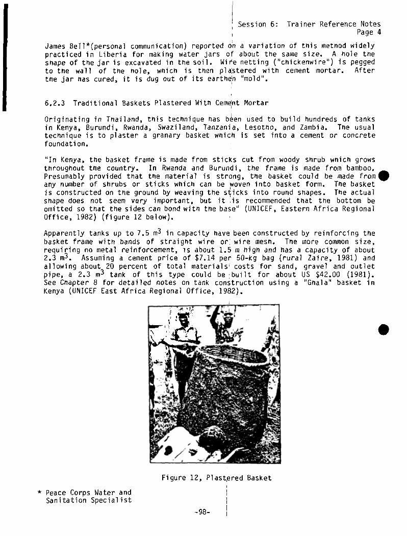
Session 6: Trainer Reference NotesPage 4
James Bell*(personal cornniunication) reported on a variation of this metnod widelypracticed in Liberia for making water jars of about the same size. A nole theshape of the jar is excavated in the soil. Wire netting (“chickenwire”) is peggedto the wall of the nole, which is then plastered with cement mortar. Afterthe jar has cured, it is dug out of its earth~n “mold”.
6.2.3 Traditional Baskets Plastered With Cern~ntMortar
Originating in Tnailand, this technique has been used to build hundreds of tanksin Kenya, Burundi, Rwanda, Swaziland, Tanzania, Lesotho, and Zambia. The usualtechnique is to plaster a granary basket which is set into a cement or concretefoundation.
“In Kenya, the basket frame is made from sticks cut from woody shrub which growsthroughout the country. In Rwanda and Burundi, the frame is made from bamboo.Presumably provided that the material is strong, the basket could be made fromany number of shrubs or sticks which can be ~oven into basket form. The basketis constructed on the ground by weaving the sticks into round shapes. The actualshape does not seem very important, but it is recommended that the bottom beomitted so that the sides can bond with the base” (UNICEF, Eastern Africa RegionalOffice, 1982) (figure 12 below).
Apparently tanks up to 7.5 m3 in capacity have, been constructed by reinforcing thebasket frame with bands of straight wire or: wire mesh. Tne more common size,requiring no metal reinforcement, is about 1.5 rn high and has a capacity of about2.3 m3. Assuming a cement price of $7.14 per 50—kg bag (rural Zaire, 1981) andallowing about 20 percent of total materials’ costs for sand, gravel and outletpipe, a 2.3 m3 tank of this type could be built for about US $42.00 (1981).See Chapter 8 for detailed notes on tank construction using a “Gnala” basket inKenya (UNICEF East Africa Regional Office, 1982).
I
Figure 12, Plast~redBasket
* Peace Corps Water andSanitation Specialist
-98-
, S
~ ~

Session 6: Trainer Reference NotesPage 3
picture at the front of this report). These drums hold about 0.17 m3 and costabout US $2.50 (1969); they can be covered with a board and a rock. Watt (1975)notes that Thais collect rainwater from roofs in large pottery jars. He reportsa price of about US $5.00 (1975) for a 0.3 m3 jar.
6.2.2 Cement Mortar Jars
Apparently first devised in Thailand (Watt, 1975), these jars have been enthusi-astically built in other parts of southeast Asia and Africa (McDowell, 1976).Cloth sacking filled with rice hulls or some vegetable waste is used as a jar—shaped mold, onto which cement mortar is plastered. McDowell (1976) says thatjars can be constructed with capacities up to 3 m3 using this method. Prototypesof even larger models, made of soil—cement, have been made in Java. A greatttraction of this method of storing rainwater is its low cost. Watt (1975)ports materials costs of US $0.50 per 0.25 m3 jar. That entire sum was for
cement (see figure 11 below).
Most jars of this type are apparently made in the size range of 0.15—0.5 m3,as larger jars, lacking reinforcement, tend to crack where the wall meets the base.See Chapter 8 for Watt’s instructions for making a 0.25 m3 jar.
Figure 11, Homemade Cement Jar
McDowell (1976)both by permission
-97-

Session 6: Trainer Reference NotesI Page4
James Bell*(personal communication) reported on a variation of this method widelypracticed in Liberia for making water jars of about the same size. A hole theshape of the jar is excavated in the soil. Wire netting (“chickenwire”) is peggedto the wall of tne nole, which is therm plastered with cement mortar. Afterthe jar has cured, it is dug out of its earthen “mold”.
6.2.3 Traditional Baskets Plastered With Cem~nt Mortar
Originating in Thailand, this technique has been used to build hundreds of tanksin Kenya, Burundi, Rwanda, Swaziland, Tanzania, Lesotrmo, and Zambia. The usualtechnique is to plaster a granary basket which is set into a cement or concretefoundati on.
“In Kenya, the basket frame is made from sticks cut from woody shrub which growsthroughout the country. In Rwanda and Burundi, the frame is made from bamboo.Presumably provided that the material is strong, the basket could be made fromSany number of shrubs or sticks which can be woven into basket form. The basketis constructed on the ground by weaving the sticks into round shapes. The actualshape does not seem very important, but it , is recommended that the bottom beomitted so that the sides can bond with the babe” (UNICEF, Eastern Africa RegionalOffice, 1982) (figure 12 below).
Apparently tanks up to 7.5 m3 in capacity have been constructed by reinforcing thebasket frame with bands of straight wire or wire mesh. Tne more common size,requiring no metal reinforcement, is about 1.5 in high and has a capacity of about2.3 in3. Assuming a cement price of $7.14 pe;r 50—kg bag (rural Zaire, 1981) andallowing about 20 percent of total materials costs for sand, gravel and outletpipe, a 2.3 in3 tank of this type could be; built for about US $42.00 (1981).See Chapter 8 for detailed notes on tank construction using a “Gflala” basket inKenya (UNICEF East Africa Regional Office, 182).
.
Figure 12, Plastered Basket
* Peace Corps Water and ISanitation Specialist
-98-

Session 6: Trainer Reference NotesPage 5
6.2.4 Cast Concrete Ring Tank
Relying on thin unreinforced concrete rings, poured between concentric steelforms, these tanks have been promoted by the Thai Ministry of Healtn for use atschools in a country where many buildings in rural areas nave galvanized sneetmetal or tile roofs (Watt, 1978 b). The rings, which are about 1.5 in in diameterand 0.6 m nigh, can be stacked to give tank capacities of up to 7 in
3. Wattestimates materials costs of US $40.00 (1977) for a tank of this size, not includ-ing the cost of the forms. Watt points out that forms could be used again andagain in a tank construction project and suggests central production of therings under skilled supervision. The cured, high—quality rings could then betransported by truck to the tank location for placement on their concrete founda-tions.
Brian Grover (personal communication) reports that the Thai Ministry of Healtnand the Population Development Association of Thailand, in collaboration with theU.S. Peace Corps, are building similar tanks with bamboo staves cast into therings for reinforcement.
6.2.5 Ferrocenient Tanks
These tanks are built using a technique in which cement mortar paste is appliedby hand to a reinfo~’rcing wire mnesh. “True” ferrocement has much more steel rein-forcement than called for in the tanks described here. Still the principle isthe same: metal reinforcing strands distribute loads evenly through the cementmortar, preventing the cracking that would occur in unreinforced materials ofsimilar thickness (NAS, 1973). Tank walls 4 cm thick are strong enough to hold2 m depths of water above ground. Thus reinforced cement walls require much lesstotal material than conventional concrete walls. (Briscoe, 1981, notes thatferrocement tank walls do not necessarily require less cement than concrete walls.)
In his nandbook for field workers (Watt, 1978, Ferrocement Water Tanks and Their•Construction, see section 8.2 below), Watt notes:
“The main advantages...of this material over other tank construction materials,such as galvanized corrugated iron, are its cheapness and easy working using theminimum of expensive materials, equipment and skills. It is, in addition, verydurable. Some of the tanks described in the manual have been in constant usefor over 25 years with only a few instances of failure——due in the main to poorworkmanship in construction.”
Watt goes on to say that ferrocement techniques are particularly suited for low—income rural areas because 1) they use commonly available materials (cement,sand, water, and wire); 2) only simple skills are needed: “...untrained peoplecan make satisfactory tanks after only a few days supervision...”; 3) users ofthe tanks can help in construction; and 4) only simple hand tools are required.
Clearly an important advantage of ferrocement tank construction is that it canbe taught and learned readily. Early development of these techniques was doneat the Friends Rural Training Center, Hlekweni, near Bulawayo, Zimbabwe. RoyHenson of the Center reports training of a half—dozen craftsmen and construc-tion of 210 9 m3 tanks in Matabeleland in 1971—72 (Farrar and Pacey, 1974). Attne Asian Institute of Technology (AlT) in Bangkok, training is provided for
-99-
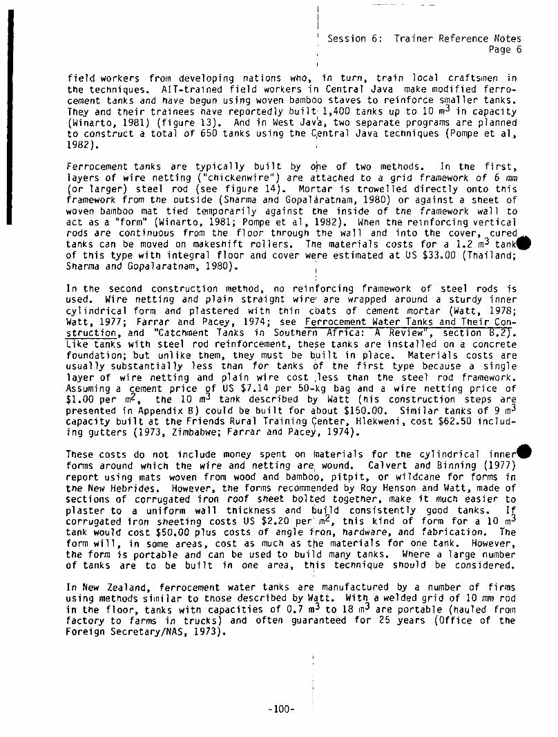
Session 6: Trainer Reference NotesI Page6
field workers from developing nations who, in turn, train local craftsmen inthe techniques. AlT—trained field workers in Central Java make modified ferro-.cement tanks and have begun using woven bamboo staves to reinforce smaller tanks.They and their trainees have reportedly built 1,400 tanks up to 10 in
3 in capacity(Winarto, 1981) (figure 13). And in West Jav~a, two separate programs are plannedto construct a total of 650 tanks using the C~entral Java techniques (Pompe et a],1982).
Ferrocement tanks are typically built by o~e of two methods. In the first,layers of wire netting (“chickenwire”) are attached to a grid framework of 6 mm(or larger) steel rod (see figure 14). Mortar is trowelled directly onto thisframework from the outside (Snarma and Gopaläratnam, 1980) or against a sheet ofwoven bamboo mat tied temporarily against the inside of the framework wall toact as a “form” (Winarto, 1981; Pompe et a], 1982). When the reinforcing verticalrods are continuous from the floor through the wall and into the cover, curedtanks can be moved on makeshift rollers. The materials costs for a 1.2 m3 tansof this type with integral floor and cover were estimated at US $33.00 (Thailand;Snarma and Gopalaratnam, 1980).
In the second construction method, no reinforcing framework of steel rods isused. Wire netting and plain straight wire’ are wrapped around a sturdy innercylindrical form and plastered with thin cbats of cement mortar (Watt, 1978;Watt, 1977; Farrar and Pacey, 1974; see Ferrocement Water Tanks and Their Con-ET1 w333 446 m561 446 lSBTstruction, and “Catchment Tanks in Soutnern Africa: A Review”, section 8.2).Like tanks with steel rod reinforcement, these tanks are installed on a concretefoundation; but unlike them, they must be built in place. Materials costs areusually substantially less than for tanks Of the first type because a singlelayer of wire netting and plain wire cost less than the steel rod framework.Assuming a cement price of US $7.14 per 50-kg bag and a wire netting price of$1.00 per m2, the 10 in3 tank described by Watt (his construction steps arepresented in Appendix B) could be built for about $150.00. Similar tanks of 9 in3
capacity built at the Friends Rural Training Center, Hlekweni, cost $62.50 includ-ing gutters (1973, Zimbabwe; Farrar and Pace)~, 1974).
These costs do not include money spent on materials for the cylindrical inner5forms around which the wire and netting are, wound. Calvert and Binning (1977)report using mats woven from wood and bamboQ, pitpit, or wildcane for forms intne New Hebrides. However, the forms recommended by Roy Henson and Watt, made ofsections of corrugated iron roof sheet bolted together, make it much easier toplaster to a uniform wall thickness and build consistently good tanks. Ifcorrugated iron sheeting costs US $2.20 per’ m2, this kind of form for a 10 in3
tank would cost $50.00 plus costs of angle i1ron, hardware, and fabrication. Theform will, in some areas, cost as much as t~e materials for one tank. However,the form is portable and can be used to build many tanks. Where a large numberof tanks are to be built in one area, this technique should be considered.
In New Zealand, ferrocement water tanks are manufactured by a number of firmsusing methods similar to those described by Watt. With a welded grid of 10 mm rodin the floor, tanks with capacities of 0.7 in3 to 18 m3 are portable (hauled fromfactory to farms in trucks) and often guaranteed for 25 years (Office of theForeign Secretary/NAS, 1973).
-100-

Session 6:
Figure 13, Ferrocement Tank Installation in Java.
Trainer Reference NotesPage 7
.
-10 1-

Session 6: Trainer Reference NotesPage 8
A pasteofmortaris forced intothe layers of mesh byhand . (Smith Kam-pempool, AppliedScientific ResearchCorporation of Thai-
ortrowel. The mortar isdry enoughto remainin placewhen applied;a formwork is notneeded.(Noel D. Viet-meyer, National Acad-emy of Sciences)
.
I
Offlcc cf the Foreign Secretary/NAS, 1973by permission
Figure 14, Building Ferrocement Tank.
-102-

Session 6: Trainer Reference Notes
Page 9
6.2.6 Manufactured “Tin” or Corrugated Sheet Metal Tanks
These tanks have been used for many years in many areas. Farrar and Pacey (1974)report that in parts of southern Africa, most foreigners have “tin” tanks alongsidetheir homes. The costs of these tanks are high and extremely variable, dependinon distance from point of manufacture. Farrar and Pacey give the cost of a 9 in
version as US $112.00 in 1973 Zimbabwe; White et al (1973) say that “tin” tanksof 1.4 m3 capacity cost $39.00 to $84.00 in East Africa (1912). The corrugatedmetal from which these tanks are fabricated may not last longer than 5 years ina damp climate, even then galvanized. Calvert and Binning (1977) report that inthe salt—laden atmosphere of New Hebrides, 16 gage tanks fail after 3 or 4 years.
6.3 Tanks For Use With Larger Rooftops or Several Rooftops*
S3.3.1 Underground Ferrocement Tanks
Most tanks of this type are basically an earthen pit lined with wire—reinforcedmortar. As with other underground tank designs, structural strength is providedby the confining earth walls, meaning that the ferrocement lining can be madeonly a centimeter thick. A further advantage of these tanks is that their con-struction requires neither the steel rod framework nor forms needed to buildaboveground ferrocement tanks.
Calvert and Binning (1977; see “Low Cost Water Tanks in the Pacific Islands” insection 8.2 below) describe an innovative design complete with reinforced cover,3.5 in in diameter and 2 in deep, volume 15—20 m~. First a circular concrete ring
or “footing” is poured; soil from the footing trench is used to make agently sloping earthen dome in the center of the circle. A 5 cm layer of cementplaster reinforced with wire netting and steel rod is laid over the dome, andtwo 0.6 in holes are left near opposite edges. After this ferrocement domecures digging begins through the holes, and the tank is excavated beneath. Twolayers of wire netting are used to strengthen the plaster applied to the earth
•alls.
Tne authors believed that these tanks should not cost more than about US $250 in1976 in New Hebrides. They suggest that the design is suitable for “collecting avillage’s water supply drained from the roof of a large public building.” Whilefabrication of a cover which will not crack may require some experimentation, theapproach seems promising. Maikano and Nyberg (1980) report trials of similarcovers for underground tanks in Botswana.
*Tnis report does not deal with tanks used with surface catcnments (see section
3.1.2 ). There are, however, at least 3 types of tanks used with surface catch—ments which should be briefly mentioned here because they might also be used withlarger rooftops or several rooftops. Maikano and Nyberg (19801 describe 10—25 m3ferrocement—lined pits collecting water from grain threshing floors in Botswana;Farrar and Pacey (,1974) describe the “Water Harvester” (three linked brickcisterns) with 9 m~capacity in Zimbabwe; and lonides et al (1969) describe aproject in Botswana to promote “beehive” tanks, built of polythene “sand sausages”,with capacities in the 50 m3 range. Cost information for these tanks is includedin section 7.4.
-10 3-

I Session 6: Trainer Reference NotesPage 10
A ferroceinent-lined underground grain storage bin suitable for storing waterhas been documented in the Harar Province of Etniopia (NAS, 1973; Sharma et al1979; see Ferrocement: Applications in Deve~opingCountries and “State-of-the-art Review on F~rrocement Gr~arn Storage ~1ns’1, section 8.2 below). Traditionalgrain pits, conical in snape with sides sloping inward to a narrow mouth at triesurface, are lined with plaster reinforced wiltfl wire netting and given a concretefloor. A small cover is needed, and provision made so that surface water willrun away from the moutn of the pit. Ferrocement linings have been installed inpits of this type with deptns of up to 3 in and floor diameters of 4 :n (see figure15).
Soil type will affect smoothness of earthen walls and the ease with which plastercan be applied to the sides of an excavation. Calvert and Binning (1977) saythat their tanks should be dug out in “soft” soil. Snarma et al (1979) say tnattraditional grain pits have been lined successfully in all the major soil typesof the Harar province of Ethiopia.
The lining of traditional Dogon granaries, with ferroceirient pioneered by HansGuggenheim and described by Watt (1978), represents an interesting above-groundversion of tfl~ Etniopian scheme. Edsting adobe—brick granaries, about 2.4 inhign and 2.6 m in diameter, are lined with’ plaster reinforced with wire netting
.
.
Sealant Ring of Stones‘o Raise Mouth
Office of theby permission
Chicken Wire
Storage Chamber2nd Layerof Mortar
Figure 15, Cross—section of Ferroceinent-linéd Underground Storage Pit.
-.104-
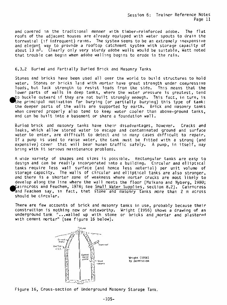
Session 6: Trainer Reference NotesPage 11
and covered in the traditional manner with timber-reinforced adobe. The flatroofs of the adjacent houses are already equipped with water spouts to drain thetorrential (if infrequent) rains. The system seems to be an extremely inexpensiveand elegant way to provide a rooftop catchment system with storage capacity ofabout 13 in
3. Clearly only very sturdy adobe walls would be suitable, Watt notedthat trouble can begin when adobe walling begins to erode in the rain.
6.3.2 Buried and Partially Buried Brick and Masonry Tanks
Stones and bricks have been used all over the world to build structures to holdwater. Stones or bricks laid with mortar have great strength under compressiveloads, but lack strength to resist loads from the side. This means that thelower parts of walls in deep tanks, where the water pressure is greatest, tendto buckle outward if they are not built strongly enough. This fact, in turn, ishe principal motivation for burying (or partially burying) this type of tank:
the deeper parts of the walls are supported by earth. Brick and masonry tankswhen covered properly also tend to keep water cooler than above—ground tanks,and can be built into a basement or share a foundation wall.
Buried brick and masonry tanks have their disadvantages, however. Cracks andleaks, which allow stored water to escape and contaminated ground and surfacewater to enter, are difficult to detect and in many cases difficult to repair.If a pump is used to raise water, the tank must be fitted with a strong (andexpensive) cover that will bear human traffic safely. A pump, in itself, maybring with it serious maintenance problems.
A wide variety of shapes and sizes is possible. Rectangular tanks are easy todesign and can be readily incorporated into a building. Circular and ellipticaltanks require less wall surface (arid hence less material) per unit volume ofstorage capacity. The walls of circular and elliptical tanks are also stronger,and there is a shorter zone of weakness where mortar cracks are most likely todevelop along the line where the wall meets the floor (Maikano and Nybery, 1980;airncross and Feachem, 1978; see Small Water Supplies, section 8.2). Cairncross
and Feachem say, in fact, that stone and masonry tanks more than 2 in acrossshould be circular.
There are few accounts of brick and masonry tanks in use, probably because theirconstruction is nothing new or noteworthy. Wright (1956) shows a drawing of anunderground tank “...walled up with stone or bricks and •mortar and plasteredwith cement mortar” (see figure 16 below).
Wright (1956)by permission
Figure 16, Cross-section of Underground Masonry Storage Tank.
Puri~P
Overflow
Stonemasonry
-105-

Session 6: Trainer Reference NotesPage 12
In Southern Africa, “...the occasional large buildings in rural areas--schools,churches, halls, etc.--can provide a water supply to the community on about thesame scale as that from ‘beehive’ tanks (45—90 m3). Four or five 9,000 litertanks would be needed for many school buildings, though a more usual method ofproviding this capacity is to build a single~large tank of concrete blocks. Thedifficulty is that tank walls built in thi~ way are ill-suited to resist thesideways pressure of the water, so concrete block tanks are usually built inshallow excavations with piled earth used to buttress the sides. (Figure 17below) illustrates a tank of this kind, showing how the tap may be placed sothat water can be drawn off by gravity flow” (Farrar and Pacey, 1974; see“Catchment Tanks in Southern Africa: A Review”, section 8.2). In this same
~ ~ - -
Farrar and Pacey, 1974 by permission
Figure 17, Concrete Block Tank.
paper, a 71 in3 tank of this type built in dhana (Parker, 1973) is said to havecost US $260.00 (1973). At $3.63/rn3 (~973) of storage capacity, this would beone of the cheaper tanks (in cost/mi of storage) we have seen documented.
Many of the cisterns built into the basements of residences in Bermuda, whereprovision for rooftop catchment and storage is required by building codes, aremade of concrete block plastered with cement mortar. Volume of these cisternsvaries with the size of the dwelling, but most fall within the range of 50 in3 to
mu3 (John Sands, Solar Engineering Technology, personal communication).~
One of the strongest arguments for considering tanks of this type is that theycan readily be designed and built into or ~longside new public buildings for arelatively small increment in procurement and labor costs. See the discussionof construction details of stone and masonrytanks in Appendix B.
6.3.3 Underground Concrete Tanks
These tanks have been widely used for rainwater storage in the developed countries.In the United States they are usually referr~d to as “cisterns” and are frequentlybuilt into or alongside basements with capacities ranging from 10 m3 to 50 m3.Properly reinforced with steel rod, concrete is probably the strongest materialfor walls for water storage. It is resistant to cracking and leaking, and itscover can be cast with an inspection hole so as to effectively seal out contam-inants from the surface. The great disadvantage of underground concrete tanksis their expense: they require large quantities of cement, gravel, sand, andsteel; and materials for forms, and expertise in the methods, are often alsoexpensive and scarce in rural areas of developing countries.
-106-
- / /
/‘/‘

Session 6: Trainer Reference NotesPage 13
This type of tank or “cistern” is widely documented in U.S. textbooks on ruralwater supply and sanitation. Salvato (1958) and Wright (1959) describe acistern with simple sand filters, overlapping manhole covers and handpumps, and “butterfly” valves in the downpipe for diverting dirty water fromthe roof at the beginning of a rain. Both sources give simple guidelines formatching cistern size to roof area in light of the water needs of farming house-holds in the U.S. Wagner and Lanoix (1959) give simple sizing guidelines anddiscuss location: tanks should be higher than and at least 3 in from any sewagedisposal installation. They also emphasize the need to keep gutters clean andsloping evenly toward the downpipe to prevent setting water. VITA’s Using WaterResources (see section 8.2) gives tools and mnaterials lists, and quantitities,proportions, and procedures for constructing a cistern and sand-gravel filter.The Village Technology Handbook (VITA, 1973; see section 8.2) gives detailedinformation on building with concrete. The sizing guidelines given for matching, istern volume to roof area assume that the cistern should hold a full year’s
ater supply for the family using it. (See the note in Appendix A on usingrainfall data to plan a rooftop catchrnent system.)
The Manual of Individual Water Systems (Office of Water Programs/EPA, 1974),originally published by the U.S. Public Health Service in 1950, presents the textand cross-section drawings of a cistern which are referred to and appear in Salvato(1959), Wagner and Lanoix (1959), and VITA (1973). Henderson and Smith (1973;see Planning for an Individual Water System, section 8.2) and Midwest PlanService (1979) are two more recent books published by government extension programsin the U.S. for use in rural areas. They give similar information on cisterns,with useful color sketches and cross-sections. Midwest Plan Service recommendsagainst use of filters for the water from the downpipe, noting that they canquickly become contaminated. They suggest, instead, an adequate “roofwasher”.
Heaven’s Water: in Rural Places, Cisterns Gather the Rain (1980) is a usefulpresentation of the pros and cons of cistern systems written for a popularaudience. The users emphasize the importance of some kind of a “roofwastier”system, discussing several alternatives. This article also relates some of the. otential problems with rooftop catchment systems in industrialized countries:Rainfall itself carries dust and even chemicals. Near highways, there is
probably a significant lead content in the air. Downwind from industrial plants,there will be a problem with pollution. You need to be site-specific withcisterns.” Also mentioned are cleaning solutions for yearly scrubbing of theinsides of cistern walls: 3 parts vinegar to one part water; 1 kg baking sodadissolved in 8 liters of water. This was the only source which recommendedagainst the addition of chlorine to water being stored in a tank, saying that itcan interact with impurities to form chloroform. A chlorinator which treats thewater as it is pumped to the house, or iodine solution or pasteurization, isrecommended instead. Other sources recomnien~i periodic chlorination of thewater in the tank.
Dooley (1978) discusses cisterns for the rural U.S. in another popular journal.She uses chlorine bleach to disinfect cistern water and describes a chlorinelevel test using hydrochloric acid. Dooley also recommends scrubbing the insideof the cistern with bleach to disinfect it every two or three years. Even inthe U.S., where the materials are readily available, concrete cisterns are expen-sive. Dooley (1978) estimates materials costs of a 36 m3 underground reinforcedtank at about US $1,000 in the U.S. in 1977. Such a tank would be impossibleto build in most situations in rural areas of developing countries. The discus-sion of underground reinforced concrete tanks is included here because elements
-10 7-

Session 6: Trainer Reference NotesPage 14
of their design may be useful when large rectangular tanks are built into publicbuildings. Wright (1956) shows a design in which one wall of a cistern is thewall of a building foundation or basement (figi~re 18).
r-~
Inserl Leat catcher
— _~__ — ‘i t~ and strainer
Trap door ~:J-1~
0vert~ow9~1T ~~‘“~‘-°‘-
WrIght (1956) — —-
by permission - -: - —
-, ~ ~To purrrp
?5
1’; drain pipe
The foundot,on wall servos as one ormore sudet of the cistern, the other wolli being constructed of concrete Note that thecuitern ii entirely enclosed to keep out dust and rodents and that a leaf catcher anditro,npr us pron’uded on the down spout Entrance to the ci,tern for cleaning and repairsmay be through a trap door, as shown, or through a special door ru the s,de between
two floor sills as shown ,n the insert
Figure 18, Cistern Suitable for Basement.
64 Other Tanks I
Tb-is section describes tanks which have been’used with ground surface catctimentsbut which could also be adapted and used with rooftop systems.*
One particularly interesting kind of tank is used with traditional threshingfloors in Botswana (Maikano and Nyberg, 1980;j see Rural Water Supply in Developi~Countries, section 3.3.6). The tanks are about 2 mu deep, 2.5 to 4 mu in diameter,and hold 10-25 m
3 of water. The first of these tanks were rectangular, but cir-cular ones have been recommended to the pildt project because their wall area is
*A widely—known ground surface catchment tank, known as the “sand—sausage” or
“beehive” tank, grew out of a pilot project for providing water to irrigate schoolgardens in Bostwana (Ionides et al , 1969). These tanks--now apparently abandoned--have no immediate applications in rooftop systems, but they represent an innovativeapproach to effective use of local resources.
-108-
Session 6: Trainer Reference NotesPage 15
less for an equal storage capacity, and the finished walls should be less likelyto crack. Water is channeled into the tanks through a short length of PVC pipefrom a shallow settling basin in one corner of floor, where some sedimentationoccurs. A brick curb is built around the perimeter of the tank to keep outsurface water and provide a foundation for the cover, made of lengths of treetrunk or precast ~oricrete slabs reinforced with barbed wire. Domed cement covers,plastered over wire mesh on an earthen mold, are also being tried. These coversare allowed to cure and then lifted into place on the curb. The construction ofthe cover seems to be much like the method of Calvert and Binning (1977). Insidethe excavation a “thin layer” of cement mortar plaster is applied on wire nettingpegged to the sides. Again the approach seems to be much like that of Calvertand Binning (1977), who splashed a liquid cement mixture on the soil walls andplastered cement mortar onto the surface. The materials costs of the tanks appearto be fairly low: for a 25 mu3 tank, the authors estimate about US$135.00 for, ment, chicken wire, and PVC pipe (Botswana, 1980). It is not clear if this
ount includes the cover.
The tanks are intended to provide water for people and cattle. Maikano and Nyberg(1980) note that “The cistern will require cleaning before the beginning of thenext rains. Plastering of the tank and cover nay have to be done as cracks arenoticed.” Farrar and Pacey (1974) give a brief description of the “WaterHarvester”, built by the Christian CARE Organization in Zimbabwe: “The cylindricalholes are dug to about 2 meters depth, lined with brick or stone, then plasteredwith cement to make them water proof. Concrete lids are made to keep the waterclean.” The system shown uses three tanks linked underground with pipe, so thatonly one pump is needed. The rough estimate of the cost of these linked cylindertanks is US$75.00 for 9 in3 of storage (1973, Zimnbabwe).
-109-


Session 6: Trainer Reference NotesPage 15
less for an equal storage capacity, and the finished walls should be less likelyto crack. Water is channeled into the tanks through a short length of PVC pipefrom a shallow settling basin in one corner of floor, where some sedimentationoccurs. A brick curb is built around the perimeter of the tank to keep outsurface water and provide a foundation for the cover, made of lengths of treetrunk or precast concrete slabs reinforced with barbed wire. Domed cement covers,’plastered over wire mesh on an earthen mold, are also being tried. These coversare allowed to cure and then lifted into place on the curb. The construction ofthe cover seems to be much like the method of Calvert and Binning (1917). Insidethe excavation a “thin layer” of cement Inortar plaster is applied on wire nettingpegged to the sides. Again the approach seems to be much like that of Calvertand Binning (1977), who splashed a liquid cement mixture on the soil walls andplastered cement mortar onto the surface. The materials costs of the tanks appearto be fairly low: for a 25 m3 tank, the authors estimate about US$135.00 for, ment, chicken wire, and PVC pipe (Botswana, 1980). It is not clear if this
ount includes the cover.
The tanks are intended to provide water for people and cattle. Maikano and Nyberg(1980) note that “The cistern will require cleaning before the beginning of thenext rains. Plastering of the tank and cover nay have to be done as cracks arenoticed.” Farrar and Pacey (1974) give a brief description of the “WaterHarvester”, built by the Christian CARE Organization in Zimbabwe: “The cylindricalholes are dug to about 2 meters depth, lined with brick or stone, then plasteredwith cement to make them water proof. Concrete lids are made to keep the waterclean.” The system shown uses three tanks linked underground with pipe, so thatonly one pump is needed. The rough estimate of the cost of these linked cylindertanks is US$75.00 for 9 in3 of storage (1973, Zimbabwe).
-109-

. I

II
SESSION 7


1. Introduction
2. Review, Calculate
and Graph Roof Yields
3. Determine CumulativeYield
4. Location ConsumptionRate
5. Comparing Roof Yieldto Consumption Esti-mates
6. Computing CumulativeConsumption and Com-paring to CumulativeYield
7. Determining OptimalTank Size
8. Practice Applicationsand Review Concept
9. Closure
ACTIVITY
.
PROCEDURE
Discuss
Discuss,Calculate,Making Graphs
Corn putati on
Small GroupDiscussing,Calculating
Discussion
SSYNOPSIS
SESSION 7: Sizing the Tank
TIME HANDOUTS/MATERIALS(In minutes
unless otherwiseindicated)
5
40
15
15
20
(Materials forOptional Demonstration)
FL I P CHARTS
Session Goals
Monthly Total Roof YieldBar GraphRoof Yield Tables
Same Tables as Above
Consumption Equation
Above Tables
Cumulative Consumption andYield Table
Same Table as Above
Sane Table as Above
Calculating 15
Discuss,Calculating 20—35
Calculating,Discuss 30
Discuss 5
TOTAL: 2 hours, 45 minutes to 3 hours

S

Session 7: Sizing the Tank
GOAL Total time: 2 hours & 45 mm. to 3 hours
To learn how to calculate an optimum tank size and evaluate the result.
OBJ ECTIV ES
By the end of this session, the participants will be able to:
• Calculate the water yield from the roof(s) which will supply the tank
• Make and use a table showing cumulative yield from the roof(s)
• Discuss how consumption of water from the tank is limited by yield fromthe roof during rainy and dry periods
• Determine an optimum tank size from the roof-yield table
• Consider alternatives for increasing the supply of rainwater
OVERVIEW
This session follows the choice of appropriate guttering and tank types.Before the group can determine specifications and costs of materials, it mustdecide how large the tank should be (how much water the tank should be able tohold). This session takes the group through exercises to a decision on howlarge the tank should be based on the rainfall data (discussed in Session 3:Initial Technical Assessment). If the rainfall totals calculated are notrepresentative of local rainfall patterns or are of doubtful use, the trainermay choose to go through all the steps in this session as an example forfuture use and estimate the data.
. The activities in this session require arithmetic and working with graphs andtables. Because in any group some are more adept at handling numbers thanothers, the trainer should organize small groups so that each has some of themore capable members. It is important that participants understand that thereservoir must be large enough to hold a surplus of water during the rainyseason, that is, more water coiling in than being taken out to get the usersthrough the dry season when the reservoir is not being refilled by rainfall.Once they understand the concept they can move to learning how to compute thenet cumulative surplus (the difference between the cumulative roof yield andthe estimated cumulative consumption) reached at the end of the rainy season.Enough time has been allotted for Steps 5 to 8 to allow the participants towork together using different roof yield and consumption figures to do severalcomputations.
-113-
ACTIVITIES I
1. Introduction Time: 5 minutes
Give the information in the overview explaining the basic principle behinddetermining the tank size (see Trainer Note 1), and explain what the sessionobjectives are.
2. Review, Calculate, and Put Roof Yields on a Graph Time: 40 minutes
Review the decision made in the previous session approving the site and typeof tank under construction, and ask participants how they think the size ofthe tank was determined. Ask what factors have to be considered in determiningthe size of the tank. Explain that this session will show how to computeoptimum size by comparing roof yields to estimated consumption patterns.
Review Step 3 of Session 3: Initial Technical Assessment by looking at theMonthly Total Roof—Yield Bar Graph done at that time and recalling how it wasgenerated. (The height of the bar for each month, in cubic meters of water,was calculated by multiplying roof area x rainfall x 0.80.)
If rainfall totals used in Step 3 (mentioned above) are thought to berepresentative of local rainfall patterns, the group can use them to fill outa new monthly total graph using the actual roof area for the system selectedin Session 6. Before the group calculates these monthly roof-yields, reviewthe assumption of roof-yield efficiency (80 percent) in light of the chosenroof and guttering system. Use a lower figure if appropriate.
Divide the group into pairs and trios andj using the actual roof area for theproposed system, fill in a blank Monthly Total Roof Yield Bar Graph for twoyears already prepared on a flipchart (see example below). Have each groupfill in two or three months on the graph. Explain that the graph is only avisual means of showing roof yield. Point out rainfall patterns at the startand end of the rainy and dry seasons. Put the same figures in the Roof YieldTable (below) at the same time as they are being put onto the bar graph. Coverup the column for cumulative yields until the next step.
-114-

Monthly Total Roof Yield Bar Graph
RoofYieldIn
M3
J F MAMJ 3 ASOND
1982
3 F MAMJ 3 ASO ND
1983
Month
Jan
.
Feb
.
Mar
.
April
May
June
July
Aug
.
Sept
.
Oct
.
Nov.
Dec.
Roof Yield Table
(in M3/Month)
Monthly Roof Yield Cumulative Roof Yield
.
-115-

3. Determine Cumulative Yield Time: 15 minutes
Explain that the determination of tank size is based on cumulative yields(i.e., the accumulated yield over any period--in this case months of the yearor the rainy season). The cumulative yield is determined by adding each monthto the total of the previous months. The total is always greater than or, inthe case of a month with no rainfall, the same as the previous months. Pointout that the last figure is the total for t~e year.
Using the same small groups, have participants compute cumulative yield risingfigures in the Roof Yield Table above and also in a Roof Yield Table whichstarts with the first month of the heavy rainy season (see Trainer Note 3).Finish both tables and ask if there are any questions. Point out that thecumulative yield at the end of the rainy season in the second table gives thetotal amount of rainfall during that rainy season. Point out othersimilarities and differences in the two tables.
4. Local Consumption Rates Time: 15 minutes
Write the following equation on the blackboard or flipchart:
? people x ? liters/person/day x 30 month/days = ? liters/month
Explain that the point of this activity is to choose values for the questionmarks in the left of the equation, so that a value for the right of theequation can be calculated. With the group, establish the number of people whowill be using water regularly from the tanI~. Then divide the group in two anddirect each small group to independently come up with a liters-per-person-per-day figure. Remind the small groups to assume that the tank cannot providewater for all needs and that it is better to have a small amount of water forhigh priority uses (like drinking) than to use up all the stored water in ashort time. Point out that it will be interesting to compare the two figuresfrom the two groups and that these figur~s will be added to the CumulativeConsumption and Yield Table to compare monthly and cumulative consumption withmonthly and cumulative roof yields. Give the groups 10 minutes (see TrainerNote 2). 1Take a short break at this point.
5. Comparing Roof Yield to Consumption Estimates Time: 20 minutes
Reconvene and ask the groups to briefly present their consumption figures andoutline the assumptions they made to reach them. Briefly discuss the figuresand assumptions and agree upon a liters-per-person-per-day consumption figure.Return to the above equation ( people x _____liters/person/day x 30 days =
_____liters/month) and compute the number of liters per month. Turn the litersper month into cubic meters per month (1,000 liters = 1 cubic meter).
Compare the monthly consumption estimate (in cubic meters) to the monthly roofyield figures in the Roof Yield Table for the rainy season.. See if there is asufficient monthly roof yield during the rainy season months to meet the
-116-
estimated consumption. Point out that “water into” the tank (roof yield) mustbe greater than the “water out” of the tank (consumption) for the system towork. If consumption is greater than the roof yield, discuss ways to increasethe roof yield or decrease consumption and rework the figures.
If monthly roof yields are greater than monthly consumption during the rainyseason, compute the annual consumption (i.e., multiply monthly consumption by12) and compare to the annual roof yield (the last cumulative yield figure).Point out that if the annual net (the difference between yield and consump-tion) is positive, i.e., a surplus, there is enough water to get through theentire year. If the annual net is negative, i.e., a deficit, there is notenough water to get through the year. Discuss both options in light of thepurpose of the system. For example, if the system is a supplement to anothersource of potable water it can run out at the end of the dry season, but if itis the only source of water this cannot be allowed to happen and roof yieldmust be increased or consumption decreased. For the purposes of the followingexercise, determine a consumption figure that results in a small annualsurpl us.
6. Computing Cumulative Consumption andComparing to Cumulative Yield Time: 15 minutes
Using the following table, compute the cumulative consumption based on themonthly consumption decided upon in Step 5. During the break between Steps 4and 5, fill in the monthly and cumulative roof yield figures from the RoofYield Table for the rainy season. To compute cumulative consumption, firstfill in the monthly consumption figures, and then, adding each month to thepreceding months, fill out the cumulative comparison column. Ask participantsto do the computations and fill in the table.
.
-117-
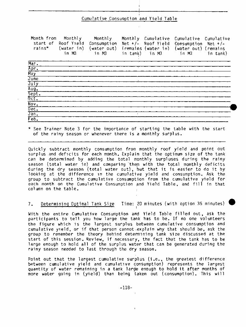
Month from
Cumulative Consumption and Yield Table
CumulativeMonthly Monthly Monthly Cumulative Cumulativestart of Roof Yield Consumption Net +/- Roof Yield Consumption Net 4/-rains* (water in)
in M3(water out)
in M3(remainsin tank)
(water in)in M3
(water out)in M3
(remainsin tank)
Mar.Apr. pMayJune pJulyAug.Sept.Oct.Nov.Dec
.
Jan.Feb.
* See Trainer Note 3 for the importance of starting the table with the startof the rainy season or whenever there is a monthly surplus.
Quickly subtract monthly consumption from monthly roof yield and point outsurplus and deficits for each month. Explain that the optimum size of the tankcan be determined by adding the total monthly surpluses during the rainyseason (total water in) and comparing them with the total monthly deficitsduring the dry season (total water out), but that it is easier to do it bylooking at the difference in the cumulative yield and consumption. Ask thegroup to subtract the cumulative consumption from the cumulative yield foreach month on the Cumulative Consumption ~nd Yield Table, and fill in thatcolumn on the table. I
7. Determining Optimal Tank Size Time: 120 minutes (with option 35 minutes)
With the entire Cumulative Consumption and Yield Table filled out, ask theparticipants to tell you how large the tank has to be. If no one volunteersthe figure which is the largest surplus between cumulative consumption andcumulative yield, or if that person cannot explain why that should be, ask thegroup to remember the theory behind determining tank size discussed at thestart of this session. Review, if necessary, the fact that the tank has to belarge enough to hold all of the surplus water that can be generated during therainy season needed to last through the dry season.
Point out that the largest cumulative surplus (i.e., the greatest differencebetween cumulative yield and cumulative consumption) represents the largestquantity of water remaining in a tank large enough to hold it after months ofmore water going in (yield) than being taken out (consumption). This will
.
-118-
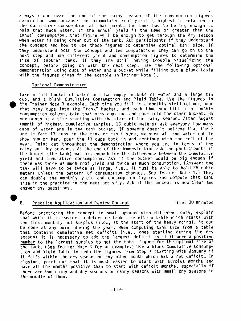
always occur near the end of the rainy season if the consumption figuresremain the same because the accumulated roof yield is highest in relation tothe cumulative consumption at that point. The tank has to be big enough tohold that much water. If the annual yield is the same or greater than theannual consumption, that figure will be enough to get through the dry seasonwhen water is being drawn out of the tank. Ask participants if they understandthe concept and how to use these figures to determine optimal tank size. Ifthey understand both the concept and the computations they can go on to thenext step and use different yield and consumption figures to determine thesize of another tank. If they are still having trouble visualizing theconcept, before going on with the next step, use the following optionaldemonstration using cups of water and a bucket while filling out a blank tablewith the figures given in the example in Trainer Note 3.
Optional Demonstration
Take a full bucket of water and two empty buckets of water and a large tincup, and a blank Cumulative Consumption and Yield Table. Use the figures inthe Trainer Note 3 example. Each time you fill in a monthly yield column, pourthat many cups into the “tank” bucket, and each time you fill in a monthlyconsumption column, take that many cups out and pour into the other bucket. Goone month at a time starting with the start of the rainy season. After August(month of highest cumulative surplus, 13 cubic meters) ask everyone how manycups of water are in the tank bucket. If someone doesn’t believe that thereare in fact 13 cups in the tank or isn’t sure, measure all the water out toshow him or her, pour the 13 cups back in and continue with the rest of theyear. Point out throughout the demonstration where you are in terms of therainy and dry seasons. At the end of the demonstration ask the participants ifthe bucket (the tank) was big enough for the difference between the cumulativeyield and cumulative consumption. Ask if the bucket would be big enough ifthere was twice as much roof yield and twice as much consumption. (Answer: thetank will have to be twice as large, i.e., it must be able to hold 26 cubicmeters unless the pattern of consumpti on changes. See Trai ner Note 4.) Theycan double the monthly yield and consumption figures and compute that tanksize in the practice in the next activity. Ask if the concept is now clear and
answer any questions..8. Practice Application and Review Concept Time: 30 minutes
Before practicing the concept in small groups with different data, explainthat while it is easier to determine tank size with a table which starts withthe first monthly net surplus (i.e., at the start of the heavy rains), it canbe done at any point during the year. When computing tank size from a tablethat contains cumulative net deficits (i.e., ones starting during the dryseason) it is necessary to add the largest deficit as if it were a positivenumber to the largest surplus to get the total figure for the optimal size ofthe tank. (See Trainer Note 3 for an example.) Use a blank Cumulative Consump-tion and Yield Table to redo the figures from Step 7 starting with January ifit falls within the dry season or any other month which has a net deficit. Inclosing, point out that it is much easier to start with surplus months andhave all the months positive than to start with deficit months, especially ifthere are two rainy and dry seasons or rainy seasons with small dry seasons inthe middle of them.
-119-
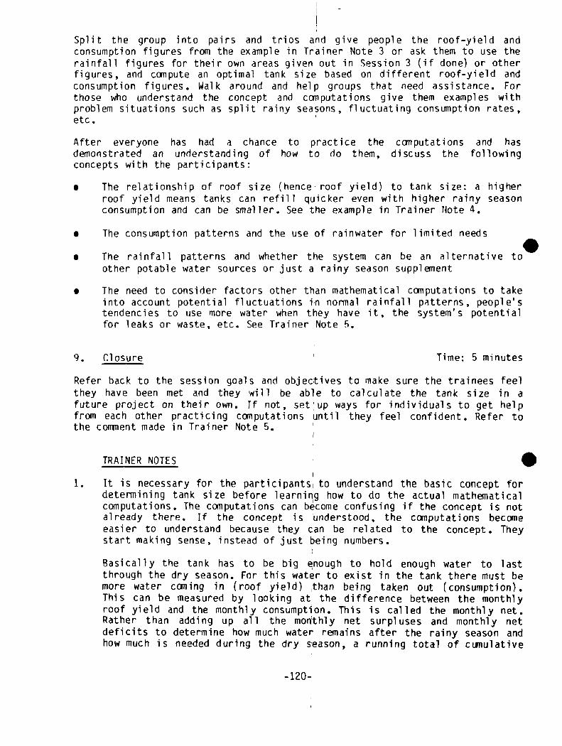
Split the group into pairs and trios and give people the roof—yield andconsumption figures from the example in Trainer Note 3 or ask them to use therainfall figures for their own areas given out in Session 3 (if done) or otherfigures, and compute an optimal tank size based on different roof-yield andconsumption figures. Walk around and help groups that need assistance. Forthose who understand the concept and computations give them examples withproblem situations such as split rainy seasons, fluctuating consumption rates,etc.
After everyone has had a chance to practice the computations and hasdemonstrated an understanding of how to do them, discuss the followingconcepts with the participants:
• The relationship of roof size (hence~ roof yield) to tank size: a higherroof yield means tanks can refill quicker even with higher rainy seasonconsumption and can be smaller. See the example in Trainer Note 4.
• The consumption patterns and the use of rainwater for limited needs
• The rainfall patterns and whether the system can be an alternative toother potable water sources or just a rainy season supplement
• The need to consider factors other than mathematical computations to takeinto account potential fluctuations in normal rainfall patterns, people’stendencies to use more water when they have it, the system’s potentialfor leaks or waste, etc. See Trainer Note 5.
9. Closure p Time: 5 minutes
Refer back to the session goals and objectives to make sure the trainees feelthey have been met and they will be able to calculate the tank size in afuture project on their own. If not, setup ways for individuals to get helpfrom each other practicing computations until they feel confident. Refer tothe coninent made in Trainer Note 5.
TRAINER NOTES
1. It is necessary for the participants to understand the basic concept fordetermining tank size before learnir~g how to do the actual mathematicalcomputations. The computations can become confusing if the concept is notalready there. If the concept is understood, the computations becomeeasier to understand because they can be related to the concept. Theystart making sense, instead of just being numbers.
Basically the tank has to be big enough to hold enough water to lastthrough the dry season. For this water to exist in the tank there must bemore water coming in (roof yield) than being taken out (consumption).This can be measured by looking at the difference between the monthlyroof yield and the monthly consumption. This is called the monthly net.Rather than adding up all the monthly net surpluses and monthly netdeficits to determine how much water remains after the rainy season andhow much is needed during the dry season, a running total of cumulative
-120-

nets can be computed by subtracting the cumulative consumption (the totalwater taken out over the course of several months) from the cumulativeroof yield (the total of water going in over the course of severalmonths). The highest cumulative net will occur near the end of the rainyseason and will represent the total of the monthly surpluses. The tankhas to be big enough to hold that amount. If a table listing thesefigures is started in the dry season or at any point when there is adeficit (i.e., more water going out than in) these figures becomedistorted by the deficit and the deficit has be added to the highestsurplus as if it were a positive number (see Trainer Note 3).
2. In Step 4 the minimum liters per person per day for drinking, washinghands, and cooking is about 15 liters/day. This figure may be greaterthan a roof catchment system can provide to a large community from justone roof, so a lower figure may have to be used when doing Step 5.
3. It is important to introduce the computations for determining tank sizewith a table which starts with the first month of the rainy season or the. start of the heavy rains during the rainy season. The following table*illustrates this point.
Cumulative Consumption and Yield Table
* All figures are in cubic meters
In the table, the figures start with March, the first month in whichthere is rain. Since the yield and consumption are the same, there is nonet surplus or deficit. Throughout the next five months of the rainy
Month Monthly Monthly Monthly Cumulative Cumulative CumulativeYield
(waterin)
Consumption(water out)
Net(remainsin tank)
Yield(water in)
Consumption(water out)
Net(remainsin tank)
March 2 2 0 2 2 0April 4 2 +2 6 4 +2MayJune
56
22
+3+4
1117
68
+ 5+9
~ulyWug.
33
22
+1+1
2023
1012
+10~33~Sept. 1 2 -1 24 14 +10Oct. 0 2 -2 24 16 +8Nov. 0 2 -2 24 18 +6Dec. 0 2 -2 24 20 +4Jan. 0 2 -2 24 22 + 2Feb. 0 2 -2 24 24 +0
-121-

season the monthly yield is greater than’ the monthly consumption and themonthly net (the water remaining in the tank or added to or subtractedfrom that amount each month) is positive, i.e., a surplus. The cumulativenet shows the total of those monthly surpluses and represents the actualwater in the tank after any given month. For example there could be 11cubic meters of water in the tank at end of August, if the tank is bigenough to contain that amount. From September through February less watergoes into the tank than is taken out and the monthly nets are all nega-tive and the cumulative net decreases proportionately.
4. In Step 8, the point is made that increasing the roof yield can, in somecases, reduce the size of the tank because the tank can be refilledquicker. This is true if there is more water remaining in the tank afterthe rainy season than is needed for dry season consumption. The tank musthold enough water to provide the minimal needs for the dry season, butconstruction costs may not allow for the construction of a tank to meetall needs. In the optional demonstration in Step 7 participants are askedif the tank (the bucket) would be big enough if both the roof yield andconsumption were doubled. If the consumption for each month is doubled,then the tank has to be twice as large because the community needs twiceas much water during that period of time.
But if the yield were doubled to a total yield of 52 cubic meters insteadof 26 cubic meters (using the example below) and the consumption remainedat 2 cubic meters during the five month dry season, a smaller tank couldbe built to hold only enough water needed to get through the dry season.In the following example the roof yield is doubled during each of themonths it rains and consumption is increased accordingly. The followingfigures tell us that we need a tank with a minimal capacity of only 10cubic meters even though we have doubled the roof yield.
Cumulative Consumption and Yield Table
.Month Monthly Monthly Monthly Cumulative Cumulative Cumulative
Yield Consumption Net Yield Consumption Net(water (water out) (remain— (water in) (water out) (remaining)
in) ing) I
Mar. 4 4I 0
Apr. 8 6 +2 12 10 + 2May 10 7 +3 22 17 +5June 12 8 +4 ‘ 34 25 + 9July 10 9 +1 44 34 +10Aug. 6 6 0 50 40 +10Sept. 2 2 0 r 52 42 +10Oct. 0 2 -2 52 44 +8Nov. 0 2 -2 .52 46 +6Dec. 0 2 -2 52 48 +4Jan. 0 2 -2 , 52 50 + 2Feb. 0 2 -2 52 52 0
-122-

This is the smallest tank which can provide 2 cubic meters of water toeveryone during the dry season. Slight changes in consumption will alterthe size of the tank. If you reduce August’s consumption by 2 cubicmeters and increase September’s by the same amount (i.e., 4 cubic metersfor both months) the tank size will have to be increased to 12 cubicmeters from 10 cubic meters to hold the 2 cubic meters extra that willaccumulate by the end of August in order to have 10 cubic meters in thetank by the end of September. Try the new monthly consumption figures andsee how the cumulative net column will give you a different result forthe size of the tank.
5. Finally, it should he pointed out to the group that designing the sizeand configuration of the tank is not based only on mathematical con-siderations of how much water is needed to get through the dry season andhow much surplus can be generated during the rainy season. The cost oftank construction and the time required to build a large tank have to betaken into consideration as do the desires of a community to use morewater when it is available. The mathematical computations are only oneset of factors which have to be considered.
MATERIALS
- Flipchart for session goals and objectives- Flipchart for Monthly Total Roof Yield Bar Graph from Session 3- Fl ipchart for blank Monthly Total Roof Yield Bar Graph- Flipcharts with Roof Yield Tables (one for a calendar year, one starting
with the first month of the heavy rainy season)- Flipchart with the equation for calculation consumption in liters per
month- Flipcharts with three or four blank Cumulative Consumption and Yield
Tables for Steps 6, 7, and 8- Three buckets and a cup for the optional demonstration in Step 7
.
-123-

—
1
.

This is the smallest tank which can provide 2 cubic meters of water toeveryone during the dry season. Slight changes in consumption will alterthe size of the tank. If you reduce August’s consumption by 2 cubicmeters and increase September’s by the same amount (i.e., 4 cubic metersfor both months) the tank size will have to be increased to 12 cubicmeters from 10 cubic meters to hold the 2 cubic meters extra that willaccumulate by the end of August in order to have 10 cubic meters in thetank by the end of September. Try the new monthly consumption figures andsee how the cumulative net column will give you a different result forthe size of the tank.
5. Finally, it should he pointed out to the group that designing the sizeand configuration of the tank is not based only onmathematical con-siderations of how much water is needed to get through the dry season andhow much surplus can be generated during the rainy season. The cost oftank construction and the time required to build a large tank have to betaken into consideration as do the desires of a community to use morewater when it is available. The mathematical coiiputations are only oneset of factors which have to be considered.
MATERIALS
- Flipchart for session goals and objectives- Flipchart for Monthly Total Roof Yield Bar Graph from Session 3- Flipchart for blank Monthly Total Roof Yield Bar Graph- Flipcharts with Roof Yield Tables (one for a calendar year, one starting
with the first month of the heavy rainy season)- Flipchart with the equation for calculation consumption in liters per
month- Flipcharts with three or four blank Cumulative Consumption and Yield
Tables for Steps 6, 7, and 8- Three buckets and a cup for the optional demonstration in Step 7
-123-

.

.
SESSION 8 - -

I.

.SYNOPSIS
SESSION 8: Building Small Cement Household Storage Tanks
Construction Activity
Discussion
Closure
Discuss
Di scuss
Field Work
Discuss
Discuss
ACTIVITY
1. Introduction
2. Work Orientation
PROCEDURE
~3.
4.
5.
TIME(In minutes
unless otherwiseindicated)
5
30
2 1/2 hrs.
60
5
HANDOUTS/MATERI ALS
Handout 8-1:Building Water Tanks
See Materials List
FL IPC H AR TS
Session Goals
Discussion Questions
Total: 4 hours, 10 minutes

S
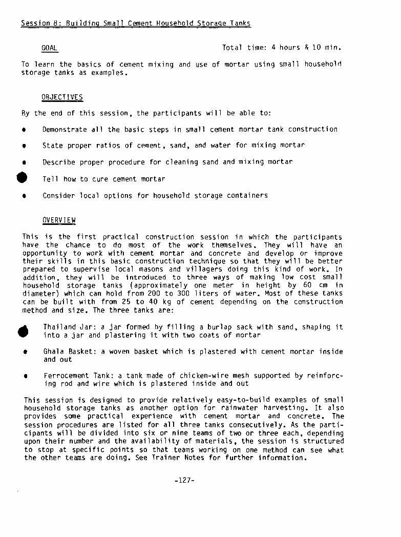
Session 8: Building Small Cement Household Storage Tanks
GOAL Total time: 4 hours P~ 10 mm.
To learn the basics of cement mixing and use of mortar using small household
storage tanks as examples.
OBJECTIVES
By the end of this session, the participants will be able to:
• Demonstrate all the basic steps in small cement mortar tank construction
• State proper ratios of cement, sand, and water for mixing mortar
• Describe proper procedure for cleaning sand and mixing mortar
Tell how to cure cement mortar
• Consider local options for household storage containers
OVERVIEW
This is the first practical construction session in which the participantshave the chance to do most of the work themselves. They will have anopportunity to work with cement mortar and concrete and develop or improvetheir skills in this basic construction technique so that they will be betterprepared to supervise local masons and villagers doing this kind of work. Inaddition, they will be introduced to three ways of making low cost smallhousehold storage tanks (approximately one meter in height by 60 cm indiameter) which can hold from 200 to 300 liters of water. Most of these tankscan be built with from 25 to 40 kg of cement depending on the constructionmethod and size. The three tanks are:
. Thailand Jar: a jar formed by filling a burlap sack with sand, shaping itinto a jar and plastering it with two coats of mortar
• Ghala Basket: a woven basket which is plastered with cement mortar insideand out
• Ferrocement Tank: a tank made of chicken-wire mesh supported by reinforc-ing rod and wire which is plastered inside and out
This session is designed to provide relatively easy-to-build examples of smallhousehold storage tanks as another option for rainwater harvesting. It alsoprovides some practical experience with cement mortar and concrete. Thesession procedures are listed for all three tanks consecutively. As the parti-cipants will be divided into six or nine teams of two or three each, dependingupon their number and the availability of materials, the session is structuredto stop at specific points so that teams working on one method can see whatthe other teams are doing. See Trainer Notes for further information.
-127-

ACTiVITIES
1. Introduction Time: 5 minutes
Open the session by explaining the material in the overview given above andstating the goals and objectives of the session.
2. Work Orientation Time: 30 minutes
Distribute Handout 8-1: Building Water Tanks and ask everyone to read it. Thengo over all of the steps for the three methods and explain what will be donethat day. See if there are any questions at each step. Depending on the numberof participants and availability of construction materials, divide the groupinto six or nine work teams of two or three people each. Assign two or threeteams to each of the three technologies to be demonstrated and go out to thework site.
3. Construction Activity Time: 2 hours & 30 minutes
The following construction activity is presented in three columns--one foreach type of tank. There are periodic breaKs in the work sequence so that allparticipants can observe the work being done on each tank. Fuller technicalinformation is provided in the Trainer Notes.
THAILAND JAR
Pre-session preparation:• construct concrete bases(see Trainer Notes, 1 & 2)• cut open burlap bags• have all materials ready
Make jar mold:• draw jar pattern on bur-
lap• sew the two burlap sacks
together leaving top andbottom open; turn insideout
• place sack on base andfill with sand
GHALA BASKET TANK
Pre-session preparation:• mix concrete for base(see Trainer Notes 1 & 3)• have base mold and
foundation ready• have all mat~rials ready
Make base and placebasket: I• pour concrete into mold
on foundation, compactand level I
• place pipe i,n base ifdesired
• place basket into basesecurely
FERROCEMENT TANK
Pre-session preparation:• mix concrete for base(see Trainer Notes 1 & 4)• have base mold ready• have all materials
ready
Make 70 cm wide baseand place re-rod andwire mesh into base:• pour concrete into
form, compact andlevel
• place reinforcing rodin base
• wrap chicken wirearound re-rod frameand tie securely
(Have all participants look at the finish~d concrete bases for the jar and theconcrete mixed for the other tanks. Have all participants look at the varioumaterials and answer any questions about them.)
-128-
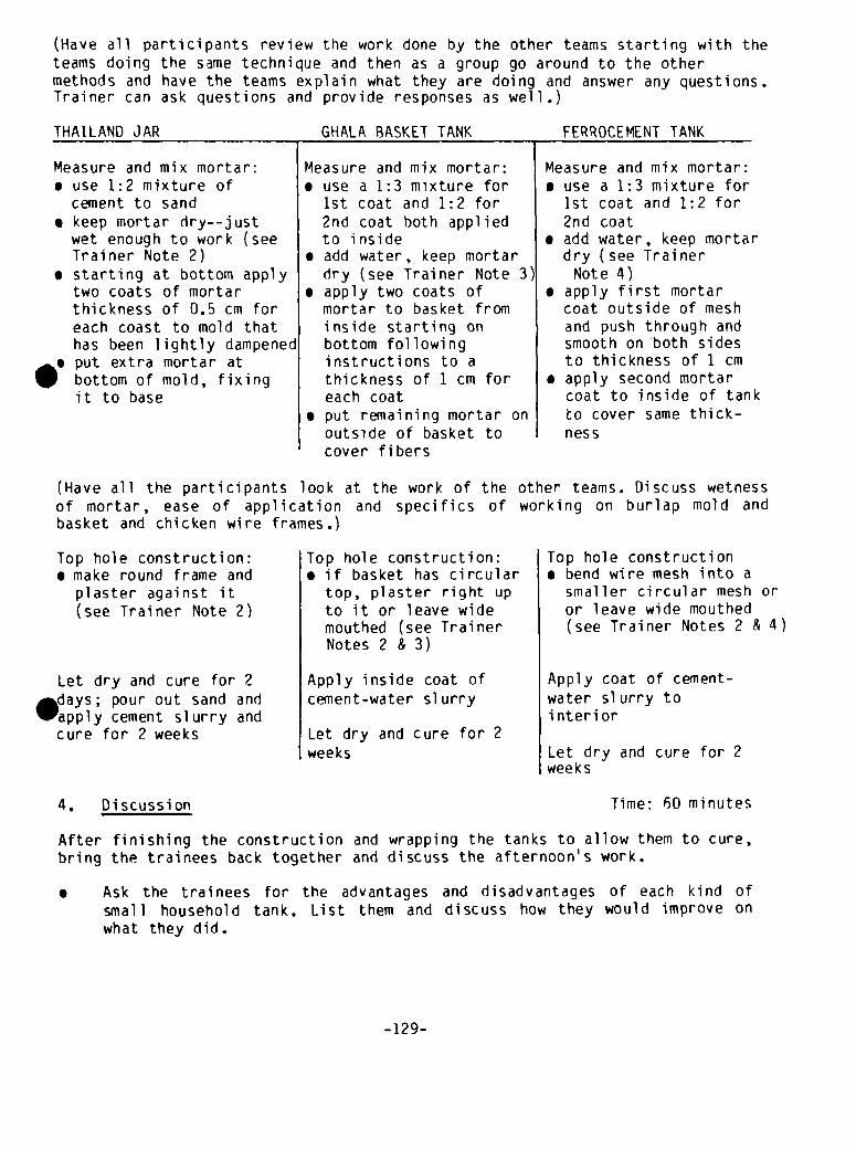
(Have all participants review the work done by the other teams starting with theteams doing the same technique and then as a group go around to the othermethods and have the teams explain what they are doing and answer any questions.Trainer can ask questions and provide responses as well.)
THAILAND JAR
Measure and mix mortar:• use 1:2 mixture of
cement to sand• keep mortar dry--just
wet enough to work (seeTrainer Note 2)
• starting at bottom applytwo coats of mortarthickness of 0.5 cm foreach coast to mold thathas been lightly dampened
• put extra mortar atbottom of mold, fixingit to base
GHALA BASKET TANK
Measure and mix mortar:• use a 1:3 mixture for
1st coat and 1:2 for2nd coat both appliedto inside
• add water, keep mortardry (see Trainer Note 3~
• apply two coats ofmortar to basket frominside starting onbottom followinginstructions to athickness of 1 cm foreach coat
• put remaining mortar onoutside of basket tocover fibers
FERROCEMENTTANK
Measure and mix mortar:• use a 1:3 mixture for
1st coat and 1:2 for2nd coat
• add water, keep mortardry (see Trainer
Note 4)• apply first mortar
coat outside of meshand push through andsmooth on both sidesto thickness of 1 cm
• apply second mortarcoat to inside of tank~o cover same thick-ness
Top hole construction:• make round frame and
plaster against it(see Trainer Note 2)
Let dry and cure for 2days; pour out sand andapply cement slurry andcure for 2 weeks
Top hole construction:• if basket has circular
top, plaster right upto it or leave widemouthed (see TrainerNotes 2 & 3)
Apply inside coat ofcement-water si urry
Let dry and cure for 2weeks
Top hole construction• bend wire mesh into a
smaller circular mesh oror leave wide mouthed(see Trainer Notes 2 & 4)
Apply coat of cement-water sl urry tointerior
Let dry and cure for 2
4. Discussion Time: 60 minutes
After finishing the construction and wrapping the tanks to allow them to cure,
bring the trainees back together and discuss the afternoon’s work.
• Ask the trainees for the advantages and disadvantages of each kind ofsmall household tank. List them and discuss how they would improve onwhat they did.
(Have all the participants look at the work of the other teams. Discuss wetnessof mortar, ease of application and specifics of working on burlap mold andbasket and chicken wire frames.)
weeks
-129-

• Ask the trainees to identify the problems they encountered inconstructing the tanks. List and discuss how they would improve on whatthey did.
• Discuss local options for small household tanks and the difficulty andestimated cost of each (for a discussion of costs and their calculationsee Trainer Reference Notes which follow the handout).
• Ask the trainees to discuss the applications of what they learned todayfor their work.
5. Closure Time: 5 minutes
Refer to the session objectives, summarize the major points of the discussionand refer to the following day’s practical session on thatch roof systems andbamboo gutters.
TRAINER NOTES
1. Before the start of the workshop, carefully read Handout 8-1: BuildingWater Tanks for the three construction’ methods. Discuss the constructionmethods and session’s learning objectives with the construction foreman.Have the foreman brief the masons on their responsibilities in preparingfor the session and helping the participants make the tanks. It is veryimportant to make sure that the masons understand that they are not to dothe work for the participants or take over for them when they make amistake but merely to suggest to them how they can do the work better oreasier. Local masons must be supervised to avoid having them take overfrom the participants during practical~ sessions.
2. Thailand Jars
Make the bases for the jars out of concrete (1:2:4--cement:sand:gravel)to a thickness of 3 cm if they do not need to be moved to the construc-tion site or 5 cm if they do need to be moved. Bases being moved shouldbe made before the start of the workshop so they have a full week tocure; those not being moved can be made five days before this activity.
The sacking material can be burlap bags used for transporting rice orother foods, and should be at least 125 cm x 110 cm when opened. They canbe filled with rice husks, sawlust, or small pebbles if sand is notavailable. p
Be very careful when the participants are dampening the mold beforeapplying the mortar (a dry mold will absorb the moisture in the mortar~to make sure that they do not pour water over the mold or splash on toomuch. Any excess water will be absorbed into the sand and will thenfilter slowly down to the base of the mold and leak out, breaking themortar at the base.
-130-
The rich 1:2 mixture of cement to clean, coarse sand should be mixed withonly a little water and applied as dry as possible. This makes the appli-cation more difficult but results in a stronger jar. Most local masonsare used to using mortar as plaster on walls and work with a very wetmortar which is easier to apply. In all tank construction methods, theforeman will have to explain the reasons for the drier mixture andclosely supervise the work of the local masons and help in this area.
The mold for the top of a jar can be made out of wood c~rsand held inplace with a narrow band of thin corrugated iron sheet formed into acircle. The plaster is applied against the circular mold to produce anattractive circular top to the jar.
The jars need to be cured for two weeks before moving and using. The moldcan be poured out and the sack removed after 48 hours. Finish the insidewith a cement slurry and cure out of direct sunlight and keep wet withthe empty burlap bag.
Ghala Basket
A woven basket common to the area can be used as an inexpensive basis formaking a strong tank. The term “ghala basket” comes from the large grainstorage baskets woven in East Africa. Any sturdy woven basket will do.For the purposes of the demonstration it should be big enough to hold 100to 300 liters of water when finished. If no such baskets are made in yourcountry do not do this demonstration and just demonstrate the other twomethods.
The bases for these tanks must be made during the demonstration. Sometime can be saved by having the cOncrete dry mixed and ready for thewater to be added before the demonstration. The form for the foundationand base, if it is to have one, can also be prepared ahead of time. Use amix of 1:2:4 cement-sand-gravel for the concrete. Do not add too muchwater as the concrete should be fairly dry. Drier concrete and mortarmakes a stronger final product. The base should be about 5 cm thick for asmall basket unless a pipe is used to get the water out in which case itcan be little thicker. The base of the basket should be placed firmly5 into the concrete base. The bottom of the basket can be cut off as theconcrete does not need the additional structure.
In choosing or ordering a basket for this demonstration consider size,shape, and the access into the inside, as it has to be plastered from theinside. Also try to find a weave that is open enough for the mortar to gothrough the holes--a very tightly woven basket is not suitable. Elaborateweaving designs and dyed materials are also not necessary. Apply twocoats of mortar to a thickness of 1 cm each. The first coat (1:3 cementto sand) is applied to the inside and left to dry for a few minutes. Thesecond coat (1:2 cement to sand) is then applied. The remaining mortar(first and second coats) should be applied to the outside of the basketto cover and seal it when done. For other general instructions seeTrainer Note 2 (Thailand Jar).
-131-
4. Ferrocement Tank
The tank resembles an oil drum when finished but is a little larger andmuch heavier. The concrete base should be 70 cm in diameter and 5 cmthick and should be made with a 1:2:4 mixture of cement, sand, andgravel. The concrete should not be too wet. The one meter wide chickenwire mesh (1” [2.54 cm] mesh in 20 gauge wire is preferable to 2” [5 cm]mesh) should be wrapped around the reinforcing rod frame tightly andanchored into the wet concrete base. Use six one meter lengths of 8 mm or10 mm reinforcing rod spaced 30 cm apart in a circle 5 cm inside theouter rim of the base. Tie the mesh in place with 20 gauge wire. If only2” chicken wire is available, wrap it around twice to reduce the size ofthe holes. If no chicken wire or other suitable metal wire material isavailable a mesh can be made by weaving thinly cut bamboo stripstogether. Thicker bamboo slats can also replace the reinforcing rod.
Apply the first coat of mortar (made with a 1:3 ratio of cement to sand)to the outside of the mesh and push through and smooth on both sides to athickness of 1 cm. When dry, mix the second coat of mortar (made withricher 1:2 ratio of cement to sand) and apply to the inside of the tankto a thickness of 1 cm. Start both coats from the bottom and add a littleextra where the sides join the concrete base. Make sure all of thereinforcing wire is well covered and sealed. See Trainer Notes I and 2 onwetness of mortar and working with local masons, curing mortar, etc.
MATERIALS
Flipchart for session goals, objective and questions (Step 4)- Handout 8-1: Building Water Tanks— Material s from lists in Handout 8—1
S
-132-

Handout, 8-1, p. 1
BUILDING WATER TANKS*
The construction information in this section is for three of the most widelydocumented of the tanks. Here is detailed information on the materials, tools,and skills involved in their construction; some readers with confidence intheir manual skills would be able to attempt construction from the informationgiven. These are not necessarily the three “best” tank designs for householdrooftop catchment; in fact, each of these three tanks requires a relativelygreat amount of cement per cubic meter of storage (see below). They are, how-ever, three of the most “teachable” of the designs documented.
Each of the tanks described in this section is made with cement mortar, whichis a mixture of sand and cement and water. It is always important to make, ortar with the cleanest available materials, and to keep soil and other
ontaminants out of the mortar mixture. Watt (1978) suggests using a mixingboard or making a small concrete pad on a layer of gravel. The board isprobably a better choice where the tanks or jars will be built far from eachother (see figure below).
.
Watt (1978) by permission
Equipment and Material for Mixing Cement Mortar.
* From WASH Working Paper No. 20, “Rainwater Harvesting for Domestic WaterSupplies in Developing Countries” by Kent Keller, as adapted for thissession by David Yohalem, 1984.
Gauge sand inmeasur,ng box
Cement
-133-

Handout 8-1, p. 2
The mortar mixtures used for the following tanks and jars contain proportionsof cement:sand ranging from 1:2 to 1:3 (measured by volume). Mixtures withmore cement are easier to plaster with and may be stronger and more waterprooffor the surfaces of smaller jars with little reinforcement. For largercontainers, a 1:3 cernent:sand mixture is strong enough and less likely tocrack when curing.
Sand for mortar should be clean. A range of sand grain sizes is permissiblebut sand with lots of find silt should be avoided because it causes flaking ofdry mortar. Sand and any other materials to be used in construction should begathered before any work starts. Study the list of materials for each of thetanks, and read through the instructions carefully before beginning.
Clean water should be added to the cement and sand after they have beethoroughly mixed together with a trowel or shovel. Make a hole in the pile ocement/sand mix and pour the water in, a little at a time. While a mix that istoo “dry” will be difficult to apply, a “wet” mix will not be as strong whencured. Use as little water as possible to obtain a workable mixture. Startwith an amount of water that is half the volume of the cement, and add watersparingly.
Do not mix more mortar than can be applied to the tank or jar in about onehalf hour! After about this amount of time, mortar begins to set and cannot beapplied properly (Watt, 1978).*
Concrete is used instead or mortar for the foundations of most tanks and jarsbecause it contains gravel or small stones and is less likely to break orweaken under the load of a heavy tank and its contents. The gravel used inconcrete ideally contains a range of sizes, and the stones should not be flat.Like sand, gravel must be clean, or the concrete will be weak.
Concrete used for foundations can be mixed in proportions of cement:sand:gravel ranging from 1:2:3 to 1:3:6. Regardless of the proportions, concreteshould be made with as little water as possible and mixed in a clean place.Containers like those shown in the figure above can be used to measure theproportions of materials in mortar and concrete mixes. Resist the temptationto estimate proportions or use the blade of a trowel to measure with; thiswill result in a weaker mix. I
The Village Technology Handbook (VITA, 1978) includes an excellent section onselecting mixes, preparing, and building with concrete.
* See Annotated Bibliography at the end of the Session Guides.
—134~-

Handout 8-1, p. 3
1. Quarter Cubic Meter Cement Plaster Jar (“Thailand Jar”)
Unlike the other water containers in this section, this jar is built entirelyof mortar. It contains no strengthening fibers nor wires. The mortar isapplied to a “mold” which is usually made of sacking material (like burlap)filled with something heavy enough to plaster against.
Because these jars have no reinforcing material, they are made with a mortarmix which is “rich” in cement. The proportions of materials recommended in thefollowing instructions (copied by permission from Watt, 1978 are 1:2, cement:sand (measured by volume). Watt does not mention the proportion of watar to beused. He says instead that the mortar should be mixed as “dry” as possible,
•or maximum strength. Refer back to the discussion of making mortar above.
The following instructions are for construction of a small jar which holdsapproximately a quarter of a cubic meter of water (figure 2). Watt says thatpeople with no experience have been taught to make the jars in less than twodays. Much larger jars which have screens, lids, and taps have been cons-tructed using this method. Substituting soil and lime for some of the cementand sand in the mortar has also been tried.
MATERIALS: 1/2 bag of cement (less than this should be required) per jarclean sandclean waterburlap, “gunny cloth”, or other strong sacking materialsand, grain husks, or sawdust tO fill the sackingprepared concrete bases
TOOLS: needle and thread, or other tool for sewing the sackingmixing board or pad and containers, for measuring and mixing mortarshovel for mixing mortartrowel and wooden stickbucket for carry mortar
STEPS IN CONSTRUCTIONREQUIRING SPECIAL CARE:
Making sure that the material used to fill the sacking (Step 2.4 infigure 2) is heavy enough to keep its shape during plastering. Itis a good idea to try filling the sack on the ground beforebeginning construction.
Making the mortar. Do not make the mortar for applying to the molduntil you are actually ready to begin (Step 2.8 in figure 3). Thisshould allow you to work with a “dry” mortar mixture for maximumstrength. Mixing the cement and sand well, before adding the water,is especially important.
Curing the new jar (Step 2.10 in figure 3), also requiresparticular attention.
-135-
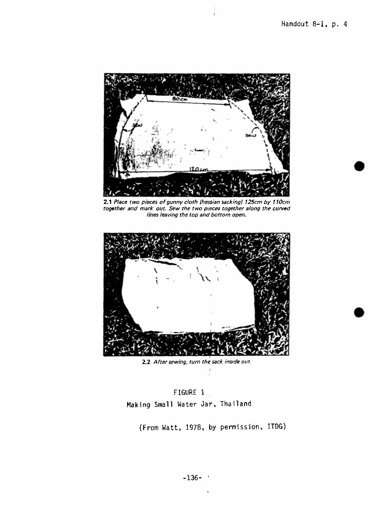
FIGURE 1
Making Small Water Jar, Thailand
Handout 8-1, p. 4
(From Watt, 1978, by permission, ITDG)
-136-
2.1 Place two pieces of gunny cloth (hessian sacking) 125cm by 110cmtogether and mark out. Sew the two pieces together along the curved
lines leaving the top and bottom open.
2.2 After sewing, turn the sack inside out.
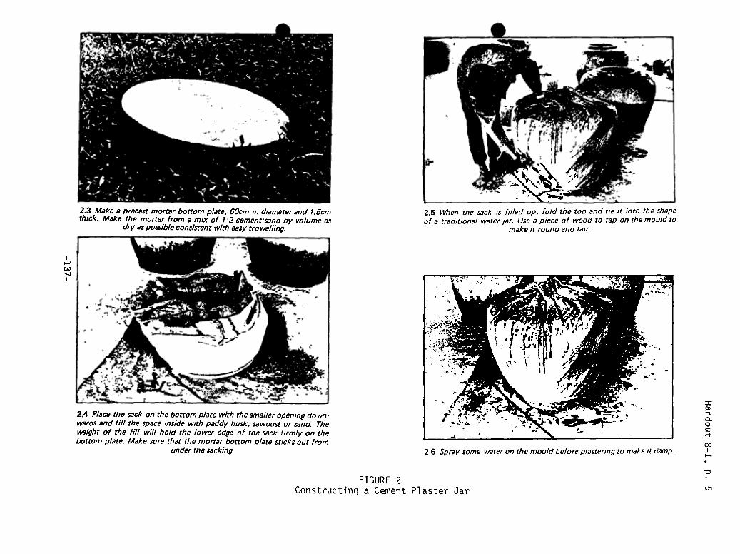
C.)
FIGURE 2Constructing a Cement
2.3 Make a precast mortar bottom p/ate, 60cm in diameter and 1.5cmthick. Make the mortar from a mix of 1 2 cement sand by volume as
dry as possible consistent with easy trowelling.
2.5 When the sack is filled up, fold the top and tie it into the shapeof a traditional water jar. Use a piece of wood to tap on the mould to
make it round and fair.
2.4 P/ace the sack on the bottom p/ate with the smaller opening down-wards and fill the space inside with paddy husk, sawdust or sand. Thewaight of the fill will hold the lower edge of the sack firmly on thebottom plate. Make sure that the mortar bottom plate sticks out from
under the sacking. 2.6 Spray some water on the mould before plastering to make it damp.
=0)
0
‘-F
U,Plaster Jar
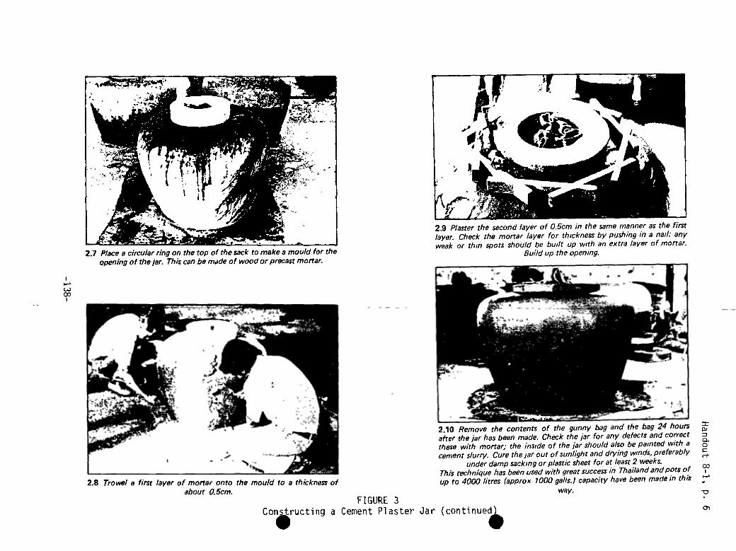
‘-~C-.)cc
FIGURE 3Con1ructing a Cement Plaster Jar (continue~
way.
2.7 Place a circular ring on the top of the sack to make a mould for theopening of the jar. This can be made of wood or precast mortar.
2.9 Plaster the second layer of 0.5cm in the same manner as the firstlayer. Check the mortar layer for thickness by pushing in a nail: anyweak or thin spots should be built up with an extra layer of mortar.
Buildup the opening.
2.8 Trowel a first layer of mortar onto the mould to a thickness ofabout 0.5cm.
2.10 Remove the contents of the gunny bag and the bag 24 hoursafter the jar has been made. Check the jar for any defects and correctthese with mortar; the inside of the jar should also be painted with acement slurry. Cure the jar out of sunlight and drying winds, preferably
under damp sacking or plastic sheet for at least 2 weeks.This technique has been used with great success in Thai/and and pots ofup to 4000 litres (approx 1000 galls.) capacity have been made in this
0)
0~
0
cc
Handout 8-1, p. 7
2. Woven “Ghala” Basket Reinforced Tank
The f~llowing guidelines are adapted from Keller’s instructions for a larger2.3 m tank made out of ghala basket. These guidelines are for similar sizetank as above and can be made out of any appropriate basket with about onehalf a sack of cement.
Choosing an Appropriate Woven Basket
The basket should be made out of a thick sturdy weaving material so that thebasket will stand on its own and not bend while being plastered. The weaveshould be open enough to enable the mortar to go through the weave. Intricateweaving designs and different colored fibers are not necessary and onlyincrease the cost of the basket. The top of the basket should be large enougho allow an adult to reach in to plaster the basket from the inside. The base
of the basket should not be too small relative to the widest diameter or itwill be unstable.
Base
Follow the same instructions for a ferrocement tank base to make a base alittle bigger than the basket. Place the basket into the base while it isstill wet. If the bottom weave of the basket is very tight and the concretecannot go through it, cut the bottom of the basket off and push the lowersides of the basket into the concrete so it is firmly in place. Allow the baseto dry enough so that the basket doesn’t move when being plastered.
Mortar and Plastering
Apply a first coat of mortar made with a ratio of 1:3 cement to sand to theinside of the basket starting at the bottom and working up to a thickness of 1cm. As with the above tanks, keep the mortar as dry as possible. Place extramortar on the bottom where the basket joins the base. Push the mortar through
he weave of the basket and smooth on the outside as well as inside. Let themortar basket dry while mixing the second coat of mortar with a richer mixtureof 1:2 cement to sand. Apply the second coat to the inside of the basketincluding the base of a thickness of 1 cm. Use any leftover mortar to coverthe outside of the basket so that the woven basket frame is entireTy coveredwith plaster. This will protect the frame from insects, moisture, etc. andmake the tank last longer. When the second coat is dry enough apply a cementslurry to seal the inside.
Cu:i ng
cure and cover as in above instructions.
MATERIALS
1/2 sack of cement per tankclean sand gravel and waterwoven basket
-139-
Handout 8-1, p. 8
3. Ferrocement Tank for Small Household Use
The following construction guidelines3are adapted from Keller’s instructionsfor the construction of a larger 10 m ferrocement tank. The tank to be builtwith these guidelines is approx3imately I mtall and 60 cm in diameter and willhold about 280 liters (0.28 m ) of water. If made with walls 2 cm thick ofmortar mixed to a ratio of 1:3 cement to sand it will use a half a sack ofcement, 6 meters of #8 reinforcing rod and 2-4 meters of 1 m wide chicken wiredepending on the size of the wire mesh.
Base
A concrete base 70 cm in diameter by 5 cm thick is poured with a mixture of1:2:4 cement:sand:gravel in a 5 cm deep x 70 cm wide circular form excavatedin clay soil. Make sure the sand and gravel are clean and free of any organicmatter. Mix in only enough water to make the concrete workable. The drier theconcrete the better. Let dry a little as you prepare the other materials.
Wire Mesh and Supports
Cut a 6 meter length of #8 reinforcing rod into six one meter lengths (#6 or10 re-rod can be used but the #6 is a little weak for this purpose and the #10is stronger than needed and more costly). Place the rods about 30 cm apart ina circle 5 cm inside the outer rim of the still wet base. This will produce anew circle with a diameter of 60 cm. Take the wire mesh and wrap it around thereinforcing rod and push the bottom into the concrete base. If you are usingchicken wire with a one inch (2.54 cm) mesh you only have to wrap it aroundonce. If you have to use 2 inch (5 cm) mesh chicken wire, wrap it around twiceand make sure that the second layer overlaps the first in such a way as to cutthe size of the holes in half. Tie the chicken wire itself and secure to thereinforcing rod. I
Mortar and Plastering
Mix mortar with a 1:3 ratio of cement to sand and as little water as needed tomake it workable. The drier the mortar, the stronger the tank will be when itdries. Apply a coat of mortar plaster 12 cm thick to the outside of thechicken wire mesh, starting at the base and working up. Put a little extramortar onto the bottom of the mesh where it joins the base. Push the mortarthrough the wire mesh so it completely covers the inside of the reinforcingrod and wire mesh. Smooth the plaster on both sides and let dry a little. Whenthe mortar is dry enough to be worked (abQut 20 minutes) put on a second coatof mortar made with a richer mixture (1:2 cement to sand) to the same thick-ness to the inside of the tank. Plaster the concrete base and use more plasteras above where the wall and base meet.
Start from the bottom and work up to the top. Make sure that all the mortarwalls are to a uniform thickness and fill in any thin spots. When completed,the walls should be 2 cm thick and no reinforcing rod or chicken wire shouldbe visible. Finish the top of the wall to make a smooth lip for the barrel.Apply a cement slurry to the inside to smooth and seal the interior.
-140-
Handout 8-1, p. 9
Curing
Dry in the direct sunlight, and keep damp for two weeks before moving. A wetburlap sack can be placed over the tank to keep it wet during this time. Aftera day, put 20 cm of water in the tank to keep the inside moist. A wooden topcan be made to sit over this tank as a cover.
MATERIALS
1/2 sack of cement per tankclean sand, gravel and water6 m of #8 reinforcing rod per tank
S_4m of 1 m wide chicken wire or similar wire mesh per tank
i re
TOOLS
shovels and buckets for mixing and carrying mortar and concretetools for cutting re-rod and wire meshtrowels, floats, etc.
.
-14 1-

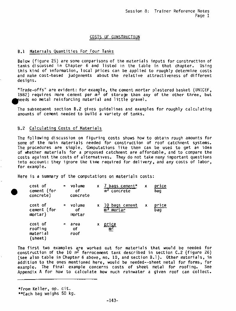
Session 8: Trainer Reference NotesPage 1
COSTS OF CONSTRUCTION
B.1 Materials Quantities For Four Tanks
Below (figure 25) are some comparisons of the materials inputs for construction oftanks discussed in Chapter 6 and listed in the table in that chapter. Usingthis kind of information, local prices can be applied to roughly determine costsand make cost-based judgeinents about the relative attractiveness of differentdesigns.
“Trade-offs” are evident: for example, the cement mortar plastered basket (UNICEF,1982) requires more cement per m~of storage than any of the other three, butieeds no metal reinforcing material and little gravel.
The subsequent section B.2 gives guidelines and examples for roughly calculatingamounts of cement needed to build a variety of tanks.
B.2 Calculating Costs of Materials
The following discussion on figuring costs shows how to obtain rough amounts forsome of the main materials needed for construction of roof catchment systems.The procedures are simple, Computations like them can be used to get an ideaof whether materials for a proposed catchment are affordable, and to compare thecosts against the costs of alternatives. They do not take many important questionsinto account: they ignore the time required for delivery, and any costs of labor,for example.
Here is a summary of the computations on materials costs:
cost of = volume x 7 bags cement* x pricecement (for of concrete bagconcrete) concrete
cost of = volume x 10 bags cement x pricecement (for of rn:3 mortar bagmortar) mortar
cost of = area x priceroofing of m2material roof(sheet)
The first two examples are worked out for materials that would be needed forconstruction of the 10 m2 ferrocement tank described in section C.2 (figure 26)(see also table in Chapter 6 above, no. 10, and section B.l). Other materials, inaddition to the ones mentioned here, would be needed--sheet metal for forms, forexample. The final example concerns costs of sheet metal for roofing. SeeAppendix A for how to calculate how much rainwater a given roof can collect.
*From Keller, op. cit.**Each bag weighs 50 kg
-14 3-
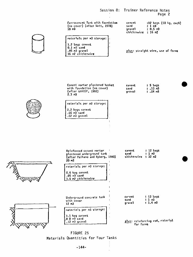
Session 8:
rerroccn~nt Tank with foundation(no cover) (after Watt, 1978)10 m3
materials per m3 storage:
1.2 bags cement0.1 m3 sand.05 m3 gravel16 m2 chickenwire
Cement mortar plastered basketwith foundation (no cover)(after inilCEF, 1982)2.3 m3
rr.aterials per m3 storage:
2.2 bags cement.06 m3 sand.02 m3 gravel
Reinforced ce-tent mortarplastered underground tank(after t~~aikano and ~yberg. 1980)20m3 I
iraterials per m3 storage:
0.6 bag certent.05 m3 sand1.6 m2 chickenwire
Underground concrete tankwith cover12 m3
iraterials per m3
1.1 bag cer~ent.0 8 m3 sand
.12 m3 gravel
FIGURE 25Materials Quantities for Four Tanks
Trainer Reference NotesPage 2
cement :12 bags (50 ~. each)sand :1m3gravel : 0.5 m3chickenwire : 16 mZ
~ straight wire, use of forms
cement : S bagssand : .13 ,n3gravel : .04 m3
cement 12 bagssand :1m3chickenwire 32 in2
ce—ent : 13 bagssand :1m3gravel : 1.4 rn3
~ reinforcing rod, raterialfor formS
.
S
-144-
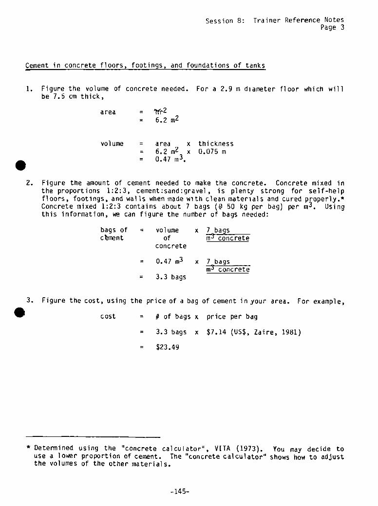
Session 8: Trainer Reference NotesPage 3
Cement in concrete floors, footings, and foundations of tanks
1. Figure the volume of concrete needed. For a 2.9 m diameter floor which willbe 7.5 cm thick,
area = 1fr2= 6.2m2
volume = area= 6.2m2= 0.47 rn3.
x thicknessx 0.075 m
2. Figure the amount of cement needed to make the concrete. Concrete mixed inthe proportions 1:2:3, cement:sand:gravel , is plenty strong for self-helpfloors, footings, and walls when made with clean materials and cured properly.tConcrete mixed 1:2:3 contains about 7 bags (@ 50 kg per bag) per m3. Usingthis information, we can figure the number of bags needed:
bags ofc bme n t
= volumeof
concrete
= 0.47 m3
= 3.3 bags
x 7 bagsm3 concrete
x 7 bagsm3 concrete
3. Figure the cost, using the price of a bag of cement in your area. For example,
cost = # of bags x price per bag
= 3.3 bags x $7.14 (US$, Zaire, 1981)
= $23.49
* Determined using the “concrete calculator”, VITA (1973). You may decide touse a lower proportion of cement. The “concrete calculator” shows how to adjustthe volumes of the other materials.
-145-

Session 8: Trainer Reference NotesPage 4
1. Figure the volume of mortar needed. For a floor plastered with 5 cm. ofmortar, 2.5 rn in diameter,
area =
= 4.9m2
area= 4.9m2= 0.25 m3
x thicknessx 0.05 m
For a cylindrical tank with walls 2 m high, plastered with a total of 4 cm ofnortar
area = 2rrl’ x height= 15.7 m2
volume = area x thickness= 15.7 rn~ x 0.04 m= 0.63 m3
So the total volume needed, for walls and floor, is 0.25 m3 + 0.63 m3 =
0.88 m3.
2. Figure the amount of cement needed to make this volume of mortar. Mortarmixed 1:3, ceinent:sand, is recommended for waterproof walls. This mixcontains about 10 bags (@ 50 kg) per m3 always check with local masons andcollect opinions on mixes, if you are inexperienced). So:
3. Figure the cost of the cement, using the price of a bag of cement in yourarea. For example, in Zaire, I
cost = # of bags x cost per bag
= 8.8 bags x $7.14bag
= $62.83
Mortar for plastering floors, walls, and roofs of tanks
volume =
.
.bags of =
cementvolume x 10 bags
of rn3 mortarmortar I
= 0.88 m3 x 10 bagsrn3 mortar
= 8.8 bags
-146-

Session 8: Trainer Reference NotesPage 5
k 1ng material (corrugated metal sheet)
1. Figure the area of roof to be covered with the metal sheet. Allow foroverhang, and consider where gutters will be hung, when making measurements.A building 8 m long with a pitched roof might have 2 roof surfaces of equalarea:
total = 2 (length x width)area = 2 (8 m x 3 m)
= 48 m2
2. Using this area, figure the cost, using the local price of metal sheet.
S For example, ea x price per n12- ~ m2 x $2.20 (Monrovia 1981, US$)
= $105.60
This is only a rough f~iure, because it ignores the size of the individualsheets and how much they must be cut to fit the roof surface. Also, the sheetsmust overlap a little to shed water properly. This means that the actualarea of sheet needed, and the cost, may be 15-20 percent more.
If gutters are to be made with the sheet material , this may increase the costagain. Sometimes sections of gutter and hanging straps can be made with piecescut when the sheets are fit to the roof.
.
-147-

S

0 0
- ~SESSIQN9—~


ISYNOPSIS
SESSION 9: Designing the System
.
ACTIVITY PROCEDURE TIME(In minutes
unless otherwiseindicated)
HANDOUTS/MATERIALS FLIPCHARTS
2. Guided Discussion onRainwater HarvestingSystems
3. Determining TankDimnensi ons
GuidedDiscussion
Lecturette,Discussion,Writing
Lecturette andSmall GroupCalculations
Small GroupCalculations
Handout 9—1:Tank Design GuideHandout 9-2:Calculation Sheets
Session GoalsObj ectives
6. Examining Results
7. Conclusion
Discuss 30
Discuss 5
1. Introduction Discuss 10
20
60
40
15
4. Calculating Quantitiesof Materials
5. Calculating Materialsfor the Tank UnderConsiderati on
Computation Examples
Total : 3 hours

Session 9: Designing the System
GOAL Total time: 3 hours
To describe all the components of the system to be built in enough detail to
plan construction.
OBJECTIVES
By the end of this session, the participants will be able to:
• Use Handout 9—1: Tank Design Guide and tank size as calculated in Session7 to determine tank dimensions
• Use Handout 9-2: Calculation Sheets to determine the quantities ofmaterials needed for construction of the tank
Calculate quantities of materials needed for gutters and downpipe/foulfl ush
OVERVIEW
The aim of this session is to use the selected tank size to determine thetank’s dimensions and materials required. Once this is done construction canbe planned (Session 11). The activities involve the use of tables and somearithmetic, so those with numerical ability should be dispersed in the groupto work with the others.
Ability to work with Handout 9-1: Tank Design Guide and Handout 9-2: Calcula-ET1 w390 369 m516 369 lSBTtion Sheets, which go with it, is important. Participants can use the guide tohelp make design decisions in the different areas where they work. However
,
the design guide and calculations cannot provide all the information needed.Some of the tanks require materials (such as wire anThsteel bar) which are notmentioned in the guide, and the calculations for cement quantities do notdescribe how to determine amounts of sand and gravel needed in mortar andconcrete. While cement is usually the most costly material in a rooftopcatchmnent system, clean sand and gravel may be hard to get locally. Because ofthis, it is particularly important to stress Steps 5 and 6.
Before the session, the trainer should review the Trainers Notes for thecalculation sheets.
ACT IV ITI ES
1. Introduction Time: 10 minutes
Go over the goal and objectives, give out Handout 9—1: Tank Design Guide andHandout 9-2: Calculation Sheets and explain how they will be used during thesession. Answer any questions.
-151-
2. Guided Discussion on Rainwater Roof Catchment Systems Time: 20 minutes
The aim of this activity is to review the different components of a rainwaterroof catchment system and to explain the function and composition of eachcomponent. Solicit from the group the information that a rainwater roof catch-ment sytem has four components: a water collecton surface (a roof or any othersuitable surface), a water transmission line (the gutters), a water treatmentdevice (the foul flush, screen, and/or filter), and a water storage anddistribution device (the cistern). I
The following design characteristics should be elicited if possible from thegroup and discussed for each component. Provide whatever information is notbrought up.
• The collection surface: type of suitable material, slope, efficiency ofsurface, etc.
• The transmission line: type of material, minimum cross section area,minimum slope, connection devices, etc.
• The water treatment device: foul flushes, screen, and filters.
• The water storage tank: type of tanks (above ground, underground,partially underground), configuration of tanks (circular, square,rectangular), tank appurtenances (in-flow pipe, overflow pipe, manhole,withdrawal device, sediment handling device), type of material for tankconstruction (concrete blocks, reinforced concrete, rocks, bricks,ferrocement, etc.)
3. Determining Tank Dimension Time: 60 minutes
The purpose of this activity is to demonstra~e and provide practice in how todetermine the dimension of the tank from a given volume (found in Session 7:Sizing the Tank). The trainer will introduce the concept, present an exampleand then allow the participants to practice the calculations for each of thethree possible tank forms: rectangular, square, and cylindrical.
State that the dimensions of a tank can he determined given the volume in twoways:
1. The designer can reverse the mathematical equation for determiningvolume to find the dimensions of the length, width, or height; or
2. The designer can ~ different sizes for the sides and height untilthe result is close to the desired~ volume.
For example, the size of a rectangular tank with a volume of 10 m3 can becomputed as follows:
1. Take the formula for determining the volume of a rectangular tank:length x width x height = volume, and reverse it to find the lengthand width: length x width = volume ~ height.
-152-
2. Choose a height for the tank that makes sense given the height ofthe gutters, construction method, etc. For the purposes of thisexample use 2 meters. Point out that you are basically dividing thevolume of the tank (10 cubic meters) by a desired height (2 meters)to determine the area of the tank surface (i.e., 5 cubic meters):that is, 10 = 5.
2
3. The length and width of the tank with an area of 5 square meters canbe computed the same way. If length x width = area, the length canbe found by dividing the area by the width (length = area ‘ width).For an area of 5 square meters a width of 2 meters will produce alength of 2.5 meters: that is, S = 2.5.
2
4. Reversing the whole process to verify the calculation gives thecomputation: 2.5 meters (length) x 2 meters (width) = 5 squaremeters (area); 5 square meters (area) x 2 meters (height) = 10 cubicmeters (vol ume)
5. Guessing sizes would have produced a similar result:
2x2=4x2= 8 toosmall2 x 3 = 6 x 2 = 12 too large2 x 2.5 = 5 x 2 = 10 just right
Give the participants 10 minutes to compute rectangular tank dimensions fromdimensions from different volumes. Break them into pairs, give them the taskand walk around the room checking on their work. When everyone understands theprinciple and has had success doing several calculations move on to squares.
A square tank has two equal sides, so it is best to start with the sides firstand then compute the height by dividing the volume by the area (heightvolume £ area). As it is difficult to compute square roots without a calcula-tor it does not pay to try to compute the dimension of the sides from thearea.
Sor example, to determine the dimensions of a square tank needed to hold 10cubic meters of water, try tanks with 2 and 3 meter sides:
2 x 2 = 4; 10 ‘ 4 = 2.5 (height of the tank)3 x 3 = 9; 10 ~ 9 = 1.11 (height of the tank)
As 2.5 meters in height may be too tall and 1.11 meters too short, you could
then try 2.5 meters for each side as follows:
2.5 x 2.5 = 6.25; 10 ‘- 6.25 = 1.6
A square tank with sides 2.5 meters and a height 1.6 meters will hold 10 cubicmeters of water.
-153-

Point out that these dimensions are the interior dimensions of the tank, andthat additional centimeters would have to be ~addedfor the width of the tankwalls. Ask the participants to spend a few minutes computing the dimensions ofsquare tanks in pairs using different volumes and verify their results beforecontinuing.
Next, introduce the equation for determining the volume of a cylindricaltank:*
Volume = pi r2 x h or pi o2 x h (either are the same).4 I
Remind people that pi = 3.14 and the radius is half the diameter. As a squareroot is required to compute the diameter from the area of the circle it iseasiest to guess at the size of a diameter and try it with a given height. Forexample, to determine the dimensions of a cylinder with a volume of one cubicmeter and a height of 1 meter try the equation with a diameter of 1 meter:
pi x D2 x h = V or 3.14 x i2 x 1 = 0.79 m3 5
Since that is too small, try it again with a diameter of 1.25 m:
3.14 x 1.252 x 1 = 1.23 (too large)4
Trying again with a diameter of 1.1 m: 3.14 x i.i2 x 1 =
—~
This is close enough. The actual diameterHs 1.129, so 1.1 is close enough.
Do another example with a volume of 9 cubIc meters and an arbitrary height of1.5 meters to determine area:
9 in3 .‘ 1.5 nm = 6 in2. What is the diameter’ of a circle with an area of 6 m2?
-Try a diameter of 2 rn. 2 2 x p1 =1 3.14 (too small)
I 5-Try a diameter of 3 m. 32 x pi =1 7 (too large)
—Try a diameter of 2.75 2.75 2 x pi = 5.94 (close enough)4
*pj314
-154-
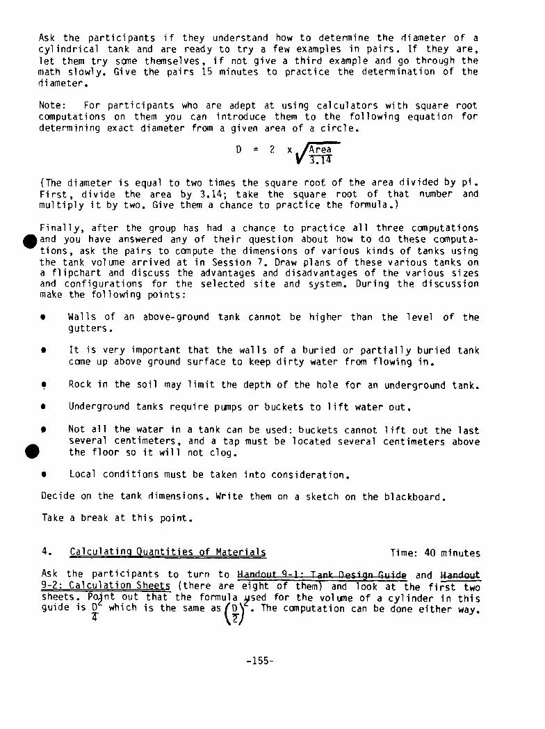
Ask the participants if they understand how to determine the diameter of acylindrical tank and are ready to try a few examples in pairs. If they are,let them try some themselves, if not give a third example and go through themath slowly. Give the pairs 15 minutes to practice the determination of thediameter.
Note: For participants who are adept at using calculators with square rootcomputations on them you can introduce them to the following equation fordetermining exact diameter from a given area of a circle.
O = 2 ____
(The diameter is equal to two times the square root of the area divided by pi.First, divide the area by 3.14; take the square root of that number andmultiply it by two. Give them a chance to practice the formula.)
Finally, after the group has had a chance to practice all three computationsand you have answered any of their question about how to do these computa-tions, ask the pairs to compute the dimensions of various kinds of tanks usingthe tank volume arrived at in Session 7. Draw plans of these various tanks ona flipchart and discuss the advantages and disadvantages of the various sizesand configurations for the selected site and system. During the discussionmake the following points:
• Walls of an above-ground tank cannot be higher than the level of thegutters.
• it is very important that the walls of a buried or partially buried tankcome up above ground surface to keep dirty water from flowing in.
. Rock in the soil may limit the depth of the hole for an underground tank.
• Underground tanks require pumps or buckets to lift water out.
• Not all the water in a tank can be used: buckets cannot lift out the lastseveral centimeters, and a tap must be located several centimeters abovethe floor so it will not clog.
• Local conditions must be taken into consideration.
Decide on the tank dimensions. Write them on a sketch on the blackboard.
Take a break at this point.
4. Calculating Quantities of Materials Time: 40 minutes
Ask the participants to turn to Handout 9-1: Tank Design Guide and Handout9-2: Calculation Sheets (there are eight of themT and look at the first twosheets. Po~nt out thafthe formula ~jsed for the volume of a cylinder in thisguide is 0 which is the same as(D\ . The computation can be done either way.
.4: tjJ
-155-
Explain that the numbers in the last colum~ of Handout 9—1 refer to the numberof the calculation sheet used to determine the quantity of the materialsneeded to construct such a tank. Tell the trainees that the next 45 minutes ofthe session will be devoted to using these sheets to determine quantities ofmateri al s.
Go over Calculation Sheet #1 with everyone. Point out first that the sheet isused to determine the amount of cement that will be needed in a variety ofcylindrical tanks made out of mortar. In order to do this one must firstdetermine the thickness of the wall and multiply it by the total area of thewall (i.e., the circumference x the height). Once the amount of mortar in thewal 1 is deteniii ned, one can compute the amount of cement needed to make thatmuch mortar with the formula given in the sheet, i.e., bags of cement needed =
mortar needed x 10 bags cement.m3 of mortar
(Note: This formula is based on a 50 kg. sack of cement and mortar made with a1:3 mixture of cement to sand.)
Go through each step of the calculation sheet (11aH to “e”) with the trainees5and make sure that they understand the reason for each step and how to do thecalculation. Give a simple example such as a cement mortar jar with a heightof 1 meter and a diameter of 60 cm and do the computation. Do another examplewith the group. Then ask the group to return to their pairs and do a couple ofexamples on their own for five minutes. When they are done ask for some of theexamples and answer any questions.
Go on to the next calculation sheet and repeat the same process, explainingthe subject of the calculation and the individual steps and giving one or twoexamples from the Trainer Refernce Note~ which follow Handout 9—2. Explainthat the thickness of plaster will depend on the job being done and that somecommon applications are given in the construction procedures in Session 13.Ask if the trainees understand the sheet and give them five minutes topractice computations in pairs.
Then briefly introduce the next three calculation sheets (2 through 5) asabove, ask if there are any questions, and give the participants 10 minutes todo a few examples. See Trainer Reference Notes for the information you wileneed to have available for doing calculation sheets 4 and 5. This includesbrick or block size and the number per square meter of wall, and mortar neededto lay 100 bricks. After they have finished ask if there are any questions.Then introduce the last three sheets and tell participants that they shoulduse them to practice some examples aftei- the session and that there will betime to discuss problems if they have any with their calculations.
5. Calculating Materials for the Tank Under Construction Time: 15 minutes
Divide the group into the number of calculations relevant to the type of tankunder construction or the one agreed upon for the purposes of the designexercise, and have each group calculate the materials needed for the tank(i.e., cement for plastering, cement for laying brick, concrete forfoundation, number of bricks, etc.). Have each group complete the calculations
-156-
in 10 minutes and write the material quantity up on the blackboard or flip-chart. Ask the groups what other materials they will need for each task (i.e.,sand and water for mortar; sand, gravel and water for concrete; reinforcingrod for foundation, pipes for above-ground walls, etc.) and write these on theblackboard or flipchart as well. With the group try to estimate or calculatethe quantities of these materials as well.
6. Examine Results and Discuss Materials Needed Time: 30 minutes
Go over the list of materials developed in Step #5. Return to the list ofrainwater catchment system components developed in Step 2 and solicit allother materials needed for each component of the system. Each of the followingshould be covered in this exercise:
• Foundation of tank• Walls and floor of tank• Waterproofing finish for floors and walls of tank (usually cement
mortar)Tap or bucket hole (hardware for tap or reinforcement for rim of hole)Inlet hole and screenTank coverOverflow hole and screenRock or gravel for drainage in overflow and outlet areas, if neededFoul flush mechanism or filterDownpi peGutters (including materials for hanging them)
The resulting list of materials will be a shopping list including itemsranging from rock and gravel to coarse metal screen. For each of the materialson the list, write a quanti~yand a source and an estimate of cost.
7. Conclusion Time: 5 minutes
At the end of the above activity there will be some question marks: unsolvedquantities, sources, and costs. Have the group assign one or more of its
articipants the task of finding the information needed in consultation withthe trainer. Review the session objectives and goals. Link to the afternoonpractical session on inexpensive guttering technologies and Sesson 11 on thenext day.
MATERIALS
- Handout 9-1: Tank Design Guide- Handout 9-2: Calculation Sheets- Flipchart for session goals and objectives- Flipcharts with examples of computations for Step 3
—157—

.
.
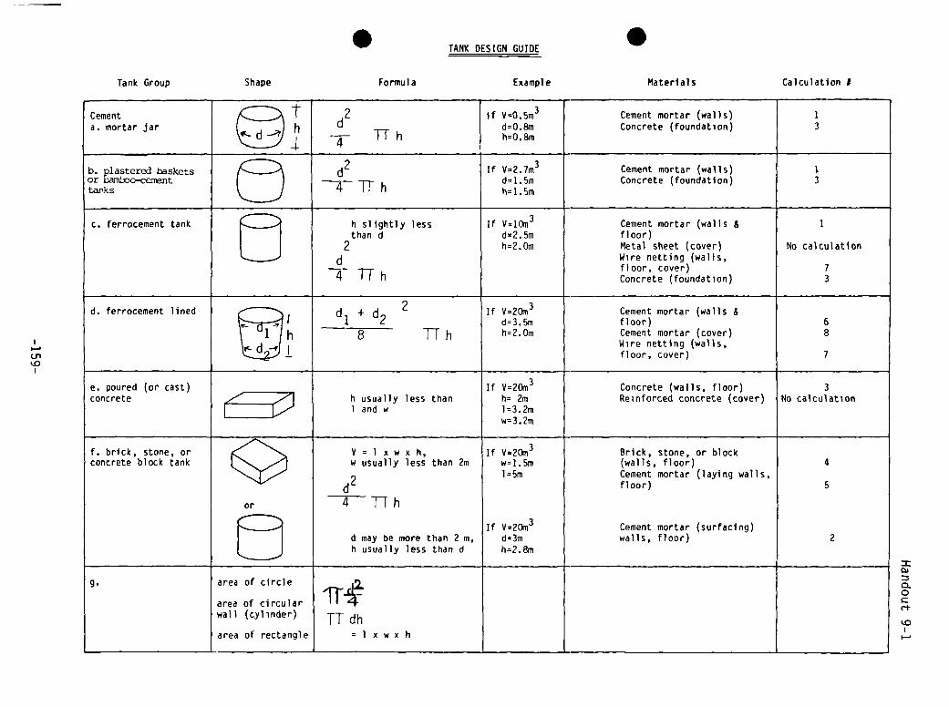
I—01‘.0
Tank Group
TANK DESIGN GUIDE
Shape Formula Example
d24TTh
d may be more than 2 m,h usually less than d
S
Materials Calculation I
Cement mortar (walls) 1Concrete (foundation) 3
Cement mortar (walls)Concrete (foundation) 3
Cement mortar (walls & 1floor)Metal sheet (cover) No calculationWire netting (walls,floor, cover) 7Concrete (foundation) 3
Cement mortar (walls &floor) 6Cement mortar (cover) 8Wire netting (walls,floor, cover) 7
Concrete (walls, floor) 3Reinforced concrete (cover) No calculation
Brick, stone, or block(walls, floor) 4Cement mortar (laying walls,floor) 5
Cement mortar (surfacing)walls, floor) 2
0.
0
c-t.
‘.0
I-,
Cementa. mortar jar
1~1h
c. ferrocement tank
d. ferrocement lined
f. brick, stone, orconcrete block tank
V=l xww usually
x h,less than 2m
g. ii
I dhxwx h


Handout 9-2, p. 1
CALCULATION SHEETS
1. Calculation #1: Cement in mortar walls for above ground cylindricalcontai ners
Height Wall Thickness Typical Container Type
1.0 m = 1.0 cm Cement Mortar Jar
1.5 m = 2.5 cm Plastered Basket
1.75 in = 3.0 cm Ferrocement Tank (1.75 in3 volume)
2.0 m = 4.0 cm Ferrocement Tank (10 m3 volume)
Walls in these kinds of tanks are rarely more than 2 in high]
Steps:
a. Using wall height (h) , determine wall thickness from above chart.
b. Calculate the area of the wall:
c. Multiply the wall area b~the wall thickness to determine the amount ofmortar needed:
Multiply the amount of mortar ne~ded by 10 bags cement/rn3 mortar, todetermine the amount of cement needed.
___ ‘I, __
Bags of cement needed = mortar needed x 10 bags cernent*
in3 mortar
e. Cost = bags of cement needed x price/bag
* 50 kg bags of cement. Based on a cement to sand ratio 1:3. This is a
reconynended figure for watertight mortar. Local masons may use less cement(more sand), and the formula would have to be ~djusted accordingly. Mortarswith 1:2 cecnent:sand use 13 bags of cement per m of mortar.
Area = p1 x diameter x height
Mortar needed = area x thicknessI
-161-

Handout 9-2, p. 2
2. Calculation #2: Cement mortar for plastering over walls and floors made
of other materials
Steps:
b. Multiply the area by the thickness of mortar to be applied to determinethe amount of mortar needed:
c. Multiply the amount of mortar needed bydetermine the amount of cement needed:
d.
I10 bags cement*/m3 mortar, to
Bags of cement needed = mortar neede~d x 10 bags cement*
m3 mortar
¶1?Cost = bags of cement needed x price/bag
* 50 kg bags. Based on a cement to sand ratio of 1:3. This is a recommendedfigure for watertight mortar. Local masons may use less cement (more sand),and the formula would have to be adjusted accordingly. Mortars with 1:~cement:sand mixtures for final waterproofing coats use 13 bags cement per in
of mortar.
a. Calculate area to be plastered:
-162~
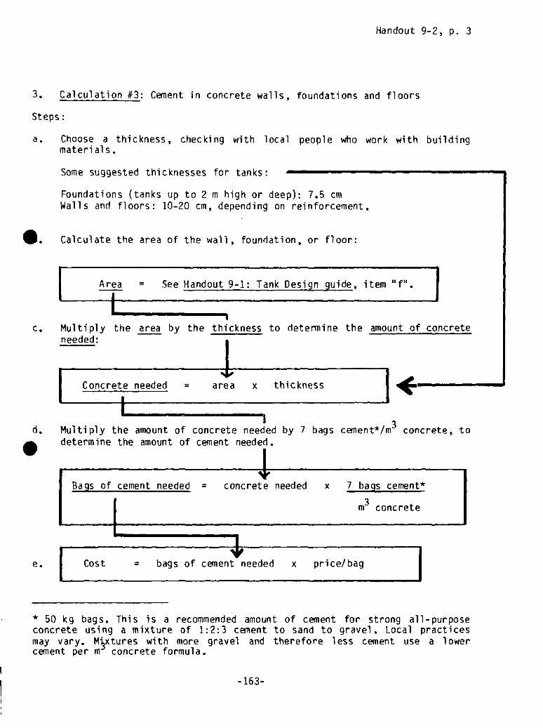
Handout 9-2, p. 3
3. Calculation #3: Cement in concrete walls, foundations and floors
Steps:
a. Choose a thickness, checking with local people who work with building
materi al 5.
Some suggested thicknesses for tanks:
Foundations (tanks up to 2 m high or deep): 7.5 cm
Walls and floors: 10-20 cm, depending on reinforcement.
Calculate the area of the wall, foundation, or floor:
c. Multiply the area by the thickness to determine the amount of concreteneeded:
e.
I
~I,Cost = bags of cement needed x price/bag
* 50 kg bags. This is a recommended amount of cement for strong all-purposeconcrete using a mixture of 1:2:3 cement to sand to gravel. Local practicesmay vary. M~xtures with more gravel and therefore less cement use a lowercement per m concrete formula.
Multiply the amount of concrete needed by 7 bags cenlent*/m3 concrete, to
determine the amount of cement needed.
IBags of cement needed = concrete needed x 7 bags cement*
in3 concrete
-16 3-

Handout 9-2, p. 4
4. Calculation #4: Miounts of brick, stone, or block in tank walls andfloors
Steps:
a. Consult masons (who have built walls to hold water) to choose wall
thickness.
Suggestions:
Walls (supported by earth):Walls (more than 1 m heightFloors: Same as walls
2in
c. Calculate the area of wall or floor to be laid:
d. Calculate
15-20 cmunsupported by earth: 30 cm
b. Determine the number of bricks (stones or blocks)I in of wall or floor: bricks
needed to build 1 in x
Area = See Handout 9-1: Tank Desi~gnGuide, item “f’.I-i
the number of bricks (stones or blocks) required:
.
e.
-164-
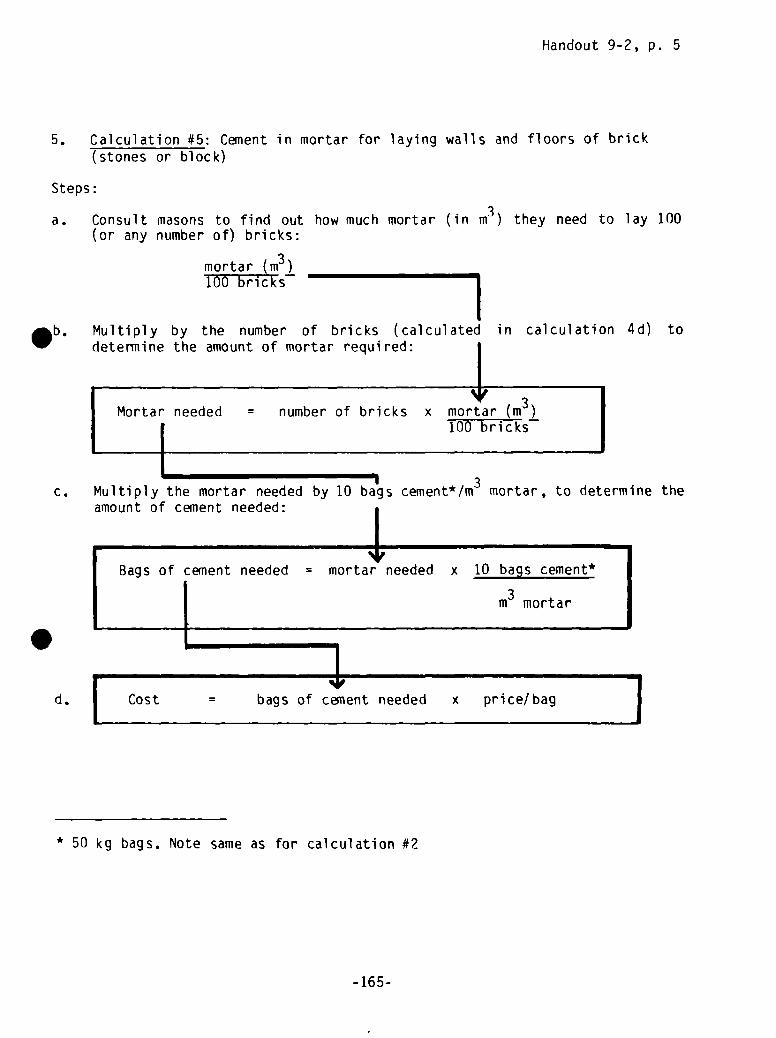
Handout 9-2, p. 5
5. Calculation #5: Cement in mortar for laying walls and floors of brick
Steps
(stones or block)
a. Consult masons to find out how much mortar (in m3) they need to lay 100(or any number of) bricks:
Sb. Multiply by the number of bricks (calculatecdetermine the amount of mortar required:
*3Mortar needed = number of bricks x mortar (m )
100 bricks
c. Multiply the mortar needed by 10 ba~scement*/rn3 mortar, to determine theamount of cement needed:
d.
Bags of cement needed = mortar needed x 10 bags cement*
m3 mortar
Cost = bags of cement needed x price/bag 1
* 50 kg bags. Note same as for calculation #2
mortar (m3)100 bricks
in calculation 4d) to
I
-16 5-

Handout 9-2, p. 6
6. Calculation #6: Cement in mortar walls
lined pit
Steps:
and floor of circular ferrocement-
a. Calculate the area of the pit to be lined:
Area of walls = pi x diameter x height2 Total area
Area of floor = p1 x (1/2 diameter)
Multiply the area by the thickness of plaster to be applied. To be safe,assume a thickness of 4 cm (less may actually be needed):
4I Mortar needed = area x thicknessLj
To find the am~unt of cement n~eded, multiply the amount of mortar by 10bags cement*/m mortar:
Bags of cement = mortar needed x 10 bags cement*/m mortar
4,Cost = bags of cement x price/bag
* 50 kg bags. Same note as for calculation #2
.b.
c.
d.
1 I
-166-’
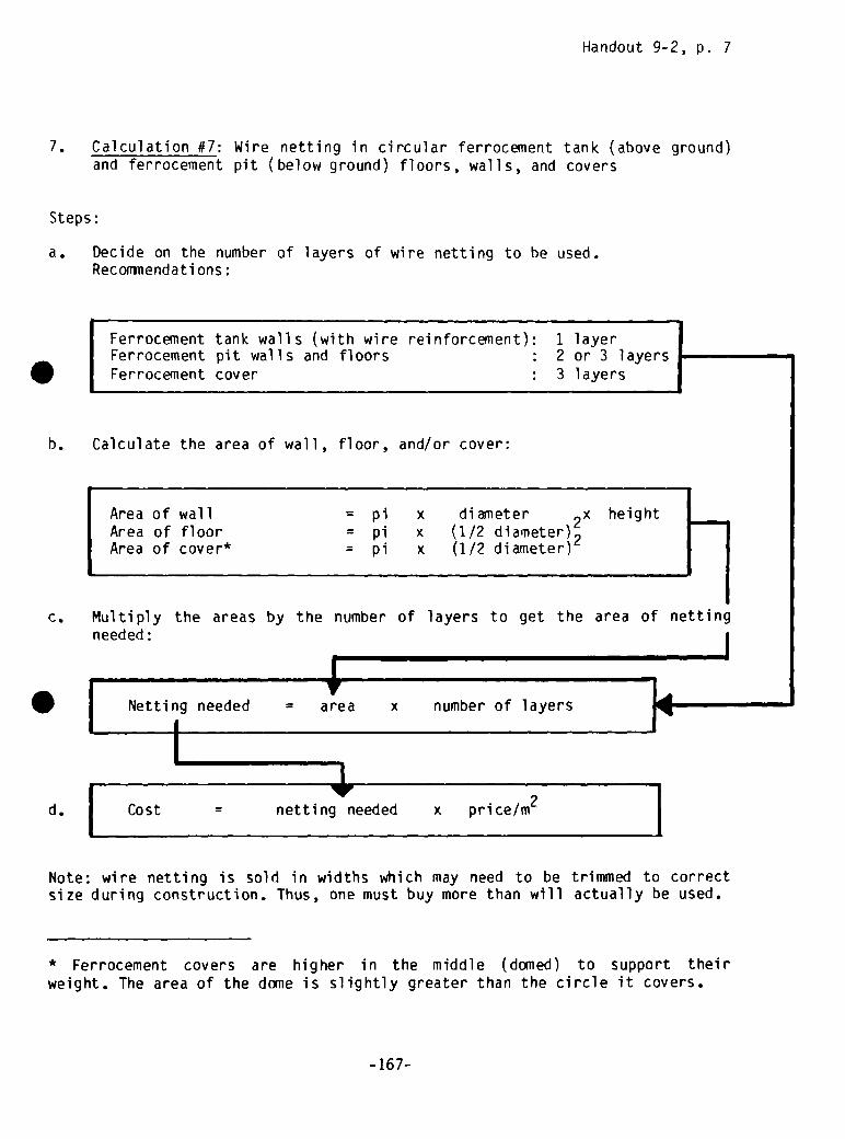
Handout 9-2, p. 7
7. Calculation #7: Wire netting in circular ferrocement tank (above ground)and ferrocement pit (below ground) floors, walls, and covers
Steps:
a. Decide on the number of layers of wire netting to be used.Reconiiiendati ons:
Calculate the area of wall, floor, and/or cover:
AreaAreaArea
ofofof
wallfloorcover*
=
=
=
p1pip1
xxx
diameter 2x(1/2 diameter)2(1/2 diameter)
height
c. Multiply the areas by the number of layers to get the area of nettingneeded:
IV
Netting needed = area x number of layersI
d. Cost = netting needed x price/rn2
Note: wire netting is sold in widths which may need to be trimmed to correctsize during construction. Thus, one must buy more than will actually be used.
* Ferrocement covers are higher in the middle (domed) to support theirweight. The area of the dome is slightly greater than the circle it covers.
Sr
h.
Ferrocernent tank walls (with wire reinforcement):Ferrocement pit walls and floorsFerrocement cover
1 layer2 or 3 layers3 layers
I
-16 7-
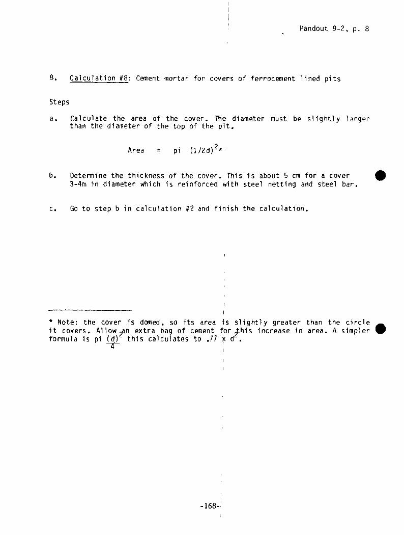
Handout 9-2, p. 8
8. Calculation #8: Cement mortar for covers of ferrocement lined pits
Stepsa. Calculate the area of the cover. The diameter must be slightly larger
than the diameter of the top of the pit.
Area = p1 (1/?d)2*
b. Determine the thickness of the cover. This is about 5 cm for a cover3-4m in diameter which is reinforced with steel netting and steel bar.
c. Go to step b in calculation #2 and finish the calculation.
S
* Note: the cover is domed, so its area Is slightly greater than the circleit covers. Allow ~n extra bag of cement for this increase in area. A simplerformula is pi (d) this calculates to .77 x d
-4--
-168-~
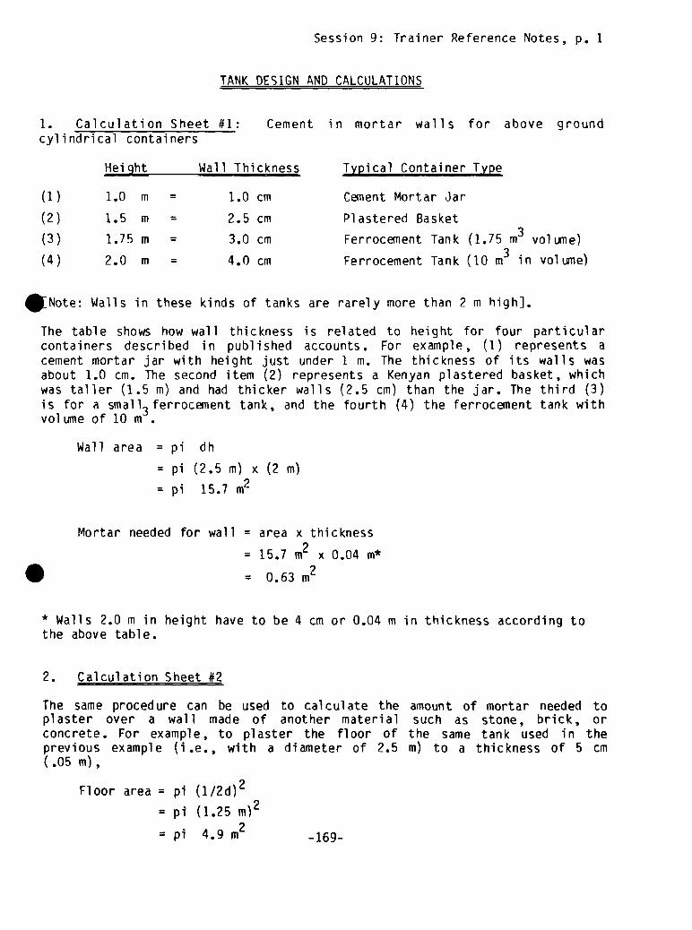
Session 9: Trainer Reference Notes, p. 1
TANK DESIGN AND CALCULATIONS
1. Calculation Sheet #1: Cement in mortar walls for above groundcylindrical containers
Height Wall Thickness Typical Container Type
(1) 1.0 in = 1.0 cm Cement Mortar Jar
(2) 1.5 m = 2.5 cm Plastered Basket
(3) 1.75 m = 3.0 cm Ferrocement Tank (1.75 m3 volume)
(4) 2.0 m = 4.0 cm Ferrocement Tank (10 in3 in volume)
Note: Walls in these kinds of tanks are rarely more than 2 in high].
The table shows how wall thickness is related to height for four particularcontainers described in published accounts. For example, (1) represents acement mortar jar with height just under 1 m. The thickness of its walls wasabout 1.0 cm. The second item (2) represents a Kenyan plastered basket, whichwas taller (1.5 in) and had thicker walls (2.5 cm) than the jar. The third (3)is for a small
3 ferrocement tank, and the fourth (4) the ferrocement tank withvolume of 10 m
Wall area = pi dh
= pi (2.5 in) x (2 in)
= p1 15.7
Mortar needed for wall = area x thickness
= 15,7 m2 x 0.04 m*
= 0.63 in2
* Walls 2.0 in in height have to be 4 cm or 0.04 rn in thickness according tothe above table.
2. Calculation Sheet #2
The same procedure can be used to calculate the amount of mortar needed toplaster over a wall made of another material such as stone, brick, orconcrete. For example, to plaster the floor of the same tank used in theprevious example (i.e., with a diameter of 2.5 m) to a thickness of 5 cm(.05 in)
Floor area = p1 (1/2d)2
= pi (1.25 rn)2
=pi 4.9m2 -169-

Sessi1on 9: Trainer Reference Notes, p. 2
Mortar needed for floor = area x thickness
= 4.9 m2 x 0.05 in
= 0.25 in3
To plaster the inside walls of the brick tank with interior dimensions of 2 in
x 3 m x 1.5 in to a thickness of 3 cm, the calculation would be:
Total Wall Area = 2 x (1 x h) + 2 x (w x h)*2 x (3 in x 1.5 in) + 2 (2 in x 1.5 in)
= 2 (4.5 in2) ÷ 2 (3 m2)=15m2
Mortar needed for wall plaster area x thickness
= 15m2 x 0.03m
= .45 rn3
* The interior wall area of a tank requires adding all four surfaces (length xheight) + (length x height) + (width x height) + (width x height) or 2 (1 x h)+2(wxh).
3. Calculation Sheet #3
The prescribed thickness of concrete to be used in a watertight wall varies agreat deal. In rich countries, the reinforced concrete walls of cisterns areoften 25 cm thick. In Thailand unreinforced (or bamboo-reinforced) concreterings, only 5 cm thick, hold the same depth of water. Methods of mixing,pouring, reinforcing, and curing all greatly affect the ability of concrete towithstand loads without cracking.
Below is an example of how to calculate the cement needed for a concretefloor. I
• Figure the volume of concrete needed for a 2.8 diameter floor which willbe 7.5 cm thick:
Area =pi xr2
3.14 x 1.42 = p1 x r2 = Area
3.14 x (1.4)2 = 6.2
-170-

Session 9: Trainer Reference Notes, p. 3
Volume = area 2 x thickness= 6.2 in 3x 0.075 m= 0.47 m
• Figure the amount of cement needed to make the concrete. Concrete mixedin the proportions 1:2:3, for cement:sand:gravel is strong enough forsel f- hel p floors, footings, and wall s when made with clean material s andcured properly.* Concrete mixed 1:2:3 contains about 7 bags of cement(@ 50 kg per bag) per cubic meter. Using this information, we can figurethe number of bags needed.
Bags of cement = vol inie of concrete x 7 bagsm
3 concrete
= 0.47 in3 x 7 bags
rn3 concrete
= 3.3 bags
• Figure the cost, using the price of a bag of cement in your area. Forexample:
Cost = # of bags x price per bag= 3.3 bags x $20.00 (for example)= $66.00
* Determined by using the “concrete calculator,” Village Technology Handbook,VITA (1973). You may decide to use a lower proportion of cement. The“concrete cal cul ator” shows how to adj ust the vol ines of the other
materi al s.
S4. Calculation Sheets #4 & 5Water-holding walls of brick, stone, or block are built to a wide variety ofspecifications. Quality of materials, whether or not walls are supported byearth, and construction technique all determine how thick a wall must be.People who have lined wells with masonry have done much the same thing asbuilding tank walls. Learn from their experience. Ask the construction foremanor local mason to give you the size of locally available bricks or blocks.Compute the number needed for one square meter of wall or fo~dation at thedesired thickness (for sheet #4) and the amount of mortar (in m ) they need tolay 100 bricks (or any specific number of bricks or blocks)(for sheet #5).Have these figures available when introducing these sheets.
—171—
I -

— I
5. Preparing the Hole for the Tank
Session 9: Trainer Reference Notes, p. 4
Dig down to firm soil or rock, in most cases at least 50 cm. As you plan thedepth of the hole, remember that the wall of the tank should rise at least 30cm above ground level (to keep out surface water and dirt); however, the wallshould not rise more than 100 cm above ground level unless it is thickened, oran earth bank is later built against it.
Deepen the hole slightly where the “sump” ‘will be located. The “sump” is adepression built into the floor for scooping out mud and debris each time thetank is emptied. If the tank is much longer than it is wide, the sump can be ashallow trough along the length of the tank floor.
If the materials are available, the floor4 should be made of concrete laid ontop of 10 cm of sand and gravel . A floor thickness of 15 cm is probablysufficient for a tank 3 in deep; some sources recorTinend 20 cm. If wire mesh ofany kind is available, it should be laid on the gravel foundation. If theefloor of the tank is to be made of the same material as the walls, it shouldbe at least as thick as the walls (explained below). Reinforcing mesh can beplaced between brick or stone layers.
If the walls of the tank are to be more than two meters high, they should bebuilt on a supporting pad or “footing” which can be made of concrete ormasonry at the same time as the floor. Extend any mesh or reinforcing materialfrom the floor into the footing.
If concrete is used for the floor, make the depression or trough for the sumpbefore the concrete stiffens. Figure 1 is a drawing showing the details of thefloor.
1.
zc_MJ4* ,~,
/~htI~cl4floWS .M,vz~#~
I~11X61’ 86~’.
FIGURE 1Construction Detail for Masonry Tank
fMsr c~~$v8vf~:2sW7-~4WD ~e~ur C~4~
A/&e i~a
I,
5U~p
r~
~ ~ c~. ‘~-
v~.
FAooi~ -
(AJL4,2~~~Q~ ‘~flI?.a~JA.4~j~:ficOR .~
-172—

Session 9: Trainer Reference Notes, p. 5
6. The Walls of the Tank
The walls are built up from the floor or from the footing. Cairncross andFeachem (Small Water Supplies) recoimiend that brick or masonry walls be atleast 30 cm thick. In fact, masonry walls to retain water are often builtsomewhat thinner than this, even when they are not supported by earth. Thethickness chosen will depend upon local experience, and this choice should bemade in consultation with local brick-layers or masons.
The mortar used should be mixed carefully in the proportions 1:4 cement:sand(measured by volume). If the walls are built of brick, wet the bricks beforelaying them. This will help the mortar to cure more completely.
If water is to be drawn out of the tank by a tap, an outlet pipe for the tapshould be built into the wall about 10 cm above the floor level so that itwill not be clogged with mud or debris. Every tank must have some kind of out-. let for overflow which does not allow the water level to rise all the way tothe roof; usually this overflow outlet is a piece of pipe built into the upperpart of the wall. This pipe should have a diameter at least as large as thediameter of the pipe or gutter bringing water into the tank, and it must bescreened to prevent insects or small animals from getting in.
7. Using a Diagram
• The trainer may wish to add to the training in Step 6 to give the groupmore experience in working with the design and comunicating the designto construction masons. To do this, the following is suggested:
• The trainer explains that in order to look at the design in more detail,we need to consider each part of the tank and system and be able tocommunicate it to the construction masons who will build the system.Using the system which is now under construction, the trainer sketches atop view diagram with appropriate dimensions. For example:
.Pipe
Manhole forCl&~aningTank
Hole for Small Haridp~imp
40m 1 . Sm
Cutter
O.6m x O.6m to.75m x .7m
-173—

Sessi~n9: Trainer Reference Notes, p. 6
Then the trainer asks for a volunteer to draw a side view of the demon-stration tank that will show all of the elements of the construction. Thetrainer monitors and guides this activity to ensure that nothing isforgotten (foundation, walls, top slab, slope of the foundation floor orsump for cleaning, wire mesh to cover overflow pipe, size of pipe, etc.).
The trainer should then add in the other parts of the system and includethe costs and materials needed: gutter and downspouts. (If time is short,this may be given as an assignment to be done before the next session.)
-174-

.
SESSION

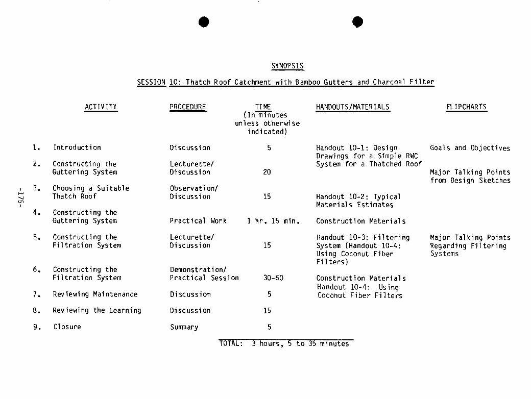
I
SYNOPSIS
SESSION 10: Thatch Roof Catchment with Bamboo Gutters and Charcoal Filter
ACTIVITY PROCEDURE TIME(In minutes
unless otherwiseindicated)
HANDOUTS/MATERIALS FLIPCHARTS
1. Introduction
2. Constructing the
Guttering System
3. Choosing a Suitable
Thatch Roof
4. Constructing theGuttering System
Discussion 5
Lecturette/
Discussion 20
Observati on/
Discussion 15
Practical Work 1 hr. 15 mm.
Handout 10-1: DesignDrawings for a Simple RWCSystem for a Thatched Roof
Handout 10-2: Typical
Materials Estimates
Construction Materials
Goals and Objectives
Major Talking Pointsfrom Design Sketches
5. Constructing theFiltration System
6. Constructing the
Filtration System
7. Reviewing Maintenance
Lecturette/Discussion
Demonstration!
Practical Session
Discussion
15
30-60
5
Handout 10—3: FilteringSystem (Handout 10-4:Using Coconut FiberFilters)
Construction Material sHandout 10-4: UsingCoconut Fiber Filters
Major Talking PointsRegarding FilteringSystems
8. Reviewing the Learning Discussion 15
9. Closure Surmiary 5
01
TOTAL: 3 hours, 5 to 35 minutes

I

Session 10: Thatch Roof Catchiient with Bamboo Gutters and Charcoal Filter*
GOAL Total time: 3 hours & 5 to 35 mm.
To learn how to design and construct a roof catchment and filtration systemfor thatch roofs.
OBJECTIVES
At the end of this session participants will be able to:
• Select an appropriate thatch roof for collecting rainwater
• Construct and attach or place bamboo gutters appropriately using a bushpole support structure
• Build one of two alternative charcoal filtering systems using burnt ricehusk or crushed charcoal as the filtering medium**
• Understand the maintenance requirements of the filtration device
OVERVIEW
In many parts of the world it is not always possible to use zinc or other hardsurface roofs for rainwater catchment. Many villages will have roofs which areconstructed with thatching using locally avail able materials such as palmleaf, woven grass, or other thatching. These materials are quite inexpensive(usually free) and very durable over many years. The first major objection tousing a thatch roof to collect run—off is that the water appears dirty (oftenyellowish) and has the smell of decomposed leaves. However, with a simplefiltration device made of crushed charcoal or burnt rice husk, the water willbecome clear. Foul flush procedures are followed as in the other systems. Thesecond major objection to thatch is the relative difficulty of gutter~ing. Thisobstacle is overcome in this session with the use of a free-standing tripod or. bush-pole supported gutter which can be removed easily and stored during thedry season to prevent cracking if split bamboo is used. The major advantage tousing this system is its simplicity and low cost.
* If thatch roofing is not used in the workshop location and bamboo is either
unavailable or inappropriate for guttering, this session may not benecessary. In that case, move Session 13 up to Day 5 and keep Saturdayafternoon free.
** For an alternative filtering medium using coconut fiber instead of graveland charcoal , see Handout 10-4.
—177—

ACTIVITIES
1. Introduction Time: 5 minutes
Introduce the session by presenting the material in the overview (above) inyour own words. It is important to point out the normal reservations peoplehave about using thatch roof catchment and t~ocounter these reservations whichare overcome with proper filtration and guttering. The advantages of low cost,simple materials should be pointed out. Relate this to the previous day’spractical session on building small storage tanks. After discussing this,state the goals and objectives of the session. Tell the participants what theycan expect to do in the session (construct a guttering system and make afilter) and inform them of the time available.
2. Lecturette/Discussion: Constructing the Guttering System Time: 20 minutes
Display a sketch of the Figure on page 1 of Handout 10—1: Design Drawings fora Simple RWC System for a Thatched Roof on the flipchart. Point out each partof the system (using split bamboo, split palm, wood or other material forgutters, supports, ties) on the drawing and explain how it is constructed.Explain the need for building the flow path of the water by sloping thegutters gradually.
Referring to the sketch of the guttering~ system, make the following keypoints:
• The gutters can be made of split bamboo, split palm or wood boards.Bamboo, if available, is the best~choice.
• Bamboo should be thick (15-20 cm)~andstrong. It can be simply splitlengthwise with a machete and the diaphrams removed with a macheteor knife. Bamboo can be cut in t~ielengths needed or overlapped atsupports and tied firmly. I
• The gutters can be supported by dimple poles with a V notch at thetop, or by simple tripods which are tied together at the top andburied about 30 cm in the ground ~t the bottom to make them stable.
• The gutters are tied on the tripods using wire or a locally avail-able heavy string.
• Each pole or set of three poles (making up a tripod) in a row is cutshorter than the last in order to1 ensure a slope into the filter andstorage vessel (this is demonstrated in the practical session).
Before leaving the classroom for the co~istruction site ask the group todescribe the characteristics of a thatch roof which would be suitable for arainwater catchment system. Discuss size ~nd height of the roof, quality ofthe thatch, strength of the rafters, etc. After this discussion, ask if thereare any final questions before starting work.
-178—
3. Choosing a Suitable Thatch Roof for aRainwater Catchment System Time: 15 minutes
On the way to the construction site, walk through the village and point outthatch roofs and discuss their suitability for catching water. Discuss thematerials used for the thatch, how well it sheds water, how often it has to bereplaced, the height of the roof line, condition of the rafters and howgutters could be attached or whether they have to be free—standing. Whenarriving at the house selected for the demonstration, point out why it waschosen and discuss.
4. Constructing Bamboo Gutters andSupporting Them with Poles Time: 1 hour 15 minutes
Have all materials ready at the site (see Handout 10-2: Typical MaterialsEstimate). Break the group into three or four teams based on the number ofparticipants and the design of the guttering system to he constructed.
Distribute Handouts 10-1: Design Drawings for a Simple RWC System for aThatched Roof.
Give the teams the following instructions:
A. Split bamboo lengthwise with a machete and heavy stick for pounding the
machete blade. Cut out diaphrams when split.
B. Design supports for the bamboo gutters so they will be held securely inposition to catch water running off the roof, and slope at 1 percent downtoward the downspout.
C. Cut the V-notch poles or tripod poles and place them in the ground forthe 1 percent slope. Verify the slope with string. Fix the poles securelywith stones and dirt and lash gutters into place with wire or local rope.Attach to downspout or position above platform for filter depending ondesign.
(Note: The easiest guttering system to demonstrate is a single, straight line. of bamboo gutters supported by V poles pouring freely into a filter. There areadvantages for demonstrating how to attach gutters at right angles and todownspouts and for collecting water from both sides of the roof, but thedecision whether or not to demonstrate these fine points should be based onthe number and skills of the participants. See Handout 6-2 from Session 6 forinformation on guttering systems).
When the gutters are connected, test them with water and discuss what theparticipants have learned about constructing and installing bamboo gutters.Remaining at the site, go on to the next step.
-179-
5. Lecturette/Discussion: Constructing theFiltration System Time: 15 minutes
Distribute a copy of Handout 10-3: Filtering Systems to each participant andexplain the major component of the filter (depending upon local conditions,you will have selected either a 200 liter metal drum or wooden box fordemonstration purposes) by pointing out each element as follows:
• The pea gravel in the bottom keeps the rice nusk charcoal or the crushedwood charcoal from clogging the perforated holes in the bottom of thefilter. The wood charcoal must be crushed to the size of rice husks towork properly.
• The charcoal does the job of filtration. It will remove the odor and theyellowish color of the rainwater. (The use of sand is optional; it willhelp remove insects and any dirt. A 30 cm layer of sand over the gravelwill suffice).
• The large gravel on top keeps the rice husk or crushed charcoal fromblowing out and compacts it with its weight so that the filter is tightand stable.
• The box or barrel has holes perforated in the bottom (either with ahammer and spike or drill). Place holes only in the center of the tank incase the jar has a narrower mouth than the oil drum. Punch holes frominside out to make the filter easier to clean inside.
• The filter is placed directly over the1cistern or set on a platform overa large clay jar (from which the water is dipped into other containers).
• A filter such as this will produce cl~ar water for several weeks. If itgets clogged, or the water starts geLtting yellow, then it is time tochange the charcoal (usually once or t~ice a rainy season, depending uponrainfall).
• The dimensions of the filter and the depth of the charcoal and gravels,have proven to be effective in tests in Southeast Asia. This filter willhandle the run-off for a 40 square meter roof (an average sized ruralfamily dwelling). If you have a larger area, we suggest you construct twofilters and divide the run-off with a supplementary downspout (a Y shapedconnector should work).
After making the above points, answer any questions. Then prepare to move thetrainees to a hands—on experience in the next step where they put a filtertogether and mount it on top of the storage1facility.
6. Constructing the Filtration System, Der~ionstration Time: 30 to 60 minutes
In this demonstration, the group will learn~how to burn rice husk into a char-coal-like medium (if this is the chosen option) and put together the filter.We assume that the process of loading the material into the container is very
-180-

straightforward. Therefore, let volunteers from the group put the materialsinto the container referring to the materials list in Handout 10—2: TypicalMaterials Estimate and the diagram in Handout 10—3: Filtering Systems.
We suggest that the trainer have all of the materials prepared in advance andready to go. If a metal drum is used (the easiest option), the process ofperforating holes in the bottom can be done by the group using a hammer and alarge spike or a hand drill (if readily available in the local environment).The construction steps for building the wooden box filter are included in thetrainer notes. For the rice husk demonstration, the trainer will need to havea “before and after” exhibit set up (i.e., some unburned raw rice husk andsome already prepared and burned rice husk). If wood charcoal is to be usedhave it crushed to the size of rice husks before the start of the demonstra-tion. Conduct the demonstration as follows:
A. Rice Husk Charcoal Making:
1. Pile 100 litres of raw rice husk in a place out of the wind.
2. Set it on fire and let it burn slowly, occasionally mixing thepile with a shovel until the rice husk is charred and uniformly“toasted” but not burned to ash (i.e., what you are looking foris a fiberous, darkly roasted husk, not an ash).
3. When the husk is charred sufficiently, douse it with water andlet it cool
4. After it is cool , it is ready for use.
B. Loading the Filter:
Load the filter following the diagram in Handout 10—3. Putting inthe pea gravel, the charcoal, and the large gravel in that order,measuring the depth after each step.
(Note: It will he easier if the oil drum is on top of the cistern platformbefore the filtering materials are put in. In order for the participants toremember the depth measurements of the three materials (5 cm pea gravel, 45 cmhusk or crushed charcoal, 15 cm large gravel), have them mark the threemeasurements on their arms or legs so they will have a future reference pointon their own bodies.)
After the group has put together the filter, test it with water off the roofand see if there are any questions about the procedure.
7. Reviewing the Maintenance Requirements Time: 5 minutes
In the previous talk about the filter, you have mentioned when to change thefilter (when the filtered water turns color or once or twice a season). Atthis point the trainer should reiterate these points and hold a brief discus-sion with the group about what problems might arise in maintenance and someways the group might ~anticipate maintenance needs or ways to make it easier toprovide maintenance such as preparing enough charcoal for the season in
-181-

advance and having it stored. (Note: the gravel need not be replaced, it canbe saved and used again; it may need to be washed a bit before it is put backinto the filter.)
8. Reviewing the Session Time: 15 minutes
After the field work, return to the classroom or meet in any convenient loca-tion and ask the group to review what they’have learned. Close the session byasking the group to meet in sub-groups of three persons and to review each ofthe steps in putting together both gutters and filters. Ask them to recordquestions they still have; and potential pr~oblems they feel they will have indoing this again in the village setting.
After about five minutes, ask each group to report on its discussions and holda full group question, answer, and discussion session on any issues that havecome up.
9. Closure Time: 5 minutes
Close the session by reviewing the original goals and objectives. Ask thegroup if they have been met. If there are some areas of doubt left, clear themup at this point. Link this to the next sessions (11 and 13) on planning forthe construction of a large rooftop catchment system and starting the work onthe tank.
TRAINER NOTES
Construction Steps for Wooden Box Filter
1. Cut 4 pieces of 2 cm thick lumber 98 x 38 cm—-sides1 piece of 2 cm thick lumber 40 x 40 cm--bottom8 pieces of 4 cm thick lumber 8 x1O cm--supporting blocks
2. Drill or punch 10-15 holes .05 mm in diameter in the 40 x 40 cm bottompiece.
3. Nail together the 4 sides piece ( 98 ~ 38 cm) at right angles.
4. Nail the S supporting blocks in the 4 corners at the top and bottom ofthe box (see diagram below)
-182-

Top View Side View
-~ r
:•cDC)3
5. Nail bottom piece (40 x 40) on to the 40 x 100 cm box.
6. See box filter illustration in Handout 10—3 for comparison.
MATERIALS
- Fl ipchart diagrams prepared from Handout 10-1- Flipcharts prepared of the goals and objectives- Flipcharts prepared for the major talking points in the lecturettes- Handout 10-1: Design Drawings for a Simple RWC System for a Thatched Roof— Handout 10—2: Typical Materials Estimate- Handout-lO-3: Filtering Systems- Construction tools and materials (see Handout 10-2)
L1~LT
J 4
Supporting blocks
L
iE~._.40cm “—~‘
40 cm
-183-


Handou� 10-1, p. 1
w
U-


‘-~
E
c~.0
D
I-
N.)
HO TO DETEPIIINE THE SLOPE OF GUTTER
Assume a slope of 3% — In lOm of gutters, the first tripod is 30cmhigher than the last one. Put the tripods (3 poles each) in theirplace. The slope is determined by placinq a strina between tripodA and Tripod B. Mark the intermediate tripods accordingly and cut.
40cm
30cm
Ground
Level
30cmDepth ofPoles inGround
10 meters - I
FIGURE 2

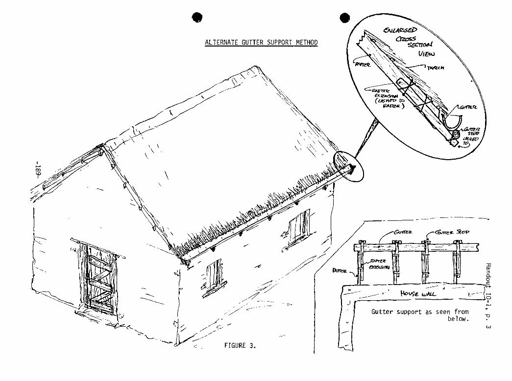
ALTERNATEGUTTER SUPPORTMETHOD
S
--/
Gutter support as seen frombelow.
c~)
FIGURE 3.


Handout 10-2
TYPICAL MATERIALS ESTIMATE*
~1aterials Quantity Cost
A. Guttering materials using bamboo, bush pole supports for a roof 10 M long
x 4 M wide, collection on both sides of the roof.
1.. Bamboo 15-20 cm in diameter 15 M
2. 9 V notch poles 5-10 cm indiameter, or 9 sets of polesfor tripods (27 poles),5 cm in diameter and 4 meterslong
36-110 M of pole
3. Twisted wire, or locallyavailable twine 20 M
Tools: machetes, mallets, knives, digging tools, bucket for water
B. Filtration System Using a Barrel
1. Barrel, 200 Liter 1
2. Gravel (large) 35 Liters
3. Pea gravel 12 Liters
4. Raw rice husk 100 Liters
5. Or charcoal 50 Liters
Tools: drill or hammer and nail or spike; hammer or mallet for crushingcharcoal , tools and material s for making stand for filter
C. Filtration System Using a Box
1. Lumber: 40 cm x 2 cm 5 M
2. Nails 1 Kg
3. Gravel, rice husk (same as B)
Tools: Hammer, saw, drill; tools and materials for making stand
*Note: Since costs vary widely, the cost column is left open forto fill in depending on the local prices.
the trainers
-191-

S
I
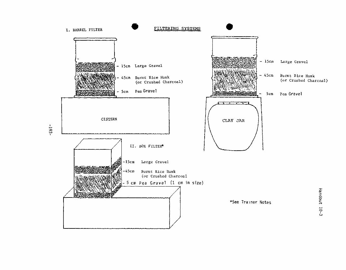
FILTERING SYSTEMS .
15cm Large Gravel
45cm Burnt Rice Husk
(or Crushed Charcoal)
5cm Pea Gravel
I. BPRREL FILTER
Burnt Rice Musk(or Ctushed Charcoal)
I-.
(A)
II. BOX FLLTER*
Burnt Rice Husk(or Crushed Charcoal
Pea Gravel (1 cm in size)
*See Trainer Notes
0-
0
C-,-

I
Handout 10-4
USING COCONUTFIBER FILTERS
Filters using shredded coconut fibers for the filter medium have been said tobe successful in Thailand (Frankel, 1974) and have been installed in over 100rural villages in Southest Asia (Frankel , 1981). The raw coconut husks arefound throughout Southeast Asia ana have little market value, hence theyprovide a low-cost filter medium for treatment plants in that part of theworld.
Shredded coconut fiber may be prepared manually by soaking the husk for 2 to 3days in water and then shredding the husk by pulling off the individual fibersand removing the solid particles which bind the fibers. Shredded coconut
bers may also be purchased directly from upholstery stores or coir (coconutiber) factories. The shredded fiber should be imersed in water for about
three days, until the fiber does not impart any more color to the water(Frankel , 1977). The depth of the coconut fiber in the filter box is usually60-80 cm. There are no backwashing arrangements for cleaning the coconutfibers as the fibers do not readily relinquish entrapped particles because oftheir fibrous nature. Instead, water is drained from the filter box and thedirty fibers are removed and discarded. Coconut fiber stock, which has beenproperly cleaned, is then packed into the filter. The filter medium generallymust be replaced every three or four months. The availability of the rawcoconut husks at low cost, as well as the elimination of backwash pumps andancillary equipment, combine to make this manual fil ter bed regenerati onprocess economical in areas where coconut trees are coniiion. The use of suchindigenous materials for filter media is also a practical alternative toconventional filter design.
Several small water filter plants ranging in capacity from 24 to 360 m3/daywere constructed from 1972 to 1976 in the Lower Mekong River Basin countries
Ihailand, Viet Nam, Cambodia) and in the Philippines (Frankel , 1981). Two-age filtration, using shredded coconut fibers and burnt rice husks for the
roughing and polishing filters, respectively, was typical for all filterplants. The filtration systems generally produced a clear effluent (less than5 NTU) when treating raw water with a turbidity less than 150 NTtJ. The unitswere designed at a filtration rate of 1.25-1.5 rn/hr., which is about 10 timeshigher than that used for conventional slow sand filters. Bacterial removalsaveraged 60 to 90 percent without the use of any disinfectant. The mediagenerally required changing once very 3-5 months depending on the level ofturbidity in the raw water.
-195-

S

.
SESSION 11

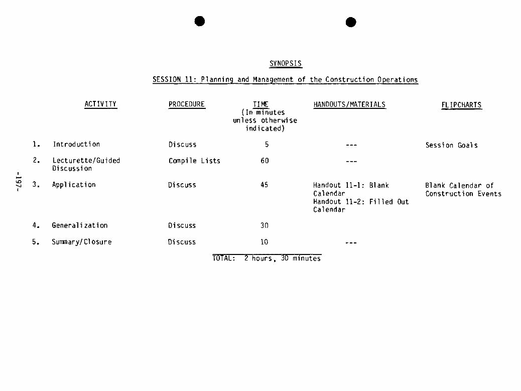
ACTIVITY PROCEDURE
SYNOPSIS
TIME(In minutes
unless otherwiseindicated)
HANDOUTS/MATERIALS FL IPCHARTS
1. Introduction Discuss 5 Session Goals
2. Lecturette/GuidedDiscussion
Handout 11—1: BlankCalendarHandout 11-2: Filled OutCalendar
Blank Calendar ofConstruction Events
4. Generalization
5. Summary/Closure
Discuss 30
Discuss 10
S
SESSION 11: Planning and Management of
.
the Construction Operations
(0 -,i. Application
Compile Lists
Discuss
60
45
1ULAL: Z hours, iU minutes

S
.

Session 11: Planning and Management of the Construction Operations
GOAL Total time: 2 hours & 30 mm.
To learn all of the steps and procedures necessary for detailing, ordering,and managing the materials and labor necessary for constructing a rainwaterroof catchment system.
OBJECTIVES
By the end of the session, the participants will be able to:
• Develop a list of all the construction steps needed to complete thesystem
• Develop a list of key considerations in each construction step necessaryto assure completion of the system
• Propose a complete plan for the proper management of material s andresources needed for the construction
OVERVIEW
This session provides training in systematically thinking through all of thelittle details necessary to conduct a construction project for a rainwaterroof catchment system. It uses the experience of the training group to developcheck lists and a construction events calendar which will be added to andcompleted in subsequent sessions.
ACTIVITIES
1. Introduction Time: 5 Minutes
SPresent the content of the overview and the goal and objectives for thesession. Stress the importance of this session by pointing out that this willbe the first review of all activities needed to achieve a complete roof catch-ment system. A basic planning tool , the construction events calendar (Handout11-1) for the demonstration site, will be developed and completed byparticipants during future sessions. This calendar will be added to theproject guide for the participants’ future reference.
2. Lecturette/Guided Discussion: Compiling Lists Time: 60 minutes
Present the idea that construction “operations” involve t~hree major aspects:human resources, materials, and financing. To make the most efficient use ofthese often scarce resources, it is necessary to plan the construction opera-tions well. Ask the participants what the advantages of good planning are.Write their responses on a flipchart. The following points should be made:
-199-

• To save time• To reduce loss• To avoid improvisation and potential mistakes• To reduce cost• To foresee and thus avoid potential problems• To make the most of the coimnunity’s participation• To avoid mixing up other parts of the total work schedule
Discuss these points and solicit examples of problems that the trainers havehad in their work because of inadequate planning. Close by pointing out to thetrainees that this session is designed to improve their ability to plan andmonitor the construction of the large rainwater catchment demonstration systemalready under construction.
Briefly review with the group the type of tank being built for the demonstra-tion. Ask the participants to describe the major design features and construc-tion materials and technologies being used in the tank construction and toenumerate the steps they think need to be gone through in doing the actualconstruction project. Write down on a flipchart the steps they mention. Each5system design and choice of construction technology will produce a differentlist. The following example is for a tank made with cement blocks and coveredwith a concrete slab. Similar steps should be listed for the actual construc-tion which is in process. Point out that these are construction steps and notplanning or management steps, which will be considered later:
• Clearing and lay out• Excavation• Putting in bed of gravel• Building the foundation form• Preparing the reinforced iron grill for the foundation• Pouring the foundation (including curing)• Making the cement blocks (or assembling stone for mortared stone
wal 1)• Constructing the walls and placing the pipes• Building the forms for the top slab• Preparing the iron grill for the top slab• Pouring, curing, and placing the top slab• Plastering• Constructing and placing the gutters, downspout, foul flush or
filter• Disinfection of the system• Putting the system into operation
After all the steps have been listed, review them and place in chronologicalorder along with an estimate of the time it will take to complete each step.
Now lead the group to consider the factors that are needed to assure that theconstruction can go forward. Give them five minutes to make individual listsof these factors and then list on a flipchart the factors mentioned by them.Make sure that the following are brought out:
• Financing (sources, timing, and management)
• Estimate of all needed materials
-200-
• Identification of resources and places for obtaining the materials mostinexpensively when needed
• Time needed to acquire materials (include a realistic estimate of
potential logistic and transporation problems)
• Storage/security plan for the materials
• Involvement of community in identification and organization of the laborforce needed
• Detailed daily construction work plan
• Clear management plan that spells out the responsibilities of eachperson. Point out that this management plan must be very clear regardingthree key items:
- division of responsibilities- training responsibilties (i.e., project masons training village
masons)- supervision responsibilities
As a wrap—up to this guided discussion, ask what additional step needs to beconsidered to assure that all the above goes as planned. This should bring outthe need to have a continuous evaluation aspect throughtout the entireprocess.
3. Application Time: 45 minutes
Review the major goals of good planning identified in the previous activity.Explain that the major planning tool to be used throughout the rest of thetraining will be a calendar of construction events for the demonstrationsystem. Present the blank calendar on a series of flipcharts that will remainposted until the end of the workshop. Have the participants review the list ofconstruction activities they developed in the previous activity and fill inthe 15 major activities on the blank calendar and the relevant labor,
aterial , and tool categories. After clarifying any questions about thecalendar, assign one or two participants the responsibility of getting theinformation necessary to complete the line for each of the constructionactivities. Then distribute Handout 11-1: Blank Calendar and Handout 11-2
:
Filled Out Calendar.
4. Generalizing Discussion Time: 30 minutes
Divide the group into three or four smaller groups depending on the number ofparticipants. Give them the following task:
• Identify the activities of the involved comunity in the planning,organization, and construction of a rainwater catchment system.
• Discuss how you would plan their involvement in these activities.
-20 1-
• List the most important factors in guaranteeing the community’s
involvement on a sheet of newsprint.
Give the groups 15 minutes to complete this task.
Post the four sheets of newsprint. Ask the groups to clarify any unclearpoints. Discuss the major points starting with those that were con~iion. Thediscussion should touch on the following points:
• Communities are more involved in project implementation if they have arole in the planning of the project.
• Communities develop “ownership” of a water supply system if they con-tribute money to the purchase of the materials as well as providing free1 abor.
• Construction projects can be a chance for villagers to learn or improvetheir construction skills if the construction work is organized so thatthey can learn.
• Adequate preparation and village “animation” is needed to keep peopleinformed and involved.
Close the discussion by emphasizing that in village water supply projects whatthe people learn in doing the project can be as important as the watersupplied if it encourages them to undertake other projects.
5. Summary/Closure Time: 10 minutes
Review the objectives of the session and clarify any remaining questions. Makesure that the assignment regarding completion of the calendar is clear andstate that the trainees should complete their line as soon as they can get theinformation from the construction foreman or masons.
TRAINER NOTE
The construction foreman and masons should be shown the completed calendarevents after this session, so that they will be prepared to provide answers toquestions posed by the participants filling out the calendar. The participantscan gather this information before or after the work session scheduled for theafternoon of the sixth day.
MATERIALS
— Flipchart with session goals and objectives- Flipcharts for listing points the participants generate during the guided
discussions- Flipcharts with the blank calendar of construction events for the
demonstration system- Handout 11-1: Blank Calendar- Handout 11—2: Filled Out Calendar
-202-

Handout 11 - 1
.
S

.

CALEIC Handout 11 - 2
onstruct on ActivitiesDcccBegun
DeteEnded
SueberDeys
iocberF~urs
Nueberasools
Nueberiron— General ObSerosti ens or Reriarks
1 Clrering/Ley Oct
tecavatlon
I Placing Bed of greed
4 Building foundation for.
B. Preparing iron grill forfoundatiOc
5. PO.uring the foundation(including curing)
1. Raking cr.Cnt blocks
B. Constructing She cells
9. BuIlding Ponies for tep slab
10. Preparing iron grill for
top slab
II. Pouring, curing, piecing top
slab
12 Plastering
13. Constructing and placing gutters
14. Disinfecting the systea
15. PAtting systc. into function
-2li


. .
SESSION 12

I.
S

N)0—1
ACTIVITY PROCEDURE
SYNOPSIS
TI ME(In minutes
unless otherwiseindicated)
HANDOUTS/MATER I ALS FLIP CHARTS
Open Discussion Presentati on/Question & Answer
30-90 Summary of Objectivesof All Sessions to Date
SESSION 12: Mid-Point Evaluation/Feedback

S

Session 12: Mid—~”ointEvaluation/Feedback
GOAL Total time: 30-90 minutes
To review the work done during the first week and identUy those areas whereadditional work or explanation are necessary.
OBJECTIVES
This session enables the trainers to better understand the positive andnegative factors which have affected the workshop as a whole during the firstweek and to be able to respond in an appropriate manner Lo the needs of theparticipants.
The trainers are to make a resume or synthesis of the strengths and problemsnoted by the participants and to suggest possible solutions. This feedback and
Iview session should be scheduled for one to three hours the day after theanning session (Session 10 or Monday morning if the session is held on
Saturday of the first week). The amount of time necessary for the reviewsession will obviously depend on the number of questions that need to beclarified.
ACTIVITIES Time: 30 minutes
Review the objectives for Sessions 1 through 11 that have been covered, writethem on a flipchart, and have these posted around the room. Ask the followingquestions:
1. Do you feel capable of accomplishing all the objectives of the sessions?If not, which ones pose difficulties for you? Please note the number ofthe session and the specific objective. Also state what it is that givesyou difficulty with the objective.
What things have you learned during this first week that you did not knowbefore? Miong these, which ones seem the most useful for your work?
3. In general , what problem have you encountered during the first week? Whatdo you think could be done to alleviate or solve these problems? (Note:Clarify that this is the place for them to mention problems related toroom, board, transport, per diem, etc.)
TRAINER NOTE
These questions can be answered anonymously on a piece of paper and handed inor orally and recorded on a flipchart and discussed.
MATERIALS
— Flipcharts with Sessions 1-11 goals and objectives.— Flipcharts with evaluation questions.
-209-


--4
.
1- -~ SESSION 13

.
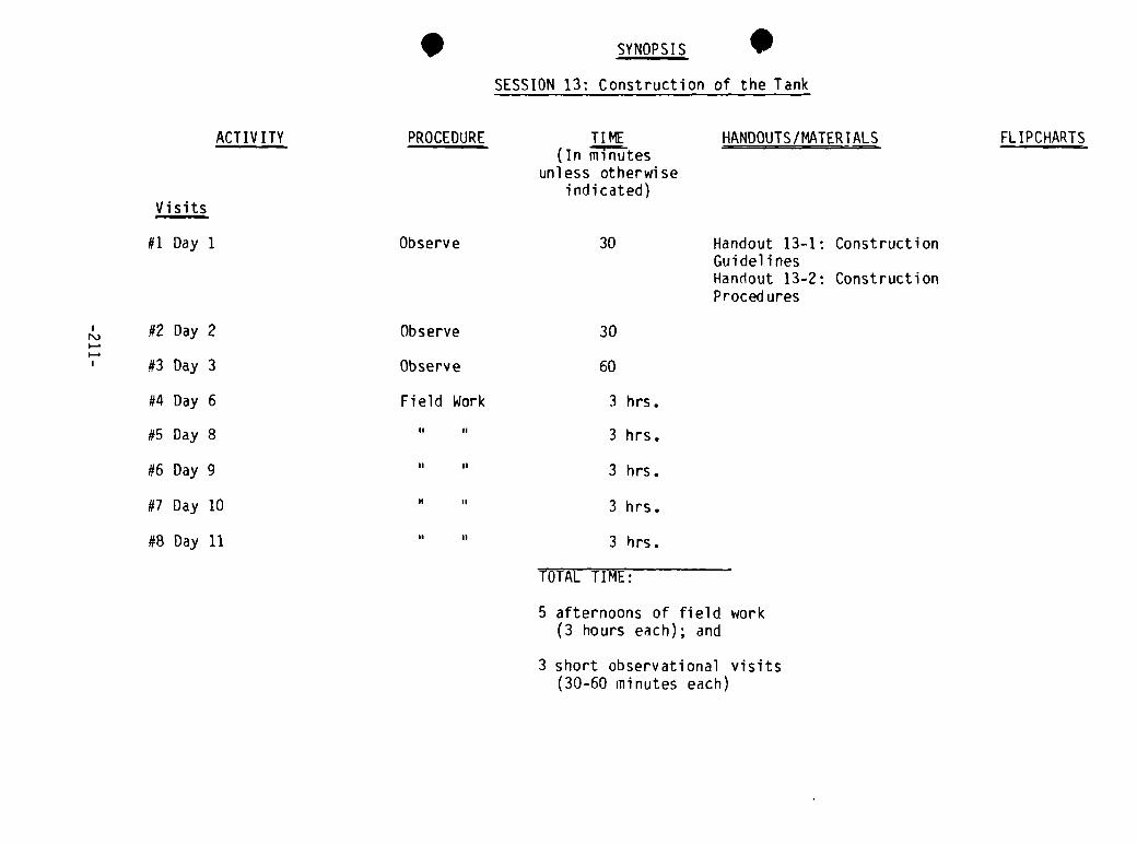
SYNOPSIS
SESSION 13: Construction of the Tank
Visits
#1 Day 1
ACT IV ITY PROCEDURE
Observe
TIME(In minutes
unless otherwiseindicated)
30
HANDOUTS/MATER I ALS
Handout 13—1: ConstructionGuidelinesHandout 13-2: ConstructionProced ures
FL IPCHARTS
#2 Day 2#3 Day 3
#4 Day 6
#5 Day 8
#6 Day 9
#7 Day 10
#8 Day 11
Observe
Observe
Field Work
,,
I, II
30
60
3 hrs.
3 hrs.
3 hrs.
3 hrs.
3 hrs.
TOTAL TIME:
5 afternoons of field work(3 hours each); and
3 short observational visits(30-60 minutes each)


Session 13: Construction of the Tank
GOAL Total time: 3—1/2 days
To learn the basic steps and processes in larger (coriinunity) storage tank
construction.
OBJECTIVES
Note: The following objectives are generic to most tank construction methods.They will have to be made specific to the actual construction technology andtank design decided upon.
At the end of the session the trainees will be able to:
Demonstrate all the basic steps for construction of the tank type
sel ected• Describe how to organize a construction site
• Describe how to lay out and dig the hole for in-ground tanks or toprepare for above-ground tank foundations and/or footings
• Demonstrate how to prepare and use all materi al s and processes for theconstruction of the tank foundation and/or footings
• Demonstrate how to prepare and use all material s and processes for theconstruction of the tank walls and cover
• Demonstrate knowledge of proper cement/sand/gravel ratios and mortar andconcrete mixing techniques for the various construction processes usingthese material s
• Apply skills in mortar and concrete placing, tamping, leveling,plastering, surfacing, and curing
Demonstrate how to connect a finished tank to the other components of thesystem and make the entire system operational
OVERVIEW
(Note: Before continuing, read Preparation for Construction under Section1.6.4 in the introduction to this guide and the introduction to the TrainerReference Notes which follow the handouts for this session.)
This session is designed to expose the participants to all the steps in theconstruction of a large storage tank for a community rainwater roof catchmentsystem. In addition, it will give them practical, hands—on experience in thebasic procedures required for tank construction. On the first three visits,which occur on the first three days of the workshop, the participants observethe preparatory work being done by local masons and laborers. On the other
-2 13-

five visits (Days 6-11) the participants work on various stages of the tank’sconstruction and the completion of the system. The work schedule should bestructured to permit the participants to pour the concrete foundation,construct and waterproof the walls, and finish the tank and system during thefive afternoon practical sessions. See the Trainer Reference Notes for how toorganize the work schedule for different construction technologies so that thesystem can be completed by the end of the workshop and the participants havethe opportunity to work on the major construction tasks.
The following plan for this session is organized around the eight visits tothe construction site and the basic steps in tank construction which occur atthose times. While the specific activities will depend on the choice oftechnology, materials, and tank design, it is recomended that the workschedule be coordinated with these general tasks according to the followingschedule wherever possible.
Visit 1 (Day 1): Observe site preparation and excavationVisit 2 (Day 2): Observe foundation/footing preparationVisit 3 (Day 3): Observe cover construction; laying footingsVisit 4 (Day 6): Pour foundationVisit 5 (Day 8):* Wall constructionVisit 6 (Day 9): Wall construction/plasteringVisit 7 (Day 10): WaterproofingVisit 8 (Day 11): Complete system
The same general procedures are followed for each visit: the trainer intro-duces the objectives and tasks for the visit, organizes the group into workteams wherever necessary, points out the key things learned during and/orafter the work as suitable, and leads a final discussion at the end of thevisit. The following session plan is organized by visits and includes intro-ductory comments, key things to be learned, and suggested questions for thefinal discussion for each visit. Specific examples are drawn froni two commonlyused construction methods and tank designs: an in—ground ferrocement lined pitand an above-ground brick masonry tank. They are used as examples to help thetrainer understand the kinds of generic learning which should be emphasized.The specific introductory comments, learning objectives, and final discussionquestions will have to be developed by the trainer and construction foremanbased on the construction technology, materials, tank design and work schedule 5chosen. The following procedures should be used as a guide to that task.
* If the workshop begins on a Monday, Day 8 will also fall on a Monday andDay 7 will be a day off on which the foundation can dry and start curing,permitting people to work on the wall on Day 7. Adapt for schedules withother days off.
-2 14-

ACTIVITIES
Visit One (Day 1) Time: 30-60 minutes
1. Introduction
The initial visit to the construction site should be structured to introducethe group to the site and the construction workers, show them the sitepreparation, excavation, etc. already done, and discuss how the site and workis organized. Tell the group to spend 10 minutes observing:
• How the work site is organized• Placement of tank in relation to catchment surface• Method of excavation
2. Key Thing~s Learned
he key things learned for this visit are:
Construction Site Organization
• Placement of materials in relation to tank site and method• Site and method for cleaning sand and gravel• Site for mixing mortar and concrete• Storage, transport, and control of tools and materials• P~mount of open space needed for work force• Protection of excavation
Location of future tank
• Relative to catchment surface• Relative to lay of land• Relative to water supply use• Relative to rest of the construction site
How is/was the excavation laid out
Pegs and string for straight lines3, 4, 5 triangle, or other appropriate methods for getting right anglesor
• Method for tracing circle for cylindrical tank• Plumb bobs or levels for vertical surfaces
How is/was the excavation dug
• Soil conditions, lay of land• Number of workers and time; labor costs• Tools and digging techniques
-215-
3. Final Discussion
Pose questions to elicit the key things learned; volunteer information wherenecessary; discuss key points. If time permits ask a generalizing questionabout the organization of the work site such as, “What kinds of problems canbe avoided by organizing a construction site like this?” and discuss. Concludewith mention of the purpose of the next visit.
Visit Two (Day 2) Time: 30-60 minutes
1. Introduction
The goal of the second visit is to dllOW the participants to observe how themasons are preparing the base for the foundation or footings and making thereinforcing rod frame for the foundation or floor. Ask the trainees to look atthe stone or broken brick base first and ask questions of the mason for fiveminutes. Then discuss key things learned (below) with them for five minutesbefore repeating the same procedure with the re-rod grill. Total time for bothobservations and discussions is 20 minutes.
2. Key Things Learned
The key things learned for this visit are:
Floor, foundation and footing bases
• Why put down a base first?• Why use the materials chosen; what other materials could be used?• What is the relationship of soil type to base?• What thickness should the base be? Why?• How is the base attached to the foundation, floor, or footing?
Reinforcing rod grill for foundation
• Why does concrete have to be reinforced? 5• What size reinforcing rod is best?• What other materials can be used to reinforce concrete?• What is the proper spacing of re-rod in a grill? Why?• How much time and material is required? How much does it cost?
3. Final Discussion
If all the key learning objectives were brought out during the previousdISCUSSiOnS, use this time to generalize about the materials, skills and laborused in tank construction and relate to the day’s sessions on cotirnunityevaluation and local resource inventories. For example:
• What do you think it took to get all these materials here on time? (Bringout community involvement and participation, as well as planning,budgeting, transport, etc.)
-216-

• How are skilled and manual laborers provided for a community rainwatercatchment project? Should the community pay these laborers?
• How are the laborers organized at the work site? Who is in charge? Whatresponsibility should the community have for their supervision?
Visit Three (Day 3) Time: 30-60 minutes
1. Introduction
The goals of this visit will vary with the construction technology and workschedule. For example, for a masonry tank the footings for the walls have tobe laid or poured at this time. For some other tanks the foundations have tobe laid more than two days before constructing the walls. The tank’s roof canbe constructed at this time as well. As in the two previous brief visits tothe construction site, the participants should observe the work then in, rogress and already completed during the morning and discuss what was learned
bout the specific construction activities. The discussions can occur duringthe observations and/or at the end of the visit.
2. Key Things Learned
The key things learned about above-ground masonry and ferrocement pit tankscould be:
For masonry wall footings for the above-ground part of a ferrocementpit tank
• How large do the footings have to be for a specific wall?• How are they constructed (materials, construction method)?• How are they levelled?• How are the footings joined to the wall and tank floor?
For poured concrete foundations and floors
Proper concrete mixture, material s, moi sture?• Pouring, compacting and levelling concrete. How much concrete?• How is the re-rod grill (or other reinforcing structure) placed?• How is the floor tied into the wall, footings, etc.?• How is the concrete cured?• (See key things learned for Visit #4 for more detail)
For wood and corrugated iron roofs
• How is the wood frame shaped and constructed?• What size corrugated iron sheet is used and how is it fixed to the frame?• Special design features (access for person to clean tank; connection of
downpipe, filter or foul flush; keeping dirty water and insects out,venting tanks).
-217-

3. Final Discussion
Review what was learned on this and the previous two visits. If time permits,dicuss the use of available materials and chosen construction technologies interms of the choices made during Session 6. Compare actual construction to thealternative technologies considered that morning. For example, why build acorrugated iron sheet and wood frame roof rather than a concrete slab?
Visit Four (Day 6) Time: 3 hours
1. Introduction
The participants start working on the tank themselves on the fourth visit tothe construction site which occurs on the sixth day of the workshop. On theprevious two afternoons, they have made small household cement tanks and aguttering and filtering system for a thatch roof. This practical sessionfollows on the concrete work in Session 8 and builds upon it. If the workschedule permits, this session can be devoted to pouring the concrete 5foundation for a ferrocement pit or the floor for an above ground masonrytank.
Before starting, review the work that has been accomplished during the firstthree days of the workshop and any work that has been done over the previoustwo days such as completing the tank roof or continuing the masonry wall.After reviewing the work done up to this point, break the group into workteams of from two to four participants each and explain their tasks. Giveclear instructions concerning concrete mixture, wetness of the concrete andhow to pour, compact, and level it. Keep people informed of the time and bringthem together at appropriate times to bring out what they are learning. Forexample, if two groups are about to pour concrete of different consistenciesask them which is preferable and why, and discuss briefly before having themcontinue.
2. Key Things Learned
The learning objectives regarding reinforced concrete in tank foundations and 5floors are:
Quality of Materials
• Age, dryness, and condition of cement• Cleanliness, coarseness, and composition of sand• Cleanliness, composition, and size of gravel
Ratio of Ingredients
• Difference among 1:1-1/2:3, 1:2:3, and 1:2:4 mixtures of cement to sandto gravel and when to use which mixture
• Amount of water in concrete for different tasks• “Feel” of concrete when ready to pour
-2 18-

How to pour, compact, level, and cure concrete
• How much to pour at one time• Time in which concrete starts to set• Tools and techniques for compacting and levelling concrete• Time and method of curing concrete
Special tank design features
• Slope of tank floor
• Sump, drainage and cleaning
Reinforcing materials
• Size and spacing of reinforcing rod in re-rod grill• Depth of grill in concrete• Attaching reinforcing rod to walls, footing, etc.• Other reinforcing materials
Using forms other than clay soil excavations
• Materials for forms• Form construction• Laying floor inside walls on footings
3. Final Discussion
Review what was learned and discussed during the practical. Bring out throughfurther discussion and question and answer any of the key session points notalready disLussed. Leave sufficient time for several general and practicalquestions about working with concrete such as:
• What is the most important thing to remember when working with concrete?
• What would you do differently the next time you use concrete?
, f time permits, lead a discussion about the organization of their labor andhat they learned from it about supervising a large group of community
laborers. Mention the next practical session and Session 14 in closing.
Visit Five (Day 8) Time: 3 hours
1. Introduction
If the workshop begins on a Monday, Day 6 falls on a Saturday and Day 8 on aMonday, giving the foundation or floor 48 hours to set and start curing beforethe participants work on the wall of the tank during Visit #5*. The work onthe tank should be scheduled so that the participants have an opportunity to
~Adapt for cultures which use Friday or Saturday as a traditional day ofrest.
-219-
lay enough bricks, blocks, or stones in a masonry tank wall and apply enoughof the second coat of mortar in a ferrocement tank to learn the basicprocedures of wall construction for their selected tank technology. Forexample, in a brick masonry tank, the participants should have several coursesof brick to lay for two hours to gain experience in preparing mortar and inthe techniques and problems of bricklaying. In a ferrocement pit tank, theparticipants should be involved in working on the reinforcing mesh and mortarmixing and application. As in other practical sessions, explain the purpose ofthe afternoon’s work, give the trainees specific technical instructions,organize them into work teams and get them working. Stop the work at appro-priate times to point out and discuss what was learned during the session.
2. Key Things Learned
The key things learned during this session for masonry tanks are:
Masonry design
• Thickness of masonry walls• Placement of bricks, blocks, or stones• Bonding bricks or bondstones• Thickness of mortar
Materials
• Size, choice, condition of baked clay bricks, cement or cindaram bricks,stone
• Reason for soaking bricks and blocks• Cleanliness of materials• Comparative costs of masonry materials• Cement, sand, and mortar
Masonry construction mortar
• Cement to sand ratio for mortar• Wetness of mortar• Thickness of mortar• Applying mortar evenly and keeping bricks level
Laying bricks, blocks, or stones
• Keeping course level• Choosing stones while laying wall• Spacing of bricks and blocks in mortar
Placing water pipes in a masonry wall
• Connection of wall to footings, foundatori and tank floor• Setting and curing mortar
-220-

The key learning objectives of this session for ferrocement pit wall construc-
tion are:
Preparing the pit wall
• Finishing excavation and the need for a clean wall• Use of reinforcing rod to hold chicken wire mesh or other internal
structure
Applying mortar
• Why use mortar with a cement to sand ratio of 1:3~• How much water should be mixed into the mortar? Why?• How much mortar is applied in each coat?• How long does it need to dry between coats?• How long does it need to cure?
Reinforcing mesh
What materials can be used in the mesh? Which is best2When and how is it put into the mortar?How is it attached to the reinforcing rod in the foundation?
3. Final Discussion
After the work is completed for the afternoon, bring the trainees together andask them what the most significant things they learned that afternoon were.Review what was discussed during the work activity and bring up other thingsnot already mentioned. Discuss. Ask the participants what problems they thinkmight arise supervising village artisans and laborers responsible for doingthis work and what other problems might arise in using this tank constructiontechnology in a village. In closing, mention the next afternoon’s session.
Visit Six (Day 9) Time: 3 hours
.1. Introduction
During the sixth field visit the participants continue working on the walls ofthe tank. For a ferrocement lined pit, this means adding the second two coatsof plaster. For a masonry tank, the walls should be laid at this point so thatwork can start on plastering them. As usua’, break the group into work teams,give them their instructions, and get them started.
2. Key Things Learned
The key things learned with regard to a ferrocement lined pit are the same asthe previous day.
-22 1-
For plastering a masonry tank they are:
Preparing the masonry wall for plaster and mortar combinations and
plastering
• Why a 1:3 cement to sand mixture for first coat?• How dry should the plaster be?• How thick does the plaster need to be?• Specific technical facts about plastering.
3. Final Discussion
Review the day’s work and what was learned, concentrating on working withmortar. Ask general question linked to the morning’s session on maintenanceand community responsibility such as, “How can the community be betterprepared to maintain the system while they are involved in building the tank?”
Visit Seven (Day 10) Time: 3 hours
1. Introduction
This visit is very similar to the previous day’s work. A second coat ofplaster is put on the masonry tank and the ferrocement pit is plastered with awaterproofing coat. By the end of this visit, both tanks should be almostfinished. Have the groups work as they did the previous day.
2. Key Things LearnedMost of the learning objectives are the same as those of the previous visit.
The following should be stressed:
• Why the waterproofing coat is done with a 1:2 mixture of cement to sand.
• How wet the plaster should be. What it feels like when ready.
• How many materials are used to plaster a tank. How long it takes. The
costs.
3. Final Discussion
The final discussion after this visit should review the tank construction inlight of the conclusions of Session 16: Critiquing and Refining the Design.Ask the participants to list the advantages and disadvantages of the construc-tion method used to build the tank. Discuss the availability and cost ofmaterials, the tools and skills needed to do the job, and the time and cost oflabor. Also ask if this method could be easily taught to village masons andworkers and if they feel competent to supervise the construction of such atank. Close with mention of the practical sessions scheduled for the next dayon guttering and connecting the tank to the gutters.
-222-

Visit Eight (Day 11) Time: 3 hours
1. Introduction
The last visit is designed to complete the rainwater roof catchment system:finish the tank, finish attaching gutters, put tank roof in place and connectdownpipe and foul flush or filter to the gutters and tank, and see that allthe systems work. The actual work will depend on how much was accomplishedduring the morning (Session 17), and what has been previously done tocomplete the other components of the system. Plan the work tasks accordinglyand split the group up into work teams, give them their tasks and start work.If several different work teams are doing different tasks, stop the work as inSession 8 and let people show each other what they are doing and discuss whatthey have learned at that time.
2. Learning Objectives
e specific learning objectives for this visit will depend upon the tasksequiring attention. They will probably include:
Waterproofing the Tank
• What is the function of the final cement slurry7• How moist should the slurry be?• How much should be applied?• How much can he mixed at any one time?
Finishing the tank top to receive the roof
• How is the top of the tank finished to hold the roof?
• How is the reinforcing rod connected to the wall? To the roof?
Placing the roof
What has to he considered in putting a roof on a tank?If a concrete slab roof was made prior to the workshop (it requires twoweeks to cure) , how can it be placed on a tank in the easiest and safestfashi on?
Connecting gutters (see Session 17)
Connecting downpipe and foul flush or filter to gutters and tank
• How is foul flush water evacuated?• How is the filter or foul flush system supported by the tank or roof?• What are the regular operations and maintenance requirements of these
systems?
Finishing around the tank
• How will the area around the tank be kept clean and dry?• How will dirty water or excess water be evacuated?
-223-

• How will dirty water, insects, etc., be kept out of the tank (especiallya pit tank)?
Putting the system into operation
• How much time does the tank have to cure before it can hold water?• How will the system be cleaned and disinfected before being put in use7• Who is responsible for maintenance and monitoring of the system?
3. Final Discussion
(Note: If the processing and final discussions for Session ii were not heldthat morning they should be combined with the following final discussion.)
This discussion should concentrate on reviewing briefly the key things learnedwhich were brought out during the periodic breaks in the construction work.This should lead to generalizing from the practical construction sessionsabout what trainees have learned which will improve their abilities to planiand supervise the constructon of a large (community) roof catchment system.Sample questions to generate such a discussion could be:
• What is the most important thing you have learned from working on theconstruction of this system? Why7
• What have you learned from working on the construction of this systemwhich will be most helpful to you in planning and organizing a villageconstruction project in the future7
• What have you learned about working with village masons and organizing alarge work force that will be most helpful the next time you are incharge of a village construction project7
TRAINER NOTES
1. The construction materials and tools will vary depending on the construc-tion technology, the design of the system, and the number and skills of5the participants. See Section 1.6.5 of the Introduction to this guide fora suggested list.
2. Pedagogic tools should be kept simple so they can be easily used at thework site. Participants can be given small pocket notebooks and pencilsso they can jot down technical notes to themselves while working. Thetrainer may want to have a flipchart and newsprint available for empha-sizing the key points during the final discussions.
MATERIALS
— Construction materials- Handout 13-1: Construction Guidelines- Handout 13-2: Construction Procedures
-224-
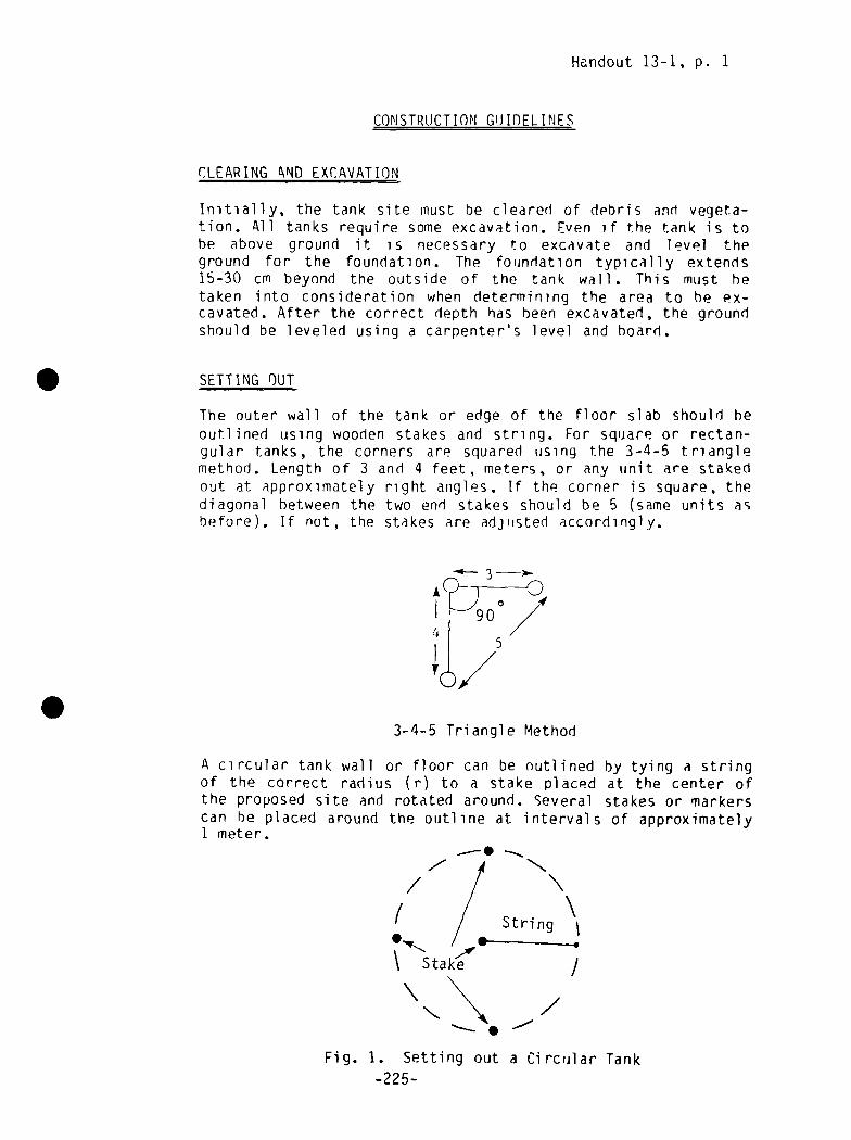
Handout 13-1, p. 1
CONSTRUCTIONGUIDELINES
CLEARING ~ND EXCAVATION
Initially, the tank site must be cleared of debris and vegeta-tion. All tanks require some excavation. Even if the tank is tohe above ground it is necessary to excavate and level theground for the foundation. The foundation typically extends15-30 cm beyond the outside of the tank wall. This must hetaken into consideration when determining the area to he ex-cavated. After the correct depth has been excavated, the groundshould be leveled using a carpenter’s level and hoard.
5 SETTING OUT
The outer wall of the tank or edge of the floor slab should heoutlined using wooden stakes and string. For square or rectan-gular tanks, the corners are squared using the 3-4-5 trianglemethod. Length of 3 and 4 feet, meters, or any unit are stakedout at approximately right angles. If the corner is square, thediagonal between the two end stakes should be 5 (same units asbefore). If not, the stakes are adjusted accordingly.
~—
~
S3-4-5 Triangle Method
A circular tank wall or floor can be outlined by tying a stringof the correct radius (r) to a stake placed at the center ofthe proposed site and rotated around. Several stakes or markerscan he placed around the outline at intervals of approximately1 meter.
~ 4
/ // / String
.,,~_ 2~
Stake /
Fig. 1. Setting out a Circular Tank
-22 5-

Handout 13-1, p. 2
FOUNDATION/FOOTING
Before the floor slab can he laid, a foundation of gravel orcrushed stone is necessary. The thickness should be approxi-mately 10 cm. The gravel bed should be tamped and leveledbefore proceeding with the floor construction. If the tank isto have a sump, then a depression should he made in the founda-tion for this. For masonry walls it is common practice toconstruct a footing of masonry or concrete. The footing shouldbe approximately 20 cm thick and extend 10 cm beyond the baseof the tank wall on both sides. This also requires a 10 cmthick foundation of either gravel or lean concrete (1 part
cement, 3 parts sand, 6 parts gravel).
.~a11
Footing 420 cm
H~HFig. 2 Masonry Footing
PLACING FORMS
All concrete work requires a form into which the concrete ispoured. Fonns are usually made from boards or planks, althoughother materials are also used. Wooden forms are nailed togethaccording to the proper measurements. To ensure that the cocrete does not stick to the forms it is advisable to coat themwith oil first. It is very important that the forms be sup-ported on the outside. Otherwise, when the concrete is beingcompacted the forms can bulge or burst apart.
-226-

Hnadout 13-1, p. 3
MIXING CONCRETE
Proper mixing of concrete is essential if it is to meet itsrequirements of strength and durability. The first step is toprepare a mixing pad or platform. For this, boards, metalsheets, or a hardened concrete slab is suitable. The aggregateand cement are then measured and piled into a heap. This thenshould be turned over using shovels or trowels until themixture is uniform. The mix is then heaped and a depression ismade in the center of the pile. Water is slowly poured into thedepression and worked into the dry mix. It is important not toadd too much water. Otherwise the concrete will not reach itsfull strength. A rule of thumb is to add approximately 3/4parts of water for each part of dry cement. The concrete shouldbe mixed in volumes no larger than that which can be pouredwithin 30 minutes. At this point the concrete begins to set.
PLACING CONCRETE
After mixing, the concrete should be placed into the formsimmediately. Floor slabs are poured beginning with one side orcorner and working towards the opposite one. The concreteshould be placed in adjacent piles, compacted, and leveled. Thesimplest way this can be done is to assign teams to carry outeach of these 3 tasks. The first team transports and places theconcrete. The second team follows by compacting, and the thirdteam levels the slab.
Compacting is usually done by means of a tamping foot. Theconcrete should be compacted until the top surface is fairlysmooth with none of the coarse aggregate jutting out.
Leveling is carried out using a trowel or screed (short, smoothpiece of wood) and a carpenter’s level. The floor should slopetowards the sump or drain.
Walls should he poured in a similar manner with the exceptionthat the compacting or rodding should be carried out in 30—40cm layers. Iron rods are best for doing this.
-22 7-
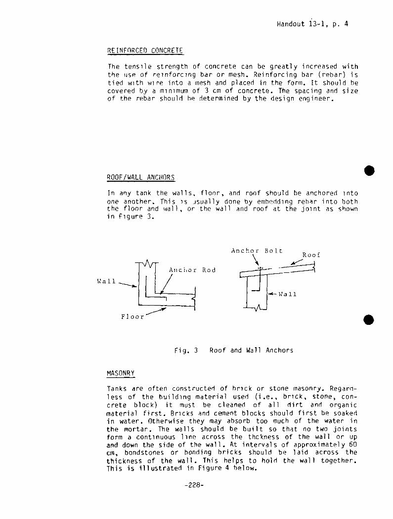
Handout 13-1, p. 4
REINFORCED CONCRETE
The tensile strength of concrete can be greatly increased withthe use of reinforcing bar or mesh. Reinforcing bar (rebar) istied with wire into a mesh and placed in the form. It should hecovered by a minimum of 3 cm of concrete. The spacing and sizeof the rebar should he determined by the design engineer.
ROOF/WALL ANCHORS
In any tank the walls, floor, and roof should be anchored intoone another. This is usually done by embedding rehar into boththe floor and wall, or the wall and roof at the joint as shownin Figure 3.
Anchor Rod
W a 1 1
Floor
Anchor BoltRoof
MASONRY
Fig. 3 Roof and Wall Anchors
Tanks are often constructed of brick or stone masonry. Regarn-less of the building material used (i.e., brick, stone, con-crete block) it must be cleaned of all dirt and organicmaterial first. Bricks and cement blocks should first be soakedin water. Otherwise they may absorb too much of the water inthe mortar. The walls should be built so that no two jointsform a continuous line across the thckness of the wall or upand down the side of the wall. At intervals of approximately 60cm, bondstones or bonding bricks should be laid across thethickness of the wall. This helps to hold the wall together.This is illustrated in Figure 4 below.
.
S
-228-

Fig. 4 Brick Masonry
Handout 13-1, p. 5Bonding Brick
To ensure the strength of the wall it is very important that notwo adjacent stones or bricks touch. The recommended thicknessof all mortar joints is 1.0 cm. In masonry tanks, it is morecommon to construct the walls first beginning with the cornersand then pour the floor slab. In this case, the wall is notanchored into the floor as for other types of tanks. This isshown in Figure 5.
Masonary Wall
Footing
Fig. 5 Masonry Tank Wall
1)
The roof of a masonry tank is usually attached to an anchorbolt embedded 10-15 cm into the top of the masonry wall.
Wall
Anchor Bolt
Fig. 6 Anchor Bolt
-229-
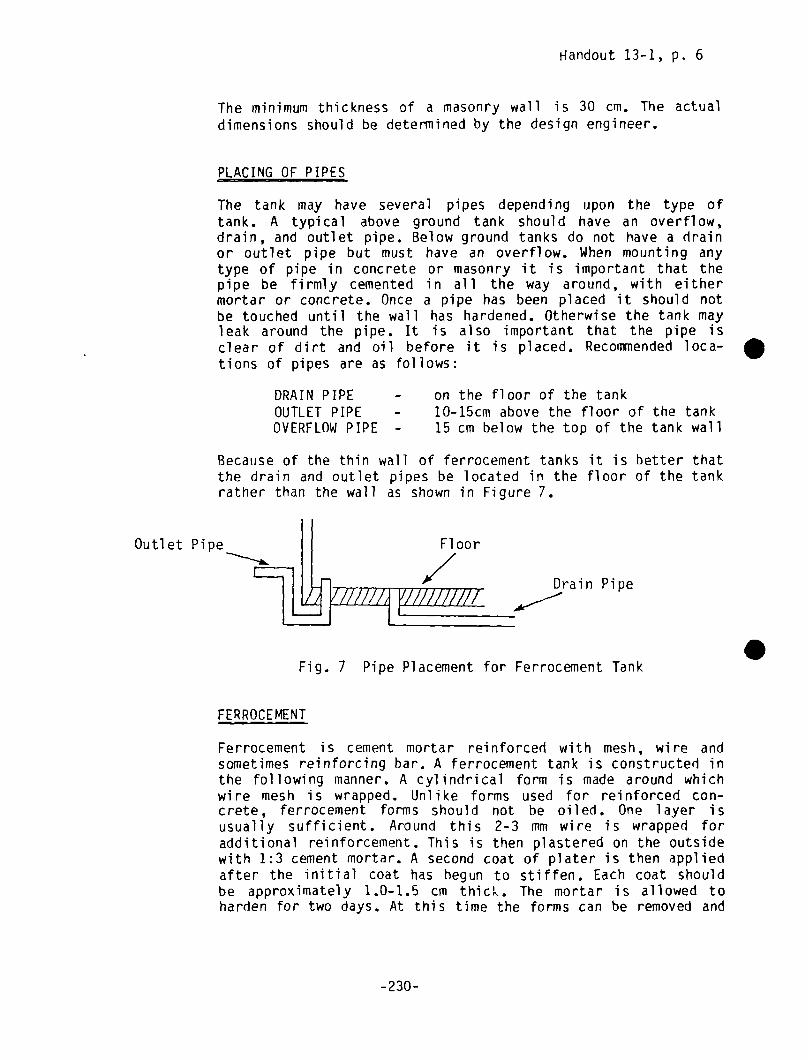
Handout 13-1, p. 6
The minimum thickness of a masonry wall is 30 cm. The actualdimensions should be determined by the design engineer.
PLACING OF PIPES
The tank may have several pipes depending upon the type oftank. A typical above ground tank should have an overflow,drain, and outlet pipe. Below ground tanks do not have a drainor outlet pipe but must have an overflow. When mounting anytype of pipe in concrete or masonry it is important that thepipe be firmly cemented in all the way around, with eithermortar or concrete. Once a pipe has been placed it should notbe touched until the wall has hardened. Otherwise the tank mayleak around the pipe. It is also important that the pipe isclear of dirt and oil before it is placed. Recommended loca—tions of pipes are as follows:
DRAIN PIPE — on the floor of the tankOUTLET PIPE - 10-15cm above the floor of the tankOVERFLOW PIPE - 15 cm below the top of the tank wall
Because of the thin wall of ferrocement tanks it is better thatthe drain and outlet pipes be located in the floor of the tankrather than the wall as shown in Figure 7.
Outlet Pipe
Drain Pipe
.Fig. 7 Pipe Placement for Ferrocement Tank
FE RR OC E MENT
Ferrocement is cement mortar reinforced with mesh, wire andsometimes reinforcing bar. A ferrocement tank is constructed inthe following manner. A cylindrical form is made around whichwire mesh is wrapped. Unlike forms used for reinforced con-crete, ferrocement forms should not be oiled. One layer isusually sufficient. Around this 2-3 mm wire is wrapped foradditional reinforcement. This is then plastered on the outsidewith 1:3 cement mortar. A second coat of plater is then appliedafter the initial coat has begun to stiffen. Each coat shouldbe approximately LO—1.5 cm thicL. The mortar is allowed toharden for two days. At this time the forms can be removed and
Floor
/
-230-
Handout 13-1, p. 7
the inside of the tank is then plastered in two more coats. Thetotal thickness of the wall should be 4-5 cm. It is very im-portant that the tank be kept covered and moist, particularlyduring the first few days. Otherwise the mortar will crack andthe tank may leak.
After approximately one week a roof can be built on the tank. Aferrocenient roof can be constructed using two layers of meshinstead of the single layer as for the walls. Again it is im-portant to anchor the roof to the walls using rebar.
PLASTERING
To ensure that the tank is waterproof it should be internallyplastered. Recommended plastering procedures vary from two tofour coats. Regardless of the number of coats, only one coatshould be applied each day.
The following plastering method is recommended here:
Initially a 1:3 cement mortar coat is applied to athickness of 1.0-1.2 cm. This coat is applied roughlyand is not smoothed out. Next a coat of 1:2 mortar isapplied to a thickness of 0.8-1.0 cm, and smoothed.finally, a thin 0.2-0.4 cm coat of cement paste(cement A water only) is applied.
CURING
All cement work must be cured for a minimum of one week andpreferably two. The structure must be kept moist and protectedfrom direct sunlight. Other wise the cement will dry out toorapidly, crack and will not reach its full strength. Curingshould begin immediately after the cement has finished setting,usually 2-4 hours after it has been placed. This can be bestdone by wetting the structure and then covering it with dampburlap, paper leaves or other suitable material. Concrete slabscan be cured by building up a rim of soil around the edge ofthe slab and flooding it with a few centimeters of water.
DRAl NAGE
The area surrounding the tank should be graded so that rain andoverflow water drains away from the tank. This is especiallyimportant for below ground tanks where surface runoff can enterthe tank and contaminate the water.
-231-
Handout 13-1, p. 8
MANHOLEAND AIR VENTS
In addition to the structural features mentioned above, thetank should be provided with a manhole or access door, since itwill be necessary to enter the tank for cleaning and main-tenance. The door should be locked at other times to preventunauthorized persons from entering. Also, the tank should bewell ventilated. In most cases, this will occur naturally butfor certain types of tanks such as reinforced concrete orferrocement tanks with tight-fitting covers it may be necessaryto provide an air vent.
.
.
-232—

ACTIVITY
A. SITE PREPARATION
1. Clear Site
2. Set out tank floors/
walls
3. Excavate
Level
Place foundation
Digging tools, carpenter’slevel , board
Level , shovel s,compacting tools
6. Outline wall footing Measuring tape, string
hammer, stakes
B. FOOTING ~ WALL CONSTRUCTION
1. Clean & soak bricks Water container, wirebrush
2. Measure quantities Measuring containerfor mix
3. Dry mix mortar Mixing pad, trowels,shovels.
4. Wet mix mortar Mixing pad, trowels,shovels.
Measuring container.
1 Hr
Clear all vegetation,boulders, etc.
3-4—5 triangle method.
Include trench for footing,hole for sump (depth dependson design decisionspreviously made)
1-2 Hrs 10 cm gravel or stone layer,compact with hammer, tampingfoot or other tool.
1 Hr Outline with string tied tocorner stakes.
1:4 Cement/sand ratio.
Mix to uniform color &consi stency.
Add water gradually untilmortar is workable; mixonly volume which can beused in 1/2 hour or less.
.
TOOLS
CONSTRUCTIONPROCEDURESBRICK MASONRYTANK
(Square, Above riround)
MATERI ALS TIME TECHNIQUE
Digging, Clearing Tools
Measuring tape, string,hammer, stakes
Digging, tools, tape
4.
5.
1-4 Hrs.
1 Hr.
2—8 FIrs.
Gravel , stone
Bricks, water
Sand, cement
Sand, cement
Water, mortarmix.
1-2 Hrs
1/2 Hr.
1/4 Hr.
1/4 hr.
c~.aC-,.
I.
-a

CONSTRUCTIONPROCEDURESBRICK MASONRYTANK
(Square, Above Ground)
TIME TECHNIQUE
5. Lay footing Tape, trowels, hammers& other masonry tools.
Mortar, bricks[Alternative:concrete mixed1:3:6]
1—4 Hrs. Begin with corners & worktowards center of wall;cover & wet at end of day.
6. Place drain pipe Level , masonry tools GI pipe, mortar 5 Mm. Place pipe level or slopingslightly downward from tank.
7. Lay tank wall — firstcourses
Masonry tools, plumbob Mortar, bricks 1 toseveraldays
Same as B.5 above.
8. Place outlet pipe
(~)
9. Lay tank wall tooverflow pipe.
Same as B.6 above, 10 cm
above floor.
Same as 8.5 above.
10. Place overflow pipeand roof anchorbolts.
Galvanized Ironpipe, roof anchorhol ts
Same as B.6 above - 15 cmfrom top of tank wall.
11. Complete tank wall Same as B.5 above.
aC
1. Measure quantities forconcrete
Measuring containers Cement, sand,gravel
1/2 Hr. 1:1 1/2:3 cement/sand/gravelratio.
2. Dry mix concreteMixing pad, trowels,
shovel S
.Cement, sand, 1/2-lHr Mix to uniform color and
consistency overturningseveral times.
N.)
ACTIVITY TOOLS MATERIALS
12. Allow to harden/cure Water contai ner Water, hurl ap, 2-4 days Wet severalpaper or other keep covered.such material
C. FLOOR

CONSTRUCTIONPROCEDURESBRICK MASONRYTANK
(Square, Above Ground)
ACTIVITY TOOLS MATERIALS TIME TECHNIQUE
3. Wet mix concrete Mixing pad, trowels,shovel 5
Dry mix, water 1/4 Hr Gradually add water to appro-ximately 3/4 parts water to1 part cement. Mix thorough-ly in volumes which can hepoured in 1/2 hour or less.
4. Pour concrete Transport containers,compacting tools,trowels screed, level
Concrete 1-3 hrs Place incompacttowards
adjacent piles,and level; slopedrain
N.)C-.-,U,
5. Allow to harden/cure
D. PLASTERING (WATERPROOFING)
Water container Water, burlap,paper or other
2-3 days 2—3 hours after concrete hasbeen poured flood with 2-5cm of water.
~ days See guidelines for plasteringmethod for masonry tanks.
E. ROOF Hammer, nails, wrenches~etc. Require for specifictype of roof.
Depends on typeof roof
1-4 days Include lockinq access door.
F. FINAL GRADING/FINISHING Digging tools 1-2 days Slope ground away from tankallow for overflow drainage.
0~
0C
. .

CONSTRUCTIONPROCEDURESPLASTERING OF MASONRYTANKS
TECHNIQUE
N.)
A. FIRST COAT
I. Clean wall
2. Measure quantities formortar mix (firstcoat.
3. Dry mix mortar
4. Wet mix mortar
5. Apply mortar
6. Allow i.o set
Wire brush, trowels
Measuring container
Mixing pad, trovels,shovels
Mixing pad, trowels,shovels, measuringcontainer
Trowels
Sand, cement
Sand, cement
Water, mortar
Mortar
Water, burlap,paper, etc.
1—2 Hrs Scrape off loose mortar,dirt, etc.
1/2 Hr 1:3 cement/sand ratio.
1/4 Hr Mix to uniform color Aconsi stency.
1/4 Hr Add water gradually untilmortar is workable; mixonly volume which can heused in 1/2 hour or less.
1—2 Hrs Apply in rough coat ofapproximately 1.0-1.2 cmthickness; do not smooth.
1 day Cover sprinkle with wateroccasionally.
0)
0-0CC-,.
ACTIVITY TOOLS MATERIALS TIME
B. SECONDCOAT
1. Dampen wall Water
2. Measure quantities Measuring container Sand, cement
3. Mix mortar
4. Apply mortar Trowels Mortar
5. Allow to set
1/2 Hr Sprinkle with water.
1:2 cement/sand ratio
As in steps A.3 — A.4 above.
1-2 Hrs Apply coat of approximately0.8-1.0 cm thickness andsmooth.
Same as step A.6 above.. S

. CONSTRUCTIONPROCEDURESPLASTERING OF MASONRYTANKS
ACTIVITY
C. FINAL COAT
TOOLS MATERIALS TIME TECHNIQUE
1. Dampen wall Water 1/2 Hr Sprinkle with water.
2. Mix mortar Mixing pad, trowels Sand, Cement 5 mm Cement A water only mixed toa thick paste; mix onlysmall amounts.
3. Apply mortar Trowel s Apply 0.2-0.4 cm coat andsmooth.
N)C.-,
4. Allow to harden/cure Water, burlap,paper, etc.
2—4 days Wet several times per day andcover.
0)
0-0CC-f
~t’N)
01
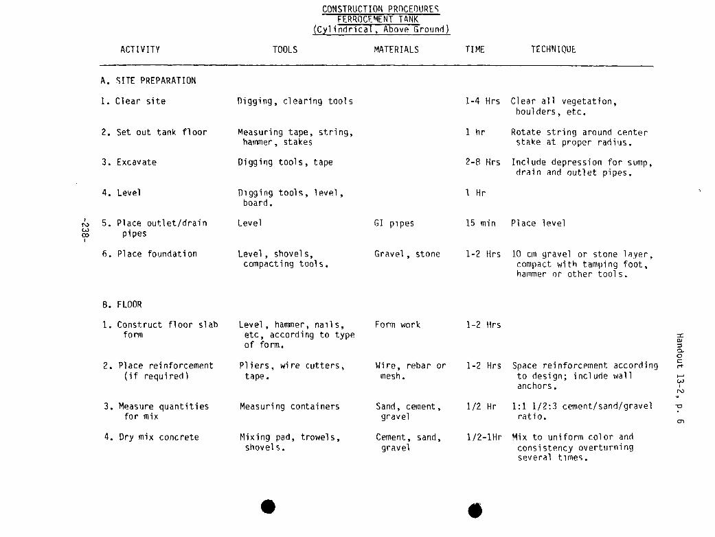
ACTIVITY TOOLS
CONSTRUCTIONPROCEDURESFERROCEMENTTANK
(~ylindrical, Above Ground)
MATERIALS TIME TECHNIQUE
A. SITE PREPARATION
1. Clear site
2. Set out tank floor
3. Excavate
4. Level
r!. 5. Place outlet/drainpipes
6. Place foundation
Digging, clearing tools
Measuring tape, string,hammer, stakes
Digging tools, tape
Digging tools, level,board.
Level
Level , shovel s,compacting tools.
Level, hammer, nails,etc, according to typeof form.
Pliers, wire cutters,tape.
Measuring containers
Mixing pad, trowels,shovels.
Wire, rebar ormesh.
Sand, cement,gravel
Cement, sand,gravel
1-4 Hrs
1 hr
2-8 Hrs
1 Hr
15 mm
1-2 Hrs
Clear all vegetation,boulders, etc.
Rotate string around centerstake at proper radius.
Include depression for sump,drain and outlet pipes.
Place level
10 cm gravel or stone layer,compact with tamping foot,hammer or other tools.
GI pipes
Gravel , stone
B. FLOOR
1. Construct floor slab
fo nii
2. Place reinforcement
(if required)
3. Measure quantitiesfor mix
4. Dry mix concrete
Form work 1-2 Hrs
0)
0-aCC-F
(I.)N)
1-2 Hrs Space reinforcement accordingto design; include wallanchors.
1/2 Hr 1:1 1/2:3 cement/sand/gravelratio.
1/2—lHr Mix to uniform color andconsistency overturningseveral times.
S
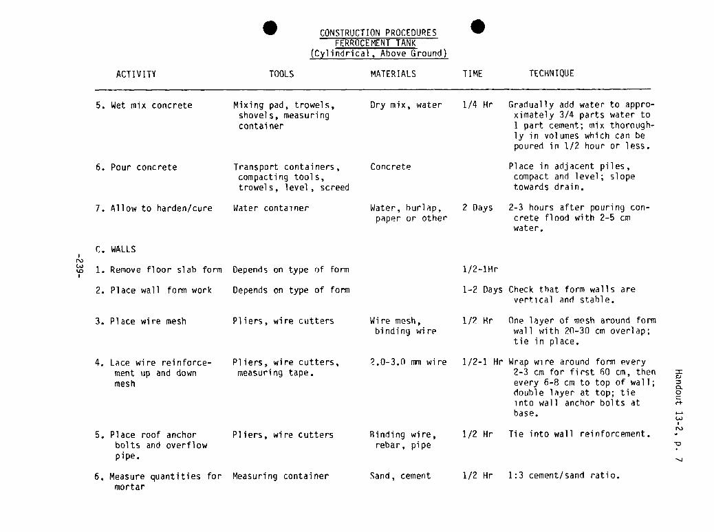
ACTIVITY TOOLS
CONSTRUCTIONPROCEDURESFERROCEMENTTANK
(Cylindrical, Above Ground)
TIME TECHNIQUE
5. Wet mix concrete Mixing pad, trowels,shovels, measuringcontai ner
Dry mix, water 1/4 Hr Gradually add water to appro-ximately 3/4 parts water to1 part cement; mix thorough-ly in volumes which can bepoured in 1/2 hour or less.
6. Pour concrete Transport containers,compacting tools,trowels, level, screed
Concrete Place in adjacent piles,compact and level; slopetowards drain.
7. Allow to harden/cure Water container Water, burlap,paper or other
2 Days 2-3 hours after pouring con-crete flood with 2-5 cmwater.
C. WALLS
~ 1. Remove floor slab form
2. Place wall form work
1/2—lHr
1—2 Days Check that form walls arevertical and stable.
3. Place wire mesh Pliers, wire cutters Wire mesh,binding wire
1/2 Hr One layer of mesh around formwall with 20-30 cm overlap;tie in place.
1/2-1 Hr Wrap wire around form every2-3 cm for first 60 cm, thenevery 6-8 cm to top of wall;double layer at top; tieinto wall anchor bolts at
N)
6. Measure quantities formortar
Measuring container Sand, cement 1/2 Hr 1:3 cement/sand ratio.
. S
MATERIALS
Depends on type of form
Depends on type of form
4. Lace wire reinforce— Pliers, wire cutters, 2.0-3.0 mm wirement up and down measuring tape.mesh
5. Place roofbolts and
anchoroverflow
Pliers, wire cutters Bindingrebar,
wire,pipe
pipe.
0.0CC-P
base.
1/2 Hr Tie into wall reinforcement.

ACTIVITY
CONSTRUCTIONPROCEDURESFER~OCEMENTTANK
(Cylindrical, Above Ground)
TIME TECHNIQUE
7. Dry mix mortar. Mixing pad, trowels,shovel s
Sand, cement 1/4 Hr Mix to uniform color andconsi stency.
8. Wet mix mortar Mixing pad, trowels,shovels, measuringcontai ner
Water, mortarmix
1/4 Hr Add water gradually untilmortar is workable; mixonly volume which can heused in 1/2 hour or less.
9. Apply first coat(outside)
Masonry tool s Mortar 1—2 Hrs Apply 1.0—1.5 cm thick roughcoat without smoothing.
10. Allow to set 2 Hours11. Apply second coat
(outside)
~ 12. Allow to harden/cure
Trowels Mortar
Water container Water, burlap,paper or othermaterial
1-2 hrs Same as C.6-C.9 above; smoothfinish
2 Days Wet several times per day andcover.
13. Remove wall forms Depends on type of form 1-3 Hrs Carefully remove withoutdisturbing wall.
14. Apply 2 inside
coats of plaster
15. Allow to harden/cure Water, burlap,paper, etc.
1-1 1/2 Same as C.6-C.11 above.Days
2 Days Wet several times per day andcover.
0. PLASTERING (WATERPROOFING)
0)
0-0CC-t
I-.
N)
Go
TOOLS MATERIALS
1. Apply first coat Mixing containers, padtrowels, measuring
Cement, sand,water
1-2 hrs Apply1.0
1:2cm thick
cement/sand mortarand smooth
containers, etc. according to steps C.6—C.9
.above.
2. Allow to set Protect from direct sunlight.
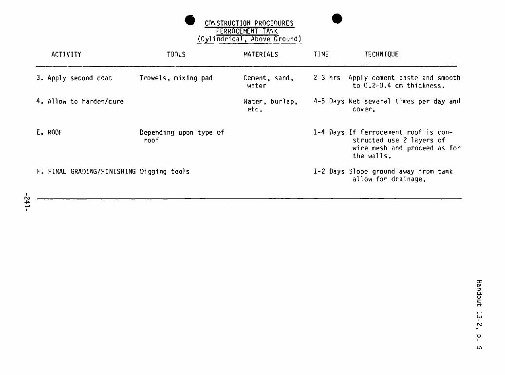
I CONSTRUCTIONPROCEDURESFERROCEMENTTANK
(cylindrical, Above Ground)
ACTIVITY TOOLS MATERIALS TIME TECHNIQUE
3. Apply second coat Trowels, mixing pad Cement, sand,water
2-3 hrs Apply cement paste and smoothto 0.2-0.4 cm thickness.
4. Allow to harden/cure Water, burlap,etc.
4-5 Days Wet several times per day andcover.
N)
E. ROOF Depending upon type ofroof
F. FINAL GRADING/FINISHING Digging tools
1-4 Days If ferrocement roof is con-structed use 2 layers ofwire mesh and proceed as forthe walls.
1-2 Days Slope ground away from tankallow for drainage.
0)
0.0C
N)
~0
.
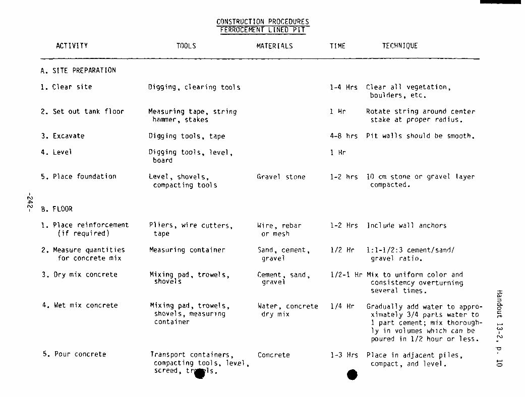
ACTIVITY
A. SITE PREPARATiON
TOOLS
CONSTRUCTIONPROCEDURESFERROCEMENTLINED PIT
TIME TECHNIQUE
1. Clear site Digging, clearing tools 1-4 Hrs Clear all vegetation,boulders, etc.
2. Set out tank floor Measuring tape, stringhammer, stakes
1 Hr Rotate string around centerstake at proper radius.
3. Excavate Digging tools, tape 4—8 hrs Pit walls should be smooth.
4. Level Digging tools, level,board
1 Hr
5. Place foundation
)
N) B. FLOOR
Level, shovels,compacting tools
Gravel stone 1—2 hrs 10 cm stone or gravel layercompacted.
1. Place reinforcement(if required)
Pliers, wire cutters,tape
Wire, rebaror mesh
1—2 Hrs mci ude wall anchors
2. Measure quantitiesfor concrete mix
Measuring container Sand, cement,gravel
1/2 Hr 1:1-1/2:3 cement/sand/gravel ratio.
3. Dry mix concrete Mixing pad, trowels,shovel s
Cement, sand,gravel
1/2-i Hr Mix to uniform color andconsistency overturningseveral times.
Mixing pad, trowels,shovels, measuringcontai ner
Transport containers, Concretecompacting tools, levElscreed, tr.ls.
1/4 Hr Gradually add water to appro-ximately 3/4 parts water to1 part cement; mix thorough-ly in volumes which can bepoured in 1/2 hour or less.
1—3 Hrs Place in adjacent piles,compact, and level.
MATERIALS
4. Wet mix concrete
5. Pour concrete
Water, concretedry mix
:30-0C
~.)N)
I—.
cD
S

N)
CA)
Measuring container
Mixing pad, trowels,shovel s
Mixing pad, trowels,shovels, measuringcontai ner
Water, burlap,etc.
TIME TECHNIQUE
1 Day 2-3 hours after pouring con-crete, dampen and cover.
ACTI VI TV
I
TOOLS
CONSTRUCTIONPROCEDURESFERROCEMENTLINED PIT
MATERIALS
Water container6. Allow to harden/cure
C. WALLS
1. Measure quantitiesfor mortar mix.
2. Dry mix mortar
3. Wet mix mortar
4. Apply first coat
1/2 Hr
1/4 Hr
1/4 Hr
Water, burlap,paper or other
Sand, cement
Sand, cement
Water, mortarmix
Mor tar
Mortar
Wire mesh,binding wire
Water, burlap,paper or other
5. Allow
6. Apply
7. Place
to set
second coat
rei nforcement
Trowel s
Trowel s
Wire cutters, pliers
Water container
Water container
1:1 cement/sand ratio.
Mix to uniform color andcons I stency.
Add water gradually untilmortar is workable; mix involumes which can be usedin 1/2 hour or less.
1-2 Hrs Apply 1.0 cm thick roughcoat to walls withoutsmoothing.
Keep protected from sunlight.
Same as (‘..1-C.4 Above.
Place 1 layer immediatelyafter applying 2nd coat; tieinto floor reinforcement.
Wet several times per day andcover.
Same as steps C.1-C.6 above.
Wet several times per day andcover.
2 Hrs
1-2 hrs
1/2—1 Hr
8. Allow to harden/cure
9. Apply inside plasterin 2 coats.
10. Allow to harden/cure
1 Day
4-8 Hrs.
1 Day
=0):30-0CC-P
N)

CONSTRUCTIONPROCEDURESFERROCEMENTLINED PIT
ACTI VI TV
D. WATERPROOFING
TOOLS MATERIALS TI ME TECHNIQUE
1. Apply fi rst coat Shovels, trowels,measuring container,mixing pad
Cement, sandwater
1-2 Hrs 1:2 cement/sand ratio appliedas in steps C.1-C.4 aboveand smoothed.
2. Apply second coat Shovels, trowels,measuring container,mixing pad
Cement, water 1—3 hrs Apply cement paste 0.2-0.4 cmthick and smooth on dayfollowing application offirst coat.
3. Allow to harden/cure Water, burlap,etc.
2-4 Days Wet several times per day andcover.
E. ROOF
N)
~ F. FINAL GRADING/FINISHING Digging tools
Depending on type of roof 2—4 Hrs Place roof on pit.
1-2 Days Slope ground away from tank
and allow for drainage.
I
=:30-0C
I—.C..)
N.)
-a
N)

Session 13: Trainer Reference Notes, p. 1
CONSTRUCTIONOF THE TANK
Introduction
The following trainer notes should be read in conjunction with Preparationsfor Construction in the Introduction to this training guide under Section1.6.4, and the two handouts for Session 13 should be given to theparticipants. General coments on preparing for the workshop and choosing theconstruction technology and system design for the demonstration system arediscussed in the former, and specific construction instructions for masonrytanks and ferrocement pits and tanks are given in the latter. Analagousdescriptions of construction guidelines and procedures will have to be writtenand distributed to the participants if other technologies are used.
•These Trainer Reference Notes cover: (1) planning the practical session; (2)organizing and supervising the work of village artisans and laborers; (3)maximizing the practical session as an experiential learning session; and (4)several specific construction recommendations.
1. Planning the Practical Session
The demonstration system of practical construction work is the major activityof this workshop. For it to be successful, it must be well planned, organizedand conducted. As mentioned in the introduction to this guide, this planningmust start several months before the start of the workshop. Once a certainconstruction technology has been selected and materials needed to build ithave been determined, the materials, workers and tools have to be assembledand prepared. If local communities are to be involved in gathering locallyavailable materials such as sand, gravel, water, boards, etc., they must beinformed and involved well enough in advance so that all these materials areat the work site before the start of the work. Adequate time is also neededfor ordering and purchasing cement, reinforcing materials, corrugated iron
•heeting. and tools——especially if these materials are being procured in ruralareas rather than a capital city. A workshop which has been planned for fourmonths cannot be delayed a week because the cement hasn’t arrived on time.
The large roof catchment system constructed during the workshop must beplanned so that it will be completed by the end of the workshop. Theconstruction schedule should be designed accordingly. Wherever possible, themajor construction procedures such as laying the concrete foundation, buildingthe walls, waterproofing the tank, and connecting the various componentsshould be scheduled to occur on Days 6-11 when the afternoons are set asidefor the practical sessions. Specific practical construction technologies andsystem designs should be chosen which permit such a construction schedule ifat all possible. Local village artisans and laborers should be hired to do as-‘ch work as necessary to keep the construction on schedule. They will have to
-245-

Session 13: Trainer Reference Notes, p. 2
start work before Day 6 and in some cases will have to start same work beforethe arrival of the participants. In planning the schedule, remember that someof the artisans or laborers may need to be involved in the other twoconstruction sessions which occur on Days 4 and 5 (Session 8 and 10).
2. Organizing and Supervising Village Artisans and Laborers
The following local artisans may be needed to work on the system’s
construction:
• Masons for all mortar and concrete construction
• Carpenters for forms, roof frames, and gutter supports
• Metal workers for reinforcing rods, mesh, and gutter construction (if
using corrugated iron sheet for gutters and downpipes)
• Plumbers for connecting pipes, faucets, pumps, etc.
In addition to these local artisans, day laborers with relevant constructionexperience will also be needed to help the artisans complete their work in therequired time and to do such tasks as gathering materials, preparing the worksite, cleaning sand and gravel, excavating the tank site, etc.
These artisans and laborers should be drawn from the local community so thatthe construction techniques demonstrated are shared with the community.Depending on the community’s interest and involvement, they can be donated andsupported by the community or paid on a daily wage basis by the projectsponsoring the workshop. If workers are provided by the community and not paidby the project, the training staff must be very sure that they understandtheir responsibilties and are available for all the work required of them.The workshop construction foreman must thoroughly brief and supervise theseartisans. They must understand that they have dual responsibilities which mayat times seem to conflict. Along with having to take primary responsibilityfor completing all the work, they also have to provide technical assistance tothe workshop participants during the practicals when they have an opportunitto do some of the work. Local artisans are not experienced trainers, and theyhave to be thoroughly briefed beforehand and adequately supervised to assurethat they help the participants learn by doing rather than taking over fromthem.
In developing the construction schedule, the lead trainer and foreman mustwork closely together to plan what specific tasks will be done by the localconstruction workers and what tasks by the participants. The workers will bedoing most of the work, but the key tasks mentioned above should he done bythe participants. The workers can complete the work started by the partici-pants or start it so the participants can complete it, whichever makes moresense given the construction schedule, procedure, and participants’ learningneeds. For example, the workers might start the wall of a masonry tank andbring it up 60-80 cm before Visit ~5 when the participants spend 2-1/2 hours
-246-
Session 13: Trainer Reference Notes, p. 3
working on the wall. The participants might do another 40—60 cm at that visitand the remaining wall could be completed by the masons after the participantsleave so that the wall is ready for plastering the next day.
3. Maximizing the Learning Experience
The trainer must keep in mind that the construction of the tank is primarily alearning event and not a constructon project. At times, the pressure tocomplete the tank by the end of the workshop makes it seem more like thelatter than the former. All efforts should be made to complete the demonstra-tion system because the participants need to learn all the constructionprocedures and see what a finished system looks like and how it operates. Itis also important for their feelings of self-confidence to have been able tocomplete an entire system. But the completion of the system should not be
S accomplished at the price of the participants’ learning.As with all activities in this workshop, the practical, “hands—on” learningobjectives of this session can only be met by following all the steps in theexperiential learning cycle. The participants will have ample opportunityduring the practical sessions to become familiar with constructing a roofcatchment system. The trainer must intervene in the practical work to help theparticipants “process” what they have learned, and to make sense out of whatthey are doing by reflecting upon their activity and pulling out the mostimportant things learned. The participants must also be brought together afterthe work to discuss what they did and what they learned and to generalize fromthe experience and relate it to the rest of what they know. Finally, they aregiven several opportunities to apply what they have learned during oneafternoon on other afternoons. The design of this session which stressesintroductory instructions, key learning objectives, and topics and samplequestions for final discussions should maximize the learning in this session.Given the fact that there are many construction technologies and systemdesigns to choose from, it is the responsibility of the workshop trainers toadapt this design to the specific construction methods chosen, to developlists of key things learned, and to develop processing and generalizing
•questions based on them.
4. Construction Recomendations
The following recommendations regarding construction are specific to the twoexamples used throughout this design.
Masonry Tank Construction (See Handout 13-2: Construction Procedures)
Material s
• Baked brick and stones should be of good quality and clean.
• Cement blocks should be well made and given adequate time to curebefore using in wall construction.
-24 7-
Session 13: Trainer Reference Notes, p. 4
• All cement mortar and concrete materials (sand, gravel, and water)should be well cleaned and free of organic matter.
• Corrugated iron sheet for roofs has to be thicker and stronger thansheeting for gutters.
Site Preparation
• The site should be well organized to accommodate up to 25 peopleworking on the tank at any one time and also to serve as a model forhow to organize a construction site. Emphasize placement and storageof materials, the area needed for mixing mortar and concrete,adequate space, and flow of workers.
• See Handout 13-1: Construction Guidelines for preparing and layingwall and floor footings.
• Set construction schedule for these tasks so that as much work aspossible is being done while the participants are visiting the site.
Wall Construction
• Follow Handout 13-1: Construction Guidelines and Handout 13-2
:
Construction Procedures• 1:4 cenient:sand ratio is recommended for laying bricks, etc., rather
than a less rich mixture (1:5 or 1:6) because of the need for thetank to hold water and be leakproof.
• A finished masonry wall only needs one day to cure before startingplastering. It should have several days of curing before placing aheavy cover on it.
Floor Construction
• Follow guidelines and procedures handouts.
• 1:1-1/2:3 cement-sand-gravel is reconii~ended because it is richerthan 1:2:3 or 1:2:4 and floor has to hold water.
• Reinforcing rod grill for the floor should be made with 6 mm or 8 mmre-rod tied by wire into a grill with spacing of from 10 to 20 cmapart. It should he tied into re-bar (8 or 10 mm) embedded vertical-ly in the inside lip of the wall footing, or coming out horizontallyfrom under the first course of bricks.
Roof
• It is recommended to make the roof out of corrugated iron sheet anda sturdy wood board frame rather than trying to lay reinforcedconcrete slabs and place them on the tank as a cover. The former isless expensive and easier to construct in a village. It should be
-248-

Session 13: Trainer Reference Notes, p. 5
bolted to the top of the wall securely so that it cannot be liftedoff the tank. The manhole cover should he made with a lock. The roofshould slop so that water from the system or rainfall will flow offthe roof. Reinforced concrete slabs are not suitable for the demon-stration tank because of their cost, weight, the time needed forcuring (2 weeks) , and the technical sophistication of building slabswhich can span two meters.
Ferrocement Lined Pit (See Handout 13—2: Construction Procedures)
Design Issues
• The pit can be built to hold large~quantities of water but shouldnot be made much bigger than 10 m for the purposes of the demon-stration so it can be completed in the time allotted for construc-tion during the workshop. It can be made in any form (rectangular,square, or cyclindrical). It should have an above-ground portioncoming up 30 cm so that water does not run into the pit and peopledo not walk on the cover. The pit should not be deeper than one anda half meters and the total height of the tank should be under twometers so that it is easy for the participants to work in it. Themeans of drawing or piinping water out of the tank will have to bedecided before the roof is constructed.
Preparation
• Prepare the site as in the above notes for a masonry tank.
• Construct the above-ground wall out of masonry using the notes,guidelines, and procedures for that method. Excavate the pit inline with the inside wall and footings of the masonry wall, andbuild the ferrocement wall against the masonry wall as well as the
surface of the pit. See illustration below.
.
-249-

Session 13: Trainer Reference Notes, p. 6
• Follow instructions in guidelines and procedures handouts, and theabove trainer notes for masonry tank floors.
Walls
• As with all mortar construction, use as dry a mixture of mortar asworkable. Surpervise local masons carefully as they prefer workingwith a very wet mortar which is not suitable for this type ofconstruction.
• Reinforcement for the wall should be 1” (2.54 cm) mesh chickenwire. The thinner the wire and smaller the holes in the mesh, thebetter it is for reinforcing.
rod to secure roof to wall
3Ocr’~
i~J////// ///
0 cm footing /
plaster wallwith rein-forcing mesh
Floor
//
J,/ ,~ / / / 1/
~10 cm foundation for footing
//
/ (qrou~) /
/
/
2///
7/
/ / /
S
.
-250-

Session 13: Trainer Reference Notes, p. 7
Roof
• The roof should be strong enough to support the weight of an adult,
and should be designed to be visible and obvious.• The roof should be made to support a pump or other mechanism for
lifting water. If a door is built into the roof it should bewatertight when closed.
• See above notes on roofs for masonry tanks.
-251-


.
SESSION14 -

I.
S
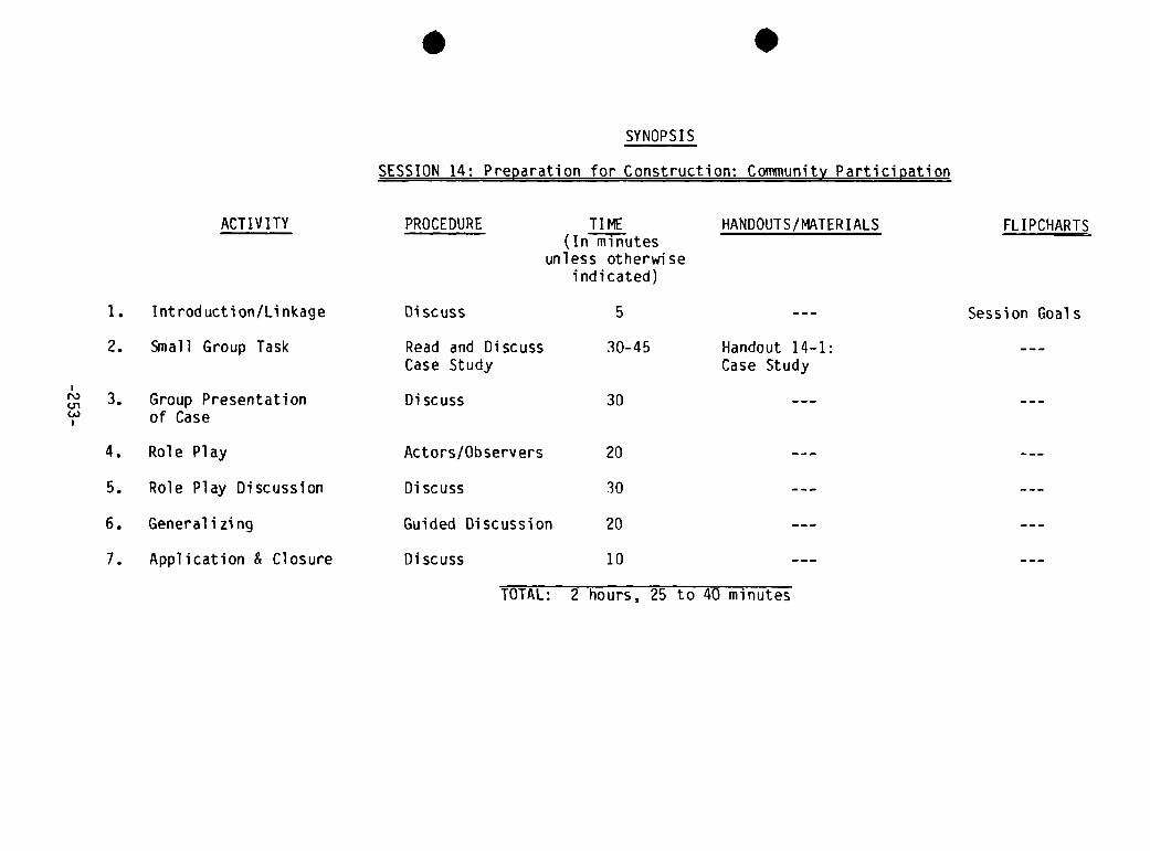
SYNOPSIS
SESSION 14: Preparation for Construction: Community Participation
ACTIVITY
1. Introduction/Linkage
2. Small Group Task
3. Group Presentation
of Case
4. Role Play
5. Role Play Discussion
6. Generalizing
7. Application & Closure
PROCEDURE
Discuss
Read and DiscussCase Study
Discuss
Actors /Observers
Discuss
Guided Discussion
Discuss
TI ME(In minutes
unless otherwiseindicated)
HANDOUTS/MATERIALS FL I PCHARTS
N)Ui(A)
Session Goals5
30-45 Handout 14—1:Case Study
30
20
30
20
10
TOTAL: 2 hours, 25 to 40 minutes

.

Session 14: Preparation for Construction: Community Participation
GOAL Total time: 2 hours & 25-40 mm.
To consider the process of organizing the community for the project.
OBJECTIVES
At the end of this session the trainees will be able to:
• Develop strategies for involving the community in organizing the tank
construction
• List some of the problems which can occur when insufficient community
participation has taken place. • State the linkage between community social assessment and community
proj ect involvement
OVERVIEW
In the session on conducting a community social assessment, the trainees con-sidered the minimum social criteria necessary for developing a rainwater roofcatchment project, but minimal consideration was given to the process of howto actually work with the community in doing it. This session takes theproject development process a step further and considers some of the elementsnecessary for actual community participation at the point just prior toconstruction. The session uses a case study which poses certain problems whichcan occur when proper community participation has not been planned.
ACTIVITIES
1. Introduction/Linkage Time: 5 minutes
Refer back to Session 4 on community social assessment and explain the linkageto this session (explained above in the overview). Explain the goals of thesession. Lead into the next step which uses a case study, by telling thetrainees that the exercise will consider the factors necessary for engagingthe community members in organizing to carry out the construction work andcommitting themselves to the next step in the project.
2. Read and Discuss Case Study Time: 30-45 minutes
Distribute Handout 14—1: Case Study. Divide the group into two smaller groupsand ask them to read the case study individually and then discuss the tasks atthe end of the case study and prepare their answers for the full groupdiscussion.
-255-

3. Group Presentation of Case Time: 30 minutes
Discuss the first two questions in the case study, reserving the communitymeeting strategy for the next step, which is a role play. Each group should hegiven the opportunity to discuss its points.
(Note: One of the things which may need to be asked is the question of therole of women in the project organization and the relationship of the twowomen on the project coninittee to the men who could provide the construction.The group should consider some of the possible solutions to the problem withinthe appropriate cultural context.)
4. Role Play (Optional, See Trainer Notes) Time: 20 minutes
Ask one of the two groups to select one or two of their members to play therole of the community health worker. Give this person time to review thestrategy which his/her group prepared and be ready to interact with acommunity health committee in a role play. While this role player is pre~paring, ask the other group members to think about how they will act as thecommunity health committee. The people who are not role playing can be observ-ers. Ask them to get together and decide what some of the things are that theywill observe (for example, community reactions, approach of the worker to theconinittee, non—verbal communication, etc.).
When everyone is well prepared, conduct a short role play. Ten minutes or lessshould be enough time.
5. Role Play Discussion (Optional, See Trainer Note) Time: 30 minutes
Process the role play by “debriefing” first the role players, then the
observers. A suggested list of questions follows:
Role Players:
• Community Group: What reactions do you have about the way the healthworker worked with you? What worked well? Was the strategy successful~What might have been more effective?
• Community Worker: What was the strategy you had planned to use? Do youfeel it worked? What might you do differently next time?
• Observers: From your point of view, what did you see happening in therole play? What worked well? What would you do to make the strategy workbetter? Note: if someone has a good suggestion, ask this person to tryout this improved strategy by doing another role play. Then discuss thisrole play following the same format of questions above. This is suggestedif time permits.
—2 56-

6. Generalizing from the Session Time: 20 minutes
Draw out what the group has learned from both the discussion of the case studyand the role play by asking the following questions:
• What are the best strategies for involving the community in organizing towork on tank construction; what are the essential steps and minimumcriteria? (List on a flipchart.)
• What are the major problems which may occur when the community is notproperly involved?
• How can one assess if a community will cooperate in a project during theinitial social assessment and avoid cooperation problems at a laterstage, such as the construction phase?
• What other things can we learn from this session?
Application and Closure Time: 10 minutes
Ask the trainees to note in their project guides what they have learned fromthis session that they want to make sure they do not forget when they developtheir own projects in the future. Ask for one or two examples from the group.Refer back to the session objectives and check to see if they have beenachieved. Close the session.
TRAINER NOTES
1. If this group is very experienced at community promotion, the role playmay not be necessary. It is designed to enhance or build skills forworking with community people. If the role play and the role playdiscussion (Steps 4 and 5) are eliminated, an additional 50 minutes isgained. Some of this time may be used to deepen the discussion andbroaden the generalization of the case study.
MATERI AL S
- Flipchart with goals and objectives of the session- Handout 14-1: Case Study
-257-

S
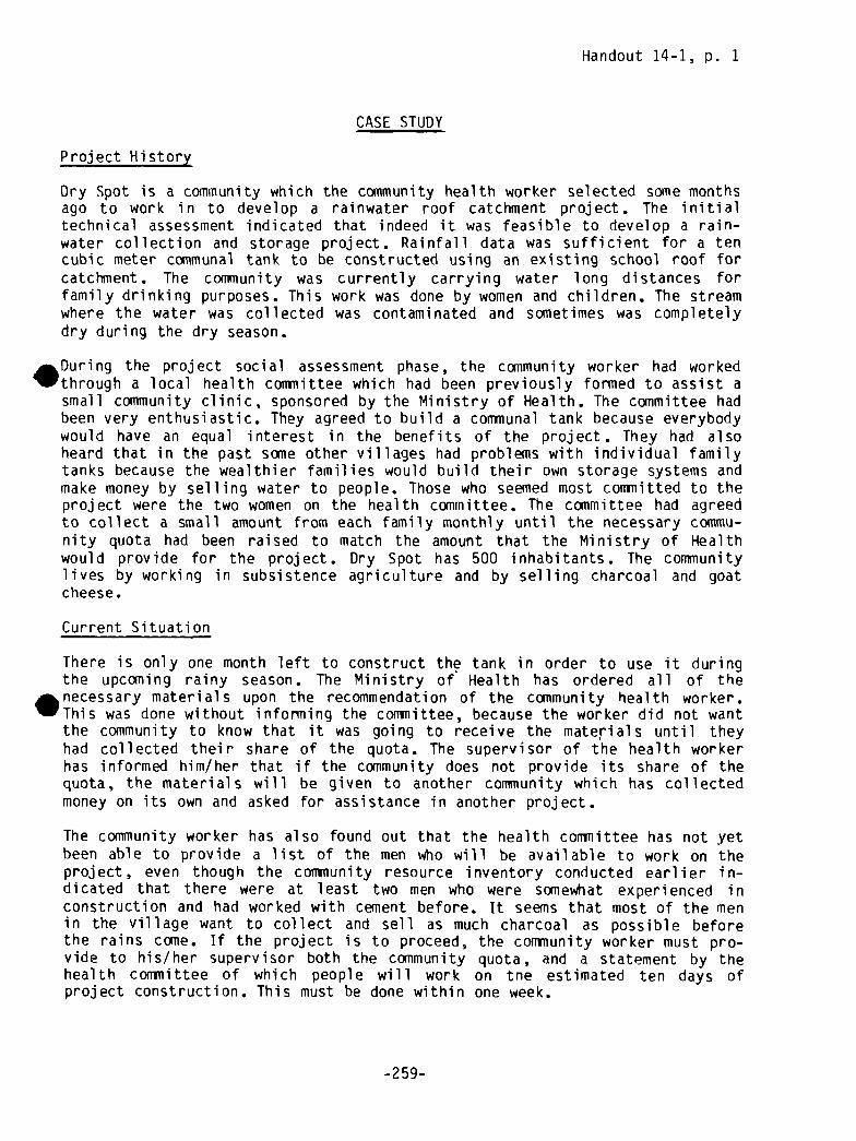
Handout 14-1, p. 1
CASE STUDY
Project History
Dry Spot is a community which the community health worker selected some monthsago to work in to develop a rainwater roof catchment project. The initialtechnical assessment indicated that indeed it was feasible to develop a rain-water collection and storage project. Rainfall data was sufficient for a tencubic meter communal tank to be constructed using an existing school roof forcatchment. The community was currently carrying water long distances forfamily drinking purposes. This work was done by women and children. The streamwhere the water was collected was contaminated and sometimes was completelydry during the dry season.
. During the project social assessment phase, the community worker had workedthrough a local health committee which had been previously formed to assist asmall community clinic, sponsored by the Ministry of Health. The committee hadbeen very enthusiastic. They agreed to build a communal tank because everybodywould have an equal interest in the benefits of the project. They had alsoheard that in the past some other villages had problems with individual familytanks because the wealthier families would build their own storage systems andmake money by selling water to people. Those who seemed most committed to theproject were the two women on the health committee. The committee had agreedto collect a small amount from each family monthly until the necessary commu-nity quota had been raised to match the amount that the Ministry of Healthwould provide for the project. Dry Spot has 500 inhabitants. The communitylives by working in subsistence agriculture and by selling charcoal and goatcheese.
Current Situation
There is only one month left to construct the tank in order to use it duringthe upcoming rainy season. The Ministry of Health has ordered all of the. necessary materials upon the recommendation of the community health worker.This was done without informing the conTnittee, because the worker did not wantthe community to know that it was going to receive the materials until theyhad collected their share of the quota. The supervisor of the health workerhas informed him/her that if the community does not provide its share of thequota, the materials will be given to another community which has collectedmoney on its own and asked for assistance in another project.
The community worker has also found out that the health committee has not yetbeen able to provide a list of the men who will be available to work on theproject, even though the community resource inventory conducted earlier in-dicated that there were at least two men who were somewhat experienced inconstruction and had worked with cement before. It seems that most of the menin the village want to collect and sell as much charcoal as possible beforethe rains come. If the project is to proceed, the community worker must pro-vide to his/her supervisor both the community quota, and a statement by thehealth cormiittee of which people will work on tne estimated ten days ofproject construction. This must be done within one week.
-259-
Handout 14-1, p. 2
Task in Small Groups
1. List the possible mistakes the project developer has made.
2. Analyze the above case study. Discuss and decide what you would do.
3. Prepare a strategy for a meeting with the health committee which willaddress the problems of collecting the quota and organizing the conuliunityworkers.
-260-

SESSION 15


SYNOPSIS
SESSION 15: Developing a Plan for Rainwater Roof Catchment System Monitoring and Maintenance
ACTIVITY PROCEDURE TI ME(In minutes
unless otherwiseindicated)
HANDDIJTS/MATERI ALS FLIPCHARTS
1. Introduction Discuss 10 Session Goals
2. Monitoring/Maintenance Discuss/Brainstorm 30 Maintenance Checklist
3. Lecturette onDisinfection
Chlorine Test Kit,Bucket and Rope,Bleach and Chlorine,Measuring Cup, MeterSt i ck
4. Small Group Work Three Groups 45
5. Small Group Strategies Presentati on/Discussion
30 Handout 15—1: MaintenanceChecklist
6. Presentations toVillage Groups
7. Generalizing and
Applying
8. Closure
In Village 45
N)
I-.
Lecturette 30
Discuss 30
Discuss 5
TOTAL: 3 hours, 45 minutes


Session 15: Developing a Plan for Rainwater Roof Catchment~y~~emMonitoring and Maintenance
GOAL Total time: 3 hours & 45 mm.
To learn how to develop and co1mnunicate a monitoring and maintenance plan forthe rainwater roof catchment system which the community will be able to use.
OBJECTIVES
At the end of the session, the trainees will be able to:
• Describe the importance of monitoring and maintenance activities to the
life and use of the rainwater catchment system
• Describe the basics of system monitoring and maintenance
• Develop a strategy to communicate basic procedures relating to watertransportation and sanitary water extraction to community members
• Develop a strategy to communicate system monitoring and maintenanceprocedures to community members.
OVERVIEW
The results of this session are critical to the long—range success of therai nwater roof catchment project. There are many such systems in the worldthat have been abandoned because they were not maintained (and not properlydesigned in the first place). This session is designed to cover some basicinformation and allow local project developers to adapt their knowledge tolocal conditions and develop strategies which have a good chance of success.
This session should take place with the community workers during construction.
ACTiVITIES
1. Introduction Time: 10 minutes
Present the overview in your own words and explain the goal and objectives of
the session.
2. Discussion/Brainstorming Time: 30 minutes
Open the discussion by asking the participants whether they think monitoringand maintenance are necessary for a rainwater catchment system. Lead them to aconsideration of the activities necessary for inspecting all aspects of thesystem by dealing in turn with each of the major parts of the system asfollows:
-263-
1) Roof: leaks, debris, etc.2) Gutters: leaks, debris, bird nests, incline, etc.3) Down Spout: leaks, debris, foul flush system, etc.4) Tank: cracks, sediment, quality of water, screen for overflow pipe,
sanitary conditions, etc.
Write on a flipchart the points they mention as being necessary for theinspection of each part of the system, adding any that may be missed (seeTrainer Note 1). When all pertinent points have been listed, ask the traineeswhen the critical inspection times are. This should bring out the end of therainy season, the end of the dry season, and after any major storms.
Explain that after a lecturette on disinfection procedures they will work insmall groups to develop presentations for appropriate village groups regardingmonitoring, disinfecting and maintenance of the system.
3. Lecturette on Disinfection Time: 30 minutes
First define disinfection as the reduction of pathogenic germs in an area andthen list the most common types of disinfectants: chlorine, iodine, perman-ganate of soda, CaCI2O9 calcium hypochiorite. Explain that chlorine is themost common disinfectant used for water and that the most available and leastcostly form of chlorine is bleach used for laundry (sodium hypochiorite).
Describe the qualities and effects of chlorine as a disinfectant. Explain theoxidation effect chlorine has on organic matter and how its effect diminishesas the temperature of the water rises. Also explain that the effect of chlo-rine is related to the time it has to work, i.e. disinfection is proportionalto the concentration of the disinfectant and the time of contact (D)~ C x 1).
(Optional )*
The normal dosage recommended is 1 mg chlorine for each liter of water.An instriiiient called a chlorine test kit is used to measure the residualchlorine left after the oxidation or disinfection process.
To disinfect a tank or well, put the chlorine in a bucket and pour it~into the water in the tank or well. Let it work for fifteen minutes andthen measure the residual chlorine with a chlorine test kit.
Give practical experience at calculating the amount of chlorine needed todisinfect the demonstration tank and a pre—selected village well.
4. Small Group Work Time: 45 minutes
Divide the group into two sub-groups and assign them the following tasks:
Group 1: Prepare a 30 minute presentation for members of the Village HealthConiiiittee on monitoring and maintenance aspects/responsibilities for the roofcatchment system.
* If chlorine test kits are available.
-264-
Group 2: Prepare a 30 minute presentation for the users of the demonstrationsystem on how to extract, transport, and store the water in a sanitary manner.
Explain that they have 40 minutes to develop their strategy for the pre-sentations. This will be followed by a brief explanation and discussion oftheir strategy before the whole group.
5. Presentation/Discussion of Small Group Strategies Time: 30 minutes
A reporter from each group presents how they plan to communicate this informa-tion to the community (five minutes). Then the trainer leads a five minutediscussion on what was good about it and on suggestions to improve thestrategy. Stress that this is definitely the time to offer constructivesuggestions and not to criticize.
Presentations to Village Groups Time: 45 minutes
The two groups from step 4 make their presentations in the village. Make surethat adequate arrangements have been made for meeting places for each groupand that the respective audiences have been notified and have agreed toattend.
7. Generalizing and Applying Time: 30 minutes
After the groups have had the opportunity to try out their strategies in thedemonstration community, bring them back together for a half hour and draw outwhat they have learned from this experience. Suggested questions are:
• Did your strategies work?• How did the community receive your efforts?• What did you learn from this exercise?• What will you do differently next time you do this?
Closure Time: 5 minutes
Refer back to the objectives of the session to check goal attaimient.
TRAINER NOTES
1. In Step 2, add these points to the discussion if they do not arise:
a. The roof, gutters and cistern should be periodically inspected toidentify problems (cavings, cracks, and leaks; potential environ-mental problems such as ground shifts or slides; or behavioralproblems such as children playing in or on the system).
b. Gutters should be replaced when worn out or waterproofed whenneeded or realigned when the slope is altered.
-265-

c. Debris should be swept off roof and gutters when needed.
d. The cistern water shculd be inspected for taste and odor.
e. The cistern should be cleaned periodically (at the beginning of the
rainy season or at the end of the dry season).
f. The environment should he monitored for health hazards such as
standing water or animal contamination.2. If time permits, the trainer may wish to demonstrate how to disinfect the
tank on the last day of the workshop as a follow-up practical exercise tothis session. This will only be possible if the tank is completed andoperational. If not, the trainer could use a nearby well if one wereavailable. For this reason materials for disinfecting and testing areincluded in the materials list.
3. In Step 6 the group will be making presentations to community groups atthe work Site. This will require advance planning on the part of th~trainers. It is suggested that those people who will be taking care ofthe tank (such as a village health committee) and those who will behandling the water (such as school children or others) be prepared toreceive these two presentations.
4. Handout 15-1: Maintenance Checklist is included as a reminder forpromoters to use after the workshop. It is suggested that this bereferred to during Step 8 (closure). Each participant may wish to modifythis checklist for his/her- own use.
MATERIALS
- Flipchart with session goal and objectives- Flipchart for Step 2- Flipchart for Step 3- Chlorine test kit (optional)- Bucket and rope— Bleach/chlorine- Measuring cup- Meter stick- Handout 15-1: Maintenance Checklist
-266-

Handout 15-1
.
MAINTENANCE CHECKLIST
WHO ISFREQUENCY ACTIVITY RESPONSIBLE
A. At the beginning of 1. Engage foul flush mechanismeach rain
B. At the end of each 1. Clear debris from catchment areadry period
2. Check gutter supports and repair
C. At the end of each dry 1. Clean gutters of debrisperiod and weekly duringrainy periods 2. Check and clean screen at downpipe
3. Check gutters for leaks and repairaccordingly
4. Check gutters for overflowing andadjust position or slope accordingly
5. Check drainage around tank
D. Monthly throughout the 1. Check tank cover and ventilationyear
2. Check tank for leakage
E. Weekly throughout the 1. Check water quality in tank and
year clean out if necessary
F. Annually 1. Clean out and disinfect tank
-26 7-

.

. .
SESSION 16

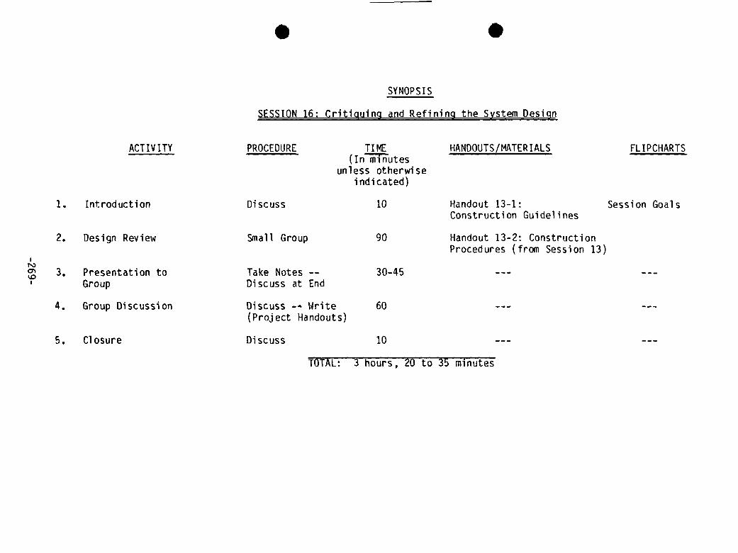
ACTIV ITY
1. tntroduction
2. Design Review
3. Presentation toGroup
4. Group Discussion
5. Closure
Discuss
Small Group
Take Notes --
Discuss at End
Discuss —~ Write(Project Handouts)
Discuss
. .
SYNOPSIS
SESSION 16: Critiquing and Refining the System Design
PROCEDURE TIME HANDOUTS/MATERIALS(In minutes
unless otherwiseindicated)
FLIPCHARTS
Session GoalsHandout 13—1:Construction Guidelines
Handout 13-2: ConstructionProcedures (from Session 13)
10
go
30-45
60
10
TOTAL: 3 hours, ~U to 35 minutes

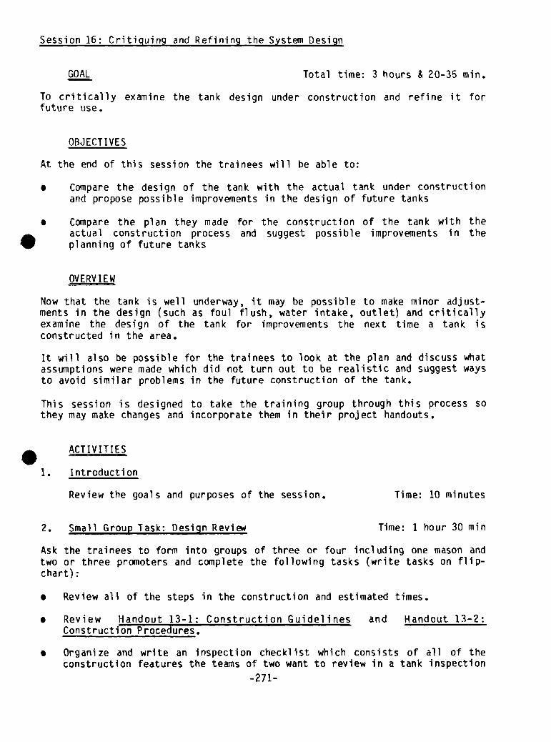
Session 16: Critiquing and Refining the System Design
GOAL Total time: 3 hours & 20-35 mm.
To critically examine the tank design under construction and refine it for
future use.
OBJECTIVES
At the end of this session the trainees will be able to:
• Compare the design of the tank with the actual tank under constructionand propose possible improvements in the design of future tanks
• Compare the plan they made for the construction of the tank with theactual construction process and suggest possible improvements in theplanning of future tanks
OVERVIEW
Now that the tank is well underway, it may be possible to make minor adjust-.ments in the design (such as foul flush, water intake, outlet) and criticallyexamine the design of the tank for improvements the next time a tank isconstructed in the area.
It will also be possible for the trainees to look at the plan and discuss whatassumptions were made which did not turn out to be realistic and suggest waysto avoid similar problems in the future construction of the tank.
This session is designed to take the training group through this process sothey may make changes and incorporate them in their project handouts.
ACTIVITIES
1. Introduction
Review the goals and purposes of the session. Time: 10 minutes
2. Small Group Task: Design Revie~ Time: 1 hour 30 mm
Ask the trainees to form into groups of three or four including one mason andtwo or three promoters and complete the following tasks (write tasks on flip-chart):
• Review all of the steps in the construction and estimated times.
• Review Handout 13-1: Construction Guidelines and Handout 13—2
:
Construction Procedures.
• Organize and write an inspection checklist which consists of all of theconstruction features the teams of two want to review in a tank inspection
-271-

• Visit the tank and critically review each design feature, considering whatmodifications should be made the next time a tank is constructed.
• Organize a presentation fcr the rest of the group on what changes theywould make and be prepared to present their recommendations in a 5 to 10minute time period.
3. Presentations to Group Time: 30-45 minutes
Ask each group to present its recommendations on design modifications andconstruction changes to the full group. The presentations will be easier tomanage if every one gets to present his/her recommendations before they arediscussed by the group. The group can take notes, holding comments until thenext step.
4. Group Discussion Time: 1 hour
Conduct a group discussion based upon the recommendations presented previous-ly. Try to arrive at a consensus on design and construction modifications,recording the agreed upon modifications. At the end, give the group time torecord these changes in their handouts.
5. Closure: Generalizations and Applications Time: 10 minutes
Ask the trainees to review all they have done in this session. Ask if theycould have forseen any of these changes when they first started. Ask whatfactors will need to be considered as contingencies the next time theyconstruct a tank on their own.
TRAINER NOTE
In the introduction some explanation may be necessary to explain that thissession is not intended to be a review of how to design the system (an earliersession); rather it is Intended as a way to learn from mistakes so that theewill not be repeated when the participant works alone on a project after theworkshop.
MATERIALS
— Handouts 13—1 and 13-2 from Session 13
—272-

.

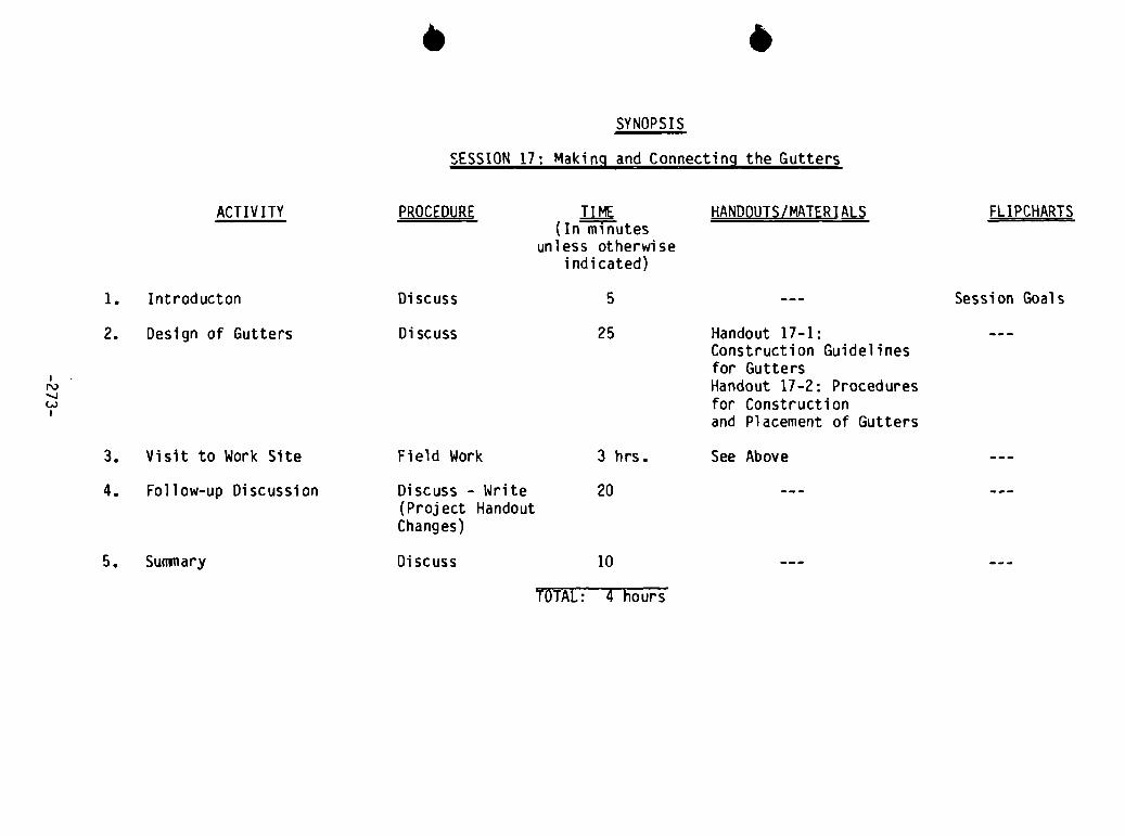
o eSYNOPSIS
SESSION 17: Making and Connecting the Gutters
ACTIVITY PROCEDURE TIME(In minutes
unless otherwiseindicated)
HANDOUTS/MATER1 ALS FLIPCHARTS
Handout 17-1:Construction Guidelinesfor GuttersHandout 17-2: Proceduresfor Constructionand Placement of Gutters
See Above
N)
C..)
51. Introducton Discuss
2. Design of Gutters Discuss 25
3. Visit to Work Site Field Work 3 hrs.
4. Follow—up Discussion Discuss - Write(Project HandoutChanges)
20
5. Summary Discuss 10
Session Goals
TOTAL: 4 hours


Session 17: Making and Connecting the Gutters
GOAL Total time: 4 hours
To learn the basic steps and procedures in constructing and connecting
gutters.
OBJECTIVES
At the end of the session, the trainees will be able to:
• Make simple gutters, using the materials used in the construction of thegutters of the demonstration tank
• Install gutters on roofs similar to the one used in the demonstrationproject
Discuss how to avoid some of the problems which may occur during theinstallation of gutters
OVERVIEW
In this session the trainees will review the design of the gutters in theprevious session and their selection of materials and procedures for install-ing the gutters. They will also have practical experience with the construc-tion and installation of such gutters. During the practical work the trainershould point out what problems to avoid and what may happen if the gutters areimproperly made or installed.
ACTIVITIES
1. Introduction Time: 5 minutes
Give the group the information in the overview and state the goals and
objectives. Answer any questions.
2. Design of Gutters Time: 25 minutes
Review the design of the gutters which was developed in the earlier sessions.Discuss the rationale for the choice of materials and review the plans thatwere made for gutter construction and placement. Emphasize the plans forbuilding the gutter supports, attaching the gutters to the roof so that theycatch all the runoff, and making sure they have an adequate slope to carry thewater to the tank fast enough so they do not overflow or leak.
-2 75-
3. Visit to the Work Site Time: 3 hours
Read the Trainer Reference Notes which follow the handouts for this sessionfirst and plan the construction activity accordingly. Divide the group intowork teams. Explain the work to be accomplished in the next three hours. Givethe specific teams their tasks and say how much time they will have beforetrading tasks with another team (if there are several different tasks to beaccomplished and not enough tools or space for each team to do all the tasks),and get them started.
If it has been decided to spend most of the time on gutter installation ratherthan construction, show the participants the completed gutters and demonstratehow they were constructed based upon the design decided upon in Sessions 6 and16. Answer any questions about the construction procedures. Review the mainpoints made in Step 2 on installing the gutters and then get the group workingon that task.
Bring up the following key learning objectives at appropriate times during thework. See Trainer Refernece Notes and handouts for details.
• Dimensions and form of the gutters
• Costs of alternative guttering technologies (from Session ~)
• Any special problems in gutter construction (check with foreman)
• How to securely attach gutl:ers to roof
• How to line up slope of gutters using measuring tape or ruler and string
• Placement of gutter in relation to roof to catch heavy and light rains
• Connection of gutter to downspout or foul flush mechansim
• Connecting lengths of gutter to minimize leaking. Are resin sealants or
tar locally available?
• What tools and skills are needed to accomplish the task?
• How much time does the task take?
When the work is completed, reconvene the group at the work site or return to
the classroom for the next step i.e., the follow-up discussion.
4. Follow-Up Discussion Time: 20 minutes
Discuss the experience the trainees have had and answer any questions they mayhave had. Review the changes in the design (if any) which had to be made andhow these could have been avoided by better planning. The three basic ques-tions for processing are: What did you learn? What would you change next time?And what have you learned which you could apply to the rest of your work?
-276-

5. Summary Time: 10 minutes
Summarize the two discussions. Review key things learned. Mention the
afternoon practical session on completing the system.
MATERIALS
- Flipchart with goals and objectives.- Handout 17—1: Construction Guidelines for Gutters- Handout 17-2: Procedures for Construction and Placement of Gutters— Construction materials (based on chosen technology and materials)
Note: You may choose to have gutters, downspout, etc. built before thesession and ready for installation. See Trainer Reference Notes.
- Construction and installation tools and equipment depending on technologyand design
-277-

.
S

Handout 17-1, p. 1
CONSTRUCTIONGUIDELINES FOR GUTTERS*
Materi als
The gutter material selected should be light in weight, water resistant, andeasily joined. To reduce the number of joints and thus the likelihood ofleakages, a material which is available in long straight sections is pre-ferred. Some examples of materials coniiionly used for gutters are split bamboo,wood, and metal sheeting.
Size and Shape
The gutter must be large enough to channel water from heavy rains withoutoverflowing. The shape is also very important. If the gutter is too shallow itmay overflow. If it is too narrow the water from the roof may shoot over thegutter and be lo~st. For most roof catchments a gutter with a cross-sectionalarea of 70-80 cm is sufficient for the range of slopes recommended here. Theminimum recoarnended width for square and semi-circular gutters is 8 cm. For atriangular shaped gutter the width should be at least 10 cm. The minimum re-commended depth is 7.0 cm for any gutter.
a. Bamboo splitlengthwise
seamtarred
b. joining 2 pieces ofbamboo
Figure 2, Bamboo Guttering Joining
Sections.
* From Keller, op.cit.
Figure 3, Alternative Forms ofGutteri ng.
rimo~’e-~
Institute for Rural Water, 1982 (draft), by pertnisslon
Basics. October 1978, page 4
-279-

Slope
Handout 17-1, p. 2
The gutter should be placed at a uniform slope to prevent water from poolingand overflowing the gutter. For most roof catchments the slope should be inthe range of 0.8 cm/meter to 1.0 cm/meter.
Location
The gutter must collect all of the water running off the roof during light andheavy rainstorms. To achieve this the gutter should be located so that theroof overhangs the gutter by 1 or 2 cm, and the gutter extends beyond the edgeof the roof by at least 7 cm.
Supports
The gutter must be well supported. The number of supports depends upon thetype of guttering material but it is reconiriended that most gutters be sup-ported at least every 50-60 cm. The simplest means of support is by tying wirearound the gutter and fastening it to the roof. The gutter can also be nailedto the roof or be provided with wooden supports underneath.
Joints
All joints should be leak proof. Joints can be sealed using tar, pitch or asimilar material. Strips of plastic can also be laid in the gutter to preventleakage. The joining material should be one which does not contaminate thewater.
-280-
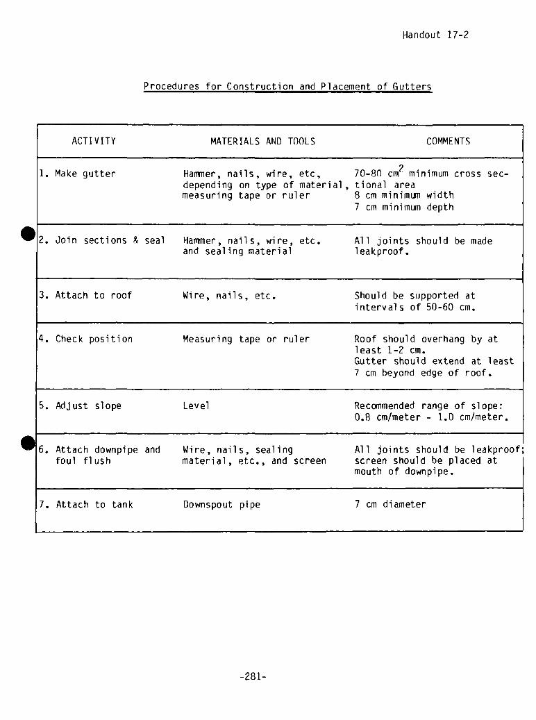
Handout 17-2
Procedures for Construction and Placement of Gutters
ACTIVITY MATERIALS AND TOOLS COMMENTS
1. Make gutter Hammer, nails, wire, etc, 70—80 cm2 minimum cross sec-depending on type of material , tional areameasuring tape or ruler 8 cm minimum width
7 cm minimum depth
2. Join sections & seal Hammer, nails, wire, etc. All joints should be madeand sealing material leakproof.
3. Attach to roof Wire, nails, etc. Should be supported atintervals of 50-60 cm.
4. Check position Measuring tape or ruler Roof should overhang by at
least 1-2 cm.Gutter should extend at least7 cm beyond edge of roof.
5. Adjust slope Level Recommended range of slope:0.8 cm/meter - 1.0 cm/meter.
6. Attach downpipe and Wire, nails, sealing All joints should be leakproof;foul flush material, etc., and screen screen should be placed at
mouth of downpipe.
7. Attach to tank Downspout pipe 7 cm diameter
-28 1-

.

Session 17: Trainer Reference Notes, p. 1
CONSTRUCTINGAND PLACING THE GUTTERS
Constructing and placing the gutters, like building the tank, is probably nota task which can be completed by the participants by themselves in the timealloted for the practical demonstration. The practical session is designed tolet them have hands-on experience with the construction and placementprocedures so they understand them well enough to supervise the villageartisans responsible for the actual construction. They should have anopportunity to learn how to do these tasks, but time may not permit them tocomplete all the work themselves. The specific work assigned to theparticipants during the three hours at the work site will depend on theirlearning needs, the guttering technology, and the size of the roof surface tobe guttered.
For example, if a large roof is being guttered on both sides, the participants. might do one side and the workers the other. If a simple but time-consumingtechnology i s being used to make more than 10 meters of gutters, it isreconinended that the gutters be made prior to this session and be ready to beinstalled. One of the workers can briefly demonstrate how the gutters weremade (such as flattening a small piece of corrugated iron sheeting, cutting itin half lengthwise, bending it into a semi-circular gutter and tying it inthat shape with wire). Answer any questions. This will permit the participantsto concentrate on the more difficult task of installing the gutters.
To whatever extent possible, in installing the gutters, the participantsshould learn by doing. This does not include making time-consuming mistakes,but should include solving the major installation problems such as how to setthe 0.8 to 1.0 percent slope, how far away from the roof the gutter has to beto catch a heavy rain, and how to attach the gutters securely to the roof. Thetrainer and construction foreman should answer their questions, but theyshould be allowed to make most of the decisions and try them out.
One way of lining up the gutters to follow the chosen slope is with a string.The longer the run of gutters and the less friction in the material (corru—
S gated iron sheet compared to wooden boards) the less the slope has to be.Choose a slope from 0.8 to 1.0 cm per meter and measure the total length ofthe gutters. A gutter 15 meters long will have to be 12 to 15 cm lower at theend by the tank depending on the chosen slope. Fasten a piece of gutter inplace at the far end of the roof away from the tank (the start of the gutter)and measure the distance from the bottom of the gutter or a fixed point on thegutter support to the edge of the roof. Then add the number of centimeters,determined by the total length of the gutter, to that figure and fix thesupport or gutter to the roof at the end of the gutter. Run a string from onepoint to the other and line up the gutters or supports with the string. Seeillustration below:
r-o o— tOrn
I Tcr.
-283-
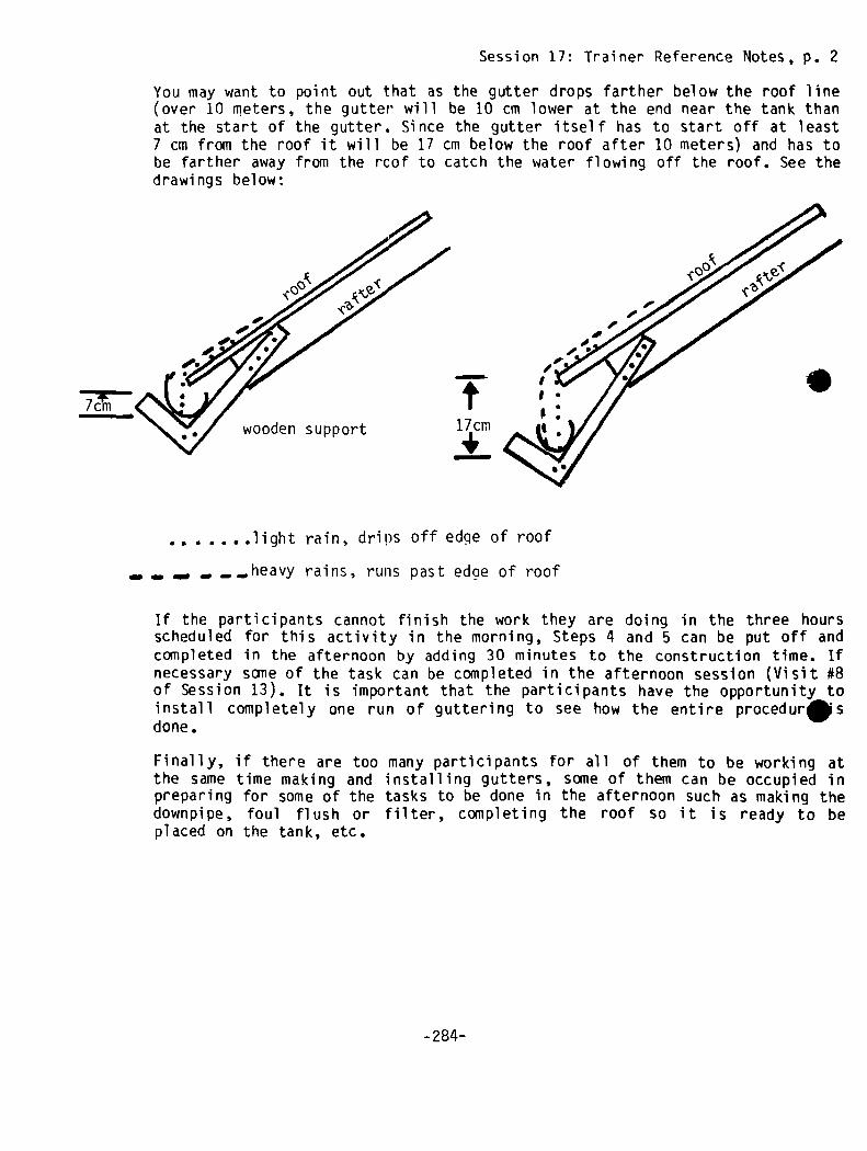
Session 17: Trainer Reference Notes, p. 2
You may want to point out that as the gutter drops farther below the roof line(over 10 meters, the gutter’ will be 10 cm lower at the end near the tank thanat the start of the gutter. Since the gutter itself has to start off at least7 cm from the roof it will be 17 cm below the roof after 10 meters) and has tobe farther away from the roof to catch the water flowing off the roof. See thedrawings below:
.light rain, drips off edge of roof
_,.,.,heavy rains, runs past edcie of roof
If the participants cannot finish the work they are doing in the three hoursscheduled for this activity in the morning, Steps 4 and 5 can be put off andcompleted in the afternoon by adding 30 minutes to the construction time. Ifnecessary some of the task can be completed in the afternoon session (Visit #8of Session 13). It is important that the participants have the opportunity toinstall completely one run of guttering to see how the entire proceduresdone.
Finally, if there are too many participants for all of them to be working atthe same time making and installing gutters, some of them can be occupied inpreparing for some of the tasks to be done in the afternoon such as making thedownpipe, foul flush or filter, completing the roof so it is ready to beplaced on the tank, etc.
7c~i
/
wooden support
T17cm
.
-284-

SESSION 18


SYNOPSIS
SESSION 18: Planning Applications of the
ACTIVITY PROCEDURE TIME(In minutes
unless otherwiseindicated)
HANDOUTS/MATERIALS FL IPCHARTS
1. Introduction Discuss 5 Session Goals
N)OD(3,
2. Unresolved Questions
3. Changes in the ProjectProcess
Review; Discuss
Li St
Brai nstorm
10
45
Trainees should haveindividual workshopnotes at hand
4. Future Project Promotion Respond; Record;Discuss; Write
60
5. Institutional Support
Needs
6. Closure Discuss
30
5
S
Workshoo in “Home” Villages
TOTAL: 2 hours, 35 minutes

S

Session 18: Planning Applications of the Workshop in “Home” Villages
GOAL Total time: 2 hours & 35 mm.
To plan applications of the workshop to the work setting.
OBJECTIVES
• To specify the changes that local promoters would make in the projectdevelopment and construction process on the basis of the workshopexperience
• To state and clarify unresolved questions that have surfaced on the basisof the workshop experience
• To consider what important factors should be considered in future projectpromotion
• To develop an action plan for promotion of rainwater catchment in theproject area of responsibility
OVERVIEW
This session is designed as a workshop wrap-up. It should allow the par-ticipants to critically review the work they have done to date, answer anylingering questions, and look to the future of rainwater catchment in theirwork areas.
ACTIVITIES
1. Introduction Time: 5 minutes
~Introduce the goals and objectives of the session. Briefly review the contentin the overview and add any appropriate comments.
2. Unresolved Questions Time: 10 minutes
Ask all participants to think through all of the things they have done duringthe workshop. Have them look through their notes and their Project DevelopmentGuide (handouts packet) as well. As they do this they should write down all ofthe questions that still remain about the project process and the technicalprocess. After this is done, explain that each individual will need to takeresponsibility to get the required information from colleagues or instructorsafter the session. At this roint major points of curiosity should have beenanswered.
-28 7-

3. Brainstorm: Changes in the Project Process Time: 45 minutes
Write down the following question: What changes would you make in either theproject steps we have gone through or the technical information and skillsthat you have used in this workshop7 Ask the group to consider these questionsfor a minute and then elicit a series of responses by listing everything thatis said. At this point do not comment or discuss the responses, just list themon the flipchart or blackboard.
Once this has been done, go back through the responses and ask the group toconsider the merits of each response, holding a group discussion. In the pro-cess, clarify the viability of the changes that are suggested.
4. Future Project Promotion Time: 60 minutes
The following is a beginning project planning exercise. Give the followinginstructions to the group: “I’bw that we have a very good idea of how todevelop projects in rainwater roof catchment, let’s look a bit to the futuresWhat essential criteria is important to consider in the selection of a villagefor a project?” Elicit responses and record. Then discuss (10 minutes).
Planning Task: Instruct the participants: “Individually, write down all of thevillages in your project area which you feel meet the criteria we have justdiscussed. Then begin to plan the steps in your work plan for the next monththat you will take to start project promotion, include the following: peopleto contact, technical feasibility studies, schedule, resources needed to dopromotion, and strategies to get people interested in projects. After you havecompleted a work plan for one month, discuss this with one other person in thegroup to add ideas and try out your thinking.
Bring the participants back together and ask them to share a sample of theirproject planning so that others may get ideas.
5. Institutional Support Needs Time: 30 minutes
Explain to the participants that now that they have a beginning plan of actior~for getting started, they will need to consider what kind of institutionalsupport they are going to need. In order to do this, we have one last grouptask.
Divide the group into four sub-groups and give them the following task:
-288-

Discuss the needs you will have for institutional support from the officialagencies for which you work or which are funding your work to enable you toobtain the goals you have just set for yourselves in your action plan. Beprepared to share your conclusions with other groups (15 minutes).
Bring the full group back together and ask each of the sub-groups to sharetheir conclusions with each other. Record and discuss the major points (15minutes).
6. Closure Time: 5 minutes
Review the goals of the session. See if any questions have been left un-answered. Close the session in the locally appropriate manner with apprecia-tion for the group’s participation in the workshop.
TRAINER NOTE
In step 5 some important institutional supports might include but notbe limited to the following:
• Funding for expendable materials• Tools• Transport of supplies to sites• Expert technical assistance for system design, problem—solving, etc.• Follow-up training and continuing skill development
MATERI AL S
— Flipchart
-289-

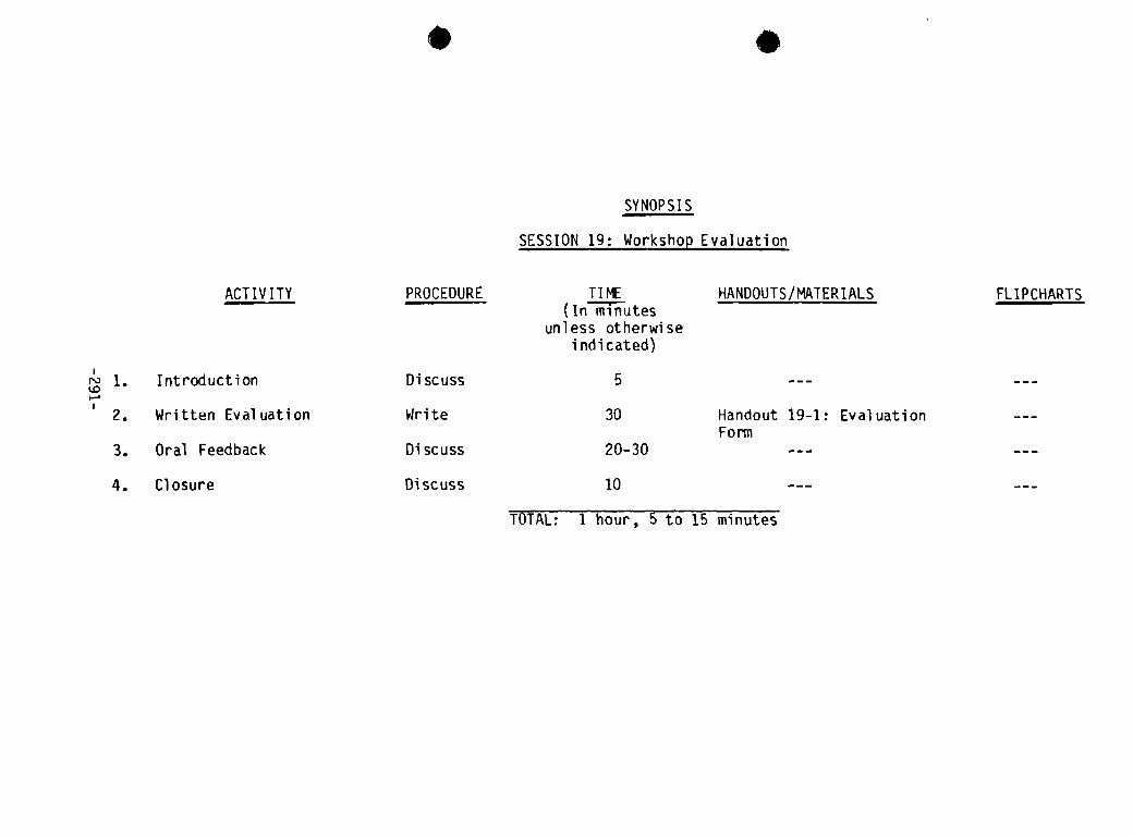
S
SYNOPSIS
SESSION 19: Workshop Evaluation
ACTIV ITY
Handout 19-1: EvaluationForm
FLIPCHARTSPROCEDURE TIME(In minutes
unless otherwiseindicated)
HANDOUTS/MATERI ALS
1. Introduction Discuss 5
‘ 2. Written Evaluation Write 30
3. Oral Feedback Discuss 20-30
4. Closure Discuss 10
TOTAL: 1 hour, 5 to 15 minutes

S
S

SESSION 19
r


Session 19: Workshop Evaluation
GOALS Total time: 1 hour & 5-15 mm.
To conduct an evaluation of the workshop.
OBJECTIVES
• To fill out the workshop evaluation questionnaire
• To provide oral feedback to the trainers on the workshop
OVERVIEW
It is assumed that the trainers will be able to evaluate the workshop in a5 variety of ways, formally and informally. Each session contains objectiveswhich are generally verifiable by observation: skills can be either de-monstrated or not. It is also assumed that the recipients of this training arewell motivated adults who will seek help if they don’t understand something.The ultimate evaluation measure, however, will be demonstrated long after theworkshop when the participant develops his/her own rainwater roof catchmentproject. If the training has been successful, the participant will be able touse the handouts introduced in the workshop (see Participant Reference Packet)to promote a project which is technically and socially sound.
This evaluation session provides one additional source of data. It is basedupon the participants’ feelings and observations about the workshop. The in-formation gained from this session can be used both to improve the trainingdesign and to help the trainer do a better job next time in conducting thisworkshop. This session uses two tools, a written opinionnaire and an informaloral feedback session. The written portion should be given to provide a recordfor the trainer. It is intended to be done anonynously to ensure more openfeedback. The oral portion is designed to gather information about the work-shop which will help explain and interpret the written data and provide5 opportunity for give and take between the trainers and the participants.
PROCEDURES
1. Introduction Time: 5 minutes
Introduce the evaluation session by explaining that the evaluation is irn-portant to the trainers as a way of learning how the training has beenreceived and for future learning purposes. Describe the two parts of theevaluation (written and oral) and the time constraints.
2. Written Evaluation Time: 30 minutes
Hand out the written evaluation form (attached) and answer any questions aboutthe instructions on the form. Then give the group time to fill it out.
-293-

3. Oral Feedback Time: 20-30 minutes
Write on the flipchart a two column divided space as follows:
Workshop Strengths Constructive Suggestions
for Improvement
Ask the group to volunteer corrinents on both sides of the question. Record thecomments as they are given. At each comment, it is good to verify the commentwith others in the group to see if the conilient is shared by others or is onlyone person’s opinion. It is particularly important that the trainer not actdefensively and spend a lot of time explaining weaknesses. This will onlyserve to discourage constructive feedback.
4. Closure Time: 10 minutes
When the participants have discussed their feedback sufficiently, close thesession by acknowledging all of the good ideas and feedback.
MATERIALS
— Flipchart prepared for feedback- Handout 19—1: Evaluation Form
-294-
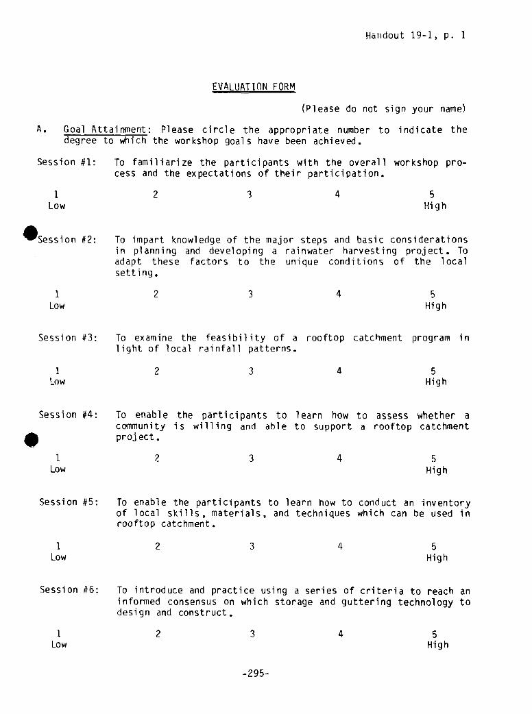
Handout 19-1, p. 1
EVALUATION FORM
(Please do not sign your name)
A. Goal Attainment: Please circle the appropriate number to indicate the
degree to which the workshop goals have been achieved.
Session #1: To familiarize the participants with the overall workshop pro-cess and the expectations of their participation.
1 2 3 4 5Low High
Session #2: To impart knowledge of the major steps and basic considerationsin planning and developing a rainwater harvesting project. Toadapt these factors to the unique conditions of the local
1 2 3 4 5Low High
Session #3: To examine the feasibility of a rooftop catchment program inlight of local rainfall patterns.
1 2 3 4 5~ow High
Session #4: To enable the participants to learn how to assess whether acommunity is willing and able to support a rooftop catchmentproject.
2 3 4 5
Session #5: To enable the participants to learn how to conduct an inventoryof local skills, materials, and techniques which can be used inrooftop catchment.
1 2 3 4 5Low High
Session #6: To introduce and practice using a series of criteria to reach aninformed consensus on which storage and guttering technology todesign and construct.
1 2 3 4 5Low High
setting.
1Low High
-295-
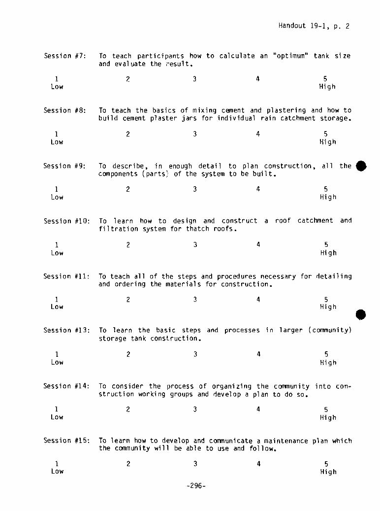
Handout 19-1, p. 2
Session #7: To teach participants how to calculate an “optimum” tank sizeand evaluate the result.
1 2 3 4 5Low High
Session #8: To teach the basics of mixing cement and plastering and how tobuild cement plasl:er jars for individual rain catchment storage.
1 2 3 4 5Low High
Session #9: To describe, in enough detail to plan construction, all thecomponents (parts) of the system to be built.
1 2 3 4 5Low High
Session #10: To learn how to design and construct a roof catchment andfiltration system for thatch roofs.
1 2 3 4 5Low High
Session #11: To teach all of the steps and procedures necessary for detailingand ordering the materials for construction.
1 2 3 4 5Low High
Session #13: To learn the basic steps and processes in larger (conniuunity)storage tank construction.
1 2 3 4 5Low High
Session #14: To consider the process of organizing the coninunity into con-struction working groups and develop a plan to do so.
1 2 3 4
Session #15: To learn how to develop and communicate a maintenance plan whichthe community will be able to use and follow.
1 2 3 4
5Low High
5Low High
-296-

Handout 19-1, p. 3
Session #16: To critically examine the tank design under construction andrefine it for future use.
2 3 4 5Low High
Session #17: To learn how to construct and connect gutters.
1 2 3 4 5
Session #18: To plan applications of the workshop to the work setting.
I1Low High
B. Workshop Feedback and Learning: Please answer the following questions asfully as possible so that the trainers can learn how effective the work-shop methodology was.
1. What have been the most positive things about this workshop? Comments:
2. What have been the most negative things about this workshop? Comments:
1
Low High
2 3 4 5
3. What one thing stands out as important to you in this workshop? Comments:
-297-

Handout 19-1, p. 4
4. What things have you learned that you did not know before? Coments:
C. Workshop Organization and Training
1. What comments do you have about the way the workshop was planned andorgani zed?
2. What can be done in the future to improve a workshop like this?
3. What specific steps in developing a rainwater harvesting system do youfeel you will need to learn more about in order to successfully promoteand develop a project in the future?
4. What comments do you have about the trainers?
-298-
ANNOTATEDBIBLIOGRAPHY*
8.1 Catchment Technologies
Frasier, G.W., ed., 1974, Proceedings of Water Harvesting Symposium, Phoenix
,
Arizona, March 26-28, 1974, Agricultural Research Service/USDA report no. ARS-W—22, 323 pages, currently out of print. Request information from the editor,Southwest Rangeland Watershed Research Center, 442 East 7th Street, Tucson,Arizona 85705, USA.
A wide—ranging compilation of 4U papers and reports on rainwater harvesting.Much of the material is quite technical and most of it concerns development ofsystems for agriculture. It is, however, a fine overview of the spectrum ofdevelopments in ground surface catchment. Of particular interest: “Engineeringaspects of water harvesting research at the University of Arizona” (Cluff, 1974,pages 27—39) and “Storage systems for harvested water” (Dedrick, 1974, pages 1/5—
Hall, N., 1981, “Has Thatch a Future?”, Appropriate Technology, London, Vol. 8, no.3, December 1981, pages 7-9, ~ 1.50 for the issue with Air Speeded Post fromIntermediate Technology Publications, Ltd., 9 King Street, London WC2E 8HN, UnitedKi ngdom.
“Thatch is currently out of favour almost everywhere. It is being replaced bymodern sheet materials or expensively manufactured tiles. However, as theessential ingredients of modern building become more and more costly with therising price of raw materials and the fuel required to process them, it isundoubtedly worth re-appraising traditional materials.” The author, who isstudying thatch and has found little information available on the topic, presentsa concise summary of thatch grass types and methods of thatching roofs, highlight-ing Balinese “prefabricated” techniques. There is no mention of guttering thatchroofs for rainwater catchment. The author’s address: Open University, WaltonHall, Milton Keynes, Bucks, United Kingdom.
nstitute for Rural Water, 1982, “Constructing, Operating, and Maintaining RoofCatchments”, Water for the World technical note no. RWS.1.C.4, USAID, requestfrom the Development Information Center, Agency for International Development,Washington, D.C., 20523, USA.
A good overview of simple rooftop catchment systems, discussing roofing andgutter installation, foul flush disposal, and maintenance. About four pages oftext, the remainder figures, several of which are reproduced above with permission.(Request “Evaluating Rainfall Catchrnents,” RWS.1.P.5, “Designing Roof Catchments,”RWS.l.D.4, “Designing a Household Cistern,” RWS.5.D.1, and “Constructing a House-hold Cistern,” RWS.5.C.l, from the same source.)
*From Keller, Kent, Rainwater Harvesting for Domestic Water Supplies in DevelopingCountries, WASHWorking Paper No. 20, Water and Sanitation for Health ProjectArlington, Va. 1982.
-299-

I.T. Building Materials Workshop, “Production and Installation of Corrugated RoofSheet made from Fibre Reinforced Cement: Basic Operating Manual from Hondurasand Guatemala”, 19 pages, request from I.T. Building Materials Workshop, Corn—greaves Trading Estate, Overend Road, Larley, West Midlands, B64 700, UnitedKingdom.
Describes, in good detail and with excellent line drawings, the tools, sheetmakingtable and molds, and techniques for FRC sheets outlined in Parry (1981, below).“This manual describes the basic production and application techniques for theroofing products. Modifications have been incorporated to suit local circum-stances in Honduras and Guatemala. The document is intended as a manual forassisting groups who already have I.T. equipment to make corrugated roof sheetsand ridge tiles, and have received firsthand training from an experienced opera-tor”. (See also figure 19).
Figure 19, Ideal Deployment of Sheetmaking and CuringEqui pment.
NAS, 1974, Roofing in Developing Countries: Research for New Technologies, book57 pages. Give name of group or institutional affiliation when requesting a fr5copy from BOSTID (JH215), Office of the Foreign Secretary, National Academy ofSciences, 2101 Constitution Avenue, Washington, D.C., 20418, USA.
A useful overview of the range of possible low-cost roofing materials relying onlocal materials and/or new techniques. Includes appendices on low-cost roofingresearch in India.
Parry, J.P.M., 1981, “Development and Testing of Roof Cladding Materials Madefrom Fibre Reinforced Cement”, Appropriate Technology, London, Volume 8, no.2,September 1981, pages 20-23, 1. 1.50 for the issue and Air Speeded Post fromIntermediate Technology Publications Ltd., 9 King Street, London WC2E 8HN, UnitedKingdom.
-300-

A summary of the I.T. Building Materials Workshop findings on fibre-reinforcedcement sheeting for use in the manufacture of roofing components, “The finaloutcome of the development work was a complete low-cost roofing system involvinga new corrugated cladding panel which has the coverage of a one metre sheet butwhich is fitted like an extremely large but lightweight tile.” Manufacturingprocesses for implementation on a small scale in developing countries (see I.T.
Building Materials Workshop, this section) are outlined. The author believesthat FRC sheets were being made at the combined rate of about 2,000 a month byseveral production teams in at least seven countries in April 1981. Cost androof structure requirements comparisons are made with conventional materials;cost advantages hinge on the lifetime of the new sheets: “only time will tell theeventual lifespan of the FRC products, but the development has now reached thepoint where it can be considered as a viable alternative to conventional materialsand one which is especially appropriate because of its facility to be produced
labour—intensively, on a small scale, in virtually any urban or rural situation.”
I8.2 Storage Technologies
Cairncross, S., and Feachem, R. , 1978, Small Water Supplies, book, 78 pages,�1.50 from the Ross Institute, London School of Hygiene and Tropical Medicine,Keppel Street (Gower Street), London WCIE 7HT, United Kingdom.
This book is a compact presentation of basic information on building small—scalewater supply systems. Discussions include sources of water, water treatment,water lifting, and storage and distribution. Contains a two-page section on build-ing water tanks of bricks and masonry. No diagrams, but text gives guidelinesfor wall, footing, and floor thicknesses; plastering and waterproofing; cleaningand maintenance; inlets, outlets, overflows, screening, and covers; and drainage.In some cases the construction specifications given provide for more strength,and use more materials, than necessary.
Cal vert, R.C., and Binning, R.J., 1977, “Low Cost Water Tanks in the Pacific• slands”, article, 3 pages, in Appropriate Technology magazine, Vol 4, no. 3,
November 1977, �0.75 for the issue including Air Speeded Post, from IntermediateTechnology Publications, Ltd., 9th King Street, London WC2E 8HN, United Kingdom.
Describes fabrication of ferrocement cover on an earthen dome, excavation of tankfran beneath the cover, and plastering of ferrocement lining for 15-20 m3 tanksbuilt in “soft” soil in the New Hebrides. The authors believe the tanks can bebuilt for under US $250.00. They also describe a method for building above-groundferrocement tanks using locally available wood and reed materials for forms.
Farrar, D.M., and Pacey, A.J., 1974, “Catchment Tanks in Southern Africa: AReview”, Africa Fieldwork and Field Technology Report no. 6, 13 pages, requestfrom Paul Sherlock, OXFAM, 274 Banbury Road, Oxford 0X2 7DZ United Kingdom.
-30 1-

An excellent critical description and evalution of open and “beehive” “sand-sausage” ground surface catchment tanks, ferrocenient roof catchment tanks, andcombinations of these designs in Swaziland, Botswana, and Zimbabwe. The authorsgive the most complete construction cost information we have seen, and alsodiscuss manual labor requirements as a barrier to completion of some of thetechnically sound “sand—sausage” tank projects. Step-by—step instructions formaking a 7.5 m3 version of the ferrocement tanks built by the hundreds around theFriends Rural Center, Bulawayo. Anyone considering a rooftop catchment systemor project in Africa should read this report.
Henderson, G.E., Jones, E.E., and Smitn, G.W., 1973, Planning for an IndividualWater System, book, 156 pages, $5.00 from American Association for VocationalInstructional Materials, Engineering Center, Athens, Georgia, 30602, USA.
A well—written book on conventional water installations for rural and farmingfamilies in the U.S. Includes good color drawings of cisterns, roofwashers, anda filter. Better pictures, but less construction detail, than in Usin WaterResources (below).
Maikano, G.J. , and Nybery, L. , 1980, “Rainwater Catchment in Botswana”, paper, 5pages, in the book Rural Water Supply in Developing Countries: Proceedings of aWorkshop on Training held in Zomba, Malawi, 5—12 August 1980. Ask for a freecopy of the book from International Development Research Center, Box 8500, Ottawa,Canada K1G 3H9.
An account of a pilot program for popularizing underground ferrocement tanks tostore water caught on traditional grain threshing floors. Scant rainwater har-vested using these systems is for families and cattle early in the growingseason, and should allow seasonally migrating farmers to move to their landand begin plowing 17 days earlier than otherwise. Not many construction detailsare given, but domed ferrocement covers and poured concrete covers reinforcedwith barbed wire are mentioned. Maintenance of the tank and catchment floor areemphasized. “Today, the pilot project has about 10 underground tanks built andmore are under construction. Iii all it is hoped to have 80 comnpleted by theend of 1980”. .National Academy of Sciences, 1973, Ferrocement: Applications in DevelopingCountries, book, 91 pages, mention yoUr institutional affiliation or name ofyour group when requesting a free copy from: Board on Science and Technology forInternational Development (BOST]D)(JH215), Office of the Foreign Secretary,National Academy of Sciences, 2101 Constitution Avenue, Washington, D.C. 20418,USA.
A basic book on the range of ferrocemnent techniques and potential applications,widely referred to throughout the literature on the topic. Chapters cover ferro-cement for boatbuilding, food storage facilities, food-processing equipment,low-cost roofing, and the basics of construction of shells and walls. Appendicesinclude diagrams of construction steps, and cost breakdowns for food-storage silosin Thailand and Ethiopia which can be used for storing water. (These silos arealso described in the article by Sharma, et al, below).
-302-

Pornpe, C., van Kerkvoorden, R., and Siswoyo, H., 1982, “Ferrocement Applicationsin the West Java Rural Water Supply Project”, article, pages 51—61 in Journal ofFerrocement, Vol. 12, no. 1, January 1982. Ask for a reprint or xeroxed copy at$.20 per page plus $2.00 per request. from International Ferrocemnent InformationCenter, Asian Institute of Technology, P. 0. Box 2754, Thailand.
An overview of the project which plans to construct hundreds of 5 m3 and iO~ferrocernent tanks, as well as a reservoir and community water supply system builtlargely of ferroceinent. Presents a chart comparing costs of various rainwaterstorage tanks in Java, including gutters and labor costs of Rp 1000 (US$1.60) perman—day. Also includes good drawings showing construction details of the 10 m3tank and 2.5 mu3 bamboo—cement tank.
Sharma, P.C., Pama, R.P., Valls, J., and Gopalaratnamn, V.S., 1979, “State-of-the—
Irt Review on Ferrocernent Grain Storage Bins”, article, pages 135-150 in Journalf Ferrocement, Vol 9, no. 3, July 1979. Reprint or xerox copy at $0.20 per page
plus $2.00 from International Ferrocenient Information Center, Asian Institute ofTechnology, P. 0. Box 2754, Bangkok, Thailand.
Describes construction techniques and costs for four ferrocement grain storagestructures “...developed in different parts of the world that have been extensivelyfield tested satisfactorily.” An above—ground conical bin which has been calledthe “Thailo”, holding 4 tons of grain or 9.5 m3 of water, and an underground pitsilo lined with reinforced plaster are two models which have been used to storewater. The cost of a 9.5 m3 underground plastered pit built in India is givenas US$62.00.
UNICEF East Africa Regional office, 1982, “From Kenya--How to Make Plastered baskettanks for storing water”, article (pages 7-8) in Appropriate Technology magazine,Vol 8, no. 4, March 1982, ~ 1.50 from Intermediate Technology Publications, 9 KingStreet, London WCZE81-tN, United Kingdom. Also available from UNICEF, East African
•egional Office, P. 0. Box 44145, Nairobi, Kenya.
Describes activities and gives background of the Karen Appropriate TechnologyUnit outside Nairobi. Cement mortar jars (like those described by Watt, 1975,below) and a PVC bag suspended in a thatch-covered bamboo-lined pit are two tankdesigns tried at the center. Also mentions other ideas in passing: “It is noticedthat, in many areas, houses will have a short length of roughly fashioned gutteringfixed under the eaves just above the door, and that water from this will becollected in an old oil drum or container...(this) could provide the link pointfor development to simple but effective roof catchment systems.” And, “Collectionof water from grass roofs, even on circular huts, is poSsible by using a polythenefilm guttering or by simple guttering made from split bamboo or from two planksjoined to give a “V” section.” Many other ideas for food production/storage!preparation, and effective institutional involvement in village technology acti-vities.
-303-

VITA, 1977, Using Water Resources, book, 143 pages, $5.95 from Volunteers inTechnical Assistance, 1815 North Lynn Street, Suite 200, Arlington, VA 22209 USA.
This is a reprint of a part of VITA’s Village Technology Handbook, available for$10.00 (387 pages) from the same address. The Handbook includes excellent sec-tions on concrete and bamboo construction as well as health and sanitation,agriculture, and food processing and preservation. Using Water Resources containsa good 6page piece on planning and building a conventional US-type concretecistern with a capacity of 10 m3 or more, including drawings of a filter and a“roofwasher”. The book as a whole is good basic reading for anyone consideringconstruction of a small water supply.
Watt, S.B., 1978, Ferrocement Water Tanks and Their Construction, book, 118 pages,~ 2.95 from Intermediate Technology Publications, Ltd., 9 King Street, LondonWC2E 8HN, United Kingdom.
For those considering a rooftop catchment system, this book may be the singlemost useful publication listed here. Gives straightforward guidelines for design,descriptions of materials and tools required, and a detailed, step-by-stepsummary of methods for building the ferrocement tanks (using metal forms) whichhave been “used successfully for over 25 years in different parts of the world”(see technical note in Appendix C). Also describes construction of several varia-tions on the basic method, includinq small jars of unreinforced mortar (seetechnical note -- Appendix C), 1-25 rn~ manufactured tanks in New Zealand, a 6 m3tank built without formwork in the U.K., 10 in3 ferrocement-lined traditionaladobe grain storage bins in Mali ~ a 40 mu3 roofed tank built with makeshiftformwork in Zimbabwe, and a 150 ~ open tank built with makeshift formwork inArizona, USA. Lists amounts of materials required for each design, and gives abrief discussion of using rainfall data to plan a rooftop catchment system (seetechnical notes in Appendices A and B below).
Watt, S.B., 1978, “Rainwater Storage Tank in Thailand”, article (pages 16—17) inAppropriate Technology magazine, Vol 5, no. 2, August 1978, -~ 0.75 for the issueincluding Air Speeded Post, frormi Intermediate Technology Publications, Ltd., •King Street, London, WC2E 8HN, United Kingdom.
Describes construction of tanks made out of stacked ureinforced concrete rings,cast in 1.5 m. diameter cylindrical steel forms. The 60—cm-high rings can bestacked up to four high and have low materials costs (US $40.00 for a 7 m3 tank)but the inner and outer steel forms would be expensive. Watt suggests that high—quality rings could be cast centrally under supervision and trucked to locationfor assembly.
Winarto, 1981, “Rainwater Collection Tanks Constructed on Self—Help Basis”,article (pages 247-253) in Journal of Ferrocement, Vol 11, no. 3, July 1981. Askfor a reprint or xeroxed copy at $.20 per page plus $2.00 per request from Inter-national Ferrocement Information Center, Asian Institute of Technology, P. 0.Box 2754, Bangkok, Thailand.
-304-
An account of the adaptation of standard ferrocement tank methods to the materialsavailable in rural Java. Detailed verbal instructions for building a steel rodreinforced 9 m3 tank with integral floor and cover. Bamboo mats are used asplastering forms. Some pictures; construction could be attempted with basicknowledge of the techniques in Ferrocement Water Tanks and Their Construction(Watt, 1978). Also describes construction of smaller tanks built with bamboo(instead of steel rod) reinforcement cages. The steel rod and bamboo cage designspresented here have been adopted by the West Java Rural Water Supply Project (Pomnpeet al , above).
8.3 General*
Commission on International Relations/NAS, 1974, More Water for Arid Lands
:
Promising Technologies and Research Opportunities, book, 154 pages, mention nameof your group or institutional affiliation when requesting a free copy from BUSTID(JH215), Office of the Foreign Secretary, National Academy of Sciences, 2101
I Avenue, Washington, D.C. 20418, USA.Still useful after eight years in print, this overview is divided into two halves,“water supply” and “water conservation”. Topics include runoff agriculture,reuse of water, reducing evaporation from water and soil surfaces, trickle irriga~tion, selecting water—efficient crops. The chapter on rainwater harvestingdiscusses techniques and research in Australia, Zimbabwe, and the western UnitedStates as well as the ancient gravel mounds and strips used to harvest rainwaterfrom hillsides in the Negev 4,000 years ago. Includes good photographs of the“sand-sausage” tanks described in Ionides et al (1969) and Farrar and Pacey(1974).
Frasier, G.W., and Myers, L.E., in preparation, a handbook on rainwater harvestingwith parts devoted to domestic water supply. Will be published as a USDA handbook,available from the Superintendent of Documents, Washington, D.C., in 1983. Forfurther information contact Dr. Frasier (see section 8.1 above).
I*The Intermediate Technology Development Group (ITDG), is preparing “a practical
manual describing rainwater harvesting techniques as an option for water supply.”This book will probably not be available until late 1983, but the consistentquality of ITDG publications leads us to believe that it will be well-researchedand useful to a broad range of workers. “The emphasis will be on low-cost systemnsfor small communities and the scope will cover the provision of water for domesticand agricultural purposes. The manual is intended for use by project holders andfield workers and consequently is planned to include, wherever possible, practicalinformation derived from experience in the field. In order to achieve this objec-tive hUG is anxious to make contact with field personnel who would be willing to“A handbook/source document on technology of small community water supplysystems.” This useful overview contains a 12-page section which is probably thebest short published summary for rainwater as a source of domestic water supplythat we have share something of their experiences----successes and failures.”(personal communication, Adrian Cullis, ITDG.) Write to Mr. Cullis at: AppliedResearch Section, Shinfield Road, Reading, Berkshire RG2 YBE, United Kingdomn.
-30 5-
Hofkes, E.H., ed., 1981, Small Community Water Supplies, Technical Paper no. 18,JRC/WHO, booK 413 pages, free for groups in developing countries, from IRC, P.O.Box 5500, 2280 HM RIJSWIJK, The Netherlands.
“A handbook/source document on technology of smnall community water supply systems.”This useful overview contains a 12-page section which is probably the best shortpublished Sumnmary on rainwater as a source of domestic water supply that we haveseen. Includes good drawings of an underground rainwater storage well (as usedin China) and a Venetian cistern. Bibliography of 12 items. IRC says that theeditor is currently working on a “design manual for RWHsystemns”.
White, G.F., Bradley, D.J., and White, A.U., 1972, Drawers of Water: DomesticWater Supply in East Africa, book, 306 pages, US$16.00 (clothbound) from Univer-sity of Chicago Press, 11030 S. Langley. Chicago, Illinois, 60628, USA.
An effective, carefully assembled overview of domestic water supply in the dev —
oping tropics, of interest to a broad range of workers involved in the formulatof water supply strategies. Of particular interest: analysis of basic types ofwater imnprovernents and their varying applicability over the range of environmuentsand settlement patterns in East Africa, where the authors studied from 1965—68.A key source for planners, containing lessons and insights relevant to much ofthe developing world.
.
—306-

REF E RENCES *
BRADLEY, R., 1Yb7, “Butyl Rain Traps”, Arizona Engineer and Scientist, May 1967,pages 8-9.
BRISCUE, J., 1981, “Water Storage and Treatment Devices Suitable for Home andCommunity Use”, Water and Sanitation for Health Project OTU 50,USAIL), Washington, D.C., 34 pages.
*CAIRNCROSS, S., and FEACHEM, R., 1978, Small Water Supplies, Bul letin No. 10, The
Ross Institute of Tropical Hygiene, London, 78 pages. (see section8.2).
*CALVERT, R.C., and BINNING, R.J., 19/7, “Low Cost Water Tanks in the PacificIslands (New Hebrides)”, Appropriate Technology, London, Vol.4, no.3, Nov. 1977. (see section 8.2).
CLUFF, C.B., 1975, “Surface Water Storage Potential in the Nara and Sangha Areasof Mali”, unpublished project report, The Wunderman Foundation, New
York, 78 pages.
CLUFF, B.C., 1974, “Engineering Aspects of Water Harvesting Research at theUniversity of Arizona”, Proceedings of the Water Harvesting Sympo—sium, Phoenix, Arizona, March 26-28, 1974, Agricultural ResearchService/USDA report No. ARS-W-22, Washington, D.C., pages 27-39.(see section 8.1).
*Commllisslon on International Relations NAS, 1974, More Water for Arid Lands: Prom-ising Technologies and Research Opportunities, National Academy ofSciences, Washington, D.C., 14 pages (see section 8.3).
CtJRRIER, W.F., 1973, “Water Harvesting by Trickle Tanks, Rain Traps and Guzzlers”,Water-Animal Relations Symposium, Twin Falls, Idaho.
L)ARRUW, K., and PAMA, R. , 1976, revised 1981, Appropriate Technology SourcebookVolume I, Volunteers in Asia Press, Stanford, 318 pages.
DARROW, K., KELLER, K., and PAMA, R., 1981, Appropriate Technology Source BookVolume II, Volunteers in Asia Press, Sanford, 496 pages.
DAVIES, W.J., 1963, “Use of roman-type cisterns and small dams for rainwaterstorage in the highlands of the base valley of the Medjerda,”unpublished report, USAID/Tunis, 5 pages.
DEDRICK, A.R., 1974, “Storage Systems for Harvested Water”, Proceedings ot theWater Harvesting Symposium, Phoenix, Arizona, March 26-28
,
1974, Agricultural Research Service/USDA report No. ARS—W-22,Washington, D.C., pages 175-191.
~‘FromKeller, Kent, Rainwater Harvesting for Domestic Water Supplies in DevelopingCountries, WASH Working Paper No. 20, Water and Sanitation for HealthProject, Arlington, Va. 1982.
-307-

DIAMANT, B.Z., 1982, “Roof catchments: the appropriate safe drinking watertechnology for developing countries, in Proceedings of the Inter-ET1 w405 731 m554 731 lSBTnational Conference on Rain Water Cistern Systems, June 1982,Unfversity of Hawaii at Manoa, pages 276-~83.
DUOLEY, L.K. , 1978, “Rainwater Cisterns”, Organic Gardening and Farming, Emmaus,Pennsylvania, May 1978, pages 141—146.
DOELHOMIU, S., 1982, “Rain Water Cistern Systems in Indonesia”, in Proceedings ofthe International Conference on Rain Water Cistern Systems, June1982, University of Hawaii at Manoa, pages 387-395.
ELLSPERMAN, L.M., 1962, “Buried Asphalt Membrane Test Lining for Hafirs”,report to the Government of the Republic of Sudan, USAIL)/UnitedStates Department of the Interior, 23 pages.
ESHENAUR, W., 1982, “Water Harvesting by Chemical Soil Treatment--a literaturereview”, unpublished report, School of Engineering, University ofMinnesota. I
*FARRAR, D.M., and PACEY, A.J., 1974, “Catchment Tanks in Southern Africa: aReview”, Africa Fieldwork and Technology Field Report No. 6, OXFAM,Oxford. Request directly from Paul Sherlock, OXFAM, 274 BanouryRoad, Oxford, U.K., 0X2 7DZ. (see section 8.2).
FEACHErI, R. , BURNS, E. , CAIRNCRUSS, S., CRONIN, A., CROSS, P., CURTIS, D. , KHAN,M.K., LAMB, D., and SUUTHALL,H., 1978, Water, Health and Development
:
an Interdisciplinary Evaluation, Tn-Med Books Ltd., London, 260pages.
*FRASIER, G.W., ed., 1975, Proceedings of the Water Harvesting Symposium, Phoenix,
Arizona, March 26-28, 1974, Agricultural Research Service/USDA reportNo. ARS-W—22, Washington, D.C., 323 pages (see section 8.1).
“Fiber-Cement Corrugated Roofing Panels’, 1981, Journal of Ferroceinent, Bangkok,Vol.11, No. 2, April 1981, pages 183-184.
FOK, Y.S. , chairman, 1982, Proceedings of the International Conference on RainsWater Cistern Systems, June 1982, Wat~r Resources Research Center,University of Hawaim at Manoa, 396 pages.
GISCHLER, C., and Viaene, M., 1982, “Cisterns as a regulating element forintermittent water resources under arid rural conditions”, unpub-lished paper, UNESCO Regional Office for Science and Technology forLatin America and the Caribbean, Montevideo, Uruguay, 10 pages.
GROVE, A.T., 1978, Africa, Oxford University Press, 337 pages.
GROVER, B., 1971, “Harvesting Precipitation for Community Water Supplies,” M.Sc.
Thesis, University of Manitoba, 110 pages.
GUGGENHEIM, H., 1977, “Dual Technological Sy stems in Water and Grain Storage”,The Application of Technology in Develojiing Countries, Interdis-ciplinary programs Seminar Series August - December 1976, Officeof Arid Land, Studies, Tucson, pages 21—35.
-308-

HALL, N., 1981, “Has Thatch a Future?”, Appropriate Technology, London, Volume8, no. 3., December 1981, pages 7-9 (see section 3.2.4)
HARDENBERGH,W.A., and RUDIE, E.B., 1960, Water Supply and Waste Disposal,International Textbook Company, Sc,-~nton, Penn., 513 pages.
“Heaven’s Water: in Rural Places, Cisterns Gather the Rai~, 1980, Rodale’s NewShelter, Ejnmaus, Pennsylvania, April 1980, pages 34-37-
HEGGEN, R.J., 1982, “Optimal catchment design by marginal analysis , in Proceed-ings of the International Conference on Rain Water Cistern 3ys.cmc
.
June 1982, University of Hawaii at Manoa, pages 135-143.
*IIENDERSON, G.E., JONES, E.E., and SMITH, G.W., 1Y73, Planning for an
Individual Water System, American Association for Vocational Instruc-tional Materials, Athens, Georgia, pages 156. (see section 8.2).
*HOFKES, E.H., ed., 1981, Small Community Water Supplies, Technical Paper No. 18,
International Reference Centre for Community Water Supply and
Sanitation, The Hague, 413 pages (see section 8.3).IONIDES, M.G., ap RELS, G., GIBBERD, V., MOODY, P.R., Thornton, U.S., and UPTON,
M., 1969, The Introduction of Rainwater Catchment Tanks and Micro-ET1 w179 474 m536 474 lSBTIrrigation to Botswana, Intermediate Technology Development Group,London, 74 pages.
*Instltute for Rural Water, 1982, “Constructing, Operating, and Maintaining RoofCatchmnents”, Water for the World technical note No. RWS.1.C.4, USAID,
approximately 10 papers (see section 8.1).
Institute for Rural Water, 1982c, “Designing Roof Catchiients”, Water for the
World technical note no. RWS1, D.4, USAID, about 8 pages.
*Institute for Rural Water, 1982, “Evaluating Rainfall Catchments”, Water for theWorld technical note No. RWS.1.P.5, USAID, 8 pages (see section 3.1.5)
IRISH, J.L., SUKARNA, AND MURDIYARSU, D. , “Reliability of roof runoff in
selected areas of Indonesia”, in Proceedings of the InternationalConference on Rain Water Cistern Systemns, June, 1982, University ofHawaii at Manoa, pages 171-183.
*I.T. Building Materials Workshop, “Production and Installation of CorrugatedRoof Sheets mnade fromn Fibre Reinforced Cement: Basic OperatingManual for Honduras and Guatemnala”, report/A.I.D. contract 522—T-43O,Intennediate Technology Developmermt Group, London, 19 pages (seesection 8.1).
KALBERMATTEN, J.M., The Role and Importance of Appropriate Technology inAchieving the Objectives of the International Drinking Water Supplyand Sanitation Decade, paper presented at the International Confer-ence on Rain Water Cistern Systems, Honolulu, June 1982.
KUKIELKA, B.J. 1981, “Interimn Report on Experimental Family Rain Water StordgeProgramnme”, United Nations Development Programme/World HealthOrganization Bangkok, 6 pages plus annexes, Report: EnvironmentalHealth THA/76/0U4.
-309-

LAURITZEN, C.W., 1961, “Collectmng Desert Rainfall”, Crops and Soils, August -
September 1961, page 2.
LAURITZEN, C.W., 1967, “Rain Tmaps of Steel”, Utah Science, Salt Lake City,Vol.28, No. 3, September 1967, 3 pages.
LAURITLEN, C.W., AND THAYER, A.A., 1966, “Rain Traps for Intercepting and StoringWater for Livestock”, Agriculture Information Bulletin no. 307,Agricultural Research Service/USDA, Washington, D.C., 9 pages.
LINDBLAU, C., and DRUBEN, L., 1976, Small Farm Grain Storage, Vol.111, Volun-teers in Technical Assistance, Washington, D.C., 148 pages.
MADDOCKS, D., 1975, “An Introduction to Methods of Rainwater Collection andStorage”, Appropriate Technology, Vol.2, No.3, pages 24-25.
*MAIKANO, G.J. , and NYBERG, L. , 1980, “Rainwater Catchment in Botswana”, RuralWater Supply in Developing Countries: Proceedings of a Workshop onTraining Held in Zomnba,Malawi, 5-12 August 1980, International ueviTopmnent Researc~i Center. 11980, Ottawa, pages 13-17 (see section 8.2).
MALIK, U., Rain Water Cistern Systemns and Policy in Malaysia, Paper presented atthe International Conference on Rain Water Cistern Systems, Honolulu,June 1982.
*IIcDUWELL, J., ed., 1976, Village Technology in Eastern Africa: a RegionalSeminar orm Simple Technology for the Rural Family, UNICEF East AfricaRegional Office, Nairobi, 60 pages (see section 8.2).
MEEK, J.L., 1982, “Copnstructmorm of a Ferrocemnent Water Tank of Novel Design”,unpublished paper, Department of Civil Engineering, University ofQueensland, Brisbane, Queensland, Australia, 6 pages.
MIDWEST PLAN SERVICE, 1979, Private Water Systems Handbook, Iowa State Univer-sity, 72 pages.
MYERS, L.E., 1962, “Harvesting Precipitation”, publication No. 65, I.A.S.H.Land Erosion, Precipitation, Hydrometry, Soil Moisture, page 343-3511
NYERS, L.E. , 1974, “Water harvesting 2000 b.C. to 1974 A.D.”, Proceedings ofthe Water harvesting Symposium, Phoenix, Arizona, March 26-28, 1974,Agricultural Research Service/USDA report No. ARS-W-22, Washington,D.C., pages 1-7.
NATIONAL PHYSiCS INSTITUTE (LFN/LIPI), 1980 (?), “Penampung Air Ferrocemnerit”(“Ferroceinent Water Container”), National Institute of Sciences,Bandung, Indonesia, 5 pages.
NAS, 1973, Ferroceinent: Applications in Developing Countries, National Academyof Sciences, Washington, D.C. 91 pages (see section 8.2).
*NAS, 1974, Roofing in Developing Countries: research for new technologies,National Academy of Sciences, Washington, D.C., 57 pages (see section8.1).
-310-

NETHERLANDS, GOVERNMENTOF, and GOVERNMENTOF INDONESIA, Construction Manual fora 10 m~.Rain Water Reservoir of Ferrocement, May 1982.
OFFICE OF WATER PROGRAMS/EPA, 1974, Manual of Individual Water Supply Systems,Environmnental Protection Agency, Washington, D.C., 155 pages.
U’MEARA, C., 1982, “Rain water cistern utilization in selected hamlets of theRepublic of Belau, Western Caroline Islands”, in Proceedings of theInternational Conference on Rain Water Cistern Systems, June 1982,University of Hawaii at Manoa, pages 266—2/5.
PAMA, R.P., LEE, S., and VIETMEYER, N.D., 1976, Ferrocement, a VersatileConstruction Material: Its Increasing Use in Asia, InternationalFerrocemnent Information Center, Bangkok, 108 pages.
PARKER, R.N., 1973, article on catchmnent systems in Agriculture in S.E. Ghana,by Dalton, G.E., and Parker, R.N., Univesity of Reading, UnitedKingdom.. ,,
POMPE, C.L.P.M., Design and calculation of rainwater collection systemns , inProceedings of the International Conference on Rain Water CisternSystems, June, 1982, University of Hawaii at Manao, pages 151-157.
*p(j~vlPE, C., VAN KERKVUURDEN, R., and SISWOYU, H., 1982, “Ferrocement Applicationsin the West Java Rural Water Supply Project”, Journal of Ferrocement,Bangkok, Vol.12 No.1, January 1982, pages 51-61 (see section 8.2).
PREMPRIDI, T. , 1982, “Collection and Storage of Rainwater in Rural Thailand”,unpublished paper, Faculty of Engineering, Chulalongkorn University,Bangkok 10500, Thailand, 7 pages.
REE, W.O., 1976, “Rooftop Runoff for Water Supply”, Agricultural ResearchService/ USDA Report ARS-S—133, Washington, D.C., 10 pages.
SALVATO, J.A. , 1958, Environmental Sanitation, John Wiley and Sons, New York,pages 88-91.
SHARMA, P.C., and GOPALARATNAM,V.S., 1980, Ferrocement Water Tank, InternationalFerrocemnent Informnation Center, Bangkok, 37 pages.
*SIIARMA, P.C., PAMA, R.P., VALLS, J., and GOPALARATNAM,V.S., 1979, “State-of-the-
art Review on Ferrocernent Grain Storage Bins”, Journal of Ferrocement,London, Vol.9 No.3, July 1979, pages 135—150. (see secton 3.3.6).
STEPHENSON, R.A., KURUSHINA, H., and WINTER, S.J., 1982, “Assessment of RainwaterCatchment and Storage Systems on Majuro”, in Proceedings of the Inter-ET1 w392 199 m541 199 lSBTnational Conference on Rain Water Cistern Systems, June, 1982, Univer-sity of Hawaii at Manoa, pages 158—163.
THORSKY, G.N., 1961, “Test Linings for Hafirs”, report to the Government of theRepublic of the Sudan, International Cooperation Administration/UnitedStates Departmnent of the Interior, 35 pages.
-311-

UNEP, 1979, “Rain and Storm Water Harvesting for Additional Water Supply inRural Areas”, Expert Group Meeting 30 October - 2 November 1979, Nairobi,United Nations Envirominient Programme, Nairobi, 23 pages.
*UNICEF East Africa Regional Office, 1982, “From Kenya — how to Make Plasteredbasket tanks for storing water”, Appropriate Technology, London,Vol.8, No.4, March 1982, pages 7-8. (see section 3.3.6).
UNIDO, 1978, “Sisal Fibre Concrete for Roofing Shjeets and Other Purposes”,background paper for International Forum on Approprite IndustrialTechnology, New Delhi/Anand, India, 20—30 Novemnber 1978, 57 pages.
Van der LEEDEN, 1975, Water Resources of the World: Selected Statistics, WaterInfonnation Center, Inc. , Port Washington, New York.
van KERKVOORDEN, R., “Rainwater collectors for villages in West Java, Indo-nesia, in Proceedings of the International Conference on Rain WaterCistern Systems, June, 1982, University of Hawaii at Manoa, page299-307.
VIETMEYER, KAMPEMPUOL, NUTALAYA, DESATHIEN, and PATARAGETVIT, 1976, “‘ Ihailo’(Ferrocemnent Water Container”), National Institute of Sciences,Bandung, Indonesia, 5 pages.
*VITA Publications, 1973, Village Technology Handbook, Volunteers in TechnicalAssistance, Washington, D.C. 387 pages (see section 8.2).
*VITE Publications, 1977, Using Water Resources, Volunteers in Technical Assis-
tance, Washington, D.C., 143 pages (see section 8.2)
WAGNER, E.G., and LANUIX, J.N., 1969, Water Supply for Rural Areas and SmallCommunities, World Health Organization, Geneva, 340 pages.
WATERENGINEERING GROUP, 2982, Short Course: Water Supply and Sanitation forDeveloping Countries, Department o’f Civil Engineering, University ofOttawa, approximately 400 pages.
WATT, Simon, 1975, “Water Jars from Cement Mortar”, Appropriate Technology, VolS2 No.2, August 1975, pages 10-11.
*wATT, Simon, 1978 b, “Rainwater Storage Tanks in Thailand”, AppropriateTechnology, London, Vol.5 No.2, August 1978, pages 16-17 (see section8.2).
WATT, Simon, 1977, “Wire-Reinforced Cement Mortar Water Tanks”, AppropriateTechnology, London, Vol.4 No.2, August 1977, pages 6—7.
*WATT, Simon, 19713, Ferrocement Water Tanks and Their Construction, IntermediateTechnology Pub1icat~ons, London, 1978, 118 pages. (see section 8.2).
*WHITE, G.F., BRADLEY, D.J., and WHITE, A.U., 1972, Drawers of Water: DomesticWater Use in East Africa, University of Chicago Press, 3O6pages (seesection 8.3).
—312-

I
*WINARTO, 1981, “Rainwater Collection Tanks Constructed on Self-Help Basis:
Journal of Ferrocemnent, Bangkok, Vol.11 No.3, July 1981, pages
247-253. (see section 8.2).
WINARTO, 1982, “Rural rainwater cistern design in Indonesia”, in Proceedingsof the International Conference on Rain Water Cistern Systems,June, 1982, University of Hawaii at Manoa, pages 294-298.
WRIGHT, F.B., 1956, Rural Water Supply and Sanitation, John Wiley and Sons,New York, 252 pages.
—313-

.

. S
PARTICIPANTREFERENCE PACKET


PARTICIPANT REFERENCEPACKET

-I

Pre-Workshop Handout, p.1
PRE-WORKSHOPSKILL ASSESSMENTFORM
Please fill out the following form by checking in the appropriate columnwhether you feel that you have no experience, some skill , or adequatecompetency in the following skill areas:
Skill Area
1. Identify the technical feasi-bility of a rainwater catchmentproject. 1 identify best sources of informa-
tion on local rainfall
• identify suitable roof surfaces
• calculate roof yield from above
2. Social and community assessment
• survey community needs
• assess community interest
• determine community preferencefor individual or group project
•, present information to a community
3. Local resource inventory
I • identify available materials
• identify available skills
• determine resources neededfor a roof catchment project
• determine community’s priorexperience with such a project
4. Choose an appropriate combinationof technologies
• familiar with alternativetechnologies used in constructinga water tank
NoExperience
SomeSkill
AdequateCompetency
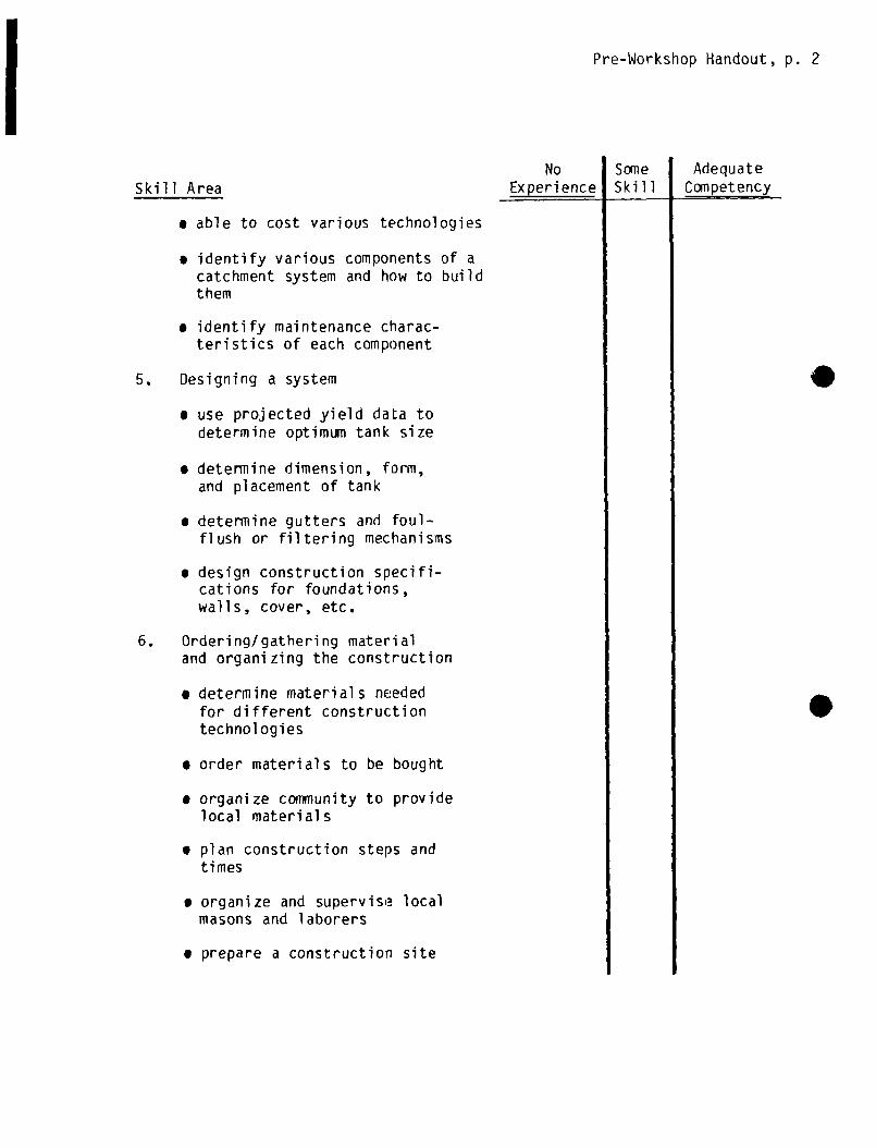
Pre-Workshop Handout, p. 2
Skill Area
• able to cost various technologies
• identify various components of acatchment system and how to buildthem
• identify maintenance charac-teristics of each component
5. Designing a system
• use projected yield data todetermine optimum tank size
• determine dimension, form,and placement of tank
• determine gutters and foul-flush or filtering mechanisms
• design construction specifi-cations for foundations,walls, cover, etc.
6. Ordering/gathering materialand organizing the construction
• determine materials neededfor different constructiontechnologies
• order materials to be bought
• organize community to providelocal materials
• plan construction steps andtimes
• organize and supervise local
masons and laborers
• prepare a construction site
No Some AdequateExperience Skill Competency
.

Pre-Workshop Handout, p. 3
Skill Area
7. Construction skills
• mix and apply mortar
• mix and pour concrete
• use reinforcing rod in
reinforced concrete
• use chicken wire in ferrocement
• construct cement blocks
• lay blocks or bricks
• construct forms for pouringconcrete walls, foundations,top slabs
• waterproof a tank
• construct and install gutters
• construct and install downspout, foul flush and filters
• disinfect the system
• cure concrete and plaster
8. Monitoring and maintenance
• organize a community to maintaina roof catchment system
• assess a community’s skillsand willingness to maintainsuch a system
• teach community members to
maintain the system
• monitor water quality
No SomeExperience Skill
AdequateCompetency

I

Handout 1-1
WORKSHOPGOALS FOR PARTICIPANT
At the end of this workshop, participants will be able to:
• Plan and develop a rainwater roof catchment project
• Determine the feasibility of a rooftop catchment program in light oflocal rainfall patterns
• Assess a conimunity’s willingness and ability to support a rooftopcatchment system
• Conduct an inventory of local skills, materials, and techniques whichcan be used in rooftop catchment
• Choose the most appropriate technologies for tank and gutter
construction
• Calculate an optimum size for a storage tank
• Mix and prepare cement and mortar
• Design and plan a rainwater catchrnent system using all of the stepsand procedures necessary for detailing and ordering constructionmaterial s
• Design and construct a roof catchment and filtration system for thatchroofs
• Manage the ordering of material and labor necessary for constructing a
rainwater roof catchment system
• Build a small household storage tank and a large cistern tank
• Develop strategies for involving communities in the construction of
the system
• Develop a monitoring and maintenance plan for the system which the
coiinunity can use and implement
• Construct, connect and hang gutters for the system
• Develop action plans for promoting rainwater roof catchment in theirproject areas

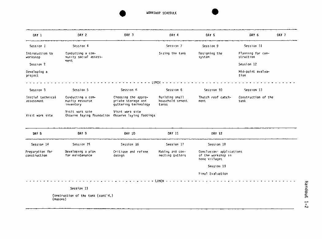
I WORKSHOPSCHEDULE I
=0)
0C
r”)
DAY I DAY 2 DAY 3 DAY 4 DAY S DAY 6 DAY 7
Session 1 Session 4 Session 7 Session 9 Session ii
Introduction to Conducting a corn- Sizing the tank Designing the Planning for con—workshop nlunity social assess— system struction
mentSession 2 Session 12
Developing a Mid—point evaiua-project t,on
LUNCH
Session 3 Session S Session ~ Session 8 Session 10 Session 13
Initial technical Conducting a corn- Choosing the appro- Building small Thatch roof catch- Construction of theassessment munity resource priate storage and household cement merit tank
inventory quttering technology tanks
Visit work site Visit work siteVisit work site Observe laying foundation Observe laying footings
DAY 8 DAY 9 DAY 10 DAY 11 DAY 12
Session 14 Session 15 Session 16 Session 17 Session 18
Preparation for Developing a planconstruction for maintenance
Critique and refine Making and con-design necting gutters
Conclusion- ap’plicationsof the workshop inhome villages
Session 19
Final Evaluation
LUNCH
Session 13
Construction of the tank (cont’d.)(masons)

.
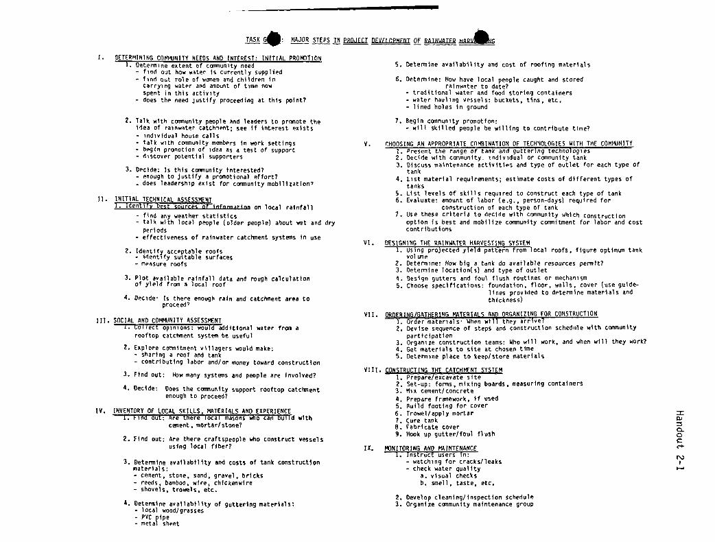
TASK •: MAJOR STEPS IN PROJECT DEVELOPMENTOF RAINWATER HARVSIG
I. DETERMINING cm-B-UNITY NEEDS AND INTEREST: INITIAL PRoP4ifiONI. Determine extent of community need
— find out how water is currently supplied— find out role of women and children in
carrying water and amount of time nowSpent in this activity
— does the need justify proceeding at this point?
2. Talk with community people hnd leaders to promote theidea of rainwater catchment; see if interent exists— individual house calls- talk with community members in work settings- begin promotion of idea as a test of support- discover potential supporters
3. Decide: Is this comnunity interested?- enough to justify a promotional effort?— does leadership exist for community mobilization’
Ii. INITIAL TECHNICAL ASSESSMENT1. Identify best sources orinfonnation on local rainfall
- find any weather statistics- talk with local people (older people) about wet and dry
periods— effectiveness of rainwater catcisnent systems in use
2. Identify acceptable roofs- identify suitable surfaces— measure roofs
3. Plot available rainfall data and rough calculationof yield fran a local roof
4. Oecide Is there enough rain and catcisnent area toproceed’
III. SOCIAL AND COMMJNITY ASSESSMENT1. Collect opinions: would additional water fran a
rooftop catct,nent system be useful
2. Explore commitment villagers would make:- sharing a roof and tank— contributing labor and/or money toward construction
3. Find out: How many systems and people are involved?
4. Decide: Does the community support rooftop catcisnent
enough to proceed?
IV. INVENTORY OF LOCAL SKILLS, MATERIALS AND EXPERIENCE1. Find out: Are there local masons who can build with
cement • mortar/stone?
2. Find out: Are there craftspeople who construct vesselsusing local fiber?
3. Determine availability and costs of tank constructionmaterials:— cement, stone, sand, gravel, bricks— reeds, bamboo, wire, chickenwire- shovels, trowels. etc.
4. Determine availability of guttering materials:- local wood/grasses— PVC pipe- metal sheet
5. Determine availability and cost of roofing materials
6. Determine: How have local people caught and storedrainwater co date?
— traditional water and food storing containers— water hauling vessels: buckets, tins, etc.- lined holes in ground
7. Begin community promotion:— will skilled people be willing to contribute time?
V. CHOOSINGAN APPROPRIATE COMBINATION OF TECHNOLOGIESWITH THE COMI4JNITYI. Present the range of tank and guttering technologies
2. Decide with community. individual or community tank3. Discuss maintenance activities and type of outlet for each type of
tank4. List material requirements; estimate costs of different types of
tanks5. List levels of skills required to construct each cype of tank6. Evaluate: amount of labor (e.g., person-days) required for
construction of each type of tank7. Use these criteria to decide with community which construction
option is best and mobilize conxmunity commitment for labor and costcontributions
vi. DESIGNING THE RAINWATERHARVESTING SYSTEM1. Using projected yield pattern from local roofs, figure optimum tank
vol time2. Determine: How big a tank do available resources pensit?3. Determine location(s) and type of outlet4. Design gutters and foul flush routines or mechanism5. Choose specifications: foundation, floor, walls, cover (use guide-
lines provided to determine materials andthickness)
vii. DROERING/GATHERING MATERIALS AND ORGANIZING FOR CONSTRUCTION1. Order materials When wilFthey arrive?2. Devise sequence of steps and construction schedule with community
participation3. Organize construction teams: Who will work, and when will they work?4. Get materials to site at chosen time5. Determine place to keep/store materials
VIII. CONSTRUCTINGTHE CATCHMENTSYSTEM1. Prepare/excavate site2. Set-up: forms, mixing boards, measuring containers3. Mix cement/concrete4. Prepare frmmework, if used5. Build footing for cover6. Trowel/apply mortar7. Cure tankB. Fabricate cover9. Hook up gutter/foul flush
IX, P~3NITORINGAND MAINTENANCEI. Instruct users in:
— watching for cracks/leaks— check water quality
a. visual checksb. smell, taste, etc.
2. Develop cleaning/inspection schedule3. Organize community maintenance group
=Eu
a0Cc-s.

S

I
no
CC
Ct
yNJDECISIONS JN THE PRQCESS OF PROJECT

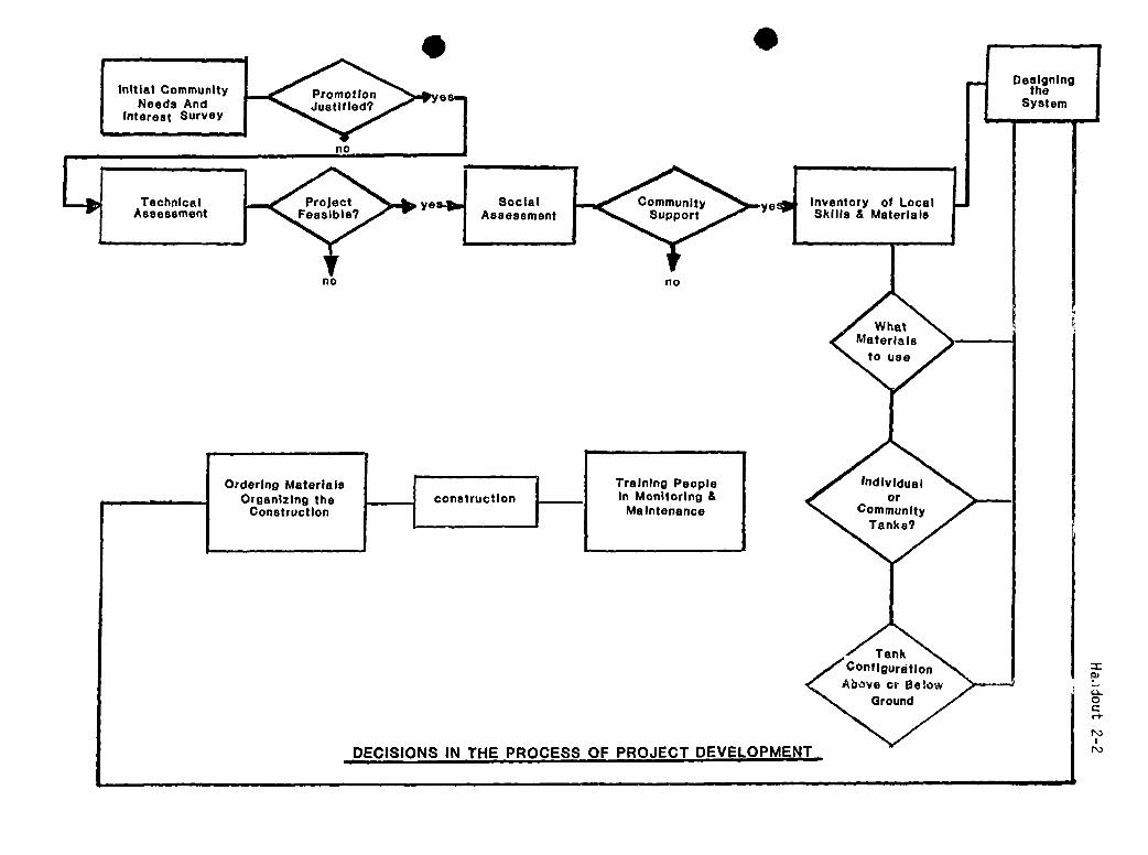
I
no
t
0CCt
N)DECISIONS IN THE PROCESS OF PROJECT

I
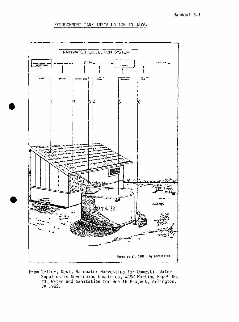
Handout 5~1
FERROCEMENTTANK INSTALLATION IN JAVA.
From Keller, Kent, Rainwater Harvesting for Domestic WaterSupplies in Develooinci Countries, WASHWorking Paper No.20, Water and Sanitation for Health Project, Arlington,VA 1982.

I

Handout 5-2
COMMUNITYRESOURCEINVENTORY CHECKLIST
Here is one way to organize a checklist for finding out availabilities andcosts of local materials and skills. The checklist below is an example; in anyparticular area, other materials and skills would be included.
Category Material Available Price
Roofs Corrugated metal sheetFired local tileFiber-reinforced cement sheetShingles/local wood or fiberSlate
Gutters Metal sheet, any kindWood planks or boardsWood pieces (hollowed)BambooPVC pipeWire (hanging)Fiber (hanging)Pitch (sealing)Tar (sealing)
Tanks CementStonesSandGravelFired brickConcrete blockBambooLocal basketsChicken wireStraight wireSteel reinforcing rod
Skills MasonryCarpentryBasketryPotteryTinsmithWelding
Rate


Tank
LABOR & SKILLS
Decision Matrix for Tank Type
SITE & TYPE OUTLET. COVER
.
MATERIALS
0)
a0C

I

Handout 6-2, p. 1
Chapter 4
GUTTER ING SYSTEMS *
Clearly, effective guttering is a key to rooftop catchment systems; water can beneittier stored nor consumed if it is not channelled efficiently from the capturearea to the tank. Yet the materials and techniques for construction of effectivegutters is a topic that is omitted from almost all accounts. Technically, gutter—ing is far less challenging than construction of cost—effective water storage,and its cost is usually a relatively small part of total costs. Possibly gutter—ing has been largely ignored in published accounts for these reasons.
4.1 General Considerations
How big do gutters need to be? Size needs will obviously vary with the intensitylocal storms and the ground area covered by the roof. Ree (1976), investigating
runoff yields from sloping metal roofs, used sheet metal gutters 20 cm wide by10 cm deep, each with a downpipe 15 cm in diameter. Each of these gutters had acapacity of twice the greatest runoff rate recorded from half a 12 x 18 m areaof roof over a period of one year in Oklahoma. Thus, gutters half as wide orhalf as deep would have handled the year’s heaviest rain from the roof. Ingeneral, gutters and downpipes with a cross—sectional area (width x depth) of 100cm2 will probably be big enough to handle all but the most torrential rains frommost roofs.
A greater problem than gutter size is probably hanging gutters securely so thatthey do not sag or fall during heavy rainfall, and keeping them positioned sothat they catch both gushing flow and dripping flow from the edges of the roof.Ensuring adequate slope for the entire system, so that water does not stand anddamage gutters or attract mosquitoes, is equally important.
4.2 Manufactured Metal Gutters
Iluminum or galvanized Sheet metal guttering is the technology of choice in mostareas in developed countries. The gutter sections are joined with special bracketsand hung with metal straps or long spikes with sleeves which are driven throughthe upper part of the gutter’s width and into wood backing. As of this writing,in the U.S. aluminum guttering and downpipe sections cost about $US1.85/m(galvanized Sheet is sligntly less expensive but tends to corrode more quicklyunless coated with high—quality rust—resistant paint). Hardware for joining andhanging the system costs another $0.60 per meter. This would make the materialscosts of guttering and downpipe for a building 6 in long approximately $30.00.Higher cost or unavailability are likely to eliminate manufactured metal guttersas possibilities in most rural areas of developing countries.
4.3 Alternatives Using Local Materials
McDowell (1976, page 33)** observes:
“It is noticed that, in many areas, houses will have a snort length of roughlyfashioned guttering fixed under the eaves just above the door, and that water
From Keller, Kent, Rainwater Harvesting for DOMESTIC Water Supplies in DevelopingCountries, WASH Working Paper No. 20, Water and Sanitation for HealthProject, Arlington, VA 1982.

Handout 6-2, p. 2
Institute for Rural Water. 1982 (draft), by perimission
seam
Figure 2, Bamboo Guttering JoiningSections.
Figure 3, Alternative Forms of IGuttering.
8,1) provides good ideas for joining sections of bamboo guttering with wire andsome flexible sheet materials such as rubber or canvas, and joining gutters anddownpipes with similar materials (see figures 2 and 3 above). The Institute forRural Water also suggests flanging gutters with twisted wire or local fiber,wrapped around the gutter and tied to noles in roof sheeting or to the ends ofroof supports (see figures 4 and 5).
from this will be collected in an old oil drum or other container. It seems thatthis type of device is used more for the purpose of preventing water from runningin through the doorway of the hut than as a serious approach to water collection.However, the existence of this “technology” could provide the link point fordevelopment of simple but effective roof catchment systems.”
McDowell also reports on the use of split bamboo cuims with joints removed, and“V”—shaped gutters made by nailing two boards together at right angles edge-to—edge. This construction seems likely to leak but the “V’1 might be sealed withtar, pitch, or some local gum. The Institute for Rural Water (1982; see section
I
a. Bamboo splitlengthwise b. joining 2 pieces of
bamboo
Basics, October 1978, page 4
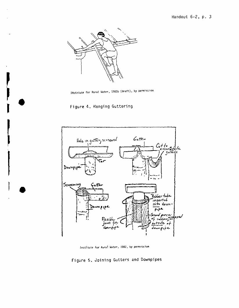
Handout 6-2, p. 3
INstitute for Rural Water, 1982b (draft), by permission
Figure 4. Hanging Guttering
17-
maeCo~-~’i
institute for Rural Water, 1982, by permission
Figure 5. Joining Gutters and Downpipes

S
S
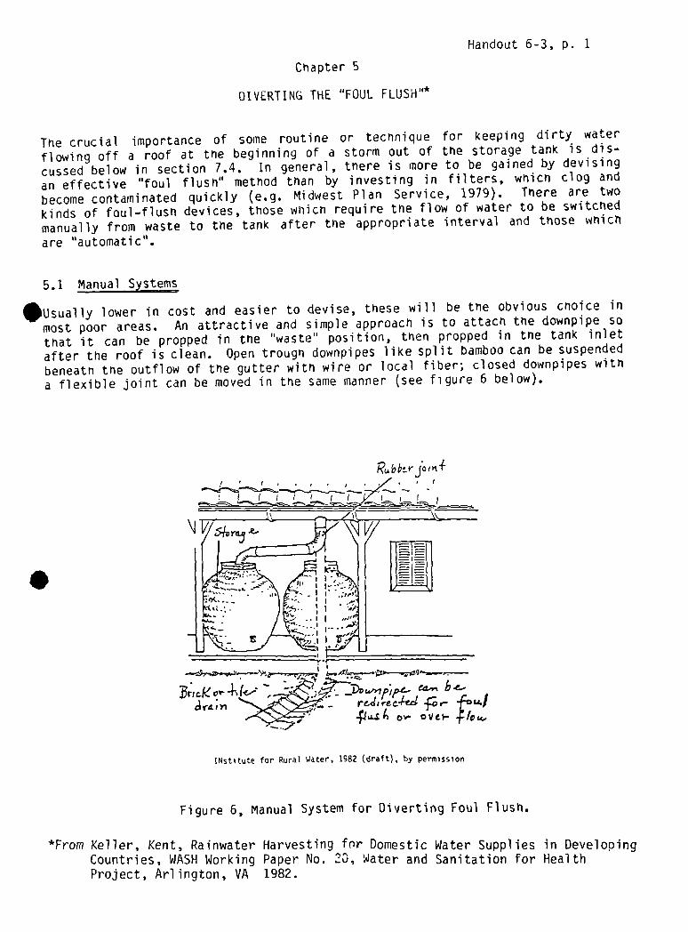
Handout 6-3, p. 1
Chapter 5
DIVERTIN(i THE “FOUL FLUSHII*
The crucial importance of some routine or technique for keeping dirty waterflowing off a roof at the beginning of a storm out of the storage tank is dis-cussed below in section 7.4. In general, there is more to be gained by devisingan effective “foul flush” method than by investing in filters, which clog andbecome contaminated quickly (e.g. Midwest Plan Service, 1979). There are twokinds of foul—flush devices, those wfllcfl require the flow of water to be switchedmanually from waste to tne tank after the appropriate interval and those whichare HautomatiCl~.
5.1 Manual Systems
•Usually lower in cost and easier to devise, these will be the obvious cnoice inmost poor areas. An attractive and simple approach is to attach the downpipe sothat it can be propped in the “waste” position, then propped in tne tank inletafter the roof is clean. Open trough downpipeS like split bamboo can be suspendedbeneath the outflow of the gutter with wire or local fiber; closed downpipes witha flexible joint can be moved in the same manner (see figure 6 below).
INstitute for Rural Water, 1982 (draft), by permission
Figure 6, Manual System for Diverting Foul Flush.
*From Keller, Kent, Rainwater Harvesting fnr Domestic Water Supplies in DevelopingCountries, WASH Working Paper No. 23, Water and Sanitation for HealthProject, Arlington, VA 1982.
RuE.’be-rjot~t4
- -,---:~ ~..-_. . DC..-~ ~ ~ ~~rL’fl A ~

Handout 6-3, p. 2
The task of moving the downpipe can be performed consistently by anyone includingchildren. People in developing countries tend to be conscious of the precisemoment it begins to rain because drying laundry must be brought in.
Another simple technique for tanks with small covers is to leave the cover on,blocking the flow of water into the tank, until the roof is clean. A similarapproach (for very small containers like jars) is to move the container intoposition under the downpipe only after an appropriate interval. Both theseroutines may be objectionable from a public health point of view: they causemud and pools of standing water at the tank. Nevertheless, they may be the methodof choice where a more complex downpipe and foul flush arrangement is impract-icable.
By—pass valves built into metal downpipes may be an option in some areas. Oftenreferred to as “butterfly” valves, they are made of sheet metal and thus would beexpensive or impossible to fabricate in many situations. It might be possible todevise a similar valve for downpipe arrangements made of other materials, but amovable downpipe will probably be the cheaper, more functional alternativel(see figure 7 below).
~1’~’~-r,~~ .5C415 i,c~,—
~cr,~’-f f.w’~r~~d,c4.4~cd,kG)4,m,
r’,rv~
Institute for Rural Water, 1982b (draft), by permisssiOn
4
ChPisYi C.CfIØIn
To
S
Figure 7, By-pass Valve.
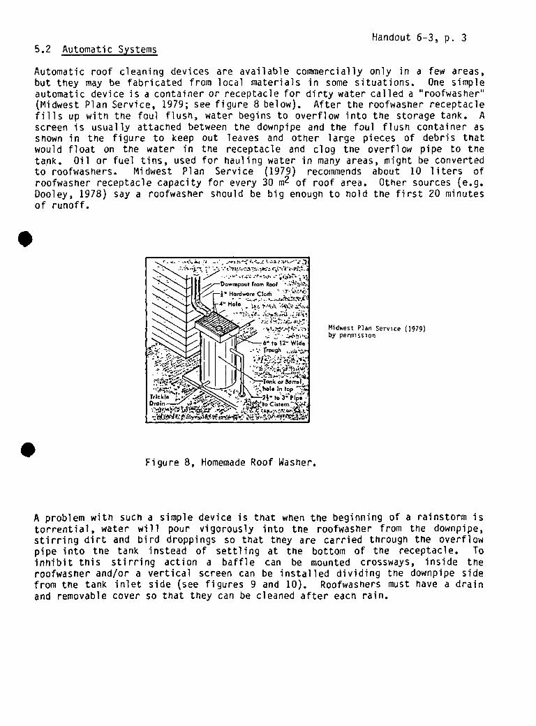
Handout 6-3, p. 35.2 Automatic Systems
Automatic roof cleaning devices are available commercially only in a few areas,but they may be fabricated from local materials in some situations. One simpleautomatic device is a container or receptacle for dirty water called a “roofwasher”(Midwest Plan Service, 1979; see figure 8 below). After the roofwasher receptaclefills up with the foul flush, water begins to overflow into the storage tank. Ascreen is usually attached between the downpipe and the foul flush container asshown in the figure to keep out leaves and other large pieces of debris thatwould float on the water in the receptacle and clog the overflow pipe to thetank. Oil or fuel tins, used for hauling water in many areas, might be convertedto roofwashers. Midwest Plan Service (1979) recommends about 10 liters ofroofwasfler receptacle capacity for every 30 m2 of roof area. Other sources (e.g.Dooley, 1978) say a rootwasher should be big enough to hold the first 20 minutesof runoff.
Midwest Plan Service (1979)by permission
A problem with Such a simple device is that when the beginning of a rainstorm istorrential, water will pour vigorously into the roofwasfler from the downpipe,stirring dirt and bird droppings so that they are carried through the overflowpipe into the tank instead of settling at the bottom of the receptacle. Toinhibit this stirring action a baffle can be mounted crossways, inside theroofwasfler and/or a vertical screen can be installed dividing the downpipe sidefrom the tank inlet side (see figures 9 and 10). RoofwasherS must have a drainand removable cover so that they can be cleaned after each rain.
Figure 8, Homemade Roof Washer.

Handout 6-3, p. 4
Figure 9, Roof Washers
Corer
More complicated “automatic” foul flush devices tend to require more attentionand stronger structures with more hardware for mounting in the downpipe. Reportedi’~use in Australia are, “swing funnels” made of sheet metal, with a large inflowside divided into two compartments, and hinged on a horizontal pin (see figure10 below). At the start of a storm, water pours from tne gutter into the first
compartment. As the weight ofthe assembly increases, thefunnel swings so that water poursfrom the gutter into the secondcompartment which leads throughthe downpipe into the tank. Suca funnel would have to be quitelarge to hold the recommendedvolume of foul flush. Mountingand hinge—pins would also have tobe quite strong. This particulardevice is unlikely to be the mostattractive of foul flush optionsin most places, but it is aninteresting idea.
Ctp,5C ‘-t-~’—
w~CI
Fi~ ~dIPl.
.A£.umuI.I.dlid. 1, Ifli
Institute for Rural Water. 1982 Ui4EP (1979)(draft) by permission by permission
I,•. l~~ I.n,dlwill ill...., C..p.,Im.pI B,. mimi ~.li, ,mo~ mid,
p,.vm~.Iy cl..n.d by flow .vFimCii
•CCU.,,.lII.I •1 01.1.1St iii
Figure 10, Swing Funnel

Handout, 8-1, p. 1
BUILDING WATER TANKS*
The construction information in this section is for three of the most widelydocumented of the tanks. Here is detailed information on the materials, tools,and skills involved in their construction; some readers with confidence intheir manual skills would be able to attempt Construction from the informationgiven. These are not necessarily the three “best” tank designs for householdrooftop catchment; in fact, each of these three tanks requires a relativelygreat amount of cement per cubic meter of storage (see below). They are, how-ever, three of the most “teachable” of the designs documented.
Each of the tanks described in this section is made with cement mortar, whichis a mixture of sand and cement and water. It is always important to make
S mortar with the cleanest available materials, and to keep soil and othercontaminants out of the mortar mixture. Watt (1978) suggests using a mixingboard or making a small concrete pad on a layer of gravel. The board isprobably a better choice where the tanks or jars will be built far from eachother (see figure below).
Watt (1978) by periii~ssthn
Equipment and Material for Mixing Cement Mortar
* From WASH Working Paper No. 20, “Rainwater Harvesting for Domestic WaterSupplies in Developing Countries” by Kent Keller, as adapted for thissession by David Yohalem, 1984.
Water b,nsGauge sand ,nmeasur,ng box
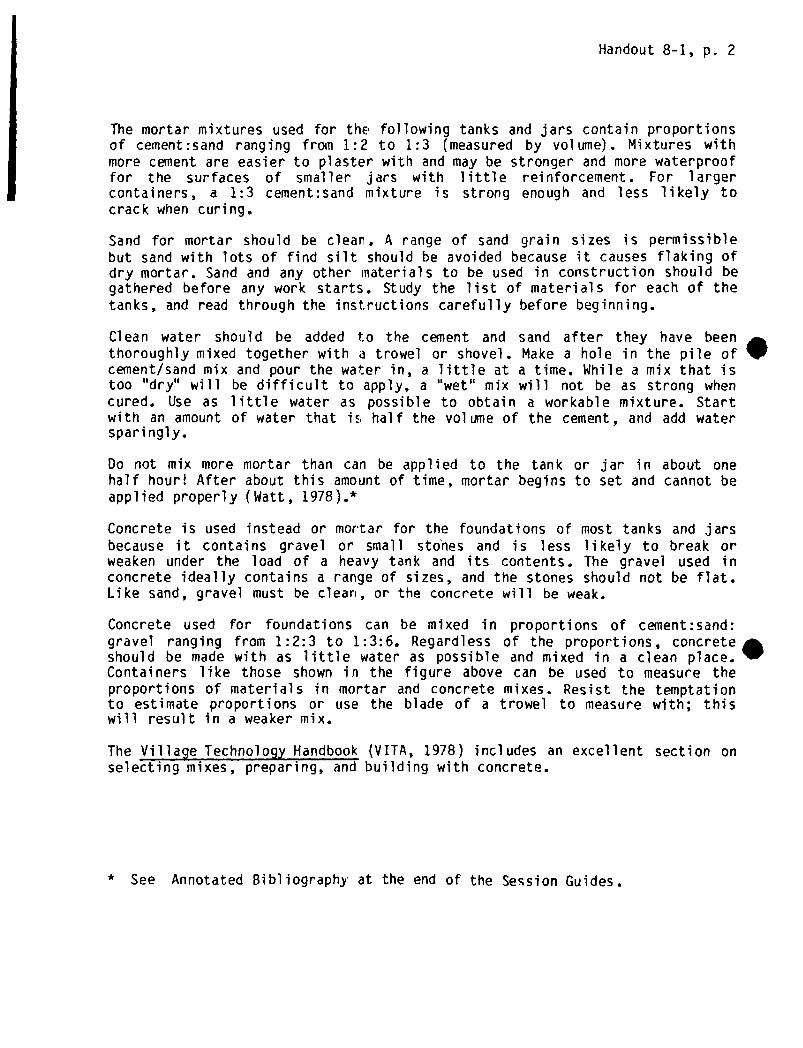
Handout 8-1, p. 2
The mortar mixtures used for the following tanks and jars contain proportionsof cement:sand ranging from 1:2 to 1:3 (measured by volume). Mixtures withmore cement are easier to plaster with and may be stronger and more waterprooffor the surfaces of smaller jars with little reinforcement. For largercontainers, a 1:3 cement:sand mixture is strong enough and less likely tocrack when curing.
Sand for mortar should be clean. A range of sand grain sizes is permissiblebut sand with lots of find silt should be avoided because it causes flaking ofdry mortar. Sand and any other materials to be used in construction should begathered before any work starts. Study the list of materials for each of thetanks, and read through the inst.ructions carefully before beginning.
Clean water should be added t:o the cement and sand after they have beenthoroughly mixed together with a trowel or shovel. Make a hole in the pile ofcement/sand mix and pour the water in, a little at a time. While a mix that istoo “dry” will be difficult to apply, a “wet” mix will not be as strong whencured. Use as little water as possible to obtain a workable mixture. Startwith an amount of water that is half the volume of the cement, and add watersparingly.
Do not mix more mortar than can be applied to the tank or jar in about onehalf hour! After about this amount of time, mortar begins to set and cannot beapplied properly (Watt, 1978).*
Concrete is used instead or mortar for the foundations of most tanks and jarsbecause it contains gravel or small sto’nes and is less likely to break orweaken under the load of a heavy tank and its contents. The gravel used inconcrete ideally contains a range of sizes, and the stones should not be flat.Like sand, gravel must be clean, or the concrete will be weak.
Concrete used for foundations can be mixed in proportions of cement:sand:gravel ranging from 1:2:3 to 1:3:6. Regardless of the proportions, concreteshould be made with as little water as possible and mixed in a clean place.Containers like those shown in the figure above can be used to measure theproportions of materials in mortar and concrete mixes. Resist the temptationto estimate proportions or use the blade of a trowel to measure with; thiswill result in a weaker mix.
The Village Technology Handbook (VITA, 1978) includes an excellent section onselecting mixes, preparing, and building with concrete.
* See Annotated Bibliography’ at the end of the Session Guides.

Handout 8-1, p. 3
1. Quarter Cubic Meter Cement Plaster Jar (“Thailand Jar”)
Unlike the other water containers in this section, this jar is built entirelyof mortar. It contains no strengthening fibers nor wires. The mortar isapplied to a “mold” which is usually made of sacking material (like burlap)filled with something heavy enough to plaster against.
Because these jars have no reinforcing material , they are made with a mortarmix which is “rich” in cement. The proportions of materials recommended in thefollowing instructions (copied by permission from Watt, 1978 are 1:2, cement:sand (measured by volume). Watt does not mention the proportion of watar to beused. He says instead that the mortar should be mixed as “dry” as possible,for maximum strength. Refer back to the discussion of making mortar above.
The following instructions are for construction of a small jar which holdsapproximately a quarter of a cubic meter of water (figure 2). Watt says thatpeople with no experience have been taught to make the jars in less than twodays. Much larger jars which have screens, lids, and taps have been cons-tructed using this method. Substituting soil and lime for some of the cementand sand in the mortar has also been tried.
MATERIALS: 1/2 bag of cement (less than this should be required) per jarclean sandclean waterburlap, “gunny cloth”, or other strong sacking materialsand, grain husks, or sawdust to fill the sackingprepared concrete bases
TOOLS: needle and thread, or other tool for sewing the sackingmixing board or pad and containers for measuring and mixing mortarshovel for mixing mortartrowel and wooden stickbucket for carry mortar
STEPS IN CONSTRUCTIONREQUIRING SPECIAL CARE:
Making sure that the material used to fill the sacking (Step 2.4 infigure 2) is heavy enough to keep its shape during plastering. It
is a good idea to try filling the sack on the ground beforebeginning construction.
Making the mortar. Do not make the mortar for applying to the molduntil you are actually ready to begin (Step 2.8 in figure 3). Thisshould allow you to work with a “dry” mortar mixture for maximumstrength. Mixing the cement and sand well, before adding the water,is especially important.
Curing the new jar (Step 2.10 in figure 3), also requiresparticular attention.
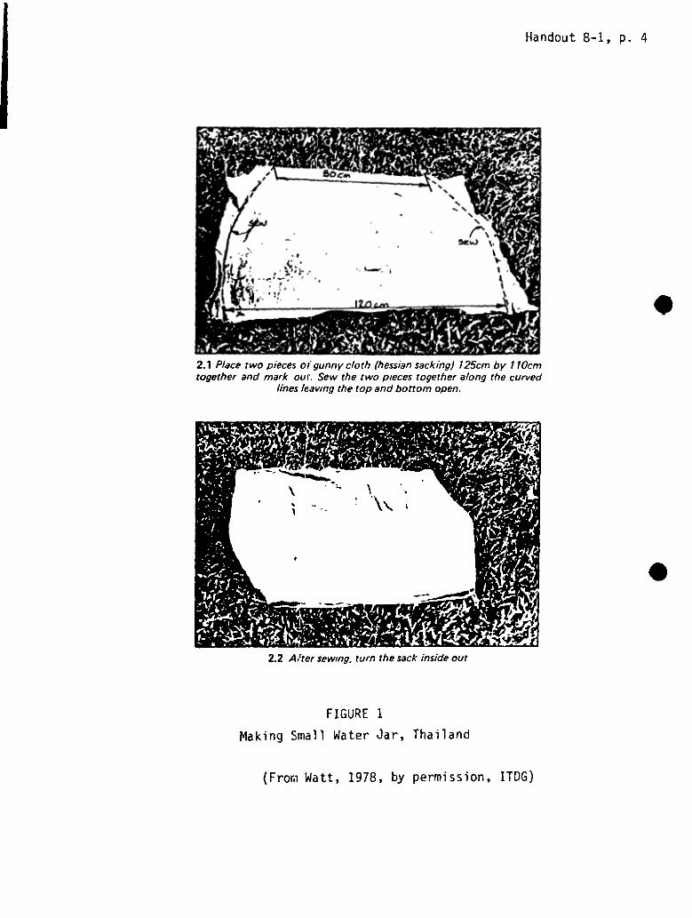
Handout 8—1, p. 4
FIGURE 1
Making Small Water Jar, Thailand
2.1 P/acetwo piecesof gunnycloth (hessiansacking) 125cm by 110cmtogether and mark our. Sew the two piecestogether along thecurved
lines leaving the top andbottomopen.
2.2 After sewing,turn the sackinside our
(From Watt, 1978, by permission, ITDG)
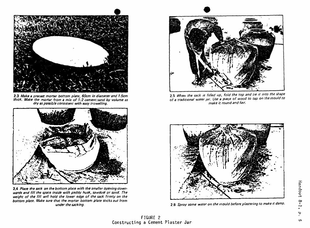
.
2.3 Make a precastmortar bottom p/ate, 60cmin diameterand 1.5cmthick. Make the mortar from a mix of 1:2 cemenr:sandby volumeas
dry aspossibleconsistentwith easytrowelling.
, 11~1.
I ‘1’-
2.5 When the sack is filled up, fold the top and tie it into the shapeof a traditional waterjar. Use a piece of wood to tap on the mould to
make it round and fair.
2.4 P/acethesack on thebottomp/ate with thesmalleropeningdown-wards and fill thespaceinside with paddyhusk,sawdustor sand. Theweight of the fill will hold the lower edgeof the sack firmly on thebottom plate. Make sure that themortar bottom plate sticksOut from
under thesacking.
FIGURE 2Constructing a Cement Plaster Jar
2.6 Spraysomewateron the mouldbeforeplasteringto make it damp.
=oJ
0

• FIGURE 3Constructing a Cement Plaster Jar (continued)
2.7 P/acea ci. ~ular ring on thetopof thesack to makea mouldfor theopeningof thejar. This can bemadeof woodorprecastmortar.
2.9 Plaster the secondlayer of 0.5cmin thesamemanneras the firstlayer. Check the mortar layer for thicknessbypushing in a nail: anyweak or thin spotsshould ye buik up with an extra layer of mortar.
Build up the opening.
2.8 Trowel a first layer of mortar onto the mould to a thicknessofabout 0.5cm.
2.10 Removethe contentsof the gunny bag and the bag 24 hoursafter the jar has beenmade. Check thejar for any defectsandcorrectthese with mortar; the inside of the jar shouldalsobepaintedwith acementslurry. Cure thejar out of sunlight anddrying winds,preferably
underdampsackingorplasticsheetfor at least2 weeks.This techniquehas beenusedwith greatsuccessin Thailandandpotsofup to 4000 litres (approx 1000gal/s.) capacityhave beenmadein this
way.

Handout 8-1, p. 7
2. Woven “Ghala” Basket Reinforced Tank
The f~llowing guidelines are adapted from Keller’s instructions for a larger2.3 m tank made out of ghala basket. These guidelines are for similar sizetank as above and can be made out of any appropriate basket with about onehalf a sack of cement.
Choosin~ an Apprqpriate Woven Basket
The basket should be made out of a thick sturdy weaving material so that thebasket will stand on its own and not bend while being plastered. The weaveshould be open enough to enable the mortar to go through the weave. Intricateweaving designs and different colored fibers are not necessary and onlyincrease the cost of the basket. The top of the basket should be large enough
So allow an adult to reach in to plaster the basket from the inside. The basef the basket should not be too small relative to the widest diameter or it
will be unstable.
Base
Follow the same instructions for a ferrocement tank base to make a base alittle bigger than the basket. Place the basket into the base while it isstill wet. If the bottom weave of the basket is very tight and the concretecannot go through it, cut the bottom of the basket off and push the lowersides of the basket into the concrete so it is firmly in place. Allow the baseto dry enough so that the basket doesn’t move when being plastered.
Mortar and Plastering
Apply a first coat of mortar made with a ratio of 1:3 cement to sand to theinside of the basket starting at the bottom and working up to a thickness of 1cm. As with the above tanks, keep the mortar as dry as possible. Place extramortar on the bottom where the basket joins the base. Push the mortar through
e weave of the basket and smooth on the outside as well as inside. Let theortar basket dry while mixing the second coat of mortar with a richer mixture
of 1:2 cement to sand. Apply the second coat to the inside of the basketincluding the base of a thickness of 1 cm. Use any leftover mortar to coverthe outside of the basket so that the woven basket frame is entirely coveredwith plaster. This will protect the frame from insects, moisture, etc. andmake the tank last longer. When the second coat is dry enough apply a cementslurry to seal the inside.
Curing
Cure and cover as in above instructions.
MATERIALS
1/2 sack of cement per tankclean sand gravel and waterwoven basket

Handout 8-1, p. 8
3. Ferrocement Tank for Small Household Use
The following construction guidelines are adapted from Keller’s instructionsfor the construction of a larger 10 m3 ferrocenient tank. The tank to be builtwith these guidelines is approx
3imately 1 m tall and 60 cm in diameter and willhold about 280 liters (0.28 m ) of water. If made with walls 2 cm thick ofmortar mixed to a ratio of 1:3 cement to sand it will use a half a sack ofcement, 6 meters of #8 reinforcing rod and 2-4 meters of 1 m wide chicken wfredepending on the size of the wire mesh.
Base
A concrete base 70 cm in diameter by 5 cm thick is poured with a mixture of1:2:4 cement:sand:gravel in li 5 cm deep x 70 cm wide circular form excavatein clay soil . Make sure the sand and gravel are clean and free of any organimatter. Mix in only enough water to make the concrete workable. The drier theconcrete the better. Let dry a little as you prepare the other materials.
Wire Mesh and Supports
Cut a 6 meter length of #8 reinforcing rod into six one meter lengths (#6 or10 re-rod can be used but the #6 is a little weak for this purpose and the #10is stronger than needed and more costly). Place the rods about ‘30 cm apart ina circle 5 cm inside the outer rim of the still wet base. This will produce anew circle with a diameter of 60 cm. Take the wire mesh and wrap it around thereinforcing rod and push the bottom into the concrete base. If you are usingchicken wire with a one inch (2.54 cm) mesh you only have to wrap it aroundonce. If you have to use 2 inch (5 cm) mesh chicken wire, wrap it around twiceand make sure that the second layer overlaps the first in such a way as to cutthe size of the holes in half. Tie the chicken wire itself and secure to thereinforcing rod.
Mortar and Plastering
Mix mortar with a 1:3 ratio of cement to sand and as little water as needed tomake it workable. The drier the mortar, the stronger the tank will be when itdries. Apply a coat of mortar plaster 12 cm thick to the outside of thechicken wire mesh, starting at the base and working up. Put a little extramortar onto the bottom of the mesh where it joins the base. Push the mortarthrough the wire mesh so it completely covers the inside of the reinforcingrod and wire mesh. Smooth the plaster on both sides and let dry a little. Whenthe mortar is dry enough to be worked (about 20 minutes) put on a second coatof mortar made with a richer mixture (1:2 cement to sand) to the same thick-ness to the inside of the tank. Plaster the concrete base and use more plasteras above where the wall and base meet.
Start from the bottom and work up to the top. Make sure that all the mortarwalls are to a uniform thickness and fill in any thin spots. When completed,the walls should be 2 cm thick and no reinforcing rod or chicken wire shouldbe visible. Finish the top of the wall to make a smooth lip for the barrel.Apply a cement slurry to the inside to smooth and seal the interior.

Handout 8-1, p. 9
Curing
Dry in the direct sunlight, and keep damp for two weeks before moving. A wetburlap sack can be placed over the tank to keep it wet during this time. Aftera day, put 20 cm of water in the tank to keep the inside moist. A wooden topcan be made to sit over this tank as a cover.
MATERIALS
1/2 sack of cement per tankclean sand, gravel and water6 m of #8 reinforcing rod per tank‘ 4 m of 1 m wide chicken wire or similar wire mesh per tank
re
TOOLS
shovels and buckets for mixing and carrying mortar and concretetools for cutting re-rod and wire meshtrowels, floats, etc.

I

S TANK DESIGN GUIDE
Shape Formula Example
0)
0C
Tank Group
•
d2
4
If V’0.5rn3d 0. 8mTI h
Materials
Cementa. mortar jar
b. ~ered baskets-ceirerit
tanks
C. ferrocement tank
d. ferrocement lined
Calculation I
Cement mortar (walls)Concrete (foundation) 3
d~4 iT h
If V2.7m3d~1.5mh~’1.5m
Cement mortar (walls)Concrete (foundation)
13
h slightly less If V=1t~n3 Cement mortar (walls & 1than d d~2.5m floor)
2 h~2.0m Metal sheet (cover) No calculation
d4 h
Wire netting (walls.floor, cover)Concrete (foundation)
73
d1 + d2
8
2 If V~20m3
d=3. Sm
TI h
Cement mortar (walls &floor)Cement mortar (cover)Wire netting (walls,floor, cover)
68
7
e. poured (or cast)concrete
h usvally less than
1 and w
If V=20m3h~2ml~3.2mw=3.2m
Concrete (walls, floor)Reinforced concrete (cover)
3No calculation
f. brick, stone, orconcrete block tank
or
~
V 1 x w x ii,w usually less than 2rn
2d4 TJh
d may be more than 2 m,h usually less than d
If V=20m3w=l.5nil=5m
If V=20m3d=3mh~2.8m
Brick, stone, or block(walls, floor)Cement mortar (laying walls,floor)
Cement mortar (surfacing)walls, floor)
4
5
2
g. area of circle
area of circularwall (cylinder)
area of rectangle
~4rr dh
1 x w ~ h

I

CALCULATION SHEETS
Handout 9-2, p. 1
1. Calculation #1: Cement in mortar walls for above ground cylindricalcontai ners
Height
1.0 m
1.5 m1.75 m
2.0 m
Wall Thickness
= 1.0 cm
= 2.5cm
= 3.0cm
= 4.0 cm
Typical Container Typ~
Cement Mortar Jar
Plastered Basket
Ferrocement Tank (1.75 m’3 volume)
Ferrocement Tank (10 m3 volume)
S Note: Walls in these kinds of tanks are rarely more than 2 m high]
Steps:
a. Using wall height (h) , determine wall thickness from above chart.
b. Calculate the area of the wall:
C.
e.
IMultiply the wall area by the wall thickness to determine the amount ofmortar needed:
3Multiply the amount of mortar ne~ded by 10 bags cement/rn mortar, todetermine the amount of cement needed.
IBag~of cement needed = mortar needed x 10 bags cement*
m’3 mortar
Cost = bags of cement needed x price/bag
* 50 kg bags of cement. Based on a cement to sand ratio 1:3. This is arecomended figure for watertight mortar. Local masons may use less cement(more sand), and the formula would have to be ~djusted accordingly. Mortarswith 1:2 cement:sand use 13 bags of cement per m of mortar.
Area = pi x diameter x height
‘pMortar needed = area x thickness
I

Handout 9—2, p. 2
2. Calculation #2: Cement mortar for plastering over walls and floors madeof other materials
Steps:
a. Calculate area to be plastered:
c. Multiply the amount of mortar needed by 10determine the amount of cement needed:
* 50 kg bags. Based on a cement to sand ratio of 1:3. This is a recommended
figure for watertight mortar. Local masons may use less cement (more sand),and the formula would have to be adjusted accordingly. Mortars withcement:sand mixtures for final waterproofing coats use 13 bags cement per mof mortar.
.b. Multiply the area by the thickness of mortar to be applied to determine
the amount of mortar needed:
~rneeded=ar~~a x thickness I
Ibags cement*/m3 mortar, to
d.
Bags of cement needed mortar needed x 10 bags cement*[ m’3 mortar
1Cost = bags of cement needed x price/bag

Handout 9-2, p. 1
CALCULATION SHEETS
1. Calculation #1: Cement in mortar walls for above ground cylindricalcontai ners
Height Wall Thickness Typical Container Type
1.0 iii = 1.0 cm Cement Mortar Jar
1.5 Tn = 2.5 cm Plastered Basket
1.75 rn = 3.0 cm Ferrocement Tank (1.75 rn3 volume)
2.0 in = 4.0 cm Ferrocement Tank (10 m3 volume)
SNote: Walls in these kinds of tanks are rarely more than 2 m high]
Steps:
a. Using wall height (h), determine wall thickness from above chart.
b. Calculate the area of the wall:
-Ic. Multiply the wall area by the wall thickness to determine the amount of
mortar needed:
Multiply •the amount of mortar n~ded by 10 bags cement/rn3 mortar, todetermine the amount of cement needed.
___________ ~1~ ________
Bags of cement needed = mortar needed x 10 bags cement*
mortar
e. Cost = bags of cement needed x price/bag
* 50 kg bags of cement. Based on a cement to sand ratio 1:3. This is arecomended figure for watertight mortar. Local masons may use less cement(more sand), and the formula would have to be ~djusted accordingly. Mortarswith 1:2 cement:sand use 13 bags of cement per m of mortar.
Area p1 x diameter x height
I
9Mortar needed = area x thickness
I

Handout 9-2, p. 2
2. Calculation #2: Cement mortar for plastering over walls and floors made
of other materials
Steps:
a. Calculate area to be plastered:
.b. Multiply the area by the thickness of mortar to be applied to determine
the amount of mortar needed:
~rneeded= area x thickness 1c. Multiply the amount of mortar needed by 10 bags cement*/m mortar, to
determine the amount of cement needed:
1Bags of cement needed = mortar needed x 10 bags cement*
mortar .
d. Cost = bags of cement needed x price/bag
* 50 kg bags. Based on a cement to sand ratio of 1:3. This is a recommended
figure for watertight mortar. Local masons may use less cement (more sand),and the formula would have to be adjusted accordingly. Mortars with 1:~cement:sand mixtures for final waterproofing coats use 13 bags cement per mof mortar.
I
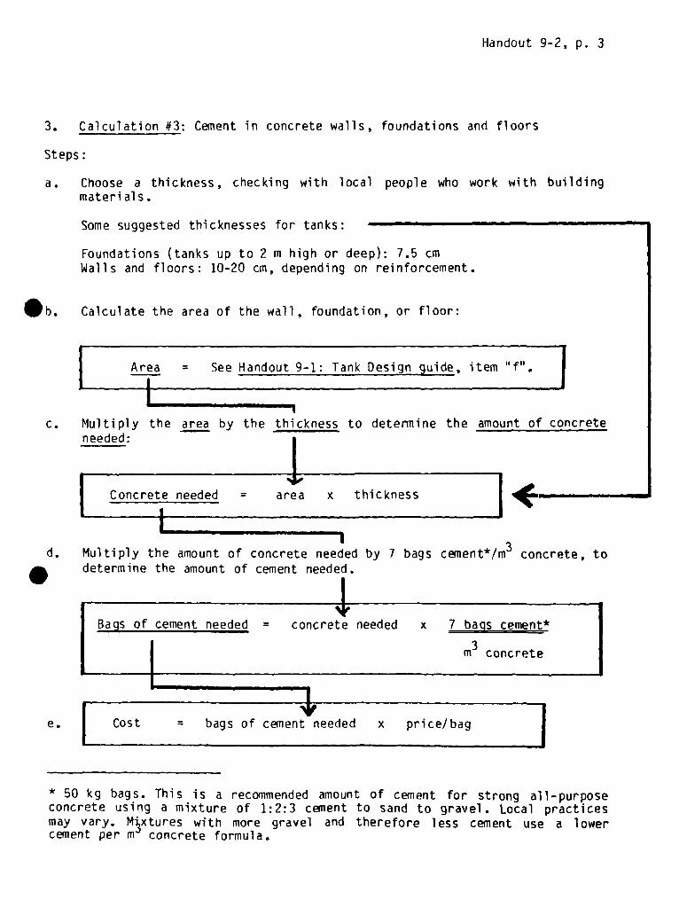
Handout 9-2, p. 3
3. Calculation #3: Cement in concrete walls, foundations and floors
Steps:
a. Choose a thickness, checking with local people who work with building
materi al 5.
Some suggested thicknesses for tanks:
Foundations (tanks up to 2 m high or deep): 7.5 cmWalls and floors: 10-20 cm, depending on reinforcement.
Calculate the area of the wall, foundation, or floor:
I I,[ Cost = bags of cement needed x price/bag
* 50 kg bags. This is a recommended amount of cement for strong all—purposeconcrete using a mixture of 1:2:3 cement to sand to gravel. Local practicesmay vary. M~xtures with more gravel and therefore less cement use a lowercement per m concrete formula.
c. Multiply the area by the thickness to determine the amount of concreteneeded:
Multiply the amount of concrete needed by 7 bags cement*1m3 concrete, todetermine the amount of cement needed.
d.
.
e.
B~js of cement needed = concrete needed x 7 bags cement*
Tn3 concrete

Handout 9-2, p. 4
4. Calculation #4: Mlounts of brick, stone, or block in tank walls and
Steps:
floors
a. Consult masonsthickness.
(who have built walls to hold water) to choose wall
Suggestions:
Walls (supported by earth):Walls (more than 1 m heightFloors: Same as walls
15—20 cmunsupported by earth: 30 cm
b. Determine the number of bricks (stones or blocks)
1 m of wall or floor: bricks
fl’2
needed to build 1 m x
.
c. Calculate the area of wall or floor to be laid:
d.
e.
.4,Number of bricks = ar~a x bricks
m2
1rCost number of bricks x price/brick
I .
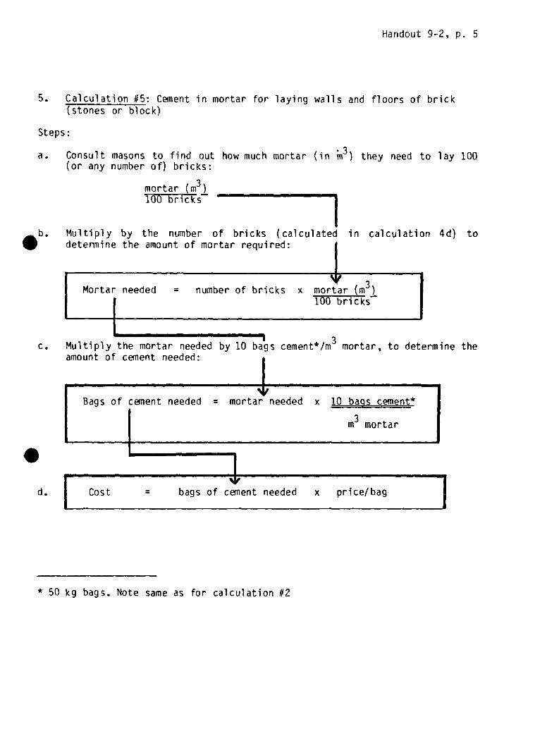
Handout 9-2, p. 5
5. Calculation #5: Cement in mortar for laying walls and floors of brick
(stones or block)
Steps:
a. Consult masons to find out how much mortar (in ~n3) they need to lay 100(or any number of) bricks:
mortar (m3) _____________________100 bricks
Multiply by the number of bricks (calculated in calculation 4d) todetermine the amount of mortar required: I
s~3
Mortar needed = number of bricks x mortar (m )
1 100 bricksI-ET1 w121 427 m126 427 lSBT
c. Multiply the mortar needed by 10 ba~js cement*/m3 mortar, to determine the
amount of cement needed:
Bags of cement needed = mortar needed x 10 bags cement*
I in3 mortar
Id. [ Cost = bags of cement needed x price/bag 1
* 50 kg bags. Note same as for calculation #2

Handout 9-2, p. 6
6. Calculation #6: Cement in mortar walls and floor of circular ferrocement—lined pit
Steps:
a. Calculate the area of the pit to be lined:
I
.b. Multiply the area by the thickness of plaster to be applied. To be safe,
assume a thickness of 4 cm (less may actually be needed):
c. To find the am~unt of cement needed, multiply the amount of mortar by 10bags cemnent*/m mortar:
d.
I3Bags of cement = mortar needed x 10 bags cement*/m mortar
II
Cost = bags of cement x price/bag
Area of walls = pi x diameter x heightTotal area
Area of floor = p1 x (1/2 diameter)2
* 50 kg bags. Same note as for calculation #2

Handout 9-2, p. 7
7. Calculation #7: Wire netting in circular ferrocement tank (above ground)and ferrocement pit (below ground) floors, walls, and covers
Steps:
a. Decide on the number of layers of wire netting to be used.ReconiTlendati ons:
b.
c. Multiply the areas by the number of layers to get the area of nettingneeded:
I‘V
Netting needed = area x number of layersI
‘Srd. Cost = netting needed x price/rn2
Note: wire netting is sold in widths which may need to be trimmed to correctsize during construction. Thus, one must buy more than will actually be used.
* Ferrocement covers are higher in the middle (domed) to support theirweight. The area of the dome is slightly greater than the circle it covers.
Ferrocement tank walls (with wireFerrocement pit walls and floorsFerrocement cover
reinforcement-): 1: 2: 3
layeror 3 layerslayers
Calculate the area of wall, floor, and/or cover:
Area of wallArea of floorArea of cover*
= p1= p1
p1
xxx
diameter(1/2 diameter)(1/2 diameter)
2x height
I
L4
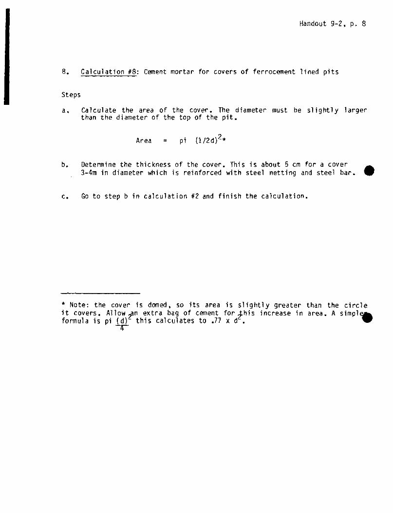
Handout 9-2, p. 8
8. Calculation #8: Cement mortar for covers of ferrocement lined pits
Steps
a. Calculate the area of the cover. The diameter must be slightly largerthan the diameter of the top of the pit.
Area = p1 (1/2d)2*
b. Determine the thickness of the cover. This is about 5 cm for a cover- 3-4m in diameter which is reinforced with steel netting and steel bar. 5
c. Go to step b in calculation #2 and finish the calculation.
* Note: the cover is dc~iied, so its area is slightly greater than the circle
it covers. Allow ~n extra bag of cement for ~his increase in area. A simpiformula is p1 (d) this calculates to .77 x d
-V
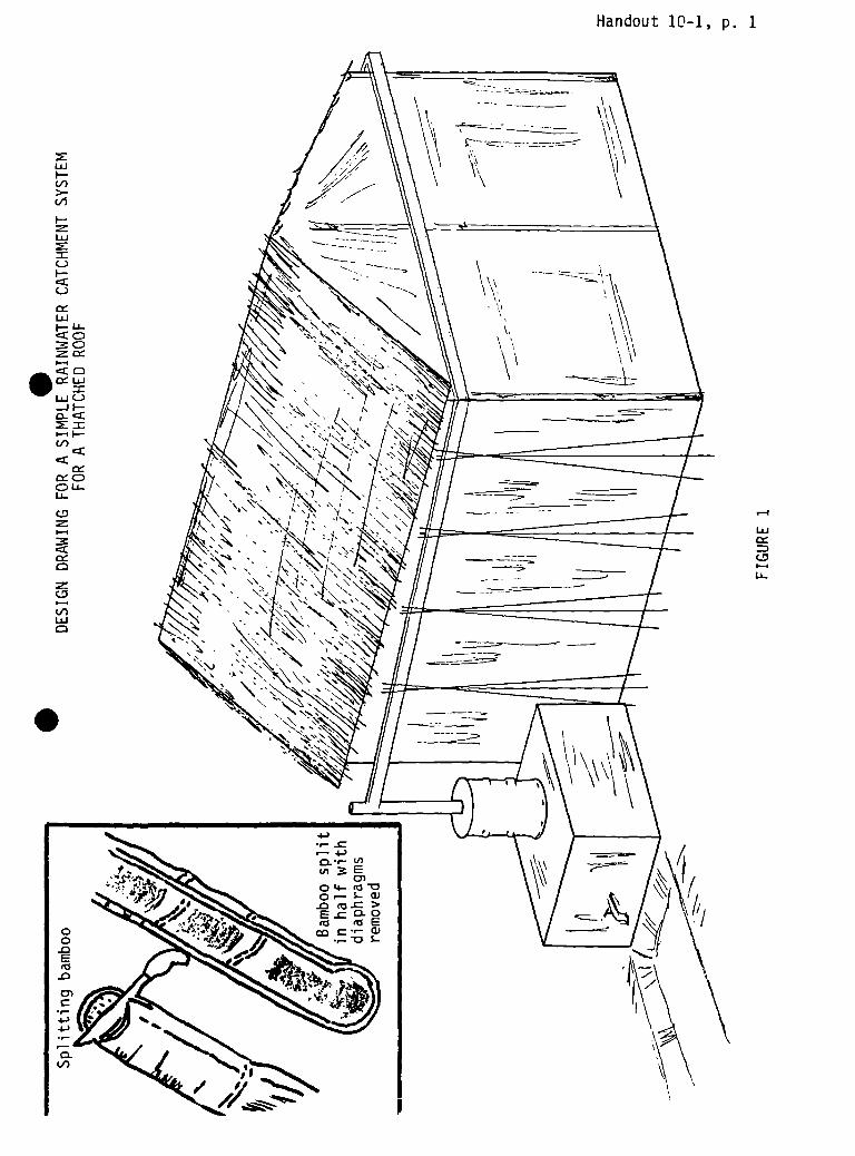
UJF-V)>-
I—
w
I—
wF-U-
.~o~w-JI-..
(I)
U-
(D
w
‘-4
U-
Handout 10-1, p. 1

S

40cm
30cm
Ground
Level
30cm
HOW• DETERIIINE TUE SLOPE OF GUTT
Assume a slope of 3% — In lOm of gutters, the first tripod is 30cmhigher than the last one. Put the tripods (3 poles each) in theirplace. The slope is determined by placing a strinci between tripodP~and Tripod B. Mark the intermediate tripods accordingly and cut.
N
10 meters
Depth of IPoles inGround
=0)
0~0CV-p
I-.,
.~
FIGURE 2

.
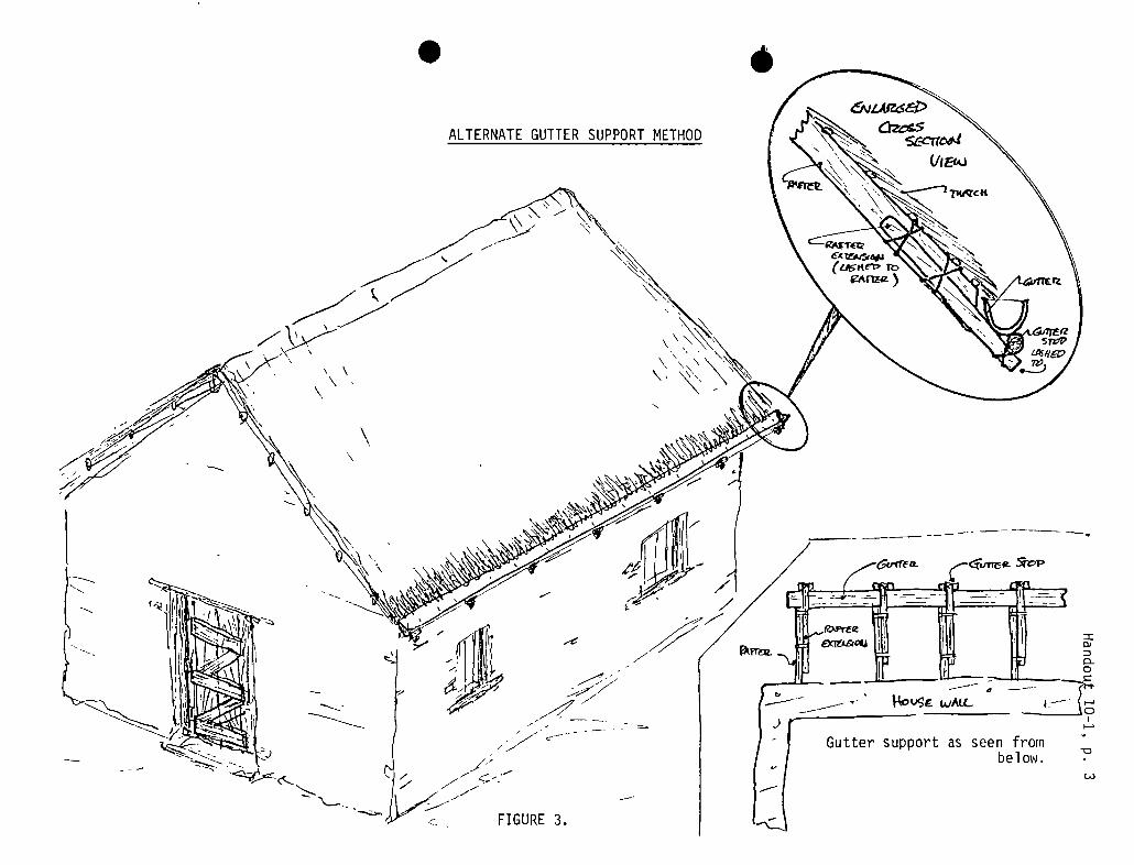
.
ALTERNATE GUTTER SUPPORTMETHOD
-e
a
~tp
/ Gutter support as seen frombelow.
=ci~0
I~a
~0
FIGURE 3.


Handout 10-2
TYPICAL MATERIALS ESTIMATE*
Materials Quantity Cost —
A. Guttering materials using bamboo, bush pole supports for a roof 10 M long
x 4 M wide, collection on both sides of the roof.1. Bamboo 15-20 cm in diameter 15 M
2. 9 V notch poles 5-10 cm indiameter, or 9 sets of polesfor tripods (27 poles),5 cm in diameter and 4 meterslong. 36-110 M of pole
3. Twisted wire, or locallyavailable twine 20 M
Tools: machetes, mallets, knives, digging tools, bucket for water
B. Filtration System Using a Barrel
1. Barrel, 200 Liter 1
2. Gravel (large) 35 Liters
3. Pea gravel 12 Liters
4. Raw rice husk 100 Liters
5. Or charcoal 50 Liters
Tools: drill or hammer and nail or spike; hammer or mallet for crushingcharcoal, tools and materials for making stand for filter
C. Filtration System Using a Box
1. Lumber: 40 cm x 2 cm 5 M
2. Nails 1 Kg
3. Gravel , rice husk (same as B)
Tools: Hammer, saw, drill; tools and materials for making stand
*Note: Since costs vary widely, the cost column is left open forto fill in depending on the local prices.
the trainers

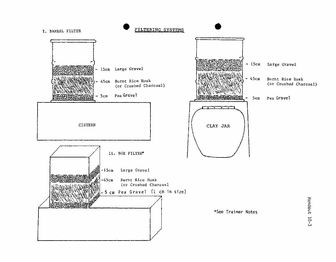
I. BARREL FILTER FILTERING SYSTEMS S
0)
0.0C
Large Gravel
Burnt Rice 1-1us1~(or Crushed Charcoal)
15cm Large Gravel
45cm Burnt Rice Husk(or Crushed Charcoal)
5cm Pea Gravel
Large Gravel
Burnt Rice Husk(or Crushed Charcc’ü
Pea Gravel (1 cm in size)
*See Trainer Notes

.
Handout 10-4
USING COCONUT FIBER FILTERS
Filters using shredded coconut fibers for the filter medium have been said tobe successful in Thailand (Frankel, 1974) and have been installed in over 100rural villages in Southest Asia (Frankel , 1981). The raw coconut husks arefound throughout Southeast Asia and have little market value, hence theyprovide a low-cost filter medium for treatment plants in that part of thewor 1 d.
Shredded coconut fiber may be prepared manually by soaking the husk for 2 to 3days in water and then shredding the husk by pulling off the individual fibersand removing the solid particles which bind the fibers. Shredded coconut. fibers may also be purchased directly from upholstery stores or coir (coconutfiber) factories. The shredded fiber should be imersed in water for aboutthree days, until the fiber does not impart any more color to the water(Frankel, 1977). The depth of the coconut fiber In the filter box is usually60—80 cm. There are no backwashing arrangements for cleaning the coconutfibers as the fibers do not readily relinquish entrapped particles because oftheir fibrous nature. Instead, water is drained from the filter box and thedirty fibers are removed and discarded. Coconut fiber stock, which has beenproperly cleaned, is then packed into the filter. The filter medium generallymust be replaced every three or four months. The availability of the rawcoconut husks at low cost, as well as the elimination of backwash pumps andancillary equipment, combine to make this manual filter bed regenerationprocess economical in areas where coconut trees are common. The use of suchindigenous materials for filter media is also a practical alternative toconventional filter design.
Several small water filter plants ranging in capacity from 24 to 360 m3/daywere constructed from 1972 to 1976 in the Lower Mekong River Basin countries(Thailand, Viet Nam, Cambodia) and in the Philippines (Frankel, 1981). Two-. stage filtration, using shredded coconut fibers and burnt rice husks for theroughing and polishing filters, respectively, was typical for all filterplants. The filtration systems generally produced a clear effluent (less than5 NTU) when treating raw water with a turbidity less than 150 NTU. The unitswere designed at a filtration rate of 1.25-1.5 rn/hr., which is about 10 timeshigher than that used for conventional slow sand filters. Bacterial removalsaveraged 60 to 90 percent without the use of any disinfectant. The mediagenerally required changing once very 3-5 months depending on the level ofturbidity in the raw water.

Handout 11 - 1
.
I


Handout 11 - 2

.
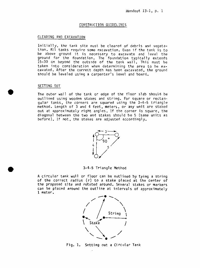
Handout 13-1, p. 1
CONSTRUCTIONGUIDELINES
CLEARING AND EXCAVATION
Initially, the tank site must be cleared of debris and vegeta-tion. All tanks require some excavation. Even if the tank is tobe above ground it is necessary to excavate and level theground for the foundation. The foundation typically extends15-30 cm beyond the outside of the tank wall. This must hetaken into consideration when determining the area to be ex-cavated. After the correct depth has been excavated, the groundshould be leveled using a carpenter’s level and board.
SETTING OUT
The outer wall of the tank or edge of the floor slab should heoutlined using wooden stakes and string. For square or rectan-gular tanks, the corners are squared using the 3-4-5 trianglemethod. Length of 3 and 4 feet, meters, or any unit are stakedout at approximately right angles. If the corner is square, thediagonal between the two end stakes should be 5 (same units asbefore). If not, the stakes are adjusted accordingly.
3-4-5 Triangle Method
A circular tank wall or floor can be outlined by tying a stringof the correct radius (r) to a stake placed at the center ofthe proposed site and rotated around. Several stakes or markerscan be placed around the outline at intervals of approximately1 meter.
,.- 4/ /
/ / String
Stake J
~ ~/
5
/
Fig. 1. Setting out a Circular Tank

Handout 13-1, p. 2
FOUNDATION/FOOTING
Before the floor slab can be laid, a foundation of gravel orcrushed stone is necessary. The thickness should be approxi-mately 10 cm. The gravel bed should be tamped and leveledbefore proceeding with the floor construction. If the tank isto have a sump, then a depression should be made in the founda-tion for this. For masonry walls it is common practice toconstruct a footing of masonry or concrete. The footing shouldbe approximately 20 cm thick and extend 10 cm beyond the baseof the tank wall on both sides. This also requires a 10 cmthick foundation or either gravel or lean concrete (1 partcement, 3 parts sand, 6 parts gravel).
Wall
Footing 420 cm
-~‘i~H-
Fig~ 2 Masonry Footing
PLACING FORMS
All concrete work requires a form into which the concrete ispoured. Forms are usually made from boards or planks, althoughother materials are also used. Wooden forms are nailed togetheraccording to the proper measurements. To ensure that the con-crete does not stick to the forms it is advisable to coat themwith oil first. It is very important that the forms be sup-ported on the outside. Otherwise, when the concrete is beingcompacted the forms can bulge or burst apart.
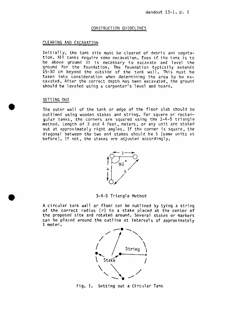
Handout 13-1, p. 1
CONSTRUCTIONGtJIDELINES
CLEARING AND EXCAVATION
Initially, the tank site must be cleared of debris and vegeta-tion. All tanks require some excavation. Even if the tank is tobe above ground it is necessary to excavate and level theground for the foundation. The foundation typically extends15-30 cm beyond the outside of the tank wall. This must hetaken into consideration when determining the area to be ex-cavated. After the correct depth has been excavated, the groundshould be leveled using a carpenter’s level and board.
SETTING OUT
The outer wall of the tank or edge of the floor slab should heoutlined using wooden stakes and string. For square or rectan-gular tanks, the corners are squared using the 3—4-5 trianglemethod. Length of 3 and 4 feet, meters, or any unit are stakedout at approximately right angles. If the corner is square, thediagonal between the two end stakes should be 5 (same units asbefore). If not, the stakes are adjusted accordingly.
3-4-5 Triangle Method
A circular tank wall or floor can be outlined by tying a stringof the correct radius (r) to a stake placed at the center ofthe proposed site and rotated around. Several stakes or markerscan he placed around the outline at intervals of approximately1 meter.
,— 4/ /
/ // String
~ ~
Stake /
Fig. 1. Setting out a Circular Tank

Handout 13-1, p. 2
FOUNDATION/FOOTING
Before the floor slab can be laid, a foundation of gravel orcrushed stone is necessary. The thickness should be approxi-mately 10 cm. The gravel bed should be tamped and leveledbefore proceeding with the floor construction. If the tank isto have a sump, then a depression should be made in the founda-tion for this. For masonry walls it is common practice toconstruct a footing of masonry or concrete. The footing shouldbe approximately 20 cm thick and extend 10 cm beyond the baseof the tank wall on both sides. This also requires a 10 cmthick foundation of either gravel or lean concrete (1 partcement, 3 parts sand, 6 parts gravel).
Wall
Footing 1 420cm
Fig1 2 Masonry Footing
PLACING FORMS
All concrete work requires a form into which the concrete ispoured. Forms are usually made from boards or planks, althoughother materials are also used. Wooden forms are nailed togetheraccording to the proper measurements. To ensure that the con-crete does not stick to the forms it is advisable to coat themwith oil first. It is very important that the forms be sup-ported on the outside. Otherwise, when the concrete is beingcompacted the form; can bulge or burst apart.

Handout 13-1, p. 3
MIXING CONCRETE
Proper mixing of concrete is essential if it is to meet itsrequirements of strength and durability. The first step is toprepare a mixing pad or platform. For this, boards, metalsheets, or a hardened concrete slab is suitable. The aggregateand cement are then measured and piled into a heap. This thenshould be turned over using shovels or trowels until themixture is uniform. The mix is then heaped and a depression ismade in the center of the pile. Water is slowly poured into thedepression and worked into the dry mix. It is important not toadd too much water. Otherwise the concrete will not reach itsfull strength. A rule of thumb is to add approximately 3/4parts of water for each part of dry cement. The concrete shouldbe mixed in volumes no larger than that which can be pouredwithin 30 minutes. At this point the concrete begins to set.
PLACING CONCRETE
After mixing, the concrete should be placed into the formsimmediately. Floor slabs are poured beginning with one side orcorner and working towards the opposite one. The concreteshould be placed in adjacent piles, compacted, and leveled. Thesimplest way this can be done is to assign teams to carry Outeach of these 3 tasks. The first team transports and places theconcrete. The second team follows by compacting, and the thirdteam levels the slab.
Compacting is usually done by means of a tamping foot. Theconcrete should be compacted until the top surface is fairlysmooth with none of the coarse aggregate jutting out.
Leveling is carried out using a trowel or screed (short, smoothpiece of wood) and a carpenter’s level. The floor should slopetowards the sump or drain.
Walls should be poured in a similar manner with the exceptionthat the compacting or rodding should be carried out in 30-40cm layers. Iron rods are best for doing this.

Handout 13-1, p. 4
REINFORCED CONCRETE
The tensile strength of concrete can be greatly increased withthe use of reinforcing bar or mesh. Reinforcing bar (rebar) istied with wire into a mesh and placed in the form. It should hecovered by a minimum oF 3 cm of concrete. The spacing and sizeof the rebar should he determined by the design engineer.
ROOF/WALL ANCHORS
In any tank the walls, floor, and roof should be anchored intoone another. This is usually done by embedding rebar into boththe floor and wall , or the wall and roof at the joint as shownin Figure 3.
.
Wall
Floor
Rod
Anchor BoltRoof
MASONRY
Fig. 3 Roof and Wall Anchors
Tanks are often constructed of brick or stone masonry. Regard-less of the building material used (i.e., brick, stone, con-crete block) it must be cleaned of all dirt and organicmaterial first. Bricks~and cement blocks should first be soakedin water. Otherwise they may absorb too much of the water inthe mortar. The walls should be built so that no two jointsform a continuous line across the thckness of the wall or upand down the side of t.he wall. At intervals of approximately 60cm, bondstones or bonding bricks should be laid across thethickness of the wall. This helps to hold the wall together.This is illustrated in Figure 4 below.

Fig. 4 Brick Masonry
Handout 13—1, p. 5
Brick
To ensure the strength of the wall it is very important that notwo adjacent stones or bricks touch. The recommended thicknessof all mortar joints is 1.0 cm. In masonry tanks, it is morecommon to construct the walls first beginning with the cornersand then pour the floor slab. In this case, the wall is notanchored into the floor as for other types of tanks. This isshown in Figure 5.
Masonry ~‘1
Footing
Fig. 5 Masonry Tank Wall
The roof of a masonry tank is usually attached to an anchorbolt embedded 10-15 cm into the top of the masonry wall.
Wall
Anchor Bolt
Floor Slab
/
Fig. 6 Anchor Bolt
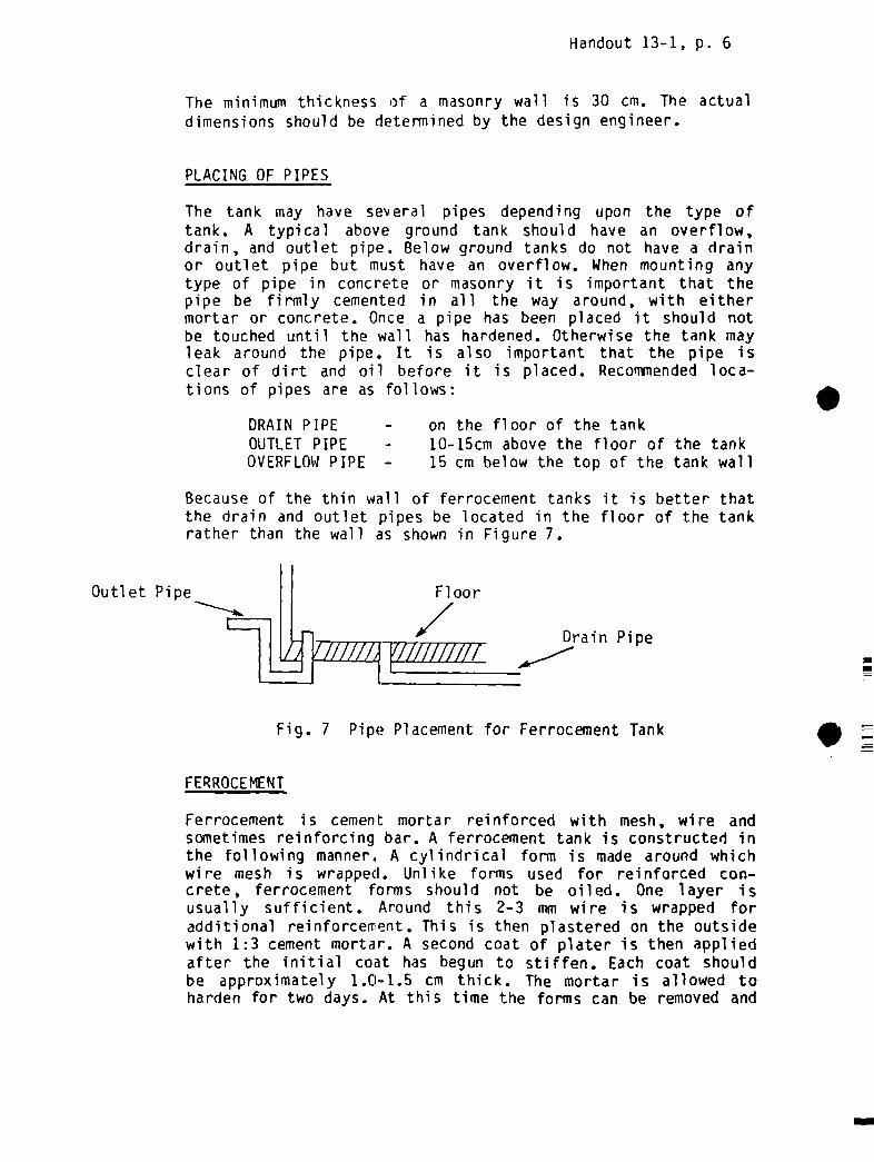
Handout 13-1, p. 6
The minimum thickness of a masonry wall is 30 cm. The actualdimensions should be determined by the design engineer.
PLACING OF PIPES
The tank may have several pipes depending upon the type oftank. A typical above ground tank should have an overflow,drain, and outlet pipe~. Below ground tanks do not have a drainor outlet pipe but must have an overflow. When mounting anytype of pipe in concrete or masonry it is important that thepipe be firmly cemented in all the way around, with eithermortar or concrete. Once a pipe has been placed it should notbe touched until the wall has hardened. Otherwise the tank mayleak around the pipe. It is also important that the pipe isclear of dirt and oil before it is placed. Recommended loca-tions of pipes are as follows:
DRAIN PIPE - on the floor of the tankOUTLET PIPE - 10-15cm above the floor of the tankOVERFLOWPIPE — 15 cm below the top of the tank wall
Because of the thin wall of ferrocement tanks it is better thatthe drain and outlet pipes be located in the floor of the tankrather than the wall as shown in Figure 7.
Outlet Pipe
Drain Pipe
Fig. 7 Pipe Placement for Ferrocement Tank
FERROCEMENT
Ferrocement is cement mortar reinforced with mesh, wire andsometimes reinforcing bar. A ferrocement tank is constructed inthe following manner. A cylindrical form is made around whichwire mesh is wrapped. Unlike forms used for reinforced con-crete, ferrocement forms should not be oiled. One layer isusually sufficient. Around this 2-3 mm wire is wrapped foradditional reinforcement. This is then plastered on the outsidewith 1:3 cement mortar. A second coat of plater is then appliedafter the initial coat has begun to stiffen. Each coat shouldbe approximately 1.0-1.5 cm thick. The mortar is allowed toharden for two days. At this time the forms can be removed and
Floor
/

Handout 13-1, p. 7
the inside of the tank is then plastered in two more coats. Thetotal thickness of the wall should be 4—5 cm. It is very im-portant that the tank be kept covered and moist, particularlyduring the first few days. Otherwise the mortar will crack andthe tank may leak.
After approximately one week a roof can be built on the tank. Aferrocement roof can be constructed using two layers of meshinstead of the single layer as for the walls. Again it is im-portant to anchor the roof to the walls using rebar.
PLASTERING
To ensure that the tank is waterproof it should be internallyplastered. Recommended plastering procedures vary from two tofour coats. Regardless of the number of coats, only one coatshould be applied each day.
The following plastering method is recommended here:
Initially a 1:3 cement mortar coat is applied to athickness of 1.0-1.2 cm. This coat is applied roughlyand is not smoothed out. Next a coat of 1:2 mortar isapplied to a thickness of 0.8-1.0 cm, and smoothed.finally, a thin 0.2-0.4 cm coat of cement paste(cement & water only) is applied.
CURING
All cement work must be cured for a minimum of one week andpreferably two. The structure must be kept moist and protectedfrom direct sunlight. Other wise the cement will dry out toorapidly, crack and will not reach its full strength. Curingshould begin immediately after the cement has finished setting,usually 2—4 hours after it has been placed. This can be bestdone by wetting the structure and then covering it with dampburlap, paper leaves or other suitable material. Concrete slabscan be cured by building up a rim of soil around the edge ofthe slab and flooding it with a few centimeters of water.
DRAINAGE
The area surrounding the tank should be graded so that rain andoverflow water drains away from the tank. This is especiallyimportant for below ground tanks where surface runoff can enterthe tank and contaminate the water.

Handout 13-1, p. 8
MANHOLE AND AIR VENTS
In addition to the structural features mentioned above, thetank should be provided with a manhole or access door, since itwill be necessary to enter the tank for cleaning and main-tenance. The door shou~d be locked at other times to preventunauthori zed persons from entering. Al so, the tank should bewell ventilated. In most cases, this will occur naturally butfor certain types of tanks such as reinforced concrete orferrocement tanks with 1;ight-fitting covers it may be necessaryto provide an air vent.

CONSTRUCTIONPROCEDURESBRICK MASONRYTANK
(Square, Above Ground)
ACTIVITY
A. SITE PREPARATION
TOOLS MATERIALS TI ME TECHNIQUE
1. Clear Site Digging, Clearing Tools 1-4 Hrs. Clear all vegetation,boulders, etc.
2. Set out tank floors/wall s
Measuring tape, string,hammer, stakes
1 Hr. 3-4-5 triangle method.
3. Excavate Digging, tools, tape 2-8 Hrs. Include trench for footing,hole for sunip (depth dependson design decisionsprevinusly made)
Digging tools, carpenter’slevel , board
5. Place foundation Level , shovel s,compacting tools
Gravel , stone 1-2 Hrs 10 cm gravel or stone layer,compact with hammer, tampingfoot or other tool
6. Outline wall footing Measuring tape, stringhammer, stakes
1 Hr Outline with string tied tocorner stakes.
B. FOOTING & WALL CONSTRUCTION
1. Clean & soak bricks Water container, wirebrush
Bricks, water 1—2 Hrs
2. Measure quantitiesfor mix
3. Dry mix mortar Mixing pad, trowels,shovels.
Sand, cement 1/4 Hr. Mix to uniform color &consi stency.
4. Wet mix mortar Mixing pad, trowels,shovels.
Measuring container.
Water, mortarmix.
1/4 hr. Add water gradually untilmortar is workable; mixonly volume which can beused in 1/2 hour or less.
. O
4. Level 1 Hr
Measuring container Sand, cement 1/2 Hr. 1:4 Cement/sand ratio.
0)
0
rt

CONSTRUCTION PROCEDURESBRICK MASONRY TANK
(Square, Above Ground)
ACTIVITY TOOLS MATERIALS TIME TECHNIQUE
5. Lay footing Tape, trowels, hammers& other masonry tools.
Mortar, bricks[Al ternati ye:concrete mixed1:3:6]
1—4 Hrs. Begin with corners & worktowards center of wall;cover & wet at end of day.
6. Place drain pipe Level , masonry tools GI pipe, mortar 5 Mm. Place pipe level or slopingslightly downward from tank.
7. Lay tank wall — firstcourses
-Masonry tools, plumbob Mortar, bricks 1 toseveraldays
Same as B.5 above.
8. Place outlet pipe
9. Lay tank wall tooverflow pipe.
Same as B.6 above, 10 cm
above floor.
Same as B.5 above.
10. Place overflow pipeand roof anchorbolts.
Galvanized Ironpipe, roof anchorbol ts
Same as B.6 above - 15 cmfrom top of tank wall.
11. Complete tank wall Same as B.5 above.
12. Allow to harden/cure
C. FLOOR
Water container Water, burlap,paper or othersuch material
2-4 days Wet several times each daykeep covered.
1. Measure quantities forconcrete
Measuring containers Cement, sand,gravel
1/2 Hr. 1:1 1/2:3 cement/sand/gravelratio.
2. Dry mix concrete Mixing pad, trowels,shovel s
Cement, sand, 1/2—lHr Mix to uniform color andconsistency overturningseveral times.
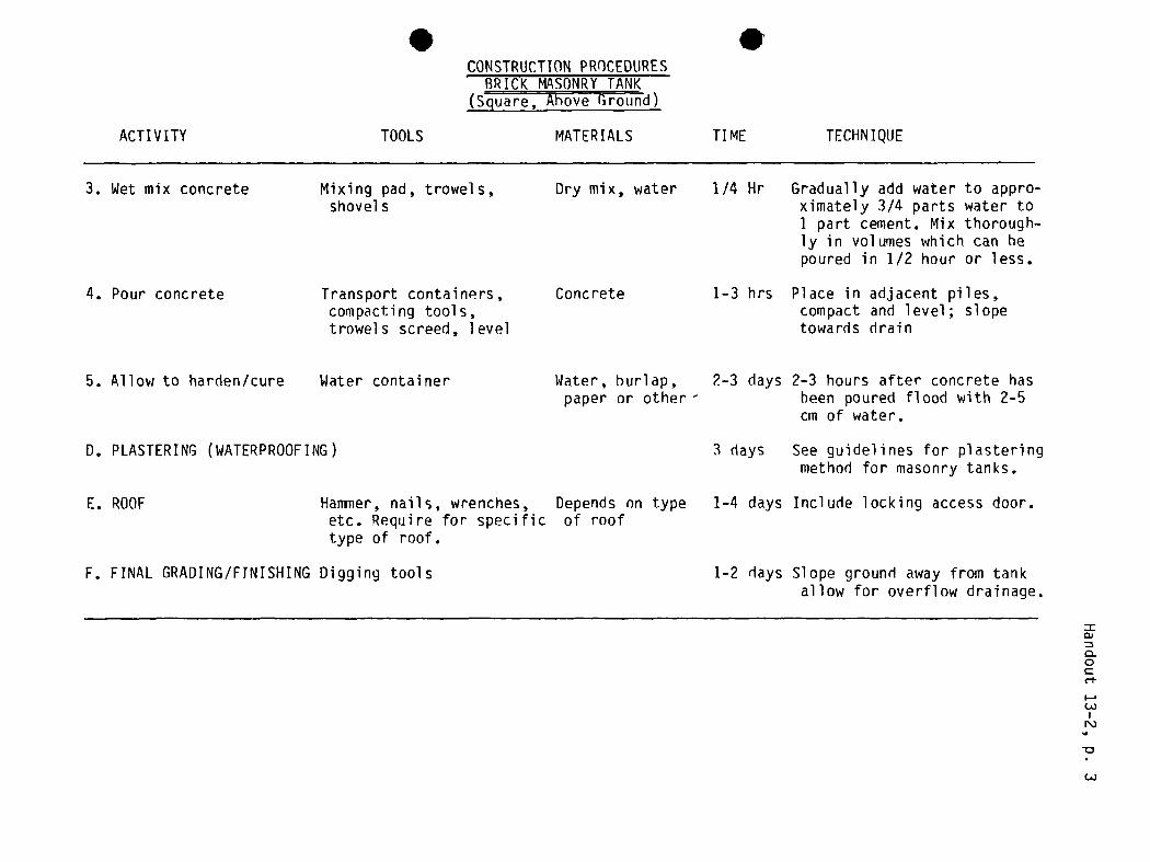
.CONSTRUCTIONPROCEDURES
BRICK MASONRYTANK(Square, Above Ground)
ACTIVITY TOOLS MATERIALS TIME TECHNIQUE
3. Wet mix concrete Mixing pad, trowels,shovel s
Dry mix, water 1/4 Hr Gradually add water to appro-ximately 3/4 parts water to1 part cement. Mix thorough-ly in volumes which can hepoured in 1/2 hour or less.
4. Pour concrete Transport containers,compacting tools,trowels screed, level
Concrete 1—3 hrs Place in adjacent piles,compact and level; slopetowards drain
5. Allow to harden/cure Water container Water, burlap,paper or other
2—3 days 2—3 hours after concrete hasbeen poured flood with 2-5cm of water.
D. PLASTERING (WATERPROOFING) 3 days See guidelines for plasteringmethod for masonry tanks.
E. ROOF Hammer, nails, wrenches,etc. Require for specifictype of roof.
Depends on typeof roof
1—4 days Include locking access door.
F. FINAL GRADING/FTNISHING Digging tools 1-2 days Slope ground away from tankallow for overflow drainage.
=0)
0.0
(~~)

CONSTRUCTION PROCEDURESPLASTERING OF MASONRYTANKS
ACTIVITY TOOLS MATERIALS TIME TECHNIQUE
A. FIRST COAT
1. Clean wall
2. Measure quantities formortar mix (firstcoat.
Wire brush, trowels
Measuring container Sand, cement
1—2 Hrs Scrape off loose mortar,
dirt, etc.
1/2 Hr 1:3 cement/sand ratio.
3. Dry mix mortar
4. Wet mix mortar
5. Apply mortar
6. Allow to set
Mixing pad, trovels,shovel s
Mixing pad, trowels,shovels, measuringcontai ner
Trowels
Sand, cement
Water, mortar
Mortar
Water, burlap,paper, etc.
1/4 Hr Mix to uniform color &consi stency.
1/4 Hr Add water gradually untilmortar is workable; mixonly volume which can heused in 1/2 hour or less.
1-2 Hrs Apply in rough coat ofapproximately 1.0—1.2 cmthickness; do not smooth.
1 day Cover sprinkle with wateroccasi onal ly.
B. SECONDCOAT
1. Dampen wall
2. Measure quantities
3. Mix mortar
4. Apply mortar
5. Allow to set
Measuring container
Trowels
Water
Sand, cement
Mortar
1/2 Hr Sprinkle with water.
1:2 cement/sand ratio
As in steps A.3 — A.4 above.
1-2 Hrs Apply coat of approximately0.8-1.0 cm thickness andsmooth.
S Same as step A.6 above.

CONSTRUCTION PROCEDURESPLASTERING OF MASONRYTANKS
ACTI VII V TOOLS MATERIALS TIME TECHNIQUE
=0)
0.0C
N)
c-n
. .
C. FINAL COAT
1. Dampen wall
2. Mix mortar
3. Apply mortar
4. Allow to harden/cure
Water
Mixing pad, trowels Sand, Cement
Trowels
Water, burlap,paper, etc.
1/2 Hr Sprinkle with water.
5 mm Cement & water only mixed toa thick paste; mix onlysmall amounts.
Apply 0.2-0.4 cm coat andsmooth.
2—4 days Wet several times per day andcover.
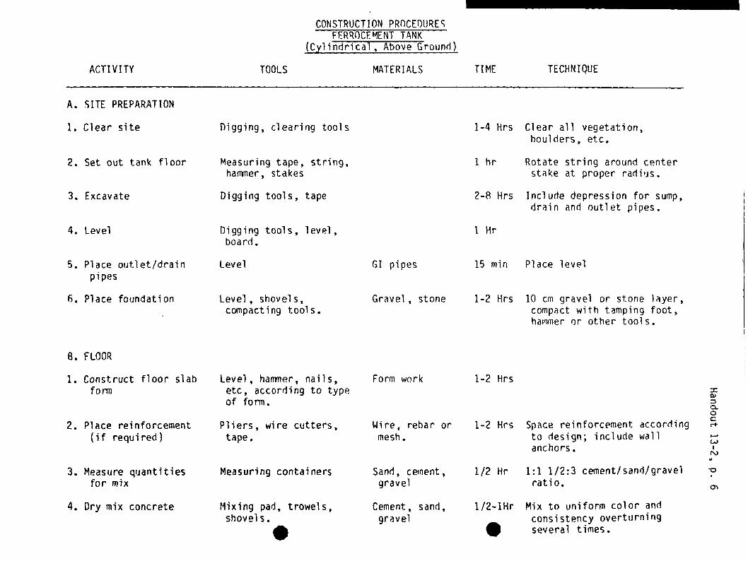
CONSTRUCTIONPROCEDURESFERROCEMENTTANK
(Cylindrical, Above Ground)
ACTIVITY
A. SITE PREPARATION
TOOLS MATERIALS TIME TECHNIQUE
1. Clear site fligging, clearing tools 1-4 Hrs Clear all vegetation,boulders, etc.
2. Set out tank floor Measuring tape, string,hammer, stakes
1 hr Rotate string around centerstake at proper radius.
3. Excavate Digging tools, tape 2-8 Hrs Include depression for sump,drain and outlet pipes.
4. Level Digging tools, level,board.
1 Hr
5. Place outlet/drainpipes
Level GI pipes 15 mm Place level
6. Place foundation
B. FLOOR
Level, shovels,compacting tools.
Gravel , stone 1-2 HrS 10 cm gravel or stone layer,compact with tamping foot,hammer or other tools.
1. Construct floor slabform
Level, hammer, nails,etc., according to typeof form.
Form work 1-2 Hrs
2. Place reinforcement(if required)
Pliers, wire cutters,tape.
Wire, rehar ormesh.
1-2 Hrs Space reinforcement accordingto design; include wallanchors.
3. Measure quantitiesfor mix
Measuring containers Sand, cement,gravel
1/2 Hr 1:1 1/2:3 cement/sand/gravelratio.
=0)
0.0C
4. Dry mix concreteMixing pad, trowels,
shovels.
.Cement, sand,
gravel1/2-lHr
SMix to uniform color andconsistency overturningseveral times.
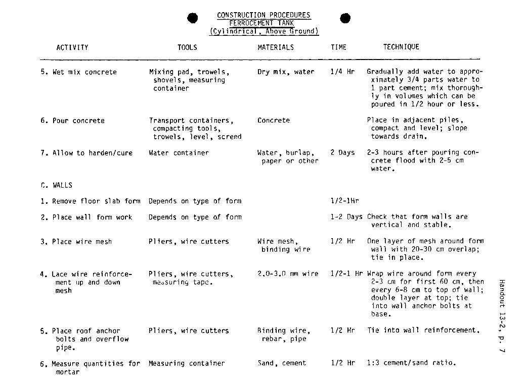
. CONSTRUCTION PROCEDURESFERROCEMENT TANK
(Cylindrical, Above Ground)
TOOLS MATERIALS TIME TECHNIQUE
5. Wet mix concrete Mixing pad, trowels,shovels, measuringcontai ner
Dry mix, water 1/4 Hr Gradually add water to appro-ximately 3/4 parts water to1 part cement; mix thorough-ly in volumes which can bepoured in 1/2 hour or less.
6. Pour concrete Transport containers,compacting tools,trowels, level, screed
Concrete Place in adjacent piles,compact and level; slopetowards drain.
7. Allow to harden/cure
C. WALLS
Water container Water, burlap,paper or other
2 Days 2-3 hours after pouring con-crete flood with 2-5 cmwater.
1. Remove floor slab form Depends on type of form 1/2—lHr
2. Place wall form work Depends on type of form 1—2 Days Check that form walls arevertical and stable.
3. Place wire mesh Pliers, wire cutters Wire mesh,binding wire
1/2 Hr One layer of mesh around formwall with 20—30 cm overlap;tie in place.
5. Place roof anchorbolts and overflow
Binding wire,rebar, pipe
1/2—1 Hr Wrap wire around form every2-3 cm for first 60 cm, thenevery 6-8 cm to top of wall;double layer at top; tieinto wall anchor bolts at
N)
6. Measure quantities formortar
Measuring container Sand, cement 1/2 Hr 1:3 cement/sand ratio.
ACTIVITY
.
4. Lace wire reinforce-ment up and downmesh
2.0-3.0 ruin wire
Pliers, wire cutters,
me~surin~tape.
Pliers, wire cutters
pipe.
=0)
0.0C
base.
1/2 Hr Tie into wall reinforcement.
~-1
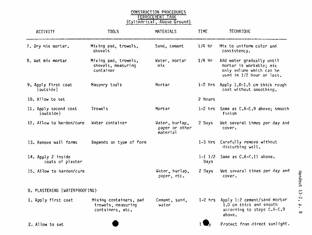
CONSTRUCTION PROCEDURESFERROCEMENT TANK
(Cylindrical , Above Ground)
TIME TECHNIQUE
7. Dry mix mortar. Mixing pad, trowels,shovels
Sand, cement 1/4 Hr Mix to uniform color andconsi stency.
8. Wet mix mortar Mixing pad, trowels,shovel s, measuringcontainer
Water, mortarmix
1/4 Hr Add water gradually untilmortar is workable; mixonly volume which can heused in 1/2 hour or less.
9. Apply first coat(outside)
Masonry tool S Mortar 1-2 Hrs Apply 1.0-1.5 cm thick roughcoat without smoothing.
10. Allow to set 2 Hours
11. Apply second coat Trowels(outside)
1-2 hrs Same as C.6-C.9 above; smoothfinish
12. Allow to harden/cure Water container Water, burlap,paper or othermaterial
2 Days Wet several times per day andcover.
13. Remove wall forms Depends on type of form 1—3 Hrs Carefully remove withoutdisturbing wall.
1—1 1/2 Same as C.6—C.11 above.Days
15. Allow to harden/cure Water, burlap,paper, etc.
2 Days Wet several times per day andcover.
0. PLASTERING (WATERPROOFING)
Mixing containers, padtrowels, measuringcontainers, etc.
0)
0.0Crt
ACTIVITY TOOLS MATERIALS
Mortar
14. Apply 2 insidecoats of plaster
1. Apply first coat Cement, sand,water
1—2 hrs Apply 1:2 cement/sand mortar1.0 cm thick and smoothaccording to steps C.6—C.9above.
1•
N)
2. Allow to set . Protect from direct sunlight.
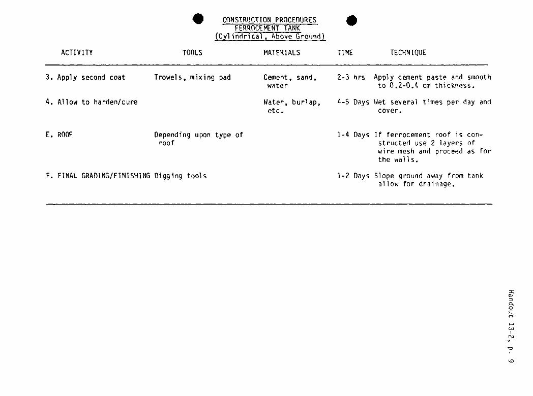
CONSTRUCTION PROCEDURESFERROCEMENTTANK
(Cylindrical, Above Ground)
TIME TECHNIQUE
3. Apply second coat Trowels, mixing pad Cement, sand,water
2-3 hrs Apply cement paste and smoothto 0.2-0.4 cm thickness.
4. Allow to harden/cure Water, burlap,etc.
4-5 Days Wet several times per day andcover.
E. ROOF Depending upon type ofroof
F. FINAL GRADING/FINISHING Digging tools
1—4 Days If ferrocement roof is con-structed use 2 layers ofwire mesh and proceed as forthe walls.
1-2 Days Slope ground away from tankallow for drainage.
0)
0.0Cri-
N)
.ACTIVITY TOOLS
.MATER I ALS

ACTI VII Y
A. SITE PREPARATION
TOOLS
CONSTRUCTION PROCEDURES
FERROCEMENT LINED PIT
MATER I ALS TI ME TECHNIQUE
1. Clear site Digging, clearing tools 1—4 Hrs Clear all vegetation,boulders, etc.
2. Set out tank floor Measuring tape, stringhammer, stakes
1 Hr Rotate string around centerstake at proper radius.
3. Excavate Digging tools, tape 4-8 hrs Pit walls should be smooth.
4. Level Digging tools, levelboard
1 Hr
5. Place foundation
B. FLOOR
Level, shovels,compacting tools
Gravel stone 1-2 hrs 10 cm stone or gravel iayer~compacted.
1. Place reinforcement(if required)
Pliers, wire cutters,tape
Wire, rebaror mesh
1-2 Hrs Include wall anchors
2. Measure quantitiesfor concrete mix
Measuring container Sand, cement,gravel
1/2 Hr 1:1-1/2:3 cement/sand/gravel ratio.
3. Dry mix concrete Mixing pad, trowels,shovel s
Cement, sand,gravel
1/2-1 Hr Mix to uniform color andconsistency overturningseveral times.
Water, concretedry mix
1/4 Hr Gradually add water to appro-ximately 3/4 parts water to1 part cement; mix thorough-ly in volumes which can bepoured in 1/2 hour or less.
5. Pour concrete Transport containers,compacting tools, levelscreed, •wels.
Concrete 1—3 Hrs Place in adjacent piles,compact, and level.
I—.
Q
4. Wet mix concrete Mixing pad, trowels,shovel s, measuringcontai ner
=
0.0C
I—.
N)
S

CONSTRUCTIONPROCEDURESFERROCEMENTLINED PIT
ACTI V I I Y TOOLS MATERIALS TIME TECHNIQUE
6. Allow to harden/cure
C. WALLS
Water container Water, burlap,paper or other
1 Day 2-3 hours after pouring con-crete, dampen and cover.
1. Measure quantitiesfor mortar mix.
Measuring container Sand, cement 1/2 Hr 1:1 cement/sand ratio.
2. Dry mix mortar Mixing pad, trowels,shovel s
Sand, cement 1/4 Hr Mix to uniform color andconsi stency.
3. Wet mix mortar Mixing pad, trowels,shovels, measuringcontai ner
Water, mortarmix
1/4 Hr Add water gradually untilmortar is workable; mix involumes which can be usedin 1/2 hour or less.
Mortar 1-2 Hrs Apply 1.0 cm thick roughcoat to walls withoutsmoothing.
5. Allow to set
6. Apply second coat Trowels
2 Hrs Keep protected from sunlight.
Mortar 1-2 hrs Same as C.1—C.4 Above.
7. Place reinforcement Wire cutters, pliers Wire mesh,binding wire
1/2—1 Hr Place 1 layer immediatelyafter applying 2nd coat; tieinto floor reinforcement.
0)
0.0Cc-s.
9. Apply inside plasterin 2 coats.
4-8 Hrs. Same as steps C.1-C.6 above.(~JN)
10. Allow to harden/cure Water container Water, burlap,etc.
1 Day Wet several times per day andcover.
.
4. Apply first coat Trowels
8. Allow to harden/cure Water container Water, burlap,paper or other
1 Day Wet several times per day andcover.
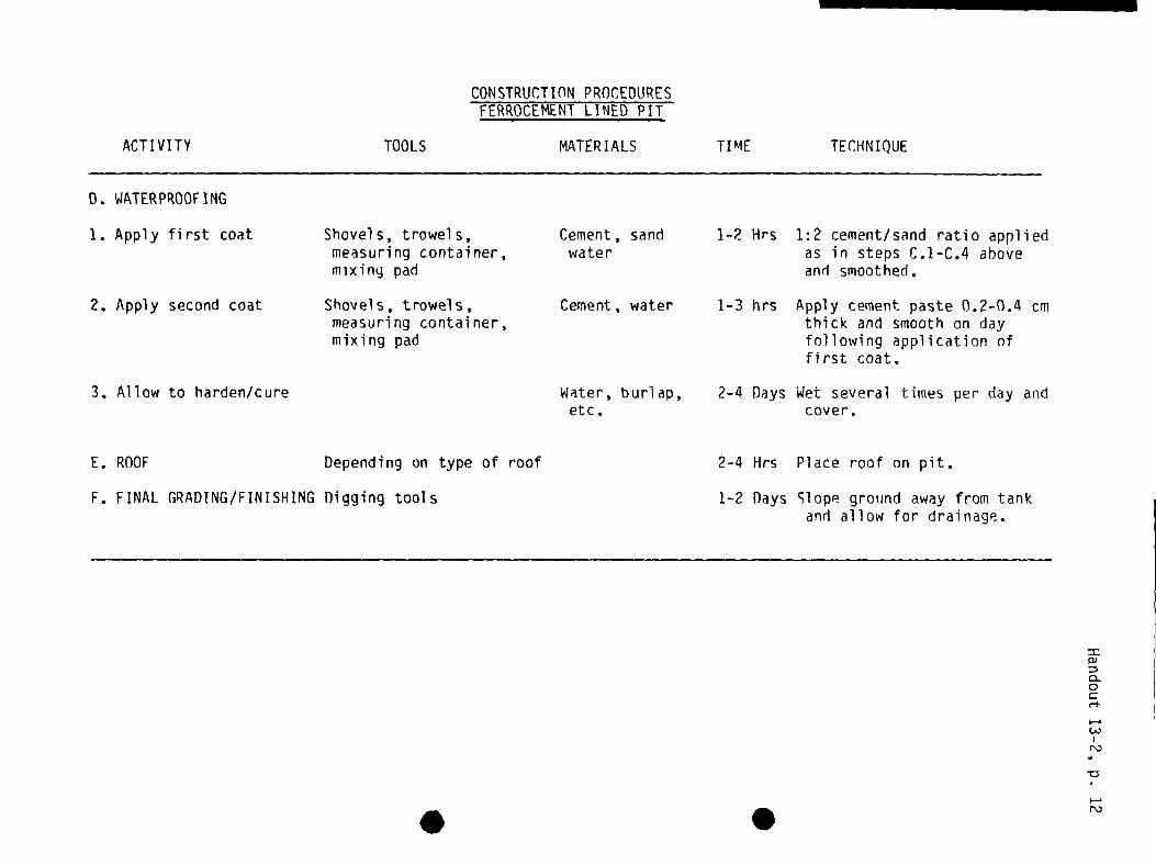
CONSTRUCTION PROCEDURESFERROCEMENT LINED PIT
ACTIVITY
0. WATERPROOFING
TOOLS MATER IALS TI ME TECHNIQUE
1. Apply first coat Shovels, trowels,measuring container,mixing pad
Cement, sandwater
1-2 Hrs 1:2 cement/sand ratio appliedas in steps C.1-C.4 aboveand smoothed.
2. Apply second coat Shovels, trowels,measuring container,mixing pad
Cement, water 1-3 hrs Apply cement paste 0.2-0.4 cmthick and smooth on dayfollowing application offirst coat.
3. Allow to harden/cure Water, burlap,etc.
2-4 Days Wet several times per day andcover.
E. ROOF Depending on type of roof
F. FINAL GRADING/FINISHING Digging tools
2—4 Hrs Place roof on pit.
1-2 Days Slope ground away from tank
and allow for drainage.
S
=0)
0.0C
N)
I—.NJ

Handout 14-1, p. 1
CASE STUDY
Project History
Dry Spot is a community which the community health worker selected some monthsago to work in to develop a rainwater roof catchment project. The initialtechnical assessment indicated that indeed it was feasible to develop a rain-water collection and storage project. Rainfall data was sufficient for a tencubic meter communal tank to be constructed using an existing school roof forcatchment. The community was currently carrying water long distances forfamily drinking purposes. This work was done by women and children. The streamwhere the water was collected was contaminated and sometimes was completelydry during the dry season.
During the project social assessment phase, the community worker had worked•through a local health committee which had been previously formed to assist a
small community clinic, sponsored by the Ministry of Health. The committee hadbeen very enthusiastic. They agreed to build a conrnunal tank because everybodywould have an equal interest in the benefits of the project. They had alsoheard that in the past some other villages had problems with individual familytanks because the wealthier families would build their own storage systems andmake money by selling water to people. Those who seemed most committed to theproject were the two women on the health committee. The committee had agreedto collect a small amount from each family monthly until the necessary commu-nity quota had been raised to match the amount that the Ministry of Healthwould provide for the project. Dry Spot has 500 inhabitants. The communitylives by working in subsistence agriculture and by selling charcoal and goatcheese.
Current Situation
There is only one month left to construct the tank in order to use it duringthe upcoming rainy season. The Ministry of Health has ordered all of thenecessary materials upon the recommendation of the community health worker.This was done without informing the committee, because the worker did not wantthe community to know that it was going to receive the materials until theyhad collected their share of the quota. The supervisor of the health workerhas informed him/her that if the community does not provide its share of thequota, the materials will be given to another community which has collectedmoney on its own and asked for assistance in another project.
The community worker has also found out that the health committee has not yetbeen able to provide a list of the men who will be available to work on theproject, even though the community resource inventory conducted earlier in-dicated that there were at least two men who were somewhat- experienced inconstruction and had worked with cement before. It seems that most of the menin the village want to collect and sell as much charcoal as possible beforethe rains come. If the project is to proceed, the coninunity worker must pro-vide to his/her supervisor both the community quota, and a statement by thehealth committee of which people will work on the estimated ten days ofproject construction. This must be done within one week.

Handout 14-1, p. 2
Task in Small Groups
1. List the possible mistakes the project developer has made.
2. Analyze the above case study. Discuss and decide what you would do.
3. Prepare a strategy for a meeting with the health committee which willaddress the problems of collecting the quota and organizing the communityworkers.
.

Handout 15-1
MAINTENANCECHECKLIST
WHOISFREQUENCY ACTIVITY RESPONSIBLE
A. At the beginning of 1. Engage foul flush mechanismeach rain
B. At the end of each 1. Clear debris from catchment areadry period
2. Check gutter supports and repair
IC. At the end of each dry 1. Clean gutters of debris
period and weekly duringrainy periods 2. Check and clean screen at downpipe
3. Check gutters for leaks and repairaccordingly
4. Check gutters for overflowing andadjust position or slope accordingly
5. Check drainage around tank
0. Monthly throughout the 1. Check tank cover and ventilationyear
2. Check tank for leakage
E. Weekly throughout the 1. Check water quality in tank and
year clean out if necessary
F. Annually 1. Clean out and disinfect tank

.
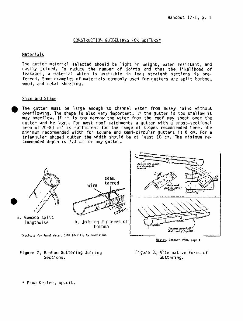
Handout 17-1, p. 1
CONSTRUCTIONGUIDELINES FOR GUTTERS*
Materials
The gutter material selected should be light in weight, water resistant, andeasily joined. To reduce the number of joints and thus the likelihood ofleakages, a material which is available in long straight sections is pre-ferred. Some examples of materials coniiionly used for gutters are split bamboo,wood, and metal sheeting.
Size and Shape
The gutter must be large enough to channel water from heavy rains withoutoverflowing. The shape is also very important. If the gutter is too shallow itmay overflow. If it is too narrow the water from the roof may shoot over thegutter and be lo~st. For most roof catchments a gutter with a cross-sectionalarea of 70-80 cm is sufficient for the range of slopes recommended here. Theminimum recoiimended width for square and semi—circular gutters is 8 cm. For atriangular shaped gutter the width should be at least 10 cm. The minimum re—commended depth is 7.0 cm for any gutter.
seam
.b. joining 2 pieces of
bamboo
Institute for Rural Water, 1982 (draft), by permissionBasics, October 1978, page 4
a. Bamboo splitlengthwise
Figure 2, Bamboo Guttering JoiningSections.
Figure 3, Alternative Forms ofGutterl ng.
* From Keller, op.cit.

Slope
Handout 17-1, p. 2
The gutter should be placed at a uniform slope to prevent water from poolingand overflowing the gutter. For most roof catchments the slope should be inthe range of 0.8 cm/meter to 1.0 cm/meter.
Location
The gutter must collect all of the water running off the roof during light andheavy rainstorms. To achieve this the gutter should be located so that theroof overhangs the gutter by 1 or 2 cm, and the gutter extends beyond the edgeof the roof by at least 7 cm.
Supports
The gutter must be well supported. The number of supports depends upon thetype of guttering material but it is recommended that most gutters be sup-ported at least every 50-60 cm. The simplest means of support is by tying wirearound the gutter and fastening it to the roof. The gutter can also be nailedto the roof or be provided with wooden supports underneath.
Joints
All joints should be leak proof., Joints can be sealed using tar, pitch or asimilar material. Strips of plastic can also be laid in the gutter to preventleakage. The joining material should be one which does not contaminate thewater.
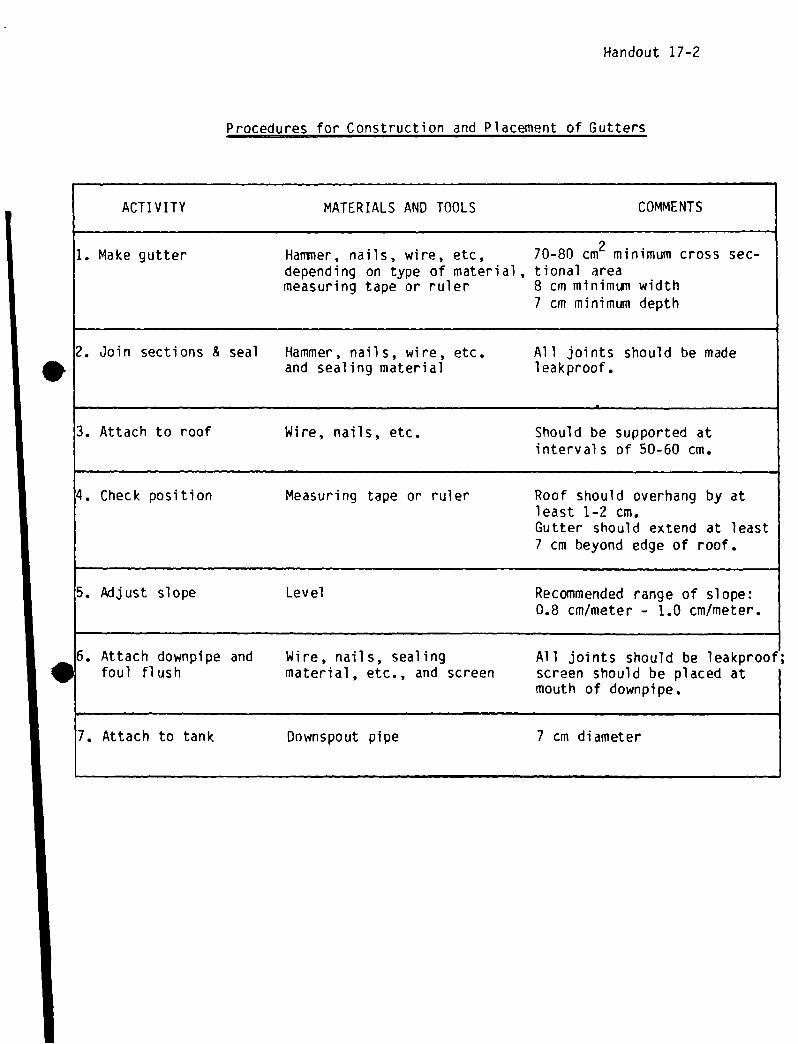
Handout 17-2
Procedures for Construction and Placement of Gutters
ACTIVITY MATERIALS AND TOOLS COMMENTS
1. Make gutter Hammer, nails, wire, etc, 70-80 cm2 minimum cross sec-depending on type of material , tional areameasuring tape or ruler 8 cm minimum width
7 cm minimum depth
2. Join sections & seal Hammer, nails, wire, etc. All joints should be madeand sealing material leakproof.
3. Attach to roof Wire, nails, etc. Should be supported atintervals of 50-60 cm.
4. Check position Measuring tape or ruler Roof should overhang by atleast 1—2 cm.Gutter should extend at least7 cm beyond edge of roof.
5. kijust slope Level Recommended range of slope:0.8 cm/meter - 1.0 cm/meter.
6. Attach downpipe and Wire, nails, sealing All joints should be leakproof;foul flush material, etc., and screen screen should be placed at
mouth of downpipe.
7. Attach to tank Downspout pipe 7 cm diameter

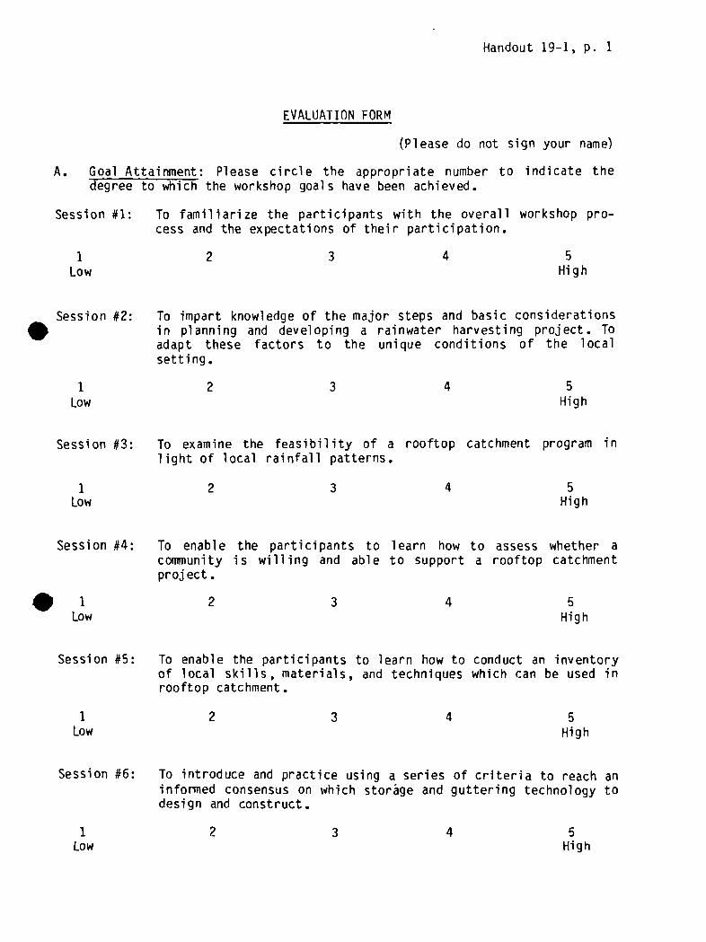
Handout 19-1, p. 1
EVALUATION FORM
(Please do not sign your name)
A. Goal Attainment: Please circle the appropriate number to indicate thedegree to which the workshop goals have been achieved.
Session #1: To familiarize the participants with the overall workshop pro-cess and the expectations of their participation.
1 2 3 4 5Low High
Session #2: To impart knowledge of the major steps and basic considerationsin planning and developing a rainwater harvesting project. Toadapt these factors to the unique conditions of the localsetting.
1 2 3 4Low High
Session #3: To examine the feasibility of a rooftop catchment program inlight of local rainfall patterns.
1 2 3 4 5Low High
Session #4: To enable the participants to learn how to assess whether acommunity is willing and able to support a rooftop catchmentproject.
1 2 3 4 5Low High
Session #5: To enable the participants to learn how to conduct an inventoryof local skills, materials, and techniques which can be used inrooftop catchment.
3 4 5Low High
Session #6: To introduce and practice using a series of criteria to reach aninformed consensus on which storage and guttering technology todesign and construct.
5
1 2
I 2 3 4 5HighLow

Handout 19-1, p. 2
Session #7: To teach participants how to calculate an ~optimum” tank sizeand evaluate the result.
1 2 3
Session #8: To teach the basic!; of mixing cement and plastering and how tobuild cement plaster jars for individual rain catchment storage.
1 2 3 4 5
Session #9: To describe, in enough detail to plan construction, all thecomponents (parts) of the system to be built.
1 2 3 4 5Low High
Session #10: To learn how to design and construct a roof catchment andfiltration system for thatch roofs.
1 2 3 4 5Low High
Session #11: To teach all of the steps and procedures necessary for detailingand ordering the materials for construction.
5Low High
Session #13: To learn the basic steps and processes in larger (community)storage tank construction.
1 2 3 4Low High
Session #14: To consider the process of organizing the conlTlunity into con-struction working groups and develop a plan to do so.
1 2 3 4 5Low High
Session #15: To learn how to develop and communicate a maintenance plan whichthe community will be able to use and follow.
1 2 3 4
4 5Low High
Low High
1 2 3 4
5
5Low High

Handout 19-1, p. 3
Session #16: To critically examine the tank design under construction andrefine it for future use.
1 2 3 4 5Low High
Session #17: To learn how to construct and connect gutters.
1 2 3 4 5Low High
Session #18: To plan applications of the workshop to the work setting.
1 2 3 4 5• Low High
B. Workshop Feedback and Learning: Please answer the following questions asfully as possible so that the trainers can learn how effective the work-shop methodology was.
1. What have been the most positive things about this workshop? Comments:
2. What have been the most negative things about this workshop? Comments:
3. What one thing stands out as important to you in this workshop? Comments:

Handout 19-1, p. 4
4. What things have you learned that you did not know before? Comments:
C. Workshop Organization and Training
1. What comments do you have about the way the workshop was planned andorgani zed?
2. What can be done in the future to improve a workshop like this?
3. What specific steps in developing a rainwater harvesting system do youfeel you will need to learn more about in order to successfully promoteand develop a project in the future?
4. What comments do you have about the trainers?


a
Related Documents