Welcome message from author
This document is posted to help you gain knowledge. Please leave a comment to let me know what you think about it! Share it to your friends and learn new things together.
Transcript


WiMAX Evolution
WiMAX Evolution: Emerging Technologies and Applications Edited by Tsutomu Ishikawa© 2009 John Wiley & Sons, Ltd. ISBN: 978-0-470-69680-4
WiMAX Evolution
Emerging Technologies and Applications
Marcos D. Katz
VTT, Finland
Frank H.P. Fitzek
Aalborg University, Denmark
A John Wiley and Sons, Ltd, Publication

This edition first published 2009© 2009 John Wiley & Sons Ltd
Registered officeJohn Wiley & Sons Ltd, The Atrium, Southern Gate, Chichester, West Sussex, PO19 8SQ,United Kingdom.
For details of our global editorial offices, for customer services and for information about how to applyfor permission to reuse the copyright material in this book please see our website at www.wiley.com.
The right of the author to be identified as the author of this work has been asserted in accordance withthe Copyright, Designs and Patents Act 1988.
All rights reserved. No part of this publication may be reproduced, stored in a retrieval system, ortransmitted, in any form or by any means, electronic, mechanical, photocopying, recording orotherwise, except as permitted by the UK Copyright, Designs and Patents Act 1988, without the priorpermission of the publisher.
Wiley also publishes its books in a variety of electronic formats. Some content that appears in printmay not be available in electronic books.
Designations used by companies to distinguish their products are often claimed as trademarks.All brand names and product names used in this book are trade names, service marks, trademarks orregistered trademarks of their respective owners. The publisher is not associated with any product orvendor mentioned in this book. This publication is designed to provide accurate and authoritativeinformation in regard to the subject matter covered. It is sold on the understanding that the publisher isnot engaged in rendering professional services. If professional advice or other expert assistance isrequired, the services of a competent professional should be sought.
Nokia is a registered trademark of Nokia Corporation. With thanks to Nokia for permitting the use ofNokia trademark images in this publication.
Library of Congress Cataloging-in-Publication Data
Katz, Marcos D.WiMAX evolution : emerging technologies and applications / Marcos Katz, Frank Fitzek.
p. cm.Includes bibliographical references and index.ISBN 978-0-470-69680-4 (cloth)
1. Wireless communication systems. 2. Broadband communication systems. 3. Mobile communicationsystems. 4. Wireless LANs. 5. IEEE 802.16 (Standard) I. Fitzek, Frank H. P. II. Title.
TK5103.2.K36 2009621.384–dc22 2008038550
A catalogue record for this book is available from the British Library.
ISBN 9780470696804 (H/B)
Set in 10/12pt Times by Sunrise Setting Ltd, Torquay, UK.Printed in Great Britain by Antony Rowe.
Contents
List of Contributors xv
Foreword xxi
Preface xxiii
Acknowledgements xxvii
List of Acronyms xxix
I Introduction 1
1 Introduction to WiMAX Technology 3Wonil Roh and Vladimir Yanover
1.1 Overview of State-of-the-art WiMAX Technology . . . . . . . . . . . . . . . 41.1.1 Structure of the System Profile . . . . . . . . . . . . . . . . . . . . . 41.1.2 Key PHY Features . . . . . . . . . . . . . . . . . . . . . . . . . . . 51.1.3 Key MAC Features . . . . . . . . . . . . . . . . . . . . . . . . . . . 71.1.4 Advanced Networking Features . . . . . . . . . . . . . . . . . . . . 9
1.2 WiMAX Evolution Path . . . . . . . . . . . . . . . . . . . . . . . . . . . . 91.2.1 Release 1.5 . . . . . . . . . . . . . . . . . . . . . . . . . . . . . . . 101.2.2 Release 2.0 . . . . . . . . . . . . . . . . . . . . . . . . . . . . . . . 12
References . . . . . . . . . . . . . . . . . . . . . . . . . . . . . . . . . . . . . . . 12
II WiMAX Validation: Validating Current Fixed andMobile WiMAX through Advanced Testbeds 15
2 WiMAX Performance in Practice 17Kostas Pentikousis, Esa Piri, Jarno Pinola and Ilkka Harjula
2.1 Empirical Evaluations of WiMAX . . . . . . . . . . . . . . . . . . . . . . . 182.2 Fixed WiMAX Testbed Evaluation . . . . . . . . . . . . . . . . . . . . . . . 20
2.2.1 Audio and Video Traffic over WiMAX . . . . . . . . . . . . . . . . 212.2.2 Traffic Generation . . . . . . . . . . . . . . . . . . . . . . . . . . . 22
vi CONTENTS
2.2.3 Host Clock Synchronization . . . . . . . . . . . . . . . . . . . . . . 222.2.4 Baseline Capacity Measurements . . . . . . . . . . . . . . . . . . . 25
2.3 VoIP Over Fixed WiMAX . . . . . . . . . . . . . . . . . . . . . . . . . . . 262.3.1 VoIP Overhead . . . . . . . . . . . . . . . . . . . . . . . . . . . . . 262.3.2 Synthetic G.723.1 VoIP Over WiMAX . . . . . . . . . . . . . . . . . 272.3.3 Synthetic G.729.1 VoIP Over WiMAX . . . . . . . . . . . . . . . . . 272.3.4 Synthetic Speex VoIP over WiMAX . . . . . . . . . . . . . . . . . . 282.3.5 VoIP Aggregation . . . . . . . . . . . . . . . . . . . . . . . . . . . . 29
2.4 IPTV over fixed WiMAX . . . . . . . . . . . . . . . . . . . . . . . . . . . . 342.5 Mobile WiMAX Testbed Evaluation . . . . . . . . . . . . . . . . . . . . . . 36
2.5.1 The VTT CNL Mobile WiMAX Testbed . . . . . . . . . . . . . . . . 372.5.2 Baseline Capacity Measurements . . . . . . . . . . . . . . . . . . . 38
2.6 Summary . . . . . . . . . . . . . . . . . . . . . . . . . . . . . . . . . . . . 392.7 Further Reading . . . . . . . . . . . . . . . . . . . . . . . . . . . . . . . . . 40References . . . . . . . . . . . . . . . . . . . . . . . . . . . . . . . . . . . . . . . 41
III Novel Scenarios 45
3 Novel WiMAX Scenarios for Future Broadband Wireless Access Networks 47Pedro Neves, Kostas Pentikousis, Susana Sargento, Marília Curado, Paulo Simões
and Francisco Fontes
3.1 Introduction . . . . . . . . . . . . . . . . . . . . . . . . . . . . . . . . . . . 473.2 WMAN Network Provider . . . . . . . . . . . . . . . . . . . . . . . . . . . 48
3.2.1 Broadband Wireless Access . . . . . . . . . . . . . . . . . . . . . . 483.2.2 Advanced Mobile WiMAX . . . . . . . . . . . . . . . . . . . . . . . 54
3.3 Telemedicine Applications . . . . . . . . . . . . . . . . . . . . . . . . . . . 573.3.1 Remote Patient Monitoring . . . . . . . . . . . . . . . . . . . . . . . 583.3.2 On-site Medical Assistance . . . . . . . . . . . . . . . . . . . . . . . 59
3.4 Environmental Monitoring . . . . . . . . . . . . . . . . . . . . . . . . . . . 603.4.1 Seismic Activity . . . . . . . . . . . . . . . . . . . . . . . . . . . . 603.4.2 Fire Prevention . . . . . . . . . . . . . . . . . . . . . . . . . . . . . 613.4.3 Other Applications . . . . . . . . . . . . . . . . . . . . . . . . . . . 65
3.5 Conclusions . . . . . . . . . . . . . . . . . . . . . . . . . . . . . . . . . . . 66References . . . . . . . . . . . . . . . . . . . . . . . . . . . . . . . . . . . . . . . 66
4 Pricing in WiMAX Networks 69Ioannis Papapanagiotou, Jie Hui and Michael Devetsikiotis
4.1 Introduction . . . . . . . . . . . . . . . . . . . . . . . . . . . . . . . . . . . 694.2 Economics in Network Engineering . . . . . . . . . . . . . . . . . . . . . . 70
4.2.1 Building a Business Model . . . . . . . . . . . . . . . . . . . . . . . 704.2.2 Control and Pricing . . . . . . . . . . . . . . . . . . . . . . . . . . . 71
4.3 Building the Pricing Schemes . . . . . . . . . . . . . . . . . . . . . . . . . . 734.3.1 Utility, Demand Functions and Optimization Objectives . . . . . . . 734.3.2 Flat-rate Pricing . . . . . . . . . . . . . . . . . . . . . . . . . . . . 744.3.3 User-based Pricing . . . . . . . . . . . . . . . . . . . . . . . . . . . 75
CONTENTS vii
4.4 Pricing in Different WiMAX Topologies . . . . . . . . . . . . . . . . . . . . 764.4.1 Point-to-point Unlimited Capacity . . . . . . . . . . . . . . . . . . . 764.4.2 Mesh Mode Operation . . . . . . . . . . . . . . . . . . . . . . . . . 774.4.3 Point-to-point Limited Capacity . . . . . . . . . . . . . . . . . . . . 784.4.4 WiMAX/WiFi Architecture . . . . . . . . . . . . . . . . . . . . . . 81
4.5 Conclusion . . . . . . . . . . . . . . . . . . . . . . . . . . . . . . . . . . . 83References . . . . . . . . . . . . . . . . . . . . . . . . . . . . . . . . . . . . . . . 83
IV Advanced WiMAX Architectures 85
5 WiMAX Femtocells 87Chris Smart, Clare Somerville and Doug Pulley
5.1 Introduction . . . . . . . . . . . . . . . . . . . . . . . . . . . . . . . . . . . 875.1.1 A Brief History of Cell Sizes . . . . . . . . . . . . . . . . . . . . . . 875.1.2 Definition of a Femtocell . . . . . . . . . . . . . . . . . . . . . . . . 87
5.2 Architecture of a WiMAX Femtocell . . . . . . . . . . . . . . . . . . . . . . 885.2.1 WiMAX Network Architectures for a Femtocell . . . . . . . . . . . 885.2.2 Femtocell Deployment Configurations . . . . . . . . . . . . . . . . . 89
5.3 Femtocell Fundamentals . . . . . . . . . . . . . . . . . . . . . . . . . . . . 905.3.1 Synchronization . . . . . . . . . . . . . . . . . . . . . . . . . . . . 915.3.2 Self-configuration . . . . . . . . . . . . . . . . . . . . . . . . . . . 925.3.3 Remote Configuration . . . . . . . . . . . . . . . . . . . . . . . . . 945.3.4 User Configuration . . . . . . . . . . . . . . . . . . . . . . . . . . . 955.3.5 Backhaul Security . . . . . . . . . . . . . . . . . . . . . . . . . . . 955.3.6 Handovers . . . . . . . . . . . . . . . . . . . . . . . . . . . . . . . 95
5.4 Femtocell–Macrocell Interference . . . . . . . . . . . . . . . . . . . . . . . 975.4.1 Interference Scenarios . . . . . . . . . . . . . . . . . . . . . . . . . 975.4.2 Downlink Coverage Definitions . . . . . . . . . . . . . . . . . . . . 985.4.3 Downlink Coverage Analysis . . . . . . . . . . . . . . . . . . . . . 995.4.4 Setting the Maximum Femtocell Transmit Power . . . . . . . . . . . 101
References . . . . . . . . . . . . . . . . . . . . . . . . . . . . . . . . . . . . . . . 103
6 Cooperative Principles in WiMAX 105Qi Zhang, Frank H.P. Fitzek and Marcos D. Katz
6.1 Introduction . . . . . . . . . . . . . . . . . . . . . . . . . . . . . . . . . . . 1056.2 Cooperative Diversity Schemes in Mobile Multihop Relay Based WiMAX
(802.16j) . . . . . . . . . . . . . . . . . . . . . . . . . . . . . . . . . . . . . 1126.3 Cooperative Schemes for Multicast Broadcast Services in WiMAX . . . . . . 115
6.3.1 Cooperative Transmission for Multimedia Multicast Services . . . . . 1166.3.2 Cooperative Retransmission Scheme for Reliable Multicast Services
Using Network Coding . . . . . . . . . . . . . . . . . . . . . . . . . 1186.4 Network Coding Implementation in the Commercial WiMAX Mobile Device 1236.5 Conclusion . . . . . . . . . . . . . . . . . . . . . . . . . . . . . . . . . . . 125References . . . . . . . . . . . . . . . . . . . . . . . . . . . . . . . . . . . . . . . 126
viii CONTENTS
7 The Role of WiMAX Technology in Distributed Wide Area MonitoringApplications 129Francesco Chiti, Romano Fantacci, Leonardo Maccari, Dania Marabissi and
Daniele Tarchi
7.1 Monitoring with the WSN Paradigm . . . . . . . . . . . . . . . . . . . . . . 1297.2 Overall System Architecture . . . . . . . . . . . . . . . . . . . . . . . . . . 1317.3 Efficient Access Management Schemes . . . . . . . . . . . . . . . . . . . . 133
7.3.1 System Model and Problem Formulation . . . . . . . . . . . . . . . 1357.4 Secure Communications Approaches . . . . . . . . . . . . . . . . . . . . . . 136References . . . . . . . . . . . . . . . . . . . . . . . . . . . . . . . . . . . . . . . 142
8 WiMAX Mesh Architectures and Network Coding 145Parag S. Mogre, Matthias Hollick, Christian Schwingenschloegl, Andreas Ziller
and Ralf Steinmetz
8.1 Introduction . . . . . . . . . . . . . . . . . . . . . . . . . . . . . . . . . . . 1458.2 Background on the IEEE 802.16 MeSH Mode . . . . . . . . . . . . . . . . . 1478.3 Design Principles for Network Coding in the IEEE 802.16 MeSH Mode . . . 1498.4 Enabling WNC for the IEEE 802.16 MeSH Mode . . . . . . . . . . . . . . . 153
8.4.1 Modeling the Coding Gain . . . . . . . . . . . . . . . . . . . . . . . 1548.4.2 Network Coding Framework . . . . . . . . . . . . . . . . . . . . . . 1558.4.3 Reservation Strategies . . . . . . . . . . . . . . . . . . . . . . . . . 1568.4.4 Implementation Issues . . . . . . . . . . . . . . . . . . . . . . . . . 158
8.5 Related Work . . . . . . . . . . . . . . . . . . . . . . . . . . . . . . . . . . 1608.6 Conclusions and Outlook . . . . . . . . . . . . . . . . . . . . . . . . . . . . 161References . . . . . . . . . . . . . . . . . . . . . . . . . . . . . . . . . . . . . . . 162
9 ASN-GW High Availability through Cooperative Networking in MobileWiMAX Deployments 163Alexander Bachmutsky
9.1 Introduction . . . . . . . . . . . . . . . . . . . . . . . . . . . . . . . . . . . 1639.2 Classic HA Implementation . . . . . . . . . . . . . . . . . . . . . . . . . . . 1659.3 Network-based Resiliency Solutions for Routing . . . . . . . . . . . . . . . 1679.4 WiMAX Network Elements R4/R6 Health Management . . . . . . . . . . . 1689.5 R6 Load Balancing . . . . . . . . . . . . . . . . . . . . . . . . . . . . . . . 1729.6 ASN-GW Failure and Recovery . . . . . . . . . . . . . . . . . . . . . . . . 1729.7 N :N Redundancy . . . . . . . . . . . . . . . . . . . . . . . . . . . . . . . . 1779.8 Multi-instance ASN-GW . . . . . . . . . . . . . . . . . . . . . . . . . . . . 1809.9 The Proposal Summary . . . . . . . . . . . . . . . . . . . . . . . . . . . . . 1819.10 Conclusions . . . . . . . . . . . . . . . . . . . . . . . . . . . . . . . . . . . 182
V WiMAX Extensions 183
10 Robust Header Compression for WiMAX Femto Cells 185Frank H.P. Fitzek, Gerrit Schulte, Esa Piri, Jarno Pinola, Marcos D. Katz,
Jyrki Huusko, Kostas Pentikousis and Patrick Seeling
CONTENTS ix
10.1 Introduction . . . . . . . . . . . . . . . . . . . . . . . . . . . . . . . . . . . 18510.2 ROHC in a Nutshell . . . . . . . . . . . . . . . . . . . . . . . . . . . . . . . 18610.3 Scenario Under Investigation . . . . . . . . . . . . . . . . . . . . . . . . . . 18810.4 WiMAX and ROHC Measurement Setup . . . . . . . . . . . . . . . . . . . . 19010.5 WiMAX and ROHC Measurements Results . . . . . . . . . . . . . . . . . . 192
10.5.1 ROHC on WiMAX Downlink . . . . . . . . . . . . . . . . . . . . . 19210.5.2 ROHC on WiMAX Uplink . . . . . . . . . . . . . . . . . . . . . . . 19410.5.3 ROHC Capacity Gain . . . . . . . . . . . . . . . . . . . . . . . . . . 195
10.6 Conclusion . . . . . . . . . . . . . . . . . . . . . . . . . . . . . . . . . . . 196References . . . . . . . . . . . . . . . . . . . . . . . . . . . . . . . . . . . . . . . 197
11 A WiMAX Cross-layer Framework for Next Generation Networks 199Pedro Neves, Susana Sargento, Ricardo Matos, Giada Landi, Kostas Pentikousis,
Marília Curado and Francisco Fontes
11.1 Introduction . . . . . . . . . . . . . . . . . . . . . . . . . . . . . . . . . . . 19911.2 IEEE 802.16 Reference Model . . . . . . . . . . . . . . . . . . . . . . . . . 20011.3 Cross-layer Design for WiMAX Networks . . . . . . . . . . . . . . . . . . . 203
11.3.1 Cross-layer Mechanisms for QoS Support . . . . . . . . . . . . . . . 20311.3.2 Cross-layer Mechanisms for Seamless Mobility Optimization . . . . 206
11.4 WEIRD: A Practical Case of WiMAX Cross-layer Design . . . . . . . . . . 21011.4.1 WEIRD Architecture . . . . . . . . . . . . . . . . . . . . . . . . . . 212
11.5 WEIRD Framework Performance Evaluation . . . . . . . . . . . . . . . . . 21511.5.1 Cross-layer Signaling Measurements . . . . . . . . . . . . . . . . . 21511.5.2 QoS Evaluation . . . . . . . . . . . . . . . . . . . . . . . . . . . . . 219
11.6 Summary . . . . . . . . . . . . . . . . . . . . . . . . . . . . . . . . . . . . 222References . . . . . . . . . . . . . . . . . . . . . . . . . . . . . . . . . . . . . . . 224
12 Speech Quality Aware Resource Control for Fixed and Mobile WiMAX 227Thomas Michael Bohnert, Dirk Staehle and Edmundo Monteiro
12.1 Introduction . . . . . . . . . . . . . . . . . . . . . . . . . . . . . . . . . . . 22712.2 Quality of Experience versus Quality of Service Assessment . . . . . . . . . 22812.3 Methods for Speech Quality Assessment . . . . . . . . . . . . . . . . . . . . 230
12.3.1 Auditory Quality Assessment . . . . . . . . . . . . . . . . . . . . . 23012.3.2 Instrumental Quality Assessment . . . . . . . . . . . . . . . . . . . 230
12.4 Continuous Speech Quality Assessment for VoIP . . . . . . . . . . . . . . . 23112.4.1 VoIP Components and their Impact on Speech Quality . . . . . . . . 23112.4.2 Continuous Assessment of Time-varying QoE . . . . . . . . . . . . . 23312.4.3 Instationary Quality Distortion and Human Perception . . . . . . . . 235
12.5 Speech Quality Aware Admission Control for Fixed IEEE 802.16 WirelessMAN . . . . . . . . . . . . . . . . . . . . . . . . . . . . . . . . . . . . . . 23712.5.1 IEEE 802.16d Background and the Deployment Scenario . . . . . . . 23712.5.2 The Principle of Admission Control and its Application to VoIP . . . 23812.5.3 Experimental Setup and Parameterization . . . . . . . . . . . . . . . 23912.5.4 Performance Results . . . . . . . . . . . . . . . . . . . . . . . . . . 240
12.6 The Idea of an R-score-based Scheduler . . . . . . . . . . . . . . . . . . . . 24312.6.1 Scenario . . . . . . . . . . . . . . . . . . . . . . . . . . . . . . . . . 243
x CONTENTS
12.6.2 The Most Simple R-Score Scheduler . . . . . . . . . . . . . . . . . 24412.6.3 Performance Evaluation . . . . . . . . . . . . . . . . . . . . . . . . 245
12.7 Conclusion . . . . . . . . . . . . . . . . . . . . . . . . . . . . . . . . . . . 248References . . . . . . . . . . . . . . . . . . . . . . . . . . . . . . . . . . . . . . . 249
13 VoIP over WiMAX 251Rath Vannithamby and Roshni Srinivasan
13.1 Introduction . . . . . . . . . . . . . . . . . . . . . . . . . . . . . . . . . . . 25113.2 Features to Support VoIP over WiMAX . . . . . . . . . . . . . . . . . . . . 252
13.2.1 Silence Suppression using ertPS . . . . . . . . . . . . . . . . . . . . 25213.2.2 HARQ . . . . . . . . . . . . . . . . . . . . . . . . . . . . . . . . . 25313.2.3 Channel Aware Scheduling . . . . . . . . . . . . . . . . . . . . . . . 25413.2.4 Protocol Header Compression . . . . . . . . . . . . . . . . . . . . . 255
13.3 Enhanced Features for Improved VoIP Capacity . . . . . . . . . . . . . . . . 25513.3.1 VoIP Traffic Characteristics . . . . . . . . . . . . . . . . . . . . . . 25513.3.2 Dynamic Resource Allocation for VoIP . . . . . . . . . . . . . . . . 25513.3.3 Individual Persistent Scheduling . . . . . . . . . . . . . . . . . . . . 25713.3.4 Group Scheduling . . . . . . . . . . . . . . . . . . . . . . . . . . . 260
13.4 Simulation Results . . . . . . . . . . . . . . . . . . . . . . . . . . . . . . . 26013.5 Conclusion . . . . . . . . . . . . . . . . . . . . . . . . . . . . . . . . . . . 262References . . . . . . . . . . . . . . . . . . . . . . . . . . . . . . . . . . . . . . . 263
14 WiMAX User Data Load Balancing 265Alexander Bachmutsky
14.1 Introduction . . . . . . . . . . . . . . . . . . . . . . . . . . . . . . . . . . . 26514.2 Local Breakout Use for Load Balancing . . . . . . . . . . . . . . . . . . . . 265
14.2.1 Local Breakout at the Base Station Level . . . . . . . . . . . . . . . 26614.2.2 Local Breakout at the ASN-GW Level . . . . . . . . . . . . . . . . . 267
14.3 Network-level Load Balancing over Tunneled Interfaces . . . . . . . . . . . 26714.3.1 Is WiMAX Special for the Case of Traffic Load Balancing? . . . . . 26914.3.2 Analysis of Possible Solutions . . . . . . . . . . . . . . . . . . . . . 269
14.4 Conclusions . . . . . . . . . . . . . . . . . . . . . . . . . . . . . . . . . . . 276
15 Enabling Per-flow and System-wide QoS and QoE in Mobile WiMAX 277Thomas Casey, Xiongwen Zhao, Nenad Veselinovic, Jari Nurmi and Riku Jäntti
15.1 Introduction . . . . . . . . . . . . . . . . . . . . . . . . . . . . . . . . . . . 27715.2 Overview . . . . . . . . . . . . . . . . . . . . . . . . . . . . . . . . . . . . 279
15.2.1 Incoming Traffic . . . . . . . . . . . . . . . . . . . . . . . . . . . . 27915.2.2 System and Resources . . . . . . . . . . . . . . . . . . . . . . . . . 28015.2.3 QoS and QoE . . . . . . . . . . . . . . . . . . . . . . . . . . . . . . 281
15.3 Per-flow-based QoS and QoE . . . . . . . . . . . . . . . . . . . . . . . . . . 28215.3.1 MAC scheduler considerations . . . . . . . . . . . . . . . . . . . . . 28315.3.2 Scheduler Optimization Based on the QoS and QoE Measures . . . . 284
15.4 System-wide Tools for Enabling QoS and QoE . . . . . . . . . . . . . . . . 28715.4.1 Load Balancing . . . . . . . . . . . . . . . . . . . . . . . . . . . . . 287
CONTENTS xi
15.4.2 HO Prioritization . . . . . . . . . . . . . . . . . . . . . . . . . . . . 29915.5 Conclusions . . . . . . . . . . . . . . . . . . . . . . . . . . . . . . . . . . . 303References . . . . . . . . . . . . . . . . . . . . . . . . . . . . . . . . . . . . . . . 303
VI WiMAX Evolution and Future Developments 305
16 MIMO Technologies for WiMAX Systems: Present and Future 307Chan-Byoung Chae, Kaibin Huang and Takao Inoue
16.1 Introduction . . . . . . . . . . . . . . . . . . . . . . . . . . . . . . . . . . . 30716.2 IEEE802.16e: Single-user MIMO Technologies . . . . . . . . . . . . . . . . 308
16.2.1 Open-loop Solutions . . . . . . . . . . . . . . . . . . . . . . . . . . 30916.2.2 Closed-loop Solutions . . . . . . . . . . . . . . . . . . . . . . . . . 31116.2.3 Limitations . . . . . . . . . . . . . . . . . . . . . . . . . . . . . . . 311
16.3 IEEE802.16m: Evolution Towards Multiuser MIMO Technologies – Part I.Nonlinear Processing . . . . . . . . . . . . . . . . . . . . . . . . . . . . . . 31216.3.1 System Model . . . . . . . . . . . . . . . . . . . . . . . . . . . . . 31216.3.2 Vector Perturbation . . . . . . . . . . . . . . . . . . . . . . . . . . . 31416.3.3 Performance of a Vector Perturbation System . . . . . . . . . . . . . 316
16.4 IEEE802.16m: Evolution Towards Multiuser MIMO Technologies – Part II.Linear Processing . . . . . . . . . . . . . . . . . . . . . . . . . . . . . . . . 31616.4.1 Linear Multiuser MIMO: Perfect Channel State Information . . . . . 31716.4.2 Linear Multiuser MIMO: Limited Feedback . . . . . . . . . . . . . . 32216.4.3 Linear Multiuser MIMO: Multiuser Diversity . . . . . . . . . . . . . 325
16.5 Conclusion . . . . . . . . . . . . . . . . . . . . . . . . . . . . . . . . . . . 331References . . . . . . . . . . . . . . . . . . . . . . . . . . . . . . . . . . . . . . . 331
17 Hybrid Strategies for Link Adaptation Exploiting Several Degrees ofFreedom in WiMAX Systems 335Suvra Sekhar Das, Muhammad Imadur Rahman and Yuanye Wang
17.1 Introduction . . . . . . . . . . . . . . . . . . . . . . . . . . . . . . . . . . . 33517.2 Link Adaptation Preliminaries . . . . . . . . . . . . . . . . . . . . . . . . . 336
17.2.1 Trade-offs and Optimization Target . . . . . . . . . . . . . . . . . . 33717.3 Link Adaptation Algorithms . . . . . . . . . . . . . . . . . . . . . . . . . . 339
17.3.1 SAMPDA Algorithm . . . . . . . . . . . . . . . . . . . . . . . . . . 34017.4 Link Adaptation Scenario . . . . . . . . . . . . . . . . . . . . . . . . . . . . 341
17.4.1 Link Adaptation Process . . . . . . . . . . . . . . . . . . . . . . . . 34117.4.2 System Parameters . . . . . . . . . . . . . . . . . . . . . . . . . . . 34217.4.3 Frame Structure . . . . . . . . . . . . . . . . . . . . . . . . . . . . . 343
17.5 Role of Power Adaptation in Collaboration with Bit Adaptation . . . . . . . . 34417.5.1 AMC and Power Adaptation at the Same Rate . . . . . . . . . . . . . 34517.5.2 AMC and Power Adaptation at Different Rates . . . . . . . . . . . . 34817.5.3 Overhead Analysis . . . . . . . . . . . . . . . . . . . . . . . . . . . 354
17.6 Link Adaptation Considering Several System Issues . . . . . . . . . . . . . . 35617.6.1 Subchannelization . . . . . . . . . . . . . . . . . . . . . . . . . . . 35717.6.2 Fixed Coding Rate . . . . . . . . . . . . . . . . . . . . . . . . . . . 357
xii CONTENTS
17.6.3 AMC Rate . . . . . . . . . . . . . . . . . . . . . . . . . . . . . . . 36117.7 Summary . . . . . . . . . . . . . . . . . . . . . . . . . . . . . . . . . . . . 363
17.7.1 Guidelines for Hybrid Link Adaptation . . . . . . . . . . . . . . . . 36317.7.2 Conclusion from Bit and Power Allocation Analysis . . . . . . . . . 36417.7.3 Future Work . . . . . . . . . . . . . . . . . . . . . . . . . . . . . . 365
References . . . . . . . . . . . . . . . . . . . . . . . . . . . . . . . . . . . . . . . 365
18 Applying WiMAX in New Scenarios: Limitations of the Physical Layerand Possible Solutions 367Ilkka Harjula, Paola Cardamone, Matti Weissenfelt, Mika Lasanen,
Sandrine Boumard, Aaron Byman and Marcos D. Katz
18.1 WiMAX in New Scenarios . . . . . . . . . . . . . . . . . . . . . . . . . . . 36718.2 Channel Model for Mountainous Environments . . . . . . . . . . . . . . . . 369
18.2.1 COST 259/273 . . . . . . . . . . . . . . . . . . . . . . . . . . . . . 36918.2.2 3GPP/3GPP2 Statistical Channel Model . . . . . . . . . . . . . . . . 36918.2.3 SUI Models and IEEE 802.16a Channel Models . . . . . . . . . . . . 37018.2.4 WINNER Phase I and II Channel Models . . . . . . . . . . . . . . . 370
18.3 Mountainous Scenario and Channel Modeling . . . . . . . . . . . . . . . . . 37118.3.1 Analytical Modeling of the Channel in the Presence of Mountains . . 37118.3.2 Extension of the WINNER Phase I Channel Model for the
Mountainous Scenario . . . . . . . . . . . . . . . . . . . . . . . . . 37118.4 Beamforming Algorithms and Simulation . . . . . . . . . . . . . . . . . . . 372
18.4.1 Pre-FFT Receive EVD Beamforming . . . . . . . . . . . . . . . . . 37318.4.2 Post-FFT Receive EVD Beamforming . . . . . . . . . . . . . . . . . 37418.4.3 Simulation Results . . . . . . . . . . . . . . . . . . . . . . . . . . . 374
18.5 A Timing Synchronization Study in a Mountain Environment . . . . . . . . . 37718.6 Analysis and Conclusions . . . . . . . . . . . . . . . . . . . . . . . . . . . . 382References . . . . . . . . . . . . . . . . . . . . . . . . . . . . . . . . . . . . . . . 383
19 Application of Radio-over-Fiber in WiMAX: Results and Prospects 385Juan Luis Corral, Roberto Llorente, Valentín Polo, Borja Vidal, Javier Martí,
Jonás Porcar, David Zorrilla and Antonio José Ramírez
19.1 Introduction . . . . . . . . . . . . . . . . . . . . . . . . . . . . . . . . . . . 38519.1.1 Radio-over-Fiber systems . . . . . . . . . . . . . . . . . . . . . . . 38519.1.2 Analog Transmission on Fiber State-of-the-Art . . . . . . . . . . . . 38719.1.3 Market Overview and Technology Forecast . . . . . . . . . . . . . . 387
19.2 Optical Transmission of WiMAX Signals . . . . . . . . . . . . . . . . . . . 38819.2.1 Optical Link Key Elements . . . . . . . . . . . . . . . . . . . . . . . 38819.2.2 Transmission Performance . . . . . . . . . . . . . . . . . . . . . . . 390
19.3 WiMAX-on-Fiber Applications . . . . . . . . . . . . . . . . . . . . . . . . . 39419.3.1 Target Applications . . . . . . . . . . . . . . . . . . . . . . . . . . . 39419.3.2 Transmission Impairments . . . . . . . . . . . . . . . . . . . . . . . 39519.3.3 Field Trials . . . . . . . . . . . . . . . . . . . . . . . . . . . . . . . 396
19.4 Conclusions . . . . . . . . . . . . . . . . . . . . . . . . . . . . . . . . . . . 398References . . . . . . . . . . . . . . . . . . . . . . . . . . . . . . . . . . . . . . . 398
CONTENTS xiii
20 Network Planning and its Part in Future WiMAX Systems 401Avraham Freedman and Moshe Levin
20.1 Introduction . . . . . . . . . . . . . . . . . . . . . . . . . . . . . . . . . . . 40120.2 The Network Planning Process . . . . . . . . . . . . . . . . . . . . . . . . . 403
20.2.1 Data Collection . . . . . . . . . . . . . . . . . . . . . . . . . . . . . 40320.2.2 Network Planning . . . . . . . . . . . . . . . . . . . . . . . . . . . 40420.2.3 Planning Verification and Update . . . . . . . . . . . . . . . . . . . 410
20.3 The Impact of WiMAX on Network Planning . . . . . . . . . . . . . . . . . 41120.3.1 Flexibility of WiMAX Deployment . . . . . . . . . . . . . . . . . . 41120.3.2 WiMAX Network Planning . . . . . . . . . . . . . . . . . . . . . . 412
20.4 Planning of Future WiMAX Networks . . . . . . . . . . . . . . . . . . . . . 41420.4.1 Advanced Spatial Techniques . . . . . . . . . . . . . . . . . . . . . 41420.4.2 Relays, Femtocells and Mesh Networks . . . . . . . . . . . . . . . . 41520.4.3 Cognitive Radios, Self-configuring and Cooperative Networks . . . . 416
20.5 Modeling: the Key to Integration of Planning Information . . . . . . . . . . . 41720.5.1 The Problem . . . . . . . . . . . . . . . . . . . . . . . . . . . . . . 41820.5.2 Suggested Solutions . . . . . . . . . . . . . . . . . . . . . . . . . . 419
20.6 Conclusions . . . . . . . . . . . . . . . . . . . . . . . . . . . . . . . . . . . 420References . . . . . . . . . . . . . . . . . . . . . . . . . . . . . . . . . . . . . . . 422
21 WiMAX Network Automation: Neighbor Discovery, CapabilitiesNegotiation, Auto-configuration and Network Topology Learning 425Alexander Bachmutsky
21.1 Introduction . . . . . . . . . . . . . . . . . . . . . . . . . . . . . . . . . . . 42521.2 WiMAX Network Elements Auto-discovery . . . . . . . . . . . . . . . . . . 42621.3 Automatic Learning of the WiMAX Network Topology . . . . . . . . . . . . 43021.4 Capabilities Exchange . . . . . . . . . . . . . . . . . . . . . . . . . . . . . 43321.5 Automatic WiMAX Version Management . . . . . . . . . . . . . . . . . . . 43421.6 Automated Roaming . . . . . . . . . . . . . . . . . . . . . . . . . . . . . . 43721.7 Conclusion: Network Automation as a WiMAX Differentiator . . . . . . . . 438References . . . . . . . . . . . . . . . . . . . . . . . . . . . . . . . . . . . . . . . 439
22 An Overview of Next Generation Mobile WiMAX: Technology and Prospects 441Sassan Ahmadi
22.1 Introduction . . . . . . . . . . . . . . . . . . . . . . . . . . . . . . . . . . . 44122.2 Summary of IEEE 802.16m System Requirements . . . . . . . . . . . . . . . 44222.3 Areas of Improvement and Extension in Mobile WiMAX . . . . . . . . . . . 44522.4 IEEE 802.16m Architecture and Protocol Structure . . . . . . . . . . . . . . 44722.5 IEEE 802.16m Mobile Station State Diagram . . . . . . . . . . . . . . . . . 45222.6 IEEE 802.16m Physical Layer . . . . . . . . . . . . . . . . . . . . . . . . . 45622.7 IEEE 802.16m MAC Layer . . . . . . . . . . . . . . . . . . . . . . . . . . . 46022.8 Conclusions . . . . . . . . . . . . . . . . . . . . . . . . . . . . . . . . . . . 462References . . . . . . . . . . . . . . . . . . . . . . . . . . . . . . . . . . . . . . . 462
Index 463

List of Contributors
Sassan AhmadiIntel CorporationMail Stop: JF3-3362111 NE 25th AvenueHillsboroOR [email protected]
Alexander BachmutskyNokia Siemens Networks313 Fairchild DriveMountain ViewCA [email protected]
Thomas Michael BohnertSAP Research CEC ZurichKreuzstrasse 208008 [email protected] [email protected]
Sandrine BoumardVTT Technical Research Centre of FinlandKaitoväylä 1FI-90571 [email protected]
Aaron BymanEB Corp.Tutkijantie 790570 [email protected]
Paola CardamoneTHALES Security Solutions and Services S.p.A.via Provinciale Lucchese, 3350019 Sesto [email protected]
Thomas CaseyElektrobitKeilasatama 502150 [email protected]
Chan-Byoung ChaeWireless Networking and Communications
GroupDepartment of Electrical and Computer
EngineeringThe University of Texas at AustinAustin, [email protected]
Francesco ChitiDepartment of Electronics and
TelecommunicationsUniversity of Florencevia di S. Marta 3I-50139 [email protected]
Juan Luis CorralNanophotonics Technology CenterUniversidad Politécnica de ValenciaCamino de Vera s/n46022 [email protected]

xvi LIST OF CONTRIBUTORS
Marília CuradoDEI-CISUCUniversity of CoimbraPolo II, Pinhal de Marrocos3030-290 [email protected]
Suvra Sekhar Das Ph.DTata Consultancy ServicesInnovation Lab, Convergence Practice,
Tata Consultancy [email protected]
Michael DevetsikiotisElectrical and Computer EngineeringNorth Carolina State UniversityRaleighNC [email protected]
Romano FantacciDepartment of Electronics and
TelecommunicationsUniversity of Florencevia di S. Marta 3I-50139 [email protected]
Frank H.P. FitzekElectronic Systems – Mobile Device GroupAalborg [email protected]
Francisco FontesPortugal Telecom InovaçãoR. Eng. José Ferreira Pinto Basto3810-106 [email protected]
Avraham FreedmanHexagon System Engineering LtdP.O. Box 1014914 Imber StreetSuite 51Petach Tikva [email protected]
Ilkka HarjulaVTT Technical Research Centre of FinlandKaitoväylä 1FI-90571 [email protected]
Matthias HollickMultimedia Communications Lab (KOM)TU DarmstadtMerckstr. 2564283 [email protected]
Kaibin HuangDepartment of Electrical and Electronic
EngineeringHong Kong University of Science and
TechnologyHong [email protected]
Jie HuiIntel Communication Technology LabPortland, [email protected]
Jyrki HuuskoVTT Technical Research Centre of FinlandKaitoväylä 1FI-90571 [email protected]
Takao InoueWireless Networking and Communications
GroupDepartment of Electrical and Computer
EngineeringThe University of Texas at AustinAustin, [email protected]
Riku JänttiDepartment of Communications and NetworkingHelsinki University of TechnologyPL 300002015 TKK [email protected]

LIST OF CONTRIBUTORS xvii
Marcos D. KatzVTT Technical Research Centre of FinlandKaitoväylä 1FI-90571 [email protected]
Giada LandiNextworksVia Turati, 4356125 [email protected]
Mika LasanenVTT Technical Research Centre of FinlandKaitoväylä 1FI-90571 [email protected]
Moshe LevinHexagon System Engineering LtdP.O. Box 1014914 Imber Street, Suite 51Petach Tikva [email protected]
Roberto LlorenteNanophotonics Technology CenterUniversidad Politécnica de ValenciaCamino de Vera s/n46022 [email protected]
Leonardo MaccariDepartment of Electronics and
TelecommunicationsUniversity of Florencevia di S. Marta 3I-50139 [email protected]
Dania MarabissiDepartment of Electronics and
TelecommunicationsUniversity of Florencevia di S. Marta 3I-50139 [email protected]
Javier MartíNanophotonics Technology CenterUniversidad Politécnica de ValenciaCamino de Vera s/n46022 [email protected]
Ricardo MatosIT/UA Telecommunications Institute/University
of AveiroCampus Universitário de Santiago3810-193 [email protected]
Parag S. MogreMultimedia Communications Lab (KOM)TU DarmstadtMerckstr. 2564283 [email protected]
Edmundo MonteiroUniversity of CoimbraPinhal de Marrocos, Polo II3030 [email protected]
Pedro NevesPortugal Telecom InovaçãoR. Eng. José Ferreira Pinto Basto3810-106 [email protected]
Jari NurmiElektrobitKehräämöntie 587400 [email protected]
Ioannis PapapanagiotouElectrical and Computer EngineeringNorth Carolina State UniversityRaleighNC [email protected]

xviii LIST OF CONTRIBUTORS
Kostas PentikousisVTT Technical Research Centre of FinlandKaitoväylä 1FI-90571 [email protected]
Jarno PinolaVTT Technical Research Centre of FinlandKaitoväylä 1FI-90571 [email protected]
Esa PiriVTT Technical Research Centre of FinlandKaitoväylä 1FI-90571 [email protected]
Valentín PoloAIMPLASValència Parc TecnològicC/ Gustave Eiffel, 446980 [email protected]
Jonás PorcarDAS Photonics S.L.Camino de Vera s/nBuilding 8F46022 [email protected]
Doug PulleypicoChipRiverside Buildings108 Walcot StreetBath BA1 [email protected]
Muhammad Imadur Rahman Ph.DCenter for TeleInFrastrutur (CTIF)Department of Electronic SystemsAalborg [email protected]
Antonio José RamírezDAS Photonics S.L.Camino de Vera s/nBuilding 8F46022 [email protected]
Wonil RohSamsung Electronic Corp., Ltd416 Maetan-3dongYeongtong-guSuwon-cityGyeonggi-do, [email protected]
Susana SargentoIT/UA Telecommunications Institute/University
of AveiroCampus Universitário de Santiago3810-193 [email protected]
Gerrit SchulteacticomAm Borsigturm 4213507 BerlinGermany
Christian SchwingenschloeglSiemens AGCorporate Technology, Information and
CommunicationOtto-Hahn-Ring 681730 [email protected]
Patrick SeelingDepartment of Computing and
New Media TechnologiesUniversity of Wisconsin - Stevens PointScience Building, Room B243Stevens PointWI [email protected]

LIST OF CONTRIBUTORS xix
Paulo SimõesDEI-CISUCUniversity of CoimbraPolo II, Pinhal de Marrocos3030-290, [email protected]
Chris SmartpicoChipRiverside Buildings108 Walcot StreetBath BA1 [email protected]
Clare SomervillepicoChipRiverside Buildings108 Walcot StreetBath BA1 [email protected]
Roshni SrinivasanIntel Corporation2200 Mission College Boulevard RNB 5-123Santa ClaraCA [email protected]
Dirk StaehleUniversity of WuerzburgInstitute of Computer ScienceChair of Distributed SystemsAm HublandD-97074 [email protected]
Ralf SteinmetzMultimedia Communications Lab (KOM)TU DarmstadtMerckstr. 2564283 [email protected]
Daniele TarchiDepartment of Electronics and
TelecommunicationsUniversity of Florencevia di S. Marta 3I-50139 [email protected]
Rath VannithambyIntel Corporation2111 NE 25th AvenueMail Stop JF3-206HillsboroOR [email protected]
Borja VidalNanophotonics Technology CenterUniversidad Politécnica de ValenciaCamino de Vera s/n46022 [email protected]
Nenad VeselinovicElektrobitKeilasatama 502150 [email protected]
Yuanye Wang M.ScAalborg UniversityRadio Access Technology SectionDepartment of Electronic SystemsAalborg [email protected]
Matti WeissenfeltVTT Technical Research Centre of FinlandKaitoväylä 1FI-90571 [email protected]
Vladimir YanoverAlvarion Ltd11/4 Nahshon Str.Kfar Saba [email protected]

xx LIST OF CONTRIBUTORS
Qi ZhangDepartment of Communications,
Optics and MaterialsTechnical University of [email protected]
Xiongwen ZhaoElektrobitKeilasatama 502150 [email protected]
Andreas ZillerSiemens AGCorporate Technology, Information and
CommunicationOtto-Hahn-Ring 681730 [email protected]
David ZorrillaDAS Photonics S.L.Camino de Vera s/nBuilding 8F46022 [email protected]
Foreword
Mobile WiMAX: the Enabler for the Mobile InternetRevolution
The Internet has become one the most important assets for the growth of economies across theglobe. More than a billion people use the Internet at their workplace and in their daily lives forbusiness interactions, social interactions and entertainment. The Internet has had a profoundeffect on the economy of developed and developing nations having made economic activitymore efficient, accessible and affordable. Most of the productivity gains in today’s economiesare thanks to the Internet and ecommerce. There have been profound social impacts fromincreased the access to valuable information and social interaction between the masses. Theimpact is at many socioeconomic levels: business productivity, energy savings, healthcaredelivery, improved government functions, education, improved citizen interactions (locallyand globally), etc. Despite the benefits of the Internet, today only about 20% of the World’spopulation have access to the Internet. In particular, the emerging countries that could benefitgreatly are seriously deprived of this valuable asset. There are a number of reasons forthe small number of users in the emerging countries: lack of infrastructure, affordability ofpersonal computers, unaffordable access fees, etc.
The next big step in the evolution of the Internet is ubiquitous availability enabled throughmobile Internet. This revolutionary step is poised to increase the value of the Internetenormously as it will create a fundamental shift in the use of the Internet by bringing theInternet to the users as opposed to users having to go to the Internet. For this vision tobecome a reality, a number of requirements need to be met. First and foremost, affordableand ubiquitous mobile Internet access needs to be provided using the mobile cellular concept.This is poised to be fulfilled thanks to mobile WiMAX. Secondly, affordable and low-powermobile Internet devices and mobile PCs are needed. This is also happening with the computerindustry making huge strides in making these devices more affordable. The low-cost netbookcategory with examples such as the ASUS Eee PC and variety of small mobile PCs orMobile Internet Devices (MIDs) are now available and will undoubtedly become even moreaffordable in the near future.
Mobile WiMAX has been designed with the purpose of enabling mobile Internet from thephysical layer to the network layer. The physical layer design relies on Orthogonal FrequencyDivision Multiple Access (OFDMA) and Multiple Input Multiple Output (MIMO) as thetwo key technologies to optimize coverage and spectral efficiency. In addition, sophisticatedtechniques for link adaptation and error control provide improved performance and robust-ness. Mobile WiMAX technology includes many other important aspects such as security

xxii FOREWORD
and power-saving methods, provisions for location-based services, support for hierarchicaldeployments, quality-of-service, and open Internet user and network management schemes,which are essential in enabling deployment and consumer adoption of the technology.
The Internet is dynamic by nature and is evolving rapidly on the application level andcreating ever-increasing demands on connectivity. Studies indicate that Internet traffic hasbeen doubling roughly every two years. Mobile Internet will undoubtedly change the Internetas we know it today and may create even more traffic than ever anticipated. Mobile WiMAXneeds to evolve constantly to keep up with the growth of mobile Internet. The WiMAXindustry has already been working on the next technology in IEEE 802.16m to build thebasis for the next generation of mobile Internet.
This book provides the material that is essential to understand the underlying conceptsfor mobile WiMAX and it also provides an overview of technologies that will enable theevolution of the technology in the future. I sincerely hope that the book will further motivateresearchers and developers to create innovative ideas and techniques that will help fulfill thepromise of the new era of mobile Internet.
Siavash M. Alamouti, Intel FellowChief Technology Officer, Mobile Wireless Group
Preface
The remarkable development of wireless and mobile communications in the last twodecades is a unique phenomenon in the history of technology. Even the most optimisticpredictions on penetration of mobile subscribers and capabilities of wireless devices havebeen surpassed by reality. In a quarter of century the number of mobile subscribers soaredfrom a few to half the world population (in 2008), and according to some forecasts by2010 the number of mobile users will exceed the number of toothbrush users (four billion).The Wireless World Research Forum (WWRF) envisions that by year 2017 there willbe seven trillion wireless devices serving seven billion people. Two main developmentdirections in untethered communications can be identified, wide-area communications,with the omnipresent cellular systems as the most representative example, and short-rangecommunications, involving an array of networking technologies for providing wirelessconnectivity over short distances, for instance Wireless Local Area Networks (WLANs),Wireless Personal Area Networks (WPANs), Wireless Body Area Networks (WBANs),Wireless Sensor Networks (WSNs), Bluetooth, etc. Recent years have witnessed an enormousgrowth in interest in the metropolitan wireless networks. This should not be a surprise, as in2008, for the first time in history more than half of the world population lives in urban areas,according to the United Nations Population Fund. WiMAX (Worldwide Interoperability forMicrowave Access) is the most representative worldwide initiative focusing on metropolitancommunications. WiMAX, based on the IEEE 802.16 standard, defines wireless networkscombining key characteristics of wide-area cellular networks as well as short-range networks,namely mobility and high data throughput. IEEE 802.16 is a very active and rapidly evolvingstandard that serves as the fundamental basis for WiMAX systems. Several amendments arecurrently being developed addressing particular technical aspects or capabilities, including802.16g, 802.16h, 802.16i, 802.16j, 802.16k and 802.16m. There are already several booksdealing with WiMAX technology, describing mostly the basic operating principles, currentstandards and associated technical solutions. The current vertiginous developments in theWiMAX arena have lead the Editors to conceive of this book, taking over where mostof the published WiMAX volumes left off, that is, looking in future directions. Leadingresearch scientists and engineers from key WiMAX industry, academia and research centersworldwide have contributed to this book with their ideas, concepts, concrete technicalsuggestions and visions.
As WiMAX as a whole encompasses a very broad area, it is impossible to find asingle author able to write in detail about a large array of advanced concepts and solutionsapplicable at different system levels of WiMAX: the Editors have thus invited specialistsin the field to contribute with their ideas in different chapters. The goal of this book is
xxiv PREFACE
Novel A
pplications
andBusinessAd
vanced
Advanced
Architectures
Architectures
Evolution ExtensionsPerformance/Performance/
ValidationValidation
IntroductionIntroduction
Novel A
pplications
Novel A
pplications
andBusiness
andBusiness
Extensions
Extensions Evolution
Evolution
II
IIII
IVIV IIIIII
VV VIVI
Figure 1 WiMAX evolution: organization of the book.
to create concrete supportive links between the presented concepts and future metropolitancommunication systems, discussing technical solutions as well as novel identified scenarios,business applications and visions that are likely to become integral parts of the futureWiMAX. Thus, this book tries to answer questions including the following. Which are theemerging WiMAX technologies that are being developed? What are the new scenarios fordeploying WiMAX? What are the most promising WiMAX applications and business? Howare standards evolving? What are the visions of industry? What are the capabilities andmeasured performance of real (commercial) WiMAX systems?
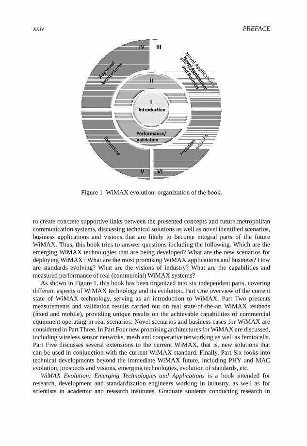
As shown in Figure 1, this book has been organized into six independent parts, coveringdifferent aspects of WiMAX technology and its evolution. Part One overview of the currentstate of WiMAX technology, serving as an introduction to WiMAX. Part Two presentsmeasurements and validation results carried out on real state-of-the-art WiMAX testbeds(fixed and mobile), providing unique results on the achievable capabilities of commercialequipment operating in real scenarios. Novel scenarios and business cases for WiMAX areconsidered in Part Three. In Part Four new promising architectures for WiMAX are discussed,including wireless sensor networks, mesh and cooperative networking as well as femtocells.Part Five discusses several extensions to the current WiMAX, that is, new solutions thatcan be used in conjunction with the current WiMAX standard. Finally, Part Six looks intotechnical developments beyond the immediate WiMAX future, including PHY and MACevolution, prospects and visions, emerging technologies, evolution of standards, etc.
WiMAX Evolution: Emerging Technologies and Applications is a book intended forresearch, development and standardization engineers working in industry, as well as forscientists in academic and research institutes. Graduate students conducting research in

PREFACE xxv
WiMAX and next generation mobile communications will also find in this book relevantmaterial for further research. The Editors think that this book provides novel views anddetailed technical solutions, foreseeing future WiMAX while being a stimulating source ofinspiration for further advanced research in the field.
The Editors welcome any suggestions, comments or constructive criticism on this book.Such feedback will be used to improve forthcoming editions. The Editors can be contactedat [email protected].
Marcos D. KatzVTT (Technical Research Centre of Finland), Finland
Frank H.P. FitzekAalborg University, Denmark
September 2008
Acknowledgements
At times, our own light goes out, and is rekindled by a sparkfrom another person. Each of us has cause to think with deepgratitude of those who have lighted the flame within us.
Albert Schweitzer
The Editors are deeply indebted to each and every contributor to this book. Without thevaluable contributions and enthusiastic participation of specialists around the globe this bookwould have never been possible. We wish to place on record our deep appreciation to all ofthe authors of the chapters, who are, in alphabetical order:
Sassan Ahmadi, Alexander Bachmutsky, Sandrine Boumard, Aaron Byman, ThomasBohnert, Paola Cardamone, Thomas Casey, Chan-Byoung Chae, Francesco Chiti, Juan LuisCorral, Marília Curado, Suvra Sekhar Das, Michael Devetsikiotis, Romano Fantacci,Francisco Fontes, Avraham Freedman, Ilkka Harjula, Matthias Hollick, Kaibin Huang,Jie Hui, Jyrki Huusko, Takao Inoue, Riku Jäntti, Giada Landi, Mika Lasanen, MosheLevin, Roberto Llorente, Leonardo Maccari, Dania Marabissi, Javier Martí, Ricardo Matos,Parag S. Mogre, Edmundo Monteiro, Pedro Neves, Jari Nurmi, Ioannis Papapanagiotou,Kostas Pentikousis, Jarno Pinola, Esa Piri, Valentín Polo, Jonás Porcar, Doug Pulley,Muhammad Imadur Rahman, Antonio Ramírez, Wonil Roh, Susana Sargento, Gerrit Schulte,Christian Schwingenschloegl, Patrick Seeling, Paulo Simões, Chris Smart, Clare Somerville,Roshni Srinivasan, Dirk Staehle, Ralf Steinmetz, Daniele Tarchi, Rath Vannithamby, NenadVeselinovic, Borja Vidal, Yuanye Wang, Matti Weissenfelt, Vladimir Yanover, Qi Zhang,Xiongwen Zhao, Andreas Ziller and David Zorrilla.
We would like to express our gratitude to several people and organizations that supportedthis book. First, we are grateful to Mr Siavash Alamouti, Intel Fellow and CTO of the MobileWireless Group, for his motivating and enlightening foreword.
VTT, the Technical Research Centre of Finland, provided financial and logistical supportfor the preparation of this book. We are grateful to Technology Director Dr Jussi Paakkari,Technology Manager Kyösti Rautiola and Research Professor Dr Aarne Mämmelä for theirunconditional support during this initiative. We also thank our research colleagues at VTT(Communications Platform Group, and in particular the Cooperative and Cognitive NetworksTeam) for their technical contributions, motivating discussions and for creating a trulypleasant working atmosphere. Our colleagues from the Converging Networks Laboratory(CNL) also deserve our deep appreciation, particularly Dr Marko Jurvansuu, Jyrki Huusko,Marko Palola, Dr Kostas Pentikousis and Dr Martin Varela Rico.

xxviii ACKNOWLEDGEMENTS
The European Project WEIRD (WiMAX Extension to Isolated Research Data Networks),coordinated and technically supervised by Enrico Angori (Datamat, Italy) and MarcosKatz, respectively, was the source of several chapters of this book. We are grateful to theWEIRD consortium and its people across Europe for the received support. For their supportand enlightening discussions, we are also grateful to Gerrit Schulte (acticom, Germany),Kari Horneman (Nokia Siemens Networks, Finland), Dr Wonil Roh (Samsung ElectronicCorp., Ltd, Korea), Dr Jaakko Talvitie (Elektrobit, Finland) and Professor Garik Markarian(Lancaster University, UK).
Parts of the book were financed by the X3MP project granted by the Danish Ministryof Science, Technology and Innovation. Furthermore we would like to thank our colleaguesfrom Aalborg University, Denmark for their support, namely Børge Lindberg, Ben Krøyer,Peter Boie Jensen, Bo Nygaard Bai, Henrik Benner, Finn Hybjerg Hansen and Svend ErikVolsgaard.
The Editors would like to thank Nokia for providing invaluable technical support as wellas mobile devices for testing purposes. Special thanks go to Harri Pennanen, Nina Tammelinand Per Møller from Nokia. We are grateful to Jarmo Tikka (Nokia) who kindly provided theN810 wireless tablets that were used in the measurement setup of Chapter 6. Particular thanksgo to Alberto Bestetti and Antonio Cimmino (Alcatel-Lucent, Italy) and Arto Grönholm(Alcatel-Lucent, Finland) for support with the WiMAX equipment used in some of themeasurement test-beds.
We thank John Wiley & Sons Ltd, for their encouragement and support during the processof creating this book. Special thanks to Tiina Ruonamaa, Anna Smart and Sarah Tilleyfor their kindness, patience, flexibility and professionalism. Birgitta Henttunen from VTT,Finland is acknowledged for her support in many administrative issues.
Finally, the Editors would like to thank their respective families for their support andunderstanding during the entire process of creating this book.

List of Acronyms
µC MicroController
16-QAM 16 Quadrature Amplitude Modulation
2G 2nd Generation
3G 3rd Generation
3GPP 3rd Generation Partnership Project
3GPP2 3rd Generation Partnership Project 2
4G Fourth Generation
A/V Audio/Visual
AAA Authentication, Authorization andAccounting
AAS Adaptive Antenna System
AC Admission Control; Antenna Circulation
ACIR Adjacent Channel Interference Ratio
ACK Acknowledgement
ACR Absolute Category Rating
ADSL Asymmetric Digital Subscriber Line
AG Antenna Grouping
AMC adaptive modulation and coding
AMR Adaptive Multi-Rate
AMS Adaptive MIMO Switching
AP Access Point
APD Adaptive Power Distribution
APFR Adaptive Power Fixed Rate
API Application Programming Interface
APMC Adaptive Power, Modulation and Coding
AQ Assessed QoS
ARP Address Resolution Protocol
ARQ Automatic Repeat Request
AS Antenna Selection
ASN Access Service Network
ASN-GW Access Service Network Gateway
ATM Asynchronous Transfer Mode
AVC Advanced Video Coding
AWGN Additive White Gaussian Noise
BD Block Diagonalization
BE Best Effort
BER Bit Error Rate
BF Beamforming
BGP Border Gateway Protocol (routing)
BLER Block Error Rate
BOM Bill Off Materials
bps Bits Per Second
BPSK Binary Phase Shift Keying
BS Base Station
BSID Base Station Identifier
BWA Broadband Wireless Access
C/I Carrier to Interference Ratio
CAPEX Capital Expenditures
CATV Cable Television
CBC Cipher Block Chaining
CBF Coordinated Beamforming
CBR Constant Bit Rate
CC Chase Combining; Convolutional Code;Coordination Center
CCF Call Control Function
CCP2P Cellular Controlled Peer to Peer
CDF Cumulative Distribution Function
CDL Clustered Delay Line

xxx LIST OF ACRONYMS
CDMA Code Division Multiplex Access
CELP Code Excited Linear Prediction
CH Compressed Header
C/I Carrier-to-Interference Ratio
CID Connection Identifier
CI-STBC Coordinate Interleaved Space–TimeBlock Code
CMIP Client Mobile IP
CN Correspondent Node
CN Core Network
CNL VTT Converging Networks Laboratory
CNR Channel-to-Noise Ratio
CoA Care-of-Address
CODEC Compression/Decompression
COST European Cooperation in the Field ofScientific and Technical Research
COTS Commercial Off The Shelf
CP Cyclic Prefix
CPE Customer Premises Equipment
CPS Common Part Sublayer
CPU Central Processing Unit
CQI Channel Quality Indicator
CQICH Channel Quality Indicator Channel
CRC Cyclic Redundancy Check
CS Convergence Sublayer
C-SAP Control Service Access Point
CSG Closed Subscriber Group
CSI Channel State Information
CSN Connectivity Services Network
CTS Clear to Send
DAS Distributed Antenna System
DCA Dynamic Channel Allocation
DCD Downlink Channel Descriptor
DCF Discounted Cash Flow
DES Data Encryption Standard
DFB Distributed Feedback
DHCP Dynamic Host Configuration Protocol
DL Downlink
DMTBR Dynamic Multiple-ThresholdBandwidth Reservation
DNS Domain Name System
DNS-SD Dynamic Name System ServiceDiscovery
DPT Dirty Paper Theory
DRR Deficit Round Robin
DRX Discontinuous Reception
DS-CDMA Direct Sequence Code DivisionMultiple Access
DSL Digital Subscriber Line
DSLAM Digital Subscriber Line AccessMultiplexer
DWRR Deficit Weighed Round Robin
EAP Extensible Authentication Protocol
ECMP Equal Cost Multi-Path
EDF Earliest Deadline First
EpBR Energy per Bit Ratio
ertPS Extended Real-Time Polling Service
ERT-VR Extended Real-Time Variable Rate
ESP Encapsulating Security Payload
ETX Expected Transmission Count
EVD Eigenvalue Decomposition
EVRC Enhanced Variable Rate Codec
FA Foreign Agent
FBSS Fast Base Station Switching
FCH Frame Control Header
FDD Frequency-Division Duplex
FDM Frequency Division Multiplexing
FEC Forward Error Correction
FER Frame Error Rate
FFMS Forest Fire Monitoring Station
FFT Fast Fourier Transform
FIFO First In First Out
FP Framework Programme
FPAR Fixed Power Adaptive Rate
FPGA Field-programmable Gate Array
FTP File Transfer Protocol
FUSC Fully Used Subcarriers
GA Generic Adapter

LIST OF ACRONYMS xxxi
GIS Geographic Information Systems
GIST General Internet Signaling Transport
GMH Generic MAC Header
GoS Grade of Service
GPRS General Packet Radio Service
GPS Global Positioning System
GRE Generic Routing Encapsulation
GSM Global System for MobileCommunications
GTP GPRS Tunneling Protocol
GUI Graphical User Interface
GW Gateway
HA High Availability; Home Agent
HARQ Hybrid Automatic Repeat Request
HD High Definition
HFC Hybrid Fiber Coaxial
HFDD Half-duplex Frequency Division Duplex
HFR Hybrid Fiber Radio
HHO Hard Handover
HO Handover
HSDPA High Speed Data Packet Access
HSPA High Speed Packet Access
HSRP Hot Standby Router Protocol
HTTP Hyper Text Transfer Protocol
HW Hardware
ICMP Internet Control Message Protocol
ICT Information and CommunicationTechnologies
ID Identification
IETF Internet Engineering Task Force
IFFT Inverse Fast Fourier Transform
IMDD Intensity Modulation, Direct Detection
IMS IP Multimedia Subsystem
IMT International Mobile Telecommnications
IP Internet Protocol
Ipsec Internet Protocol Security
IPTV Internet Protocol Television
IPv4 Internet Protocol version 4
IPv6 Internet Protocol version 6
IQ Intrinsic QoS
IQA Instrumental Quality Assessment
IRR Internal Rate of Return
ISD Inter-site Distance
IST Information Society Technologies
ITU International Telecommunications Union
kbps kilobits per second (1000 bits s−1)
KPI Key Performance Indicator
L1 Layer 1 (Physical Layer)
L2 Layer 2 (Data Link Layer)
L2TP Layer 2 Tunneling Protocol
LA Link Adaptation
LACP Link Aggregation Control Protocol
LAG Ling Aggregation
LAN Local Area Network
LBC Load Balancing Cycle
LBS Location Based Services
LDAP Lightweight Directory Access Protocol
LLA Low Level Agent
LLL Lenstra–Lenstra–Lovász
LOS Line-of-Sight
LPC Linear Predictive Coding
LPM Loss Packet Matrix
LSB Least Significant Bit
LTE Long Term Evolution
LU Lenstra–Lenstra–Lovász
MAC Medium Access Control
MAN Metropolitan Area Network
MAP Medium Access Protocol; MobileApplication Part
MBAC Measurement Based Admission Control
MBB Make Before Break
MBMS Multimedia Broadcast Multicast Service
Mbps Megabits per second (1 000 000 bits s−1)
MBS Mesh Base Station; Multicast andBroadcast Service
MCBCS Multicast and Broadcast Service
MCS Modulation and Coding Scheme

xxxii LIST OF ACRONYMS
MCW Multi Codeword
MDHO Macro Diversity Handover
MeSH IEEE 802.16-2004 Mesh Mode
MIB Management Information Base
MICS Media Independent Command Service
MIES Media Independent Event Service
MIH Media Independent Handover
MIHF Media Independent Handover Function
MIHO Mobile Initiated Handover
MIHU Media Independent Handover User
MIIS Media Independent Information Service
MIMO Multiple Input Multiple Output
MIP Mobile Internet Protocol
ML Maximum Latency
MLD Maximum Likelihood Decoder
MLI Modulation Level Information
MM Mobility Management
MMF Multimode Fiber
MMR Mobile Multihop Relay
MMSE Minimum Mean Square Error
MN Mobile Node
MOS Mean Opinion Score
MPEG Moving Picture Experts Group
MRC Maximum Ratio Combining
MRT Maximum Ratio Transmission
MRTR Minimum Reserved Traffic Rate
MS Mobile Station
M-SAP Management Service Access Point
MSB Most Significant Bit
MSDU MAC Service Data Unit
MSE Mean Square Error
MSID Mobile Subscriber ID
MSTR Maximum Sustained Traffic Rate
MTBF Mean Time Between Failures
MTU Maximum Transmission Unit
NACK Negative Acknowledgement
NAI Network Access Identifier
NC Network Coding
NCMS Network Control and ManagementSystem
NDCQ Nondegenerate Constraint Qualification
NE Network Element
NET Network Layer
NGMN Next-Generation Mobile Network
NGN Next Generation Network
NIHO Network Initiated Handover
NLOS Non-Line-of-Sight
NMS Network Management System
NPV Net Present Value
NRM Network Reference Model
nrt Non-real-time
nrtPS Non-real-time Polling Service
NSIS Next Steps in Signaling
NSLP NSIS Signaling Layer Protocol
NTLP NSIS Transport Layer Protocol
NTP Network Time Protocol
NWG Network Working Group
O&M Operations and Management
OFDM Orthogonal Frequency DivisionMultiplexing
OFDMA Orthogonal Frequency DivisionMultiple Access
OGBF Orthogonal Beamforming
OMC Operation and Maintenance Center
OMF Operation and Maintenance Function
OPEX Operational Expenditures
OSPF Open Shortest Path First
P2P Peer to Peer
PA ITU Pedestrian A
PB ITU Pedestrian B
PAN Personal Area Network
PAPR Peak to Average Power Ratio
PBE Perfect Bayesian Equilibrium
PC Paging Controller; Power Control
PCM Pulse Code Modulation
PDA Personal Digital Assistant
PDU Protocol Data Unit
LIST OF ACRONYMS xxxiii
PEP Performance Enhancing Proxy
PER Packet Error Rate
PHB Per Hop Behavior
PHY Physical Layer
PLC Packet Loss Concealment
PLR Packet Loss Rate
PMIP Proxy Mobile IP
PMP Point to Multipoint
PN Psedorondam Noise
POF Plastic Optical Fiber
PQ Perceived QoS
PSTN Public Switched Telphone Network
PTMP Point-to-Multipoint
PTP Precision Time Protocol
PTP Point-to-point
PU2RC Per-User Unitary and Rate Control
PUSC Partially Used Subcarrier; Partially UsedSubchannelization
QAM Quadrature Amplitude Modulation
QoE Quality of Experience
QoS Quality of Service
QPSK Quadrature Phase-Shift Keying
RADIUS Remote Authentication Dial-In UserService
RAN Radio Access Network
RAU Remote Antenna Unit
RB Resource Block
RF Radiofrequency
RFC Request for Comments (IETF standarddocument)
RMF Resource Management Function
RMS Root Mean Square
RoF Radio-over-Fiber
ROHC Robust Header Compression
RRM Radio Resource Management
RS Relay Station
RSS Received Signal Strength
RSSI Received Signal Strength Indicator
rt real-time
RTP Real-time Transport Protocol
rtPS Real-Time Polling Service
RTS Request to Send
RTT Round Trip Time
RT-VR Real-Time Variable Rate
Rx Receive
SA Specific Adapter
SAF Service Availability Forum
SAMPDA Simple Adaptive Modulation andPower Adaptation Algorithm
SAP Service Access Point
SBS Serving Base Station
SC Serra do Carvalho
SCM Spatial Channel Model
SCR Spare Capacity Report
SCTP Stream Control Transmission Protocol
SCW Single Codeword
SDMA Spatial Division Multiple Access
SDU Service Data Unit
SE Spectral Efficiency
SF Service Flow
SFDR Spurious Free Dynamic Range
SFM Service Flow Management
SID Silent Insertion Descriptor
SINR Signal-to-Interference + Noise Ratio
SIP Session Initiation Protocol
SISO Single Input Single Output
SL Serra da Lousã
SLA Service Level Agreement
SM Spatial Multiplexing
SMF Singlemode Fiber
SMS Short Message Service
SNMP Simple Network Management Protocol
SNR Signal-to-Noise Ratio
S-OFDMA Scalable Orthogonal FrequencyDivision Multiple Access
SOHO Small Office/Home Office
SON Self-Organized Network
xxxiv LIST OF ACRONYMS
SP Synchronization Pattern
SRA Simple Rate Adaptation
SRD System Requirement Document
SS Subscriber Station
SSL Secure Socket Layer
STBC Space Time Block Coding
STC Space-Time Coding
SUI Standford University Interim
SW Software
TBS Target Base Station
TCP Transmission Control Protocol
TDD Time Division Duplex
TDM Time Division Multiplexing
TDMA Time Division Multiple Access
TEM Telecommunications EquipmentManufacturer
TETRA Terrestrial Trunked Radio
TTI Transmission Time Interval
TTP Trusted Third Party
TWG Technical Working Group
Tx Transmit
UC University of Coimbra
UCD Uplink Channel Descriptor
UDP User Datagram Protocol
UGS Unsolicited Grant Service
UL Uplink
UMB Ultra Mobile Broadband
UMTS Universal Mobile TelecommunicationsSystem
UMTS-LTE Universal MobileTelecommunications Systems – LongTerm Evolution
VAD Voice Activity Detection
VBR Variable Bit Rate
VCEG Video Coding Experts Group
VCSEL Vertical Cavity Surface Emitting Laser
VDT Virtual Drive Test
VLSI Very-Large-Scale Integration
VoD Video on Demand
VoIP Voice over Internet Protocol
VP Vector Perturbation
VR Virtual Router
VRRP Virtual Router Redundancy Protocol
W3GPP third generation partnership project
WAC Wireless Access Controller
WDM Wavelength Division Multiplexing
WEIRD WiMAX Extension to IsolatedResearch Data Networks
WEP Wired Equivalent Privacy
WiFi Wireless Fidelity
WiMAX Worldwide Interoperability forMicrowave Acccess
WINNER Wireless World Initiative New Radio
WLAN Wireless Local Area Network
W-LSB Windowed Least Significant Bits
WMAN Wireless Metropolitan Area Network
WMN Wireless Mesh Network
WNC Wireless Network Coding
WNEA WiMAX Network ElementAdvertisement
WPAN Wireless Personal Area Network
WRR Weighted Round Robin
WSN Wireless Sensor Network
WT WiMAX Terminal
WWRF Wireless World Research Forum
ZFBF Zero-Forcing Beamforming

Part I
Introduction
WiMAX Evolution: Emerging Technologies and Applications Edited by Tsutomu Ishikawa© 2009 John Wiley & Sons, Ltd. ISBN: 978-0-470-69680-4
1
Introduction to WiMAXTechnology
Wonil Roh and Vladimir Yanover
WiMAX stands for Worldwide Interoperability for Microwave Access. WiMAX technologyenables ubiquitous delivery of wireless broadband service for fixed and/or mobile users,and became a reality in 2006 when Korea Telecom started the deployment of a 2.3 GHzversion of mobile WiMAX service called WiBRO in the Seoul metropolitan area to offerhigh performance for data and video. In a recent market forecast published in April 2008,WiMAX Forum Subscriber and User Forecast Study, the WiMAX Forum projects a ratheraggressive forecast of more than 133 million WiMAX users globally by 2012 (WiMAXForum, 2008c). The WiMAX Forum also claims that there are more than 250 trials anddeployments worldwide.
The WiMAX Forum is an industry-led non-profit organization which, as of the 1st quarterof 2008, has more than 540 member companies including service providers, equipmentvendors, chip vendors and content providers. Its primary mission is to ensure interoperabilityamong IEEE 802.16 based products through its certification process.
The air interface of WiMAX technology is based on the IEEE 802.16 standards. Inparticular, the current Mobile WiMAX technology is mainly based on the IEEE 802.16eamendment (IEEE, 2006a), approved by the IEEE in December 2005, which specifiesthe Orthogonal Frequency Division Multiple Access (OFDMA) air interface and providessupport for mobility.
The selection of features to be implemented in WiMAX systems and devices is presentedin the mobile WiMAX System Profile Release 1.0 (WiMAX Forum, 2007) which wasdeveloped in early 2006 and is currently maintained by the WiMAX Forum (WiMAX Forum,2008a). It is this very technology defined in WiMAX Forum (2007) that was adopted byInternational Telecommunications Union (ITU) as the 6th air interface of IMT-2000 family
WiMAX Evolution: Emerging Technologies and Applications Edited by Tsutomu Ishikawa© 2009 John Wiley & Sons, Ltd. ISBN: 978-0-470-69680-4
4 WiMAX EVOLUTION: EMERGING TECHNOLOGIES AND APPLICATIONS
(ITU, 2007). The flexible bandwidth allocation and multiple built-in types of Quality-of-Service (QoS) support in the WiMAX network allow the provision of high-speed Internetaccess, Voice Over IP (VoIP) and video calls, multimedia chats and mobile entertainment.In addition, the WiMAX connection can be used to deliver content to multimedia gadgetssuch as the iPod.
Since the completion of the Release 1.0 Mobile System Profile, the WiMAX Forum hasbeen working on a certification program which is a critical step for the proliferation of anymodern communication technology throughout the world. As the result, the first WiMAXForum Certified Seal of Approval for the 2.3 GHz spectrum was awarded to four base stationsand four mobile stations in April 2008 (WiMAX Forum, 2008d). In June 2008, another fourbase stations and six mobile stations were awarded the WiMAX Forum Certified Seal ofApproval for the 2.5 GHz spectrum with advanced features such as Multiple Input MultipleOutput (MIMO) in time for commercial deployments around the world (WiMAX Forum,2008e).
This chapter is intended to provide a high-level overview of the current mobile WiMAXtechnology with an emphasis on the Physical (PHY) layer and Medium Access Control(MAC) layer features. Some recent discussions and developments of further WiMAXevolution path are also addressed briefly at the end of the chapter.
1.1 Overview of State-of-the-art WiMAX Technology
1.1.1 Structure of the System Profile
As stated earlier, mobile WiMAX products and certification follow the IEEE 802.16 airinterface specifications. The network specifications of mobile WiMAX products, however,are being developed internally by the WiMAX Forum, which include the end-to-endnetworking specifications and network interoperability specifications. The Network WorkingGroup (NWG) within the WiMAX Forum is responsible for these network specifications,some of which involve Access Service Network (ASN) control and data plane protocols,ASN profiles, Connectivity Services Network (CSN) mobility support, Authentication,Authorization and Accounting (AAA) interworking with other technologies, and variousservices such as Location-Based Service (LBS), Multicast and Broadcast Service (MCBCS)etc. In this chapter, however, we will focus on the overview of mobile WiMAX technologyfrom the air interface perspective.
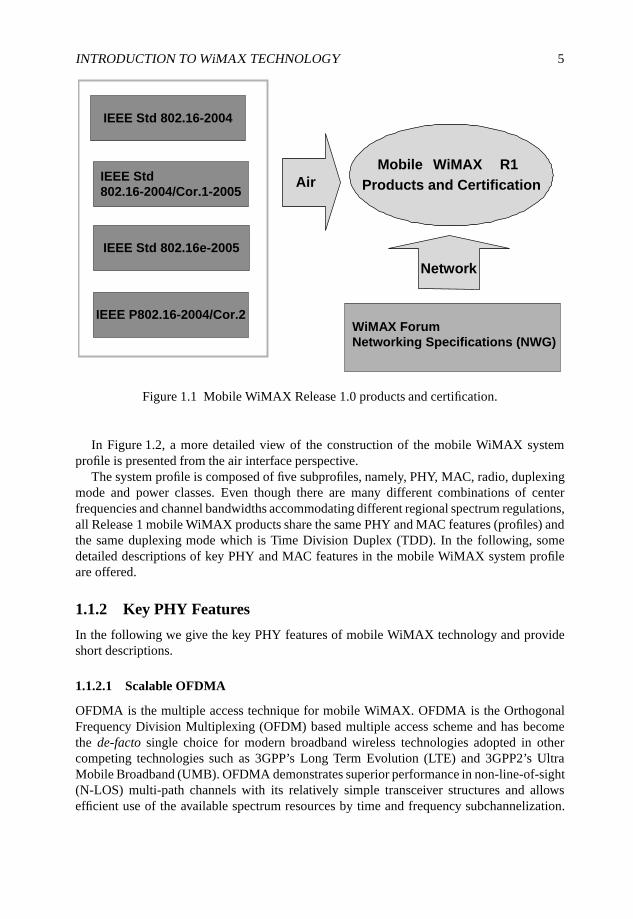
Figure 1.1 presents the aforementioned composition of the current mobile WiMAXtechnology, commonly referred to as Release 1.0 profile. Its air interface specificationsconsist of four related IEEE 802.16 Broadband Wireless Access Standards, that is, IEEEStandard 802.16-2004, IEEE Standard 802.16-2004/Cor.1-2005, IEEE Standard 802.16e-2005 and the IEEE Draft Standard P802.16-2004/Cor.2.
Not all of the optional features defined in these IEEE Standards are implemented inWiMAX products and tested for certifications. Through extensive technical investigationanalysis to build up the best competitive products, the WiMAX Forum Technical WorkingGroup (TWG) published the first version of mobile WiMAX System Profile Release 1in early 2006 (WiMAX Forum, 2007). The latest published version to date (Release 10rev. 1.6.1) incorporated error fixes and minor corrections without touching the main featuresselected in the first revision.
INTRODUCTION TO WiMAX TECHNOLOGY 5
IEEE Std 802.16-2004
IEEE Std 802.16e-2005
IEEE Std
802.16-2004/Cor.1-2005
IEEE P802.16-2004/Cor.2
Air
Mobile WiMAX R1
Products and Certification
WiMAX Forum
Networking Specifications (NWG)
Network
Figure 1.1 Mobile WiMAX Release 1.0 products and certification.
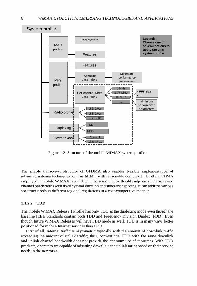
In Figure 1.2, a more detailed view of the construction of the mobile WiMAX systemprofile is presented from the air interface perspective.
The system profile is composed of five subprofiles, namely, PHY, MAC, radio, duplexingmode and power classes. Even though there are many different combinations of centerfrequencies and channel bandwidths accommodating different regional spectrum regulations,all Release 1 mobile WiMAX products share the same PHY and MAC features (profiles) andthe same duplexing mode which is Time Division Duplex (TDD). In the following, somedetailed descriptions of key PHY and MAC features in the mobile WiMAX system profileare offered.
1.1.2 Key PHY Features
In the following we give the key PHY features of mobile WiMAX technology and provideshort descriptions.
1.1.2.1 Scalable OFDMA
OFDMA is the multiple access technique for mobile WiMAX. OFDMA is the OrthogonalFrequency Division Multiplexing (OFDM) based multiple access scheme and has becomethe de-facto single choice for modern broadband wireless technologies adopted in othercompeting technologies such as 3GPP’s Long Term Evolution (LTE) and 3GPP2’s UltraMobile Broadband (UMB). OFDMA demonstrates superior performance in non-line-of-sight(N-LOS) multi-path channels with its relatively simple transceiver structures and allowsefficient use of the available spectrum resources by time and frequency subchannelization.
6 WiMAX EVOLUTION: EMERGING TECHNOLOGIES AND APPLICATIONS
System profile
MAC
profile
Features
Parameters
PHY
profile
Absolute
parameters
Features
Per-channel width
parameters
....
5 MHz
8.75 MHz
10 MHz
Radio profile
Duplexing
Power class
2.3 GHz
2.5 GHz
Minimum
performance
parameters
- FFT size- ...
Minimum
performance
parameters
TDD
FDD
3.x GHz
Class 1
Class 2 …
Legend:
Choose one of
several options toget to specific system profile
Figure 1.2 Structure of the mobile WiMAX system profile.
The simple transceiver structure of OFDMA also enables feasible implementation ofadvanced antenna techniques such as MIMO with reasonable complexity. Lastly, OFDMAemployed in mobile WiMAX is scalable in the sense that by flexibly adjusting FFT sizes andchannel bandwidths with fixed symbol duration and subcarrier spacing, it can address variousspectrum needs in different regional regulations in a cost-competitive manner.
1.1.2.2 TDD
The mobile WiMAX Release 1 Profile has only TDD as the duplexing mode even though thebaseline IEEE Standards contain both TDD and Frequency Division Duplex (FDD). Eventhough future WiMAX Releases will have FDD mode as well, TDD is in many ways betterpositioned for mobile Internet services than FDD.
First of all, Internet traffic is asymmetric typically with the amount of downlink trafficexceeding the amount of uplink traffic; thus, conventional FDD with the same downlinkand uplink channel bandwidth does not provide the optimum use of resources. With TDDproducts, operators are capable of adjusting downlink and uplink ratios based on their serviceneeds in the networks.
INTRODUCTION TO WiMAX TECHNOLOGY 7
In addition, TDD is inherently better suited to more advanced antenna techniques suchas Adaptive Antenna System (AAS) or Beamforming (BF) than FDD due to the channelreciprocity between the uplink and downlink. Mobile Internet with increased multimediaservices naturally requires the use of advanced antenna techniques to improve capacity andcoverage.
1.1.2.3 Advanced Antenna Techniques (MIMO and BF)
Various advanced antenna techniques have been implemented in the mobile WiMAXRelease 1 profile to enable higher cell and user throughputs and improved coverage. As amatter of fact, mobile WiMAX was the first commercially available cellular technology thatactually realized the benefits of MIMO techniques promised by academia for years. With itsdownlink and uplink MIMO features, both operators and end-users enjoy up to twice the datarates of Single-Input Single-Output (SISO) rate, resulting in up to 37 Mbps for downlink and10 Mbps for uplink sector throughput using just 10 MHz TDD channel bandwidth.
Mobile WiMAX also enhances the cell coverage with its inherent BF techniques. Coupledwith TDD operation, its powerful BF mechanism allows base stations to accurately form achannel matching beam to a terminal station so that uplink and downlink signals can reachreliably from and to terminals at the cell edge, thus effectively extending the cell range.
1.1.2.4 Full Mobility Support
Full mobility support is yet another strength of the mobile WiMAX products. The baselinestandard of mobile WiMAX was designed to support vehicles at highway speed withappropriate pilot design and Hybrid Automatic Repeat Request (HARQ), which helps tomitigate the effect of fast channel and interference fluctuation. The systems can detect themobile speed and automatically switch between different types of resource blocks, calledsubchannels, to optimally support the mobile user. Furthermore, HARQ helps to overcomethe error of link adaptation in fast fading channels and to improve overall performance withits combined gain and time diversity.
1.1.2.5 Frequency Reuse One and Flexible Frequency Reuse
From the operators’ perspective, securing greater frequency spectrum for their services isalways costly. Naturally it is in their best interest if a technology allows decent performancein the highly interference-limited conditions with frequency reuse one. Mobile WiMAXtechnology was designed to meet this goal in a respectable way with its cell-specificsubchannelization, low rate coding and power boosting and deboosting features. It alsoenables real-time application of flexible frequency reuse where frequency reuse one appliedto terminals close to the cell center whereas a fraction of frequency is used for terminals atthe cell edge, thereby reducing heavy co-channel interference.
1.1.3 Key MAC Features
The MAC layer of mobile WiMAX (802.16e) technology includes the following featureswhich provide for high efficiency and flexibility.
8 WiMAX EVOLUTION: EMERGING TECHNOLOGIES AND APPLICATIONS
1.1.3.1 Connection-based Data Transmission with Classification and QoS perConnection
The WiMAX technology provides an environment for connection-oriented services. For eachservice, certain classification rules are specified to define the category of traffic associatedwith the connection. For example, it could be Internet Protocol (IP) traffic destined fora specific IP address/port. For each connection, certain QoS parameters are defined, forexample, the minimum reserved rate and maximum sustained rate. There are several typesof scheduling such as real-time services that can be applied based on the applicationrequirements. A special scheduling type (ertPS) is defined for the VoIP service with silencesuppression and adaptive codecs.
1.1.3.2 Scheduled Transmissions and the Flexible Bandwidth Allocation Mechanism
Bandwidth allocation mechanism is based on real time bandwidth requests transmitted by theterminals, per connection. Bandwidth requests may be transmitted using a contention basedmechanism or they can be piggybacked with the data messages. The Base Station executesresources allocation based on the requests and QoS parameters of the connection.
1.1.3.3 MAC Overhead Reduction
WiMAX technology includes support of the general Purpose Header Suppression (PHS) andIP Header Compression (ROHC). PHS can be used for packets of virtually any format suchas IPv4 or IPv6 over Ethernet. It is beneficial if a considerable part of the traffic has identicalheaders which is typical for IP or Ethernet destination addresses. The PHS mechanismreplaces the repeated part of the header with a short context identifier, thus reducing theoverhead associated with headers.
ROHC is a highly efficient IETF standard for which WiMAX MAC has all necessarysupport.
1.1.3.4 Mobility Support: Handover
Handover procedures include numerous means of optimization. In particular, to reduce timeexpenses for the mobile to find the central frequency and acquire parameters of the neighborbase station, the mobile can apply a scanning process when the mobile is away from theserving base station to scan the wireless media for neighbor base stations. Informationcollected during scanning such as central frequencies of the neighbor base stations canthen be used in actual handover. In some deployment scenarios, scanning can be performedwithout service interruption. For this purpose, information about the central frequency andparameters of the neighbor base stations is periodically advertised by the serving base station.
To shorten the time needed for the mobile to enroll into the new cell the network is capableof transferring the context associated with the mobile from the serving base station to thetarget base station.
All of these means provide a potential for high optimization in terms of handover latency.Under ideal conditions the interval of service interruption may be as short as several 5 msframes. The specific handover optimization scheme used in a particular handover depends onthe information available to the mobile.
INTRODUCTION TO WiMAX TECHNOLOGY 9
1.1.3.5 Power Saving: Sleep Mode
Sleep mode is the primary procedure for power saving. In sleep mode the mobile is awayfrom the base station for certain time intervals, normally of exponentially increasing size.During these intervals the mobile remains registered at the base station but can power downcertain circuits to reduce power consumption.
1.1.3.6 Power Saving: Idle Mode
If the mobile has no traffic for a long time it can switch to idle mode in which it is nolonger registered at any particular base station. To resume traffic between the network andthe mobile, a paging procedure may be used by the network.
1.1.3.7 Security
The security sublayer provides Extensible Authentication Protocol (EAP)-based mutualauthentication between the mobile and the network. It protects against unauthorized access tothe transferred data by applying strong encryption of data blocks transferred over the air. Tokeep the encryption keys fresh, the security sublayer employs an authenticated client/serverkey management protocol which allows the base station to distribute keying material tomobiles. Basic security mechanisms are strengthened by adding digital-certificate-basedSubscriber Station (SS) device authentication to the key management protocol.
1.1.3.8 MAC Layer Support for the Multicast and Broadcast Service
Multicast and Broadcast Services (MBSs) allow WiMAX mobile terminals to receivemulticast data even when they are in idle mode. The most popular application of this featureis TV broadcasting to mobile terminals.
1.1.4 Advanced Networking Features
The WiMAX Forum developed specifications of the network infrastructure which comple-ment the 802.16e specifications of the air interface (see WiMAX Forum (2008b)).
1.2 WiMAX Evolution Path
Figure 1.3 provides an overview of mobile WiMAX roadmaps for standards and products.The first release labeled as Release 1.0 is described earlier in this chapter. The othertwo, Releases 1.5 and 2.0, are short-term and long-term migration, respectively, and theirbrief summaries are provided in this section. The corresponding IEEE baseline standardsfor Releases 1.5 and 2.0 are IEEE 802.16 REV2 (IEEE, 2008) and IEEE 802.16m (IEEE,2006b), respectively. Owing to the dependency on the ongoing IEEE standards, REV2 and16m, the schedules of Releases 1.5 and 2.0 are projections by the authors and may change.
Each new generation of the technology needs changes in the profile and/or the standarditself.
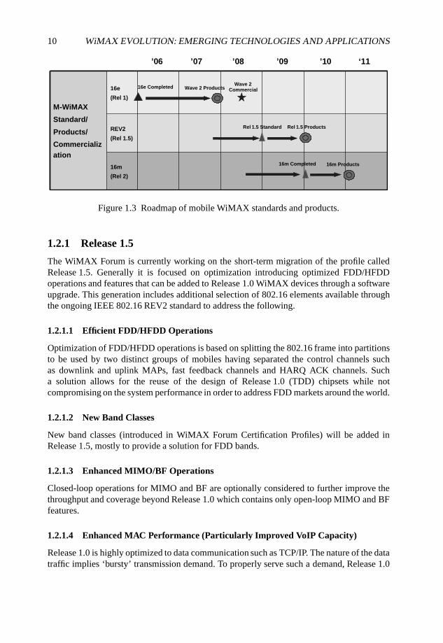
10 WiMAX EVOLUTION: EMERGING TECHNOLOGIES AND APPLICATIONS
16m
(Rel 2)
REV2
(Rel 1.5)
16e
(Rel 1)
M-WiMAX
Standard/
Products/
Commercializ
ation
16m
(Rel 2)
REV2
(Rel 1.5)
16e
(Rel 1)
M-WiMAX
Standard/
Products/
Commercializ
ation
Rel 1.5 Standard Rel 1.5 Products
Wave 2 Products16e Completed
’06 ’07 ’08 ’09 ’10 ‘11
16m Completed 16m Products
Wave 2Commercial
Figure 1.3 Roadmap of mobile WiMAX standards and products.
1.2.1 Release 1.5
The WiMAX Forum is currently working on the short-term migration of the profile calledRelease 1.5. Generally it is focused on optimization introducing optimized FDD/HFDDoperations and features that can be added to Release 1.0 WiMAX devices through a softwareupgrade. This generation includes additional selection of 802.16 elements available throughthe ongoing IEEE 802.16 REV2 standard to address the following.
1.2.1.1 Efficient FDD/HFDD Operations
Optimization of FDD/HFDD operations is based on splitting the 802.16 frame into partitionsto be used by two distinct groups of mobiles having separated the control channels suchas downlink and uplink MAPs, fast feedback channels and HARQ ACK channels. Sucha solution allows for the reuse of the design of Release 1.0 (TDD) chipsets while notcompromising on the system performance in order to address FDD markets around the world.
1.2.1.2 New Band Classes
New band classes (introduced in WiMAX Forum Certification Profiles) will be added inRelease 1.5, mostly to provide a solution for FDD bands.
1.2.1.3 Enhanced MIMO/BF Operations
Closed-loop operations for MIMO and BF are optionally considered to further improve thethroughput and coverage beyond Release 1.0 which contains only open-loop MIMO and BFfeatures.
1.2.1.4 Enhanced MAC Performance (Particularly Improved VoIP Capacity)
Release 1.0 is highly optimized to data communication such as TCP/IP. The nature of the datatraffic implies ‘bursty’ transmission demand. To properly serve such a demand, Release 1.0
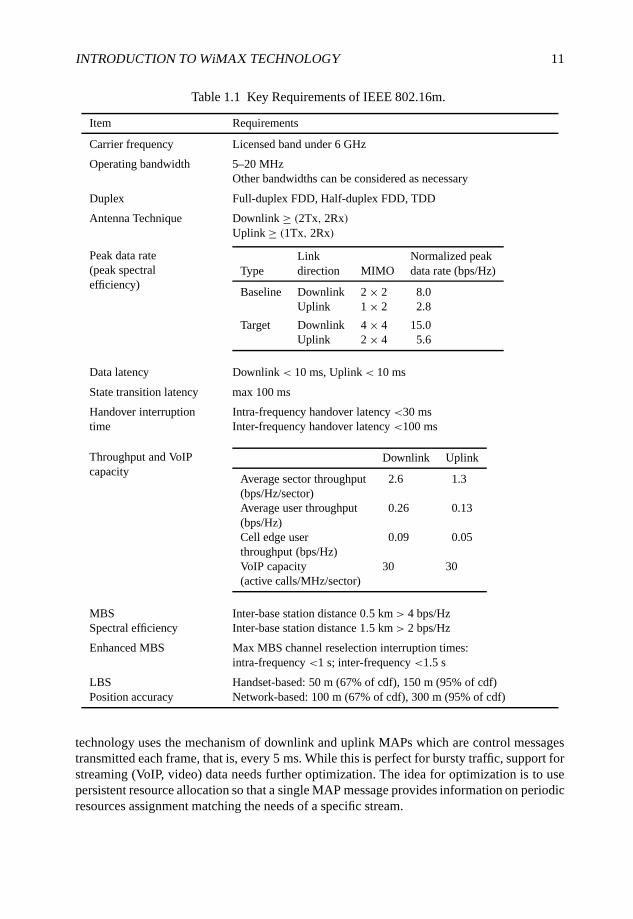
INTRODUCTION TO WiMAX TECHNOLOGY 11
Table 1.1 Key Requirements of IEEE 802.16m.
Item Requirements
Carrier frequency Licensed band under 6 GHz
Operating bandwidth 5–20 MHzOther bandwidths can be considered as necessary
Duplex Full-duplex FDD, Half-duplex FDD, TDD
Antenna Technique Downlink ≥ (2Tx, 2Rx)Uplink ≥ (1Tx, 2Rx)
Peak data rate(peak spectralefficiency)
Link Normalized peakType direction MIMO data rate (bps/Hz)
Baseline Downlink 2 × 2 8.0Uplink 1 × 2 2.8
Target Downlink 4 × 4 15.0Uplink 2 × 4 5.6
Data latency Downlink < 10 ms, Uplink< 10 ms
State transition latency max 100 ms
Handover interruption Intra-frequency handover latency <30 mstime Inter-frequency handover latency <100 ms
Throughput and VoIPcapacity
Downlink Uplink
Average sector throughput 2.6 1.3(bps/Hz/sector)Average user throughput 0.26 0.13(bps/Hz)Cell edge user 0.09 0.05throughput (bps/Hz)VoIP capacity 30 30(active calls/MHz/sector)
MBS Inter-base station distance 0.5 km> 4 bps/HzSpectral efficiency Inter-base station distance 1.5 km> 2 bps/Hz
Enhanced MBS Max MBS channel reselection interruption times:intra-frequency <1 s; inter-frequency <1.5 s
LBS Handset-based: 50 m (67% of cdf), 150 m (95% of cdf)Position accuracy Network-based: 100 m (67% of cdf), 300 m (95% of cdf)
technology uses the mechanism of downlink and uplink MAPs which are control messagestransmitted each frame, that is, every 5 ms. While this is perfect for bursty traffic, support forstreaming (VoIP, video) data needs further optimization. The idea for optimization is to usepersistent resource allocation so that a single MAP message provides information on periodicresources assignment matching the needs of a specific stream.
12 WiMAX EVOLUTION: EMERGING TECHNOLOGIES AND APPLICATIONS
1.2.1.5 Extended and Enhanced Networking Features
Most of the extensions are related to MBSs. The Release 1.5 extension provides for moreflexible allocation of MBS zones which is suitable also for small (micro and pico) cells.Another attractive part of Release 1.5 is the set of features supporting LBSs.
1.2.1.6 Support for WiMAX and WiFi: Bluetooth Coexistence in the Same Mobile
Special attention is paid to provide more efficient support to WiMAX terminals havingadditional wireless Local Area Network (LAN) and/or Personal Area Network (PAN)interfaces. As the timing of WiFi or Bluetooth interfaces does not match the timing of theWiMAX interface, special arrangements are needed to, for example, prevent the Bluetoothtransmitter from interfering with the WiMAX receiver and vice versa.
1.2.2 Release 2.0
As was mentioned earlier, the long-term migration from Release 1.0 is known as Release 2.0and the corresponding specification is being developed in the IEEE 802.16m project (IEEE,2006b). Unlike Release 1.5, which focused on FDD/HFDD and software-based additionsto Release 1.0, the goal of Release 2.0 is to meet International Mobile Telecommnications(IMT)-Advanced requirements for next-generation mobile networks which will be done byproviding major improvements in all areas. The requirements for 16m can be found in (IEEE,2007) and Table 1.1 summaries some of the key requirements of 16m.
References
IEEE (2006a) IEEE Std 802.16e-2005. Amendment to IEEE Standard for Local and Metropolitan AreaNetworks – Part 16: Air Interface for Fixed Broadband Wireless Access Systems – Physical andMedium Access Control Layers for Combined Fixed and Mobile Operation in Licensed Bands,February.
IEEE (2006b) IEEE P802.16. IEEE Standard for Local and Metropolitan Area Networks – Part 16:Air Interface for Fixed Broadband Wireless Access Systems – Amendment: Advanced Air Interface,December.
IEEE (2007) IEEE 802.16m. System Requirements,http://www.wirelessman.org/tgm/docs/80216m-07_002r4.pdf, October.
IEEE (2008) IEEE P802.16Rev2. Revision of IEEE Std 802.16-2004 and consolidates material fromIEEE Std 802.16e-2005, IEEE Std 802.16-2004/Cor1-2005, IEEE Std 802.16f-2005 and IEEEStd802.16g-2007, June.
ITU (2007) Recommendation ITU-R M.1457. Detailed Specifications of the Radio Interfaces ofInternational Mobile Telecommunications-2000 (IMT-2000).
WiMAX Forum (2007) WiMAX Forum Mobile System Profile Release 1.0 Approved Specification,Revision 1.4.0, May.
WiMAX Forum (2008a) www.wimaxforum.org.
WiMAX Forum (2008b) www.wimaxforum.org/technology/documents/WiMAX_Forum_Network_Architecture_Stage_2-3_Rel_1v1.2.zip.
WiMAX Forum (2008c) WiMAX Technology Forecast,www.wimaxforum.org/technology/downloads/wimax_forum_wimax_forecasts_6_1_08.pdf.

INTRODUCTION TO WiMAX TECHNOLOGY 13
WiMAX Forum (2008d) WiMAX Forum Announces First Mobile WiMAX Certified Products atWiMAX Forum Congress Asia 2008,www.wimaxforum.org/news/pr/view?item_key=59390fb727bfa15b5b8d11bf9341b2b1176099f8.
WiMAX Forum (2008e) WiMAX Forum announces first certified MIMO 2.5 GHz Mobile WiMAXproducts,www.wimaxforum.org/news/pr/view?item_key=cffca4e77e1900b83fa727fe754a60be0db849e6.
Part II
WiMAX Validation:Validating Current Fixed and
Mobile WiMAX throughAdvanced Testbeds
WiMAX Evolution: Emerging Technologies and Applications Edited by Tsutomu Ishikawa© 2009 John Wiley & Sons, Ltd. ISBN: 978-0-470-69680-4
2
WiMAX Performance in Practice
Kostas Pentikousis, Esa Piri, Jarno Pinola andIlkka Harjula
According to some estimates, by 2010 WiMAX operators will cover areas inhabited by morethan 650 million people; however, current deployment is not meeting previous expectationsand predictions. Moreover, non-vendor, third-party empirical evaluations of the technologyare far from common. In fact, most WiMAX studies have up to now solely employedsimulation, modeling and analytical tools. It is not really well understood what is in practicepossible with Commercial Off-The-Shelf (COTS) WiMAX equipment. This chapter presentsresults from our recently concluded baseline, VoIP and IPTV synthetic traffic measurementand analysis studies over WiMAX at the VTT Converging Networks Laboratory (CNL) inOulu, Finland, and aims at contributing to our understanding about the potential of WiMAXin practice.
This chapter is organized as follows. Section 2.1 provides a short literature reviewof other empirical studies of WiMAX. Section 2.2 introduces our fixed WiMAX testbedand our methodology with respect to traffic generation, metrics and testbed host clocksynchronization. It also provides baseline capacity measurements and relates them withpreviously published works. Section 2.3 presents our empirical evaluation of VoIP overfixed WiMAX. Here we explain the issues arising from header overhead in VoIP, discussthe performance of different VoIP codecs and highlight the performance gains that may beattained by employing VoIP aggregation. Section 2.4 presents our evaluation of emulatedIPTV audio/video streaming over fixed WiMAX, for both line-of-sight (LOS) and non-line-of-sight (NLOS) conditions. Section 2.5 presents an empirical evaluation study of thebaseline capacity of a mobile WiMAX testbed, which we consider to be the first publiclydisclosed. Finally, Section 2.6 summarizes this chapter and Section 2.7 provides pointers forfurther reading.
WiMAX Evolution: Emerging Technologies and Applications Edited by Tsutomu Ishikawa© 2009 John Wiley & Sons, Ltd. ISBN: 978-0-470-69680-4
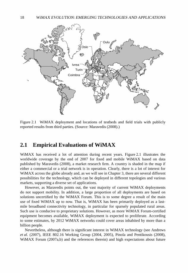
18 WiMAX EVOLUTION: EMERGING TECHNOLOGIES AND APPLICATIONS
Oulu
Oslo
Coimbra
Turin
Ivrea
Figure 2.1 WiMAX deployment and locations of testbeds and field trials with publiclyreported results from third parties. (Source: Maravedis (2008).)
2.1 Empirical Evaluations of WiMAX
WiMAX has received a lot of attention during recent years. Figure 2.1 illustrates theworldwide coverage by the end of 2007 for fixed and mobile WiMAX based on datapublished by Maravedis (2008), a market research firm. A country is shaded in the map ifeither a commercial or a trial network is in operation. Clearly, there is a lot of interest forWiMAX across the globe already and, as we will see in Chapter 3, there are several differentpossibilities for the technology, which can be deployed in different topologies and variousmarkets, supporting a diverse set of applications.
However, as Maravedis points out, the vast majority of current WiMAX deploymentsdo not support mobility. In addition, a large proportion of all deployments are based onsolutions uncertified by the WiMAX Forum. This is to some degree a result of the mainuse of fixed WiMAX up to now. That is, WiMAX has been primarily deployed as a last-mile broadband connectivity technology, in particular for sparsely populated rural areas.Such use is conducive to proprietary solutions. However, as more WiMAX Forum-certifiedequipment becomes available, WiMAX deployment is expected to proliferate. Accordingto some estimates, by 2012 WiMAX networks could cover areas inhabited by more than abillion people.
Nevertheless, although there is significant interest in WiMAX technology (see Andrewset al. (2007), IEEE 802.16 Working Group (2004, 2005), Pinola and Pentikousis (2008),WiMAX Forum (2007a,b) and the references therein) and high expectations about future
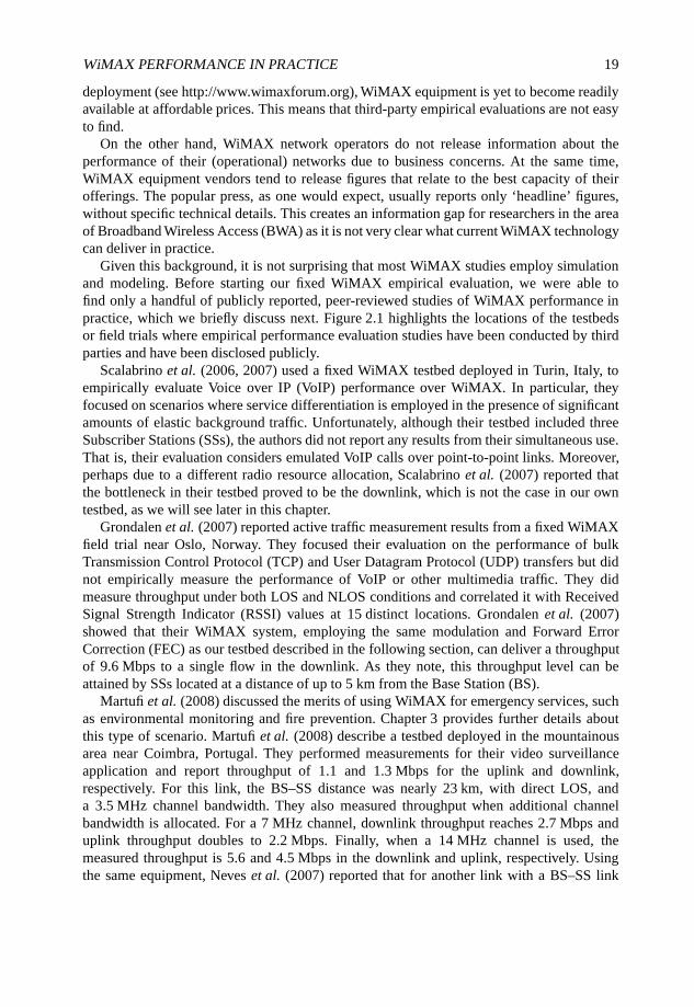
WiMAX PERFORMANCE IN PRACTICE 19
deployment (see http://www.wimaxforum.org), WiMAX equipment is yet to become readilyavailable at affordable prices. This means that third-party empirical evaluations are not easyto find.
On the other hand, WiMAX network operators do not release information about theperformance of their (operational) networks due to business concerns. At the same time,WiMAX equipment vendors tend to release figures that relate to the best capacity of theirofferings. The popular press, as one would expect, usually reports only ‘headline’ figures,without specific technical details. This creates an information gap for researchers in the areaof Broadband Wireless Access (BWA) as it is not very clear what current WiMAX technologycan deliver in practice.
Given this background, it is not surprising that most WiMAX studies employ simulationand modeling. Before starting our fixed WiMAX empirical evaluation, we were able tofind only a handful of publicly reported, peer-reviewed studies of WiMAX performance inpractice, which we briefly discuss next. Figure 2.1 highlights the locations of the testbedsor field trials where empirical performance evaluation studies have been conducted by thirdparties and have been disclosed publicly.
Scalabrino et al. (2006, 2007) used a fixed WiMAX testbed deployed in Turin, Italy, toempirically evaluate Voice over IP (VoIP) performance over WiMAX. In particular, theyfocused on scenarios where service differentiation is employed in the presence of significantamounts of elastic background traffic. Unfortunately, although their testbed included threeSubscriber Stations (SSs), the authors did not report any results from their simultaneous use.That is, their evaluation considers emulated VoIP calls over point-to-point links. Moreover,perhaps due to a different radio resource allocation, Scalabrino et al. (2007) reported thatthe bottleneck in their testbed proved to be the downlink, which is not the case in our owntestbed, as we will see later in this chapter.
Grondalen et al. (2007) reported active traffic measurement results from a fixed WiMAXfield trial near Oslo, Norway. They focused their evaluation on the performance of bulkTransmission Control Protocol (TCP) and User Datagram Protocol (UDP) transfers but didnot empirically measure the performance of VoIP or other multimedia traffic. They didmeasure throughput under both LOS and NLOS conditions and correlated it with ReceivedSignal Strength Indicator (RSSI) values at 15 distinct locations. Grondalen et al. (2007)showed that their WiMAX system, employing the same modulation and Forward ErrorCorrection (FEC) as our testbed described in the following section, can deliver a throughputof 9.6 Mbps to a single flow in the downlink. As they note, this throughput level can beattained by SSs located at a distance of up to 5 km from the Base Station (BS).
Martufi et al. (2008) discussed the merits of using WiMAX for emergency services, suchas environmental monitoring and fire prevention. Chapter 3 provides further details aboutthis type of scenario. Martufi et al. (2008) describe a testbed deployed in the mountainousarea near Coimbra, Portugal. They performed measurements for their video surveillanceapplication and report throughput of 1.1 and 1.3 Mbps for the uplink and downlink,respectively. For this link, the BS–SS distance was nearly 23 km, with direct LOS, anda 3.5 MHz channel bandwidth. They also measured throughput when additional channelbandwidth is allocated. For a 7 MHz channel, downlink throughput reaches 2.7 Mbps anduplink throughput doubles to 2.2 Mbps. Finally, when a 14 MHz channel is used, themeasured throughput is 5.6 and 4.5 Mbps in the downlink and uplink, respectively. Usingthe same equipment, Neves et al. (2007) reported that for another link with a BS–SS link
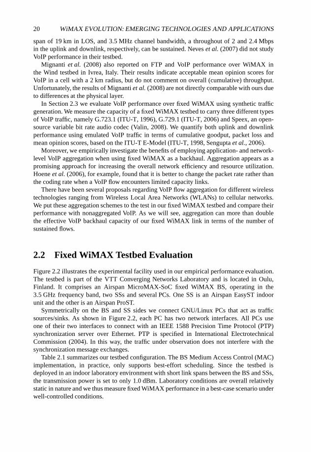
20 WiMAX EVOLUTION: EMERGING TECHNOLOGIES AND APPLICATIONS
span of 19 km in LOS, and 3.5 MHz channel bandwidth, a throughout of 2 and 2.4 Mbpsin the uplink and downlink, respectively, can be sustained. Neves et al. (2007) did not studyVoIP performance in their testbed.
Mignanti et al. (2008) also reported on FTP and VoIP performance over WiMAX inthe Wind testbed in Ivrea, Italy. Their results indicate acceptable mean opinion scores forVoIP in a cell with a 2 km radius, but do not comment on overall (cumulative) throughput.Unfortunately, the results of Mignanti et al. (2008) are not directly comparable with ours dueto differences at the physical layer.
In Section 2.3 we evaluate VoIP performance over fixed WiMAX using synthetic trafficgeneration. We measure the capacity of a fixed WiMAX testbed to carry three different typesof VoIP traffic, namely G.723.1 (ITU-T, 1996), G.729.1 (ITU-T, 2006) and Speex, an open-source variable bit rate audio codec (Valin, 2008). We quantify both uplink and downlinkperformance using emulated VoIP traffic in terms of cumulative goodput, packet loss andmean opinion scores, based on the ITU-T E-Model (ITU-T, 1998, Sengupta et al., 2006).
Moreover, we empirically investigate the benefits of employing application- and network-level VoIP aggregation when using fixed WiMAX as a backhaul. Aggregation appears as apromising approach for increasing the overall network efficiency and resource utilization.Hoene et al. (2006), for example, found that it is better to change the packet rate rather thanthe coding rate when a VoIP flow encounters limited capacity links.
There have been several proposals regarding VoIP flow aggregation for different wirelesstechnologies ranging from Wireless Local Area Networks (WLANs) to cellular networks.We put these aggregation schemes to the test in our fixed WiMAX testbed and compare theirperformance with nonaggregated VoIP. As we will see, aggregation can more than doublethe effective VoIP backhaul capacity of our fixed WiMAX link in terms of the number ofsustained flows.
2.2 Fixed WiMAX Testbed Evaluation
Figure 2.2 illustrates the experimental facility used in our empirical performance evaluation.The testbed is part of the VTT Converging Networks Laboratory and is located in Oulu,Finland. It comprises an Airspan MicroMAX-SoC fixed WiMAX BS, operating in the3.5 GHz frequency band, two SSs and several PCs. One SS is an Airspan EasyST indoorunit and the other is an Airspan ProST.
Symmetrically on the BS and SS sides we connect GNU/Linux PCs that act as trafficsources/sinks. As shown in Figure 2.2, each PC has two network interfaces. All PCs useone of their two interfaces to connect with an IEEE 1588 Precision Time Protocol (PTP)synchronization server over Ethernet. PTP is specified in International ElectrotechnicalCommission (2004). In this way, the traffic under observation does not interfere with thesynchronization message exchanges.
Table 2.1 summarizes our testbed configuration. The BS Medium Access Control (MAC)implementation, in practice, only supports best-effort scheduling. Since the testbed isdeployed in an indoor laboratory environment with short link spans between the BS and SSs,the transmission power is set to only 1.0 dBm. Laboratory conditions are overall relativelystatic in nature and we thus measure fixed WiMAX performance in a best-case scenario underwell-controlled conditions.
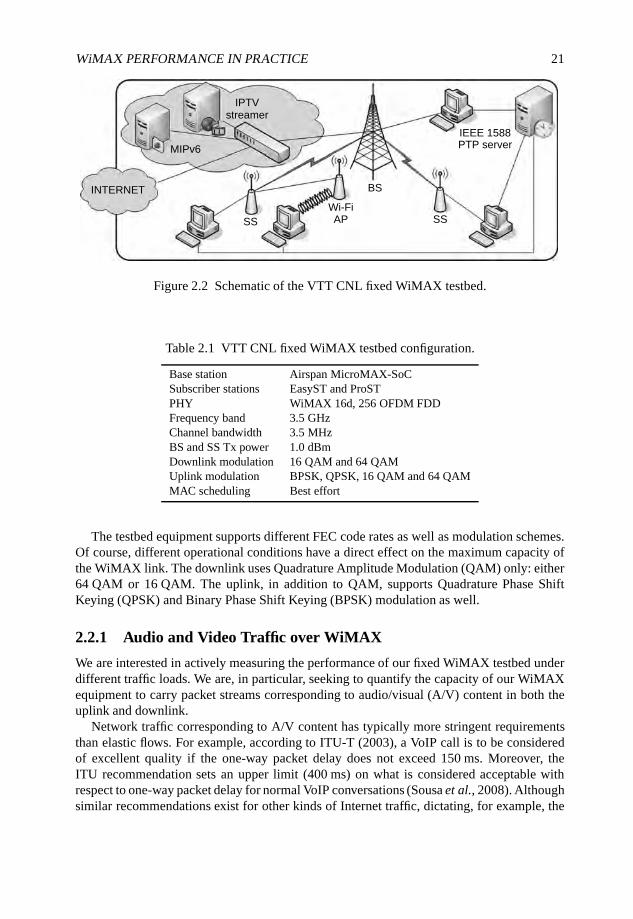
WiMAX PERFORMANCE IN PRACTICE 21
IPTVstreamer
IEEE 1588PTP serverMIPv6
SS SSWi-FiAP
BSINTERNET
Figure 2.2 Schematic of the VTT CNL fixed WiMAX testbed.
Table 2.1 VTT CNL fixed WiMAX testbed configuration.
Base station Airspan MicroMAX-SoCSubscriber stations EasyST and ProSTPHY WiMAX 16d, 256 OFDM FDDFrequency band 3.5 GHzChannel bandwidth 3.5 MHzBS and SS Tx power 1.0 dBmDownlink modulation 16 QAM and 64 QAMUplink modulation BPSK, QPSK, 16 QAM and 64 QAMMAC scheduling Best effort
The testbed equipment supports different FEC code rates as well as modulation schemes.Of course, different operational conditions have a direct effect on the maximum capacity ofthe WiMAX link. The downlink uses Quadrature Amplitude Modulation (QAM) only: either64 QAM or 16 QAM. The uplink, in addition to QAM, supports Quadrature Phase ShiftKeying (QPSK) and Binary Phase Shift Keying (BPSK) modulation as well.
2.2.1 Audio and Video Traffic over WiMAX
We are interested in actively measuring the performance of our fixed WiMAX testbed underdifferent traffic loads. We are, in particular, seeking to quantify the capacity of our WiMAXequipment to carry packet streams corresponding to audio/visual (A/V) content in both theuplink and downlink.
Network traffic corresponding to A/V content has typically more stringent requirementsthan elastic flows. For example, according to ITU-T (2003), a VoIP call is to be consideredof excellent quality if the one-way packet delay does not exceed 150 ms. Moreover, theITU recommendation sets an upper limit (400 ms) on what is considered acceptable withrespect to one-way packet delay for normal VoIP conversations (Sousa et al., 2008). Althoughsimilar recommendations exist for other kinds of Internet traffic, dictating, for example, the
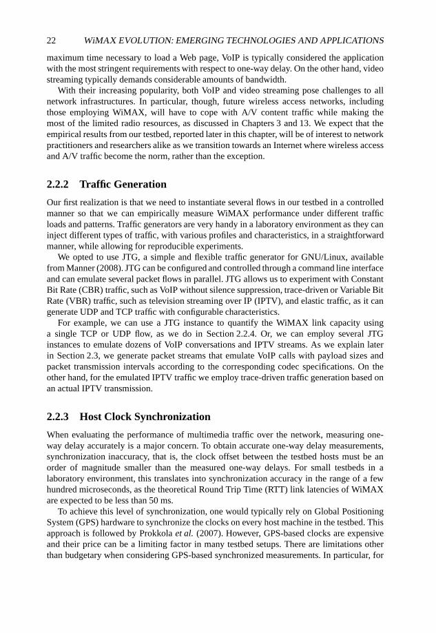
22 WiMAX EVOLUTION: EMERGING TECHNOLOGIES AND APPLICATIONS
maximum time necessary to load a Web page, VoIP is typically considered the applicationwith the most stringent requirements with respect to one-way delay. On the other hand, videostreaming typically demands considerable amounts of bandwidth.
With their increasing popularity, both VoIP and video streaming pose challenges to allnetwork infrastructures. In particular, though, future wireless access networks, includingthose employing WiMAX, will have to cope with A/V content traffic while making themost of the limited radio resources, as discussed in Chapters 3 and 13. We expect that theempirical results from our testbed, reported later in this chapter, will be of interest to networkpractitioners and researchers alike as we transition towards an Internet where wireless accessand A/V traffic become the norm, rather than the exception.
2.2.2 Traffic Generation
Our first realization is that we need to instantiate several flows in our testbed in a controlledmanner so that we can empirically measure WiMAX performance under different trafficloads and patterns. Traffic generators are very handy in a laboratory environment as they caninject different types of traffic, with various profiles and characteristics, in a straightforwardmanner, while allowing for reproducible experiments.
We opted to use JTG, a simple and flexible traffic generator for GNU/Linux, availablefrom Manner (2008). JTG can be configured and controlled through a command line interfaceand can emulate several packet flows in parallel. JTG allows us to experiment with ConstantBit Rate (CBR) traffic, such as VoIP without silence suppression, trace-driven or Variable BitRate (VBR) traffic, such as television streaming over IP (IPTV), and elastic traffic, as it cangenerate UDP and TCP traffic with configurable characteristics.
For example, we can use a JTG instance to quantify the WiMAX link capacity usinga single TCP or UDP flow, as we do in Section 2.2.4. Or, we can employ several JTGinstances to emulate dozens of VoIP conversations and IPTV streams. As we explain laterin Section 2.3, we generate packet streams that emulate VoIP calls with payload sizes andpacket transmission intervals according to the corresponding codec specifications. On theother hand, for the emulated IPTV traffic we employ trace-driven traffic generation based onan actual IPTV transmission.
2.2.3 Host Clock Synchronization
When evaluating the performance of multimedia traffic over the network, measuring one-way delay accurately is a major concern. To obtain accurate one-way delay measurements,synchronization inaccuracy, that is, the clock offset between the testbed hosts must be anorder of magnitude smaller than the measured one-way delays. For small testbeds in alaboratory environment, this translates into synchronization accuracy in the range of a fewhundred microseconds, as the theoretical Round Trip Time (RTT) link latencies of WiMAXare expected to be less than 50 ms.
To achieve this level of synchronization, one would typically rely on Global PositioningSystem (GPS) hardware to synchronize the clocks on every host machine in the testbed. Thisapproach is followed by Prokkola et al. (2007). However, GPS-based clocks are expensiveand their price can be a limiting factor in many testbed setups. There are limitations otherthan budgetary when considering GPS-based synchronized measurements. In particular, for
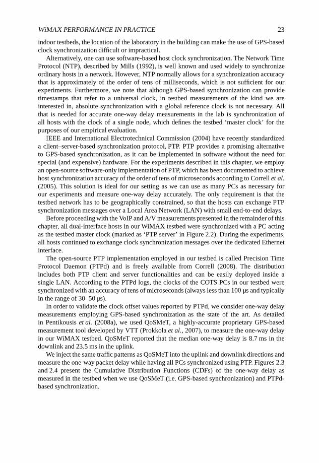
WiMAX PERFORMANCE IN PRACTICE 23
indoor testbeds, the location of the laboratory in the building can make the use of GPS-basedclock synchronization difficult or impractical.
Alternatively, one can use software-based host clock synchronization. The Network TimeProtocol (NTP), described by Mills (1992), is well known and used widely to synchronizeordinary hosts in a network. However, NTP normally allows for a synchronization accuracythat is approximately of the order of tens of milliseconds, which is not sufficient for ourexperiments. Furthermore, we note that although GPS-based synchronization can providetimestamps that refer to a universal clock, in testbed measurements of the kind we areinterested in, absolute synchronization with a global reference clock is not necessary. Allthat is needed for accurate one-way delay measurements in the lab is synchronization ofall hosts with the clock of a single node, which defines the testbed ‘master clock’ for thepurposes of our empirical evaluation.
IEEE and International Electrotechnical Commission (2004) have recently standardizeda client–server-based synchronization protocol, PTP. PTP provides a promising alternativeto GPS-based synchronization, as it can be implemented in software without the need forspecial (and expensive) hardware. For the experiments described in this chapter, we employan open-source software-only implementation of PTP, which has been documented to achievehost synchronization accuracy of the order of tens of microseconds according to Correll et al.(2005). This solution is ideal for our setting as we can use as many PCs as necessary forour experiments and measure one-way delay accurately. The only requirement is that thetestbed network has to be geographically constrained, so that the hosts can exchange PTPsynchronization messages over a Local Area Network (LAN) with small end-to-end delays.
Before proceeding with the VoIP and A/V measurements presented in the remainder of thischapter, all dual-interface hosts in our WiMAX testbed were synchronized with a PC actingas the testbed master clock (marked as ‘PTP server’ in Figure 2.2). During the experiments,all hosts continued to exchange clock synchronization messages over the dedicated Ethernetinterface.
The open-source PTP implementation employed in our testbed is called Precision TimeProtocol Daemon (PTPd) and is freely available from Correll (2008). The distributionincludes both PTP client and server functionalities and can be easily deployed inside asingle LAN. According to the PTPd logs, the clocks of the COTS PCs in our testbed weresynchronized with an accuracy of tens of microseconds (always less than 100 µs and typicallyin the range of 30–50 µs).
In order to validate the clock offset values reported by PTPd, we consider one-way delaymeasurements employing GPS-based synchronization as the state of the art. As detailedin Pentikousis et al. (2008a), we used QoSMeT, a highly-accurate proprietary GPS-basedmeasurement tool developed by VTT (Prokkola et al., 2007), to measure the one-way delayin our WiMAX testbed. QoSMeT reported that the median one-way delay is 8.7 ms in thedownlink and 23.5 ms in the uplink.
We inject the same traffic patterns as QoSMeT into the uplink and downlink directions andmeasure the one-way packet delay while having all PCs synchronized using PTP. Figures 2.3and 2.4 present the Cumulative Distribution Functions (CDFs) of the one-way delay asmeasured in the testbed when we use QoSMeT (i.e. GPS-based synchronization) and PTPd-based synchronization.
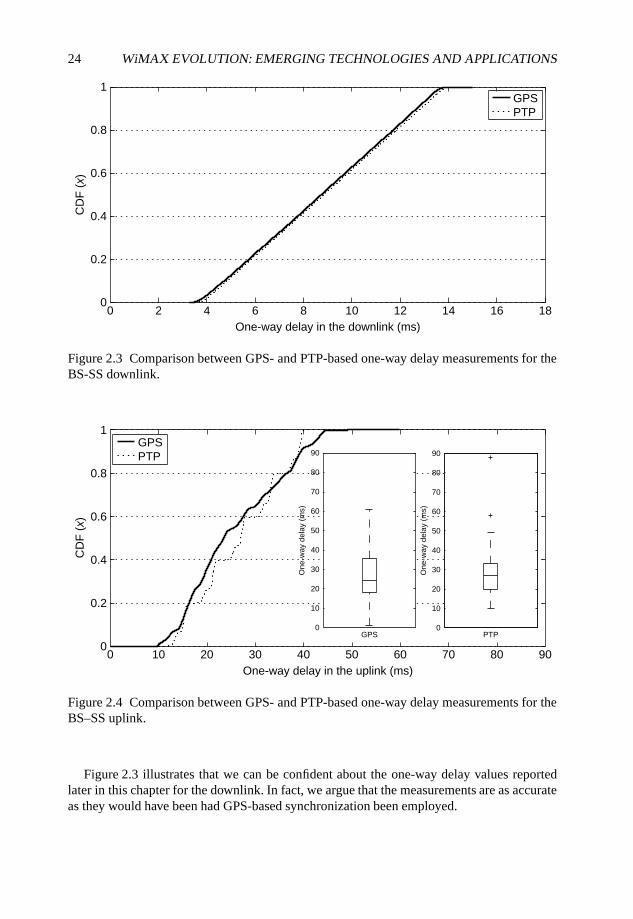
24 WiMAX EVOLUTION: EMERGING TECHNOLOGIES AND APPLICATIONS
0 2 4 6 8 10 12 14 16 180
0.2
0.4
0.6
0.8
1
One-way delay in the downlink (ms)
CD
F (
x)
GPSPTP
Figure 2.3 Comparison between GPS- and PTP-based one-way delay measurements for theBS-SS downlink.
0 10 20 30 40 50 60 70 80 900
0.2
0.4
0.6
0.8
1
One-way delay in the uplink (ms)
CD
F (
x)
0
10
20
30
40
50
60
70
80
90
One
-way
del
ay (
ms)
GPS0
10
20
30
40
50
60
70
80
90
One
-way
del
ay (
ms)
PTP
GPSPTP
Figure 2.4 Comparison between GPS- and PTP-based one-way delay measurements for theBS–SS uplink.
Figure 2.3 illustrates that we can be confident about the one-way delay values reportedlater in this chapter for the downlink. In fact, we argue that the measurements are as accurateas they would have been had GPS-based synchronization been employed.
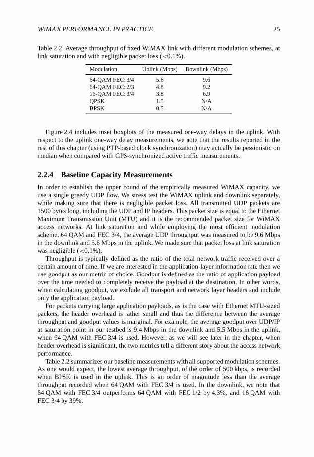
WiMAX PERFORMANCE IN PRACTICE 25
Table 2.2 Average throughput of fixed WiMAX link with different modulation schemes, atlink saturation and with negligible packet loss (<0.1%).
Modulation Uplink (Mbps) Downlink (Mbps)
64-QAM FEC: 3/4 5.6 9.664-QAM FEC: 2/3 4.8 9.216-QAM FEC: 3/4 3.8 6.9QPSK 1.5 N/ABPSK 0.5 N/A
Figure 2.4 includes inset boxplots of the measured one-way delays in the uplink. Withrespect to the uplink one-way delay measurements, we note that the results reported in therest of this chapter (using PTP-based clock synchronization) may actually be pessimistic onmedian when compared with GPS-synchronized active traffic measurements.
2.2.4 Baseline Capacity Measurements
In order to establish the upper bound of the empirically measured WiMAX capacity, weuse a single greedy UDP flow. We stress test the WiMAX uplink and downlink separately,while making sure that there is negligible packet loss. All transmitted UDP packets are1500 bytes long, including the UDP and IP headers. This packet size is equal to the EthernetMaximum Transmission Unit (MTU) and it is the recommended packet size for WiMAXaccess networks. At link saturation and while employing the most efficient modulationscheme, 64 QAM and FEC 3/4, the average UDP throughput was measured to be 9.6 Mbpsin the downlink and 5.6 Mbps in the uplink. We made sure that packet loss at link saturationwas negligible (<0.1%).
Throughput is typically defined as the ratio of the total network traffic received over acertain amount of time. If we are interested in the application-layer information rate then weuse goodput as our metric of choice. Goodput is defined as the ratio of application payloadover the time needed to completely receive the payload at the destination. In other words,when calculating goodput, we exclude all transport and network layer headers and includeonly the application payload.
For packets carrying large application payloads, as is the case with Ethernet MTU-sizedpackets, the header overhead is rather small and thus the difference between the averagethroughput and goodput values is marginal. For example, the average goodput over UDP/IPat saturation point in our testbed is 9.4 Mbps in the downlink and 5.5 Mbps in the uplink,when 64 QAM with FEC 3/4 is used. However, as we will see later in the chapter, whenheader overhead is significant, the two metrics tell a different story about the access networkperformance.
Table 2.2 summarizes our baseline measurements with all supported modulation schemes.As one would expect, the lowest average throughput, of the order of 500 kbps, is recordedwhen BPSK is used in the uplink. This is an order of magnitude less than the averagethroughput recorded when 64 QAM with FEC 3/4 is used. In the downlink, we note that64 QAM with FEC 3/4 outperforms 64 QAM with FEC 1/2 by 4.3%, and 16 QAM withFEC 3/4 by 39%.
26 WiMAX EVOLUTION: EMERGING TECHNOLOGIES AND APPLICATIONS
To sum up, the modulation scheme and the FEC code rate play a critical role in themeasured throughput (and goodput). Our testbed equipment employs mechanisms thatautomatically adapt modulation and FEC according to the operational conditions. Forexample, when the received Signal to Noise Ratio (SNR) deteriorates considerably, say,because the SS operates under NLOS conditions, the modulation scheme changes fromQAM to QPSK or even to BPSK. Thus, the actual performance of individual SSs in a realdeployment may vary greatly.
In the remainder of this chapter we only report empirical measurements for 64 QAM withFEC 3/4 employed, which provide an upper bound of what is possible in practice today withCOTS fixed WiMAX equipment.
2.3 VoIP Over Fixed WiMAX
As mentioned earlier, there is great interest in using VoIP over packet-switched wirelessnetworks, but there are few publicly available empirical studies of VoIP over fixed WiMAX.In this section we present our empirical evaluation study of three different VoIP codecs overWiMAX and discuss the benefits of application- and network-layer aggregation with respectto the effective capacity of our WiMAX testbed.
2.3.1 VoIP Overhead
Typically, VoIP calls do not place high demands on bandwidth. In fact, codec technology hasbeen making great strides towards minimizing bandwidth demands, while delivering evenbetter audio quality. As better audio compression techniques are developed, VoIP packetscarrying voice samples tend to become smaller, which is reflected in the total bandwidthconsumed by a VoIP call. For example, a codec standardized in the late 1980s, such as G.711,requires 100 kbps of available bandwidth ITU-T (1988). A recently developed codec, suchas Speex, on the other hand, is highly configurable allowing for layered encoding. Speexsupports 12 different payload bitrates ranging between 2.15–24.6 kbps and 4–44.2 kbps forthe narrowband and wideband codecs, respectively (Valin, 2008). Nevertheless, codecs dohave to sample voice conversations frequently, thus generating traffic flows with small packetsizes and short inter-packet times.
Raake (2006) pointed out that when considering most current VoIP codecs, each VoIPpacket typically carries a voice sample representing 10–60 ms of audio. This roughlytranslates into voice frame sizes in the range of 20–100 bytes, depending on the codecemployed. The Real-time Transport Protocol (RTP) (Schulzrinne et al., 2003) is often used toencapsulate voice frames, which are then transmitted over UDP/IP. This, in turn, means thateach VoIP packet comprises the voice sample and the RTP, UDP and IP headers. The RTPand UDP headers consume 12 and 8 bytes, respectively. The IPv4 standard header consumesanother 20 bytes; the IPv6 fixed header part consumes 40 bytes. In other words, the totalheader overhead is 40 or 60 bytes, depending on whether IPv4 or IPv6 is used, respectively.
To sum up, due to the small size of a single voice frame, the header overhead wheneach voice sample is sent over RTP/UDP/IP can often exceed 100%. Compare this levelof overhead with the case when the recommended packet size for WiMAX, the EthernetMTU (1500 bytes), is used. In this case, the RTP/UDP/IP header overhead for an MTU-size packet is only 2.74%. The TCP/IP header overhead is also 2.74%, while the UDP/IP
WiMAX PERFORMANCE IN PRACTICE 27
header overhead is only 1.9%. Of course, this header overhead is an issue that emerges inall networks, although it particularly hinders wireless access networks, including WiMAX.Several solutions have been proposed, including VoIP aggregation (empirically evaluated anddiscussed in Section 2.3.5) and Robust Header Compression (ROHC), which is evaluated inpractice by Piri et al. (2008) and in Chapter 10.
In the following sections we empirically evaluate the performance of three commonlyused VoIP codecs at the VTT CNL fixed WiMAX testbed (see Section 2.2) using synthetictraffic generation. First we consider two ITU-T standardized codecs, namely G.723.1 (ITU-T, 1996) and G.729.1 (ITU-T, 2006) and then an open-source VBR audio codec specificallydesigned for speech compression in VoIP applications over packet-switched networks (Valin,2008).
2.3.2 Synthetic G.723.1 VoIP Over WiMAX
G.723.1 (ITU-T, 1996) is a low-rate, narrowband codec with small processing requirementsfor real-time encoding and decoding. We synthetically generate simultaneous unidirectionalflows with JTG (see Section 2.2.2) stressing the WiMAX uplink and downlink separately.
The emulated G.723.1 codec information rate is assumed to be 6.4 kbps and thus the trafficgenerator injects a new packet carrying an emulated sample frame size of 24 bytes every30 ms. In other words, 24 bytes carry 30 ms worth of speech. The application informationrate in this case is 9.6 kbps (accounting for the codec payload and the RTP headers). Thetotal network bitrate for each emulated VoIP flow is slightly over 17 kbps.
Recall that the average goodput attained with Ethernet MTU-sized packets, at linksaturation with negligible loss (<0.1%), is 9.4 Mbps and the maximum throughput is9.6 Mbps. In theory, a simple back-of-the-envelope calculation based on the maximumthroughput measured would tell us that the fixed WiMAX downlink can sustain more than560 G.723.1 emulated unidirectional flows. In practice, this is not the case. Our stress testsshowed that the fixed WiMAX downlink can only carry up to 200 synthetic unidirectionalVoIP flows with negligible loss (<0.1%). At link saturation, which is attained in the downlinkwith 400 VoIP flows, the packet loss rate exceeds 5%, which is unacceptable for G.723.1.
Similarly, in the uplink, the goodput attained with Ethernet MTU-sized packets, atlink saturation with negligible loss (<0.1%), is 5.5 Mbps and the maximum throughput is5.6 Mbps. Although these figures would predict that the uplink can sustain more than 320flows, in practice, we can only have 150 G.723.1 emulated unidirectional flows withoutobserving significant packet loss. If we inject 175 unidirectional flows in the uplink weexceed its saturation point and observe packet loss ratios greater than 5%.
2.3.3 Synthetic G.729.1 VoIP Over WiMAX
G.729.1 (ITU-T, 2006) is a sophisticated wideband codec, which is based on a layeredstructure. The layered encoding allows for 12 different payload bitrates ranging from 8 to32 kbps. The core layer information rate is 8 kbps, carrying 20 ms worth of voice data. Thecore layer is the only layer necessary for a successful decoding of all received VoIP packets.The additional layers improve the received audio quality considerably, but are not as criticalas the core layer.
28 WiMAX EVOLUTION: EMERGING TECHNOLOGIES AND APPLICATIONS
Although G.729.1 defines sophisticated traffic adaptation features, we do not employ themin our empirical evaluation. Instead we choose a single operation mode with four additionallayers, and synthetically generate emulated codec payloads of 40 bytes at a constant codecinformation rate of 16 kbps. The application information rate is 20.8 kbps and the totalnetwork bitrate for each emulated G.729.1 VoIP flow (including the RTP/UDP/IP headers)is 32 kbps.
In this set of experiments we consider the case of bidirectional VoIP flows which areterminated inside the same WiMAX cell. That is, we emulate G.729.1 VoIP calls by injectingthe same number of flows in both uplink and downlink in parallel, modeling a more realisticVoIP call scenario. Moreover, for the tests described in the previous section we used only asingle SS, while for the measurements described in the remainder we use two SSs.
Evidently, the bidirectional VoIP flows need to transit both the uplink and the downlink ofthe same BS. As we saw earlier, the uplink is the bottleneck in our testbed due the specific(fixed) radio resource allocation. Our experiments showed that the WiMAX BS can handle65 bidirectional VoIP flows with an average loss rate of less than 5%, which is an acceptablesample loss threshold for G.729.1. Note that G.729.1 is designed to be more tolerant to packetloss than G.723.1.
Through separate experiments we found out that in our lab the central schedulingperformed by the BS allows us to apportion a number of flows evenly between PCs connectedto SS1 and SS2, split the same number of flows in any random manner between the two SSsor use only one of the SSs while observing negligible packet loss and similar performance.
Although the experiment setup is different from that described in the previous section, wecould attempt a comparison. Effectively, the uplink can sustain 130 synthetic G.729.1 VoIPflows with acceptable packet loss (<5%). That translates into a average cumulative goodputof 2.7 Mbps (and a cumulative throughput of 4.16 Mbps). This is only 49% of the maximumattainable goodput with Ethernet MTU-sized packets.
2.3.4 Synthetic Speex VoIP over WiMAX
Speex is an open-source VBR audio codec specifically designed for speech compressionin VoIP applications over packet-switched networks (Valin, 2008). Speex can be used withthree different sampling rates (narrowband at 8 kHz, wideband at 16 kHz and ultra-widebandat 32 kHz), and has a large range of operational bitrates (2.15–44.2 kbps). Speex uses CodeExcited Linear Prediction (CELP) for encoding voice samples and is robust to packet loss.Owing to its open source and good quality, it has been incorporated into several applications,including Microsoft’s Xbox Live.
Similarly with the experiments in the previous section we consider the case of duplex,bidirectional parallel VoIP flows. We select the wideband codec variant with a codecinformation rate of 12.8 kbps. That is, for each VoIP flow, JTG generates 50 packets persecond with 32 bytes of emulated codec payload. After including the necessary RTP, UDPand IP headers, each JTG instance injects 28.8 kbps of total emulated Speex CBR traffic intothe testbed network.
In our testbed, we were able to have a total of 100 Speex flows in the uplink with negligible(<0.1%) average packet loss. Again, this is nearly half of what a back-of-the-envelopecalculation would have predicted based on the maximum recorded goodput. Owing to thelarge header overhead, the average cumulative goodput in the uplink is only 1.76 Mbps. This
WiMAX PERFORMANCE IN PRACTICE 29
is only 32% of the average goodput achieved by a single UDP flow transmitting EthernetMTU-sized packets.
2.3.5 VoIP Aggregation
The empirical evaluations presented above make it clear that the header overhead, coupledwith the processing delays associated with each packet, and the small inter-arrival packettimes put a drag on VoIP performance over fixed WiMAX. A simple way to reduce headeroverhead is to pack more voice frames in a single packet before transmitting it over theWiMAX link. For example, a G.723.1 VoIP client can buffer two or three voice frames andencapsulate them together, using the same RTP header, before handing them over to UDP.Schulzrinne et al. (2003) explicitly allow voice frame aggregation. As we will see shortly,application-layer aggregation performs significantly better than trivial encapsulation, whichplaces a single voice frame in each RTP/UDP/IP packet.
As mentioned earlier, VoIP packets usually carry voice data which corresponds to only afew tens of milliseconds. When voice frame aggregation is employed, audio samples needto be buffered at the sender before they are transmitted over the WiMAX access network.When a VoIP application bundles samples together, it will need to cope with increased end-to-end delays, over and above their normal level. The additional buffering delays caused byaggregation need to be considered carefully by application developers as they may actuallyworsen the quality of VoIP calls if they are excessive. According to Kitawaki and Itoh (1991),round-trip delays of 500 ms reduce conversational efficiency by approximately 20–30%. Inaddition, recall that ITU-T (2003) recommends that one-way packet delays should not exceed400 ms, and should remain below 150 ms for optimal VoIP call quality. Thus, aggregationlevels that introduce voice frame buffering delays that exceed 100 ms may be problematicfor long-distance VoIP calls.
Next, we quantify the capacity of our fixed WiMAX testbed in terms of the number ofsynthetic G.723.1 VoIP flows it can sustain with negligible packet loss depending on whetheraggregation is employed or not. Then we measure the testbed capacity to sustain VoIP flowsusing Mean Opinion Scores (MOSs) as the metric to determine the performance saturationpoint.
2.3.5.1 Application-layer VoIP Aggregation
As we reported earlier, the fixed WiMAX downlink can sustain 200 unidirectional syntheticG.723.1 flows with negligible loss. When JTG is configured to emulate the aggregation oftwo G.723.1 voice frames per packet, the WiMAX downlink can sustain 650 flows withnegligible packet loss. This represents an impressive effective capacity increase of 225%.Note that in this case the buffering delay increases by 30 ms for every other packet, whichcan be easily handled by modern VoIP applications. If the VoIP sender bundles three voiceframes per packet, then our testbed can sustain more than 800 synthetic unidirectional flowsin the downlink while incurring negligible packet loss.
In the uplink, the testbed can sustain 150 synthetic unidirectional synthetic G.723.1 flowswith negligible loss. When two voice samples are encapsulated per packet injected into theWiMAX uplink, nearly 300 flows can be sustained with negligible loss, effectively doublingthe capacity of the testbed in terms of number of calls. We refer to this application-layer
30 WiMAX EVOLUTION: EMERGING TECHNOLOGIES AND APPLICATIONS
aggregation scheme as ‘L1’. If three voice samples are aggregated, referred to as ‘L2’, thenthe WiMAX uplink can carry at least 400 unidirectional synthetic flows without any packetloss.
It is important to note that the two ends of the VoIP call may decide to use aggregation inan asymmetric manner. Given the relative uplink/downlink radio resource allocation in ourtestbed, which may be quite typical of future real-world deployments, the VoIP peers couldadopt aggregation for the traffic traversing the uplink, but continue to use trivial encapsulationfor the reverse traffic direction. Or, alternatively, given the higher one-way delay observed inthe uplink, the two VoIP peers may decide to use trivial encapsulation in the uplink directionin order to avoid exacerbating the end-to-end one-way delay. Aggregation could be adopted inthe downlink, on the other hand, sparing valuable access network resources for other traffic,such as IPTV or Video on Demand (VoD), which is unidirectional by nature and can use theleftover downlink bandwidth.
2.3.5.2 Network-layer VoIP Aggregation
Despite the impressive performance gains promised by application-layer aggregation, itsadoption necessitates software updates across all end hosts. It also requires that hosts areaware that they are connected over WiMAX and they are willing to share this informationwith their peer.
An alternative to application-layer aggregation, which does not necessitate the cooperationof end users or the rollout of new or updated VoIP software, is network-layer aggregation. Innetwork-layer aggregation a Performance Enhancing Proxy (PEP) is introduced at both theSS and the BS ends. The PEP can work in cooperation with other active network elements,such as routers and firewalls, in order to detect VoIP traffic and start aggregating triviallyencapsulated voice samples. The PEP can bundle together several packets, possibly belongingto different VoIP calls, and transmit them over the fixed WiMAX link. Its peer on the otherend of the WiMAX link will deaggregate the packets and route them to their final destination.
Similarly to application-layer aggregation, a PEP can bundle two or more complete VoIPpackets into a new packet augmented with a PEP header. The term ‘complete VoIP packet’here means the VoIP codec payload plus the RTP, UDP and IP headers. At the transmittingPEP side, multiple VoIP packets including their RTP/UDP/IP headers are bundled; at thereceiving PEP, on the other end of the fixed WiMAX link, deaggregation takes place. Notethat this is a rather trivial network-layer aggregation scheme that does not attain any gain interms of cumulative goodput. In fact, this aggregation scheme actually increases the overallheader overhead due to the introduction of the PEP header. Nevertheless, the PEPs makebetter use of the network resources simply by decreasing the number of packets that need tobe transmitted over the WiMAX link.
Our testbed evaluation showed that when a simple network-layer aggregation schemeis adopted, more than 500 synthetic unidirectional G.723.1 flows can be sustained in thedownlink while incurring negligible packet loss. In the uplink, nearly 300 flows can besustained with negligible loss.
Table 2.3 summarizes our empirical effective capacity measurements over the WiMAXtestbed.
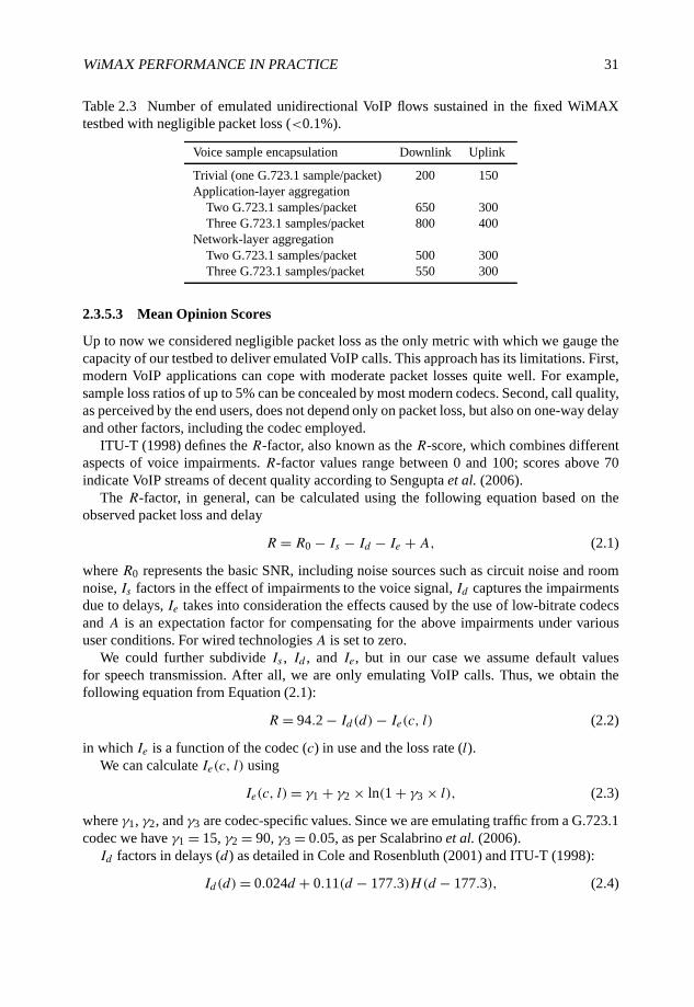
WiMAX PERFORMANCE IN PRACTICE 31
Table 2.3 Number of emulated unidirectional VoIP flows sustained in the fixed WiMAXtestbed with negligible packet loss (<0.1%).
Voice sample encapsulation Downlink Uplink
Trivial (one G.723.1 sample/packet) 200 150Application-layer aggregation
Two G.723.1 samples/packet 650 300Three G.723.1 samples/packet 800 400
Network-layer aggregationTwo G.723.1 samples/packet 500 300Three G.723.1 samples/packet 550 300
2.3.5.3 Mean Opinion Scores
Up to now we considered negligible packet loss as the only metric with which we gauge thecapacity of our testbed to deliver emulated VoIP calls. This approach has its limitations. First,modern VoIP applications can cope with moderate packet losses quite well. For example,sample loss ratios of up to 5% can be concealed by most modern codecs. Second, call quality,as perceived by the end users, does not depend only on packet loss, but also on one-way delayand other factors, including the codec employed.
ITU-T (1998) defines the R-factor, also known as the R-score, which combines differentaspects of voice impairments. R-factor values range between 0 and 100; scores above 70indicate VoIP streams of decent quality according to Sengupta et al. (2006).
The R-factor, in general, can be calculated using the following equation based on theobserved packet loss and delay
R = R0 − Is − Id − Ie + A, (2.1)
where R0 represents the basic SNR, including noise sources such as circuit noise and roomnoise, Is factors in the effect of impairments to the voice signal, Id captures the impairmentsdue to delays, Ie takes into consideration the effects caused by the use of low-bitrate codecsand A is an expectation factor for compensating for the above impairments under varioususer conditions. For wired technologiesA is set to zero.
We could further subdivide Is , Id , and Ie, but in our case we assume default valuesfor speech transmission. After all, we are only emulating VoIP calls. Thus, we obtain thefollowing equation from Equation (2.1):
R = 94.2 − Id(d)− Ie(c, l) (2.2)
in which Ie is a function of the codec (c) in use and the loss rate (l).We can calculate Ie(c, l) using
Ie(c, l)= γ1 + γ2 × ln(1 + γ3 × l), (2.3)
where γ1, γ2, and γ3 are codec-specific values. Since we are emulating traffic from a G.723.1codec we have γ1 = 15, γ2 = 90, γ3 = 0.05, as per Scalabrino et al. (2006).Id factors in delays (d) as detailed in Cole and Rosenbluth (2001) and ITU-T (1998):
Id(d)= 0.024d + 0.11(d − 177.3)H(d − 177.3), (2.4)
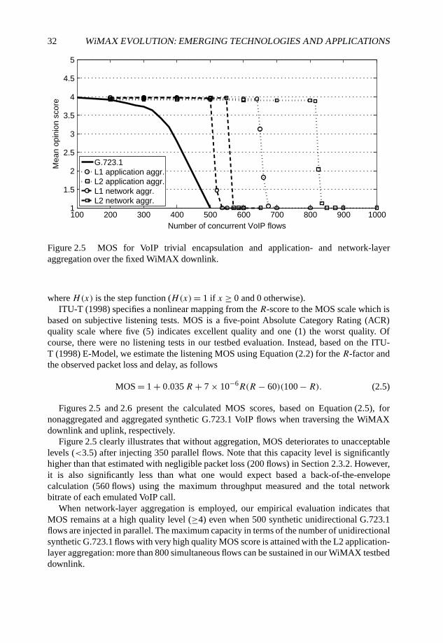
32 WiMAX EVOLUTION: EMERGING TECHNOLOGIES AND APPLICATIONS
100 200 300 400 500 600 700 800 900 10001
1.5
2
2.5
3
3.5
4
4.5
5
Number of concurrent VoIP flows
Mea
n op
inio
n sc
ore
G.723.1L1 application aggr.L2 application aggr.L1 network aggr.L2 network aggr.
Figure 2.5 MOS for VoIP trivial encapsulation and application- and network-layeraggregation over the fixed WiMAX downlink.
where H(x) is the step function (H(x)= 1 if x ≥ 0 and 0 otherwise).ITU-T (1998) specifies a nonlinear mapping from the R-score to the MOS scale which is
based on subjective listening tests. MOS is a five-point Absolute Category Rating (ACR)quality scale where five (5) indicates excellent quality and one (1) the worst quality. Ofcourse, there were no listening tests in our testbed evaluation. Instead, based on the ITU-T (1998) E-Model, we estimate the listening MOS using Equation (2.2) for the R-factor andthe observed packet loss and delay, as follows
MOS = 1 + 0.035R + 7 × 10⁻⁶R(R − 60)(100 − R). (2.5)
Figures 2.5 and 2.6 present the calculated MOS scores, based on Equation (2.5), fornonaggregated and aggregated synthetic G.723.1 VoIP flows when traversing the WiMAXdownlink and uplink, respectively.
Figure 2.5 clearly illustrates that without aggregation, MOS deteriorates to unacceptablelevels (<3.5) after injecting 350 parallel flows. Note that this capacity level is significantlyhigher than that estimated with negligible packet loss (200 flows) in Section 2.3.2. However,it is also significantly less than what one would expect based a back-of-the-envelopecalculation (560 flows) using the maximum throughput measured and the total networkbitrate of each emulated VoIP call.
When network-layer aggregation is employed, our empirical evaluation indicates thatMOS remains at a high quality level (≥4) even when 500 synthetic unidirectional G.723.1flows are injected in parallel. The maximum capacity in terms of the number of unidirectionalsynthetic G.723.1 flows with very high quality MOS score is attained with the L2 application-layer aggregation: more than 800 simultaneous flows can be sustained in our WiMAX testbeddownlink.
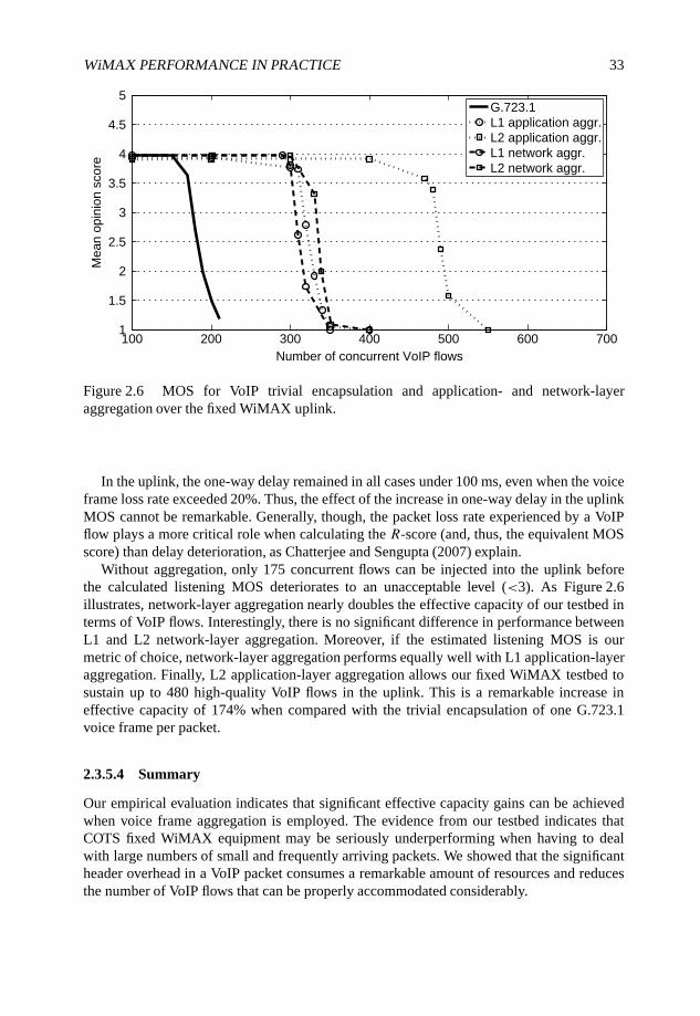
WiMAX PERFORMANCE IN PRACTICE 33
100 200 300 400 500 600 7001
1.5
2
2.5
3
3.5
4
4.5
5
Number of concurrent VoIP flows
Mea
n op
inio
n sc
ore
G.723.1L1 application aggr.L2 application aggr.L1 network aggr.L2 network aggr.
Figure 2.6 MOS for VoIP trivial encapsulation and application- and network-layeraggregation over the fixed WiMAX uplink.
In the uplink, the one-way delay remained in all cases under 100 ms, even when the voiceframe loss rate exceeded 20%. Thus, the effect of the increase in one-way delay in the uplinkMOS cannot be remarkable. Generally, though, the packet loss rate experienced by a VoIPflow plays a more critical role when calculating the R-score (and, thus, the equivalent MOSscore) than delay deterioration, as Chatterjee and Sengupta (2007) explain.
Without aggregation, only 175 concurrent flows can be injected into the uplink beforethe calculated listening MOS deteriorates to an unacceptable level (<3). As Figure 2.6illustrates, network-layer aggregation nearly doubles the effective capacity of our testbed interms of VoIP flows. Interestingly, there is no significant difference in performance betweenL1 and L2 network-layer aggregation. Moreover, if the estimated listening MOS is ourmetric of choice, network-layer aggregation performs equally well with L1 application-layeraggregation. Finally, L2 application-layer aggregation allows our fixed WiMAX testbed tosustain up to 480 high-quality VoIP flows in the uplink. This is a remarkable increase ineffective capacity of 174% when compared with the trivial encapsulation of one G.723.1voice frame per packet.
2.3.5.4 Summary
Our empirical evaluation indicates that significant effective capacity gains can be achievedwhen voice frame aggregation is employed. The evidence from our testbed indicates thatCOTS fixed WiMAX equipment may be seriously underperforming when having to dealwith large numbers of small and frequently arriving packets. We showed that the significantheader overhead in a VoIP packet consumes a remarkable amount of resources and reducesthe number of VoIP flows that can be properly accommodated considerably.
34 WiMAX EVOLUTION: EMERGING TECHNOLOGIES AND APPLICATIONS
Simple aggregation schemes which bundle together multiple voice sample frames into oneIP packet appear to be very promising. Our empirical evaluation indicates that application-layer aggregation may more than double the effective capacity of a WiMAX cell. Of course,VoIP application developers need always to consider the effect of aggregation on the end-to-end delay.
From an operator point of view, we found that the introduction of transparent network-layer VoIP aggregation can prove to be as effective as application-layer aggregation. SimplePEPs can effectively double the number of sustained VoIP flows and they may take advantageof information already available at other active network elements such as routers andfirewalls. PEPs can also be installed, for example, at the traffic control systems residing atthe ingress/egress of a backhaul WiMAX link.
2.4 IPTV over fixed WiMAX
Video streaming applications, including IPTV, VoD, and contemporary web- and P2P-basedvideo services, require significantly more network resources than VoIP. Video is considereda premium service. Delivering high data rates and constraining jitter consistently, overboth short and long periods, are difficult challenges to meet, in particular when wirelesscommunication is involved. In order to deliver high-quality video over a network, supportfor high data rates, bounded latencies and low delay jitter are typically required. Of course,the exact bounds on all of these parameters depend on the specifics of the video streamingapplication.
Different video applications have slightly different demands with respect to the networkcapabilities. For example, live video streaming is the most demanding: the maximumacceptable end-to-end delay and jitter need to be low, so that the interactivity and real-timequalities of a live video feed are preserved and smooth playback of the video content ispossible. From a football fan’s point of view, there is nothing worse than hearing the neighborcelebrating the scoring of a goal during a football match while his own video feed has yet toplay out the event. On the other hand, for VoD services, the bounds on end-to-end delay arenot a critical factor, as extensive buffering can be employed. Larger delay jitter can also betolerated, if pre-play buffering is used at the receiving end.
WiMAX and IEEE 802.16 are from the ground up designed to be able to handle differentQoS requests. In particular, WiMAX can deal with different video streaming applications,as the QoS classes defined for the MAC layer take all of the necessary requirements intoaccount. The Real-Time Variable Rate (RT-VR) and Extended Real-Time Variable Rate(ERT-VR) QoS classes are tailored for real-time applications such as video and audiostreaming which use VBR in their transmissions. The RT-VR QoS class provides guaranteedbitrates and delay for all applications requiring it. If ERT-VR is chosen, low delay jitter, atleast for the WiMAX access link, is guaranteed as well.
Unfortunately, though, not all currently available COTS WiMAX equipment support QoSprovisioning. In fact, we expect that for many deployments best-effort delivery could be thenorm.
Video packet streams comprise mainly large payloads of several hundreds of bytes. Incontrast with VoIP, the total packet size can often be close to the Ethernet MTU and,therefore, header overhead is small. In other words, efficient bandwidth use is feasible for
WiMAX PERFORMANCE IN PRACTICE 35
video streaming over a WiMAX air interface provided, of course, that the capacity of thelink is sufficient for the target rate of the video streams. In fact, by employing state-of-the-art video codecs, such as the ITU-T H.264/Advanced Video Coding (AVC) (also known asISO/IEC MPEG4 Part 10 International Telecommunication Union (2005)), the nominal datarate of each video stream can be relatively low, enabling a single WiMAX BS to deliverseveral video streams simultaneously to multiple users in its cell.
H.264/AVC is a video codec designed to emerge as the de facto codec for a variety ofdifferent multimedia devices operating over a variety of network technologies. This videocoding standard is the result of the joint work of the ITU-T Video Coding Experts Group(VCEG) and the ISO/IEC Moving Picture Experts Group (MPEG). The improvements incoding efficiency through enhanced video compression and representation capabilities makeH.264/AVC suitable also for use in wireless and mobile communication systems, as explainedby Wiegand et al. (2003).
One of the most promising video applications using H.264/AVC is IPTV. There are severalpredictions that claim that IPTV and VoIP are to be the next ‘big thing’ in the IP-basedmultimedia services world. Many network service providers around the world anticipate thatmultimedia services will increase their revenue dramatically. As one would expect, the topichas attracted attention also in the WiMAX research community (see, for example, She et al.(2007), Retnasothie et al. (2006) and Uilecan et al. (2007), just to cite a few).
WiMAX, with the expected high data rates and forthcoming mobility support, poses asa technology over which new kinds of IPTV services can be deployed. For example, TVtransmissions with High Definition (HD) picture quality can be delivered to multiple mobileusers located in the same WiMAX cell. Such services could be offered, for example, to usersof public transport by strategically locating WiMAX BSs along the main routes of the busand train network. Unfortunately, once again due to the lack of affordably available WiMAXequipment, publicly disclosed performance evaluations are mainly based on theoreticalanalysis and simulations.
We fill this gap by empirically investigating two use cases for H.264/AVC-encoded IPTVover our fixed WiMAX testbed. In particular, we focus on measuring the capacity of currentCOTS WiMAX equipment to carry mixed multimedia traffic comprising VoIP and IPTVflows. Interested readers can find more details about this evaluation in Pentikousis et al.(2008a,b).
The first use case considers communication that takes place exclusively inside a singleWiMAX cell. In the second use case, the hosts inside a single WiMAX cell communicatewith remote peers located outside the cell. For both cases, we saturate the uplink WiMAXlink with bidirectional synthetic Speex-encoded VoIP flows. As mentioned earlier, the uplinkcan sustain 100 synthetic Speex VoIP flows. Since the overall capacity of the fixed WiMAXdownlink (9.6 Mbps) is larger than the uplink (5.6 Mbps), we introduce in the downlink, inaddition to the Speex VoIP flows, several emulated IPTV streams. That is, although the uplinkis saturated by the VoIP flows only, we let the IPTV flows effectively use the remainingnetwork resources in the downlink.
In our experiments, the data rate of the transmissions is set to 512 kbps for the VBRvideo and to 192 kbps for the CBR audio, which together comprise the A/V signal of theIPTV channel. This setting corresponds to an actual transmission of an IPTV music channelconfigured at 360 × 288 pixels and 25 frames per second, which is suitable for display onportable/mobile devices equipped with small integrated screens.
36 WiMAX EVOLUTION: EMERGING TECHNOLOGIES AND APPLICATIONS
Our testbed measurements indicate that even when all communications are between nodesinside a single WiMAX cell and, thus, through a single BS, it is possible to inject as manyas five simultaneous H.264/AVC encoded IPTV streams into the downlink without observingservice degradation. Note that in this case the WiMAX BS carries in addition to the fiveIPTV streams, 50 simultaneous bidirectional synthetic Speex VoIP ‘calls’, which originateand terminate inside the cell.
In the second use case, when the emulated VoIP calls involve peers outside the WiMAXcell, which may be a more realistic assumption for real-world deployments, the number ofIPTV streams in the downlink can be increased to seven without service degradation. As amatter of fact, the downlink can sustain eight emulated IPTV transmissions with packet lossless than 5%, but with high one-way packet delays, which exceed 600 ms. If buffering canbe employed, such as for VoD applications, the IPTV application can use pre-play bufferingand deliver the content to the user in a seamless manner.
We also experimented with situations where the signal quality is decreased so that themodulation scheme used in the transmissions is forced to change from 64 QAM to 16 QAM.This would be the case in NLOS operation, for SSs located at cell edges, or in deep shadowingconditions, and of course the performance is naturally lower. In more densely populatedsuburban areas, where the cell size is smaller due to the large number of users and the heightof the buildings is low, this should not be a problem. Difficulties with signal quality will beencountered more likely in vast rural areas with larger cells or in metropolitan city centreswith tall buildings, as discussed in Chapter 3.
We find the results presented very promising for real WiMAX deployments. Recall that inour testbed experiments we were not able to test any other scheduling than best effort due tolack of support from the vendor equipment. Furthermore, we used the default radio resourceallocation. Operators can configure different cells based on the anticipated traffic load. Theycan also increase the channel bandwidth allocation and use directional antennas. In the future,WiMAX equipment will also come with adaptive antenna techniques implemented such asbeamforming and Multiple Input Multiple Output (MIMO), which effectively multiply thecapacity of each WiMAX link. Traffic engineering techniques and teletraffic analysis andtools can also assist operators in accurately estimating and managing the user population andapplication usage in each WiMAX cell.
All in all, WiMAX has some highly attractive features considering IPTV applications,including the ability to serve point-to-multipoint topologies well, an all-IP system architec-ture, high data rates that are expected to keep increasing in the future, mobility support andQoS differentiation. These are all salient features of the WiMAX technology. Our testbedmeasurements, although conducted with rudimentary COTS WiMAX equipment, indicatethat the technology’s potential is not simply theoretical.
2.5 Mobile WiMAX Testbed Evaluation
An important difference between fixed WiMAX and mobile WiMAX is the physicallayer. Mobile WiMAX uses Orthogonal Frequency Division Multiple Access (OFDMA)as its physical layer transmission scheme instead of plain Orthogonal Frequency DivisionMultiplexing (OFDM). OFDMA can also be used as a multiple-access mechanism whengroups of data subcarriers, called subchannels, are allocated to different users. This kind
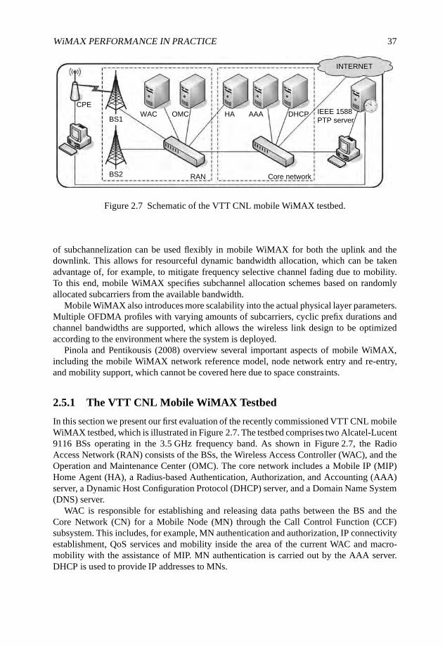
WiMAX PERFORMANCE IN PRACTICE 37
CPE
BS1
BS2 RAN Core network
WAC OMC HA AAA DHCP IEEE 1588
INTERNET
PTP server
Figure 2.7 Schematic of the VTT CNL mobile WiMAX testbed.
of subchannelization can be used flexibly in mobile WiMAX for both the uplink and thedownlink. This allows for resourceful dynamic bandwidth allocation, which can be takenadvantage of, for example, to mitigate frequency selective channel fading due to mobility.To this end, mobile WiMAX specifies subchannel allocation schemes based on randomlyallocated subcarriers from the available bandwidth.
Mobile WiMAX also introduces more scalability into the actual physical layer parameters.Multiple OFDMA profiles with varying amounts of subcarriers, cyclic prefix durations andchannel bandwidths are supported, which allows the wireless link design to be optimizedaccording to the environment where the system is deployed.
Pinola and Pentikousis (2008) overview several important aspects of mobile WiMAX,including the mobile WiMAX network reference model, node network entry and re-entry,and mobility support, which cannot be covered here due to space constraints.
2.5.1 The VTT CNL Mobile WiMAX Testbed
In this section we present our first evaluation of the recently commissioned VTT CNL mobileWiMAX testbed, which is illustrated in Figure 2.7. The testbed comprises two Alcatel-Lucent9116 BSs operating in the 3.5 GHz frequency band. As shown in Figure 2.7, the RadioAccess Network (RAN) consists of the BSs, the Wireless Access Controller (WAC), and theOperation and Maintenance Center (OMC). The core network includes a Mobile IP (MIP)Home Agent (HA), a Radius-based Authentication, Authorization, and Accounting (AAA)server, a Dynamic Host Configuration Protocol (DHCP) server, and a Domain Name System(DNS) server.
WAC is responsible for establishing and releasing data paths between the BS and theCore Network (CN) for a Mobile Node (MN) through the Call Control Function (CCF)subsystem. This includes, for example, MN authentication and authorization, IP connectivityestablishment, QoS services and mobility inside the area of the current WAC and macro-mobility with the assistance of MIP. MN authentication is carried out by the AAA server.DHCP is used to provide IP addresses to MNs.
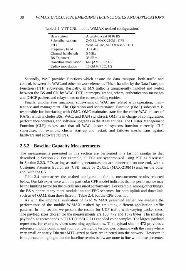
38 WiMAX EVOLUTION: EMERGING TECHNOLOGIES AND APPLICATIONS
Table 2.4 VTT CNL mobile WiMAX testbed configuration.
Base station Alcatel-Lucent 9116 BSSubscriber stations ZyXEL MAX-210M1 CPEPHY WiMAX 16e, 512 OFDMA TDDFrequency band 3.5 GHzChannel bandwidth 5 MHzBS Tx power 35 dBmDownlink modulation 64 QAM FEC: 1/2Uplink modulation 16 QAM FEC: 1/2
Secondly, WAC provides functions which ensure the data transport, both traffic andcontrol, between the WAC and other network elements. This is handled by the Data TransportFunction (DTF) subsystem. Basically, all MN traffic is transparently handled and routedbetween the BS and CN by WAC. DTF intercepts, among others, authentication messagesand DHCP packets and relays them to the corresponding entities.
Finally, another two functional subsystems of WAC are related with operation, main-tenance and management. The Operation and Maintenance Function (OMF) subsystem isresponsible for interfacing with OMC. OMC maintains state for the entire WAC cluster ofRANs, which includes BSs, WAC, and RAN switch(es). OMF is in charge of configuration,performance counters, and software upgrades in the RAN entities. The Cluster ManagementFunction (CLF) makes sure that all WAC cluster subsystems function correctly. CLFsupervises, for example, cluster start-up and restart, and failover mechanisms againsthardware and software failures.
2.5.2 Baseline Capacity Measurements
The measurements presented in this section are performed in a fashion similar to thatdescribed in Section 2.2. For example, all PCs are synchronized using PTP as discussedin Section 2.2.3. PCs acting as traffic generators/sinks are connected, on one end, with aCustomer Premises Equipment (CPE) made by ZyXEL (MAX-210M1) and, on the otherend, with the CN.
Table 2.4 summarizes the testbed configuration for the measurement results reportedbelow. Our lab experience with the particular CPE model indicates that its performance maybe the limiting factor for the overall measured performance. For example, among other things,the BS supports many more modulation and FEC schemes, for both uplink and downlink,such as 64 QAM, than those listed in Table 2.4, but the CPE does not.
As with the empirical evaluation of fixed WiMAX presented earlier, we evaluate theperformance of the mobile WiMAX testbed by emulating different application trafficpatterns. In this section we present the results for UDP traffic with varying packet sizes.The payload sizes chosen for the measurements are 100, 472 and 1372 bytes. The smallestpayload size corresponds to ITU-T (1988) G.711 encoded voice samples. The largest payloadrepresents, for example, video streaming applications. The payload size of 472 provides areference middle point, mainly for comparing the testbed performance with the cases wherevery small or nearly Ethernet MTU-sized packets are injected into the network. However, itis important to highlight that the baseline results below are more in line with those presented
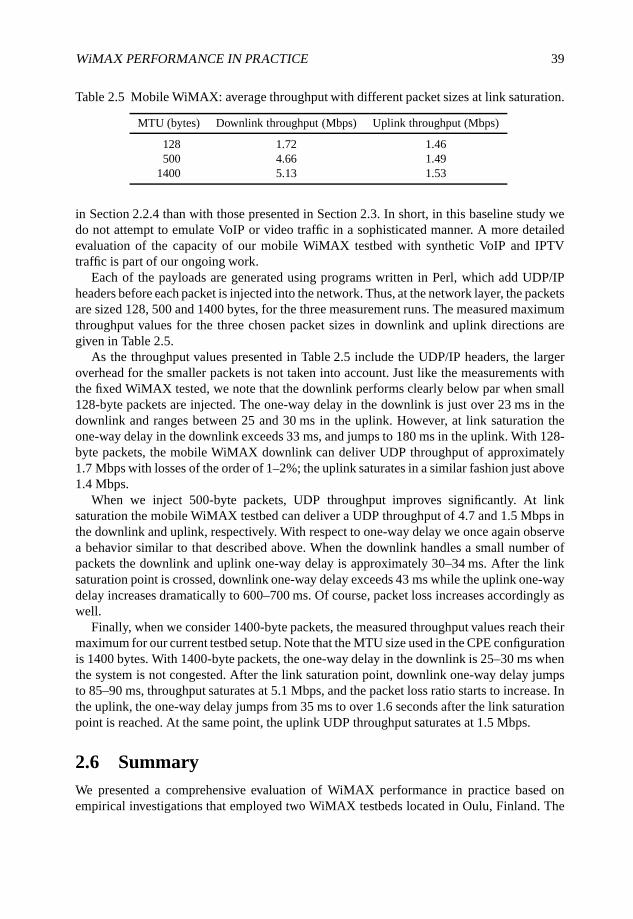
WiMAX PERFORMANCE IN PRACTICE 39
Table 2.5 Mobile WiMAX: average throughput with different packet sizes at link saturation.
MTU (bytes) Downlink throughput (Mbps) Uplink throughput (Mbps)
128 1.72 1.46500 4.66 1.49
1400 5.13 1.53
in Section 2.2.4 than with those presented in Section 2.3. In short, in this baseline study wedo not attempt to emulate VoIP or video traffic in a sophisticated manner. A more detailedevaluation of the capacity of our mobile WiMAX testbed with synthetic VoIP and IPTVtraffic is part of our ongoing work.
Each of the payloads are generated using programs written in Perl, which add UDP/IPheaders before each packet is injected into the network. Thus, at the network layer, the packetsare sized 128, 500 and 1400 bytes, for the three measurement runs. The measured maximumthroughput values for the three chosen packet sizes in downlink and uplink directions aregiven in Table 2.5.
As the throughput values presented in Table 2.5 include the UDP/IP headers, the largeroverhead for the smaller packets is not taken into account. Just like the measurements withthe fixed WiMAX tested, we note that the downlink performs clearly below par when small128-byte packets are injected. The one-way delay in the downlink is just over 23 ms in thedownlink and ranges between 25 and 30 ms in the uplink. However, at link saturation theone-way delay in the downlink exceeds 33 ms, and jumps to 180 ms in the uplink. With 128-byte packets, the mobile WiMAX downlink can deliver UDP throughput of approximately1.7 Mbps with losses of the order of 1–2%; the uplink saturates in a similar fashion just above1.4 Mbps.
When we inject 500-byte packets, UDP throughput improves significantly. At linksaturation the mobile WiMAX testbed can deliver a UDP throughput of 4.7 and 1.5 Mbps inthe downlink and uplink, respectively. With respect to one-way delay we once again observea behavior similar to that described above. When the downlink handles a small number ofpackets the downlink and uplink one-way delay is approximately 30–34 ms. After the linksaturation point is crossed, downlink one-way delay exceeds 43 ms while the uplink one-waydelay increases dramatically to 600–700 ms. Of course, packet loss increases accordingly aswell.
Finally, when we consider 1400-byte packets, the measured throughput values reach theirmaximum for our current testbed setup. Note that the MTU size used in the CPE configurationis 1400 bytes. With 1400-byte packets, the one-way delay in the downlink is 25–30 ms whenthe system is not congested. After the link saturation point, downlink one-way delay jumpsto 85–90 ms, throughput saturates at 5.1 Mbps, and the packet loss ratio starts to increase. Inthe uplink, the one-way delay jumps from 35 ms to over 1.6 seconds after the link saturationpoint is reached. At the same point, the uplink UDP throughput saturates at 1.5 Mbps.
2.6 SummaryWe presented a comprehensive evaluation of WiMAX performance in practice based onempirical investigations that employed two WiMAX testbeds located in Oulu, Finland. The
40 WiMAX EVOLUTION: EMERGING TECHNOLOGIES AND APPLICATIONS
first testbed uses Airspan fixed WiMAX equipment. The second testbed uses Alcatel-Lucentmobile WiMAX equipment.
Baseline capacity measurements showed that the fixed WiMAX testbed can deliver athroughput of 9.6 and 5.6 Mbps in the downlink and uplink, respectively, to a single UDPflow. Then, we considered the performance of aggregated and nonaggregated VoIP overour fixed WiMAX testbed. We measured the performance of different transmission schemesin terms of cumulative goodput, packet and sample loss rates, and calculated the objectiveMOSs using the R-Score specified by ITU. We found that VoIP flows carrying single samplepayloads generated by the G.723.1 codec are clearly underperforming in both uplink anddownlink and that simple voice sample aggregation schemes can more than double theeffective capacity of the fixed WiMAX testbed when measured in terms of emulated VoIPcalls with high-level MOSs.
We also evaluated VoIP and A/V streaming over a point-to-multipoint WiMAX testbedwith one BS and two SSs. We measured the capacity of a single WiMAX cell under LOSand NLOS conditions to deliver tens of emulated bidirectional VoIP calls and a handful ofemulated IPTV streams. Although our fixed WiMAX equipment does not have full supportfor QoS differentiation, we find the results presented very promising for real WiMAXdeployments.
Last but not least, we presented a baseline capacity measurements study using our mobileWiMAX testbed, which, to the best of our knowledge, is the first of its kind provided by athird-party and disclosed publicly. We expect that our empirical evaluation results will be ofgreat interest to other researchers in the BWA area, including simulationists and practitioners.
2.7 Further Reading
This chapter has been based on our experience with the fixed and mobile WiMAX testbedsof the VTT Converging Networks Laboratory. Our empirical evaluation methodology alongwith more detailed results can be found in Pentikousis et al. (2008a,b,c), Pinola (2008), Piri(2008) and Piri et al. (2008).
Readers interested in finding out more about the VTT Converging Networks Laboratoryshould visit http://cnl.willab.fi.
Acknowledgements
We would like to thank our colleagues Frerk Fitzek and Tuomas Nissilä for their invaluablework in earlier incarnations of this study; Mikko Hanski, Pekka Perälä, and Jarmo Prokkolafor their assistance with the QoSMeT measurements; and Antti Heikkinen for his supportwhile collecting the IPTV traces.
Part of this work was conducted at the VTT Converging Networks Laboratory within theframework of the IST 6th Framework Programme Integrated Project WEIRD (IST-034622),which was partially funded by the Commission of the European Union.
Study sponsors had no role in study design, data collection and analysis, interpretation orwriting this report. The views expressed do not necessarily represent the views of VTT, theWEIRD project, or the Commission of the European Union.
WiMAX PERFORMANCE IN PRACTICE 41
References
Andrews, J.G., Ghosh, A. and Muhamed, R. (2007) Fundamentals of WiMAX: UnderstandingBroadband Wireless Networking. Prentice Hall, Englewood Cliffs, NJ.
Chatterjee, M. and Sengupta, S. (2007) VoIP over WiMAX. WiMAX Applications (eds Ahson, S. andIlyas, M.). CRC Press, Boca Raton, FL, pp. 55–76.
Cole, R.G. and Rosenbluth, J.H. (2001) Voice over IP performance monitoring. Proceedings of ACMSIGCOMM, 31, 9–24.
Correll, K. (2008) PTP daemon (PTPd). http://ptpd.sourceforge.net.Correll, K., Barendt, N. and Branicky, M. (2005) Design considerations for software only
implementations of the IEEE 1588 Precision Time Protocol. Proceedings of the IEEE, 1588.Grondalen, O., Gronsund, P., Breivik, T. and Engelstad, P. (2007) Fixed WiMAX field trial
measurements and analyses. Proceedings of the 16th IST Mobile and Wireless CommunicationsSummit, pp. 1–5.
Hoene, C., Karl, H. and Wolisz, A. (2006) A perceptual quality model intended for adaptive VoIPapplications. International Journal of Communication Systems, 19(3), 299–316.
IEEE 802.16 Working Group (2004) IEEE Standard for Local and Metropolitan Area Networks.Part 16: Air Interface for Fixed Broadband Wireless Access Systems. IEEE Standard 802.16-2004.
IEEE 802.16 Working Group (2005) IEEE Standard for Local and Metropolitan Area Networks.Part 16: Air Interface for Fixed Broadband Wireless Access Systems. Amendment 2: Physical andMedium Access Control Layer for Combined Fixed and Mobile Operation in Licensed Bands. IEEEStandard 802.16e-2005.
International Electrotechnical Commission (2004) Precision Clock Synchronization Protocol forNetworked Measurement and Control Systems. IEC 61588:2004(E), IEEE 1588-2002(E).
International Telecommunication Union (2005) Advanced video coding for generic audiovisualservices. ITU-T Recommendation H.264.
ITU-T (1988) Pulse Code Modulation (PCM) of Voice Frequencies. ITU-T Recommendation G.711.ITU-T (1996) Dual rate speech coder for multimedia communications transmitting at 5.3 and 6.3 kbs.
ITU-T Recommendation G.723.1.ITU-T (1998) The E-Model, a computational model for use in transmission planning. ITU-T
Recommendation G.107.ITU-T (2003) ITU-T Recommendation G.114.ITU-T (2006) G.729 based Embedded Variable bit-rate coder: an 8-32 kbit/s scalable wideband coder
bitstream interoperable with G.729. ITU-T Recommendation G.729.1.Kitawaki, N. and Itoh, K. (1991) Pure delay effects on speech quality in telecommunications. IEEE
Journal on Selected Areas in Communications, 9, 586–593.Manner, J. (2008) Jugi’s Traffic Generator (JTG). http://hoslab.cs.helsinki.fi/savane/projects/jtg.Maravedis (2008) http://www.maravedis-bwa.com.Martufi, G., Katz, M., Neves, P.M., Curado, M., Castrucci, M., Simoes, P., Piri, E. and Pentikousis, K.
(2008) Extending WiMAX to new scenarios: key results on system architecture and test-beds ofthe WEIRD project. Proceedings of the Second European Symposium on Mobile Media Delivery(EUMOB), Oulu, Finland.
Mignanti, S., Tamea, G., Marchetti, I., Castellano, M., Cimmino, A., Andreotti, F., Spada, M.,Neves, P.M., Landi, G., Simoes, P. and Pentikousis, K. (2008) WEIRD testbeds with fixed andmobile WiMAX technology for user applications, telemedicine and monitoring of impervious areas.Proceedings of the Fourth International Conference on Testbeds and Research Infrastructures forthe Development of Networks and Communities (TRIDENTCOM), Innsbruck, Austria.
Mills, D.L. (1992) Network Time Protocol (Version 3). Request for Comments 1305, IETF.
42 WiMAX EVOLUTION: EMERGING TECHNOLOGIES AND APPLICATIONS
Neves, P., Simoes, P., Gomes, A., Mario, L., Sargento, S., Fontes, F., Monteiro, E. and Bohnert, T.(2007) WiMAX for emergency services: an empirical evaluation. Proceedings of the InternationalConference Next Generation Mobile Applications, Services and Technologies, pp. 340–345.
Pentikousis, K., Pinola, J., Piri, E. and Fitzek, F. (2008a) An experimental investigation of VoIP andvideo streaming over fixed WiMAX. Proceedings of the Fourth International Workshop on WirelessNetwork Measurements (WiNMee), Berlin, Germany.
Pentikousis, K., Pinola, J., Piri, E. and Fitzek, F. (2008b) A measurement study of Speex VoIP andH.264/AVC video over IEEE 802.16d and IEEE 802.11g. Proceedings of the Third Workshop onMultiMedia Applications over Wireless Networks (MediaWiN), Marrakech, Morocco.
Pentikousis, K., Piri, E., Pinola, J., Fitzek, F., Nissilä, T. and Harjula, I. (2008c) Empirical evaluation ofVoIP aggregation over a fixed WiMAX testbed. Proceedings of the Fourth International Conferenceon Testbeds and Research Infrastructures for the Development of Networks and Communities(TRIDENTCOM), Innsbruck, Austria.
Pinola, J. (2008) Mobility management in next generation wireless metropolitan area networks.Master’s Thesis, The University of Oulu, Department of Electrical and Information Engineering,Oulu, Finland.
Pinola, J. and Pentikousis, K. (2008) Mobile WiMAX. The Internet Protocol Journal, 11(2), 19–35.Piri, E. (2008) Implementation of media independent handover for wireless broadband multimedia
applications. Master’s Thesis, The University of Oulu, Department of Electrical and InformationEngineering, Oulu, Finland.
Piri, E., Pinola, J., Fitzek, F. and Pentikousis, K. (2008) ROHC and aggregated VoIP over fixedWiMAX: an empirical evaluation. Proceedings of the 13th IEEE Symposium on Computers andCommunications (ISCC), Marrakech, Morocco.
Prokkola, J., Hanski, M., Jurvansuu, M. and Immonen, M. (2007) Measuring WCDMA andHSDPA delay characteristics with QoSMeT. Proceedings of the IEEE International Conference onCommunications (ICC), Glasgow, Scotland, pp. 492–498.
Raake, A. (2006) Speech Quality of VoIP: Assessment and Prediction. John Wiley & Sons Ltd,Hoboken, NJ.
Retnasothie, F.E., Özdemir, M.K., Yücek, T., Celebi, H., Zhang, J. and Muththaiah, R. (2006) WirelessIPTV over WiMAX: challenges and applications. Proceedings of the WAMICON.
Scalabrino, N., Pelegrini, F.D., Chlamtac, I., Ghittino, A. and Pera, S. (2006) Performance evaluationof a WiMAX testbed under VoIP traffic. Proceedings of the ACM WiNTECH, pp. 97–98.
Scalabrino, N., Pellegrini, F.D., Riggio, R., Maestrini, A., Costa, C. and Chlamtac, I. (2007) Measuringthe quality of VoIP traffic on a WiMAX testbed. Proceedings of the Third International Conferenceon Testbeds and Research Infrastructures for the Development of Networks and Communities(TRIDENTCOM), pp. 1–10.
Schulzrinne, H., Casner, S., Frederick, R. and Jacobson, V. (2003) RTP: a transport protocol for real-time applications. Request for Comments 3550, IETF.
Sengupta, S., Chatterjee, M., Ganguly, S. and Izmailov, R. (2006) Improving R-Score of VoIP streamsover WiMAX. Proceedings of the IEEE International Conference on Communications (ICC), 2,866–871.
She, J., Hou, F., Ho, P.H. and Xie, L.L. (2007) IPTV over WiMAX: key success factors, challenges,and solutions. IEEE Communications Magazine, 45(8), 87–93.
Sousa, B., Pentikousis, K. and Curado, M. (2008) Experimental evaluation of multimedia services inWiMAX. Proceedings of the Fourth International Mobile Multimedia Communications Conference(MobiMedia), Oulu, Finland. ACM Press, New York.
Uilecan, IV., Zhou, C. and Atkin, G.E. (2007) Framework for Delivering IPTV Services over WiMAXWireless Networks. Proceedings of the EIT.
Valin, J.M. (2008) Speex: a free codec for free speech. http://www.speex.org.

WiMAX PERFORMANCE IN PRACTICE 43
Wiegand, T., Sullivan, G.J., Bjøntegaard, G. and Luthra, A. (2003) Overview of the H.264/AVC VideoCoding Standard. IEEE Transactions on Circuits and Systems for Video Technology, 13(7), 560–576.
WiMAX Forum (2007a) WiMAX End-to-End Network Systems Architecture Stage 2: ArchitectureTenets, Reference Model and Reference Points, Release 1.1.0, WiMAX Forum.
WiMAX Forum (2007b) WiMAX End-to-End Network Systems Architecture Stage 3: DetailedProtocols and Procedures, Release 1.1.0, WiMAX Forum.

Part III
Novel Scenarios
WiMAX Evolution: Emerging Technologies and Applications Edited by Tsutomu Ishikawa© 2009 John Wiley & Sons, Ltd. ISBN: 978-0-470-69680-4
3
Novel WiMAX Scenarios forFuture Broadband WirelessAccess Networks
Pedro Neves, Kostas Pentikousis, Susana Sargento,Marília Curado, Paulo Simões and Francisco Fontes
3.1 Introduction
One of the concerns about the current Internet access technologies is that they cannot providebroadband access to all areas in a cost-effective manner. Current technologies either requirea substantial investment in cabling and other infrastructure or cannot deliver broadbandconnections to several users round the clock. To address this issue, several proposals havebeen put forward that improve the efficiency of specific access technologies. For broadbandwireless access, one promising option is based on the IEEE 802.16-2004 (IEEE, 2004)and IEEE 802.16e-2005 (IEEE, 2005) standards. Worldwide Interoperability for MicrowaveAccess (WiMAX) (WiMAX Forum, 2008), is a broadband wireless access technology forlocal and metropolitan area networks (LANs/MANs), based on IEEE 802.16. WiMAX is anattractive broadband wireless alternative that can be used in urban and rural areas as well asin more demanding remote locations. By deploying WiMAX, broadband Internet access canbe provided at only a fraction of the cost of wiring undeveloped areas.
Furthermore, IEEE 802.16 supports fixed subscriber stations, according to the IEEE802.16-2004 (IEEE, 2004) standard, and mobile nodes, based on the IEEE 802.16e-2005(IEEE, 2005) standard. The latter allows for node mobility in broadband wireless MANscenarios. WiMAX is capable of supporting high-mobility nodes, with velocities exceeding60 km/hour, while delivering application-layer throughput in excess of 10 Mbps. Using
WiMAX Evolution: Emerging Technologies and Applications Edited by Tsutomu Ishikawa© 2009 John Wiley & Sons, Ltd. ISBN: 978-0-470-69680-4
48 WiMAX EVOLUTION: EMERGING TECHNOLOGIES AND APPLICATIONS
different profiles, WiMAX can cover wide areas, which may reach 15 km in Non-Line-Of-Sight (NLOS) conditions and up to 50 km in Line-Of-Sight (LOS) environments, which isextremely important for rural areas. Using this access technology, operators can reach usersdistributed over large areas, with low installation costs when compared to fiber, cable orDigital Subscriber Line (DSL) deployments. Operational and management costs are alsoexpected to be lower, which is an important factor especially when considering developingcountries or rural areas. Another important factor is interoperability. Presently, the WiMAXForum is leading the development of standardized system profiles that WiMAX Forumcertified equipment must comply with. As an outcome of this effort, equipment prices areexpected to decrease over time, and both users and operators will be able to avoid beinglocked in proprietary solutions by a single vendor.
In this chapter we present several scenarios for which we already envision the use ofWiMAX technology ranging from fixed to mobile solutions, from backhaul for coverageextension to last mile connectivity, from business to residential and from urban to rural andimpervious areas. Of course, this list of scenarios is not exhaustive and we expect that severalmore scenarios will also emerge. Let us also recall that the IEEE 802.16 working group is infact developing its standards for both local and metropolitan wireless access. In the future, itmay be the case that in-building connectivity could be provided solely with WiMAX or that,when prices become competitive, low-end profile equipment can be used as an alternativeto WiFi (IEEE, 2007), thus taking advantage of the inherent Quality of Service (QoS) andsecurity features of WiMAX.
This chapter is organized as follows. Section 3.2 describes possible scenarios for theuse of WiMAX as last mile connectivity, including use cases where WiMAX is employedas a backhaul technology for coverage extension. Section 3.3 presents telemedicine-relatedscenarios, both for remote long-term patient monitoring and emergency services support.Section 3.4 presents several scenarios where WiMAX can prove to be valuable: environ-mental monitoring of volcanoes, forests and glaciers, to name a few. Finally, Section 3.5summarizes and concludes this chapter.
3.2 WMAN Network Provider
In this section we present a very interesting set of application scenarios for WiMAX, relatedwith its capacity to provide last mile connectivity to Internet users, based either on the fixed(IEEE, 2004) or on the mobile (IEEE, 2005) profile of the technology. Furthermore, wediscuss developments initiated by newly established IEEE 802.16 working groups, which aimat enhancing WiMAX with relay and mesh networking functionalities. These working groupswill also look into methods that will allow WiMAX to deliver even higher data rates, asrequired by the ITU IMT-Advanced (International Mobile Telecommunications – Advanced)(ITU, 2003b), for 4G compliant radio access technologies.
3.2.1 Broadband Wireless Access
IEEE 802.16 and WiMAX have evolved considerably over the years. Once considered assolely a fixed wireless local loop technology, for the most part suitable only for residentialconnectivity, WiMAX has emerged as a perfect candidate for providing broadband wirelessaccess in numerous and quite diverse scenarios, as we explain in the remainder of this section.
NOVEL WiMAX SCENARIOS 49
WiMAX can backhaul traffic from other technologies, such as WiFi in Point-to-Point (PTP)and Point-to-Multipoint (PTMP) scenarios, replacing wires in remote areas, or even inbusiness and residential urban areas.
Another likely scenario has one or more WiMAX Base Stations (BSs) providing accessto several Subscriber Stations (SSs) connected through a mesh multi-hop network, extendingWiMAX access coverage. This particular scenario is envisioned for urban residential areas.Furthermore, the mobility support of IEEE 802.16e-2005 opens up a different set of businessopportunities for operators, turning IEEE 802.16 into a viable technology for the nextgeneration of mobile communications, so-called 4G, as users will be able to access a widerange of services while moving.
Next, we review broadband access scenarios for rural and urban areas.
3.2.1.1 Rural Broadband Access
Delivering high-quality, wireless broadband access to rural communities is a challengingWiMAX deployment scenario for both developed and developing countries. This is mainlydue to the large distances between the remote area and the operator infrastructure. As a rule,the small number of potential subscribers in rural areas does not entice operators to put inplace the wired infrastructure necessary for broadband access. Even in developed countries,it is not always cost-effective to deploy wired solutions and public sector subsidies are oftennecessary. In developing countries, deploying wired alternatives is simply not viable. Wiredsolutions, such as DSL or cable, are only easily deployed in areas with existing infrastructure.As a result, rural areas are often left uncovered contributing to the Digital Divide (ITU,2003a), or are covered with bare bones connectivity. In this case, WiMAX technology,particularly fixed WiMAX, can prove instrumental for providing broadband wireless accessover large distances.
For example, in Finland, a country with low overall population density (about 16 peopleper square kilometer) but at the forefront of wireless communications developments,municipalities in the Kainuu Region have entered a joint venture with the local networkoperator (KPO) to deploy fixed WiMAX in suburban and rural areas. The population densityin the Kainuu Region is only a quarter of the national population density (4 people per squarekilometer). Until recently, residents in such areas had to contemplate narrowband-only andexpensive connectivity options, as the economics of covering them with other broadbandtechnologies are prohibitive.
Figure 3.1 illustrates a typical rural access connectivity scenario using fixed WiMAXtechnology. One or more WiMAX BSs are connected to the operator core network andprovide wireless broadband connectivity to the rural area. Several WiMAX SSs, connectedto the WiMAX BSs, are distributed over the remote area, including public institutions,residential areas, enterprises and healthcare centers, in a point to multipoint topology.
In these areas, nomadic scenarios are also an interesting application that can benefitWiMAX-based wireless access subscribers. The user can take his indoor WiMAX SSto another place and connect automatically to the WiMAX BS without requiring anytechnical support or contact between the customer and the network operator. For example,during construction projects, a company can benefit from the nomadic capability providedby WiMAX, connecting the construction head-office to the construction site temporarily,without having to subscribe for another access with the network provider.
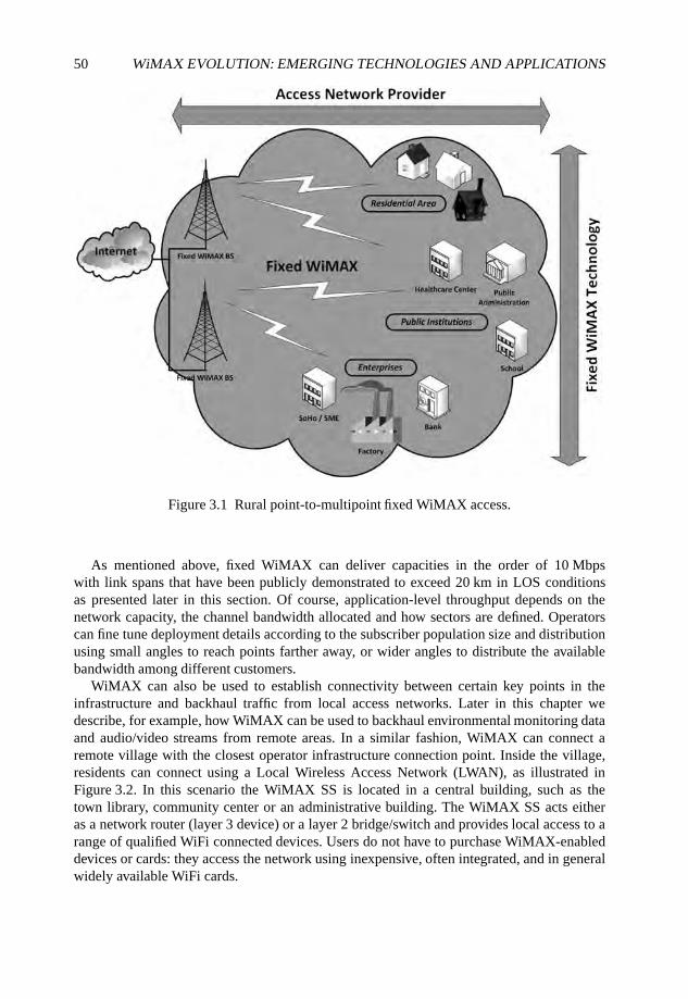
50 WiMAX EVOLUTION: EMERGING TECHNOLOGIES AND APPLICATIONS
Figure 3.1 Rural point-to-multipoint fixed WiMAX access.
As mentioned above, fixed WiMAX can deliver capacities in the order of 10 Mbpswith link spans that have been publicly demonstrated to exceed 20 km in LOS conditionsas presented later in this section. Of course, application-level throughput depends on thenetwork capacity, the channel bandwidth allocated and how sectors are defined. Operatorscan fine tune deployment details according to the subscriber population size and distributionusing small angles to reach points farther away, or wider angles to distribute the availablebandwidth among different customers.
WiMAX can also be used to establish connectivity between certain key points in theinfrastructure and backhaul traffic from local access networks. Later in this chapter wedescribe, for example, how WiMAX can be used to backhaul environmental monitoring dataand audio/video streams from remote areas. In a similar fashion, WiMAX can connect aremote village with the closest operator infrastructure connection point. Inside the village,residents can connect using a Local Wireless Access Network (LWAN), as illustrated inFigure 3.2. In this scenario the WiMAX SS is located in a central building, such as thetown library, community center or an administrative building. The WiMAX SS acts eitheras a network router (layer 3 device) or a layer 2 bridge/switch and provides local access to arange of qualified WiFi connected devices. Users do not have to purchase WiMAX-enableddevices or cards: they access the network using inexpensive, often integrated, and in generalwidely available WiFi cards.
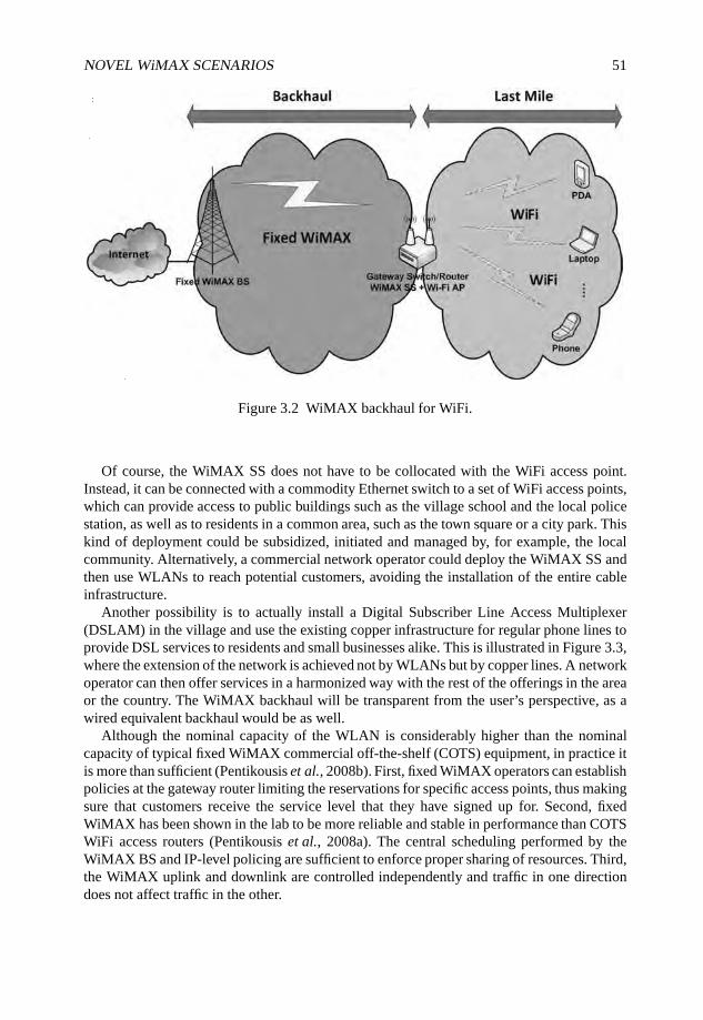
NOVEL WiMAX SCENARIOS 51
Figure 3.2 WiMAX backhaul for WiFi.
Of course, the WiMAX SS does not have to be collocated with the WiFi access point.Instead, it can be connected with a commodity Ethernet switch to a set of WiFi access points,which can provide access to public buildings such as the village school and the local policestation, as well as to residents in a common area, such as the town square or a city park. Thiskind of deployment could be subsidized, initiated and managed by, for example, the localcommunity. Alternatively, a commercial network operator could deploy the WiMAX SS andthen use WLANs to reach potential customers, avoiding the installation of the entire cableinfrastructure.
Another possibility is to actually install a Digital Subscriber Line Access Multiplexer(DSLAM) in the village and use the existing copper infrastructure for regular phone lines toprovide DSL services to residents and small businesses alike. This is illustrated in Figure 3.3,where the extension of the network is achieved not by WLANs but by copper lines. A networkoperator can then offer services in a harmonized way with the rest of the offerings in the areaor the country. The WiMAX backhaul will be transparent from the user’s perspective, as awired equivalent backhaul would be as well.
Although the nominal capacity of the WLAN is considerably higher than the nominalcapacity of typical fixed WiMAX commercial off-the-shelf (COTS) equipment, in practice itis more than sufficient (Pentikousis et al., 2008b). First, fixed WiMAX operators can establishpolicies at the gateway router limiting the reservations for specific access points, thus makingsure that customers receive the service level that they have signed up for. Second, fixedWiMAX has been shown in the lab to be more reliable and stable in performance than COTSWiFi access routers (Pentikousis et al., 2008a). The central scheduling performed by theWiMAX BS and IP-level policing are sufficient to enforce proper sharing of resources. Third,the WiMAX uplink and downlink are controlled independently and traffic in one directiondoes not affect traffic in the other.
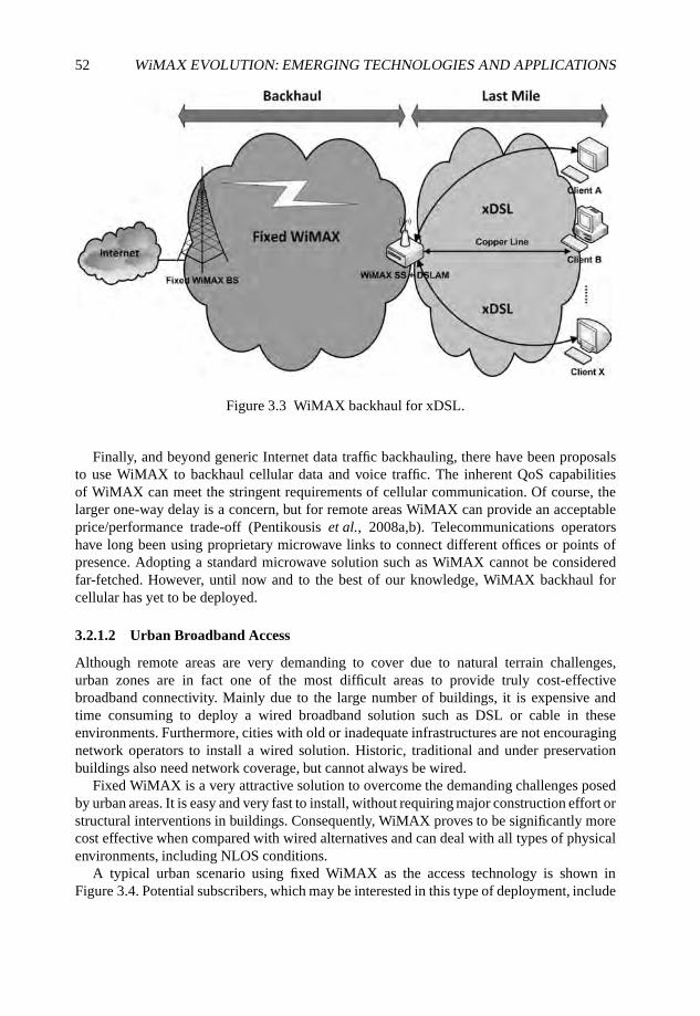
52 WiMAX EVOLUTION: EMERGING TECHNOLOGIES AND APPLICATIONS
Figure 3.3 WiMAX backhaul for xDSL.
Finally, and beyond generic Internet data traffic backhauling, there have been proposalsto use WiMAX to backhaul cellular data and voice traffic. The inherent QoS capabilitiesof WiMAX can meet the stringent requirements of cellular communication. Of course, thelarger one-way delay is a concern, but for remote areas WiMAX can provide an acceptableprice/performance trade-off (Pentikousis et al., 2008a,b). Telecommunications operatorshave long been using proprietary microwave links to connect different offices or points ofpresence. Adopting a standard microwave solution such as WiMAX cannot be consideredfar-fetched. However, until now and to the best of our knowledge, WiMAX backhaul forcellular has yet to be deployed.
3.2.1.2 Urban Broadband Access
Although remote areas are very demanding to cover due to natural terrain challenges,urban zones are in fact one of the most difficult areas to provide truly cost-effectivebroadband connectivity. Mainly due to the large number of buildings, it is expensive andtime consuming to deploy a wired broadband solution such as DSL or cable in theseenvironments. Furthermore, cities with old or inadequate infrastructures are not encouragingnetwork operators to install a wired solution. Historic, traditional and under preservationbuildings also need network coverage, but cannot always be wired.
Fixed WiMAX is a very attractive solution to overcome the demanding challenges posedby urban areas. It is easy and very fast to install, without requiring major construction effort orstructural interventions in buildings. Consequently, WiMAX proves to be significantly morecost effective when compared with wired alternatives and can deal with all types of physicalenvironments, including NLOS conditions.
A typical urban scenario using fixed WiMAX as the access technology is shown inFigure 3.4. Potential subscribers, which may be interested in this type of deployment, include
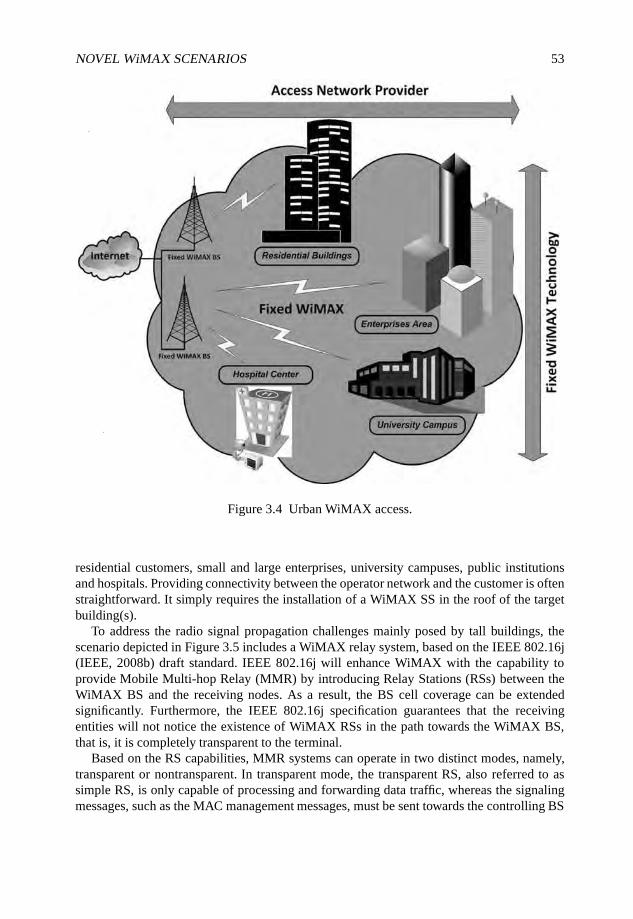
NOVEL WiMAX SCENARIOS 53
Figure 3.4 Urban WiMAX access.
residential customers, small and large enterprises, university campuses, public institutionsand hospitals. Providing connectivity between the operator network and the customer is oftenstraightforward. It simply requires the installation of a WiMAX SS in the roof of the targetbuilding(s).
To address the radio signal propagation challenges mainly posed by tall buildings, thescenario depicted in Figure 3.5 includes a WiMAX relay system, based on the IEEE 802.16j(IEEE, 2008b) draft standard. IEEE 802.16j will enhance WiMAX with the capability toprovide Mobile Multi-hop Relay (MMR) by introducing Relay Stations (RSs) between theWiMAX BS and the receiving nodes. As a result, the BS cell coverage can be extendedsignificantly. Furthermore, the IEEE 802.16j specification guarantees that the receivingentities will not notice the existence of WiMAX RSs in the path towards the WiMAX BS,that is, it is completely transparent to the terminal.
Based on the RS capabilities, MMR systems can operate in two distinct modes, namely,transparent or nontransparent. In transparent mode, the transparent RS, also referred to assimple RS, is only capable of processing and forwarding data traffic, whereas the signalingmessages, such as the MAC management messages, must be sent towards the controlling BS
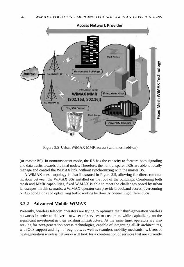
54 WiMAX EVOLUTION: EMERGING TECHNOLOGIES AND APPLICATIONS
Figure 3.5 Urban WiMAX MMR access (with mesh add-on).
(or master BS). In nontransparent mode, the RS has the capacity to forward both signalingand data traffic towards the final nodes. Therefore, the nontransparent RSs are able to locallymanage and control the WiMAX link, without synchronizing with the master BS.
A WiMAX mesh topology is also illustrated in Figure 3.5, allowing for direct commu-nication between the WiMAX SSs installed on the roof of the buildings. Combining bothmesh and MMR capabilities, fixed WiMAX is able to meet the challenges posed by urbanlandscapes. In this scenario, a WiMAX operator can provide broadband access, overcomingNLOS conditions and optimizing traffic routing by directly connecting different SSs.
3.2.2 Advanced Mobile WiMAX
Presently, wireless telecom operators are trying to optimize their third-generation wirelessnetworks in order to deliver a new set of services to customers while capitalizing on thesignificant investment in their existing infrastructure. At the same time, operators are alsoseeking for next-generation access technologies, capable of integrating all-IP architectures,with QoS support and high throughputs, as well as seamless mobility mechanisms. Users ofnext-generation wireless networks will look for a combination of services that are currently
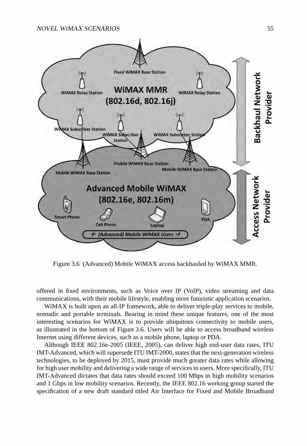
NOVEL WiMAX SCENARIOS 55
Figure 3.6 (Advanced) Mobile WiMAX access backhauled by WiMAX MMR.
offered in fixed environments, such as Voice over IP (VoIP), video streaming and datacommunications, with their mobile lifestyle, enabling more futuristic application scenarios.
WiMAX is built upon an all-IP framework, able to deliver triple-play services to mobile,nomadic and portable terminals. Bearing in mind these unique features, one of the mostinteresting scenarios for WiMAX is to provide ubiquitous connectivity to mobile users,as illustrated in the bottom of Figure 3.6. Users will be able to access broadband wirelessInternet using different devices, such as a mobile phone, laptop or PDA.
Although IEEE 802.16e-2005 (IEEE, 2005), can deliver high end-user data rates, ITUIMT-Advanced, which will supersede ITU IMT-2000, states that the next-generation wirelesstechnologies, to be deployed by 2015, must provide much greater data rates while allowingfor high user mobility and delivering a wide range of services to users. More specifically, ITUIMT-Advanced dictates that data rates should exceed 100 Mbps in high mobility scenariosand 1 Gbps in low mobility scenarios. Recently, the IEEE 802.16 working group started thespecification of a new draft standard titled Air Interface for Fixed and Mobile Broadband
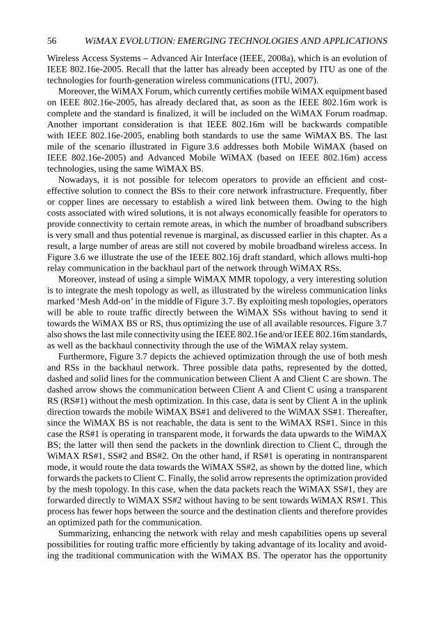
56 WiMAX EVOLUTION: EMERGING TECHNOLOGIES AND APPLICATIONS
Wireless Access Systems – Advanced Air Interface (IEEE, 2008a), which is an evolution ofIEEE 802.16e-2005. Recall that the latter has already been accepted by ITU as one of thetechnologies for fourth-generation wireless communications (ITU, 2007).
Moreover, the WiMAX Forum, which currently certifies mobile WiMAX equipment basedon IEEE 802.16e-2005, has already declared that, as soon as the IEEE 802.16m work iscomplete and the standard is finalized, it will be included on the WiMAX Forum roadmap.Another important consideration is that IEEE 802.16m will be backwards compatiblewith IEEE 802.16e-2005, enabling both standards to use the same WiMAX BS. The lastmile of the scenario illustrated in Figure 3.6 addresses both Mobile WiMAX (based onIEEE 802.16e-2005) and Advanced Mobile WiMAX (based on IEEE 802.16m) accesstechnologies, using the same WiMAX BS.
Nowadays, it is not possible for telecom operators to provide an efficient and cost-effective solution to connect the BSs to their core network infrastructure. Frequently, fiberor copper lines are necessary to establish a wired link between them. Owing to the highcosts associated with wired solutions, it is not always economically feasible for operators toprovide connectivity to certain remote areas, in which the number of broadband subscribersis very small and thus potential revenue is marginal, as discussed earlier in this chapter. As aresult, a large number of areas are still not covered by mobile broadband wireless access. InFigure 3.6 we illustrate the use of the IEEE 802.16j draft standard, which allows multi-hoprelay communication in the backhaul part of the network through WiMAX RSs.
Moreover, instead of using a simple WiMAX MMR topology, a very interesting solutionis to integrate the mesh topology as well, as illustrated by the wireless communication linksmarked ‘Mesh Add-on’ in the middle of Figure 3.7. By exploiting mesh topologies, operatorswill be able to route traffic directly between the WiMAX SSs without having to send ittowards the WiMAX BS or RS, thus optimizing the use of all available resources. Figure 3.7also shows the last mile connectivity using the IEEE 802.16e and/or IEEE 802.16m standards,as well as the backhaul connectivity through the use of the WiMAX relay system.
Furthermore, Figure 3.7 depicts the achieved optimization through the use of both meshand RSs in the backhaul network. Three possible data paths, represented by the dotted,dashed and solid lines for the communication between Client A and Client C are shown. Thedashed arrow shows the communication between Client A and Client C using a transparentRS (RS#1) without the mesh optimization. In this case, data is sent by Client A in the uplinkdirection towards the mobile WiMAX BS#1 and delivered to the WiMAX SS#1. Thereafter,since the WiMAX BS is not reachable, the data is sent to the WiMAX RS#1. Since in thiscase the RS#1 is operating in transparent mode, it forwards the data upwards to the WiMAXBS; the latter will then send the packets in the downlink direction to Client C, through theWiMAX RS#1, SS#2 and BS#2. On the other hand, if RS#1 is operating in nontransparentmode, it would route the data towards the WiMAX SS#2, as shown by the dotted line, whichforwards the packets to Client C. Finally, the solid arrow represents the optimization providedby the mesh topology. In this case, when the data packets reach the WiMAX SS#1, they areforwarded directly to WiMAX SS#2 without having to be sent towards WiMAX RS#1. Thisprocess has fewer hops between the source and the destination clients and therefore providesan optimized path for the communication.
Summarizing, enhancing the network with relay and mesh capabilities opens up severalpossibilities for routing traffic more efficiently by taking advantage of its locality and avoid-ing the traditional communication with the WiMAX BS. The operator has the opportunity
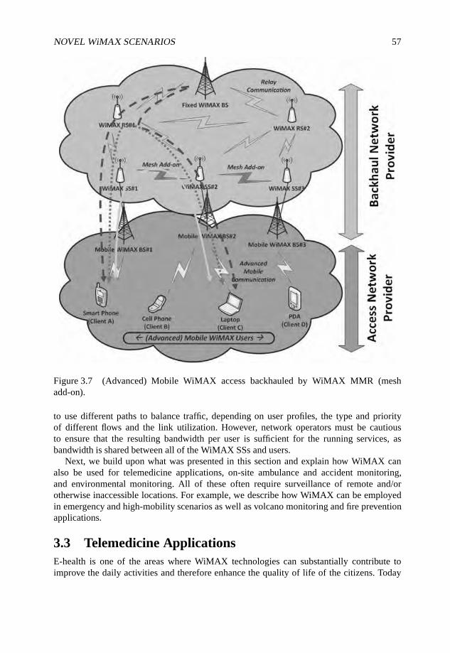
NOVEL WiMAX SCENARIOS 57
Figure 3.7 (Advanced) Mobile WiMAX access backhauled by WiMAX MMR (meshadd-on).
to use different paths to balance traffic, depending on user profiles, the type and priorityof different flows and the link utilization. However, network operators must be cautiousto ensure that the resulting bandwidth per user is sufficient for the running services, asbandwidth is shared between all of the WiMAX SSs and users.
Next, we build upon what was presented in this section and explain how WiMAX canalso be used for telemedicine applications, on-site ambulance and accident monitoring,and environmental monitoring. All of these often require surveillance of remote and/orotherwise inaccessible locations. For example, we describe how WiMAX can be employedin emergency and high-mobility scenarios as well as volcano monitoring and fire preventionapplications.
3.3 Telemedicine ApplicationsE-health is one of the areas where WiMAX technologies can substantially contribute toimprove the daily activities and therefore enhance the quality of life of the citizens. Today
58 WiMAX EVOLUTION: EMERGING TECHNOLOGIES AND APPLICATIONS
a large number of medical activities are carried out with limited success, unnecessary costsand human difficulties because of the inability to exchange real-time information betweendifferent elements of the chain that are not at fixed locations. Some of the possible advancedmedical services that can benefit from the integration of a wireless broadband accesstechnology are as follows.
• Remote diagnosis: need to transmit urgent data in order to make an immediate basicdiagnosis, for example, street accidents, people in special health conditions (pace-maker bearers, pregnant women, to name a few).
• Need to intervene on nontransportable patients (e.g. accidents) may require off-airtransmission of critical data or images.
• Remote monitoring: today the elderly are monitored remotely when at home, but notwhen traveling or simply moving around town. This limits their ability to enjoy lifeand be integrated in the community around them.
• Remote follow-up: today patients travel to distant hospitals to be followed-up aftertherapies or surgical interventions.
3.3.1 Remote Patient Monitoring
During the last decade, the healthcare system has been giving much more attention to remotemonitoring and assistance of patients. Remote patient monitoring poses difficult challenges inorder to give a differentiated support to each patient, creating a personalized follow-up plan,which depends on the patient illness. Furthermore, it is very important that a bidirectional,secure, reliable and trustworthy relationship between the patient and the healthcare provideris established, allowing the patient to proactively trigger communication with the hospitaland share important information or symptoms with the medical team. By the same token,hospital doctors must also be able to remotely control and monitor patient measurements, aswell as send periodical reminders to the patient in order to take his medication.
Another important category comprises patients with chronic diseases that can be remotelymonitored during the day, without having to change their daily routine. For instance, if thepatient’s professional life demands a constant need to travel abroad, they can easily maintaintheir work routine. Keeping chronic patients physically away from the healthcare center, notonly improves the patients’ quality of life, but is also cost effective for healthcare institutions,as it allows for operation with less medical personnel and requires a smaller number ofhospital beds.
Despite the benefits provided by the telemedicine applications, until this moment noaccess technology was able to fulfill its challenging requirements, namely, wireless broad-band availability, including QoS differentiation, as well as intrinsic mobility support.WiMAX, as a broadband wireless access technology for metropolitan environments, is a verypromising candidate technology to overcome this gap and allows both healthcare institutionsand patients to benefit from this application, as illustrated in Figure 3.8. Here, the mobileversion of WiMAX is employed, allowing the patients to be monitored remotely by thehealthcare institution.
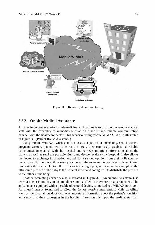
NOVEL WiMAX SCENARIOS 59
Figure 3.8 Remote patient monitoring.
3.3.2 On-site Medical Assistance
Another important scenario for telemedicine applications is to provide the remote medicalstaff with the capability to immediately establish a secure and reliable communicationchannel with the healthcare center. This scenario, using mobile WiMAX, is also illustratedin Figure 3.8 (Patient House Assistance).
Using mobile WiMAX, when a doctor assists a patient at home (e.g. senior citizen,pregnant women, patient with a chronic illness), they can easily establish a reliablecommunication channel with the hospital and retrieve important information about thepatient, as well as send the portable ultrasound device results to the hospital. It also allowsthe doctor to exchange information and ask for a second opinion from their colleagues atthe hospital. Furthermore, if necessary, a video-conference session can be established in realtime using the doctor’s laptop. If the doctor is visiting a pregnant woman, he can upload theultrasound pictures of the baby to the hospital server and configure it to distribute the picturesto the father of the baby.
Another interesting scenario, also illustrated in Figure 3.8 (Ambulance Assistance), iswhen a doctor is on duty in an ambulance and is called to intervene on a car accident. Theambulance is equipped with a portable ultrasound device, connected to a WiMAX notebook.An injured man is found and to allow the fastest possible intervention, while travellingtowards the hospital, the doctor collects important information about the patient’s conditionand sends it to their colleagues in the hospital. Based on this input, the medical staff can

60 WiMAX EVOLUTION: EMERGING TECHNOLOGIES AND APPLICATIONS
start to prepare equipment, as well as share important information about the patient with theambulance doctor.
3.4 Environmental Monitoring
WiMAX technology also fits very well into a large number of environmental monitoringapplications, mainly due to its wide coverage potential in remote areas but also as a resultof its inherent support for broadband applications and QoS mechanisms. In this section, fourenvironmental monitoring application areas will be discussed: monitoring of seismic andvolcanic activity, fire prevention and other applications such as meteorological forecasting,pollution monitoring and law enforcement.
3.4.1 Seismic Activity
Europe has several regions with high seismic activity, requiring permanent monitoring inorder to prevent calamity situations. The main affected regions are in the south, due to thefault zone between the Euro-Asian and African plates, and in the north, due to the fault zonebetween the Euro-Asian and North-America plates. This section describes typical seismicactivity scenarios and presents the main challenges associated with volcano monitoring,which relies strongly on the observation of seismic activity patterns.
3.4.1.1 Seismic Activity Monitoring
Monitoring of seismic activity plays a critical role on the minimization of the impact of itseffects on populations and facilities. The effect of seismic activities, or earthquakes, have adirect impact on the ground shaking and rupture, causing damage to service structures, suchas dams and bridges, but can also be responsible for other nonexclusive natural disasters suchas fires, tsunamis and floods. Therefore, the detection or even prediction of seismic activitiesis critical for planning preventive actions, as well as for all of the remedial actions to becarried out during and after such occurrences.
Nowadays, there are several sensor networks deployed in critical regions, dedicated to thecollection of seismic signals. Usually, the information is stored in local storage devices andregularly sent to the acquisition center. However, the continuous and real-time transmissionof data to the acquisition center would improve the reaction time in the event of a crisis. In thiscontext, WiMAX technology introduces significant value, due to its broadband capabilitiesover long distances. Namely, by providing, in real-time, data from seismic sensors of differentsources, many located in places farther than 30 km, the prediction of earthquakes maybecome more efficient and focused.
3.4.1.2 Volcano Monitoring
From the different events associated with seismic activity, volcano eruption is one of themost feared, especially in places with a long history of volcano activity, such as Iceland, Italyand Portugal. It is therefore critical an increased coverage to monitor the seismic activityassociated with volcanic activities. This is even more important, given that seismic activitypreceding volcanic eruptions, are only observed approximately one hour before the magma
NOVEL WiMAX SCENARIOS 61
reaches the surface. With such a hard constraint, real-time transmission of data is vital forearly warning systems and preparation for the oncoming risk.
In addition to relying on seismic activity observation, volcano monitoring is comple-mented by the use of gas monitoring equipment, which is located close to the peak of thevolcano. In addition, video surveillance cameras are placed in mountains around the volcanoin order to expose the location of the eruptive site and to follow the ascension of the volcaniccolumn into the upper atmosphere.
In this scenario, wired technologies are naturally inappropriate, and most wirelesstechnologies do not fulfil the connectivity at long distances with high bandwidth. Moreover,the access to the seismic and gas monitoring sensors, as well as to the video surveillancecameras can benefit from communication both with LOS and NLOS. Therefore, the useof WiMAX as a broadband wireless access technology becomes appealing and a strongcandidate to fulfil the communication requirements of such demanding scenarios.
In addition to being an important contribution for the successful deployment of theapplication scenarios described above, the WiMAX technology also brings benefits to thefield personnel who installs and maintains the monitoring equipment, as well as to the civilprotection personnel and rescue teams in disaster situations. Namely, the wireless broadbandaccess with mobility features allows for real-time communication between the personnel andthe acquisition center, as well as with emergency services.
3.4.2 Fire Prevention
For Southern European countries, such as Portugal, Spain, Greece and southern France,forest fires represent a dramatic loss of life and property, as well as an increased risk ofdesertification and the higher emissions of greenhouse gases. The same applies, to someextent, to some areas of the United States, Australia and other countries. In order to addressthis situation, considerable public investment has been made in fire prevention (e.g. proactiveland management and preventive clearing of ground vegetation), fire detection networks(surveillance posts, aerial patrols, car patrols, semi-automated fire detection mechanisms) andfire fighting resources (aerial resources, firefighting vehicles, firefighters and civil protectionpersonnel, etc.). Nevertheless, due to climatic factors, increased desertification and land usagepractices, these efforts remain largely unsuccessful.
3.4.2.1 Fire Detection
One of the key success factors in this area of environmental monitoring is early firedetection, since an unattended fire ignition can evolve, depending on weather conditions,into uncontrollable proportions in less than an hour. However, forest areas are typicallyscarcely populated and difficult to reach. In these areas, fire detection is traditionallyperformed by human spotters, on top of surveillance towers or, in some cases, small airplanes,searching for smoke signals and communicating their findings to centralized control centers.These methods are not cost-efficient: each tower requires the permanent presence of humanwatchers. Moreover, verbal radio communication can be ineffective as the control center losesprecious minutes processing the spotter description and attempting to locate the potentialfire precisely, before dispatching an airborne first response team. A small country such as
62 WiMAX EVOLUTION: EMERGING TECHNOLOGIES AND APPLICATIONS
Portugal, for instance, needs to keep a network of more than 230 surveillance towers, just toget basic coverage of fire-sensitive territories.
Electronic surveillance mechanisms (for instance, video surveillance with automaticdetection of smoke or heat sources) are not fully autonomous, since human confirmation ofpotential fires is always required. Nevertheless, they do improve the efficiency of surveillancenetworks.
• Personnel costs are greatly reduced. Even with plain and simple remote videosurveillance, one centrally located operator can easily manage multiple surveillancetowers.
• Fire location becomes faster and more precise, due to automated triangulation betweenadjacent surveillance towers and association with Geographic Information Systems(GIS).
• False alarms are easier to identify. Instead of relying in verbal descriptions from remotehuman spotters, the centralized operator can have simultaneous access to the videoand data gathered at each surveillance tower that covers the potential fire location.The decision process becomes faster and more precise, leading to reduced costs withunnecessary dispatches of helicopter crews.
• Electronic surveillance can operate continuously, unlike traditional surveillance net-works which, due to their high costs, are usually limited to a few months per year,despite the fact that recent climatic changes increase the frequency of violent off-season fires.
• Recorded data has great forensic value for criminal investigation and scientificresearch.
Video is the basis of electronic fire surveillance. Plain video surveillance already providesvery positive results, and more sophisticated tools can be easily added for automateddetection of smoke of heat sources. Other data, such as local meteorological data and digitalcompasses, play an important role during the detection and monitoring phases, but video isusually the key component (and also the most bandwidth demanding component).
One of the major shortcomings of electronic surveillance is communication betweensurveillance towers and control centers. Broadband access technologies such as DSL or 3Gare not available in remote forests, and alternatives such as GPRS, GSM, TETRA or UHFradio-links, in addition to also presenting coverage limitations, rarely provide the bandwidthrequired for effective electronic monitoring.
WiMAX technology appears to fit well in this scenario. Given its potential range,bandwidth and adaptability to environmental conditions, WiMAX may provide connectivityto remote monitoring systems, capable of effectively providing early detection of fire in amore efficient and cost-effective manner.
3.4.2.2 Fire Monitoring and Firefight Coordination
Electronic surveillance is also critical during the firefighting phase. Senior coordinators,located at the operations control centers, can themselves follow the evolution of the fire live,
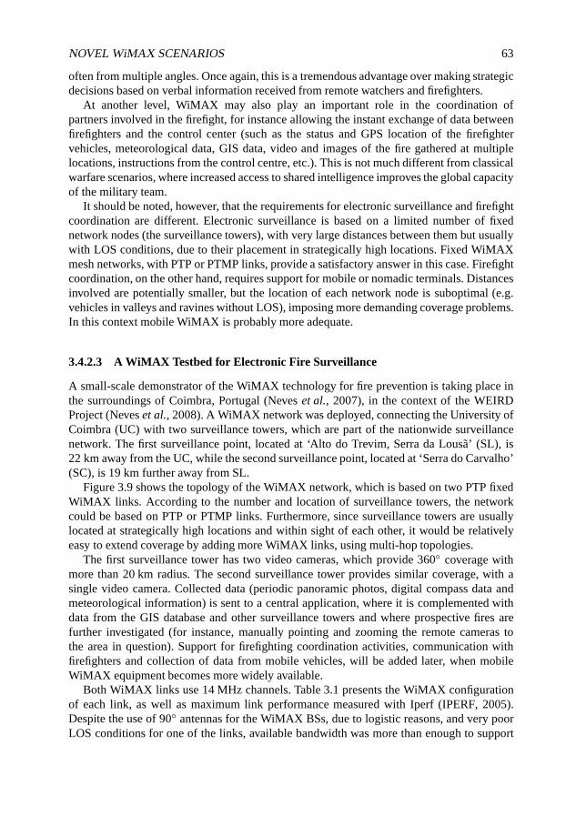
NOVEL WiMAX SCENARIOS 63
often from multiple angles. Once again, this is a tremendous advantage over making strategicdecisions based on verbal information received from remote watchers and firefighters.
At another level, WiMAX may also play an important role in the coordination ofpartners involved in the firefight, for instance allowing the instant exchange of data betweenfirefighters and the control center (such as the status and GPS location of the firefightervehicles, meteorological data, GIS data, video and images of the fire gathered at multiplelocations, instructions from the control centre, etc.). This is not much different from classicalwarfare scenarios, where increased access to shared intelligence improves the global capacityof the military team.
It should be noted, however, that the requirements for electronic surveillance and firefightcoordination are different. Electronic surveillance is based on a limited number of fixednetwork nodes (the surveillance towers), with very large distances between them but usuallywith LOS conditions, due to their placement in strategically high locations. Fixed WiMAXmesh networks, with PTP or PTMP links, provide a satisfactory answer in this case. Firefightcoordination, on the other hand, requires support for mobile or nomadic terminals. Distancesinvolved are potentially smaller, but the location of each network node is suboptimal (e.g.vehicles in valleys and ravines without LOS), imposing more demanding coverage problems.In this context mobile WiMAX is probably more adequate.
3.4.2.3 A WiMAX Testbed for Electronic Fire Surveillance
A small-scale demonstrator of the WiMAX technology for fire prevention is taking place inthe surroundings of Coimbra, Portugal (Neves et al., 2007), in the context of the WEIRDProject (Neves et al., 2008). A WiMAX network was deployed, connecting the University ofCoimbra (UC) with two surveillance towers, which are part of the nationwide surveillancenetwork. The first surveillance point, located at ‘Alto do Trevim, Serra da Lousã’ (SL), is22 km away from the UC, while the second surveillance point, located at ‘Serra do Carvalho’(SC), is 19 km further away from SL.
Figure 3.9 shows the topology of the WiMAX network, which is based on two PTP fixedWiMAX links. According to the number and location of surveillance towers, the networkcould be based on PTP or PTMP links. Furthermore, since surveillance towers are usuallylocated at strategically high locations and within sight of each other, it would be relativelyeasy to extend coverage by adding more WiMAX links, using multi-hop topologies.
The first surveillance tower has two video cameras, which provide 360◦ coverage withmore than 20 km radius. The second surveillance tower provides similar coverage, with asingle video camera. Collected data (periodic panoramic photos, digital compass data andmeteorological information) is sent to a central application, where it is complemented withdata from the GIS database and other surveillance towers and where prospective fires arefurther investigated (for instance, manually pointing and zooming the remote cameras tothe area in question). Support for firefighting coordination activities, communication withfirefighters and collection of data from mobile vehicles, will be added later, when mobileWiMAX equipment becomes more widely available.
Both WiMAX links use 14 MHz channels. Table 3.1 presents the WiMAX configurationof each link, as well as maximum link performance measured with Iperf (IPERF, 2005).Despite the use of 90◦ antennas for the WiMAX BSs, due to logistic reasons, and very poorLOS conditions for one of the links, available bandwidth was more than enough to support
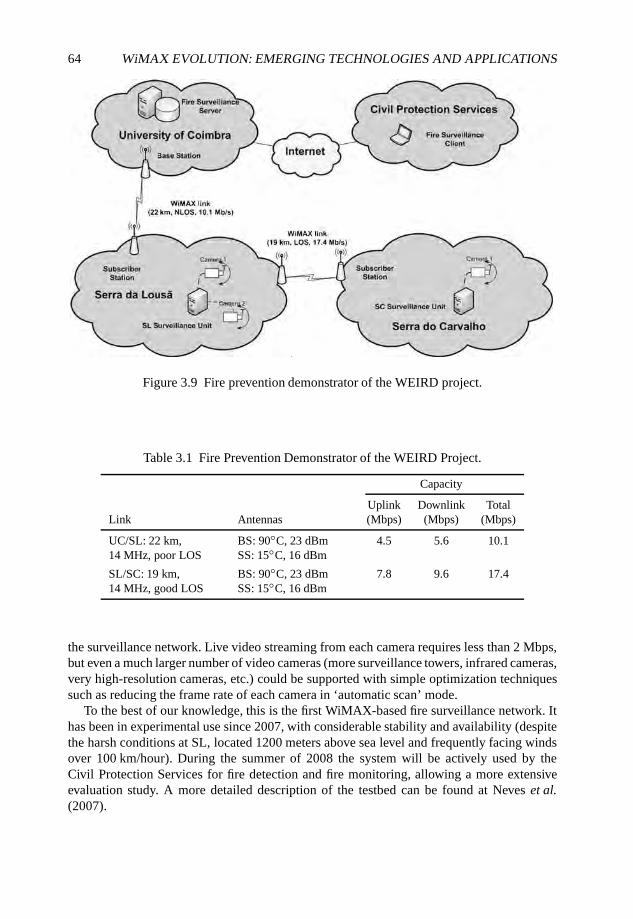
64 WiMAX EVOLUTION: EMERGING TECHNOLOGIES AND APPLICATIONS
Figure 3.9 Fire prevention demonstrator of the WEIRD project.
Table 3.1 Fire Prevention Demonstrator of the WEIRD Project.
Capacity
Uplink Downlink TotalLink Antennas (Mbps) (Mbps) (Mbps)
UC/SL: 22 km,14 MHz, poor LOS
BS: 90◦C, 23 dBmSS: 15◦C, 16 dBm
4.5 5.6 10.1
SL/SC: 19 km,14 MHz, good LOS
BS: 90◦C, 23 dBmSS: 15◦C, 16 dBm
7.8 9.6 17.4
the surveillance network. Live video streaming from each camera requires less than 2 Mbps,but even a much larger number of video cameras (more surveillance towers, infrared cameras,very high-resolution cameras, etc.) could be supported with simple optimization techniquessuch as reducing the frame rate of each camera in ‘automatic scan’ mode.
To the best of our knowledge, this is the first WiMAX-based fire surveillance network. Ithas been in experimental use since 2007, with considerable stability and availability (despitethe harsh conditions at SL, located 1200 meters above sea level and frequently facing windsover 100 km/hour). During the summer of 2008 the system will be actively used by theCivil Protection Services for fire detection and fire monitoring, allowing a more extensiveevaluation study. A more detailed description of the testbed can be found at Neves et al.(2007).
NOVEL WiMAX SCENARIOS 65
3.4.3 Other Applications
In addition to the already mentioned scenarios, WiMAX technology can also play animportant role in other applications, such as pollution and generic environmental monitoringand video surveillance in wild areas.
3.4.3.1 Pollution and Generic Environmental Monitoring
The category of pollution monitoring and more generic environmental monitoring encom-passes all sorts of telemetry targeted at specific environmental indicators. Examples includemonitoring of pollutant levels in the air, soil or water; collection of local meteorological data;river and stream flow monitoring; monitoring of water reservoir levels, and so on.
From a communications point of view these applications are usually based on regulartransmission of measured data to remote locations. Usually it is acceptable that some delayoccurs between data collection and data transmission, and the size of data to transmit isrelatively contained.
From a logistic perspective these applications may have two important requirements totake into account: location and energy consumption. The location of telemetry units is ofteninflexible (they need to be close to the monitored objects), which may impose coverageproblems for a number of wireless transmission technologies. Quite often, these telemetryunits are also far away from the energy grid, which means they have to rely on batteriesor solar power. This imposes limitations both on the measurement equipment and on thecommunication equipment that might imply, for instance, nonpermanent connections andwireless technologies with lower power requirements. This is not the most favorable scenariofor the WiMAX technology: other solutions, such as GPRS or even GSM/SMS mightprovide enough bandwidth for these telemetry applications, with lower power consumption(e.g. using nonpermanent connections).
However, in other cases, WiMAX still brings some potential advantages, especially whenthere is a need for considerable bandwidth or when GPRS or GSM coverage is simplynot available. Communication costs also need to be taken into account, since the costs ofGPRS-based telemetry can become quite high. Although the business model for commercialWiMAX use is still not clear, costs will probably be lower in these cases.
WiMAX networks can also interconnect ‘sink’ components of wireless sensor networks.Instead of directly communicating with a remote collector, each telemetry unit might uselimited-range wireless technologies to communicate with a relatively close ‘sink’ (a commonconcept in wireless sensor networks, which also applies to generic telemetry networks). This‘sink’ can then use WiMAX to relay monitoring data to the remote data collectors. Sinkshave less energy restrictions, can have better WiMAX coverage and have higher bandwidthrequirements. In this context, WiMAX is a very competitive technology.
3.4.3.2 Video Surveillance in Wild Areas
Another category of environmental monitoring relates with video surveillance in wild areas.Video surveillance, in these areas, can be used, for instance, to detect illegal activities(hunting, illegal logging, etc.) or to monitor wildlife activities (e.g. wild cattle or birdactivity).
66 WiMAX EVOLUTION: EMERGING TECHNOLOGIES AND APPLICATIONS
For the same reasons already discussed for fire surveillance, WiMAX fits quite well intothis kind of applications, easily covering wild areas and providing the required bandwidth.In fact, once a video surveillance network is installed in a wild area, it is expected to be usedsimultaneously for a number of activities: fire prevention, detection of illegal activities and,sometimes, monitoring of wildlife.
Logistic problems are not much different from fire surveillance scenario, althoughthe location of surveillance units can be less favorable (e.g. worst LOS conditions) andavailability of energy sources can also be a problem. Nevertheless, energy sources area problem associated with the remote surveillance unit, not specifically with WiMAXtechnology (no other technology can provide the required bandwidth with lower energyconsumption).
3.5 Conclusions
It is unquestionable that WiMAX represents an important step on the evolution of commu-nication scenarios. The great advantage of providing broadband communication to remotelocations without wires enables the support of numerous different scenarios that were notenvisioned before, both business and residential, in rural and urban areas.
This chapter has overviewed the most relevant scenarios, considering different standards,fixed, mobile and mesh, from simple scenarios, such as using fixed WiMAX to serve asbackhaul to several buildings in an urban scenario, to the most complex scenarios, such asusing mesh mode and RSs balancing the traffic and serving as backhaul to mobile WiMAX.In terms of applications in addition to normal communication between users, two main typeswere described, namely, medical and environmental monitoring applications. The broadbandand reliability characteristics of the communications using WiMAX make it suitable tobe used in emergency situations, such as on-site medical assistance, where it is requiredto maintain constant connectivity in usually remote locations. The distant communicationrequired by environmental monitoring is also strongly benefiting from WiMAX, as it enablessimultaneously reliability, QoS, broadband and remote access.
Acknowledgements
Part of this work was conducted within the framework of the IST 6th Framework ProgrammeIntegrated Project WEIRD (IST-034622), which was partially funded by the Commission ofthe European Union. Study sponsors had no role in study design, data collection and analysis,interpretation or writing the report. The views expressed do not necessarily represent theviews of the authors’ employers, the WEIRD project, or the Commission of the EuropeanUnion. We thank our colleagues from all partners in WEIRD for fruitful discussions.
References
IEEE (2004) IEEE Standard for Local and Metropolitan Area Networks; Part 16: Air Interface for FixedBroadband Wireless Access Systems, IEEE Standard 802.16-2004, IEEE 802.16 Working Group.
IEEE (2005) IEEE Standard for Local and Metropolitan Area Networks; Part 16: Air Interface for Fixedand Mobile Broadband Wireless Access Systems; Amendment 2: Physical and Medium Access

NOVEL WiMAX SCENARIOS 67
Control Layers for Combined Fixed and Mobile Operation in Licensed Bands, IEEE Std. 802.16e-2005, IEEE 802.16 Working Group.
IEEE (2007) IEEE Standard for Information Technology; Telecommunications and informationexchange between systems; Local and Metropolitan Area Networks; Specific Requirements; Part 11:Wireless LAN Medium Access Control (MAC) and Physical Layer (PHY) Specifications, IEEE Std.802.11-2007, IEEE 802.11 Working Group.
IEEE (2008a) Draft Amendment to IEEE Standard for Local and Metropolitan Area Networks; Part 16:Air Interface for Fixed and Mobile Broadband Wireless Access Systems – Advanced Air Interface,IEEE P802.16m/D0.0, IEEE 802.16 Working Group.
IEEE (2008b) Draft Amendment to IEEE Standard for Local and Metropolitan Area Networks;Part 16: Air Interface for Fixed and Mobile Broadband Wireless Access Systems – Multi-hop RelaySpecification, IEEE P802.16j/D5.0, IEEE 802.16 Working Group.
IPERF (2005) Iperf, NLANR DAST, http://dast.nlanr.net/Projects/Iperf/.ITU (2003a) ITU Press Release, ITU Group, http://www.itu.int/newsroom/press_releases/2003/30.html.ITU (2003b) ITU-R, Framework and Overall Objectives of the Future Development of IMT-2000 and
Systems Beyond IMT-2000, M.1645, ITU Group.ITU (2007) ITU Press Release, ITU Group, http://www.itu.int/newsroom/press_releases/2007/30.html.Neves, P., Nissila, T., Pereira, T., Ilkka, H., Monteiro, J., Pentikousis, K., Sargento, S. and Fontes, F.
(2008) A vendor independent resource control framework for WiMAX. Proceedings of the 13thIEEE Symposium on Computers and Communications (ISCC), Marrakech, Morocco.
Neves, P., Simões, P., Gomes, A., Mário, L., Sargento, S., Fontes, F., Monteiro, E. and Bohnert, T.(2007) WiMAX for emergency services: an empirical evaluation. Proceedings of the 1st BroadbandWireless Access Workshop (BWA), Collocated with 1st Next Generation Mobile Applications,Services and Technologies (NGMAST), Cardiff, UK.
Pentikousis, K., Pinola, J., Piri, E. and Fitzek, F. (2008a) A measurement study of Speex VoIP andH.264/AVC Video over IEEE 802.16d and IEEE 802.11g. Proceedings of the Third Workshop onMultiMedia Applications over Wireless Networks (MediaWiN), Marrakech, Morocco.
Pentikousis, K., Pinola, J., Piri, E. and Fitzek, F. (2008b) An experimental investigation of VoIP andvideo streaming over fixed WiMAX. Proceedings of the Fourth International Workshop on WirelessNetwork Measurements (WiNMee), Berlin, Germany.
WiMAX Forum (2008) WiMAX End-to-End Network Systems Architecture Stage 2–3: ArchitectureTenets, Reference Model and Reference Points, Release 1, Version 1.2, WiMAX Forum.
4
Pricing in WiMAX Networks
Ioannis Papapanagiotou, Jie Hui and Michael Devetsikiotis
4.1 Introduction
Pricing for multi-service and multi-topology Broadband Wireless Access (BWA) networksremains a major issue for the efficient design of WiMAX networks. With the proliferationof Voice over IP (VoIP) , entertainment video, triple play services and towards the evolutionof the future Internet, an exorbitant demand for wireless broadband technologies has beencreated. However, little effort has been devoted to how users should be charged both from theeconomic interest of the provider but also from the way that a WiMAX network is designed.
In this chapter we discuss the use of economics and pricing in the design of a WiMAXnetwork. Our initial focus shall be on whether the investment of building a WiMAXnetwork is profitable or not, using terms such as Capital Expenditure (CAPEX), OperationalExpenditure (OPEX), Net Present Value (NPV) and identifying who shall pay for the extracharges. Another major issue is the role of pricing in Quality of Service (QoS), congestioncontrol and provisioning of a network (DaSilva, 2000). This provides insight into why pricesfor network services are not only a marketing and strategic decision but also an engineeringconcern. Moreover, the users’ preferences need to be captured as well as their sensitivitywhen changes tend to happen in the form of a utility function, so as to compose the networkutility maximization problem or that equilibrium that will satisfy all of the entities in a multi-topology scenario.
In the following we also study ways to build WiMAX networks from an economicperspective and describe the role of pricing in bandwidth allocation. We are interestedin different topologies depicting most of the applications of WiMAX networks. The firsttopology shall be the one-hop topology in a singe cell environment when the Mobile Station(MS) is directly connected to the Base Station (BS). To capture the dynamics of such a model,a two-player game is built between the two functioning entities. In the second case the model
WiMAX Evolution: Emerging Technologies and Applications Edited by Tsutomu Ishikawa© 2009 John Wiley & Sons, Ltd. ISBN: 978-0-470-69680-4
70 WiMAX EVOLUTION: EMERGING TECHNOLOGIES AND APPLICATIONS
is extended to the multihop mesh mode case, where the MS is not in the range of the BS anduses other nodes, called Relay Stations (RSs), to route their packets towards it. The pricingmodel will encourage participation and cooperation among the nodes in order to accomplishthe goal of accessing the information provided by the BS (called ‘the Internet’), as in the casedescribed in the latest effort of IEEE 802.16j in the Mobile Two-Hop Relay case.
Those two models are described in terms of unlimited capacity, which is a case when theInternet provider has dimensioned the network in such a way so that there is no congestionon the wireless channel and the user gains instant access without competition with the rest ofthe nodes after paying the price for it. Next we investigate the way to allocate resources in acongested channel according to the IEEE 802.16 and based on the price that the user intendsto pay. The last application model includes a scenario where WiMAX and WiFi networkproviders are cooperating to provide the optimum pricing strategy for bandwidth sharing.Such models will generally be used in rural environments where short-range high-bandwidthwireless connections through WiFi are encouraged in terms of spectrum usage and low-costdeployment.
4.2 Economics in Network Engineering
4.2.1 Building a Business Model
As WiMAX is evolving through different standardization procedures, it is expected thatWiMAX will be the technology that extends the current capabilities of broadband networks.Our intention in this chapter is to present the cost and charges for a broadband network froma traditional financial and economic perspective. According to Mason and Varian (1994) thecosts for a network are divided as follows.
1. Fixed cost of providing a network infrastructure.
2. An incremental cost of connection to the network, which is usually paid by the user inthe form of a connection cost.
3. Cost of expanding the network’s capacity. Users who are willing to defer theirtransmission during congestion times should not pay for the expansion of network’scapacity.
4. Incremental cost of sending an extra packet. This cost should be very low or zerowithout congestion, since the bandwidth of a broadband network is typically a sharedresource.
5. Social cost defined as the extra delay incurred to other users by the transmission of apacket
The costs that the provider takes into account are usually divided into CAPEX andOPEX. CAPEX are the expenditures for investments in the purchase and installation ofnetwork equipment and we denote them by the variable C. There are cases that such initialinvestment is regarded as a sunk cost (and for that reason is disregarded in a chargingscheme). CAPEX includes the BSs, spectrum, site preparation, site installation and backbonenetwork equipment costs. One of the advantages of WiMAX in the battle with LTE is that it
PRICING IN WiMAX NETWORKS 71
is an open standard developed by the IEEE 802.16 workgroup, which leads to less cost perdevice, and less CAPEX, since the modus operandi of 3GPP is to provide a closed standardfor LTE.
The other category is OPEX (O(y)), which includes the operation, administration,management and provisioning costs (e.g. site leasing, equipment maintenance, networkexpansion and customer acquisition). However, such expenditures are difficult to predictsince technology evolution plays a crucial role when calculating them (Pareek, 2006). Wedefine y here as the discrete time usually in the scale of years. In order for a providerto cover the costs and make profit from the investment, a charging scheme is imposedon the users. It is thus straightforward that the profit for the provider can be defined asP(y, py)= Revenue(y, py)−O(y). The standard economic measure for evaluating thevalue of investment at time y is called the Discounted Cash Flow (DCF), which takes intoaccount the rate used to discount future cash flows to their present values (r):
DCF = P(y, py)
(1 + r)y. (4.1)
To measure the profitability of the investment a widely used value is the NPV. It is used as amapping of the value of the investment, to the present value (PV) and is given by
NPV(T )=T∑y=1
DCF − C, (4.2)
where T is the total time of the project. According to the NPV method a provider shall investin the project if it is positive. If it is zero it does not add any monetary value and other criteriashall be taken into account. Two other economic terms can be defined here. The Internal Rateof Return (IRR), which specifies the rate of return of the investment r , in which NPV(T )= 0.There is also the time to break even, which is the smallest time y from which the providershall recoup the entire investment, NPV(y) > 0.
In Figure 4.1 we show the cost flow diagram which specifies both the economic andengineering considerations and results from the deployment of a WiMAX network (singlepoint-to-point, mesh/relay mode and WiFi/WiMAX) as an extension to Gunasekaran andHarmantzis (2006). In the following we study the pricing schemes in order to define theappropriate ptm and the possible charges that the provider can impose on the users.
4.2.2 Control and Pricing
According to Walrand and Varaiya (1996) the charges imposed on the user can be split intofour categories:
1. access charge, which is the amount the user is required to pay for accessing thenetwork;
2. usage charges are imposed to recover the variable costs of running the network(OPEX);
3. congestion charges reflect the additional cost when transmitting under congestion ofthe network (pricing schemes exist that differentiate charges according to congestionperiods);
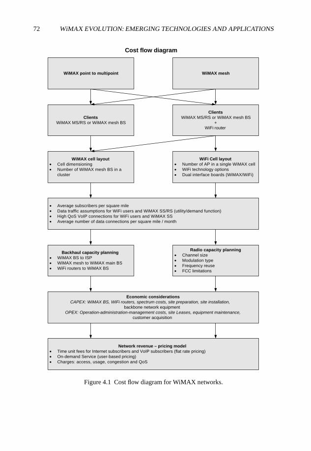
72 WiMAX EVOLUTION: EMERGING TECHNOLOGIES AND APPLICATIONS
WiMAX point to multipoint
Cost flow diagram
WiMAX mesh
Clients
WiMAX MS/RS or WiMAX mesh BS
+
WiFi router
WiMAX cell layout
Cell dimensioning
Number of WiMAX mesh BS in a
cluster
WiFi Cell layout
Number of AP in a single WiMAX cell
WiFi technology options
Dual interface boards (WiMAX/WiFi)
Average subscribers per square mile
Data traffic assumptions for WiFi users and WiMAX SS/RS (utility/demand function)
High QoS VoIP connections for WiFi users and WiMAX SS
Average number of data connections per square mile / month
Backhaul capacity planning
WiMAX BS to ISP
WiMAX mesh to WiMAX main BS
WiFi routers to WiMAX BS
Radio capacity planning
Channel size
Modulation type
Frequency reuse
FCC limitations
Economic considerations
CAPEX: WiMAX BS, WiFi routers, spectrum costs, site preparation, site installation, backbone network equipment
OPEX: Operation-administration-management costs, site Leases, equipment maintenance,customer acquisition
Network revenue – pricing model
Time unit fees for Internet subscribers and VoIP subscribers (flat rate pricing)
On-demand Service (user-based pricing)
Charges: access, usage, congestion and QoS
Clients
WiMAX MS/RS or WiMAX mesh BS
Figure 4.1 Cost flow diagram for WiMAX networks.
PRICING IN WiMAX NETWORKS 73
4. QoS charge, which the user has to pay to receive a certain QoS (e.g. an extra chargepaid for a user to have VoIP access through a UGS traffic class).
Pricing schemes are those methods that define how the users of a network are billed andtend to be optimum when they succeed social welfare. However, complex pricing schemesare not always applicable since they must take into account a number of economic, social andtechnical factors, for example, will the prices prevent poor users from accessing a WiMAXnetwork, how the charges should be accounted for, who is paying for extra cell development?Another property of a pricing scheme is that it is sometimes used by network engineers tocontrol traffic and dimension the network (Courcoubetis and Weber, 2003). Setting higherprices for a product can reduce the demand, while decreasing the prices can lead to theopposite effect and so pricing can be regarded as a communication mechanism between theprovider and the client. In the following we summarize the main features of pricing.
• Congestion control. A monetary charge could be imposed on the congestion signalssuch that to alleviate congested routes or reduce the transmission rate of a user. Thus,the demand function of a user is closely related to the price they are charged fortransmitting a specific unit (e.g. packets, calls). The simplest pricing schemes do notdifferentiate congestion pricing in terms of the class of service (priority pricing) buttreat each user equally, applying the same charge.
• Admission control. There are cases where users have access to the network accordingto the price paid, as described in their Service Level Agreement (SLA). Service isprovided only to those who afford to pay the extra price, or even to those who wishto share their traffic descriptor and are rewarded for providing more information to theprovider.
• Overprovisioning. Time of day pricing and dynamic pricing policies may influence thedistribution of traffic over some time intervals, for example, providers can providelower charges during night hours or weekends leading to equal share and bettermanagement of resources.
Another issue can be the billing, which requires the collection, maintenance and process-ing of network usage patters. In order to design the network efficiently, one must model boththe user preferences and the provider objectives, both of which have an influence on theapplied pricing scheme and are studied in the following sections.
4.3 Building the Pricing Schemes
4.3.1 Utility, Demand Functions and Optimization Objectives
Utility denotes the ‘level of satisfaction’ of a user or the performance of an application. Inmost of the networking cases it is a nondecreasing function of the amount of bandwidth, andit is a common practice to assume that the function is concave. If, in addition, we assumethat the utility function U(·) is strictly concave, there is a unique maximizer that solvesmax{U(BW)− BW ∗ py}. The resulting strictly decreasing function is called the demandfunction.
74 WiMAX EVOLUTION: EMERGING TECHNOLOGIES AND APPLICATIONS
The advantage of the utility function is that it can reflect the user’s QoS requirementswith the level of satisfaction and quantify the adaptability of an application. Ideally utilityshould be expressed as a function of actual QoS parameters, for example, delay or packetloss. However, in most cases it is impossible to predict such quality measures in advance andutility is expressed as a function of the resources allocated such as bandwidth or number ofconnections.
The traffic offered to a network is assumed to belong to three classes and can be mappedwith different utility functions.
• Class I: inelastic traffic (real-time nonadaptive). This usually refers to applicationsthat can have strict bandwidth requirements such as VoIP. If the allocated bandwidth isless than a Bmin, users utility will drop to zero. Once the bandwidth threshold is met,more bandwidth allocation will not lead to performance enhancement (e.g. in G.711,Bmin = 64 kbps). Such traffic is similar to the UGS traffic flow of WiMAX in whichdedicated slots are allocated to those applications. The utility function is expressed asa step function.
• Class II: partially elastic traffic (real-time adaptive). This refers to applications whichcan adapt to the available bandwidth through adaptive coding. However, it requires thenetwork to provide a minimum level of performance guarantees which can vary fromsome kilobits per second (as in online gaming) to megabits per second (as in streamingIPTV). The model is depicted as an S-type curve where Bmin represents the bandwidthderived from the minimum encoding rate, whereas Bmax is the intrinsic encoding rate.Such a traffic model is similar to rtPS traffic flow in WiMAX.
• Class III: elastic (nonreal-time data). Those applications belonging to this class arerather tolerant to delay. Sometimes it is preferred to buffer nonreal-time data at anetwork node (e.g. BS) and transmit them at a slower rate. It can function in a similarmanner to the BE or even nrtPS traffic flows of WiMAX only by minor changes tosome tunable parameters.
In Figure 4.2 we sketch the utility functions of the above classes, an overview of the utilityfunctions can be found in Liu et al. (2007). The two main methods of pricing users are asfollows.
4.3.2 Flat-rate Pricing
According to this pricing scheme the user is charged a fixed amount per time unit (e.g.month), irrespective of the usage. It is believed to be that pricing scheme that will initiallydominate (WiMAX-TELECOM in Austria and Irish Broadband already use such a pricingscheme and US Sprint is looking into applying it). The reasoning for this is that flat pricingis simple and convenient: there is no need for measurements, complex billing and achievessocial fairness since there is no distinction on the service level provided among poor and richusers. In the following it is proved that in some cases, such as when the network is designedin such a way that no congestion occurs, flat-rate pricing is the optimal strategy for the periodthat the client wishes to connect.
Flat-rate pricing tends to have many disadvantages compared with user-sensitive dynamicpricing methods. Demand for bandwidth in a WiMAX network is expected to grow in
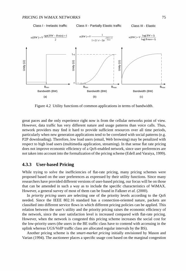
PRICING IN WiMAX NETWORKS 75
Unity (
U)
Unity (
U)
Unity (
U)
Bandwidth (BW)
(a)
Bandwidth (BW)
(b)
Bandwidth (BW)
(c)
Bmin Bmin Bmax Bmax
Class I - Inelastic traffic Class II - Partially Elastic traffic Class III - Elastic
sgn( min) 1( )
2BW B
u BW V− += 2ln(1/ 1)
max
1( )
1 (1/ 1) B
u BW V
eε
ε− −=
+ −
log( 1)( )
log( max 1)
BWu BW V
B
+=+
Figure 4.2 Utility functions of common applications in terms of bandwidth.
great paces and the only experience right now is from the cellular networks point of view.However, data traffic has very different nature and usage patterns than voice calls. Thus,network providers may find it hard to provide sufficient resources over all time periods,particularly when new generation applications tend to be correlated with social patterns (e.g.P2P downloading). Therefore, low load users (email, Web browsing) may be penalized withrespect to high load users (multimedia application, streaming). In that sense flat rate pricingdoes not improve economic efficiency of a QoS-enabled network, since user preferences arenot taken into account into the formalization of the pricing scheme (Edell and Varaiya, 1999).
4.3.3 User-based Pricing
While trying to solve the inefficiencies of flat-rate pricing, many pricing schemes wereproposed based on the user preferences as expressed by their utility functions. Since manyresearchers have provided different versions of user-based pricing, our focus will be on thosethat can be amended in such a way as to include the specific characteristics of WiMAX.However, a general survey of most of them can be found in Falkner et al. (2000).
In priority pricing users are selecting one of the priority levels according to the QoSneeded. Since the IEEE 802.16 standard has a connection-oriented nature, packets areclassified into different service flows in which different pricing policies can be applied. Thisrelation between the user’s utility and the priority pricing raises the economic efficiency ofthe network, since the user satisfaction level is increased compared with flat-rate pricing.However, when the network is congested this pricing scheme increases the social cost forthe low-priority users (the users in the BE traffic class have to contend with accessing in theuplink whereas UGS/VoIP traffic class are allocated regular intervals by the BS).
Another pricing scheme is the smart-market pricing initially envisioned by Mason andVarian (1994). The auctioneer places a specific usage cost based on the marginal congestion
76 WiMAX EVOLUTION: EMERGING TECHNOLOGIES AND APPLICATIONS
cost. Then, prior to transmitting a packet, the user either accepts the extra cost or if the user’sbid does not exceed the current cutoff amount set by the auctioneer, they do not gain accessto the network (‘the Internet’). Although the applicability of Smart market pricing is difficultdue to the significant technical changes required, in a WiMAX network the scheduler of theBS, which is fully aware of the congestion level of the network, may cooperate with theauctioneer to impose the correct amount on the users, thus making a great candidate thatencourages both network and economic efficiency.
In effective bandwidth pricing the network sets prices to reflect the demand for effectivebandwidth and publishes a number of pricing curves, differentiated according to the QoSservice flow (Courcoubetis and Siris, 1999). Prices are then determined over a long timescale and users then accept those prices in their signed SLA. Such a pricing scheme can bevery effective, but requires the traffic patterns of the user, which can be either measured in atest period or can be approximated through field test and user surveys.
In the following section we apply those pricing methods in different WiMAX topologies.
4.4 Pricing in Different WiMAX Topologies
WiMAX networks are to be deployed in metropolitan areas where users may either connectinstantly to the BS, or through other WiMAX nodes (as in the case of RSs) and throughWiFi APs that provide access to local areas. In this section we analyze all of these topologiesin terms of how the provider is going to charge the users (optimum price allocation) forthe service offered, and also based on how the network is designed. For these reasonsmathematical tools such as game theory and convex optimization are used. The understandingof the following section requires basic knowledge of terms associated with those theories.
4.4.1 Point-to-point Unlimited Capacity
In this architecture, which is based on the work of Musacchio and Walrand (2006), it isassumed that each MS participates in a single cell scenario with one BS. Moreover, the MSis not able to have access in multiple contenting BSs leading to a pricing topology of a singleseller single buyer. Time is divided into time slots, which can be in the scale of minutes orhours. In each time frame t the MS requests for a service and the BS replies with a pt (e.g. theclient requests access to the Internet for 10 minutes and the BS replies with the correspondingvalue, for example, when waiting in the airport). The MS then either accepts the price and thegame continues for the next time slot or rejects the price and the game ends immediately. Itis also assumed that the network is never congested, there is no QoS differentiation and thusthe game of each MS with the BS is independent of the other MSs.
Three quantities are specified: τ is a discrete random variable representing the numberof time slots the client intends to connect and T the discrete time slots the MS receives forthe specified service; finally, U is a continuous random variable which represents the utilityfunction of the user in a time slot.
The utility function of that model is specified by
F(T , τ )= U · min(T , τ ). (4.3)
The MS is aware of both τ and U , whereas the BS may only obtain their PDF (in case it hadfull knowledge, then pt = U and the MS would always connect).

PRICING IN WiMAX NETWORKS 77
• The MS connects or remains connected in slot t if and only if t ≤ τ and U > pt .
• The BS charges a nondecreasing price sequence pt such that
pt ∈ arg maxppP(U > p). (4.4)
Musacchio and Walrand (2006) proved that it is a Probability Bayesian Equilibrium (PBE)for the BS to choose a single maximizing value of pP(U > p) and charge it for alltime slots (pt = p∗). Moreover, a maximum is achieved in [0,∞), because for y(p)=arg maxp pP(U > p), we know that y(0)= 0 and limx→∞ y(p)= 0. In the end of the gamethe MS has a net payoff of F(T , τ )− ∑T
t=1 pt and the BS a profit equal to∑Tt=1 pt . In
order to find the revenue of the BS provider, as specified in Section 4.2.1, we need to sum theprofit over all users connected N , plus the mean number of reconnections E[R] multipliedby the users, K =N + E[R]N (K can be easily measured by the provider either on the BSor on the billing system). Now the intended connection time of each user k ∈ [1, . . . , K] isa function T (k). Since it is proved that the same price is charged over the entire duration ofT (k) the revenue is
Revenue(y, py)=K∑k=1
T (k)pt , (4.5)
where y = max(T (K)), which is the duration of measurement.
4.4.2 Mesh Mode Operation
The multi-hop case, as shown in Figure 4.3, can be abstracted to an aggregate branch of thescheduling tree in order to involve all of the nodes from the BS to the last MS. We supposethat the MS is not in the range of the BS, thus all of the packets are relayed from the relayingnodes towards the BS. As described by Lam et al. (2007), the BS charges the one-hop RSwith a price pNt , which in turn charges the next hop a price pN−1
t , until we reach the MSwhere the price is specified as p1
t . It is straightforward from the previous analysis that thepayoff of the BS is a function of all of the prices from the MS to the BS. Equivalently foreach RS its price is a function of the rest of the stations towards the client. The price receivedby MS after price pi has been set by node i is marked up by all its downstream relays:
mi(pi)= p1∗(p2∗(. . . (pi∗))) for all i ∈ 2, . . . , n. (4.6)
Since the last node 1 does not have any other downstream relays m1(p1)= p1. The payoffsare as follows.
• For the MS: F(T , τ )− ∑Tt=1 p
1t .
• For the RS:∑Tt=1(p
it − pit ) for i = 1, . . . , N − 1.
• For the BS:∑Tt=1 p
Nt .
As proved by Lam et al. (2007) the optimal price can be found as a PBE with the followingstrategy profile:
• the MS connects or remains connected in slot t if and only if t ≤ τ and U > pt ;
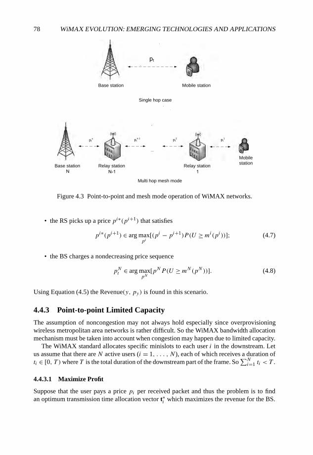
78 WiMAX EVOLUTION: EMERGING TECHNOLOGIES AND APPLICATIONS
t
...
ptn pt
n-1pt
1pt
2
Base station
Single hop case
Base station Mobile station
Multi hop mesh mode
Relay station Relay station
Mobilestation
Figure 4.3 Point-to-point and mesh mode operation of WiMAX networks.
• the RS picks up a price pi∗(pi+1) that satisfies
pi∗(pi+1) ∈ arg maxpi
[(pi − pi+1)P (U ≥mi(pi))]; (4.7)
• the BS charges a nondecreasing price sequence
pNt ∈ arg maxpN
[pNP(U ≥mN(pN))]. (4.8)
Using Equation (4.5) the Revenue(y, py) is found in this scenario.
4.4.3 Point-to-point Limited Capacity
The assumption of noncongestion may not always hold especially since overprovisioningwireless metropolitan area networks is rather difficult. So the WiMAX bandwidth allocationmechanism must be taken into account when congestion may happen due to limited capacity.
The WiMAX standard allocates specific minislots to each user i in the downstream. Letus assume that there are N active users (i = 1, . . . , N), each of which receives a duration ofti ∈ [0, T )where T is the total duration of the downstream part of the frame. So
∑Ni=1 ti < T .
4.4.3.1 Maximize Profit
Suppose that the user pays a price pi per received packet and thus the problem is to findan optimum transmission time allocation vector t∗i which maximizes the revenue for the BS.
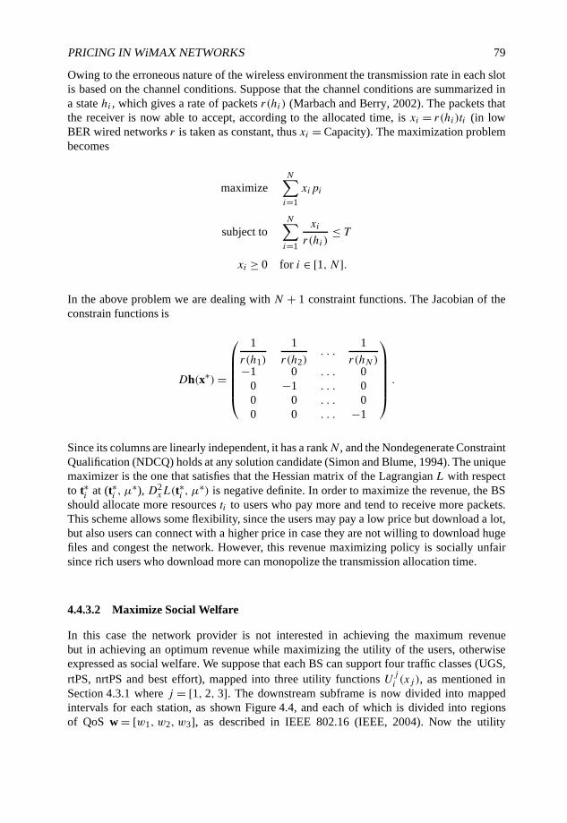
PRICING IN WiMAX NETWORKS 79
Owing to the erroneous nature of the wireless environment the transmission rate in each slotis based on the channel conditions. Suppose that the channel conditions are summarized ina state hi , which gives a rate of packets r(hi) (Marbach and Berry, 2002). The packets thatthe receiver is now able to accept, according to the allocated time, is xi = r(hi)ti (in lowBER wired networks r is taken as constant, thus xi = Capacity). The maximization problembecomes
maximizeN∑i=1
xipi
subject toN∑i=1
xi
r(hi)≤ T
xi ≥ 0 for i ∈ [1, N].
In the above problem we are dealing with N + 1 constraint functions. The Jacobian of theconstrain functions is
Dh(x∗)=
1
r(h1)
1
r(h2). . .
1
r(hN)−1 0 . . . 00 −1 . . . 00 0 . . . 00 0 . . . −1
.
Since its columns are linearly independent, it has a rankN , and the Nondegenerate ConstraintQualification (NDCQ) holds at any solution candidate (Simon and Blume, 1994). The uniquemaximizer is the one that satisfies that the Hessian matrix of the Lagrangian L with respectto t∗i at (t∗i , µ∗), D2
xL(t∗i , µ
∗) is negative definite. In order to maximize the revenue, the BSshould allocate more resources ti to users who pay more and tend to receive more packets.This scheme allows some flexibility, since the users may pay a low price but download a lot,but also users can connect with a higher price in case they are not willing to download hugefiles and congest the network. However, this revenue maximizing policy is socially unfairsince rich users who download more can monopolize the transmission allocation time.
4.4.3.2 Maximize Social Welfare
In this case the network provider is not interested in achieving the maximum revenuebut in achieving an optimum revenue while maximizing the utility of the users, otherwiseexpressed as social welfare. We suppose that each BS can support four traffic classes (UGS,rtPS, nrtPS and best effort), mapped into three utility functions Uji (xj ), as mentioned inSection 4.3.1 where j = [1, 2, 3]. The downstream subframe is now divided into mappedintervals for each station, as shown Figure 4.4, and each of which is divided into regionsof QoS w = [w1, w2, w3], as described in IEEE 802.16 (IEEE, 2004). Now the utility
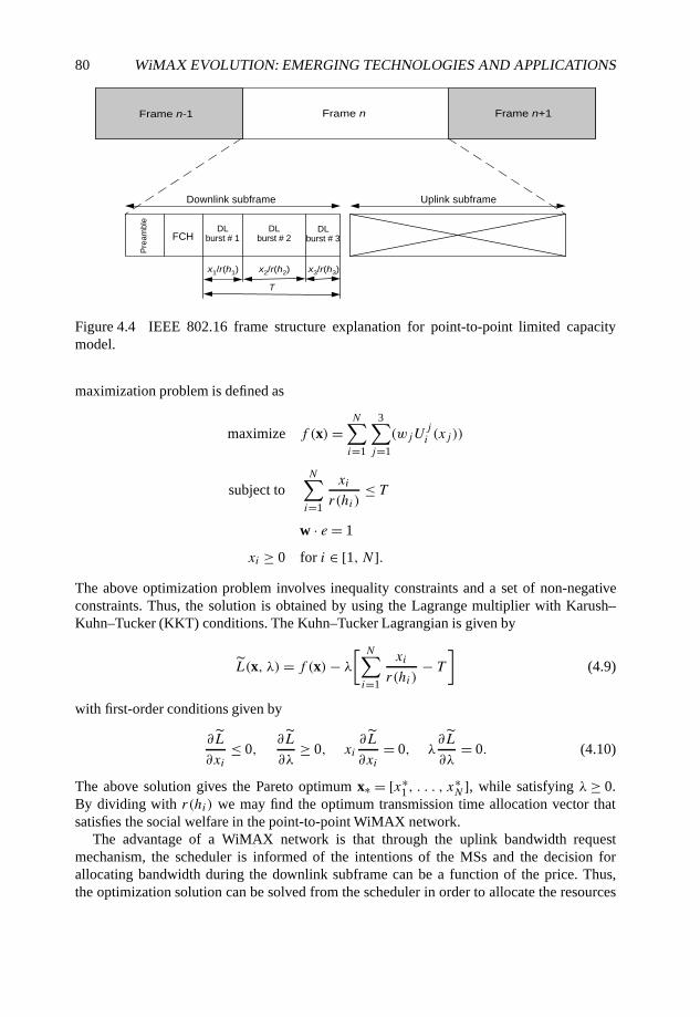
80 WiMAX EVOLUTION: EMERGING TECHNOLOGIES AND APPLICATIONS
Downlink subframe
Frame n-1 Frame n Frame n+1
Uplink subframe
Pre
am
ble
FCHDL
burst # 1
x1/r(h1) x2/r(h2) x3/r(h3)
DLburst # 2
T
DLburst # 3
Figure 4.4 IEEE 802.16 frame structure explanation for point-to-point limited capacitymodel.
maximization problem is defined as
maximize f (x)=N∑i=1
3∑j=1
(wjUji (xj ))
subject toN∑i=1
xi
r(hi)≤ T
w · e = 1
xi ≥ 0 for i ∈ [1, N].The above optimization problem involves inequality constraints and a set of non-negativeconstraints. Thus, the solution is obtained by using the Lagrange multiplier with Karush–Kuhn–Tucker (KKT) conditions. The Kuhn–Tucker Lagrangian is given by
L(x, λ)= f (x)− λ
[ N∑i=1
xi
r(hi)− T
](4.9)
with first-order conditions given by
∂L
∂xi≤ 0,
∂L
∂λ≥ 0, xi
∂L
∂xi= 0, λ
∂L
∂λ= 0. (4.10)
The above solution gives the Pareto optimum x∗ = [x∗1 , . . . , x
∗N ], while satisfying λ≥ 0.
By dividing with r(hi) we may find the optimum transmission time allocation vector thatsatisfies the social welfare in the point-to-point WiMAX network.
The advantage of a WiMAX network is that through the uplink bandwidth requestmechanism, the scheduler is informed of the intentions of the MSs and the decision forallocating bandwidth during the downlink subframe can be a function of the price. Thus,the optimization solution can be solved from the scheduler in order to allocate the resources
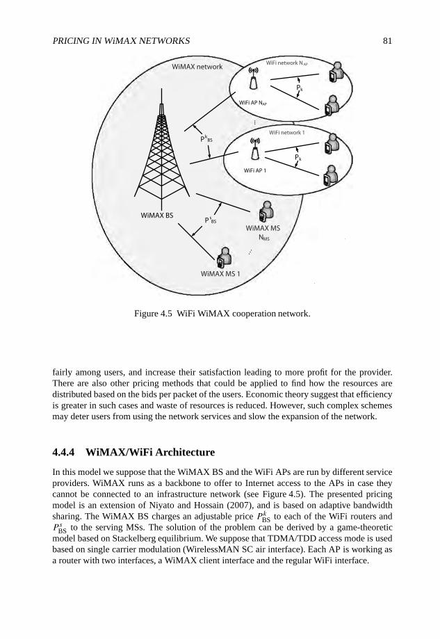
PRICING IN WiMAX NETWORKS 81
WiMAX BS
WiMAX MSNMS
WiMAX MS 1
WiFi AP 1
WiFi AP NAP
WiFi network 1
WiFi network N APWiMAX network
......
P sBS
PkBS
Pk
Pk
Figure 4.5 WiFi WiMAX cooperation network.
fairly among users, and increase their satisfaction leading to more profit for the provider.There are also other pricing methods that could be applied to find how the resources aredistributed based on the bids per packet of the users. Economic theory suggest that efficiencyis greater in such cases and waste of resources is reduced. However, such complex schemesmay deter users from using the network services and slow the expansion of the network.
4.4.4 WiMAX/WiFi Architecture
In this model we suppose that the WiMAX BS and the WiFi APs are run by different serviceproviders. WiMAX runs as a backbone to offer to Internet access to the APs in case theycannot be connected to an infrastructure network (see Figure 4.5). The presented pricingmodel is an extension of Niyato and Hossain (2007), and is based on adaptive bandwidthsharing. The WiMAX BS charges an adjustable price PkBS to each of the WiFi routers andP sBS to the serving MSs. The solution of the problem can be derived by a game-theoreticmodel based on Stackelberg equilibrium. We suppose that TDMA/TDD access mode is usedbased on single carrier modulation (WirelessMAN SC air interface). Each AP is working asa router with two interfaces, a WiMAX client interface and the regular WiFi interface.

82 WiMAX EVOLUTION: EMERGING TECHNOLOGIES AND APPLICATIONS
4.4.4.1 The Model
The reason for this choice of game is because in the network there are two entities thatdeploy their own strategies to theirs clients. The equilibrium can be obtained by backwardsinduction, in which the follower (AP) chooses its profit maximizing quantity given its belieffor the choice of the leader (BS). Then the leader will go ahead and maximize their profitalready knowing how the follower (AP) will respond.
• Players: WiMAX BS, WiMAX SSs and WiFi APs.
• Strategies: WiMAX BS, the price charged to the WiFi AP and to the WiMAX SSs. Forthe WiFi AP, the price charged to the WiFi clients.
• Payoffs: The corresponding profit.
Assumption 1: The bandwidth demand of a WiFi node is a linear strictly decreasing functionDj (Pk)= aj − bjPk of user j ∈ [1, . . . , Nk], for aj , bj ∈ R+ and for which there exists aprice Pmax
k = aj/bj such that Dj(Pmaxk )= 0, for all Pk ≥ Pmax
k .The profit of the AP k can be defined as the difference between the revenue of the WiFi
networks and the cost of offering a service πk = Rk − Ck . The revenue Rk can be defined as
Rk =Nk∑j=1
Pk ∗ bj (Pk), (4.11)
where bj (Pk) is the demand function of node j served by the AP k and is a function of theprice Pk charged by AP k, which is assumed to be the same offered to all users. The costfunction is given by
Ck =Nk∑j=1
PkBS ∗ bj (Pk)+ Fk = PkBS
Nk∑j=1
bj (Pk)+ Fk, (4.12)
which is the sum over all clients Nk served by the AP, of the price set to the AP by theWiMAX BS PkBS plus the fixed cost (costs paid for installation, equipment, etc.). The firststep of the problem is to define the optimal price P ∗
k charged by the WiFi AP to the nodes,which is obtained by solving a straightforward Lagrangian constrained optimization problem
maximize πk = Rk − Ck
subject to P ∗k ≤ Pmax
k
Pk ≥ 0.
The leaders payoff (BS) can be defined equivalently as the difference of the revenueobtained by the BS from the APs and the MSs minus the expenditures in a given timedescribed as follows:
πBS = RMS +NAP∑k=1
Rk − FBS (4.13)
the revenue obtained by the SSs is a function of their demand function bs(PMS), whereasthe revenue obtained by the AP is a function of the AP’s price P ∗
k found by the previous
PRICING IN WiMAX NETWORKS 83
optimization. Thus,
πBS =NMS∑s=1
PMSbs(PMS)+NAP∑k=1
PkBS
Nk∑j=1
bj (P∗k )− FBS. (4.14)
Assumption 2: The bandwidth demand of a MS node is a linear strictly decreasing functionDs(PMS)= as − bsPMS of MS s ∈ [1, . . . , NMS], for as, bs ∈ R+ and for which there existsa price Pmax
MS = as/bs such that Ds(PmaxMS )= 0, for all PMS ≥ Pmax
MS .The problem is again a Lagrangian constrained optimization, which is easily solved in
order to find the optimal price vector P∗BS = [Pk,∗BS , P
s,∗BS ] set by the BS to each of the WiFi
APs and each MS (since both share the same wireless channel). Having the optimal pricevector which maximizes the profit of the BS, the π∗
BS = P(t, pt ) and the NPV can be found.
4.5 Conclusion
To summarize, this chapter has dealt with the design of a WiMAX network in terms ofeconomic theory, business modeling and engineering applications. Initially a business modelwas presented as a way to measure the profitability of deploying a WiMAX network takinginto account profits and ways to charge the users in order to either maximize the revenueor the social welfare. Multiple network topology analyses were presented from which theprovider may decide which depicts their application scenario.
From the pricing point of view we have showcased that although flat-rate pricing is simpleand convenient it does not provide economic efficiency. Moreover, we have proved that whenthe network is designed in such a way that there is no congestion (unlimited capacity) in thewireless link between BS and MS, the Nash equilibrium is to provide an equal price for theconnection time of the user (e.g. paying a standard amount of dollars for intended duration ofconnection). However, when the MSs compete for accessing the channel (limited capacity)the provider shall price the users a specific amount of dollars for each transmitted packet(user-based pricing). In the last model the pricing was used to allocate the resources fairly ina WiFi/WiMAX cooperated network. Such an analysis can be extended to other 4G wirelesstechnology cooperating scenarios.
References
Courcoubetis, C. and Siris, V.A. (1999) Managing and pricing service level agreements fordifferentiated services. Proceedings of the 7th International Workshop on Quality of Service,pp. 165–173.
Courcoubetis, C. and Weber, R. (2003) Pricing Communication Networks. John Wiley & Sons Ltd,Chichester.
DaSilva, L.A. (2000) Pricing for QoS enabled networks: a survey. IEEE Communication Surveys andTutorials, 3(2), 2–8.
Edell, R. and Varaiya, P. (1999) Providing Internet access: what we learn from index. IEEE Network,13(5), 18–25.
Falkner, M., Devetsikiotis, M. and Lambadaris, I. (2000) An overview of pricing concepts forbroadband IP networks. IEEE Communications Survey, 3(2).
84 WiMAX EVOLUTION: EMERGING TECHNOLOGIES AND APPLICATIONS
Gunasekaran, V. and Harmantzis, F. (2006) Financial assessment of city wide WiFi deployment.Communications and Strategies, i63.
IEEE (2004). Part 16: Air Interface for Fixed Broadband Wireless Access Systems. IEEE Standard802.16, IEEE.
Lam, R.K., Chiu, D. and Lui, J. (2007) On the access pricing and network scaling issues of wirelessmesh networks. IEEE Transactions on Computers, 56(11), 1456–1469.
Liu C, Shi, L. and Liu, B. (2007) Utility based bandwidth allocation for triple play services. Proceedingsof the 4th European Conference on Universal Multiservice Networks ECUMN’07, pp. 327–336.
Marbach, P. and Berry, R. (2002) Downlink resource allocation and pricing for wireless networks. IEEEInfocom, pp. 1470–1479.
Mason, J.K.M. and Varian, H.R. (1994) Pricing the Internet. Proceedings of the InternationalConference of Telecommunication System Modeling, Nashville TN, pp. 378–393.
Musacchio, J. and Walrand, J. (2006) WiFi access point pricing as a dynamic game. IEEE/ACMTransactions on Networks, 14(2), 289–301.
Niyato, D. and Hossain, E. (2007) Integration of WiMAX and WiFi: optimal pricing for bandwidthsharing. IEEE Communications Magazine, 45(5), 140–146.
Pareek, D. (2006) The Business of WiMAX. John Wiley & Sons Ltd, Chichester.Simon, C.P. and Blume, L. (1994) Mathematics for Economists (1st edn). Norton, New York.Walrand, J. and Varaiya, P. (1996) High Performance Communication Networks (1st edn). Morgan
Kaufmann, San Francisco, CA.
Part IV
Advanced WiMAX Architectures
WiMAX Evolution: Emerging Technologies and Applications Edited by Tsutomu Ishikawa© 2009 John Wiley & Sons, Ltd. ISBN: 978-0-470-69680-4
5
WiMAX Femtocells
Chris Smart, Clare Somerville and Doug Pulley
5.1 Introduction
5.1.1 A Brief History of Cell Sizes
It is over 60 years since it was first proposed that terrestrial radio coverage of indefinite extentcould be achieved using multiple transmitters and continued reuse of a small number of radiochannels (Brinkley, 1946). The simple presentation of the coverage area of each Base Station(BS) represented as a regular hexagon (a special case of a Voronoi polygon (Voronoi diagram,2008)) with the base site at its center has since become the defining symbol of the cellularindustry.
Traffic densities and coverage challenges in dense urban areas soon demanded morestrategically placed BS sites, using antennas sited at or below the skyline. These more closelypacked ‘microcells’ use buildings to tailor the coverage area, minimizing interference to localco-channel BSs. The ‘picocell’ rapidly joined its larger ‘siblings’ as the BS carefully targetedat the highest user densities in airports, railway stations, hotels and large enterprise buildings(Saunders and Aragón-Zavala, 2007).
5.1.2 Definition of a Femtocell
The term ‘femtocell’ is a relatively recent introduction and may be taken to imply a numberof different functional and architectural alternatives. It is therefore important to establishexactly what is being referred to here as a femtocell in the WiMAX context.
The following is a list of key attributes that define a WiMAX femtocell with respect to amore traditional macrocell base station.
(A) Deployment scenario:
• indoor;
WiMAX Evolution: Emerging Technologies and Applications Edited by Tsutomu Ishikawa© 2009 John Wiley & Sons, Ltd. ISBN: 978-0-470-69680-4
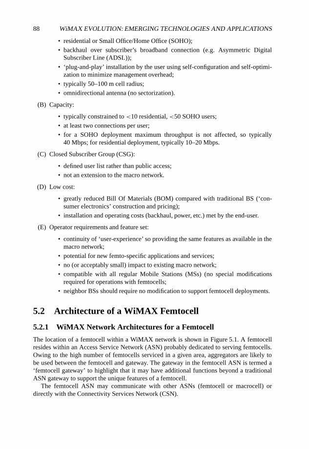
88 WiMAX EVOLUTION: EMERGING TECHNOLOGIES AND APPLICATIONS
• residential or Small Office/Home Office (SOHO);
• backhaul over subscriber’s broadband connection (e.g. Asymmetric DigitalSubscriber Line (ADSL));
• ‘plug-and-play’ installation by the user using self-configuration and self-optimi-zation to minimize management overhead;
• typically 50–100 m cell radius;
• omnidirectional antenna (no sectorization).
(B) Capacity:
• typically constrained to <10 residential,<50 SOHO users;
• at least two connections per user;
• for a SOHO deployment maximum throughput is not affected, so typically40 Mbps; for residential deployment, typically 10–20 Mbps.
(C) Closed Subscriber Group (CSG):
• defined user list rather than public access;
• not an extension to the macro network.
(D) Low cost:
• greatly reduced Bill Of Materials (BOM) compared with traditional BS (‘con-sumer electronics’ construction and pricing);
• installation and operating costs (backhaul, power, etc.) met by the end-user.
(E) Operator requirements and feature set:
• continuity of ‘user-experience’ so providing the same features as available in themacro network;
• potential for new femto-specific applications and services;
• no (or acceptably small) impact to existing macro network;
• compatible with all regular Mobile Stations (MSs) (no special modificationsrequired for operations with femtocells;
• neighbor BSs should require no modification to support femtocell deployments.
5.2 Architecture of a WiMAX Femtocell
5.2.1 WiMAX Network Architectures for a Femtocell
The location of a femtocell within a WiMAX network is shown in Figure 5.1. A femtocellresides within an Access Service Network (ASN) probably dedicated to serving femtocells.Owing to the high number of femtocells serviced in a given area, aggregators are likely tobe used between the femtocell and gateway. The gateway in the femtocell ASN is termed a‘femtocell gateway’ to highlight that it may have additional functions beyond a traditionalASN gateway to support the unique features of a femtocell.
The femtocell ASN may communicate with other ASNs (femtocell or macrocell) ordirectly with the Connectivity Services Network (CSN).
WiMAX FEMTOCELLS 89
CSN
Internet
ASN
gateway
BS BS
ASN
Femtocell
ASN gateway
Aggregator Aggregator
Femto Femto FemtoFemto
Femtocell ASN
Figure 5.1 WiMAX network elements.
5.2.2 Femtocell Deployment Configurations
In a conventional network the radio resource is centrally managed; however, this will not bethe case for femtocells which are, by definition, much more autonomous. Hence, to all intentsand purposes, a femtocell will be seen by the macro network as a hostile interferer. Wherepossible, the femtocell ‘layer’ could be deployed on a separate Radiofrequency (RF) channelto the macrocell layer but this is not necessarily the case with all operators. Even in thededicated RF channel case, interference between neighbor femtocells needs to be considered.To this end several deployment configurations have been proposed.
5.2.2.1 Closed, Dedicated Channel, Fixed Power Deployment
Closed in this sense means that the femtocell is available to a restricted set of subscribers(e.g. those who usually dwell in a residence) agreed between the femtocell owner and theoperator.
The femtocell is deployed on a dedicated RF channel, that is, an RF channel that isnot used within the macro layer. The worst-case dedicated RF channel deployment is theadjacent channel. The worst-case adjacent RF channel deployment is when the adjacent RFchannel is owned by a different operator. Although the femtocell is deployed on a dedicatedfrequency with respect to the macro network, a co-channel interference scenario remainsbetween femtocells: this is especially significant within a dense population of femtocells.It is possible that operators would use a dedicated RF channel for all types of small cellin general, hence femtocells may also experience/create interference from/to picocells andmicrocells.
A fixed maximum transmit power limit is defined for this deployment option, with avalue of 5 dBm suggested in 3GPP. This limit must be defined such that the femtocell willcause an acceptably low level of interference in the worst case, that is, in a weak macrocellenvironment, and so may be too restrictive for general deployment.
90 WiMAX EVOLUTION: EMERGING TECHNOLOGIES AND APPLICATIONS
5.2.2.2 Closed, Dedicated Channel, Adaptive Power Deployment
This option is similar to the previous configuration in that the femtocell is configured for aclosed subscriber group and for a dedicated RF channel. The difference is that the maximumfemtocell transmit power may be set as high as allowed by the standards or by the equipmentcapability, using a self-configuring algorithm. Higher power levels should only be used whenappropriate for the deployed environment and when the resulting interference is acceptable.
5.2.2.3 Closed, Co-channel Deployment
The femtocell is deployed on the same RF channel frequency as the surrounding macro layer(co-channel) but has the ability to control its transmit power in order to minimize its impacton the macro layer by monitoring the macro layer interference. Isolation between the twosystems is provided by the penetration losses of the building materials. This configurationbecomes especially challenging when visitors to the home operate on the same RF channelbut are power controlled by the macrocell and may cause interference (due to so-called ‘near–far’ effects).
5.2.2.4 Closed, Partial Co-channel Deployment
This option applies where more than one RF channel frequency is used on the macro layer butthere is no frequency dedicated solely for the use of femtocells. The femtocell is required toselect a RF channel frequency from the available set by determining one that is not deployedin the immediate vicinity. This helps provide an additional degree of isolation, relative tofull co-channel deployments, to minimize interference and distribute the load between thefemtocell and the macro layer.
Provided that the correct choice of RF channel frequency can be automated, the RFperformance of this configuration should be similar to that of dedicated channel deploymentoptions.
5.2.2.5 Open Femtocell Deployment
In this configuration the femtocell is deployed as part of an open system, that is, sharedamongst all of the subscribers attached to a single operator. This option may therefore beconsidered to be beyond the scope of femtocell deployments and instead fall into the categoryof more traditional pico- or microcells.
Any of the previous four deployment configurations could be valid for an open deploy-ment, but with the consideration that the femtocell is no longer a hostile interferer but shouldinstead be considered an extension to the macro network.
5.3 Femtocell Fundamentals
In addition to the WiMAX air interface PHY (physical) and MAC (Medium Access Control),the femtocell includes the following key components.
(A) Femtocell management:
• timing and synchronization;
WiMAX FEMTOCELLS 91
• self-configuration of operational parameters.
(B) Remote/local configuration:
• Remote configuration options:
– maintain a femtocell Management Information Base (MIB) using the SimpleNetwork Management Protocol (SNMP);
– maintain a femtocell data model using TR-069;
• Local configuration:
– user configuration for CSG management.
(C) Network interface:
• authentication;
• backhaul security;
• handovers.
In the following sections we investigate these functional elements, focusing on those aspectsthat are unique to femtocells and providing suggestions for solutions to the special issues thatarise.
5.3.1 Synchronization
WiMAX femtocells, like all BSs, are required to be synchronized with each other in time suchthat the preamble is broadcast from all BSs at the same instant. Specifically the requirementis for the time alignment to be accurate to within 1 µs. In addition, the transmit frequencyfrom each BS must be accurate to within ±2 ppm of the RF channel frequency.
5.3.1.1 GPS
This is the traditional method for providing synchronization to a WiMAX BS. GPS iscombined with a cheaper oscillator to provide accurate frequency synchronization. Inaddition, GPS provides a regular pulse which is used to provide time synchronization. GPSdoes not traditionally work well inside buildings but indoor solutions are now starting tobecome available driven to a large extent by the femtocell market.
5.3.1.2 NTP/PTP
The Network Time Protocol (NTP) and the IEEE1588 Precision Time Protocol (PTP) areboth packet-based synchronization schemes that can extract timing information from thebackbone. Their use would be combined with a cheap oscillator to provide an accuratefrequency reference and also to generate the regular timing pulse required for time synchro-nization.
92 WiMAX EVOLUTION: EMERGING TECHNOLOGIES AND APPLICATIONS
5.3.1.3 Other BSs
In areas where WiMAX coverage is already available, the femtocell can synchronize itselfto a nearby macrocell. This requires the ability to receive Downlink (DL) signals fromthe macrocell, derive timing and frequency estimates from that cell and discipline a localoscillator to align with it. The DL Receive mode of operation to support this approach isdiscussed further in the following section.
5.3.2 Self-configuration
A key differentiator between a femtocell and a traditional macrocell is the manner in whichit is installed. The femtocell must be a ‘plug-and-play’ device.
Part of the self-installation process involves the femtocell achieving accurate frequencyand time synchronization, as defined above. Other information which needs to be self-configured includes:
• transmission frequency;
• maximum transmission power;
• preamble selection;
• neighbor cell list (WiMAX and other technologies, e.g. GSM).
A key enabler of femtocell self-configuration is the ability to operate in a DL Receive mode:in other words to operate, temporarily, as though it were a WiMAX MS. This allows thefemtocell to detect any surrounding WiMAX macrocells, and possibly other femtocells, inorder to integrate into the overall radio network without causing significant degradation tothe performance of these neighbor cells.
5.3.2.1 Transmission Frequency
Selection of a RF channel frequency will determine to a large extent how the femtocellinterferes with surrounding macrocells.
Single WiMAX frequency In some cases operators will be constrained to the use of asingle frequency, for both macrocell and femtocell networks, in which case the considerationsof a ‘co-channel’ deployment as discussed earlier will come into play. In this case thefemtocell can be statically provisioned by the operator to use the defined frequency withoutany self-configuration. However, the selection of Tx power, as discussed below, will becomeespecially important for interference mitigation.
Single femtocell frequency Another alternative is that the operator will identify a fixed RFchannel frequency for femtocells but one that is distinct from that/those used by the macrocellnetwork. This alternative will imply the ‘dedicated channel’ considerations defined earlier. Aswith the single frequency case, this option will not require self-configuration of the femtocellfrequency: it can be statically defined by the operator. Further, in this dedicated channel casethe selection of Tx power is less critical as far as macrocell interference is concerned andcould potentially also be statically configured.
WiMAX FEMTOCELLS 93
Self-configuration A third option is to introduce a pre-defined set of frequencies availablefor the femtocell network, possibly the same as or overlapping with the macrocell frequencyset, and allow the femtocell to make its own selection in order to minimize interferencewith neighbor cells. This self-configuration procedure requires that the femtocell uses itsDL Receive mode to scan for frequencies used in the surrounding cells and then selects thechannel on which the lowest energy is present.
5.3.2.2 Maximum Transmission Power
Selection of the femtocell maximum transmission power, in conjunction with the RF channelfrequency choice, will affect the level of interference that the femtocell generates towardsneighbor cells.
Co-channel vs dedicated channel The choice of transmission power is especially criticalin co-channel deployments. In this case the femtocell DL transmissions will appear as in-band interference to neighbor cells, with a direct impact on their coverage: the femtocells areeffectively punching a hole in the geographical area served by the macrocells. In dedicatedchannel scenarios there is a little more flexibility in the selection of transmission power as theinterference is now out of band, but this can still have an impact on neighbor cell coverageespecially in terms of adjacent channel rejection performance. All DL transmissions will to alarge extent be contained within the building where the femtocell is installed, but this cannotbe assumed for all deployments; for example, the femtocell could be sited next to a window.Therefore, control of the transmission power is a key requirement.
Fixed maximum limit One option that is potentially attractive in dedicated channeldeployments is to set the maximum transmission power of the femtocell at a pre-defined fixedlimit. This level needs to be carefully selected to ensure that it is sufficiently low to cause nomore than an acceptable level of interference in the majority of deployment scenarios. Thislimit can be statically defined by the operator and requires no self-configuration functionalityin the femtocell. However, there will always be deployment cases where this pre-definedlevel is inappropriate, both in terms of minimizing interference and also providing effectivecoverage within the femtocell area.
Self-configuration A more flexible option, applicable in both co-channel and dedicatedchannel deployments, is for the femtocell to make measurements of the power levels receivedfrom neighbor cells and use these to determine its own transmission power. The generalprinciple is that if the femtocell can hear a strong macrocell signal then so can any nearbyMSs: therefore, it can afford to transmit at a higher level without generating too muchinterference. Clearly this self-configuration procedure requires that the femtocell is capableof detecting DL transmissions from surrounding cells: the DL Receive mode.
5.3.2.3 Preamble Selection
The DL preamble is the first OFDMA symbol transmitted in each frame. It spans all sub-channels, dividing them into three sets, each set mapping to a specific segment. One of 32
94 WiMAX EVOLUTION: EMERGING TECHNOLOGIES AND APPLICATIONS
possible Pseudorandom Noise (PN) sequences is carried on the preamble for each segment,identifying the ‘IDcell’ parameter for the BS.
One possible use for the preamble would be to carry an IDcell parameter which identifiesthe BS as a femtocell, rather than a macrocell: this would allow femtocells to identify eachother and avoid creating ‘circular references’ during self-configuration (for example, trying tosynchronize to each other’s frequency reference). This approach would require the operatorto partition IDcell into ranges; some values valid for macrocells and others for femtocells.The macrocell would be provisioned as normal to use an IDcell from the macro range butpre-programming a single fixed value in the femtocell could create contentions when multiplefemtocells are deployed in the same area. Therefore, it makes sense to configure the femtocellwith a definition of the valid IDcell range it can use, and allow it to self-configure from thisrange. This would require detection of the IDcell value being used by any neighbor femtocellsin order to select a locally unique value: the DL receive mode again.
Another option would be to have no distinction between femtocells and macrocells in theiruse of IDcell, and simply allow the femtocell to select from the entire range available basedagain on detection of neighbor usage. This would permit locally unique IDs to be deployed,but would not provide a mechanism for identifying other femtocells.
5.3.2.4 Advertising Neighbor Cells
WiMAX BSs advertise information about their neighbor cells in order to assist the MShandover procedure. For macrocells this information would be provisioned by the operatorbased on knowledge of the geographical deployment of the BSs, but for femtocells suchprovisioning is clearly not feasible.
A solution to this is for the femtocell to construct its own neighbor list. This list would bebased directly on the results of scanning for surrounding macrocells using the DL Receivemode.
In order to avoid advertising neighbor femtocells as handover candidates, there wouldneed to be a mechanism defined for distinguishing between femtocells and macrocells. Onesuch mechanism would be to use subsets of the IDcell parameter carried on the DL preamble,as described above.
5.3.3 Remote Configuration
A macrocell typically includes a MIB, as defined by the IEEE (2007). This standardised MIBenables a network operator to remotely configure the BS. It also gives the network operatorthe ability to gather statistics from the BS.
The self-configuration of the femtocell makes many of these MIB functions redundant.However, some MIB features, such as statistics gathering, are still useful. One option is fora femtocell to implement a subset of this MIB; however, a standardized subset MIB forfemtocells has not yet been defined.
An alternative would be to use TR-069 which has been developed to allow remote con-figuration of Customer Premises Equipment (CPE). An extension to provide a standardizedmanagement system for a WiMAX femtocell could be defined.
WiMAX FEMTOCELLS 95
5.3.4 User Configuration
The femtocell is a plug-and-play device, which requires a minimum of user configuration.One element that does require input from the end-user is that of the allowed subscriber list.
To allow rejection of unauthorized users the femtocell should be configured with theidentity of any permitted MS: this is the concept of a CSG. A good candidate identity forthe CSG is the MAC address of the MS. The MAC address is unique to an MS and sent tothe BS during network entry.
The management of the CSG could be either performed by the user, via a Web browser,or by the user contacting their network operator who then manages the CSG via remotemanagement.
5.3.5 Backhaul Security
A network operator will have security concerns regarding the connection of femtocells to itsnetwork. The femtocell model, where an unknown entity performs installation and activation,is inherently less secure than a macrocell. The network operator will want to ensure that thefemtocell was purchased from a legitimate source and that the control messages it transmitsinto the operator’s network have not been tampered with. Of equal importance is that thefemtocell user requires confidence that its data remains secure between the femtocell andASN GW.
One option to ensure the validity of the femtocell is to provide the same authenticationmechanism as used by the MS, namely the Extensible Authentication Protocol (EAP).This would allow the WiMAX network to authenticate a femtocell with the same networkcomponents and signalling protocols.
An alternative would be to use Internet Protocol Security (IPsec) for authentication. IPsecis also a strong candidate for ensuring both control messages, and user data remain privateand unmodified across the backhaul connection.
5.3.6 Handovers
Handover in a WiMAX network is designed to guarantee quality of service providing aseamless multimedia experience to the user. This handover consists of several different stageseach designed to make sure the MS selects the most appropriate BS and that the transfer fromone BS to another is as fast as possible. In the first stage the MS surveys the signal qualityof neighboring BSs. Based on the results, the MS may decide to investigate handover to aneighbor BS: part of this stage involves the current (serving) BS and potential (target) BScommunicating over the backbone network. If the negotiation is successful the MS leavesits serving BS and establishes communication with the target BS. This network re-entry isfast and efficient due to the information exchanged over the backbone. Handover, between afemtocell and macrocell should provide the same seamless behavior.
5.3.6.1 Femto-to-Macrocell Handover
To achieve a seamless femto-to-macrocell handover there are several requirements thatshould be met. The MS must be aware of the neighboring BS, allowing it to locate potentialtarget BS, and the femtocell should be able to communicate with neighboring BS via the
96 WiMAX EVOLUTION: EMERGING TECHNOLOGIES AND APPLICATIONS
backbone network. This section assumes that the femtocell ASN has a backbone connectionto the macrocell ASN.
The femtocell self-configuration phase described earlier can provide the MS with a list ofneighbor macrocells for potential handover. This list will allow the MS to perform the samecontrolled handover used in macrocell-to-macrocell handover.
If the femtocell was unable to detect any macrocells during self-configuration, then itsneighbor cell-list will be empty. In this case the MS will need to perform an uncontrolledhandover. In an uncontrolled handover a macrocell will not be expecting a MS: however, byusing the backbone network it can retrieve information from the femtocell to aid networkre-entry. Uncontrolled handover also occurs in macrocell-only networks.
5.3.6.2 Macro-to-Femtocell Handover
A seamless macro-to-femtocell handover is more challenging. The same requirements mustbe met as femto-to-macrocell handover, namely, the MS must be aware of the femtocell, anda backbone connection exists. For macro-to-femtocell handover the challenge is make theMS aware of the femtocell. Possible options are detailed in this section.
Advertise the femtocell in the macrocell neighbor cell-list After the self-configurationphase, where the femtocell detects the surrounding macrocells, the network operator coulduse remote configuration to add the femtocell into the neighbor cell-list of these macrocells.
A disadvantage of this method is the potential number of femtocells which would need tobe advertised by a macrocell. This could make the macrocell neighbor cell-list large. Also,since MS are unaware of the difference between femto and macrocells, there is a risk thatMSs will encounter a degraded quality of service as they attempt to perform handover intofemtocell which will not provide them with a service.
Network detects when MS is near femtocell After the surrounding macrocells aredetermined by self-configuration, the network operator could use remote configuration toextract the neighbor cell-list from a femtocell. When the network detects a CSG MS is locatedin one of these macrocells it will request the MS handover into the femtocell. This methodrequires a new module in the network to associate MSs with femtocells, and femtocells withnearby macrocells.
When the network has detected the potential for macro-to-femtocell handover it hasseveral options. It could instruct the MS to measure the signal quality of the femtocell andbased on this information request the MS to perform handover. It could periodically suggestthe MS should perform handover into the femtocell. The MS can then make the assessmenton whether or not to perform handover. Finally, it could force the MS to perform handoverinto the femtocell. With this option, the network should be confident of the signal qualitybetween the MS and femtocell.
MS detects when MS is near femtocell A MS could build up a list of macrocells that areclose to a femtocell it has permission to access. When present in one of these macrocells itwould begin assessing the femtocell for handover. However, this would require changes tothe MS. A specific aim of femtocell deployment is to not require MS changes; therefore, thismethod must be discounted.
WiMAX FEMTOCELLS 97
5.4 Femtocell–Macrocell Interference
5.4.1 Interference Scenarios
In addition to coverage, the performance of a femtocell will be governed by the degree towhich it is able to withstand interference. It is important to anticipate the level of interferencethese devices will be exposed to in order that they can be designed accordingly.
5.4.1.1 Downlink Interference
In some circumstances, an external, nearby macro user could experience some interferencefrom a femtocell located in a nearby residence. As a result the macrocell transmitter willincrease power to that user to overcome the interference. Where the macrocell user is onthe edge of a cell it is likely the macrocell transmitter will be unable to increase the powersufficiently and the macrocell user may experience outage. However, it should be stressedthat this type of interference only affects macro users near edge of coverage and near a houseequipped with a femtocell. The effect may be exacerbated if the femtocell is located in anelevated position or is near a window which would offer less isolation to the macrocell.
On the plus side, the macrocell transmitter will have more power available to serve outdoormacrocell users since it no longer has to serve a significant portion of indoor users (nowserved by femtocells). More power is required to serve this type of user from outside thebuilding due to the significant external wall losses.
To further counter interference to macro users, femtocells can be designed to ‘listen’ tothe macrocell transmitter, determine the interference loading on the macrocell and limit theirpower accordingly. Femtocells can also be designed to have a degree of intelligence such thatthey only transmit just enough power to serve their users. Femtocells will only rarely operateat full power.
5.4.1.2 Uplink Interference
In some situations, a femtocell could interfere with a macrocell receiver, limiting its abilityto receive distant users. As a result the macrocell will instruct distant users to increase theirtransmit power. Where distant users are at the edge of cell they may experience outage,resulting in diminished coverage at the cell edge. Again, the effect may be made worse ifthe femtocell user is at the edge of femtocell coverage and is therefore transmitting at ahigher than average power level or if they are in an elevated position with a clear view to themacrocell itself.
On the other hand, with a population of femtocells across the network, the macrocellreceiver will experience a reduced demand for resources thus leaving the macrocell withgreater ability to overcome interference in isolated cases.
5.4.1.3 Interference Matrix
In the following interference matrix a macrocell is used to designate any outdoor wirelessinfrastructure and may actually be a macrocell, microcell or picocell. It is assumed thatfemtocells are deployed in an uncoordinated fashion.
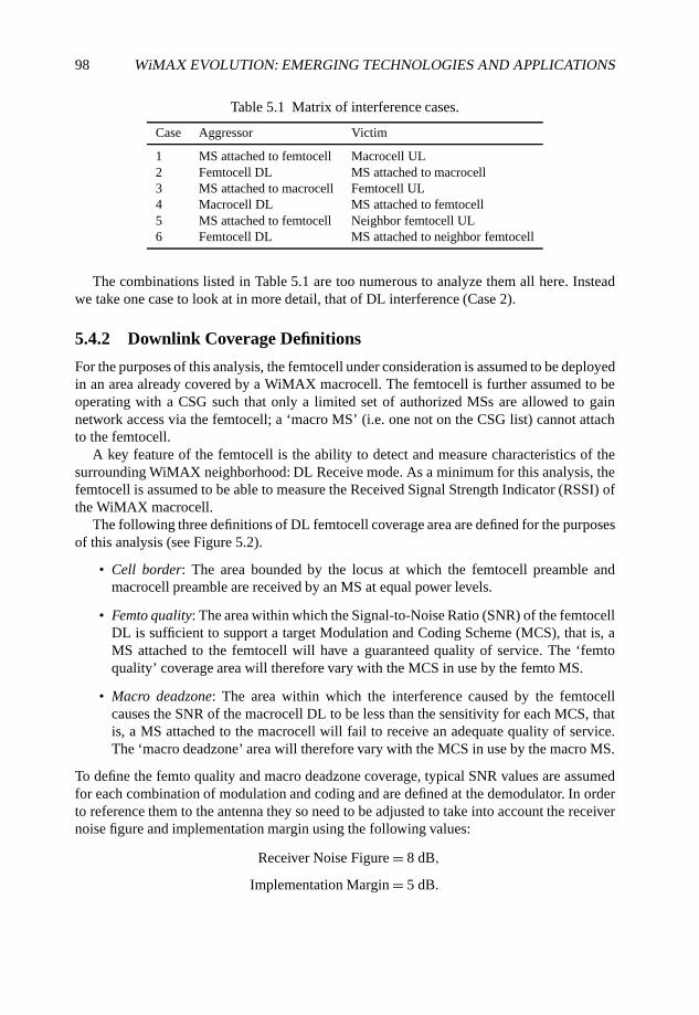
98 WiMAX EVOLUTION: EMERGING TECHNOLOGIES AND APPLICATIONS
Table 5.1 Matrix of interference cases.
Case Aggressor Victim
1 MS attached to femtocell Macrocell UL2 Femtocell DL MS attached to macrocell3 MS attached to macrocell Femtocell UL4 Macrocell DL MS attached to femtocell5 MS attached to femtocell Neighbor femtocell UL6 Femtocell DL MS attached to neighbor femtocell
The combinations listed in Table 5.1 are too numerous to analyze them all here. Insteadwe take one case to look at in more detail, that of DL interference (Case 2).
5.4.2 Downlink Coverage Definitions
For the purposes of this analysis, the femtocell under consideration is assumed to be deployedin an area already covered by a WiMAX macrocell. The femtocell is further assumed to beoperating with a CSG such that only a limited set of authorized MSs are allowed to gainnetwork access via the femtocell; a ‘macro MS’ (i.e. one not on the CSG list) cannot attachto the femtocell.
A key feature of the femtocell is the ability to detect and measure characteristics of thesurrounding WiMAX neighborhood: DL Receive mode. As a minimum for this analysis, thefemtocell is assumed to be able to measure the Received Signal Strength Indicator (RSSI) ofthe WiMAX macrocell.
The following three definitions of DL femtocell coverage area are defined for the purposesof this analysis (see Figure 5.2).
• Cell border: The area bounded by the locus at which the femtocell preamble andmacrocell preamble are received by an MS at equal power levels.
• Femto quality: The area within which the Signal-to-Noise Ratio (SNR) of the femtocellDL is sufficient to support a target Modulation and Coding Scheme (MCS), that is, aMS attached to the femtocell will have a guaranteed quality of service. The ‘femtoquality’ coverage area will therefore vary with the MCS in use by the femto MS.
• Macro deadzone: The area within which the interference caused by the femtocellcauses the SNR of the macrocell DL to be less than the sensitivity for each MCS, thatis, a MS attached to the macrocell will fail to receive an adequate quality of service.The ‘macro deadzone’ area will therefore vary with the MCS in use by the macro MS.
To define the femto quality and macro deadzone coverage, typical SNR values are assumedfor each combination of modulation and coding and are defined at the demodulator. In orderto reference them to the antenna they so need to be adjusted to take into account the receivernoise figure and implementation margin using the following values:
Receiver Noise Figure = 8 dB,
Implementation Margin = 5 dB.
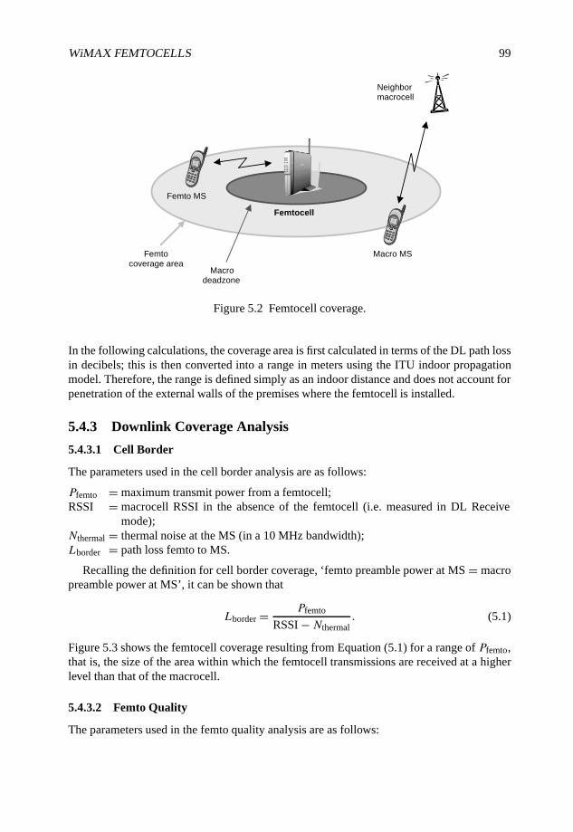
WiMAX FEMTOCELLS 99
Macro MS
Femto MS
Femtocell
Femtocoverage area
Macrodeadzone
Neighbormacrocell
Figure 5.2 Femtocell coverage.
In the following calculations, the coverage area is first calculated in terms of the DL path lossin decibels; this is then converted into a range in meters using the ITU indoor propagationmodel. Therefore, the range is defined simply as an indoor distance and does not account forpenetration of the external walls of the premises where the femtocell is installed.
5.4.3 Downlink Coverage Analysis
5.4.3.1 Cell Border
The parameters used in the cell border analysis are as follows:
Pfemto = maximum transmit power from a femtocell;RSSI = macrocell RSSI in the absence of the femtocell (i.e. measured in DL Receive
mode);Nthermal = thermal noise at the MS (in a 10 MHz bandwidth);Lborder = path loss femto to MS.
Recalling the definition for cell border coverage, ‘femto preamble power at MS = macropreamble power at MS’, it can be shown that
Lborder = Pfemto
RSSI − Nthermal. (5.1)
Figure 5.3 shows the femtocell coverage resulting from Equation (5.1) for a range of Pfemto,that is, the size of the area within which the femtocell transmissions are received at a higherlevel than that of the macrocell.
5.4.3.2 Femto Quality
The parameters used in the femto quality analysis are as follows:
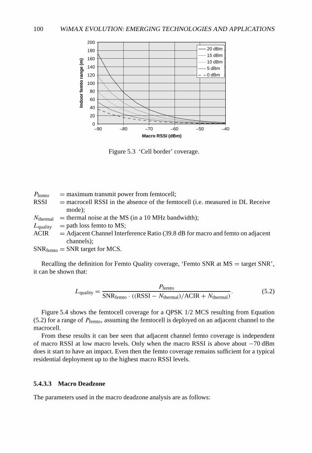
100 WiMAX EVOLUTION: EMERGING TECHNOLOGIES AND APPLICATIONS
0
20
40
60
80
100
120
140
160
180
200
–90 –80 –70 –60 –50 –40
Macro RSSI (dBm)
Ind
oo
r fe
mto
ra
ng
e (
m)
20 dBm
15 dBm
10 dBm
5 dBm
0 dBm
Figure 5.3 ‘Cell border’ coverage.
Pfemto = maximum transmit power from femtocell;RSSI = macrocell RSSI in the absence of the femtocell (i.e. measured in DL Receive
mode);Nthermal = thermal noise at the MS (in a 10 MHz bandwidth);Lquality = path loss femto to MS;ACIR = Adjacent Channel Interference Ratio (39.8 dB for macro and femto on adjacent
channels);SNRfemto = SNR target for MCS.
Recalling the definition for Femto Quality coverage, ‘Femto SNR at MS = target SNR’,it can be shown that:
Lquality = Pfemto
SNRfemto · ((RSSI − Nthermal)/ACIR +Nthermal). (5.2)
Figure 5.4 shows the femtocell coverage for a QPSK 1/2 MCS resulting from Equation(5.2) for a range of Pfemto, assuming the femtocell is deployed on an adjacent channel to themacrocell.
From these results it can bee seen that adjacent channel femto coverage is independentof macro RSSI at low macro levels. Only when the macro RSSI is above about −70 dBmdoes it start to have an impact. Even then the femto coverage remains sufficient for a typicalresidential deployment up to the highest macro RSSI levels.
5.4.3.3 Macro Deadzone
The parameters used in the macro deadzone analysis are as follows:
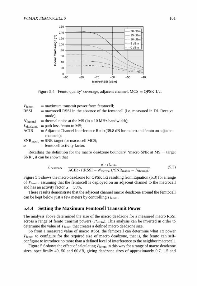
WiMAX FEMTOCELLS 101
0
20
40
60
80
100
120
140
160
20 dBm
15 dBm
10 dBm
5 dBm
0 dBm
–90 –80 –70 –60 –50 –40
Macro RSSI (dBm)
Ind
oo
r fe
mto
ra
ng
e (
m)
Figure 5.4 ‘Femto quality’ coverage, adjacent channel, MCS = QPSK 1/2.
Pfemto = maximum transmit power from femtocell;RSSI = macrocell RSSI in the absence of the femtocell (i.e. measured in DL Receive
mode);Nthermal = thermal noise at the MS (in a 10 MHz bandwidth);Ldeadzone = path loss femto to MS;ACIR = Adjacent Channel Interference Ratio (39.8 dB for macro and femto on adjacent
channels);SNRmacro = SNR target for macrocell MCS;α = femtocell activity factor.
Recalling the definition for the macro deadzone boundary, ‘macro SNR at MS = targetSNR’, it can be shown that
Ldeadzone = α · Pfemto
ACIR · ((RSSI −Nthermal)/SNRmacro −Nthermal). (5.3)
Figure 5.5 shows the macro deadzone for QPSK 1/2 resulting from Equation (5.3) for a rangeof Pfemto, assuming that the femtocell is deployed on an adjacent channel to the macrocelland has an activity factor α = 50%.
These results demonstrate that the adjacent channel macro deadzone around the femtocellcan be kept below just a few meters by controlling Pfemto.
5.4.4 Setting the Maximum Femtocell Transmit Power
The analysis above determined the size of the macro deadzone for a measured macro RSSIacross a range of femto transmit powers (Pfemto). This analysis can be inverted in order todetermine the value of Pfemto that creates a defined macro deadzone size.
So from a measured value of macro RSSI, the femtocell can determine what Tx powerPfemto to configure for the required size of macro deadzone, that is, the femto can self-configure to introduce no more than a defined level of interference to the neighbor macrocell.
Figure 5.6 shows the effect of calculating Pfemto in this way for a range of macro deadzonesizes; specifically 40, 50 and 60 dB, giving deadzone sizes of approximately 0.7, 1.5 and
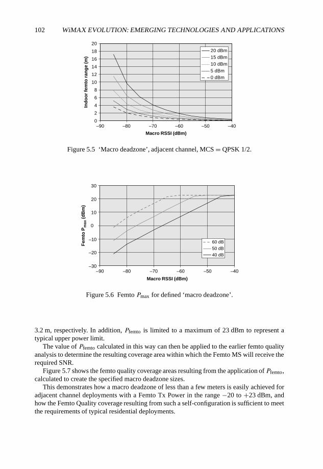
102 WiMAX EVOLUTION: EMERGING TECHNOLOGIES AND APPLICATIONS
0
2
4
6
8
10
12
14
16
18
20
20 dBm
15 dBm
10 dBm
5 dBm
0 dBm
–90 –80 –70 –60 –50 –40
Macro RSSI (dBm)
Ind
oo
r fe
mto
ra
ng
e (
m)
Figure 5.5 ‘Macro deadzone’, adjacent channel, MCS = QPSK 1/2.
–30
–20
–10
0
10
20
30
Fem
to P
ma
x (
dB
m)
60 dB
50 dB
40 dB
–90 –80 –70 –60 –50 –40
Macro RSSI (dBm)
Figure 5.6 Femto Pmax for defined ‘macro deadzone’.
3.2 m, respectively. In addition, Pfemto is limited to a maximum of 23 dBm to represent atypical upper power limit.
The value of Pfemto calculated in this way can then be applied to the earlier femto qualityanalysis to determine the resulting coverage area within which the Femto MS will receive therequired SNR.
Figure 5.7 shows the femto quality coverage areas resulting from the application of Pfemto,calculated to create the specified macro deadzone sizes.
This demonstrates how a macro deadzone of less than a few meters is easily achieved foradjacent channel deployments with a Femto Tx Power in the range −20 to +23 dBm, andhow the Femto Quality coverage resulting from such a self-configuration is sufficient to meetthe requirements of typical residential deployments.
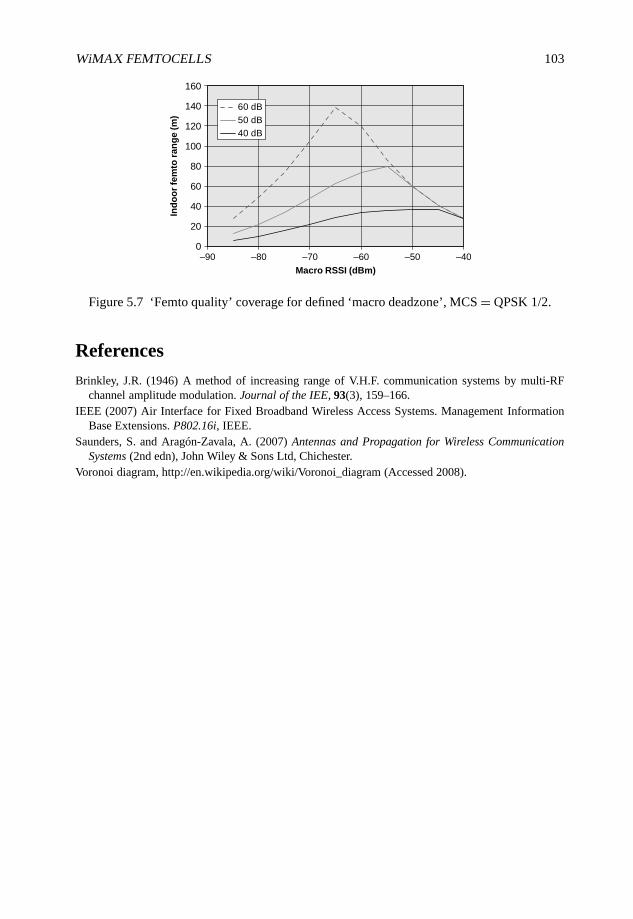
WiMAX FEMTOCELLS 103
0
20
40
60
80
100
120
140
160
60 dB
50 dB
40 dB
–90 –80 –70 –60 –50 –40
Macro RSSI (dBm)
Ind
oo
r fe
mto
ra
ng
e (
m)
Figure 5.7 ‘Femto quality’ coverage for defined ‘macro deadzone’, MCS = QPSK 1/2.
References
Brinkley, J.R. (1946) A method of increasing range of V.H.F. communication systems by multi-RFchannel amplitude modulation. Journal of the IEE, 93(3), 159–166.
IEEE (2007) Air Interface for Fixed Broadband Wireless Access Systems. Management InformationBase Extensions. P802.16i, IEEE.
Saunders, S. and Aragón-Zavala, A. (2007) Antennas and Propagation for Wireless CommunicationSystems (2nd edn), John Wiley & Sons Ltd, Chichester.
Voronoi diagram, http://en.wikipedia.org/wiki/Voronoi_diagram (Accessed 2008).
6
Cooperative Principles in WiMAX
Qi Zhang, Frank H.P. Fitzek and Marcos D. Katz
6.1 Introduction
In this chapter the application of cooperative principles in WiMAX is advocated. Eventhough WiMAX is a new promising communication standard, which supports higher datarates than most existing infrastructure-based mobile or wireless communication systemsalready, cooperative principles will enrich and improve mobile communication in WiMAXsystems even further. In this chapter we introduce the main ideas of cooperation and latergive several dedicated examples where cooperation is applied and describe the benefits thatcan be achieved.
Cooperation describes an action of individuals collaborating towards a common orindividual goal. Each of the individuals may have egoistic motivation to join the cooperation.With the exception of individuals driven by pure altruistic behavior, egoistic cooperationwill take place as long as individuals gain by the collaborative activity. Cooperativecommunication has many different interpretations and various extensions. One of the mainresearch areas on cooperative communication is the cooperative diversity exploiting thebroadcast nature of the radio channel, as in Boyer et al. (2004), Gastpar et al. (2002), Guptaand Kumar (2003), Hunter and Nosratinia (2002), Laneman et al. (2004) and Sendonariset al. (1998). In fact, the concept of the cooperative diversity originates from the relaywireless network which is not new and can be traced back to Cover and Gamal (1979) andvan der Meulen (1971). The motivation for cooperative diversity is to exploit the spatial andtemporal diversity to improve the reliability of communications, for example, in terms ofoutage probability, or symbol error probability, for a given transmission rate, etc. (Laneman,2006). The following is a list with important related variations based on the relay concept.
WiMAX Evolution: Emerging Technologies and Applications Edited by Tsutomu Ishikawa© 2009 John Wiley & Sons, Ltd. ISBN: 978-0-470-69680-4
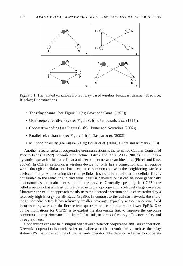
106 WiMAX EVOLUTION: EMERGING TECHNOLOGIES AND APPLICATIONS
c d
a bS
S
S2
S1 D1
D2
D
S
D
D
R
R1
R2
R1 R2
Figure 6.1 The related variations from a relay-based wireless broadcast channel (S: source;R: relay; D: destination).
• The relay channel (see Figure 6.1(a); Cover and Gamal (1979)).
• User cooperative diversity (see Figure 6.1(b); Sendonaris et al. (1998)).
• Cooperative coding (see Figure 6.1(b); Hunter and Nosratinia (2002)).
• Parallel relay channel (see Figure 6.1(c); Gastpar et al. (2002)).
• Multihop diversity (see Figure 6.1(d); Boyer et al. (2004), Gupta and Kumar (2003)).
Another research area of cooperative communications is the so-called Cellular-ControlledPeer-to-Peer (CCP2P) network architecture (Fitzek and Katz, 2006, 2007a). CCP2P is adynamic approach to bridge cellular and peer-to-peer network architectures (Fitzek and Katz,2007a). In CCP2P networks, a wireless device not only has a connection with an outsideworld through a cellular link but it can also communicate with the neighboring wirelessdevices in its proximity using short-range links. It should be noted that the cellular link isnot limited to the radio link in traditional cellular networks but it can be more genericallyunderstood as the main access link to the service. Generally speaking, in CCP2P thecellular network has a infrastructure-based network topology with a relatively large coverage.Moreover, the cellular approach mostly uses the licensed spectrum and is characterized by arelatively high Energy-per-Bit Ratio (EpBR). In contrast to the cellular network, the short-range nomadic network has relatively smaller coverage, typically without a central fixedinfrastructure, works in the license-free spectrum and exhibits a much lower EpBR. Oneof the motivations for CCP2P is to exploit the short-range link to improve the on-goingcommunication performance on the cellular link, in terms of energy efficiency, delay andthroughput, etc.
Cooperation can also be distinguished between network cooperation and user cooperation.Network cooperation is much easier to realize as each network entity, such as the relaystation (RS), is under control of the network operator. The decision whether to cooperate
COOPERATIVE PRINCIPLES IN WiMAX 107
or not is taken by the network operator and not by individuals. Network cooperation ischaracterized by altruistic behavior of the participating entities. Representatives cases ofnetwork cooperation are the parallel relay channel scenario (see Figure 6.1(c)) and themultihop diversity scenario (see Figure 6.1(d)) when the relays are installed by the networkoperator. User cooperation on the other side is realized by individuals with their own pay-offschemes and no overlay decision maker is present. Unlike network cooperation where thecollaborative interactions are embedded in the system and completely transparent to the user,the user behind a wireless device has a key role in the user cooperation approaches. Altruisticbehavior is not the main driving force in user cooperation, it is egoist behavior. Even thoughegoistic behavior is dominating, cooperation will be established as long as all participatingindividuals receive some benefits from it. Therefore, user cooperation is the most interestingand challenging field. The user cooperative diversity scenario and cooperative codingscenario (see Figure 6.1(b)) are examples of user cooperation in cooperative diversity area.Moreover, the cooperation scenarios in CCP2P network architectures are clear examples ofuser cooperation.
In the following we discuss why cooperation is needed for wireless networks. Currentcellular communication systems are grouped into different types of generations depending ontheir basic technology that they support. With the introduction of GSM, the second generation(2G) was launched. The main novelty was the change from analog mobile systems to digitalmobile systems. In recent years, following the worldwide success of 2G, the third generation(3G) was introduced. 3G changed the access scheme from Time Division Multiplex Access(TDMA) towards wideband Code Division Multiplex Access (CDMA), although it did notintroduce novel services. 3G was targeting mainly Internet access with high data rates. Thisevolution is continued now with new technologies such as WiMAX and Long Term Evolution(LTE), sometimes referred to as 3.75G. However, all of these new technologies will notprovide a solution to the limitation of the coverage-rate trade-off defined by the Shannon law.This means that to achieve reliable transmission the signal-to-noise ratio of each receivedbit should be above a certain threshold. At a given transmission power, the higher data rateresults in less energy at each bit. Therefore, the increased data rate reduces the coveragerange. Exploiting cooperative diversity, it can extend the coverage range with enhanced datarate (Pabst et al., 2004, Sadek et al., 2006, Sendonaris et al., 1998, 2003a,b) and reduce theoutage probability (Laneman et al., 2001).
Furthermore, the new technologies such as WiMAX and LTE will be unable to overcomethe problem of the power and energy consumption on the mobile device (MD). As MDs arebattery driven, the energy that can be pulled out of it is limited. The quicker the energy isconsumed, the shorter the operational or stand-by time of the MD. Users are quite well awareon the available service time of their MD. In fact, it has been recognized as one of the majorselling criteria. With the introduction of 3G MDs, the standby time was nearly cut in halfcompared with those available in 2G. This had to do with the larger energy consumption of3G chipsets and the 3G network situation at that time. 3G chipsets are real ‘power hogs’as Steve Jobs mentioned recently in one of his iPhone presentations. The more complex theair interface of a MD becomes, the more energy will be consumed. To support a variety ofservices with higher data rate and better Quality of Service (QoS), the trend is to make the airinterface even more complex in the future, introducing technologies such as Multiple InputMultiple Output (MIMO) for the MD. From approximately half to two-thirds of the overallpower requirements of current mobile devices corresponds to the communication functions
108 WiMAX EVOLUTION: EMERGING TECHNOLOGIES AND APPLICATIONS
(e.g. baseband processing, Radiofrequency (RF) chains, and others). Clearly, there is a largemargin for improvement. Furthermore, there seems to be a clear tendency for higher datarates at the cost of higher energy requirements. The increased complexity can be supported byMoore’s law. Unfortunately developments in battery technology cannot keep up, and batterycapacity only doubles roughly every decade only. From the users’ perspective, there will bebetter services supported by higher data rates but the operational time will decrease. Thistendency has already been recognized by the mobile manufactures and even standardizationbodies and major efforts are being undertaken to reduce the overall battery consumption. Inaddition to the energy consumption, the power consumption is also relevant as it is directlylinked to the heating problem of a mobile device. The more energy consumed in a given timeperiod, the more the device will be heated. As the heating is produced at given hot spots,the heat needs to be distributed over the whole device as quickly as possible. So far mobilephones are cooled in a passive way, but if the tendency for greater energy consumption andsmaller form factors continues, active cooling may be the only option. Active cooling doesnot only disturb the user by producing annoying noise, it also consumes additional energy.Fitzek and Katz (2006, 2007a) described a technique exploiting user cooperation in a CCP2Pnetwork architecture as a powerful way out of this problematic situation.
Introducing cooperation among users in the CCP2P network architecture means basicallybreaking the very old and fundamental paradigm of cellular communications. Very quicklyafter the early demonstrations by Marconi, mobile communication systems were dominatedby a centralized architecture, as given in Figure 6.2. As can be appreciated, each MD isconnected to an overlay BS (or access point (AP)) and each device is equipped with a set ofcapabilities that it can make use of. However, with the clear trend of more and more wirelessdevices populating the world and surrounding each other1, the centralized architectureshould be enriched by the communication among MDs. By allowing communication linksamong MDs in proximity to each other, MDs can form a cooperative cluster. Since theMD is composed of several entities or functionalities grouped into user interfaces (camera,keyboard, sensors, etc.), communication interfaces (cellular and short-range) and a numberof built-in resources as given in Figure 6.3), this cooperative cluster can be referred to as awireless grid as the devices are able to share their essential resources such as battery, CPU,wireless links, etc. By accumulating those resources into a virtual entity, the cooperativecluster may use those parts more efficiently than any stand-alone device could ever do.
As given in Figure 6.4 cooperative clusters are formed by multiple MDs within proximityusing short-range technology. It is obvious that all capabilities (or resources) of the MDs canbe used in different novel ways, exploiting cooperative principles. For instance, resources canbe shared by some or all of the participating nodes, or they can be moved to a particular node,if needed. A simple case in point, assuming that each MD has a certain data rateR and J MDsform one cooperative cluster, then the cluster has a virtual data rate of R · J . The virtual datarate can be used by all MDs, a subset of MDs or by a single MD. Nevertheless, the virtualdata rate can be used by the cooperative cluster in a more clever way than the stand-alonedevice. In the worst case the resource allocation will give each device the data rate R, whichis the same as the stand-alone device. In all other cases the resources can be shared in a betterway and this is not only true for the data rate but also for all other capabilities.
1According to the visions of the Wireless World Research Forum (WWRF), by year 2017 there will be about1000 wireless devices per person on the globe.
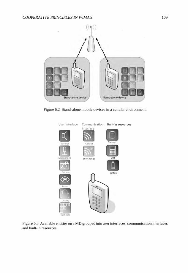
COOPERATIVE PRINCIPLES IN WiMAX 109
Stand-alone deviceStand-alone device
Figure 6.2 Stand-alone mobile devices in a cellular environment.
Figure 6.3 Available entities on a MD grouped into user interfaces, communication interfacesand built-in resources.
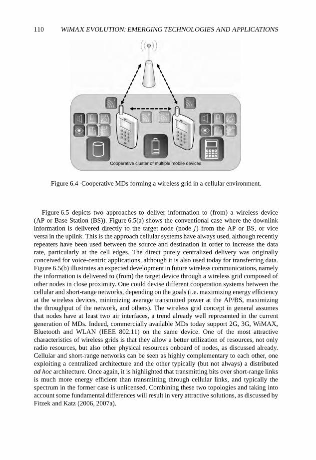
110 WiMAX EVOLUTION: EMERGING TECHNOLOGIES AND APPLICATIONS
Cooperative cluster of multiple mobile devices
Figure 6.4 Cooperative MDs forming a wireless grid in a cellular environment.
Figure 6.5 depicts two approaches to deliver information to (from) a wireless device(AP or Base Station (BS)). Figure 6.5(a) shows the conventional case where the downlinkinformation is delivered directly to the target node (node j ) from the AP or BS, or viceversa in the uplink. This is the approach cellular systems have always used, although recentlyrepeaters have been used between the source and destination in order to increase the datarate, particularly at the cell edges. The direct purely centralized delivery was originallyconceived for voice-centric applications, although it is also used today for transferring data.Figure 6.5(b) illustrates an expected development in future wireless communications, namelythe information is delivered to (from) the target device through a wireless grid composed ofother nodes in close proximity. One could devise different cooperation systems between thecellular and short-range networks, depending on the goals (i.e. maximizing energy efficiencyat the wireless devices, minimizing average transmitted power at the AP/BS, maximizingthe throughput of the network, and others). The wireless grid concept in general assumesthat nodes have at least two air interfaces, a trend already well represented in the currentgeneration of MDs. Indeed, commercially available MDs today support 2G, 3G, WiMAX,Bluetooth and WLAN (IEEE 802.11) on the same device. One of the most attractivecharacteristics of wireless grids is that they allow a better utilization of resources, not onlyradio resources, but also other physical resources onboard of nodes, as discussed already.Cellular and short-range networks can be seen as highly complementary to each other, oneexploiting a centralized architecture and the other typically (but not always) a distributedad hoc architecture. Once again, it is highlighted that transmitting bits over short-range linksis much more energy efficient than transmitting through cellular links, and typically thespectrum in the former case is unlicensed. Combining these two topologies and taking intoaccount some fundamental differences will result in very attractive solutions, as discussed byFitzek and Katz (2006, 2007a).
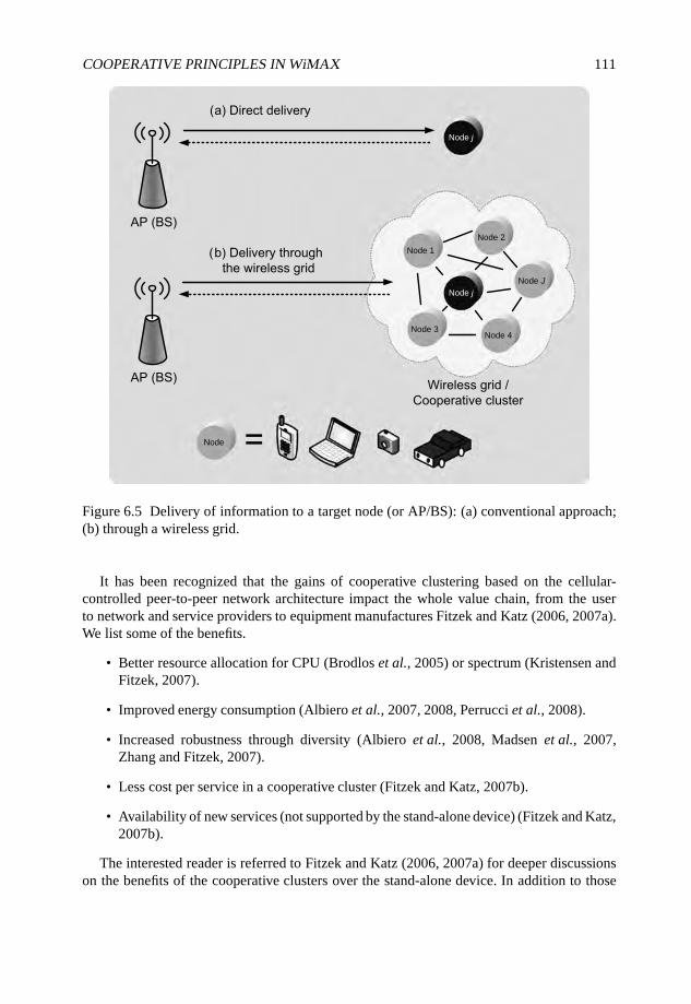
COOPERATIVE PRINCIPLES IN WiMAX 111
Node 1
Node 2
Node 3Node 4
Node J
Node j
Node
Node j
Figure 6.5 Delivery of information to a target node (or AP/BS): (a) conventional approach;(b) through a wireless grid.
It has been recognized that the gains of cooperative clustering based on the cellular-controlled peer-to-peer network architecture impact the whole value chain, from the userto network and service providers to equipment manufactures Fitzek and Katz (2006, 2007a).We list some of the benefits.
• Better resource allocation for CPU (Brodlos et al., 2005) or spectrum (Kristensen andFitzek, 2007).
• Improved energy consumption (Albiero et al., 2007, 2008, Perrucci et al., 2008).
• Increased robustness through diversity (Albiero et al., 2008, Madsen et al., 2007,Zhang and Fitzek, 2007).
• Less cost per service in a cooperative cluster (Fitzek and Katz, 2007b).
• Availability of new services (not supported by the stand-alone device) (Fitzek and Katz,2007b).
The interested reader is referred to Fitzek and Katz (2006, 2007a) for deeper discussionson the benefits of the cooperative clusters over the stand-alone device. In addition to those
112 WiMAX EVOLUTION: EMERGING TECHNOLOGIES AND APPLICATIONS
benefits directly linked to the user, the mobile manufacture and network operator will alsobenefit from cooperative principles. Even though network operators are often scared bythe term peer-to-peer (and cooperation involves mobile peer-to-peer), cooperation amongusers will enable network providers with new business segments without changing their pre-installed cellular networks at all. In the following some representative examples for the crossover of cooperative principles and WiMAX are presented and discussed.
6.2 Cooperative Diversity Schemes in Mobile MultihopRelay Based WiMAX (802.16j)
WiMAX offers high data rates over a relatively large coverage. However, the currentdeployment of WiMAX suffers from the following issues:
• coverage limitations or low Signal-to-Interference Noise Ratio (SINR) at cell edgecaused by significant signal attenuation at high spectrum;
• poor signal reception due to shadowing or even coverage holes;
• limited spectrum.
Deploying a dense network with WiMAX BSs is a possible solution but is not costefficient. A more efficient solution to extend coverage and enhance throughput is to deploylow-cost RSs in the network. A new task group 802.16j was established in 2006 to supportthe Mobile Multihop Relay (MMR) operation in WiMAX. The basic idea is that the WiMAXMDs in unfavorable locations can communicate with BS through the intermediate RS at highdata rates. The RS can be fixed, nomadic or mobile. The main targeted usage scenarios ofMMR WiMAX is as follows (802.16j Task Group, 2006):
• fixed infrastructure;
• in-building coverage;
• temporary coverage;
• coverage on mobile vehicle usage.
As mentioned in Section 6.1, the relay-based wireless network is not new and can betraced back to Cover and Gamal (1979) and van der Meulen (1971). The performance ofa wireless relay network has been thoroughly studied from an information-theoretic point-of-view (Cover and Gamal, 1979, Host-Madsen, 2006, Kramer et al., 2005, Laneman et al.,2004). The communication between BS and MD through one intermediate RS is the simplestcooperative scenario. Many of the latest research efforts have been focused on cooperativediversity schemes (Kramer et al., 2005, Laneman, 2002) and resource allocation (Can et al.,2007b, Hammerstrom et al., 2004, Li and Liu, 2006, Lin et al., 2005, Onat et al., 2007)in wireless relay networks. The main scheduling issues in cooperative relay-based wirelessnetworks are: (i) which entity (or entities) make the cooperation decision; (ii) whether to userelay or not; and (iii) how to relay the data (different cooperative diversity schemes). In usercooperative diversity it is quite a challenge to choose the decision-maker entity, either BS,
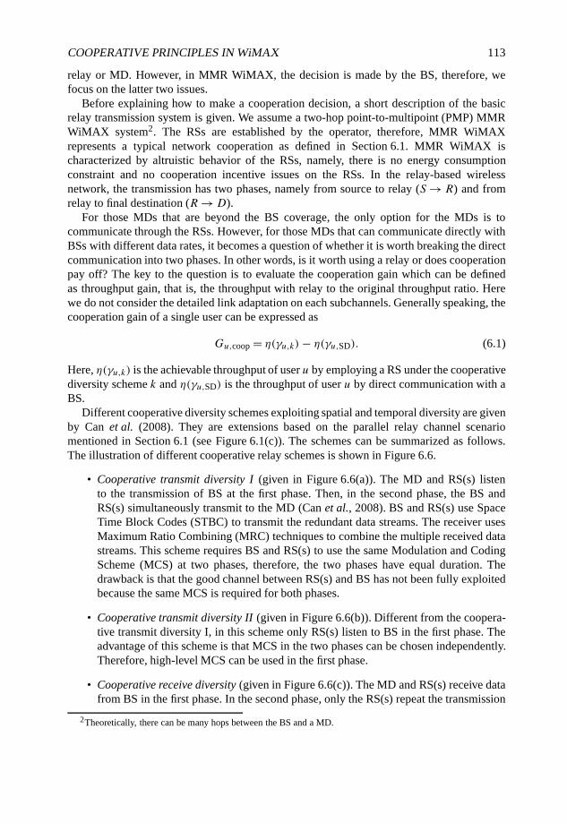
COOPERATIVE PRINCIPLES IN WiMAX 113
relay or MD. However, in MMR WiMAX, the decision is made by the BS, therefore, wefocus on the latter two issues.
Before explaining how to make a cooperation decision, a short description of the basicrelay transmission system is given. We assume a two-hop point-to-multipoint (PMP) MMRWiMAX system2. The RSs are established by the operator, therefore, MMR WiMAXrepresents a typical network cooperation as defined in Section 6.1. MMR WiMAX ischaracterized by altruistic behavior of the RSs, namely, there is no energy consumptionconstraint and no cooperation incentive issues on the RSs. In the relay-based wirelessnetwork, the transmission has two phases, namely from source to relay (S → R) and fromrelay to final destination (R →D).
For those MDs that are beyond the BS coverage, the only option for the MDs is tocommunicate through the RSs. However, for those MDs that can communicate directly withBSs with different data rates, it becomes a question of whether it is worth breaking the directcommunication into two phases. In other words, is it worth using a relay or does cooperationpay off? The key to the question is to evaluate the cooperation gain which can be definedas throughput gain, that is, the throughput with relay to the original throughput ratio. Herewe do not consider the detailed link adaptation on each subchannels. Generally speaking, thecooperation gain of a single user can be expressed as
Gu,coop = η(γu,k)− η(γu,SD). (6.1)
Here, η(γu,k) is the achievable throughput of user u by employing a RS under the cooperativediversity scheme k and η(γu,SD) is the throughput of user u by direct communication with aBS.
Different cooperative diversity schemes exploiting spatial and temporal diversity are givenby Can et al. (2008). They are extensions based on the parallel relay channel scenariomentioned in Section 6.1 (see Figure 6.1(c)). The schemes can be summarized as follows.The illustration of different cooperative relay schemes is shown in Figure 6.6.
• Cooperative transmit diversity I (given in Figure 6.6(a)). The MD and RS(s) listento the transmission of BS at the first phase. Then, in the second phase, the BS andRS(s) simultaneously transmit to the MD (Can et al., 2008). BS and RS(s) use SpaceTime Block Codes (STBC) to transmit the redundant data streams. The receiver usesMaximum Ratio Combining (MRC) techniques to combine the multiple received datastreams. This scheme requires BS and RS(s) to use the same Modulation and CodingScheme (MCS) at two phases, therefore, the two phases have equal duration. Thedrawback is that the good channel between RS(s) and BS has not been fully exploitedbecause the same MCS is required for both phases.
• Cooperative transmit diversity II (given in Figure 6.6(b)). Different from the coopera-tive transmit diversity I, in this scheme only RS(s) listen to BS in the first phase. Theadvantage of this scheme is that MCS in the two phases can be chosen independently.Therefore, high-level MCS can be used in the first phase.
• Cooperative receive diversity (given in Figure 6.6(c)). The MD and RS(s) receive datafrom BS in the first phase. In the second phase, only the RS(s) repeat the transmission
2Theoretically, there can be many hops between the BS and a MD.
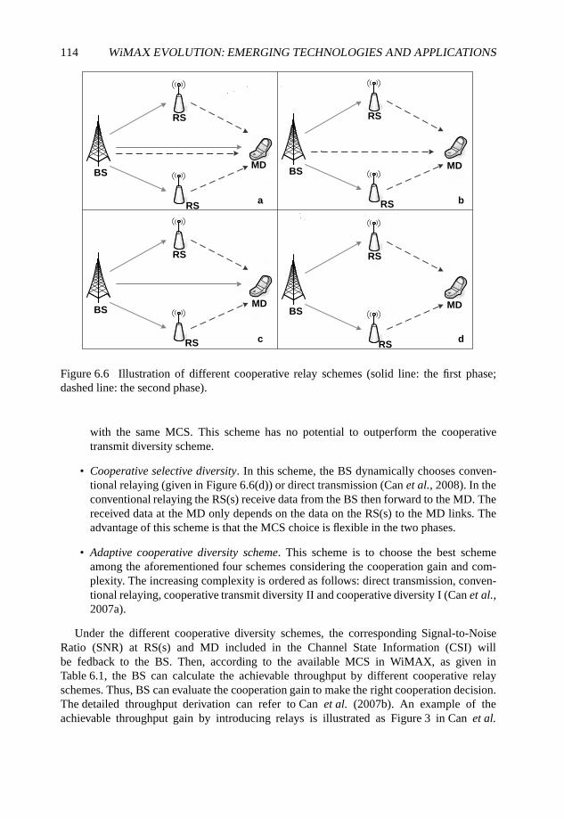
114 WiMAX EVOLUTION: EMERGING TECHNOLOGIES AND APPLICATIONS
a
c
BS BS
BS BS
RS RS
RSRS
RS
RS RS
RS
MDMD
MD MD
d
b
Figure 6.6 Illustration of different cooperative relay schemes (solid line: the first phase;dashed line: the second phase).
with the same MCS. This scheme has no potential to outperform the cooperativetransmit diversity scheme.
• Cooperative selective diversity. In this scheme, the BS dynamically chooses conven-tional relaying (given in Figure 6.6(d)) or direct transmission (Can et al., 2008). In theconventional relaying the RS(s) receive data from the BS then forward to the MD. Thereceived data at the MD only depends on the data on the RS(s) to the MD links. Theadvantage of this scheme is that the MCS choice is flexible in the two phases.
• Adaptive cooperative diversity scheme. This scheme is to choose the best schemeamong the aforementioned four schemes considering the cooperation gain and com-plexity. The increasing complexity is ordered as follows: direct transmission, conven-tional relaying, cooperative transmit diversity II and cooperative diversity I (Can et al.,2007a).
Under the different cooperative diversity schemes, the corresponding Signal-to-NoiseRatio (SNR) at RS(s) and MD included in the Channel State Information (CSI) willbe fedback to the BS. Then, according to the available MCS in WiMAX, as given inTable 6.1, the BS can calculate the achievable throughput by different cooperative relayschemes. Thus, BS can evaluate the cooperation gain to make the right cooperation decision.The detailed throughput derivation can refer to Can et al. (2007b). An example of theachievable throughput gain by introducing relays is illustrated as Figure 3 in Can et al.
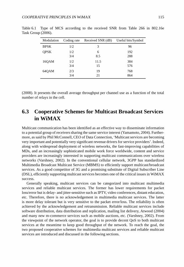
COOPERATIVE PRINCIPLES IN WiMAX 115
Table 6.1 Type of MCS according to the received SNR from Table 266 in 802.16eTask Group (2006).
Modulation Coding rate Received SNR (dB) Useful bits/Symbol
BPSK 1/2 3 96
QPSK 1/2 6 1923/4 8.5 288
16QAM 1/2 11.5 3843/4 15 576
64QAM 2/3 19 7683/4 21 864
(2008). It presents the overall average throughput per channel use as a function of the totalnumber of relays in the cell.
6.3 Cooperative Schemes for Multicast Broadcast Servicesin WiMAX
Multicast communication has been identified as an effective way to disseminate informationto a potential group of receivers sharing the same service interest (Yamamoto, 2004). Further-more, as said by Phil McConnell, CEO of Data Connection, ‘Multicast services are becomingvery important and potentially very significant revenue drivers for service providers’. Indeed,along with widespread deployment of wireless networks, the fast-improving capabilities ofMDs, and an increasingly sophisticated mobile work force worldwide, content and serviceproviders are increasingly interested in supporting multicast communications over wirelessnetworks (Varshney, 2002). In the conventional cellular network, 3GPP has standardizedMultimedia Broadcast Multicast Service (MBMS) to efficiently support multicast/broadcastservices. As a good competitor of 3G and a promising substitute of Digital Subscriber Line(DSL), efficiently supporting multicast services becomes one of the critical issues in WiMAXsuccess.
Generally speaking, multicast services can be categorized into multicast multimediaservices and reliable multicast services. The former has lower requirements for packetloss/error but is delay- and jitter-sensitive such as IPTV, video conferences, distant education,etc. Therefore, there is no acknowledgement in multimedia multicast services. The latteris more delay tolerant but is very sensitive to the packet error/loss. The reliability is oftenachieved by the acknowledgement and retransmission. Reliable multicast services includesoftware distribution, data distribution and replication, mailing list delivery, Atwood (2004)and many new m-commerce services such as mobile auctions, etc. (Varshney, 2002). Fromthe viewpoint of the network operator, the goal is to provide decent QoS to both multicastservices at the meantime to keep good throughput of the network. To reach the goal, thetwo proposed cooperative schemes for multimedia multicast services and reliable multicastservices are introduced and discussed in the following sections.
116 WiMAX EVOLUTION: EMERGING TECHNOLOGIES AND APPLICATIONS
6.3.1 Cooperative Transmission for Multimedia Multicast Services
As for multimedia multicast services in WiMAX, the challenge is in the radio access part, thatis, the transmission from BS to the end users. The motivation of introducing the cooperativeschemes is that each member in a multicast group has a different channel condition at a timeinstant. An important issue is how to balance the trade-off between the user outage probabilityand the network throughput in the wireless multicast services. Conventionally, the BS, notonly in the traditional cellular network but in WiMAX, chooses the data rate according to thechannel condition of the worst user. By this approach a user who suffers from deep fadingor shadowing will deteriorate the network throughput performance. A cooperation schemehas been proposed as one feasible solution to improve the network throughput by Hou et al.(2008).
The basic idea of cooperative transmission for multimedia multicast service is quitesimilar as the so-called cooperative diversity selective scheme in the MMR WiMAX (seeFigure 6.6(d)). Namely, the BSs transmit multicast data with high MCS in the first phasethen the users with good channel condition receive the data, decode and forward to thosewho are not able to successfully decode the received data in the first phase. (In this chapterthe users who can successfully decode the data in the first phase are called group 1, denotedasG1. The remaining users are called group 2, denoted asG2.) The main differences betweenthe relaying in this scenario and the relaying in MMR WiMAX are as follows. First, the RSshere are not built by operators but some MDs with good channel conditions. The capabilitiesof those MDs have certain limitations such as energy consumption constraints and antennaheight. Second, it is a big challenge to select a proper transmission rate at the BS for bothtransmission phases. The reasons lie in that the BS needs to figure out how many members ofthe multicast group should be grouped inG1 and the geographic relation between the users inG1 and G2. Third, in this scenario, some MDs work not only as end user but as a RS. Sincethese double-role MDs are individual entities, they need incentive to cooperate. To someextent, the network operator cannot force the individuals to forward data together. However,the network operator can use some kind of rewarding-based mechanism encouraging the MDsto cooperate. Therefore, this application scenario essentially belongs to network cooperationalthough it looks like user cooperation.
The feasible transmission rate selection algorithm is discussed in the following. To selectthe transmission rate at the BS at the first phase, R1, there are two options.
• It selects the average of the data rate which can be supported by individual member inthe multicast group.
• It selects the data rate which can be supported by certain percentage, such as, 50%, ofthe multicast group members, which is used by Hou et al. (2008).
We denote the SNR at member j as γj ; the data rate that can be supported by member j ,Rj
0 , is
Rj
0 = FMCS(γj ), (6.2)
where FMCS is the MCS discrete mapping function according to Table 6.1. So the set of thedata rate that can be supported by each member in the multicast group,GR , is
GR = {Rj0 , j ∈G}, (6.3)
COOPERATIVE PRINCIPLES IN WiMAX 117
where, G is the set of all of the members in the multicast group.In the conventional multicast, the data rate R0 is the minimum value of GR , that is,
R0 = min{GR}, if the minimum SNR at the members is no less than 3 dB (see Table 6.1).Otherwise, R0 is the minimum data rate which can be supported in WiMAX. In the lattercase the users that cannot support the minimum available data rate will be out of service.
If using the aforementioned mean data rate based selection algorithm, it is clear that theselected transmission rate at the BS at the first phase equals to the average of GR , that is,R1 = E(GR). Correspondingly, the selected transmission rate at the BS in the first phase ofthe second algorithm, R1, can be expressed as
P(GR ≥ R1)≥ ζ ∩ P(GR ≤ R1) ≥ 1 − ζ, (6.4)
where ζ is the percentage of the members that can support the data rate R1.To decide the data rate at the second phase, R2, it considers the combined received
signal from all of the cooperation partners. Therefore, it depends on how the cooperativetransmission is done and how many cooperative partners are involved in the second phase.
In the cooperative transmission scheme, each MD in G2 can measure the link quality toknow the received SNR from its cooperation partners. Assuming there areM andN membersthat belong toG1 andG2, respectively. The received SNR at MDn on the link between MDmand MDn is denoted by γm,n. The data rate can be supported by MDn at second phase, Rn2 .Here Rn2 depends on the SNR of the combined received signal γn according to the MCSmapping (Table 6.1). Hence, Rn2 can be expressed as
Rn2 = FMCS(γn)
= FMCS
( ∑m∈G1
γm,n
), n ∈G2. (6.5)
The data rate can be received by the MDs in G2 in the second phase, R2, can beexpressed by
R2 ={
min{Rn2 , n ∈G2} min{γn, n ∈G2} ≥ 3,
ξ min{γn, n ∈G2}< 3.(6.6)
where ξ is the minimum available data rate in WiMAX and γn is the SNR of the receivedcombined signal at a member n in G2.
For the multicast multimedia service, a utility function is defined as the product of thenumber of the supported multicast group members and the throughput of each member. Thus,the utility function of the conventional multicast services Ucon is
Ucon = (1 − σ)R0|G|, (6.7)
where R0 is the data rate in the conventional multicast services, |G| is the number ofthe members in the multicast group and σ is the probability of the multicast membersthat cannot support R0. Usually those are the members that cannot support the minimumavailable transmission rate defined in Table 6.1. Correspondingly, the utility function of thecooperation scheme Ucoop is
Ucoop = R1|G1| + (1 − σ ′)R2|G2|, (6.8)
118 WiMAX EVOLUTION: EMERGING TECHNOLOGIES AND APPLICATIONS
where R1 and R2 are the transmission rate of the first and second phase, respectively, |G1|and |G2| are the number of multicast members that belong toG1 andG2, respectively, and σ ′is the probability of the members in G2 that cannot support R2. Those are often the membersthat cannot support the minimum available data rate defined in Table 6.1.
To make the cooperation decision, the BS has to evaluate the cooperation gain. Thecooperation gain is defined as the gain of the utility function by the cooperation schemeto that of the original. Hence, the cooperation gain can be expressed as
Gcoop = Ucoop − Ucon
Ucon
= (R1G1 + (1 − σ ′)R2G2)− ((1 − σ)R0G)
(1 − σ)R0G. (6.9)
Based on the cooperation transmission scheme and the two transmission rate selectionalgorithms for the first phase, we ran a simulation to show the cooperation gain that canbe achieved by the cooperative transmission scheme. In the simulation the channel betweenthe BS and MD is modeled by the IEEE 802.16 (SUI) model (Anderson, 2003). The modelconstant is based on Terrain Type C. The BS and MD height are 30 m and 2 m, respectively.The signal attenuation on the link between MDs is modeled by the path loss with exponentequal to 3 (Anderson, 2003). The two transmission rate selection algorithms for the firstphase are both simulated. We refer to the first algorithm as the mean data rate based selectionsince it chooses the mean data rate as R1. The second algorithm is referred to as the mediandata rate based selection since it chooses the data rate R1 which 50% of MDs can support.The cooperation gain in the simulation is shown in Figure 6.7 which illustrates the greatpotential of the cooperation scheme. From Figure 6.7 we can also see that the cooperationgain increases with the increasing number of the multicast group members. The reason isthat the more users join the cooperation transmission, the more cooperative diversity can beobtained. The relative cooperation gain relation between the two algorithms is not absolute,because it depends on the distribution of the MDs. Under the simulation condition thatthe MDs are uniformly distributed in a geographic area, the median SNR-based selectionalgorithm outperforms the mean SNR-based selection algorithm.
6.3.2 Cooperative Retransmission Scheme for Reliable MulticastServices Using Network Coding
For reliable multicast services in the wireless network, one of the key challenges is error/lossrecovery. The reasons are as follows. First of all, the traditional error/loss recovery schemessuch as Forward Error Correction (FEC), Automatic Repeat Request (ARQ) and HybridARQ (HARQ) are not efficient in the wireless multicast services due to implosion andexposure issues. Implosion is a result of the multiple Negative Acknowledgments (NACKs)from many receivers. It might swamp the sender and the network, even other receivers(Zhang et al., 2007). Exposure occurs when the retransmitted packets are delivered to thosereceivers who did not lose the packets (Zhang et al., 2007). Both implosion and exposureare fatal impediments for multicasting in wireless networks (Zhang et al., 2007). Second,the heterogeneity of the wireless channel conditions results in heterogenous error/loss.
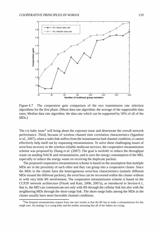
COOPERATIVE PRINCIPLES IN WiMAX 119
20 40 60 80 100 120 140 160
1.4
1.6
1.8
2
2.2
2.4
2.6
2.8
3
Number of multicast group members
Co
op
era
tio
n g
ain
R1--Mean data rate
R1--Median data rate
Figure 6.7 The cooperation gain comparison of the two transmission rate selectionalgorithms for the first phase. (Mean data rate algorithm: the average of the supportable datarates; Median data rate algorithm: the data rate which can be supported by 50% of all of theMDs.)
The cry baby issue3 will bring about the exposure issue and deteriorate the overall networkperformance. Third, because of wireless channel time correlation characteristics (Sgardoniet al., 2007), when a radio link suffers from the instantaneous bad channel condition, it cannoteffectively help itself out by requesting retransmission. To solve these challenging issues oferror/loss recovery in the wireless reliable multicast services, the cooperative retransmissionscheme was proposed by Zhang et al. (2007). The goal is twofold: to reduce the throughputwaste on sending NACK and retransmission, and to save the energy consumption of the MD,especially to reduce the energy waste on receiving the duplicate packets.
The proposed cooperative retransmission scheme is based on the assumption that multipleMDs are in the proximity of each other and they can group into a cooperative cluster. Sincethe MDs in the cluster have the heterogeneous error/loss characteristics (namely differentMDs missed the different packets), the error/loss can be recovered within the cluster withoutor with very little BS involvement. The cooperative retransmission scheme is based on theCCP2P network architecture (Fitzek and Katz, 2006, 2007a), as introduced in Section 6.1,that is, the MD can communicate not only with BS through the cellular link but also with theneighboring MDs through the short-range link. The short-range links among the MDs in thecluster usually have more favorable channel conditions.
3The frequent retransmission request from one user results in that the BS has to make a retransmission for thissingle user. An analogy is a crying baby and the mother assuming that all of her babies are crying.
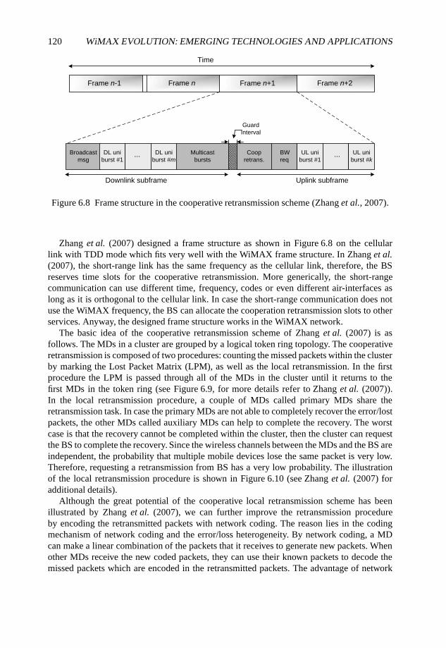
120 WiMAX EVOLUTION: EMERGING TECHNOLOGIES AND APPLICATIONS
Broadcast
msg
DL uni
burst #1... DL uni
burst #mMulticast
bursts
Coop
retrans.
UL uni
burst #1...
Downlink subframe Uplink subframe
Time
Frame n-1 Frame n+1Frame n Frame n+2
Guard
Interval
UL uni
burst #kBW
req
Figure 6.8 Frame structure in the cooperative retransmission scheme (Zhang et al., 2007).
Zhang et al. (2007) designed a frame structure as shown in Figure 6.8 on the cellularlink with TDD mode which fits very well with the WiMAX frame structure. In Zhang et al.(2007), the short-range link has the same frequency as the cellular link, therefore, the BSreserves time slots for the cooperative retransmission. More generically, the short-rangecommunication can use different time, frequency, codes or even different air-interfaces aslong as it is orthogonal to the cellular link. In case the short-range communication does notuse the WiMAX frequency, the BS can allocate the cooperation retransmission slots to otherservices. Anyway, the designed frame structure works in the WiMAX network.
The basic idea of the cooperative retransmission scheme of Zhang et al. (2007) is asfollows. The MDs in a cluster are grouped by a logical token ring topology. The cooperativeretransmission is composed of two procedures: counting the missed packets within the clusterby marking the Lost Packet Matrix (LPM), as well as the local retransmission. In the firstprocedure the LPM is passed through all of the MDs in the cluster until it returns to thefirst MDs in the token ring (see Figure 6.9, for more details refer to Zhang et al. (2007)).In the local retransmission procedure, a couple of MDs called primary MDs share theretransmission task. In case the primary MDs are not able to completely recover the error/lostpackets, the other MDs called auxiliary MDs can help to complete the recovery. The worstcase is that the recovery cannot be completed within the cluster, then the cluster can requestthe BS to complete the recovery. Since the wireless channels between the MDs and the BS areindependent, the probability that multiple mobile devices lose the same packet is very low.Therefore, requesting a retransmission from BS has a very low probability. The illustrationof the local retransmission procedure is shown in Figure 6.10 (see Zhang et al. (2007) foradditional details).
Although the great potential of the cooperative local retransmission scheme has beenillustrated by Zhang et al. (2007), we can further improve the retransmission procedureby encoding the retransmitted packets with network coding. The reason lies in the codingmechanism of network coding and the error/loss heterogeneity. By network coding, a MDcan make a linear combination of the packets that it receives to generate new packets. Whenother MDs receive the new coded packets, they can use their known packets to decode themissed packets which are encoded in the retransmitted packets. The advantage of network
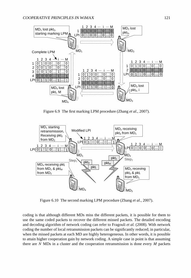
COOPERATIVE PRINCIPLES IN WiMAX 121
MD4 lost
pkti, M
MD1 lost pkt2,
starting marking LPM
MD2 lost
pkt3,
MD3 lost
pkt3, i
MD1 MD2
MD3MD4
Complete LPM
LPI
1 2 3 4 ... i ... M
10 0 0 ... 0 ... 0
0 0 0 0 0
1
1 ... ...
LPI
1 2 3 4 ... i ... M
10 0 0 ... 0 ... 0
0 0 0 0 0
1
1 ... ...
0 1 1 0 0 0... ...
2
LPI
1 2 3 4 ... i ... M
10 0 0 ... 0 ... 0
0 0 0 0 0
1
1 ... ...
0
1 1
0 1 0... ...
2
3 0 1
00 ... ...1 0
1 2 3 4 ... i ... M
10 0 0 ... 0 ... 0
0 0 0 0 0
1
1 ... ...
0 0 1 0... ...
2
3 0 1
00 ... ...1 14 0 0
LPI 10 0 ... ...1 1 1
Figure 6.9 The first marking LPM procedure (Zhang et al., 2007).
MD1 starting
retransmission,
Receiving pkt2from MD2
MD4 receiving pktifrom MD1 & pktMfrom MD2
MD4
pkt3
pkti
pkt2
pktMStep1
Step2
Modified LPI
1 2 3 4 ... i ... MLPI 10 0 ... ...0 0 1
MD2 receiving
pkt3 from MD1
1 2 3 4 ... i ... MLPI 0 0 ... ...0 00 0
MD2MD1
LPI 10 0 ... ...1 1 1
1 2 3 4 ... i ... M
MD3 receving
pkt3 & pktifrom MD1
MD3
Figure 6.10 The second marking LPM procedure (Zhang et al., 2007).
coding is that although different MDs miss the different packets, it is possible for them touse the same coded packets to recover the different missed packets. The detailed encodingand decoding algorithm of network coding can refer to Fragouli et al. (2008). With networkcoding the number of local retransmission packets can be significantly reduced; in particular,when the missed packets at each MD are highly heterogeneous. In other words, it is possibleto attain higher cooperation gain by network coding. A simple case in point is that assumingthere are N MDs in a cluster and the cooperation retransmission is done every M packets
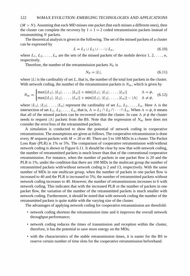
122 WiMAX EVOLUTION: EMERGING TECHNOLOGIES AND APPLICATIONS
(M >N). Assuming that each MD misses one packet (but each misses a different ones), thenthe cluster can complete the recovery by 1 + 1 = 2 coded retransmission packets instead ofretransmitting N packets.
The theoretical analysis is given in the following. The set of the missed packets of a clustercan be expressed by
L= L1 ∪ L2 ∪ · · · ∪ Ln, (6.10)
where L1, L2, . . . , Ln are the sets of the missed packets of the mobile device 1, 2, . . . , n,respectively.
Therefore, the number of the retransmission packets Nlr is
Nlr = |L|, (6.11)
where |L| is the cardinality of set L, that is, the number of the total lost packets in the cluster.With network coding, the number of the retransmission packets is Nnc, which is given by
Nnc ={
max{|L1|, |L2|, . . . , |Ln|} + min{|L1|, |L2|, . . . , |Ln|} �= φ,
max{|L1|, |L2|, . . . , |Ln|} + min{|L1|, |L2|, . . . , |Ln|} − |�| � �= φ,(6.12)
where |L1|, |L2|, . . . , |Ln| represent the cardinality of set L1, L2, . . . , Ln. Here � is theintersection of set L1, L2, . . . , Ln, that is, �= L1 ∩ L2 ∩ · · · ∩ Ln. When�= φ, it meansthat all of the missed packets can be recovered within the cluster. In case � �= φ the clusterneeds to request |�| packets from the BS. Note that the expression of Nnc here does notconsider the error/loss of the retransmitted packets.
A simulation is conducted to show the potential of network coding in cooperativeretransmission. The assumptions are given as follows. The cooperative retransmission is doneeveryM sequent packets withM = 20 or 40. There are 5 to 100 MDs in a cluster. The PacketLoss Rate (PLR) is 1% or 5%. The comparison of cooperative retransmission with/withoutnetwork coding is shown in Figure 6.11. It should be clear by now that with network coding,the number of retransmitted packets is much lower than that of the conventional cooperativeretransmission. For instance, when the number of packets in one packet flow is 20 and thePLR is 1%, under the condition that there are 100 MDs in the multicast group the number ofretransmitted packets with/without network coding is 2 and 13, respectively. With the samenumber of MDs in one multicast group, when the number of packets in one packet flow isincreased to 40 and the PLR is increased to 5%; the number of retransmitted packets withoutnetwork coding increases to 40. However, the number of retransmissions increases to 6 withnetwork coding. This indicates that with the increased PLR or the number of packets in onepacket flow, the variation of the number of the retransmitted packets is much smaller withnetwork coding. Furthermore, it should be noted that with network coding the number of theretransmitted packets is quite stable with the varying size of the cluster.
The advantages of applying network coding for cooperative retransmission are threefold:
• network coding shortens the retransmission time and it improves the overall networkthroughput performance;
• network coding reduces the times of transmission and reception within the cluster,therefore, it has the potential to save more energy on the MDs;
• with the characteristics of the stable retransmission times, it is easier for the BS toreserve certain number of time slots for the cooperative retransmission beforehand.
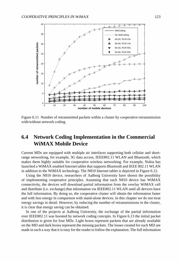
COOPERATIVE PRINCIPLES IN WiMAX 123
0 10 20 30 40 50 60 70 80 90 1000
5
10
15
20
25
30
35
40
number of mobile devices
nu
mb
er
of
retr
an
sm
itte
d p
ac
ke
ts
NetCoding
No NetCoding
M=20, PLR=1%
M=40, PLR=1%
M=20, PLR=5%
M=40, PLR=5%
Figure 6.11 Number of retransmitted packets within a cluster by cooperative retransmissionwith/without network coding.
6.4 Network Coding Implementation in the CommercialWiMAX Mobile Device
Current MDs are equipped with multiple air interfaces supporting both cellular and short-range networking, for example, 3G data access, IEEE802.11 WLAN and Bluetooth, whichmakes them highly suitable for cooperative wireless networking. For example, Nokia haslaunched a WiMAX enabled Internet tablet that supports Bluetooth and IEEE 802.11 WLANin addition to the WiMAX technology. The N810 Internet tablet is depicted in Figure 6.12.
Using the N810 device, researchers of Aalborg University have shown the possibilityof implementing cooperative principles. Assuming that each N810 device has WiMAXconnectivity, the devices will download partial information from the overlay WiMAX celland distribute (i.e. exchange) that information via IEEE802.11 WLAN until all devices havethe full information. By doing so, the cooperative cluster will obtain the information fasterand with less energy in comparison with stand-alone devices. In this chapter we do not treatenergy savings in detail. However, by reducing the number of retransmissions in the cluster,it is clear that energy saving can be obtained.
In one of the projects at Aalborg University, the exchange of the partial informationover IEEE802.11 was boosted by network coding concepts. In Figure 6.13 the initial packetdistribution is given for four MDs. Light boxes represent packets that are already availableon the MD and dark boxes represent the missing packets. The losses created for each MD aremade in such a way that it is easy for the reader to follow the explanation. The full information
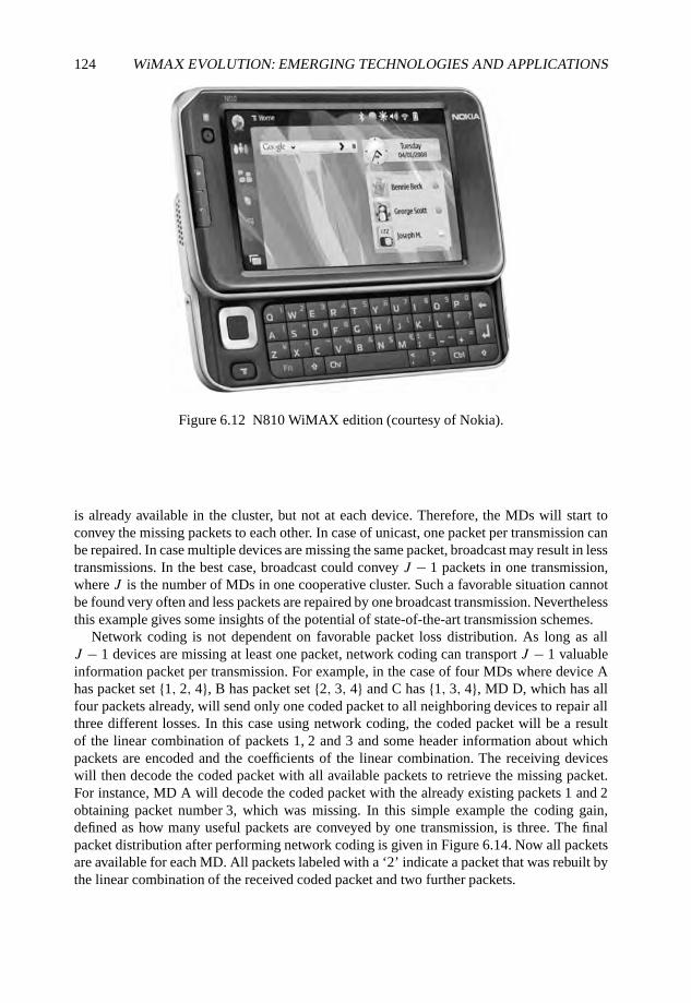
124 WiMAX EVOLUTION: EMERGING TECHNOLOGIES AND APPLICATIONS
Figure 6.12 N810 WiMAX edition (courtesy of Nokia).
is already available in the cluster, but not at each device. Therefore, the MDs will start toconvey the missing packets to each other. In case of unicast, one packet per transmission canbe repaired. In case multiple devices are missing the same packet, broadcast may result in lesstransmissions. In the best case, broadcast could convey J − 1 packets in one transmission,where J is the number of MDs in one cooperative cluster. Such a favorable situation cannotbe found very often and less packets are repaired by one broadcast transmission. Neverthelessthis example gives some insights of the potential of state-of-the-art transmission schemes.
Network coding is not dependent on favorable packet loss distribution. As long as allJ − 1 devices are missing at least one packet, network coding can transport J − 1 valuableinformation packet per transmission. For example, in the case of four MDs where device Ahas packet set {1, 2, 4}, B has packet set {2, 3, 4} and C has {1, 3, 4}, MD D, which has allfour packets already, will send only one coded packet to all neighboring devices to repair allthree different losses. In this case using network coding, the coded packet will be a resultof the linear combination of packets 1, 2 and 3 and some header information about whichpackets are encoded and the coefficients of the linear combination. The receiving deviceswill then decode the coded packet with all available packets to retrieve the missing packet.For instance, MD A will decode the coded packet with the already existing packets 1 and 2obtaining packet number 3, which was missing. In this simple example the coding gain,defined as how many useful packets are conveyed by one transmission, is three. The finalpacket distribution after performing network coding is given in Figure 6.14. Now all packetsare available for each MD. All packets labeled with a ‘2’ indicate a packet that was rebuilt bythe linear combination of the received coded packet and two further packets.
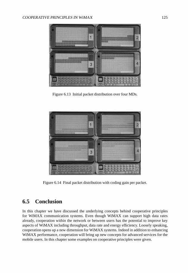
COOPERATIVE PRINCIPLES IN WiMAX 125
Figure 6.13 Initial packet distribution over four MDs.
Figure 6.14 Final packet distribution with coding gain per packet.
6.5 Conclusion
In this chapter we have discussed the underlying concepts behind cooperative principlesfor WiMAX communication systems. Even though WiMAX can support high data ratesalready, cooperation within the network or between users has the potential to improve keyaspects of WiMAX including throughput, data rate and energy efficiency. Loosely speaking,cooperation opens up a new dimension for WiMAX systems. Indeed in addition to enhancingWiMAX performance, cooperation will bring up new concepts for advanced services for themobile users. In this chapter some examples on cooperative principles were given.
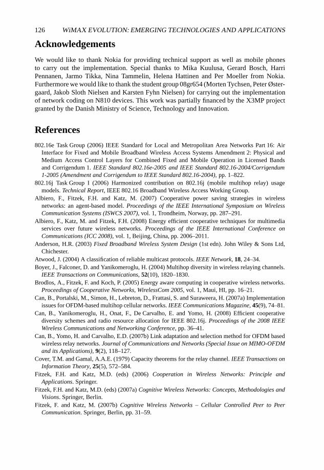
126 WiMAX EVOLUTION: EMERGING TECHNOLOGIES AND APPLICATIONS
Acknowledgements
We would like to thank Nokia for providing technical support as well as mobile phonesto carry out the implementation. Special thanks to Mika Kuulusa, Gerard Bosch, HarriPennanen, Jarmo Tikka, Nina Tammelin, Helena Hattinen and Per Moeller from Nokia.Furthermore we would like to thank the student group 08gr654 (Morten Tychsen, Peter Øster-gaard, Jakob Sloth Nielsen and Karsten Fyhn Nielsen) for carrying out the implementationof network coding on N810 devices. This work was partially financed by the X3MP projectgranted by the Danish Ministry of Science, Technology and Innovation.
References
802.16e Task Group (2006) IEEE Standard for Local and Metropolitan Area Networks Part 16: AirInterface for Fixed and Mobile Broadband Wireless Access Systems Amendment 2: Physical andMedium Access Control Layers for Combined Fixed and Mobile Operation in Licensed Bandsand Corrigendum 1. IEEE Standard 802.16e-2005 and IEEE Standard 802.16-2004/Corrigendum1-2005 (Amendment and Corrigendum to IEEE Standard 802.16-2004), pp. 1–822.
802.16j Task Group I (2006) Harmonized contribution on 802.16j (mobile multihop relay) usagemodels. Technical Report, IEEE 802.16 Broadband Wireless Access Working Group.
Albiero, F., Fitzek, F.H. and Katz, M. (2007) Cooperative power saving strategies in wirelessnetworks: an agent-based model. Proceedings of the IEEE International Symposium on WirelessCommunication Systems (ISWCS 2007), vol. 1, Trondheim, Norway, pp. 287–291.
Albiero, F., Katz, M. and Fitzek, F.H. (2008) Energy efficient cooperative techniques for multimediaservices over future wireless networks. Proceedings of the IEEE International Conference onCommunications (ICC 2008), vol. 1, Beijing, China, pp. 2006–2011.
Anderson, H.R. (2003) Fixed Broadband Wireless System Design (1st edn). John Wiley & Sons Ltd,Chichester.
Atwood, J. (2004) A classification of reliable multicast protocols. IEEE Network, 18, 24–34.Boyer, J., Falconer, D. and Yanikomeroglu, H. (2004) Multihop diversity in wireless relaying channels.
IEEE Transactions on Communications, 52(10), 1820–1830.Brodlos, A., Fitzek, F. and Koch, P. (2005) Energy aware computing in cooperative wireless networks.
Proceedings of Cooperative Networks, WirelessCom 2005, vol. 1, Maui, HI, pp. 16–21.Can, B., Portalski, M., Simon, H., Lebreton, D., Frattasi, S. and Suraweera, H. (2007a) Implementation
issues for OFDM-based multihop cellular networks. IEEE Communications Magazine, 45(9), 74–81.Can, B., Yanikomeroglu, H., Onat, F., De Carvalho, E. and Yomo, H. (2008) Efficient cooperative
diversity schemes and radio resource allocation for IEEE 802.16j. Proceedings of the 2008 IEEEWireless Communications and Networking Conference, pp. 36–41.
Can, B., Yomo, H. and Carvalho, E.D. (2007b) Link adaptation and selection method for OFDM basedwireless relay networks. Journal of Communications and Networks (Special Issue on MIMO-OFDMand its Applications), 9(2), 118–127.
Cover, T.M. and Gamal, A.A.E. (1979) Capacity theorems for the relay channel. IEEE Transactions onInformation Theory, 25(5), 572–584.
Fitzek, F.H. and Katz, M.D. (eds) (2006) Cooperation in Wireless Networks: Principle andApplications. Springer.
Fitzek, F.H. and Katz, M.D. (eds) (2007a) Cognitive Wireless Networks: Concepts, Methodologies andVisions. Springer, Berlin.
Fitzek, F. and Katz, M. (2007b) Cognitive Wireless Networks – Cellular Controlled Peer to PeerCommunication. Springer, Berlin, pp. 31–59.
COOPERATIVE PRINCIPLES IN WiMAX 127
Fragouli, C., Boudec, J.Y.L. and Widmer, J. (2008) Network coding: an instant primer,http://algo.epfl.ch/ christin/primer.ps.
Gastpar, M., Kramer, G. and Gupta, P. (2002) The multiple-relay channel: coding and antenna-clustering capacity. Proceedings of the IEEE International Symposium on Information Theory,p. 136.
Gupta, P. and Kumar, P. (2003) Towards an information theory of large networks: an achievable rateregion. IEEE Transactions on Information Theory, 49(8), 1877–1894.
Hammerstrom, I., Kuhn, M. and Wittneben, A. (2004) Channel adaptive scheduling for cooperativerelay networks. Proceedings of IEEE 60th Vehicular Technology Conference (VTC2004-Fall), vol. 4,pp. 2784–2788.
Host-Madsen, A. (2006) Capacity bounds for cooperative diversity. IEEE Transactions on InformationTheory, 52(4), 1522–1544.
Hou, F., Cai, L.X., She, J., Ho, P.H., Shen, X. and Zhang, J. (2008) Cooperative multicast schedulingscheme for IPTV service over IEEE 802.16 networks. Proceedings of the 2008 IEEE InternationalConference on Communications, pp. 2566–2570.
Hunter, T.E. and Nosratinia, A. (2002) Cooperation diversity through coding. Proceedings of the IEEEInternational Symposium on Information Theory, p. 220.
Kramer, G., Gastpar, M. and Gupta, P. (2005) Cooperative strategies and capacity theorems for relaynetworks. IEEE Transactions on Information Theory, 51(9), 3037–3063.
Kristensen, J. and Fitzek, F. (2007) Cognitive Wireless Networks – Cellular Controlled P2PCommunication Using Software Defined Radio. Springer, Berlin, pp. 435–455.
Laneman, J., Tse, D. and Wornell, G. (2004) Cooperative diversity in wireless networks: efficientprotocols and outage behavior. IEEE Transactions on Information Theory, 50(12), 3062–3080.
Laneman, J., Wornell, G. and Tse, D. (2001) An efficient protocol for realizing cooperative diversityin wireless networks. Proceedings of the IEEE International Symposium on Information Theory,p. 294.
Laneman, J.N. (2002) Cooperative diversity in wireless networks: algorithms and architectures. PhDthesis, Massachusetts Institute of Technology, Cambridge, MA.
Laneman, J.N. (2006) Cooperation in Wireless Networks: Principle and Applications. Springer, Berlin,pp. 163–187.
Li, G. and Liu, H. (2006) Resource allocation for OFDMA relay networks with fairness constraints.IEEE Journal on Selected Areas in Communications, 24(11), 2061–2069.
Lin, Z., Erkip, E. and Ghosh, M. (2005) Adaptive modulation for coded cooperative systems.Proceedings of the IEEE 6th Workshop on Signal Processing Advances in Wireless Communications,pp. 615–619.
Madsen, T., Zhang, Q. and Fitzek, F. (2007) Cognitive Wireless Networks – IP Header Compression forCellular-Controlled P2P Networks. Springer, Berlin, pp. 499–511.
Onat, F., Adinoyi, A., Fan, Y., Yanikomeroglu, H. and Thompson, J. (2007) Optimum threshold for snr-based selective digital relaying schemes in cooperative wireless networks. Proceedings of the 2007IEEE Wireless Communications and Networking Conference, pp. 969–974.
Pabst, R., Walke, B., Schultz, D., Herhold, P., Yanikomeroglu, H., Mukherjee, S., Viswanathan, H.,Lott, M., Zirwas, W., Dohler, M., Aghvami, H., Falconer, D. and Fettweis, G. (2004) Relay-baseddeployment concepts for wireless and mobile broadband radio. IEEE Communications Magazine,42(9), 80–89.
Perrucci, G., Fitzek, F. and Petersen, M. (2008) Heterogeneous Wireless Access Networks: Architecturesand Protocols – Energy Saving Aspects for Mobile Device Exploiting Heterogeneous WirelessNetworks. Springer, Berlin (accepted).
128 WiMAX EVOLUTION: EMERGING TECHNOLOGIES AND APPLICATIONS
Sadek, A., Han, Z. and Liu, K. (2006) A distributed relay-assignment algorithm for cooperativecommunications in wireless networks. Proceedings of the 2006 IEEE International Conference onCommunications, vol. 4, pp. 1592–1597.
Sendonaris, A., Erkip, E. and Aazhang, B. (1998) Increasing uplink capacity via user cooperationdiversity. Proceedings of the IEEE International Symposium on Information Theory, p. 156.
Sendonaris, A., Erkip, E. and Aazhang, B. (2003a) User cooperation diversity. Part I. Systemdescription. IEEE Transactions on Communications, 51(11), 1927–1938.
Sendonaris, A., Erkip, E. and Aazhang, B. (2003b) User cooperation diversity. Part II. Implementationaspects and performance analysis. IEEE Transactions on Communications, 51(11), 1939–1948.
Sgardoni, V., Ferre, P., Doufexi, A., Nix, A. and Bull, D. (2007) Frame delay and loss analysis forvideo transmission over time-correlated 802.11a/g channels. Proceedings of the 2007 IEEE 18thInternational Symposium on Personal, Indoor and Mobile Radio Communications, pp. 1–5.
van der Meulen, E. (1971) Three-terminal communication channels. Advances in Applied Probability,3(1), 120–154.
Varshney, U. (2002) Multicast over wireless networks. Communications of the ACM, 45(12), 31–37.Yamamoto, M. (2004) Multicast communication in next-generation Internet. Proceedings of the 10th
IFAC/IFORS/IMACS/IFIP Symposium on Large Scale Systems: Theory and Applications, pp. 639–645.
Zhang, Q. and Fitzek, F. (2007) Cognitive Wireless Networks – Cooperative Retransmission for ReliableWireless Multicast Services. Springer, Berlin, pp. 485–498.
Zhang, Q., Fitzek, F.H. and Iversen, V.B. (2007) Design and performance evaluation of cooperativeretransmission scheme for reliable multicast services in cellular controlled P2P networks.Proceedings of the 18th Annual IEEE International Symposium on Personal, Indoor and MobileRadio Communications (PIMRC07).

7
The Role of WiMAX Technologyin Distributed Wide AreaMonitoring Applications
Francesco Chiti, Romano Fantacci, Leonardo Maccari,Dania Marabissi and Daniele Tarchi
7.1 Monitoring with the WSN Paradigm
Wireless sensor networks (WSNs) represent an inherently disruptive approach specificallydesigned to detect events or phenomena, collect and process related data, and transmit sensedinformation to final users in a distributed way (Akyildiz et al., 2001).
Although WSNs exhibit several features common to wireless ad hoc or mesh networks,such as self-organizing capabilities or short-range broadcast communication with a multihoprouting, they present additional constraints in terms of limitations in energy, transmit power,memory and computing power. Further, the operative conditions usually require cooperativeefforts of sensor nodes in the presence of frequently changing topology due to fading andnode failures or node mobility (Ilyas and Mahgoub, 2005).
A typical WSN is comprised of the following basic components:
• A set of distributed or localized sensors;
• An interconnecting network usually, but not always, wireless-based;
• A central point of information clustering;
• Computing resources at the central point (or beyond) to handle data correlation, eventtrending, status querying and data mining.
WiMAX Evolution: Emerging Technologies and Applications Edited by Tsutomu Ishikawa© 2009 John Wiley & Sons, Ltd. ISBN: 978-0-470-69680-4
130 WiMAX EVOLUTION: EMERGING TECHNOLOGIES AND APPLICATIONS
These elements allow a system administrator to observe and react to events and phenom-ena in a specified environment. The administrator can be a civil, governmental, commercialor industrial entity. Typical application fields can span from agriculture (AgroSense, 2007–2010, GoodFood, 2004–2006) and environmental monitoring (DustBot, 2007–2009), civilengineering, disaster management (InSyEme, 2007–2010), military applications up to healthmonitoring and surgery (Chiti and Fantacci, 2006).
Generally speaking WSN systems can be classified into two basic categories:
• Mesh-based systems with multihop radio connectivity between WSNs, utilizingdynamic routing in both the wireless and wired portions of the network.
• Point-to-point or multipoint-to-point (star-based) systems generally with single-hopradio connectivity to WSNs, utilizing static routing over the wireless network.
The latter scheme is composed of networks in which the end devices (i.e. the sensors)are one radio hop away forwarding node, for example, a wireless router connected to theterrestrial network via either a wired or a point-to-point wireless link. On the other hand, theformer approach allows end devices (sensors) to be more than one radio hop away from arouting or forwarding node. The forwarding node is a wireless router that supports dynamicrouting, while wireless routers are often connected over wired links covering a wider area.
Presently WSNs have been largely focused on dense, small-scale homogeneous deploy-ments to monitor a specific physical phenomenon. Nevertheless, the integration of multipleheterogeneous sensor networks operating in different environments could provides the abilityto monitor diverse physical phenomena at a global scale, as addressed in WP122 (2008).In addition, such remote integration will make the infrastructure able to query and fusedata across multiple, possibly overlapping, sensor networks in different domains. Moreover,new types of sensor networks based on mobile sensor platforms are becoming available, forexample, vehicles in the urban grid or firefighters in a disaster recovery operation equippedwith a variety of sensors (Ilyas and Mahgoub, 2005, InSyEme, 2007–2010) (location, video,chemical, radiation, acoustic, etc). The vehicle grid then becomes a sensor network thatcan be remotely accessed from the Internet to monitor vehicle traffic congestion and toprevent accidents, chemical spills and possible terrorist attacks. Likewise, on-site operatorsas firefighters might be equipped with several wearable devices such as cameras or sensors,allowing the commander to be aware of the conditions in the field and to direct the operationsto maximize the use of the forces, while preserving the life of his responders.
As a consequence, one of the most interesting applications of an integrated WSN is theability to create a macroscope to take a look at a picture of the monitored environmentwider than the areas monitored by a single WSN (WP122, 2008). There have been severalattempts, for instance, the WSN deployed on redwood trees, a wildlife monitoring site onGreat Duck Island, tracking zebras in their natural habitat and monitoring volcanic eruptions.All of these systems have been deployed in remote locations with limited access: someareas might be accessible only once in several months, straining the lifetime of sensors withlimited battery power. Many are subject to harsh elements of nature that cause rapid deviceand sensor malfunction. Network links to back-end monitoring and collection systems maybe intermittent due to weather or other problems, while in-network data storage is limited,leading to important observations being missed.
In addition to this, there is an increasing interest in real-time connecting heterogeneousdevices with application to building/commercial automation (security, lighting control,
DISTRIBUTED WIDE AREA MONITORING APPLICATIONS 131
access control) or industrial control (asset management, process control, environmental,energy management). These applications usually addressed as invisible computing involvedifferent technologies such as (WPANs: Wireless Personal Area Networks in which IEEE802.15.4/ZigBee standard plays a crucial role), Wireless Local Area Networks (WLANs;mainly IEEE 802.11a/b/g/h, etc. standards) and metropolitan transport (for which IEEE802.15.3/WiMAX standards are ideally suited).
For the aforementioned applications, the sensor networks cannot operate in a stand-alonemanner; there must be a way to monitor an entity to gain access to the data produced bythe WSN. By connecting the sensor network to an existing network infrastructure such asthe global Internet, a local-area network, or a private Intranet, remote access to the sensornetwork can be achieved. Given that the TCP/IP protocol suite has become the de-factonetworking standard, not only for the global Internet but also for local-area networks, it isof particular interest to look at methods for interconnecting sensor networks and IP corenetworks. Sensor networks often are intended to run specialized communication protocols,for example IEEE 802.15.4 or Zigbee, therefore an all-IP-network will not be viable, due tothe fundamental differences in the architecture of IP-based networks and sensor networks. Itis envisaged that the integration of sensor networks with the Internet will need gateways inmost cases. A proxy server at the core network edge is able to communicate both with thesensors in the sensor network and hosts on the TCP/IP network, and is thereby able to eitherrelay the information gathered by the sensors, or to act as a front-end for the sensor network.It is also envisaged that sensing devices will be equipped with interfaces to wireless accessnetworks such as 2/3G and WLAN enabling total ubiquitous connectivity.
7.2 Overall System Architecture
As discussed previously, a wide area WSN could be achieved by integrating specializedand even heterogeneous subnetworks through a reliable transport backbone. For manykinds of applications a wireless connection represents a flexible and cost-effective solution.In particular, the Worldwide Interoperability for Microwave Access (WiMAX), provideswireless broadband services on the scale of the Metropolitan Area Network (MAN). WiMAXbrings a standards-based technology to a sector that otherwise depends on proprietarysolutions: the standardized approach ensures interoperability between WiMAX equipmentfrom vendors worldwide reducing costs and making the technology more accessible. Thistechnology can provide fast and cheap broadband access in areas that lack infrastructure(fiberoptics or copper wire) such as rural areas, unwired countries and disaster recoveryscenes where the wired networks have broken down (WiMAX can be used as backup links forbroken wired links). Very often WSNs are used in these areas to monitor the environment,to prevent natural disasters or to aid rescue operations. WiMAX can also provide the lastmile coverage in urban areas where the monitoring and control of anthropic processestaking place, including buildings, streets, factories and storehouses. WiMAX attributes openthe technology to a wide variety of applications: with its wide coverage range and hightransmission rate, WiMAX can serve as a backbone for integrating specialized sensorssubnetworks and for connecting the WSN to the data processing center. Alternatively, userscan connect mobile devices such as laptops and handsets directly to WiMAX base stations;WiMAX is able to support vehicular speeds of up to 125 km hour−1 providing ubiquitous
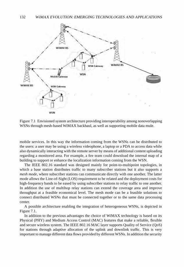
132 WiMAX EVOLUTION: EMERGING TECHNOLOGIES AND APPLICATIONS
Figure 7.1 Envisioned system architecture providing interoperability among nonoverlappingWSNs through mesh-based WiMAX backhaul, as well as supporting mobile data mule.
mobile services. In this way the information coming from the WSNs can be distributed tothe users: a user may be using a wireless videophone, a laptop or a PDA to access data whilealso dynamically interacting with the remote server by means of additional content uploadingregarding a monitored area. For example, a fire team could download the internal map of abuilding to support or enhance the localization information coming from the WSN.
The IEEE 802.16 standard was designed mainly for point-to-multipoint topologies, inwhich a base station distributes traffic to many subscriber stations but it also supports amesh mode, where subscriber stations can communicate directly with one another. The lattermode allows the Line-of-Sight (LOS) requirement to be related and the deployment costs forhigh-frequency bands to be eased by using subscriber stations to relay traffic to one another.In addition the use of multihop relay stations can extend the coverage area and improvethroughput at a feasible economical level. The mesh mode can be a feasible solutions toconnect distributed WSNs that must be connected together or to the same data processingcenter.
A possible architecture enabling the integration of heterogeneous WSNs, is depicted inFigure 7.1.
In addition to the previous advantages the choice of WiMAX technology is based on itsPhysical (PHY) and Medium Access Control (MAC) features that make a reliable, flexibleand secure wireless system. The IEEE 802.16 MAC layer supports Quality of Service (QoS)for stations through adaptive allocation of the uplink and downlink traffic. This is veryimportant to manage different data flows provided by different WSNs. In addition the security
DISTRIBUTED WIDE AREA MONITORING APPLICATIONS 133
sublayer provides functionalities such as authentication, secure key exchange and encryptionassuring the WSNs data is not corrupted. The MAC of 802.16 supports different transporttechnologies such as Internet Protocol version 4 (IPv4), IPv6, Ethernet, and AsynchronousTransfer Mode (ATM) making the integration of heterogeneous networks easier.
Finally, PHY layer is characterized by a high level of flexibility in the allocatedspectrum. the work frequency can be chosen to improve performance and interferenceand the bandwidth can be varied depending on the requirements (i.e. IEEE 802.16e usesthe Scalable Orthogonal Frequency Division Multiple Access (S-OFDMA) scheme). Theadaptive features at the PHY allow trade-offs between robustness and capacity and therobustness to the adverse propagation conditions permits the use of Non-Line-of-Sight(NLOS) communications, differently from alternative technologies currently available forfixed broadband wireless supporting only LOS coverage.
7.3 Efficient Access Management Schemes
As stated in the previous section, WiMAX represents a promising and reliable solution toprovide a transport backbone among sensor subnetworks. As a matter of fact, it allows theestablishment of effective communications handling different data flows with specific QoSrequirements in terms of priority level, throughput, delay and jitter as well. The dynamic andflexible resource allocation scheme WiMAX is able to support typical application featuresconcerning, for instance, the monitoring of synchronous processes, dispatching warnings andalarms and the reliability of data exchange.
The IEEE 802.16 family of standards (IEEE, 2005, 2004), supported by the WiMAXcommercial consortium, defines the PHY and MAC layers specifications for a BroadbandWireless Access (BWA) communication protocol. Both MAC and PHY are designed to havea flexible access scheme and an adaptive resource management. This aspect is very importantin the proposed architecture to manage a high number of distributed users including sensorssubnetworks also under mobility conditions.
As for the PHY layer, among several alternatives, the IEEE 802.16 standard proposesthe use of Orthogonal Frequency Division Multiplexing (OFDM) for mitigating frequency-dependent distortion across the channel band and simplifying the equalization in a multipathfading environment (van Nee and Prasad, 2000). The basic OFDM principle is parallelization:by dividing the available bandwidth into several smaller bands that are called subcarriers, thetransmitted signal over each subcarrier may experience flat fading. Moreover, OrthogonalFrequency Division Multiple Access (OFDMA) is used to provide a flexible multiuser accessscheme: disjunctive sets of subcarriers and OFDM symbols are allocated to different users.
To have more flexible and efficient OFDM/OFDMA systems, adaptive OFDM schemesare adopted to maximize the system capacity and maintain the desired system performance(Bohge et al., 2007, Keller and Hanzo, 2000b). In particular, in an OFDM-based wirelesssystem, the inherent multi-carrier nature of OFDM allows the use of link adaptationtechniques according to the behavior of the narrow-band channels: the bit-error probabilityof different OFDM subcarriers, transmitted in time-dispersive channels, depends on thefrequency-domain channel transfer function (Bohge et al., 2007, Keller and Hanzo, 2000b).
Transmission techniques which do not adapt the transmission parameters to the fadingchannel require a fixed link margin or coding to maintain acceptable performance under
134 WiMAX EVOLUTION: EMERGING TECHNOLOGIES AND APPLICATIONS
deep fade conditions. Thus, these systems are effectively designed for the worst-casechannel conditions, resulting in an insufficient utilization of the available channel bandwidth.Conversely, if the channel fade level is known at the transmitter, Shannon capacity is achievedby matching transmission parameters to time-varying channel: the signal transmitted to andby a particular station can be modified to take into account the signal quality variation.
Usually, wireless systems adopt power control as the preferred method for link adaptation.In a system with power control, the power of the transmitted signal is tuned in order tomaintain the quality of the received signal at each individual subcarrier. Therefore, thetransmit power will typically be low when a user is close to the base station (BS) and itwill increase with the distance from the BS.
Power control is based on the water filling theorem: given a certain power budget, moretransmit power is applied to frequencies experiencing lower attenuation. Thus, given thetransfer function, the optimal power distribution is similar to inverting the transfer functionand pouring a liquid (i.e. power) into the shape.
Although the use of just power control can improve the system performance in terms ofthe Bit Error Rate (BER), the total channel capacity is not used efficiently at any transmissiontime, if the modulation scheme is fixed. To overcome this drawback, Adaptive Modulationand Coding (AMC) or subcarrier allocation should be considered. In a system with AMC,the power of the transmitted signal is held constant but the modulation and coding ordersare changed to match the current received signal quality. Users close to the BS are typicallyassigned higher-order modulations and higher code rates but the modulation order and/or thecode rate usually decrease when their distance from the BS increases (Keller and Hanzo,2000a).
Furthermore, in a multiuser OFDMA wireless network where the given system resourcesare shared by several terminals an adaptive subcarrier allocation strategy can significantlyincreases the system capacity by exploiting the multiuser diversity: the channel characteristicsfor different users are almost mutually independent; more attenuated subcarriers for a usermay not result in a deep fade for other users. Subcarrier allocation strategies dynamicallyassign subcarriers with the best frequency response to the users.
Subcarrier allocation strategies can follow different criteria, such as having a fair datarate distribution among users or to maximize the overall network throughput. A possiblesubcarrier allocation strategy has been proposed by Rhee and Cioffi (2000) with the aim ofobtaining almost equal data rates for all users. With this strategy more resources are allocatedto users with bad channel conditions or far away from the BS. As a consequence, the capacityof users with good channel conditions are not fully exploited. Absolute fairness may lead tolow bandwidth efficiency. However, throughput maximization is sometimes unfair for thoseusers with bad channel conditions.
Adaptive subcarrier allocation techniques have been addressed, also jointly with otherresource-allocation strategies, by Kim et al. (2005), Kulkarni et al. (2005), Wong et al.(1999) and Ermolova and Makarevitch (2007). The adaptive subcarriers and bits assignmentscheme presented by Kulkarni et al. (2005) has the aim of minimizing the total transmittedpower over the entire network while satisfying the data rate requirement of each link.Ermolova and Makarevitch (2007) considered a low-complexity suboptimal power andsubcarrier allocation for OFDMA systems, proposing a heuristic noniterative method as anextension of the ordered subcarrier selection algorithm for a single user case to OFDMAsystems.
DISTRIBUTED WIDE AREA MONITORING APPLICATIONS 135
The traffic types and services made by the devices composing a WMAN are stronglyspecialized and they have to be scheduled respecting transmission time and used bandwidthconstraints. In order to provide the compliance of service parameters and QoS, a trafficmanagement model is needed: IEEE 802.16 divides all services in four different groups,distinguished by traffic parameters, bandwidth request and resource-allocation techniques.However, WiMAX does not specify any uplink or downlink scheduling algorithm.
Recently the scheduling issue of multimedia traffic in wireless network has become a hottopic for the research community. Song and Li (2005) proposed a utility-based function forresource allocation and scheduling for downlink traffic in an OFDM-based communicationsystem by exploiting wireless channel status jointly with packet queue information. Caiet al. (2005) proposed a downlink resource management technique for OFDM wirelesscommunication systems, considering different traffic types and by exploiting subcarriers andpower allocation. Liu et al. (2001) discussed the principles of opportunistic scheduling inresource-sharing wireless communication by focusing on the time varying conditions of thephysical channel. Wong et al. (1999) devoted particular attention to the resource allocationin OFDMA systems. In particular, a suitable adaptive subcarrier, bit and power allocationalgorithm is proposed for the case of a frequency selective wireless channel. Likewise, Ergenet al. (2003) proposed a fair scheduling technique that exploits subcarriers and bit allocationfor an OFDMA wireless system.
Cicconetti et al. (2007), Lee et al. (2005) and Niyato and Hossain (2006) investigatedthe resource management for the case of IEEE 802.16 systems. Cicconetti et al. (2007)presented a performance evaluation for the different scheduling services offered in the IEEE802.16 standard, by focusing on a Frequency Division Duplexing (FDD) system. Niyatoand Hossain (2006) performed a queue analysis for IEEE 802.16 networks by consideringreal-time services and their impact on the highest priority traffic. Finally, Lee et al. (2005)investigated the VoIP service in IEEE 802.16 networks by focusing on the uplink and a mobileenvironment.
7.3.1 System Model and Problem FormulationThe system under consideration, as specified by the IEEE 802.16e standard, exploits theOFDMA among users for allocating the resources.
On the other hand, each user terminal is supposed to have different requirements ofbandwidth and bit rate due to the type of traffic to be sent out and the QoS constraintsespecially in terms of priority (e.g. video-monitoring sensor networks or alarm delivery).Finally, we assume that the BS and user terminal transmits on each subcarrier with the samepower, that is fixed and independent from the total available power and number of allocatedsubcarriers (Rhee and Cioffi, 2000).
For optimizing the access scheme two main aspects have to be considered: the adaptationof the modulation and coding and the optimization of the scheduling. Both aspects dependson the channel behavior as well as on the QoS requirements of each device in the coveragearea.
7.3.1.1 AMC techniques
AMC denotes the possibility of choosing the most suitable modulation and channel codingscheme according to the propagation conditions of the radio link (channel state) known at thetransmitting end.
136 WiMAX EVOLUTION: EMERGING TECHNOLOGIES AND APPLICATIONS
For our purposes we have considered that the channel quality degradation is mainly dueto the path loss and multipath fading.
There are mainly two types of AMC technique: maximum throughput AMC, in which theModulation and Coding Scheme (MCS) is selected to achieve the best overall throughputwithout any constraint on the data reliability (i.e. bit error probability), and minimum biterror probability AMC, in which, conversely, the main goal is to meet specific data reliabilityconstraints and, hence, the MCS is selected accordingly.
7.3.1.2 Scheduling Strategy
The aim of a scheduling strategy is to perform an optimal allocation of the network resourcesamong the users in order to maximize the overall network throughput and meet the user QoSconstraints in terms of minimum bit rate needed, Rkmin, and Pber. From above, it follows thatthe objective is to search for the subcarriers allocation matrix M for which we have:
maxM
K−1∑k=0
∑n∈Mk
rk(n) such as
N−1∑n=0
rk(n)≥ Rkmin, for all k,
K−1∑k=0
δ [rk(n)] ≤ 1, for all n,
Pber ≤ Pber,
(7.1)
where rk(n) is the bit rate achieved by user k on subcarrier n, δ[·] is the Kronecker deltafunction, Mk is the allocation matrix for user k, K is the total number of users and N thetotal number of subcarriers. Note that M can be considered as a time-frequency grid withthe x-axis and y-axis formed, respectively, by the number of OFDM symbols contained in aframe and all of the subcarriers.
7.4 Secure Communications Approaches
Security services are essential for any modern network, whether they are general purposenetworks, such as a network for access delivery or specific purpose-driven networks. Ingeneral, security services such as authentication, confidentiality, access control, integrity andavailability, as defined by Stallings (2006) have to be guaranteed in most real-life scenarios.In the context of monitoring of wide areas, the security of the overall system depends onthe security features of each component and from their interaction. In this section we brieflyreview the security features of the building blocks of the monitoring network.
The most delicate component of the system is surely the WSN, for the hardwarelimitations and for the specific requirements it presents. In general, security in WSN is anunderestimated feature, meaning that the stringent hardware requirements force the designersto give more attention to other details. Still, the application that a WSN can be targeted toare often critical and some security services should be guaranteed. We give three practicalexample scenarios.
• In a surveillance network an intruder must be unable to alter the flow of informationtoward the gateway, or pollute the gateway with fake messages. We can imagine an
DISTRIBUTED WIDE AREA MONITORING APPLICATIONS 137
attacker that wants to access a restricted area using a laptop to flood the nodes, or tohijack routing protocols in order to prevent the gateway from receiving alarms.
• In a WSN for home automation it is imperative to guarantee some form of accesscontrol in order to avoid an attacker from taking control of the environment.
• In a body network the parameters that are monitored are private and should not bedisclosed. If the parameters are processed automatically to control health equipmentauthentication and access control is, again, fundamental.
The hardware used for WSN is unable, in most cases, to perform the computationnecessary to use public/private key schemes which is a great limitation since most of themodern security protocols are based on such algorithms. This makes the WSN a stand-alonenetwork that must be interfaced with the rest of the system, but cannot be easily integrated.
Another important issue is the degree of distribution that a WSN implements. In general,security schemes are easier to implement when there is a strict hierarchy between thecomponents of a network. If the WSN presents a star topology, with a single gatewayalways reachable by all of the nodes, the security associations between the nodes and thegateway can be easily pre-loaded. Otherwise if the WSN is a multi-hop mesh network with anunpredictable (and even varying) topology the security association between a couple of nodesthat share the same link must be automatically negotiated using some pre-shared credentials,which introduces scalability problems.
Lastly, WSN are generally unattended, nodes can be stolen, their keys can be compromisedand even the software can be reprogrammed. Large-area WSNs should resist the presence ofa certain number of compromised nodes.
A completely different situation can be found in the transport WiMAX network. Firstof all, most of the time WiMAX networks use a centralized model which helps thecreation of a security hierarchy, then WiMAX standards mandate that the equipment mustbe capable of performing computations needed for public/private key cryptography; lastly,robust security protocols can be used. Nevertheless some severe vulnerabilities have beenfound in IEEE 802.16d, in part fixed in the later IEEE 802.16e.
The security scheme used in WiMAX is distinct for the so-called Point-to-Multipoint(PMP) mode, in which a BS serves various clients, and the mesh mode in which a certainnumber of peers form a distributed flat network. In the first case the authentication of a IEEE802.16d network is based on an original protocol designed for WiMAX which makes useof RSA certificates. The standard mandates that each network client should be in possessionof a factory installed certificate that bounds the MAC address of the device to an RSA key,and this key is used to perform authentication to the BS. With a packet exchange definedin the standard, two fresh symmetric keys are generated during authentication, the so-calledAK and TEK, where the first is used as a proof to perform periodical re-authentications thesecond is used for encrypting and authenticating data. The introduction of mandatory RSAcertificates and hardware capable of performing public key cryptography is a new featurethat distinguishes WiMAX from previous standards. With such feature it should be possibleto prevent an attacker from stealing the MAC address of another client in order to accessthe network. In a WiFi network, for example, MAC-based access lists are widely used butthey are much more insecure then certificate-based authorization. Nevertheless, the overallsecurity scheme of IEEE 802.16d has been proven to be insecure (Maccari et al., 2007).Briefly, some of the defects that it presents are as follows.
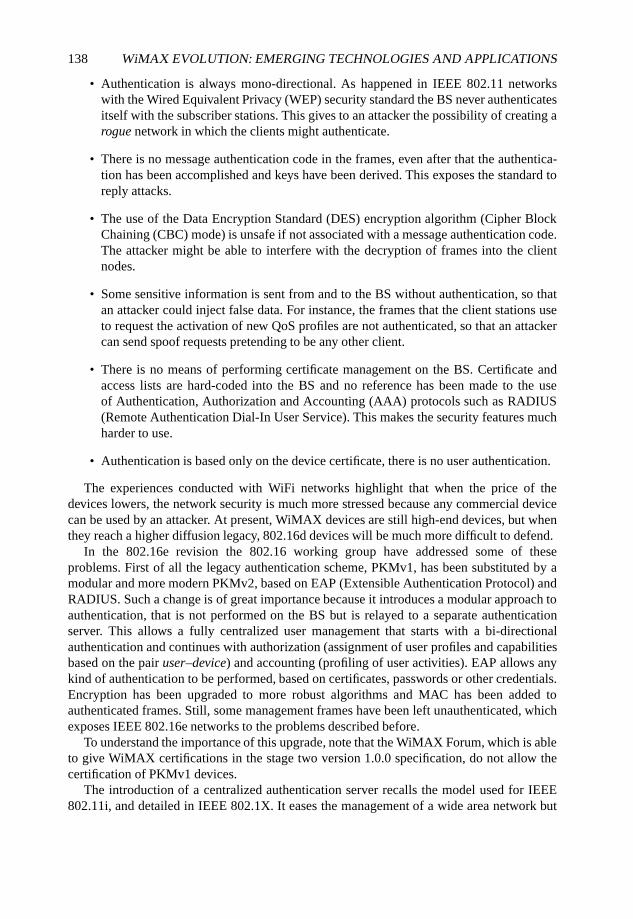
138 WiMAX EVOLUTION: EMERGING TECHNOLOGIES AND APPLICATIONS
• Authentication is always mono-directional. As happened in IEEE 802.11 networkswith the Wired Equivalent Privacy (WEP) security standard the BS never authenticatesitself with the subscriber stations. This gives to an attacker the possibility of creating arogue network in which the clients might authenticate.
• There is no message authentication code in the frames, even after that the authentica-tion has been accomplished and keys have been derived. This exposes the standard toreply attacks.
• The use of the Data Encryption Standard (DES) encryption algorithm (Cipher BlockChaining (CBC) mode) is unsafe if not associated with a message authentication code.The attacker might be able to interfere with the decryption of frames into the clientnodes.
• Some sensitive information is sent from and to the BS without authentication, so thatan attacker could inject false data. For instance, the frames that the client stations useto request the activation of new QoS profiles are not authenticated, so that an attackercan send spoof requests pretending to be any other client.
• There is no means of performing certificate management on the BS. Certificate andaccess lists are hard-coded into the BS and no reference has been made to the useof Authentication, Authorization and Accounting (AAA) protocols such as RADIUS(Remote Authentication Dial-In User Service). This makes the security features muchharder to use.
• Authentication is based only on the device certificate, there is no user authentication.
The experiences conducted with WiFi networks highlight that when the price of thedevices lowers, the network security is much more stressed because any commercial devicecan be used by an attacker. At present, WiMAX devices are still high-end devices, but whenthey reach a higher diffusion legacy, 802.16d devices will be much more difficult to defend.
In the 802.16e revision the 802.16 working group have addressed some of theseproblems. First of all the legacy authentication scheme, PKMv1, has been substituted by amodular and more modern PKMv2, based on EAP (Extensible Authentication Protocol) andRADIUS. Such a change is of great importance because it introduces a modular approach toauthentication, that is not performed on the BS but is relayed to a separate authenticationserver. This allows a fully centralized user management that starts with a bi-directionalauthentication and continues with authorization (assignment of user profiles and capabilitiesbased on the pair user–device) and accounting (profiling of user activities). EAP allows anykind of authentication to be performed, based on certificates, passwords or other credentials.Encryption has been upgraded to more robust algorithms and MAC has been added toauthenticated frames. Still, some management frames have been left unauthenticated, whichexposes IEEE 802.16e networks to the problems described before.
To understand the importance of this upgrade, note that the WiMAX Forum, which is ableto give WiMAX certifications in the stage two version 1.0.0 specification, do not allow thecertification of PKMv1 devices.
The introduction of a centralized authentication server recalls the model used for IEEE802.11i, and detailed in IEEE 802.1X. It eases the management of a wide area network but
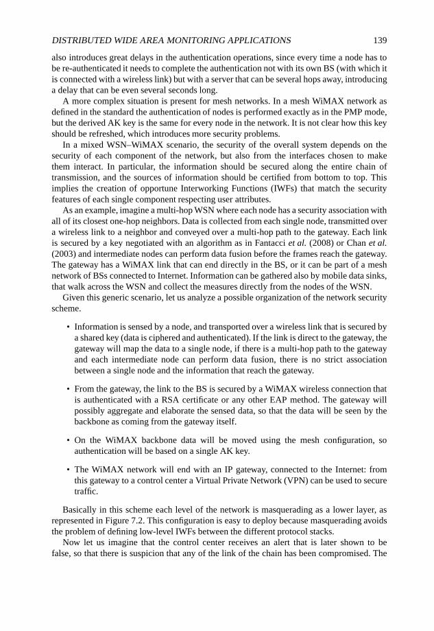
DISTRIBUTED WIDE AREA MONITORING APPLICATIONS 139
also introduces great delays in the authentication operations, since every time a node has tobe re-authenticated it needs to complete the authentication not with its own BS (with which itis connected with a wireless link) but with a server that can be several hops away, introducinga delay that can be even several seconds long.
A more complex situation is present for mesh networks. In a mesh WiMAX network asdefined in the standard the authentication of nodes is performed exactly as in the PMP mode,but the derived AK key is the same for every node in the network. It is not clear how this keyshould be refreshed, which introduces more security problems.
In a mixed WSN–WiMAX scenario, the security of the overall system depends on thesecurity of each component of the network, but also from the interfaces chosen to makethem interact. In particular, the information should be secured along the entire chain oftransmission, and the sources of information should be certified from bottom to top. Thisimplies the creation of opportune Interworking Functions (IWFs) that match the securityfeatures of each single component respecting user attributes.
As an example, imagine a multi-hop WSN where each node has a security association withall of its closest one-hop neighbors. Data is collected from each single node, transmitted overa wireless link to a neighbor and conveyed over a multi-hop path to the gateway. Each linkis secured by a key negotiated with an algorithm as in Fantacci et al. (2008) or Chan et al.(2003) and intermediate nodes can perform data fusion before the frames reach the gateway.The gateway has a WiMAX link that can end directly in the BS, or it can be part of a meshnetwork of BSs connected to Internet. Information can be gathered also by mobile data sinks,that walk across the WSN and collect the measures directly from the nodes of the WSN.
Given this generic scenario, let us analyze a possible organization of the network securityscheme.
• Information is sensed by a node, and transported over a wireless link that is secured bya shared key (data is ciphered and authenticated). If the link is direct to the gateway, thegateway will map the data to a single node, if there is a multi-hop path to the gatewayand each intermediate node can perform data fusion, there is no strict associationbetween a single node and the information that reach the gateway.
• From the gateway, the link to the BS is secured by a WiMAX wireless connection thatis authenticated with a RSA certificate or any other EAP method. The gateway willpossibly aggregate and elaborate the sensed data, so that the data will be seen by thebackbone as coming from the gateway itself.
• On the WiMAX backbone data will be moved using the mesh configuration, soauthentication will be based on a single AK key.
• The WiMAX network will end with an IP gateway, connected to the Internet: fromthis gateway to a control center a Virtual Private Network (VPN) can be used to securetraffic.
Basically in this scheme each level of the network is masquerading as a lower layer, asrepresented in Figure 7.2. This configuration is easy to deploy because masquerading avoidsthe problem of defining low-level IWFs between the different protocol stacks.
Now let us imagine that the control center receives an alert that is later shown to befalse, so that there is suspicion that any of the link of the chain has been compromised. The
140 WiMAX EVOLUTION: EMERGING TECHNOLOGIES AND APPLICATIONS
Figure 7.2 Security architecture based on link-layer protocols.
compromised link could be the single sensor node that generated the false information, but itcould be also any node on the path to the gateway that performed data fusion. Alternativelyit could be coming from a compromised gateway, or it could even have been injected over acompromised WiMAX link.
Another difficult issue to resolve is key revocation, when one of the mobile sinks is stolen.Mobile sinks draw data directly from the sensor nodes, so they need a key shared with eachof them. It is not an easy task to reprogram every node in order to invalidate that key. We seethat a layered approach has disadvantages under a security and management point of view.Now let us imagine a completely opposite scenario.
• Each sensor node is in possession of a shared key with a unique authentication server,for the whole network. Each time a node wants to create a link with one of itsneighbors, it will communicate with the authentication server and ask for a freshshared key. Communications with the authentication server must pass through thesensor technology, WiMAX links and Internet with proper encapsulation. In this waythe WSN mesh is formed.
DISTRIBUTED WIDE AREA MONITORING APPLICATIONS 141
Figure 7.3 Security architecture based on end-to-end protocols.
• When the node wants to send information it will sent a frame ciphered and authenti-cated with its key, that will be encapsulated in the WiMAX link.
• The control center receives data that are authenticated directly by the single nodes.
We see that in such a configuration as depicted in Figure 7.3, there is an end-to-endauthentication, so that a misbehaving sensor node can be recognized in the control center.Moreover, since links are dynamically created with the help of an authentication server, astolen node can be easily excluded by the network revoking its keys and credentials fromthe server. On the other side such a configuration introduces new difficulties in managing thewhole network. Since data is authenticated and ciphered, no fusion can be made along thepath, and information can be lost on the way (for instance, the gateway in the field mightknow information useful for data fusion, such as the position of the sensors, which will notbe available in the control center). Then, for each link that has to be created, a multi-hop,multi-technology handshake must be fulfilled. Lastly, specific encapsulation must be definedfor every network bridge.
142 WiMAX EVOLUTION: EMERGING TECHNOLOGIES AND APPLICATIONS
Acknowledgements
This work is partially supported by MIUR-FIRB Integrated System for Emergency (InSyEme)project under the grant RBIP063BPH and by the Italian National Project Wireless multiplat-fOrm mimo active access netwoRks for QoS-demanding muLtimedia Delivery (WORLD),under grant number 2007R989S.
References
AgroSense (2007–2010) Wireless sensor networks and remote sensing – foundation of a modernagricultural infrastructure in the region, http://www.agrosense.org/.
Akyildiz, I., Su, W., Sankarasubramanian, Y. and Cayirci, E. (2001) Wireless sensor networks: a survey.Computer Networks, 38, 393–422.
Bohge, M., Gross, J., Wolisz, A. and Mayer, M. (2007) Dynamic resource allocation in OFDM systems:An overview of cross-layer optimization principles and techniques. IEEE Network, 21(1), 53–59.
Cai, J., Shen, X. and Mark, J.W. (2005) Downlink resource management for packet transmission inOFDM wireless communication systems. IEEE Transactions on Wireless Communications, 4(4),1688–1703.
Chan, H., Perrig, A. and Song, D. (2003) Random key predistribution schemes for sensor networks.Proceedings of 2003 Symposium on Security and Privacy, pp. 197–213.
Chiti, F. and Fantacci, R. (2006) Wireless sensor network paradigm: overview on communicationprotocols design and application to practical scenarios. EURASIP Newsletter 17(4), 6–27.
Cicconetti, C., Erta, A., Lenzini, L. and Mingozzi, E. (2007) Performance evaluation of the IEEE 802.16MAC for QoS support. IEEE Transactions on Mobile Computing, 6(1), 26–38.
DustBot (2007–2009) Networked and cooperating robots for urban hygiene, http://www.dustbot.org/.
Ergen, M., Coleri, S. and Varaiya, P. (2003) QoS aware adaptive resource allocation techniquesfor fair scheduling in OFDMA based broadband wireless access systems. IEEE Transactions onBroadcasting, 49(4), 362–370.
Ermolova, N.Y. and Makarevitch, B. (2007) Low complexity adaptive power and subcarrier allocationfor OFDMA. IEEE Transactions on Wireless Communications, 6(2), 433–437.
Fantacci, R., Chiti, F. and Maccari, L. (2008) Fast distributed bi-directional authentication for wirelesssensor networks. Journal on Security and Communication Networks, 1(1), 17–24.
GoodFood (2004–2006), http://www.goodfood-project.org/.
Ilyas, M. and Mahgoub, I. (2005) Handbook of Sensor Networks: Compact Wireless and Wired SensingSystems. CRC Press, Boca Raton, FL.
InSyEme FIMFR (2007–2010) Integrated System for Emergency, http://www.unifi.it/insyeme/.
Keller, T. and Hanzo, L. (2000a) Adaptive modulation techniques for duplex OFDM transmission. IEEETransactions on Vehicular Technology, 49(5), 1893–1906.
Keller, T. and Hanzo, L. (2000b) Adaptive multicarrier modulation: a convenient framework for time-frequency processing in wireless communications. Proceedings of the IEEE, 88(5), 611–640.
Kim, K., Han, Y. and Kim, S.L. (2005) Joint subcarrier and power allocation in uplink OFDMAsystems. IEEE Communications Letters, 9(6), 526–528.
Kulkarni, G., Adlakha, S. and Srivastava, M. (2005) Subcarrier allocation and bit loading algorithmsfor OFDMA-based wireless networks. IEEE Transactions on Mobile Computing, 4(6), 652–662.
Lee, H., Kwon, T. and Cho, D.H. (2005) An enhanced uplink scheduling algorithm based on voiceactivity for VoIP services in IEEE 802.16d/e system. IEEE Communications Letters, 9(8), 691–694.
DISTRIBUTED WIDE AREA MONITORING APPLICATIONS 143
Liu, X., Chong, E.K.P. and Shroff, N.B. (2001) Opportunistic transmission scheduling with resource-sharing constraints in wireless networks. IEEE Journal on Selected Areas in Communications,19(10), 2053–2064.
Maccari, L., Paoli, M. and Fantacci, R. (2007) Security analysis of IEEE 802.16. Proceedings of the2007 IEEE International Conference on Communications.
Niyato, D. and Hossain, E. (2006) Queue-aware uplink bandwidth allocation and rate control for pollingservice in IEEE 802.16 broadband wireless networks. IEEE Transactions on Mobile Computing,5(6), 668–679.
Rhee, W. and Cioffi, J.M. (2000) Increase in capacity of multiuser OFDM system using dynamicsubchannel allocation. Proceedings of IEEE VTC 2000-Spring, vol. 2, Tokyo, Japan, pp. 1085–1089.
Song, G. and Li, Y.G. (2005) Utility-based resource allocation and scheduling in OFDM-based wirelessbroadband networks. IEEE Communications Magazine, 43(12), 127–134.
Stallings, W. (2006) Cryptography and Network Security. Prentice Hall, Englewood Cliffs, NJ.IEEE (2005) Amendment to IEEE Standard for Local and Metropolitan Area Networks – Part 16:
Air Interface for Fixed Broadband Wireless Access Systems – Physical and Medium Access ControlLayers for Combined Fixed and Mobile Operation in Licensed Bands. IEEE Standard 802.16e-2005.
IEEE (2004) IEEE Standard for Local and Metropolitan Area Networks – Part 16: Air Interface forFixed Broadband Wireless Access Systems. IEEE Standard 802.16-2004.
van Nee, R. and Prasad, R. (2000) OFDM for Wireless Multimedia Communications. Artech House.Wong, C.Y., Cheng, R.S., Letaief, K.B. and Murch, R.D. (1999) Multiuser OFDM with adaptive
subcarrier, bit, and power allocation. IEEE Journal on Selected Areas in Communications, 17(10),1747–1758.
WP122 (2008) Report on experimental capabilities of the integrated test bed. Technical Report FP6-IST-4-027738-NoE, ’CRUISE’.
8
WiMAX Mesh Architectures andNetwork Coding
Parag S. Mogre, Matthias Hollick,Christian Schwingenschloegl, Andreas Ziller andRalf Steinmetz
8.1 Introduction
The seminal work of Ahlswede et al. (2000) introduced the notion of Network Coding(NC) as a means to achieve bandwidth savings for multicast data transmissions. The authorsdemonstrated that suboptimal results in terms of required bandwidth are achieved in general,if the information to be multicast is considered as a fluid which is to be routed or replicatedon a set of outgoing links at each node relaying the information in the network, that is, thetransportation network capacity is not equal to the information network capacity. The conceptof network coding was later also extended to unicast information transmission. Recently,the application of network coding in wireless networks (Wireless Network Coding (WNC))is being investigated intensively. In particular, the deployment of WNC in Wireless MeshNetworks (WMNs) to achieve bandwidth savings and throughput gain is very promising. Wedemonstrate this functionality with the help of Figure 8.1. In a WMN, nodes typically senddata to destinations via multi-hop routes. Here, a number of nodes relay the data packetsbetween the source and destination. Readers can find more background information aboutWMNs and a survey of respective research challenges in Akyildiz et al. (2005).
Consider a simple linear WMN topology as shown in Figure 8.1. Assume that node N1and node N2 transmit data to each other, which is relayed by the node R1. Figure 8.1(a)shows the behavior in WMNs without application of WNC. Here, N1 transmits data to thenext hop R1 in slot (or transmission number) 1. The data received is relayed by R1 in slot 2 tonode N2. Similarly, data transmitted by N2 addressed to node N1 is transmitted and relayedin slots 3 and 4, respectively. Figure 8.1(b) shows how the same data can be transferred to the
WiMAX Evolution: Emerging Technologies and Applications Edited by Tsutomu Ishikawa© 2009 John Wiley & Sons, Ltd. ISBN: 978-0-470-69680-4
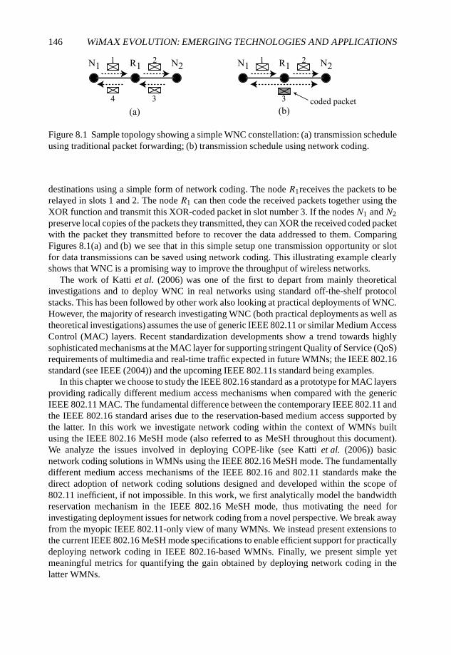
146 WiMAX EVOLUTION: EMERGING TECHNOLOGIES AND APPLICATIONS
Figure 8.1 Sample topology showing a simple WNC constellation: (a) transmission scheduleusing traditional packet forwarding; (b) transmission schedule using network coding.
destinations using a simple form of network coding. The node R1receives the packets to berelayed in slots 1 and 2. The node R1 can then code the received packets together using theXOR function and transmit this XOR-coded packet in slot number 3. If the nodesN1 and N2preserve local copies of the packets they transmitted, they can XOR the received coded packetwith the packet they transmitted before to recover the data addressed to them. ComparingFigures 8.1(a) and (b) we see that in this simple setup one transmission opportunity or slotfor data transmissions can be saved using network coding. This illustrating example clearlyshows that WNC is a promising way to improve the throughput of wireless networks.
The work of Katti et al. (2006) was one of the first to depart from mainly theoreticalinvestigations and to deploy WNC in real networks using standard off-the-shelf protocolstacks. This has been followed by other work also looking at practical deployments of WNC.However, the majority of research investigating WNC (both practical deployments as well astheoretical investigations) assumes the use of generic IEEE 802.11 or similar Medium AccessControl (MAC) layers. Recent standardization developments show a trend towards highlysophisticated mechanisms at the MAC layer for supporting stringent Quality of Service (QoS)requirements of multimedia and real-time traffic expected in future WMNs; the IEEE 802.16standard (see IEEE (2004)) and the upcoming IEEE 802.11s standard being examples.
In this chapter we choose to study the IEEE 802.16 standard as a prototype for MAC layersproviding radically different medium access mechanisms when compared with the genericIEEE 802.11 MAC. The fundamental difference between the contemporary IEEE 802.11 andthe IEEE 802.16 standard arises due to the reservation-based medium access supported bythe latter. In this work we investigate network coding within the context of WMNs builtusing the IEEE 802.16 MeSH mode (also referred to as MeSH throughout this document).We analyze the issues involved in deploying COPE-like (see Katti et al. (2006)) basicnetwork coding solutions in WMNs using the IEEE 802.16 MeSH mode. The fundamentallydifferent medium access mechanisms of the IEEE 802.16 and 802.11 standards make thedirect adoption of network coding solutions designed and developed within the scope of802.11 inefficient, if not impossible. In this work, we first analytically model the bandwidthreservation mechanism in the IEEE 802.16 MeSH mode, thus motivating the need forinvestigating deployment issues for network coding from a novel perspective. We break awayfrom the myopic IEEE 802.11-only view of many WMNs. We instead present extensions tothe current IEEE 802.16 MeSH mode specifications to enable efficient support for practicallydeploying network coding in IEEE 802.16-based WMNs. Finally, we present simple yetmeaningful metrics for quantifying the gain obtained by deploying network coding in thelatter WMNs.
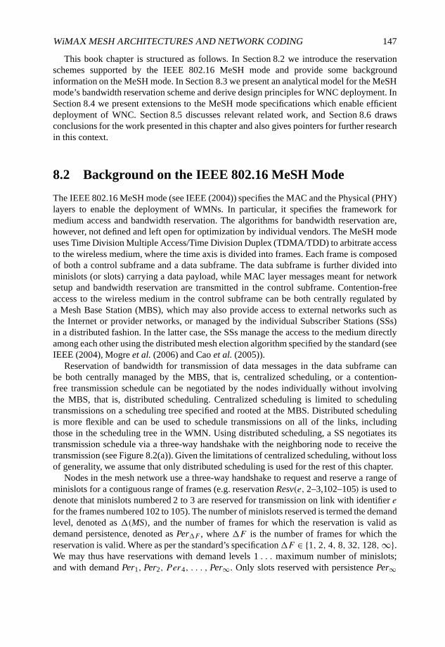
WiMAX MESH ARCHITECTURES AND NETWORK CODING 147
This book chapter is structured as follows. In Section 8.2 we introduce the reservationschemes supported by the IEEE 802.16 MeSH mode and provide some backgroundinformation on the MeSH mode. In Section 8.3 we present an analytical model for the MeSHmode’s bandwidth reservation scheme and derive design principles for WNC deployment. InSection 8.4 we present extensions to the MeSH mode specifications which enable efficientdeployment of WNC. Section 8.5 discusses relevant related work, and Section 8.6 drawsconclusions for the work presented in this chapter and also gives pointers for further researchin this context.
8.2 Background on the IEEE 802.16 MeSH Mode
The IEEE 802.16 MeSH mode (see IEEE (2004)) specifies the MAC and the Physical (PHY)layers to enable the deployment of WMNs. In particular, it specifies the framework formedium access and bandwidth reservation. The algorithms for bandwidth reservation are,however, not defined and left open for optimization by individual vendors. The MeSH modeuses Time Division Multiple Access/Time Division Duplex (TDMA/TDD) to arbitrate accessto the wireless medium, where the time axis is divided into frames. Each frame is composedof both a control subframe and a data subframe. The data subframe is further divided intominislots (or slots) carrying a data payload, while MAC layer messages meant for networksetup and bandwidth reservation are transmitted in the control subframe. Contention-freeaccess to the wireless medium in the control subframe can be both centrally regulated bya Mesh Base Station (MBS), which may also provide access to external networks such asthe Internet or provider networks, or managed by the individual Subscriber Stations (SSs)in a distributed fashion. In the latter case, the SSs manage the access to the medium directlyamong each other using the distributed mesh election algorithm specified by the standard (seeIEEE (2004), Mogre et al. (2006) and Cao et al. (2005)).
Reservation of bandwidth for transmission of data messages in the data subframe canbe both centrally managed by the MBS, that is, centralized scheduling, or a contention-free transmission schedule can be negotiated by the nodes individually without involvingthe MBS, that is, distributed scheduling. Centralized scheduling is limited to schedulingtransmissions on a scheduling tree specified and rooted at the MBS. Distributed schedulingis more flexible and can be used to schedule transmissions on all of the links, includingthose in the scheduling tree in the WMN. Using distributed scheduling, a SS negotiates itstransmission schedule via a three-way handshake with the neighboring node to receive thetransmission (see Figure 8.2(a)). Given the limitations of centralized scheduling, without lossof generality, we assume that only distributed scheduling is used for the rest of this chapter.
Nodes in the mesh network use a three-way handshake to request and reserve a range ofminislots for a contiguous range of frames (e.g. reservation Resv(e, 2–3,102–105) is used todenote that minislots numbered 2 to 3 are reserved for transmission on link with identifier efor the frames numbered 102 to 105). The number of minislots reserved is termed the demandlevel, denoted as �(MS), and the number of frames for which the reservation is valid asdemand persistence, denoted as Per�F , where �F is the number of frames for which thereservation is valid. Where as per the standard’s specification�F ∈ {1, 2, 4, 8, 32, 128,∞}.We may thus have reservations with demand levels 1 . . . maximum number of minislots;and with demand Per1, Per2, P er4, . . . , Per∞. Only slots reserved with persistence Per∞
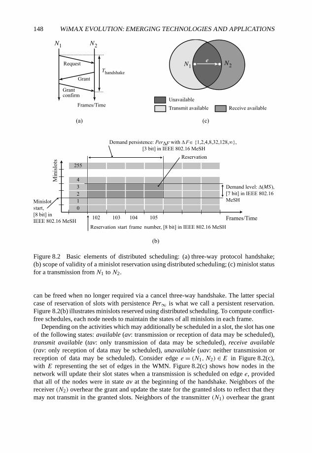
148 WiMAX EVOLUTION: EMERGING TECHNOLOGIES AND APPLICATIONS
Figure 8.2 Basic elements of distributed scheduling: (a) three-way protocol handshake;(b) scope of validity of a minislot reservation using distributed scheduling; (c) minislot statusfor a transmission from N1 to N2.
can be freed when no longer required via a cancel three-way handshake. The latter specialcase of reservation of slots with persistence Per∞ is what we call a persistent reservation.Figure 8.2(b) illustrates minislots reserved using distributed scheduling. To compute conflict-free schedules, each node needs to maintain the states of all minislots in each frame.
Depending on the activities which may additionally be scheduled in a slot, the slot has oneof the following states: available (av: transmission or reception of data may be scheduled),transmit available (tav: only transmission of data may be scheduled), receive available(rav: only reception of data may be scheduled), unavailable (uav: neither transmission orreception of data may be scheduled). Consider edge e = (N1, N2) ∈E in Figure 8.2(c),with E representing the set of edges in the WMN. Figure 8.2(c) shows how nodes in thenetwork will update their slot states when a transmission is scheduled on edge e, providedthat all of the nodes were in state av at the beginning of the handshake. Neighbors of thereceiver (N2) overhear the grant and update the state for the granted slots to reflect that theymay not transmit in the granted slots. Neighbors of the transmitter (N1) overhear the grant
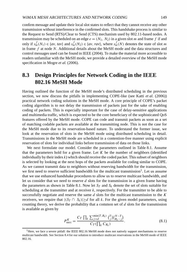
WiMAX MESH ARCHITECTURES AND NETWORK CODING 149
confirm message and update their local slot states to reflect that they cannot receive any othertransmission without interference in the confirmed slots. This handshake process is similar tothe Request to Send (RTS)/Clear to Send (CTS) mechanism used by 802.11-based nodes. Atransmission may be scheduled on an edge e = (N1, N2) in a given slotm and frame f if andonly if sfm(N1) ∈ {av, tav} and sfm(N2) ∈ {av, rav}, where sfm(N) denotes the state of slot min frame f at node N . Additional details about the MeSH mode and the data structures andcontrol messages used can be found in IEEE (2004). To make the material more accessible toreaders unfamiliar with the MeSH mode, we provide a detailed overview of the MeSH modespecification in Mogre et al. (2006).
8.3 Design Principles for Network Coding in the IEEE802.16 MeSH Mode
Having outlined the function of the MeSH mode’s distributed scheduling in the previoussection, we now discuss the pitfalls in implementing COPE-like (see Katti et al. (2006))practical network coding solutions in the MeSH mode. A core principle of COPE’s packetcoding algorithm is to not delay the transmission of packets just for the sake of enablingcoding of packets. This is especially important for the case of delay-sensitive applicationsand multimedia traffic, which is expected to be the core beneficiary of the sophisticated QoSfeatures offered by the MeSH mode. COPE can code and transmit packets as soon as a setof matching codable packets are available at the transmitting node. This is not the case forthe MeSH mode due to its reservation-based nature. To understand the former issue, welook at the reservation of slots in the MeSH mode using distributed scheduling in detail.Transmissions in the MeSH mode are scheduled in a contention-free manner using explicitreservation of slots for individual links before transmission of data on those links.
We next formulate our model. Consider the parameters outlined in Table 8.1. Assumethat the parameters hold for a given frame. Let K be the number of neighbors (identifiedindividually by their index k) which should receive the coded packet. This subset of neighborsis selected by looking at the next hops of the packets available for coding similar to COPE.As we cannot transmit data to neighbors without reserving bandwidth for the transmission,we first need to reserve sufficient bandwidth for the multicast transmission1. Let us assumethat we use enhanced handshake procedures to allow us to reserve multicast bandwidth, andlet us consider that we need to reserve d slots for the transmission in a given frame havingthe parameters as shown in Table 8.1. Now let ST and Sk denote the set of slots suitable forscheduling at the transmitter and at receiver k, respectively. For the transmitter to be able tosuccessfully negotiate and reserve the same d slots for the multicast transmission to the Kreceivers, we require that |(ST ∩ Sk)|≥d for all k. For the given model parameters, usingcounting theory, we derive the probability that a common set of d slots for the transmissionis available as given by
PKsucc = CT∏k
∑min(T ,Rk)j=d
(Tj
)(N−TRk−j
)CT (
∏k CRk )
. (8.1)
1Here, we face a severe pitfall: the IEEE 802.16 MeSH mode does not natively support mechanisms to reservemulticast bandwidth. See Section 8.4 for our solution to introduce multicast reservations in the MeSH mode of IEEE802.16.
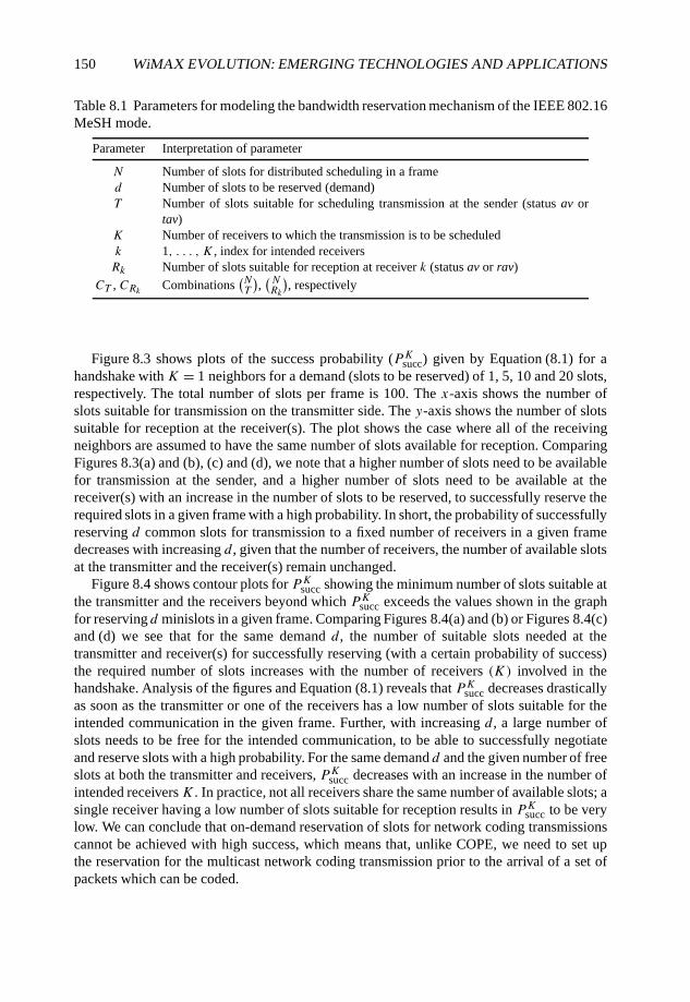
150 WiMAX EVOLUTION: EMERGING TECHNOLOGIES AND APPLICATIONS
Table 8.1 Parameters for modeling the bandwidth reservation mechanism of the IEEE 802.16MeSH mode.
Parameter Interpretation of parameter
N Number of slots for distributed scheduling in a framed Number of slots to be reserved (demand)T Number of slots suitable for scheduling transmission at the sender (status av or
tav)K Number of receivers to which the transmission is to be scheduledk 1, . . . , K , index for intended receiversRk Number of slots suitable for reception at receiver k (status av or rav)
CT , CRk Combinations(NT
),(NRk
), respectively
Figure 8.3 shows plots of the success probability (PKsucc) given by Equation (8.1) for ahandshake with K = 1 neighbors for a demand (slots to be reserved) of 1, 5, 10 and 20 slots,respectively. The total number of slots per frame is 100. The x-axis shows the number ofslots suitable for transmission on the transmitter side. The y-axis shows the number of slotssuitable for reception at the receiver(s). The plot shows the case where all of the receivingneighbors are assumed to have the same number of slots available for reception. ComparingFigures 8.3(a) and (b), (c) and (d), we note that a higher number of slots need to be availablefor transmission at the sender, and a higher number of slots need to be available at thereceiver(s) with an increase in the number of slots to be reserved, to successfully reserve therequired slots in a given frame with a high probability. In short, the probability of successfullyreserving d common slots for transmission to a fixed number of receivers in a given framedecreases with increasing d , given that the number of receivers, the number of available slotsat the transmitter and the receiver(s) remain unchanged.
Figure 8.4 shows contour plots for PKsucc showing the minimum number of slots suitable atthe transmitter and the receivers beyond which PKsucc exceeds the values shown in the graphfor reserving d minislots in a given frame. Comparing Figures 8.4(a) and (b) or Figures 8.4(c)and (d) we see that for the same demand d , the number of suitable slots needed at thetransmitter and receiver(s) for successfully reserving (with a certain probability of success)the required number of slots increases with the number of receivers (K) involved in thehandshake. Analysis of the figures and Equation (8.1) reveals that PKsucc decreases drasticallyas soon as the transmitter or one of the receivers has a low number of slots suitable for theintended communication in the given frame. Further, with increasing d , a large number ofslots needs to be free for the intended communication, to be able to successfully negotiateand reserve slots with a high probability. For the same demand d and the given number of freeslots at both the transmitter and receivers, PKsucc decreases with an increase in the number ofintended receiversK . In practice, not all receivers share the same number of available slots; asingle receiver having a low number of slots suitable for reception results in PKsucc to be verylow. We can conclude that on-demand reservation of slots for network coding transmissionscannot be achieved with high success, which means that, unlike COPE, we need to set upthe reservation for the multicast network coding transmission prior to the arrival of a set ofpackets which can be coded.

WiMAX MESH ARCHITECTURES AND NETWORK CODING 151
020
4060
80100 0
2040
6080
1000
0.2
0.4
0.6
0.8
1
Available minislotsat receiver Available minislots
at transmitter
Psu
ccGrid lines show Psucc for K = 1, d = 1
020
4060
80100 0
2040
6080
1000
0.2
0.4
0.6
0.8
1
Available minislotsat receiver Available minislots
at transmitter
Psu
cc
Psu
cc
Psu
cc
Grid lines show Psucc for K = 1, d = 5
(b)(a)
(d)(c)
020
4060
80100 0
2040
6080
1000
0.2
0.4
0.6
0.8
1
Available minislotsat receiver Available minislots
at transmitter
Grid lines show Psucc for K = 1, d = 20
020
4060
80100 0
2040
6080
1000
0.2
0.4
0.6
0.8
1
Available minislotsat receiver Available minislots
at transmitter
Grid lines show Psucc for K = 1, d = 10
Figure 8.3 Plots showing the probability PKsucc of successfully reserving d slots in a givenframe for simultaneous reception at K neighboring nodes: (a)K = 1, d = 1; (b)K = 1, d =5; (c) K = 1, d = 10; (d) K = 1, d = 20.
An important aspect of the IEEE 802.16 MeSH mode is the way the reservations arecarried out. Nodes perform the three-way handshake shown in Figure 8.2(a) to reservebandwidth for links to individual neighbors; distributed scheduling messages (MSH-DSCH)containing Request, Grant and Grant-confirmation are exchanged to reserve a setof slots for the required transmission. In the above analysis we have computed the value forPKsucc considering the entire range of available slots at the transmitter and all of the receivers.However, due to message size restrictions, with the bandwidth request in a MSH-DSCHmessage, the transmitter can only advertise a subset of the slots suitable for transmissionto the receivers. This effectively reduces the value of PKsucc by reducing the number ofslots available at the transmitter for negotiating the reservation. However, a more importantproblem with multicast reservation is that each node maintains its own independent statefor all of the minislots. Thus, the individual receivers for the multicast transmission do notpossess a common view about which slots are suitable at the other receiver(s) and may, hence,issue grants for different slot ranges. Such disjoint grants require multiple transmissions
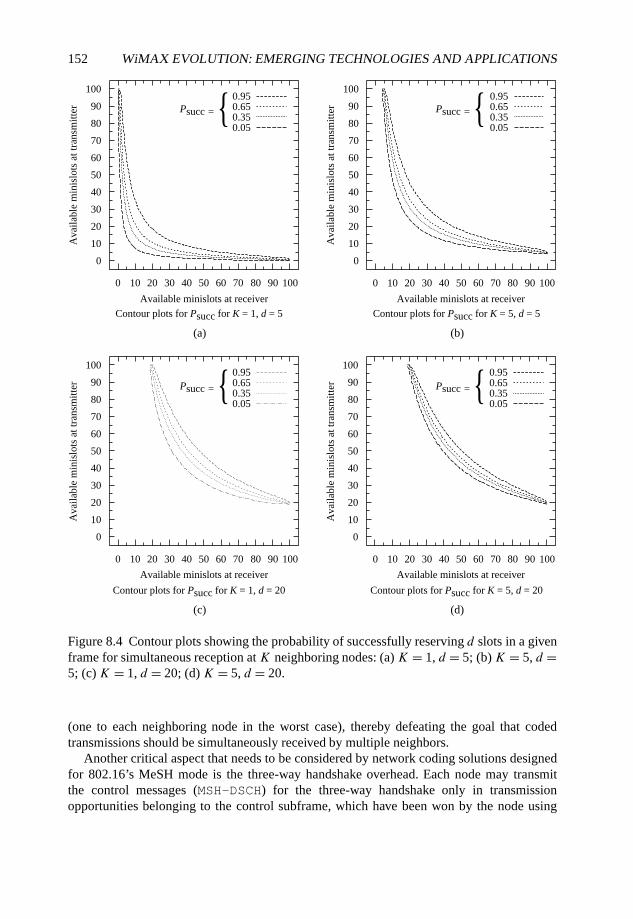
152 WiMAX EVOLUTION: EMERGING TECHNOLOGIES AND APPLICATIONS
0
10
20
30
40
50
60
70
80
90
100
Ava
ilabl
e m
inis
lots
at t
rans
mitt
er
Ava
ilabl
e m
inis
lots
at t
rans
mitt
er
Ava
ilabl
e m
inis
lots
at t
rans
mitt
er
Available minislots at receiver Available minislots at receiver
Available minislots at receiver Available minislots at receiver
Ava
ilabl
e m
inis
lots
at t
rans
mitt
er
0.950.650.350.05
(a)
Contour plots for Psucc for K = 1, d = 5
0 10 20 30 40 50 60 70 80 90 100
0 10 20 30 40 50 60 70 80 90 100
0
10
20
30
40
50
60
70
80
90
1000.950.650.350.05
Contour plots for Psucc for K = 5, d = 5
(b)
(c)
Contour plots for Psucc for K = 1, d = 20 Contour plots for Psucc for K = 5, d = 20
(d)
Psucc =Psucc = {{
Psucc = {
0
10
20
30
40
50
60
70
80
90
1000.950.650.350.05
Psucc = {
0 10 20 30 40 50 60 70 80 90 100
0 10 20 30 40 50 60 70 80 90 100
0
10
20
30
40
50
60
70
80
90
1000.950.650.350.05
Figure 8.4 Contour plots showing the probability of successfully reserving d slots in a givenframe for simultaneous reception at K neighboring nodes: (a) K = 1, d = 5; (b)K = 5, d =5; (c)K = 1, d = 20; (d) K = 5, d = 20.
(one to each neighboring node in the worst case), thereby defeating the goal that codedtransmissions should be simultaneously received by multiple neighbors.
Another critical aspect that needs to be considered by network coding solutions designedfor 802.16’s MeSH mode is the three-way handshake overhead. Each node may transmitthe control messages (MSH-DSCH) for the three-way handshake only in transmissionopportunities belonging to the control subframe, which have been won by the node using
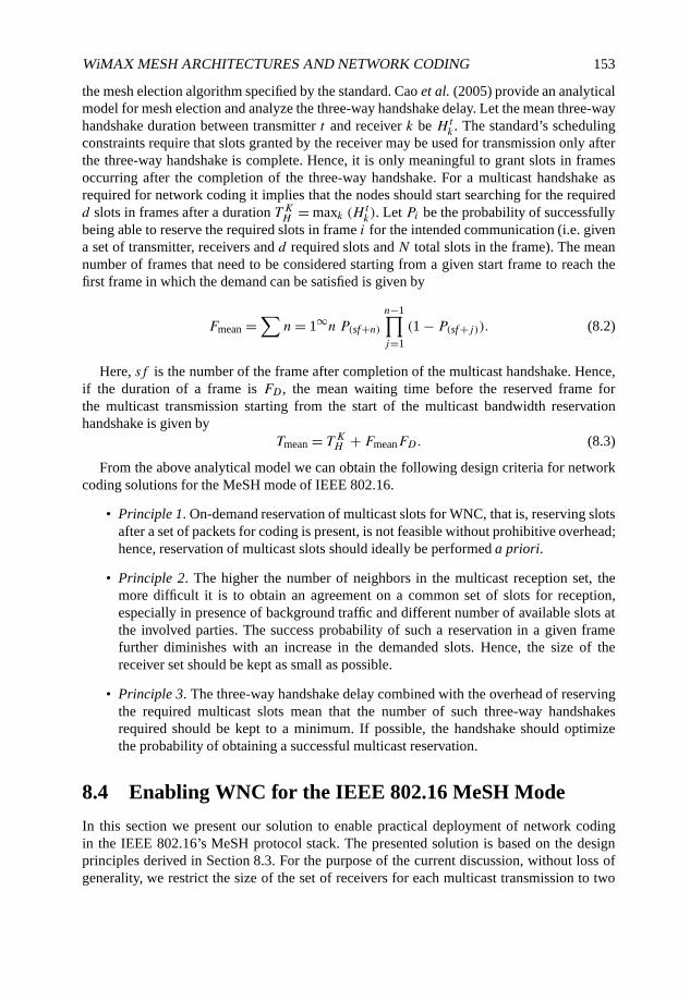
WiMAX MESH ARCHITECTURES AND NETWORK CODING 153
the mesh election algorithm specified by the standard. Cao et al. (2005) provide an analyticalmodel for mesh election and analyze the three-way handshake delay. Let the mean three-wayhandshake duration between transmitter t and receiver k be Ht
k . The standard’s schedulingconstraints require that slots granted by the receiver may be used for transmission only afterthe three-way handshake is complete. Hence, it is only meaningful to grant slots in framesoccurring after the completion of the three-way handshake. For a multicast handshake asrequired for network coding it implies that the nodes should start searching for the requiredd slots in frames after a duration T KH = maxk (H t
k). Let Pi be the probability of successfullybeing able to reserve the required slots in frame i for the intended communication (i.e. givena set of transmitter, receivers and d required slots and N total slots in the frame). The meannumber of frames that need to be considered starting from a given start frame to reach thefirst frame in which the demand can be satisfied is given by
Fmean =∑
n= 1∞n P(sf+n)n−1∏j=1
(1 − P(sf+j)). (8.2)
Here, sf is the number of the frame after completion of the multicast handshake. Hence,if the duration of a frame is FD , the mean waiting time before the reserved frame forthe multicast transmission starting from the start of the multicast bandwidth reservationhandshake is given by
Tmean = T KH + FmeanFD. (8.3)
From the above analytical model we can obtain the following design criteria for networkcoding solutions for the MeSH mode of IEEE 802.16.
• Principle 1. On-demand reservation of multicast slots for WNC, that is, reserving slotsafter a set of packets for coding is present, is not feasible without prohibitive overhead;hence, reservation of multicast slots should ideally be performed a priori.
• Principle 2. The higher the number of neighbors in the multicast reception set, themore difficult it is to obtain an agreement on a common set of slots for reception,especially in presence of background traffic and different number of available slots atthe involved parties. The success probability of such a reservation in a given framefurther diminishes with an increase in the demanded slots. Hence, the size of thereceiver set should be kept as small as possible.
• Principle 3. The three-way handshake delay combined with the overhead of reservingthe required multicast slots mean that the number of such three-way handshakesrequired should be kept to a minimum. If possible, the handshake should optimizethe probability of obtaining a successful multicast reservation.
8.4 Enabling WNC for the IEEE 802.16 MeSH Mode
In this section we present our solution to enable practical deployment of network codingin the IEEE 802.16’s MeSH protocol stack. The presented solution is based on the designprinciples derived in Section 8.3. For the purpose of the current discussion, without loss ofgenerality, we restrict the size of the set of receivers for each multicast transmission to two
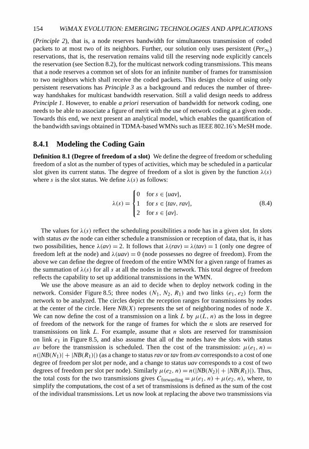
154 WiMAX EVOLUTION: EMERGING TECHNOLOGIES AND APPLICATIONS
(Principle 2), that is, a node reserves bandwidth for simultaneous transmission of codedpackets to at most two of its neighbors. Further, our solution only uses persistent (Per∞)reservations, that is, the reservation remains valid till the reserving node explicitly cancelsthe reservation (see Section 8.2), for the multicast network coding transmissions. This meansthat a node reserves a common set of slots for an infinite number of frames for transmissionto two neighbors which shall receive the coded packets. This design choice of using onlypersistent reservations has Principle 3 as a background and reduces the number of three-way handshakes for multicast bandwidth reservation. Still a valid design needs to addressPrinciple 1. However, to enable a priori reservation of bandwidth for network coding, oneneeds to be able to associate a figure of merit with the use of network coding at a given node.Towards this end, we next present an analytical model, which enables the quantification ofthe bandwidth savings obtained in TDMA-based WMNs such as IEEE 802.16’s MeSH mode.
8.4.1 Modeling the Coding Gain
Definition 8.1 (Degree of freedom of a slot) We define the degree of freedom or schedulingfreedom of a slot as the number of types of activities, which may be scheduled in a particularslot given its current status. The degree of freedom of a slot is given by the function λ(s)where s is the slot status. We define λ(s) as follows:
λ(s)=
0 for s ∈ {uav},1 for s ∈ {tav, rav},2 for s ∈ {av}.
(8.4)
The values for λ(s) reflect the scheduling possibilities a node has in a given slot. In slotswith status av the node can either schedule a transmission or reception of data, that is, it hastwo possibilities, hence λ(av)= 2. It follows that λ(rav)= λ(tav)= 1 (only one degree offreedom left at the node) and λ(uav)= 0 (node possesses no degree of freedom). From theabove we can define the degree of freedom of the entire WMN for a given range of frames asthe summation of λ(s) for all s at all the nodes in the network. This total degree of freedomreflects the capability to set up additional transmissions in the WMN.
We use the above measure as an aid to decide when to deploy network coding in thenetwork. Consider Figure 8.5; three nodes (N1, N2, R1) and two links (e1, e2) form thenetwork to be analyzed. The circles depict the reception ranges for transmissions by nodesat the center of the circle. Here NB(X) represents the set of neighboring nodes of node X.We can now define the cost of a transmission on a link L by µ(L, n) as the loss in degreeof freedom of the network for the range of frames for which the n slots are reserved fortransmissions on link L. For example, assume that n slots are reserved for transmissionon link e1 in Figure 8.5, and also assume that all of the nodes have the slots with statusav before the transmission is scheduled. Then the cost of the transmission: µ(e1, n)=n(|NB(N1)| + |NB(R1)|) (as a change to status rav or tav from av corresponds to a cost of onedegree of freedom per slot per node, and a change to status uav corresponds to a cost of twodegrees of freedom per slot per node). Similarly µ(e2, n)= n(|NB(N2)| + |NB(R1)|). Thus,the total costs for the two transmissions gives Cforwarding = µ(e1, n)+ µ(e2, n), where, tosimplify the computations, the cost of a set of transmissions is defined as the sum of the costof the individual transmissions. Let us now look at replacing the above two transmissions via
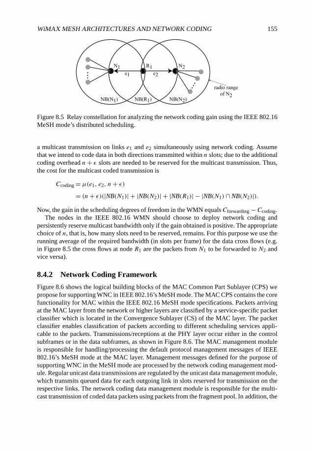
WiMAX MESH ARCHITECTURES AND NETWORK CODING 155
Figure 8.5 Relay constellation for analyzing the network coding gain using the IEEE 802.16MeSH mode’s distributed scheduling.
a multicast transmission on links e1 and e2 simultaneously using network coding. Assumethat we intend to code data in both directions transmitted within n slots; due to the additionalcoding overhead n+ ε slots are needed to be reserved for the multicast transmission. Thus,the cost for the multicast coded transmission is
Ccoding = µ(e1, e2, n+ ε)
= (n+ ε)(|NB(N1)| + |NB(N2)| + |NB(R1)| − |NB(N1) ∩ NB(N2)|).Now, the gain in the scheduling degrees of freedom in the WMN equalsCforwarding − Ccoding.
The nodes in the IEEE 802.16 WMN should choose to deploy network coding andpersistently reserve multicast bandwidth only if the gain obtained is positive. The appropriatechoice of n, that is, how many slots need to be reserved, remains. For this purpose we use therunning average of the required bandwidth (in slots per frame) for the data cross flows (e.g.in Figure 8.5 the cross flows at node R1 are the packets from N1 to be forwarded to N2 andvice versa).
8.4.2 Network Coding Framework
Figure 8.6 shows the logical building blocks of the MAC Common Part Sublayer (CPS) wepropose for supporting WNC in IEEE 802.16’s MeSH mode. The MAC CPS contains the corefunctionality for MAC within the IEEE 802.16 MeSH mode specifications. Packets arrivingat the MAC layer from the network or higher layers are classified by a service-specific packetclassifier which is located in the Convergence Sublayer (CS) of the MAC layer. The packetclassifier enables classification of packets according to different scheduling services appli-cable to the packets. Transmissions/receptions at the PHY layer occur either in the controlsubframes or in the data subframes, as shown in Figure 8.6. The MAC management moduleis responsible for handling/processing the default protocol management messages of IEEE802.16’s MeSH mode at the MAC layer. Management messages defined for the purpose ofsupporting WNC in the MeSH mode are processed by the network coding management mod-ule. Regular unicast data transmissions are regulated by the unicast data management module,which transmits queued data for each outgoing link in slots reserved for transmission on therespective links. The network coding data management module is responsible for the multi-cast transmission of coded data packets using packets from the fragment pool. In addition, the
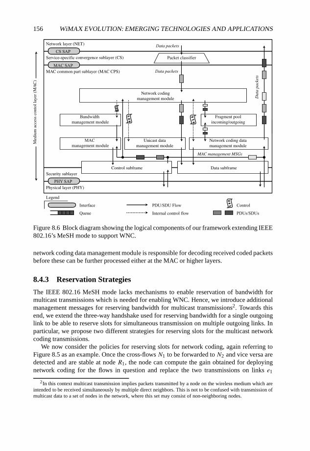
156 WiMAX EVOLUTION: EMERGING TECHNOLOGIES AND APPLICATIONS
Figure 8.6 Block diagram showing the logical components of our framework extending IEEE802.16’s MeSH mode to support WNC.
network coding data management module is responsible for decoding received coded packetsbefore these can be further processed either at the MAC or higher layers.
8.4.3 Reservation Strategies
The IEEE 802.16 MeSH mode lacks mechanisms to enable reservation of bandwidth formulticast transmissions which is needed for enabling WNC. Hence, we introduce additionalmanagement messages for reserving bandwidth for multicast transmissions2. Towards thisend, we extend the three-way handshake used for reserving bandwidth for a single outgoinglink to be able to reserve slots for simultaneous transmission on multiple outgoing links. Inparticular, we propose two different strategies for reserving slots for the multicast networkcoding transmissions.
We now consider the policies for reserving slots for network coding, again referring toFigure 8.5 as an example. Once the cross-flows N1 to be forwarded to N2 and vice versa aredetected and are stable at node R1, the node can compute the gain obtained for deployingnetwork coding for the flows in question and replace the two transmissions on links e1
2In this context multicast transmission implies packets transmitted by a node on the wireless medium which areintended to be received simultaneously by multiple direct neighbors. This is not to be confused with transmission ofmulticast data to a set of nodes in the network, where this set may consist of non-neighboring nodes.
WiMAX MESH ARCHITECTURES AND NETWORK CODING 157
and e2 with a single multicast transmission. Here, let s(e1) and s(e2) denote the sets ofn slots reserved for the unicast transmissions on links e1 and e2, respectively. Node R1may now select a set of suitable slots still free and use these to reserve n+ ε slots for themulticast coded transmission to nodesN1 andN2. However, with increasing traffic (either thecross-flows, or other unrelated background traffic) the number of slots additionally availableis reduced, implying the decrease of the probability of successfully reserving multicastbandwidth, as shown in Section 8.3. We introduce our novel slot allocation strategy termedthe replacement strategy to counteract this decrease in slots: the core idea is to consider thereuse of the slots already reserved for transmission to the nodesN1 and N2 in addition to theadditionally available slots at the transmitter to negotiate and reserve a common set of slotsfor transmission to neighborsN1 and N2. In addition to the available slots at the transmitter,the sets s(e1) and s(e2) are therefore also sent with the request for multicast bandwidth bynodeR1. NodesN1 andN2 may then use these slot ranges for the grant if reception is allowedby the current network schedule in these slots. The additional range of slots available for thegrants increases the probability of successful reservation of the multicast bandwidth. Here,we see that N1 is guaranteed to be able to receive in slots s(e1) and N2 is guaranteed to beable to receive in slots s(e2). Thus, in the ideal case, the multicast handshake is now reducedto the case of a unicast handshake, thereby further increasing the probability of successfulreservation (Principles 2 and 3).
Figure 8.7 illustrates our advanced two-phase handshake mechanism for reserving slotsfor the network coding transmissions using the same base topology as in Figure 8.5. Werefer to Figure 8.7(a), (b), and (c) for the following discussion. Each subfigure shows thenetwork topology augmented by the status of the reservation (illustrated using the particularslot numbers of the reserved slots; one-sided dotted arrows indicate unicast reservations, two-sided dotted arrows indicate multicast reservations). The topology shown in Figure 8.7(a)depicts the reservation state prior to the network coding handshake. Figure 8.7(b) and (c)show the reservation state of the new allocation strategy and the replacement strategy afterthe handshake, respectively. Unicast slots can correspondingly be freed for the given exampleafter a successful multicast reservation has been established (please note, however, that we donot show the protocol interactions to actually free these slots). The message sequence chartin Figure 8.7(a) shows the initialization of the handshake process, which is common to bothhandshake variants. Figures 8.7(b) and (c) show the subsequent message sequence of the newallocations strategy and the replacement strategy, respectively.
Let us consider the reservation state as shown by the topology in Figure 8.7(a). Here,node R1 may deploy network coding for relaying the packets between nodes N1 and N2. Weemploy our two-phase handshake mechanism for reserving slots for coded transmissions: thetwo phases are the initial handshake shown in Figure 8.7(a) followed by either the handshaketo reserve as yet unused slots in Figure 8.7(b) or the handshake to repurpose existing unicastreservations in Figure 8.7(c), depending on our strategy used for reserving slots for networkcoding. The two-phase network coding handshake should be followed by normal three-wayhandshakes to free any superfluous slots reserved for unicast transmissions. Here, we shouldrecall that we will only reserve slots for network coding for flows which are stable and,hence, will usually have persistent reservations (Per∞). Similarly, for the current discussionwe assume that slots are reserved for network coding with persistence3 Per∞.
3It is also possible to reserve slots for NC with persistences less than Per∞; here the two-phase handshakepresented can be optimized and adapted slightly for efficiently reserving non-Per∞ slots.
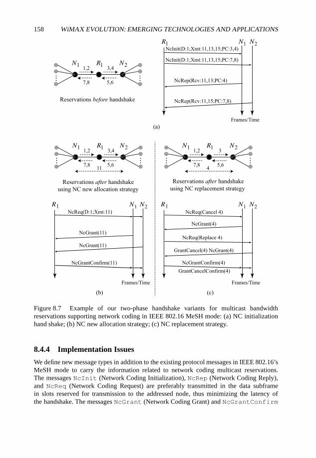
158 WiMAX EVOLUTION: EMERGING TECHNOLOGIES AND APPLICATIONS
Figure 8.7 Example of our two-phase handshake variants for multicast bandwidthreservations supporting network coding in IEEE 802.16 MeSH mode: (a) NC initializationhand shake; (b) NC new allocation strategy; (c) NC replacement strategy.
8.4.4 Implementation Issues
We define new message types in addition to the existing protocol messages in IEEE 802.16’sMeSH mode to carry the information related to network coding multicast reservations.The messages NcInit (Network Coding Initialization), NcRep (Network Coding Reply),and NcReq (Network Coding Request) are preferably transmitted in the data subframein slots reserved for transmission to the addressed node, thus minimizing the latency ofthe handshake. The messages NcGrant (Network Coding Grant) and NcGrantConfirm
WiMAX MESH ARCHITECTURES AND NETWORK CODING 159
(Network Coding Grant Confirmation) are transmitted in the schedule control subframe. Themessage NcInit is used to initiate the process of reservation of slots to multiple neighboringnodes for the transmission of coded data, it contains the following fields.
• D: the value for D specifies the number of slots to be reserved for the transmission ofcoded data to multiple neighbors.
• Xmt: this field specifies the slots which are suitable and available for transmission ofdata at the node initiating the network coding handshake.
• PC: pseudo cancel, which specifies the set of slots which the addressed node shouldalso check for their suitability for receiving data transmissions considering that thenode initiating the handshake will free these slots reserved by it for transmissions tosome other node.
The nodes addressed by the NcInit message reply using the NcRep message. TheNcRep message has the following fields.
• Rcv: this field specifies the set of slots which are suitable at the node for receiving datatransmissions.
• PC: this field specifies the set of slots which would be suitable for reception at the nodeif the transmitter of the initiating NcInit message would free these currently reservedslots.
After this initial handshake (Figure 8.7(a)), the initiator of the handshake knows whichslots are suitable for transmitting the coded packets to the intended receivers. The intendedreceivers on the other hand know which slots should not be used in the near future forconcurrent grants, as the relay would be initiating the next phase of the NC reservationprocess using these indicated slots. The next phase of the NC reservation may use either thenew allocation strategy (Figure 8.7(b)) or the replacement strategy (Figure 8.7(c)). We nextdiscuss the remaining handshake messages followed by a brief outline of both the reservationstrategies.
The NcReq message is the NC counterpart for the normal request message used inthe three-way handshake (Figure 8.2(a)) for distributed scheduling. NcReq can specify thenumber of slots to be reserved with the slots to be used for transmission as shown in the newallocation strategy. NcReq has the following fields.
• D: the value for D specifies the number of slots to be reserved for the transmission ofcoded data to multiple neighbors (similar to NcInit).
• Xmt: this field specifies the particular slots selected for the multicast network codingreservation (a subset of the Xmt-slots given in NcInit and Rcv-slots given inNcRep).
• Cancel: this field indicates that the given slots shall be cancelled and repurposed fora novel multicast reservation.
• Replace: this field specifies the slots for which the novel multicast reservation is tobe issued.
160 WiMAX EVOLUTION: EMERGING TECHNOLOGIES AND APPLICATIONS
For the replacement strategy, as discussed previously, the relay reuses some slots alreadyreserved by itself for unicast transmission to one of the intended recipients of the codeddata to schedule new coded transmissions to multiple recipients. Hence, when using thereplacement strategy, based on which neighboring node is being addressed, the NcReqmessage is used with differing intentions. The relay sends a NcReq message with aCancel indication, notifying the neighbor that it is cancelling the slots specified by theCancel field (which had been reserved previously for a unicast transmission to some otherneighbor) and that the node being addressed should reserve these slots for the multicast NCtransmission. The neighbor then replies using a NcGrant message granting the slot for theNC transmission (the semantic of the NcGrant message is similar to the Grant message inIEEE 802.16). The relay uses the NcReq message with a Replace indication to addressa node to which it has reserved the slots specified in the Replace field. This tells theneighbors that these slots which had been reserved previously for the unicast transmissionfrom the relay to itself will be used for the transmission of coded (multicast) data by the relayto itself. The addressed neighbor then responds by simultaneously cancelling the unicastreservation and granting the same slots for the NC transmission. A NcGrantConfirmconfirms the novel multicast reservation to all neighbors (similar to the GrantConfirm inIEEE 802.16). Readers interested in the exact implementation details and extensions to theMeSH mode (the control message formats and extensions to the MeSH mode specifications)can find them in Kropff (2006).
8.5 Related Work
The seminal work of Ahlswede et al. (2000) introduced network coding and demonstratedthat bandwidth savings are possible when network coding is deployed. This was followedby literature which further investigated the benefits that can be obtained theoretically byapplying network coding (see, e.g., Li et al. (2003) and Sagduyu and Ephremides (2005)).The work of Katti et al. (2006) is one of the first that considered the deployment ofnetwork coding in a realistic setting. Katti et al. (2006) present their COPE architecture,which uses opportunistic network coding to combine multiple packets from different sourcesbefore forwarding. The authors show that gains obtainable via opportunistic network codingcan overhaul the gains in the absence of opportunistic listening. They deployed theirarchitecture in a mesh network which uses the IEEE 802.11a MAC layer. In a MACbased on IEEE 802.11 (see IEEE (1999)) a basic access scheme as well as an RTS/CTSscheme are specified to enable access to the medium for unicast data transmissions.The RTS/CTS scheme ensures that when a node transmits unicast data, all nodes in thedirect neighborhood of both the sender as well as the receiver do not transmit any datasimultaneously. Thus, when a node transmits any data or acknowledgements following thesuccessful RTS/CTS handshake, all of its neighbors remain silent themselves and will beable to receive the unicast data/acknowledgement transmission as long as none of theirneighbors transmits simultaneously. This provides a conducive environment for opportunisticlistening. However, as shown in Section 8.2, the neighbors of the node transmitting data in aslot may schedule simultaneous transmissions making opportunistic listening difficult if notimpossible. Further, the IEEE 802.16 standard introduces a security and privacy sublayerin the MAC layer which encrypts data on a per link basis before transmission making
WiMAX MESH ARCHITECTURES AND NETWORK CODING 161
opportunistic listening impossible. Another key aspect of the IEEE 802.16 MAC is theneed for a priori reservation of minislots before transmission of data can take place, theimplications of which have been presented in Section 8.3. The key question which the workof Katti et al. (2006) addresses is to determine which of the pending outgoing packets shouldbe combined together before transmission, using information obtained via opportunisticlistening as well as heuristics based on usage and availability of the Expected TransmissionCount (ETX) routing metric (see De Couto et al. (2003)). In contrast, we do not rely on theavailability of any particular routing metric or routing algorithm. The key questions whichwe addressed in this book chapter are as follows.
• When does network coding help in terms of throughput/bandwidth savings consideringadvanced MAC layers?
• How can we dynamically manage the multicast reservations for network coding with-out leading to conflict with other existing data transmission schedules in reservation-based MAC layers?
• How do we design practical solutions to deploy WNC in IEEE 802.16’s MeSH mode?
8.6 Conclusions and Outlook
We discussed the applicability of WNC for WMNs based on the IEEE 802.16 MeSH modewith particular emphasis on MAC layer issues. First, we presented an analytical model forthe distributed bandwidth reservation process of the IEEE 802.16 MeSH mode. The analysiswas used to derive design principles for implementing and deploying efficient network codingsolutions for the MeSH mode. We next designed solutions for deploying network coding inthe MeSH mode using the derived design principles as a roadmap. Furthermore, advancedstrategies for reserving slots for transmission of coded data were presented. The presentedsolutions have been initially discussed and investigated by means of simulations in Mogreet al. (2008); the results provide a proof of concept for the presented solutions and givepointers for future investigation.
However, MAC layer mechanisms alone are not sufficient for obtaining the maximumpossible gain via deployment of network coding in IEEE 802.16’s MeSH mode. Our workpresented in Mogre et al. (2007) presents a first step towards effectively deploying networkcoding in IEEE 802.16’s MeSH mode, where routing, scheduling and network coding areoptimized simultaneously. In the future, we will look for further improvements to thelatter work, and perform an evaluation of more advanced multicast bandwidth reservationstrategies. Solutions which are suitable for coding real-time data and other delay sensitivedata are of special interest, as these form the major class of traffic which benefits from theuse of advanced bandwidth reservation mechanisms provided by the MeSH mode.
In summary, any solutions for network coding to be deployed in MAC layers supportingbandwidth reservation need to be able to work seamlessly with the specified reservationschemes. Furthermore, in most cases a one-to-one mapping of network coding solutionsdesigned and developed within the scope of the IEEE 802.11 standard will not workoptimally in advanced MAC layers. Owing to this fact, a lot of interesting and challengingaspects persist for further research in deploying network coding efficiently in next-generationWMNs.
162 WiMAX EVOLUTION: EMERGING TECHNOLOGIES AND APPLICATIONS
Acknowledgements
We thank Matthias Kropff and Nico d’Heureuse for stimulating discussion on the subject ofWireless Network Coding for the MeSH mode of IEEE 802.16 as well as for supporting thetask of implementing a simulation environment. Moreover, regards go to Rainer Sauerweinfor critical discussion on the achievable performance gains under realistic usage scenarios,and Andreas Reinhardt for improving the readability of this manuscript. The research carriedout has been supported by Siemens Corporate Technology.
References
Ahlswede, R., Cai, N., Li, S.R. and Yeung, R.W. (2000) Network information flow. IEEE Transactionson Information Theory, 46(4), 1204–1216.
Akyildiz, I.F., Wang, X. and Wang, W. (2005) Wireless mesh networks: a survey. Computer Networks,47(4), 445–487.
Cao, M., Ma, W., Zhang, Q., Wang, X. and Zhu, W. (2005) Modelling and performance analysis ofthe distributed scheduler in IEEE 802.16 mesh mode. Proceedings of the 6th ACM InternationalSymposium on Mobile Ad Hoc Networking and Computing (MobiHoc 2005), pp. 78–89.
De Couto, D., Aguayo, D., Bicket, J. and Morris, R. (2003) High-throughput path metric for multi-hopwireless routing. Proceedings of the 9th Annual International Conference on Mobile Computing andNetworking (MobiCom 2003), pp. 134–146.
IEEE 1999, IEEE Standard for Information Technology, Telecommunications and InformationExchange between Systems, Local and Metropolitan Area Networks, Specific Requirements,Part 11: Wireless LAN Medium Access Control (MAC) and Physical Layer (PHY) Specifications,IEEE Standard 802.11-1999.
IEEE 2004, IEEE Standard for Local and Metropolitan Area Networks, Part 16: Air Interface for FixedBroadband Wireless Access Systems, IEEE Standard 802.16-2004.
Katti, S., Rahul, H., Hu, W., Katabi, D., Medard, M. and Crowcroft, J. (2006) XORs in the air: practicalwireless network coding. ACM SIGCOMM Computer Communication Review, 36(4), 243–254.
Kropff, M. (2006) Network coding for bandwidth management in IEEE 802.16 mesh networks.Master’s Thesis TU Darmstadt.
Li, S.R., Yeung, R.W. and Cai, N. (2003) Linear network coding. IEEE Transactions on InformationTheory, 49(2), 371–381.
Mogre, P.S., d’Heureuse, N., Hollick, M. and Steinmetz, R. (2007) A case for joint near-optimalscheduling and routing in TDMA-based wireless mesh networks: a cross-layer approach withnetwork coding support (poster abstract and poster). Proceedings of the IEEE InternationalConference on Mobile Adhoc and Sensor Systems (MASS 2007).
Mogre, P.S., Hollick, M. and Steinmetz, R. (2006) The IEEE 802.16-2004 MeSH mode explained,Technical Report, KOM-TR-2006-08. KOM, TU Darmstadt, Germany,ftp://ftp.kom.tu-darmstadt.de/pub/TR/KOM-TR-2006-08.pdf.
Mogre, P.S., Hollick, M., Kropff, M., Steinmetz, R. and Schwingenschloegl, C. (2008) A note onpractical deployment issues for network coding in the IEEE MeSH mode. Proceedings of the IEEEInternational Workshop on Wireless Network Coding (WiNC 2008).
Sagduyu, Y.E. and Ephremides, A. (2005) Joint scheduling and wireless network coding. Proceedingsof the First Workshop on Network Coding, Theory, and Applications (NetCod 2005).
9
ASN-GW High Availabilitythrough Cooperative Networkingin Mobile WiMAX Deployments
Alexander Bachmutsky
9.1 Introduction
High Availability (HA) is one of the most important features on the operator’s requirementslist, but it is left out of scope of most standardization bodies. The reason is simple: HAis usually considered as implementation specific and has to be covered somehow by everynetwork element internally.
Before diving into the HA topic, it is necessary to clarify a few definitions. The first isreliability, which means correct functionality as per specification. The second is availability,which can be defined as a period of time when the system is reliable; the network elementis usually considered as highly available if it performs its tasks reliably for 99.999% of thetime, the measure sometimes referred to as ‘five nines’ or as a carrier-grade implementation;it is translated into at most 5.26 minutes per year of unplanned down time. The third relatedterm is redundancy, which assumes having one or more extra functional elements capable oftaking over failed identical functional elements; two main types of redundancy are Active–Standby, where the standby functional block does not perform any service until the activeelement fails, and Active–Active, where all functional blocks are performing their work atall times, and one or more blocks can increase their work dynamically by taking over tasksfrom the failed function. One-to-one (1:1) active–standby redundancy means that for everysingle active component there is a corresponding dedicated standby one.N :1 active–standbyredundancy means that a single standby component protects N active components. N :Mactive–standby or active–active redundancy means thatM standby or active functions protect
WiMAX Evolution: Emerging Technologies and Applications Edited by Tsutomu Ishikawa© 2009 John Wiley & Sons, Ltd. ISBN: 978-0-470-69680-4
164 WiMAX EVOLUTION: EMERGING TECHNOLOGIES AND APPLICATIONS
N active components. An additional level of the active–standby redundancy is it being eithercold, when the standby starts only after the active failure, or warm, when the standby is startedand always ready, but does not have all active states and has to recreate these states in someway, or hot, when the standby is started, ready to take over at any point of time with all activestates always in sync. The fourth definition to remember is the resiliency that can be viewedas capability to maintain the reliability even in the case of failure. Resiliency can be improvedthrough, for example, redundancy, but it is not the only way. Resiliency of a processor canbe enhanced with an automatic power degradation when temperature rises above certainlevel; resiliency of an operating system can become better with a particular architecture orimplementation (take carrier-grade Linux as an example); applications can also be designedto be resilient to denial-of-service attacks (for example, rate limit Transmission ControlProtocol (TCP) SYN or ICMP packets, detect port scanning attempts) or failure of otherapplications (for example, Linux memory protection between processes). In most cases theresiliency directly affects the availability.
There is one confusion (coming frequently from operators) related to the reliability. As perthe definition above, reliability means correctness. In general, it does not include performanceand scalability dimensions. On the other side, operators do not want to call the networkreliable if it can serve only a fraction of all intended subscribers. Some operators even definethat the reliable function includes 100% scalability and 100% performance. However, thesame operators are absolutely fine with products that have an extra redundant component forevery function (for example, in a bladed system each control card, line card or processingcard has its own standby redundant peer); in many cases the same box without redundancycan practically double the scalability and performance. That just means that these operatorsagree to reduce the capacity by half as a starting point, and after that require 100% reliability.Therefore, this paper adopts the definition that the function performs reliably when it servescorrectly with at least 50% of the planned capacity for a nonredundant configuration and100% of the planned capacity in a fully redundant configuration.
Network element availability is frequently used instead of the network availability or viceversa. The truth is that operators do not really care about a specific network element or eventhe entire network availability; they care about the service availability: capability to servesubscribers most of the time. However, service availability is not equal to the network elementavailability. For example, if we have the network with two routers, and one router can performthe job for the second router in the case of failure, we can obtain practically 100% of theservice availability while every separate router availability is only 50%, assuming that bothrouters never fail at the same time (a so-called single point of failure in the network).
Another misconception is in calculating the network availability based on Mean TimeBetween Failures (MTBF). For example, we can compare a network element that fails onaverage once a year, but comes back into service in 10 minutes, with a network elementthat fails every month on average but comes back to service in 10 seconds. MTBF for thefirst network will be much higher, but availability for the second network will be higher.Regarding the service availability in our example, it is even more complex calculation. Onthe one hand a network element that boots longer can usually (not always) serve moresubscribers, meaning that failure affects more sessions. On the other hand, a network elementfailure might require subscribers to renew their sessions bringing out-of-service time muchbeyond just a network element coming back into service; taking that into account might bringthe service availability down for our faster booting and smaller network element.
ASN-GW HIGH AVAILABILITY 165
It is also necessary to remember that availability is not a static number, it is a curve withtime as one of the function parameters. For a new product the probability of Hardware (HW)failure is usually lower, but the probability of Software (SW) failure is much higher. Whentime passes, HW failure probability grows, but SW becomes more mature with bug fixes,so SW failure probability drops. We need to take into account both HW and SW whencalculating projected network element availability.
At the end, availability calculations are often meaningless and provide just failureprobability calculations. The only real way to measure the availability is to calculateretroactively the network element and/or service availability and derive from that whetherit was highly available or not.
9.2 Classic HA Implementation
In many systems high availability is achieved through redundancy. Frequently, it is a bladedsystem with 1:1 active–standby redundancy for the control card (sometimes called alsosystem card), 1:1 active–standby redundancy for line cards and a variety of redundancyschemes for processing/application cards: usually 1:1 active–standby, sometimes 1:1 active–active, in rare cases other implementations. In some systems the hardware even provideseither dedicated switch fabric for redundancy management or dedicated backplane connec-tion between adjacent slots for easier 1:1 protection. All that exists in addition to redundantpower supplies, at least one redundant cooling fan, redundant disks, redundant ports andmore.
The diagram of Nortel ASN-GW in Figure 9.1 is an example of a classic HA design.Classic design has its advantages and disadvantages. One of the biggest pros for such designis (excuse the pun) the availability of HA components. First of all, many vendors reuseprevious products by adding new functionality achieving faster time-to-market and higherreliability because of integrated previously productized SW and HW components. Also,one can find some commercial HW and SW parts even when building the solution fromscratch: redundant power supplies, redundant switch fabrics, open standards defined by theService Availability Forum (SAF) and correspondingly many middleware products ready tobe integrated into the system. All of those components create good justification for manyTelecommunications Equipment Manufacturers (TEMs) to choose that path.
The classic implementation also has its cons. The biggest is a very significant additionalcomplexity. It requires much more code for middleware, additional Application Program-ming Interfaces (APIs), complex state synchronization between active and standby, moredebugging, more maintenance, more negative and corner use cases during failover. All ofthe above reduces SW reliability and MTBF defeating the original redundancy purpose, anddefinitely increases not only HW but also SW and operational costs. Another disadvantageis the failover time in cold and warm redundancy: it takes time to load SW and/or recreateall static and dynamic states, and as a result it increases the time between the failure andreadiness to serve. In a hot standby mode the failover time is shorter, but the performancesuffers because of the requirement for constant state synchronization even when there is nofailure at all: both active and standby work continuously really hard to maintain everythingin sync only to protect against a potential crash one or few times a year.
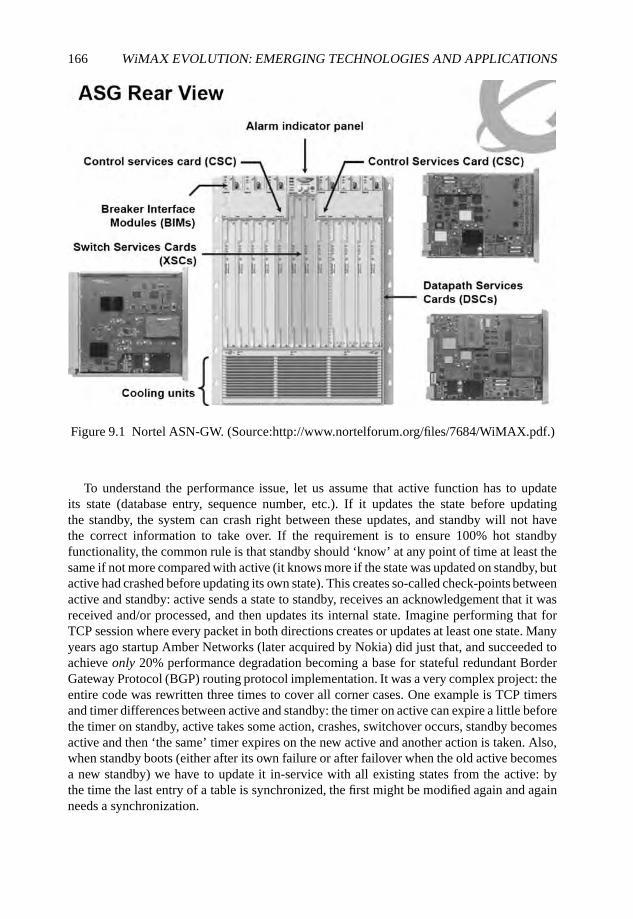
166 WiMAX EVOLUTION: EMERGING TECHNOLOGIES AND APPLICATIONS
Figure 9.1 Nortel ASN-GW. (Source:http://www.nortelforum.org/files/7684/WiMAX.pdf.)
To understand the performance issue, let us assume that active function has to updateits state (database entry, sequence number, etc.). If it updates the state before updatingthe standby, the system can crash right between these updates, and standby will not havethe correct information to take over. If the requirement is to ensure 100% hot standbyfunctionality, the common rule is that standby should ‘know’ at any point of time at least thesame if not more compared with active (it knows more if the state was updated on standby, butactive had crashed before updating its own state). This creates so-called check-points betweenactive and standby: active sends a state to standby, receives an acknowledgement that it wasreceived and/or processed, and then updates its internal state. Imagine performing that forTCP session where every packet in both directions creates or updates at least one state. Manyyears ago startup Amber Networks (later acquired by Nokia) did just that, and succeeded toachieve only 20% performance degradation becoming a base for stateful redundant BorderGateway Protocol (BGP) routing protocol implementation. It was a very complex project: theentire code was rewritten three times to cover all corner cases. One example is TCP timersand timer differences between active and standby: the timer on active can expire a little beforethe timer on standby, active takes some action, crashes, switchover occurs, standby becomesactive and then ‘the same’ timer expires on the new active and another action is taken. Also,when standby boots (either after its own failure or after failover when the old active becomesa new standby) we have to update it in-service with all existing states from the active: bythe time the last entry of a table is synchronized, the first might be modified again and againneeds a synchronization.
ASN-GW HIGH AVAILABILITY 167
Stateful TCP redundancy might be viewed as an extreme example, but WiMAX AccessServices Network Gateway (ASN-GW) does not have smaller challenges, especially takinginto account its scalability. First of all, there are protocols similar to TCP in some aspects: IPSecurity (IPsec) can protect R4 and R6 control channel communication between networkelements, Generic Routing Encapsulation (GRE) with sequence numbers is used for thedata integrity (lossless handover) mechanism. There are also transaction states and IDsbeing modified with received or sent packets, hundreds or even thousands of subscribersare entering or leaving the ASN-GW every second, Quality of Service (QoS) states withmultiple QoS layers (per flow, per subscriber, per port, etc.) are changing with every userpacket, millions of timers are being updated every second, and so on.
The solution is usually to give up the requirement for 100% hot standby redundancy andnot to replicate all states all of the time, but such a decision can cause the active sessions tobe dropped for many mobiles when the active failure occurs. Performance issues might alsobring some trade-offs in a way of additional algorithm complexity or protection much below100%. For example, the checkpoint can be implemented without an acknowledgement; inmost cases the message will arrive at standby without problems, but sometimes that stateupdate message will be lost, and the corresponding state will not be recovered after a failure.The worst part here is that message losses will happen right before the active crash because ofsome problems already happening on active for some time before the real failure is detected.In addition, there could be dependency between states, and the loss of one message cancause a different system view on standby. A classic example of this is table managementfunctions with two sequential operations for the same element: delete the current operation,add another. If the first message (delete) has been lost, the addition of the second operationmight fail, or duplicate elements in the table can be created. In the case of the second messageloss standby will not have that element in the table at all; it can be service affecting for eitherspecific subscriber or the entire system.
To summarize, a very complex solution is created, and 100% protection against failure isnot achieved.
9.3 Network-based Resiliency Solutions for Routing
As mentioned above stateful TCP and BGP redundancy is a very good solution, but it iscomplex to implement. There is, however, a different way to go: network-based resiliency thatis based on cooperation from other network elements. The concept is simple: if everything isOK, the network element can do everything on its own, but if a problem occurs, it will askfor a help from its neighbors. In the case of routing it is actually pretty much built-in as a partof routing architecture, because neighbors usually have all advertised routes. When the failedrouter comes back, it just asks its neighbors to send their entire table, and after that it can startserving traffic normally. Special protocols and concepts were created for that (Virtual RouterRedundancy Protocol (VRRP), Hot Standby Router Protocol (HSRP), nonstop forwarding,nonstop routing; Cisco Systems is naturally one of their biggest developers and promoters),but the implementation is definitely simpler compared with hot standby redundancy.
The diagram in Figure 9.2 has been borrowed from the Cisco Web site and describesthe VRRP concept: two or more routers share the same virtual IP address; there is onemaster (selected by the protocol) that usually processes the traffic; when the master fails,the slave/secondary router takes over.
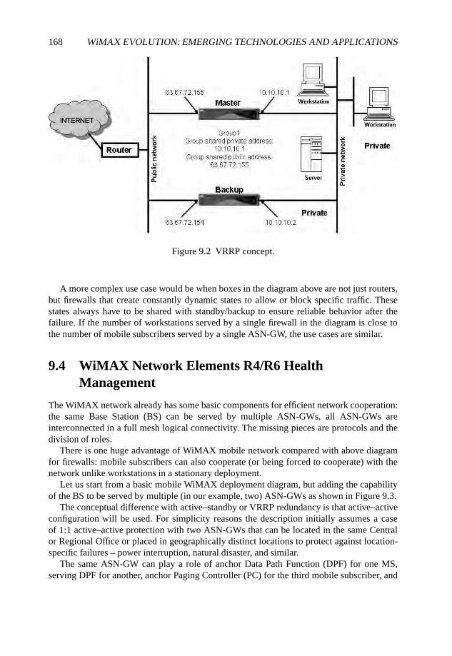
168 WiMAX EVOLUTION: EMERGING TECHNOLOGIES AND APPLICATIONS
Figure 9.2 VRRP concept.
A more complex use case would be when boxes in the diagram above are not just routers,but firewalls that create constantly dynamic states to allow or block specific traffic. Thesestates always have to be shared with standby/backup to ensure reliable behavior after thefailure. If the number of workstations served by a single firewall in the diagram is close tothe number of mobile subscribers served by a single ASN-GW, the use cases are similar.
9.4 WiMAX Network Elements R4/R6 HealthManagement
The WiMAX network already has some basic components for efficient network cooperation:the same Base Station (BS) can be served by multiple ASN-GWs, all ASN-GWs areinterconnected in a full mesh logical connectivity. The missing pieces are protocols and thedivision of roles.
There is one huge advantage of WiMAX mobile network compared with above diagramfor firewalls: mobile subscribers can also cooperate (or being forced to cooperate) with thenetwork unlike workstations in a stationary deployment.
Let us start from a basic mobile WiMAX deployment diagram, but adding the capabilityof the BS to be served by multiple (in our example, two) ASN-GWs as shown in Figure 9.3.
The conceptual difference with active–standby or VRRP redundancy is that active–activeconfiguration will be used. For simplicity reasons the description initially assumes a caseof 1:1 active–active protection with two ASN-GWs that can be located in the same Centralor Regional Office or placed in geographically distinct locations to protect against location-specific failures – power interruption, natural disaster, and similar.
The same ASN-GW can play a role of anchor Data Path Function (DPF) for one MS,serving DPF for another, anchor Paging Controller (PC) for the third mobile subscriber, and
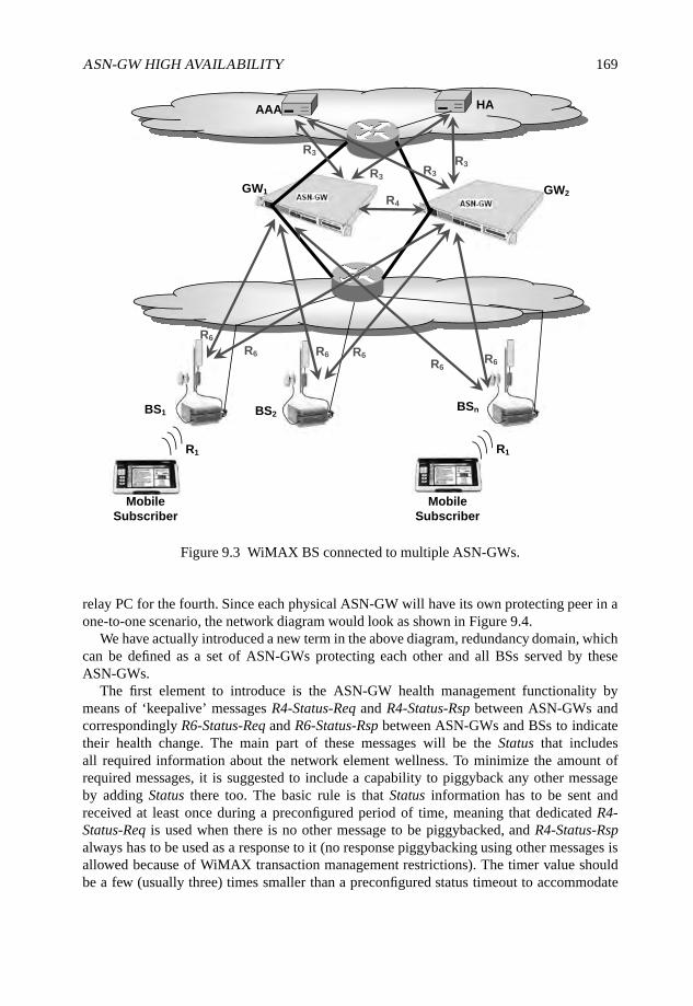
ASN-GW HIGH AVAILABILITY 169
HAAAA
BS1 BS2BSn
R1 R1
Mobile
Subscriber
Mobile
Subscriber
R6
R6 R6 R6
R6R6
R4
R3
R3R3
R3
GW1 GW2
Figure 9.3 WiMAX BS connected to multiple ASN-GWs.
relay PC for the fourth. Since each physical ASN-GW will have its own protecting peer in aone-to-one scenario, the network diagram would look as shown in Figure 9.4.
We have actually introduced a new term in the above diagram, redundancy domain, whichcan be defined as a set of ASN-GWs protecting each other and all BSs served by theseASN-GWs.
The first element to introduce is the ASN-GW health management functionality bymeans of ‘keepalive’ messages R4-Status-Req and R4-Status-Rsp between ASN-GWs andcorrespondingly R6-Status-Req and R6-Status-Rsp between ASN-GWs and BSs to indicatetheir health change. The main part of these messages will be the Status that includesall required information about the network element wellness. To minimize the amount ofrequired messages, it is suggested to include a capability to piggyback any other messageby adding Status there too. The basic rule is that Status information has to be sent andreceived at least once during a preconfigured period of time, meaning that dedicated R4-Status-Req is used when there is no other message to be piggybacked, and R4-Status-Rspalways has to be used as a response to it (no response piggybacking using other messages isallowed because of WiMAX transaction management restrictions). The timer value shouldbe a few (usually three) times smaller than a preconfigured status timeout to accommodate
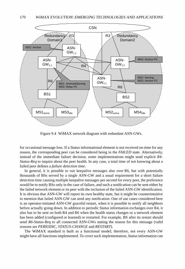
170 WiMAX EVOLUTION: EMERGING TECHNOLOGIES AND APPLICATIONS
ASN-GW1.1
ASN-GW1.2
ASN-GW2.1
ASN-GW2.2
BS1BS2
CSN
MS1active MS2activeMS3idle MS4idle
R6
R6
R4
R3 R3 Redundancy Domain2
Redundancy Domain1
MS1: Anchor&Serving MS3: Relay PC
MS2: Serving MS3: Anchor PC
MS4: Anchor PC
MS2: Anchor
Figure 9.4 WiMAX network diagram with redundant ASN-GWs.
for occasional message loss. If a Status informational element is not received on-time for anyreason, the corresponding peer can be considered being in the FAILED state. Alternatively,instead of the immediate failure decision, some implementations might send explicit R4-Status-Req to inquire about the peer health. In any case, a total time of not knowing about afailed peer defines a failure detection time.
In general, it is possible to run keepalive messages also over R6, but with potentiallythousands of BSs served by a single ASN-GW and a usual requirement for a short failuredetection time causing multiple keepalive messages per second for every peer, the preferencewould be to notify BSs only in the case of failure, and such a notification can be sent either bythe failed network element or its peer with the inclusion of the failed ASN-GW identification.It is obvious that ASN-GW will report its own healthy state, but it might be counterintuitiveto mention that failed ASN-GW can send any notification. One of use cases considered hereis an operator-initiated ASN-GW graceful restart, when it is possible to notify all neighborsbefore actually going down. In addition to periodic Status information exchanges over R4, italso has to be sent on both R4 and R6 when the health status changes or a network elementhas been added (configured or learned) or restarted. For example, BS after its restart shouldsend R6-Status-Req to all connected ASN-GWs stating the reason for this message (validreasons are PERIODIC, STATUS-CHANGE and RESTART).
The WiMAX standard is built as a functional model; therefore, not every ASN-GWmight have all functions implemented. To cover such implementation, Status information can
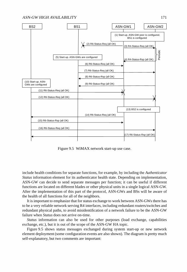
ASN-GW HIGH AVAILABILITY 171
BS2 BS1 ASN-GW1 ASN-GW2
(1) Start-up. ASN-GW peer is configured.
BS1 is configured
(3) R4-Status-Req (all OK)
(4) R4-Status-Rsp (all OK) (5) Start-up. ASN-GWs are configured
(2) R6-Status-Req (all OK)
(6) R6-Status-Req (all OK)
(8) R6-Status-Rsp (all OK)
(10) Start-up. ASN-GWs are configured
(13) BS2 is configured
(7) R6-Status-Req (all OK)
(9) R6-Status-Rsp (all OK)
(11) R6-Status-Req (all OK)
(14) R6-Status-Req (all OK)
(15) R6-Status-Rsp (all OK)
(16) R6-Status-Req (all OK)
(17) R6-Status-Rsp (all OK)
Pe
rio
dic
(12) R6-Status-Req (all OK)
Figure 9.5 WiMAX network start-up use case.
include health conditions for separate functions, for example, by including the AuthenticatorStatus information element for its authenticator health state. Depending on implementation,ASN-GW can decide to send separate messages per function; it can be useful if differentfunctions are located on different blades or other physical units in a single logical ASN-GW.After the implementation of this part of the protocol, ASN-GWs and BSs will be aware ofthe health of all functions for all of the neighbors.
It is important to emphasize that for status exchange to work between ASN-GWs there hasto be a very reliable network serving R4 interfaces, including redundant routers/switches andredundant physical paths, to avoid misidentification of a network failure to be the ASN-GWfailure when Status does not arrive on-time.
Status information can also be used for other purposes (load exchange, capabilitiesexchange, etc.), but it is out of the scope of the ASN-GW HA topic.
Figure 9.5 shows status messages exchanged during system start-up or new networkelement deployment (some configuration events are also shown). The diagram is pretty muchself-explanatory, but two comments are important:
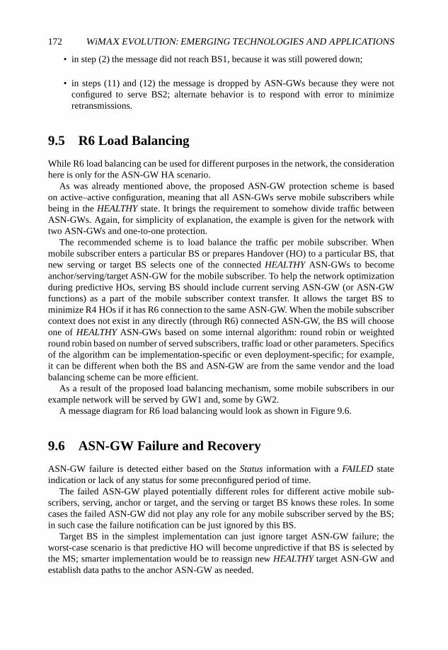
172 WiMAX EVOLUTION: EMERGING TECHNOLOGIES AND APPLICATIONS
• in step (2) the message did not reach BS1, because it was still powered down;
• in steps (11) and (12) the message is dropped by ASN-GWs because they were notconfigured to serve BS2; alternate behavior is to respond with error to minimizeretransmissions.
9.5 R6 Load Balancing
While R6 load balancing can be used for different purposes in the network, the considerationhere is only for the ASN-GW HA scenario.
As was already mentioned above, the proposed ASN-GW protection scheme is basedon active–active configuration, meaning that all ASN-GWs serve mobile subscribers whilebeing in the HEALTHY state. It brings the requirement to somehow divide traffic betweenASN-GWs. Again, for simplicity of explanation, the example is given for the network withtwo ASN-GWs and one-to-one protection.
The recommended scheme is to load balance the traffic per mobile subscriber. Whenmobile subscriber enters a particular BS or prepares Handover (HO) to a particular BS, thatnew serving or target BS selects one of the connected HEALTHY ASN-GWs to becomeanchor/serving/target ASN-GW for the mobile subscriber. To help the network optimizationduring predictive HOs, serving BS should include current serving ASN-GW (or ASN-GWfunctions) as a part of the mobile subscriber context transfer. It allows the target BS tominimize R4 HOs if it has R6 connection to the same ASN-GW. When the mobile subscribercontext does not exist in any directly (through R6) connected ASN-GW, the BS will chooseone of HEALTHY ASN-GWs based on some internal algorithm: round robin or weightedround robin based on number of served subscribers, traffic load or other parameters. Specificsof the algorithm can be implementation-specific or even deployment-specific; for example,it can be different when both the BS and ASN-GW are from the same vendor and the loadbalancing scheme can be more efficient.
As a result of the proposed load balancing mechanism, some mobile subscribers in ourexample network will be served by GW1 and, some by GW2.
A message diagram for R6 load balancing would look as shown in Figure 9.6.
9.6 ASN-GW Failure and Recovery
ASN-GW failure is detected either based on the Status information with a FAILED stateindication or lack of any status for some preconfigured period of time.
The failed ASN-GW played potentially different roles for different active mobile sub-scribers, serving, anchor or target, and the serving or target BS knows these roles. In somecases the failed ASN-GW did not play any role for any mobile subscriber served by the BS;in such case the failure notification can be just ignored by this BS.
Target BS in the simplest implementation can just ignore target ASN-GW failure; theworst-case scenario is that predictive HO will become unpredictive if that BS is selected bythe MS; smarter implementation would be to reassign new HEALTHY target ASN-GW andestablish data paths to the anchor ASN-GW as needed.
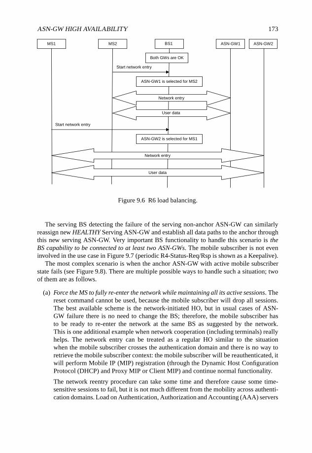
ASN-GW HIGH AVAILABILITY 173
MS1 MS2 BS1 ASN-GW1 ASN-GW2
Both GWs are OK
Start network entry
ASN-GW1 is selected for MS2
Network entry
User data
Start network entry
ASN-GW2 is selected for MS1
Network entry
User data
Figure 9.6 R6 load balancing.
The serving BS detecting the failure of the serving non-anchor ASN-GW can similarlyreassign new HEALTHY Serving ASN-GW and establish all data paths to the anchor throughthis new serving ASN-GW. Very important BS functionality to handle this scenario is theBS capability to be connected to at least two ASN-GWs. The mobile subscriber is not eveninvolved in the use case in Figure 9.7 (periodic R4-Status-Req/Rsp is shown as a Keepalive).
The most complex scenario is when the anchor ASN-GW with active mobile subscriberstate fails (see Figure 9.8). There are multiple possible ways to handle such a situation; twoof them are as follows.
(a) Force the MS to fully re-enter the network while maintaining all its active sessions. Thereset command cannot be used, because the mobile subscriber will drop all sessions.The best available scheme is the network-initiated HO, but in usual cases of ASN-GW failure there is no need to change the BS; therefore, the mobile subscriber hasto be ready to re-enter the network at the same BS as suggested by the network.This is one additional example when network cooperation (including terminals) reallyhelps. The network entry can be treated as a regular HO similar to the situationwhen the mobile subscriber crosses the authentication domain and there is no way toretrieve the mobile subscriber context: the mobile subscriber will be reauthenticated, itwill perform Mobile IP (MIP) registration (through the Dynamic Host ConfigurationProtocol (DHCP) and Proxy MIP or Client MIP) and continue normal functionality.
The network reentry procedure can take some time and therefore cause some time-sensitive sessions to fail, but it is not much different from the mobility across authenti-cation domains. Load on Authentication, Authorization and Accounting (AAA) servers
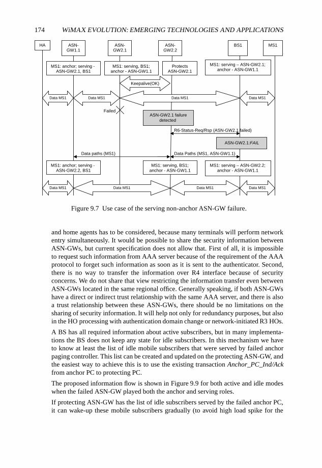
174 WiMAX EVOLUTION: EMERGING TECHNOLOGIES AND APPLICATIONS
HA BS1 ASN-GW1.1
Keepalive(OK)
Data MS1
Failed ASN-GW2.1 failure
detected
ASN-GW2.1
ASN-GW2.2
MS1
MS1: anchor; serving -ASN-GW2.1, BS1
MS1: serving, BS1; anchor - ASN-GW1.1
MS1: serving – ASN-GW2.1; anchor - ASN-GW1.1
Data MS1 Data MS1 Data MS1
R6-Status-Req/Rsp (ASN-GW2.1 failed)
ASN-GW2.1:FAIL
Data Paths (MS1, ASN-GW1.1) Data paths (MS1)
MS1: anchor; serving -ASN-GW2.2, BS1
MS1: serving, BS1; anchor - ASN-GW1.1
MS1: serving – ASN-GW2.2; anchor - ASN-GW1.1
Data MS1 Data MS1 Data MS1 Data MS1
Protects ASN-GW2.1
Figure 9.7 Use case of the serving non-anchor ASN-GW failure.
and home agents has to be considered, because many terminals will perform networkentry simultaneously. It would be possible to share the security information betweenASN-GWs, but current specification does not allow that. First of all, it is impossibleto request such information from AAA server because of the requirement of the AAAprotocol to forget such information as soon as it is sent to the authenticator. Second,there is no way to transfer the information over R4 interface because of securityconcerns. We do not share that view restricting the information transfer even betweenASN-GWs located in the same regional office. Generally speaking, if both ASN-GWshave a direct or indirect trust relationship with the same AAA server, and there is alsoa trust relationship between these ASN-GWs, there should be no limitations on thesharing of security information. It will help not only for redundancy purposes, but alsoin the HO processing with authentication domain change or network-initiated R3 HOs.
A BS has all required information about active subscribers, but in many implementa-tions the BS does not keep any state for idle subscribers. In this mechanism we haveto know at least the list of idle mobile subscribers that were served by failed anchorpaging controller. This list can be created and updated on the protecting ASN-GW, andthe easiest way to achieve this is to use the existing transaction Anchor_PC_Ind/Ackfrom anchor PC to protecting PC.
The proposed information flow is shown in Figure 9.9 for both active and idle modeswhen the failed ASN-GW played both the anchor and serving roles.
If protecting ASN-GW has the list of idle subscribers served by the failed anchor PC,it can wake-up these mobile subscribers gradually (to avoid high load spike for the
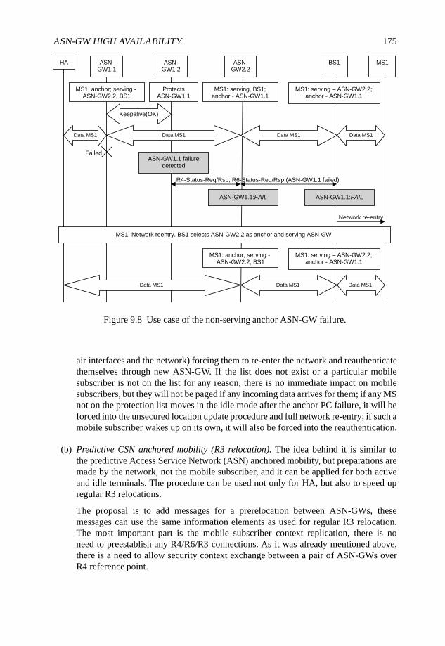
ASN-GW HIGH AVAILABILITY 175
HA BS1 ASN-GW1.1
Keepalive(OK)
Data MS1
Failed ASN-GW1.1 failure
detected
ASN-GW1.2
ASN-GW2.2
MS1
MS1: anchor; serving -ASN-GW2.2, BS1
MS1: serving – ASN-GW2.2; anchor - ASN-GW1.1
Data MS1 Data MS1 Data MS1
R4-Status-Req/Rsp, R6-Status-Req/Rsp (ASN-GW1.1 failed)
ASN-GW1.1:FAIL
MS1: anchor; serving -ASN-GW2.2, BS1
MS1: serving – ASN-GW2.2; anchor - ASN-GW1.1
Data MS1 Data MS1 Data MS1
MS1: serving, BS1; anchor - ASN-GW1.1
Protects ASN-GW1.1
ASN-GW1.1:FAIL
Network re-entry
MS1: Network reentry. BS1 selects ASN-GW2.2 as anchor and serving ASN-GW
Figure 9.8 Use case of the non-serving anchor ASN-GW failure.
air interfaces and the network) forcing them to re-enter the network and reauthenticatethemselves through new ASN-GW. If the list does not exist or a particular mobilesubscriber is not on the list for any reason, there is no immediate impact on mobilesubscribers, but they will not be paged if any incoming data arrives for them; if any MSnot on the protection list moves in the idle mode after the anchor PC failure, it will beforced into the unsecured location update procedure and full network re-entry; if such amobile subscriber wakes up on its own, it will also be forced into the reauthentication.
(b) Predictive CSN anchored mobility (R3 relocation). The idea behind it is similar tothe predictive Access Service Network (ASN) anchored mobility, but preparations aremade by the network, not the mobile subscriber, and it can be applied for both activeand idle terminals. The procedure can be used not only for HA, but also to speed upregular R3 relocations.
The proposal is to add messages for a prerelocation between ASN-GWs, thesemessages can use the same information elements as used for regular R3 relocation.The most important part is the mobile subscriber context replication, there is noneed to preestablish any R4/R6/R3 connections. As it was already mentioned above,there is a need to allow security context exchange between a pair of ASN-GWs overR4 reference point.
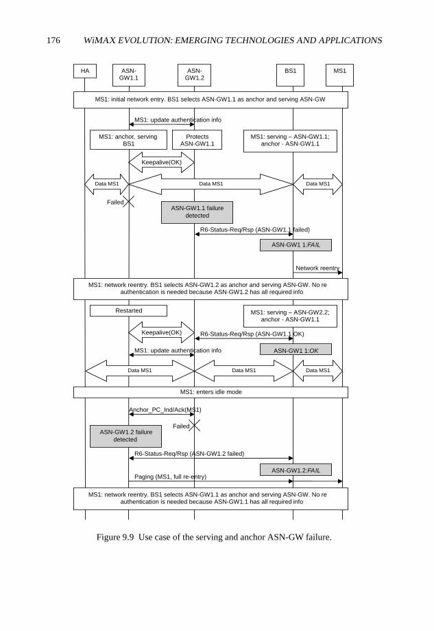
176 WiMAX EVOLUTION: EMERGING TECHNOLOGIES AND APPLICATIONS
HA BS1 ASN-GW1.1
Keepalive(OK)
Data MS1
Failed ASN-GW1.1 failure
detected
ASN-GW1.2
MS1
MS1: anchor, serving BS1
MS1: serving – ASN-GW1.1; anchor - ASN-GW1.1
Data MS1 Data MS1
R6-Status-Req/Rsp (ASN-GW1.1 failed)
ASN-GW1 1:FAIL
MS1: serving – ASN-GW2.2; anchor - ASN-GW1.1
Data MS1 Data MS1 Data MS1
Protects ASN-GW1.1
Network reentry
MS1: network reentry. BS1 selects ASN-GW1.2 as anchor and serving ASN-GW. No reauthentication is needed because ASN-GW1.2 has all required info
MS1: initial network entry. BS1 selects ASN-GW1.1 as anchor and serving ASN-GW
MS1: update authentication info
Restarted
Keepalive(OK)
MS1: enters idle mode
Anchor_PC_Ind/Ack(MS1)
Failed ASN-GW1.2 failure
detected
R6-Status-Req/Rsp (ASN-GW1.2 failed)
ASN-GW1.2:FAILPaging (MS1, full re-entry)
MS1: update authentication info
MS1: network reentry. BS1 selects ASN-GW1.1 as anchor and serving ASN-GW. No reauthentication is needed because ASN-GW1.1 has all required info
R6-Status-Req/Rsp (ASN-GW1.1 OK)
ASN-GW1 1:OK
Figure 9.9 Use case of the serving and anchor ASN-GW failure.
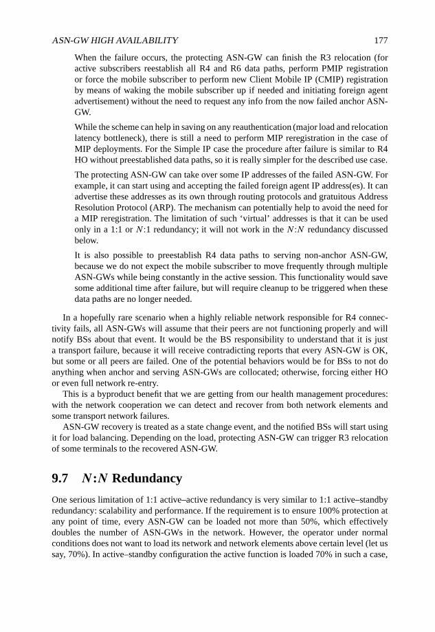
ASN-GW HIGH AVAILABILITY 177
When the failure occurs, the protecting ASN-GW can finish the R3 relocation (foractive subscribers reestablish all R4 and R6 data paths, perform PMIP registrationor force the mobile subscriber to perform new Client Mobile IP (CMIP) registrationby means of waking the mobile subscriber up if needed and initiating foreign agentadvertisement) without the need to request any info from the now failed anchor ASN-GW.
While the scheme can help in saving on any reauthentication (major load and relocationlatency bottleneck), there is still a need to perform MIP reregistration in the case ofMIP deployments. For the Simple IP case the procedure after failure is similar to R4HO without preestablished data paths, so it is really simpler for the described use case.
The protecting ASN-GW can take over some IP addresses of the failed ASN-GW. Forexample, it can start using and accepting the failed foreign agent IP address(es). It canadvertise these addresses as its own through routing protocols and gratuitous AddressResolution Protocol (ARP). The mechanism can potentially help to avoid the need fora MIP reregistration. The limitation of such ‘virtual’ addresses is that it can be usedonly in a 1:1 or N :1 redundancy; it will not work in the N :N redundancy discussedbelow.
It is also possible to preestablish R4 data paths to serving non-anchor ASN-GW,because we do not expect the mobile subscriber to move frequently through multipleASN-GWs while being constantly in the active session. This functionality would savesome additional time after failure, but will require cleanup to be triggered when thesedata paths are no longer needed.
In a hopefully rare scenario when a highly reliable network responsible for R4 connec-tivity fails, all ASN-GWs will assume that their peers are not functioning properly and willnotify BSs about that event. It would be the BS responsibility to understand that it is justa transport failure, because it will receive contradicting reports that every ASN-GW is OK,but some or all peers are failed. One of the potential behaviors would be for BSs to not doanything when anchor and serving ASN-GWs are collocated; otherwise, forcing either HOor even full network re-entry.
This is a byproduct benefit that we are getting from our health management procedures:with the network cooperation we can detect and recover from both network elements andsome transport network failures.
ASN-GW recovery is treated as a state change event, and the notified BSs will start usingit for load balancing. Depending on the load, protecting ASN-GW can trigger R3 relocationof some terminals to the recovered ASN-GW.
9.7 N:N Redundancy
One serious limitation of 1:1 active–active redundancy is very similar to 1:1 active–standbyredundancy: scalability and performance. If the requirement is to ensure 100% protection atany point of time, every ASN-GW can be loaded not more than 50%, which effectivelydoubles the number of ASN-GWs in the network. However, the operator under normalconditions does not want to load its network and network elements above certain level (let ussay, 70%). In active–standby configuration the active function is loaded 70% in such a case,

178 WiMAX EVOLUTION: EMERGING TECHNOLOGIES AND APPLICATIONS
the standby function is not loaded, thus bringing the average load to 35%. In active–activeconfiguration we can load both ASN-GWs to 50% and still fully survive a single failure,meaning that it still has advantages over the active–standby case.
Sometimes active–standby resiliency is implemented asN :1 redundancy: a single standbyfunction protects N active components. Any active failure will trigger the standby to takeover. The problem is that it is relatively simple for cold and warm redundancy, but becomescomplex in hot redundancy, because the standby function has to receive and maintain statesfrom all active functions. In some situations standby works much harder than any individualactive causing stability issues on the standby itself. While standby failure is not that severe,it can affect the performance of the active function because of the required in-service updateof all states at once (so-called bulk update) after the standby recovery. Also, failure ofstandby means that there is a window when the system is not protected at all, and a longerstandby recovery time means longer period without protection, an increased probability ofthe unrecoverable active failure and a lower availability as a result of that.
There is alsoN :M active–standby redundancy whenM standby functions protectN activecomponents. The scheme brings a higher availability compared with N :1, but increasedcomplexity limits such implementation. Also, average scalability and performance in N :Mis lower than in N :1 because of the greater number of standby functions.
That is where active–active redundancy really shines. Let us analyze the diagram ofWiMAX ASN connectivity in Figure 9.10.
All BSs are divided into clusters C1 to C20 for more efficient HOs; all BSs in the samecluster are connected to the same ASN-GWs; a cluster can be as small as a single BS orinclude arbitrary number of BSs. Clusters from C11 to C20 will be connected in the sameway as the clusters from C1 to C10 correspondingly; it is made just to illustrate that multipleclusters can be connected to the same set of ASN-GWs. From ASN-GW point of view theconnectivity is as follows:
ASN-GW1 is connected to clusters C1, C2, C3, C4, C11, C12, C13, C14;
ASN-GW2 is connected to clusters C1, C5, C6, C7, C11, C15, C16, C17;
ASN-GW3 is connected to clusters C2, C5, C8, C9, C12, C15, C18, C19;
ASN-GW4 is connected to clusters C3, C6, C8, C10, C13, C16, C18, C20;
ASN-GW5 is connected to clusters C4, C7, C9, C10, C14, C17, C19, C20.
For every BS this connectivity is not different from 1:1 active–active connectivity describedpreviously, its role in handling health management and ASN-GW failure and recovery isexactly the same. ASN-GW implementation is also the same except the need to keep fullmesh health exchange between all ASN-GWs. The distinction is in the distributed protection.For example, when ASN-GW1 fails, the first subset of mobile subscribers served by BSs inclusters C1 and C11 will be moved to ASN-GW2; the second subset of mobile subscribersserved by BSs in clusters C2 and C12 will be moved to ASN-GW3; the third subset of mobilesubscribers served by BSs in clusters C3 and C13 will be moved to ASN-GW4; finally, thefourth subset of mobile subscribers served by BSs in clusters C4 and C14 will be moved toASN-GW5. The result is that each ASN-GW is protected by all other ASN-GWs.
With just a smarter configuration and without any implementation change the proposeddiagram increases the scalability and performance of each ASN-GW in our example up to
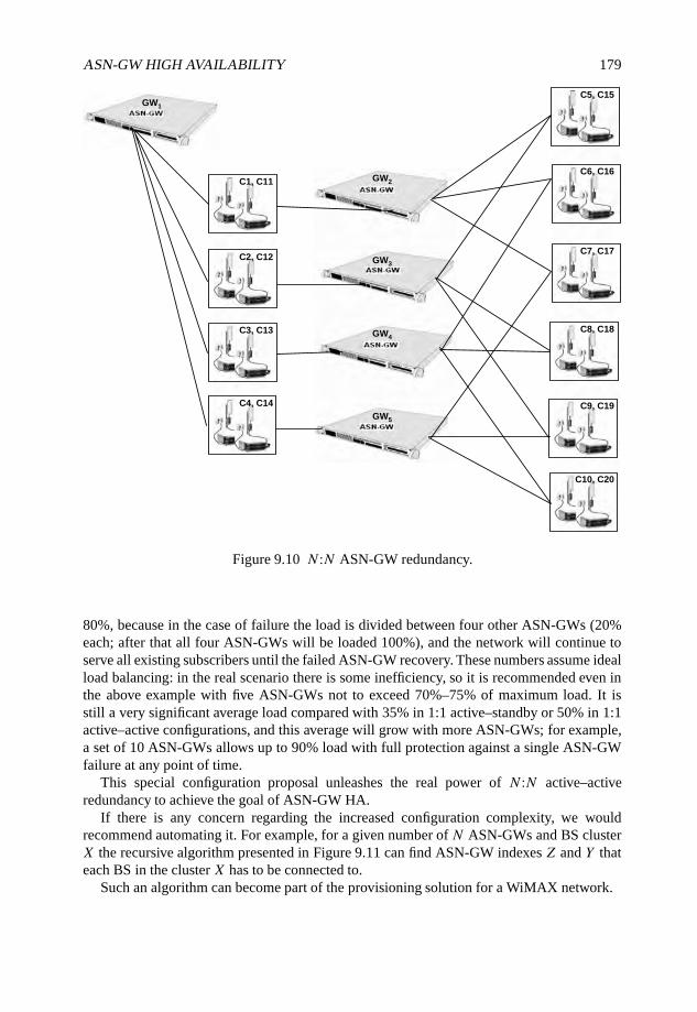
ASN-GW HIGH AVAILABILITY 179
GW1
GW2
GW3
GW4
GW5
C1, C11
C2, C12
C3, C13
C4, C14
C5, C15
C6, C16
C7, C17
C8, C18
C9, C19
C10, C20
Figure 9.10 N :N ASN-GW redundancy.
80%, because in the case of failure the load is divided between four other ASN-GWs (20%each; after that all four ASN-GWs will be loaded 100%), and the network will continue toserve all existing subscribers until the failed ASN-GW recovery. These numbers assume idealload balancing: in the real scenario there is some inefficiency, so it is recommended even inthe above example with five ASN-GWs not to exceed 70%–75% of maximum load. It isstill a very significant average load compared with 35% in 1:1 active–standby or 50% in 1:1active–active configurations, and this average will grow with more ASN-GWs; for example,a set of 10 ASN-GWs allows up to 90% load with full protection against a single ASN-GWfailure at any point of time.
This special configuration proposal unleashes the real power of N :N active–activeredundancy to achieve the goal of ASN-GW HA.
If there is any concern regarding the increased configuration complexity, we wouldrecommend automating it. For example, for a given number of N ASN-GWs and BS clusterX the recursive algorithm presented in Figure 9.11 can find ASN-GW indexes Z and Y thateach BS in the cluster X has to be connected to.
Such an algorithm can become part of the provisioning solution for a WiMAX network.
180 WiMAX EVOLUTION: EMERGING TECHNOLOGIES AND APPLICATIONS
Red (x)
{ IF
(x ≤ N ∗ (N − 1)
2
)THEN {IF (x ≤ (N − 1)) THEN RETURN (Y = 1; Z = x + 1);
ELSE FOR (2 ≤ i ≤ (N − 1); i + +)
{IF[x ≤ (N − 1)+
i∑j=2
(N − j)
]IF (i = 2) THEN RETURN (Y = i, X = i + x − (N − 1));
ELSE RETURN
(Y = i; Z = i + x − (N − 1)−
i−1∑j=2
(N − j)
);
ELSE ;}
}
ELSE
{x = x − N ∗ (N − 1)
2;
RETURN (Re d(x)); /* RESTART THE ALGORITHM WITH THIS NEW X VALUE */}
}
Figure 9.11 Algorithm for ASN-GW selection.
Function-based MUX
Function A Function D
QA
MS DBA
MS DBSHARED
QD
Thread A Thread D
Process 1
(Instance 1)
MS DBD
Function-based MUX
Function A Function D
QA
MS DBA
MS DBSHARED
QD
Thread A Thread D
Process N(Instance N)
MS DBD
Global DBSHARED
MSID-based Instance MUX
Q1 QN
Figure 9.12 Concept of multi-instance ASN-GW.
9.8 Multi-instance ASN-GW
Many ASN-GW implementations use the concept of multi-instance application. Instance canbe with HW boundary (blade in the chassis, CPU on the blade, etc.) or SW boundary (threador process). The diagram in Figure 9.12 presents SW based multi-instance.
ASN-GW HIGH AVAILABILITY 181
In both SW and HW cases there is usually an internal or external load balancingmechanism between these instances, and the example of the most obvious algorithm is basedon mobile subscriber or flow identification (Mobile Subscriber ID (MSID), Network AccessIdentifier (NAI), GRE key, etc.) when every instance becomes responsible for a subset of allsubscribers or flows served by the ASN-GW.
Multi-instance support is usually well shielded from the network. HA requirements canchange that, because the failure cannot occur for the entire ASN-GW, but only for a specificinstance. Of course, it can be assumed that the whole network element is unhealthy if at leastone instance is unhealthy, but it is not a very good way to improve the availability.
One way is to expose the instance handling into the health management protocol byadding one more layer of hierarchy into the Status information element, Instance Status,that includes the instance ID and a function-specific status. An instance failure is treated inexactly the same way as an ASN-GW failure as explained previously, but BSs should havethe mapping between instances and mobile subscribers. It can be achieved by the addition ofInstance Identification in, for example, data path establishment messages or, alternatively, bythe instance ID encoding into the data path ID (GRE key).
The health state of a multi-instance ASN-GW can be now represented by three states:HEALTHY (all instances are HEALTHY), UNHEALTHY (at least one instance is failed) andFAILED (more than half of ASN-GW instances are failed).
Since every instance handles only a subset of all served subscribers, and the most probablefailure will occur for a single instance as opposed to the entire ASN-GW, we can significantlyminimize the system impact by the health monitoring per instance.
9.9 The Proposal Summary
The condensed version of the new functionalities to implement the proposed ASN-GW HAscheme is as follows.
(a) Operations and Management (O&M): configure protecting ASN-GW peer(s); reportcurrent self or peer status to the management layer upon change, or periodically, or onrequest.
(b) ASN-GW: Periodically exchange keepalive messages between protecting peers with atimeout for a peer failure detection.
(c) ASN-GW and BS: R4/R6 redundancy status transaction to notify about the self or peerstatus change and the status after the network element restart.
(d) ASN-GW: transfer security context over R4 to the protecting peer after successfulmobile subscriber (re)authentication.
(e) ASN-GW: Notify the protecting peer about mobile subscriber entering/exiting the idlestate; keep the information about idle mobile subscribers in the protecting ASN-GW.
(f) ASN-GW: gradually wake up relevant idle mobile subscribers after taking over thefailed ASN-GW peer.
(g) BS: maintain the health state for every connected ASN-GW; assign new MSs only tohealthy ASN-GW(s).

182 WiMAX EVOLUTION: EMERGING TECHNOLOGIES AND APPLICATIONS
(h) BS: force HO for terminals affected by anchor ASN-GW failure (in an alternateimplementation it can be R3 HO forced by an ASN-GW peer); establish new R6 datapath for mobile subscribers with only serving ASN-GW failure.
As is easy to see, there is not much needed during the normal data and control planeprocessing; the ‘real’ work only starts when the failure really occurs, as it should be in theefficient HA scheme. Previously it was possible only using cold or warm redundancy. A newproposal based on the network cooperation principles allows the same capability for a hotredundancy with virtually no performance and scalability degradation compared with thesystem without HA.
9.10 Conclusions
The proposed active–active network-assisted HA mechanism achieves the required carrier-grade reliability by distributing the functionality between multiple network elements, ASN-GWs and BSs, with much simpler implementation for each of them.
This chapter has concentrated on ASN-GW HA. When the concept of network-assistedresiliency is accepted, the scheme can be extended to HA for other network elements: AAAservers, home agents and others. This will enable more efficient deployments of WiMAXnetwork with significantly reduced capital expenditure (CAPEX) as a result of simplerimplementation and higher utilization of the network components.

Part V
WiMAX Extensions
WiMAX Evolution: Emerging Technologies and Applications Edited by Tsutomu Ishikawa© 2009 John Wiley & Sons, Ltd. ISBN: 978-0-470-69680-4
10
Robust Header Compression forWiMAX Femto Cells
Frank H.P. Fitzek, Gerrit Schulte, Esa Piri, Jarno Pinola,Marcos D. Katz, Jyrki Huusko, Kostas Pentikousis andPatrick Seeling
10.1 Introduction
Even though WiMAX technology offers high data rates, the overall capacity over the air isshared among several WiMAX users. This is especially true for the WiMAX support of femtocells. In this scenario very small wireless cells, covered by short-range technologies such asWLAN or Bluetooth, are wirelessly connected to the Internet backbone by WiMAX links.The number of accumulated users will be high and any means to gain additional capacityare more than welcomed. An effective approach to increase capacity is to utilize headercompression. In the wireless world, Robust Header Compression (ROHC), as standardized inRFC3095 (Bormann et al., 2001), is a widely applied header compression scheme. ROHC isa method to reduce the overhead of the packet header information down to 10% or less. Thismethod is especially effective if the payload is relatively small in contrast to the header itself.In this chapter we will motivate the use of ROHC in WiMAX, as proposed in the WiMAXdocuments (Fitzek et al., 2004), and demonstrate the potential gain of using ROHC forWiMAX femto cells by implementation and measurements. The results presented here are theoutcome of a collaborative work of acticom (acticom GmbH , 2008b) and VTT implementingacticom’s ROHC protocol stack in a commercial WiMAX system. As shown throughout thischapter, ROHC demonstrates outstanding performance over the standard system.
This chapter is organized as follows. First, ROHC is introduced. Then the basic conceptand motivation for applying ROHC in WiMAX systems is given. The Technical Research
WiMAX Evolution: Emerging Technologies and Applications Edited by Tsutomu Ishikawa© 2009 John Wiley & Sons, Ltd. ISBN: 978-0-470-69680-4
186 WiMAX EVOLUTION: EMERGING TECHNOLOGIES AND APPLICATIONS
Centre of Finland (VTT) and the German company acticom joined forces to integrate ROHCas defined by RFC3095 into fixed and mobile WiMAX systems. Measurement results using anovel WiMAX testbed with integrated ROHC technology are presented and discussed beforewe conclude. Measurements show that using ROHC for a given WiMAX scenario will morethan double system capacity.
10.2 ROHC in a Nutshell
ROHC supports the efficient use of scarce wireless resources for multimedia data withreal-time constraints. Reducing the overhead of Internet Protocol (IP)-based headers inpacket-oriented communication networks significantly improves performance, especiallyfor multimedia data services, such as audio or video transmissions. Thus, by employingROHC, 2.5G and 3G network operators will be able to increase the amount of resourcesavailable to their customers, resulting in an improved return on investment. Robust headercompression was standardized by the Internet Engineering Task Force (IETF) in RFC3095and will be an integral part of releases 4 and 5 of the Third Generation Phone Partnership(3GPP) Universal Mobile Telecommunications System (UMTS) specification as well asstandards for WiMAX networks. The efficient transport of multimedia data over packet-oriented (wireless) data networks has gained much interest in recent years. To meet therequirements in terms of delay, jitter and latency for interactive communication, for example,Voice over IP (VoIP), sampling and packetization delays must be minimized. When usingthe Real-time Transport Protocol (RTP) and RTP/User Datagram Protocol (UDP)/IP headersfor encapsulating voice samples, the ratio between the size of the RTP/UDP/IP headers andthe payload size is typically 2:1 (or 3:1 for IPv6). Thus there is a significant overhead andwaste of resources. ROHC uses a connection-oriented approach to remove packet inter-and intra-dependencies and thus reduces the header payload significantly. In a multimediascenario with real-time voice services and IPv6, the overall bandwidth can be reduced by afactor of four. The error characteristics on wireless links differ dramatically from wired links.ROHC was designed to operate in error-prone environments by providing error detection andcorrection mechanisms combined with robustness for IP-based data streams.
The basic motivation for IP-based header compression is based on the fact that packetheader information has significant redundancy. The combined headers for a real-timemultimedia stream using IPv4 includes the 20-byte IPv4 header, the 8-byte UDP headerand the 12-byte RTP header. The headers for IPv6 total 60 bytes. Redundancy exists amongthe different headers (IP, UDP and RTP), but in particular between consecutive packetsbelonging to the same IP flow. The header fields can be separated into nonchanging andchanging. The nonchanging group consists of static, static-known and inferred header fieldsand is more or less easy to compress. A large portion of the header fields are static orstatic-known and therefore can be compressed easily or will not be sent at all after thefirst successful transmission between sender and receiver. Other header fields are referredto as inferred. These fields can be inferred from other header fields and are also easy tocompress. The changing group consists out of not-classified a priori, rarely-changing, staticor semi-static changing, and alternating changing header fields. These types of header fieldsare more difficult to compress and it depends on the header compression scheme how thecompression is implemented. The potential savings for voice and audio services are presented
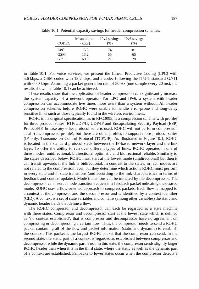
ROBUST HEADER COMPRESSION FOR WiMAX FEMTO CELLS 187
Table 10.1 Potential capacity savings for header compression schemes.
Mean bit rate IPv4 savings IPv6 savingsCODEC (kbps) (%) (%)
LPC 5.6 74 81GSM 13.2 55 65G.711 60.0 21 29
in Table 10.1. For voice services, we present the Linear Predictive Coding (LPC) with5.6 kbps, a GSM codec with 13.2 kbps, and a codec following the ITU-T standard G.711with 60.0 kbps. Assuming a packet generation rate of 50 Hz (one sample every 20 ms), theresults shown in Table 10.1 can be achieved.
These results show that the application of header compression can significantly increasethe system capacity of a network operator. For LPC and IPv6, a system with headercompression can accommodate five times more users than a system without. All headercompression schemes before ROHC were unable to handle error-prone and long-delaysensitive links such as those typically found in the wireless environment.
ROHC in its original specification, as in RFC3095, is a compression scheme with profilesfor three protocol suites: RTP/UDP/IP, UDP/IP and Encapsulating Security Payload (ESP)Protocol/IP. In case any other protocol suite is used, ROHC will not perform compressionat all (uncompressed profile), but there are other profiles to support more protocol suites(IP only, Transmission Control Protocol (TCP)/IP). As illustrated in Figure 10.1, ROHCis located in the standard protocol stack between the IP-based network layer and the linklayer. To offer the ability to run over different types of links, ROHC operates in one ofthree modes: unidirectional, bidirectional optimistic and bidirectional reliable. Similarly tothe states described below, ROHC must start at the lowest mode (unidirectional) but then itcan transit upwards if the link is bidirectional. In contrast to the states, in fact, modes arenot related to the compression level, but they determine which actions ROHC must performin every state and in state transitions (and according to the link characteristics in terms offeedback and context updates). Mode transitions can be initiated by the decompressor. Thedecompressor can insert a mode transition request in a feedback packet indicating the desiredmode. ROHC uses a flow-oriented approach to compress packets. Each flow is mapped toa context at the compressor and the decompressor and is identified by a context identifier(CID). A context is a set of state variables and contains (among other variables) the static anddynamic header fields that define a flow.
The ROHC compressor and decompressor can each be regarded as a state machinewith three states. Compressor and decompressor start at the lowest state which is definedas ‘no context established’, that is compressor and decompressor have no agreement oncompressing or decompressing a certain flow. Thus, the compressor needs to send a ROHCpacket containing all of the flow and packet information (static and dynamic) to establishthe context. This packet is the largest ROHC packet that the compressor can send. In thesecond state, the static part of a context is regarded as established between compressor anddecompressor while the dynamic part is not. In this state, the compressor sends slightly largerROHC header than when it is in the third state, where the static as well as the dynamic partof a context are established. Fallbacks to lower states occur when the compressor detects a
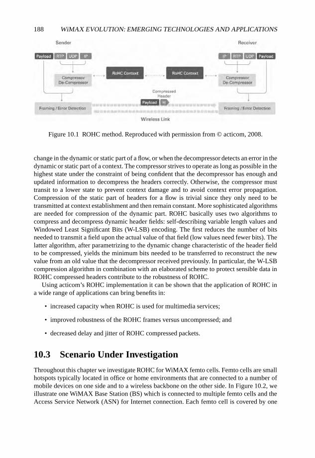
188 WiMAX EVOLUTION: EMERGING TECHNOLOGIES AND APPLICATIONS
Figure 10.1 ROHC method. Reproduced with permission from © acticom, 2008.
change in the dynamic or static part of a flow, or when the decompressor detects an error in thedynamic or static part of a context. The compressor strives to operate as long as possible in thehighest state under the constraint of being confident that the decompressor has enough andupdated information to decompress the headers correctly. Otherwise, the compressor musttransit to a lower state to prevent context damage and to avoid context error propagation.Compression of the static part of headers for a flow is trivial since they only need to betransmitted at context establishment and then remain constant. More sophisticated algorithmsare needed for compression of the dynamic part. ROHC basically uses two algorithms tocompress and decompress dynamic header fields: self-describing variable length values andWindowed Least Significant Bits (W-LSB) encoding. The first reduces the number of bitsneeded to transmit a field upon the actual value of that field (low values need fewer bits). Thelatter algorithm, after parametrizing to the dynamic change characteristic of the header fieldto be compressed, yields the minimum bits needed to be transferred to reconstruct the newvalue from an old value that the decompressor received previously. In particular, the W-LSBcompression algorithm in combination with an elaborated scheme to protect sensible data inROHC compressed headers contribute to the robustness of ROHC.
Using acticom’s ROHC implementation it can be shown that the application of ROHC ina wide range of applications can bring benefits in:
• increased capacity when ROHC is used for multimedia services;
• improved robustness of the ROHC frames versus uncompressed; and
• decreased delay and jitter of ROHC compressed packets.
10.3 Scenario Under Investigation
Throughout this chapter we investigate ROHC for WiMAX femto cells. Femto cells are smallhotspots typically located in office or home environments that are connected to a number ofmobile devices on one side and to a wireless backbone on the other side. In Figure 10.2, weillustrate one WiMAX Base Station (BS) which is connected to multiple femto cells and theAccess Service Network (ASN) for Internet connection. Each femto cell is covered by one
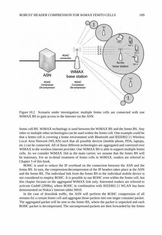
ROBUST HEADER COMPRESSION FOR WiMAX FEMTO CELLS 189
Figure 10.2 Scenario under investigation: multiple femto cells are connected with oneWiMAX BS to gain access to the Internet via the ASN.
femto cell BS. WiMAX technology is used between the WiMAX BS and the femto BS. Anyother or multiple other technologies can be used within the femto cell. One example could bethat a femto cell is covering a home environment with Bluetooth and IEEE802.11 WirelessLocal Area Network (WLAN) such that all possible devices (mobile phone, PDA, laptops,etc.) can be connected. All of these different technologies are aggregated and conveyed overWiMAX to the wireless Internet provider. One WiMAX BS is able to support multiple femtocells. As we consider WiMAX 16d as the main carrier, we assume that the femto BS willbe stationary. For an in-detail treatment of femto cells in WiMAX, readers are referred toChapter 5 of this book.
ROHC is used to reduce the IP overhead on the connection between the ASN and thefemto BS. In turn, the compression/decompression of the IP headers takes place at the ASNand the femto BS. The individual link from the femto BS to the individual mobile device isnot considered to employ ROHC. It is possible to use ROHC even within the femto cell, butthis chapter focuses on the aggregated WiMAX link only. Interested readers are referred toacticom GmbH (2008a), where ROHC in combination with IEEE802.11 WLAN has beendemonstrated on Nokia’s Internet tablet N810.
In the case of downlink traffic, the ASN will perform the ROHC compression of allstreams for a certain femto cell and aggregate those packets into one larger container packet.The aggregated packet will be sent to the femto BS, where the packet is unpacked and eachROHC packet is decompressed. The uncompressed packets are then forwarded by the femto
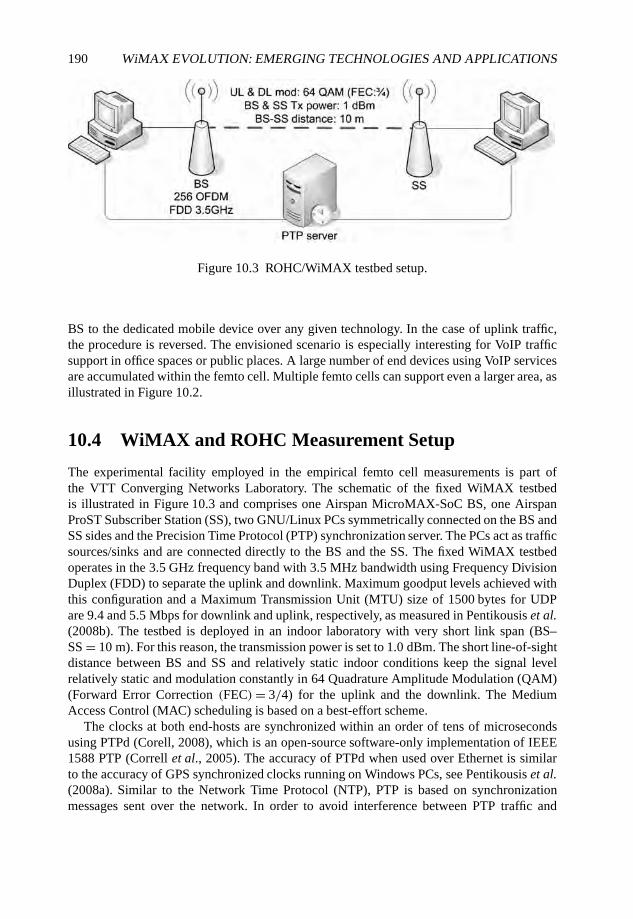
190 WiMAX EVOLUTION: EMERGING TECHNOLOGIES AND APPLICATIONS
Figure 10.3 ROHC/WiMAX testbed setup.
BS to the dedicated mobile device over any given technology. In the case of uplink traffic,the procedure is reversed. The envisioned scenario is especially interesting for VoIP trafficsupport in office spaces or public places. A large number of end devices using VoIP servicesare accumulated within the femto cell. Multiple femto cells can support even a larger area, asillustrated in Figure 10.2.
10.4 WiMAX and ROHC Measurement Setup
The experimental facility employed in the empirical femto cell measurements is part ofthe VTT Converging Networks Laboratory. The schematic of the fixed WiMAX testbedis illustrated in Figure 10.3 and comprises one Airspan MicroMAX-SoC BS, one AirspanProST Subscriber Station (SS), two GNU/Linux PCs symmetrically connected on the BS andSS sides and the Precision Time Protocol (PTP) synchronization server. The PCs act as trafficsources/sinks and are connected directly to the BS and the SS. The fixed WiMAX testbedoperates in the 3.5 GHz frequency band with 3.5 MHz bandwidth using Frequency DivisionDuplex (FDD) to separate the uplink and downlink. Maximum goodput levels achieved withthis configuration and a Maximum Transmission Unit (MTU) size of 1500 bytes for UDPare 9.4 and 5.5 Mbps for downlink and uplink, respectively, as measured in Pentikousis et al.(2008b). The testbed is deployed in an indoor laboratory with very short link span (BS–SS = 10 m). For this reason, the transmission power is set to 1.0 dBm. The short line-of-sightdistance between BS and SS and relatively static indoor conditions keep the signal levelrelatively static and modulation constantly in 64 Quadrature Amplitude Modulation (QAM)(Forward Error Correction (FEC)= 3/4) for the uplink and the downlink. The MediumAccess Control (MAC) scheduling is based on a best-effort scheme.
The clocks at both end-hosts are synchronized within an order of tens of microsecondsusing PTPd (Corell, 2008), which is an open-source software-only implementation of IEEE1588 PTP (Correll et al., 2005). The accuracy of PTPd when used over Ethernet is similarto the accuracy of GPS synchronized clocks running on Windows PCs, see Pentikousis et al.(2008a). Similar to the Network Time Protocol (NTP), PTP is based on synchronizationmessages sent over the network. In order to avoid interference between PTP traffic and
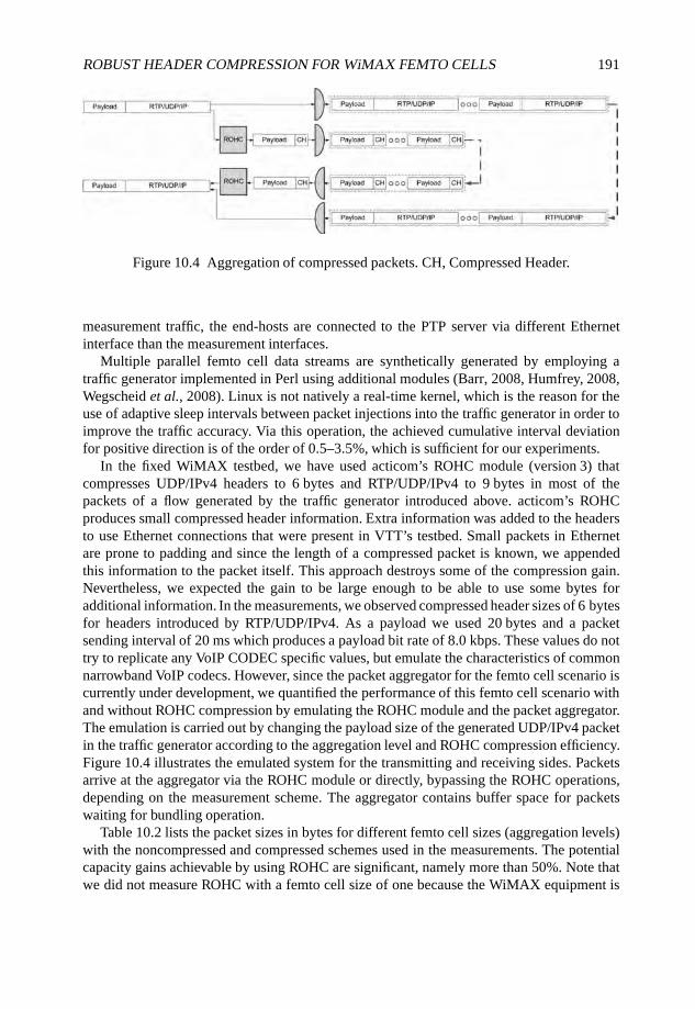
ROBUST HEADER COMPRESSION FOR WiMAX FEMTO CELLS 191
Figure 10.4 Aggregation of compressed packets. CH, Compressed Header.
measurement traffic, the end-hosts are connected to the PTP server via different Ethernetinterface than the measurement interfaces.
Multiple parallel femto cell data streams are synthetically generated by employing atraffic generator implemented in Perl using additional modules (Barr, 2008, Humfrey, 2008,Wegscheid et al., 2008). Linux is not natively a real-time kernel, which is the reason for theuse of adaptive sleep intervals between packet injections into the traffic generator in order toimprove the traffic accuracy. Via this operation, the achieved cumulative interval deviationfor positive direction is of the order of 0.5–3.5%, which is sufficient for our experiments.
In the fixed WiMAX testbed, we have used acticom’s ROHC module (version 3) thatcompresses UDP/IPv4 headers to 6 bytes and RTP/UDP/IPv4 to 9 bytes in most of thepackets of a flow generated by the traffic generator introduced above. acticom’s ROHCproduces small compressed header information. Extra information was added to the headersto use Ethernet connections that were present in VTT’s testbed. Small packets in Ethernetare prone to padding and since the length of a compressed packet is known, we appendedthis information to the packet itself. This approach destroys some of the compression gain.Nevertheless, we expected the gain to be large enough to be able to use some bytes foradditional information. In the measurements, we observed compressed header sizes of 6 bytesfor headers introduced by RTP/UDP/IPv4. As a payload we used 20 bytes and a packetsending interval of 20 ms which produces a payload bit rate of 8.0 kbps. These values do nottry to replicate any VoIP CODEC specific values, but emulate the characteristics of commonnarrowband VoIP codecs. However, since the packet aggregator for the femto cell scenario iscurrently under development, we quantified the performance of this femto cell scenario withand without ROHC compression by emulating the ROHC module and the packet aggregator.The emulation is carried out by changing the payload size of the generated UDP/IPv4 packetin the traffic generator according to the aggregation level and ROHC compression efficiency.Figure 10.4 illustrates the emulated system for the transmitting and receiving sides. Packetsarrive at the aggregator via the ROHC module or directly, bypassing the ROHC operations,depending on the measurement scheme. The aggregator contains buffer space for packetswaiting for bundling operation.
Table 10.2 lists the packet sizes in bytes for different femto cell sizes (aggregation levels)with the noncompressed and compressed schemes used in the measurements. The potentialcapacity gains achievable by using ROHC are significant, namely more than 50%. Note thatwe did not measure ROHC with a femto cell size of one because the WiMAX equipment is
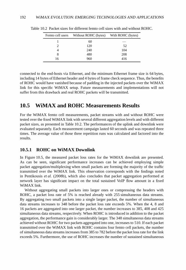
192 WiMAX EVOLUTION: EMERGING TECHNOLOGIES AND APPLICATIONS
Table 10.2 Packet sizes for different femto cell sizes with and without ROHC.
Femto cell users Without ROHC (bytes) With ROHC (bytes)
1 60 —2 120 524 240 1048 480 208
16 960 416
connected to the end-hosts via Ethernet, and the minimum Ethernet frame size is 64 bytes,including 14 bytes of Ethernet header and 4 bytes of frame check sequence. Thus, the benefitsof ROHC would have vanished because of padding in the injected packets over the WiMAXlink for this specific WiMAX setup. Future measurements and implementations will notsuffer from this drawback and real ROHC packets will be transmitted.
10.5 WiMAX and ROHC Measurements Results
For the WiMAX femto cell measurements, packet streams with and without ROHC weretested over the fixed WiMAX link with several different aggregation levels and with differentpacket sizes, as presented in Table 10.2. The performances of the uplink and downlink wereevaluated separately. Each measurement campaign lasted 60 seconds and was repeated threetimes. The average value of those three repetition runs was calculated and factored into theresults.
10.5.1 ROHC on WiMAX Downlink
In Figure 10.5, the measured packet loss rates for the WiMAX downlink are presented.As can be seen, significant performance increases can be achieved employing simplepacket aggregation/multiplexing when small packets are forming the majority of the traffictransmitted over the WiMAX link. This observation corresponds with the findings notedin Pentikousis et al. (2008b), which also concludes that packet aggregation performed atnetwork layer has significant impact on the total sustained VoIP flow amount in a fixedWiMAX link.
Without aggregating small packets into larger ones or compressing the headers withROHC, a packet loss rate of 5% is reached already with 255 simultaneous data streams.By aggregating two small packets into a single larger packet, the number of simultaneousdata streams increases to 348 before the packet loss rate exceeds 5%. When the 4, 8 and16 packets are aggregated into one larger packet, the number increases to 385, 408 and 425simultaneous data streams, respectively. When ROHC is introduced in addition to the packetaggregation, the performance gain is considerably larger. The 348 simultaneous data streamsachieved without ROHC for two packets aggregated into one, increases to 510. If each packettransmitted over the WiMAX link with ROHC contains four femto cell packets, the numberof simultaneous data streams increases from 385 to 782 before the packet loss rate for the linkexceeds 5%. Furthermore, the use of ROHC increases the number of sustained simultaneous
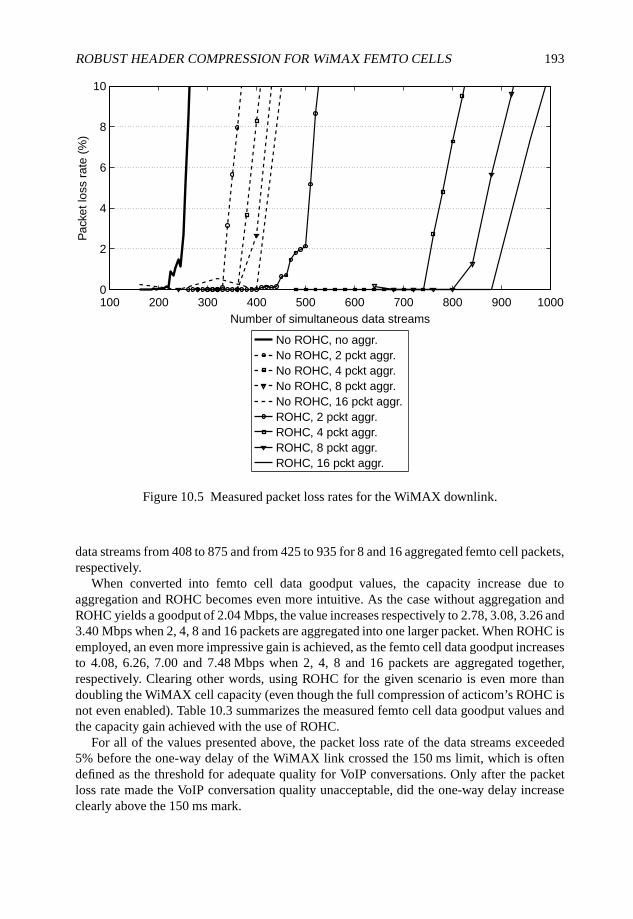
ROBUST HEADER COMPRESSION FOR WiMAX FEMTO CELLS 193
100 200 300 400 500 600 700 800 900 10000
2
4
6
8
10
Number of simultaneous data streams
Pac
ket l
oss
rate
(%
)
No ROHC, no aggr.No ROHC, 2 pckt aggr.No ROHC, 4 pckt aggr.No ROHC, 8 pckt aggr.No ROHC, 16 pckt aggr.ROHC, 2 pckt aggr.ROHC, 4 pckt aggr.ROHC, 8 pckt aggr.ROHC, 16 pckt aggr.
Figure 10.5 Measured packet loss rates for the WiMAX downlink.
data streams from 408 to 875 and from 425 to 935 for 8 and 16 aggregated femto cell packets,respectively.
When converted into femto cell data goodput values, the capacity increase due toaggregation and ROHC becomes even more intuitive. As the case without aggregation andROHC yields a goodput of 2.04 Mbps, the value increases respectively to 2.78, 3.08, 3.26 and3.40 Mbps when 2, 4, 8 and 16 packets are aggregated into one larger packet. When ROHC isemployed, an even more impressive gain is achieved, as the femto cell data goodput increasesto 4.08, 6.26, 7.00 and 7.48 Mbps when 2, 4, 8 and 16 packets are aggregated together,respectively. Clearing other words, using ROHC for the given scenario is even more thandoubling the WiMAX cell capacity (even though the full compression of acticom’s ROHC isnot even enabled). Table 10.3 summarizes the measured femto cell data goodput values andthe capacity gain achieved with the use of ROHC.
For all of the values presented above, the packet loss rate of the data streams exceeded5% before the one-way delay of the WiMAX link crossed the 150 ms limit, which is oftendefined as the threshold for adequate quality for VoIP conversations. Only after the packetloss rate made the VoIP conversation quality unacceptable, did the one-way delay increaseclearly above the 150 ms mark.
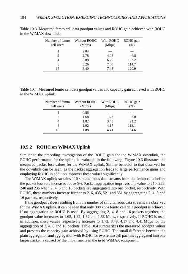
194 WiMAX EVOLUTION: EMERGING TECHNOLOGIES AND APPLICATIONS
Table 10.3 Measured femto cell data goodput values and ROHC gain achieved with ROHCin the WiMAX downlink.
Number of femto Without ROHC With ROHC ROHC gaincell users (Mbps) (Mbps) (%)
1 2.04 — —2 2.78 4.08 46.84 3.08 6.26 103.28 3.26 7.00 114.7
16 3.40 7.48 120.0
Table 10.4 Measured femto cell data goodput values and capacity gain achieved with ROHCin the WiMAX uplink.
Number of femto Without ROHC With ROHC ROHC gaincell users (Mbps) (Mbps) (%)
1 0.88 — —2 1.68 1.73 3.04 1.82 3.48 91.28 1.92 4.17 113.1
16 1.88 4.41 134.6
10.5.2 ROHC on WiMAX Uplink
Similar to the preceding investigation of the ROHC gain for the WiMAX downlink, theROHC performance for the uplink is evaluated in the following. Figure 10.6 illustrates themeasured packet loss values for the WiMAX uplink. Similar behavior to that observed forthe downlink can be seen, as the packet aggregation leads to large performance gains andemploying ROHC in addition improves these values significantly.
The WiMAX uplink sustains 110 simultaneous data streams from the femto cells beforethe packet loss rate increases above 5%. Packet aggregation improves this value to 210, 228,240 and 235 when 2, 4, 8 and 16 packets are aggregated into one packet, respectively. WithROHC, these numbers increase further to 216, 435, 521 and 551 by aggregating 2, 4, 8 and16 packets, respectively.
If the goodput values resulting from the number of simultaneous data streams are observedfor the WiMAX uplink, it can be seen that only 880 kbps femto cell data goodput is achievedif no aggregation or ROHC is used. By aggregating 2, 4, 8 and 16 packets together, thegoodput value increases to 1.68, 1.82, 1.92 and 1.88 Mbps, respectively. If ROHC is usedin addition, these values respectively increase to 1.73, 3.48, 4.17 and 4.41 Mbps for theaggregation of 2, 4, 8 and 16 packets. Table 10.4 summarizes the measured goodput valuesand presents the capacity gain achieved by using ROHC. The small difference between theplain aggregation and aggregation with ROHC for two femto cell packets aggregated into onelarger packet is caused by the impairments in the used WiMAX equipment.
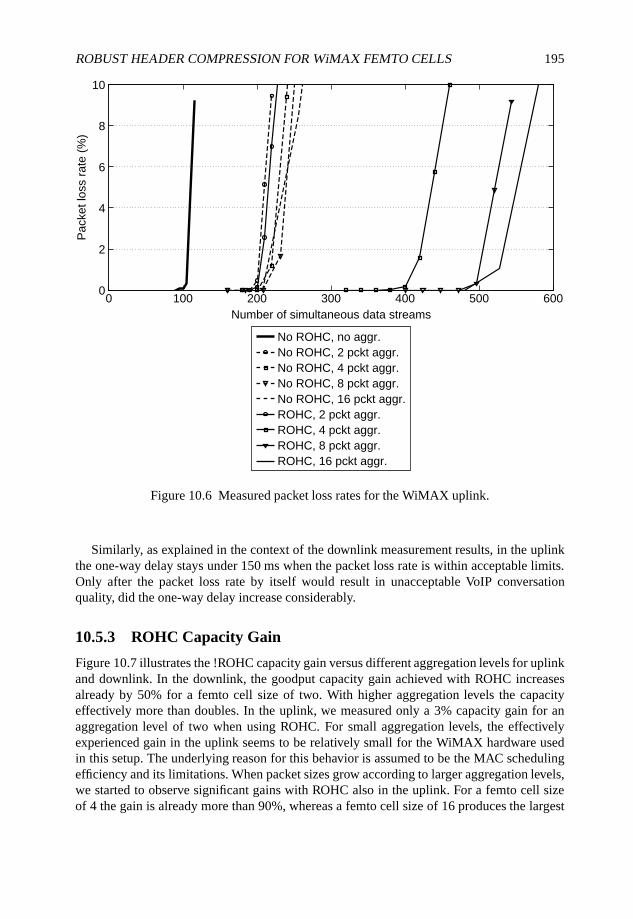
ROBUST HEADER COMPRESSION FOR WiMAX FEMTO CELLS 195
0 100 200 300 400 500 6000
2
4
6
8
10
Number of simultaneous data streams
Pac
ket l
oss
rate
(%
)
No ROHC, no aggr.No ROHC, 2 pckt aggr.No ROHC, 4 pckt aggr.No ROHC, 8 pckt aggr.No ROHC, 16 pckt aggr.ROHC, 2 pckt aggr.ROHC, 4 pckt aggr.ROHC, 8 pckt aggr.ROHC, 16 pckt aggr.
Figure 10.6 Measured packet loss rates for the WiMAX uplink.
Similarly, as explained in the context of the downlink measurement results, in the uplinkthe one-way delay stays under 150 ms when the packet loss rate is within acceptable limits.Only after the packet loss rate by itself would result in unacceptable VoIP conversationquality, did the one-way delay increase considerably.
10.5.3 ROHC Capacity Gain
Figure 10.7 illustrates the !ROHC capacity gain versus different aggregation levels for uplinkand downlink. In the downlink, the goodput capacity gain achieved with ROHC increasesalready by 50% for a femto cell size of two. With higher aggregation levels the capacityeffectively more than doubles. In the uplink, we measured only a 3% capacity gain for anaggregation level of two when using ROHC. For small aggregation levels, the effectivelyexperienced gain in the uplink seems to be relatively small for the WiMAX hardware usedin this setup. The underlying reason for this behavior is assumed to be the MAC schedulingefficiency and its limitations. When packet sizes grow according to larger aggregation levels,we started to observe significant gains with ROHC also in the uplink. For a femto cell sizeof 4 the gain is already more than 90%, whereas a femto cell size of 16 produces the largest
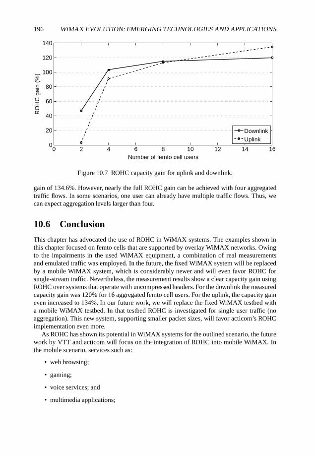
196 WiMAX EVOLUTION: EMERGING TECHNOLOGIES AND APPLICATIONS
0 2 4 6 8 10 12 14 160
20
40
60
80
100
120
140
Number of femto cell users
RO
HC
gai
n (%
)
DownlinkUplink
Figure 10.7 ROHC capacity gain for uplink and downlink.
gain of 134.6%. However, nearly the full ROHC gain can be achieved with four aggregatedtraffic flows. In some scenarios, one user can already have multiple traffic flows. Thus, wecan expect aggregation levels larger than four.
10.6 Conclusion
This chapter has advocated the use of ROHC in WiMAX systems. The examples shown inthis chapter focused on femto cells that are supported by overlay WiMAX networks. Owingto the impairments in the used WiMAX equipment, a combination of real measurementsand emulated traffic was employed. In the future, the fixed WiMAX system will be replacedby a mobile WiMAX system, which is considerably newer and will even favor ROHC forsingle-stream traffic. Nevertheless, the measurement results show a clear capacity gain usingROHC over systems that operate with uncompressed headers. For the downlink the measuredcapacity gain was 120% for 16 aggregated femto cell users. For the uplink, the capacity gaineven increased to 134%. In our future work, we will replace the fixed WiMAX testbed witha mobile WiMAX testbed. In that testbed ROHC is investigated for single user traffic (noaggregation). This new system, supporting smaller packet sizes, will favor acticom’s ROHCimplementation even more.
As ROHC has shown its potential in WiMAX systems for the outlined scenario, the futurework by VTT and acticom will focus on the integration of ROHC into mobile WiMAX. Inthe mobile scenario, services such as:
• web browsing;
• gaming;
• voice services; and
• multimedia applications;

ROBUST HEADER COMPRESSION FOR WiMAX FEMTO CELLS 197
will be used to investigate the ROHC gain. For all of these services a large gain in capacityis expected using ROHC.
References
acticom GmbH (2008a). acticom shows RoHC enabled Nokia N810 Internet Tablet,http://acticom.de/en/news/2008-05-26/ (accessed 15 July 2008).
acticom GmbH (2008b). RoHC enabled 802.16 WiMAX network,http://acticom.de/en/news/2008-01-31/ (accessed 15 July 2008).
Barr, G. (2008) IO::Socket::INET – Object interface for AF_INET domain sockets, CPAN.http://search.cpan.org/∼gbarr/IO-1.2301/IO/Socket.pm (accessed 15 July 2008).
Bormann, C. et al. (2001) RObust Header Compression (ROHC): Framework and four profiles: RTP,UDP, ESP, and uncompressed. Request for Comments 3095 IETF.
Correll, K., Barendt, N. and Branicky, M. (2005) Design considerations for software onlyimplementations of the IEEE 1588 Precision Time Protocol. Proceedings of the Conference on IEEE1588.
Corell, K. (2008) PTP daemon (PTPd), http://ptpd.sourceforge.net/ (accessed 15 July 2008).Fitzek, F.-P., et al. (2004) Header compression schemes for wireless Internet access. Wireless Internet.
CRC Press, Boca Ratan, FL.Humfrey, N. J. (2008) Net::RTP – Send and receive RTP packets (RFC3550), CPAN.
http://search.cpan.org/∼njh/Net-RTP-0.09/lib/Net/RTP.pm (accessed 15 July 2008).International Electrotechnical Commission (2004) Precision Clock Synchronization Protocol for
Networked Measurement and Control Systems, IEC 61588:2004(E), IEEE 1588-2002(E),September 2004.
Pentikousis, K., et al. (2008a) An experimental investigation of VoIP and video streaming overfixed WiMAX. Proceedings of the 4th International Workshop on Wireless Network Measurements(WiNMee), March 2008.
Pentikousis, K., et al. (2008b) Empirical evaluation of VoIP aggregation over a fixed WiMAX testbed.Proceedings of the 4th International Conference on Testbeds and Research Infrastructures for theDevelopment of Networks and Communities (TRIDENTCOM), March 2008.
Piri, E., et al. (2008) ROHC and aggregated VoIP over fixed WiMAX: an empirical evaluation.Proceedings of the IEEE Symposium on Computers and Communications (ISSC), May 2008.
Wegscheid, D., et al. (2008) Time::HiRes – High resolution alarm, sleep, gettimeofday, interval timers,CPAN. http://search.cpan.org/∼jhi/Time-HiRes-1.9715/HiRes.pm (accessed 15 July 2008).
11
A WiMAX Cross-layerFramework for Next GenerationNetworks
Pedro Neves, Susana Sargento, Ricardo Matos,Giada Landi, Kostas Pentikousis, Marília Curado andFrancisco Fontes
11.1 Introduction
Ubiquitous Internet access is one of the main challenges for the telecommunications industry.The number of users accessing the Internet is growing at a very fast pace. At the same time,the average customer uses more than one device to connect to the Internet, and downloadsand uploads digital media of an unprecedented magnitude. The network access paradigmof ‘always connected, anytime, anywhere’ is a central requirement for Next GenerationNetworks (NGNs).
Such a requirement places a tall order to operators that ought to find ways to providebroadband connectivity to their subscribers independently of their location and accessdevice. Furthermore, the popularity of high-bandwidth services (including those arisingfrom social networking sites) and other demanding multimedia applications is expected tocontinue to increase. IEEE 802.16 (IEEE, 2004, 2005b) and the WiMAX Forum networkarchitecture extensions (WiMAXForum, 2008) provide an attractive solution for this type ofNGN environments. WiMAX is a Point-to-Multipoint (PTMP) technology, providing highthroughputs, and it is oriented for Wireless Metropolitan Area Networks (WMANs). Thebuilt-in Quality of Service (QoS) functionalities through the use of unidirectional connections
WiMAX Evolution: Emerging Technologies and Applications Edited by Tsutomu Ishikawa© 2009 John Wiley & Sons, Ltd. ISBN: 978-0-470-69680-4
200 WiMAX EVOLUTION: EMERGING TECHNOLOGIES AND APPLICATIONS
and service flows between Base Stations (BSs) and Subscriber Stations (SSs) are also animportant feature provided by this wireless technology.
Another aspect of NGN is the seamless integration of heterogeneous network technolo-gies. Future network architectures will provide seamless QoS support, mobility and security,among other features, which are crucial for the success of the future networks. Taking intoaccount the convergence scenario envisioned in the telecommunications area, it is essentialthat different access technologies, wired and wireless, are able to work together, allowingmobile users to Handover (HO) between them seamlessly. In this sense, in order to integrateWiMAX technology (WiMAXForum, 2008), in next generation environments, one needsto support a cross-layer framework that enables seamless communication between WiMAXand other access technologies, as well as with the QoS, security and mobility managementprotocols.
IEEE has been working on a standard which enables Media Independent Handovers(MIHs) (IEEE, 2008). The IEEE 802.21 standard (IEEE, 2008) is expected to be ratifiedduring 2008 and its main objective is to assist in optimizing mobility processes through aset of services and interfaces that can be used in a standard way for different wired andwireless technologies and higher-layer mobility management protocols. MIHs and radiodetail abstraction mechanisms have been explored in the research literature for some timeand with IEEE 802.21 finalized it is expected that these concepts will play a dominant rolein the integration of different technologies in future networks.
In this chapter we present a cross-layer framework that seamlessly integrates WiMAX inheterogeneous NGNs. We concentrate on QoS and mobility aspects and explain how NextSteps in Signaling (NSIS) (Hancock et al., 2005) and IEEE 802.21 can be taken advantageof and integrated with the specifics of WiMAX technology in terms of service flow QoSprovisioning and mobility management messages. This framework allows for standards-based end-to-end QoS support and seamless mobility management. The foundation of thisframework is the architecture designed in the European WEIRD project (Guainella et al.,2007). A prototype implementation of this framework has already been evaluated in theproject’s testbeds.
The chapter is organized as follows. Section 11.2 provides an overview of the WiMAXarchitecture and Section 11.3 introduces our proposed cross-layer framework for the integra-tion of WiMAX networks in next generation networks. Section 11.4 presents a case studybased on the WEIRD architecture; results from this study are given in Section 11.5. Finally,Section 11.6 concludes this chapter outlining future work items.
11.2 IEEE 802.16 Reference Model
The IEEE 802.16 standard (IEEE, 2004, 2005b) reference model comprises the data, controland management planes. The data plane protocol stack is illustrated in Figure 11.1. It includesthe Physical (PHY) layer and the Medium Access Control (MAC) layer. Multiple physicallayers are supported, operating in the 2–66 GHz frequency spectrum, and support single andmulti-carrier air interfaces, depending on the particular operational environment.
The MAC layer is connection-oriented and provides QoS assurances through the use ofservice flows and scheduling services. A connection is defined as a unidirectional mappingbetween the BS and the SS/Mobile Station (MS) MAC layers for transporting a service flow’s
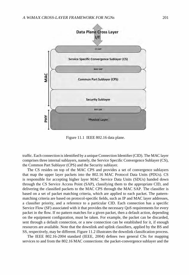
A WiMAX CROSS-LAYER FRAMEWORK FOR NGNs 201
Figure 11.1 IEEE 802.16 data plane.
traffic. Each connection is identified by a unique Connection Identifier (CID). The MAC layercomprises three internal sublayers, namely, the Service Specific Convergence Sublayer (CS),the Common Part Sublayer (CPS) and the Security sublayer.
The CS resides on top of the MAC CPS and provides a set of convergence sublayersthat map the upper layer packets into the 802.16 MAC Protocol Data Units (PDUs). CSis responsible for accepting higher layer MAC Service Data Units (SDUs) handed downthrough the CS Service Access Point (SAP), classifying them to the appropriate CID, anddelivering the classified packets to the MAC CPS through the MAC SAP. The classifier isbased on a set of packet matching criteria, which are applied to each packet. The pattern-matching criteria are based on protocol-specific fields, such as IP and MAC layer addresses,a classifier priority, and a reference to a particular CID. Each connection has a specificService Flow (SF) associated with it that provides the necessary QoS requirements for everypacket in the flow. If no pattern matches for a given packet, then a default action, dependingon the equipment configuration, must be taken. For example, the packet can be discarded,sent through a default connection, or a new connection can be established for it, if enoughresources are available. Note that the downlink and uplink classifiers, applied by the BS andSS, respectively, may be different. Figure 11.2 illustrates the downlink classification process.
The IEEE 802.16-2004 standard (IEEE, 2004) defines two general CSs for mappingservices to and from the 802.16 MAC connections: the packet-convergence sublayer and the
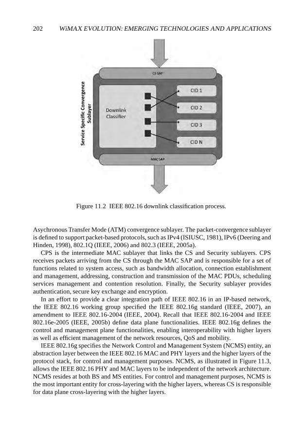
202 WiMAX EVOLUTION: EMERGING TECHNOLOGIES AND APPLICATIONS
Figure 11.2 IEEE 802.16 downlink classification process.
Asychronous Transfer Mode (ATM) convergence sublayer. The packet-convergence sublayeris defined to support packet-based protocols, such as IPv4 (ISIUSC, 1981), IPv6 (Deering andHinden, 1998), 802.1Q (IEEE, 2006) and 802.3 (IEEE, 2005a).
CPS is the intermediate MAC sublayer that links the CS and Security sublayers. CPSreceives packets arriving from the CS through the MAC SAP and is responsible for a set offunctions related to system access, such as bandwidth allocation, connection establishmentand management, addressing, construction and transmission of the MAC PDUs, schedulingservices management and contention resolution. Finally, the Security sublayer providesauthentication, secure key exchange and encryption.
In an effort to provide a clear integration path of IEEE 802.16 in an IP-based network,the IEEE 802.16 working group specified the IEEE 802.16g standard (IEEE, 2007), anamendment to IEEE 802.16-2004 (IEEE, 2004). Recall that IEEE 802.16-2004 and IEEE802.16e-2005 (IEEE, 2005b) define data plane functionalities. IEEE 802.16g defines thecontrol and management plane functionalities, enabling interoperability with higher layersas well as efficient management of the network resources, QoS and mobility.
IEEE 802.16g specifies the Network Control and Management System (NCMS) entity, anabstraction layer between the IEEE 802.16 MAC and PHY layers and the higher layers of theprotocol stack, for control and management purposes. NCMS, as illustrated in Figure 11.3,allows the IEEE 802.16 PHY and MAC layers to be independent of the network architecture.NCMS resides at both BS and MS entities. For control and management purposes, NCMS isthe most important entity for cross-layering with the higher layers, whereas CS is responsiblefor data plane cross-layering with the higher layers.
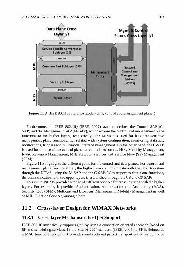
A WiMAX CROSS-LAYER FRAMEWORK FOR NGNs 203
Figure 11.3 IEEE 802.16 reference model (data, control and management planes).
Furthermore, the IEEE 802.16g (IEEE, 2007) standard defines the Control SAP (C-SAP) and the Management SAP (M-SAP), which expose the control and management planefunctions to the higher layers, respectively. The M-SAP is used for less time-sensitivemanagement plane functionalities related with system configuration, monitoring statistics,notifications, triggers and multimode interface management. On the other hand, the C-SAPis used for time-sensitive control plane functionalities such as HOs, Mobility Management,Radio Resource Management, MIH Function Services and Service Flow (SF) Management(SFM).
Figure 11.3 highlights the different paths for the control and data planes. For control andmanagement plane functionalities, the higher layers communicate with the 802.16 systemthrough the NCMS, using the M-SAP and the C-SAP. With respect to data plane functions,the communication with the upper layers is established through the CS and CS SAPs.
To sum up, NCMS provides a range of different services for cross-layering with the higherlayers. For example, it provides Authentication, Authorization and Accounting (AAA),Security, QoS (SFM), Multicast and Broadcast Management, Mobility Management as wellas MIH Function Services, among others.
11.3 Cross-layer Design for WiMAX Networks
11.3.1 Cross-layer Mechanisms for QoS Support
IEEE 802.16 intrinsically supports QoS by using a connection oriented approach, based onSF and scheduling services. In the 802.16-2004 standard (IEEE, 2004), a SF is defined asa MAC transport service that provides unidirectional packet transport either for uplink or
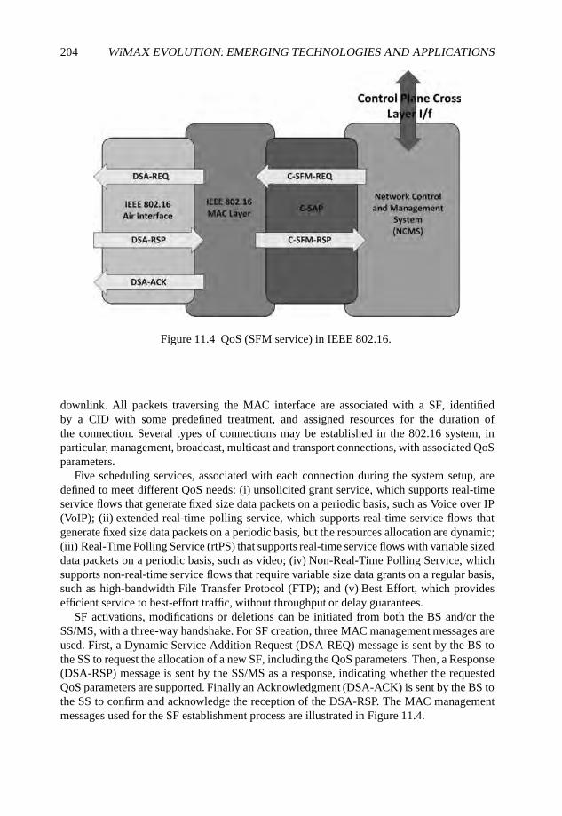
204 WiMAX EVOLUTION: EMERGING TECHNOLOGIES AND APPLICATIONS
Figure 11.4 QoS (SFM service) in IEEE 802.16.
downlink. All packets traversing the MAC interface are associated with a SF, identifiedby a CID with some predefined treatment, and assigned resources for the duration ofthe connection. Several types of connections may be established in the 802.16 system, inparticular, management, broadcast, multicast and transport connections, with associated QoSparameters.
Five scheduling services, associated with each connection during the system setup, aredefined to meet different QoS needs: (i) unsolicited grant service, which supports real-timeservice flows that generate fixed size data packets on a periodic basis, such as Voice over IP(VoIP); (ii) extended real-time polling service, which supports real-time service flows thatgenerate fixed size data packets on a periodic basis, but the resources allocation are dynamic;(iii) Real-Time Polling Service (rtPS) that supports real-time service flows with variable sizeddata packets on a periodic basis, such as video; (iv) Non-Real-Time Polling Service, whichsupports non-real-time service flows that require variable size data grants on a regular basis,such as high-bandwidth File Transfer Protocol (FTP); and (v) Best Effort, which providesefficient service to best-effort traffic, without throughput or delay guarantees.
SF activations, modifications or deletions can be initiated from both the BS and/or theSS/MS, with a three-way handshake. For SF creation, three MAC management messages areused. First, a Dynamic Service Addition Request (DSA-REQ) message is sent by the BS tothe SS to request the allocation of a new SF, including the QoS parameters. Then, a Response(DSA-RSP) message is sent by the SS/MS as a response, indicating whether the requestedQoS parameters are supported. Finally an Acknowledgment (DSA-ACK) is sent by the BS tothe SS to confirm and acknowledge the reception of the DSA-RSP. The MAC managementmessages used for the SF establishment process are illustrated in Figure 11.4.
A WiMAX CROSS-LAYER FRAMEWORK FOR NGNs 205
When dynamic SF modification is required, a similar set of messages is used: DynamicService Change Request (DSC-REQ), Dynamic Service Change Response (DSC-RSP) andDynamic Service Change Acknowledgment (DSC-ACK). Finally, the group of messagesused to delete service flows are Dynamic Service Deletion Request (DSD-REQ), DynamicService Deletion Response (DSD-RSP) and Dynamic Service Deletion Acknowledgment(DSD-ACK).
In order to trigger QoS procedures in a IEEE 802.16 system, NCMS provides the SFMservice. The SFM service is composed of a set of primitives for supporting QoS managementbetween the BS and SS/MS. The interaction between the NCMS and the 802.16 QoS systemis done through the C-SAP.
The SFM service is based on a two-way handshake, shown on the right-hand side ofFigure 11.4, based on following two primitives. First, a Control Service Flow ManagementRequest (C-SFM-REQ) primitive is sent by the NCMS to the 802.16 MAC system to starta SFM procedure, such as SF creation. Effectively a C-SFM-REQ triggers the DSA-REQMAC message, described earlier, or a modification (triggers a DSC-REQ MAC message), ordeletion (triggers a DSC-DEL MAC message). Second, a Control Service Flow ManagementResponse (C-SFM-RSP) primitive is sent back as a response to the requested SFM procedure(based on a DSA-RSP, DSC-RSP or DSD-RSP MAC messages, respectively).
A SF reservation process in the IEEE 802.16 system is shown in Figure 11.4, illustratingboth the SFM primitives (C-SFM-REQ and C-SFM-RSP) in the C-SAP interface, as well thecorresponding MAC management messages (DSA-REQ, DSA-RSP and DSA-ACK) in theIEEE 802.16 air interface.
Two main approaches have been proposed to achieve QoS support at the IP level, namely,the integrated services (Braden et al., 1994) and the differentiated services (Blake et al.,1998). While the former has shown scalability problems, the later is used in networks toprovide qualified applications the service level that is adequate for their requirements. Inorder to provide different levels of service, the differentiated services framework includesa set of Per Hop Behaviors (PHBs), namely, Expedited Forwarding (EF) (Jacobson et al.,1999), Assured Forwarding (AF) (Heinanen et al., 1999) and best effort. The AF PHBis further divided into four subclasses with different requirements for buffer space andbandwidth.
End-to-end QoS support needs to resort to a signaling protocol in order to convey theresource reservation requests along the network. The NSIS framework (Hancock et al., 2005)has been conceived in order to support network signaling, in general, with QoS signaling asits first application. The NSIS framework comprises two layers, namely, the NSIS TransportLayer Protocol (NTLP) and the NSIS Signaling Layer Protocol (NSLP). The NTLP layer,also known as General Internet Signaling Transport (GIST) (Schulzrinne and Hancock, 2008)is responsible for the transport of the signaling messages sent by NSLPs. The NSLP layeris specific to each application. The first NSLP defined, named QoS-NSLP, was designed toprovide resource reservation signaling support (Manner et al., 2008).
The QoS parameters specific for the QoS model of each context are defined on the QoSSpecification (QSPEC) object defined in the NSIS framework (Ash et al., 2006). Dependingon the context, the QoS parameters may vary. In order to establish an end-to-end resourcereservation which crosses different domains and technologies, there is a need to map betweenthe QoS parameters associated with each context. This function of QSPEC mapping may beperformed horizontally and vertically. In the first case, the mapping is done between the QoS
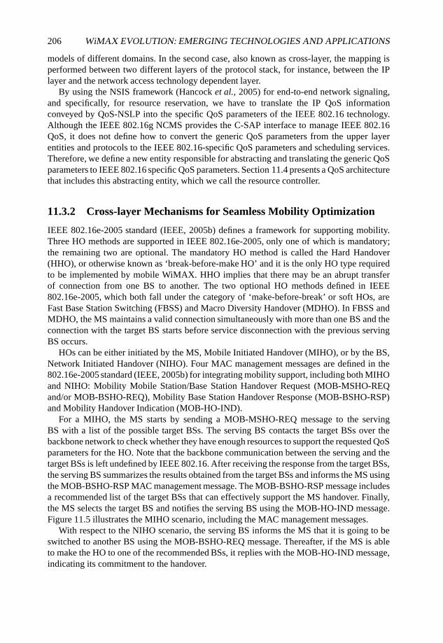
206 WiMAX EVOLUTION: EMERGING TECHNOLOGIES AND APPLICATIONS
models of different domains. In the second case, also known as cross-layer, the mapping isperformed between two different layers of the protocol stack, for instance, between the IPlayer and the network access technology dependent layer.
By using the NSIS framework (Hancock et al., 2005) for end-to-end network signaling,and specifically, for resource reservation, we have to translate the IP QoS informationconveyed by QoS-NSLP into the specific QoS parameters of the IEEE 802.16 technology.Although the IEEE 802.16g NCMS provides the C-SAP interface to manage IEEE 802.16QoS, it does not define how to convert the generic QoS parameters from the upper layerentities and protocols to the IEEE 802.16-specific QoS parameters and scheduling services.Therefore, we define a new entity responsible for abstracting and translating the generic QoSparameters to IEEE 802.16 specific QoS parameters. Section 11.4 presents a QoS architecturethat includes this abstracting entity, which we call the resource controller.
11.3.2 Cross-layer Mechanisms for Seamless Mobility Optimization
IEEE 802.16e-2005 standard (IEEE, 2005b) defines a framework for supporting mobility.Three HO methods are supported in IEEE 802.16e-2005, only one of which is mandatory;the remaining two are optional. The mandatory HO method is called the Hard Handover(HHO), or otherwise known as ‘break-before-make HO’ and it is the only HO type requiredto be implemented by mobile WiMAX. HHO implies that there may be an abrupt transferof connection from one BS to another. The two optional HO methods defined in IEEE802.16e-2005, which both fall under the category of ‘make-before-break’ or soft HOs, areFast Base Station Switching (FBSS) and Macro Diversity Handover (MDHO). In FBSS andMDHO, the MS maintains a valid connection simultaneously with more than one BS and theconnection with the target BS starts before service disconnection with the previous servingBS occurs.
HOs can be either initiated by the MS, Mobile Initiated Handover (MIHO), or by the BS,Network Initiated Handover (NIHO). Four MAC management messages are defined in the802.16e-2005 standard (IEEE, 2005b) for integrating mobility support, including both MIHOand NIHO: Mobility Mobile Station/Base Station Handover Request (MOB-MSHO-REQand/or MOB-BSHO-REQ), Mobility Base Station Handover Response (MOB-BSHO-RSP)and Mobility Handover Indication (MOB-HO-IND).
For a MIHO, the MS starts by sending a MOB-MSHO-REQ message to the servingBS with a list of the possible target BSs. The serving BS contacts the target BSs over thebackbone network to check whether they have enough resources to support the requested QoSparameters for the HO. Note that the backbone communication between the serving and thetarget BSs is left undefined by IEEE 802.16. After receiving the response from the target BSs,the serving BS summarizes the results obtained from the target BSs and informs the MS usingthe MOB-BSHO-RSP MAC management message. The MOB-BSHO-RSP message includesa recommended list of the target BSs that can effectively support the MS handover. Finally,the MS selects the target BS and notifies the serving BS using the MOB-HO-IND message.Figure 11.5 illustrates the MIHO scenario, including the MAC management messages.
With respect to the NIHO scenario, the serving BS informs the MS that it is going to beswitched to another BS using the MOB-BSHO-REQ message. Thereafter, if the MS is ableto make the HO to one of the recommended BSs, it replies with the MOB-HO-IND message,indicating its commitment to the handover.
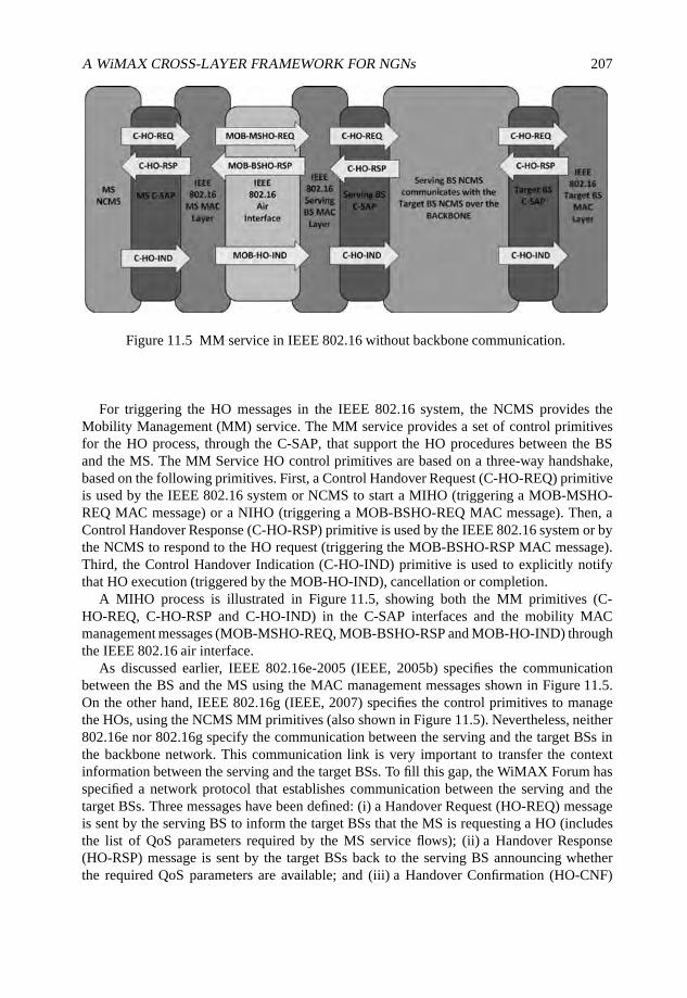
A WiMAX CROSS-LAYER FRAMEWORK FOR NGNs 207
Figure 11.5 MM service in IEEE 802.16 without backbone communication.
For triggering the HO messages in the IEEE 802.16 system, the NCMS provides theMobility Management (MM) service. The MM service provides a set of control primitivesfor the HO process, through the C-SAP, that support the HO procedures between the BSand the MS. The MM Service HO control primitives are based on a three-way handshake,based on the following primitives. First, a Control Handover Request (C-HO-REQ) primitiveis used by the IEEE 802.16 system or NCMS to start a MIHO (triggering a MOB-MSHO-REQ MAC message) or a NIHO (triggering a MOB-BSHO-REQ MAC message). Then, aControl Handover Response (C-HO-RSP) primitive is used by the IEEE 802.16 system or bythe NCMS to respond to the HO request (triggering the MOB-BSHO-RSP MAC message).Third, the Control Handover Indication (C-HO-IND) primitive is used to explicitly notifythat HO execution (triggered by the MOB-HO-IND), cancellation or completion.
A MIHO process is illustrated in Figure 11.5, showing both the MM primitives (C-HO-REQ, C-HO-RSP and C-HO-IND) in the C-SAP interfaces and the mobility MACmanagement messages (MOB-MSHO-REQ, MOB-BSHO-RSP and MOB-HO-IND) throughthe IEEE 802.16 air interface.
As discussed earlier, IEEE 802.16e-2005 (IEEE, 2005b) specifies the communicationbetween the BS and the MS using the MAC management messages shown in Figure 11.5.On the other hand, IEEE 802.16g (IEEE, 2007) specifies the control primitives to managethe HOs, using the NCMS MM primitives (also shown in Figure 11.5). Nevertheless, neither802.16e nor 802.16g specify the communication between the serving and the target BSs inthe backbone network. This communication link is very important to transfer the contextinformation between the serving and the target BSs. To fill this gap, the WiMAX Forum hasspecified a network protocol that establishes communication between the serving and thetarget BSs. Three messages have been defined: (i) a Handover Request (HO-REQ) messageis sent by the serving BS to inform the target BSs that the MS is requesting a HO (includesthe list of QoS parameters required by the MS service flows); (ii) a Handover Response(HO-RSP) message is sent by the target BSs back to the serving BS announcing whetherthe required QoS parameters are available; and (iii) a Handover Confirmation (HO-CNF)
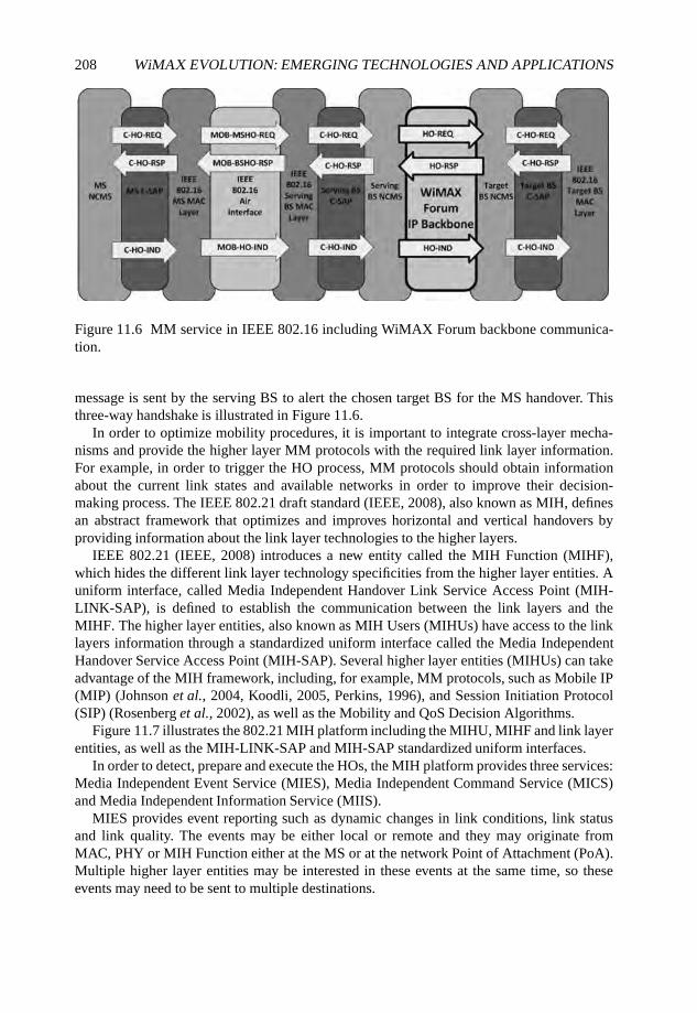
208 WiMAX EVOLUTION: EMERGING TECHNOLOGIES AND APPLICATIONS
Figure 11.6 MM service in IEEE 802.16 including WiMAX Forum backbone communica-tion.
message is sent by the serving BS to alert the chosen target BS for the MS handover. Thisthree-way handshake is illustrated in Figure 11.6.
In order to optimize mobility procedures, it is important to integrate cross-layer mecha-nisms and provide the higher layer MM protocols with the required link layer information.For example, in order to trigger the HO process, MM protocols should obtain informationabout the current link states and available networks in order to improve their decision-making process. The IEEE 802.21 draft standard (IEEE, 2008), also known as MIH, definesan abstract framework that optimizes and improves horizontal and vertical handovers byproviding information about the link layer technologies to the higher layers.
IEEE 802.21 (IEEE, 2008) introduces a new entity called the MIH Function (MIHF),which hides the different link layer technology specificities from the higher layer entities. Auniform interface, called Media Independent Handover Link Service Access Point (MIH-LINK-SAP), is defined to establish the communication between the link layers and theMIHF. The higher layer entities, also known as MIH Users (MIHUs) have access to the linklayers information through a standardized uniform interface called the Media IndependentHandover Service Access Point (MIH-SAP). Several higher layer entities (MIHUs) can takeadvantage of the MIH framework, including, for example, MM protocols, such as Mobile IP(MIP) (Johnson et al., 2004, Koodli, 2005, Perkins, 1996), and Session Initiation Protocol(SIP) (Rosenberg et al., 2002), as well as the Mobility and QoS Decision Algorithms.
Figure 11.7 illustrates the 802.21 MIH platform including the MIHU, MIHF and link layerentities, as well as the MIH-LINK-SAP and MIH-SAP standardized uniform interfaces.
In order to detect, prepare and execute the HOs, the MIH platform provides three services:Media Independent Event Service (MIES), Media Independent Command Service (MICS)and Media Independent Information Service (MIIS).
MIES provides event reporting such as dynamic changes in link conditions, link statusand link quality. The events may be either local or remote and they may originate fromMAC, PHY or MIH Function either at the MS or at the network Point of Attachment (PoA).Multiple higher layer entities may be interested in these events at the same time, so theseevents may need to be sent to multiple destinations.
A WiMAX CROSS-LAYER FRAMEWORK FOR NGNs 209
Figure 11.7 IEEE 802.21 MIH framework.
IEEE 802.21 defines two types of events: link events and MIH events. Link eventsoriginate from the lower layers and then are propagated by the MIHF to registered MIHUs.Events that propagate from the MIHF to the MIHUs are called MIH events. MIH events maybe local or remote. Local MIH events may be propagated across different layers within thelocal protocol stack, whereas the remote MIH events traverse across the network to a peerMIHU.
MICS enables MIHUs to control the physical, data link and logical link layer. The higherlayers may utilize MICS command services to determine the status of links and/or controla multi-mode terminal. Furthermore, MICS may also enable MIHUs to facilitate optionalHO policies. The commands are classified in two categories: MIH commands and linkcommands. MIH commands originate from the higher layer(s) addressing the MIHF, andthey may be local or remote. Local MIH commands are sent by higher layers to the MIHFin the local protocol stack. Remote MIH commands are sent by higher layers to a MIHF inthe peer stack. Link commands originate from the MIHF and sent to the link layers. Thesecommands mainly control the behavior of the link layer entities.
Finally, MIIS provides a framework by which a MIHF located in the MS or in the networkside may discover and obtain network information within a geographical area to facilitatehandovers. The objective is to acquire a global view of all of the heterogeneous networks inthe area in order facilitate seamless HOs when roaming across these networks.
Next, we discuss how we employ the IEEE 802.21 framework in a novel WiMAX cross-layer design solution.
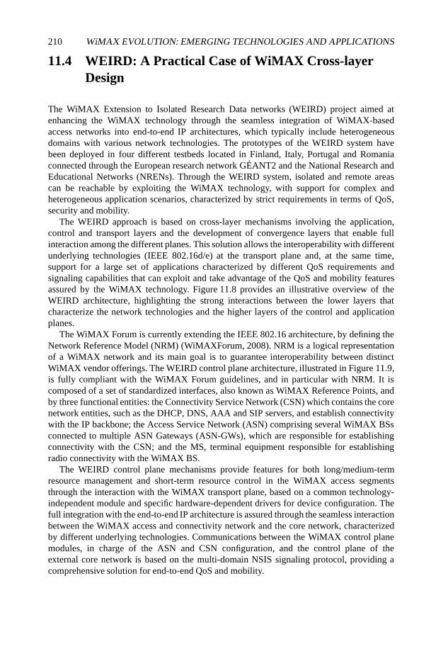
210 WiMAX EVOLUTION: EMERGING TECHNOLOGIES AND APPLICATIONS
11.4 WEIRD: A Practical Case of WiMAX Cross-layerDesign
The WiMAX Extension to Isolated Research Data networks (WEIRD) project aimed atenhancing the WiMAX technology through the seamless integration of WiMAX-basedaccess networks into end-to-end IP architectures, which typically include heterogeneousdomains with various network technologies. The prototypes of the WEIRD system havebeen deployed in four different testbeds located in Finland, Italy, Portugal and Romaniaconnected through the European research network GÉANT2 and the National Research andEducational Networks (NRENs). Through the WEIRD system, isolated and remote areascan be reachable by exploiting the WiMAX technology, with support for complex andheterogeneous application scenarios, characterized by strict requirements in terms of QoS,security and mobility.
The WEIRD approach is based on cross-layer mechanisms involving the application,control and transport layers and the development of convergence layers that enable fullinteraction among the different planes. This solution allows the interoperability with differentunderlying technologies (IEEE 802.16d/e) at the transport plane and, at the same time,support for a large set of applications characterized by different QoS requirements andsignaling capabilities that can exploit and take advantage of the QoS and mobility featuresassured by the WiMAX technology. Figure 11.8 provides an illustrative overview of theWEIRD architecture, highlighting the strong interactions between the lower layers thatcharacterize the network technologies and the higher layers of the control and applicationplanes.
The WiMAX Forum is currently extending the IEEE 802.16 architecture, by defining theNetwork Reference Model (NRM) (WiMAXForum, 2008). NRM is a logical representationof a WiMAX network and its main goal is to guarantee interoperability between distinctWiMAX vendor offerings. The WEIRD control plane architecture, illustrated in Figure 11.9,is fully compliant with the WiMAX Forum guidelines, and in particular with NRM. It iscomposed of a set of standardized interfaces, also known as WiMAX Reference Points, andby three functional entities: the Connectivity Service Network (CSN) which contains the corenetwork entities, such as the DHCP, DNS, AAA and SIP servers, and establish connectivitywith the IP backbone; the Access Service Network (ASN) comprising several WiMAX BSsconnected to multiple ASN Gateways (ASN-GWs), which are responsible for establishingconnectivity with the CSN; and the MS, terminal equipment responsible for establishingradio connectivity with the WiMAX BS.
The WEIRD control plane mechanisms provide features for both long/medium-termresource management and short-term resource control in the WiMAX access segmentsthrough the interaction with the WiMAX transport plane, based on a common technology-independent module and specific hardware-dependent drivers for device configuration. Thefull integration with the end-to-end IP architecture is assured through the seamless interactionbetween the WiMAX access and connectivity network and the core network, characterizedby different underlying technologies. Communications between the WiMAX control planemodules, in charge of the ASN and CSN configuration, and the control plane of theexternal core network is based on the multi-domain NSIS signaling protocol, providing acomprehensive solution for end-to-end QoS and mobility.
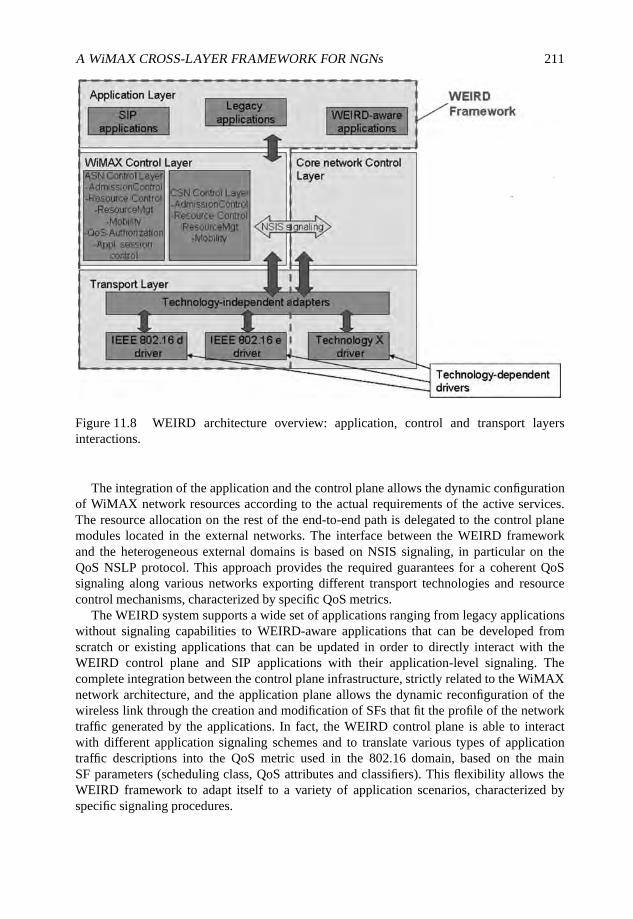
A WiMAX CROSS-LAYER FRAMEWORK FOR NGNs 211
Figure 11.8 WEIRD architecture overview: application, control and transport layersinteractions.
The integration of the application and the control plane allows the dynamic configurationof WiMAX network resources according to the actual requirements of the active services.The resource allocation on the rest of the end-to-end path is delegated to the control planemodules located in the external networks. The interface between the WEIRD frameworkand the heterogeneous external domains is based on NSIS signaling, in particular on theQoS NSLP protocol. This approach provides the required guarantees for a coherent QoSsignaling along various networks exporting different transport technologies and resourcecontrol mechanisms, characterized by specific QoS metrics.
The WEIRD system supports a wide set of applications ranging from legacy applicationswithout signaling capabilities to WEIRD-aware applications that can be developed fromscratch or existing applications that can be updated in order to directly interact with theWEIRD control plane and SIP applications with their application-level signaling. Thecomplete integration between the control plane infrastructure, strictly related to the WiMAXnetwork architecture, and the application plane allows the dynamic reconfiguration of thewireless link through the creation and modification of SFs that fit the profile of the networktraffic generated by the applications. In fact, the WEIRD control plane is able to interactwith different application signaling schemes and to translate various types of applicationtraffic descriptions into the QoS metric used in the 802.16 domain, based on the mainSF parameters (scheduling class, QoS attributes and classifiers). This flexibility allows theWEIRD framework to adapt itself to a variety of application scenarios, characterized byspecific signaling procedures.
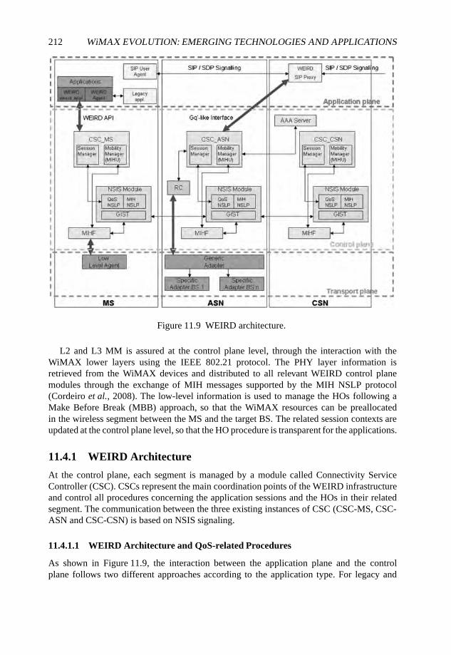
212 WiMAX EVOLUTION: EMERGING TECHNOLOGIES AND APPLICATIONS
Figure 11.9 WEIRD architecture.
L2 and L3 MM is assured at the control plane level, through the interaction with theWiMAX lower layers using the IEEE 802.21 protocol. The PHY layer information isretrieved from the WiMAX devices and distributed to all relevant WEIRD control planemodules through the exchange of MIH messages supported by the MIH NSLP protocol(Cordeiro et al., 2008). The low-level information is used to manage the HOs following aMake Before Break (MBB) approach, so that the WiMAX resources can be preallocatedin the wireless segment between the MS and the target BS. The related session contexts areupdated at the control plane level, so that the HO procedure is transparent for the applications.
11.4.1 WEIRD Architecture
At the control plane, each segment is managed by a module called Connectivity ServiceController (CSC). CSCs represent the main coordination points of the WEIRD infrastructureand control all procedures concerning the application sessions and the HOs in their relatedsegment. The communication between the three existing instances of CSC (CSC-MS, CSC-ASN and CSC-CSN) is based on NSIS signaling.
11.4.1.1 WEIRD Architecture and QoS-related Procedures
As shown in Figure 11.9, the interaction between the application plane and the controlplane follows two different approaches according to the application type. For legacy and
A WiMAX CROSS-LAYER FRAMEWORK FOR NGNs 213
WEIRD-aware applications the WEIRD Application Programming Interface (API) allowsthe CSC-MS to retrieve all information about the current services, such as traffic type,required bandwidth, maximum supported latency and jitter, classifiers and authorization data.In this case, CSC-MS is the main coordinator and the initiator of the end-to-end QoS NSISsignaling. CSC-MS translates the application traffic description into an initiator QSPECbased on the WiMAX QoS model and initiates the NSIS signaling towards the core network.The QoS NSLP messages are intercepted by each NSIS node along the end-to-end path,where the QSPEC is processed by the related Resource Management Function (RMF) and thecorresponding resources are allocated in the specific segment, according to the QoS attributesincluded in the QSPEC. In particular, CSC-ASN, located at the ASN-GW, has the role of theRMF for the WiMAX access network, while CSC-CSN acts as RMF for the CSN.
On the other hand, the QoS signaling for SIP applications is based on the network-initiatedapproach, following the IP Multimedia Subsystem (IMS) model (3GPP, 2008). An enhancedSIP proxy located at the CSN intercepts the incoming SIP messages from the SIP useragents and interacts with the CSC-ASN. This interface is based on the Gq’ specification(Calhoun and Loughney, 2003): the description of the SIP session is retrieved from the SDPmessages and all of the information concerning media types, bandwidth and classifiers ismapped in a diameter (Calhoun and Loughney, 2003) Authentication Authorization Request(AAR) message and sent to the CSC-ASN. In this case the CSC-ASN has a dual role: it isresponsible for the resource allocation in the WiMAX segment and acts as NSIS initiator forthe end-to-end QoS signaling through the core network, creating the initiator QSPEC.
The tight coordination between the SIP signaling at the application layer, and the resourcereservation and the QoS NSIS signaling at the control plane allows the WEIRD system tosupport both QoS-enabled and QoS-assured models for SIP applications. In the former case,the actual bandwidth allocation along the end-to-end path does not have an impact on theprocedures for the call setup, but only on the quality of the audio/video for that call. Thesignaling at the application layer and at the control layer are two distinct, parallel processes:the NSIS signaling is only triggered by SIP signaling, and then they can both proceed withoutinterfering with each other. On the other hand, in the QoS-assured model the successfulresource allocation along the full path is a precondition for the establishment of the SIPsession and the two procedures must be coordinated at the ASN.
While QoS signaling can be managed following the host-initiated or the network-initiatedmodel, the resource allocation for the WiMAX segment is always handled through thenetwork-initiated approach and it is coordinated at the ASN by the CSC-ASN and theResource Controller (RC). This choice allows the WEIRD system to adopt the proceduresfor the BS-initiated SFM, defined as mandatory in the IEEE 802.16 specifications and widelysupported by different vendor hardware.
At the ASN, resource allocation must be authorized through diameter message exchangesbetween the CSC-ASN and the AAA server located in the CSN, following the specificationsof the diameter QoS application. This procedure includes two different phases: first the user isauthenticated through the user credentials conveyed by the NSIS signaling and thereafter theresource utilization is authorized, according to the user profile and the QSPEC specifications.
The actual resource reservation in the wireless segment is handled by the RC (detailed inNeves et al. (2008) and Sousa et al. (2008)). RC manages all resources in the Radio AccessNetwork (RAN). The WiMAX SF creation and activation can be performed following theone-phase or the two-phase activation model, as defined by the IEEE 802.16 specifications.
214 WiMAX EVOLUTION: EMERGING TECHNOLOGIES AND APPLICATIONS
Each SF is firstly created with the provisioned status allowing efficient resource utilization.When required by new user service sessions, the related SFs can be immediately activated(one-phase activation model) or first admitted and then activated (two-phase activationmodel). The WEIRD system adopts the latter model for SIP applications: during theprocedure for the session setup the SFs are only admitted, and subsequently activated inorder to carry the media traffic.
The device configuration for the SF management is handled at the transport layer by theadapter (Nissila et al., 2007) through the Simple Network Management Protocol (SNMP)protocol (Case and Fedor, 1990), using the Management Information Base (MIB) (Caseet al., 2002), defined in the IEEE 802.16f specification (IEEE, 2005c). The adapter includesa single module, called the Generic Adapter (GA), that handles the common interface withthe RC and one or more Specific Adapters (SAs) to control each specific WiMAX system, asillustrated in Figure 11.9. This solution provides the flexibility required to support a variety ofvendor equipment, without any significant impact on the higher layers. New equipment canbe added to the WEIRD system through the development of a single hardware-dependentdriver supporting a subset of the API exported by the GA.
11.4.1.2 WEIRD Architecture and Mobility-related Procedures
The WEIRD cross-layer mechanisms can be used to provide seamless mobility by processingthe lower-layer information retrieved from the MS and BS, as well as by dynamicallyreconfiguring the resources related to the current application sessions hosted by the MSsinvolved in the handovers. Lower-layer data about the links status are retrieved on the MSside by a module called a Low Level Agent (LLA). LLA translates link status events toMIH event messages, such as link up, link going down and link down. These messages arehanded over to the MIHF modules located at the MS, ASN and CSN using the MIH NSLPprotocol and sent to the MM entities residing on each CSC. The various Mobility Managershave the role of MIHUs: they elaborate the information about the imminent HOs in orderto coordinate all mobility actions through the reconfiguration of resources on the networksegments involved in the HO, the update of the session contexts and the management of thetransport layer procedures through MIH command messages.
WEIRD MM is based on the MBB approach for both micro and macro mobility. Theresource reservation along the new path is a precondition for the HO, so that when the MSmoves towards the target BS it can immediately use the set of SFs required by its activesessions. This approach aims at providing seamless mobility while maintaining the QoS asperceived by the user during the HO. This mechanism requires multiple interactions betweenthe lower layers, the MIHF modules, the mobility managers at different WiMAX entities andMobile IP.
It should be noted that both the Mobility Managers and the MIP protocol act asMIHUs Users, but at different levels. The former are the main coordinators of the mobilityprocedures, handling at the same time the user application status, the links status (through thereceived MIH event messages) and the resource reservations. Mobility managers are the onlyentities that take active decisions about the HOs. MIP receives only some MIH commandsmessages originated by the mobility managers and enforces the HO.
WEIRD supports both ASN-anchored (micro-mobility) and CSN-anchored mobility(macro-mobility). In the former case the MS moves between two BSs controlled by the
A WiMAX CROSS-LAYER FRAMEWORK FOR NGNs 215
same ASN, while in the latter case serving and target BSs are located on different ASNsand managed by different CSC-ASNs. The procedures for micro-mobility require onlythe reconfiguration of the wireless and ASN segments. They are managed directly by theCSC-MS (MM) for legacy applications and by the CSC-ASN (MM) for SIP applications.For macro-mobility the reconfiguration involves also the CSN segment and the applicationcontext must be transferred from the serving ASN-GW to the target one. In this case, the HOprocedures are controlled by the CSC-CSN (MM), with the active cooperation of both theserving and the target CSC-ASN (MM).
In the next section we present a set of measurements related with cross-layer mechanismscollected on a WiMAX testbed.
11.5 WEIRD Framework Performance Evaluation
In this section we present a set of measurements from our testbed performance evaluationof the WiMAX cross-layer framework described in Section 11.4. We start by evaluating thetime necessary to establish an end-to-end SF reservation over a fixed WiMAX network. Then,we present a set of tests that evaluate the QoS performance of the implemented system usingVoIP and IPTV services.
11.5.1 Cross-layer Signaling Measurements
In order to evaluate the efficiency of the implemented cross-layer mechanisms, it is importantto integrate the WiMAX system in a NGN environment, which is able to support real-timeservices. Therefore, in addition to evaluating the performance of the standalone WiMAXcross-layer mechanisms, it is also important to evaluate the global performance of themechanisms that interact with the WiMAX cross-layer entities. Hence, this section presentsan evaluation of the Layer 3 QoS (L3QoS) framework, composed of the CSCs and the NSISframework, as well as an assessment of the total end-to-end time required to perform areservation over the WiMAX system.
11.5.1.1 Implemented Demonstrator and Tests Methodology
The demonstrator implemented to validate and evaluate the WiMAX cross-layering frame-work is illustrated in Figure 11.10. The testbed is composed of three main parts: the ASN,the WiMAX RAN and the Customer Premises Equipment (CPE). The ASN is generallycomposed of several gateways (ASN-GWs), which establish connectivity with the corenetwork. Moreover, ASN performs relay functions to the core network in order to establishIP connectivity and Authentication, Authorization and Accounting (AAA) mechanisms. ACorrespondent Node (CN) is connected to one of the ASN-GWs for the communication withthe WiMAX terminals. The testbed WiMAX RAN includes one BS, which provides radioconnectivity to the WiMAX SSs in a PTMP topology.
The testbed WiMAX BS operates at 3.5 GHz, with a 3.5 MHz channel using a 64 QAMmodulation scheme with 3/4 Forward Error Correction (FEC) (see Table 11.1 for moredetails). The WiMAX BS is connected to the ASN via the ASN-GW. On the host side, aWiMAX Terminal (WT) is connected to each WiMAX SS.
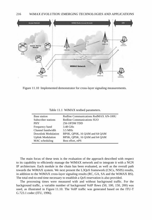
216 WiMAX EVOLUTION: EMERGING TECHNOLOGIES AND APPLICATIONS
Figure 11.10 Implemented demonstrator for cross-layer signaling measurements.
Table 11.1 WiMAX testbed parameters.
Base station Redline Communications RedMAX AN-100USubscriber stations Redline Communications SUOPHY 256 OFDM TDDFrequency band 3.48 GHzChannel bandwidth 3.5 MHzDownlink Modulation BPSK, QPSK, 16 QAM and 64 QAMUplink Modulation BPSK, QPSK, 16 QAM and 64 QAMMAC scheduling Best effort, rtPS
The main focus of these tests is the evaluation of the approach described with respectto its capability to efficiently manage the WiMAX network and to integrate it with a NGNIP architecture. Each module in the chain has been evaluated, as well as the overall pathtowards the WiMAX system. We next present the L3QoS framework (CSCs, NSIS) results,in addition to the WiMAX cross-layer signaling results (RC, GA, SA and the WiMAX BS).The total end-to-end time necessary to establish a QoS reservation is also provided.
The processing times were measured with and without background traffic. For thebackground traffic, a variable number of background VoIP flows (50, 100, 150, 200) wasused, as illustrated in Figure 11.10. The VoIP traffic was generated based on the ITU-TG.723.1 codec (ITU, 1996).
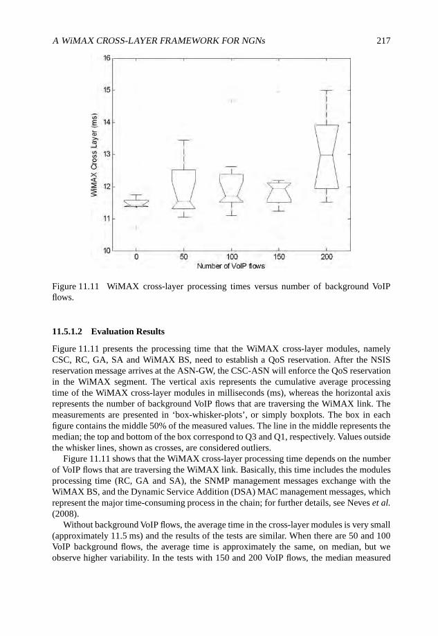
A WiMAX CROSS-LAYER FRAMEWORK FOR NGNs 217
Figure 11.11 WiMAX cross-layer processing times versus number of background VoIPflows.
11.5.1.2 Evaluation Results
Figure 11.11 presents the processing time that the WiMAX cross-layer modules, namelyCSC, RC, GA, SA and WiMAX BS, need to establish a QoS reservation. After the NSISreservation message arrives at the ASN-GW, the CSC-ASN will enforce the QoS reservationin the WiMAX segment. The vertical axis represents the cumulative average processingtime of the WiMAX cross-layer modules in milliseconds (ms), whereas the horizontal axisrepresents the number of background VoIP flows that are traversing the WiMAX link. Themeasurements are presented in ‘box-whisker-plots’, or simply boxplots. The box in eachfigure contains the middle 50% of the measured values. The line in the middle represents themedian; the top and bottom of the box correspond to Q3 and Q1, respectively. Values outsidethe whisker lines, shown as crosses, are considered outliers.
Figure 11.11 shows that the WiMAX cross-layer processing time depends on the numberof VoIP flows that are traversing the WiMAX link. Basically, this time includes the modulesprocessing time (RC, GA and SA), the SNMP management messages exchange with theWiMAX BS, and the Dynamic Service Addition (DSA) MAC management messages, whichrepresent the major time-consuming process in the chain; for further details, see Neves et al.(2008).
Without background VoIP flows, the average time in the cross-layer modules is very small(approximately 11.5 ms) and the results of the tests are similar. When there are 50 and 100VoIP background flows, the average time is approximately the same, on median, but weobserve higher variability. In the tests with 150 and 200 VoIP flows, the median measured
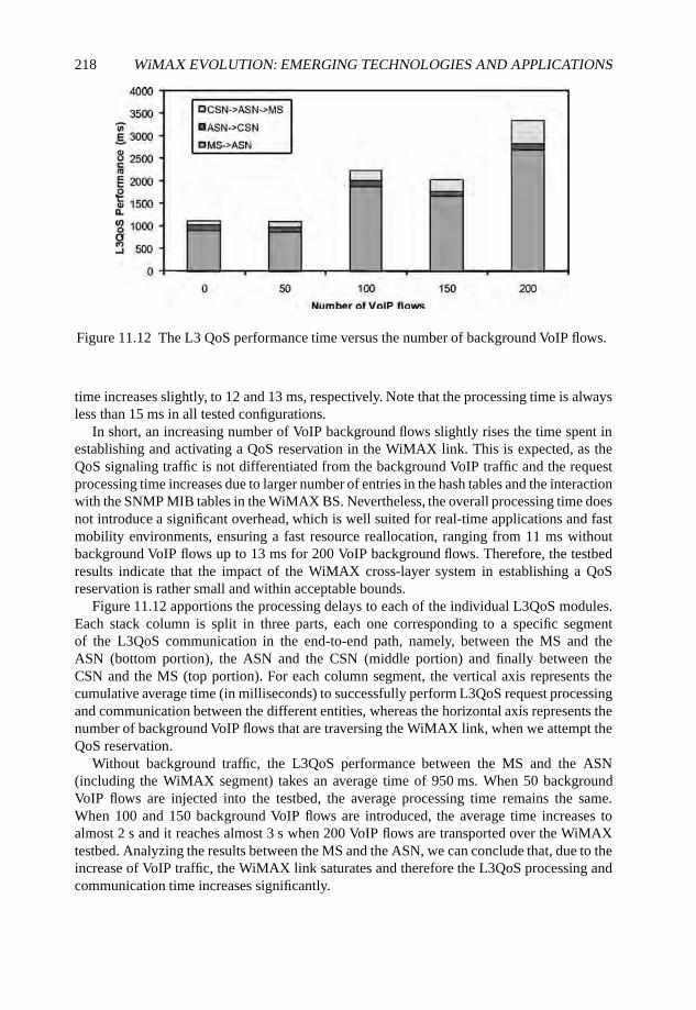
218 WiMAX EVOLUTION: EMERGING TECHNOLOGIES AND APPLICATIONS
Figure 11.12 The L3 QoS performance time versus the number of background VoIP flows.
time increases slightly, to 12 and 13 ms, respectively. Note that the processing time is alwaysless than 15 ms in all tested configurations.
In short, an increasing number of VoIP background flows slightly rises the time spent inestablishing and activating a QoS reservation in the WiMAX link. This is expected, as theQoS signaling traffic is not differentiated from the background VoIP traffic and the requestprocessing time increases due to larger number of entries in the hash tables and the interactionwith the SNMP MIB tables in the WiMAX BS. Nevertheless, the overall processing time doesnot introduce a significant overhead, which is well suited for real-time applications and fastmobility environments, ensuring a fast resource reallocation, ranging from 11 ms withoutbackground VoIP flows up to 13 ms for 200 VoIP background flows. Therefore, the testbedresults indicate that the impact of the WiMAX cross-layer system in establishing a QoSreservation is rather small and within acceptable bounds.
Figure 11.12 apportions the processing delays to each of the individual L3QoS modules.Each stack column is split in three parts, each one corresponding to a specific segmentof the L3QoS communication in the end-to-end path, namely, between the MS and theASN (bottom portion), the ASN and the CSN (middle portion) and finally between theCSN and the MS (top portion). For each column segment, the vertical axis represents thecumulative average time (in milliseconds) to successfully perform L3QoS request processingand communication between the different entities, whereas the horizontal axis represents thenumber of background VoIP flows that are traversing the WiMAX link, when we attempt theQoS reservation.
Without background traffic, the L3QoS performance between the MS and the ASN(including the WiMAX segment) takes an average time of 950 ms. When 50 backgroundVoIP flows are injected into the testbed, the average processing time remains the same.When 100 and 150 background VoIP flows are introduced, the average time increases toalmost 2 s and it reaches almost 3 s when 200 VoIP flows are transported over the WiMAXtestbed. Analyzing the results between the MS and the ASN, we can conclude that, due to theincrease of VoIP traffic, the WiMAX link saturates and therefore the L3QoS processing andcommunication time increases significantly.
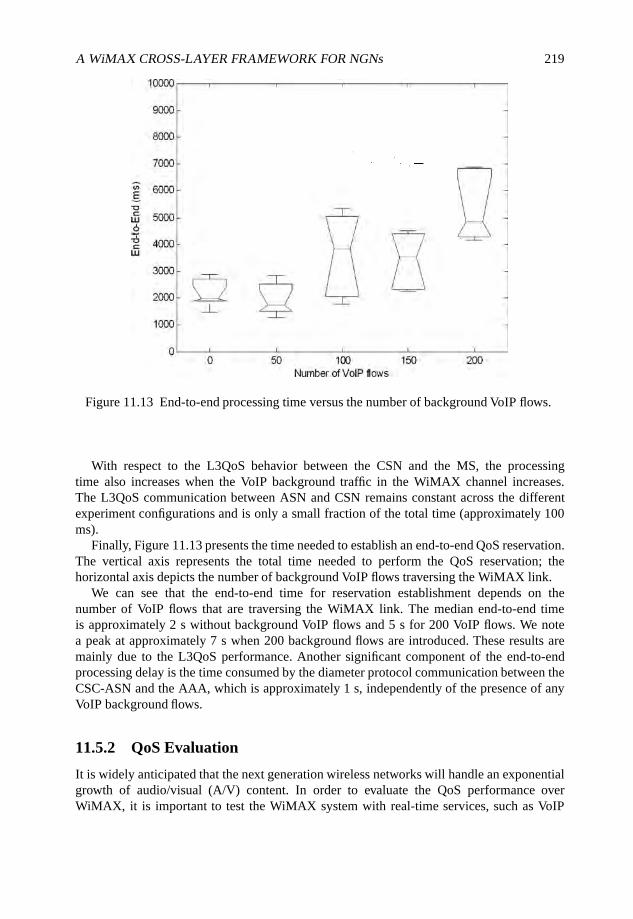
A WiMAX CROSS-LAYER FRAMEWORK FOR NGNs 219
Figure 11.13 End-to-end processing time versus the number of background VoIP flows.
With respect to the L3QoS behavior between the CSN and the MS, the processingtime also increases when the VoIP background traffic in the WiMAX channel increases.The L3QoS communication between ASN and CSN remains constant across the differentexperiment configurations and is only a small fraction of the total time (approximately 100ms).
Finally, Figure 11.13 presents the time needed to establish an end-to-end QoS reservation.The vertical axis represents the total time needed to perform the QoS reservation; thehorizontal axis depicts the number of background VoIP flows traversing the WiMAX link.
We can see that the end-to-end time for reservation establishment depends on thenumber of VoIP flows that are traversing the WiMAX link. The median end-to-end timeis approximately 2 s without background VoIP flows and 5 s for 200 VoIP flows. We notea peak at approximately 7 s when 200 background flows are introduced. These results aremainly due to the L3QoS performance. Another significant component of the end-to-endprocessing delay is the time consumed by the diameter protocol communication between theCSC-ASN and the AAA, which is approximately 1 s, independently of the presence of anyVoIP background flows.
11.5.2 QoS Evaluation
It is widely anticipated that the next generation wireless networks will handle an exponentialgrowth of audio/visual (A/V) content. In order to evaluate the QoS performance overWiMAX, it is important to test the WiMAX system with real-time services, such as VoIP
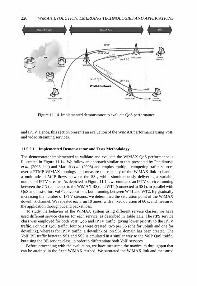
220 WiMAX EVOLUTION: EMERGING TECHNOLOGIES AND APPLICATIONS
Figure 11.14 Implemented demonstrator to evaluate QoS performance.
and IPTV. Hence, this section presents an evaluation of the WiMAX performance using VoIPand video streaming services.
11.5.2.1 Implemented Demonstrator and Tests Methodology
The demonstrator implemented to validate and evaluate the WiMAX QoS performance isillustrated in Figure 11.14. We follow an approach similar to that presented by Pentikousiset al. (2008a,b,c) and Martufi et al. (2008) and employ multiple competing traffic sourcesover a PTMP WiMAX topology and measure the capacity of the WiMAX link to handlea multitude of VoIP flows between the SSs, while simultaneously delivering a variablenumber of IPTV streams. As depicted in Figure 11.14, we emulated an IPTV service, runningbetween the CN (connected to the WiMAX BS) and WT1 (connected to SS1), in parallel withQoS and best-effort VoIP conversations, both running between WT1 and WT2. By graduallyincreasing the number of IPTV streams, we determined the saturation point of the WiMAXdownlink channel. We repeated each run 10 times, with a fixed duration of 60 s, and measuredthe application throughput and packet loss.
To study the behavior of the WiMAX system using different service classes, we haveused different service classes for each service, as described in Table 11.2. The rtPS serviceclass was employed for both VoIP QoS and IPTV traffic, giving lower priority to the IPTVtraffic. For VoIP QoS traffic, four SFs were created, two per SS (one for uplink and one fordownlink), whereas for IPTV traffic, a downlink SF on SS1 domain has been created. TheVoIP BE traffic between SS1 and SS2 is emulated in a similar way to the VoIP QoS traffic,but using the BE service class, in order to differentiate both VoIP services.
Before proceeding with the evaluation, we have measured the maximum throughput thatcan be attained in the fixed WiMAX testbed. We saturated the WiMAX link and measured
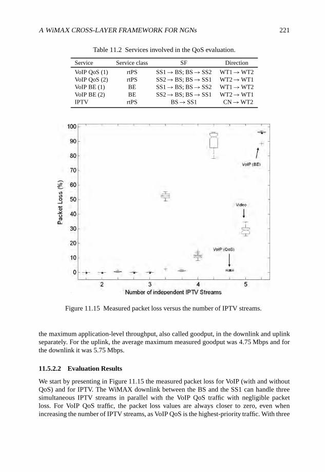
A WiMAX CROSS-LAYER FRAMEWORK FOR NGNs 221
Table 11.2 Services involved in the QoS evaluation.
Service Service class SF Direction
VoIP QoS (1) rtPS SS1 → BS; BS → SS2 WT1 → WT2VoIP QoS (2) rtPS SS2 → BS; BS → SS1 WT2 → WT1VoIP BE (1) BE SS1 → BS; BS → SS2 WT1 → WT2VoIP BE (2) BE SS2 → BS; BS → SS1 WT2 → WT1IPTV rtPS BS → SS1 CN → WT2
Figure 11.15 Measured packet loss versus the number of IPTV streams.
the maximum application-level throughput, also called goodput, in the downlink and uplinkseparately. For the uplink, the average maximum measured goodput was 4.75 Mbps and forthe downlink it was 5.75 Mbps.
11.5.2.2 Evaluation Results
We start by presenting in Figure 11.15 the measured packet loss for VoIP (with and withoutQoS) and for IPTV. The WiMAX downlink between the BS and the SS1 can handle threesimultaneous IPTV streams in parallel with the VoIP QoS traffic with negligible packetloss. For VoIP QoS traffic, the packet loss values are always closer to zero, even whenincreasing the number of IPTV streams, as VoIP QoS is the highest-priority traffic. With three
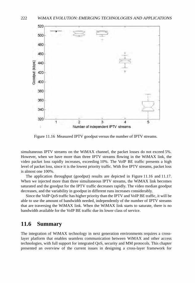
222 WiMAX EVOLUTION: EMERGING TECHNOLOGIES AND APPLICATIONS
Figure 11.16 Measured IPTV goodput versus the number of IPTV streams.
simultaneous IPTV streams on the WiMAX channel, the packet losses do not exceed 5%.However, when we have more than three IPTV streams flowing in the WiMAX link, thevideo packet loss rapidly increases, exceeding 10%. The VoIP BE traffic presents a highlevel of packet loss, since it is the lowest priority traffic. With five IPTV streams, packet lossis almost one 100%.
The application throughput (goodput) results are depicted in Figure 11.16 and 11.17.When we injected more than three simultaneous IPTV streams, the WiMAX link becomessaturated and the goodput for the IPTV traffic decreases rapidly. The video median goodputdecreases, and the variability in goodput in different runs increases considerably.
Since the VoIP QoS traffic has higher priority than the IPTV and VoIP BE traffic, it will beable to use the amount of bandwidth needed, independently of the number of IPTV streamsthat are traversing the WiMAX link. When the WiMAX link starts to saturate, there is nobandwidth available for the VoIP BE traffic due its lower class of service.
11.6 Summary
The integration of WiMAX technology in next generation environments requires a cross-layer platform that enables seamless communication between WiMAX and other accesstechnologies, with full support for integrated QoS, security and MM protocols. This chapterpresented an overview of the current issues in designing a cross-layer framework for
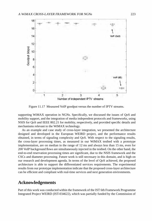
A WiMAX CROSS-LAYER FRAMEWORK FOR NGNs 223
Figure 11.17 Measured VoIP goodput versus the number of IPTV streams.
supporting WiMAX operation in NGNs. Specifically, we discussed the issues of QoS andmobility support, and the integration of media independent protocols and frameworks, usingNSIS for QoS and IEEE 802.21 for mobility, respectively, and provided specific details andmechanisms relevant to the WiMAX technology.
As an example and case study of cross-layer integration, we presented the architecturedesigned and developed in the European WEIRD project, and the performance resultsobtained, in terms of signaling complexity and QoS. With respect to the signaling results,the cross-layer processing times, as measured in our WiMAX testbed with a prototypeimplementation, are on median in the range of 12 ms and always less than 15 ms, even for200 VoIP background flows are simultaneously injected in the testbed. On the other hand, theend-to-end reservation processing times are significant, due to the NSIS framework and theCSCs and diameter processing. Future work is still necessary in this domain, and is high onour research and development agenda. In terms of the level of QoS achieved, the proposedarchitecture is able to support the differentiated services requirements. The experimentalresults from our prototype implementation indicate that the proposed cross-layer architecturecan be efficient and compliant with real-time services and next generation environments.
Acknowledgements
Part of this work was conducted within the framework of the IST 6th Framework ProgrammeIntegrated Project WEIRD (IST-034622), which was partially funded by the Commission of
224 WiMAX EVOLUTION: EMERGING TECHNOLOGIES AND APPLICATIONS
the European Union. Study sponsors had no role in study design, data collection and analysis,interpretation or writing the report. The views expressed do not necessarily represent theviews of the authors’ employers, the WEIRD project, or the Commission of the EuropeanUnion. We thank our colleagues from all partners in WEIRD project for fruitful discussions.
References
3GPP (2008) Technical Specification Group Service and System Aspects; IP Multimedia Subsystem;Stage 2, TS23.228 - Release 8, 3GPP.
Ash, G., Bader, A., Kappler, C. and Oran, D. (2006) QoS NSLP QSPEC Template, IETF Internet-Draft,IETF.
Blake, S., Black, D., Carlson, M., Davies, E., Wang, Z. and Weiss, W. (1998) An architecture fordifferentiated services, IETF Request for Comments 2475, IETF.
Braden, R., Clark, D. and Shenker, S. (1994) Integrated services in the Internet architecture: anoverview, IETF Request for Comments 1633, IETF.
Calhoun, P. and Loughney, J. (2003) Diameter base protocol, IETF Request for Comments 3588, IETF.
Case, J. and Fedor, M. (1990) A Simple Network Management Protocol (SNMP), IETF Request forComments 1157, IETF.
Case, J., McCloghrie, K. and Rose, M. (2002) Management Information Base (MIB) for the SimpleManagement Protocol (SNMP), IETF Request for Comments 3418, IETF.
Cordeiro, L., Curado, M., Neves, P., Sargento, S., Landi, G. and Fu, X. (2008) Media IndependentHandover Network Signaling Layer Protocol (MIH NSLP), IETF Internet-Draft, IETF.
Deering, S. and Hinden, R. (1998) Internet Protocol - Version 6 (IPv6) Specification, IETF Request forComments 2460, IETF.
Guainella, E., Borcoci, E., Katz, M., Neves, P., Curado, M., Andreotti, F. and Angori, E. (2007)WiMAX technology support for applications in environmental monitoring, fire prevention andtelemedicine. Proceedings of the IEEE Mobile WiMAX Symposium, Florida.
Hancock, R., Karagiannis, G., Loughney, J. and den Bosch, S.V. (2005) Next Step in Signalling (NSIS):Framework, IETF Request for Comments 4080 IETF.
Heinanen, J., Baker, F., Weiss, W. and Wroclawski, J. (1999) Assured Forwarding PHB Group, IETFRequest for Comments 2597, IETF.
IEEE (2004) IEEE Standard for Local and Metropolitan Area Networks; Part 16: Air Interface for FixedBroadband Wireless Access Systems, IEEE Standard 802.16-2004, IEEE 802.16 Working Group.
IEEE (2005a) IEEE Standard for Information Technology - Telecommunications and InformationExchange between Systems - Local and Metropolitan Area Networks - Specific Requirements Part 3:Carrier Sense Multiple Access with Collision Detection (CSMA/CD) Access Method and PhysicalLayer Specifications, IEEE Standard 802.3-2005, IEEE 802.3 Working Group.
IEEE (2005b) IEEE Standard for Local and Metropolitan Area Networks; Part 16: Air Interfacefor Fixed and Mobile Broadband Wireless Access Systems; Amendment 2: Physical and MediumAccess Control Layers for Combined Fixed and Mobile Operation in Licensed Bands, IEEEStandard 802.16e-2005, IEEE 802.16 Working Group.
IEEE (2005c) IEEE Standard for Local and Metropolitan Area Networks; Part 16: Air Interface forFixed Broadband Wireless Access Systems - Amendment 1: Management Information Base, IEEEStandard 802.16f-2005, IEEE 802.16 Working Group.
IEEE (2006) IEEE Standard for Local and Metropolitan Area Networks. Virtual Bridged Local AreaNetworks, IEEE Standard 802.1Q-2005, IEEE 802.1 Working Group.
A WiMAX CROSS-LAYER FRAMEWORK FOR NGNs 225
IEEE (2007) IEEE Standard for Local and Metropolitan Area Networks; Part 16: Air Interface for FixedBroadband Wireless Access Systems; Amendment 3: Management Plane Procedures and Services,IEEE Standard 802.16g-2007, IEEE 802.16 Working Group.
IEEE (2008) IEEE Draft Standard for Local and Metropolitan Area Networks: Media IndependentHandover Services, IEEE P802.21/D10.0, IEEE 802.21 Working Group.
ISIUSC (1981) Internet Protocol, IETF Request for Comments 791, IETF.ITU (1996) ITU-T, Dual rate speech coder for multimedia communications transmitting at 5.3 and
6.3 Kbps, ITU-T Recommendation G.723.1 ITU Group.Jacobson, V., Nichols, K. and Poduri, K. (1999) An expedited forwarding PHB, IETF Request for
Comments 2598 IETF.Johnson, D., Perkins, C. and Arkko, J. (2004) Mobility Support in IPv6, IETF Request for Comments
3775 IETF.Koodli R. (2005) Fast Handovers for Mobile IPv6, IETF Request for Comments 4068 IETF.Manner, J., Karagiannis, G. and McDonald, A. (2008) NSLP for Quality-of-Service Signalling, IETF
Internet-Draft, IETF.Martufi, G., Katz, M., Neves, P., Curado, M., Castrucci, M., Simoes, P., Piri, E. and Pentikousis, K.
(2008) Extending WiMAX to new scenarios: key results on system architecture and test-beds of theWEIRD project. Proceedings of EUMOB, Oulu, Finland.
Neves, P., Nissila, T., Pereira, T., Ilkka, H., Monteiro, J., Pentikousis, K., Sargento, S. and Fontes F.(2008) A vendor independent resource control framework for WiMAX. Proceedings of the 13thIEEE Symposium on Computers and Communications (ISCC), Marrakech, Morocco.
Nissila, T., Huusko, J., Harjula, I. and Katz, M. (2007) Adapter implementation between WiMAXspecific layers and network/application layers. Proceedings of the First Broadband WirelessAccess Workshop (BWA), Collocated with 1st Next Generation Mobile Applications, Services andTechnologies (NGMAST), Cardiff, UK.
Pentikousis, K., Pinola, J., Piri, E. and Fitzek, F. (2008a) A measurement study of Speex VoIP andH.264/AVC Video over IEEE 802.16d and IEEE 802.11g. Proceedings of the Third Workshop onMultiMedia Applications over Wireless Networks (MediaWiN), Marrakech, Morocco.
Pentikousis, K., Pinola, J., Piri, E. and Fitzek, F. (2008b) An experimental investigation of VoIP andvideo streaming over fixed WiMAX. Proceedings of the Fourth International Workshop on WirelessNetwork Measurements (WiNMee), Berlin, Germany.
Pentikousis, K., Pinola, J., Piri, E., Fitzek, F., Nissilä, T. and Harjula, I. (2008c) Empirical evaluation ofVoIP aggregation over a fixed WiMAX testbed. Proceedings of the Fourth International Conferenceon Testbeds and Research Infrastructures for the Development of Networks and Communities(TRIDENTCOM), Innsbruck, Austria.
Perkins, C. (1996) IP Mobility Support, IETF Request for Comments 2002, IETF.Rosenberg, J., Schulzrinne, H. and Camarillo, G. (2002) Session Initiation Protocol (SIP), IETF
Request for Comments 3261, IETF.Schulzrinne, H. and Hancock, R. (2008) GIST: General Internet Signalling Transport, IETF Internet-
Draft, IETF.Sousa, B., Neves, P., Curado, M., Sargento, S., Fontes, F. and Boavida, F. (2008) The cost of using
IEEE 802.16 dynamic channel configuration. Proceedings of the IEEE International Conference onCommunications (ICC), Beijing, China.
WiMAX Forum (2008) WiMAX End-to-End Network Systems Architecture Stage 2–3: ArchitectureTenets, Reference Model and Reference Points, Release 1, Version 1.2, WiMAX Forum.
12
Speech Quality Aware ResourceControl for Fixed and MobileWiMAX
Thomas Michael Bohnert, Dirk Staehle andEdmundo Monteiro
12.1 Introduction
Hardly any subjects in telecommunications caused such controversy as the Quality ofService (QoS) issue in the Internet. The persistent advance in switching capacity overbandwidth demand by real-time services is dividing those calling for Internet QoS from theircounterparts. The Internet2 QoS Working Group, for instance, concluded after years-longlarge-scale QoS deployment that conceptual issues plus a lack of demand, that is, missingreal-time applications, severely inhibits the evolution of the Internet rather than fosteringit (Teitelbaum and Shalunov, 2002). They even went as far as calling for banning end-to-end Internet QoS by regulation in order to guarantee a free and therefore powerful Internetbased on its original principles. Meanwhile this conviction turned into a concept known asnet neutrality and became subject of a fierce power struggle between telecommunication andservice providers (Bohnert et al., 2007).
While this conclusion might possibly hold for wireline communications it is a verydifferent story for wireless communications and WiMAX is a perfect example of this. Withthe roll-out of mobile WiMAX the long-awaited IP convergence comes true and meansthat traditional real-time services, such as voice and video, will have to be delivered over
WiMAX Evolution: Emerging Technologies and Applications Edited by Tsutomu Ishikawa© 2009 John Wiley & Sons, Ltd. ISBN: 978-0-470-69680-4
228 WiMAX EVOLUTION: EMERGING TECHNOLOGIES AND APPLICATIONS
the Internet infrastructure. However, subscribers will not change their expectations alongwith exchanging access technology and voice is therefore a very intuitive example. Mobilevoice subscribers are meanwhile used to cellular-phone-like service quality and will expecta similar experience. The success of WiMAX will thus ultimately depend on the success ofoperators in providing competitive QoS levels.
This awareness has settled right at the beginning of IEEE 802.16 standardization and adesignated feature of mobile WiMAX, based on IEEE 802.16-2005, commonly called IEEE802.16e (IEEE, 2005) is its inherent QoS support which is largely based on the concepts ofATM’s comprehensive QoS body (Eklund et al., 2006). So WiMAX defines a set of servicescategorized and parameterized by their respective target applications. One of these servicesis voice and assumes standard Voice over IP (VoIP) technology at the application layer. TheWiMAX QoS model in turn defines semantics adopted by VoIP to control packet delay, lossand jitter. Explicit implementation instructions, however, are not part of the IEEE 802.16standards and the choice of which particular resource control algorithms to implement isentirely left to manufactures.
In the context of VoIP these two decisions, using the QoS model of the AsynchronousTransfer Mode (ATM) as the bottom line without implementation instructions, renderthemselves as a considerable challenge: the identification and implementation of efficientresource control components capable of achieving VoIP QoS support in WiMAX systems.By way of simulation we present two such resource control algorithms, Admission Control(AC) and scheduling, where they are both based on dynamic quality estimations derived frominstantaneous local measurements. In order to do so we first discuss quality assessment assuch in Section 12.2 before we introduce speech quality assessment as the only appropriatemeans for this purpose in Section 12.3. In Section 12.4 we then present our approach fordynamic and on-demand quality assessment, the fundamental resource control criterion. Thefirst resource control algorithm leveraging this approach is a Measurement Based AdmissionControl (MBAC) algorithm. Its theoretical underpinning plus performance evaluation arepresented in Section 12.5. In Section 12.6 we present the concept of a scheduler thatuses measurements or estimations of the current speech quality for making its schedulingdecisions. We present a simple R-score based scheduler and show that its performance issuperior to the channel-oblivious Earliest Deadline First (EDF) scheduler and comparable tothe channel-aware MaxSNR scheduler. Finally, we give a short conclusion on this chapter inSection 12.7.
12.2 Quality of Experience versus Quality of ServiceAssessment
Before entering into technical details, the very first question to answer is how to define QoSfor VoIP. While there is a common notion attached to the term quality, the actual space for itsdefinition is divided into two parts: subjective and objective. Customers define quality as theoverall satisfaction based on subjective assessment in multiple dimensions while engineerstend to express quality in terms of physical and measurable parameters and thus objectively.This is a fundamental discrepancy and frequently leads to notable misunderstandings.
A comprehensive QoS definition and terminology coverage has been given by Gozdeckiet al. (2003), from which this section is partly borrowed. In brief, and according to
SPEECH QUALITY AWARE RESOURCE CONTROL FOR WiMAX 229
Hardy (2001), a general model divides QoS into three notions: intrinsic, perceived andassessed QoS. Intrinsic QoS (IQ) is purely technical and evaluates measured and expectedcharacteristics expressed by network parameters such as delay and loss. Perceived QoS(PQ) reflects user satisfaction while using a particular service. It is therefore a subjectivemeasure and the only method to ultimately capture it is to survey human subjects. AssessedQoS (AQ) extends the notion of PQ to secondary aspects such as service price, availability,usability and reliability. Each of this definition can be considered separately but there is atight interdependence. PQ is a function of IQ and is an element of AQ. Nevertheless, theyare commonly considered in isolation and interesting enough, the IETF as well as the ITU-Tand ETSI direct their focus on different definitions and neither of them considers AQ to a fullextent (Gozdecki et al., 2003).
The IETF lastingly coined the notion of QoS adhering to IQ with the introduction of theIntServ (Braden et al., 1994) and DiffServ (Blake et al., 1998) frameworks. Consequently,a later published IETF QoS definition reads ‘A set of service requirements to be met by thenetwork while transporting a flow’ (Crawley et al., 1998). In contrast, the ITU-T and ETSIjointly define QoS as ‘the collective effect of service performance which determine the degreeof satisfaction of a user of the service’, expressed the first time in ITU-T (1993) and clearlycompliant with PQ. On top of this, the ITU-T recently released the Quality of Experience(QoE) framework ITU-T (2004) in which an explicit distinction has been made between QoSand QoE. In this document, QoS expresses the ‘degree of objective service performance’and QoE the ‘overall acceptability of an application or service, as perceived subjectively bythe end user’. According to these definitions, QoS is equal to IQ and QoE is equal to AQ.Notwithstanding, QoE is prevailingly associated with SQ and as SQ is an element of AQ, weadopt this definition together with QoS for IQ for the remainder of this work.
So far it has been shown that looking at service quality calls for a careful distinction basedon its assessment. While QoS evaluation is deemed straightforward and merely a matter ofmeasuring physical parameters, it appears much more complicated (and tedious) for QoEas it involves humans. However, QoE is the ultimate measure and in order to harness it insystems the interdependence between QoS and QoE is to be exploited. This can be achievedby observing that QoE is a function of QoS which can be expressed by mapping physicalparameters to user ratings. This quality assessment method based on mapping measuredparameters, such as delay or loss, to a QoE scale, such as the Mean Opinion Score (MOS), iscalled Instrumental Quality Assessment (IQA) (Raake, 2006b).
IQA is central to our work and an elaborate coverage in the context of VoIP will bepresented in Section 12.3. For now the reader should note that there is considerable volumeof work related to quality assessment and its applications, see Janssen et al. (2002), Raake(2006a), Takahashi et al. (2006) and Markopoulou et al. (2003). In a mobile environment, therelationship of QoS and QoE for a Skype call over a Universal Mobile TelecommunicationsSystem (UMTS) Internet access was investigated by Hoßfeld and Binzenhöfer (2008).General investigations on the exponential interdependency between QoS and QoE fordifferent voice codecs can be found in Hoßfeld et al. (2008, 2007).
At last IQA paved the way for an emerging area in research and development: resourcemanagement based on QoE. Traditionally, resource management was mostly concerned withQoS but frameworks are increasingly considering QoE as the ultimate performance metric.Some examples are given by Sengupta et al. (2006) who present parameterization guidelinesto improve VoIP quality for WiMAX.

230 WiMAX EVOLUTION: EMERGING TECHNOLOGIES AND APPLICATIONS
12.3 Methods for Speech Quality Assessment
No matter how a voice service is implemented, either analog or digital, over a circuit-switched or packet network, it essentially means speech transmission and the ultimateservice quality depends on how uttered information is being understood by communicationparticipants. Henceforth, the only appropriate quality assessment method for voice servicesis that of subjective speech quality assessment. Given the adopted terminology it thereforerelates to QoE.
12.3.1 Auditory Quality Assessment
As briefly outlined in the previous sections subjective quality assessment involves surveyinghuman subjects. Methods falling into this category are classified as auditory methods andshare a basic commonality: in controlled experiments human subjects listen to speechsamples subject to varying impairment in space and time and record the perceived quality.
The outcome of an auditory method is highly individual and controlled by a multitudeof features anchored in human physiology. Human perception depends on spectral andtemporal processing capabilities of the auditory system, on echoic, short-term and long-termauditory memory and speech comprehension, intelligibility and communicability. Finally,it is influenced by the ability to restore missing sounds by way of analyzing context, afeature known as the ‘picket fence effect’ in analogy to a visual modality: whilst watching alandscape through a picket fence, the fence interrupts the view periodically but the landscapeis seen to continue as the human brain is padding missing pieces from memory. Apparentlybeneficial at first sight, this feature can severely impair perception if padded pieces areselected from alleged context composed of the actual plus extracts of previous contextinformation stored in memory. In an advanced state, subjects even try to anticipate futureor missing information and if it does not match the perceived version, they likely classify itfalsely as distorted, wrong or even entirely missing.
There is a whole science behind auditory test methods. They are divided in utilitarianand analytic tests. The former aim at directly comparing the quality of different speechcommunication systems while the latter try to reveal the perceptual features underlyingspeech quality. Utilitarian methods are subdivided into listening quality, comprehension andlistening and talking tests according to different stimuli, context and other features; see Raake(2006b) for a complete treatise. Central to any of these methods is the question on how toscale ratings: absolute, relative, discrete or continuous. The well-known MOS, for example(illustrated in Figure 12.3) is a five-point Absolute Continuous Rating (ACR) scale. Its nameis derived from the fact that it expresses the average over a set of individual ratings obtainedin an controlled experiment. It is frequently used in methods aiming at capturing time varyingquality impairment by recording the instantaneous quality over time, typically with a sliderover the ACR scale; cf. Watson and Sasse (1998). As shown later in this chapter, time varyingquality impairment plays a central role in speech quality assessment. Nevertheless, it isfrequently neglected due to its alleged complexity.
12.3.2 Instrumental Quality Assessment
In many cases it is desirable to evaluate speech quality on demand, in real-time and withouthuman involvement. Accordingly, much effort has been spent in developing alternatives to

SPEECH QUALITY AWARE RESOURCE CONTROL FOR WiMAX 231
auditory tests, so-called instrumental methods or IQA. The principle of these methods is tocorrelate physical and measurable magnitudes with quality as perceived by a human subject.While such unique relationships exist in theory, it has to be noted that, so far, it remainsimpossible to establish them in practice, even for very simple applications.
Nevertheless, recent advances disclosed methods with considerable precisions and consis-tency. In particular, signal-based methods achieve accurate and reliable results based on therelatively well-understood signal processing performed by human. Examples are PerceptualEvaluation of Speech Quality (PESQ) (ITU-T, 2001) and Perceptual Speech Quality Measure(PSQM) (ITU-T, 1996). Either of these methods compares a clean reference signal withthe same signal after been processed by the system under test. In a final step the estimateddeviation is mapped to a rating scale, such as the five-point ACR, where this mapping ispurely empirical and the result of a large number of auditory tests.
The alternative to signal-based methods are so-called parameter-based methods. Thesemethods require instrumentally measurable magnitudes which are evaluated in a parametricmodel. The most popular method of this category is the E-Model (ITU-T, 1998), which isthe basic component of the presented framework and is presented in detail in Section 12.4.In addition to its distinct internal rationale, it maps the result to a subjective rating based ona purely empirically found function, just like a signal-based method.
12.4 Continuous Speech Quality Assessment for VoIP
As stated in Section 12.1, the objective of this work is to devise the ‘identification andimplementation of efficient resource control components capable of achieving VoIP QoSsupport in WiMAX systems’. At this point in time, however, the reader should note theerror in this statement. In accordance with the preceding argumentation it must be called‘VoIP QoE support’. The immediate conclusion is that a purpose-built framework requiresa component capable of continuously assessing VoIP QoE levels. Furthermore, the overallobjective is to assure VoIP QoE levels by means of resource control and thus the secondrequirement on this framework is the delivery of precise QoE estimates in real-time as acriterion for resource assignment. Obviously this can only be an instrumental method andprecludes signal-based methods since there is no space and time for transmitting referencesignals over the radio interface.
12.4.1 VoIP Components and their Impact on Speech Quality
Speech is a slowly varying analog signal over time and its frequency components are limitedto the lower 4 kHz band. Owing to linguistic structures a speech signal alternates between talkspurts and silence periods. The origin of talk spurts are typically syllables which themselvesare phoneme sequences containing one vocalic sound. Average durations of talk spurtsrange from 300 to 400 ms while silence periods range from 500 to 700 ms. In order totransmit speech over a packet network several pre- and post-processing steps are required.In Figure 12.1, each of these processing steps is represented by a single logical buildingblock and the complete set makes a basic end-to-end VoIP system.
Any of the elements of the VoIP system has an impact on the speech quality perceived bythe receiver. First, the analog signal is converted into a digital signal. This step is commonlyassumed to be negligible with respect to the overall quality. Additive noise is canceled
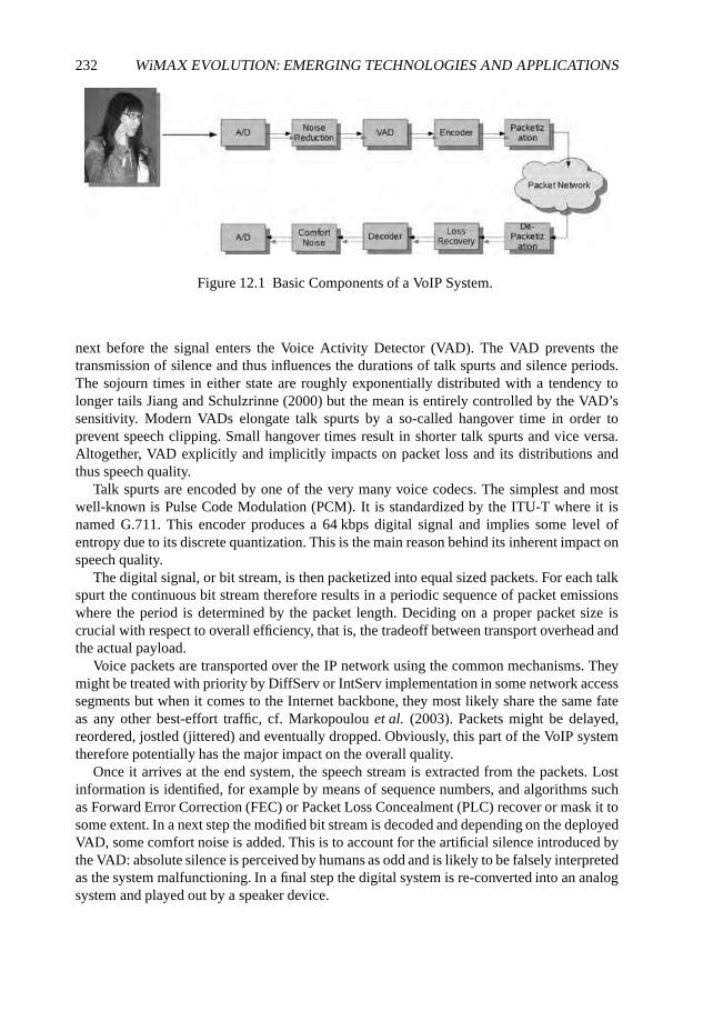
232 WiMAX EVOLUTION: EMERGING TECHNOLOGIES AND APPLICATIONS
Figure 12.1 Basic Components of a VoIP System.
next before the signal enters the Voice Activity Detector (VAD). The VAD prevents thetransmission of silence and thus influences the durations of talk spurts and silence periods.The sojourn times in either state are roughly exponentially distributed with a tendency tolonger tails Jiang and Schulzrinne (2000) but the mean is entirely controlled by the VAD’ssensitivity. Modern VADs elongate talk spurts by a so-called hangover time in order toprevent speech clipping. Small hangover times result in shorter talk spurts and vice versa.Altogether, VAD explicitly and implicitly impacts on packet loss and its distributions andthus speech quality.
Talk spurts are encoded by one of the very many voice codecs. The simplest and mostwell-known is Pulse Code Modulation (PCM). It is standardized by the ITU-T where it isnamed G.711. This encoder produces a 64 kbps digital signal and implies some level ofentropy due to its discrete quantization. This is the main reason behind its inherent impact onspeech quality.
The digital signal, or bit stream, is then packetized into equal sized packets. For each talkspurt the continuous bit stream therefore results in a periodic sequence of packet emissionswhere the period is determined by the packet length. Deciding on a proper packet size iscrucial with respect to overall efficiency, that is, the tradeoff between transport overhead andthe actual payload.
Voice packets are transported over the IP network using the common mechanisms. Theymight be treated with priority by DiffServ or IntServ implementation in some network accesssegments but when it comes to the Internet backbone, they most likely share the same fateas any other best-effort traffic, cf. Markopoulou et al. (2003). Packets might be delayed,reordered, jostled (jittered) and eventually dropped. Obviously, this part of the VoIP systemtherefore potentially has the major impact on the overall quality.
Once it arrives at the end system, the speech stream is extracted from the packets. Lostinformation is identified, for example by means of sequence numbers, and algorithms suchas Forward Error Correction (FEC) or Packet Loss Concealment (PLC) recover or mask it tosome extent. In a next step the modified bit stream is decoded and depending on the deployedVAD, some comfort noise is added. This is to account for the artificial silence introduced bythe VAD: absolute silence is perceived by humans as odd and is likely to be falsely interpretedas the system malfunctioning. In a final step the digital system is re-converted into an analogsystem and played out by a speaker device.
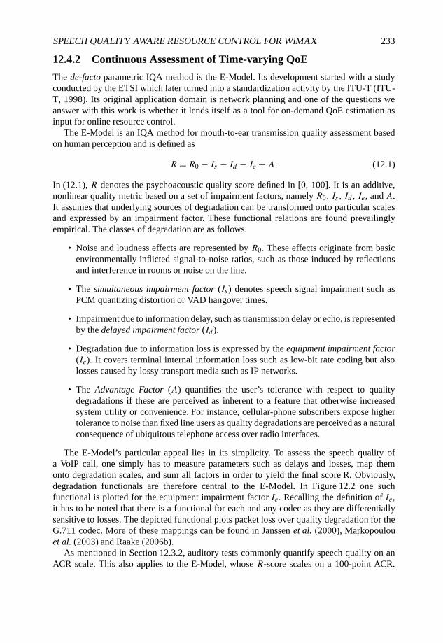
SPEECH QUALITY AWARE RESOURCE CONTROL FOR WiMAX 233
12.4.2 Continuous Assessment of Time-varying QoE
The de-facto parametric IQA method is the E-Model. Its development started with a studyconducted by the ETSI which later turned into a standardization activity by the ITU-T (ITU-T, 1998). Its original application domain is network planning and one of the questions weanswer with this work is whether it lends itself as a tool for on-demand QoE estimation asinput for online resource control.
The E-Model is an IQA method for mouth-to-ear transmission quality assessment basedon human perception and is defined as
R = R0 − Is − Id − Ie + A. (12.1)
In (12.1), R denotes the psychoacoustic quality score defined in [0, 100]. It is an additive,nonlinear quality metric based on a set of impairment factors, namely R0, Is , Id , Ie, and A.It assumes that underlying sources of degradation can be transformed onto particular scalesand expressed by an impairment factor. These functional relations are found prevailinglyempirical. The classes of degradation are as follows.
• Noise and loudness effects are represented by R0. These effects originate from basicenvironmentally inflicted signal-to-noise ratios, such as those induced by reflectionsand interference in rooms or noise on the line.
• The simultaneous impairment factor (Is) denotes speech signal impairment such asPCM quantizing distortion or VAD hangover times.
• Impairment due to information delay, such as transmission delay or echo, is representedby the delayed impairment factor (Id ).
• Degradation due to information loss is expressed by the equipment impairment factor(Ie). It covers terminal internal information loss such as low-bit rate coding but alsolosses caused by lossy transport media such as IP networks.
• The Advantage Factor (A) quantifies the user’s tolerance with respect to qualitydegradations if these are perceived as inherent to a feature that otherwise increasedsystem utility or convenience. For instance, cellular-phone subscribers expose highertolerance to noise than fixed line users as quality degradations are perceived as a naturalconsequence of ubiquitous telephone access over radio interfaces.
The E-Model’s particular appeal lies in its simplicity. To assess the speech quality ofa VoIP call, one simply has to measure parameters such as delays and losses, map themonto degradation scales, and sum all factors in order to yield the final score R. Obviously,degradation functionals are therefore central to the E-Model. In Figure 12.2 one suchfunctional is plotted for the equipment impairment factor Ie. Recalling the definition of Ie,it has to be noted that there is a functional for each and any codec as they are differentiallysensitive to losses. The depicted functional plots packet loss over quality degradation for theG.711 codec. More of these mappings can be found in Janssen et al. (2000), Markopoulouet al. (2003) and Raake (2006b).
As mentioned in Section 12.3.2, auditory tests commonly quantify speech quality on anACR scale. This also applies to the E-Model, whose R-score scales on a 100-point ACR.
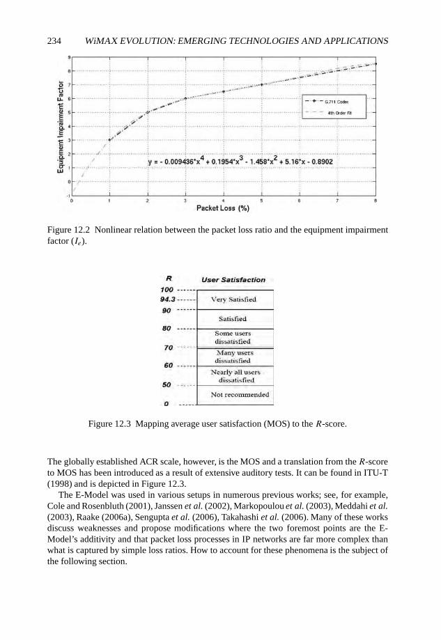
234 WiMAX EVOLUTION: EMERGING TECHNOLOGIES AND APPLICATIONS
Figure 12.2 Nonlinear relation between the packet loss ratio and the equipment impairmentfactor (Ie).
Figure 12.3 Mapping average user satisfaction (MOS) to the R-score.
The globally established ACR scale, however, is the MOS and a translation from the R-scoreto MOS has been introduced as a result of extensive auditory tests. It can be found in ITU-T(1998) and is depicted in Figure 12.3.
The E-Model was used in various setups in numerous previous works; see, for example,Cole and Rosenbluth (2001), Janssen et al. (2002), Markopoulou et al. (2003), Meddahi et al.(2003), Raake (2006a), Sengupta et al. (2006), Takahashi et al. (2006). Many of these worksdiscuss weaknesses and propose modifications where the two foremost points are the E-Model’s additivity and that packet loss processes in IP networks are far more complex thanwhat is captured by simple loss ratios. How to account for these phenomena is the subject ofthe following section.

SPEECH QUALITY AWARE RESOURCE CONTROL FOR WiMAX 235
Figure 12.4 A series of consecutive periods of different microscopic loss behaviors, thatis packet loss ratio and distribution, together form a macroscopic loss profile. There are twoalternating microscopic loss behaviors, loss gaps and loss bursts. Stars represent VoIP packetsand arrows indicate packet loss events. The distance between them is called delta. If deltais larger (smaller) than 16, and the model is in gap (burst) state, it remains is this state.Otherwise it changes from burst (gap) to gap (burst) state. In the event of an transition theimpairment factor is calculated for the abandoned state. Over time, this leads to a series of Ievalues.
12.4.3 Instationary Quality Distortion and Human Perception
The quality of speech is by far most influenced by information loss, that is, Ie (Kostas et al.,1998, Markopoulou et al., 2003, Raake, 2006b). The functional relation expressing this factis nonlinear and the most relevant part for a G.711 codec is depicted in Figure 12.2. Using asimple fourth-order least-squares fit, the function reads
Ie = −0.009436x4 + 0.1954x3 − 1.458x2 + 5.16x − 0.8902. (12.2)
However, measuring packet loss and mapping it to Ie is insufficient. In particular, if speech isdelivered over IP networks by means of VoIP, the final quality is prevailingly determined bythe packet loss distribution. Intuitively, single packet losses are always preferable over lossbursts. This is exactly the difference between IQ and SQ since by taking averages, as withIQ, such details are inherently ignored. Furthermore, packet loss distributions themselves arefrequently instationary over a call’s life time and instantaneous as well as ultimate qualityassessment by humans exhibits strong correlation with this characteristic Raake (2006b,Chapter 4).
To account for this phenomenon we divide the packet loss process into periods withdifferent loss behaviors, as proposed by Clark (2001) and refined by Markopoulou et al.(2003) and Raake (2006a,b). In particular, we adopt the principles proposed by Clark(2001) but modified for our purpose. Essentially, this packet loss driven model defines twoalternating states of microscopic loss behavior, loss gap and loss burst state, with respectto the distance of packet loss events, cf. Figure 12.4. According to Clark (2001), the modelremains in the (loss) gap state as long as there is a minimum of 16 successfully receivedpackets between two loss events (delta, δ). Otherwise there is a transition from (loss) gapto (loss) burst. The idea behind staying in a gap state under this condition is that modernloss recovery algorithms can handle isolated packet loss relatively well. In the case of atransition to burst state, the model remains in this state until 16 packets are successfullyreceived between the latest and the previous loss event.

236 WiMAX EVOLUTION: EMERGING TECHNOLOGIES AND APPLICATIONS
Figure 12.5 The expected rating (solid line) associated with either loss or gap state. The true,delayed perception (dashed line) by humans is indicated as an exponential decay or rise ofthe R-score with respect to a state transition. (Source: Raake (2006a).)
Upon the detection of any state transition the loss ratio for the previous state is used tocalculate the corresponding impairment level, Ie, using the relation depicted in Figure 12.2,resulting in a time series of Ie values with respect to states. However, before these values canbe used to compute R, there is another feature, inherent to human perception, which has beenintegrated into this model, the delayed perception (or acceptance) of quality change.
Naturally, humans tend to perceive a quality change rather continuously and not instan-taneously at state transitions. A further distinction has to be made between transitions fromgood to bad and vice versa. So do humans confirm a change from good to bad much fasterthan the other way around. Generally, this feature can be modeled by an exponential function,similar to a transistor saturation curve, with specific time constants. It is shown in Figure 12.5by the dashed lines.
Given Ie,g and Ie,b, the impairment linked to gap or burst, I1 is the estimated instantaneousimpairment level at the change from burst to gap condition and I2 equals the level at the returnfrom gap to burst. In mathematical terms, I1 and I2 can be expressed as
I1 = Ie,b − (Ie,b − I2)e−b/τ1, (12.3)
I2 = Ie,g + (I1 − Ie,g)e−g/τ2 . (12.4)
Here g and b denote the sojourn time in gap or burst state and τ1 and τ2 are the time constants,respectively. Typical values are τ1 = 9 s and τ2 = 22 s (Raake, 2006b). A proper combinationof (12.3) and (12.4) yields an expression for I2 independent from I1:
I2 = Ie,g(1 − e−g/τ2)+ Ie,b(1 − e−b/τ1)e−g/τ2 . (12.5)
Using (12.5) we are now in a position to calculate the average impairment level over acertain time, for example, for the life time of a call. Therefore, we first calculate average gapand burst length, b and g, as well as the average impairment levels, Ie,g and Ie,b . Puttingthese in (12.5) and integrating it over one burst and gap yields the average impairment levelfor a certain loss profile of certain length. It reads
Ie = 1
b + g× [Ie,b × b + Ie,g × g + τ1 × (Ie,b − I2)
× (eb/τ1 − 1)− τ2 × (Ie,b − (Ie,b − I2)
× e−b/τ1 − Ie,g)× (eg/τ2 − 1)]. (12.6)
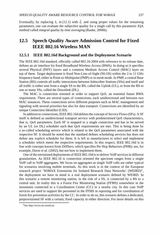
SPEECH QUALITY AWARE RESOURCE CONTROL FOR WiMAX 237
Eventually, by replacing Ie in (12.1) with Ie and using proper values for the remainingparameters, one can evaluate the subjective quality for a single call by this parametric IQAmethod called integral quality by time averaging (Raake, 2006b).
12.5 Speech Quality Aware Admission Control for FixedIEEE 802.16 Wireless MAN
12.5.1 IEEE 802.16d Background and the Deployment Scenario
The IEEE 802.16d standard, officially called 802.16-2004 with reference to its release date,defines an air interface for fixed Broadband Wireless Access (BWA). In doing so it specifiesseveral Physical (PHY) layers and a common Medium Access Control (MAC) layer ontop of them. Target deployment is fixed Non-Line-of-Sight (NLOS) within the 2 to 11 GHzfrequency band, either in Point-to-Multipoint (PMP) or in mesh mode. In PMP, a central BaseStation (BS) controls all traffic interactions between Subscriber Stations (SSs) and itself andall traffic is either sent from a single SS to the BS, called the Uplink (UL), or from the BS toone or many SSs, called the Downlink (DL).
The MAC is connection oriented in order to support QoS, an essential future BWArequirement. There are several types of connections, each unidirectional and between twoMAC instances. These connections serve different purposes such as MAC management andsignaling with several priorities but also for data transport. Connections are identified by anunique Connection Identifier (CID).
In addition to connections, IEEE 802.16d defines the concept of Service Flows (SFs). A SFitself is defined as unidirectional transport service with predetermined QoS characteristics,that is, QoS parameters. Each SF is mapped to a single connection and has to be servedby an UL (or DL) scheduler such that QoS requirements are met. This is being done bya so-called scheduling service which is related to the QoS parameters associated with therespective SF. It should be noted that the standard defines scheduling services but does notdefine any explicit scheduler for them. It is left to manufactures to select and implementa scheduler which meets the respective requirements. In this respect, IEEE 802.16d is inline with concepts known from DiffServ, which specifies Per Hop Behaviors (PHB); see, forexample, Davie et al. (2002), but not how to implement them.
One of the envisioned deployments of IEEE 802.16d is to deliver VoIP services in differentgranularities. As IEEE 802.16 is connection oriented the spectrum ranges from a singleVoIP call to VoIP aggregates. We focus on aggregates as single VoIP calls are rather typicalfor scenarios involving mobile terminals. As this work is in the context of the Europeanresearch project ‘WiMAX Extensions for Isolated Research Data Networks’ (WEIRD)1,the deployment we have in mind is a real deployment scenario defined by WEIRD. Inthis scenario a remote monitoring station, in the role of a SS, is connected by a BS to acentral unit. In reality this is a Forest Fire Monitoring Station (FFMS) somewhere in themountains connected to a Coordination Center (CC) in a nearby city. In this case VoIPservices are used to support the personnel in the FFMS in reporting and for coordination offorest fire prevention activities by the CC. In order to do so, this scenario defines a dedicated,preprovisioned SF with a certain, fixed capacity in either direction. For more details on this
1See http://www.ist-weird.eu.
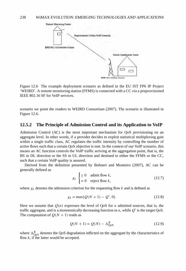
238 WiMAX EVOLUTION: EMERGING TECHNOLOGIES AND APPLICATIONS
Figure 12.6 The example deployment scenario as defined in the EU IST FP6 IP Project‘WEIRD’. A remote monitoring station (FFMS) is connected with a CC via a preprovisionedIEEE 802.16 SF for VoIP services.
scenario we point the readers to WEIRD Consortium (2007). The scenario is illustrated inFigure 12.6.
12.5.2 The Principle of Admission Control and its Application to VoIP
Admission Control (AC) is the most important mechanism for QoS provisioning on anaggregate level. In other words, if a provider decides to exploit statistical multiplexing gainwithin a single traffic class, AC regulates the traffic intensity by controlling the number ofactive flows such that a certain QoS objective is met. In the context of our VoIP scenario, thismeans an AC function controls the VoIP traffic arriving at the aggregation point, that is, theBS in DL direction or the SS in UL direction and destined to either the FFMS or the CC,such that a certain VoIP quality is assured.
Derived from the definition presented by Bohnert and Monteiro (2007), AC can begenerally defined as
χk
{≥ 0 admit flow k,
= 0 reject flow k,(12.7)
where χk denotes the admission criterion for the requesting flow k and is defined as
χk = max{Q(N + 1)−Q′, 0}. (12.8)
Here we assume that Q(n) expresses the level of QoS for n admitted sources, that is, thetraffic aggregate, and is a monotonically decreasing function in n, whileQ′ is the target QoS.The computation of Q(N + 1) reads as
Q(N + 1)=Q(N)−�KQoS (12.9)
where �KQoS denotes the QoS degradation inflicted on the aggregate by the characteristics offlow k, if the latter would be accepted.

SPEECH QUALITY AWARE RESOURCE CONTROL FOR WiMAX 239
Equipped with the expressions derived in the previous sections we can formulate anadmission criterion based on QoE (speech quality). Therefore, we replace Q(N + 1)in (12.8) with R(R0, Is , Id , Ie, A) and set R0 − Is = 94, the default value with respect toinherent features of the G.711 codec. Further, Id is set to an upper bound determined by thebuffer length ω and the link capacity C; see Cox and Perkins (1999) for details. Beyond thisbound, packet delay translates into packet loss and is captured by Ie. The respective equationfor Id reads
Id = 4 + 1 ∗ (ω/C). (12.10)
Combining all pieces and further assuming the worst case, that is, we set A to zero, weobtain
RT = 94 − 4 + 1 ∗ (ω/C)− Ie(T ). (12.11)
In this equation the parameter T in Ie(T ) indicates that the average impairment factor fortime-varying speech quality assessment has been calculated over a window of T seconds.This is to account for an inherent feature of Measurement Based Admission Control (MBAC)algorithms, which generally estimate a QoE/QoS criterion over a limited window. Eventually,we can express the admission criterion as follows:
χk = max{RT − R′, 0}. (12.12)
It has to be noted that the criterion in (12.12) slightly differs from that in (12.8) as we putQ(N) (RT ) in place ofQ(N + 1). This is due to the difficulty in expressing and quantifying�KQoS without a precise traffic model. As we show, this has little or no impact but we arecurrently investigating alternatives and their merit.
Furthermore, by using this setup speech quality is assessed on an aggregate level witha method that was originally designed to assess individual call quality. Whether this makessense is discussed in the following; see Section 12.5.4.2. At least from a model point ofview there is little difference in computing Ie on an aggregate or call level. What is requiredin either case are the loss ratio, burst length and gap length. The single difference is thenumber of packets received (or lost) to trigger state transition, which is 16 for a single call,cf. Section 12.4.3.
In order to translate this trigger threshold to an aggregate level we apply a simpleintuitive approach. The AC algorithm knows at any time the number of admitted flows N .By assuming that VoIP traffic can be modeled by a standard exponential on/off model withan average sojourn time in the on (talk) state of 300 ms and a mean off (silence) of 600 ms(Markopoulou et al., 2003), we know that each flow is active (on) for roughly a third of itslife time. We further assume that any contribution as well as impact on an individual callscales linearly with the number of calls aggregated. In other words, the contribution of anycall as well as the impact on it equals in average that of any other call. On the basis of thisassumptions we set the number of packets received (or lost) to trigger state transitions to16 ×N × 0.33.
12.5.3 Experimental Setup and Parameterization
In order to evaluate the concept and performance of the algorithm, we implemented it inthe NS-2 framework2. The basic scenario has been already described in Section 12.5.1 and
2See http://www.isi.edu/nsnam/ns.
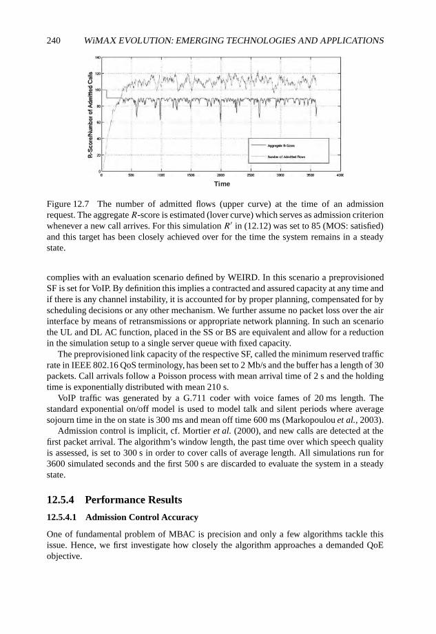
240 WiMAX EVOLUTION: EMERGING TECHNOLOGIES AND APPLICATIONS
Time
Figure 12.7 The number of admitted flows (upper curve) at the time of an admissionrequest. The aggregateR-score is estimated (lover curve) which serves as admission criterionwhenever a new call arrives. For this simulation R′ in (12.12) was set to 85 (MOS: satisfied)and this target has been closely achieved over for the time the system remains in a steadystate.
complies with an evaluation scenario defined by WEIRD. In this scenario a preprovisionedSF is set for VoIP. By definition this implies a contracted and assured capacity at any time andif there is any channel instability, it is accounted for by proper planning, compensated for byscheduling decisions or any other mechanism. We further assume no packet loss over the airinterface by means of retransmissions or appropriate network planning. In such an scenariothe UL and DL AC function, placed in the SS or BS are equivalent and allow for a reductionin the simulation setup to a single server queue with fixed capacity.
The preprovisioned link capacity of the respective SF, called the minimum reserved trafficrate in IEEE 802.16 QoS terminology, has been set to 2 Mb/s and the buffer has a length of 30packets. Call arrivals follow a Poisson process with mean arrival time of 2 s and the holdingtime is exponentially distributed with mean 210 s.
VoIP traffic was generated by a G.711 coder with voice fames of 20 ms length. Thestandard exponential on/off model is used to model talk and silent periods where averagesojourn time in the on state is 300 ms and mean off time 600 ms (Markopoulou et al., 2003).
Admission control is implicit, cf. Mortier et al. (2000), and new calls are detected at thefirst packet arrival. The algorithm’s window length, the past time over which speech qualityis assessed, is set to 300 s in order to cover calls of average length. All simulations run for3600 simulated seconds and the first 500 s are discarded to evaluate the system in a steadystate.
12.5.4 Performance Results
12.5.4.1 Admission Control Accuracy
One of fundamental problem of MBAC is precision and only a few algorithms tackle thisissue. Hence, we first investigate how closely the algorithm approaches a demanded QoEobjective.
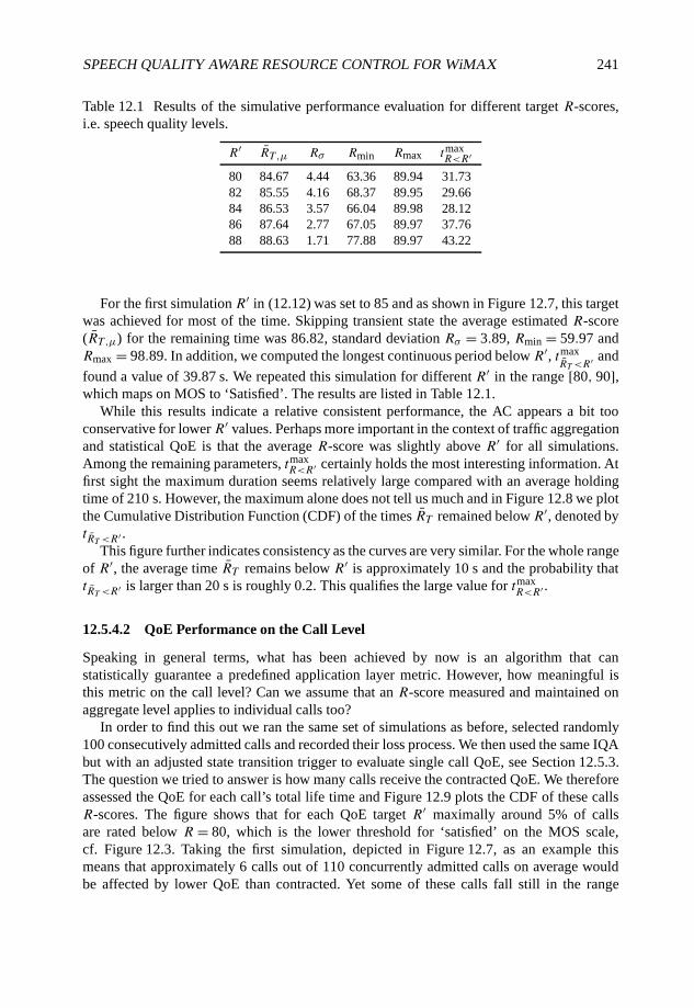
SPEECH QUALITY AWARE RESOURCE CONTROL FOR WiMAX 241
Table 12.1 Results of the simulative performance evaluation for different target R-scores,i.e. speech quality levels.
R′ RT ,µ Rσ Rmin Rmax tmaxR<R′
80 84.67 4.44 63.36 89.94 31.7382 85.55 4.16 68.37 89.95 29.6684 86.53 3.57 66.04 89.98 28.1286 87.64 2.77 67.05 89.97 37.7688 88.63 1.71 77.88 89.97 43.22
For the first simulation R′ in (12.12) was set to 85 and as shown in Figure 12.7, this targetwas achieved for most of the time. Skipping transient state the average estimated R-score(RT ,µ) for the remaining time was 86.82, standard deviation Rσ = 3.89, Rmin = 59.97 andRmax = 98.89. In addition, we computed the longest continuous period below R′, tmax
RT <R′ and
found a value of 39.87 s. We repeated this simulation for different R′ in the range [80, 90],which maps on MOS to ‘Satisfied’. The results are listed in Table 12.1.
While this results indicate a relative consistent performance, the AC appears a bit tooconservative for lowerR′ values. Perhaps more important in the context of traffic aggregationand statistical QoE is that the average R-score was slightly above R′ for all simulations.Among the remaining parameters, tmax
R<R′ certainly holds the most interesting information. Atfirst sight the maximum duration seems relatively large compared with an average holdingtime of 210 s. However, the maximum alone does not tell us much and in Figure 12.8 we plotthe Cumulative Distribution Function (CDF) of the times RT remained belowR′, denoted bytRT <R′ .
This figure further indicates consistency as the curves are very similar. For the whole rangeof R′, the average time RT remains below R′ is approximately 10 s and the probability thattRT <R′ is larger than 20 s is roughly 0.2. This qualifies the large value for tmax
R<R′ .
12.5.4.2 QoE Performance on the Call Level
Speaking in general terms, what has been achieved by now is an algorithm that canstatistically guarantee a predefined application layer metric. However, how meaningful isthis metric on the call level? Can we assume that an R-score measured and maintained onaggregate level applies to individual calls too?
In order to find this out we ran the same set of simulations as before, selected randomly100 consecutively admitted calls and recorded their loss process. We then used the same IQAbut with an adjusted state transition trigger to evaluate single call QoE, see Section 12.5.3.The question we tried to answer is how many calls receive the contracted QoE. We thereforeassessed the QoE for each call’s total life time and Figure 12.9 plots the CDF of these callsR-scores. The figure shows that for each QoE target R′ maximally around 5% of callsare rated below R = 80, which is the lower threshold for ‘satisfied’ on the MOS scale,cf. Figure 12.3. Taking the first simulation, depicted in Figure 12.7, as an example thismeans that approximately 6 calls out of 110 concurrently admitted calls on average wouldbe affected by lower QoE than contracted. Yet some of these calls fall still in the range
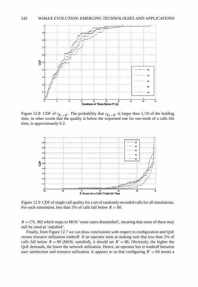
242 WiMAX EVOLUTION: EMERGING TECHNOLOGIES AND APPLICATIONS
Figure 12.8 CDF of tRT <R′ . The probability that tRT <R′ is larger than 1/10 of the holdingtime, in other words that the quality is below the requested one for one-tenth of a calls lifetime, is approximately 0.2.
Figure 12.9 CDF of single call quality for a set of randomly recorded calls for all simulations.For each simulation, less than 5% of calls fall below R = 80.
R = [70, 80] which maps to MOS ‘some users dissatisfied’, meaning that some of these maystill be rated as ‘satisfied’.
Finally, from Figure 12.7 we can draw conclusions with respect to configuration and QoEversus resource utilization tradeoff. If an operator aims at making sure that less than 2% ofcalls fall below R = 80 (MOS: satisfied), it should set R′ = 88. Obviously, the higher theQoE demands, the lower the network utilization. Hence, an operator has to tradeoff betweenuser satisfaction and resource utilization. It appears to us that configuring R′ = 84 seems a
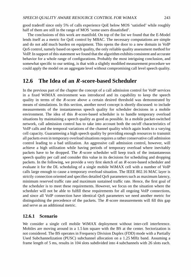
SPEECH QUALITY AWARE RESOURCE CONTROL FOR WiMAX 243
good tradeoff since only 5% of calls experience QoE below MOS ‘satisfied’ while roughlyhalf of them are still in the range of MOS ‘some users dissatisfied’.
The conclusions of this work are manifold. On top of the list we found that the E-Modellends itself as a metric for QoE control by MBAC. The necessary computations are simpleand do not add much burden on equipment. This opens the door to a new domain in VoIPQoS control, namely based on speech quality, the only reliable quality assessment method forVoIP. In support of this statement we found that the algorithm exhibits consistent and accuratebehavior for a whole range of configurations. Probably the most intriguing conclusion, andsomewhat specific to our setting, is that with a slightly modified measurement procedure wecould apply the model on an aggregate level without compromising call level speech quality.
12.6 The Idea of an R-score-based Scheduler
In the previous part of the chapter the concept of a call admission control for VoIP servicesin a fixed WiMAX environment was introduced and its capability to keep the speechquality in terms of the R-score above a certain desired threshold was demonstrated bymeans of simulations. In this section, another novel concept is shortly discussed: to includemeasurements of the instantaneous speech quality for scheduler decisions in a mobileenvironment. The idea of this R-score-based scheduler is to handle temporary overloadsituations by maintaining a speech quality as good as possible. In a mobile packet-switchednetwork, call admission control has to take into account both the on/off characteristics ofVoIP calls and the temporal variations of the channel quality which again leads to a varyingcell capacity. Guaranteeing a high speech quality by providing enough resources to transmitall packets even in temporary overload situations requires a rather conservative call admissioncontrol leading to a bad utilization. An aggressive call admission control, however, willachieve a high utilization while having periods of temporary overload where inevitablypackets have to be dropped. The R-score scheduler will keep track of the instantaneousspeech quality per call and consider this value in its decisions for scheduling and droppingpackets. In the following, we provide a very first sketch of an R-score-based scheduler andevaluate it for the DL scheduling of a single mobile WiMAX cell with a number of VoIPcalls large enough to cause a temporary overload situation. The IEEE 802.16 MAC layer isstrictly connection oriented and specifies detailed QoS parameters such as maximum latency,minimum reserved traffic rate and maximum sustained traffic rate. Hence, the first goal ofthe scheduler is to meet these requirements. However, we focus on the situation where thescheduler will not be able to fulfill these requirements for all ongoing VoIP connections,and since all VoIP connection have identical QoS parameters we need another metric fordistinguishing the precedence of the packets. The R-score measurements will fill this gapand serve as an additional metric.
12.6.1 Scenario
We consider a single cell mobile WiMAX deployment without inter-cell interference.Mobiles are moving around in a 1.5 km square with the BS at the center. Sectorization isnot considered. The BS operates in Frequency Division Duplex (FDD) mode with a PartiallyUsed Subchannelization (PUSC) subchannel allocation on a 1.25 MHz band. Assuming aframe length of 5 ms, results in 104 slots subdivided into 4 subchannels with 26 slots each.
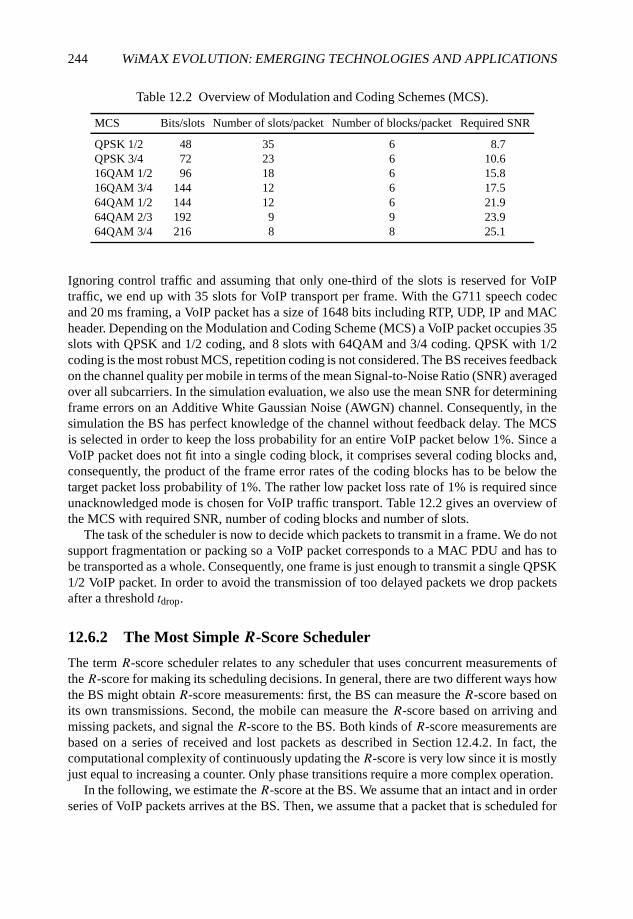
244 WiMAX EVOLUTION: EMERGING TECHNOLOGIES AND APPLICATIONS
Table 12.2 Overview of Modulation and Coding Schemes (MCS).
MCS Bits/slots Number of slots/packet Number of blocks/packet Required SNR
QPSK 1/2 48 35 6 8.7QPSK 3/4 72 23 6 10.616QAM 1/2 96 18 6 15.816QAM 3/4 144 12 6 17.564QAM 1/2 144 12 6 21.964QAM 2/3 192 9 9 23.964QAM 3/4 216 8 8 25.1
Ignoring control traffic and assuming that only one-third of the slots is reserved for VoIPtraffic, we end up with 35 slots for VoIP transport per frame. With the G711 speech codecand 20 ms framing, a VoIP packet has a size of 1648 bits including RTP, UDP, IP and MACheader. Depending on the Modulation and Coding Scheme (MCS) a VoIP packet occupies 35slots with QPSK and 1/2 coding, and 8 slots with 64QAM and 3/4 coding. QPSK with 1/2coding is the most robust MCS, repetition coding is not considered. The BS receives feedbackon the channel quality per mobile in terms of the mean Signal-to-Noise Ratio (SNR) averagedover all subcarriers. In the simulation evaluation, we also use the mean SNR for determiningframe errors on an Additive White Gaussian Noise (AWGN) channel. Consequently, in thesimulation the BS has perfect knowledge of the channel without feedback delay. The MCSis selected in order to keep the loss probability for an entire VoIP packet below 1%. Since aVoIP packet does not fit into a single coding block, it comprises several coding blocks and,consequently, the product of the frame error rates of the coding blocks has to be below thetarget packet loss probability of 1%. The rather low packet loss rate of 1% is required sinceunacknowledged mode is chosen for VoIP traffic transport. Table 12.2 gives an overview ofthe MCS with required SNR, number of coding blocks and number of slots.
The task of the scheduler is now to decide which packets to transmit in a frame. We do notsupport fragmentation or packing so a VoIP packet corresponds to a MAC PDU and has tobe transported as a whole. Consequently, one frame is just enough to transmit a single QPSK1/2 VoIP packet. In order to avoid the transmission of too delayed packets we drop packetsafter a threshold tdrop.
12.6.2 The Most Simple R-Score Scheduler
The term R-score scheduler relates to any scheduler that uses concurrent measurements ofthe R-score for making its scheduling decisions. In general, there are two different ways howthe BS might obtain R-score measurements: first, the BS can measure the R-score based onits own transmissions. Second, the mobile can measure the R-score based on arriving andmissing packets, and signal the R-score to the BS. Both kinds of R-score measurements arebased on a series of received and lost packets as described in Section 12.4.2. In fact, thecomputational complexity of continuously updating the R-score is very low since it is mostlyjust equal to increasing a counter. Only phase transitions require a more complex operation.
In the following, we estimate the R-score at the BS. We assume that an intact and in orderseries of VoIP packets arrives at the BS. Then, we assume that a packet that is scheduled for
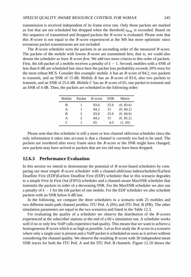
SPEECH QUALITY AWARE RESOURCE CONTROL FOR WiMAX 245
transmission is received independent of its frame error rate. Only those packets are markedas lost that are not scheduled but dropped when the threshold tdrop is exceeded. Based onthis sequence of transmitted and dropped packets the R-score is evaluated. Please note thatthis R-score is not equal to the R-score experienced at the MS but more optimistic sinceerroneous packet transmissions are not included.
The R-score scheduler sorts the packets in an ascending order of the measured R-score.The packets of the mobile with lowest R-score are transmitted first, that is, we could alsodenote the scheduler as least R-score first. We add two more criteria to this order of packets.First, the kth packet of a mobile receives a penalty of k − 1. Second, mobiles with a SNR ofless than 6 dB are scheduled last since here the packet loss probability exceeds 20% even forthe most robust MCS. Consider this example: mobile A has an R-score of 84.2, two packetsto transmit, and an SNR of 15 dB. Mobile B has an R-score of 83.6, also two packets totransmit, and an SNR of 25.6 dB. Mobile C has an R-score of 65, one packet to transmit andan SNR of 4 dB. Then, the packets are scheduled in the following order:
Mobile Packet R-score SNR Metric
B 1 83.6 25.6 (0, 83.6)A 1 84.2 15 (0, 84.2)B 2 83.6 25.6 (0, 84.6)A 2 84.2 15 (0, 85.2)C 1 65 4.5 (1, 65)
Please note that this scheduler is still a more or less channel oblivious scheduler since theonly information it takes into account is that a channel is currently too bad to be used. Thepackets are reordered after every frame since the R-score or the SNR might have changed,new packets may have arrived or packets that are too old may have been dropped.
12.6.3 Performance Evaluation
In this section we intend to demonstrate the potential of R-score-based schedulers by com-paring our most simple R-score scheduler with a channel-oblivious indexscheduler!EarliestDeadline First (EDF)Earliest Deadline First (EDF) scheduler that in this scenario degradesto a simple First In First Out (FIFO) scheduler and a channel-aware MaxSNR scheduler thattransmits the packets in order of a decreasing SNR. For the MaxSNR scheduler we also usea penalty of k − 1 for the kth packet of one mobile. For the EDF scheduler we also schedulepackets with an SNR below 6 dB last.
In the following, we compare the three schedulers in a scenario with 25 mobiles andtwo different multi-path channel profiles: ITU Ped. A (PA) and ITU Ped. B (PB). The othersimulation parameters are equal in the two scenarios and listed in the Table 12.3.
For evaluating the quality of a scheduler we observe the distribution of the R-scoresexperienced at the subscriber stations at the end of a 60 s simulation run. A scheduler workswell if no or only few VoIP calls experience bad quality. This means that we want to achieve ahomogeneousR-score which is as high as possible. Let us first study theR-score in a scenariowhere only a single user is present and a VoIP packet is scheduled as soon as it arrives withoutconsidering the channel quality. We observe the resulting R-score with 30 independent meanSNR traces for both the ITU Ped. A and the ITU Ped. B channels. Figure 12.10 shows the
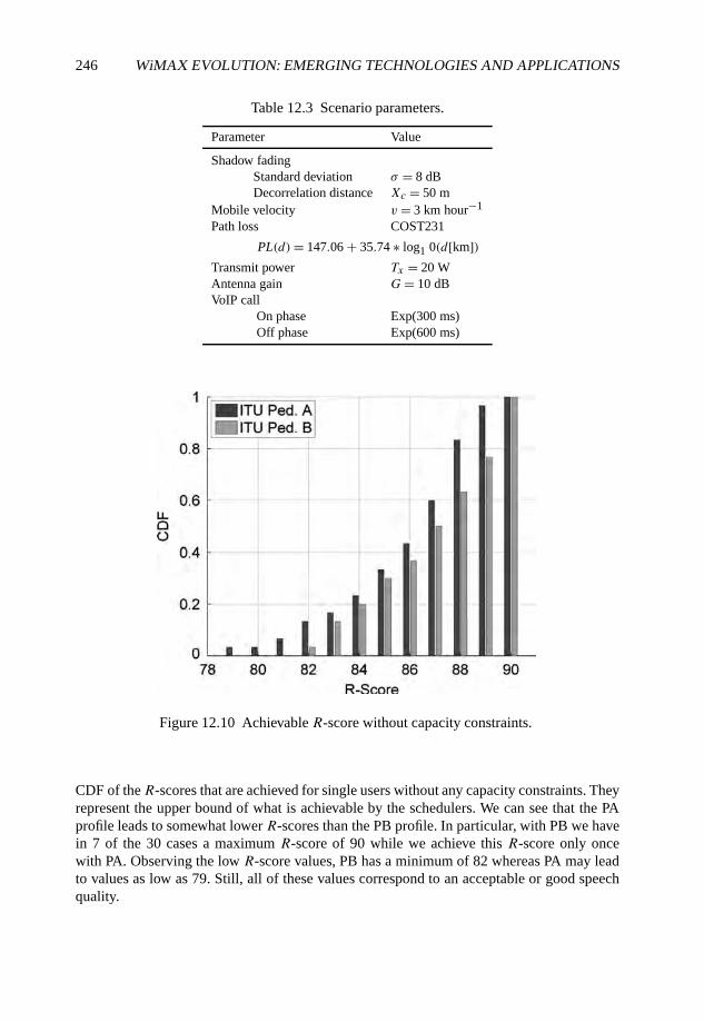
246 WiMAX EVOLUTION: EMERGING TECHNOLOGIES AND APPLICATIONS
Table 12.3 Scenario parameters.
Parameter Value
Shadow fadingStandard deviation σ = 8 dBDecorrelation distance Xc = 50 m
Mobile velocity v = 3 km hour−1
Path loss COST231
PL(d)= 147.06 + 35.74 ∗ log1 0(d[km])Transmit power Tx = 20 WAntenna gain G= 10 dBVoIP call
On phase Exp(300 ms)Off phase Exp(600 ms)
Figure 12.10 Achievable R-score without capacity constraints.
CDF of theR-scores that are achieved for single users without any capacity constraints. Theyrepresent the upper bound of what is achievable by the schedulers. We can see that the PAprofile leads to somewhat lower R-scores than the PB profile. In particular, with PB we havein 7 of the 30 cases a maximum R-score of 90 while we achieve this R-score only oncewith PA. Observing the low R-score values, PB has a minimum of 82 whereas PA may leadto values as low as 79. Still, all of these values correspond to an acceptable or good speechquality.
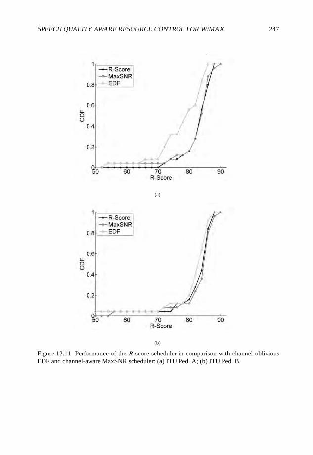
SPEECH QUALITY AWARE RESOURCE CONTROL FOR WiMAX 247
(a)
(b)
Figure 12.11 Performance of the R-score scheduler in comparison with channel-obliviousEDF and channel-aware MaxSNR scheduler: (a) ITU Ped. A; (b) ITU Ped. B.
248 WiMAX EVOLUTION: EMERGING TECHNOLOGIES AND APPLICATIONS
Now, let us compare the impact of the different schedulers when we have a system withlight overload, such as with 25 mobiles. Figure 12.11 shows the CDF of the R-score for thethree schedulers with Figure 12.11(a) presenting the results for the PA multi-path channelprofile and Figure 12.11(b) presenting the results for the PB profile. First, we can observe thatin the light overload situation the R-score degrades down to 50 for some of the users whileothers still experience an excellent speech quality with an R-score close to 90. This holds forboth channel profiles. If we observe the performance of the three schedulers in the PB profile,we can see that the three schedulers show marginal differences: only the EDF schedulerperforms a little worse than the others. Figure 12.11(a) confirms this observation. Here, theEDF scheduler is clearly worse than the R-score and MaxSNR scheduler. At first glance, wealso note that MaxSNR and R-score scheduler show an almost identical performance as inthe PB case. If we have a closer look, we detect that for the high R-scores the performance isthe same. For the low R-scores, however, the MaxSNR yields one R-score of below 55 whilethe R-scores obtained by the R-score scheduler are all above 70. This means that at least inthis special case the R-score scheduler outperforms the MaxSNR scheduler and is able toavoid the strong degradation of the speech quality of the worst call.
In general, we can state that the ‘most simple R-score scheduler’ seems to be clearlybetter than the channel-oblivious EDF or FIFO scheduler. In addition, the performance ofthe channel-oblivious R-score scheduler is comparable and at least in one case better thanthe performance of the channel-aware MaxSNR scheduler which is quite remarkable. As asummary from the first experiences with an R-score scheduler, we conclude that the resultsare quite promising and encourage the further development of QoE aware schedulers notonly for VoIP but also for other services such as Video on Demand (VoD), etc. The currentsimulation results are of course only examples and have to be further confirmed. In particular,the impact of different parameters such as the shadowing model, the velocity, the droppingthreshold tdrop and many more has to be investigated. Furthermore, the simulation scenarioshould be more realistic in the sense that, for example, we should not assume a perfect packetarrival process at the BS, perfect knowledge of the channel or the unacknowledged mode. Onthe other hand, we also feel that there is still a lot of potential for improving the scheduler bycombining different metrics for the scheduling decision, in particular current speech quality,current channel quality and urgency of the packet.
12.7 Conclusion
In this chapter we have presented the idea to utilize concurrent measurements of theinstantaneous QoE for an improved resource control. We showed two examples of this QoE-based resource control at the scenario of the VoIP service in a WiMAX network. In the firstexample, a measurement-based admission control scheme for a fixed WiMAX deploymentwas proposed. The admission decision depends on a certain threshold for the aggregated R-score of ongoing calls. In the second example, a scheduling scheme for the DL of a mobileWiMAX BS is proposed. The scheduler uses the R-score as ordering metric and transmitsthe packets in a least R-score first fashion.
In both examples the proposed R-score-based resource control schemes show greatpromise through preliminary results. A more sophisticated evaluation of their performance isrequired and there is also room for optimization. Furthermore, using the R-score as a QoE
SPEECH QUALITY AWARE RESOURCE CONTROL FOR WiMAX 249
metric for speech quality based resource control is only the first and probably most simpleexample for QoE-based resource control. Of great interest in the future will be QoE-basedresource control schemes for different service composites including speech, video or gamingapplications.
References
Blake S., Black D., Carlson M., Davies E., Wang Z. and Weiss W. (1998) An Architecture forDifferentiated Services, Request for Comments 2475, IETF.
Bohnert, T.M. and Monteiro, E. (2007) Multi-class measurement based admission control for a QoSframework with dynamic resource management. Journal of Network and Systems Management,15(2), 219–240.
Bohnert, T.M., Monteiro, E., Curado, M., Fonte, A., Moltchanov, D., Koucheryavy, Y. and Ries, M.(2007) Internet quality of service: a bigger picture. Proceedings of the First OpenNet QoS Workshop‘Service Quality and IP Network Business: Filling the Gap’, Diegem, Belgium.
Braden, R., Clark, D. and Shenker, S. (1994) Integrated services in the Internet architecture: AnOverview, Request for Comments 1633, IETF.
Clark, A. (2001) Modeling the effects of burst packet loss and recency on subjective voice quality.Proceedings of the IP Telephony Workshop.
Cole, R.G. and Rosenbluth, J.H. (2001) Voice over ip performance monitoring. ACM SIGCOMMComputer Communication Review, 31(2), 9–24.
Cox, R. and Perkins, R. (1999) Results of a Subjective Listening Test for G.711 with Frame ErasureConcealment, Committee contribution T1A1.7/99-016.
Crawley, E., Nair, R., Rajagopalan, B., and Sandick, H. (1998) A framework for QoS-based routing inthe internet, Request for Comments 2386, IETF.
Davie, B., Chany, A., Baker, F., Bennet, J.C.R., Benson, K., Bedeuc, J.Y.L., Chui, A., Courtney, W.,Davari, S., Firoiu, V., Kalmanek, C., Ramakrishnan, K. and Stiliadis, D. (2002) An ExpeditedForwarding PHB (Per-Hop Behavior), Request for Comments 3246, IETF.
Eklund, C., Marks, R.B., Ponnuswamy, S., Stanwood, K.L. and van Waes, N.J.M. (2006) Wireless-MAN Inside the IEEE 802.16 Standard for wireless metropolitan networks. IEEE Standards WirelessNetworks Series (1st edn). IEEE Press, Piscataway, NJ.
Gozdecki, J., Jajszczyk, A. and Stankiewicz, R. (2003) Quality of service terminology in IP networks.IEEE Communications Magazine 41(3), 153–159.
Hardy W.C. (2001) QoS Measurement and Evaluation of Telecommunications Quality of Service. JohnWiley & Sons Ltd, Chichester.
Hoßfeld, T. and Binzenhöfer, A. (2008) Analysis of skype voIP traffic in UMTS: End-to-end QoS andQoE measurements. Computer Networks.
Hoßfeld, T., Hock, D., Tran-Gia, P., Tutschku, K. and Fiedler, M. (2008) Testing the IQX hypothesis forexponential interdependency between QoS and QoE of voice codecs iLBC and g.711. Proceedingsof the 18th ITC Specialist Seminar on Quality of Experience, Karlskrona, Sweden.
Hoßfeld, T., Tran-Gia, P. and Fiedler, M. (2007) Quantification of quality of experience for edge-basedapplications. Proceedings of the 20th International Teletraffic Congress (ITC20), Ottawa, Canada.
IEEE (2005) Part 16: Air Interface for Fixed Broadband Wireless Access Systems, Amendment 2, IEEEStandard for Local and Metropolitan Area Networks, IEEE.
ITU-T (1993) Terms and Definitions Related to Quality of Service and Network Performance IncludingDependability, ITU-T Rec. E.800, ITU-T.
ITU-T (1996) Objective Quality Measurement of Telephone-Band (300-3400 Hz) Speech Codecs.International Telecommunication Union, Geneva, Switzerland.

250 WiMAX EVOLUTION: EMERGING TECHNOLOGIES AND APPLICATIONS
ITU-T (1998) The Emodel: a computational model for use in transmission planning, ITU-TRecommendation G.107, ITU-T.
ITU-T (2001) Perceptual Evaluation of Speech Quality (PESQ), an Objective Method for End-to-endSpeech Quality Assessment of Narrowband Telephone Networks and Speech Codecs, InternationalTelecommunication Union, Geneva, Switzerland.
ITU-T (2004) Definition of quality of experience, ITU-T Rec. D.197, ITU-T.Janssen, J., De Vleeschauwer, D. and Petit, G.H. (2000) Delay and distortion bounds for packetized
voice calls of traditional pstn quality. Proceedings of the First IP-Telephony Workshop (IPTel 2000),Berlin, pp. 105–110.
Janssen, J., De Vleeschauwer, D. D., Buechli, M. and Petit, G.H. (2002) Assessing voice quality inpacket-based telephony. IEEE Internet Computing, 6(3), 48–56.
Jiang, W. and Schulzrinne, H. (2000) Analysis of on–off patterns in VoIP and their effect on voice trafficaggregation. Proceedings of the Ninth IEEE International Conference on Computer CommunicationNetworks.
Kostas, T.J., Borella, M.S., Sidhu, I., Schuster. G.M., Brabiec, J. and Mahler, J. (1998) Real-time voiceover packet-switched networks. IEEE Network, 12, 1827.
Markopoulou, A.P., Tobagi, F.A. and Karam, M.J. (2003) Assessing the quality of voicecommunications over internet backbones. IEEE Transactions on Networking, 11(5), 747–760.
Meddahi, A., Afifl, H. and Zeghlache, D. (2003) Packet-E-model: E-model for wireless VoIP qualityevaluation. Proceedings of the 14th IEEE Proceedings on Personal, Indoor and Mobile RadioCommunications. (PIMRC 2003), vol. 3, pp. 2421–2425.
Mortier, R., Pratt, I., Clark, C. and Crosby, S. (2000) Implicit admission control. IEEE Journal onSelected Areas in Communications, 18(12), 2629–2639.
Raake, A. (2006a) Short- and long-term packet loss behavior: towards speech quality prediction forarbitrary loss distributions. IEEE Transactions on Audio, Speech, and Language Processing, 14(6),1957–1968.
Raake, A. (2006b) Speech Quality of VoIP, John Wiley & Sons Ltd, Chichester.Sengupta, S., Chatterjee, M., Ganguly, S. and Izmailov, R. (2006) Improving R-score of VoIP streams
over WiMAX. Proceedings IEEE International Conference on Communications (ICC ’06), vol. 2,Istanbul, Turkey, pp. 866–871.
Takahashi. A, Kurashima, A. and Yoshino, H. (2006) Objective assessment methodology for estimatingconversational quality of VoIP. IEEE Transactions on Audio, Speech and Language Processing14(6), 1984–1993.
Teitelbaum, B. and Shalunov, S. (2002) Why premium IP service has not deployed (and probably neverwill), Technical Report, Internet2.
WEIRD Consortium (2007) D.2.2 System Scenarios, Business Models and System Requirements(version 2), Project Deliverable, WEIRD Consortium.
Watson, A. and Sasse, M.A. (1998) Measuring perceived quality of speech and video in multimediaconferencing applications. International Multimedia Conference, Proceedings of the Sixth ACMInternational Conference on Multimedia, Bristol, UK. ACM, pp. 55–60.
13
VoIP over WiMAX
Rath Vannithamby and Roshni Srinivasan
13.1 Introduction
Voice over Internet Protocol (VoIP) provides an alternative to the telephone service offeredby the traditional Public Switched Telephone Network (PSTN) by using an IP network tocarry digitized voice. Packet switched air interfaces that support flat IP architectures havenow made it possible to run VoIP applications over wireless technology.
Compression/Decompression (CODEC) techniques for VoIP transform audio signals intodigital bit streams. While preserving voice quality, speech samples are further compressedto produce bit streams of 8–12 kbps that are carried over the IP network. The compressedspeech sample is then is transmitted using the Real-time Transport Protocol (RTP) over theUser Datagram Protocol (UDP) over the Internet Protocol (IP).
VoIP over wireless networks is affected by the choice of CODEC and packet loss, delayand jitter. Fluctuating channel conditions typically cause packet loss and increased latency.In order to keep mouth-to-ear round trip latencies to reasonable levels of 250–300 ms, thedelay budget for transmission over the air interface is 50–80 ms. The CODEC, jitter bufferand backbone account for the remaining delay. Channel aware scheduling with Qualityof Service (QoS) differentiation, Hybrid Automatic Repeat Request (HARQ) and dynamiclink adaptation are used to keep delays within acceptable limits. Jitter buffers are used tocompensate for delay jitter experienced by packets due to network congestion, timing driftor route changes.
Third Generation (3G) systems such as 1xEV-DO (Ericson et al., 2006) and High SpeedPacket Access (HSPA) (Yavuz et al., 2006) and Fourth Generation (4G) standards such as802.16e (IEEE, 2006, WiMAX Forum, 2006), Long Term Evolution (LTE) (3GPP, 2007)and Ultra Mobile Broadband (UMB) (3GPP2, 2007) have several features that have beenoptimized for VoIP support. Fine-grained resource multiplexing to pack many small VoIP
WiMAX Evolution: Emerging Technologies and Applications Edited by Tsutomu Ishikawa© 2009 John Wiley & Sons, Ltd. ISBN: 978-0-470-69680-4
252 WiMAX EVOLUTION: EMERGING TECHNOLOGIES AND APPLICATIONS
packets in the available spectrum results in significant overhead to signal resource allocation.This inherent trade-off has led to several innovative techniques to improve VoIP capacity.This chapter provides an overview of VoIP over WiMAX. It includes a detailed descriptionof essential and advanced mobile WiMAX features that support VoIP as well as systemsimulation results with VoIP capacity based on the mobile WiMAX system profile (WiMAXForum, 2007).
The chapter is structured as follows. Section 13.2 describes the essential features inthe 802.16e standard that support VoIP. Enhanced features including support for persistentscheduling are described in Section 13.3. System simulation results to determine mobileWiMAX VoIP capacity are described in Section 13.4. Finally, Section 13.5 provides asummary and concludes the chapter.
13.2 Features to Support VoIP over WiMAX
802.16e provides a number of features to support VoIP. Prioritization of delay-sensitive VoIPtraffic is achieved through the classification of flows into scheduling classes. Voice activitydetection and Extended Real-Time Polling Service (ertPS) conserve air link resources duringperiods of silence. HARQ and channel aware scheduling are used reduce transmission latencyover the airlink. Protocol header compression is supported to transport the speech sampleefficiently.
13.2.1 Silence Suppression using ertPS
Mobile WiMAX supports QoS requirements for a wide range of data services and applica-tions by mapping those requirements to unidirectional service flows that are carried overUplink (UL) or Downlink (DL) connections. Table 13.1 describes the five QoS classes,Unsolicited Grant Service (UGS), Real-Time Polling Service (rtPS), ertPS, Non-Real-TimePolling Service (nrtPS) and Best Effort (BE) service, used to provide service differentiationby the Medium Access Control (MAC) scheduler.
In the absence of silence suppression, service requirements for VoIP flows in 802.16e(IEEE, 2006) are ideally served by the UGS, which is designed to support flows that generatefixed size data packets on a periodic basis. The fixed grant size and period are negotiatedduring the initialization process of the voice session.
Service flows such as VoIP with silence suppression generate larger data packets whena voice flow is active, and smaller packets during periods of silence. rtPS is designedto support real-time service flows that generate variable size data packets on a periodicbasis. rtPS requires more request overhead than UGS, but supports variable grant sizes. Inconventional rtPS, a bandwidth request header is sent in a unicast request opportunity toallow the Subscriber Station (SS) to specify the size of the desired grant. The desired grant isthen allocated in the next UL subframe.
Although the polling mechanism of rtPS facilitates variable sized grants, using rtPS toswitch between VoIP packet sizes when the SS switches between the talk and silent statesintroduces access delay. rtPS also results in MAC overhead during a talk spurt since thesize of the VoIP packet is too large to be accommodated in the polling opportunity, whichonly accommodates a bandwidth request header. The delay between the bandwidth requestand subsequent bandwidth allocation with rtPS could violate the stringent delay constraints
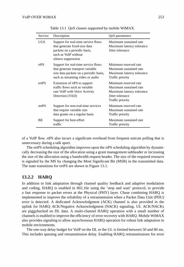
VoIP OVER WiMAX 253
Table 13.1 QoS classes supported by mobile WiMAX.
Service Description QoS parameters
UGS Support for real-time service flows Maximum sustained ratethat generate fixed-size data Maximum latency tolerancepackets on a periodic basis, Jitter tolerancesuch as VoIP withoutsilence suppression
rtPS Support for real-time service flows Minimum reserved ratethat generate transport variable Maximum sustained ratesize data packets on a periodic basis, Maximum latency tolerancesuch as streaming video or audio Traffic priority
ertPS Extension of rtPS to support Minimum reserved ratetraffic flows such as variable Maximum sustained raterate VoIP with Voice Activity Maximum latency toleranceDetection (VAD) Jitter tolerance
Traffic priority
nrtPS Support for non-real-time services Minimum reserved ratethat require variable size Maximum sustained ratedata grants on a regular basis Traffic priority
BE Support for best-effort Maximum sustained ratetraffic Traffic priority
of a VoIP flow. rtPS also incurs a significant overhead from frequent unicast polling that isunnecessary during a talk spurt.
The ertPS scheduling algorithm improves upon the rtPS scheduling algorithm by dynami-cally decreasing the size of the allocation using a grant management subheader or increasingthe size of the allocation using a bandwidth request header. The size of the required resourceis signaled by the MS by changing the Most Significant Bit (MSB) in the transmitted data.The state transitions for ertPS are shown in Figure 13.1.
13.2.2 HARQIn addition to link adaptation through channel quality feedback and adaptive modulationand coding, HARQ is enabled in 802.16e using the ‘stop and wait’ protocol, to providea fast response to packet errors at the Physical (PHY) layer. Chase combining HARQ isimplemented to improve the reliability of a retransmission when a Packet Data Unit (PDU)error is detected. A dedicated Acknowledgment (ACK) channel is also provided in theuplink for HARQ ACK/Negative Acknowledgment (NACK) signaling. UL ACK/NACKsare piggybacked on DL data. A multi-channel HARQ operation with a small number ofchannels is enabled to improve the efficiency of error recovery with HARQ. Mobile WiMAXalso provides signaling to allow asynchronous HARQ operation for robust link adaptation inmobile environments.
The one-way delay budget for VoIP on the DL or the UL is limited between 50 and 80 ms.This includes queuing and retransmission delay. Enabling HARQ retransmissions for error
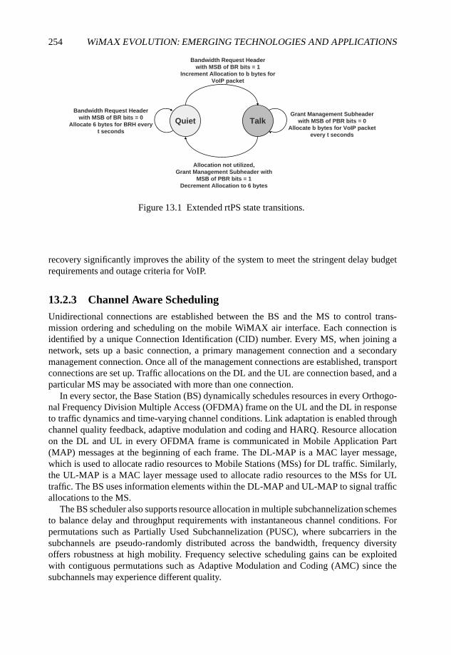
254 WiMAX EVOLUTION: EMERGING TECHNOLOGIES AND APPLICATIONS
Bandwidth Request Header
with MSB of BR bits = 0
Allocate 6 bytes for BRH every
t seconds
Quiet Talk
Allocation not utilized,
Grant Management Subheader with
MSB of PBR bits = 1
Decrement Allocation to 6 bytes
Bandwidth Request Header
with MSB of BR bits = 1
Increment Allocation to b bytes for
VoIP packet
Grant Management Subheader
with MSB of PBR bits = 0
Allocate b bytes for VoIP packet
every t seconds
Figure 13.1 Extended rtPS state transitions.
recovery significantly improves the ability of the system to meet the stringent delay budgetrequirements and outage criteria for VoIP.
13.2.3 Channel Aware SchedulingUnidirectional connections are established between the BS and the MS to control trans-mission ordering and scheduling on the mobile WiMAX air interface. Each connection isidentified by a unique Connection Identification (CID) number. Every MS, when joining anetwork, sets up a basic connection, a primary management connection and a secondarymanagement connection. Once all of the management connections are established, transportconnections are set up. Traffic allocations on the DL and the UL are connection based, and aparticular MS may be associated with more than one connection.
In every sector, the Base Station (BS) dynamically schedules resources in every Orthogo-nal Frequency Division Multiple Access (OFDMA) frame on the UL and the DL in responseto traffic dynamics and time-varying channel conditions. Link adaptation is enabled throughchannel quality feedback, adaptive modulation and coding and HARQ. Resource allocationon the DL and UL in every OFDMA frame is communicated in Mobile Application Part(MAP) messages at the beginning of each frame. The DL-MAP is a MAC layer message,which is used to allocate radio resources to Mobile Stations (MSs) for DL traffic. Similarly,the UL-MAP is a MAC layer message used to allocate radio resources to the MSs for ULtraffic. The BS uses information elements within the DL-MAP and UL-MAP to signal trafficallocations to the MS.
The BS scheduler also supports resource allocation in multiple subchannelization schemesto balance delay and throughput requirements with instantaneous channel conditions. Forpermutations such as Partially Used Subchannelization (PUSC), where subcarriers in thesubchannels are pseudo-randomly distributed across the bandwidth, frequency diversityoffers robustness at high mobility. Frequency selective scheduling gains can be exploitedwith contiguous permutations such as Adaptive Modulation and Coding (AMC) since thesubchannels may experience different quality.
VoIP OVER WiMAX 255
13.2.4 Protocol Header CompressionThe speech payload from the Adaptive Multi-Rate (AMR) vocoder (3G, 2007) operatingat 12.2 kbps is 33 bytes every 20 ms in the active state and 7 bytes every 160 ms in theinactive state. This payload is typically carried over RTP, UDP and IP. Protocol headersassociated with RTP, UDP and IP constitute 40 bytes with IPv4 and 60 bytes with IPv6.Excluding the 6 byte MAC header and 2 byte HARQ Cyclic Redundancy Check (CRC), it canbe seen that a significant portion of the VoIP packet transmitted over the air interface includesprotocol overheads. The fraction of overhead from protocol headers is even greater for VoIPpackets carrying speech samples from CODECs operating at lower bit rates (7.95 kbps) suchas Enhanced Variable Rate Codec (EVRC) or G.729.
To reduce the protocol header overhead, header compression techniques are typically usedfor VoIP. With Robust Header Compression (ROHC) (Bormann et al., 2001), the protocolheaders are compressed to about 3–4 bytes prior to transmission. Mobile WiMAX enablesheader compression with support for ROHC. The typical 802.16e VoIP packet size for AMRand G.729 CODECs is shown in Table 13.2.
13.3 Enhanced Features for Improved VoIP Capacity
In this section, we describe the characteristics of VoIP traffic that can be exploited to supportefficient scheduling of VoIP packets and the associated control signaling. Enhanced featuresthat provide significant improvement in VoIP capacity are also described in detail.
13.3.1 VoIP Traffic Characteristics
There are several characteristics of VoIP traffic that make VoIP packet scheduling chal-lenging: (a) VoIP packets are small in size; (b) number of VoIP users supported in a givenfrequency band is large compared with the number of high data rate users that can besupported; (c) the packet inter-arrival time is roughly constant; and (d) speech includesperiods of silence for roughly half the time and activity during the rest of the time.
The fact that the VoIP packet size is small makes the ratio of the resources needed fortransmitting control information to schedule VoIP to the resources needed for actual VoIPtraffic transmission much higher than that observed in data-only systems. Moreover, the highnumber of VoIP users supported in a given frequency band also adds to the total overheadrequired to transmit the control information related to the VoIP resource allocation.
In supporting high data rate applications, the focus is on optimizing the throughput, butin supporting VoIP the focus shifts towards delay sensitivity and minimizing the controloverhead associated with the VoIP resource allocation.
13.3.2 Dynamic Resource Allocation for VoIP
To support VoIP in an OFDMA system, VoIP packets need to be scheduled on the DL andthe UL within a fixed delay bound every time a packet arrives at the BS and at the MS,respectively. The OFDMA resources in frequency and time as well as transmit power andtransmission mode need to be specified in each allocation. Furthermore, the MS identificationand HARQ transmission related information also need to be specified. All this information
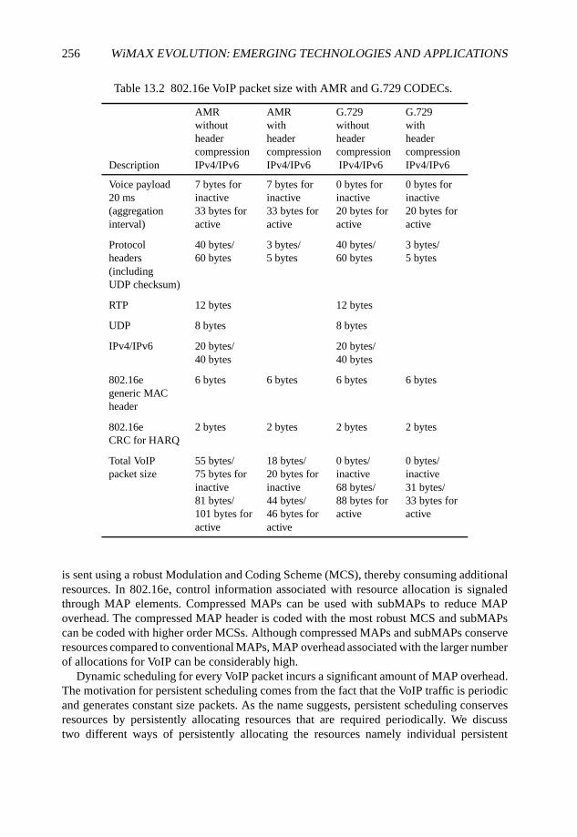
256 WiMAX EVOLUTION: EMERGING TECHNOLOGIES AND APPLICATIONS
Table 13.2 802.16e VoIP packet size with AMR and G.729 CODECs.
AMR AMR G.729 G.729without with without withheader header header headercompression compression compression compression
Description IPv4/IPv6 IPv4/IPv6 IPv4/IPv6 IPv4/IPv6
Voice payload 7 bytes for 7 bytes for 0 bytes for 0 bytes for20 ms inactive inactive inactive inactive(aggregation 33 bytes for 33 bytes for 20 bytes for 20 bytes forinterval) active active active active
Protocol 40 bytes/ 3 bytes/ 40 bytes/ 3 bytes/headers 60 bytes 5 bytes 60 bytes 5 bytes(includingUDP checksum)
RTP 12 bytes 12 bytes
UDP 8 bytes 8 bytes
IPv4/IPv6 20 bytes/ 20 bytes/40 bytes 40 bytes
802.16e 6 bytes 6 bytes 6 bytes 6 bytesgeneric MACheader
802.16e 2 bytes 2 bytes 2 bytes 2 bytesCRC for HARQ
Total VoIP 55 bytes/ 18 bytes/ 0 bytes/ 0 bytes/packet size 75 bytes for 20 bytes for inactive inactive
inactive inactive 68 bytes/ 31 bytes/81 bytes/ 44 bytes/ 88 bytes for 33 bytes for101 bytes for 46 bytes for active activeactive active
is sent using a robust Modulation and Coding Scheme (MCS), thereby consuming additionalresources. In 802.16e, control information associated with resource allocation is signaledthrough MAP elements. Compressed MAPs can be used with subMAPs to reduce MAPoverhead. The compressed MAP header is coded with the most robust MCS and subMAPscan be coded with higher order MCSs. Although compressed MAPs and subMAPs conserveresources compared to conventional MAPs, MAP overhead associated with the larger numberof allocations for VoIP can be considerably high.
Dynamic scheduling for every VoIP packet incurs a significant amount of MAP overhead.The motivation for persistent scheduling comes from the fact that the VoIP traffic is periodicand generates constant size packets. As the name suggests, persistent scheduling conservesresources by persistently allocating resources that are required periodically. We discusstwo different ways of persistently allocating the resources namely individual persistent
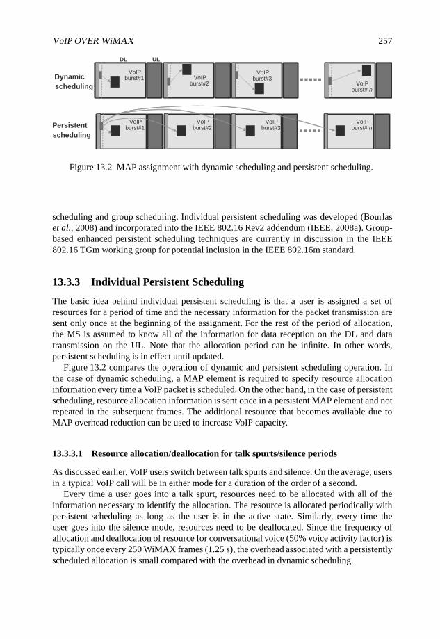
VoIP OVER WiMAX 257
VoIP
Burst#1
VoIP
Burst#2
VoIP
Burst#3
VoIP
Burst# nVoIP
burst#1VoIP
burst#2VoIP
burst#3VoIP
burst# nPersistent
scheduling
VoIP
Burst#1 VoIP
Burst#2
VoIP
Burst#3VoIP
Burst# n
DL UL
VoIP
Burst#1 VoIP
Burst#2
VoIP
Burst#3VoIP
Burst# n
VoIPburst#1 VoIP
burst#2
VoIPburst#3
VoIPburst# n
Dynamic
scheduling
Figure 13.2 MAP assignment with dynamic scheduling and persistent scheduling.
scheduling and group scheduling. Individual persistent scheduling was developed (Bourlaset al., 2008) and incorporated into the IEEE 802.16 Rev2 addendum (IEEE, 2008a). Group-based enhanced persistent scheduling techniques are currently in discussion in the IEEE802.16 TGm working group for potential inclusion in the IEEE 802.16m standard.
13.3.3 Individual Persistent Scheduling
The basic idea behind individual persistent scheduling is that a user is assigned a set ofresources for a period of time and the necessary information for the packet transmission aresent only once at the beginning of the assignment. For the rest of the period of allocation,the MS is assumed to know all of the information for data reception on the DL and datatransmission on the UL. Note that the allocation period can be infinite. In other words,persistent scheduling is in effect until updated.
Figure 13.2 compares the operation of dynamic and persistent scheduling operation. Inthe case of dynamic scheduling, a MAP element is required to specify resource allocationinformation every time a VoIP packet is scheduled. On the other hand, in the case of persistentscheduling, resource allocation information is sent once in a persistent MAP element and notrepeated in the subsequent frames. The additional resource that becomes available due toMAP overhead reduction can be used to increase VoIP capacity.
13.3.3.1 Resource allocation/deallocation for talk spurts/silence periods
As discussed earlier, VoIP users switch between talk spurts and silence. On the average, usersin a typical VoIP call will be in either mode for a duration of the order of a second.
Every time a user goes into a talk spurt, resources need to be allocated with all of theinformation necessary to identify the allocation. The resource is allocated periodically withpersistent scheduling as long as the user is in the active state. Similarly, every time theuser goes into the silence mode, resources need to be deallocated. Since the frequency ofallocation and deallocation of resource for conversational voice (50% voice activity factor) istypically once every 250 WiMAX frames (1.25 s), the overhead associated with a persistentlyscheduled allocation is small compared with the overhead in dynamic scheduling.
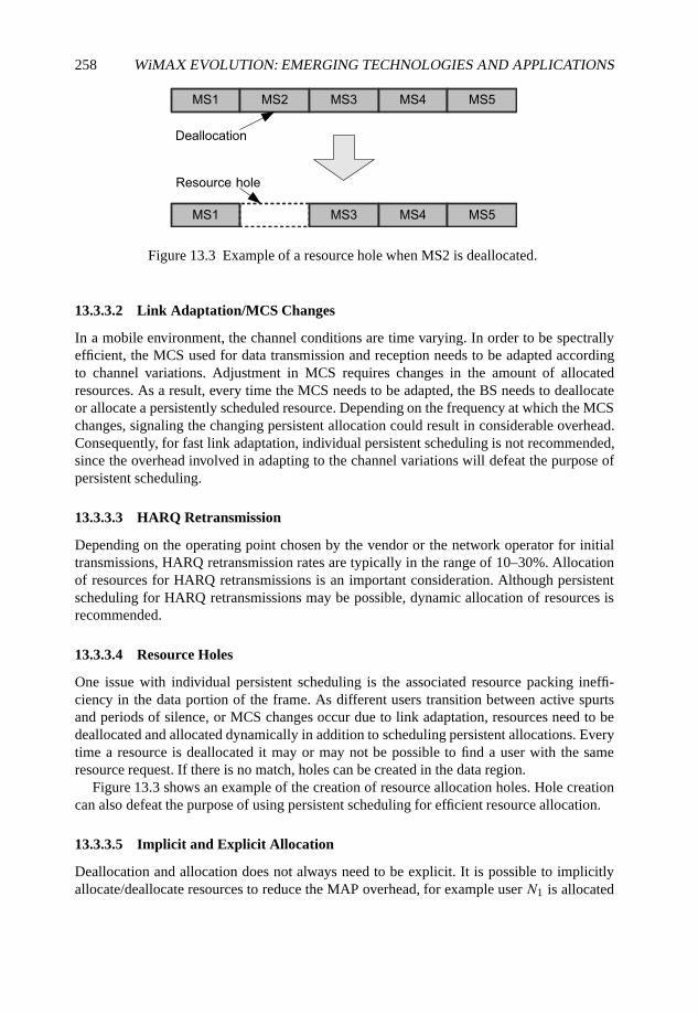
258 WiMAX EVOLUTION: EMERGING TECHNOLOGIES AND APPLICATIONS
Figure 13.3 Example of a resource hole when MS2 is deallocated.
13.3.3.2 Link Adaptation/MCS Changes
In a mobile environment, the channel conditions are time varying. In order to be spectrallyefficient, the MCS used for data transmission and reception needs to be adapted accordingto channel variations. Adjustment in MCS requires changes in the amount of allocatedresources. As a result, every time the MCS needs to be adapted, the BS needs to deallocateor allocate a persistently scheduled resource. Depending on the frequency at which the MCSchanges, signaling the changing persistent allocation could result in considerable overhead.Consequently, for fast link adaptation, individual persistent scheduling is not recommended,since the overhead involved in adapting to the channel variations will defeat the purpose ofpersistent scheduling.
13.3.3.3 HARQ Retransmission
Depending on the operating point chosen by the vendor or the network operator for initialtransmissions, HARQ retransmission rates are typically in the range of 10–30%. Allocationof resources for HARQ retransmissions is an important consideration. Although persistentscheduling for HARQ retransmissions may be possible, dynamic allocation of resources isrecommended.
13.3.3.4 Resource Holes
One issue with individual persistent scheduling is the associated resource packing ineffi-ciency in the data portion of the frame. As different users transition between active spurtsand periods of silence, or MCS changes occur due to link adaptation, resources need to bedeallocated and allocated dynamically in addition to scheduling persistent allocations. Everytime a resource is deallocated it may or may not be possible to find a user with the sameresource request. If there is no match, holes can be created in the data region.
Figure 13.3 shows an example of the creation of resource allocation holes. Hole creationcan also defeat the purpose of using persistent scheduling for efficient resource allocation.
13.3.3.5 Implicit and Explicit Allocation
Deallocation and allocation does not always need to be explicit. It is possible to implicitlyallocate/deallocate resources to reduce the MAP overhead, for example user N1 is allocated
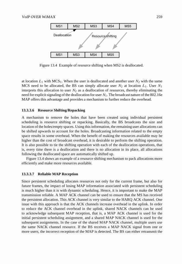
VoIP OVER WiMAX 259
shiftingResource
Figure 13.4 Example of resource shifting when MS2 is deallocated.
at location L1 with MCS1. When the user is deallocated and another user N2 with the sameMCS need to be allocated, the BS can simply allocate user N2 at location L1. User N1interprets this allocation to user N2 as a deallocation of resources, thereby eliminating theneed for explicit signaling of the deallocation for userN1. The broadcast nature of the 802.16eMAP offers this advantage and provides a mechanism to further reduce the overhead.
13.3.3.6 Resource Shifting/Repacking
A mechanism to remove the holes that have been created using individual persistentscheduling is resource shifting or repacking. Basically, the BS broadcasts the size andlocation of the holes/empty spaces. Using this information, the remaining user allocations canbe shifted upwards to account for the holes. Broadcasting information related to the emptyspace results in some overhead. When the benefit of making the resources available may behigher than the cost of broadcast overhead, it is desirable to perform the shifting operation.It is also possible to tie the shifting operation with each of the deallocation operations, thatis, every time there is a deallocation and there is no allocation in its place, all allocationsfollowing the deallocated space are automatically shifted up.
Figure 13.4 shows an example of a resource shifting mechanism to pack allocations moreefficiently and make more resources available.
13.3.3.7 Reliable MAP Reception
Since persistent scheduling allocates resources not only for the current frame, but also forfuture frames, the impact of losing MAP information associated with persistent schedulingis much higher than it is with dynamic scheduling. Hence, it is important to make the MAPtransmission reliable. A MAP ACK channel can be used to ensure that the MS has receivedthe persistent allocation. This ACK channel is very similar to the HARQ ACK channel. Oneissue with this approach is that the ACK channels increase overhead in the uplink. In orderto reduce the ACK channel overhead in the uplink, shared NACK channels can be usedto acknowledge subsequent MAP reception, that is, a MAP ACK channel is used for theinitial persistent scheduling assignment, and a shared MAP NACK channel is used for thesubsequent assignments. In the case of the shared MAP NACK channel, multiple users usethe same NACK channel resource. If the BS receives a MAP NACK signal from one ormore users, the incorrect reception of the MAP is detected. The BS can either retransmit the
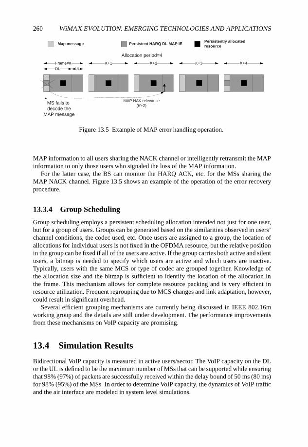
260 WiMAX EVOLUTION: EMERGING TECHNOLOGIES AND APPLICATIONS
Map message Persistent HARQ DL MAP IE
Frame#K K+1 K+2 K+3
Persistently allocated
resource
DL UL
MS fails to
decode the
MAP message
MAP NAK relevance
(K+2)
Allocation period=4
K+4
Figure 13.5 Example of MAP error handling operation.
MAP information to all users sharing the NACK channel or intelligently retransmit the MAPinformation to only those users who signaled the loss of the MAP information.
For the latter case, the BS can monitor the HARQ ACK, etc. for the MSs sharing theMAP NACK channel. Figure 13.5 shows an example of the operation of the error recoveryprocedure.
13.3.4 Group Scheduling
Group scheduling employs a persistent scheduling allocation intended not just for one user,but for a group of users. Groups can be generated based on the similarities observed in users’channel conditions, the codec used, etc. Once users are assigned to a group, the location ofallocations for individual users is not fixed in the OFDMA resource, but the relative positionin the group can be fixed if all of the users are active. If the group carries both active and silentusers, a bitmap is needed to specify which users are active and which users are inactive.Typically, users with the same MCS or type of codec are grouped together. Knowledge ofthe allocation size and the bitmap is sufficient to identify the location of the allocation inthe frame. This mechanism allows for complete resource packing and is very efficient inresource utilization. Frequent regrouping due to MCS changes and link adaptation, however,could result in significant overhead.
Several efficient grouping mechanisms are currently being discussed in IEEE 802.16mworking group and the details are still under development. The performance improvementsfrom these mechanisms on VoIP capacity are promising.
13.4 Simulation Results
Bidirectional VoIP capacity is measured in active users/sector. The VoIP capacity on the DLor the UL is defined to be the maximum number of MSs that can be supported while ensuringthat 98% (97%) of packets are successfully received within the delay bound of 50 ms (80 ms)for 98% (95%) of the MSs. In order to determine VoIP capacity, the dynamics of VoIP trafficand the air interface are modeled in system level simulations.
VoIP OVER WiMAX 261
A typical 19 cell network topology with wrap-around is used to model the system. MSsare dropped independently with uniform distribution throughout the system. In addition toaccounting for wireless channel variations from path loss and shadow fading in systemsimulations, mobiles are assigned channel models to simulate fast fading corresponding to amixed mobility scenario with 60% ITU Pedestrian-B at 3 km hour−1, 30% ITU Vehicular-A at 30 km hour−1 and 10% ITU Vehicular-A at 120 km hour−1. Fading signal and fadinginterference are computed from each MS into each sector and from each sector to each mobilefor each simulation interval. Channel quality feedback delay and Packet Data Unit errorsare modeled and packets are retransmitted as necessary. Asynchronous, nonadaptive, chasecombining HARQ is modeled by explicitly rescheduling a packet after a two-frame HARQfeedback delay period.
Each mobile in the system corresponds to an active VoIP session. A series of VoIP packetsis generated using a simplified on/off Markov model of the AMR vocoder operating at12.2 kbps and a voice activity factor of 50% (40%) to model the speech source dynamics.During active speech, the 44 byte VoIP packets are generated every 20 ms, and in periods ofinactivity, 18 byte packets are generated every 160 ms. The packet size includes the vocoderpayload, compressed RTP/UDP/IP header, 802.16e generic MAC header and CRC.
System parameters are configured according to the WiMAX Forum Wave II SystemProfile (Release 1.0) (WiMAX Forum, 2007) for PUSC. A TDD test scenario with frequencyreuse of 1 corresponding to the baseline configuration and simulation assumptions inSection 2 of the 802.16m evaluation methodology (IEEE, 2008b) is used for performanceevaluation. A 2 × 2 antenna configuration on the downlink and a 1 × 2 configuration on theuplink were modeled. Adaptive Multiple Input Multiple Output (MIMO) Switching (AMS)between open loop transmit diversity (matrix A) and spatial multiplexing (matrix B) wasimplemented at the BS. Collaborative Spatial Multiplexing (CSM) was implemented on theuplink. Transmission of MAP signaling was limited to one transmit antenna and two receiveantennas.
MAP overhead is dynamically modeled in the simulations using compressed MAPs andthree sub-MAPs. Channel aware scheduling and link adaptation are used in the simulationsto model the VoIP packet allocations and the corresponding MAP overhead that changefrom frame to frame. The downlink overhead includes overhead for uplink assignments. Inaddition, MAP errors were taken into consideration.
A system bandwidth of 10 MHz was assumed for all simulations. The 5 ms Time DivisionDuplex (TDD) frame was split with 23 Orthogonal Frequency Division Multiplex (OFDM)symbols for the DL, and 24 symbols for the UL when dynamic scheduling was used. In thecase of persistent scheduling using the baseline IE defined in IEEE (2008a) and Bourlas et al.(2008), 20 symbols were allocated to the DL , while the UL was allocated 27 symbols. Sincethe system is UL limited, the overhead reduction from persistent scheduling was used toincrease the available UL resource and thereby increase overall bidirectional VoIP capacity.Table 13.3 provides a comparison of VoIP capacity with dynamic and persistent scheduling.The system simulation results for two definitions of outage criteria show a reduction in MAPoverhead from about 10 symbols to about 6 symbols and a 15% improvement in systemcapacity. It must be noted that features such as AMC and closed loop MIMO that are currentlysupported in IEEE (2008a) and expected to provide additional capacity gains have not beensimulated.
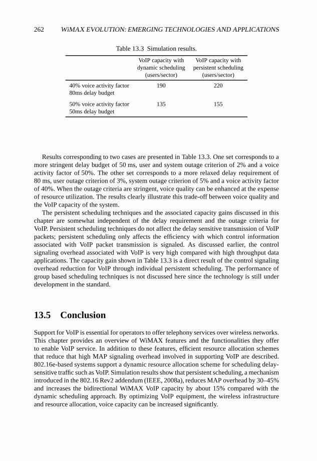
262 WiMAX EVOLUTION: EMERGING TECHNOLOGIES AND APPLICATIONS
Table 13.3 Simulation results.
VoIP capacity with VoIP capacity withdynamic scheduling persistent scheduling
(users/sector) (users/sector)
40% voice activity factor 190 22080ms delay budget
50% voice activity factor 135 15550ms delay budget
Results corresponding to two cases are presented in Table 13.3. One set corresponds to amore stringent delay budget of 50 ms, user and system outage criterion of 2% and a voiceactivity factor of 50%. The other set corresponds to a more relaxed delay requirement of80 ms, user outage criterion of 3%, system outage criterion of 5% and a voice activity factorof 40%. When the outage criteria are stringent, voice quality can be enhanced at the expenseof resource utilization. The results clearly illustrate this trade-off between voice quality andthe VoIP capacity of the system.
The persistent scheduling techniques and the associated capacity gains discussed in thischapter are somewhat independent of the delay requirement and the outage criteria forVoIP. Persistent scheduling techniques do not affect the delay sensitive transmission of VoIPpackets; persistent scheduling only affects the efficiency with which control informationassociated with VoIP packet transmission is signaled. As discussed earlier, the controlsignaling overhead associated with VoIP is very high compared with high throughput dataapplications. The capacity gain shown in Table 13.3 is a direct result of the control signalingoverhead reduction for VoIP through individual persistent scheduling. The performance ofgroup based scheduling techniques is not discussed here since the technology is still underdevelopment in the standard.
13.5 Conclusion
Support for VoIP is essential for operators to offer telephony services over wireless networks.This chapter provides an overview of WiMAX features and the functionalities they offerto enable VoIP service. In addition to these features, efficient resource allocation schemesthat reduce that high MAP signaling overhead involved in supporting VoIP are described.802.16e-based systems support a dynamic resource allocation scheme for scheduling delay-sensitive traffic such as VoIP. Simulation results show that persistent scheduling, a mechanismintroduced in the 802.16 Rev2 addendum (IEEE, 2008a), reduces MAP overhead by 30–45%and increases the bidirectional WiMAX VoIP capacity by about 15% compared with thedynamic scheduling approach. By optimizing VoIP equipment, the wireless infrastructureand resource allocation, voice capacity can be increased significantly.
VoIP OVER WiMAX 263
Acknowledgements
The authors would like to thank their colleagues, Apostolos Papthanassiou and ShailenderTimiri in the Mobile Wireless Group and Shweta Shrivastava in the Corporate TechnologyGroup at Intel Corporation, as well as Mohammad Mamunur Rashid, a student intern from theUniversity of British Colombia, for fruitful discussions in defining and developing simulationmodels.
References
3G (2007) 3G Technical Specification 26.071, Mandatory speech CODEC speech processing functions;AMR speed CODEC; General description, July 2007.
3GPP (2007) TS 36.201 V8.1.0, Technical Specification Group Radio Access Network EvolvedUniversal Terrestrial Radio Access (E-UTRA); LTE Physical Layer - General Description(Release 8), November 2007.
3GPP2 (2007) C.S0084 v2.0, Ultra Mobile Broadband (UMB) Air Interface Specification, September2007.
Bormann, C. et al. (2001) Request for Comments 3095, RObust Header Compression (ROHC):Framework and four profiles: RTP, UDP, ESP, and uncompressed, July 2001.
Bourlas, Y., Etemad, K., Fong, M. Lavi, N., Lim, G., Lu, J. McBeath, S. and Oh, C. (2008), IEEE802.16maint-08/095r4, Persistent Allocation, IEEE 802.16 Broadband Wireless Access WorkingGroup.
Ericson, M., Wanstedt, S. and Ericson, P.J. (2006) Effects of simultaneous circuit and packet switchedvoice traffic on total capacity. Proceedings of the 2006 Spring IEEE Vehicle Technology Conference,May 2006.
IEEE (2006) 802.16e-2005, IEEE Standard for Local and Metropolitan Area Networks – Part 16: AirInterface for Fixed and Mobile Broadband Wireless Access Systems - Amendment 2: Physical andMedium Access Control Layers for Combined Fixed and Mobile Operation in Licensed Bands andCorrigendum 1, February 28, 2006.
IEEE (2008a) P802.16Rev2/D4, Draft Standard for Local and Metropolitan Area Networks – Part 16:Air Interface for Fixed and Mobile Broadband Wireless Access Systems, May 2008.
IEEE (2008b) 802.16m-08/004r1, Project IEEE 802.16m Evaluation Methodology,http://www.ieee802.org/16/tgm/docs/80216m-08_004r2.pdf, May 2008.
WiMAX Forum (2006) Mobile WiMAX - Part I: A Technical Overview and Performance Evaluation,White Paper,http://www.wimaxforum.org/news/downloads/Mobile_WiMAX_Part1_Overview_and_Performance.pdf,August 2006.
WiMAX Forum (2007) Mobile System Profile, Release 1.0 Approved Specification (Revision 1.4.0:2007-05-02), http://www.wimaxforum.org/technology/documents.
Yavuz, M., Diaz, D., Kapoor, R., Grob, M., Black, P., Tokgoz, Y. and Lott, C. (2006) VoIP overcdma2000 1xEV-DO, IEEE Communications Magazine, 44(2), 88–95.
14
WiMAX User Data LoadBalancing
Alexander Bachmutsky
14.1 Introduction
Load balancing is an important topic, and it has started to appear frequently on the radar ofmany WiMAX vendors. The WiMAX Forum does not discuss load balancing functionalityformally at any level, and one can barely find that term in the latest specification, but theincreasing number of contributions has raised the topic as a reason for the requested change.Some discussions are concentrated on signaling load balancing, others on mobile subscribersbalancing between different network elements in the WiMAX network.
There are many aspects for load balancing. One way to achieve it is to perform R3/R4/R6handovers when appropriate to create more evenly loaded paths. Another way is to terminatethe traffic at different points in the network by means of local breakout at different levels. Yetanother is to perform network level load balancing. The latter two are described here.
14.2 Local Breakout Use for Load Balancing
Local breakout is another controversial topic that received little attention in the standard.It was in fact raised multiple times on different occasions by different TelecommunicationEquipment Manufacturers (TEMs), but was not very well accepted by the operators. Themain reason, of course, is a revenue split between visited and home operators in the roamingscenarios. However, that is not what we discuss here, because from a load-balancing point ofview the roaming traffic is a relatively small percentage of the total traffic, so that topic canwait until some bigger problems are solved.
WiMAX Evolution: Emerging Technologies and Applications Edited by Tsutomu Ishikawa© 2009 John Wiley & Sons, Ltd. ISBN: 978-0-470-69680-4
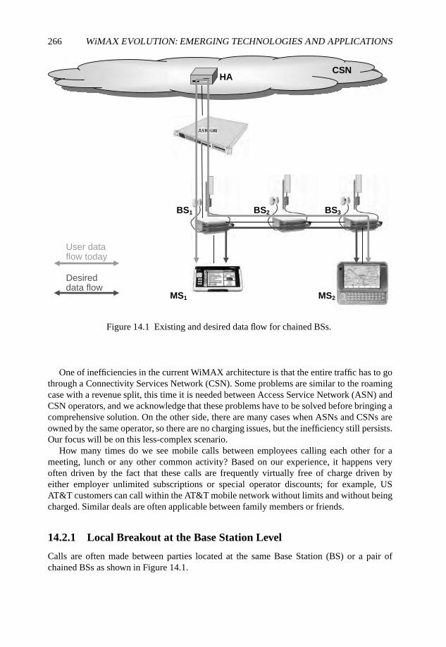
266 WiMAX EVOLUTION: EMERGING TECHNOLOGIES AND APPLICATIONS
BS1
MS1
HACSN
BS2 BS3
MS2
User dataflow today
Desireddata flow
Figure 14.1 Existing and desired data flow for chained BSs.
One of inefficiencies in the current WiMAX architecture is that the entire traffic has to gothrough a Connectivity Services Network (CSN). Some problems are similar to the roamingcase with a revenue split, this time it is needed between Access Service Network (ASN) andCSN operators, and we acknowledge that these problems have to be solved before bringing acomprehensive solution. On the other side, there are many cases when ASNs and CSNs areowned by the same operator, so there are no charging issues, but the inefficiency still persists.Our focus will be on this less-complex scenario.
How many times do we see mobile calls between employees calling each other for ameeting, lunch or any other common activity? Based on our experience, it happens veryoften driven by the fact that these calls are frequently virtually free of charge driven byeither employer unlimited subscriptions or special operator discounts; for example, USAT&T customers can call within the AT&T mobile network without limits and without beingcharged. Similar deals are often applicable between family members or friends.
14.2.1 Local Breakout at the Base Station Level
Calls are often made between parties located at the same Base Station (BS) or a pair ofchained BSs as shown in Figure 14.1.
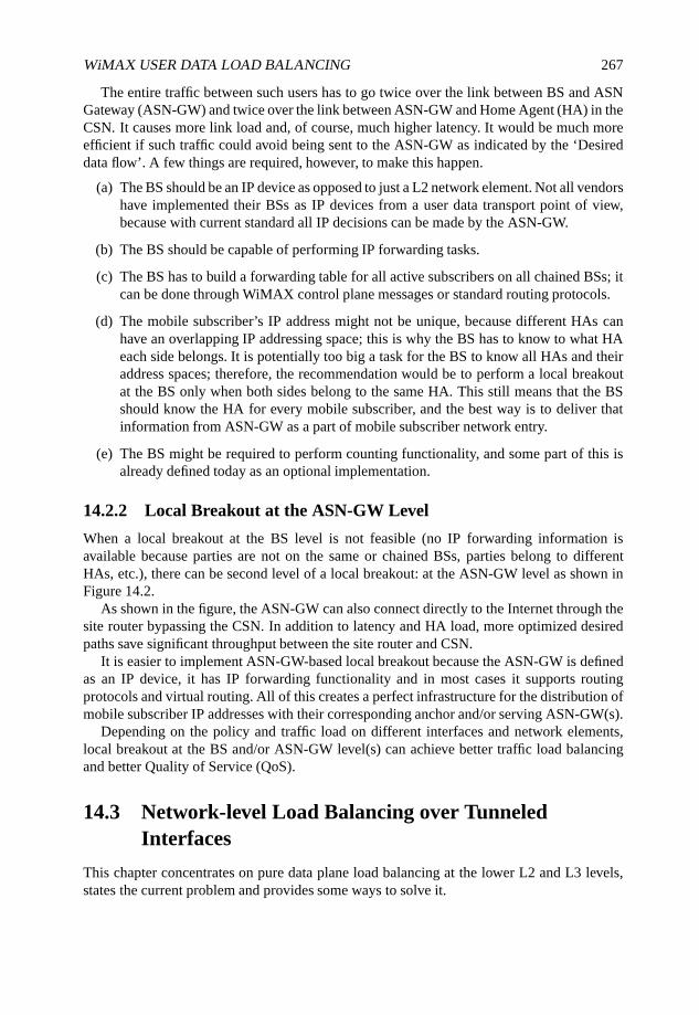
WiMAX USER DATA LOAD BALANCING 267
The entire traffic between such users has to go twice over the link between BS and ASNGateway (ASN-GW) and twice over the link between ASN-GW and Home Agent (HA) in theCSN. It causes more link load and, of course, much higher latency. It would be much moreefficient if such traffic could avoid being sent to the ASN-GW as indicated by the ‘Desireddata flow’. A few things are required, however, to make this happen.
(a) The BS should be an IP device as opposed to just a L2 network element. Not all vendorshave implemented their BSs as IP devices from a user data transport point of view,because with current standard all IP decisions can be made by the ASN-GW.
(b) The BS should be capable of performing IP forwarding tasks.
(c) The BS has to build a forwarding table for all active subscribers on all chained BSs; itcan be done through WiMAX control plane messages or standard routing protocols.
(d) The mobile subscriber’s IP address might not be unique, because different HAs canhave an overlapping IP addressing space; this is why the BS has to know to what HAeach side belongs. It is potentially too big a task for the BS to know all HAs and theiraddress spaces; therefore, the recommendation would be to perform a local breakoutat the BS only when both sides belong to the same HA. This still means that the BSshould know the HA for every mobile subscriber, and the best way is to deliver thatinformation from ASN-GW as a part of mobile subscriber network entry.
(e) The BS might be required to perform counting functionality, and some part of this isalready defined today as an optional implementation.
14.2.2 Local Breakout at the ASN-GW Level
When a local breakout at the BS level is not feasible (no IP forwarding information isavailable because parties are not on the same or chained BSs, parties belong to differentHAs, etc.), there can be second level of a local breakout: at the ASN-GW level as shown inFigure 14.2.
As shown in the figure, the ASN-GW can also connect directly to the Internet through thesite router bypassing the CSN. In addition to latency and HA load, more optimized desiredpaths save significant throughput between the site router and CSN.
It is easier to implement ASN-GW-based local breakout because the ASN-GW is definedas an IP device, it has IP forwarding functionality and in most cases it supports routingprotocols and virtual routing. All of this creates a perfect infrastructure for the distribution ofmobile subscriber IP addresses with their corresponding anchor and/or serving ASN-GW(s).
Depending on the policy and traffic load on different interfaces and network elements,local breakout at the BS and/or ASN-GW level(s) can achieve better traffic load balancingand better Quality of Service (QoS).
14.3 Network-level Load Balancing over TunneledInterfaces
This chapter concentrates on pure data plane load balancing at the lower L2 and L3 levels,states the current problem and provides some ways to solve it.
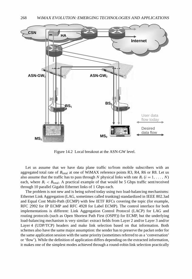
268 WiMAX EVOLUTION: EMERGING TECHNOLOGIES AND APPLICATIONS
BS1
MS1
HACSN
BS2
MS2
ASN-GW1 WG-NSA 2
Internet
User dataflow today
Desireddata flow
Figure 14.2 Local breakout at the ASN-GW level.
Let us assume that we have data plane traffic to/from mobile subscribers with anaggregated total rate of Btotal at one of WiMAX reference points R3, R4, R6 or R8. Let usalso assume that the traffic has to pass through N physical links with rate Bi (i = 1, . . . , N)each, where Bi < Btotal. A practical example of that would be 5 Gbps traffic sent/receivedthrough 10 parallel Gigabit Ethernet links of 1 Gbps each.
The problem is not new and is being solved today using two load-balancing mechanisms:Ethernet Link Aggregation (LAG, sometimes called trunking) standardized in IEEE 802.3adand Equal Cost Multi-Path (ECMP) with few IETF RFCs covering the topic (for example,RFC 2992 for IP ECMP and RFC 4928 for Label ECMP). The control interface for bothimplementations is different: Link Aggregation Control Protocol (LACP) for LAG androuting protocols (such as Open Shortest Path First (OSPF)) for ECMP, but the underlyingload-balancing mechanism is very similar: extract fields from Layer 2 and/or Layer 3 and/orLayer 4 (UDP/TCP) headers and make link selection based on that information. Bothschemes also have the same major assumption: the sender has to preserve the packet order forthe same application session with the same priority (sometimes referred to as a ‘conversation’or ‘flow’). While the definition of application differs depending on the extracted information,it makes one of the simplest modes achieved through a round-robin link selection practically
WiMAX USER DATA LOAD BALANCING 269
useless. The reason for this is that even in parallel links connected between two physicaldevices we cannot always ensure that the receiving order of packets will be the same asa sending order, because every link has its own queues and QoS, and every packet hasa potentially different size causing different transmit times for all previous messages incorresponding interface queues. Some link types will also cause delayed transmit (such asEthernet congestion control) or end-to-end retransmits in the case of error detection. Thismeans that we have to send all packets for the same application over the same physical link.The usual implementation is to hash the extracted information and select a link based on thehash value.
One of important properties of load-balancing schemes is in making the treatment ofapplication/flow in the network consistent, because load balancing can be applied multipletimes between different network elements while passing messages from source to destination.On the other side, it is frequently impossible to ensure exactly the same configuration in alldevices, especially if the packet passes through multiple networks that belong to differenttransport providers. For example, if one device has a better knowledge of ‘real’ flows byinterpreting some application-level flow identifications, it can apply that knowledge to thelocal load-balancing scheme for LAG or ECMP, but it will be hard or impossible to enforcethe same treatment in already deployed Layer 2 or Layer 3 switches and routers.
14.3.1 Is WiMAX Special for the Case of Traffic Load Balancing?All of the above is fairly generic and can be applied to most networks. So what is unique inWiMAX networks?
Actually, the problem is not WiMAX-specific. It is the same problem for any tunneledtraffic, but WiMAX is one of the first to suffer because it brings multi-gigabit traffic intothe network while higher capacity interfaces (10 Gbps and higher) are too expensive ornonexistent.
It is the easiest to explain the problem using the traffic on R3 reference point for a MobileIPv4-based WiMAX network. In MIPv4 architecture (RFC 3344 - IP Mobility Support forIPv4) all user traffic has to flow through Foreign Agents (FAs) and HAs. All user packetsare encapsulated between FAs and HAs into a tunnel (we use IP-in-IP in our example, butGeneric Routing Encapsulation (GRE) or any other tunnel will have the same issues). Thismeans that from the point of view of the network devices between FAs and HAs the entireuser traffic for all mobile subscribers is a single IP flow between the FA IP address and the HAIP address. There is no differentiation at Layer 4, because the entire traffic has a single IP-in-IP protocol. From the LAG and ECMP points of view there is only a single conversation/flow.The entire traffic can be represented by the diagram in Figure 14.3 (the assumption in thisexample is the multi-gigabit traffic with Gigabit Ethernet interfaces).
Having a single conversation would mean that switches and routers will not be able toperform load balancing and will use a single link to transfer the data, and a significantportion of that data (everything above 1 Gbps) will be dropped. Of course, this is absolutelyunacceptable.
14.3.2 Analysis of Possible SolutionsIt is obvious that this problem has to be solved. There are multiple layers of possible solutions,from the physical layer to the application layer; some are WiMAX-independent, others areWiMAX-specific.
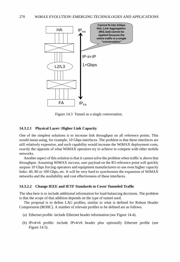
270 WiMAX EVOLUTION: EMERGING TECHNOLOGIES AND APPLICATIONS
HA
L2/L3
FA
IP-in-IP
1+Gbps
IPHA
IPFA
Cannot fit into 1Gbps
link; Link Aggregation
(802.3ad) cannot be
applied because the
entire traffic is a single
“conversation”
Figure 14.3 Tunnel as a single conversation.
14.3.2.1 Physical Layer: Higher Link Capacity
One of the simplest solutions is to increase link throughput on all reference points. Thiswould mean using, for example, 10 Gbps interfaces. The problem is that these interfaces arestill relatively expensive, and such capability would increase the WiMAX deployment costs,exactly the opposite of what WiMAX operators try to achieve to compete with other mobilenetworks.
Another aspect of this solution is that it cannot solve the problem when traffic is above thatthroughput. Assuming WiMAX success, user payload on the R3 reference point will quicklysurpass 10 Gbps forcing operators and equipment manufacturers to use even higher capacitylinks: 40, 80 or 100 Gbps, etc. It will be very hard to synchronize the expansion of WiMAXnetworks and the availability and cost effectiveness of these interfaces.
14.3.2.2 Change IEEE and IETF Standards to Cover Tunneled Traffic
The idea here is to include additional information for load-balancing decisions. The problemis that the scope of that addition depends on the type of tunnel used.
The proposal is to define LAG profiles, similar to what is defined for Robust HeaderCompression (ROHC). A number of relevant profiles to be defined are as follows.
(a) Ethernet profile: include Ethernet header information (see Figure 14.4).
(b) IPv4/v6 profile: include IPv4/v6 header plus optionally Ethernet profile (seeFigure 14.5).
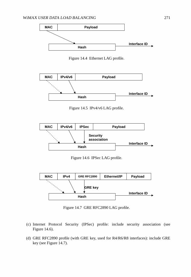
WiMAX USER DATA LOAD BALANCING 271
MAC Payload
Hash Interface ID
Figure 14.4 Ethernet LAG profile.
MAC Payload
Hash Interface ID
IPv4/v6
Figure 14.5 IPv4/v6 LAG profile.
MAC Payload
Hash Interface ID
IPv4/v6 IPSec
Securityassociation
Figure 14.6 IPSec LAG profile.
MAC Payload
Hash Interface ID
IPv4 GRE RFC2890 Ethernet/IP
GRE key
Figure 14.7 GRE RFC2890 LAG profile.
(c) Internet Protocol Security (IPSec) profile: include security association (seeFigure 14.6).
(d) GRE RFC2890 profile (with GRE key, used for R4/R6/R8 interfaces): include GREkey (see Figure 14.7).
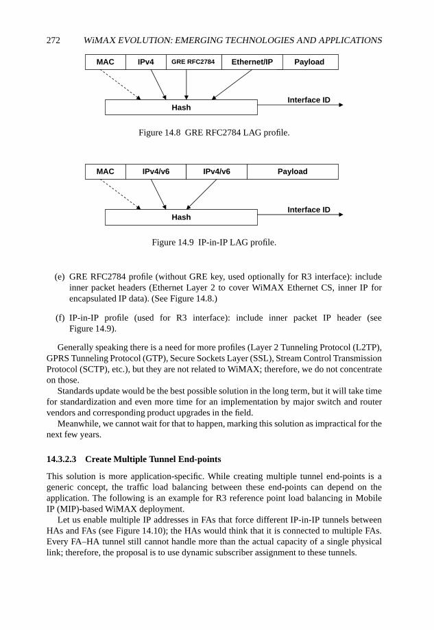
272 WiMAX EVOLUTION: EMERGING TECHNOLOGIES AND APPLICATIONS
MAC Payload
Hash Interface ID
IPv4 GRE RFC2784 Ethernet/IP
Figure 14.8 GRE RFC2784 LAG profile.
MAC Payload
Hash Interface ID
IPv4/v6 IPv4/v6
Figure 14.9 IP-in-IP LAG profile.
(e) GRE RFC2784 profile (without GRE key, used optionally for R3 interface): includeinner packet headers (Ethernet Layer 2 to cover WiMAX Ethernet CS, inner IP forencapsulated IP data). (See Figure 14.8.)
(f) IP-in-IP profile (used for R3 interface): include inner packet IP header (seeFigure 14.9).
Generally speaking there is a need for more profiles (Layer 2 Tunneling Protocol (L2TP),GPRS Tunneling Protocol (GTP), Secure Sockets Layer (SSL), Stream Control TransmissionProtocol (SCTP), etc.), but they are not related to WiMAX; therefore, we do not concentrateon those.
Standards update would be the best possible solution in the long term, but it will take timefor standardization and even more time for an implementation by major switch and routervendors and corresponding product upgrades in the field.
Meanwhile, we cannot wait for that to happen, marking this solution as impractical for thenext few years.
14.3.2.3 Create Multiple Tunnel End-points
This solution is more application-specific. While creating multiple tunnel end-points is ageneric concept, the traffic load balancing between these end-points can depend on theapplication. The following is an example for R3 reference point load balancing in MobileIP (MIP)-based WiMAX deployment.
Let us enable multiple IP addresses in FAs that force different IP-in-IP tunnels betweenHAs and FAs (see Figure 14.10); the HAs would think that it is connected to multiple FAs.Every FA–HA tunnel still cannot handle more than the actual capacity of a single physicallink; therefore, the proposal is to use dynamic subscriber assignment to these tunnels.
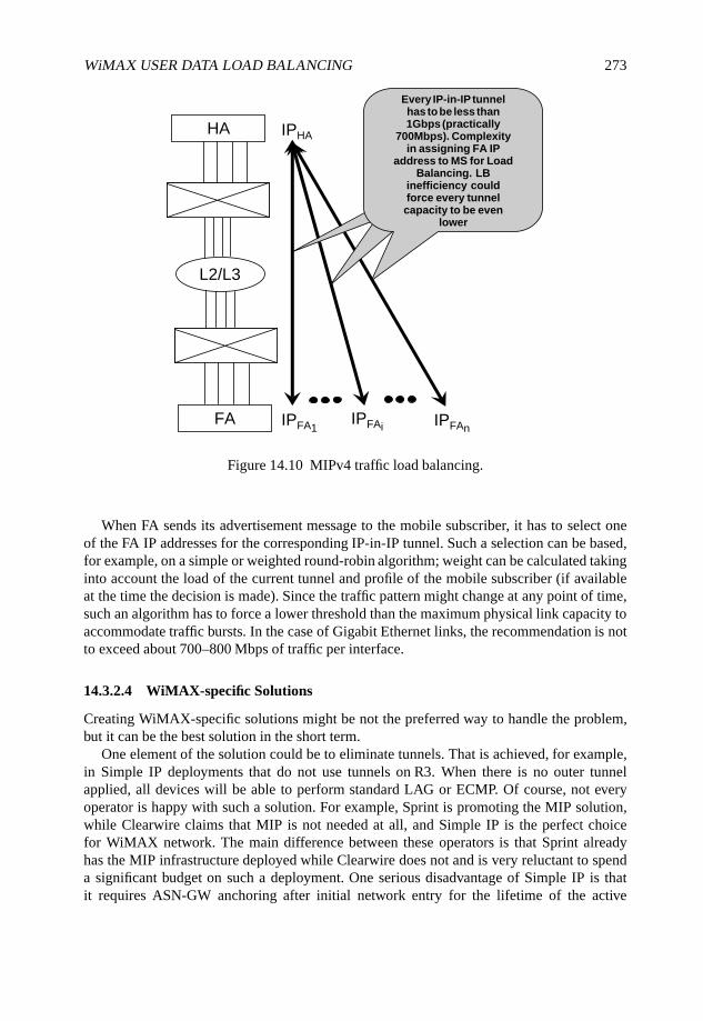
WiMAX USER DATA LOAD BALANCING 273
HA
L2/L3
FA
IPHA
IPFA1IPFAi IPFAn
Every IP-in-IP tunnelhas to be less than1Gbps (practically
700Mbps). Complexityin assigning FA IP
address to MS for LoadBalancing. LB
inefficiency couldforce every tunnelcapacity to be even
lower
Figure 14.10 MIPv4 traffic load balancing.
When FA sends its advertisement message to the mobile subscriber, it has to select oneof the FA IP addresses for the corresponding IP-in-IP tunnel. Such a selection can be based,for example, on a simple or weighted round-robin algorithm; weight can be calculated takinginto account the load of the current tunnel and profile of the mobile subscriber (if availableat the time the decision is made). Since the traffic pattern might change at any point of time,such an algorithm has to force a lower threshold than the maximum physical link capacity toaccommodate traffic bursts. In the case of Gigabit Ethernet links, the recommendation is notto exceed about 700–800 Mbps of traffic per interface.
14.3.2.4 WiMAX-specific Solutions
Creating WiMAX-specific solutions might be not the preferred way to handle the problem,but it can be the best solution in the short term.
One element of the solution could be to eliminate tunnels. That is achieved, for example,in Simple IP deployments that do not use tunnels on R3. When there is no outer tunnelapplied, all devices will be able to perform standard LAG or ECMP. Of course, not everyoperator is happy with such a solution. For example, Sprint is promoting the MIP solution,while Clearwire claims that MIP is not needed at all, and Simple IP is the perfect choicefor WiMAX network. The main difference between these operators is that Sprint alreadyhas the MIP infrastructure deployed while Clearwire does not and is very reluctant to spenda significant budget on such a deployment. One serious disadvantage of Simple IP is thatit requires ASN-GW anchoring after initial network entry for the lifetime of the active
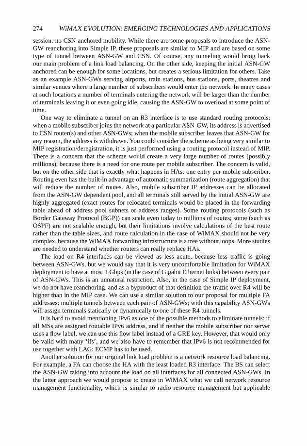
274 WiMAX EVOLUTION: EMERGING TECHNOLOGIES AND APPLICATIONS
session: no CSN anchored mobility. While there are some proposals to introduce the ASN-GW reanchoring into Simple IP, these proposals are similar to MIP and are based on sometype of tunnel between ASN-GW and CSN. Of course, any tunneling would bring backour main problem of a link load balancing. On the other side, keeping the initial ASN-GWanchored can be enough for some locations, but creates a serious limitation for others. Takeas an example ASN-GWs serving airports, train stations, bus stations, ports, theatres andsimilar venues where a large number of subscribers would enter the network. In many casesat such locations a number of terminals entering the network will be larger than the numberof terminals leaving it or even going idle, causing the ASN-GW to overload at some point oftime.
One way to eliminate a tunnel on an R3 interface is to use standard routing protocols:when a mobile subscriber joins the network at a particular ASN-GW, its address is advertisedto CSN router(s) and other ASN-GWs; when the mobile subscriber leaves that ASN-GW forany reason, the address is withdrawn. You could consider the scheme as being very similar toMIP registration/deregistration, it is just performed using a routing protocol instead of MIP.There is a concern that the scheme would create a very large number of routes (possiblymillions), because there is a need for one route per mobile subscriber. The concern is valid,but on the other side that is exactly what happens in HAs: one entry per mobile subscriber.Routing even has the built-in advantage of automatic summarization (route aggregation) thatwill reduce the number of routes. Also, mobile subscriber IP addresses can be allocatedfrom the ASN-GW dependent pool, and all terminals still served by the initial ASN-GW arehighly aggregated (exact routes for relocated terminals would be placed in the forwardingtable ahead of address pool subnets or address ranges). Some routing protocols (such asBorder Gateway Protocol (BGP)) can scale even today to millions of routes; some (such asOSPF) are not scalable enough, but their limitations involve calculations of the best routerather than the table sizes, and route calculation in the case of WiMAX should not be verycomplex, because the WiMAX forwarding infrastructure is a tree without loops. More studiesare needed to understand whether routers can really replace HAs.
The load on R4 interfaces can be viewed as less acute, because less traffic is goingbetween ASN-GWs, but we would say that it is very uncomfortable limitation for WiMAXdeployment to have at most 1 Gbps (in the case of Gigabit Ethernet links) between every pairof ASN-GWs. This is an unnatural restriction. Also, in the case of Simple IP deployment,we do not have reanchoring, and as a byproduct of that definition the traffic over R4 will behigher than in the MIP case. We can use a similar solution to our proposal for multiple FAaddresses: multiple tunnels between each pair of ASN-GWs; with this capability ASN-GWswill assign terminals statically or dynamically to one of these R4 tunnels.
It is hard to avoid mentioning IPv6 as one of the possible methods to eliminate tunnels: ifall MSs are assigned routable IPv6 address, and if neither the mobile subscriber nor serveruses a flow label, we can use this flow label instead of a GRE key. However, that would onlybe valid with many ‘ifs’, and we also have to remember that IPv6 is not recommended foruse together with LAG: ECMP has to be used.
Another solution for our original link load problem is a network resource load balancing.For example, a FA can choose the HA with the least loaded R3 interface. The BS can selectthe ASN-GW taking into account the load on all interfaces for all connected ASN-GWs. Inthe latter approach we would propose to create in WiMAX what we call network resourcemanagement functionality, which is similar to radio resource management but applicable
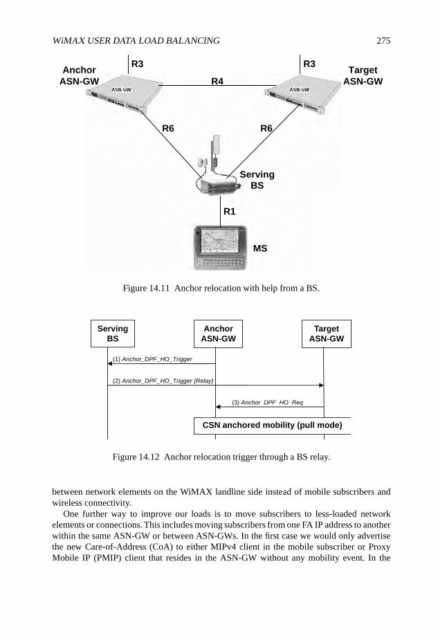
WiMAX USER DATA LOAD BALANCING 275
R6 R6
R4
R3
R1
Anchor
ASN-GW
R3
ServingBS
MS
Target
ASN-GW
Figure 14.11 Anchor relocation with help from a BS.
Serving
BS
Anchor
ASN-GW
Target
ASN-GW
(1) Anchor_DPF_HO_Trigger
(2) Anchor_DPF_HO_Trigger (Relay)
(3) Anchor DPF HO Req
CSN anchored mobility (pull mode)
Figure 14.12 Anchor relocation trigger through a BS relay.
between network elements on the WiMAX landline side instead of mobile subscribers andwireless connectivity.
One further way to improve our loads is to move subscribers to less-loaded networkelements or connections. This includes moving subscribers from one FA IP address to anotherwithin the same ASN-GW or between ASN-GWs. In the first case we would only advertisethe new Care-of-Address (CoA) to either MIPv4 client in the mobile subscriber or ProxyMobile IP (PMIP) client that resides in the ASN-GW without any mobility event. In the
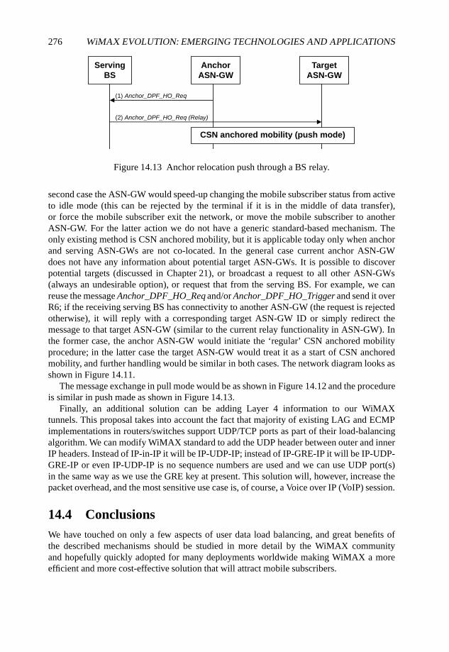
276 WiMAX EVOLUTION: EMERGING TECHNOLOGIES AND APPLICATIONS
Serving
BS
Anchor
ASN-GW
Target
ASN-GW
(1) Anchor_DPF_HO_Req
(2) Anchor_DPF_HO_Req (Relay)
CSN anchored mobility (push mode)
Figure 14.13 Anchor relocation push through a BS relay.
second case the ASN-GW would speed-up changing the mobile subscriber status from activeto idle mode (this can be rejected by the terminal if it is in the middle of data transfer),or force the mobile subscriber exit the network, or move the mobile subscriber to anotherASN-GW. For the latter action we do not have a generic standard-based mechanism. Theonly existing method is CSN anchored mobility, but it is applicable today only when anchorand serving ASN-GWs are not co-located. In the general case current anchor ASN-GWdoes not have any information about potential target ASN-GWs. It is possible to discoverpotential targets (discussed in Chapter 21), or broadcast a request to all other ASN-GWs(always an undesirable option), or request that from the serving BS. For example, we canreuse the message Anchor_DPF_HO_Req and/or Anchor_DPF_HO_Trigger and send it overR6; if the receiving serving BS has connectivity to another ASN-GW (the request is rejectedotherwise), it will reply with a corresponding target ASN-GW ID or simply redirect themessage to that target ASN-GW (similar to the current relay functionality in ASN-GW). Inthe former case, the anchor ASN-GW would initiate the ‘regular’ CSN anchored mobilityprocedure; in the latter case the target ASN-GW would treat it as a start of CSN anchoredmobility, and further handling would be similar in both cases. The network diagram looks asshown in Figure 14.11.
The message exchange in pull mode would be as shown in Figure 14.12 and the procedureis similar in push made as shown in Figure 14.13.
Finally, an additional solution can be adding Layer 4 information to our WiMAXtunnels. This proposal takes into account the fact that majority of existing LAG and ECMPimplementations in routers/switches support UDP/TCP ports as part of their load-balancingalgorithm. We can modify WiMAX standard to add the UDP header between outer and innerIP headers. Instead of IP-in-IP it will be IP-UDP-IP; instead of IP-GRE-IP it will be IP-UDP-GRE-IP or even IP-UDP-IP is no sequence numbers are used and we can use UDP port(s)in the same way as we use the GRE key at present. This solution will, however, increase thepacket overhead, and the most sensitive use case is, of course, a Voice over IP (VoIP) session.
14.4 ConclusionsWe have touched on only a few aspects of user data load balancing, and great benefits ofthe described mechanisms should be studied in more detail by the WiMAX communityand hopefully quickly adopted for many deployments worldwide making WiMAX a moreefficient and more cost-effective solution that will attract mobile subscribers.
15
Enabling Per-flow andSystem-wide QoS and QoE inMobile WiMAX
Thomas Casey, Xiongwen Zhao, Nenad Veselinovic,Jari Nurmi and Riku Jäntti
15.1 Introduction
The 802.16 standard offers a possibility for very high utilization of radio resources and goodQuality of Service (QoS). QoS has been defined as the ability of the network to provide aservice at an assured service level (Kilkki, 1999, Soldani et al., 2006) and has undoubtedlybeen one of the most attractive features of WiMAX. QoS within one Base Station (BS)in WiMAX is provided by connection-oriented Medium Access Control (MAC) and agilescheduling, which have been popular targets of research. While it is important to guaranteeproper QoS, an even more vital issues is how the end-user perceives and experiences theservices. This has often been referred to as Quality of Experience (QoE) (Kilkki, 1999,Soldani et al., 2006) and although it is a subjective measure, it will in the end determinehow satisfied the user is.
Furthermore the expansion from a fixed WiMAX network to a mobile WiMAX network,with a cellular infrastructure, introduces new challenges to providing QoS as a user is notnecessarily static or nomadic, but is likely to be roaming around the network while engagingin a session, thus resulting in Handovers (HOs) between BSs. For example, it is a veryannoying experience to be dropped out of an ongoing call due to insufficient resources ina target BS. On the other hand, overlapping cells introduce new possibilities to enhance QoSin the form of load balancing between BSs. Therefore, in a mobile WiMAX access network
WiMAX Evolution: Emerging Technologies and Applications Edited by Tsutomu Ishikawa© 2009 John Wiley & Sons, Ltd. ISBN: 978-0-470-69680-4

278 WiMAX EVOLUTION: EMERGING TECHNOLOGIES AND APPLICATIONS
QoS and QoE also become system-level issues, a point of view that has not, so far, receivedmuch attention.
In this chapter we discuss different aspects of QoS and QoE on a per-flow level (withinone BS) but also on a system-wide level (within a cluster of BSs). The chapter is outlined asfollows. In Section 15.2 we conduct an overview of the environment for guaranteeing QoSand QoE both within a single BS and system-wide and introduce the corresponding tools. InSection 15.3 we discuss different aspects of the MAC packet scheduler in charge of per-flowscheduling in the BS and look at it in particular from the QoE point of view. In Section 15.4we deal with system-level QoS and QoE issues in a mobile WiMAX access network and,finally, in Section 15.5 we draw conclusions.
Nomenclature
δ Hysteresis parameter.
BQ Base quantum size.
dmax Maximum delay allowed.
Fmax Maximum radio resource fluctuation.
Fsys Average radio resource fluctuation in the system.
G Guard band.
Gnrt,ho Guard band for non-real-time rescue handovers.
Grt,ho Guard band for real-time rescue handovers.
Grt,new Guard band for new real-time flows.
hmax Maximum handover rate allowed.
L Average load.
Lmax Maximum average load in the system to conduct load balancing.
Qi Quantum size for the ith service flow.
R Reserved resources.
rmax Maximum packet dropping rate allowed.
T Triggering threshold for load balancing.
TR Resource reservation-based triggering threshold.
TU,max Maximum for the resource utilization-based triggering threshold.
TU,min Minimum for the resource utilization-based triggering threshold.
TU Resource utilization-based triggering threshold.
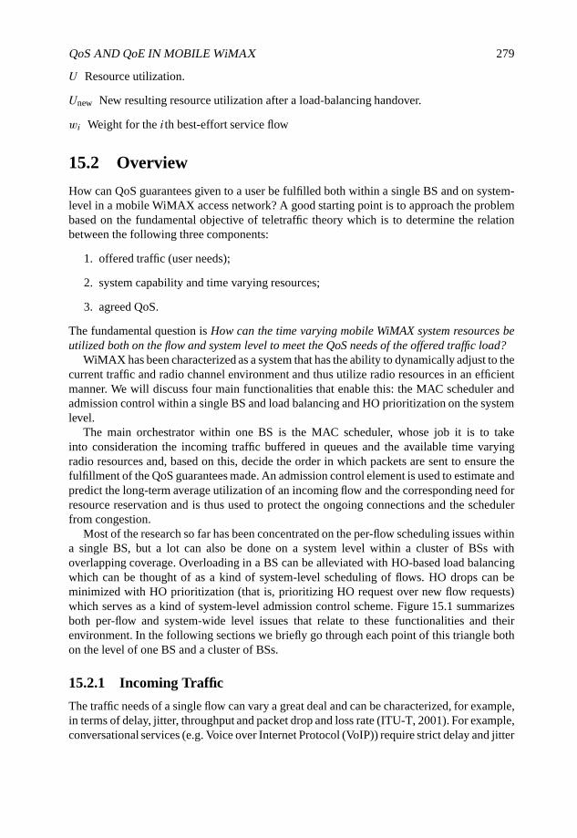
QoS AND QoE IN MOBILE WiMAX 279
U Resource utilization.
Unew New resulting resource utilization after a load-balancing handover.
wi Weight for the ith best-effort service flow
15.2 Overview
How can QoS guarantees given to a user be fulfilled both within a single BS and on system-level in a mobile WiMAX access network? A good starting point is to approach the problembased on the fundamental objective of teletraffic theory which is to determine the relationbetween the following three components:
1. offered traffic (user needs);
2. system capability and time varying resources;
3. agreed QoS.
The fundamental question is How can the time varying mobile WiMAX system resources beutilized both on the flow and system level to meet the QoS needs of the offered traffic load?
WiMAX has been characterized as a system that has the ability to dynamically adjust to thecurrent traffic and radio channel environment and thus utilize radio resources in an efficientmanner. We will discuss four main functionalities that enable this: the MAC scheduler andadmission control within a single BS and load balancing and HO prioritization on the systemlevel.
The main orchestrator within one BS is the MAC scheduler, whose job it is to takeinto consideration the incoming traffic buffered in queues and the available time varyingradio resources and, based on this, decide the order in which packets are sent to ensure thefulfillment of the QoS guarantees made. An admission control element is used to estimate andpredict the long-term average utilization of an incoming flow and the corresponding need forresource reservation and is thus used to protect the ongoing connections and the schedulerfrom congestion.
Most of the research so far has been concentrated on the per-flow scheduling issues withina single BS, but a lot can also be done on a system level within a cluster of BSs withoverlapping coverage. Overloading in a BS can be alleviated with HO-based load balancingwhich can be thought of as a kind of system-level scheduling of flows. HO drops can beminimized with HO prioritization (that is, prioritizing HO request over new flow requests)which serves as a kind of system-level admission control scheme. Figure 15.1 summarizesboth per-flow and system-wide level issues that relate to these functionalities and theirenvironment. In the following sections we briefly go through each point of this triangle bothon the level of one BS and a cluster of BSs.
15.2.1 Incoming Traffic
The traffic needs of a single flow can vary a great deal and can be characterized, for example,in terms of delay, jitter, throughput and packet drop and loss rate (ITU-T, 2001). For example,conversational services (e.g. Voice over Internet Protocol (VoIP)) require strict delay and jitter
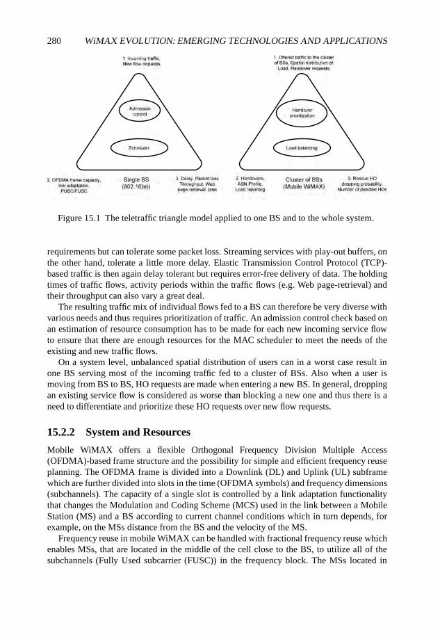
280 WiMAX EVOLUTION: EMERGING TECHNOLOGIES AND APPLICATIONS
Figure 15.1 The teletraffic triangle model applied to one BS and to the whole system.
requirements but can tolerate some packet loss. Streaming services with play-out buffers, onthe other hand, tolerate a little more delay. Elastic Transmission Control Protocol (TCP)-based traffic is then again delay tolerant but requires error-free delivery of data. The holdingtimes of traffic flows, activity periods within the traffic flows (e.g. Web page-retrieval) andtheir throughput can also vary a great deal.
The resulting traffic mix of individual flows fed to a BS can therefore be very diverse withvarious needs and thus requires prioritization of traffic. An admission control check based onan estimation of resource consumption has to be made for each new incoming service flowto ensure that there are enough resources for the MAC scheduler to meet the needs of theexisting and new traffic flows.
On a system level, unbalanced spatial distribution of users can in a worst case result inone BS serving most of the incoming traffic fed to a cluster of BSs. Also when a user ismoving from BS to BS, HO requests are made when entering a new BS. In general, droppingan existing service flow is considered as worse than blocking a new one and thus there is aneed to differentiate and prioritize these HO requests over new flow requests.
15.2.2 System and Resources
Mobile WiMAX offers a flexible Orthogonal Frequency Division Multiple Access(OFDMA)-based frame structure and the possibility for simple and efficient frequency reuseplanning. The OFDMA frame is divided into a Downlink (DL) and Uplink (UL) subframewhich are further divided into slots in the time (OFDMA symbols) and frequency dimensions(subchannels). The capacity of a single slot is controlled by a link adaptation functionalitythat changes the Modulation and Coding Scheme (MCS) used in the link between a MobileStation (MS) and a BS according to current channel conditions which in turn depends, forexample, on the MSs distance from the BS and the velocity of the MS.
Frequency reuse in mobile WiMAX can be handled with fractional frequency reuse whichenables MSs, that are located in the middle of the cell close to the BS, to utilize all of thesubchannels (Fully Used subcarrier (FUSC)) in the frequency block. The MSs located in
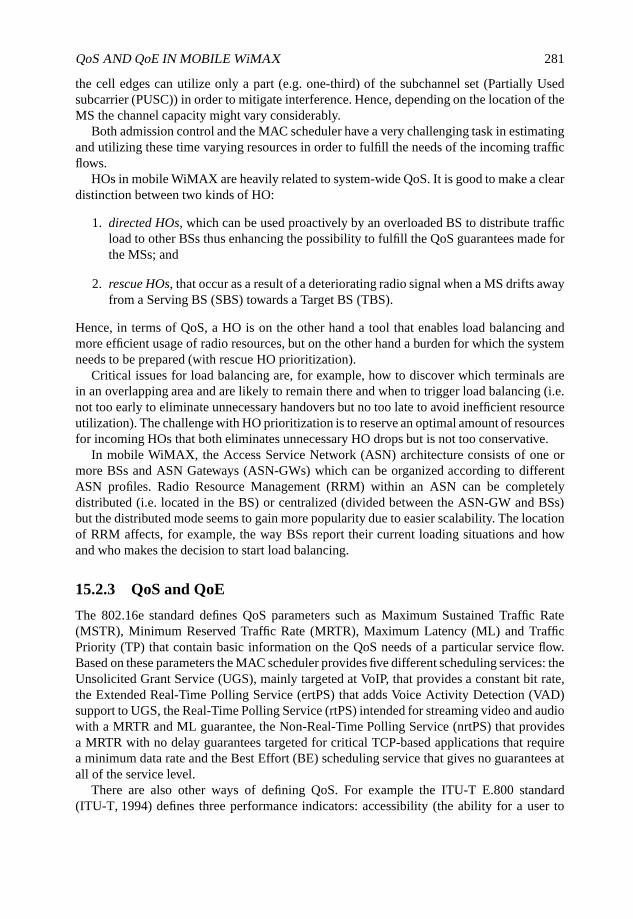
QoS AND QoE IN MOBILE WiMAX 281
the cell edges can utilize only a part (e.g. one-third) of the subchannel set (Partially Usedsubcarrier (PUSC)) in order to mitigate interference. Hence, depending on the location of theMS the channel capacity might vary considerably.
Both admission control and the MAC scheduler have a very challenging task in estimatingand utilizing these time varying resources in order to fulfill the needs of the incoming trafficflows.
HOs in mobile WiMAX are heavily related to system-wide QoS. It is good to make a cleardistinction between two kinds of HO:
1. directed HOs, which can be used proactively by an overloaded BS to distribute trafficload to other BSs thus enhancing the possibility to fulfill the QoS guarantees made forthe MSs; and
2. rescue HOs, that occur as a result of a deteriorating radio signal when a MS drifts awayfrom a Serving BS (SBS) towards a Target BS (TBS).
Hence, in terms of QoS, a HO is on the other hand a tool that enables load balancing andmore efficient usage of radio resources, but on the other hand a burden for which the systemneeds to be prepared (with rescue HO prioritization).
Critical issues for load balancing are, for example, how to discover which terminals arein an overlapping area and are likely to remain there and when to trigger load balancing (i.e.not too early to eliminate unnecessary handovers but no too late to avoid inefficient resourceutilization). The challenge with HO prioritization is to reserve an optimal amount of resourcesfor incoming HOs that both eliminates unnecessary HO drops but is not too conservative.
In mobile WiMAX, the Access Service Network (ASN) architecture consists of one ormore BSs and ASN Gateways (ASN-GWs) which can be organized according to differentASN profiles. Radio Resource Management (RRM) within an ASN can be completelydistributed (i.e. located in the BS) or centralized (divided between the ASN-GW and BSs)but the distributed mode seems to gain more popularity due to easier scalability. The locationof RRM affects, for example, the way BSs report their current loading situations and howand who makes the decision to start load balancing.
15.2.3 QoS and QoE
The 802.16e standard defines QoS parameters such as Maximum Sustained Traffic Rate(MSTR), Minimum Reserved Traffic Rate (MRTR), Maximum Latency (ML) and TrafficPriority (TP) that contain basic information on the QoS needs of a particular service flow.Based on these parameters the MAC scheduler provides five different scheduling services: theUnsolicited Grant Service (UGS), mainly targeted at VoIP, that provides a constant bit rate,the Extended Real-Time Polling Service (ertPS) that adds Voice Activity Detection (VAD)support to UGS, the Real-Time Polling Service (rtPS) intended for streaming video and audiowith a MRTR and ML guarantee, the Non-Real-Time Polling Service (nrtPS) that providesa MRTR with no delay guarantees targeted for critical TCP-based applications that requirea minimum data rate and the Best Effort (BE) scheduling service that gives no guarantees atall of the service level.
There are also other ways of defining QoS. For example the ITU-T E.800 standard(ITU-T, 1994) defines three performance indicators: accessibility (the ability for a user to
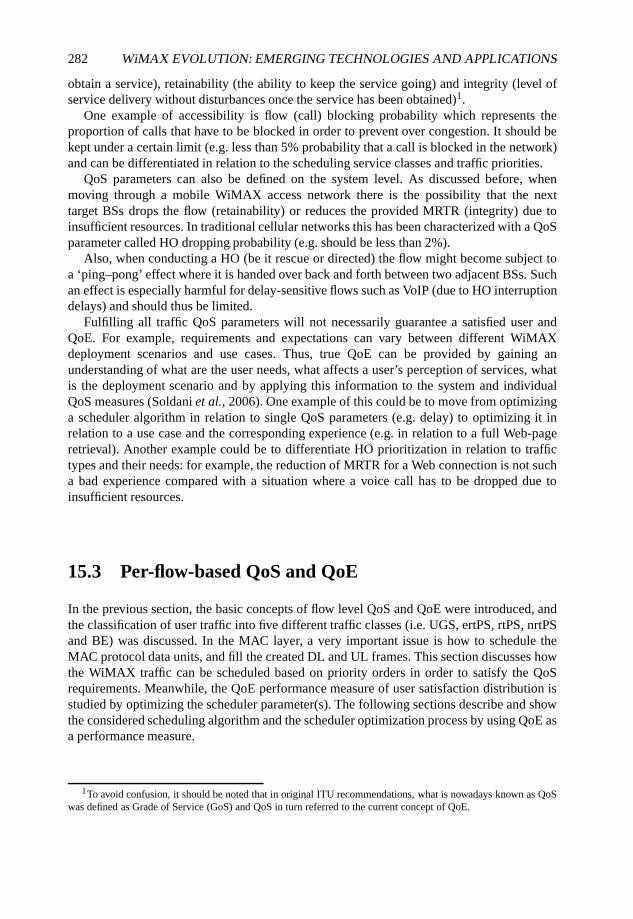
282 WiMAX EVOLUTION: EMERGING TECHNOLOGIES AND APPLICATIONS
obtain a service), retainability (the ability to keep the service going) and integrity (level ofservice delivery without disturbances once the service has been obtained)1.
One example of accessibility is flow (call) blocking probability which represents theproportion of calls that have to be blocked in order to prevent over congestion. It should bekept under a certain limit (e.g. less than 5% probability that a call is blocked in the network)and can be differentiated in relation to the scheduling service classes and traffic priorities.
QoS parameters can also be defined on the system level. As discussed before, whenmoving through a mobile WiMAX access network there is the possibility that the nexttarget BSs drops the flow (retainability) or reduces the provided MRTR (integrity) due toinsufficient resources. In traditional cellular networks this has been characterized with a QoSparameter called HO dropping probability (e.g. should be less than 2%).
Also, when conducting a HO (be it rescue or directed) the flow might become subject toa ‘ping–pong’ effect where it is handed over back and forth between two adjacent BSs. Suchan effect is especially harmful for delay-sensitive flows such as VoIP (due to HO interruptiondelays) and should thus be limited.
Fulfilling all traffic QoS parameters will not necessarily guarantee a satisfied user andQoE. For example, requirements and expectations can vary between different WiMAXdeployment scenarios and use cases. Thus, true QoE can be provided by gaining anunderstanding of what are the user needs, what affects a user’s perception of services, whatis the deployment scenario and by applying this information to the system and individualQoS measures (Soldani et al., 2006). One example of this could be to move from optimizinga scheduler algorithm in relation to single QoS parameters (e.g. delay) to optimizing it inrelation to a use case and the corresponding experience (e.g. in relation to a full Web-pageretrieval). Another example could be to differentiate HO prioritization in relation to traffictypes and their needs: for example, the reduction of MRTR for a Web connection is not sucha bad experience compared with a situation where a voice call has to be dropped due toinsufficient resources.
15.3 Per-flow-based QoS and QoE
In the previous section, the basic concepts of flow level QoS and QoE were introduced, andthe classification of user traffic into five different traffic classes (i.e. UGS, ertPS, rtPS, nrtPSand BE) was discussed. In the MAC layer, a very important issue is how to schedule theMAC protocol data units, and fill the created DL and UL frames. This section discusses howthe WiMAX traffic can be scheduled based on priority orders in order to satisfy the QoSrequirements. Meanwhile, the QoE performance measure of user satisfaction distribution isstudied by optimizing the scheduler parameter(s). The following sections describe and showthe considered scheduling algorithm and the scheduler optimization process by using QoE asa performance measure.
1To avoid confusion, it should be noted that in original ITU recommendations, what is nowadays known as QoSwas defined as Grade of Service (GoS) and QoS in turn referred to the current concept of QoE.
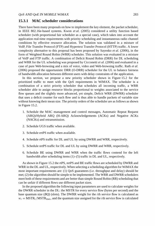
QoS AND QoE IN MOBILE WiMAX 283
15.3.1 MAC scheduler considerations
There have been many proposals on how to implement the key element, the packet scheduler,in IEEE 802.16e-based systems. Kwon et al. (2005) considered a utility function basedscheduler (with proportional fair scheduler as a special case), which takes into account theapplication real-time requirements with priority scheduling and instantaneous radio channelconditions by effective resource allocation. The solution was validated in a mixture ofVoIP, File Transfer Protocol (FTP) and Hypertext Transfer Protocol (HTTP) traffic. A lowercomplexity alternative to this proposal has been proposed by Sayenko et al. (2006), in theform of Weighted Round Robin (WRR) scheduler. This solution was evaluated in a mixtureof VoIP and FTP traffic. A combination of Deficit Round Robin (DRR) for DL schedulingand WRR for the UL scheduling was proposed by Cicconetti et al. (2006) and evaluated in acase of pure Web-browsing and a mix of voice, video and Web-browsing traffic. Rath et al.(2006) proposed the opportunistic DRR (O-DRR) scheduler for the UL to balance fairnessof bandwidth allocation between different users with delay constraints of the application.
In this section, we propose a new priority scheduler shown in Figure 15.2 for theprioritized traffic to meet with the QoS requirements in WiMAX. The scheduler is acombination of a strict priority scheduler that schedules all incoming traffic, a WRRscheduler able to assign resource blocks proportional to weights associated to the serviceflow queues and the slightly more advanced, yet simple, Deficit WRR (DWRR) schedulerthat uses a deficit counter for each flow and is thus able to handle packets of variable sizewithout knowing their mean size. The priority orders of the scheduler are as follows as shownin Figure 15.2.
1. Schedule the MAC management and control messages, Automatic Repeat Request(ARQ)/Hybrid ARQ (H-ARQ) Acknowledgements (ACKs) and Negative ACKs(NACKs) and retransmission.
2. Schedule UGS traffic when available.
3. Schedule ertPS traffic when available.
4. Schedule rtPS traffic for DL and UL by using DWRR and WRR, respectively.
5. Schedule nrtPS traffic for DL and UL by using DWRR and WRR, respectively.
6. Schedule BE using DWRR and WRR when the traffic flows contend for the leftbandwidth after scheduling items (1)–(5) traffic in DL and UL, respectively.
As shown in Figure 15.2 the rtPS, nrtPS and BE traffic flows are scheduled by DWRR andWRR in the DL and UL, respectively. When selecting a scheduling algorithm for WiMAX themost important requirements are: (1) QoS guarantees (i.e. throughput and delay) should bemet; (2) the algorithm should be simple to be implemented. The WRR and DWRR schedulersmeet both of these requirements and are better than simple Round Robin (RR) scheduling thatcan be unfair if different flows use different packet sizes.
In the proposed algorithm the following input parameters are used to calculate weights forthe DWRR scheduler in the DL: the MSTR for every service flow (bytes per second) and thebase quantum size (BQ) (slots). The DWRR weight for the ith service flow is calculated aswi = MSTRi/MSTRmax, and the quantum size assigned for the ith service flow is calculated
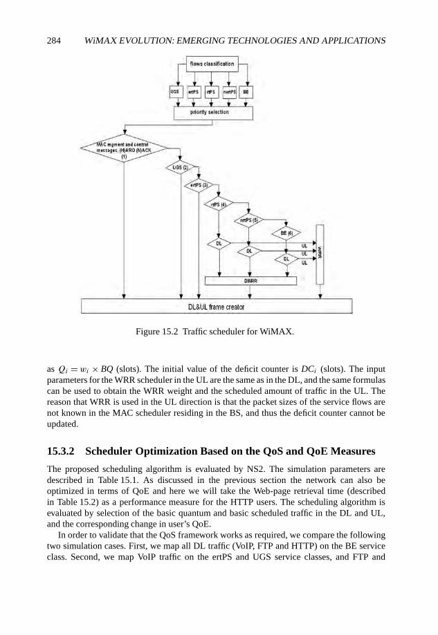
284 WiMAX EVOLUTION: EMERGING TECHNOLOGIES AND APPLICATIONS
Figure 15.2 Traffic scheduler for WiMAX.
as Qi =wi × BQ (slots). The initial value of the deficit counter is DCi (slots). The inputparameters for the WRR scheduler in the UL are the same as in the DL, and the same formulascan be used to obtain the WRR weight and the scheduled amount of traffic in the UL. Thereason that WRR is used in the UL direction is that the packet sizes of the service flows arenot known in the MAC scheduler residing in the BS, and thus the deficit counter cannot beupdated.
15.3.2 Scheduler Optimization Based on the QoS and QoE Measures
The proposed scheduling algorithm is evaluated by NS2. The simulation parameters aredescribed in Table 15.1. As discussed in the previous section the network can also beoptimized in terms of QoE and here we will take the Web-page retrieval time (describedin Table 15.2) as a performance measure for the HTTP users. The scheduling algorithm isevaluated by selection of the basic quantum and basic scheduled traffic in the DL and UL,and the corresponding change in user’s QoE.
In order to validate that the QoS framework works as required, we compare the followingtwo simulation cases. First, we map all DL traffic (VoIP, FTP and HTTP) on the BE serviceclass. Second, we map VoIP traffic on the ertPS and UGS service classes, and FTP and
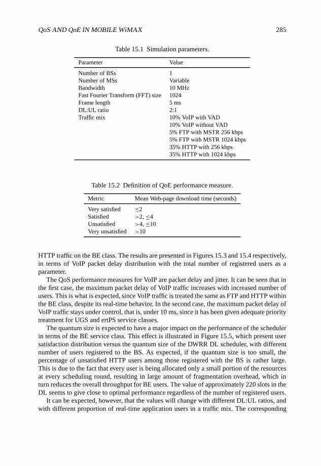
QoS AND QoE IN MOBILE WiMAX 285
Table 15.1 Simulation parameters.
Parameter Value
Number of BSs 1Number of MSs VariableBandwidth 10 MHzFast Fourier Transform (FFT) size 1024Frame length 5 msDL:UL ratio 2:1Traffic mix 10% VoIP with VAD
10% VoIP without VAD5% FTP with MSTR 256 kbps5% FTP with MSTR 1024 kbps35% HTTP with 256 kbps35% HTTP with 1024 kbps
Table 15.2 Definition of QoE performance measure.
Metric Mean Web-page download time (seconds)
Very satisfied ≤2Satisfied >2, ≤4Unsatisfied >4, ≤10Very unsatisfied >10
HTTP traffic on the BE class. The results are presented in Figures 15.3 and 15.4 respectively,in terms of VoIP packet delay distribution with the total number of registered users as aparameter.
The QoS performance measures for VoIP are packet delay and jitter. It can be seen that inthe first case, the maximum packet delay of VoIP traffic increases with increased number ofusers. This is what is expected, since VoIP traffic is treated the same as FTP and HTTP withinthe BE class, despite its real-time behavior. In the second case, the maximum packet delay ofVoIP traffic stays under control, that is, under 10 ms, since it has been given adequate prioritytreatment for UGS and ertPS service classes.
The quantum size is expected to have a major impact on the performance of the schedulerin terms of the BE service class. This effect is illustrated in Figure 15.5, which present usersatisfaction distribution versus the quantum size of the DWRR DL scheduler, with differentnumber of users registered to the BS. As expected, if the quantum size is too small, thepercentage of unsatisfied HTTP users among those registered with the BS is rather large.This is due to the fact that every user is being allocated only a small portion of the resourcesat every scheduling round, resulting in large amount of fragmentation overhead, which inturn reduces the overall throughput for BE users. The value of approximately 220 slots in theDL seems to give close to optimal performance regardless of the number of registered users.
It can be expected, however, that the values will change with different DL:UL ratios, andwith different proportion of real-time application users in a traffic mix. The corresponding
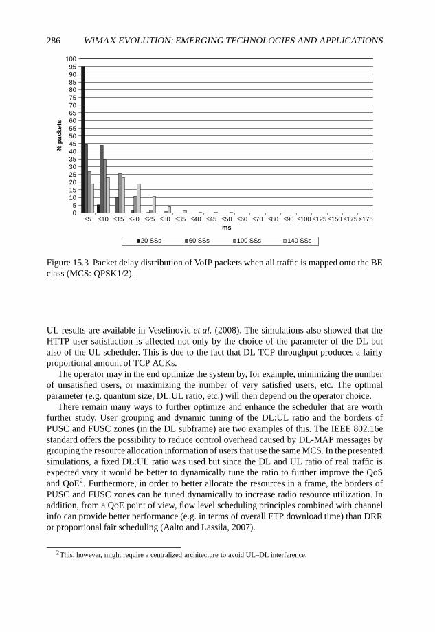
286 WiMAX EVOLUTION: EMERGING TECHNOLOGIES AND APPLICATIONS
05
101520253035404550556065707580859095
100
≤5 ≤10 ≤15 ≤20 ≤25 ≤30 ≤35 ≤40 ≤45 ≤50 ≤60 ≤70 ≤80 ≤90 ≤100 ≤125 ≤150 ≤175 >175ms
% p
acke
ts
20 SSs 60 SSs 100 SSs 140 SSs
Figure 15.3 Packet delay distribution of VoIP packets when all traffic is mapped onto the BEclass (MCS: QPSK1/2).
UL results are available in Veselinovic et al. (2008). The simulations also showed that theHTTP user satisfaction is affected not only by the choice of the parameter of the DL butalso of the UL scheduler. This is due to the fact that DL TCP throughput produces a fairlyproportional amount of TCP ACKs.
The operator may in the end optimize the system by, for example, minimizing the numberof unsatisfied users, or maximizing the number of very satisfied users, etc. The optimalparameter (e.g. quantum size, DL:UL ratio, etc.) will then depend on the operator choice.
There remain many ways to further optimize and enhance the scheduler that are worthfurther study. User grouping and dynamic tuning of the DL:UL ratio and the borders ofPUSC and FUSC zones (in the DL subframe) are two examples of this. The IEEE 802.16estandard offers the possibility to reduce control overhead caused by DL-MAP messages bygrouping the resource allocation information of users that use the same MCS. In the presentedsimulations, a fixed DL:UL ratio was used but since the DL and UL ratio of real traffic isexpected vary it would be better to dynamically tune the ratio to further improve the QoSand QoE2. Furthermore, in order to better allocate the resources in a frame, the borders ofPUSC and FUSC zones can be tuned dynamically to increase radio resource utilization. Inaddition, from a QoE point of view, flow level scheduling principles combined with channelinfo can provide better performance (e.g. in terms of overall FTP download time) than DRRor proportional fair scheduling (Aalto and Lassila, 2007).
2This, however, might require a centralized architecture to avoid UL–DL interference.
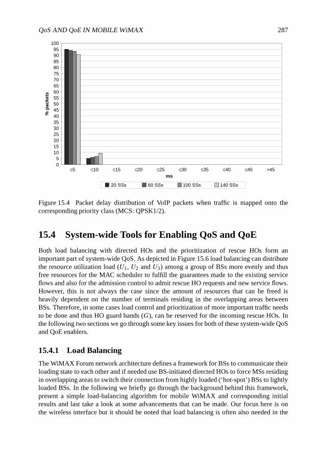
QoS AND QoE IN MOBILE WiMAX 287
05
101520253035404550556065707580859095
100
≤5 ≤10 ≤15 ≤20 ≤25 ≤30 ≤35 ≤40 ≤45 >45ms
% p
acke
ts
20 SSs 60 SSs 100 SSs 140 SSs
Figure 15.4 Packet delay distribution of VoIP packets when traffic is mapped onto thecorresponding priority class (MCS: QPSK1/2).
15.4 System-wide Tools for Enabling QoS and QoE
Both load balancing with directed HOs and the prioritization of rescue HOs form animportant part of system-wide QoS. As depicted in Figure 15.6 load balancing can distributethe resource utilization load (U1, U2 and U3) among a group of BSs more evenly and thusfree resources for the MAC scheduler to fulfill the guarantees made to the existing serviceflows and also for the admission control to admit rescue HO requests and new service flows.However, this is not always the case since the amount of resources that can be freed isheavily dependent on the number of terminals residing in the overlapping areas betweenBSs. Therefore, in some cases load control and prioritization of more important traffic needsto be done and thus HO guard bands (G), can be reserved for the incoming rescue HOs. Inthe following two sections we go through some key issues for both of these system-wide QoSand QoE enablers.
15.4.1 Load Balancing
The WiMAX Forum network architecture defines a framework for BSs to communicate theirloading state to each other and if needed use BS-initiated directed HOs to force MSs residingin overlapping areas to switch their connection from highly loaded (‘hot-spot’) BSs to lightlyloaded BSs. In the following we briefly go through the background behind this framework,present a simple load-balancing algorithm for mobile WiMAX and corresponding initialresults and last take a look at some advancements that can be made. Our focus here is onthe wireless interface but it should be noted that load balancing is often also needed in the
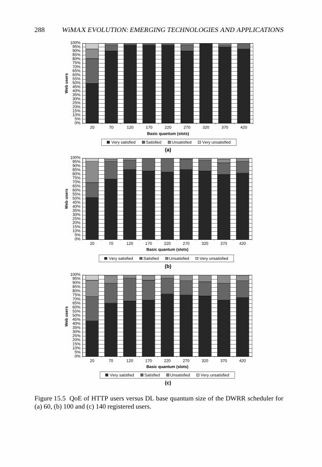
288 WiMAX EVOLUTION: EMERGING TECHNOLOGIES AND APPLICATIONS
(a)
0%5%
10%15%20%25%30%35%40%45%50%55%60%65%70%75%80%85%90%95%
100%
20 70 120 170 220 270 320 370 420
Basic quantum (slots)
Web
use
rs
(b)
0%5%
10%15%20%25%30%35%40%45%50%55%60%65%70%75%80%85%90%95%
100%
20 70 120 170 220 270 320 370 420
Basic quantum (slots)
Web
use
rs
(c)
0%5%
10%15%20%25%30%35%40%45%50%55%60%65%70%75%80%85%90%95%
100%
20 70 120 170 220 270 320 370 420
Basic quantum (slots)
Web
use
rs
Very satisfied Satisfied Unsatisfied Very unsatisfied
Very satisfied Satisfied Unsatisfied Very unsatisfied
Very satisfied Satisfied Unsatisfied Very unsatisfied
Figure 15.5 QoE of HTTP users versus DL base quantum size of the DWRR scheduler for(a) 60, (b) 100 and (c) 140 registered users.
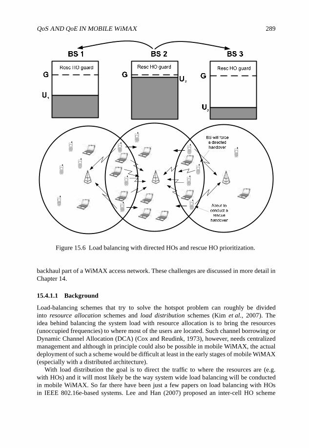
QoS AND QoE IN MOBILE WiMAX 289
Figure 15.6 Load balancing with directed HOs and rescue HO prioritization.
backhaul part of a WiMAX access network. These challenges are discussed in more detail inChapter 14.
15.4.1.1 Background
Load-balancing schemes that try to solve the hotspot problem can roughly be dividedinto resource allocation schemes and load distribution schemes (Kim et al., 2007). Theidea behind balancing the system load with resource allocation is to bring the resources(unoccupied frequencies) to where most of the users are located. Such channel borrowing orDynamic Channel Allocation (DCA) (Cox and Reudink, 1973), however, needs centralizedmanagement and although in principle could also be possible in mobile WiMAX, the actualdeployment of such a scheme would be difficult at least in the early stages of mobile WiMAX(especially with a distributed architecture).
With load distribution the goal is to direct the traffic to where the resources are (e.g.with HOs) and it will most likely be the way system wide load balancing will be conductedin mobile WiMAX. So far there have been just a few papers on load balancing with HOsin IEEE 802.16e-based systems. Lee and Han (2007) proposed an inter-cell HO scheme
290 WiMAX EVOLUTION: EMERGING TECHNOLOGIES AND APPLICATIONS
for load balancing where MSs react to congestion and themselves initiate a HO to a less-congested sector. In this scheme load balancing is not controlled by the network and thusload balancing cannot be done in a controlled manner. Moiseev et al. (2006) proposedan advanced, network controlled, HO-based load-balancing algorithm that tries to find theoptimal MS–BS association set to both minimize and balance the utilization of commonresources in the whole system. In order to be deployed this algorithm would require anextensive amount of signaling and preferably a centralized architecture.
Many mobile WiMAX vendors are likely to implement a more distributed profile (ProfileC) of the ASN since it enables better interoperability between BS and central ASN-GW nodesfrom different vendors and thus results in good scalability. In this case the load-balancinglogic will reside in the BS and it will be our working assumption from now on.
One of the load-balancing components in mobile WiMAX is the Spare Capacity Report(SCR) procedure with which a BS can report its loading situation to its peers. In this reportspare capacity is described with UL and DL available radio resource indicators that describethe average ratios of nonassigned UL and DL resources to the total usable UL and DL radioresources. Resources are defined by slots which are a good indicator of resource utilizationsince they describe the used resources not just in terms of traffic throughput, but also inrelations to the MCSs used based on the channel conditions experienced by the MSs. Sinceall measurements are reported in percentages, comparisons can also be made between BSswith different capacities. The SCR can also include the total number of UL and DL slots inthe frame so that the BS initiating load balancing has an idea of the actual amount of availableresources in the target BS.
Based on the SCR, a threshold can be set that indicates when a BS is in an overloaded state.If it is exceeded a BS can initiate directed HOs for the MSs that reside in the overlapping areasprovided that they have been discovered or order MSs most likely residing in the overlappingareas to scan neighboring target BSs. This cell reselection can be conducted before, afteror both before and after load-balancing HOs are initiated. The trade-off is that preliminaryscanning results in a high number of periodically occurring scans that are especially bad forreal-time connections such as VoIP but on the other hand conducting scanning after the load-balancing decision might make load balancing too slow to react to load changes and resultin, for example, new flow blocking.
The resulting HOs for the MSs can be conducted in many ways. The IEEE 802.16especification offers a wide range of options on how to conduct HOs that can be used tomeet the requirements of different traffic and mobility characteristics a user might have. Forexample, a moving VoIP user needs a reliable HO scheme with short interruption whereas astatic Web-browsing session a can tolerate several seconds of HO interruption. Based on theneeds of the service flow, different preliminary association levels to the TBS can be used tospeed up ranging and different types of handover execution mechanisms such as optimizedhard handover, Fast Base Station Switching (FBSS) and Macro Diversity Handover (MDHO)can also be used (Dong and Dai, 2007). Reliability, however, comes with the cost of higherHO overhead and general consumption of processing resources.
15.4.1.2 A Load-balancing Algorithm for Mobile WiMAX
To demonstrate some key issues of load balancing in mobile WiMAX we present a simpleload-balancing algorithm and show some corresponding initial results. Velayos et al. (2004)

QoS AND QoE IN MOBILE WiMAX 291
proposed a directed HO-based load-balancing scheme for a WLAN AP cluster that servesas a good starting point for an algorithm since it features similar load level reports sentbetween Access Points (APs) every Load Balancing Cycle (LBC). The reports received fromneighbors are used locally in each AP to compute an average load level, L, in the system.The scheme defines three possible loading states: underloaded, balanced and overloadedfor each AP. The AP is in an underloaded state if its load U is under the average L andin an overloaded state if its load U exceeds a threshold computed with the equation T =L+ δL. In this equation δ characterizes the size of a hysteresis margin (i.e. how much trafficunbalance will be tolerated in the system) used to avoid the ‘ping–pong’ effect resultingeither from conducting too many directed HOs or from highly varying traffic. Using sucha hysteresis offers a simple way to dynamically adjust to the current loading situation inthe whole system instead of using a single fixed threshold. Manual configuration of the δparameter can, however, be challenging. When δ is set large the ‘ping–pong’ effect is avoidedbut it can result in call blocking and lower QoS. Then again setting a small hysteresis marginguarantees balance in the system and efficient resource utilization but might cause the ‘ping–pong’ effect.
A modified version of the scheme tailored to mobile WiMAX is presented in Figure 15.7.In the scheme a SCR will be broadcasted every LBC and its length will also be used as theaveraging time. Since spare capacity in the SCR is reported both for DL and UL a worst-caseapproach will be used for the resource utilization calculations and, hence, the final resourceutilization value for BS i is
Ui = max
(UUL,i
UUL,tot,UDL,i
UDL,tot
)(15.1)
where UUL,i and UDL,i are the number of assigned slots and UUL,tot and UDL,tot the totalnumber of slots during the averaging interval in the UL and DL3.
Based on the SCRs the BS will compute L and T and determine its loading state whichwill in turn define the way incoming requests for new service flows and rescue and directedHOs will be treated.
When a AP goes into the overloaded state it starts conducting directed HOs to the APsthat are in the underloaded state4. If an AP is in the balanced state, below the threshold T andabove the average L, or in the overloaded state it can accept both rescue HO and new serviceflow request as long the flow is also admitted by admission control5.
When load balancing is triggered the BS will initiate directed HOs for MSs that residein overlapping areas or order the MSs to scan neighboring BSs, depending on whetheroverlap discovery has already been conducted. When resolving the overlapping terminalsmeasurements of the pilot signal strength, round trip delay and channel variation could beused and possibly also mobility prediction techniques could be utilized to narrow down theset of candidate MSs. It might also be beneficial to try to identify and concentrate on nomadicMSs that are likely to reside in the overlapping area throughout their session (i.e. not goingto conduct a rescue HO back to the congested BS).
3Note, that SCR reports UL and DL spare capacity to the other BSs.4Bounding values (Tmin, Tmax and Lmax) for the triggering threshold T and for the average resource utilization
L can be used to ensure that load balancing is not triggered unnecessarily (e.g. when the system is only lightlyloaded or too overloaded) or to make sure that load balancing is initiated before call blocking occurs.
5Different from the original scheme, BSs in mobile WiMAX have an admission control function protecting theexisting connections and, hence, new flows (and rescue HOs) can be accepted also in the overloaded state.
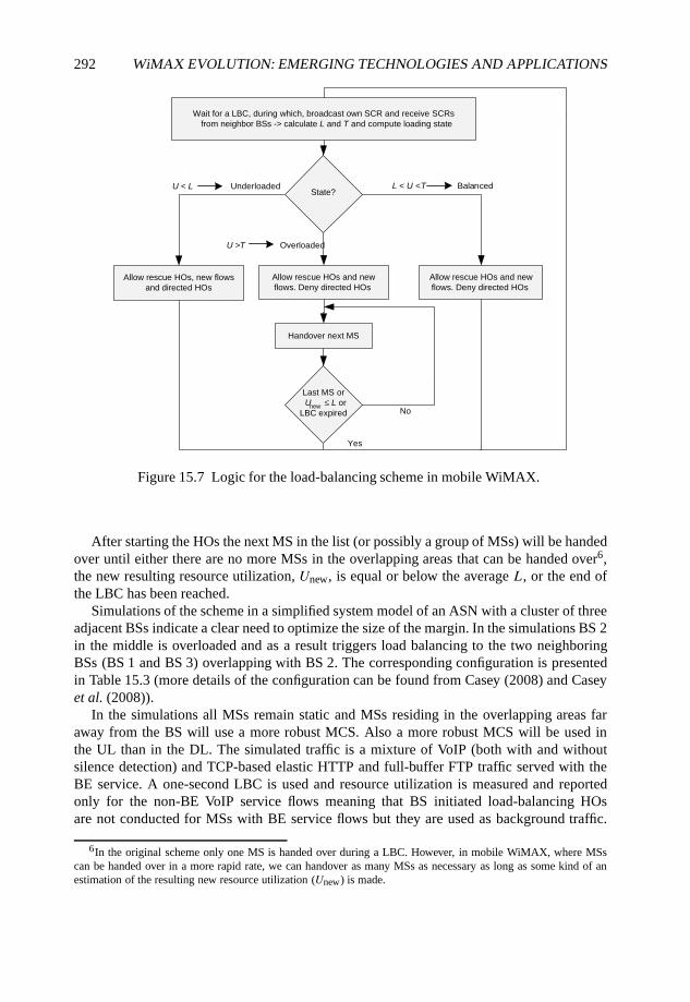
292 WiMAX EVOLUTION: EMERGING TECHNOLOGIES AND APPLICATIONS
Wait for a LBC, during which, broadcast own SCR and receive SCRs
from neighbor BSs -> calculate L and T and compute loading state
Allow rescue HOs, new flows
and directed HOs
Allow rescue HOs and new
flows. Deny directed HOs
Allow rescue HOs and new
flows. Deny directed HOs
U < L Underloaded L < U <T Balanced
Handover next MS
Last MS or
LBC expired
U ≤ L ornew
Yes
No
State?
U >T Overloaded
Figure 15.7 Logic for the load-balancing scheme in mobile WiMAX.
After starting the HOs the next MS in the list (or possibly a group of MSs) will be handedover until either there are no more MSs in the overlapping areas that can be handed over6,the new resulting resource utilization, Unew, is equal or below the average L, or the end ofthe LBC has been reached.
Simulations of the scheme in a simplified system model of an ASN with a cluster of threeadjacent BSs indicate a clear need to optimize the size of the margin. In the simulations BS 2in the middle is overloaded and as a result triggers load balancing to the two neighboringBSs (BS 1 and BS 3) overlapping with BS 2. The corresponding configuration is presentedin Table 15.3 (more details of the configuration can be found from Casey (2008) and Caseyet al. (2008)).
In the simulations all MSs remain static and MSs residing in the overlapping areas faraway from the BS will use a more robust MCS. Also a more robust MCS will be used inthe UL than in the DL. The simulated traffic is a mixture of VoIP (both with and withoutsilence detection) and TCP-based elastic HTTP and full-buffer FTP traffic served with theBE service. A one-second LBC is used and resource utilization is measured and reportedonly for the non-BE VoIP service flows meaning that BS initiated load-balancing HOsare not conducted for MSs with BE service flows but they are used as background traffic.
6In the original scheme only one MS is handed over during a LBC. However, in mobile WiMAX, where MSscan be handed over in a more rapid rate, we can handover as many MSs as necessary as long as some kind of anestimation of the resulting new resource utilization (Unew) is made.
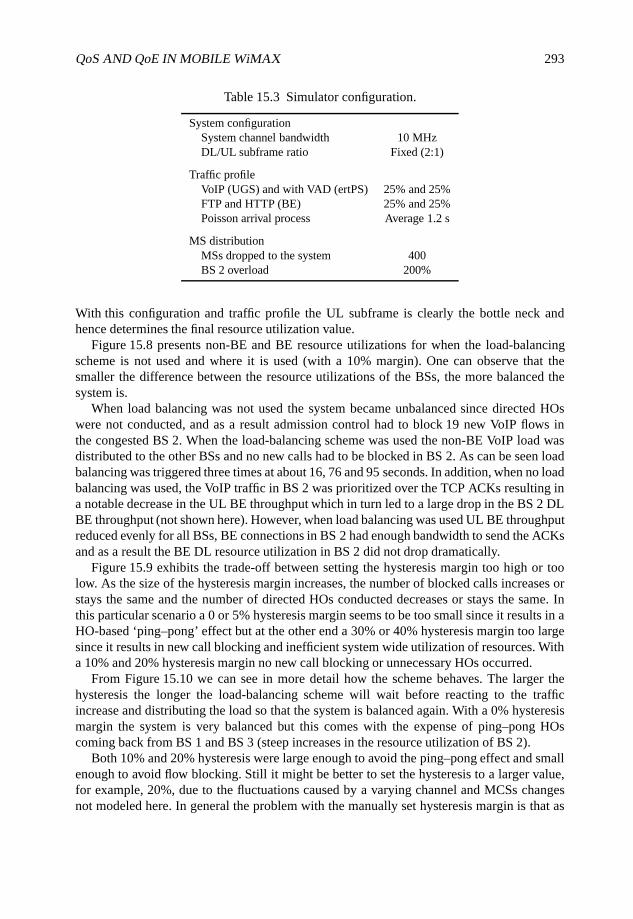
QoS AND QoE IN MOBILE WiMAX 293
Table 15.3 Simulator configuration.
System configurationSystem channel bandwidth 10 MHzDL/UL subframe ratio Fixed (2:1)
Traffic profileVoIP (UGS) and with VAD (ertPS) 25% and 25%FTP and HTTP (BE) 25% and 25%Poisson arrival process Average 1.2 s
MS distributionMSs dropped to the system 400BS 2 overload 200%
With this configuration and traffic profile the UL subframe is clearly the bottle neck andhence determines the final resource utilization value.
Figure 15.8 presents non-BE and BE resource utilizations for when the load-balancingscheme is not used and where it is used (with a 10% margin). One can observe that thesmaller the difference between the resource utilizations of the BSs, the more balanced thesystem is.
When load balancing was not used the system became unbalanced since directed HOswere not conducted, and as a result admission control had to block 19 new VoIP flows inthe congested BS 2. When the load-balancing scheme was used the non-BE VoIP load wasdistributed to the other BSs and no new calls had to be blocked in BS 2. As can be seen loadbalancing was triggered three times at about 16, 76 and 95 seconds. In addition, when no loadbalancing was used, the VoIP traffic in BS 2 was prioritized over the TCP ACKs resulting ina notable decrease in the UL BE throughput which in turn led to a large drop in the BS 2 DLBE throughput (not shown here). However, when load balancing was used UL BE throughputreduced evenly for all BSs, BE connections in BS 2 had enough bandwidth to send the ACKsand as a result the BE DL resource utilization in BS 2 did not drop dramatically.
Figure 15.9 exhibits the trade-off between setting the hysteresis margin too high or toolow. As the size of the hysteresis margin increases, the number of blocked calls increases orstays the same and the number of directed HOs conducted decreases or stays the same. Inthis particular scenario a 0 or 5% hysteresis margin seems to be too small since it results in aHO-based ‘ping–pong’ effect but at the other end a 30% or 40% hysteresis margin too largesince it results in new call blocking and inefficient system wide utilization of resources. Witha 10% and 20% hysteresis margin no new call blocking or unnecessary HOs occurred.
From Figure 15.10 we can see in more detail how the scheme behaves. The larger thehysteresis the longer the load-balancing scheme will wait before reacting to the trafficincrease and distributing the load so that the system is balanced again. With a 0% hysteresismargin the system is very balanced but this comes with the expense of ping–pong HOscoming back from BS 1 and BS 3 (steep increases in the resource utilization of BS 2).
Both 10% and 20% hysteresis were large enough to avoid the ping–pong effect and smallenough to avoid flow blocking. Still it might be better to set the hysteresis to a larger value,for example, 20%, due to the fluctuations caused by a varying channel and MCSs changesnot modeled here. In general the problem with the manually set hysteresis margin is that as
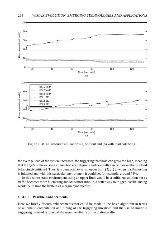
294 WiMAX EVOLUTION: EMERGING TECHNOLOGIES AND APPLICATIONS
20 40 60 80 100 1200
20
40
60
80
100
Time (seconds)
Res
ourc
e ut
iliza
tion
(%)
0
20
40
60
80
100
Res
ourc
e ut
iliza
tion
(%)
BS 1 VoIPBS 2 VoIPBS 3 VoIPBS 1 BEBS 2 BEBS 3 BE
(a)
20 40 60 80 100 120Time (seconds)
(b)
Figure 15.8 UL resource utilizations (a) without and (b) with load balancing.
the average load of the system increases, the triggering threshold can grow too high, meaningthat the QoS of the existing connections can degrade and new calls can be blocked before loadbalancing is initiated. Thus, it is beneficial to set an upper limit (Tmax) to when load balancingis initiated and with this particular environment it could be, for example, around 74%.
In this rather static environment using an upper limit would be a sufficient solution but astraffic becomes more fluctuating and MSs more mobile, a better way to trigger load balancingwould be to tune the hysteresis margin dynamically.
15.4.1.3 Possible Enhancements
Here we briefly discuss enhancements that could be made to the basic algorithm in termsof automatic computation and tuning of the triggering threshold and the use of multipletriggering thresholds to avoid the negative effects of fluctuating traffic.
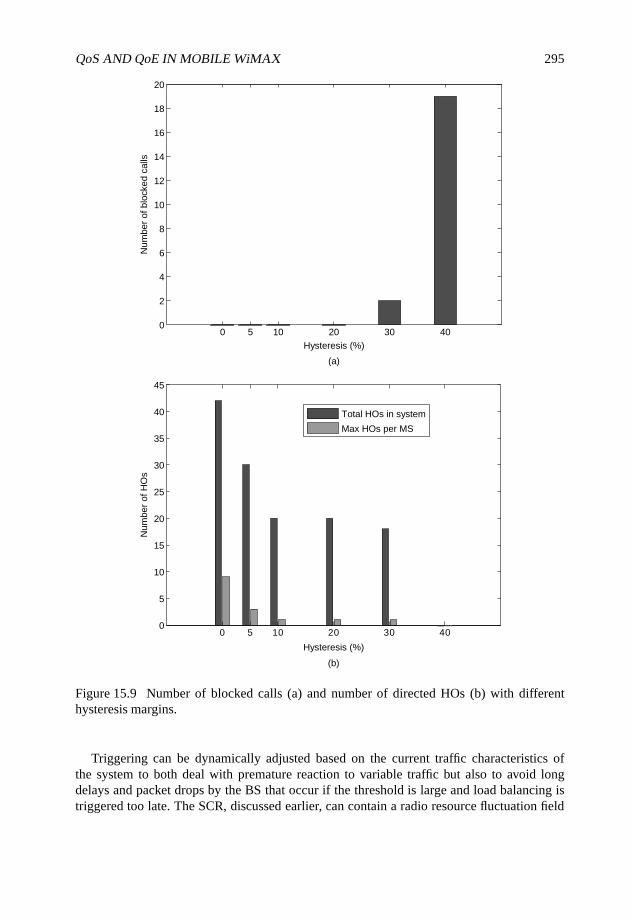
QoS AND QoE IN MOBILE WiMAX 295
0 5 10 20 30 400
2
4
6
8
10
12
14
16
18
20
(a)
Hysteresis (%)
Num
ber
of b
lock
ed c
alls
0 5 10 20 30 400
5
10
15
20
25
30
35
40
45
Hysteresis (%)
Num
ber
of H
Os
(b)
Total HOs in system
Max HOs per MS
Figure 15.9 Number of blocked calls (a) and number of directed HOs (b) with differenthysteresis margins.
Triggering can be dynamically adjusted based on the current traffic characteristics ofthe system to both deal with premature reaction to variable traffic but also to avoid longdelays and packet drops by the BS that occur if the threshold is large and load balancing istriggered too late. The SCR, discussed earlier, can contain a radio resource fluctuation field
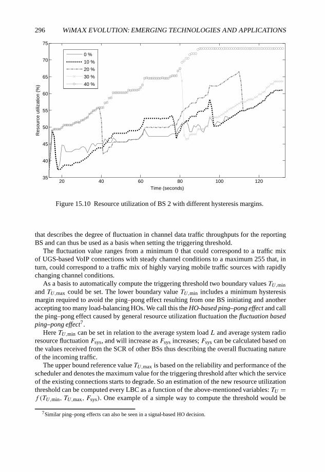
296 WiMAX EVOLUTION: EMERGING TECHNOLOGIES AND APPLICATIONS
20 40 60 80 100 12035
40
45
50
55
60
65
70
75
Time (seconds)
Res
ourc
e ut
iliza
tion
(%)
0 %
10 %
20 %
30 %
40 %
Figure 15.10 Resource utilization of BS 2 with different hysteresis margins.
that describes the degree of fluctuation in channel data traffic throughputs for the reportingBS and can thus be used as a basis when setting the triggering threshold.
The fluctuation value ranges from a minimum 0 that could correspond to a traffic mixof UGS-based VoIP connections with steady channel conditions to a maximum 255 that, inturn, could correspond to a traffic mix of highly varying mobile traffic sources with rapidlychanging channel conditions.
As a basis to automatically compute the triggering threshold two boundary values TU,minand TU,max could be set. The lower boundary value TU,min includes a minimum hysteresismargin required to avoid the ping–pong effect resulting from one BS initiating and anotheraccepting too many load-balancing HOs. We call this the HO-based ping–pong effect and callthe ping–pong effect caused by general resource utilization fluctuation the fluctuation basedping–pong effect7.
Here TU,min can be set in relation to the average system load L and average system radioresource fluctuation Fsys, and will increase as Fsys increases; Fsys can be calculated based onthe values received from the SCR of other BSs thus describing the overall fluctuating natureof the incoming traffic.
The upper bound reference value TU,max is based on the reliability and performance of thescheduler and denotes the maximum value for the triggering threshold after which the serviceof the existing connections starts to degrade. So an estimation of the new resource utilizationthreshold can be computed every LBC as a function of the above-mentioned variables: TU =f (TU,min, TU,max, Fsys). One example of a simple way to compute the threshold would be
7Similar ping–pong effects can also be seen in a signal-based HO decision.
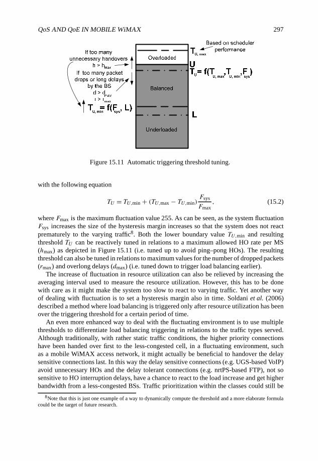
QoS AND QoE IN MOBILE WiMAX 297
Figure 15.11 Automatic triggering threshold tuning.
with the following equation
TU = TU,min + (TU,max − TU,min)Fsys
Fmax, (15.2)
where Fmax is the maximum fluctuation value 255. As can be seen, as the system fluctuationFsys increases the size of the hysteresis margin increases so that the system does not reactprematurely to the varying traffic8. Both the lower boundary value TU,min and resultingthreshold TU can be reactively tuned in relations to a maximum allowed HO rate per MS(hmax) as depicted in Figure 15.11 (i.e. tuned up to avoid ping–pong HOs). The resultingthreshold can also be tuned in relations to maximum values for the number of dropped packets(rmax) and overlong delays (dmax) (i.e. tuned down to trigger load balancing earlier).
The increase of fluctuation in resource utilization can also be relieved by increasing theaveraging interval used to measure the resource utilization. However, this has to be donewith care as it might make the system too slow to react to varying traffic. Yet another wayof dealing with fluctuation is to set a hysteresis margin also in time. Soldani et al. (2006)described a method where load balancing is triggered only after resource utilization has beenover the triggering threshold for a certain period of time.
An even more enhanced way to deal with the fluctuating environment is to use multiplethresholds to differentiate load balancing triggering in relations to the traffic types served.Although traditionally, with rather static traffic conditions, the higher priority connectionshave been handed over first to the less-congested cell, in a fluctuating environment, suchas a mobile WiMAX access network, it might actually be beneficial to handover the delaysensitive connections last. In this way the delay sensitive connections (e.g. UGS-based VoIP)avoid unnecessary HOs and the delay tolerant connections (e.g. nrtPS-based FTP), not sosensitive to HO interruption delays, have a chance to react to the load increase and get higherbandwidth from a less-congested BSs. Traffic prioritization within the classes could still be
8Note that this is just one example of a way to dynamically compute the threshold and a more elaborate formulacould be the target of future research.
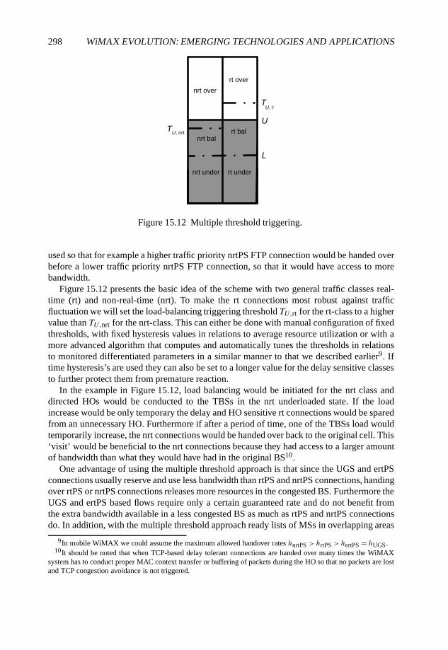
298 WiMAX EVOLUTION: EMERGING TECHNOLOGIES AND APPLICATIONS
U
T U, rt
rt over
nrt over
nrt balrt bal
rt undernrt under
L
T U, nrt
Figure 15.12 Multiple threshold triggering.
used so that for example a higher traffic priority nrtPS FTP connection would be handed overbefore a lower traffic priority nrtPS FTP connection, so that it would have access to morebandwidth.
Figure 15.12 presents the basic idea of the scheme with two general traffic classes real-time (rt) and non-real-time (nrt). To make the rt connections most robust against trafficfluctuation we will set the load-balancing triggering threshold TU,rt for the rt-class to a highervalue than TU,nrt for the nrt-class. This can either be done with manual configuration of fixedthresholds, with fixed hysteresis values in relations to average resource utilization or with amore advanced algorithm that computes and automatically tunes the thresholds in relationsto monitored differentiated parameters in a similar manner to that we described earlier9. Iftime hysteresis’s are used they can also be set to a longer value for the delay sensitive classesto further protect them from premature reaction.
In the example in Figure 15.12, load balancing would be initiated for the nrt class anddirected HOs would be conducted to the TBSs in the nrt underloaded state. If the loadincrease would be only temporary the delay and HO sensitive rt connections would be sparedfrom an unnecessary HO. Furthermore if after a period of time, one of the TBSs load wouldtemporarily increase, the nrt connections would be handed over back to the original cell. This‘visit’ would be beneficial to the nrt connections because they had access to a larger amountof bandwidth than what they would have had in the original BS10.
One advantage of using the multiple threshold approach is that since the UGS and ertPSconnections usually reserve and use less bandwidth than rtPS and nrtPS connections, handingover rtPS or nrtPS connections releases more resources in the congested BS. Furthermore theUGS and ertPS based flows require only a certain guaranteed rate and do not benefit fromthe extra bandwidth available in a less congested BS as much as rtPS and nrtPS connectionsdo. In addition, with the multiple threshold approach ready lists of MSs in overlapping areas
9In mobile WiMAX we could assume the maximum allowed handover rates hnrtPS > hrtPS > hertPS = hUGS.10It should be noted that when TCP-based delay tolerant connections are handed over many times the WiMAX
system has to conduct proper MAC context transfer or buffering of packets during the HO so that no packets are lostand TCP congestion avoidance is not triggered.
QoS AND QoE IN MOBILE WiMAX 299
could be kept only of the delay tolerant MSs not sensitive to scanning and thus scanning forthe delay sensitive connections could be minimized.
15.4.2 HO Prioritization
Since the proactive use of load balancing with directed HOs will only improve the possibilityto fulfill QoS guarantees, load control functions are also needed. Load control can beconducted for example by blocking new service flow requests, by lowering the QoS ofexisting flows (and restoring it later) or if possible by conducting vertical HOs to othersystems11. As a last resort ongoing flows can be dropped but should be done in a controlledand prioritized manner.
The focus in this section will be on how HO prioritization over new flow requests could beconducted in mobile WiMAX, how traffic differentiation in HO prioritization could be doneto enable better QoE in the mobile WiMAX access network and finally how load balancingcould complement HO prioritization and how the two could be combined.
15.4.2.1 Background
HO prioritization is usually conducted by reserving some of the resources (i.e. a guard band)for incoming rescue handovers and can be roughly classified to two categories: fixed guardband schemes and dynamic guard band schemes. In fixed guard band schemes the guard bandis fixed and defined manually in network planning. With dynamic guard channel schemes theidea is to tune the guard channel dynamically based on, for example, the number of ongoingcalls in neighboring cells, the estimation of the channel holding times and the number ofHOs to and from the BS. The biggest advantage that the dynamic schemes introduce is moreefficient resource utilization without compromising the QoS requirements. Complexity thatresults from required information exchange between BSs and logic are on the other hand adisadvantage.
Roughly speaking it seems that there are two approaches to dynamic HO resourcereservation. The threshold can be adjusted based on information recorded only locally orbased on both local information and information exchanged between adjacent BSs. Theinformation exchange-based schemes can further be divided into those that just try to estimatethe resources needed in each BS for incoming HOs and those that enable explicit HO resourcereservation per-connection for the entire route that each MS will traverse (the latter canbecome quite expensive unless the mobility patterns of the MSs are known).
In terms of the existing WiMAX Forum network architecture both approaches, local andinformation exchange-based, are in principle possible but the local approach seems morefeasible due to its simplicity and distributed nature. The WiMAX Forum network architecturedoes not currently provide a framework for such information exchange between BSs whichmeans that new messages would have to be introduced to enable information exchange-baseddynamic reservation which would in turn result in lower scalability. Therefore, due to thedistributed, but also flexible nature of mobile WiMAX, local dynamic guard band adaptation
11An approach called Directed Retry (DR) (introduced by Eklundh (1986)) could in principle also be used by theBS to direct blocked flows to another BS and even direct the users that are not in an overlapping area to the nearest BSwith most free capacity (this kind of Network Directed Roaming, proposed by Balachandran et al. (2002), however,requires cross-layer design).
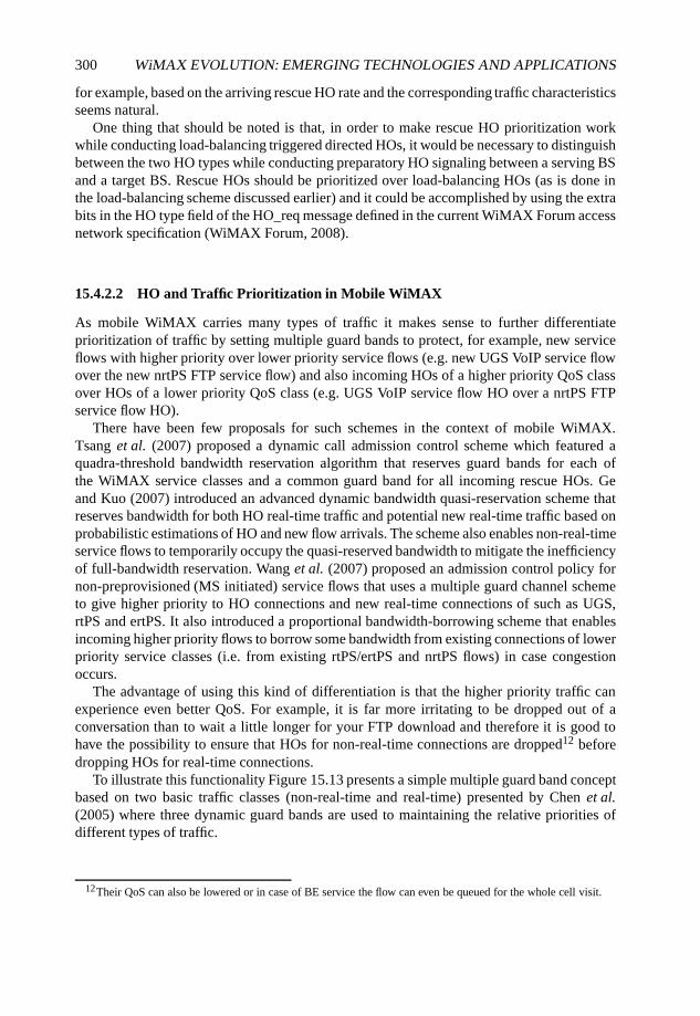
300 WiMAX EVOLUTION: EMERGING TECHNOLOGIES AND APPLICATIONS
for example, based on the arriving rescue HO rate and the corresponding traffic characteristicsseems natural.
One thing that should be noted is that, in order to make rescue HO prioritization workwhile conducting load-balancing triggered directed HOs, it would be necessary to distinguishbetween the two HO types while conducting preparatory HO signaling between a serving BSand a target BS. Rescue HOs should be prioritized over load-balancing HOs (as is done inthe load-balancing scheme discussed earlier) and it could be accomplished by using the extrabits in the HO type field of the HO_req message defined in the current WiMAX Forum accessnetwork specification (WiMAX Forum, 2008).
15.4.2.2 HO and Traffic Prioritization in Mobile WiMAX
As mobile WiMAX carries many types of traffic it makes sense to further differentiateprioritization of traffic by setting multiple guard bands to protect, for example, new serviceflows with higher priority over lower priority service flows (e.g. new UGS VoIP service flowover the new nrtPS FTP service flow) and also incoming HOs of a higher priority QoS classover HOs of a lower priority QoS class (e.g. UGS VoIP service flow HO over a nrtPS FTPservice flow HO).
There have been few proposals for such schemes in the context of mobile WiMAX.Tsang et al. (2007) proposed a dynamic call admission control scheme which featured aquadra-threshold bandwidth reservation algorithm that reserves guard bands for each ofthe WiMAX service classes and a common guard band for all incoming rescue HOs. Geand Kuo (2007) introduced an advanced dynamic bandwidth quasi-reservation scheme thatreserves bandwidth for both HO real-time traffic and potential new real-time traffic based onprobabilistic estimations of HO and new flow arrivals. The scheme also enables non-real-timeservice flows to temporarily occupy the quasi-reserved bandwidth to mitigate the inefficiencyof full-bandwidth reservation. Wang et al. (2007) proposed an admission control policy fornon-preprovisioned (MS initiated) service flows that uses a multiple guard channel schemeto give higher priority to HO connections and new real-time connections of such as UGS,rtPS and ertPS. It also introduced a proportional bandwidth-borrowing scheme that enablesincoming higher priority flows to borrow some bandwidth from existing connections of lowerpriority service classes (i.e. from existing rtPS/ertPS and nrtPS flows) in case congestionoccurs.
The advantage of using this kind of differentiation is that the higher priority traffic canexperience even better QoS. For example, it is far more irritating to be dropped out of aconversation than to wait a little longer for your FTP download and therefore it is good tohave the possibility to ensure that HOs for non-real-time connections are dropped12 beforedropping HOs for real-time connections.
To illustrate this functionality Figure 15.13 presents a simple multiple guard band conceptbased on two basic traffic classes (non-real-time and real-time) presented by Chen et al.(2005) where three dynamic guard bands are used to maintaining the relative priorities ofdifferent types of traffic.
12Their QoS can also be lowered or in case of BE service the flow can even be queued for the whole cell visit.
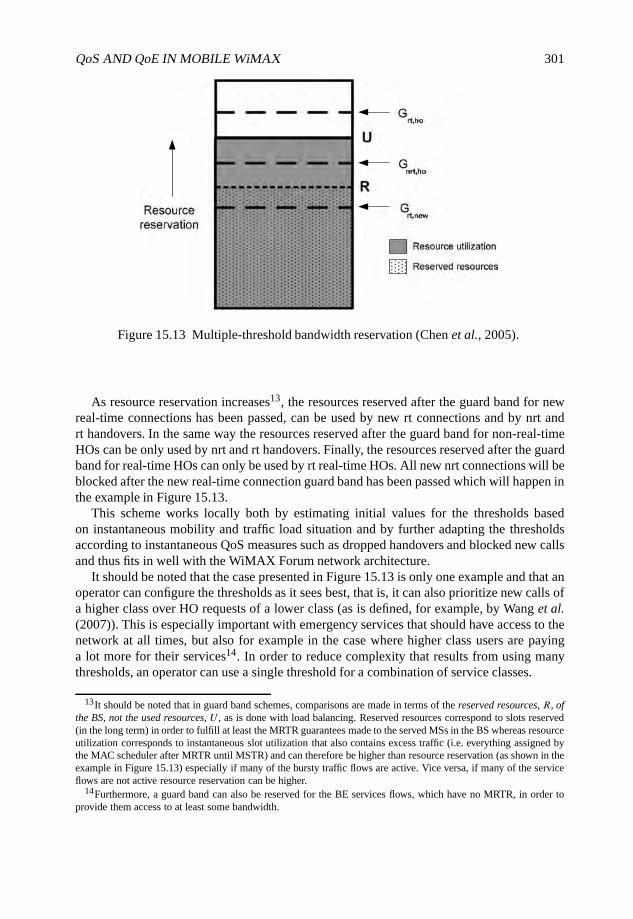
QoS AND QoE IN MOBILE WiMAX 301
Figure 15.13 Multiple-threshold bandwidth reservation (Chen et al., 2005).
As resource reservation increases13, the resources reserved after the guard band for newreal-time connections has been passed, can be used by new rt connections and by nrt andrt handovers. In the same way the resources reserved after the guard band for non-real-timeHOs can be only used by nrt and rt handovers. Finally, the resources reserved after the guardband for real-time HOs can only be used by rt real-time HOs. All new nrt connections will beblocked after the new real-time connection guard band has been passed which will happen inthe example in Figure 15.13.
This scheme works locally both by estimating initial values for the thresholds basedon instantaneous mobility and traffic load situation and by further adapting the thresholdsaccording to instantaneous QoS measures such as dropped handovers and blocked new callsand thus fits in well with the WiMAX Forum network architecture.
It should be noted that the case presented in Figure 15.13 is only one example and that anoperator can configure the thresholds as it sees best, that is, it can also prioritize new calls ofa higher class over HO requests of a lower class (as is defined, for example, by Wang et al.(2007)). This is especially important with emergency services that should have access to thenetwork at all times, but also for example in the case where higher class users are payinga lot more for their services14. In order to reduce complexity that results from using manythresholds, an operator can use a single threshold for a combination of service classes.
13It should be noted that in guard band schemes, comparisons are made in terms of the reserved resources, R, ofthe BS, not the used resources, U , as is done with load balancing. Reserved resources correspond to slots reserved(in the long term) in order to fulfill at least the MRTR guarantees made to the served MSs in the BS whereas resourceutilization corresponds to instantaneous slot utilization that also contains excess traffic (i.e. everything assigned bythe MAC scheduler after MRTR until MSTR) and can therefore be higher than resource reservation (as shown in theexample in Figure 15.13) especially if many of the bursty traffic flows are active. Vice versa, if many of the serviceflows are not active resource reservation can be higher.
14Furthermore, a guard band can also be reserved for the BE services flows, which have no MRTR, in order toprovide them access to at least some bandwidth.
302 WiMAX EVOLUTION: EMERGING TECHNOLOGIES AND APPLICATIONS
TR, rt
TR, nrt
R
U
Reserved resources
Resource utilization
L
U
TU, rt
rt over
nrt over
nrt bal
rt bal
rt undernrt under
R
TU, nrt
Gnrt, ho
Grt, new
Figure 15.14 Resource utilization- and reservation-based multiple threshold triggering.
15.4.2.3 Combined Scheme with Load Balancing
In the load-balancing schemes discussed earlier load balancing is triggered in relations tohigh resource utilization. It is, however, possible, especially if guard bands are used toprioritize incoming traffic and if many of the admitted service flows are not very active,that load balancing will not be triggered (i.e. resource utilization based triggering thresholdis not exceeded) before a reserved guard band is exceeded and hence admission control canunnecessarily start to block flows. Therefore, it would be beneficial to be able to trigger loadbalancing also in relation to the reserved guard bands.
In order to trigger load balancing before a guard band is reached, but not too earlyto avoid unnecessary HOs, a resource reservation based triggering threshold can becomputed based on, for example, the average arrival rate of new slot reservations and thecorresponding average holding times of slots and also in relations to the rate at which theload-balancing scheme can release slots. After computing such a reservation-based triggeringthreshold, it can be further reactively tuned in relations to experienced call blocking and HOrate15. As in resource utilization-based triggering these parameters could be differentiatedcorrespondingly.
Putting all of the pieces together, an example of the final framework with the rt and nrtclasses is presented in Figure 15.14. It features differentiated thresholds TU,nrt and TU,rt forresource utilization-based load balancing, differentiated guard bandsGnrt,ho and Grt,new andthe corresponding resource reservation-based load-balancing triggering thresholds TR,nrt andTR,rt.
Although the examples for both of the schemes have been presented with the nrt and rtexample classes, the schemes can be extended to all of the scheduling services that mobileWiMAX supports by adding more thresholds or used as such for aggregated groups ofscheduling services16 to simplify the scheme and limit the number of thresholds. All in
15Also possibly in relation to bandwidth borrowing.16For example, UGS, ertPS and rtPS use real-time and nrtPS and BE use non-real-time.
QoS AND QoE IN MOBILE WiMAX 303
all this kind of a framework has the ability to react to the loading situation on the level17
that is at the time most critical and can thus maximize the efficient use of resources andminimize unnecessary packet drops and flow blocking. At the same time it is able to avoidhandover drops in a differentiated way resulting in a mobile WiMAX access network that hasan improved capability to meet the needs of users and provide better QoE on a system level.
15.5 Conclusions
In this chapter we have discussed different ways of enabling QoS and QoE in a mobileWiMAX system. The issue has been discussed both on the view point of per-flow schedulingwithin a single BS and on the system-level within a cluster of BSs.
The BS MAC scheduler was discussed and evaluation cases were presented where theMAC scheduler was optimized in relation to the service experienced in a Web-page retrievalprocedure. The system-level QoS tools load balancing and HO prioritization, were alsocovered and new enhancements were proposed to enable differentiation of QoS and betteruser experiences.
As discussed in some of the other chapters of the book, requirements and expectations canvary between different WiMAX scenarios and use cases. Thus, when designing and deployinga WiMAX access network, the important question to ask, is not necessarily how to ensurethat the requirement of a certain QoS parameter is fulfilled but rather, what are the needs ofthe users. Then, once there is a good understanding on what kind of an experience a user of aservice (e.g. UGS or BE) would typically like to have in the particular WiMAX deployment,the parameters of the access network can be optimized and differentiated in relations to theseneeds to enable better QoE for the end user.
Acknowledgements
The authors of Chapter 15 are grateful to Mr Jose Pradas, Mr Keijo Hyttinen and Dr JaakkoTalvitie for their contributions to this work.
References
Aalto, S. and Lassila, P.E. (2007) Impact of size-based scheduling on flow level performance in wirelessdownlink data channels. Proceedings of the 20th International Teletraffic Congress, pp. 1096–1107.
Balachandran, A., Bahl, P. and Voelker, G.M. (2002) Hot-Spot congestion relief in public-area wirelessnetworks. Proceedings of the 4th IEEE Workshop on Mobile Computing Systems and Applications,pp. 70–80.
Casey, T. (2008) Base Station Controlled Load Balancing with Handovers in Mobile WiMAX. Master’sthesis Department of Communications and Networking, Helsinki University of Technology.
Casey, T., Veselinovic, N. and Jäntti, R. (2008) Base station controlled load balancing with handoversin mobile WiMAX. Proceedings of the 19th IEEE International Symposium on Personal, Indoor andMobile Radio Communications.
17Packet-level resource utilization versus flow level resource reservation.
304 WiMAX EVOLUTION: EMERGING TECHNOLOGIES AND APPLICATIONS
Chen, X., Li, B. and Fang, Y. (2005) A dynamic multiple-threshold bandwidth reservation (DMTBR)scheme for QoS provisioning in multimedia wireless networks. IEEE Transactions on WirelessCommunications 4(2), 583–592.
Cicconetti, C., Lenzini, L., Mingozzi, E. and Eklund, C. (2006) Quality of service support in IEEE802.16 networks. IEEE Network 20(2), 50–55.
Cox, D. and Reudink, D. (1973) Increasing channel occupancy in large-scale mobile radio systems:Dynamic channel REassignment. IEEE Transactions on Vehicular Technology 22(4), 218–222.
Dong, G. and Dai, J. (2007) An improved handover algorithm for scheduling services in IEEE 802.16e.Proceedings of the IEEE Mobile WiMAX Symposium, 2007, pp. 38–42.
Eklundh, B. (1986) Channel utilization and blocking probability in a cellular mobile telephone systemwith directed retry. IEEE Transactions on Communications 34(4), 329–337.
Ge, Y. and Kuo, G.S. (2007) Dynamic bandwidth quasi-reservation scheme for real-time servicesin IEEE 802.16e networks. Proceedings of the IEEE Wireless Communications and NetworkingConference, 2007, pp. 1700–1705.
ITU-T (1994) ITU-T Recommendation E.600 - Terms and Definitions Related to QoS and NetworkPerformance Including Dependability.
ITU-T (2001) End-user multimedia QoS categories - Recommendation G.1010.Kilkki, K. (1999) Differentiated Services for the Internet. Macmillan Technical Publishing, USA.Kim, D., Sawhney, M. and Yoon, H. (2007) An effective traffic management scheme using adaptive
handover time in next-generation cellular networks. International Journal of Network Management17, 139–154.
Kwon, T., Lee, H., Choi, S. et al. (2005) Design and implementation of a simulator based on a cross-layer protocol between MAC and PHY layers in a WiBro compatible IEEE 802.16e OFDMA system.IEEE Communications Magazine 43(12), 136–146.
Lee, S.H. and Han, Y. (2007) A novel inter-FA handover scheme for load balancing in IEEE 802.16esystem. Proceedings of the IEEE 65th Vehicular Technology Conference, pp. 763–767.
Moiseev, S., Filin, S., Kondakov, M. et al. (2006) Load-balancing QoS-guaranteed handover in theIEEE 802.16e OFDMA network. Proceedings of the Global Telecommunications Conference, 2006,pp. 1–5.
Rath, H.K., Bhorkar, A. and Sharma, V. (2006) An opportunistic DRR (O-DRR) uplink schedulingscheme for IEEE 802.16-based broadband wireless networks. Proceedings of the IETE InternationalConference on Next Generation Networks (ICNGN).
Sayenko, A., Alanen, O., Karhula, J. and Hämäläinen, T. (2006) Ensuring the QoS requirements in802.16 scheduling. Proceedings of the 9th ACM International Symposium on Modeling, Analysisand Simulation of Wireless and Mobile Systems, pp. 108–117.
Soldani, D., Cuny, R. and Li, M. (2006) QoS and QoE Management in UMTS Cellular Networks. JohnWiley & Sons Ltd, Chichester, England.
Tsang, K.F., Lee, L.T., Tung, H.Y. et al. (2007) Admission control scheme for mobile WiMAXnetworks. Proceedings of the IEEE International Symposium on Consumer Electronics, 2007,pp. 1–5.
Velayos, H., Aleo, V. and Karlsson, G. (2004) Load balancing in overlapping wireless LAN cells.Proceedings of the IEEE International Conference on Communications, 2004, Vol. 7, pp. 3833–3836.
Veselinovic, N. et al. (2008) QoS of experience in 802.16e. Proceedings of the 11th InternationalSymposium on Wireless Personal Multimedia Communications.
Wang, L., Liu, F., Ji, Y. and Ruangchaijatupon, N. (2007) Admission control for non-preprovisionedservice flow in wireless metropolitan area networks. Proceedings of the 4th European Conferenceon Universal Multiservice Networks, pp. 243–249.
WiMAX Forum (2008) WiMAX Forum Network Architecture (Stage 3: Detailed Protocols andProcedures - Release 1, Version 1.2).

Part VI
WiMAX Evolution and FutureDevelopments
WiMAX Evolution: Emerging Technologies and Applications Edited by Tsutomu Ishikawa© 2009 John Wiley & Sons, Ltd. ISBN: 978-0-470-69680-4
16
MIMO Technologies for WiMAXSystems: Present and Future
Chan-Byoung Chae, Kaibin Huang and Takao Inoue
16.1 Introduction
Multiple input multiple output (MIMO) technology is a key breakthrough in wirelesscommunication. By using multiple antennas, MIMO technology multiplies throughputwithout requiring additional frequency bandwidth, enhances link reliability through spatialdiversity and enlarges the coverage area by increasing the transmission range. These featureshave motivated extensive research on developing MIMO theory and techniques in the lastdecade. One of the main goals of the IEEE802.16 standard (WiMAX)1 is to deliver last-mile wireless broadband access as an alternative to cable and Digital Subscriber Line (DSL).Achieving this goal critically hinges on the application of MIMO for enhancing throughputand link reliability as expected in the last-mile of wireless access, for applications such ashigh-quality video streaming. In this chapter we summarize single-user MIMO techniquesthat have been adopted in IEEE 802.16e, and multiuser MIMO techniques that are beingconsidered for IEEE802.16m (WiMAX evolution).
MIMO techniques can be grouped into two categories: single-user and multiuser MIMO.As illustrated in Figure 16.1(a), a single-user MIMO system is a point-to-point link betweena Base Station (BS) and one scheduled Mobile Station (MS), where multiple antennas areemployed at both ends. For single-user MIMO systems, MIMO techniques help to increaseuser throughput by either supporting multiple data streams or improving link reliability.In Section 16.2, we discuss various single-user MIMO techniques that have been includedin the IEEE802.16e standard.
Multiuser MIMO techniques represent the latest developments in MIMO theory. As shownin Figure 16.1(b), multiuser MIMO enables a BS to transmit multiple data streams to multiple
1WiMAX, the World Interoperability for Microwave Access, is based on the IEEE802.16 standard. Hereafter,we use the IEEE802.16 for consistency.
WiMAX Evolution: Emerging Technologies and Applications Edited by Tsutomu Ishikawa© 2009 John Wiley & Sons, Ltd. ISBN: 978-0-470-69680-4
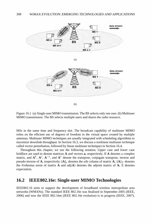
308 WiMAX EVOLUTION: EMERGING TECHNOLOGIES AND APPLICATIONS
(a)
(b)
Figure 16.1 (a) Single-user MIMO transmission. The BS selects only one user. (b) MultiuserMIMO transmission. The BS selects multiple users and shares the radio resource.
MSs in the same time and frequency slot. The broadcast capability of multiuser MIMOrelies on the efficient use of degrees of freedom in the virtual space created by multipleantennas. Multiuser MIMO techniques are usually integrated with scheduling algorithms tomaximize downlink throughput. In Section 16.3, we discuss a nonlinear multiuser techniquecalled vector perturbation, followed by linear multiuser techniques in Section 16.4.
Throughout this chapter, we use the following notation. Upper case and lower caseboldface are used to denote matrices A and vectors a, respectively. If A denotes a complexmatrix, and AT, A∗, A−1, and A† denote the transpose, conjugate transpose, inverse andpseudo-inverse of A, respectively; [A]u denotes the uth column of matrix A; ‖A‖F denotesthe Frobenius norm of matrix A and adj(A) denotes the adjoint matrix of A; E denotesexpectation.
16.2 IEEE802.16e: Single-user MIMO Technologies
IEEE802.16 aims to support the development of broadband wireless metropolitan areanetworks (WMANs). The standard IEEE 802.16e was finalized in September 2005 (IEEE,2006) and now the IEEE 802.16m (IEEE 802.16e evolution) is in progress (IEEE, 2007).
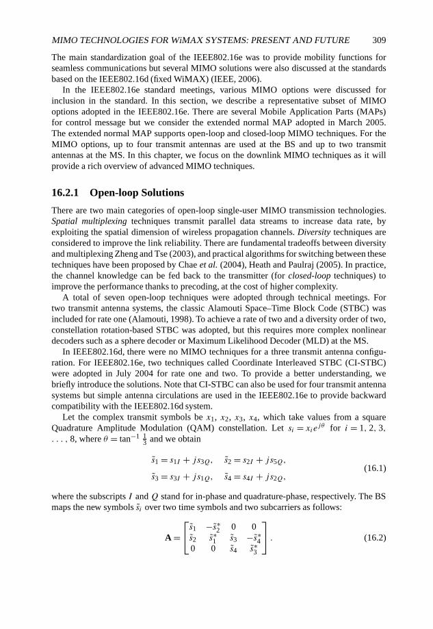
MIMO TECHNOLOGIES FOR WiMAX SYSTEMS: PRESENT AND FUTURE 309
The main standardization goal of the IEEE802.16e was to provide mobility functions forseamless communications but several MIMO solutions were also discussed at the standardsbased on the IEEE802.16d (fixed WiMAX) (IEEE, 2006).
In the IEEE802.16e standard meetings, various MIMO options were discussed forinclusion in the standard. In this section, we describe a representative subset of MIMOoptions adopted in the IEEE802.16e. There are several Mobile Application Parts (MAPs)for control message but we consider the extended normal MAP adopted in March 2005.The extended normal MAP supports open-loop and closed-loop MIMO techniques. For theMIMO options, up to four transmit antennas are used at the BS and up to two transmitantennas at the MS. In this chapter, we focus on the downlink MIMO techniques as it willprovide a rich overview of advanced MIMO techniques.
16.2.1 Open-loop Solutions
There are two main categories of open-loop single-user MIMO transmission technologies.Spatial multiplexing techniques transmit parallel data streams to increase data rate, byexploiting the spatial dimension of wireless propagation channels. Diversity techniques areconsidered to improve the link reliability. There are fundamental tradeoffs between diversityand multiplexing Zheng and Tse (2003), and practical algorithms for switching between thesetechniques have been proposed by Chae et al. (2004), Heath and Paulraj (2005). In practice,the channel knowledge can be fed back to the transmitter (for closed-loop techniques) toimprove the performance thanks to precoding, at the cost of higher complexity.
A total of seven open-loop techniques were adopted through technical meetings. Fortwo transmit antenna systems, the classic Alamouti Space–Time Block Code (STBC) wasincluded for rate one (Alamouti, 1998). To achieve a rate of two and a diversity order of two,constellation rotation-based STBC was adopted, but this requires more complex nonlineardecoders such as a sphere decoder or Maximum Likelihood Decoder (MLD) at the MS.
In IEEE802.16d, there were no MIMO techniques for a three transmit antenna configu-ration. For IEEE802.16e, two techniques called Coordinate Interleaved STBC (CI-STBC)were adopted in July 2004 for rate one and two. To provide a better understanding, webriefly introduce the solutions. Note that CI-STBC can also be used for four transmit antennasystems but simple antenna circulations are used in the IEEE802.16e to provide backwardcompatibility with the IEEE802.16d system.
Let the complex transmit symbols be x1, x2, x3, x4, which take values from a squareQuadrature Amplitude Modulation (QAM) constellation. Let si = xie
jθ for i = 1, 2, 3,. . . , 8, where θ = tan−1 1
3 and we obtain
s1 = s1I + js3Q, s2 = s2I + js5Q,
s3 = s3I + js1Q, s4 = s4I + js2Q,(16.1)
where the subscripts I and Q stand for in-phase and quadrature-phase, respectively. The BSmaps the new symbols si over two time symbols and two subcarriers as follows:
A =s1 −s∗2 0 0s2 s∗1 s3 −s∗40 0 s4 s∗3
. (16.2)

310 WiMAX EVOLUTION: EMERGING TECHNOLOGIES AND APPLICATIONS
Figure 16.2 Transmitter and receiver structures for Matrix A and Matrix B for three transmitantenna systems.
Thus, the transmit symbols s1 and s2 are transmitted through subcarrier f1 and transmitantennas 1 and 2 over time 1 and 2, while s3 and s4 are transmitted through subcarrier f2and transmit antennas 2 and 3 over time 1 and 2.
For rate two transmission, the BS uses the following mapping matrix,
B =
√
34 0 0
0√
34 0
0 0√
32
s1 −s∗2 s5 −s∗6s2 s∗1 s6 s∗5s7 −s∗8 s3 −s∗4
, (16.3)
where the definition for the remaining variables are given by
s5 = s5I + js7Q, s6 = s6I + js8Q,
s7 = s7I + js5Q, s8 = s8I + js6Q.(16.4)
Since each symbol si experiences more independent channels (than a simple Alamouti-basedapproach), better diversity gains are attained. The mapping matrices A and B are permutedbased on the mapping subcarrier index to avoid a power imbalance. Figure 16.2 illustratesthe transmitter and receiver structures for three transmit antenna systems.
For rate three transmission, simple spatial multiplexing is used as follows:
C =x1x2x3
. (16.5)
Note that original complex transmit symbols xi are used for the rate three transmission whilethe coordinated interleaved symbols si are used for the rate one and two transmissions.
For four transmit antenna systems, simple concatenated Alamouti codes were adoptedfor rate one and two cases even though CI-STBC can also be used because of backward
MIMO TECHNOLOGIES FOR WiMAX SYSTEMS: PRESENT AND FUTURE 311
compatibility. The mapping matrices A, B and C are given by
A =
x1 −x∗
2 0 0x2 x∗
1 0 00 0 x3 −x∗
40 0 x4 x∗
3
, (16.6)
B =
x1 −x∗
2 x5 −s∗7x2 x∗
1 x6 −x∗8
x3 −x∗4 x7 −x∗
5x4 x∗
3 x8 x∗6
, (16.7)
C =
x1x2x3x4
. (16.8)
It is notable that full diversity cannot be achieved through the matrices A and B, so circulatedversions of the matrices are used to achieve better diversity gain (see IEEE (2006)).
16.2.2 Closed-loop Solutions
Aiming to improve open-loop MIMO systems, several closed-loop solutions with a goodperformance-complexity trade-off were proposed Chae et al. (2008c), Gore and Paulraj(2002), Heath et al. (2001), Shim et al. (2005). Most closed-loop MIMO techniques exhibitgood link performance in low-mobility environments, but link performance deterioratesconsiderably in rapidly changing channels.
In the IEEE802.16e, there are two categories of closed-loop solutions: (i) antennagrouping/selection; (ii) beamforming/precoding. Exploiting only a few feedback bits wasshown to significantly enhance the link quality. As an example, for a four transmit antennacase, antenna grouping techniques to minimize Frobenius norm of each grouping pair wereproposed for rate one (Chae et al., 2008c) and as well as to minimize the received MeanSquare Error (MSE) for rate two (Shim et al., 2005), based on the mapping matrices Aand B. Diversity gain can be further enhanced through antenna selection methods but theirperformance deteriorates in high mobility environments. In contrast, antenna grouping showsgood performance with relatively low complexity in a wide range of mobility environments.
When more than two bits are available for the feedback channel, Grassmannian beam-forming and precoding can be used (Love and Heath, 2005, Love et al., 2003). The MSscalculate their MSE of the received signal or capacity to choose the codeword that the BSwill use in data transmission and feed back the codeword index to the BS. Instead of storingall the codewords, efficient codewords construction methods were included in IEEE802.16e.
We summarize all MIMO solutions adopted in the IEEE802.16e in Table 16.1.
16.2.3 Limitations
From the point of view of information theory, supporting multiple users in the spatial domainis necessary to enhance the cell throughput (Gesbert et al., 2007). As can be seen fromTable 16.1, however, no multiuser MIMO solution exists in the IEEE802.16e standard. This
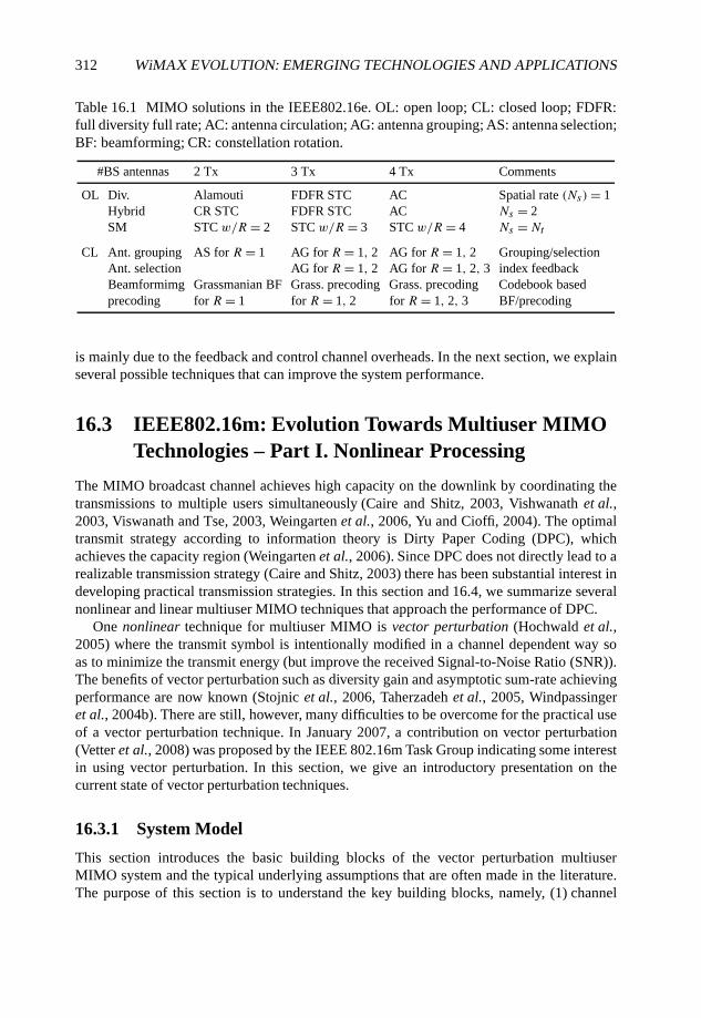
312 WiMAX EVOLUTION: EMERGING TECHNOLOGIES AND APPLICATIONS
Table 16.1 MIMO solutions in the IEEE802.16e. OL: open loop; CL: closed loop; FDFR:full diversity full rate; AC: antenna circulation; AG: antenna grouping; AS: antenna selection;BF: beamforming; CR: constellation rotation.
#BS antennas 2 Tx 3 Tx 4 Tx Comments
OL Div. Alamouti FDFR STC AC Spatial rate (Ns)= 1Hybrid CR STC FDFR STC AC Ns = 2SM STC w/R = 2 STC w/R = 3 STC w/R = 4 Ns =Nt
CL Ant. grouping AS for R = 1 AG for R = 1, 2 AG for R = 1, 2 Grouping/selectionAnt. selection AG for R = 1, 2 AG for R = 1, 2, 3 index feedbackBeamformimg Grassmanian BF Grass. precoding Grass. precoding Codebook basedprecoding for R = 1 for R = 1, 2 for R = 1, 2, 3 BF/precoding
is mainly due to the feedback and control channel overheads. In the next section, we explainseveral possible techniques that can improve the system performance.
16.3 IEEE802.16m: Evolution Towards Multiuser MIMOTechnologies – Part I. Nonlinear Processing
The MIMO broadcast channel achieves high capacity on the downlink by coordinating thetransmissions to multiple users simultaneously (Caire and Shitz, 2003, Vishwanath et al.,2003, Viswanath and Tse, 2003, Weingarten et al., 2006, Yu and Cioffi, 2004). The optimaltransmit strategy according to information theory is Dirty Paper Coding (DPC), whichachieves the capacity region (Weingarten et al., 2006). Since DPC does not directly lead to arealizable transmission strategy (Caire and Shitz, 2003) there has been substantial interest indeveloping practical transmission strategies. In this section and 16.4, we summarize severalnonlinear and linear multiuser MIMO techniques that approach the performance of DPC.
One nonlinear technique for multiuser MIMO is vector perturbation (Hochwald et al.,2005) where the transmit symbol is intentionally modified in a channel dependent way soas to minimize the transmit energy (but improve the received Signal-to-Noise Ratio (SNR)).The benefits of vector perturbation such as diversity gain and asymptotic sum-rate achievingperformance are now known (Stojnic et al., 2006, Taherzadeh et al., 2005, Windpassingeret al., 2004b). There are still, however, many difficulties to be overcome for the practical useof a vector perturbation technique. In January 2007, a contribution on vector perturbation(Vetter et al., 2008) was proposed by the IEEE 802.16m Task Group indicating some interestin using vector perturbation. In this section, we give an introductory presentation on thecurrent state of vector perturbation techniques.
16.3.1 System Model
This section introduces the basic building blocks of the vector perturbation multiuserMIMO system and the typical underlying assumptions that are often made in the literature.The purpose of this section is to understand the key building blocks, namely, (1) channel
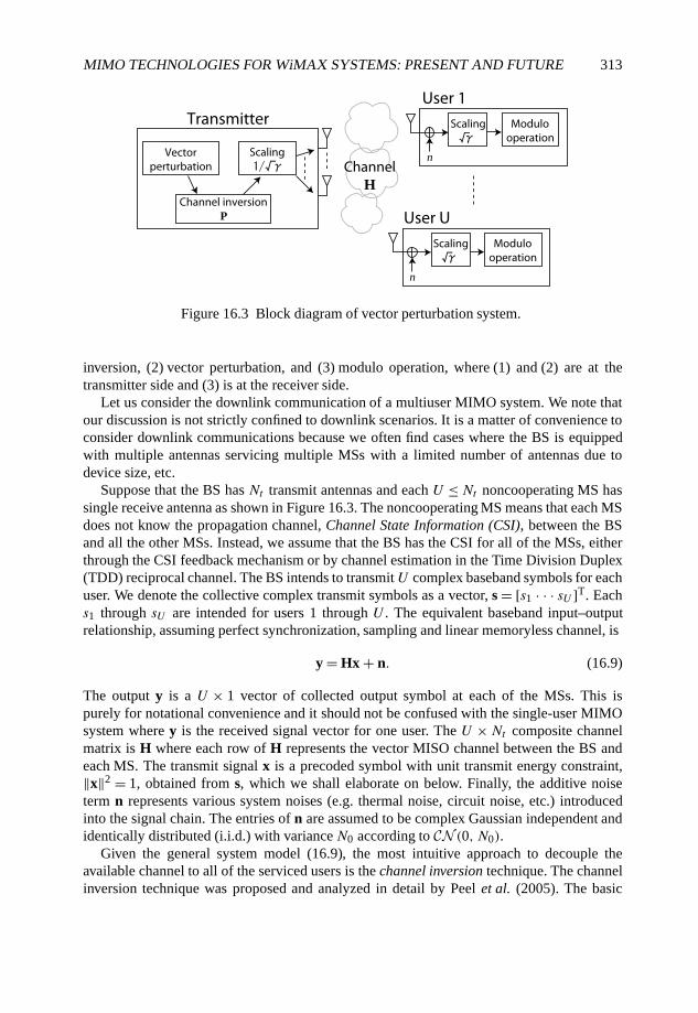
MIMO TECHNOLOGIES FOR WiMAX SYSTEMS: PRESENT AND FUTURE 313
Vectorperturbation
Scaling Modulooperation
Channel inversionP
Scaling n
User 1Transmitter
ChannelH
Scaling Modulooperation
n
User U
Figure 16.3 Block diagram of vector perturbation system.
inversion, (2) vector perturbation, and (3) modulo operation, where (1) and (2) are at thetransmitter side and (3) is at the receiver side.
Let us consider the downlink communication of a multiuser MIMO system. We note thatour discussion is not strictly confined to downlink scenarios. It is a matter of convenience toconsider downlink communications because we often find cases where the BS is equippedwith multiple antennas servicing multiple MSs with a limited number of antennas due todevice size, etc.
Suppose that the BS has Nt transmit antennas and each U ≤Nt noncooperating MS hassingle receive antenna as shown in Figure 16.3. The noncooperating MS means that each MSdoes not know the propagation channel, Channel State Information (CSI), between the BSand all the other MSs. Instead, we assume that the BS has the CSI for all of the MSs, eitherthrough the CSI feedback mechanism or by channel estimation in the Time Division Duplex(TDD) reciprocal channel. The BS intends to transmit U complex baseband symbols for eachuser. We denote the collective complex transmit symbols as a vector, s = [s1 · · · sU ]T. Eachs1 through sU are intended for users 1 through U . The equivalent baseband input–outputrelationship, assuming perfect synchronization, sampling and linear memoryless channel, is
y = Hx + n. (16.9)
The output y is a U × 1 vector of collected output symbol at each of the MSs. This ispurely for notational convenience and it should not be confused with the single-user MIMOsystem where y is the received signal vector for one user. The U ×Nt composite channelmatrix is H where each row of H represents the vector MISO channel between the BS andeach MS. The transmit signal x is a precoded symbol with unit transmit energy constraint,‖x‖2 = 1, obtained from s, which we shall elaborate on below. Finally, the additive noiseterm n represents various system noises (e.g. thermal noise, circuit noise, etc.) introducedinto the signal chain. The entries of n are assumed to be complex Gaussian independent andidentically distributed (i.i.d.) with variance N0 according to CN (0, N0).
Given the general system model (16.9), the most intuitive approach to decouple theavailable channel to all of the serviced users is the channel inversion technique. The channelinversion technique was proposed and analyzed in detail by Peel et al. (2005). The basic
314 WiMAX EVOLUTION: EMERGING TECHNOLOGIES AND APPLICATIONS
principle of channel inversion, as the name implies, is to precode the complex data vectors by the pseudo-inverse of the channel matrix, P = H∗(HH∗)−1. We use pseudo-inverse tocover the possibility that U may be less than Nt . The transmit symbol becomes
x = Ps√γ, (16.10)
where γ = ‖Ps‖2 is the normalization factor to maintain unit transmit energy. The receivedsignal for the uth MS can be written as
yu = 1√γsu + nu. (16.11)
Therefore, precoding the data by the pseudo-inverse of the channel results in a parallelGaussian channel without inter-user interference (uth user’s received signal does not dependon any other user’s signal). The received SNR for the uth user thus becomes
SNRu = ‖su‖2
γN0. (16.12)
The unfortunate implication of channel inversion is that the received SNR is scaled bya channel dependent factor γ . To see this, consider the eigenvalue decomposition of thechannel matrix product, HH∗ = V�V∗, where V is the matrix of eigenvectors and � is adiagonal matrix with ordered eigenvalues, λu for k = 1, . . . , U , along the diagonal. Usingthe eigenvalues and eigenvectors, we may rewrite the scaling factor γ as
γ =U∑k=1
1
λu|〈fu, s〉|2, (16.13)
where 〈·, ·〉 denotes the inner product of vectors and fu is the uth eigenvector of V. When thechannel is ill-conditioned, the smallest eigenvalue may become very small leading to a verylarge γ (Edelman, 1989). Thus, conditioned on the channel, some users may see a very poorsignal degrading the sum rate performance. The next component, vector perturbation, helpsto reduce the effect of the channel and improve the sum rate performance of the system.
16.3.2 Vector Perturbation
Vector perturbation (Hochwald et al., 2005) was proposed to overcome the aforementionedeffects of γ in channel inversion. The basic idea is to perturb the data symbols individually bya scaled integer such that the scaling factor γ is minimized. By minimizing γ , the receivedSNR is maximized, thus resulting in better Bit Error Rate (BER) performance. But howexactly do we perturb the data?
The perturbations are performed for real and imaginary components of the complex datasymbol s. For this reason, we now modify our notation to consider the real and imaginarycomponents separately. Using the notation from Windpassinger et al. (2004a), we define anequivalent real-valued system model. Let � and � denote the real and imaginary parts of acomplex variable, respectively. Then, (16.9) can be rewritten as[�y
�y
]=
[�H −�H�H �H
] [�x�x
]+
[�n�n
]. (16.14)
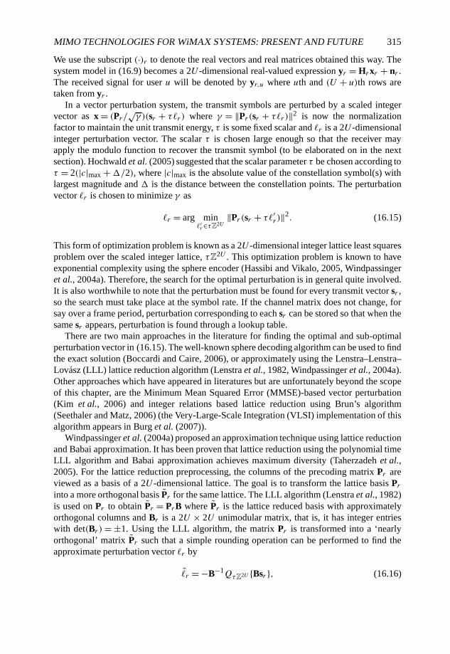
MIMO TECHNOLOGIES FOR WiMAX SYSTEMS: PRESENT AND FUTURE 315
We use the subscript (·)r to denote the real vectors and real matrices obtained this way. Thesystem model in (16.9) becomes a 2U -dimensional real-valued expression yr = Hrxr + nr .The received signal for user u will be denoted by yr,u where uth and (U + u)th rows aretaken from yr .
In a vector perturbation system, the transmit symbols are perturbed by a scaled integervector as x = (Pr/
√γ )(sr + τ�r ) where γ = ‖Pr (sr + τ�r )‖2 is now the normalization
factor to maintain the unit transmit energy, τ is some fixed scalar and �r is a 2U -dimensionalinteger perturbation vector. The scalar τ is chosen large enough so that the receiver mayapply the modulo function to recover the transmit symbol (to be elaborated on in the nextsection). Hochwald et al. (2005) suggested that the scalar parameter τ be chosen according toτ = 2(|c|max +�/2), where |c|max is the absolute value of the constellation symbol(s) withlargest magnitude and � is the distance between the constellation points. The perturbationvector �r is chosen to minimize γ as
�r = arg min�′r∈τZ2U
‖Pr (sr + τ�′r )‖2. (16.15)
This form of optimization problem is known as a 2U -dimensional integer lattice least squaresproblem over the scaled integer lattice, τZ
2U . This optimization problem is known to haveexponential complexity using the sphere encoder (Hassibi and Vikalo, 2005, Windpassingeret al., 2004a). Therefore, the search for the optimal perturbation is in general quite involved.It is also worthwhile to note that the perturbation must be found for every transmit vector sr ,so the search must take place at the symbol rate. If the channel matrix does not change, forsay over a frame period, perturbation corresponding to each sr can be stored so that when thesame sr appears, perturbation is found through a lookup table.
There are two main approaches in the literature for finding the optimal and sub-optimalperturbation vector in (16.15). The well-known sphere decoding algorithm can be used to findthe exact solution (Boccardi and Caire, 2006), or approximately using the Lenstra–Lenstra–Lovász (LLL) lattice reduction algorithm (Lenstra et al., 1982, Windpassinger et al., 2004a).Other approaches which have appeared in literatures but are unfortunately beyond the scopeof this chapter, are the Minimum Mean Squared Error (MMSE)-based vector perturbation(Kim et al., 2006) and integer relations based lattice reduction using Brun’s algorithm(Seethaler and Matz, 2006) (the Very-Large-Scale Integration (VLSI) implementation of thisalgorithm appears in Burg et al. (2007)).
Windpassinger et al. (2004a) proposed an approximation technique using lattice reductionand Babai approximation. It has been proven that lattice reduction using the polynomial timeLLL algorithm and Babai approximation achieves maximum diversity (Taherzadeh et al.,2005). For the lattice reduction preprocessing, the columns of the precoding matrix Pr areviewed as a basis of a 2U -dimensional lattice. The goal is to transform the lattice basis Printo a more orthogonal basis Pr for the same lattice. The LLL algorithm (Lenstra et al., 1982)is used on Pr to obtain Pr = PrB where Pr is the lattice reduced basis with approximatelyorthogonal columns and Br is a 2U × 2U unimodular matrix, that is, it has integer entrieswith det(Br )= ±1. Using the LLL algorithm, the matrix Pr is transformed into a ‘nearlyorthogonal’ matrix Pr such that a simple rounding operation can be performed to find theapproximate perturbation vector �r by
�r = −B−1QτZ2U {Bsr }, (16.16)
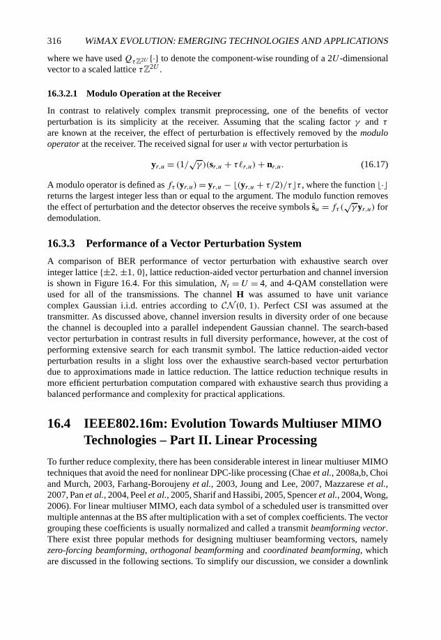
316 WiMAX EVOLUTION: EMERGING TECHNOLOGIES AND APPLICATIONS
where we have used QτZ2U {·} to denote the component-wise rounding of a 2U -dimensionalvector to a scaled lattice τZ
2U .
16.3.2.1 Modulo Operation at the Receiver
In contrast to relatively complex transmit preprocessing, one of the benefits of vectorperturbation is its simplicity at the receiver. Assuming that the scaling factor γ and τ
are known at the receiver, the effect of perturbation is effectively removed by the modulooperator at the receiver. The received signal for user u with vector perturbation is
yr,u = (1/√γ )(sr,u + τ�r,u)+ nr,u. (16.17)
A modulo operator is defined as fτ (yr,u)= yr,u − �(yr,u + τ/2)/τ�τ , where the function �·�returns the largest integer less than or equal to the argument. The modulo function removesthe effect of perturbation and the detector observes the receive symbols su = fτ (
√γ yr,u) for
demodulation.
16.3.3 Performance of a Vector Perturbation System
A comparison of BER performance of vector perturbation with exhaustive search overinteger lattice {±2,±1, 0}, lattice reduction-aided vector perturbation and channel inversionis shown in Figure 16.4. For this simulation, Nt = U = 4, and 4-QAM constellation wereused for all of the transmissions. The channel H was assumed to have unit variancecomplex Gaussian i.i.d. entries according to CN (0, 1). Perfect CSI was assumed at thetransmitter. As discussed above, channel inversion results in diversity order of one becausethe channel is decoupled into a parallel independent Gaussian channel. The search-basedvector perturbation in contrast results in full diversity performance, however, at the cost ofperforming extensive search for each transmit symbol. The lattice reduction-aided vectorperturbation results in a slight loss over the exhaustive search-based vector perturbationdue to approximations made in lattice reduction. The lattice reduction technique results inmore efficient perturbation computation compared with exhaustive search thus providing abalanced performance and complexity for practical applications.
16.4 IEEE802.16m: Evolution Towards Multiuser MIMOTechnologies – Part II. Linear Processing
To further reduce complexity, there has been considerable interest in linear multiuser MIMOtechniques that avoid the need for nonlinear DPC-like processing (Chae et al., 2008a,b, Choiand Murch, 2003, Farhang-Boroujeny et al., 2003, Joung and Lee, 2007, Mazzarese et al.,2007, Pan et al., 2004, Peel et al., 2005, Sharif and Hassibi, 2005, Spencer et al., 2004, Wong,2006). For linear multiuser MIMO, each data symbol of a scheduled user is transmitted overmultiple antennas at the BS after multiplication with a set of complex coefficients. The vectorgrouping these coefficients is usually normalized and called a transmit beamforming vector.There exist three popular methods for designing multiuser beamforming vectors, namelyzero-forcing beamforming, orthogonal beamforming and coordinated beamforming, whichare discussed in the following sections. To simplify our discussion, we consider a downlink
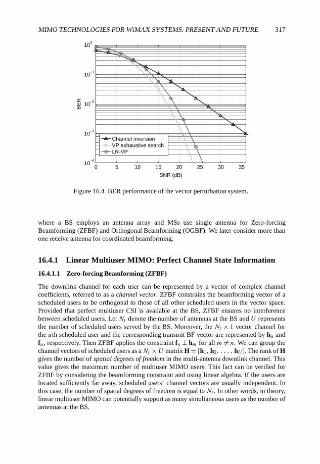
MIMO TECHNOLOGIES FOR WiMAX SYSTEMS: PRESENT AND FUTURE 317
0 5 10 15 20 25 30 3510
–4
10–3
10–2
10–1
100
SNR (dB)
BE
R
Channel inversion
VP exhaustive search
LR-VP
Figure 16.4 BER performance of the vector perturbation system.
where a BS employs an antenna array and MSs use single antenna for Zero-forcingBeamforming (ZFBF) and Orthogonal Beamforming (OGBF). We later consider more thanone receive antenna for coordinated beamforming.
16.4.1 Linear Multiuser MIMO: Perfect Channel State Information
16.4.1.1 Zero-forcing Beamforming (ZFBF)
The downlink channel for each user can be represented by a vector of complex channelcoefficients, referred to as a channel vector. ZFBF constrains the beamforming vector of ascheduled users to be orthogonal to those of all other scheduled users in the vector space.Provided that perfect multiuser CSI is available at the BS, ZFBF ensures no interferencebetween scheduled users. Let Nt denote the number of antennas at the BS and U representsthe number of scheduled users served by the BS. Moreover, the Nt × 1 vector channel forthe uth scheduled user and the corresponding transmit BF vector are represented by hu andfu, respectively. Then ZFBF applies the constraint fn ⊥ hm for all m �= n. We can group thechannel vectors of scheduled users as aNt × U matrix H = [h1, h2, . . . , hU ]. The rank of Hgives the number of spatial degrees of freedom in the multi-antenna downlink channel. Thisvalue gives the maximum number of multiuser MIMO users. This fact can be verified forZFBF by considering the beamforming constraint and using linear algebra. If the users arelocated sufficiently far away, scheduled users’ channel vectors are usually independent. Inthis case, the number of spatial degrees of freedom is equal to Nt . In other words, in theory,linear multiuser MIMO can potentially support as many simultaneous users as the number ofantennas at the BS.
318 WiMAX EVOLUTION: EMERGING TECHNOLOGIES AND APPLICATIONS
For downlink using linear multiuser MIMO, a data symbol2 received at the uth MS isgiven as
yu = P
Uf∗uhuxu +
U∑m=1m�=u
P
Uf∗mhuxm + zu, (16.18)
where zu represents a sample of the additive Gaussian white noise process. Under the ZFBFconstraint with perfect transmit CSI, the second term on the right-hand-size of (16.18) isequal to zero, indicating no multiuser interference. Hence, the downlink throughput can bewritten as
Rz =U∑u=1
E
[log2
(1 + P
Uσ 2 |h∗ufu|2
)], (16.19)
where P is the total transmission power and σ 2 represents the variance of zu. Usually, ZFBFis designed to achieve high throughput by maximizing the number of scheduled users, namelyU =Nt . In contrast, Time Division Multiple Access (TDMA) schedules a single user andapplies beamforming for maximizing this user’s link reliability. Using MIMO terminologies,multiuser MIMO and TDMA achieve multiplexing gain and diversity gain, respectively. Thisdifference between multiuser MIMO using ZFBF and TDMA using single-user beamformingis illustrated by the following example.
Example 16.1 In this example, the downlink channel coefficients h1, h2, . . . , hNt are i.i.d.CN (0, 1). For TDMA, one user is scheduled in each slot and the single data stream istransmitted using Maximum Ratio Transmission (MRT), mentioned earlier. For high SNRsand using Lapidoth and Moser (2003, Equation 209), the TDMA ergodic throughput isobtained as
R(TDMA)≈ E
[log2
(P
Nt∑u=1
|hu|2)], SNR � 1, (16.20)
= log2 P − ζ +Nt−1∑u=1
1
u, (16.21)
where ζ denotes Euler’s constant (ζ = 0.577 . . .). For linear multiuser MIMO using ZFBFand having Nt scheduled users, note that the term |h∗
ufu| in (16.19) is CN (0, 1) since fu isindependent of hu under the ZFBF constraint. Thus, from (16.19) and Lapidoth and Moser(2003, Equation 209), the multiuser MIMO throughput is
R(MU-MIMO)≈ E
[Nt log2
(P
Nt|h1|2
)], SNR � 1, (16.22)
=Nt log2 P − logNt − ζ. (16.23)
For high SNRs, R(TDMA) in (16.21) and R(MU-MIMO) in (16.23) can be further approxi-mated as log2 P andNt log2 P , respectively. Thus, the throughput of linear multiuser MIMOis about Nt times higher than that of TDMA for high SNRs.
2The time index of a data symbol is omitted to simplify notation.
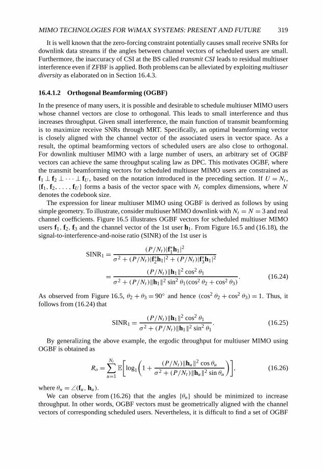
MIMO TECHNOLOGIES FOR WiMAX SYSTEMS: PRESENT AND FUTURE 319
It is well known that the zero-forcing constraint potentially causes small receive SNRs fordownlink data streams if the angles between channel vectors of scheduled users are small.Furthermore, the inaccuracy of CSI at the BS called transmit CSI leads to residual multiuserinterference even if ZFBF is applied. Both problems can be alleviated by exploiting multiuserdiversity as elaborated on in Section 16.4.3.
16.4.1.2 Orthogonal Beamforming (OGBF)
In the presence of many users, it is possible and desirable to schedule multiuser MIMO userswhose channel vectors are close to orthogonal. This leads to small interference and thusincreases throughput. Given small interference, the main function of transmit beamformingis to maximize receive SNRs through MRT. Specifically, an optimal beamforming vectoris closely aligned with the channel vector of the associated users in vector space. As aresult, the optimal beamforming vectors of scheduled users are also close to orthogonal.For downlink multiuser MIMO with a large number of users, an arbitrary set of OGBFvectors can achieve the same throughput scaling law as DPC. This motivates OGBF, wherethe transmit beamforming vectors for scheduled multiuser MIMO users are constrained asf1 ⊥ f2 ⊥ · · · ⊥ fU , based on the notation introduced in the preceding section. If U =Nt ,{f1, f2, . . . , fU } forms a basis of the vector space with Nt complex dimensions, where Ndenotes the codebook size.
The expression for linear multiuser MIMO using OGBF is derived as follows by usingsimple geometry. To illustrate, consider multiuser MIMO downlink withNt = N = 3 and realchannel coefficients. Figure 16.5 illustrates OGBF vectors for scheduled multiuser MIMOusers f1, f2, f3 and the channel vector of the 1st user h1. From Figure 16.5 and (16.18), thesignal-to-interference-and-noise ratio (SINR) of the 1st user is
SINR1 = (P/Nt )|f∗1h1|2σ 2 + (P/Nt )|f∗2h1|2 + (P/Nt )|f∗3h1|2
= (P/Nt )‖h1‖2 cos2 θ1
σ 2 + (P/Nt )‖h1‖2 sin2 θ1(cos2 θ2 + cos2 θ3). (16.24)
As observed from Figure 16.5, θ2 + θ3 = 90◦ and hence (cos2 θ2 + cos2 θ3)= 1. Thus, itfollows from (16.24) that
SINR1 = (P/Nt )‖h1‖2 cos2 θ1
σ 2 + (P/Nt )‖h1‖2 sin2 θ1. (16.25)
By generalizing the above example, the ergodic throughput for multiuser MIMO usingOGBF is obtained as
Ro =Nt∑u=1
E
[log1
(1 + (P/Nt )‖hu‖2 cos θu
σ 2 + (P/Nt )‖hu‖2 sin θu
)], (16.26)
where θu = ∠(fu, hu).We can observe from (16.26) that the angles {θn} should be minimized to increase
throughput. In other words, OGBF vectors must be geometrically aligned with the channelvectors of corresponding scheduled users. Nevertheless, it is difficult to find a set of OGBF

320 WiMAX EVOLUTION: EMERGING TECHNOLOGIES AND APPLICATIONS
Figure 16.5 OGBF vectors and the channel vector of the 1st user in R3 for downlink
multiuser MIMO.
vectors that aligned with channel vectors so that throughput is maximized. We can find anapproximation of the optimal set of OGBF vectors by performing an exhaustive search overa sequence of randomly generated orthonormal bases, denoted as {V (m)}Mm=1 with V (n) ={f(m)1 , f(m)2 , . . . , f(m)Nt
}. Specifically, the throughput achieved by the exhaustive search is
R�o = max1≤m≤M
Nt∑u=1
E
[log1
(1 + (P/Nt )|h∗
uf(m)u |2
σ 2 + (P/Nt )∑Nt
n=1n�=u
|h∗uf(m)n |2
)](16.27)
and the corresponding transmit beamforming vectors belong to the orthonormal set V(m�)where m� is the maximizing index in (16.27). Although inefficient, the above approachfor finding OGBF vectors is simple. Moreover, higher computational complexity is moreaffordable at the BS where the power consumption requirement is less stringent than the MS.
16.4.1.3 Coordinated Beamforming
ZFBF and OGBF described above only work for one receive antenna per user. Throughputperformance, however, can be further improved using jointly optimized transmitter andreceiver beamforming vectors when each MS has more than one receive antenna (Chaeet al., 2006a,b, Farhang-Boroujeny et al., 2003, Pan et al., 2004, Schubert and Boche, 2004).These approaches perform close to the sum capacity but require an iterative algorithm tocompute the transmit and receive beamformers. In this section, we summarize a noniterativelinear multiuser MIMO technique called coordinated beamforming (Chae et al., 2008a,b,Mazzarese et al., 2007).
Consider a multiuser MIMO system with two antennas at the transmitter and Nr receiveantennas for each of U users. Here we specifically focus on the case where the transmitter is

MIMO TECHNOLOGIES FOR WiMAX SYSTEMS: PRESENT AND FUTURE 321
equipped with two transmit antennas3. In this case, the channel between the transmitter andthe uth user is represented by an Nr × Nt matrix. Let xu denote the transmit symbol of theuth user, and nu be the additive white Gaussian noise vector observed at the receiver. Let fudenote the unit-norm transmit beamforming vector and wu the unit-norm receive combiningvector for the uth user. The signal at the uth user after receiver combining is
yu = w∗uHufuxu + w∗
uHu
U∑l=1,l �=u
flxl + w∗unu. (16.28)
The subspace decomposition algorithm presented in Farhang-Boroujeny et al. (2003)iteratively leads to a choice of the transmit and receive beamformers that achieve the property
w∗uHufl
{= 0, u �= l,
> 0, u= l.(16.29)
Therefore, there is no inter-user interference by applying this algorithm in an ideal channel.It was noted in Farhang-Boroujeny et al. (2003) that although the iterative algorithm seemedto converge in most cases, it could not be guaranteed. Note that Maximal Ratio Combining(MRC) is assumed at the MS, given by wu = Hufu. This is a reasonable design since itachieves the sum rate very close to capacity under the zero interference constraint.
Thus, the effective channel of user u, which includes the effect of the receiver matchedfilter, is f∗uRu where Ru = H∗
uHu. The U transmit beamformers are initialized to somerandom vectors fu,1, u= 1, . . . , U . Then the following two operations are repeated withincreasing i (iteration index) until a stopping criterion is met
Hi = [(f∗1,iR1)T · · · (f∗U,iRU)T]T, (16.30)
Fi+1 = H−1i , (16.31)
where Fi+1 = [f1,i+1 · · · fU,i+1], and fu,i+1 is the transmit beamforming column–vector forthe uth user at the (i + 1)th iteration, without normalization. A stopping criterion based onconvergence can be used, but a fixed number of iterations, for example 20 with four transmitantennas, is sufficient in most cases to obtain a stable solution.
In Chae et al. (2008a), the authors derived a closed-form expression for the transmitbeamforming vectors. As shown in Chae et al. (2008a), we can exactly solve[
f1 f2] = [[(f∗1R1)
T(f∗2R2)T]T]−1. (16.32)
The cases where the convergence fails occur with probability zero, and are thus notconsidered in practice. The closed-form expression allows us to solve the problem of slowiteration cases, and offers a computationally attractive solution.
As shown in Chae et al. (2008a) that the algorithm will converge to the same solution ifwe define
Ru = H∗uHu
‖Hu‖2F
=(Ru,11 Ru,12Ru,21 Ru,22
), (16.33)
3For more than two antenna cases, see Chae et al. (2008a).
322 WiMAX EVOLUTION: EMERGING TECHNOLOGIES AND APPLICATIONS
where ‖Hu‖2F is the squared Frobenius norm of the 2 × 2 complex matrix Hu. Let us define
the following notation
A1 =(R1,22 −R1,12
−R∗1,12 R1,11
), (16.34)
A2 =(R2,11 R2,12R∗
2,12 R2,22
). (16.35)
With the matrices A1 and A2, we define G, a, b, t1 and t2 as
G = A1A2 =(g11 g12g21 g22
), (16.36)
a = (g11 − g22)/2, (16.37)
b =√(a2 + g21g12), (16.38)
t1 =(a − b
g21
)and t2 =
(a + b
g21
). (16.39)
Finally, the transmit beamformers for user 1 and 2 are given by
f1 = t1√(a − b)2 + g2
21
, (16.40)
f2 = t2√(a + b)2 + g2
21
. (16.41)
The derivation of the closed-form expression in the two transmit antenna case, explainedby Chae et al. (2008a), gives insights as to why the algorithm does not converge, or convergesin some cases very slowly.
16.4.2 Linear Multiuser MIMO: Limited Feedback
Linear multiuser MIMO requires transmit CSI for adapting beamforming to time-varyingchannels. For most systems including the IEEE802.16, transmit CSI is acquired throughfeedback by the receiver that performs channel estimation. In the IEEE802.16 systems, CSIfeedback relies on finite-rate feedback channels. Thus, efficient CSI quantization is required,which is related to an active research field known as limited feedback, focusing on the designof efficient CSI feedback techniques (Love and Heath Jr., 2006, Love et al., 2003).
The most common approach for limited feedback relies on codebook-based quantizationfor reducing CSI feedback into a small number of bits for each feedback instant. Designingcodebooks is a popular theme in the area of limited feedback. The most important findingrelated to the codebook design is its equivalence with the classic geometry problem ofpacking on the Grassmannian or the Stiefel manifold (Love et al., 2003, Mukkavilli et al.,2003). Beamforming and precoding codebooks designed based on such a relationship havebeen demonstrated to achieve low-rate CSI feedback with near optimal performance. Let Cdenote the codebook of N Nt × 1 unitary vectors that is designed based on the criterion of

MIMO TECHNOLOGIES FOR WiMAX SYSTEMS: PRESENT AND FUTURE 323
packing on the Grassmannian manifold. Then at the uth MS, the CSI is quantized as
hu = maxf∈C
|f∗hu|2. (16.42)
The codebook index of hu is sent back from the uth MS to the BS, where the CSI feedbackrequires log2 N bits. Based on limited feedback, the BS obtains quantized multiuser CSI anduses it for computing transmit beamforming vectors.
Limited feedback results in CSI inaccuracy in transmit CSI. Consequently, if all MSs havesingle antennas, MSs can no longer be decoupled even if zero-forcing transmit beamformingis applied. Specifically, limited feedback results in residual interference for linear multiuserMIMO. From (16.18), the ergodic throughput for linear multiuser MIMO is given as
R =NtE
[log2
(1 + (P/Nt )|h∗
ufu|2σ 2 + (P/Nt )
∑Ntn=1n�=u
|h∗ufn|2
)]. (16.43)
The above expression holds for ZFBF, OGBF and coordinated beamforming. Nevertheless,they differ in both the CSI quantizer codebook design and the computation of beamformingvectors, resulting in different throughput. For ZFBF, the single-user Grassmannian code-books (see, e.g., Love et al. (2003), Mukkavilli et al. (2003)) are suitable for CSI quantizationin (16.42). For OGBF, the quantizer codebook C in (16.42) must consist of multiple setsof orthonormal vectors. This facilitates OGBF where a particular orthonormal vector setis selected as beamforming vectors and the associated users are scheduled. For ZFBF,transmit beamforming vectors are computed from quantized feedback CSI such that thebeamforming vector fn ⊥ hm for allm �= n. This computation involves inversion of the matrix[h1, h2, . . . , hNt ] and normalization of the columns of the resultant matrix.
It has been found that limited feedback places an upper-bound on downlink throughput,which is independent of transmission power (Ding et al., 2007, Jindal, 2006). A relevantobservation is that constraining the throughput loss due to limited feedback requires moreCSI feedback for larger transmission power. These two observations are quantified in thefollowing example for ZFBF and the rich scattering environment. Similar results in thisexample can be also obtained for OGBF.
Example 16.2 We consider downlink where Nt users are scheduled for multiuser MIMOusing ZFBF. The downlink channel is narrow-band and channel coefficients are i.i.d.CN (0, 1). Each MS sends back CSI using limited feedback. The codebook C used forquantizing CSI as in (16.42) consists of randomly generated unitary vectors which arei.i.d. and isotropic. Given these assumptions, the throughput in (16.19) is upper-bounded as(Jindal, 2006)
Rz ≤Nt
[1 + B + log2 e
Nt − 1+ log2(Nt − 2)+ log2 e
], (16.44)
where Q= log2 M is the number of feedback bits per user. The upper-bound in (16.44) isindependent of the transmission powerP and is a function ofQ. This implies that the residualinterference caused by CSI inaccuracy prevents throughput from continuously growing withincreasing transmission.
The throughput loss due to limited feedback can be measured by the throughput differencebetween the cases of perfect CSI and limited feedback, which is define as �Rz = Rz − Rz
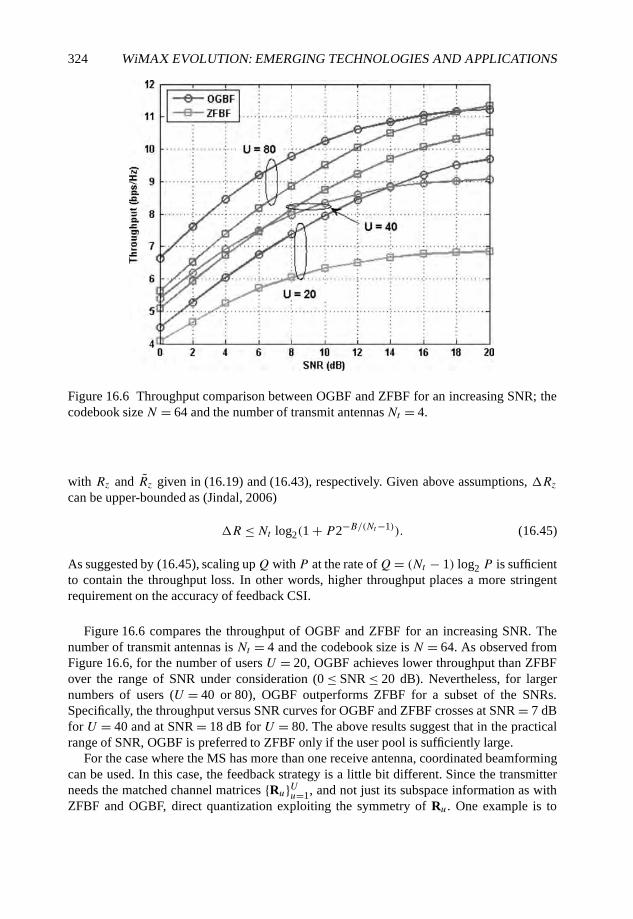
324 WiMAX EVOLUTION: EMERGING TECHNOLOGIES AND APPLICATIONS
Figure 16.6 Throughput comparison between OGBF and ZFBF for an increasing SNR; thecodebook size N = 64 and the number of transmit antennasNt = 4.
with Rz and Rz given in (16.19) and (16.43), respectively. Given above assumptions, �Rzcan be upper-bounded as (Jindal, 2006)
�R ≤Nt log2(1 + P2−B/(Nt−1)). (16.45)
As suggested by (16.45), scaling upQ with P at the rate ofQ= (Nt − 1) log2 P is sufficientto contain the throughput loss. In other words, higher throughput places a more stringentrequirement on the accuracy of feedback CSI.
Figure 16.6 compares the throughput of OGBF and ZFBF for an increasing SNR. Thenumber of transmit antennas is Nt = 4 and the codebook size is N = 64. As observed fromFigure 16.6, for the number of users U = 20, OGBF achieves lower throughput than ZFBFover the range of SNR under consideration (0 ≤ SNR ≤ 20 dB). Nevertheless, for largernumbers of users (U = 40 or 80), OGBF outperforms ZFBF for a subset of the SNRs.Specifically, the throughput versus SNR curves for OGBF and ZFBF crosses at SNR = 7 dBfor U = 40 and at SNR = 18 dB for U = 80. The above results suggest that in the practicalrange of SNR, OGBF is preferred to ZFBF only if the user pool is sufficiently large.
For the case where the MS has more than one receive antenna, coordinated beamformingcan be used. In this case, the feedback strategy is a little bit different. Since the transmitterneeds the matched channel matrices {Ru}Uu=1, and not just its subspace information as withZFBF and OGBF, direct quantization exploiting the symmetry of Ru. One example is to

MIMO TECHNOLOGIES FOR WiMAX SYSTEMS: PRESENT AND FUTURE 325
quantize Ru as follows:
Ru,11 = αu and Ru,22 = 1 − αu, (16.46)
Ru,21 = βuejϕu and Ru,12 = R∗
u,21, (16.47)
where 0 ≤ αu, βu ≤ 1 and 0 ≤ ϕu < 2π . By choosing αu, βu and ϕu uniformly distributedin these intervals, the users can directly quantize the channel using a finite number of bits.We choose the following quantization method. Parameters αu and βu are quantized usingQ1bits, while ϕu is quantized using Q2 bits:
αu, βu ∈[
1
2Q1+1,
1
2Q1+1+ 1
2Q1, . . . , 1 − 1
2Q1+1
],
ϕu ∈[−π,−π + 2π
2Q2, . . . , π − 2π
2Q2
].
Quantization loss can be further reduced using non-uniform quantization (see Chae et al.(2008a) for more information).
Figure 16.7 illustrates the sum rate of closed-form coordinated beamforming with limitedfeedback, the sum capacity and the largest single-user closed-loop MIMO capacity withperfect channel state information, when the number of users in the cell is the same as thenumber of transmit antennas. In this case, no scheduling algorithm is needed. As can beseen from Figure 16.7, the throughput of coordinated beamforming is quite close to the sumcapacity even with limited feedbackQ1 = 6 bits. It also has about 3.3 bps/Hz gap gain againstthe TDMA approach.
16.4.3 Linear Multiuser MIMO: Multiuser Diversity
As we saw in Example 16.2, the CSI inaccuracy inherent in limited feedback causes residualinterference between multiuser MIMO users even if ZFBF is applied (Jindal, 2008, Yooet al., 2007). Multiuser interference becomes a bottleneck for increasing multiuser MIMOthroughput at high SNRs or for a relatively larger number of multiuser MIMO users. Thisplaces a more stringent requirement on CSI accuracy for multiuser MIMO than that forpoint-to-point MIMO. To acquire highly-accurate CSI without incurring excessive overhead,limited feedback can be integrated with multiuser diversity.
Multiuser diversity refers to the degrees of freedom due to independent fading in differentusers’ channels. This concept was introduced by Knopp and Humblet (1995) for single-antenna downlink, where scheduling the user with the largest channel gain is shown tomaximize capacity. The downlink throughput gain contributed by multiuser diversity iscalled multiuser diversity gain. For MU-MIMO, this gain is achieved by scheduling userswith not only large channel gains but also small mutual interference. Thereby the stringentrequirement on CSI accuracy is relaxed and as a result CSI feedback overhead decreases.In the following section, scheduling algorithms that exploit multiuser diversity are discussedseparately for ZFBF and OGBF.
16.4.3.1 ZFBF with Limited Feedback
A greedy search scheduling algorithm has been designed by Yoo et al. (2007) for the zero-forcing multiuser MIMO discussed in the preceding section, which provides a suboptimal
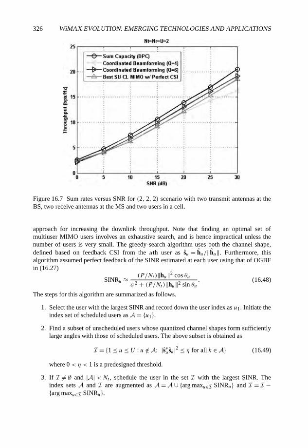
326 WiMAX EVOLUTION: EMERGING TECHNOLOGIES AND APPLICATIONS
Figure 16.7 Sum rates versus SNR for (2, 2, 2) scenario with two transmit antennas at theBS, two receive antennas at the MS and two users in a cell.
approach for increasing the downlink throughput. Note that finding an optimal set ofmultiuser MIMO users involves an exhaustive search, and is hence impractical unless thenumber of users is very small. The greedy-search algorithm uses both the channel shape,defined based on feedback CSI from the uth user as su = hu/‖hu‖. Furthermore, thisalgorithm assumed perfect feedback of the SINR estimated at each user using that of OGBFin (16.27)
SINRu ≈ (P/Nt )‖hu‖2 cos θuσ 2 + (P/Nt )‖hu‖2 sin θu
. (16.48)
The steps for this algorithm are summarized as follows.
1. Select the user with the largest SINR and record down the user index as u1. Initiate theindex set of scheduled users as A = {u1}.
2. Find a subset of unscheduled users whose quantized channel shapes form sufficientlylarge angles with those of scheduled users. The above subset is obtained as
I = {1 ≤ u≤ U : u /∈ A; |s∗usk |2 ≤ η for all k ∈ A} (16.49)
where 0< η < 1 is a predesigned threshold.
3. If I �= ∅ and |A|<Nt , schedule the user in the set I with the largest SINR. Theindex sets A and I are augmented as A = A ∪ {arg maxu∈I SINRu} and I = I −{arg maxu∈I SINRu}.
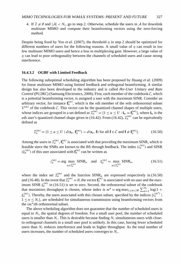
MIMO TECHNOLOGIES FOR WiMAX SYSTEMS: PRESENT AND FUTURE 327
4. If I �= ∅ and |A|<Nt , go to step 2. Otherwise, schedule the users in A for downlinkmultiuser MIMO and compute their beamforming vectors using the zero-forcingmethod.
Despite being fixed by Yoo et al. (2007), the threshold η in step 2 should be optimized fordifferent numbers of users for the following reasons. A small value of η can result in toofew multiuser MIMO users and hence a loss in multiplexing gain. However, a large value ofη can lead to poor orthogonality between the channels of scheduled users and cause stronginterference.
16.4.3.2 OGBF with Limited Feedback
The following suboptimal scheduling algorithm has been proposed by Huang et al. (2009)for linear multiuser MIMO using limited feedback and orthogonal beamforming. A similardesign has also been developed in the industry and is called Per-User Unitary and RateControl (PU2RC) (Samsung Electronics, 2006). First, each member of the codebook C, whichis a potential beamforming vector, is assigned a user with the maximum SINR. Consider anarbitrary vector, for instance f(m)n , which is the nth member of the mth orthonormal subsetV (m) of the codebook C. This vector can be the quantized channel shapes of multiple users,whose indices are grouped in a set defined as I(m)n = {1 ≤ u ≤ U : su = f(m)n }, where su is theuth user’s quantized channel shape given in (16.42). From (16.42), I(m)n can be equivalentlydefined as
I(m)n = {1 ≤ u≤ U | d(su, f(m)n ) < d(su, f) for all f ∈ C and f �= f(m)n }. (16.50)
Among the users in I(m)n , f(m)n is associated with that providing the maximum SINR, which isfeasible since the SNRs are known to the BS through feedback. The index (i(m)n ) and SINR(ξ(m)n ) of this user associated with f(m)n can be written as
i(m)n = arg maxu∈I(m)n
SINRu and ξ(m)n = maxu∈I(m)n
SINRu, (16.51)
where the index set I(m)n and the function SINRu are expressed respectively in (16.50)and (16.48). In the event that I(m)n = ∅, the vector f(m)n is associated with no user and the max-imum SINR ξ
(m)n in (16.51) is set to zero. Second, the orthonormal subset of the codebook
that maximizes throughput is chosen, whose index is m� = arg max1≤m≤M∑Ntn=1 log(1 +
ξ(m)n ). Thereby, the users associated with this chosen subset, specified by the indices {i(m�)n |
1 ≤ n≤Nt }, are scheduled for simultaneous transmission using beamforming vectors fromthe (m�)th orthonormal subset.
The above scheduling algorithm does not guarantee that the number of scheduled users isequal to Nt , the spatial degrees of freedom. For a small user pool, the number of scheduledusers is smaller than Nt . This is desirable because finding Nt simultaneous users with close-to-orthogonal channels in a small user pool is unlikely. In this case, having fewer scheduledusers than Nt reduces interference and leads to higher throughput. As the total number ofusers increases, the number of scheduled users converges to Nt .
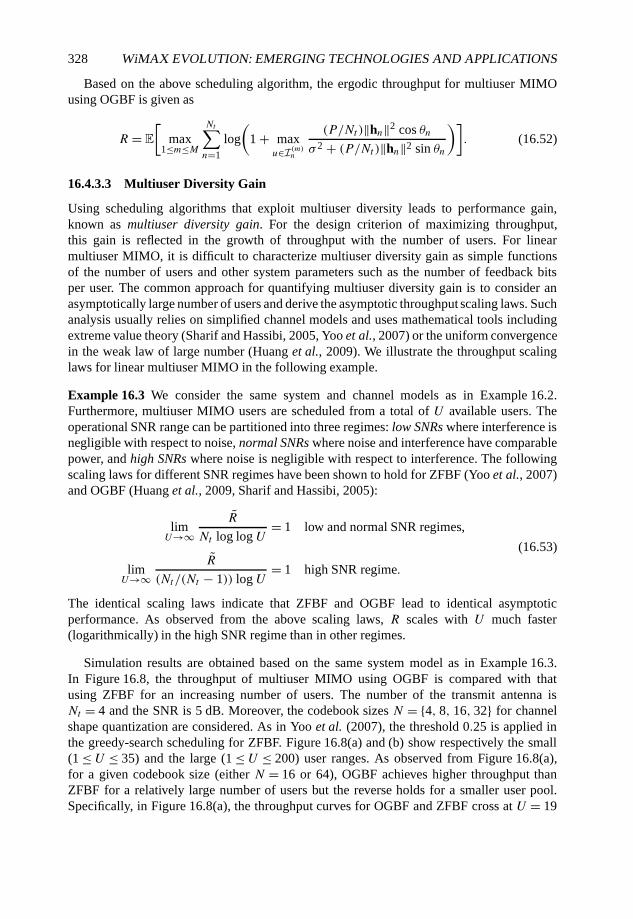
328 WiMAX EVOLUTION: EMERGING TECHNOLOGIES AND APPLICATIONS
Based on the above scheduling algorithm, the ergodic throughput for multiuser MIMOusing OGBF is given as
R = E
[max
1≤m≤M
Nt∑n=1
log
(1 + max
u∈I(m)n
(P/Nt )‖hn‖2 cos θnσ 2 + (P/Nt )‖hn‖2 sin θn
)]. (16.52)
16.4.3.3 Multiuser Diversity Gain
Using scheduling algorithms that exploit multiuser diversity leads to performance gain,known as multiuser diversity gain. For the design criterion of maximizing throughput,this gain is reflected in the growth of throughput with the number of users. For linearmultiuser MIMO, it is difficult to characterize multiuser diversity gain as simple functionsof the number of users and other system parameters such as the number of feedback bitsper user. The common approach for quantifying multiuser diversity gain is to consider anasymptotically large number of users and derive the asymptotic throughput scaling laws. Suchanalysis usually relies on simplified channel models and uses mathematical tools includingextreme value theory (Sharif and Hassibi, 2005, Yoo et al., 2007) or the uniform convergencein the weak law of large number (Huang et al., 2009). We illustrate the throughput scalinglaws for linear multiuser MIMO in the following example.
Example 16.3 We consider the same system and channel models as in Example 16.2.Furthermore, multiuser MIMO users are scheduled from a total of U available users. Theoperational SNR range can be partitioned into three regimes: low SNRs where interference isnegligible with respect to noise, normal SNRs where noise and interference have comparablepower, and high SNRs where noise is negligible with respect to interference. The followingscaling laws for different SNR regimes have been shown to hold for ZFBF (Yoo et al., 2007)and OGBF (Huang et al., 2009, Sharif and Hassibi, 2005):
limU→∞
R
Nt log log U= 1 low and normal SNR regimes,
limU→∞
R
(Nt/(Nt − 1)) log U= 1 high SNR regime.
(16.53)
The identical scaling laws indicate that ZFBF and OGBF lead to identical asymptoticperformance. As observed from the above scaling laws, R scales with U much faster(logarithmically) in the high SNR regime than in other regimes.
Simulation results are obtained based on the same system model as in Example 16.3.In Figure 16.8, the throughput of multiuser MIMO using OGBF is compared with thatusing ZFBF for an increasing number of users. The number of the transmit antenna isNt = 4 and the SNR is 5 dB. Moreover, the codebook sizes N = {4, 8, 16, 32} for channelshape quantization are considered. As in Yoo et al. (2007), the threshold 0.25 is applied inthe greedy-search scheduling for ZFBF. Figure 16.8(a) and (b) show respectively the small(1 ≤ U ≤ 35) and the large (1 ≤ U ≤ 200) user ranges. As observed from Figure 16.8(a),for a given codebook size (either N = 16 or 64), OGBF achieves higher throughput thanZFBF for a relatively large number of users but the reverse holds for a smaller user pool.Specifically, in Figure 16.8(a), the throughput curves for OGBF and ZFBF cross at U = 19
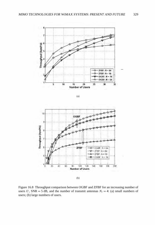
MIMO TECHNOLOGIES FOR WiMAX SYSTEMS: PRESENT AND FUTURE 329
(a)
(b)
Figure 16.8 Throughput comparison between OGBF and ZFBF for an increasing number ofusers U , SNR = 5 dB, and the number of transmit antennas Nt = 4: (a) small numbers ofusers; (b) large numbers of users.
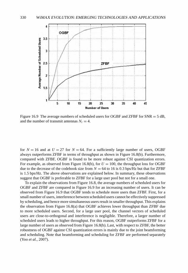
330 WiMAX EVOLUTION: EMERGING TECHNOLOGIES AND APPLICATIONS
Figure 16.9 The average numbers of scheduled users for OGBF and ZFBF for SNR = 5 dB,and the number of transmit antennasNt = 4.
for N = 16 and at U = 27 for N = 64. For a sufficiently large number of users, OGBFalways outperforms ZFBF in terms of throughput as shown in Figure 16.8(b). Furthermore,compared with ZFBF, OGBF is found to be more robust against CSI quantization errors.For example, as observed from Figure 16.8(b), for U = 100, the throughput loss for OGBFdue to the decrease of the codebook size from N = 64 to 16 is 0.3 bps/Hz but that for ZFBFis 1.5 bps/Hz. The above observations are explained below. In summary, these observationssuggest that OGBF is preferable to ZFBF for a large user pool but not for a small one.
To explain the observations from Figure 16.8, the average numbers of scheduled users forOGBF and ZFBF are compared in Figure 16.9 for an increasing number of users. It can beobserved from Figure 16.9 that OGBF tends to schedule more users than ZFBF. First, for asmall number of users, interference between scheduled users cannot be effectively suppressedby scheduling, and hence more simultaneous users result in smaller throughput. This explainsthe observation from Figure 16.8(a) that OGBF achieves lower throughput than ZFBF dueto more scheduled users. Second, for a large user pool, the channel vectors of scheduledusers are close-to-orthogonal and interference is negligible. Therefore, a larger number ofscheduled users leads to higher throughput. For this reason, OGBF outperforms ZFBF for alarge number of users as observed from Figure 16.8(b). Last, with respect to ZFBF, the betterrobustness of OGBF against CSI quantization errors is mainly due to the joint beamformingand scheduling. Note that beamforming and scheduling for ZFBF are performed separately(Yoo et al., 2007).
MIMO TECHNOLOGIES FOR WiMAX SYSTEMS: PRESENT AND FUTURE 331
16.5 Conclusion
In this chapter, we introduced single-user MIMO techniques that have been included inIEEE 802.16e and multiuser MIMO techniques being considered for IEEE 802.16m. Forsingle-user MIMO, we discussed open-loop techniques including classic, concatenated andconstellation rotation-based STBCs, and closed-loop techniques including antenna grouping,antenna selection and limited feedback beamforming and precoding. Multiuser MIMOsolutions were not adopted in IEEE 802.16e due to potentially overwhelming feedback andcontrol overhead. Nevertheless, with increasing demands for high throughput and the recentprogresses in multiuser limited feedback, multiuser MIMO techniques will certainly becomea key physical-layer component for IEEE 802.16m. In the second part of this chapter, wediscussed a nonlinear multiuser MIMO technique, namely vector perturbation and latticereduction-aided precoding, and linear techniques including ZFBF, OGBF and coordinatedbeamforming. Furthermore, we presented multiuser limited feedback for reducing channelfeedback overhead and multiuser diversity algorithms for enhancing the throughput ofmultiuser MIMO.
In this chapter, we did not consider another popular multiuser MIMO solution called blockdiagonalization, which supports multiple data streams for each user given multiple antennasavailable at MSs. In our discussion, we also omitted practical factors such as CSI feedbackdelay and channel estimation errors. In summary, with multiuser MIMO techniques findingtheir way into the IEEE802.16m, there is no doubt that MIMO will continue to play a keyrole in supporting high-rate access in the next-generation of WiMAX systems.
References
Alamouti, S.M. (1998) A simple transmit diversity technique for wireless communications. IEEEJournal of Selected Areas in Communications, 16, 1451–1458.
Boccardi, F. and Caire, G. (2006) The p-sphere encoder: peak-power reduction by lattice precoding forthe MIMO Gaussian broadcast channel. IEEE Transactions on Communications, 54(11), 2085–2091.
Burg, A., Seethaler, D. and Matz, G. (2007) VLSI implementation of a lattice-reduction algorithm formulti-antenna broadcast precoding. Proceedings of the IEEE International Symposium on Circuitsand Systems (ISCAS), pp. 673–676.
Caire, G. and Shitz, S.S. (2003) On the achievable throughput of a multi-antenna Gaussian broadcastchannel. IEEE Transactions on Information Theory, 43, 1691–1706.
Chae, C.B., Heath, Jr., R.W. and Mazzarese, D. (2006a) Achievable sum rate bounds of zero-forcingbased linear multi-user MIMO systems. Proceedings of the Allerton Conference on CommunicationsControl and Computers pp. 1134–1140. Available athttp://users.ece.utexas.edu/∼rheath/papers/2006/allerton/.
Chae, C.B., Katz, M., Suh, C.H. and Jeong, H.S. (2004) Adaptive spatial modulation for MIMO-OFDM. Proceedings of the IEEE Wireless Communications and Networks Conference, 1, 87–92.
Chae, C.B., Mazzarese, D. and Heath, Jr., R.W. (2006b) Coordinated beamforming for multiuser MIMOsystems with limited feedforward. Proceedings of the Asilomar Conference on Signals, Systems andComputers, pp. 1511–1515.
Chae, C.B., Mazzarese, D., Jindal, N. and Heath, Jr., R.W. (2008a) Coordinated beamformingwith limited feedback in the MIMO broadcast channel. IEEE Journal of Selected Areas inCommunications, 26, 1505–1515.
332 WiMAX EVOLUTION: EMERGING TECHNOLOGIES AND APPLICATIONS
Chae, C.B., Mazzarese, D., Jindal, N. and Heath, Jr., R.W. (2008b) A low complexity linear multiuserMIMO beamforming system with limited feedback. Proceedings of the Conference on InformationScience and Systems, pp. 418–422.
Chae, C.B., Shim, S. and Heath, Jr., R.W. (2008c) Space–time block codes with limited feedback usingantenna grouping. IEICE Transactions on Communications, E91-B, 3387–3390.
Choi, L. and Murch, R.D. (2003) A transmit preprocessing technique for multiuser MIMO systemsusing a decomposition approach. IEEE Transactions Wireless Communications, 2, 773–786.
Ding, P., Love, D.J. and Zoltowski, M.D. (2007) Multiple antenna broadcast channels with shapefeedback and limited feedback. IEEE Transactions on Signal Processing, 55, 3417–3428.
Edelman, A. 1989 Eigenvalues and Condition Numbers of Random Matrices. PhD thesis,Massachusetts Institute of Technology.
Farhang-Boroujeny, B., Spencer, Q. and Swindlehurst, A.L. (2003) Layering techniques for space–timecommunications in multi-user networks. Proceedings of the IEEE Vehicle Technology Conference,2, 1339–1342.
Gesbert, D., Kountouris, M., Heath, Jr., R.W., Chae, C.B. and Salzer, T. (2007) Shifting the MIMOparadigm: From single user to multiuser communications. IEEE Signal Processing Magazine, 24,36–46.
Gore, D.A. and Paulraj, A. (2002) MIMO antenna subset selection with space–time coding. IEEETransactions on Signal Processing, 50, 2580–2588.
Hassibi, B. and Vikalo, H. (2005) On the sphere-decoding algorithm I. expected complexity. IEEETransactions on Signal Processing, 53(8), 2806–2818.
Heath, Jr., R.W. and Paulraj, A. (2005) Switching between spatial multiplexing and transmit diversitybased on constellation distance. IEEE Transactions on Communications, 53(6), 962–968.
Heath, Jr., R.W., Sandhu, S. and Paulraj, A. (2001) Antenna selection for spatial multiplexing systemswith linear receivers. IEEE Communication Letters, 5, 142–144.
Hochwald, B., Peel, C. and Swindlehurst, A. (2005) A vector-perturbation technique for near-capacity multiantenna multiuser communication-part II: perturbation. IEEE Transactions onCommunications, 53(3), 537–544.
Huang, K., Andrews, J.G. and Heath, Jr., R.W. (2009) Performance of orthogonal beamforming forSDMA with limited feedback. IEEE Transactions on Vehicle Technologies.
IEEE (2006) IEEE P802.16e-2006 draft standards for local and metropolitan area networks part 16: Airinterface for fixed broadcast wireless access systems. IEEE Standard 802.16e.
IEEE (2007) IEEE P802.16m-2007 draft standards for local and metropolitan area networks part 16:Air interface for fixed broadcast wireless access systems. IEEE Standard 802.16m.
Jindal, N. (2006) MIMO broadcast channels with finite-rate feedback. IEEE Transactions onInformation Theory, 52(11), 5045–60.
Jindal, N. (2008) Antenna combining for the MIMO downlink channel. IEEE Transactions on WirelessCommunications, 7, 3834–3844.
Joung, J. and Lee, Y.H. (2007) Regularized channel diagonalization for multiuser MIMO downlinkusing a modified MMSE criterion. IEEE Transactions on Signal Processing, 55, 1573–1579.
Kim, E.Y., Kim, E.Y. and Chun, J. (2006) Optimum vector perturbation minimizing total MSE inmultiuser MIMO downlink. Proceedings of the IEEE International Conference on Communications(ed. Chun, J.), vol. 9, pp. 4242–4247.
Knopp, R. and Humblet, P. (1995) Information capacity and power control in single-cell multiusercommunications. Proceedings of the IEEE International Conference on Communications, 1,pp. 331–335.
Lapidoth, A. and Moser, S.M. (2003) Capacity bounds via duality with applications to multiple-antennasystems on flat-fading channels. IEEE Transactions on Information Theory, 49(10), 2426–67.
MIMO TECHNOLOGIES FOR WiMAX SYSTEMS: PRESENT AND FUTURE 333
Lenstra, A.K., Lenstra, H.W. and Lováz, L. (1982) Factoring polynomials with rational coefficients.Mathematische Annalen, 261(4), 515–534.
Love, D.J. and Heath, Jr., R.W. (2005) Limited feedback unitary precoding for spatial multiplexing.IEEE Transactions on Information Theory, 51, 2967–2976.
Love, D.J. and Heath Jr., R.W. (2006) Feedback techniques for MIMO channels. MIMO AntennaTechnology for Wireless Communications. CRC Press Boca Raton, FL.
Love, D.J., Heath, Jr., R.W. and Strohmer, T. (2003) Grassmannian beamforming for multiple-inputmultiple-output wireless systems. IEEE Transactions on Information Theory, 49, 2735–2747.
Mazzarese, D., Chae, C.B. and Heath, Jr., R.W. (2007) Jointly optimized multiuser beamforming for theMIMO broadcast channel with limited feedback. Proceedings of the IEEE International Symposiumon Pers., Indoor and Mobile Radio Comm., pp. 1–5.
Mukkavilli, K.K., Sabharwal, A., Erkip, E. and Aazhang, B. (2003) On beamforming with finite ratefeedback in multiple antenna systems. IEEE Transactions on Information Theory, 49(10), 2562–79.
Pan, Z., Wong, K.K. and Ng, T.S. (2004) Generalized multiuser orthogonal space-division multiplexing.IEEE Transactions on Wireless Communications, 3, 1969–1973.
Peel, C.B., Hochwald, B.M. and Swindlehurst, A.L. (2005) A vector-perturbation technique for nearcapacity multiantenna multiuser communication – part I: channel inversion and regularization. IEEETransactions on Communications, 53, 195–202.
Samsung Electronics (2006) Downlink MIMO for EUTRA 3GPP TSG RAN WG1 # 44/R1-060335.Schubert, M. and Boche, H. (2004) Solution of the multiuser downlink beamforming problem with
individual SINR constraints. IEEE Transactions on Vehicle Technologies, 53, 18–28.Seethaler, D. and Matz, G. (2006) Efficient vector perturbation in multi-antenna multi-user systems
based on approximate integer relations. Proceedings of the European Signal Processing Conference(EUSIPCO).
Sharif, M. and Hassibi, B. (2005) On the capacity of MIMO broadcast channel with partial sideinformation. IEEE Transactions on Information Theory, 51, 506–522.
Shim, S., Kim, K. and Lee, C. (2005) An efficient antenna shuffling scheme for a DSTTD system. IEEECommunications Letters, 9, 124–126.
Spencer, Q., Swindlehurst, A.L. and Haardt, M. (2004) Zero-forcing methods for downlink spatialmultiplexing in multiuser MIMO channels. IEEE Transactions on Signal Processing, 52, 462–471.
Stojnic, M., Stojnic, M., Vikalo, H. and Hassibi, B. (2006) Asymptotic analysis of the gaussianbroadcast channel with perturbation preprocessing. Proceedings of the IEEE InternationalConference on Acoustics, Speech and Signal Processing (ed. Vikalo, H.), vol. 4, pp. IV–IV.
Taherzadeh M, Mobasher A and Khandani A (2005) LLL lattice-basis reduction achieves the maximumdiversity in MIMO systems. Proceedings of the IEEE International Symposium on InformationTheory, pp. 1300–1304.
Vetter, H., Sun, Y., Ponnampalam, V., Aoki, T., Kikuchi, S. and Mori, H. (2008) Proposal on multi-usermimo precoding considerations of IEEE802.16m. IEEE 802.16m Standards Contribution – IEEEC802.16m-08/058r1.
Vishwanath, S., Jindal, N. and Goldsmith, A. (2003) Duality, achievable rates, and sum capacity ofGaussian MIMO broadcast channels. IEEE Transactions on Information Theory, 49, 2658–2668.
Viswanath, P. and Tse, D. (2003) Sum capacity of the vector Gaussian broadcast channel and uplink-downlink duality. IEEE Transactions on Information Theory, 49, 1912–1921.
Weingarten, H., Steinberg, Y. and Shitz, S.S. (2006) The capacity region of the Gaussian multiple-inputmultiple-output broadcast channel. IEEE Transactions on Information Theory, 52, 3936–3964.
Windpassinger, C., Fischer, R. and Huber, J. (2004a) Lattice-reduction-aided broadcast precoding.IEEE Transactions on Communications, 52(12), 2057–2060.
Windpassinger, C., Fischer, R., Vencel, T. and Huber, J. (2004b) Precoding in multiantenna andmultiuser communications. IEEE Transactions on Wireless Communications, 3(4), 1305–1316.

334 WiMAX EVOLUTION: EMERGING TECHNOLOGIES AND APPLICATIONS
Wong, K.K. (2006) Maximizing the sum-rate and minimizing the sum-power of a broadcast 2-user 2-input multiple-output antenna system using a generalized zeroforcing approach. IEEE Transactionson Wireless Communications, 5, 3406–3412.
Yoo, T., Jindal, N. and Goldsmith, A. (2007) Multi-antenna broadcast channels with limited feedbackand user selection. IEEE Journal on Selected Areas in Communications, 25(7), 1478–91.
Yu, W. and Cioffi, J. (2004) Sum capacity of Gaussian vector broadcast channels. IEEE Transactionson Information Theory, 50, 1875–1892.
Zheng, L. and Tse, D.N.C. (2003) Diversity and multiplexing: a fundamental tradeoff in multiple-antenna channels. IEEE Transactions on Information Theory, 49(5), 1073–1096.
17
Hybrid Strategies for LinkAdaptation Exploiting SeveralDegrees of Freedom in WiMAXSystems
Suvra Sekhar Das, Muhammad Imadur Rahman andYuanye Wang
17.1 Introduction
The wireless channel condition is constantly changing, both in time and frequency. This isespecially evident in cases when there is relative motion between transmitter and receiver,and when multipaths exist between them. The signal can experience high fluctuation in veryshort intervals of time and frequency. This makes it difficult to achieve high data rates whilemaintaining a target Bit Error Rate (BER)/Frame Error Rate (FER) constraint. Thus, thevariation in channel gain, which is termed as channel dynamics, has to be well exploited tomaximize the data rate. One of the techniques to achieve this is Link Adaptation (LA), wheresystem parameters are adapted according to the channel condition. This allows us to takeadvantage when channel conditions are favorable while optimizing bit and power resourcesduring poorer conditions.
LA is a technique used to introduce a real-time balancing in the link budget in order toincrease the spectral efficiency of a system over fading channels (Chow et al., 1995, Chungand Goldsmith, 2001, Goldsmith, 2005, Hayes, 1968). Parameters such as transmitted powerlevel, modulation scheme, coding rate or any combination of these can be adapted according
WiMAX Evolution: Emerging Technologies and Applications Edited by Tsutomu Ishikawa© 2009 John Wiley & Sons, Ltd. ISBN: 978-0-470-69680-4
336 WiMAX EVOLUTION: EMERGING TECHNOLOGIES AND APPLICATIONS
to the channel conditions. Channel conditions are estimated at the receiver and the ChannelState Information (CSI) is sent to the transmitter to adapt the transmission accordingly.
Nearly all communication systems require some target BER not to be exceeded. It isreasonable to assume an average BER or an instantaneous BER (or FER) as a constraint.One assumption that we make is that we have knowledge of the instantaneous CSI for eachsubcarrier. With this knowledge, transmission parameters can be changed at the transmitter.
When no adaptation is done, the performance is highly dependent on the channelcondition. In cases when the channel gain is poor, the system presents low values of Signal-to-Noise Ratio (SNR) and results in poor BER performance. On the other hand, whenchannel gain is very high, this high gain is not efficiently exploited hence the throughputis not optimized. In order to improve the system performance, adaptation of transmittingbits per symbol and/or power is required. With LA, a low modulation level or high transmitpower will be used when the channel is in deep fade and vice versa, so that the receivedSNR is just enough to provide the required BER target. Some reference points of SNR arerequired to ‘switch’ from one modulation level to another. Theoretically these referencepoints correspond to the SNR-BER curve under Additive White Gaussian Noise (AWGN)channel conditions.
Defining the thresholds for switching between LA parameters is an interesting area ofresearch. One possible criterion for switching points is described by Siebert and Stauffer(2003). A different approach can be found in the work of Song et al. (2002), where theadaptation process is performed considering the subcarrier fading statistics rather thaninstantaneous values. The adaptation can be performed individually for each subcarrier asin Tase et al. (2005) and Zhen et al. (2002), or a certain number of subcarriers can begrouped together to apply the same modulation technique, as described by Hwang et al.(2005). An advantage of performing adaptation by using blocks is a reduction in the amountof information sent during the feedback to the transmitter, as well as a reduced calculationcomplexity. The effects of imperfect CSI in multi-carrier systems with adaptive modulationhave been studied by Ahn and Sasase (2002), Leke and Cioffi (1998), Souryal and Pickholtz(2001) and Ye et al. (2002).
17.2 Link Adaptation Preliminaries
In this section we describe a basic scenario of how the LA is done in an Orthogonal FrequencyDivision Multiplying (OFDM) system. A block diagram of an adaptive modulation over onesingle subcarrier (or subchannel) is shown in Figure 17.1. However, the concept shown inFigure 17.1 can be extended to multi-carrier scenarios by including the channels for the Nsubcarriers (or Nsch subchannels).
We assume that the entire frequency band is divided into N flat fading subcarriers basedon the criteria that the symbol duration is shorter than the coherence time of the channel andthe bandwidth of each subcarrier is narrower than the coherence bandwidth of the system.
We denote hk as the channel response for the kth subcarrier. To simplify the study atthe beginning, it is assumed that an error-free and instantaneous estimation/feedback of thechannel gain is done at the receiver so that the transmitter knows the channel gain perfectly.However, later on we study the effects of delay and noisy estimations of the channel on thesystem.
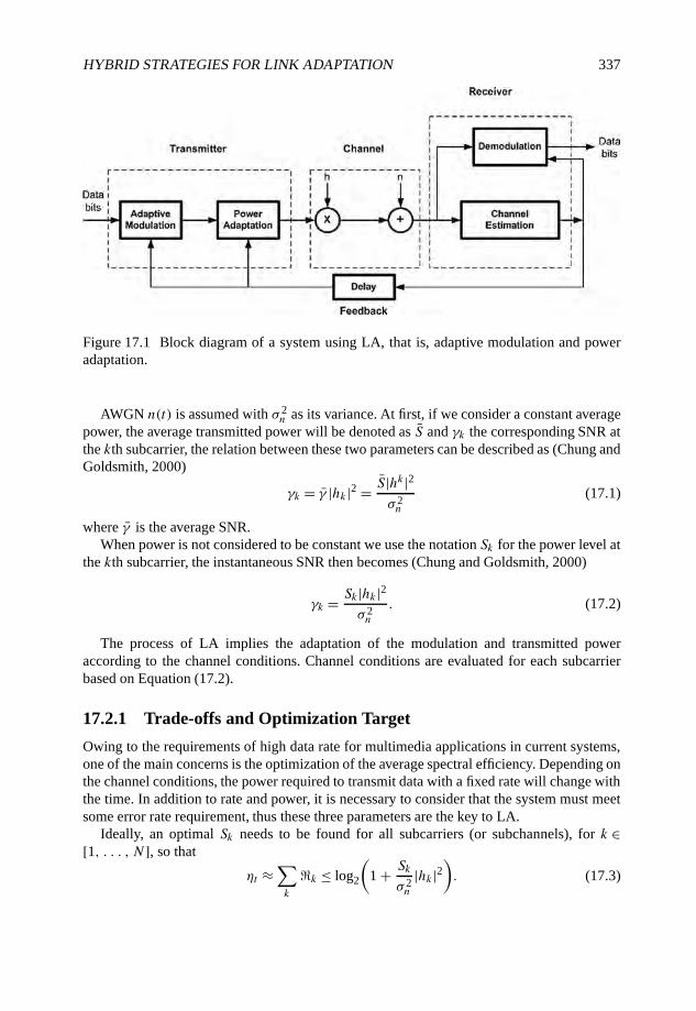
HYBRID STRATEGIES FOR LINK ADAPTATION 337
Figure 17.1 Block diagram of a system using LA, that is, adaptive modulation and poweradaptation.
AWGN n(t) is assumed with σ 2n as its variance. At first, if we consider a constant average
power, the average transmitted power will be denoted as S and γk the corresponding SNR atthe kth subcarrier, the relation between these two parameters can be described as (Chung andGoldsmith, 2000)
γk = γ |hk|2 = S|hk|2σ 2n
(17.1)
where γ is the average SNR.When power is not considered to be constant we use the notation Sk for the power level at
the kth subcarrier, the instantaneous SNR then becomes (Chung and Goldsmith, 2000)
γk = Sk|hk|2σ 2n
. (17.2)
The process of LA implies the adaptation of the modulation and transmitted poweraccording to the channel conditions. Channel conditions are evaluated for each subcarrierbased on Equation (17.2).
17.2.1 Trade-offs and Optimization Target
Owing to the requirements of high data rate for multimedia applications in current systems,one of the main concerns is the optimization of the average spectral efficiency. Depending onthe channel conditions, the power required to transmit data with a fixed rate will change withthe time. In addition to rate and power, it is necessary to consider that the system must meetsome error rate requirement, thus these three parameters are the key to LA.
Ideally, an optimal Sk needs to be found for all subcarriers (or subchannels), for k ∈[1, . . . , N], so that
ηt ≈∑k
�k ≤ log2
(1 + Sk
σ 2n
|hk|2). (17.3)
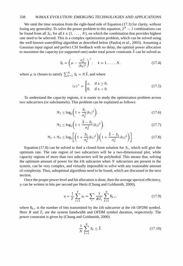
338 WiMAX EVOLUTION: EMERGING TECHNOLOGIES AND APPLICATIONS
We omit the time notation from the right-hand side of Equation (17.3) for clarity, withoutlosing any generality. To solve the power problem in this equation, 2N − 1 combinations canbe found from all Sk , for all k ∈ [1, . . . , N], on which the combination that provides highestrate need to be selected. This is a complex optimization problem, which can be solved usingthe well-known waterfilling algorithm as described below (Paulraj et al., 2003). Assuming aGaussian input signal and perfect CSI feedback with no delay, the optimal power allocationto maximize the capacity (or supported rate) under total power constraint S can be solved as
Sk =(µ− σ 2
n
|hk|2)+
; k = 1, . . . , N, (17.4)
where µ is chosen to satisfy∑Nk=1 Sk =NS, and where
(x)+ ={x, if x ≥ 0,
0, if x < 0.(17.5)
To understand the capacity regions, it is easier to study the optimization problem acrosstwo subcarriers (or subchannels). This problem can be explained as follows:
�1 ≤ log2
(1 + S1
σ 2n
|h1|2), (17.6)
�2 ≤ log2
(1 + S − S1
σ 2n
|h2|2), (17.7)
�1 + �2 ≤ log2
[(1 + S1
σ 2n
|h1|2)(
1 + S − S1
σ 2n
|h2|2)]. (17.8)
Equation (17.8) can be solved to find a closed-form solution for S1, which will give theoptimum rate. The rate region of two subcarriers will be a two-dimensional plot, whilecapacity regions of more than two subcarriers will be polyhedral. This means that, solvingthe optimum amount of power for the kth subcarrier when N subcarriers are present in thesystem, can be very complex, and virtually impossible to solve with any reasonable amountof complexity. Thus, suboptimal algorithms need to be found, which are discussed in the nextsection.
Once the proper power level and bit allocation is done, then the average spectral efficiency,η can be written in bits per second per Hertz (Chung and Goldsmith, 2000),
η = 1
T
T∑t=1
ηt =∑t
1
BTs
N∑k=1
ßk,t , (17.9)
where ßk,t is the number of bits transmitted by the kth subcarrier at the tth OFDM symbol.Here B and Ts are the system bandwidth and OFDM symbol duration, respectively. Thepower constraint is given by (Chung and Goldsmith, 2000)
1
N
N∑k=1
Sk ≤ S. (17.10)

HYBRID STRATEGIES FOR LINK ADAPTATION 339
17.3 Link Adaptation Algorithms
Based on the requirements mentioned in Section 17.2, we move on to find a suitable LAalgorithm for our analysis and studies. After an extensive literature survey, we chose twoalgorithms for further review.
Simple Rate Adaptation (SRA). This algorithm is described by Toyserkani et al. (2004).This algorithm is based on the criteria of maximizing the throughput while keeping thetotal transmission power constant. It does not necessarily assign the best modulationscheme based on the Carrier-to-Interference Ratio (C/I). The bit loading is performedby comparing the actual channel gain for each subcarrier with pre-defined thresholds.This algorithm is very simple but its throughput performance is not optimized.
Adaptive Power Distribution (APD). APD is an adaptive power distribution algorithm, theobjective of which is to improve the spectral efficiency in OFDM systems (Lei et al.,2004). It starts with 0 bits and 0 power for each subcarrier. Then uses an iterativeadaptive power distribution that tries to achieve a high throughput while satisfyingthe transmit power threshold and maintaining a target BER. In each iteration, thisalgorithm allocates one subcarrier with the ‘best’ possible bit loading and powerlevel. Iterations are continued until the maximum power threshold is reached orall subcarriers are assigned the highest possible bit level. The price for the highperformance achieved is high calculation complexity which increases with the numberof subcarriers and maximum power threshold.
To find a balance between complexity and spectral efficiency, a new algorithm is proposed.It is a combination of the two algorithms discussed above: the iterative approach is stilltaken, but unlike the APD algorithm, instead of starting from 0 power and 0 bits, it startswith equal power for all subcarriers. Then by comparing received SNR with the SNR-lookuptable, loaded bits for each subcarrier can be found, and power required for each subcarrier isrecalculated. Then an approach similar to the APD algorithm is taken, to find the best bit andpower distribution. We call such an algorithms as Simple Adaptive Modulation and PowerAdaptation Algorithm (SAMPDA).
Different symbols that are used for describing SAMPDA are as follows:
• PT , transmit power threshold;
• PL, loaded power;
• N , number of subcarriers;
• F , the highest modulation level;
• ψmod = [0, 1, . . . , F ], usable modulation set;
• P1×N , vector of power for each subcarrier;
• k1×N , vector of loaded bits for each subcarrier;
• M1×N , vector of modulation scheme for each subcarrier;
• k, sequence number of the subcarrier;
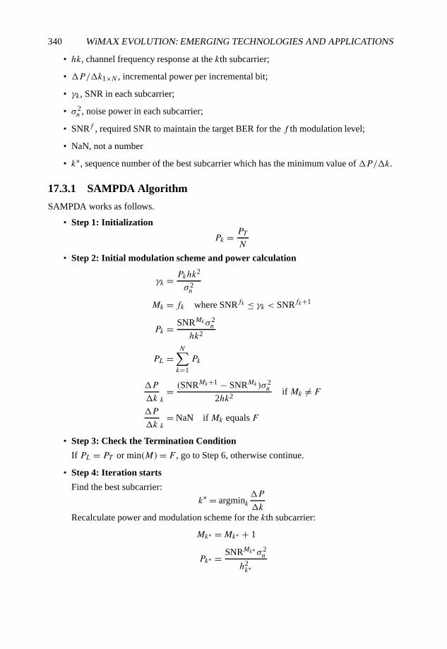
340 WiMAX EVOLUTION: EMERGING TECHNOLOGIES AND APPLICATIONS
• hk, channel frequency response at the kth subcarrier;
• �P/�k1×N , incremental power per incremental bit;
• γk, SNR in each subcarrier;
• σ 2n , noise power in each subcarrier;
• SNRf , required SNR to maintain the target BER for the f th modulation level;
• NaN, not a number
• k∗, sequence number of the best subcarrier which has the minimum value of �P/�k.
17.3.1 SAMPDA Algorithm
SAMPDA works as follows.
• Step 1: Initialization
Pk = PT
N
• Step 2: Initial modulation scheme and power calculation
γk = Pkhk2
σ 2n
Mk = fk where SNRfk ≤ γk < SNRfk+1
Pk = SNRMkσ 2n
hk2
PL =N∑k=1
Pk
�P
�k k= (SNRMk+1 − SNRMk)σ 2
n
2hk2if Mk �= F
�P
�k k= NaN if Mk equals F
• Step 3: Check the Termination Condition
If PL = PT or min(M)= F , go to Step 6, otherwise continue.
• Step 4: Iteration starts
Find the best subcarrier:
k∗ = argmink�P
�k
Recalculate power and modulation scheme for the kth subcarrier:
Mk∗ =Mk∗ + 1
Pk∗ = SNRMk∗σ 2n
h2k∗
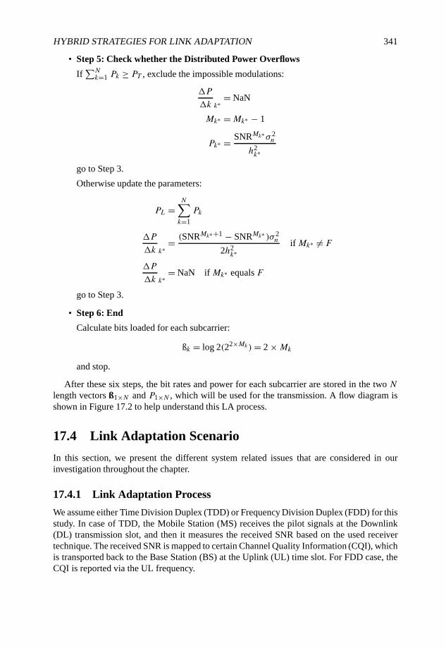
HYBRID STRATEGIES FOR LINK ADAPTATION 341
• Step 5: Check whether the Distributed Power Overflows
If∑Nk=1 Pk ≥ PT , exclude the impossible modulations:
�P
�k k∗ = NaN
Mk∗ =Mk∗ − 1
Pk∗ = SNRMk∗σ 2n
h2k∗
go to Step 3.
Otherwise update the parameters:
PL =N∑k=1
Pk
�P
�k k∗ = (SNRMk∗+1 − SNRMk∗ )σ 2n
2h2k∗
if Mk∗ �= F
�P
�k k∗ = NaN if Mk∗ equals F
go to Step 3.
• Step 6: End
Calculate bits loaded for each subcarrier:
ßk = log 2(22×Mk)= 2 ×Mk
and stop.
After these six steps, the bit rates and power for each subcarrier are stored in the two Nlength vectors ß1×N and P1×N , which will be used for the transmission. A flow diagram isshown in Figure 17.2 to help understand this LA process.
17.4 Link Adaptation Scenario
In this section, we present the different system related issues that are considered in ourinvestigation throughout the chapter.
17.4.1 Link Adaptation Process
We assume either Time Division Duplex (TDD) or Frequency Division Duplex (FDD) for thisstudy. In case of TDD, the Mobile Station (MS) receives the pilot signals at the Downlink(DL) transmission slot, and then it measures the received SNR based on the used receivertechnique. The received SNR is mapped to certain Channel Quality Information (CQI), whichis transported back to the Base Station (BS) at the Uplink (UL) time slot. For FDD case, theCQI is reported via the UL frequency.
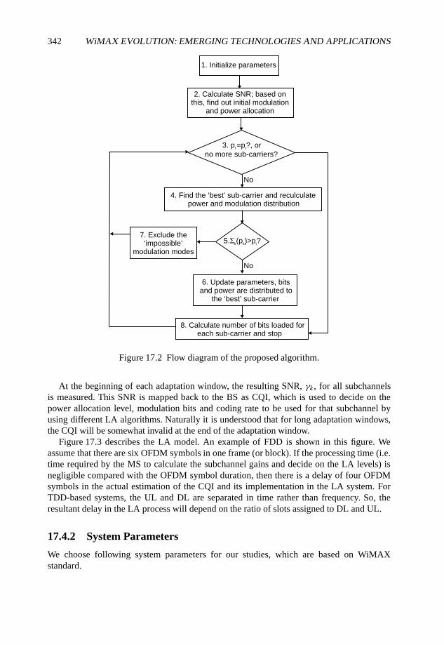
342 WiMAX EVOLUTION: EMERGING TECHNOLOGIES AND APPLICATIONS
1. Initialize parameters
8. Calculate number of bits loaded foreach sub-carrier and stop
4. Find the ‘best’ sub-carrier and reculculatepower and modulation distribution
2. Calculate SNR; based onthis, find out initial modulation
and power allocation
6. Update parameters, bitsand power are distributed to
the ‘best’ sub-carrier
7. Exclude the‘impossible’
modulation modes
No
No
3. pl =p
t?, or
no more sub-carriers?
5.Σk(p
k)>p
t?
Figure 17.2 Flow diagram of the proposed algorithm.
At the beginning of each adaptation window, the resulting SNR, γk, for all subchannelsis measured. This SNR is mapped back to the BS as CQI, which is used to decide on thepower allocation level, modulation bits and coding rate to be used for that subchannel byusing different LA algorithms. Naturally it is understood that for long adaptation windows,the CQI will be somewhat invalid at the end of the adaptation window.
Figure 17.3 describes the LA model. An example of FDD is shown in this figure. Weassume that there are six OFDM symbols in one frame (or block). If the processing time (i.e.time required by the MS to calculate the subchannel gains and decide on the LA levels) isnegligible compared with the OFDM symbol duration, then there is a delay of four OFDMsymbols in the actual estimation of the CQI and its implementation in the LA system. ForTDD-based systems, the UL and DL are separated in time rather than frequency. So, theresultant delay in the LA process will depend on the ratio of slots assigned to DL and UL.
17.4.2 System Parameters
We choose following system parameters for our studies, which are based on WiMAXstandard.
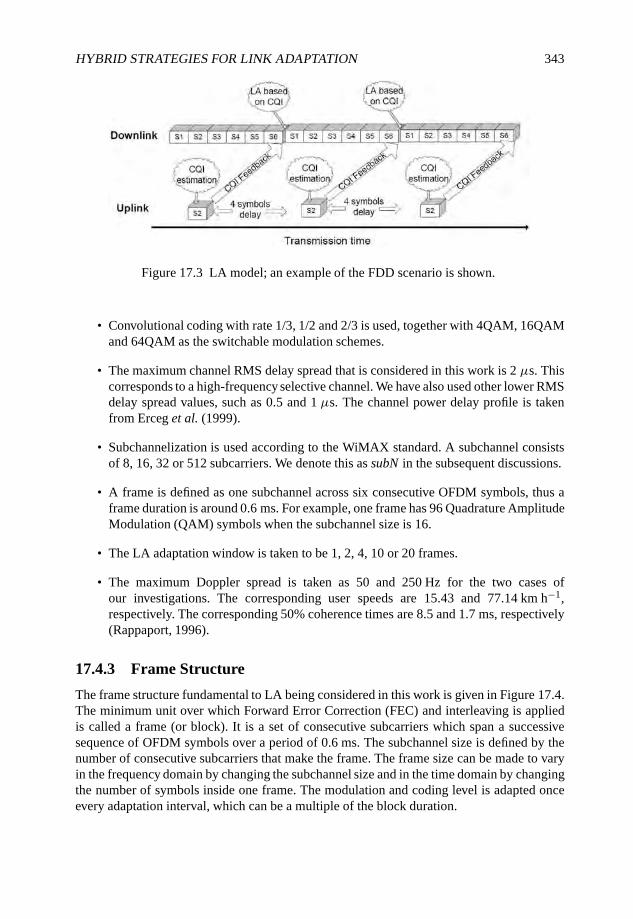
HYBRID STRATEGIES FOR LINK ADAPTATION 343
Figure 17.3 LA model; an example of the FDD scenario is shown.
• Convolutional coding with rate 1/3, 1/2 and 2/3 is used, together with 4QAM, 16QAMand 64QAM as the switchable modulation schemes.
• The maximum channel RMS delay spread that is considered in this work is 2 µs. Thiscorresponds to a high-frequency selective channel. We have also used other lower RMSdelay spread values, such as 0.5 and 1 µs. The channel power delay profile is takenfrom Erceg et al. (1999).
• Subchannelization is used according to the WiMAX standard. A subchannel consistsof 8, 16, 32 or 512 subcarriers. We denote this as subN in the subsequent discussions.
• A frame is defined as one subchannel across six consecutive OFDM symbols, thus aframe duration is around 0.6 ms. For example, one frame has 96 Quadrature AmplitudeModulation (QAM) symbols when the subchannel size is 16.
• The LA adaptation window is taken to be 1, 2, 4, 10 or 20 frames.
• The maximum Doppler spread is taken as 50 and 250 Hz for the two cases ofour investigations. The corresponding user speeds are 15.43 and 77.14 km h−1,respectively. The corresponding 50% coherence times are 8.5 and 1.7 ms, respectively(Rappaport, 1996).
17.4.3 Frame Structure
The frame structure fundamental to LA being considered in this work is given in Figure 17.4.The minimum unit over which Forward Error Correction (FEC) and interleaving is appliedis called a frame (or block). It is a set of consecutive subcarriers which span a successivesequence of OFDM symbols over a period of 0.6 ms. The subchannel size is defined by thenumber of consecutive subcarriers that make the frame. The frame size can be made to varyin the frequency domain by changing the subchannel size and in the time domain by changingthe number of symbols inside one frame. The modulation and coding level is adapted onceevery adaptation interval, which can be a multiple of the block duration.
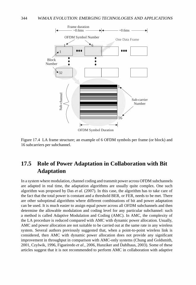
344 WiMAX EVOLUTION: EMERGING TECHNOLOGIES AND APPLICATIONS
~0.6ms
1
32
1 6
~0.6ms
BlockNumber
OFDM Symbol Number
Frame duration
One Data Frame
OFDM Symbol Duration
Sub-carrierNumber
Sub-
chan
nel
1
16
Figure 17.4 LA frame structure; an example of 6 OFDM symbols per frame (or block) and16 subcarriers per subchannel.
17.5 Role of Power Adaptation in Collaboration with BitAdaptation
In a system where modulation, channel coding and transmit power across OFDM subchannelsare adapted in real time, the adaptation algorithms are usually quite complex. One suchalgorithm was proposed by Das et al. (2007). In this case, the algorithm has to take care ofthe fact that the total power is constant and a threshold BER, or FER, needs to be met. Thereare other suboptimal algorithms where different combinations of bit and power adaptationcan be used. It is much easier to assign equal power across all OFDM subchannels and thendetermine the allowable modulation and coding level for any particular subchannel: sucha method is called Adaptive Modulation and Coding (AMC). In AMC, the complexity ofthe LA procedure is reduced compared with AMC with dynamic power allocation. Usually,AMC and power allocation are not suitable to be carried out at the same rate in any wirelesssystem. Several authors previously suggested that, when a point-to-point wireless link isconsidered, then AMC with dynamic power allocation does not provide any significantimprovement in throughput in comparison with AMC-only systems (Chung and Goldsmith,2001, Czylwik, 1996, Figueiredo et al., 2006, Hunziker and Dahlhaus, 2003). Some of thesearticles suggest that it is not recommended to perform AMC in collaboration with adaptive

HYBRID STRATEGIES FOR LINK ADAPTATION 345
power distribution due to excessive system complexity. Rhee and Cioffi (2000) suggested thesame for multi-user OFDM systems.
In this section, we study bit and power allocation strategies for multi-antenna assistedOFDM systems. In contrast to the suggestions in the above-mentioned articles, we havefound that in some scenarios and in some system conditions, some form of power adaptationalong with bit allocation across OFDM subchannels are required together for efficient systemperformance. For broadband OFDM systems, the channel variations are quite high inside theOFDM system bandwidth, thus dynamic power distribution is advantageous together withAMC. This is in-line with the conclusions made by Bohge et al. (2005). Using differentLA mechanisms, we have found that, when we cannot find the exact SNR thresholds due todifferent reasons, such as reduced LA rate, CSI error, feedback delay etc., it is better to fix thetransmit power across all subchannels to guarantee the target FER. Then the power allocationwill actually act as a safety margin for the impairment to a certain degree. Otherwise, we canuse adaptive power distribution to save power, which can be used for other purposes, or wecan increase the modulation level to increase the system throughput. These benefits are evenmore visible when multi-antenna schemes are used in the system.
Our investigation is mainly concentrated on different bit and power allocation rates inOFDM systems. In Section 17.5.1 we study the impact of both adaptations at the same rateand in Section 17.5.2 we investigate the adaptations at different rates.
17.5.1 AMC and Power Adaptation at the Same Rate
In this section, we study bit and power adaptation at the same rate, so the adaptation windowfor bit and power allocation is always same. In this way, the channel conditions and usermobility have the same impact on both of the allocations.
As we have seen in Section 17.4, when the adaptation window is only one frame long, thenthe channel conditions are quite static for the Doppler conditions that we are consideringhere. Thus, we can say that the feedback CQI is almost correct according to the channelconditions when the LA decisions are implemented. Our previous analysis points out thatthe resultant FER is well below the FER threshold when instantaneous AMC is performed.Thus, we clearly see that some power is wasted when only AMC is performed. When we alsoadapt the power after the AMC decisions are made, we find that the FER threshold is stillmaintained. Now, we need to look at the corresponding spectral efficiency curves. Intuitively,when some power is removed after power adaptation, the spectral efficiency should be lower.However, we can observe that the spectral efficiency is almost equal with and without poweradaptation. Note that, in this case, the power adaptation essentially means that we are savingsome power, as described in Figure 17.5(a) and discussed later.
For the outdated feedback case, we should find new AMC thresholds compared with theoriginal AMC thresholds used in previous simulations. These new threshold margins can befound via Monte Carlo simulations. Again, referring to previous analysis, we can see that theFER threshold is not met when AMC is followed by power adaptation. This is the case whenthe adaptation window is equal to four frames. In the same scenario, the fixed power basedmechanism works well. As we have a slower rate of adaptation, we practically need a newthreshold (which is obviously higher than the previous threshold) for the slower adaptationrate. In this case, the extra power available after bit and coding rate allocation compensatesfor the required additional power when the adaptation is slowed down. The spectral efficiency
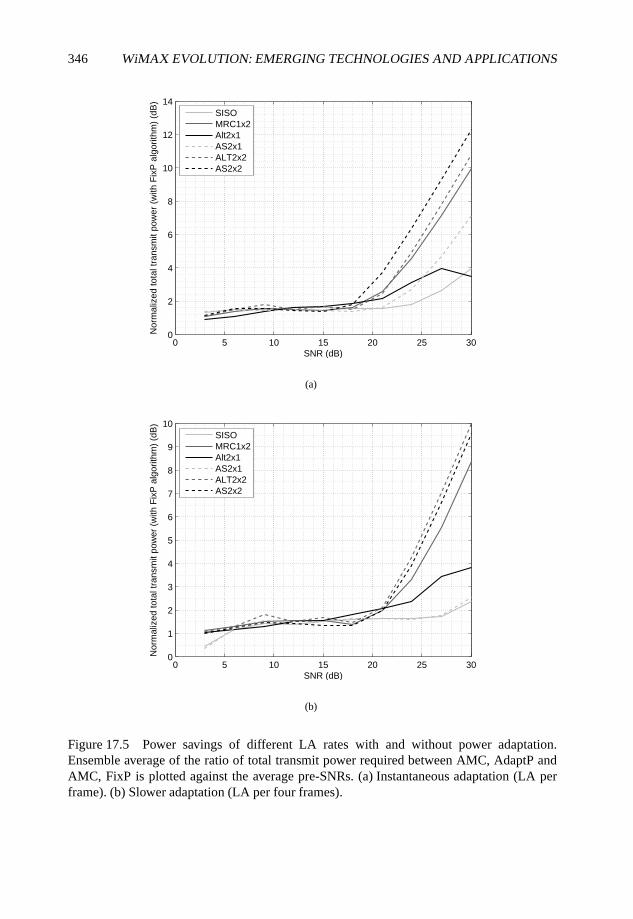
346 WiMAX EVOLUTION: EMERGING TECHNOLOGIES AND APPLICATIONS
0 5 10 15 20 25 300
2
4
6
8
10
12
14
SNR (dB)
Nor
mal
ized
tota
l tra
nsm
it po
wer
(w
ith F
ixP
alg
orith
m)
(dB
)
SISOMRC1x2Alt2x1AS2x1ALT2x2AS2x2
(a)
0 5 10 15 20 25 300
1
2
3
4
5
6
7
8
9
10
SNR (dB)
Nor
mal
ized
tota
l tra
nsm
it po
wer
(w
ith F
ixP
alg
orith
m)
(dB
)
SISOMRC1x2Alt2x1AS2x1ALT2x2AS2x2
(b)
Figure 17.5 Power savings of different LA rates with and without power adaptation.Ensemble average of the ratio of total transmit power required between AMC, AdaptP andAMC, FixP is plotted against the average pre-SNRs. (a) Instantaneous adaptation (LA perframe). (b) Slower adaptation (LA per four frames).

HYBRID STRATEGIES FOR LINK ADAPTATION 347
is almost the same when the power is adapted and the power is fixed for all of the schemes,but the FER threshold is not met when power adaptation follows the AMC procedure. Also,a loss in spectral efficiency is experienced when a wider adaptation window is used.
Figure 17.5(a) and (b) summarize the resulting power saving when AMC followed by apower adjustment is performed, in comparison with the AMC-only scheme. We can see thata significant amount of power can be saved for instantaneous adaptation. When the systemSNR is roughly more than 20 dB, the power savings to meet the FER requirement are morethan 2 dB. When the average SNR increases, the power saving increases greatly. This resultdemonstrates that power allocation also has a role to play in WiMAX-like broadband OFDMsystems, in contrast to the original claim that power allocation does not bring much benefitwhen AMC is already performed (Chung and Goldsmith, 2000, 2001). As expected, thepower savings becomes irrelevant when the adaptation window is longer. In this case, thepower saving is performed, but the threshold FER is not met. Thus, we see a throughputdegradation.
The transmit power saved can be used for many other purposes in the system. For example,more bits can be transmitted in a particular subchannel. Thus, a window of opportunity ariseswhen we perform the power adaptation in collaboration with AMC. In a multi-user scenario,the power saved can be allocated to a user with a weaker SNR and the spectral efficiency ofthe system can be improved in that way.
17.5.1.1 Impact of Different Power Adaptation Algorithms
Figures 17.6, 17.7(a) and 17.7(b) give us the FER, resultant spectral efficiency and powersavings respectively, when we use two different power adaptation mechanisms. In theseresults, APMC refers to our optimal SAMPDA algorithm as developed by Das et al. (2007),and AMC with subsequent power adaptation refers to power adaptation applied after AMCdecision is made (labeled as ‘AMC,AdaptP’ in the figures). Under a low-SNR regime, APMCwill utilize more power than AMC with power allocation. APMC algorithms (e.g. SAMPDA)do not assign any bit to any weaker subchannel (i.e. withdraws power from the weakersubchannels), rather it concentrates the available power across subchannels where somebits can be transmitted. For the case of AMC with power adaptation, not many bits canbe transmitted at low SNR, so throughput is very low (as seen in Figure 17.7(a)), althoughsome power saving is seen in Figure 17.7(b). In the same figures, we can see that APMCis able to transmit significantly higher throughput even at very low average SNR, becauseAPMC allocates most of the available power to some subchannels where some bits can betransmitted. So, we can conclude that APMC utilizes the total available power efficiently.This throughput optimization in APMC is obtained at the price of added complexity in theLA algorithm. Under a high SNR regime, both of these algorithms can save power, but APMCwill utilize the available power more efficiently than AMC with adapted power to achieve abetter throughput performance.
In these results, we have only shown the FER, throughput and power saving performancesfor fast (or instantaneous) LA rate, because both AMC with adapted power and APMC canmaintain the FER target at fast LA rates, while at a low LA rate, an additional margin isneeded.
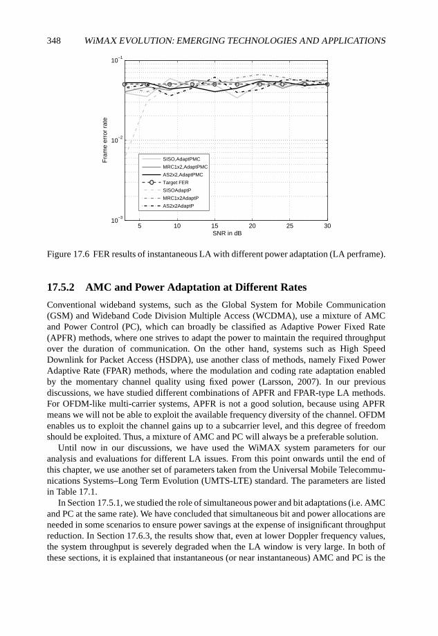
348 WiMAX EVOLUTION: EMERGING TECHNOLOGIES AND APPLICATIONS
5 10 15 20 25 3010
–3
10–2
10–1
SNR in dB
Fra
me
erro
r ra
te
SISO,AdaptPMC
MRC1x2,AdaptPMC
AS2x2,AdaptPMC
Target FER
SISOAdaptP
MRC1x2AdaptP
AS2x2AdaptP
Figure 17.6 FER results of instantaneous LA with different power adaptation (LA perframe).
17.5.2 AMC and Power Adaptation at Different Rates
Conventional wideband systems, such as the Global System for Mobile Communication(GSM) and Wideband Code Division Multiple Access (WCDMA), use a mixture of AMCand Power Control (PC), which can broadly be classified as Adaptive Power Fixed Rate(APFR) methods, where one strives to adapt the power to maintain the required throughputover the duration of communication. On the other hand, systems such as High SpeedDownlink for Packet Access (HSDPA), use another class of methods, namely Fixed PowerAdaptive Rate (FPAR) methods, where the modulation and coding rate adaptation enabledby the momentary channel quality using fixed power (Larsson, 2007). In our previousdiscussions, we have studied different combinations of APFR and FPAR-type LA methods.For OFDM-like multi-carrier systems, APFR is not a good solution, because using APFRmeans we will not be able to exploit the available frequency diversity of the channel. OFDMenables us to exploit the channel gains up to a subcarrier level, and this degree of freedomshould be exploited. Thus, a mixture of AMC and PC will always be a preferable solution.
Until now in our discussions, we have used the WiMAX system parameters for ouranalysis and evaluations for different LA issues. From this point onwards until the end ofthis chapter, we use another set of parameters taken from the Universal Mobile Telecommu-nications Systems–Long Term Evolution (UMTS-LTE) standard. The parameters are listedin Table 17.1.
In Section 17.5.1, we studied the role of simultaneous power and bit adaptations (i.e. AMCand PC at the same rate). We have concluded that simultaneous bit and power allocations areneeded in some scenarios to ensure power savings at the expense of insignificant throughputreduction. In Section 17.6.3, the results show that, even at lower Doppler frequency values,the system throughput is severely degraded when the LA window is very large. In both ofthese sections, it is explained that instantaneous (or near instantaneous) AMC and PC is the
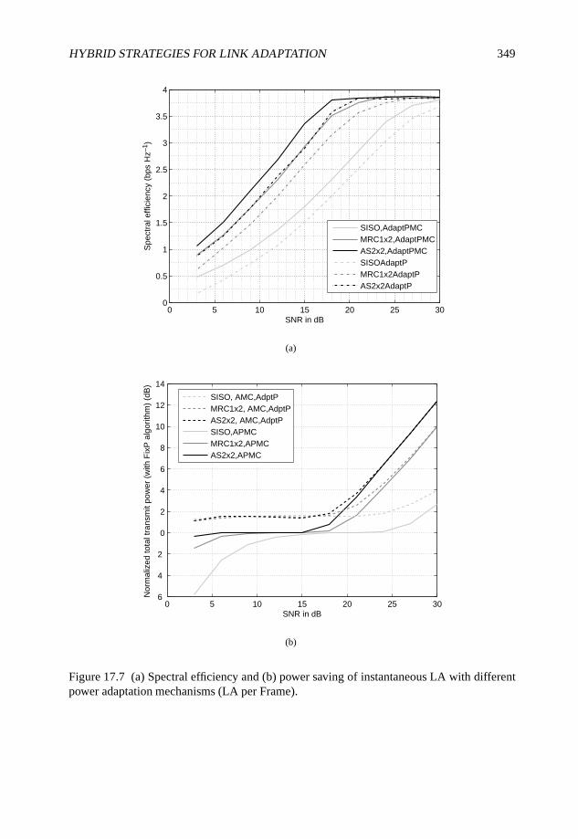
HYBRID STRATEGIES FOR LINK ADAPTATION 349
0 5 10 15 20 25 300
0.5
1
1.5
2
2.5
3
3.5
4
SNR in dB
Spe
ctra
l effi
cien
cy (
bps
Hz–
1 )
SISO,AdaptPMCMRC1x2,AdaptPMCAS2x2,AdaptPMCSISOAdaptPMRC1x2AdaptPAS2x2AdaptP
(a)
0 5 10 15 20 25 30 6
4
2
0
2
4
6
8
10
12
14
SNR in dB
Nor
mal
ized
tota
l tra
nsm
it po
wer
(w
ith F
ixP
alg
orith
m)
(dB
)
SISO, AMC,AdptPMRC1x2, AMC,AdptPAS2x2, AMC,AdptPSISO,APMCMRC1x2,APMCAS2x2,APMC
(b)
Figure 17.7 (a) Spectral efficiency and (b) power saving of instantaneous LA with differentpower adaptation mechanisms (LA per Frame).
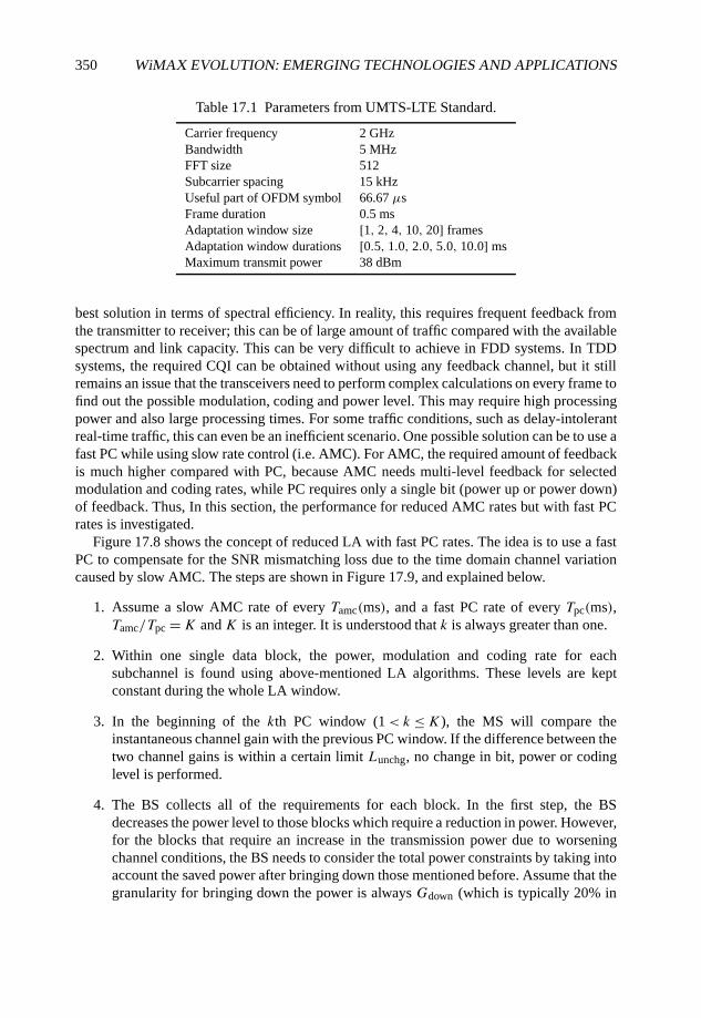
350 WiMAX EVOLUTION: EMERGING TECHNOLOGIES AND APPLICATIONS
Table 17.1 Parameters from UMTS-LTE Standard.
Carrier frequency 2 GHzBandwidth 5 MHzFFT size 512Subcarrier spacing 15 kHzUseful part of OFDM symbol 66.67 µsFrame duration 0.5 msAdaptation window size [1, 2, 4, 10, 20] framesAdaptation window durations [0.5, 1.0, 2.0, 5.0, 10.0] msMaximum transmit power 38 dBm
best solution in terms of spectral efficiency. In reality, this requires frequent feedback fromthe transmitter to receiver; this can be of large amount of traffic compared with the availablespectrum and link capacity. This can be very difficult to achieve in FDD systems. In TDDsystems, the required CQI can be obtained without using any feedback channel, but it stillremains an issue that the transceivers need to perform complex calculations on every frame tofind out the possible modulation, coding and power level. This may require high processingpower and also large processing times. For some traffic conditions, such as delay-intolerantreal-time traffic, this can even be an inefficient scenario. One possible solution can be to use afast PC while using slow rate control (i.e. AMC). For AMC, the required amount of feedbackis much higher compared with PC, because AMC needs multi-level feedback for selectedmodulation and coding rates, while PC requires only a single bit (power up or power down)of feedback. Thus, In this section, the performance for reduced AMC rates but with fast PCrates is investigated.
Figure 17.8 shows the concept of reduced LA with fast PC rates. The idea is to use a fastPC to compensate for the SNR mismatching loss due to the time domain channel variationcaused by slow AMC. The steps are shown in Figure 17.9, and explained below.
1. Assume a slow AMC rate of every Tamc(ms), and a fast PC rate of every Tpc(ms),Tamc/Tpc =K and K is an integer. It is understood that k is always greater than one.
2. Within one single data block, the power, modulation and coding rate for eachsubchannel is found using above-mentioned LA algorithms. These levels are keptconstant during the whole LA window.
3. In the beginning of the kth PC window (1< k ≤K), the MS will compare theinstantaneous channel gain with the previous PC window. If the difference between thetwo channel gains is within a certain limit Lunchg, no change in bit, power or codinglevel is performed.
4. The BS collects all of the requirements for each block. In the first step, the BSdecreases the power level to those blocks which require a reduction in power. However,for the blocks that require an increase in the transmission power due to worseningchannel conditions, the BS needs to consider the total power constraints by taking intoaccount the saved power after bringing down those mentioned before. Assume that thegranularity for bringing down the power is always Gdown (which is typically 20% in

HYBRID STRATEGIES FOR LINK ADAPTATION 351
0.5
3.5
6.5
2.0
5.0
8.0
1.0
4.0
7.0
2.5
5.5
8.5
9.5
1.5
4.5
7.5
3.0
6.0
9.0
10.0
time in ms
Approx. Coherence time for 50Hz
Approx. Coherence time for 250Hz
Example: Bit loading every 0.5ms and Power loading every 0.5ms
Example: Bit loading every 2.0ms and Power loading every 0.5ms
Example: Bit loading every 5.0ms and Power loading every 1.0ms
Figure 17.8 Examples of different power and bit allocation rates. For clarity, the coherencetime related to 50 and 250 Hz is also shown.
our investigations) and the maximum granularity for increasing the power is Gup. Theincrease in power, Gup, can be decided dynamically. It can start from an increase of20%, and then increase step-by-step until the requirement of the subchannel is met.Thus, the actual increasing in power level, Gup,actual, can be calculated as
Gup,actual = εGpu where ε = min
{1,Pav +Gdown
∑Ndownn=1 Pk−1,n
Gup∑Nup
n=1 Pk−1,n
}, (17.11)
where Ndown is the number of blocks which need less power and Nup is the number ofblocks which need more power; Pk−1,n is the power assigned for the nth block duringthe (k − 1)th PC window; Pav is available power before redistributing the power andis calculated using
Pav = PT −N∑n=1
Pk−1,n; (17.12)
PT is the total power constraint which indicates the up-limit for the total transmissionpower.
5. Step 3 is then repeated for each PC window within the same AMC window. Steps 2and 3 are repeated for each AMC window during the whole transmission time.
In this work, we take that Gup =Gdown = 0.2. Figure 17.10(a) and (b) show the achiev-able spectral efficiency for different combinations of AMC and PC rates, for low- and high-diversity conditions, respectively. This analysis is valid when 16 consecutive subcarriers areplaced together in one subchannel (i.e. subN = 16). For a better understanding of the ratio oftime between the adaptation windows and channel characteristics, we can check Figure 17.8.
For low-diversity conditions, we can see the following.
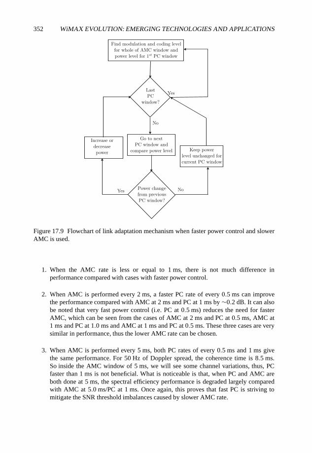
352 WiMAX EVOLUTION: EMERGING TECHNOLOGIES AND APPLICATIONS
Figure 17.9 Flowchart of link adaptation mechanism when faster power control and slowerAMC is used.
1. When the AMC rate is less or equal to 1 ms, there is not much difference inperformance compared with cases with faster power control.
2. When AMC is performed every 2 ms, a faster PC rate of every 0.5 ms can improvethe performance compared with AMC at 2 ms and PC at 1 ms by ∼0.2 dB. It can alsobe noted that very fast power control (i.e. PC at 0.5 ms) reduces the need for fasterAMC, which can be seen from the cases of AMC at 2 ms and PC at 0.5 ms, AMC at1 ms and PC at 1.0 ms and AMC at 1 ms and PC at 0.5 ms. These three cases are verysimilar in performance, thus the lower AMC rate can be chosen.
3. When AMC is performed every 5 ms, both PC rates of every 0.5 ms and 1 ms givethe same performance. For 50 Hz of Doppler spread, the coherence time is 8.5 ms.So inside the AMC window of 5 ms, we will see some channel variations, thus, PCfaster than 1 ms is not beneficial. What is noticeable is that, when PC and AMC areboth done at 5 ms, the spectral efficiency performance is degraded largely comparedwith AMC at 5.0 ms/PC at 1 ms. Once again, this proves that fast PC is striving tomitigate the SNR threshold imbalances caused by slower AMC rate.
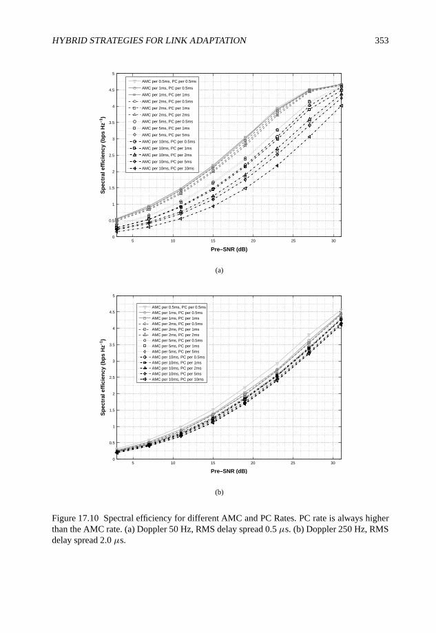
HYBRID STRATEGIES FOR LINK ADAPTATION 353
5 10 15 20 25 300
0.5
1
1.5
2
2.5
3
3.5
4
4.5
5
Pre–SNR (dB)
Sp
ectr
al e
ffic
ien
cy (
bp
s H
z–1)
AMC per 0.5ms, PC per 0.5ms
AMC per 1ms, PC per 0.5ms
AMC per 1ms, PC per 1ms
AMC per 2ms, PC per 0.5ms
AMC per 2ms, PC per 1ms
AMC per 2ms, PC per 2ms
AMC per 5ms, PC per 0.5ms
AMC per 5ms, PC per 1ms
AMC per 5ms, PC per 5ms
AMC per 10ms, PC per 0.5ms
AMC per 10ms, PC per 1ms
AMC per 10ms, PC per 2ms
AMC per 10ms, PC per 5ms
AMC per 10ms, PC per 10ms
(a)
5 10 15 20 25 300
0.5
1
1.5
2
2.5
3
3.5
4
4.5
5
Pre–SNR (dB)
Sp
ectr
al e
ffic
ien
cy (
bp
s H
z–1)
AMC per 0.5ms, PC per 0.5msAMC per 1ms, PC per 0.5msAMC per 1ms, PC per 1msAMC per 2ms, PC per 0.5msAMC per 2ms, PC per 1msAMC per 2ms, PC per 2msAMC per 5ms, PC per 0.5msAMC per 5ms, PC per 1msAMC per 5ms, PC per 5msAMC per 10ms, PC per 0.5msAMC per 10ms, PC per 1msAMC per 10ms, PC per 2msAMC per 10ms, PC per 5msAMC per 10ms, PC per 10ms
(b)
Figure 17.10 Spectral efficiency for different AMC and PC Rates. PC rate is always higherthan the AMC rate. (a) Doppler 50 Hz, RMS delay spread 0.5 µs. (b) Doppler 250 Hz, RMSdelay spread 2.0 µs.
354 WiMAX EVOLUTION: EMERGING TECHNOLOGIES AND APPLICATIONS
4. Similar trends are seen for the case of AMC at 10 ms. The cases of AMC at 10 ms/PCat 0.5 ms and AMC at 10 ms/PC at 1.0 ms show that the resultant spectral efficiency isimproved by almost 50% compared with the spectral efficiency of AMC at 10 ms/PCat 10 ms case, as seen in Figure 17.10.
In essence, decreasing the AMC rate has a severe impact on the system performance,as also seen earlier. In a real scenario, a reduction in the AMC rate may sometimes berequired. In those cases, faster PC rates need to be implemented for acceptable level of systemperformance. For the particular system and user parameters as shown in Figure 17.10(a), PCrate of 1 ms provides good performance for several AMC rate combinations.
Figure 17.10(b) shows the performance when fd = 250 Hz. As can be seen from thisfigure, with high Doppler frequency, PC gives very limited benefit as compared with lowDoppler cases. This result is in accordance with Figure 17.13(b).
To conclude, a reduced AMC rate can be used to reduce the system complexity. At highDoppler frequency, this reduced AMC rate will not affect performance much, while at lowDoppler frequency, a large degradation can be observed for low AMC rate. By using PC at afast rate, the combined performance can be improved at reasonably lower complexity than afast AMC-only rate.
17.5.3 Overhead Analysis
In our work related to LA, we have mainly considering the gain in throughput obtained bybit and power adaptation, while this gain is obtained at a cost of increased overhead. Fora proper system design, the exact amount of overhead needs to be measured, and properfeedback mechanisms also need to be found to minimize the feedback overhead while stillmaintaining the system performance at a satisfactory level. In this section, we perform aninitial evaluation of the required feedback when different rates of AMC and PC are used.
Considering the discussions related to different rates of AMC and PC rates, we need tohave a look at the required overhead bits for transporting the channel information betweenthe transmitter and the receiver.
The following parameters are used for overhead estimates:
• N , total number of available subcarriers;
• subN, number of subcarriers in one subchannel;
• Tamc, AMC interval, that is, 1/Tamc gives us the AMC rate;
• Tpc, power adaptation interval, that is, 1/Tpc gives us the AMC rate;
• K = Tamc/Tpc, an integer number representing AMC over PC duration;
• PCix, the index of power adaptation times within one AMC window.
We can divide the overhead into two parts, DL and UL. The total overhead can bewritten as
overheadtotal = overheadul + overheaddl. (17.13)

HYBRID STRATEGIES FOR LINK ADAPTATION 355
17.5.3.1 Overhead in the UL
In the UL, we need to transmit two types of overhead information.
1. We need to transport the CQI from the MS to inform the BS about the possiblemodulation and coding level that can be supported for each subchannel. Thus, 5 bits(i.e. 25 levels of information) for one subchannel will be fed back to the BS for thereceived SNR level.
2. For faster PC, we need to transport the PCix = [2, . . . , K]. In this case, only 1 bit isneeded per subchannel per Tpc to indicate whether the power should go up or down.Note that we are considering the situation when Tamc > Tpc.
So, we can express the overhead in the UL as follows:
overheadul =[
5 +(Tamc
Tpc− 1
)]N
subN
1
Tamc
= (Tamc/Tpc + 4)N
subN Tamc
= (K + 4)N
subN Tamc. (17.14)
17.5.3.2 Overheads in Downlink
In the DL, the BS needs to inform the MS about the modulation and coding level for eachsubchannel. If we have 16 possible rate levels, then 4 bits for each subchannel will betransmitted from the BS via the control channels. This can be expressed as
overheaddl = 4N
subN
1
Tamc= 4N
subN Tamc. (17.15)
17.5.3.3 Overhead Calculation Corresponding to Our System Parameters
Using (17.14) and (17.15), we can write that the total system overhead expression as
overheadtotal = (K + 8)N
subN Tamc. (17.16)
Table 17.2 presents the amount of overhead signaling required for different combinationsof AMC rate, PC rate and different subchannel size. As can be seen in the table, the highestamount of overhead is required in the case of AMC at 1.0 ms/PC at 1.0 ms, while we haveseen earlier that the achievable spectral efficiency is also very high at this adaptation rates.Depending on different channel conditions and different system complexity requirements,we can choose to increase both the AMC and PC rates. We can see that when AMC windowis extended from 1.0 to 10.0 ms, we have approximately 80% less overhead requirement forall subchannel sizes.
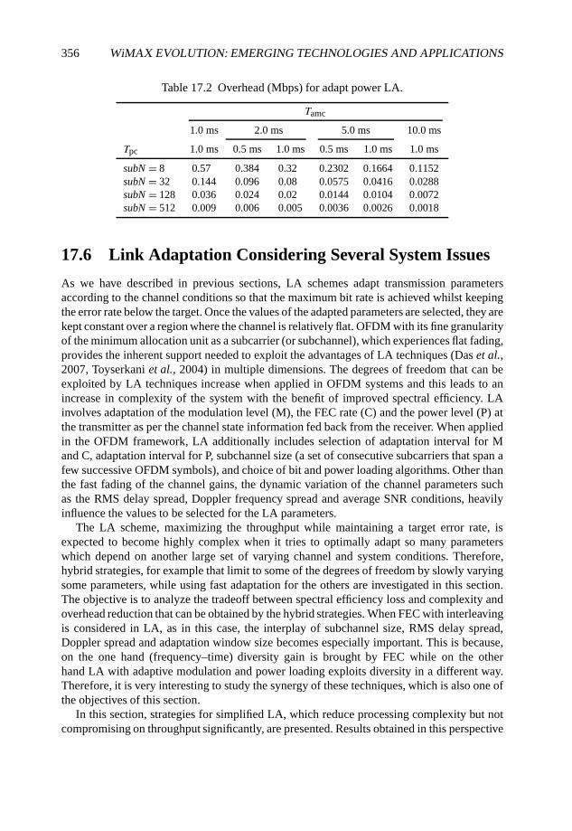
356 WiMAX EVOLUTION: EMERGING TECHNOLOGIES AND APPLICATIONS
Table 17.2 Overhead (Mbps) for adapt power LA.
Tamc
1.0 ms 2.0 ms 5.0 ms 10.0 ms
Tpc 1.0 ms 0.5 ms 1.0 ms 0.5 ms 1.0 ms 1.0 ms
subN = 8 0.57 0.384 0.32 0.2302 0.1664 0.1152subN = 32 0.144 0.096 0.08 0.0575 0.0416 0.0288subN = 128 0.036 0.024 0.02 0.0144 0.0104 0.0072subN = 512 0.009 0.006 0.005 0.0036 0.0026 0.0018
17.6 Link Adaptation Considering Several System Issues
As we have described in previous sections, LA schemes adapt transmission parametersaccording to the channel conditions so that the maximum bit rate is achieved whilst keepingthe error rate below the target. Once the values of the adapted parameters are selected, they arekept constant over a region where the channel is relatively flat. OFDM with its fine granularityof the minimum allocation unit as a subcarrier (or subchannel), which experiences flat fading,provides the inherent support needed to exploit the advantages of LA techniques (Das et al.,2007, Toyserkani et al., 2004) in multiple dimensions. The degrees of freedom that can beexploited by LA techniques increase when applied in OFDM systems and this leads to anincrease in complexity of the system with the benefit of improved spectral efficiency. LAinvolves adaptation of the modulation level (M), the FEC rate (C) and the power level (P) atthe transmitter as per the channel state information fed back from the receiver. When appliedin the OFDM framework, LA additionally includes selection of adaptation interval for Mand C, adaptation interval for P, subchannel size (a set of consecutive subcarriers that span afew successive OFDM symbols), and choice of bit and power loading algorithms. Other thanthe fast fading of the channel gains, the dynamic variation of the channel parameters suchas the RMS delay spread, Doppler frequency spread and average SNR conditions, heavilyinfluence the values to be selected for the LA parameters.
The LA scheme, maximizing the throughput while maintaining a target error rate, isexpected to become highly complex when it tries to optimally adapt so many parameterswhich depend on another large set of varying channel and system conditions. Therefore,hybrid strategies, for example that limit to some of the degrees of freedom by slowly varyingsome parameters, while using fast adaptation for the others are investigated in this section.The objective is to analyze the tradeoff between spectral efficiency loss and complexity andoverhead reduction that can be obtained by the hybrid strategies. When FEC with interleavingis considered in LA, as in this case, the interplay of subchannel size, RMS delay spread,Doppler spread and adaptation window size becomes especially important. This is because,on the one hand (frequency–time) diversity gain is brought by FEC while on the otherhand LA with adaptive modulation and power loading exploits diversity in a different way.Therefore, it is very interesting to study the synergy of these techniques, which is also one ofthe objectives of this section.
In this section, strategies for simplified LA, which reduce processing complexity but notcompromising on throughput significantly, are presented. Results obtained in this perspective
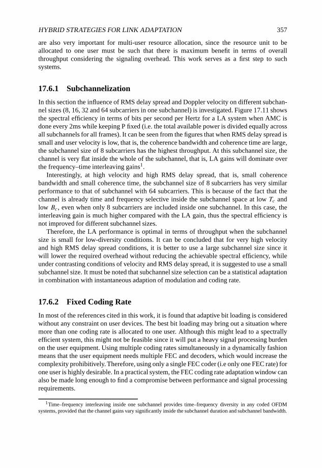
HYBRID STRATEGIES FOR LINK ADAPTATION 357
are also very important for multi-user resource allocation, since the resource unit to beallocated to one user must be such that there is maximum benefit in terms of overallthroughput considering the signaling overhead. This work serves as a first step to suchsystems.
17.6.1 Subchannelization
In this section the influence of RMS delay spread and Doppler velocity on different subchan-nel sizes (8, 16, 32 and 64 subcarriers in one subchannel) is investigated. Figure 17.11 showsthe spectral efficiency in terms of bits per second per Hertz for a LA system when AMC isdone every 2ms while keeping P fixed (i.e. the total available power is divided equally acrossall subchannels for all frames). It can be seen from the figures that when RMS delay spread issmall and user velocity is low, that is, the coherence bandwidth and coherence time are large,the subchannel size of 8 subcarriers has the highest throughput. At this subchannel size, thechannel is very flat inside the whole of the subchannel, that is, LA gains will dominate overthe frequency–time interleaving gains1.
Interestingly, at high velocity and high RMS delay spread, that is, small coherencebandwidth and small coherence time, the subchannel size of 8 subcarriers has very similarperformance to that of subchannel with 64 subcarriers. This is because of the fact that thechannel is already time and frequency selective inside the subchannel space at low Tc andlow Bc, even when only 8 subcarriers are included inside one subchannel. In this case, theinterleaving gain is much higher compared with the LA gain, thus the spectral efficiency isnot improved for different subchannel sizes.
Therefore, the LA performance is optimal in terms of throughput when the subchannelsize is small for low-diversity conditions. It can be concluded that for very high velocityand high RMS delay spread conditions, it is better to use a large subchannel size since itwill lower the required overhead without reducing the achievable spectral efficiency, whileunder contrasting conditions of velocity and RMS delay spread, it is suggested to use a smallsubchannel size. It must be noted that subchannel size selection can be a statistical adaptationin combination with instantaneous adaption of modulation and coding rate.
17.6.2 Fixed Coding Rate
In most of the references cited in this work, it is found that adaptive bit loading is consideredwithout any constraint on user devices. The best bit loading may bring out a situation wheremore than one coding rate is allocated to one user. Although this might lead to a spectrallyefficient system, this might not be feasible since it will put a heavy signal processing burdenon the user equipment. Using multiple coding rates simultaneously in a dynamically fashionmeans that the user equipment needs multiple FEC and decoders, which would increase thecomplexity prohibitively. Therefore, using only a single FEC coder (i.e only one FEC rate) forone user is highly desirable. In a practical system, the FEC coding rate adaptation window canalso be made long enough to find a compromise between performance and signal processingrequirements.
1Time–frequency interleaving inside one subchannel provides time–frequency diversity in any coded OFDMsystems, provided that the channel gains vary significantly inside the subchannel duration and subchannel bandwidth.
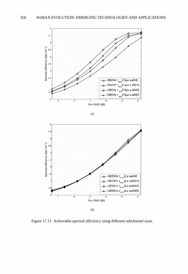
358 WiMAX EVOLUTION: EMERGING TECHNOLOGIES AND APPLICATIONS
Pre–SNR (dB)
Spe
ctra
l effi
cien
cy (
bps
Hz–1
)
(a)
Pre–SNR (dB)
Spe
ctra
l effi
cien
cy (
bps
Hz–1
)
(b)
Figure 17.11 Achievable spectral efficiency using different subchannel sizes.
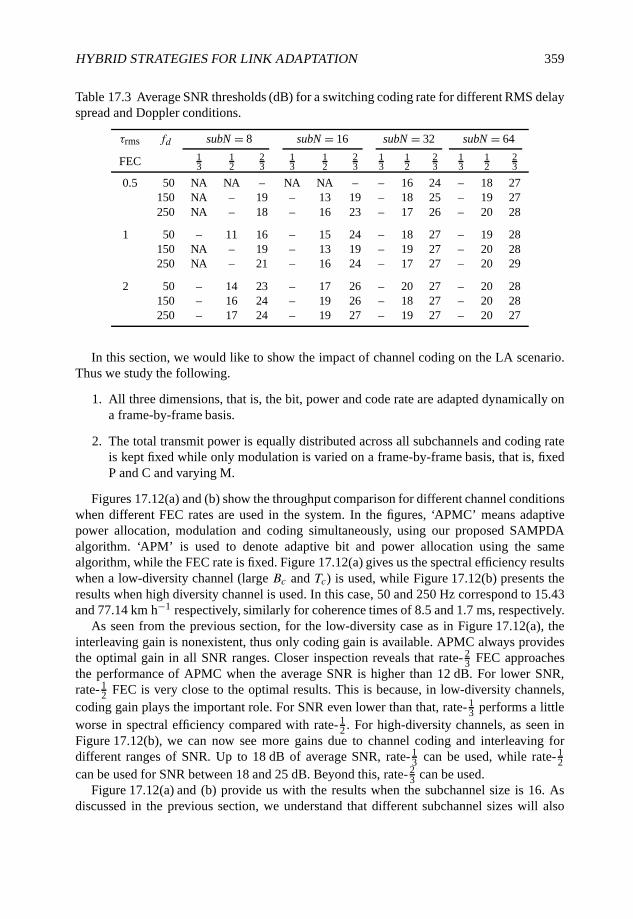
HYBRID STRATEGIES FOR LINK ADAPTATION 359
Table 17.3 Average SNR thresholds (dB) for a switching coding rate for different RMS delayspread and Doppler conditions.
τrms fd subN = 8 subN = 16 subN = 32 subN = 64
FEC 13
12
23
13
12
23
13
12
23
13
12
23
0.5 50 NA NA – NA NA – – 16 24 – 18 27150 NA – 19 – 13 19 – 18 25 – 19 27250 NA – 18 – 16 23 – 17 26 – 20 28
1 50 – 11 16 – 15 24 – 18 27 – 19 28150 NA – 19 – 13 19 – 19 27 – 20 28250 NA – 21 – 16 24 – 17 27 – 20 29
2 50 – 14 23 – 17 26 – 20 27 – 20 28150 – 16 24 – 19 26 – 18 27 – 20 28250 – 17 24 – 19 27 – 19 27 – 20 27
In this section, we would like to show the impact of channel coding on the LA scenario.Thus we study the following.
1. All three dimensions, that is, the bit, power and code rate are adapted dynamically ona frame-by-frame basis.
2. The total transmit power is equally distributed across all subchannels and coding rateis kept fixed while only modulation is varied on a frame-by-frame basis, that is, fixedP and C and varying M.
Figures 17.12(a) and (b) show the throughput comparison for different channel conditionswhen different FEC rates are used in the system. In the figures, ‘APMC’ means adaptivepower allocation, modulation and coding simultaneously, using our proposed SAMPDAalgorithm. ‘APM’ is used to denote adaptive bit and power allocation using the samealgorithm, while the FEC rate is fixed. Figure 17.12(a) gives us the spectral efficiency resultswhen a low-diversity channel (large Bc and Tc) is used, while Figure 17.12(b) presents theresults when high diversity channel is used. In this case, 50 and 250 Hz correspond to 15.43and 77.14 km h−1 respectively, similarly for coherence times of 8.5 and 1.7 ms, respectively.
As seen from the previous section, for the low-diversity case as in Figure 17.12(a), theinterleaving gain is nonexistent, thus only coding gain is available. APMC always providesthe optimal gain in all SNR ranges. Closer inspection reveals that rate- 2
3 FEC approachesthe performance of APMC when the average SNR is higher than 12 dB. For lower SNR,rate- 1
2 FEC is very close to the optimal results. This is because, in low-diversity channels,coding gain plays the important role. For SNR even lower than that, rate- 1
3 performs a littleworse in spectral efficiency compared with rate- 1
2 . For high-diversity channels, as seen inFigure 17.12(b), we can now see more gains due to channel coding and interleaving fordifferent ranges of SNR. Up to 18 dB of average SNR, rate- 1
3 can be used, while rate- 12
can be used for SNR between 18 and 25 dB. Beyond this, rate- 23 can be used.
Figure 17.12(a) and (b) provide us with the results when the subchannel size is 16. Asdiscussed in the previous section, we understand that different subchannel sizes will also
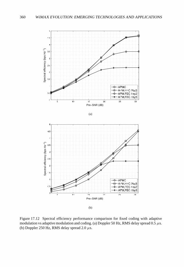
360 WiMAX EVOLUTION: EMERGING TECHNOLOGIES AND APPLICATIONS
Pre–SNR (dB)
Spe
ctra
l effi
cien
cy (
bps
Hz–1
)
(a)
Pre–SNR (dB)
Spe
ctra
l effi
cien
cy (
bps
Hz–1
)
(b)
Figure 17.12 Spectral efficiency performance comparison for fixed coding with adaptivemodulation vs adaptive modulation and coding. (a) Doppler 50 Hz, RMS delay spread 0.5 µs.(b) Doppler 250 Hz, RMS delay spread 2.0 µs.
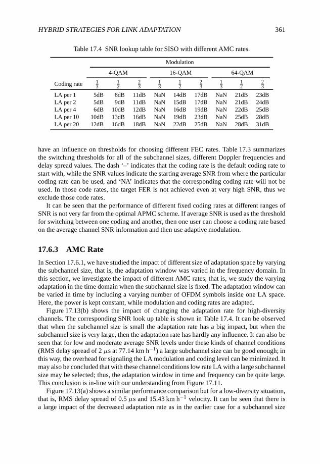
HYBRID STRATEGIES FOR LINK ADAPTATION 361
Table 17.4 SNR lookup table for SISO with different AMC rates.
Modulation
4-QAM 16-QAM 64-QAM
Coding rate 13
12
23
13
12
23
13
12
23
LA per 1 5dB 8dB 11dB NaN 14dB 17dB NaN 21dB 23dBLA per 2 5dB 9dB 11dB NaN 15dB 17dB NaN 21dB 24dBLA per 4 6dB 10dB 12dB NaN 16dB 19dB NaN 22dB 25dBLA per 10 10dB 13dB 16dB NaN 19dB 23dB NaN 25dB 28dBLA per 20 12dB 16dB 18dB NaN 22dB 25dB NaN 28dB 31dB
have an influence on thresholds for choosing different FEC rates. Table 17.3 summarizesthe switching thresholds for all of the subchannel sizes, different Doppler frequencies anddelay spread values. The dash ‘–’ indicates that the coding rate is the default coding rate tostart with, while the SNR values indicate the starting average SNR from where the particularcoding rate can be used, and ‘NA’ indicates that the corresponding coding rate will not beused. In those code rates, the target FER is not achieved even at very high SNR, thus weexclude those code rates.
It can be seen that the performance of different fixed coding rates at different ranges ofSNR is not very far from the optimal APMC scheme. If average SNR is used as the thresholdfor switching between one coding and another, then one user can choose a coding rate basedon the average channel SNR information and then use adaptive modulation.
17.6.3 AMC Rate
In Section 17.6.1, we have studied the impact of different size of adaptation space by varyingthe subchannel size, that is, the adaptation window was varied in the frequency domain. Inthis section, we investigate the impact of different AMC rates, that is, we study the varyingadaptation in the time domain when the subchannel size is fixed. The adaptation window canbe varied in time by including a varying number of OFDM symbols inside one LA space.Here, the power is kept constant, while modulation and coding rates are adapted.
Figure 17.13(b) shows the impact of changing the adaptation rate for high-diversitychannels. The corresponding SNR look up table is shown in Table 17.4. It can be observedthat when the subchannel size is small the adaptation rate has a big impact, but when thesubchannel size is very large, then the adaptation rate has hardly any influence. It can also beseen that for low and moderate average SNR levels under these kinds of channel conditions(RMS delay spread of 2 µs at 77.14 km h−1) a large subchannel size can be good enough; inthis way, the overhead for signaling the LA modulation and coding level can be minimized. Itmay also be concluded that with these channel conditions low rate LA with a large subchannelsize may be selected; thus, the adaptation window in time and frequency can be quite large.This conclusion is in-line with our understanding from Figure 17.11.
Figure 17.13(a) shows a similar performance comparison but for a low-diversity situation,that is, RMS delay spread of 0.5 µs and 15.43 km h−1 velocity. It can be seen that there isa large impact of the decreased adaptation rate as in the earlier case for a subchannel size
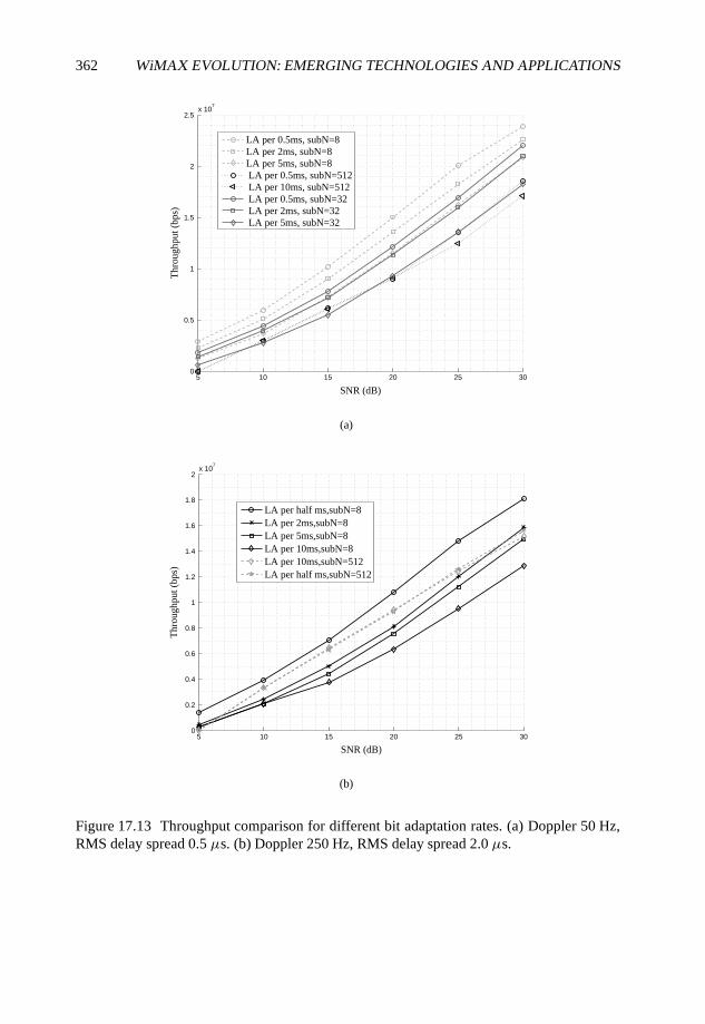
362 WiMAX EVOLUTION: EMERGING TECHNOLOGIES AND APPLICATIONS
5 10 15 20 25 300
0.5
1
1.5
2
2.5x 10
7
Thr
ough
put (
bps)
SNR (dB)
LA per 0.5ms, subN=8LA per 2ms, subN=8LA per 5ms, subN=8 LA per 0.5ms, subN=512 LA per 10ms, subN=512 LA per 0.5ms, subN=32 LA per 2ms, subN=32 LA per 5ms, subN=32
(a)
5 10 15 20 25 300
0.2
0.4
0.6
0.8
1
1.2
1.4
1.6
1.8
2x 10
7
SNR (dB)
Thr
ough
put (
bps)
LA per half ms,subN=8LA per 2ms,subN=8LA per 5ms,subN=8LA per 10ms,subN=8LA per 10ms,subN=512LA per half ms,subN=512
(b)
Figure 17.13 Throughput comparison for different bit adaptation rates. (a) Doppler 50 Hz,RMS delay spread 0.5 µs. (b) Doppler 250 Hz, RMS delay spread 2.0 µs.
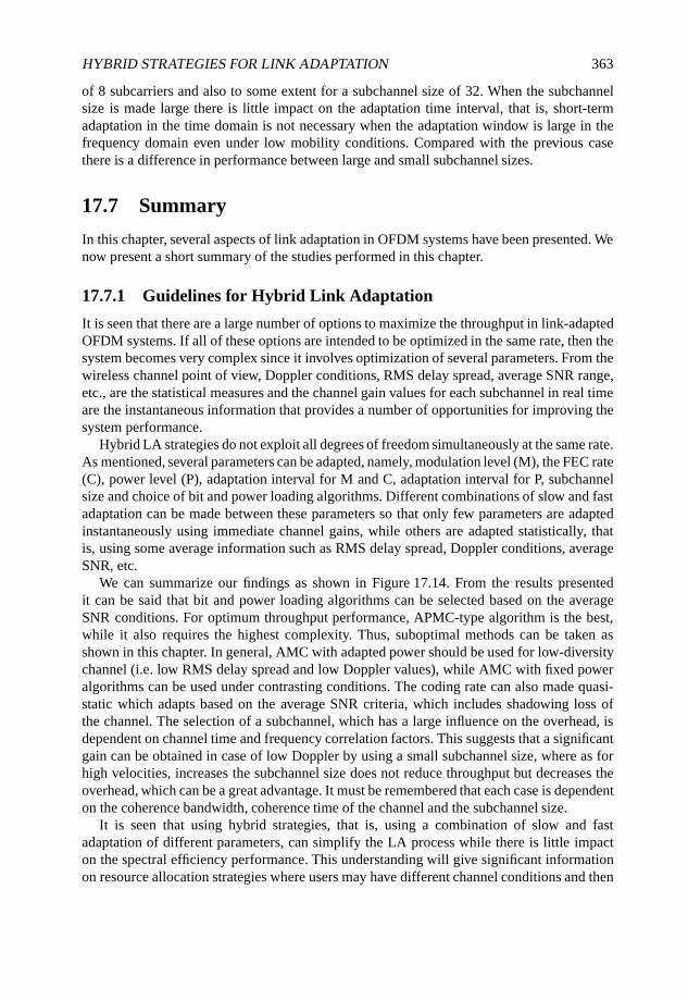
HYBRID STRATEGIES FOR LINK ADAPTATION 363
of 8 subcarriers and also to some extent for a subchannel size of 32. When the subchannelsize is made large there is little impact on the adaptation time interval, that is, short-termadaptation in the time domain is not necessary when the adaptation window is large in thefrequency domain even under low mobility conditions. Compared with the previous casethere is a difference in performance between large and small subchannel sizes.
17.7 Summary
In this chapter, several aspects of link adaptation in OFDM systems have been presented. Wenow present a short summary of the studies performed in this chapter.
17.7.1 Guidelines for Hybrid Link Adaptation
It is seen that there are a large number of options to maximize the throughput in link-adaptedOFDM systems. If all of these options are intended to be optimized in the same rate, then thesystem becomes very complex since it involves optimization of several parameters. From thewireless channel point of view, Doppler conditions, RMS delay spread, average SNR range,etc., are the statistical measures and the channel gain values for each subchannel in real timeare the instantaneous information that provides a number of opportunities for improving thesystem performance.
Hybrid LA strategies do not exploit all degrees of freedom simultaneously at the same rate.As mentioned, several parameters can be adapted, namely, modulation level (M), the FEC rate(C), power level (P), adaptation interval for M and C, adaptation interval for P, subchannelsize and choice of bit and power loading algorithms. Different combinations of slow and fastadaptation can be made between these parameters so that only few parameters are adaptedinstantaneously using immediate channel gains, while others are adapted statistically, thatis, using some average information such as RMS delay spread, Doppler conditions, averageSNR, etc.
We can summarize our findings as shown in Figure 17.14. From the results presentedit can be said that bit and power loading algorithms can be selected based on the averageSNR conditions. For optimum throughput performance, APMC-type algorithm is the best,while it also requires the highest complexity. Thus, suboptimal methods can be taken asshown in this chapter. In general, AMC with adapted power should be used for low-diversitychannel (i.e. low RMS delay spread and low Doppler values), while AMC with fixed poweralgorithms can be used under contrasting conditions. The coding rate can also made quasi-static which adapts based on the average SNR criteria, which includes shadowing loss ofthe channel. The selection of a subchannel, which has a large influence on the overhead, isdependent on channel time and frequency correlation factors. This suggests that a significantgain can be obtained in case of low Doppler by using a small subchannel size, where as forhigh velocities, increases the subchannel size does not reduce throughput but decreases theoverhead, which can be a great advantage. It must be remembered that each case is dependenton the coherence bandwidth, coherence time of the channel and the subchannel size.
It is seen that using hybrid strategies, that is, using a combination of slow and fastadaptation of different parameters, can simplify the LA process while there is little impacton the spectral efficiency performance. This understanding will give significant informationon resource allocation strategies where users may have different channel conditions and then
364 WiMAX EVOLUTION: EMERGING TECHNOLOGIES AND APPLICATIONS
Figure 17.14 Summary of the hybrid LA approach.
selecting different LA parameters for different users will be very important. Results, suchas those presented in this chapter, will play a key role in identifying such cases. Theseresults are also expected to trigger investigations into resource allocation algorithms forfuture broadband wireless systems, such as UMTS-LTE and IMT-Advanced.
17.7.2 Conclusion from Bit and Power Allocation Analysis
We have studied several combinations of bit and power allocation rates, so that the throughputcan be optimized without increasing the system complexity. It is popular belief thatsimultaneous bit and power allocation at the same rate is not very useful in terms of systemthroughput. In contrast to this popular belief, we have found that in some scenarios and undersome system conditions, some kind of power adaptation along with bit allocations acrossOFDM subchannels are required together for efficient exploitation of the wireless channel.In the case of multi-antenna schemes, the benefits of simultaneous bit and power allocationare even greater compared with bit allocation only schemes. We have tested different LAalgorithms in different multi-antenna systems. We have found that, if we cannot find theexact SNR thresholds due to different reasons, such as a reduced LA rate, CSI error, feedbackdelay, etc., it is better to fix the transmit power across all subchannels to guarantee the targetFER. Otherwise, we can use adaptive power distribution to save power, which can be used forother purposes, or to increase the throughput of the system by transmitting a higher numberof bits.
Owing to system complexity requirements, if we need to reduce the adaptation rates, thenmodulation and coding can be adapted at a slower rate if fast power control is applied in thetime domain. This provides a satisfactory system performance compared with the requiredsystem complexity. We make the following conclusions.
1. If the LA window is quite narrow (i.e. short in the time domain), then we practicallywaste the transmit power if we fix the amount of power for each subchannel. If we canadjust the power, once the FER threshold is met based on our AMC threshold table,then there will be power saving without losing much of the spectral efficiency.
HYBRID STRATEGIES FOR LINK ADAPTATION 365
2. For power-nonadapted cases, if we adapt both FEC and modulation, then by intro-ducing more switchable rates, the difference in wastage power for the cases with andwithout power adaptation will be smaller, thus less power will be wasted. This can bedone by introducing more channel-coding rates. However, this will also bring othersystem-level complexities.
3. If the LA window is quite wide (i.e. long in the time domain), then faster PC ratescan be used to compensate for the mismatch between actual SNR and modulation levelassigned to any subchannel.
17.7.3 Future Work
In the future, the impact of different subchannel sizes in collaboration with different bit andpower allocation rates can be studied. More importantly, studying these issues in a multi-userscenario will more clearly demonstrate the benefits of the power savings.
References
Ahn, C.J. and Sasase, I. (2002) The effects of modulation combination, target BER, Doppler frequency,and adaptation interval on the performance of adaptive OFDM in broadband mobile channel. IEEETransactions on Consumer Electronics, 48(1), 167–174.
Bohge, M., Gross, J. and Wolisz, A. (2005) The potential of dynamic power and subcarrier assignmentsin multi-user OFDM-FDMA cells. Proceedings of the IEEE GlobeComm’05, St. Louis, MO,pp. 2932–2936.
Chow, P.S. Cioffi, J. and Bingham, J.A.C. (1995) A practical discrete multitone transceiverloading algorithm for data transmission over spectrally shaped channel. IEEE Transactions onCommunication, 43(234), 773–775.
Chung, S.T. and Goldsmith, A.J. (2000) Adaptive multicarrier modulation for wireless systems.Proceedings of the 34th Asilomar Conference on Signals, Systems and Computers, Vol. 2, pp. 1603–1607.
Chung, S.T. and Goldsmith, A.J. (2001) Degrees of freedom in adaptive modulation: a unified view.IEEE Transactions on Communications, 49(9), 1561–1571.
Czylwik, A. (1996) Adaptive OFDM for wideband radio channels. Proceedings of the GlobalTelecommunications Conference, Vol. 2, pp. 713–718.
Das, S.S. et al. (2007) Influence of PAPR on link adaptation algorithms in OFDM systems. Proceedingsof the Semiannual Vehicular Technology Conference, Dublin, Ireland.
Erceg, V. et al. (1999) A model for the multipath delay profile of fixed wireless channels. IEEE Journalof Selected Areas in Communications, 17(3), 399–410.
Figueiredo, D.V.P., de Carvalho, E., Deneire, L. and Prasad, R. (2006) Impact of feedback delay on rateadaptation for multiple antenna systems. Proceedings of the IEEE PIMRC’06, Helsinki, Finland.
Goldsmith, A. (2005) Wireless Communications. Cambridge University Press.Hayes, J. (1968) Adaptive Feedback Communications. IEEE Transactions on Communications, 16(1),
29–34.Hunziker, T. and Dahlhaus, D. (2003) Optimal power adaptation for OFDM systems with ideal bit-
interleaving and hard-decision decoding. Proceedings of the IEEE ICC’03, Vol. 5, pp. 3392–3397.Hwang, Y.-T., Tsai, C.-Y. and Lin, C.-C. (2005) Block wise adaptive modulation for OFDM WLAN
systems. Proceedings of the IEEE International Symposium on Circuits and Systems, Vol. 6, 6098–6101.
366 WiMAX EVOLUTION: EMERGING TECHNOLOGIES AND APPLICATIONS
Larsson, P. (2007) Joint power and rate control for delay tolerant traffic in a wireless system.Proceedings of the IEEE Semiannual Vehicular Technology Conference, Dublin, Ireland.
Lei, M., Zhang, P., Harada, H. and Wakana, H. (2004) An adaptive power distribution algorithm forimproving spectral efficiency in OFDM. IEEE Transactions on Broadcasting, 50(3), 347–351.
Leke, A. and Cioffi, J.M. (1998) Multicarrier systems with imperfect channel knowledge. Proceedingsof the Ninth IEEE International Symposium on Personal, Indoor and Mobile Radio Communications,Vol. 2, pp. 549–553.
Paulraj, A.J., Nabar, R. and Gore, D. (2003) Introduction to Space–Time Wireless Communications, 1stedn. Cambridge University Press, Cambridge.
Rappaport, T.S. (1996) Wireless Communications Principles and Practice. Prentice Hall, EnglewoodCliffs, NJ.
Rhee, W. and Cioffi, J.M. (2000) Increase in capacity of multiuser OFDM system using dynamicsubchannel allocation. Proceedings of the IEEE Semiannual Vehicular Technology Conference,Tokyo, Japan, pp. 1085–1089.
Siebert, M. and Stauffer, O. (2003) Enhanced link adaptation performance applying adaptive subcarriermodulation in OFDM systems. Proceedings of the 57th IEEE Semiannual Vehicular TechnologyConference, Vol. 2, pp. 920–924.
Song, Z., Zhang, K. and Guan, Y.L. (2002) Statistical adaptive modulation for QAM-OFDM systems.Proceedings of the IEEE Semiannual Vehicular Technology Conference, Vol. 1, pp. 706–710.
Souryal, M.R. and Pickholtz, R. (2001) Adaptive modulation with imperfect channel information inOFDM. Proceedings of the IEEE International Conference on Communications, Vol. 6, pp. 1861–1865.
Tase, H., Ono S. and Hinamoto, T. (2005) Bit-rate maximization for multiuser OFDM systems.Transactions of the Institute of Electronics Information and Communication Engineering A, J88-A(3), 364–372.
Toyserkani, A.T., Naik, S., Ayan, J. et al. (2004) Subcarrier based adaptive modulation in HIPERLAN/2system. Proceedings of IEEE ICC’04, Vol. 6, pp. 3460–3464.
Ye, S., Blum, R. and Cimini, L.J. (2002) Adaptive modulation for variable-rate OFDM systems withimperfect channel information. Proceedings of the 55th IEEE Semiannual Vehicular TechnologyConference, Vol. 2, pp. 767–771.
Zhen, L. et al. (2002) Link adaptation of wideband OFDM systems in multi-path fading channel.Proceedings of IEEE CCECE, Vol. 3, pp. 1295–1299.
18
Applying WiMAX in NewScenarios: Limitations of thePhysical Layer and PossibleSolutions
Ilkka Harjula, Paola Cardamone, Matti Weissenfelt,Mika Lasanen, Sandrine Boumard, Aaron Byman andMarcos D. Katz
18.1 WiMAX in New Scenarios
While the WiMAX systems have been designed for Local Area Network (LANs) andMetropolitan Area Networks (MANs), the system parameters and algorithms have beendesigned to meet the requirements set by the radio channel in dense urban, suburban andrural areas. This is natural considering the fact that the majority of the potential customersreside in urban, densely populated areas. However, as the specification of the IEEE 802.16e-2005 standard, on which the WiMAX systems are based, is highly flexible, it is natural toraise a question of extending the usage environment from the urban areas to less-populatedareas outside the urban environment.
As the WiMAX specification makes it possible to use high data rates for relatively longlink distances, the number of applications that could be used in such systems outside thedense urban areas would be vast. This topic has been discussed for example in InformationSociety Technologies (IST) 6th Framework Programme (FP) project WiMAX Extension to
WiMAX Evolution: Emerging Technologies and Applications Edited by Tsutomu Ishikawa© 2009 John Wiley & Sons, Ltd. ISBN: 978-0-470-69680-4
368 WiMAX EVOLUTION: EMERGING TECHNOLOGIES AND APPLICATIONS
Isolated Research Data Networks (WEIRD) (WEIRD, 2008), where an extension of WiMAXto isolated research networks was considered. In WEIRD, possible applications such asenvironmental monitoring, fire prevention and telemedicine were identified, and a networkarchitecture supporting these applications was proposed. In WEIRD, the physical (PHY) andmedium access control (MAC) layers of WiMAX were also studied from the viewpoint ofextending the use of the standardized systems to uninhabited areas, namely mountainousareas covering application scenarios such as volcano monitoring in Iceland and Italy and fireprevention in Portugal.
The operational environment of the mobile WiMAX systems considered in this sectionconsist of environmental monitoring devices transmitting over fixed WiMAX stations placedin the valleys and slopes of the mountains, as well as communications and data-miningapplications used by the scientist visiting the environmental monitoring sites either by foot orrelatively slowly moving vehicles. Therefore, we consider here slow mobility and a situationwhere the Line-of-Sight (LOS) connection between the Mobile Station (MS) and BaseStation (BS) might or might not exist. The link distances might be relatively high, up toseveral kilometers, and the terrain is relatively free from buildings and similar obstacles, butinstead characterized by the presence of the mountain slopes and valleys.
One of the major challenges of modeling a communication system in a given environmentis choosing a channel model that accurately represents the prevailing transmission conditionsaffecting the performance of the system. In the next section, several publicly availablechannel models are reviewed in order to select the correct channel model for the novelWiMAX scenarios. These channel models include the European Cooperation in the Fieldof Scientific and Technical Research (COST) modes (Correia, 2001, Molisch and Hofstetter,2006), Third Generation Partnership Project (3GPP) model (3GPP, 2003) and the WirelessWorld Initiative New Radio (WINNER) Phase I and II channel models (WINNER, 2008). Ascan be seen from that section, none of the channel models was designed to specifically modelmountainous environments. Therefore, the WINNER Phase I channel model developed wasused as a starting point, and analytical tools were used for deriving an extension to theexisting Matlab channel model in section 18.3 to model the transmission conditions in themountainous environment (Cardamone et al., 2008).
The IEEE 802.16-2005 standard offers a variety of tools for tailoring the transmission fordifferent operational environments including several levels of modulation, variable CyclicPrefix (CP) length, variety of error-correction coding rates and types, and different MultipleInput Multiple Output (MIMO) technologies including Space–Time Coding (STC), spatialmultiplexing, and beamforming just to mention a few. In the mountainous environment, thedominant features of the channel model are long channel delay spread and highly directiveangle-of-arrival of the received signal. Therefore, scarce signal bandwidth must be sacrificedfor extensive CP, and multi-antenna techniques are recommended to deal with the spatialproperties of the channel. As a result, two beamforming techniques, namely pre- and post-FFT receiver beamforming, are proposed as solutions for the mountainous environmentsin Sections 18.4.1 and 18.4.2 and their performance is studied with Matlab simulations inSection 18.4.3 (see Harjula et al. (2008)).
The mountainous environment may also be challenging for synchronization between theBS and MS. We study the performance of Downlink (DL) timing synchronization in sucha scenario in Section 18.5. We use a practical hardware (HW) system in the study anddemonstrate various approaches that may be used for synchronization purposes.
APPLYING WiMAX IN NEW SCENARIOS 369
18.2 Channel Model for Mountainous Environments
As the radio channel places fundamental limits on the current wireless communicationssystems, the modeling of the radio channel has been under active study for a relatively longperiod of time. Starting from Maxwell’s well-known equations for the electromagnetic wavepropagation from 1861 (Maxwell, 1861) and pioneering work by Bello (1963, 1969) andKailath (1963), the work has been continuing actively to recent days. While the fundamentalsof the channel modeling have been derived for the Single Input Single Output (SISO)channel, the modeling of the MIMO channel has been gaining increased attention in therecent years.
In the following sections, we briefly present some recent standardized or publiclyavailable radio channel models for outdoor environments. The study has been limited toMIMO channel models, and the focus has been on searching for a suitable channel modelfor modeling the radio environment for mountainous environment. The channel modelspresented in this section include COST 259 and COST 273 channel modes, 3GPP and 3GPP2Spatial Channel Models (SCMs), Stanford University Interim (SUI) models, models definedfor the IEEE 802.16a standard and the channel model developed in the WINNER Phase Iand II projects.
18.2.1 COST 259/273
According to COST (2008), COST is the longest-running instrument supporting co-operationamong scientists and researchers across Europe. In the telecommunications field, COST ismost probably best known for the standardized channel models, referred to as COST 259and COST 273 (Correia, 2001, Molisch and Hofstetter, 2006). Sometimes the 3GPP SCMand the WINNER Phase I channel model are considered as the subsets of the very generalCOST 259.
18.2.2 3GPP/3GPP2 Statistical Channel Model
The 3GPP/3GPP2 SCM (3GPP, 2003) was developed for evaluating different MIMOconcepts in outdoor environments at a frequency of 2 GHz with a system bandwidthof 5 MHz. This model is divided into two parts: link-level evaluation for calibrationpurposes and system-level evaluation for simulations. The link-level calibration modelcan be implemented either as a physical model or as an analytical model. The first is anongeometrical stochastic physical model. It describes the wideband characteristics of thechannel as a tapped delay line, and all of the paths are assumed to be independent. Eachresolvable path is characterized by its own spatial channel parameters, such as power azimuthspectrum which is Laplacian or uniform, angular spread and mean direction, at both the BSand the MS. The parameters are fixed, thus the model shows stationary channel conditions.The speed and the direction of the MS characterizes implicitly the Doppler spectrum. Thephysical model can be transformed into an equivalent analytical model using the antennaconfigurations defined in the model itself.
370 WiMAX EVOLUTION: EMERGING TECHNOLOGIES AND APPLICATIONS
18.2.3 SUI Models and IEEE 802.16a Channel Models
The IEEE 802.16a channel model is based on the SUI channel model (Erceg et al., 2001).Therefore, they share mostly the same features, and they are therefore discussed together inthis section. However, there are some differences between the channel models, and these arealso pointed out in this discussion.
The common features regard the cell radius of less than 10 km, the system bandwidthfrom 2 to 20 MHz, the BS height varying from 15 to 40 m, and the use of a fixed user endantenna. The channel models can be used in the 1 to 4 GHz range. The concept of MIMOand directional characteristics of the transmission are not considered in the standard, butsubsequent studies have taken these elements into account (COST, 2008).
The IEEE 802.16a channel model is based on a modified version of the SUI channelmodel, valid for both omni-directional and directional antennas. The second aspect causesan increase in the Ricean factor, but a decrease in the delay spread. The model also includesdifferent path loss models, the K-factor model and introduces an antenna gain reductionfactor which considers the reduction of the antenna gain due to a scattering effect.
18.2.4 WINNER Phase I and II Channel Models
The channel model developed in the WINNER Phase I (WINNER, 2008) project in phase 1is focusing on the beyond 3G radio system using a frequency bands up to 100 MHz forthe frequency band between 2 and 6 GHz. The channel model is related to both the COST259 model and the 3GPP SCM model. The WINNER Phase I channel model is based onseven different propagation scenarios for indoor and outdoor environments. As a 3GPPSCM model, it is divided into link-level simulation and system-level simulation models.The generic channel model is a geometric-based stochastic channel model and most of itsfeatures are based on the principle of the 3GPP SCM model. Actually, these aspects arevalid for six scenarios; the other scenario is not considered in the generic model since itis a stationary wireless feeder scenario, where transmitted and receiver ends are fixed. It ismodeled separately as Clustered Delay Line (CDL) model. Various measurement campaignsprovide the parameterization of the scenarios for both LOS and Non-Line-of-Sight (NLOS)conditions.
From the WINNER Phase I channel model, the scenario D1 defined for the flat rural areaseems very interesting from the point of view of this work. The possibility of adjusting thecenter frequency to 3.5 GHz which is the center frequency for mobile WiMAX used in thetestbeds in the WEIRD project is a very appealing property. The Matlab code is readilyavailable at the WINNER Web site (WINNER, 2008).
At the time of writing the WINNER Phase II channel models had also became public(WINNER, 2008). According to their Web page, the WINNER Phase II channel modelincludes the model parametrization based on measurements, 17 model scenarios (includingindoor), stochastic models for system-level simulations, fixed CDL models for calibrationsimulations, network layout visualization tool autocorrelation of large-scale channel param-eters and support for arbitrary 3D antenna geometry and field patterns. However, as the workin this section is based on the WINNER Phase I channel model, the reader is advised to lookfor more information on the WINNER Phase II Web site (WINNER, 2008).
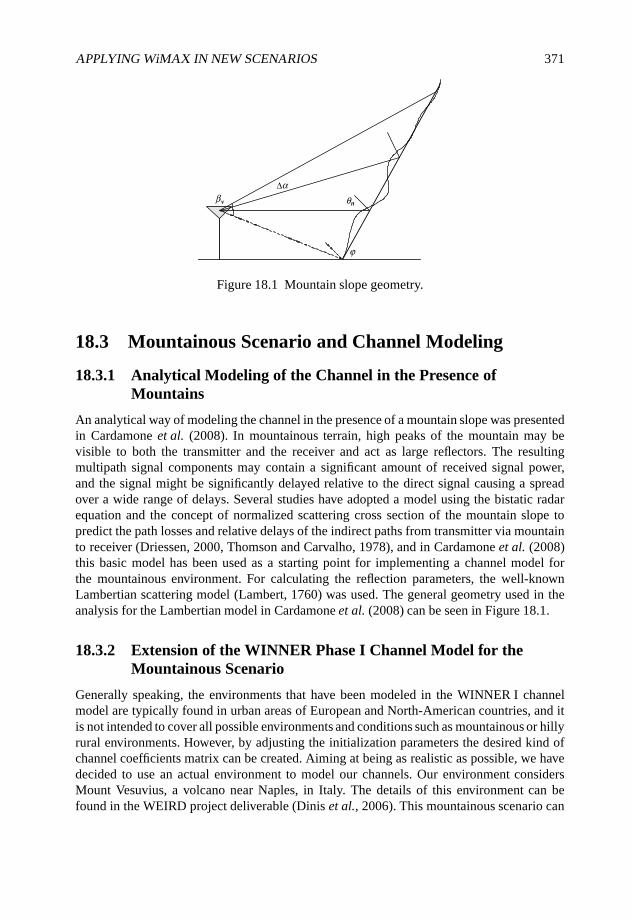
APPLYING WiMAX IN NEW SCENARIOS 371
v n
∆
Figure 18.1 Mountain slope geometry.
18.3 Mountainous Scenario and Channel Modeling
18.3.1 Analytical Modeling of the Channel in the Presence ofMountains
An analytical way of modeling the channel in the presence of a mountain slope was presentedin Cardamone et al. (2008). In mountainous terrain, high peaks of the mountain may bevisible to both the transmitter and the receiver and act as large reflectors. The resultingmultipath signal components may contain a significant amount of received signal power,and the signal might be significantly delayed relative to the direct signal causing a spreadover a wide range of delays. Several studies have adopted a model using the bistatic radarequation and the concept of normalized scattering cross section of the mountain slope topredict the path losses and relative delays of the indirect paths from transmitter via mountainto receiver (Driessen, 2000, Thomson and Carvalho, 1978), and in Cardamone et al. (2008)this basic model has been used as a starting point for implementing a channel model forthe mountainous environment. For calculating the reflection parameters, the well-knownLambertian scattering model (Lambert, 1760) was used. The general geometry used in theanalysis for the Lambertian model in Cardamone et al. (2008) can be seen in Figure 18.1.
18.3.2 Extension of the WINNER Phase I Channel Model for theMountainous Scenario
Generally speaking, the environments that have been modeled in the WINNER I channelmodel are typically found in urban areas of European and North-American countries, and itis not intended to cover all possible environments and conditions such as mountainous or hillyrural environments. However, by adjusting the initialization parameters the desired kind ofchannel coefficients matrix can be created. Aiming at being as realistic as possible, we havedecided to use an actual environment to model our channels. Our environment considersMount Vesuvius, a volcano near Naples, in Italy. The details of this environment can befound in the WEIRD project deliverable (Dinis et al., 2006). This mountainous scenario can
372 WiMAX EVOLUTION: EMERGING TECHNOLOGIES AND APPLICATIONS
generally be represented as a rural terrain with a great mountain, acting as a reflector inthe background. Since the reflector is obviously fixed, the starting point of the model isdeterministic, that is, the powers and the delays are not considered to be extracted from aProbability Distribution Function (PDF), but calculated in a deterministic manner.
One of the partners of the WEIRD project is the Osservatorio Vesuviano, and this institutegave us the maps with the locations of their sensors which are used to monitor the activity ofthe volcano and for the purposes of fire, eruption and earthquake prevention. By using thesemaps, we have chosen one fixed sensor as our BS and one of the mobile sensors as the MS.We also had the geographical coordinates of each sensor and of Mount Vesuvius. Thus, wehave used this information to compute the distances between the BS and MS and betweenthem and the mountain.
The results of the channel modeling in Matlab can be seen in Figure 18.2, which shows thedelay spread of the paths due to the mountainous environment. In this Matlab simulation withWINNER Phase I channel model enhanced with the analytical mountain model, a NLOS pathbetween source and receiver has been assumed. As we can see, the mountain acts as a largereflector resulting in long-delayed echoes which are exponentially distributed. In order torelate the timescale to the WiMAX system, all of the possible WiMAX cyclic prefix sizes areremarked: it simple to see that only a CP of 1/4 (22.85 µs) can be used without affecting theperformance of the IEEE 802.16e-2005-based system. On the other hand, using the longestsize for the CP means that a great fraction of the power is assigned to the transmission of theCP itself and cannot be used for the data-carrying symbols. In addition, the simulation resultswith the WINNER Phase I D1 scenario are presented in this Figure 18.2, and the division ofpower is assumed to be equal between the D1 and the reflections from the mountain.
18.4 Beamforming Algorithms and Simulation
MIMO channels arise in many different scenarios in communications, such as modelingfrequency selective channel using transmit and receive filter banks, treating a bundle oftwisted pairs in digital subscriber lines as a whole, or when using multiple antennas atboth sides of the wireless link (Palomar et al., 2003). This work focuses on MIMO channelsarising from the use of multiple antennas at both sides of the wireless link since they offer asignificant capacity increase over SISO channels in certain channel conditions (Foschini andGans, 1998, Telatar, 1999). Good references for the MIMO techniques in general includeGiannakis et al. (2008) and Goldsmith (2005).
In recent years, the trend in the MIMO studies has been more towards the multiuser MIMOtechniques. These systems consist of several BS and MS, each equipped with several antennasand operating in the same frequency bands while sharing the same spatial resources. A goodoverview of these techniques is given in Gesbert et al. (2007), and the same topic has beenapproached from a viewpoint of spatial diversity in Diggavi et al. (2004). However, in thissection the focus is in a cell with a single user or several users sharing the spectrum by usingOrthogonal Frequency Division Multiple Access (OFDMA), and sharing the properties ofthe mountainous environment.
The IEEE 802.16-2004 standard (IEEE, 2004) with the IEEE802.16-2005 standardamendment (IEEE, 2005) offers a variety of tools for MIMO processing including STC,spatial multiplexing and beamforming. The WirelessMAN-OFDMA PHY layer definition
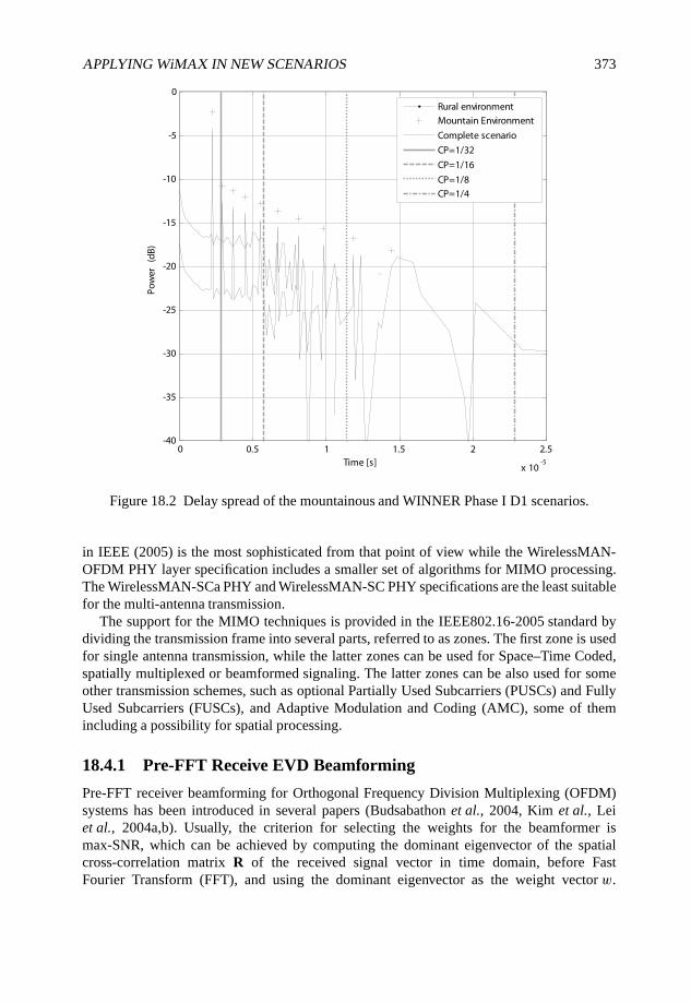
APPLYING WiMAX IN NEW SCENARIOS 373
0 0.5 1 1.5 2 2.5
x 10-5
-40
-35
-30
-25
-20
-15
-10
-5
0
Time [s]
Pow
er
(dB)
Rural environmentMountain EnvironmentComplete scenarioCP=1/32CP=1/16CP=1/8CP=1/4
Figure 18.2 Delay spread of the mountainous and WINNER Phase I D1 scenarios.
in IEEE (2005) is the most sophisticated from that point of view while the WirelessMAN-OFDM PHY layer specification includes a smaller set of algorithms for MIMO processing.The WirelessMAN-SCa PHY and WirelessMAN-SC PHY specifications are the least suitablefor the multi-antenna transmission.
The support for the MIMO techniques is provided in the IEEE802.16-2005 standard bydividing the transmission frame into several parts, referred to as zones. The first zone is usedfor single antenna transmission, while the latter zones can be used for Space–Time Coded,spatially multiplexed or beamformed signaling. The latter zones can be also used for someother transmission schemes, such as optional Partially Used Subcarriers (PUSCs) and FullyUsed Subcarriers (FUSCs), and Adaptive Modulation and Coding (AMC), some of themincluding a possibility for spatial processing.
18.4.1 Pre-FFT Receive EVD Beamforming
Pre-FFT receiver beamforming for Orthogonal Frequency Division Multiplexing (OFDM)systems has been introduced in several papers (Budsabathon et al., 2004, Kim et al., Leiet al., 2004a,b). Usually, the criterion for selecting the weights for the beamformer ismax-SNR, which can be achieved by computing the dominant eigenvector of the spatialcross-correlation matrix R of the received signal vector in time domain, before FastFourier Transform (FFT), and using the dominant eigenvector as the weight vector w.
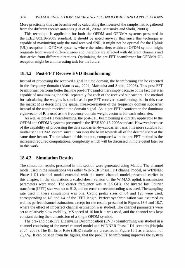
374 WiMAX EVOLUTION: EMERGING TECHNOLOGIES AND APPLICATIONS
More practically this can be achieved by calculating the inverse of the sample matrix gatheredfrom the different receive antennas (Lei et al., 2004a, Matsuoka and Shoki, 20003).
This technique is applicable for both the OFDM and OFDMA systems presented inthe IEEE 802.16-2005 standard. It should be noted anyway that since this technique iscapable of maximizing only the total received SNR, it might not be optimal for the Uplink(UL) reception in OFDMA systems, where the subcarriers within an OFDM symbol mightoriginate from several different users and therefore are affected with different channels andthus arrive from different directions. Optimizing the pre-FFT beamformer for OFDMA ULreception might be an interesting task for the future.
18.4.2 Post-FFT Receive EVD Beamforming
Instead of processing the received signal in time domain, the beamforming can be executedin the frequency domain (Alam et al., 2004, Matsuoka and Shoki, 20003). This post-FFTbeamformer performs better than the pre-FFT beamformer simply because of the fact that it iscapable of maximizing the SNR separately for each of the received subcarriers. The methodfor calculating the weights is similar as in pre-FFT receiver beamforming, but in this casethe matrix R is describing the spatial cross-correlation of the frequency domain subcarrierinstead of the whole received time domain signal. As in pre-FFT beamformer, the dominanteigenvector of R is used as the frequency domain weight vector w for each subcarrier.
As well as pre-FFT beamforming, the post-FFT beamforming is directly applicable to theOFDM and OFDMA systems presented in the IEEE 802.16-2005 standard. However, becauseof the capability of processing the data subcarrier-by-subcarrier basis, it is more suitable formulti-user OFDMA system since it can steer the beam towards all of the desired users at thesame time instant. The drawback of this method, compared with the pre-FFT method is theincreased required computational complexity which will be discussed in more detail later onin this work.
18.4.3 Simulation Results
The simulation results presented in this section were generated using Matlab. The channelmodel used in the simulations was either WINNER Phase I D1 channel model, or WINNERPhase I D1 channel model extended with the novel channel model presented earlier inthis chapter. In the simulations a scaled-down version of the WiMAX uplink transmissionparameters were used. The carrier frequency was at 3.5 GHz, the inverse fast Fouriertransform (IFFT) size was set to 512, and no error-correction coding was used. The samplingrate used in these simulations was one. Cyclic prefix sizes of 64 and 128 were used,corresponding to 1/8 and 1/4 of the IFFT length. Perfect synchronization was assumed aswell as perfect channel estimation, except for the results presented in Figures 18.6 and 18.7,where the effect of imperfect channel estimation was studied. The channel parameters wereset to relatively slow mobility, MS speed of 10 km h−1 was used, and the channel was keptconstant during the transmission of a single OFDM symbol.
The pre- and post-FFT Eigenvalue Decomposition (EVD) beamforming was studied in achannel consisting of the novel channel model and WINNER Phase I D1 scenario (Harjulaet al., 2008). The Bit Error Rate (BER) results are presented in Figure 18.3 as a function ofEb/N0. It can be seen from the figures, that the pre-FFT beamforming improves the system
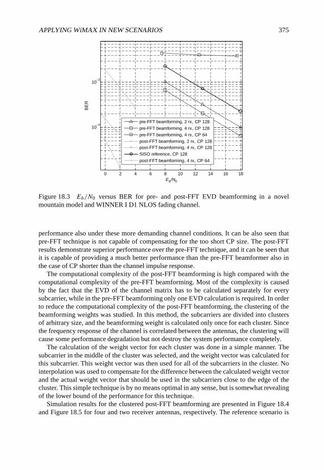
APPLYING WiMAX IN NEW SCENARIOS 375
0 2 4 6 8 10 12 14 16 18
10–4
10–3
Eb/N0
BE
R
pre-FFT beamforming, 2 rx, CP 128
pre-FFT beamforming, 4 rx, CP 128
pre-FFT beamforming, 4 rx, CP 64
post-FFT beamforming, 2 rx, CP 128
post-FFT beamforming, 4 rx, CP 128
SISO reference, CP 128
post-FFT beamforming, 4 rx, CP 64
Figure 18.3 Eb/N0 versus BER for pre- and post-FFT EVD beamforming in a novelmountain model and WINNER I D1 NLOS fading channel.
performance also under these more demanding channel conditions. It can be also seen thatpre-FFT technique is not capable of compensating for the too short CP size. The post-FFTresults demonstrate superior performance over the pre-FFT technique, and it can be seen thatit is capable of providing a much better performance than the pre-FFT beamformer also inthe case of CP shorter than the channel impulse response.
The computational complexity of the post-FFT beamforming is high compared with thecomputational complexity of the pre-FFT beamforming. Most of the complexity is causedby the fact that the EVD of the channel matrix has to be calculated separately for everysubcarrier, while in the pre-FFT beamforming only one EVD calculation is required. In orderto reduce the computational complexity of the post-FFT beamforming, the clustering of thebeamforming weights was studied. In this method, the subcarriers are divided into clustersof arbitrary size, and the beamforming weight is calculated only once for each cluster. Sincethe frequency response of the channel is correlated between the antennas, the clustering willcause some performance degradation but not destroy the system performance completely.
The calculation of the weight vector for each cluster was done in a simple manner. Thesubcarrier in the middle of the cluster was selected, and the weight vector was calculated forthis subcarrier. This weight vector was then used for all of the subcarriers in the cluster. Nointerpolation was used to compensate for the difference between the calculated weight vectorand the actual weight vector that should be used in the subcarriers close to the edge of thecluster. This simple technique is by no means optimal in any sense, but is somewhat revealingof the lower bound of the performance for this technique.
Simulation results for the clustered post-FFT beamforming are presented in Figure 18.4and Figure 18.5 for four and two receiver antennas, respectively. The reference scenario is
376 WiMAX EVOLUTION: EMERGING TECHNOLOGIES AND APPLICATIONS
10 10.5 11 11.5 1210
–5
10–4
10–3
10–2
SNR
BE
R
cluster size = 64
cluster size = 14
cluster size = 4
cluster size = 1
Figure 18.4 SNR versus BER for post-FFT EVD beamforming with clustering and 4 rxantennas in a WINNER I D1 NLOS fading channel.
presented with the line with triangles and it corresponds to the case where the weight vectoris calculated separately for each subcarrier. Simulation results for cluster sizes 4, 14 and 64are presented in the other lines. A cluster size of 4 corresponds to the size of UL tile definedin IEEE (2004), and a cluster size of 14 corresponds to the size of DL cluster in IEEE (2004).A cluster size of 64 is studied to see the performance with a relatively large cluster size. It canbe seen from the figures that the post-FFT beamforming is highly sensitive to the clusteringof the subcarriers, and the clustering seems to cause an error floor to different BER levelsdepending on the cluster size. This might be caused by the high-frequency sensitivity of thechannel model used in the simulations.
The sensitivity of the pre- and post-FFT beamforming algorithms to the channel estimationerrors was also studied. The channel estimation errors were modeled as Gaussian Independentand Identically Distributed (IID) noise, which is the worst-case estimation error assumptionfor the linear Minimum Mean Squared Error (MMSE)-type channel estimator. A detailedexplanation and justification for this kind of approach can be found, for example, in Tölli(2008).
The simulation results for pre- and post-FFT beamforming with imperfect channelestimates are presented in Figure 18.6 and Figure 18.7, respectively. The results are presentas BER versus SNR graphs for two receiver antennas, and the different curves indicate thedifferent amount of estimation error as a function of Channel-to-Noise ratio (CNR). In thiscase the noise refers to the noise used to model the channel estimation error, not the noiseused in the AWGN channel. The results indicate that the post-FFT beamformer is far moresensitive to the estimation errors than the pre-FFT beamformer. While the CNR value of 5 dBis enough providing the receiver with pre-FFT beamformer a nondegraded performance, the
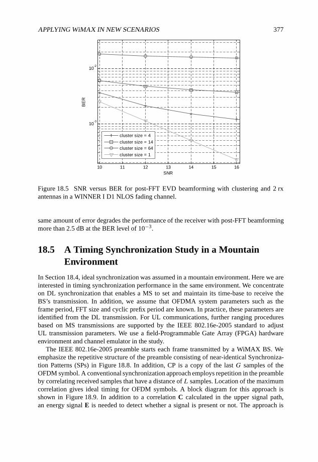
APPLYING WiMAX IN NEW SCENARIOS 377
10 11 12 13 14 15 16
10-3
10-2
SNR
BE
R
cluster size = 4
cluster size = 14
cluster size = 64
cluster size = 1
Figure 18.5 SNR versus BER for post-FFT EVD beamforming with clustering and 2 rxantennas in a WINNER I D1 NLOS fading channel.
same amount of error degrades the performance of the receiver with post-FFT beamformingmore than 2.5 dB at the BER level of 10−3.
18.5 A Timing Synchronization Study in a MountainEnvironment
In Section 18.4, ideal synchronization was assumed in a mountain environment. Here we areinterested in timing synchronization performance in the same environment. We concentrateon DL synchronization that enables a MS to set and maintain its time-base to receive theBS’s transmission. In addition, we assume that OFDMA system parameters such as theframe period, FFT size and cyclic prefix period are known. In practice, these parameters areidentified from the DL transmission. For UL communications, further ranging proceduresbased on MS transmissions are supported by the IEEE 802.16e-2005 standard to adjustUL transmission parameters. We use a field-Programmable Gate Array (FPGA) hardwareenvironment and channel emulator in the study.
The IEEE 802.16e-2005 preamble starts each frame transmitted by a WiMAX BS. Weemphasize the repetitive structure of the preamble consisting of near-identical Synchroniza-tion Patterns (SPs) in Figure 18.8. In addition, CP is a copy of the last G samples of theOFDM symbol. A conventional synchronization approach employs repetition in the preambleby correlating received samples that have a distance of L samples. Location of the maximumcorrelation gives ideal timing for OFDM symbols. A block diagram for this approach isshown in Figure 18.9. In addition to a correlation C calculated in the upper signal path,an energy signal E is needed to detect whether a signal is present or not. The approach is
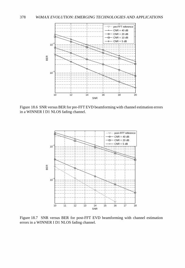
378 WiMAX EVOLUTION: EMERGING TECHNOLOGIES AND APPLICATIONS
10 12 14 16 18 20
10–3
10–2
SNR
BE
R
pre-FFT reference
CNR = 40 dB
CNR = 20 dB
CNR = 10 dB
CNR = 5 dB
Figure 18.6 SNR versus BER for pre-FFT EVD beamforming with channel estimation errorsin a WINNER I D1 NLOS fading channel.
10 11 12 13 14 15 16 17 18
10–3
10–2
SNR
BE
R
post-FFT reference
CNR = 40 dB
CNR = 20 dB
CNR = 5 dB
Figure 18.7 SNR versus BER for post-FFT EVD beamforming with channel estimationerrors in a WINNER I D1 NLOS fading channel.
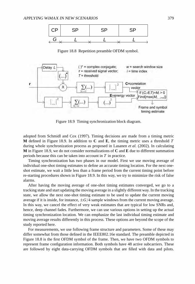
APPLYING WiMAX IN NEW SCENARIOS 379
CP
G L L L
SP SP SP
Figure 18.8 Repetition preamble OFDM symbol.
Figure 18.9 Timing synchronization block diagram.
adopted from Schmidl and Cox (1997). Timing decisions are made from a timing metricM defined in Figure 18.9. In addition to C and E, the timing metric uses a threshold Tduring whole synchronization process as proposed in Lasanen et al. (2002). In calculatingM in Figure 18.9, we do not consider normalizations of C and E due to different summationperiods because this can be taken into account in T in practice.
Timing synchronization has two phases in our model. First we use moving average ofindividual one-shot timing estimates to define an accurate timing location. For the next one-shot estimate, we wait a little less than a frame period from the current timing point beforere-starting procedures shown in Figure 18.9. In this way, we try to minimize the risk of falsealarms.
After having the moving average of one-shot timing estimates converged, we go to atracking state and start updating the moving average in a slightly different way. In the trackingstate, we allow the next one-shot timing estimate to be used to update the current movingaverage if it is inside, for instance, ±G/4 sample windows from the current moving average.In this way, we cancel the effect of very weak estimates that are typical for low SNRs and,hence, deep channel fades. Furthermore, we can use various options in setting up the actualtiming synchronization location. We can emphasize the last individual timing estimate andmoving average results differently in this process. These options are beyond the scope of thestudy reported here.
For measurements, we use following frame structure and parameters. Some of these maydiffer somewhat from those defined in the IEEE802.16e standard. The preamble depicted inFigure 18.8 is the first OFDM symbol of the frame. Then, we have two OFDM symbols torepresent frame configuration information. Both symbols have 48 active subcarriers. Theseare followed by eight data-carrying OFDM symbols that are filled with data and pilots.
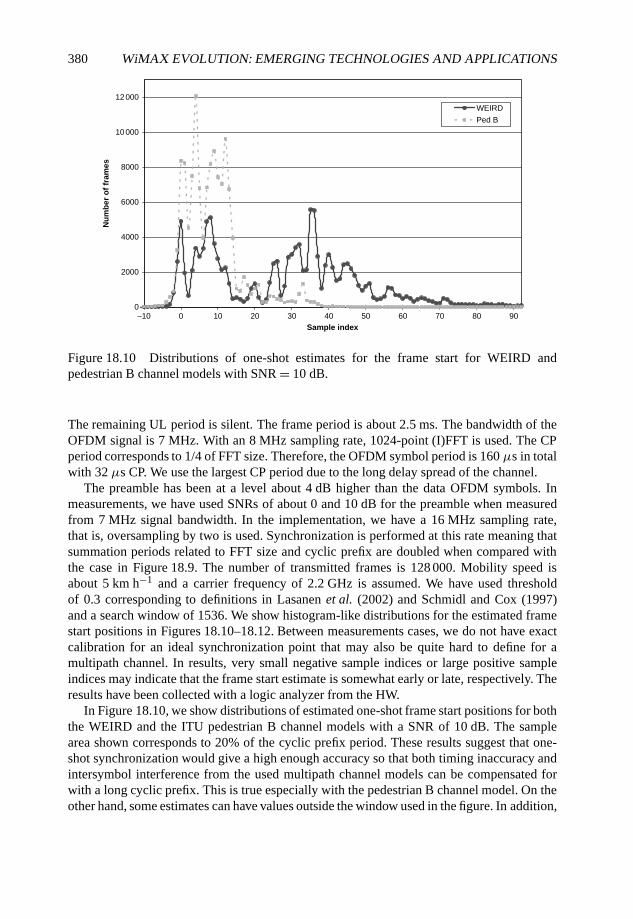
380 WiMAX EVOLUTION: EMERGING TECHNOLOGIES AND APPLICATIONS
0
2000
4000
6000
8000
10 000
12 000
–10 0 10 20 30 40 50 60 70 80 90
Sample index
Nu
mb
er
of
fra
me
sWEIRD
Ped B
Figure 18.10 Distributions of one-shot estimates for the frame start for WEIRD andpedestrian B channel models with SNR = 10 dB.
The remaining UL period is silent. The frame period is about 2.5 ms. The bandwidth of theOFDM signal is 7 MHz. With an 8 MHz sampling rate, 1024-point (I)FFT is used. The CPperiod corresponds to 1/4 of FFT size. Therefore, the OFDM symbol period is 160 µs in totalwith 32 µs CP. We use the largest CP period due to the long delay spread of the channel.
The preamble has been at a level about 4 dB higher than the data OFDM symbols. Inmeasurements, we have used SNRs of about 0 and 10 dB for the preamble when measuredfrom 7 MHz signal bandwidth. In the implementation, we have a 16 MHz sampling rate,that is, oversampling by two is used. Synchronization is performed at this rate meaning thatsummation periods related to FFT size and cyclic prefix are doubled when compared withthe case in Figure 18.9. The number of transmitted frames is 128 000. Mobility speed isabout 5 km h−1 and a carrier frequency of 2.2 GHz is assumed. We have used thresholdof 0.3 corresponding to definitions in Lasanen et al. (2002) and Schmidl and Cox (1997)and a search window of 1536. We show histogram-like distributions for the estimated framestart positions in Figures 18.10–18.12. Between measurements cases, we do not have exactcalibration for an ideal synchronization point that may also be quite hard to define for amultipath channel. In results, very small negative sample indices or large positive sampleindices may indicate that the frame start estimate is somewhat early or late, respectively. Theresults have been collected with a logic analyzer from the HW.
In Figure 18.10, we show distributions of estimated one-shot frame start positions for boththe WEIRD and the ITU pedestrian B channel models with a SNR of 10 dB. The samplearea shown corresponds to 20% of the cyclic prefix period. These results suggest that one-shot synchronization would give a high enough accuracy so that both timing inaccuracy andintersymbol interference from the used multipath channel models can be compensated forwith a long cyclic prefix. This is true especially with the pedestrian B channel model. On theother hand, some estimates can have values outside the window used in the figure. In addition,
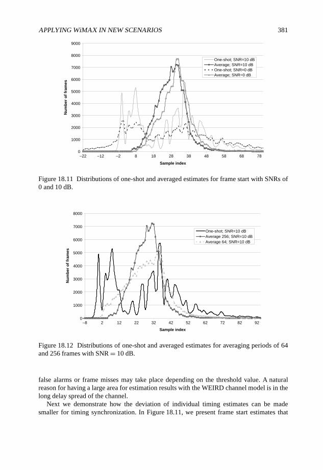
APPLYING WiMAX IN NEW SCENARIOS 381
0
1000
2000
3000
4000
5000
6000
7000
8000
9000
–22 –12 –2 8 18 28 38 48 58 68 78
Sample index
Nu
mb
er
of
fram
es
One-shot; SNR=10 dB
Average; SNR=10 dB
One-shot; SNR=0 dB
Average; SNR=0 dB
Figure 18.11 Distributions of one-shot and averaged estimates for frame start with SNRs of0 and 10 dB.
0
1000
2000
3000
4000
5000
6000
7000
8000
–8 2 12 22 32 42 52 62 72 82 92
Sample index
Nu
mb
er
of
fram
es
One-shot; SNR=10 dB
Average 256; SNR=10 dB
Average 64; SNR=10 dB
Figure 18.12 Distributions of one-shot and averaged estimates for averaging periods of 64and 256 frames with SNR = 10 dB.
false alarms or frame misses may take place depending on the threshold value. A naturalreason for having a large area for estimation results with the WEIRD channel model is in thelong delay spread of the channel.
Next we demonstrate how the deviation of individual timing estimates can be madesmaller for timing synchronization. In Figure 18.11, we present frame start estimates that
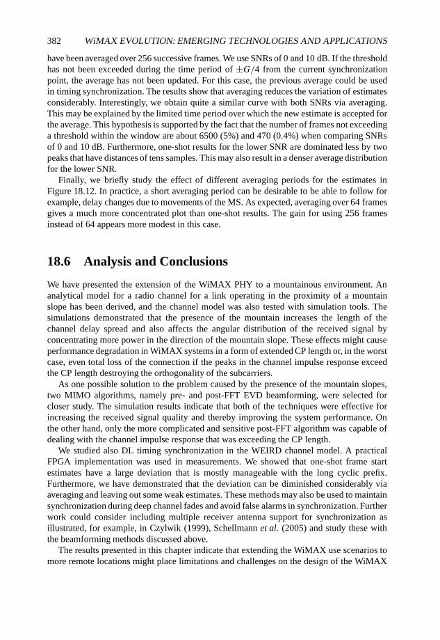
382 WiMAX EVOLUTION: EMERGING TECHNOLOGIES AND APPLICATIONS
have been averaged over 256 successive frames. We use SNRs of 0 and 10 dB. If the thresholdhas not been exceeded during the time period of ±G/4 from the current synchronizationpoint, the average has not been updated. For this case, the previous average could be usedin timing synchronization. The results show that averaging reduces the variation of estimatesconsiderably. Interestingly, we obtain quite a similar curve with both SNRs via averaging.This may be explained by the limited time period over which the new estimate is accepted forthe average. This hypothesis is supported by the fact that the number of frames not exceedinga threshold within the window are about 6500 (5%) and 470 (0.4%) when comparing SNRsof 0 and 10 dB. Furthermore, one-shot results for the lower SNR are dominated less by twopeaks that have distances of tens samples. This may also result in a denser average distributionfor the lower SNR.
Finally, we briefly study the effect of different averaging periods for the estimates inFigure 18.12. In practice, a short averaging period can be desirable to be able to follow forexample, delay changes due to movements of the MS. As expected, averaging over 64 framesgives a much more concentrated plot than one-shot results. The gain for using 256 framesinstead of 64 appears more modest in this case.
18.6 Analysis and Conclusions
We have presented the extension of the WiMAX PHY to a mountainous environment. Ananalytical model for a radio channel for a link operating in the proximity of a mountainslope has been derived, and the channel model was also tested with simulation tools. Thesimulations demonstrated that the presence of the mountain increases the length of thechannel delay spread and also affects the angular distribution of the received signal byconcentrating more power in the direction of the mountain slope. These effects might causeperformance degradation in WiMAX systems in a form of extended CP length or, in the worstcase, even total loss of the connection if the peaks in the channel impulse response exceedthe CP length destroying the orthogonality of the subcarriers.
As one possible solution to the problem caused by the presence of the mountain slopes,two MIMO algorithms, namely pre- and post-FFT EVD beamforming, were selected forcloser study. The simulation results indicate that both of the techniques were effective forincreasing the received signal quality and thereby improving the system performance. Onthe other hand, only the more complicated and sensitive post-FFT algorithm was capable ofdealing with the channel impulse response that was exceeding the CP length.
We studied also DL timing synchronization in the WEIRD channel model. A practicalFPGA implementation was used in measurements. We showed that one-shot frame startestimates have a large deviation that is mostly manageable with the long cyclic prefix.Furthermore, we have demonstrated that the deviation can be diminished considerably viaaveraging and leaving out some weak estimates. These methods may also be used to maintainsynchronization during deep channel fades and avoid false alarms in synchronization. Furtherwork could consider including multiple receiver antenna support for synchronization asillustrated, for example, in Czylwik (1999), Schellmann et al. (2005) and study these withthe beamforming methods discussed above.
The results presented in this chapter indicate that extending the WiMAX use scenarios tomore remote locations might place limitations and challenges on the design of the WiMAX

APPLYING WiMAX IN NEW SCENARIOS 383
PHY layer algorithms. The use of MIMO techniques, especially beamforming, might offera solution for providing the end user with reliable operation even in a challenging radioenvironment.
References
3GPP (2003) 3rd Generation Partnership Project; technical specification group radio access network;spatial channel model for MIMO simulations (release 6), 3GPP Technical Report 25.996, V6.1.0.
Alam, F., Cheung, B.L.P., Mostafa, R., Newhall, W.G. and Reed, J.H. (2004) Sub-band beamformingfor OFDM system in practical channel condition. Proceedings of the IEEE Semiannual VehicularTechnology Conference, Vol. 1, pp. 235–239.
Bello, P.A. (1963) Characterization of randomly timevariant linear channels. IEEE Transactions onCommunication Systems, 11, 360–393.
Bello, P.A. (1969) Measurement of random time-variant linear channels. IEEE Transactions onInformation Theory, 15, 469–475.
Budsabathon, M., Hara, Y. and Hara, S. (2004) Optimum beamforming for pre-FFT OFDM adaptiveantenna array. IEEE Transactions on Vehicular Technology, 53, 945–955.
Cardamone, P., Harjula, I., Katz, M. and Mucchi, L. (2008) Proposal of a New WiMAX channel modelfor mountainous areas. Proceedings of the IEEE Semiannual Vehicular Technology Conference.
Correia, L.M. (2001) Wireless Flexible Personalized Communications – COST259: European Co-operation in Mobile Radio Research. John Wiley & Sons Ltd, Chichester.
COST 273 Web page, http://www.ftw.at/cost273 (accessed 2008).Czylwik, A. (1999) Synchronization for systems with antenna diversity. Proceedings of the IEEE
Semiannual Vehicular Technology Conference, Vol. 2.Diggavi, S. N., Al-Dahir, N., Stamoulis, A. and Calderbank, A.R. (2004) Great expectations: the value
of spatial diversity in wireless networks. Proceedings of the IEEE, 92(2), 219–270.Dinis, M., Neves, P., Angori, E. et al. (2006) Deliverable D2.1; System Scenarios, Business Models
and System Requirements. IST-034622-IP WEIRD deliverable D2.1.Driessen, P.F. (2000) Prediction of multipath delay profiles in mountainous terrain. IEEE Journal on
Selected Areas in Communications, 8(3), 336–346.Erceg, V., Hari, K.V.S., Smith, M.S., Baum, D.S. et al. (2001) Channel models for fixed wireless
applications. Contribution IEEE 802.16.3c-01/29r1, February.Foschini, G. and Gans, M. (1998) On limits of wireless communications in a fading environment when
using multiple antennas. Wireless Personal Communications, 6, 311–335.Gesbert, D., Kountouris, M., Heath, Jr., R.W. Chae, C.-B. and Sälzer, T. (2007) Shifting the MIMO
paradigm. IEEE Signal Processing Magazine, September 2007, pp. 36–46.Giannakis, G.B., Liu, Z., Ma, X. and Zhou, S. (2008) Space–Time Coding for Broadband Wireless
Communications. John Wiley & Sons Ltd, Chichester.Goldsmith, A. (2005) Wireless Communications. Cambridge University Press, Cambridge, pp. 644.Harjula, I., Cardamone, P., Katz, M. and Albiero, F. (2008) MIMO Processing for WiMAX in
Challenging Radio Environment. Proceedings of the ICT Mobile Summit 2008.IEEE (2004) IEEE standard for local and metropolitan area networks part 16: air interface for fixed
broadband wireless access systems, IEEE Standard 802.16-2004.IEEE (2005) IEEE standard for local and metropolitan area networks part 16: air interface for fixed
broadband wireless access systems. Amendment 2: physical and medium access control layers forcombined fixed and mobile operation in licensed bands. IEEE Std 802.16e™-2005 and IEEE Std802.16™-2004/Cor1-2005 (Amendment and Corrigendum to IEEE Std 802.16-2004).
384 WiMAX EVOLUTION: EMERGING TECHNOLOGIES AND APPLICATIONS
Kailath, T. (1963) Time-variant communication channels. IEEE Transactions on Information Theory,9, 233–237.
Kim, C.K., Lee, K. and Cho, Y.S. (2000) Adaptive beamforming algorithm for OFDM systems withantenna arrays. IEEE Transactions on Consumer Electronics, 46(4), 1052–1058.
Lambert, J.H. (1760) Photometria sive de mensure de gratibus luminis, colorum umbrae. EberhardKlett.
Lasanen, M., Rautio, J. and Nissilä, M. (2002) Timing Synchronization of the WIND-FLEX OFDMPrototype. Proceedings of the IST Mobile Wireless Telecommunications Summit.
Lei, M., Zhang, P., Harada, H. and Wakana, H. (2004a) Adaptive beamforming based on frequency-to-time pilot transform for OFDM. Proceedings of the IEEE Semiannual Vehicular TechnologyConference, Vol. 1, pp. 285–289.
Lei, M., Zhang, P., Harada, H. and Wakana, H. (2004b) A combinational scheme of pre-FFT adaptivebeamforming and frequency-domain adaptive loading for OFDM. Proceedings of the IEEESemiannual Vehicular Technology Conference, Vol. 1, pp. 290–294.
Matsuoka, H. and Shoki, H. (2003) Comparison post-FFT and pre-FFT processing adaptive arrays forOFDM systems in the presence of co-channel interference. Proceedings of the PIMRC2003, Vol. 2,pp. 1603–1607.
Maxwell, J.C. (1861) On physical lines of force. The Philosophical Magazine, XXI (as quotedin Simpson T.K. (1997) Maxwell on the Electromagnetic Field. Rutgers University Press, 1997,pp. 146).
Molisch, A.F. and Hofstetter, H. (2006) The COST 273 channel model. Mobile Broadband MultimediaNetworks, ed. Correia, L. Academic Press.
Palomar, D.P., Cioffi, J.M. and Lagunas, M.A. (2003) Joint transmit-receive beamforming design formulticarrier MIMO channels: a unified framework for convex optimization. IEEE Transactions onSignal Processing, 51(2), 2381–2401.
Schellmann, M., Jungnickel, V. and Helmolt, C. (2005) On the value of spatial diversity for thesynchronisation in MIMO-OFDM systems. Proceedings of the IEEE PIMRC 2005, Vol. 1.
Schmidl, T.M. and Cox, D.C. (1997) Robust frequency and timing synchronization for OFDM. IEEETransactions on Communications, 45(12).
Telatar, I.E. (1999) Capacity of multi-antenna Gaussian channels. European Transactions onTelecommunications (ETT), 10, 585–595.
Thomson, W. E. and Carvalho, P.F. (1978) VHF and UHF links using mountains as reflectors. IEEETransactions on Communications, 26(3), 391–400.
Tölli, A. (2008) Resource management in cooperative MIMO-OFDM cellular systems. PhDdissertation, University of Oulu, Acta Universitatis Ouluensis, Oulu, pp. 196.
WEIRD project web page, http://www.ist-weird.eu/ (accessed 2008).WINNER project Web page, http://www.ist-winner.org/ (accessed 2008).
19
Application of Radio-over-Fiber inWiMAX: Results and Prospects
Juan Luis Corral, Roberto Llorente, Valentín Polo,Borja Vidal, Javier Martí, Jonás Porcar, David Zorrilla andAntonio José Ramírez
19.1 Introduction
19.1.1 Radio-over-Fiber systems
The increasing demand for broadband communication systems to deliver multimedia contentto a growing number of users that must be able to access ICT content in a seamlessand ubiquitous manner has pushed the development of several standards, both wirelineand wireless, as discussed by Stuckmann and Zimmermann (2007). Wireless access hasexperienced a high degree of development due to their intrinsic benefits, such as mobility, fastdeployment and quick revenue. The proliferation of wireless technologies and the spectrumscarcity has pushed the need to develop efficient means to transport and distribute the wirelesssignals remotely, avoiding the use of costly equipment to implement the wireless backhaulnetwork in the millimeter-wave band. This technology is called microwave photonics,as in Seeds and Williams (2006), or Radio-over-Fiber (RoF) in a more system-orienteddenomination. RoF technology offers a cost-effective scalable and transparent solution toimplement transport architectures to distribute wireless signals in both indoor and outdoorenvironments.
RoF systems comprise broadband optical sources either based on direct or externalmodulation, a suitable transmission media such as Multi-Mode Fiber (MMF), SinglemodeFiber (SMF) or Plastic Optical Fiber (POF), and equally broadband photodetectors orphotoreceivers (Dagli, 1999).
WiMAX Evolution: Emerging Technologies and Applications Edited by Tsutomu Ishikawa© 2009 John Wiley & Sons, Ltd. ISBN: 978-0-470-69680-4
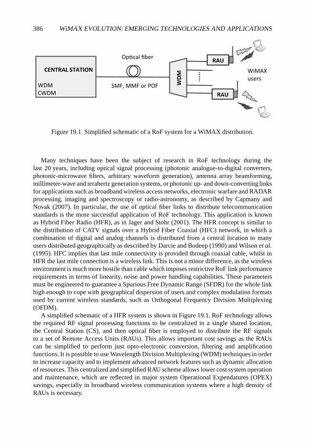
386 WiMAX EVOLUTION: EMERGING TECHNOLOGIES AND APPLICATIONS
CENTRAL STATION
WDM
CWDM
RAU
RAU
SMF, MMF or POF
WiMAX
users
WD
M
O e
Figure 19.1 Simplified schematic of a RoF system for a WiMAX distribution.
Many techniques have been the subject of research in RoF technology during thelast 20 years, including optical signal processing (photonic analogue-to-digital converters,photonic-microwave filters, arbitrary waveform generation), antenna array beamforming,millimeter-wave and terahertz generation systems, or photonic up- and down-converting linksfor applications such as broadband wireless access networks, electronic warfare and RADARprocessing, imaging and spectroscopy or radio-astronomy, as described by Capmany andNovak (2007). In particular, the use of optical fiber links to distribute telecommunicationstandards is the more successful application of RoF technology. This application is knownas Hybrid Fiber Radio (HFR), as in Jager and Stohr (2001). The HFR concept is similar tothe distribution of CATV signals over a Hybrid Fiber Coaxial (HFC) network, in which acombination of digital and analog channels is distributed from a central location to manyusers distributed geographically as described by Darcie and Bodeep (1990) and Wilson et al.(1995). HFC implies that last mile connectivity is provided through coaxial cable, whilst inHFR the last mile connection is a wireless link. This is not a minor difference, as the wirelessenvironment is much more hostile than cable which imposes restrictive RoF link performancerequirements in terms of linearity, noise and power handling capabilities. These parametersmust be engineered to guarantee a Spurious Free Dynamic Range (SFDR) for the whole linkhigh enough to cope with geographical dispersion of users and complex modulation formatsused by current wireless standards, such as Orthogonal Frequency Division Multiplexing(OFDM).
A simplified schematic of a HFR system is shown in Figure 19.1. RoF technology allowsthe required RF signal processing functions to be centralized in a single shared location,the Central Station (CS), and then optical fiber is employed to distribute the RF signalsto a set of Remote Access Units (RAUs). This allows important cost savings as the RAUscan be simplified to perform just opto-electronic conversion, filtering and amplificationfunctions. It is possible to use Wavelength Division Multiplexing (WDM) techniques in orderto increase capacity and to implement advanced network features such as dynamic allocationof resources. This centralized and simplified RAU scheme allows lower cost system operationand maintenance, which are reflected in major system Operational Expendatures (OPEX)savings, especially in broadband wireless communication systems where a high density ofRAUs is necessary.
APPLICATION OF RADIO-OVER-FIBER IN WiMAX 387
In both the CS and the RAU, both electro-optical (E/O) and opto-electronic (O/E)conversion of WiMAX signals to/from electrical and optical domains are carried out, mainlyusing Intensity Modulation Direct Detection (IMDD) techniques. E/O conversion is achievedemploying either directly modulated lasers or external modulators and O/E conversionemploying photodetectors or photoreceivers, as described by Seeds and Williams (2006).There are several possibilities to transport the RF signal from the CS to the RAU, as discussedby Jager and Stohr (2001). In particular, when the signal is transported directly at thefrequency of operation many benefits regarding cost and complexity and also upgradeabilityarise, as there is no need for complex RF signal processing at the RAU, such as up/downconversion or base-band mux/demux, always required when alternative techniques such asdigital-over-fiber or intermediate-frequency-over-fiber are used.
19.1.2 Analog Transmission on Fiber State-of-the-Art
RoF systems have been demonstrated (Hirata et al., 2003) at frequencies up to 120 GHz,being commercially available for inter-satellite and RADAR antenna remoting for frequen-cies up to 40 GHz and above. The market-driving application of RoF technology has beenthe transmission of wireless standards over optical fiber links in centralized architectures.The broad bandwidth of the optical fiber and the available devices facilitate independentstandards and multiservice operation for existing cellular systems, such as GSM as in Ogawaet al. (1992), UMTS as in Persson et al. (2006), wireless LAN (WiFi 802.11 a/b/g/n) as inChia et al. (2003), Niiho et al. (2004) and Nkansah et al. (2006), WiMAX as in Pfrommeret al. (2006), and Ultra Wide-Band (UWB), as reported in Llorente et al. (2008).
The devices required in RoF technology operate at frequencies used for major wirelessstandards (GSM, WiFi 802.11 a/b/g, UMTS) and also WiMAX up to 5–6 GHz. Directly mod-ulated semiconductor lasers are preferred as optical transmitter due to lower cost (Qian et al.,2005). At higher frequencies, the required performances can only be satisfied by externallymodulated transmitters. For indoor applications where picocell configurations are envisaged,advanced multi-function devices such as waveguide electro-absorption modulators (Wakeet al., 1997), or polarization independent asymmetric Fabry–Perot modulators, as describedby Liu et al. (2000, 2003) can be used as both detector and modulator.
Devices with bandwidth handling capabilities in excess of these required by near-termWiMAX deployments exist commercially. In particular Distributed Feedback (DFB) lasersoffer the required bandwidth and performances, but normally at a high cost. Recently, impor-tant research efforts have been devoted to the development of low-cost/high-performancetransmitters, for instance uncooled lasers (Ingham et al., 2003, Hartman et al., 2003) orVertical-Cavity Surface Emitting Lasers (VCSELs), (Chia et al., 2003, Persson et al., 2006).Probably, the most restrictive requirement for wireless services provision over RoF systemsis the SFDR. Nowadays SFDRs in excess of 100 dB Hz−2/3 have been demonstratedexperimentally, providing enough dynamic range to be employed in the targeted applications,as discussed by Seeds and Williams (2006).
19.1.3 Market Overview and Technology Forecast
The growth in high-bandwidth radio services such as WiMAX, has led to a renewed focuson the definition of the optimum network infrastructure to transmit signals between central
388 WiMAX EVOLUTION: EMERGING TECHNOLOGIES AND APPLICATIONS
offices and remote antenna units. To provide some indicators regarding WiMAX only,Sprint/Nextel are deploying an 802.16e compliant mobile WiMAX network which will reach100 million American users by the end of 2008. The estimated revenue for the worldwideWiMAX equipment market will grow to more than $3.3 billion, and connections will reach$48 million by 2010, as forecasted by Daily Wireless (2008).
Mobile operators are investigating several radio access interfaces such as HSDPA, LTE orWiMAX, not only from the technology point of view but also taking into account CAPEXand OPEX minimization. It is not clear at this moment which technology will becomedominant in the near future, as they are in a different stage of development, so coexistenceand compatibility are key requirements in RoF technology. Taking into account this hetero-geneous environment, huge efforts have been made to develop converged infrastructures ableto cope with increasing bandwidth demand, including dynamic adaptation to changing trafficconditions, offering multi-standard transmission capabilities and providing integration withboth the fiber-based transport network and the wireless backhaul.
The required integration of the transport network with the wireless access network is astraightforward application of RoF technologies and systems and is of particular importancein highly sectorized indoor environments. This market is growing very fast as several marketanalysts have recently predicted. ABI Research, for instance, has estimated the CAGR forthis market to be 20% with today’s market of $3.8 billion growing to $15 billion by 2013.ABI states that distributed-antenna indoor systems will make a significant impact in largerbuildings because they offer multi-service broadband capabilities.
The use of RoF technologies is expected to become important in indoor deployments dueto the flexibility, multi-standard capabilities, transparency and unlimited bandwidth offeredby fiber-based solutions. In the case of WiMAX, recent field trial demonstrations have shownthe potential of this technology to increase the coverage of WiMAX deployments using RoFtechnology. For example, the development of RoF systems adapted to both fixed and mobileWiMAX has been started in the frame of WEIRD project (IST, 2008). The transmission ofmobile WiMAX requires a careful engineering of the time division duplexing hardware anddifferent transmission aspects in order to support advanced features such as Multiple InputMultiple Output (MIMO) and beamforming, as described by Harjula et al. (2008).
19.2 Optical Transmission of WiMAX Signals
19.2.1 Optical Link Key Elements
The basic elements of any RoF link, as shown in Figure 19.2, are a device capable of up-converting the radio signal to optical frequencies (i.e. E/O conversion), the optical fiber astransmission medium towards the remote facility, and a device performing the recovery ofthe radio signal from the optical carrier (i.e. O/E conversion).
E/O conversion can be carried out using mainly two approaches: direct modulationof a laser and the use of a CW-laser with an external modulator. External modulationis usually performed using Mach–Zehnder modulators (Blumenthal, 1962) or electro-absorption modulators (Dagli, 1999). It benefits from broad bandwidth, low drive voltageand good linearity. However, owing to the cost of external modulators, direct modulation ispreferred for low-cost RoF applications.
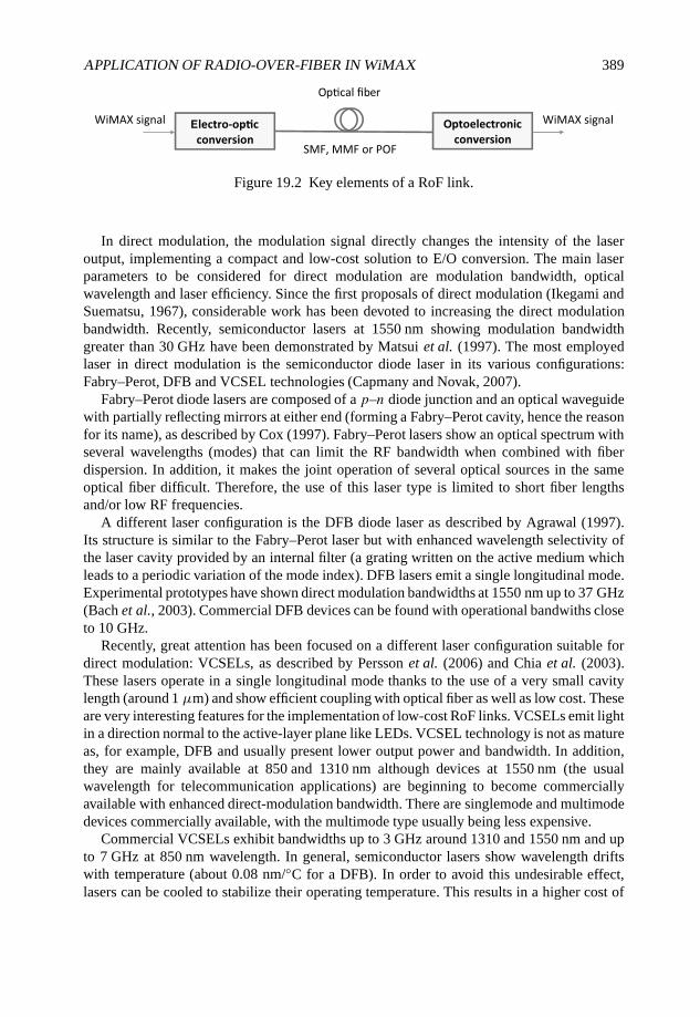
APPLICATION OF RADIO-OVER-FIBER IN WiMAX 389
Figure 19.2 Key elements of a RoF link.
In direct modulation, the modulation signal directly changes the intensity of the laseroutput, implementing a compact and low-cost solution to E/O conversion. The main laserparameters to be considered for direct modulation are modulation bandwidth, opticalwavelength and laser efficiency. Since the first proposals of direct modulation (Ikegami andSuematsu, 1967), considerable work has been devoted to increasing the direct modulationbandwidth. Recently, semiconductor lasers at 1550 nm showing modulation bandwidthgreater than 30 GHz have been demonstrated by Matsui et al. (1997). The most employedlaser in direct modulation is the semiconductor diode laser in its various configurations:Fabry–Perot, DFB and VCSEL technologies (Capmany and Novak, 2007).
Fabry–Perot diode lasers are composed of a p–n diode junction and an optical waveguidewith partially reflecting mirrors at either end (forming a Fabry–Perot cavity, hence the reasonfor its name), as described by Cox (1997). Fabry–Perot lasers show an optical spectrum withseveral wavelengths (modes) that can limit the RF bandwidth when combined with fiberdispersion. In addition, it makes the joint operation of several optical sources in the sameoptical fiber difficult. Therefore, the use of this laser type is limited to short fiber lengthsand/or low RF frequencies.
A different laser configuration is the DFB diode laser as described by Agrawal (1997).Its structure is similar to the Fabry–Perot laser but with enhanced wavelength selectivity ofthe laser cavity provided by an internal filter (a grating written on the active medium whichleads to a periodic variation of the mode index). DFB lasers emit a single longitudinal mode.Experimental prototypes have shown direct modulation bandwidths at 1550 nm up to 37 GHz(Bach et al., 2003). Commercial DFB devices can be found with operational bandwiths closeto 10 GHz.
Recently, great attention has been focused on a different laser configuration suitable fordirect modulation: VCSELs, as described by Persson et al. (2006) and Chia et al. (2003).These lasers operate in a single longitudinal mode thanks to the use of a very small cavitylength (around 1 µm) and show efficient coupling with optical fiber as well as low cost. Theseare very interesting features for the implementation of low-cost RoF links. VCSELs emit lightin a direction normal to the active-layer plane like LEDs. VCSEL technology is not as matureas, for example, DFB and usually present lower output power and bandwidth. In addition,they are mainly available at 850 and 1310 nm although devices at 1550 nm (the usualwavelength for telecommunication applications) are beginning to become commerciallyavailable with enhanced direct-modulation bandwidth. There are singlemode and multimodedevices commercially available, with the multimode type usually being less expensive.
Commercial VCSELs exhibit bandwidths up to 3 GHz around 1310 and 1550 nm and upto 7 GHz at 850 nm wavelength. In general, semiconductor lasers show wavelength driftswith temperature (about 0.08 nm/◦C for a DFB). In order to avoid this undesirable effect,lasers can be cooled to stabilize their operating temperature. This results in a higher cost of
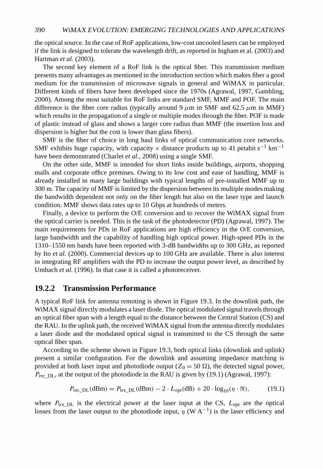
390 WiMAX EVOLUTION: EMERGING TECHNOLOGIES AND APPLICATIONS
the optical source. In the case of RoF applications, low-cost uncooled lasers can be employedif the link is designed to tolerate the wavelength drift, as reported in Ingham et al. (2003) andHartman et al. (2003).
The second key element of a RoF link is the optical fiber. This transmission mediumpresents many advantages as mentioned in the introduction section which makes fiber a goodmedium for the transmission of microwave signals in general and WiMAX in particular.Different kinds of fibers have been developed since the 1970s (Agrawal, 1997, Gambling,2000). Among the most suitable for RoF links are standard SMF, MMF and POF. The maindifference is the fiber core radius (typically around 9 µm in SMF and 62.5 µm in MMF)which results in the propagation of a single or multiple modes through the fiber. POF is madeof plastic instead of glass and shows a larger core radius than MMF (the insertion loss anddispersion is higher but the cost is lower than glass fibers).
SMF is the fiber of choice in long haul links of optical communication core networks.SMF exhibits huge capacity, with capacity × distance products up to 41 petabit s−1 km−1
have been demonstrated (Charlet et al., 2008) using a single SMF.On the other side, MMF is intended for short links inside buildings, airports, shopping
malls and corporate office premises. Owing to its low cost and ease of handling, MMF isalready installed in many large buildings with typical lengths of pre-installed MMF up to300 m. The capacity of MMF is limited by the dispersion between its multiple modes makingthe bandwidth dependent not only on the fiber length but also on the laser type and launchcondition. MMF shows data rates up to 10 Gbps at hundreds of meters.
Finally, a device to perform the O/E conversion and to recover the WiMAX signal fromthe optical carrier is needed. This is the task of the photodetector (PD) (Agrawal, 1997). Themain requirements for PDs in RoF applications are high efficiency in the O/E conversion,large bandwidth and the capability of handling high optical power. High-speed PDs in the1310–1550 nm bands have been reported with 3-dB bandwidths up to 300 GHz, as reportedby Ito et al. (2000). Commercial devices up to 100 GHz are available. There is also interestin integrating RF amplifiers with the PD to increase the output power level, as described byUmbach et al. (1996). In that case it is called a photoreceiver.
19.2.2 Transmission Performance
A typical RoF link for antenna remoting is shown in Figure 19.3. In the downlink path, theWiMAX signal directly modulates a laser diode. The optical modulated signal travels throughan optical fiber span with a length equal to the distance between the Central Station (CS) andthe RAU. In the uplink path, the received WiMAX signal from the antenna directly modulatesa laser diode and the modulated optical signal is transmitted to the CS through the sameoptical fiber span.
According to the scheme shown in Figure 19.3, both optical links (downlink and uplink)present a similar configuration. For the downlink and assuming impedance matching isprovided at both laser input and photodiode output (Z0 = 50 �), the detected signal power,Prec_DL, at the output of the photodiode in the RAU is given by (19.1) (Agrawal, 1997):
Prec_DL(dBm)= Ptrx_DL(dBm)− 2 · Lopt(dB)+ 20 · log10(η · �), (19.1)
where Ptrx_DL is the electrical power at the laser input at the CS, Lopt are the opticallosses from the laser output to the photodiode input, η (W A−1) is the laser efficiency and

APPLICATION OF RADIO-OVER-FIBER IN WiMAX 391
Figure 19.3 RoF link: uplink and downlink operation.
� (A/W) is the photodiode responsivity. In a typical scenario (Ptrx_DL = 5 dBm,Lopt = 8 dB,η = 0.4 W A−1 and � = 0.7 A W−1), the detected electrical power is Ptrx_DL = −22 dBm.In an actual implementation, the maximum detected power at the photodiode output will belimited by the nonlinear performance of the laser diode when modulated by the WiMAXsignal.
Considering the main noise contributions, Relative Intensity Noise (RIN) from lasersource, shot noise from the photodiode and electrical thermal noise at the photodiode output,the total noise power at the photodiode output is given by
Nrec_DL =NRIN + Nshot +Nthermal
= 10RIN/10(ηPopt)2�fRL + 2q(ηPopt + idark)�fRL + 4kT�f, (19.2)
where RIN (dB/Hz) is the relative intensity noise of the laser source, Popt (W) is the meanoptical power impinging the photodiode, idark (A) is the dark current of the photodiode,�f (Hz) is the electrical signal bandwidth at the photodiode output, RL (�) is the loadresistance at the photodiode output, T (K) is the actual temperature, q (C) is the electroncharge (1.6 × 10⁻¹⁹ C) and k is Boltzmann’s constant (1.38 × 10⁻²³ J K−1). It is importantto point out that the mean optical power at the photodiode input depends basically on thelaser bias point as the optical losses of the optical fiber will just modify this value by a coupleof decibels for typical scenarios depending on the total fiber length.
In the downlink, the influence of the electrical thermal noise at the laser diode input can beconsidered negligible if compared with the other noise contributions owing to the relativelyhigh level of the available electrical signal power driving the laser source.
Figure 19.4 shows the respective values of each noise contribution as a function of themean optical power at the photodiode input. From the results shown it can be stated that themain noise contribution is the thermal noise for low optical powers at the photodiode inputand the RIN for high optical powers owing to its dependence on the square of the incidentoptical power. This behavior is standard for any optical link although the specific values foreach noise contribution will depend on the actual parameters of the E/O components in use.
Taking into account that the signal power level at the photodiode output is also propor-tional to the square of the optical power at the photodiode input, the SNR at the photodiodeoutput will increase with the optical power at the photodiode input reaching its maximumvalue when the RIN contribution is dominant. At this point the SNR at the photodiode outputwill remain constant.
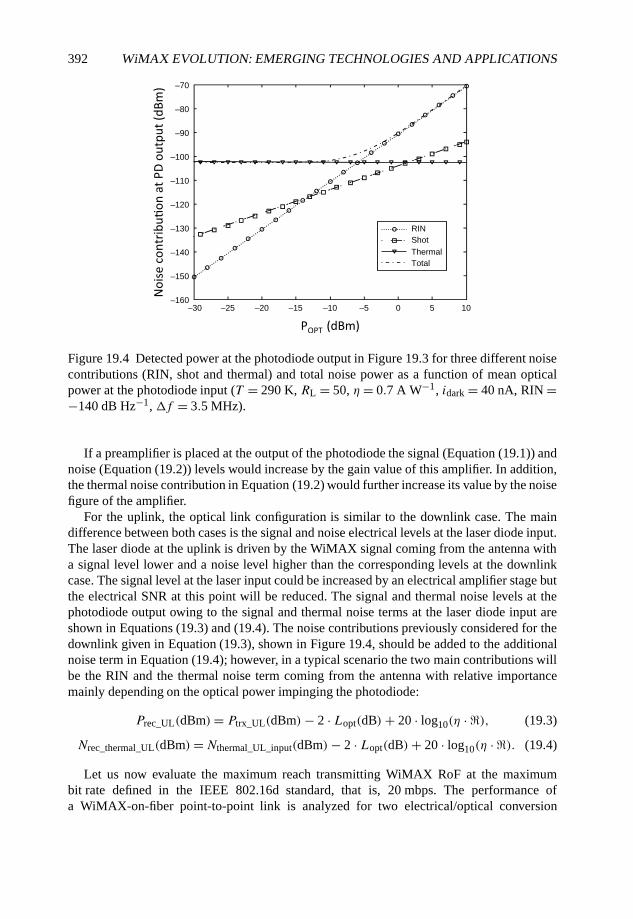
392 WiMAX EVOLUTION: EMERGING TECHNOLOGIES AND APPLICATIONS
–30 –25 –20 –15 –10 –5 0 5 10–160
–150
–140
–130
–120
–110
–100
–90
–80
–70
RINShotThermalTotal
Figure 19.4 Detected power at the photodiode output in Figure 19.3 for three different noisecontributions (RIN, shot and thermal) and total noise power as a function of mean opticalpower at the photodiode input (T = 290 K, RL = 50, η = 0.7 A W−1, idark = 40 nA, RIN =−140 dB Hz−1, �f = 3.5 MHz).
If a preamplifier is placed at the output of the photodiode the signal (Equation (19.1)) andnoise (Equation (19.2)) levels would increase by the gain value of this amplifier. In addition,the thermal noise contribution in Equation (19.2) would further increase its value by the noisefigure of the amplifier.
For the uplink, the optical link configuration is similar to the downlink case. The maindifference between both cases is the signal and noise electrical levels at the laser diode input.The laser diode at the uplink is driven by the WiMAX signal coming from the antenna witha signal level lower and a noise level higher than the corresponding levels at the downlinkcase. The signal level at the laser input could be increased by an electrical amplifier stage butthe electrical SNR at this point will be reduced. The signal and thermal noise levels at thephotodiode output owing to the signal and thermal noise terms at the laser diode input areshown in Equations (19.3) and (19.4). The noise contributions previously considered for thedownlink given in Equation (19.3), shown in Figure 19.4, should be added to the additionalnoise term in Equation (19.4); however, in a typical scenario the two main contributions willbe the RIN and the thermal noise term coming from the antenna with relative importancemainly depending on the optical power impinging the photodiode:
Prec_UL(dBm)= Ptrx_UL(dBm)− 2 · Lopt(dB)+ 20 · log10(η · �), (19.3)
Nrec_thermal_UL(dBm)=Nthermal_UL_input(dBm)− 2 · Lopt(dB)+ 20 · log10(η · �). (19.4)
Let us now evaluate the maximum reach transmitting WiMAX RoF at the maximumbit rate defined in the IEEE 802.16d standard, that is, 20 mbps. The performance ofa WiMAX-on-fiber point-to-point link is analyzed for two electrical/optical conversion
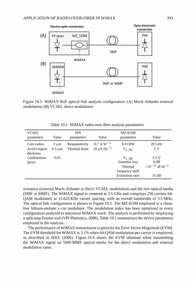
APPLICATION OF RADIO-OVER-FIBER IN WiMAX 393
Figure 19.5 WiMAX RoF optical link analysis configuration: (A) Mach–Zehnder externalmodulation; (B) VCSEL direct modulation.
Table 19.1 WiMAX radio-over-fiber analysis parameters.
VCSEL PIN MZ-EOMparameters Value parameters Value parameters Value
Core radius 2 µm Responsitivity 0.7 A W−1 E/O BW 20 GHzActive region 0.3 µm Thermal noise 10 pA Hz−1 Vπ_DC 5 VthicknessConfinement 0.03 Vπ_RF 5.5 Vfactor Insertion loss 6 dB
Thermal −10−12 df dJ−1
frequency shiftExtinction ratio 35 dB
scenarios (external Mach–Zehnder or direct VCSEL modulation) and the two optical media(SMF or MMF). The WiMAX signal is centered at 3.5 GHz and comprises 256 carriers 64-QAM modulated, at 15.625 KHz carrier spacing, with an overall bandwidth of 3.5 MHz.The optical link configuration is shown in Figure 19.5. The MZ-EOM employed is a chirp-free lithium-niobate x-cut modulator. The modulation index has been optimized in everyconfiguration analyzed to maximize WiMAX reach. The analysis is performed by employinga split-step Fourier tool (VPI Photonics, 2006). Table 19.1 summarizes the device parametersemployed in the analysis.
The performance of WiMAX transmission is given by the Error Vector Magnitude (EVM).The EVM threshold for WiMAX is 3.1% when 64-QAM modulation per carrier is employed,as described in IEEE (2006). Figure 19.6 shows the EVM obtained when transmittingthe WiMAX signal on SMF/MMF optical media for the direct modulation and externalmodulation cases.
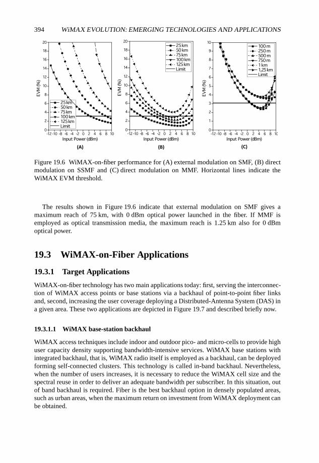
394 WiMAX EVOLUTION: EMERGING TECHNOLOGIES AND APPLICATIONS
Figure 19.6 WiMAX-on-fiber performance for (A) external modulation on SMF, (B) directmodulation on SSMF and (C) direct modulation on MMF. Horizontal lines indicate theWiMAX EVM threshold.
The results shown in Figure 19.6 indicate that external modulation on SMF gives amaximum reach of 75 km, with 0 dBm optical power launched in the fiber. If MMF isemployed as optical transmission media, the maximum reach is 1.25 km also for 0 dBmoptical power.
19.3 WiMAX-on-Fiber Applications
19.3.1 Target Applications
WiMAX-on-fiber technology has two main applications today: first, serving the interconnec-tion of WiMAX access points or base stations via a backhaul of point-to-point fiber linksand, second, increasing the user coverage deploying a Distributed-Antenna System (DAS) ina given area. These two applications are depicted in Figure 19.7 and described briefly now.
19.3.1.1 WiMAX base-station backhaul
WiMAX access techniques include indoor and outdoor pico- and micro-cells to provide highuser capacity density supporting bandwidth-intensive services. WiMAX base stations withintegrated backhaul, that is, WiMAX radio itself is employed as a backhaul, can be deployedforming self-connected clusters. This technology is called in-band backhaul. Nevertheless,when the number of users increases, it is necessary to reduce the WiMAX cell size and thespectral reuse in order to deliver an adequate bandwidth per subscriber. In this situation, outof band backhaul is required. Fiber is the best backhaul option in densely populated areas,such as urban areas, when the maximum return on investment from WiMAX deployment canbe obtained.
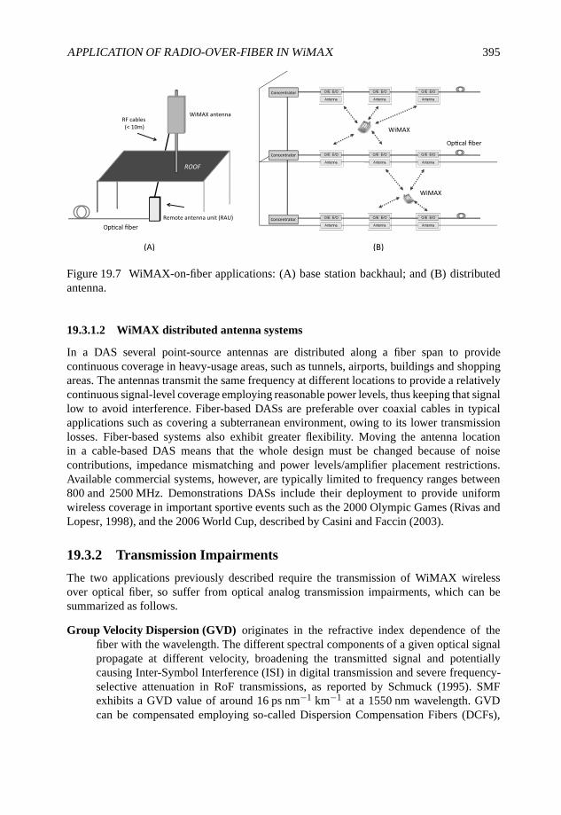
APPLICATION OF RADIO-OVER-FIBER IN WiMAX 395
Figure 19.7 WiMAX-on-fiber applications: (A) base station backhaul; and (B) distributedantenna.
19.3.1.2 WiMAX distributed antenna systems
In a DAS several point-source antennas are distributed along a fiber span to providecontinuous coverage in heavy-usage areas, such as tunnels, airports, buildings and shoppingareas. The antennas transmit the same frequency at different locations to provide a relativelycontinuous signal-level coverage employing reasonable power levels, thus keeping that signallow to avoid interference. Fiber-based DASs are preferable over coaxial cables in typicalapplications such as covering a subterranean environment, owing to its lower transmissionlosses. Fiber-based systems also exhibit greater flexibility. Moving the antenna locationin a cable-based DAS means that the whole design must be changed because of noisecontributions, impedance mismatching and power levels/amplifier placement restrictions.Available commercial systems, however, are typically limited to frequency ranges between800 and 2500 MHz. Demonstrations DASs include their deployment to provide uniformwireless coverage in important sportive events such as the 2000 Olympic Games (Rivas andLopesr, 1998), and the 2006 World Cup, described by Casini and Faccin (2003).
19.3.2 Transmission Impairments
The two applications previously described require the transmission of WiMAX wirelessover optical fiber, so suffer from optical analog transmission impairments, which can besummarized as follows.
Group Velocity Dispersion (GVD) originates in the refractive index dependence of thefiber with the wavelength. The different spectral components of a given optical signalpropagate at different velocity, broadening the transmitted signal and potentiallycausing Inter-Symbol Interference (ISI) in digital transmission and severe frequency-selective attenuation in RoF transmissions, as reported by Schmuck (1995). SMFexhibits a GVD value of around 16 ps nm−1 km−1 at a 1550 nm wavelength. GVDcan be compensated employing so-called Dispersion Compensation Fibers (DCFs),
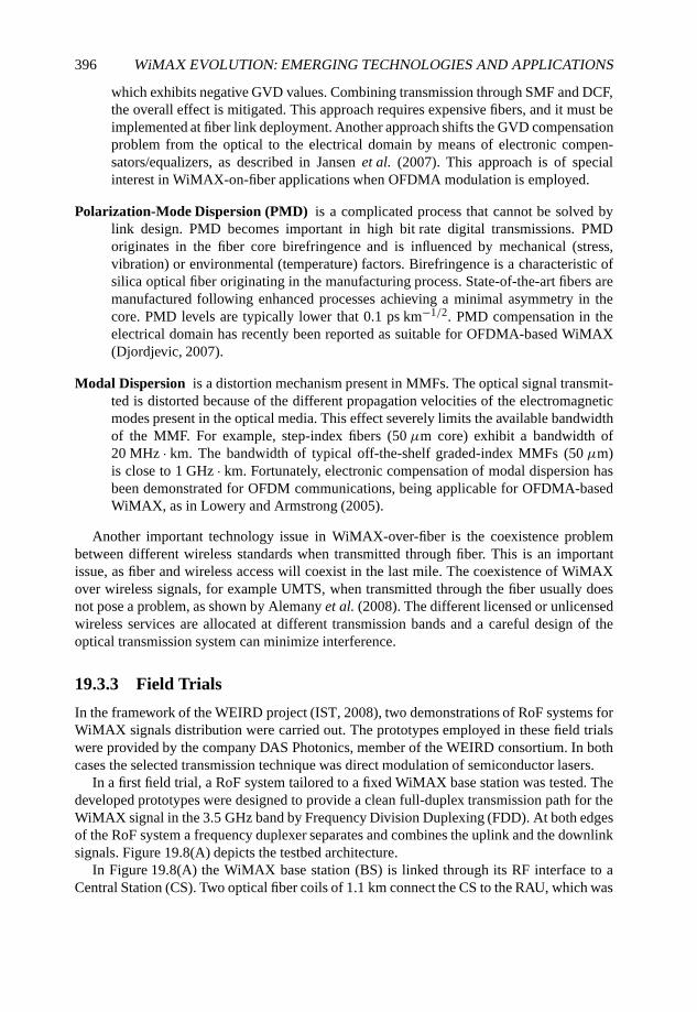
396 WiMAX EVOLUTION: EMERGING TECHNOLOGIES AND APPLICATIONS
which exhibits negative GVD values. Combining transmission through SMF and DCF,the overall effect is mitigated. This approach requires expensive fibers, and it must beimplemented at fiber link deployment. Another approach shifts the GVD compensationproblem from the optical to the electrical domain by means of electronic compen-sators/equalizers, as described in Jansen et al. (2007). This approach is of specialinterest in WiMAX-on-fiber applications when OFDMA modulation is employed.
Polarization-Mode Dispersion (PMD) is a complicated process that cannot be solved bylink design. PMD becomes important in high bit rate digital transmissions. PMDoriginates in the fiber core birefringence and is influenced by mechanical (stress,vibration) or environmental (temperature) factors. Birefringence is a characteristic ofsilica optical fiber originating in the manufacturing process. State-of-the-art fibers aremanufactured following enhanced processes achieving a minimal asymmetry in thecore. PMD levels are typically lower that 0.1 ps km−1/2. PMD compensation in theelectrical domain has recently been reported as suitable for OFDMA-based WiMAX(Djordjevic, 2007).
Modal Dispersion is a distortion mechanism present in MMFs. The optical signal transmit-ted is distorted because of the different propagation velocities of the electromagneticmodes present in the optical media. This effect severely limits the available bandwidthof the MMF. For example, step-index fibers (50 µm core) exhibit a bandwidth of20 MHz · km. The bandwidth of typical off-the-shelf graded-index MMFs (50 µm)is close to 1 GHz · km. Fortunately, electronic compensation of modal dispersion hasbeen demonstrated for OFDM communications, being applicable for OFDMA-basedWiMAX, as in Lowery and Armstrong (2005).
Another important technology issue in WiMAX-over-fiber is the coexistence problembetween different wireless standards when transmitted through fiber. This is an importantissue, as fiber and wireless access will coexist in the last mile. The coexistence of WiMAXover wireless signals, for example UMTS, when transmitted through the fiber usually doesnot pose a problem, as shown by Alemany et al. (2008). The different licensed or unlicensedwireless services are allocated at different transmission bands and a careful design of theoptical transmission system can minimize interference.
19.3.3 Field Trials
In the framework of the WEIRD project (IST, 2008), two demonstrations of RoF systems forWiMAX signals distribution were carried out. The prototypes employed in these field trialswere provided by the company DAS Photonics, member of the WEIRD consortium. In bothcases the selected transmission technique was direct modulation of semiconductor lasers.
In a first field trial, a RoF system tailored to a fixed WiMAX base station was tested. Thedeveloped prototypes were designed to provide a clean full-duplex transmission path for theWiMAX signal in the 3.5 GHz band by Frequency Division Duplexing (FDD). At both edgesof the RoF system a frequency duplexer separates and combines the uplink and the downlinksignals. Figure 19.8(A) depicts the testbed architecture.
In Figure 19.8(A) the WiMAX base station (BS) is linked through its RF interface to aCentral Station (CS). Two optical fiber coils of 1.1 km connect the CS to the RAU, which was
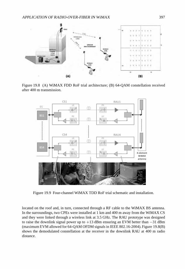
APPLICATION OF RADIO-OVER-FIBER IN WiMAX 397
Figure 19.8 (A) WiMAX FDD RoF trial architecture; (B) 64-QAM constellation receivedafter 400 m transmission.
Figure 19.9 Four-channel WiMAX TDD RoF trial schematic and installation.
located on the roof and, in turn, connected through a RF cable to the WiMAX BS antenna.In the surroundings, two CPEs were installed at 1 km and 400 m away from the WiMAX CSand they were linked through a wireless link at 3.5 GHz. The RAU prototype was designedto raise the downlink signal power up to +13 dBm ensuring an EVM better than −31 dBm(maximum EVM allowed for 64-QAM OFDM signals in IEEE 802.16-2004). Figure 19.8(B)shows the demodulated constellation at the receiver in the downlink RAU at 400 m radiodistance.
398 WiMAX EVOLUTION: EMERGING TECHNOLOGIES AND APPLICATIONS
Two applications were tested by the WEIRD consortium over this WiMAX RoF network:remote volcano monitoring using seismic sensors and Voice-over-IP communication. Theresults of the trial showed that the implemented RoF system provided good quality of serviceto the WiMAX CPEs in terms of signal strength and SNR, allowing the use of high spectral-efficient modulations combined with high channel coding rates in both uplink and downlinkpaths.
A second field trial performed within the WEIRD project aimed at the demonstration of aRoF system adapted to mobile WiMAX features. The system was developed in accordancewith the mobile WiMAX base station C-WBS (Compact WiMAX Base Station) fromAlcatel-Lucent. The C-WBS had four RF (3.4–3.6 GHz) ports that are connected to a four-element panel WiMAX antenna, which allows beamforming, if desired. In this case Time-Division Duplexing (TDD) was employed as a multiple-access technique.
The RoF system implemented in this case consisted of optical and electronic hardwareallowing the optical analog transmission of the WiMAX signal between the base stationand its antenna. In the case of the C-WBS, four RF signals had to be transmitted. In orderto transmit four WiMAX signals in parallel, the selected approach was to produce fourindependent RoF links as shown in the Figure 19.9. This figure also shows a picture of theRoF system deployed and its integration with the WiMAX C-WBS.
These two field trials validated the RoF WiMAX approach in both FDD and TDD WiMAXoperation in a real-world scenario, employing fully commercial equipment.
19.4 Conclusions
In this chapter, RoF systems as an efficient technology to support WiMAX servicesdeployment in base station backhaul and distributed antenna scenarios have been described.Simulation work and field trials that were published recently validate this approach. RoFtechnology can play a significant role in the widespread adoption of WiMAX services inhigh user density environments, such as office buildings, government premises and also asbackhaul technology for access networks. The key factor for the success of this technologyis the optimization of high-performance/low-cost devices to reduce deployment expenses.Recent technological advances in this direction, as discussed in Section 19.2.1, foresee asuccessful market introduction of WiMAX over RoF systems.
References
Agrawal, G.P. (ed.) (1997) Fibre-Optic Communication Systems. John Wiley & Sons Ltd, Chichester.
Alemany, R., Pérez, J., Llorente, R., Polo, V. and Martí, J. (2008) Coexistence of WiMAX 802.16d andMB-OFDM UWB in Radio Over Multi-mode Fiber Indoor Systems. Proceedings of MWP 2008.
Bach, L., Kaiser, W., Reithmaier, J.P., et al. (2003) Enhanced direct-modulated bandwidth of 37 GHz bya multi-section laser with a coupled-cavity-injection-grating design. IEE Electronics Letters, 39(22),1592–1593.
Blumenthal, R.H. (1962) Design of a microwave frequency light modulator. Proceedings of the IRE,50(4), 452–456.
Capmany, J. and Novak, D. (2007) Microwave photonics combines two worlds. Nature Photonics, 1(6),319–330.
APPLICATION OF RADIO-OVER-FIBER IN WiMAX 399
Casini, A. and Faccin, P. (2003) Wavelength Division. Multiplication Technologies for UMTS Radio.Coverage extension by using the radio over fibre technique. Proceedings of the IEEE InternationalTopical Meeting on Microwave Photonics, Budapest, pp. 123–128.
Charlet, G., Renaudier, J., Mardoyan, H., et al. (2008) Transmission of 16.4 Tbit/s capacity over2550 km using PDM QPSK modulation format and coherent receiver. Proceedings of the OpticalFiber Conference 2008, San Diego, CA, Post Deadline Paper PDP3.
Chia, M., Luo, B., Yee, M.L. and Hao, E.J.Z. (2003) Radio over multimode fibre transmission forwireless LAN using VCSELs. IEE Electronics Letters, 39(15), 1143–1144.
Cox, C.H. (ed.) (1997) Analog Optical Links. Theory and Practice. Cambridge University Press,Cambridge.
Dagli, N. (1999) Wide-bandwidth lasers and modulators for RF photonics. IEEE Transactions onMicrowave Theory and Techniques, 47(7), 1151–1171.
Daily Wireless (2008) LTE vs Wimax, http://www.dailywireless.org/ (accessed 13 February 2008)
Darcie, T.E. and Bodeep, G.E. (1990) Lightwave subcarrier CATV transmission systems. IEEETransactions on Microwave Theory and Techniques, 38(5), 524–533.
Djordjevic, B. (2007) PMD compensation in fibre-optic communication systems with direct detectionusing LDPC-coded. OFDM. Optics Express, 15(7), 3692–3701.
Gambling, W.A. (2000) The rise and rise of optical fibers. IEEE Journal on Selected Topics in QuantumElectronics, 6(6), 1084–1093.
IEEE (2006) WiMAX 802.16 Standard, http://standards.ieee.org/getieee802/802.16.html (accessed 2October 2008).
Ihgham, J., Webster, M., Wanfar, A., et al. (2003) Wide-frequency-range operation of a highlinearity uncooled DFB laser for next-generation radio-over-fibre. Proceedings of the Optical FiberConference 2003, Atlanta, GA, pp. 754–756.
IST (2008) WiMAX extension to isolated research data networks, http://www.ist-weird.eu/ (accessed2008)
Harjula, I., Ramirez, A., Martinez, F., et al. (2008) Practical issues in the combining of mimotechniques and RoF in OFDM/A systems. Proceedings of The 7th WSEAS International Conferenceon Electronics, Hardware, Wireless and Optical Conference, Cambridge, pp. 244–248.
Hartman, P., Webster, M., Wonfor, A., et al. (2003) Low-cost multimode fibre-based wireless LANdistribution system using uncooled directly modulated DFB laser diodes. Proceedings of the OpticalFiber Conference 2008, Rimini, pp. 804–805.
Hirata, A., Harada, M. and Nagatsuma, T. (2003) 120-GHz wireless link using photonic techniques forgeneration, modulation, and emission of millimeter-wave signals. Journal of Lightwave Technology,21(10), 2145–2153.
Ikegami, T. and Suematsu, Y. (1967) Resonance-like characteristics of the direct modulation of ajunction laser. Proceedings of the IEEE, 55, 122–123.
Ito, H., Furata, T., Kodama, S. and Ishibashi, T. (2000) INP/INGAAS uni-traveling-carrier photodiodewith 310 GHz bandwidth. IEE Electronics Letters, 36, 1809–1819.
Jager, D. and Stohr, A. (2001) Microwave photonics. Proceedings of the European MicrowaveConference, London, pp. 1–4.
Jansen, S.L., Morita, I., Takeda, N. and Tanaka, H. (2007) 20-GB/s ofdm transmission over 4,160-km SSMF enabled by RF-pilot tone phase noise compensation. Proceedings of the Optical FiberConference, Anaheim, CA, Post-deadline paper PDP15.
Liu, C., Polo, V., Dijk, F.V., Pfrommer, H., et al. (2000) Full-duplex docsis/wirelessdocsis fibre-radio network employing packaged AFPMs as optical/electrical transducers. Journal of LightwaveTechnology, 25(3), 673–684.
400 WiMAX EVOLUTION: EMERGING TECHNOLOGIES AND APPLICATIONS
Liu, C., Seeds, A., Chadha, J., et al. (2003) Bi-directional transmission of broadband 5.2 GHz wirelesssignals over fibre using a multiple quantum-well asymmetric Fabry–Perot modulator/photodetector.Proceedings of the Optical Fiber Conference 2003, Atlanta, GA, pp. 738–740.
Llorente, R., Alves, T., Morant, M., et al. (2008) Ultra-wideband radio signals distribution in FTTHnetworks. Journal of Lightwave Technology, 20(11), 945–947.
Lowery, A.J. and Armstrong, J. (2005) 10 Gbit/s multimode fibre link using power efficient orthogonalfrequency division multiplexing. Optics Express, 13, 10003–10009.
Matsui, Y., Murai, H., Arahira, S., et al. (1997) 30-Ghz bandwidth 1.55 µm strained-compensatedINGAALAS-INGAASP MQW laser. IEEE Photonics Technology Letters, 9, 25–27.
Niiho, T., Nakaso, M., Masuda, K., et al. (2004) Multi-channel wireless LAN distributed antennasystem based on radio-over-fibre techniques. Proceedings of the IEEE LEOS Annual Meeting., RioGrande, Puerto Rico, pp. 57–58.
Nkansah, A., Das, A., Lethien, C., et al. (2006) Simultaneous dual band transmission over multimodefibre-fed indoor wireless network. IEEE Microwave and Wireless Components Letters, 16(11), 627–629.
Ogawa, H., Polifko, D. and Banba, S. (1992) Millimetre-wave fibre optic systems for personal radiocommunication. IEEE Transactions on Microwave Theory Technology, 40(12), 2285–2292.
Persson, K.A., Carlsson, C., Alping, A., et al. (2006) WCDMA radio-over-fibre transmissionexperiment using singlemode VCSEL and multimode fibre. IEE Electronics Letters, 42(12), 372–374.
Pfrommer, H., Piqueras, M.A., Polo, V., et al. (2006) Radio-over-fibre architecture for simultaneousfeeding of 5.5 and 41 Ghz WIFI or WiMAX access networks. Proceedings of the MicrowaveSymposium Digest, IEEE MTT-S International Volume, pp. 301–303.
Qian, X., Hartmann, P., Ingham, J.D., et al. (2005) Directly-modulated photonic devices for microwaveapplications. Proceedings of the IEEE MTT-S Intl Microwave Symp., Long Beach (CA) USA.
Rivas, I. and Lopesr, L. (1998) A microcellular DCA scheme using variable channel exclusion zones.Proceedings of the IEEE Semiannual Vehicular Technology Conference pp. 1395–1399, Ottawa,Canada.
Schmuck, H. (1995) Comparison of optically millimeter-wave system concepts with regard tochromatic dispersion. IEE Electronics Letters, 31(21), 1848–1849.
Seeds, A.J. and Williams, K.J. (2006) Microwave photonics. Journal of Lightwave Technology, 24(12),4628–4641.
Stuckmann, P. and Zimmermann, R. (2007) Towards ubiquitous and unlimited capacity communicationnetworks: European research in framework programme 7. Journal of Lightwave Technology, 45(5),148–147.
Umbach, A., Waasen, S., Auer, U., et al. (1996) Monolithic pin-hemt 1.55 µm photoreceiver on INPwith 27 Ghz bandwidth. Electronics Letters, 32(23), 2142–2143.
VPI Photonics (2006) VPItransmissionMaker, Version 7.1.Wake, D., Hansson, D. and Moodie, D.G. (1997) Passive picocell: A new concept in wireless network
infrastructure. Electronics Letters, 33(5), 404–406.Wilson, B., Ghassemlooy, Z. and Darwazeh, I. (eds.) (1995) Coexistence Study Between UWB and
WiMAX at 3.5 GHz Band. Institute of Electronic Engineers, London.
20
Network Planning and its Part inFuture WiMAX Systems
Avraham Freedman and Moshe Levin
20.1 Introduction
Wireless network planning is the art of ‘integrating’ a given wireless system into an specificgeographic and market environment. The task facing the network planners is complex. Theyhave to offer a deployment plan that would answer the operator requirements and businessplan, making the best use of the wireless system properties and features in the most cost-effective way. This plan has to be robust enough to accommodate the inherent uncertainty inthe information available in the environment, scalable and flexible enough to enable networkgrowth and demand changes. The role of the network planner does not end with providing thebest deployment plan. It goes further during the lifetime of a network, and includes networkoptimization, trouble shooting, scaling and upgrading. Mishra (2007) provides a descriptionof the network planning process for various cellular systems, while Laiho et al. (2007) givea detailed analysis of Universal Mobile Telecommunications System (UMTS) planning.
WiMAX (Andrews et al., 2007, Eklund et al., 2006) offers robustness and flexibility ina level exceeding any other system. The IEEE 802.16 standard (IEEE (2004) amended inIEEE (2005)) was developed to provide a variety of options to the manufacturer and theoperator. The WiMAX Forum had narrowed down the range of possibilities by providinginteroperability profiles that enable economy of scale (WiMAX Forum, 2006). Still, a setof options and features provide the system with enhanced capacity, robust operation andinterference mitigation within a variety of equipment cost ranges.
New technologies may offer capabilities that may render some of the traditional planningtasks obsolete. For example, frequency planning is not as fundamental a task in Orthog-onal Frequency Division Multiple Access (OFDMA) and Code Division Multiple Access
WiMAX Evolution: Emerging Technologies and Applications Edited by Tsutomu Ishikawa© 2009 John Wiley & Sons, Ltd. ISBN: 978-0-470-69680-4
402 WiMAX EVOLUTION: EMERGING TECHNOLOGIES AND APPLICATIONS
(CDMA) system as it has been for Time Division Multiple Access (TDMA) systems.Nevertheless, WiMAX represents a careful step-back from the Direct Sequence CDMA(DS-CDMA) concept of ‘no planning and optimization’: it provides several mechanismsthat allow the network to control the RF channel by generating different levels of isolationamong customers. Consequently, deployment planning and optimization are importanttasks, and probably will always remain so. Similarly, system configuration in the generalsense, including frequency planning, fractional frequency planning, power planning, frameplanning, etc., will be the bread and butter of planners of current WiMAX systems. Whereassystem designers seek new ways and new means to improve system performance in a givenenvironment, it is the planner’s task to make use of the additional capabilities and plan themost cost-effective deployment for the actual environment at hand.
The systems described in this book provide much more. Base station coordination, selforganizing networks, cognitive radios and other techniques put intelligence at the base stationlevel. A central optimization entity will still be needed, to plan, for example, the base stations’locations and to serve as a hub to gather and distribute information across the network,however a lot of the system monitoring and optimization activities will take place in adistributed manner across the network, thus allowing for fast real-time response and improvedperformance.
The wireless network operator seeks better control of the network, higher networkquality, better use of resources, lower maintenance costs, faster responses to problems andadaptability to changing reality: the actual service demand, traffic load and propagationenvironment.
The main theme in our vision of the future wireless planning and optimization is the newconcept of a network model. Current wireless networks are installed and managed usingreports generated by the network planning department: the Plan. The main limitation of thePlan is that it is not dynamically updated; therefore the decisions taken, which are based onit, are not optimal.
The Model is a constantly updated version of the Plan, escorting the network throughoutits life cycle. Appropriate processes and interfaces should be provided to facilitate simpleand accurate dynamic integration of network information: configuration and traffic demandpatterns. Such a model will allow the user to perform planning and optimization on anaccurate database. A key success factor for efficient modeling is accurate estimation of thetraffic demand: geographical distribution and resources used. One solution to that might beradio location techniques, applied to information collected from the network.
One might be tempted to claim that planning is not important. The technology is ‘smart’enough to autonomously optimize itself and find real-time solutions for real-time problems.Our answer is that wise planning will generate better infrastructure over which smartoptimization will be able to operate. On top of that, planning as a methodological processhas two distinctive properties that cannot be met by any online optimization mechanism:
(i) planning for a future scenario, e.g. what-if and sensitivity analysis;
(ii) optimization that is influenced by arbitrary external requirements such as preferring togive a certain area of the network greater preference than its relative traffic impact.
In this chapter we describe the process of planning a wireless network to cover largemetropolitan or rural areas. We define the various stages of the process, and its role in
NETWORK PLANNING AND ITS PART IN FUTURE WiMAX SYSTEMS 403
WiMAX deployment. The impact of WiMAX system features on network planning isdescribed and, in particular, we discuss the role network planning is going to take in futureWiMAX systems deployments. Finally the concept of the Model is described as a key to theintegration of planning information into a system.
20.2 The Network Planning Process
Figure 20.1 is a schematic network planning process, with the purpose of planning a newwireless system in a given area: a green-field deployment planning. A planning process canbe described as comprising three main phases. The first is the information-gathering stage, thesecond is the planning itself and the third is the planning testing, verification and optimizationstage, which, as a matter of fact, lasts throughout the whole lifetime of a system. The processis by no means linear. Feedback from the third stage can, and always does, affect the gatheredinformation and may change the planning. Other feedback loops are inherent in the process,mainly due to the limitation of gathering full and reliable information on the deploymentenvironment.
20.2.1 Data Collection
The information the planner has to use is of three main types.Geographical information includes all of the geographical data of the area to be covered,
terrain ground heights, land use maps and maps of the location and shapes of buildings andtheir heights. The latter type of information is very important when planning wireless systemsin cities and urban areas, although it is not always easy to come by. One should also note thatthe availability and accuracy of geographical information varies greatly from place to placeand project to project. As part of the information the planner needs for an area, a list ofpotential locations for base stations should also be included or created by the planner.
Customer information includes the market data, namely the expected number of users, amap of expected user density across the area, expected traffic profile of the users, etc. Whiletraditional cellular networks assumed a single type of user with a single type of service, andthird-generation systems introduced several types of service, modern systems enable us todefine different types of users, each with their own usage profile, service-level agreements,etc.
Technology information refers the parameters of the wireless system to be deployed.Those parameters include base station and terminals transmission powers and powercontrol capabilities, receiver sensitivity under various operation conditions, rejection ofinterference capability (adjacent channel attenuation, net filter discrimination against externalinterference, etc.), total capacity, adaptive modulation and coding support, antenna systemdescription, which includes the radiation pattern of the antenna, total antenna gain andcross polarization. Modern cellular systems also include antenna arrays with a variety ofspatial techniques, such as diversity, beamforming, interference cancellation and spatialmultiplexing. Thus, the parameters of the array and the applicable spatial technique to thebase stations and terminals should be determined.
An important part of the technology information is a specification of the spectrum to beused, which includes the number of the frequency channels (at the system bandwidth) avail-able for deployment. Information about external systems operation, regulatory limitations
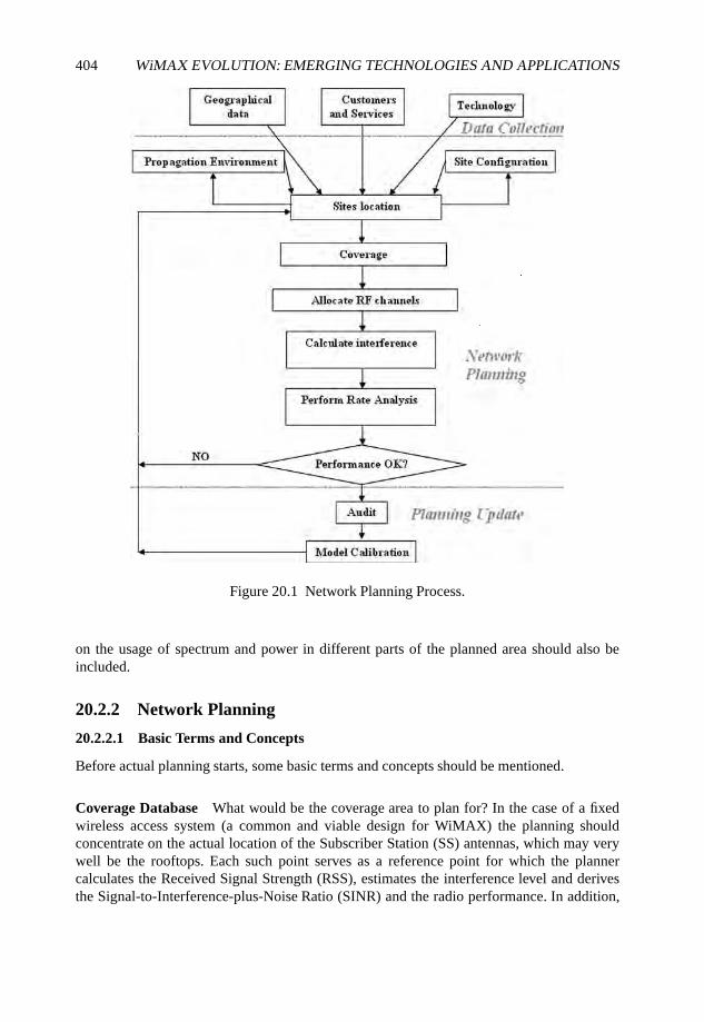
404 WiMAX EVOLUTION: EMERGING TECHNOLOGIES AND APPLICATIONS
Figure 20.1 Network Planning Process.
on the usage of spectrum and power in different parts of the planned area should also beincluded.
20.2.2 Network Planning
20.2.2.1 Basic Terms and Concepts
Before actual planning starts, some basic terms and concepts should be mentioned.
Coverage Database What would be the coverage area to plan for? In the case of a fixedwireless access system (a common and viable design for WiMAX) the planning shouldconcentrate on the actual location of the Subscriber Station (SS) antennas, which may verywell be the rooftops. Each such point serves as a reference point for which the plannercalculates the Received Signal Strength (RSS), estimates the interference level and derivesthe Signal-to-Interference-plus-Noise Ratio (SINR) and the radio performance. In addition,
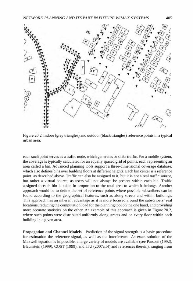
NETWORK PLANNING AND ITS PART IN FUTURE WiMAX SYSTEMS 405
Figure 20.2 Indoor (grey triangles) and outdoor (black triangles) reference points in a typicalurban area.
each such point serves as a traffic node, which generates or sinks traffic. For a mobile system,the coverage is typically calculated for an equally spaced grid of points, each representing anarea called a bin. Advanced planning tools support a three-dimensional coverage database,which also defines bins over building floors at different heights. Each bin center is a referencepoint, as described above. Traffic can also be assigned to it, but it is not a real traffic source,but rather a virtual source, as users will not always be present within each bin. Trafficassigned to each bin is taken in proportion to the total area to which it belongs. Anotherapproach would be to define the set of reference points where possible subscribers can befound according to the geographical features, such as along streets and within buildings.This approach has an inherent advantage as it is more focused around the subscribers’ reallocations, reducing the computation load for the planning tool on the one hand, and providingmore accurate statistics on the other. An example of this approach is given in Figure 20.2,where such points were distributed uniformly along streets and on every floor within eachbuilding in a given area.
Propagation and Channel Models Prediction of the signal strength is a basic procedurefor estimation the reference signal, as well as the interference. As exact solution of theMaxwell equation is impossible, a large variety of models are available (see Parsons (1992),Blaunstein (1999), COST (1999), and ITU (2007a,b)) and references therein), ranging from
406 WiMAX EVOLUTION: EMERGING TECHNOLOGIES AND APPLICATIONS
empirical models, based on a set of experiments and tests made in various conditions,and physical models, which perform the prediction based on a simplified model of thepropagation environment. The more elaborate models, such as ray tracing, take into accountreflection, diffraction and scattering, however these models usually require a very longcomputation time for complete region coverage. Model selection depends on the nature ofthe area, but also on available information and available computation time. Different modelsshould be applied to different points in the coverage area according to the land use and thelocation of the users (indoor, outdoor, rooftop level, street level, etc.)
System performance is not determined only by the RSS or SINR at the receiver. It alsodepends on the channel and the receiver used, and it is random in nature, as the channel fadesin an unpredictable manner. A statistical model should be applied in order to predict theactual performance in a required availability level. Sophisticated tools use different modelsfor different reference points to provide a better picture of the environment.
Range-limited or Capacity-limited Deployment The number of base stations required tocover a given area is determined either by the size of the area to be covered, relative to thearea that can be covered by a single base station, or by the total traffic that needs to be carrieddivided by the capacity a single base station can carry. In the first case, the deployment issaid to be range limited, while in the second case is a capacity limited deployment. Planningis different in the two cases. In the first case the focus of the planner is to increase, as muchas possible, the range each base station can reach. In the second case, a base station will notcover to its full range, which may lead to interference between base stations. The focus ofthe planner is to mitigate this interference.
Supply-driven or Demand-driven Deployment These are two different approaches to theplanning process. In the first approach planning will be made for the projected system sizein the future. Actual system deployment will be derived out of this master plan, and can bescaled up until it reaches the final system size. This approach ensures optimized long-termoperation, and provides a path for system growth. On the other hand, if the predictions arenot accurate, planning and deployment may have to be redone. The demand driven approachstarts with the minimum system configuration needed to provide for the existing demand. Fora fixed wireless access system this would mean deploying only the base stations in limitedregions where demand exists. For a mobile system this would mean deployment only a rangelimited system at the first stage and later addition of cells to provide capacity where needed.Cell splitting is a good example of this approach. Demand driven deployment is more flexible,however, it results in an unoptimized system, as each growth has to be made based on theconstraints imposed by existing deployment and an overall network optimization is neverperformed at any stage.
Base Station Configuration A base station’s range and capacity depend on its configu-ration, namely the height of the antenna above ground and the antenna directivity, whichimplies the number of sectors deployed. Tall antenna masts provide wider coverage andlonger range and thus are widely used for range limited deployments, while installation belowrooftops limits the base station range. For capacity limited deployments, this is a preferredoption as the interference between cells is reduced. Multi-sector base stations (four, six and
NETWORK PLANNING AND ITS PART IN FUTURE WiMAX SYSTEMS 407
even more) can be found in fixed wireless access deployments. Increasing the number ofsectors, increases the directivity of the antenna and the cell range, reduces the interferenceand increases the over all capacity of a base station. However, in mobile scenarios a multitudeof sectors will burden the system with a large number of handovers. The typical number ofsectors in mobile systems is three. Within a single network, one can find a variety of cellconfigurations, depending on the specific zone. In mobile networks one can find a hierarchyof base stations which cover the same region but for different purposes.
• Umbrella cells, also called macrocells, installed on high masts. Those cells carry thetraffic of high-speed users along roads and streets. Their long range and wide coveragereduces the need for handovers for the fast moving mobiles.
• Microcells, installed on roof tops or below rooftop levels. They are designed to carrythe traffic of pedestrian users, and indoor users reachable by indoor penetration.
• Picocells, installed outdoor below rooftop levels or indoor, mainly within commercialbuildings, such as shopping malls, airports, bus stations etc. The purpose of those cellsis to cover hot spots and provide indoor coverage.
• Femtocells, installed indoor within residences, with the goal to provide indoorcoverage for a small number of users and provide cellular access to the fixed users.
20.2.2.2 Site Location
Base station site location is critical in wireless networks deployments. Base station sitesare one of the main cost factors of the network. It is not only the cost of equipment butalso the cost of acquisition or rental, licensing, environmental implications, building andconstruction, electricity and air conditioning, backhaul and transmission network and long-term maintenance. All of these add up to form one of the major sources for capital andoperation expanses. A planning tool that enables network optimization and deployment witha minimal number of sites will provide a very handsome return on investment on the toolcost. The classical method of planning (Lee, 1986, McDonald, 1979) was based on the well-known hexagonal grid pattern. The hexagon, being the polygon with the largest number ofedges which can cover a plane, is the best approximation for a circle, which reflects the factthat the signal strength is highly dependent on range. After determining the cell range, thegrid of hexagons is overlaid over the area to be covered. Actual locations of base stations areselected as close as possible to cell centers, no further than a quarter of the cell radius.
The problem of base station placement in a realistic environment, taking into account theuser density, has attracted a lot of attention in the literature. Direct search, genetic algorithms,simulated annealing, vector quantization and heuristic approaches have all been presentedfor macrocellular, microcellular and indoor environments. (Aguado-Agelet et al. (2002),Anderson and McGeehan (1994), Chavez-Santiago et al. (2007), Huang et al. (2000), Hurley(2002), Molina et al. (2000), Yang and Ephremides (1997) are only a small sample of theliterature available.)
Sophisticated algorithms are aiming to find a minimal number of base station sites suchthat the coverage and capacity constraints are satisfied. More complex external constraintscan be considered, for example, to enable the deployment of a microwave backbonenetwork, that will require, on top of meeting adequate coverage and signal-to-noise levels, an

408 WiMAX EVOLUTION: EMERGING TECHNOLOGIES AND APPLICATIONS
Figure 20.3 Site connectivity map (by highest signal power) showing noncontiguous cells.Each grey level indicates connectivity to a certain cell.
appropriate site-to-site propagation environment that ensures Radiofrequency (RF) visibility.More elaborate cost functions, which take into account sites’ cost and even possible profit,can also be implemented.
20.2.2.3 Sites Connectivity and Coverage
Once the sites are in place, the coverage area of each cell (a cell is typically referred to asa sector within a base station) can be determined. A cell is said to cover a reference pointor a bin if its signal strength at that point is above a given level that enables the base stationto serve a SS at that point. In a fixed wireless environment, the coverage area, or the set ofpossible SS locations, is partitioned among the cells with no overlap. In the case of a mobilesystem, there is an inherent overlap, which is essential to provide the ability of handover, buta too large overlap indicates a high overload on the network and possible interference source.
An important point to emphasize is that the coverage zone of a realistic cell is neithercircular nor hexagonal. As a matter of fact it is not even contiguous. Figure 20.3 shows arealistic scenario with three cells, showing the largest received signal strength in each bin.Figure 20.3 shows how the land cover, buildings in this case, affects the coverage area ofeach cell. In the figure, each grey level indicates which base station’s signal is the strongestat the particular point. The coverage area of a cell is not contiguous and interlaces with thatof its neighbors.
NETWORK PLANNING AND ITS PART IN FUTURE WiMAX SYSTEMS 409
20.2.2.4 Required Cell Capacity
Once the coverage area per cell is determined, the total traffic capacity to be carried by eachcell can be readily calculated, summing over the traffic nodes and the estimated handoverload. Accordingly the number of RF channels/physical resource blocks needed for each cellmay be determined (in terms of WiMAX this would be the number of physical symbolsper frame or an equivalent measure). However, it should be noted that this number may varyaccording to the actual channel conditions and interference of each SS. Adaptive modulation,spatial multiplexing and other techniques may enable more traffic to be carried per physicalresource block, and reduce the requirement per channel. So, a rough evaluation is taken atthe first stage, and later corrected when more accurate estimate of the channel condition peruser is made.
20.2.2.5 Frequency and System Configuration Planning
Given the number of RF channels per cell, it is now possible to plan the frequency of eachRF channel. In a mobile WiMAX system this stage includes much more, as elaborated inthe next section. Classical frequency planning algorithms (e.g. Lee (1986) and McDonald(1979)) are based on the reuse factor principle. Based on the hexagonal grid, frequencies areassigned such that co-channel frequencies are reused in cells as far away as possible. Modernfrequency planning algorithms use graph coloring techniques, simulated annealing, geneticalgorithms and other approaches; Niessen (1997) and Struzak (1982) provide examples ofsolutions to this problem.
20.2.2.6 Performance Evaluation and Plan Optimization
Now that the base station sites and their configurations are determined, the system per-formance can be evaluated. This involves the calculation, for each reference point or bin,the RSS, the interference and the resulting SINR value, which determines the operationconditions at that reference point. The actual channel nature can also be evaluated and,together with the SINR estimate, the achievable throughput can be estimated. Performanceevaluation will most likely make it necessary for the planner to return to previous stages,improve and optimize the plan. This may include recalculation of cells load, replanningof frequency and system configuration, changing the cells configuration such as antennaazimuths and tilts, adjust handover thresholds, etc. As systems become more complex,simulation, which involves traffic and scheduler simulation, might also be used. Still, as itis most often a time-consuming process, simulation is usually made at the last stage for finalverification.
20.2.2.7 The Planning Process Output
The output of the process we have described includes:
• base station sites;
• sector loads;
• base station antenna configurations;
• cells frequencies and other parameters;
410 WiMAX EVOLUTION: EMERGING TECHNOLOGIES AND APPLICATIONS
• performance maps including SINR maps, expected rate and throughput;
• neighbor list.
20.2.3 Planning Verification and Update
The planning process is actually a closed-loop process. Planning should be verified andupdated according to feedback from the field, received along the lifetime of the system.
Before the actual deployment, field surveys are performed to verify the data used forplanning. Radio surveys are also performed wherein measurements of test links are made toverify the suitability of the propagation model.
The current art of prediction verification is to perform drive tests. During systemdeployment and operation a set of drive tests and walk tests are made, aiming to check theactual coverage and compare it with the predicted coverage. During those tests the signalstrength of the cells are measured at each point along the test track. The test equipment istypically equipped with navigation equipment, such as a Global Positioning System (GPS)receiver and provides a list of coordinates and the corresponding signal strength from thebase stations received at that point.
A typical usage of drive tests is to calibrate the propagation models. In the calibrationprocess a set of parameters of the models are adjusted to yield a minimal deviation fromthe measurements. The calibrated models are assumed to provide more accurate predictionsfor points where measurements were not made. Given a large enough set of drive tests,calibration can be specific to a given area and take into account local effects. Sophisticatedtools provide calibrated models specific to a part of a cell.
However, with the accumulated experience in cellular network operation, most of theoperators agree that a drive test is a very limited technique to collect information on thenetwork coverage: it is often compared with searching for a coin under a lamp post. Drivetests provide coverage information on the roads and, to a very limited extent, on public areaswhere walk tests can be performed. Today, most of the traffic, 70% to 80%, is performedfrom the customer premises, away from the road. Furthermore, data services such as Webbrowsing and video steaming, will significantly increase the amount of indoor traffic. Acommon concern that operators state today is if, after performing drive tests, one learns thatdown-tilting sector A will decrease the amount of interference it generates to sector B, howcan one be sure that such an antenna down tilt will not damage our customers in the second,third and higher floors?
An acceptable solution must provide an efficient and accurate means to collect thecoverage information at the customer premises. Regular mobile stations’ reports can also beused for this purpose. However, since most of the reports are not accompanied by coordinatesreading, a location technique should be applied, be it GPS, assisted GPS, triangulation,trilateration, finger printing or others (see Hata and Nagatsu (1980), Ott (1977), Riter andMcCoy (1977) and Wigren (2007)). With such a technique mobile stations’ measurementsare turned into a Virtual Drive Test (VDT), which extends the capability of drive tests in timeand place and, most importantly, reflects the actual usage of the system by its users and notby an artificial measurement equipment.
In many wireless systems such mobile station reports are sent to indicate problems, suchas dropped calls. Locating a dropped call report and comparing the measurements with thepredicted coverage database at that point enables the planner to fix the problem. This is an
NETWORK PLANNING AND ITS PART IN FUTURE WiMAX SYSTEMS 411
example where an integration of three sources of information: the predicted coverage, drivetest measurements and mobile station measurements provides the ability to obtain a completepicture of the network status. While predictions are ubiquitous and can be used for what-ifanalyses, they are not so accurate. Drive tests are accurate but are limited to the time andplace they were performed. Launching a drive test requires time and manpower resources.Mobile Station readings are not as accurate as drive test equipment, but they provide actualstatus of real users. They cannot be used for analyses of areas where the coverage does notexist. Hence, the integration of the three sources provides the most complete picture.
In addition to the signal strength information it is very important to measure the actualtraffic distribution. Aggregate traffic data can be read of base stations and cells. Thedistribution of that traffic within the cells coverage area is not always straightforward.A common technique is to distribute it by clutter, namely land use data.
Updated coverage and traffic information can be used to optimize the network. Theoptimization process can be seen as repeating the planning process, using the measured data,with constraints imposed by the existing network deployment and parameters.
It is very common to use Key Performance Indicators (KPIs) to monitor networkperformance. These KPIs can include accessibility indicators such as service availability,service access success ratio, etc., retainability indicators such as drop ratios, and integrityindicators such as service access time, round trip time and more. Mapping the indicator onthe coverage database brings the insight of the wireless planning process into those indicatorsand provides means to optimize the network accordingly.
20.3 The Impact of WiMAX on Network Planning
20.3.1 Flexibility of WiMAX Deployment
From the network operator point of view, WiMAX brings to the table, first and foremost,flexibility. There are many aspects to this flexibility.
• Trade-off throughput with robustness. Mobile stations which enjoy ideal channelconditions can use the full rate of the channel using spatial multiplexing, togetherwith high bandwidth and very high level modulation and coding. This could bring thespectral efficiency of the link to be in an order of magnitude of tens of bits per second(bps) per Hertz. On the other hand, the WiMAX system has at its disposal a set of toolsto support Mobile Stations that do not have good reception conditions. These includespace diversity, robust modulation and coding, decrease in the allocated bandwidth,Automatic Request (ARQ) and Hybrid Automatic Request (HARQ) mechanisms. Allof these techniques increase robustness and hence increase operation range and enableoperation in difficult reception conditions, such as indoors, at the street level or underhigh interference conditions. To obtain the increased robustness one must trade-offthroughput.
• Trade-off in frequency allocation. In traditional cellular systems, channel allocationwas rigidly made per cell. The introduction of CDMA techniques enabled a trade-off between system load and interference. Practically it enables operation of a wholesystem with multiple cells, using a single wide frequency channel. Thanks to theCDMA technique, each transmission interferes very lightly with other transmissions.
412 WiMAX EVOLUTION: EMERGING TECHNOLOGIES AND APPLICATIONS
Only the aggregation of interference caused by many users may inhibit the operation ofthe system. In a WiMAX system, which uses OFDMA as the basic modulation scheme,the subcarriers comprising the OFDMA symbols can be allocated orthogonally like atraditional system or, similarly to CDMA, the same subcarriers can be allocated toseveral transmitters thus creating interference. However, thanks to the statistical natureof the use of the common channel and to the coding scheme that is able to correcterrors caused by interference, the transmissions involved can be successfully decoded.The interference is a function of the system load and, as in the CDMA case, thereis a trade-off between load and interference. In an extreme situation WiMAX can beoperated using a ‘universal reuse 1’, namely all of the cells are allocated a single RFchannel.
WiMAX offers another degree of flexibility: the concept of zones, in which theframe is divided into time intervals, each with its own set of parameters. This allowsthe frequency assignment plan to change within a basic frame. Thus, interferencefree planning can be applied to part of the frame, in which nonoverlapping sets ofsubcarriers are allocated to different cells, then, in another zone, the whole bandwidthcan be applied to all of the cells, and the interference between them is mitigated thanksto statistical nature of the load.
• Flexibility in traffic assignment. WiMAX basic profile is Time Division Duplex(TDD), in which transmission time is divided into base station transmission andterminal station transmission, to enable bidirectional communications. This modeallows flexible allocation of resources for downlink and uplink traffic.
• Advantage in multi-user environments. WiMAX offers the ability to enhance theoverall system performance in case of multi-user environments. The first mechanism isthat of a localized allocation, which uses the selective nature of the channel to allocateto each user the best set of subcarriers, as it is most likely that those subcarriers wouldnot be identical for all users, it allows the best usage of the system subcarriers. Anothermechanism is of collaborative spatial multiplexing, in which two terminals share thesame time and frequency resources, but thanks to the different spatial channel, the basestation can separate the transmissions. A similar technique, spatial multiplexing fromtwo base stations, can be applied to a single terminal station, if it is equipped withseveral antennas.
• Variety of user equipment and user services. WiMAX provides a lot of possibilities tothe operator to offer a variety of services within a large set of cost and pricing schemes.WiMAX can support fixed wireless applications, with outdoor antennas or self-installindoor antennas. It can support mobile applications with a variety of user equipment.WiMAX also supports quality of service, allowing the operator to slice the market andprovide a cost-effective service according to the customers needs.
20.3.2 WiMAX Network Planning
Let us now follow the network planning process described above, and discuss the impact thatWiMAX might have on it.

NETWORK PLANNING AND ITS PART IN FUTURE WiMAX SYSTEMS 413
20.3.2.1 Data Collection
The main difference between a deployment of a WiMAX system and a non-WiMAX systemis in the variety of services enabled by the system. In view of this the market data, marketpenetration, service offers and pricing schemes should be prepared and fit a viable businessplan. In addition, one of the key factors in the deployment is the spectrum allocation. AsWiMAX is capable of a ‘reuse 1’ deployment, it could be envisaged that only a singlefrequency channel is allocated for the deployment.
20.3.2.2 Network Planning
The impact of the new WiMAX features is the greatest at the stage of estimating the requiredcell capacity and frequency planning. Obviously, as WiMAX trades off interference withcapacity, the two stages are highly linked and should be treated together. Frequency planningin WiMAX is not limited to the assignment of frequency channels to the radios. Actually thisis only the first stage in the planning, and in some deployments, where only a single frequencychannel is allocated, this is a trivial stage. In fact, at this stage a large set of parameters has tobe planned. A better name for this stage would be cell configuration phase and it comprisesof the following parts:
1. planning of the segmented zones;
2. planning of the full usage zones;
3. throughput estimation for the users covered by each cell;
4. frame planning;
5. power planning.
The segmented zones are the zones in which the cells use only a part of channel bandwidth.Cells that are allocated different segments of the spectrum do not interfere with each other. Inthe full usage zones there is interference between cells, but it is controlled, and is a function ofthe load. Full usage zones enable basically higher capacity, as resources in those zones can bereused by neighboring cells. For each cell, one must determine the segment each base stationwill take when operating in a segmented zone, the preamble sequence, the permutation basesfor the downlink and uplink directions and the sequence used for pilot modulation and datarandomization, etc.
The throughput a user can enjoy is highly dependent on the SINR, channel conditionsand equipment capability. The average resource requirements per frame (in terms of time–frequency physical slots) are a function of the throughput and the user demand. At theplanning stage one cannot know exactly the users’ demand, equipment capability andoperation conditions by location, however, assuming some user distribution the global userdemand and equipment capability can be translated into specific user distribution per cell,which, in conjunction with throughput estimation of the bins within the cell coverage area,can be used to estimate the resource requirement per cell.
This resource requirement is needed for frame design. It is well known that in TDDsystems, the downlink and uplink intervals should be switched simultaneously in all of thecells, to avoid base station to base station and mobile station to mobile station interference.
414 WiMAX EVOLUTION: EMERGING TECHNOLOGIES AND APPLICATIONS
The same is true with the segmented usage and full usage zones. Those zones should beallocated exactly the same time intervals in all cells, to avoid interference between full usagezones and segmented zones. The process of frame design is basically location of the switchingpoint between the zones, and its goal is to provide adequate resources to each zone accordingto the demand. It is an iterative process whereby the user demand per cell is partitionedbetween the zones. Allocation of a user to the segmented zone will enable its operation withless interference, but it will require more time slots as the base station is limited to a smallernumber of subcarriers. Moving the demand to the full usage zone will enable to reduce thenumber of required time slots but it might expose the receiver to interference. It is thenexpected that users at the cell edge will be allocated to the segmented zone, while thosewhich are not susceptible to interference will be allocated to the full usage zone.
Another dimension of planning would be power adjustment. Basically it is the schedulerfunction; however, at the planning stage it is important to assess the effect of poweradjustment. The procedure can be performed by reducing the power allocated to users forwhich the allocated power is above the threshold needed for the particular modulation andcoding state they can operate with. In the downlink this power can be allocated to other users,without affecting the interference to other cells, or decrease the total transmission power ofthe base station, reducing the interference to other cells. In the uplink, reducing the powercan only reduce the interference caused to other base station receivers. Reduction of theinterference will increase the possible supported rate.
All of those processes are inter-related and dependent on each other. The planning processis usually iterative; starting from a certain frequency and zone plan, the SINR distribution canbe calculated, and out of this, and the channel conditions, the throughput can be estimated,and the resources required per cell evaluated. Following frame design and power allocationplanning, a new frequency and segment planning can be made.
20.4 Planning of Future WiMAX Networks
Browsing this book, one cannot fail to be impressed by the potential and extent of newdevelopments that can clearly extend the capabilities of future WiMAX systems and thenew services and applications it can support. We have chosen to concentrate on the impacton network planning of five of those developments:
• advanced spatial techniques;
• mesh, relays and femtocells;
• self-configuring networks;
• cooperative WiMAX;
• cognitive radios.
20.4.1 Advanced Spatial Techniques
Advanced spatial techniques, such as beamforming, interference cancellation, diversityenhancement and spatial multiplexing are not techniques of the future but are very much
NETWORK PLANNING AND ITS PART IN FUTURE WiMAX SYSTEMS 415
present-day and currently implemented. Those techniques make use of the fact that multipleantennas are present in the base station, mobile station or in both. A very brief list of thosetechniques is given below, with the impact they have on network planning.
• Receive diversity and transmit diversity: improves link performance in fading condi-tions and hence reduces the fade margin that needs to be taken.
• Beamforming: increases the effective antenna gain towards a wanted user and decreasesthe power radiated in other directions. The impact on network planning is that somestatistics have to be applied for the beam direction, in order to estimate the interferencecaused by an interfering base station to a victim mobile, as the transmission directionis not always the same.
• Interference cancellation: helps avoid energy being transmitted in a direction where avictim is found, and in suppressing the reception of an interfering signal coming froman unwanted direction. The impact of such a technique on planning is highly dependenton the specific implementation.
• SDMA: enables a number of users to be served simultaneously, using the same fre-quency resources, by using beamforming to a wanted user and interference cancellationto unwanted users. The effect on network planning is by increasing the number of usersa base station is capable of supporting.
• Spatial multiplexing: using multi-user detection techniques, a receiver with multipleantennas can separate the transmission arriving at it from several different sourceantennas, as long as the number of sources is less than or equal to that of the receiverantennas and the medium is scattering rich, namely it provides enough independentpaths such that the separation is possible. The source antennas can either belong tothe same transmitter, thus increasing the throughput of a link, or belong to differenttransmitters thus enabling a better use of the time and frequency resource by increasingthe number of users. A network planning tool has to be able to predict, in additionto the propagation loss and interference strength, if the channel can support spatialmultiplexing, and also estimate the link, cell and system capacities when thosetechniques are used.
20.4.2 Relays, Femtocells and Mesh Networks
Relays, femtocells and mesh networks shift the paradigm of the point-to-multipoint cellularnetwork into a distributed network and extend the range of solutions for network deployment.Relays extend the coverage of a cell beyond the reach of a base station. The relay should bea device that is simpler and much less expensive than a base station. There are many typesof relays, but we should distinguish between in-band relays and out-of-band relays, The in-band relay uses the resources of the cell both for the base station to relay links and for theaccess link between the relay and the mobile station. The out-of-band relay uses other means(microwave point-to-point link, optical fiber, etc.) for the base station to relay link. From thepoint of view of the wireless network the relay transforms the point of transmission closerto the mobile stations, thus allowing the transmission to overcome obstacles, reducing thetransmission power needed both on the relay side and on the mobile station side and thus it
416 WiMAX EVOLUTION: EMERGING TECHNOLOGIES AND APPLICATIONS
may reduce interference. An in-band relay requires that resources be allocated also for thebase station to relay link, thus reducing the total available capacity.
Relays can be considered as an additional means for the planner, replacing costly basestations with relays, while loading the traffic they cover on the source base station, as long asit is possible.
Femtocells offer the possibility for private users to install a small base station at theirpremises, thus providing the counterpart of fixed service by a mobile operator, bundled withsmooth handover to the cellular network when on the move. With such a solution available,a lot of the load is taken off the outdoor wireless network, which can now focus on outdoorcoverage. The indoor coverage and indoor penetration problem is relieved.
Planning a system with femtocells could be made similarly to the way conventionalplanning is made, with the difference that the exact location and often the number of thefemtocells are not known. System dimensioning, in terms of traffic and system capacity,can be performed assuming a certain penetration of femtocells. As for possible interference,it should be emphasized that although femtocells are supposed to be low-power devices,with the expected density of those devices, the interference cannot be taken as negligible.Means have to be taken to control the interference between the femtocells and the outdoornetwork and between a femtocell and its neighbors. The first problem can be handled byallocation of different resource (e.g. other frequency channels) to the femtocells or, by theplanner consideration, take the random interference into account by requiring higher carrierto interference ratio and assuming the interference results in some uniform noise rise. Theextent of the second problem is more difficult to predict as no previous experience withfemtocells exist. Judging from the spread of Wireless Local Area Networks (WLANs) accesspoints nowadays, any single mobile station may be exposed to receiving tens of femtocellsignals in an urban environment. The femtocells should be made to coexist in such a denseenvironment.
Mesh networks use SSs to relay information to other users. Information can travel in thosenetworks in any path: between users or through the base stations. Many network structuresexist. In one extreme the base stations serve only as points of presence of the Internet and theoutside world. In other schemes, the base station serves as a controller for the traffic of theSSs within its coverage zone. In other cases traffic must be routed through the base station ina tree-like topology, where the base station is the root of the tree.
Planning of conventional cellular networks reflects the centralized nature of those systems.Deployment planning of distributed systems, such as mesh networks, should take this factinto consideration. The planner cannot initially know the traffic routes, and hence is notable to tell the load, interference patterns or link performance and throughput. In order todimension the system, the network capacity should be evaluated taking into account the factthat a terminal is not only a traffic source but also provides capacity to the system. For a green-field deployment the planner has to provide the infrastructure to enable basic operation, andcan start with a coverage only deployment. As more users join the network, each may provideadditional traffic routes that provide additional capacity to the system.
20.4.3 Cognitive Radios, Self-configuring and Cooperative NetworksWith the development of computing power and processing capability, it is only natural to findmore and more intelligence on the front-end of the communication link, namely at the basestations and terminal stations.
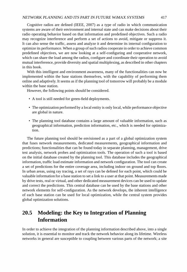
NETWORK PLANNING AND ITS PART IN FUTURE WiMAX SYSTEMS 417
Cognitive radios are defined (IEEE, 2007) as a type of radio in which communicationsystems are aware of their environment and internal state and can make decisions about theirradio operating behavior based on that information and predefined objectives. Such a radiomay recognize interference and perform a set of actions to avoid, mitigate or suppress it.It can also sense the traffic, assess and analyze it and determine its internal configuration tooptimize its performance. When a group of such radios cooperate in order to achieve commonpredefined objectives, we are now looking at a self-configuring and cooperative network,which can share the load among the radios, configure and coordinate their operation to avoidmutual interference, provide diversity and spatial multiplexing, as described in other chaptersin this book.
With this intelligent and environment awareness, many of the functionalities can now beimplemented within the base stations themselves, with the capability of performing themonline and adaptively. It seems as if the planning tool of tomorrow will probably be a modulewithin the base station.
However, the following points should be considered.
• A tool is still needed for green-field deployments.
• The optimization performed by a local entity is only local, while performance objectiveare global in nature.
• The planning tool database contains a large amount of valuable information, such asgeographical information, prediction information, etc., which is needed for optimiza-tion.
The future planning tool should be envisioned as a part of a global optimization systemthat fuses network measurements, dedicated measurements, geographical information andpredictions; functionalities that can be found today in separate planning, management, drivetest analysis, network probes and optimization tools. The operation of such a tool is basedon the initial database created by the planning tool. This database includes the geographicalinformation, traffic load estimate information and network configuration. The tool can createa set of predictions for the entire coverage area, including indoor on ground and top floors.In urban areas, using ray tracing, a set of rays can be defined for each point, which could bevaluable information for a base station to set a link to a user at that point. Measurements madeby drive tests, real or virtual, and other dedicated measurement devices can be used to updateand correct the predictions. This central database can be used by the base stations and othernetwork elements for self-configuration. As the network develops, the inherent intelligenceof each base station can be used for local optimization, while the central system providesglobal optimization solutions.
20.5 Modeling: the Key to Integration of PlanningInformation
In order to achieve the integration of the planning information described above, into a singlesolution, it is essential to monitor and track the network behavior along its lifetime. Wirelessnetworks in general are susceptible to coupling between various parts of the network; a site
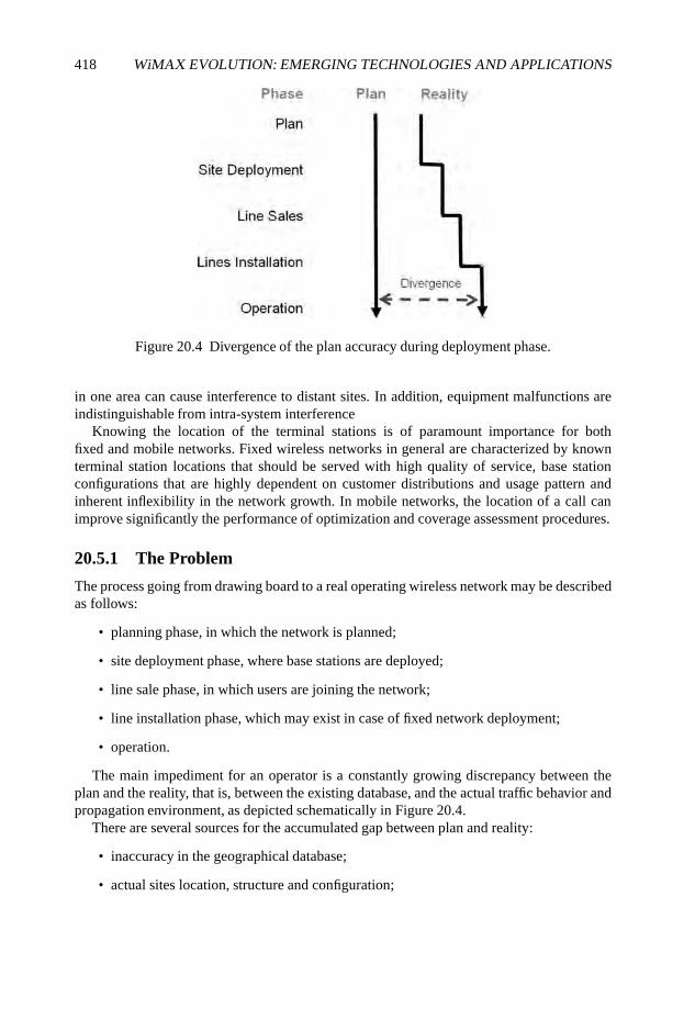
418 WiMAX EVOLUTION: EMERGING TECHNOLOGIES AND APPLICATIONS
Figure 20.4 Divergence of the plan accuracy during deployment phase.
in one area can cause interference to distant sites. In addition, equipment malfunctions areindistinguishable from intra-system interference
Knowing the location of the terminal stations is of paramount importance for bothfixed and mobile networks. Fixed wireless networks in general are characterized by knownterminal station locations that should be served with high quality of service, base stationconfigurations that are highly dependent on customer distributions and usage pattern andinherent inflexibility in the network growth. In mobile networks, the location of a call canimprove significantly the performance of optimization and coverage assessment procedures.
20.5.1 The Problem
The process going from drawing board to a real operating wireless network may be describedas follows:
• planning phase, in which the network is planned;
• site deployment phase, where base stations are deployed;
• line sale phase, in which users are joining the network;
• line installation phase, which may exist in case of fixed network deployment;
• operation.
The main impediment for an operator is a constantly growing discrepancy between theplan and the reality, that is, between the existing database, and the actual traffic behavior andpropagation environment, as depicted schematically in Figure 20.4.
There are several sources for the accumulated gap between plan and reality:
• inaccuracy in the geographical database;
• actual sites location, structure and configuration;
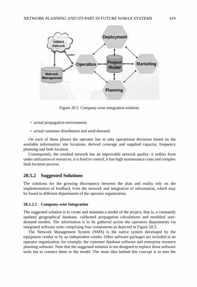
NETWORK PLANNING AND ITS PART IN FUTURE WiMAX SYSTEMS 419
Figure 20.5 Company-wise integration solution.
• actual propagation environment;
• actual customer distribution and used demand.
On each of these phases the operator has to take operational decisions based on theavailable information: site locations, derived coverage and supplied capacity, frequencyplanning and fault location.
Consequently, the resulted network has an improvable network quality; it suffers fromunder utilization of resources, it is hard to control, it has high maintenance costs and complexfault location process.
20.5.2 Suggested Solutions
The solutions for the growing discrepancy between the plan and reality rely on theimplementation of feedback from the network and integration of information, which maybe found in different departments of the operator organization.
20.5.2.1 Company-wise Integration
The suggested solution is to create and maintain a model of the project, that is, a constantlyupdated geographical database, calibrated propagation calculations and modified user-demand models. The information is to be gathered across the operators departments viaintegrated software suite comprising four components as depicted in Figure 20.5.
The Network Management System (NMS) is the native system developed by theequipment vendor or by an independent vendor. Other software packages are included in anoperator organization, for example, the customer database software and enterprise resourceplanning software. Note that the suggested solution is not designed to replace these softwaretools but to connect them to the model. The main idea behind this concept is to turn the
420 WiMAX EVOLUTION: EMERGING TECHNOLOGIES AND APPLICATIONS
model into common knowledge across the company. Deployment teams, which deploy basestations and, in the fixed network case, terminal stations, update the project model. Themarketing team consults the project model for coverage information and updates the planningdepartment for current and future user demand information. The operation team analyzesmeasurements and reports from the NMS and from the network elements via SNMP andinteracts with the model by updating the coverage information and performing optimization.
The model enhances the whole operator’s organization. It facilitates coordination ofoperator activities: planning, deployment, sale and operation. It constantly monitors theactual structure and performance of the network and provides a geographical Graphical UserInterface (GUI). The main benefit is that the model allows online network optimization:constantly monitoring the frequency plan and the traffic pattern and provide appropriatealarms to the network manager, testing network manipulation on an updated model, providingplatform for fault location expert system, calculating new cell service policy and guiding thesales/marketing efforts.
20.5.2.2 Calls Positioning: VDTs
The information integration solution described above is not sufficient for a mobile operator,as one of the key components: the terminal station location is not known a priori. Figure 20.6describes a proposed solution. The solution is based on analysis of events (e.g. normal call,dropped calls, transfer of calls from one technology to another) collected by probes, whichtrace the various interfaces. Using the probe data observations the tool performs VDT whichaccurately locates calls on a geographical three-dimensional map and uses the measuredsignal strength information for the located event to assess the coverage in that area as well asany other applicable information such as distance measure and timing information. The nextstage would be to apply automatic optimization to the network, which includes:
• cell configuration (e.g. azimuth, tilt);
• frequency and RF parameters planning:
– measurements-based impact matrix;
– accurate balance of full and partial frequency schemes;
• neighbor list;
• load balancing via handover parameters optimization.
At this stage the optimization tool automatically identifies and reports problematic spots,coverage holes, etc.
20.6 Conclusions
Network planning is the primary stage before any wireless system deployment. The networkplanning tools is essential for any operator for dimensioning the network, assess vendorproposals and provide a deployment plan that provides the necessary capacity and coverage
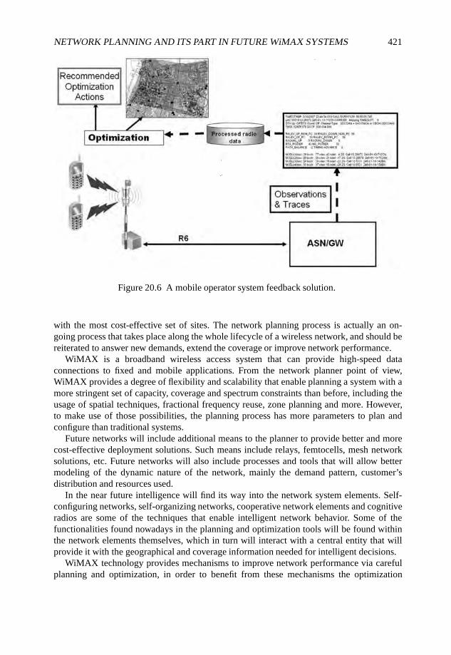
NETWORK PLANNING AND ITS PART IN FUTURE WiMAX SYSTEMS 421
Figure 20.6 A mobile operator system feedback solution.
with the most cost-effective set of sites. The network planning process is actually an on-going process that takes place along the whole lifecycle of a wireless network, and should bereiterated to answer new demands, extend the coverage or improve network performance.
WiMAX is a broadband wireless access system that can provide high-speed dataconnections to fixed and mobile applications. From the network planner point of view,WiMAX provides a degree of flexibility and scalability that enable planning a system with amore stringent set of capacity, coverage and spectrum constraints than before, including theusage of spatial techniques, fractional frequency reuse, zone planning and more. However,to make use of those possibilities, the planning process has more parameters to plan andconfigure than traditional systems.
Future networks will include additional means to the planner to provide better and morecost-effective deployment solutions. Such means include relays, femtocells, mesh networksolutions, etc. Future networks will also include processes and tools that will allow bettermodeling of the dynamic nature of the network, mainly the demand pattern, customer’sdistribution and resources used.
In the near future intelligence will find its way into the network system elements. Self-configuring networks, self-organizing networks, cooperative network elements and cognitiveradios are some of the techniques that enable intelligent network behavior. Some of thefunctionalities found nowadays in the planning and optimization tools will be found withinthe network elements themselves, which in turn will interact with a central entity that willprovide it with the geographical and coverage information needed for intelligent decisions.
WiMAX technology provides mechanisms to improve network performance via carefulplanning and optimization, in order to benefit from these mechanisms the optimization
422 WiMAX EVOLUTION: EMERGING TECHNOLOGIES AND APPLICATIONS
process has to take into account the information available in many shapes and forms acrossthe network operator organization. All information gathering solutions should have the abilityto translate feedback and measurements into a geographical information system format. Thiscan be done using VDTs, which transform measurements made by subscriber terminals intoa drive test associating them with a specific location.
Thus, the future network will witness the integration of a variety of support systems:network management, customer database, enterprise resource planning and radio planningand optimization systems, together with the inherent intelligence embedded within thenetwork elements themselves to provide a better solution for wireless network operation.
References
Aguado-Agelet, F., Varela, A., Alvarez-Vazquez, L. et al. (2002) Optimization methods for optimaltransmitter locations in a mobile wireless system. IEEE Transactions on Vehicular Technology,51(6), 1316–1321.
Anderson, H. and McGeehan, J. (1994) Optimizing microcell base station locations using simulatedannealing techniques. Proceedings of the IEEE Semiannual Vehicular Technology Conference,Vol. 2, pp. 858–862.
Andrews, J. Ghosh, A. and Muhamed, R. (2007) Fundamentals of WiMAX. Prentice Hall, EnglewoodCliffs, NJ.
Blaunstein, N. (1999) Radio Propagation in Cellular Systems. Artech House, Boston, MA.Chavez-Santiago, R., Raymond, A. and Lyandres, V. (2007) Enhanced efficiency and frequency
assignment by optimizing the base stations location in a mobile radio network. Wireless NetworksOnline First.
COST (1999) Digital Mobile Radio Towards Future Generation Systems, COST Action 231.Eklund, C., Marks, R., Ponnuswamy, S. and Stanwood, K. (2006) WirelessMAN: Inside the IEEE
802.16 Standard for Wireless Metropolitan Area Networks. IEEE Press, New York.Hata, M. and Nagatsu, T. (1980) Mobile location using signal strength measurements in a cellular
system. IEEE Transactions on Vehicular Technology, 29(2), 245–252.Huang, X., Behr, U. and Wiesbeck, W. (2000) Automatic base station placement and dimensioning
for mobile network planning. Proceedings of the 52nd IEEE Semiannual Vehicular TechnologyConference, Vol. 4, pp. 1544–1549.
Hurley, S. (2002) Planning effective cellular mobile radio networks. IEEE Transactions on VehicularTechnology, 51(2), 48–56.
ITU (2007a) Method for point-to-area predictions for terrestrial services in the frequency range 30 MHzto 3000 MHz. Technical Report 1546 IRRP, ITU.
ITU (2007b) A path-specific propagation prediction method for point-to-area terrestrial services in thevhf and uhf bands. Technical Report 1812 IRRP, ITU.
IEEE (2004) Part 16: Air Interface for Fixed Broadband Wireless Access Systems, IEEE Standard802.16-2004.
IEEE (2005) Part 16: Air Interface for Fixed and Mobile Broadband Wireless Access SystemsAmendment 2: Physical and Medium Access Control Layers for Combined Fixed and MobileOperation in Licensed Bands and Corrigendum 1. IEEE Standard 802.16e 2005.
IEEE (2007) Draft Standard Definitions and Concepts for Dynamic Spectrum Access: TerminologyRelating to Emerging Wireless Networks, System Functionality, and Spectrum Management. IEEE,Draft Standard P1900.1/D2.0 I.
Laiho, J. Wacker, A. and Novosad, T. (eds) (2007) Radio Network Planning and Optimisation forUMTS. John Wiley & Sons Ltd, Chichester.

NETWORK PLANNING AND ITS PART IN FUTURE WiMAX SYSTEMS 423
Lee, W.C.Y. (1986) Elements of cellular mobile radio systems. IEEE Transactions on VehicularTechnology, 35(2), 48–56.
McDonald, V.H. (1979) The cellular concept. Bell Systems Technical Journal, 58(1), 15–41.Mishra, A.R. (ed.) (2007) Advanced Cellular Network Planning and Optimisation: 2G/2.5G/3G. . .
Evolution to 4G. John Wiley & Sons Ltd, Chichester.Molina, A., Nix, A. and Athanasiadou, G. (2000) Optimised base-station location algorithm for next
generation microcellular networks. Electronics Letters, 36(7), 68–669.Niessen, T. (1997) Optimal channel allocation for several types of radio networks. Discrete Applied
Mathematics, 79(1–3), 155–170.Ott, G. (1977) Vehicle location in cellular mobile radio systems. IEEE Transactions on Vehicular
Technology, 26(1), 43–46.Parsons, J.D. (1992) The Mobile Radio Propagation Channel. Pentech Press, London.Riter, S. and McCoy, J. (1977) Automatic vehicle location – an overview. IEEE Transactions on
Vehicular Technology, 26(1), 7–11.Struzak, R.G. (1982) Optimum frequency planning: a new concept. Telecommunication Journal, 49,
29–36.WiMAX Forum (2006) WiMAX Forum mobile system profile, http://www.wimaxforum.org/
technology/documents/wimax_forum_mobile_system_profile_v1_40.pdf.Wigren, T. (2007) Adaptive enhanced cell-ID fingerprinting localization by clustering of precise
position measurements. IEEE Transactions on Vehicular Technology, 56(5), 3199–3209.Yang, S. and Ephremides, A. (1997) Optimal network design: the base station placement problem.
Proceedings of the 36th IEEE Conference on Decision and Control, Vol. 3, pp. 2381–2386. IEEE,Press, Piscataway, NJ.
21
WiMAX Network Automation:Neighbor Discovery, CapabilitiesNegotiation, Auto-configurationand Network Topology Learning
Alexander Bachmutsky
21.1 Introduction
Mobile networks frequently have very complex hierarchical architectures (for example,Node B–RNC–SGSN–GGSN). WiMAX networks are not much different with AccessService Networks (ASNs) consisting of Base Stations (BSs) and ASN Gateways (ASN-GWs), and Connectivity Service Networks (CSNs) consisting of Home Agents (HAs),Authentication, Authorization and Accounting (AAA) proxies and servers, Dynamic HostConfiguration Protocol (DHCP) proxies, relays and servers, IP Multimedia Subsystem (IMS)infrastructure and more. The deployment and management of such networks is a huge taskand one of the biggest investments from both Telecommunications Equipment Manufacturers(TEMs) and operators. Based on the experience of many different projects from many TEMs,the development of Operations and Management (O&M) infrastructure and products countsfor as much as a half of all development costs.
At the same time standards do not really help to ease the deployment and management ofmobile networks. Of course, there is a Simple Network Management Protocol (SNMP) thatis used for some management tasks, but it is very basic and cannot be used for many complexmanagement jobs, and definitely not the deployment ones. The WiMAX Forum does not
WiMAX Evolution: Emerging Technologies and Applications Edited by Tsutomu Ishikawa© 2009 John Wiley & Sons, Ltd. ISBN: 978-0-470-69680-4
426 WiMAX EVOLUTION: EMERGING TECHNOLOGIES AND APPLICATIONS
pay much attention to the problem either: it concentrates more on the terminal management(over-the-air provisioning), not on the network management.
In addition, any network automation should take into account the dynamic nature of thenetwork, which is affected by upgrades and downgrades, failures and recoveries, overloadsituations and mobility changing a processing chain per subscriber.
In this chapter we try to describe some related topics and to at least ignite a discussionof the WiMAX network automation helping all involved parties to build better, more reliableand lower cost solutions.
21.2 WiMAX Network Elements Auto-discovery
Performing the relatively simple task of adding one BS to the existing network requiresconfiguring this BS with all neighboring BSs, configuring all neighboring BSs to includethe new one, configuring the new BS with all logically connected ASN-GWs and configuringall of these ASN-GWs to include the new BS. Taking into account that the operator needsto perform such operations for every deployed BS, it is understandable why they require socomplex and sophisticated O&M tools.
The first step in network automation is to discover the neighbors instead of a manualprovisioning. BSs can discover their neighbor BSs from their radio resource management,either by themselves or with the help of a terminal. In the latter case the terminals report BSsthat they can hear, and such information can be processed and saved by all BSs. Operators can‘train’ the network during the deployment stage by driving around with a few terminals (theydo this anyway in many cases for various reasons). On the other side, such learning will onlyprovide information about BS identification, but will not provide the networking parameters(for example, Internet Protocol (IP) addresses). It is also possible to apply techniques andbasic learning principles from mesh networking and Self-Organized Networks (SONs) thatcan help to automatically build a list of neighboring devices.
There are multiple ways to automatically learn a mapping between the WiMAX informa-tion (WiMAX Network Element (NE) identifications) and the transport information (MediaAccess Control (MAC) and IP addresses).
The first option is similar to a scheme that allows IPv4 routers to auto-discover each other(Deering, 1991). The proposal is to reuse ICMP Router Discovery from RFC 1256 in WiMAXNetwork Element Advertisements (WNEAs) by including the WiMAX Network ElementAdvertisement Extension. The presented mechanism covers only an IPv4 advertisement, butit can be easily extended to the IPv6 case.
WNEAs are sent using the network element IP address as a source and either ‘all systemson this link’ multicast address (224.0.0.1) or broadcast address (255.255.255.255) as adestination. In addition, WNEAs can be sent with a unicast address if such an address isknown a priori, for example, from a previous WNEA. Usually, a new NE would advertiseitself to the network using a multicast or broadcast IP address, while existing NEs wouldadvertise themselves to this new one using its unicast address taken from a previouslyreceived multicast/broadcast packet. To eliminate a need for solicitation request, it ismandated to send the WNEA if another WNEA was received from a previously unknownnetwork element.

WiMAX NETWORK AUTOMATION 427
0 1 2 3
0 1 2 3 4 5 6 7 8 9 0 1 2 3 4 5 6 7 8 9 0 1 2 3 4 5 6 7 8 9 0 1
+-+-+-+-+-+-+-+-+-+-+-+-+-+-+-+-+-+-+-+-+-+-+-+-+-+-+-+-+-+-+-+-+
| Type | Length | Sequence Number |
+-+-+-+-+-+-+-+-+-+-+-+-+-+-+-+-+-+-+-+-+-+-+-+-+-+-+-+-+-+-+-+-+
| Registration Lifetime |H|A|B|G|r|r|r|O| Num User Plane|
| | | | | | | | | | Addresses |
+-+-+-+-+-+-+-+-+-+-+-+-+-+-+-+-+-+-+-+-+-+-+-+-+-+-+-+-+-+-+-+-+
| zero or more User Plane Addresses |
| zero or more Control Plane Addresses |
| ... |
Figure 21.1 WNEA extension.
WiMAX NEs can have separate user and control planes with separate IP addresses. Toaccommodate such a case it is possible to include all user plane IP addresses in a standardInternet Control Message Protocol (ICMP) portion of the packet in the ‘Router Address(es)’field. If the NE does not have a user plane component, the ICMP message ‘Num User PlaneAddresses’ field shall be set to zero; otherwise it is set to the number of addresses providedin the ‘Router Address(es)’ field. All control plane IP addresses will be specified using theWNEA Extension (shown in Figure 21.1 in a form used frequently in IETF documents).
• Registration Lifetime is the time in seconds that this element should be kept as a validWiMAX NE in tables of other NEs without receiving an updated WNEA. A value of0xFFFF indicates infinity. Registration lifetime is the same for all functions advertisedin the message. If there is a need for different registration lifetimes for every function,separate WNEA messages should be sent.
• H: HA functionality is included in this NE if set to 1.
• A: AAA server functionality is included in this NE if set to 1.
B: BS functionality is included in this NE if set to 1.
• G: ASN-GW functionality is included in this NE if set to 1.
• r: Reserved bit.
• O: overload/busy flag; setting this to 1 means that this NE should not be used for anynew connections until the end of a registration lifetime or new advertisement withoutan ‘O’ flag being set. This flag is applicable to all advertised functions (H, A, B and/orG). This flag is not relevant purely for a neighbor discovery, but shows that it is possibleto perform both discovery and a status exchange in the same message.
• User Plane Addresses: IP addresses used for the transport of end-user packets. Alladdresses will apply to all advertised functions.
• Control Plane Addresses: IP addresses used for a WiMAX control/signaling plane. Alladdresses will apply to all advertised functions.
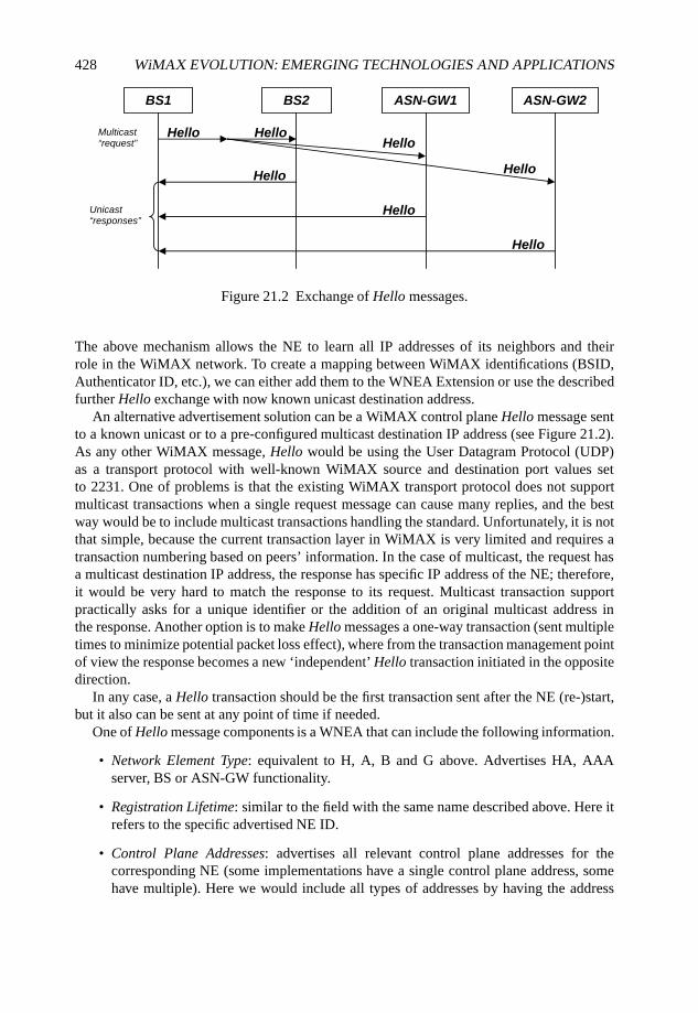
428 WiMAX EVOLUTION: EMERGING TECHNOLOGIES AND APPLICATIONS
BS1 BS2 ASN-GW1 ASN-GW2
HelloHello
Hello Hello
Hello
Hello
Multicast “request”
Unicast “responses”
Hello
Figure 21.2 Exchange of Hello messages.
The above mechanism allows the NE to learn all IP addresses of its neighbors and theirrole in the WiMAX network. To create a mapping between WiMAX identifications (BSID,Authenticator ID, etc.), we can either add them to the WNEA Extension or use the describedfurther Hello exchange with now known unicast destination address.
An alternative advertisement solution can be a WiMAX control plane Hello message sentto a known unicast or to a pre-configured multicast destination IP address (see Figure 21.2).As any other WiMAX message, Hello would be using the User Datagram Protocol (UDP)as a transport protocol with well-known WiMAX source and destination port values setto 2231. One of problems is that the existing WiMAX transport protocol does not supportmulticast transactions when a single request message can cause many replies, and the bestway would be to include multicast transactions handling the standard. Unfortunately, it is notthat simple, because the current transaction layer in WiMAX is very limited and requires atransaction numbering based on peers’ information. In the case of multicast, the request hasa multicast destination IP address, the response has specific IP address of the NE; therefore,it would be very hard to match the response to its request. Multicast transaction supportpractically asks for a unique identifier or the addition of an original multicast address inthe response. Another option is to make Hello messages a one-way transaction (sent multipletimes to minimize potential packet loss effect), where from the transaction management pointof view the response becomes a new ‘independent’ Hello transaction initiated in the oppositedirection.
In any case, a Hello transaction should be the first transaction sent after the NE (re-)start,but it also can be sent at any point of time if needed.
One of Hello message components is a WNEA that can include the following information.
• Network Element Type: equivalent to H, A, B and G above. Advertises HA, AAAserver, BS or ASN-GW functionality.
• Registration Lifetime: similar to the field with the same name described above. Here itrefers to the specific advertised NE ID.
• Control Plane Addresses: advertises all relevant control plane addresses for thecorresponding NE (some implementations have a single control plane address, somehave multiple). Here we would include all types of addresses by having the address
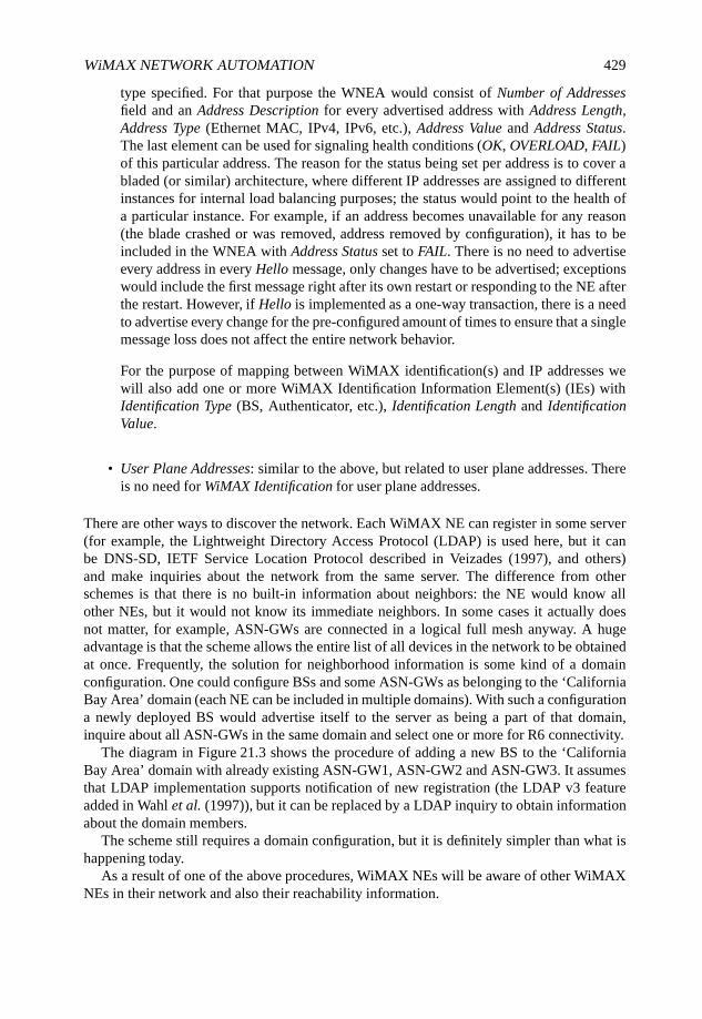
WiMAX NETWORK AUTOMATION 429
type specified. For that purpose the WNEA would consist of Number of Addressesfield and an Address Description for every advertised address with Address Length,Address Type (Ethernet MAC, IPv4, IPv6, etc.), Address Value and Address Status.The last element can be used for signaling health conditions (OK, OVERLOAD, FAIL)of this particular address. The reason for the status being set per address is to cover abladed (or similar) architecture, where different IP addresses are assigned to differentinstances for internal load balancing purposes; the status would point to the health ofa particular instance. For example, if an address becomes unavailable for any reason(the blade crashed or was removed, address removed by configuration), it has to beincluded in the WNEA with Address Status set to FAIL. There is no need to advertiseevery address in every Hello message, only changes have to be advertised; exceptionswould include the first message right after its own restart or responding to the NE afterthe restart. However, if Hello is implemented as a one-way transaction, there is a needto advertise every change for the pre-configured amount of times to ensure that a singlemessage loss does not affect the entire network behavior.
For the purpose of mapping between WiMAX identification(s) and IP addresses wewill also add one or more WiMAX Identification Information Element(s) (IEs) withIdentification Type (BS, Authenticator, etc.), Identification Length and IdentificationValue.
• User Plane Addresses: similar to the above, but related to user plane addresses. Thereis no need for WiMAX Identification for user plane addresses.
There are other ways to discover the network. Each WiMAX NE can register in some server(for example, the Lightweight Directory Access Protocol (LDAP) is used here, but it canbe DNS-SD, IETF Service Location Protocol described in Veizades (1997), and others)and make inquiries about the network from the same server. The difference from otherschemes is that there is no built-in information about neighbors: the NE would know allother NEs, but it would not know its immediate neighbors. In some cases it actually doesnot matter, for example, ASN-GWs are connected in a logical full mesh anyway. A hugeadvantage is that the scheme allows the entire list of all devices in the network to be obtainedat once. Frequently, the solution for neighborhood information is some kind of a domainconfiguration. One could configure BSs and some ASN-GWs as belonging to the ‘CaliforniaBay Area’ domain (each NE can be included in multiple domains). With such a configurationa newly deployed BS would advertise itself to the server as being a part of that domain,inquire about all ASN-GWs in the same domain and select one or more for R6 connectivity.
The diagram in Figure 21.3 shows the procedure of adding a new BS to the ‘CaliforniaBay Area’ domain with already existing ASN-GW1, ASN-GW2 and ASN-GW3. It assumesthat LDAP implementation supports notification of new registration (the LDAP v3 featureadded in Wahl et al. (1997)), but it can be replaced by a LDAP inquiry to obtain informationabout the domain members.
The scheme still requires a domain configuration, but it is definitely simpler than what ishappening today.
As a result of one of the above procedures, WiMAX NEs will be aware of other WiMAXNEs in their network and also their reachability information.
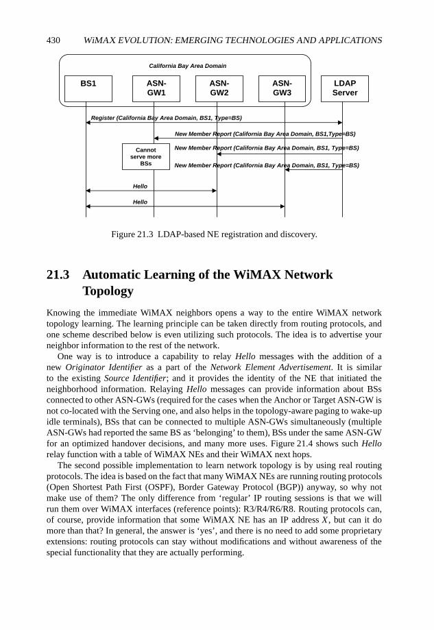
430 WiMAX EVOLUTION: EMERGING TECHNOLOGIES AND APPLICATIONS
BS1 ASN-GW1
ASN-GW2
ASN-GW3
LDAPServer
California Bay Area Domain
Register (California Bay Area Domain, BS1, Type=BS)
New Member Report (California Bay Area Domain, BS1,Type=BS)
New Member Report (California Bay Area Domain, BS1, Type=BS)
New Member Report (California Bay Area Domain, BS1, Type=BS)
Cannotserve more
BSs
Hello
Hello
Figure 21.3 LDAP-based NE registration and discovery.
21.3 Automatic Learning of the WiMAX NetworkTopology
Knowing the immediate WiMAX neighbors opens a way to the entire WiMAX networktopology learning. The learning principle can be taken directly from routing protocols, andone scheme described below is even utilizing such protocols. The idea is to advertise yourneighbor information to the rest of the network.
One way is to introduce a capability to relay Hello messages with the addition of anew Originator Identifier as a part of the Network Element Advertisement. It is similarto the existing Source Identifier; and it provides the identity of the NE that initiated theneighborhood information. Relaying Hello messages can provide information about BSsconnected to other ASN-GWs (required for the cases when the Anchor or Target ASN-GW isnot co-located with the Serving one, and also helps in the topology-aware paging to wake-upidle terminals), BSs that can be connected to multiple ASN-GWs simultaneously (multipleASN-GWs had reported the same BS as ‘belonging’ to them), BSs under the same ASN-GWfor an optimized handover decisions, and many more uses. Figure 21.4 shows such Hellorelay function with a table of WiMAX NEs and their WiMAX next hops.
The second possible implementation to learn network topology is by using real routingprotocols. The idea is based on the fact that many WiMAX NEs are running routing protocols(Open Shortest Path First (OSPF), Border Gateway Protocol (BGP)) anyway, so why notmake use of them? The only difference from ‘regular’ IP routing sessions is that we willrun them over WiMAX interfaces (reference points): R3/R4/R6/R8. Routing protocols can,of course, provide information that some WiMAX NE has an IP address X, but can it domore than that? In general, the answer is ‘yes’, and there is no need to add some proprietaryextensions: routing protocols can stay without modifications and without awareness of thespecial functionality that they are actually performing.
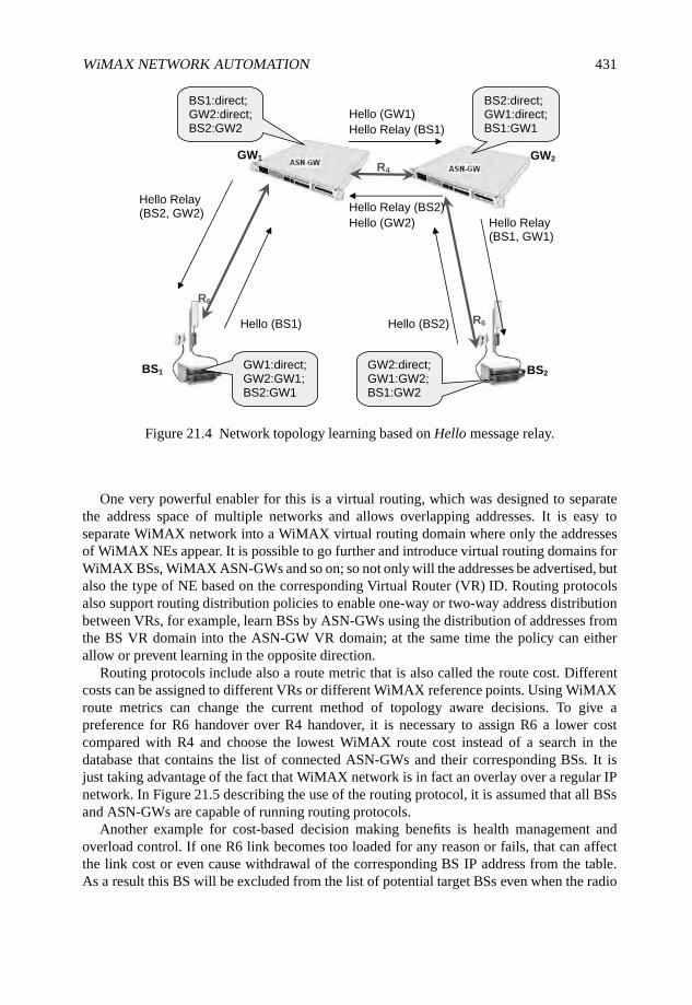
WiMAX NETWORK AUTOMATION 431
BS1 BS2
R6
R6
R4
GW1 GW2
Hello (BS1) Hello (BS2)
Hello Relay (BS1)
Hello Relay (BS2)Hello Relay (BS2, GW2)
Hello Relay (BS1, GW1)
BS1:direct; GW2:direct;BS2:GW2
Hello (GW1)
Hello (GW2)
BS2:direct;GW1:direct; BS1:GW1
GW1:direct; GW2:GW1; BS2:GW1
GW2:direct; GW1:GW2; BS1:GW2
Figure 21.4 Network topology learning based on Hello message relay.
One very powerful enabler for this is a virtual routing, which was designed to separatethe address space of multiple networks and allows overlapping addresses. It is easy toseparate WiMAX network into a WiMAX virtual routing domain where only the addressesof WiMAX NEs appear. It is possible to go further and introduce virtual routing domains forWiMAX BSs, WiMAX ASN-GWs and so on; so not only will the addresses be advertised, butalso the type of NE based on the corresponding Virtual Router (VR) ID. Routing protocolsalso support routing distribution policies to enable one-way or two-way address distributionbetween VRs, for example, learn BSs by ASN-GWs using the distribution of addresses fromthe BS VR domain into the ASN-GW VR domain; at the same time the policy can eitherallow or prevent learning in the opposite direction.
Routing protocols include also a route metric that is also called the route cost. Differentcosts can be assigned to different VRs or different WiMAX reference points. Using WiMAXroute metrics can change the current method of topology aware decisions. To give apreference for R6 handover over R4 handover, it is necessary to assign R6 a lower costcompared with R4 and choose the lowest WiMAX route cost instead of a search in thedatabase that contains the list of connected ASN-GWs and their corresponding BSs. It isjust taking advantage of the fact that WiMAX network is in fact an overlay over a regular IPnetwork. In Figure 21.5 describing the use of the routing protocol, it is assumed that all BSsand ASN-GWs are capable of running routing protocols.
Another example for cost-based decision making benefits is health management andoverload control. If one R6 link becomes too loaded for any reason or fails, that can affectthe link cost or even cause withdrawal of the corresponding BS IP address from the table.As a result this BS will be excluded from the list of potential target BSs even when the radio
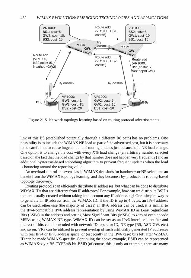
432 WiMAX EVOLUTION: EMERGING TECHNOLOGIES AND APPLICATIONS
BS1 BS2
R6 cost=5
R4
cost=10 GW1
GW2
Route add(VR1000, BS1,cost=5)
VR1000: BS1: cost=5; GW2: cost=10; BS2: cost=15
VR1000: BS2: cost=5; GW1: cost=10; BS1: cost=15
VR1000: GW1: cost=5; GW2: cost=15; BS2: cost=20
VR1000: GW2: cost=5; GW1: cost=15; BS1: cost=20
Route add (VR1000, BS2, cost=5)
Route add (VR1000, BS1,cost=15, Nexthop=GW1)
Route add (VR1000, BS2,cost=15, Nexthop=GW2)
R6 cost=5
Figure 21.5 Network topology learning based on routing protocol advertisements.
link of this BS (established potentially through a different R8 path) has no problems. Onepossibility is to include the WiMAX NE load as part of the advertised cost, but it is necessaryto be careful not to cause huge amount of routing updates just because of a NE load change.One option is to change the cost with every X% load change (an arbitrary number selectedbased on the fact that the load change by that number does not happen very frequently) and anadditional hysteresis-based smoothing algorithm to prevent frequent updates when the loadis bouncing around the reporting value.
An overload control and even classic WiMAX decisions for handovers or NE selection canbenefit from the WiMAX topology learning, and they become a by-product of a routing-basedtopology discovery.
Routing protocols can efficiently distribute IP addresses, but what can be done to distributeWiMAX IDs that are different from IP addresses? For example, how can we distribute BSIDsthat are usually created without taking into account any IP addressing? One ‘simple’ way isto generate an IP address from the WiMAX ID: if the ID is up to 4 bytes, an IPv4 addresscan be used; otherwise (the majority of cases) an IPv6 address can be used; it is similar tothe IPv4-compatible IPv6 address representation by using WiMAX ID as Least SignificantBits (LSBs) in the address and setting Most Significant Bits (MSBs) to zero or even encodeMSBs using WiMAX NE type. WiMAX ID can be set as an IPv6 interface identifier andthe rest of bits can be encoded with network ID, operator ID, NE type (BS, ASN-GW, etc.)and so on. VRs can be utilized to prevent overlap of such artificially generated IP addresseswith real IPv4 or IPv6 address space, or (especially in the IPv6 case) bits left after WiMAXID can be made WiMAX-specific. Continuing the above example, BSID can be representedas WIMAX:x:y:z:BS-TYPE:48-bit-BSID (of course, this is only an example, there are many
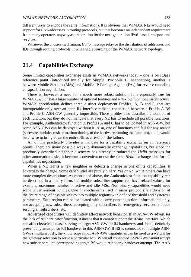
WiMAX NETWORK AUTOMATION 433
different ways to encode the same information). It is obvious that WiMAX NEs would needsupport for IPv6 addresses in routing protocols, but that becomes an independent requirementfrom many operators anyway as preparation for the next generation IPv6-based transport andservices.
Whatever the chosen mechanism, Hello message relay or the distribution of addresses andIDs through routing protocols, it will enable learning of the WiMAX network topology.
21.4 Capabilities Exchange
Some limited capabilities exchange exists in WiMAX networks today – one is on R3aaareference point (introduced initially for Simple IP/Mobile IP negotiation), another isbetween Mobile Stations (MSs) and Mobile IP Foreign Agents (FAs) for reverse tunnelingencapsulation negotiation.
There is, however, a need for a much more robust solution. It is especially true forWiMAX, which has a large number of optional features and a flexible functional architecture.WiMAX specification defines three distinct deployment Profiles, A, B and C, that areinteroperable only over an open R4 interface making connection between a Profile A BSand Profile C ASN-GW generally impossible. These profiles also describe the location ofeach function, but they do not mandate that every NE has to include all possible functions.For example, Authenticator function in Profiles A and C has to be located in ASN-GW, butsome ASN-GWs can be deployed without it. Also, one of functions can fail for any reason(software module crash or malfunctioning of the hardware running the function), and it wouldbe unwise to bring down the entire NE as a result of the failure.
All of this practically provides a mandate for a capability exchange on all referencepoints. There are many possible ways to dynamically exchange capabilities, but since thepreviously described neighbor discovery has already introduced the Hello messages forother automation tasks, it becomes convenient to use the same Hello exchange also for thecapabilities negotiation.
When a NE learns a new neighbor or detects a change in one of its capabilities, itadvertises the change. Some capabilities are purely binary, Yes or No, while others can havemore complex descriptions. As mentioned above, the Authenticator function capability canbe described in a binary form, but mobile subscriber support can have related values, forexample, maximum number of active and idle MSs. Non-binary capabilities would needsome advertisement policies. One of mechanisms used in many protocols is a division ofthe entire range of possible values into multiple regions with defined threshold and hysteresisparameters. Each region can be associated with a corresponding action: informational only,not accepting new subscribers, accepting only subscribers for emergency services, stoppedserving all subscribers, etc.
Advertised capabilities will definitely affect network behavior. If an ASN-GW advertisesthe lack of Authenticator function, it means that it cannot support the R3aaa interface, whichcan affect its selection as a serving or target ASN-GW for R4 handovers, and should definitelyprevent any attempt for R3 handover to this ASN-GW. If BS is connected to multiple ASN-GWs simultaneously, the knowledge about ASN-GW capabilities can be used as a weight forthe gateway selection to serve a particular MS. When all connected ASN-GWs cannot acceptnew subscribers, the corresponding target BS would reject any handover attempt. The AAA
434 WiMAX EVOLUTION: EMERGING TECHNOLOGIES AND APPLICATIONS
Auth
Ver. X1
and Y1
MS1 MS2
FA
AAA verX1 AAA verX2
HA verY 1 HA verY2
Ver. X1
and Y1
Ver. X1 Ver. X2
Ver. Y1 Ver. Y2
Home operator1 Home operator2
Visited operator
Figure 21.6 MS-dependent version handling.
server would have standard-based way to select the least-loaded HA for Mobile IP (MIP)subscriber. The list of possible smart network decisions enabled by the capabilities exchangecan be very large.
21.5 Automatic WiMAX Version Management
Version management is a very important network automation feature for the operator. Onecan even call it critical because it cannot be replaced by any configuration.
The first challenge is to synchronize the version of all NEs. Let us assume for simplicitythat an operator deploys his entire network to run a single WiMAX version X. Eventhis ‘perfect’ scenario has a potential risk, correct support for roaming subscribers. It ispractically impossible to synchronize versions of all WiMAX NEs throughout the entireworldwide roaming domain. In some cases a visited operator will have to connect to a homeAAA running a different version Y . The home AAA will also select a HA for MIP-baseddeployments (CMIP or PMIP), and that HA might run another version Z. This means thatAuthenticator and Charging functions in the visited network have to support version Y , andthe visited network FA has to support version Z. Just add more subscribers roaming intotheir home networks running different WiMAX versions and it becomes obvious that thecomplexity is enormous with different functions running potentially multiple versions. InFigure 21.6 the Authenticator function is running versions X1 and X2, while the FA in thesame ASN-GW is running versions X2 and Y2:
The first basic problem is to know all supported versions on both sides. Today there is amechanism to advertise a single version X support in the Access Request message, and it isfar from being as easy as shown in the above example. It definitely makes sense to advertisein our example all versions for the Authenticator and FA, and it would be possible to justdefine that the highest common version has to be selected, but an immediate issue is that
WiMAX NETWORK AUTOMATION 435
the decision made by the home network can significantly complicate subscriber handling inthe visited network when different home networks select different versions. There should bea way for a visited operator to influence the process, and one solution is to prioritize thesupported version list.
The example touches one additional aspect of the version management: per functionversions. The WiMAX standard is driven by a functional model where each function can beindependent and not all functions have to be collocated. If the standard will allow differentversions for different functions, the problem might become unmanageable because of addeddimensions. The recommendation would be at least initially to force a single WiMAX versionper NE, but even such a restriction does not fix the entire problem. In our example it meansthat the Authenticator and FA support the same version Y , but it would also mean that theAAA server and MIP HA have to support the same version Y .
Operators would require NEs to be interoperable with at least one common version, andthis version is supported by all roaming partners. Is it possible to ensure that there is always acommon version between any networks? The answer is ‘yes’ if all WiMAX devices supportall versions starting from the very first. While initially such requirement does not seem to bea big deal, it will become a limiting factor with more and more new releases. The problem isnot the development effort, but the verification complexity to test the entire functionality inall scenarios and all versions. A quick poll of a number of major TEMs confirms that existingproducts usually support no more than two or three previous versions. In this situation it isimpossible to ensure that any network can talk to any network, moving the problem intothe operator’s domain of signing roaming agreements in a way that enables interoperability.The working assumption is that two or three previous versions would tolerate about 3 yearsdifference between WiMAX versions supported by different operators. Otherwise, therewill be cases when the network access for some subscribers is denied because of versionincompatibility between home and visited networks.
TEMs and operators have another headache: minor versions. Each major WiMAX versioncan have multiple minor versions (for example, WiMAX version 1 has minor versions 1.0,1.1, 1.2 and 1.3), and these minor versions might be not backwards compatible. With onlythree major versions and four minor versions every device has to support many differentsystem behaviors simultaneously, again causing complex development, verification and fieldtroubleshooting. This requires that the WiMAX Forum define only a single public potentiallydeployed minor version for every major version.
Until now the example for version management was relatively simple, because versionswere static. The complexity significantly increases when operators perform upgrade ordowngrade of some NEs. It is practically impossible to perform the version change for alldevices in the network at once, in many cases it is impossible to do that at once even forspecific type of NE, for example, all ASN-GWs. Therefore, there will be always a time periodwhen multiple versions coexist in ASNs and CSNs. There is a possibility of different versionsinside a single ASN, and Figure 21.7 can be considered as an example.
When the terminal was at BS1, the version X was negotiated between all parties on R6,R4 and R3. If BS2 was upgraded or downgraded to version Y , and then the mobile subscribermoves to the BS2, there would be a mismatch between versions on R6 and R4. This is notvery positive development, because BS2 will communicate with ASN-GW1 using version Y ,but the messages will come through the R4 interface running version X.
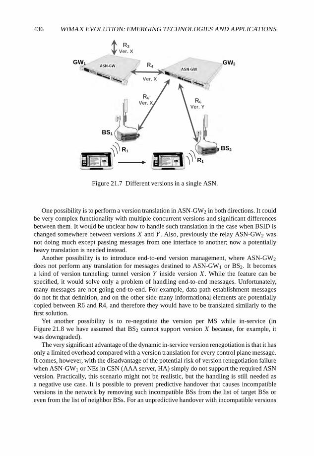
436 WiMAX EVOLUTION: EMERGING TECHNOLOGIES AND APPLICATIONS
BS2
R4
Ver. X
GW1 GW2
BS1
R6
Ver. X R6
Ver. Y
R3
Ver. X
R1
R1
Figure 21.7 Different versions in a single ASN.
One possibility is to perform a version translation in ASN-GW2 in both directions. It couldbe very complex functionality with multiple concurrent versions and significant differencesbetween them. It would be unclear how to handle such translation in the case when BSID ischanged somewhere between versions X and Y . Also, previously the relay ASN-GW2 wasnot doing much except passing messages from one interface to another; now a potentiallyheavy translation is needed instead.
Another possibility is to introduce end-to-end version management, where ASN-GW2does not perform any translation for messages destined to ASN-GW1 or BS2. It becomesa kind of version tunneling: tunnel version Y inside version X. While the feature can bespecified, it would solve only a problem of handling end-to-end messages. Unfortunately,many messages are not going end-to-end. For example, data path establishment messagesdo not fit that definition, and on the other side many informational elements are potentiallycopied between R6 and R4, and therefore they would have to be translated similarly to thefirst solution.
Yet another possibility is to re-negotiate the version per MS while in-service (inFigure 21.8 we have assumed that BS2 cannot support version X because, for example, itwas downgraded).
The very significant advantage of the dynamic in-service version renegotiation is that it hasonly a limited overhead compared with a version translation for every control plane message.It comes, however, with the disadvantage of the potential risk of version renegotiation failurewhen ASN-GW1 or NEs in CSN (AAA server, HA) simply do not support the required ASNversion. Practically, this scenario might not be realistic, but the handling is still needed asa negative use case. It is possible to prevent predictive handover that causes incompatibleversions in the network by removing such incompatible BSs from the list of target BSs oreven from the list of neighbor BSs. For an unpredictive handover with incompatible versions
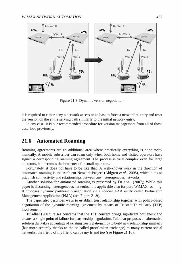
WiMAX NETWORK AUTOMATION 437
GW1 GW2
R6
Ver. X
R1
BS1
R6
Ver. Y
S2
R3 Ver. Y
R4 Ver. Y
GW1
R3 Ver. X
R4 Ver. XGW2
R6
Ver. X
R1
BS1
R6
Ver. Y
S2
Figure 21.8 Dynamic version negotiation.
it is required to either deny a network access or at least to force a network re-entry and resetthe version on the entire serving path similarly to the initial network entry.
In any case, it is our recommended procedure for version management from all of thosedescribed previously.
21.6 Automated Roaming
Roaming agreements are an additional area where practically everything is done todaymanually. A mobile subscriber can roam only when both home and visited operators havesigned a corresponding roaming agreement. The process is very complex even for largeoperators, but becomes the bottleneck for small operators.
Fortunately, it does not have to be like that. A well-known work in the direction ofautomated roaming is the Ambient Network Project (Ahlgren et al., 2005), which aims toestablish connectivity and relationships between any heterogeneous networks.
Another solution for automated roaming is presented by Fu et al. (2007); While thispaper is discussing heterogeneous networks, it is applicable also for pure WiMAX roaming.It proposes dynamic partnership negotiation via a special AAA entity called PartnershipManagement Application (PMA) (see Figure 21.9).
The paper also describes ways to establish trust relationship together with policy-basednegotiation of the dynamic roaming agreement by means of Trusted Third Party (TTP)involvement.
Tuladhar (2007) raises concerns that the TTP concept brings significant bottleneck andcreates a single point of failure for partnership negotiation. Tuladhar proposes an alternativesolution that takes advantage of existing trust relationships to build new relationship similarly(but more securely thanks to the so-called proof-token exchange) to many current socialnetworks: the friend of my friend can be my friend too (see Figure 21.10).
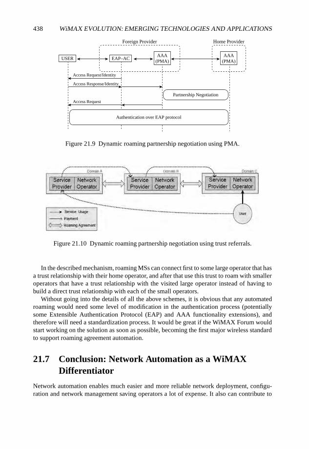
438 WiMAX EVOLUTION: EMERGING TECHNOLOGIES AND APPLICATIONS
Foreign Provider Home Provider
Partnership Negotiation
Authentication over EAP protocol
Access Request
Access Response/Identity
Access Request/Identity
USER EAP–ACAAA
(PMA)AAA
(PMA)
Figure 21.9 Dynamic roaming partnership negotiation using PMA.
Figure 21.10 Dynamic roaming partnership negotiation using trust referrals.
In the described mechanism, roaming MSs can connect first to some large operator that hasa trust relationship with their home operator, and after that use this trust to roam with smalleroperators that have a trust relationship with the visited large operator instead of having tobuild a direct trust relationship with each of the small operators.
Without going into the details of all the above schemes, it is obvious that any automatedroaming would need some level of modification in the authentication process (potentiallysome Extensible Authentication Protocol (EAP) and AAA functionality extensions), andtherefore will need a standardization process. It would be great if the WiMAX Forum wouldstart working on the solution as soon as possible, becoming the first major wireless standardto support roaming agreement automation.
21.7 Conclusion: Network Automation as a WiMAXDifferentiator
Network automation enables much easier and more reliable network deployment, configu-ration and network management saving operators a lot of expense. It also can contribute to
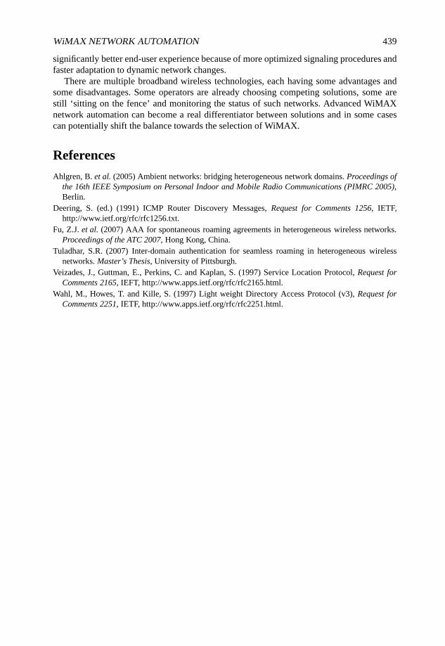
WiMAX NETWORK AUTOMATION 439
significantly better end-user experience because of more optimized signaling procedures andfaster adaptation to dynamic network changes.
There are multiple broadband wireless technologies, each having some advantages andsome disadvantages. Some operators are already choosing competing solutions, some arestill ‘sitting on the fence’ and monitoring the status of such networks. Advanced WiMAXnetwork automation can become a real differentiator between solutions and in some casescan potentially shift the balance towards the selection of WiMAX.
References
Ahlgren, B. et al. (2005) Ambient networks: bridging heterogeneous network domains. Proceedings ofthe 16th IEEE Symposium on Personal Indoor and Mobile Radio Communications (PIMRC 2005),Berlin.
Deering, S. (ed.) (1991) ICMP Router Discovery Messages, Request for Comments 1256, IETF,http://www.ietf.org/rfc/rfc1256.txt.
Fu, Z.J. et al. (2007) AAA for spontaneous roaming agreements in heterogeneous wireless networks.Proceedings of the ATC 2007, Hong Kong, China.
Tuladhar, S.R. (2007) Inter-domain authentication for seamless roaming in heterogeneous wirelessnetworks. Master’s Thesis, University of Pittsburgh.
Veizades, J., Guttman, E., Perkins, C. and Kaplan, S. (1997) Service Location Protocol, Request forComments 2165, IEFT, http://www.apps.ietf.org/rfc/rfc2165.html.
Wahl, M., Howes, T. and Kille, S. (1997) Light weight Directory Access Protocol (v3), Request forComments 2251, IETF, http://www.apps.ietf.org/rfc/rfc2251.html.
22
An Overview of Next GenerationMobile WiMAX: Technology andProspects
Sassan Ahmadi
22.1 Introduction
The growing demand for mobile Internet and wireless multimedia applications has motivatedthe development of broadband wireless access technologies in recent years. Mobile WiMAXwas the first mobile broadband wireless access solution, based on IEEE 802.16e-2005standard (IEEE, 2008d), that has enabled the convergence of mobile and fixed broadbandnetworks through a common wide-area radio access technology and flexible networkarchitecture. The mobile WiMAX air interface utilizes Orthogonal Frequency DivisionMultiple Access (OFDMA) as the preferred multiple access method in the Downlink (DL)and Uplink (UL) for improved multipath performance and bandwidth scalability.
Since January 2007, the IEEE 802.16 Working Group has embarked on the developmentof a new amendment of the IEEE 802.16 standard (i.e. IEEE 802.16m) in order to develop anadvanced air interface to meet the requirements of ITU-R/IMT-Advanced for 4G systems aswell as the next-generation mobile network operators.
Depending on the available bandwidth and antenna configuration, the next-generationmobile WiMAX will enable over-the-air data transfer rates in excess of 1 Gbps and willsupport a wide range of high-quality and high-capacity IP-based services and applicationswhile maintaining full backward compatibility with the existing mobile WiMAX systems topreserve investments and continuing support for the first-generation products.
WiMAX Evolution: Emerging Technologies and Applications Edited by Tsutomu Ishikawa© 2009 John Wiley & Sons, Ltd. ISBN: 978-0-470-69680-4
442 WiMAX EVOLUTION: EMERGING TECHNOLOGIES AND APPLICATIONS
Mobile WiMAX and its evolution are facing serious challenges from other wireless broad-band access technologies including 3GPP Long-Term Evolution (LTE), 3GPP2 Ultra-MobileBroadband (UMB) and IEEE 802.20 that are expected to offer the same functionalities.Nevertheless, there are certain distinctive features and advantages that make mobile WiMAXand its evolution more attractive and more suitable for the realization of ubiquitous mobileInternet access. In this chapter we briefly describe the salient technical features of IEEE802.16m and potentials for successful deployment of the next-generation of mobile WiMAXin 2011+.
The next-generation mobile WiMAX will build on the success of the existing WiMAXtechnology and its time-to-market advantage over other mobile broadband wireless accesstechnologies. In fact, all Orthogonal Frequency Division Multiplex (OFDM)-based mobilebroadband access technologies that have been developed lately exploit, enhance and expandfundamental concepts that were originally utilized in mobile WiMAX.
The IEEE 802.16m will be suitable for both green-field and mixed deployments withlegacy Mobile Stations (MSs) and Base Stations (BSs). The backwards-compatibility featurewill allow smooth upgrades and evolution paths for the existing deployments. It will enableroaming and seamless connectivity across IMT-Advanced and IMT-2000 systems throughthe use of appropriate interworking functions. The IEEE 802.16m systems can furtherutilize multi-hop transparent or nontransparent relay architectures for improved coverage andperformance.
The active participation of a great number of companies from several countries acrossthe globe adds more credibility to IEEE 802.16 efforts to create a worldwide radio accesstechnology to satisfy 4G system and service requirements.
It should be noted that the IEEE 802.16m standard is currently under development and thefeatures and functionalities described here are only proposals under consideration that havenot been finalized and are subject to change (IEEE, 2008a).
22.2 Summary of IEEE 802.16m System Requirements
One of the most controversial requirements of IEEE 802.16m, during the development ofits system requirement document (IEEE, 2008b), was the requirement for full backwardscompatibility and interoperability with the legacy systems. However, the network operatorhas the ability to disable legacy support (i.e. green-field deployments). The reference systemis defined as a system compliant with a subset of the IEEE 802.16e-2005 (IEEE, 2008d)features as specified by WiMAX Forum Mobile System Profile, Release 1.0 (WiMAX Forum,2007).
The following items are the backwards compatibility requirements for IEEE 802.16msystems (IEEE, 2008b).
• An IEEE 802.16m MS shall be able to operate with a legacy BS, at a level ofperformance equivalent to that of a legacy MS.
• Systems based on IEEE 802.16m and the reference system shall be able to operate onthe same Radiofrequency (RF) carrier, with the same channel bandwidth; and shouldbe able to operate on the same RF carrier with different channel bandwidths.
AN OVERVIEW OF NEXT GENERATION MOBILE WiMAX 443
• An IEEE 802.16m BS shall support a mix of IEEE 802.16m and legacy terminals whenboth are operating on the same RF carrier. The system performance with such a mixshould improve with the fraction of IEEE 802.16m terminals attached to the BS.
• An IEEE 802.16m BS shall support handover of a legacy MS to and from a legacy BSand to and from an IEEE 802.16m BS, at a level of performance equivalent to handoverbetween two legacy BSs.
• An IEEE 802.16m BS shall be able to support a legacy MS while also supporting IEEE802.16m terminals on the same RF carrier, at a level of performance equivalent to thata legacy BS provides to a legacy MS.
The consideration and implementation of the above requirements ensure a smooth migrationfrom the legacy to new systems without any significant impact on the performance of thelegacy systems as long as they exist.
The requirements for IEEE 802.16m have been selected to ensure competitiveness withthe emerging 4G radio access technologies while addressing and eliminating the perceivedshortcomings of the reference system such as extreme L2 control/signaling overhead,unreliability and insufficient coverage of control and traffic channels at the cell edge, highair-link access latency due to long transmission time interval and Hybrid Automatic RepeatRequest (HARQ) round-trip time of three radio frames, link budget deficiency in the UL, highMS power consumption due to several reasons including high UL Peak-to-Average-Power-Ratio (PAPR), frequent need to decode DL Medium Access Protocol (MAP), long scanlatency and system entry/reentry time due to inefficient initialization procedures, extremeUL L1 overhead due to use of a subchannelization scheme with high pilot density in the UL,message-based signaling mechanism with extremely large Medium Access Control (MAC)header overhead, lack of support for Frequency Division Duplex (FDD) mode (this has beenfixed in IEEE 802.16REV2 revision (IEEE, 2008d)), etc.
The IMT-Advanced requirements defined and approved by ITU-R/Working Party 5Dand published as IMT.TECH (ITU, 2008b) are referred to as target requirements in IEEE802.16m system requirement document and will be evaluated based on the methodology andguidelines specified by IMT.EVAL (ITU, 2008a). The baseline performance requirementswill be evaluated according to the IEEE 802.16m evaluation methodology document (IEEE,2008c). A careful examination of the IMT-Advanced requirements reveals that they are asubset of and less stringent than the IEEE 802.16m system requirements; therefore, the IEEE802.16m standard will qualify as an IMT-Advanced technology.
Table 22.1 summarizes the IEEE 802.16m baseline system requirements. In the followingsections we briefly discuss how these requirements can be met or exceeded. For the Voiceover IP (VoIP) capacity, a 12.2 kbps codec with a 50% speech activity factor is assumedsuch that the percentage of users in outage is less than 2% where a user is defined to haveexperienced outage if less than 98% of the VoIP packets have been delivered successfully tothe user within a one way radio access delay bound of 50 ms (IEEE, 2008b). It should benoted that the VoIP capacity is the minimum of the capacities calculated for the DL and UL.
Note that bidirectional VoIP capacity is measured in active users per megahertz per sector.The total number of active users on the DL and UL is divided by total bandwidth occupiedby the system accounting for frequency reuse. For FDD configuration, the bandwidth iscalculated as the sum of the UL and DL channel bandwidths. For a Time Division Duplex

444 WiMAX EVOLUTION: EMERGING TECHNOLOGIES AND APPLICATIONS
Tabl
e22
.1Su
mm
ary
ofIE
EE
802.
16m
base
line
syst
emre
quir
emen
ts.
Met
ric
Dow
nlin
kre
quir
emen
tU
plin
kre
quir
emen
t
Pea
ksp
ectr
alef
fici
ency
15bp
spe
rH
ertz
(4×
4M
IMO
)6.
75bp
spe
rH
ertz
(2×
4M
IMO
)O
pera
ting
band
wid
th5
to20
MH
z(u
pto
100
MH
zth
roug
hba
ndag
greg
atio
n)D
uple
xsc
hem
eT
DD
,FD
Dan
dH
-FD
Dte
rmin
als
Ant
enna
confi
gura
tion
2×
2(b
asel
ine)
,2×
4,4
×2,
4×
4,8
×8
1×
2(b
asel
ine)
,1×
4,2
×4,
4×
4D
ata
plan
ela
tenc
y<
10m
sC
ontr
olpl
ane
late
ncy
<10
0m
sH
ando
ver
inte
rrup
tion
time
27.5
ms
(int
ra-f
requ
ency
)40
ms
(int
er-f
requ
ency
with
insp
ectr
um)
60m
s(i
nter
-fre
quen
cybe
twee
nsp
ectr
um)
Ave
rage
user
thro
ughp
ut>
2×(r
efer
ence
syst
em)
>2×
(Ref
eren
ceS
yste
m)
(usi
ngba
seli
nean
tenn
aco
nfigu
rati
on)
0.26
bps
per
Her
tzpe
rse
ctor
0.13
bps
per
Her
tzpe
rse
ctor
Cel
l-ed
geus
erth
roug
hput
>2×
(ref
eren
cesy
stem
)>
2×(R
efer
ence
Sys
tem
)(u
sing
base
line
ante
nna
confi
gura
tion
)0.
09bp
spe
rH
ertz
per
sect
or0.
05bp
spe
rH
ertz
per
sect
orS
ecto
rth
roug
hput
>2×
(ref
eren
cesy
stem
)>
2×(r
efer
ence
syst
em)
(usi
ngba
seli
nean
tenn
aco
nfigu
rati
on)
2.6
bps
per
Her
tzpe
rse
ctor
1.3
bps
per
Her
tzpe
rse
ctor
VoI
Pca
paci
ty>
30ac
tive
user
spe
rm
egah
ertz
per
sect
or(u
sing
base
line
ante
nna
confi
gura
tion
)M
obil
ity
Up
to50
0km
/hw
ith
opti
mal
perf
orm
ance
upto
10km
/hC
ellr
ange
and
cove
rage
Up
to10
0km
wit
hop
tim
alpe
rfor
man
ceup
to5
kmM
ulti
cast
and
Bro
adca
stS
ervi
ce4
bps
per
Her
tzfo
rIS
D0.
5km
and
2bp
spe
rH
ertz
for
ISD
1.5
kmM
BS
chan
nelr
esel
ectio
nin
terr
uptio
ntim
e1.
0s
(int
ra-f
requ
ency
)1.
5s
(int
er-f
requ
ency
)L
ocat
ion-
Bas
edS
ervi
ceL
ocat
ion
dete
rmin
atio
nla
tenc
y<
30s
MS
-bas
edpo
sitio
nde
term
inat
ion
accu
racy<
50m
Net
wor
k-ba
sed
posi
tion
dete
rmin
atio
nac
cura
cy<
100
m
AN OVERVIEW OF NEXT GENERATION MOBILE WiMAX 445
(TDD) configuration, the bandwidth is simply the channel bandwidth. Therefore, the VoIPcapacity requirement for FDD and TDD systems is 60 and 30 active users per megahertz persector, respectively.
Minimum performance requirements for enhanced multicast and broadcast are expressedin terms of spectral efficiency over 95% coverage area. The performance requirements applyto a wide-area multi-cell multicast broadcast single frequency network.
22.3 Areas of Improvement and Extension in MobileWiMAX
Following a thorough gap analysis of the features, functionalities and performance ofmobile WiMAX technology and further study of the 4G technology prospects and servicerequirements, we identified areas of improvement and extension to be pursued in IEEE802.16m.
The following is a summary of key performance enhancement areas in IEEE 802.16m.
• Support for higher mobility.
– Support for vehicular speeds up to 350 km h−1 (and up to 500 km h−1 dependingon frequency band) is enabled through improved link adaptation and shorter linkaccess delays and faster feedback mechanisms using subframe structure as wellas faster and more reliable cell switching and handover.
• Higher spectral efficiency and peak data rates.
– Downlink and uplink peak spectral efficiencies in the excess of 15 and6.75 bps Hz−1 using 4 × 4 and 2 × 4 antenna configurations, respectively.
• Higher-order single-user and multi-user open-loop and closed-loop Multiple InputMultiple Output (MIMO) schemes with single-stream and multi-stream capability foreach user.
• Lower overhead and increased efficiency that would translate into increased applicationcapacity.
– L1 overhead reduction through the use of new physical resource blocks andresource allocation, new pilot structure, etc.
– L2 overhead reduction through new control/signaling channel design, compactsingle-user and multi-user MAC headers, etc.
• Lower latencies that would enable seamless connectivity and increased applicationperformance and quality.
– Air-link access latencies of less than 10 ms, inter-frequency and intra-frequencyhandover interruption times of 40–60 and 27.5 ms, respectively, and idle-stateto active-state transition time of less than 100 ms have been targeted for IEEE802.16m.
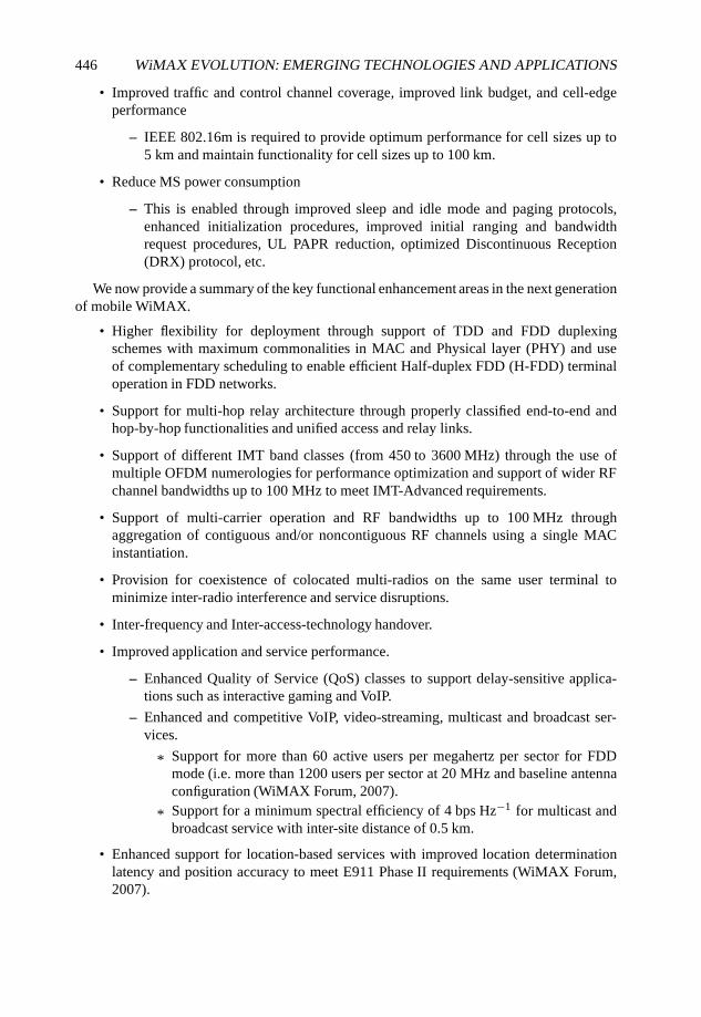
446 WiMAX EVOLUTION: EMERGING TECHNOLOGIES AND APPLICATIONS
• Improved traffic and control channel coverage, improved link budget, and cell-edgeperformance
– IEEE 802.16m is required to provide optimum performance for cell sizes up to5 km and maintain functionality for cell sizes up to 100 km.
• Reduce MS power consumption
– This is enabled through improved sleep and idle mode and paging protocols,enhanced initialization procedures, improved initial ranging and bandwidthrequest procedures, UL PAPR reduction, optimized Discontinuous Reception(DRX) protocol, etc.
We now provide a summary of the key functional enhancement areas in the next generationof mobile WiMAX.
• Higher flexibility for deployment through support of TDD and FDD duplexingschemes with maximum commonalities in MAC and Physical layer (PHY) and useof complementary scheduling to enable efficient Half-duplex FDD (H-FDD) terminaloperation in FDD networks.
• Support for multi-hop relay architecture through properly classified end-to-end andhop-by-hop functionalities and unified access and relay links.
• Support of different IMT band classes (from 450 to 3600 MHz) through the use ofmultiple OFDM numerologies for performance optimization and support of wider RFchannel bandwidths up to 100 MHz to meet IMT-Advanced requirements.
• Support of multi-carrier operation and RF bandwidths up to 100 MHz throughaggregation of contiguous and/or noncontiguous RF channels using a single MACinstantiation.
• Provision for coexistence of colocated multi-radios on the same user terminal tominimize inter-radio interference and service disruptions.
• Inter-frequency and Inter-access-technology handover.
• Improved application and service performance.
– Enhanced Quality of Service (QoS) classes to support delay-sensitive applica-tions such as interactive gaming and VoIP.
– Enhanced and competitive VoIP, video-streaming, multicast and broadcast ser-vices.
* Support for more than 60 active users per megahertz per sector for FDDmode (i.e. more than 1200 users per sector at 20 MHz and baseline antennaconfiguration (WiMAX Forum, 2007).
* Support for a minimum spectral efficiency of 4 bps Hz−1 for multicast andbroadcast service with inter-site distance of 0.5 km.
• Enhanced support for location-based services with improved location determinationlatency and position accuracy to meet E911 Phase II requirements (WiMAX Forum,2007).
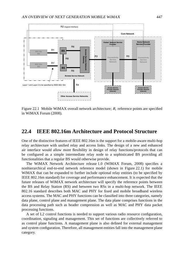
AN OVERVIEW OF NEXT GENERATION MOBILE WiMAX 447
Access Service Network
R8
R6
R1
R2 (logical interface)
Ac
ce
ss S
erv
ice N
etw
ork
Gate
way
R6
802.16e
MS
BS
BS
R1’802.16m
MS
Other Access Service Networks
R4
ConnectivityServiceNetwork
ConnectivityService
Network
R3 R5
Access Service Provider Network
(Internet)
Access Service Provider Network
(Internet)
Home Network Service Provider
Visited Network Service
Provider
Layer 1 and Layer 2 to be specified by IEEE 802.16m
Core Network
Figure 22.1 Mobile WiMAX overall network architecture; Ri reference points are specifiedin WiMAX Forum (2008).
22.4 IEEE 802.16m Architecture and Protocol Structure
One of the distinctive features of IEEE 802.16m is the support for a mobile-aware multi-hoprelay architecture with unified relay and access links. The design of a new and enhancedair interface would allow more flexibility in design of relay functions/protocols that canbe configured as a simple intermediate relay node to a sophisticated BS providing allfunctionalities that a regular BS would otherwise provide.
The WiMAX Network Architecture release 1.0 (WiMAX Forum, 2008) specifies anonhierarchical end-to-end network reference model (shown in Figure 22.1) for mobileWiMAX that can be expanded to further include optional relay entities (to be specified byIEEE 802.16m standard) for coverage and performance enhancement. It is expected that thefuture releases of WiMAX network architecture will specify the reference points betweenthe BS and Relay Station (RS) and between two RSs in a multi-hop network. The IEEE802.16 standard describes both MAC and PHY for fixed and mobile broadband wirelessaccess systems. The MAC and PHY functions can be classified into three categories, namelydata plane, control plane and management plane. The data plane comprises functions in thedata processing path such as header compression as well as MAC and PHY data packetprocessing functions.
A set of L2 control functions is needed to support various radio resource configuration,coordination, signaling and management. This set of functions are collectively referred toas control plane functions. A management plane is also defined for external managementand system configuration. Therefore, all management entities fall into the management planecategory.
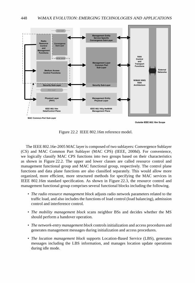
448 WiMAX EVOLUTION: EMERGING TECHNOLOGIES AND APPLICATIONS
IEEE 802.16mData/Control Plane
IEEE 802.16f/g NetMANManagement Plane
Physical Layer(PHY)
PHY SAP
Security Sub-Layer
Medium AccessControl Functions
Radio ResourceControl
andManagement
Functions
MAC SAP
Convergence
Sub-Layer
CS SAP
Security Sub-Layer
Management LayerCommon Part
Sub-Layer
Management EntityPhysical Layer
Management EntityService Specific
Convergence Sub-Layer
RANControl
and
TransportFunctions
WiMAX NWGRAN
Architecture
External
Networks
MAC Common-Part Sub-Layer
Outside IEEE 802.16m Scope
Figure 22.2 IEEE 802.16m reference model.
The IEEE 802.16e-2005 MAC layer is composed of two sublayers: Convergence Sublayer(CS) and MAC Common Part Sublayer (MAC CPS) (IEEE, 2008d). For convenience,we logically classify MAC CPS functions into two groups based on their characteristicsas shown in Figure 22.2. The upper and lower classes are called resource control andmanagement functional group and MAC functional group, respectively. The control planefunctions and data plane functions are also classified separately. This would allow moreorganized, more efficient, more structured methods for specifying the MAC services inIEEE 802.16m standard specification. As shown in Figure 22.3, the resource control andmanagement functional group comprises several functional blocks including the following.
• The radio resource management block adjusts radio network parameters related to thetraffic load, and also includes the functions of load control (load balancing), admissioncontrol and interference control.
• The mobility management block scans neighbor BSs and decides whether the MSshould perform a handover operation.
• The network-entry management block controls initialization and access procedures andgenerates management messages during initialization and access procedures.
• The location management block supports Location-Based Service (LBS), generatesmessages including the LBS information, and manages location update operationsduring idle mode.
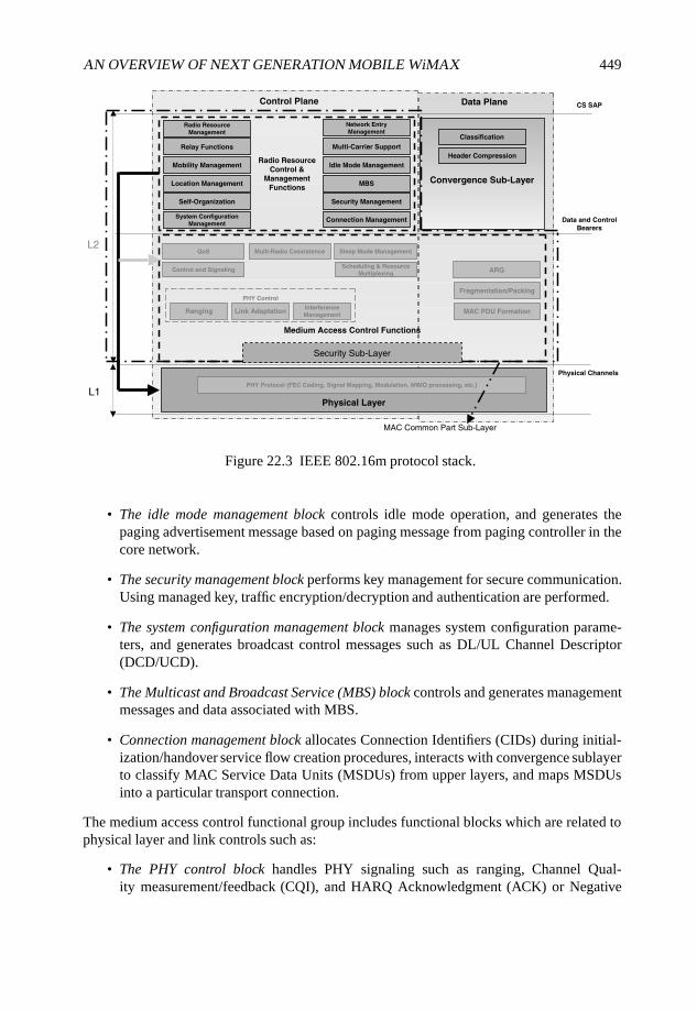
AN OVERVIEW OF NEXT GENERATION MOBILE WiMAX 449
QoS
Convergence Sub-Layer
Physical Layer
PHY Protocol (FEC Coding, Signal Mapping, Modulation, MIMO processing, etc.)
Medium Access Control Functions
MAC PDU Formation
Radio Resource
Control &
Management
Functions
L2
L1
Idle Mode Management
Relay Functions
Mobility Management
Radio Resource
Management
Network Entry
Management
Multi-Carrier Support
MBS
Data and Control
Bearers
CS SAP
Multi-Radio Coexistence
Location Management
ARQControl and Signaling
Security Sub-Layer
MAC Common Part Sub-Layer
Physical Channels
Fragmentation/Packing
Ranging
Control Plane Data Plane
Self-Organization Security Management
System Configuration
Management
Link AdaptationInterference
Management
PHY Control
Sleep Mode Management
Scheduling & Resource
Multiplexing
Classification
Header Compression
Connection Management
Figure 22.3 IEEE 802.16m protocol stack.
• The idle mode management block controls idle mode operation, and generates thepaging advertisement message based on paging message from paging controller in thecore network.
• The security management block performs key management for secure communication.Using managed key, traffic encryption/decryption and authentication are performed.
• The system configuration management block manages system configuration parame-ters, and generates broadcast control messages such as DL/UL Channel Descriptor(DCD/UCD).
• The Multicast and Broadcast Service (MBS) block controls and generates managementmessages and data associated with MBS.
• Connection management block allocates Connection Identifiers (CIDs) during initial-ization/handover service flow creation procedures, interacts with convergence sublayerto classify MAC Service Data Units (MSDUs) from upper layers, and maps MSDUsinto a particular transport connection.
The medium access control functional group includes functional blocks which are related tophysical layer and link controls such as:
• The PHY control block handles PHY signaling such as ranging, Channel Qual-ity measurement/feedback (CQI), and HARQ Acknowledgment (ACK) or Negative
450 WiMAX EVOLUTION: EMERGING TECHNOLOGIES AND APPLICATIONS
Acknowledgment (NACK) signaling. Based on CQI and HARQ ACK/NACK signals,PHY control block estimates channel environment of MS and performs link adaptationvia adjusting Modulation and Coding Scheme (MCS) or power level.
• The control signaling block generates resource allocation messages such as DL/ULMAP as well as specific control signaling messages, and other signaling messagesnot in the form of general MAC messages, for example, a DL Frame Control Header(FCH).
• The sleep mode management block handles sleep mode operation and generatesmanagement messages related to sleep operation, and may communicate with thescheduler block in order to operate properly according to the sleep period.
• The QoS block performs rate control based on QoS input parameters from connectionmanagement function for each connection. The scheduler operates based on the inputfrom the QoS block in order to satisfy QoS requirements.
• The scheduling and resource and multiplexing block schedules and multiplexes packetsbased on the properties of connections. In order to reflect the properties of connections,the scheduling and resource and multiplexing block receives QoS information fromQoS block for each connection.
• The Automatic Repeat Request (ARQ) block performs MAC ARQ function. For ARQ-enabled connections, the ARQ block logically splits MSDUs and sequences logicalARQ blocks. The ARQ block may also generate ARQ management messages such asa feedback message (ACK/NACK information).
• The fragmentation/packing block performs fragmentation or packing of MSDUs basedon input from the scheduler block.
• The MAC Protocol Data Unit (PDU) formation block constructs MAC PDUs sothat BSs/MSs can transmit user traffic or management messages into PHY channels.MAC PDU formation block may add subheaders or extended subheaders. MAC PDUformation block may also add MAC Cyclic Redundancy Checks (CRCs) if necessary,and add a generic MAC header.
IEEE 802.16m protocol structure is expected to be similar to that of IEEE 802.16e-2005with some additional functional blocks for newly proposed features. In the proposed protocolstructure for IEEE 802.16m, the following additional functional blocks are included.
• Routing (relay) functions to enable relay functionalities and packet routing.
• Self-organization and self-optimization functions to enable home BS for femtocells andplug-and-play form of operation for indoor BS.
• Multi-carrier functions to enable control and operation of a number of adjacentor nonadjacent RF carriers (virtual wideband operation) where the RF carriers canbe assigned to unicast and/or multicast and broadcast services. A single MACinstantiation will be used to control several physical layers. The mobile terminal is
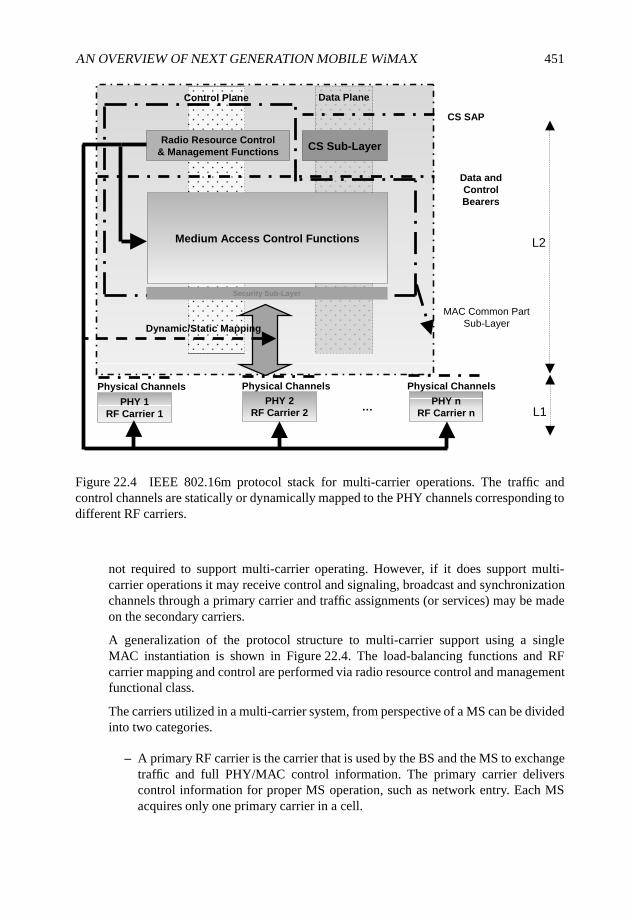
AN OVERVIEW OF NEXT GENERATION MOBILE WiMAX 451
Data PlaneControl Plane
Radio Resource Control& Management Functions CS Sub-Layer
Medium Access Control Functions
PHY 1RF Carrier 1
PHY 2RF Carrier 2
PHY nRF Carrier n
CS SAP
Data and ControlBearers
Physical Channels Physical Channels
…
Physical Channels
L2
L1
MAC Common Part Sub-Layer
Security Sub-Layer
Dynamic/Static Mapping
Figure 22.4 IEEE 802.16m protocol stack for multi-carrier operations. The traffic andcontrol channels are statically or dynamically mapped to the PHY channels corresponding todifferent RF carriers.
not required to support multi-carrier operating. However, if it does support multi-carrier operations it may receive control and signaling, broadcast and synchronizationchannels through a primary carrier and traffic assignments (or services) may be madeon the secondary carriers.
A generalization of the protocol structure to multi-carrier support using a singleMAC instantiation is shown in Figure 22.4. The load-balancing functions and RFcarrier mapping and control are performed via radio resource control and managementfunctional class.
The carriers utilized in a multi-carrier system, from perspective of a MS can be dividedinto two categories.
– A primary RF carrier is the carrier that is used by the BS and the MS to exchangetraffic and full PHY/MAC control information. The primary carrier deliverscontrol information for proper MS operation, such as network entry. Each MSacquires only one primary carrier in a cell.
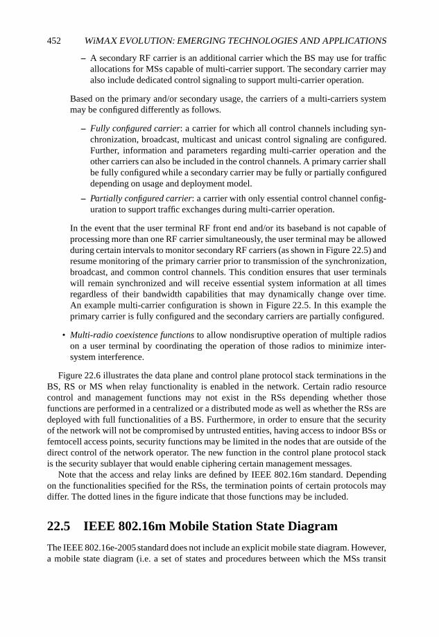
452 WiMAX EVOLUTION: EMERGING TECHNOLOGIES AND APPLICATIONS
– A secondary RF carrier is an additional carrier which the BS may use for trafficallocations for MSs capable of multi-carrier support. The secondary carrier mayalso include dedicated control signaling to support multi-carrier operation.
Based on the primary and/or secondary usage, the carriers of a multi-carriers systemmay be configured differently as follows.
– Fully configured carrier: a carrier for which all control channels including syn-chronization, broadcast, multicast and unicast control signaling are configured.Further, information and parameters regarding multi-carrier operation and theother carriers can also be included in the control channels. A primary carrier shallbe fully configured while a secondary carrier may be fully or partially configureddepending on usage and deployment model.
– Partially configured carrier: a carrier with only essential control channel config-uration to support traffic exchanges during multi-carrier operation.
In the event that the user terminal RF front end and/or its baseband is not capable ofprocessing more than one RF carrier simultaneously, the user terminal may be allowedduring certain intervals to monitor secondary RF carriers (as shown in Figure 22.5) andresume monitoring of the primary carrier prior to transmission of the synchronization,broadcast, and common control channels. This condition ensures that user terminalswill remain synchronized and will receive essential system information at all timesregardless of their bandwidth capabilities that may dynamically change over time.An example multi-carrier configuration is shown in Figure 22.5. In this example theprimary carrier is fully configured and the secondary carriers are partially configured.
• Multi-radio coexistence functions to allow nondisruptive operation of multiple radioson a user terminal by coordinating the operation of those radios to minimize inter-system interference.
Figure 22.6 illustrates the data plane and control plane protocol stack terminations in theBS, RS or MS when relay functionality is enabled in the network. Certain radio resourcecontrol and management functions may not exist in the RSs depending whether thosefunctions are performed in a centralized or a distributed mode as well as whether the RSs aredeployed with full functionalities of a BS. Furthermore, in order to ensure that the securityof the network will not be compromised by untrusted entities, having access to indoor BSs orfemtocell access points, security functions may be limited in the nodes that are outside of thedirect control of the network operator. The new function in the control plane protocol stackis the security sublayer that would enable ciphering certain management messages.
Note that the access and relay links are defined by IEEE 802.16m standard. Dependingon the functionalities specified for the RSs, the termination points of certain protocols maydiffer. The dotted lines in the figure indicate that those functions may be included.
22.5 IEEE 802.16m Mobile Station State Diagram
The IEEE 802.16e-2005 standard does not include an explicit mobile state diagram. However,a mobile state diagram (i.e. a set of states and procedures between which the MSs transit
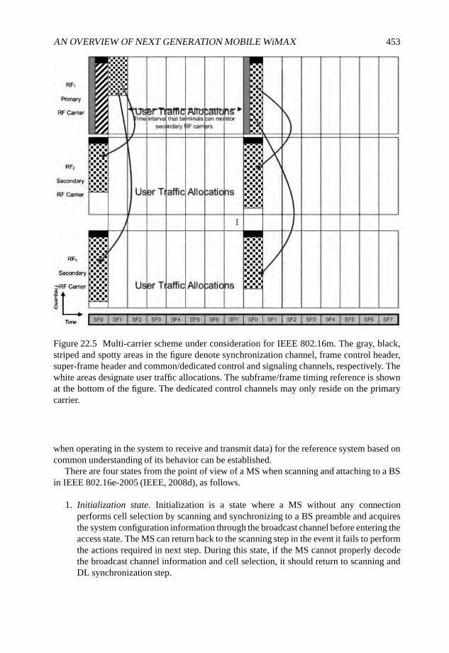
AN OVERVIEW OF NEXT GENERATION MOBILE WiMAX 453
Figure 22.5 Multi-carrier scheme under consideration for IEEE 802.16m. The gray, black,striped and spotty areas in the figure denote synchronization channel, frame control header,super-frame header and common/dedicated control and signaling channels, respectively. Thewhite areas designate user traffic allocations. The subframe/frame timing reference is shownat the bottom of the figure. The dedicated control channels may only reside on the primarycarrier.
when operating in the system to receive and transmit data) for the reference system based oncommon understanding of its behavior can be established.
There are four states from the point of view of a MS when scanning and attaching to a BSin IEEE 802.16e-2005 (IEEE, 2008d), as follows.
1. Initialization state. Initialization is a state where a MS without any connectionperforms cell selection by scanning and synchronizing to a BS preamble and acquiresthe system configuration information through the broadcast channel before entering theaccess state. The MS can return back to the scanning step in the event it fails to performthe actions required in next step. During this state, if the MS cannot properly decodethe broadcast channel information and cell selection, it should return to scanning andDL synchronization step.
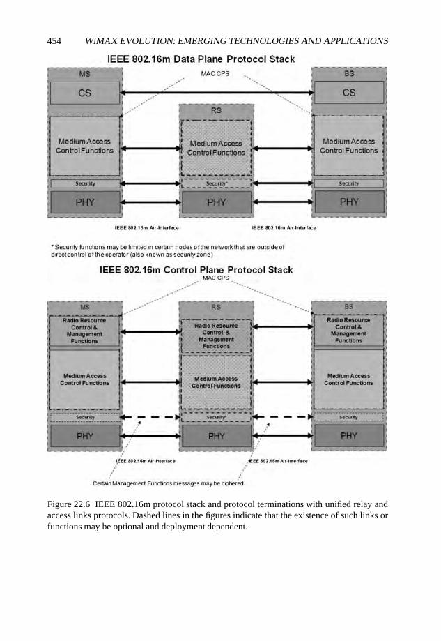
454 WiMAX EVOLUTION: EMERGING TECHNOLOGIES AND APPLICATIONS
Figure 22.6 IEEE 802.16m protocol stack and protocol terminations with unified relay andaccess links protocols. Dashed lines in the figures indicate that the existence of such links orfunctions may be optional and deployment dependent.
AN OVERVIEW OF NEXT GENERATION MOBILE WiMAX 455
2. Access state. Access is a state where the MS performs network entry to the selected BS.The MS performs the initial ranging process (initial ranging code and RNG-REQ/RSPMAC message is used in the reference system) in order to obtain UL synchronization.Then the MS performs basic capability negotiation with the BS (SBC-REQ/RSP MACmessage is used in the reference system). The MS later performs the authentication andauthorization process. Next, the MS performs the registration process (REG-REQ/RSPMAC message is used in the reference system). The MS receives the 802.16m specificuser identification as part of access state procedures. The IP address assignment mayfollow using appropriate procedures.
3. Connected state: The connected state consists of the following modes: (1) sleep mode,(2) active mode and (3) scanning mode. During the connected state, the MS maintainsat least one connection as established during the access state, while the MS and BSmay establish additional transport connections. In addition, in order to reduce powerconsumption of the MS, the MS or BS can request a transition to sleep mode. Also, theMS can scan neighbor BSs to reselect a cell which provides more robust and reliableservices.
• Active mode: where the MS and BS perform normal operations to exchange theDL or UL traffic. The MS can perform the fast network reentry procedures afterhandover. While in handover, the MS maintains any 802.16m specific user IDsrequired for handover and its IP address in accordance with upper layer protocols.Without going through access state, the MS may remain in connected state withthe target BS.
• Sleep mode: where the MS may enable power-saving techniques. The MS inactive mode transitions to sleep mode through sleep mode MAC signalingmanagement messages (MOB_SLP-REQ/RSP message is used in the referencesystem). The MS does not transmit and receive any traffic to/from its serving BSduring the sleep interval. A MS can receive an indication message (MOB_TRF-IND message is used in the reference system) during listening interval and thenbased on the message content to decide whether it should transit to active modeor continue to stay in sleep mode. During the sleep interval, the MS may chooseto transit to active mode.
• Scanning mode: where the MS performs scanning operation and may temporarilybe unavailable to the BS. While in active mode, the MS transitions to scanningmode via explicit MAC signaling (MOB_SCN-REQ/RSP message is used inthe Reference System) or implicitly without scanning management messagesgeneration. In scanning intervals, the MS is unavailable to the serving BS.
4. Idle state: The idle state consists of two separate modes, paging available mode andpaging unavailable mode. During the idle state, the MS may attempt power saving byswitching between paging available mode and paging unavailable mode. In the pagingavailable mode, the MS may be paged by the BS (MOB_PAG-ADV message is usedin the reference system). If the MS is paged, it shall transition to the access state forits network reentry. The MS may perform location update procedure during idle state.In the paging unavailable mode, the MS does not need to monitor the DL channel in
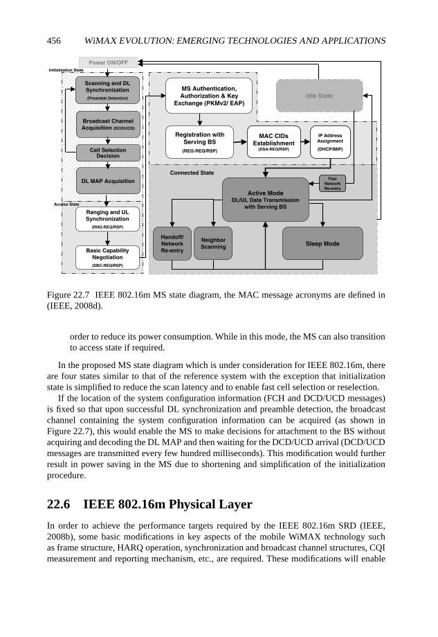
456 WiMAX EVOLUTION: EMERGING TECHNOLOGIES AND APPLICATIONS
Scanning and DL
Synchronization
(Preamble Detection)
Ranging and UL
Synchronization
(RNG-REQ/RSP)
Basic Capability
Negotiation
(SBC-REQ/RSP)
Registration with
Serving BS
(REG-REQ/RSP)
MS Authentication,
Authorization & Key
Exchange (PKMv2/ EAP)
Sleep ModeNeighbor
Scanning
Active ModeDL/UL Data Transmission
with Serving BS
Idle State
Power ON/OFF
Connected State
Handoff/
Network
Re-entry
IP Address Assignment
(DHCP/MIP)
MAC CIDs
Establishment(DSA-REQ/RSP)
Fast
Network
Re-entry
Initialization State
Access State
Broadcast Channel
Acquisition (DCD/UCD)
DL MAP Acquisition
Cell Selection Decision
Figure 22.7 IEEE 802.16m MS state diagram, the MAC message acronyms are defined in(IEEE, 2008d).
order to reduce its power consumption. While in this mode, the MS can also transitionto access state if required.
In the proposed MS state diagram which is under consideration for IEEE 802.16m, thereare four states similar to that of the reference system with the exception that initializationstate is simplified to reduce the scan latency and to enable fast cell selection or reselection.
If the location of the system configuration information (FCH and DCD/UCD messages)is fixed so that upon successful DL synchronization and preamble detection, the broadcastchannel containing the system configuration information can be acquired (as shown inFigure 22.7), this would enable the MS to make decisions for attachment to the BS withoutacquiring and decoding the DL MAP and then waiting for the DCD/UCD arrival (DCD/UCDmessages are transmitted every few hundred milliseconds). This modification would furtherresult in power saving in the MS due to shortening and simplification of the initializationprocedure.
22.6 IEEE 802.16m Physical Layer
In order to achieve the performance targets required by the IEEE 802.16m SRD (IEEE,2008b), some basic modifications in key aspects of the mobile WiMAX technology suchas frame structure, HARQ operation, synchronization and broadcast channel structures, CQImeasurement and reporting mechanism, etc., are required. These modifications will enable
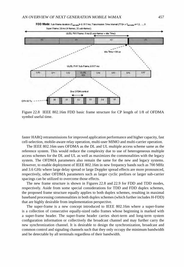
AN OVERVIEW OF NEXT GENERATION MOBILE WiMAX 457
Figure 22.8 IEEE 802.16m FDD basic frame structure for CP length of 1/8 of OFDMAsymbol useful time.
faster HARQ retransmissions for improved application performance and higher capacity, fastcell-selection, mobile-aware relay operation, multi-user MIMO and multi-carrier operation.
The IEEE 802.16m uses OFDMA as the DL and UL multiple access scheme same as thereference system. This would reduce the complexity due to use of heterogeneous multipleaccess schemes for the DL and UL as well as maximizes the commonalities with the legacysystem. The OFDMA parameters also remain the same for the new and legacy systems.However, to enable deployment of IEEE 802.16m in new frequency bands such as 700 MHzand 3.6 GHz where large delay spread or large Doppler spread effects are more pronounced,respectively, other OFDMA parameters such as larger cyclic prefixes or larger sub-carrierspacings can be utilized to overcome those effects.
The new frame structure is shown in Figures 22.8 and 22.9 for FDD and TDD modes,respectively. Aside from some special considerations for TDD and FDD duplex schemes,the proposed frame structure equally applies to both duplex schemes, resulting in maximalbaseband processing commonalities in both duplex schemes (which further includes H-FDD)that are highly desirable from implementation perspective.
The super-frame is a new concept introduced to IEEE 802.16m where a super-frameis a collection of consecutive equally-sized radio frames whose beginning is marked witha super-frame header. The super-frame header carries short-term and long-term systemconfiguration information or collectively the broadcast channel and may further carry thenew synchronization channel. It is desirable to design the synchronization, broadcast andcommon control and signaling channels such that they only occupy the minimum bandwidthand be detectable by all terminals regardless of their bandwidth.
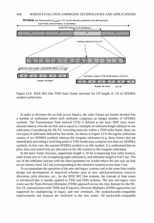
458 WiMAX EVOLUTION: EMERGING TECHNOLOGIES AND APPLICATIONS
Figure 22.9 IEEE 802.16m TDD basic frame structure for CP length of 1/8 of OFDMAsymbol useful time.
In order to decrease the air-link access latency, the radio frames are further divided intoa number of subframes where each subframe comprises an integer number of OFDMAsymbols. The Transmission Time Interval (TTI) is defined as the basic PHY layer trans-mission latency over the air-link and is equal to a multiple of subframe length (default of onesubframe). Considering the DL/UL switching intervals within a TDD radio frame, there aretwo types of subframes defined for this mode. As shown in Figure 22.9, the regular subframesconsist of six OFDMA symbols whereas the irregular subframes (e.g. those frames that areimmediately preceding a switching point in TDD mode) may comprise less than six OFDMAsymbols. In that case, the unused OFDMA symbol is an idle symbol. It is understood that nopilot, data and control bits are allocated on the idle symbol in the irregular subframes.
In the basic frame structure, superframe length is 20 ms (comprising four radio frames),radio frame size is 5 ms (comprising eight subframes), and subframe length is 0.617 ms. Theuse of the subframe concept with the latter parameter set would reduce the one-way air-linkaccess latency from 18.5 ms (corresponding to the reference system) to less than 5 ms.
To accommodate the operation of the new and legacy systems and at the same time enabledesign and development of improved schemes such as new subchannelization, resourceallocation, pilot structure, etc., for the IEEE 802.16m systems, the concept of time zonesis introduced that is equally applied to TDD and FDD systems. The new and legacy timezones use the Time-Division Multiplex (TDM) approach across the time domain for the DL.For UL transmissions both TDM and Frequency-Division Multiplex (FDM) approaches aresupported for multiplexing of legacy and new terminals. The nonbackwards-compatibleimprovements and features are restricted to the new zones. All backwards-compatible
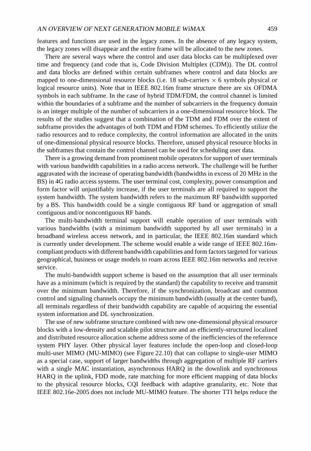
AN OVERVIEW OF NEXT GENERATION MOBILE WiMAX 459
features and functions are used in the legacy zones. In the absence of any legacy system,the legacy zones will disappear and the entire frame will be allocated to the new zones.
There are several ways where the control and user data blocks can be multiplexed overtime and frequency (and code that is, Code Division Multiplex (CDM)). The DL controland data blocks are defined within certain subframes where control and data blocks aremapped to one-dimensional resource blocks (i.e. 18 sub-carriers × 6 symbols physical orlogical resource units). Note that in IEEE 802.16m frame structure there are six OFDMAsymbols in each subframe. In the case of hybrid TDM/FDM, the control channel is limitedwithin the boundaries of a subframe and the number of subcarriers in the frequency domainis an integer multiple of the number of subcarriers in a one-dimensional resource block. Theresults of the studies suggest that a combination of the TDM and FDM over the extent ofsubframe provides the advantages of both TDM and FDM schemes. To efficiently utilize theradio resources and to reduce complexity, the control information are allocated in the unitsof one-dimensional physical resource blocks. Therefore, unused physical resource blocks inthe subframes that contain the control channel can be used for scheduling user data.
There is a growing demand from prominent mobile operators for support of user terminalswith various bandwidth capabilities in a radio access network. The challenge will be furtheraggravated with the increase of operating bandwidth (bandwidths in excess of 20 MHz in theBS) in 4G radio access systems. The user terminal cost, complexity, power consumption andform factor will unjustifiably increase, if the user terminals are all required to support thesystem bandwidth. The system bandwidth refers to the maximum RF bandwidth supportedby a BS. This bandwidth could be a single contiguous RF band or aggregation of smallcontiguous and/or noncontiguous RF bands.
The multi-bandwidth terminal support will enable operation of user terminals withvarious bandwidths (with a minimum bandwidth supported by all user terminals) in abroadband wireless access network, and in particular, the IEEE 802.16m standard whichis currently under development. The scheme would enable a wide range of IEEE 802.16m-compliant products with different bandwidth capabilities and form factors targeted for variousgeographical, business or usage models to roam across IEEE 802.16m networks and receiveservice.
The multi-bandwidth support scheme is based on the assumption that all user terminalshave as a minimum (which is required by the standard) the capability to receive and transmitover the minimum bandwidth. Therefore, if the synchronization, broadcast and commoncontrol and signaling channels occupy the minimum bandwidth (usually at the center band),all terminals regardless of their bandwidth capability are capable of acquiring the essentialsystem information and DL synchronization.
The use of new subframe structure combined with new one-dimensional physical resourceblocks with a low-density and scalable pilot structure and an efficiently-structured localizedand distributed resource allocation scheme address some of the inefficiencies of the referencesystem PHY layer. Other physical layer features include the open-loop and closed-loopmulti-user MIMO (MU-MIMO) (see Figure 22.10) that can collapse to single-user MIMOas a special case, support of larger bandwidths through aggregation of multiple RF carrierswith a single MAC instantiation, asynchronous HARQ in the downlink and synchronousHARQ in the uplink, FDD mode, rate matching for more efficient mapping of data blocksto the physical resource blocks, CQI feedback with adaptive granularity, etc. Note thatIEEE 802.16e-2005 does not include MU-MIMO feature. The shorter TTI helps reduce the
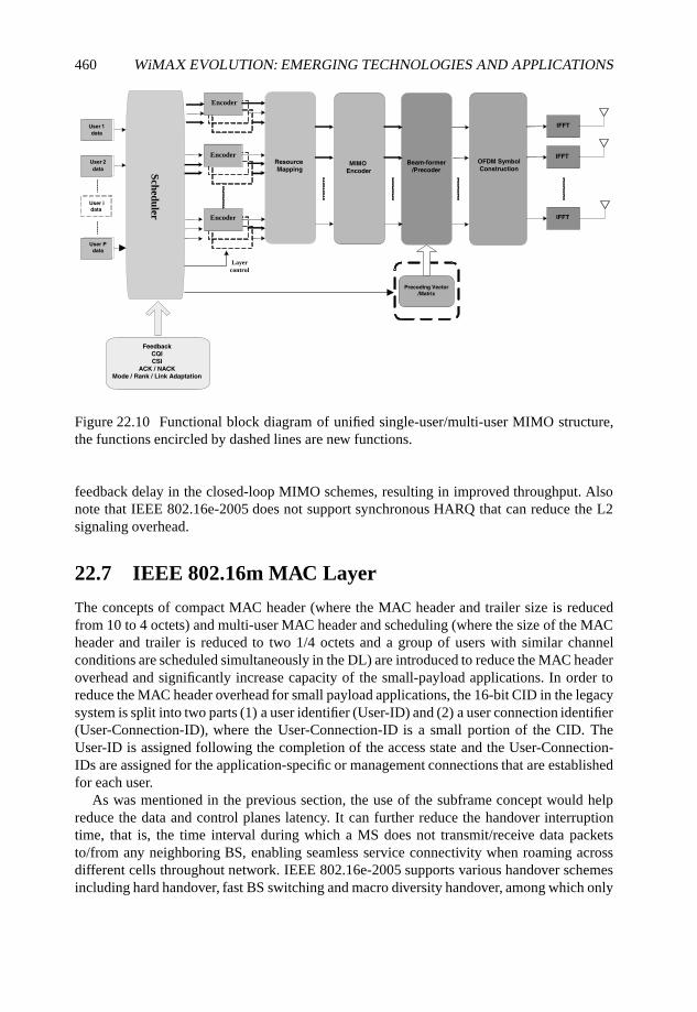
460 WiMAX EVOLUTION: EMERGING TECHNOLOGIES AND APPLICATIONS
User 1
data
User 2
data
User P
data
User idata
MIMO
Encoder
Beam-former
/Precoder
IFFT
OFDM Symbol
Construction
IFFT
IFFT
Precoding Vector
/Matrix
EncoderEncoder
EncoderEncoder
EncoderEncoder
Layercontrol
Scheduler
Resource Mapping
FeedbackCQI
CSI
ACK / NACKMode / Rank / Link Adaptation
Figure 22.10 Functional block diagram of unified single-user/multi-user MIMO structure,the functions encircled by dashed lines are new functions.
feedback delay in the closed-loop MIMO schemes, resulting in improved throughput. Alsonote that IEEE 802.16e-2005 does not support synchronous HARQ that can reduce the L2signaling overhead.
22.7 IEEE 802.16m MAC Layer
The concepts of compact MAC header (where the MAC header and trailer size is reducedfrom 10 to 4 octets) and multi-user MAC header and scheduling (where the size of the MACheader and trailer is reduced to two 1/4 octets and a group of users with similar channelconditions are scheduled simultaneously in the DL) are introduced to reduce the MAC headeroverhead and significantly increase capacity of the small-payload applications. In order toreduce the MAC header overhead for small payload applications, the 16-bit CID in the legacysystem is split into two parts (1) a user identifier (User-ID) and (2) a user connection identifier(User-Connection-ID), where the User-Connection-ID is a small portion of the CID. TheUser-ID is assigned following the completion of the access state and the User-Connection-IDs are assigned for the application-specific or management connections that are establishedfor each user.
As was mentioned in the previous section, the use of the subframe concept would helpreduce the data and control planes latency. It can further reduce the handover interruptiontime, that is, the time interval during which a MS does not transmit/receive data packetsto/from any neighboring BS, enabling seamless service connectivity when roaming acrossdifferent cells throughout network. IEEE 802.16e-2005 supports various handover schemesincluding hard handover, fast BS switching and macro diversity handover, among which only
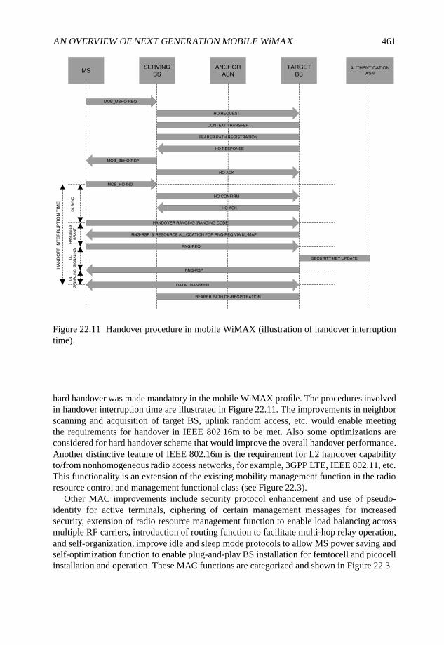
AN OVERVIEW OF NEXT GENERATION MOBILE WiMAX 461
MSSERVING
BS
ANCHOR
ASN
TARGET
BSAUTHENTICATION
ASN
MOB_MSHO-REQ
HO REQUEST
HO RESPONSE
CONTEXT TRANSFER
BEARER PATH REGISTRATION
MOB_BSHO-RSP
MOB_HO-IND
HO ACK
HO CONFIRM
HO ACK
HANDOVER RANGING (RANGING CODE)
RNG-RSP & RESOURCE ALLOCATION FOR RNG-REQ VIA UL-MAP
RNG-REQ
RNG-RSP
SECURITY KEY UPDATE
DATA TRANSFER
BEARER PATH DE-REGISTRATION
HA
ND
OF
F I
NT
ER
RU
PT
ION
TIM
E
DL S
YN
CR
AN
GIN
G &
GR
AN
TU
LS
IGN
ALIN
GD
LS
IGN
ALIN
G
Figure 22.11 Handover procedure in mobile WiMAX (illustration of handover interruptiontime).
hard handover was made mandatory in the mobile WiMAX profile. The procedures involvedin handover interruption time are illustrated in Figure 22.11. The improvements in neighborscanning and acquisition of target BS, uplink random access, etc. would enable meetingthe requirements for handover in IEEE 802.16m to be met. Also some optimizations areconsidered for hard handover scheme that would improve the overall handover performance.Another distinctive feature of IEEE 802.16m is the requirement for L2 handover capabilityto/from nonhomogeneous radio access networks, for example, 3GPP LTE, IEEE 802.11, etc.This functionality is an extension of the existing mobility management function in the radioresource control and management functional class (see Figure 22.3).
Other MAC improvements include security protocol enhancement and use of pseudo-identity for active terminals, ciphering of certain management messages for increasedsecurity, extension of radio resource management function to enable load balancing acrossmultiple RF carriers, introduction of routing function to facilitate multi-hop relay operation,and self-organization, improve idle and sleep mode protocols to allow MS power saving andself-optimization function to enable plug-and-play BS installation for femtocell and picocellinstallation and operation. These MAC functions are categorized and shown in Figure 22.3.
462 WiMAX EVOLUTION: EMERGING TECHNOLOGIES AND APPLICATIONS
22.8 Conclusions
The IEEE 802.16m standard will build on the success of mobile WiMAX to provide the state-of-the-art broadband wireless access in the next decade and to satisfy the growing demandfor advanced wireless multimedia applications and services. The standardization of IEEE802.16m and release 2.0 of mobile WiMAX profile are expected to complete by the end of2010.
Multi-hop relay architecture, self-configuration, advanced single-user/multi-user multi-antenna schemes and interference mitigation techniques, enhanced multicast broadcastservice, increased VoIP capacity, improved cell-edge user throughput, support of vehicularspeeds up to 500 km h−1, etc. are among the most prominent features that would make IEEE802.16m one of the most successful and advanced broadband wireless access systems in thenext decade.
References
IEEE (2008a) IEEE 802.16m System Description Document, 80216m-08-003r4.IEEE (2008b) IEEE 802.16m System Requirements Document, IEEE 802.16m-07/002r5.IEEE (2008c) IEEE 802.16m Evaluation Methodology Document, IEEE 802.16m-08/004r2.IEEE (2008d) PART 16: Air Interface For Broadband Wireless Access Systems, P802.16Rev2/D6,
Revision of IEEE Std 802.16-2004 and consolidates material from IEEE Std 802.16e-2005,IEEEStd 802.16-2004/Cor1-2005,IEEE Std 802.16f-2005 and IEEE Std802.16g-2007.
ITU (2008a) Guidelines for evaluation of radio interface technologies for IMT-Advanced [IMT.EVAL].Draft New Report ITU-R M.[IMT.EVAL]
ITU (2008b) Requirements related to technical system performance for IMT-Advanced radiointerface(s) [IMT.TECH]. Draft new Report ITU-R M.[IMT.TECH]
WiMAX Forum (2007) WiMAX Forum Mobile System Profile, Release 1.0 Approved Specification.WiMAX Forum (2008) WiMAX Forum Network Architecture Stage 2–3: Release 1, Version 1.2.
Index
3G, 624G, 48
Absolute Continuous Rating (ACR), 230Access Service Network (ASN), 88, 188, 210,
215, 266, 281, 425Access Service Network Gateway
(ASN-GW), 165, 267, 425Adaptive Modulation and Coding (AMC), 134Adaptive Power Distribution (APD), 339Additive White Gaussian Noise (AWGN), 244Admission Control (AC), 228, 238, 279
Measurement Based Admission Control(MBAC), 228
speech quality aware, 237advantage factor, 233Application Programming Interface (API),
165application session
conversation flow, 268asymptotic throughput scaling laws, 328Asynchronous Transfer Mode (ATM), 133authentication domain, 173Authentication, Authorization and Accounting
(AAA), 138, 173, 203, 210Automatic Repeat Request (ARQ), 118availability, 163
Base Station (BS), 168, 266, 425backhaul, 394cluster, 178
beamforming, 415post-FFT, 374pre-FFT, 373
Best Effort (BE), 204, 281, 283Border Gateway Protocol (BGP), 166, 274,
430Broadband Wireless Access (BWA), 133broadcast address, 426
capabilities exchange, 433capacity limited deployment, 406Capital Expenditure (CAPEX), 69–71, 182Care-of-Address (CoA), 275carrier-grade, 163
Linux (CGL), 164Cellular-Controlled Peer-to-Peer (CCP2P),
106centralized scheduling, 147channel model, 369
3GPP/3GPP2, 369analytical, 371COST 259/273, 369SUI, 370WINNER, 370
Cipher Block Chaining (CBC), 138Client Mobile IP (CMIP), 173, 434coding
cost, 155gain, 154management module, 155
cognitive radios, 416commercial off-the-shelf (COTS), 51Common Part Sublayer (CPS), 201, 202compact MAC header, 460Connection Identifier (CID), 201, 204Connectivity Services Network (CSN), 210,
266anchored mobility, 276
context identifier (CID), 187control plane, 447control plane IP address, 427Control Service Access Point (C-SAP), 203,
205–207Convergence Sublayer (CS), 155, 201–203cooperative networks, 416cooperative principles, 105coordinated beamforming, 320
WiMAX Evolution: Emerging Technologies and Applications Edited by Tsutomu Ishikawa© 2009 John Wiley & Sons, Ltd. ISBN: 978-0-470-69680-4
464 INDEX
correlation, 377coverage database, 404Customer Premises Equipment (CPE), 94, 215
Data Encryption Standard (DES), 138Data Path Function (DPF), 168data plane, 447Deficit Weighted Round Robin (D(W)RR),
283degree of freedom, 154demand level, 147demand persistence, 147Digital Subscriber Line (DSL), 48, 51, 52, 62Digital Subscriber Line Access Multiplexer
(DSLAM), 51direct modulation, 388distributed antenna systems, 395Distributed Feedback (DFB) diode laser, 389distributed scheduling, 147Domain Name System (DNS), 210drive test, 410Dynamic Host Configuration Protocol
(DHCP), 173, 210Dynamic Service Addition (DSA), 217
Earliest Deadline First (EDF) scheduler, 245Encapsulating Security Payload (ESP), 187Energy-per-Bit Ratio (EpBR), 106Equal Cost Multi-Path (ECMP), 268Ethernet, 133Ethernet Convergence Sublayer (Ethernet
CS), 272Ethernet Link Aggregation (LAG), 268Extended Real-Time Polling Service (ertPS),
204, 252, 281, 283Extensible Authentication Protocol (EAP), 9,
138, 438external modulation, 388
Fabry–Perot diode lasers, 389failure detection time, 170Fast Base Station Switching (FBSS), 206femtocell, 87, 185, 415
definition of, 87downlink, 97handover, 95remote configuration, 94synchronization of, 91
field trials, 396File Transfer Protocol (FTP), 204fixed WiMAX, 18, 20
flexible frequency reuse, 7Foreign Agent (FA), 269, 433Forward Error Correction (FEC), 118, 232forwarding cost, 154frame design, 413frequency planning, 409, 413
General Internet Signaling Transport (GIST),205
General Packet Radio Service (GPRS), 62, 65Generic Routing Encapsulation (GRE), 167,
269Geographic Information Systems (GIS), 63Global System for Mobile Communications
(GSM), 62, 65goodput, 25graceful restart, 170group scheduling, 260
H.264/AVC, 35Handover (HO), 173, 281, 290
based load balancing, 279, 287dynamic tuning, 295multiple threshold, 297resource reservation based, 302
prioritization, 279, 299differentiated, 300
hangover times, 232Hard Handover (HHO), 206Hardware (HW), 165Hello transaction, 428heterogeneous networks, 437High Availability (HA), 163Home Agent (HA), 267, 425Hybrid Fiber Radio (HFR), 386
idle mode, 9IEEE
802.11a/b/g/h, 131802.15.4/ZigBee, 131802.16, 401802.16 MeSH mode, 147802.16 REV2, 10802.16j, 112802.16m, 12, 441
requirements, 11impairment factor
delayed, 233equipment, 233simultaneous, 233
IMT-Advanced, 441

INDEX 465
in-service version renegotiation, 436Instrumental Quality (IQ) assessment, 229integral quality by time averaging, 237interference cancellation, 415Internal Rate of Return (IRR), 71International Telecommunications Union
(ITU), 56Internet Control Message Protocol (ICMP),
427Internet Protocol (IP), 201, 205, 206
forwarding, 267Multimedia Subsystem (IMS), 213Security (IPSec), 167, 270version 4–6, 133
Internet Protocol Television (IPTV), 35, 215Interworking Function (IWF), 139IP-in-IP, 269IPv6, 274
interface identifier, 432
‘keepalive’ messages, 169Key Performance Indicator (KPI), 411
lattice reduction algorithm, 315Lightweight Directory Access Protocol
(LDAP), 429limited feedback, 322Line-of-Sight (LOS), 48, 50, 61, 63, 132linguistic structure of speech, 231Link Adaptation (LA), 336
hybrid, 356overheads, 354
Link Aggregation Control Protocol (LACP),268
load balancing, 172, 265Local Area Network (LAN), 47local breakout, 265loss burst, 235loss gap, 235
Macro Diversity Handover (MDHO), 206Make Before Break (MBB), 212Management Information Base (MIB), 214management plane, 447Management Service Access Point (M-SAP),
203maximize profit, 78Maximum Ratio Combining (MRC), 113MaxSNR scheduler, 245Mean Time Between Failures (MTBF), 164
Measurement Based Admission Control(MBAC), 239
Media Independent Command Service(MICS), 208, 209
Media Independent Event Service (MIES),208
Media Independent Handover (MIH), 200,203, 208, 209
Media Independent Handover Function(MIHF), 208, 209
Media Independent Handover User (MIHU),208, 209, 214
Media Independent Information Service(MIIS), 208, 209
Medium Access Control (MAC), 53,200–206, 208
Common Part Sublayer (CPS), 155Mesh Base Station (MBS), 147mesh networks, 415Metropolitan Area Network (MAN), 47microwave photonics, 385middleware, 165minislots, 147Mobile Initiated Handover (MIHO), 206, 207Mobile IP (MIP), 173, 208, 214, 433Mobile IPv4 (MIPv4), 269Mobile Multihop Relay (MMR), 53, 54, 56,
112mobile station state diagram, 452Mobile Subscriber (MS), 168mobile WiMAX, 36
Release 1.0 Profile, 4Release 1.5, 10Release 2.0, 12roadmap, 10
Mobility Management (MM), 207Modulation and Coding Scheme (MCS), 136modulo operation, 316MSH-DSCH, 151multi-carrier, 450multi-hop relay, 446multi-instance, 180Multi-Mode Fiber (MMF), 390multi-radio coexistence, 452multi-user MAC header, 460multicast address, 426Multicast and Broadcast Services (MBSs), 9multicast reservation, 151Multiple Input Multiple Output (MIMO)
algorithms, 372
466 INDEX
multiuser diversity, 325
neighborhood domain, 429net neutrality, 227Net Present Value (NPV), 71network
automation, 426availability, 164discovery, 426element type, 428resource management, 274topology learning, 430
Network Coding (NC), 145advanced two-phase handshake, 157new allocation strategy, 158replacement allocation strategy, 158
Network Control and Management System(NCMS), 202, 203, 205–207
network element availability, 164Network Initiated Handover (NIHO), 206Network Reference Model (NRM), 210network-based resiliency, 167Next Steps in Signaling (NSIS), 200, 205,
206, 210next-generation mobile networks (NGMN),
441Nokia N810, 123Non-Line-of-Sight (NLOS), 48, 52, 54, 61Non-real-time Polling Service (nrtPS), 204,
281, 283NSIS Signaling Layer Protocol (NSLP), 205NSIS Transport Layer Protocol (NTLP), 205
Open Shortest Path First (OSPF), 268Operational Expenditure (OPEX), 69–71Operations and Management (O&M), 425Orthogonal Beamforming (OGBF), 319overload control, 431
Packet Loss Concealment (PLC), 232Paging Controller (PC), 168Partnership Management Application (PMA),
437Per Hop Behavior (PHB), 205Performance Enhancing Proxy (PEP), 30persistent scheduling, 257Personal Digital Assistant (PDA), 55photodetector (PD), 390Physical Layer (PHY), 200, 202, 208picket fence effect, 230planning process, 403
Point-to-Multipoint (PTMP), 49, 63, 199power adaptation, 344power planning, 414preamble, 377Precision Time Protocol (PTP), 23, 49, 63price allocation, 76pricing, 69
flat-rate, 74user-based, 75
proof-token exchange, 437propagation models, 405Protocol Data Unit (PDU), 201, 202protocol header compression, 255Proxy Mobile IP (PMIP), 173, 275, 434pseudo cancel, 159Pulse Code Modulation (PCM), 232
quality changedelayed perception of, 236
Quality of Experience (QoE), 229, 277, 282Quality of Service (QoS), 48, 52, 54, 58, 60,
66, 132, 167, 199–206, 208, 210,267, 277, 281
assessed, 229intrinsic, 229perceived, 229
R-score, 233R3 reference point, 269R4, 167R6, 167Radio Access Network (RAN), 213, 215Radio Resource Management (RMM), 426radio resource management (RRM), 274Radio-over-Fiber (RoF), 385range limited deployment, 406ray tracing, 406Real-Time Polling Service (rtPS), 204, 281,
283Real-time Transport Protocol (RTP), 26redundancy, 163
N :1, 163N :M , 163N :N , 1771:1, 163Active–Active, 163Active–Standby, 163
registration lifetime, 427reliability, 163Remote Access Unit (RAU), 386
INDEX 467
Remote Authentication Dial-In User Service(RADIUS), 138
reservation strategies, 156resiliency, 164resource holes, 258Resource Management Function (RMF), 213resource shifting, 259reverse tunneling encapsulation, 433roaming, 434
automation, 437Robust Header Compression (ROHC), 185,
189, 270capacity gain, 195
route metric, 431route summarization
route aggregation, 274routing protocol, 274, 430
Open Shortest Path First (OSPF), 430RSA key, 137
Scalable Orthogonal Frequency DivisionMultiple Access (S-OFDMA), 5,133
scheduler, 279, 283channel-aware MaxSNR, 228, 245Earliest Deadline First (EDF), 228R-score based, 228, 243scheduling, 228
schedulingdegree of freedom, 154
self-configuration, 92self-configuring networks, 416Self-Organized Network (SON), 426Serra da Lousã (SL), 63, 64Serra do Carvalho (SC), 63Service Access Point (SAP), 201, 203service availability, 164Service Availability Forum (SAF), 165Service Data Unit (SDU), 201Service Flow (SF), 201, 203–205, 213Service Flow Management (SFM), 205Session Initiation Protocol (SIP), 208, 210,
214silence suppression, 252Simple Adaptive Modulation and Power
Adaptation Algorithm(SAMPDA), 340
Simple IP, 273, 433Simple Network Management Protocol
(SNMP), 214, 425
Simple Rate Adaptation (SRA), 339single-user MIMO, 308Singlemode Fiber (SMF), 390site location, 407sleep mode, 9slot states, 148social welfare, 79Software (SW), 165space diversity, 415Space Time Block Codes (STBC), 113Spare Capacity Report (SCR), 290spatial degrees of freedom, 317Spatial Division Multiple Access (SDMA),
415spatial multiplexing, 415speech quality assessment, 228
continuous speech quality, 231E-Model, 233Mean Opinion Score (MOS), 234R-score, 228, 233, 243
standbycold, 164hot, 164warm, 164
Subscriber Station (SS), 147
talk spurts and silence periods, 231TCP/IP protocols, 131Telecommunications Equipment
Manufacturer (TEM), 165, 265,425
Terrestrial Trunked Radio (TETRA), 62throughput, 25Time Division Duplex (TDD), 6Time Division Multiple Access/Time Division
Duplex (TDMA/TDD), 147timing metric, 379timing synchronization, 379TR-069, 94traffic, 279Transmission Control Protocol (TCP), 164trunking, 268trust referrals, 438Trusted Third Party (TTP), 437tunnel, 269
Ultra High Frequency (UHF), 62University of Coimbra (UC), 63Unsolicited Grant Service (UGS), 204, 281,
283User Datagram Protocol (UDP), 428

468 INDEX
user plane IP address, 427utilitarian and analytic tests, 230
vector perturbation, 312, 315version
granularity, 435management, 434translation, 436tunneling, 436
Vertical-Cavity Surface Emitting Lasers(VCSELs), 389
video over fixed WiMAX, 34virtual drive tests, 420Virtual Router Redundancy Protocol (VRRP),
167virtual routing (VR), 431
domain, 431Voice Activity Detector (VAD), 232voice activity factor, 257Voice over Internet Protocol (VoIP), 26, 55,
204, 215, 228, 243, 251, 276aggregation, 29codecs
G.711, 26G.723.1, 27G.729.1, 27Speex, 26, 28
header overhead, 26mean opinion score, 31over fixed WiMAX, 26R-score, 31
Weighted Round Robin (WRR), 283well-known port, 428WiFi, 48–51
WiMAX, 18, 36, 47–63, 65, 66, 199, 200,206, 210, 213, 215
deployment, 18downlink
one-way delay, 24throughput, 19, 25, 27, 31
empirical evaluation, 19, 25field trial, 19one-way delay, 22, 23testbed, 18–21, 37traffic generation, 22
modulation, 25uplink
one-way delay, 24, 25throughput, 25, 27, 28, 31
WiMAX Extension to Isolated Research DataNetworks (WEIRD), 63, 210, 396
WiMAX Forum, 3, 401Certified Seal of Approval, 4Technical Working Group (TWG), 4
WiMAX Network Element Advertisement(WNEA), 426
Windowed Least Significant Bits (W-LSB),188
Wired Equivalent Privacy (WEP), 138Wireless Local Area Network (WLAN), 131Wireless Mesh Network (WMN), 145Wireless Metropolitan Area Network
(WMAN), 199Wireless Network Coding (WNC), 145Wireless Personal Area Network (WPAN),
131Wireless sensor network (WSN), 129
Zero-forcing Beamforming (ZFBF), 317
Related Documents