A virtual prototyping system for simulating construction processes Ting Huang a , C.W. Kong a , H.L. Guo a , Andrew Baldwin b , Heng Li a, ⁎ a Department of Building and Real Estate, The Hong Kong Polytechnic University, Hong Kong b Faculty of Construction and Land Use, The Hong Kong Polytechnic University, Hong Kong Accepted 26 September 2006 Abstract Virtual prototyping (VP) technology has been regarded as a cost-effective way of envisaging real circumstances that enhance effective communication of designs and ideas, without manufacturing physical samples. In the construction field, although a large number of digital technologies have been developed to visualize the innovative architectural design, few VP systems have been developed to facilitate integrated planning and visualization of construction plans of the building projects. This paper describes a virtual prototyping system, called the Construction Virtual Prototyping (CVP) system, which is developed for modeling, simulation, analysis and VP of construction processes from digital design. The CVP system allows project teams to check constructability, safety and to visualize 3D models of a facility before the commencement of construction works. The real-life case study presented in the study shows that the CVP system is effective in assessing the executability of a construction planning including site layout, temporary work design, as well as resource planning. © 2006 Elsevier B.V. All rights reserved. Keywords: Construction process planning; 3D model; Simulation; Virtual prototyping 1. Introduction Construction project planning has been considered as a critical process in the early project phases that determines the successful implementation and delivery of project. During this stage, project planners need to develop main construction strategies, to establish construction path and assembly sequences, and to arrange construction methods and resources required for the execution of work packages [1,2,15]. The critical path method (CPM) and bar charts have still been widely employed by project teams as a main tool to express the project schedules and coordinate the activities of members of project team [2]. Many project planners have continually relied on these traditional ways in selecting construction equipment, reviewing constructability, and arranging construction methods and site layout. These approaches impose a heavy burden on project teams due to the large amount of information and the inter- dependence between different elements [1]. Such shortcomings of traditional communication tools together with the advances in digital technologies have stimulated various research and development efforts to develop new innovative construction process planning techniques in order to enhance the visualization of the construction sequence and finished product. The latest research development relates to the development of graphical presentation of construction plan via the four-dimensional (4D) geometric models (i.e. 4D- Planner) [1]. A 4D CAD model is generated from the combi- nation of 3D graphic images and the time. The 4D visualization technique provides an effective means for communicating temporal and spatial information to project participants [2]. Finished projects are visualized and spatial configurations directly shown. Visualization of construction plans allows the project team to be more creative in providing and testing so- lutions by means of viewing the simulated time-lapse represen- tation of corresponding construction sequences [3], and prompting users to think about all missing details (e.g. site access) [15]. Despite such advancements, the current 4D models do not convey all the information required to evaluate the schedule. For example, building components and construction equipment are Automation in Construction 16 (2007) 576 – 585 www.elsevier.com/locate/autcon ⁎ Corresponding author. E-mail address: [email protected] (H. Li). 0926-5805/$ - see front matter © 2006 Elsevier B.V. All rights reserved. doi:10.1016/j.autcon.2006.09.007

Welcome message from author
This document is posted to help you gain knowledge. Please leave a comment to let me know what you think about it! Share it to your friends and learn new things together.
Transcript

16 (2007) 576–585www.elsevier.com/locate/autcon
Automation in Construction
A virtual prototyping system for simulating construction processes
Ting Huang a, C.W. Kong a, H.L. Guo a, Andrew Baldwin b, Heng Li a,⁎
a Department of Building and Real Estate, The Hong Kong Polytechnic University, Hong Kongb Faculty of Construction and Land Use, The Hong Kong Polytechnic University, Hong Kong
Accepted 26 September 2006
Abstract
Virtual prototyping (VP) technology has been regarded as a cost-effective way of envisaging real circumstances that enhance effectivecommunication of designs and ideas, without manufacturing physical samples. In the construction field, although a large number of digitaltechnologies have been developed to visualize the innovative architectural design, few VP systems have been developed to facilitate integratedplanning and visualization of construction plans of the building projects. This paper describes a virtual prototyping system, called the ConstructionVirtual Prototyping (CVP) system, which is developed for modeling, simulation, analysis and VP of construction processes from digital design.The CVP system allows project teams to check constructability, safety and to visualize 3D models of a facility before the commencement ofconstruction works. The real-life case study presented in the study shows that the CVP system is effective in assessing the executability of aconstruction planning including site layout, temporary work design, as well as resource planning.© 2006 Elsevier B.V. All rights reserved.
Keywords: Construction process planning; 3D model; Simulation; Virtual prototyping
1. Introduction
Construction project planning has been considered as acritical process in the early project phases that determines thesuccessful implementation and delivery of project. During thisstage, project planners need to develop main constructionstrategies, to establish construction path and assembly sequences,and to arrange construction methods and resources required forthe execution of work packages [1,2,15]. The critical pathmethod (CPM) and bar charts have still been widely employedby project teams as a main tool to express the project schedulesand coordinate the activities of members of project team [2].Many project planners have continually relied on thesetraditional ways in selecting construction equipment, reviewingconstructability, and arranging construction methods and sitelayout. These approaches impose a heavy burden on projectteams due to the large amount of information and the inter-dependence between different elements [1].
⁎ Corresponding author.E-mail address: [email protected] (H. Li).
0926-5805/$ - see front matter © 2006 Elsevier B.V. All rights reserved.doi:10.1016/j.autcon.2006.09.007
Such shortcomings of traditional communication toolstogether with the advances in digital technologies havestimulated various research and development efforts to developnew innovative construction process planning techniques inorder to enhance the visualization of the construction sequenceand finished product. The latest research development relates tothe development of graphical presentation of construction planvia the four-dimensional (4D) geometric models (i.e. 4D-Planner) [1]. A 4D CAD model is generated from the combi-nation of 3D graphic images and the time. The 4D visualizationtechnique provides an effective means for communicatingtemporal and spatial information to project participants [2].Finished projects are visualized and spatial configurationsdirectly shown. Visualization of construction plans allows theproject team to be more creative in providing and testing so-lutions by means of viewing the simulated time-lapse represen-tation of corresponding construction sequences [3], andprompting users to think about all missing details (e.g. siteaccess) [15].
Despite such advancements, the current 4D models do notconvey all the information required to evaluate the schedule. Forexample, building components and construction equipment are

577T. Huang et al. / Automation in Construction 16 (2007) 576–585
usually modeled in the 3D images and linked with schedule.These 4D CAD systems lack construction-specific componentssuch as scaffolding and other temporary works integrated in the3D model. Such 4D models do not show the space needs andcorresponding potential congestion of temporary works [2,4].However, temporary works are a critical element of the overallconstruction plan. Failure in planning appropriate temporarystructures affects safety, quality, and productivity adversely [5].In view of these practical deficiencies, the current paper purportsto report on the development of a Construction VirtualPrototyping (CVP) system. The CVP is a construction processsimulator developed based on the Dassault Systemes (DS). Thesystem can easily generate, reuse and modify 3D models ofbuilding components, construction equipment, temporary worksas well as labour force. The proposed system will make 4Dmodels more complete by adding temporary works and theiractivities to set them and dismantle them. It will aid planners toreview the construction process planning and analyze the workspace layout more efficiently. In this paper, the second sectionpresents the current IT tools developed for improving construc-tion process planning and implementation, and features of thesystem developed by us. The third section describes the overallapproach of CVP. In the fourth section, a case study is presentedto reveal the advantages of using CVP. The last sectionconcludes and discusses the further development of CVP.
2. Virtual prototyping (VP)
Virtual prototyping (VP) is a computer-aided design processconcerned with the construction of digital product models(‘virtual prototypes') and realistic graphical simulations thataddress the broad issues of physical layout, operational concept,functional specifications, and dynamics analysis under variousoperating environments [6–8]. Dedicated VP technology hasbeen extensively and successfully applied to the automobile andaerospace fields [9]. For instance, an automobile can befabricated virtually via the VP technology and allows variousteam members to view the 3D image of the finished products,evaluate the design, and identify the production problems priorto the actual start of mass production. However, the developmentand application of VP technology in the construction industry(i.e. construction process simulation) has been limited. This isprobably because that each construction project is unique interms of their conditions, requirements, and constraints. Sarshar
Table 1Summary of current construction process planning IT tools
IT tool Application
Scheduling software Planning of construction activity sequence and t
Resource leveling Optimization of resources usage.Layout planning Plan layout of plant and materials for safe and sm4D Visualization of construction plan by linking act
building models to reveal status of constructionProcess simulation Calculation of construction process duration bas
productivity information.Virtual reality Mimicking real world physical property in comp
interface to examine construction process.
et al. [10] identified three major industrial barriers to the uptakeof VP technology, including cultural and risk issues related toinformation sharing, fragmentation of business interests and thelack of piloting on real construction projects.
Given the successful implementation in manufacturingindustries, various research efforts have attempted to apply theVP concept in forming an effective dynamic construction projectplanning and scheduling tools. The Virtual Design andConstruction (VDC) method was designed as a model forintegrating the product (typically a building or plant) so that thecontractor can design, construct and operate based on the model[11]. Virtual Facility Prototyping (VFP) was another interestingwork developed for visualizing the building facilities during theconstruction planning phase by Penn State and ImmersiveVirtual Environment (IVE) was designed to improve the projectplanning process by generating and reviewing constructionplans in a virtual environment [12]. A 4D site managementmodel incorporates the 4D concept into fields of constructionresource management and dynamic site planning [4]. Waly andThabet [1] developed an integrated virtual planning tool calledthe Virtual Construction Environment (VCE) which allows theproject team to undertake inexperience rehearsals of majorconstruction processes and examine various execution strategiesin a near reality sense before the real construction work. In aresearch project named DIVERCITY, virtual workspaces hasbeen developed to conduct client briefing, design reviews,simulation of lighting and acoustic design and energy consump-tion, site planning for time and safety enhancement, and 4Dvisualization of building sequence [10].
The IT tools developed for improving construction processplanning and implementation so far can be summarized asTable 1. Currently there is no integrated application to include allfunctions listed in the table. However, virtual prototypingapplication in manufacturing is far more advanced thanconstruction. Integrated virtual prototyping application has beenused for years in manufacturing and is proved to be effective inreducing cost and time, and improving safety and quality.
One of the most powerful virtual prototyping applications inmanufacturing is DELMIA from Dassault Systemes. DELMIAis part of the product lifecycle management applications foraddressing requirements from design to production andmaintenance. The core of DELMIA is a product, process andresources model that link up with various application like 3Dmodel design, process planning, resources planning, discrete
Information presentation
he associated resources. Gantt chart, bar chart,network diagramText, bar chart
ooth construction operations. 3D visualizationivity sequence with 3Dworks in different period of the project.
3D visualization
ed on sequence of works and Text, diagram
uter and provide intuitive interactive 3D visualization

1 CATIAV5 is one of the PLM technologies developed from IBM. DassaultSystemes has been used this system for digital design in the construction industry,such as the GuggenheimMuseum in Bilbao, Spain, the ExperienceMusic Projectin Seattle and the Walt Disney Concert Hall in Los Angeles [13]. Digital Projectprovided by Gehry Technologies is built on the advanced CATIAV5 geometryand information management engine, and a suite of applications designed tosupport the digital design of construction projects [14]. Swire Properties haspioneered the application of those technologies in Hong Kong.2 DELMIAV5 is another PLM technology from IBM.
Fig. 1. Parametric models of temporary work elements.
578 T. Huang et al. / Automation in Construction 16 (2007) 576–585
and continuous event simulation, 3D visualization, layoutplanning and virtual reality, all in the same platform. TheDELMIA application has been customized by the authors to suitconstruction use and this customized version is calledConstruction Virtual Prototyping (CVP). CVP contains libraryof parametric 3D models of construction plants, temporary workfacilities and building components, virtual agent technology forsimulating spontaneous collaborations among constructionworkers, stochastic discrete event simulation engine forsimulating construction activities. This CVP is a tool whichallows the project team to visually assemble 3D models of abuilding project before the actual construction. This approachalso allows the project team to check on the design construct-ability, anticipate shortages and pitfalls before the execution ofthe construction works. The proposed CVP model assists theplanners to modify the design or to make corrective action inorder to overcome the potential constructability problems.
3. Construction Virtual Prototyping — overall approach
One of the main concerns of planners for the constructionproject planning is the issue of which construction approachesand methodologies to be adopted during the real constructionexecution. This is particularly important to the buildingcontractors during the project tender bidding stage. TheConstruction Virtual Prototyping (CVP) system developedhelps to provide a rapid prototyping of projects and present thefeasibility of construction method statements. The CVP systemcan also assist in developing a detailed or improved constructionprogram during the construction phase. Both constructabilityand safety can be evaluated in the virtual experiment.
The proposed CVPmodel has chosen the ‘Product', ‘Process’and ‘Resources’ (PPR) models of Dassault Systemes forprogram development. The first model is the ‘Product’ whichrepresents the building which is intended to be constructed. The‘Resources’ is another model in the proposed CVP which relates
to the construction equipment and temporary work to be used formoving or supporting building components. The ‘Process’model represents the procedure of how ‘Product’ is built byusing the ‘Resources'. The CATIA V51 and DELMIAV52 aretwo core softwares in the PPR framework. The CATIA moduleallows the users to create 3D models of building, temporarywork as well as construction equipment, while the DELMIAmodule helps define and simulate construction processes. BothCATIA and DELMIA are built on the same platform called V5.The DELMIA shares the single, unified interface with CATIA.The following section will describe and summarize the mainfeatures of the CVP system.
3.1. Digital models of building and temporary works
The CVP application is commenced from the 3DCADmodelswhich are provided by architects or planners. The resources plan(i.e., construction equipment and temporary work) however areusually not generated in the digital design. In the proposed CVP,the digital model of temporary work can be constructed as thecomponents of building (i.e. columns, walls and slabs) fromscratch in CATIA V5 and linked to a digital design. To enablerapid prototyping, parametric models are developed to generatetemporary work elements (i.e., wall form, slab form, beam formand working platform) (Fig. 1). Parameters in these models aredefined according to their specific design criteria. Categories areused to contain resource databases which allow storing and

579T. Huang et al. / Automation in Construction 16 (2007) 576–585
retrieving required information, and provide the project teamwithsupport information necessary for project planning.
3.2. Definition of construction equipment
One important step of the development of the project-specificCVP relates to the definition of the construction equipment. Theconstruction equipment in CVP is established by using the De-vice Building workbench. The 3D CAD models of equipmentparts are first generated through the CATIAV5. To accomplishthe equipment motion, every movable part has to be distinct. Ifthe construction equipment required n degree of freedom, thedistinct parts of n+1 are needed for the nmovable part with onefixed base. Using the tower crane as an example, the tower cranehas three degrees of freedom. The jib circumvolves with the baseand the roller moves along with the jib. The hook is put downand raised by the roller. Finally, the 3D model of tower craneconsists of four parts including base, jib, roller and hook.
Constraint-driven assembly is suitable for the definition ofconstruction equipment. By carefully defining assembly con-straints, fixed parts can be constrained and unmoved. Parts thatare not fully constrained are able to move in accordance with theremaining ‘degrees of freedom'. Using the illustrative exampleof tower crane, the crane base is assumed to be a fixed part. Onerevolute joint is created for the jib's rotation, and two prismaticjoints are created for the motions of roller and hook of tower
Fig. 2. Mechanism mod
crane. Once all the joints are defined, the ‘command’ is thendefined for each remaining degree of freedom in order to drivethe mechanism. The command defines the travel limit of jointssuch as the jib's length or the jib's rotation limitation (Fig. 2).
3.3. Process simulation
DELMIA Digital Process for Manufacturing (DPM) is anassembly process planning and verification solution fordeveloping manufacturing and maintenance processes. Thisprovides the capability to link and view product data from anymajor CAD system, examine construction sequences andprocesses, and connect each process step to the constructionresources. Planners usually break down construction processinto small activities. DELMIA DPM helps to define process asa series of linked activities, each of which has a definedduration. Activities can be independent (parallel), dependent(serial) or a combination of parallel and serial, as shown inPERT chart (Fig. 3). Furthermore, DELMIA DPM providesthree ways to view a process. Prior to defining the constructionprocesses, the default Process, Product and Resource (PPR)model defines digital building as ‘Product', and both temporaryworks and construction equipment as ‘Resource'. The PERTchart in Fig. 3 showed the relationships among activities. Thestart time, duration and end time of activities are displayed in aGantt chart (Fig. 4). When an activity is created, it is linked to
el of tower crane.

Fig. 4. The Gantt Chart view.
Fig. 3. Linking serial and parallel activities using PERT chart view.
580 T. Huang et al. / Automation in Construction 16 (2007) 576–585
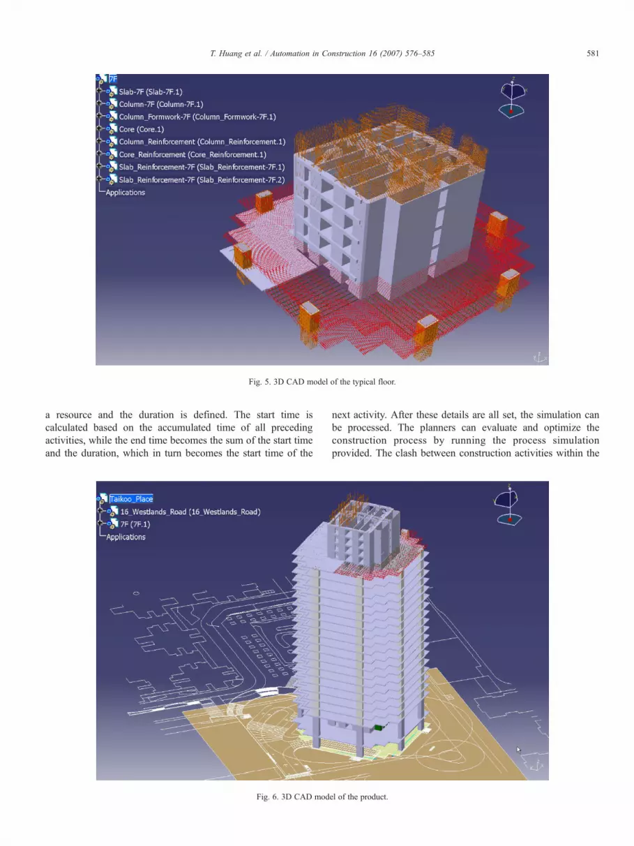
Fig. 5. 3D CAD model of the typical floor.
581T. Huang et al. / Automation in Construction 16 (2007) 576–585
a resource and the duration is defined. The start time iscalculated based on the accumulated time of all precedingactivities, while the end time becomes the sum of the start timeand the duration, which in turn becomes the start time of the
Fig. 6. 3D CAD mod
next activity. After these details are all set, the simulation canbe processed. The planners can evaluate and optimize theconstruction process by running the process simulationprovided. The clash between construction activities within the
el of the product.

Fig. 7. PPR model of the Westlands Road Project.
Fig. 8. Window of time message.
582 T. Huang et al. / Automation in Construction 16 (2007) 576–585
proposed construction process can be automatically detectedwhile running the simulation.
4. Case study
A real-life construction project is presented to demonstratethe applicability of the Construction Virtual Prototyping (CVP)approach. In this case study, the objective is to assist planner,project teams and client to justify the feasibility of shorteningthe floor construction cycle.
4.1. Project description
The project consists of the development of a 70-story officebuilding located in a central business area of Hong Kong. Thearchitectural, structural, and M&E design were made using Di-gital Project from Gehry Technologies. Digital Project isdeveloped on the CATIA platform and is specialized for theAEC industry. 3D CADmodels of the building were provided aspart of tender documents for this project. In order to shorten theconstruction progress, the client intended to reduce the length ofthe typical floor construction to a 3- or 4-day cycle. One of thetenderers decided to employ the CVP approach to demonstrate tothe client the feasibility of their construction approach and theirconcern in safety and environmental issues.
In order to visualize the construction process, the construc-tion schedule and site layout were firstly prepared by the projectmanager and program planner. The locations and utilization oftower cranes, climb forms/table forms, hoists, and safety screenwere then evaluated. The planner proposed that table forms
should be adopted as the temporary supports for slab and aproprietary climb form should be designed for core wallconstruction. Two tower cranes and four hoists were assignedfor lifting. In the simulation, a typical floor was extracted fromthe digital building model and was rearranged according to theconstruction process. To implement a 4-day floor constructioncycle, a floor was divided into four parts which include slab bay1, slab bay 2, core wall bay 1, and core wall bay 2. The ongoingcore wall is four stories ahead of the ongoing slab in thesimulation (Figs. 5 and 6). The CVP allows the generation of 3DCAD models of resources (i.e., table forms, climb forms, safetyscreens, tower cranes and hoists) in CATIA and assembling themwith Product in the PPR model (Fig. 7). The logical sequence ofactivities in every bay is linked using the PERT chart.
4.2. Simulation of construction process
The CVP system can convert 2D engineering design to a 3Dconstruction model, and finally to a model with erectionsequences. The 3D CAD models of climb forms/ table formswere built according to the workshop drawings. They can beeasily placed to the building structure in the virtual environment

Fig. 9. Window of process message.
583T. Huang et al. / Automation in Construction 16 (2007) 576–585
in order to check the appropriateness of their dimensions ordesign. The clearance or collision between climb forms or tableforms can be visualized and checked. Reports can be generatedautomatically to inform the location of collision.
The CVP system produces a precise and detailed planning andscheduling prior to the execution of real construction work givingthe ability to observe potential risks and foresee possibleproblems. For example, two tower cranes with the same jiblength were initially purposed by the planners for this project, thejib length and location of tower cranes were reviewed andmodified by the PPRmodel of the CVP system. The visualizationof site layout and the two tower cranes suggested that one towercrane can achieve the target of 4-day floor construction cycle, andthus, the planner decided to reduce the number of tower cranes toone. On the other hand, the CVP system provides the planner anopportunity to improve the resource utilization. Two types ofresource usage report can be generated automatically from thesimulation. The first type of report shows the usage of a particularresource for the activities, while the second type of report shows
Fig. 10. Presentation of ‘Construction
what resources can be employed for a particular activity. Thesereports were presented in bar chart or table format to supportplanning and evaluation of resource utilization. In this example,the idle time of tower cranewas identified by the CVP system, andthe tower crane can be allocated to lift other M&E components inorder to optimize crane usage.
The planning of table form hoisting is another important issueto be considered in this project. More than 150 pieces of tableforms were used in one floor. Half of them should be hoistedfrom the lower story within one day. Due to the spatialconstraint, parts of the table forms in the lower floor are removedprior to their installation in the upper floor. The CVP systemenables the planner to optimize the table forms installationsequence. The simulation environment also provided anintuitive way to plan floor areas for table forms storage.
In the visualization module, users can view the constructionactivities at a particular time, and their interrelationship withother activities. The CVP system provides the text windows inthe module to explain the work instructions and details of theprocess (Figs. 8 and 9). Pictures were also captured and help theusers to present the construction methods (Fig. 10). Thissimulation of 4-day typical floor construction cycle allows anefficient and effective transmission of the proposed ideas of theplanner to the client.
4.3. User feedback
A number of interviews were made with the project teammembers including project manager, planning manager and
Methods’ with captured picture.

Table 2Effectiveness of virtual prototyping
Virtual prototyping as a visualization tool 4Virtual prototyping as a planning tool 3.4Virtual prototyping as an analyzing tool 3Virtual prototyping as a communication tool 3.7
584 T. Huang et al. / Automation in Construction 16 (2007) 576–585
project engineer to collect feedback on utilizing virtualprototyping technology in the tender stage constructionplanning. Questions were asked in the areas of softwarefunctionality and benefits on project performance. The overallfeedback was on the positive side.
The project team members think that the most usefulsoftware functions are visualization and clash detection.Visualization allows them to review their planned scheduleintuitively and it facilitates modification to the schedule. Theyfind clash detection an indispensable tool in analyzing worksequence in confined area, especially when the work involvesinstallation of large prefabricated element. The drawbacks of theemployed virtual prototyping facilities are tedious data inputand the difficulty to modify the simulation. Planners find thesetasks too time consuming and difficult to cope with the tighttender preparation time. The average rating of the effectivenessof virtual prototyping in different areas is listed in Table 2. Arating of 5 represents highly effective and a rating of 1represents not effective at all.
A number of benefits are identified by the project teammembers in the area of project performance. They think thatvirtual prototyping increases the accuracy of their projectschedule and their ability to predict and plan constructiontasks. The most important benefits of virtual prototyping in thistendering process are its ability to impress client and well definethe project scope. It increases client satisfaction and the projectteam on the case study project thinks that it is one of the reasonsfor being awarded the construction contract. They predict thatutilizing virtual prototyping in construction stage will help themto reduce rework and change orders, and improve coordinationand communication effectiveness.
The project team members have some concern on the timerequired for building all the detailed 3D models of building,temporary work and plant, as it takes long time to build thedetailed and accurate models. This is a problem that has to befaced by the first virtual prototyping project, but it can bealleviated in the future project as those common 3D parametricmodels can be reused directly from library or just slightly bemodified to suit the new project condition.
These views were supported from data collected on threeother projects where the same virtual prototyping software hadbeen used. There was full appreciation of the ability provided bythe system to visualize the construction process but concern withrespect to the time taken to collect and input the data required topresent the simulation. Where the client had stipulated the needto present the construction process in this way its importance tosecuring the project was recognised. For one major constructionorganisation there was the recognition that, if the benefits of thetechnology are to be realized at this time then there must bespecialist input to the project team to facilitate the virtual
prototyping process. The potential for benefits to both the designand construction process was clearly recognised by seniormanagement who indicated the potential for savings in time andcost as well as co-ordination. There were other benefits, e.g.virtual prototyping models were considered to improve theeffectiveness of meetings between the client and the constrictionteam. For virtual prototyping to be more widely accepted andused by construction personnel feedback indicated requirementfor improved facilities for the time analysis of construction tasks.Time analysis features should more closely replicate the timeanalysis facilities within existing planning software. The abilityvia a library of model data to reduce the time taken to build themodels would clearly assist the task.
5. Conclusions and further studies
This paper presented the Construction Virtual Prototyping(CVP) approach for modeling and visualizing the constructionprocesses based on the Dassault Systemes solutions. Theframework enables the users to rehearse and simulate construc-tion process virtually prior to the commencement of a realconstruction project. The example illustrated in this studyshowed that the CVP enables the users to visualize theconstructability of the proposed construction approach. TheCVP system also assists the project team to design a preciseconstruction schedule so as to remove any potential unproduc-tive activities. The rapid prototyping of the CVP system can beenhanced by improving the existing process and resourceoptimization, constructability and safety evaluation.
From the feedback of planners and our past experiences ofdeveloping industry specific IT applications, DELMIA shouldbe further customized to satisfy the demand of constructionprocess planning. For instance, arranging activities is tediousand too time consuming. Gantt chart interface is not user-friendly for construction planning. Some construction specificactivities are also needed. We are currently working collabora-tively with the Dassault Systems in order to develop an AECspecific version of the DELMIA system.
Acknowledgements
Funding for data collection and analysis was supplied throughthe Research Grants Council of Hong Kong through allocationfrom the Competitive Earmarked Research Grant for 2005/06under GrantNumber PolyU5103/05E. The research has also beensupported by another Competitive Earmarked Research Grant for2005/06 under Grant Number PolyU 5209/05E.
References
[1] A.F. Waly, W.Y. Thabet, A virtual construction environment forpreconstruction planning, Automation in Construction 12 (2002) 139–154.
[2] B. Koo, M. Fischer, Feasibility study of 4D CAD in commercialconstruction, Journal of Construction Engineering and Management 126(4) (2000) 251–260.
[3] K. McKinney, M. Fischer, 4D analysis of temporary support, Proceedingsof 1997 4th Congress on Computing in Civil Engineering, ASCE, NewYork, 1997, pp. 470–476.

585T. Huang et al. / Automation in Construction 16 (2007) 576–585
[4] K.W. Chau, M. Anson, J.P. Zhang, 4D dynamic construction managementand visualization software: 1. Development, Automation in Construction14 (2005) 512–524.
[5] A. Chini, G. Genauer, Technical guidance available to designers oftemporary structures, American Society of Civil Engineers FifteenthStructures Congress, Portland, Oregon, 1997.
[6] Q. Shen, J. Gausemeier, J. Bauch, R. Radkowski, A cooperative virtualprototyping system for mechatronic solution elements based assembly,Advanced Engineering Informatics 19 (2005) 169–177.
[7] W. Xiang, S.C. Fok, G. Thimm, Agent-based composable simulation forvirtual prototyping of fluid power system, Computers in Industry 54 (2004)237–251.
[8] M.J. Pratt, Virtual prototyping and product models in mechanicalengineering, Virtual Prototyping— Virtual Environments and the ProductDesign Process, Chapman and Hall, London, 1995, pp. 113–128.
[9] S.H. Choi, A.M.M. Chan, A virtual prototyping system for rapid productdevelopment, Computer-Aided Design 36 (2004) 401–412.
[10] M. Sarshar, P. Christiansson, J. Winter, Towards virtual prototyping in theconstruction industry: the case study of the DIVERCITY project,
Proceedings of the World IT Conference for Design and Construction,18–24 Feb 2004, Langkawi, Malaysia, 2004, pp. 581–588.
[11] J. Kunz, M. Fischer, Virtual Design and Construction: Themes, CaseStudies and Implementation Suggestions, CIFE Working Paper, vol. 097,2005, http://www.stanford.edu/group/CIFE/Publications/index.html.
[12] S. Yerrapathruni, J.I. Messner, A.J. Baratta, M.J. Horman, Using 4D CADand Immersive Virtual Environments to Improve Construction Planning,CIC Technical Reports in Penn State, vol. 45, 2005, http://www.engr.psu.edu/ae/cic/publications/TechReports/TR_045_Yerrapathruni_2003_Using_4D_CAD_and_Immersive_Virtual_Environments.pdf.
[13] M2 Presswire, IBM: Innovation: Frank Gehry, IBM and Dassault OfferPLM Solutions to Construction Industry, M2 Communications Ltd.,September 30 2003.
[14] M2 Presswire, Gehry Technologies: Gehry Technologies AnnouncesMajor New Software Update; Digital Project V1, R2 Now Shipping, M2Communications Ltd., Jul 14 2005.
[15] A. Jaafari, K.K. Manivong, M. Chaaya, Interactive system for teachingconstruction management, Journal of Construction Engineering andManagement 127 (2001) 66–75.
Related Documents