Ž . Physics of the Earth and Planetary Interiors 113 1999 355–365 A two-point, three-dimensional seismic ray tracing using genetic algorithms Hossein Sadeghi ) , Sadaomi Suzuki 1 , Hiroshi Takenaka 2 Department of Earth and Planetary Sciences, Kyushu UniÕersity, Hakozaki 6-10-1, Fukuoka 812-8581, Japan Received 5 January 1998; received in revised form 4 May 1998; accepted 4 May 1998 Abstract Ray tracing between two fixed points is a boundary value problem. An initial path connecting two points, the source and the receiver, is algorithmically perturbed until it converges to a solution giving a minimum travel-time path. In multi-pathing cases, it is quite possible for an algorithm to converge to a ray path with local minimum travel time. Furthermore, when the velocity structure has discontinuities, there is another serious problem, i.e., how to determine the correct intersection between the ray and the surface of discontinuity. In this paper, a new approach for two-point ray tracing is presented, which Ž . uses genetic algorithms GAs to overcome these problems. Since GAs are efficient global search techniques, the proposed method guarantees to find a global minimum travel-time path and also the correct intersections. A micro-GA implementation is adopted to further enhance computational efficiency. This approach is suitable for tracing the first arriving seismic waves through a 3-D heterogeneous medium with discontinuities. The method can also find the minimum time paths of later arrivals, such as reflected and refracted waves, by constraining the ray to hit a prescribed interface. The accuracy of the method is demonstrated on the numerical examples. q 1999 Elsevier Science B.V. All rights reserved. Keywords: Discontinuity; Genetic algorithms; Minimum travel time; Ray tracing 1. Introduction Seismic ray tracing is a powerful tool for studying complicated heterogeneous structures. There are three methods for tracing rays through a velocity structure: shooting, exhaustive grid search and bending. In the shooting method, ray tracing is an initial value problem. An initial point is fixed and the ray is ) Corresponding author. Fax: q81-92-642-2685; e-mail: [email protected] 1 E-mail: [email protected]. 2 E-mail: [email protected]. propagated by using some first guess of take-off angles. The take-off angles are iteratively improved until the ray hits the target location. The target point is frequently an ill-behaved function of the take-off angles. It is then impossible to trace some rays Ž . Langan et al., 1985 . The exhaustive grid search tries to find the first arrival rays by finite-difference solution of the eikonal Ž . equation e.g., Vidale, 1990 , or by using network Ž . theory e.g., Moser, 1991 . The implementation re- quires computation and storage of travel times to all spatial locations in a 3-D grid. It can be efficient if travel paths for a large set of sources and receivers are needed. 0031-9201r99r$ - see front matter q 1999 Elsevier Science B.V. All rights reserved. Ž . PII: S0031-9201 99 00011-4

Welcome message from author
This document is posted to help you gain knowledge. Please leave a comment to let me know what you think about it! Share it to your friends and learn new things together.
Transcript
Ž .Physics of the Earth and Planetary Interiors 113 1999 355–365
A two-point, three-dimensional seismic ray tracing using geneticalgorithms
Hossein Sadeghi ), Sadaomi Suzuki 1, Hiroshi Takenaka 2
Department of Earth and Planetary Sciences, Kyushu UniÕersity, Hakozaki 6-10-1, Fukuoka 812-8581, Japan
Received 5 January 1998; received in revised form 4 May 1998; accepted 4 May 1998
Abstract
Ray tracing between two fixed points is a boundary value problem. An initial path connecting two points, the source andthe receiver, is algorithmically perturbed until it converges to a solution giving a minimum travel-time path. In multi-pathingcases, it is quite possible for an algorithm to converge to a ray path with local minimum travel time. Furthermore, when thevelocity structure has discontinuities, there is another serious problem, i.e., how to determine the correct intersectionbetween the ray and the surface of discontinuity. In this paper, a new approach for two-point ray tracing is presented, which
Ž .uses genetic algorithms GAs to overcome these problems. Since GAs are efficient global search techniques, the proposedmethod guarantees to find a global minimum travel-time path and also the correct intersections. A micro-GA implementationis adopted to further enhance computational efficiency. This approach is suitable for tracing the first arriving seismic wavesthrough a 3-D heterogeneous medium with discontinuities. The method can also find the minimum time paths of laterarrivals, such as reflected and refracted waves, by constraining the ray to hit a prescribed interface. The accuracy of themethod is demonstrated on the numerical examples. q 1999 Elsevier Science B.V. All rights reserved.
Keywords: Discontinuity; Genetic algorithms; Minimum travel time; Ray tracing
1. Introduction
Seismic ray tracing is a powerful tool for studyingcomplicated heterogeneous structures. There are threemethods for tracing rays through a velocity structure:shooting, exhaustive grid search and bending.
In the shooting method, ray tracing is an initialvalue problem. An initial point is fixed and the ray is
) Corresponding author. Fax: q81-92-642-2685; e-mail:[email protected]
1 E-mail: [email protected] E-mail: [email protected].
propagated by using some first guess of take-offangles. The take-off angles are iteratively improveduntil the ray hits the target location. The target pointis frequently an ill-behaved function of the take-offangles. It is then impossible to trace some raysŽ .Langan et al., 1985 .
The exhaustive grid search tries to find the firstarrival rays by finite-difference solution of the eikonal
Ž .equation e.g., Vidale, 1990 , or by using networkŽ .theory e.g., Moser, 1991 . The implementation re-
quires computation and storage of travel times to allspatial locations in a 3-D grid. It can be efficient iftravel paths for a large set of sources and receiversare needed.
0031-9201r99r$ - see front matter q 1999 Elsevier Science B.V. All rights reserved.Ž .PII: S0031-9201 99 00011-4
( )H. Sadeghi et al.rPhysics of the Earth and Planetary Interiors 113 1999 355–365356
In the bending method, ray tracing solves aboundary value problem by iteratively refining aproposed path between fixed source and receiverpositions. The ray path is refined by searching aminimum time path based on Fermat’s principle.
ŽExact bending ray-tracing methods e.g., Wesson,1971; Julian and Gubbins, 1977; Pereyra et al.,
.1980 are very time-consuming and formidable forŽroutine use in seismological applications Thurber
. Ž .and Ellsworth, 1980 . Um and Thurber 1987 intro-duced an accurate approximate algorithm, thepseudo-bending technique, as a fast alternative to thebending method. The pseudo-bending is also morereliable than the exact bending with respect to nu-
Ž .merical stability Koketsu and Sekine, 1998 . How-ever, this algorithm has still two inherent limitations.For complicated velocity structures, there can bemany paths connecting two points of interest. Whenmulti-arriving is possible, the solution depends onthe starting path, and it is easy to miss the firstarrival. Updating the ray path around discontinuitiesis another problem because in general, bending re-quires a gradient direction to update the path.
We propose a new ray bending approach fortracing the first arrival rays through a heterogeneousstructure with discontinuities. A kind of genetic algo-
Ž .rithm GA is used as a global search technique forminimum time ray tracing. While large-populationGAs have already been used in several other seismo-
Žlogical field e.g., Sen and Stoffa, 1992; Nolte and.Frazer, 1994; Xie et al., 1996 , in this paper a
micro-population GA is employed to increase thecomputing speed. This GA, termed a micro-genetic
Ž .algorithm micro-GA , was first proposed by Krish-Ž .nakumar 1989 . In our new approach for ray trac-
ing, the micro-GA introduces a starting ray path thatis set to be in the vertical plane containing twoendpoints. The initial path is then refined three-di-mensionally in continuous regions by the pseudo-bending, and in discontinuities by the micro-GA. Wecall this method the micro-GA bending. The methodalso allows the calculation of later arrivals, such asreflected, refracted and converted waves. In Section2, we give a brief review of the micro-GA, and inSection 3, we describe our approach to ray tracing indetail. Then, in Section 4, we discuss its accuracyand efficiency. Conclusions are mentioned in Section5.
2. Genetic algorithms
GAs are stochastic search algorithms based on themechanics of natural selection and natural geneticsŽ .Goldberg, 1989 . Unlike other stochastic tech-niques, GAs work simultaneously with a populationof solutions in the search space. A possible solutionto a problem is referred to as an indiÕidual. Thepopulation sizes are quite often in excess of 50
Ž .individuals Johnson and Abushagur, 1995 . EachŽ .individual is coded as a string chromosome , where
variables are sub-strings sitting next to each other onthe chromosome. In the most general form, a chro-mosome consists of a string of binary bits. Bits ofthe string are called genes and the two distinctvalues of a gene, 0 and 1, are called alleles. Thenumber of bits in a chromosome depends on therequired precision of the associated variables. If N isthe number of bits assigned to a variable, then thereare 2 N possible values which will be evenly spreadout in the search internal of that particular variable.If our problem has M variables to each of which Nbits are assigned, the length of chromosome will beM=N.
In each iteration, called a generation, the ran-domly selected initial population is updated so that itapproaches the optimum. A single iteration of atypical GA proceeds in the following three stages:
Žreproduction, crossoÕer and mutation Goldberg,.1989 . We briefly describe these stages below. For
comprehensive descriptions, the reader can refer toŽ .Sambridge and Drijkoningen 1992 .
Reproduction is a process in which individualstrings are copied according to the values of their
Ž .objective function called the fitness . This meansthat strings with a higher fitness have a higherprobability of being reproduced and passed downinto the next generation. The probability of reproduc-tion is calculated for each individual by:
fiP s , 1Ž .i Q
fÝ kks1
where f is the fitness of the individual i, and Q isi
the population size. This probability is used as thebasis of the selection of a new population from theold. For selection we use a stochastic tournament
Ž .algorithm e.g., Goldberg, 1989 . In this algorithm,
( )H. Sadeghi et al.rPhysics of the Earth and Planetary Interiors 113 1999 355–365 357
successive pairs of individuals are drawn at randomfrom the entire old population, but the probability ofchoice is proportional to the individual’s probabilityP . A random number, r, is generated between 0 andi
1, and compared to P . If P )r, then the individuali i
is drawn. After drawing a pair, the string with higherfitness is inserted in the new population and anotherpair drawn. This process is continued until the popu-lation has the same size as the old one.
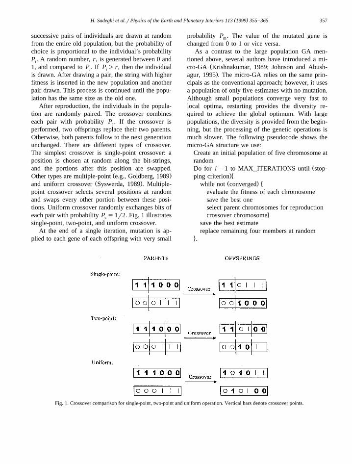
After reproduction, the individuals in the popula-tion are randomly paired. The crossover combineseach pair with probability P . If the crossover isc
performed, two offsprings replace their two parents.Otherwise, both parents follow to the next generationunchanged. There are different types of crossover.The simplest crossover is single-point crossover: aposition is chosen at random along the bit-strings,and the portions after this position are swapped.
Ž .Other types are multiple-point e.g., Goldberg, 1989Ž .and uniform crossover Syswerda, 1989 . Multiple-
point crossover selects several positions at randomand swaps every other portion between these posi-tions. Uniform crossover randomly exchanges bits ofeach pair with probability P s1r2. Fig. 1 illustratesc
single-point, two-point, and uniform crossover.At the end of a single iteration, mutation is ap-
plied to each gene of each offspring with very small
probability P . The value of the mutated gene ism
changed from 0 to 1 or vice versa.As a contrast to the large population GA men-
tioned above, several authors have introduced a mi-Žcro-GA Krishnakumar, 1989; Johnson and Abush-.agur, 1995 . The micro-GA relies on the same prin-
cipals as the conventional approach; however, it usesa population of only five estimates with no mutation.Although small populations converge very fast tolocal optima, restarting provides the diversity re-quired to achieve the global optimum. With largepopulations, the diversity is provided from the begin-ning, but the processing of the genetic operations ismuch slower. The following pseudocode shows themicro-GA structure we use:
Create an initial population of five chromosome atrandom
ŽDo for is1 to MAX_ITERATIONS until stop-.�ping criterionŽ . �while not converged
evaluate the fitness of each chromosomesave the best oneselect parent chromosomes for reproduction
4crossover chromosomesave the best estimatereplace remaining four members at random
4.
Fig. 1. Crossover comparison for single-point, two-point and uniform operation. Vertical bars denote crossover points.
( )H. Sadeghi et al.rPhysics of the Earth and Planetary Interiors 113 1999 355–365358
An initial set of five individuals is selected at ran-dom. Each individual is then evaluated in term of itsfitness, and the best estimate is saved. The remainingfour individuals compete for the reproduction by thetournament selection method. The selected parentsare mated and crossed-over by means of the uniformcrossover operation. This cycle is repeated until con-vergence is realized. The convergence condition isthat the number of different bits from the best mem-ber in the micro-population is less than 5%. Oncethis condition is achieved, the best individual ispassed onto the next iteration and an additional fourindividuals are selected at random. When the bestestimate of a convergence does not differ signifi-cantly from the previous one, we stop the micro-GAsearch.
3. Micro-GA and two-point ray tracing
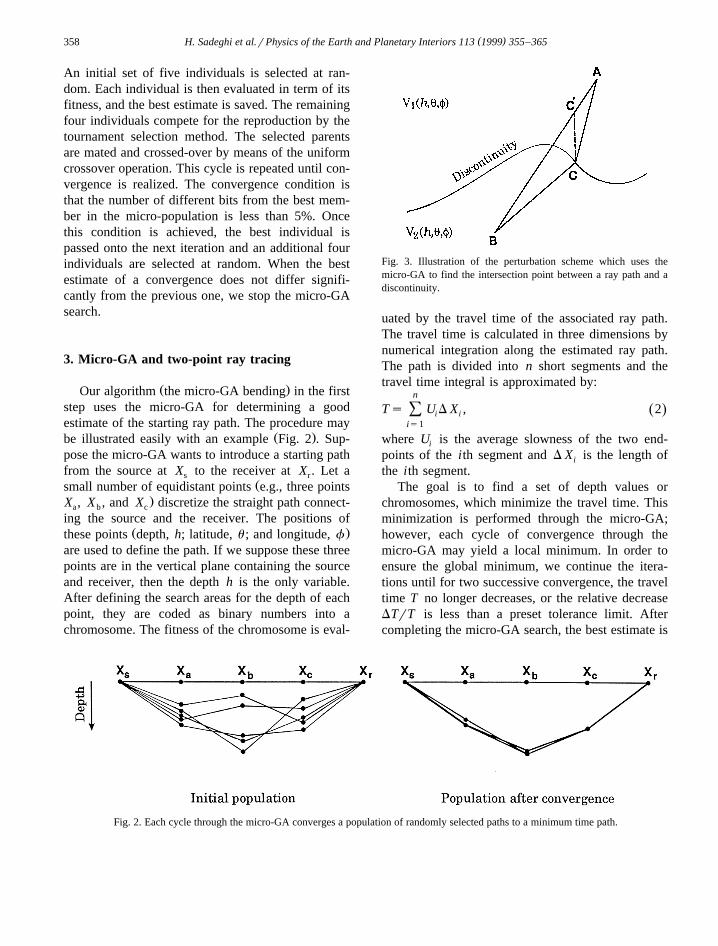
Ž .Our algorithm the micro-GA bending in the firststep uses the micro-GA for determining a goodestimate of the starting ray path. The procedure may
Ž .be illustrated easily with an example Fig. 2 . Sup-pose the micro-GA wants to introduce a starting pathfrom the source at X to the receiver at X . Let as r
Žsmall number of equidistant points e.g., three points.X , X , and X discretize the straight path connect-a b c
ing the source and the receiver. The positions ofŽ .these points depth, h; latitude, u ; and longitude, f
are used to define the path. If we suppose these threepoints are in the vertical plane containing the sourceand receiver, then the depth h is the only variable.After defining the search areas for the depth of eachpoint, they are coded as binary numbers into achromosome. The fitness of the chromosome is eval-
Fig. 3. Illustration of the perturbation scheme which uses themicro-GA to find the intersection point between a ray path and adiscontinuity.
uated by the travel time of the associated ray path.The travel time is calculated in three dimensions bynumerical integration along the estimated ray path.The path is divided into n short segments and thetravel time integral is approximated by:
n
Ts U D X , 2Ž .Ý i iis1
where U is the average slowness of the two end-i
points of the ith segment and D X is the length ofi
the ith segment.The goal is to find a set of depth values or
chromosomes, which minimize the travel time. Thisminimization is performed through the micro-GA;however, each cycle of convergence through themicro-GA may yield a local minimum. In order toensure the global minimum, we continue the itera-tions until for two successive convergence, the traveltime T no longer decreases, or the relative decreaseDTrT is less than a preset tolerance limit. Aftercompleting the micro-GA search, the best estimate is
Fig. 2. Each cycle through the micro-GA converges a population of randomly selected paths to a minimum time path.
( )H. Sadeghi et al.rPhysics of the Earth and Planetary Interiors 113 1999 355–365 359
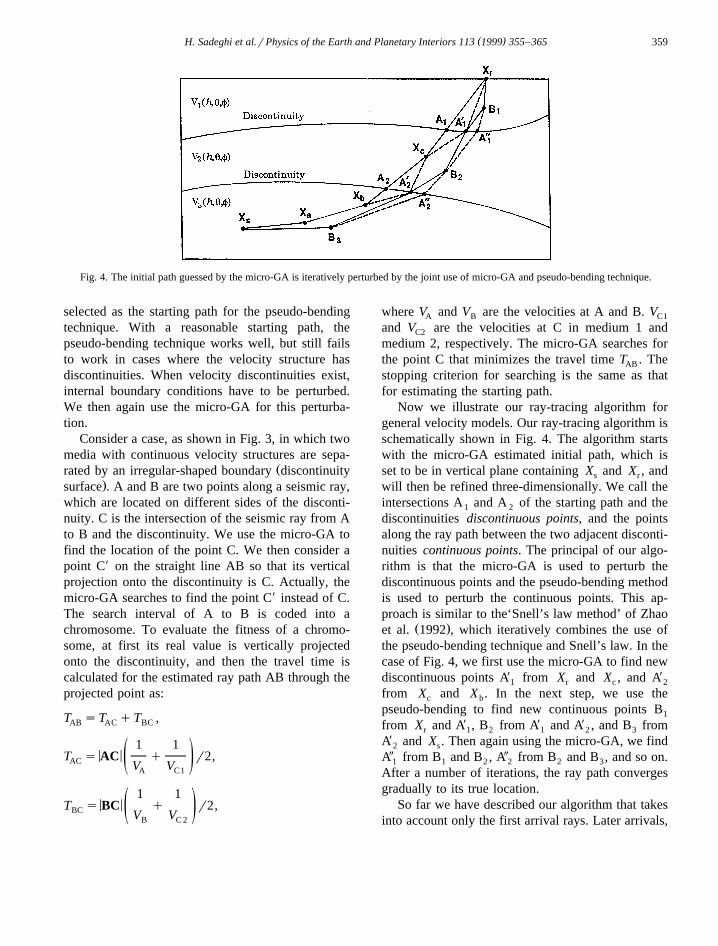
Fig. 4. The initial path guessed by the micro-GA is iteratively perturbed by the joint use of micro-GA and pseudo-bending technique.
selected as the starting path for the pseudo-bendingtechnique. With a reasonable starting path, thepseudo-bending technique works well, but still failsto work in cases where the velocity structure hasdiscontinuities. When velocity discontinuities exist,internal boundary conditions have to be perturbed.We then again use the micro-GA for this perturba-tion.
Consider a case, as shown in Fig. 3, in which twomedia with continuous velocity structures are sepa-
Žrated by an irregular-shaped boundary discontinuity.surface . A and B are two points along a seismic ray,
which are located on different sides of the disconti-nuity. C is the intersection of the seismic ray from Ato B and the discontinuity. We use the micro-GA tofind the location of the point C. We then consider apoint CX on the straight line AB so that its verticalprojection onto the discontinuity is C. Actually, themicro-GA searches to find the point CX instead of C.The search interval of A to B is coded into achromosome. To evaluate the fitness of a chromo-some, at first its real value is vertically projectedonto the discontinuity, and then the travel time iscalculated for the estimated ray path AB through theprojected point as:
T sT qT ,AB AC BC
1 1< <T s AC q r2,AC ž /V VA C1
1 1< <T s BC q r2,BC ž /V VB C 2
where V and V are the velocities at A and B. VA B C1
and V are the velocities at C in medium 1 andC2
medium 2, respectively. The micro-GA searches forthe point C that minimizes the travel time T . TheAB
stopping criterion for searching is the same as thatfor estimating the starting path.
Now we illustrate our ray-tracing algorithm forgeneral velocity models. Our ray-tracing algorithm isschematically shown in Fig. 4. The algorithm startswith the micro-GA estimated initial path, which isset to be in vertical plane containing X and X , ands r
will then be refined three-dimensionally. We call theintersections A and A of the starting path and the1 2
discontinuities discontinuous points, and the pointsalong the ray path between the two adjacent disconti-nuities continuous points. The principal of our algo-rithm is that the micro-GA is used to perturb thediscontinuous points and the pseudo-bending methodis used to perturb the continuous points. This ap-proach is similar to the‘Snell’s law method’ of Zhao
Ž .et al. 1992 , which iteratively combines the use ofthe pseudo-bending technique and Snell’s law. In thecase of Fig. 4, we first use the micro-GA to find newdiscontinuous points AX from X and X , and AX
1 r c 2
from X and X . In the next step, we use thec b
pseudo-bending to find new continuous points B1
from X and AX , B from AX and AX , and B fromr 1 2 1 2 3
AX and X . Then again using the micro-GA, we find2 s
AY from B and B , AY from B and B , and so on.1 1 2 2 2 3
After a number of iterations, the ray path convergesgradually to its true location.
So far we have described our algorithm that takesinto account only the first arrival rays. Later arrivals,
( )H. Sadeghi et al.rPhysics of the Earth and Planetary Interiors 113 1999 355–365360
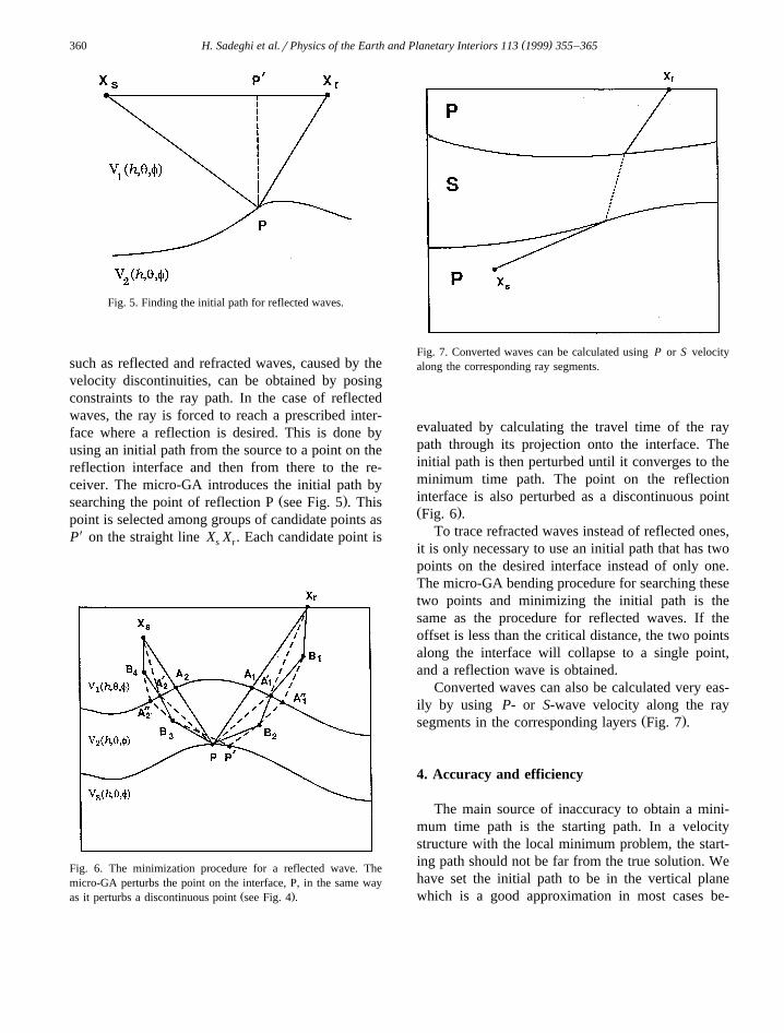
Fig. 5. Finding the initial path for reflected waves.
such as reflected and refracted waves, caused by thevelocity discontinuities, can be obtained by posingconstraints to the ray path. In the case of reflectedwaves, the ray is forced to reach a prescribed inter-face where a reflection is desired. This is done byusing an initial path from the source to a point on thereflection interface and then from there to the re-ceiver. The micro-GA introduces the initial path by
Ž .searching the point of reflection P see Fig. 5 . Thispoint is selected among groups of candidate points asPX on the straight line X X . Each candidate point iss r
Fig. 6. The minimization procedure for a reflected wave. Themicro-GA perturbs the point on the interface, P, in the same way
Ž .as it perturbs a discontinuous point see Fig. 4 .
Fig. 7. Converted waves can be calculated using P or S velocityalong the corresponding ray segments.
evaluated by calculating the travel time of the raypath through its projection onto the interface. Theinitial path is then perturbed until it converges to theminimum time path. The point on the reflectioninterface is also perturbed as a discontinuous pointŽ .Fig. 6 .
To trace refracted waves instead of reflected ones,it is only necessary to use an initial path that has twopoints on the desired interface instead of only one.The micro-GA bending procedure for searching thesetwo points and minimizing the initial path is thesame as the procedure for reflected waves. If theoffset is less than the critical distance, the two pointsalong the interface will collapse to a single point,and a reflection wave is obtained.
Converted waves can also be calculated very eas-ily by using P- or S-wave velocity along the ray
Ž .segments in the corresponding layers Fig. 7 .
4. Accuracy and efficiency
The main source of inaccuracy to obtain a mini-mum time path is the starting path. In a velocitystructure with the local minimum problem, the start-ing path should not be far from the true solution. Wehave set the initial path to be in the vertical planewhich is a good approximation in most cases be-

( )H. Sadeghi et al.rPhysics of the Earth and Planetary Interiors 113 1999 355–365 361
cause vertical velocity gradients are generally muchlarger than horizontal ones in most velocity struc-
tures. The main advantage of this approximation,however, is its minimal computation time.
Ž . Ž .Fig. 8. Comparison of the initial and final paths of the micro-GA bending A , and the pseudo-bending B for the velocity model ofŽ . Ž .northeastern Japan. a Projections on the Earth’s surface and b vertical projections.
( )H. Sadeghi et al.rPhysics of the Earth and Planetary Interiors 113 1999 355–365362
Table 1Comparison of the solutions of the micro-GA bending and thepseudo-bending methods in the velocity model of northeasternJapan
Method Travel times Ray length CPUŽ . Ž . Ž .s km s
Micro-GA bending 53.632 405.537 1.13Pseudo-bending 58.176 404.379 1.57
The second factor which affects the accuracy isour approximation for finding the correct intersectionof a ray and surface of discontinuity. This approxi-
mation may be poor when the two points, A and B inFig. 3, are far away from the discontinuity. However,it can become sufficiently good because the numberof points along the path gradually increases, so thatA and B move towards the discontinuity.
The accuracy of the algorithm can be adjusted byvarying the micro-GA parameters: the number ofpoints defining the initial path, the number of bitsassigned to a variable, and the stopping criteria. Thispliability allows us to minimize the computationtime for obtaining a solution at a desired level ofaccuracy.
To demonstrate the accuracy and efficiency of themicro-GA bending a number of examples are pre-
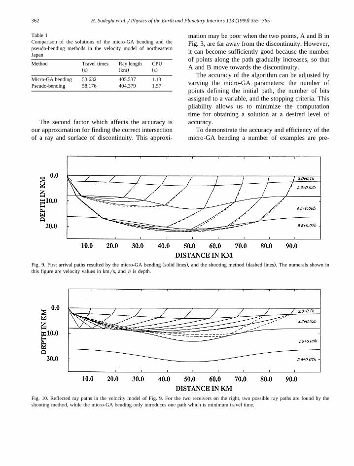
Ž . Ž .Fig. 9. First arrival paths resulted by the micro-GA bending solid lines , and the shooting method dashed lines . The numerals shown inthis figure are velocity values in kmrs, and h is depth.
Fig. 10. Reflected ray paths in the velocity model of Fig. 9. For the two receivers on the right, two possible ray paths are found by theshooting method, while the micro-GA bending only introduces one path which is minimum travel time.

( )H. Sadeghi et al.rPhysics of the Earth and Planetary Interiors 113 1999 355–365 363
Table 2Reflected paths for receivers at 80 and 90 km from the source
Receiver at Shooting method Micro-GA bending
Take-off angle Travel time Travel timeŽ . Ž . Ž .8 s s
80 km 35.0535 25.9539 25.956580 km 35.3997 26.2241 –90 km 35.0897 28.7930 28.800690 km 35.6019 28.8612 –
sented below. All FORTRAN codes have been exe-Ž .cuted on a SUN Ultra 1 Model 140 143 MHz .
We first compare the results of the micro-GAbending and the pseudo-bending using a model forthe P-wave velocity structure of northeastern JapanŽ .Zhao and Hasegawa, 1993 . The source is located at
Ž .the depth of 43.0 km lat 37.08N, long 142.08E , andŽthe receiver is chosen at the free surface lat 40.08N,
.long 140.08E . The micro-GA bending estimates thestarting path by searching the depth positions ofthree points which are uniformly spaced along thestraight path connecting the source and the receiver.We define the search intervals from their positionson the straight path to 100 km below. All variablesare coded as binary numbers with Ns6 bits. Thus,each variable can take 64 possible values. The traveltime tolerance is set at DTrTs0.01. We comparethese two methods under the following identical
conditions: the ‘enhancement factor’ Fs1.0, andthe ‘travel time improvement parameter’ Ps1 msŽ .see Um and Thurber, 1987 . Fig. 8 shows theprojected paths, and Table 1 shows the comparisonof the calculated travel times, paths, and computationtimes for the two methods. It can be seen from Table1 that the micro-GA bending is not only more suc-cessful in finding the minimum time path but alsofaster than the pseudo-bending method. The reason isthat the micro-GA starts closer to the optimum, andthus the required number of travel time computationsdecreases and also perturbation of discontinuity con-ditions can speed up the rate of convergence.
A two-dimensional syncline velocity model shownin Fig. 9 is also adopted to check our algorithm. Themodel is composed of four layers, within each layerthe velocity increases linearly with depth. One sourceand nine receivers are located at intervals of 10 km.Another ray tracing program is needed to check theaccuracy of the results of our algorithm. We haveused a two-dimensional ray-tracing program modi-
Ž .fied from the shooting method Iwasaki, 1988 . Themicro-GA bending parameters for this example arechosen as Ns6 bits, DTrTs0.01, Fs1.0, Ps1ms, and the search interval for the depth is from 0 tomaximum 25 km. Fig. 9 illustrates the first arrivalray paths. Solid lines are the results of the micro-GAbending, and the dashed lines show the shootingmethod ray paths. The mean difference travel time is0.005 s.
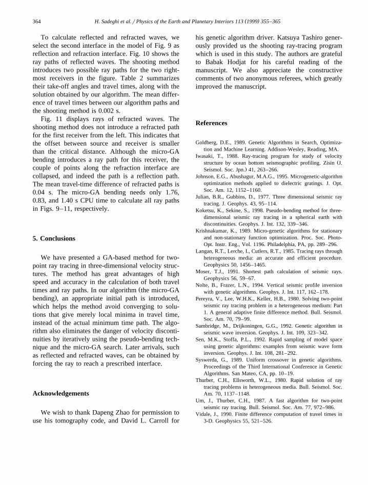
Fig. 11. Refracted ray paths in the velocity model of Fig. 9. There is no refracted wave for the first receiver on the left, and the ray pathfound by the micro-GA bending is a reflection.
( )H. Sadeghi et al.rPhysics of the Earth and Planetary Interiors 113 1999 355–365364
To calculate reflected and refracted waves, weselect the second interface in the model of Fig. 9 asreflection and refraction interface. Fig. 10 shows theray paths of reflected waves. The shooting methodintroduces two possible ray paths for the two right-most receivers in the figure. Table 2 summarizestheir take-off angles and travel times, along with thesolution obtained by our algorithm. The mean differ-ence of travel times between our algorithm paths andthe shooting method is 0.002 s.
Fig. 11 displays rays of refracted waves. Theshooting method does not introduce a refracted pathfor the first receiver from the left. This indicates thatthe offset between source and receiver is smallerthan the critical distance. Although the micro-GAbending introduces a ray path for this receiver, thecouple of points along the refraction interface arecollapsed, and indeed the path is a reflection path.The mean travel-time difference of refracted paths is0.04 s. The micro-GA bending needs only 1.76,0.83, and 1.40 s CPU time to calculate all ray pathsin Figs. 9–11, respectively.
5. Conclusions
We have presented a GA-based method for two-point ray tracing in three-dimensional velocity struc-tures. The method has great advantages of highspeed and accuracy in the calculation of both travel
Žtimes and ray paths. In our algorithm the micro-GA.bending , an appropriate initial path is introduced,
which helps the method avoid converging to solu-tions that give merely local minima in travel time,instead of the actual minimum time path. The algo-rithm also eliminates the danger of velocity disconti-nuities by iteratively using the pseudo-bending tech-nique and the micro-GA search. Later arrivals, suchas reflected and refracted waves, can be obtained byforcing the ray to reach a prescribed interface.
Acknowledgements
We wish to thank Dapeng Zhao for permission touse his tomography code, and David L. Carroll for
his genetic algorithm driver. Katsuya Tashiro gener-ously provided us the shooting ray-tracing programwhich is used in this study. The authors are gratefulto Babak Hodjat for his careful reading of themanuscript. We also appreciate the constructivecomments of two anonymous referees, which greatlyimproved the manuscript.
References
Goldberg, D.E., 1989. Genetic Algorithms in Search, Optimiza-tion and Machine Learning. Addison-Wesley, Reading, MA.
Iwasaki, T., 1988. Ray-tracing program for study of velocityŽstructure by ocean bottom seismographic profiling. Zisin J.
.Seismol. Soc. Jpn. 41, 263–266.Johnson, E.G., Abushagur, M.A.G., 1995. Microgenetic-algorithm
optimization methods applied to dielectric gratings. J. Opt.Soc. Am. 12, 1152–1160.
Julian, B.R., Gubbins, D., 1977. Three dimensional seismic raytracing. J. Geophys. 43, 95–114.
Koketsu, K., Sekine, S., 1998. Pseudo-bending method for three-dimensional seismic ray tracing in a spherical earth withdiscontinuities. Geophys. J. Int. 132, 339–346.
Krishnakumar, K., 1989. Micro-genetic algorithms for stationaryand non-stationary function optimization. Proc. Soc. Photo-Opt. Instr. Eng., Vol. 1196. Philadelphia, PA, pp. 289–296.
Langan, R.T., Lerche, I., Cutlers, R.T., 1985. Tracing rays throughheterogeneous media: an accurate and efficient procedure.Geophysics 50, 1456–1465.
Moser, T.J., 1991. Shortest path calculation of seismic rays.Geophysics 56, 59–67.
Nolte, B., Frazer, L.N., 1994. Vertical seismic profile inversionwith genetic algorithms. Geophys. J. Int. 117, 162–178.
Pereyra, V., Lee, W.H.K., Keller, H.B., 1980. Solving two-pointseismic ray tracing problem in a heterogeneous medium: Part1. A general adaptive finite difference method. Bull. Seismol.Soc. Am. 70, 79–99.
Sambridge, M., Drijkoningen, G.G., 1992. Genetic algorithm inseismic wave inversion. Geophys. J. Int. 109, 323–342.
Sen, M.K., Stoffa, P.L., 1992. Rapid sampling of model spaceusing genetic algorithms: examples from seismic wave forminversion. Geophys. J. Int. 108, 281–292.
Syswerda, G., 1989. Uniform crossover in genetic algorithms.Proceedings of the Third International Conference in GeneticAlgorithms. San Mateo, CA, pp. 10–19.
Thurber, C.H., Ellsworth, W.L., 1980. Rapid solution of raytracing problems in heterogeneous media. Bull. Seismol. Soc.Am. 70, 1137–1148.
Um, J., Thurber, C.H., 1987. A fast algorithm for two-pointseismic ray tracing. Bull. Seismol. Soc. Am. 77, 972–986.
Vidale, J., 1990. Finite difference computation of travel times in3-D. Geophysics 55, 521–526.

( )H. Sadeghi et al.rPhysics of the Earth and Planetary Interiors 113 1999 355–365 365
Wesson, R.L., 1971. Travel-time inversion for laterally inhomoge-neous crustal velocity model. Bull. Seismol. Soc. Am. 61,729–746.
Xie, Z., Spencer, T.W., Rabinowitz, P.D., Fahlquist, A.D., 1996.A new regional hypocenter location method. Bull. Seismol.Soc. Am. 86, 946–958.
Zhao, D., Hasegawa, A., 1993. P wave tomographic imaging ofthe crust and upper mantel beneath Japan Island. J. Geophys.Res. 98, 4333–4353.
Zhao, D., Hasegawa, A., Horiuchi, S., 1992. Tomographic imag-ing of P and S wave velocity structure beneath northeasternJapan. J. Geophys. Res. 97, 19909–19928.
Related Documents