A Tutorial on Beam Loss Monitoring Robert E. Shafer TechSource, Inc. Santa Fe, NM Abstract. The beam loss monitoring system is one of the two most widely distributed beam diagnostic systems at most particle accelerator facilities. This tutorial reviews the characteristics of the ionizing radiation from beam losses, and the properties of beam loss radiation detectors. INTRODUCTION The beam loss monitoring system is one of the two most widely distributed beam diagnostic systems at most particle accelerator facilities. In addition to being a beam- tuning device, beam loss monitors (BLMs) are the front-line devices for protecting the beam line components from damage due to beam loss. In addition, the BLMs monitor losses that lead to long-term activation and radiation damage, as well as provide alarms when the radiation from beam losses may lead to excessive radiation levels outside the radiation enclosures. The Effects of Ionizing Radiation The effects of ionizing radiation can be categorized in the following table. Material damage overheating, thermal stress, radiation damage. Cryogenic systems excessive heat load, magnet quenching. Optics darkening (optical transmission). Solid-state electronics single event upset, long-term damage (dislocations). Activation personnel hazard (exposure). Prompt radiation backgrounds in experiments. personnel hazard (neutrons). Sources of Ionizing Radiation Ionizing radiation can come from both beam and non-beam sources: Beam halo Residual gas scattering Residual gas stripping (H- beams) Magnetic stripping (H- beams) Focus and steering errors Intercepting beam diagnostics Foreign objects in the beam Synchrotron radiation X-rays from rf cavities CP648, Beam Instrumentation Workshop 2002: Tenth Workshop, edited by G. A. Smith and T. Russo © 2002 American Institute of Physics 0-7354-0103-9/02/$19.00 44

Welcome message from author
This document is posted to help you gain knowledge. Please leave a comment to let me know what you think about it! Share it to your friends and learn new things together.
Transcript
A Tutorial on Beam Loss Monitoring
Robert E. Shafer
TechSource, Inc.Santa Fe, NM
Abstract. The beam loss monitoring system is one of the two most widely distributed beamdiagnostic systems at most particle accelerator facilities. This tutorial reviews the characteristicsof the ionizing radiation from beam losses, and the properties of beam loss radiation detectors.
INTRODUCTION
The beam loss monitoring system is one of the two most widely distributed beamdiagnostic systems at most particle accelerator facilities. In addition to being a beam-tuning device, beam loss monitors (BLMs) are the front-line devices for protecting thebeam line components from damage due to beam loss. In addition, the BLMs monitorlosses that lead to long-term activation and radiation damage, as well as providealarms when the radiation from beam losses may lead to excessive radiation levelsoutside the radiation enclosures.
The Effects of Ionizing Radiation
The effects of ionizing radiation can be categorized in the following table.
Material damage overheating, thermal stress, radiation damage.Cryogenic systems excessive heat load, magnet quenching.Optics darkening (optical transmission).Solid-state electronics single event upset, long-term damage (dislocations).Activation personnel hazard (exposure).Prompt radiation backgrounds in experiments.
personnel hazard (neutrons).
Sources of Ionizing Radiation
Ionizing radiation can come from both beam and non-beam sources:
Beam halo Residual gas scatteringResidual gas stripping (H- beams) Magnetic stripping (H- beams)Focus and steering errors Intercepting beam diagnosticsForeign objects in the beam Synchrotron radiationX-rays from rf cavities
CP648, Beam Instrumentation Workshop 2002: Tenth Workshop, edited by G. A. Smith and T. Russo© 2002 American Institute of Physics 0-7354-0103-9/02/$19.00
44
Types of Ionizing Radiation
Types of ionizing radiation from high-energy particle beams include protons,electrons, pions, muons, gammas (including x-rays), and neutrons. Lost protons, ifthey are over a few GeV, will produce secondaries via hadronic showers, whichincludes pions, neutrons, and muons. Pi-zeros produce high-energy gammas. Lostelectrons produce electromagnetic showers via bremsstrahlung. Gamma rays producedin electromagnetic showers convert back to electrons via Compton scattering and pairproduction.
DETECTION OF IONIZING RADIATION
Eventually, the primary mechanism by which a beam loss monitor detects beamloss is by ionization or by fluorescence. Both ionization and fluorescence represent atransfer of energy from the incoming charged particle to the atomic electrons.Interactions between the incident particle and nuclei are far less likely, and usuallytransfer momentum, rather than energy, resulting in multiple Coulomb scattering andbeam divergence growth.
Energy loss of incident charged particles scattering on atomic electrons is describedby the Bethe-Bloch equation, found in most textbooks on nuclear and particle physics.
4xe4NA Z. _ . .dE dx=- eV per gram/cm (1)(32mc2 A
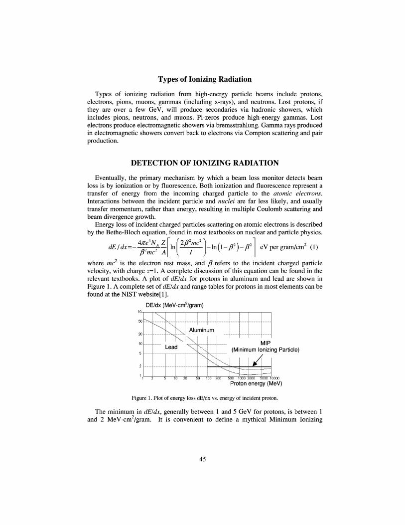
where me2 is the electron rest mass, and ft refers to the incident charged particlevelocity, with charge z=l. A complete discussion of this equation can be found in therelevant textbooks. A plot of dE/dx for protons in aluminum and lead are shown inFigure 1. A complete set of dE/dx and range tables for protons in most elements can befound at the NIST website[l].
DE/dx (MeV-cm2/gram)
MIP(Minimum Ionizing Particle)
A50 100 200 500 1000 2000 5000 10000
Proton energy (MeV)
Figure 1. Plot of energy loss dE/dx vs. energy of incident proton.
The minimum in dE/dx, generally between 1 and 5 GeV for protons, is between 1and 2 MeV-cm2/gram. It is convenient to define a mythical Minimum Ionizing
45
Particle (MIP) as a particle that has an energy loss of 2 MeV-cm2/gram (shown as aline in Figure 1).
Using the definition of a rad of radiation dose as 100 ergs per gram leads to anotherdefinition, in terms of MIPs.
100 ergs MeV MlP-gram 7 2lrad= ——— — • ——— - —— • ——— - —— -=3.1-10 MIPs per cm (2)1.6-10 ergs 2 MeV -cm
So now we can describe the rad response of a beam loss monitor in terms of eitherenergy deposition (100 ergs/gram), or in terms of a charged particle flux (3.1-107
M/Ps/cm2).
Radiation Detection Methods
The most common method for detecting ionizing radiation is to observe theinteraction of charged particles with the atomic electrons in the detector, by measuringthe ionization charge (ionization chambers), the fluorescence (phototube-scintillatorcombinations), or the secondary emission current (SEM chambers). Other methods ofdetecting the ionizing radiation include measuring Cerenkov light (from relativisticcharged particles) or Compton electrons (from high energy gammas). Other detectionmethods (e.g., Smith Purcell radiation) have not been found to be useful.
Considerations in selecting a beam loss monitor
There are many factors that must be considered in selecting a beam loss monitordesign. Some relate to the type of radiation, some relate to the expected dose rates andpeak pulsed doses, and some relate to other factors such as reliability, physical space,calibration issues, cost, etc. Another consideration is whether to use an integratingtype, whose output is measured in Coulombs per rad, or a pulse type detector, whoseoutput is measured in counts per rad. A few factors are listed below.
Detector output signal (current-integrating or pulse-type outputs)Sensitivity (Coulombs or pulses per rad)Detector dynamic range (rads per sec and instantaneous rad doses)Saturation characteristics for high radiation dosesSensitivity to backgrounds (e.g., RF cavity x-rays, synchrotron radiation)Sensitivity to magnetic fieldsSensitivity to high voltage drift (e.g., photomultipliers)Uniformity of calibration (unit to unit)RAMI analysis (reliability, availability, maintainability, inspectability)On-line system testabilityPeriodic calibration requirementsRadiation hardness of materials used in constructionBandwidth (time resolution)Robustness (suitability for use in an accelerator enclosure environment)Physical sizeCost
46
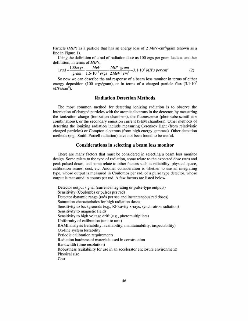
BEAM LOSS MONITORS USING IONIZATION DETECTION
When a charged particle passes through a gas, the gas is ionized, producing ionelectron pairs. The amount of energy loss in creating an ion-electron pair is called theionization constant. The following list shows the ionization constant for somecommon gases [2].
Gas ____ Ionization constant Gas ______ Ionization ConstantAir 34 eV hydrogen 36 eVHelium 41 nitrogen 35Neon 36 argon 26Krypton 23 xenon 21
We can use these numbers to estimate the ionization yield per MIP in a cm of argongas at STP:
A T lion pair 2 • W6eV - cm2 40 grams I40ion pairsN= —— - ———————————— - ——— - = ———— - —— per MIP (3)26 eV MIP gram 22,414cm3 cm
We can also estimate the number of Coulombs per rad in argon:.. UOion pairs 3.1-107 MIPs 1.6-Kr19C _m „ , 3 , ,A.N= ———— - —— • ——— - ——— • —————— = 700 pC I cm per rad (4)
MIP cm cm rad ion pairWe can also make the same estimate more directly from the definition of a rad:lrad=mergS leV
12 l^/rl.6-10-"C M grams 100pC/cnf (5)gram 1.6-10 ergs 26 eV ion pair 22, 414 cm
We can also calculate the cross section for creating an ion pair in argon, tocompare to nuclear interaction rates:
1 pair 2'W6eV cm2 40 grams f , ̂ 18 2a=— ———————————— | ——— =5 -10~18 cm2 per atom (6)26 eV gram 6-10 atoms
This is roughly 6 orders of magnitude larger than typical nuclear cross sections.Because we will also discuss solid-state "ionization chambers" (silicon PIN
diodes), the number of electron-hole pairs per cm in silicon per MIP is> T I pair 2-l06eVcm2 23 grams . . . _ 6 electron — hole pairs ,^T^N=— ———————————— ̂ — — =1.4-10 ———————— - —— per MIP (7)
3.6eV MIP gram cm cmSo the charge production in solid-state ion chambers is much larger than in gas ion
chambers.Finally, we calculate the response of a 100 cm2, 21 -foil secondary-electron-emission
monitor (SEM) to MIPs:, , 3.l-lQ7MIPs 1on 2 O.Olelectrons 1.6-1Q-19Clraa= ———— - —— -100cm • ——————— -20surfaces- —————— =100 pC (8)
cm surface electronSo a SEM detector is a very inefficient beam loss monitor.
47
Gas lonization Chambers
We first review the properties of ionization chambers in general. At very low appliedvoltages, the collection of ion-electron pairs is inefficient, because of recombinationbefore the charges reach the electrodes. As the voltage is increased, the collectionefficiency usually reaches 100%, unless the density of ions and electrons is too largeor the recombination rate is too high. As the voltage is raised further in cylindricalchambers with the electrons collected on the inner conductor (the preferred polarity)gas multiplication begins. There are two mechanisms for multiplication. The first isgas fluorescence near the anode producing uv light which in turn producesphotoelectrons on the cathode. The second is ionization of the gas near the anodeproducing more ion-electron pairs. This is referred to as the proportional mode. In thismode, the multiplication is very dependent on the applied voltage, unlike theionization chamber that has multiplication of 1.
Finally, as the voltage is raised further, the gas actually breaks down, discharging thevoltage across the chamber. This is called the Geiger mode. In this case, the amplitudeof the pulse is independent of the initial ionization. Because the tube voltage isdischarged, the tube is "paralyzed" for 10's or 100"s of microseconds until the voltagerecharges.
In cylindrical ion chambers with the inner conductor having positive polarity, morethan 50% of the external signal is due to the motion of the electrons (or negative ions),and less than 50% due to motion of the positive ions. For a cylindrical ion chamberwith a 6:1 diameter ratio, 75% of the total external signal is due to the motion of theelectrons. This is because most of the image charges for both ions and electrons areinitially on the outer electrode. The current in the external circuit is due to the motionof these image charges from one electrode to the other, as the internal charges drift tothe electrodes. In the case of proportional and Geiger tubes, additional charge carriersare created near the anode, and most of the external signals are thus due to positiveions rather than to electrons.
The preference for having positive polarity on the center electrode arises from therelative drift velocities of electrons and ions. At 1 atm, electron drift velocities at 1000V/cm are of the order of 1 cm per jis (depending on the specific gas), while forpositive ions, it is of the order of 1 cm/ms. Thus when the center electrode is positive,the dominant signal is produced by the high mobility electrons, providing a dominantfast external signal, while the slow moving ions produce a relatively small externalsignal.
Because the number of ion pairs created per incident MIP is small (about 140 pairsper cm in argon gas at 1 atm), gas ion chambers are always used in the current-integrating (charge) mode. Typically, the calibration ranges from about 50 to 500nanoCoulombs per rad.
The ion chamber dynamic range is limited by leakage currents at the low end, and bycharge recombination at the high end[3]. Good guard-ring design will limit leakagecurrents to 1 pA or less. In argon ion chambers, recombination is less because the freeelectron does not attach to neutral ions to form negative ions. In cases where therecombination is very small, the positive ion space-charge density can inhibit ioncollection, and have a similar effect [4]. The dynamic range of the FNAL chamber
48

discussed below is limited to about 100 rads/sec (7 jiA) on the high end, thus giving adynamic range of over 106 to 1. Maintaining this dynamic range in the front-endelectronics at these low currents is difficult.
Unlike pulse-counting beam loss monitors, current-integrating ion chambers have avery high instantaneous dose limit. Very roughly, the instantaneous dose limit is thedose rate limit (e.g., 100 rads/sec mentioned above) times the positive ion collectiontime (typically about 1 msec), or 0.1 rads. A pulse-type detector with a calibration of 1Hz at 1 rad/hr would have to count at 360 MHz to measure a 0.1-rad pulse in 1 jisec.
The FNAL Argon lonization Chamber
The FNAL argon ionization chamber[5] is an example of a conventional ionchamber developed for use around accelerators. It is a sealed-glass cylindrical ionchamber, with 10-cm long nickel electrodes, 3.81-cm outer electrode diameter and0.635-cm inner electrode diameter. It is shown in Figure 2. The inner electrode is theanode (signal output), and the outer electrode is the cathode, biased at -2000 volts.Connections are at opposite ends of the sealed glass chamber, and a guard ring ispainted on the outside of the glass to minimize end-to-end leakage currents. Its activevolume is about 110 cm3, and it is filled with argon gas at 725 mm Hg. Argon gas waschosen because the electron attachment rate to form negative ions is very small, andthe electron drift velocity is about 0.5 cm/|is, thus giving a large prompt signal. Itscalibration, using Eqn (5), is about 70 nC per rad. Because the chamber is sealed andthere are no organic materials inside, it requires no gas replacement.
Figure 2. FNAL 110-cm3
sealed-glass argon ionizationchamber and its container.
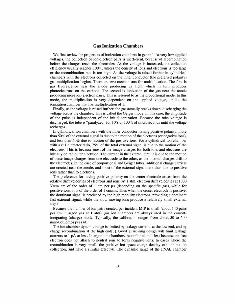
Figure 3 shows a saturation curve for five identical ion chambers taken with aradioactive source. Note in particular that all chambers have the same output current,and that the saturation plateau ranges from about 200 volts to over 2000 volts. Abeneficial characteristic of ion chambers is that the rad calibration is determined bygeometry, and that the calibration is relatively independent of the applied voltage. This
49
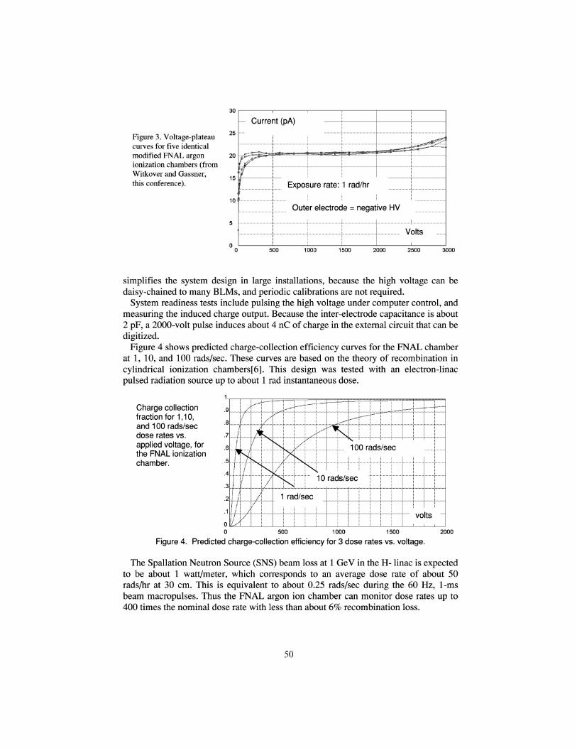
Figure 3. Voltage-plateaucurves for five identicalmodified FNAL argonionization chambers (fromWitkover and Gassner,this conference).
25
20
15
10
Current (pA)
Exposure rate: 1 rad/hr
Outer electrode = negative HV
Volts
500 1000 1500 2000 2500 3000
simplifies the system design in large installations, because the high voltage can bedaisy-chained to many BLMs, and periodic calibrations are not required.
System readiness tests include pulsing the high voltage under computer control, andmeasuring the induced charge output. Because the inter-electrode capacitance is about2 pF, a 2000-volt pulse induces about 4 nC of charge in the external circuit that can bedigitized.
Figure 4 shows predicted charge-collection efficiency curves for the FNAL chamberat 1, 10, and 100 rads/sec. These curves are based on the theory of recombination incylindrical ionization chambers [6]. This design was tested with an electron-linacpulsed radiation source up to about 1 rad instantaneous dose.
Charge collectionfraction for 1,10,and 100 rads/secdose rates vs.applied voltage, forthe FNAL ionizationchamber.
500 1000 1500
Figure 4. Predicted charge-collection efficiency for 3 dose rates vs. voltage.2000
The Spallation Neutron Source (SNS) beam loss at 1 GeV in the H- linac is expectedto be about 1 watt/meter, which corresponds to an average dose rate of about 50rads/hr at 30 cm. This is equivalent to about 0.25 rads/sec during the 60 Hz, 1-msbeam macropulses. Thus the FNAL argon ion chamber can monitor dose rates up to400 times the nominal dose rate with less than about 6% recombination loss.
50
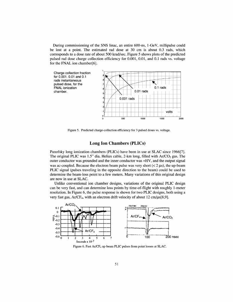
During commissioning of the SNS linac, an entire 600-ns, 1-GeV, millipulse couldbe lost at a point. The estimated rad dose at 30 cm is about 0.3 rads, whichcorresponds to a dose rate of about 500 krad/sec. Figure 5 shows plots of the predictedpulsed rad dose charge collection efficiency for 0.001, 0.01, and 0.1 rads vs. voltagefor the FNAL ion chamber[6].
Charge collection fractionfor 0.001. 0.01 and 0.1rads instantaneouspulsed dose, for theFNAL ionizationchamber.
Figure 5. Predicted charge-collection efficiency for 3 pulsed doses vs. voltage.
Long Ion Chambers (PLICs)
Panofsky long ionization chambers (PLICs) have been in use at SLAC since 1966 [7].The original PLIC was 1.5" dia. Heliax cable, 2-km long, filled with Ar/COz gas. Theouter conductor was grounded and the inner conductor was +HV, and the output signalwas ac-coupled. Because the electron beam pulse was very short (< 2 jis), the up-beamPLIC signal (pulses traveling in the opposite direction to the beam) could be used todetermine the beam-loss point to a few meters. Many variations of this original designare now in use at SLAC.
Unlike conventional ion chamber designs, variations of the original PLIC designcan be very fast, and can determine loss points by time-of-flight with roughly 1-meterresolution. In Figure 6, the pulse response is shown for two PLIC designs, both using avery fast gas, Ar/CF4, with an electron drift velocity of about 12 cm/|is[8,9].
Ar/CO2 IQmV/div 20nsMv
1002 3 4 5Seconds x10-7
Figure 6. Fast Ar/CF4 up-beam PLIC pulses from point losses at SLAC.
Ar/CO2
200 nsec
51
Solid State Ion Chambers (PIN Diodes)
Solid-state ionization chambers are usually reverse-biased silicon PIN diodes withfrontal areas ranging from a few to 100 mm2, and with depletion depths ranging fromperhaps 100 to 300 jim. They can be used in either the current output mode or thepulsed output mode. We review the basic characteristics of two PIN diodes, theSiemens BPW 34 and the Hamamatsu S2662, used in some beam loss monitors.
PropertvAreaDepletion depthVolumeLeakage current
Integrating modeCoulombs per radRad equiv. of leakage currentRad hardness (leakage current)
Pulse modeMIPs per radMax rads/sec (@ 107 counts/sec)Rad hardness (spurious counts)
BPW 342.75 x 2.75 mm2
-100 jim0.75 mm3
-100 pA
5nC70 rads/hr-1 Mrad
2.3E64 rads/sec-100 Mrads
Hamamatsu S26627.5 x 20 mm2
-100 jim15mm3
-500 pA
100 nC20 rads/hr-1 Mrad
4.6E70.2 rads/sec-100 Mrads
PIN Diode Pulse-Mode Coincidence Circuit BLM
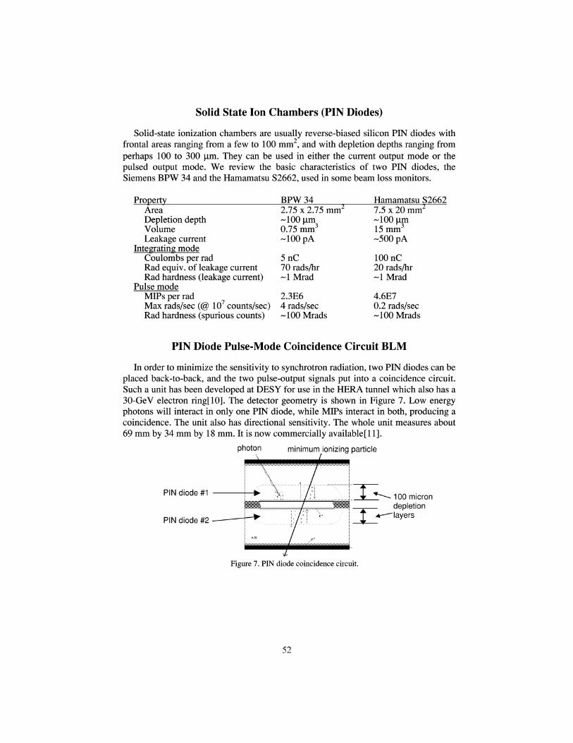
In order to minimize the sensitivity to synchrotron radiation, two PIN diodes can beplaced back-to-back, and the two pulse-output signals put into a coincidence circuit.Such a unit has been developed at DESY for use in the HERA tunnel which also has a30-GeV electron ring[10]. The detector geometry is shown in Figure 7. Low energyphotons will interact in only one PIN diode, while MIPs interact in both, producing acoincidence. The unit also has directional sensitivity. The whole unit measures about69 mm by 34 mm by 18 mm. It is now commercially available[ll].
photon minimum ionizing particle
PIN diode #1
PIN diode #2
-100 microndepletion
'layers
Figure 7. PIN diode coincidence circuit.
52
BEAM LOSS MONITORS USING LIGHT DETECTION
Detection of beam-induced light in scintillators or Cerenkov radiators represents theother most common method of monitoring beam losses. The scintillation process isalso based on the Bethe-Bloch dEldx equation. Some combinations, using the current-integrating mode, are:
Phototube___________Radiator
Photomuliplier Organic scintillator (e.g., NE 102 or BC-400)Tube Liquid scintillator (mineral oil based)
Inorganic scintillators (e.g., CsI(Tl), BGO)Cerenkov radiator (e.g., fused silica)Bare PMT
Vacuum Scintillators as per above listPhotodiode Cerenkov radiators as per above list
Scintillation constants of some organic and organic scintillator materials are listedbelow[12].
Scintillator__________Scintillation constantInorganic
Nal(Tl)CsI(Tl)BGO (Bi4Ge3Oi2)CdWO4Csl (unacivated)Ce-activated Li glass
26 eV energy loss per emitted photon1512267500300
Organic
Gas
AnthraceneNE-102ABC-400BC-517P (mineral oil)
Nitrogen
6010090250
1250
A useful feature of scintillators is the very fast risetime (a few to 100's of ns). Radhardness varies from a few krads (e.g., Nal(Tl)) to about 100 Mrad (BGO, akaBi4Ge3Oi2). We examine two scintillator-based beam loss monitors.
The LAMPF "Paint Can" Beam Loss Monitor
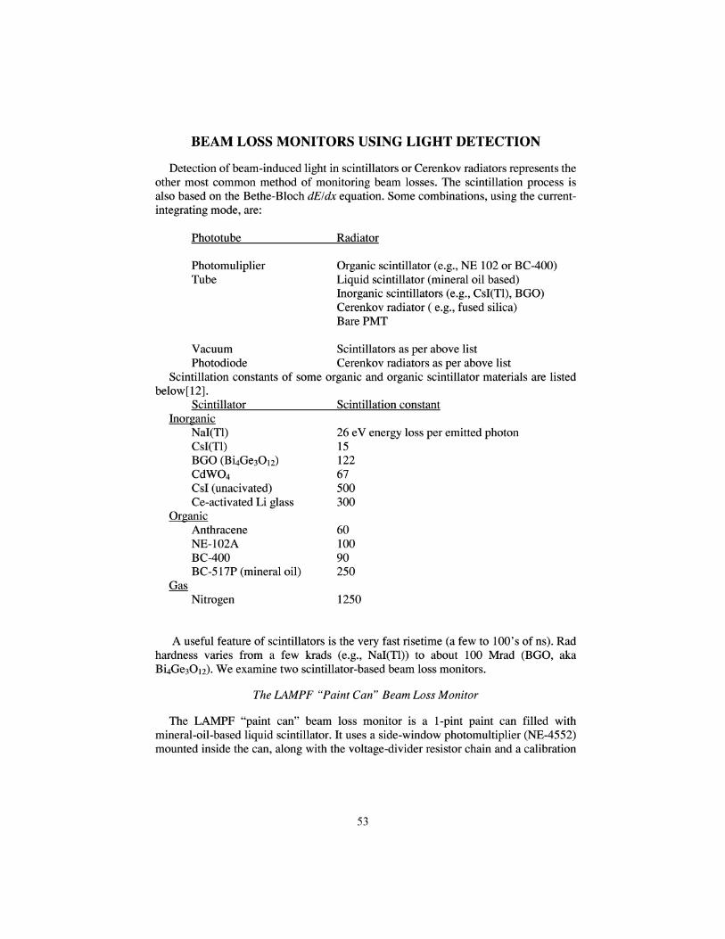
The LAMPF "paint can" beam loss monitor is a 1-pint paint can filled withmineral-oil-based liquid scintillator. It uses a side-window photomultiplier (NE-4552)mounted inside the can, along with the voltage-divider resistor chain and a calibration
53
lamp. It operates on negative HV, with a current-mode anode output. It is shown inFimirp, 8Figure 8.
Figures. LAMPF"Paint Can" beam loss monitor, andNE-4552 side-window photomultiplier.. The photomultiplier, mounted insidethe can, is immersed in mineral-oilliquid scintillator.
The calibration is approximately 1000 jiC per rad, including factors of 250 eV ofenergy loss per detectable photon, 3% collection efficiency, and 20% conversionefficiency.
WOergs leV I photon 13Irad = ———— -350grams-————-——•————=9-10 photons;gram 1.6 -10"12 ergs 250 eV
9-1013 photons -0.03-0.2-10,000 gain-1'6'™ C=1000//C (9)electron
Thus the units are very sensitive, relative to ionization chambers. On the downside,there is a large unit-to-unit gain variation, a large sensitivity to voltage setting, and themineral-oil scintillator eventually turns milky and must be replaced.
The LED A CsI(Tl) Beam Loss Monitor
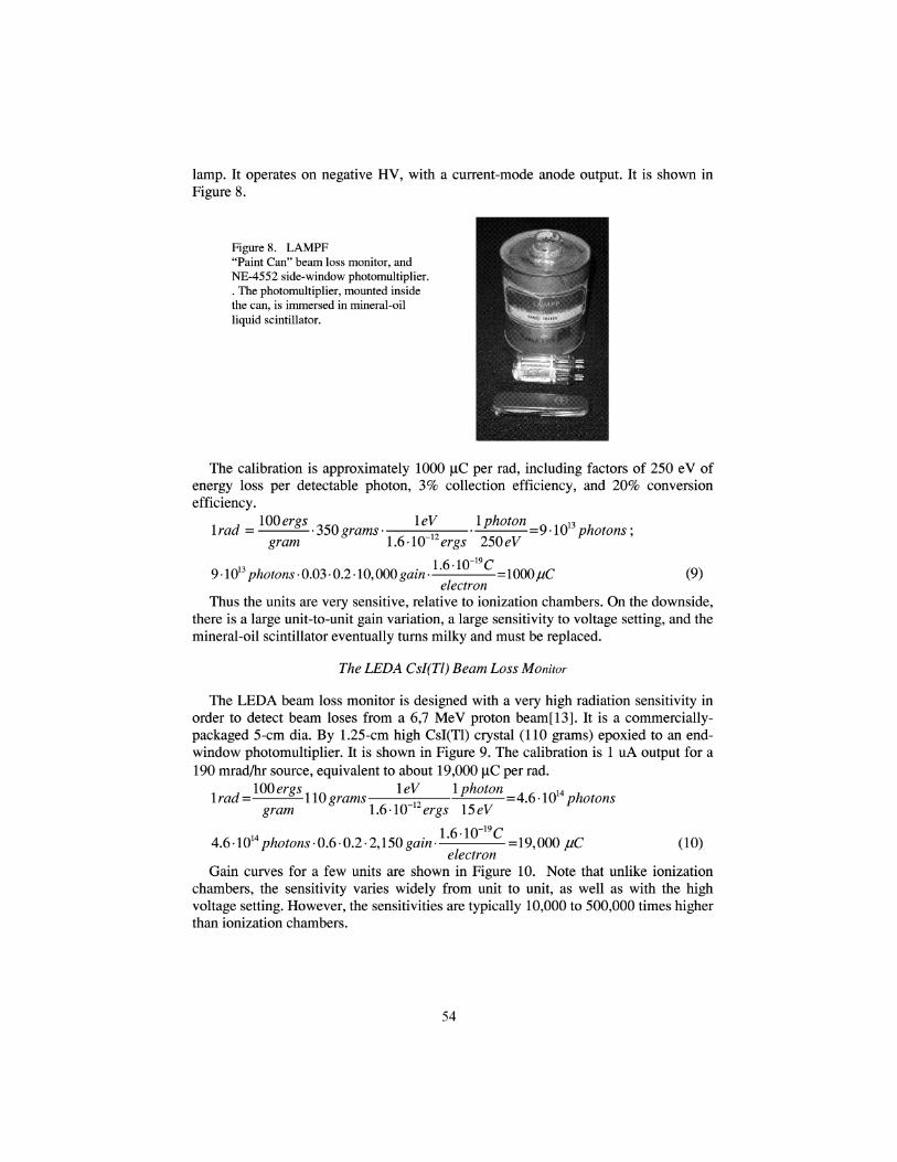
The LEDA beam loss monitor is designed with a very high radiation sensitivity inorder to detect beam loses from a 6,7 MeV proton beam[13]. It is a commercially-packaged 5-cm dia. By 1.25-cm high CsI(Tl) crystal (110 grams) epoxied to an end-window photomultiplier. It is shown in Figure 9. The calibration is 1 uA output for a190 mrad/hr source, equivalent to about 19,000 jiC per rad.
, 100ergs ^ ^ „ leV I photon A ^ ^u *lrad=————IW grams————-———-———=4.6-1014 photonsgram l.6-W~12ergs !5eV
4.6-1014photons-0.6-0.2-2,150gain.L6'10 C =19,000 juC (10)electron
Gain curves for a few units are shown in Figure 10. Note that unlike ionizationchambers, the sensitivity varies widely from unit to unit, as well as with the highvoltage setting. However, the sensitivities are typically 10,000 to 500,000 times higherthan ionization chambers.
54
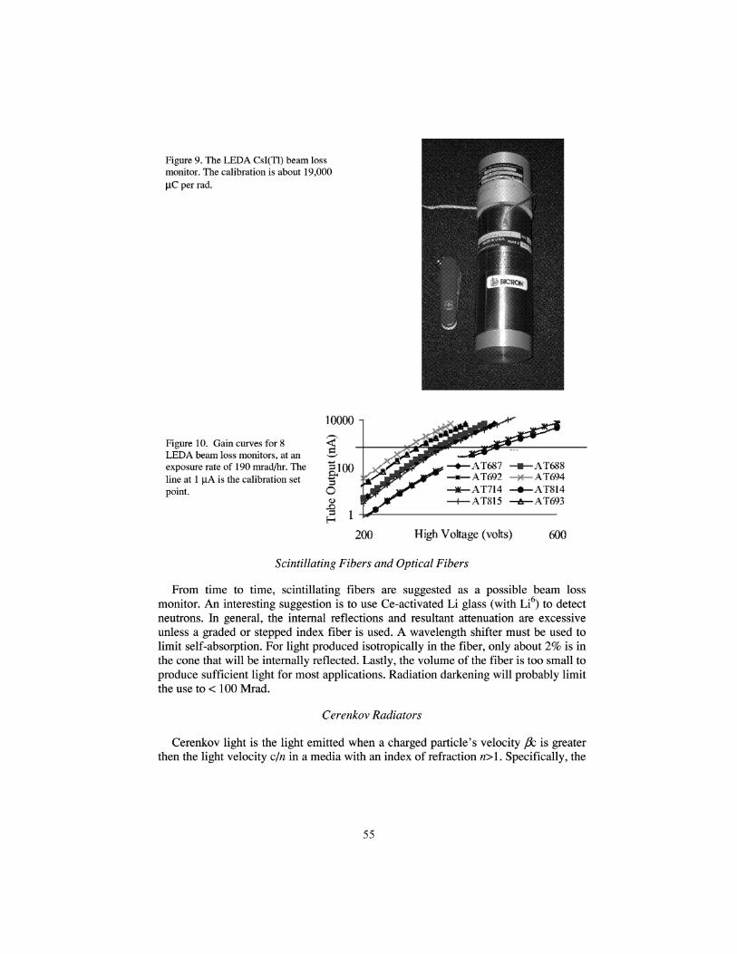
Figure 9. The LEDA CsI(Tl) beam lossmonitor. The calibration is about 19,000UC per rad.
10000 -i
Figure 10. Gain curves for 8LEDA beam loss monitors, at anexposure rate of 190 mrad/hr. Theline at 1 uA is the calibration setpoint.
AT688AT694AT814AT693
High Voltage (volts) 600
Scintillating Fibers and Optical Fibers
From time to time, scintillating fibers are suggested as a possible beam lossmonitor. An interesting suggestion is to use Ce-activated Li glass (with Li6) to detectneutrons. In general, the internal reflections and resultant attenuation are excessiveunless a graded or stepped index fiber is used. A wavelength shifter must be used tolimit self-absorption. For light produced isotropically in the fiber, only about 2% is inthe cone that will be internally reflected. Lastly, the volume of the fiber is too small toproduce sufficient light for most applications. Radiation darkening will probably limitthe use to < 100 Mrad.
Cerenkov Radiators
Cerenkov light is the light emitted when a charged particle's velocity J3c is greaterthen the light velocity c/n in a media with an index of refraction n>l. Specifically, the
55
number of photons TV in an energy range AE eV emitted per cm in a Cerenkov radiator
TV = 369.8 1 photons I cm (11)
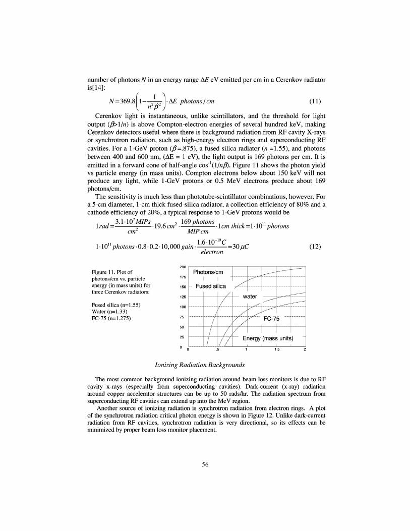
Cerenkov light is instantaneous, unlike scintillators, and the threshold for lightoutput (f)>lln) is above Compton-electron energies of several hundred keV, makingCerenkov detectors useful where there is background radiation from RF cavity X-raysor synchrotron radiation, such as high-energy electron rings and superconducting RFcavities. For a 1-GeV proton (/?=.875), a fused silica radiator (n =1.55), and photonsbetween 400 and 600 nm, (AE = 1 eV), the light output is 169 photons per cm. It isemitted in a forward cone of half-angle cos~l(l/nfl). Figure 11 shows the photon yieldvs particle energy (in mass units). Compton electrons below about 150 keV will notproduce any light, while 1-GeV protons or 0.5 MeV electrons produce about 169photons/cm.
The sensitivity is much less than phototube-scintillator combinations, however. Fora 5-cm diameter, 1-cm thick fused-silica radiator, a collection efficiency of 80% and acathode efficiency of 20%, a typical response to 1-GeV protons would be
, , 3.l'W7MIPs , _ , 2 169 photons , .. . , ,-n .\rad- ———— = —— -19.6cm2 • —— - ———— -1cm thick =1'IQU photonscm MIPcm
1 photons •0.8-0.2.W,OOOgain-l'6'W C =3QjuCelectron
(12)
Figure 11. Plot ofphotons/cm vs. particleenergy (in mass units) forthree Cerenkov radiators:
Fused silica (n= 1.55)Water (n=l.33)FC-75 (n=1.275)
200
175
150
125
100
75
50
25
0
Photons/cm
Fused silica
Ionizing Radiation Backgrounds
The most common background ionizing radiation around beam loss monitors is due to RFcavity x-rays (especially from superconducting cavities). Dark-current (x-ray) radiationaround copper accelerator structures can be up to 50 rads/hr. The radiation spectrum fromsuperconducting RF cavities can extend up into the MeV region.
Another source of ionizing radiation is synchrotron radiation from electron rings. A plotof the synchrotron radiation critical photon energy is shown in Figure 12. Unlike dark-currentradiation from RF cavities, synchrotron radiation is very directional, so its effects can beminimized by proper beam loss monitor placement.
56
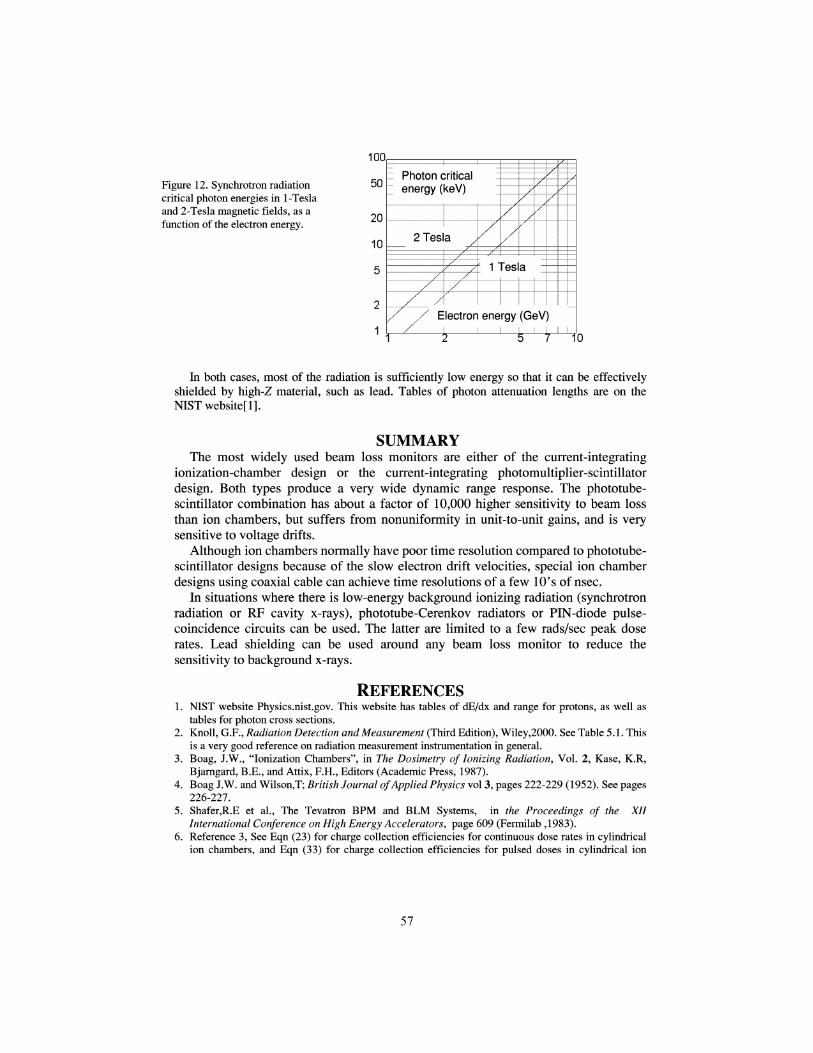
Figure 12. Synchrotron radiationcritical photon energies in 1-Teslaand 2-Tesla magnetic fields, as afunction of the electron energy.
100
50
20
10
5
2
1
Photon criticalenergy (keV)
2 Tesla
f 1 Tesla
Electron energy (GeV)
10
In both cases, most of the radiation is sufficiently low energy so that it can be effectivelyshielded by high-Z material, such as lead. Tables of photon attenuation lengths are on theNISTwebsitefl].
SUMMARYThe most widely used beam loss monitors are either of the current-integrating
ionization-chamber design or the current-integrating photomultiplier-scintillatordesign. Both types produce a very wide dynamic range response. The phototube-scintillator combination has about a factor of 10,000 higher sensitivity to beam lossthan ion chambers, but suffers from nonuniformity in unit-to-unit gains, and is verysensitive to voltage drifts.
Although ion chambers normally have poor time resolution compared to phototube-scintillator designs because of the slow electron drift velocities, special ion chamberdesigns using coaxial cable can achieve time resolutions of a few 10's of nsec.
In situations where there is low-energy background ionizing radiation (synchrotronradiation or RF cavity x-rays), phototube-Cerenkov radiators or PIN-diode pulse-coincidence circuits can be used. The latter are limited to a few rads/sec peak doserates. Lead shielding can be used around any beam loss monitor to reduce thesensitivity to background x-rays.
REFERENCES1. NIST website Physics.nist.gov. This website has tables of dE/dx and range for protons, as well as
tables for photon cross sections.2. Knoll, G.F., Radiation Detection and Measurement (Third Edition), Wiley,2000. See Table 5.1. This
is a very good reference on radiation measurement instrumentation in general.3. Boag, J.W., "lonization Chambers", in The Dosimetry of Ionizing Radiation, Vol. 2, Kase, K.R,
Bjarngard, B.E., and Attix, F.H., Editors (Academic Press, 1987).4. Boag J.W. and Wilson,T; British Journal of Applied Physics vol 3, pages 222-229 (1952). See pages
226-227.5. Shafer,R.E et al., The Tevatron BPM and BLM Systems, in the Proceedings of the XII
International Conference on High Energy Accelerators, page 609 (Fermilab ,1983).6. Reference 3, See Eqn (23) for charge collection efficiencies for continuous dose rates in cylindrical
ion chambers, and Eqn (33) for charge collection efficiencies for pulsed doses in cylindrical ion
57
chambers, in chapter 3. This is an important reference for anyone designing an ion chamber for highdose rates.
7. Panofsky,W.K.H., SLAC Internal Tech Note TN-63-57 (1963).8. McCormick, D., Proceedings of the 1991 Particle Accelerator Conference, pages 1240-42 (1991).9. Ross, M.C. and McCormick, D. Proceedings of the 1998 Linac Conference, pages 192-194 (1998).10. Wittenburg, K., in Beam Instrumentation Workshop 2000, pages 3-17 (AIP Conference Proceedings
#546).11. Website www.bergoz.com.12. Reference 2, pages 226 and 235.13.Sellyey W.C. et al., Proceedings of the 2001 Particle Accelerator Conference, pages 1315-1317
(2001)14.Schiff L.I., Quantum Mechanics (Second Edition) McGraw Hill (1955). See Eqn(37.14) on page
271.
58
Related Documents


