Welcome message from author
This document is posted to help you gain knowledge. Please leave a comment to let me know what you think about it! Share it to your friends and learn new things together.
Transcript


A Tradition of Excellence
With the development of the first rubber seated butterfly valve more than 70 years ago, the Henry Pratt Company became a trusted name in the flow control industry, setting the standard for product quality and customer service. Today Pratt provides the following range of superior products to the water, waste water and power generation industries.
Butterfly ValVes: from 3" to 162"
rectangular ValVes: 1' x 1' to 14' x 16'
Ball ValVes — ruBBer seated: from 4" to 60"Metal seated: from 6" to 48"
Plug ValVes: from 1/2" to 36", 3 ways
Hydraulic control systeMs
ValVe controls
energy dissiPating ValVes and fixed energy dissiPaters
cone ValVes
cHeck ValVes
A Commitment to Meeting The Customers’ Needs
Henry Pratt valves represent a long-term commitment to both the customer and to a tradition of product excellence. This commitment is evident in the number of innovations we have brought to the industries we serve. In fact, the Henry Pratt Company was the first to introduce many of the flow control products in use today, including the first rubber seated butterfly valve, one of the first nuclear N-Stamp valves, and the bonded seat butterfly valve.
Innovative Products For Unique Applications
Though many of the standard valves we produce are used in water filtration and distribution applica tions, Pratt has built a reputation on the ability to develop specialized products that help customers to meet their individual operational challenges.
Creative Engineering for Fluid Systems
Pratt’s ability to provide practical solutions to complex issues is demonstrated by the following case histories:
nEarthquake Proof Valves Pratt designed and manufactured hydraulically
actuated valves for a water storage application so that the valves would automatically operate in the event of earthquakes. This lead to the development of a valve that will withstand forces of up to 6g’s.
nCustom Actuation/Isolation Valves Pratt designed and manufactured valves that
would isolate a working chamber in the event of a nuclear emergency during the decommissioning of armed nuclear warheads. The valves were able to close in a millisecond using specially designed Pratt electro-pneumatic actuators.
nValves Designed for Harsh Environments Pratt designed and manufactured a 144" diameter
butterfly valve for the emergency cooling system at a jet engine test facility. The valve was designed to supply water to help dissipate the tremen dous heat generated by the engines during testing.
Through experience, commitment and creative engineering, Pratt is uniquely suited to provide superior products for our customers’ special needs.
For more information, contact our corporate headquarters in Aurora, Illinois.
Valves for the 21st Century
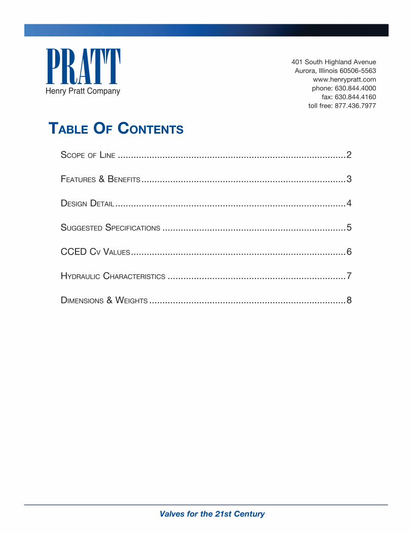
taBle of contents
Scope of Line .......................................................................................2
featureS & BenefitS ..............................................................................3
DeSign DetaiL ........................................................................................4
SuggeSteD SpecificationS ......................................................................5
cceD cv vaLueS ..................................................................................6
HyDrauLic cHaracteriSticS ....................................................................7
DimenSionS & WeigHtS ...........................................................................8
401 South Highland AvenueAurora, Illinois 60506-5563
www.henrypratt.comphone: 630.844.4000
fax: 630.844.4160toll free: 877.436.7977

Henry Pratt Companypage 2
scoPe of line: coMPact controllaBle energy dissiPater (cced)
Design AdvantagesThe Pratt Compact Controllable Energy Dissipater (CCED) is a manual, hydraulically or electrically operated flow control valve is specially designed for extremely high velocity and high pressure drop applications. Their effectiveness is due to the large number of engineered orifices into which the flowing media is divided, creating a specified throttling effect. These jets are evenly distributed over the entire face of the upstream valve plate. The uniform, venturi-jet configuration suppresses unwanted operating hazards such as excessive vibration, cavitation, pressure fluctuations and noise.
Operating Principal (Bi-Directional)The simplicity of the Pratt CCED valve is described and illustrated in Figure A. There are two plates – fixed(2) and moving(3). Both plates have perforations that line up when the valve is full open.
The valve is fully closed when the moving plate moves one perforation diameter upward. Under specified flow control conditions the valve open position can be intermediate, with the orifices in the fixed plate only partially open. The valve position is controlled by a valve position feedback device per the customer’s specification.
FunctionThe high velocity dissipation design prevents typical disturbances in the flow. Typically, large fluctuations in flow and headloss cause vibration of the pipe work, create damaging cavitations (i.e. fluid vapor bubbles), and noise. Cavitation is caused by the sudden, explosive collapse of bubbles.
In the Pratt CCED valve, energy dissipation is controlled by multiple, evenly distributed jets into which perforated plates divide the flow equally. Uncontrolled fluctuations of flow are reduced due to the jet induction port design.
The distance in which the energy is dissipated is linear, with recovery taking place in a short distance and controlled relative to positioning in the downstream pipe. Pratt CCED valves provide cavitation figures which are more desirable than conventional control valves.
Cavitation does not create a hazard within the valve or downstream. This condition exceeds the typical performance of conventional control valves where cavitation is frequently observed within the body or downstream. Vapor cavities are not created when Pratt CCED valves are properly sized, preventing pressure oscillation risks.
1. An annular body is mounted between pipe flanges.2. Downstream Plate is fixed and locked into position.3. Linear Upstream Plate slides and is guided top
and bottom.

Valves for the 21st Century page 3
features & Benefits of Pratt
coMPact controllaBle energy dissiPater (cced)
feature Benefit
nCapable of transient conditions and reversal of flow (Patented)
nNo damage to the upstream plate or actuator, eliminating linear plate lockup
nGuided P1 plate (lower shaft) nNo possibility of misalignment (Bi-directional), allows for horizontal mounting when specified
nEliminates cavitation nNo damage to pipe or valve internals
nShort operation of travel and reduced thrust
nSmaller actuation package and overall dimensions
nLow co-efficient of friction barrier on both mating surfaces
nLower thrust, reduced wear on mating surfaces
nThicker plate construction coated and hardened
nReduced plate deflection and reduced wear with lower frictional thrust required
nBlow-out-proof stems (upper and lower) nShafts are locked in place and maintain their full diameter
nManual or automated control nFull control packages, fail safe modulating
nAnti-corrosion ring nEase of removal of the fixed plate and all components
nValve shafts can be mounted vertically or horizontally due to lower shaft guiding
nAccommodates all piping configurations including submerged service
n316 stainless steel bearing Journals nCorrosion free surface for seals and packing (Patented)
nLower shaft nPrevents disc shift, allows for horizontal mounting and intermittent bi-directional flow
nFixed plate dielectric links nAllows for ease of disassembly of the fixed plate. Eliminates corrosion and fixed plate seizure
nHigh visability valve position indication nIndicates valve position directly on valve
nRetained chevron packaging n‘O’-Ring seals are replaceable under pressure
nNon-metallic bearings nNo corrosive materials in the upper body, non metallic linear bore and lower shaft journal
nTaper ring nThe taper ring incorporates a dielectric link with a low coefficient of friction with the linear plate. The design permits intermittent bi-directional flow or transient conditions. This taper ring incorporates a retained di-electric surface, eliminating corrosion or seizure during long periods of valve inactivity
nRemovable O-Ring seals (Patented) n‘O’-Ring seals are removable in the upper and lower shafts without valve removal or system depressurization
nDisc lifting holes nFor ease of disassembly and assembly
nAsymmetric design nEase of assembly to ensure proper orientation of the upper and lower plates
nDouble T-shaft design nAllows for vertical and horizontal mounting and operation

Henry Pratt Company
design detail
Top Stem Packing and Seal DetailThe stem seal allows for bushing and ‘O’-Ring replacement, while under pressure. The self-adjusting chevron packing is live loaded and internally retained. Adjustment is not required and the chevron packing is maintenance free. No lubrication is required. The ‘O’-Ring seals are self contained, dynamic and static, housed in a non-corrosive, non-metallic bushing that also maintains the loading on the chevron packing.
Bottom Stem and Seal DetailThe lower stem maintains the moving linear plate in any position during intermittent bi-directional conditions. The unique stem design incorporates relief ports, eliminating hydraulic lift or position lock. The stem is guided in a Duralon bearing, eliminating shaft journal corrosion. Sealing is maintained with static ‘O’-Ring seals with the stem bolted in place. A secondary security cap is bolted and sealed to ensure a positive seal, requiring no adjustment. The body retaining step for the fixed plate incorporates an anti-corrosion ring that permits easy removal of the fixed plate should disassembly be required.
page 4
Anti-Corrosion Ring
DuralonBearing
‘O’-Ring Seals
NOTABLE FEATURES
Feature Pratt CCED
Double Plate Design Yes
Upward Operation to Close Yes
Hardened Plates Yes (standard)
Bi-Directional Capabilities on Reversal of Flow
Yes
Lower Shaft and Seals Yes
Field Replaceable O-Rings Yes
RTFE Taper Rings – Carbon Steel Delron Backed
Yes
Anti-Hydraulic Lift Yes
Body Coatings to NSF Standard
Fixed Plate Anti-Corrosion Ring for Field Replacement or Inspection in Body
Yes
Backup Static and Dynamic ‘O’ Ring Shaft Seals – Replaceable Under Pressure
Yes
Optional Materials – 316 SS (plates), 17-4PH (shaft)
Yes
Horizontal Shaft Mounting Yes
The above features become a benefit to the end user in terms of performance, ease of maintenance and long design life of the valve.
ANSI 150/300 Drilling

Valves for the 21st Century page 5
suggested sPecifications
Body: All bodies shall be cast Ductile Iron 65-45-12 or fabricated Carbon steel. MTR’s shall be submitted at time of shipment. All bodies shall be epoxy coated internally and externally per the paint specification as indicated. All bodies shall incorporate identification plates in stainless steel indicating the maximum pressure, temperature, date of manufacture, and SO number for full traceability. All bodies shall incorporate lifting pads and hoist rings for vertical and horizontal lifting. The hoist rings shall not penetrate the diameter or radius of the valve body. All lifting ears shall be cast in the body. Cast mounting ears for actuators are unacceptable. All mounting pad surfaces shall incorporate a machined or milled surface to ensure mounting concentricity. All bodies shall incorporate 316 stainless steel packing and seal body journals. Bodies shall be available in wafer, lug and full-flanged configurations
Fixed Discs: All fixed discs shall incorporate a dielectric link between the body and disc to prevent corrosion. All fixed discs shall be recessed in the body and supported by the disc step in the body and downstream flange. All discs shall be capable of horizontal mounting when specified and incorporate non-corrosive dowels to prevent rotation allowing for field disassembly when required. All discs shall be designed with zero deflection under maximum operating pressure. The fixed disc shall be 420 stainless steel with a Rockwell of 45-55. The fixed disc shall incorporate an asymmetric located groove to ensure accurate placement of the holes relative to the moving disc and dual shafts. Fixed discs shall incorporate tapped lifting holes to permit field disassembly and assembly.
Moving Discs: All discs shall be surface ground with the mating disc with tolerances not exceeding three thousands of an inch. All linear discs shall incorporate a T shaft connection designed with zero tensile deflection under full thrust load. All lower shaft bores shall incorporate non-metallic non-corrosive bearings the full length of the bore for shaft engagement. All moving discs shall incorporate the anti-hydraulic lift mechanism in the lower shaft. All discs shall be capable of horizontal mounting. The disc or body shall incorporate non- corrosive, non-metallic guides to support the disc in the horizontal position when required. The disc shall be 420 stainless steel with a Rockwell of 45-55. Linear discs shall incorporate tapped lifting holes to permit field disassembly and assembly. All linear discs shall operate within a machined groove in the body and travel in the fully open and closed position aligning with all holes in the fixed disc. The disc shall not
contact the upstream side of the body groove. All linear discs shall incorporate an upstream taper ring incorporating a non-corrosive non-metallic friction plate on the face and perimeter capable of intermittent bi-directional flow.
Shafts: All shafts shall be of solid one-piece construction. Material shall be 316 stainless Steel ground and polished. Lower shafts shall incorporate multiple milled linear or spiral grooves to prevent hydraulic lift of the disc.
Lower Shafts: All lower shafts shall be ground and milled incorporating an O-Ring seal with a solid thrust hub bolted to the body of the valve. All lower shafts shall incorporate an outer thrust Cap with an O-Ring and seals capable of field replacement without shaft removal or depressurizing the piping system. The lower cap seal and O-Ring shall be field replaceable under flowing conditions without taking the valve out of service.
Upper Packing & Seals: All upper shaft packing shall be chevron housed in a 316 stainless steel chevron body journal. The chevron shall be retained by a floating internal C-Clip and live loaded by a floating ring and upper seal bearing. The O-Ring seals shall be housed in a non-metallic non-corrosive bearing. The bearing shall house two dynamic and two static O-Ring seals. Both static O-Rings shall be in full contact with the 316 stainless steel journal housing. The bearing and O-Rings shall be field replaceable under flowing conditions without valve removal or system depressurization. The upper bearing will also live load the packing under normal operational conditions and be retained by a 316 stainless steel bearing cap.
Indication: All valves shall have high visibility manual visual indication on the mounting housing for the actuator. A scale shall be provided for 10 percent increments from the fully open and closed position. The indicator shall be adjustable for re calibration should the valve be field adjusted.
Shaft Adjustment: The valve shaft shall be fully compatible with an actuator or shaft extension coupling. The coupling shall incorporate an indicator that will operate in any orientation and be tamper proof. All removable components and hardware shall be 316 stainless steel.
All valves shall be manufactured by Henry Pratt Inc. or reviewed equivalent.

Henry Pratt Companypage 6
REQUIRED INFORMATION FOR SIZINGFor Application calculations of CCED Valve and Actuator Sizing,allowable cavitation factor, the following information is required:• Maximumandminimumdownstreampressure• Requiredflow• Maximumandminimumupstreampressure• Sketchofpipesystematthevalve• Typeofactuatorandpoweravailable• Controlsignalsandfeedbackrequirements
Size(in)
CCED Cv VALUES
Percent of Valve Opening
100 90 80 70 60 50 40 30 20
6 223 210 177 127 80.5 48.5 27.8 13.0 3.60
8 396 373 314 226 143 86.2 49.3 23.2 6.40
10 618 583 490 353 224 135 77.1 36.2 10.0
12 890 840 706 509 322 194 111 52.1 14.4
14 1,211 1,143 961 693 438 264 151 70.9 19.6
16 1,582 1,493 1,255 905 572 345 197 92.6 25.6
18 2,003 1,890 1,589 1,145 725 437 250 117 32.4
20 2,472 2,333 1,961 1,414 894 539 308 145 40.0
24 4,652 3,897 3,298 2,325 1,541 1,125 712 380 114
30 7,268 6,090 5,153 3,633 2,408 1,758 1,112 594 178
36 10,466 8,769 7,420 5,231 3,467 2,532 1,601 856 256
42 14,245 11,936 10,099 7,120 4,719 3,446 2,179 1,165 348
48 18,606 15,589 13,191 9,300 6,164 4,501 2,846 1,522 455
54 23,549 19,730 16,695 11,770 7,801 5,697 3,602 1,926 576
60 29,072 24,358 20,611 14,531 9,631 7,033 4,447 2,378 711
cced aPPlications
ReseRvoiR DischaRgePratt CCED valves are used to control flow and dissipate excess energy from a reservoir outlet. Commonly used in areas with high pressure drop, the CCED can discharge to atmosphere, or to a stilling well to minimize the effects of flow erosion.
TuRbine bypassWhere the CCED shows the most benefit is in applications where energy shedding is required. In turbine bypass applications the elimination of pressure sures typically associated with turbine shut down can be achieved with the CCED valve. Also, the compact design makes this valve the most applicable where installation footprints need to be minimized.
pRessuRe RegulaTionIn lieu of traditional pressure reducing valves, the CCED benefits the user through higher flow rates at greater pressure drops, and the elimination of maintenance issues related to most globe style PRV’s.
Tank level conTRolWhen used for water level control, the compact design of the CCED valve allows designers to place storage tanks in closer proximity thus minimizing land requirements.

Valves for the 21st Century page 7
Hydraulic cHaracteristics
caviTaTionThe tendency of a valve to cavitate is usually characterized by a cavitation number defined as:
p1 = Upstream head; PSI
p2 = Downstream head; PSI
∆p = P1 – P2 = Headloss across valve; PSI
pv = Adjusted water vapor pressure(-14.2 PSI) at sea level
c = Cavitation constant; dimensionless
ccr = .15 to .25
To determine the cavitation constant, use the below formula:
P2 – Pv P2 + 14.2C = ——————— or C = ——————— P1 – P2 ∆P
If C < Ccr serious cavitation can occur.
Cl Cavitation is the implosion of vapor bubbles which form in a flowing liquid when the pipeline pressure at some point decreases to below the vapor pressure of the liquid. The implosion is caused by an abrupt increase in pipeline pressure point to a value exceeding the vapour pressure of the liquid. Valves located in pipelines are a common cause of cavitation due to the increased velocities and lowered pressures caused by their effect on the flowing fluid.
heaD lossThe pressure drop caused by flow through the CCED Valve is written as:
V2∆H = K ———— 2g
Where,
∆h = headloss in feet of water;
k = flow coefficient in terms of velocity head;
v = the velocity of the liquid in feet per second;
g = gravitational constant of 32.17 feet per second.

Henry Pratt Companypage 8
NOTE: All Dimensions are approximateand subject to design modifications
D
AE
STEALTHINTERNATIONAL
INC.d
(E) Electric
A
(M ) Manual
DSTEALTH
INTERNATIONALINC.
STEALTHINTERNATIONAL
INC.
Downstream View
Hydraulic/Pneumatic
B
Dimensions and weights are approximate and for reference only, subject to change.Please request certified drawings once actuation has been determined.Dimensions based on 150 lb flanges in sizes 4" (100mm) through 28" (700mm) and 32" (800mm) through 60 (1500mm) AWWA Table 3 Class E steel hub flanges
Dimensions & WeightsWeight(Lbs)Size Act. A (In.) B (In.) C (In.) D (In.) E (In.) d
4" M 11.339 3.937 9.843 15.354 7 284" E 11.339 3.937 15.079 18.898 11.417 7 686" M 10.984 3.937 9.843 20.315 11 516" E 10.984 3.937 15.079 22.835 12.598 11 978" M 13.465 3.937 9.843 23.110 15 888" E 13.465 3.937 15.079 25.394 13.780 15 117
10" M 15.984 3.937 12.402 28.622 18 14210" E 15.984 3.937 18.701 31.299 14.843 18 20312" M 18.976 5.906 15.748 29.803 22 20012" EM 18.976 5.906 18.701 33.465 15.748 22 50314" E 20.984 5.906 19.685 36.220 15.748 25 30014" M 20.984 5.906 19.685 36.220 15.748 25 39816" M 23.465 5.906 19.685 37.126 29 37516" E 23.465 5.906 15.748 45.669 23.701 29 54518" E/M 25.000 5.906 19.685 56.693 33.268 33 86520" E/M 27.480 5.906 22.835 67.717 35.433 36 121724" E/M 31.969 7.874 22.835 72.441 37.795 43 142028" E/M 36.496 7.874 22.835 75.591 39.764 50 152130" E/M 38.740 7.874 22.835 78.346 46.063 54 160332" E/M 41.732 7.874 22.835 80.315 41.732 58 177536" E/M 45.984 7.874 22.835 84.646 44.094 65 202940" E/M 50.748 7.874 22.835 89.764 46.063 72 228242" E/M 52.992 7.874 22.835 92.520 50.394 79 243148" E/M 59.488 7.874 22.835 96.850 50.394 87 278954" E/M 66.220 9.843 22.835 105.118 54.331 102 355060" E/M 80.000 9.843 22.835 109.055 56.693 109 4311

Valves for the 21st Century page 9
notes

Model 2FII
Triton®
XR70
Indicating Butterfly ValveUL & FM approved
N-Stamp Nuclear Butterfly Valve
PIVA Post IndicatingValve AssemblyUL & FM approved
Monoflange MKII
Triton®
XL
Rectangular
Rubber SeatedBall Valve
Groundhog®
Valve
Triton®
HP250
ControlSystems
Metal SeatedBall Valve
©2009 Henry Pratt CompanyPrinted in the U.S.A.CED0109
PRATT PRODUCT GUIDE
PlugValve
Tilting Disc Check Valve
Cone Valve
Sleeve Valve
Check Valve
Compact Controllable Energy Dissipater
Henry Pratt Company401 South Highland AvenueAurora, Illinois 60506-5563Toll Free 877-436-7977630-844-4000Fax 630-844-4160www.henrypratt.comISO 9001: 2000 Certified
Related Documents