A Tour Beyond BIOS Using the Intel® Firmware Support Package (2.0) with the EFI Developer Kit II May 2016 White Paper Jiewen Yao, Intel Corporation Vincent J. Zimmer, Intel Corporation Giri Mudusuru, Intel Corporation Satya Yarlagadda, Intel Corporation Ravi Rangarajan, Intel Corporation Maurice Ma, Intel Corporation Amy Chen, Intel Corporation

Welcome message from author
This document is posted to help you gain knowledge. Please leave a comment to let me know what you think about it! Share it to your friends and learn new things together.
Transcript
A Tour Beyond BIOS Using the Intel® Firmware Support Package (2.0) with the EFI Developer Kit II
May 2016 White Paper Jiewen Yao, Intel Corporation
Vincent J. Zimmer, Intel Corporation
Giri Mudusuru, Intel Corporation
Satya Yarlagadda, Intel Corporation
Ravi Rangarajan, Intel Corporation
Maurice Ma, Intel Corporation
Amy Chen, Intel Corporation
This paper is for informational purposes only. THIS DOCUMENT IS PROVIDED "AS IS" WITH NO WARRANTIES WHATSOEVER, INCLUDING ANY WARRANTY OF MERCHANTABILITY, NONINFRINGEMENT, FITNESS FOR ANY PARTICULAR PURPOSE, OR ANY WARRANTY OTHERWISE ARISING OUT OF ANY PROPOSAL, SPECIFICATION OR SAMPLE. Intel disclaims all liability, including liability for infringement of any proprietary rights, relating to use of information in this specification. No license, express or implied, by estoppel or otherwise, to any intellectual property rights is granted herein.
Intel, the Intel logo, Intel. leap ahead. and Intel. Leap ahead. logo, and other Intel product name are trademarks or registered trademarks of Intel Corporation or its subsidiaries in the United States and other countries.
*Other names and brands may be claimed as the property of others.
Copyright © 2016 by Intel Corporation. All rights reserved
3
Executive Summary
This paper presents the internal structure and boot flow of the Intel® Firmware Support Package (Intel® FSP) v2.0 wrapper package in EDKII [EDK2], which consumes an Intel FSP binary to support a UEFI OS boot. This paper will focus on the FSP2.0 specification. For the FSP1.0/1.1 specification, please refer to previous version white paper.
Prerequisite
This paper assumes that the audience has EDKII/UEFI firmware development experience. He or she should be familiar with UEFI/PI firmware infrastructure (e.g., SEC, PEI, DXE, runtime phase), and know the UEFI/PI firmware boot flow (e.g., normal boot, S3, Capsule update, recovery) [UEFI][UEFI Book].

4
Table of Contents Executive Summary ............................................................................................................................................................... 3
Prerequisite ..................................................................................................................................................................................... 3
Table of Contents ................................................................................................................................................................... 4
Overview .................................................................................................................................................................................... 5
Introduction to FSP ............................................................................................................................................................... 5
Introduction to FSP 2.0 ........................................................................................................................................................ 6
Introduction to EDKII ............................................................................................................................................................ 8
FSP Produce/Consumer ...................................................................................................................................................... 9
FSP Wrapper Boot Flow .................................................................................................................................................... 10
FSP API Parameter ............................................................................................................................................................. 10
Normal Boot .......................................................................................................................................................................... 13
Boot Flow ............................................................................................................................................................................... 13
Memory Layout .................................................................................................................................................................... 14
S3 Boot .................................................................................................................................................................................... 16
Boot Flow ............................................................................................................................................................................... 16
Memory Layout .................................................................................................................................................................... 16
S3 NV Data Passing ........................................................................................................................................................... 17
Capsule Flash Update ....................................................................................................................................................... 18
Boot Flow ............................................................................................................................................................................... 18
Memory Layout .................................................................................................................................................................... 18
Recovery .................................................................................................................................................................................. 19
Boot Flow ............................................................................................................................................................................... 19
Memory Layout .................................................................................................................................................................... 19
Conclusion .............................................................................................................................................................................. 20
Glossary ................................................................................................................................................................................... 21
References .............................................................................................................................................................................. 22
5
Overview
Introduction to FSP
The Intel® Firmware Support Package (Intel® FSP) [FSP] provides key programming information for initializing Intel silicon and can be easily integrated into a firmware boot environment of the developer’s choice.
Different Intel hardware devices may have different Intel FSP binary instances, so a platform user needs to choose the right Intel FSP binary release. The FSP binary should be independent of the platform design but specific to the Intel CPU and chipset complex. We refer to the entities that create the FSP binary as the “FSP Producer” and the developer who integrates the FSP into some platform firmware as the “FSP Consumer.”
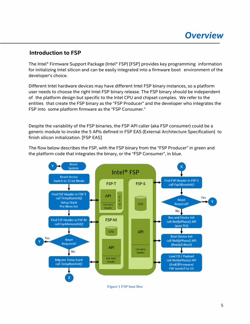
Despite the variability of the FSP binaries, the FSP API caller (aka FSP consumer) could be a generic module to invoke the 5 APIs defined in FSP EAS (External Architecture Specification) to finish silicon initialization. [FSP EAS]
The flow below describes the FSP, with the FSP binary from the “FSP Producer” in green and the platform code that integrates the binary, or the “FSP Consumer”, in blue.
Figure 1 FSP boot flow

6
The FSP EAS describes the API interface to the FSP binary that the consumer code will invoke, and it also describes the hand off state from the execution of the FSP binary. The latter information is conveyed in Hand-Off Blocks, or HOB’s. The FSP uses many of the data structures defined in the PI Specification including HOBs, Firmware Volumes, Firmware Files, etc.
The FSP binary can be integrated into any firmware solution, such as UEFI firmware (EDK2), or coreboot.
The FSP consumption, which is the topic of this paper, can be a plurality of firmware environments, of which an EDKII-style consumer will be described in more detail.
Introduction to FSP 2.0
The FSP 1.x specification defines the FSP APIs in one FSP binary. This is OK for SPI/NOR flash because all the flash regions can be mapped by the silicon during the system power on. However if the flash part is an NVMe/NAND flash device, not all the flash regions can be mapped during the system power on by default. The flash part has to be mapped step by step. For example, the first part, the TempRam (system SRAM or CPU cache) initialization code, is mapped during the system power on. Then the second part, the memory initialization code, is loaded to the TempRam by an early stage boot loader. Finally, the third part, the silicon initialization code, is loaded to the system DRAM by a later stage boot loader. FSP 1.x cannot support this model.
The FSP 2.0 specification resolves this architecture limitation of needing the flash story memory
7
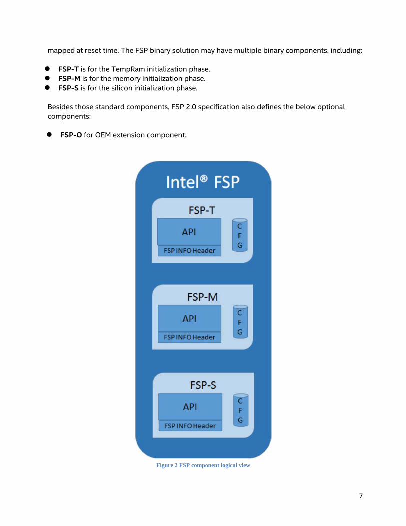
mapped at reset time. The FSP binary solution may have multiple binary components, including:
FSP-T is for the TempRam initialization phase. FSP-M is for the memory initialization phase. FSP-S is for the silicon initialization phase.
Besides those standard components, FSP 2.0 specification also defines the below optional components:
FSP-O for OEM extension component.
Figure 2 FSP component logical view
8
The FSP 1.x specification defines both PostPciBusEnumeration and ReadyToBoot notification phases. However, some firmware solutions may enable devices in PCI mode at BIOS phase and enable devices in ACPI mode at OS runtime phase. As such, the firmware needs a hook point to switch the device mode. ReadyToBoot is still too early because these devices may stop working due to lack of driver in firmware phase if the device mode is switched. The proper place to switch the mode is in ExitBootServices for UEFI firmware. FSP 2.0 defines EndOfFirmware notify phase to support this model of device switching.
The FSP 1.x specification defines both VPD and UPD as configuration data. FSP2.0 simplifies the concept and treats all configuration data as UPD. An FSP consumer may copy the default UPD data, update it, and then pass the new data as the FSP API parameter in order to override the default configuration information.
Introduction to EDKII
EDKII is open source implementation for UEFI firmware which can boot multiple UEFI-aware operating systems (OS). This document will introduce how to use EDKII as an FSP consumer module to build a platform BIOS.
Summary
This section provided an overview of Intel FSP and EDKII.

9
FSP Produce/Consumer
In EDKII, there are 2 different FSP related packages. One is the producer, IntelFsp2Pkg, which is used to produce an FSP binary together with other EDKII core and silicon packages. The other is the consumer, IntelFsp2WrapperPkg, which will consume the FSP API’s exposed by the FSP binary.
Since FSP 2.0 specification is not backward compatible with the FSP 1.1 specification, IntelFspPkg and IntelFspWrapperPkg support is limited to FSP 1.1 specification and FSP 2.0 specification support is provided by separate IntelFsp2Pkg and IntelFsp2WrapperPkg.
This paper focuses only on how IntelFsp2WrapperPkg code consumes the FSP binary. This paper will not describe on how IntelFsp2Pkg produces an FSP binary.[FSP Producer] This paper
will not describe the consumption of FSP binary by other firmware, like coreboot [COREBOOT].
Figure 3 FSP producer/consumer
Summary
This section describes the FSP producer/consumer elements in EDKII.

10
FSP Wrapper Boot Flow
According to the FSP EAS, an FSP.bin exposes 5 API’s: TempRamInitApi, FspMemoryInitApi, TempRamExitApi, FspSiliconInitApi, and FspNotifyPhaseApi (i.e., PostPciBusEnumeration, ReadyToBoot and EndOfFirmware).
When should these FSP API’s be invoked in an EDKII BIOS?
There are many architectural choices. EDKII uses the below implementation solution.
In the PEI phase, the SecCore calls TempRamInitApi, registers SecTempRamDonePpi, and then enters the PeiCore. The FspmWrapperPeim module calls FspMemoryInit. After memory is initialized, the PeiCore calls SecTempRamDonePpi and SecTempRamDonePpi calls TempRamExitApi to tear down the CAR. Then the FspWrapperPeim calls FspSiliconInit.
In the DXE phase, the FspWrapperNotifyDxe will register for a notification on PciEnumerationDone, ReadyToBoot, ExitBootServices callback functions. Finally, the FspNotifyApi will be called in the callback functions.
Figure 4 FSP2.0 wrapper boot flow
IntelFsp2WrapperPkg (https://github.com/tianocore/edk2/tree/master/IntelFsp2WrapperPkg) can support multiple PI boot modes, including normal boot, S3 [ACPI] resume, capsule update, as well as recovery. Boot modes are describes in the UEFI PI Specification [UEFI PI Specification].
FSP API Parameter
Each FSP module (FSP-T, FSP-M, FSP-S) contains its own configurable data region which will be used by the FSP during initialization. This configuration region is a data structure called the Updateable Product Data (UPD) and will contain the default parameters for the FSP initialization.
11
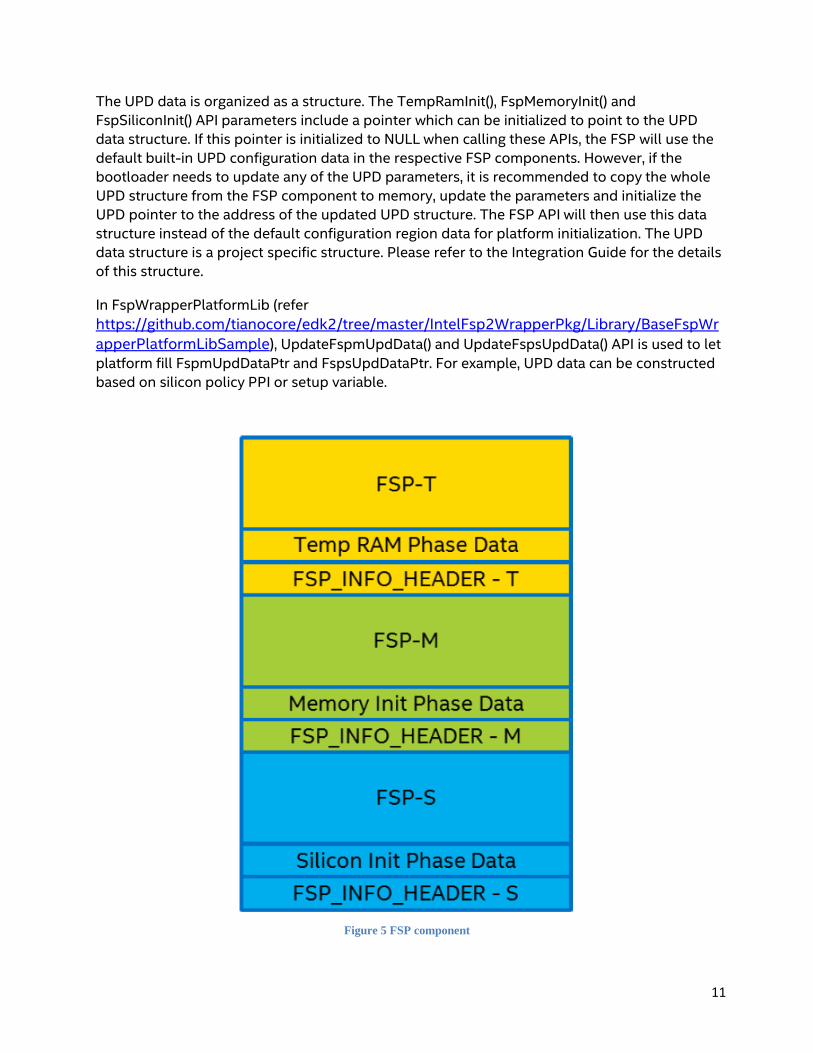
The UPD data is organized as a structure. The TempRamInit(), FspMemoryInit() and FspSiliconInit() API parameters include a pointer which can be initialized to point to the UPD data structure. If this pointer is initialized to NULL when calling these APIs, the FSP will use the default built-in UPD configuration data in the respective FSP components. However, if the bootloader needs to update any of the UPD parameters, it is recommended to copy the whole UPD structure from the FSP component to memory, update the parameters and initialize the UPD pointer to the address of the updated UPD structure. The FSP API will then use this data structure instead of the default configuration region data for platform initialization. The UPD data structure is a project specific structure. Please refer to the Integration Guide for the details of this structure.
In FspWrapperPlatformLib (refer https://github.com/tianocore/edk2/tree/master/IntelFsp2WrapperPkg/Library/BaseFspWrapperPlatformLibSample), UpdateFspmUpdData() and UpdateFspsUpdData() API is used to let platform fill FspmUpdDataPtr and FspsUpdDataPtr. For example, UPD data can be constructed based on silicon policy PPI or setup variable.
Figure 5 FSP component

12
Summary
This section has a generic overview of FSP wrapper boot flow. The detail boot flow in each boot mode will be described in next several sections.

13
Normal Boot
Boot Flow
The normal boot flow of FSP2.0 is shown as figure 6. In normal boot, the SecPlatformLib (sample at https://github.com/tianocore/edk2/tree/master/IntelFsp2WrapperPkg/Library/SecFspWrapperPlatformSecLibSample ), which is linked by the SecCore (https://github.com/tianocore/edk2/tree/master/UefiCpuPkg/SecCore ), calls first FSP API – TempRamInitApi, and then transfers the control to the PeiCore. SecPlatformLib also registers SecTempRamDonePpi (https://github.com/tianocore/edk2/blob/master/IntelFsp2WrapperPkg/Library/SecFspWrapperPlatformSecLibSample/SecTempRamDone.c ) for TempRamExitApi.
One platform PEIM is responsible to detect the current boot mode and finds some variables (like capsule variable) to finalize the boot mode selection. The FspmWrapperPeim (https://github.com/tianocore/edk2/tree/master/IntelFsp2WrapperPkg/FspmWrapperPeim ) has a dependency on MasterBootModePpi, so after the boot mode is determined, the FspmWrapperPeim is invoked. FspmWrapperPeim gets the UPD data, allocates buffer for UPD override data, then calls UpdateFspmUpdData() to update the UPD data according to platform policy (sample at https://github.com/tianocore/edk2/tree/master/IntelFsp2WrapperPkg/Library/BaseFspWrapperPlatformLibSample ). Then FspmWrapperPeim calls second FSP API – FspMemoryInitApi. Once this API returns, FspmWrapperPeim calls PostFspmHobProcess() to process the initial FSP HOB. (sample at https://github.com/tianocore/edk2/tree/master/IntelFsp2WrapperPkg/Library/PeiFspWrapperHobProcessLibSample ). FspWrapperHobProcessLib parses resource HOB and installs PEI memory to PEI core.
Once the PeiCore gets permanent memory, PeiCore does TemporaryRam migration and calls PeiTemporaryRamDonePpi, where TempRamExitApi is called. After that, PeiCore installs PeiMemoryDiscovered. Then the dependency of FspsWrapperPeim (https://github.com/tianocore/edk2/tree/master/IntelFsp2WrapperPkg/FspsWrapperPeim ) is satisfied. FspsWrapperPeim gets the UPD data, allocates buffer for UPD override data, then calls UpdateFspsUpdData() to update the UPD data according to platform policy. (sample at https://github.com/tianocore/edk2/tree/master/IntelFsp2WrapperPkg/Library/BaseFspWrapperPlatformLibSample ). Then FspsWrapperPeim calls FspSiliconInitApi to finish final silicon initialization. Once this API returns, FspsWrapperPeim calls PostFspsHobProcess() to process FSP HOB after silicon initialization. (sample at https://github.com/tianocore/edk2/tree/master/IntelFsp2WrapperPkg/Library/PeiFspWrapperHobProcessLibSample ). Typically, there will be more data in the FSP HOB at this time. Most work in PostFspsHobProcess() is to migrate the HOB data from FSP to FspWrapper.

14
Then the PeiCore will continue dispatching the final PEIMs and jump into the DxeCore. Then the DxeCore launches FspWrapperNotifyDxe (https://github.com/tianocore/edk2/tree/master/IntelFsp2WrapperPkg/FspWrapperNotifyDxe ). FspWrapperNotifyDxe registers a callback function for the last FSP API – FspNotifyApi, for AfterPciEnumeration, ReadyToBoot, and EndOfFirmware.
Figure 6 FSP2.0 normal boot flow
Memory Layout
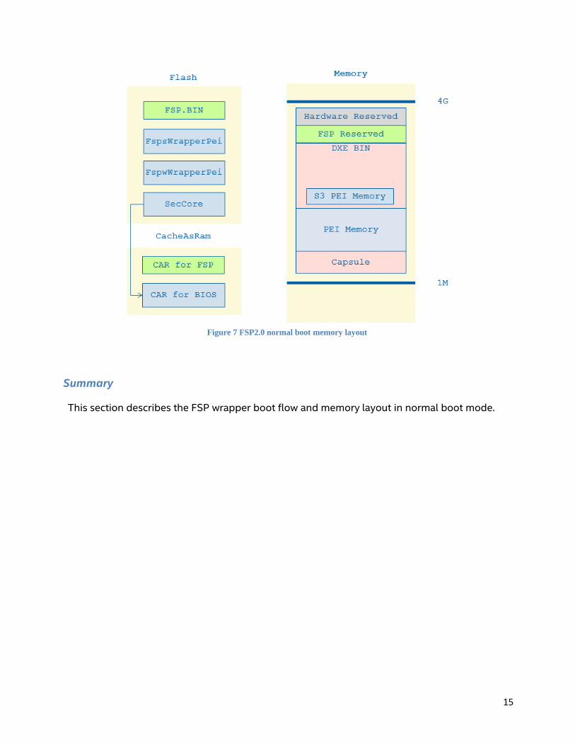
The memory layout for the FSP normal boot is shown in figure 7. The left hand side is the component on the flash and the temporary memory, such as cache as RAM. The right hand side is the DRAM layout. The GREEN part is for the FSP binary. The BLUE part is for the EDKII BIOS wrapper.
The SecCore in FspWrapper path is same as the normal platform SecCore. The only difference is that the SecCore in FspWrapper uses the FSP API to initialize the CAR. When the SecCore calls TempRamInitApi, the FSP binary will setup the CAR, and use part of them, and leave rest of these activities to the EDKII BIOS. This CAR information is reported as a return parameter of TempRamInitApi. (See left bottom)
Then the FspmWrapperPei calls FspMemoryInitApi, wherein the FSP binary will initialize silicon including DRAM, and reserved portions of DRAM. The full memory layout, including full DRAM size, reserved DRAM location, and SMRAM location will be reported by the FSP HOB.
Finally the FSP HOB is converted to the PEI HOB so that PEI/DXE can know the system memory information.
15
Figure 7 FSP2.0 normal boot memory layout
Summary
This section describes the FSP wrapper boot flow and memory layout in normal boot mode.
16
S3 Boot
Boot Flow
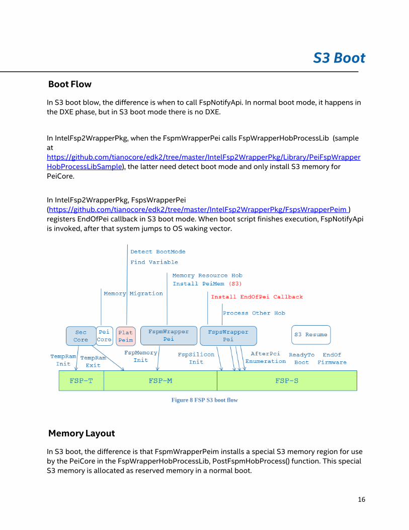
In S3 boot blow, the difference is when to call FspNotifyApi. In normal boot mode, it happens in the DXE phase, but in S3 boot mode there is no DXE.
In IntelFsp2WrapperPkg, when the FspmWrapperPei calls FspWrapperHobProcessLib (sample at https://github.com/tianocore/edk2/tree/master/IntelFsp2WrapperPkg/Library/PeiFspWrapperHobProcessLibSample), the latter need detect boot mode and only install S3 memory for PeiCore.
In IntelFsp2WrapperPkg, FspsWrapperPei (https://github.com/tianocore/edk2/tree/master/IntelFsp2WrapperPkg/FspsWrapperPeim ) registers EndOfPei callback in S3 boot mode. When boot script finishes execution, FspNotifyApi is invoked, after that system jumps to OS waking vector.
Figure 8 FSP S3 boot flow
Memory Layout
In S3 boot, the difference is that FspmWrapperPeim installs a special S3 memory region for use by the PeiCore in the FspWrapperHobProcessLib, PostFspmHobProcess() function. This special S3 memory is allocated as reserved memory in a normal boot.
17
S3 NV Data Passing
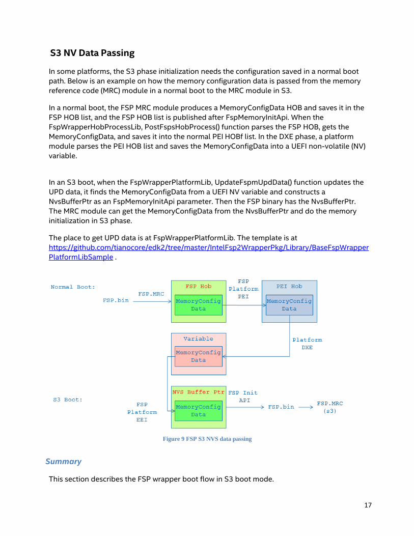
In some platforms, the S3 phase initialization needs the configuration saved in a normal boot path. Below is an example on how the memory configuration data is passed from the memory reference code (MRC) module in a normal boot to the MRC module in S3.
In a normal boot, the FSP MRC module produces a MemoryConfigData HOB and saves it in the FSP HOB list, and the FSP HOB list is published after FspMemoryInitApi. When the FspWrapperHobProcessLib, PostFspsHobProcess() function parses the FSP HOB, gets the MemoryConfigData, and saves it into the normal PEI HOBf list. In the DXE phase, a platform module parses the PEI HOB list and saves the MemoryConfigData into a UEFI non-volatile (NV) variable.
In an S3 boot, when the FspWrapperPlatformLib, UpdateFspmUpdData() function updates the UPD data, it finds the MemoryConfigData from a UEFI NV variable and constructs a NvsBufferPtr as an FspMemoryInitApi parameter. Then the FSP binary has the NvsBufferPtr. The MRC module can get the MemoryConfigData from the NvsBufferPtr and do the memory initialization in S3 phase.
The place to get UPD data is at FspWrapperPlatformLib. The template is at https://github.com/tianocore/edk2/tree/master/IntelFsp2WrapperPkg/Library/BaseFspWrapperPlatformLibSample .
Figure 9 FSP S3 NVS data passing
Summary
This section describes the FSP wrapper boot flow in S3 boot mode.
18
Capsule Flash Update
Boot Flow
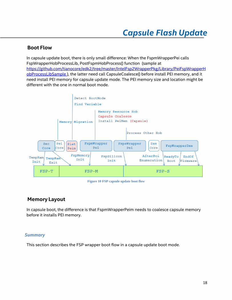
In capsule update boot, there is only small difference: When the FspmWrapperPei calls FspWrapperHobProcessLib, PostFspmHobProcess() function (sample at https://github.com/tianocore/edk2/tree/master/IntelFsp2WrapperPkg/Library/PeiFspWrapperHobProcessLibSample ), the latter need call CapsuleCoalesce() before install PEI memory, and it need install PEI memory for capsule update mode. The PEI memory size and location might be different with the one in normal boot mode.
Figure 10 FSP capsule update boot flow
Memory Layout
In capsule boot, the difference is that FspmWrapperPeim needs to coalesce capsule memory before it installs PEI memory.
Summary
This section describes the FSP wrapper boot flow in a capsule update boot mode.
19
Recovery
Boot Flow
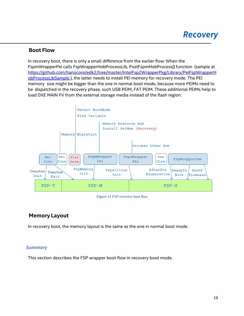
In recovery boot, there is only a small difference from the earlier flow: When the FspmWrapperPei calls FspWrapperHobProcessLib, PostFspmHobProcess() function (sample at https://github.com/tianocore/edk2/tree/master/IntelFsp2WrapperPkg/Library/PeiFspWrapperHobProcessLibSample ), the latter needs to install PEI memory for recovery mode. The PEI memory size might be bigger than the one in normal boot mode, because more PEIMs need to be dispatched in the recovery phase, such USB PEIM, FAT PEIM. These additional PEIMs help to load DXE MAIN FV from the external storage media instead of the flash region.
Figure 11 FSP recovery boot flow
Memory Layout
In recovery boot, the memory layout is the same as the one in normal boot mode.
Summary
This section describes the FSP wrapper boot flow in recovery boot mode.
20
Conclusion
The Firmware Support Package (FSP) provides a simple silicon initialization solution that reduces time-to-market, and it is economical to build. IntelFsp2WrapperPkg is the FSP consumer in EDKII to support building out a FSP wrapper based UEFI BIOS. This paper describes the detail work flow and data structure in IntelFsp2WrapperPkg.
21
Glossary
ACPI – Advanced Configuration and Power Interface. Describe system configuration that is not discoverable and provide runtime interpreted capabilities
CAR – Cache-As-RAM. Use of the processor cache as a temporary memory / stack store FPDT –Firmware Performance Data Table defined in ACPI specification.
FSP –Intel Firmware Support Package
FSP Consumer – the entity that integrates the FSP binary, such as EDKII or other firmware like coreboot
FSP Producer – the entity that creates the FSP binary, such as the CPU and chipset manufacturer (e.g., “Silicon Vendor”).
Bootloader – another name for an “FSP Consumer”, as distinct from a MBR-based loader for PC/AT BIOS or the OS loader as a UEFI Executable for UEFI [UEFI Overview]
PI – Platform Initialization. Volume 1-5 of the UEFI PI specifications.
UEFI – Unified Extensible Firmware Interface. Firmware interface between the platform and the operating system.

22
References
[ACPI] Advanced Configuration and Power Interface, vesion 6.0, www.uefi.org [COREBOOT] coreboot firmware www.coreboot.org
[BSF] Boot Setting File (BSF) Specification
https://firmware.intel.com/sites/default/files/BSF_1_0.pdf
[EDK2] UEFI Developer Kit www.tianocore.org
[FSP] Intel Firmware Support Package http://www.intel.com/content/www/us/en/intelligent- systems/intel-firmware-support-package/intel-fsp-overview.html
[FSP EAS] FSP External Architecture Specification http://www.intel.com/content/dam/www/public/us/en/documents/technical-specifications/fsp- architecture-spec-v2.pdf
[FSP Producer] Yao, Zimmer, Rangarajan, Ma, Estrada, Mudusuru, “A_Tour_Beyond_BIOS_Creating_the_Intel_Firmware_Support_Package_with_the_EFI_Devel oper_Kit_II_(FSP2.0)” https://github.com/tianocore/tianocore.github.io/wiki/EDK-II-white- papers
[UEFI] Unified Extensible Firmware Interface (UEFI) Specification, Version 2.5 www.uefi.org
[UEFI Book] Zimmer,, et al, “Beyond BIOS: Developing with the Unified Extensible Firmware Interface,” 2nd edition, Intel Press, January 2011
[UEFI Overview] Zimmer, Rothman, Hale, “UEFI: From Reset Vector to Operating System,” Chapter 3 of Hardware-Dependent Software, Springer, February 2009
[UEFI PI Specification] UEFI Platform Initialization (PI) Specifications, volumes 1-5, Version
1.4 www.uefi.org
23
Authors
Jiewen Yao ([email protected]) is EDKII BIOS architect, EDKII FSP package maintainer with Software and Services Group (SSG) at Intel Corporation.
Vincent J. Zimmer ([email protected]) is a Senior Principal Engineer with the Software and Services Group (SSG) at Intel Corporation.
Giri Mudusuru ([email protected]) is BIOS architect and Principal Engineer in the Client Components Group (CCG) at Intel Corporation.
Satya P. Yarlagadda ([email protected]) is BIOS architect in the Client Components Group (CCG) at Intel Corporation.
Ravi P. Rangarajan ([email protected]) is BIOS architect in the Internet of Things (IOT) Group (IOTG) at Intel Corporation.
Maurice Ma ([email protected]) is BIOS architect in the Internet of Things (IOT) IOT Group (IOTG) at Intel Corporation.
Amy Chan ([email protected]) is BIOS architect in the Client Components Group (CCG) at Intel Corporation.
Related Documents


