A THREE DIMENSIONAL RECONSTRUCTION ALGORITHM FOR ROTATIONALLY SCANNED OBJECTS An Undergraduate Research Scholars Thesis by SIAMAK NARIMAN Submitted Honors and Undergraduate Research Texas A&M University in partial fulfillment of the requirements for the designation as an UNDERGRADUATE RESEARCH SCHOLAR Approved by Research Advisor: Dr. Raffaella Righetti May 2014 Major: Electrical Engineering

Welcome message from author
This document is posted to help you gain knowledge. Please leave a comment to let me know what you think about it! Share it to your friends and learn new things together.
Transcript

A THREE DIMENSIONAL RECONSTRUCTION ALGORITHM FOR
ROTATIONALLY SCANNED OBJECTS
An Undergraduate Research Scholars Thesis
by
SIAMAK NARIMAN
Submitted Honors and Undergraduate Research
Texas A&M University
in partial fulfillment of the requirements for the designation as an
UNDERGRADUATE RESEARCH SCHOLAR
Approved by Research Advisor: Dr. Raffaella Righetti
May 2014
Major: Electrical Engineering

TABLE OF CONTENTS
Page
ABSTRACT ....................................................................................................................................1
DEDICATION .................................................................................................................................3
ACKNOWLEDGMENTS ...............................................................................................................4
NOMENCLATURE ........................................................................................................................5
CHAPTERS
I INTRODUCTION ..............................................................................................................6
II METHODS.......................................................................................................................10
The 3D Reconstruction Algorithm...................................................................................10
Experiments .....................................................................................................................15
Sample Preparation ..........................................................................................................16
Rotational Mechanical Scanning Framework ..................................................................16
Ultrasound Data Collection..............................................................................................17
III RESULTS .......................................................................................................................19
Limitation of the 3D Reconstruction Algorithm ............................................................23
IV CONCLUSION...............................................................................................................24
REFERENCES ..............................................................................................................................25

1
ABSTRACT
A Three Dimensional Reconstruction Algorithm for Rotationally Scanned Objects
(May 2014)
Siamak Nariman
Department of Electrical Engineering
Texas A&M University
Research Advisor: Dr. Raffaella Righetti
Department of Electrical Engineering
Ultrasound imaging is a medical modality that uses high frequency sound waves to produce high
resolution images of internal tissues’ structures. Since ultrasound images are captured in real
time, the modality provides a refined method to analyze internal organs such as liver, kidney and
heart. Ultrasound imaging is relatively inexpensive and safe compared to other imaging
modalities. So, it is used for diagnosis of a wide range of diseases.
One of the emerging techniques in the ultrasound imaging field is three-dimensional (3D)
imaging. Typically, ultrasound transducer arrays are used to capture 2D views of the tissue under
investigation. 2D images can be clinically useful. However, it is sometimes difficult to visualize
the entire surface of an organ or tissue’s abnormalities using only 2D images. Additionally, 2D
images can be difficult to interpret. Therefore, obtaining 3D volumes or snapshots of the tissue
of interest can greatly help the diagnosis of diseases or abnormalities. Creating 3D volumes may
be a very useful tool in clinical practices and is often used in obstetrics, cardiology, cancer
imaging and image-guided surgeries.

2
In order to generate 3D volumes, a set of 2D ultrasound images needs to be acquired first. The
2D images can be obtained using an imaging probe capturing the tissue from different angles.
Then, a reconstruction algorithm is applied to the data to produce a 3D volume. This thesis
focuses on the development and analysis of a 3D reconstruction algorithm that uses 2D
ultrasound images acquired from a tissue that is been scanned rotationally with the transducer.
The algorithm is validated using experimental data obtained from phantoms of known geometry.
The results of this thesis show that the proposed algorithm can be used to reconstruct 3D
volumes of the controlled phantom with high accuracy. While more experiments are needed to
fully understand the limitations of the algorithm, these preliminary results suggest that, in the
future, this algorithm may also be used for 3D imaging of biological tissues.

3
DEDICATION
I dedicate this research to my parents. Without their continuous support and help this
opportunity would not have been possible.

4
ACKNOWLEDGEMENTS
For most, I would like to express my deepest gratitude to Dr. Raffaella Righetti for giving me
this incredible opportunity and her continuous support, immense knowledge and patience.
Throughout this research, I have learned many new skills. I would also like to thank her for
helping me to shape my interest and ideas.
My second and sincere appreciation goes to Peer Mohamed Shafeeq Shajudeen for his
tremendous help. He has being such a great mentor, friend and supervisor throughout my
research. His advices and insights were so valuable to me. His perception and attitude towards
my research always inspired me to go above and beyond. He has always been an open person to
ideas and encouraging in all stages of my thesis. Shafeeq has always been a great reliable
person who I could talk about my frustrations and excitements.
I would also like to thank Lucas Stephen Kimble for all his help throughout collecting data,
writing the algorithm and supporting me in the lab. He has been so helpful to me when I needed
him.
And lastly, my appreciation and friendship goes to Severiano Mata, who helped me in making
samples for collecting data. He has always been a great support in my struggles and willing to
give help.
5
NOMENCLATURE
US Ultrasound
2D 2 Dimensional
3D 3 Dimensional
RGB Red-Green-Blue triple color

6
CHAPTER I
INTRODUCTION
Biomedical imaging is a reliable method for visualizing anatomic structure and determining
biological functions within the organs. Ultrasound is one of the most widely used biomedical
imaging modality for examinations and diagnosis of a large number of diseases in the world.
Ultrasound imaging features include: low cost, durability, portability, safety (radiation-free) and
high spatial and temporal resolutions.
The origin of medical ultrasound imaging could be traced back half a century, and tremendous
improvements have been made in this field since then. Ultrasound is capable of providing cross-
sectional views of anatomical structures with high spatial and temporal resolutions and is
typically used in obstetrics, gynecology and cardiology. However, due to its flexibility and non-
invasive nature, it has recently become one of the main biomedical imaging tools also for
detecting kidney and liver diseases, musculoskeletal abnormalities and cancers. In the last
decade, image quality of ultrasound images has improved significantly, and it is now possible to
obtain accurate information on blood flow and minute changes in tissues’ structures. These
advancements in the field have progressively left a great impact on radiology and image-guided
therapies as well.
Propagation of ultrasound in tissues produces echoes that can be captured and used to identify
the inner structure of a tissue. During an examination, an ultrasonic transducer is used to acquire
data from the tissue of interest. This transducer releases sound and captures the waves reflected

7
by the various tissue interfaces encountered while the sound wave propagates in the body. These
echoes are used to form live images of the organs that are being examined.(7) Each section has a
different acoustic impedance, which affects the sound reflection.
Figure 1: Ultrasound waves bounce back to the transducer to create an echo. (10)
In a typical US medical examination, the ultrasound transducer captures a series of 2D
ultrasound images as the device is swept along the surface of the body. The radiologist who
needs to interpret the 2D images to identify the presence of tissue’s abnormalities needs to create
a 3D subjective impression from prior knowledge of the anatomy and pathology of the organ.
“Mentally transforming multiple 2D images from a 3D impression of the anatomy and pathology
is not only time-consuming and inefficient, but is also more importantly, variable and subjective,
which can lead to incorrect decisions in diagnosis, and in the planning and delivery of
therapy.”(3)

8
Figure 2: Representation of the transducer pulse generation and reflection.(1)
Application of 3D reconstruction techniques from a set of 2D images allows visualization of a
volume of data and thus can provide additional information about the organ under investigation.
3D ultrasound imaging is in general a much more accurate way to visualize the anatomy than 2D
imaging, and it is also more flexible as it allows visualizations of tissue’s structures from many
points of view.
Figure 3: Schematic of transducer showing two types of scanning movements. Diagram
a. represents linear scanning and b. demonstrates tilt scanning approach. The collected
images from these approaches are used for 3D reconstruction.(3)
3D ultrasound imaging can be achieved in different ways. One way is to use a special volume
probe (3D transducer). A second way is to sweep across the area of interest to collect a large
stack of 2D images and then perform a 3D reconstruction. Typically, 3D reconstruction

9
algorithms use 2D images obtained along a plane in the free hand acquisition mode, and then
combing all the slices to perform a volume rendering of the acquired data.(8)
This research aims at developing and analyzing the performance of an algorithm able to perform
a 3D reconstruction from a set of 2D ultrasound images obtained at different insonicating angles.
The algorithm is tested using experimental ultrasound data obtained from a phantom containing
an object of a known shape. The reconstructed 3D volumes are validated with respect to the
actual dimensions of the object. In the future, this algorithm may be used for volumetric
visualization and assessment of real tissues.

10
CHAPTER II
METHODS
In this section, the technical details of the proposed 3D reconstruction algorithm and the
experimental methodology used to test the proposed algorithm are reported.
The 3D Reconstruction Algorithm
A number of algorithms for reconstructing 3D volumes from 2D ultrasound images have been
reported in the past but most of them are not suitable for 2D images acquired at different
insonicating angles. The 3D reconstruction algorithm proposed in this thesis uses 120 2D
ultrasound images acquired by rotating an ultrasound transducer around the object of interest
(details on the data acquisition method are described in the next section). This algorithm is
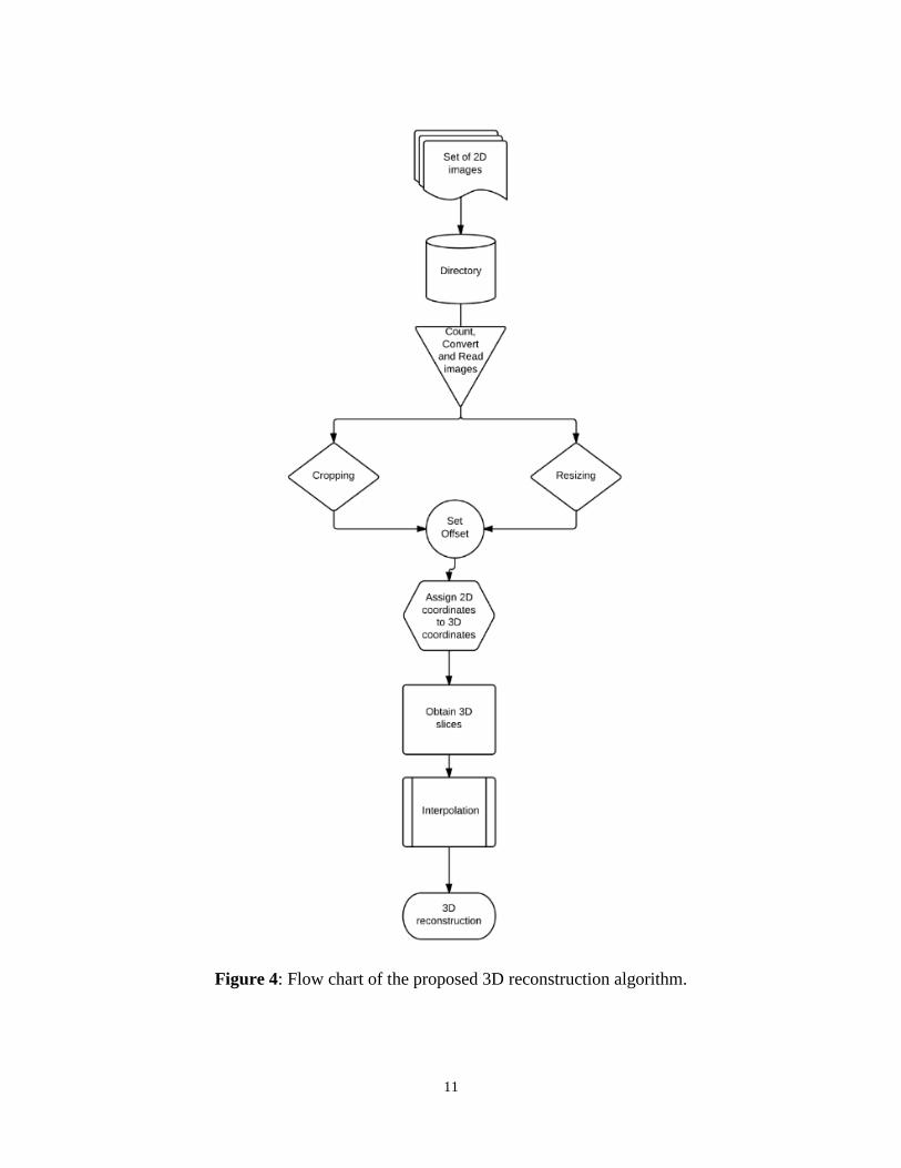
composed of multiple steps as demonstrated by its flow chart:
11
Figure 4: Flow chart of the proposed 3D reconstruction algorithm.

12
Figure 5: Typical B-mode image obtained from the saw handle at 0o.
1. The entire algorithm is written in Matlab. The process begins by counting each image
corresponding to a given captured angle in a FOR loop. First, all the collected images are
saved in a directory to be accessed during computation. Second, the directory is identified
to read all the images. In addition, all the images are converted from true color
image RGB to a grayscale intensity image. This process helps to eliminate the saturation
information while retaining the luminance. A typical captured image (figure 5) contains
text with information regarding the captured image that needs to be eliminated. In order
to use only the actual ultrasound data, a cropping function is used to crop the object
image. All the cropped images are then saved in a new directory.

13
Figure 6: Cropped image at 0o.
2. To ensure the accuracy of the object location, a fixed offset is identified and used for all
the images. The offset is the distance from the center of the phantom to the transducer’s
face. This offset varies from image to image depending on the geometry of the object. To
incorporate the offset into the images, centimeter to pixel calculation is utilized for image
adjustment in pixel environment. This provides uniform sized images for the
reconstruction. In order to set up each image on a uniform offset; rows and columns of
each image as well as the offset are defined as matrices. If the image does not fit the
offset, it is cropped from the top to be fitted in the offset matrix. Then, the location of a
new matrix is defined. All the new offset images are saved in a new directory. Figure 6
shows a cropped image, which is fitted in the offset.

14
Figure 7: Offset image at 0o.
3. All the offset images are resized to ¼ of the offset image size, which speeds up the
overall process of reconstruction without affecting the resolution significantly. Each
image is processed in another FOR loop. Starting from image one, each image is swept
along its height from the bottom of the image to the top, beginning at the left most side
and moving across the image width, by placing each pixel in the 2D image and assign
that coordinates to its corresponding 3D coordinates. For each 3D point, the voxel value
is calculated using interpolation and following this equation:
𝑥𝑛𝑒𝑤 = 𝑟𝑐𝑜𝑠𝜃 𝑦𝑛𝑒𝑤 = 𝑟𝑠𝑖𝑛𝜃 𝑧𝑛𝑒𝑤 = 𝑧𝑜𝑙𝑑
0 < 𝑟 < 𝑖𝑚𝑎𝑔𝑒 ℎ𝑒𝑖𝑔ℎ𝑡 0 < 𝑧𝑜𝑙𝑑 < 𝑖𝑚𝑎𝑔𝑒 𝑤𝑖𝑑𝑡ℎ
𝑓𝑖𝑛𝑎𝑙𝑖𝑚𝑎𝑔𝑒(𝑥𝑛𝑒𝑤, 𝑦𝑛𝑒𝑤, 𝑧𝑛𝑒𝑤) = 𝑖𝑚𝑎𝑔𝑒 (𝑥, 𝑦)

15
Where 𝑥𝑛𝑒𝑤 , 𝑦𝑛𝑒𝑤 , 𝑧𝑛𝑒𝑤 are the new coordinates in the 3D environment. Each coordinate is
defined based on the angle 𝜃 (in this case 3 degrees) as each image is swept along its height and
width.
4. In the next step, all the 2D images previously cropped and placed in the 3D matrix enter
the interpolation phase. This algorithm removes singleton dimensions, uses a cubic spline
interpolation and isosurface to create the reconstructed surface. The spline interpolation
was used to create a smooth surface since it possesses a high degree of smoothness at the
places where the images are connected in the 3D grid.
This approach should preserve the original information in the captured images. As the algorithm
sweeps across each column and row of 120 images, the 3D volume is reconstructed from the 2D
images’ pixels. Therefore, by taking any cross section of the 3D volume, the original 2D image
can be recovered.
Experiments
Assessing the feasibility of an algorithm requires controlled experimental data. In this case, a
phantom object was used so that the corresponding 3D reconstruction could be validated with the
object’s actual physical dimensions. Four sets of experiments were performed. For every
experiment, 120 images were captured while rotating the ultrasound transducer around the
phantom with a gap of 3 degrees between successive images.

16
Sample Preparation
A saw handle embedded in a clear gelatin phantom was used as a testing object to validate the
developed 3D reconstruction algorithm (see figure 8). This phantom allowed to test the algorithm
in controlled conditions and to acquire multiple sets of data for analysis.
Figure 8: The gelatin phantom containing a saw handle used for experimental validation of the
proposed 3D reconstruction algorithm
Rotational Mechanical Scanning Framework
In order to collect the images, a conventional high frequency ultrasound transducer was rotated
around the object of interest, and 120 2D ultrasound images were captured at every 3 degrees
during the rotation. This forms a set of images radial to the axis of the object. Every captured
image represents a view of the object at a different angle. Since the gap between successive
images was set at 3 degrees and 120 images were acquired, each set of 2D images represented a

17
complete 360o rotation around the phantom. As the transducer was moved across the surface of
the object, the transducer location corresponding to each captured image was recorded.
Figure 9: Schematic of transducer full 360o rotation and demonstration of the transducer location
on the object.
Ultrasound Data Collection
The phantom was scanned using a Sonix RP diagnostic ultrasound system (Ultrasonix Medical
Corp., Richmond, BC, Canada) available in the Ultrasound Imaging Laboratory at Texas A&M
University. This system uses a 38 mm real-time linear array transducer with 128 channels, 5-14
MHz bandwidth, 50% fractional bandwidth at -6 dB, sampling frequency of 40 MHz, and 1 mm
beamwidth at the focus. Acquisitions were performed using a transmission frequency of 10
MHz. No significant attenuation was observed in the visualization of the object’s surface when
using ultrasonic signals in this frequency band. The focal spot was set at the location of the
object’s surface and adjusted for each acquired image.

18
Once the experimental data were collected, the 3D reconstruction algorithm previously explained
was applied to visualize the volume of the object contained in the gelatin phantom.

19
CHAPTER III
RESULTS
The results of a 3D reconstruction obtained using the experimental ultrasound images acquired
from the phantom are shown in figure 10. The 3D reconstruction shows only the lower portion of
the saw handle because the transducer’s face is limited to 4 cm, which defines the lateral width
of each captured image. So, the height of the reconstructed image corresponds to the length of
the transducer’s face. From the 3D reconstruction, the height of the handle was measured to be
about 4cm and the diameter to be about 3cm at the widest point, which corresponds to the base
of the object.

20
Figure 10: Reconstructed volume of the saw handle.
Image below displays the physical dimensions of the saw handle used for the experiments. A
measurement ruler is shown next to the saw handle to show the actual dimensions of the object.
These dimensions are: 12 cm height and 3 cm diameter at the widest point. Therefore, there
appears to be a good agreement between the 3D reconstructed object and the actual physical
dimensions of the object.
3
cm
2 1
2
1
4
3
cm

21
Figure 11: Actual saw handle with physical measurements for validation.
The wall thickness of the saw handle as visualized in the reconstructed images may be
misleading because it does not correspond to the actual physical properties of the object. Rather,
it depends on the thickness of the bright area corresponding to the surface of the obejct in the
ultrasound image. Furthermore, the roughness along the surface of the reconstructed images is
due to the presence of noise close to the surface of the object and possible limitations of the
interpolation method .
The number of triangles used to render the surface may be used to get an idea of the surface
roughness . The reconstruction of the saw handle with offset had 144131 number of vertices and
284280 number of triangles. The processing time for a complete 3D reconstruction was

22
72.376760 seconds. The reconstruction with no offset had 68664 number of vertices and 135054
number of triangles with 55.959576 seconds elapsing time. As the reconstruction was completed,
there were 98 slices that were interpolated to form a 3D volume. Figure 12 shows examples of
the slices 1, 50 and 98.
Figure 12: Interpolated slices 1, 50 and 98 respectively. These slices were used for the complete
3D reconstruction.
To demonstrate the graphical representation of the tonal distribution of the reconstructed
volume, one of the image used for the 3D reconstruction is examined below (figure 13). The
histogram can be used to evaluate the distribution of the intensities in the image and to evaluate
the number of pixels having each intensity.

23
Figure 13: Histogram of a typical image used for the 3D reconstruction. The histogram
represents the intensities present in the image divided in 50 bins.
Limitation of the 3D Reconstruction Algorithm
The accuracy of the algorithm depends on how accurately the images are acquired at the each
angle. Furthermore, if there are two or more objects in the image, this algorithm may not be
able to reconstruct all individual objects completely and accurately. If there are holes or
defects on the object’s surface, the algorithm would treat them as an empty space in the
reconstruction and may not reconstruct them properly. To determine the dimensions of the
object, manual calculation of centimeter to pixel needs to be done and the final dimensions
need to be entered in the algorithm. Finally, to apply this algorithm to real tissues, a
segmentation method may need to be used prior to the 3D reconstruction.
24
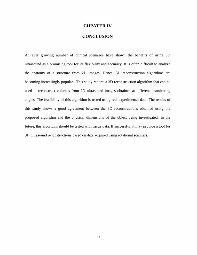
CHPATER IV
CONCLUSION
An ever growing number of clinical scenarios have shown the benefits of using 3D
ultrasound as a promising tool for its flexibility and accuracy. It is often difficult to analyze
the anatomy of a structure from 2D images. Hence, 3D reconstruction algorithms are
becoming increasingly popular. This study reports a 3D reconstruction algorithm that can be
used to reconstruct volumes from 2D ultrasound images obtained at different insonicating
angles. The feasibility of this algorithm is tested using real experimental data. The results of
this study shows a good agreement between the 3D reconstructions obtained using the
proposed algorithm and the physical dimensions of the object being investigated. In the
future, this algorithm should be tested with tissue data. If successful, it may provide a tool for
3D ultrasound reconstructions based on data acquired using rotational scanners.

25
REFERENCES
(1) Chan, Vincent, and Anahi Perlas. "Basics of ultrasound imaging." Atlas of Ultrasound-
Guided Procedures in Interventional Pain Management. Springer New York, 2011. 13-19.
(2) Dai, Yakang, et al. "Real-time visualized freehand 3D ultrasound reconstruction based on
GPU." Information Technology in Biomedicine, IEEE Transactions on14.6 (2010): 1338-
1345.
(3) Fenster, Aaron, Donal B. Downey, and H. Neale Cardinal. "Three-dimensional ultrasound
imaging." Physics in medicine and biology 46.5 (2001): R67.
(4) Huang, Wei. "Abstract." National Center for Biotechnology Information. 18 Mar. 2008. U.S.
National Library of Medicine. 03 Apr. 2014
<http://www.ncbi.nlm.nih.gov/pmc/articles/PMC2276701/>.
(5) Parmer, Biren J. "3D Reconstruction of Bone Ultrasound Data."
(6) Prager, Richard, et al. "Freehand 3D ultrasound without voxels: volume measurement and
visualisation using the Stradx system." Ultrasonics 40.1 (2002): 109-115.
(7) Robb, Richard A., and Biomedical Imaging Resource Director. "Biomedical imaging: past,
present and predictions." Journal of Medical Imaging Technology24 1 (2006): 25-37.
(8) Solberg, Ole Vegard, et al. "Freehand 3D ultrasound reconstruction algorithms—a
review." Ultrasound in medicine & biology 33.7 (2007): 991-1009.
(9) Toonkum, Pollakrit, Nijasri C. Suwanwela, and Chedsada Chinrungrueng. "Reconstruction
of 3D ultrasound images based on Cyclic Regularized Savitzky–Golay
filters." Ultrasonics 51.2 (2011): 136-147.
(10) Ultrasound Scans. (1999). Comprehensive Diagnostic Imaging.
<http://cdiok.com/?page_id=18>
Related Documents


