Republic of Iraq Ministry of Higher Education and Scientific Research Al Nahrain University College of Science A Thesis Submitted to college of Science, Al-Nahrain University in partial fulfillment of the requirements for the Degree of Master of Science in Computer Science BY Haider Majeed Jaber AL-Bakry (B. Sc. 2003) Supervisor Dr. Loay E. George Safar 1428 February 2007

Welcome message from author
This document is posted to help you gain knowledge. Please leave a comment to let me know what you think about it! Share it to your friends and learn new things together.
Transcript

Republic of IraqMinistry of Higher Education and Scientific ResearchAl Nahrain UniversityCollege of Science
A ThesisSubmitted to college of Science, Al-Nahrain University in
partial fulfillment of the requirements for the Degree of Master of Science in Computer Science
BY
Haider Majeed Jaber AL-Bakry
(B. Sc. 2003)
Supervisor
Dr. Loay E. George
Safar 1428 February 2007

< << <
Üéu†Ö]<à·†Ö]<]<ÜŠe
�
<�]<Ñ‚‘<ê×ÃÖ]Üé¿ÃÖ]< <
���������
�
Supervisor Certification
I certify that this thesis was prepared under our supervision at the
Department of Computer Science/College of Science/Al-Nahrain
University, by Haider Majeed Jaber as partial fulfillment of the
requirements for the degree of Master of Science in Computer Science.
Signature:
Name : Dr. Loay E. George
Title : Assist. Prof.
Date : / / 2006
In view of the available recommendations, I forward this thesis for
debate by the examination committee.
Signature:
Name : Dr. Taha S. Bashaga
Title : Head of the department of Computer Science,
Al-Nahrain University.
Date : / / 2006

Certification of the Examination Committee
We chairman and members of the examination committee, certify
that we have studies this thesis "Network Management System for
Public Services" presented by the student Haider Majeed Jaber and
examined her in its contents and that we have found it worthy to be
accepted for the degree of Master of Science in Computer Science.
Signature:
Name: Dr. Kader H. AL-SharaTitle : Assist. Prof.Date : / /2007
(Chairman)
Signature: Signature:
Name: Dr.Kamal M. Abood Name: Dr. Sawsan K. ThamerTitle : Assist. Prof. Title : LecturerDate : / /2007 Date : / /2007
(Member) (Member)
Signature:
Name: Dr. Loay E. George Title : Assist. Prof.Date : / /2007
(Supervisor)
Approved by the Dean of the Collage of Science, Al-Nahrain University.
Signature:
Name: Dr. LAITH ABDUL AZIZ AL-ANITitle : Assist. Prof. Date : / /2007
(Dean of Collage of Science)

�

����������������
�
�����������
���� �����
������������
�
��������������� ������� ����
�
��
��������

��
����
������������ ��
��
���������� ������� �� � ��� �������������������� �
�� ���������������������� ������������� �� �� ������������
��������������������������� �����
������������������������ �������� ������������� ��
� ������ �������� ���� ���� ��� �������� ��� ��� ����� ��� ����
��������� ����������� �������� ���������
�������� �� ��� ����� ����������� � ��� ������ � �� �����
���������������� ���������� ��������� � ��������� �����
��� ��������� ����� ���� � ������������� ����������������
�� ����� � �� ����� � ���� � ������ ��� ����� ����� ��� � ���� ��
������������������ ��������������������������������
�
�
�������
�
�
����
ii
ABSTRACT
Due to the expansion of the data transmission capabilities, it is utilized
to make many services easier, efficient, and more controlled. The public
services are more effective if they have online data transmission to get
faster request servicing, maintenance, and control.
This project is concerned with designing and implementing a
dedicated network management system prototype. Also, it concerned with
building the necessary application software tools which may needed for
managing public services (electricity, water, medical help alarm, police
monitoring, and fire monitoring). It toke into consideration that the
distributed system must be reliable, real time, secure, and scalable. The
project tried to achieve these considerations on two levels, the first is by
suggesting system layout and hardware that may provide an acceptable
solution, and the second is by the applications and protocols designed.
This thesis shows the layout of the system that composed of four
major parts: customer’s agent, service provider, zone center, and primary
center. The geographic area covered by the system was divided into
regions called zones; each zone contains customers and may contain
service providers. Each zone is controlled by network management station
called zone center that monitor and receive alarms from the agents and
send it to the appropriate nearest (estimated) available service provider. All
the zone centers are controlled by one primary network management
station called primary center. The primary center monitors and connects all
zone centers together, and plays as a backup station in case of shutting
down one of the zone centers.
The project suggests the connection media to be used (for example,
using Power Line Communication (PLC) to connect the customers with
iii
zone center, because the power line infrastructure is already exist), using
cluster of computers in each center, and distributed backup places to
achieve maximal possible reliability with good performance. The designed
system uses the Internet Protocol version 6 (IPv6) as the network protocol
to support addressing huge number of customers, quality of service,
support the anycast message type (which decrease the difficulty of building
clusters), and the facility of leaving the unused options to increase
performance. Also, the Simple Network Management Protocol version 2
(SNMPv2) was utilized because it is simple in development and takes low
bandwidth, and it was adopted to achieve more security.
In this project a distributed database was established, and the two
problems: data synchronization and the way of data storage to achieve an
acceptable performance within the multi-threaded system were handled.
The project prototype was established by using Microsoft Visual Basic
.NET 2003 which depends on the .NET framework that supports the multi-
threaded system with good utilization.
List of Abbreviations
iv
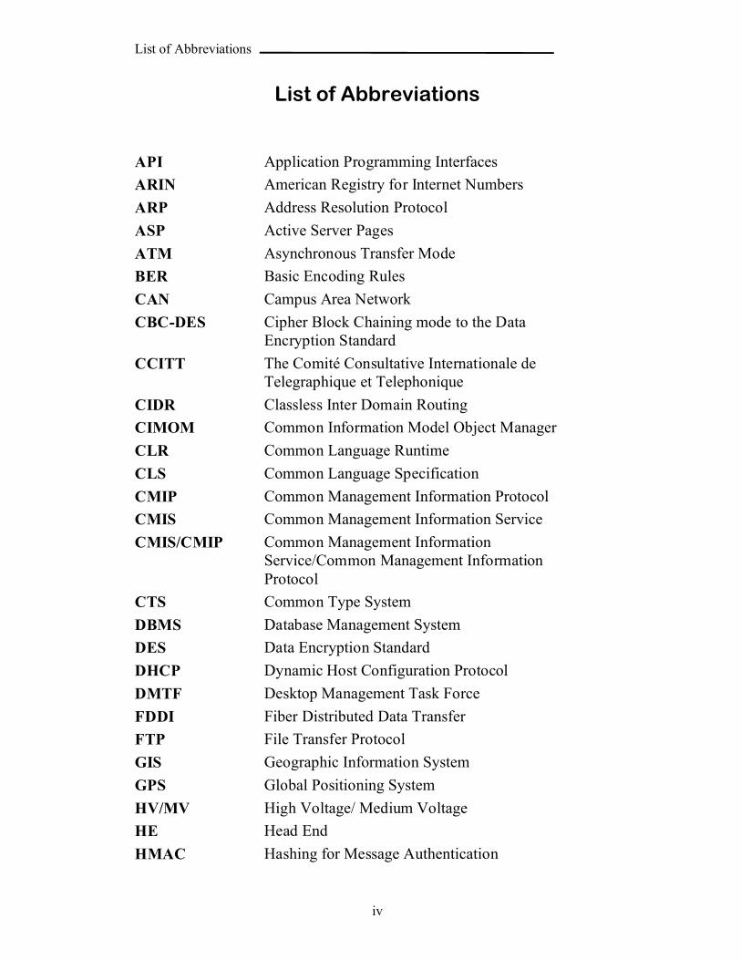
List of Abbreviations
API Application Programming Interfaces
ARIN American Registry for Internet Numbers
ARP Address Resolution Protocol
ASP Active Server Pages
ATM Asynchronous Transfer Mode
BER Basic Encoding Rules
CAN Campus Area Network
CBC-DES Cipher Block Chaining mode to the Data Encryption Standard
CCITT The Comité Consultative Internationale de Telegraphique et Telephonique
CIDR Classless Inter Domain Routing
CIMOM Common Information Model Object Manager
CLR Common Language Runtime
CLS Common Language Specification
CMIP Common Management Information Protocol
CMIS Common Management Information Service
CMIS/CMIP Common Management Information Service/Common Management Information Protocol
CTS Common Type System
DBMS Database Management System
DES Data Encryption Standard
DHCP Dynamic Host Configuration Protocol
DMTF Desktop Management Task Force
FDDI Fiber Distributed Data Transfer
FTP File Transfer Protocol
GIS Geographic Information System
GPS Global Positioning System
HV/MV High Voltage/ Medium Voltage
HE Head End
HMAC Hashing for Message Authentication
List of Abbreviations
v
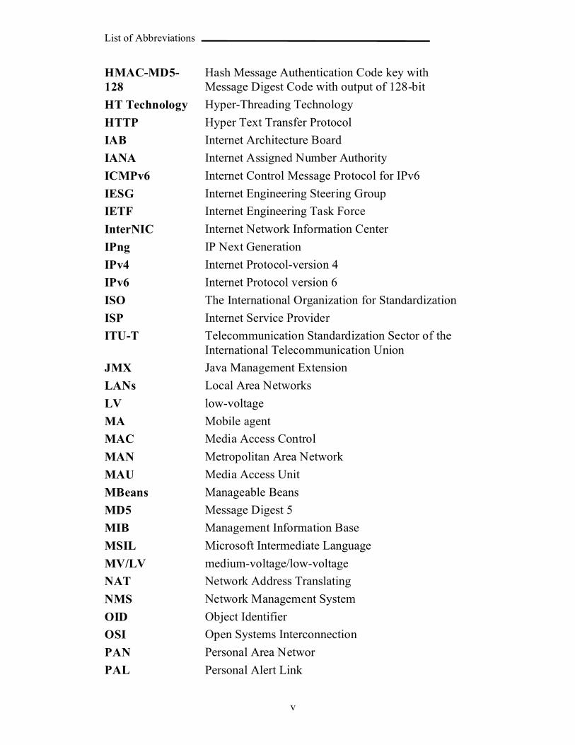
HMAC-MD5-128
Hash Message Authentication Code key with Message Digest Code with output of 128-bit
HT Technology Hyper-Threading Technology
HTTP Hyper Text Transfer Protocol
IAB Internet Architecture Board
IANA Internet Assigned Number Authority
ICMPv6 Internet Control Message Protocol for IPv6
IESG Internet Engineering Steering Group
IETF Internet Engineering Task Force
InterNIC Internet Network Information Center
IPng IP Next Generation
IPv4 Internet Protocol-version 4
IPv6 Internet Protocol version 6
ISO The International Organization for Standardization
ISP Internet Service Provider
ITU-T Telecommunication Standardization Sector of the International Telecommunication Union
JMX Java Management Extension
LANs Local Area Networks
LV low-voltage
MA Mobile agent
MAC Media Access Control
MAN Metropolitan Area Network
MAU Media Access Unit
MBeans Manageable Beans
MD5 Message Digest 5
MIB Management Information Base
MSIL Microsoft Intermediate Language
MV/LV medium-voltage/low-voltage
NAT Network Address Translating
NMS Network Management System
OID Object Identifier
OSI Open Systems Interconnection
PAN Personal Area Networ
PAL Personal Alert Link
List of Abbreviations
vi
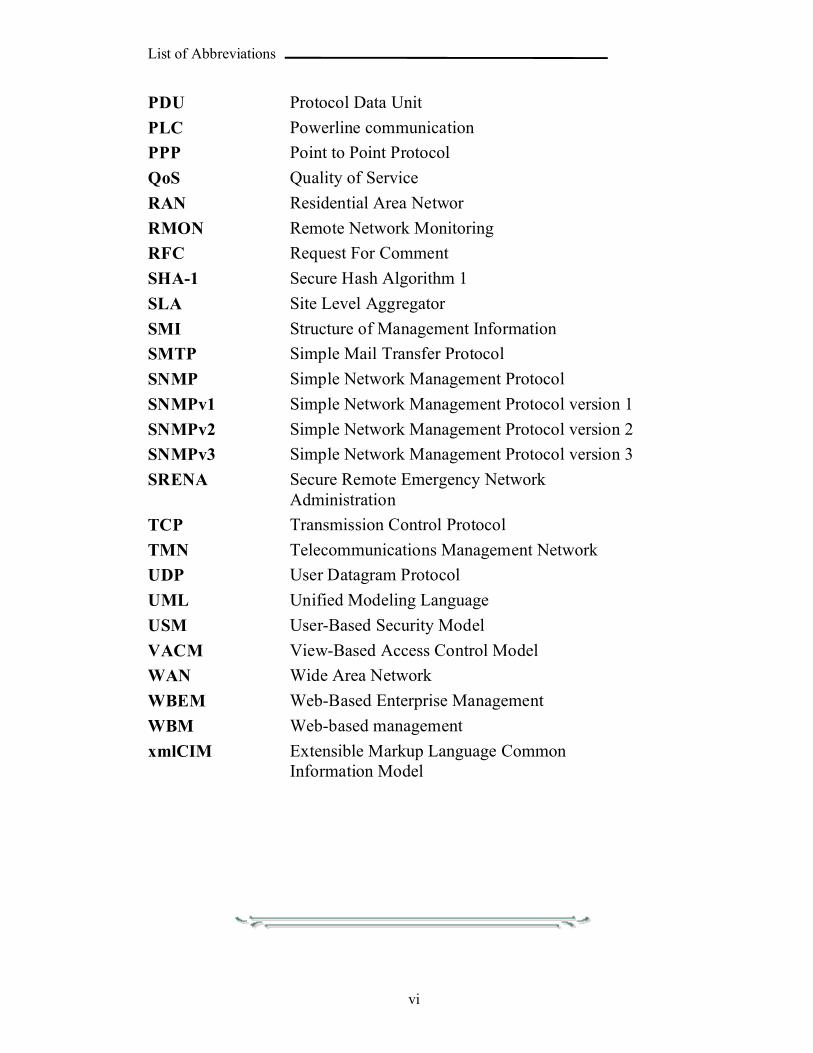
PDU Protocol Data Unit
PLC Powerline communication
PPP Point to Point Protocol
QoS Quality of Service
RAN Residential Area Networ
RMON Remote Network Monitoring
RFC Request For Comment
SHA-1 Secure Hash Algorithm 1
SLA Site Level Aggregator
SMI Structure of Management Information
SMTP Simple Mail Transfer Protocol
SNMP Simple Network Management Protocol
SNMPv1 Simple Network Management Protocol version 1
SNMPv2 Simple Network Management Protocol version 2
SNMPv3 Simple Network Management Protocol version 3
SRENA Secure Remote Emergency Network Administration
TCP Transmission Control Protocol
TMN Telecommunications Management Network
UDP User Datagram Protocol
UML Unified Modeling Language
USM User-Based Security Model
VACM View-Based Access Control Model
WAN Wide Area Network
WBEM Web-Based Enterprise Management
WBM Web-based management
xmlCIM Extensible Markup Language Common Information Model
List of contents
vii
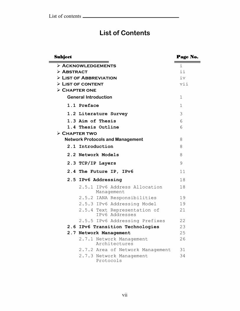
List of Contents
Subject Page No.
Acknowledgements i Abstract ii List of Abbreviation iv List of content vii Chapter one
General Introduction 1
1.1 Preface 1
1.2 Literature Survey 3
1.3 Aim of Thesis 61.4 Thesis Outline 6
Chapter twoNetwork Protocols and Management 8
2.1 Introduction 8
2.2 Network Models 8
2.3 TCP/IP Layers 9
2.4 The Future IP, IPv6 11
2.5 IPv6 Addressing 18
2.5.1 IPv6 Address Allocation Management
18
2.5.2 IANA Responsibilities 192.5.3 IPv6 Addressing Model 192.5.4 Text Representation of
IPv6 Addresses21
2.5.5 IPv6 Addressing Prefixes 222.6 IPv6 Transition Technologies 232.7 Network Management 25
2.7.1 Network Management Architectures
26
2.7.2 Area of Network Management 312.7.3 Network Management
Protocols34
List of contents
viii
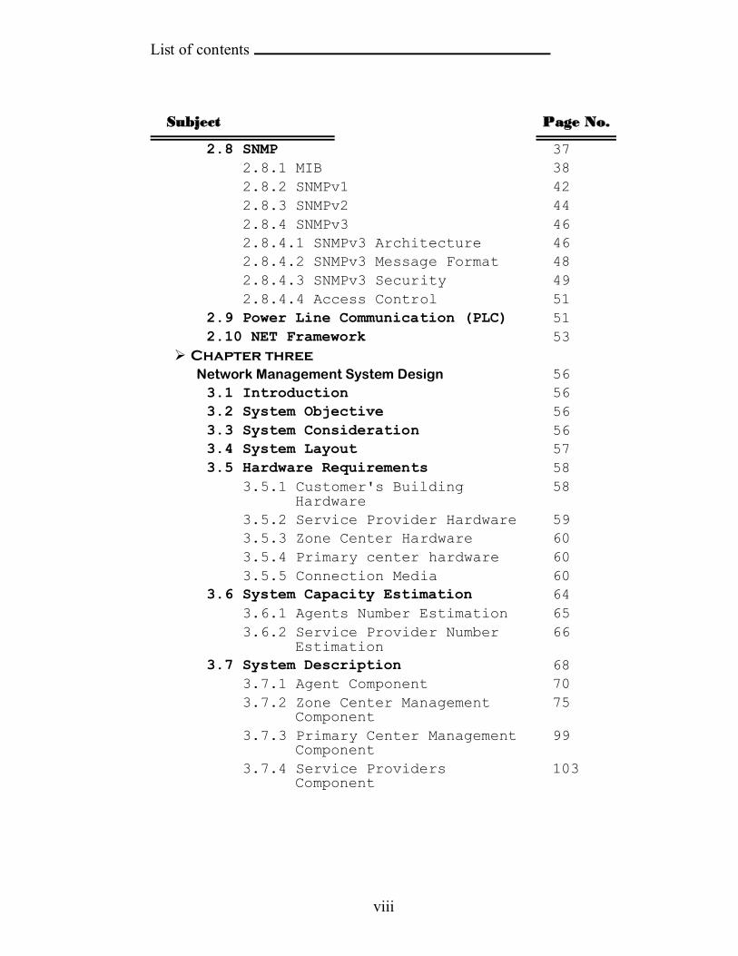
Subject Page No.
2.8 SNMP 372.8.1 MIB 382.8.2 SNMPv1 422.8.3 SNMPv2 442.8.4 SNMPv3 462.8.4.1 SNMPv3 Architecture 462.8.4.2 SNMPv3 Message Format 482.8.4.3 SNMPv3 Security 492.8.4.4 Access Control 51
2.9 Power Line Communication (PLC) 512.10 NET Framework 53
Chapter threeNetwork Management System Design 563.1 Introduction 563.2 System Objective 563.3 System Consideration 563.4 System Layout 573.5 Hardware Requirements 58
3.5.1 Customer's BuildingHardware
58
3.5.2 Service Provider Hardware 593.5.3 Zone Center Hardware 603.5.4 Primary center hardware 603.5.5 Connection Media 60
3.6 System Capacity Estimation 643.6.1 Agents Number Estimation 653.6.2 Service Provider Number
Estimation66
3.7 System Description 683.7.1 Agent Component 703.7.2 Zone Center Management
Component75
3.7.3 Primary Center Management Component
99
3.7.4 Service ProvidersComponent
103

List of contents
ix
SubjectPage No.
Chapter fourSystem Implementation 1074.1 Introduction 1074.2 Time Diagrams 1074.2 Time Estimation 117
Chapter five
Conclusion and Suggestions
5.1 Conclusion 120
5.2 Suggestions for Future Work 121
References 123
Appendixes
Appendixes A
Appendixes B
Appendixes C
Appendixes D
Appendixes E
Appendixes F


CHAPTER ONE GENERAL INTRODUCTION
1
CHAPTER ONE
GENERAL INTRODUCTION
1.1 Preface
The expansion of the data transmission capabilities is utilized to make
many services easier, efficient, and more controlled. The public services
(like electricity measurements, water measurements, medical help alarm,
police monitoring, and fire monitoring) are more effective if they have
online data transmission to get faster request servicing, maintenance, and
control. These operations must be under control and monitoring to ensure
their best performance. The network control, configuring, and monitoring
tasks are called Network Management which is established by a Network
Management System (NMS), such system try to make the management of
devices and data flow in the network system easy to maintain [MEL98].
Network management is the task of monitoring, configuring and
maintaining a network environment. Network management can be divided
into a number of areas such as fault management, performance
management, configurations management, security management and
accounting management. Fault management detect, isolate, notify, and
correct faults encountered in the network, while performance management
means the collection of network traffic analysis task to keep the data
throughput overall network elements is close to its designed
correspondence. Configurations management consists of tasks such as
installation, administration and configure network components. Security
management control access to services with the purpose of protecting
sensitive information from unauthorized access. Accounting Management
CHAPTER ONE GENERAL INTRODUCTION
2
is concerned with the allocation of resources within a networked system
and charging for their services [TER02].
Central to the theme of network management are the two concepts:
"manager" and "agent". The model of manager/agent is based on the
Client/Server model. The Client/Server model consists of the concept that
the client request a service from the server and the server respond with the
appropriate respond upon the service requested. Sometimes the same node
contains the server and the client.
In the network management system, the agent is the server that
provides information about the devices it monitor and the manager is the
client that request services (get or set information about the device or other
information). The responsibility of the manager (it also called network
management station or network management center) is to monitor and
control the agents. An agent is a software component residing in a
networked appliance that is responsible for monitoring and controlling the
environment in which it operates. This includes any device connected to
the network through a network interface that can be reached by the network
management station. A single network management station can manage a
variety of agents [MEL98].
Network management can be implemented by utilizing various models
based on their type and size. Basically, there are two management models
that can be used, they are centralized management and distributed
management. Centralized management enables the centralization of
management control and responsibility in one location. This is ideal for
systems that are limited in size or geographically isolated. Distributed
management enables the distribution of management control and
responsibility. Distributed models provide management for large
geographically distributed systems; they are also beneficial when the
CHAPTER ONE GENERAL INTRODUCTION
3
critical network resources must be conserved [MEL98]. Usually, the
management in the distributed model is organized as multi-level managers,
where the mid-level managers are responsible of their own domain, but
whose manage those managers is the manager of managers which control
and monitor those managers and synchronize their work if needed.
There are many standards protocols to define how to exchange data
and alarms between the agent and manager in the network management
system (like Common Management Information Protocol (CMIP), Simple
Network Management Protocol (SNMP), and Remote Monitoring
(RMON)).
Each of the manager and agent holds database. The agent holds
monitoring information about the device it monitors. The manager stores
information about each device it responsible of (for example location,
device status, alarms received, maintenance information, etc) and other
information (for example customers account, authorities, etc) needed. The
data stored in the database are either permanent (for example, information
about the devices connected in the system) or temporary for a period of
time until expired (for example, alarms are expired after a period of time).
1.2 Literature Survey
Pras 1995 [PRA95]: In his Ph.D. thesis (named "Network Management
Architectures"), he analyzed the two primary network architectures: OSI
and TMN Management architectures which are defined by ISO and
ITU-T respectively. Also, he analyzed the Internet Management
represented by SNMP (which was defined by IETF). He compared
between them and proposed alternate network management architecture
based on the concepts of OSI architecture, and he solved most the
problems in the architectures discussed.
CHAPTER ONE GENERAL INTRODUCTION
4
Sandlund 2001 [SAN01]: In his M.Sc. thesis (entitled "Network
management using WBEM - Web-Based Enterprise Management"), he
evaluated the different parts that make up the WBEM standard and
found that WBEM is extremely versatile and generalized standard that
can be applied in almost any area of network management. Also, he
compared between the WBEM and SNMP and noticed that the SNMP
has better performance than WBEM. He built a prototype of a WBEM
access module for NMS to see if his theoretical conclusions hold up.
The results of his work showed that WBEM will most likely have a
large impact on how network management is performed and most NMS
systems have to consider the support of WBEM. But he also showed
that on a network with limited bandwidth, WBEM might not be an ideal
choice for the manager.
OutPost Sentinel Company 2002 [SER02]: Had built Secure Remote
Emergency Network Administration (SRENA) system, which was
designed to monitor and manage servers and intelligent devices both
locally (through TCP/IP) and remotely out of network. The system uses
Simple Network Management Protocol (SNMP) to monitor and control
the fire alarm devices.
Terlegå rd 2002 [TER02]: In his M.Sc. thesis (named "Design of a
Secure Network Management System"), he designed a new NMS that
deals with devices that support standard protocols (like SNMP and
CMIP) by making an intermediate layer which work as a translator
between the standard protocol and his new protocol. This thesis
concerned to make a new protocol with more flexibility and security.
Uzuner 2002[UZU02]: In his Ph.D. thesis (entitled "Integrated
Network Management Systems"), he attempted to find a universally
applicable metric which measures the costs of complexity and
CHAPTER ONE GENERAL INTRODUCTION
5
establishing principles for making network architecture decisions (such
as choice of topology and infrastructure) based on market value and
service provider strategy. He built a simulation system to test the
studied architecture.
Lee and Hsu 2004 [LEE04]: Had presented an object-oriented
approach to achieve the systematical design and implementation of
SNMP agents for remote monitoring and control systems. They applied
standard Unified Modeling Language (UML) and Petri-net model on the
system to achieve both qualitative and quantitative analysis for the
system's dynamic behavior. The developed system has been used
successfully in a mobile switching center of Taiwan Cellular
Corporation for the remote monitoring and control, through the Internet,
of its environmental conditions, including the temperature, humidity,
power, and security, with a total 316 sensors and 140 actuators.
PAV Data Systems Ltd [PAV05]: Had built NIMBUS Network
Management System, which is a graphical user interface application that
has central site comprising of a single application server, running
Microsoft Windows NT4 or 2000. The client's sensors monitored
through PSTN or GSM. It responses to fire and security alarms.
TelleAlarm Group Company [PAL05]: Had introduced PAL Medical
alert system where PAL stands for Personal Alert Link. It is a Medical
Monitoring Center responds to device panic buttons distributed in the
customer places. When an alert comes to the Medical Monitoring
Center, the operator calls the customer to confirm the alert, if he didn't
answer then and according to the medical history of the customer, the
operator dispatches the necessary assistance. The alarms sent by
wireless connection.
CHAPTER ONE GENERAL INTRODUCTION
6
1.3 Aim of Thesis
The aim of this thesis is to design and build a dedicated network
management system. Also, it concerned with building the necessary
application software tools which may needed for managing public services
(electricity, water, medical help alarm, police monitoring, and fire
monitoring). It toke into consideration that the distributed system must be
reliable, real time, secure, and scalable.
The services are scheduled according to their priorities, to give the
most important service the privilege to be served first. For example, if
water is cut off and fire happen the priority is to the fire alarm to be sent
first and served first. The system must provide statistics and reports that
give the manager an overall description about the system performance, the
type of alarms occur frequently, the time that the alarm spent to be received
by the manager, the time spent to send the alarm to service provider, the
places with large number of alarms, and the time varying load on specific
service providers. Those reports and statistics will help the manager to
decide how to improve the system performance, if it is needed, and let him
to assess the future occurrence of some problems.
1.4 Thesis Outline
Chapter Two
This chapter concerned with the definition of network system,
its models, its protocols, and specifically make some highlights on
the future Internet Protocol (IPv6). Then define the Network
Management System, its concept, its protocols and architectures.
Also describes the Power Line Communication (PLC) and the .NET
framework.
CHAPTER ONE GENERAL INTRODUCTION
7
Chapter Three
This chapter introduces the design of the network management
system for public services (electricity power measurement and
maintenance, water measurement and maintenance, medical help
alarm, fire monitoring, and security monitoring) and its necessary
application software tools.
Chapter Four
This chapter introduces the time diagrams of the main
operations in the system and estimations for response and validation
time.
Chapter Five
This chapter introduces the conclusions and the suggested future
work.

CHAPTER TWO Net. Protocols & Management
8
CHAPTER TWO
NETWORK PROTOCOLS AND MANGEMENT
2.1 IntroductionA computer network is an interconnected system of computing devices
that provides shared economical access to computer services. Networks are
important since they provide several benefits such as resource sharing,
saving money, etc.
Networks can be divided into Local Area Networks (LANs),
Metropolitan Area Networks (MANs), and Wide Area Networks (WANs),
each network type has its own characteristics, technologies, speeds, and
niches. LANs cover a building and operate at high speeds. MANs cover a
city (for example, the cable television system) which is now used by many
people to access the internet. WANs cover country or continent. LANs and
MANs are unswitched (i.e. do not have routers); WANs are switched.
Networks can be interconnected to form internetworks. [TAN03]
Computers can be connected in several topologies like bus, star, and
ring. For more information see appendix A.
2.2 Network Models
A Network model also referred to as protocol suits reflects the design
or architecture to accomplish communication between different systems. A
network model usually consists of layers. Each layer of a model represents
specific functionality. [Hel00]
There are two important network models: (1) International Standard
Organization/Open System Interconnection (ISO/OSI) model and
(2) Transmission Control Protocol/Internet Protocol (TCP/IP) model. The
protocols associated with ISO/OSI model are rarely used any more while
the protocols of the TCP/IP model are widely used [TAN03]. TCP/IP
works in a very similar manner to OSI model in that it takes a layered
approach to provide network services [Hel00]. The OSI has 7-layers but the

CHAPTER TWO Net. Protocols & Management
9
TCP/IP has 5-layers as shown in the Figure (2.1). Only the TCP/IP layers
are introduced in the following section.
Fig.(2.1) OSI and TCP/IP layers
2.3 TCP/IP Layers
As shown in Figure (2.1) the TCP/IP model consists of the following
five layers:
1. Application Layer: The application layer is responsible for supporting
network applications. The application layer includes many protocols,
including Hyper Text Transfer Protocol (HTTP) to support the Web,
Simple Mail Transfer Protocol (SMTP) to support electronic mail, and
File Transfer Protocol (FTP) to support file transfer [KUR01].
2. Transport Layer: The transport layer provides the service of
transporting application-layer messages between the client and server
sides of an application. In the Internet there are two transport protocols,
Transmission Control Protocol (TCP) and User Datagram Protocol
(UDP), either of which can transport application-layer messages. TCP
provides a connection-oriented service to its applications. This service
includes guaranteed delivery of application-layer messages to the
destination and flow control (that is, sender/receiver speeds matching).
TCP also segments long messages into shorter segments, and provides a
congestion control mechanism, so that a source throttles its transmission
rate when the network is congested.
CHAPTER TWO Net. Protocols & Management
10
The UDP protocol provides its applications a connectionless
service [KUR01]. It does not do flow control, error control, or
retransmission upon receipt of a bad segment. Both TCP and UDP have
in its header the source and destination port numbers. The two ports
serve to identify the end points within the source and destination
machines. The port number is 16-bit integer. (i.e. Ports are numbered 1
through 65535). Port numbers below 1024 are called well-known ports
and are reserved standard services. For example, any process wishes to
establish a connection to a host to transfer a file using FTP can connect
to the destination host's port 21 to contact its FTP daemon [TAN03].
3. Internet Layer: Its job is to permit hosts to inject packets into any
network, and have them travel independently to the destination
(potentially on a different network). They may even arrive in a different
order than they were sent; it is the job of higher layers to rearrange them
(if in-order delivery is desired). Note that "internet" is used here in a
generic sense, even though this layer is present in the Internet.
The job of the Internet layer is analogous to the mail system. A
person can drop a sequence of international letters into a mail box in one
country, and with a little luck most of them will be delivered to the
correct address in the destination country. Probably the letters will travel
through one or more international mail gateways along the way, but this
is transparent to the users. Furthermore, each country (i.e. each network)
has its own stamps, preferred envelope sizes, and the delivery rules are
hidden from the users.
The internet layer defines an official packet format and protocol
called IP (Internet Protocol). The job of the internet layer is to deliver IP
packets where they are supposed to go. Packet routing is clearly the
major issue here, as is avoiding congestion [TAN03].
Different versions of Internet Protocols have been evolved; the
widely deployed version is Internet Protocol-version 4 (more commonly
known as IPv4), and Internet Protocol version 6 (IPv6) which had been
proposed to replace IPv4 in upcoming years [KUR01].

CHAPTER TWO Net. Protocols & Management
11
4. Data Link Layers [KUR01]: The services provided at the link layer
depend on the specific link-layer protocol that is employed over the
link. For example, some protocols provide reliable delivery on a link
basis. (That is, from transmitting node, over one link, to receiving
node). Note that this reliable delivery service is different from the
reliable delivery service of TCP, which provides reliable delivery from
one end system to another. Examples of link layers include Ethernet and
Point to Point Protocol (PPP); in some contexts, Asynchronous Transfer
Mode (ATM) and frame relay can be considered as link layers.
5. Physical Layer [KUR01]: While the job of the link layer is to move
entire frames from one network element to an adjacent network element,
the job of the physical layer is to move the individual bits within the
frame from one node to the next. The protocols in this layer are again
link dependent, and further depend on the actual transmission media of
the link (for example; twisted-pair copper wire, single-mode fiber
optics). For example, Ethernet has many physical layer protocols: one
for twisted-pair copper wire, another for coaxial cable, another for fiber,
and so on.
2.4 The Future IP, IPv6
In the early 1990s, the Internet Engineering Task Force (IETF) began
an effort to develop a successor to the IPv4 protocol. The prime motivation
for this effort was the realization that the 32-bit IP address space was begun
to be used up with new networks and IP nodes being attached to the
Internet (and being allocated unique IP addresses) at a high rate. To
respond to this need for a large IP address space, a new IP protocol (i.e.
IPv6) was developed. The designers of IPv6 also took this opportunity to
increase and enhance the aspects of IPv4, based on the accumulated
operational experience with IPv4 [KUR01].
The two leaders of the IETF's Address Lifetime Expectations working
group estimated that the IPv4 addresses would exhausted in 2005 and 2018,
respectively [SOL96]. In 1996, the American Registry for Internet
CHAPTER TWO Net. Protocols & Management
12
Numbers (ARIN) reported that all of the IPv4 class A addresses had been
assigned, 62 percent of the class B addresses had been assigned, and 37
percent of the class C addresses had been assigned [ARN96] (for more
information on classes see Appendix C). Although these estimates and
numbers suggested that a considerable amount of time might be left until
the IPv4 address space became exhausted, it was realized that a
considerable time would be needed to deploy a new technology on such an
extensive scale, and for this reason the "IP Next Generation" (IPng) effort
was begun [BRA96].
The small range of IPv4 addresses is the main reason to develop a new
protocol but not the only one. The following are the major goals to develop
a new protocol [TAN03]:
1. Support billion of hosts.
2. Reduce the size of the routing tables.
3. Simplify the protocol, to allow routers to process packets faster.
4. Provide better security (authentication and privacy) than IPv4.
5. Pay more attention to type of service, particularly for real-time data.
6. Aid multicasting by allowing scopes to be specified.
7. Make it possible for host to roam without changing.
8. Allow the protocol to evolve in the future.
The advent of the IPv6 initiative doesn’t mean that the technologies
will exhaust the capabilities of the current Internet technology (i.e. IPv4).
However, there are still compelling reasons to begin adopting IPv6 as soon
as possible. However, this process has its challenges, and as essential to
any evolution of Internet technology, there are requirements for seamless
compatibility with IPv4, especially with regards to a manageable migration,
which would allow us to take the advantage of the power of IPv6, without
forcing the entire Internet to upgrade simultaneously [GON98].
The IPv6 features are the following:
CHAPTER TWO Net. Protocols & Management
13
1. New Header Format
The IPv6 header has a new format that is designed to minimize header
overhead. This is achieved by moving both nonessential fields and option
fields to extension headers that are placed after the IPv6 header. The
streamlined IPv6 header provides more efficient processing at intermediate
routers.
IPv4 headers and IPv6 headers are not interoperable, and the IPv6
protocol is not backward compatible with the IPv4 protocol. A host or
router must use an implementation of both IPv4 and IPv6 in order to
recognize and process both header formats. The new IPv6 header is only
twice as large as the IPv4 header, even though IPv6 addresses are four
times as large as IPv4 addresses [IPF02].
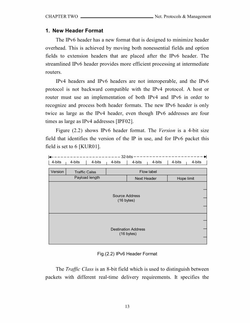
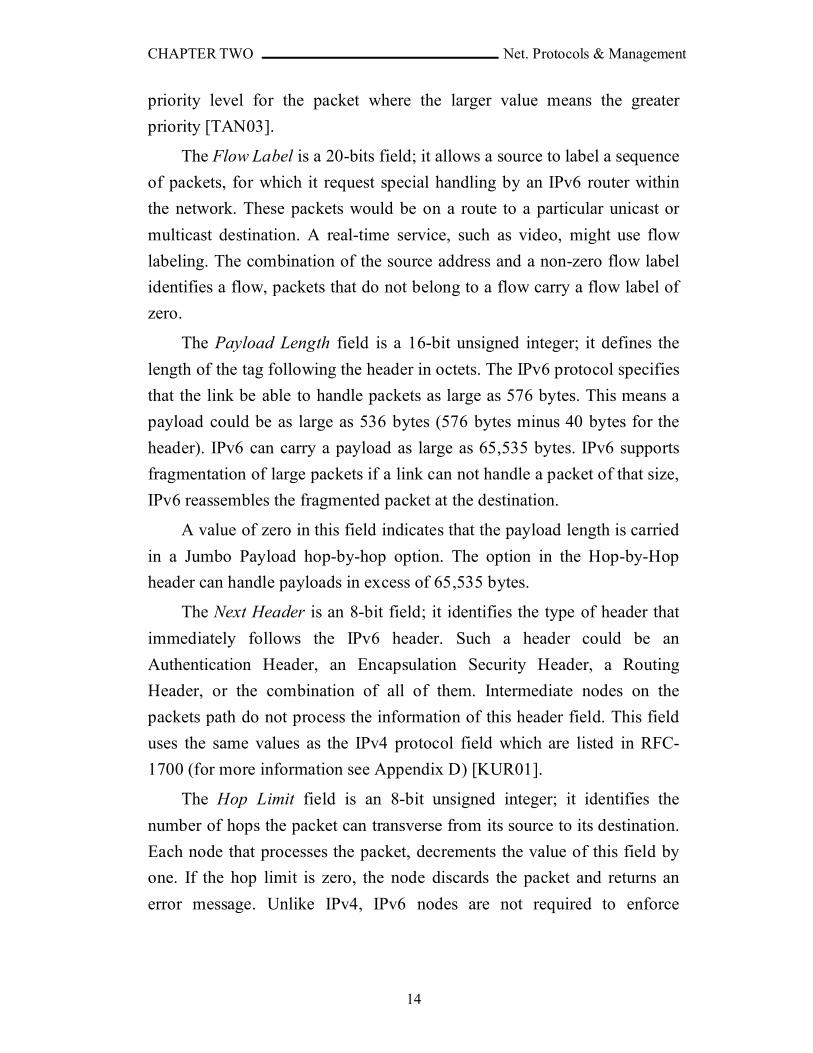
Figure (2.2) shows IPv6 header format. The Version is a 4-bit size
field that identifies the version of the IP in use, and for IPv6 packet this
field is set to 6 [KUR01].
Fig.(2.2) IPv6 Header Format
The Traffic Class is an 8-bit field which is used to distinguish between
packets with different real-time delivery requirements. It specifies the
32-bits
Traffic Calss Flow label
Next Header
Source Address (16 bytes)
Destination Address (16 bytes)
Payload length
Version
Hope limit
4-bits 4-bits 4-bits 4-bits 4-bits 4-bits 4-bits 4-bits
CHAPTER TWO Net. Protocols & Management
14
priority level for the packet where the larger value means the greater
priority [TAN03].
The Flow Label is a 20-bits field; it allows a source to label a sequence
of packets, for which it request special handling by an IPv6 router within
the network. These packets would be on a route to a particular unicast or
multicast destination. A real-time service, such as video, might use flow
labeling. The combination of the source address and a non-zero flow label
identifies a flow, packets that do not belong to a flow carry a flow label of
zero.
The Payload Length field is a 16-bit unsigned integer; it defines the
length of the tag following the header in octets. The IPv6 protocol specifies
that the link be able to handle packets as large as 576 bytes. This means a
payload could be as large as 536 bytes (576 bytes minus 40 bytes for the
header). IPv6 can carry a payload as large as 65,535 bytes. IPv6 supports
fragmentation of large packets if a link can not handle a packet of that size,
IPv6 reassembles the fragmented packet at the destination.
A value of zero in this field indicates that the payload length is carried
in a Jumbo Payload hop-by-hop option. The option in the Hop-by-Hop
header can handle payloads in excess of 65,535 bytes.
The Next Header is an 8-bit field; it identifies the type of header that
immediately follows the IPv6 header. Such a header could be an
Authentication Header, an Encapsulation Security Header, a Routing
Header, or the combination of all of them. Intermediate nodes on the
packets path do not process the information of this header field. This field
uses the same values as the IPv4 protocol field which are listed in RFC-
1700 (for more information see Appendix D) [KUR01].
The Hop Limit field is an 8-bit unsigned integer; it identifies the
number of hops the packet can transverse from its source to its destination.
Each node that processes the packet, decrements the value of this field by
one. If the hop limit is zero, the node discards the packet and returns an
error message. Unlike IPv4, IPv6 nodes are not required to enforce
CHAPTER TWO Net. Protocols & Management
15
maximum packet lifetime, this is the reason why the "Time to Live" field of
IPv4 was renamed "Hop Limit" in IPv6.
The Source Address field contains the 128-bit address of the initial
sender of the packet. The Destination Address field contains the 128-bit
address of the intended recipient of the packet [KUR01].
2. Large Address Space [IPF02]
IPv6 has 128-bit (16-byte) source and destination addresses. Although
128 bits can provide over 3.4×1038 possible combinations, the large address
space of IPv6 has been designed to allow for multiple levels of subnetting
and address allocation from the Internet backbone to the individual subnets
within an organization.
Although only a small percentage of possible addresses are currently
allocated for use by hosts, there are plenty of addresses available for future
use. With a much larger number of available addresses, address-
conservation techniques, such as the deployment of Network Address
Translating (NAT) (for more information see Appendix C), are no longer
necessary.
3. Hierarchical Addressing and Routing Infrastructure
IPv6 global addresses used on the IPv6 portion of the Internet are
designed to create an efficient, hierarchical, and summarizable routing
infrastructure that addresses the common occurrence of multiple levels of
Internet service providers. On the IPv6 Internet, backbone routers have
much smaller routing tables [IPF02].
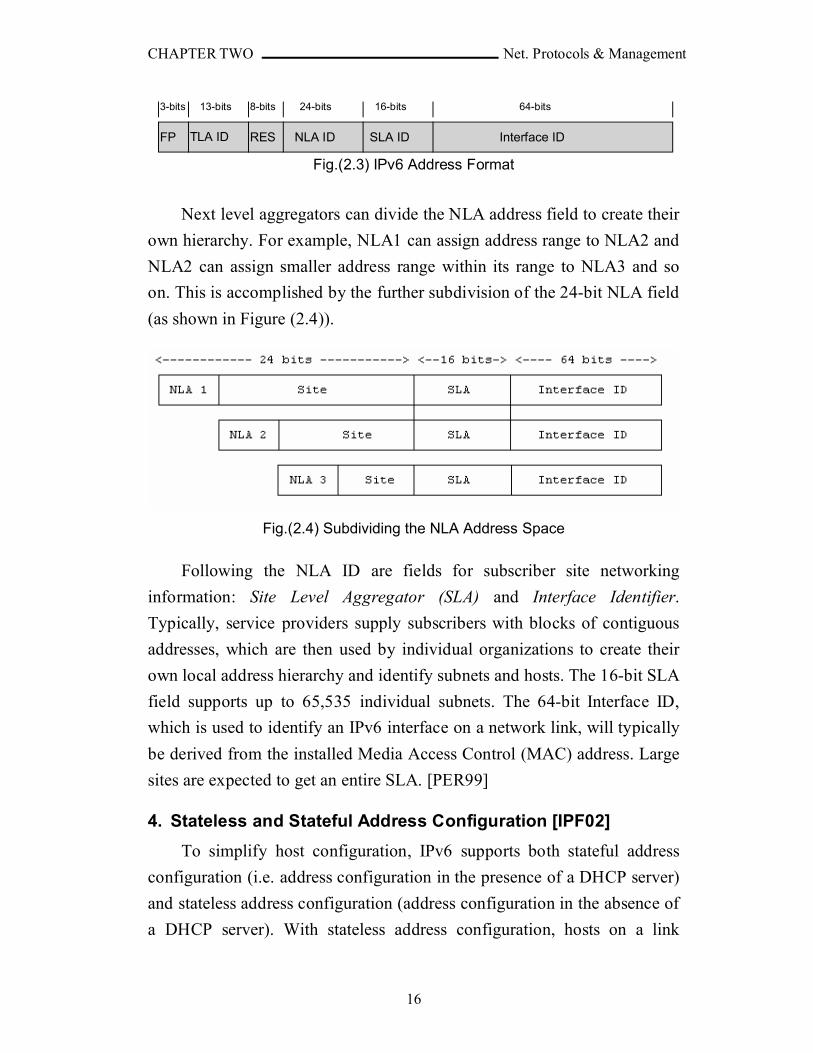
As shown in Figure (2.3), the first 3 address bits (Format Prefix)
indicate what type of address follows (unicast, multicast, etc.). The next 13
bits are allocated to the various Top Level Aggregators around the world.
Eight bits are reserved for future use, and the following 24 bits (Next level
aggregators) are allocated to the next lower level of providers and
subscribers [PER99].
CHAPTER TWO Net. Protocols & Management
16
Fig.(2.3) IPv6 Address Format
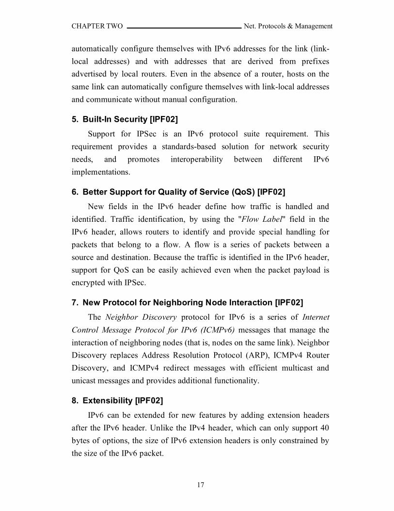
Next level aggregators can divide the NLA address field to create their
own hierarchy. For example, NLA1 can assign address range to NLA2 and
NLA2 can assign smaller address range within its range to NLA3 and so
on. This is accomplished by the further subdivision of the 24-bit NLA field
(as shown in Figure (2.4)).
Fig.(2.4) Subdividing the NLA Address Space
Following the NLA ID are fields for subscriber site networking
information: Site Level Aggregator (SLA) and Interface Identifier.
Typically, service providers supply subscribers with blocks of contiguous
addresses, which are then used by individual organizations to create their
own local address hierarchy and identify subnets and hosts. The 16-bit SLA
field supports up to 65,535 individual subnets. The 64-bit Interface ID,
which is used to identify an IPv6 interface on a network link, will typically
be derived from the installed Media Access Control (MAC) address. Large
sites are expected to get an entire SLA. [PER99]
4. Stateless and Stateful Address Configuration [IPF02]
To simplify host configuration, IPv6 supports both stateful address
configuration (i.e. address configuration in the presence of a DHCP server)
and stateless address configuration (address configuration in the absence of
a DHCP server). With stateless address configuration, hosts on a link
FP TLA ID NLA ID Interface IDSLA IDRES
3-bits 13-bits 8-bits 24-bits 16-bits 64-bits
CHAPTER TWO Net. Protocols & Management
17
automatically configure themselves with IPv6 addresses for the link (link-
local addresses) and with addresses that are derived from prefixes
advertised by local routers. Even in the absence of a router, hosts on the
same link can automatically configure themselves with link-local addresses
and communicate without manual configuration.
5. Built-In Security [IPF02]
Support for IPSec is an IPv6 protocol suite requirement. This
requirement provides a standards-based solution for network security
needs, and promotes interoperability between different IPv6
implementations.
6. Better Support for Quality of Service (QoS) [IPF02]
New fields in the IPv6 header define how traffic is handled and
identified. Traffic identification, by using the "Flow Label" field in the
IPv6 header, allows routers to identify and provide special handling for
packets that belong to a flow. A flow is a series of packets between a
source and destination. Because the traffic is identified in the IPv6 header,
support for QoS can be easily achieved even when the packet payload is
encrypted with IPSec.
7. New Protocol for Neighboring Node Interaction [IPF02]
The Neighbor Discovery protocol for IPv6 is a series of Internet
Control Message Protocol for IPv6 (ICMPv6) messages that manage the
interaction of neighboring nodes (that is, nodes on the same link). Neighbor
Discovery replaces Address Resolution Protocol (ARP), ICMPv4 Router
Discovery, and ICMPv4 redirect messages with efficient multicast and
unicast messages and provides additional functionality.
8. Extensibility [IPF02]
IPv6 can be extended for new features by adding extension headers
after the IPv6 header. Unlike the IPv4 header, which can only support 40
bytes of options, the size of IPv6 extension headers is only constrained by
the size of the IPv6 packet.
CHAPTER TWO Net. Protocols & Management
18
2.5 IPv6 Addressing
The IPv6 addressing scheme more closely accommodates different
user types, because it is based on the demographic nature of the served
community. Additionally, IPv6 addressing provides the necessary
compatibility and interoperability with today's IPv4 network architecture.
This ability of IPv6 to coexist indefinitely with IPv4 in both host computers
and routers, helps to preserve the world's enormous investment in
TCP/IP[GON98].
2.5.1 IPv6 Address Allocation Management [GON98]
As the Internet transitions to IPv6, the plan for distributed allocation
and assignment of the IPv4 address space, established in RFC-1466 (For
more information see Appendix D), forms a base for the distributed
allocation and assignment of the IPv6 address space.
The IPv6 address space must be managed for the good of the Internet
community. The Internet community recognizes that good management
requires at least some central authority over the delegation and allocation of
the address space. Therefore, the Internet community has delegated the
responsibility for the management of the IPv6 address space to the Internet
Assigned Number Authority (IANA.). The IANA is the principal registry
for the IPv6 address space. As representatives of the Internet community,
the Internet Architecture Board (IAB) and the Internet Engineering
Steering Group (IESG) provide advice to the IANA from time-to-time
about management of the IPv6 address space.
The IANA carries out address allocation management with an element
of central authority over the delegation to regional registries. These
regional registries make specific address allocations to network service
providers and other subregional registries.
The IANA delegates to regional registries the task of making specific
address allocations to network service providers and other subregional
registries. Individuals and organizations that need IP addresses obtain them
from their internet service provider. The IANA serves as the default
CHAPTER TWO Net. Protocols & Management
19
registry in cases where no delegated registration authority has been
identified.
2.5.2 IANA Responsibilities
The IANA is responsible for the development of:
1. A plan for assignment of IPv6 addresses.
2. A method for the automatic allocation of IPv6 addresses to registries,
ISPs, organizations, and individuals that already hold IPv4 address.
3. A set of procedures for mediation and appeals concerning the delegation
and revocation of IP address space assignments.
2.5.3 IPv6 Addressing Model
Technically IPv6 addresses are 128-bit identifiers for interfaces and
sets of interfaces. This is equivalent to an IPv4 address space squared twice
(the IPv4 address size is 32-bit) which is very large number of addresses. It
should be noted however that the size of the address is less important than
its structure [GON98]. The emerging IPv6 protocols define three types of
addresses:
1. Unicast Addresses [UNI02]: identify a single interface within the
scope of the type of unicast address. With the appropriate unicast
routing topology, packets addressed to a unicast address are delivered to
a single interface. The following types of addresses are unicast IPv6
addresses:
a. Aggregatable Global Unicast Addresses: Which are equivalent to
public IPv4 addresses. They are globally routable and reachable on
the IPv6 portion of the Internet known as the 6bone (IPv6 backbone).
Aggregatable global unicast addresses are also known as global
addresses
b. Link-Local Addresses: Which are used between on-link neighbors
and for Neighbor Discovery processes
CHAPTER TWO Net. Protocols & Management
20
c. Site-Local Addresses: Which are used between nodes that
communicate with other nodes in the same site.
d. Special Addresses: The special IPv6 addresses are: (1) the
unspecified address (0:0:0:0:0:0:0:0 or ::), which is used only to
indicate the absence of an address. It is equivalent to the IPv4
unspecified address of 0.0.0.0, and (2) the loopback address
(0:0:0:0:0:0:0:1 or ::1) which is used to identify a loopback interface,
enabling a node to send packets to itself. It is equivalent to the IPv4
loopback address of 127.0.0.1
e. Compatibility Addresses: To aid in the migration from IPv4 to IPv6
and facilitate the coexistence of both types of hosts. Like IPv4-
compatible address, IPv4-mapped address, and 6to4 address.
2. Anycast Addresses [GON98]: which are a new kind of address. An
anycast address is an identifier (a single value) assigned to a more than
one interface. The set of interfaces assigned an anycast address typically
belong to more than one computer. It can be used in clustering and
avoiding replications.
When you send a packet to an anycast address, the routing protocol
currently in use delivers the packet to the nearest interface identified by
that address. The nearest interface is determined according to the
particular routing protocol’s measure of distance.
3. Multicast Addresses [GON98]: whose format allows for possibly
trillions of multicast group codes. A multicast address is an identifier for
a set of interfaces that typically belong to different nodes. Each
multicast group code identifies two or more packet recipients. In
addition, a particular multicast address can be confined to a single
system, restricted within a specific site, associated with a particular
network link, or distributed worldwide. When you send a packet to a
multicast address, the protocol delivers the packet to all interfaces
identified by that address.
CHAPTER TWO Net. Protocols & Management
21
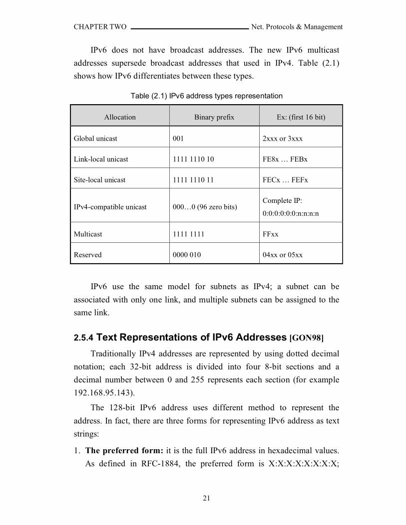
IPv6 does not have broadcast addresses. The new IPv6 multicast
addresses supersede broadcast addresses that used in IPv4. Table (2.1)
shows how IPv6 differentiates between these types.
Table (2.1) IPv6 address types representation
Allocation Binary prefix Ex: (first 16 bit)
Global unicast 001 2xxx or 3xxx
Link-local unicast 1111 1110 10 FE8x … FEBx
Site-local unicast 1111 1110 11 FECx … FEFx
IPv4-compatible unicast 000…0 (96 zero bits)Complete IP:
0:0:0:0:0:0:n:n:n:n
Multicast 1111 1111 FFxx
Reserved 0000 010 04xx or 05xx
IPv6 use the same model for subnets as IPv4; a subnet can be
associated with only one link, and multiple subnets can be assigned to the
same link.
2.5.4 Text Representations of IPv6 Addresses [GON98]
Traditionally IPv4 addresses are represented by using dotted decimal
notation; each 32-bit address is divided into four 8-bit sections and a
decimal number between 0 and 255 represents each section (for example
192.168.95.143).
The 128-bit IPv6 address uses different method to represent the
address. In fact, there are three forms for representing IPv6 address as text
strings:
1. The preferred form: it is the full IPv6 address in hexadecimal values.
As defined in RFC-1884, the preferred form is X:X:X:X:X:X:X:X;

CHAPTER TWO Net. Protocols & Management
22
where X represent the hexadecimal values of the eight 16-bit pieces of
the address. For example, an IPv6 address could have the following
form:
FEDC:BA98:7654:3210:FFFF:CD91:5664:6743
A colon separates each section and four hexadecimal numbers
represent each 16-bit section. Sometimes a 16-bit section contains
leading zeros. It is not necessary to include the leading zeros in an
individual field, but there must be at least one numeral in every field in
the text representation of an address; as shown in the following
simplified example of IPv6 address:
1080:0:0:0:8:800:200C:417A
2. The compressed form: in this form the zero strings are substituted with
a special syntax to compress the zeros. This form uses double colons (::)
to indicate multiple groups of 16-bit zeros. You can use the
double colon (::) only once in an address. For example you can
further simplify the address (1080:0:0:0:8:800:200C:417A) to be
(1080::8:800:200C:417A).
The double colon can also be used to compress the leading or
trailing zeros in an address. This form shows the simplification of some
IPv6 addresses using the double colon.
3. The mixed form: it is convenient to use for mixed environments of
IPv4 and IPv6 nodes. This form takes the representation of
X:X:X:X:X:X:D.D.D.D. The Xs represent the hexadecimal values of
the six high-order 16-bit pieces of the address. The Ds represent the
standard IPv4 decimal value representation of the four low-order 8-bit
pieces of the address. This form shows some representative mixed form
addresses in both a simplified and compressed form (for example,
1080::8:800:192.168.95.143).

CHAPTER TWO Net. Protocols & Management
23
2.5.5 IPv6 Address Prefixes [GON98]
IPv6, like IPv4 can have an address prefix. For our purposes, and IPv6
address prefix is defined as an IPv6 address and some indication of the
leftmost contiguous significant bits within this address portion. The
representation of an IPv6 address prefix is similar to the way IPv4
addresses prefixes are written in Classless Inter Domain Routing (CIDR)
notation.
The user can write the IPv6 address by using any of the address forms
described previously (preferred, compressed, or mixed) with one
difference: "if the written address ends in a double colon (::), you can omit
the trailing double colon".
The prefix-length is a decimal value. It specifies the number of
leftmost contiguous bits of the address that comprise the prefix. The
following examples show various legal representations for the 60-bit prefix
12AB00000000CD3 :
12AB:0000:0000:CD30:0000:0000:0000:0000/60
12AB::CD30:0:0:0:0/60
12AB:0:0:CD30::/60
12AB:0:0:CD30/60
2.6 IPv6 Transition Technologies [IPT04]
The migration of IPv4 to IPv6 will not happen overnight. Rather, there
will be a period of transition when both protocols are in use over the same
infrastructure. To address this, the designers of IPv6 have created
technologies and types of addresses so that nodes can communicate with
each other in a mixed environment, even if they are separated by an IPv4
infrastructure.
To coexist with an IPv4 infrastructure and to provide an eventual
transition to an IPv6-only infrastructure, the following mechanisms are
used:
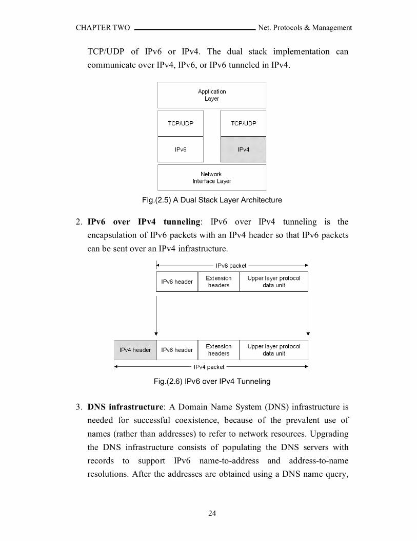
1. Dual Stack: The dual stack contains a separate implementation of TCP
and UDP, and the process in the application layer can communicate to
CHAPTER TWO Net. Protocols & Management
24
TCP/UDP of IPv6 or IPv4. The dual stack implementation can
communicate over IPv4, IPv6, or IPv6 tunneled in IPv4.
Fig.(2.5) A Dual Stack Layer Architecture
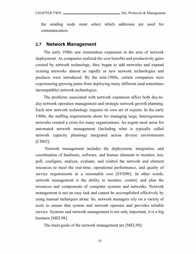
2. IPv6 over IPv4 tunneling: IPv6 over IPv4 tunneling is the
encapsulation of IPv6 packets with an IPv4 header so that IPv6 packets
can be sent over an IPv4 infrastructure.
Fig.(2.6) IPv6 over IPv4 Tunneling
3. DNS infrastructure: A Domain Name System (DNS) infrastructure is
needed for successful coexistence, because of the prevalent use of
names (rather than addresses) to refer to network resources. Upgrading
the DNS infrastructure consists of populating the DNS servers with
records to support IPv6 name-to-address and address-to-name
resolutions. After the addresses are obtained using a DNS name query,
CHAPTER TWO Net. Protocols & Management
25
the sending node must select which addresses are used for
communication.
2.7 Network Management
The early 1980s saw tremendous expansion in the area of network
deployment. As companies realized the cost benefits and productivity gains
created by network technology, they began to add networks and expand
existing networks almost as rapidly as new network technologies and
products were introduced. By the mid-1980s, certain companies were
experiencing growing pains from deploying many different (and sometimes
incompatible) network technologies.
The problems associated with network expansion affect both day-to-
day network operation management and strategic network growth planning.
Each new network technology requires its own set of experts. In the early
1980s, the staffing requirements alone for managing large, heterogeneous
networks created a crisis for many organizations. An urgent need arose for
automated network management (including what is typically called
network capacity planning) integrated across diverse environments
[CIS02].
Network management includes the deployment, integration, and
coordination of hardware, software, and human elements to monitor, test,
poll, configure, analyze, evaluate, and control the network and element
resources to meet the real-time, operational performance, and quality of
service requirements at a reasonable cost [SYD96]. In other words,
network management is the ability to monitor, control, and plan the
resources and components of computer systems and networks. Network
management is not an easy task and cannot be accomplished effectively by
using manual techniques alone. So, network managers rely on a variety of
tools to ensure that system and network operates and provides reliable
service. Systems and network management is not only important, it is a big
business [MEL98].
The main goals of the network management are [MEL98]:
CHAPTER TWO Net. Protocols & Management
26
1. Keeping networks running: systems and networks must be operational
to accomplish the needed task.
2. Maintaining Network Performance: Simply initiating an operational
network is not sufficient. A network must also perform at some
minimally acceptable level of quality. A major responsibility of network
management is to provide an acceptable level of performance level, or
Quality of Service (QoS). If a performance problem exists, it must be
pinpointed and resolved in a timely manner.
3. Reducing the Cost of Ownership: Simply purchasing network
equipment and installing it is quite inexpensive compared to the longer-
term cost of managing and maintaining it. Network management can be
divided into two main categories, reactive and proactive management.
In terms of the reduction of owner-ship costs, reactive management is
much more expensive. This is true because when a network fails, it
frequently needs to be fixed immediately and at any cost. While fault
and performance management are important, they are primarily used in
a reactive manner. When there is a fault in a system, you react to it by
identifying the problem and eliminating it. When performance reaches
an unacceptable level, you react to it by finding the source of the
problem and fixing it. While reactive management is required, proactive
management keeps these problems from happening in the first place. In
doing so, proactive management promotes the reduction of ownership
costs. Proactive management allows a network to be properly planned
and built, thus avoiding expensive crisis scenarios.
So to achieve those goals, an NMS typically includes tools for
gathering data on network elements, tools for data storage, analysis and
prediction, tools for configuration and control of network elements, and
tools for performance and system planning management.
2.7.1. Network Management Architectures
The structure that all network management architectures use is
basically the same. The main components are [TERL02]:
CHAPTER TWO Net. Protocols & Management
27
1. Managed Device: managed devices run software that enables them to
send alerts, be configured and monitored. Managed devices can be
anything on a network that has the ability to run an agent. More and
more devices are nowadays running agents (for example, there are
washing machines running agents). This means that managed devices
can be routers, switches, printers, servers, workstations, mobile phones,
microwave ovens, DVDs and so on. And if they have agents, they can
be managed.
2. Agents: agents are software running on a device. They mostly act as
servers, responding to requests about their status, but they can also send
alarms when they want to warn about something. As the years go by,
agents will get more and more sophisticated and the picture of them just
behaving as servers is changing slowly. Often the manufacturer of the
managed device provides agents to their products.
3. Network Management Protocols: Protocols describe the way the
systems (hardware or software) can communicate. If people speak
different languages they do not understand each other. If two devices
communicate by using different protocols they will not understand each
other. So if a management application wants to manage a device, the
manager application and the agent on the device have to use the same
protocol. Applications are easy to develop, but the agents are often static
and knows only one protocol. That makes the choice of protocol critical
for both the application and the agent. There are several network
management protocols: Common Management Information
Service/Common Management Information Protocol (CMIS/CMIP),
Simple Network Management Protocol (SNMP), Remote Monitoring
(RMON), Web-Based Management (WBM), Web-Based Enterprise
Management (WBEM), Java Management Extension (JMX), and
Mobile agents.
4. Managers: Manager is the application that gets information from agents
and informs the network engineers of the status of the network and
CHAPTER TWO Net. Protocols & Management
28
performs the necessary operations needed to increase performance and
decrease faults.
There are several organizations have developed services, protocols and
architectures for network management. The three most important
organizations are:
1. The International Organization for Standardization (ISO).
2. The Comité Consultative Internationale de Telegraphique et
Telephonique (CCITT); this organization is nowadays called the
Telecommunication Standardization Sector of the International
Telecommunication Union (ITU-T).
3. The Internet Engineering Task Force (IETF).
ISO was the first who started, as part of its "Open Systems
Interconnection" (OSI) program, the development of an architecture for
network management. The first proposals for such an architecture appeared
during the early 1980; nowadays a large number of standards exist for the
architecture as well as for network management services and protocols (for
example, Common Management Information Service/Common
Management Information Protocol (CMIS/CMIP)).
Initially the aim of ISO was to define management standards for
datacom networks; development of management standards for telecom
networks was left to CCITT. In 1985 CCITT started the development of
such management standards; these standards have become known as the
"Telecommunications Management Network" (TMN) recommendations.
Originally these recommendations were self standing, but during the 1988-
1992 study period they have been rewritten to include the ideas of OSI
management. Nowadays OSI management and TMN can be seen as each
others complements [PRA95].
Looking back at the last decade it may be concluded that the growth of
the Internet has played a decisive role in the development of network
management protocols. Initially the Internet Architecture Board (IAB)
intended to apply the OSI management approach, but at the time the size of
CHAPTER TWO Net. Protocols & Management
29
the Internet reached a level at which management became indispensable,
OSI management groups were still busy with discussing the OSI
management framework. Since implementations of OSI management were
not expected to appear soon, the IAB requested the IETF (the organization
who is responsible for the development of Internet protocols) to define an
ad hoc management protocol. The "Simple Network Management Protocol"
(SNMP) was completed within a year and soon many manufacturers started
the production of SNMP compliant systems. Although the SNMP has some
deficiencies, it has become the de facto standard for management of
datacom networks. In 1993 an attempt was made to tackle these
deficiencies and an improved version of SNMP (SNMPv2) appeared.
The ISO and IUT-T have many common concepts between them but
they still have differences in fundamental philosophy (for example, the
IUT-T group prefer to use a separate network for the transfer of
management information. An interesting difference between the IETF and
ISO is that the IETF takes a more pragmatic and result driven approach
than ISO. In the IETF it is for instance unusual to spend much time on
architectural discussions; people prefer to use their time on the
development of protocols and implementations. This different attitude
explains why no special standards have been defined for the Internet
management architecture; only protocols and MIBs have been
standardized [PRA95].
Each of these architectures is based on the concept of manager-agent
concept. Network management can be implemented by utilizing various
models based on their type and size. Basically, there are two management
models that can be used, they are centralized management and distributed
management. Centralized management enables the centralization of
management control and responsibility in one location where a top-level
manager is responsible of mid-level managers that in turn responsible of
one or many agents. This is ideal for systems that are limited in size or
geographically isolated. Distributed management enables the distribution of
management control and responsibility. Distributed models provide
management for large geographically distributed systems; they are also
CHAPTER TWO Net. Protocols & Management
30
beneficial when the critical network resources must be conserved
[MEL98]. The distributed management can be one of the following types:
1. Weekly distributed
2. Strongly Distributed
3. Cooperative
If the managers (both top-level and mid-level) are approximately as
many as the agents, it is called cooperative management. The weakly and
strongly distributed management are between the centralized and the
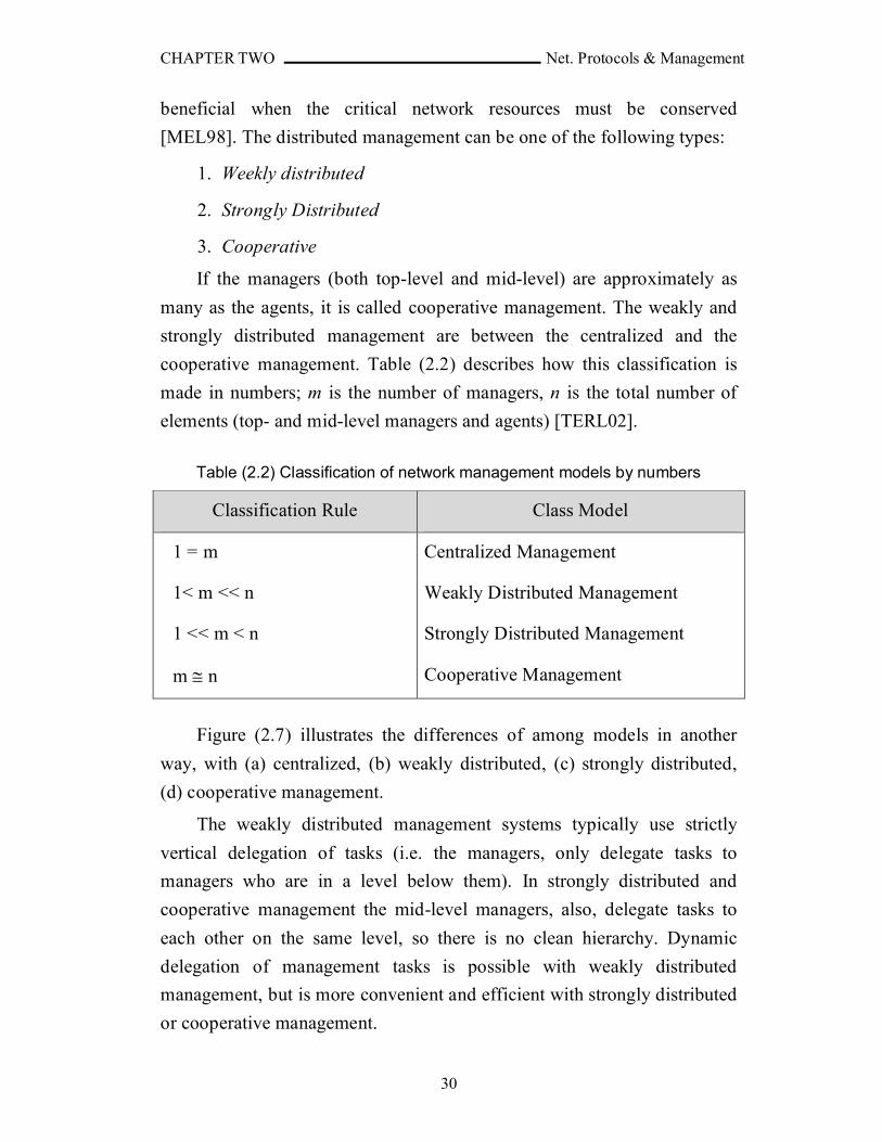
cooperative management. Table (2.2) describes how this classification is
made in numbers; m is the number of managers, n is the total number of
elements (top- and mid-level managers and agents) [TERL02].
Table (2.2) Classification of network management models by numbers
Classification Rule Class Model
1 = m
1< m << n
1 << m < n
m n
Centralized Management
Weakly Distributed Management
Strongly Distributed Management
Cooperative Management
Figure (2.7) illustrates the differences of among models in another
way, with (a) centralized, (b) weakly distributed, (c) strongly distributed,
(d) cooperative management.
The weakly distributed management systems typically use strictly
vertical delegation of tasks (i.e. the managers, only delegate tasks to
managers who are in a level below them). In strongly distributed and
cooperative management the mid-level managers, also, delegate tasks to
each other on the same level, so there is no clean hierarchy. Dynamic
delegation of management tasks is possible with weakly distributed
management, but is more convenient and efficient with strongly distributed
or cooperative management.

CHAPTER TWO Net. Protocols & Management
31
Fig. (2.7) Network Management models
2.7.2. Area of Network Management
Network management can be broken down into five functional areas
according to OSI management. Each area defines a discrete domain of
management with specific needs. Depending on the network to be
managed, a specific area may be emphasized or de-emphasized.
1. Fault Management: whenever a service or network device fails, the
management system shall detect the fault, find the cause and report the
failure. In some cases the management system can also restore the
service automatically, but most often a network operator has to fix the
fault manually. The goal of fault management is to increase the network
reliability, discover failures as quickly as possible so a network operator
can fix the problem, hopefully even before the network’s users notices
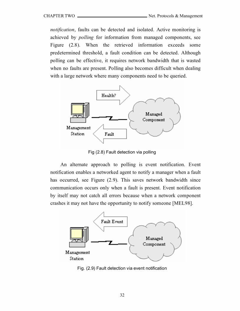
there is a problem [TERL02]. Through active monitoring and event
CHAPTER TWO Net. Protocols & Management
32
notification, faults can be detected and isolated. Active monitoring is
achieved by polling for information from managed components, see
Figure (2.8). When the retrieved information exceeds some
predetermined threshold, a fault condition can be detected. Although
polling can be effective, it requires network bandwidth that is wasted
when no faults are present. Polling also becomes difficult when dealing
with a large network where many components need to be queried.
Fig (2.8) Fault detection via polling
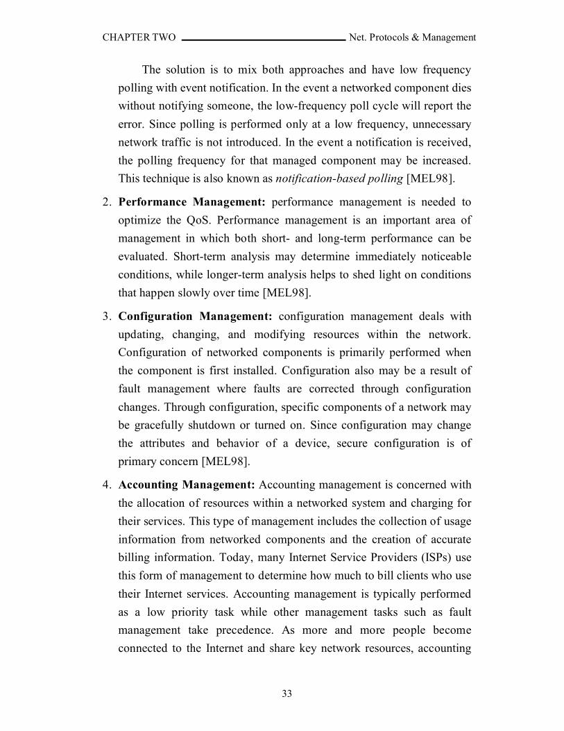
An alternate approach to polling is event notification. Event
notification enables a networked agent to notify a manager when a fault
has occurred, see Figure (2.9). This saves network bandwidth since
communication occurs only when a fault is present. Event notification
by itself may not catch all errors because when a network component
crashes it may not have the opportunity to notify someone [MEL98].
Fig. (2.9) Fault detection via event notification
CHAPTER TWO Net. Protocols & Management
33
The solution is to mix both approaches and have low frequency
polling with event notification. In the event a networked component dies
without notifying someone, the low-frequency poll cycle will report the
error. Since polling is performed only at a low frequency, unnecessary
network traffic is not introduced. In the event a notification is received,
the polling frequency for that managed component may be increased.
This technique is also known as notification-based polling [MEL98].
2. Performance Management: performance management is needed to
optimize the QoS. Performance management is an important area of
management in which both short- and long-term performance can be
evaluated. Short-term analysis may determine immediately noticeable
conditions, while longer-term analysis helps to shed light on conditions
that happen slowly over time [MEL98].
3. Configuration Management: configuration management deals with
updating, changing, and modifying resources within the network.
Configuration of networked components is primarily performed when
the component is first installed. Configuration also may be a result of
fault management where faults are corrected through configuration
changes. Through configuration, specific components of a network may
be gracefully shutdown or turned on. Since configuration may change
the attributes and behavior of a device, secure configuration is of
primary concern [MEL98].
4. Accounting Management: Accounting management is concerned with
the allocation of resources within a networked system and charging for
their services. This type of management includes the collection of usage
information from networked components and the creation of accurate
billing information. Today, many Internet Service Providers (ISPs) use
this form of management to determine how much to bill clients who use
their Internet services. Accounting management is typically performed
as a low priority task while other management tasks such as fault
management take precedence. As more and more people become
connected to the Internet and share key network resources, accounting
CHAPTER TWO Net. Protocols & Management
34
management will come to play a bigger role. Another important area of
accounting management is asset management and the inventory of
networked components. This enables the automatic creation of
inventory lists of networked equipment. When dealing with large
systems, this can be particularly useful [MEL98].
5. Security Management: Security management provides for the
protection of resources within a system or network. Security becomes
more important with increased connectivity. Security management is
closely related to fault and configuration management since
configuration of important devices must be secure. Security
management can be divided into two areas: management of the security
of a network and management using secure protocols. Management of
the security of a network includes managing and configuring passwords
on servers so that unauthorized access is prohibited. Management using
secure protocols includes making sure that management of agents is
performed using protocols that prevent unauthenticated access
[MEL98].
2.7.3. Network Management Protocols
There are many protocols to define how to exchange data and alarms
between the agent and manager in the network management system:
Common Management Information Service/Common Management
Information Protocol (CMIS/CMIP), Simple Network Management
Protocol (SNMP), Remote Monitoring (RMON), Web-Based Management
(WBM), Web-Based Enterprise Management (WBEM), Java Management
Extension (JMX), and Mobile agents.
1. SNMP: Simple Network Management Protocol (SNMP) is by far the
most popular system and network management protocol. More devices
and systems are managed with SNMP than with any other management
protocol. This is true because SNMP is quite small and inexpensive to
deploy. That is, it can be implemented in devices with minimal memory
and CPU resources. This is in contrast to the Open Systems
CHAPTER TWO Net. Protocols & Management
35
Interconnection (OSI) management protocols, which are complex and
thus more expensive to deploy. SNMP was developed to provide basic,
easy-to-implement network management tool for the Transport Control
Protocol/Internet Protocol (TCP/IP) suite of protocols. This includes a
framework of operation and a representation of management
information within the framework. The Structure of Management
Information (SMI) allows for the definition of Management Information
Bases (MIBs). MIBs are analogous to database schemas. A managed
entity, also known as an agent, includes one or more MIBs that define
what information is manageable. This includes a standard set of
management information resources that are part of the SNMP
framework, as well as vendor-specific management information that
enables a vendor to specify their device specific information. The ability
to define a custom MIB allows SNMP management to be extended to
meet a particular need of a vendor's device [MEL98]. The first version
of this protocol (SNMPv1) had some deficiencies that fixed in the
second version (SNMPv2). Also, a new SMI and MIB (SMIv2 and
MIB-II) had been developed. But the security in the SNMPv2 was also
weak, so the SNMPv3 had been developed with stronger security
[KUR01].
2. CMIS/CMIP: The ISO and the CCITT have worked together to create a
network management standard for the Open Systems Interconnection
(OSI) environment. The result is the Common Management Information
Service (CMIS) and the Common Management Information Protocol
(CMIP), which implements CMIS. The OSI system management
standard is a large and complex platform. Due to its complexity and
size, a simpler scheme was introduced, SNMP. Nevertheless, CMIS and
CMIP have found usage in the telecommunications industry [MEL98].
3. RMON: Remote Network Monitoring (RMON) is an addition to the
SNMP standards (SMI, MIB, and SNMP) [RFC1747]. It defines a
remote monitoring MIB that supplements MIB-II and provides the
network engineers with lots of useful information that MIB-II does not
provide. The information in the RMON MIB can be accessed by using
CHAPTER TWO Net. Protocols & Management
36
the ordinary SNMP operations. An SNMP-enabled device can, with
MIB-II, learn about the traffic in and out of the device, but can not learn
about the traffic on the LAN as a whole. An RMON agent monitors the
network in promiscuous mode, that is it analyzes every packet on the
LAN, not only the traffic meant for itself. The captured traffic can be
used for statistics, checking performance etc. The monitor can also store
packets or partial packets for later analysis. Filters can be used to drop
packets, based on their content or type, allowing the monitor to ignore
irrelevant traffic. As a monitor only can see packets in its own Ethernet
LAN, there has to be an RMON device in each subnetwork. The
monitor can be a standalone device whose whole purpose is to monitor
and analyze traffic. RMON introduces a feature called action
invocation. SNMP provides no specific mechanism for issuing a
command to an agent to perform an action. The only capabilities of
SNMP are to read and set managed objects. RMON uses the SNMP Set
operation to issue a command. RMON specifies a number of objects
that, if the values of them are changed, triggers a certain action. Another
version of RMON were developed, RMON2. It is an extension to
RMON. Both use MIB-II, but RMON uses SMIv1 and RMON2 uses
SMIv2. RMON works on Link layer and below, while RMON2 operates
on Network (IP) layer and above. This adds lots of new information that
can be used by a network management system [TERL02].
4. WBM: In Web-based management (WBM), Web servers are embedded
in the network devices. One can use a Web browser to browse the
configuration and status of the device and also to configure it. Web
servers are more intelligent than SNMP agents and can be more
sophisticated. WBM uses a centralized model and suits for small
offices, whose management requirements are not that big [TERL02].
5. WBEM: There are many standards for managing networks: SNMP,
CMIP, WBM etc. Web-based Enterprise Management (WBEM) is an
initiative by Desktop Management Task Force (DMTF) trying to
integrate all these standards. This makes the protocol used transparent to
the management applications. A client can send requests to any agent,
CHAPTER TWO Net. Protocols & Management
37
using the same protocol with all the agents, the Extensible Markup
Language Common Information Model (xmlCIM) protocol. The client
communicates with the Common Information Model Object Manager
(CIMOM), which then transforms the request to the agent-specific
protocol. When CIMOM receives messages from the clients, it uses the
information from CIM schema to determine which protocol the
managed object belongs to and switches the message to that protocol
provider [TERL02].
6. JMX: Java Management Extensions (JMX) defines an architecture,
APIs and the services for network management in the Java
programming language. JMX runs on most Java-enabled devices. For a
device to be Java-enabled, it needs to run a Java Virtual Machine that
can interpret Java bytecode. Almost anything can be managed using
JMX: applications, services or devices. For something to be manageable
it needs to embed a managed object server and make some of its
functionality available as one or several Manageable Beans (MBeans)
registered in the object server. JMX provides a standard way to enable
manageability for any Java based application, service or device
[TERL02].
7. Mobile Agent: Mobile agents (MAs) are programs that can be
dispatched by a client for execution on a remote server. Mobile agents
are not an implementation or protocol; it is an infrastructure or
framework. To implement mobile agents you can use any protocol and
any programming language, the choice is up to the programmer. There
are a couple of implementations of the mobile agents framework, for
instance Aglets from IBM, Tryllian and Grasshopper [TERL02].
2.8 SNMP
The Simple Network Management Protocol (SNMP) was developed to
provide a basic, easy-to-implement network management tool for the
Transport Control Protocol/Internet Protocol (TCP/IP) suite of protocols.
SNMP is more than just a protocol. It is a collection of specifications that

CHAPTER TWO Net. Protocols & Management
38
are used for network management. SNMP includes the actual protocol, the
definition of managed information, and other related components. The
SNMP management model is based on the notion of an SNMP manager
and an SNMP agent where an agent is "managed" by a manager. Agents
typically instrument components in a network or system and provide this
information to a manager that requests the information. The simplicity of
SNMP is mostly appreciated by these agents, which frequently have limited
computing resources [MEL98]. There are three versions of SNMP:
SNMPv1, SNMpv2, and SNMPv3. The three versions have a common
which is the Management Information Base (MIB) that is a definition of
the information accessible on a device through a network management
protocol. The information consists of managed objects and every managed
object has a value which can be read or set [TERL02].
2.8.1 MIB
Network management stations execute management applications
which monitor and control network elements. Network elements are
devices such as hosts, routers, terminal servers, etc., which are monitored
and controlled through access to their management information.
Management information is viewed as a collection of managed objects,
residing in a virtual information store, termed the Management Information
Base (MIB). Collections of related objects are defined in MIB modules.
These modules are written using a subset of OSI's Abstract Syntax Notation
One (ASN.1), termed the Structure of Management Information (SMI)
[RFC1450].
Each type of object (termed an object type) has a name, a syntax, and
an encoding. The name is represented uniquely as an Object Identifier
(OID). An OID is an administratively assigned name. The syntax for an
object type defines the abstract data structure corresponding to that object
type. For example, the structure of a given object type might be an
INTEGER or OCTET STRING [RFC1155]. Table (2.3) shows the
primitive types of an ASN.1.
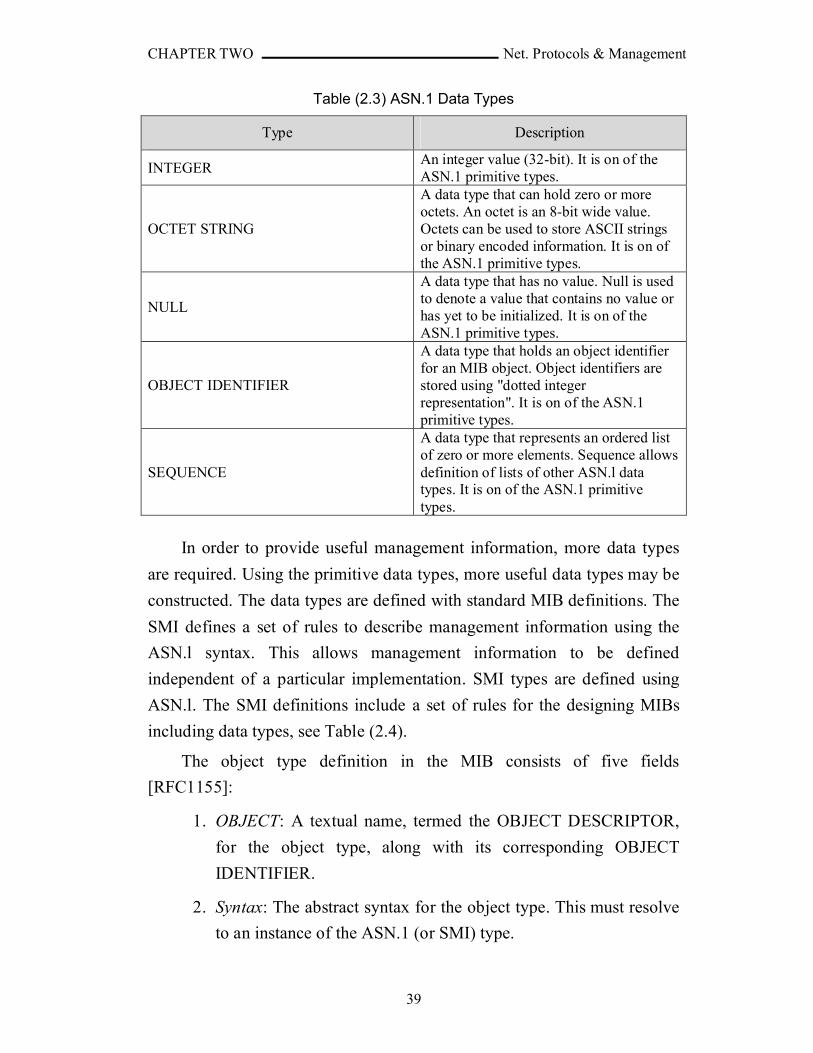
CHAPTER TWO Net. Protocols & Management
39
Table (2.3) ASN.1 Data Types
Type Description
INTEGERAn integer value (32-bit). It is on of the ASN.1 primitive types.
OCTET STRING
A data type that can hold zero or more octets. An octet is an 8-bit wide value. Octets can be used to store ASCII strings or binary encoded information. It is on of the ASN.1 primitive types.
NULL
A data type that has no value. Null is used to denote a value that contains no value or has yet to be initialized. It is on of the ASN.1 primitive types.
OBJECT IDENTIFIER
A data type that holds an object identifier for an MIB object. Object identifiers are stored using "dotted integer representation". It is on of the ASN.1 primitive types.
SEQUENCE
A data type that represents an ordered list of zero or more elements. Sequence allows definition of lists of other ASN.l data types. It is on of the ASN.1 primitive types.
In order to provide useful management information, more data types
are required. Using the primitive data types, more useful data types may be
constructed. The data types are defined with standard MIB definitions. The
SMI defines a set of rules to describe management information using the
ASN.l syntax. This allows management information to be defined
independent of a particular implementation. SMI types are defined using
ASN.l. The SMI definitions include a set of rules for the designing MIBs
including data types, see Table (2.4).
The object type definition in the MIB consists of five fields
[RFC1155]:
1. OBJECT: A textual name, termed the OBJECT DESCRIPTOR,
for the object type, along with its corresponding OBJECT
IDENTIFIER.
2. Syntax: The abstract syntax for the object type. This must resolve
to an instance of the ASN.1 (or SMI) type.

CHAPTER TWO Net. Protocols & Management
40
3. Definition: A textual description of the semantics of the object
type.
4. Max-Access: One of read-only, read-write, write-only, or not-
accessible.
5. Status: One of mandatory, optional, or obsolete.
An example of an object definition is shown in Figure (2.10).
Table (2.4) SMI Data Types
Type Description
IpAddress Representation of an Internet Protocol address.
Counter32Representation of a non-negative data type used for counting. Internally, this is a 32-bit value. It may increase monotonically until a maximum value is reached, when it will wrap back to a 0 value.
Counter64
Representation of a non-negative data type used for counting. Internally, this is a 64-bit value. It may increase monotonically until a maximum value is reached, when it will wrap back to a 0 value. (Available in SNMP version 2 and 3 only)
Gauge32
Representation of a non-negative data type used for gauging. Internally, this is a 32-bit value. Its value may increase or decrease. If the value exceeds the maximum value then it latches to the maximum value. If the value later drops below the maximum value then the actual value thereafter can change.
TimeTicksRepresentation of a non-negative data type used for the relative time representation. TimeTicks are measured in hundredths of a second relative to some time (typically time since reboot).
Unsigned32Representation of a data type used when a signed integer will not suffice. Internally, this is a 32-bit value.
Fig. (2.10) example of Managed Object Definition
myMIBObject OBJECT-TYPE S YNTAX INTEGER MAX-ACCESS read-write STATUS manadtory DESCRIPTION "An example of MIB object"
::= { myobjects 1 )
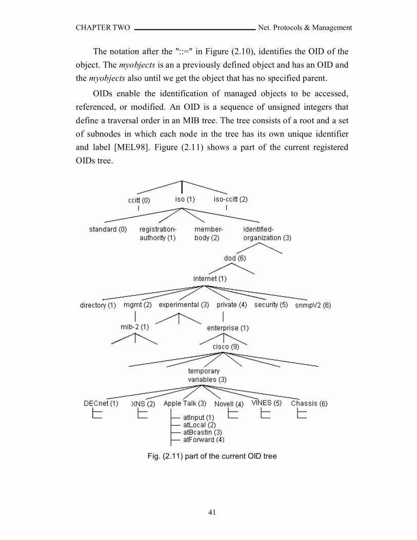
CHAPTER TWO Net. Protocols & Management
41
The notation after the "::=" in Figure (2.10), identifies the OID of the
object. The myobjects is an a previously defined object and has an OID and
the myobjects also until we get the object that has no specified parent.
OIDs enable the identification of managed objects to be accessed,
referenced, or modified. An OID is a sequence of unsigned integers that
define a traversal order in an MIB tree. The tree consists of a root and a set
of subnodes in which each node in the tree has its own unique identifier
and label [MEL98]. Figure (2.11) shows a part of the current registered
OIDs tree.
Fig. (2.11) part of the current OID tree

CHAPTER TWO Net. Protocols & Management
42
So, the OID of atInput is "1.3.6.1.4.1.9.3.3.1". The experimental
subtree is dedicated for adding the objects of researches.
2.8.2 SNMPv1
Communication among protocol entities is accomplished by the
exchange of messages, each of which is entirely and independently
represented within a single UDP datagram using the Basic Encoding Rules
(BER) of Abstract Syntax Notation One (ASN.1). A message consists of a
version identifier, an SNMP community name, and a Protocol Data Unit
(PDU), as shown in Figure (2.12). A protocol entity receives messages at
UDP port 161 on the host with which it is associated for all messages
except for those which report traps (i.e., all messages except those which
contain the Trap-PDU). Messages which report traps should be received on
UDP port 162 for further processing. An implementation of this protocol
need not accept messages whose length exceeds 484 octets (Octets is an 8-
bit wide value; Octets can be used to store ASCII strings or binary encoded
information). However, it is recommended that implementations support
larger datagrams whenever feasible. It is mandatory that all
implementations of the SNMP support the five PDUs: GetRequest-PDU,
GetNextRequest-PDU, GetResponse-PDU, SetRequest-PDU, and Trap-
PDU [RFC1157]. The SNMP message in ASN.1 notation is defined in
Appendix B.
Fig. (2.12) SNMPv1 Message
When an agent picks up an SNMP request message (GetRequest), the
message is passed to the SNMP protocol engine where is it decoded and
processed. The engine decodes the message to determine its type and the
exact information being requested. If the request is authorized, the request
is processed and a response (GetResponse) is generated to the manager that
issued the request. The manager can request message by using GetRequest
and then by using GetNextRequest message to get the next MIB. The
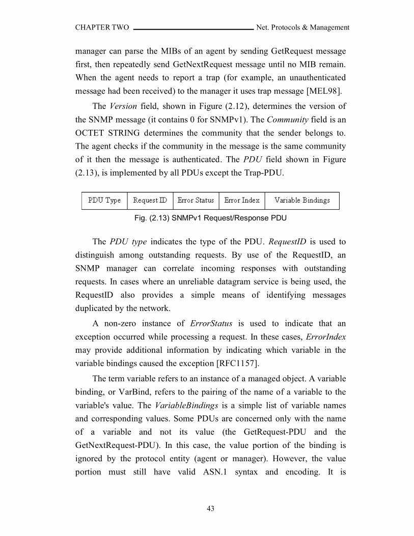
CHAPTER TWO Net. Protocols & Management
43
manager can parse the MIBs of an agent by sending GetRequest message
first, then repeatedly send GetNextRequest message until no MIB remain.
When the agent needs to report a trap (for example, an unauthenticated
message had been received) to the manager it uses trap message [MEL98].
The Version field, shown in Figure (2.12), determines the version of
the SNMP message (it contains 0 for SNMPv1). The Community field is an
OCTET STRING determines the community that the sender belongs to.
The agent checks if the community in the message is the same community
of it then the message is authenticated. The PDU field shown in Figure
(2.13), is implemented by all PDUs except the Trap-PDU.
Fig. (2.13) SNMPv1 Request/Response PDU
The PDU type indicates the type of the PDU. RequestID is used to
distinguish among outstanding requests. By use of the RequestID, an
SNMP manager can correlate incoming responses with outstanding
requests. In cases where an unreliable datagram service is being used, the
RequestID also provides a simple means of identifying messages
duplicated by the network.
A non-zero instance of ErrorStatus is used to indicate that an
exception occurred while processing a request. In these cases, ErrorIndex
may provide additional information by indicating which variable in the
variable bindings caused the exception [RFC1157].
The term variable refers to an instance of a managed object. A variable
binding, or VarBind, refers to the pairing of the name of a variable to the
variable's value. The VariableBindings is a simple list of variable names
and corresponding values. Some PDUs are concerned only with the name
of a variable and not its value (the GetRequest-PDU and the
GetNextRequest-PDU). In this case, the value portion of the binding is
ignored by the protocol entity (agent or manager). However, the value
portion must still have valid ASN.1 syntax and encoding. It is
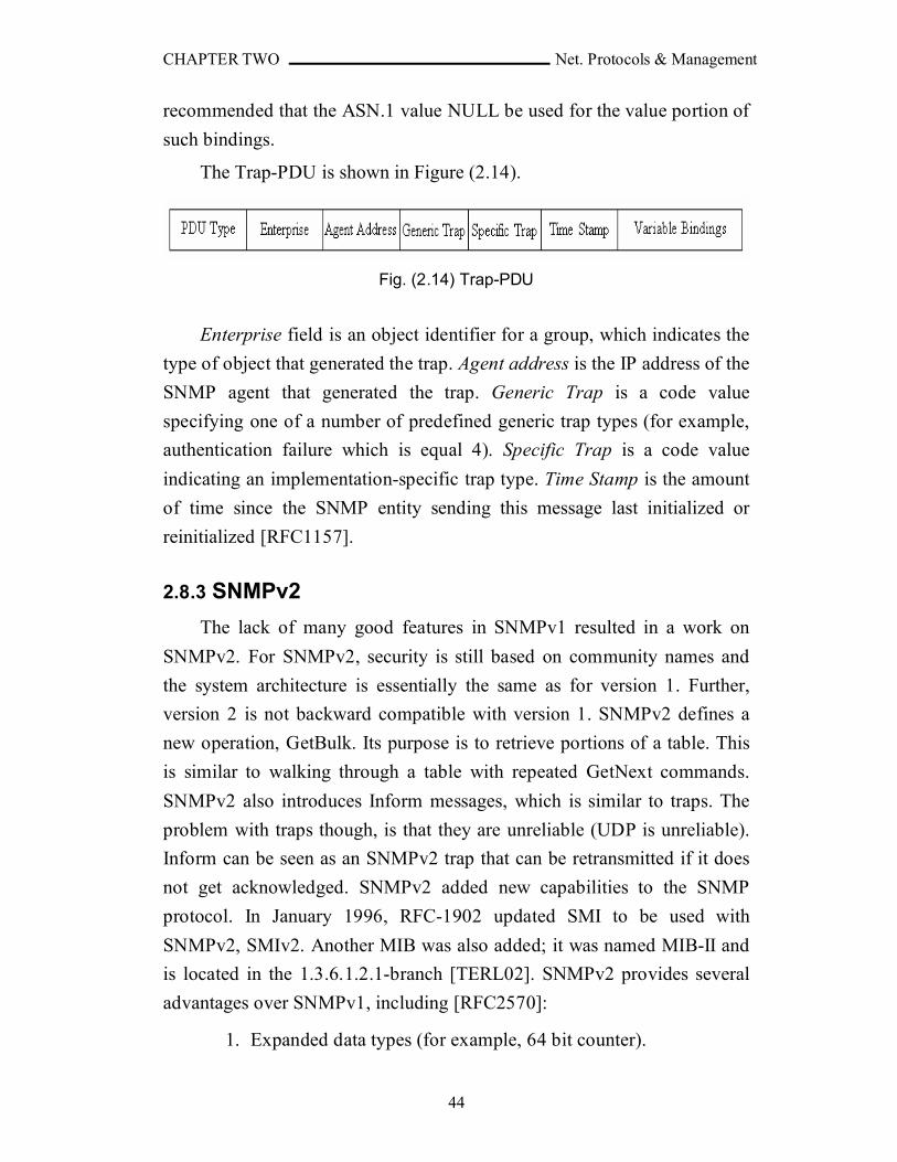
CHAPTER TWO Net. Protocols & Management
44
recommended that the ASN.1 value NULL be used for the value portion of
such bindings.
The Trap-PDU is shown in Figure (2.14).
Fig. (2.14) Trap-PDU
Enterprise field is an object identifier for a group, which indicates the
type of object that generated the trap. Agent address is the IP address of the
SNMP agent that generated the trap. Generic Trap is a code value
specifying one of a number of predefined generic trap types (for example,
authentication failure which is equal 4). Specific Trap is a code value
indicating an implementation-specific trap type. Time Stamp is the amount
of time since the SNMP entity sending this message last initialized or
reinitialized [RFC1157].
2.8.3 SNMPv2
The lack of many good features in SNMPv1 resulted in a work on
SNMPv2. For SNMPv2, security is still based on community names and
the system architecture is essentially the same as for version 1. Further,
version 2 is not backward compatible with version 1. SNMPv2 defines a
new operation, GetBulk. Its purpose is to retrieve portions of a table. This
is similar to walking through a table with repeated GetNext commands.
SNMPv2 also introduces Inform messages, which is similar to traps. The
problem with traps though, is that they are unreliable (UDP is unreliable).
Inform can be seen as an SNMPv2 trap that can be retransmitted if it does
not get acknowledged. SNMPv2 added new capabilities to the SNMP
protocol. In January 1996, RFC-1902 updated SMI to be used with
SNMPv2, SMIv2. Another MIB was also added; it was named MIB-II and
is located in the 1.3.6.1.2.1-branch [TERL02]. SNMPv2 provides several
advantages over SNMPv1, including [RFC2570]:
1. Expanded data types (for example, 64 bit counter).
CHAPTER TWO Net. Protocols & Management
45
2. Improved efficiency and performance (get-bulk operator).
3. Confirmed event notification (inform operator).
4. Richer error handling (errors and exceptions).
5. Improved sets, especially row creation and deletion.
6. Fine tuning of the data definition language.
RFC-1445 [RFC1445] and RFC-1446 [RFC1446] describe an
administrative and a security model to be used with SNMPv2. RFC-1446
specified the following two principal threats to be protected in SNMPv2:
1. Modification of Information: The SNMPv2 protocol provides the
means for management stations to interrogate and to manipulate the
value of objects in a managed agent. The modification threat is the
danger that some party may alter in-transit messages generated by an
authorized party in such a way as to effect unauthorized management
operations, including falsifying the value of an object.
2. Masquerade: The SNMPv2 administrative model includes an access
control model. Access control necessarily depends on knowledge of the
origin of a message. The masquerade threat is the danger that
management operations not authorized for some party may be attempted
by that party by assuming the identity of another party that has the
appropriate authorizations.
And RFC-1446 specified two secondary threats [RFC1446]:
1. Message Stream Modification: The SNMPv2 protocol is based upon a
connectionless transport service which may operate over any
subnetwork service. The re-ordering, delay or replay of messages can
and does occur through the natural operation of many such subnetwork
services. The message stream modification threat is the danger that
messages may be maliciously re-ordered, delayed or replayed to an
extent which is greater than can occur through the natural operation of a
subnetwork service, in order to produce an effect on the unauthorized
management operations.
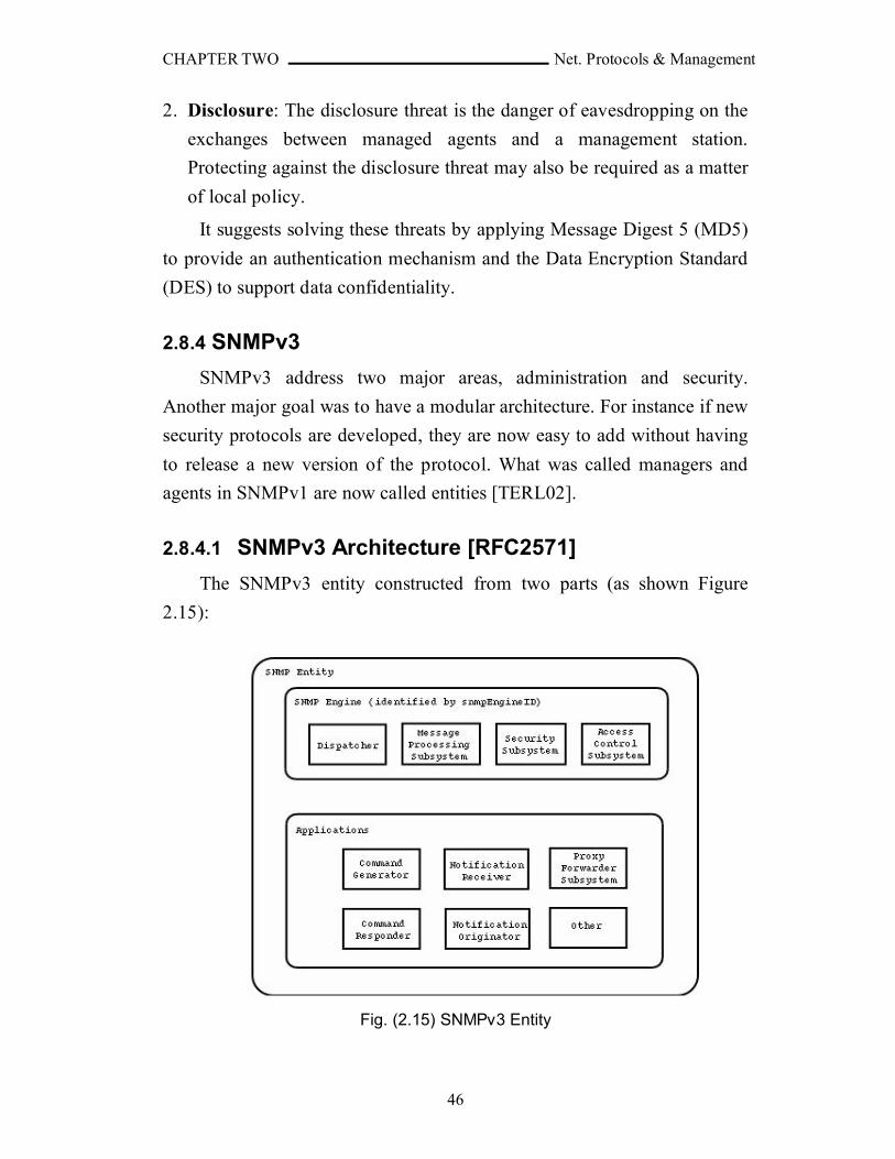
CHAPTER TWO Net. Protocols & Management
46
2. Disclosure: The disclosure threat is the danger of eavesdropping on the
exchanges between managed agents and a management station.
Protecting against the disclosure threat may also be required as a matter
of local policy.
It suggests solving these threats by applying Message Digest 5 (MD5)
to provide an authentication mechanism and the Data Encryption Standard
(DES) to support data confidentiality.
2.8.4 SNMPv3
SNMPv3 address two major areas, administration and security.
Another major goal was to have a modular architecture. For instance if new
security protocols are developed, they are now easy to add without having
to release a new version of the protocol. What was called managers and
agents in SNMPv1 are now called entities [TERL02].
2.8.4.1 SNMPv3 Architecture [RFC2571]
The SNMPv3 entity constructed from two parts (as shown Figure
2.15):
Fig. (2.15) SNMPv3 Entity

CHAPTER TWO Net. Protocols & Management
47
1. SNMP engine: An SNMP engine provides services for sending and
receiving messages, authenticating and encrypting messages, and
controlling access to managed objects. There is a one-to-one association
between an SNMP engine and the SNMP entity which contains it.
The engine contains:
a. Dispatcher: There is only one Dispatcher in an SNMP engine. It
allows for concurrent support of multiple versions of SNMP
messages in the SNMP engine.
b. Message Processing Subsystem: it is responsible for preparing
messages for sending, and extracting data from received messages.
The Message Processing Subsystem potentially contains multiple
Message Processing Models. The Message Processing Models
defines the format of a particular version of an SNMP message and
coordinates the preparation and extraction of each such version-
specific message format. For example, SNMPv3 Message Processing
Model, SNMPv2 Message Processing Model, SNMPv1 Message
Processing Model, and any other.
c. Security Subsystem: it provides security services such as the
authentication and privacy of messages and potentially contains
multiple Security Models. For example, User-Based Security Model
(USM).
d. Access Control Subsystem: provides authorization services by means
of one or more Access Control Models. For example, View-Based
Access Control Model (VACM).
For each SNMP engine, there is a unique snmpEngineID within an
administrative domain. Since there is a one-to-one association between
SNMP engines and SNMP entities, it also uniquely and unambiguously
identifies the SNMP entity within that administrative domain. Note that
it is possible for SNMP entities in different administrative domains to
have the same value for snmpEngineID.
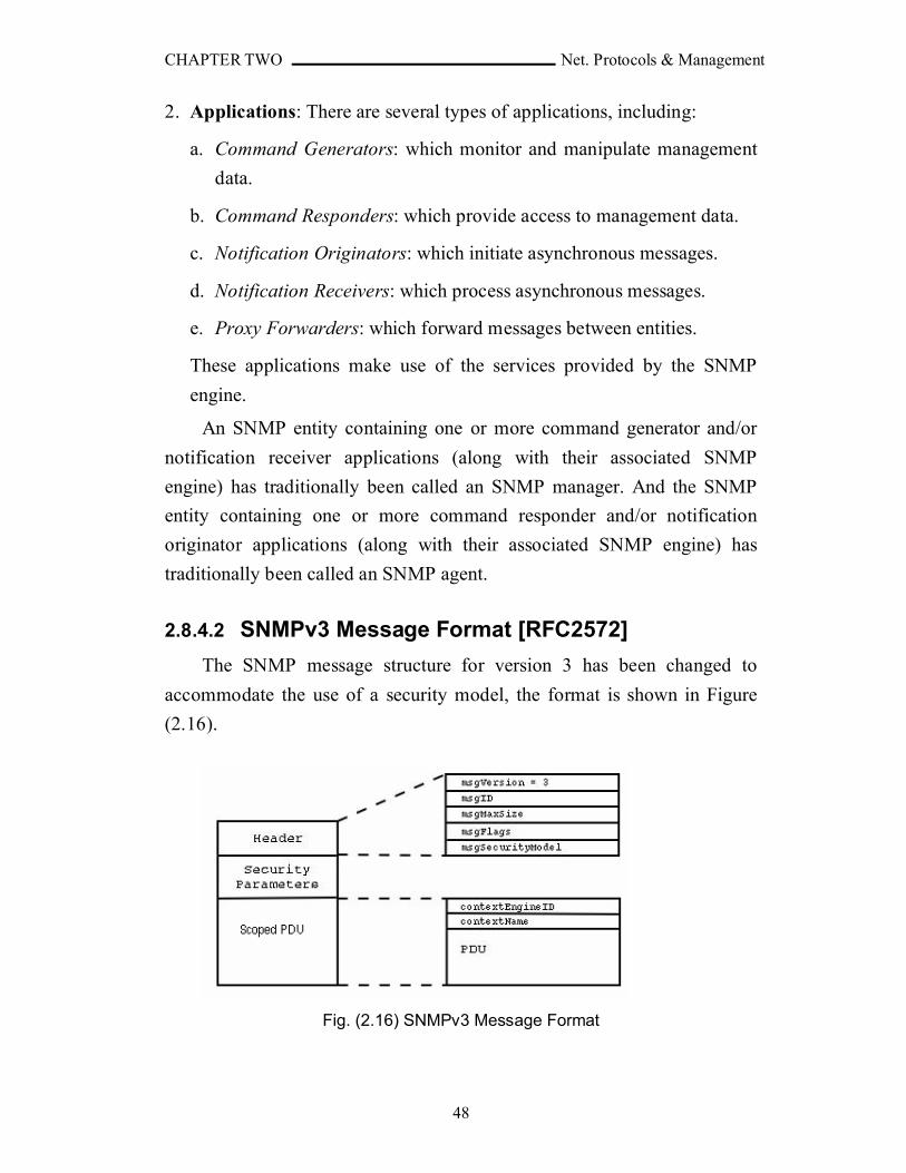
CHAPTER TWO Net. Protocols & Management
48
2. Applications: There are several types of applications, including:
a. Command Generators: which monitor and manipulate management
data.
b. Command Responders: which provide access to management data.
c. Notification Originators: which initiate asynchronous messages.
d. Notification Receivers: which process asynchronous messages.
e. Proxy Forwarders: which forward messages between entities.
These applications make use of the services provided by the SNMP
engine.
An SNMP entity containing one or more command generator and/or
notification receiver applications (along with their associated SNMP
engine) has traditionally been called an SNMP manager. And the SNMP
entity containing one or more command responder and/or notification
originator applications (along with their associated SNMP engine) has
traditionally been called an SNMP agent.
2.8.4.2 SNMPv3 Message Format [RFC2572]
The SNMP message structure for version 3 has been changed to
accommodate the use of a security model, the format is shown in Figure
(2.16).
Fig. (2.16) SNMPv3 Message Format
CHAPTER TWO Net. Protocols & Management
49
The msgVersion field is set to SNMPv3(3) and identifies the message
as an SNMP version 3 Message.
The msgID is used between two SNMP entities to coordinate request
messages and responses, and to coordinate the processing of the message
by different subsystem models within the architecture. A msgID in a
response must be same as the msgID received in the request.
The msgMaxSize field of the message conveys the maximum message
size supported by the sender of the message. The msgFlags field of the
message contains several bit fields which control processing of the
message. For instance, two bits of the msgFlags are used to specify whether
or not the message has been authenticated and whether or not it has been
encrypted.
The SNMPv3 supports the concurrent existence of multiple Security
Models to provide security services for SNMPv3 messages. The
msgSecurityModel field in an SNMPv3 Message identifies which Security
Model was used by the sender to generate the message and therefore which
security model must be used by the receiver to perform security processing
for the message.
The msgSecurityParameters is an octet string that contains the security
model specific data. This data is defined by and used only by the security
model specified by the msgSecurityModel.
The scopedPDU contains the normal PDU and information for
identifying the administratively unique context for processing the PDU.
The context is a collection of management information accessible by an
SNMP entity. Where, an item of management information may exist in
more than one context. An SNMP entity potentially has access to many
contexts.
2.8.4.3 SNMPv3 Security
Security is normally applied at two different stages: in the
transmission/receipt of messages, and in the processing of the contents of
messages. The security can be achieved by authentication, encryption, and
CHAPTER TWO Net. Protocols & Management
50
timeliness checking. The default security model for the SNMPv3 is User-
based Security Model (USM) [RFC2571].
The USM specifies the use of the Message Digest 5 (MD5) and Secure
Hash Algorithm 1 (SHA-1) algorithms for authenticating SNMPv3
messages. These algorithms are used to create unique fixed sized message
digests, also called digital signatures or fingerprints, of a variable length
message. MD5 creates a digest of 128 bits (16 bytes) and SHA-1 creates a
digest of 160 bits (20 bytes). Both MD5 and SHA-1 cannot be used directly
as a message authentication code because they do not use secret keys as
input to derivate the computed message digest. This is why the Keyed
Hashing for Message Authentication (HMAC) algorithm in combination
with MD5 and SHA-1 is used for computing message digests. The HMAC
algorithm defines a procedure for appending a secret key to the data and
then computing the MD5 or SHA-1 message digest. This guarantees that
parties who wish to compute identical message digests for the same block
of data must share a common secret key.
The USM specifies the use of the Cipher Block Chaining mode to the
Data Encryption Standard (CBC-DES) algorithm for encrypting and
decrypting SNMPv3 messages. The scope of the encryption only covers the
scopedPDU which contains the PDU and context data used by the View-
based Access Control Module (VACM). The DES algorithm takes three
inputs. These inputs are the data to be encrypted, a 56 bit secret key, and a
56 bit randomly generated salt which is used to ensure that two different
initialization vectors are used for two different data inputs encrypted with
the same secret key. For two parties to use encryption during
communication, each must share a secret privacy key as well as the salt
used to derivate the initialization vector. The secret privacy keys are stored
in the User Table (in each entity, there exist a table contains the names of
the users and their information, for example: authentication method,
authentication key, privacy method, and privacy key), and the salt is
transmitted with the message [DAV00].
CHAPTER TWO Net. Protocols & Management
51
The USM also supports message timeliness and limited replay
protection which is the provision of the property that a message whose
generation time is outside of a specified time window is not accepted. The
timeliness check is only performed if authentication is applied to the
message [RFC2572].
2.8.4.4 Access Control [RFC2575]
The Access Control Subsystem of an SNMP engine has the
responsibility for checking whether a specific type of access (read, write,
notify) to a particular object is allowed.
Access Control occurs (either implicitly or explicitly) in an SNMP
entity when processing SNMP retrieval or modification request messages
from an SNMP entity. For example a Command Responder application
applies Access Control when processing requests that it received from a
Command Generator application.
Access Control, also, occurs in an SNMP entity when an SNMP
notification message is generated (by a Notification Originator application).
The default SNMPv3 access control model is the View-based Access
Control Model (VACM), which defines a set of services that an application
(such as a Command Responder or a Notification Originator application)
can use for checking access rights. It is the responsibility of the application
to make the proper service calls for access checking.
2.9 Power Line Communication (PLC)
Digital communications over powerlines is an old idea that dates back
to the early 1920s. For some decades, the omnipresent power grid has been
used for low-speed data communications. Many different standardized or
proprietary systems have been used for the transmission of control and
management signals (e.g. remote meter reading) by power supply
companies. However, the powerline has largely been dismissed as being
too noisy and unpredictable to be useful as a practical high-speed
communication channel [SAR04].
CHAPTER TWO Net. Protocols & Management
52
A significant change occurred when the last monopolies were ended
by 1998. In the same time, major advances in the fields of modulation,
coding and detection enabled the design of efficient broadband
communication systems over powerlines. The idea of exploiting the low-
voltage (LV) power grid to provide broadband Internet access to residential
customers has been proposed as an alternative to the other classical 'last-
mile solutions' such as ADSL, cable modems, or wireless access systems.
LV powerline communication (PLC) networks have a tree-like topology,
with a PLC modem installed at the medium-voltage/low-voltage (MV/LV)
transformer and providing connectivity to all premises in the neighborhood.
The architecture of the LV PLC network has to be optimized for the special
characteristics of the distribution grid, which changes from one geographic
area to another, considering the number of households per transformer and
the distance from the transformer to the customer premises. When larger
distances are involved, as it is the case in European topologies,
intermediate repeaters are typically needed to regenerate the signal from
the head-end and provide adequate coverage in every customer outlet.
Also, there is growing interest in the prospects of reusing in-building
powerline cables to provide a broadband LAN within the home or office.
The major advantage offered by powerline-based home networks is the
availability of an existing infrastructure of wires and wall outlets, so new
cable installation is not required. The user can employ home networking
devices for connecting several computers, sharing printers, or sharing a
broadband Internet connection [SAR04].
Another important field of research is the use of the MV network for
communication purposes. It can be used as a backbone to connect the low
voltage transformer stations to the Internet if the conventional backbone
networks, like fiber optic cables, are missing. MV lines have their own
characteristics for communication: they are typically less noisy, and have
fewer branches and taps than LV lines, so the environment is less hostile
for communications and longer distances can be achieved. The problem
with MV lines is that special couplers are needed for injecting the signal in

CHAPTER TWO Net. Protocols & Management
53
the line to ensure that the mains voltage does not damage the
equipment.
There are three components to make a connection through power
lines [SAR04]:
1. Head End: it is the key component in a power grid topology. The HE is
the master of the other units in the network. As a master the Head End
coordinates the frequency and timeslots from the individual customer
modems to maintain a smooth stream of packets in the dense spectrum
of the power grid. The Head End also enables the WAN connection to
the ISP where the Internet connects to the power grid.
2. Intermediate Repeater: it is used to extend the coverage offered by
power-line communication. Installed with the secondary switchboard or
in a metering unit, a riser or in a street-side cubicle, a repeater is
required when there is a significant distance between the server modem
and the customer modem. It is of two types: point to point or point to
multipoint.
3. Customer modem: is used to connect the end-user to the electrical
network thereby creating a data link. The modem is connected directly
to an electrical socket at the customer location.
The speed of the PLC modems reaches 47Mbps and some companies
announced of coming faster PLCs.
2.10 .NET Framework
The .NET Framework is the next generation of Microsoft's platform
for developing component-based software. It provides fundamental
advances in runtime services for application software. It also supports
development of applications that can be free of dependencies on hardware,
operating system, and language compiler [GIA02].
The .NET Framework encompasses the following:
CHAPTER TWO Net. Protocols & Management
54
1. A new way to expose operating system and other Application
Programming Interfaces (APIs): for years, the set of Windows
functionality that was available to developers and the way that
functionality was invoked were dependent on the language environment
being used. For example, the Windows operating system provides the
ability to create windows (obviously). Yet, the way this feature was
invoked from a C++ program was dramatically different from the way it
was invoked from a Visual Basic program. With .NET, the way that
operating system services are invoked is uniform across all languages
(including code embedded in ASP.NET pages). This portion of .NET is
commonly referred to as the .NET Framework class library.
2. A new infrastructure for managing application execution: to provide
a number of sophisticated new operating-system services (including
code-level security, cross-language class inheritance, cross-language
type compatibility, and hardware and operating-system independency),
Microsoft had developed a new runtime environment known as the
Common Language Runtime (CLR). The CLR includes the Common
Type System (CTS), for cross-language type compatibility, and the
Common Language Specification (CLS), for ensuring that third-party
libraries can be used from all .NET-enabled languages. To support
hardware and operating-system independence, Microsoft developed the
Microsoft Intermediate Language (MSIL, or just IL). IL is a CPU-
independent machine language-style instruction set into which .NET
Framework programs are compiled. IL programs are compiled to the
actual machine language on the target platform prior to execution
(known as just-in-time, or JIT, compiling). IL is never interpreted.
3. A new web server paradigm: to support high-capacity web sites,
Microsoft has replaced its Active Server Pages (ASP) technology with
ASP.NET. While developers who are used to classic ASP will find
ASP.NET familiar on the surface, the underlying engine is different, and
far more features are supported. One difference is that ASP.NET web
page code is now compiled rather than interpreted; this feature is greatly
increasing execution speed.
CHAPTER TWO Net. Protocols & Management
55
4. A new focus on distributed-application architecture: Visual Studio
.NET provides top-notch tools for creating and consuming web services
(vendor-independent software services) that can be invoked over the
Internet.
5. Building multi-threading into .NET applications is a powerful tool
for the developer: It empowers applications that demand high
scalability, such as enterprise applications, as well as desktop
applications that need to process more than one task at the same time. In
order to enable multi-threading technology, Intel developed Hyper-
Threading Technology (HT Technology) for the Pentium® 4 processor
on the desktop and the Intel® Xeon™ processor for workstations and
servers. These platforms make a particularly good choice for the
deployment of threaded .NET solutions. The coming trend of
parallelism in hardware is that of multi-core processors, which will
make multi-threading even more important. Intel has announced planes
to introduce the first versions of both the Itanium® processor and the
Pentium 4 processor, that have multiple processor cores on a single die,
in 2005. These introductions will be followed in 2006 by the first multi-
core Intel Xeon processors and Intel Xeon processors MP. As these and
other advances make hardware platforms ever more parallel in nature,
the stage is set for software threading to deliver ever-larger performance
gains. Software makers that gear up for this advance now, stand to gain
a competitive advantage as this trend continues.

CHAPTER THREE NMS DESIGN
56
CHAPTER THREE
NETWORK MANAGEMENT SYSTEM
DESIGN
3.1 Introduction
This chapter is dedicated to introduce the design of the network
management system for public services (electricity power measurement
and maintenance, water flow measurement and maintenance, medical help
alarm, fire monitoring, and security monitoring) and its necessary
application software tools. This system was implemented using Visual
Basic .NET 2003.
3.2 System Objectives
1. Designing and building network management system for public services.
2. Designing and building software tools that manage these public services.
3. The system must be reliable, secure, extendable and easy to use.
3.3 System Considerations
1. The network traffic must be minimum.
2. The alerts must be sent to the service provider to be served, as fast as possible.
3. The alerts must have priorities.
4. The system must consider false alarms.
5. The database must be distributed, and efficiently work in multi-threaded system.
6. The addresses of services providers and customers’ buildings must be easy to maintain.
7. Keeps the technologies used as standard as possible.
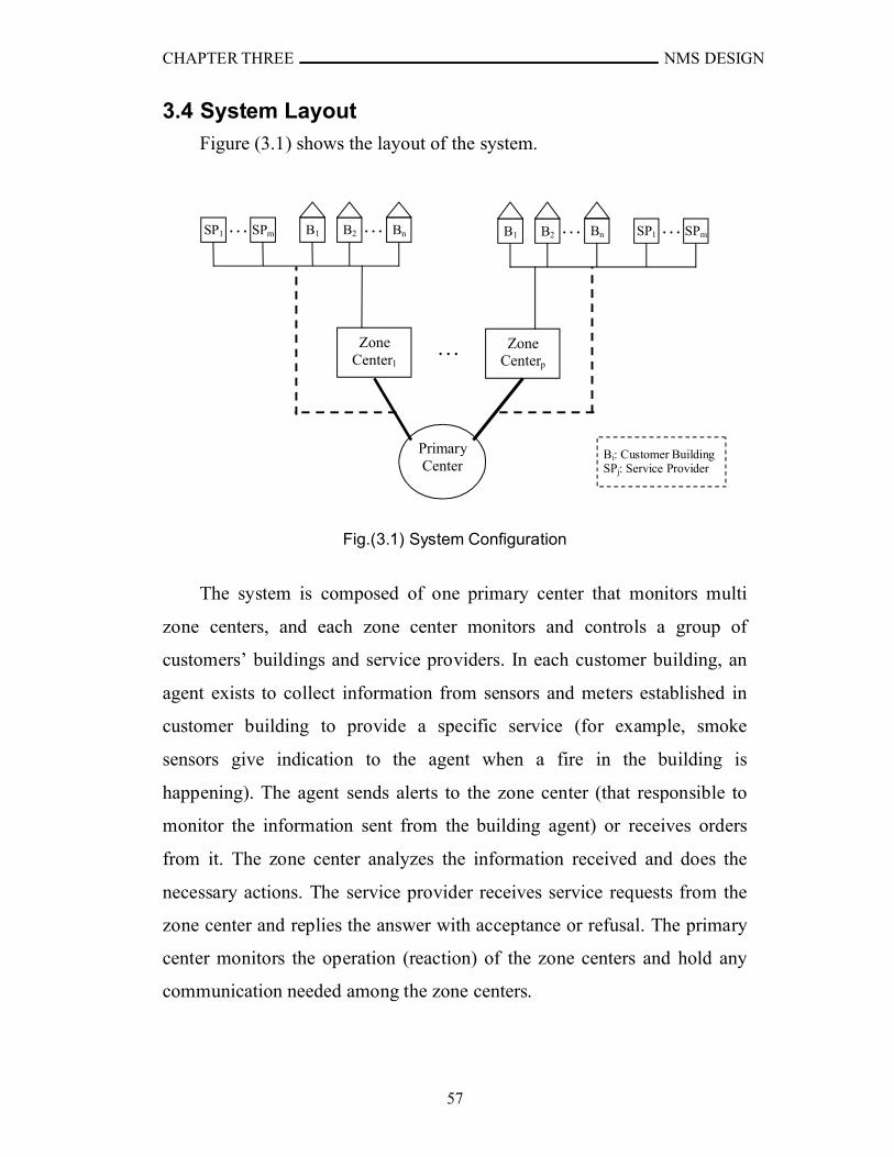
CHAPTER THREE NMS DESIGN
57
3.4 System Layout
Figure (3.1) shows the layout of the system.
Fig.(3.1) System Configuration
The system is composed of one primary center that monitors multi
zone centers, and each zone center monitors and controls a group of
customers’ buildings and service providers. In each customer building, an
agent exists to collect information from sensors and meters established in
customer building to provide a specific service (for example, smoke
sensors give indication to the agent when a fire in the building is
happening). The agent sends alerts to the zone center (that responsible to
monitor the information sent from the building agent) or receives orders
from it. The zone center analyzes the information received and does the
necessary actions. The service provider receives service requests from the
zone center and replies the answer with acceptance or refusal. The primary
center monitors the operation (reaction) of the zone centers and hold any
communication needed among the zone centers.
BnB2B1 SPmSP1 ……
Zone Centerp
Primary Center
Bi: Customer BuildingSPj: Service Provider
Zone Center1
B2B1 BnSPmSP1 … …
…
CHAPTER THREE NMS DESIGN
58
Each zone center monitor and control a group of buildings called zone.
The zone is specified according to two factors:
1. Geographical factor: the area covered by the one zone should be as
large as possible to hold a specific number such that the network
infrastructure establishment and maintenance is feasible and
proportional with the importance of the supported public service.
2. Capacity factor: The number of customers covered within the zone is
important, it should be not small (because this will make the
infrastructure infeasible), and too large (because this may cause
some operational failures due to network overload).
3.5 Hardware Requirements
The hardware requirements are grouped into four sets. The first set is
concerned with hardware needed at the customers’ buildings; the second
set is for zone center building; the third set is for primary center building;
and the last set is for the network media.
3.5.1 Customer’s Building Hardware
To monitor and then provide the services requested by the customer,
the customer’s building must contain sensors and meters. The considered
sensors in this project are classified into three major types according to the
provided service:
1. Smoke sensors to provide fire monitoring service.
2. Security sensors to provide security alarm service.
3. Water sensors to monitor the water flow, and consequently detect the
cut of the water from the pipes (water service).
CHAPTER THREE NMS DESIGN
59
To read the measurements of the electricity and water, electrometers
and water meters are needed for each service respectively. All these devices
are connected to the agent’s device that collects data from them and do the
necessary operations related to storing data or sending alarms to the zone
center.
The medic help alarm service is achieved by using a panic button in
the building that is pressed when medic help is needed. The panic button
could be exists in every room in the building or specific places according to
the need of the customer.
In case that the sensors couldn’t detect a problem happened, manual
alarms can be raised by pushing the required button. The manual buttons
are: (1) Fire Alarm, (2) Security Break Alarm, (3) Electricity Maintenance,
(4) Water Maintenance, (5) Fire Devices Maintenance, and (6) Security
Devices Maintenance. The Fire Alarm and the security Break Alarm
buttons can be distributed in the house as needed like the Medic Help
button.
Also, a liquid crystal display (LCD) devices are provided for
displaying the electricity meter reading, water flow, and other devices
status with a Control button to display the required information. Also, there
are speakers (if demanded) to announce the customer when critical alerts
happened.
3.5.2 Service Provider Hardware
The main job of the service provider software is receiving requests
from the zone center. The number of orders that the service provider can
serve is the factor that specifies the hardware needed. But, basically the
service provider must provide reliability and availability to its services. To
achieve that, the service provider software is put on a cluster of fast nodes
CHAPTER THREE NMS DESIGN
60
(computers). When one node is breakdown the others are ready to monitor
and control the agents. Also, the cluster configuration provides load
balancing between the nodes.
3.5.3 Zone Center Hardware
The main jobs of the zone center are monitoring and controlling large
number of customers. The zone center must provide reliability and
availability to its services. To achieve that, two strategies have been taken
into consideration:
1. The zone center system software is put on a cluster of fast nodes
(computers). When one node is breakdown the others are ready to
monitor and control the agents. Also, the cluster configuration
provides load balancing between the nodes.
2. When the whole zone center break down, the primary center takes
the responsibility of its functionality until it reruns again.
3.5.4 Primary Center HardwareThe jobs of primary center are monitoring and controlling a number of
zone centers, and provides a backup to them in case of break down one of
them. So, the primary center must provide reliability and availability to its
service. This can be achieved by using cluster of fast nodes to hold the
primary center system software.
3.5.5 Connection Media
This system is designed to cover a large geographical area with large
number of customers. To suggest the suitable connection media that can
achieve minimum cost with acceptable performance with scalability, a set
of connections with different features must be established:
CHAPTER THREE NMS DESIGN
61
1. Connection between customer’s building and zone center. This
connection holds the transfer of alarms (from the agent in the
Customer’s building to the zone center), requests (from zone center to
the agent) and their responds. The average size of messages transferred
through this connection is 158 byte. The number of connections of this
type is equal to the number of customers’ buildings, which is very large.
The large number of the connections of this type causes the
construction of totally new infrastructure to cost very much. Even using
wireless connections with this large number of connections with the
existence of mobile networks and wireless internet service providers
could generate large interference. So, the existing wired connection is
the most suitable key in respect with cost. Usually the existing public
networks are the unleased telephone lines (most of the existing
telephone lines are unleased) and the electricity power lines. In the
sense of the low bandwidth need, these two types of networks are
suitable. But using the telephone lines (that are unleased connections)
would cause problems, such as: (a) opening connection could be slow
which in turn affects the time of alert notification, (b) when the
telephone line is in use by the customer and it is needed to send an alert
then the customer call must be closed unless the telephone central is
supporting this capability, and (c) how the agent knows if the telephone
call is from the manager (zone center) directed to it or it is for the
customer from a friend; if the agent depends on the caller number (not
all the telephone centrals supports that) then this number must be stored
in the agent connection list and when it is needed to be replaced then it
must be replaced by all agents.
The other option is the electricity power lines. The devices needed
to communicate through the electricity power lines are described in
CHAPTER THREE NMS DESIGN
62
chapter two; they are the Head End, Intermediate Repeater, and
Customer Modem. The customer modem would be setup in the
customer’s building, the intermediate repeater in the transformers or in a
dedicated box in case of long distance between the transformers and the
customer’s building, and the Head End is put in the HV/MV
transformers.
Last thing is the media connecting between the zone center and the
Head End. The Head End collects data from relatively large number of
agents. So, the zone is partitioned into sub zones, each one is supplied
with Head End to avoid bottleneck problems and to increase the
reliability. The media connecting the Head Ends and the zone center is
suggested to be fiber optics and wireless for backing up.
2. Connection between zone center and service provider. This connection
holds transfer of alarms (from the zone center to the service provider)
and keeps information about the state of the service provider. Some
statistical information may be delivered from the service provider to the
zone center. This connection does not necessarily need to be high
bandwidth because usually the amount of information transferred
through it is small. The size of the messages transferred through this
connection is 105 byte in average. The number of connections of this
type equal to the number of service providers, which is, relatively, very
small in comparison with the number of customers’ buildings.
The connection between zone center and the service provider could
be achieved mainly by wireless connection because the wireless satisfies
the needs of this type, and it is less expensive than others like twisted
pair or optical fiber, or by unleased telephone lines. The backup
connection is the electricity power lines, which is utilized only for alerts
and states.
CHAPTER THREE NMS DESIGN
63
3. Connection between zone center and primary center. This connection
holds the transfer of synchronization information, backup data, reports
(from the zone center to the primary center), and disaster warnings. This
connection needs to be high bandwidth because the amount of
information is relatively large. The size of the messages transferred
through this connection is 105…>100 Mbyte (in average 100 Mbyte).
This large size is caused by the large backup files transferred between
the zone center and the primary center. The distance between the
primary center and the zone center could be long distance. The number
of connections of this type is equal to the number of zone centers. The
Optical Fiber is a suitable media could be installed and the wireless for
the backup. The use of the wireless as a backup and not as primary
connection is due to its instability in very bad weather and insecure. For
very long distances, the Internet Satellite connection could be used with
tunneling support, like Virtual Private Network (VPN) for secure
connection.
4. Connection between primary center and each zone. This connection is
needed to make the primary center capable of monitoring and
controlling the zone in case the zone center was break down. The
connection could be used temporarily until the zone center rerun again.
This connection is used to connect the primary center with the
Head Ends of the zone. The type of this connection depends on the
average time of repairing the zone center. Unleased telephone lines
could be used if the zone center repairing process requires little time
that not affects the performance of the system. The wireless medium is
suitable for this type of connection for long repairing process. Another
strategy could be adopted which is installing unleased telephone lines

CHAPTER THREE NMS DESIGN
64
but when the zone center breaks down and long time needed for
repairing then the wireless should installed temporarily.
3.6 System Capacity Estimation
The calculation of the number of customers or service providers that
each zone center can handle depends on many factors, the most effective
factors are: (1) software capability, (2) zone center computers speed and
capacity, (3) the transmission rate of the connection between agent or
service provider and the zone center, and (4) the speed and capacity of the
agent device or the service provider computers. The software in this thesis
is designed to provide large capability and scalability where in each zone
the zone center software can handle 232-1 (=4,294,967,295) agent and 216-1
(=65535) service provider at maximum. But the performance is depending
on the other factors (Hardware factors). Because of the development of
computers with high speed and large capacity, the second and the fourth
factors are neglected during this estimation. So, the calculations depend on
the third factor (connection media) only which is specified in section 3.5.5.
The equations (3.1-2) are used to estimate the average number of nodes
(agents or service providers) can be handled by the zone center depending
on the usage of the connection media and its transmission rate:
L
RNS ……… (3.1)
r
NN S
T ……… (3.2)
Where R is the transmission rate of the communication channel,
L is the average length of the message transmitted between the node
and the zone center,
NS is the average number of nodes that use the communication channel
at the same time,
CHAPTER THREE NMS DESIGN
65
r is the rate of the nodes (agent or service provider) that use the
communication channel at the same time,
and NT is the total number of nodes connected to the zone center by the
same connection.
The average number of agents and service providers that can be
handled by each zone center is defined in the following sections.
3.5.1 Agents Number Estimation
There are two main types of messages transferred between zone center
and agent which are request messages and trap messages. The request
messages must be replied with at least one response message. The trap
messages are sent at least 5-times. After receiving trap message, the zone
center send two request messages and responded by two response
messages. The size of the request messages is 140 byte (in average)
including the header size of the data link, network (IPv6), and transport
layers (UDP). The response messages have the same size. The size of trap
messages is 178 byte. If it is supposed that one trap and one request
message per month are transferred between the zone center and each agent
then the average size of message is calculated as follow:
452
)14041785(1402)(
LsageSizeAverageMes
byte15827.157
If it is assumed that one from every 15 agent in the same sub zone is
sending or receiving message at the same time. Thus:
15
1r
According to section 3.5.5, the power lines are the suitable
communication media between zone center and agents. It is assumed that
CHAPTER THREE NMS DESIGN
66
ILEVO (LR1000, LR1100, LR120, and LR100) modems are used (see
[ILV05]). The following calculations depend on equations (3.1-2):
MbpsR 36
2986529864.518158
236 20
SN agent
447975
15
129865
TN agent (maximum total number of agents in each sub zone that can be controlled by zone center)
Note that this number is calculated according to the maximum
performance of the hardware used (according to the manufacturer) but even
if this number is divided by two (=223987) then it still acceptable.
3.5.2 Service Providers Number EstimationThere is more than one type of messages transferred between zone
center and service provider. The status messages sent at least every five
minutes for monitoring purposes. The size of the status messages is 105
byte including the header size of the data link, network (IPv6), and
transport layers (UDP). Other types of messages excluding the report
messages approximately have the same size. The report messages that
assumed to be requested every one or more months have different sizes.
The following calculations would assume that for each month there is one
report request of size 105 and report response of size 1000 byte (which is
approximately 50 records). Thus, for one month (30 days, 24 hours per day,
and 60 minutes per hour), there are at least 8640 status request and also
8640 status response. Then, the average length is calculated as follows:
22*8640
10511000110528640)(
LsageSizeAverageMes
byte10505.105
It is assumed that all the service providers in the same zone (or sub
zone) are transmitting data at the same time. Thus:
CHAPTER THREE NMS DESIGN
67
11
1r
According to section 3.5.5, the wireless media or unleased telephone
lines are the suitable connection media between zone center and service
providers. The following calculations depend on equations (3.1-2):
1. Wireless: if the Cisco Aironet® 350 series [CIS06] (which is built
on 802.11b standard with transmission rate of 11Mbps and there is faster
and there are faster products) are used then:
MbpsR 11
1373213731.358105
211 20
SN service provider
137321
13732TN service provider (maximum total number of
service providers service provider in each sub zone that can be controlled by zone center)
Note that this number is calculated according to the
maximum performance of the hardware used (according to the
manufacturer) but even if this number is divided by two (=6866)
then it still acceptable.
2. Unleased Telephone Lines:
KbpsR 56
1441.138105
211 10
SN service provider
141
14TN service provider (maximum total number of service
providers service provider in each sub zone that can be controlled by zone center)
The system administrator can decide whether this number of service
providers is suitable or not taking in consideration that these calculations
assume that all the service providers are transmitting and receiving data at
the same time. This thesis suggests using the wireless connection to
provide acceptable performance.
CHAPTER THREE NMS DESIGN
68
3.7 System Description
The time zone is unified in all components even if the large
geographical area covered by the system has different time zones. The
main components of the system are:
1. Agent component.
2. Zone Center Management component.
3. Primary Center Management component.
4. Services Providers components.
The SNMP protocol used in this system is SNMPv2 as basis with
some changes. The established system uses the SNMPv2 as basis rather
than SNMPv3 due to the complexity of the SNMPv3 and its need to wide
bandwidth and time consuming.
The used protocol has different authentication technique, time delay
protection, message redirection protection, confidentiality, and an
additional community. The authentication in the original SNMPv2 depends
on the community name only which is a plain text and can be exploited
easily. In the used protocol, it depends on Hash Message Authentication
Code key with Message Digest Code (whose output is 128-bit; HMAC-
MD5-128) algorithm for authentication. The time delay protection depends
on the time that the message sent by the agent, where if the time difference
between the receiving time and the sending time is larger than 2 seconds
(default) then the message is considered delayed. The interceptor can not
get a message and change the time because the HMAC-MD5-128 works on
the whole message including the time which means any change on the time
would make the MAC code invalid and the message would considered as
unauthenticated. To protect the message from redirection to another
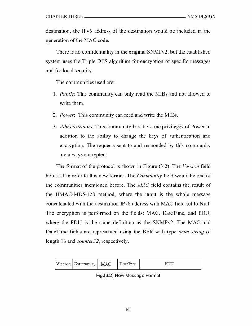
CHAPTER THREE NMS DESIGN
69
destination, the IPv6 address of the destination would be included in the
generation of the MAC code.
There is no confidentiality in the original SNMPv2, but the established
system uses the Triple DES algorithm for encryption of specific messages
and for local security.
The communities used are:
1. Public: This community can only read the MIBs and not allowed to
write them.
2. Power: This community can read and write the MIBs.
3. Administrators: This community has the same privileges of Power in
addition to the ability to change the keys of authentication and
encryption. The requests sent to and responded by this community
are always encrypted.
The format of the protocol is shown in Figure (3.2). The Version field
holds 21 to refer to this new format. The Community field would be one of
the communities mentioned before. The MAC field contains the result of
the HMAC-MD5-128 method, where the input is the whole message
concatenated with the destination IPv6 address with MAC field set to Null.
The encryption is performed on the fields: MAC, DateTime, and PDU,
where the PDU is the same definition as the SNMPv2. The MAC and
DateTime fields are represented using the BER with type octet string of
length 16 and counter32, respectively.
Fig.(3.2) New Message Format
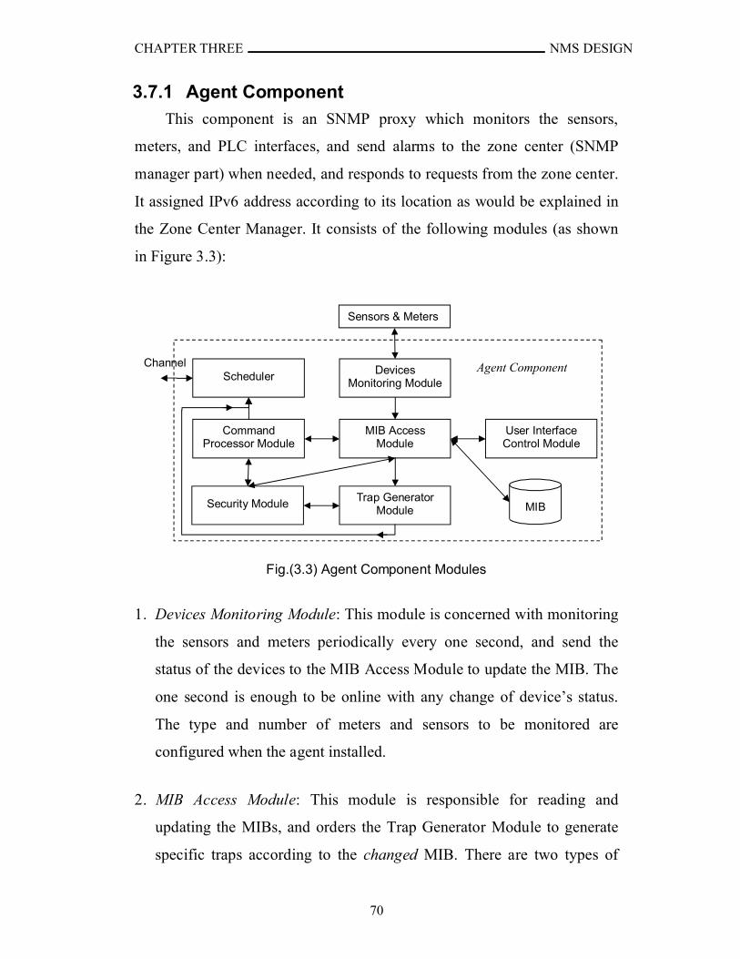
CHAPTER THREE NMS DESIGN
70
3.7.1 Agent Component
This component is an SNMP proxy which monitors the sensors,
meters, and PLC interfaces, and send alarms to the zone center (SNMP
manager part) when needed, and responds to requests from the zone center.
It assigned IPv6 address according to its location as would be explained in
the Zone Center Manager. It consists of the following modules (as shown
in Figure 3.3):
Fig.(3.3) Agent Component Modules
1. Devices Monitoring Module: This module is concerned with monitoring
the sensors and meters periodically every one second, and send the
status of the devices to the MIB Access Module to update the MIB. The
one second is enough to be online with any change of device’s status.
The type and number of meters and sensors to be monitored are
configured when the agent installed.
2. MIB Access Module: This module is responsible for reading and
updating the MIBs, and orders the Trap Generator Module to generate
specific traps according to the changed MIB. There are two types of
Devices Monitoring Module
MIB AccessModule
Trap Generator Module
User Interface Control Module
Security Module
Command Processor Module
Channel
Sensors & Meters
MIB
Agent ComponentScheduler
CHAPTER THREE NMS DESIGN
71
MIBs: (1) MIB that changing it doesn’t require generating traps; (2)
MIB that changing it requires generating trap(s). For example, changing
the electricity measurement MIB doesn’t need to generate trap but
changing electrometer response to not responding would need to
generate trap. Also, changing one MIB could cause more than one trap,
for example, fire alarm would cause to generate fire, security, and
medical alarms because if a fire happened it may need medical support
to deal with injuries, and it may need police officers to control the area.
Also, the MIB Access module is responsible of authorizing the
community and the access rights of the MIBs. For example, if an
authenticated request, issued from a community Public, to change the
number of times the trap must be sent, and Public has the authorization
of read-only then the MIB Access Module return an error to the
Command Processor Module. Another error situation may occur when
the Power community has the authorization of read-write but the MIB is
set as not-accessible which means it can not be read or write. Some of
the MIBs are encrypted to give local security to these MIBs. When the
MIB Access Module needs to access an encrypted MIB, it sends the
MIB data with the key to the Security Module for encryption or
decryption.
3. Trap Generator Module: This module is responsible of the generation of
the trap and sending it to the Scheduler to be sent to the manager (zone
center). The trap message is sent using UDP protocol which is
unreliable, so the trap message is sent many times (default value = 5)
every 5-minutes for the non high priority traps, and every 30 seconds for
high priority traps until set request is received, then the MIB service of
the trapped service is changed to off, or the sensors status returned
normal in case of fire alarm only because changing, for example, the

CHAPTER THREE NMS DESIGN
72
security sensor’s status could be caused by the intruder. If one of the
previous conditions not occurs for the high priority traps then a warning
message would be displayed on the LCD device. The authentication
failures, the start and the shutdown traps are sent once (i.e. just the first
five times) and don’t send again. The time interval between one trap and
another is set to 500 milliseconds to give enough time to change the
status of the network. Signature needed to authenticate the trap at the
manager is generated by the Security Module.
Sometimes, the user may press a manual alarm button accidentally
or a false alarm is generated from one of the sensors then a trap is sent
to the zone center. Phone call to the zone center by the customer is the
only way to discard the alarm. The zone center would check the identity
of the caller before discarding the alert request by turning off the trap.
The traps have different priorities as follow (from the highest to the
lowest):
a. Fire, medical, police traps.
b. Authentication failures trap (which is generated when number of
unauthenticated messages had been received), agent start trap,
agent shutdown trap, and changing key trap.
c. Maintenance traps.
Also the alarms have higher priorities than the requests and
responses issued by the manager. The priorities are implemented in two
ways. First, the Trap Generator would generate the highest priority
alarm, and the Scheduler sends it first. Second, the packet handling the
alarm has higher priority which means that the device receives this
packet and will serve it first.
CHAPTER THREE NMS DESIGN
73
4. User Interface Control Module: This module handles the user
(customer). The customer can only see the readings and sensors’ status
through the LCD in addition to the ability of pressing the manual alarm
buttons when needed. When the customer needs to see some
information, he should press the Control button one or more times until
the needed information are displayed. For example, if he need to see the
status of the security sensors, he should press the Control button one or
more times until the security sensors status are displayed, each time he
press the Control button some information about the specific device is
shown. When the user press a manual alarm button, the User Interface
Control module sends a request to the MIB Access module to update the
MIB, then the MIB Access Module issues a command to the Trap
Generator module to send a trap.
5. Command Processor Module: This module is the responsible of
processing the requests and responding to them if needed. When the
Command Processor module get a request for reading or setting MIBs,
it sends the message to the Security module to check the authenticity of
the community (by sending the source IPv6 address and the message
with MAC field set to NULL to the Security model), and then if it is
authenticated it checks the validity of the message time. It validates the
time if the period between the time of receiving the message and the
time specified in the DateTime field is less than the specified period in
the MIB (the default is 2 seconds). If the time is valid then the
Command Processor issues the MIB Access module to do the required
operation and then send the response of the request to the Scheduler to
be sent to the requester. If not authenticated or time is invalid then the
Command Processor issues to the MIB Access module a command to
increment the authentication failures MIB value, then the MIB access
CHAPTER THREE NMS DESIGN
74
module generates an authentication failure trap. Also, it does the same
for the encrypted message.
6. Scheduler: It manages the reception of requests, the sending of
responses, and the sending of traps. It controls the number of requests to
be served to avoid degradation of the agent performance from serving a
lot of requests at same time. Also, it is responsible of granting the
priorities of sending and serving. For example, the traps (in general)
have higher priorities than responses, so the Scheduler will send them
before sending the responses; in addition to the priority set in the IPv6
packet header which makes the devices serve them before the lower
priorities packets.
7. Security Module: It is responsible of the security methods used for
authentication and encryption/decryption processes. HMAC-MD5-128
algorithm is used for authentication, and Triple DES algorithm for
encryption/decryption. HMAC-MD5-128 and Triple DES are used
because they don’t require a lot of resources, relatively fast, and
provides enough security. The keys used are five, three of them for
authenticating each community with HMAC-MD5-128 (each one is
128-bit). The other two keys are used for encryption/decryption (each
one is 192-bits), one key is for local encryption and the other for
encrypting messages (this key is only used with the Administrators
community). The main reason for the ability to encrypt messages is
providing secure connection to change the keys. In addition to
encrypting the message the way of sending the key provide more
security in case the encryption is broken. The method used for sending
the key is that the zone center applies the following function before
sending the result:
Keys = Keyn MD5(Keyo) ……… (3.3)
CHAPTER THREE NMS DESIGN
75
Where Keyn is the new key with 128-bits,
Keyo is the old key with 128-bits,
Keys is the key to be sent,
and is the XOR bitwise operation
The agent would extract the new key by the following function:
Keyn = Keys MD5(Keyo) ……… (3.4)
8. MIB Database: It holds all the MIBs values used in the agent for storing
the states of the sensors and meters, readings, authentication and
encryption keys, addresses, and history. Some of the MIBs are
encrypted to provide local security and they checked as encrypted by
setting the first word in the Description part of the MIB object to be
“Encrypted”. The system uses MIB-II standards. The IDs of the MIBs
objects are under the ISO(1).Organization(3).DoD(6).Internet(1)
.Experimental(3).PubMgmt(17) tree (or simply 1.3.6.1.3.17) which is a
branch of the experimental tree. The enterprise that uses this system
could register its own tree with IANA. To see the used MIB definitions
see Appendix E.
3.7.2 Zone Center Management Component
This component is responsible of monitoring and controlling the
agents and requesting the needed service from the nearest available service
provider. Also, it is responsible of getting the electricity and the water
readings of the customers. It communicates with the primary center to
synchronize information and to request or provide the services needed in
the case of disaster situations. The zone center is composed of following
parts:
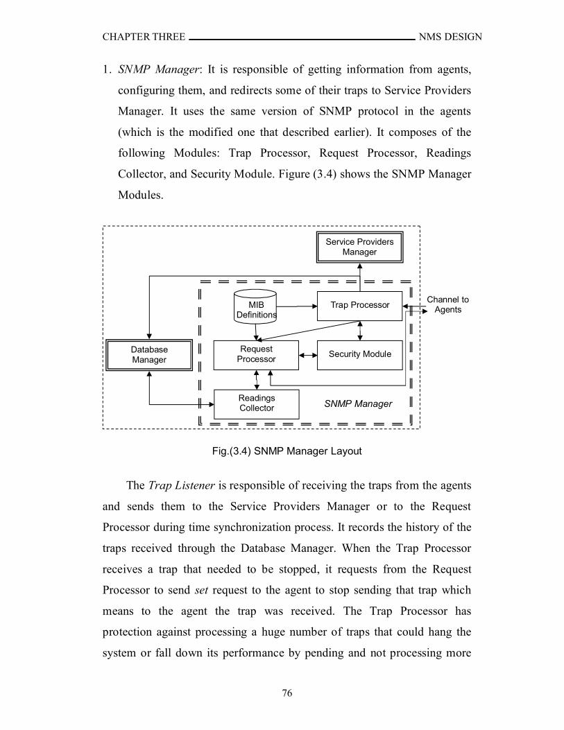
CHAPTER THREE NMS DESIGN
76
1. SNMP Manager: It is responsible of getting information from agents,
configuring them, and redirects some of their traps to Service Providers
Manager. It uses the same version of SNMP protocol in the agents
(which is the modified one that described earlier). It composes of the
following Modules: Trap Processor, Request Processor, Readings
Collector, and Security Module. Figure (3.4) shows the SNMP Manager
Modules.
Fig.(3.4) SNMP Manager Layout
The Trap Listener is responsible of receiving the traps from the agents
and sends them to the Service Providers Manager or to the Request
Processor during time synchronization process. It records the history of the
traps received through the Database Manager. When the Trap Processor
receives a trap that needed to be stopped, it requests from the Request
Processor to send set request to the agent to stop sending that trap which
means to the agent the trap was received. The Trap Processor has
protection against processing a huge number of traps that could hang the
system or fall down its performance by pending and not processing more
aChannel to
Agents
I
Request Processor
Readings Collector
Trap Processor
Security Module
Service ProvidersManager
Database Manager
MIB Definitions
SNMP Manager
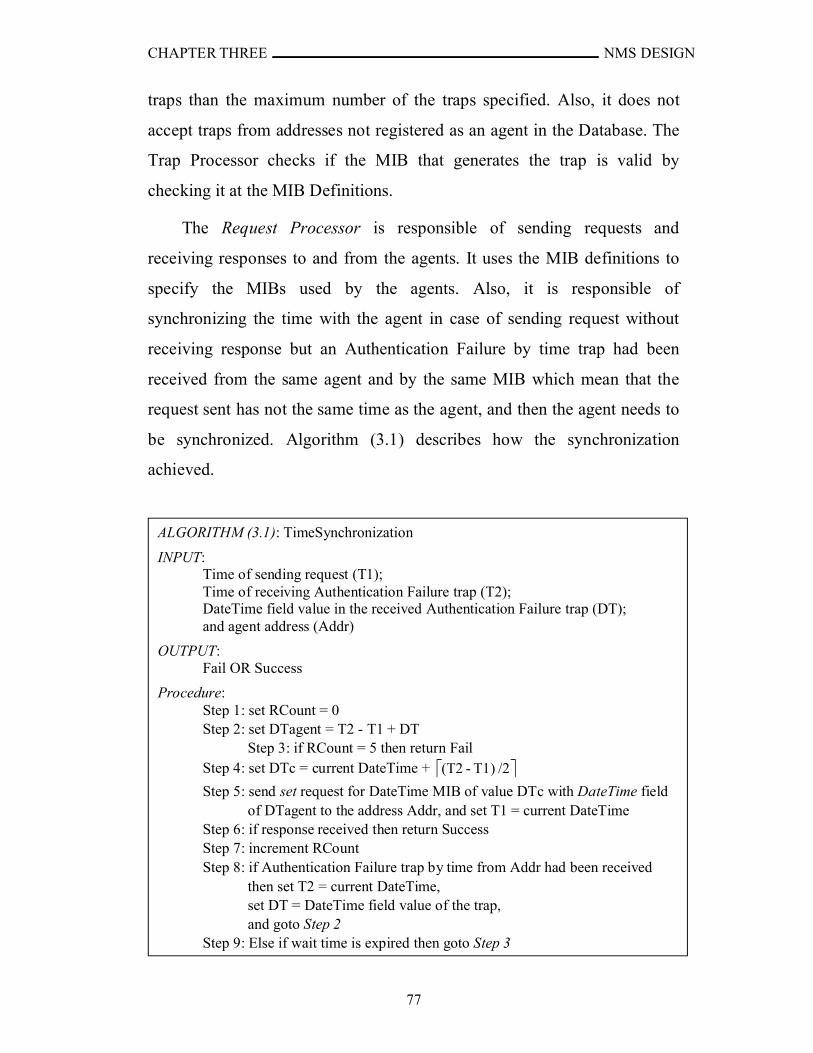
CHAPTER THREE NMS DESIGN
77
traps than the maximum number of the traps specified. Also, it does not
accept traps from addresses not registered as an agent in the Database. The
Trap Processor checks if the MIB that generates the trap is valid by
checking it at the MIB Definitions.
The Request Processor is responsible of sending requests and
receiving responses to and from the agents. It uses the MIB definitions to
specify the MIBs used by the agents. Also, it is responsible of
synchronizing the time with the agent in case of sending request without
receiving response but an Authentication Failure by time trap had been
received from the same agent and by the same MIB which mean that the
request sent has not the same time as the agent, and then the agent needs to
be synchronized. Algorithm (3.1) describes how the synchronization
achieved.
ALGORITHM (3.1): TimeSynchronization
INPUT: Time of sending request (T1); Time of receiving Authentication Failure trap (T2);DateTime field value in the received Authentication Failure trap (DT);and agent address (Addr)
OUTPUT: Fail OR Success
Procedure:Step 1: set RCount = 0Step 2: set DTagent = T2 - T1 + DT
Step 3: if RCount = 5 then return FailStep 4: set DTc = current DateTime + /2T1)-(T2
Step 5: send set request for DateTime MIB of value DTc with DateTime field of DTagent to the address Addr, and set T1 = current DateTime
Step 6: if response received then return SuccessStep 7: increment RCountStep 8: if Authentication Failure trap by time from Addr had been received
then set T2 = current DateTime, set DT = DateTime field value of the trap, and goto Step 2
Step 9: Else if wait time is expired then goto Step 3
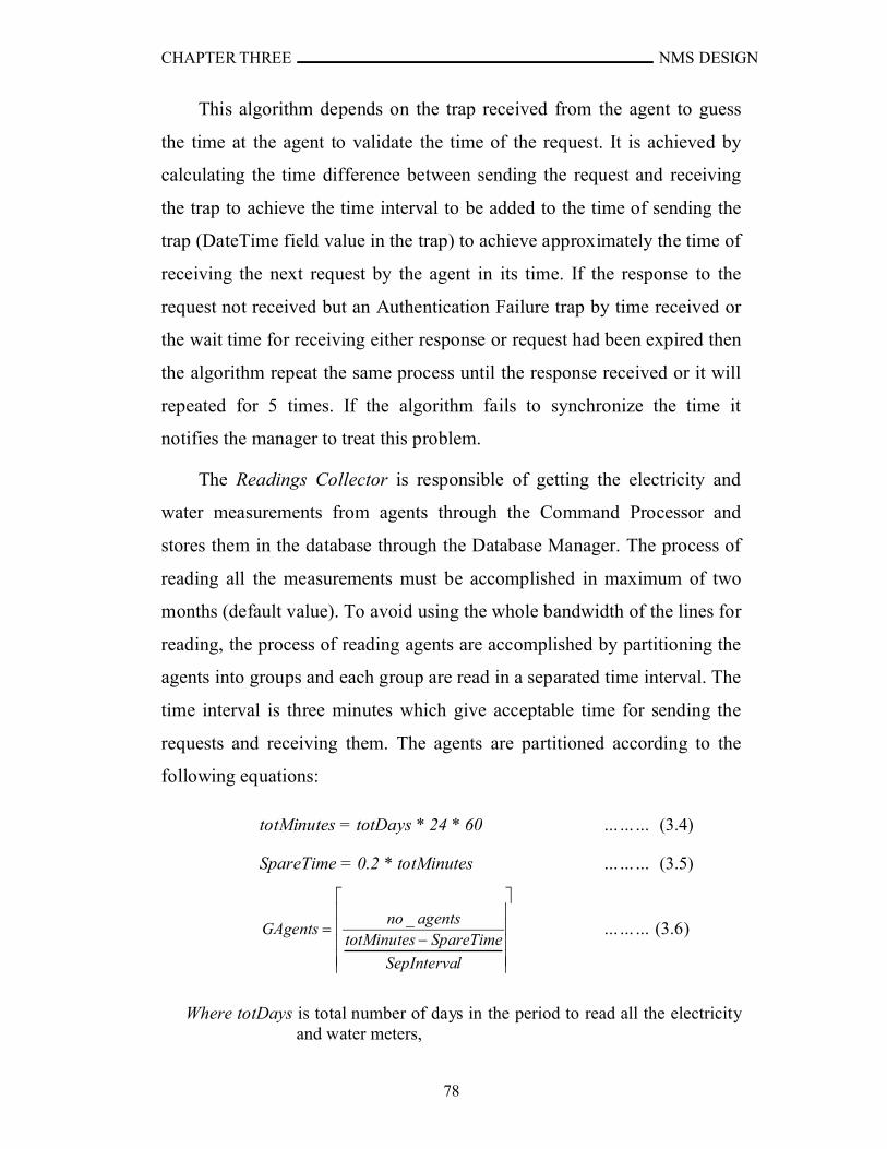
CHAPTER THREE NMS DESIGN
78
This algorithm depends on the trap received from the agent to guess
the time at the agent to validate the time of the request. It is achieved by
calculating the time difference between sending the request and receiving
the trap to achieve the time interval to be added to the time of sending the
trap (DateTime field value in the trap) to achieve approximately the time of
receiving the next request by the agent in its time. If the response to the
request not received but an Authentication Failure trap by time received or
the wait time for receiving either response or request had been expired then
the algorithm repeat the same process until the response received or it will
repeated for 5 times. If the algorithm fails to synchronize the time it
notifies the manager to treat this problem.
The Readings Collector is responsible of getting the electricity and
water measurements from agents through the Command Processor and
stores them in the database through the Database Manager. The process of
reading all the measurements must be accomplished in maximum of two
months (default value). To avoid using the whole bandwidth of the lines for
reading, the process of reading agents are accomplished by partitioning the
agents into groups and each group are read in a separated time interval. The
time interval is three minutes which give acceptable time for sending the
requests and receiving them. The agents are partitioned according to the
following equations:
totMinutes = totDays * 24 * 60 ……… (3.4)
SpareTime = 0.2 * totMinutes ……… (3.5)
lSepInterva
SpareTimetotMinutesagentsno
GAgents_
……… (3.6)
Where totDays is total number of days in the period to read all the electricity and water meters,
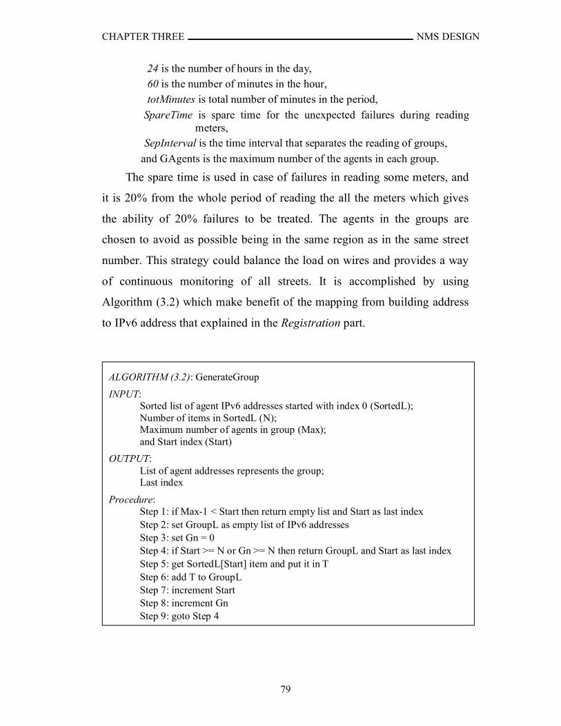
CHAPTER THREE NMS DESIGN
79
24 is the number of hours in the day, 60 is the number of minutes in the hour, totMinutes is total number of minutes in the period,
SpareTime is spare time for the unexpected failures during reading meters,
SepInterval is the time interval that separates the reading of groups,
and GAgents is the maximum number of the agents in each group.
The spare time is used in case of failures in reading some meters, and
it is 20% from the whole period of reading the all the meters which gives
the ability of 20% failures to be treated. The agents in the groups are
chosen to avoid as possible being in the same region as in the same street
number. This strategy could balance the load on wires and provides a way
of continuous monitoring of all streets. It is accomplished by using
Algorithm (3.2) which make benefit of the mapping from building address
to IPv6 address that explained in the Registration part.
ALGORITHM (3.2): GenerateGroup
INPUT: Sorted list of agent IPv6 addresses started with index 0 (SortedL); Number of items in SortedL (N);Maximum number of agents in group (Max);and Start index (Start)
OUTPUT: List of agent addresses represents the group;Last index
Procedure:Step 1: if Max-1 < Start then return empty list and Start as last indexStep 2: set GroupL as empty list of IPv6 addressesStep 3: set Gn = 0Step 4: if Start >= N or Gn >= N then return GroupL and Start as last indexStep 5: get SortedL[Start] item and put it in T Step 6: add T to GroupLStep 7: increment StartStep 8: increment GnStep 9: goto Step 4
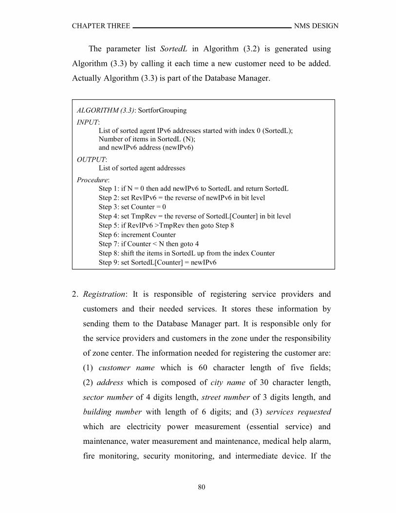
CHAPTER THREE NMS DESIGN
80
The parameter list SortedL in Algorithm (3.2) is generated using
Algorithm (3.3) by calling it each time a new customer need to be added.
Actually Algorithm (3.3) is part of the Database Manager.
2. Registration: It is responsible of registering service providers and
customers and their needed services. It stores these information by
sending them to the Database Manager part. It is responsible only for
the service providers and customers in the zone under the responsibility
of zone center. The information needed for registering the customer are:
(1) customer name which is 60 character length of five fields;
(2) address which is composed of city name of 30 character length,
sector number of 4 digits length, street number of 3 digits length, and
building number with length of 6 digits; and (3) services requested
which are electricity power measurement (essential service) and
maintenance, water measurement and maintenance, medical help alarm,
fire monitoring, security monitoring, and intermediate device. If the
ALGORITHM (3.3): SortforGrouping
INPUT: List of sorted agent IPv6 addresses started with index 0 (SortedL);Number of items in SortedL (N);and newIPv6 address (newIPv6)
OUTPUT: List of sorted agent addresses
Procedure:Step 1: if N = 0 then add newIPv6 to SortedL and return SortedLStep 2: set RevIPv6 = the reverse of newIPv6 in bit levelStep 3: set Counter = 0Step 4: set TmpRev = the reverse of SortedL[Counter] in bit levelStep 5: if RevIPv6 >TmpRev then goto Step 8Step 6: increment CounterStep 7: if Counter < N then goto 4Step 8: shift the items in SortedL up from the index CounterStep 9: set SortedL[Counter] = newIPv6

CHAPTER THREE NMS DESIGN
81
intermediate device had been chosen, it assumes to be not a customer
but an intermediate device connecting customer (for example, repeater).
The information needed for registering service provider are:
(1) service provider name which is 50 character length; (2) address
which is the same as needed to register customer in addition to Latitude
which is composed of 3 digits degree, 2 digits minutes, and 3 digits
seconds, and Longitude which is composed of 3 digits degree, 2 digits
minutes, and 3 digits seconds; (3) services provided which are
electricity power maintenance, water maintenance, ambulance station,
fire station, and police station; and (4) IPv6 addresses that would be
assigned to the service provider. Each sector number has reference point
assigned by its longitude and latitude. The latitude and longitude is
needed to find the nearest service provider to customer. For both the
agent and the service provider, the IPv6 address is build automatically
from the building address as shown in Figure (3.5).
Fig.(3.5) The building address mapping to IPv6 address
The Enterprise Network field is the network address reserved by
the enterprise that uses this system and the other fields represent the
building address.
3. Service Providers Manager: It is responsible of monitoring and
requesting services from the nearest available service provider to the
customer in addition to serving requests from the primary center. Also,
it is responsible of requesting reports from the service providers. It
composes of the following modules: Service Providers Monitor, Service
Enterprise Network Address SectorCity Building NumberStreet
76-bits 14-bits 10-bits8-bits 20-bits
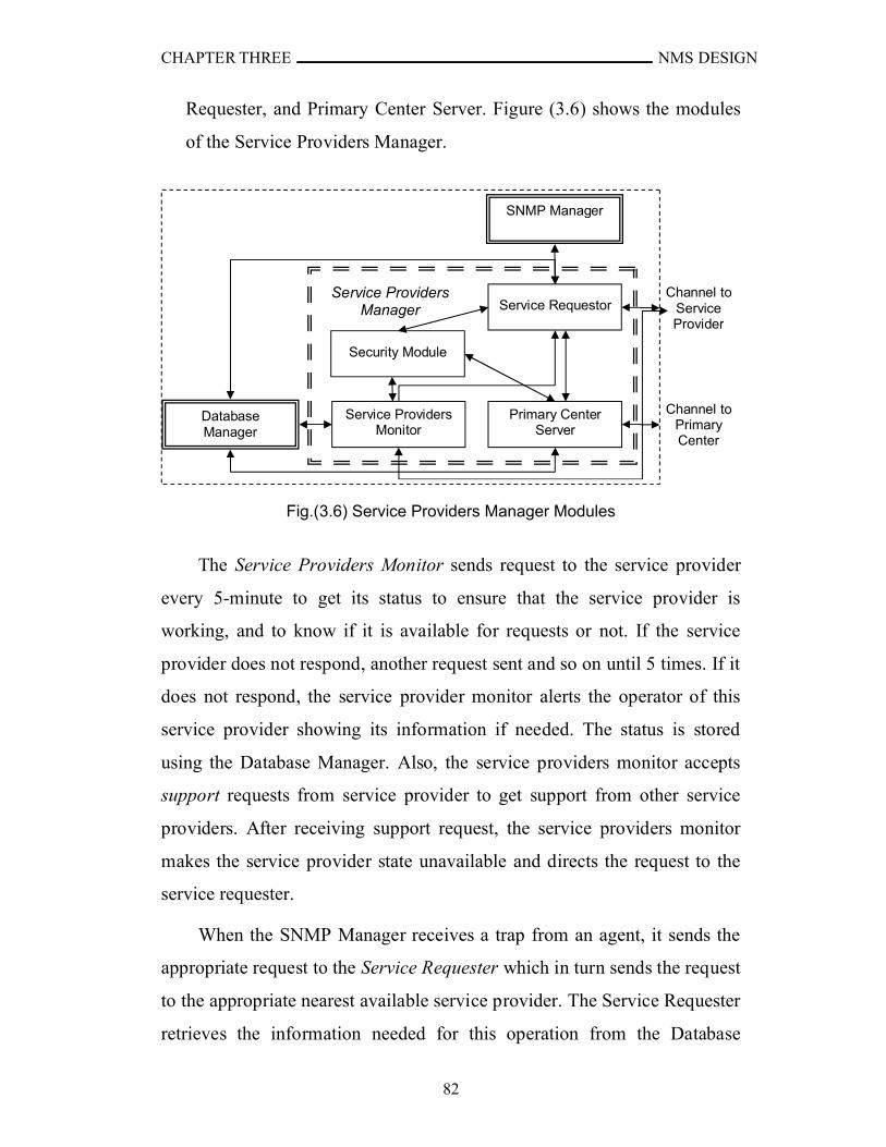
CHAPTER THREE NMS DESIGN
82
Requester, and Primary Center Server. Figure (3.6) shows the modules
of the Service Providers Manager.
Fig.(3.6) Service Providers Manager Modules
The Service Providers Monitor sends request to the service provider
every 5-minute to get its status to ensure that the service provider is
working, and to know if it is available for requests or not. If the service
provider does not respond, another request sent and so on until 5 times. If it
does not respond, the service provider monitor alerts the operator of this
service provider showing its information if needed. The status is stored
using the Database Manager. Also, the service providers monitor accepts
support requests from service provider to get support from other service
providers. After receiving support request, the service providers monitor
makes the service provider state unavailable and directs the request to the
service requester.
When the SNMP Manager receives a trap from an agent, it sends the
appropriate request to the Service Requester which in turn sends the request
to the appropriate nearest available service provider. The Service Requester
retrieves the information needed for this operation from the Database
aChannel to
Service Provider
aChannel to
Primary Center
Service Requestor
Primary Center Server
SNMP Manager
Database Manager
Service Providers Manager
I
Service Providers Monitor
Security Module
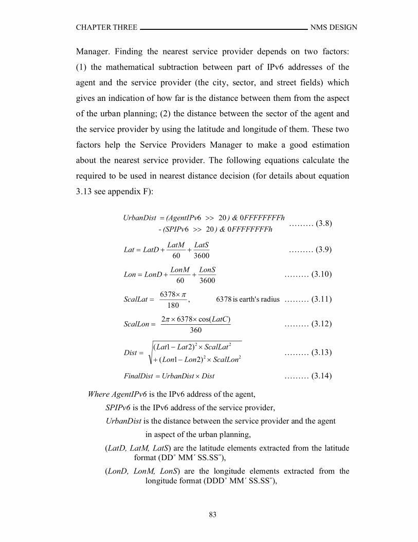
CHAPTER THREE NMS DESIGN
83
Manager. Finding the nearest service provider depends on two factors:
(1) the mathematical subtraction between part of IPv6 addresses of the
agent and the service provider (the city, sector, and street fields) which
gives an indication of how far is the distance between them from the aspect
of the urban planning; (2) the distance between the sector of the agent and
the service provider by using the latitude and longitude of them. These two
factors help the Service Providers Manager to make a good estimation
about the nearest service provider. The following equations calculate the
required to be used in nearest distance decision (for details about equation
3.13 see appendix F):
FFFFFFFFh) & (SPIPv -
FFFFFFFFh ) & (AgentIPvUrbanDist
0206
0206
……… (3.8)
360060
LatSLatMLatDLat ……… (3.9)
360060
LonSLonMLonDLon ……… (3.10)
radiussearth'is6378,180
6378 ScalLat ……… (3.11)
360
)cos(63782 LatCScalLon
……… (3.12)
22
22
)21(
)21(
ScalLonLonLon
ScalLatLatLatDist
……… (3.13)
DistUrbanDistFinalDist ……… (3.14)
Where AgentIPv6 is the IPv6 address of the agent,
SPIPv6 is the IPv6 address of the service provider,
UrbanDist is the distance between the service provider and the agent
in aspect of the urban planning,
(LatD, LatM, LatS) are the latitude elements extracted from the latitude format (DD˚ MM΄ SS.SS˝),
(LonD, LonM, LonS) are the longitude elements extracted from the longitude format (DDD˚ MM΄ SS.SS˝),
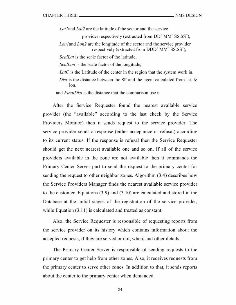
CHAPTER THREE NMS DESIGN
84
Lat1and Lat2 are the latitude of the sector and the service
provider respectively (extracted from DD˚ MM΄ SS.SS˝),
Lon1and Lon2 are the longitude of the sector and the service provider respectively (extracted from DDD˚ MM΄ SS.SS˝),
ScalLat is the scale factor of the latitude,
ScalLon is the scale factor of the longitude,
LatC is the Latitude of the center in the region that the system work in.
Dist is the distance between the SP and the agent calculated from lat. & lon.
and FinalDist is the distance that the comparison use it
After the Service Requester found the nearest available service
provider (the “available” according to the last check by the Service
Providers Monitor) then it sends request to the service provider. The
service provider sends a response (either acceptance or refusal) according
to its current status. If the response is refusal then the Service Requester
should get the next nearest available one and so on. If all of the service
providers available in the zone are not available then it commands the
Primary Center Server part to send the request to the primary center for
sending the request to other neighbor zones. Algorithm (3.4) describes how
the Service Providers Manager finds the nearest available service provider
to the customer. Equations (3.9) and (3.10) are calculated and stored in the
Database at the initial stages of the registration of the service provider,
while Equation (3.11) is calculated and treated as constant.
Also, the Service Requester is responsible of requesting reports from
the service provider on its history which contains information about the
accepted requests, if they are served or not, when, and other details.
The Primary Center Server is responsible of sending requests to the
primary center to get help from other zones. Also, it receives requests from
the primary center to serve other zones. In addition to that, it sends reports
about the center to the primary center when demanded.
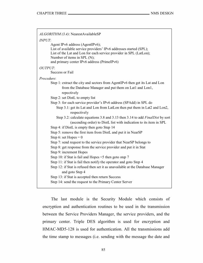
CHAPTER THREE NMS DESIGN
85
The last module is the Security Module which consists of
encryption and authentication routines to be used in the transmission
between the Service Providers Manager, the service providers, and the
primary center. Triple DES algorithm is used for encryption and
HMAC-MD5-128 is used for authentication. All the transmissions add
the time stamp to messages (i.e. sending with the message the date and
ALGORITHM (3.4): NearestAvailableSP
INPUT: Agent IPv6 address (AgentIPv6);List of available service providers’ IPv6 addresses started (SPL);List of the Lat and Lon for each service provider in SPL (LatLon);Number of items in SPL (N);and primary center IPv6 address (PrimeIPv6)
OUTPUT: Success or Fail
Procedure:Step 1: extract the city and sectors from AgentIPv6 then get its Lat and Lon
from the Database Manager and put them on Lat1 and Lon1, repectively
Step 2: set DistL to empty listStep 3: for each service provider’s IPv6 address (SPAdd) in SPL do
Step 3.1: get its Lat and Lon from LatLon then put them in Lat2 and Lon2, respectively
Step 3.2: calculate equations 3.8 and 3.13 then 3.14 to add FinalDist by sort (ascending order) to DistL list with indication to its item in SPL
Step 4: if DistL is empty then goto Step 14Step 5: remove the first item from DistL and put it in NearSPStep 6: set Hopes = 0Step 7: send request to the service provider that NearSP belongs toStep 8: get response from the service provider and put it in StatStep 9: increment HopesStep 10: if Stat is fail and Hopes <5 then goto step 7Step 11: if Stat is fail then notify the operator and goto Step 4Step 12: if Stat is refused then set it as unavailable at the Database Manager
and goto Step 4Step 13: if Stat is accepted then return SuccessStep 14: send the request to the Primary Center Server
CHAPTER THREE NMS DESIGN
86
time to protect them from delay, and add the destination IPv6 address to
protect them from redirecting the messages. Also it uses the same
technique as used by the SNMP manager in exchanging keys.
4. Electricity Measurements Displayer: It is responsible of displaying the
electricity readings collected from agents. It issues reports about the
customers’ meters readings in every two months and shows which
meters were not read yet because of failure in reading or waiting for its
time.
5. Water Measurements Displayer: It is responsible of displaying the water
readings collected from agents. It shows reports about the customers’
meters readings in every two months and shows which meters were not
read yet because of failure in reading or waiting for its time.
6. Database Manager: It manages the system’s data storage and
manipulation. The Database Manager is responsible of backing up the
registered customers, service providers, and other information. Also, it
manages synchronization of the data shared between zone center and
other parts of the system to keep the distributed data integrity valid (for
example, synchronizing the registered customers with primary center or
within the same center). The Database Manager is composed of three
modules: Data Manipulator module, Backup module, and
Synchronization module. The Data Manipulator module is responsible
of how to store the data, read the data, and thus serve requests from
other parts of the system. The involved data are structured into the
tables shown in Tables (3.1-20). Note that the field (or fields) with bold
font is the primary key for the table. The history tables are needed as
statistical information and could refer to the cause of failures,
degradation of performance, and intruding operations to the system.
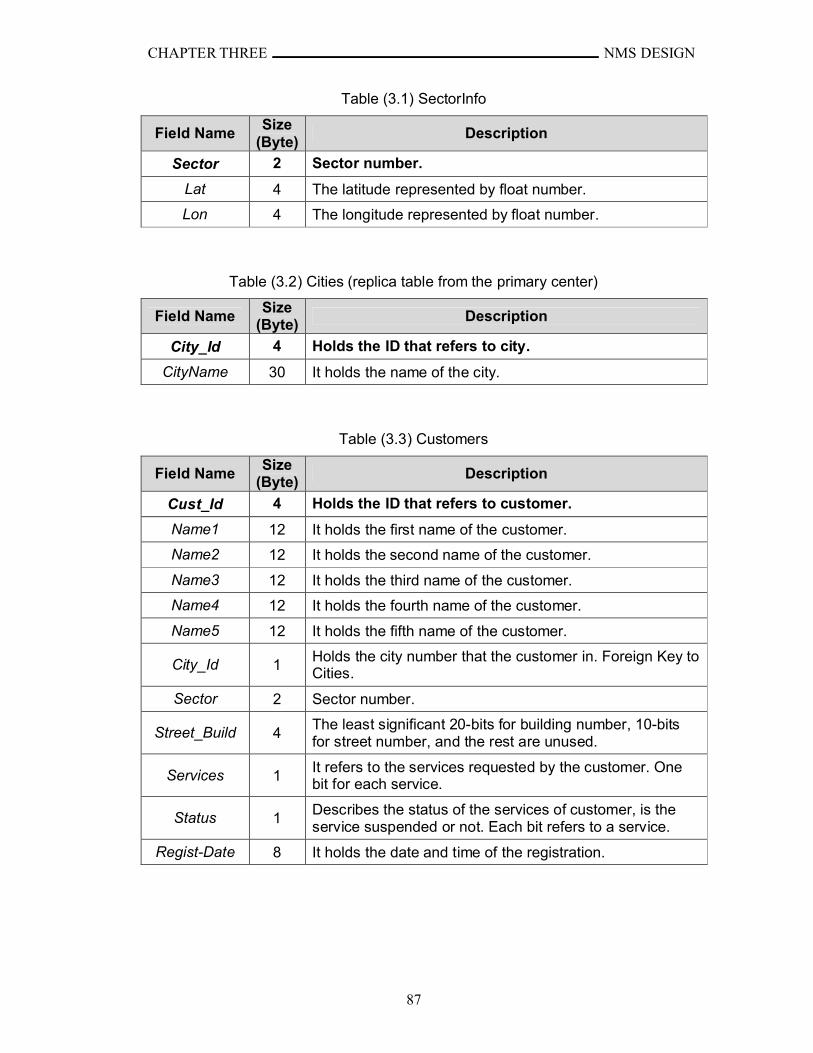
CHAPTER THREE NMS DESIGN
87
Table (3.1) SectorInfo
Field NameSize
(Byte)Description
Sector 2 Sector number.
Lat 4 The latitude represented by float number.
Lon 4 The longitude represented by float number.
Table (3.2) Cities (replica table from the primary center)
Field NameSize
(Byte)Description
City_Id 4 Holds the ID that refers to city.
CityName 30 It holds the name of the city.
Table (3.3) Customers
Field NameSize
(Byte)Description
Cust_Id 4 Holds the ID that refers to customer.
Name1 12 It holds the first name of the customer.
Name2 12 It holds the second name of the customer.
Name3 12 It holds the third name of the customer.
Name4 12 It holds the fourth name of the customer.
Name5 12 It holds the fifth name of the customer.
City_Id 1Holds the city number that the customer in. Foreign Key to Cities.
Sector 2 Sector number.
Street_Build 4The least significant 20-bits for building number, 10-bits for street number, and the rest are unused.
Services 1It refers to the services requested by the customer. One bit for each service.
Status 1Describes the status of the services of customer, is the service suspended or not. Each bit refers to a service.
Regist-Date 8 It holds the date and time of the registration.
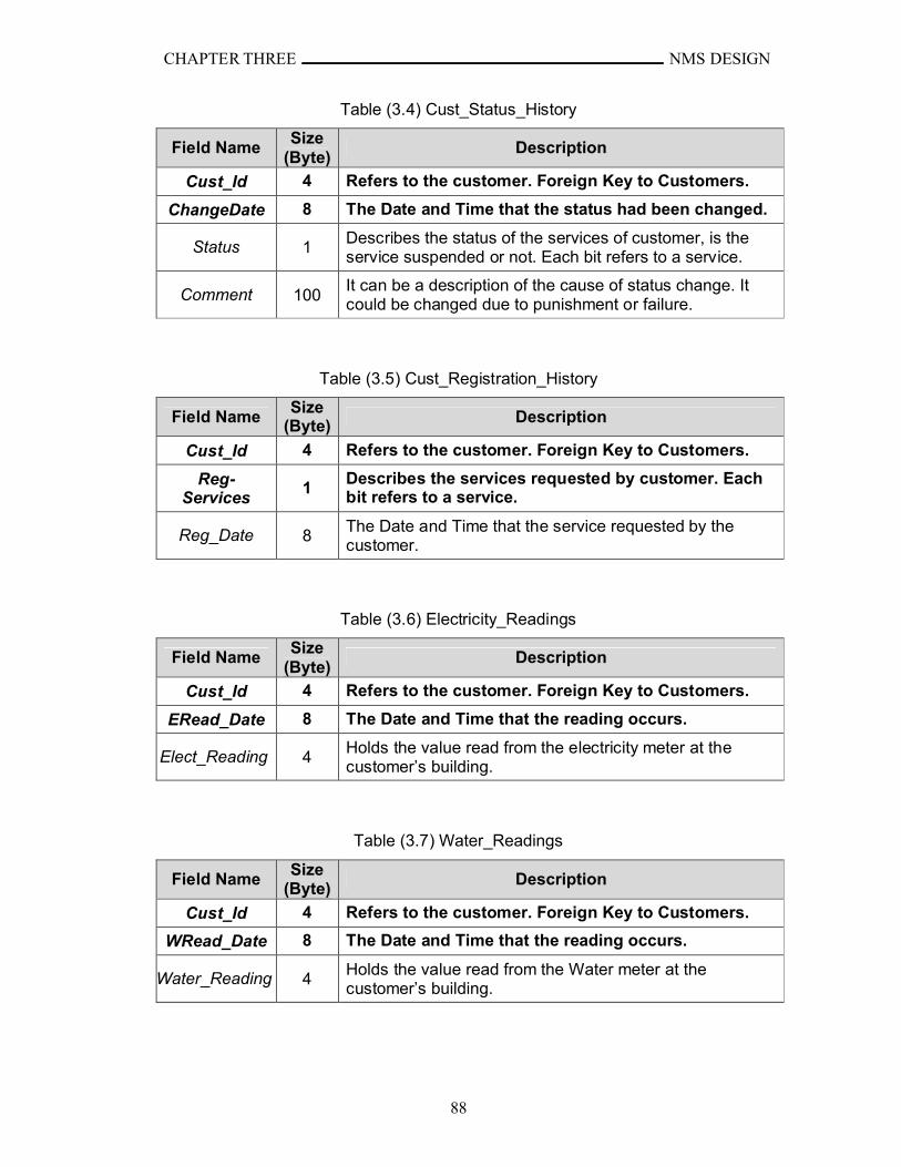
CHAPTER THREE NMS DESIGN
88
Table (3.4) Cust_Status_History
Field NameSize
(Byte)Description
Cust_Id 4 Refers to the customer. Foreign Key to Customers.
ChangeDate 8 The Date and Time that the status had been changed.
Status 1Describes the status of the services of customer, is the service suspended or not. Each bit refers to a service.
Comment 100It can be a description of the cause of status change. It could be changed due to punishment or failure.
Table (3.5) Cust_Registration_History
Field NameSize
(Byte) Description
Cust_Id 4 Refers to the customer. Foreign Key to Customers.
Reg-Services
1Describes the services requested by customer. Each bit refers to a service.
Reg_Date 8The Date and Time that the service requested by the customer.
Table (3.6) Electricity_Readings
Field NameSize
(Byte)Description
Cust_Id 4 Refers to the customer. Foreign Key to Customers.
ERead_Date 8 The Date and Time that the reading occurs.
Elect_Reading 4Holds the value read from the electricity meter at the customer’s building.
Table (3.7) Water_Readings
Field NameSize
(Byte)Description
Cust_Id 4 Refers to the customer. Foreign Key to Customers.
WRead_Date 8 The Date and Time that the reading occurs.
Water_Reading 4Holds the value read from the Water meter at the customer’s building.
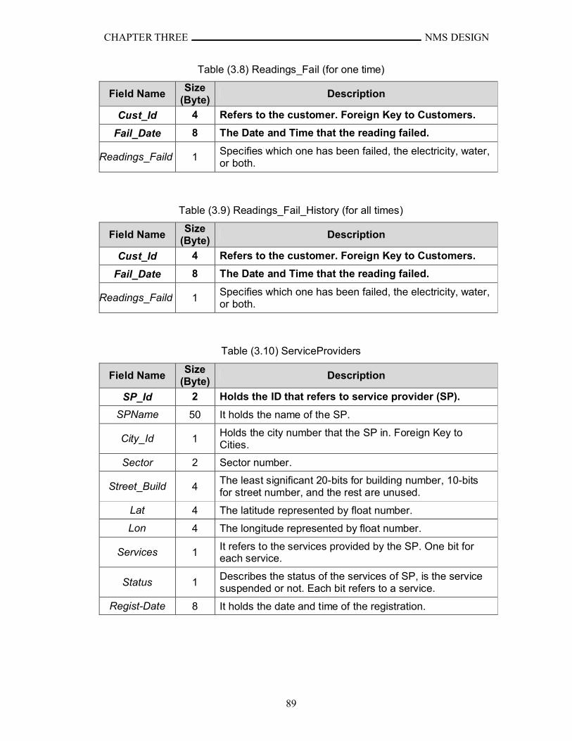
CHAPTER THREE NMS DESIGN
89
Table (3.8) Readings_Fail (for one time)
Field NameSize
(Byte)Description
Cust_Id 4 Refers to the customer. Foreign Key to Customers.
Fail_Date 8 The Date and Time that the reading failed.
Readings_Faild 1Specifies which one has been failed, the electricity, water, or both.
Table (3.9) Readings_Fail_History (for all times)
Field NameSize
(Byte)Description
Cust_Id 4 Refers to the customer. Foreign Key to Customers.
Fail_Date 8 The Date and Time that the reading failed.
Readings_Faild 1Specifies which one has been failed, the electricity, water, or both.
Table (3.10) ServiceProviders
Field NameSize
(Byte)Description
SP_Id 2 Holds the ID that refers to service provider (SP).
SPName 50 It holds the name of the SP.
City_Id 1Holds the city number that the SP in. Foreign Key to Cities.
Sector 2 Sector number.
Street_Build 4The least significant 20-bits for building number, 10-bits for street number, and the rest are unused.
Lat 4 The latitude represented by float number.
Lon 4 The longitude represented by float number.
Services 1It refers to the services provided by the SP. One bit for each service.
Status 1Describes the status of the services of SP, is the service suspended or not. Each bit refers to a service.
Regist-Date 8 It holds the date and time of the registration.
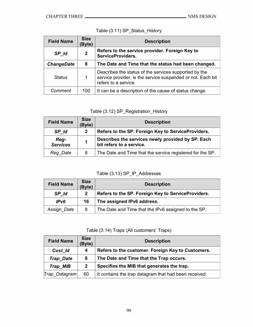
CHAPTER THREE NMS DESIGN
90
Table (3.11) SP_Status_History
Field NameSize
(Byte)Description
SP_Id 2Refers to the service provider. Foreign Key to ServiceProviders.
ChangeDate 8 The Date and Time that the status had been changed.
Status 1Describes the status of the services supported by the service provider, is the service suspended or not. Each bit refers to a service.
Comment 100 It can be a description of the cause of status change.
Table (3.12) SP_Registration_History
Field NameSize
(Byte)Description
SP_Id 2 Refers to the SP. Foreign Key to ServiceProviders.
Reg-Services
1Describes the services newly provided by SP. Each bit refers to a service.
Reg_Date 8 The Date and Time that the service registered for the SP.
Table (3.13) SP_IP_Addresses
Field NameSize
(Byte)Description
SP_Id 2 Refers to the SP. Foreign Key to ServiceProviders.
IPv6 16 The assigned IPv6 address.
Assign_Date 8 The Date and Time that the IPv6 assigned to the SP.
Table (3.14) Traps (All customers’ Traps)
Field NameSize
(Byte)Description
Cust_Id 4 Refers to the customer. Foreign Key to Customers.
Trap_Date 8 The Date and Time that the Trap occurs.
Trap_MIB 2 Specifies the MIB that generates the trap.
Trap_Datagram 60 It contains the trap datagram that had been received.
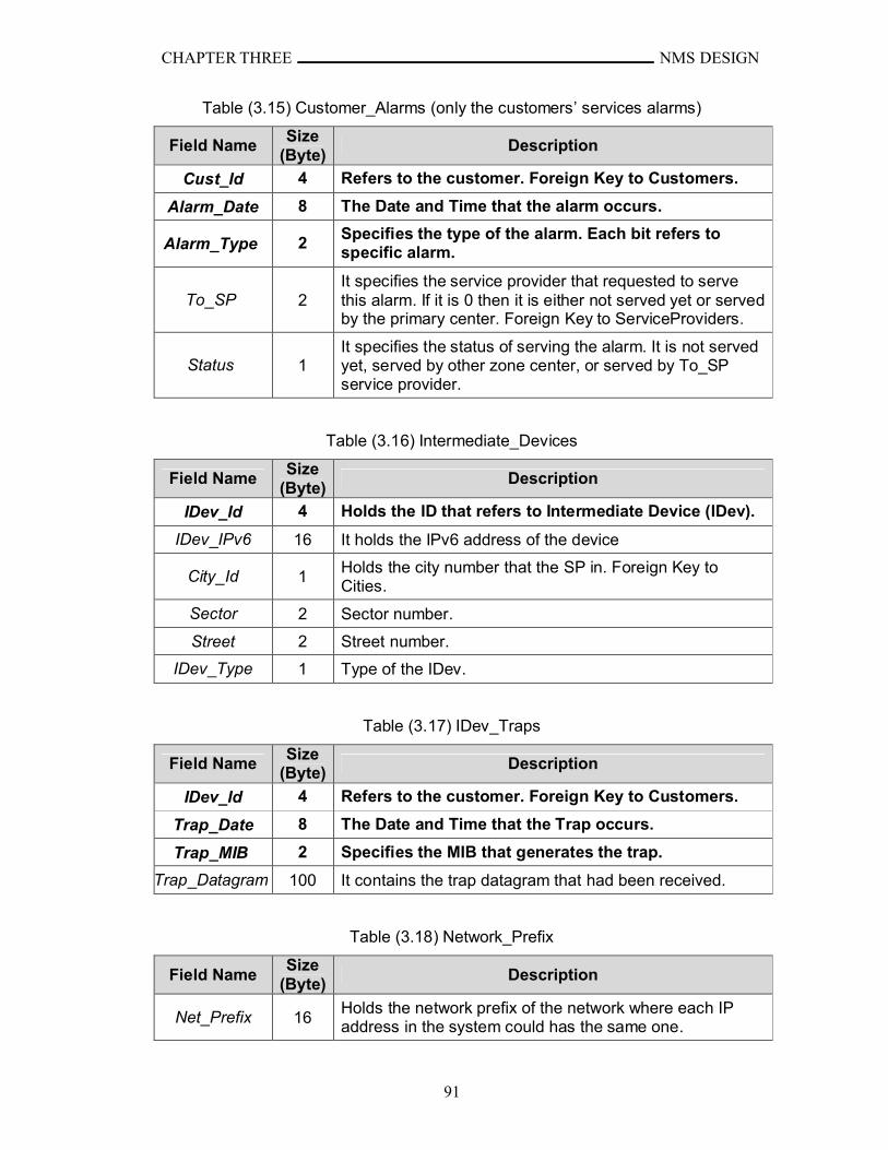
CHAPTER THREE NMS DESIGN
91
Table (3.15) Customer_Alarms (only the customers’ services alarms)
Field NameSize
(Byte)Description
Cust_Id 4 Refers to the customer. Foreign Key to Customers.
Alarm_Date 8 The Date and Time that the alarm occurs.
Alarm_Type 2Specifies the type of the alarm. Each bit refers to specific alarm.
To_SP 2It specifies the service provider that requested to serve this alarm. If it is 0 then it is either not served yet or served by the primary center. Foreign Key to ServiceProviders.
Status 1It specifies the status of serving the alarm. It is not served yet, served by other zone center, or served by To_SP service provider.
Table (3.16) Intermediate_Devices
Field NameSize
(Byte)Description
IDev_Id 4 Holds the ID that refers to Intermediate Device (IDev).
IDev_IPv6 16 It holds the IPv6 address of the device
City_Id 1Holds the city number that the SP in. Foreign Key to Cities.
Sector 2 Sector number.
Street 2 Street number.
IDev_Type 1 Type of the IDev.
Table (3.17) IDev_Traps
Field NameSize
(Byte)Description
IDev_Id 4 Refers to the customer. Foreign Key to Customers.
Trap_Date 8 The Date and Time that the Trap occurs.
Trap_MIB 2 Specifies the MIB that generates the trap.
Trap_Datagram 100 It contains the trap datagram that had been received.
Table (3.18) Network_Prefix
Field NameSize
(Byte)Description
Net_Prefix 16Holds the network prefix of the network where each IP address in the system could has the same one.
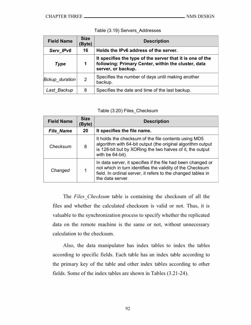
CHAPTER THREE NMS DESIGN
92
Table (3.19) Servers_Addresses
Field NameSize
(Byte)Description
Serv_IPv6 16 Holds the IPv6 address of the server.
Type 1It specifies the type of the server that it is one of the following: Primary Center, within the cluster, data server, or backup.
Bckup_duration 2Specifies the number of days until making another backup.
Last_Backup 8 Specifies the date and time of the last backup.
Table (3.20) Files_Checksum
Field NameSize
(Byte)Description
File_Name 20 It specifies the file name.
Checksum 8
It holds the checksum of the file contents using MD5algorithm with 64-bit output (the original algorithm output is 128-bit but by XORing the two halves of it, the output with be 64-bit).
Changed 1
In data server, it specifies if the file had been changed or not which in turn identifies the validity of the Checksum field. In ordinal server, it refers to the changed tables in the data server.
The Files_Checksum table is containing the checksum of all the
files and whether the calculated checksum is valid or not. Thus, it is
valuable to the synchronization process to specify whether the replicated
data on the remote machine is the same or not, without unnecessary
calculation to the checksum.
Also, the data manipulator has index tables to index the tables
according to specific fields. Each table has an index table according to
the primary key of the table and other index tables according to other
fields. Some of the index tables are shown in Tables (3.21-24).
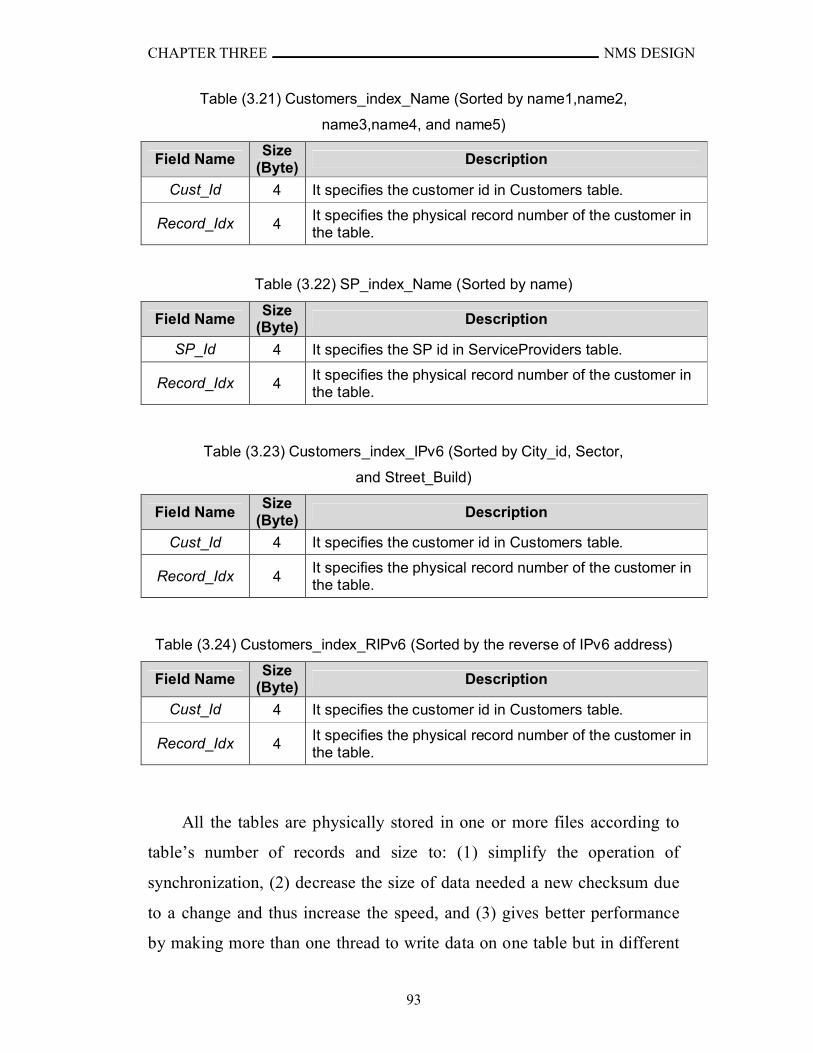
CHAPTER THREE NMS DESIGN
93
Table (3.21) Customers_index_Name (Sorted by name1,name2,
name3,name4, and name5)
Field NameSize
(Byte)Description
Cust_Id 4 It specifies the customer id in Customers table.
Record_Idx 4It specifies the physical record number of the customer in the table.
Table (3.22) SP_index_Name (Sorted by name)
Field NameSize
(Byte) Description
SP_Id 4 It specifies the SP id in ServiceProviders table.
Record_Idx 4It specifies the physical record number of the customer in the table.
Table (3.23) Customers_index_IPv6 (Sorted by City_id, Sector,
and Street_Build)
Field NameSize
(Byte) Description
Cust_Id 4 It specifies the customer id in Customers table.
Record_Idx 4It specifies the physical record number of the customer in the table.
Table (3.24) Customers_index_RIPv6 (Sorted by the reverse of IPv6 address)
Field NameSize
(Byte) Description
Cust_Id 4 It specifies the customer id in Customers table.
Record_Idx 4It specifies the physical record number of the customer in the table.
All the tables are physically stored in one or more files according to
table’s number of records and size to: (1) simplify the operation of
synchronization, (2) decrease the size of data needed a new checksum due
to a change and thus increase the speed, and (3) gives better performance
by making more than one thread to write data on one table but in different

CHAPTER THREE NMS DESIGN
94
files. Each table has header that contains information about the table which
are:
SizeOfRecord: is two bytes positive integer that contains the size of
the record in the table.
TotalRecords: is four bytes positive integer that contains the total
number of records without the deleted ones.
LastFileNoOfRecs: is two bytes positive integer that contains the
Number of records in the last file.
MaxNoOfRecsInFiles: is the maximum number of records allowed in
one file.
NumberOfFiles: is two bytes positive integer that contains the
number of files contains the data of the table.
LastTimeBackup: is eight bytes that contains the Date and Time of
the last time that this table is backed up.
LastTimeClean: is eight bytes that contains the Date and Time of the
last time that cleaned from deleted records.
Each record in the table has an additional physical attribute field
that indicates the status of the record. It is one byte length contains, state
(unused, used, or deleted) and access permission (locked or unlocked).
The state indicates that the record has not correct values (unused), has
correct values (used), or has previously correct values but deleted. The
access permission ensures that the record can not be processed (read or
write) by more than one thread to ensure the integrity of the table.
Locking file or record by one thread makes other threads waiting. The
waiting state to the threads can be either by infinite looping (or even
timed looping that is loop for specific time and return fail when expired)
or by sleeping the thread until the table is unlocked or for specific time.
The first way would use most of its time quantum in checking, but the
second could give its time quantum to other threads that need processing
and do not need that specific file which provide better utilization of the
CPU. But both ways could make one (or more) thread either starved (i.e.

CHAPTER THREE NMS DESIGN
95
the file or record is locked each time the thread check for it) or returned
with fail in case of time expire. This problem is happened due to the
relatively large number of threads need to access the file or record and
each time the starved thread check for the file lock, another thread reach
its time quantum and locks the file before the starved thread reaches its
next time quantum and so on.
For example, T1, T2, T3, T4 are threads want to access the same
file (F). T1 was started and locked F and its time quantum expired.
Then, T2 started and check for F and find that F is locked so, it sleeps
for one time quantum, T1 reaches its time quantum and use the file F
and complete then unlock it. When T1 time quantum is expired, T3 is
started and wants to access F so; it locks F. T3’s time quantum has
expired. When T2 reaches its next time quantum, it checks for F and
find that it locked then it sleep again. So when T3 reaches its time
quantum and unlock F then its time is expired, T4 started and lock F,
and so on. Thus, the threads accessing files must be managed to avoid
the starvation. The management is achieved by creating queue for each
file locked by a thread. When thread wants to lock a file, it sends
request to thread management object which in turn create queue for that
file to hold the waiting threads. Each thread wants to lock the file (i.e. to
read or write on file) sends request to the thread management object
then the thread management to checks if this file has a waiting queue. If
not it creates waiting queue for that file and permit locking the file to
the requesting thread. If the waiting queue exists, the thread
management object adds the requesting thread to the waiting queue and
reply with deny. When the thread receives deny reply, it go into sleep
state. But when it receives permission to lock, it locks the file and do
process its process then when completed it unlock the file and send
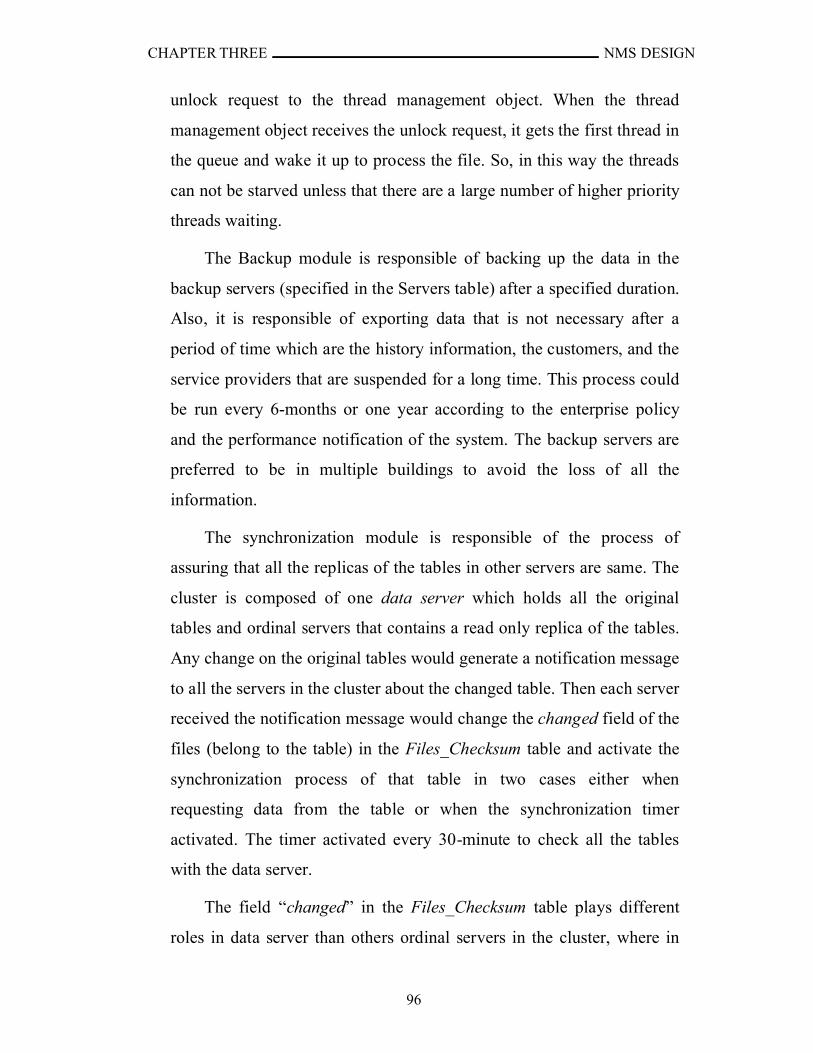
CHAPTER THREE NMS DESIGN
96
unlock request to the thread management object. When the thread
management object receives the unlock request, it gets the first thread in
the queue and wake it up to process the file. So, in this way the threads
can not be starved unless that there are a large number of higher priority
threads waiting.
The Backup module is responsible of backing up the data in the
backup servers (specified in the Servers table) after a specified duration.
Also, it is responsible of exporting data that is not necessary after a
period of time which are the history information, the customers, and the
service providers that are suspended for a long time. This process could
be run every 6-months or one year according to the enterprise policy
and the performance notification of the system. The backup servers are
preferred to be in multiple buildings to avoid the loss of all the
information.
The synchronization module is responsible of the process of
assuring that all the replicas of the tables in other servers are same. The
cluster is composed of one data server which holds all the original
tables and ordinal servers that contains a read only replica of the tables.
Any change on the original tables would generate a notification message
to all the servers in the cluster about the changed table. Then each server
received the notification message would change the changed field of the
files (belong to the table) in the Files_Checksum table and activate the
synchronization process of that table in two cases either when
requesting data from the table or when the synchronization timer
activated. The timer activated every 30-minute to check all the tables
with the data server.
The field “changed” in the Files_Checksum table plays different
roles in data server than others ordinal servers in the cluster, where in

CHAPTER THREE NMS DESIGN
97
ordinal server, it refers to the change of the contents of the original files,
but in the data server it refers that the checksum is invalid. Algorithm
(3.5) shows how to synchronize a table.
ALGORITHM (3.5): SynchonizeTable
INPUT: Table name (TableName);List of files names (FNameL)List of files checksum (ChksumL);Number of items in ChksumL (N);and data server IPv6 address (ServIPv6)
OUTPUT: Success or Fail
Procedure:Step 1: get from the data server the number of files and put it in OriginN
Step 2: get the list of original files names and checksum from the data server and put
it in OFNameL and OChksunL, respectively
Step 3: if no response then repeats Step 1 until getting the lists or repeated five times
Step 4: if no response then return Fail
Step 5: if N equal OriginalN then goto Step 7
Step 6: for each item FX in list FNameL and not exist in list OFNameL do
Step 6.1: get FX from the data server and its checksum then put them in a
temporary place
Step 6.2: if no response then repeats Step 6.1 until getting the file or repeated
five times
Step 6.3: if no response then return Fail.
Step 7: for each item X in list ChksumL and Y with in list OChksumL with the same
names in FNameL and OFNameL do
Step 7.1: if X not equal Y then
Step 7.1.1: get its file from the data server and its checksum then put them
in a temporary place
Step 7.1.2: if no response then repeats Step 7.1.1 until getting the file or
repeated five times
Step 7.1.3: if no response then return Fail.
Step 8: delete all local files belong to the table with name not exist in FNameL
Step 9: replace all the old files by the new files and update their checksums
Step 10: return Success

CHAPTER THREE NMS DESIGN
98
7. Tools: It is a collection of programs can be used to help the manager to
test connections, change settings of agents, and time synchronizing. The
Tester tool test connection by sending a specified number of application
layer messages to the destination and waits for respond for each one.
The time between sending one the messages is specified. If the respond
does not come after a specified time, it sends another one and so on. If
no respond had been received for all the messages it is considered as not
responding. If a respond received, the tool calculates the speed of
sending message and receiving its respond. The speed is calculated by
dividing the difference between the sending and the receiving time by 2
then divides the result by the size of the message (see equation 3.15).
eMessageSiz
SendTimecieveTime 2/)(ReSpeed
bps … (3.15)
Another tool is the MIB browser that shows the MIBs in the
agents and gives the capability of changing their values. It is supported
by the MIB definitions in the agent to provide ability to change the
values of the MIBs. It provides two ways in browsing the MIBs. The
first is by writing the OID of the MIB and then send the request and
receive the value of the MIB. The second is graphical tree that is built
by sending sequence of Get-Next requests until the end of the tree then
display it in graphical tree.
The Time Synchronizer tool synchronizes the time between the
server and a specified agent or service provider. It uses Algorithm
(3.1) to accomplish its target.
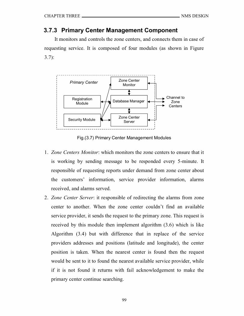
CHAPTER THREE NMS DESIGN
99
3.7.3 Primary Center Management Component
It monitors and controls the zone centers, and connects them in case of
requesting service. It is composed of four modules (as shown in Figure
3.7):
Fig.(3.7) Primary Center Management Modules
1. Zone Centers Monitor: which monitors the zone centers to ensure that it
is working by sending message to be responded every 5-minute. It
responsible of requesting reports under demand from zone center about
the customers’ information, service provider information, alarms
received, and alarms served.
2. Zone Center Server: it responsible of redirecting the alarms from zone
center to another. When the zone center couldn’t find an available
service provider, it sends the request to the primary zone. This request is
received by this module then implement algorithm (3.6) which is like
Algorithm (3.4) but with difference that in replace of the service
providers addresses and positions (latitude and longitude), the center
position is taken. When the nearest center is found then the request
would be sent to it to found the nearest available service provider, while
if it is not found it returns with fail acknowledgement to make the
primary center continue searching.
Channel to Zone
Centers
Zone Center Monitor
Zone Center Server
Primary Center
I
Registration Module
Database Manager
Security Module
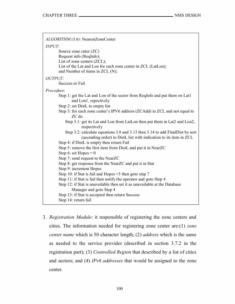
CHAPTER THREE NMS DESIGN
100
3. Registration Module: it responsible of registering the zone centers and
cities. The information needed for registering zone center are:(1) zone
center name which is 50 character length; (2) address which is the same
as needed to the service provider (described in section 3.7.2 in the
registration part); (3) Controlled Region that described by a list of cities
and sectors; and (4) IPv6 addresses that would be assigned to the zone
center.
ALGORITHM (3.6): NearestZoneCenter
INPUT: Source zone cnter (ZC)Request info (ReqInfo);List of zone centers (ZCL);List of the Lat and Lon for each zone center in ZCL (LatLon);and Number of items in ZCL (N);
OUTPUT: Success or Fail
Procedure:Step 1: get the Lat and Lon of the sector from ReqInfo and put them on Lat1
and Lon1, repectivelyStep 2: set DistL to empty listStep 3: for each zone center’s IPV6 address (ZCAdd) in ZCL and not equal to
ZC do Step 3.1: get its Lat and Lon from LatLon then put them in Lat2 and Lon2,
respectively Step 3.2: calculate equations 3.8 and 3.13 then 3.14 to add FinalDist by sort
(ascending order) to DistL list with indication to its item in ZCLStep 4: if DistL is empty then return FailStep 5: remove the first item from DistL and put it in NearZCStep 6: set Hopes = 0Step 7: send request to the NearZC Step 8: get response from the NearZC and put it in StatStep 9: increment HopesStep 10: if Stat is fail and Hopes <5 then goto step 7Step 11: if Stat is fail then notify the operator and goto Step 4Step 12: if Stat is unavailable then set it as unavailable at the Database
Manager and goto Step 4Step 13: if Stat is accepted then return SuccessStep 14: return fail
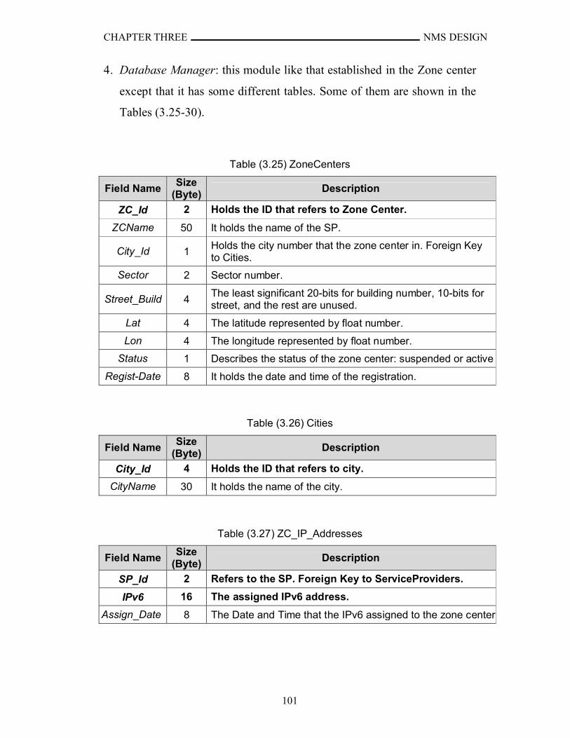
CHAPTER THREE NMS DESIGN
101
4. Database Manager: this module like that established in the Zone center
except that it has some different tables. Some of them are shown in the
Tables (3.25-30).
Table (3.25) ZoneCenters
Field NameSize
(Byte)Description
ZC_Id 2 Holds the ID that refers to Zone Center.
ZCName 50 It holds the name of the SP.
City_Id 1Holds the city number that the zone center in. Foreign Key to Cities.
Sector 2 Sector number.
Street_Build 4The least significant 20-bits for building number, 10-bits for street, and the rest are unused.
Lat 4 The latitude represented by float number.
Lon 4 The longitude represented by float number.
Status 1 Describes the status of the zone center: suspended or active
Regist-Date 8 It holds the date and time of the registration.
Table (3.26) Cities
Field NameSize
(Byte)Description
City_Id 4 Holds the ID that refers to city.
CityName 30 It holds the name of the city.
Table (3.27) ZC_IP_Addresses
Field NameSize
(Byte)Description
SP_Id 2 Refers to the SP. Foreign Key to ServiceProviders.
IPv6 16 The assigned IPv6 address.
Assign_Date 8 The Date and Time that the IPv6 assigned to the zone center.
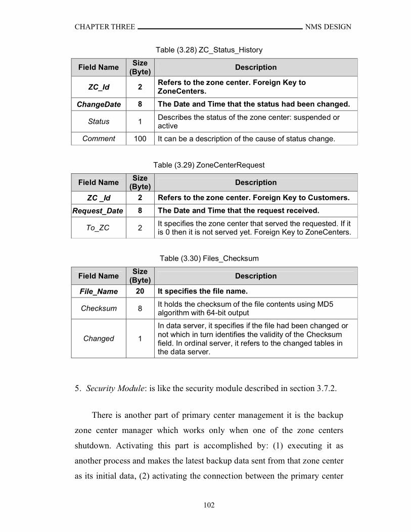
CHAPTER THREE NMS DESIGN
102
Table (3.28) ZC_Status_History
Field NameSize
(Byte)Description
ZC_Id 2Refers to the zone center. Foreign Key to ZoneCenters.
ChangeDate 8 The Date and Time that the status had been changed.
Status 1Describes the status of the zone center: suspended or active
Comment 100 It can be a description of the cause of status change.
Table (3.29) ZoneCenterRequest
Field NameSize
(Byte) Description
ZC _Id 2 Refers to the zone center. Foreign Key to Customers.
Request_Date 8 The Date and Time that the request received.
To_ZC 2It specifies the zone center that served the requested. If it is 0 then it is not served yet. Foreign Key to ZoneCenters.
Table (3.30) Files_Checksum
Field NameSize
(Byte) Description
File_Name 20 It specifies the file name.
Checksum 8It holds the checksum of the file contents using MD5 algorithm with 64-bit output
Changed 1
In data server, it specifies if the file had been changed or not which in turn identifies the validity of the Checksum field. In ordinal server, it refers to the changed tables in the data server.
5. Security Module: is like the security module described in section 3.7.2.
There is another part of primary center management it is the backup
zone center manager which works only when one of the zone centers
shutdown. Activating this part is accomplished by: (1) executing it as
another process and makes the latest backup data sent from that zone center
as its initial data, (2) activating the connection between the primary center

CHAPTER THREE NMS DESIGN
103
and the zone, and (3) assign the same IPv6 address of the zone center to it
with updating to route tables in routers. The backup zone center manager is
a copy of the zone center manager that explained in section 3.7.2.
3.7.4 Service Providers Component
All the service providers management applications have the same
general properties, and because the aim of thesis is concerned with the
network management so, the detailed information of each service would
not discussed. Thus all of them have the same application but their names
are different. The management application of the service provider is
composed of the following modules (see Figure 3.8):
Fig.(3.8) Service Provider Management Modules
1. Request Listener: is responsible of receiving requests and responding
them. The requests are either serving an alarm or statistical information
about the accomplished services and those not yet accomplished. If it is
an alarm this module saves the request in the database through Database
Manager and sends it to the Service Manipulator. The Service
Manipulator returns answer to the Request Listener as accept or refuse
the request. In turn, the Request Listener returns the answer to the Zone
Center. When the request asks for information, the Request Listener
retrieves it from the Database Manager and sends it to the zone center.
Channel to Zone
Centers
Request Listener
Database Manager
Service Provider
Service Manipulator
Security Module

CHAPTER THREE NMS DESIGN
104
2. Service Manipulator: it receives alarm request from the Request
Listener to send cars for serving specific building, the request added to
the database and set as waiting state then it decides the answer of the
request either manually or automatically, stores it in the database, and
returns it. Manually means it only accepted or refused by the dispatcher.
The dispatcher can configure the application to either auto-refuse or
auto-serve state. The auto-refuse makes the Service Manipulator refuses
all the requests automatically. The auto-serve accepts the request when
there are minimum number of cars (which is specified by the dispatcher)
ready to serve request, and refuses if not enough. The automatic answer
helps the dispatcher to be faster in answer to the zone center and
simplify the refusing of all incoming requests when needed. If the
request accepted, it transferred to the serving state and waits for the
dispatcher to end serving the request and returning the cars to the
station. Sometimes, service needs more cars than sent to serve (for
example, very big fire within street that has closed buildings), thus the
dispatcher can send more cars to help, but if the station does not has the
needed available number of cars then the dispatcher send support
request to the zone center. Another option is the simulation state which
is only for tests situations that work as auto-serve with auto completion
which means that when the request completed the service manipulator
set a random time within range specified for the completion of the
service, and decreases the number of cars stored in the database by the
minimum number of cars needed to serve request. When the time is
expired, it increases the number of cars in the database and set the
request as completed.
3. Database Manager: this module is like the one in the Zone center
except it has different tables. Tables (3.31-37) showing some of them.
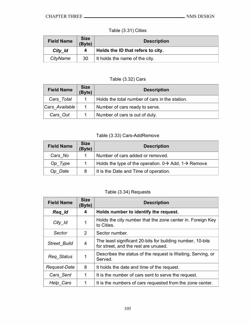
CHAPTER THREE NMS DESIGN
105
Table (3.31) Cities
Field NameSize
(Byte)Description
City_Id 4 Holds the ID that refers to city.
CityName 30 It holds the name of the city.
Table (3.32) Cars
Field NameSize
(Byte) Description
Cars_Total 1 Holds the total number of cars in the station.
Cars_Available 1 Number of cars ready to serve.
Cars_Out 1 Number of cars is out of duty.
Table (3.33) Cars-AddRemove
Field NameSize
(Byte)Description
Cars_No 1 Number of cars added or removed.
Op_Type 1 Holds the type of the operation. 0 Add, 1 Remove
Op_Date 8 It is the Date and Time of operation.
Table (3.34) Requests
Field NameSize
(Byte)Description
Req_Id 4 Holds number to identify the request.
City_Id 1Holds the city number that the zone center in. Foreign Key to Cities.
Sector 2 Sector number.
Street_Build 4The least significant 20-bits for building number, 10-bits for street, and the rest are unused.
Req_Status 1Describes the status of the request is Waiting, Serving, or Served.
Request-Date 8 It holds the date and time of the request.
Cars_Sent 1 It is the number of cars sent to serve the request.
Help_Cars 1 It is the numbers of cars requested from the zone center.
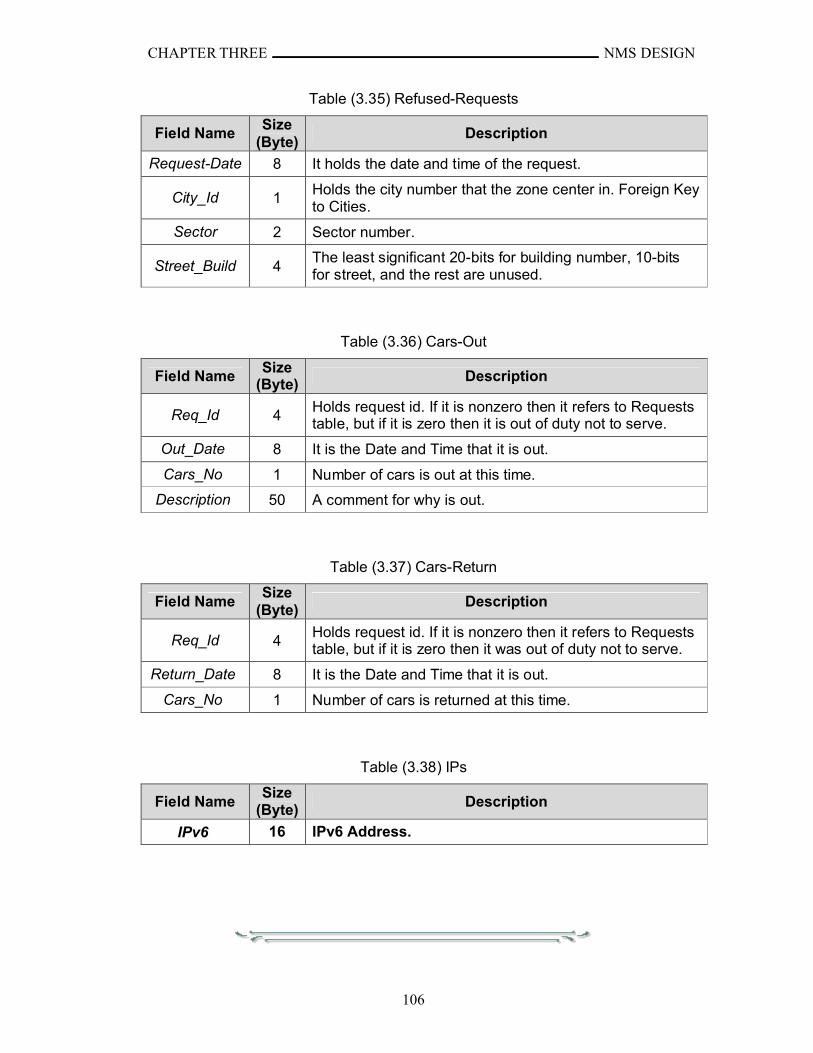
CHAPTER THREE NMS DESIGN
106
Table (3.35) Refused-Requests
Field NameSize
(Byte)Description
Request-Date 8 It holds the date and time of the request.
City_Id 1Holds the city number that the zone center in. Foreign Key to Cities.
Sector 2 Sector number.
Street_Build 4The least significant 20-bits for building number, 10-bits for street, and the rest are unused.
Table (3.36) Cars-Out
Field NameSize
(Byte) Description
Req_Id 4Holds request id. If it is nonzero then it refers to Requests table, but if it is zero then it is out of duty not to serve.
Out_Date 8 It is the Date and Time that it is out.
Cars_No 1 Number of cars is out at this time.
Description 50 A comment for why is out.
Table (3.37) Cars-Return
Field NameSize
(Byte)Description
Req_Id 4Holds request id. If it is nonzero then it refers to Requests table, but if it is zero then it was out of duty not to serve.
Return_Date 8 It is the Date and Time that it is out.
Cars_No 1 Number of cars is returned at this time.
Table (3.38) IPs
Field NameSize
(Byte) Description
IPv6 16 IPv6 Address.

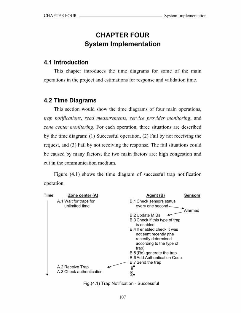
CHAPTER FOUR System Implementation
107
CHAPTER FOURSystem Implementation
4.1 IntroductionThis chapter introduces the time diagrams for some of the main
operations in the project and estimations for response and validation time.
4.2 Time Diagrams
This section would show the time diagrams of four main operations,
trap notifications, read measurements, service provider monitoring, and
zone center monitoring. For each operation, three situations are described
by the time diagram: (1) Successful operation, (2) Fail by not receiving the
request, and (3) Fail by not receiving the response. The fail situations could
be caused by many factors, the two main factors are: high congestion and
cut in the communication medium.
Figure (4.1) shows the time diagram of successful trap notification
operation.
Time Zone center (A) Agent (B) Sensors
A.1 Wait for traps for unlimited time
B.1 Check sensors status every one second
AlarmedB.2 Update MIBsB.3 Check if this type of trap
is enabledB.4 If enabled check It was
not sent recently (the recently determined according to the type of trap)
B.5 (Re) generate the trapB.6 Add Authentication CodeB.7 Send the trap
A.2 Receive TrapA.3 Check authentication
Fig.(4.1) Trap Notification - Successful
500
ms
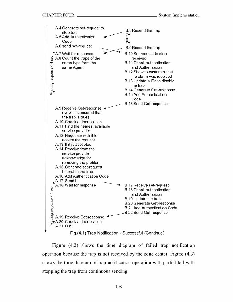
CHAPTER FOUR System Implementation
108
B.8 Resend the trapA.4 Generate set-request to
stop trapA.5 Add Authentication
CodeA.6 send set-request B.9 Resend the trap
A.7 Wait for responseA.8 Count the traps of the
same type from the same Agent
B.10 Set request to stop received
B.11 Check authentication and Autherization
B.12 Show to customer that the alarm was received
B.13 Update MIBs to disable the trap
B.14 Generate Get-responseB.15 Add Authentication
CodeB.16 Send Get-response
A.9 Receive Get-response (Now it is ensured that the trap is true)
A.10 Check authenticationA.11 Find the nearest available
service providerA.12 Negotiate with it to
accept the request A.13 If it is acceptedA.14 Receive from the
service provider acknowledge for removing the problem
A.15 Generate set-request to enable the trap
A.16 Add Authentication CodeA.17 Send it A.18 Wait for response B.17 Receive set-request
B.18 Check authentication and Autherization
B.19 Update the trapB.20 Generate Get-response B.21 Add Authentication CodeB.22 Send Get-response
A.19 Receive Get-responseA.20 Check authenticationA.21 O.K.
Fig.(4.1) Trap Notification - Successful (Continue)
Figure (4.2) shows the time diagram of failed trap notification
operation because the trap is not received by the zone center. Figure (4.3)
shows the time diagram of trap notification operation with partial fail with
stopping the trap from continuous sending.
500
ms
Wai
ting
res
pons
e ≤
4se
cW
aiti
ng r
espo
nse ≤
4se
c
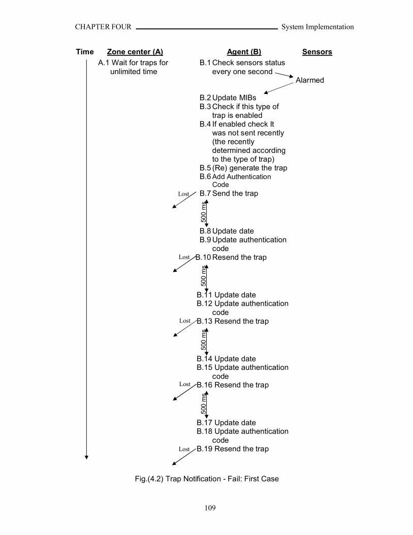
CHAPTER FOUR System Implementation
109
Time Zone center (A) Agent (B) Sensors
A.1 Wait for traps for unlimited time
B.1 Check sensors status every one second
Alarmed
B.2 Update MIBsB.3 Check if this type of
trap is enabledB.4 If enabled check It
was not sent recently (the recently determined according to the type of trap)
B.5 (Re) generate the trapB.6 Add Authentication
CodeB.7 Send the trap
500
ms
B.8 Update dateB.9 Update authentication
codeB.10 Resend the trap
500
ms
B.11 Update dateB.12 Update authentication
codeB.13 Resend the trap
500
ms
B.14 Update dateB.15 Update authentication
codeB.16 Resend the trap
500
ms
B.17 Update dateB.18 Update authentication
codeB.19 Resend the trap
Fig.(4.2) Trap Notification - Fail: First Case
Lost
Lost
Lost
Lost
Lost
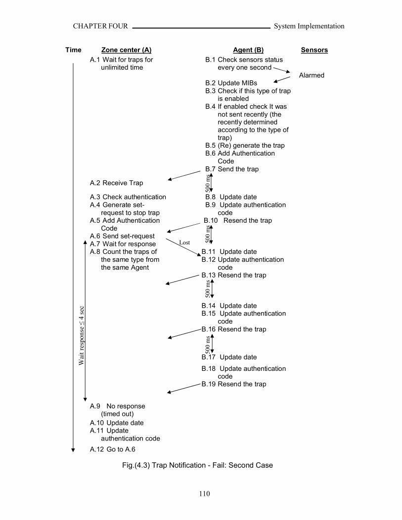
CHAPTER FOUR System Implementation
110
Time Zone center (A) Agent (B) Sensors
A.1 Wait for traps for unlimited time
B.1 Check sensors status every one second
AlarmedB.2 Update MIBsB.3 Check if this type of trap
is enabledB.4 If enabled check It was
not sent recently (the recently determined according to the type of trap)
B.5 (Re) generate the trapB.6 Add Authentication
CodeB.7 Send the trap
A.2 Receive Trap
A.3 Check authentication B.8 Update dateA.4 Generate set-
request to stop trapB.9 Update authentication
codeA.5 Add Authentication
CodeA.6 Send set-requestA.7 Wait for response
B.10 Resend the trap
A.8 Count the traps of the same type from the same Agent
B.11 Update dateB.12 Update authentication
codeB.13 Resend the trap
B.14 Update dateB.15 Update authentication
codeB.16 Resend the trap
B.17 Update date
B.18 Update authentication code
B.19 Resend the trap
A.9 No response (timed out)
A.10 Update dateA.11 Update
authentication code
A.12 Go to A.6
Fig.(4.3) Trap Notification - Fail: Second Case
500
ms
500
ms
Wai
t re
spon
se ≤
4 se
c
Lost
500
ms
500
ms
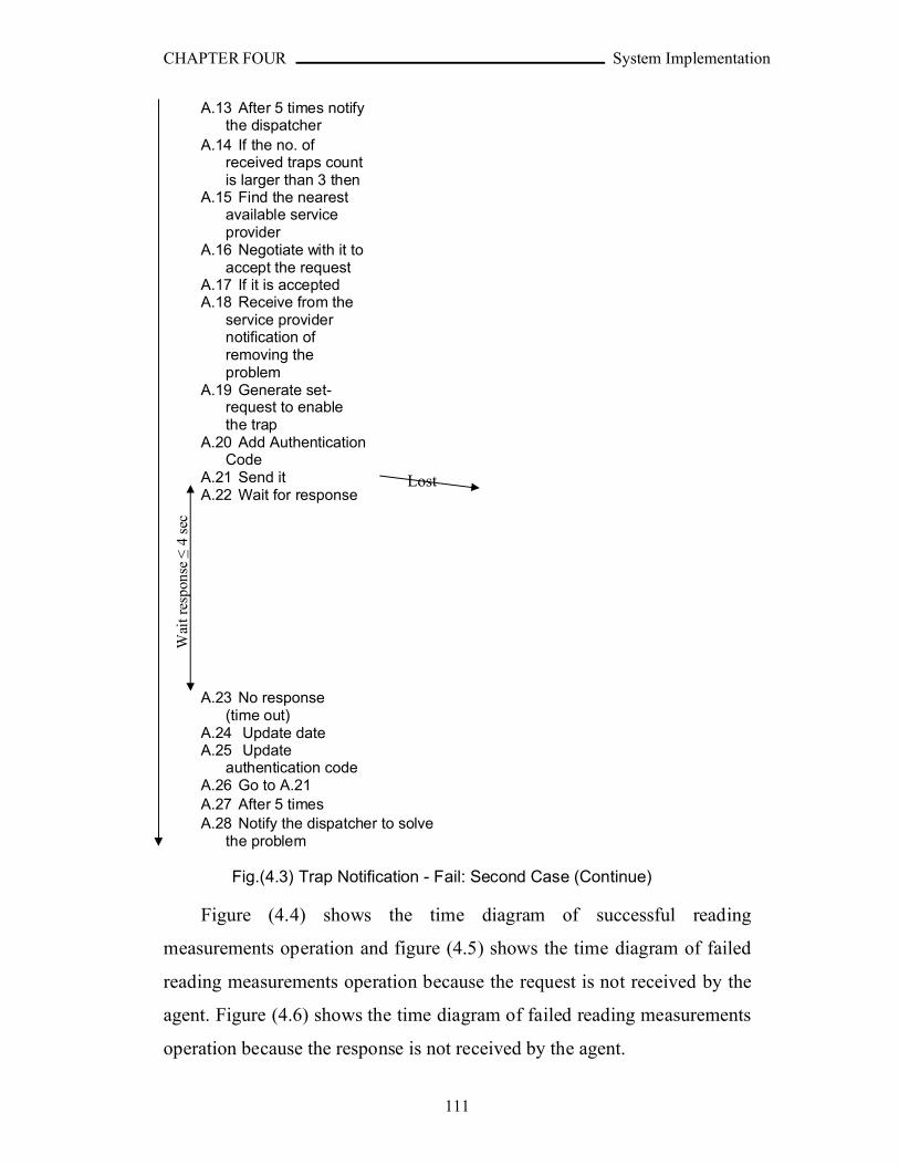
CHAPTER FOUR System Implementation
111
A.13 After 5 times notify the dispatcher
A.14 If the no. of received traps count is larger than 3 then
A.15 Find the nearest available service provider
A.16 Negotiate with it to accept the request
A.17 If it is acceptedA.18 Receive from the
service provider notification ofremoving the problem
A.19 Generate set-request to enable the trap
A.20 Add Authentication Code
A.21 Send it A.22 Wait for response
A.23 No response (time out)
A.24 Update dateA.25 Update
authentication codeA.26 Go to A.21A.27 After 5 times A.28 Notify the dispatcher to solve
the problem
Fig.(4.3) Trap Notification - Fail: Second Case (Continue)
Figure (4.4) shows the time diagram of successful reading
measurements operation and figure (4.5) shows the time diagram of failed
reading measurements operation because the request is not received by the
agent. Figure (4.6) shows the time diagram of failed reading measurements
operation because the response is not received by the agent.
Lost
Wai
t res
pons
e ≤
4 se
c
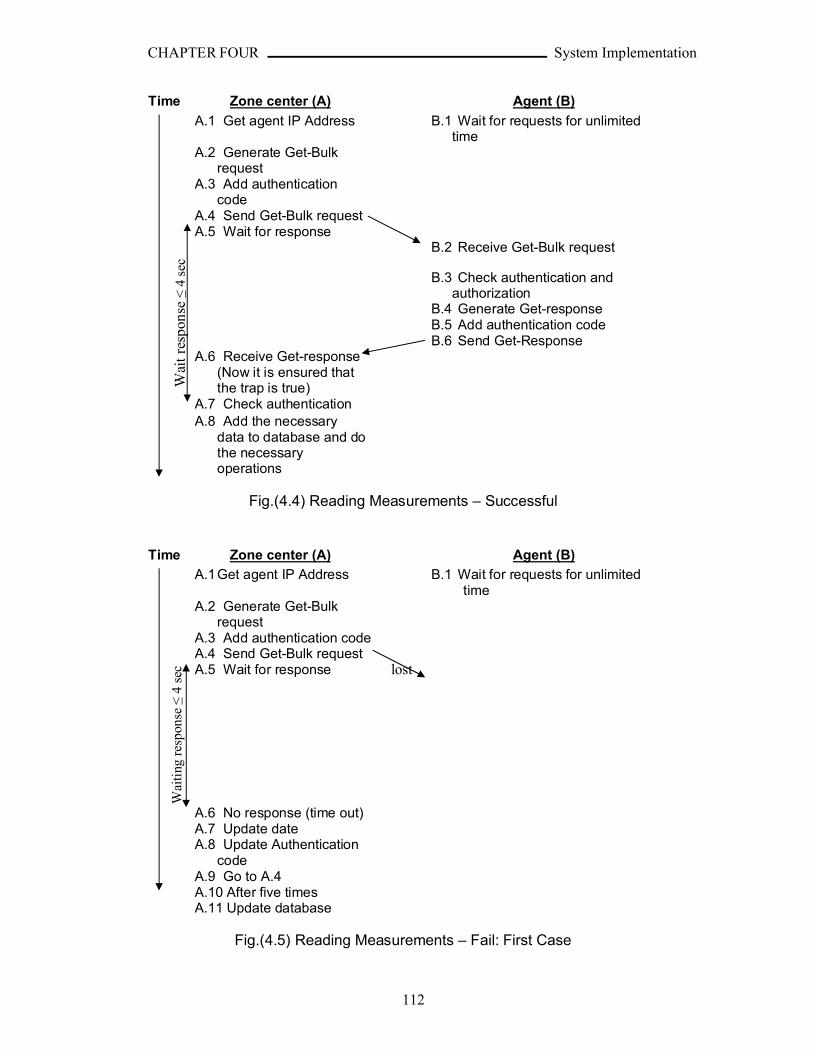
CHAPTER FOUR System Implementation
112
Time Zone center (A) Agent (B)
A.1 Get agent IP Address B.1 Wait for requests for unlimited time
A.2 Generate Get-Bulk request
A.3 Add authentication code
A.4 Send Get-Bulk requestA.5 Wait for response
B.2 Receive Get-Bulk request
B.3 Check authentication and authorization
B.4 Generate Get-responseB.5 Add authentication code B.6 Send Get-Response
A.6 Receive Get-response (Now it is ensured that the trap is true)
A.7 Check authenticationA.8 Add the necessary
data to database and do the necessary operations
Fig.(4.4) Reading Measurements – Successful
Time Zone center (A) Agent (B)
A.1Get agent IP Address B.1 Wait for requests for unlimited time
A.2 Generate Get-Bulk request
A.3 Add authentication codeA.4 Send Get-Bulk requestA.5 Wait for response
A.6 No response (time out)A.7 Update dateA.8 Update Authentication
codeA.9 Go to A.4A.10 After five timesA.11 Update database
Fig.(4.5) Reading Measurements – Fail: First Case
Wai
t res
pons
e ≤
4 se
cW
aiti
ng r
espo
nse ≤
4 se
c lost
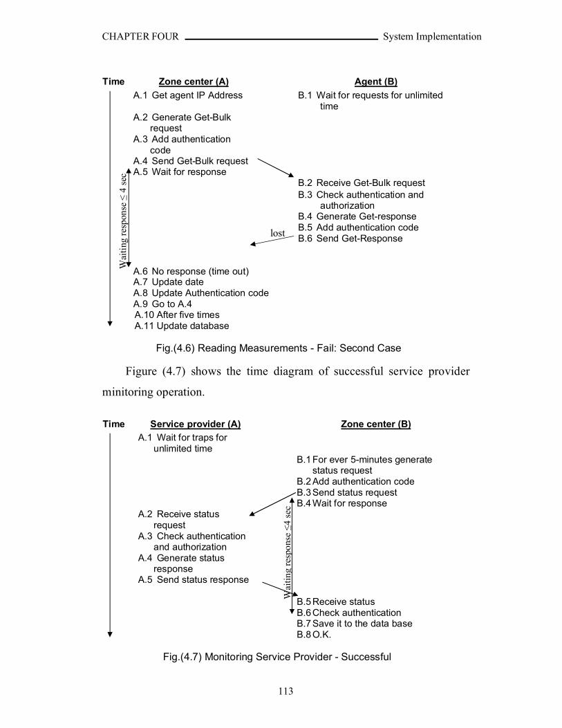
CHAPTER FOUR System Implementation
113
Time Zone center (A) Agent (B)
A.1 Get agent IP Address B.1 Wait for requests for unlimited time
A.2 Generate Get-Bulk request
A.3 Add authentication code
A.4 Send Get-Bulk requestA.5 Wait for response
B.2 Receive Get-Bulk requestB.3 Check authentication and
authorizationB.4 Generate Get-responseB.5 Add authentication code B.6 Send Get-Response
A.6 No response (time out)A.7 Update dateA.8 Update Authentication codeA.9 Go to A.4A.10 After five timesA.11 Update database
Fig.(4.6) Reading Measurements - Fail: Second Case
Figure (4.7) shows the time diagram of successful service provider
minitoring operation.
Time Service provider (A) Zone center (B)
A.1 Wait for traps for unlimited time
B.1 For ever 5-minutes generate status request
B.2 Add authentication codeB.3 Send status requestB.4 Wait for response
A.2 Receive status request
A.3 Check authenticationand authorization
A.4 Generate status response
A.5 Send status response
B.5 Receive statusB.6 Check authenticationB.7 Save it to the data baseB.8 O.K.
Fig.(4.7) Monitoring Service Provider - Successful
Wai
ting
res
pons
e ≤
4 se
c
lost
Wai
ting
res
pons
e ≤
4 se
c
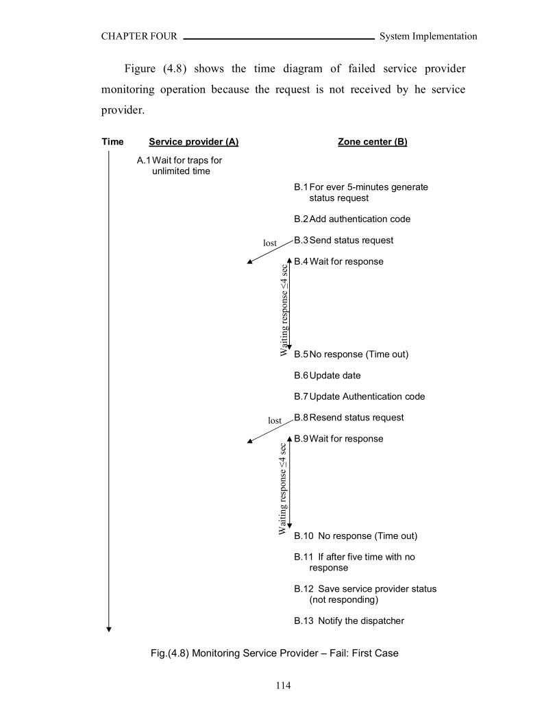
CHAPTER FOUR System Implementation
114
Figure (4.8) shows the time diagram of failed service provider
monitoring operation because the request is not received by he service
provider.
Time Service provider (A) Zone center (B)
A.1Wait for traps for unlimited time
B.1For ever 5-minutes generate status request
B.2Add authentication code
B.3Send status request
B.4 Wait for response
B.5No response (Time out)
B.6Update date
B.7Update Authentication code
B.8Resend status request
B.9Wait for response
B.10 No response (Time out)
B.11 If after five time with no response
B.12 Save service provider status (not responding)
B.13 Notify the dispatcher
Fig.(4.8) Monitoring Service Provider – Fail: First Case
Wai
ting
res
pons
e ≤
4 se
c
lost
Wai
ting
res
pons
e ≤
4 se
c
lost
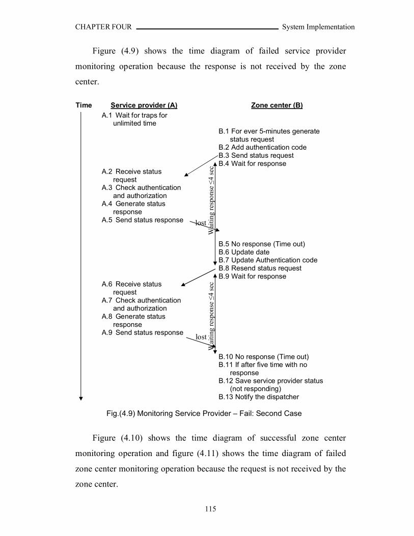
CHAPTER FOUR System Implementation
115
Figure (4.9) shows the time diagram of failed service provider
monitoring operation because the response is not received by the zone
center.
Time Service provider (A) Zone center (B)
A.1 Wait for traps for unlimited time
B.1 For ever 5-minutes generate status request
B.2 Add authentication codeB.3 Send status requestB.4 Wait for response
A.2 Receive status request
A.3 Check authenticationand authorization
A.4 Generate status response
A.5 Send status response
B.5 No response (Time out)B.6 Update dateB.7 Update Authentication codeB.8 Resend status requestB.9 Wait for response
A.6 Receive status request
A.7 Check authenticationand authorization
A.8 Generate status response
A.9 Send status response
B.10 No response (Time out)B.11 If after five time with no
responseB.12 Save service provider status
(not responding)B.13 Notify the dispatcher
Fig.(4.9) Monitoring Service Provider – Fail: Second Case
Figure (4.10) shows the time diagram of successful zone center
monitoring operation and figure (4.11) shows the time diagram of failed
zone center monitoring operation because the request is not received by the
zone center.
Wai
ting
res
pons
e ≤
4 se
c
lost
Wai
ting
res
pons
e ≤
4 se
c
lost
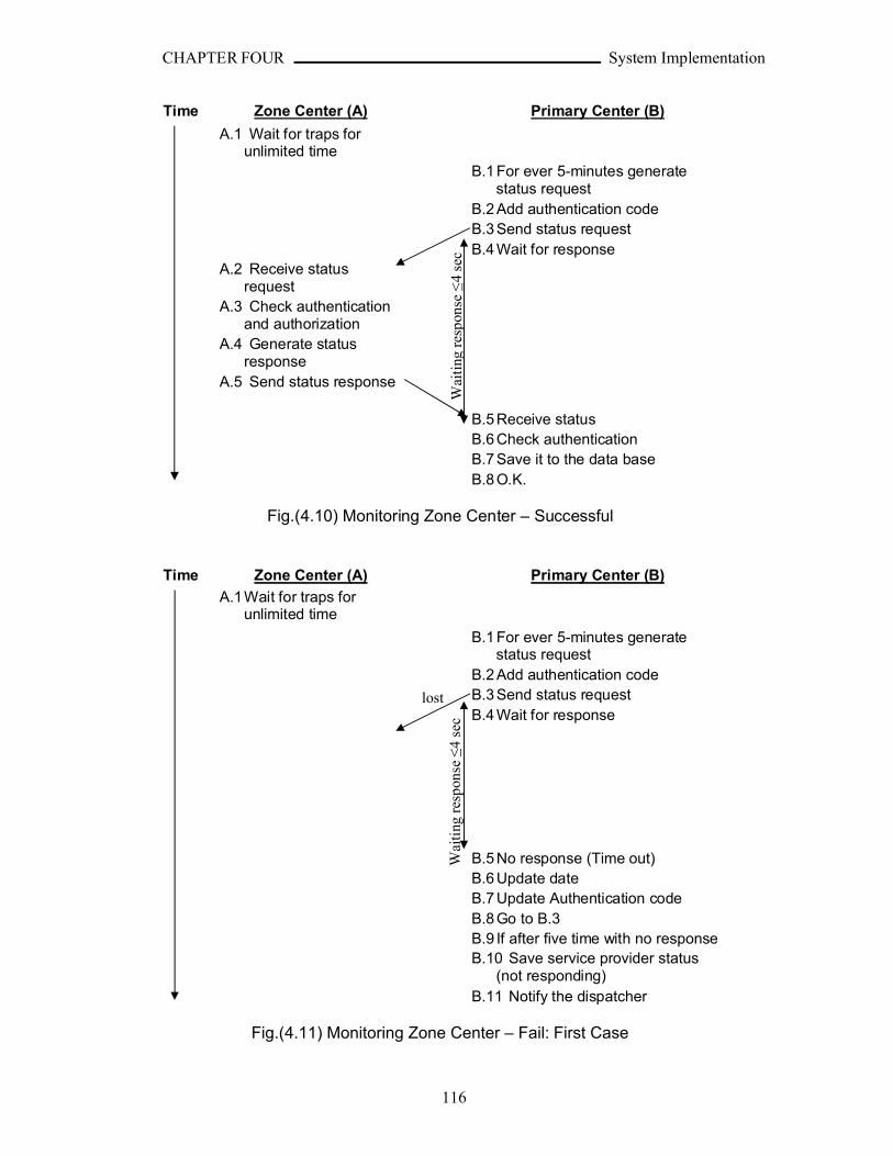
CHAPTER FOUR System Implementation
116
Time Zone Center (A) Primary Center (B)
A.1 Wait for traps for unlimited time
B.1 For ever 5-minutes generate status request
B.2 Add authentication codeB.3 Send status requestB.4 Wait for response
A.2 Receive status request
A.3 Check authenticationand authorization
A.4 Generate status response
A.5 Send status response
B.5 Receive statusB.6 Check authenticationB.7 Save it to the data baseB.8 O.K.
Fig.(4.10) Monitoring Zone Center – Successful
Time Zone Center (A) Primary Center (B)
A.1Wait for traps for unlimited time
B.1 For ever 5-minutes generate status request
B.2 Add authentication codeB.3 Send status requestB.4 Wait for response
B.5 No response (Time out)B.6 Update dateB.7 Update Authentication codeB.8 Go to B.3B.9 If after five time with no responseB.10 Save service provider status
(not responding)B.11 Notify the dispatcher
Fig.(4.11) Monitoring Zone Center – Fail: First Case
Wai
ting
res
pons
e ≤
4 se
cW
aiti
ng r
espo
nse ≤
4 se
c
lost
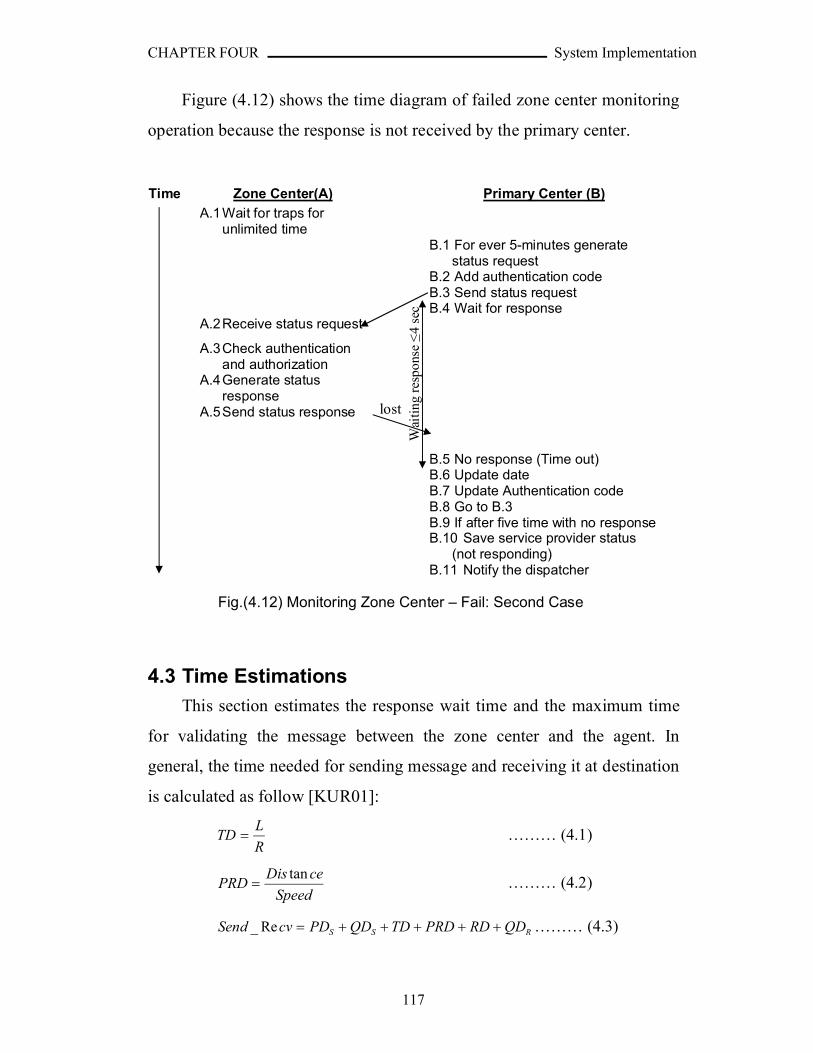
CHAPTER FOUR System Implementation
117
Figure (4.12) shows the time diagram of failed zone center monitoring
operation because the response is not received by the primary center.
Time Zone Center(A) Primary Center (B)
A.1Wait for traps for unlimited time
B.1 For ever 5-minutes generate status request
B.2 Add authentication codeB.3 Send status requestB.4 Wait for response
A.2Receive status request
A.3Check authenticationand authorization
A.4Generate status response
A.5Send status response
B.5 No response (Time out)B.6 Update dateB.7 Update Authentication codeB.8 Go to B.3B.9 If after five time with no responseB.10 Save service provider status
(not responding)B.11 Notify the dispatcher
Fig.(4.12) Monitoring Zone Center – Fail: Second Case
4.3 Time Estimations
This section estimates the response wait time and the maximum time
for validating the message between the zone center and the agent. In
general, the time needed for sending message and receiving it at destination
is calculated as follow [KUR01]:
R
LTD ……… (4.1)
Speed
ceDisPRD
tan ……… (4.2)
RSS QDRDPRDTDQDPDcvSend Re_ ……… (4.3)
Wai
ting
res
pons
e ≤
4 se
clost
CHAPTER FOUR System Implementation
118
Where R is the transmission rate of the communication channel,
L is the average length of the message transmitted between the two
nodes,
TD is the time needed for transmitting the message,
Distance is the distance of the channel,
Speed is the speed of the channel (for wire is 2*108),
PRD is the propagation delay of the channel is the time needed for
transmitting the message,
RD is the time needed for receiving the message,
PDS is the time delay due to message processing at the sender
QDS is the time delay caused by waiting the message in the queue for
sending,
and QDR is the time delay caused by waiting the message in the queue
for receiving.
The processing delay queue and queue delay is specific to the
specifications of the computers used and the load at that time. The
computers used to estimate the time have the following descriptions:
C.P.U. Speed is 2.0GHz with 512 KB cashe, R.A.M. capacity is 256MB, Bus speed is 100 MHz, and IDE H.D.D. with 5200rpm.
The average PD and QD estimated is 200ms, and it is taken in average
for both the agent and zone center.
The connection suggested in chapter three between agents and one
center is PLC and ILEVO [ILV05] is taken as a sample product. Then:
520
10*35.32*36
8*158 TDRD Sec
The ILEVO modems have maximum levels of four (i.e. the Head End,
customer modem, and two intermediate repeaters) and maximum distance
between each two nodes is 400m. the Head End modem is connected to the
CHAPTER FOUR System Implementation
119
zone center by another channel that supposed to have the same properties.
Then, there are three nodes between the zone center and the agent; each
node is receiving messages from previous one and sending them to the next
one. Thus, equation (4.3) is multiplied by 5.
58
10*2.010*2
400 PRD Sec
5*)10*20010*35.310*2.010*35.310*200(Re_ 35553 cvSend2 Sec
So, the time needed for validating a message is 2 seconds. The time
needed to wait for response is the double which is 4 seconds. These values
can be changed by the administrator according to the state of the system.

CHAPTER FIVE Conclusions and Suggestions
120
CHAPTER FIVEConclusions and Suggestions
5.1 Conclusions
The proposed system should cover a large area and huge number of
customers, this require a complicated analysis for determining the aspects
of the network capable to connect the distributed parts of the system. In this
thesis it had been shown, analytically, that the PLC communication is
suitable for connecting a large number of customers with the zone center.
Taking into consideration that a low cost PLC communication technology
is already exists, and offers enough bandwidth for the transmission of traps
and reading data from the agents. Also, in this project some suggestions
about other connections between the parts of the system have been
discussed and implemented.
During the designing, implementation and testing phases a lot of
remarks have been issued; the following are some of them:
1. The distribution of the system parts needs to be handled by using simple
and reliable techniques, and some fast decision making rules should be
used because the system covers large geographical area and need real-
time reception of the alarms by the service providers.
2. Building a dedicated distributed DBMS specific to the system
requirements, that is simpler and faster than the existed commercial
DBMS, in order to speed up the system performance, and to simplify
the interaction between the system parts and the DBMS.
3. The multi-threaded programming improves the system capability of
receiving, processing, and sending data in concurrent way, but it adds
more complexity in managing the threads, especially in processing data.

CHAPTER FIVE Conclusions and Suggestions
121
4. The systems cover very large geographical area may face the problem of
different time zones. This problem is solved by setting all the parts of
the system referenced to the same time. Therefore, an automatic
synchronization between the distributed system components is very
necessary. This synchronization was handled by implementing
algorithm (3.1).
5. The use of two simple criteria for estimating the nearest service provider
(SP) to the service requester (SR) is necessary to get better estimation
results than using one of the formulas. By using only the distance
between customer’s sector and the service provider as a criteria may not
express the actual distance should be passed on roads to move between
SP and SR. And by using only the urban map for the estimating the
distance may not lead the nearest also. So, as an average both formulas
together could give better results than using only one.
6. By using simplified formula (even less accurate) for determining the
distance between customer’s sector and the service provider had speed
up the process of estimating the nearest service provider, without losing
significant accuracy. The determination of the exact distance is not
target, the actual target is the comparison between the distances and thus
a highly accurate distance formula is not necessary, its low
computational load should be considered as an important requirement.
5.2 Suggestions for Future Work
In the following some conducted suggestions for future work are given
to enhance the project and make it more effective:
1. Giving the facility of direct communications among the zone centers,
and not necessarily through the primary center. This will improve the
system reliability and become more efficient.
CHAPTER FIVE Conclusions and Suggestions
122
2. Enhance the way of estimating the nearest service provider by using
Geographic Information System (GIS) technology supported by Global
Positioning System (GPS).
3. Adding other tools to help the administrator to allocate the factors that
might cause decrease in the system performance. If the utilized tools use
different mechanisms, they would let the administrator to see the
problem in different ways and then he might make faster diagnosis. For
example, ping utility, and trace route utility that can detect all the
devices between the zone center and agent or service provider.
4. Enhance the backup operation by backuping only the new data and
compressing it if needed to decrease the size of transferred data.
5. Using a graphical mapping tool that can easily show the positions of
customers and service providers.

REFRENCES
١٢٣
REFRENCES
[ARN96] ARIN; "IP allocation report".
http://ftp.utoronto.ca/doc/internic/netinfo/ip_network_allocations
[BRA96] Bradner, S.; Mankin, A.; "IPng: Internet Protocol Next
Generation", Addison-Wesley, 1996.
[CIS02] CISCO Systems; "Internetworking Technology Handbook";
CISCO Systems, 2002.
[CIS06] CISCO Systems.
http://www.cisco.com
[DAV00] Davis, E.; "SNMPv3 - User Security Model"; Sys Admin
Magazine, Vol. 9 Issue 5, May 2000.
[GIA02] Giantdino, D.; "Programming Visual Basic .NET"; O'Reilly,
2002.
[GIL05] Gillespie, M.; "Multi-Threading in .NET Environment";
Intel Corporation, 2005.
[GON98] Goncalves, M.; Niles, K.; "IPv6 Networks"; McGraw-Hill
Companies Inc., 1998.
[Hel00] Helton, P. G., "Security in Computing", Prentice Hall PTR,
2000.
[ILV05] ILEVO, Schneider Electric Powerline Communications
Company. http://www.ilevo.com. Visit Date: December 2005
[IPF02] Microsoft Corporation, Help and Support Center; "IPv6
Features"; Windows XP SP2 Professional Help, 2002.
REFRENCES
١٢٤
[IPT04] Microsoft Corporation; "IPv6 Transition Technologies";
Internet Paper, 2004.
[JAY06] Jayaswal, K.; “Administering Data Centers: Servers,
Storage, and Voice over IP”; Wiley Publishing; 2006.
[KUR01] Kurose, J. F.; Ross, K. W.; "Computer Networks - A Top-
Down Approach Featuring the Internet"; Addison Wesley
Longman Inc., 2001.
[LEE04] Lee, J.; Hsu, P.; "Design and Implementation of the SNMP
Agents for Remote Monitoring and Control via UML and
Petri Nets"; IEEE Transactions on Control Systems
Technology, Vol. 12, No. 2, March 2004.
[MEL98] Mellquist, P. E.; "SNMP++: an object-oriented approach to
developing network management applications"; Prentice-
Hall Inc., 1998.
[PAL05] TelleAlarm Group Company; "PAL Medical alert system",
http://www.med-alert.org/index.html, Visit Date: December
2005
[PAV05] PAV Data Systems Ltd; "NIMBUS Network Management
System".
http://www.pavdata.com , Visit Date: December 2005
[PER99] Perkins, C. E.; "The Case for IPv6"; Internet Architecture
Board, Nokia Research Center, 1999.
[PRA95] Pras, A.; "Network Management Architectures"; Ph.D.
thesis, University of Twente, Enschede, Netherlands, 1995.
REFRENCES
١٢٥
[RFC1155] Rose, M.; McCloghrie, K.; "Structure and Identification
of Management Information for TCP/IP-based Internets";
RFC-1155, Dover Beach Consulting Inc., Hughes LAN
Systems, May 1990.
[RFC1157] Case, J.; Fedor M.; Schoffstall, M.; Davin, J.; "A Simple
Network Management Protocol (SNMP)"; RFC-1157,
SNMP Research, Performance Systems International,
Performance Systems International, MIT Laboratory for
Computer Science, May 1990
[RFC1445] Galvin, J.; McCloghrie, K.; "Administrative Model for
version 2 of the Simple Network Management Protocol
(SNMPv2)"; RFC-1445, Trusted Information Systems,
Hughes LAN Systems, April 1993.
[RFC1747] Waldbusser, S.; "Remote Network Monitoring
Management Information Base"; RFC-1757, Carnegie
Mellon University, February 1995.
[RFC1446] Galvin, J.; McCloghrie, K.; "An Architecture for
Describing SNMP Management Frameworks"; RFC-1446,
Trusted Information Systems, Hughes LAN Systems, April
1993.
[RFC1450] Case, J.; McCloghrie, K.; Rose, M.; Waldbusser, S.;
"Management Information Base for version 2 of the
Simple Network Management Protocol (SNMPv2)"; RFC-
1450, SNMP Research Inc., Hughes LAN Systems, Dover
Beach Consulting Inc., Carnegie Mellon University, April
1993.
REFRENCES
١٢٦
[RFC2570] Case, J.; Mundy, R.; Partain, D.; Stewart, B.; "Introduction
to Version 3 of the Internet-standard Network
Management Framework"; RFC-2570, SNMP Research
Inc., TIS Labs at Network Associates Inc., Ericsson, Cisco
Systems, April 1999.
[RFC2571] Case, J.; Harrington, D.; Presuhn, R.; Wijnen, B.; "An
Architecture for Describing SNMP Management
Frameworks"; RFC-2571, Cabletron Systems Inc., BMC
Software Inc., IBM T. J. Watson Research, April 1999.
[RFC2572] Case, J.; Harrington, D.; Presuhn, R.; Wijnen, B.; "Message
Processing and Dispatching for the Simple Network
Management Protocol (SNMP)"; RFC-2572, SNMP
Research Inc., Cabletron Systems Inc., BMC Software Inc.,
IBM T. J. Watson Research, April 1999.
[RFC2575] Wijnen, B.; Presuhn, R.; McCloghrie, K.; "View-based
Access Control Model (VACM) for the Simple Network
Management Protocol (SNMP)"; RFC-2575, IBM T. J.
Watson Research, BMC Software Inc., Cisco Systems Inc.,
April 1999.
[SAN01] Sandlund, K.; "Network management using WBEM (Web-
Based Enterprise Management)"; M.Sc. thesis, Luleå
Tekniska University (LTU), Sweden, 2001.
[SAR04] Sartenar, T.; "Multiuser Communications over Frequency
Selective Wired Channels and Applications to the
Powerline Access Network"; Luc Vandendorpe, 2004.
REFRENCES
١٢٧
[SER02] OutPost Sentinel Company; "SERENA System"; 2002.
http://www.outpostsentinel.com/pdf/SRENA White
Paper3.pdf, Visit Date: December 2005
[SOL96] Solensky, F.;"IPv4 Address Lifetime Expectation";
Addison-Wesley, 1996
[SYD96] Sydam, T.; Magedanz, T.; "From Networks and Network
Management into Service and Service Management";
Journal of Networks and System Management, Vol. 4, No. 4,
pp. 345-348, December 1996.
[SZA01] Szall, K.; "Network+ Certification Training Kit"; Microsoft
Press, 2nd edition, 2001.
[TAN03] Tanenbaum, A. S.; "Computer Networks"; Prentice-Hall
PTR, New Jersy, Fourth Edition, 2003.
[TER02] Terlegå rd, T.; "Design of a Secure Network Management
System"; M.Sc. thesis, Institution for Systemteknik, Sweden,
2002.
[UNI02] Microsoft Corporation, Help and Support Center; "Unicast
IPv6 addresses"; Windows XP SP2 Professional Help, 2002.
[UZU02] Uzuner, T.; "Integrated Network Management Systems";
Ph.D. thesis, University of Cambridge, 2002.
.

Appendix A Network Topologies
A-1
APPENDIX A
Network Topologies [JAY06]
The word topology comes from the Greek word “topos”, which means
“place”. Topology is the description of the physical layout of a place. In
networking, it means the pictorial layout of a network, including hosts,
other devices, and lines that connect them.
Networks can be defined by protocol (for example, an IP network or
AppleTalk network), by the physical and logical connections (such as ring
or star topology), or by geography (for example, a local, metropolitan, or
wide area network).
In spite of the specific criteria used to move data between devices or
LAN segments, network infrastructures, in general, follow a hierarchy that
extends from the physical layer up through the end-user application.
A.1 Architecture-Based Network Topologies
Topologies are logical arrangements and need not be physically cabled
as shown in topology diagrams. Following are examples of the various
architecture-based network topologies:
1. Bus topology
2. Tree topology
3. Ring topology
4. Single-star topology
5. Hierarchical-star topology
6. Wireless topology
7. Point-to-point topology
8. Mesh topology

Appendix A Network Topologies
A-2
LANs are interconnected using routers. Based on a packet’s
destination IP address, the packet travels from router to router until it
reaches its last destination router, which usually happens to be inside an
office building or campus. Then it must hop out of the router’s cloud and
look at the wall plates and ports to find its destination host. This stage
requires making the transition from the destination host’s IP address to the
host’s physical address, also called the media access control (MAC)
address. The transition is done via hubs and switches. All hosts, printers,
servers, and other devices in a LAN must have a NIC with a unique MAC
address. In short, The IP address gets the message over the routers to the
neighborhood, and the MAC address gets the message over the hub or
switch to the host.
A.1.1. Bus Topology
A bus topology is a linear architecture where hosts or devices are
cabled directly to a line. All signals propagate the length of the medium
and are received by all devices. Each device has a unique identity and can
recognize (and accept) signals intended for it. In the early days of
networking, bus topologies were common. A fat coaxial cable called
thicknet ran through the building. All hosts tapped directly into the cable,
which seemed like the network backbone. This is shown in Figure (A1).
As technology developed, a thinner coaxial cable called thinnet was
introduced. It was cheaper, easier to work with, and less bulky. The
topology and all its trouble remained the same, however. If any part of the
network broke down, a number of hosts connected along the cable lost their
LAN links. Bus topologies were hard to manage. Adding taps for additional
hosts was a lot of manual work. Someone had to crawl into the plenum,
find the coaxial cable, make a tap, connect a new cable to the tap, and drop
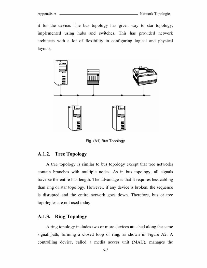
Appendix A Network Topologies
A-3
it for the device. The bus topology has given way to star topology,
implemented using hubs and switches. This has provided network
architects with a lot of flexibility in configuring logical and physical
layouts.
Fig. (A1) Bus Topology
A.1.2. Tree Topology
A tree topology is similar to bus topology except that tree networks
contain branches with multiple nodes. As in bus topology, all signals
traverse the entire bus length. The advantage is that it requires less cabling
than ring or star topology. However, if any device is broken, the sequence
is disrupted and the entire network goes down. Therefore, bus or tree
topologies are not used today.
A.1.3. Ring Topology
A ring topology includes two or more devices attached along the same
signal path, forming a closed loop or ring, as shown in Figure A2. A
controlling device, called a media access unit (MAU), manages the
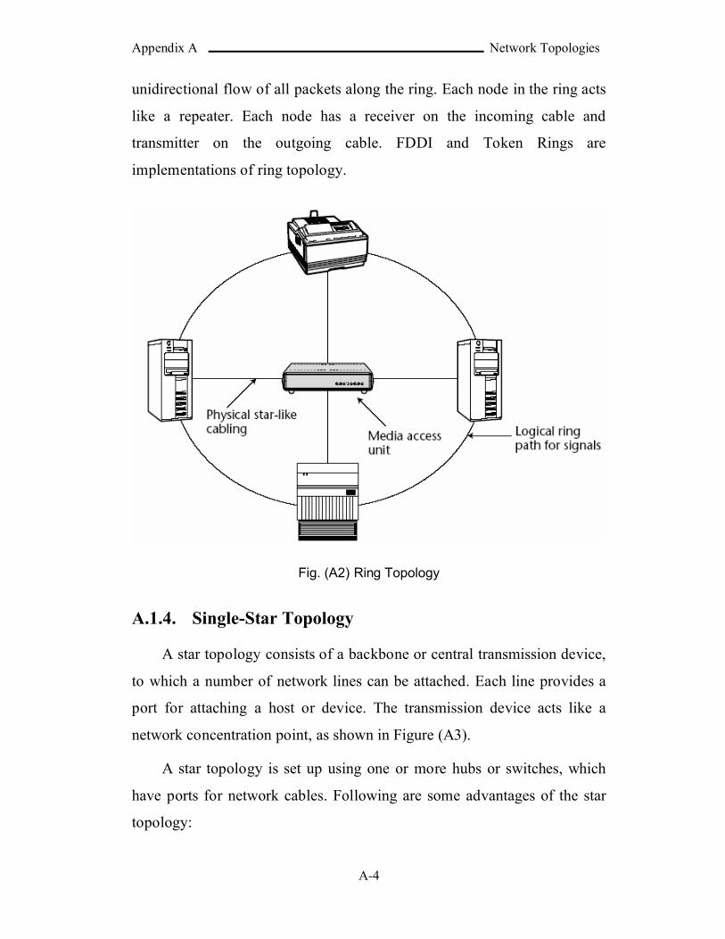
Appendix A Network Topologies
A-4
unidirectional flow of all packets along the ring. Each node in the ring acts
like a repeater. Each node has a receiver on the incoming cable and
transmitter on the outgoing cable. FDDI and Token Rings are
implementations of ring topology.
Fig. (A2) Ring Topology
A.1.4. Single-Star Topology
A star topology consists of a backbone or central transmission device,
to which a number of network lines can be attached. Each line provides a
port for attaching a host or device. The transmission device acts like a
network concentration point, as shown in Figure (A3).
A star topology is set up using one or more hubs or switches, which
have ports for network cables. Following are some advantages of the star
topology:

Appendix A Network Topologies
A-5
1. Modular design: It is easier to set up and manage many small
segments, as opposed to a large number of interconnected hosts.
Adding a host is as easy as plugging a telephone-type connector
into a hub or switch.
2. Increased reliability: Failures are localized within a segment.
3. Improved performance: User traffic within a segment does not
impact others.
A single-star topology uses one hub or switch to form a LAN. This
setup is common in small office networks or home networks.
Fig. (A3) Single-Star Topology
A.1.5. Hierarchical-Star Topology
In a hierarchical-star topology, outlying hubs and switches are
connected to a master switch (Figure A4). This allows a far greater number
of hosts to be connected to the network than is possible with a single hub or
switch. There is Physical star-like cabling media access unit logical ring
path for signals. Also, there is no need to lay many long cables to connect
distant hosts. This topology is closely tied to the geographical or building
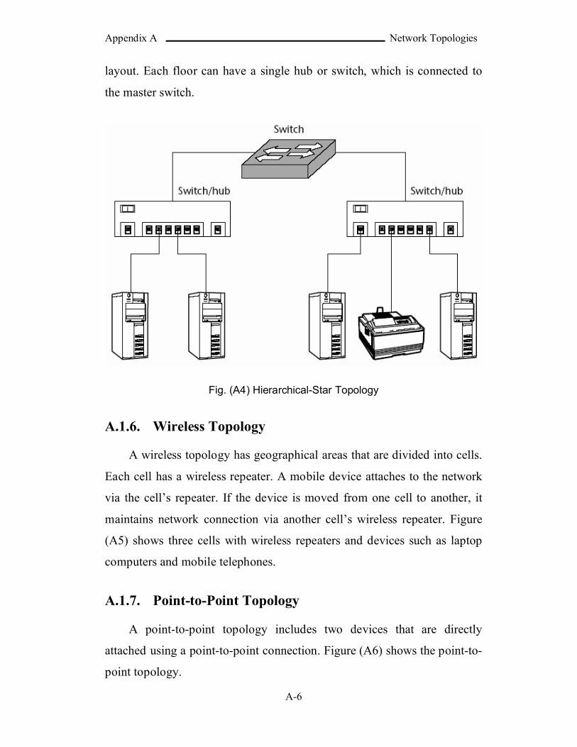
Appendix A Network Topologies
A-6
layout. Each floor can have a single hub or switch, which is connected to
the master switch.
Fig. (A4) Hierarchical-Star Topology
A.1.6. Wireless Topology
A wireless topology has geographical areas that are divided into cells.
Each cell has a wireless repeater. A mobile device attaches to the network
via the cell’s repeater. If the device is moved from one cell to another, it
maintains network connection via another cell’s wireless repeater. Figure
(A5) shows three cells with wireless repeaters and devices such as laptop
computers and mobile telephones.
A.1.7. Point-to-Point Topology
A point-to-point topology includes two devices that are directly
attached using a point-to-point connection. Figure (A6) shows the point-to-
point topology.
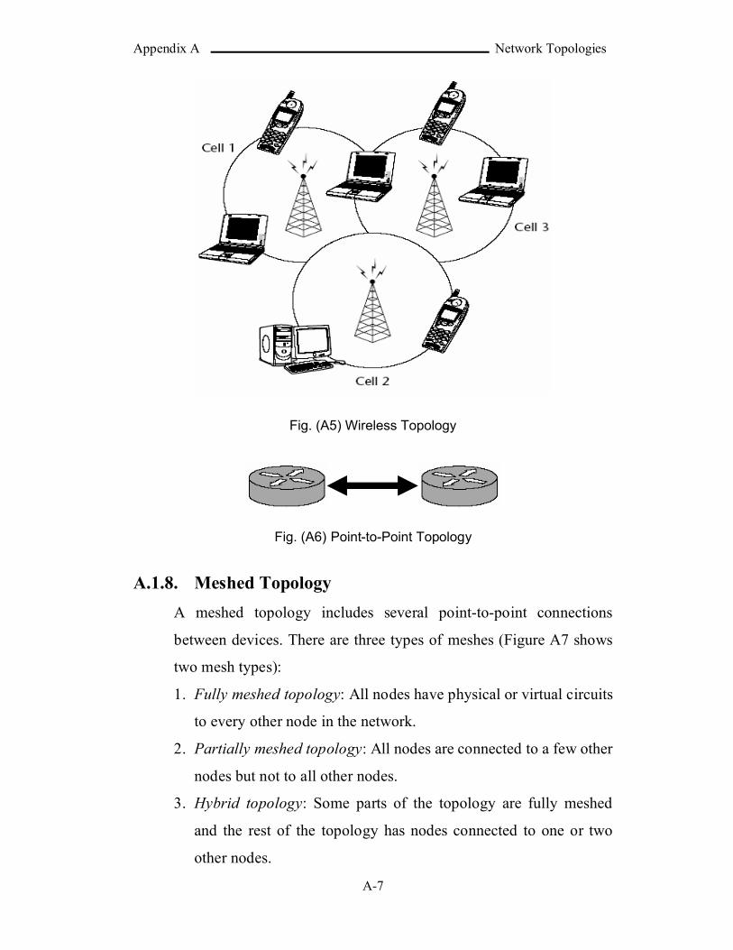
Appendix A Network Topologies
A-7
Fig. (A5) Wireless Topology
Fig. (A6) Point-to-Point Topology
A.1.8. Meshed Topology
A meshed topology includes several point-to-point connections
between devices. There are three types of meshes (Figure A7 shows
two mesh types):
1. Fully meshed topology: All nodes have physical or virtual circuits
to every other node in the network.
2. Partially meshed topology: All nodes are connected to a few other
nodes but not to all other nodes.
3. Hybrid topology: Some parts of the topology are fully meshed
and the rest of the topology has nodes connected to one or two
other nodes.
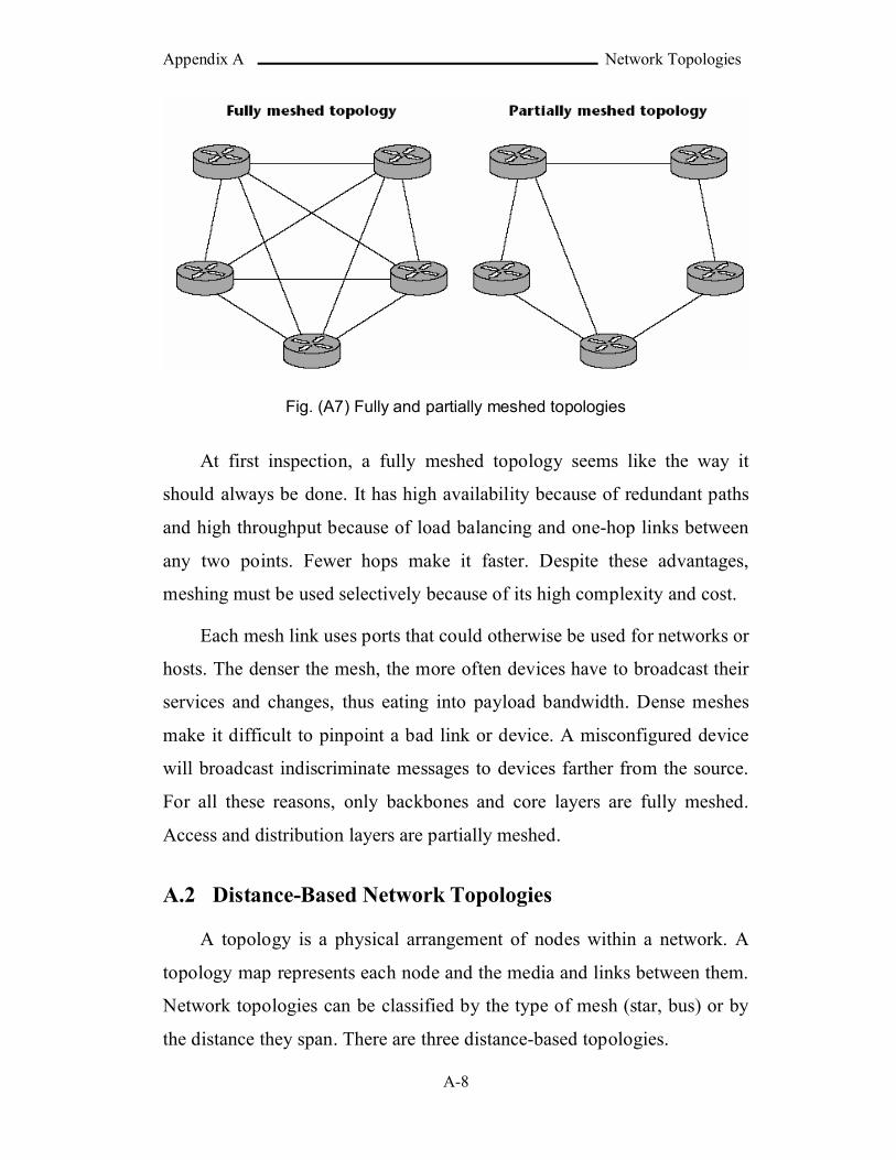
Appendix A Network Topologies
A-8
Fig. (A7) Fully and partially meshed topologies
At first inspection, a fully meshed topology seems like the way it
should always be done. It has high availability because of redundant paths
and high throughput because of load balancing and one-hop links between
any two points. Fewer hops make it faster. Despite these advantages,
meshing must be used selectively because of its high complexity and cost.
Each mesh link uses ports that could otherwise be used for networks or
hosts. The denser the mesh, the more often devices have to broadcast their
services and changes, thus eating into payload bandwidth. Dense meshes
make it difficult to pinpoint a bad link or device. A misconfigured device
will broadcast indiscriminate messages to devices farther from the source.
For all these reasons, only backbones and core layers are fully meshed.
Access and distribution layers are partially meshed.
A.2 Distance-Based Network Topologies
A topology is a physical arrangement of nodes within a network. A
topology map represents each node and the media and links between them.
Network topologies can be classified by the type of mesh (star, bus) or by
the distance they span. There are three distance-based topologies.
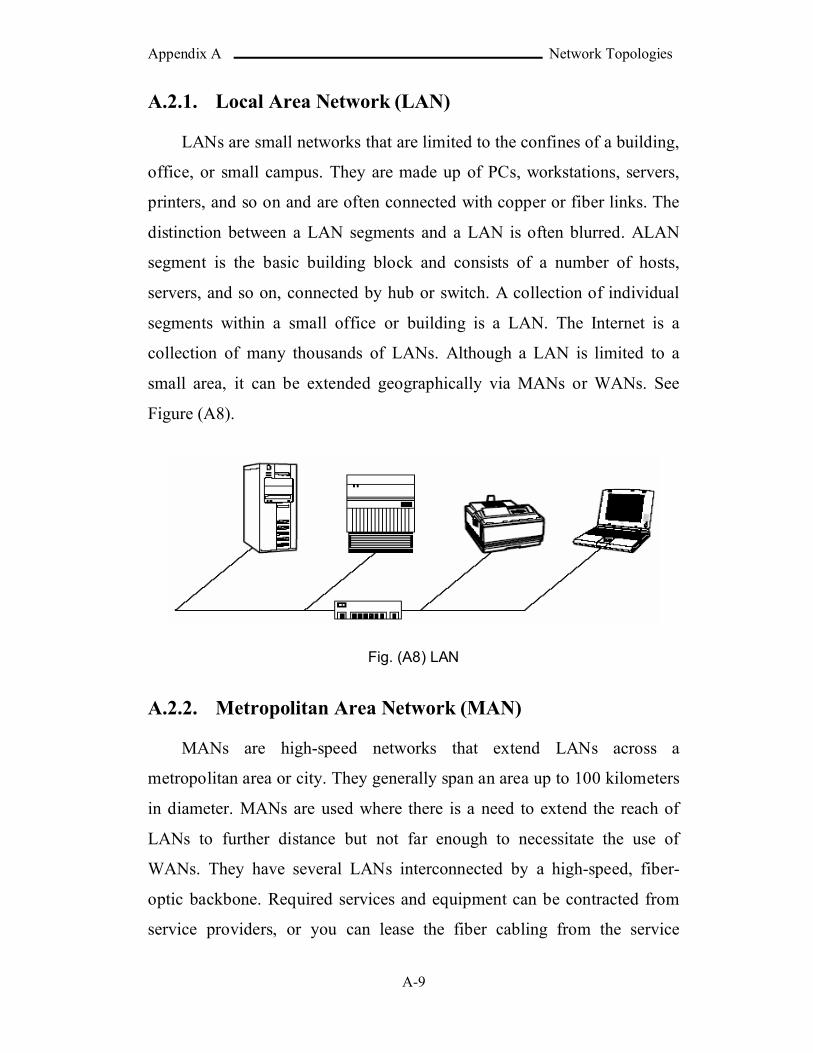
Appendix A Network Topologies
A-9
A.2.1. Local Area Network (LAN)
LANs are small networks that are limited to the confines of a building,
office, or small campus. They are made up of PCs, workstations, servers,
printers, and so on and are often connected with copper or fiber links. The
distinction between a LAN segments and a LAN is often blurred. ALAN
segment is the basic building block and consists of a number of hosts,
servers, and so on, connected by hub or switch. A collection of individual
segments within a small office or building is a LAN. The Internet is a
collection of many thousands of LANs. Although a LAN is limited to a
small area, it can be extended geographically via MANs or WANs. See
Figure (A8).
Fig. (A8) LAN
A.2.2. Metropolitan Area Network (MAN)
MANs are high-speed networks that extend LANs across a
metropolitan area or city. They generally span an area up to 100 kilometers
in diameter. MANs are used where there is a need to extend the reach of
LANs to further distance but not far enough to necessitate the use of
WANs. They have several LANs interconnected by a high-speed, fiber-
optic backbone. Required services and equipment can be contracted from
service providers, or you can lease the fiber cabling from the service
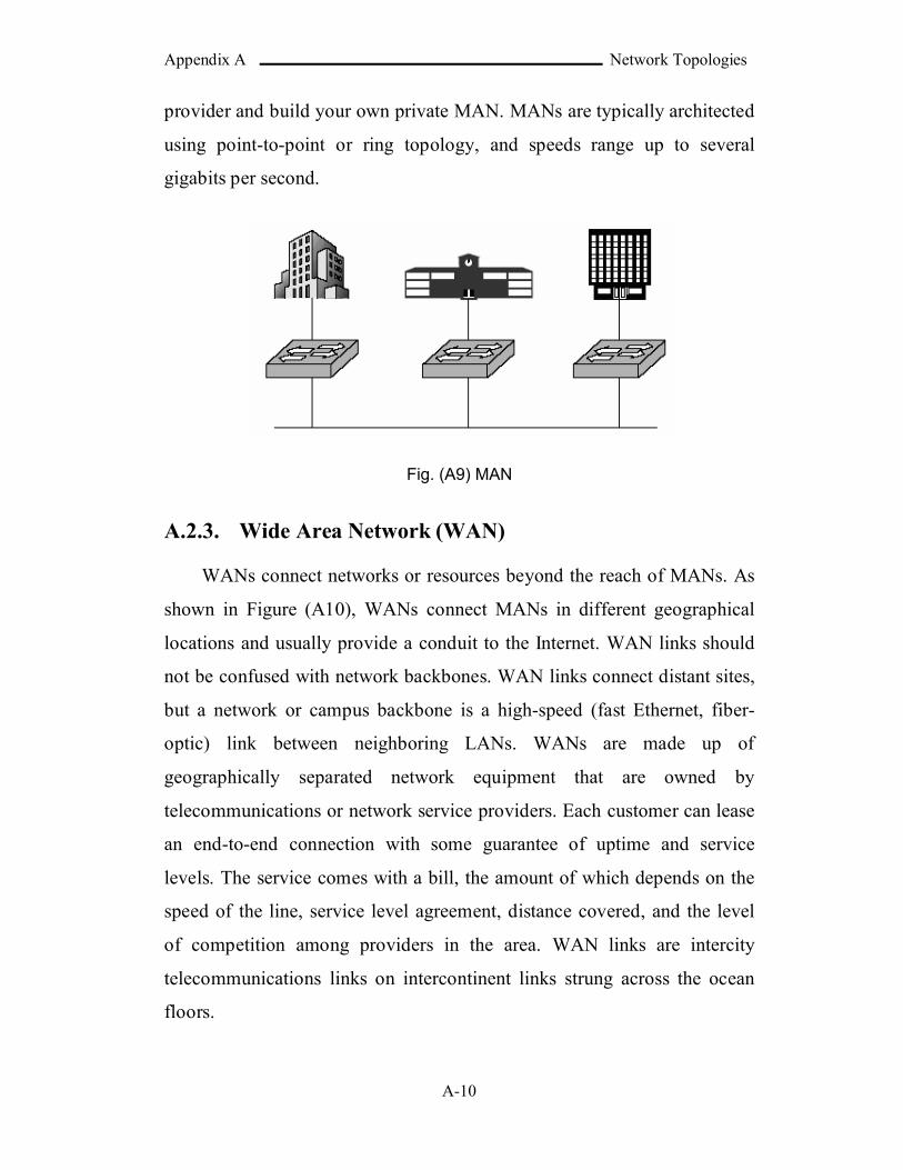
Appendix A Network Topologies
A-10
provider and build your own private MAN. MANs are typically architected
using point-to-point or ring topology, and speeds range up to several
gigabits per second.
Fig. (A9) MAN
A.2.3. Wide Area Network (WAN)
WANs connect networks or resources beyond the reach of MANs. As
shown in Figure (A10), WANs connect MANs in different geographical
locations and usually provide a conduit to the Internet. WAN links should
not be confused with network backbones. WAN links connect distant sites,
but a network or campus backbone is a high-speed (fast Ethernet, fiber-
optic) link between neighboring LANs. WANs are made up of
geographically separated network equipment that are owned by
telecommunications or network service providers. Each customer can lease
an end-to-end connection with some guarantee of uptime and service
levels. The service comes with a bill, the amount of which depends on the
speed of the line, service level agreement, distance covered, and the level
of competition among providers in the area. WAN links are intercity
telecommunications links on intercontinent links strung across the ocean
floors.
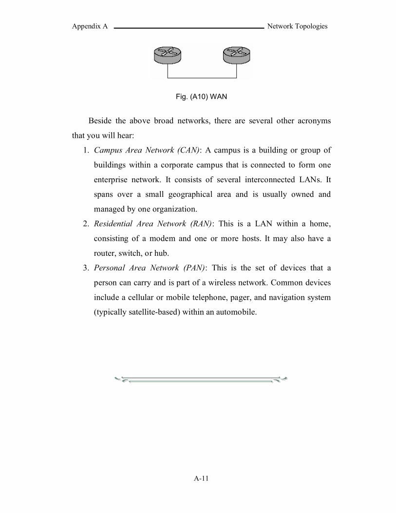
Appendix A Network Topologies
A-11
Fig. (A10) WAN
Beside the above broad networks, there are several other acronyms
that you will hear:
1. Campus Area Network (CAN): A campus is a building or group of
buildings within a corporate campus that is connected to form one
enterprise network. It consists of several interconnected LANs. It
spans over a small geographical area and is usually owned and
managed by one organization.
2. Residential Area Network (RAN): This is a LAN within a home,
consisting of a modem and one or more hosts. It may also have a
router, switch, or hub.
3. Personal Area Network (PAN): This is the set of devices that a
person can carry and is part of a wireless network. Common devices
include a cellular or mobile telephone, pager, and navigation system
(typically satellite-based) within an automobile.

Appendix B SNMP Message
B-1
APPENDIX B
SNMP MessageThe following sections describe the SNMP version 1 and 3 formats.
The sign "--" indicates that the text following the sign is comment.
B.1 SNMPv1 [RFC1157]
SNMPv1 DEFINITIONS ::= BEGIN
IMPORTS ObjectName, ObjectSyntax, NetworkAddress, IpAddress, TimeTicks FROM RFC1155-SMI;
-- top-level message
Message ::= SEQUENCE {
version -- version-1 INTEGER {
version-1(0)},
community -- community nameOCTET STRING,
data -- e.g., PDUs if trivialANY -- authentication is being used
}
-- protocol data units
PDUs ::=CHOICE {
get-requestGetRequest-PDU,
get-next-requestGetNextRequest-PDU,
get-responseGetResponse-PDU,
set-requestSetRequest-PDU,
trapTrap-PDU
}

Appendix B SNMP Message
B-2
-- PDUs
GetRequest-PDU ::=[0]
IMPLICIT PDU
GetNextRequest-PDU ::=[1]
IMPLICIT PDU
GetResponse-PDU ::=[2]
IMPLICIT PDU
SetRequest-PDU ::=[3]
IMPLICIT PDU
PDU ::=SEQUENCE {
request-idINTEGER,
error-status -- sometimes ignoredINTEGER {
noError(0),tooBig(1),noSuchName(2),badValue(3),readOnly(4),genErr(5)
},
error-index -- sometimes ignoredINTEGER,
variable-bindings -- values are sometimes ignoredVarBindList
}
Trap-PDU ::=[4]
IMPLICIT SEQUENCE {enterprise -- type of object generating
-- trap, see sysObjectID in [5]
OBJECT IDENTIFIER,agent-addr -- address of object generating
NetworkAddress, -- trap
generic-trap -- generic trap typeINTEGER {
coldStart(0),warmStart(1),
Appendix B SNMP Message
B-3
linkDown(2),linkUp(3),authenticationFailure(4),egpNeighborLoss(5),enterpriseSpecific(6)
},
specific-trap -- specific code, present evenINTEGER, -- if generic-trap is not enterpriseSpecific
time-stamp -- time elapsed between the lastTimeTicks, -- (re)initialization of the network
-- entity and the generation of the trap
variable-bindings -- "interesting" informationVarBindList
}
-- variable bindings
VarBind ::=SEQUENCE {
nameObjectName,
valueObjectSyntax
}VarBindList ::=
SEQUENCE OFVarBind
END
B.2 SNMPv3 [RFC2572]
SNMPv3MessageSyntax DEFINITIONS IMPLICIT TAGS ::= BEGIN
SNMPv3Message ::= SEQUENCE {msgVersion INTEGER ( 0 .. 2147483647 ), -- the value 3 is used for snmpv3msgGlobalData HeaderData, -- administrative parametersmsgSecurityParameters OCTET STRING, -- security model-specific
-- parameters format defined by -- Security Model
msgData ScopedPduData}
HeaderData ::= SEQUENCE {msgID INTEGER (0..2147483647),msgMaxSize INTEGER (484..2147483647),

Appendix B SNMP Message
B-4
msgFlags OCTET STRING (SIZE(1)),-- .... ...1 authFlag-- .... ..1. privFlag-- .... .1.. reportableFlag-- Please observe:-- .... ..00 is OK, means noAuthNoPriv-- .... ..01 is OK, means authNoPriv-- .... ..10 reserved, MUST NOT be used.-- .... ..11 is OK, means authPriv
msgSecurityModel INTEGER (1..2147483647)}
ScopedPduData ::= CHOICE {plaintext ScopedPDU,encryptedPDU OCTET STRING -- encrypted scopedPDU value
}
ScopedPDU ::= SEQUENCE {contextEngineID OCTET STRING,contextName OCTET STRING,data ANY -- e.g., PDUs as defined in [RFC3416]
}END
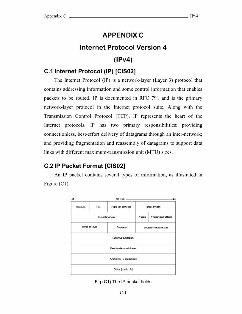
Appendix C IPv4
C-1
APPENDIX C
Internet Protocol Version 4
(IPv4)
C.1 Internet Protocol (IP) [CIS02]
The Internet Protocol (IP) is a network-layer (Layer 3) protocol that
contains addressing information and some control information that enables
packets to be routed. IP is documented in RFC 791 and is the primary
network-layer protocol in the Internet protocol suite. Along with the
Transmission Control Protocol (TCP), IP represents the heart of the
Internet protocols. IP has two primary responsibilities: providing
connectionless, best-effort delivery of datagrams through an inter-network;
and providing fragmentation and reassembly of datagrams to support data
links with different maximum-transmission unit (MTU) sizes.
C.2 IP Packet Format [CIS02]
An IP packet contains several types of information, as illustrated in
Figure (C1).
Fig.(C1) The IP packet fields

Appendix C IPv4
C-2
The Version field indicates the version of IP used. IP Header Length
(IHL) field indicates the datagram header length in 32-bit words. Type-of-
Service field specifies how an upper-layer protocol would like a current
datagram to be handled, and assigns datagrams various levels of
importance. Total Length field specifies the length, in bytes, of the entire IP
packet, including the data and header. Identification field contains an
integer that identifies the current datagram. This field is used to combine
the datagram fragments to the original one. Flags field consists of a 3-bit
field of which the two low-order (least-significant) bits control
fragmentation of the IP datagram. The low-order bit specifies whether the
packet can be fragmented. The middle bit specifies whether the packet is
the last fragment in a series of fragmented packets. The third or high-order
bit is not used. Fragment Offset field indicates the position of the
fragment's data relative to the beginning of the data in the original
datagram, which allows the destination IP process to properly reconstruct
the original datagram. Time-to-Live field maintains a counter that gradually
decrements down to zero, at which point the datagram is discarded. This
keeps packets from looping endlessly. Protocol field indicates which
upper-layer protocol receives incoming packets after IP processing is
completed (for example, this field could refer to the TCP protocol to
receive the packet). Header Checksum field helps to ensure IP header
integrity. Source Address field specifies the sending node. Destination
Address field specifies the receiving node. Options field allows IP to
support various options, such as security. Data field contains upper-layer
information.
C.3 IP Addressing [CIS02]
Each IP address has specific components and follows a basic format.
These IP addresses can be subdivided and used to create addresses for
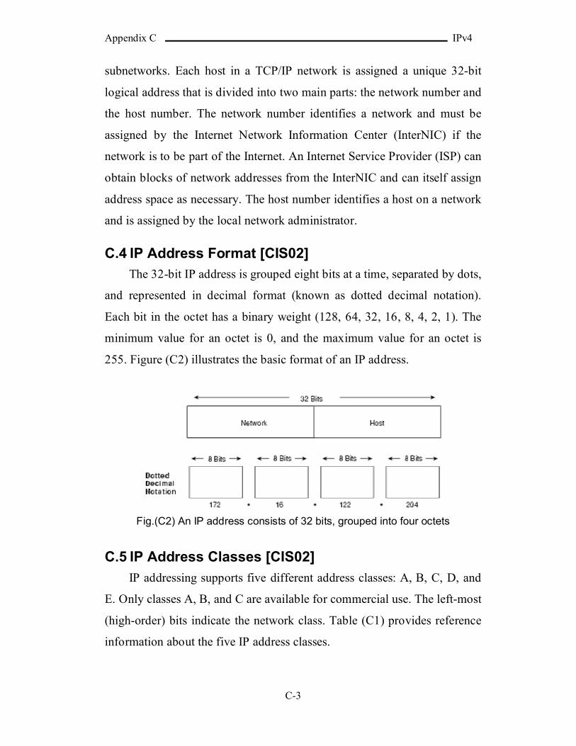
Appendix C IPv4
C-3
subnetworks. Each host in a TCP/IP network is assigned a unique 32-bit
logical address that is divided into two main parts: the network number and
the host number. The network number identifies a network and must be
assigned by the Internet Network Information Center (InterNIC) if the
network is to be part of the Internet. An Internet Service Provider (ISP) can
obtain blocks of network addresses from the InterNIC and can itself assign
address space as necessary. The host number identifies a host on a network
and is assigned by the local network administrator.
C.4 IP Address Format [CIS02]
The 32-bit IP address is grouped eight bits at a time, separated by dots,
and represented in decimal format (known as dotted decimal notation).
Each bit in the octet has a binary weight (128, 64, 32, 16, 8, 4, 2, 1). The
minimum value for an octet is 0, and the maximum value for an octet is
255. Figure (C2) illustrates the basic format of an IP address.
Fig.(C2) An IP address consists of 32 bits, grouped into four octets
C.5 IP Address Classes [CIS02]
IP addressing supports five different address classes: A, B, C, D, and
E. Only classes A, B, and C are available for commercial use. The left-most
(high-order) bits indicate the network class. Table (C1) provides reference
information about the five IP address classes.
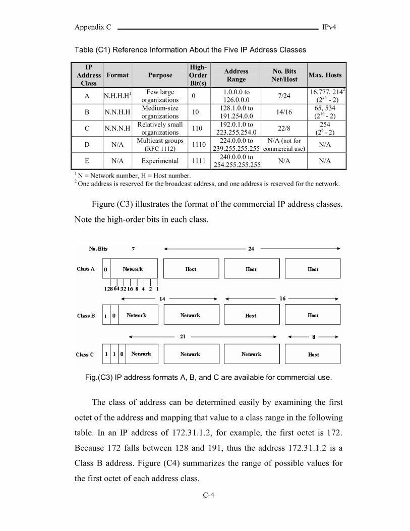
Appendix C IPv4
C-4
Table (C1) Reference Information About the Five IP Address Classes
IP Address
ClassFormat Purpose
High-Order Bit(s)
Address Range
No. Bits Net/Host
Max. Hosts
A N.H.H.H1 Few large organizations
01.0.0.0 to 126.0.0.0
7/2416,777, 2142
(224 - 2)
B N.N.H.HMedium-size organizations
10128.1.0.0 to 191.254.0.0
14/1665, 534(216 - 2)
C N.N.N.HRelatively small
organizations 110
192.0.1.0 to 223.255.254.0
22/8254
(28 - 2)
D N/AMulticast groups
(RFC 1112) 1110
224.0.0.0 to 239.255.255.255
N/A (not for commercial use)
N/A
E N/A Experimental 1111240.0.0.0 to
254.255.255.255N/A N/A
1 N = Network number, H = Host number. 2 One address is reserved for the broadcast address, and one address is reserved for the network.
Figure (C3) illustrates the format of the commercial IP address classes.
Note the high-order bits in each class.
Fig.(C3) IP address formats A, B, and C are available for commercial use.
The class of address can be determined easily by examining the first
octet of the address and mapping that value to a class range in the following
table. In an IP address of 172.31.1.2, for example, the first octet is 172.
Because 172 falls between 128 and 191, thus the address 172.31.1.2 is a
Class B address. Figure (C4) summarizes the range of possible values for
the first octet of each address class.
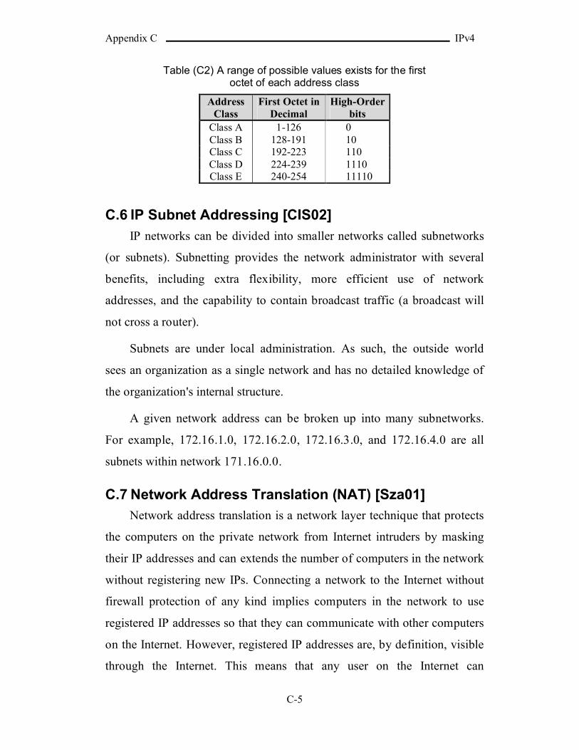
Appendix C IPv4
C-5
Table (C2) A range of possible values exists for the first octet of each address class
Address Class
First Octet in Decimal
High-Order bits
Class A 1-126 0Class B 128-191 10Class C 192-223 110Class D 224-239 1110Class E 240-254 11110
C.6 IP Subnet Addressing [CIS02]
IP networks can be divided into smaller networks called subnetworks
(or subnets). Subnetting provides the network administrator with several
benefits, including extra flexibility, more efficient use of network
addresses, and the capability to contain broadcast traffic (a broadcast will
not cross a router).
Subnets are under local administration. As such, the outside world
sees an organization as a single network and has no detailed knowledge of
the organization's internal structure.
A given network address can be broken up into many subnetworks.
For example, 172.16.1.0, 172.16.2.0, 172.16.3.0, and 172.16.4.0 are all
subnets within network 171.16.0.0.
C.7 Network Address Translation (NAT) [Sza01]
Network address translation is a network layer technique that protects
the computers on the private network from Internet intruders by masking
their IP addresses and can extends the number of computers in the network
without registering new IPs. Connecting a network to the Internet without
firewall protection of any kind implies computers in the network to use
registered IP addresses so that they can communicate with other computers
on the Internet. However, registered IP addresses are, by definition, visible
through the Internet. This means that any user on the Internet can
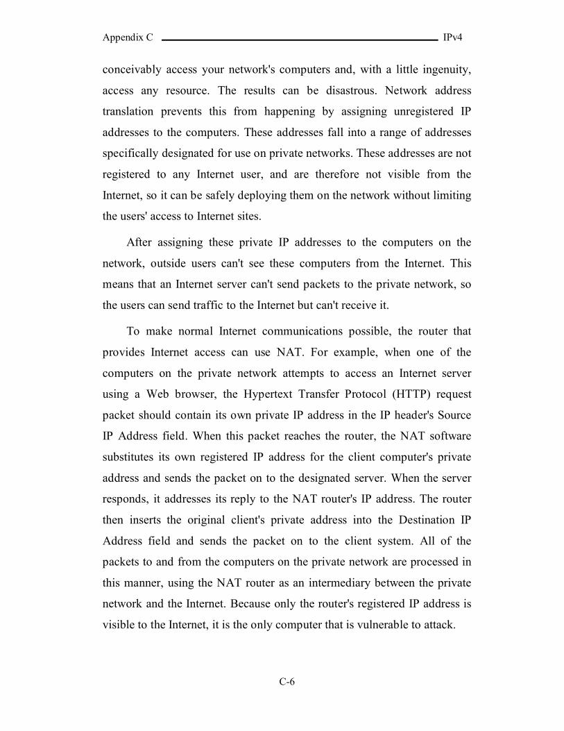
Appendix C IPv4
C-6
conceivably access your network's computers and, with a little ingenuity,
access any resource. The results can be disastrous. Network address
translation prevents this from happening by assigning unregistered IP
addresses to the computers. These addresses fall into a range of addresses
specifically designated for use on private networks. These addresses are not
registered to any Internet user, and are therefore not visible from the
Internet, so it can be safely deploying them on the network without limiting
the users' access to Internet sites.
After assigning these private IP addresses to the computers on the
network, outside users can't see these computers from the Internet. This
means that an Internet server can't send packets to the private network, so
the users can send traffic to the Internet but can't receive it.
To make normal Internet communications possible, the router that
provides Internet access can use NAT. For example, when one of the
computers on the private network attempts to access an Internet server
using a Web browser, the Hypertext Transfer Protocol (HTTP) request
packet should contain its own private IP address in the IP header's Source
IP Address field. When this packet reaches the router, the NAT software
substitutes its own registered IP address for the client computer's private
address and sends the packet on to the designated server. When the server
responds, it addresses its reply to the NAT router's IP address. The router
then inserts the original client's private address into the Destination IP
Address field and sends the packet on to the client system. All of the
packets to and from the computers on the private network are processed in
this manner, using the NAT router as an intermediary between the private
network and the Internet. Because only the router's registered IP address is
visible to the Internet, it is the only computer that is vulnerable to attack.
Appendix C IPv4
C-7
A popular security solution, NAT is implemented in numerous
firewall products, ranging from high-end routers used on large corporate
networks to inexpensive Internet connection-sharing solutions designed for
home and small business networks. In fact, the Internet Connection Sharing
(ICS) feature included with the latest versions of Windows is based on the
principle of NAT.
Also, the NAT can be used to extend the number of computers in the
network without registering new IPs by making the private network
communicates with the Internet through one IP (or more). This facility
serve the need of expanding networks without IP overhead costs resulted
from registering IPs and solves the problem of limited number of available
IPs but on the cost of performance. The degradation of performance is
resulted from the translation process in sending and receiving.
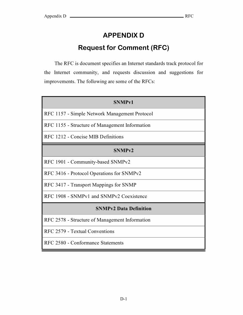
Appendix D RFC
D-1
APPENDIX D
Request for Comment (RFC)
The RFC is document specifies an Internet standards track protocol for
the Internet community, and requests discussion and suggestions for
improvements. The following are some of the RFCs:
SNMPv1
RFC 1157 - Simple Network Management Protocol
RFC 1155 - Structure of Management Information
RFC 1212 - Concise MIB Definitions
SNMPv2
RFC 1901 - Community-based SNMPv2
RFC 3416 - Protocol Operations for SNMPv2
RFC 3417 - Transport Mappings for SNMP
RFC 1908 - SNMPv1 and SNMPv2 Coexistence
SNMPv2 Data Definition
RFC 2578 - Structure of Management Information
RFC 2579 - Textual Conventions
RFC 2580 - Conformance Statements
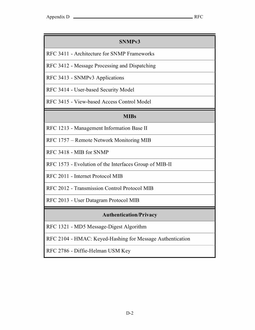
Appendix D RFC
D-2
SNMPv3
RFC 3411 - Architecture for SNMP Frameworks
RFC 3412 - Message Processing and Dispatching
RFC 3413 - SNMPv3 Applications
RFC 3414 - User-based Security Model
RFC 3415 - View-based Access Control Model
MIBs
RFC 1213 - Management Information Base II
RFC 1757 – Remote Network Monitoring MIB
RFC 3418 - MIB for SNMP
RFC 1573 - Evolution of the Interfaces Group of MIB-II
RFC 2011 - Internet Protocol MIB
RFC 2012 - Transmission Control Protocol MIB
RFC 2013 - User Datagram Protocol MIB
Authentication/Privacy
RFC 1321 - MD5 Message-Digest Algorithm
RFC 2104 - HMAC: Keyed-Hashing for Message Authentication
RFC 2786 - Diffie-Helman USM Key

Appendix E Agent MIB Definitions
E-1
APPENDIX E
Agent MIB Definitions
Fig.(E.1) Shows the OID tree of the MIBs
PubMgmt OBJECT IDENTIFIER ::= { ISO(1) Organization(3) DoD(6) Internet(1) Experimental(3) 17 }
ElectricitySrvc OBJECT IDENTIFIER ::= { PubMgmt 1 }
EService OBJECT-TYPE SYNTAX INTEGER (SIZE (0..1))ACCESS read-writeSTATUS mandatoryDESCRIPTION “ ; It shows if the electricity power measurement and
maintenance service is supported or not. 0--> Service Not Supported, 1--> Service supported.”
::= { ElectricitySrvc 1 }
Experimental (3)
ISO (1)
Organization (3)
DoD (6)
Internet (1)
PubMgmt (17)
Addresses(10)
ElectricitySrvc(1)
FireSrvc (3)
WaterSrvc(2)
SecuritySrvc(4)
TrapConfig (6)
Time (9)Counters (7)
SecurityConfig(8)
MedicalSrvc (5)

Appendix E Agent MIB Definitions
E-2
EMeasure OBJECT-TYPE SYNTAX INTEGER (SIZE (0..2^32-1))ACCESS read-onlySTATUS optionalDESCRIPTION “ ; It holds the electricity meter last reading.”
::= { ElectricitySrvc 2 }
EResponse OBJECT-TYPE SYNTAX INTEGER (SIZE (2^32-2..2^32-1))ACCESS read-onlySTATUS optionalDESCRIPTION “ ; It holds the condition of the electricity meter, if it is
responding or not.”::= { ElectricitySrvc 3 }
EStopTrap OBJECT-TYPE SYNTAX INTEGER (SIZE (0..1))ACCESS read-writeSTATUS optionalDESCRIPTION “ ; It indicates whether to stop sending electricity traps or
not. 0 for send traps and 1 for don’t send.”::= { ElectricitySrvc 4 }
WaterSrvc OBJECT IDENTIFIER ::= { PubMgmt 2 }
WService OBJECT-TYPE SYNTAX INTEGER (SIZE (0..1))ACCESS read-writeSTATUS mandatoryDESCRIPTION “ ; It shows if the water flow measurement and
maintenance service is supported or not. 0--> Service Not Supported, 1--> Service supported”
::= { WaterSrvc 1 }
WMeasure OBJECT-TYPE SYNTAX INTEGER (SIZE (0..2^32-1))ACCESS read-onlySTATUS optionalDESCRIPTION “ ; It holds the water meter last reading.”
::= { WaterSrvc 2 }
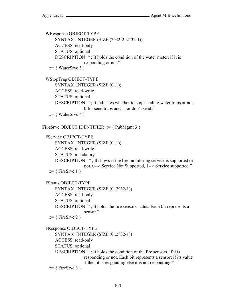
Appendix E Agent MIB Definitions
E-3
WResponse OBJECT-TYPE SYNTAX INTEGER (SIZE (2^32-2..2^32-1))ACCESS read-onlySTATUS optionalDESCRIPTION “ ; It holds the condition of the water meter, if it is
responding or not.”::= { WaterSrvc 3 }
WStopTrap OBJECT-TYPE SYNTAX INTEGER (SIZE (0..1))ACCESS read-writeSTATUS optionalDESCRIPTION “ ; It indicates whether to stop sending water traps or not.
0 for send traps and 1 for don’t send.”::= { WaterSrvc 4 }
FireSrvc OBJECT IDENTIFIER ::= { PubMgmt 3 }
FService OBJECT-TYPE SYNTAX INTEGER (SIZE (0..1))ACCESS read-writeSTATUS mandatoryDESCRIPTION “ ; It shows if the fire monitoring service is supported or
not. 0--> Service Not Supported, 1--> Service supported.”::= { FireSrvc 1 }
FStatus OBJECT-TYPE SYNTAX INTEGER (SIZE (0..2^32-1))ACCESS read-onlySTATUS optionalDESCRIPTION “ ; It holds the fire sensors status. Each bit represents a
sensor.”::= { FireSrvc 2 }
FResponse OBJECT-TYPE SYNTAX INTEGER (SIZE (0..2^32-1))ACCESS read-onlySTATUS optionalDESCRIPTION “ ; It holds the condition of the fire sensors, if it is
responding or not. Each bit represents a sensor; if its value 1 then it is responding else it is not responding.”
::= { FireSrvc 3 }
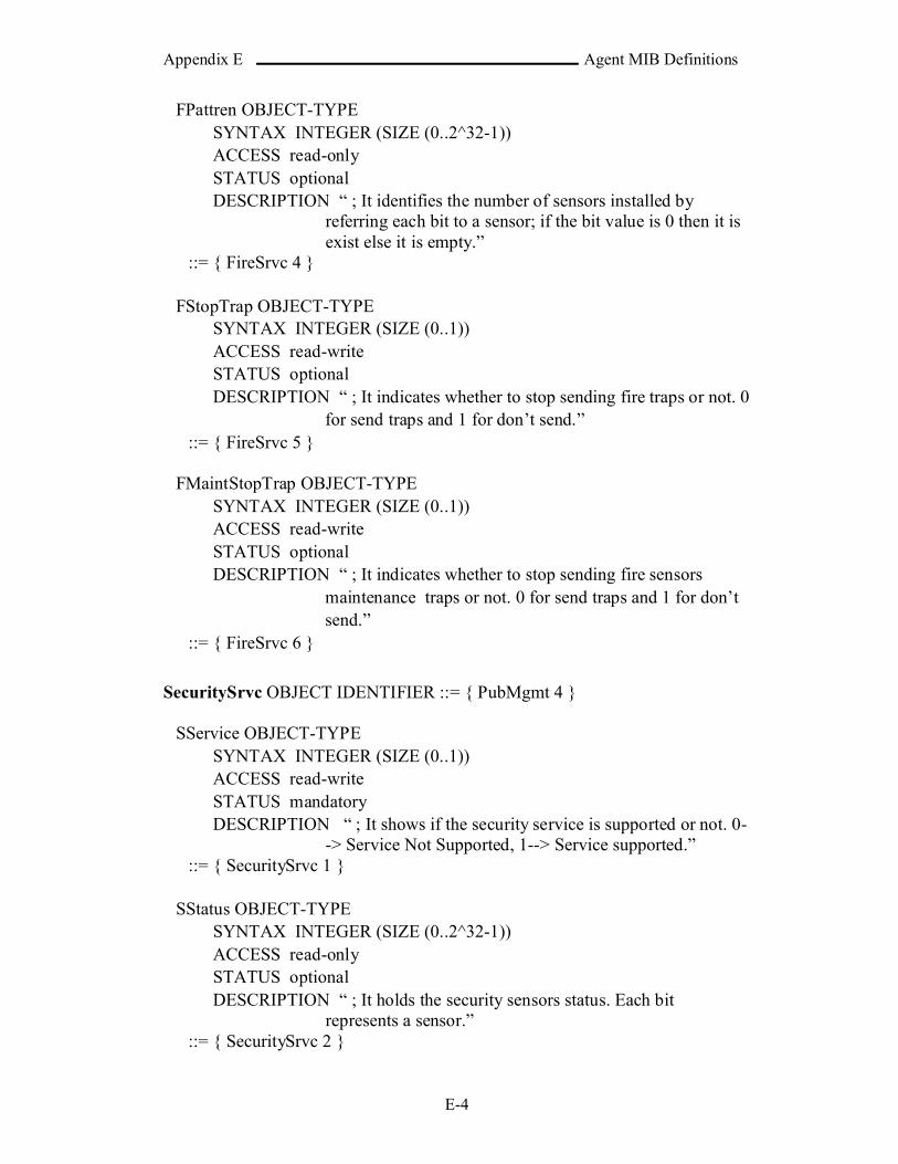
Appendix E Agent MIB Definitions
E-4
FPattren OBJECT-TYPE SYNTAX INTEGER (SIZE (0..2^32-1))ACCESS read-onlySTATUS optionalDESCRIPTION “ ; It identifies the number of sensors installed by
referring each bit to a sensor; if the bit value is 0 then it is exist else it is empty.”
::= { FireSrvc 4 }
FStopTrap OBJECT-TYPE SYNTAX INTEGER (SIZE (0..1))ACCESS read-writeSTATUS optionalDESCRIPTION “ ; It indicates whether to stop sending fire traps or not. 0
for send traps and 1 for don’t send.”::= { FireSrvc 5 }
FMaintStopTrap OBJECT-TYPE SYNTAX INTEGER (SIZE (0..1))ACCESS read-writeSTATUS optionalDESCRIPTION “ ; It indicates whether to stop sending fire sensors
maintenance traps or not. 0 for send traps and 1 for don’t send.”
::= { FireSrvc 6 }
SecuritySrvc OBJECT IDENTIFIER ::= { PubMgmt 4 }
SService OBJECT-TYPE SYNTAX INTEGER (SIZE (0..1))ACCESS read-writeSTATUS mandatoryDESCRIPTION “ ; It shows if the security service is supported or not. 0-
-> Service Not Supported, 1--> Service supported.”::= { SecuritySrvc 1 }
SStatus OBJECT-TYPE SYNTAX INTEGER (SIZE (0..2^32-1))ACCESS read-onlySTATUS optionalDESCRIPTION “ ; It holds the security sensors status. Each bit
represents a sensor.”::= { SecuritySrvc 2 }

Appendix E Agent MIB Definitions
E-5
SResponse OBJECT-TYPE SYNTAX INTEGER (SIZE (0..2^32-1))ACCESS read-onlySTATUS optionalDESCRIPTION “ ; It holds the condition of the security sensors, if it is
responding or not. Each bit represents a sensor; if its value 1 then it is responding else it is not responding.”
::= { SecuritySrvc 3 }
SPattren OBJECT-TYPE SYNTAX INTEGER (SIZE (0..2^32-1))ACCESS read-onlySTATUS optionalDESCRIPTION “ ; It identifies the number of sensors installed by
referring each bit to a sensor; if the bit value is 0 then it is exist else it is empty.”
::= { SecuritySrvc 4 }
SStopTrap OBJECT-TYPE SYNTAX INTEGER (SIZE (0..1))ACCESS read-writeSTATUS optionalDESCRIPTION “ ; It indicates whether to stop sending security traps or
not. 0 for send traps and 1 for don’t send.”::= { SecuritySrvc 5 }
SMaintStopTrap OBJECT-TYPE SYNTAX INTEGER (SIZE (0..1))ACCESS read-writeSTATUS optionalDESCRIPTION “ ; It indicates whether to stop sending security sensors
maintenance traps or not. 0 for send and 1 for don’t send.”::= { SecuritySrvc 6 }
MedicalSrvc OBJECT IDENTIFIER ::= { PubMgmt 5 }
MStopTrap OBJECT-TYPE SYNTAX INTEGER (SIZE (0..1))ACCESS read-writeSTATUS optionalDESCRIPTION “ ; It indicates whether to stop sending medical help
traps or not. 0 for send traps and 1 for don’t send.”::= { MedicalSrvc 1 }

Appendix E Agent MIB Definitions
E-6
TrapConfig OBJECT IDENTIFIER ::= { PubMgmt 6 }
NoOfTimesToSendTraps OBJECT-TYPE SYNTAX INTEGER (SIZE (1..255))ACCESS read-writeSTATUS mandatoryDESCRIPTION “ ; It is the number of times to send the traps to decrease
the possibility of not receiving the trap by the zone center.”
::= { TrapConfig 1 }
TimeDelayOfHighTraps OBJECT-TYPE SYNTAX INTEGER (SIZE (1..2^15-1))ACCESS read-writeSTATUS mandatoryDESCRIPTION “ ; It is the delay time between sending a group of high
priority traps and another in seconds.”::= { TrapConfig 2 }
TimeDelayOfLowTraps OBJECT-TYPE SYNTAX INTEGER (SIZE (1..2^15-1))ACCESS read-writeSTATUS mandatoryDESCRIPTION “ ; It is the delay time between sending a group of high
priority traps and another in seconds.”::= { TrapConfig 3 }
Counters OBJECT IDENTIFIER ::= { PubMgmt 7 }
NoOfTimesStarted OBJECT-TYPE SYNTAX COUNTER16ACCESS read-onlySTATUS mandatoryDESCRIPTION “ ; It holds the number of times the agent started.”
::= { Counters 1 }
NoOfTimesShutdown OBJECT-TYPE SYNTAX COUNTER16ACCESS read-onlySTATUS mandatoryDESCRIPTION “ ; It holds the number of times the agent shut downed.”
::= { Counters 2 }

Appendix E Agent MIB Definitions
E-7
NoOfTimesAuthenticationFailure OBJECT-TYPE SYNTAX COUNTER16ACCESS read-onlySTATUS mandatoryDESCRIPTION “ ; It holds the number of times that received
unauthenticated message.”::= { Counters 3 }
NoOfTimesAuthenticationFailureByTime OBJECT-TYPE SYNTAX COUNTER16ACCESS read-onlySTATUS mandatoryDESCRIPTION “ ; It holds the number of times that received
unauthenticated message because of the time.”::= { Counters 4 }
NoOfTimesElectMaintTrap OBJECT-TYPE SYNTAX COUNTER16ACCESS read-onlySTATUS mandatoryDESCRIPTION “ ; It holds the number of times that a need to electricity
maintenance was detected and then generated electricity maintenance trap.”
::= { Counters 5 }
NoOfTimesElectMaintTrapManual OBJECT-TYPE SYNTAX COUNTER16ACCESS read-onlySTATUS mandatoryDESCRIPTION “; It holds the number of times that a need to electricity
maintenance was manually requested and then an electricity maintenance trap was generated.”
::= { Counters 6 }
NoOfTimesWaterMaintTrap OBJECT-TYPE SYNTAX COUNTER16ACCESS read-onlySTATUS mandatoryDESCRIPTION “ ; It holds the number of times that a need to water
maintenance was detected and then generated water maintenance trap.”
::= { Counters 7 }
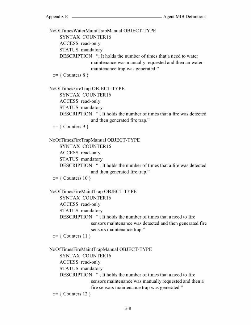
Appendix E Agent MIB Definitions
E-8
NoOfTimesWaterMaintTrapManual OBJECT-TYPE SYNTAX COUNTER16ACCESS read-onlySTATUS mandatoryDESCRIPTION “; It holds the number of times that a need to water
maintenance was manually requested and then an water maintenance trap was generated.”
::= { Counters 8 }
NoOfTimesFireTrap OBJECT-TYPE SYNTAX COUNTER16ACCESS read-onlySTATUS mandatoryDESCRIPTION “ ; It holds the number of times that a fire was detected
and then generated fire trap.”::= { Counters 9 }
NoOfTimesFireTrapManual OBJECT-TYPE SYNTAX COUNTER16ACCESS read-onlySTATUS mandatoryDESCRIPTION “ ; It holds the number of times that a fire was detected
and then generated fire trap.”::= { Counters 10 }
NoOfTimesFireMaintTrap OBJECT-TYPE SYNTAX COUNTER16ACCESS read-onlySTATUS mandatoryDESCRIPTION “ ; It holds the number of times that a need to fire
sensors maintenance was detected and then generated fire sensors maintenance trap.”
::= { Counters 11 }
NoOfTimesFireMaintTrapManual OBJECT-TYPE SYNTAX COUNTER16ACCESS read-onlySTATUS mandatoryDESCRIPTION “ ; It holds the number of times that a need to fire
sensors maintenance was manually requested and then a fire sensors maintenance trap was generated.”
::= { Counters 12 }
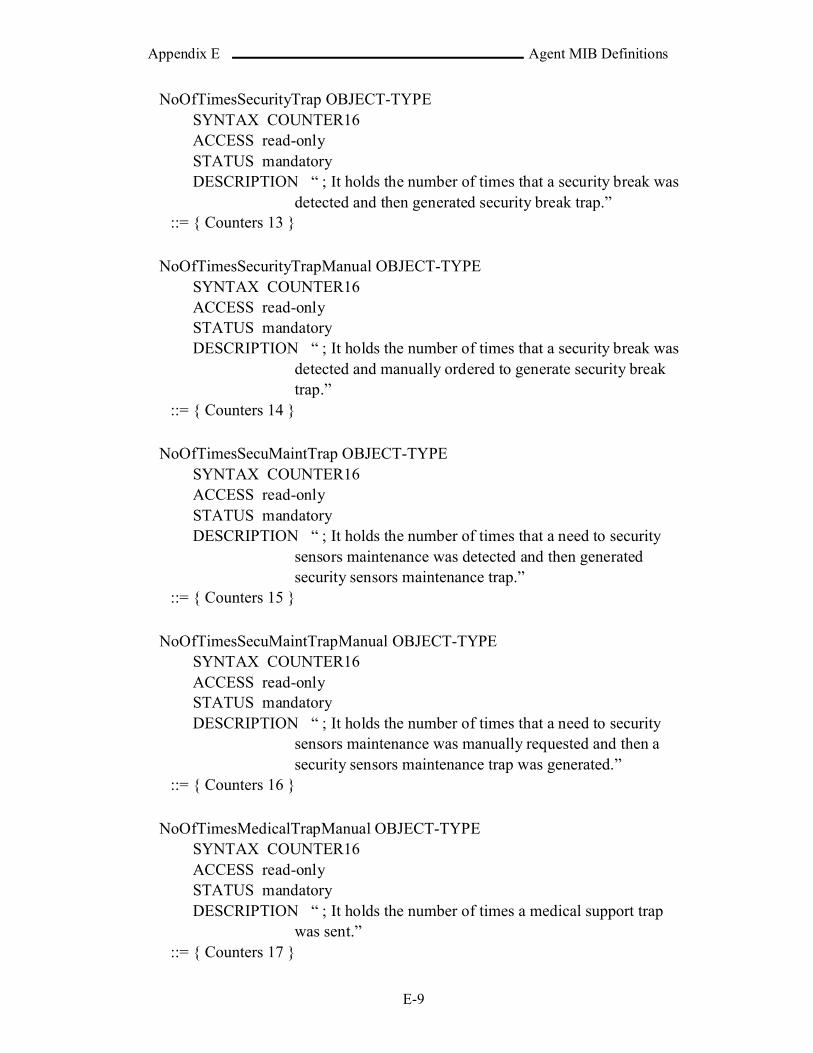
Appendix E Agent MIB Definitions
E-9
NoOfTimesSecurityTrap OBJECT-TYPE SYNTAX COUNTER16ACCESS read-onlySTATUS mandatoryDESCRIPTION “ ; It holds the number of times that a security break was
detected and then generated security break trap.”::= { Counters 13 }
NoOfTimesSecurityTrapManual OBJECT-TYPE SYNTAX COUNTER16ACCESS read-onlySTATUS mandatoryDESCRIPTION “ ; It holds the number of times that a security break was
detected and manually ordered to generate security breaktrap.”
::= { Counters 14 }
NoOfTimesSecuMaintTrap OBJECT-TYPE SYNTAX COUNTER16ACCESS read-onlySTATUS mandatoryDESCRIPTION “ ; It holds the number of times that a need to security
sensors maintenance was detected and then generated security sensors maintenance trap.”
::= { Counters 15 }
NoOfTimesSecuMaintTrapManual OBJECT-TYPE SYNTAX COUNTER16ACCESS read-onlySTATUS mandatoryDESCRIPTION “ ; It holds the number of times that a need to security
sensors maintenance was manually requested and then a security sensors maintenance trap was generated.”
::= { Counters 16 }
NoOfTimesMedicalTrapManual OBJECT-TYPE SYNTAX COUNTER16ACCESS read-onlySTATUS mandatoryDESCRIPTION “ ; It holds the number of times a medical support trap
was sent.”::= { Counters 17 }

Appendix E Agent MIB Definitions
E-10
NoOfTimesPUBLICKeyChange OBJECT-TYPE SYNTAX COUNTER16ACCESS read-onlySTATUS mandatoryDESCRIPTION “ ; It holds the number of times that received
unauthenticated message.”::= { Counters 18 }
NoOfTimesPOWERKeyChange OBJECT-TYPE SYNTAX COUNTER16ACCESS read-onlySTATUS mandatoryDESCRIPTION = “ ; It holds the number of times that the POWER
community key had been changed.”::= { Counters 19}
NoOfTimesADMINISTRATORKeyChange OBJECT-TYPE SYNTAX COUNTER16ACCESS read-onlySTATUS mandatoryDESCRIPTION = “ ; It holds the number of times that the
ADMINISTRATOR community key had been changed.”::= { Counters 20 }
NoOfTimesMessageKeyChange OBJECT-TYPE SYNTAX COUNTER16ACCESS read-onlySTATUS mandatoryDESCRIPTION = “ ; It holds the number of times that the message
encryption key had been changed.”::= { Counters 21 }
NoOfTimesLocalKeyChange OBJECT-TYPE SYNTAX COUNTER16ACCESS read-onlySTATUS mandatoryDESCRIPTION = “ ; It holds the number of times that the local key for
encryption had been changed.”::= { Counters 22 }
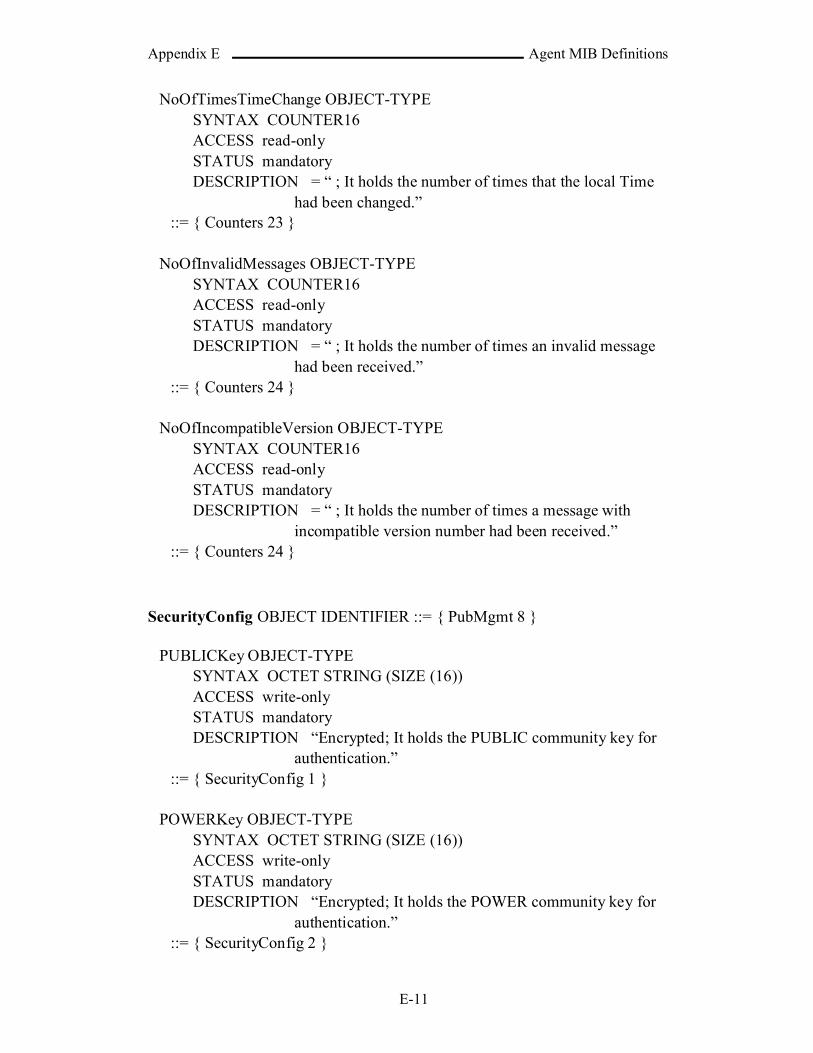
Appendix E Agent MIB Definitions
E-11
NoOfTimesTimeChange OBJECT-TYPE SYNTAX COUNTER16ACCESS read-onlySTATUS mandatoryDESCRIPTION = “ ; It holds the number of times that the local Time
had been changed.”::= { Counters 23 }
NoOfInvalidMessages OBJECT-TYPE SYNTAX COUNTER16ACCESS read-onlySTATUS mandatoryDESCRIPTION = “ ; It holds the number of times an invalid message
had been received.”::= { Counters 24 }
NoOfIncompatibleVersion OBJECT-TYPE SYNTAX COUNTER16ACCESS read-onlySTATUS mandatoryDESCRIPTION = “ ; It holds the number of times a message with
incompatible version number had been received.”::= { Counters 24 }
SecurityConfig OBJECT IDENTIFIER ::= { PubMgmt 8 }
PUBLICKey OBJECT-TYPE SYNTAX OCTET STRING (SIZE (16))ACCESS write-onlySTATUS mandatoryDESCRIPTION “Encrypted; It holds the PUBLIC community key for
authentication.”::= { SecurityConfig 1 }
POWERKey OBJECT-TYPE SYNTAX OCTET STRING (SIZE (16))ACCESS write-onlySTATUS mandatoryDESCRIPTION “Encrypted; It holds the POWER community key for
authentication.”::= { SecurityConfig 2 }

Appendix E Agent MIB Definitions
E-12
ADMINISTRATORKey OBJECT-TYPE SYNTAX OCTET STRING (SIZE (16))ACCESS write-onlySTATUS mandatoryDESCRIPTION “Encrypted; It holds the ADMINISTRATOR
community key for authentication.”::= { SecurityConfig 3 }
MessageKey OBJECT-TYPE SYNTAX OCTET STRING (SIZE (24))ACCESS write-onlySTATUS mandatoryDESCRIPTION “Encrypted; It holds the key for encrypting message.”
::= { SecurityConfig 4 }
LocalKey OBJECT-TYPE SYNTAX OCTET STRING (SIZE (24))ACCESS write-onlySTATUS mandatoryDESCRIPTION “Virtual; It holds the key for encrypting local data.”
::= { SecurityConfig 5 }
ValidTimePeriod OBJECT-TYPE SYNTAX INTEGER (SIZE (0..2^16))ACCESS read-writeSTATUS mandatoryDESCRIPTION “ ; The maximum time (in seconds) difference between
the receiving and the sending time of message to be stated as a valid.”
::= { SecurityConfig 6 }
Time OBJECT IDENTIFIER ::= { PubMgmt 9 }
LocalDateTime OBJECT-TYPE SYNTAX OCTET STRING (SIZE (8))ACCESS read-writeSTATUS mandatoryDESCRIPTION “Virtual; It holds the local date and time of the agent.”
::= { Time 1 }
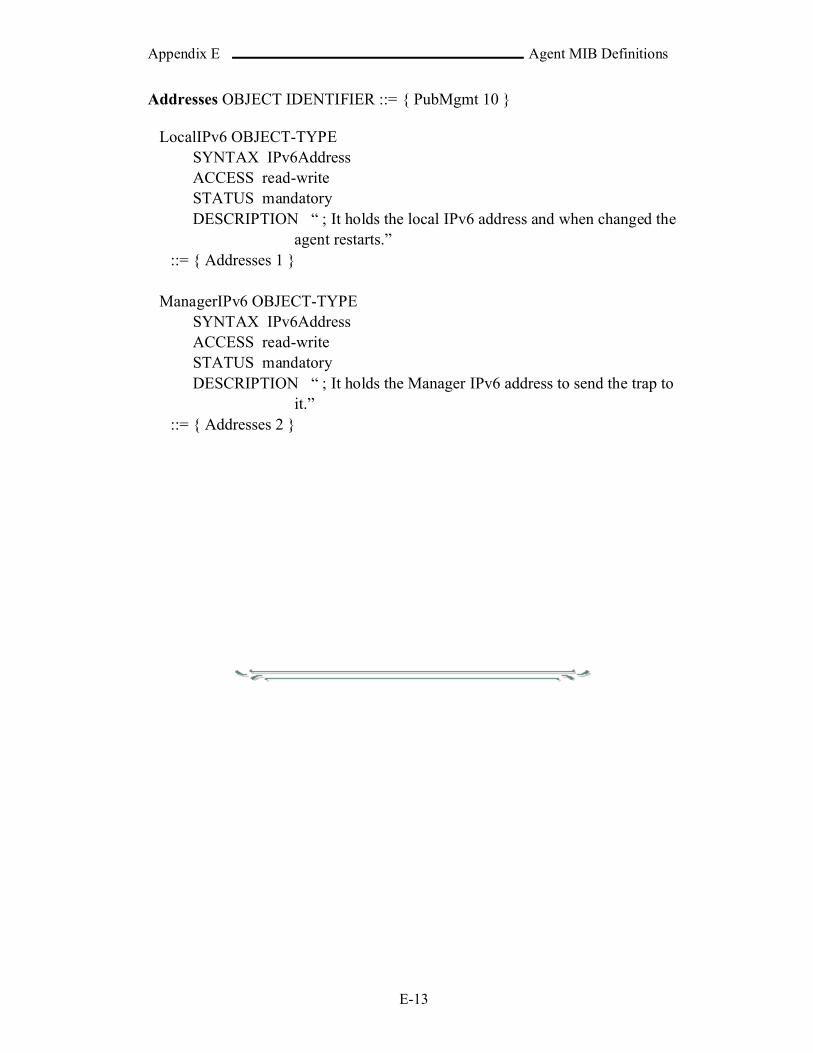
Appendix E Agent MIB Definitions
E-13
Addresses OBJECT IDENTIFIER ::= { PubMgmt 10 }
LocalIPv6 OBJECT-TYPE SYNTAX IPv6AddressACCESS read-writeSTATUS mandatoryDESCRIPTION “ ; It holds the local IPv6 address and when changed the
agent restarts.”::= { Addresses 1 }
ManagerIPv6 OBJECT-TYPE SYNTAX IPv6AddressACCESS read-writeSTATUS mandatoryDESCRIPTION “ ; It holds the Manager IPv6 address to send the trap to
it.”::= { Addresses 2 }

Appendix F Distance Equation Derivation
F-1
APPENDIX F
Distance Equation Derivation
The latitude and longitude lines specify the points on the earth. The
earth are divided into 180 latitude lines with the “equator” (where 90 lines
northern the equator and 90 lines southern equator) and 360 lines longitude
lines with the “meridian” (where 180 lines eastern meridian and 180 lines
western meridian). The points between the lines are specified by minutes
and seconds of arc (i.e. not unit of time) northern or southern a specified
latitude and minutes and seconds of arc eastern or western a specified
longitude. If the earth is considered as a sphere and then the radius of earth
is the radius of the equator R=6378 km. Figure (F1) shows the latitude and
longitude lines.
Fig.(F1) shows the latitude and longitude lines
Calculating the distance between two points (Lat1, Lon1) and (Lat2,
Lon2) on the surface of earth is determined by the following equation:

Appendix F Distance Equation Derivation
F-2
RLonLat
LonLatLonLat
LonLatLatLatDist
*))2sin(*)2cos(*
)1sin(*)1cos()2cos(*)2cos(*
)1cos(*)1cos()2sin(*)1(arccos(sin
………(F1)
OR can be simplified to:
RLonLon
LatLatLatLatDist
*))21cos(*
)2cos(*)1cos()2sin(*)1(arccos(sin
………(F2)
Where Lat and Lon are in radians and R is the radius of the earth. The
search operation could be slowed if it depends on this equation. Thus,
simpler equation is needed to improve the search operation.
The following section shows the derivation of the distance between
two points in specific region on earth.
First, determine each latitude degree in km. Because that there are 180
latitude lines, the earth is considered as a sphere, and the latitude line is a
circle around the earth (that is the latitude line is cross each vertical circle
around the earth with 2- points, see Figure F2) then:
reekmR
lat
RR
lat
deg317.111180
1
2
2180
Fig.(F2) shows the latitude lines
Second, determine each longitude degree in km. The distance between
the longitude lines in different latitude lines is varying because the
longitude lines are closed to each other on going far away from the equator

Appendix F Distance Equation Derivation
F-3
(see Figure F3). Thus, the longitude degree would be calculated according
to specific latitude line. Therefore, the final equation would be specific to
some region with center latitude (Latc).
rLon 2360
Where r is radius of the latitude Latc. Then:
)deg(360
cos21
cos2360
reekmscllon
LatcRLon
LatcRLon
………(F3)
Fig.(F3) shows the longitude lines
Now, if the surface of the earth is considered as a plane then the
distance between the two points can be calculated by using the normal
distance formula, which is:
22 )21()21(Distance XXYY ………(F4)
Let p1 is a point on region a (where the Latc is the latitude of the a’s
center point) and composed of (Lat1, Lon1) and p2 is a point on the same
region and composed of (Lat2, Lon2) then:
kmRLonLonD xx *12 ………(F5)
kmRLatLatD yy *21 ………(F6)
Distance = )(22 kmDD xy ………(F7)
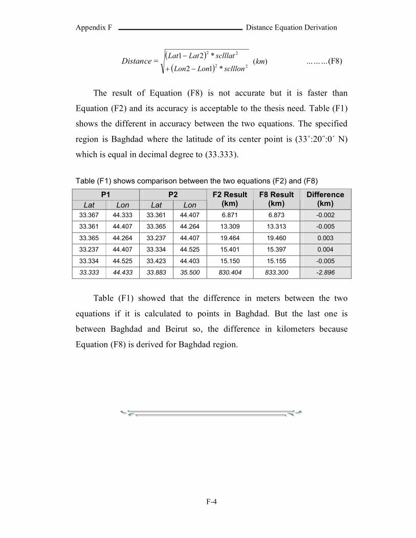
Appendix F Distance Equation Derivation
F-4
Distance =
)(*12
*2122
22
kmsclllonLonLon
sclllatLatLat
………(F8)
The result of Equation (F8) is not accurate but it is faster than
Equation (F2) and its accuracy is acceptable to the thesis need. Table (F1)
shows the different in accuracy between the two equations. The specified
region is Baghdad where the latitude of its center point is (33˚:20˝:0΄ N)
which is equal in decimal degree to (33.333).
Table (F1) shows comparison between the two equations (F2) and (F8)
P1 P2Lat Lon Lat Lon
F2 Result (km)
F8 Result (km)
Difference (km)
33.367 44.333 33.361 44.407 6.871 6.873 -0.002
33.361 44.407 33.365 44.264 13.309 13.313 -0.005
33.365 44.264 33.237 44.407 19.464 19.460 0.003
33.237 44.407 33.334 44.525 15.401 15.397 0.004
33.334 44.525 33.423 44.403 15.150 15.155 -0.005
33.333 44.433 33.883 35.500 830.404 833.300 -2.896
Table (F1) showed that the difference in meters between the two
equations if it is calculated to points in Baghdad. But the last one is
between Baghdad and Beirut so, the difference in kilometers because
Equation (F8) is derived for Baghdad region.

!! !!!!!!
!!!!!!!! !!!!!!!!!!!!!¿!!!! !!!!!!!! !!!!!!!!» !!!!!!!!!¿!! !!!!!! !!!!!!!!! !» ! !!!!!!!» ! !!!!!» !
!!!!!!!!!!! ! !! !!!!!!!!!!!! !!!! !!!!!! !!! !!!! !!!!!!!!!!!!!!!!! !!!!!! !!!!!!! !!!!!!!!!!!!!!!!!!!» !!!!¿» !!
!!! !! !!!!! ! !! !!!!!!!!! !!!!!!!! !!!!!! !¿!!! !!!! ! !!!! !!!!!!!!
!!!!!!!!!! !!!!!! !!!!!!!!!!!!!!! !!!!!!!!! !!!!!!! !!! !!!!!! !!!» ! !!!!! !!!!!» !! !!!!! !!!!!
!!!!!!!!!!!!!!!!! !!!!!!!!! !!!!!! ! !!!!!!!!! !!!!!!! !!!!!!!! !!!!! !!!!!!! !!!!!!! !!! !!!!!!!!!!» ! !!!!» !
!!!!!!!! !!!!!!!!!!!!!! !!!!!!!! ! !!!!!!!! !!!!!!!!! ! !!!!!!!!!!!!!!!!! !! !!!!!!!!!!!!!!!!!!!!!!!!!!» ! !!!!!!!
!!!!!!!!¿! !!!!!! !!!!!!!!!!!!!!!!!!!!!! !!!!!!!! ! ! !!!!! !!!!!¿!!!!!!!!!!! !!!! !! !!!!!!!!!!!!!!!! !!!
!!!!!! ! !!!!!!!!!!!! !!!!! !!!!!!! !!!!!!!! !! !!!!! !!!!! !!!!!!!! !! !!!! !!!!!!!!!!!
!!!!!!!!!! !!! ! ! !! ! !! !!!! !! !!!!!!!!!! !!! !!!! ! ! ! !! !!! !!!!!! ! !!!!!!!» !!!¿!!!!!!!!!!!! !! » !!!
!!!!!!!!! !!!! !! !!!!!!!!!! !! !!!!!!!!! !!!!!! !! !! !!!!!!!!!!! !!!!!!! !!!!!!!!!! !! » !!!!» ! !!!!!!!!!!! ! !!
!!!!! !!!!!!!!zones!!!!!!!!!!!!! !!!!!! !! !!!!!!¿!!!!!!! !! !!!!!! » !! !!!» !!!! !!!!!!!!!!!!¿» !
!!!! !!!!!! !!!!!! !!!!!!!!!! ! !!!!!!!!!!network management station!!!!!! » !! !!!!!» !
!!!! !!!!!zone center!!!!!!!!! !!! !!!!!! !!!!!!!!!! !! !!!!!!!!!!!!!!!! ! !!!!!!!!!!!! » !!!!!!
!!! !! !!!!!!!!!! ! !!!!!¿!!!!!!!!!!!!! !!!!! !!!!!!!!! !!!!!!! !!! !!¿!!!!!!!» !!!!!! ! !!!!!!! !!!!!» !!!
! !!! !!!!!!!!!!!!!!!!!!!!! !!! !! !! !!!primary center!!!!!!!!!!! !!! !!!! !! !!!!!!!!!!!!! !
!!¿! !!!!!!!!!!!!!!!!!!!!!!!!! » !!! !!!» !!!! » !!!!¿!» !!! !!!!! !!!!!!!! !!!¿!!!!!!!!!!!!!!!! !!!!!!! !!! !
!! !!!!!!!!
!!!!!! !!!!!!! !!!!!!!!! !! ! !!! !! !!!!!!!! !! !!!!!!!! !!!!¿!! !!!!! !!! !!!! !!!!!!!!!!! » !!!!!!!» !
!!!!!!!!!!!!!!!» !!!!!» !!!!!!!! !! !!!!!!!! !! !!!!!!!!!!!! !! !!¿!!!!!! !!!!!!!!! !!!!!!!!! !!!! ! !!!!! !! !
!!!!!!!!!!!!!!!!!!!!! !!!!!!!!!!!! !! !!!cluster of computers!!!!!!!!» !!!!!!!! » !! !!¿» !!! » !
!!!!! !!!!!!!!! ! !!!!!!!!!!!!!!!!!!!!! !!!! !!!!!!!!¿!! !!!!!!! !!!!!!! !!» !!!!! !!!!!!!!!!!!!!!!!! » !!!!

!!!!!!!!!! !!!!!!!!!!!!!!!! !! !!!!!!!!!!!!!!! !!!!!!!!!!!!¿!!! !!anycast!!!!!!!!! !» !!!!!!!! !!!!¿!!!!! !!!
!clusters!!!!! !!! !! !! !!!!!!!!!!!! !!!!! !!!!! !! !!!! !! !!!! ! !! ! ! !! !!!!!!!!!¿!!!!! !!! !! !!!! !!! !! !! !!!!
!!!IPV6!!!!!!!!!!!!! !!! !! !! !!!!SNMPV2!!!!!!!! !» !!!!! !!!!!!¿!!! !!! ! !!!!!! ! !!! !!!!!¿! !! » !!
!!!! !!bandwidth!!!!¿!!!!!!!!!!!!! !!!!!!!!!!!!!!!!!!!!!!!!!!!!!!!!
!!!!!!!!!!!!! !!!!!!!!!!!! !!!! !!!!!!!!!!!! ! !!!!! !!! !!!!! !!!!!!!!!!!! !!!!!» !!!¿!» ! !!!!! !!!!!!!!¿!!!
!!!!! !! !!!¿!!!!!multi-threaded system!!!!!! !!!!!! !! !!!!!!!! !!!!!!!! !!!!!MS Visual
Basic net 2003!!!!!!!!!!!!!! !!!!Net frame work!!!!!!!!! » !!! !» !!!multi-threaded
system!!!!! !!!!!!! !!

�������������� ������������ ��������������������
��������������
��������������
��
��
����
��
��
������������������������������� ���!������"�������������������
#��������$� %��������������&���
��
��
�������
���������������
'�(������)**+,��
��
-��&.��
���� �������������
�
��!��&�)**/���01�23)4��
����������������������������������������
Related Documents